/


Текст
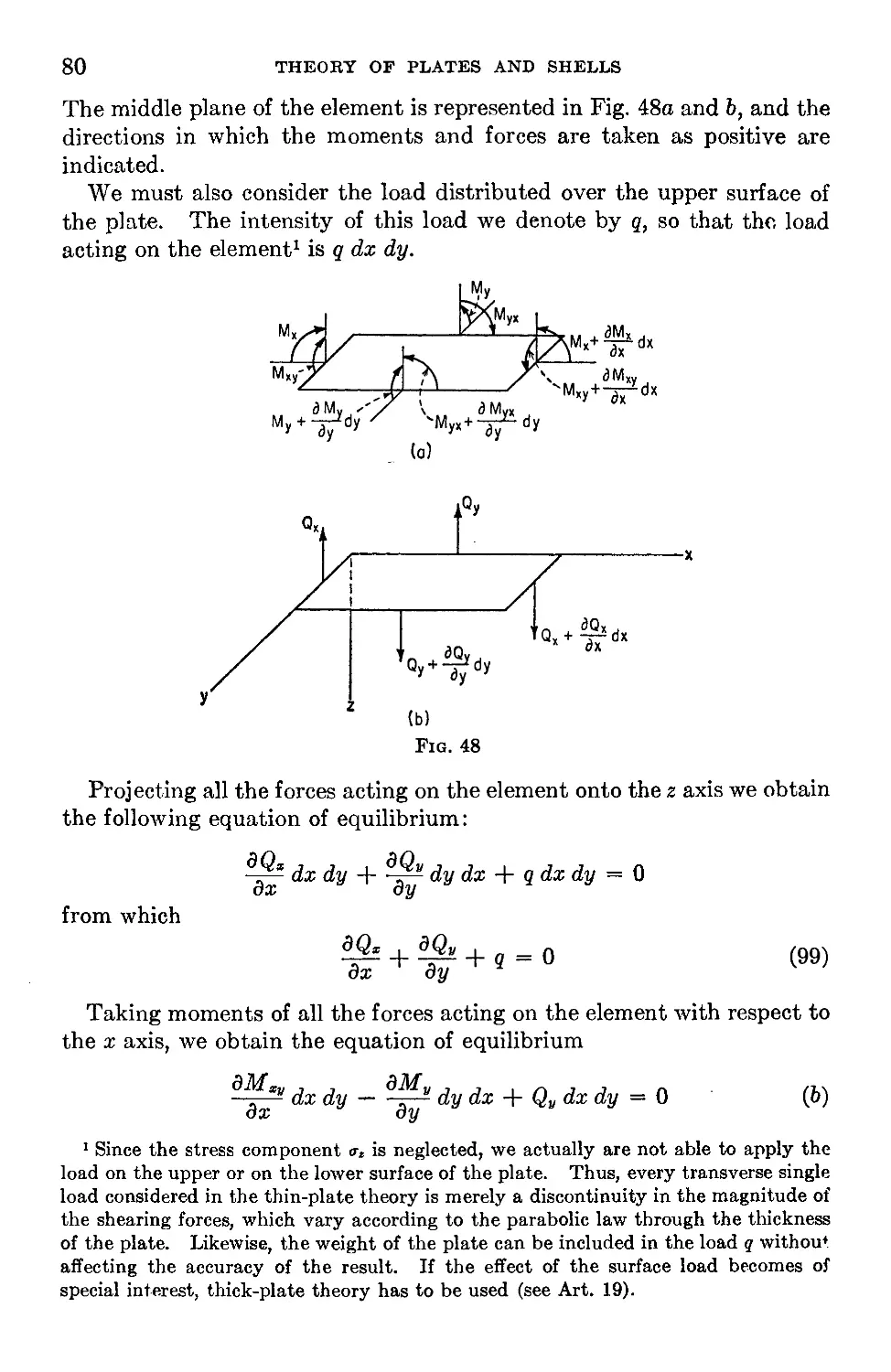
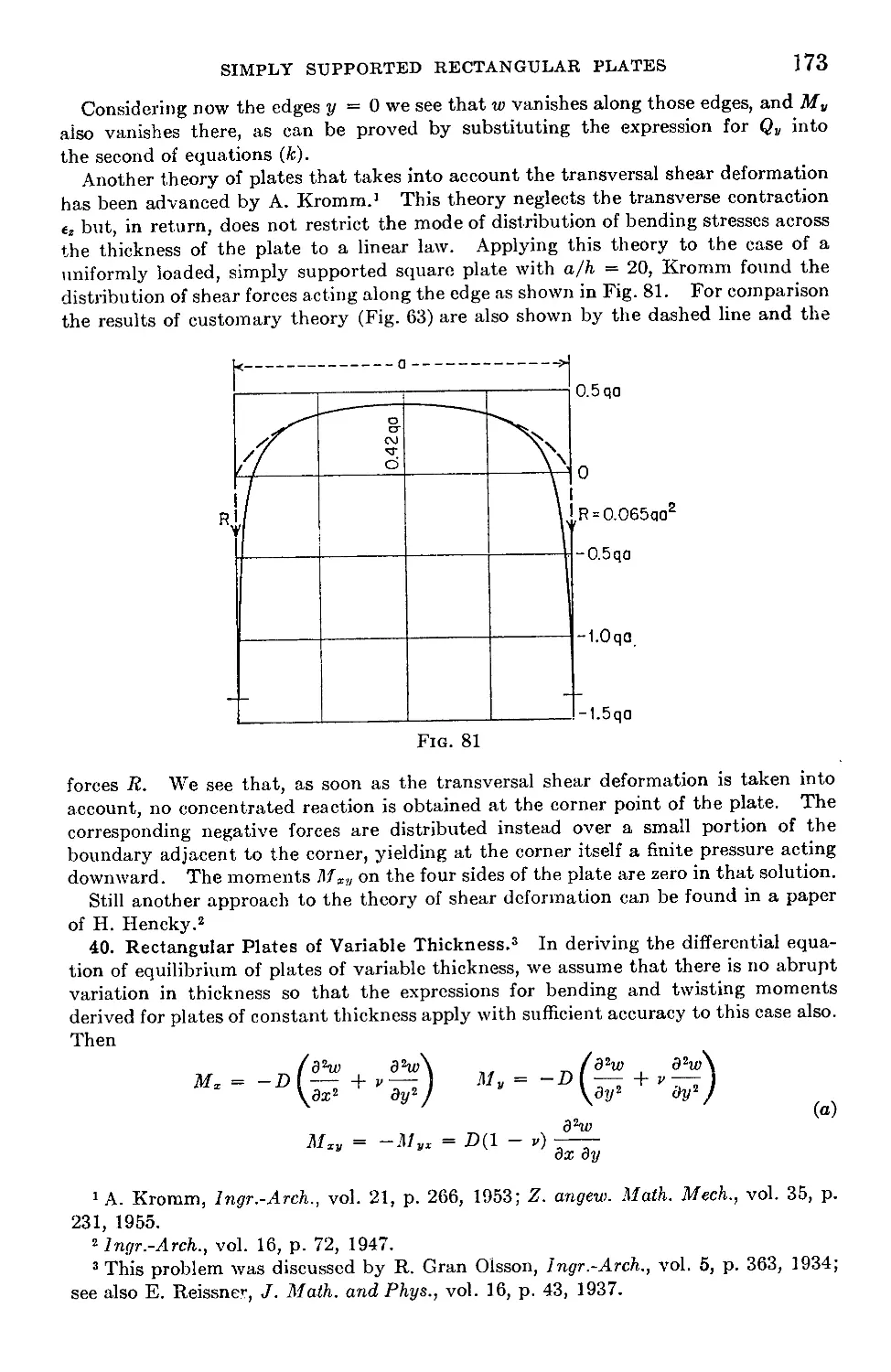
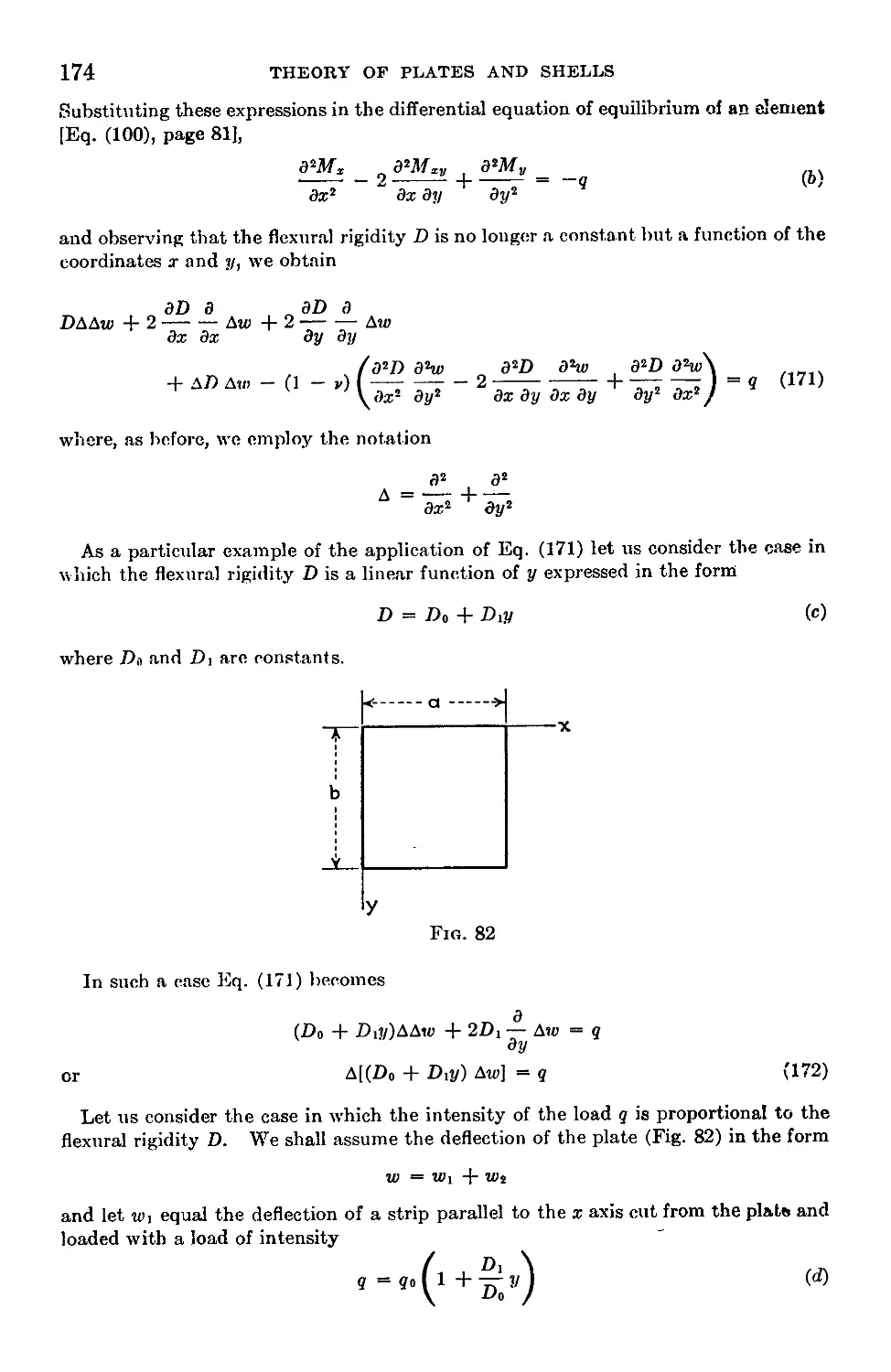
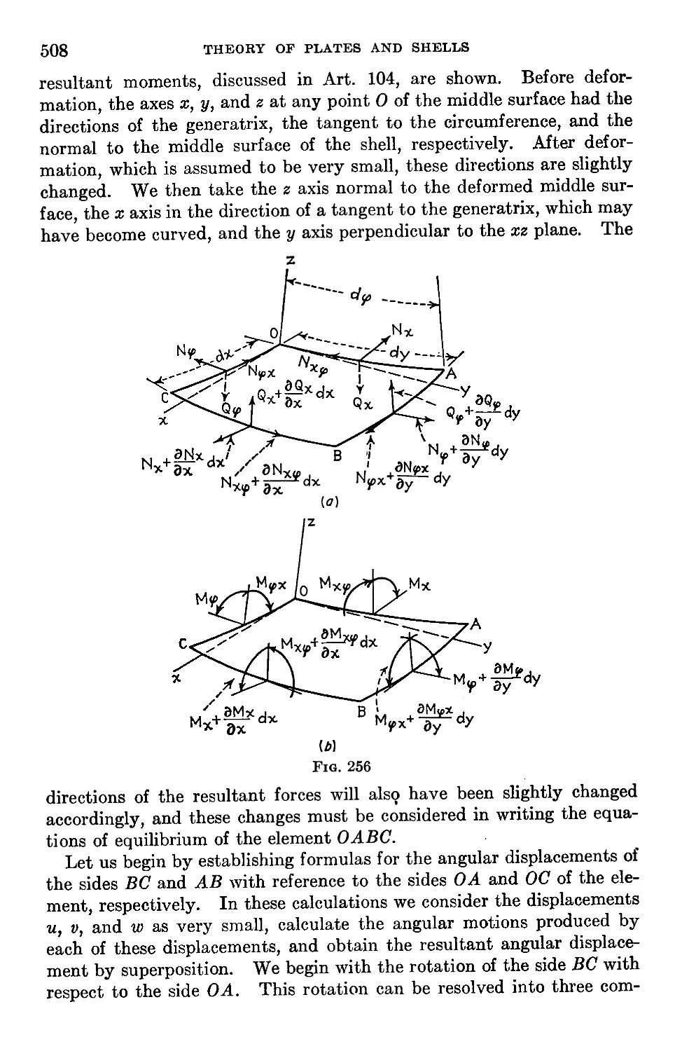
THEORY OF
PLATES AND SHELLS
S. TIMOSHENKO
Professor Emeritus of Engineering Mechanics
Stanford University
S. WOINOWSKY-KRIEGER
Professor of Engineering Mechanics
catalogue^
Laval University
LIBRARY
Second Edition
24 JUIL1989
McGRAW-HILU
CANADAIR LIMITED
CLASSIC
ТЕХТВФК
REISSUE
McGRAW-HILL BOOK COMPANY
New York St. Louis San Francisco Auckland Bogota Hamburg London
Madrid Mexico Milan Montreal New Delhi Panama Paris
Sao Paulo Singapore Sydney Tokyo Toronto
ENGINEERING SOCIETIES MONOGRAPHS
Bakhmeteff: Hydraulics of Open Channels
Bleich: Buckling Strength of Metal Structures
Crandall: Engineering Analysis
Elevatorski: Hydraulic En&rgy Dissipators
Leontovich: Frames and Arches
Nadai: Theory of Flow and Fracture of Solids
Timoshenko and Gere: Theory of Elastic Stability
Timoshenko and Goodier: Theory of Elasticity
Timoshenko and Woinowsky-Krieger: Theory of Plates and Shells
Five national engineering societies, the American Society of Civil Engineers, the
American Institute of Mining, Metallurgical, and Petroleum Engineers, the American
Society of Mechanical Engineers, the American Institute of Electrical Engineers,
and the American Institute of Chemical Engineers, have an arrangement with the
McGraw-Hill Book Company, Inc., for the production of a series of selected books
adjudged to possess usefulness for engineers and industry.
The purposes of this arrangement are: to provide monographs of high technical
quality within the field of engineering; to rescue from obscurity important technical
manuscripts which might not be published commercially because of too limited sale
without special introduction; to develop manuscripts to fill gaps in existing literature;
to collect into one volume scattered information of especial timeliness on a given
subject.
The societies assume no responsibility for any statements made in these books.
Each book before publication has, however, been examined by one or more representa-
tives of the societies competent to express an opinion on the merits of the manuscript.
Ralph H. Phelps, chairman
Engineering Societies Library
New York
ENGINEERING SOCIETIES MONOGRAPHS COMMITTEE
A. S. С. E.
Howard T. Critchlow
H. Alden Foster
A. I. M. E.
Nathaniel Arbiter
John F. Elliott
A. S. M. E.
Calvin S. Cronan
Raymond D. Mindlin
A. I. E. E.
F. Malcolm Farmer
Royal W. Sorensen
A. I. Ch. E.
Joseph F. Skelly
Charles E. Reed
McGRAW-HILL CLASSIC TEXTBOOK REISSUE SERIES
Davenport: Probability Random Process: An Introduction For
Applied Scientists and Engineers
Papoulis: The Fourier Integral and its Applications
Schlichting: Boundary Layer Theory
Timoshenko: Theory of Plates and Shells
Treybal: Mass Transfer Operations
THEORY OF PLATES AND SHELLS
Copyright © 1959 by the McGraw-Hill Book Company, Inc. Reissued 1987 by the McGraw-
Hill Book Company, Inc. All rights reserved. Printed in the United States of America.
Except as permitted under the United States Copyright Act of 1976, no part of this pub-
lication may be reproduced or distributed in any form or by any means, or stored in a data
base or retrieval system, without the prior written permission of the publisher.
ISBN о-от-оьчттп-а
30 31 32 33 34 35 VBA VBA 8 9 2 1 0 9 8
PREFACE
Since the publication of the first edition of this book, the application of
the theory of plates and shells in practice has widened considerably, and
some new methods have been introduced into the theory. To take these
facts into consideration, we have had to make many changes and addi-
tions. The principal additions are (1) an article on deflection of plates due
to transverse shear, (2) an article on stress concentrations around a cir-
cular hole in a bent plate, (3) a chapter on bending of plates resting on
an elastic foundation, (4) a chapter on bending of anisotropic plates, and
(5) a chapter reviewing certain special and approximate methods used in
plate analysis. We have also expanded the chapter on large deflections
of plates, adding several new cases of plates of variable thickness and
some numerical tables facilitating plate analysis.
In the part of the book dealing with the theory of shells, we limited
ourselves to the addition of the stress-function method in the membrane
theory of shells and some minor additions in the flexural theory of shells.
The theory of shells has been developing rapidly in recent years, and
several new books have appeared in this field. Since it was not feasible
for us to discuss these new developments in detail, we have merely re-
ferred to the new bibliography, in which persons specially interested in
this field will find the necessary information.
S'. Timoshenko
S. Woinow sky-Krieg er
CONTENTS
Preface........................................................................ v
Notation......................................................................xiu
Introduction................................................................... 1
Chapter 1. Bending of Long Rectangular Plates to a Cylindrical Surface . 4
1. Differential Equation for Cylindrical Bending of Plates.................. 4
2. Cylindrical Bending of Uniformly Loaded Rectangular Plates with Simply
Supported Edges.............................................................. 6
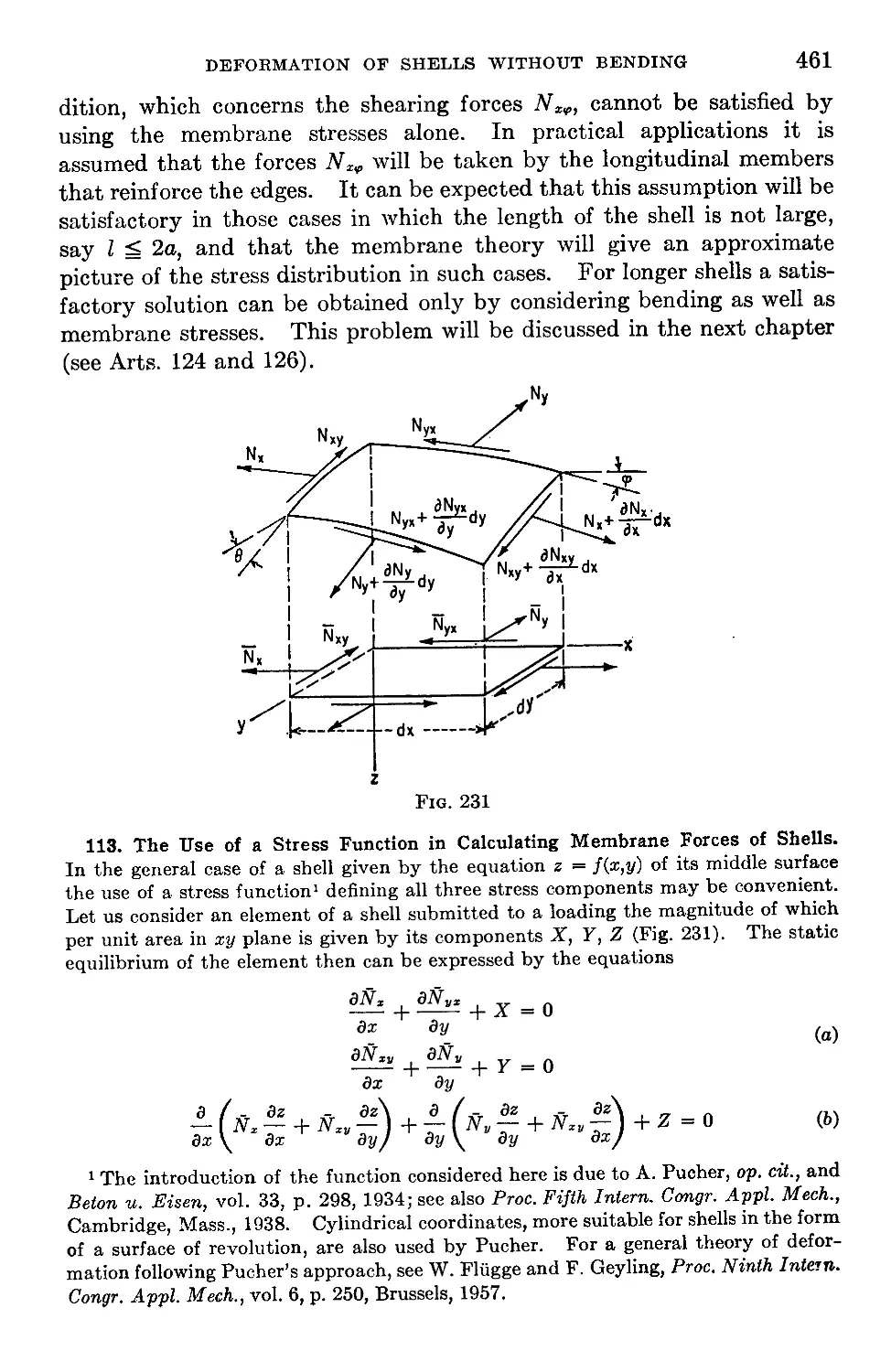
3. Cylindrical Bending of Uniformly Loaded Rectangular Plates with Built-in
Edges........................................................................13
4. Cylindrical Bending of Uniformly Loaded Rectangular Plates with Elasti-
cally Built-in Edges.........................................................17
5. The Effect on Stresses and Deflections of Small Displacements of Longi-
tudinal Edges in the Plane of the Plate..................................20
6. An Approximate Method of Calculating the Parameter и.....................24
7. Long Uniformly Loaded Rectangular Plates Having a Small Initial Cylin-
drical Curvature.............................................................27
8. Cylindrical Bending of a Plate on an Elastic Foundation..................30
Chapter 2. Pure Bending of Plates.............................................33
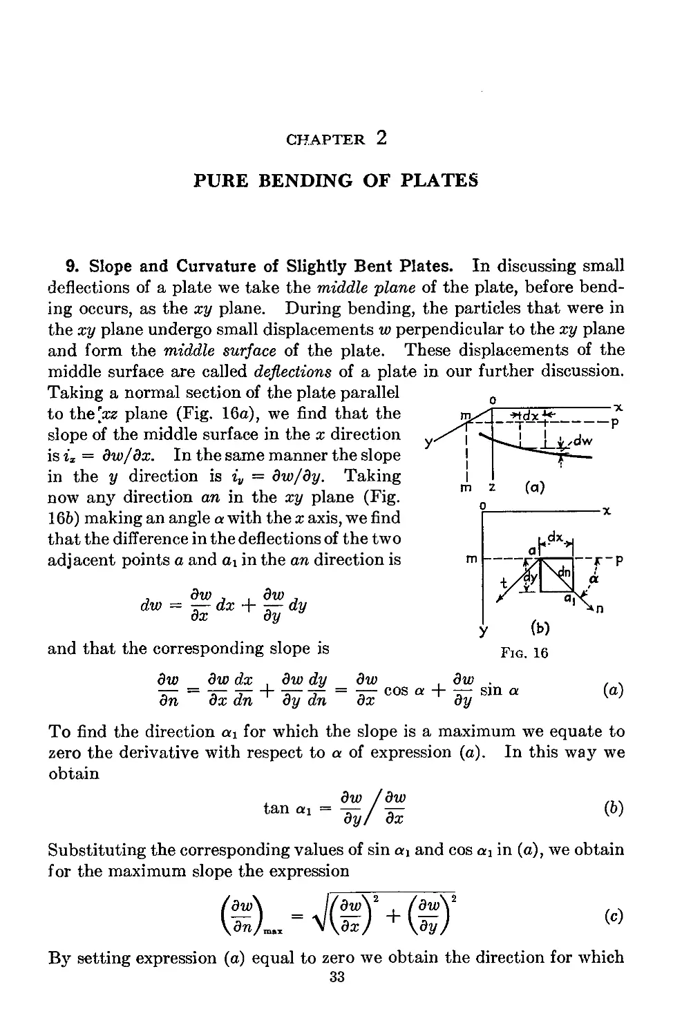
9. Slope and Curvature of Slightly Bent Plates..............................33
10. Relations between Bending Moments and Curvature in Pure Bending of
Plates........................................................................37
11. Particular Cases of Pure Bending.........................................42
12. Strain Energy in Pure Bending of Plates..................................46
13. Limitations on the Application of the Derived Formulas...................47
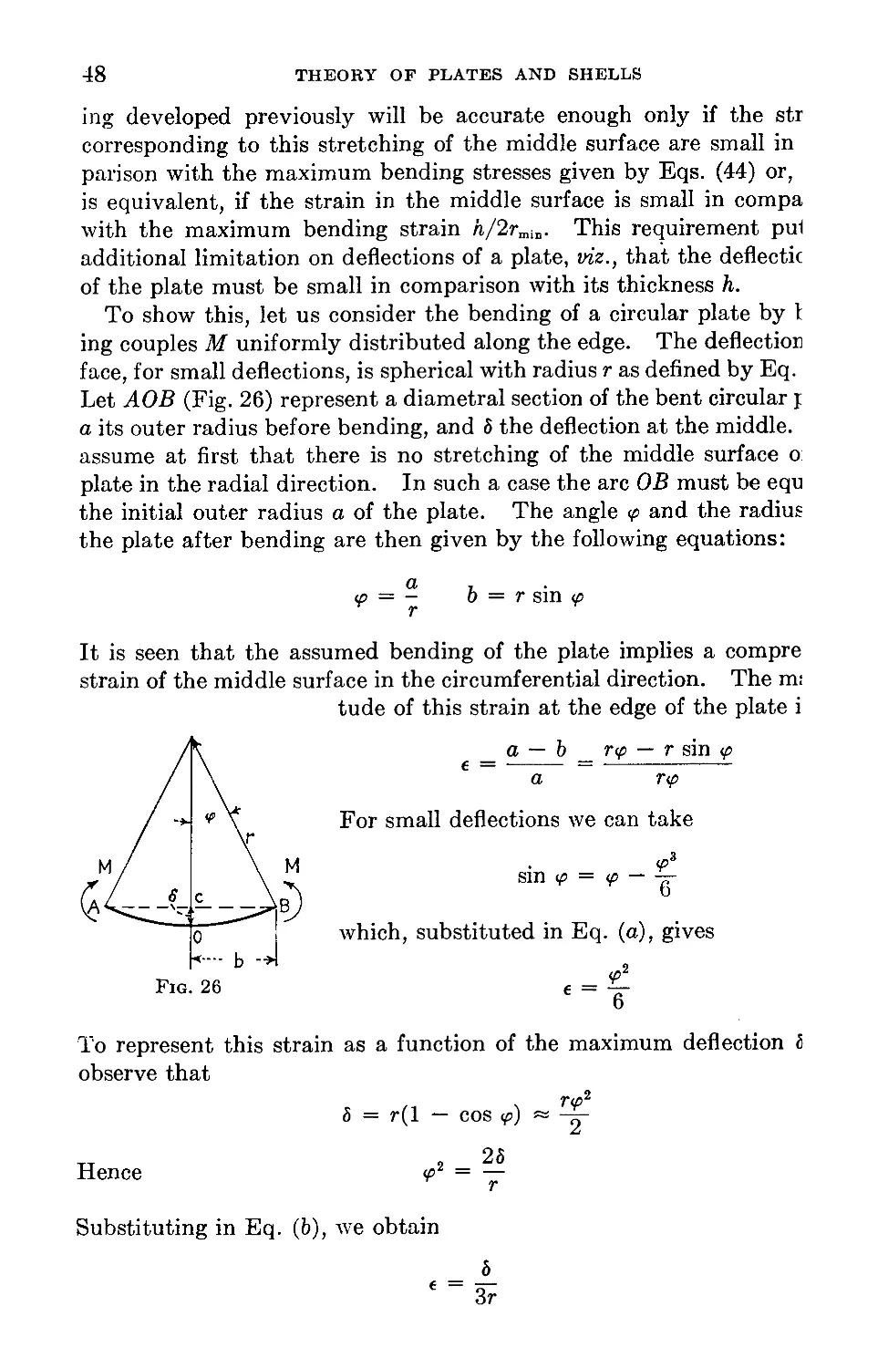
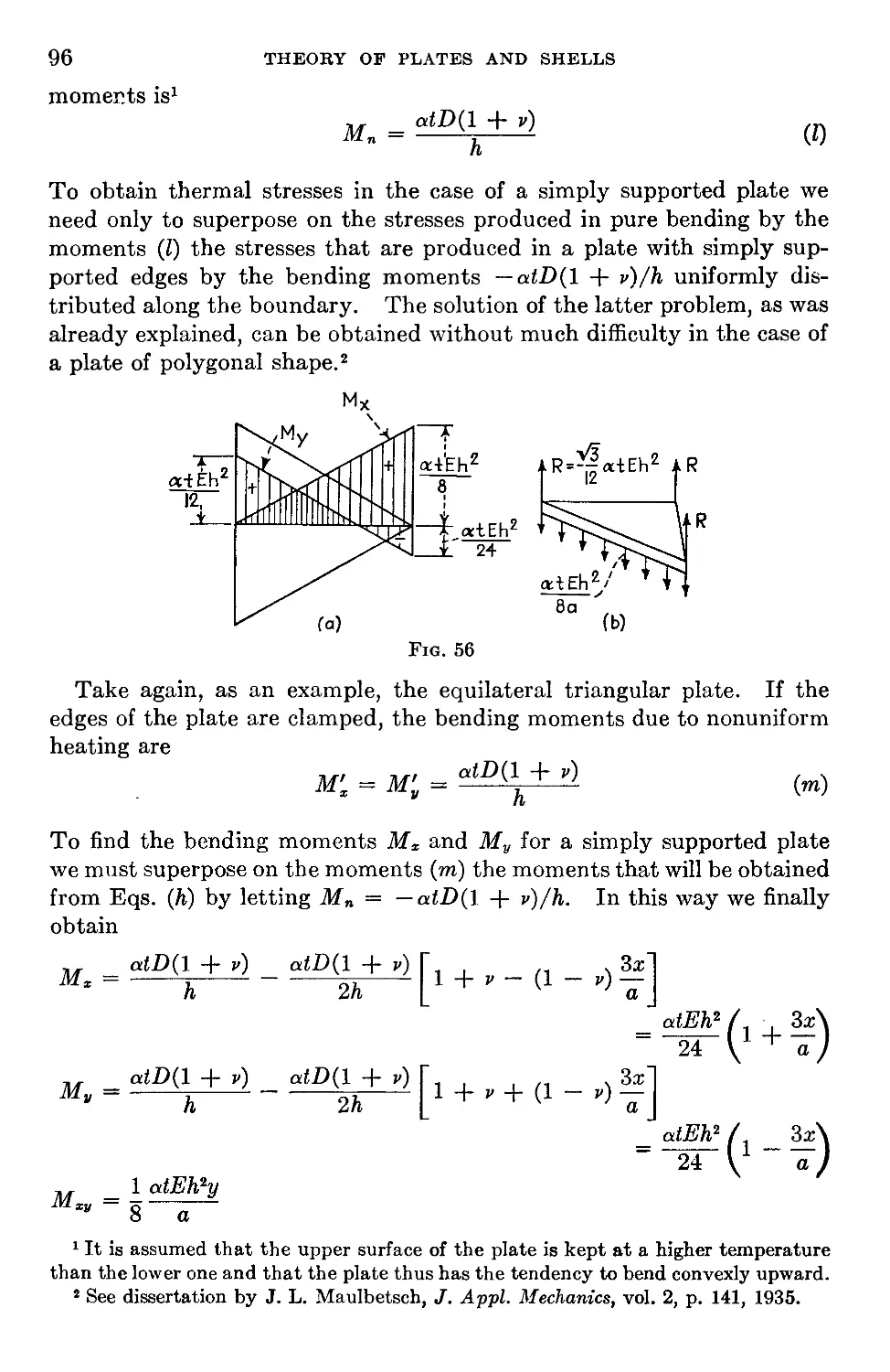
14. Thermal Stresses in Plates with Clamped Edges............................49
Chapter 3. Symmetrical Bending of Circular Plates.............................51
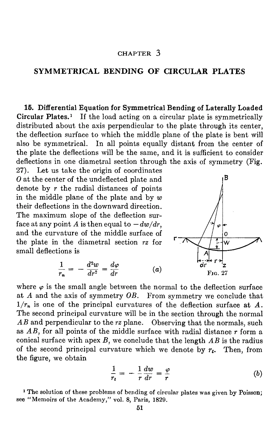
15. Differential Equation for Symmetrical Bending of Laterally Loaded Cir-
cular Plates..................................................................51
16. Uniformly Loaded Circular Plates.........................................54
17. Circular Plate with a Circular Hole at the Center........................58
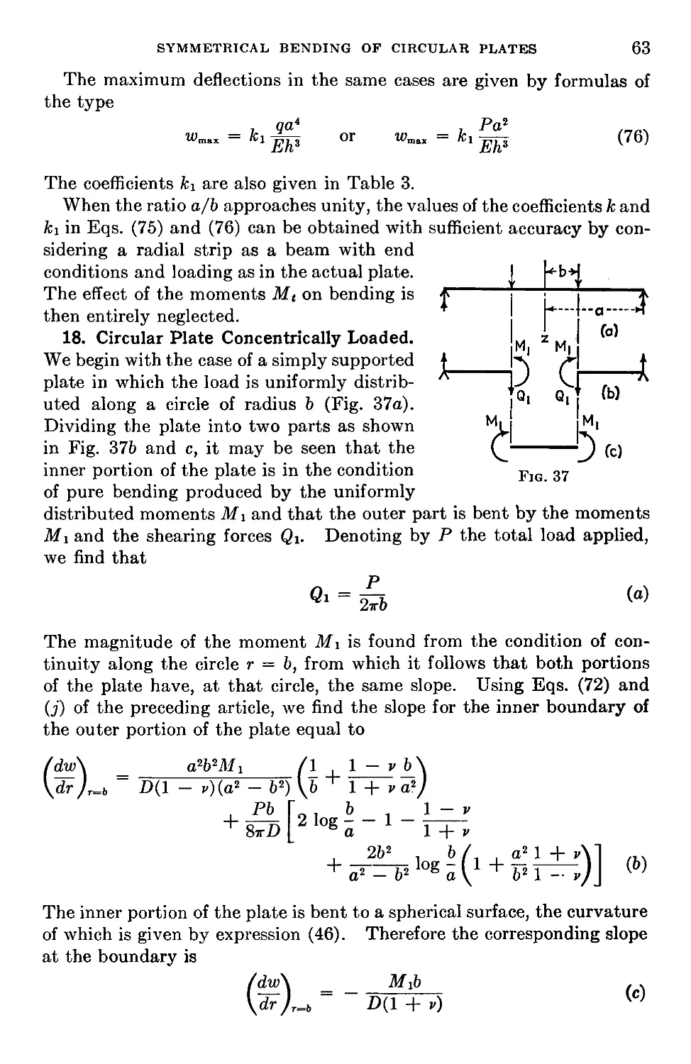
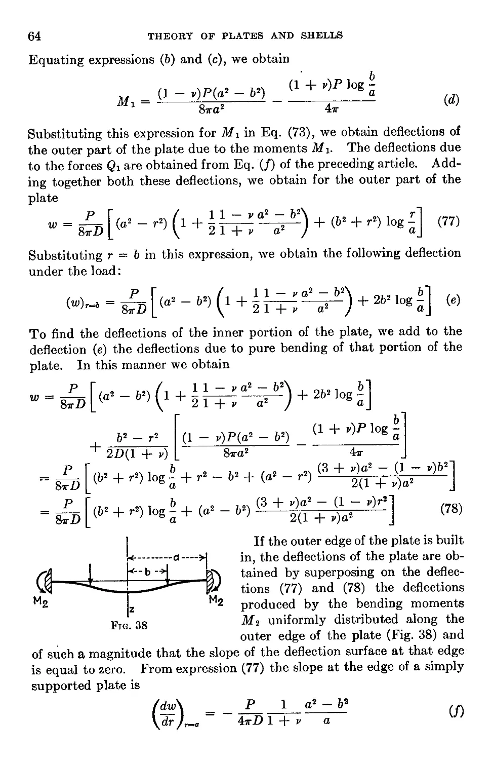
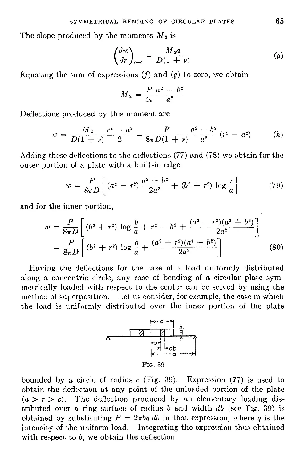
18. Circular Plate Concentrically Loaded.................................• 63
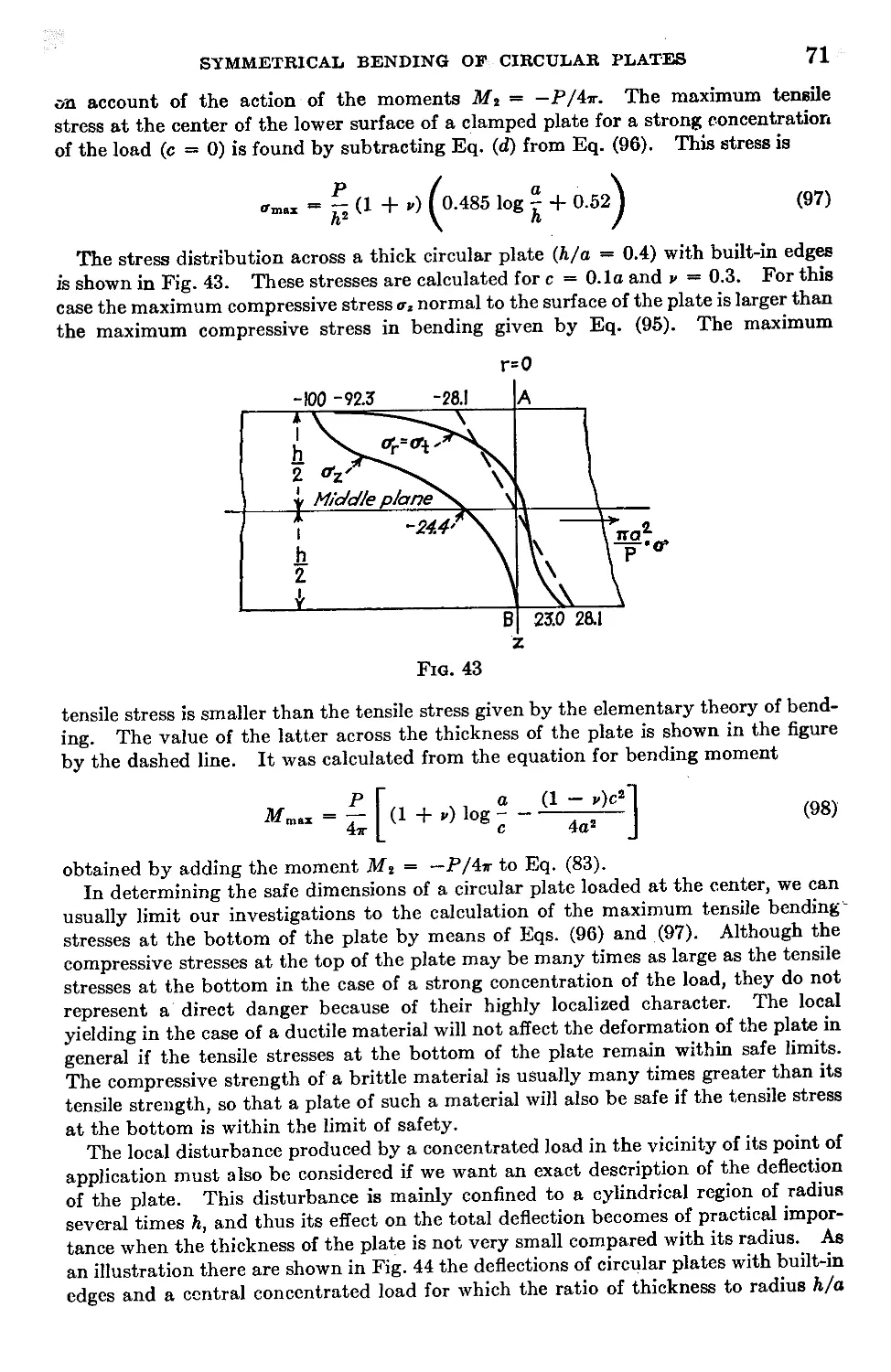
19. Circular Plate Loaded at the Center......................................67
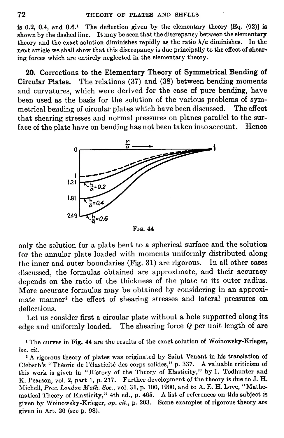
20. Corrections to the Elementary Theory of Symmetrical Bending of Cir-
cular Plates..................................................................72
Chapter 4. Small Deflections of Laterally Loaded Plates.......................79
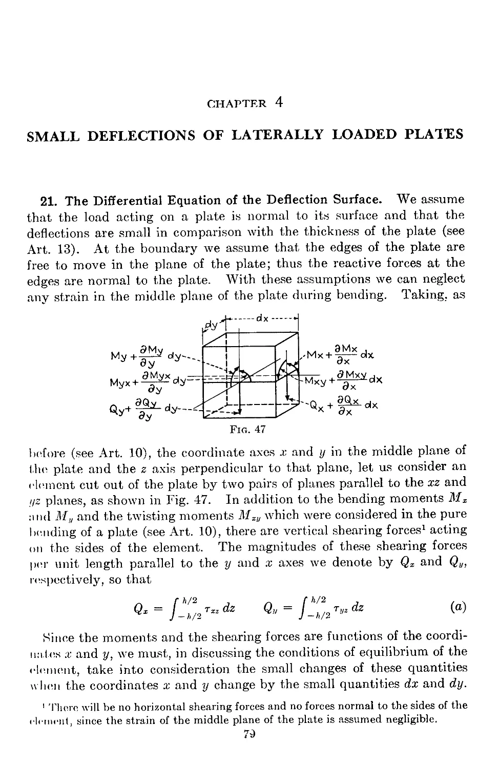
21. The Differential Equation of the Deflection Surface . ................7S
vii
viii CONTENTS
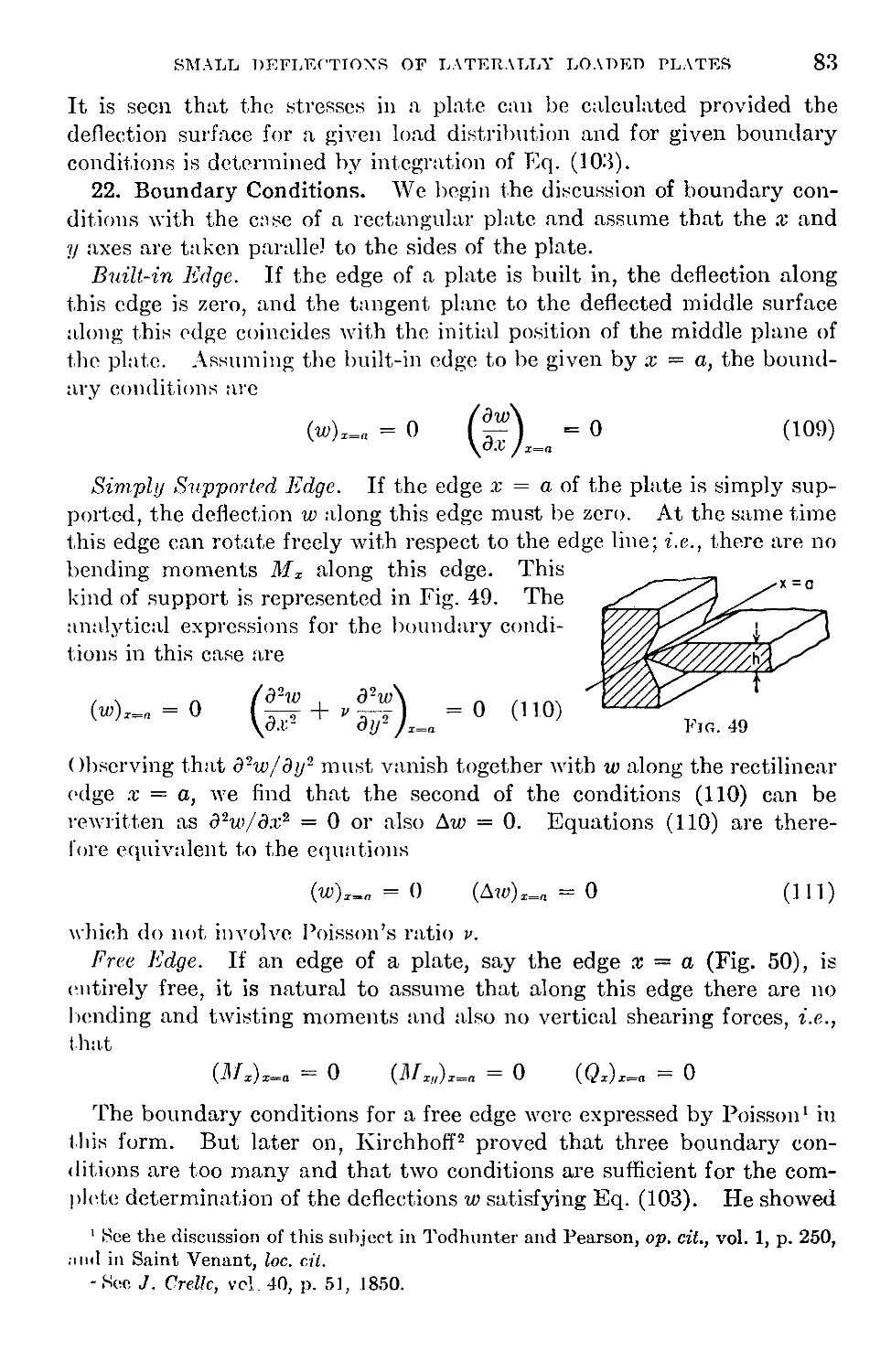
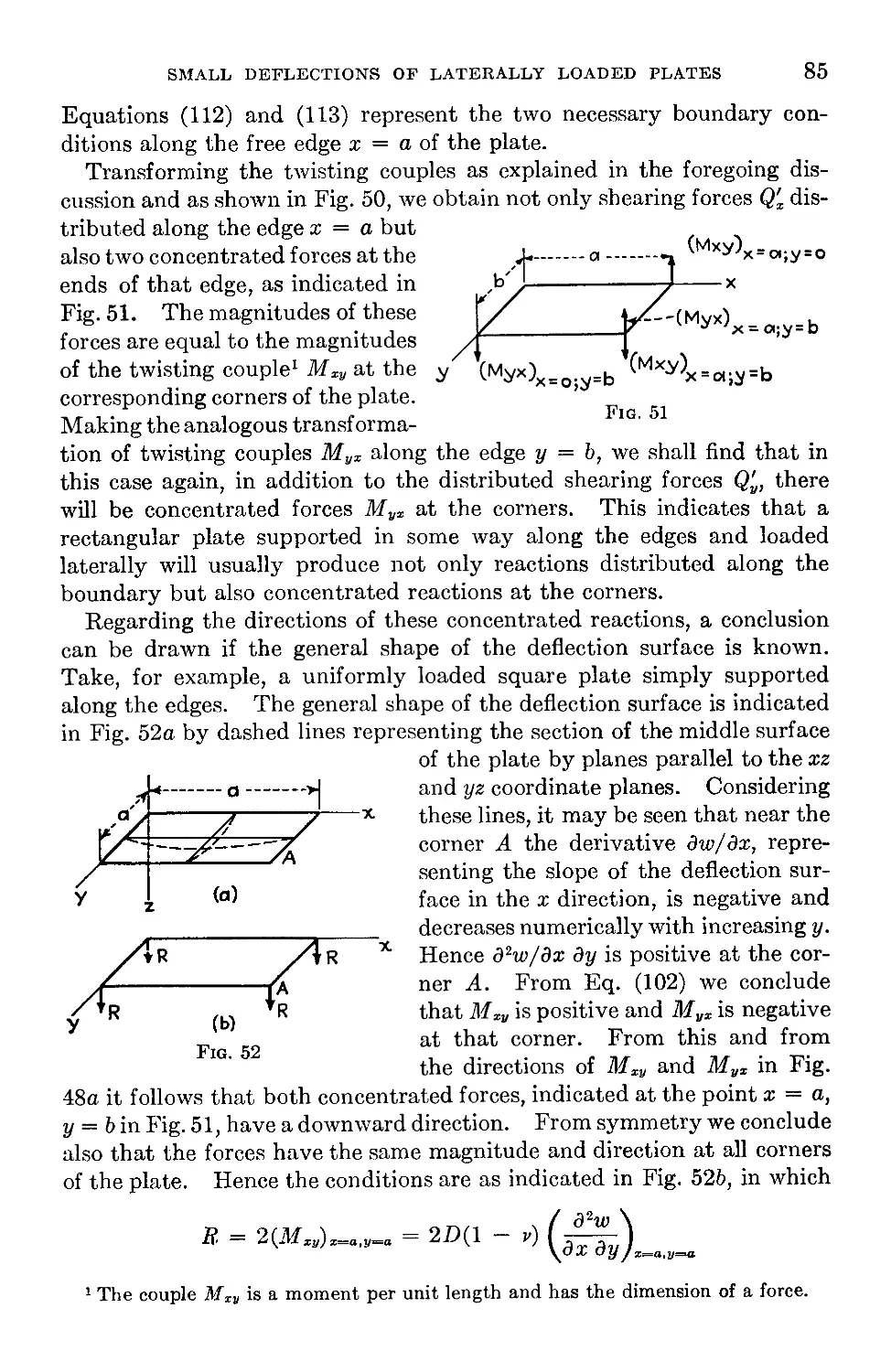
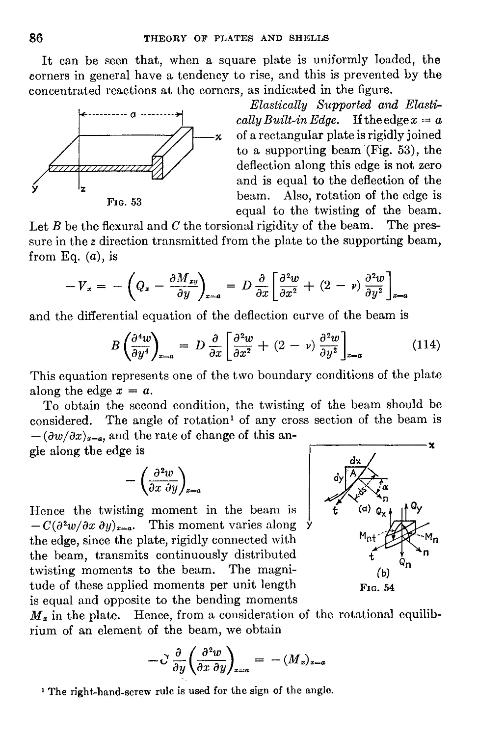
22. Boundary Conditions..................................................83
23. Alternate Method of Derivation of the Boundary Conditions .... 88
24. Reduction of the Problem of Bending of a Plate to That of Deflection of a
Membrane..............................................................92
25. Effect of Elastic Constants on the Magnitude of Bending Moments . . 97
26. Exact Theory of Plates...............................................98
Chapter 5. Simply Supported Rectangular Plates............................105
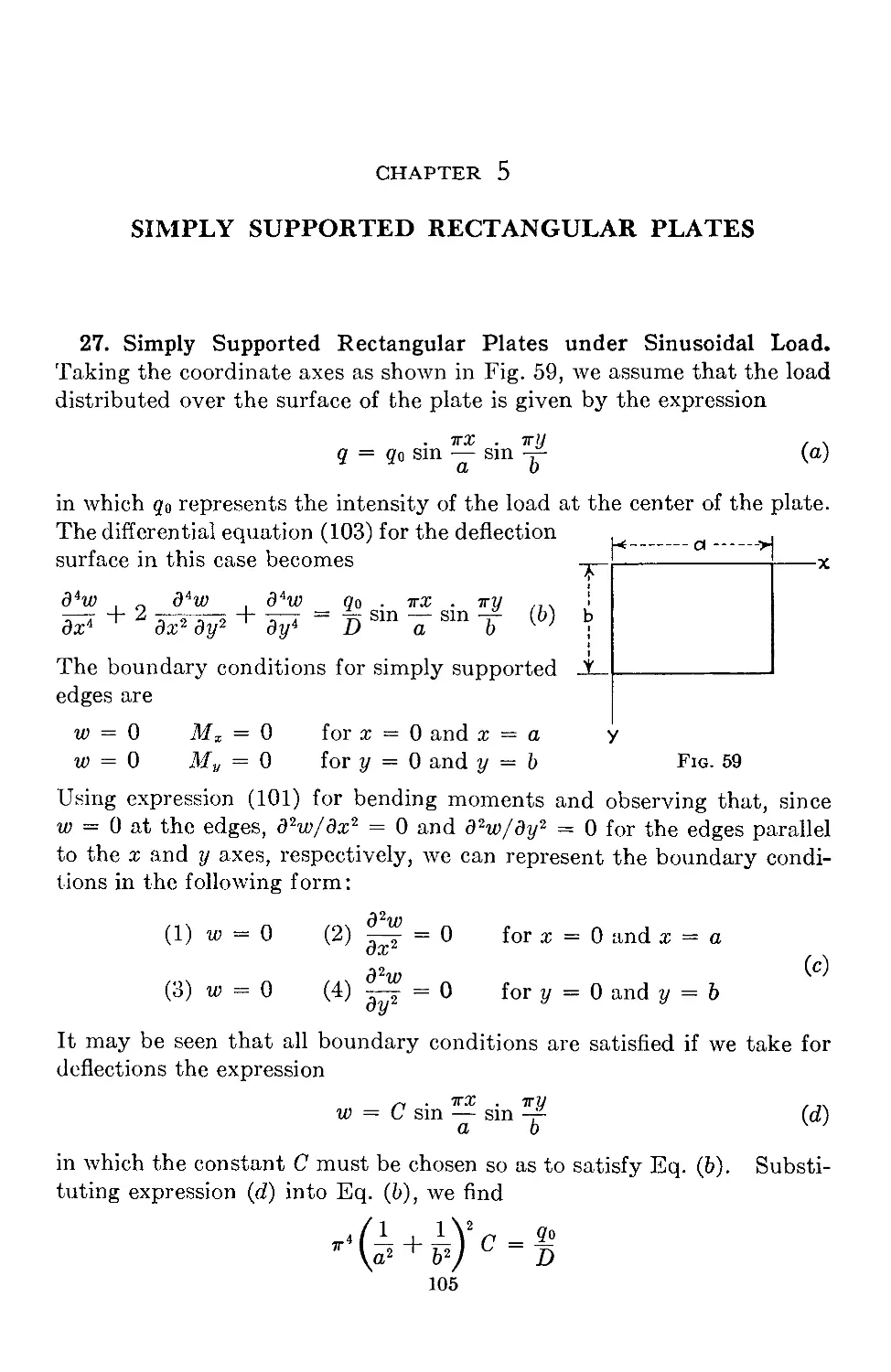
27. Simply Supported Rectangular Plates under Sinusoidal Load .... 105
28. Navier Solution for Simply Supported Rectangular Plates..............108
29. Further Applications of the Navier Solution.........................Ill
30. Alternate Solution for Simply Supported and Uniformly Loaded Rectangu-
lar Plates...........................................................113
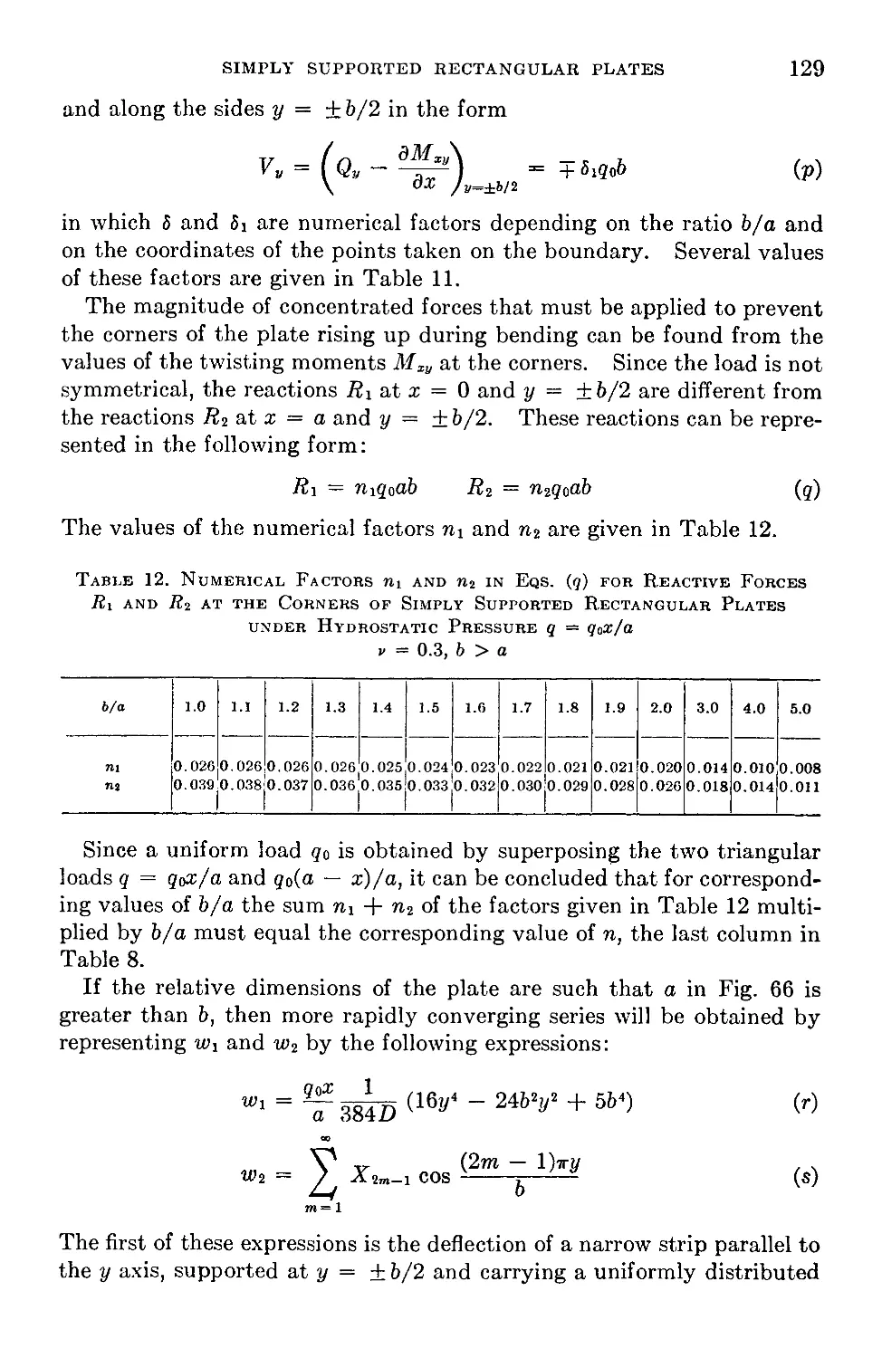
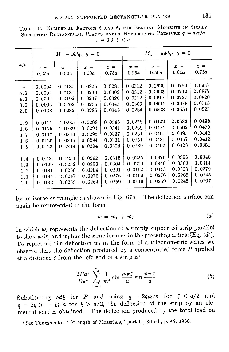
31. Simply Supported Rectangular Plates under Hydrostatic Pressure . 124
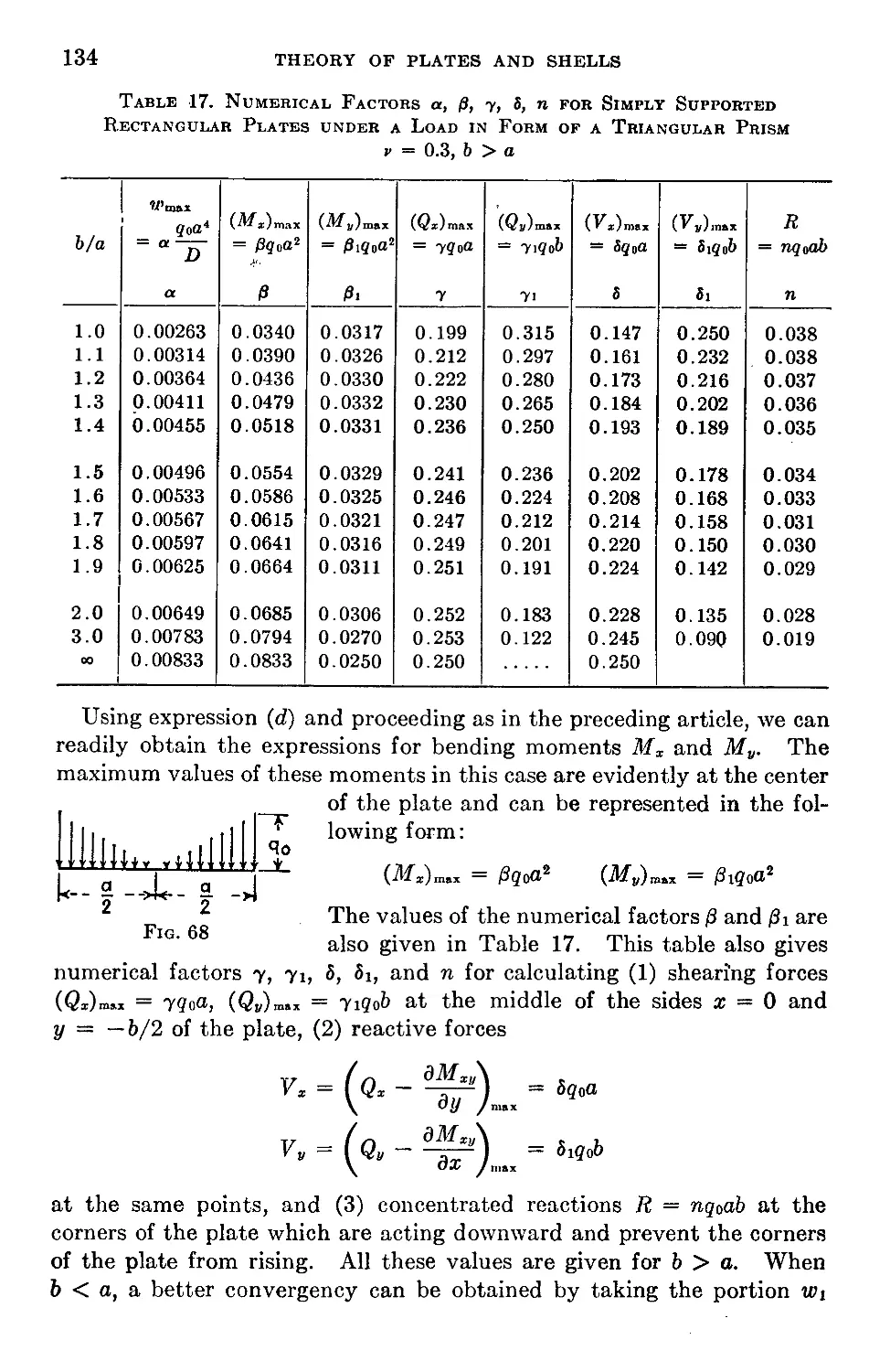
32. Simply Supported Rectangular Plate under a Load in the Form of a Tri-
angular Prism........................................................130
33. Partially Loaded Simply Supported Rectangular Plate.................135
34. Concentrated Load on a Simply Supported Rectangular Plate . . .141
35. Bending Moments in a Simply Supported Rectangular Plate with a Con-
centrated Load.......................................................143
36. Rectangular Plates of Infinite Length with Simply Supported Edges . 149
37. Bending Moments in Simply Supported Rectangular Plates under a Load
Uniformly Distributed over the Area of a Rectangle...................158
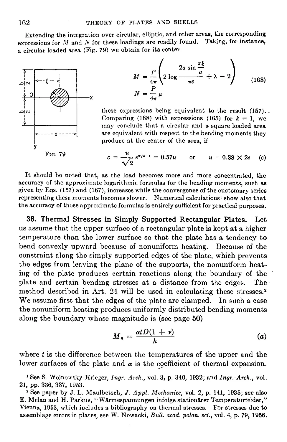
38. Thermal Stresses in Simply Supported Rectangular Plates.............162
39. The Effect of Transverse Shear Deformation on the Bending of Thin Plates 165
40. Rectangular Plates of Variable Thickness.............................173
Chapter 6. Rectangular Plates with Various Edge Conditions...............180
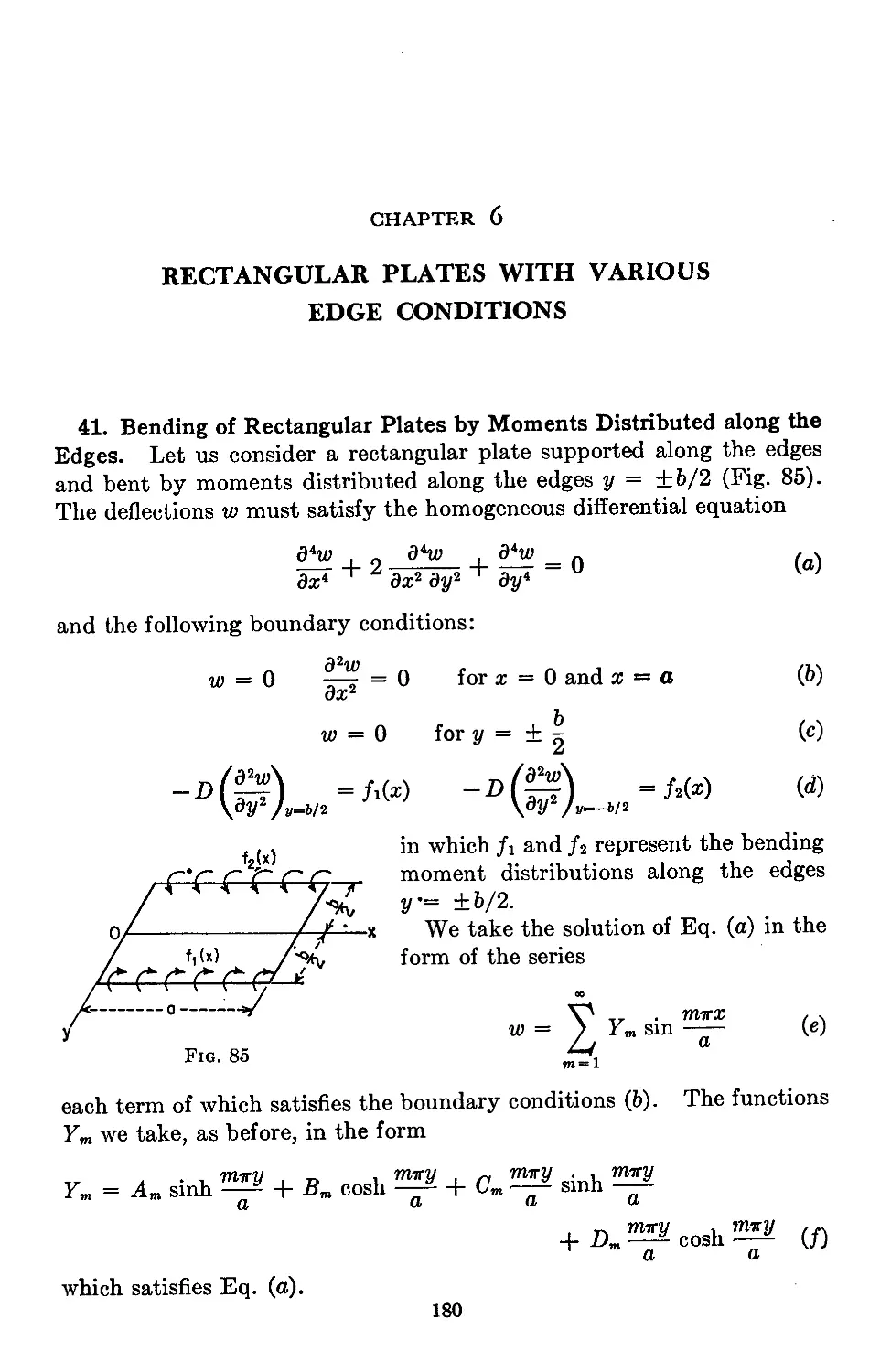
41. Bending of Rectangular Plates by Moments Distributed along the Edges . 180
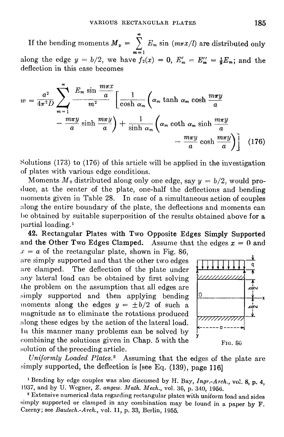
42. Rectangular Plates with Two Opposite Edges Simply Supported and the
Other Two Edges Clamped..............................................185
43. Rectangular Plates with Three Edges Simply Supported and One Edge
Built In.............................................................192
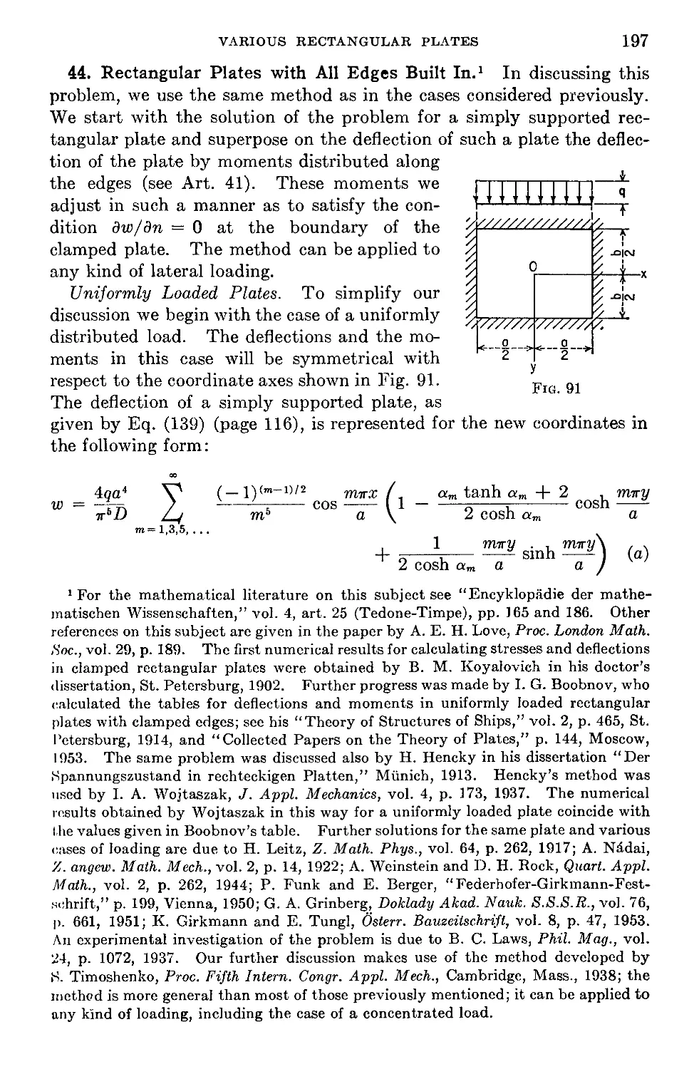
44. Rectangular Plates with All Edges Built In..........................197
45. Rectangular Plates with One Edge or Two Adjacent Edges Simply Sup-
ported and the Other Edges Built In..................................205
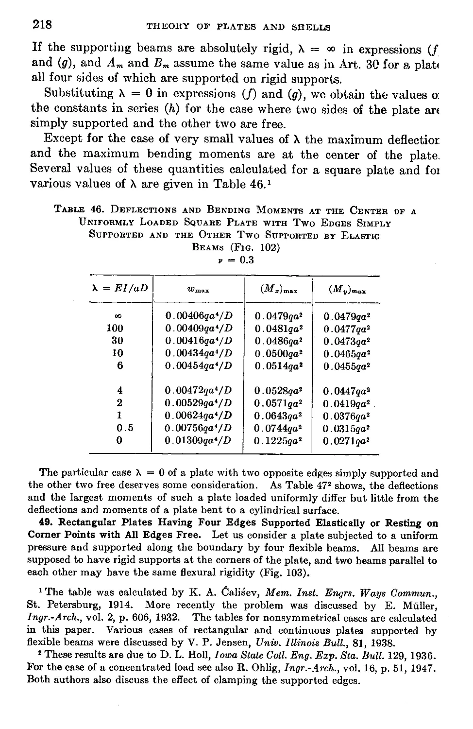
46. Rectangular Plates with Two Opposite Edges Simply Supported, the Third
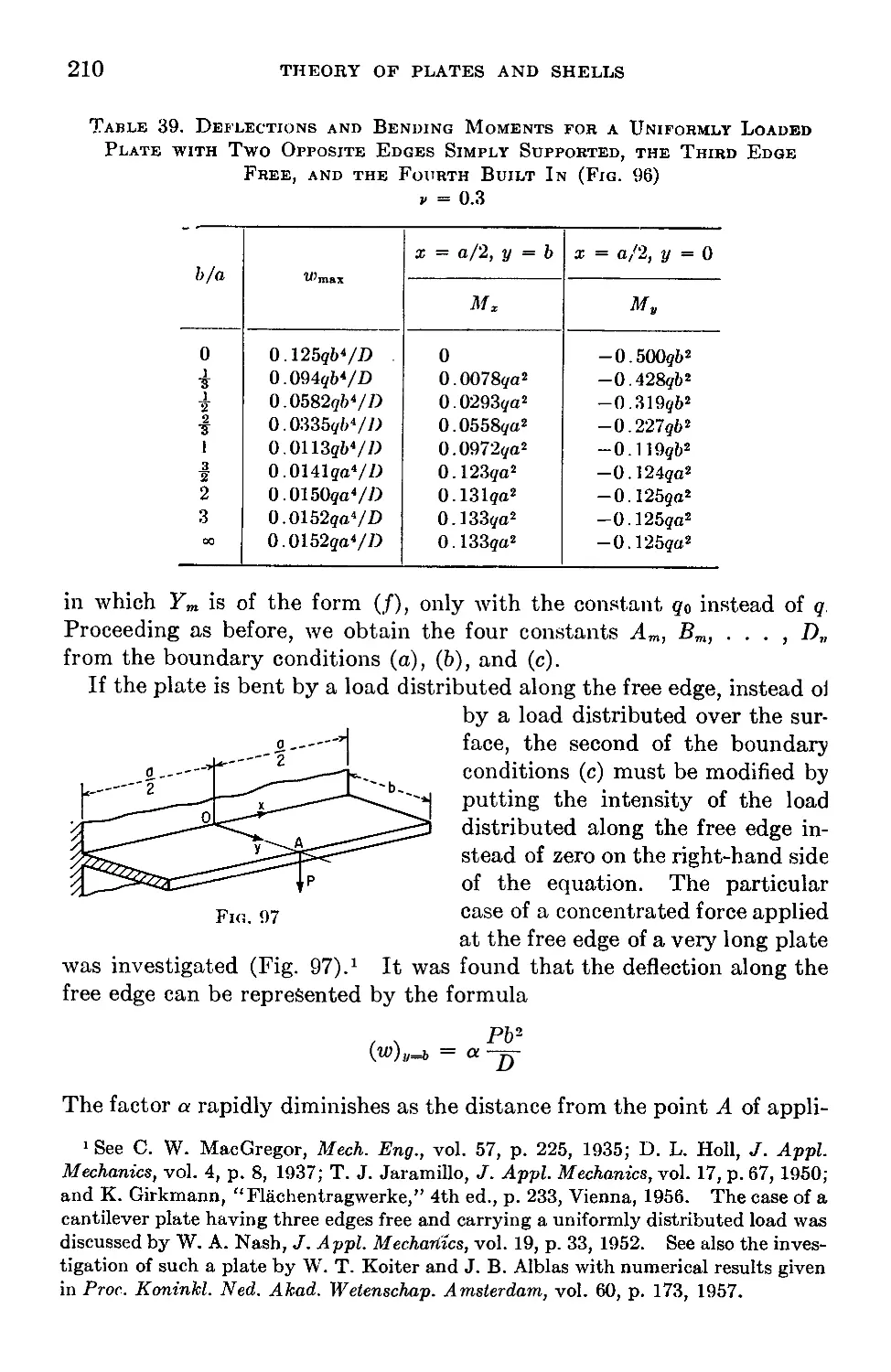
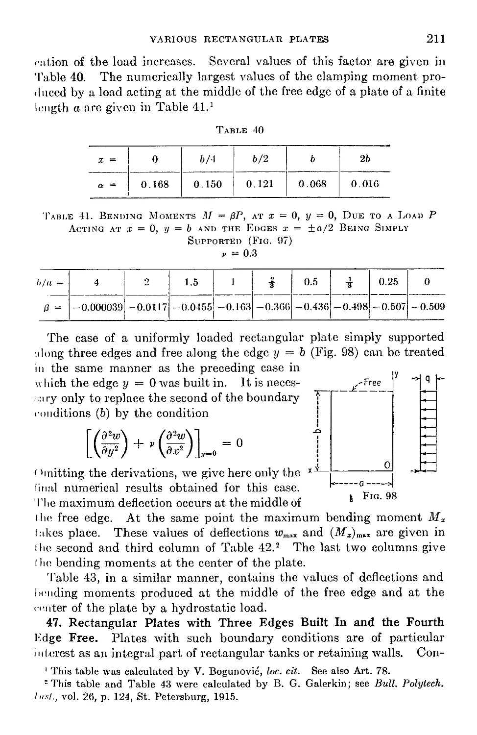
Edge Free, and the Fourth Edge Built In or Simply Supported . . . 208
47. Rectangular Plates with Three Edges Built In and the Fourth Edge Free. 211
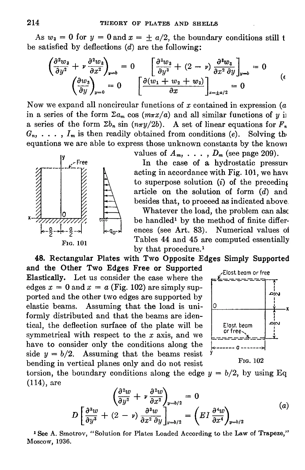
48. Rectangular Plates with Two Opposite Edges Simply Supported and the
Other Two Edges Free or Supported Elastically........................214
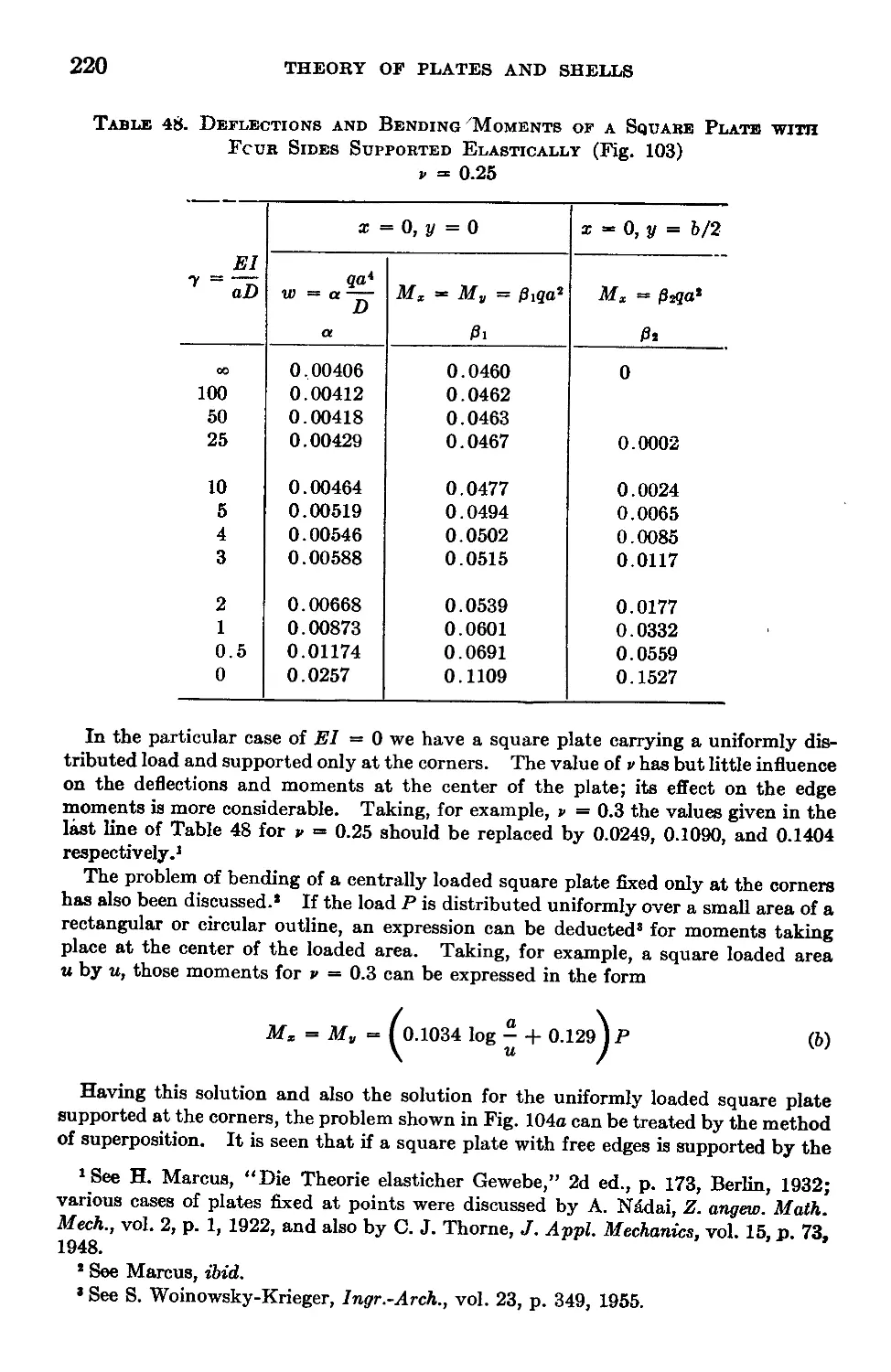
49. Rectangular Plates Having Four Edges Supported Elastically or Resting
on Corner Points with All Edges Free.................................218
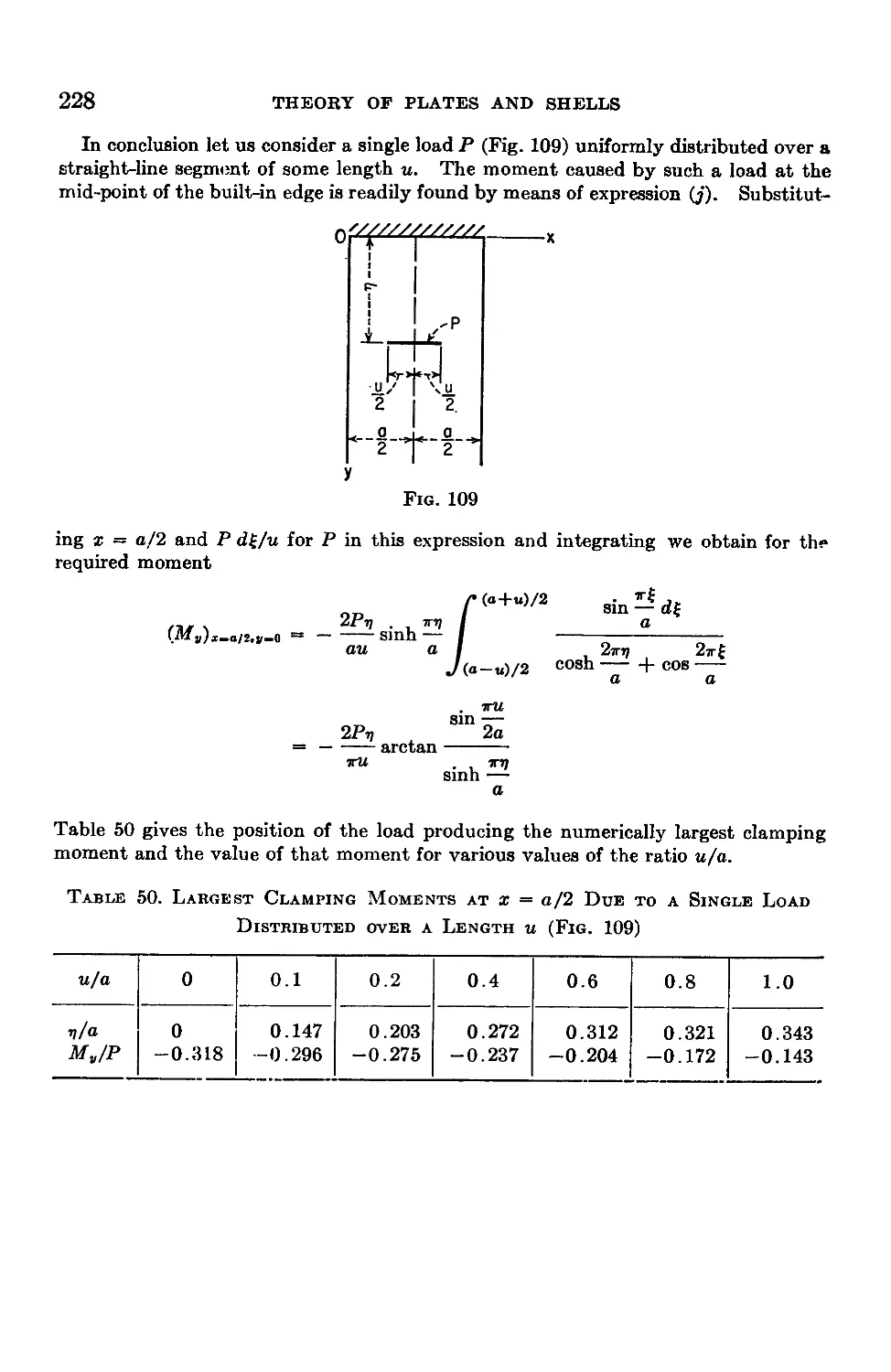
50. Semi-infinite Rectangular Plates under Uniform Pressure.............221
51. Semi-infinite Rectangular Plates under Concentrated Loads .... 225
Chapter 7. Continuous Rectangular Plates.................................229
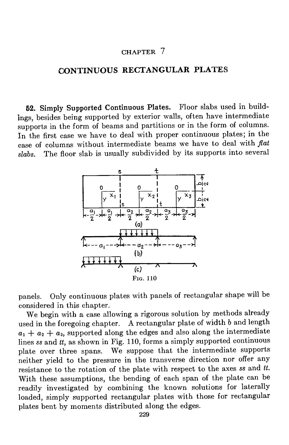
52. Simply Supported Continuous Plates..................................229
53. Approximate Design of Continuous Plates with Equal Spans .... 236
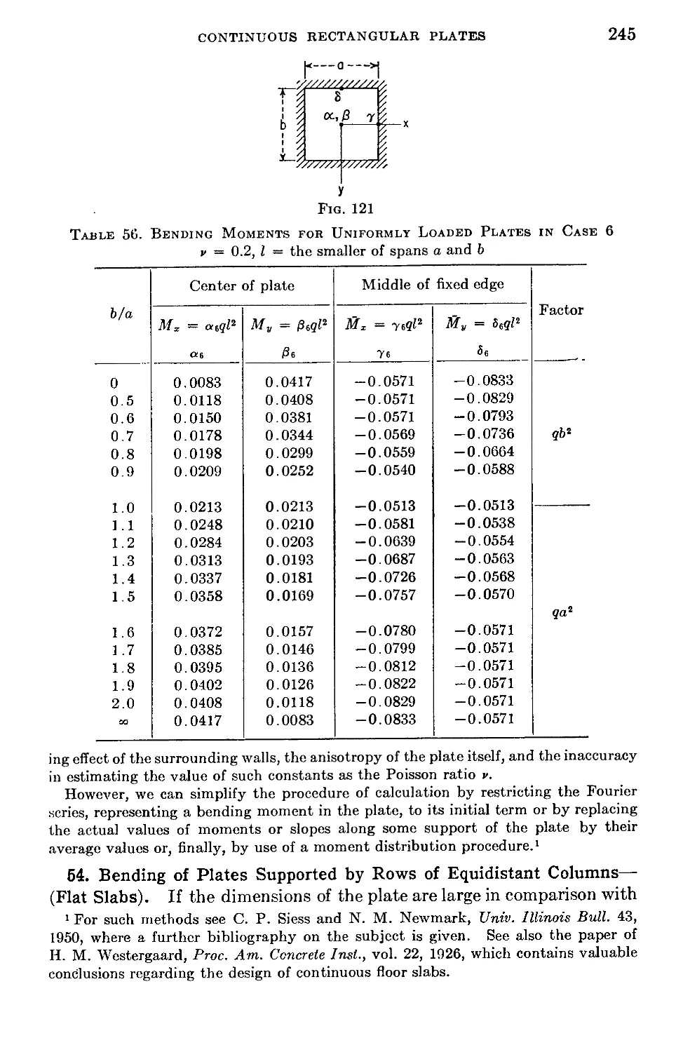
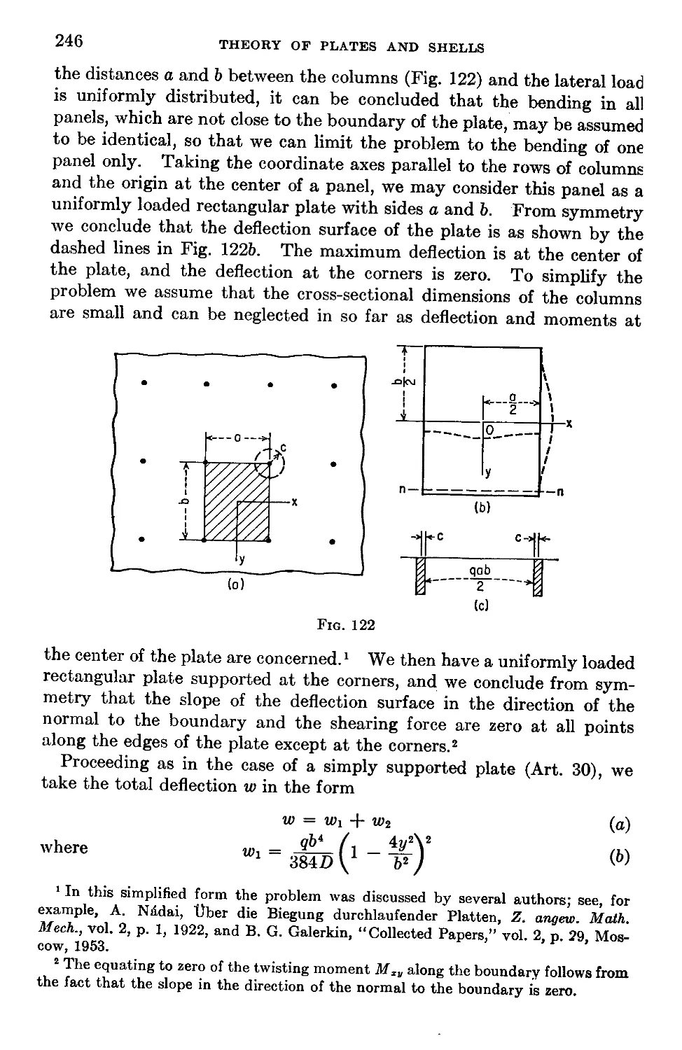
54. Bending of Plates Supported by Rows of Equidistant Columns (Flat Slabs) 245
55. Flat Slab Having Nine Panels and Slab with Two Edges Free .... 253
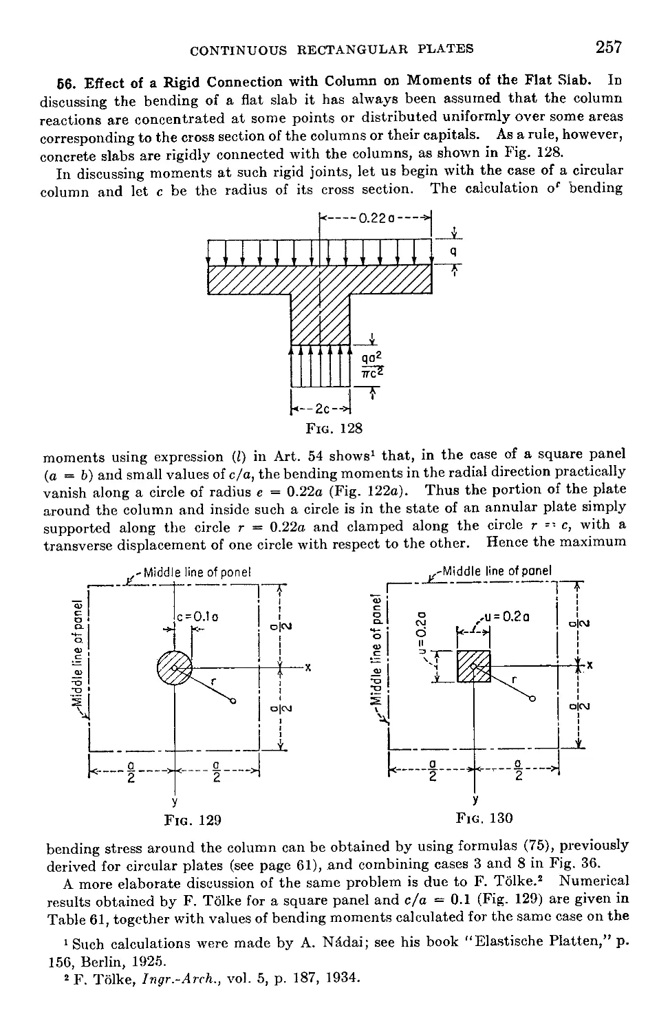
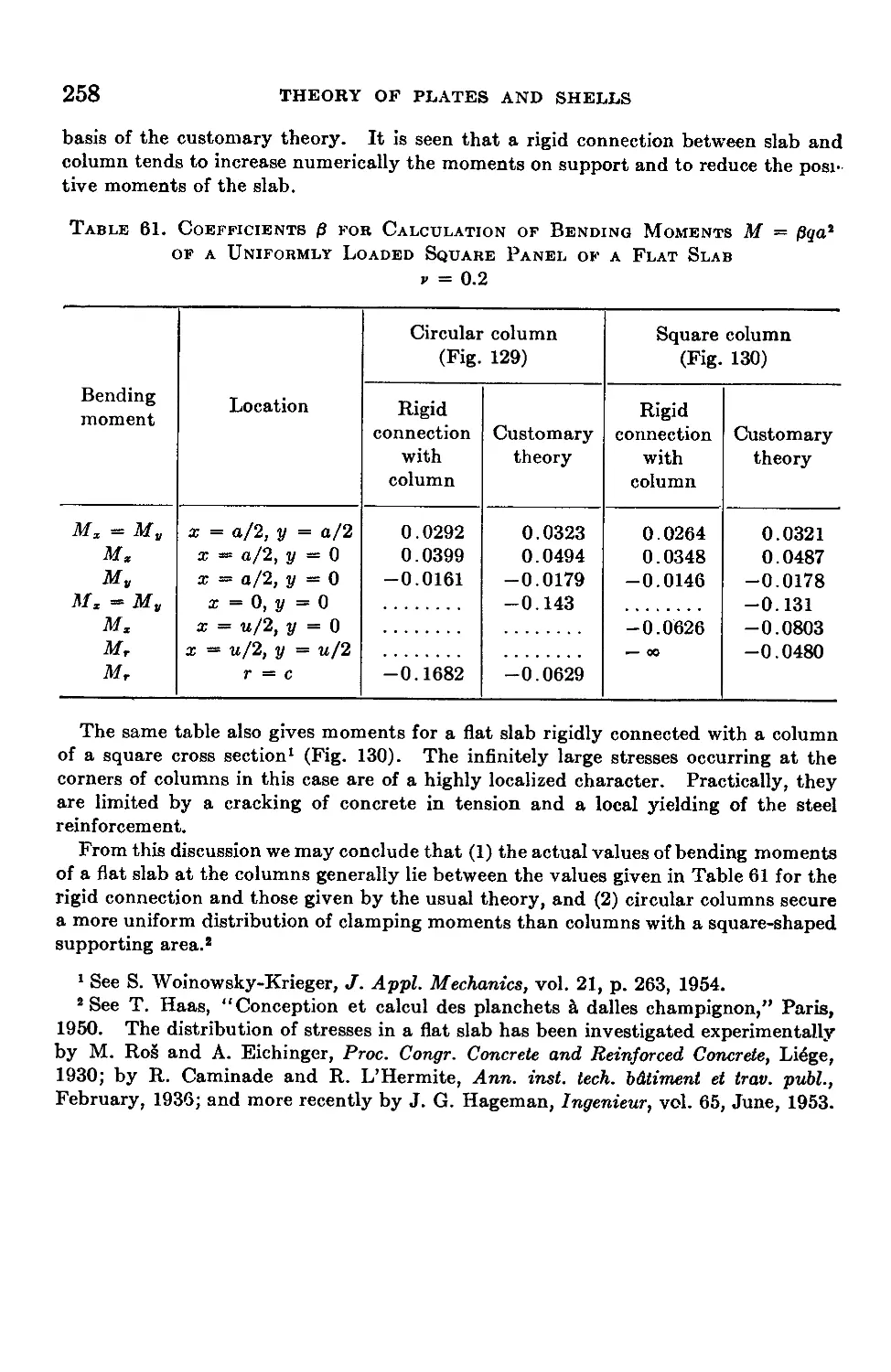
56. Effect of a Rigid Connection with Column on Moments of the Flat Slab. 257
CONTENTS lx
Chapter 8. Plates on Elastic Foundation....................................259
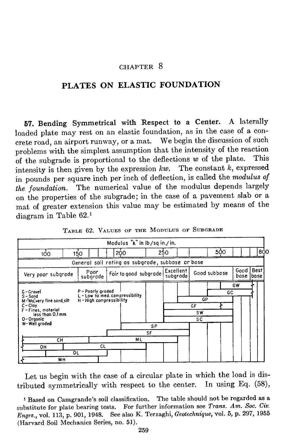
57. Bending Symmetrical with Respect to a Center..........................259
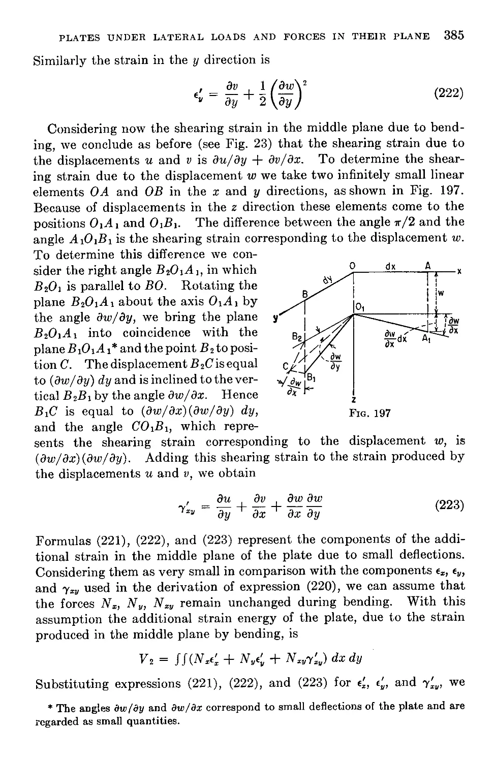
58. Application of Bessel Functions to the Problem of the Circular Plate . . 265
59. Rectangular and Continuous Plates on Elastic Foundation .... 269
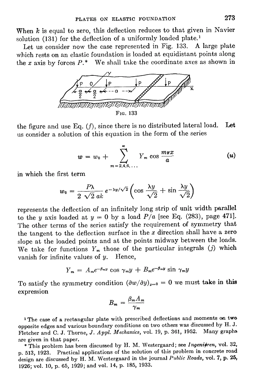
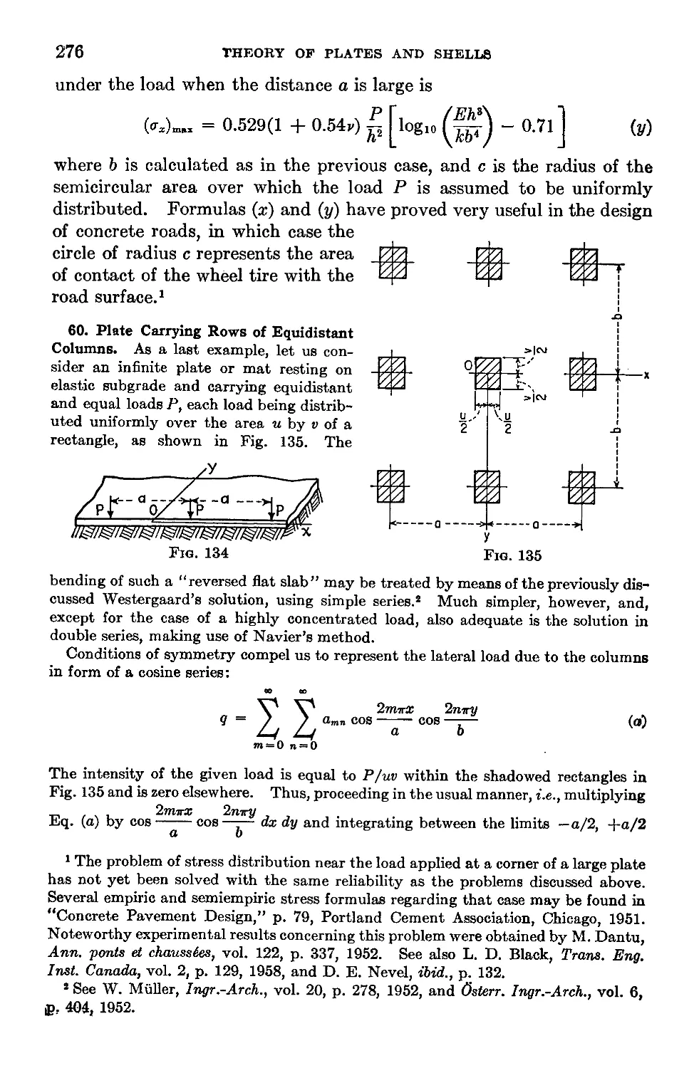
60. Plate Carrying Rows of Equidistant Columns............................276
61. Bending of Plates Resting on a Semi-infinite Elastic Solid............278
Chapter 9. Plates of Various Shapes........................................282
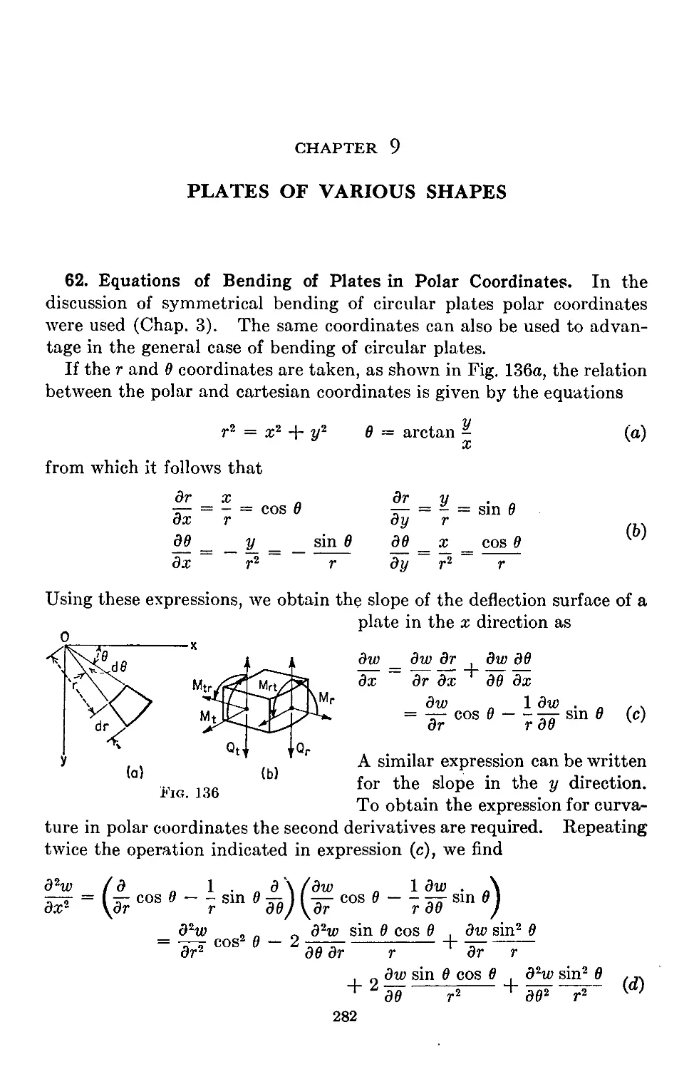
62. Equations of Bending of Plates in Polar Coordinates...................282
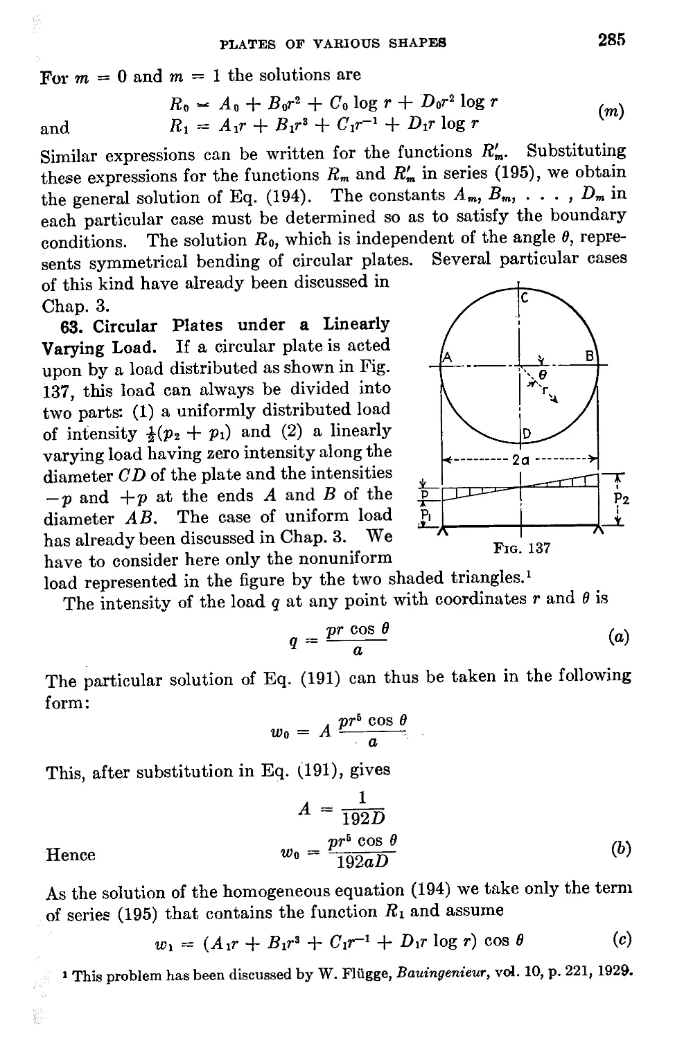
63. Circular Plates under a Linearly Varying Load.........................285
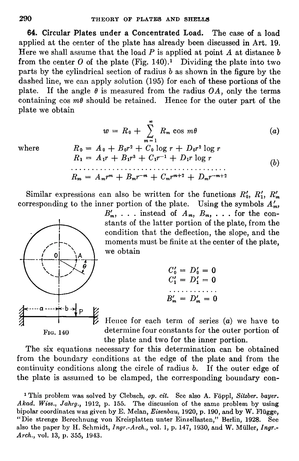
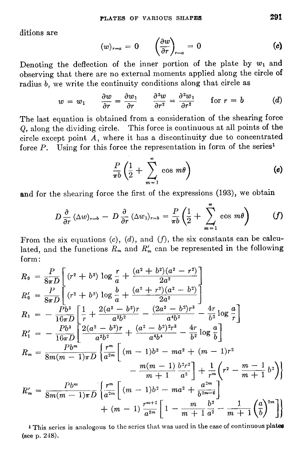
64. Circular Plates under a Concentrated Load.............................290
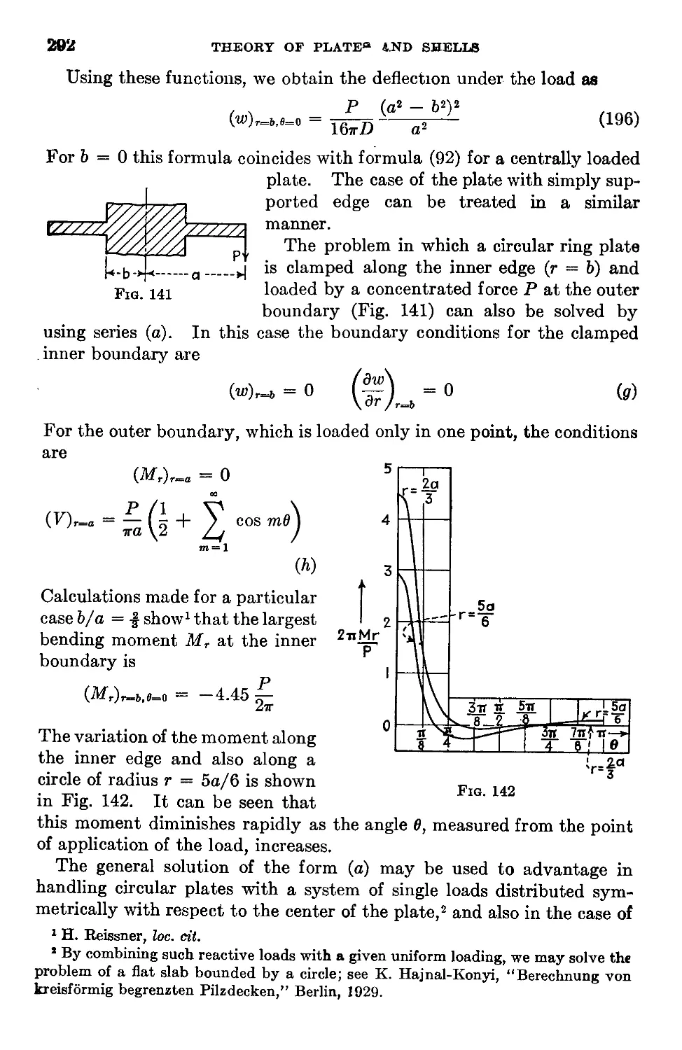
65. Circular Plates Supported at Several Points along the Boundary . . . 293
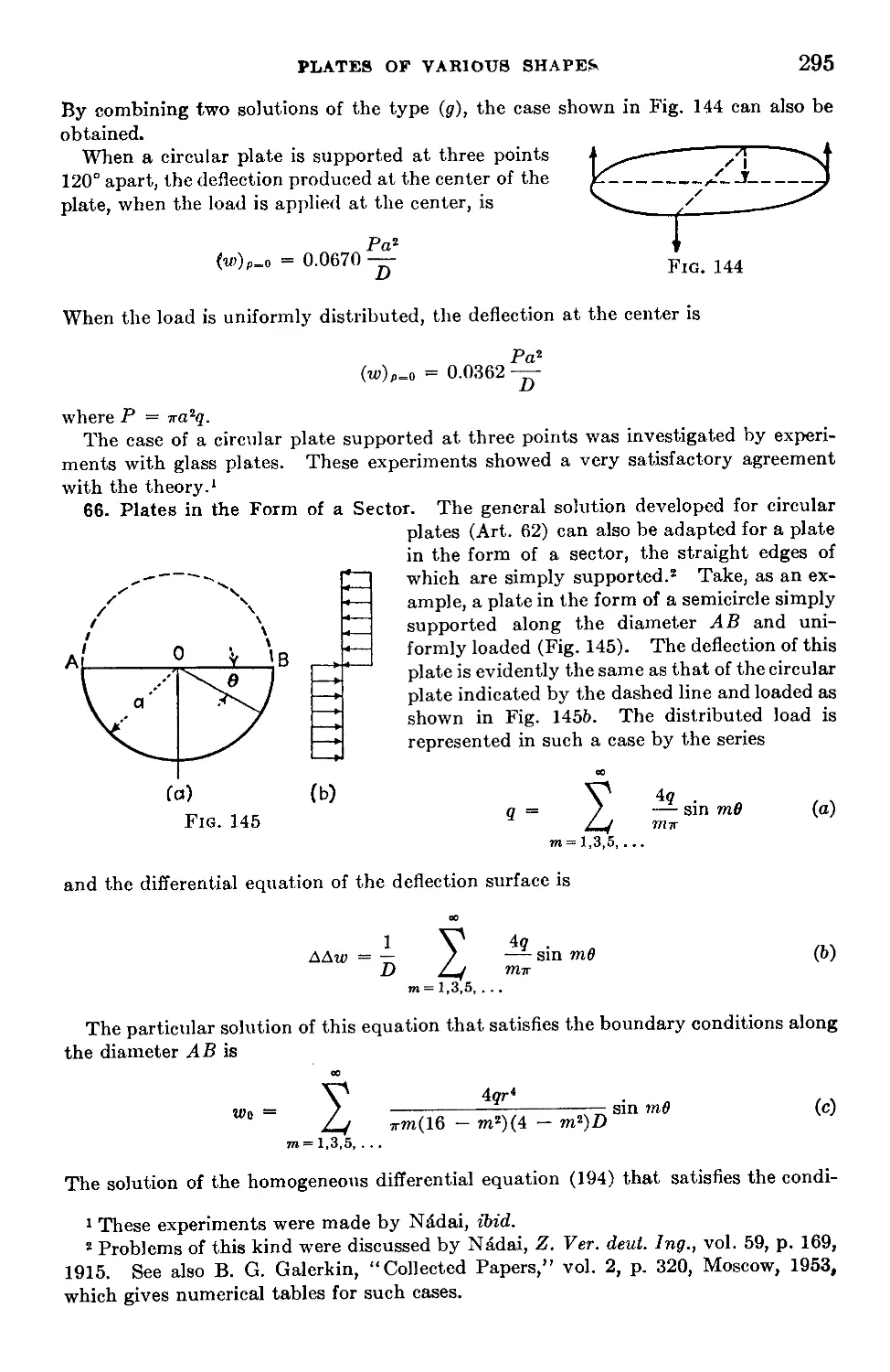
66. Plates in the Form of a Sector........................................295
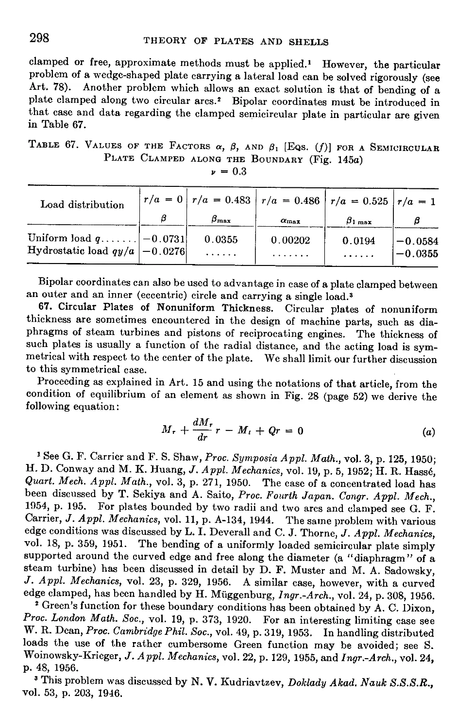
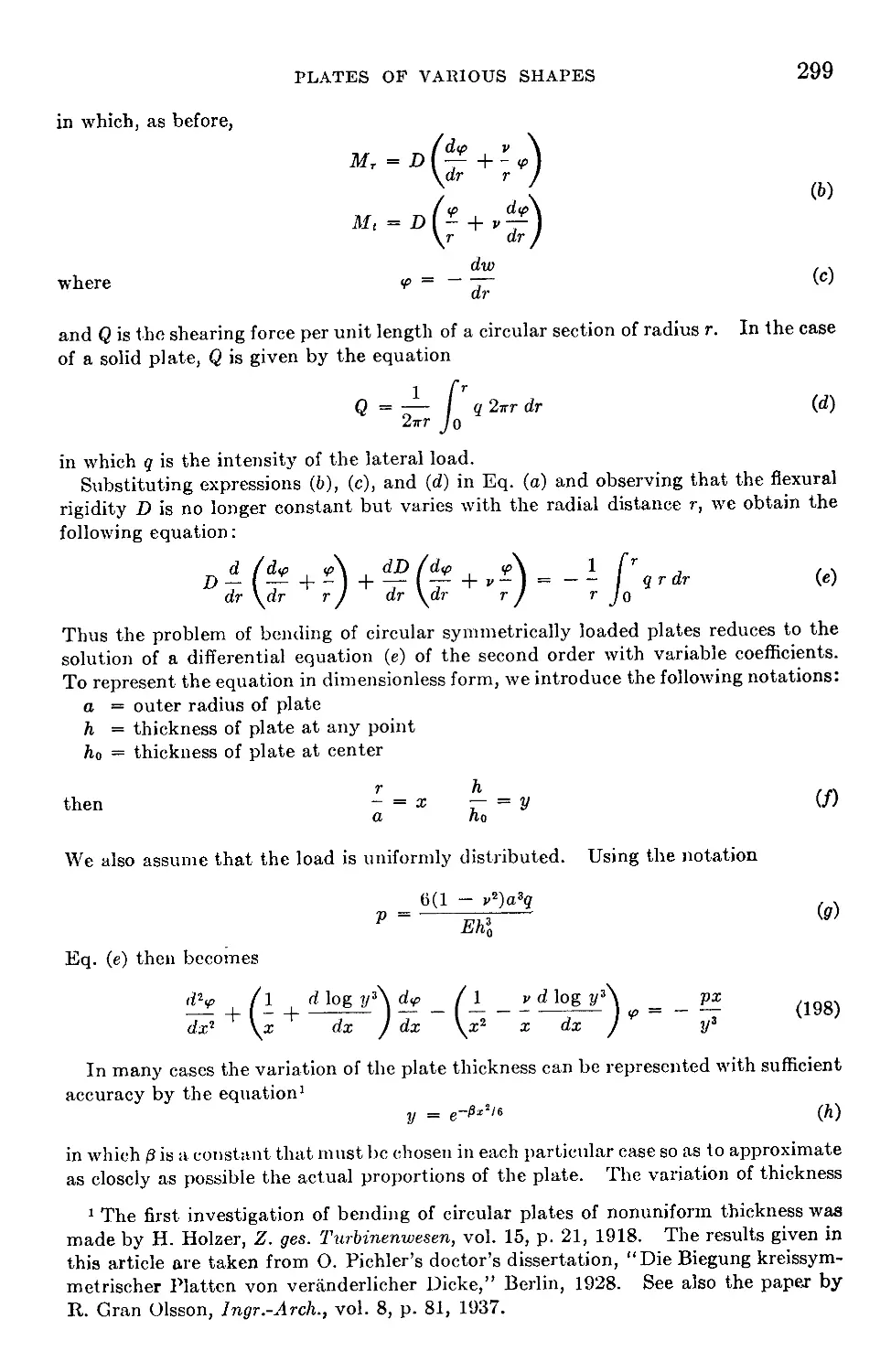
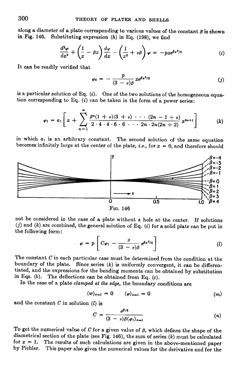
67. Circular Plates of Nonuniform Thickness...............................298
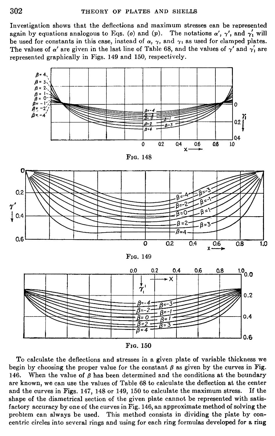
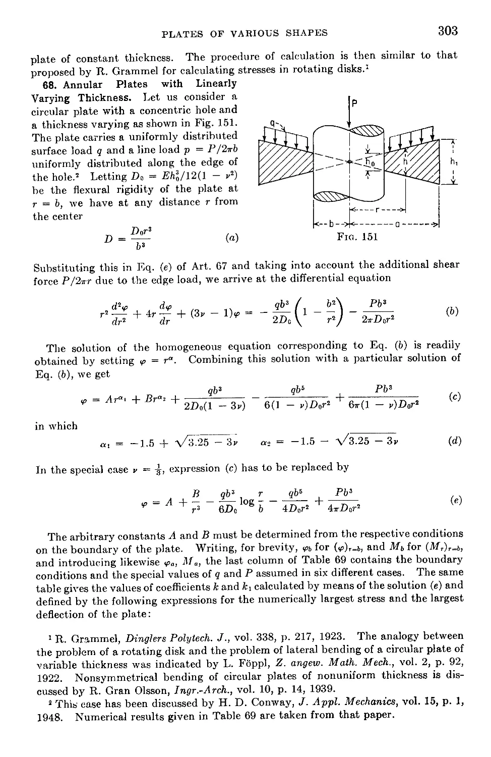
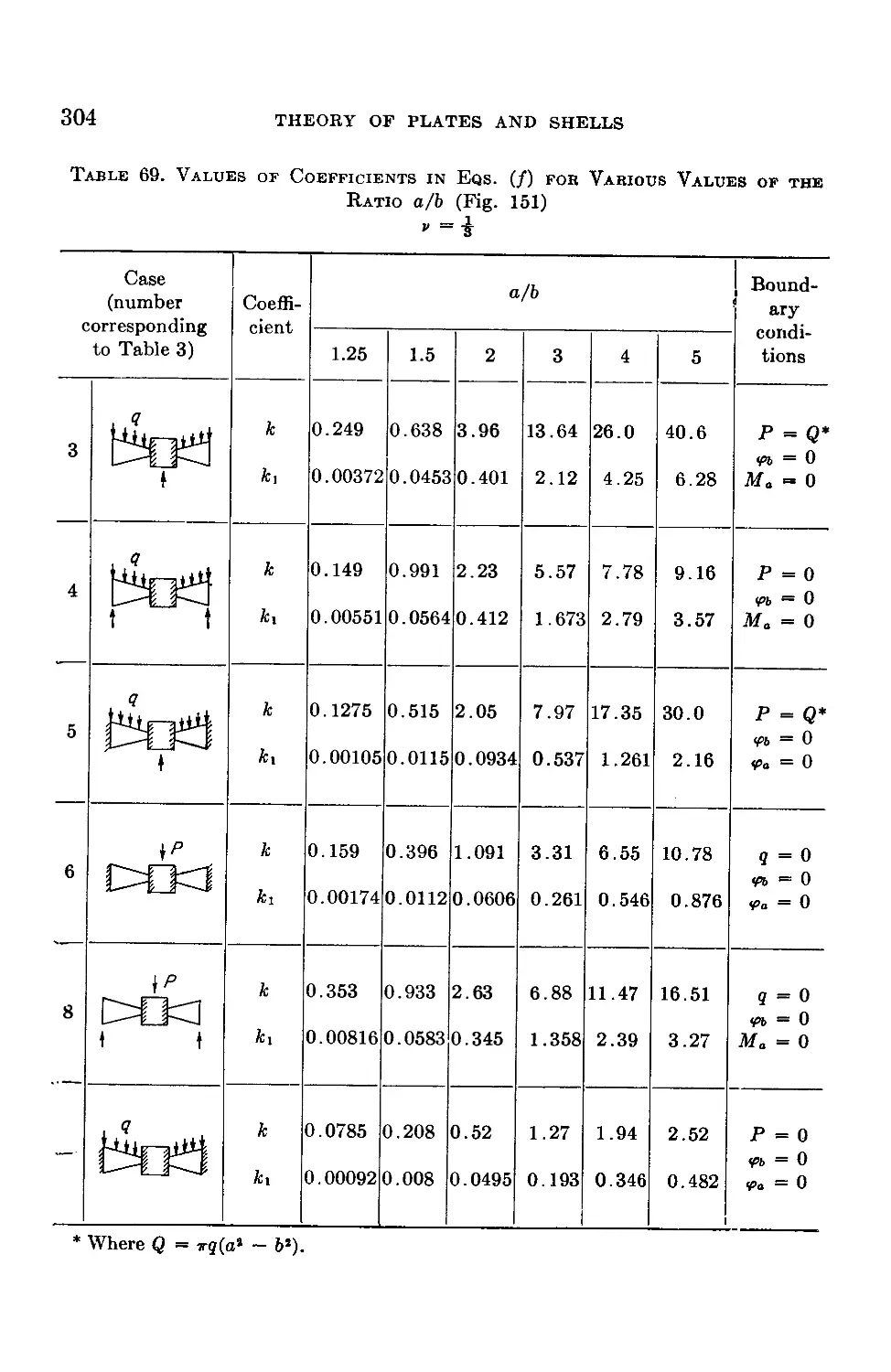
68. Annular Plates with Linearly Varying Thickness........................303
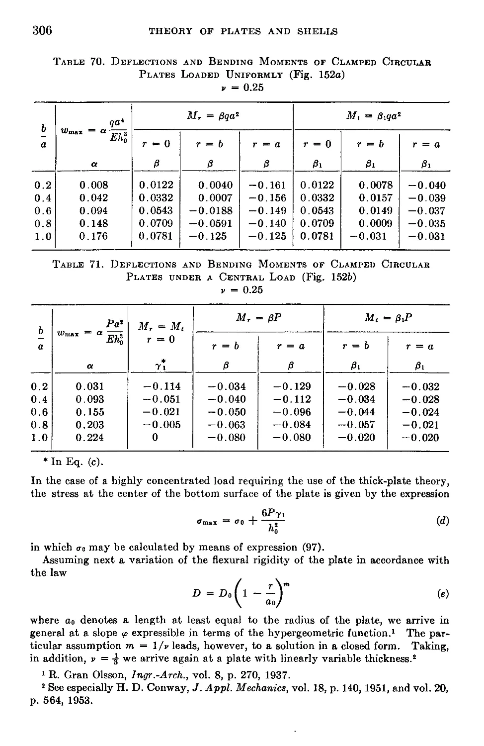
69. Circular Plates with Linearly Varying Thickness.......................305
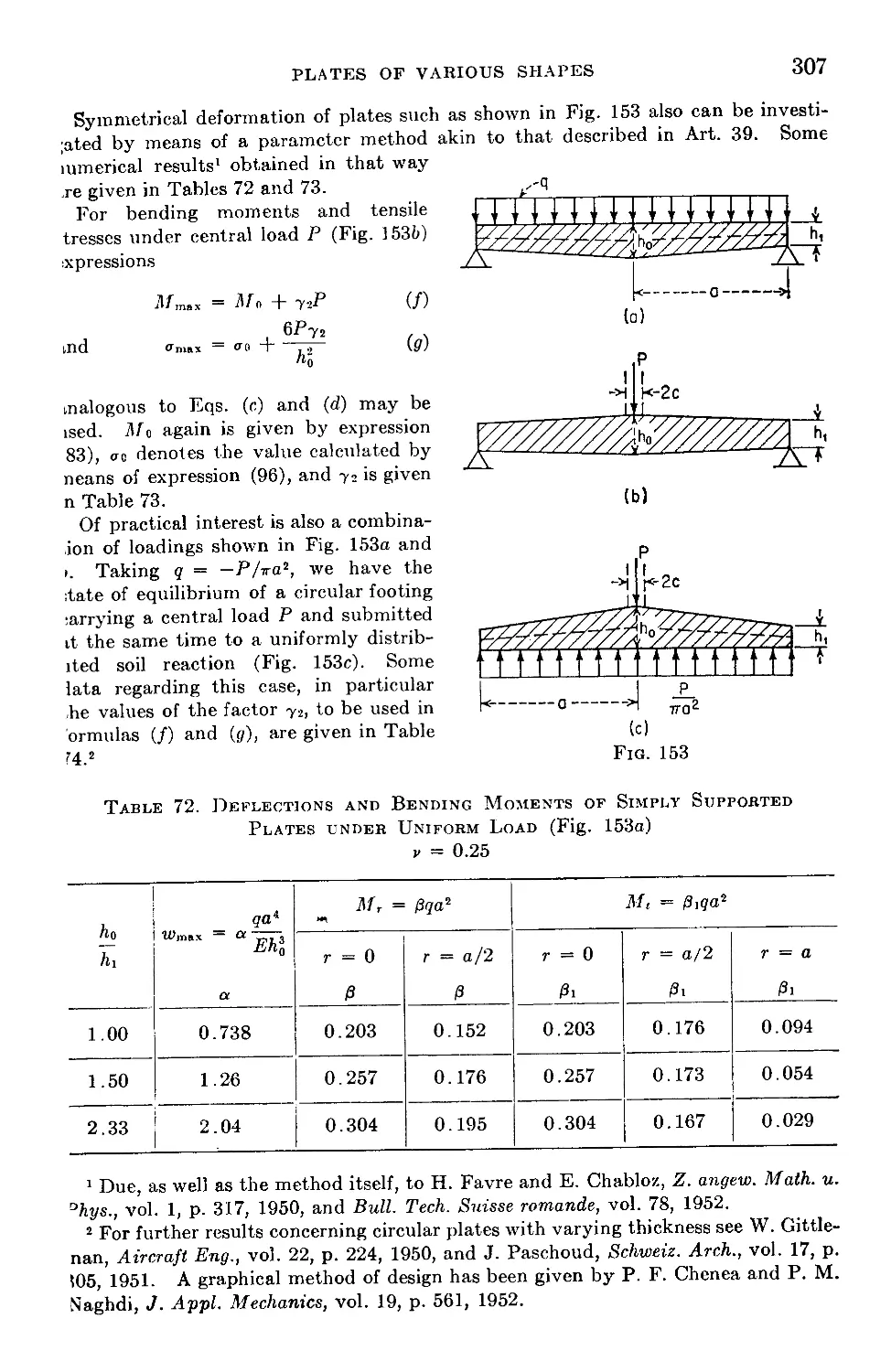
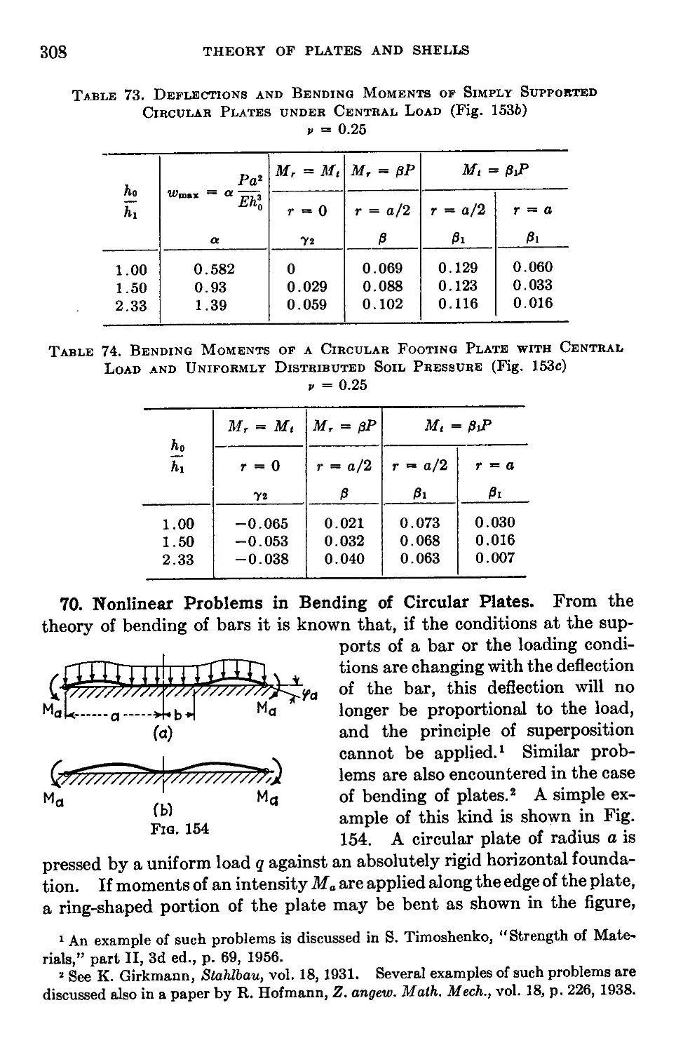
70. Nonlinear Problems in Bending of Circular Plates......................308
71. Elliptical Plates.....................................................310
72. Triangular Plates.....................................................313
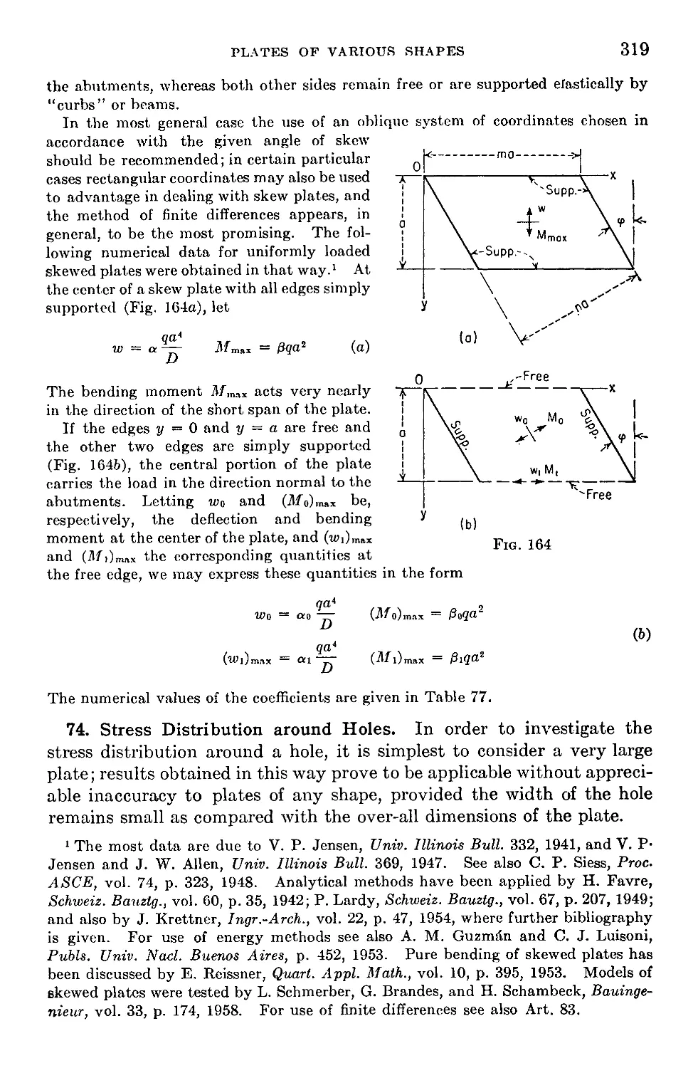
73. Skewed Plates.........................................................318
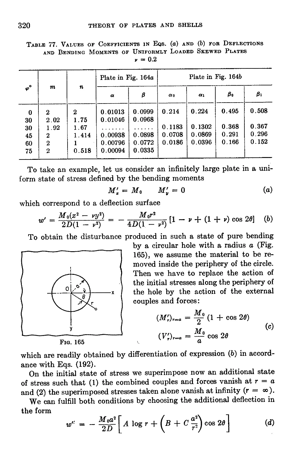
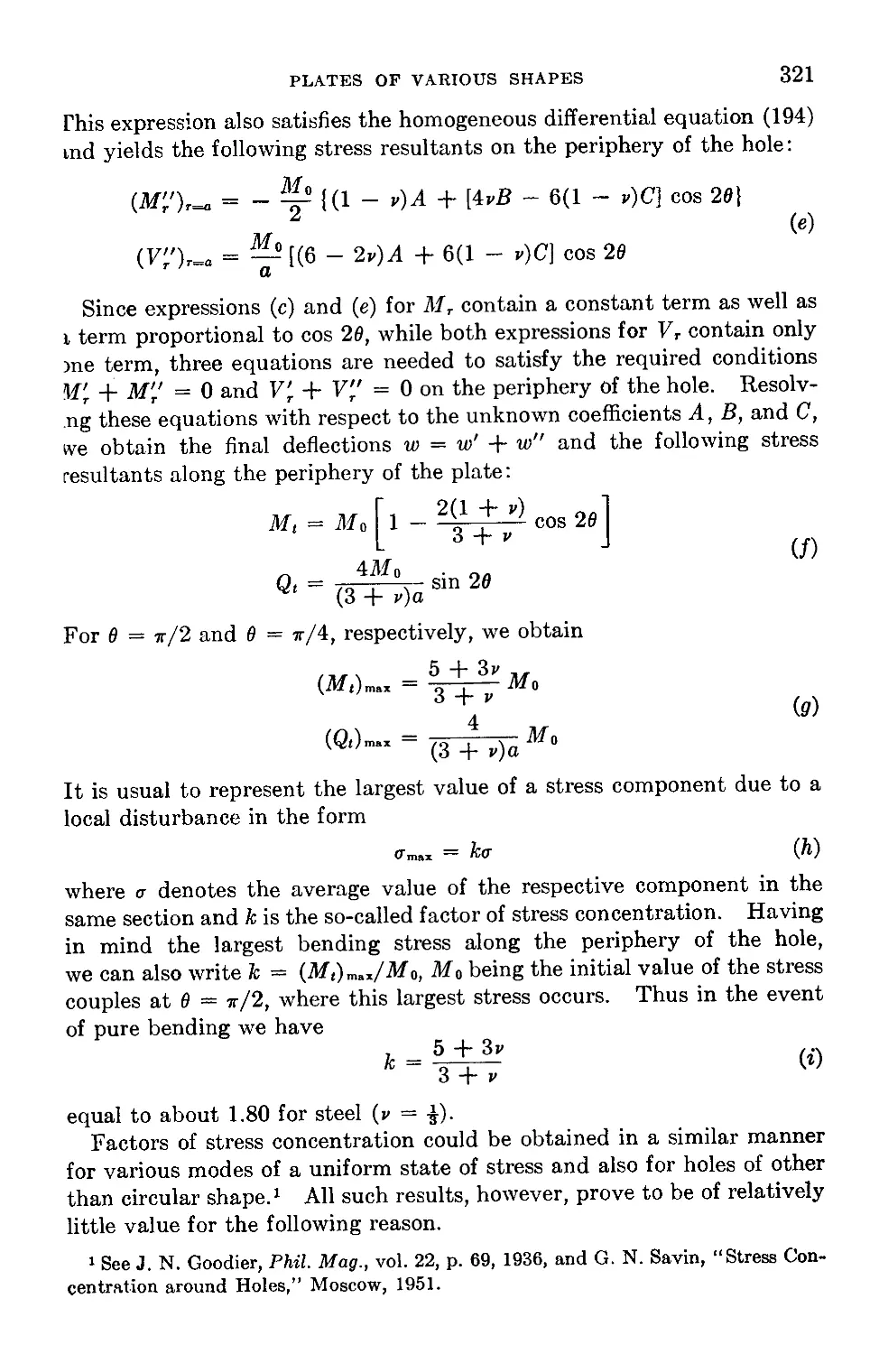
74. Stress Distribution around Holes......................................319
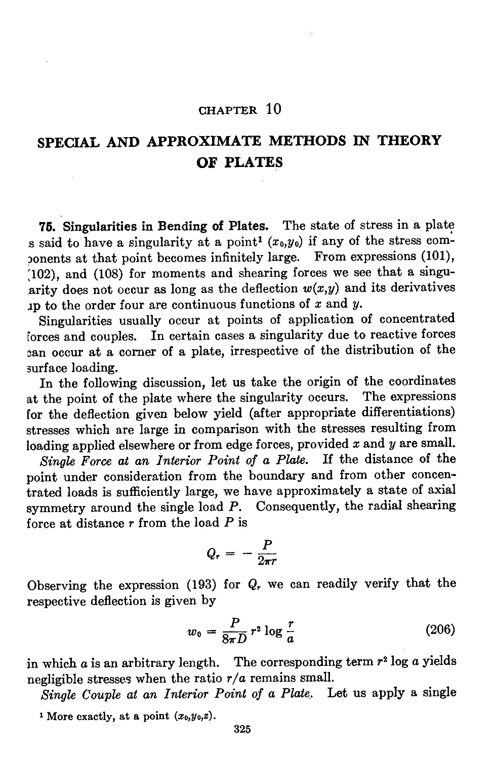
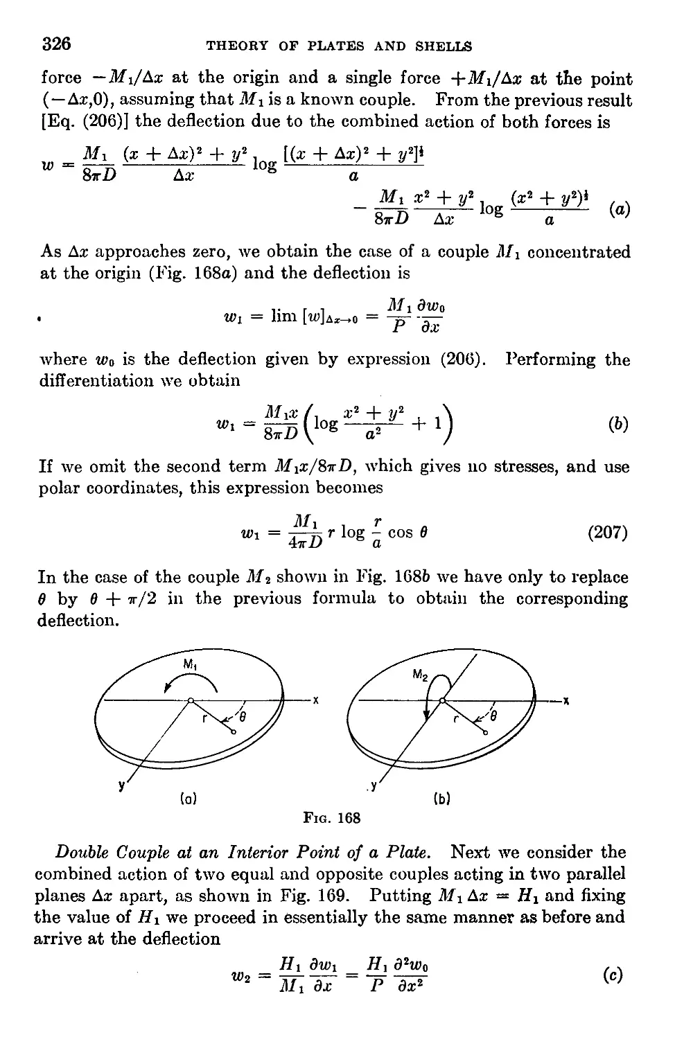
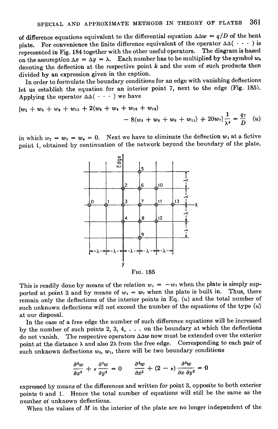
Chapter 10. Special and Approximate Methods in Theory of Plates 325
75. Singularities in Bending of Plates....................................325
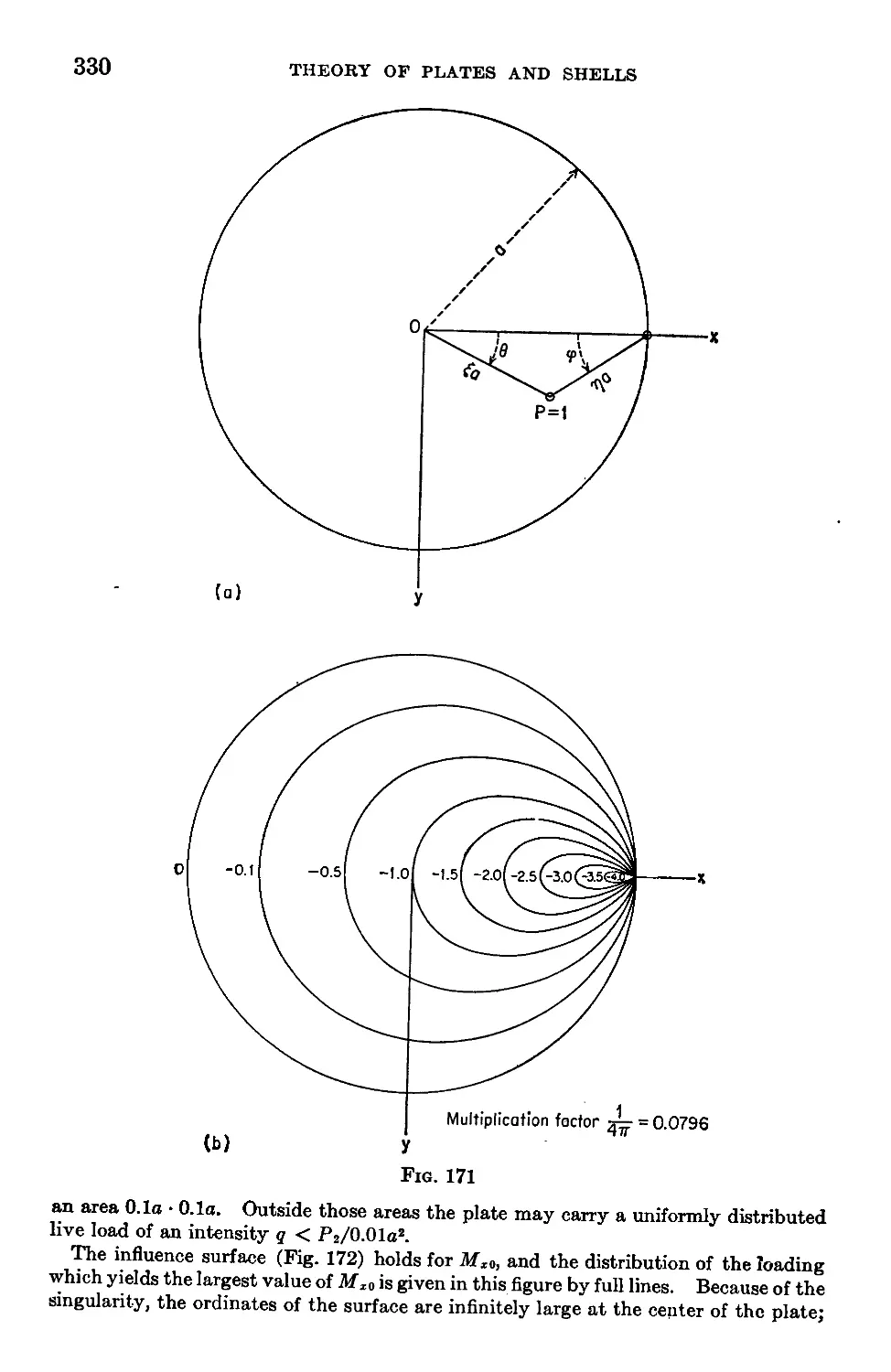
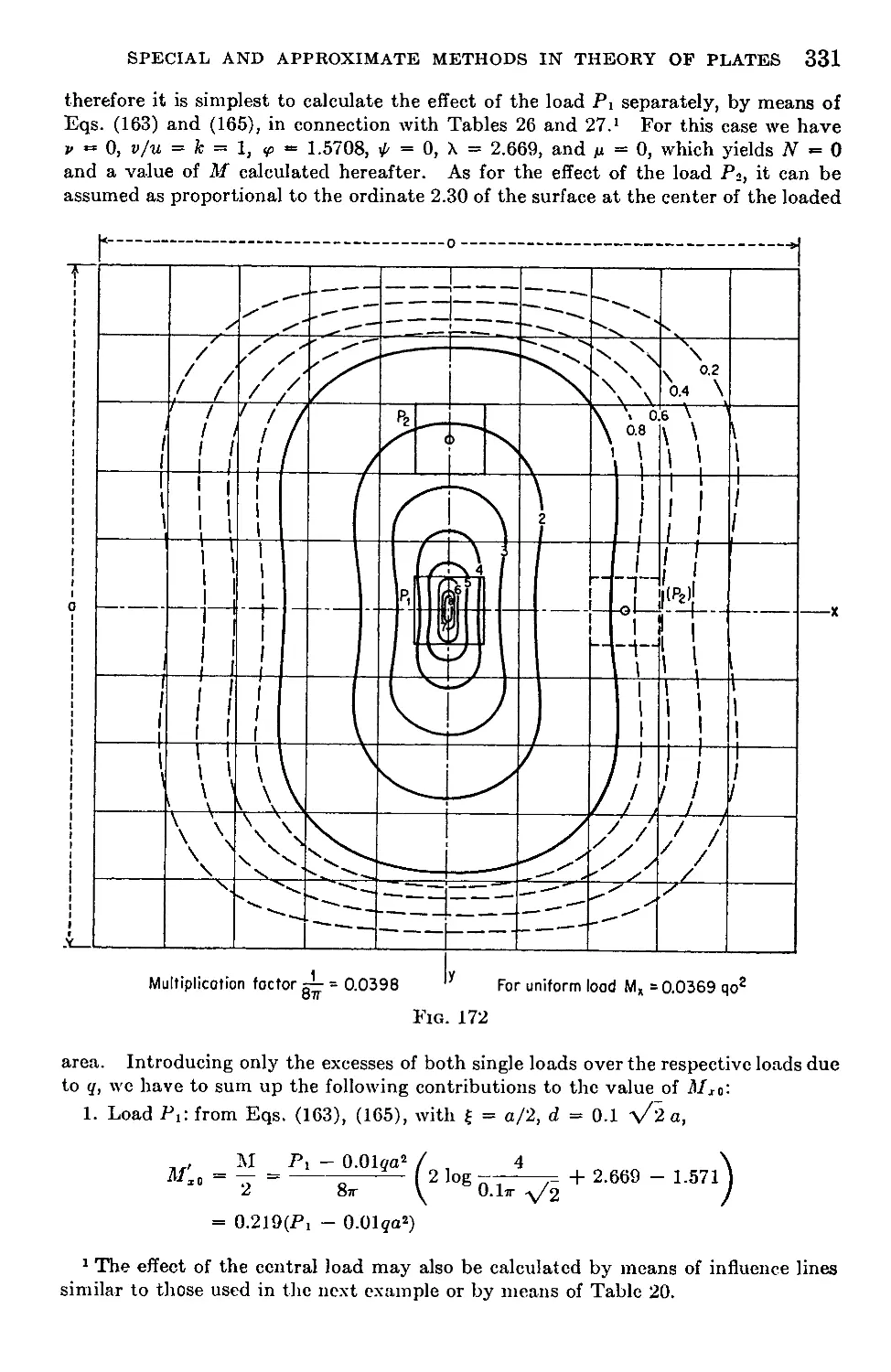
76. The Use of Influence Surfaces in the Design of Plates.................328
77. Influence Functions and Characteristic Functions......................334
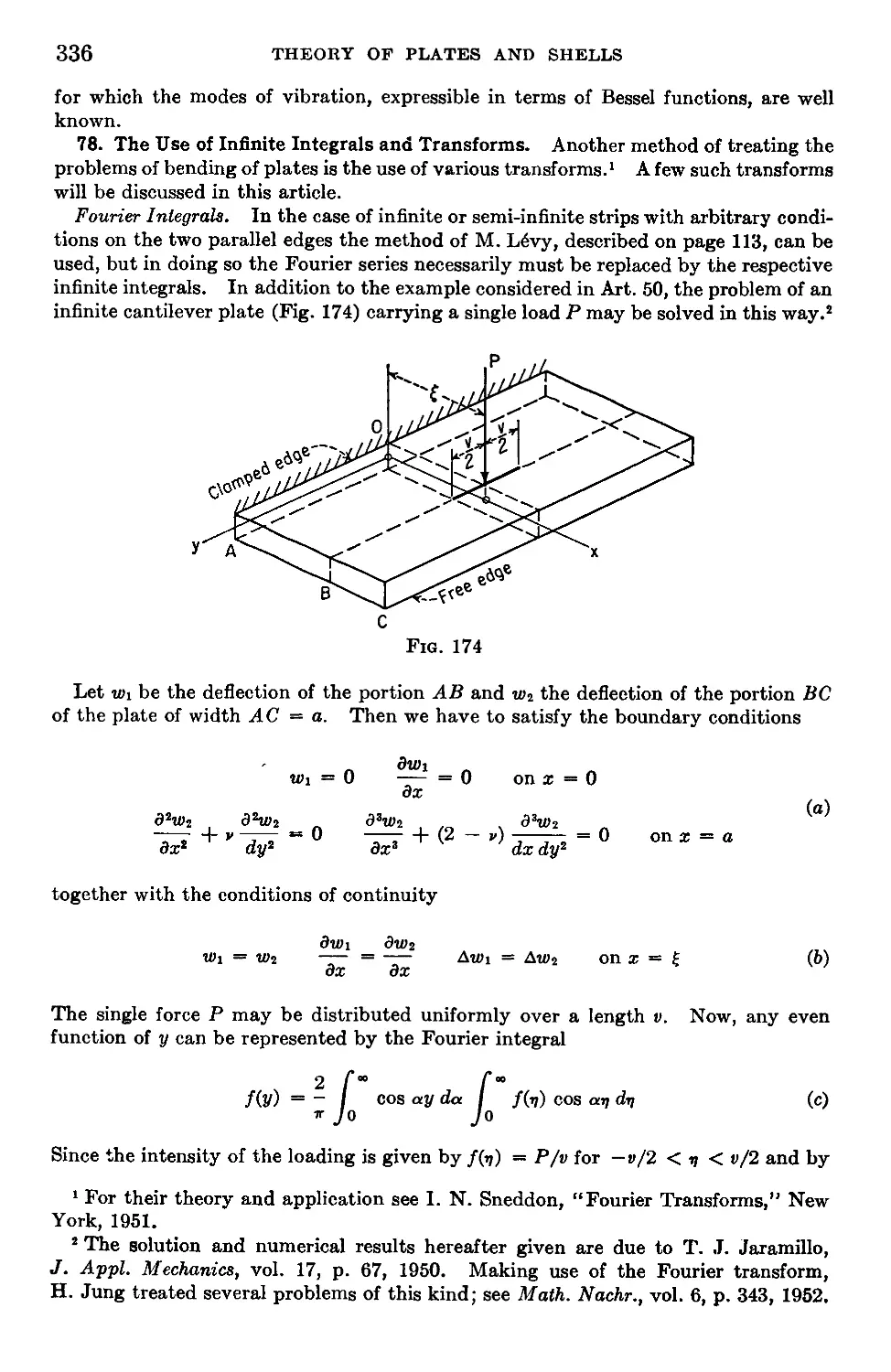
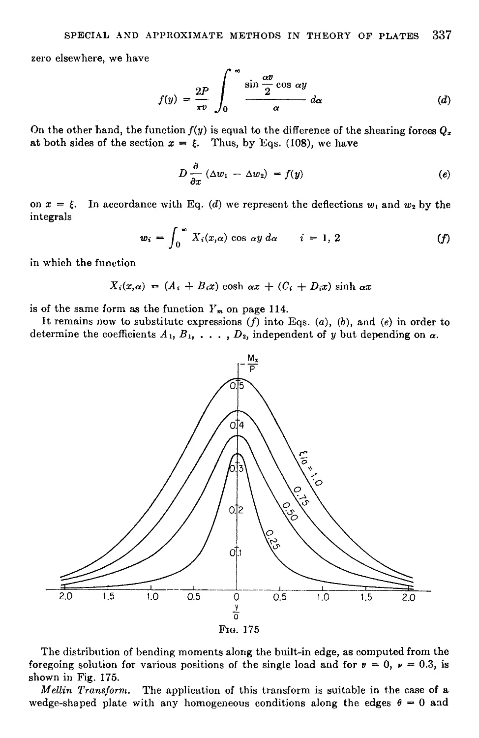
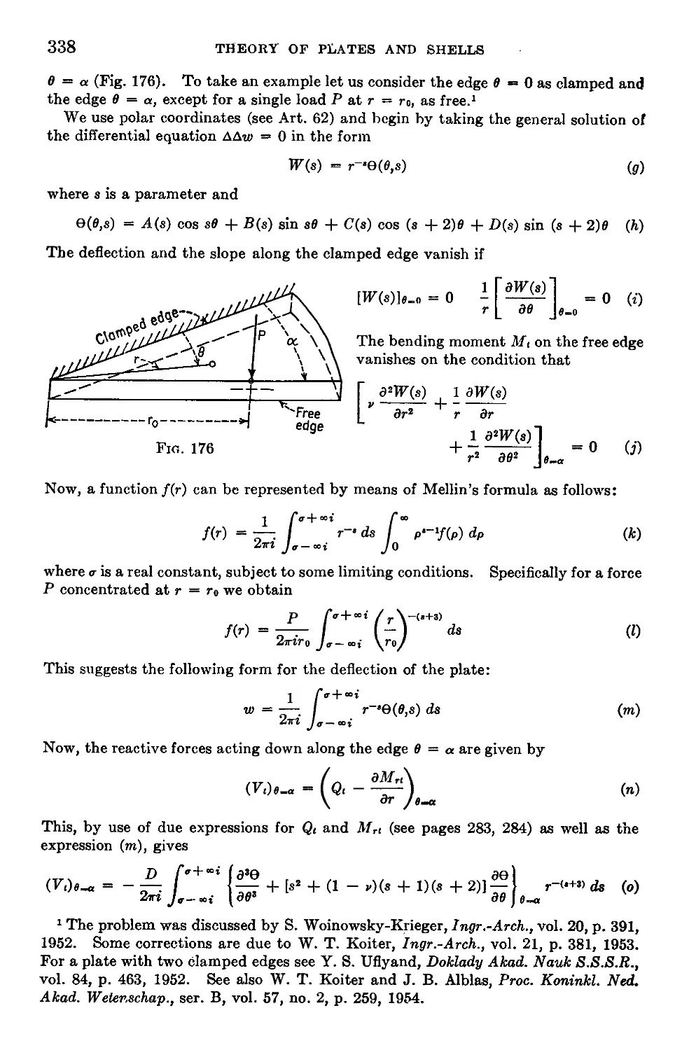
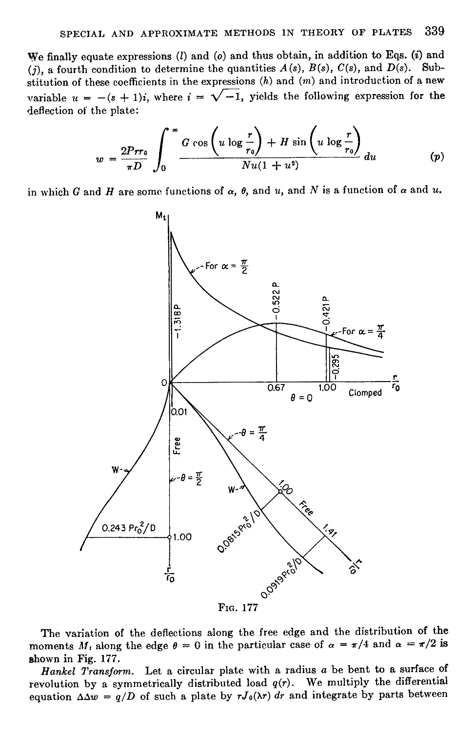
78. The Use of Infinite Integrals and Transforms..........................336
79. Complex Variable Method...............................................340
80. Application of the Strain Energy Method in Calculating Deflections . 342
81. Alternative Procedure in Applying the Strain Energy Method .... 347
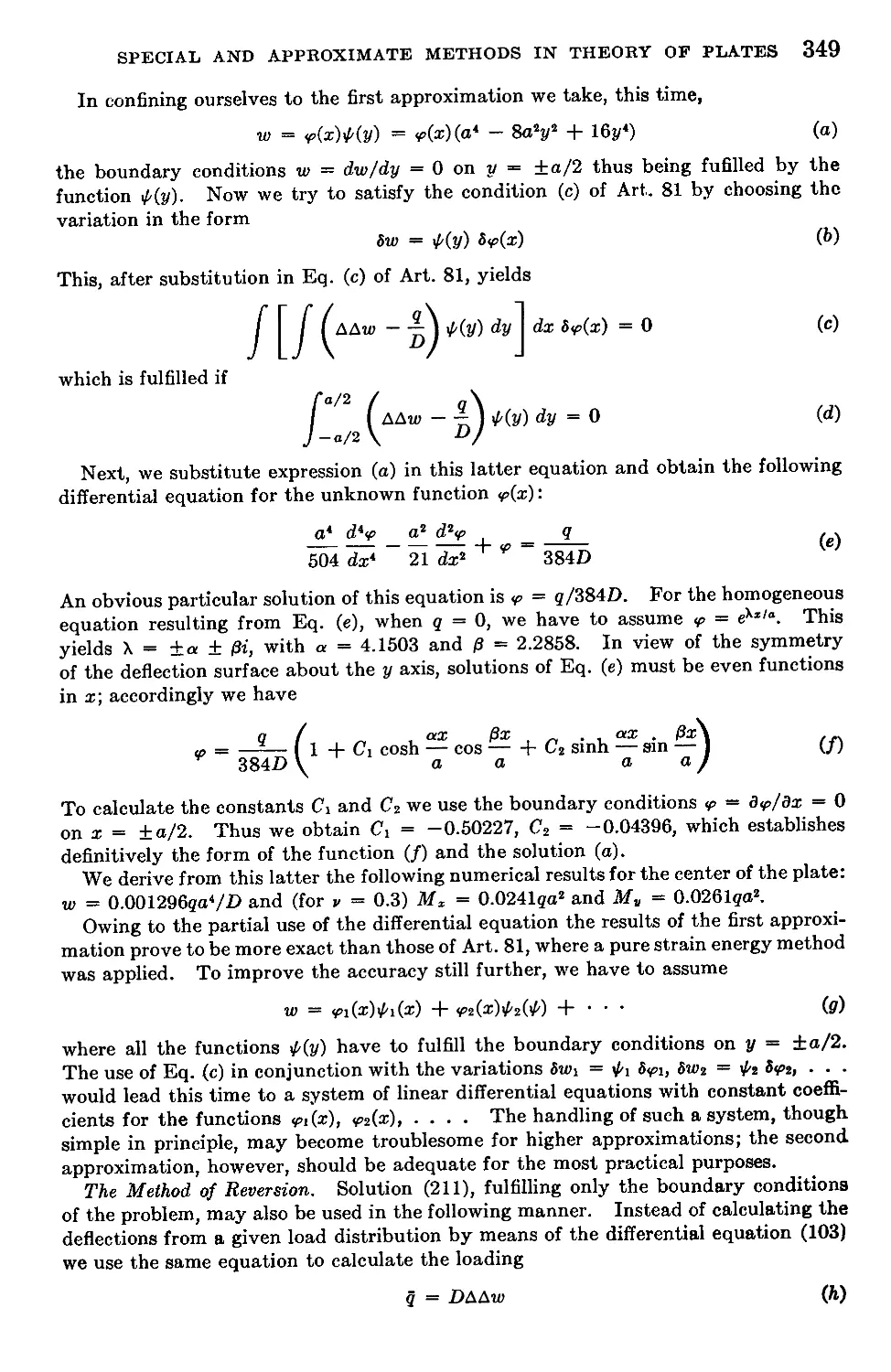
82. Various Approximate Methods...........................................348
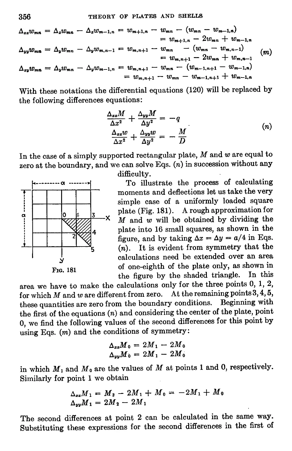
83. Application of Finite Differences Equations to the Bending of Simply Sup-
ported Plates..............................................................351
84. Experimental Methods..................................................362
Chapter 11. Bending of Anisotropic Plates..................................364
85. Differential Equation of the Bent Plate...............................364
86. Determination of Rigidities in Various Specific Cases.................366
87. Application of the Theory to the Calculation of Gridworks .... 369
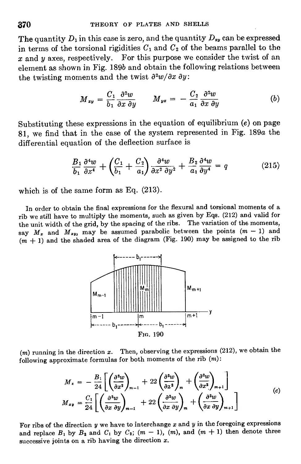
88. Bending of Rectangular Plates.........................................371
89. Bending of Circular and Elliptic Plates...............................376
Chapter 12. Bending of Plates under the Combined Action of Lateral Loads
and Forces in the Middle Plane of the Plate.................................378
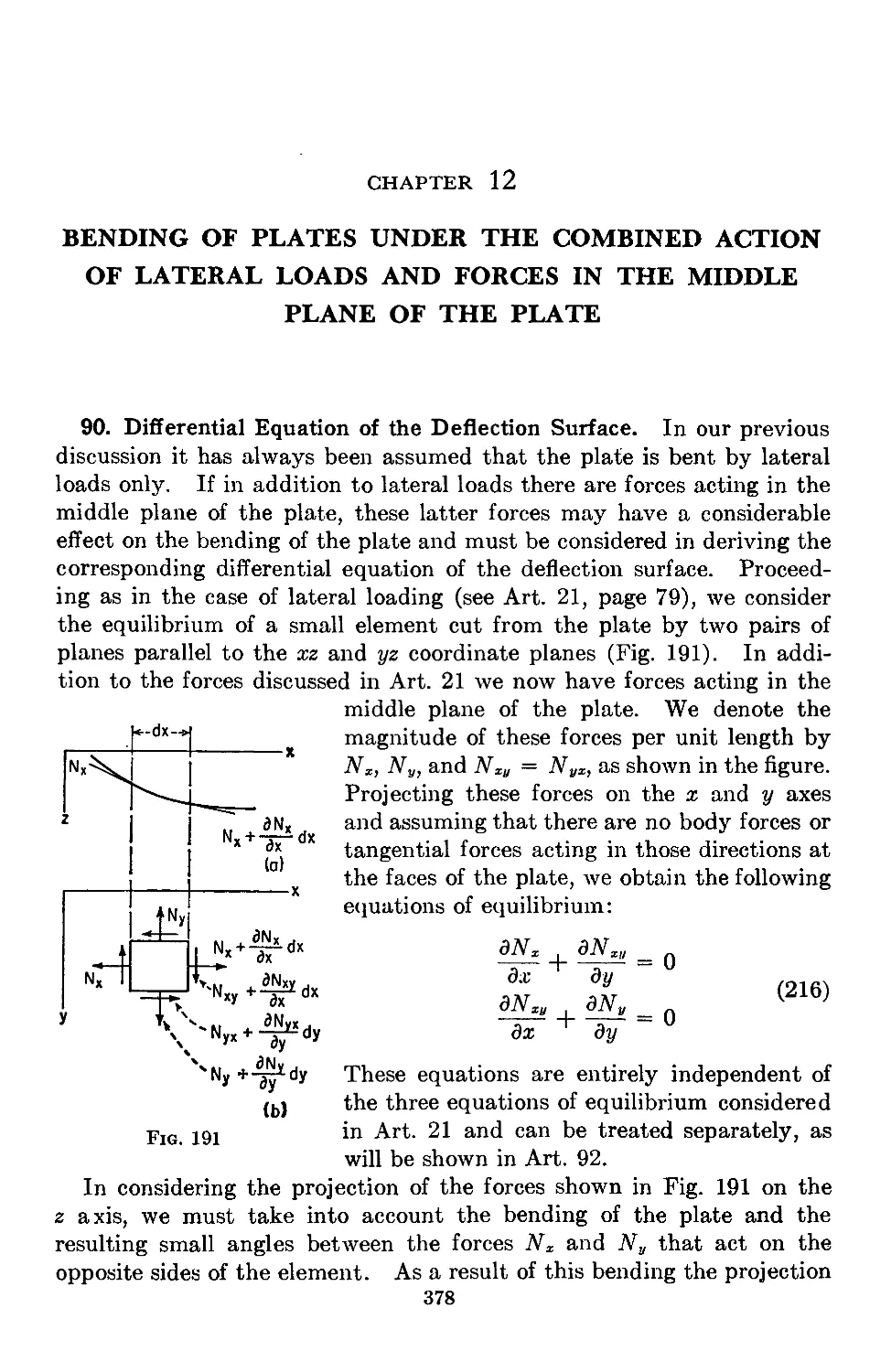
90. Differential Equation of the Deflection Surface.......................378
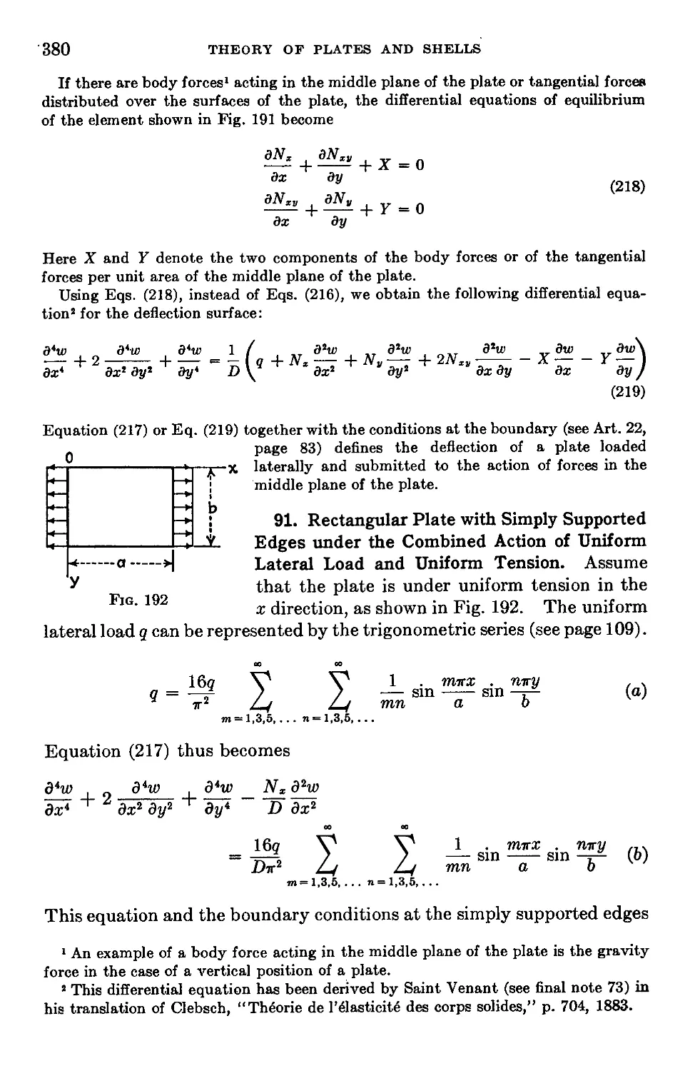
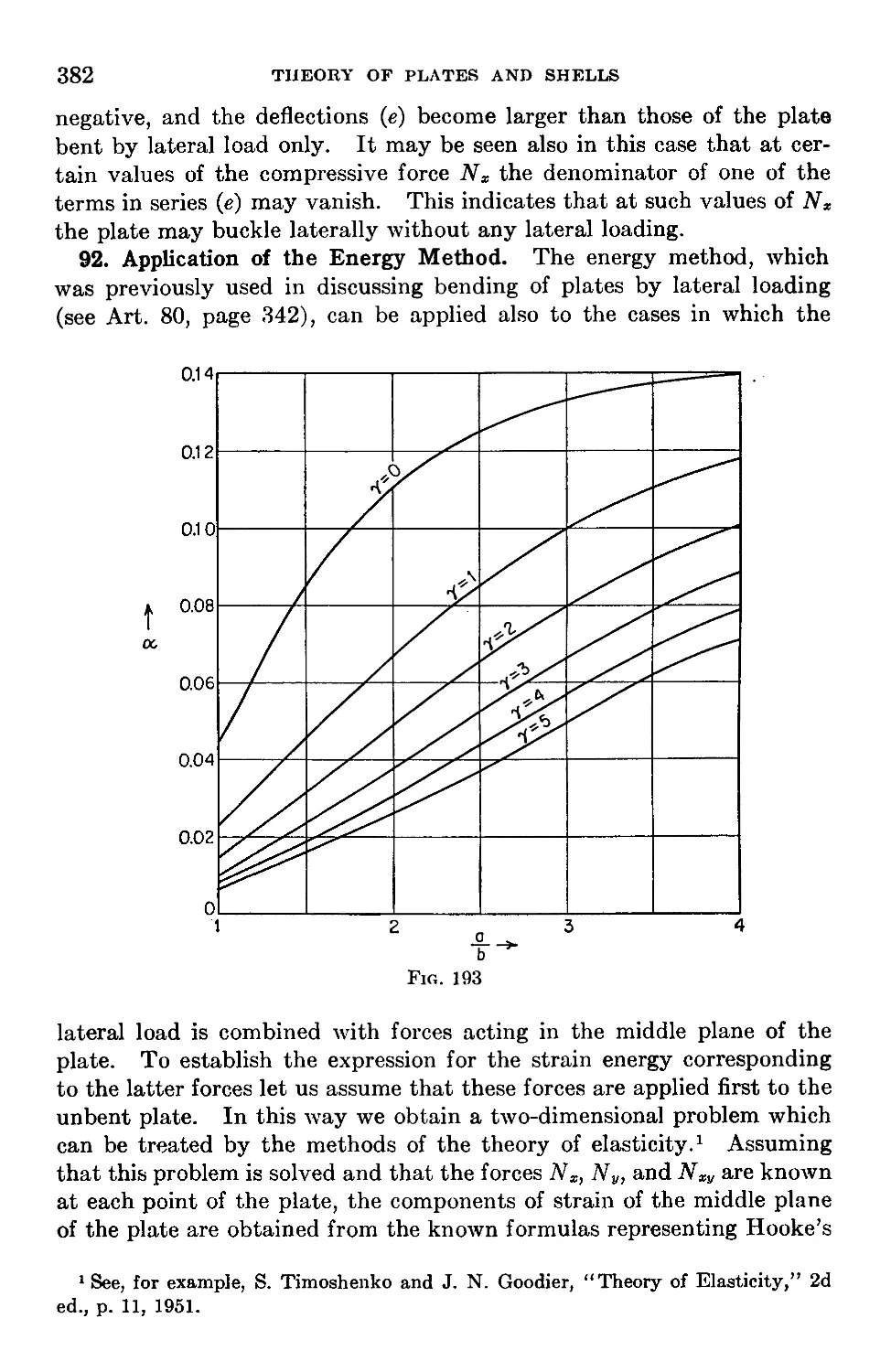
91. Rectangular Plate with Simply Supported Edges under the Combined
Action of Uniform Lateral Load and Uniform Tension.........................380
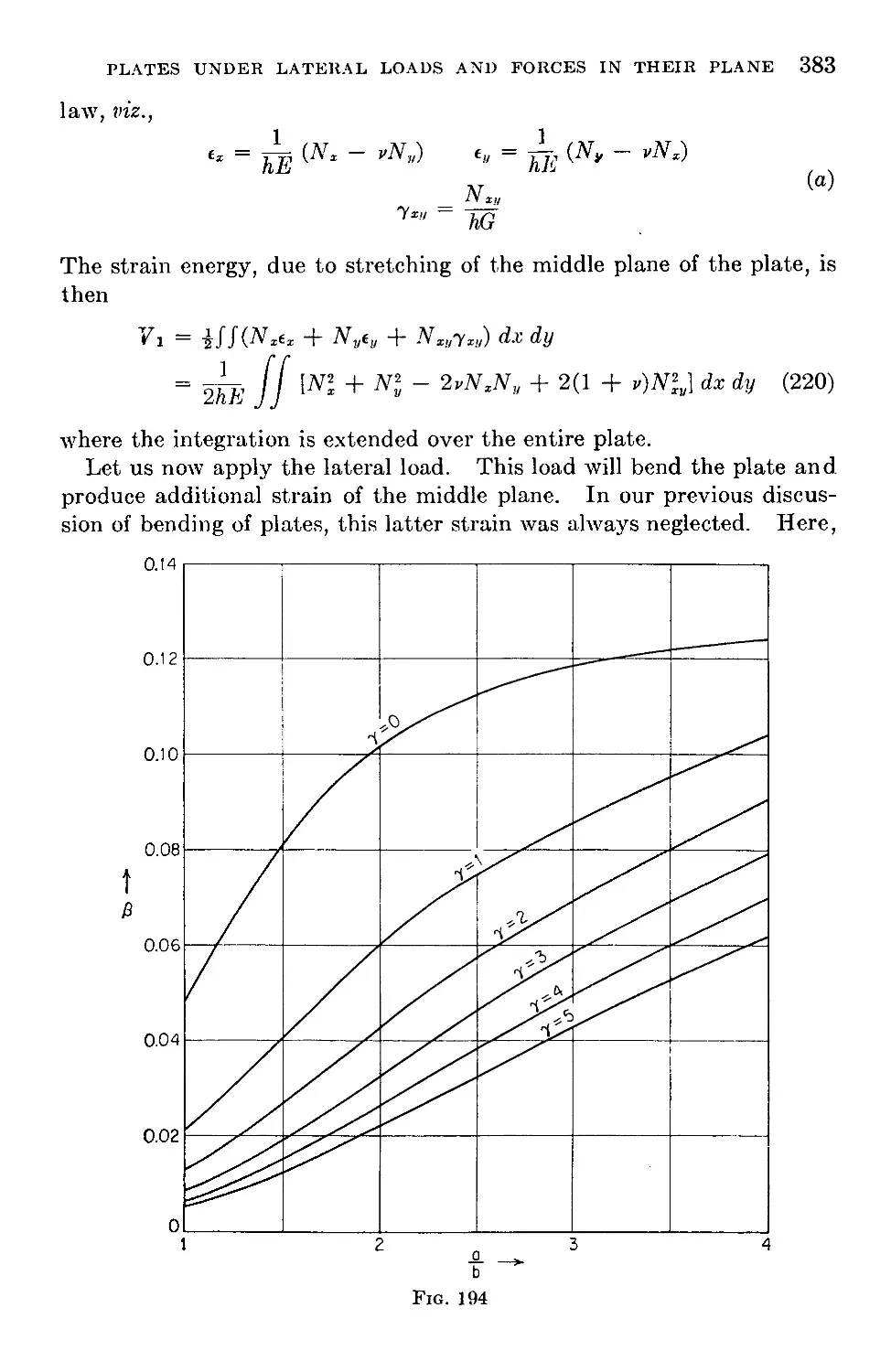
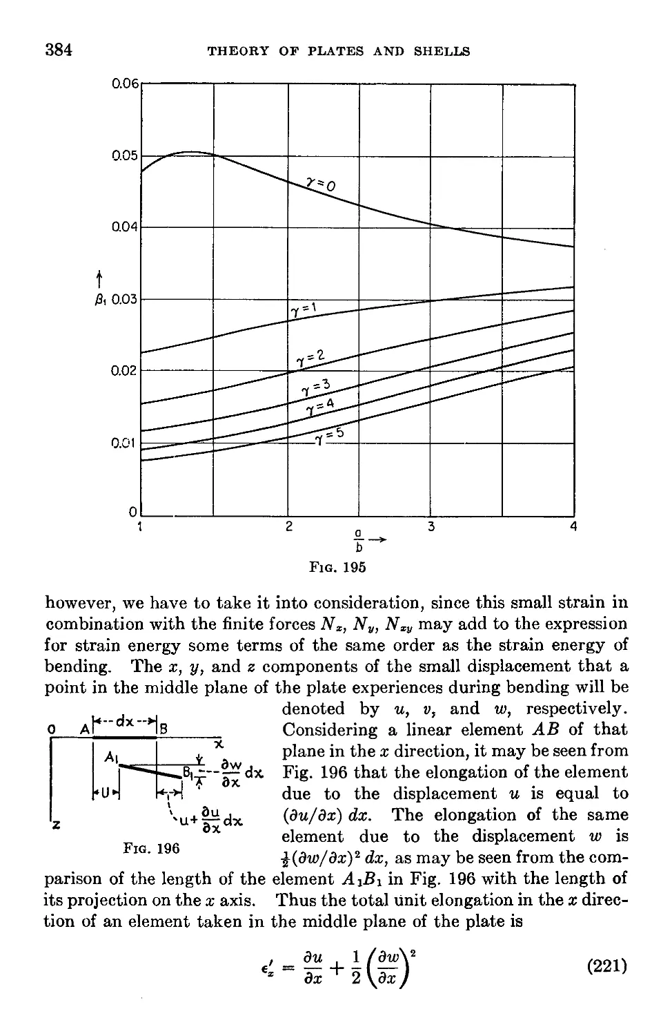
92. Application of the Energy Method......................................382
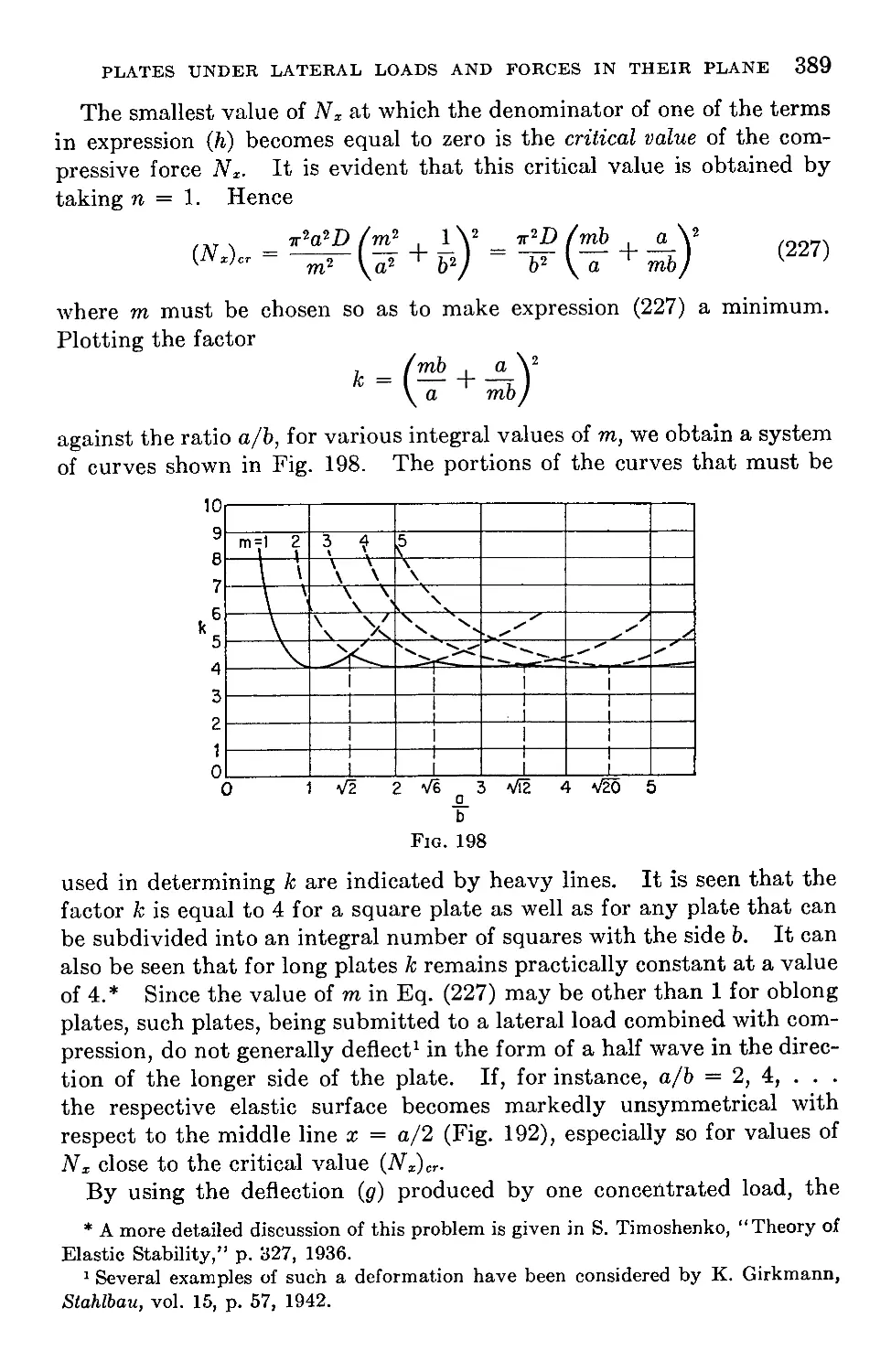
93. Simply Supported Rectangular Plates under the Combined Action of
Lateral Loads and of Forces in the Middle Plane of the Plate .... 387
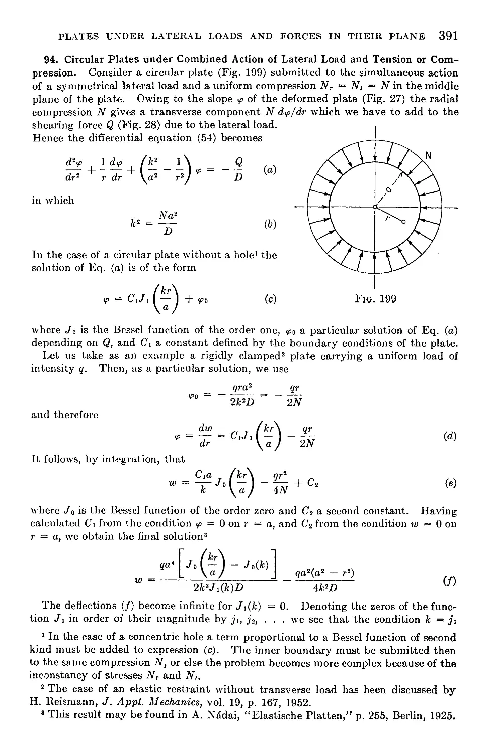
94. Circular Plates under Combined Action of Lateral Load and Tension or
Compression................................................................391
95. Bending of Plates with a Small Initial Curvature......................393
X
CONTENTS
Chapter 13. Large Deflections of Plates........................................396
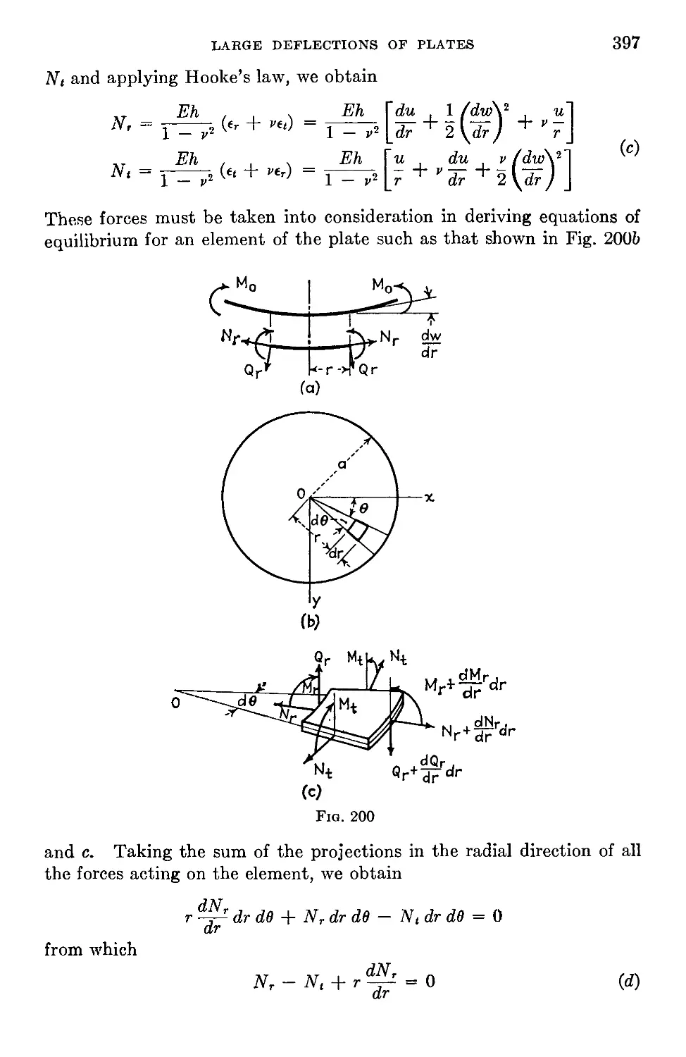
96. Bending of Circular Plates by Moments Uniformly Distributed along the
Edge........................................................................396
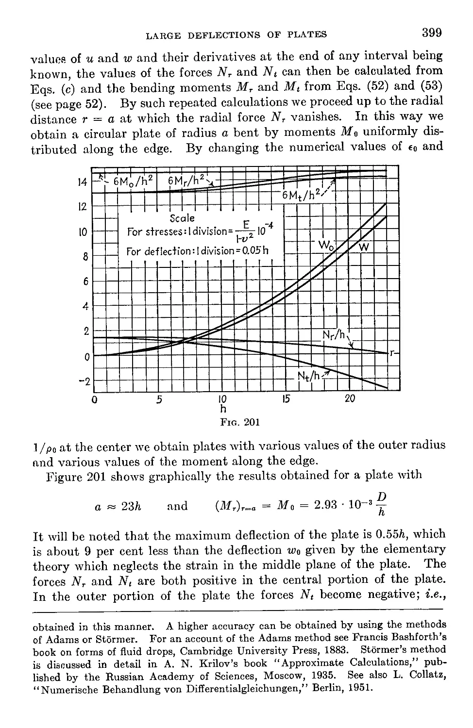
97. Approximate Formulas for Uniformly Loaded Circular Plates with Large
Deflections.................................................................400
98. Exact Solution for a Uniformly Loaded Circular Plate with a Clamped
Edge......................................................................404
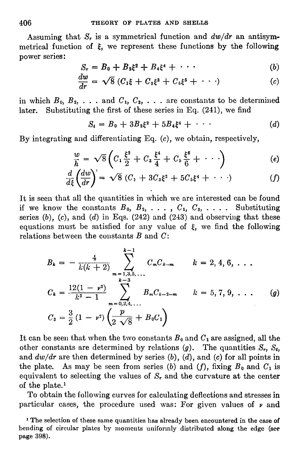
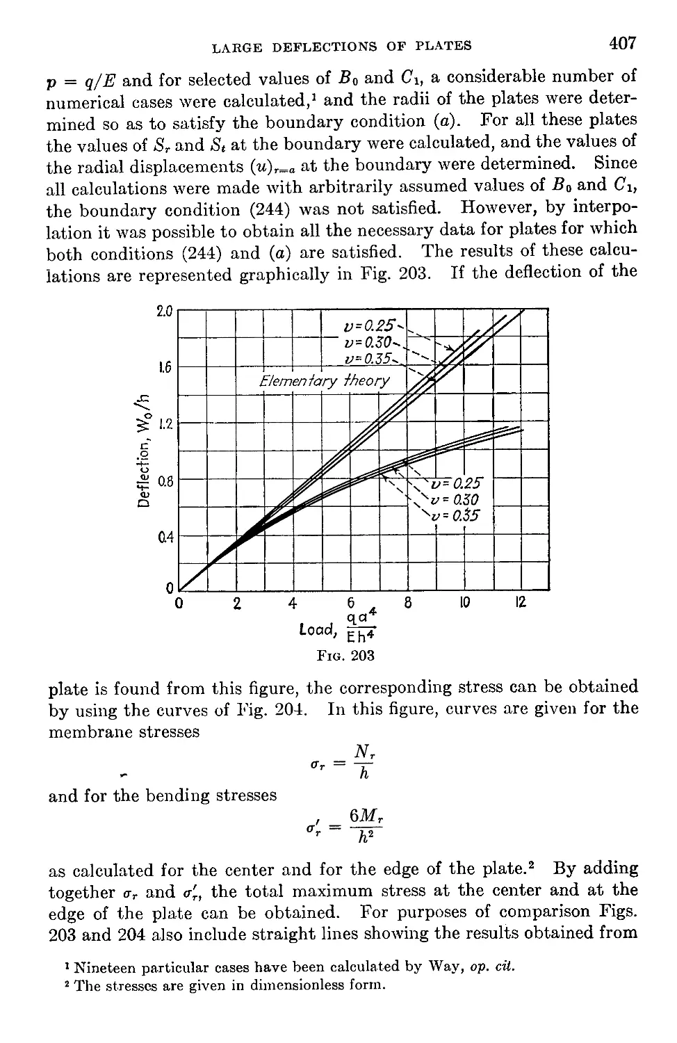
99. A Simply Supported Circular Plate under Uniform Load.................408
100. Circular Plates Loaded at the Center..................................412
101. General Equations for Large Deflections of Plates.....................415
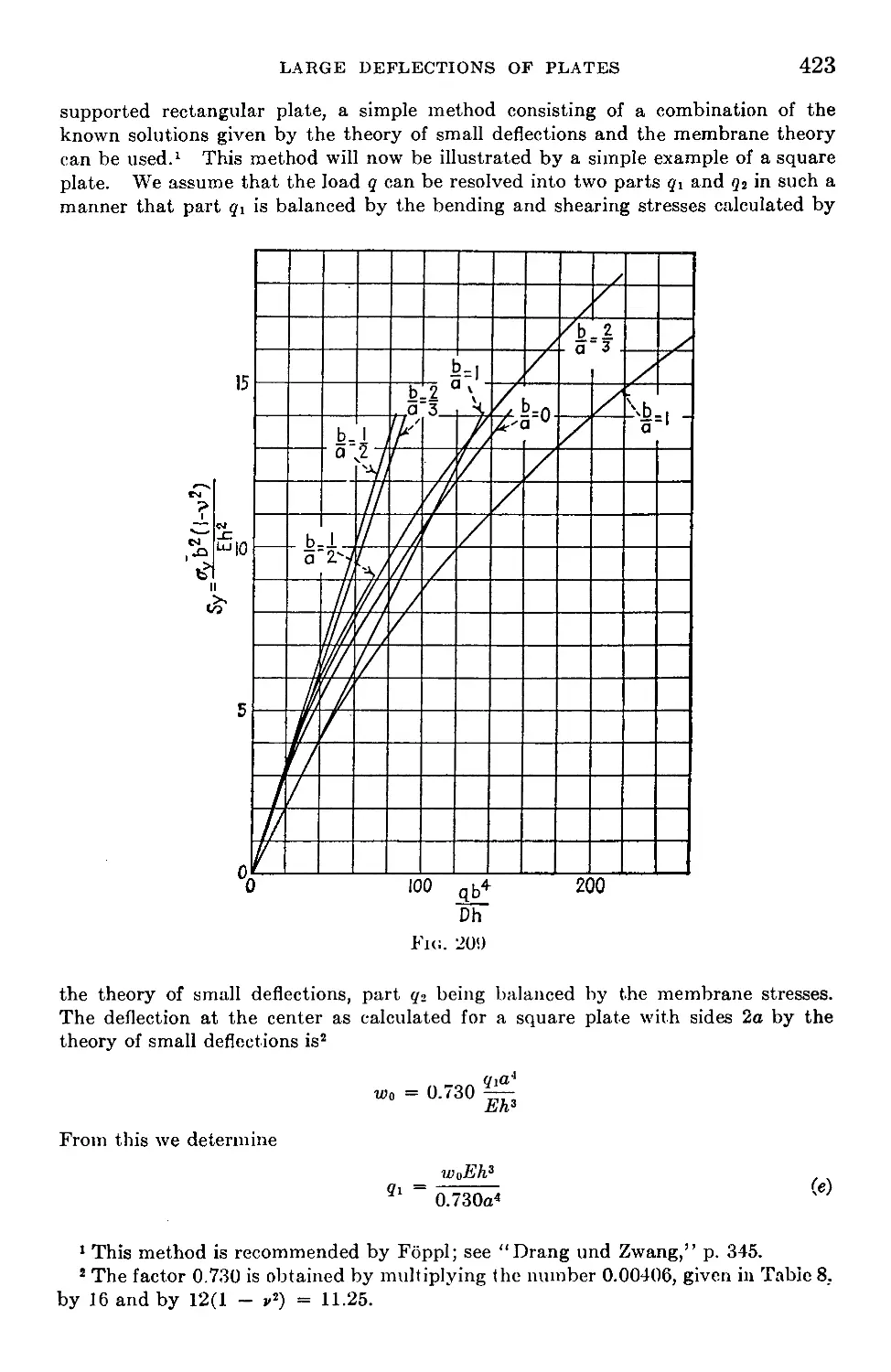
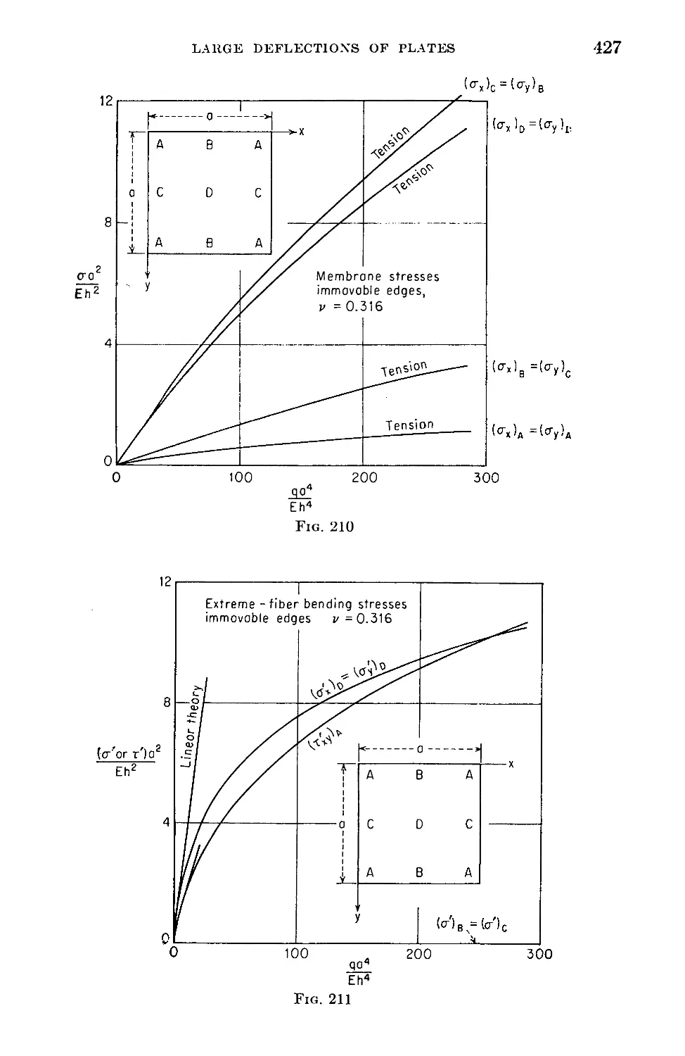
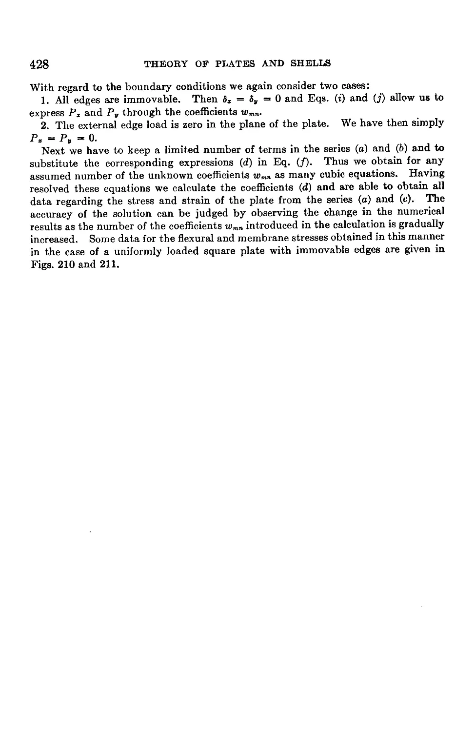
102. Large Deflections of Uniformly Loaded Rectangular Plates . . . .421
103. Large Deflections of Rectangular Plates with Simply Supported Edges . 425
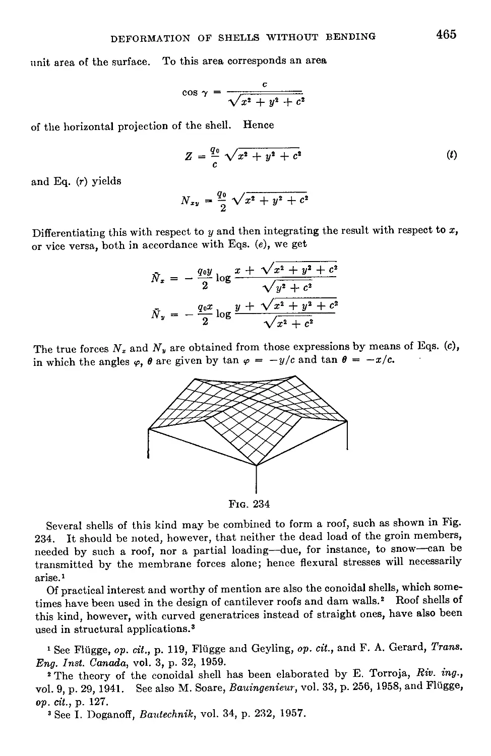
Chapter 14. Deformation of Shells without Bending..............................429
104. Definitions and Notation...................................................429
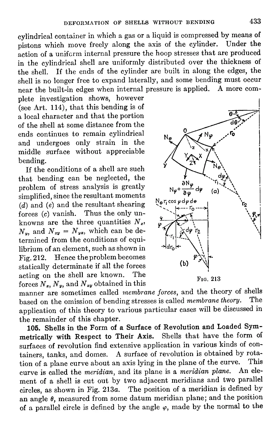
105. Shells in the Form of a Surface of Revolution and Loaded Symmetrically
with Respect to Their Axis...................................................433
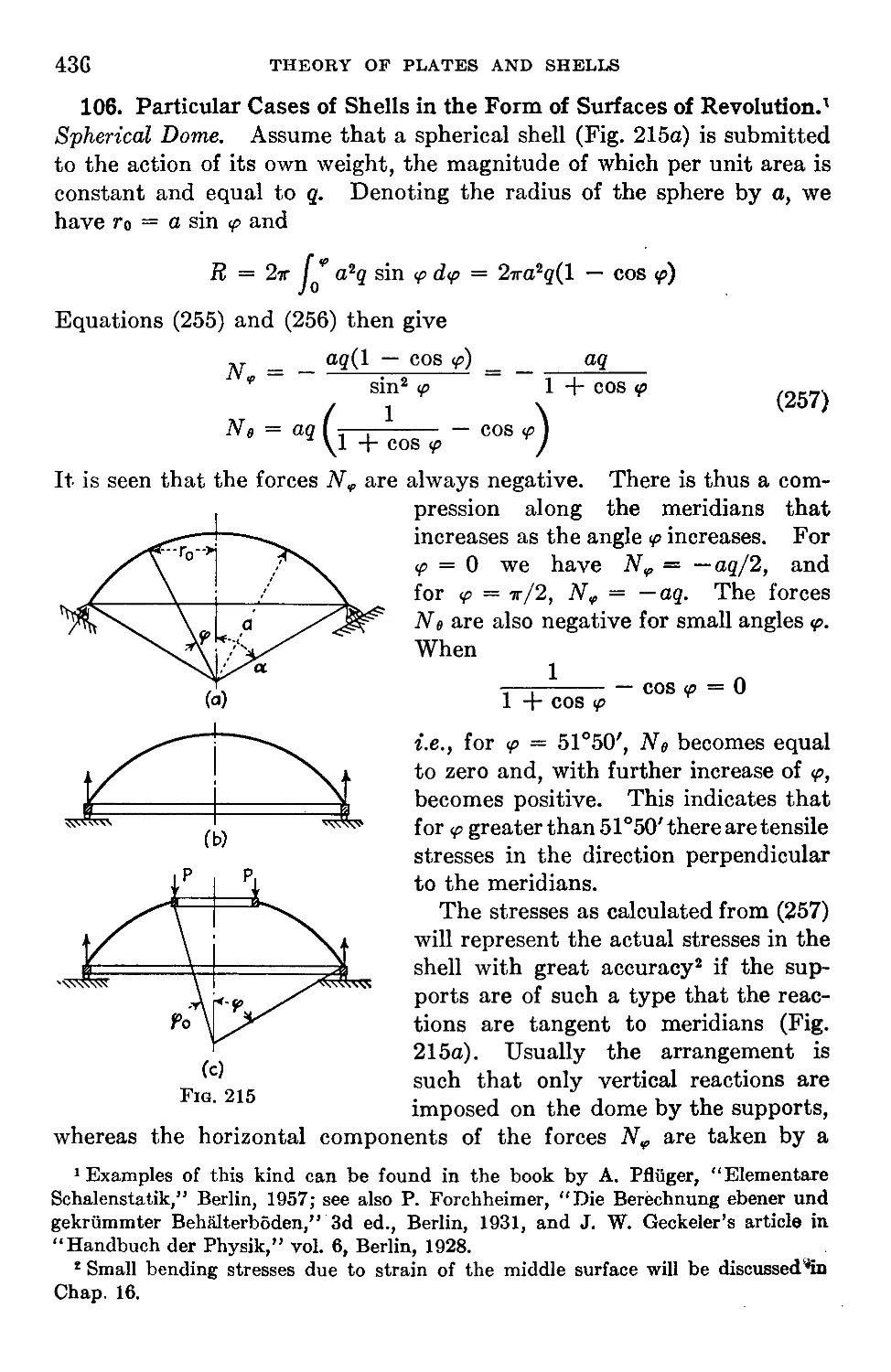
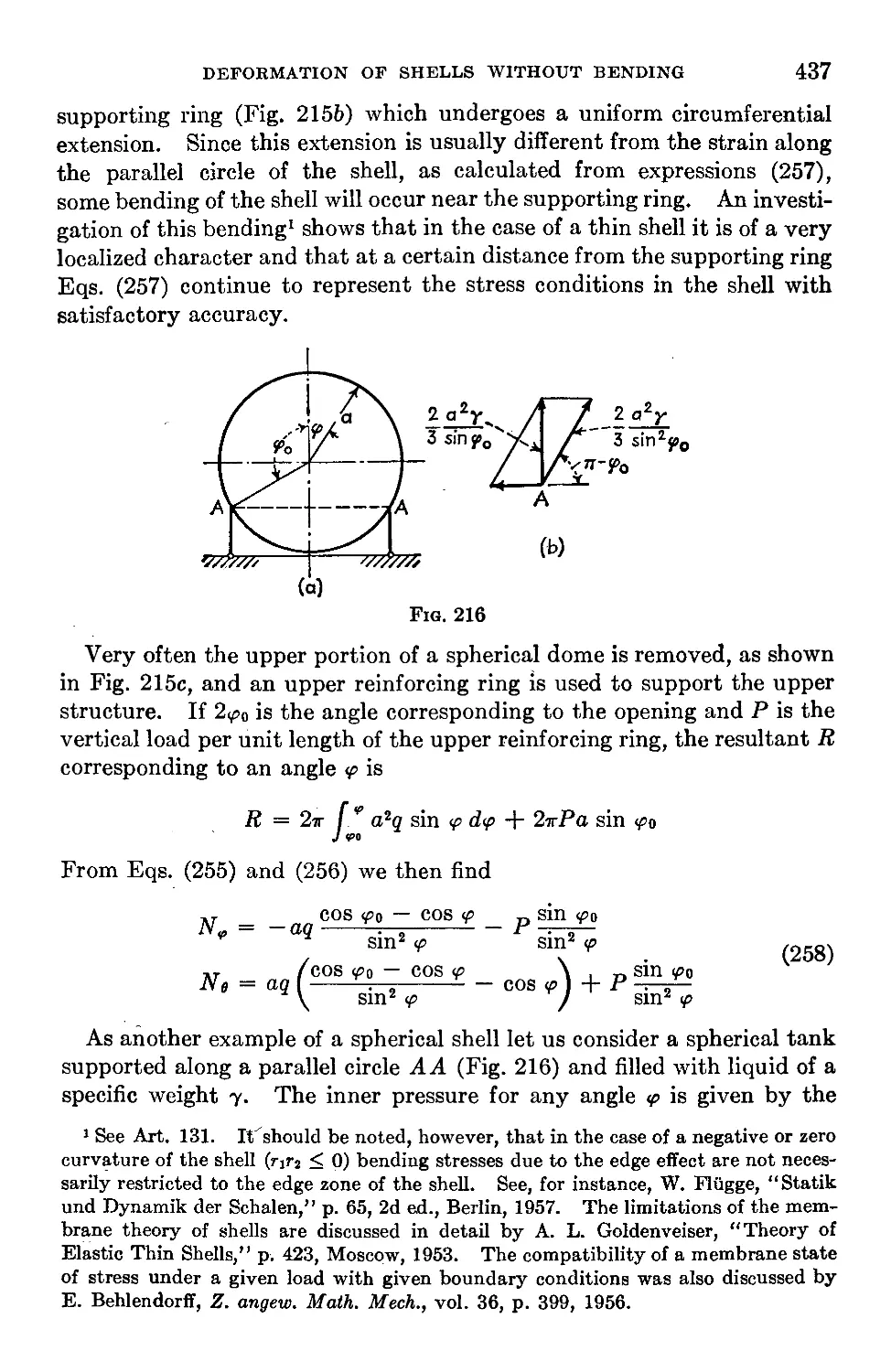
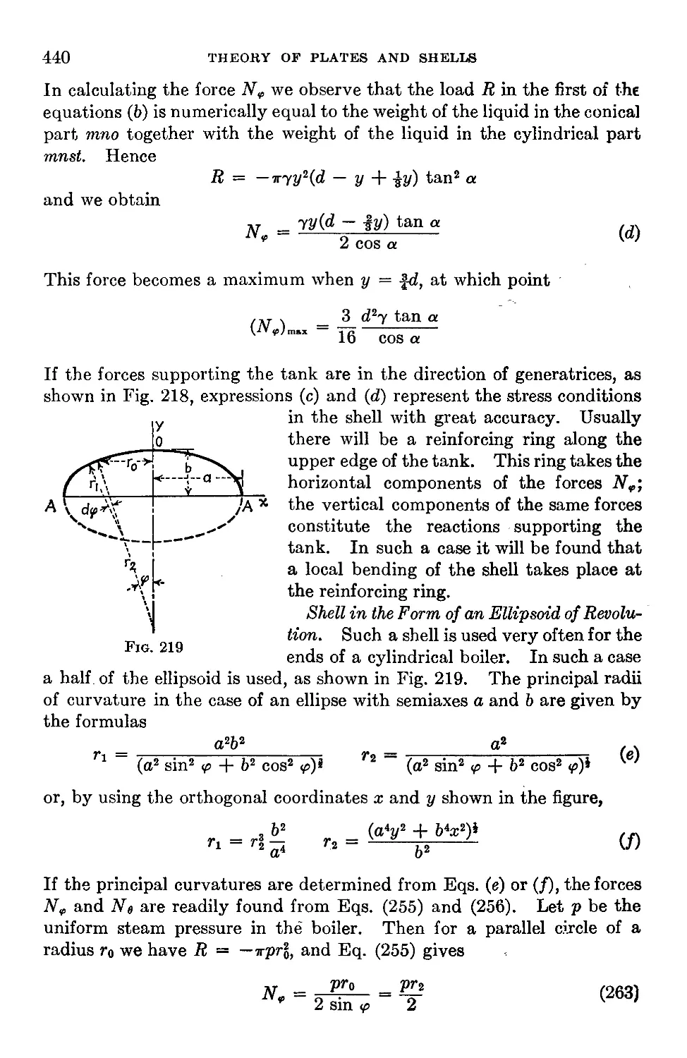
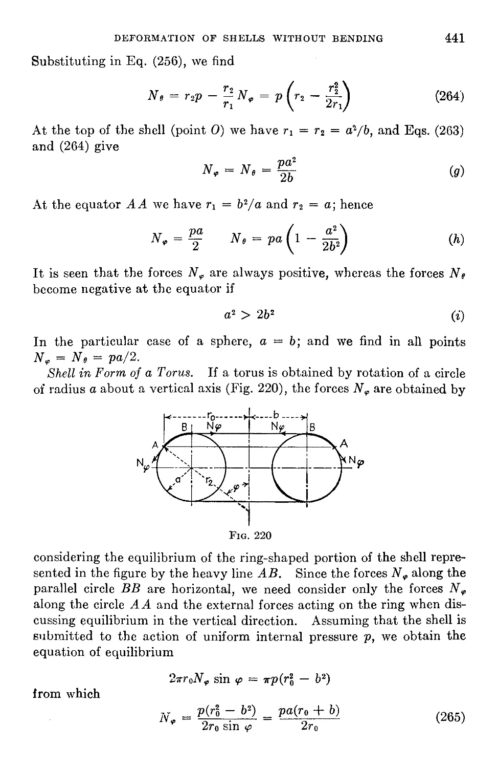
106. Particular Cases of Shells in the Form of Surfaces of Revolution . . . 436
107. Shells of Constant Strength................................................442
108. Displacements in Symmetrically Loaded Shells Having the Form of a
Surface of Revolution....................................................445
109. Shells in the Form of a Surface of Revolution under Unsymmetrical
Loading..................................................................447
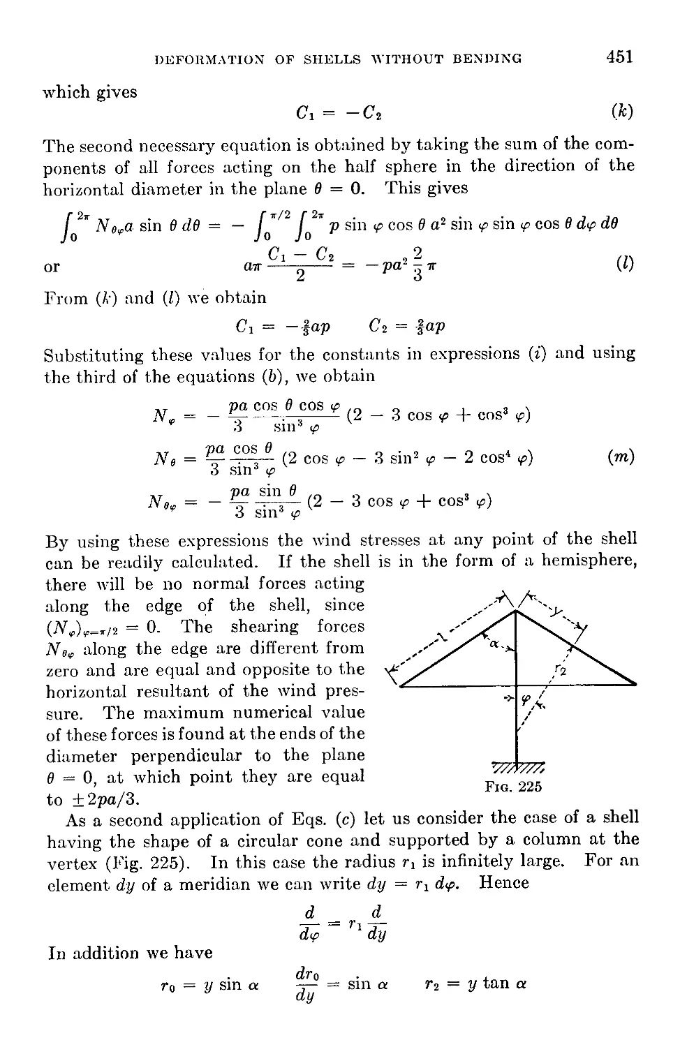
110. Stresses Produced by Wind Pressure..................................449
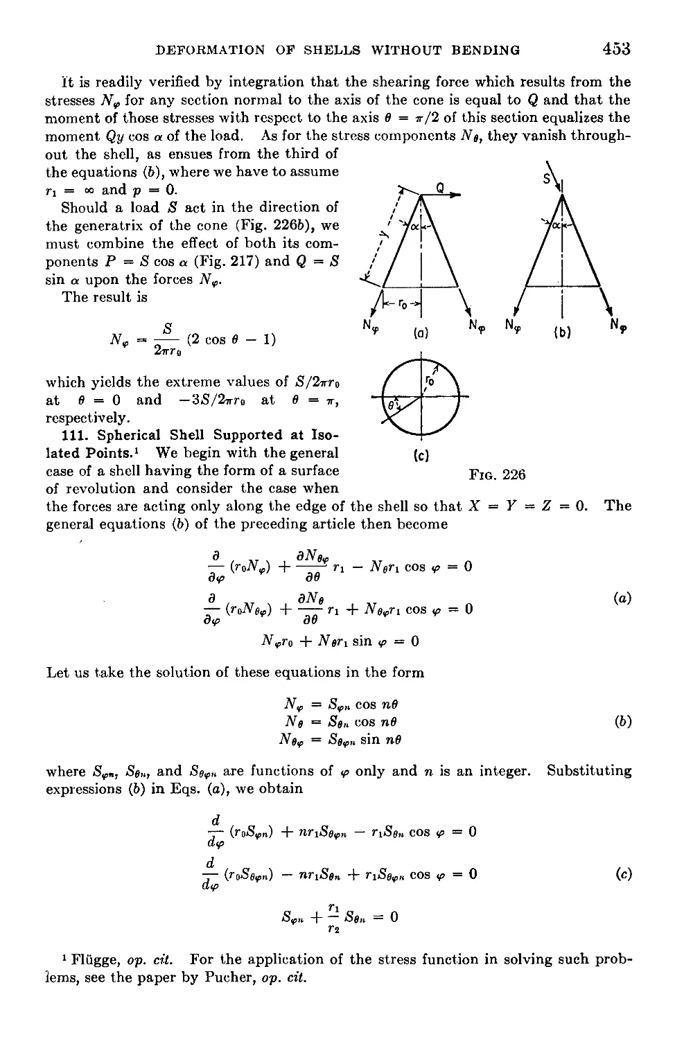
111. Spherical Shell Supported at Isolated Points........................453
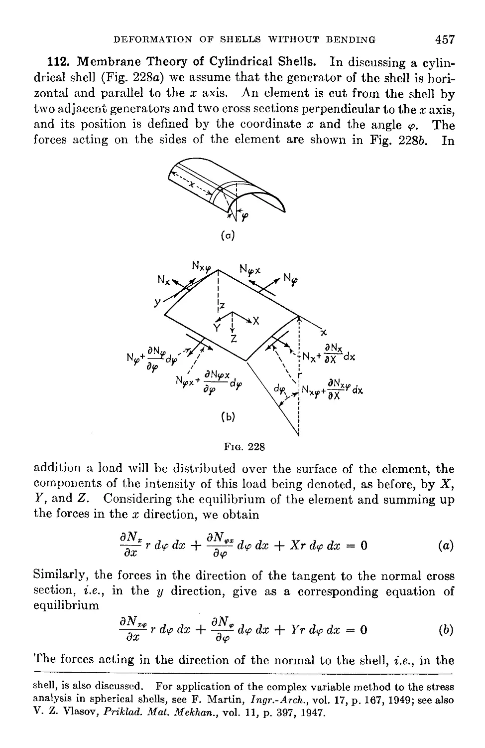
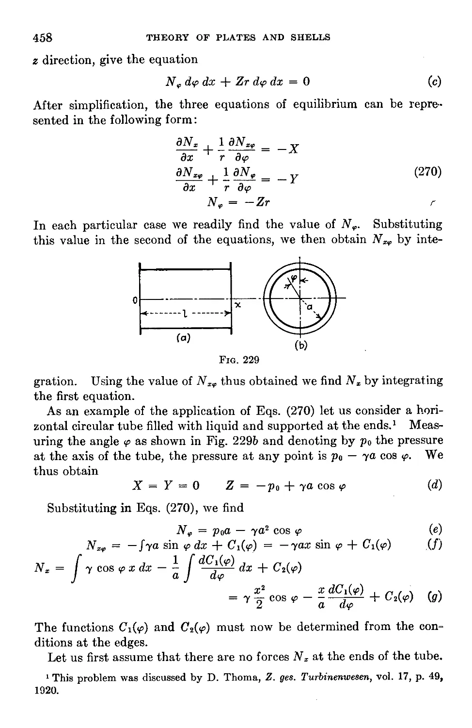
112. Membrane Theory of Cylindrical Shells...............................457
113. The Use of a Stress Function in Calculating Membrane Forces of Shells . 461
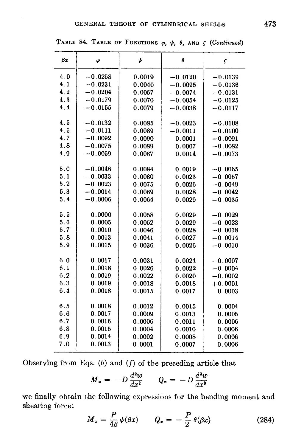
Chapter 16. General Theory of Cylindrical Shells.................................466
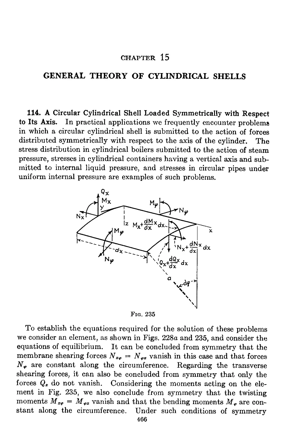
114. A Circular Cylindrical Shell Loaded Symmetrically with Respect to Its Axis 466
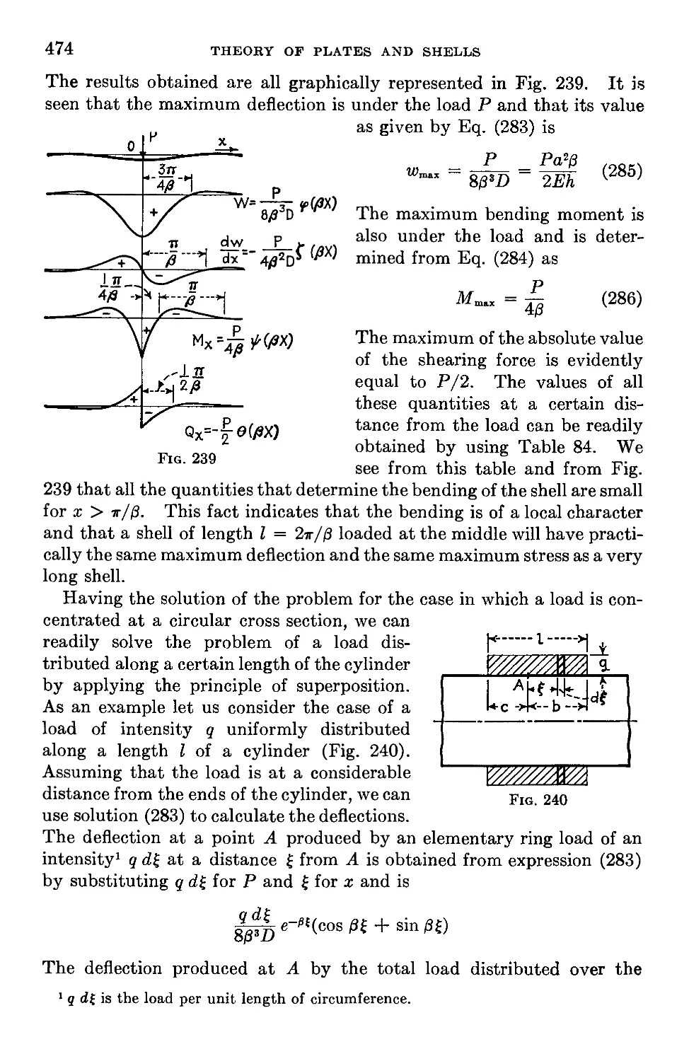
115. Particular Cases of Symmetrical Deformation of Circular Cylindrical Shells 471
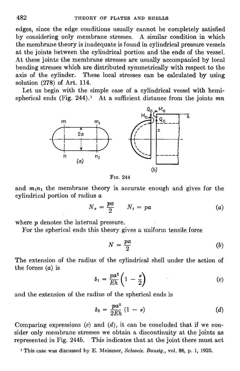
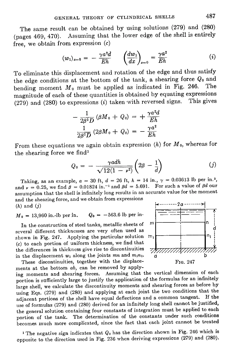
116. Pressure Vessels....................................................481
117. Cylindrical Tanks with Uniform Wall Thickness.......................485
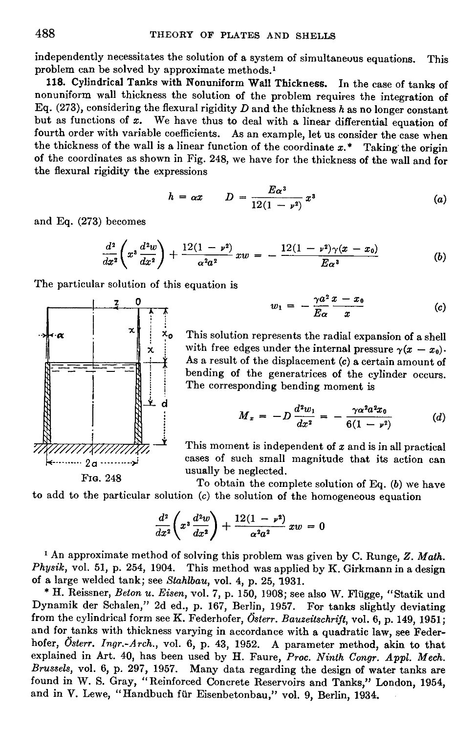
118. Cylindrical Tanks with Nonuniform Wall Thickness....................488
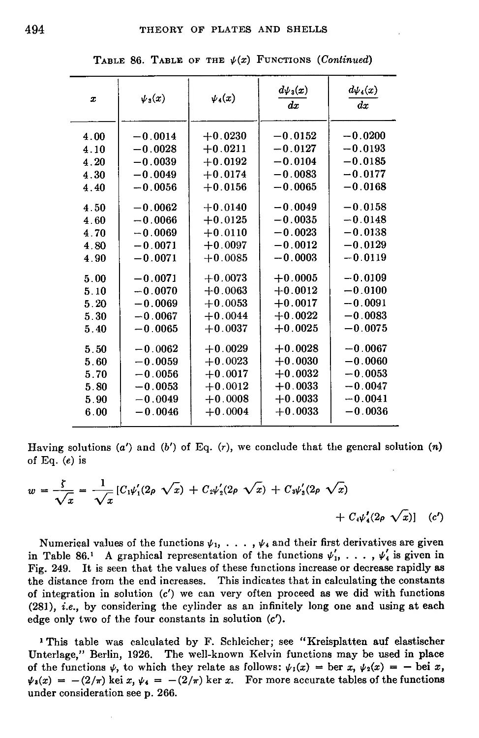
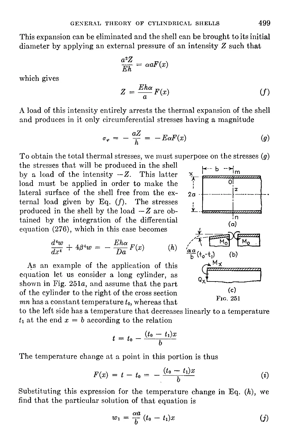
119. Thermal Stresses in Cylindrical Shells..............................497
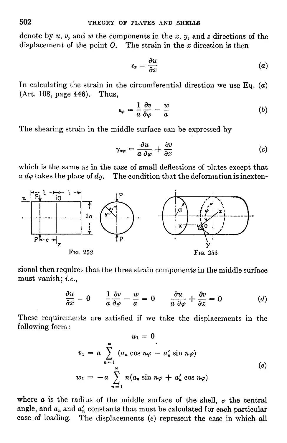
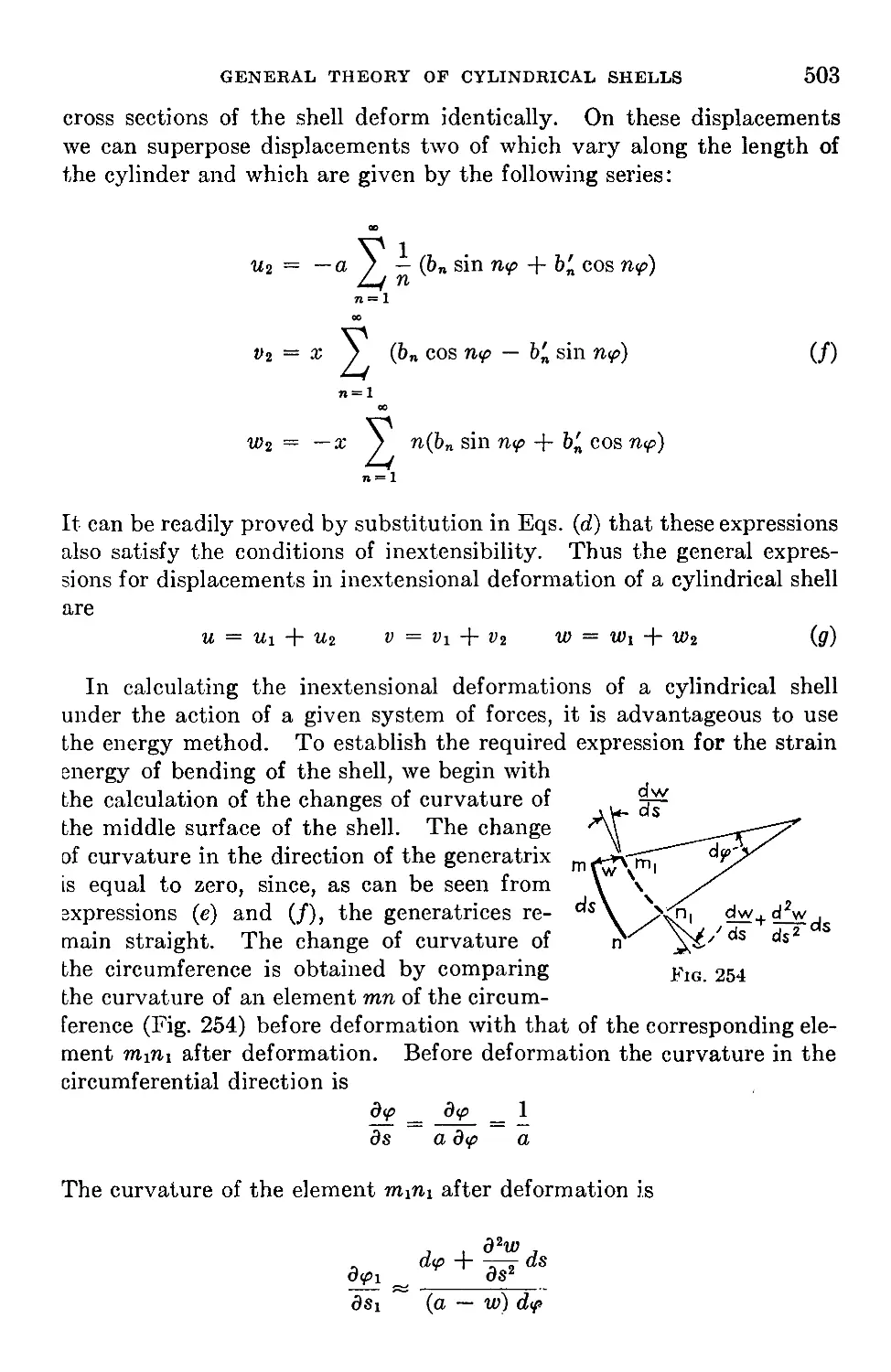
120. Inextensional Deformation of a Circular Cylindrical Shell...........501
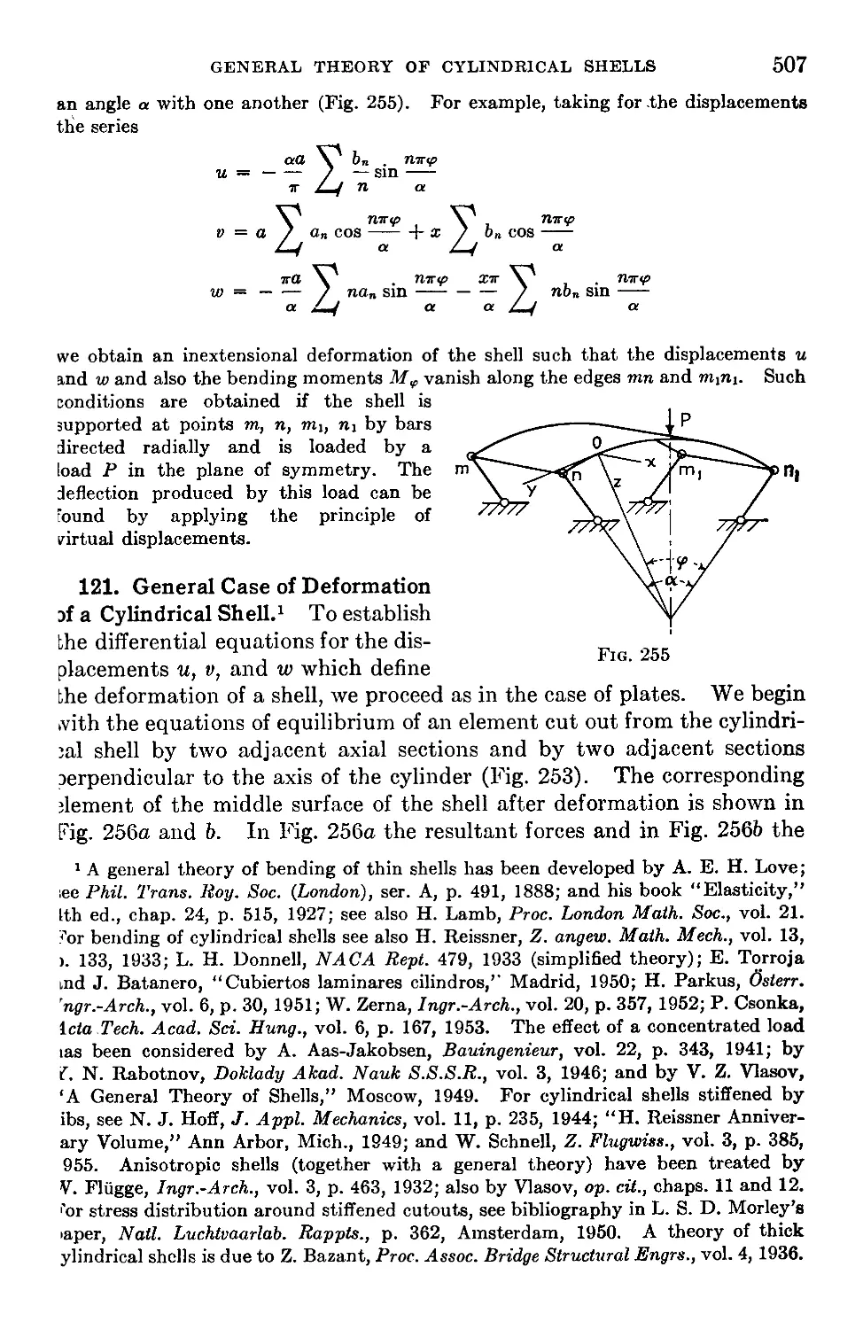
121. General Case of Deformation of a Cylindrical Shell..................507
122. Cylindrical Shells with Supported Edges.............................514
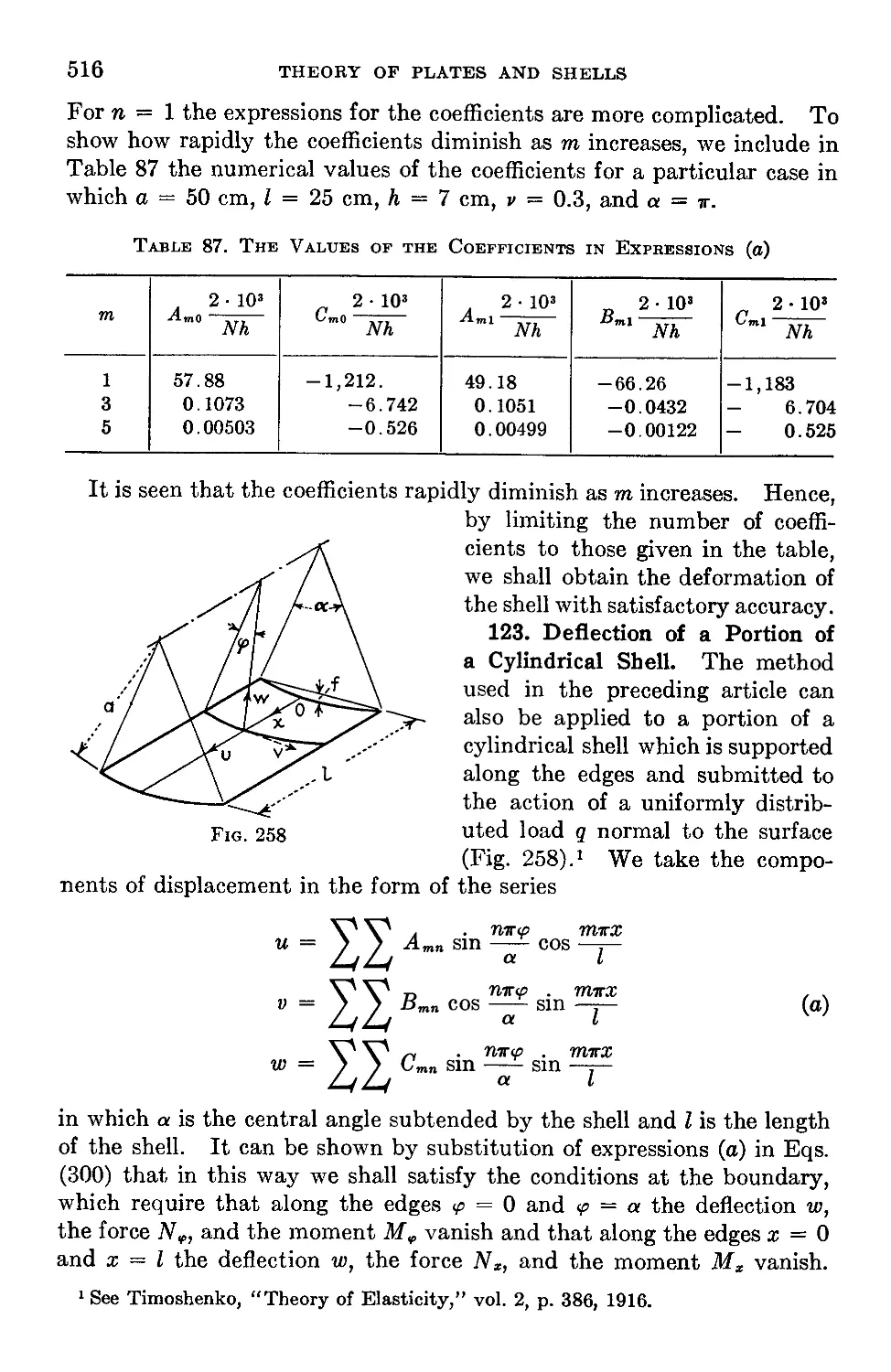
123. Deflection of a Portion of a Cylindrical Shell......................516
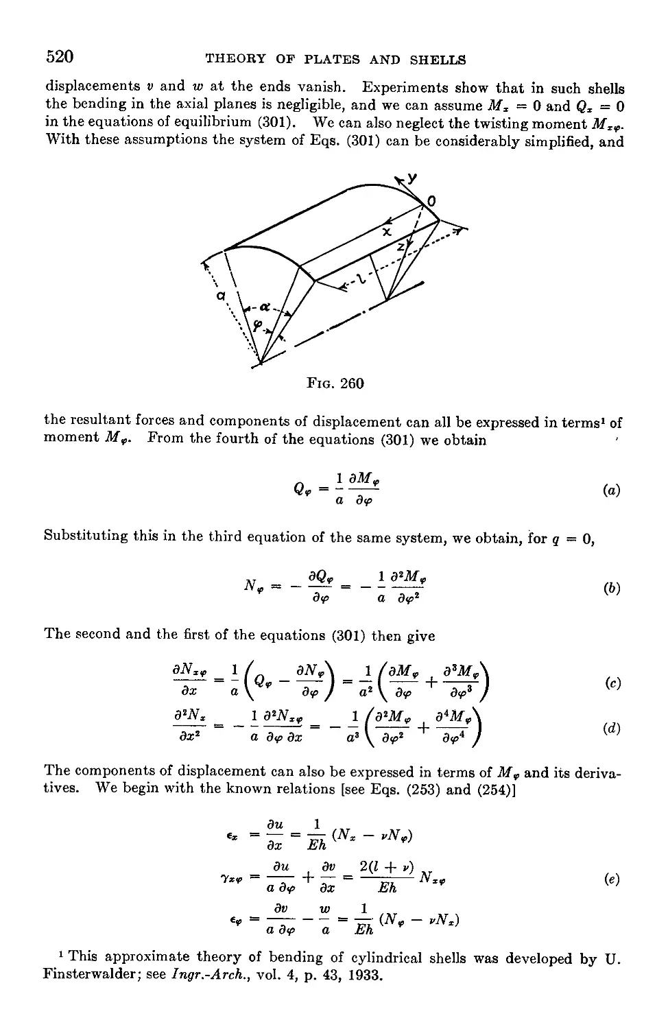
124. An Approximate Investigation of the Bending of Cylindrical Shells . . 519
125. The Use of a Strain and Stress Function.............................522
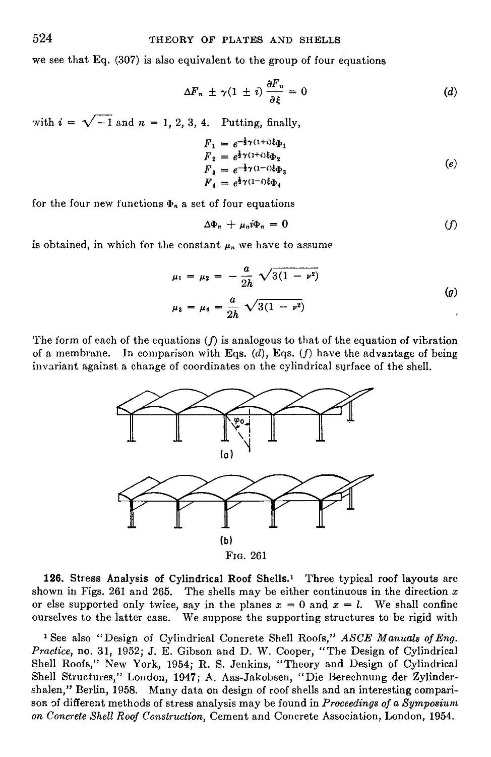
126. Stress Analysis of Cylindrical Roof Shells..........................524
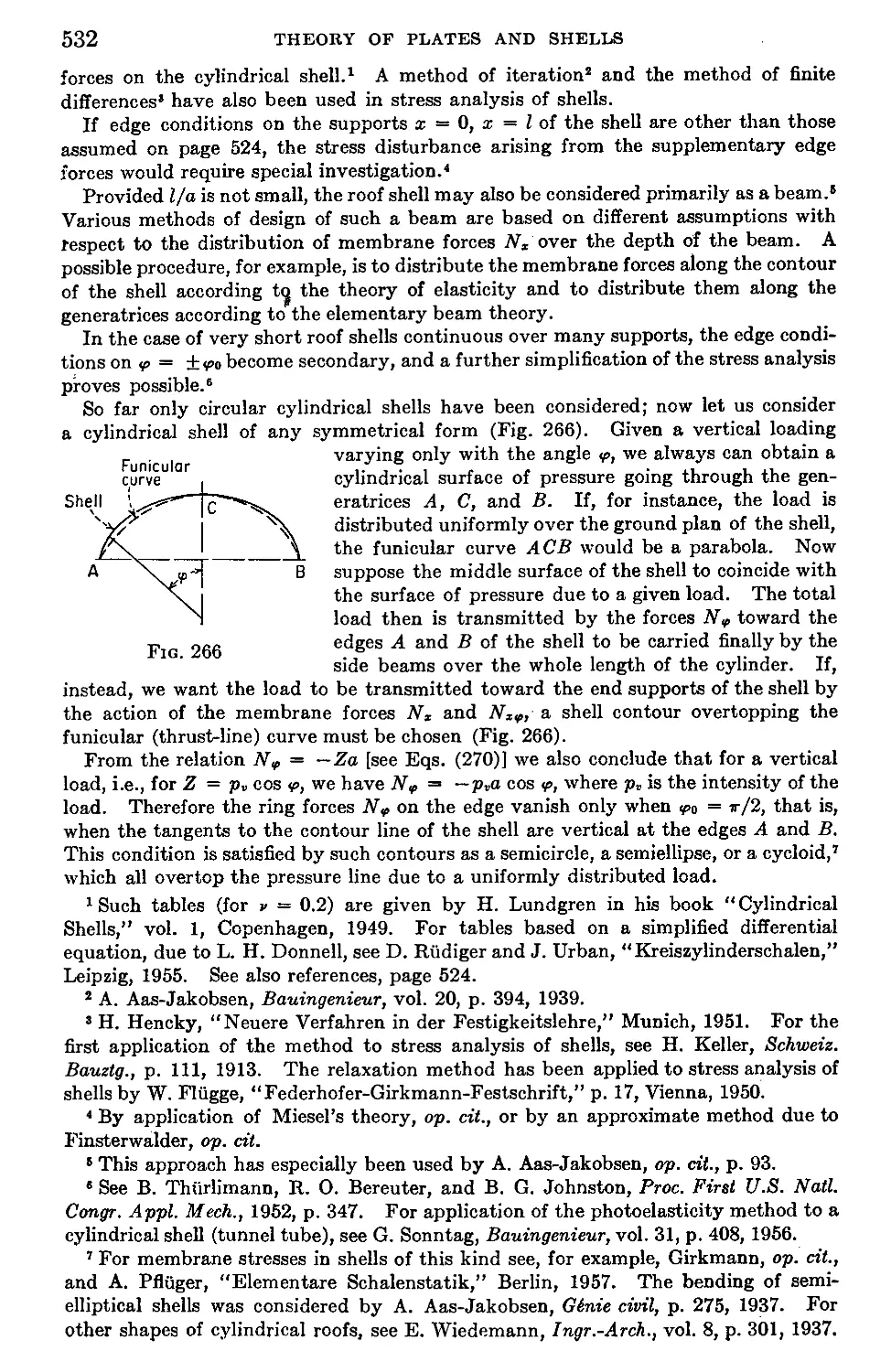
Chapter 16. Shells Having the Form of a Surface of Revolution and Loaded
Symmetrically with Respect to Their Axis........................................533
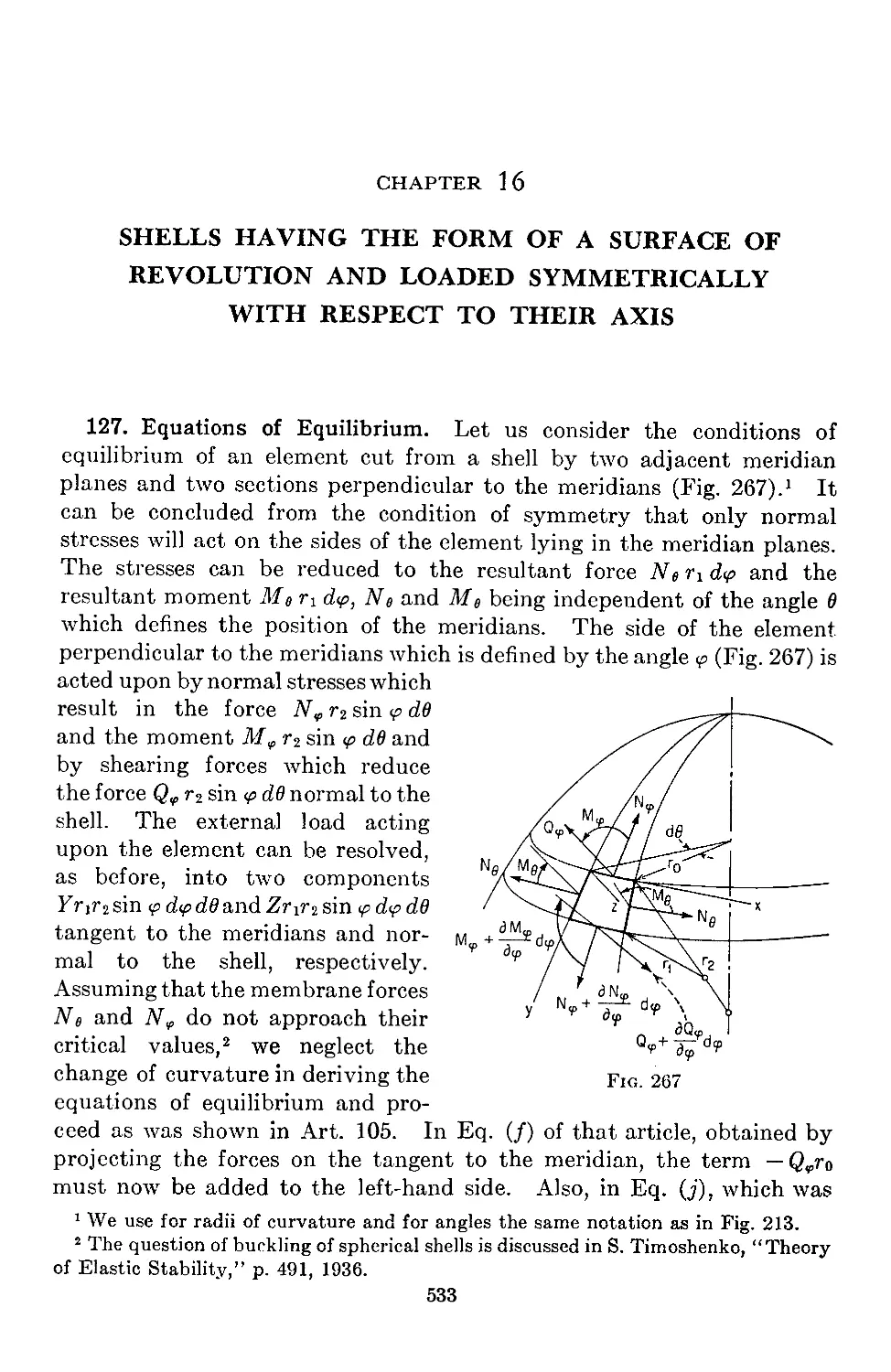
127. Equations of Equilibrium...................................................533
128. Reduction of the Equations of Equilibrium to Two Differential Equations
of the Second Order . .......................................537
129. Spherical Shell of Constant Thickness......................................540
CONTENTS Xi
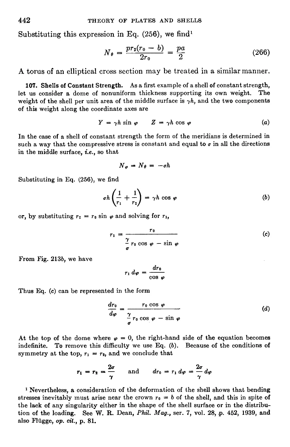
130. Approximate Methods of Analyzing Stresses in Spherical Shells . . 547
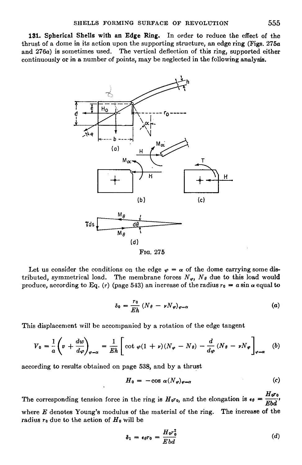
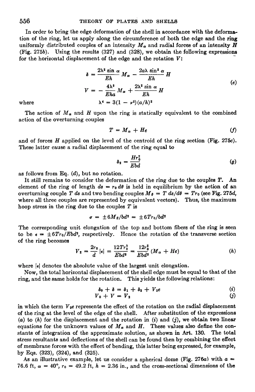
131. Spherical Shells with an Edge Ring........................555
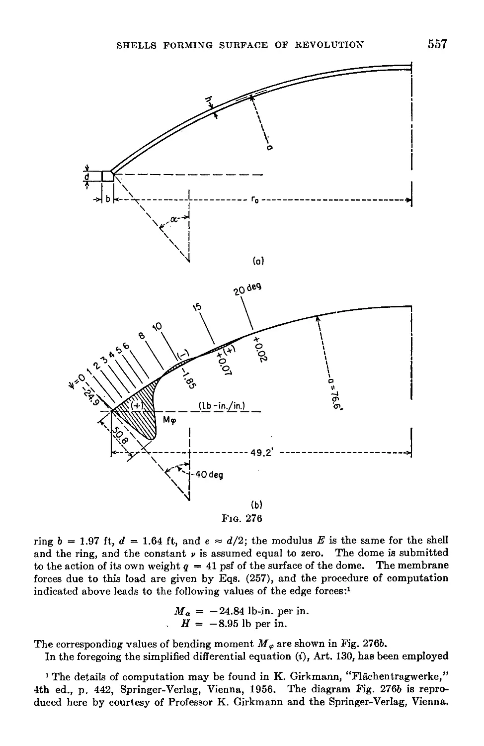
132. Symmetrical Bending of Shallow Spherical Shells...................558
133. Conical Shells....................................................562
134. General Case of Shells Having the Form of a Surface of Revolution . 566
Name Index.............................................................569
Subject Index...................................................... 575
NOTATION
x, у, z
r, e
rx, ry
h
<1
P
P
7
(Tj, <Ty, &z
<Tn
Gr
<Tt, (Г6
Txyj TgZ) Tyz
U, V, w
€
€x, €z
er
et, ее
e<p, ее
Уху} Угг, Ууг
Угв
Е
G
V
V
D
Мх, Му
М XV
М„, Mnt
Qx, Qv
Qn
Nx, Ny
Rectangular coordinates
Polar coordinates
Radii of curvature of the middle surface of a plate in xz and yz planes,
respectively
Thickness of a plate or a shell
Intensity of a continuously distributed load
Pressure
Single load
Weight per unit volume
Normal components of stress parallel to x, y, and z axes
Normal component of stress parallel to n direction
Radial stress in polar coordinates
Tangential stress in polar coordinates
Shearing stress
Shearing stress components in rectangular coordinates
Components of displacements
Unit elongation
Unit elongations in x, y, and z directions
Radial unit elongation in polar coordinates
Tangential unit elongation in polar coordinates
Unit elongations of a shell in meridional direction and in the direction
of parallel circle, respectively
Shearing strain components in rectangular coordinates
Shearing strain in polar coordinates
Modulus of elasticity in tension and compression
Modulus of elasticity in shear
Poisson’s ratio
Strain energy
Flexural rigidity of a plate or shell
Bending moments per unit length of sections of a plate perpendicular
to x and у axes, respectively
Twisting moment per unit length of section of a plate perpendicular
to x axis
Bending and twisting moments per unit length of a section of a plate
perpendicular to n direction
Shearing forces parallel to z axis per unit length of sections of a plate
perpendicular to x and у axes, respectively
Shearing force parallel to z axis per unit length of section of a plate
perpendicular to n direction
Normal forces per unit length of sections of a plate perpendicular to
x and у directions, respectively
xiii
xiv NOTATION
Nxy Shearing force in direction of у axis per unit length of section of a plate
perpendicular to x axis
Mr, Mi, Mn Radial, tangential, and twisting moments when using polar coordinates
Qr, Qi Radial and tangential shearing forces
Nr, Nt Normal forces per unit length in radial and tangential directions
Zi, Г2 Radii of curvature of a shell in the form of a surface of revolution in
meridional plane and in the normal plane perpendicular to meridian,
respectively
xo Changes of curvature of a shell in meridional plane and in the plane
perpendicular to meridian, respectively
xev Twist of a shell
X, Y, Z Components of the intensity of the external load on a shell, parallel to
x, y, and z axes, respectively
Ne, Nve Membrane forces per unit length of principal normal sections of a shell
Me, Mv Bending moments in a shell per unit length of meridional section and a
section perpendicular to meridian, respectively
Xx, Xf Changes of curvature of a cylindrical shell in axial plane and in a plane
perpendicular to the axis, respectively
Nv, Nx, Nxv Membrane forces per unit length of axial section and a section perpen-
dicular to the axis of a cylindrical shell
Mf, Mx Bending moments per unit length of axial section and a section perpen-
dicular to the axis of a cylindrical shell, respectively
Mxf Twisting moment per unit length of an axial section of a cylindrical
shell
Qv, Qx Shearing forces parallel to z axis per unit length of an axial section and
a section perpendicular to the axis of a cylindrical shell, respectively
log Natural logarithm
logic, Log Common logarithm
INTRODUCTION
The bending properties of a plate depend greatly on its thickness as
compared with its other dimensions. In the following discussion, we
shall distinguish between three kinds of plates: (1) thin plates with small
deflections, (2) thin plates with large deflections, (3) thick plates.
Thin Plates with Small Deflection. If deflections w of a plate are small
in comparison with its thickness h, a very satisfactory approximate theory
of bending of the plate by lateral loads can be developed by making the
following assumptions:
1. There is no deformation in the middle plane of the plate. This
plane remains neutral during bending.
2. Points of the plate lying initially on a normal-to-the-middle plane
of the plate remain on the normal-to-the-middle surface of the plate after
bending.
3. The normal stresses in the direction transverse to the plate can be
disregarded.
Using these assumptions, all stress components can be expressed by
deflection w of the plate, which is a function of the two coordinates in
the plane of the plate. This function has to satisfy a linear partial
differential equation, which, together with the boundary conditions, com-
pletely defines w. Thus the solution of this equation gives all necessary
information for calculating stresses at any point of the plate.
The second assumption is equivalent to the disregard of the effect of
shear forces on the deflection of plates. This assumption is usually satis-
factory, but in some cases (for example, in the case of holes in a plate)
the effect of shear becomes important and some corrections in the theory
of thin plates should be introduced (see Art. 39).
If, in addition to lateral loads, there are external forces acting in the
middle plane of the plate, the first assumption does not hold any more,
and it is necessary to take into consideration the effect on bending of the
plate of the stresses acting in the middle plane of the plate. This can be
done by introducing some additional terms into the above-mentioned
differential equation of plates (see Art. 90).
2
THEORY OF PLATES AND SHELLS
Thin Plates with Large Deflection. The first assumption is completely
satisfied only if a plate is bent into a developable surface. In other eases
bending of a plate is accompanied by strain in the middle plane, but
calculations show that the corresponding stresses in the middle plane are
negligible if the deflections of the plate are small in comparison with its
thickness. If the deflections are not small, these supplementary stresses
must be taken into consideration in deriving the differential equation of
plates. In this way we obtain nonlinear equations and the solution of the
problem becomes much more complicated (see Art. 96). In the case of
large deflections we have also to distinguish between immovable edges
and edges free to move in the plane of the plate, which may have a con-
siderable bearing upon the magnitude of deflections and stresses of the
plate (see Arts. 99, 100). Owing to the curvature of the deformed middle
plane of the plate, the supplementary tensile stresses, which predominate,
act in opposition to the given lateral load; thus, the given load is now
transmitted partly by the flexural rigidity and partly by a membrane
action of the plate. Consequently, very thin plates with negligible
resistance to bending behave as membranes, except perhaps for a narrow
edge zone where bending may occur because of the boundary conditions
imposed on the plate.
The case of a plate bent into a developable, in particular into a cylindri-
cal, surface should be considered as an exception. The deflections of
such a plate may be of the order of its thickness without necessarily pro-
ducing membrane stresses and without affecting the linear character of
the theory of bending. Membrane stresses would, however, arise in such
a plate if its edges are immovable in its plane and the deflections are
sufficiently large (see Art. 2). Therefore, in “plates with small deflec-
tion” membrane forces caused by edges immovable in the plane of the
plate can be practically disregarded.
Thick Plates. The approximate theories of thin plates, discussed
above, become unreliable in the case of plates of considerable thickness,
especially in the case of highly concentrated loads. In such a case the
thick-plate theory should be applied. This theory considers the prob-
lem of plates as a three-dimensional problem of elasticity. The stress
analysis becomes, consequently, more involved and, up to now, the prob-
lem is completely solved only for a few particular cases. Using this
analysis, the necessary corrections to the thin-plate theory at the points of
application of concentrated loads can be introduced.
The main suppositions of the theory of thin plates also form the basis
for the usual theory of thin shells. There exists, however, a substantial
difference in the behavior of plates and shells under the action of external
loading. The static equilibrium of a plate element under a lateral load
is only possible by action of bending and twisting moments, usually
INTRODUCTION
3
accompanied by shearing forces, while a shell, in general, is able to trans-
mit the surface load by “membrane” stresses which act parallel to the
tangential plane at a given point of the middle surface and are distributed
uniformly over the thickness of the shell. This property of shells makes
them, as a rule, a much more rigid and a more economical structure than
a plate would be under the same conditions.
In principle, the membrane forces are independent of bending and are
wholly defined by the conditions of static equilibrium. The methods of
determination of these forces represent the so-called “membrane theory
of shells.” However, the reactive forces and deformation obtained by
the use of the membrane theory at the shell’s boundary usually become
incompatible with the actual boundary conditions. To remove this dis-
crepancy the bending of the shell in the edge zone has to be considered,
which may affect slightly the magnitude of initially calculated membrane
forces. This bending, however, usually has a very localized1 character
and may be calculated on the basis of the same assumptions which were
used in the case of small deflections of thin plates. But there are prob-
lems, especially those concerning the elastic stability of shells, in which
the assumption of small deflections should be discontinued and the “large-
deflection theory” should be used.
If the thickness of a shell is comparable to the radii of curvature, or
if we consider stresses near the concentrated forces, a more rigorous
theory, similar to the thick-plate theory, should be applied.
1 There are some kinds of shells, especially those with a negative Gaussian curva-
ture, which provide us with a lot of exceptions. In the case of developable surfaces
such as cylinders or cones, large deflection without strain of the middle surface is
possible, and, in some cases, membrane stresses can be neglected and consideration
of the bending stresses alone may be sufficient.
CHAPTER t
BENDING OF LONG RECTANGULAR PLATES TO A
CYLINDRICAL SURFACE
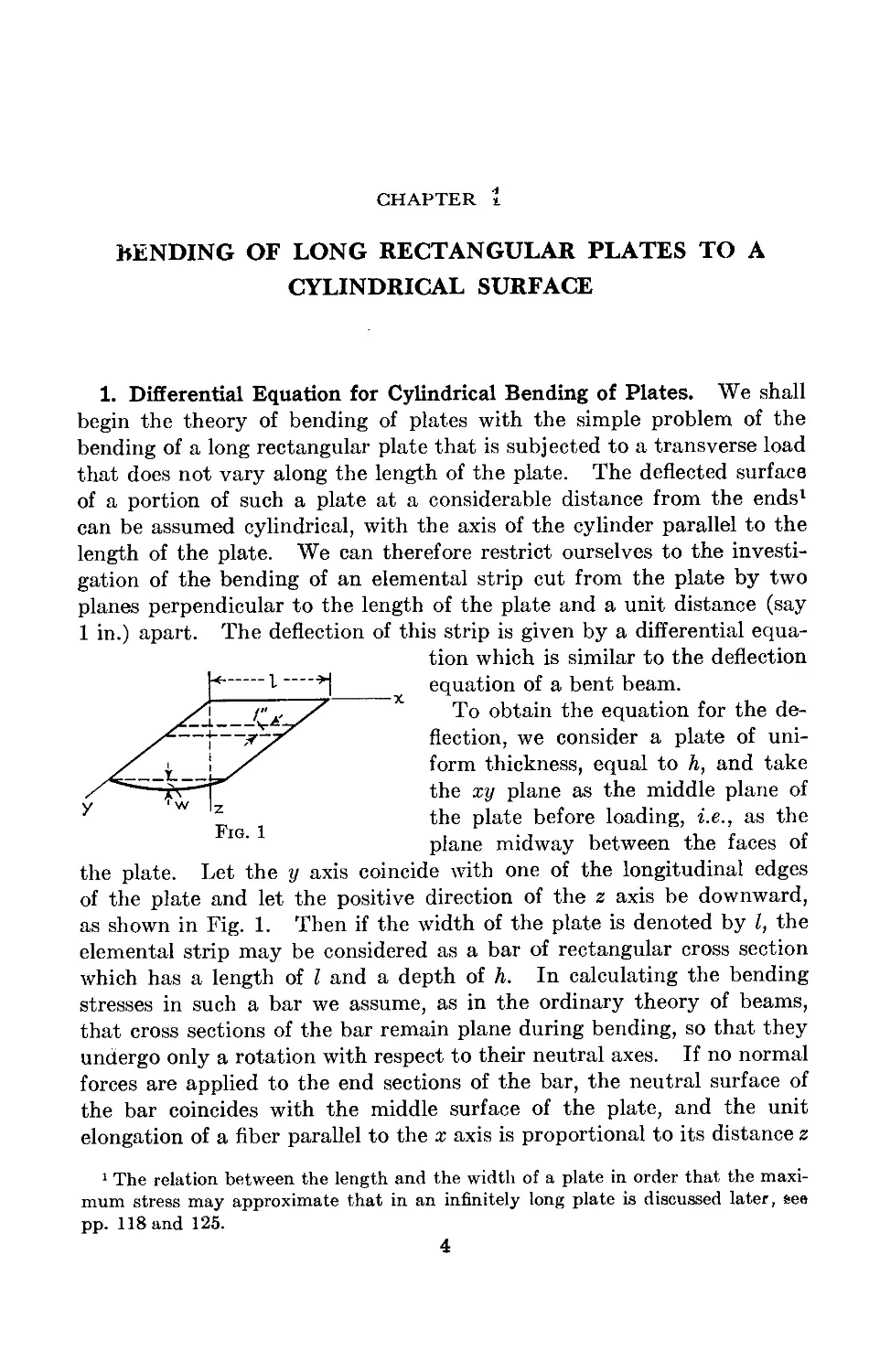
1. Differential Equation for Cylindrical Bending of Plates. We shall
begin the theory of bending of plates with the simple problem of the
bending of a long rectangular plate that is subjected to a transverse load
that does not vary along the length of the plate. The deflected surface
of a portion of such a plate at a considerable distance from the ends1 * *
can be assumed cylindrical, with the axis of the cylinder parallel to the
length of the plate. We can therefore restrict ourselves to the investi-
gation of the bending of an elemental strip cut from the plate by two
planes perpendicular to the length of the plate and a unit distance (say
1 in.) apart. The deflection of this strip is given by a differential equa-
tion which is similar to the deflection
p 1 *j equation of a bent beam.
______________To obtain the equation for the de-
_____________flection, we consider a plate of uni-
y' \ jS form thickness, equal to Л, and take
X4 Г the xy plane as the middle plane of
Fl the P^a^e before loading, i.e., as the
plane midway between the faces of
the plate. Let the у axis coincide with one of the longitudinal edges
of the plate and let the positive direction of the z axis be downward,
as shown in Fig. 1. Then if the width of the plate is denoted by Z, the
elemental strip may be considered as a bar of rectangular cross section
which has a length of I and a depth of h. In calculating the bending
stresses in such a bar we assume, as in the ordinary theory of beams,
that cross sections of the bar remain plane during bending, so that they
undergo only a rotation with respect to their neutral axes. If no normal
forces are applied to the end sections of the bar, the neutral surface of
the bar coincides with the middle surface of the plate, and the unit
elongation of a fiber parallel to the x axis is proportional to its distance z
1 The relation between the length and the width of a plate in order that the maxi-
mum stress may approximate that in an infinitely long plate is discussed later, see
pp. 118 and 125.
4
bending to a cylindrical surface
5
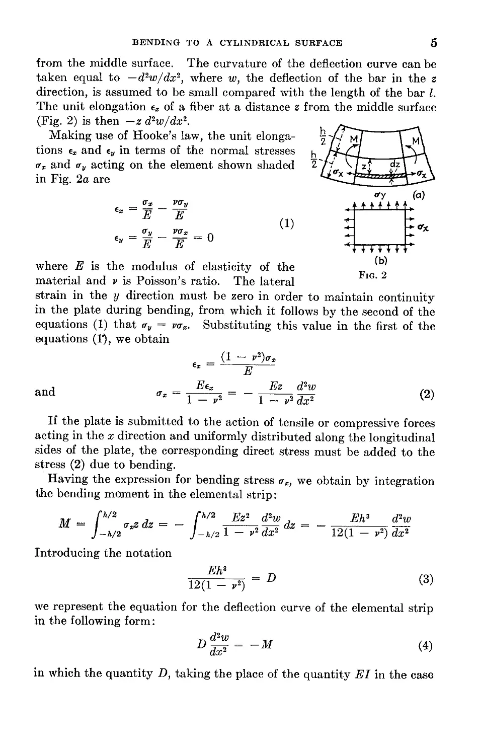
from the middle surface. The curvature of the deflection curve can be
taken equal to —d2wldx2, where w, the deflection of the bar in the z
direction, is assumed to be small compared with the length of the bar I.
The unit elongation ex of a fiber at a distance z from the middle surface
(Fig. 2) is then —z d'-w/dx2.
Making use of Hooke’s law, the unit elonga-
tions ex and ey in terms of the normal stresses
ax and <ty acting on the element shown shaded
in Fig. 2a are
_ V_x _ vav
tx ~E
= Oy _ W, =
y E E
where E is the modulus of elasticity of the
material and v is Poisson’s ratio. The lateral
strain in the у direction must be zero in order to maintain continuity
in the plate during bending, from which it follows by the second of the
equations (1) that <ry = vax. Substituting this value in the first of the
equations (1% we obtain
and
_ (1 - V2)vx
€x E
Eex _ _ Ez d2w
1 — v2 1 — v2 dx2
(2)
If the plate is submitted to the action of tensile or compressive forces
acting in the x direction and uniformly distributed along the longitudinal
sides of the plate, the corresponding direct stress must be added to the
stress (2) due to bending.
Having the expression for bending stress <rx, we obtain by integration
the bending moment in the elemental strip:
,, p/2 , p/2 Ez2 d2w J Eh3 d2w
M ]-h/2axZdZ J-h/2 1 - v2 dx2 dz 12(1 - r2)dx2
Introducing the notation
_ Eh3 = D
12(1 - v2)
(3)
we represent the equation for the deflection curve of the elemental strip
in the following form:
dx2
(4)
in which the quantity D, taking the place of the quantity El in the case
6
THEORY or PLATES AND SHELLS
of beams, is called the flexural rigidity of the plate. It is seen that the
calculation of deflections of the plate reduces to the integration of Eq. (4),
which has the same form as the differential equation for deflection of
beams. If there is only a lateral load acting on the plate and the edges
are free to approach each other as deflection occurs, the expression for
the bending moment M can be readily derived, and the deflection curve
is then obtained by integrating Eq. (4). In practice the problem is more
complicated, since the plate is usually attached to the boundary and its
edges are not free to move. Such a method of support sets up tensile
reactions along the edges as soon as deflection takes place. These reac-
tions depend on the magnitude of the deflection and affect the magnitude
of the bending moment M entering in Eq. (4). The problem reduces to
the investigation of bending of an elemental strip submitted to the action
of a lateral load and also an axial force which depends on the deflection
of the strip.1 In the following we consider this problem for the particular
case of uniform load acting on a plate and for various conditions along
the edges.
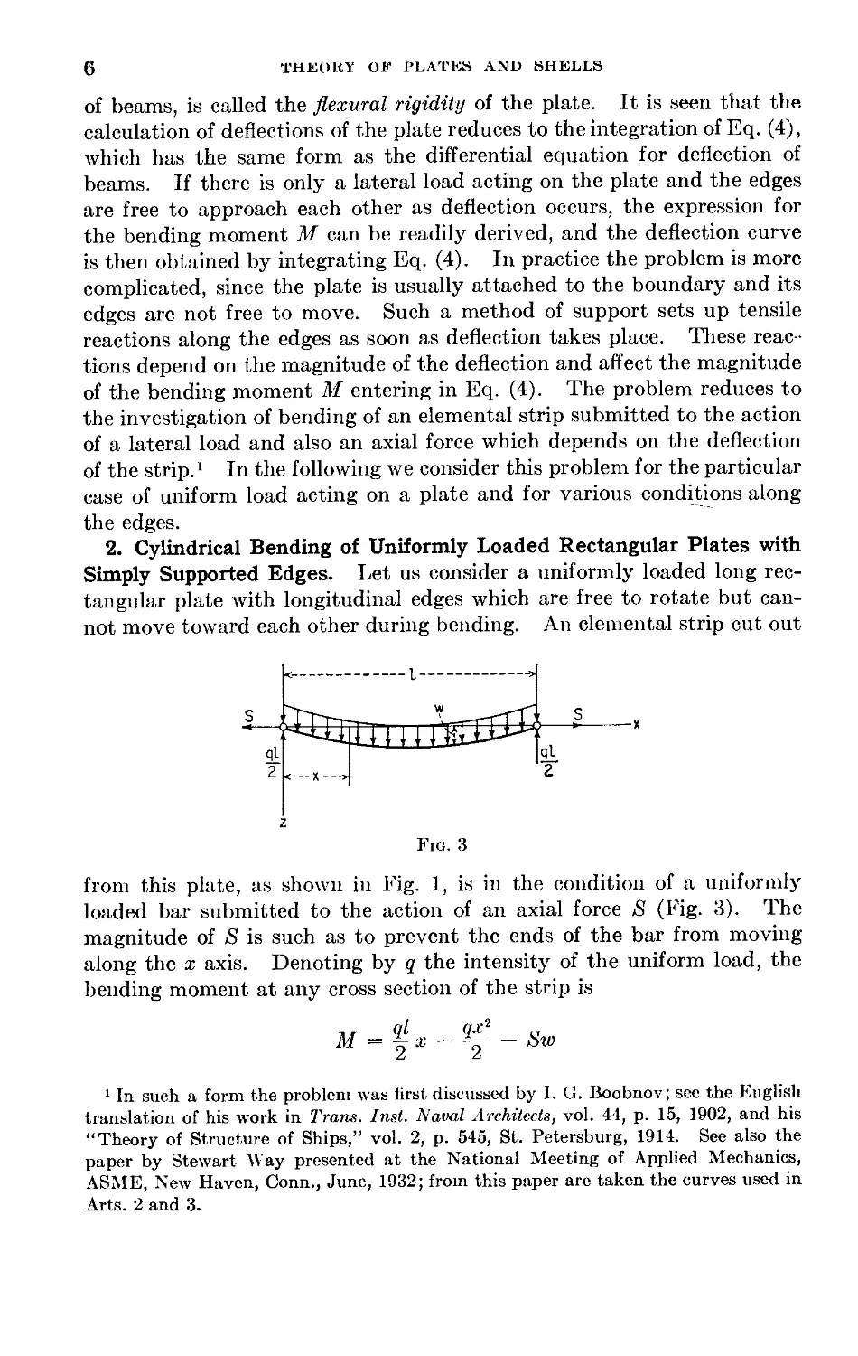
2. Cylindrical Bending of Uniformly Loaded Rectangular Plates with
Simply Supported Edges. Let us consider a uniformly loaded long rec-
tangular plate with longitudinal edges which are free to rotate but can-
not move toward each other during bending. An elemental strip cut out
Fig. 3
from this plate, as shown in Fig. 1, is in the condition of a uniformly
loaded bar submitted to the action of an axial force 5 (Fig. 3). The
magnitude of »S is such as to prevent the ends of the bar from moving
along the x axis. Denoting by q the intensity of the uniform load, the
bending moment at any cross section of the strip is
,, fl <7.r2 „
M = 2 X ~ 2 ~ Sw
1 In such a form the problem was first discussed by 1. G. Boobnov; see the English
translation of his work in Trans. Inst. Naval Architects, vol. 44, p. 15, 1902, and his
“Theory of Structure of Ships,” vol. 2, p. 545, St. Petersburg, 1914. See also the
paper by Stewart Way presented at the National Meeting of Applied Mechanics,
ASME, New Haven, Conn., June, 1932; from this paper are taken the curves used in
Arts. 2 and 3.
BENDING TO A CYLINDRICAL SURFACE
7
Substituting in Eq. (4), we obtain
d2w Sw _ qlx qx2
dx2 - ~D ~ ~ 2D + 2D \14'/
Introducing the notation
S I2 D 4 = u2 (5)
the general solution of Eq. (a) can be written in the following firm:
„ . , 2ux , „ , 2wt , ql3x ql2x2 ql
w - Ci sinh ~j- + C2 cosh Su2D D (b)
The constants of integration Ci and C2 will be determined from the
conditions at the ends. Since the deflections of the strip at the ends are
zero, we have
w = 0 for x = 0 and x = I (c)
Substituting for w its expression (b), we obtain from these two c< editions
r1 _ </Z4 1 — cosh 2w r» _
C1 “ 16 г?D sinh 2u 2 ~
and the expression (6) for the deflection w becomes
oZ4 /1 — cosh 2u . , 2w.i: , , 2ш: ,\ , ol3x ql2x2
w = WD sinh ~T + cosh ~V ~ 9 + 8гЛС' “ WD
Substituting
cosh 2u = cosh2 и + sinh2 и sinh 2u = 2 sinh и cosh и
cosh2 и = 1 + sinh2 и
we can represent this expression in a simpler form:
or
. , . , 2ux , , . 2ux \
— sinh и sinh -----f- cosh и cosh —5— \ ,,
_______________1_________________L _ । i '/z r
cosh w___________________________}
w
Г и Л 2Л
,, cosh и I 1--г I ,,
7Z4 \ I / _ 1 ql2x
16u4D cosh и 8u2D
(6)
Thus, deflections of the elemental strip depend upon the quantity u,
which, as we see from Eq. (5), is a function of the axial force >S'. This
force can be determined from the condition that the ends of the strip
(Eig. 3) do not move along the x axis. Hence the extension of the strip
produced by the forces »S is equal to the difference between the length of
the arc along the deflection curve and the chord length Z. This difference
8
THEORY OF PLATES AND SHELLS
for small deflections can be represented by the formula1
. _ 1 Л (dw\2
A ~ 2 Jo \dx ) dx
In calculating the extension of the strip produced by the forces jS. we
assume that the lateral strain of the strin in the у direction is prevented
and use Eq. (2). Then
«(1 - r2)Z 1 /dw\2 , z
X = “^ =2Jo wdx
Substituting expression (6) for w and performing the integration, we
obtain the following equation for calculating >S':
>S(1 — v2~)l _ q2l7 / 5 tanh и 1 tanh2 и 5 1 \
hE ~ D2 \256 —u7 h 256 гГ6 256г? + 384г?)
or substituting >S' = 4w2D/Z2, from Eq. (5), and the expression for D,
from Eq. (3), we finally obtain the equation
E2hs _ 135 tanh и 27 tanh2 и 135 9 ,o.
(1 - p2)2q2Z8 ~ 16 H 16 i? 16г? + 8г? W
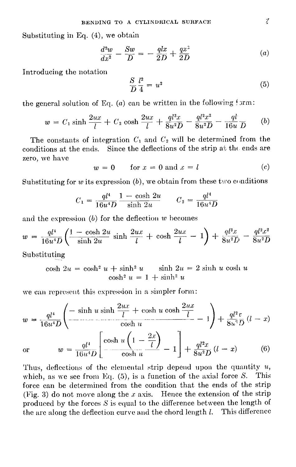
For a given material, a given ratio h/l, and a given load q the left-hand
side of this equation can be readily calculated, and the value of и satis-
fying the equation can be found by a trial-and-error method. To simplify
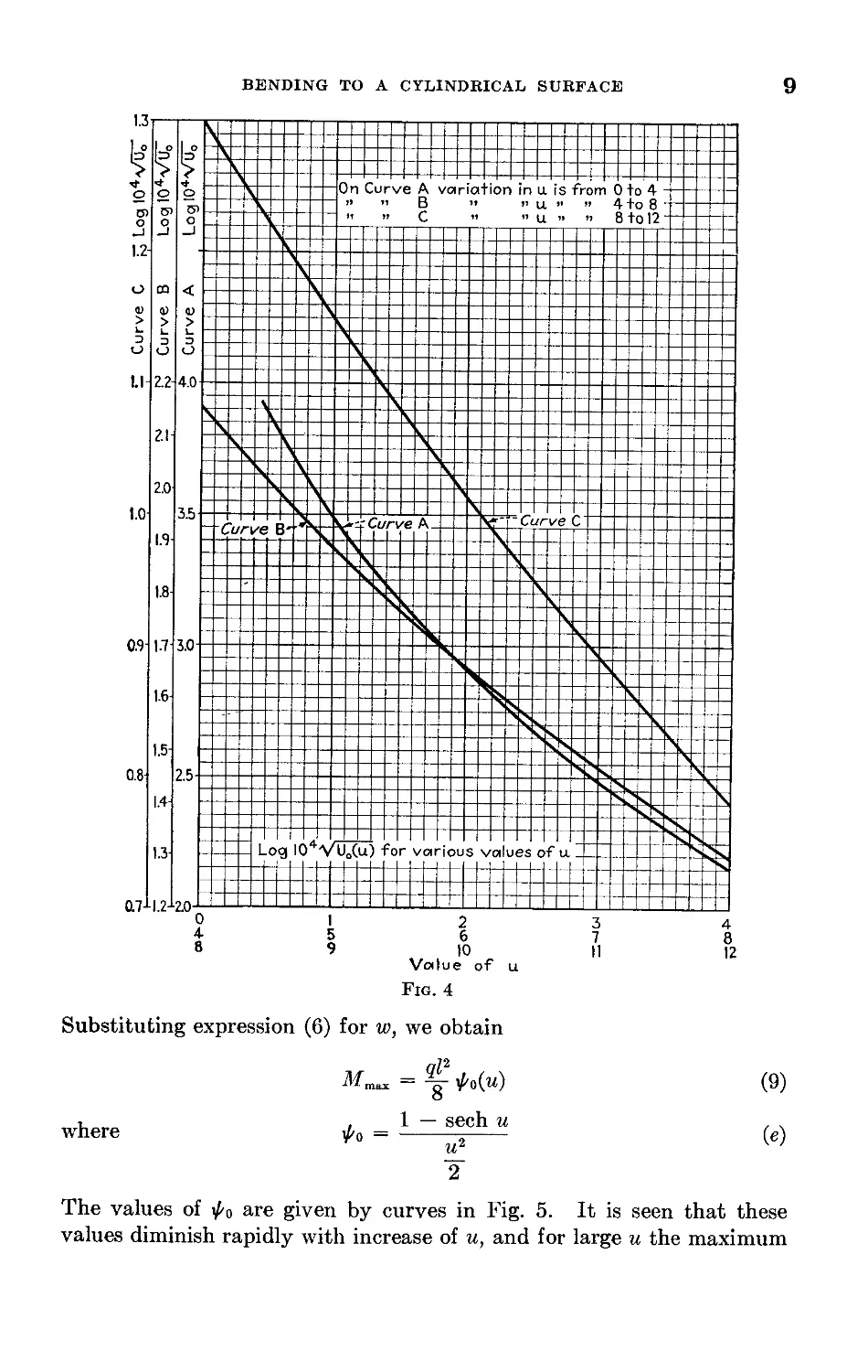
this solution, the curves shown in Fig. 4 can be used. The abscissas of
these curves represent the values of и and the ordinates represent the
quantities log™ (IO4 y/Uo), where Uq denotes the numerical value of the
right-hand side of Eq. (8). y/Uo is used because it is more easily calcu-
lated from the plate constants and the load; and the factor 104 is intro-
duced to make the logarithms positive. In each particular case we begin
by calculating the square root of the left-hand side of Eq. (8), equal to
Eh4/(l — v2)ql4, which gives y/Ut>. The quantity logic (104 VlTo) then
gives the ordinate which must be used in Fig. 4, and the corresponding
value of и can be readily obtained from the curve. Having u, we obtain
the value of the axial force >S' from Eq. (5).
In calculating stresses we observe that the total stress at any cross
section of the strip consists of a bending stress proportional to the bend-
ing moment and a tensile stress of magnitude S/h which is constant along
the length of the strip. The maximum stress occurs at the middle of the
strip, where the bending moment is a maximum. From the differential
equation (4) the maximum bending moment is
1 See Timoshenko, “Strength of Materials,” part I, 3d ed., p. 178, 1955.
BENDING TO A CYLINDRICAL SURFACE
9
Fig. 4
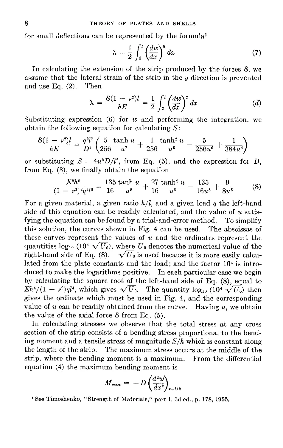
Substituting expression (6) for w, we obtain
О
, , 1 — sech и
where y-o = -----«---
и2
¥
(9)
(в)
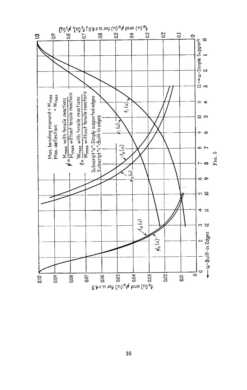
The values of /0 are given by curves in Fig. 5. It is seen that these
values diminish rapidly with increase of u, and for large и the maximum
Fig. £
f0(u) and^0(u)foru.<4.5;ft(u),
BENDING TO A CYLINDRICAL SURFACE 11
bending moment is several times smaller than the moment ql2/8 which
would be obtained if there were no tensile reactions at the ends of the
strip.
The direct tensile stress ai and the maximum bending stress o-2 are now
readily expressed in terms of u, q, and the plate constants as follows:
<S 4lu2D Eu2 //Д2 , .
ffl “ h ~ ~ 3(1 - v2) V7 (10)
*2 = = | q 0У (11)
The maximum stress in the plate is then
O'max = ®T + О2
To show how the curves in Figs. 4 and 5 can be used in calculating
maximum stresses, let us take a numerical example and assume that a
long rectangular steel plate 50 in. wide and in. thick carries a uniformly
distributed load q = 20 psi. We start with a computation of Vх No:
/ТГ _ E 30-106 1 _ПП1РЛО
V L ° (1 - v2)q\l) (1 - 0.32)20 108 0'01b48
Then, from tables,
logl0 (10* VU~a) = 2.217
From the curve A in Fig. 4 we find и = 3.795, and from Fig. 5 we obtain
= 0.1329.
Now, computing stresses by using Eqs. (10) and (11), we find
_ 30 • 106 • 3.7952 1 _ 1r OQn •
ffl 3(1 - o.32) io4 10,830 рн
= I 20 • 104 • 0.1329 = 19,930 psi
O'max = 0-1 + O-2 = 35,760 psi
In calculating the maximum deflection we substitute .c = 1/2 in Eq. (6)
of the deflection curve. In this manner we obtain
where
5qZ4 , , .
ITmas 384D
sech и — 1 + ~
fo(u)=----------~
24
(12)
To simplify calculations, values of /o(u) are given by the curve in Fig. 5.
If there were no tensile reactions at the ends of the strip, the maximum
12
THEORY OF PLATES AND SHELLS
deflection would be 5?Z4/384D. The effect of the tensile reactions is given
by the factor /o(w), which diminishes rapidly with increasing u.
Using Fig. 5 in the numerical example previously discussed, we find
that for и = 3.795 the value of /о(м) is 0.145. Substituting this value in
Eq. (12), we obtain
wmax = 4.74 • 0.145 = 0.688 in.
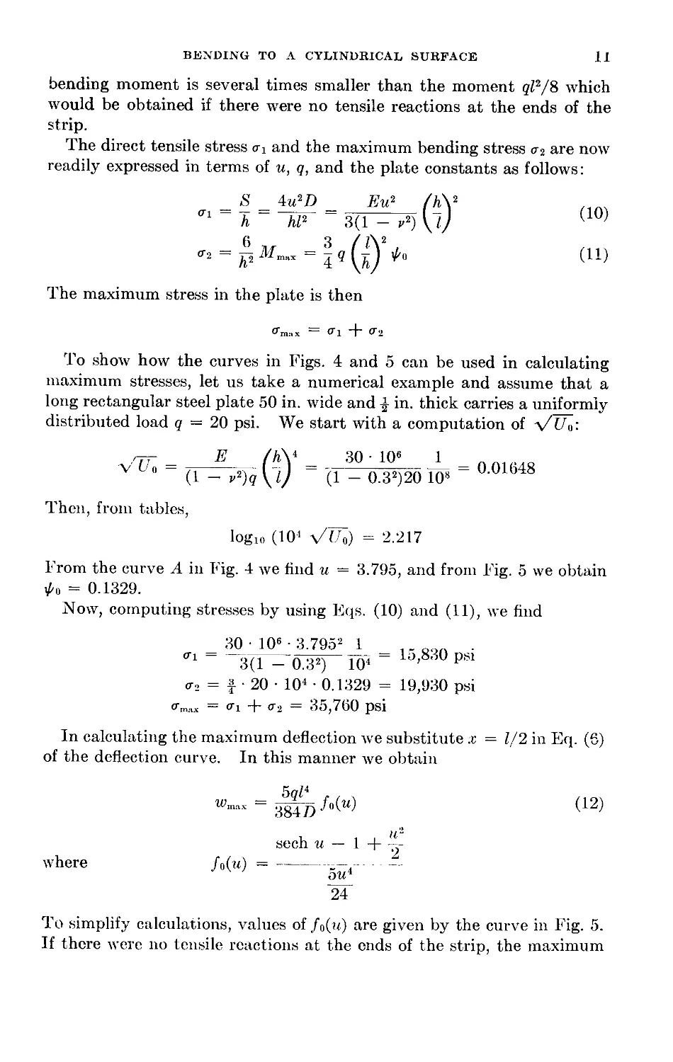
It is seen from Eq. (8) that the tensile parameter и depends, for a
given material of the plate, upon the intensity of the load q and the
ratio l/h of width to thickness of the plate. From Eqs. (10) and (11)
we see that the stresses ai and a2 are also functions of u, q, and l/h.
Therefore, the maximum stress in the plate depends only on the load q
and the ratio l/h. This means that we can plot a set of curves giving
maximum stress in terms of q, each curve in the set corresponding to a
particular value of l/h. Such curves are given in Fig. 6. It is seen that
because of the presence of tensile forces S, which increase with the load,
the maximum stress is not proportional to the load q; and for large values
of q this stress does not vary much with the thickness of the plate. By
taking the curve marked l/h = 100 and assuming q = 20 psi, we obtain
from the curve the value calculated before in the numerical example.
BENDING TO A CYLINDRICAL SURFACE 13
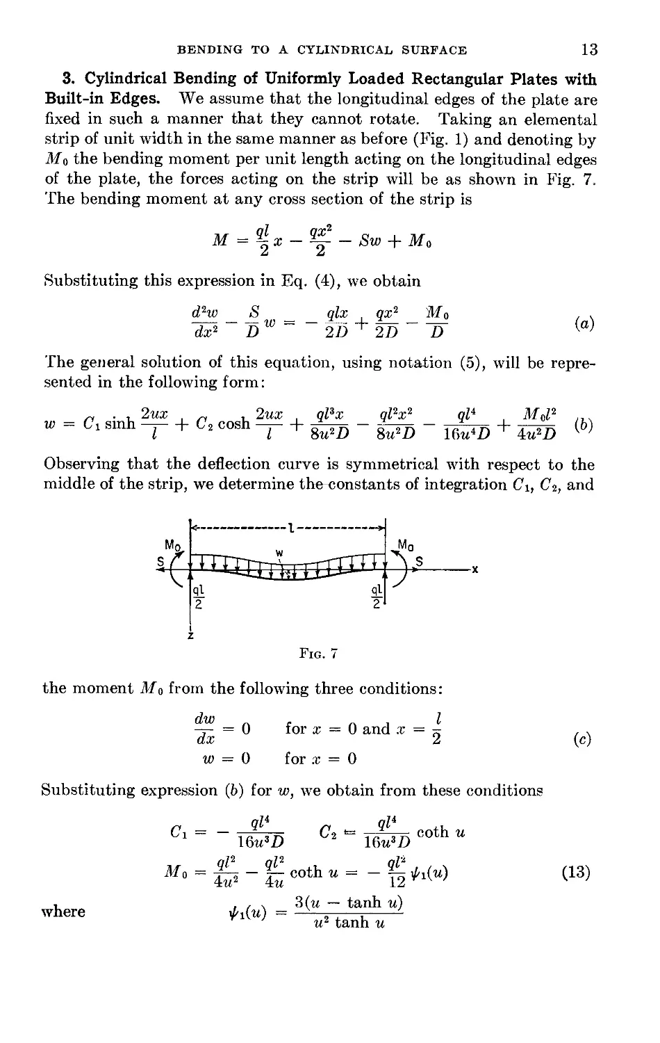
3. Cylindrical Bending of Uniformly Loaded Rectangular Plates with
Built-in Edges. We assume that the longitudinal edges of the plate are
fixed in such a manner that they cannot rotate. Taking an elemental
strip of unit width in the same manner as before (Fig. 1) and denoting by
MQ the bending moment per unit length acting on the longitudinal edges
of the plate, the forces acting on the strip will be as shown in Fig. 7.
The bending moment at any cross section of the strip is
M = ^x - Sw + Ma
А и
Substituting this expression in Eq. (4), we obtain
d2w <S qlx , qx2 ~Mo , ,
DW= ~2D + 2D-^
The general solution of this equation, using notation (5), will be repre-
sented in the following form:
„ . , 2ux „ , 2ux , ql3x ql2x2 ql4 , M0l2 ...
w = Ci sinh -j- + C2 cosh -j- + (b)
I I 8u2D 8u2D 16u4D 4m2D
Observing that the deflection curve is symmetrical with respect to the
middle of the strip, we determine the-constants of integration Ci, C2, and
Fig. 7
the moment from the following three conditions:
-г- = 0 for x = 0 and x = „
ax 2
w = 0 for x = 0
(c)
Substituting expression (b) for w, we obtain from these conditions
ql4
\&u3D
C2 *= . $ n coth и
16u3D
ql2 ql2 , ql2 . .
Mo = Й2 “SCOthM= “12^
(13)
where
^i(w)
3(w — tanh w)
u2 tanh и
14 THEORY OF PLATES AND SHELLS
The deflection w is therefore given by the expression
w
ql4 . , 2ux , ql4 ,, , 2w.r
16^5Slnh — + Тело coth “ cosh ~T
qlsx ql2x2 ql4
П — 77 TF C'Oth u
Su~D Su-D lQuAD
This can be further simplified and finally put in the following form:
___________
Wusl) tanh и
cosh
cosh и
. ql2(l - -t)x
8u2D
(14)
For calculating the parameter и we proceed as in the previous article
and use Eq. (d) of that article. Substituting in it expression (14) for w
and performing the integration, we obtain
S(1 - v2)l = qW(______________3________________1________1 1 \
hE D- \ 256?z5 tanh и 256u4 sinh2 и 64?z6 384w4/
Substituting $ from Eq. (5) and expression (3) for D, the equation for
calculating и finally becomes
E2A8 = _ 81________________27________27 9
(1 — v2)2q2ls 16a7 tanh и 16u6 sinh2 и -ius 8u6
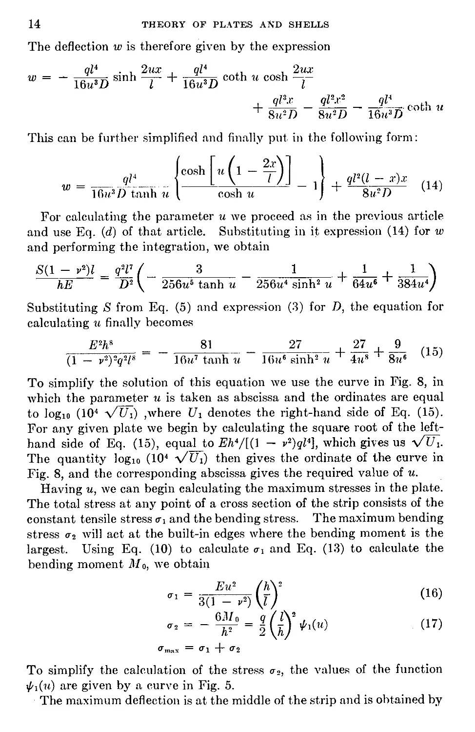
To simplify the solution of this equation we use the curve in Fig. 8, in
which the parameter и is taken as abscissa and the ordinates are equal
to logic (Ю4 Vt/i) ,where Ui denotes the right-hand side of Eq. (15).
For any given plate we begin by calculating the square root of the left-
hand side of Eq. (15), equal to E/i4/[(l — v2)gZ4], which gives us -\/Ui.
The quantity logic (Ю4 y/Ui) then gives the ordinate of the curve in
Fig. 8, and the corresponding abscissa gives the required value of u.
Having u, we can begin calculating the maximum stresses in the plate.
The total stress at any point of a cross section of the strip consists of the
constant tensile stress ai and the bending stress. The maximum bending
stress a2 will act at the built-in edges where the bending moment is the
largest. Using Eq. (10) to calculate ai and Eq. (13) to calculate the
bending moment Tlfo, we obtain
- = 3(T^(r)! <16)
- = - 64“ = 1 <17)
O’.nr.x = &1 + a2
To simplify the calculation of the stress a2, the values of the function
^i(n) are given by a curve in Fig. 5.
The maximum deflection is at the middle of the strip and is obtained by
BENDING TO A CYLINDRICAL SURFACE
15
substituting x = 1/2 in Eq. (14), from which
where
1Тт!1Х 354/)
24 /и2 и _ и \
и4 \ 2 sinh и tanh и J
(18)
The function /i(w) is also given by a curve in Fig. 5.
16
THEORY OF PLATES AND SHELLS
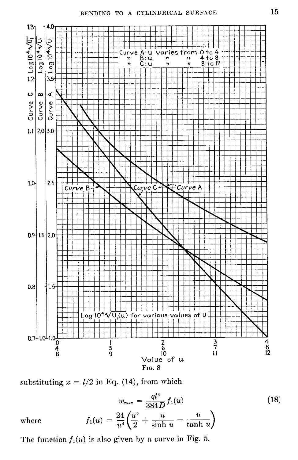
The use of the curves in Figs. 5 and 8 will now be illustrated
numerical example. A long rectangular steel plate has the dimei
I = 50 in., h = -J in., and q = 10 psi. In such a case we have
VTA = 0)* - " 0 032966
log jo 104 VUi = 2.5181
From Fig. 8 we now find и = 1.894; and from Fig. 5, = 0.8212.
stituting these values in Eqs. (16) and (17), we find
30 • 106 • 1.8942
3(1 - 0.32)104
= 3,940 psi
| • 10 • 104 • 0.8212 = 41,060 psi
^шях
= o-i + a2 = 45,000 psi
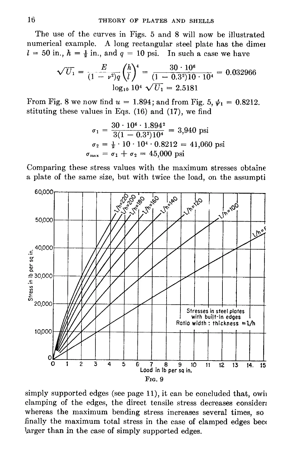
Comparing these stress values with the maximum stresses obtaine
a plate of the same size, but with twice the load, on the assumpti
simply supported edges (see page 11), it can be concluded that, owii
clamping of the edges, the direct tensile stress decreases consider;
whereas the maximum bending stress increases several times, so
finally the maximum total stress in the case of clamped edges bec<
larger than in the case of simply supported edges.
BENDING TO A CYLINDRICAL SURFACE
17
Proceeding as in the previous article it can be shown that the maxi-
mum stress in a plate depends only on the load q and the ratio l/h, and
we can plot a set of curves giving maximum stress in terms of q, each
curve in the set corresponding to a particular value of l/h. Such curves
are given in Fig. 9. It is seen that for small values of the intensity of
the load q, when the effect of the axial force on the deflections of the
strip is small, the maximum stress increases approximately in the same
ratio as q increases. But for larger values of q the relation between the
load and the maximum stress becomes nonlinear.
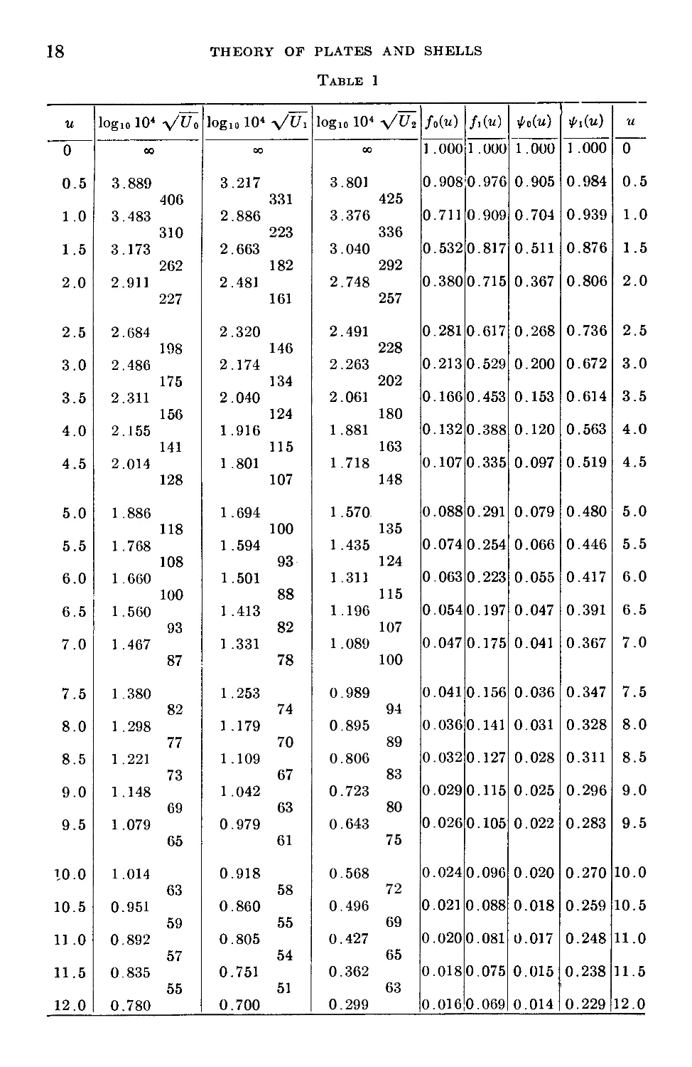
In conclusion, we give in Table 1 the numerical values of all the func-
tions plotted in Figs. 4, 5, and 8. This table can be used instead of the
curves in calculating maximum stresses and maximum deflections of long,
uniformly loaded rectangular plates.
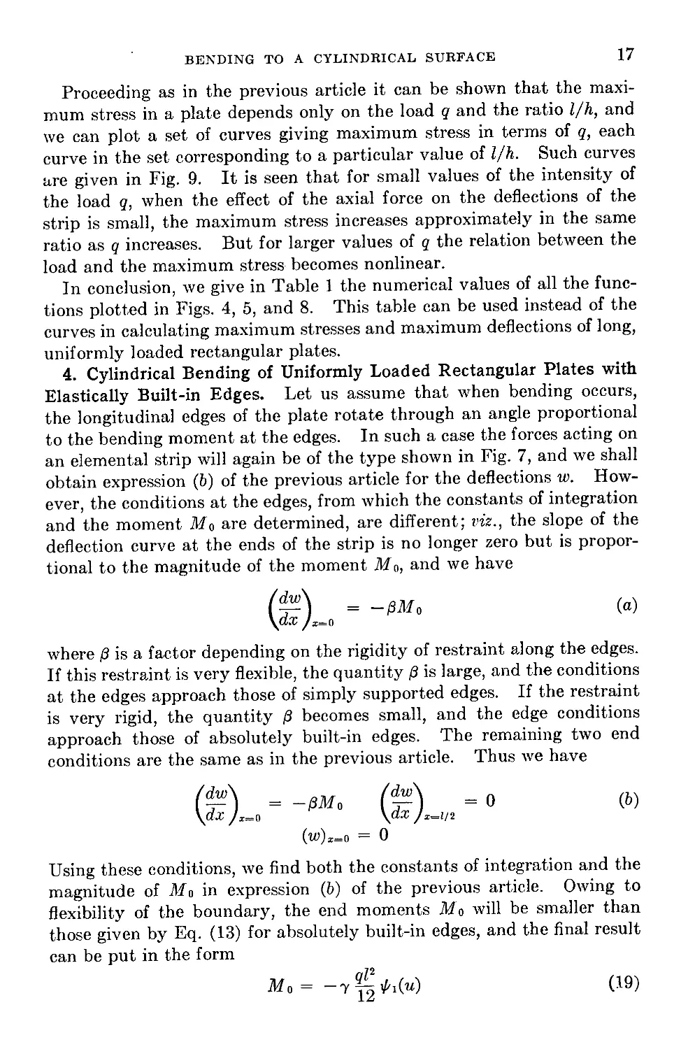
4. Cylindrical Bending of Uniformly Loaded Rectangular Plates with
Elastically Built-in Edges. Let us assume that when bending occurs,
the longitudinal edges of the plate rotate through an angle proportional
to the bending moment at the edges. In such a case the forces acting on
an elemental strip will again be of the type shown in Fig. 7, and we shall
obtain expression (6) of the previous article for the deflections w. How-
ever, the conditions at the edges, from which the constants of integration
and the moment Mo are determined, are different; viz., the slope of the
deflection curve at the ends of the strip is no longer zero but is propor-
tional to the magnitude of the moment Mo, and we have
(^) =
\az у
where /3 is a factor depending on the rigidity of restraint along the edges.
If this restraint is very flexible, the quantity /3 is large, and the conditions
at the edges approach those of simply supported edges. If the restraint
is very rigid, the quantity /3 becomes small, and the edge conditions
approach those of absolutely built-in edges. The remaining two end
conditions are the same as in the previous article. Thus we have
(a)
= 0
(b)
x=0
= -зм, m
yaz /x=o \dx jx=ii2
(w)x=0 = 0
Using these conditions, we find both the constants of integration and the
magnitude of Mo in expression (&) of the previous article. Owing to
flexibility of the boundary, the end moments Mo will be smaller than
those given by Eq. (13) for absolutely built-in edges, and the final result
can be put in the form
JL = —
(19)
18
THEORY OF PLATES AND SHELLS
Table 1
и logic 104 y/Uо log10 Ю4 y/Ui logic Ю4 y/lh Jo(«) f/u) ’Ao(u) ^i(u) u
0 00 00 00 1 .000 1 .000 1 .000 1 .000 0
0.5 3.889 406 3.217 331 3.801 425 0.908 0.976 0.905 0.984 0.5
1.0 3.483 310 2.886 223 3.376 336 0.711 0.909 0.704 0.939 1.0
1.5 3.173 262 2.663 182 3.040 292 0.532 0.817 0.511 0.876 1.5
2.0 2.911 227 2.481 161 2.748 257 0.380 0.715 0.367 0.806 2.0
2.5 2.684 198 2.320 146 2.491 228 0.281 0.617 0.268 0.736 2.5
3.0 2.486 175 2.174 134 2.263 202 0.213 0.529 0.200 0.672 3.0
3.5 2.311 156 2.040 124 2.061 180 0.166 0.453 0.153 0.614 3.5
4.0 2.155 141 1.916 115 1.881 163 0.132 0.388 0.120 0.563 4.0
4.5 2.014 128 1 .801 107 1.718 148 0.107 0.335 0.097 0.519 4.5
5.0 1.886 118 1.694 100 1.570 135 0.088 0.291 0.079 0.480 5.0
5.5 1.768 108 1.594 93 1.435 124 0.074 0.254 0.066 0.446 5.5
6.0 1.660 100 1.501 88 1.311 115 0.063 0.223 0.055 0.417 6.0
6.5 1.560 93 1.413 82 1.196 107 0.054 0.197 0.047 0.391 6.5
7.0 1.467 87 1.331 78 1.089 100 0.047 0.175 0.041 0.367 7.0
7.5 1 .380 82 1.253 74 0.989 94 0.041 0.156 0.036 0.347 7.5
8.0 1.298 77 1 .179 70 0.895 89 0.036 0.141 0.031 0.328 8.0
8.5 1.221 73 1.109 67 0.806 83 0.032 0.127 0.028 0.311 8.5
9.0 1.148 69 1.042 63 0.723 80 0.029 0.115 0.025 0.296 9.0
9.5 1.079 65 0.979 61 0.643 75 0.026 0.105 0.022 0.283 9.5
10.0 1.014 63 0.918 58 0.568 72 0.024 0.096 0.020 0.270 10.0
10.5 0.951 59 0.860 55 0.496 69 0.021 0.088 0.018 0.259 10.5
11.0 0.892 57 0.805 54 0.427 65 0.020 0.081 0.017 0.248 11.0
11.5 0.835 55 0.751 51 0.362 63 0.018 0.075 0.015 0.238 11.5
12.0 0.780 0.700 0.299 0.016 0.069 0.014 0.229 12,0
BENDING TO A CYLINDRICAL SURFACE
19
where 7 is a numerical factor smaller than unity and given by the formula
T =
tanh и
2/3 n , , ,
-j- Du + tanh и
L
It is seen that the magnitude of the moments Mo at the edges depends
upon the magnitude of the coefficient /3 defining the rigidity of the
restraint. When 0 is very small, the coefficient 7 approaches unity,
and the moment Mo approaches the value (13) calculated for absolutely
built-in edges. When /3 is very large, the coefficient 7 and the moment
Mo become small, and the edge conditions approach those of simply
supported edges.
The deflection curve in the case under consideration can be repre-
sented in the following form:
_ ql4 tanh и — 7(tanh и — и)-
W 16it4D tanh и
. (_ 2x
cosh id 1-----r-
cosh и
+ 8^1)
- 1
For 7 = 1 this expression reduces to expression (14) for deflections of a
plate with absolutely built-in edges. For 7 = 0 we obtain expression (6)
for a plate with simply supported edges.
In calculating the tensile parameter и we proceed as in the previous
cases and determine the tensile force S from the condition that the exten-
sion of the elemental strip is equal to the difference between the length of
the arc along the deflection curve and the chord length I. Hence
S(1 - _ 1 Л (dw\
hE 2 Jo \d.r) X
Substituting expression (20) in this equation and performing the inte-
gration, we obtain
n “ г8 = (! - Y)t7o + yUr - 7(1 - y)U2 (21)
(1 — v) q I
where Uo and Uy denote the right-hand sides of Eqs. (8) and (15), respec-
tively, and
r7 27 (it — tanh иУ . , , , . , , ч
U2 = 77; i—5-7—r-5—— (it tanh2 it — it + tanh it)
16 it9 tanh2 it
The values of logic (Ю4 у/U2) are given in Table 1. By using this table,
Eq. (21) can be readily solved by the trial-and-error method. For any
particular plate we first calculate the left-hand side of the equation and,
20
THEORY OF PLATES AND SHELLS
by using the curves in Figs. 4 and 8, determine the values of the parame-
ter и (1) for simply supported edges and (2) for absolutely built-in edges.
Naturally и for elastically built-in edges must have a value intermediate
between these two. Assuming one such value for u, we calculate Uo, Ui,
and Uz by using Table 1 and determine the value of the right-hand side
of Eq. (21). Generally this value will be different from the value of the
left-hand side calculated previously, and a new trial calculation with a
new assumed value for и must be made. Two such trial calculations
will usually be sufficient to determine by interpolation the value of и
satisfying Eq. (21). As soon as the parameter и is determined, the bend-
ing moments Af0 at the ends may be calculated from Eq. (19). We can
also calculate the moment at the middle of the strip and find the maxi-
mum stress. This stress will occur at the ends or at the middle, depend-
ing on the degree of rigidity of the constraints at the edges.
5. The Effect on Stresses and Deflections of Small Displacements of
Longitudinal Edges in the Plane of the Plate. It was assumed in the
previous discussion that, during bending, the longitudinal edges of the
plate have no displacement in the plane of the plate. On the basis of this
assumption the tensile force >8 was calculated in each particular case.
Let us assume now that the edges of the plate undergo a displacement
toward each other specified by A. Owing to this displacement the
extension of the elemental strip will be diminished by the same amount,
and the equation for calculating the tensile force >8 becomes
81(1 - r2)
hE
1 С1 / dw\2
2 Jo \dxJ
dx — A
(a)
At the same time Eqs. (6), (14), and (20) for the deflection curve hold
true regardless of the magnitude of the tensile force >8. They may be
differentiated and substituted under the integral sign in Eq. (a). After
evaluating this integral and substituting S = 4w2D/Z2, we obtain for
simply supported edges
2 -
E2hs u h2
?2(1 - v2}2l* u2
(22)
and for built-in edges
E2h*
g2(l - p2)2Z8
3ZA
' h2
~2~~~ = U'
u2
(23)
If A is made zero, Eqs. (22) and (23) reduce to Eqs. (8) and (15), obtained
previously for immovable edges.
The simplest case is obtained by placing compression bars between the
longitudinal sides of the boundary to prevent free motion of one edge of
BENDING TO A CYLINDRICAL SURFACE 21
the plate toward the other during bending. Tensile forces $ in the plate
produce contraction of these bars, which results in a displacement Д pro-
portional to 8.* If к is the factor of proportionality depending on the
elasticity and cross-sectional area of the bars, we obtain
S = /сД
or, substituting = 4w2D/Z2, we obtain
1 Eu2h3
к 3Z2(1 - y2)
and
1 +
Eh
kl(l - v2)
Thus the second factor on the left-hand side of Eqs. (22) and (23) is э
constant that can be readily calculated if the dimensions and the elastic
properties of the structure are known. Having the magnitude of this
factor, the solution of Eqs. (22) and (23) can be accomplished in exactly
the same manner as used for immovable edges.
In the general case the second factor on the left-hand side of Eqs. (22)
and (23) may depend on the magnitude of the load acting on the struc-
ture, and the determination of the parameter и can be accomplished only
by the trial-and-error method. This procedure will now be illustrated
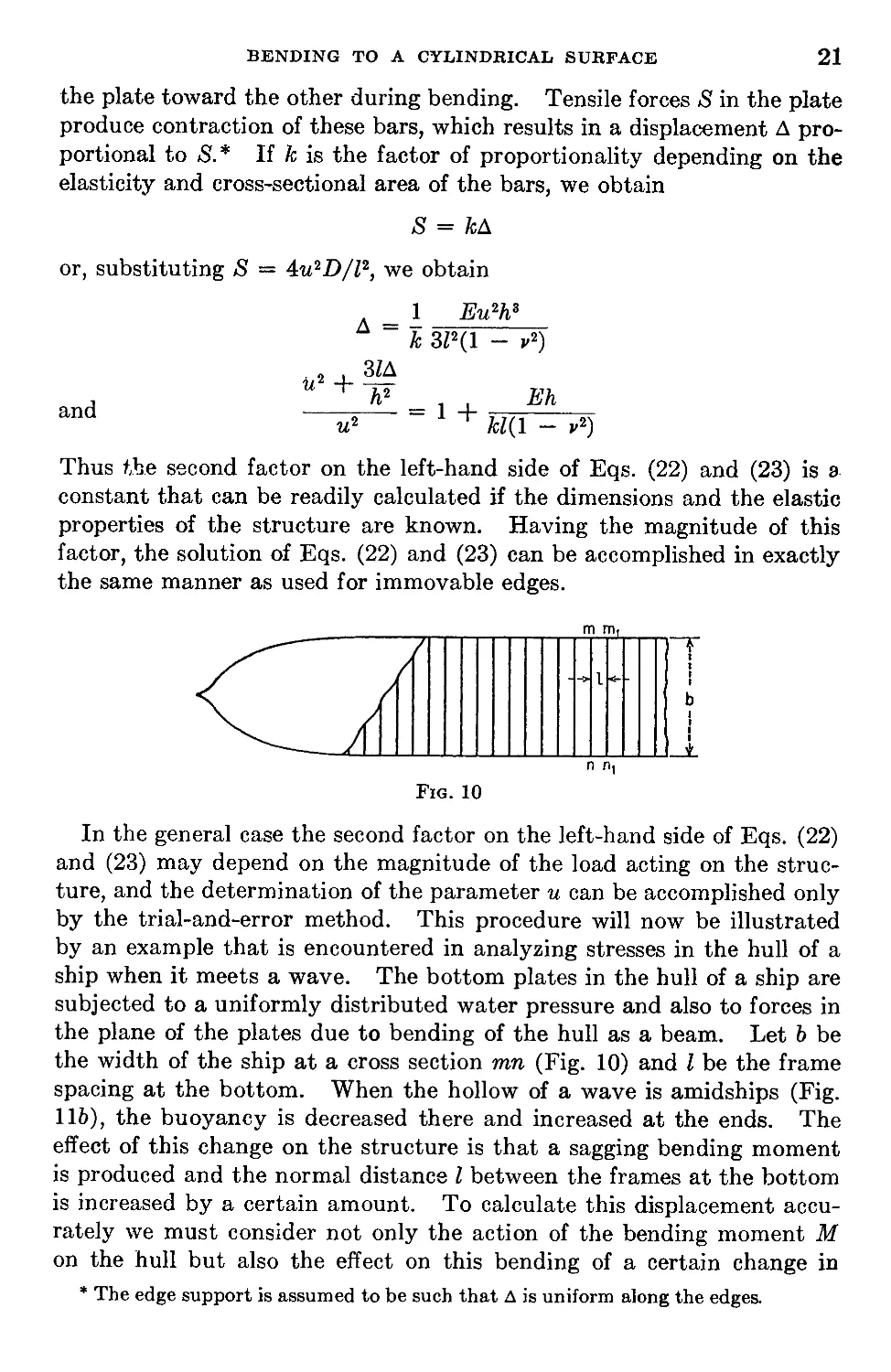
by an example that is encountered in analyzing stresses in the hull of a
ship when it meets a wave. The bottom plates in the hull of a ship are
subjected to a uniformly distributed water pressure and also to forces in
the plane of the plates due to bending of the hull as a beam. Let b be
the width of the ship at a cross section mn (Fig. 10) and I be the frame
spacing at the bottom. When the hollow of a wave is amidships (Fig.
116), the buoyancy is decreased there and increased at the ends. The
effect of this change on the structure is that a sagging bending moment
is produced and the normal distance I between the frames at the bottom
is increased by a certain amount. To calculate this displacement accu-
rately we must consider not only the action of the bending moment M
on the hull but also the effect on this bending of a certain change in
* The edge support is assumed to be such that Д is uniform along the edges.
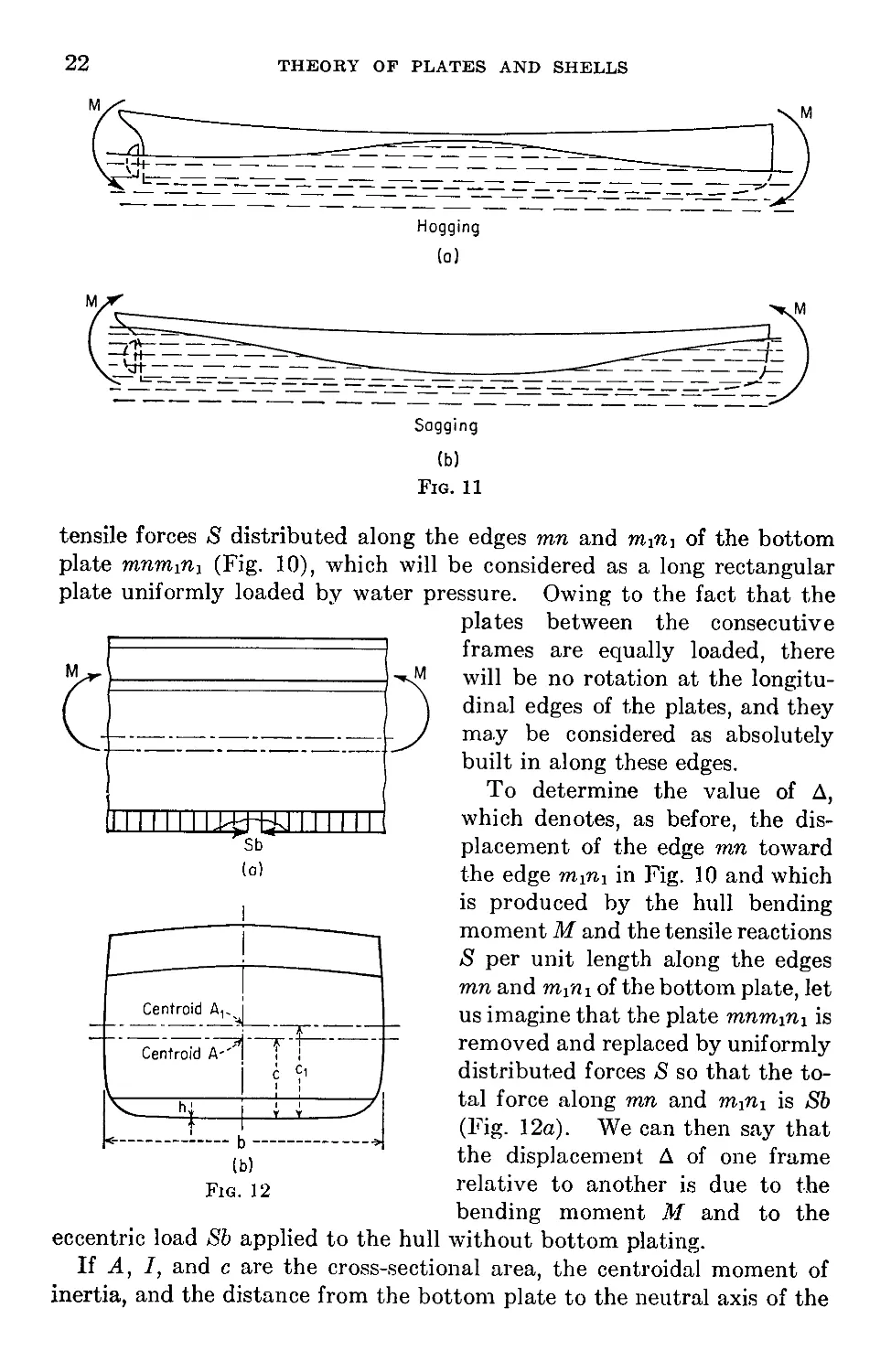
22
THEORY OF PLATES AND SHELLS
(o)
(b)
Fig. 11
tensile forces distributed along the edges mn and mini of the bottom
plate rnnm^m (Fig. 10), which will be considered as a long rectangular
plate uniformly loaded by water pressure. Owing to the fact that the
plates between the consecutive
frames are equally loaded, there
will be no rotation at the longitu-
dinal edges of the plates, and they
may be considered as absolutely
built in along these edges.
To determine the value of Д,
which denotes, as before, the dis-
placement of the edge mn toward
the edge mmi in Fig. 10 and which
is produced by the hull bending
moment M and the tensile reactions
$ per unit length along the edges
mn and mfrii of the bottom plate, let
us imagine that the plate mnmmi is
removed and replaced by uniformly
distributed forces £ so that the to-
tal force along mn and mmi is Sb
(Fig. 12a). We can then say that
the displacement Д of one frame
relative to another is due to the
bending moment M and to the
eccentric load Sb applied to the hull without bottom plating.
If A, I, and c are the cross-sectional area, the centroidal moment of
inertia, and the distance from the bottom plate to the neutral axis of the
BENDING TO A CYLINDRICAL SURFACE
23
complete hull section, and if Ai, 7Ъ and ci are the corresponding quanti-
ties for the hull section without bottom plates, the latter set of quantities
can be derived from the former by the relations
Ai = A - bh
Ac
C1 “ A
I у = I - bhc1 - Ax(ci - c)2
(b)
The relative displacement Ai produced by the eccentrically applied forces
Sb is
л _ Z(1 - p2) (Sb , ЭД\
Д1 “ Ё \а\ + П7)
in which the factor 1 — y2 must be introduced if one neglects the lateral
strain. The displacement due to the bending moment M is
Д2
Mai
Ely
Hence the total displacement is
A — Aj -|- Д2 —
*(1 ~ *2)
E
Sb SbC1
Л
Mcy
7i(l - »2)
(c)
Substituting in this expression
we finally obtain
4w2D _ Eu2h3
~ 3Z2(1 - г2)
u2h3 / b bc2\
~зГ \A~i + 7Г/
Mlci
Ely
(d)
This quantity must be substituted in Eq. (23) for determining the tensile
parameter u.
Let us apply this theory to a numerical example. Assume b = 54 ft,
I = 1,668 ft4, A = 13.5 ft2, c = 12.87 ft, h = 0.75 in. = 0.0625 ft,
I = 45 in. = 3.75 ft, q = 10 psi, M — 123,500 ft-tons. From Eqs. (6)
we obtain
Ai = 13.5 - 0.0625 • 54 = 10.125 ft2
_ 13.5-12.87 _
C1 10.125 17’ 6 1
h = 1,668 - 559.0 - 10.125(17.16 - 12.87)2 = 922.7 ft4
Substituting these values in expression (d), we calculate A and finally
obtain
~ = 1.410м2 - 11.48
№
24
THEORY OF PLATES AND SHELLS
Equation (23) then becomes
E2h* u2 + 1.410u2 - 11.48
52(1 - j,2)2Z8 u2
or
1.552Eh4 lu2 - 4.763
5(1 - v2)^ \ u2
Substituting numerical values and taking logarithms of both sides,
we obtain
3.597 + log10 J-------= logio (Ю4 VT\)
Using the curve in Fig. 8, this equation can be readily solved by the
trial-and-error method, and we obtain и = 2.187 and, from Fig. 5,
^i(it) = 0.780. The maximum stress is now calculated by using Eos.
(16) and (17), from which
30 • 106 • 4.783
3 • 0.91 • 602
= 14,600 psi
м2 = i • 10 • 602 • 0.780 = 14,040 psi
& max = ax + a2 = 28,640 psi
If the bending stress in the plate due to water pressure were neglected
and if the bottom plate stress were calculated from the formula a = Мс/1,
we would arrive at a figure of only 13,240 psi.
6. An Approximate Method of Calculating the Parameter u. In calcu-
lating the parameter и for plates in which the longitudinal edges do not
move in the plane of the plate, we used the equation
Sl(l - V2}
hE
which states that the extension of
If1/ dw\2 .
2 Jo \dx) dx (a)
an elemental strip produced by the
forces £ is equal to the difference between the length of the arc along the
deflection curve of the strip and the chord length I. In the particular
cases considered in the previous articles, exact expressions for the deflec-
tions w were derived, and numerical tables and curves for the right-hand
side of Eq. (a) were given. When such tables are not at hand, the solu-
tion of the equation becomes complicated, and to simplify the problem
recourse should be had to an approximate method. From the discussion
of bending of beams it is known1 that, in the case of simply supported
ends with all lateral loads acting in the same direction, the deflection
curve of an elemental strip produced by a combination of a lateral load
and an axial tensile force >8 (Fig. 3) can be represented with sufficient
1 See Timoshenko, “Strength of Materials,” part II, 3d ed., p. 52, 1956.
BENDING TO A CYLINDRICAL SURFACE
25
accuracy by the equation
Wo irx
W = -—;— sm -V
(b)
in which Wo denotes the deflection at the middle of the strip produced by
the lateral load alone, and the quantity a is given by the equation
_ S _ SI2
a Scr tt2D
(c)
Thus, a represents the ratio of the axial force S to the Euler critical load
for the elemental strip.
Substituting expression (6) in Eq. (a) and integrating, we obtain
Sl(l ~ v2) _ TV2W20
hE 4Z(1 + a)2
blow, using notation (c) and substituting for D its expression (3), we
finally obtain
2 =
h2
(24)
From this equation the quantity a can be calculated in each particular
case, and the parameter и is now determined from the equation
u2
S I2 _ тг2а
D 4 ~ ~4~
(d)
To show the application of the approximate Eq. (24) let us take a
numerical example. A long rectangular steel plate with simply sup-
ported edges and of dimensions I — 50 in. and h = in. is loaded with a
uniformly distributed load q — 20 psi. In such a case
_ 5 ql4
W° ~ 384 1)
and, after substituting numerical values, Eq. (24) becomes
a(l + a)2 = 269.56
The solution of the equation can be simplified by letting
1 + a = x (e)
Then xs — x2 = 269.56
i.e., the quantity x is such that the difference between its cube and its
square has a known value. Thus x can be readily determined from a
slide rule or a suitable table, and we find in our case
x = 6.8109 and a = 5.8109
26
THEOKT DF PLATES AND SHELLS
Then, from Eq. (d)
и = 3.7865
and from the formula (e) (see page 9)
= 0.13316
For calculating direct stress and maximum bending stress we use Eqs.
(10) and (11). In this way we find
ax = 15,759 psi
o’2 = 19,974 psi
O’max = O’! + CT2 = 35,733 psi
The calculations made in Art. 2 (page 11) give, for this example,
^max 35,760 psi
Thus the accuracy of the approximate Eq. (24) is in this case very high.
In general, this accuracy depends on the magnitude of u. The error
increases with increase of u. Calculations show that for и = 1.44 the
error in the maximum stress is only 0.065 of 1 per cent and that for
и = 12.29, which corresponds to very flexible plates, it is about 0.30 of
1 per cent. These values of и will cover the range ordinarily encountered
in practice, and we conclude that Eq. (24) can be used with sufficient
accuracy in all practical cases of uniformly loaded plates with simply
supported edges.
It can also be used when the load is not uniformly distributed, as in
the case of a hydrostatic pressure nonuniformly distributed along the
elemental strip. If the longitudinal force is found by using the approxi-
mate Eq. (24), the deflections may be obtained from Eq. (6), and the
bending moment at any cross section may be found as the algebraic sum
of the moment produced by the lateral load and the moment due to the
longitudinal force.1
In the case of built-in edges the approximate expression for the deflec-
tion curve of an elemental strip can be taken in the form
w =
w0 1 /
1 + a/4 2 \
2тгт
cos -5—
(/)
in which w0 is the deflection of the built-in beam under the lateral load
acting alone and a has the same meaning as before. Substituting this
expression in Eq. (a) and integrating, we obtain for determining a the
equation
1 More accurate values for the deflections and for the bending moments can be
obtained by substituting the approximate value of the longitudinal force in Eq. (4)
and integrating this equation, which gives Eqs. (12) and (9).
BENDING TO A CYLINDRICAL SUKFACE
27
a
(1
3wq
~h?
which can be solved in each particular case by the method suggested for
solving Eq. (24).
When a is found, the parameter и is determined from Eq. (d); the
maximum stress can be calculated by using Eqs. (16) and (17); and the
maximum deflection, by using Eq. (18).
If, during bending, one edge moves toward the other by an amount A,
the equation
must be used instead of Eq. (a). Substituting expression (6) in this
equation, we obtain for determining a in the case of simply supported
edges the equation
, 12
a(l fl- a)------------= (26)
a h
In the case of built-in edges we use expression (/).
ing a we obtain
4- 19 AZ
/, , aV “ + 12 3w«
“(I+4) ------------
Then for determin-
es?)
If the dimensions of the plate and the load q are given, and the displace-
ment A is known, Eqs. (26) and (27) can both be readily solved in the
same manner as before. If the displacement Д is proportional to the
tensile force S, the second factor on the left-hand sides of Eqs. (26) and
(27) is a constant and can be determined as explained in the previous
article (see page 21). Thus again the equations can be readily solved.
7. Long Uniformly Loaded Rectangular Plates Having a Small Initial
Cylindrical Curvature. It is seen from the discussions in Arts. 2 and 3
that the tensile forces S contribute to the strength of the plates by
counteracting the bending produced by lateral load. This action
increases with an increase in deflection. A further reduction of maxi-
mum stress can be accomplished by giving a suitable initial curvature
to a plate. The effect on stresses and deflections of such an initial curva-
ture can be investigated1 by using the approximate method developed in
the previous article.
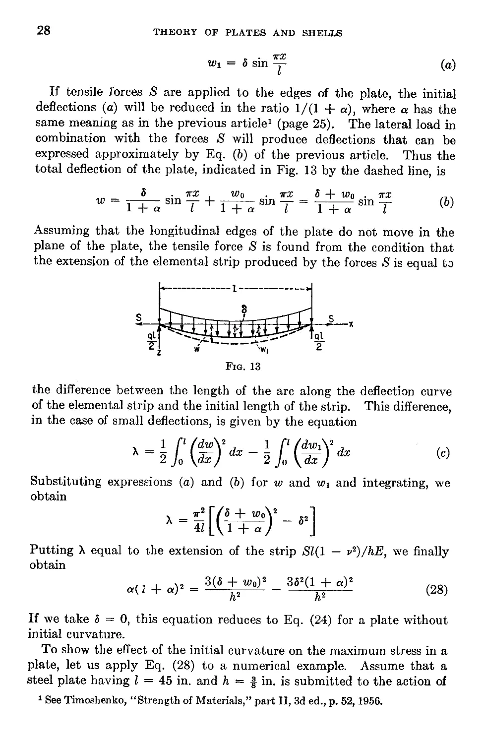
Let us consider the case of a long rectangular plate with simply sup-
ported edges (Fig. 13), the initial curvature of which is given by the
equation
1 Sec S. Timoshenko’s paper in “Festschrift zum siebzigsten Geburtstagc August
I?dppls,” p. 74, Berlin, 1923.
28
THEORY OF PLATES AND SHELLS
Wi = 5 sin -y (a)
V
If tensile forces 5 are applied to the edges of the plate, the initial
deflections (a) will be reduced in the ratio 1/(1 + a), where a has the
same meaning as in the previous article1 (page 25). The lateral load in
combination with the forces >8 will produce deflections that can be
expressed approximately by Eq. (b) of the previous article. Thus the
total deflection of the plate, indicated in Fig. 13 by the dashed line, is
3 . тгх , w0 . тгх S + w0 . тгх /7.
w = sm -r- + — sm = -y—-— sin — (b)
1 + a i 1 + a I 1 + a I
Assuming that the longitudinal edges of the plate do not move in the
plane of the plate, the tensile force >8 is found from the condition that
the extension of the elemental strip produced by the forces >S is equal to
<-------------------1--------------------->
Fig. 13
the difference between the length of the arc along the deflection curve
of the elemental strip and the initial length of the strip. This difference,
in the case of small deflections, is given by the equation
(c)
Substituting expressions (a) and (b) for w and w^ and integrating, we
obtain
я-2 Г/5 4- w0\2 x2
л = I -l—j-------1 — 52
4Z L \ 1 H- а /
Putting X equal to the extension of the strip Sl(l — v^/hE, we finally
obtain
a{ 1 + a)2
3(5 + Wo)2 352(1 + a)2
h2 h2
(28)
If we take 5 = 0, this equation reduces to Eq. (24) for a plate without
initial curvature.
To show the effect of the initial curvature on the maximum stress in a
plate, let us apply Eq. (28) to a numerical example. Assume that a
steel plate having I = 45 in. and h — f in. is submitted to the action of
1 See Timoshenko, “Strength of Materials,” part II, 3d ed., p. 52, 1956.
BENDING TO A CYLINDRICAL SURFACE 29
a uniformly distributed load q = 10 psi. If there is no initial deflection,
6 = 0 and Eq. (28) becomes
a(l + a)2 = 290
from which
a = 5.97 and и = \fa = 3.83
£
From Eq. (10) we then obtain
ai = 11,300 psi
and from Eq. (11)
a2 = 14,200 psi
The maximum stress in the plate is
amax = ai + a2 = 25,500 psi
Let us now assume that there is an initial deflection in the plate such that
5 = h = f in. In such a case Eq. (28) gives
a(l + a)2 = 351.6 - 3(1 + a)2
Letting
1 + a — x
we obtain
xs + 2.r2 = 351.6
from which
x = 6.45 a — 5.45 и = ? y/a = 3.67
&
The tensile stress, from Eq. (10), is
ai = 10,200 psi
In calculating the bending stress we must consider only the change in
deflections
. 7T.r ab . 7tx
— W! = —- sm -----—j— sin -7-
1-j-a t 1 т « i
(d)
The maximum bending stress, corresponding to the first term on the
right-hand side of Eq. (d), is the same as for a flat plate with и = 3.67.
From Table 1 we find фо = 0.142 and from Eq. (11)
a, = 15,300 psi
The bending moment corresponding to the second term in Eq. (d) is
— D —
dx2
ab
1 -j- a
атг2 bD . 7Г2Г
“ (1 + a)Z2 Sm T
30 THEORY OF PLATES AND SHELLS
This moment has a negative sign, and a corresponding maximum stress of
,, _ 6 аэт2 W _
a2 Л2 (1 + a)Z2 9,500 PS1
must be subtracted from the bending stress calculated above. Hence
the maximum stress for the plate with the initial deflection is
amax = 10,200 + 15,300 - 9,500 = 16,000 psi
Comparison of this result with that obtained for the plane plate shows
that the effect of the initial curvature is to reduce the maximum stress
from 25,500 to 16,000 psi. This result is obtained assuming the initial
deflection equal to the thickness of the plate. By increasing the initial
deflection, the maximum stress can be reduced still further.
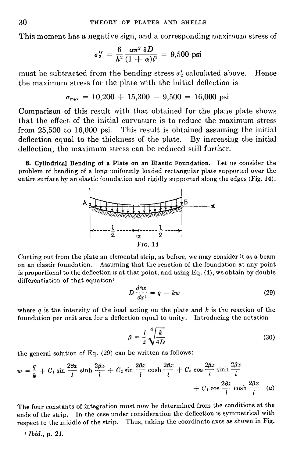
8. Cylindrical Bending of a Plate on an Elastic Foundation. Let us consider the
problem of bending of a long uniformly loaded rectangular plate supported over the
entire surface by an elastic foundation and rigidly supported along the edges (Fig. 14).
Cutting out from the plate an elemental strip, as before, we may consider it as a beam
on an elastic foundation. Assuming that the reaction of the foundation at any point
is proportional to the deflection w at that point, and using Eq. (4), we obtain by double
differentiation of that equation1
_ d4w
D—- = q-kw (29)
dx4
where q is the intensity of the load acting on the plate and к is the reaction of the
foundation per unit area for a deflection equal to unity. Introducing the notation
_Z 4/_fc_
2 V4D
(30)
the general solution of Eq. (29) can be written as follows:
q 2вх . , 2f}x . 20x 2/3x 2Bx . 20x
w = - + Ci sin — sinh —-F C2 sin —- cosh —-r G3 cos —— sinh ——
к ll ll It
2вх 20x
+ C4 cos — cosh —— (a)
I V
The four constants of integration must now be determined from the conditions at the
ends of the strip. In the case under consideration the deflection is symmetrical with
respect to the middle of the strip. Thus, taking the coordinate axes as shown in Fig.
1 Ibid.., p. 21.
BENDING TO A CYLINDRICAL SURFACE
31
14, we conclude1 that C2 = C3 = 0. The constants Ci and C4 are found from the
conditions that the deflection and the bending moment of the strip are zero at the end
(z = 1/2). Hence
(w)x^i/2 = 0
'(PuX
77) = 0
dx2
(b)
Substituting expression (a) for w and observing that C2 = C3 — 0, we obtain
q
—h C} sin /3 sinh /3 + C4 cos /3 cosh /3=0
к (c)
Ci cos /3 cosh /3 — Ca sin /3 sinh /3=0
from which we find
q sin /3 sinh /3 _ q 2 sin 0 sinh /3
1 к sin2 0 sinh2 /3 + cos2 /3 cosh2 0 к cos 2/3 + cosh 2/3
q cos /3 cosh /3 q 2 cos /3 cosh 0
С* к sin2 0 sinh2 0 + cos2 /3 cosh2 /3 к cos 2/3 + cosh 2/3
Substituting these values of the constants in expression (a) and using Eq. (30), we
finally represent the deflection of the strip by the equation
ql4 / 2 sin 0 sinh /3 . 20x . 20x
w = ——— I 1-------------------—— sin — sinh —-
64D/34 \ cos 2/3 + cosh 2/3 I I
2 cos 0 cosh /3 2/За; 2/3x\
— -----------—cos cosh ~r~ I (»)
cos 23 + cosh 2/3 I If
The deflection at the middle is obtained by substituting x = 0, which gives
” Ss55 ”<s)
(31)
where
2 cos /3 cosh /3
cos 2/3 + cosh 2/3
To obtain the angles of rotation of the edges of the plate, we differentiate expression
(d) with respect to x and put x = —1/2. In this way we obtain
dw\ ql3
= oTn
dx j x—xn 24£>
(32)
where
, 3 sinh 2/3 — sin 2/3
^(0) =------------------------—
4/33 cosh 2/3 + cos 2/3
The bending moment at any cross section of the strip is obtained from the equation
M = — D -—
dx2
(33)
where
Substituting expression (d) for w, we find for the middle of the strip
(Л/)х-0 = <P2</3)
О
2 sinh /3 sin 0
a>2(/3) =-------------------—
02 cosh 2/3 4- cos 2/3
1 It is seen that the terms with coefficients C2 and C3 change sign when x is replaced
by -x.
32
THEORTc OF PLATES AND SHELLS
To simplify the calculation of deflections and stresses, numerical values of functions
<p, and pi are given in Table 2. For small values of /3, that is, for a yielding founda-
tion, the functions <p and do not differ greatly from unity. Thus the maximum
deflection and bending stresses are close to those for a simply supported strip without
an elastic foundation. With an increase in /3, the effect of the foundation becomes
more and more important.
Fig. 15
Conditions similar to those represented in Fig. 14 are obtained if a long rectangular
plate of width I is pressed into an elastic foundation by loads uniformly distributed
along the edges and of the amount P per unit length (Fig. 15). The plate will be
Table 2
3 <P •Pi <f>2 0 <P ^>2
0.1 1.000 1.000 1.000 1.6 0.186 0.200 0.164
0.2 0.999 0.999 0.999 1.7 0.151 0.166 0.129
0.3 0.996 0.995 0.995 1.8 0.124 0.138 0.101
0.4 0.984 0.983 0.983 1.9 0.102 0.116 0.079
0.5 0.961 0.961 0.959 2.0 0.084 0.099 0.062
0.6 0.921 0.923 0.919 2.2 0.058 0.072 0.037
0.7 0.863 0.866 0.859 2.4 0.042 0.055 0.021
0.8 0.787 0.791 0.781 2.6 0.029 0.043 0.011
0.9 0.698 0.702 0.689 2.8 0.022 0.034 0.005
1.0 0.602 0.609 0.591 3.0 0.016 0.028 0.002
1.1 0.508 0.517 0.494 3.2 0.012 0.023 0.000
1.2 0.421 0.431 0.405 3.4 0.010 0.019 -0.001
1.3 0.345 0.357 0.327 3.6 0.007 0.016 -0.002
1.4 0.281 0.294 0.262 3.8 0.006 0.014 -0.002
1.5 0.228 0.242 0.208 4.0 0.005 0.012 -0.002
pressed into the elastic foundation and bent, as shown by the dashed line. If 8 denotes
the deflection at the edges of the plate, the reaction of the foundation at any point is
k(5 — w) = kb — kw
where w is given by Eq. (d) with q = kb. The magnitude of 6 is then obtained from
the condition that the load is balanced by the reaction of the foundation. Hence
ASZ
w dx
Plates on elastic foundation with other conditions at the longitudinal edges can
also be discussed in a similar manner.
CHAPTER 2
PURE BENDING OF PLATES
9. Slope and Curvature of Slightly Bent Plates. In discussing small
deflections of a plate we take the middle plane of the plate, before bend-
ing occurs, as the xy plane. During bending, the particles that were in
the xy plane undergo small displacements w perpendicular to the xy plane
and form the middle surface of the plate. These displacements of the
middle surface are called deflections of a plate in our further discussion.
Taking a normal section of the plate parallel
to the'zz plane (Fig. 16a), we find that the
slope of the middle surface in the x direction
is ix = dw/dx. In the same manner the slope
in the у direction is iv = dw/dy. Taking
now any direction an in the xy plane (Fig.
16b) making an angle a with the x axis, we find
that the difference in the deflections of the two
adjacent points a and аг in the an direction is
, dw dw .
dw = — dx + — dy
dx dy
and that the corresponding slope is
dw dw dx , dw dy dw . dw . , .
to = ta* + dFA = tacos“ + ^sm“ w
To find the direction aj for which the slope is a maximum we equate to
zero the derivative with respect to a of expression (a). In this way we
obtain
, dw /dw
tan «1 = — / -r-
dy/ dx
(b)
Substituting the corresponding values of sin aj and cos ai in (a), we obtain
for the maximum slope the expression
/ 3w\ _ //dw\2 / dw\2
\dn)m„ ~ \\dx/ + \dy)
(c)
By setting expression (a) equal to zero we obtain the direction for which
33
. The corresponding angle a2 is deter-
dw / dw
dx/ dy
34 THEORY OF PLATES AND SHELLS
the slope of the surface is zero
mined from the equation
tan «2
From Eqs. (6) and (d) we conclude that
tan aj tan a2 = ~1
which shows that the directions of zero slope and of maximum slope are
perpendicular to each other.
In determining the curvature of the middle surface of the plate we
observe that the deflections of the plate are very small. In such a case
the slope of the surface in any direction can be taken equal to the angle
that the tangent to the surface in that direction makes with the xy plane,
and the square of the slope may be neglected compared to unity. The
curvature of the surface in a plane parallel to the xz plane (Fig. 16) is
then numerically equal to
1 _ __ d /3w\ _ d2w . .
rx dx yd.r у dx2 e
We consider a curvature positive if it is convex downward. The minus
sign is taken in Eq. (e), since for the deflection convex downward, as
shown in the figure, the second derivative d2w/dx2 is negative.
In the same manner we obtain for the curvature in a plane parallel to
the yz plane
1 _ _ d /dw\ _ d2w ...
rv ” dy \dy ) ~ dy2
These expressions are similar to those used in discussing the curvature
of a bent beam.
In considering the curvature of the middle surface in any direction an
(Fig. 16) we obtain
1 _ d /dw
rn dn \dn
Substituting expression (a) for dw/dn and observing that
d d d .
— = cos a + T- sm a
dn dx dy
we find
1 / d d . \ /dw dw . \
— = — I cos a + — sm a -r- COS a + — sm a I
Tn \ox dy J \dx dy )
/ d2w d2w . d2w .
= — I cos a + 2 -—— sm a cos a + -T—s- sm2 a
\dx2 dx dy dy2
1 2 1 • о । 1 • 2
— — cos2 a--------sm 2a H-----sm2 a
(<7)
PURE BEXDIXG OF PLATES
35
It is seen that the curvature in any direction n at a point of the middle
surface can be calculated if we know at that point the curvatures
rx
and the quantity
d-w 1 _ d2w
d.r2 r,j dy2
J _ d2w
TX!/ d.r dy
(h)
which is called the twist of the surface with respect to the x and у axes.
If instead of the direction an (Fig. 166) we take the direction at per-
pendicular to an, the curvature in this new direction will be obtained from
expression (g) by substituting тг/2 + a for a. Thus we obtain
— = — sin2 ad--------sin 2a -]-----cos2 a
rt rx rX!, ry
Adding expressions (g) and (i), we find
0)
(34)
which shows that at any point of the middle surface the sum of the
curvatures in two perpendicular directions such as n and t is independent
of the angle a. This sum is usually called the average curvature of the
surface at a point.
The twist of the surface at a with respect to the an and at directions is
1 __ d /dw
rnt dt\ dn
In calculating the derivative with respect to t, we observe that the
direction at is perpendicular to an. Thus we obtain the required deriva-
tive by substituting тг/2 + a for a in Eq. (a). In this manner we find
1
Tnt
dw . dw
—— sill a d—— cos a
dx d у
, о <32w
+ cos 2a -——
dx dy
1\ , o 1
- I + cos 2a —
0)
In our further discussion we shall be interested in finding in terms of a
the directions in which the curvature of the surface is a maximum or a
minimum and in finding the corresponding values of the curvature. We
obtain the necessary equation for determining a by equating the deriva-
tive of expression (g) with respect to a to zero, which gives
— sin 2a + — cos 2a------------------sin 2a = 0
Г X 1" xy 'I'll
(*)
THEORY OF PLATES AND SHELLS
36
whence
2
tan 2a = — -
(35)
rx rv
From this equation we find two values of a, differing by тг/2. Substitut-
ing these in Eq. (<f) we find two values of l/rn, one representing the
maximum and the other the minimum curvature at a point a of the sur-
face. These two curvatures are called the principal curvatures of the
surface; and the corresponding planes naz and taz, the principal planes of
curvature.
Observing that the left-hand side of Eq. (fc) is equal to the doubled
value of expression (j), we conclude that, if the directions an and at (Fig.
16) are in the principal planes, the corresponding twist l/rnt is equal to
zero.
We can use a circle, similar to Mohr’s circle representing combined
stresses, to show how the curvature and the twist of a surface vary with
the angle a* To simplify the discussion we assume that the coordinate
planes xz and yz are taken parallel to the principal planes of curvature
at the point a. Then
— = 0
and we obtain from Eqs. (</) and (j)
for any angle a
rn
1
Tnt
= — cos2 a -J---sin2 a
Г1'/1 IV , (3e)
= - I------I sm 2a
2 Vx Гу/
Taking the curvatures as abscissas and the twists as ordinates and con-
structing a circle on the diameter l/rx — l/rv, as shown in Fig. 17, we see
that the point A defined by the angle 2a has the abscissa
OB = ОС + CB = i (- + - ) + i (- - - ) cos 2a
2 \r« ry/ 2 \ rx ry/
= — cos2 a + — sin2 a
rx Гу
and the ordinate
то i/1 A • n
AB = и i-------I sm 2a
2 V* гу/
Comparing these results with formulas (36), we conclude that the coordi-
* See S. Timoshenko, “Strength of Materials,” part I, 3d ed., p. 40, 1955.
PURE BENDING OF PLATES
37
nates of the point A define the curvature and the twist of the surface for
any value of the angle a. It is seen that the maximum twist, represented
by the radius of the circle, takes place when a = тг/4, i.e., when we take
two perpendicular directions bisecting the angles between the principal
planes.
In our example the curvature in any direction is positive; hence the
surface is bent convex downward. If the curvatures l/rx and l/ry are
both negative, the curvature in any direction is also negative, and we have
a bending of the plate convex upward. Surfaces in which the curvatures
in all planes have like signs are called synclastic. Sometimes we shall
deal with surfaces in which the two principal curvatures have opposite
signs. A saddle is a good example. Such surfaces are called anticlastic.
The circle in Fig. 18 represents a particular case of such surfaces when
l/riz = — 1/r®. It is seen that in this case the curvature becomes zero
for a = тг/4 and for a = 3r/4, and the twist becomes equal to ±l/rx.
10. Relations between Bending Moments and Curvature in Pure
Bending of Plates. In the case of pure bending of prismatic bars a
rigorous solution for stress distribution is obtained by assuming that
cross sections of the bar remain plane during bending and rotate only
with respect to their neutral axes so as to be always normal to the deflec-
tion curve. Combination of such bending in two perpendicular directions
brings us to pure bending of plates. Let us begin with pure bending of a
rectangular plate by moments that are uniformly distributed along the
edges of the plate, as shown in Fig. 19. We take the xy plane to coincide
with the middle plane of the plate before deflection and the x and у axes
along the edges of the plate as shown. The z axis, which is then per-
pendicular to the middle plane, is taken positive downward. We denote
by Mx the bending moment per unit length acting on the edges parallel
to the у axis and by Mv the moment per unit length acting on the edges
parallel to the x axis. These moments we consider positive when they
are directed as shown in the figure, i.e., when they produce compression
38
THEOliY OF PLATES AND SHELLS
in the upper surface of the plate and tension in the lower. The thickness
of the plate we denote, as before, by h and consider it small in comparison
with other dimensions.
Let us consider an element cut out of the plate by two pairs of planes
parallel to the xz and yz planes, as shown in Fig. 20. Since the case shown
in Fig. 19 represents the combination of two uniform bendings, the stress
conditions are identical in all elements, as shown in Fig. 20, and we have
a uniform bending of the plate. Assuming
that during bending of the plate the lateral
sides of the element remain plane and rotate
2 about the neutral axes nn so as to remain nor-
—F mal to the deflected middle surface of the
A plate, it can be concluded that the middle
I plane of the plate does not undergo any ex-
tension during this bending, and the middle
surface is therefore the neutral surface.1 Let
l/rx and l/ry denote, as before, the curva-
tures of this neutral surface in sections parallel to the xz and yz planes,
respectively. Then the unit elongations in the x and у directions of an
elemental lamina abed (Fig. 20), at a distance z from the neutral surface,
are found, as in the case of a beam, and are equal to
z z
(a)
Using now Hooke’s law [Eq. (1), page 5], the corresponding stresses in
the lamina abed are
(b)
These stresses are proportional to the distance z of the lamina abed from
the neutral surface and depend on the magnitude of the curvatures of the
bent plate.
The normal stresses distributed over the lateral sides of the element in
Fig. 20 can be reduced to couples, the magnitudes of which per unit
length evidently must be equal to the external moments Mx and Mv. In
this way we obtain the equations
' h/2
-h/2
h/2
— h/2
axz dy dz = M x dy
ffyz dx dz = My dx
(c)
1 It will be shown in Art. 13 that this conclusion is accurate enough if the deflections
of the plate are small in comparison with the thickness h.
PURE BENDING OF PLATES
39
Substituting expressions (6) for and oy, we obtain
Mx = D (- +
\Гх
Mv = £>(- +
1\ _ /d2w 32w\
•„/ уЭт2 V dy2)
1\ _ _ /d2w <92w\
~x) \d?/2 V dx2)
(37)
(38)
where D is the flexural rigidity of the plate defined by Eq. (3), and w
denotes small deflections of the plate in the z direction.
Let us now consider the stresses acting on a section of the lamina
abed parallel to the z axis and inclined to the x and у axes. If acd (Fig. 21)
represents a portion of the lamina cut by such a section, the stress acting
on the side ac can be found by means of the equations of statics. Resolv-
ing this stress into a normal component <rn and a shearing component rnt,
the magnitudes of these components are obtained by projecting the forces
acting on the element acd on the n and t directions respectively, which
gives the known equations
fn — ffx cos2 a + ау sin2 a , «
xnt ^x) sin 2 tv
in which a is the angle between the normal n and the x axis or between
the direction t and the у axis (Fig. 21a). The angle is considered positive
if measured in a clockwise direction.
Considering all laminas, such as acd in Fig. 216, over the thickness of
the plate, the normal stresses <rn give the bending moment acting on the
section ac of the plate, the magnitude of which per unit length along ac
is
Mn = °nz dz = Mx cos2 a + My sin2 a (39)
The shearing stresses Tnt give the twisting moment acting on the section
40 THEORY OF PLATES AND SHELLS
ac of the plate, the magnitude of which per unit length of ac is
/* h/2
Mnt = — ,n rntz dz = % sin 2a(Mx — Mv)
I — h/2
(40)
The signs of Mn and Mnt are chosen in such a manner that the positive
values of these moments are represented by vectors in the positive direc-
tions of n and t (Fig. 21a) if the rule of the right-hand screw is used.
When a is zero or тг, Eq. (39) gives Mn = Mx. For a = тг/2 or Зтг/2, we
obtain Mn = Mv. The moments Mnt become
zero for these values of a. Thus we obtain
the conditions shown in Fig. 19.
Equations (39) and (40) are similar to Eqs.
(36), and by using them the bending and
twisting moments can be readily calculated
for any value of a. We can also use the
graphical method for the same purpose and
find the values of Mn and Mnt from Mohr’s
circle, which can be constructed as shown in the previous article by tak-
ing Mn as abscissa and Mnt as ordinate. The diameter of the circle will
be equal to Mx — My, as shown in Fig. 22. Then the coordinates OB and
AB of a point A, defined by the angle 2a, give the moments Mn and Mnt
respectively.
Let us now represent Mn and Mni as functions of the curvatures and
twist of the middle surface of the plate. Substituting in Eq. (39) for
Mx and Mv their expressions (37) and (38), we find
Mn — D (— COS2 a + — sin2 a) + vD (— sin2 a + — cos2 a
'/y / V*x ГУ
Using the first of the equations (36) of the previous article, we conclude
that the expressions in parentheses represent the curvatures of the middle
surface in the n and t directions respectively. Hence
d2w d2w\
Эп2 + v It2)
(41)
To obtain the corresponding expression for the twisting moment Mnt,
let us consider the distortion of a thin lamina abed with the sides ab and
ad parallel to the n and t directions and at a distance z from the middle
plane (Fig. 23). During bending of the plate the points a, b, c, and d
undergo small displacements. The components of the displacement of
the point a in the n and t directions we denote by и and v respectively.
Then the displacement of the adjacent point d in the n direction is
и + (du/df) dt, and the displacement of the point b in the t direction is
v + (dv/dri) dn. Owing to these displacements, we obtain for the shear-
PURE BENDING OF PLATES
41
ing strain
_ du dv
7nt ~ ~dt + dn
The corresponding shearing stress is
du dv
dt dn
(e)
(7)
From Fig. 236, representing the section of the middle surface made by
the normal plane through the n axis, it may be seen that the angle of
rotation in the counterclockwise direction of an element pq, which
initially was perpendicular to the xy plane, about an axis perpendicular
to the nz plane is equal to — dw/dn. Owing to this rotation a point of the
element at a distance z from the neutral surface has a displacement in the
n direction equal to
dw
и = —z —
dn
Considering the normal section through the t axis, it can be shown that
the same point has a displacement in the t direction equal to
dw
V = —z ---
dt
Substituting these values of the displacements и and v in expression (/),
we find
T - d*w
Tnt ~ 2Gz dn dt
and expression (40) for the twisting moment becomes
Ch/2 j Gh3 d3w _ . 32w
dz —— ~ — -0(1 Ki
-h/2 6 dn dt dn dt
(42)
(43)
Mnt
42
THEORY OF ILATES AND SHELLS
It is seen that the twisting moment for the given perpendicular directions
n and t is proportional to the twist of the middle surface corresponding to
those directions. When the n and t directions coincide with the x and
у axes, there are only bending moments Mx and Mv acting on the sections
perpendicular to those axes (Fig. 19). Hence the corresponding twist is
zero, and the curvatures l/rx and l/r„ are the principal curvatures of the
middle surface of the plate. They can readily be calculated from
Eqs. (37) and (38) if the bending moments Mx and Mv are given. The
curvature in any other direction, defined by an angle a, can then be
calculated by using the first of the equations (36), or it can be taken from
Fig. 17.
Regarding the stresses in a plate undergoing pure bending, it can be
concluded from the first of the equations (d) that the maximum normal
stress acts on those sections parallel to the xz or yz planes. The magni-
tudes of these stresses are obtained from Eqs. (b) by substituting z = h/2
and by using Eqs. (37) and (38). In this way we find
. _ QMX , . _ QMV
Ух) max , 2 \CT//) max to
(44)
If these stresses are of opposite sign, the maximum shearing stress acts in
the plane bisecting the angle between the xz and yz planes and is equal to
_ 1 3(MX - My)
Гmax q (Ух °У) , 2
(45)
If the stresses (44) are of the same sign, the maximum shear acts in the
plane bisecting the angle between the xy and xz planes or in that bisecting
the angle between the xy and yz planes and is equal to-^-(ajmax or |(ax)max,
depending on which of the two principal stresses (ajmax or (o-x)max is
greater.
11. Particular Cases of Pure Bending. In the discussion of the previ-
ous article we started with the case of a rectangular plate with uniformly
distributed bending moments acting along the edges. To obtain a gen-
eral case of pure bending of a plate, let us imagine that a portion of any
shape is cut out from the plate considered above (Fig. 19) by a cylindrical
or prismatic surface perpendicular to the plate. The conditions of bend-
ing of this portion will remain unchanged provided that bending and
twisting moments that satisfy Eqs. (39) and (40) are distributed along the
boundary of the isolated portion of the plate. Thus we arrive at the
case of pure bending of a plate of any shape, and we conclude that pure
bending is always produced if along the edges of the plate bending
moments Mn and twisting moments Mnt are distributed in the manner
given by Eqs. (39) and (40).
Let us take, as a first example, the particular case in which
Mx = My = M
PURE BENDING OF PLATES
43
It can be concluded, from Eqs. (39) and (40), that in this case, for a plate
of any shape, the bending moments are uniformly distributed along the
entire boundary and the twisting moments vanish. From Eqs. (37) and
(38) we conclude that
rx ru D(1 + v) (46)
i.e., the plate in this case is bent to a spherical surface the curvature of
which is given by Eq. (46).
In the general case, when Mx is different from M'v, we put
Mx = Mi and Mv = M2
Then, from Eqs. (37) and (38), we find
52W _ 7171 - ^lA
dp “ 79(1 - r2)
d2w _ M2 - vMi \a)
<P2 ~ 79(1 - r2)
(b)
and in addition
=
dx dy
Integrating these equations, we find
_ Ml — vM2 9 M 2 — vM 1 9 r r .
W 2D(1 - С) Л 279(1 - Г2) У~ + + C21J +
where Ci, C2, and C3 are constants of integration. These constants
define the plane from which the deflections w are measured. If this
plane is taken tangent to the middle surface of the plate at the origin,
the constants of integration must be equal to zero, and the deflection
surface is given by the equation
7171 — rTI72 , M •> — vMi 9
27>(1 —' ^2.) X~ ~ 2Z9(T’^P) У~
In the particular case where Mi = M2 = M, we get from Eq. (d)
w
M (.r2 + P)
279(1 + v)
(d)
GO
i.e., a paraboloid of revolution instead of the spherical surface given by
Eq. (46). The inconsistency of these results arises merely from the use
of the approximate expressions d‘2w/dx'2 and d‘2w/dy2 for the curvatures
\/rx and l/ry in deriving Eq. (e). These second derivatives of the
deflections, rather than the exact expressions for the curvatures, will be
used also in all fui ther considerations, in accordance with the assump-
tions made in Art. 9. This procedure greatly simplifies the fundamental
equations of the theory of plates.
44
THEORY OF PLATES AND SHELLS
Returning now to Eq. (d), let us put M2 — —Mi. In this case the
principal curvatures, from Eqs. (a), are
1 _ 1 _ d2w _ Mi
rx ry dx2 Z)(l — v)
(/)
and we obtain an anticlastic surface the equation of which is
m = - 2О(ГН)
Straight lines parallel to the x axis become, after bending, parabolic
curves convex downward (Fig. 24), whereas straight lines in the у direc-
tion become parabolas convex upward. Along the lines bisecting the
angles between the x and у axes we have x = y, or x = — y; thus deflec-
tions along these lines, as seen from Eq. (g), are zero. All lines parallel
to these bisecting lines before bending remain straight during bending,
rotating only by some angle.
Fig. 24
A rectangle abed bounded by such lines
will be twisted as shown in Fig. 24.
Imagine normal sections of the plate
along lines ab, be, cd, and ad. From
Eqs. (39) and (40) we conclude that
bending moments along these sections
are zero and that twisting moments
along sections ad and be are equal to
Mi and along sections ab and cd are
equal to —Mi. Thus the portion abed of the plate is in the condition of
a plate undergoing pure bending produced by twisting moments uni-
formly distributed along the edges (Fig. 25a). These twisting moments
are formed by the horizontal shearing stresses continuously distributed
over the edge [Eq. (40)]. This horizontal stress distribution can be
replaced by vertical shearing forces which produce the same effect as
the actual distribution of stresses. To show this, let the edge ab be
divided into infinitely narrow rectangles, such as mnpq in Fig. 255. If
Д is the small width of the rectangle, the corresponding twisting couple
is Mi& and can be formed by two vertical forces equal to Mi acting along
the vertical sides of the rectangle. This replacement of the distributed
horizontal forces by a statically equivalent system of two vertical forces
cannot cause any sensible disturbance in the plate, except within a distance
comparable with the thickness of the plate,1 which is assumed small.
Proceeding in the same manner with all the rectangles, we find that all
forces Mi acting along the vertical sides of the rectangles balance one
another and only two forces Mi at the corners a and d are left. Making
1 This follows from Saint Venant’s principle; see S. Timoshenko and J. N. Goodier,
'Theory of Elasticity,” 2d ed., p. 33, 1951.
PURE BENDING OF PLATES
45
the same transformation along the other edges of the plate, we conclude
that bending of the plate to the anticlastic surface shown in Fig. 25a can
be produced by forces concentrated at the corners1 (Fig. 25c). Such an
experiment is comparatively simple to perform, and was used for the
experimental verification of the theory of bending of plates discussed
above.2 In these experiments the deflections of the plate along the line bod
(Fig. 24) were measured and were found to be in very satisfactory agree-
ment with the theoretical results obtained from Eq. (<;). Some dis-
crepancies were found only near the edges, and they were more pro-
nounced in the case of comparatively thick plates, as would be expected
from the foregoing discussion of the transformation of twisting couples
along the edges.
As a last example let us consider the bending of a plate (Fig. 19) to a
cylindrical surface having its generating line parallel to the у axis. In
such a case d2w/dy2 — 0, and we find, from Eqs. (37) and (38),
Mx=-D~2 My=-uD^ (Л)
dx2 dx2
It is seen that to produce bending of the plate to a cylindrical surface
we must apply not only the moments Mx but also the moments Mv.
Without these latter moments the plate will be bent to an anticlastic
surface.3 The first of equations (/i) has already been used in Chap. 1 in
discussing the bending of long rectangular plates to a cylindrical surface.
Although in that discussion we had a bending of plates by lateral loads
and there were not only bending stresses but also vertical shearing stresses
1 This transformation of the force system acting along the edges was first suggested
by Lord Kelvin and P. G. Tait; see “Treatise on Natural Philosophy,” vol. 1, part 2,
p. 203, 1883.
2 Such experiments were made by A. Nddai, Forschungsarb., vols. 170, 171, Berlin,
1915; see also his book “Elastische Platten,” p. 42, Berlin, 1925.
3 We always assume very small deflections or else bending to a developable surface.
The case of bending to a nondevelopable surface when the deflections are not small
will be discussed later; see p. 47.
46
THEORY OF PLATES AND SHELLS
acting on sections perpendicular to the x axis, it can be concluded from a
comparison with the usual beam theory that the effect of the shearing
forces is negligible in the case of thin plates, and the equations developed
for the case of pure bending can be used with sufficient accuracy for
lateral loading.
12. Strain Energy in Pure Bending of Plates. If a plate is bent by
uniformly distributed bending moments Mx and Mv (Fig. 19) so that the
xz and yz planes are the principal planes of the deflection surface of the
plate, the strain energy stored in an element, such as shown in Fig. 20,
is obtained by calculating the work done by the moments Mx dy and Mv dx
on the element during bending of the plate. Since the sides of the ele-
ment remain plane, the work done by the moments Mx dy is obtained by
taking half the product of the moment and the angle between the corre-
sponding sides of the element after bending. Since — d2w/dx2 represents
the curvature of the plate in the xz plane, the angle corresponding to the
moments Mx dy is — (d2w/dx2) dx, and the work done by these moments is
1 d2w , ,
2U’^dxdy
An analogous expression is also obtained for the work produced by the
moments My dx. Then the total work, equal to the strain energy of the
element, is
dV =
d2W . d2w\ , ,
~ — - j dx dy
dx2 dy2/
Substituting for the moments their expressions (37) and (38), the strain
energy of the elements is represented in the following form:
dV = i D
/ <92w\2
\a?/2/
. „ d2w d2w
+ 21 v "b-2
dx2 dy2
dx dy
(a)
+
Since in the case of pure bending the curvature is constant over the
entire surface of the plate, the total strain energy of the plate will be
obtained if we substitute the area A of the plate for the elementary area
dx dy in expression (a). Then
V = DA
£
, „ d2w d2w
+ —“2 -r—2
dx2 dy2
(47)
If the directions x and у do not coincide with the principal planes of
curvature, there will act on the sides of the element (Fig. 20) not only
the bending moments Mx dy and Mv dx but also the twisting moments
Mxy dy and Myx dx. The strain energy due to bending moments is repre-
sented by expression (a). In deriving the expression for the strain energy
due to twisting moments Mxy dy we observe that the corresponding angle
of twist is equal to the rate of change of the slope dw/dy, as x varies,
PURE BENDING OF PLATES
47
multiplied with dx', hence the strain energy due to Mxy dy is
1 d2w
Ъ M*y dx dy
2 dx dy
which, applying Eq. (43), becomes
2Л(' "
The same amount of energy will also be produced by the couples Myx dx,
so that the strain energy due to both twisting couples is
/ d2W \2
D(i - dxdy
\dx dyj
Since the twist does not affect the work produced by the bending
moments, the total strain energy of an element of the plate is obtained by
adding together the energy of bending (a) and the energy of twist (6).
Thus we obtain
dV = I D
£
d2w\2
dx2)
32iA2 2 &2w
dy2) V dx2 dy2
dx dy
+ D(1 - v)
d2W \2
dx dy)
dx dy
or
Kd2W 32ltA2
lx2 + ap)
- 2(1 - p)
d2w d2w
dx2 dy2
d2w у
dx dy)
dx dy
(48)
dV = i D
The strain energy of the entire plate is now obtained by substituting
the area A of the plate for the elemental area dx dy. Expression (48)
will be used later in more complicated cases of bending of plates.
13. Limitations on the Application of the Derived Formulas. In dis-
cussing stress distribution in the case of pure bending (Art. 10) it was
assumed that the middle surface is the neutral surface of the plate. This
condition can be rigorously satisfied only if the middle surface of the bent
plate is a developable surface. Considering, for instance, pure bending of
a plate to a cylindrical surface, the only limitation on the application of
the theory will be the requirement that the thickness of the plate be
small in comparison with the radius of curvature. In the problems of
bending of plates to a cylindrical surface by lateral loading, discussed in
the previous chapter, it is required that deflections be small in compari-
son with the width of the plate, since only under this condition will the
approximate expression used for the curvature be accurate enough.
If a plate is bent to a nondevelopable surface, the middle surface
undergoes some stretching during bending, and the theory of pure bend-
48 THEORY OF PLATES AND SHELLS
ing developed previously will be accurate enough only if the str
corresponding to this stretching of the middle surface are small in
parison with the maximum bending stresses given by Eqs. (44) or,
is equivalent, if the strain in the middle surface is small in compa
with the maximum bending strain A/2rmin. This requirement pui
additional limitation on deflections of a plate, viz., that the deflectic
of the plate must be small in comparison with its thickness h.
To show this, let us consider the bending of a circular plate by I
ing couples M uniformly distributed along the edge. The deflection
face, for small deflections, is spherical with radius r as defined by Eq.
Let AOB (Fig. 26) represent a diametral section of the bent circular j
a its outer radius before bending, and 3 the deflection at the middle,
assume at first that there is no stretching of the middle surface о
plate in the radial direction. In such a case the arc OB must be equ
the initial outer radius a of the plate. The angle <p and the radius
the plate after bending are then given by the following equations:
a
b = r sin <p
It is seen that the assumed bending of the plate implies a compre
strain of the middle surface in the circumferential direction. The m:
tude of this strain at the edge of the plate i
_ a — b _ r<p — r sin
a r<p
For small deflections we can take
<ps
sm <p = — -g-
which, substituted in Eq. (a), gives
To represent this strain as a function of the maximum deflection 3
observe that
r<p2
5 = r(l — cos <p) ~
2 25
Hence = —
r
Substituting in Eq. (b), we obtain
b
c 3r
PURE BENDING OF PLATES
4.9
This represents an upper limit for the circumferential strain at the edge
of the plate. It was obtained by assuming that the radial strain is zero.
Under actual conditions there is some radial strain, and the circumfer-
ential compression is somewhat smaller1 than that given by Eq. (49).
From this discussion it follows that the equations obtained in Art. 10,
on the assumption that the middle surface of the bent plate is its neutral
surface, are accurate provided the strain given by expression (49) is small
in comparison with the maximum bending strain h/2r, or, what is equiva-
lent, if the deflection 3 is small in comparison with the thickness h of the
plate. A similar conclusion can also be obtained in the more general
case of pure bending of a plate when the two principal curvatures are
not equal.2 Generalizing these conclusions we can state that the equa-
tions of Art. 10 can always be applied with sufficient accuracy if the
deflections of a plate from its initial plane or from a true developable
surface are small in comparison with the thickness of the plate.
14. Thermal Stresses in Plates with Clamped Edges. Equation (46)
for the bending of a plate to a spherical surface can be used in calculating
thermal stresses in a plate for certain cases of nonuniform heating.
Assume that the variation of the temperature through the thickness of
the plate follows a linear law and that the temperature does not vary in
planes parallel to the surfaces of the plate. In such a case, by measuring
the temperature with respect to that of the middle surface, it can be
concluded that temperature expansions and contractions are proportional
to the distance from the middle surface. Thus we have exactly the same
condition as in the pure bending of a plate to a spherical surface. If the
edges of the nonuniformly heated plate are entirely free, the plate will
bend to a spherical surface.3 Let a be the coefficient of linear expansion
of the material of the plate, and let t denote the difference in temperature
of the upper and lower faces of the plate. The difference between the
maximum thermal expansion and the expansion at the middle surface is
at/2, and the curvature resulting from the nonuniform heating can be
found from the equation
from which
at _ h
~2 ~ 2r
1 _ at
r h
(a)
(50)
This bending of the plate does not produce any stresses, provided the
1 This question is discussed later; see Art. 96.
2 See Kelvin and Tait, op. tit., vol. 1, part 2, p. 172.
3 It is assumed that deflections are small in comparison with the thickness of the
plate.
50 THEORY OF PLATES AND SHELLS
edges are free and deflections are small in comparison with the thickness
of the plate.
Assume now that the middle plane of the plate is free to expand but
that the edges are clamped so that they cannot rotate. In such a case
the nonuniform heating will produce bending moments uniformly dis-
tributed along the edges of the plate. The magnitude of these moments
is such as to eliminate the curvature produced by the nonuniform heat-
ing [Eq. (50)], since only in this way can the condition at the clamped
edge be satisfied. Using Eq. (46) for the curvature produced by the
bending moments, we find for determining the magnitude M of the
moment per unit length of the boundary the equation1
M _
Z)(l И- v') h
from which
M = (b)
h
The corresponding maximum stress can be found from Eqs. (44) and is
equal to
= 6M = 6аШ(1 + p)
<T,nnx h2 * * hs
Substituting for D its expression (3), we finally obtain
- atE
ffmax
It is seen that the stress is proportional to the coefficient of thermal
expansion a, to the temperature difference t between the two faces of
the plate, and to the modulus of elasticity E. The thickness h of the
plate does not enter into formula (51); but since the difference t of tem-
peratures usually increases in proportion to the thickness of the plate, it
can be concluded that greater thermal stresses are to be expected in thick
plates than in thin ones.
1 The effect of pure bending upon the curvature of the entire plate thus is equivalent
but opposite in sign to the effect of the temperature gradient. Now, if the plate
remains, in the end, perfectly plane, the conditions of a built-in edge are evidently
satisfied along any given boundary. Also, since in our case the bending moments are
equal everywhere and in any direction, the clamping moments along that given
boundary are always expressed by the same Eq. (b).
CHAPTER 3
SYMMETRICAL BENDING OF CIRCULAR PLATES
16. Differential Equation for Symmetrical Bending of Laterally Loaded
Circular Plates.1 If the load acting on a circular plate is symmetrically
distributed about the axis perpendicular to the plate through its center,
the deflection surface to which the middle plane of the plate is bent will
also be symmetrical. In all points equally distant from the center of
the plate the deflections will be the same, and it is sufficient to consider
deflections in one diametral section through the axis of symmetry (Fig.
27). Let us take the origin of coordinates
0 at the center of the undeflected plate and
denote by r the radial distances of points
in the middle plane of the plate and by w
their deflections in the downward direction.
The maximum slope of the deflection sur-
face at any point A is then equal to — dw/dr,
and the curvature of the middle surface of
the plate in the diametral section rz for
small deflections is
1 _ d2w _ dtp .
Tn~ “ fr2 - dr W
where <p is the small angle between the normal to the deflection surface
at A and the axis of symmetry OB. From symmetry we conclude that
l/rn is one of the principal curvatures of the deflection surface at A.
The second principal curvature will be in the section through the normal
AB and perpendicular to the rz plane. Observing that the normals, such
as AB, for all points of the middle surface with radial distance r form a
conical surface with apex B, we conclude that the length AR is the radius
of the second principal curvature which we denote by rt. Then, from
the figure, we obtain
1 _ _ 1 dw _ <p
rt r dr r
(b)
1 The solution of these problems of bending of circular plates was given by Poisson;
see "Memoirs of the Academy,” vol. 8, Paris, 1829.
51
52
THEORY OF PLATES AND SHELLS
Having expressions (a) and (6) for the principal curvatures, we can obtain
the corresponding values of the bending moments assuming that relations
(37) and (38), derived for pure bending, also hold between these moments
and the curvatures.1 Using these relations, we obtain
(52)
(53)
where, as before, Mr and Mt denote bending moments per unit length.
The moment MT acts along circumferential sections of the plate, such as
the section made by the conical surface with the apex at B, and Mt acts
along the diametral section rz of the plate.
Equations (52) and (53) contain only one variable, w or <p, which can
be determined by considering the equilibrium of an element of the plate
Fig. 28
such as element abed in Fig. 28 cut out
from the plate by two cylindrical sec-
tions ab and cd and by two diametral
sections ad and be. The couple acting
on the side cd of the element is
MTr de (c)
The corresponding couple on the side
ab is
(mt + dr^ (r + dr) de (d)
The couples on the sides ad and be of the element are each Mt dr, and they
give a resultant couple in the plane rOz equal to
Mt dr de (e)
From symmetry it can be concluded that the shearing forces that may
act on the element must vanish on diametral sections of the plate but
that they are usually present on cylindrical sections such as sides cd and
ab of the element. Denoting by Q the shearing force per unit length of
1 The effect on deflections of shearing stresses acting on normal sections of the plate
perpendicular to meridians, such as the section cut by the conical surface with the
apex at B, is neglected here. Their effect is slight in the case of plates in which the
thickness is small in comparison with the diameter. Further discussion of this subject
will be given in Art. 20. The stresses perpendicular to the surface of the plate are
also neglected, which is justifiable in all cases when the load is not highly concentrated
(see p. 69).
SYMMETRICAL BENDING OF CIRCULAR PLATES
53
the cylindrical section of radius r, the total shearing force acting on the
side cd of the element is Qr dO, and the corresponding force on the side ab is
Q + dr (r + dr) dO
\ dr /
Neglecting the small difference between the shearing forces on the two
opposite sides of the element, we can state that these forces give a couple
in the rz plane equal to
Qr d0 dr (/)
Summing up the moments (c), (d), (e), and (/) with proper signs and
neglecting the moment due to the external load on the element as a
small quantity of higher order, we obtain the following equation of
equilibrium of the element abed:
[Mr + - dr j (r 4* dr) dO — MTr dO — Mt dr dO + Qr dO dr = 0
\ dr J
from which we find, by neglecting a small quantity of higher order,
Mr + r - Mt + Qr - 0
dr
(P)
Substituting expressions (52) and (53) for Mr and Mt, Eq. (<7) becomes
dv . 1 d<p <p _ Q , dr2 rdr r2 D 1 }
or, in another form, d3w 1 d2w 1 dw _ Q . . + 7d^ ~ 72d^ ~ D
In any particular case of a symmetrically loaded circular plate the
shearing force Q can easily be calculated by dividing the load distributed
within the circle of radius r by 2тгг; then Eq. (54) or (55) can be used to
determine the slope and the deflection w of the plate. The integration
of these equations is simplified if we observe that they can be put in the
following forms:
A 1 d , . Q
dr _ r dr D
d_ Id/ di - Q
dr r dr у d? D
(56)
(57)
If Q is represented by a function of r, these equations can be integrated
without any difficulty in each particular case.
Sometimes it is advantageous to represent the right-hand side of Eq.
(57) as a function of the intensity q of the load distributed over the plate.
For this purpose we multiply both sides of the equation by 2тгг. Then,
THEORY OF PLATES AND SHELLS
54
observing that
Q2irr = J* q2irr dr
we obtain
d Г1 d
Y —------
dr r dr
2_
D
qr dr
Differentiating both sides of this equation with respect to r and dividing
by r, we finally obtain
r dr
н
r dr
Q_
D
(58)
This equation can easily be integrated if the intensity of the load q is
given as a function of r.
16. Uniformly Loaded Circular Plates. If a circular plate of radius a
carries a load of intensity q uniformly distributed over the entire surface
of the plate, the magnitude of the shearing force Q at a distance r from
the center of the plate is determined from the equation
2irrQ — irr2q
from which
qr
¥
Substituting in Eq. (57), we obtain
d Г1 d / dw\l qr
dr rdr\ dr) 2D
By one integration we find
Id/ dw\ qr2 . ~
— j- ( Г -у- I — ~yr “I"
r dr \ dr / 419
(a)
(V>
(c)
where Ci is a constant of integration to be found later from the conditions
at the center and at the edge of the plate. Multiplying both sides of
Eq. (c) by r, and making the second integration, we find
dw = gr4 C\r2
dr 1619 ' 2 ' C2
, dw gr3 Cir C2
and -y- = v . n + -x- H- (59)
dr 16D 2 r .
The new integration then gives
w - &+T+Сг log s+Ci (e0)
Let us now calculate the constants of integration for various particular
cases.
SYMMETRICAL BENDING OF CIRCULAR PLATES
55
Circular Plate with Clamped Edges. In this case the slope of the deflec-
tion surface in the radial direction must be zero for r = 0 and r = a.
Hence, from Eq. (59),
_£!_ + + =0
iez> 2 r y„0
vL + + £Л =o
16D 2 r /r=a
From the first of these equations we conclude that C2 = 0. Substituting
this in the second equation, we obtain
With these values of the constants, Eq. (59) gives the following expres-
sion for the slope:
dw qr . „
'’=-* = (“
Equation (60) gives
(61)
or4 qa2r2 , _
W ~ Q4D ~ 32Й + Cz
At the edge of the plate the deflection is zero. Hence,
64D 32D + Сз U
(d)
and we obtain
_ qa^_
Gs 64D
(62)
Substituting in Eq. (d), we find
W = Q4D (a2 “ r2)2
The maximum deflection is at the center of the plate and, from Eq. (62),
is equal to
_ qa*
~ Q4D
(e)
This deflection is equal to three-eighths of the deflection of a uniformly
loaded strip with built-in ends having a flexural rigidity equal to D, a
width of unity, and a length equal to the diameter of the plate.
Having expression (61) for the slope, we obtain now the bending
moments Mr and Mt by using expressions (52) and (53), from which
we find
Mr = [a2(l + v) - r2(3 + p)] (63)
Mt = [a2(l + p) - r2(l + 3r)] (64)
56
THEORY OF PLATES AND SHELLS
Substituting т = a in these expressions, we find for the bending moments
at the boundary of the plate
(M,),-. = -& (M,),.. = - (65)
At the center of the plate where r = 0,
Mr = Mt = (1 + p) (66)
16
From expressions (65) and (66) it is seen that the maximum stress is at
the boundary of the plate where
z ч _ _ 3 qa2
The variation of stresses <jt and at at the lower face of the plate along the
radius of the plate is shown in Fig. 29.
Circular Plate with Supported Edges. In calculating deflections for this
case we apply the method of superposition. It was shown that in the
case of clamped edges there are negative bending moments Mr — — qa2/8
acting along the edge (Fig. 30a). If this case is combined with that of
pure bending shown in Fig. 305, the bending moments Mr at the edge
will be eliminated, and we obtain the bending of a plate supported at the
edge. The deflection surface in the case of pure bending by the moments
oa2/8, from Eq. (46) or Eq. (e) on page 43, is
w = wb.
Adding this to the deflections (62) of the clamped plate, we find for the
plate with a simply supported edge
SYMMETRICAL BENDING OF CIRCULAR PLATES
57
w
q(a2 — r2)
64D
a2 — r2
(67)
Substituting r — 0 in this expression we obtain the deflection of the plate
at the center:
= (5 + r)ga4
max 64(1 + v)D
(68)
For v = 0.3 this deflection is about four times as great as that for the
plate with clamped edge.
In calculating bending moments in this case we must add the constant
bending moment qa2/8 to the moments (63) and (64) found above for the
case of clamped edges. Hence in the case of supported edges
Mr н)(3 + ")(a2 “ r2) (69)
Mt = w[a2(3 + “ r2(1 + 3r)] (70)
The maximum bending moment is at the center of the plate where
Mr = Mt = qa2
The corresponding maximum stress is
(frx = (fr\ = 6^G = 3(3 + у)да2
\^r)max f^Mmox 8/l2 '
To get the maximum stress at any distance r from the center we must
add to the stress calculated for the plate with clamped edges the con-
stant value
6 qa2
h2~8
58
THEOKY OF PLATES AND SHELLS
corresponding to the pure bending shown in Fig. 306. The same stress is
obtained also from Fig. 29 by measuring the ordinates from the horizontal
axis through Oi. It may be seen that by clamping the edge a more
favorable stress distribution in the plate is obtained.
17. Circular Plate with a Circular Hole at the Center. Let us begin
with a discussion of the bending of a plate by the moments Mi and М2
a
M2
Fig. 31
uniformly distributed along the inner and outer boundaries, respectively
(Fig. 31). The shearing force Q vanishes in such a case, and Eq. (57)
becomes
d Г1 d / _
dr r dr \ dr J
By integrating this equation twice we obtain
dw _ Cir C2
(a)
Integrating again, we find the deflection
? w = _ C2 log - + C3 (b)
4 a
V''
The constants of integration are now to be determined from the condi-
tions at the edges. Substituting expression (cQ into,. Eq. (52), we find
Mr = D [ т - (c)
This moment must be equal tO'Mifor r = bard equal to М2 for r = a.
Hence equations for determining constants Ci and C2 are
d[|(1 + >) - pd - ’)
- Ml
= М2
from which
2(a?M2 - b2Mi) _ агЪг(Мг - Mi)
(1 + p)Z>(a2 - b2) C2 (1 - p)D(a2 - b2)
To determine the constant C3 in Eq. (b), the deflections at the edges
SYMMETRICAL BENDING OF CIRCULAR PLATES
59
of the plate must be considered. Assume, for example, that the plate in
Fig. 31 is supported along the outer edge. Then w = 0 fox r = a, and
we find, from (6),
_ C&2 __ a2(a2M2 - b2Mi)
Сз ~ 4 ~ 2(1 + v)D{a2 - b2}
In the particular case when M2 = 0 we obtain
2Ъ2Мг _ a2b2MT
(1 4- v)D(a2 - 62) C2 (1 - v)D(a2 - 62)
a2b2Mi
Cs " 2(1 + v)D(a2 - 62)
and expressions (a) and (6) for the slope and the deflection become
w
dw _ a2b2Mi /11 — »/r\ 4
dr “ D(1 - ,/)(a2 - 62) + ГТ7 a2/
b2Mi , 2 2x . a2b2Mi r
2(1 4- v)D(a2 -b2)(a Г ) + (1 - v)D(a2 - 62) °g a (73)
As a second example we consider the case of bending of a plate by
shearing forces Qo uniformly distributed along the inner edge (Fig. 32).
The shearing force per unit length of a
circumference of radius r is
a
= P_
r 2irr
where P = 2tf6Qo denotes the total load
applied
plate.
Qo I Qo
Fig. 32
to the inner boundary of the
Substituting this in Eq. (57) and integrating, we obtain
and
dw Pr L, г Л Gr C2
* =^D(210ga_1)__2-_T
№ = Й(10«Ь1)-£Г-С’10«аГ+С>
(e)
(/)
The constants of integration will now be calculated from the boundary
conditions. Assuming that the plate is simply supported along the outer
edge, we have
(w)_e = 0
d2w । v dw\
dr2 r dr )T=a
(?)
= 0
For the inner edge of the plate we have
d2w v dw\
dr2 r dr J
(Л)
60 THEORY OF PLATES AND SHELLS
Substituting expressions (e) and (f) in Eqs. (g) and (Л), we find
P /1 - v 2Ъ2 b\
4irD у 4- v а2 -b2 °g a)
(1 4- v)P a2b2 b
(1 - v)4ttZ) a2 - 62 g a
_ Pa2 / 1 1 - v b2 6\
" 8тгР V + 2 i 4- v a2 — b2 °g a)
(i)
With these values of the constants substituted in expressions (e) and (J),
we find the slope and the deflection at any point of the plate shown in
Fig. 32. For the slope at the inner edge, which will be needed in the
further discussion, we obtain
dw\ _ Pb
dr )т=ъ SirD
о i & 1 1 ~ v
2 log - - 1 - j , -
a 1 4~ v
2b2 . Ъ , a2 1 4- v
a2 _ b2 og a V + b2 1 - v
(j)
In the limiting case where b is infinitely small, b2 log (b/d) approaches
zero, and the constants of integration become
Г = 1 ~ y p
1 1 4- v 4ttD
C2 = 0
C3
Pa2 / i i - A
8тгР V + 2 1 + V
Substituting these values in expression (/), we obtain
w
P Г 3 4- v
SttD 2(1 4-
(a2 — r2) 4- r2 log
(k)
This coincides with the deflection of a plate without a hole and loaded at
the center [see Eq. (89), page 68]. Thus a very small hole at the center
does not affect the deflection of the plate.
Combining the loadings shown in Figs. 31
and 32, we can obtain the solution for the
case of a plate built in along the inner edge
and uniformly loaded along the outer edge
(Fig. 33). Since the slope at the built-in
edge is zero in this case, using expressions
(72) and (j), we obtain the following equation for determining the bending
moment Мг at the built-in edge:
a2b2Mi /11 — p b\
D(1 - v)(a2 - b2) \b + d*)
Pb
8ttD
2 log - — 1
CL
a2 - b2
2b2
i 6 fi
a2 1 4- A
b2 1 — V/
SYMMETRICAL BENDING OF CIRCULAR PLATES
61
from which
Mi =
P
4тг
/7 2
(1 4- ,) _ +1 - v
\ Cl % П
l^+2(l + ,)^log|
(74)
Having this expression for the moment Mi, we obtain the deflections of
the plate by superposing expression (73) and expression (/), in which the
constants of integration are given by expressions (i).
By using the same method of superposition we can obtain also the
solution for the case shown in Fig. 34, in which the plate is supported
along the outer edge and carries a uniformly distributed load. In this
case we use the solution obtained in the previous article for the plate
without a hole at the center. Considering the section of this plate cut by
the cylindrical surface of radius b and perpendicular to the plate, we find
that along this section there act a shearing force Q = тгдЪ2/2тгЪ = gb/2
and a bending moment of the inten-
sity [see Eq. (69)]
Mr = (3 + r)(a2 - b2)
Fig. 34
Hence to obtain the stresses and de-
flections for the case shown in Fig. 34,
we have to superpose on the stresses and deflections obtained for the plate
without a hole the stresses and deflections produced by the bending
moments and shearing forces shown in Fig. 35. These latter quantities
are obtained from expressions (72), (73), (e), and (/), with due attention
being given to the sign of the applied shears and moments.
Several cases of practical importance
are represented in Fig. 36. In all these
cases the maximum stress is given by a
formula of the type
Fig. 35 max h2
a
qb
=
max Д2
depending on whether the applied load is uniformly distributed over the
surface or concentrated along the edge. The numerical values of the
factor k, calculated1 for several values of the ratio a/b and for Poisson’s
ratio v = 0.3, are given in Table 3.
1 The calculations for cases 1 to 8 inclusive were made by A. M. Wahl and G. Lobo,
Trans. ASME, vol. 52, 1930. Further data concerning symmetrically loaded circular
plates with and without a hole may be found in K. Beyer, “Die Statik im Stahlbe-
tonbau,” 2d ed., p. 652, Berlin, 1948.
62
THEORY OF PLATES AND SHELLS
Case 2
Cose 7
Cose 3
Cose 8
Cose 4
Cose 9
Fig. 36
Table 3. Coefficients к and fci in Eqs. (75) and (76) for the Ten
Cases Shown in Fig. 36
a/b = 1.25 1.5 2 3 4 5
Case к fci к kt к kt к ki к fci к Л»
1 1.10 0.341 1.26 0.519 1.48 0.672 1.88 0.734 2.17 0.724 2.34 0.704
2 0.66 0.202 1.19 0.491 2.04 0.902 3.34 1.220 4.30 1.300 5.10 1.310
3 0.135 0.00231 0.410 0.0183 1.04 0.0938 2.15 0.293 2.99 0.448 3.69 0.564
4 0.122 0.00343 0.336 0.0313 0.74 0.1250 1.21 0.291 1.45 0.417 1.59 0.492
5 0.090 0.00077 0.273 0.0062 0.71 0.0329 1.54 0.110 2.23 0.179 2.80 0.234
6 0.115 0.00129 0.220 0.0064 0.405 0.0237 0.703 0.062 0.933 0.092 1.13 0.114
7 0.592 0.184 0.976 0.414 1.440 0.664 1.880 0.824 2.08 0.830 2.19 0.813
8 0.227 0.00510 0.428 0.0249 0.753 0.0877 1.205 0.209 1.514 0.293 1.745 0.350
9 0.194 0.00504 0.320 0.0242 0.454 0.0810 0.673 0.172 1.021 0.217 1.305 0.238
10 0.105 0.00199 0.259 0.0139 0.480 0.0575 0.657 0.130 0.710 0.162 0.730 0.175
SYMMETRICAL BENDING OF CIRCULAR PLATES
63
The maximum deflections in the same cases are given by formulas of
the type
_ 7 7 Pa2
^max ^1 0Г ^inax (76)
The coefficients fci are also given in Table 3.
When the ratio a/b approaches unity, the values of the coefficients к and
fci in Eqs. (75) and (76) can be obtained with sufficient accuracy by con-
sidering a radial strip as a beam with end
conditions and loading as in the actual plate.
The effect of the moments Mt on bending is
then entirely neglected.
18. Circular Plate Concentrically Loaded.
We begin with the case of a simply supported
plate in which the load is uniformly distrib-
uted along a circle of radius b (Fig. 37a).
Dividing the plate into two parts as shown
in Fig. 376 and c, it may be seen that the
inner portion of the plate is in the condition
of pure bending produced by the uniformly
distributed moments Mi and that the outer part is bent by the moments
Mi and the shearing forces Qi. Denoting by P the total load applied,
we find that
~ 2tt6
(a)
The magnitude of the moment Mi is found from the condition of con-
tinuity along the circle r = 6, from which it follows that both portions
of the plate have, at that circle, the same slope. Using Eqs. (72) and
(У) of the preceding article, we find the slope for the inner boundary of
the outer portion of the plate equal to
a2b2Mi
D(1 - ,/) (a2 - 62)
Pb
8ttD
A 4-1^2
\6 1 + V
2 log - — 1
a
, 262 ! 6(л
+ "2----10g ~ I 1
a2 — 62 a \
a2 1 + v
+ b^T^v
(b)
The inner portion of the plate is bent to a spherical surface, the curvature
of which is given by expression (46). Therefore the corresponding slope
at the boundary is
dw\ _ M ib ( v
dF)r=b ~ D(1 + p) W
64 THEORY OF PLATES AND SHELLS
Equating expressions (6) and (c), we obtain
M _ (1 - ,)P(q» - 6Q _ (1 + ")P log a
° ~9 4?r
(d)
8тга2
Substituting this expression for Mi in Eq. (73), we obtain deflections of
the outer part of the plate due to the moments Mi. The deflections due
to the forces Qi are obtained from Eq. (/) of the preceding article. Add-
ing together both these deflections, we obtain for the outer part of the
plate
p /11 — v a? — b2\ т
w = SH5 ~ И 0 + 2 Г+7 + <*’ + log a] <77)
Substituting r — b in this expression, we obtain the following deflection
under the load:
P Г / 11 — v (p — Ь2\ Ъ
о r - пп M + ж ;] w
To find the deflections of the inner portion of the plate, we add to the
deflection (e) the deflections due to pure bending of that portion of the
plate. In this manner we obtain
P Г l 2 Л 1 1 1 - V 0/2 ~ I ОМ 1 Ъ
Ю = 8П>[(а d ) (1+2fT7-^-) + 2i> 10gaJ
Ьг _ гг (1 _ „)p(a2 _ (,;) _ (1 + У>Р log -
2D(1 + p) 8тга2 4тг
8ttD
Z, 2 , 2X 1 b 2 , Z 2 24 (3 + v)a2 — (1 — v)b2
((,= + r2) ]og _ + r2 _ + (a, _ --------2(.. --------
p
8irD
(b2 + r2) log - 4- (a2 — b2)
CL
(3 + v)a2 — (1 — v)r2
2(1 + r)a2
(78)
If the outer edge of the plate is built
in, the deflections of the plate are ob-
tained by superposing on the deflec-
tions (77) and (78) the deflections
produced by the bending moments
Mz uniformly distributed along the
outer edge of the plate (Fig. 38) and
of such a magnitude that the slope of the deflection surface at that edge
is equal to zero. From expression (77) the slope at the edge of a simply
supported plate is
dw\ _ _ Р 1 a2 — b2
dr / r=a 4irD 1 + v a
SYMMETRICAL BENDING OF CIRCULAR PLATES
65
The slope produced by the moments M2 is
dw\ _ M 2a
dr )r=a -0(1 + v)
Equating the sum of expressions (/) and (q) to zero, we obtain
P a2 - b
4tf a
Deflections produced by this moment are
M2 r2 - a2 _ P a2 - b2
W ~ D(1 4- p) 2 8tt-D(1 4- v) a2
Adding these deflections to the deflections (77) and (78) we obtain for the
outer portion of a plate with a built-in edge
P Г cP 4- т
T + №’ + 10S a
(79)
and for the inner portion,
= P
8irD
= P
8irD
(Ъ‘ + И 10g * + +
(80)
Having the deflections for the case of a load uniformly distributed
along a concentric circle, any case of bending of a circular plate sym-
metrically loaded with respect to the center can be solved by using the
method of superposition. Let us consider, for example, the case in which
the load is uniformly distributed over the inner portion of the plate
*
I И 'ТГ~1 Я
A i| s a
H L-db '
r.....a ....-Я
Fig. 39
bounded by a circle of radius c (Fig. 39). Expression (77) is used to
obtain the deflection at any point of the unloaded portion of the plate
(a > r > c). The deflection produced by an elementary loading dis-
tributed over a ring surface of radius b and width db (see Fig. 39) is
obtained by substituting P = 2irbq db in that expression, where q is the
intensity of the uniform load. Integrating the expression thus obtained
with respect to b, we obtain the deflection
66
THEORY OF PLATES AND SHELLS
Я Г I / о 24 3 + V
W 4D Jo I (a“ Г ) 2(1 4- p)
+ r2 log
4- b2 Flog -
Cl
(1 — v) (a2 — r2)ll
2(1 4- 4a2 J J
bdb
qc2 Г 3 4- v
8P 241 4- ?j
(a2 - r2) 4- r2 log £
Cl
4- _2£i
16Z>
>°4
1 — v a2 — r2
2(1 4- v) a2
or, denoting the total load irc2q by P,
w = (aZ “ rZ) + 2rZ loS 7
16тг1> [1 4- v a
+4logs-^MI(81)
Expression (78) is used to obtain the deflection at the center. Substi-
tuting r = 0 and P = 2irbq db in this expression and integrating, we find
(w)r-o
q
4D
b2 log - 4-
CL
a2 - b2
2
P
l&jrD
a2 4- c2 log -
a
(^Ъл
\1 4- f/J
7 4-3r J
4(1 4- p) C
(82)
3 4" v
where P = irc2q.
The maximum bending moment is at the center and is found by using
expression (d). Substituting 2irbqdb for P in this expression and inte-
grating, we find
M
max
(1 - y)c2
4a2
(1 4" v) log —Ь 1
c
(83)
where, as before, P denotes the total load irc2q*
Expression (81) is used to obtain the bending moments Mr and Mt at
any point of the unloaded outer portion of the plate. Substituting this
expression in the general formulas (52) and (53), we find
,, (1 4- v)P , a .
M, = T. log - +
(1 + -) log “
4тг
Mt = £-
4тг
(1 - v)Pc2 Л _
16тг \r2 a2)
1 (1 - V)PC2 fl , x .
+ 1 - ”------------16T~ b + a*) (85)
(84)
* This expression applies only when c is at least several times the thickness h. The
case of a very small c is discussed in Art. 19.
SYMMETRICAL BENDING OF CIRCULAR PLATES
67
The maximum values of these moments are obtained at the circle r = c,
where
M, = p + <’ log - + a -
47Г C, 1 Отга-
ЛЛ = (1 + Л log - + 1 - V
4tt c,
(1 - P)P(a* + c2)
1 ()7ra2
(86)
(87)
The same method of calculating deflections and moments can be used also
for any kind of symmetrical loading of a circular plate.
The deflection at the center of the plate can easily be calculated also for
any kind of unsymmetrical loading by using the following consideration.
Owing to the complete symmetry of the plate and of its boundary con-
ditions, the deflection produced at its center by an isolated load P depends
only on the magnitude of the load and on its radial distance from the
center. This deflection remains unchanged if the load P is moved to
another position provided the radial distance of the load from the center
remains the same. The deflection remains unchanged also if the load P
is replaced by several loads the sum of which is equal to P and the radial
distances of which are the same as that of the load P. From this it
follows that in calculating the deflection of the plate at the center we can
replace an isolated load P by a load P uniformly distributed along a circle
the radius of which is equal to the radial distance of the isolated load.
For the load uniformly distributed along a circle of radius b the deflection
at the center of a plate supported at the edges is given by Eq. (78) and is
= £» sm(o’ --61 ,og г
This formula gives the deflection at the center of the plate produced by
an isolated load P at a distance b from the center of the plate. Having
this formula the deflection at the center for any other kind of loading
can be obtained by using the method of superposition.1 It should be
noted that the deflections and stresses in a circular plate with or without
a hole can be efficiently reduced by reinforcing the plate with either con-
centric2 or radial ribs. In the latter case, however, the stress distribution
is no longer symmetrical with respect to the center of the plate.
19. Circular Plate Loaded at the Center. The solution for a concen-
trated load acting at the center of the plate can be obtained from the
1 This method of calculating deflections at the center of the plate was indicated by
Saint Venant in his translation of the “Theorie de I’elasticite des corps solides,” by
Clebsch, p. 363, Paris, 1883. The result (г) can also be obtained by applying Max-
well’s reciprocal theorem to the circular plate.
2 This case is discussed by W. A. Nash, J. Appl. Mechanics, vol. 15, p. 25, 1948.
See also С. B. Biezeno and R. Grammel, “Teehnisehe Dynamik,” 2d ed., vol. 1, p. 497,
1953.
68
THEORY OF PLATES AND SHELLS
discussion of the preceding article by assuming that the radius c of the
circle within which the load is distributed becomes infinitely small,
whereas the total load P remains finite. Using this assumption, we find
that the maximum deflection at the center of a simply supported plate,
by Eq. (82), is
_ (3 +
m“ 16r(l + v)D
The deflection at any point of the plate at a distance r from the center,
by Eq. (81), is
(88)
(a2 — r2) + 2r2 log -
CL
(89)
P Г3 + ”
W 16ttZ> [1 4- v
The bending moment for points with r > c may be found by omitting
the terms in Eqs. (84) and (85) which contain c2. This gives
Mr = (1 + *) log -r
£ f(1 + 10g 7
Mt =
(90)
(91)
To obtain formulas for a circular plate with clamped edges we differ-
entiate Eq. (89) and find for the slope at the boundary of a simply sup-
M2
*... a
P
M2
ported plate
z
Fig. 40
(dw\ _ Pa , ч
“ 4(i + p)ttB W
The bending moments M2 uniformly dis-
tributed along the clamped edge (Fig. 40)
produce a bending of the plate to a spher-
ical surface the radius of which is given by Eq. (46), and the correspond-
ing slope at the boundary is
M2a
(b)
Using (a) and (b), the condition that the built-in edge does not rotate
gives
= M2 = ~
(c)
Deflections produced by moments M2 by Eq. (A) of the preceding article
are
F(r2 - a2)
8тгЛ(1 + v)
Superposing these deflections on the deflections of a simply supported
SYMMETRICAL BENDING OF CIRCULAR PLATES
69
plate in Eq. (89), we obtain the following expression for the deflections
of a clamped plate loaded at the center:
Ргг T P
w = 8Й) 10g a + 16U5 <92>
Adding Eq. (c) to Eqs. (90) and (91) for a simply supported plate, we
obtain the following equations for the bending moment at any point not
very close to the load:
Mr = f 4тг (1 + r) log у - 1 (93)
P Mt = ^ 4тг (1 + v) log - — V r (94)
When r approaches zero, expressions (90), (91), (93), and (94) approach
infinity and hence are not suitable for calculating the bending moments.
Moreover, the assumptions that serve as the basis for the elementary
theory of bending of circular plates do not hold near the point of appli-
cation of a concentrated load. As the radius c of the circle over which
P is distributed decreases, the intensity P/ire2 of the pressure increases
till it can no longer be neglected in comparison with the bending stresses
as is done in the elementary theory. Shearing stresses which are also
disregarded in the simple theory likewise increase without limit as c
approaches zero, since the cylindrical surface 2irch over which the total
shear force P is distributed approaches zero.
Discarding the assumptions on which the elementary theory is based, we may obtain
the stress distribution near the point of application of the load by considering that
portion of the plate as a body all three dimensions of which are of the same order of
magnitude. To do this imagine the central
loaded portion separated from the rest of the
plate by a cylindrical surface whose radius b is
several times as large as the thickness h of the
plate, as shown in Fig. 41. It may be assumed
that the elementary theory of bending is accur-
ate enough at a distance b from the point of
application of the load P and that the corre-
sponding stresses may be calculated by means
of Eq. (90). The problem of stress distribu-
tion near the center of the plate is thus reduced to the problem of a symmetrical
stress distribution in a circular cylinder of height h and radius b acted upon by a
load P distributed over a small circle of radius c and by reactions along the lateral
boundary.1 The solution of this problem shows that the maximum compressive
1 Several examples of symmetrical stress distribution are discussed in S. Timo-
shenko and J. N. Goodier, “Theory of Elasticity,” 2d ed., p. 384, 1951. The case
shown in Fig. 41 was studied by A. Nddai (see his book “Elastische Flatten,” p. 308)
and also by S. Woinowsky-Krieger (see his paper in Ingr.-Arch., vol. 4, p. 305, 1933).
The results given here are from the latter paper.
70 THEORY OF PLATES AND SHELLS
stress at the center A of the upper face of the plate can be expressed by the follow-
ing approximate formula:1
p
= O’!
1 + 2v
2
— (1 + v)a
(95)
in which ai is the value of the compressive bending stress2 obtained from the approxi-
mate theory, say, by using Eq. (83) for the case of a simply supported plate, and a is a
numerical factor depending on 2c//i, the ratio of the diameter of the loaded area to the
Fig. 42
thickness of the plate. Several values of this factor are given in Table 4. Its varia-
tion with the ratio 2с/Л is shown also in Fig. 42. When c approaches zero, the stress
calculated by Eq. (95) approaches infinity.
Table 4. Values of Factor a in Eq. (95)
2c/h = 0.10 0.25 0.50 0.75 1.00 1.50 2.00 2.50
a == 0.0106 0.0466 0.1234 0.200 0.263 0.348 0.386 0.398
The maximum tensile stress occurs at B, the center of the lower surface of the plate
(Fig. 41). When c is very small, i.e., for a strong load concentration, this tensile
stress is practically independent of the ratio 2c/h and for a simply supported plate is
given by the following approximate formula:3
O’max
p
h*
[ a \
(1 + r) ( 0.485 log - + 0.52 J + 0.48
\ л /
(96)
in which a is the outer radius.
To obtain the compressive stresses <rT and <rt at the center of the upper surface of a
clamped plate, we must decrease the value of the compressive stress <n in Eq. (95)
by an amount equal to
P 6 3 P
-----=-------- (d)
4ir Л2 2
1 When c is very small, the compressive stress Р/ттсг becomes larger than the value
of ffmai given by Eq. (95) (see Fig. 43).
2 This quantity should be taken with negative sign in Eq. (95).
3 See Woinowsky-Krieger, op. cil.
SYMMETRICAL BENDING OF CIRCULAR PLATES
71
on account of the action of the moments Мг = —P/4jt. The maximum tensile
stress at the center of the lower surface of a clamped plate for a strong concentration
of the load (c = 0) is found by subtracting Eq. (d) from Eq. (96). This stress is
r I a
amax = - (1 + ?) I 0.485 log - 4- 0.52
Л2 \ A
(97)
The stress distribution across a thick circular plate (h/a = 0.4) with built-in edges
is shown in Fig. 43. These stresses are calculated for c = 0.1a and v = 0.3. For this
case the maximum compressive stress <r2 normal to the surface of the plate is larger than
the maximum compressive stress in bending given by Eq. (95). The maximum
tensile stress is smaller than the tensile stress given by the elementary theory of bend-
ing. The value of the latter across the thickness of the plate is shown in the figure
by the dashed line. It was calculated from the equation for bending moment
P a (1 — e)c2
Мтлх = - (1 + ,) log - - Z-
4тг c 4a2
(98)
obtained by adding the moment Мг = —Р/4тг to Eq. (83).
In determining the safe dimensions of a circular plate loaded at the center, we can
usually limit our investigations to the calculation of the maximum tensile bending
stresses at the bottom of the plate by means of Eqs. (96) and (97). Although the
compressive stresses at the top of the plate may be many times as large as the tensile
stresses at the bottom in the case of a strong concentration of the load, they do not
represent a direct danger because of their highly localized character. The local
yielding in the case of a ductile material will not affect the deformation of the plate in
general if the tensile stresses at the bottom of the plate remain within safe limits.
The compressive strength of a brittle material is usually many times greater than its
tensile strength, so that a plate of such a material will also be safe if the tensile stress
at the bottom is within the limit of safety.
The local disturbance produced by a concentrated load in the vicinity of its point of
application must also be considered if we want an exact description of the deflection
of the plate. This disturbance is mainly confined to a cylindrical region of radius
several times h, and thus its effect on the total deflection becomes of practical impor-
tance when the thickness of the plate is not very small compared with its radius. As
an illustration there are shown in Fig. 44 the deflections of circular plates with built-in
edges and a central concentrated load for which the ratio of thickness to radius h/a
72
THEORY OF PLATES AND SHELLS
is 0.2, 0.4, and 0.6.1 The deflection given by the elementary theory [Eq. (92)] is
shown by the dashed line. It may be seen that the discrepancy between the elementary
theory and the exact solution diminishes rapidly as the ratio Л/a diminishes. In the
next article we shall show that this discrepancy is due principally to the effect of shear-
ing forces which are entirely neglected in the elementary theory.
20. Corrections to the Elementary Theory of Symmetrical Bending of
Circular Plates. The relations (37) and (38) between bending moments
and curvatures, which were derived for the case of pure bending, have
been used as the basis for the solution of the various problems of sym-
metrical bending of circular plates which have been discussed. The effect
that shearing stresses and normal pressures on planes parallel to the sur-
face of the plate have on bending has not been taken into account. Hence
only the solution for a plate bent to a spherical surface and the solution
for the annular plate loaded with moments uniformly distributed along
the inner and outer boundaries (Fig. 31) are rigorous. In all other cases
discussed, the formulas obtained are approximate, and their accuracy
depends on the ratio of the thickness of the plate to its outer radius.
More accurate formulas may be obtained by considering in an approxi-
mate manner2 the effect of shearing stresses and lateral pressures on
deflections.
Let us consider first a circular plate without a hole supported along its
edge and uniformly loaded. The shearing force Q per unit length of arc
1 The curves in Fig. 44 are the results of the exact solution of Woinowsky-Krieger,
loc. cit.
2 A rigorous theory of plates was originated by Saint Venant in his translation of
Clebsch’s “Th6orie de l’61asticit6 des corps solides,” p. 337. A valuable criticism of
this work is given in “History of the Theory of Elasticity,” by I. Todhunter and
K. Pearson, vol. 2, part 1, p. 217. Further development of the theory is due to J. H.
Michell, Proc. London Math. Soc., vol. 31, p. 100, 1900, and to A. E. H. Love, “Mathe-
matical Theory of Elasticity,” 4th ed., p. 465. A list of references on this subject is
given by Woinowsky-Krieger, op. cit., p. 203. Some examples of rigorous theory are
given in Art. 26 (see p. 98).
SYMMETRICAL BENDING OF CIRCULAR PLATES 73
along a circle of radius r is
Q = iqr
From the exact solution for plates whose thickness is not assumed to be
small,1 it is known that the shearing stresses vary across the thickness
of the plate according to the parabolic law in the same way as in beams of
narrow rectangular cross section. Hence the maximum shearing stress is
at the middle surface of the plate, and its magnitude is
, x 3 qr
(.r„)max 2 2h (a,
The corresponding shearing strain is
dwi _ _ 3 qr .
dT “ 2 2Gh W
where Wi is the additional deflection of the middle surface of the plate
due to the shearing stress. By integration the deflections produced by
the shearing stresses are found to be
wi = lAi(-at-r^ (c)
and at the center of the plate,
Ытлх = - (d)
The lateral pressure acting on the plate produces a positive curvature,
convex downward, similar to that which occurs in a uniformly loaded
beam.2 The pressure q per unit area produces a radial elongation of
vq/E at the upper surface of the plate. At the middle surface of the
plate this elongation is vqfaE, and at the bottom of the plate it is zero.
Assuming a straight-line relation to hold, an approximate value of the
radius of curvature Я can be found from the equation
vq _ h
2Ё ~ 2R
from which
1 _ vq
2R ~ 2hE
and the negative deflection is
№ = _ 21г (“2 “r2) = " гы?(a' ~r2) (e)
1 Timoshenko and Goodier, op. cit., p. 351.
2 See ibid., p. 43.
74
THEORY OF PLATES AND SHELLS
Adding Eqs. (c) and (e) to Eq. (67), a more exact expression for deflec-
tion is found to be
w = g fa2 — r2l (+ у 2 _ A । 3 + у , 2 _ 2\
64D 1 } \1 + v ) + SD 6(1 - p2) 1 }
At the center of the plate this becomes
_ да4 /5 + v 4 3 + v Л2\
Wmax “ 64D + 3 1 - ^a2/
The second term in Eq. (/) represents the correction for shearing stresses
and lateral pressure. This correction is seen to be small when the ratio
of the thickness of the plate to its radius is small. The value of this
correction given by the exact solution is1
qa4 2 8 + v + v2 Л2
64D 5 1 - v2 a2
For v = 0.3 the exact value is about 20 per cent less than that given by
Eq. (/).
In a uniformly loaded circular plate with clamped edges the negative
deflection w2 due to pressure cannot occur, and hence only the deflection
Wi due to shear need be considered. Adding this deflection to Eq. (62),
we obtain as a more accurate value of the deflection
w = 6& ^а2 “ r^2 +
It is interesting to note that this coincides with the exact solution.2
Consider next the deflections produced by shearing stresses in the
annular plate loaded with shearing forces uniformly distributed along
the inner edge of the plate as shown in Fig. 32. The maximum shearing
stress at a distance r from the center is
( 3 P
2 2irrh
where P denotes the total shear load. The corresponding shear strain is8
dwi _ 3 P z.4
~dr~ ~ 2 ^rhG W
Integrating, we obtain for the deflection produced by shear
3 P , a Ph2 , a , .x
W1 “ 4 M log ~r ~ 8тг(1 - v)D log r
1 See Love, op. cit., p. 481.
2 See ibid., p. 485.
3 If the plate has no hole, the right-hand side of Eq. (г) should be multiplied by a
factor (1 — v)/(l + v), in accordance with the result (<) given below.
SYMMETRICAL BENDING OF CIRCULAR PLATES 75
This deflection must be added to Eq. (k) on page 60 to get a more
accurate value of the deflection of the plate shown in Fig. 32. When
the radius b of the hole is very small, the expression for the total deflec-
tion becomes
_ P 3 + v
W ~ 8tt7) 2(1 + v)
r2) +r! log a] + 10g -r ™
The deflection at the edge of the hole is
_ Pa2 Г 3 + v 1 /i2 a
’max ” SttD 2(1 + r) + 1^7 °g b
(/)
The second term in this expression represents the correction due to shear.
It increases indefinitely as b approaches zero, as a consequence of our
assumption that the load P is always finite. Thus when b approaches
zero, the corresponding shearing stress and shearing strain become
infinitely large.
The term in Eq. (Z) which represents the correction for shear cannot be applied to a
plate without a hole. The correction for a plate without a hole may be expected to be
somewhat smaller because of the wedging effect produced by the concentrated load P
applied at the center of the upper surface of the plate. Imagine that the central
portion of the plate is removed by means of a cylindrical section of small radius b and
that its action on the remainder of the plate is replaced by vertical shearing forces
equivalent to P and by radial forces <S representing the wedging effect of the load and
(a) (b)
Fig. 46
distributed along the upper edge of the hole as shown in Fig. 45. It is evident that the
latter forces produce stretching of the middle surface of the plate together with some
deflection of the plate in the upward direction. This indicates that we must decrease
the correction term in expression (fc) to make it apply to a plate without a hole. To
get an idea of the magnitude of the radial forces »S, let us consider the plate under the
two loading conditions shown in Fig. 46. In the first case the plate is compressed by
two equal and opposite forces P acting along the axis of symmetry z. In the second
case the plate is subjected to uniform compression in its plane by a pressure p uni-
formly distributed over the cylindrical surface bounding the plate. As a result of
lateral expansion these pressures produce an increase of the thickness of the plate by
the amount
E
76
THEORY OF PLATES AND SHELLS
We can now obtain from this expression the increase Ar in the radius r of the plate due
to the action of the forces P (Fig. 46a) by applying the reciprocal theorem to the two
conditions of loading shown in Fig. 46. This gives
from which
P Ah = 2irrhp Ar
PAh 2v P
Ar = ----- =-------
2-wrhp E 2irr
(m)
Let us compare this radial expansion with the radial expansion produced in a thick-
walled cylinder by an internal pressure p». If the inner radius b of the cylinder is very
small compared with the outer radius r, the increase in the outer radius by Lamd’s
formula1 is
1 + v ptb2
(n)
Comparing expressions (m) and (n), we conclude that the radial expansion which the
forces P in Fig. 46a produce in the plate has the same magnitude as the radial expansion
produced in a plate with a small cylindrical hole at the center (Fig. 45) by internal
pressure p, whose magnitude is given by the equation
2vP 1 + v pib2
Е2-кг E r
From this we obtain
-p <
r‘ - (1 + (<”
Returning to the case of one concentrated force at the center of the upper surface of
the plate, the action of which is illustrated by Fig. 45, we conclude that the force <S per
unit length of the circumference of the hole must be equal to the pressure pih/2.
Using the value of p,- from Eq. (o), we obtain
2(1 + »»)irb2
These forces applied in the upper plane of the plate produce upward deflections wi,
the magnitude of which is found by substituting
Sh vPh2
2 ~ 4(1 + v^b2
in Eq. (73) and neglecting b2 in comparison with a2. In this manner we obtain
vPh2 a2 — r2
8t(1 + v)2D a2"”
™1 =
vPh2 a
4(1 - v2)irD 1Og r
(p)
Adding this to expression (fc), we obtain the following more accurate formula for the
deflection of a plate without a hole and carrying a load P concentrated at the center
of the upper surface of the plate:
1 See S. Timoshenko, “Strength of Materials,” part II, 3d ed., p. 210, 1956.
SYMMETRICAL BENDING OE CIRCULAR PLATES
77
w
p
oirD 2(1 -J- y)
3 + v r
(a2 — r2) + r2 log -
a
Ph2 a
8tt(1 + v)D & r
vPh2 a2 — i2
~ Ml + v)2D a2
(?)
This equation can be used to calculate the deflection of all points of the plate that
are not very close to the point of application of the load. When r is of the same order
of magnitude as the thickness of the plate, Eq. (g) is no longer applicable; and to
obtain a satisfactory solution the central portion of the plate must be considered, as
explained in the preceding article. We can get an approximate value of the deflection
of this central portion considered as a plate of small radius b by adding the deflection
due to local disturbance in stress distribution near the point of application of the load
to the deflection given by the elementary theory.1 The deflection due to local dis-
turbance near the center is affected very little by the conditions at the edge of the
plate and hence can be evaluated approximately by means of the curves in Fig. 44.
The dashed-line curve in this figure is obtained by using Eq. (92). The additional
deflections due to local stress disturbance are equal to the differences between the
ordinates of the full lines and those of the dashed line.
As an example, consider a plate the radius of the inner portion of which is b = 5Л.
The deflection of the inner portion calculated from Eq. (92) and taken as unity in
Fig. 44 is
Pb2 P
51 = ----- = ------ (5^)2
1 бтгЛ 1 6ttD
Using the curve h/a = 0.2 in Fig. 44, the additional deflection due to local stress
disturbance is
62 = 0.2151 = 0.21 -Д- (5A)2 (r)
IbirD
If we consider a plate for which b = 2.5Л and use the curve for h/a = 0.4 in Fig. 44,
we obtain
52 = °-81 тА; <2W <s>
which differs only slightly from that given in expression (r) for b = 5h. It will be
unsatisfactory to take b smaller than 2.5h, since for smaller radii the edge condition
of the thick plate becomes of importance and the curves in Fig. 44, calculated for a
built-in edge, may not be accurate enough for our case.
Finally, to obtain the deflection of the plate under the load we calculate the deflec-
tion by means of Eq. (g), putting r = 0 in the first term and r — b = 2.5Л in both
other terms. To this deflection we add the deflection of the central portion of the
plate due to the shear forces as given by expression (s).
In the particular case of v = 0.3 the deflections of simply supported circular plates
may also be obtained by a simple superposition of the curves plotted in Fig. 44,* with
the deflection
P(a2 — r2)
8irD(l + ₽)
1 In the case under consideration this deflection can be calculated by using the first
term in expression (q) and substituting b for a.
* Figure 44 was calculated for v — 0.3.
78
THEORY OF PLATES AND SHELLS
due to the pure bending by radial moments P/4т applied along the boundary of the
plate.
It should be noted also that, for small values of the ratio r/a, the effect of the
shearing force P/2*r upon the deflection is represented mainly by the second term
on the right-hand side of Eq. (q). To this term corresponds a slope
dwi
dr
3 1 - v P
2 1 + » 2irrh(J
(0
Comparing this result with the expression (г), we conclude that the factor
3 1 - »
2 1+»-
M
if introduced into Eq. (г) instead of к = -%, would give a more accurate value of the
deformation due to shear in the case of a plate without a hole.
All preceding considerations are applicable only to circular plates bent to a surface
of revolution. A more general theory of bending taking into account the effect of the
shear forces on the deformation of the plate will be given in Arts. 26 and 39.
CHAPTER 4
SMALL DEFLECTIONS OF LATERALLY LOADED PLATES
21 . The Differential Equation of the Deflection Surface. We assume
that the load acting on a plate is normal to its surface and that the
deflections are small in comparison with the thickness of the plate (see
Art. 13). At the boundary we assume that the edges of the plate are
free to move in the plane of the plate; thus the reactive forces at the
edges are normal to the plate. With these assumptions we can neglect
any strain in the middle plane of the plate during bending. Taking, as
ЭМх
Эх
dx
<9 Мху
Эх
dx
Fig. 47
dx
before (see Art. 10), the coordinate axes .v and у in the middle plane of
the plate and the z axis perpendicular to that plane, let us consider an
element cut out of the plate by two pairs of planes parallel to the xz and
yz planes, as shown in Fig. 47. In addition to the bending moments Mx
and My and the twisting moments Mxu which were considered in the pure
bending of a plate (see Art. 10), there are vertical shearing forces1 acting
on the sides of the element. The magnitudes of these shearing forces
per unit length parallel to the у and x axes we denote by Qx and Qu,
respectively, so that
Since the moments and the shearing forces are functions of the coordi-
nates x and y, we must, in discussing the conditions of equilibrium of the
element, take into consideration the small changes of these quantities
when the coordinates x and у change by the small quantities dx and dy.
1 There will be no horizontal shearing forces and no forces normal to the sides of the
element, since the strain of the middle plane of the plate is assumed negligible.
79
80
THEORY OF PLATES AND SHELLS
The middle plane of the element is represented in Fig. 48a and b, and the
directions in which the moments and forces are taken as positive are
indicated.
We must also consider the load distributed over the upper surface of
the plate. The intensity of this load we denote by q, so that the load
acting on the element1 is q dx dy.
Projecting all the forces acting on the element onto the z axis we obtain
the following equation of equilibrium:
dx dy + dy dx + qdx dy = 0
dx dy
from which
+ 5 = 0 (99)
dx dy
Taking moments of all the forces acting on the element with respect to
the x axis, we obtain the equation of equilibrium
- ^sv dx dy — dy dx Qy dx dy = 0 (b)
dx dy
1 Since the stress component <г» is neglected, we actually are not able to apply the
load on the upper or on the lower surface of the plate. Thus, every transverse single
load considered in the thin-plate theory is merely a discontinuity in the magnitude of
the shearing forces, which vary according to the parabolic law through the thickness
of the plate. Likewise, the weight of the plate can be included in the load q without
affecting the accuracy of the result. If the effect of the surface load becomes of
special interest, thick-plate theory has to be used (see Art. 19).
SMALL DEFLECTIONS OF LATERALLY LOADED PLATES
81
The moment of the load q and the moment due to change in the force Qy
are neglected in this equation, since they are small quantities of a higher
order than those retained. After simplification, Eq. (6) becomes
dMxy
dx
dMy
dy
+ Qy — o
(c)
In the same manner, by taking moments with respect to the у axis, we
obtain
^ + ^_Ql = o W
Since there are no forces in the x and у directions and no moments
with respect to the z axis, the three equations (99), (c), and (d) com-
pletely define the equilibrium of the element. Let us eliminate the
shearing forces Qx and Qv from these equations by determining them from
Eqs. (c) and (d) and substituting into Eq. (99). In this manner we obtain
d2Mx d2Myx d2My _ d2Mxy = _ n
dx- dx dy dy2 dx dy $
Observing that Myx = — Mxy, by virtue of rxy = ryx, we finally represent
the equation of equilibrium (e) in the following form:
d2Mx,d2Mv od2Mxy
— 2 , , = — q (100)
dx2 dy2 dx dy
To represent this equation in terms of the deflections w of the plate,
we make the assumption here that expressions (41) and (43), developed
for the case of pure bending, can be used also in the case of laterally
loaded plates. This assumption is equivalent to neglecting the effect on
bending of the shearing forces Qx and Qu and the compressive stress a2
produced by the load q. We have already used such an assumption in
the previous chapter and have seen that the errors in deflections obtained
in this way are small provided the thickness of the plate is small in com-
parison with the dimensions of the plate in its plane. An approximate
theory of bending of thin elastic plates, taking into account the effect of
shearing forces on the deformation, will be given in Art. 39, and several
examples of exact solutions of bending problems of plates will be dis-
cussed in Art. 26.
Using x and у directions instead of n and t, which were used in Eqs.
(41) and (43), we obtain
/ eft'll) d^w\ / d~W d%w\
= = <’01>
Mxy = -Myx = D(1 - r)-^ (102)
ax dy
THEORY OF PLATES AND SHELLS
(103)
(104)
(105)
Substituting these expressions in Eq. (100), we obtain1
d4w 9 d4w d4w _ q_
aF + 2 * dx2 dy2 + dy4 ~ D
This latter equation can also be written in the symbolic form
AAw =
. . d2w . d2w
where aw = 5-
dx~ dy2
It is seen that the problem of bending of plates by a lateral load q
reduces to the integration of Eq. (103). If, for a particular case, a solu-
tion of this equation is found that satisfies the conditions at the bounda-
ries of the plate, the bending and twisting moments can be calculated
from Eqs. (101) and (102). The corresponding normal and shearing
stresses are found from Eq. (44) and the expression
( x _ 6ЛТс»
VWnus in
Equations (c) and (d) are used to determine the shearing forces Qx and
Qy, from which
_ dMyx
" “aF
= dMy
дУ
dMx _ ту & (1 a2w\
dx dx \dz2 dy2)
_ dMxy _ _ ~ d_/d2W d2w\
dx dy\dx2 dy2)
(106)
(Ю7)
or, using the symbolic form,
Qx = - D -I- (Aw) = - D ± (Aw) (108)
dx dy
The shearing stresses rxz and can now be determined by assuming
that they are distributed across the thickness of the plate according to
the parabolic law.2 Then
( X _ 3 Qx / X _ 3 Qy
(Tx’Jmax 2 Д 9
1 This equation was obtained by Lagrange in 1811, when he was examining the
memoir presented to the French Academy of Science by Sophie Germain. The
history of the development of this equation is given in I. Todhunter and K. Pearson,
“History of the Theory of Elasticity,” vol. 1, pp. 147, 247, 348, and vol. 2, part 1, p.
263. See also the note by Saint Venant to Art. 73 on page 689 of the French transla-
tion of “Theorie de I’elasticite des corps solides,” by Clebsch, Paris, 1883.
2 It will be shown in Art. 26 that in certain cases this assumption is in agreement
with the exact theory of bending of plates.
SMALL DEFLECTIONS OF LATERALLY LOADED PLATES
83
It is seen that the stresses in a plate can be calculated provided the
deflection surface for a given load distribution and for given boundary
conditions is determined by integration of Eq. (103).
22. Boundary Conditions. We begin the discussion of boundary con-
ditions with the case of a rectangular plate and assume that the x and
?/ axes are taken parallel to the sides of the plate.
Built-in Edge. If the edge of a plate is built in, the deflection along
this edge is zero, and the tangent plane to the deflected middle surface
along this edge coincides with the initial position of the middle plane of
the plate. Assuming the built-in edge to be given by x = a, the bound-
ary conditions are
(w)I=„ = 0 = 0 (109)
\(/.L / x=a
Simply Supported Edge. If the edge x = a of the plate is simply sup-
ported, the deflection w along this edge must be zero. At the same time
this edge can rotate freely with respect to the edge line; i.e., there are no
bending moments Mx along this edge. This
kind of support is represented in Fig. 49. The
analytical expressions for the boundary condi-
tions in this case are
(w)_ = 0 + v =0(110)
yv.l/ J x=a
Observing that d2w/dy2 must vanish together with w along the rectilinear
edge x — a, we find that the second of the conditions (110) can be
rewritten as d2w/dx2 = 0 or also Aw = 0. Equations (110) are there-
fore equivalent to the equations
(w)x_„ = 0 (Aw)I=a = 0 (111)
which do not involve Poisson’s ratio v.
Free Edge. If an edge of a plate, say the edge x = a (Fig. 50), is
entirely free, it is natural to assume that along this edge there are no
bending and twisting moments and also no vertical shearing forces, i.e.,
that
(Mx}x=a = 0 (2l/zW)x=n = 0 (Qz)z=a = 0
The boundary conditions for a free edge were expressed by Poisson1 in
this form. But later on, Kirchhoff2 proved that three boundary con-
ditions are too many and that two conditions are sufficient for the com-
plete determination of the deflections w satisfying Eq. (103). He showed
1 See the discussion of this subject in Todhunter and Pearson, op. cit., vol. 1, p. 250,
and in Saint Venant, loc. cit.
-See J. Crellc, vol. 40, p. 51, 1850.
84
THEORY OF PLATES AND SHELLS
also that the two requirements of Poisson dealing with the twisting
moment Mxy and with the shearing force Qx must be replaced by one
boundary condition. The physical significance of this reduction in the
number of boundary conditions has been explained by Kelvin and Tait.1
These authors point out that the bending of a plate will not be changed
if the horizontal forces giving the twisting couple Mxy dy acting on an
element of the length dy of the edge x = a are replaced by two vertical
forces of magnitude Mxy and dy apart, as shown in Fig. 50. Such a
replacement does not change the magnitude of twisting moments and
produces only local changes in the stress distribution at the edge of the
plate, leaving the stress condition of the rest of the plate unchanged.
We have already discussed a par-
ticular case of such a transforma-
tion of the boundary force system
in considering pure bending of a
plate to an anticlastic surface (see
Art. 11). Proceeding with the
foregoingTreplacement of twisting
couples along the edge of the plate
and considering two adjacent ele-
ments of the edge (Fig. 50), we
find that the distribution of twisting moments Mxy is statically equiva-
lent to a distribution of shearing forces of the intensity
/-)/ _ _ /<9ЛГау\
~ \ dy ) x=a
Hence the joint requirement regarding twisting moment Mxy and shear-
ing force Qx along the free edge x = a becomes
(a)
Substituting for Qx and Mxy their expressions (106) and (102), we finally
obtain for a free edge x = a:
d3w . 4 d3w
+ (2 ~
dx dy2Jx=a
(U2)
The condition that bending moments along the free edge are zero requires
/ d2W d2w\
\dz2 V dy2 )x=a
(113)
1 See "Treatise of Natural Philosophy,” vol. 1, part 2, p. 188, 1883. Independ-
ently the same question was explained by Boussinesq, J. Math., ser. 2, vol. 16, pp.
125-274, 1871; ser. 3, vol. 5, pp. 329-344, Paris, 1879.
SMALL DEFLECTIONS OF LATERALLY LOADED PLATES 85
(Mxy)x=
---x
---(Myx) .
з x = a;y=b
(Mxy)
' *J/x = oiiy=b
Fig. 51
— a --
Equations (112) and (113) represent the two necessary boundary con-
ditions along the free edge x = a of the plate.
Transforming the twisting couples as explained in the foregoing dis-
cussion and as shown in Fig. 50, we obtain not only shearing forces Q' dis-
tributed along the edge x = a but
also two concentrated forces at the
ends of that edge, as indicated in
Fig. 51. The magnitudes of these
forces are equal to the magnitudes
of the twisting couple1 Mxy at the
corresponding corners of the plate.
Making the analogous transforma-
tion of twisting couples Myx along the edge у = b, we shall find that in
this case again, in addition to the distributed shearing forces Q', there
will be concentrated forces Myx at the corners. This indicates that a
У (мух)х=о.у=Ь
rectangular plate supported m some way along the edges and loaded
laterally will usually produce not only reactions distributed along the
boundary but also concentrated reactions at the corners.
Regarding the directions of these concentrated reactions, a conclusion
can be drawn if the general shape of the deflection surface is known.
Take, for example, a uniformly loaded square plate simply supported
along the edges. The general shape of the deflection surface is indicated
in Fig. 52a by dashed lines representing the section of the middle surface
of the plate by planes parallel to the xz
and yz coordinate planes. Considering
these lines, it may be seen that near the
corner A the derivative dw/dx, repre-
senting the slope of the deflection sur-
face in the x direction, is negative and
decreases numerically with increasing y.
Hence d2w/dx dy is positive at the cor-
ner A. From Eq. (102) we conclude
that Mxy is positive and Myx is negative
at that corner. From this and from
the directions of Mxy and Myx in Fig.
48a it follows that both concentrated forces, indicated at the point x — a,
у = b in Fig. 51, have a downward direction. From symmetry we conclude
also that the forces have the same magnitude and direction at all corners
of the plate. Hence the conditions are as indicated in Fig. 526, in which
R = 2(MXU)
1 The couple Mxy is a moment per unit length and has the dimension of a force.
86
THEORY OF PLATES AND SHELLS
It can be seen that, when a square plate is uniformly loaded, the
corners in general have a tendency to rise, and this is prevented by the
concentrated reactions at the corners, as indicated in the figure.
Elastically Supported and Elasti-
cally Built-in Edge. If the edge ж = a
of a rectangular plate is rigidly joined
to a supporting beam (Fig. 53), the
deflection along this edge is not zero
and is equal to the deflection of the
beam. Also, rotation of the edge is
equal to the twisting of the beam.
Let В be the flexural and C the torsional rigidity of the beam. The pres-
sure in the z direction transmitted from the plate to the supporting beam,
from Eq. (a), is
dy J x*=a
= D~
dx
d2W , . d2W
dx2 dy2
and the differential equation of the deflection curve of the beam is
/ d4w\
\dy4 Jx=a
n д Гd2w I /9 \ d2w
= D — -j- + (2 — v) -г-?-
dx dx2 dy2
(114)
Fig. 54
This equation represents one of the two boundary conditions of the plate
along the edge x = a.
To obtain the second condition, the twisting of the beam should be
considered. The angle of rotation1 of any cross section of the beam is
— (dw/dx')x=a, and the rate of change of this an-
gle along the edge is
_ / d2w \
\dz dy Jx=a
Hence the twisting moment in the beam is
— C(d2w/dx dy')x=a- This moment varies along
the edge, since the plate, rigidly connected with
the beam., transmits continuously distributed
twisting moments to the beam. The magni-
tude of these applied moments per unit length
is equal and opposite to the bending moments
Mx in the plate. Hence, from a consideration of the rotational equilib-
rium of an element of the beam, we obtain
yd/ d2w \ .
-J — I 5—г- I = - (Mx)x=a
dy\dxdyjx=a
1 The right-hand-screw rule is used for the sign of the angle.
SMALL DEFLECTIONS OF LATERALLY LOADED PLATES 87
or, substituting for Mx its expression (101),
„ Э / d2w \ d2w d2w\ .
dy \dx dy)x=a \dx2 dy2 Jx=a
This is the second boundary condition at the edge x = a of the plate.
In the case of a plate with a curvilinear boundary (Fig. 54), we take
at a point A of the edge the coordinate axes in the direction of the
tangent t and the normal n as shown in the figure. The bending and
twisting moments at that point are
Mn = / zan dz Mnt = ~ ъ/г> ZTnt dz (b)
J — h/2 J ~ h/2.
Using for the stress components <rn and tu1 the known expressions1
an — &x cos2 a 4* ay sin2 a + 2tX!/ sin a cos a
Tnt ~ Txv(cos2 a — sin2 a) + (a;/ — oa) sin a COS a
we can represent expressions (b) in the following form:
Mn = Mx cos2 a + Mv sin2 a — 2Mxy sin a cos a . .
Mnt — Mxy (cos2 a — sin2 a) 4- (Mx — My) sin a cos a
The shearing force Qn at point A of the boundary will be found from the
equation of equilibrium of an element of the plate shown in Fig. 54b,
from which
Qn ds = Qxdy — Qy dx
or Qn = Qx cos a 4- Qy sin a (d)
Having expressions (c) and (d), the boundary condition in each particular
case can be written without difficulty.
If the curvilinear edge of the plate is built in, we have for such an edge
w = 0
^ = 0
dn
(e)
In the case of a simply supported edge we have
w = 0 Mn = 0 (/)
Substituting for Mn its expression from the first of equations (c) and
using Eqs. (101) and (102), we can represent the boundary conditions (/)
in terms of w and its derivatives.
If the edge of a plate is free, the boundary conditions are
Mn = 0 Vn = Qn ~ - o (g)
1 The x and у directions are not the principal directions as in the case of pure bend-
ing; hence the expressions for M„ and M„t will be different from those given by Eqs.
(39) and (40).
88
THEORY OF PLATES AND SHELLS
where the term — dMnt/ds is obtained in the manner shown in Fig. 50
and represents the portion of the edge reaction which is due to the dis-
tribution along the edge of the twisting moment Mnt. Substituting
expressions (c) and (d) for Mn, Mnt, and Qn and using Eqs. (101), (102),
(106), and (107), we can represent boundary conditions (</) in the follow-
ing form:
/ d2w d2W d2W
V Aw + (1 — v) ( cos2 a -—2 + sin2 a + sin 2a .
\ dx2 dy2 dx dy
d2W
dx dy
, 1 . _ / d2W d2w\
4- 5 sm 2a I т-v — )
2 \dy2 dx2 /
cos a — Aw + sm a — Дад + (1 — v) — cos 2a
dx dy ds
. 1
' 2
(116)
where, as before,
. d2W , d2W
Aw = v-? + и-»
dx2 dy2
Another method of derivation of these conditions will be shown in the
next article.
1 I / лХ2
dV = - D | (- +---) - 2(1 - v)
2 I Vas2 dy2 /
dx dy
2
- 2(1 - ,)
dx dy
Using
(a)
(П7)
= 0
23. Alternative Method of Derivation of the Boundary Conditions. The differential
equation (104) of the deflection surface of a plate and the boundary conditions can be
obtained by using the principle of virtual displacements together with the expression
for the strain energy of a bent plate.1 Since the effect of shearing stress on the deflec-
tions was entirely neglected in the derivation of Eq. (104), the corresponding expres-
sion for the strain energy will contain only terms depending on the action of bending
and twisting moments as in the case of pure bending discussed in Art. 12.
Eq. (48) we obtain for the strain energy in an infinitesimal element
o2»; d2^) / dfyX2!)
дх2 ду2 \дж dy
The total strain energy of the plate is then obtained by integration as follows:
d2^ d^ / d2!# V
dx2 dy2 \dx dy)
where the integration is extended over the entire surface of the plate.
Applying the principle of virtual displacements, we assume that an infinitely small
variation 6w of the deflections w of the plate is produced. Then the corresponding
change in the strain energy of the plate must be equal to the work done by the external
forces during the assumed virtual displacement. In calculating this work we must
consider not only the lateral load q distributed over the surface of the plate but also
the bending moments Mn and transverse forces Qn — (dMnt/ds) distributed along the
boundary of the plate. Hence the general equation, given by the principle of virtual
displacements, is
1 This is the method by which the boundary conditions were satisfactorily estab-
lished for the first time; see G. Kirchhoff in J. Crelle, vol. 40, 1850, and also his
Vorlesungen uber Mathematische Physik, Mechanik, p. 450, 1877. Lord Kelvin took
an interest in Kirchhoff’s derivations and spoke with Helmholtz about them; see the
biography of Kelvin by Sylvanus Thompson, vol. 1, p. 432.
SMALL DEFLECTIONS OF LATERALLY LOADED PLATES
89
8V
q 8w dx dy
- / o+l(«
d^M nt । ,
---- J 8w ds
ds /
(b)
The first integral on the right-hand side of this equation represents the work of the
lateral load during the displacement 8w. The second, extended along the boundary
of the plate, represents the work of the bending moments due to the rotation d(3w)/dn
of the edge of the plate. The minus sign follows from the directions chosen for Mn and
the normal n indicated in Fig. 54. The third integral represents the work of the
transverse forces applied along the edge of the plate.
In the calculation of the variation 8V of the strain energy of the plate we use certain
transformations which will be shown in detail for the first term of expression (117).
The small variation of this term is
6
= 2
d2W d23w
dx2 dx2
dx dy
d3w d 8w
dx3 dx
dx dy
= 2
d^w
+ — 3w dx dy (c)
dxi
In the first two terms after the last equality sign in expression (c) the double integra-
tion can be replaced by simple integrals if we remember that for any function F of x
and у the following formulas hold:
F cos a ds
(d)
F sin a ds
In these expressions the simple integrals are extended along the boundary, and a is the
angle between the outer normal and the x axis, as shown in Fig. 54. Using the first
of formulas (d), we can represent expression (c) as follows:
3
2
dx
d‘W
---3w dx
dxi
d^w d 6w
dx2 dx
d3w \
------8w J cos a ds
dx3 /
(e)
Advancing along the boundary in the direction shown in Fig. 54, we have
d 3w d 8w dn d 8w ds d 8w d 8w .
------ =--------1----------- COS a sm a
dx dn dx ds dx dn-------------------------ds
With this transformation, expression (e) becomes
3
2
dx
<i‘W 1 7
----3w dx dy
d 3w
----cos
ot
d 3w . \ „ / <Fw
-------sin а I COS ads — 2 I ----- 3w COS a ds
ds / j dx3
(/)
Integrating by parts, we have
d2w . d 3w
---sin a COS a------ds —
dx2 ds
d2W .
---Sm a COS a 8w
dx2
d (d2W . \ ,
— I ---Sin a COS a I 3W ds
a» \ar2 /
90
THEORY OF PLATES AND SHELLS
The first term on the right-hand side of this expression is zero, since we are integrating
along the closed boundary of the plate. Thus we obtain
d2w . d 8w I d {d2w . \
----sm a cos a-----as — — I — I ----sm a cos a I 8w as
dx2 ds I ds \dx2 /
Substituting this result in Eq. (/), we finally obtain the variation of the first term in the
expression for the strain energy in the following form:
f f d4W . f d2W d 8w .
I I ----5w dx dy 4- 2 I -----cos2 a-----ds
J J dx4 J dx2 dn
d /d2W . \ d3w
— I ---Sin a COS al-------COS a
ds \dx2 / dx3
8w ds (g)
Transforming in a similar manner the variations of the other terms of expression (117),
we obtain
5
d4W I d2W d 8w 1
---8w dx dy + 2 I —- sin2 a---------ds
dy4 J dy2 dn
5
d (d'Hn . \
— I ----sm a COS a | +
ds \dy2 /
d3w
---sin a
dy3
8w ds
(Л)
d4^)
------- 8w dx dy
dx2 dy2
- 2
d2W . \ d 8w
cos2 a -I----sm2 a I------ds
dx2 / dn
d3W
-----sin
dx2 dy
d3W
------cos a
dx dy2
2
8
dx
d4^)
------- 8w dx dy
dx2 dy2 У
d
ds
d2W
dx2
d2w\ .
—- I Sin a COS a
dy2/
6w ds
(f)
d2W . d 8w
-----Sin a COS a ds +
dx dy dn
d
ds
d3W
d2W . ”1
------ (sin2 a — COS2 a)
dxdy--J
d3W
COS a---------Sin a
dx dy2 dx2 dy
6w ds
(J)
By using these formulas the variation of the potential energy will be represented in the
following form:
AAw 8w dx dy
d2w
---cos2 a + 2
dx2
d2W
---sm
dx dy
d2w\ .
--- I sm
dy2/
d2» .
a COS a 4------Sin2 a
dy2
dSw
+ v Aw ---ds
dn
d2w
dx2
d3W d3W \
-----1------1 cos a
dx3 dx dy2/
d2w
a COS a---------(COS2 a — 81П2 a)
dx dy
(d3W d3W \ .
--- 4-------I Sin a
dy3 dx2 dy/
8w ds
Substituting this expression in Eq. (b) and remembering that 6w and d(8w)/dn are
arbitrary small quantities satisfying the boundary conditions, we conclude that Eq. (b)
SMALL DEFLECTIONS OF LATERALLY LOADED PLATES
91
will be satisfied only if the following three equations are satisfied:
(7JAAw — q) 8w dx dy = 0
/ d2W
D (1 — v) (------cos2
\ dx2
d2W . d2W .
-----SHI a COS a 4 Sin2 a
dx dy dy2
v Aw
d 6w
----ds
dn
+ M
= 0
The first of these equations will be satisfied only if in every point of the middle surface
of the plate we have
Z)AAw — q — 0
i.e., the differential equation (104) of the deflection surface of the plate. Equations
(Z) and (to) give the boundary conditions.
If the plate is built in along the edge, 8w and a(5w)/dn are zero along the edge; and
Eqs. (Z) and (m) are satisfied. In the case of a simply supported edge, 8w = 0 and
Mn = 0. Hence Eq. (to) is satisfied, and Eq. (Z) will be satisfied if
a a,
/ d2w d2w . d2w . \
(1 — r) I ---COS2 a + 2-------sm a COS a 4-------sin2 a I + v iw = 0 (n)
\ dx2 dx dy dy2 J
In the particular case of a rectilinear edge parallel to the у axis, a - 0; and we obtain
from Eq. (n)
d2w d2W
--- 4~ V - — 0
dx2 dy2
as it should be for a simply supported edge.
If the edge of a plate is entirely free, the quantity 8w and d(8w)/dn in Eqs. (Z) and
(m) are arbitrary; furthermore, Mn = 0 and QK — (dMni/ds) = 0. Hence, from
Eqs. (Z) and (to), for a free edge we have
(dha d2w . , a2w . \
--- COS2 a + 2------- sm a COS a 4--------Sill2 a I + V &W = 0
dx2 dx dy dy2 у
d
(1 - r) -
3s
a COS a — ----- (cos2 a — sin2 a)
dx dy
(d3W d3w \ Id3w d3w \ .
1 I COS a — I---1-------- I sin a
dx3----------------------------------dxdy2 J \dy3 dx2 dy)
= 0
These conditions are in agreement with Eqs. (116) which were obtained previously
(see page 88). In the particular case of a free rectilinear edge parallel to the у axis,
a = 0, and we obtain
d2w d2w
—; + v —; = 0
dx2 dy2
d3w d3w
---- 4- (2 — v) ------- = 0
dx3 dx dy2
These equations coincide with Eqs. (112) and (113) obtained previously.
92
THEORY OF PLATES AND SHELLS
In the case when given moments Mn and transverse forces Qn — (dMnt/ds) are dis-
tributed along the edge of a plate, the corresponding boundary conditions again can
be easily obtained by using Eqs. (Z) and (m).
24. Reduction of the Problem of Bending of a Plate to That of Deflec-
tion of a Membrane. There are cases in which it is advantageous to
replace the differential equation (103) of the fourth order developed for
a plate by two equations of the second order which represent the deflec-
tions of a membrane.1 For this purpose we use form (104) of this
equation:
/ d2 d2 \ /d2W d2w\ _ q . .
+ dy2) + ~dtf) ~ D
and observe that by adding together the two expressions (101) for bend-
ing moments (see page 81) we have
M. + M, = -0(1 + r)(^ +
\dz2 dy2 }
Introducing a new notation
(b)
Mx -f- My
1 + V
d2W
dx2
d2w\
dy2)
(119)
the two Eqs. (a) and (b) can be represented in the following form:
d2M d2M
dx2 du2
<12°)
dx2 dy2 D
Both these equations are of the same kind as that obtained for a uni-
formly stretched and laterally loaded membrane.2
The solution of these equations is very much simplified in the case of
a simply supported plate of polygonal shape, in which case along each
rectilinear portion of the boundary we have d2w/ds2 = 0 since w = 0 at
the boundary. Observing that Mn = 0 at a simply supported edge, we
conclude also that d2w/dn2 = 0 at the boundary. Hence we have [see
Eq. (34)]
d2W d2W d2W d2W M n t .
a^ + a^2“a^ + a^=~D=0 (c)
at the boundary in accordance with the second of the equations (111).
It is seen that the solution of the plate problem reduces in this case to
the integration of the two equations (120) in succession. We begin with
1 This method of investigating the bending of plates was introduced by H. Marcus
in his book “Die Theorie elastischer Gewebe,” 2d ed., p. 12, Berlin, 1932.
2 See S. Timoshenko and J. N. Goodier, “Theory of Elasticity,” 2d ed., p. 269, 1951.
SMALL DEFLECTIONS OF LATERALLY LOADED PLATES 93
the first of these equations and find a solution satisfying the condition
M = 0 at the boundary.1 Substituting this solution in the second equa-
tion and integrating it, we find the deflections w. Both problems are of
the same kind as the problem of the deflection of a uniformly stretched
and laterally loaded membrane having zero deflection at the boundary.
This latter problem is much simpler than the plate problem, and it can
always be solved with sufficient accuracy by using an approximate
method of integration such as Ritz’s or the method of finite differences.
Some examples of the application of these latter methods will be dis-
cussed later (see Arts. 80 and 83). Several applications of Ritz’s method
are given in discussing torsional problems.2
A simply supported plate of polygonal shape, bent by moments Mn
uniformly distributed along the boundary, is another simple case of the
application of Eqs. (120). Equations (120) in such a case become
d2M d2M _
? It ' M <121>
d2w d2w __ M
dx2 dy2 D
Along a rectilinear edge we have again d2w/ds2 = 0. Hence
,. тл d2w
Mn - - D —2
dn2
and we have at the boundary
d2w d2w _ d2w _ _ Mn _ _ M
dx2 dy2 dn2 D D
This boundary condition and the first of the equations (121) will be
satisfied if we take for the quantity M the constant value M = Mn
at all points of the plate, which means that the sum of the bending
moments Mx and My remains constant over the entire surface of the
plate. The deflections of the plate will then be found from the second
of the equations (121),3 which becomes
d2w d2w _ _ Mn ...
dx2 +'dy2 ~ ~D W
It may be concluded from this that, in the case of bending of a simply
supported polygonal plate by moments Mn uniformly distributed along
the boundary, the deflection surface of the plate is the same as that of
1 Note that if the plate is not of a polygonal shape, M generally does not vanish at
the boundary when M„ = 0.
2 See Timoshenko and Goodier, op. cit., p. 280.
3 This was shown first by S. Woinowsky-Krieger, Ingr.-Arch., vol. 4, p. 254, 1933.
94
THEORY OF PLATES AND SHELLS
a uniformly stretched membrane with a uniformly distributed load.
There are many cases for which the solutions of the membrane problem
are known. These can be immediately applied in discussing the corre-
Fig. 55
sponding plate problems.
Take, for example, a simply sup-
ported equilateral triangular plate
(Fig. 55) bent by moments Mn
uniformly distributed along the
boundary. The deflection surface
of the plate is the same as that of
a uniformly stretched and uni-
formly loaded membrane. The
latter can be easily obtained ex-
perimentally by stretching a soap
film on the triangular boundary
and loading it uniformly by air
pressure.1
The analytical expression of the deflection surface is also comparatively
simple in this case. We take the product of the left-hand sides of the
equations of the three sides of the triangle:
x
3
2a
- У - ”—~
xs — 3y2x a(x2 + y2) 4a3
3 3 h 3~^27
This expression evidently becomes zero at the boundary. Hence the
boundary condition w = 0 for the membrane is satisfied if we take for
deflections the expression
w = N
x3 — 3y2x
3
a(.r2 + у2) 4a3
3 + 3 • 27
(e)
where N is a constant factor the magnitude of which we choose in such a
manner as to satisfy Eq. (d). In this way we obtain the required solution:
M 4
W = ^b X*~ ^X " + y2) + 27 a*
(Л
Substituting x = у = 0 in this expression, we obtain the deflection at the
centroid of the triangle
Mna2
Wo 27D
1 Such experiments are used in solving torsional problems; see Timoshenko and
Goodier, op. tit., p. 289.
Mx
MXI>
SMALL DEFLECTIONS OF LATERALLY LOADED PLATES 95
The expressions for the bending and twisting moments, from Eqs. (101)
and (102), are
1 1 + r— (1— r) —
a _
Г] + ,+ (1 _ „)^] w
tv
3(1 — v)Mny
2a
Shearing forces, from Eqs. (106) and (107), are
Q* = Qy — 0
Along the boundary, from Eq. (d) of Art. 22, the shearing force Qn = 0,
and the bending moment is equal to Mn. The twisting moment along
the side BC (Fig. 55) from Eqs. (c) of Art. 22 is
714- 3(1 — ^)Mn , /IS \
Mnl = ------------ (y - V3 x)
4 CL
The vertical reactions acting on the plate along the side BC (Fig. 55) are
V. = (?. - M. W
From symmetry we conclude that the same uniformly distributed reac-
tions also act along the two other sides of the plate. These forces are
balanced by the concentrated reactions at the corners of the triangular
plate, the magnitude of which can be found as explained on page 85 and
is equal to
R = 2(Afni)^a,y=0 = (1 - г) л/З Mn (;)
The distribution of the reactive forces along the boundary is shown in
Fig. 556. The maximum bending stresses are at the corners and act on
the planes bisecting the angles. The magnitude of the corresponding
bending moment, from Eqs. (6), is
(ВД™, = OC).-1. = M,(32~ l,)- (O
This method of determining the bending of simply supported polygonal
plates by moments uniformly distributed along the boundary can be
applied to the calculation of the thermal stresses produced in such plates
by nonuniform heating. In discussing thermal stresses in clamped plates,
it was shown in Art. 14 [Eq. (6)] that nonuniform heating produces uni-
formly distributed bending moments along the boundary of the plate
which prevent any bending of the plate. The magnitude of these
THEORY OF PLATES AND SHELLS
96
moments is1
M = atD(l + v)
h
(0
To obtain thermal stresses in the case of a simply supported plate we
need only to superpose on the stresses produced in pure bending by the
moments (Z) the stresses that are produced in a plate with simply sup-
ported edges by the bending moments — atD{\ -f- v)/h uniformly dis-
tributed along the boundary. The solution of the latter problem, as was
already explained, can be obtained without much difficulty in the case of
a plate of polygonal shape.2
Take again, as an example, the equilateral triangular plate. If the
edges of the plate are clamped, the bending moments due to nonuniform
heating are
w atP(l -J- p)
M' = M = -----------!——
x 1/ д
(m)
To find the bending moments Mx and Mv for a simply supported plate
we must superpose on the moments (m) the moments that will be obtained
from Eqs. (Л) by letting Mn — —atD(l -f- v)/h. In this way we finally
obtain
M _ + v) _ atD(l 4- J/)
h 2h
3z
a
_ atP{\ -f- v) atP(l -f- v)
3x
a
_ atEh2
24~
3x
a
_ atEh2 / 3x
24 К1 “ IT
2h
_ 1 atEh2y
Mxv “8 a
1 It is assumed that the upper surface of the plate is kept at a higher temperature
than the lower one and that the plate thus has the tendency to bend convexly upward.
2 See dissertation by J. L. Maulbetsch, J. Appl. Mechanics, vol. 2, p. 141, 1935.
SMALL DEFLECTIONS OF LATERALLY LOADED PLATES 97
The reactive forces can now be obtained from Eqs. (i) and (j) by substi-
tution of Mn = — atD(l 4- v)/h. Hence we find
„ _ „ dMnt _ aiEh2 j? __ л/З atEh2
- Qn it - - -
The results obtained for moments and reactive forces due to nonuniform
heating are represented in Fig. 56a and b, respectively.
26. Effect of Elastic Constants on the Magnitude of Bending Moments. It is seen
from Eqs. (101) and (102) that the magnitude of the bending and twisting moments
in a plate is considerably affected by the numerical value of Poisson’s ratio v. On the
other hand, it can be easily shown that in the case of a transverse load the magnitude
of the quantity Dw is independent of both constants E and v if the plate is either
simply supported at rectilinear edges or clamped along some edges, whether rectilinear
or not.
Assuming such boundary conditions in any combination, let us consider the follow-
ing problem. Some values of the bending moments Mx and Mv being given numeri-
cally for an assumed numerical value of v, these moments must be computed for a new
value, say v', of the same elastic constant. Let Mx and My be the new values of the
bending moments. Writing Eqs. (101) first for v, then for v', eliminating from them
the curvatures Э2га/йх2 and d2w/dy2, and solving the resulting equations for Mx and
My, we obtain
Mx = —Ц- [(1 - »V')MX + (/ - v)Mv]
(122)
M’v = 1-----7. K1 -
1 — V 2
Thus M’x and M' can be readily calculated if Mx and My are known.
If the constant v is implied in some of the given boundary conditions, as in the case
of a free edge [Eq. (112)], Eqs. (122) do not hold any more.
If the plate is elastically supported or elastically clamped, the moments also depend
on the flexural rigidity D of the plate with respect to the stiffness of its restraint.
The thermal stresses, finally, are affected not only by all the above-mentioned
factors, but also by the absolute value of the rigidity D of the plate.
Average values of v for some materials are given in Table 5. The last value of the
table varies widely, depending on the age of the concrete, on the type of aggregate,
and on other factors.1
Table 5. Average Values of Poisson’s Ratio v
M aterial v
Steel.................. 0.30
Aluminum............... 0.30
Glass.................. 0.25
Concrete............ 0.15-0.25
1 The German Code (DIN 4227) gives values of v which approximately can be
expressed by v = Vf'c/'35O, f'c being the compressive strength of concrete at 28 days
in pounds per square inch. See also J. C. Simmons, Mag. of Concrete Research, vol.
8, p. 39, 1956.
98
THEORY OF PLATES AND SHELLS
26. Exact Theory of Plates. The differential equation (103), which, together with
the boundary conditions, defines the deflections of plates, was derived (see Art. 21) by
neglecting the effect on bending of normal stresses аг and shearing stresses тхг and rVz-
This means that in the derivation each thin layer of the plate parallel to the middle
plane was considered to be in a state of plane stress in which only the stress components
ax, <ry, and тху may be different from zero. One of the simplest cases of this kind is that
of pure bending. The deflection surface in this case is a second-degree function in x
and у [see Eq. (c), Art. 11] that satisfies Eq. (103). The stress components aX) aV)
and rxv are proportional to z and independent of x and y.
There are other cases of bending in which a plane stress distribution takes place and
Eq. (103) holds rigorously. Take, for example, a circular plate with a central circular
hole bent by moments MT uniformly distributed along the boundary of the hole (Fig.
57). Each thin layer of the plate cut out by two adjacent planes parallel to the middle
plane is in the same stress condition as a thick-walled cylinder subjected to a uniform
internal pressure or tension (Fig. 575). The sum ar + at of the two principal stresses
is constant in such a case,1 and it can be concluded that the deformation of the layer in
the z direction is also constant and does not interfere with the deformation of adjacent
layers. Hence we have again a planar stress distribution, and Eq. (103) holds.
Let us discuss now the general question regarding the shape of the deflection surface
of a plate when bending results in a planar stress distribution. To answer this ques-
tion it is necessary to consider the three differential equations of equilibrium together
with the six compatibility conditions. If body forces are neglected, these equations
are2
in which
and
Эст® дтХ1 дх ду ' +— = 0 dz
да у дтхг ду дх '+^ = 0 дг
да г дт хе dTyz 1 = (J dz дх ду
Aiax = — 1 д2е
1 + р дх2
1 д2е
IV у 1 + р ду2
Aiaz = — 1 д2е
1 + V дг2
AiTsy = 1 б2е
1 + V дх ду
Д1Т1г = — 1 д2е
1 + V дх дг
= ” 1 д20
1 + Г ду dz
в = ах 4- av 4- <Tz
д2 Д1 = П дх2 а2 ду2 д2 дг2
(5)
1 See Timoshenko and Goodier, op. cit., p. 60.
2 See ibid., pp. 229, 232.
SMALL DEFLECTIONS OF LATERALLY LOADED PLATES
99
Adding Eqs. (b), we find that
d2e
dx2
d2e d2e
dy2 dz2
(d)
i.e., the sum of the three normal stress components represents a harmonic function.
In the case of a planar stress rz2 = ruz = a2 = 0, and it can be concluded from the last
two of the equations (c) and the last of the equations (b) that dd/dz must be a constant,
say /3. Hence the general expression for в in the case of planar stress is
0 — ^0 "Ь Pz
(e)
where во is a plane harmonic, function, i.e.,
d28o d28o
-------1-----= Д0О = 0
a.r2 dy2
We see that in the case of planar stress the function в consists of two parts: во
independent of z and /3z proportional to z. The first part does not vary through the
thickness of the plate. It depends on deformation of the plate in its own plane and
can be omitted if we are interested only in bending of plates. Thus we can take in our
further discussion
в = pz (/)
Equations of equilibrium (a) will be satisfied in the case of a planar stress distribution
if we take
d2<p
dy2
d2<p
°" У = TT
dx2
d2<p
dx dy
(ff)
where <p is the stress function. Let us consider now the general form of this function.
Substituting expressions ((/) in Eq. (/), we obtain
d2<p d2p
dx2 "I” dy2
(h)
Furthermore, from the first of the equations (b) we conclude that
d2<p d2
Ai----- =0 or —- Д1<р = 0
dy2 dy2
which, by using Eq. (Л), can be put in the following form:
d2 ( d2<A
— (—1 = 0
dy2 \ dz2)
(f)
In the same manner, from the second and the third of the equations (b), we find
d2 /d2<A
— 1 — 1=0
dx2 \ dz2 /
d2
dx dy
= 0
(J)
From Eqs. (i) and (J) it follows that d2<f/dz2 is a linear function of x and y. This func-
tion may be taken to be zero without affecting the magnitudes of the stress components
given by expressions (<?). In such a case the general expression of the stress function is
Ф — <po + tf’lZ
100 THEORY OF PLATES AND SHELLS
where <po is a plane harmonic function and satisfies the equation
d2<pi 32<pi
dx2 dy2
(k)
Since we are not interested in the deformations of plates in their plane, we can omit
spo in our further discussion and take as a general expression for the stress function
•p = <P1Z
(0
Substituting this in Eqs. (</), the stress components can now be calculated, and the
displacements can be found from the equations
du 1 f ' dv 1 , dw _ v
= — (<Tx — Vffy) — = 7; (<rB — f^x) — 7, (o-x 4* ffv)
dx E dy E dz E
du dv 1 du dw dv dw
I ~Z. TXy 4- — = 0 — 4- — = 0
dy dx G dz dx dz dy
For the displacements w perpendicular to the plate we obtain in this way1
s 1 4- v
w = - — (x2 + y2 + rz2) 4----------— <pi
and the deflection of the middle surface of the plate is
3 1 4” p
w = - — (x2 + y2) 4--------—
The corresponding stress components, from Eqs. (g) and (I), are
32^>i 32^i 32^i
ffx = 2 ----- <TV = 2 ------- Txv ~ ~z-----------
dy2 dx2 dx dy
and the bending and twisting moments are
,, fh/2 л h* is fh/2 J h*
J-A/2 12 dy2 J—h/2 12 dx2
For the curvatures and the twist of a plate, we find, from Eq. (n)
d^Uj @ 1 4* v d2<pi d^W (3 1 4* v d2<p\ d2^ 1 4“ V d2<pi
~dx2 Ё + E dx2 dy2 Ё + E Uy2 dxdy ~ E dx dy
from which, by using Eqs. (fc) and (o), we obtain
d^ d^ 1 - v2 d2<pi M:
У ~ — dy2 E dy2 D
d^ — 4~ dy2 d^ 1 - v2 d2<p\ My
" dx2 ~ E dx2 D
d^W 1 + V d2vi M xy
dx dy E dx dy (1 — v~)D
(P)
1 Several examples of calculating u, v, and w from Eqs. (?n) are given in ibid.
SMALL DEFLECTIONS OF LATERALLY LOADED PLATES
101
From this analysis it may be concluded that, in the case of bending of plates resulting
in a planar stress distribution, the deflections w [see Eq. (n)] rigorously satisfy Eq.
(103) and also Eqs. (101) and (102) representing bending and twisting moments. If a
solution of Eq. (k) is taken in the form of a function of the second degree in x and y, the
deflection surface (n) is also of the second degree which represents the deflection for
Fig. 57
pure bending. Generally we can conclude, from Eq. (k), that the deflection of the
plate in the case of a planar stress distribution is the same as that of a uniformly
stretched and uniformly loaded membrane. The plate shown in Fig. 57 represents a
particular case of such bending, viz., the case for which the solution of Eq. (fc), given
in polar coordinates, is
<pi = Агг + В log r + C
where A, B, and C are constants that must be chosen so as to satisfy the boundary
conditions.
Plates of a polygonal shape simply supported and bent by moments uniformly
distributed along the boundary (see Art. 24) represent another example of bending in
Fig. 58
z
which the deflection surface has a form satisfying Eq. (n), and Eqs. (101), (102), and
(103) hold rigorously. In all these cases, as we may see from Eqs. (Jc) and (o), we have
Mx + My
h3 /32^>i d^tpi
12 \'dx3 + dy2
dh3
12
i.e., the sum of the bending moments in two perpendicular directions remains constant
over the entire plate.
102
THEORY OF PLATES AND SHELLS
Let us consider now the case in which bending of a plate results in a generalized
planar stress distribution, i.e., one in which the normal stress component <rz is zero at
all points of the plate and the shearing stress components rxz and t>2 are zero on the
surfaces z = +h/2 of the plate. The deflection of a rectangular plate clamped along
one edge and uniformly loaded along the opposite edge (Fig. 58) represents an example
of such bending. From the theory of bending of rectangular beams we know that
in this case аг = 0 at all points of the plate and тхг is zero on the surfaces of the plate
and varies along the depth of the plate according to the parabolic law
7 XZ
6Q A2
7г7 \ 4
— z2
Using again the general equations (a), (b), and (c) and proceeding as in the preceding
case of a planar stress distribution, we find1 that the general expression for the deflec-
tion surface in this case has the form
w
Л2^
—------F (1 + v)spi
4
(?)
in which sp is a planar harmonic function of x and y, and <pi satisfies the equation
32¥>i dt<pi 1 — v
---- -------- = —---------
dx2 dy2 1 -|- v
It can be concluded that in this case again the differential equation (103) holds with
4 = °-
The equations for the bending and twisting moments and for the shearing forces in
this case are
Mx
8 + v
40
d2
Dh2 — Ди
dy2
My
8 + v
40
d’hti
dx dy
a2
Dh2 — Дгс
dx2
Mxy
8 + v
40
d2
Dh2------Дгс
dx dy
(123)
Qx = —D — Дад Qy = — D — Д»
dx dy
Hence the expressions for the shearing forces coincide with expressions (108) given by
the approximate theory, but the expressions for moments are different, the second
terms of those expressions representing the effect of the shearing forces.
These correction terms can be obtained in an elementary way by using the same
reasoning as in the case of bending of beams. Considering the curvature in the xz
plane, we can state that the total curvature is produced by two factors, the bending
moments Mx, My and the shearing force Qx. The curvature produced by the bending
1 The rigorous solution for this case was given by Saint Venant; see his translation
of Clebsch’s “Theorie de I’elasticite des corps solides,” p. 337. A general discussion
of the rigorous theory of bending of plates was given by J. H. Michell, Proc. London
Math. Soc., vol. 31, p. 100, 1900. See also A. E. H. Love, “The Mathematical Theory
of Elasticity,” p. 473, 1927. The results given in our further discussion are taken
from the latter book.
SMALL DEFLECTIONS OF LATERALLY LOADED PLATES 103
moments is obtained by subtracting from the total curvature — o^w/dx2 the portion
— d(kQx/hG')/dx produced by the shearing force.1 Substituting
d
d2W
--» “I” ~
dx2
/ kQ A
\hG/
dx
and — (d2w/dy2) + d(kQv/hG')/dy for — d2w/dx2 and — d^tx/dy2 in Eqs. (101) and
using the last two equations of the system (123), we find for the bending moments the
expressions
Mz
Mv
kDh2 d2
kDh2 d2
These equations coincide with the first two equations of the system (123) if we take
к 8 + v
6 ~ 40
For v = 0.3 this gives к = 1.245.
From the theory of bending of beams we know that the correction due to the action
of the shearing force is small and can be neglected if the depth h is small in comparison
with the span of the beam. The same conclusion also holds in the case of plates.
The exact expressions for stress components are
ffx =
7 xy
Txz =
Ez / dhu <Э2-а> \ E (h2z 2 — v \ d2
-------- I —_ _|_ v ----- 1 ---------- I - — ------- 2’’ 1 — Aw
1 — v2 у Эх2 Эу2/ 1 — p2 у 4 6 j dy2
Ez /d2w d2w\ E /h2z 2 — v \ d2
1 — v2 \ dy2 dx2 ) 1 — v2 у 4 6 j dx2
Ez d2w E (h2z 2 — v A
----------------- ------- / -- — --------- £.3 I ---
1 + v dx dy 1 — v2 у 4 6 } dx dy
E(h2 - 4z2) d E(h2 - 4z2) d
-----------------Aw Туг =-------------------------Aw ffz = 0
8(1 - p2) dx 8(1 - p2) dy
(r)
The second terms on the right-hand sides of the equations for <rx, and rzv are the
corrections due to the effect of shearing forces on bending. It is seen that the stresses
dx, <ry, and tz,j are no longer proportional to the distance z from the middle plane but
contain a term proportional to z3. Shearing stresses txz and ryz vary according to the
same parabolic law as for rectangular beams. In the case of a plane stress distribu-
tion, Aw is a constant, and formulas (r) coincide with those given by the approximate
theory.
The problem of a uniformly loaded plate can also be treated rigorously in the same
way. Thus it can be shown that the general expression for deflections in this case is
obtained by adding to expression (ry) the term
1 о / 2h2
— ~ (z2 + 2/2) ( xt + Уг ~ ----------
64 D J \ 1 -
(s)
1 к is a numerical factor that in the case of beams depends on the shape of the croq
section.
104
THEORY OF PLATES AND SHELLS
which again satisfies Eq. (103) of the approximate theory. The equations for bending
moments do not coincide with Eqs. (101) of the approximate theory but contain some
additional correction terms. If the thickness of the plate is small in comparison with
the other dimensions, these terms are small and can be neglected.
In all previous cases general solutions of plate bending problems were discussed
without considering the boundary conditions. There are also rigorous solutions of
several problems in which boundary conditions are considered.1 These solutions
indicate that, provided the plate can be considered “thin,” the customary theory is
accurate enough for practical purposes except (1) in the vicinity of a highly con-
centrated transverse load and (2) in narrow edge zones, especially near the corners of
plates and around holes with a diameter of the order of magnitude of the plate thick-
ness itself.
In the first of these two cases the stress components <тг and the transverse shearing
stresses must be considered equally important in their effect on the deformation of the
plate. In obtaining the necessary correction to the stresses given by the approximate
theory (see page 70) the boundary conditions can be eliminated from consideration.
In such circumstances the thick-plate theory proves most convenient for the solution
of the problem.
In the second case the effect of the stress components <rz on the deformation becomes
secondary as compared with the effect of the transverse shearing stresses rxz and rVI.
Primarily taking into account this latter effect, several modified thin-plate theories
have been developed recently (see Art. 39). These theories are better suited for the
analysis of the stress distribution in the edge zone of the plates than the more rigorous
thick-plate theory.
1 In recent times the rigorous theory of plates has attracted the interest of engineers,
and several important papers in this field have been published. We shall mention
here the following: S. Woinowsky-Krieger, Ingr.-Arch., vol. 4, pp. 203 and 305, 1933.
B. Galerkin, Compt. rend.., vol. 190, p. 1047; vol. 193, p. 568; vol. 194, p. 1440. G. D.
Birkhoff, Phil. Mag., vol. 43, p. 953, 1922. C. A. Garabedian, Trans. Am. Math. Soc.,
vol. 25, p. 343, 1923; Compt. rend., vols. 178 (1924), 180 (1925), 186 (1928), 195 (1932).
R. Archie Higdon and D. L. Holl, Duke Math. J., vol. 3, p. 18, 1937. A. C. Stevenson,
Phil. Mag., ser. 7, vol. 33, p. 639, 1942; R. Ohlig, Ingr.-Arch., vol. 13, p. 155, 1942;
I. N. Sneddon, Proc. Cambridge Phil. Soc., vol. 42, p. 260, 1946; L. Leibenson, “Works,”
vol. 1, p. Ill, Moscow, 1951; H. Jung, Z. angew. Math. Meeh., vol. 32, p. 57, 1952;
E. Корре, Z. angew. Math. Meeh., vol. 37, p. 38, 1957. For thermal stresses see K.
Marguerre, Z. angew. Math. Meeh., vol. 15, p. 369, 1935; and I. S. Sokolnikoff and
E. S. Sokolnikoff, Trans. Am. Math. Soc., vol. 45, p. 235, 1939.
CHAPTER 5
SIMPLY SUPPORTED RECTANGULAR PLATES
27. Simply Supported Rectangular Plates under Sinusoidal Load.
Taking the coordinate axes as shown in Fig. 59, we assume that the load
distributed over the surface of the plate is given by the expression
. тх . тгу
q = qo sm — sm -r-
a b
in which qo represents the intensity of the load at the center of the plate.
The differential equation (103) for the deflection
surface in this case becomes
(a)
b
I
I
2L
Fig. 59
Mx = 0
My = 0
for x = 0 and x — a
for у = 0 and у — b
can represent the boundary condi-
(1) w = 0
for x = 0 and x — a
for у = 0 and у — b
(c)
7T.V
(d)
b
as to satisfy Eq. (b). Substi-
d4W , „ d4W , d4W qo ТГХ . тгу
vvr + 2 д- 2 д I + STT = n sm — Sln "Г (b)
dxi dx2 dy2 dyi D a b
The boundary conditions for simply supported
edges are
w = 0
w = 0
Using expression (101) for bending moments and observing that, since
w = 0 at the edges, d2w/dx2 = 0 and d2w/dy2 — 0 for the edges parallel
to the x and у axes, respectively, we
tions in the following form:
gu0
w w =0
It may be seen that all boundary conditions are satisfied if we take for
deflections the expression
~ . irx . тгу
w — C sm — sm -r-
a
in which the constant C must be chosen so
tuting expression (d) into Eq. (5), we find
/1 1 \2
+ c
\a2 b /
£o
D
105
106
THEORY OF PLATES AND SHELLS
and we conclude that the deflection surface satisfying Eq. (6) and bound-
ary conditions (c) is
w =
. ТГХ . Try
sm — sm -r-
a b
(e)
Having this expression and using Eqs. (101) and (102), we find
go(l ~ у)
2/l . iY A
* + ъч ab
. тгх . тгу
sin — sm -c-
a b
. irX . тгу
sm — sm
a b
(/)
Mxy
1ГХ тгу
cos — COS -r-
a b
It is seen that the maximum deflection and the maximum bending
moments are at the center of the plate. Substituting x = a/2, у — b/2
in Eqs. (e) and (J), we obtain
(124)
\Cr (Г/
In the particular case of a square plate, a — b, and the foregoing
formulas become
(M^ = (^)rai = O-4&2 (126)
4тг U <Г7Г
We use Eqs. (106) and (107) to calculate the shearing forces and obtain
irx
cos —
a
. тгх
sm —
a
• iry
sm
b
тгу
cos
0
(0)
SIMPLY SUPPORTED RECTANGULAR PLATES
107
To find the reactive forces at the supported edges of the plate we pro-
ceed as was explained in Art. 22. For the edge x = a we find
In the same manner, for the edge у = b,
V
dMX!l
dx
. ТГХ
sin —
a
Hence the pressure distribution follows a sinusoidal law. The minus sign
indicates that the reactions on the plate act upward. From symmetry
it may be concluded that formulas (Ji) and (i) also represent pressure dis-
tributions along the sides x = 0 and у = 0, respectively. The resultant
of distributed pressures is
A fb TTlJ ,
-) /„ sm T d"
Observing that
iq^ab
O')
. 7ГГ . 7Г// , ,
<7o sm — sm -V- dx dy
a b
it can be concluded that the sum of the distributed reactions is larger
than the total load on the plate given by expression (/c). This result can
be easily explained if we note that, proceeding as described in Art. 22,
we obtain not only the distributed reactions
but also reactions concentrated at the cor-
ners of the plate. These concentrated re-
actions are equal, from symmetry; and their
magnitude, as may be seen from Fig. 51, is
R = = 29°(1 ~ г (I)
’r’ab (? + p)
'Pho positive sign indicates that the reactions act downward. Their sum
is exactly equal to the second term in expression (j). The distributed
and the concentrated reactions which act on the plate and keep the load,
defined by Eq. (a), in equilibrium are shown graphically in Fig. 60. It
may be seen that the corners of the plate have a tendency to rise up
108
THEORY OF PLATES AND SHELLS
under the action of the applied load and that the concentrated forces R
must be applied to prevent this.
The maximum bending stress is at the center of the plate. Assuming
that a > b, we find that at the center My > Mx. Hence the maximum
bending stress is
( . 6(My)max _ 6q0 (v 1\
Wmx Д2 /. l\2U2't’b27
7T2/l2 ( -5 + r-2 )
\a2 o2/
The maximum shearing stress will be at the middle of the longer sides of
the plate. Observing that the total transverse force Vy = Qy —
v»C
is distributed along the thickness of the plate according to the parabolic
law and using Eq. (г), we obtain
(T ) =_________—У°________f — + 2 ~
z i\2U2^ a2 /
2-irbh (—2 + Tj,)
\a2 o2/
If the sinusoidal load distribution is given by the equation
(m)
. ттгх . птги
q = Qo sm-------sm
* * a b
where m and n are integer numbers, we can proceed as before, and we
shall obtain for the deflection surface the following expression:
(127)
Qo . ттгх . птги
w = •---------------r-s sm----- sm —
j vn CL &
\a2 b2/
from which the expressions for bending and twisting moments can be
readily obtained by differentiation.
28. Navier Solution for Simply Supported Rectangular Plates. The
solution of the preceding article can be used in calculating deflections
produced in a simply supported rectangular plate by any kind of loading
given by the equation
q = f(x,y) (a)
For this purpose we represent the function f(x,y) in the form of a double
trigonometric series:1
. mirx . niry
amn sm----- sm —
a о
(128)
jn= 1 n = 1
1 The first solution of the problem of bending of simply supported rectangular plates
and the use for this purpose of double trigonometric series are due to Navier, who
SIMPLY SUPPORTED RECTANGULAR PLATES
109
To calculate any particular coefficient am’n> of this series we multiply both
sides of Eq. (128) by sin (п'тгу/Ь") dy and integrate from 0 to b. Observing
that
f sin sin dy = 0 when n # n'
Jo b b
fb . птгу . п'тгг/ , b , ,
/ sm s*n dy — 5 when n — n
Jo b b Z
we find in this way
co
fb . n'rrw . Ь V . т-л-.т /7\
/ sm dy = ) amn’ sm
m = 1
Multiplying both sides of Eq. (6) by sin (m'-irx/a) dx and integrating from
0 to a, we obtain
from which
^mr n
m тгх .
-----sm
a
п'тгг/ , , ab
dx dy = -^ am'n>
/(x,t/) sin
sin
m тгх . n тгу , ,
-----sm dx dy
a b J
(129)
Performing the integration indicated in expression (129) for a given load
distribution, i.e., for a given/(x,y), we find the coefficients of series (128)
and represent in this way the given load as a sum of partial sinusoidal
loadings. The deflection produced by each partial loading was discussed
in the preceding article, and the total deflection will be obtained by sum-
mation of such terms as are given by Eq. (127). Hence we find
1 X^ X^ amn . mirx . niry
w = —л-г\ \ \ sm-----sm
7Г D / /m2 n2\~ a b
ГЛ W + by
(130)
Take the case of a load uniformly distributed over the entire surface
of the plate as an example of the application of the general solution (130).
Tn such a case
= qo
where qo is the intensity of the uniformly distributed load. From formula
(129) we obtain
_ 4?0 Г“ [b .
? I I sm
ao Jo Jo
mirx . птгу , ,
----sm dx dy
a b J
16go
тг2пгп
(c)
presented a paper on this subject to the French Academy in 1820. The abstract of the
paper was published in Bull. soc. phil.-math., Paris, 1823. The manuscript is in the
library of I’Ecole des Ponts et Chaussees.
110
THEORY OF PLATES AND SHELLS
where m and n are odd integers. If m or n or both of them are even
numbers, amn = 0. Substituting in Eq. (130), we find
where m = 1, 3, 5, . . . and n = 1, 3, 5, . . . .
In the case of a uniform load we have a deflection surface symmetrical
with respect to the axes x — a/2, у = b/2; and quite naturally all terms
with even numbers for m or n in series (131) vanish, since they are
unsymmetrical with respect to the above-mentioned axes. The maxi-
mum deflection of the plate is at its center and is found by substituting
x = a/2, у = b/2 in formula (131), giving
This is a rapidly converging series, and a satisfactory approximation is
obtained by taking only the first term of the series, which, for example,
in the case of a square plate gives
Wmax = = 0.00416
or, by substituting expression (3) for D and assuming v = 0.3,
wm„ = 0.0454
This result is about 2-J per cent in error (see Table 8).
From expression (132) it may be seen that the deflections of two plates
that have the same thickness and the same value of the ratio a/b increase
as the fourth power of the length of the sides.
The expressions for bending and twisting moments can be obtained
from the general solution (131) by using Eqs. (101) and (102). The
series obtained in this way are not so rapidly convergent as series (131),
and in the further discussion (see Art. 30) another form of solution will be
given, more suitable for numerical calculations. Since the moments are
expressed by the second derivatives of series (131), their maximum values,
if we keep q0 and D the same, are proportional to the square of linear
dimensions. Since the total load on the plate, equal to qoab, is also pro-
portional to the square of the linear dimensions, we conclude that, for
two plates of equal thickness and of the same value of the ratio a/b, the
SIMPLY SUPPORTED RECTANGULAR PLATES
111
maximum bending moments and hence the maximum stresses are equal
if the total loads on the two plates are equal.1
29. Further Applications of the Navier Solution. From the discussion
in the preceding article it is seen that the deflection of a simply supported
rectangular plate (Fig. 59) can always be represented in the form of a
double trigonometric series (130), the coefficients amn being given by
Eq. (129).
Let us apply this result in the case of a single load P uniformly dis-
tributed over the area of the rectangle shown in Fig. 61. By virtue of
Eq. (129) we have
4P Г ( + u/2 Г T)+v/2 . mirX . П7Гу
amn = — / / sm----------- sm —r— dx dy
abuv J^-u/2 Jv-v/2 a b
16P . mirt R-тгт? . miru . n-jrv . .
or amn = ------ sm------sm -r- sm — sm (a)
Tpmnuv a b 2a 2b
If, in particular, $ = a/2, r) = b/2, и = a, and
/’ = b, Eq. (a) yields the expression (c) obtained
in Art. 28 for the uniformly loaded plate.
Another case of practical interest is a single
load concentrated at any given point.? = £, у = >?
of the plate. Using Eq. (a) and letting и and v
tend to zero we arrive at the expression
4P . mirt . птгп
amn = —г sm------- sm -r-
ab a b
and, by Eq. (130), at the deflection
(133)
The series converges rapidly, and we can obtain the deflection at any
point of the plate with sufficient accuracy by taking only the first few
terms of the series. Let us, for example, calculate the deflection at the
middle when the load is applied at the middle as well. Then we have
ii = x = a/2, r] = у = b/2, and the series (133) yields
4P
iPabD
(<0
1
1 This conclusion was established by Mariotte in the paper “Traite du mouvement
des eaux,” published in 1686. See Mariotte’s scientific papers, new ed., vol. 2, p. 467,
17 10.
112
THEORY OF PLATES AND SHELLS
where m = 1, 3, 5, . . . and n = 1, 3, 5, . . . . In the case of a square
plate, expression (c) becomes
CO 00
4Pa2 у у 1
tt4D Д/ А/ (m2 + n2)2
m = 1 n = I
Taking the first four terms of the series we find that
^mal
0.01121Pa2
D
which is about 3^ per cent less than the correct value (see Table 23,
page 143).
As for the series (128) representing the intensity of the concentrated
load it is divergent at x = £, у = т?, and so also are the series expressing
the bending moments and shearing forces at the point of application ol
the load.
Let us consider now the expression
00 W = - *.аЬ1) У «о . ттг£ . птгу . ттгх . niry х-ч sm sm —г~ sm sm X л а Ъ а о / . /т2 . п2\2
m = 1 I + L2 1 п = 1 V а2 о2/ (134)
which, by virtue of Eq. (133), represents the deflection due to a unit load
P = 1 and for which the notation А(х,у,^,т?) is introduced for brevity.
Regarding x and у as the variables, w — K(x,y,£,y) is the equation ol
the elastic surface of the plate submitted to a unit load at a fixed point
x — S, У — V- Now considering $ and у as variable, Eq. (134)' defines
the influence surface for the deflection of the plate at a fixed point x, у
the position of the traveling unit load being given by $ and y. If, there-
fore, some load of intensity/($,7?) distributed over an area A is given, the
corresponding deflection at any point of the plate may easily be obtained
In fact, applying an elementary load f(J-,y) dy at x = £, у = у and
using the principle of superposition, we arrive at the deflection
w = Ц №,y)K(x,y,t,y) d^dy (135)
л
the double integral being extended over the loaded area and K(x,y,£,y}
being given by Eq. (134). /
The function K(x,y,£,-q) is sometimes called Green’s function of the plate. When
given as by Eq. (134), this function is associated with the boundary conditions of the
simply supported rectangular plate. Many properties of Green’s function, however,
are independent of those restrictions. An example is the property of symmetry,
SIMPLY SUPPORTED RECTANGULAR PLATES
113
expressed by the relation
K(x, = K(£,q,X,y)
which follows from the well-known reciprocal theorem of Maxwell1 and is easy to
verify in the particular case of the function (134).
As the last example in the application of Navier’s solution let us consider the case of
as ingle load P uniformly distributed over the area of a circle with radius c and with
center at x = %, у = q. Introducing polar coordinates p, 0 with the origin at the
center of the loaded area and replacing the elementary area dx dy in Eq. (129) by the
area p dp de, we have, by this latter equation,
4 P fc . niir(£ + p cos 0) . nirG? + p sin 0)
amn = — — I sin •------------------------sm----------------p dp do (d)
ab ire2 JO JO a b
Provided that the circle p = c remains entirely inside the boundary of the plate the
evaluation of the integral (d) gives the expression2
8P miri, . nirq
amn = —------Ji(ymnC) sin----sin — (e)
abcymn a b
in which ymn = 7Г л/(m/a)2 + (n/b)2 and Ji(yrrluc) is the Bessel function of order one,
with the argument ym„c. The required deflection now is obtainable by substitution
of the expression (e) into Eq. (130).
It is seen that the form of the Navier solution remains simple even in
relatively complex cases of load distribution. On the other hand, the
double series of this solution are not convenient for numerical computa-
tion especially if higher derivatives of the function w are involved. So,
another form of solution for the bending of the rectangular plate, more
suitable for this purpose, will be discussed below.
30. Alternate Solution for Simply Supported and Uniformly Loaded
Rectangular Plates. In discussing problems of bending of rectangular
plates that have two opposite edges simply supported, M. Levy3 sug-
gested taking the solution in the form of a series
w = у Ym sm - (136)
m = 1
where Ym is a function of у only. It is assumed that the sides x = 0 and
x — a (Fig. 62) are simply supported. Hence each term of series (136)
satisfies the boundary conditions w — 0 and d2w/dx2 = 0 on these two
sides. It remains to determine Ym in such a form as to satisfy the bound-
1 See, for instance, S. Timoshenko and D. H. Young, "Theory of Structures,” p.
250, 1945.
2 See S. Woinowsky-Krieger, Ingr.-Arch., vol. 3, p. 240, 1932.
3 See Compi. rend., vol. ]29, pp. 535-539, 1899. The solution was applied to several
particular cases of bending of rectangular plates by E. Estanave, “Theses,” Paris,
1900; in this paper the transformation of the double series of the Navier solution to the
simple series of M. Levy is shown.
114
THEORY OF PLATES AND SHELLS
ary conditions on the sides // = + b/2 and also the equation of the deflec-
tion surface
d4w 9 d4w_______d4w _ q_
dx4 “ dx2 dy2 dy4 D
In applying this method to uniformly loaded and simply supported
Fig. 62
rectangular plates, a further simplification can be
made by taking the solution of Eq. (a) in the form1
W = W1 + w2
(b)
and letting
Wi =
<T4 ~ 2a.c3 +
(c)
i.e., wi represents the deflection of a uniformly
loaded strip parallel to the x axis. It satisfies Eq.
(a) and also the boundary conditions at the edges
x = 0 and .r = a.
The expression w2 evidently has to satisfy the equation
M? = o
dx4 dx2 dy2 dy4
and must be chosen in such a manner as to make the sum (6) satisfy all
boundary conditions of the plate. Taking w2 in the form of the series
(136) in which, from symmetry, m = 1, 3, 5, . . . and substituting it
into Eq. (137), we obtain
V (Y"’ - 2 Y'/, + sin = 0
/ j \ CL Ct» / Ci>
m — 1
This equation can be satisfied for all values of x only if the function Ym
satisfies the equation
^-2^^+^^ = ° (d)
The general integral of this equation can be taken in the form2
Y. = g/ (a. cosh sinh
D \ a a a
+ c, sinh + D. cosh (138)
CL CL CL J
1 This form of solution was used by A. Nadai, Forschungsarb., nos. 170 and 171,
Berlin, 1915; see also his book “Elastische Flatten,” Berlin, 1925.
1 A somewhat different form for Ym, more convenient to satisfy some particular
boundary conditions, has been suggested by P. F. Papkovitch, Priklad. Mat. Mekh.,
vol. 5, 1941.
SIMPLY SUPPORTED RECTANGULAR PLATES
115
Observing that the deflection surface of the plate is symmetrical with
respect to the x axis (Fig. 62), we keep in the expression (138) only even
functions of у and let the integration constants Cm = Dm = 0.
The deflection surface (b) is then represented by the following
expression:
w
2TD ~ 2a‘( 3 +
00
. QR4 V / 4 i . r> miry i ттгу\ . ттгх
+ ) I Am cosh —- + Bm —- smh —I sm-----------------
a a a / a
m = 1
(e)
which satisfies Kq. (a) and also the boundary conditions at the sides
x = 0 and .r = a. It remains now to adjust the constants of integration
. 1 and Bm in such a manner as to satisfy the boundary conditions
- = о = о У)
on the sides у = +b/2. We begin by developing expression (c) in a
trigonometric series, which gives'
r =0 I
9/4 o , । , ч 4ga4 V 1 . ттгх
(;r4 — 2ax3 + a’.r) = / —- sm-------
24Л tt5D Lj m5 a
m = 1
where m = 1, 3, 5, . . . . The deflection surface (e) will now be repre-
sented in the form
</o4 X5 ( 4 . . . miry , „ miry . , miry\ . ттгх . .
w = ) I + Am cosh —- + Bm —- smh-------------------I sm-----(g)
D \тгьть a a a / a
m = 1
where m = 1, 3, 5, . . . . Substituting this expression in the boundary
conditions (/) and using the notation
we obtain the following equations for determining the constants Am and
Bm:
4
—7—. + Am cosh a„, + a„,Bm sinh am = 0
7r5m5
(d.fn | 2B,„) cosh cxnt | ocinBm smh otm 0
from which
j ___ 2(<xw tanh oivl | 2) jy ______ 2
Лт~ 7r5m5 cosh ~ iA>m* cosh am W
1 See S. Timoshenko, “Strength of Materials,” 3d ed., part II, p. 50, 1956.
116
THEORY OF PLATES AND SHELLS
Substituting these values of the constants in Eq. (g), we obtain the
deflection surface of the plate, satisfying Eq. (a) and the boundary con-
ditions, in the following form:
4да4 V
W ~^D If
m — 1,3,5,. . .
1
mb
cxm tanh <xm | 2 cogh
b
2 cosh am
2 cosh am
2y . , 2amy\ . mirx . _ .
-г- sinh —г— J sm---- (139)
b b j a
from which the deflection at any point can be calculated by using tables
of hyperbolic functions.1 The maximum deflection is obtained at the
middle of the plate (x = a/2, у = 0), where
„ = iff! У1
wi = 1,3,5,.
(-I)!”1-1)/2/
тъ \
tanh (X-т + 2\ ...
2 cosh am )
Disregarding the second term in the parentheses, this series represents the
deflection of the middle of a uniformly loaded strip. Hence we can
represent expression (j) in the following form:
_ 5 $a4 4qa* V'
” 384 D “ TrD
m = 1,3,5,. . .
(— am tanh am | 2
mb 2 cosh am
(140)
The series in this expression converges very rapidly,2 and sufficient accu-
racy is obtained by taking only the first term. Taking a square plate as
an example, we know from Eq. (Л) that
ТГ
ai - 2
3ir
“3 ~ ~2
and Eq. (140) gives
wm„ = Лл (0.68562 - 0.00025 +•••) = 0.00406
Oo4 J-J тг JJ
It is seen that the second term of the series in parentheses is negligible
1 See, for example, “Tables of Circular and Hyperbolic Sines and Cosines,” 1939,
and “Table of Circular and Hyperbolic Tangents and Cotangents,” 1943, Columbia
University Press, New York; also British Association for the Advancement of Science,
“Mathematical Tables,” 3d ed., vol. 1, Cambridge University Press, 1951; finally,
F. Losch, “Siebenstellige Tafeln der elementaren transzendenten Funktionen,”
Berlin, 1954.
s We assume that b a, as in Fig. 62.
SIMPLY SUPPORTED RECTANGULAR PLATES 117
and that by taking only the first term the formula for deflection is
obtained correct to three significant figures.
Making use of the formula (140), we can represent the maximum
deflection of a plate in the form
Wmax
qa4
aD
(141)
where a is a numerical factor depending on the ratio b/a of the sides of
the plate. Values of a are given in Table 8 (page 120).
The bending moments Mx and My are calculated by means of expres-
sion (e). Substituting the algebraic portion of this expression in Eqs.
(101), we find that
_ gx(a - x) _ „ ?x(a-x)
2 v 2
The substitution of the series of expression (e) in the same equations gives
M” = (1 - v)qa2ir2
m — 1
m2 Am cosh
miry
a
m
miry g.nh miry _
a a
2p
. miry
- cosh —-
v a
. m-irx
sm-------
a (0
= -(1 - V
miry
m2 Am cosh-------
a
771=1
„(A^sinh^ 2
\ a a
. mirx
sm-----
a
. miru
, cosh —-
I — v a
The total bending moments are obtained by summation of expressions
(/c) and (/). Along the x axis the expression for the bending moments
becomes
qx(a x) _ m2[2vBm - (1 - p)4B] sin
m— 1,3,5, . . .
.... ттгх
— v)Am] sm------
a
(4^j/)y—o
v 2«<z-x) _ qaV у
m = 1,3,5, . . .
Both series converge rapidly and the moments can readily be computed
and represented in the form
(AfI)!/==o = P'qa2 (MJ^o = Plqa2
(m)
The numerical values of the factors /3' and are given in Table 6.
118
THEORY OF PLATES AND SHELLS
The bending moments acting along the middle line x = <z/2 can be
computed in a similar manner and represented in the form
(Mx)I=a/2 = (М/)х=а/2 = p"qa2 (n)
Values of (3" and £'/ are given in Table 7.
The maximum values of these moments,
(MJ max = Pqa2 (MJ max = /З^Я2 (o)
are at the center of the plate (x = a/2, у — O'), and the corresponding
factors /3 and /31 are found in Table 8. The distribution of the moments
in the particular case of a square plate is shown in Fig. 63.
Table 6. Numerical Factors /3' and for Bending Moments of Simply
Supported Rectangular Plates under Uniform Pressure q
v = 0.3, b > a
b/a Mx = fi’qa2, у = 0 Mj, = fi'iqa2, у = 0
X = 0.1a x = 0.2a x = 0.3a x = 0.4a x = 0.5a x = 0.1a x = 0.2a x = 0.3a x = 0.4a x = 0.5a
1.0 0.0209 0.0343 0.0424 0.0466 0.0479 0.0168 0.0303 0.0400 0.0459 0.0479
1.1 0.0234 0.0389 0.0486 0.0541 0.0554 0.0172 0.0311 0.0412 0.0475 0.0493
1.2 0.0256 0.0432 0.0545 0.0607 0.0627 0.0174 0.0315 0.0417 0.0480 0.0501
1.3 0.0277 0.0472 0.0599 0.0671 0.0694 0.0175 0.0316 0.0419 0.0482 0.0503
1.4 0.0297 0.0509 0.0649 0.0730 0.0755 0.0175 0.0315 0.0418 0.0481 0.0502
1.5 0.0314 0.0544 0.0695 0.0783 0.0812 0.0173 0.0312 0.0415 0.0478 0.0498
1.6 0.0330 0.0572 0.0736 0.0831 0.0862 0.0171 0.0309 0.0411 0.0472 0.0492
1.7 0.0344 0.0599 0.0773 0.0874 0.0908 0.0169 0.0306 0.0405 0.0466 0.0486
1.8 0.0357 0.0623 0.0806 0.0913 0.0948 0.0167 0.0301 0.0399 0.0459 0.0479
1.9 0.0368 0.0644 0.0835 0.0948 0.0985 0.0165 0.0297 0.0393 0.0451 0.0471
2.0 0.0378 0.0663 0.0861 0.0978 0.1017 0.0162 0.0292 0.0387 0.0444 0.0464
2.5 0.0413 0.0729 0.0952 0.1085 0.1129 0.0152 0.0272 0.0359 0.0412 0.0430
3.0 0.0431 0.0763 0.1000 0.1142 0.1189 0.0145 0.0258 0.0340 0.0390 0.0406
4.0 0.0445 0.0791 0.1038 0.1185 0.1235 0.0138 0.0246 0.0322 0.0369 0.0384
00 0.0450 0.0800 0.1050 0.1200 0.1250 0.0135 0.0240 0.0315 0.0360 0.0375
From Table 8 it is seen that, as the ratio b/a increases, the maximum
deflection and the maximum moments of the plate rapidly approach the
values calculated for a uniformly loaded strip or for a plate bent to a
cylindrical surface obtained by making b/a = <». For b/a — 3 the dif-
ference between the deflection of the strip and the plate is about 6| per
cent. For b/a = 5 this difference is less than | per cent. The differ-
ences between the maximum bending moments for the same ratios of
SIMPLY SUPPORTED RECTANGULAR PLATES
119
Table 7. Numerical Factors /3" and for Bending Moments of Simply
Supported Rectangular Plates under Uniform Pressure q
v = 0.3, b > a
b/a Mx = (3"qa2, x = a/2 Mv — fl"qa2, x = a/2
У = 0.4a У = 0.3a У = 0.2a У = 0.1a У = 0 У = 0.4a У = 0.3a У = 0.2a У = 0.1a У = 0
1.0 0.0168 0.0303 0.0400 0.0459 0.0479 0.0209 0.0343 0.0424 0.0466 0.0479
1.1 0.0197 0.0353 0.0465 0.0532 0.0554 0.0225 0.0363 0.0442 0.0481 0.0493
1.2 0.0225 0.0401 0.0526 0.0600 0.0627 0.0239 0.0379 0.0454 0.0490 0.0501
1.3 0.0252 0.0447 0.0585 0.0667 0.0694 0.0252 0.0391 0.0462 0.0494 0.0503
1.4 0.0275 0.0491 0.0639 0.0727 0.0755 0.0263 0.0402 0.0468 0.0495 0.0502
1.5 0.0302 0.0532 0.0690 0.0781 0.0812 0.0275 0.0410 0.0470 0.0493 0.0498
l.G 0.0324 0.0571 0.0737 0.0832 0.0862 0.0288 0.0417 0.0471 0.0489 0.0492
1.7 0.0348 0.0607 0.0780 0.0877 0.0908 0.0295 0.0423 0.0470 0.0484 0.0486
1.8 0.0371 0.0641 0.0819 0.0917 0.0948 0.0304 0.0428 0.0469 0.0478 0.0479
1.9 0.0392 0.0673 0.0854 0.0953 0.0985 0.0314 0.0433 0.0467 0.0472 0.0471
2.0 0.0413 0.0703 0.0887 0.0986 0.1017 0.0322 0.0436 0.0464 0.0465 0.0464
2.5 0.0505 0.0828 0.1012 0.1102 0.1129 0.0360 0.0446 0.0447 0.0435 0.0430
3 0.0586 0.0923 0.1092 0.1168 0.1189 0.0389 0.0447 0.0431 0.0413 0.0406
4 0.0723 0.1054 0.1180 0.1224 0.1235 0.0426 0.0436 0.0406 0.0389 0.0384
ОС 0.1250 0.1250 0.1250 0.1250 0.1250 0.0375 0.0375 0.0375 0.0375 0.0375
120
THEORY OF PLATES AND SHELLS
b/a are 5 and £ per cent, respectively. It may be concluded from this
comparison that for b/a > 3 the calculations for a plate can be replaced
by those for a strip without substantial error.
Table 8. Numerical Factors a, p, y, 5, n for Uniformly Loaded and
Simply Supported Rectangular Plates
V = 0.3
b/a Wmax qa* = a~D a (^Ux)max = /Зда2 /3 (^Uy)max = Piqa* (Qx)max = yqa У (Qy)max = yiqa Vi (V z)max = bqa Ъ (U v)max = Siqa 5i R — nqa* n
1.0 0.00406 0.0479 0.0479 0.338 0.338 0.420 0.420 0.065
1.1 0.00485 0.0554 0.0493 0.360 0.347 0.440 0.440 0.070
1.2 0.00564 0.0627 0.0501 0.380 0.353 0.455 0.453 0.074
1.3 0.00638 0.0694 0.0503 0.397 0.357 0.468 0.464 0.079
1.4 0.00705 0.0755 0.0502 0.411 0.361 0.478 0.471 0.083
1.5 0.00772 0.0812 0.0498 0.424 0.363 0.486 0.480 0.085
1.6 0.00830 0.0862 0.0492 0.435 0.365 0.491 0.485 0.086
1.7 0.00883 0.0908 0.0486 0.444 0.367 0.496 0.488 0.088
1.8 0.00931 0.0948 0.0479 0.452 0.368 0.499 0.491 0.090
1.9 0.00974 0.0985 0.0471 0.459 0.369 0.502 0.494 0.091
2.0 0.01013 0.1017 0.0464 0.465 0.370 0.503 0.496 0.092
3.0 0.01223 0.1189 0.0406 0.493 0.372 0.505 0.498 0.093
4.0 0.01282 0.1235 0.0384 0.498 0.372 0.502 0.500 0.094
5.0 0.01297 0.1246 0.0375 0.500 0.372 0.501 0.500 0.095
CO 0.01302 0.1250 0.0375 0.500 0.372 0.500 0.500 0.095
Expression (e) can be used also for calculating shearing forces and
reactions at the boundary. Forming the second derivatives of this
expression, we find
00
A 32w . d2w qx(a — x) . 2ir2qa2 X' ,D i т^У •
Дш - to? + V = ~ 2D~ + ~6~ 2, rn’B-eosh —sm —
m= 1
Substituting this in Eqs. (106) and (107), we obtain
00
„ q(a — 2x) n , V ятз u т1ГУ m7rX
Qx = ——s---------- — 2тг3qa / m2Bm cosh —- cos-----------
2 a a
m=l
00
Л О Я V 3D • L Ш7Г?/ • 7П1ГЖ
Qy = — 2тг3да > m3Bm sinh sm ——
m = 1
SIMPLY SUPPORTED RECTANGULAR PLATES
121
For the sides x = 0 and у = — b/2 we find
(Qx)x=0
— 2ir3qa У' m3Bm cosh
2 Z_/ a
m = 1
7Г2
m= 1,3,5,..
(Qv)v=-b/2
= 2ir3qa m3Bm sinh am
m = 1
. mirx
sin----
a
_ 4qa V'
7Г2 Z/
. miry
cosh —-
a
m2 cosh at,
tanh
m2
am . mirx
— sm------
a
m= 1,3,5, ...
These shearing forces have their numerical maximum value at the middle
of the sides, where
_ qa _4qa У
Wx)x=0,v=0 — 2 7Г2 Z/
m2 cosh am
(p)
( Q v) z=-a/ 2, y=—b/ 2
_ 4qa
7Г2
;—5---tanh am = y^qa
m2
_ qa _ 4qa
_ _ _
m = 1,3,5,. .
1
m = 1,3,5,...
The numerical factors у and yi are also given in Table 8.
The reactive forces along the side x — 0 are given by the expression
x dy )x=0
_ qa 4qa
~ 2" “
miry
cosh-----
a
m2 cosh an
m= 1,3,5, . .
1
2(1 - v
7Г2
m2 cosh2 am
m = 1,3,5, . . .
. . , miry miry , . , miry
am sinh am cosh------------------— cosh am sinh------------
a a a
The maximum numerical value of this pressure is at the middle of the
side (y = 0), at which point we find
1
I .Vx)x=o,v=o — qa
1 _ A
2 7Г2
m= 1,3,5,..
m2 cosh am
2(1 - г) У
7Г2 Z/
am sinh am
m2 cosh2 a„
= bqa (?)
m= 1,3,5, . . .
122
THEORY OF PLATES AND SHELLS
where 3 is a numerical factor depending on v and on the ratio Ъ/а, which
can readily be obtained by summing up the rapidly converging series
that occur in expression (?). Numerical values of b and of 3i, which
corresponds to the middle of the sides parallel to the x axis, are given in
Table 8. The distribution of the pressures (?) along the sides of a square
plate is shown in Fig. 63. The portion of the pressures produced by the
0.15
0.10
0.05
fb
0
1.0 1.5 2.0 2.5 3.0 3.5 4.0
Ratio q-
Fig. 64
twisting moments Mxy is also shown. These latter pressures are bal-
anced by reactive forces concentrated at the corners of the plate. The
magnitude of these forces is given by the expression
R = 2{Mxv)x^bl2 = 20(1 -
х~а,у=Ъ!2
4(1 — p)?a2 V' 1 r, , . . .
—------4 • .. / ----c-----[(! + «m tanh am) sinh am
ir3 Lj m3 cosh am
m = l,3,{5, ...
— am cosh am] = nga2 (r)
The forces are directed downward and prevent the corners of a plate
from rising up during bending. The values of the coefficient n are given
in the last column of Table 8.
SIMPLY SUPPORTED RECTANGULAR PLATES
123
The values of the factors a, (3, /81, 6 as functions of the ratio b/a are
represented by the curves in Fig. 64.
In the presence of the forces R, which act downward and are by no means small,
anchorage must be provided at the corners of the plate if the plate is not solidly joined
with the supporting beams.
In order to determine the moments arising at the corner let us consider the equi-
librium of the element abc of the plate next to its corner (Fig. 65) and let us introduce,
for the same purpose, new coordinates 1, 2 at an angle of 45° to the coordinates x, у in
Fig. 59. We can then readily verify that the bending moments acting at the sides ab
and cb of the element are Mi = — R/2 and M2 = -\-R/2, respectively, and that the
corresponding twisting moments are zero,
side ac, that is, for the element of the edge,
given by a = —45°, the bending moment
Mn = Mi cos1 2 * a + M2 sin2 a = 0
in accordance with the boundary condi-
tions of a simply supported plate. The
magnitude of the twisting moment applied
at the same edge element is obtained in like
manner by means of Eq. (40). Putting
a = —45° we have
1 R
Mnt = - sin 2a(Mi — M2) = —
2 2
In fact, using Eq. (39), we obtain for the
according to Eq. (r). Thus, the portion of the plate in the vicinity of the corner is
bent to an anticlastic surface, the moments +R/2 at the corner itself being of the
same order of magnitude as the bending moments at the middle of the plate (see
Table 8).
The clamping effect of the corners of a simply supported plate is plainly illustrated
by the distribution of the bending moments M1 and M2 of a square plate (Fig. 63).
If the corners of the rectangular plate are not properly secured against lifting, the
clamping becomes ineffective and the bending moments in the center portion of the
plate increase accordingly. The values of (Mx)max and (Jfy)max given in Table 8
must then be multiplied by some factor к > 1. The approximate expression1
a4 ~ + b4
a4 — ^a2b2 + b4
may be used for that purpose.
It should be noted that in the case of a polygonal plate with simply supported edges
no single reactive forces arise at a corner point provided the angle between both
adjacent sides of the plate is other than a right angle.2
Even in rectangular plates, however, no corner reactions are obtained if the trans-
verse shear deformation is taken into account. In view of the strongly concentrated
1 Recommended by the German Code for Reinforced Concrete (1943) and basod
on a simplified theory of thin plates due to H. Marcus; see his book “Die vereinfachte
Berechnung biegsanier Flatten,” 2d ed., Berlin, 1925.
2 For a simple proof see, for example, H. Marcus, “Die Theorie elastischer Gewebe,”
2d ed., p. 46, Berlin, 1932.
124
THEORY OF PLATES AND SHELLS
reactive forces this shear deformation obviously is no longer negligible, and the
customary thin-plate theory disregarding it completely must be replaced by a more
exact theory. The latter, which will be discussed in Art. 39, actually leads to. a dis-
tribution of reactive pressures which include no forces concentrated at the corners of
the plate (see Fig. 81).
31. Simply Supported Rectangular Plates under Hydrostatic Pressure.
Assume that a simply supported rectangular plate is loaded as shown in
Fig. 66. Proceeding as in the case of a uniformly distributed load, we
take the deflection of the plate in the form1
w = Wi w2
in which
go /ЗжБ , । _ . \ 2g0a4
W1 = 3655 VV - 10“ + la x) “ 7м
m = 1,2,3, ..
(—l)m+1 . 7П7ГЖ
----7— sin-----
m6 a
(a)
(b)
represents the deflection of a strip under the tri-
angular load. This expression satisfies the differ-
ential equation
d4w _ d4w d4w _ q _ qox , .
dx4 + 2 dx* dy* + dy4 ~ D ~ aD (C)
and the boundary conditions
w = 0 = 0 for x = 0 and x = a
dx*
The part w2 is taken in the form of a series
00
X . mirx ...
Ym sin —— (d)
m= 1
where the functions Ym have the same form as in the preceding article,
and m = 1, 2, 3, . . . . Substituting expressions (b) and (d) into Eq.
(a), we obtain
ю = «£ У + Л cosh + B..^ sinh sin
D Lj L 7Г wi6 « a a J a
m=l
(e)
where the constants Am and Bm are to be determined from the conditions
n d*w A t . b
“ = 0 W fOT V = ± 2
* This problem was discussed by E. Estanave, op. cit. The numerical tables of
deflections and moments were calculated by B. G. Galerkin, Bull. Polytech. Inst.. St.
Petersburg, vols. 26 and 27, 1918.
SIMPLY SUPPORTED RECTANGULAR PLATES 125
From these conditions we find
2(— F)m+i
, ;---F Am cosh a,n + Bmam sinh am = 0
7r5m5
(2i5m 4“ Am) cosh <xm 4* Bmo^m sinh otm 0
In these equations we use, as before, the notation
mirb
@m л
2a
Solving them, we find
A = _ (2 4- <xm tanh am)(-l)Tn+1 R = (~l)m+1
m 7r5m5 cosh am m 7r5m5 cosh am
The deflection of the plate along the x axis is
gofl4
D
m = 1
m
5
. mirx
sm----
a
For a square plate a = b, and we find
(w)s=o
= (0.002055 sin — - 0.000177 sin —
D \ a a
4- 0.000025 sin
Зтг.г
a
(A)
The deflection at the center of the plate is
(w)^o/2rt,=0 = 0.00203
which is one-half the deflection of a uniformly loaded plate (see page 116)
as it should be. By equating the derivative of expression (g) to zero, we
find that the maximum deflection is at the point x = Q.bbla. This maxi-
mum deflection, which is 0.00206 q^/D, differs only very little from the
deflection at the middle as given by formula (Л). The point of maximum
deflection approaches the center of the plate as the ratio b/a increases.
For b/a — oo; as for a strip [see expression (6)], the maximum deflection
is at the point x = 0.5193a. When b/a < 1, the point of maximum
deflection moves away from the center of the plate as the ratio b/a
decreases. The deflections at several points along the x axis (Fig. 66)
are given in Table 9. It is seen that, as the ratio b/a increases, the
deflections approach the values calculated for a strip. For b/a = 4 the
differences in these values are about If per cent. We can always calcu-
late the deflection of a plate for which b/a > 4 with satisfactory accu-
racy by using formula (b) for the deflection of a strip under triangular
load. The bending moments Mx and Mu are found by substituting
126
THEORY OF PLATES AND SHELLS
Table 9. Numerical Factor a for Deflections of a Simply Supported
Rectangular Plate under Hydrostatic Pressure q = q^x/a
b > a
w = aq^/D, у = 0
b/a x = 0.25a x = 0.50a x = 0.60a x = 0.75a
1 0.00131 0.00203 0.00201 0.00162
1.1 0.00158 0.00243 0.00242 0.00192
1.2 0.00186 0.00282 0.00279 0.00221
1.3 0.00212 0.00319 0.00315 0.00248
1.4 0.00235 0.00353 0.00348 0.00273
1.5 0.00257 0.00386 0.00379 0.00296
1.6 0.00277 0.00415 0.00407 0.00317
1.7 0.00296 0.00441 0.00432 0.00335
1.8 0.00313 0.00465 0.00455 0.00353
1.9 0.00328 0.00487 0.00475 0.00368
2.0 0.00342 0.00506 0.00494 0.00382
3.0 0.00416 0.00612 0.00592 0.00456
4.0 0.00437 0.00641 0.00622 0.00477
5.0 0.00441 0.00648 0.00629 0.00483
CO 0.00443 0.00651 0.00632 0.00484
expression (e) for deflections in Eqs. (101). Along the x axis (i/ = 0)
the expression for Mx becomes
V' 2( —l)m+1 . ттгх
> - , ,— sm------
/{ rm’ a
(-^Ux)/;=0
m = 1
+ QoaV m2[(l
m = 1
\ Л О О 1 • m,JrX
- v)Am — 2vBm] sm ——
(i)
The first sum on the right-hand side of this expression represents the
bending moment for a strip under the action of a triangular load and is
equal to (д0/6)(аж — x3/a). Using expressions (J) for the constants Am
and Bm in the second sum, we obtain
(7l^x)w=o —
q0(a2x — x3)
6a
ее
q0a2 V ( —l)m+1 ro . v , , , . ттгх
“ Ц— 2 + С1 ~ tanh sin 0)
7Г3 / { ms cosh am a
m= I
The series thus obtained converges rapidly, and a sufficiently accurate
value of Mx can be realized by taking only the first few terms. In this
SIMPLY SUPPORTED RECTANGULAR PLATES
127
Table 10. Numerical Factors /3 and j3i for Bending Moments of Simply
Supported Rectangular Plates under Hydrostatic Pressure q = q&/a
v = 0.3, b > a
b/a Mx - Pa2qt>, у = 0 Mv = Pia2q0, у = 0
x = 0.25a x — 0.50a x = 0.60a x = 0.75a x = 0.25a x = 0.50a x = 0.60a X = 0.75a
1.0 0.0132 0.0239 0.0264 0.0259 0.0149 0.0239 0.0245 0.0207
1.1 0.0156 0.0276 0.0302 0.0289 0.0155 0.0247 0.0251 0.0211
1.2 0.0179 0.0313 0.0338 0.0318 0.0158 0.0250 0.0254 0.0213
1.3 0.0200 0.0346 0.0371 0.0344 0.0160 0.0252 0.0255 0.0213
1.4 0.0221 0.0376 0.0402 0.0367 0.0160 0.0253 0.0254 0.0212
1.5 0.0239 0.0406 0.0429 0.0388 0.0159 0.0249 0.0252 0.0210
1.6 0.0256 0.0431 0.0454 0.0407 0.0158 0.0246 0.0249 0.0207
1.7 0.0272 0.0454 0.0476 0.0424 0.0155 0.0243 0.0246 0.0205
1.8 0.0286 0.0474 0.0496 0.0439 0.0153 0.0239 0.0242 0.0202
1.9 0.0298 0.0492 0.0513 0.0452 0.0150 0.0235 0.0238 0.0199
2.0 0.0309 0.0508 0.0529 0.0463 0.0148 0.0232 0.0234 0.0197
3.0 0.0369 0.0594 0.0611 0.0525 0.0128 0.0202 0.0207 0.0176
4.0 0.0385 0.0617 0.0632 0.0541 0.0120 0.0192 0.0196 0.0168
5.0 0.0389 0.0623 0.0638 0.0546 0.0118 0.0187 0.0193 0.0166
CO 0.0391 0.0625 0.0640 0.0547 0.0117 0.0187 0.0192 0.0165
way the bending moment at any point of the x axis can be represented
by the equation
(Mx)v=0 = (3q0a2 (fc)
where ft is a numerical factor depending on the abscissa x of the point.
In a similar manner we get
(My)y=0 = ^iflou2
(0
The numerical values of the factors ft and /31 in formulas (fc) and (I) are
given in Table 10. It is seen that for b 4a the moments are very close
to the values of the moments in a strip under a triangular load.
Equations (106) and (107) are used to calculate shearing forces. From
the first of these equations, by using expression (j), we obtain for points
on the x axis
Т) d /d2W d2w\
дх \Эж2 dy2 )v=0
_ g0(q2 — За2)
6a
( — l)m+1 mirx
——------cos------
m2 cosh am a
_ 2q0a Vs
7Г2 Д/
m = 1
128 THEORY OF PLATES AND SHELLS
The general expressions for shearing forces Qx and Qy are
д0(а2 — Зж2)
(—l)m+l cosh
a
m2 cosh am
cos
ттгх
a
(— l)m+1 smh —-
a . mirx
-----5---г-------sm-----
m2 cosh am a
(m)
(n)
m=l
The magnitude of the vertical reactions Vx and Vv along the boundary
is obtained by combining the shearing forces with the derivatives of the
twisting moments. Along the sides x = 0 and x = a these reactions can
be represented in the form
Vx = (qx-^ = ±8qoa
\ &У /a:=0,z=s»a
(0)
Table 11. Numerical Factors Ь and Si for Reactions of Simply
Supported Rectangular Plates under Hydrostatic Pressure q = q^x/a
v = 0.3, b > a
b/a Reactions 6q oa Reactions Sig об
x — 0 x = a У = ±6/2
У = 0 У = 0.256 У = 0 У = 0.256 x = 0.25a X — 0.50a X = 0.60a x = 0.75a
1.0 0.126 0.098 0.294 0.256 0.115 0.210 0.234 0.239
1.1 0.136 0.107 0.304 0.267 0.110 0.199 0.221 0.224
1.2 0.144 0.114 0.312 0.276 0.105 0.189 0.208 0.209
1.3 0.150 0.121 0.318 0.284 0.100 0.178 0.196 0.196
1.4 0.155 0.126 0.323 0.292 0.095 0.169 0.185 0.184
1.5 0.159 0.132 0.327 0.297 0.090 0.160 0.175 0.174
1.6 0.162 0.136 0.330 0.302 0.086 0.151 0.166 0.164
1.7 0.164 0.140 0.332 0.306 0.082 0.144 0.157 0.155
1.8 0.166 0.143 0.333 0.310 0.078 0.136 0.149 0.147
1.9 0.167 0.146 0.334 0.313 0.074 0.130 0.142 0.140
2.0 0.168 0.149 0.335 0.316 0.071 0.124 0.135 0.134
3.0 0.169 0.163 0.336 0.331 0.048 0.083 0.091 0.089
4.0 0.168 0.167 0.334 0.334 0.036 0.063 0.068 0.067
5.0 0.167 0.167 0.334 0.335 0.029 0.050 0.055 0.054
CO 0.167 0.167 0.333 0.333
SIMPLY SUPPORTED RECTANGULAR PLATES
129
and along the sides у = ± 6/2 in the form
и = (<2, - - +W< (p)
\ OX /у=±Ъ/2
in which 3 and 3i are numerical factors depending on the ratio b/a and
on the coordinates of the points taken on the boundary. Several values
of these factors are given in Table 11.
The magnitude of concentrated forces that must be applied to prevent
the corners of the plate rising up during bending can be found from the
values of the twisting moments Mxy at the corners. Since the load is not
symmetrical, the reactions Ri at x = 0 and у — ±6/2 are different from
the reactions R2 at x = a and у = +b/2. These reactions can be repre-
sented in the following form:
Ri = nigoub R2 — n2q0ab (g)
The values of the numerical factors ni and n2 are given in Table 12.
Table 12. Numerical Factors ni and n2 in Eqs. (9) for Reactive Forces
7?i and T?2 at the Corners of Simply Supported Rectangular Plates
under Hydrostatic Pressure q = qox/a
v = 0.3, b > a
b/a 1.0 1.1 1.2 1.3 1.4 1.5 1.6 1.7 1.8 1.9 2.0 3.0 4.0 5.0
ni 0.026 0.026 0.026 0.026 0.025 0.024 0.023 0.022 0.021 0.021 0.020 0.014 0.010 0.008
П2 0.039 0.038 0.037 0.036^0.035|0.033 0.032 0.030 0.029 0.028 0.026 0.018 0.014 0.011
Since a uniform load go is obtained by superposing the two triangular
loads q = qox/a and g0(a — z)/a, it can be concluded that for correspond-
ing values of b/a the sum ni + n2 of the factors given in Table 12 multi-
plied by b/a must equal the corresponding value of n, the last column in
Table 8.
If the relative dimensions of the plate are such that a in Fig. 66 is
greater than b, then more rapidly converging series will be obtained by
representing Wj. and w2 by the following expressions:
W1 = 385D (16г/4 “ 24bV + 5b4) (r)
V' „ (2m — 1)тгг/ .
w2 = > X2m_t cos ---------ъ—— (s)
m— 1
The first of these expressions is the deflection of a narrow strip parallel to
the у axis, supported at у = ±6/2 and carrying a uniformly distributed
130
THEORY OF PLATES AND SHELLS
Table 13. Numerical Factors a for Deflections of Simply Supported
Rectangular Plates under Hydrostatic Pressure q = q^x/a
b < a
w = aq^/D, у — 0
a/b x = 0.25a x = 0.50a x = 0.60a x = 0.75a
00 0.00325 0.00651 0.00781 0.00976
5 0.00325 0.00648 0.00778 0.00965
4 0.00325 0.00641 0.00751 0.00832
3 0.00321 0.00630 0.00692 0.00707
2 0.00288 0.00506 0.00542 0.00492
1.9 0.00281 0.00487 0.00518 0.00465
1.8 0.00270 0.00465 0.00491 0.00434
1.7 0.00261 0.00441 0.00463 0.00404
1.6 0.00249 0.00415 0.00432 0.00372
1.5 0.00234 0.00386 0.00399 0.00339
1.4 0.00218 0.00353 0.00363 0.00304
1.3 0.00199 0.00319 0.00325 0.00269
1.2 0.00179 0 00282 0.00286 0.00234
1.1 0.00153 0.00243 0.00245 0.00199
1.0 0.00131 0.00202 0.00201 0.00162
load of intensity q^x/a. This expression satisfies the differential equa-
tion (c) and also the boundary conditions w = 0 and d^w/dy* — 0 at
у = ±6/2. Expression (s) represents an in-
finite series each term of which also satisfies
the conditions at the edges у = ± 6/2. The
functions X2m_i of x are chosen in such a
manner that each of them satisfies the homo-
geneous equation (137) of the preceding arti-
cle (see page 114) and so that expression (a)
satisfies the boundary conditions at the edges
x = 0 and x = a. Since the method of de-
termining the functions X2m_i is similar to
that already used in determining the func-
tions Ym, we shall limit ourselves to giving
only the final numerical results, which are
represented by Tables 13, 14, 15, and 16.
The notation in these tables is the same as
in the foregoing tables for the hydrostatic pressure.
32. Simply Supported Rectangular Plate under a Load in the Form of
a Triangular Prism. Assume that the intensity of the load is represented
_______
In
------------«
(a)
I 0
I
I CM
--a ---5
(b)
Fig. 67
4
z
Л |<N
•x
SIMPLY SUPPORTED RECTANGULAR PLATES
131
Table 14. Numerical Factors /3 and for Bending Moments in Simply
Supported Rectangular Plates under Hydrostatic Pressure q = q^x/a
V = 0.3, b < a
a/b Mx = fib^qo, у = 0 Mv = PiWqtt, у = 0
x = 0.25a x = 0.50a x = 0.60a x = 0.75a X = 0.25a X = 0.50a X = 0.60a X = 0.75a
00 0.0094 0.0187 0.0225 0.0281 0.0312 0.0625 0.0750 0.0937
5.0 0.0094 0.0187 0.0230 0.0309 0.0312 0.0623 0.0742 0.0877
4.0 0.0094 0.0192 0.0237 0.0326 0.0312 0.0617 0.0727 0.0820
3.0 0.0096 0.0202 0.0256 0.0345 0.0309 0.0594 0.0678 0.0715
2.0 0.0108 0.0232 0.0285 0.0348 0.0284 0.0508 0.0554 0.0523
1.9 0.0111 0.0235 0.0288 0.0345 0.0278 0.0492 0.0533 0.0498
1.8 0.0115 0.0239 0.0291 0.0341 0.0269 0.0474 0.0509 0.0470
1.7 0.0117 0.0243 0.0293 0.0337 0.0261 0.0454 0.0485 0.0442
1.6 0.0120 0.0246 0.0294 0.0331 0.0251 0.0431 0.0457 0.0412
1.5 0.0123 0.0249 0.0294 0.0324 0.0239 0.0406 0.0428 0.0381
1.4 0.0126 0.0253 0.0292 0.0315 0.0225 0.0376 0.0396 0.0348
1.3 0.0129 0.0252 0.0290 0.0304 0.0209 0.0346 0.0360 0.0314
1.2 0.0131 0.0250 0.0284 0.0291 0.0192 0.0313 0.0323 0.0279
1.1 0.0134 0.0247 0.0276 0.0276 0.0169 0.0276 0.0285 0.0245
1.0 0.0132 0.0239 0.0264 0.0259 0.0149 0.0239 0.0245 0.0207
by an isosceles triangle as shown in Fig. 67a. The deflection surface can
again be represented in the form
w — Wj. 4- (a)
in which Wi represents the deflection of a simply supported strip parallel
to the x axis, and w2 has the same form as in the preceding article [Eq. (d)].
To represent the deflection Wi in the form of a trigonometric series we
observe that the deflection produced by a concentrated force P applied
at a distance £ from the left end of a strip is1
2Pa3 V
Dir4 L-J
m — 1
1 . mirt . mirx
. sm — —
m4 a
(b)
Substituting qd% for P and using q = 2q0^/a for £ < a/2 and
q = 2q0(a — £)/a for £ > a/2, the deflection of the strip by an ele-
mental load is obtained. The deflection produced by the total load on
1 See Timoshenko, “Strength of Materials,” part II, 3d ed., p. 49, 1956.
132
THEORY OF PLATES AND SHELLS
Table 15. Numerical Factors 8 and 8i for Reactions in Simply Supported
Rectangular Plates under Hydrostatic Pressure q = q^x/a
v = 0.3, b < a
a/b Reactions bqtfi Reactions 8i<?o6
x = 0 x = a у = ±5/2
У = 0 У = 5/4 У ~ 0 У = 5/4 x = 0.25a X- 0.50a x = 0.60a x = 0.75a
00 0.125 0.250 0.300 0.375
5.0 0.008 0.006 0.092 0.076 0.125 0.250 0.301 0.379
4.0 0.013 0.010 0.112 0.093 0.125 0.251 0.301 0.377
3.0 0.023 0.018 0.143 0.119 0.125 0.252 0.304 0.368
2.0 0.050 0.038 0.197 0.166 0.127 0.251 0.296 0.337
1.9 0.055 0.041 0.205 0.172 0.127 0.251 0.294 0.331
1.8 0.060 0.045 0.213 0.179 0.128 0.249 0.291 . 0.325
1.7 0.066 0.050 0.221 0.187 0.127 0.248 0.288 0.318
1.6 0.073 0.055 0.230 0.195 0.127 0.245 0.284 0.311
1.5 0.080 0.060 0.240 0.204 0.127 0.243 0.279 0.302
1.4 0.088 0.067 0.250 0.213 0.126 0.239 0.273 0.292
' 1.3 0.097 0.074 0.260 0.223 0.124 0.234 0.266 0.281
1.2 0.106 0.081 0.271 0.233 0.122 0.227 0.257 0.269
1.1 0.116 0.090 0.282 0.244 0.120 0.220 0.247 0.255
1.0 0.126 0.098 0.294 0.256 0.115 0.210 0.234 0.239
the strip is now obtained by integration in the following form:
Wl
4g0a2 У
Dr4 Lf
m = 1
1 . ттгх
—sm-----
m4 a
% sin
[ (« ~ £) sin d$
J a/2 П
a
8g0a4 У
Dir6 L/
m= 1,3,5, . .
(—1)(”* 1)/2 . ттгх
(c)
Substituting this in Eq. (a) and using Eq. (d) of the preceding article,
we obtain
_ g0a4 у ГSC-iy™-»/2
W D Lj тг6т6
m= 1,3,5, ...
+ Am cosh + Bm sinh sin (d)
CL CL CL CL
This expression satisfies Eq. (103) and also the boundary conditions at
the edges x = 0 and x = a. The constants Am and Bm can be found
SIMPLY SUPPORTED RECTANGULAR PLATES 133
from the conditions along the edges у = ±6/2, which are the same as in
the preceding article and which give
ё ё d~ d m cosh “I- Bmam smh ocm = 0 . .
7T6m6 (e)
(25m | d m) COsh d-rn I Sinh Oim == 0
where, as before, we use the notation
mirb
2a
Solving Eqs. (e), we find
Л _ _ 4(2 am tanh «m)(—
7T6m6 cosh am ..
тг6т6 cosh am
To obtain the deflection of the plate along the x axis we put у = 0 in
Table 16. Numerical Factors ni and nz in Eqs. (q) (Art. 31) for Reactive
Forces 7?i and Rz at the Corners of Simply Supported Rectangular
Plates under Hydrostatic Pressure q = qox/a
v = 0.3, b < a
a/b 5 4 3 2 1.9 1.8 1.7 1.6 1.5 1.4 1.3 1.2 1.1 1.0
ni 0.002 0.004 0.006 0.013 0.014 0.016 0.017 0.018 0.020 0.021 0.023 0.024 0.025 0.026
m 0.017 0.020 0.025 0.033 0.034 0.035 0.036 0.037 0.037 0.038 0.039 0.039 0.039 0.039
expression (d). Then
, . ?•“* V rsf-iy—1’'2 , . .
<w>-= ~d 4 [ - + л"]sm —
1,3,5, . . .
The maximum deflection is at the center of the plate, where
00
w — ___I- A (—
mex D /j ir6m6 }
m = 1,3,5, ...
It can be represented in the form
goa4
in which a is a numerical factor depending on the magnitude of the ratio
b/a. Several values of this factor are given in Table 17.1
1 The tables are taken from the paper by Galerkin, loc. cit.
134
THEORY OF PLATES AND SHELLS
Table 17. Numerical Factors a, 0, y, 8, n for Simply Supported
Rectangular Plates under a Load in Form of a Triangular Prism
v = 0.3, b > a
b/a W’max Qoa4 “ “ D a (-Л^х)тах = j9?oa2 /3 (Л/\)т»х = 0i<7oa2 (Qx) max = yqoa. 7 (Qw)max = 7i<Zob 71 (Vx)max = 5 (P w)max = SiQob 81 R = nqoab n
1.0 0.00263 0.0340 0.0317 0.199 0.315 0.147 0.250 0.038
1.1 0.00314 0.0390 0.0326 0.212 0.297 0.161 0.232 0.038
1.2 0.00364 0.0436 0.0330 0.222 0.280 0.173 0.216 0.037
1.3 0.00411 0.0479 0.0332 0.230 0.265 0.184 0.202 0.036
1.4 0.00455 0.0518 0.0331 0.236 0.250 0.193 0.189 0.035
1.5 0.00496 0.0554 0.0329 0.241 0.236 0.202 0.178 0.034
1.6 0.00533 0.0586 0.0325 0.246 0.224 0.208 0.168 0.033
1.7 0.00567 0.0615 0.0321 0.247 0.212 0.214 0.158 0.031
1.8 0.00597 0.0641 0.0316 0.249 0.201 0.220 0.150 0.030
1.9 0.00625 0.0664 0.0311 0.251 0.191 0.224 0.142 0.029
2.0 0.00649 0.0685 0.0306 0.252 0.183 0.228 0.135 0.028
3.0 0.00783 0.0794 0.0270 0.253 0.122 0.245 0.090 0.019
QO 0.00833 0.0833 0.0250 0.250 0.250
Using expression (d) and proceeding as in the preceding article, we can
readily obtain the expressions for bending moments Mx and Mv. The
maximum values of these moments in this case are evidently at the center
of the plate and can be represented in the fol-
lowing form:
(AG)m»x = /3goa2 (Му)тлх = /3igoa2
The values of the numerical factors /3 and /Si are
also given in Table 17. This table also gives
numerical factors y, yi, 8, 8i} and n for calculating (1) shearing forces
((Wmax = тдоа, (QJm.x = yiqob at the middle of the sides x = 0 and
у = — b/2 of the plate, (2) reactive forces
Vx = (qx - = 8qoa
= (Q‘ ~ =
\ ОЯ' /шах
at the same points, and (3) concentrated reactions R = nqoab at the
corners of the plate which are acting downward and prevent the corners
of the plate from rising. All these values are given for b > a. When
Ъ < a, a better convergency can be obtained by taking the portion Wi
SIMPLY 'SUPPORTED RECTANGULAR PLATES
135
Table 18. Numerical Factors a, B, y, 8, n for Simply Supported
Rectangular Plates under a Load in Form of a Triangular Prism
v — 0.3, b < a
a/b Wmax 9 eb4 = a — a (iWx) max = jSc/ob2 3 (2Ww) max = Piqab2 (Qx) max = yqoa У (Qy)max = yiqab У1 (Fx) max = 8q oa 5 (F y)max = 8iqob 8i R — nqoab n
00 0.01302 0.0375 0.1250 0.500 0.500
3.0 0.00868 0.0387 0.0922 0.045 0.442 0.027 0.410 0.010
2.0 0.00686 0.0392 0.0707 0.091 0.412 0.057 0.365 0.023
1.9 0.00656 0.0392 0.0681 0.098 0.407 0.062 0.358 0.024
1.8 0.00624 0.0391 0.0651 0.106 0.402 0.098 0.350 0.026
1.7 0.00588 0.0390 0.0609 0.115 0.396 0.074 0.342 0.028
1.6 0.00549 0.0388 0.0585 0.124 0.389 0.081 0.332 0.029
1.5 0.00508 0.0386 0.0548 0.135 0.381 0.090 0.322 0.031
1.4 0.00464 0.0382 0.0508 0.146 0.371 0.099 0.311 0.033
1.3 0.00418 0.0376 0.0464 0.158 0.360 0.109 0.298 0.035
1.2 0.00367 0.0368 0.0418 0.171 0.347 0.120 0.284 0.036
1.1 0.00316 0.0356 0.0369 0.185 0.332 0.133 0.268 0.037
1.0 0.00263 0.0340 0.0317 0.199 0.315 0.147 0.250 0.038
of the deflection of the plate in the form of the deflection of a strip
parallel to the у direction. We omit the derivations and give only the
numerical results assembled in Table 18.
Combining the load shown in Fig. 67a with
the uniform load of intensity go, the load
shown in Fig. 68 is obtained. Information
regarding deflections and stresses in this lat-
ter case can be obtained by combining the
data of Table 8 with those of Table 17 or 18.
33. Partially Loaded Simply Supported
Rectangular Plate. Let us consider a sym-
metrical case of bending in which a uniform
load q is distributed over the shaded rectan-
Fig. 69
gle (Fig. 69) with the sides и and v.
We begin by developing the load in the series
. ттгх
sm-----
a
a Lj
m = 1
/Ч(а + «)
q sin
j(a — u)
^di
a
00
m = 1,3,5,
sm
miru
2a
sin
ттгх
a
(a)
m
136
THEORY OF PLATES AND SHELLS
which represents the load for the portion prst of the plate. The corre-
sponding deflection of this portion of the plate is governed by the differ-
ential equation (103), which becomes
00
d4w n d4w d4w 4q V' (_n(w-D/2 # miru . mirx
dx4 dx2 dy2 dy4 irD Lj m 2a a
m = 1,3,5, ...
Let us again take the deflection in the form
w = Wi + w2
(b)
(c)
Where Wi is a particular solution of Eq. (6), independent of the variable y,
that is, satisfying the equation
d4Wi 4q v (_n(»n-i)/2 . miru . mirx
-z—г = —'-------------------------sm -x— sm--------
dx4 irD Lj m 2a a
m=l,3,5...
Integrating this latter equation with respect to x, we obtain
Wl
4ga4 V
7T6Z> Д/
m = 1,3,5,
(—l)(m-1)/2 . miru
----------sm ~—
m* 2a
sin
mirx
a
(d)
Then W2 must be a solution of Eq. (137) (page 114). Choosing the form
(136) for this solution and keeping in the expression (138) for Ym only
even functions of y, because of the symmetry of the deflection surface
with respect to the x axis, we have, by Eq. (c),
00
w = У (a. + A,.TOBh^H-B..^sinhS)sii^ (e)
Z_/ \ a a a / a
m= 1,3,5, ...
in which, this time,
“’ = ?Ьв111 ' 51n аГ . (Л
Equation (e) represents deflections of the portion prst of the plate.
Considering now the unloaded portion of the plate below the line is
we can take the deflection surface in the form
2 (x.cosh^
m= 1,3,5,...
+ B^sinh^
Cl Cl
+ C'm sinh + D'm^y cosh
a a
miryX . mirx
—- I sm----
a } a
(0>
It is now necessary to choose the constants Am, Bm, . . . , D'm in the
SIMPLY SUPPORTED RECTANGULAR PLATES
137
series (e) and (y) in such a manner as to satisfy the boundary conditions
at у — 6/2 and the continuity conditions along the line is. To repre-
sent these conditions in a simpler form, let us introduce the notation
mirb mirv ,,,
= IT T” = 4o~ W
The geometric conditions along the line Is require that
. , dw dw' . v ...
w = w' and — = -r— for у = ~ (г)
dy dy 2
Furthermore, since there are no concentrated forces applied along the
line ts, the bending moments Mv and the shearing forces Qv must be
continuous along this line. Observing Eqs. (г) these latter conditions
can be written down in the form
d2w d2w' , d3w d3w' . v . ..
and = TT for у = ~ 0)
dy2 dy2 dy3 dy3 2
Substituting expressions (e) and (y) in Eqs. (г) and (j) and using notation
(6), we can represent these equations in the following form:
(Am — A„) cosh 2ym + (Bm — B^)27m sinh 2ym
— C'm sinh 2ym — D'm2ym cosh 2ym + am = 0
(Am - A'm~) sinh 27m + (Bm — Bm) (sinh 27m + 27m cosh 27m)
— Cm cosh 27m — Z)^(cosh 27m + 27m sinh 2ym) -- 0 ...
(Am — Am) cosh 27m + (BTO — Bm)(2 cosh 27m + 27m sinh 27m) '
— C'm sinh 27m — E>m(2 sinh 27„ + 27m cosh 27m) = 0
(Am — Am) sinh 27m + (Bm — Bm)(3 sinh 27m + 27m cosh 27m)
— Cm cosh 27m — D'm{3 cosh 27m + 27m sinh 27m) = 0
From these equations we find
Am — Am = am(ym sinh 2ym — cosh 27m)
Bm - в; = COSh 27m
2 (C
Cm = am(ym cosh 27m — sinh 27m)
D'm = ~ sinh 27m
To these four equations, containing six constants Am, . . . , D'm, we add
two equations representing the boundary conditions at the edge у = 6/2.
Substituting expression (y) in the conditions w' = 0, d2w'/dy2 = 0 at
у = 6/2 we obtain
A^ cosh am + B>m sinh am + C'm sinh am + D'ma cosh am = 0
B'm cosh am 4- D'm sinh am = 0
(m)
138 THEORY OF PLATES AND SHELLS
Equations (m), together with Eqs. (Z), yield the constants
m
am
cosh am
cosh (am — 27m) + 7m sinh (am — 2ym) + am 2-m I
2 cosn am \
dm
Bnt
~ 2 cosh am C°sh (am 27m)
Substituting these and expression (/) in Eq. (e), we obtain
_ 4ga4
W J^7r6 / /
m = 1,3,5, . ..
cosh (am — 27m) + Jm Sinh (»m
(—l)(m-1)/2 . miru
sm ——
2a
, miru
cosh —-
1--------
cosh am
sinh 27m
m 2 cosh am
cosh (am — 27m) miry . , miry
2 cosh am a a
. mirx
sm —— (142;
From this equation the deflection at any point of the loaded portion of
the plate can be calculated.
In the particular case where и = a and v = b we have, from Eqs. (h),
7m — ocm!2. Expressions (n) become
A. =--------(1 +^tanha„) 5m = H—-----------------------
cosh am \ 2 / 2 cosh am
and Eq. (142) coincides with Eq. (139) (page 116) derived for a uni-
formly loaded rectangular plate.
The maximum deflection of the plate is at the center and is obtained
by substituting у — 0, x = a/2 in formula (142), which gives
00
4оа4 V 1 • 1
= -5^—7 / —- sm — 11------------г---
Dirb Lj тъ 2a ( cosh am
m = 1,3,5,...
cosh (am - 27m) + 7m sinh (am — 27m) + otm I (143)
As a particular example let us consider the case where и = a and v is
very small. This case represents a uniform distribution of load along
the x axis. Considering 7m as small in Eq. (143) and retaining only small
terms of the first order, we obtain, using the notation qv = go,
00
qoa3 V
Dir4
(_ l)(m-l)/2
m4
^tanh am
aim
cosh2 am
(144)
SIMPLY SUPPORTED RECTANGULAR PLATES 139
For a square plate this equation gives
wmftX = 0.00674
In the general case the maximum deflection can be represented in the form
w.nax = a z-jj- for a < b
qobs
— а tor a > b
Several values of the coefficient a аге given in Table 19.
Table 19. Deflections of Simply Supported Rectangular Plates
Uniformly Loaded along the Axis of Symmetry Parallel to
the Dimension a
Wmax ” <XQq(P/D
b/a a 2 0.00987 1 .5 0.00911 1.4 0.00882 1.3 0.00844 1.2 0.00799 1.1 0.00742 1.0 0.00674
a/b a 1.1 0.00802 1.2 0.00926 1.3 0.01042 1.4 0.01151 1.5 0.01251 2.0 0.01629 0.02083
Returning to the general case where v is not necessarily small and и
may have any value, the expressions for the bending moments Mx and
My can be derived by using Eq. (142). The maximum values of these
Table 20. Coefficients (3 for (ALdmax in Simply Supported Partially
Loaded Square Plates
v = 0.3
и/a = 0 0.1 0.2 0.3 0.4 0.5 0.6 0.7 0.8 0.9 1.0
v/a Coefficients /3 in the expression (Mx)max = (IP
0 00 0.321 0.251 0.209 0.180 0.158 0.141 0.125 0.112 0.102 0.092
0.1 0.378 0.284 0.232 0.197 0.170 0.150 0.134 0.120 0.108 0.098 0.088
0.2 0.308 0.254 0.214 0.184 0.161 0.142 0.127 0.114 0.103 0.093 0.084
0.3 0.262 0.225 0.195 0.168 0.151 0.134 0.120 0.108 0.098 0.088 0.080
0.4 0.232 0.203 0.179 0.158 0.141 0.126 0.113 0.102 0.092 0.084 0.076
0.5 0.208 0.185 0.164 0.146 0.131 0.116 0.106 0.096 0.087 0.079 0.071
0.6 0.188 0.168 0.150 0.135 0.121 0.109 0.099 0.090 0.081 0.074 0.067
0.7 0 170 0.153 0.137 0.124 0.112 0.101 0.091 0.083 0.076 0.069 0.062
0.8 0.155 0.140 0.126 0.114 0.103 0.094 0.085 0.077 0.070 0.063 0.057
0.9 0 141 0.127 0.115 0.104 0.094 0.086 0.078 0.070 0.064 0.058 0.053
1.0 0.127 0.115 0.105 0.095 0.086 0.078 0.071 0.064 0.058 0.053 0.048
140
THEORY OF PLATES AND SHELLS
Table 21. Coefficients (J and fa fob (Мх)ткх and (Afv)max in Partially
Loaded Rectangular Plates with b = 1.4a
V - 0.3
и/a — 0 0.2 0.4 0.6 0.8 1.0 0 0.2 0.4 0.6 0.8 1.0
v/a Coefficient /3 in the expression (Mx)max = fiP Coefficient /31 in the expression (Afv)max = faP
0 00 0.276 0.208 0.163 0.134 0.110 00 0.299 0.230 0.183 0.151 0.125
0.2 0.332 0.239 0.186 0.152 0.125 0.103 0.246 0.208 0.175 0.147 0.124 0.102
0.4 0.261 0.207 0.168 0.138 0.115 0.095 0.177 0.157 0.138 0.119 0.101 0.083
0.6 0.219 0.181 0.151 0.126 0.105 0.086 0.138 0.125 0.111 0.097 0.083 0.069
0.8 0.187 0.158 0.134 0.112 0.094 0.078 0.112 0.102 0.091 0.080 0.069 0.058
1.0 0.162 0.139 0.118 0.100 0.084 0.070 0.093 0.085 0.077 0.068 0.058 0.049
1.2 0.141 0.122 0.104 0.089 0.075 0.062 0.079 0.072 0.065 0.058 0.050 0.042
1.4 0.123 0.106 0.091 0.077 0.065 0.054 0.068 0.062 0.056 0.050 0.043 0.036
Table 22. Coefficients /3 and fa fob (Afx)max and (Afjmax in Partially
Loaded Rectangular Plates with b = 2a
v = 0.3
u/a = 0 0.2 0.4 0.6 0.8 1.0 0 0.2 0.4 0.6 0.8 1.0
v/a Coefficient /3 in expression (МДпах = /ЗР Coefficient /31 in expression (MJmax - faP
0 00 0.289 0.220 0.175 0.144 0.118 00 0.294 0.225 0.179 0.148 0.122
0.2 0.347 0.252 0.199 0.163 0.135 0.111 0.242 0.203 0.170 0.143 0.120 0.099
0.4 0.275 0.221 0.181 0.150 0.125 0.103 0.172 0.152 0.133 0.114 0.097 0.081
0.6 0.233 0.195 0.164 0.138 0.115 0.095 0.133 0.120 0.106 0.093 0.079 0.066
0.8 0.203 0.174 0.148 0.126 0.106 0.088 0.107 0.097 0.087 0.076 0.065 0.054
1.0 0.179 0.155 0.134 0.115 0.097 0.080 0.089 0.081 0.073 0.064 0.055 0.046
1.2 0.161 0.141 0.122 0.105 0.089 0.074 0.074 0.068 0.061 0.054 0.046 0.039
1.4 0.144 0.127 0.111 0.096 0.081 0.068 0.064 0.058 0.052 0.046 0.040 0.033
1.6 0.130 0.115 0.101 0.087 0.074 0.062 0.056 0.051 0.046 0.040 0.035 0.029
1.8 0.118 0.104 0.091 0.079 0.067 0.056 0.049 0.045 0.041 0.036 0.031 0.026
2.0 0.107 0.094 0.083 0.072 0.061 0.051 0.044 0.041 0.037 0.032 0.028 0.023
moments occur at the center of the plate and can be represented by the
formulas
(AQrnax = fiuvq = I3P (M„)max = fiiuvq = P1P
where P — uvq is the total load. The values of the numerical factors (3
for a square plate and for various sizes of the loaded rectangle are given
in Table 20. The coefficients can also be obtained from this table by
interchanging the positions of the letters и and v.
SIMPLY SUPPORTED RECTANGULAR PLATES
141
The numerical factors fi and /Ь for plates with the ratios b — 1.4a and
b = 2a are given in Tables 21 and 22, respectively.1
34. Concentrated Load on a Simply Supported Rectangular Plate.
Using Navier’s method an expression in double-series form has been
obtained in Art. 29 for the deflection of a plate carrying a single load P
at some given point x = £, у = ij (Fig. 70). To obtain an equivalent
solution in the form of a simple series we begin by representing the Navier
solution (133) in the following manner:
= 4Pbs V
iPaD
m=l
the coefficient Sm being given by
Introducing the notation
vUb 1
b
/?n2b2 , Д2
I + n )
\ a2 /
c . mirt- . ттгх
iSm sm------- sm-------
a a
n^(v + y)
LUu 7
b
/ m2b2 „V
I -r- + n I
\ a2 /
(c)
we can also represent expression (b) in the form
Sm = i(S'm - (d)
To evaluate the sums (c) we use the known series
GO
Xcos nz _________1 7Г cosh а(тг — z) '.
a2 + П2 2a2 2a sinh тга 6
n = 1
which holds for 0 < z < 2ir and which we regard, first of all, as a func-
tion S(a) of a. Differentiation of the left-hand side of Eq. (e) with
respect to a gives
oo
dS(a) _ 9 V cos nz ,
da L/ (a2 + n2)2 W
n = 1
After differentiating also the right-hand side of Eq. (e) and substituting
1 The values of Mx and M„ for various ratios a/b, и/a, and v/b are also given in the
form of curves by G. Pigeaud, Ann. ponts et chaussies, 1929. See also Art. 37 of this
book.
142
THEORY OF PLATES AND SHELLS
the result in Eq. (/), we conclude that
V' COS nz _ 1 88(a) __ _ 1 тг cosh a(ir — Z)
(a2 + П2)2 2a 8a 2a4 4a3 sinh тга
n = 1
тг(тг — z) sinh а(тг — z) . тг2 cosh а(тг — z) cosh тга
4a2 sinh тга 4a2 sinh2 тга
(ff)
Now, to obtain the values of the sums (c) we have to put, in Eq. (<;),
first z = (тг/Ь)(т/ — i?),thenz = (тг/Ь)(т/ + i?) and, in addition, а = mb/a.
Using these values for substitution in Eqs. (d) and (a) we arrive, finally,
at the following expression for the deflection of the plate:
PIO .i о 0тУ1 .i 0тУ .1 0т2\
w = -wc / I 1 + 0т coth 0т — сoth --z— coth -j— I
ТГд1> Z_/ \ 0 0 0 0 /
т= 1
• и • к 0гпУ1 • mir% . ттгх
sinh sinh sin —- sin--
о baa
m3 sinh 0m
in which
0m = yi = b - y and у > ij
a
(145)
У
Fig. 71
In the case of у < ij the quantity yi must be
replaced by у and the quantity ij by iji = b — ij, in
using expression (145).
Let us consider more closely the particular case
of a load P concentrated at a point A on the axis
of symmetry of the plate, which may be used as the
x axis (Fig. 71). With ij = b/2 and the notation
mirb
am ~ ~2a~ ~ T
the general expression (145) for the deflection of the plate becomes
w
Pa2
2tt3Z>
(1 + OLm
tanh a„.) sinh (b — 2y)
- (b - 2//) cosh (b - 2y)
. ттг£ . ттг.г-
sin —2 sin--------
a a
m3 cosh am
(146)
which is valid for у > 0, that is, below the x axis in Fig. 71. Putting,
in particular, у = 0 we obtain the deflection of the plate along the x axis
in the form
SIMPLY SUPPORTED RECTANGULAR PLATES
143
”, . ттг£ . mux
_ Pa2 XV h am
k^)«=o 2^D 2^ (^tanh «” cosh2 aJ тз W
m — 1
This series converges rapidly, and the first few terms give the deflections
with sufficient accuracy. In the case of a load P applied at the center of
the plate, the maximum deflection, which is at the center, is obtained by
substituting x = £ = a/2 in expression (г). In this way we arrive at the
result
_ Pa2 V 1 Л и \ _ Pa2
W™x 2ir3D If m3 \tanh am cosh2 aJ a D (147)
m = 1
Values of the numerical factor a for various values of the ratio b/a are
given in Table 23.
Table 23. Factor a for Deflection (147) of a Centrally Loaded
Rectangular Plate
b/a — 1.0 1.1 1.2 1.4 1.6 1.8 2.0 3.0 00
ot — 0.01160 0.01265 0.01353 0.01484 0.01570 0.01620 0.01651 0.01690 0.01695
It is seen that the maximum deflection rapidly approaches that of an
infinitely long plate1 as the length of the plate increases. The compari-
son of the maximum deflection of a square plate with that of a centrally
loaded circular plate inscribed in the square (see page 68) indicates that
the deflection of the circular plate is larger than that of the corresponding
square plate. This result may be attributed to the action of the reactive
forces concentrated at the corners of the square plate which have the
tendency to produce deflection of the plate convex upward.
The calculation of bending moments is discussed in Arts. 35 and 37.
35. Bending Moments in a Simply Supported Rectangular Plate with
a Concentrated Load. To determine the bending moments along the
central axis у = 0 of the plate loaded according to Fig. 71 we calculate
the second derivatives of expression (146), which become
P
2Dir
m — l
2 Dir
m = 1
mir^
-----I tanh am —
m \
mir%
a /' ,
-----( tanh am +
m \
am \ . mirx
---n----) sm------
cosh2 am/ a
\ • mirx
cosh2 am) Sm a
1 The deflection of plates by a concentrated load was investigated experimentally
by M. Bergstriisser; see Forschungsarb., vol. 302, Berlin, 1928; see also the report of
N. M. Newmark and H. A. Lepper, Univ. Illinois Bull., vol. 36, no. 84, 1939.
144
THEORY OF PLATES AND SHELLS
Substituting these derivatives into expressions (101) for the bending
moments, we obtain
(Л/1)!/=о —
. ma-f
sm —5
a
m
(1 + p) tanh am - (1 ,
cosh2 am
(M^-o —
m = 1
m=l
S. mirg
sm----5
(1 + p) tanh am +
cosh2 am
. ттгх
sm-----
a
. ттгх
sm-----
a
(a)
When b is very large in comparison with a, we can put
tanh am « 1 ---
cosnz am
0
Then (Ms)„=o = (M„)v=0 =
2tf
. mirl- .
sm------sm
a
ттгх
a
(b)
Lj m
m — 1
This series does not converge rapidly enough for a satisfactory calcu-
lation of the moments in the vicinity of the point of application of the
load P, so it is necessary to derive another form of representation of the
moments near that point. From the discussion of bending of a circular
plate by a force applied at the center (see Art. 19) we know that the
shearing forces and bending moments become infi-
nitely large at the point of application of the load.
We have similar conditions also in the case of a rec-
tangular plate. The stress distribution within a
circle of small radius with its center at the point of
x application of the load is substantially the same as
that near the center of a centrally loaded circular
plate. The bending stress at a point within this cir-
cle may be considered as consisting of two parts: one
is the same as that in the case of a centrally loaded
circular plate of radius a, and the other represents the
difference between the stresses in a circular and those
in a rectangular plate. As the distance r between
the point of application of the load and the point
under consideration becomes smaller and smaller, the first part of the
stresses varies as log (a/r) and becomes infinite at the center, whereas
the second part, representing the effect of the difference in the boundary
conditions of the two plates, remains continuous.
To obtain the expressions for bending moments in the vicinity of the
point of application of the load we begin with the simpler case of an
infinitely long plate (Fig. 72). The deflection of such a plate can readily
SIMPLY SUPPORTED RECTANGULAR PLATES
145
be derived from expression (146) by increasing the length of the side b,
and consequently the quantity am = mirb/2a, indefinitely, i.e., by putting
tanh am ~ 1 cosh am ~
sinh у (b - 2y) ~ cosh у (b - 2y) ~ ± е^1ънъ-ы
Substituting this into Eq. (146) the required deflection of the simply
supported strip carrying a concentrated load P at x = %, у = 0 becomes1
Pa2 V' 1 . mir^ . mirx , ттЛ ,
w ~ n , sin —- sm-------( 1 fl----- I e~mTVla (148)
2tt3Z> m3 a a \ a /
m = 1
which holds for у > 0, that is, below the x axis (Fig. 72).
The corresponding expressions for the bending moments and the twist-
ing moment are readily obtained by means of Eqs. (101) and (102). We
have
Mx
p V i •
= тг / — sm
2?r m
m = 1
mirt .
---sm
a
mirx
1 + V + (1 — p) g-mrp/0
,, P V' 1 . mirt . mirx 1 \ miry . ....
My = / — sm —- sm------ 1 + v — (1 — p) —- e~mirvla (149)
2тг m a a L a J
m= 1
CO
_ Py(1 _ r) У Sin^cos^e-WM
v 2a £-4 a a
m— 1
Once again using the quantity M = (Mx + Mv)/(1 + p) introduced
on page 92, we have
CO
,, /d2w , d2w\ P V 1 . mir% . mirx
M = — D I TT + TT I = / — sm -------- sm ---e~mrvla (] 50)
\dx2 dy2 J тг Lj m a a
m = 1
The moments (149) can be expressed now in terms of the function M in
the following simple manner:
M. =i (1 + г)Я - (1 -
v У
(1 + + (1 - r)y
,, 1 4 dM
M., = - g (1 - -)!Z -57
(151)
1 This important case of bending of a plate has been discussed in detail by A. Nddai:
see his book “Elasiische Flatten,” pp. 78-109, Berlin, 1925.
146
THEORY OF PLATES AND SHELLS
Summing up the series (150), we obtain the expression1
U P 1
M = s log
, тгу ir(x + £)
cosh — — cos —---------
a a
, тгу зг(х — £)
cosh — — cos —------------
a a
(152)
and, using Eqs. (151), we are able now to represent the moments of the
infinitely long plate in a closed form. Observing, furthermore, that
AAw — 0 everywhere, except at the point (x = %, у = 0) of the appli-
cation of the load, we conclude that the function M = — D Aw satisfies
(except at the above-mentioned point) the equation AM = 0. By virtue
of the second of the equations (111) the boundary condition M = 0 along
the edges x = 0 and x = a is also satisfied by the function M.
For the points along the x axis Eqs. (151) yield Mx — My and therefore
= (ЛГД_. = —V (c)
A
Using Eqs. (c) and Eq. (152) in the particular
the center axis of the strip, £ = a/2, we obtain
(-^4/:)l/=0 —
(^J/)«=0
case of a load applied at
P(1 + »)
8tf
log
4 I . 1ГХ
1 + sm —
a
, . irx
1 — sin —
G
(d)
a result which also can be obtained by summation of the series (5).
Now let us return to the calculation of bending moments for points
which are close to the point of application of the load but not necessarily
on the x axis. In this case the quantities (x — £) and у are small and,
using expression (152), we can put
cos ^x ~ « i _ ~ CoSh « 1 4-
a 2a2 a 2a2
Thus we arrive at the result
1 2r£
„ 1 — cos —
,, P , a
4тг Og TT2y2 _ тг2(ж - £)2
2a2 2a2
„ (2a sin —\ „ 2a sin —
= flog I--------=flog----------------“ (153)
4тг \ ТГГ / 2тг ТГГ
1 See, for instance, W. Magnus and F. Oberhettinger, “Formeln und Satze fur die
speziellen Funktionen der mathematischen Physik,” 2d ed., p. 214, Berlin, 1948.
SIMPLY SUPPORTED RECTANGULAR PLATES
147
in which
r = V(x — $)2 + y2
represents the distance of the point under consideration from the point
of application of the load P. Now, using expression (153) for substi-
tution in Eqs. (151) we obtain the following expressions, valid for points
in the vicinity of the concentrated load:
Mx _ 2 _ 2 (i + Х7Г log 2а sin 1ГГ 0 + (£ - ^Py2 2тгг2 (154)
My 1 “ 2 (i + Zir log 2a sin 7ГГ a _ (1 - 2тгг2
It is interesting to compare this result with that for a centrally loaded,
simply supported circular plate (see Art. 19). Taking a radius r under
an angle a to the x axis, we find, from Eqs. (90) and (91), for a circular
plate
7^ (I P
Mx = Mn cos2 a + Mt sin2 a — — (1 + v) log------------F (1 — v) -r-
47Г Г 47Г r-
P a Pt2 v
My — Mn sin2 a ~F Mt cos2 a = — (1 + p) log —F (1 — p) -j— —5
47Г T -±7T
The first terms of expressions (154) and (e) will coincide if we take the
outer radius of the circular plate equal to
2a . тг£
— sm —
7Г a
Under this condition the moments Mx are the same for both cases. The
moment My for the long rectangular plate is obtained from that of the
circular plate by subtraction of the constant quantity1 (1 — p)P/4tt.
From this it can be concluded that in a long rectangular plate the stress
distribution around the point of application of the load is obtained by
superposing on the stresses of a centrally loaded circular plate with
radius (2а/тг) sin (тг£/а) a simple bending produced by the moments
My = - (1 - p)P/4tt.
It may be assumed that the same relation between the moments of
circular and long rectangular plates also holds in the case of a load P
uniformly distributed over a circular area of small radius c. In such a
case, for the center of a circular plate we obtain from Eq. (83), by neg-
lecting the term containing c2,
M = —
max <
47Г
1 We observe that x2 = r2 — y2.
(1 + p) log —hl
148 THEORY OF PLATES AND SHELLS
Hence at the center of the loaded circular area of a long rectangular
plate we obtain from Eqs. (154)
Mx
(1 + p) log
2a sin —
2a sin —
a
(1 -
4эг
(155)
From this comparison of a long rectangular plate with a circular plate
it may be concluded that all information regarding the local stresses at
the point of application of the load P, derived for a circular plate by
using the thick-plate theory (see Art. 19), can also be applied in the case
of a long rectangular plate.
When the plate is not very long, Eqs. (a) should be used instead of
Eq. (5) in the calculation of the moments Mx and My along the x axis.
Since tanh approaches unity rapidly and cosh am becomes a large
number when m increases, the differences between the sums of series (a)
and the sum of series (5) can easily be calculated, and the moments Mx
and My along the x axis and close to the point of application of the load
can be represented in the following form:
Mx =
2тг
m= 1
1 . ттгЕ . ттгх
— sm-----sin-----
m a a
P(1 + p)
4тг
2a sin —
a
ТГГ
(156)
(1 + *)P у
2тг Z/
m = I
1 . mirl- . mirx
— sin-sin---
ma a
P(1 + p)
4?r
2a sm —-
a
1ГГ
in which 7i and 72 are numerical factors the magnitudes of which depend
on the ratio b/a and the position of the load on the x axis. Several values
of these factors for the case of central application of the load are given in
Table 24.
Again the stress distribution near the point of application of the
load is substantially the same as for a centrally loaded circular plate
of radius (2a/%) sin (тг£/а). To get the bending moments Mx and My
near the load we have only to superpose on the moments of the
SIMPLY SUPPORTED RECTANGULAR PLATES
149
Table 24. Factors yi and y2 in Eqs. (156)
b/a 1.0 1.2 1.4 1.6 1.8 2.0 X
Vi -0.565 -0.350 -0.211 -0.125 -0.073 -0.042 0
У2 +0.135 +0.115 +0.085 +0.057 +0.037 +0.023 0
circular plate the uniform bending by the moments M'x = у1Р/4тг and
M'y = — (1 — v — у2)Р/4тг. Assuming that this conclusion holds also
when the load P is uniformly distributed over a circle of a small radius c,
we obtain for the center of the circle
Mx
P
4tt
2a sin —
(1 + v) log------------- + 1
7ГС
(157)
My
P
4тг
о •
2a sm —
(1 + v) log------------4- 1
7ГС
- <1 -
Just as in the case of a distributed load, reactive forces acting down-
ward and considerable clamping moments are produced by concentrated
loads at the corners of a rectangular plate. The corner reactions
R = nP (/)
due to a central load P are given in Table 25 by the numerical values of
the factor n, whereas the clamping moments have the value of — R/2
(see page 85). The computation of the values of R has been carried out
by a simple method which will be described in Art. 36.
Table 25. Numerical Factor n for Reactive Forces R at the Corners
of Simply Supported Rectangular Plates under Central Load
V = 0.3
b/a - 1.0 1.2 1.4 1.6 1.8 2.0 3.0 00
n = 0.1219 0.1162 0.1034 0.0884 0.0735 0.0600 0.0180 0
The distribution of the bending moments and reactive pressures in the
particular case of a square plate with a central load is shown in Fig. 73.
The dashed portion of the curves holds for a uniform distribution of the
load P over the shadowed circular area with a radius of c = 0.05a.
36. Rectangular Plates of Infinite Length with Simply Supported
Edges. In our foregoing discussions infinitely long plates have been
considered in several cases. The deflections and moments in such plates
were usually obtained from the corresponding solutions for a finite plate
by letting the length of the plate increase indefinitely. In some cases
150
THEORY OF PLATES AND SHELLS
it is advantageous to obtain solutions for an infinitely long plate first
and combine them in such a way as to obtain the solution for a finite
plate. Several examples of this method of solution will be given in this
article. We begin with the case of an infinitely long plate of width a
loaded along the x axis as shown in Fig. 74. Since the deflection surface
is symmetrical with respect to the x axis, we need consider only the por-
tion of the plate corresponding to positive values of у in our further dis-
u/ \ и
2 2
cussion. Since the load is distributed only along
the x axis, the deflection w of the plate satisfies the
equation
We take the solution of this equation in the form
<----о---->
У
Fig. 74
w
m= 1
, T . mirx
) sm------
a
(*>)
which satisfies the boundary conditions along the simply supported
longitudinal edges of the plate. To satisfy Eq. (a), functions Ym must
be chosen so as to satisfy the equation
SIMPLY SUPPORTED RECTANGULAR PLATES
151
Taking the solution of this equation in the form
Ym = Amem*v,a + Bm emTyla + Cme~mvyla + Dm e~mirvla
a a
zero
con-
Hence solution (b)
and observing that the deflections and their derivatives approach
at a great distance from the x axis, it may be concluded that the
stants Am and Bm should be taken equal to zero.
can be represented as follows:
w
miru\ , . ттгх
---- e-m*vla sm
a / a
(d)
m = 1
From the condition of symmetry we have
(?) =0
\dy Ju^-o
This condition is satisfied by taking Cm = Dm in expression (d).
Then
w
miryX , . mirx
---4 ) sm ---
a / a
(e)
m= 1
The constants Cm can be readily calculated in each particular case pro-
vided the load distribution along the x axis is given.
As an example, assume that the load is uniformly distributed along
the entire width of the plate. The intensity of loading can then be
represented by the following trigonometric series:
4
<1 = ~ Qo
7Г
1 . ттгх
— sm-----
m a
vi ® 1,3,5, ...
in which q0 is the load per unit length. Since the load is equally divided
between the two halves of the plate, we see that
(Ql/)ll=0
2
----qo
1 . ттгх .
— sm------ (/)
m a
m = 1,3,5 .. .
Substituting expression (e) for w, we obtain
2Dir:i у
a3
m — 1
'!mmz sin
mirx
a
J . m«:t
— sm-----
m a
m = 1,3,5, . .
from which
p _ Qoa3
m Dir*m4
where m = 1,3, 5, .
152
THEORY OF PLATES AND SHELLS
тт ffoa3 V 1 А , miry\ , ттгх , .
Hence w = ^7-=: / —; I 1 H-------- I e~mrv,a sin (o)
tt4l) Д/ m4 \ a / a
m= 1,3,5, ...
The deflection is a maximum at the center of the plate (x = a/2, у = 0),
where
(W\ = У (-!)(”-»/2 = бтгдоа3
W-».x viD mi 1>536Z) W
m= 1,3,5,...
The same result can be obtained by setting tanh am = 1 and cosh am = °o
in Eq. (144) (see page 138).
As another example of the application of solution (e), consider a load
of length и uniformly distributed along a portion of the x axis (Fig. 74).
Representing this load distribution by a trigonometric series, we obtain
□о
m = 1
штгё . miru .
---- Sin -73— sin
a 2a
ттгх
a
where qn is the intensity of the load along the loaded portion of the x axis.
The equation for determining the constants Cm, corresponding to Eq. (/),
is
j. d /d2W d2w\
ду \dz2 dy2 /y_o
00
m = 1
ттгЁ . miru . ттгх
----sin — sm----------
а 2а а
Substituting expression (e) for w, we obtain
2Дтг3
a3
00 00
У c m3 sin — = У
/ bill — /
а тт
m= 1 m=1
1 . mir£ . miru . ттгх
— sin-----sin — sm--------
m a 2a a
from which
Cm
o0a3 . mir$ . miru
.-f.—-1 sin-------sin —
тт4 Dm4 a 2a
Expression (e) for the deflections then becomes
. miri . miru
sm------sin
4 a
2a
miryX • ттгх ,
—- 1 e nTV'a sin----- (t)
a / a
The particular case of a concentrated force applied at a distance £ from
the origin is obtained by making the length и of the loaded portion of the
x axis infinitely small. Substituting
m = 1
SIMPLY SUPPORTED RECTANGULAR PLATES
153
qou = P
. . miru
and sin-------
a
miru
a
in Eq. (г), we obtain
Pa2 V
W 2ir3D Lf
m — l
. mirt
sin-----
a
miry \ , . mirx
—- ) e~mrvla sin-----
a / a
(158)
2
У
Fig. 75
v
.2
L_ x
Ti
0
an expression that coincides with expression (148) of the preceding article.
We can obtain various other cases of loading by
integrating expression (i) for the deflection of a long
plate under a load distributed along a portion и of the
x axis. As an example, consider the case of a load
of intensity q uniformly distributed over a rectangle
with sides equal to и and v (shown shaded in Fig. 75).
Taking an infinitesimal element of a load of magni-
tude qu dy at a distance у from the x axis, the corre-
sponding deflection produced by this load at points
with у > у is obtained by substituting q dy for q0 and
у — у for у in expression (г). The deflection pro-
duced by the entire load, at points for which у v/2, is now obtained by
integration as follows:
ir4D Lj
m— 1
ттгЁ .
---- sin
a
miru .
~2a~ Sm
mirx
a
Cv/2
-v/2
ттг(у - i?)l
a Г
di?
1
_ qa6 \'
“ /t~4d Li
m — 1
1
m4
mirt
sm-----
a
. miru
Sm ~2a/
. mirx
sm-----
a
2a
mir
\ mn(2y — v) / Q
П e-------2a— _ (
2/ \ттт
2a
(»
v
2
тт(2у+v) "
By a proper change of the limits of integration the deflection at points
with у < v/2 can also be obtained. Let us consider the deflection along
the x axis (Fig. 75). The deflection produced by the upper half of the
load is obtained from expression (j) by substituting the quantity v/4 for
у and for v/2. By doubling the result obtained in this way we also take
into account the action of the lower half of the load and finally obtain
a
, . 4qa4 V 1 • • miru . mirx
(wk_o = ? sm----sm o sin -—
1 ir3D Lj m3 a 2a a
m = 1
mirv \
____ I g—mrv/2a
4a J
(*)
1 -
154
THEORY OF PLATES AND SHELLS
When v = eo, the load, indicated in Fig. 75, is expanded along the entire
length of the plate, and the deflection surface is cylindrical. The corre-
sponding deflection, from expression (A:), is
, . 4oa4 V' 1 . mirt . miru . mirx
(w)y=0 = -4^ / —7 sin---------sm -jr— sm-------
ir&D m5 a 2a a
m = 1
(0
Making £ = u/2 = a/2 in this expression, we obtain
1 . ттгх
—? sin-----
m° a
m ~ 1,3,5, ..
which represents the deflection curve of a uniformly loaded strip.
The following expressions for bending moments produced by the load
uniformly distributed along a portion и of the x axis are readily obtained
from expression (i) for deflection w:
M..
_ qpa \
7Г2 Z/
m—1
. mir% . miru
sm------sm
2a
. mirx
sm-----
a
miry
a
g—mTyla
qoa V 1 • mir^ • m'irU
v 4 > —о sin----------------sm -x—
я-2 m2 a 2a
m = 1
. mirx
sin-----
a
(™)
a
mVV g—mry/a
a
These moments have their maximum values on the x axis, where
(-Л^1/)у=0
ОС
_ goa(l + r) V' 1 . m7rc . miru . mirx
--------~2----- / —s sin---------sin -jr— sm----------
v / / m2 a 2a a
m= 1
(n)
In the particular case when $ = u/2 — a/2, that is, when the load is
distributed along the entire width of the plate,
co
,,, \ x Qoa(l + v) V' 1 . ттгх
(Ms)y=0 (M/)ut=0 — 2 / . w2 Sin n
7Г flL (x-
m = 1,3,5, ...
The maximum moment is at the center of the plate where
SIMPLY SUPPORTED RECTANGULAR PLATES
155
00
(M,)„ = V “ O.O928Soa(l + г)
7Г
w—1,3,5, ...
When и is very small, i.e., in the case of a concentrated load, we put
. miru miru ,
sin ~ -7;— and Qow =
2a 2a
Then, from expression (ri), we obtain
00
,TT , . P(1 + v) Vs 1 • m7r£ • m^X
(MJy-o = (M,)m = -- ) - sm —- sin —
ATT / J та a
m = 1
(0)
which coincides with expression (b) of the preceding article and can be
expressed also in a closed form (see page 146).
In the case of a load q uniformly distributed over the area of a rec-
tangle (Fig. 75), the bending moments for the portion of the plate for
which у v/2 are obtained by integration of expressions (m) as follows:
M
. mirt . miru . ттгх
sm-----sm -7,— sin------
a 2a a
e
— v/2
mir(y — 77)
a
mn-(y-y')
(159)
V j_
7Г2 Z/ m-
m = 1
. mirt .
sm------sin
a
miru . ттгх
-- Sin ----
2a a
mir(2y+v)
2a
The moments for the portion of the plate for which у < v/2 can be calcu-
lated in a similar manner. To obtain the moments along the x axis, we
have only to substitute v/2 for v and v/4. for у in formulas (159) and
156 THEORY OF PLATES AND SHELLS
double the results thus obtained. Hence
4ga2 V' 1
тг8 m3
m = 1
. титгё . ттги . mirx
sin-----sm -77— sm ---------
a 2a ft
mirv
(MJv_o
00
m = l
mir%
a
. miru .
sm -77— sm
2a
mirx
a
,, . mirv
(160)
If values of the moments at the center of the loaded rectangular area are
required, the calculation may also be carried out by means of expressions
(167), which will be given in Art. 37. When v is very small, Eqs. (160)
coincide with Eq. (n) if we observe that qv must be replaced in such a
case by q0. When v is very large, we have the deflection of the plate to a
cylindrical surface, and Eqs. (160) become
(2HX) y=o
4ga2 V' 1 . mir% .
= -Лг- / —: sm —5 sin
тг3 m3 a
m = 1
miru . mirx
“я— sm-----
2a a
1 . mir% .
—7 sm-----sm _
m3 a 2a
miru . mirx
sm----------
a
(AfJ/)J/=o
_ 4vqa2 V'
тг3
m = l
У
(о)
Fig. 76
The expressions for the deflections
and bending moments in a plate of finite
length can be obtained from the corre-
sponding quantities in an infinitely long
plate by using the method of images.1
Let us begin with the case of a concen-
trated force P applied on the axis of
symmetry x of the rectangular plate
with sides a and b in Fig. 76a. If we
now imagine the plate prolonged in both
the positive and the negative у direc-
tions and loaded with a series of forces
P applied along the line mn at a dis-
tance b from one another and in alter-
nate directions, as shown in Fig. 76b, the deflections of such an infinitely
1 This method was used by A. NAdai (see Z. angew. Math. Meeh., vol. 2, p. 1, 1922)
and by M. T. Huber (see Z. angew. Math. Meeh., vol. 6, p. 228, 1926).
SIMPLY SUPPORTED RECTANGULAR PLATES 157
long plate are evidently equal to zero along the lines AiBb AB, CD,
CiDlf .... The bending moments along the same lines are also zero,
and we may consider the given plate ABCD as a portion of the infinitely
long plate loaded as shown in Fig. 76b. Hence the deflection and the
stresses produced in the given plate at the point of application О of the
concentrated force can be calculated Ъу using formulas derived for infi-
nitely long plates. From Eq. (158) we find that the deflection produced at
the x axis of the infinitely long plate by the load P applied at the point О is
Pa- V 1 . mirt . ттгх
2ir3D m3 a a
m — 1
The two adjacent forces P applied at the distances b from the point О
(Fig. 76b) produce at the x axis the deflection
00
Pa2 V 1 . mir% z, , o x • ттгх
w2 =-------/ —s sm-------------- (1 + 2am)e 2am sm ——
ir3D L/ m3 a a
771 = 1
in which, as before,
mirb
<xm — —
2a
The forces P at the distance 2b from the point 0 produce at the x axis
the deflection
00
Pa2 V 1 . ттгР ... . . . . . ттгх
w3 - -V7S / —5 Sin -—- (1 + 4am)e-4“'“ sm--------------
ir3D Lj m3 a a
m = 1
and so on. The total deflection at the x axis will be given by the
summation
w = Wi + w2 + w3 + • • (p)
Observing that
tanh am = 7—, 6 „ = 1 — 2e~2am + 2e-4“" • • •
1 + e~2am
1 _ 4 _ 4g-2«»>
cosh2 am (e“™ + e~am}2 (1 + e~2“’n)2
= 4e~~2“"‘(l — 2e**2““ + 3e~ 4“m — 4c~6“m + • • •)
we can bring expression (p) into coincidence with expression (146) of
Art. 34.
Let us apply the method of images to the calculation of the reactive force
7? = -2MXV
158
THEORY OF PLATES AND SHELLS
acting at the corner D of the rectangular plate ABCD (Fig. 76) and produced by a load
P at the center of this plate. Using Eqs. (151) and (152), we find that the general
expression for the twisting moment of an infinitely long plate in the case of a single
load becomes
,, 1 n \ dM
P(1 ~ у)У
8a
. тг(гг — £)
sin----------------
. Hz + $)
sm-----
, ^y
cosh------
a
a
. тг(х — £) ту т(х 4-
cos---------- cosh---------cos —---------
a a a
(?)
Hence a load P concentrated at x =
moment
£ = a/2, у = 0 produces at x = 0 the twisting
Mxy
P(1 - у) У
4a ту
cosh —
a
(r)
Now, putting у = 5/2, 35/2, 55/2, . . . consecutively, we obtain the twisting
moments produced by the loads ±P acting above the line DC. Taking the sum of
these moments we obtain
P5(l - v) / , 1 3 5
8a I тЬ Зтг5 5т5
\ cosh — cosh —— cosh ——
\ 2a 2a 2a
(s)
To take into account the loads acting below the line DC we have to double the
effect (s) of loads acting above the line DC in order to obtain the effect of all given
loads. Thus we arrive at the final result
P5(l - »)
4a
m
( _ 1 V n< -1) /2 --
k ' ттЪ
cosh----
2a
(0
As for the reactive force acting downward at the point D, and consequently at the
other corners of the plate, it is equal to R — —2Mxy> Mxy being given by Eq. (t).
The method of images can be used also when the point of application of P is not on
the axis of symmetry (Fig. 77a). The deflections and moments can be calculated by
introducing a system of auxiliary forces as shown in the figure and using the formulas
derived for an infinitely long plate. If the load is distributed over a rectangle, for-
mulas (167), which will be given in Art. 37, can be used for calculating the bending
moments produced by actual and auxiliary loads.
37. Bending Moments in Simply Supported Rectangular Plates under a Load
Uniformly Distributed over the Area of a Rectangle. Let us consider once more the
practically important case of the loading represented in Fig. 78. If we proceed as
described in Art. 33, we find that for small values of и/a and v/b the series representing
the bending moments at the center of the loaded area converge slowly and become
unsuitable for numerical computation.
In order to derive more convenient formulas1 in this case let us introduce, in exten-
sion of Eq. (119), the following notation:
1 See S. Woinowsky-Krieger, Ingr.-Arch., vol. 21, p. 331, 1953. <
a
SIMPLY SUPPORTED RECTANGULAR PLATES
159
Hence
Mx + My f d2W
M = .-------- = — D I ---
1 + V \dx2
Mx — My ( d2w
N = ------------ = — D I -------
1 - v \<')x2
d2w
i)2w
dy2
Л74 = -J(l 4* v)M + ^-(1 — p)Ar
My = |(1 4- V)M - i(l - ,)tf
(161)
(162)
At first let ns considei- a clamped circular plate of a radius cto with a central load,
distributed as shown in Fig. 78. The bending
moments at the center of such a plate can be
obtained by use of the Michell solution, for an
eccentric single load. If и and v are small in
comparison with cto, the result, evaluated by due integration of expression (197) (p.
293), can be put in the form
M = ~~ (% 4- 2 log —- -
4тг \ a f
p X
N = — ф
4ir
in which
, 1 1
tp = к arctan —|— aretan к
к к
Ф = к arctan ------arctan к (1631
к к
, v /-------
к = - and d = v и2 4- v2
и
For a simply supported circular plate with the same radius a0 as before, we have to
add a term Р/4тг to Mx and Mu (see p. 68), i.e., a term Р/2тг(1 4- v) to M and nothing
to N, so that these latter quantities become
M = ~ (2 4- 2 1og^-° - dFr/—;
4тг у d ) 2ir(l 4* *’)
P
N = — ф
4тг
(&)
160
THEORY OF PLATES AND SHELLS
Finally, to obtain the corresponding expressions for an infinite strip (Fig. 75),
we must assume ao •= 2a/n sin («-(/a) and introduce an additional moment
My “ — (1 — »)P/4n (see p. 147). This latter operation changes the quantity
M by — (1 — р)Р/4тг(1 4- v) and the quantity N by +Р/4тг. Introducing this in
Eqs. (b) we arrive at the result
\
4a sm — I
a I
21Og nd + 3 “7 (164)
#= — (14-^)
4тг
The values of the factors <p and depending only on the ratio v/u, are given in
Table 26.
Considering now the case of a rectangular plate (Fig. 78), we have only to take into
account the effect of the auxiliary loads1 ±P (Fig. 77) and to add this effect to the
values (164) of M and N. The final result, in the case shown in Fig. 78, can then be
put in the form
/ . . "£
I 4a sin —
P I a
M = — I 2 log----------------Ь X — <p
4тг \ nd ,
(165)
N = — (д + ^)
4тг
where <p, d are given by expressions (163) and Table 26, and
X = 3 - 4
X' e
cosh
m = l
sm2----
a
(166)'
1
2nb V
д = 1-------/
a LJ cosh2 a
sm2-----
a
m = l
with am = mnb/2a. The terms X and д, expressed by rapidly convergent series, are
wholly independent of the dimensions и and v (and even the shape) of the loaded area.
Their numerical values are given in Table 27.
From Eqs. (162) we obtain the expressions for the bending moments
( . "£ \
4a sm — 1
a I
2 log --1- X — J (1 + v) + (д 4- ^)(1 — v)
тга , /
(167)
„ / 4a sin — I
P I a I
2lfv = — \ 2 log------------------Ь X — 1 (1 4- »*) — (д 4- ^)(1 — v)
8тг L \ nd /
acting at the center of the loaded area (Fig. 78). Expressions (165) and (167) are also
applicable to the calculation of moments of a simply supported infinite strip as a
particular case.
1 It is permissible to regard them as concentrated provided и and v are small.
SIMPLY SUPPORTED RECTANGULAR PLATES
161
Table 26. Values of the Factor tp and Defined by Eqs. (163)
к — v/u
к <p * к к *
0 1.000 -1.000 1.0 1.571 0.000 2.5 1.427 0.475
0.05 1.075 -0.923 1.1 1.569 0.054 3.0 1.382 0.549
0.1 1.144 -0.850 1.2 1.564 0.104 4.0 1.311 0.648
0.2 1.262 -0.712 1.3 1.556 0.148 5.0 1.262 0.712
0.3 1.355 -0.588 1.4 1.547 0.189 6.0 1.225 0.757
0.4 1.427 -0.475 1.5 1.537 0.227 7.0 1.197 0.789
0.5 1.481 -0.374 1.6 1.526 0.261 8.0 1.176 0.814
0.6 1.519 -0.282 1.7 1.515 0.293 9.0 1.158 0.834
0.7 1.545 -0.200 1.8 1.504 0.322 10 1.144 0.850
0.8 1.560 -0.127 1.9 1.492 0.349 20 1.075 0.923
0.9 1.568 -0.060 2.0 1.481 0.374 O0 1.000 1.000
Table 27. Values of the Factors X and д (Eq. 166) for Simply Supported
Rectangular Plates
b/a X for f/a = д for i/a =
0.1 0.2 0.3 0.4 0.5 0.1 0.2 0.3 0.4 0.5
0.5 2.792 2.352 1.945 1.686 1.599 0.557 -0.179 -0.647 -0.852 -0.906
0.6 2.861 2.545 2.227 2.011 1.936 0.677 0.053 -0.439 -0.701 -0.779
0.7 2.904 2.677 2.433 2.259 2.198 0.758 0.240 -0.229 -0.514 -0.605
0.8 2.933 2.768 2.584 2.448 2.399 0.814 0.391 -0.031 -0.310 -0.404
0.9 2.952 2.832 2.694 2.591 2.553 0.856 0.456 ! 0.148 -0.108 -0.198
1.0 2.966 2.879 2.776 2.698 2.669 0.887 0.611 0.304 0.080 0.000
1.2 2.982 2.936 2.880 2.836 2.820 0.931 0.756 0.551 0.393 0.335
1.4 2.990 2.966 2.936 2.912 2.903 0.958 0.849 0.719 0.616 0.578
1.6 2.995 2.982 2.966 2.953 2.948 0.975 0.908 0.828 0.764 0.740
1.8 2.997 2.990 2.982 2.975 2.972 0.985 0.945 0.897 0.858 0.843
2.0 2.999 2.995 2.990 2.987 2.985 0.991 0.968 0.939 0.915 0.906
3.0 3.000 3.000 3.000 2.999 2.999 0.999 0.998 0.996 0.995 0.994
00 3.000 3.000 3.000 3.000 3.000 1.000 1.000 1.000 1.000 1.000
162
THEORY OF PLATES AND SHELLS
Extending the integration over circular, elliptic, and other areas, the corresponding
expressions for M and AT for these loadings are readily found. Taking, for instance,
a circular loaded area (Fig. 79) we obtain for its center
(168)
these expressions being equivalent to the result (157).
Comparing (168) with expressions (165) for к = 1, we
may conclude that a circular and a square loaded area
are equivalent with respect to the bending moments they
produce at the center of the area, if
и
c = —e’r/4-1 = 0.57u or и = 0.88 X 2c (c)
V2
It should be noted that, as the load becomes more and more concentrated, the
accuracy of the approximate logarithmic formulas for the bending moments, such as
given by Eqs. (157) and (167), increases while the convergence of the customary series
representing these moments becomes slower. Numerical calculations1 show also that
the accuracy of those approximate formulas is entirely sufficient for practical purposes.
38. Thermal Stresses in Simply Supported Rectangular Plates. Let
us assume that the upper surface of a rectangular plate is kept at a higher
temperature than the lower surface so that the plate has a tendency to
bend convexly upward because of nonuniform heating. Because of the
constraint along the simply supported edges of the plate, which prevents
the edges from leaving the plane of the supports, the nonuniform heat-
ing of the plate produces certain reactions along the boundary of the
plate and certain bending stresses at a distance from the edges. The
method described in Art. 24 will be used in calculating these stresses.2
We assume first that the edges of the plate are clamped. In such a case
the nonuniform heating produces uniformly distributed bending moments
along the boundary whose magnitude is (see page 50)
Mn
atD(l + r)
h
(a)
where t is the difference between the temperatures of the upper and the
lower surfaces of the plate and a is the coefficient of thermal expansion.
1 See S. Woinowsky-Krieger, Ingr.-Arch., vol. 3, p. 340, 1932; and Ingr.-Arch., vol.
21, pp. 336, 337, 1953.
2 See paper by J. L. Maulbetsch, J. Appl. Mechanics, vol. 2, p. 141, 1935; see also
E. Melan and H. Parkus, “ Warmespannungen infolge stationarer Temperaturfelder,”
Vienna, 1953, which includes a bibliography on thermal stresses. For stresses due to
assemblage errors in plates, see W. Nowacki, Bull. acad. polon. sei., vol. 4, p. 79, 1956.
SIMPLY SUPPORTED RECTANGULAR PLATES 163
To get the bending moments Mx and My for a simply supported plate
(Fig. 62), we must superpose on the uniformly distributed moments given
by Eq. (a) the moments that are produced in a simply supported rec-
tangular plate by the moments M'n = — atD(l -f- v)/h uniformly dis-
tributed along the edges. We shall use Eqs. (120) (see page 92) in dis-
cussing this latter problem. Since the curvature in the direction of an
edge is zero in the case of simply supported edges, we have M’t = vM'n.
Hence at the boundary
дт _ M* + My _ M'n + M't _ _ atD(l + v)
1 + v 1 + v h W
Thus the first of equations (120) is satisfied by taking M constant along
the entire plate and equal to its boundary value (b). Then the second
of equations (120) gives
d2w d2w _ ort(l + v) , v
d^2 + dlj2 h {C)
Hence the deflection surface of the plate produced by nonumform heat-
ing is the same as that of a uniformly stretched and uniformly loaded
rectangular membrane and is obtained by finding the solution of Eq. (c)
that satisfies the condition that w = 0 at the boundary.
Proceeding as before, we take the deflection surface of the plate in the
form
w = wi + w2 (d)
in which Wi is the deflection of a perfectly flexible string loaded uni-
formly and stretched axially in such a way that the intensity of the load
divided by the axial force is equal to —aZ(l + v)/h. In such a case the
deflection curve is a parabola which can be represented by a trigonometric
series as follows:
ai(l + v) x(a — x)
W1 ~ h 2
« . ттгх
ai(l + г) 4а2 V5 Sm ~~a~ . .
= 2^ w
m = 1,3,5, ...
This expression satisfies Eq. (c). The deflection w2, which must satisfy
the equation
can be taken in the form of the series
co
XTZ . ттгх , >,
Ym sm--------- (g)
a
m —1,3,5, ...
164 THEORY OF PLATES AND SHELLS
in which Ym is a function of у only. Substituting (p) in Eq. (/), we find
v„ _ m2ir2 v _ n
1 m л2 2 m — V
\Ju
Hence Ym = Am sinh + Bm cosh (K)
a a
From the symmetry of the deflection surface with respect to the x axis
it may be concluded that Ym must be an even function of y. Hence the
constant Am in the expression (/i) must be taken equal to zero, and we
finally obtain
co
X. mirx Г af(l + v) 4a2 . D , miry
sm----------------------^—7------ -7—5 + Bm cosh —-
a « 7г3тп3 a
m = 1,3,5,...
Ю
This expression satisfies the boundary conditions w — 0 at the edges
x — 0 and x = a. To satisfy the same condition at the edges у — + b/2,
we must have
„ , mirb af(l + v) 4a2 _
COSH , 4 3
2a ' h ir3m3
Substituting the value of Bm obtained from this equation in Eq. (г),
we find that
af(l + r)4a2
ir3h
. , miry
sm-----/ cosh —-
a I ___________a_
m3 \ cosh am
w =
(J)
in which, as before, am = mirb/2а.
Having this expression for the deflections w, we can find the corre-
sponding values of bending moments; and, combining them with the
moments (a), we finally obtain
_ 4Da/(l — v2)
irh
aiDiA + v) _ d2w । d2w\
h \dz2 v dy2 J
. mirx . miry
sm----cosh —-
a a
m cosh am
I
atD(A + v) __ /d2W d2w\
h \dy2 V dx2 J
. mirx , miry
sm----cosh —-
a_____a
m cosh am
_ af(l — v2)D _ 4Daf(l — v2)
h irh,
SIMPLY SUPPORTED RECTANGULAR PLATES
165
The sum of the series that appears in these expressions can be readily
found if we put it in the following form:
. mirx , miry
sm cosh —-
a a
m cosh am
mirx , miry
----cosh —-
a a
m cosh am
ет^у/а sjn
meam
m ~ 1,3,5,
етту/а . mirX
-----sm -----
me“m a
(0
The first series on the right-hand side of this equation converges rapidly,
since cosh (miry/a) and cosh am rapidly approach em*vla and eam as m
increases. The second series can be represented as follows.1
, . mirx
gmry/a sm ------
a
mettm
. 1ГХ
, sin —
1 J a
= - arctan-------
sinh
(m)
The bending moments Mx and Mv have their maximum values at the
boundary. These values are
(Л^а)г/=±Ь/2 7 Eh (п)
It is seen that these moments are obtained by multiplying the value of
Mn in formula (a) by (1 — v). The same conclusion is reached if we
observe that the moments M'n which were applied along the boundary
produce in the perpendicular direction the moments
M't = vM'n = - v
atD(l + v)
h
which superposed on the moment (a) give the value (ri).
39. The Effect of Transverse Shear Deformation on the Bending of
Thin Plates. We have seen that the customary theory of thin elastic
plates leads to a differential equation (103) of the fourth order for the
1 See W. E. Byerly, “Elementary Treatise on Fourier Series and Spherical, Cylin-
drical and Ellipsoidal Harmonics,” p. 100, Boston, 1893. The result can be easily
obtained by using the known series
1 2x sin <p . , x3 . x6 .
- arctan —----— = x sm >p + — sin 3^ + — sin 5^ -J- • • •
166
THEORY OF PLATES AND SHELLS
deflection and, accordingly, to two boundary conditions which can and
must be satisfied at each edge. For a plate of a finite thickness, how-
ever, it appears more natural to require the fulfillment of three boundary
conditions than of two. The formal reason for the impossibility of satis-
fying more than two conditions by the customary theory has been the
order of the basic equation of this theory; physically this reason lies in
the fact that the distortion of the elements of the plate due to transverse
forces such as Q (page 52), Qx, and Qy (page 79) has been neglected in
establishing the relations between the stresses and the deflection of the
plate. The disregard of the deformation due to the transverse stress
component obviously is equivalent to the assumption of a shearing
modulus Gz = 00 ; proceeding in this way we replace the actual material
of the plate, supposed to be isotropic, by a hypothetic material of no
perfect isotropy. Owing to the assumption Gz = oo the plate does not
respond to a rotation of some couple applied at the cylindrical surface
of the plate, if the vector of the couple coincides with the normal to this
surface. This enables us to identify
the variation dMxv/dy of twisting cou-
ples due to horizontal shearing stresses
x' and acting along an edge x — a with
у/ the effect of vertical forces Qx applied
~z at the same edge, thus reducing the
Z^dz z number of the edge conditions from
bx three to two (page 83). The stress
analysis of the elastic plates is greatly
simplified by this reduction. On the
other hand, in attributing some purely
hypothetic properties to the material of the plate we cannot expect com-
plete agreement of the theoretical stress distribution with the actual one.
The inaccuracy of the customary thin-plate theory becomes of practical
interest in the edge zones of plates and around holes that have a diameter
which is not large in comparison with the thickness of the plate.
The generalization of the customary theory with respect to the effect
of shear deformation is substantially due to E. Reissner.1
Let us consider an element of the plate submitted to the external
transversal load q dx dy and to a system of stress components (Fig. 80).
In accordance with E. Reissner’s theory we assume a linear law for the
distribution of the stress components ax, av, and rxy through the thickness
of the plate. By equations of equilibrium (a) on page 98 the distribu-
1 See J. Math, and Phys., vol. 23, p. 184, 1944; J. Appl. Mechanics, vol. 12, p. A-68,
1945; Quart. Appl. Math., vol. 5, p. 55, 1947. For the history of this question going
back to a controversy between M. Levy and Boussinesq, see L. Bolle, Bull. tech. Suisse
romande, October, 1947.
SIMPLY SUPPORTED RECTANGULAR PLATES
167
tion of the components txz and ryz then follows a parabolic law. As for
the stress component az it is readily obtained from the third of equations
of equilibrium (a) if one takes into account the conditions
(<Tz)z—-Л/2 — — $ (аг)г=Л/2 — 0
at the upper and lower surface of the plate. We arrive, in this manner,
at the following expressions for the stress components in terms of their
resultants and the coordinate z:
_ 12ЛО _ 12AGZ _ 12AGyz
ax °v ~ ~Txv ~ ~hT~
= 3& fl _
2h [ \ hJ
3q Г2
- 4 3
Туг ~ 2h I/ J
2г 1 /2г\3
h + 3\h)
(a)
(b)
Except for Eq. (b) the foregoing system of equations coincides with the
corresponding relations of the customary theory. In like manner we can
rewrite the following conditions of equilibrium of the stress resultants
(see pages 80, 81):
dQ:
dx
dMx _
dx
dMy
dy
+ ^ + ? = 0
dy
- Q* = 0
dy
- O.. = 0
(c)
(d)
Assuming an isotropic material and supposing the displacements uo, v0,
w0 of any point of the plate to be small as compared with its thickness h,
we make use of the general stress-strain relations
d'Uo ~dx dVp dy 1 “ E 1 " E [cr, - r(o-„ + O]
кг/ ~ + <Тг)]
du о . ~dy dVp dx 1 " G
duo . dz + dWo ~dx _ J G TXZ
dv0 , dz + dWp dy 1 “ G X yz
(e)
in which G — E/2(l + v). We do not use the sixth relation
dwo 1 r
= E k “
168
THEORY OF PLATES AND SHELLS
however, since this latter proves to be in contradiction with the assumed
linear law for the distribution of the stresses ax, av, тху.
Next,1 we introduce some average value w of the transverse displace-
ment, taken over the thickness of the plate, as well as some average values
tpx and <pv of the rotation of the sections x — constant and у — constant,
respectively. We define these quantities by equating the work of the
resultant couples on the average rotations and the work of the resultant
forces on the average displacement to the work of the corresponding
stresses on the actual displacements uo, v0, and w0 in the same section;
i.e., we put
axUo dz = Mx<px
TXyVo dz — ndxy^Py
ayV0 dz = My<Py
Г h/2 J ,,
/ T^yllQ dZ — W-L
J — A/2
(f)
• A/2
-h/2
rX2wodz = Qxw
tVzWo dz = QyW
Now, substituting expressions (a) for the stresses in Eqs. (f), we arrive at
the following relations between the average and the actual displacements:
3
W 2h
12
** ~ h2
12
~ h2
Wo 1 —
A/2
J-h/2
V~fdz
h
^dz
h
2z\2
h )
dz
(g)
Using Eqs. (e) and observing Eq. (b), we are also able to express the
stress components <rx, ay, and rxy in terms of the actual displacements;
we find2
E ( duo + v^) 3g p ’2 2z + 1 (2z\*~
1 - V2 {dx 4(1 - ,) 3 h 3\h)
ы 1 II A b ! dVo \dy + r^\ dx у 3g p 4(1 - v) 2 3 2z h co rH (CO (Л)
_ E /ди0 . dv0\
“ 2(1 + p) + dx)
1 E. Reissner, in his treatment of the subject, makes use of Castigliano’s principle of
least work to introduce the conditions of compatibility in the analysis. The method
here followed and leading to substantially the same results is due to A. E. Green,
Quart. Appl. Math., vol. 7, p. 223, 1949. See also M. Schafer, Z. angew. Math. Meeh.,
vol. 32, p. 161, 1952. 4
2 Terms with z3 do not actually occur in the following expressions for <jz and <rt
since they are canceled out by identical terms with opposite sign contained in дио/йз
and dvo/dy.
SIMPLY SUPPORTED RECTANGULAR PLATES
169
Substituting this in Eqs. (a), multiplying the obtained equations by
12z dz//i3, integrating between z = — h/2 and z — h/2, and observing
relations (<?), we arrive at the expressions
Mx= D + +
dx ay
6^(1 + v)
~5Eh q
My = D
Mxy —
d<Py . d<Px . 6^(1 + y) „
dy V dx 5Eh q
Z>(1 — v) /dipx d<^\
2 \dy dx)
(*)
in which D is defined, as before, by Eq. (3). In like manner, substituting
expressions (a) for the stress components тхг and туг in the last two equa-
tions (e), multiplying the result by f[l — (2z/h)2] dz/h, and integrating
between the limits z = ± h/2, we obtain
_ dw 12 1 + v
(Px “ dx + 5 Eh Qx
_ dw , 12 1 + v n
dy 5 Eh
G)
Now, eight unknown quantities, namely Mx, Mv, Mxy, Qx, Qv, w, <px, and
<py, are connected by two equations (j), three equations (г), and, finally,
by three equations of equilibrium (c) and (d).
In order to transform this set of equations into a form more convenient
for analysis we eliminate the quantities <px and <pv from Eqs. (У) and (г),
and, taking into account Eq. (c), we obtain
Mx = —D
My = — D
d2w d2W ) । , h2 dQx qh2 v
dx2 + Vdy2) 5 dx 10 1 - v
d2w d2w\ , । h2 dQv qh2 v
dy2 + dx2) 5 dy 10 1 - v
d2w h2
dx dy 10
dQx ЭОЛ
dy dx J
(fc)
Mxy = (1 - v)D
Substitution of these expressions in Eqs. (d) yields, if one observes Eq.
(c), the result
n h2 AO = n d(Aw) h2 dq
dx 10(1 - p) dx
Qy h2 ЛП 10 AQv “ D d(^w) dy _ h2 dV W 10(1 — v) dy
in which, as before, the symbol Д has the meaning (105). In the par-
ticular case of h = 0, that is, of an infinitely thin plate, the foregoing
set of five equations, expressions (E) and (/), gives Eqs. (101) and (102)
170
THEORY OF PLATES AND SHELLS
for the moments and Eqs. (108) for the shearing forces of the customary
thin-plate theory.
To obtain the more complete differential equation for the deflection
of the plate we only have to substitute expressions (Z) in Eq. (c); thus
we obtain
7,2 о _ v
DA Aw = q — уд j---------у Aq (169)
We can satisfy this equation by taking w, that is, the “average deflection”
at (x,y), in the form
w = w' 4- w" (m)
in which w' is a particular solution of the equation
£>ДДад' = ? “ Jq (n)
and w" is the general solution of the equation
ДДад” = 0 (о)
Therefore, using Eq. (169), we are able, just as in the ordinary thin-plate
theory, to satisfy four boundary conditions in all. We can obtain a sup-
plementary differential equation, however, by introducing into consider-
ation the shearing forces Qx and Qy. Equation of equilibrium (c) is
satisfied, in fact, if we express these forces in a form suggested by the
form of Eqs. (Z), i.e.,
Q.=--D^+% dx dy } n - - n _ W dy dx
or Q.-Q’.- - + Й dx dy (o) v dy dx
In these expressions ф denotes some new stress function, whereas Q'x and
Q' must satisfy the relations
И _ лл' = _ n d(Aw') _ _________
'x 10 дх 10(1 - v) дх
и _ А Л' = - D d^w'^ _ Д2 д1
" 10 ду 10(1 - и) ду
as we can conclude from Eqs. (Z) and (n). Differentiating the-foregoing
equations with respect to x and y, respectively, and adding the results
SIMPLY SUPPORTED RECTANGULAR PLATES 171
wc arrive at the condition of equilibrium
^ + ^-’ + 5 = 0 (s)
dx dy
To establish a differential equation for the stress function Ф we substitute
expressions (?) in Eqs. (0 with the result
d ( hz \ d (t л Л n
аау-1ол0 = “ ta(* “ Toд0 = 0 w
from which we conclude that the expressions in parentheses are con-
stants. Making these constants equal to zero we have the relation
Ы Ф = 0 (170)
which, still assuming that /i / 0, yields a second fundamental equation
of the generalized theory of bending, in addition to Eq. (169).
Having established two differential equations, one of which is of the
fourth and the other of the second order, we now are able to satisfy three
conditions, instead of only two, on the edge of the plate. Considering
the general case of an element of the cylindrical boundary of the plate
given by the directions of the normal n and the tangent t (Fig. 54) we can,
for instance, fix the position of the element by the equations
W = W <pn <pn <pt (w)
Herein w is the given average deflection and <pn and <pt are the given
average rotations of the element with respect to the axes t and n respec-
tively. In the particular case of a built-in edge the conditions are w = 0,
tpn — 0, and tpt = 0. Instead of displacements some values Q„, M„,
Mnt of the resultants may be prescribed on the boundary, and the corre-
sponding edge conditions would be
Qn = Qn Mn = Mn Mnt = Mnt (у)
Hence the conditions along a free edge are expressed by equations Qn = 0,
Mn = 0, Mnt = 0, and for a simply supported edge the conditions are
w = 0, Mn — 0, Mnt = 0. In the latter case we obtain no concentrated
reactions at the corners of the plate, which act there according to the
customary theory and are in obvious contradiction to the disregard of
the shear deformation postulated by this theory.
As an illustration of the refined theory let us consider a plate in form of a semi-
infinite rectangle bounded by two parallel edges у = 0, у = a and the edge x = 0.
We assume that there is no load acting on the plate, that the deflections w and the
172
THEORY OF PLATES AND SHELLS
bending moments Mv vanish along the edges у = 0, у = a, and that the edge ® = 0
is subjected to bending and twisting moments and to shearing forces given by
Tir
Mx = Ла о sin---------
a
Mry = Ho cos--
а
(«’)
Qx = Qo sin —
а
where Mo, Ho, Qo are constants and n is an integer. Then, in view of q = 0, we have
w' = 0 by Eq. (n) and w = w" by Eq. (m). We can satisfy Eq. (o) and the condition
of vanishing deflections at x = °° by taking
= w
w
niry ( . n’’rX e~nTxla
= sin-----I A 4--------В I —-—
a \ a J D
A and В being any constants. Next, assuming for ф a solution of the form
, v Птгу
ф = X cos-------
а
where X is a function of x alone, and substituting this in Eq. (170) we obtain
. л Я П?Г2/
ф = Ce~xP cos----------
а
In this last expression
/3 =
[nV 10
а2 + Л2
and C is a constant. From Eqs. (r) we have Q'x = Q'y = 0 and Eqs. (q) give
Q*
Qv —
(Птг V . ~ Птг О
— I e~nTxla + C — e~x&
a J a
2B
\ а
— I e~nTxla + Cfie~x&
. nvy
sin---
a
ПТУ
cos---
а
Finally, Eqs. (fc) yield the following expressions for moments acting along the edge
x = 0:
(Mx') 2-0 -
(,MXy)x—0 —
(n2ir2h2
1 +
oaz
fiah2 n2ir2 . niry
+ C -— —— sin--------------
5птг
a2
„ / 2 nVh2
—A (1— f)4-BI1—f+----—
\ о a2
a2
/a2 h2
+ c(^ + y
nV
n2ir2 niry
----cos-------
a2 a
a
Equating these expressions, together with the expression for the shearing force
(птг\3 nir . niry
— I + C — sm--------
a / a a
to the expressions (w), respectively, we obtain a set of three equations sufficient to
calculate the unknown constants A, B, and C. In this way, by using the refined plate
theory, all three conditions at the edge x = 0 are satisfied.
SIMPLY SUPPORTED RECTANGULAR PLATES 173
Considering now the edges у = 0 we see that w vanishes along those edges, and My
aiso vanishes there, as can be proved by substituting the expression for Qy into
the second of equations (fc).
Another theory of plates that takes into account the transversal shear deformation
has been advanced by A. Kromm.1 This theory neglects the transverse contraction
but, in return, does not restrict the mode of distribution of bending stresses across
the thickness of the plate to a linear law. Applying this theory to the case of a
uniformly loaded, simply supported square plate with a/h = 20, Kromm found the
distribution of shear forces acting along the edge as shown in Fig. 81. For comparison
the results of customary theory (Fig. 63) are also shown by the dashed line and the
forces R. We see that, as soon as the transversal shear deformation is taken into
account, no concentrated reaction is obtained at the corner point of the plate. The
corresponding negative forces are distributed instead over a small portion of the
boundary adjacent to the corner, yielding at the corner itself a finite pressure acting
downward. The moments Mxy on the four sides of the plate are zero in that solution.
Still another approach to the theory of shear deformation can be found in a paper
of H. Hencky.2
40. Rectangular Plates of Variable Thickness.3 In deriving the differential equa-
tion of equilibrium of plates of variable thickness, we assume that there is no abrupt
variation in thickness so that the expressions for bending and twisting moments
derived for plates of constant thickness apply with sufficient accuracy to this case also.
Then
(82w ЗЧсХ / 32w 02w\
--- + v----- ) M у = — D I ------- + v---- I
дх2 dy2 J ya?/2 ду2 у
a2w )
MXy = -Mv> = Z>(1 - r) ——
ox oy
1 A. Kromm, Ingr.-Arch., vol. 21, p. 266, 1953; Z. angew. Math. Meeh., vol. 35, p.
231, 1955.
2 Ingr.-Arch., vol. 16, p. 72, 1947.
3 This problem was discussed by R. Gran Olsson, Ingr.-Arch., vol. 5, p. 363, 1934;
see also E. Reissner, J. Math, and Phys., vol. 16, p. 43, 1937.
174
THEORY OF PLATES AND SHELLS
Substituting these expressions in the differential equation of equilibrium of an element
[Eq. (100), page 81],
d2Mx d2Mxv d2M„
2--------[-------- — q (ft)
dX2-----------------------------------------------------dx dy dy2
and observing that the flexural rigidity D is no longer a constant but a function of the
coordinates x and y, we obtain
dD d dD d
DAAw + 2-----Aw + 2-----Aw
dx dx dy dy
+ AD Aw — (1 — v)
d2D d^W d2D
----------2
dx2 dy2
32W d2D d2W
------ ----- -j---------- I ~ Q
dx dy dx dy dy2 dx2 !
(171)
where, as before, we employ the notation
d2 d2
dx2 + dy2
As a particular example of the application of Eq. (171) let us consider the case in
which the flexural rigidity D is a linear function of у expressed in the form
D = Do + Diy
(c)
where Do and Di are constants.
Fig. 82
In such a case Eq. (171) becomes
or
d
(Do + Dp/)AAw + 2Dj — Aw = q
dy
A[(D0 + Diy) Aw] = q
(172)
Let us consider the case in which the intensity of the load q is proportional to the
flexural rigidity D. We shall assume the deflection of the plate (Fig. 82) in the form
W = Wi + Wz
and let wi equal the deflection of a strip parallel to the x axis cut from the plate and
loaded with a load of intensity
q = <?o ( 1 + У ) (d)
\ /
SIMPLY SUPPORTED RECTANGULAR PLATES
175
This deflection can be represented, as before, by the trigonometric series
/ Dj \
4<7o I 1 + — У ) a4
\ L*o /_________
“ (Do + D1?/br“
SI mirx
— sin------
a
oo
490a4 X 1 . mirx , x
—7 — sin-------- (e)
tt5Do / 1 ?n5 a
m — 1,3,5,...
By substitution we can readily show that this expression for ил satisfies Eq. (172).
It satisfies also the boundary conditions W\ = 0 and d2wi/dx2 = 0 along the supported
edges x = 0 and x = a.
The deflection w2 must then satisfy the homogeneous equation
A[(Do + Dii/) Aw2] = 0
(/)
We take it in the form of a series
W2
00
V' ттгх
/ 1 sin ——
a
m = 1,3,5, . . .
(ff)
Substituting this series in Eq. (/), we find that the functions Ym satisfy the following
ordinary differential equation:
?П2тг2\ Г , 4
—~ ) (-Do + Diy)
а2 у
m2ir2
1 m
a2
Using the notation
in
(Do + Di?/)
mir
'—~ = dm
a
we find, from Eq. (Л),
fm = Amea^ + Bme~amV
Then, from Eq. (?), we obtain
Amea^ + Вте~ат«
Do + D^y
(Л)
(0
(J)
} m атУ m
= 0
The general solution of this equation is
Ym = Cmeamv 4- Dme + gm (fc)
in which gm is a particular integral of Eq. (J). To find this particular integral we use
the Lagrange method of variation of constants; i.e., we assume that gm has the form
g,„ = E„,ea«‘v + Fme~a«'V
(0
in which Em and Fm are functions of y. These functions have to be determined from
the following equations:1
+ F'me amV = 0
E'mea’»v
Amea^ + Bme~amv
+ D1J/)
and F'm in these equations are the derivatives with respect to у of Em and Fm-
THEORY OF PLATES AND SHELLS
176
from which
B'
Am + Bme~ia^
2am(Do 4- Diy)
_ Ane™^ + Bm
2am(Do + Diy)
Integrating these equations, we find
Em
Am + Bme-*w
2am(Do + Diy)
2^10*К<1>*+ад
— 2am(Do+Diy)
[ e D1 ^«„(P. -I- Dig)]
J 2am(Do + Diy)
F,
Ane2amV + Bm
2oim(Po + Diy)
Bm
2amDi
-2^1О8Т-?2’"+ад
2Дм(2)о4-Л1у)
f 6 Dl + Р1У)]
2amDi J 2am(Do -J- Diy)
Substituting these expressions in Eqs. (1) and (fc) and using the notation1
Ei
' “ eu
— du Ei
— oo U
U p-v.
— du
о и
К
A
we represent functions Ym in the following form:
Ym = A'„ log (Do + Diy) - e ^^Ei
- B'm e-DT(-Do+D,v) log (Do + Diy) - Ei
I M
2am(Do + Diy) I
Di JJ
—2am(Do + Diy)
Pi
+ Cmea^ + Dne-<w (m)
The four constants of integration A'm, B'm, Cm, Dm are obtained from the boundary
conditions along the sides у — 0 and у = b. In the case of simply supported edges
these are
= 0
(w)v_0 = 0
v-o
(w)v-& = 0
d*W
~dy*
—) -0
дУг Jv-J>
The numerical results for a simply supported square plate obtained by taking only the
first two terms of the series (g) are shown in Fig. 83.2 The deflections and the
moments Mx and Mv along the line x = a/2 for the plate of variable thickness are
shown by full lines; the same quantities calculated for a plate of constant flexural
rigidity D = -g-fDo + Dib) are shown by dashed lines. It was assumed in the calcula-
tion that DJ) = 7Do and v = 0.16.
1 The integral Ei(u) is the so-called exponential integral and is a tabulated function;
see, for instance, Jahnke-Emde, “Tables of Functions,” 4th ed., pp. 1 and 6, Dover
Publications, 1945; or “Tables of Sine, Cosine and Exponential Integrals,” National
Bureau of Standards, New York, 1940.
2 These results are taken from R. Gran Olsson, loc. cit.
SIMPLY SUPPORTED RECTANGULAR PLATES
177
Finally, let us consider the case in which the thickness of the plate is a linear function
of у alone and the intensity of the load is any function of у (Fig. 82). Denoting the
thickness of the plate along the line у = b/2 by Ao and the corresponding flexural
rigidity by
D
Eh3
12(1 - r2)
(n)
we have at any point of the plate
D = D
h3
°h3
and
1 + X
(o)
where X is some constant. This yields h = (1 — X)/i0 at у — 0 and h = (1 X)/i0 at
у = b.
1.2277 \
(1.4787) \
1.4778
(1.5/56)
(1.51/6) |
(1.6917) I
0.8676
(0.6800)
M
0.1082
(0.0735)
1.2683
(1.1521)
(1.6239
(7613
031754
(az
Moment M
M • 4qoC|2
----з—
ti
0.04/9-
(0.0770)
M 4t*°a4
Mx- tt5D0
.0,0220-
(0.0/48)
у = 0.0163
1.663
(12575)1 j
0.2072
(0.1526) I /
0.5935
(0.78/1) /
1.2171 I
(1.3187)L
0.3095/ /
(l.560ty\
0.1834
(0.2223)
1.3965 \\
'12190) V
0.3270
(0.3134
0.2787
(0.2968)
0.0307
0.2787
0-2144)
Moment М*. Deflection
Fig. 83
у = 0.175
у = 0.335
у = 0.494
у=0.653
у = 0.8/2
у = 0.972
The following method1 introducing the quantity X as a parameter proves to be most
efficient in handling the present problem. Considering the deflection w as a function
of the variables x, y, and X, we can express w(x,y,X) in form of the power series
w
wmXm
m = 0
(?)
in which m is an integer and the coefficients wm are merely functions of x and y.
’ See II. Favre and B. Gilg, Z. angew. Math. u. Phys., vol. 3, p. 354, 1952.
178
THEORY OF PLATES AND SHELLS
Substituting expressions (o) and (p) in Eq. (171) and equating to zero the coeffi-
cients of successive powers of X, we obtain a sequence of differential equations
AAwo —
ДДи>2 —
4 д
- •— Дмо +
Ь ду
ДД»о
4 д (2у
- — Дм>1 + I —-
Ь ду у Ь
ДДи>1
(<?)
Awo — (1
dbvo
дх2
— д«о +
ду
AAWi =
We assume the edges x = 0 and x = a to be simply supported, and we shall restrict
the problem to the case of a hydrostatic load
(/oy
g=~b-
Using the method of M. Levy we take the solution of Eqs. (q) in the form
00
Wo = Fon sin
n = L3,...
V . n-irx
wi — / 1 i„ sm------ • • •
/ f a
n = l,3, ...
CO
V' „ ПТГХ
V)<m = / mn SIH
/ / a
n=l,3,.«-
(*)
(0
(u)
the coefficients Ymn (m = 0, 1, 2, . . .) being some functions of y. We can, finally,
represent the load (r) in analogous manner by putting
q = Lt
n = l,3,.
1 . ПтгХ
— sm----
n a
(V)
Substitution of expressions (s) and (v) in the first of the equations (q) enables us to
determine the functions YOn, the boundary conditions being Yen = 0, Y"n = 0 at
у = 0 and у — b if these edges are simply supported. The substitution of expressions
(s) and (t) in the second of the equations (q) yields the function Yi„. In like manner
any function wm is found by substitution of wo, wi, . . . , wm-i in that differential
equation of the system (q) which contains wm at the left-hand side. The procedure
remains substantially the same if the edges у = 0, b are built-in or free instead of being
simply supported.
SIMPLY SUPPORTED RECTANGULAR PLATES
179
Numerical results obtained by H. Favre and B. Gilg1 for the defleetions and the
bending moments along the center line x = a/2 of a simply supported plate with
X — 0.2 and v — 0.25 under hydrostatic pressure (r) are shown in Fig. 84. Full lines
gi ve results obtained by taking three terms in the series (p), while the dashed lines
Iкild for the result of the first approximations.
1 Ibid.
CHAPTER 6
RECTANGULAR PLATES WITH VARIOUS
EDGE CONDITIONS
41. Bending of Rectangular Plates by Moments Distributed along the
Edges. Let us consider a rectangular plate supported along the edges
and bent by moments distributed along the edges у = ±6/2 (Fig. 85).
The deflections w must satisfy the homogeneous differential equation
d4w d*w d4w
dx* + 2 dx2 dy2 + dy*
and the following boundary conditions:
d2w
dx2
for x — 0 and x = a
for у = ±2
/ d2w\
Jy=b/2
I = h(x)
V--b/2
(a)
(b)
(c)
(d)
in which /i and /2 represent the bending
moment distributions along the edges
У - ±6/2.
We take the solution of Eq. (a) in the
form of the series
00
w = £ Ут sin
w = 0
w = 0
each term of which satisfies the boundary conditions (6). The functions
Ym we take, as before, in the form
„ л-, т'1ГУ । n v тку 1 n miry • к т^У
Ym = A.m sinh----------h Bm cosh---------h Cm ----sinh ——
a a a a
+ (fl
a a
which satisfies Eq. (a).
180
VARIOUS RECTANGULAR PLATES 181
To simplify the discussion let us begin with the two particular cases:
1. The symmetrical case in which (Tfy)y==b/2 = (7l/y)y=_ь/г
2. The antisymmetrical case in which (My)y==&/2 = — (My)y=_b/2
'The general case can be obtained by combining these two particular cases.
In the case of symmetry Ym must be an even function of y, and it is
necessary to put Am = Dm = 0 in expression (/). Then we obtain, from
Kq. ’(e),
00
V' /о ъ ттУ I n mijry • i miry\ . ттгх , .
w = > ( Bm cosh —- + Cm —- sinh —1 sm--------------- (g)
\ a a a J a
m = l
To satisfy the boundary condition (c) we must put
Bm cosh am + cmam sinh am = 0
where, as before,
mirb
am - "2Г
11 once Bm = — Cmam tanh am
and the deflection in the symmetrical case is
00
V5 „ (miry . , ттгу , miry\ . ттгх ...
w = / Cm I--------smh---------am tanh am cosh —- I sm------- (h)
\ a a a J a
m = 1
We use the boundary conditions (d) to determine the constants Cm.
I !e presen ting the distribution of bending moments along the edges
// ±b/2 by a trigonometric series, we have in the case of symmetry
00
AW = Л (я) = Em sin
m = 1
(i)
where the coefficients Em can be calculated in the usual way for each
particular case. For instance, in the case of a uniform distribution of
I he bending moments we have (see page 151)
(^l^y)y=b/2
4M0
7Г
1 . -ттгх
— sm —
m a
(J)
Substituting expressions (Л) and (г) into conditions (d), we obtain
т2тг2 . . ттгх
—5— Cm cosh am sm---------
a2 a
, . ттгх
m sm------
a
THEORY OF PLATES AND SHELLS
182
from which
p =___________a2Em
m 2Dm2ir2 cosh am
and
_ ”. . ттгх
, v sin---------- / \
a2 \ a ti ( , , , miry miry . , miry\
w = o’lfi / . -----C---E™ I tanh cosh —~---------------~ smh —~ )
2tt2D / у m2 cosh am \ a a a J
m= 1
(173)
In the particular case of uniformly distributed moments of intensity Mo
we obtain, by using expression (J),
1
2Moa2 \' 1 ( , , , miry
w = —ryr- / —r----г-----I <*m tanh am cosh-----
ir3D m3 cosh am \ a
m — 1,3,5,...
a
a
miry . , miryx . ттгх
—- smh —- ) sm------
a
The deflection along the axis of symmetry (y = 0) is
. . 2Moa2 V' 1 am tanh a.m . mirx /74
(w)tf=0 = —,------------------------c-----sm------ W
v ir3D Lj m3 cosh am a
m-1,3,5, ...
When a is very large in comparison with b, we can put tanh am ~ am
and cosh am « 1. Then, by using series (j), we obtain
. . Mob2 V' 1 . mirx 1 M0b2
m= 1,3,5, . ..
This is the deflection at the middle of a strip of length b bent by two
equal and opposite couples applied at the ends.
When a is small in comparison with b, cosh am is a large number, and
the deflection of the plate along the x axis is very small.
For any given ratio between the lengths of the sides of the rectangle
the deflection at the center of the plate, from expression (/c), is
(^)й=0,г=а/2
oo
Moab у
ir2D Li
m == 1,3,5, . .
1 am
v 7 m2 cosh am
Having expression (173) for deflections, we can obtain the slope of the
deflection surface at the boundary by differentiation, and we can calcu-
late the bending moments by forming the second derivatives of w.
VARIOUS RECTANGULAR PLATES
183
Some values of the deflections and the bending moments computed in
this way are given in Table 28. It is seen, for example, that the deflec-
tion of a strip of a width a is about 3-J times that of a square plate of
dimensions a. While the transverse section at the middle of a strip
transmits the entire moment M0 applied at the ends, the bending moment
at the center of the plate decreases rapidly as compared with Mo,
with an increasing ratio b/a. This is due to a damping effect of the edges
x. = 0 and x = a not exposed to couples.
Table 28. Deflections and Bending Moments at the Center of
Rectangular Plates Simply Supported and Subjected to
Couples Uniformly Distributed along the Edges у — +b/2 (Fig. 85)
v = 0.3
b/a w Mx Mv
0 O.125OMot2/D O.3OOMo 1 ,000M0
0.50 0.0964M„b2/D 0.387M0 0.770Mb
0.75 O.O62OMob7Z> O.424Mo O.476Mo
1.00 O.O368Moa2/Z> O.394Mo O.256Mo
1.50 0.0280M„a2/D O.264Mo 0.046М»
2.00 O.O174Moa2/D 0.153Л/0 -O.OlOMo
Let us consider now the antisymmetrical case in which
Ji(*) =
„ . ттгх
hm sm-----
a
In this case the deflection surface is an odd function of y, and we must
put Bm = Cm = 0 in expression (/). Hence,
00
V ( . . . ттгу . ,, miry , ттгу\ . ттгх
w = ) ( Am smh —- + Dm--------------- cosh —- I sin ----
Lj \ a a a / a
m ~ 1
I ioni the boundary conditions (c) it follows that
Am sinh am + Dmam cosh am = 0
whence Dm =-------- tanh amAm
Oim
:i nd
00
V' . i . . miry 1 , , miry . ттгу\ . ттгх
w — / A m I smh — ----------tanh am —- cosh —- 1 sm--------
\ a am a a / a
m — 3
184
THEORY OF PLATES AND SHELLS
The constants Am are obtained from conditions (d), from which it follows
that
2tt2D
a2
m= 1
m2 . , , , . ттгх
m — sinh am tanh am sm-------
a
Hence
_ a2 p ______________am_________
m 2ir2D m m2 sinh am tanh am
and
Em
_ 0,2
W 2ir2D L-j m2 sinh am
m— 1
am coth am
sinh cosh 212
a a
V n • m7rX
4 £”sm т
m = 1
a
. ттгх
sin —— (174)
We can obtain the deflection surface for the general case represented
by the boundary conditions (d) from solutions (173) and (174) for the
symmetrical and the antisymmetrical cases. For this purpose we split
the given moment distributions into a symmetrical moment distribution
M'y and an antisymmetrical distribution My, as follows:
(м;)у=ь/2 = (м;)у=_ь/2 = |[Л(х) + /2(х)]
(м'0^/2 = = да(х) -/2(х)]
These moments can be represented, as before, by the trigonometric series
(M'yf)v=b/2 =
(Af')w=b/2
E'm sin
ттгх
a
oo
£ E'Z sin
m= 1
ттгх
a
(0
and the total deflection is obtained by using expressions (173) and (174)
and superposing the deflections produced by each of the two foregoing
moment distributions (I). Hence
a2
w = 2^D
. ттгх
sm------
a
?n2
Em ( , , , ттгх
---г72— ( am tanh am cosh
cosn am \ a
_ sinh
a a
E” ( , v • 1 ттгу
— ( am coth am sinh —-
sinh a.m \ a
_ « cosh
a a
(175)
VARIOUS RECTANGULAR PLATES
185
If the bending moments My — J sin (ттгх/Г) are distributed only
1
along the edge у = b/2, we have /2(x) = 0, E'm - E'^ = %Em; and the
deflection in this case becomes
„ . ттгх
Em sm-----
_______a
m2
a2
w =
m= 1
m?ry W7r//
a " a
1 I , , , т-ку
—i-----I am tanh am cosh----
cosh am\ a
1
. , \ am coth am sinh
smh am\ a
- cosh
a a
(176)
Solutions (173) to (176) of this article will be applied in the investigation
of plates with various edge conditions.
Moments Mo distributed along only one edge, say у — b/2, would pro-
duce, at the center of the plate, one-half the deflections and bending
moments given in Table 28. In case of a simultaneous action of couples
along the entire boundary of the plate, the deflections and moments can
be obtained by suitable superposition of the results obtained above for a
partial loading.1
42. Rectangular Plates with Two Opposite Edges Simply Supported
and the Other Two Edges Clamped. Assume that the edges x — 0 and
i: = a of the rectangular plate, shown in Fig. 86,
are simply supported and that the other two edges
are clamped. The deflection of the plate under
any lateral load can be obtained by first solving
the problem on the assumption that all edges are
simply supported and then applying bending
moments along the edges у = ±6/2 of such a
magnitude as to eliminate the rotations produced
along these edges by the action of the lateral load.
In this manner many problems can be solved by
combining the solutions given in Chap. 5 with the
solution of the preceding article.
Uniformly Loaded Plates2 Assuming that the edges of the plate are
simply supported, the deflection is [see Eq. (139), page 116]
1 Bending by edge couples was also discussed by H. Bay, Ingr.-Arch., vol. 8, p. 4,
1937, and by U. Wegner, Z. angew. Math. Meeh., vol. 36, p. 340, 1956.
2 Extensive numerical data regarding rectangular plates with uniform load and sides
simply supported or clamped in any combination may be found in a paper by F.
Czerny; see Baulech.-Arch., vol. 11, p. 33, Berlin, 1955.
186
THEORY OF PLATES AND SHELLS
tanh (Xjn + 2 , miry
cosh —-
a
W
m= 1,3,5, ..
1 . mirx (л
51П-------( 1 — —o------,
m6 a \ 2 cosh am
_________
2 cosh am
s.nh ттгу
a a
and the slope of the deflection surface along the edge у = b/2 is
1 ттгх , _ ^anj1 tanh am)l
m4 a
(b)
To eliminate this slope and thus to satisfy the actual boundary conditions
we distribute along the edges у = ± b/2 the bending moments Mv given
by the series
. ттгх
sin----
a
(-^у)у=±ь/2 — /
m = 1
and we determine the coefficients Em so as to make the slope produced
by these moments equal and opposite to that given by expression (b).
Using expression (173)1 for the deflection produced by the moments, we
find that the corresponding slope along the edge у = b/2 is
(c)
a
2ttD
. ттгх
sin------
-Z?,n[tanh tanh 1) ~~ atm] (d)
m
m —1,3,5,...
Equating the negative of this quantity to expression (b), we find that
E _ 4да2 am — tanh am(l + &m tanh qm)
m ir3m3 am — tanh am(am tanh am — 1)
Hence the bending moments along the built-in edges are
GO
. ттгх
sin----
a
m3
rxm tanh ofm(l I tanh oim)
OLrn —— tanh tanh ““ 1)
(/)
— 1,3,5,. • •
The maximum numerical value of this moment occurs at the middle of
the sides, where x = a/2. Series (/) converges rapidly, and the maxi-
mum moment can be readily calculated in each particular case. For
1 From the symmetry of the deflection surface produced by the uniform load it can
be concluded that only odd numbers 1, 3, 5, . . . must be taken for m in expression
(173).
(4^1/) У=±Ь/2
m = 1,3,5,..
VARIOUS RECTANGULAR PLATES
187
example, the first three terms of series (/) give — 0.070ga2 as the maxi-
mum moment in a square plate. In the general case this moment can be
represented by the formula yqa2, where 7 is a numerical factor the magni-
tude of which depends on the ratio a/b of the sides of the plate. Several
values of this coefficient are given in Table 29.
Substituting the values (e) of the coefficients Em in expression (173),
we obtain the deflection surface produced by the moments My distributed
Table 29. Constants a, 0i, 02, 7 for a Rectangular Plate with Two
Edges Simply Supported and Two Edges Clamped (Fig. 86)
v = 0.3
b < a
a b ° II ©> e II e i<n К II в н 3 II II *^1® to « t. II to 0 «Г II II 41® to to II “ 0 bw II II O' II to toi o- »
a 01 02 7
co 0.00260 0.0125 0.0417 -0.0833
2 0.00260 0.0142 0.0420 -0.0842
1.5 0.00247 0.0179 0.0406 -0.0822
1.4 0.00240 0.0192 0.0399 -0.0810
1 .3 0.00234 0.0203 0.0388 -0.0794
1.2 0.00223 0.0215 0.0375 -0.0771
1.1 0.00209 0.0230 0.0355 -0.0739
b > a
b a qa4 ^max <X a II ъ II To =2 II “ О ь. H II та II 41® то «e i и m © II 11 Ml ® II x! « 11 © II w toi 0-
1 0.00192 0.0244 0.0332 -0.0697
1.1 0.00251 0.0307 0.0371 -0.0787
1.2 0.00319 0.0376 0.0400 -0.0868
1 .3 0.00388 0.0446 0.0426 -0.0938
1.4 0.00460 0.0514 0.0448 -0.0998
1.5 0.00531 0.0585 0.0460 -0.1049
1.6 0.00603 0.0650 0.0469 -0.1090
1.7 0.00668 0.0712 0.0475 -0.1122
1.8 0.00732 0.0768 0.0477 — 0.1152
1.9 0.00790 0.0821 0.0476 — 0.1174
2.0 0.00844 0.0869 0.0474 -0.1191
3.0 0.01168 0.1144 0.0419 — 0.1246
CO 0.01302 0.1250 0.0375 — 0.1250
2ga4
w‘ = -л>
188 THEORY OF PLATES AND SHELLS
along the edges
. ттгх
sin-----------------------------
a
m6 cosh am
m= 1,3,5,...
am — tanh am(l + tanh qm) /ттгу wiry
am — tanh am(am tanh <xm — 1) \ a a
, i i miry\
— am tanh am cosh------J
a /
The deflection at the center is obtained by substituting x = a/2, у = 0
in expression (g). Then
(l)(m-D/2 am tanh am
m6 cosh am
to = 1,3,5,...
am — tanh am(l 4~ «m tanh am)
Oim tanh tanh OZm 1)
This is a rapidly converging series, and the deflection can be obtained
with a high degree of accuracy by taking only a few terms. In the case
of a square plate, for example, the first term alone gives the deflection
correct to three significant figures, and we obtain
Wi = 0.00214
Subtracting this deflection from the deflection produced at the center by
the uniform load (Table 8, page 120), we obtain finally for the deflection
of a uniformly loaded square plate with two simply supported and two
clamped edges the value
w = 0.00192
In the general case the deflection at the center can be represented by the
formula
qa*
W ~ a~D
Several values of the numerical factor a are given in Table 29.
Substituting expression (g) for deflections in the known formulas (101)
for the bending moments, we obtain
«, . ттгх
_ 2qa2 X a am — tanh am(l + <xm tanh am)
тг3 / j m3 cosh otm am — tanh am(am tanh am — 1)
to= 1,3,5,...
(1 — v) — [2r 4- (1 — v)am tanh ccm] cosh
a a a
w
VARIOUS RECTANGULAR PLATES
189
«, . ттгх
M _ 2qa2 \ ' a am — tanh I tailh Otm)
y ;r3 / y m3 cosh am am — tanh am(am tanh am — 1)
m — 1,3,5, , . .
I (1 — v) sinh + [2 — (1 — v)am tanh am] cosh (г)
i a a a J
The values of these moments at the center of the plate are
00
M - 29q2 V (-l)(m~1)/2
7Г3 Z_/ m3 cosh am
m — 1,3,5, .. .
tanh “h tanh । /i \ j t_ i
-------—г-----7---7—г---------и I2” + (1 - v)a™ tanh am]
am — tanh tanh am — 1)
00
_ 2ga2 У (-l)^-n/2
v тг3 Lj m3 cosh am
wi = 1.3,5, . ..
otm tanh h ot-m tanh cxm) rn /-< \ . > i
----- —г------7--—д-----------Г [2 — (1 — v)am tanh
am — tanh am{am tanh am — 1)
These series converge rapidly so that sufficiently accurate values for the
moments are found by taking only the first two terms in the series.
Superposing these moments on the moments in a simply supported plate
(Table 8), the final values of the moments at the center of the plate can
be represented as follows:
Mx = fhqa2 Mv = 02qa2 (j)
where /31 and /32 are numerical factors the magnitude of which depends on
the ratio b/a. Several values of these coefficients are given in Table 29.
Taking the case of a square plate, we find that at the center the
moments are
Mx = 0.0244qa2 and Mv = 0.0332qa2
They are smaller than the moments Mx = My = 0.0479ga2 at the center
of the simply supported square plate. But the moments Mv at the
middle of the built-in edges are, as we have seen, larger than the value
0.0479(?a2. Hence, because of the constraint of the two edges, the magni-
tude of the maximum stress in the plate is increased. When the built-in
sides of a rectangular plate are the longer sides (b < a), the bending
moments at the middle of these sides and the deflections at the center of
the plate rapidly approach the corresponding values for a strip with
built-in ends as the ratio b/a decreases.
Plates under Hydrostatic Pressure (Fig. 87). The deflection surface of
a simply supported rectangular plate submitted to the action of a hydro-
190 THEORY OF PLATES AND SHELLS
static pressure, as shown in Fig. 66 (Art. 31), is
У
ir&D Lj
m= 1
w ~
(— l)m+1 A 2 + am tanh am , miry
г i ------------------v cosh.
m5 \ cosh am a
1 miry
cosh am a
sinh^
a
. mirx
sin----
a
(fc)
The slope of the deflection surface along the edge у = b/2 is
dw\
dy A=b/2
qoa3 V (—I)”1*1
ir4D L-f m4
m— 1
[am — tanh am(l + Otm tanh am)] sin (Z)
d
This slope is eliminated by distributing the moments My given by series
(c) along the edges у = + 6/2 and determining the coefficients Em of that
series so as to make the slope produced by the moments equal and oppo-
site to that given by expression (Z). In this way we obtain
p = 2go«2(—f)m+1 — tanh qm(l + qm tanh am)
m ir3m3 am — tanh am(am tanh am — 1)
Substituting this in series (c), the expression for bending moments along
the built-in edges is found to be
(-^A)//=±b/2
= 2^2
7Г3
m =I
/ • m7rX
( — l)m+1 sin --
a
m3
am — tanh aOT(l + am tanh am)
otm tanh (o?m tanh ctm 1)
(m)
The terms in series (m) for which m is even vanish
at the middle of the built-in sides where x = a/2,
and the value of the series, as it should, becomes
equal to one-half that for a uniformly loaded plate
[see Eq. (/)]. The series converges rapidly, and the value of the bending
moment at any point of the edge can be readily obtained. Several values
of this moment together with those of the bending moments along the
middle line у = 0 of the plate are given in Table 30.
Concentrated Force Acting on the Plate.1 In this case again the deflec-
tion of the plate is obtained by superposing on the deflection of a simply
supported plate (Art. 34) the deflection produced by moments distributed
1 See S. Timoshenko, Bauingenieur, 1922, p. 51.
VARIOUS RECTANGULAR PLATES
191
Table 30. Bending Moments in Rectangular Plates with Hydrostatic
Load, Two Edges Simply Supported and Two Edges Clamped (Fig. 87)
v = 0.3
b/a x = а/2, у — 0 x — 3a /4, у = 0 x — a/2, у — b/2 x = За/4, у = b/2
Mx My Mx 7I/!Z My My
0.50 0.007(7ob2 0.021?ub2 0.0187 0b2 0.029(7ob2 -0.042(7ob2 — 0.062(7ob2
0.75 0.01 O.O2O?ob2 O.O18?ob2 0.021(7 ob2 — 0.040(7ob2 — 0.045(70b2
1 .00 0.013^„a2 O.O17goa2 0.017(/oa2 0.015r/0a2 -0.035(70a2 — 0.035(7«a2
1.25 O.O21</oa2 0.0217oa2 0.024(/oa2 O.O19(/oa2 — 0.045(7oa2 - 0.043(7oa2
1.50 O.O3O(/oa2 O.O23(/oa2 0.031170a2 O.O2O(/oa2 —0.051(7 oa2 — 0.048# oa2
2 0.043(/„a2 O.O24(/oa2 O.O42(/oa2 O.O2O(/oa2 — 0.060(7 oa2 —O.O53(/oa2
00 0.063tf oa2 0.019<7 oa2 0.055(7 oa2 0.017qoa2 — O.O63(/oa2 — 0.055(/ oa2
along the clamped edges. Taking the case of a centrally loaded plate and
assuming that the edges у — + b/2 are clamped, we obtain the following
expression for the deflection under the load:
wMI
Pb2 Га2 V 1 /. , am \
2%3D [b2 4 m3 V h an cosh2 am)
m = 1,3,5, . • .
00
_ тт2 V' 1 tanh2 am
4 m sinh am cosh am + am
m = 1,3,5, . ..
(n)
The first sum in the brackets corresponds to the deflection of a simply
supported plate [see Eq. (147), page 143], and the second represents the
deflection due to the action of the moments along the clamped edges.
For the ratios Ъ/a = 2, 1, and the values of the expression in the
brackets in Eq. (n) are 0.238, 0.436, 0.448, and 0.449, respectively.
To obtain the maximum stress under the load we have to superpose on
the stresses calculated for the simply supported plate the stresses pro-
duced by the following moments:
oo
- 2
m = 1,3,5, ..
b tanh am
4а sinh am cosh am + am
[2v + (1 — v)am tanh am]
(o)
' 2
m — 1,3,5,. .
b tanh am
4а sinh am cosh am + am
[2 — (1 — v)am tanh am]
192
THEORY OF PLATES AND SHELLS
Table 31. Correction Bending Moments at x = a/2, у = 0, Due to
Constraint at у = +b/2 in Case of a Central Load P (Fig. 71)
v = 0.3
b/a m, = /9iP mu = 02P 02 b/a mx = mv — @2P 02
0 -0.0484 -0.0742 1.0 -0.0505 -0.0308
0.5 -0.0504 -0.0708 1.2 —0.0420 -0.0166
G.6 -0.0524 -0.0656 1.4 -0.0319 -0.0075
0.7 -0.0540 -0.0580 1.6 -0.0227 -0.0026
0.8 -0.0544 -0.0489 1.8 -0.0155 -0.0002
0.9 -0.0532 -0.0396 2.0 -0.0101 +0.0007
Putting those correction moments equal to
mx = /ЗтР my = 02P (p)
the numerical factors 0i and 02 for various values of the ratio b/a are
given in Table 31. When the central load P is distributed over the area
of a small circle or rectangle, we have only to add the moments (p) to
bending moments obtained for the simply supported plate by means of
the logarithmical expressions (157) and (167), respectively. The moment
My at the middle of the clamped edges of a square plate is
My = -0.166P
The calculations show that this moment changes only slightly as the
length of the clamped edges increases. It becomes equal to —0.168P
when b/a — 0.5 and drops to the value of — 0.155P when b/a = 1.2. *
It should be noted that the clamping moment with the numerically
largest possible value of — Р/v = — 0.3183P is
—produced by a load concentrated near the built-in
-y edge of the plate rather than by a central load (see
—P Art. 51). In the case of several movable loads the
influence surface for the clamping moment may be
| x used to obtain its maximum value with certainty
(see Art. 76).
I 43. Rectangular Plates with Three Edges Sim-
ply Supported and One Edge Built In. Let us
consider a rectangular plate built in along the edge
у = 6/2 and simply supported along the other edges
(Fig. 88). The deflection of the plate under any
lateral load can be obtained by combining the solution for the plate with
* For further data regarding the plate with two opposite edges built in, see A.
Pucher, Ingr.-Arch., vol. 14, p. 246, 1943-1944.
Y77//777/////7\
о
У
Fig. 88
VARIOUS RECTANGULAR PLATES 193
all sides simply supported, with solution (176) for the case where bending
moments are distributed along one side of the plate.
Uniformly Loaded Plates. The slope along the edge у = b/2 produced
by a uniformly distributed load is
dw\ 2qas v 1 • ттгх
— I = / —i sm-------
ду/У=Ы2 тг D Lf a
m = 1,3,5, . ..
[am — tanh am(l + tanh ата)] (a)
The moments Mv = ZEm sin (mirx/a} distributed along the side у = b/2
produce the slope1 [see Eq. (176)]
co
(dwA a V5 1 ттгх „ , , , ,
-z— I = 1—fs / — sin ~— Ьт(ат tanh2 am
by /y=bj2 PirL> L-j m a
m = 1,3,5, ...
— tanh am + coth2 am — coth am — 2am) (b)
From the condition of constraint these two slopes are equal in magnitude
and of opposite signs. Hence
8qa2 rxm tanh <Xm(l | cxm tanh .
m irsms am tanh2 am — tanh am + am coth2 am — coth am — 2am
and the expression for the bending moments along the side у = b/2 is
(My)w==b/2 =
8qa2 V' 1 . mirx
—v- / —, sin--------
тг' / mA a
m ~ 1,3,5,...
ttinll —1“ dm ta>Ilh Otin)
2am — tanh am(am tanh am — 1) — coth am(am coth am
1)
(d)
Taking a square plate, as an example, the magnitude of the bending
moment at the middle of the built-in edge from expression (d) is found
to be
(2l/y)w=b/2,s=,a/2 — —0.084(?a2
This moment is numerically larger than the moment — 0.070ga2 which
was found in the preceding article for a square plate with two edges built
in. Several values of the moment at the middle of the built-in side for
various values of the ratio a/b are given in Table 32.
Substituting the values (c) of the constants Em into expression (176),
we obtain the deflection surface produced by the moments of constraint,
from which the deflection at the center of the plate is
. _ a2 V (—l)(m~I)/2 Emam tanh am
l)x—a/2,y—0 4lT2D L-i m2 cosh am
m— 1,3,5, ...
1 Only odd numbers must be taken for m in this symmetrical case.
194
THEORY OF PLATES AND SHELLS
Table 32. Deflections and Bending Moments in a Rectangular Plate
with One Edge Built In and the Three Others Simply Supported
(Fig. 88)
v = 0.3
b/a (tr)x_e/2, (Л/y)x.a/2iV>b/! (Л/x') x=a/2.j/=0 (Л/ y)x—a/2,y—0
CO 0.01309aVZ> - 0.125?a2 0.1259a2 0.0379a2
2 0.0093<za4/D — 0.1229a2 0.0949a2 0.0479a2
1.5 0.00649a4/D -0.1129a2 0 0699a2 0.0489a2
1.4 0.0058?a4/Z> -0.1099a2 0.0639a2 0.0479a2
1.3 0.0050?a4/D -0.1049a2 0.0569a2 0.0459a2
1.2 0.0043?a4/D -0.0989a2 0.0499a2 0.0449a2
1.1 0.0035?a4/D -0.0929a2 0.0419a2 0.0429a2
1.0 0.0028?a4/D -0.0849a2 0.0349a2 0.0399a2
1/1.1 0.0032954/D -0.0929b2 0.0339b2 0.0439b2
1/1.2 0.0035?54/.D -0.0989b2 0.0329b2 0.0479b2
1/1.3 0.0038?b4/D -0.1039b2 0.0319b2 0.0509b2
1/1.4 0.0040yb4/D -0.1089b2 0.0309b2 0.0529b2
1/1 .5 0.0042?54/Z> -0.1119b2 0.0289b2 0.0549b2
0.5 0.0049?54/D -0.1229b2 0.0239b2 0.0609b2
0 0.0052y54/Z> -0.1259b2 0.0199b2 0.0629b2
Fig. 89
For a square plate the first two terms of this series give
(w^/^o = 0.00127
Subtracting this deflection from the deflection of the simply supported
square plate (Table 8), we find that the deflec-
tion at the center of a uniformly loaded square
plate with one edge built in is
(W)x=a/2.«=O = 0.00279
Values of deflection and bending moments for
several other values of the ratio a/b obtained in a
similar way are given in Table 32.
Plates under Hydrostatic Pressure. If the plate
is under a hydrostatic pressure, as shown in Fig.
89, the slope along the edge у = b/2, in the case
of simply supported edges, is (see page 190)
/ dw\ qoa3 V ( —l)m+1. , , , s . mirx
I — I = — (am — tanh am — am tanh* am) sm------- (j)
\ду/у=.Ы2 я И L-/ m* a
m=l
VARIOUS RECTANGULAR PLATES 195
The slope produced by bending moments distributed along the edge
у = b/2 is
00
/ dw\ a V5 1 . ттгх „ . , .
I -z— J = / — sin -----bm{am tanh2 am — tanh am
\ Эу /^ь/2 4тг74 £_/ m a
m = 1
“H ocm coth cxm coth cxm (p)
From the condition of constraint along this edge, we find by equating
expression (</) to expression (/) with negative sign
_ 4?a2(-l)’n+1
*> *>
тгй mA
Ot-m tanh O?m(l I Otm. tanh Otrn)
am tanh2 am — tanh am + am coth2 am — coth am — 2am
Hence the expression for the bending moment Mu along the edge у = b/2
is
4joa! V (-1)”+1 . яигх
= -V- 2/ sin—
m = 1
Otm tanh 4“ Oim tanh (h'}
2am — tanh am(am tanh am — 1) — coth am(am coth am — 1)
This series converges rapidly, and we can readily calculate the value of
the moment at any point of the built-in edge. Taking, for example, a
square plate and putting x = a/2, we obtain for the moment at the middle
of the built-in edge the value
(М/)у^Ы2,х=а/2 = — O.O42QoCt2
This is equal to one-half the value of the moment in Table 32 for a
uniformly loaded square plate, as it should be. Values of the moment
for several points of the built-in edge and for various values of
the ratio b/a are given in Table 33. It is seen that as the ratio b/a
decreases, the value of Mu along the built-in edge rapidly approaches the
Table 33. Values of the Moment My along the Built-in Edge у — b/2
of Rectangular Plates under Hydrostatic Load g&c/a (Fig. 89)
b/a x = a/4 x = a/2 <3 II H
00 - 0.039g 0a2 —0.O62goa2 —O.O55goa2
2 - 0.038g oa2 —O.O61goa2 —O.O53goa2
л 2 - 0.034g oa2 — 0.056goa2 -O.O5Ogoa2
] — 0.025goa2 —O.O42goa2 —0,O4Ogoa2
2 S —0.030g ob2 -O.O56gob2 -О.ОбОдоЬ2
1 —O.O31gob2 —O.O61gob2 - O.O73gob2
0 -0.031 gob2 —O.O62gob2 - O.O94gob2
196
THEORY OF PLATES AND SHELLS
value —qob2x/8a, which is the moment at the built-in end of a strip of
length b uniformly loaded with a load of intensity q^/a.
Now let us consider a plate subjected to a hydrostatic load just as
before, this time, however, having the edge x = a built in (Fig. 90).
In applying the method of M. L6vy to this case we take the deflection
surface of the plate in the form
(i)
mirx
~b~
Expression (i) satisfies the differential equation of the bent plate and the
edge conditions at у = ±6/2 as well. Expanding the expression in
parentheses in Eq. (г) in the series
1-’-5-3^ У (-!)<-»« leos^
я-5 Z_/ тъ b
m = 1,3,5, ...
we obtain the coefficients Am, Bm, .
from the conditions on both other
edges; i.e.,
(w)I=0 = 0
/ 32w\
\Эя2 /г=0
(w) x=a 0
(J)
Substitution of the coefficients in expression (г) makes the solution com-
plete. Deflections and bending moments obtained from the latter equa-
tion are given in Table 34.
Table 34. Deflections and Bending Moments in Rectangular Plates
Clamped at x = a and Carrying Hydrostatic Load (Fig. 90)
v = 0.3
b/a (w)Xn=a/2.i/—0 (^i)z-o/2ii/=0 (^x)x-o,v-0
CO 0.0024g 0a4/D O.O29goa2 0.009g oa2 —0.067goa2
2 0. OO23goa4/Z) O.O29goa2 O.Ollgoa2 —O.O63goa2
1.5 0.0019goa4/D 0.O26goa2 0.013g0a2 —O.O61goa2
1.0 O.OO13?oa4/D O.O19goa2 O.O16goa2 —0.O48goa2
i 0.0030g ob4/D O.O28gob2 O.O34gob2 —O.O71gob2
0.5 O.OO45go54/D O.O24gob2 O.O46gob2 —O.O84gob2
0 0.0065g ob4/D O.O19gob2 0.062gob2 - O.125gob2
VARIOUS RECTANGULAR PLATES
197
Fig. 91
44. Rectangular Plates with All Edges Built In.1 In discussing this
problem, we use the same method as in the cases considered previously.
We start with the solution of the problem for a simply supported rec-
tangular plate and superpose on the deflection of such a plate the deflec-
tion of the plate by moments distributed along
the edges (see Art. 41). These moments we
adjust in such a manner as to satisfy the con-
dition dw/dn = 0 at the boundary of the
clamped plate. The method can be applied to
any kind of lateral loading.
Uniformly Loaded Plates. To simplify our
discussion we begin with the case of a uniformly
distributed load. The deflections and the mo-
ments in this case will be symmetrical with
respect to the coordinate axes shown in Fig. 91.
The deflection of a simply supported plate, as
given by Eq. (139) (page 116), is represented for the new coordinates in
the following form:
4oa4
ym-D/2 ттгх
—— cos -----
m6 a
am tanh am 4- 2 . ттгу
cosh —-
a
2 cosh am
m ~ 1,3,5, . .
1
ттгу . , ттгу
2 cosh am a a
1 For the mathematical literature on this subject see “Encyklopadie der mathe-
matischen Wissenschaften,” vol. 4, art. 25 (Tedone-Timpe), pp. 165 and 186. Other
references on this subject are given in the paper by A. E. H. Love, Proc. London Math.
Soc., vol. 29, p. 189. The first numerical results for calculating stresses and deflections
in clamped rectangular plates were obtained by В. M. Koyalovich in his doctor’s
dissertation, St. Petersburg, 1902. Further progress was made by I. G. Boobnov, who
calculated the tables for deflections and moments in uniformly loaded rectangular
plates with clamped edges; see his “Theory of Structures of Ships,” vol. 2, p. 465, St.
Petersburg, 1914, and “Collected Papers on the Theory of Plates,” p. 144, Moscow,
1953. The same problem was discussed also by H. Hencky in his dissertation “Der
Spannungszustand in rechteckigen Flatten,” Munich, 1913. Hencky’s method was
used by I. A. Wojtaszak, J. Appl. Mechanics, vol. 4, p. 173, 1937. The numerical
results obtained by Wojtaszak in this way for a uniformly loaded plate coincide with
the values given in Boobnov’s table. Further solutions for the same plate and various
cases of loading are due to H. Leitz, Z. Math. Phys., vol. 64, p. 262, 1917; A. N4dai,
Z. angew. Math. Meeh., vol. 2, p. 14, 1922; A. Weinstein and D. H. Rock, Quart. Appl.
Math., vol. 2, p. 262, 1944; P. Funk and E. Berger, “Federhofer-Girkmann-Fest-
sehrift,” p. 199, Vienna, 1950; G. A. Grinberg, Doklady Akad. Nauk. S.S.S.R., vol. 76,
p. 661, 1951; K. Girkmann and E. Tungl, Osterr. Bauzeitschrift, vol. 8, p. 47, 1953.
An experimental investigation of the problem is due to В. C. Laws, Phil. Mag., vol.
24, p. 1072, 1937. Our further discussion makes use of the method developed by
S. Timoshenko, Proc. Fifth Intern. Congr. Appl. Meeh., Cambridge, Mass., 1938; the
method is more general than most of those previously mentioned; it can be applied to
any kind of loading, including the case of a concentrated load.
198
THEORY OF PLATES AND SHELLS
where am — mitb/2a. The rotation at the edge у = b/2 of the plate is
dw\ 2oa3 V (—mirx
i = -A— > ---' ---- cos --
dy J у=1,1?. t^D m4 a
m= 1,3,5,...
~~ tanh o?m(l ~I- otjfi tanh
so
2qa3 V
ir4D
m= 1,3,5, ..
( —l)(m 1)/2 mirx f am
m4 COS a \cosh2 am
— tanh am
(b)
Let us consider now the deflection of the plate by the moments dis-
tributed along the edges у = ±b/2. From considerations of symmetry
we conclude that the moments can be represented by the following series:
(М,^„1г= У (c)
O'
m= 1,3,5, ...
The corresponding deflection Wi is obtained from expression (173) by sub-
stituting x + a/2 for x and taking m — 1, 3, 5, . . . . Then
co
a2 V5 T. (—i)(m-i)/2 mirx/miry . , miry
Wi = — ,----cos-----I —- sinh-------
2ir2D m2 cosh am a \ a a
m= 1,3,5,...
— am tanh am cosh (d)
The rotation at the edge у = b/2, corresponding to this deflection, is
/ SwA
\ ^y / y=b/2
a
2ivD
(—l)(m-1)/2 mirx/, ,
-----------cos-----I tanh am
m a \
cosh2 am
(e)
In our further discussion we shall need also the rotation at the edges
parallel to the у axis. Forming the derivative of the expression (d) with
respect to x and putting x = a/2, we obtain
1
SwA __ a
/ ;cs=a/2 2ivD
ттгг/ . ,
/ \ sinh
m cosh am\ a
m = 1,3,5,...
miry
a
, . , miryX 1 v
~ am tann am cosn-------I = — vts /
a / 4D
m =1,3,5,..
(b sinh am cosh — 2y cosh
\
cosh2 am
. , mir y
am sinh-----
a
VARIOUS RECTANGULAR PLATES 199
The expression in parentheses is an even function of у which vanishes
at the edges у = ± b/2. Such a function can be represented by the series
Ai cos (0)
i = 1,3,5,...
in which the coefficients are calculated by using the formula
, 2 [+ъ/2 f,., , miry n . . ? miry\ iiry ,
Ai = т I I b smh am cosh------------------2y cosh am smh —- I cos -7- dy
0 J —b/2 \ a a/b
from which it follows that
16ш(-1)(г'-»/2 b2
m3ir2 a2
cosh2 am
Substituting this in expressions (д') and (/), we obtain
00 00
In a similar manner expressions can be obtained for the deflections w2
and for the rotation at edges for the case where moments Mx are dis-
tributed along the edges x = ±a/2. Assuming a symmetrical distribu-
tion and taking
00
(MJI=±a/2 = (г)
тп ~ 1,3,5, . ..
we find for this case, by using expressions (e) and (Л), that
(dwX _ b V „ (— l)(m 1)/2 тту ( ,
I j on / m cos , I tanh pm
\ dx / x—a/2 ^irD m b \
m —1,3,5,...
I____________________________________Pm____\
cosh2 fimJ
where pm = mira/2b, and that
O’)
00 00
When the moments (c) and (г) act simultaneously, the rotation at the
edges of the plate is obtained by the method of superposition. Taking,
200 THEOBY OF PLATES AND SHELLS
for example, the edge у = b/2, we find
dwi , dw2\ a V' „ ( —l)(m~1)/2 ттгх
-3---b I = — / En -----------------cos------
ду ду /у^ы2 2irD Lj m a
m= 1.3.5,...
ftanh am 4------ry—
\ cosh2 a.mJ
Having expressions (b) and (Z), we can now derive the equations for
calculating the constants Em and Fm in series (c) and (г) which represent
the moments acting along the edges of a clamped plate. In the case of
a clamped plate the edges do not rotate. Hence, for the edges у = + b/2,
we obtain
In a similar manner, for the edges x =
=o
+ a/2, we find
(m)
/ dw\ /dWi dw/\
I 1 I ~i I 1 I
yx=a/2 у дЗС Jx—a[2
(n)
If we substitute expressions (b) and (Z) in Eq. (m) and group1 together
the terms that contain the same cos (iirx/a) as a factor and then observe
that Eq. (m) holds for any value of x, we can conclude that the coefficient
by which cos (iirx/a) is multiplied must be equal to zero for each value
of i. In this manner we obtain a system that consists of an infinite num-
ber of linear equations for calculating the coefficients Ei and Fi as follows:
4qa2 1 / ai ,
тт3 i* (cosh2 щ tanh ai
«*
(tanh a» 4----io
г \ cosh2 ai
/2
—3 7-----------v = 0 (°)
m (a2 _l Y
m=l,3,5,... \£2 m2)
A similar system of equations is obtained also from Eq. (n). The
constants Ei, E3, . . . , Fi, F3, . . • can be determined in each particu-
lar case from these two systems of equations by the method of successive
approximations.
To illustrate this method let us consider the case of a square plate.
In such a case the distribution of the bending moments along all sides
of the square is the same. Hence Ei = Fi, and the two systems of equa-
1 It is assumed that the order of summation in expression (Z) is interchangeable.
VARIOUS RECTANGULAR PLATES
201
tions, mentioned above, are identical.
The form of the equations is
Substituting the numerical values of the coefficients in these equations
and considering only the first four coefficients, we obtain the following
system of four equations with four unknowns Ei, E3, E3, and E?:
1.8033#! I +0-0764^3 +0.0188#5 +0.0071#7 = 0.6677#
0.0764#i + 0.40457?31 +0.0330#5 +0.0159#7 = 0.01232#
0.0188#i + 0.0330#3 +0.2255#5 | +0-0163#7 = 0.00160#
0.0071#! +0.0159#з +0.0163#5 +0.1558#7 = 0.00042#
where К = — 4(?а2/7г3. It may be seen that the terms along the diagonal
have the largest coefficients. Hence we obtain the first approximations
of the constants E1} . . . , #7 by considering on the left-hand sides of
Eqs. (p) only the terms to the left of the heavy line. In such a way we
obtain from the first of the equations Ei = 0.3700#. Substituting this
in the second equation, we obtain E3 — —0.0395A". Substituting the
values of Ei and E3 in the third equation, we find E5 — — 0.0180#.
From the last equation we then obtain #7 — — 0.0083#. Substituting
these first approximations in the terms to the right of the heavy line
in Eqs. (p), we can calculate the second approximations, which are
#1 = 0.3722#, E3 = -0.0380#, #5 = -0.0178#, #7 = -0.0085#.
Repeating the calculations again, we shall obtain the third approxi-
mation, and so on.
Substituting the calculated values of the coefficients E1} E3, ... in
series (c), we obtain the bending moments along the clamped edges of
the plate. The maximum of the absolute value of these moments is at
the middle of the sides of the square. With the four equations (p) taken,
this value is
i-^7;/|y=b/2,i=o — |#i — E3 + E3 — #7| — 0.0517qci2
The comparison of this result with Boobnov’s table, calculated with a
much larger number of equations similar to Eqs. (p), shows that the
error in the maximum bending moment, by taking only four equations
(p), is less than 1 per cent. It may be seen that we obtain for the moment
a series with alternating signs, and the magnitude of the error depends on
the magnitude of the last of the calculated coefficients E1} E3, ....
Substituting the values of Ei, E3, ... in expression (d), we obtain
the deflection of the plate produced by the moments distributed along
202
THEORY OF PLATES AND SHELLS
Table 35. Deflections and Bending Moments in a Uniformly Loaded
Rectangular Plate with Built-in Edges (Fig. 91)
v = 0.3
b/a (w) Х = 0гУ-=0 (^^x)x=a/2»y=0 (^x) i«0i у=0 (Л/у) x=0,y=0
1.0 0.00126qa4/D —0.0513ga2 —0.0513ga2 0.0231ga2 0.0231да2
1.1 0.00150ga4/D - 0.0581?a2 —0.0538ga2 0.0264ga2 0.0231да2
1.2 0.00172ga4/D —0.0639ga2 —0.0554ga2 0.0299qa2 0.0228да2
1.3 0.00191qa4/D -0.0687ga2 —0.05Q3qa2 0.0327ga2 0.0222qa2
1.4 0.00207qa4/D —0.0726ga2 —0.0568ga2 0.0349ga2 0.0212да2
1.5 0.00220qa4/D -0.07 37 qa2 -0.057Oqa2 0.0368ga2 0.0203да2
1.6 0.00230qa4/D -0.0780ga2 —0.0571ga2 0.0381ga2 0.0193да2
1.7 0.00238ga4/D —0.0799ga2 —0.0571ga2 0.0392ga2 0.0182да2
1.8 0.00245ga4/D —0.0812ga2 —0.0571ga2 0.0401да2 0.0174да2
1.9 0.00249qa4/D —0,0822ga2 —0.0571ga2 0.0407да2 0.0165да2
2.0 0.00254qa4/D —0.0829ga2 —0.0571ga2 0.0412да2 0.0158да2
CO 0.00260qa4/D —0.0833ga2 —0.0571ga2 0.0417да2 0.0125да2
the edges у = +b/2. For the center of the plate (x = у = 0) this
deflection is
00
a2 V*
m — 1,3,5, ..
Ет(-ГУт~»12
m2 cosh am
-0.00140^
Doubling this result, to take into account the action of the moments dis-
tributed along the sides x = -Ea/2, and adding
to the deflection of the simply supported square
plate (Table 8), we obtain for the deflection at
the center of a uniformly loaded square plate
with clamped edges
(w),n„ = (0.00406 - 0.00280) = 0.00126
(9)
Similar calculations can be made for any ratio
of the sides of a rectangular plate. The results
of these calculations are given in Table 35.1
Plates under Hydrostatic Pressure. Representing the intensity of the
pressure distributed according to Fig. 92 in the form
1 The table was calculated by T. H. Evans; see J. Appl. Mechanics, vol. G, p. A-7,
1939.
VARIOUS RECTANGULAR PLATES
203
_ q0 , qax
2 +2a
we see that the effect of the term q0/2 on the deflections of the plate is
already given by the previous solution. Thus it remains to consider the
pressure q^x/la. The deflection surface of a simply supported plate
carrying such a load is readily obtained by combining the expression (/c)
on page 190 with the expression (a) on page 186. Putting q — — r/o/2 in
this latter expression and replacing x by x + a/2 in both expressions in
accordance with new coordinates, we obtain the deflection surface
w
2д«Р
irAD
m = 2,4,6,
2 + am tanh am , miry
-------,------- cosh —-
cosh am-------a
1 miry . . miry\ . mirx
---=--------sinh ) sm--------
cosh am a---a / a
(r)
symmetrical with respect to the axis and antisymmetrical with respect
to the у axis. Consequently, to eliminate the slope along the boundary
of the plate we have to apply edge moments of the following form;
(M,)^ = ± 2^ (~l)(w“1)/2b\n cos
m = L3,5,... (s)
(M9)9=±Wo = У (- sin ~
t*'
m— 2,4,6, . . .
Proceeding just as in the case of the uniformly distributed load, we calcu-
late the coefficients Em and Fm from a system of linear equations. The
deflections due to the simultaneous action of the
load qox/2a and the moments (s) must be added,
finally, to the deflections of the clamped plate
loaded uniformly with <?о/2. Numerical re-
sults obtained by such a procedure are given in
Table 36.1
Plates under Central Load. As a third ex-
ample let us consider the bending of a rectan-
gular plate with clamped edges under the action
of a load P concentrated at the center (Fig. 93).
Again we go back to the case of a simply sup-
ported plate. Substituting into expression (146) a/2 for £, and x + a/2
1 See Dana Young, J. Appl. Mechanics, vol. 7, p. A-139, 1940. More extensive
tables were computed, by means of the method of finite differences, by E. G. Odley,
J. Appl. Mechanics, vol. 14, p. A-289, 1947.
204
THEORY OF PLATES AND SHELLS
Table 36. Deflections and Bending Moments in Rectangular Plates
with Built-in Edges and Hydrostatic Load (Fig. 92)
v = 0.3
b a' x = 0, у = 0 x = a/2, у = 0 x = —a/2, у = 0 x = 0, у = ±6/2
qoa* w =* a D a Mx = fiiqoa2 0i My — 0гдоа2 02 Mx — 7150a2 71 Mx = 7250a2 7а Mv = 5goaJ
0.5 0.000080 0.00198 0.00515 -0.0115 -0.0028 -0.0104
i 0.000217 0.00451 0.00817 -0.0187 -0.0066 -0.0168
1.0 0.00063 0.0115 0.0115 -0.0334 -0.0179 -0.0257
1.5 0.00110 0.0184 0.0102 -0.0462 -0.0295 -0.0285
00 0.00130 0.0208 0.0063 -0.0500 -0.0333
for x, we arrive at the deflection surface (valid for у > 0)
Pa2 V' 1 ттгх Г /, , am \
2tt3jD Z_/ m3 a |\ cosh2 amJ
m = 1,3,5, . ..
, miry . , miry
cosh —- — smh —-
a a
- tanh am sinh « + « cosh
a a a a
The angle of rotation along the edge у = 6/2 is
dw\
&У )U=b/2
Pa
2tt2D
m = 1,3,5, ..
1 mirx am tanh am
m2 a cosh am
(0
To calculate the bending moments along the clamped edges we proceed
as in the case of uniform load and obtain the same two systems of Eqs.
(wi) and (n). The expressions for Wt and w2 are the same as in the former
case, and it will be necessary to change only the first term of these equa-
tions by substituting expression (t) instead of (dw/dy)y=b/2 in Eq. (m),
and also a corresponding expression for (dw/da;)x=a/2 in Eq. (n).
For the particular case of a square plate, limiting ourselves to four
equations, we find that the left-hand side of the equations will be the
same as in Eqs. (p). The right-hand sides will be obtained from the
expression (t), and we find
1.803301 + | 0.076403 + 0.0188.05 + O.OO7107 = -0.1828P
0.07640! + 0.404503 + | O.O33O05 + O.O15907 = +0.00299P
0.0188.01 + 0.033003 + 0.225505 + | O.O16307 = -0.000081P
0.007101 + 0.015903 + 0.016305 + O.155807 = +0.000005P
VARIOUS RECTANGULAR PLATES 205
Solving this system of equations by successive approximations, as before,
we find
E7 = -0.1025P E3 = 0.0263P
Еъ = 0.0042P E7 = 0.0015P
Substituting these values in expression (c), the bending moment for the
middle of the side у = b/2 can be obtained. A more accurate calcu-
lation1 gives
W^/2,x=o = -0.1257P
Comparing this result with that for the uniformly loaded square plate,
we conclude that the uniform load produces moments at the middle of
the sides that are less than half of that which the same load produces if
concentrated at the center.
Having the moments along the clamped edges, we can calculate the
corresponding deflections by using Eq. (d). Superposing deflections pro-
duced by the moments on the deflections of a simply supported plate,
we obtain the deflections of the plate with built-in edges. By the same
method of superposition the other information regarding deflection of
plates with built-in edges under a central concentrated load can be
obtained.2 Thus, if the load P is distributed uniformly over the area
of a small circle or rectangle, the bending moments at the center of the
loaded area x = у — 0 can be obtained by combining the results valid
for simply supported plates [see Eqs. (157) and (167)] with some addi-
tional moments
mx = QiP my = /32P
given in Table 37 along with data regarding the maximum deflection of
the plate and the numerically largest clamping moment. This latter
moment, however, can reach the value of — Р/тг = — 0.3183P, as men-
tioned on page 192, in the case of a movable load.
45. Rectangular Plates with One Edge or Two Adjacent Edges Simply
Supported and the Other Edges Built In. Let us begin with the case of a
plate simply supported at the edge у = 0 and clamped along the other
edges (Fig. 94). No matter how the load may be distributed over the
1 In this calculation seven equations, instead of the four equations taken above,
were used.
2 Calculated by Dana Young, J. Appl. Mechanics, vol. 6, p. A-114, 1939. To
obtain the moments with the four correct figures it was necessary to use in this calcula-
tion seven coefficients E and seven coefficients F in Eqs. (ni) and (n). Further solu-
tions of the problem were given by H. Marcus “Die Theorie elastischer Gewebe,”
2d ed., p. 155, Berlin, 1932; J. Barta, Z. angew. Math. Meeh., vol. 17, p. 184, 1937;
G. Pickett, J. Appl. Mechanics, vol. 6, p. A-168, 1939; C. J. Thorne and J. V. Atanasoff,
Iowa State Coll. J. Sci., vol. 14, p. 333, 1940. The case was investigated experi-
mentally by R. G. Sturm and R. L. Moore, J. Appl. Mechanics, vol. 4, p. A-75, 1937.
206
THEORY OF PLATES AND SHELLS
Table 37. Bending Moments at the Middle of Longer Sides and
Deflections and Additional Moments at the Center of
Rectangular Plates Loaded at the Center (Fig. 93)
v = 0.3
b/a Pa2 (w)x.v^o = a — a (Л/у)х=0,у-=Ь/2 yP У Correction moments
= PiP P, (mA-v.o = PzP P-2
1 .0 0.00560 -0.1257 -0.0536 -0.0536
1.2 0.00647 -0.1490 -0.0579 -0.0526
1.4 0.00691 -0.1604 -0.0618 -0.0517
1 .6 0.00712 -0.1651 -0.0653 -0.0510
1.8 0.00720 -0.1667 -0.0683 -0.0504
2.0 0.00722 -0.1674 -0.0710 -0.0500
CO 0.00725 -0.168 -0.0742 — 0.0484
given plate ssit, we can consider this plate as one-half of a plate rrtt hav-
ing all edges clamped and carrying a load antisymmetrical with respect
to the line ss. The deflections and the bending moments then are zero
along that line. Thus the problem under consideration is reduced to the
Fig. 94
problem already solved in Art. 44. Some numerical data concerning two
cases of load distribution are given in Table 38.1 A more extensive table
1 The tabulated results are due to Dana Young, J. Appl. Mechanics, vol. 7, p.
A-139, 1940, and to С. P. Siess and N. M. Newmark, Univ. Illinois Bull., vol. 47, p.
98, 1950. Y. S. Uflyand used quite a different method in treating this problem; see
Doklady Akad. Nauk. S.S.S.R., vol. 72, p. 655/1950.
VARIOUS RECTANGULAR PLATES
207
Table 38. Deflections and Bending Moments in Rectangular Plates
with One Edge Simply Supported and Three Edges Built In
(Fig. 94)
Load b/a (w) x.-0, у,-Ъ/2 (71/x)x=a/2»?/=b/2 y) x=Q,y=b
Filiform pressure q 0.5 0.00449qb4/D -0.0786gb2 -0.11489b2
0.75 0.002869b4/!) - 0.07309b2 -0.08389b2
1 .0 0,00157r/54/D -0.0601 qb2 -0.05519b2
4 Ъ 0.00215rya4/D —0.07509а2 -0.05719а2
2 0.00257qa'/D -0.08379а2 -0.05719а2
Hydrostatic pressure qny/b 0.5 0.00202г/0b4/D —0.036890b2 -O.O62.39ob2
0.75 0.0()132r/(,b4/D -O.O3449ob2 - O.O4849ob2
1.0 0 00074(/(,h4/D -O.O2879ob2 -0.03479ob2
of bending moments is given on page 244 in connection with a design
method for floor slabs.
The rectangular plate rsut (Fig. 95) with two adjacent edges x — 0 and
у = 0 simply supported and two other edges clamped can be regarded in
like manner as an integral part of the plate
bounded by x = +a, у — + b with all edges
built in.
Let us consider a load uniformly distributed
over the area rsut of the given plate.1 A checker-
board loading distributed over the area 2a by 2b
as shown in Fig. 95 then yields the conditions of a
simply supported edge along the lines x = 0 and
у = 0. Thus the problem of bending a plate with
two adjacent edges simply supported and two
others clamped is again reduced to the problem,
11 ready solved in Art. 44, of a plate with all
Fig. 95
edges built in. Calculations show that the numerically largest moment
is produced near the mid-point of the long side of the plate. The values
of this clamping moment prove to be —0.1180(?b2 for b/a = 0.5 and
— 0.0694(?b2 for b/a = 1.0. The maximum bending moment near the
(.enter of a square plate has the value of 0.0349a2 (for v = 0.3) and the
corresponding deflection is given by 0.0023(?а4/D. Further numerical
data regarding bending moments in this case are given on page 243.
1 A modification of Timoshenko’s method was applied in handling this case by
Siess and Newmark, loc. cil. For use of the energy method see W. B. Stiles, J. Appl.
Mechanics, vol. 14, p. A-55, 1947. See also M. K. Huang and H. D. Conway, J. Appl.
Mechanics, vol. 19, p. 451, 1952.
208
THEORY OF PLATES AND SHELLS
46. Rectangular Plates with Two Opposite Edges Simply Supported,
the Third Edge Free, and the Fourth Edge Built In or Simply Supported.1
Let us assume the edges x = 0 and x = a in Fig.
96 as simply supported, the edge у = b as free,
and the edge у = 0 as built in. In such a case
the boundary conditions are
Fig. 96
^ = 0
dx2
dy
for x = 0 and x = a (a)
for у = 0 (b)
w = 0
w = 0
and along the free edge [see Eqs. (112), (113), page 84]
d3w
W
d3w
ъ 9 n = 0
dx2 dy]y==b
(б)
In the particular case of a uniformly distributed load we proceed as in
Art. 30 and assume that the total deflection consists of two parts, as
follows:
w = Wi + w2
where Wi represents the deflection of a uniformly loaded and simply sup-
ported strip of length a which can be expressed by the series
4oa4 V 1 . mirx , 7.
Wi = > —г sm------ (d)
tt5jD Zy mb a
m = 1,3,5, . ..
and w2 is represented by the series
co
X. . ттгх , .
Ym sm —— (e)
m » 1,3,5, . ..
where
Ym = (Am cosh + Bm sinh
D \ a a a
+ Cm sinh + Dm cosh CO
a a a /
Series (d) and (e) satisfy the boundary conditions (a), and the four con-
stants in expression (/) must be determined so as to satisfy the boundary
1 This case was discussed by Boobnov; see the English translation of his work in
Trans. Inst. Naval Arch., vol. 44, p. 15, 1902, and his “Theory of Structure of Ships,”
vol. 2, p. 545, St. Petersburg, 1914. It was also discussed by K. Goriupp, Ingr.-Arch.,
vol. 16, p. 77, 1947, and by V. Bogunovic, “On the Bending of a Rectangular Plate
with One Edge Free,” Belgrade, 1953.
VARIOUS RECTANGULAR PLATES
209
conditions (b) and (c). Using the conditions (b), we obtain
4
C’m — (?)
From the remaining two conditions (c) we find
(3 +' i>)(l — v) cosh2 + 2v cosh &m
— i/(l — v)fim sinh — (1 — i»2)
(3 + y)(l - i') cosh2 /3m + (1 - vy^m + (1 + vy
= 4 (h)
тг5т5
(3 + y)(l — v) sinh cosh + i>(l + v) sinh fim
— p(l — p)/3m cosh @m — (1 — p)2/3m
(3 + y)(l - cosh2 /3m + (1 - vyfa + (1 + рУ
where /3m = mirb/a.
Substituting the constants (g) and (Ji) in Eq. (J) and using series (e)
and (d), we obtain the expression for the deflection surface. The maxi-
mum deflection occurs in this case at the middle of the unsupported edge.
If the length b is very large in comparison with a, that is, if the free edge
is far away from the built-in edge, the deflection of the free edge is the
same as that of a uniformly loaded and simply supported strip of length a
multiplied by the constant factor (3 — i>)(l + ^)/(3 + v). Owing to the
presence of this factor, the maximum deflection is larger than that of the
strip by 6.4 per cent for v = 0.3. This fact can be readily explained if we
observe that near the free edge the plate has an anticlastic deflection
surface.
Taking another extreme case, when a is very large in comparison with b,
the maximum deflection of the plate evidently is the same as for a uni-
formly loaded strip of length b built in at one end and free at the other.
Several values of the maximum deflection calculated1 for various values
of the ratio b/a are given in Table 39. This table also gives the maxi-
mum values of bending moments which can be readily calculated from
the expression for the deflection surface. The calculations show that
(/lfx)msx occurs at the middle of the unsupported edge. The numerical
maximum of the moment My occurs at the middle of the built-in edge.
The case of the hydrostatic load distributed according to the law
7o( 1 — y/b) can be treated in the same manner as the foregoing case. Let
the deflection be expressed by
4?o(l - y/b)a*
ir>D
1 . mirx
—- sm-----
m5 a
Ym sin
w
ттгх
a
1 This table was calculated by Boobnov, op. cit.
210
THEORY OF PLATES AND SHELLS
Table 39. Deflections and Bending Moments for a Uniformly Loaded
Plate with Two Opposite Edges Simply Supported, the Third Edge
Free, and the Fourth Built In (Fig. 96)
v = 0.3
b/a Wmax x = a/2, у = b x = a/2, у = 0
Mx My
0 0.12595VD 0 -0.5009b2
1 J 0.094954/D 0.00789a2 -0.4289b2
1 0.0582<7M/D 0.02939a2 -0.3199b2
2 0.0335?b4/D 0.0558^a2 -0.2279b2
1 О.ОПЗдЬ4//! 0.0972^a2 -0.1199b2
3 2 0.0141ga4/D 0.1239a2 -0.1249a2
2 0,0150ga4/D 0.1319a2 -0.1259a2
3 0.01529a4/D 0.133^a2 -0.1259a2
00 0.0152ga4/D o.1339a2 -0.1259a2
in which Ym is of the form (_f), only with the constant q0 instead of q.
Proceeding as before, we obtain the four constants Am, Bm, . . . , D„
from the boundary conditions (a), (b), and (c).
If the plate is bent by a load distributed along the free edge, instead ol
by a load distributed over the sur-
face, the second of the boundary
conditions (c) must be modified by
putting the intensity of the load
distributed along the free edge in-
stead of zero on the right-hand side
of the equation. The particular
case of a concentrated force applied
at the free edge of a very long plate
was investigated (Fig. 97).1 It was found that the deflection along the
free edge can be represented by the formula
Pb2
(w)y==b = a jy
The factor a rapidly diminishes as the distance from the point A of appli-
1 See C. W. MacGregor, Meeh. Eng., vol. 57, p. 225, 1935; D. L. Holl, J. Appl.
Mechanics, vol. 4, p. 8, 1937; T. J. Jaramillo, J. Appl. Mechanics, vol. 17, p. 67, 1950;
and K. Girkmann, “Flachentragwerke,” 4th ed., p. 233, Vienna, 1956. The case of a
cantilever plate having three edges free and carrying a uniformly distributed load was
discussed by W. A. Nash, J. Appl. Mechanics, vol. 19, p. 33, 1952. See also the inves-
tigation of such a plate by W. T. Koiter and J. B. Alblas with numerical results given
in Proc. Koninkl. Ned. Akad. Wetenschap. Amsterdam, vol. 60, p. 173, 1957.
VARIOUS RECTANGULAR PLATES
211
cation of the load increases. Several values of this factor are given in
Table 40. The numerically largest values of the clamping moment pro-
duced by a load acting at the middle of the free edge of a plate of a finite
length a are given in Table 41.1
Table 40
X = 0 b/A b/2 b 2b
a — 0.168 0.150 0.121 0.068 0.016
Table 41. Bending Moments M = flP, at x = 0, у = 0, Due to a Load P
Acting at x = 0, у = b and the Edges x = ±a/2 Being Simply
Supported (Fig. 97)
v = 0.3
b/a = 4 2 1.5 1 2 "J 0.5 1 J 0.25 0
0 = -0.000039 -0.0117 -0.0455 -0.163 -0.366 -0.436 -0.498 -0.507 -0.509
The case of a uniformly loaded rectangular plate simply supported
jlong three edges and free along the edge у — Ъ (Fig. 98) can be treated
in the same manner as the preceding case in
which the edge у = 0 was built in. It is neces-
sary only to replace the second of the boundary ;
conditions (b) by the condition I
/ d~w\ / d2w\
\w) + 'w
< hnitting the derivations, we give here only the x
final numerical results obtained for this case.
The maximum deflection occurs at the middle of
z-Free
T______
q h-
the free edge. At the same point the maximum bending moment Mx
takes place. These values of deflections wmax and (Afx)max are given in
the second and third column of Table 42.2 The last two columns give
the bending moments at the center of the plate.
'fable 43, in a similar manner, contains the values of deflections and
I «ending moments produced at the middle of the free edge and at the
«•enter of the plate by a hydrostatic load.
47. Rectangular Plates with Three Edges Built In and the Fourth
Edge Free. Plates with such boundary conditions are of particular
i 11 terest as an integral part of rectangular tanks or retaining walls. Con-
1 This table was calculated by V. Bogunovic, loc. cit. See also Art. 78.
1 This table and Table 43 were calculated by B. G. Galerkin; see Bull. Polytech.
I list., vol. 26, p. 124, St. Petersburg, 1915.
212
THEORY OF PLATES AND SHELLS
Table 42. Deflections and Bending Moments in Uniformly Loaded
Rectangular Plates with Three Edges Simply Supported and
the Fourth Edge Free (Fig. 98)
V = 0.3
b/a x = a/2, у = b x = a/2, у = b/2
Wmax (Mx)max Mx My
1 ¥ 0.00710ga4/D 0.060ga2 0.0395a2 0.0225a2
2 0.00968ga4/D 0.083ga2 0.0555a2 0.0305a2
1/1.4 0.01023ga4/D 0.0883a2 0.0595a2 0.0325a2
1/1.3 0.01092ga4/D 0.094ga2 0.0645a2 0.0345a2
1/1.2 0.01158ga4/D O.lOOga2 0.0695a2 0.0365a2
1/1.1 0.01232ga4/D 0.107ga2 0.0745a2 0.0375a2
1 0.01286ga4/D 0.112<?а2 0.0805a2 0.0395a2
1.1 0.01341ga4/D 0.117га2 0.0855a2 0.0405a2
1.2 0.01384<?a4/D 0.121га2 0.0905a2 0.0415a2
1.3 0.01417ga4/D 0.124ga2 0.0945a2 0.0425a2
1.4 0.01442ga4/D 0.1265a2 0.0983a2 0.0423a2
1.5 0.01462ga4/D 0.128за2 0.1015a2 0.0423a2
2 0.01507ga4/D 0.1325a2 0.1135a2 0.0415a2
3 0.01520ga4/D ОЛЗЗда2 0.1225a2 0.0395a2
00 0.01522ga4/D 0.1335a2 0.1255a2 0.0375a2
Table 43. Deflections and Bending Moments in Hydrostatically Loaded
Rectangular Plates with Three Edges Simply Supported and the
Fourth Edge Free (Fig. 99)
V = 0.3
b/a x = a/2, у = b x = a/2, у = b/2
w Mx w Mx My
i O.OOZWqoai/D O.O1975oa2 0.001355oa4/D O.O1455oa2 0.012050a2
2 0.003045oa 4/D 0.026650a2 O.OO2O73oa4/D O.O22O5oa2 0.015650a2
1 0.003685 oa*/D 0.032550a2 O.OO3135oa4/D 0.O3315oa2 0.021450a2
1.5 O.OO3475oa4/D 0.030850a2 0.004455oa4/D 0.045350a2 0.023150a2
2.0 0.002915oa4/D 0.025850a2 O.OO5335oa4/D 0.O5295oa2 0.022230a2
00 0 0 O.OO6515oa4/D 0.O6255oa2 О.О187зоа2
VARIOUS RECTANGULAR PLATES
213
sequently, the uniformly distributed and the hydrostatic load must be
considered first of all in that case.
Let the boundary of the plate be clamped at у = 0 and x — +a/2
:i.nd free along у — b (Fig. 100). Assuming first a uniformly distributed
load of intensity q, the expression for deflections may be taken in the form
W = Wi + w2 +
The expressions for
oo
4<ja4 V ( —1)<™-d/2 mirX
Wi = -----cos-------
тт5/) д_/ m5 a
m= 1,3,5, . ..
00
/ -.X/ 1Х/П ШТГХ
Fm( — l)(m~1)/2 cos——
m= 1,3,5, ...
(a)
(*>)
(c)
contained in Eq. (a) are identical with expressions (d) and (e) of the
preceding article if one considers the new position of the origin.
Fig. 100
A suitable form for the additional deflections w3 due to the additional
constraint on the edges x = + a/2 is1
W;;
00
oa4 V' /' , , , птгх „ nirx . , mrx\ . niry
D Lj V ” Уп tanh Уп cosh ~2b----------------------Fn ~2b sinh ~2b / Sm ~2b
n = 1,3,5, . . .
qa4
1)
(Gm sinh + H. cosh
fl fl fl
, T miry . , ттгу\ ттгх
+ Im —- smh —- I cos-----------
fl fl d
(d)
in which Fn, . . . , Im are some constants and yn = mra/4b.
’ This method of solution essentially is due to Goriupp, op. cit., p. 153 1948.
See also W. J. Van der Eb, Ingenieur, vol. 26, p. 31, 1950.
214
THEORY OF PLATES AND SHELLS
As Wi = 0 for у = 0 and x = + a/2, the boundary conditions still t
be satisfied by deflections (d) are the following:
dsw3
d2Wj d2w3\
dy2 V dx2 )у^ъ
=0
\ dy Jv=0
= 0
d3w3
L дУ3 № dyj^
'a(wx + w2 + w3)l = q
= 0
dx
_ z=±a/2
Now we expand all noncircular functions of x contained in expression (a
in a series of the form Sam cos (mirx/a) and all similar functions of у ii
a series of the form Sbn sin (птг?//2Ь). A set of linear equations for
Gn, Im is then readily obtained from conditions (e). Solving th<
equations we are able to express those unknown constants by the knowi
У
Free
2^2
Fig. 101
values of Am, . . . , Dm (see page 209).
In the case of a hydrostatic pressure
acting in accordance with Fig. 101, we have
to superpose solution (г) of the preceding
article on the solution of form (d) and
besides that, to proceed as indicated above.
Whatever the load, the problem can alsc
be handled1 by the method of finite differ-
ences (see Art. 83). Numerical values oi
Tables 44 and 45 are computed essentially
by that procedure.1
48. Rectangular Plates with Two Opposite Edges Simply Supported
and the Other Two Edges Free or Supported
Elastically. Let us consider the case where the
edges x = 0 and x = a (Fig. 102) are simply sup-
ported and the other two edges are supported by
elastic beams. Assuming that the load is uni-
formly distributed and that the beams are iden-
tical, the deflection surface of the plate will be
symmetrical with respect to the x axis, and we
have to consider only the conditions along the
side у = b/2. Assuming that the beams resist
bending in vertical planes only and do not resist
torsion, the boundary conditions along the edge у = b/2, by using Eq
(114), are
zElost beam or free
Q|OJ
0
x
У
Elost, beam
or free-
XS|CM
0 —
Fig. 102
d2w d2w
dy2 + ^dx2
d3W
n d w io \
дг/3 dx2 dy у^ь/2
I = o
y—b/l
(a)
dx* /,j=i,ft
1 See A. Smotrov, “Solution for Plates Loaded According to the Law of Trapeze,
Moscow, 1936.
Table 44. Deflections, Bending Moments, and Reactions of Uniformly Loaded Rectangular Plates with Three
Edges Built In and a Fourth Edge Free (Fig. 100)
v = I
-о I e 215 x = 0, у = b x = 0, у = b/2 x = a/2, у = b x = a/2, у = b/2 x = 0, у = 0
w qa4 = a'~D Mx = Piqa2 Pi w qa4 = "2 IT аг мх = Pzqa1 Рг Mv = p'2qa2 Рг Mx = Pzqa2 Рг vx = y>qa Тз Mx = Piqa1 Pt vx = ytqa Т4 My = P^qa2 Pt Vy = ysqc. Vs
0.6 0.00271 0.0336 0.00129 0.0168 0.0074 -0.0745 0.750 -0.0365 0.297 -0.0554 0.416
0.7 0.00292 0.0371 0.00159 0.0212 0.0097 -0.0782 0.717 -0.0439 0.346 -0.0545 0.413
0.8 0.00308 0.0401 0.00185 0.0252 0.0116 -0.0812 0.685 -0.0505 0.385 -0.0535 0.410
0.9 0.00323 0.0425 0.00209 0.0287 0.0129 -0.0836 0.656 -0.0563 0.414 -0.0523 0.406
1.0 0.00333 0.0444 0.00230 0.0317 0.0138 -0.0853 0.628 -0.0614 0.435 -0.0510 0.401
1.25 0.00345 0.0467 0.00269 0.0374 0.0142 -0.0867 0.570 -0.0708 0.475 -0.0470 0.388
1.5 0.00335 0.0454 0.00290 0.0402 0.0118 -0.0842 0.527 -0.0755 0.491 -0.0418 0.373
Table 45. Deflections, Bending Moments, and Reactions of Hydrostatically Loaded Rectangular Plates with
Three Edges Built In and a Fourth Edge Free (Fig. 101)
v = I
1 j -oie 1 216 x — 0, у — b x — 0, у = b/2 x = a/2, у — b x — a/2, у = b/2 x = 0, у = 0
w qoa* ~ai D ai Mx = 0i7t>a2 01 w qoa* ~ “2 D «2 Mx - faqoa2 02 My = 0йоа2 02 Mx = 03<7t>a2 03 vx — Тз?оа Тз Mx = 0<7 oa2 04 vx = V47oa V4 My - Pfloa2 Vy = Тз7оа Тб
0.6 0.00069 0.0089 0.00044 0.0060 0.0062 -0.0179 0.093 -0.0131 0.136 -0.0242 0.248
0.7 0.00069 0.0093 0.00058 0.0080 0.0074 -0.0172 0.081 -0.0170 0.158 -0.0261 0.262
0.8 0.00068 0.0096 0.00072 0.0100 0.0083 -0.0164 0.069 -0.0206 0.177 -0.0278 0.275
0.9 0.00067 0.0096 0.00085 0.0118 0.0090 -0.0156 0.057 -0.0239 0.194 -0.0290 0.286
1.0 0.00065 0.0095 0.00097 0.0135 0.0094 -0.0146 0.045 -0.0269 0.209 -0.0299 0.295
1.25 0.00056 0.0085 0.00121 0.0169 0.0092 -0.0119 0.018 -0.0327 0.234 -0.0306 0.309
1.5 0.00042 0.0065 0.00138 0.0191 0.0075 -0.0087 -0.006 -0.0364 0.245 -0.0291 0.311
VARIOUS RECTANGULAR PLATES
217
where EI denotes the flexural rigidity of the supporting beams. Pro-
ceeding as in Art. 46, we take the deflection surface in the form
w = Wi 4- w2 (b)
00
. 4qa4 V 1 . ттгх , .
where Wi = —/ —г sm--------- (c)
тг5/> m5 a
m — 1,3,5, . . .
00
, V -tz • m7rX zjx
and W2 = ? Ym sin —— (d)
m = l,3,5, . . .
From symmetry it can be concluded that in expression (f) of Art. 46 we
must put Cm — Dm — 0 and take
r„ = «£ (a. cosh + Bm sinh (e)
D \ a a a /
The remaining two constants Am and Bm are found from the boundary
conditions (a), from which, using the notations
mirb _ EI _
~2a~ ~ am aD ~ A
we obtain
4 v
.4m(l — v) cosh am + Bm[2 cosh am + (1 — v)am sinh am] = —7—,
т5тг5
— Am[(l — v) sinh am + mV cosh am] + Bm[(l +’ v) sinh a,n
4X
— (1 — v)am cosh am — mirXam sinh am] =
Solving these equations, we find
m mV
c(l + v) sinh am — p(l — v)ctm cosh am — mir\(2 cosh am
I cKm sinh cx.m)
(3 + 1>)(1 — v) sinh am cosh am — (1 — v)2am + 2ттгХ cosh2 am
_ 4 p(l — v) sinh am + ттгХ cosh am
mV (3 + i>)(l — v) sinh am cosh am — (1 — p)2am
+ 2ттгХ cosh2 am
(/)
(ff)
The deflection surface of the plate is found by substituting these values
of the constants in the expression
ll) = 10]+ w2
00
qa4 V' /4
D \тг5?п5
m = 1,3,5, . ..
, . , miru
+ Am cosh------
a
ттгу
a
. , ттгтЛ
smh —-
a /
. ттгх
sm ——
a
(h)
218
THEOKY OF PLATES AND SHELLS
If the supporting beams are absolutely rigid, X = «> in expressions (/
and (p), and Am and Bm assume the same value as in Art. 30 for a plat<
all four sides of which are supported on rigid supports.
Substituting X = 0 in expressions (/) and (p), we obtain the values o:
the constants in series (K) for the case where two sides of the plate an
simply supported and the other two are free.
Except for the case of very small values of X the maximum deflectior
and the maximum bending moments are at the center of the plate.
Several values of these quantities calculated for a square plate and foi
various values of X are given in Table 46.1
Table 46. Deflections and Bending Moments at the Center of a
Uniformly Loaded Square Plate with Two Edges Simply
Supported and the Other Two Supported by Elastic
Beams (Fig. 102)
V = 0.3
X = EI/aD ^max (^i)max (Afy)max
00 0,00406ga4/D 0.0479ga2 * 0.0479ga2
100 0.00409ga4/D 0.0481ga2 0.0477ga2
30 0.00416ga4/Z> 0.0486ga2 0.0473ga2
10 0.00434ga4/Z) 0.0500ga2 0.0465ga2
6 0.00454ga4/D 0.0514ga2 0.0455ga2
4 0.00472ga4/Z) 0.0528?a2 0.0447ga2
2 0.00529ga4/Z) 0.0571ga2 0.0419ga2
1 0.00624ga4/D 0.0643#a2 0.0376ga2
0.5 0.00756ga4/D 0.0744ga2 0.03165a2
0 0.01309ga4/D 0.1225ga2 0.0271ga2
The particular case X = 0 of a plate with two opposite edges simply supported and
the other two free deserves some consideration. As Table 472 shows, the deflections
and the largest moments of such a plate loaded uniformly differ but little from the
deflections and moments of a plate bent to a cylindrical surface.
49. Rectangular Plates Having Four Edges Supported Elastically or Resting on
Comer Points with All Edges Free. Let us consider a plate subjected to a uniform
pressure and supported along the boundary by four flexible beams. All beams are
supposed to have rigid supports at the corners of the plate, and two beams parallel to
each other may have the same flexural rigidity (Fig. 103).
1 The table was calculated by K. A. Calisev, Mem. Inst. Engrs. Ways Commun.,
St. Petersburg, 1914. More recently the problem was discussed by E. Muller,
Ingr.-Arch., vol. 2, p. 606, 1932. The tables for nonsymmetrical cases are calculated
in this paper. Various cases of rectangular and continuous plates supported by
flexible beams were discussed by V. P. Jensen, Univ. Illinois Bull., 81, 1938.
2 These results are due to D. L. Holl, Iowa State Coll. Eng. Exp. Sta. Bull. 129, 1936.
For the case of a concentrated load see also R. Ohlig, Ingr.-Arch., vol. 16, p. 51, 1947.
Both authors also discuss the effect of clamping the supported edges.
VARIOUS RECTANGULAR PLATES
219
Table 47. ’Deflections and Bending Moments in Uniformly Loaded
Rectangular Plates with the Edges x = 0, x = a Simply
Supported and the Other Two Free (Fig. 102)
v — 0.3
b/a x - a/2, у = 0 x — a/2, у = ±5/2
qa4 W a — ttl Mx — faqa2 fa Ms = ^\qa2 qa4 w = a2 — «2 Mx - faqa2 fa
0.5 0.01377 0.1235 0.0102 0.01443 0.1259
1.0 0.01309 0.1225 0.0271 0.01509 0.1318
2.0 0.01289 0.1235 0.0364 0.01521 0.1329
00 0.01302 0.1250 0.0375 0.01522 0.1330
By writing the deflections in the form
h’ = -------------• [-у (1— 24a2;r2 + 5a4) + 3 (16?/4 — 2462y2 + 554)]
384D(y + 3)
V' niry П1ГХ V' П1ГХ niry
+ > An cosh-------cos------ + > Bn cosh--------cos-----
/ a a / b b
V' ~ . . niry П1ГХ V' П1ГХ Птгу ,
+ > Cny smh--------cos----- + > D„x sinh-------- cos---- (a)
/ j a a / , b b
w here 3/y and A„, . . . , Dn are some constants and n = 1,3,5, . . . , we satisfy the
differential equation ДДад = q/D of the plate and also the conditions of symmetry.1
Next, let us develop the algebraic and the hyperbolic
functions contained in expression (a) in cosine series.
Then, using for x = a/2 and у = b/2 the edge condi-
l ions similar to conditions (a) of the preceding article,
we arrive at a set of equations for the constants
. I„, . . . , Dn of expression (a).
Making, in particular, 3/y = 0 and Еь!ъ = », we
would arrive at the solution of the problem already
discussed in Art. 48.
Let us consider now the bending of a square plate
(a — b) supported by four identical beams. We have
l hen, by symmetry, 3/y = 1, and An = Bn and
(= Dn. The unknown coefficients An are eliminated
l>y equating to zero the edge moments. Taking, then,
only four terms (n = 1, 3, 5, and 7) in series (a), we arrive at four linear equations for
<'i, Сз, Сь, and Ci. The results of numerical calculations carried out in this way are
given in Table 48.
1 This method of solution is due to B. G. Galerkin; see his “Collected Papers.” vol.
2, p. 15, Moscow, 1953. The boundary conditions under consideration are easily
realizable and thus appropriate for the verification of the theory by tests. See
N. Dimitrov, Bauingenieur, vol. 32, p. 359, 1957.
220
THEORY OF PLATES AND SHELLS
Table 48. Deflections and Bending Moments of a Square Plate with
Fcur Sides Supported Elastically (Fig. 103)
V = 0.25
El 7 ~ aD о II а» о II н х == 0, у = b/2
да4 к? =» а D а Мх == Mv — piqa1 2 Pi Мх = p^qa2 Pt
00 0,00406 0.0460 0
100 0.00412 0.0462
50 0.00418 0.0463
25 0.00429 0.0467 0.0002
10 0.00464 0.0477 0.0024
5 0.00519 0.0494 0.0065
4 0.00546 0.0502 0.0085
3 0.00588 0.0515 0.0117
2 0.00668 0.0539 0.0177
1 0.00873 0.0601 0.0332
0.5 0.01174 0.0691 0.0559
0 0.0257 0.1109 0.1527
In the particular case of El = 0 we have a square plate carrying a uniformly dis-
tributed load and supported only at the corners. The value of v has but little influence
on the deflections and moments at the center of the plate; its effect on the edge
moments is more considerable. Taking, for example, v = 0.3 the values given in the
last line of Table 48 for v — 0.25 should be replaced by 0.0249, 0.1090, and 0.1404
respectively.1
The problem of bending of a centrally loaded square plate fixed only at the corners
has also been discussed.* If the load P is distributed uniformly over a small area of a
rectangular or circular outline, an expression can be deducted3 for moments taking
place at the center of the loaded area. Taking, for example, a square loaded area
и by u, those moments for v = 0.3 can be expressed in the form
(a \
0.1034 log - + 0.129 1P (b)
u /
Having this solution and also the solution for the uniformly loaded square plate
supported at the corners, the problem shown in Fig. 104a can be treated by the method
of superposition. It is seen that if a square plate with free edges is supported by the
1 See H. Marcus, “Die Theorie elasticher Gewebe,” 2d ed., p. 173, Berlin, 1932;
various cases of plates fixed at points were discussed by A. Nddai, Z. angew. Math.
Meeh., vol. 2, p. 1, 1922, and also by C. J. Thorne, J. Appl. Mechanics, vol. 15, p. 73,
1948.
* See Marcus, ibid.
3 See S. Woinowsky-Krieger, Ingr.-Arch., vol. 23, p. 349, 1955.
VARIOUS RECTANGULAR PLATES
221
uniformly distributed reactions, the bending moments at the center are obtained by
subtracting from expression (6) the value Mx = My = 0.1090ga2, given above for the
uniformly loaded square plate supported at the
corners and having v = 0.3. In this way we obtain
Mx ~ Mv = ( 0.1034 log - + 0.020 ) P (c)
\ u /
valid for v — 0.3. The distribution of bending
moments along the middle line of the footing slab
is shown in Fig. 1046 for u/a = 0.1 and и/a = 0.2.
A uniform distribution of the pressure may be as-
sumed for a very rigid footing slab resting on soft
subgrade. More general hypotheses regarding the
law of distribution of that pressure will be postu-
lated in Chap. 8.
50. Semi-infinite Rectangular Plates under
Uniform Pressure. The deflection surface and the
stress distribution near the short side of long
rectangular plates are practically the same as those
at the ends of semi-infinite plates, as shown in Fig.
105. It is mainly for this reason that the simple
theory of these latter plates deserves consideration
4 4 4 4 4 4 4 4 4T 4 4 4 4 4 %2
Fig. 104a
Let the load be uniformly dis-
Fig. 1046
Iributed over the area of the entire plate and let the edges x = 0, x = a be simply
supported.1
1 The following solutions of the problem are due to A. Nddai; see his book “Elas-
tische Flatten,” p. 72, Berlin, 1925.
222
THEORY OF PLATES AND SHELLS
The deflection surface of the plate may be expressed by
w = wi 4- w2 (a)
in which
60
q , „ . . 4qa4 V 1 . m-irx
Wl = oTn “ 2ax + a x^ = Tn / T Rin-----------------------------------
241) jr67) Z-/ wr a
1,3.5, . ..
is the particular solution of the equation AAw = q /D, q being the intensity of the load,
and
4qa4
Ws = -----
ir&D
+ Bm
. m-irx
mvyla gyj .
a
(c)
is a solution of the equation AAw = 0, yielding zero deflections at у = oo. The
(а) (b) (c)
Fig. 105
coefficients Am and Bm, which are still at our
disposal, must be determined so as to satisfy
the respective conditions along the edge у = 0
of the plate. The following three cases may
be considered.
The edge у = Ois simply supported (Fig. 105a).
The particular conditions to be fulfilled are
w — 0 and d^w/dy2 = 0 for у = 0. Substitu-
tion of the series expressing w = Wi + w2 in
those conditions yields the values = —1/m6
and Bm = Am /2 for the coefficients. Thus we
arrive at the deflection surface
(d)
in which wi is given by Eq. (6).
Of particular interest are the bending moments of the plate. Along the middle
line x = a/2 of the plate we have, by differentiation,
,, vqa2 4qa2
Mv = —-------h
V 8 7Г3
?n = 1,3,5,
n m*y
Ц _ p) —-----p
2a
g—miry/a
m3
(e)
( —l)(m-l)/2
Making use of the condition dMv/dy = 0 and taking into account the first term of the
rapidly convergent series, we conclude that My becomes a maximum at
a 1 + v
7Г 1 — V
Table 49 gives the largest values of bending moments together with the largest values
of the edge reactions Vv and the forces R acting downward at the corners of the plate.
It should be noted that the value 0.03645a2 exceeds by 45 per cent the value
0.0250ga2 of the largest moment Mv of an infinitely long plate, the value of Poisson’s
constant being the same in both cases.
VARIOUS RECTANGULAR PLATES
223
Table 49. Largest Bending Moments and Reactions of a Uniformly
Loaded Semi-infinite Plate with All Edges Simply Supported
(Fig. 105a)
V (Mx) inax (Л/у) max (Vу) max R
0.2 0.1250ga2, x = — > у = «о 0.0364да2. х = — i у = 0.48а 0.520да, х — — > у = 0 0.1085да2
0.3 a 0.1250<?а2, x = у = « 0.0445</а2, х = — i у = 0.59а 0.502да, х = —, у = 0 0.0949да2
The edge у = 0 is built in (Fig. 1056). Following the general procedure described
above, but using this time the edge conditions w = 0, dw/dy = 0 on у = 0, we obtain,
instead of expression (d), the result
oc
m = 1,3,5, . . .
e~mryla _ mirx
-------sin-----
m5 a
(/)
in which wi again is given by Eq. (6). The corresponding bending moment
My
vqa2
m — 1,3,5,
m7TV
(1 — p) ----- — 1 — V
a
e mryla . ттгХ
-------sin------
m3 a
(<f)
+
becomes a maximum at x = a/2 and у = 2а/тг(1 — p). Assuming p = 0.3 we obtain
у = 0.91а and (Af„)max = 0.0427ga2, whereas the assumption of p = 0.2 yields the
values of 0.0387<?a2 and у = 0.80а, respectively. It can be shown, also, that the
variation of the clamping moments along the short side у = 0 of the plate obeys the
simple law
q
(-^p)p-o = - (ax - a:2)
Observing that at large values of у the deflection surface of the plate can be assumed
cylindrical, we have there
(ax — x2) Mv ~ y 2 ^ax ~
Thus, the distribution of the edge moments (g) is identical with the distribution of the
moments Mx across the plate at у = м but with opposite sign.
The edge у = 0 is free (Fig. 105c). If the conditions prescribed at у = 0 are
d2w d2w d3w d3w
------1 =0 F (2 - p) -
dx2 dy2--------------------------------dy3-dx2 dy
then, making use of expressions (a), (b), and (c), we arrive at the deflection surface
4vqaA
“ W1 + X „V.
m-n-y
a
w
e mryla . mirX
-------sin------
m3 a
(Л)
224
THEORY OF PLATES AND SHELLS
The deflection and the bending moment Mx are largest at the middle of the free edge.
It can be proved that
and
3 — V
= 7i—-l. Wi
(1 - »-)(3 + v)
(Mz)v—0 — _ (^x)l
О + V
Wi and (Mx)i being the deflections and the moments of an infinite simply supported
plate. We have therefore
x
(3 - p)(l + p) За2
(MJmax = -----—----------~
o + V о
As a last example, leading to a different form of solution,
let us consider a uniformly loaded semi-infinite plate with
the edge у = 0 simply supported and the edges x = + a/2
built in (Fig. 106). The solution can be obtained by sub-
stituting b = oo in a suitably chosen expression for the
deflections of a finite rectangular plate simply supported on
the edges у = 0, b and clamped on the edges x = + a/2.
The result of such a derivation, which is omitted here, is
1
2
. , 0 /3 j8\ вх fix 0 . Bx
smh - 4- - cosh - 1 cosh--------smh - smh —
„ 2 2 2/ a a 2 a
sinh /3 4- /3
Differentiating expression (г) and observing that
sin — dfi
a
0
for у > 0
we obtain
2g
AAw = -7-
jrD
sm — afi
a
h
. &У
sm —
о ,
---~ d/3
F
(i)
ч
D
Thus the differential equation for bending of plates is satisfied. It can be shown that
the required boundary conditions at у — 0 and x = ±a/2 are also satisfied by solu-
tion (г).
The expressions for the bending moments of the plate again involve infinite integrals,
which can be evaluated. Once more the moments My are of interest. Assuming, for
example, v = 0.2, we arrive at a value of (Afy)max = 0.0174ga*, occurring at у = 0.3а,
whereas the moment Mv = гдаг/24 of an infinite plate does not exceed 0.00833ga2 for
the same value of v.
It should be noted that the properties of the semi-infinite plates can be used as
a basis for calculating the deflections and bending moments of finite rectangular
plates with simply supported or built-in edges in any given combination.1
1 For this approach to the theory of rectangular plates see W. Koepcke, Ingr.-Arch.,
vol. 18, p. 106, 1950.
VARIOUS RECTANGULAR PLATES
225
61. Semi-infinite Rectangular Plates under Concentrated Loads. Assuming the
edges x = 0 and x = a of the plate to be simply supported, let us consider, regarding
the third side (y — 0), the following two cases: (1) the edge у = 0 is simply supported,
and (2) the edge у = 0 is clamped.
The edge у = 0 is simply supported (Fig. 107). Assuming that the given load P is
applied at point x = £, у = у (Fig. 107), we first consider an infinite plate supported
only at the edges x = 0 and x — a. In order to use the method of images (see page
156), we assume a second load — P acting at the point x = £, у — —у of the infinite
plate. The line у = 0 becomes then a nodal line of the deflection surface of the plate.
Thus the required bending of the semi-infinite plate is obtained by superposing the
Fig. 107
deflections [see Eq. (148), page 145] produced in the infinite plate by both concen-
trated loads. In this way we arrive at the deflection surface
W1
Pa2
2?r3Z)
m3
m = 1
7ПТ
----— (y~V)
e a
mir . 'i..„ 4
1 H------(y — y) sin------------sin-------
a ~ ~
т?г£ . ттгх
a
a
Pa2
2tt3Z>
m— 1
+ — (v + y)
a
. mir£ . ттгх
sin-----sm-------
a a
or, after some rearrangement,
Wi
Pa2 V
TT3D Z/
m= 1
g-ттч/а
m3
ттгу \ . ттгу ттгу ттгу
---- I sinh---- — -----cosh
a / a a----------------a
. ттг£ ттгх
sm-----sm-----
a a
(a)
an expression valid for 0 < у < у and yielding wt = 0, d2wi/dy2 = 0 at у =0. The
deflections in the range of у > у may be obtained in a similar manner.
If we distribute the single load over a small area, the moments Mx at the center of
that area and the corresponding deflections prove to be smaller than those of an
infinite plate without the transverse edge at у — 0. But the moment Mv is again an
226
THEORY OF PLATES AND SHELLS
exception. Let us write this moment in the form M v = + mV) where My0 is the
moment of the infinite plate. The correction mu, representing the effect of the load — P
in Fig. 107, is then readily found by means of the second of the equations (151) (see
page 145). Assuming, for example, v = 0.3 we obtain mu = 0.0065P as the largest
value of the correction, the corresponding position of the load being given by x = a/2,
у — 0.453a.
The edge у = 0 is built in (Fig. 108). We begin with the calculation of the slope
of the elastic surface (a) at у « 0, for which differentiation gives
Pr,
irD
e mnlt niir£ , niirX
-------- Sin ----- Sin ----
m a a
(b)
Next let us submit the simply supported semi-infinite plate to couples distributed
along the edge у = 0 in accordance with the law
(Af y)y^Q
= №) =
_ . m-nx
Em sm-----
a
The corresponding deflections, vanishing at у = oo, we take in the form
W2
\ .. . „ . , . ттх
? (Am + Bmy)e sin ——
m= 1
(C)
The coefficients Am and Bm in this expression are readily obtained from the conditions
(w2)!/»0 = 0
(d2w2\
5^) =№)
ду / м
(d)
This yields Am = 0, Bm = Ета12т-кВ, and, finally,
w2
ay V
2ttZ> Z/
m = 1
Eme-. ттгх
----sin
m---a
(e)
VARIOUS RECTANGULAR PLATES
227
Since we have to eliminate the slope (6), the edge condition is
(/)
Substitution of expressions (b) and (e) in Eq. (/) gives
Em --------------e mTriia sin --------
and expression (e) becomes accordingly
W2 =
Puv
7tJ)
mr
—(г/+ч)
. тптг£ . ттгх
sin------sin------
a a
The deflection surface of the semi-infinite plate clamped on у = 0 then is given by
W = Wi + TV 2
(h)
where Wi denotes expression (a). As for the series (g), it can be represented in a
closed form. We have only to express the sine functions contained in (g) in terms of
the exponential functions
g±(>nir$i7a) and ^±(wir«t7a)
and to observe the expansion
log (1 + ez) = ±ег---------— + — — • • •
If we proceed in this manner, expression (g) finally appears in the simpler form
cosh - (y + y) — cos - (x - f)
Рг/т; a a
= -----log----------------------------------—
4?rZ) 7Г 7Г
cosh - (y + y) — cos - (x + £)
a a
(г)
The value of the clamping moments at у = 0 is readily obtained by differentiation of
expression (г), and the result is
(Mvh-v = — — sinh — /--------------------------
a I , тгу 7Г
I cosh — — cos - (x —
\ a a
cosh — — cos - (x + $)
a a
When the concentrated load approaches the built-in edge у = 0, the value given by
expression (j) tends to zero in general. If, however, £ = x and у —» 0 simultaneously,
then Eq. (j) yields
(Л)
a
a
1
If, finally, ч=0, the moment Mv becomes zero.
228
THEORY OF PLATES AND SHELLS
In conclusion let us consider a single load P (Fig. 109) uniformly distributed over a
straight-line segment of some length u. The moment caused by such a load at the
mid-point of the built-in edge is readily found by means of expression (j). Substitut-
ing x = a/2 and P d^/u for P in this expression and integrating we obtain for the
required moment
(Uftf)x—a/2ty—0 —
J, (a+u)/2
I
(a-u)/2
sin — d%
a
2ttj/ 2tt£
cosh--------1- cos----
a a
. TTlZ
„ sin —-
2Pr) 2a
-----------arctan----------
1CU
sinh —
a
Table 50 gives the position of the load producing the numerically largest clamping
moment and the value of that moment for various values of the ratio u/a.
Table 50. Largest Clamping Moments at x = a/2 Due to a Single Load
Distributed over a Length u (Fig. 109)
u/a 0 0.1 0.2 0.4 0.6 0.8 1.0
ii/a 0 0.147 0.203 0.272 0.312 0.321 0.343
MJP -0.318 —0.296 -0.275 -0.237 -0.204 -0.172 -0.143
CHAPTER 7
CONTINUOUS RECTANGULAR PLATES
62. Simply Supported Continuous Plates. Floor slabs used in build-
ings, besides being supported by exterior walls, often have intermediate
supports in the form of beams and partitions or in the form of columns.
In the first case we have to deal with proper continuous plates; in the
case of columns without intermediate beams we have to deal with fiat
slabs. The floor slab is usually subdivided by its supports into several
Fig. 110
panels. Only continuous plates with panels of rectangular shape will be
considered in this chapter.
We begin with a case allowing a rigorous solution by methods already
used in the foregoing chapter. A rectangular plate of width b and length
di + аг + «з, supported along the edges and also along the intermediate
lines ss and it, as shown in Fig. 110, forms a simply supported continuous
plate over three spans. We suppose that the intermediate supports
neither yield to the pressure in the transverse direction nor offer any
resistance to the rotation of the plate with respect to the axes ss and tt.
With these assumptions, the bending of each span of the plate can be
readily investigated by combining the known solutions for laterally
loaded, simply supported rectangular plates with those for rectangular
plates bent by moments distributed along the edges.
229
230
THEORY OF PLATES AND SHELLS
Let us begin with the symmetrical case in which
(Ll = (Ll = (1$ = G,
and the middle span is uniformly loaded while the side spans are without
load (Fig. 110b). Considering the middle span as a simply supported
rectangular plate and using expression (b) of Art. 44 (see page 198), we
conclude that the slope of the deflection surface along the edge x2 = a/2 is
/chz^
\дх2/ хг=а/2
2qb3 V' (—i)(«‘-D/2 miry ( (5m , , a \ . .
= -Tn / --------4~~ cos ----t-anh ft» ) (a)
tt4D Z_/ m4 b \cosh2 /
m = 1,3,5,...
where /3m = mira/2b. Owing to the continuity of the plate, bending
moments Mx are distributed along the edges x2 = + a/2. From sym-
metry it is seen that these moments can be represented by the following
series:
00
(Mx)x2=±a/2 = (-1) ^~^Em cos (b)
m = 1,3,5, . ..
The deflections Wi produced by these moments can be obtained from
Eq. (173), and the corresponding slope along the edge x2 = a/2 [see
Eq. (e), page 198] is
Zawi\ =_____________b у „ (~l)Q»-i)/2
\dX2/xj=a/2 2тг7) 4 m
m= 1,3,5, ...
cos ftanh /3m -I---------(c)
b \ cosh2 /3m/
From the condition of continuity we conclude that the sum of expres-
sions (a) and (c) representing the slope of the plate along the line x2 = a/2
must be equal to the slope along the same line of the deflection surface
of the plate in the adjacent span. Considering this latter span as a
simply supported rectangular plate bent by the moments (b) distributed
along the edge X3 = —a/2, we find the corresponding deflection w2 of
the plate by using Eq. (176) (see page 185), from which follows
b2 V' ., miry (—1)<”‘-d/2
W2 “ 4тЛО 4 Em C0S “b m2
m= 1,3,5, ...
1 (a x К a U ЖТГХз ШтГХз . , ТИТТЛАХ
-—Г- о ( Pm tanh (Sm COsh “к---------Г- Slnh I
cosh pm \ b b о /
1 (a 4-K о • V ^ЭГЯз ттгХз , ттГХз\ 1 (
- Sinh v*coth '3- sinh “6----------------rcosh -5-)] W)
CONTINUOUS RECTANGULAR PLATES
231
The corresponding slope along the edge x3 = —a/2 is
= V — (-1)
4ttD Li m V )
cosh ftanh pm + coth pm fl-----------------• д (e)
by cosh2 pm smh2 >•
The equation for calculating the coefficients Em is
Since this equation holds for any value of y, we obtain for each value of
m the following equation:
'm
2qb3 1 / pm , \ b Em (. , „ . Pm \
„•D m‘ \cosh2 ft. tanh P”) 2rD m Val“h |3“ + cosh2 fl„)
= T-,.,— 6anh + coth I3- + ~TTS------------»
4irD m \ cosh2 pm smh2 p,
from which
„ = 8qb2______________________pm — tanh pm cosh2 pm____________________
ir3m3 3 tanh pm cosh2 pm + coth pm cosh2 pm + 3pm — Pm coth2 pm
(д')
It is seen that Em decreases rapidly as m increases and approaches the
value — 2qb2/ir3m3. Having the coefficients Em calculated from (g), we
obtain the values of the bending moments Mx along the line tt from
expression (b). The value of this moment at у = 0, that is, at the
middle of the width of the plate, is
(Mx)X2~±aW - 2 ^(-i)(m"1)/2
1,3,5, . . .
Taking, as an example, b — a, we have pm = ттг/2, and the formula (д')
gives
Ei = - 0.1555 E3 = - 0.0092 E-o = - ^0.0020
ir3 IT3 IT3
(Mx)Xl=±a/2,u=0 - — 0.0381§a2
The bending moments at the center of the middle span can be readily
obtained by combining bending moments of a simply supported plate,
bent by uniform load, with moments corresponding to the deflections Wi.
Taking, for example, a — b and v — 0.2, which is a convenient value for
232
THEORY OF PLATES AND SHELLS
concrete, we get for the first of these moments the values of
1 2
(Mx)0 = (M,)o = 0.0479 X qa2 = 0.0442?a2
.I. О
(see Table 8, page 120) and for the second moments the values
(Mx)i = — 0.0067ga2 and (My)i = — 0.0125ga2
Therefore
— 0.0375ga2 (М,)^о,н = 0.0317qa2
If a side span is uniformly loaded, as shown in Fig. 110c, the deflection
surface is no longer symmetrical with respect to the vertical axis of sym-
metry of the plate, and the bending moment distributions along the lines
ss and tt are not identical. Let
00
(-1) ^>2Em cos
(fc)
(Ms)X2=a2/2 = (-1) (m-1>/2Fm cos
m= 1,3,5, ...
To calculate the coefficients Em and Fm we derive two systems of equa-
tions from the conditions of continuity of the deflection surface of the
plate along the lines ss and tt. Considering the loaded span and using
expressions (a) and (e), we find that the slope of the deflection surface
at the points of the support ss, for ai = a2 = a3 = a, is
Ъ
m4
m =1,3,5,..
o \cosh2
+ coth +
Pm_________Pm
cosh2 pm sinh2 pm
m = 1,3,5,..
m
(_ l)(m-l)/2
m
tanh /3m
Considering now the middle span as a rectangular plate bent by the
moments Mx distributed along the lines ss and tt and given by the series
(h), we find, by using Eq. (175) (see page 184),
dw \ _ Ъ
,дХ2/x2——a/2 4tD
ym-DH mvy
’ COS ~~i
m Ъ
m = 1,3,5,...
cosh2 pn + tanh /3m) + (J?m “ Fm) (eoth pm -
U)
CONTINUOUS RECTANGULAR PLATES 233
From expressions (г) and (J) we obtain the following system of equations
for calculating coefficients Em and Fm:
Am^~s + Em(Bm + Cm) = ~Bm(Em + Fm) - Cm(Em - Fm) (fc)
where the following notations are used:
Am = —----------tanh Bm = - (—+ tanh рЛ
cosh2 \cosh2 ф
Cm = ---coth
sinh2
The slope of the deflection surface of the middle span at the supporting
line it, by using expression (J), is
z2=a/2
b
4irD
)(m-l)/2 тту
m 1 b
m = 1,3,5, ...
cosh” /3m + tanh /?m) + (Fm “ Em) (C0th “ sinh2 /3m
This slope must be equal to the slope in the adjacent unloaded span
which is obtained from expression (c) by substituting Fm for Em. In this
way we find the second system of equations which, using notations (Z),
can be written in the following form:
Bm(Em + Fm) + Cm(Fm — Em) — — (Bm + Cm)Fm (m)
From this equation we obtain
= E*2(b’„ + О.) (П)
Substituting in Eq. (fc), we find
p _ л &QC12 _________%(Bm + Cm)_________ z \
” (Cm ~ Вт)2 - 4(Bm + Cm)2
Substituting in each particular case for Am> Bm, and Cm their numerical
values, obtained from Eqs. (Z), we find the coefficients Em and Fm", and
then, from expressions (h), we obtain the bending moments along the
lines ss and tt. Take, as an example, b — a. Then = mir/2, and we
find from Eqs. (I)
Ai = -0.6677 Bi = -1.1667 Ci = -0.7936
A3 = -0.9983 B3 = -1.0013 C3 = -0.9987
For m larger than 3 we can take with sufficient accuracy
m Bm Cm
234
THEORY OF PLATES AND SHELLS
Substituting these values in Eq. (o), we obtain
Ei= - 0.1720 E3 = - 0.2496 #8 = - 0.2500
ТГЛ 7Г333 7Г353
The moment at the middle of the support ss is
(^x)x!=a/2,j/=o — Ei — E3 4- Es — • • • = — 0.0424ga2
For the middle of the support tt we obtain
(Afx)x2=a/2,i/=o = Fi — F3 + F3 — • • • = 0.00425a2
Having the bending moments along the lines of support, the deflections
of the plate in each span can readily be obtained by superposing on
the deflections produced by the lateral load the deflections due to the
moments at the supports.
The bending moments in the panels of the continuous plate can be
obtained in a similar manner. Calculating, for example, the moments
at the center of the middle span and taking v = 0.2, we arrive at the
values
(Afe)^_o,v-o = — 0.0039ga2
(-^j/)x2=o,!/=o = — 0.0051ga2
The equations obtained for three
spans can readily be generalized and
expanded for the case of any number of
spans. In this way an equation similar
to the three-moment equation of con-
tinuous beams will be obtained.1 Let
us consider two adjacent spans i and
i + 1 of the length a» and a,+i, respec-
Fig. Ill
tively (Fig. 111). The corresponding values of the functions (Z) are
denoted by Alm, Blm, C'm and A**1, BJ+1, The bending moments along
the three consecutive lines of support can be represented by the series
00
Mi-1 = (-l)^-1)/2^1 cos^
1,3,5,...
00
Mi = (_1)(т-Ш2^ COS^
m = 1,3,5,...
00
M*1 = (-l)(m-l)/2^+l COS^
tn — 1,3,5,...
1 This problem in a somewhat different way was discussed by B. G. Galerkin; see his
и Collected Papers,” vol. 2, p. 410, Moscow, 1953.
CONTINUOUS RECTANGULAR PLATES
235
Considering the span г + 1 and using expressions (a) and (j), we find
/ dw \ _ _ 2g1+ib3 V (~l)(m 1)/2 miry .+1
V.Ti+1A,1=..(o;+1)/2 ir4D Lf m4 COS b
m = 1,3,5, . . .
± у + w
4тг/9 Z-/ m b
m = 1,3,5, . . .
- (Ei+‘ + i'JCM (Pl
In the same manner, considering the span i, we obtain
/dw\ _ У ( —1)(ш 1)/2 miry ..
W/x.=a /2 = Lt cos т Am
m— 1,3,5, . ..
+ A У cos [(iY. + лгж
4тг£> Z-/ m b
m = 1,3,5, .. .
+ («j. - (г)
From the condition of continuity we conclude that
(dw \ / dw\
dxi-|-1J x + 1=—(a; и)/2 yd-T, JXi—ai!2
Substituting expressions (p) and (g) in this equation and observing that
it must be satisfied for any value of y, we obtain the following equation
for calculating Е1~г, Elm, and E1^1:
E^BL - C^) + №. + C'm + + C^1)
8b2
+ E%\B^ - сг+1) = - -3-3 + qiA^ (177)
/Г III
Equations (7c) and (?n), which we obtained previously, are particular cases
of this equation. We can write as many Eqs. (177) as there are inter-
mediate supports, and there is no difficulty in calculating the moments
at the intermediate supports if the ends of the plate are simply supported.
The left-hand side of Eq. (177) holds not only for uniform load but also
for any type of loading that is symmetrical in each span with respect to
the x and у axes. The right-hand side of Eq. (177), however, has a
different value for each type of loading, as in the three-moment equa-
tion for beams.
The problem of continuous plates carrying single loads can be treated
in a similar manner. In the particular case of an infinite number of
equal spans with a single load applied at any point of only one span, the
deflection of the plate may be obtained by resolving an equation with
236 THEORY OF PLATES AND SHELLS
finite differences for the unknown coefficient Elm as functions of the
index i.1
If the intermediate supports are elastic, the magnitude of the coeffi-
cients Егт is governed by the five-term equations, similar to the five-
moment equations of the theory of continuous beams.2 The torsional
rigidity of supporting beams, tending to reduce the rotations of the plate
along the support, can also be taken into account in considering the
bending of continuous plates.3
As the simplest example of a continuous plate carrying a concentrated load, let us
consider an infinitely long plate simply supported along the sides x = 0, x — a, con-
tinuous over the support у — 0, and submitted to a concentrated load P at some point
x = у = у (Fig. 112a). The load and boundary conditions under consideration
can be readily satisfied by superposition of cases shown in Fig. 112b and c. In the
case of Fig. 112b each panel of the plate is
simply supported along the line у = 0, and
the elastic surface is given by the expression
±Wi/2, in which the sign must be chosen
according to whether у is greater or less
than zero, Wi denotes the deflections (a) of
Art. 51, and |y| < |ij|. In the case shown in
Fig. 112c, each panel is clamped along the
edge у = 0, and the corresponding deflec-
tions are w/2, w being given by expression
(Л) in Art. 51. We have therefore
w = Wi
Wi
~2
for у < 0
for i) > у > 0
and the moments along the edge у = 0 become equal to one-half of the clamping
moments of a semi-infinite plate with one edge built in, these latter moments being
given by expression (j) of Art. 51.
63. Approximate Design of Continuous Plates with Equal Spans.4
The layout of a floor slab usually involves continuity not only in one
direction, as assumed in Art. 52, but rather in two perpendicular direc-
tions. A continuous slab of this kind is shown in Fig. 113. The spans
and the thickness of the plate are equal for all rectangular panels. Each
1 See S. Woinowsky-Krieger, Ingr.-Arch., vol. 9, p. 396, 1938.
2 Continuous plates on elastic beams were considered by V. P. Jensen, Univ. Illinois
Bull. 81, 1938, and by N. M. Newmark, Univ. Illinois Bull. 84, 1938.
* See K. Girkmann, "Flachentragwerke,” 4th ed., p. 274, Vienna, 1956.
4 The method given below is substantially due to H. Marcus; see his book "Die
vereinfachte Berechnung biegsamer Flatten,” Berlin, 1929. The coefficients of Tables
51 to 56 are, however, based on solutions considered in Chap. 6 and on the value of
Poisson’s ratio v = 0.2, whereas Marcus uses for the same purpose a simplified theory
of rectangular plates and assumes v = 0.
CONTINUOUS RECTANGULAR PLATES
237
panel may carry a dead load qo and,
possibly, a live load p, both distri-
buted uniformly over the area of
the panel, the largest intensity of
the load being q = qo + p.
Let us begin with the computation
of bending moments at the inter-
mediate supports of the floor plate.
Calculations show that these mo-
ments depend principally on the
loading of the two adjacent panels,
and the effect of loading panels
farther on is negligible. It is justi-
fiable, therefore, to calculate the
moments on supports by assuming
the load q uniformly distributed
over the entire floor slab (Fig. 114a)
Neglecting, at first, the rotations
of the plate along the intermediate supports, each panel in Fig. 114a will
have the same conditions as a rectangular plate clamped along the inter-
Fig.114
238
THEORY OF PLATES AND SHELLS
The maximum bending moments for plates with such boundary con-
ditions have been tabulated (see Tables 51 to 56). Six possible combi-
nations of simply supported and built-in edges of a rectangular plate are
shown at the head of these tables. The direction of the x and у axes in
each panel of the slab (Fig. 113) must be chosen in accordance with Figs.
116 to 121; span a must be measured in the direction of the x axis and
span b in the direction of the у axis of the respective panel. The six
cases shown in Figs. 116 to 121 may be numbered 1 to 6, and the corre-
sponding indices are attached to the coefficients of Tables 51 to 56.
To illustrate the application of the tables, let us calculate the bending
moment at the middle of the support tw (Fig. 113). We calculate for
this purpose the clamping moment of both panels adjacent to the sup-
port. For panel 2 we have to use the formula
M2u = 32$Z2 (a)
and Table 52, I being the smaller of spans a and b of the panel. In a
similar manner we obtain the clamping moment of panel 6 from the
expression
M6x = y6ql2 (b)
by making use of Table 56. The moment in question now is given with
sufficient accuracy by
Mtw = ^(-^2;/ + Мбх) (б)
and the moments on other intermediate supports are obtainable in a sim-
ilar manner.
It should be noted that Eq. (c) expresses nothing else than a moment-
distribution procedure in its simplest form, i.e., a procedure in which the
“carried-over” moments from other supports, as well as any difference
in the stiffness values of both adjacent panels, are neglected. Such a
simplified procedure is far more justified in the case of a continuous plate
than in the case of a continuous beam.
Next, let us consider the bending moments at the center of panel 6
(Fig. 113) as an example. The load distribution most unfavorable for
these moments can be obtained by superposition of loads shown in Fig.
114b and c.
The contribution of the uniformly distributed load qo + p/2 to the
values of the moments is obtained by use of Table 56, which gives
M'x = «6 (qo + l2 М'Ъу = /36 (qo + x'j Z2 (d)
I denoting the smaller of both spans of panel 6.
Let us consider now the effect of the checkerboard loading as shown in
Fig. 114c. The boundary conditions of each panel here are the same as
CONTINUOUS RECTANGULAR PLATES 239
those of a simply supported plate, and the. moments at the center are
readily computed by means of Table 51 for case 1. The load +p/2
acting in panel 6 yields
МЦ = ^P Mil = P W
and the largest moments at the center of panel 6 are
= M'tl + M"
M62/ = + M" W
In order to calculate the largest nega-
tive moments at the same point we
have only to alter the sign of the load
in Fig. 114c. Still using results (d) and
(e), we then have
M6x = M'x - M''x
M6y = M'y - M'' {g)
As a second example of the application of
the approximate method, let us compute
the bending moments of the continuous
plate shown in Fig. 115, which was treated
rigorously in Art. 52.
First we choose the direction of the x and
у axes in accordance with Figs. 117 and 118.
Assuming next a load q = q0 + p uniformly
distributed over the entire surface of the
plate (Fig. 1155) and using the coefficients
given in Tables 52 and 53 for cases 2 and 3,
with Ъ/a = 1, we obtain at the center of the
support ss the moment
I I I I I фр - i
(d)Xxt nflliij^
46
W H II II I II II HTOPfF
A A A Qo
tf) 4 4 4 4 4 t * f 4 4 4 4 4 ~l
F
Fig. 115
0.0840 -I- 0.0697
•-------------- (qa + p)a2 =
A
— O.O769(<Zo + p)a2
W
the procedure being the same as in the foregoing example [Eq. (c)]. Using the rigorous
solution, the numerically largest moment at ss is produced by the load distribution
shown in Fig. 115c. Superposing the bending moment obtained on page 231 upon
those calculated on page 234, the exact minimum value of the moment Afss proves
to be
= - [0.0381 (q0 + p) + O.O424(?o + p) - O.OO42?o]a2
or M„ = - (O.O8O5go + 0.0763p)a2 (i)
Putting, for instance, q0 = g/3, p = 2q/3, the result (г) yields —0.0777gra2as compared
with the value — 0.0769(?a2 obtained by the approximate method.
Finally, let us calculate the largest bending moment at the center of the middle
panel, the most unfavorable load distribution being such as shown in Fig. 115d.
240
THEORY OF PLATES AND SHELLS
Fig. 116
Table 51. Bending Moments fob Uniformly Loaded Plates in Case I
v = 0.2, I = the smaller of spans a and b
b/a Center of plate Factor
— cnql2 ai My = faql2
Л 0.0250* 0.1250
0.5 0.0367 0.0999
0.6 0.0406 0.0868
0.7 0.0436 0.0742 qb2
0.8 0.0446 0.0627
0.9 0.0449 0.0526
1.0 0.0442 0.0442 — —
1.1 0.0517 0.0449
1.2 0.0592 0.0449
1.3 0.0660 0.0444
1.4 0.0723 0.0439
1.5 0.0784 0.0426
qa2
1.6 0.0836 0.0414
1.7 0.0885 0.0402
1.8 0.0927 0.0391
1.9 0.0966 0.0378
2.0 0.0999 0.0367
00 0.1250 0.02501
* Afmax = 0.0364gb2 at 0.48b from the short edge.
t Afmax = 0.0364ga2 at 0.48a from the short edge.
Combining the load in accordance with Fig. 115e and / and using the coefficients a
and /3 of Tables 53 and 51, we arrive at the following expressions for these moments:
Mx
Mv =
0.0216
+ 0.0442 -
2
a2 = (O.O216?o + 0.0329p)a2
0.0316
+ 0.0442 -
2
a2 =
(0.0316?o + 0.0379pJa2
0)
CONTINUOUS RECTANGULAR PLATES
241
У
Fig. 117
Table 52. Bending Moments for Uniformly Loaded Plates in Case 2
v = 0.2; I = the smaller of spans a and b
b/a Center of plate Middle of fixed edge Factor
M x = «2^2 «2 My = fh ТЙу = &2ql2 З2
0 0.0125 0.0625 -0.1250
0.5 0.0177 0.0595 -0.1210
0.6 0.0214 0.0562 -0.1156
0.7 0.0249 0.0514 -0.1086 qb2
0.8 0.0272 0.0465 -0.1009
0.9 0.0294 0.0415 -0.0922
1.0 0.0307 0.0367 -0.0840 —
1.1 0.0378 0.0391 -0.0916
1.2 0.0451 0.0404 -0.0983
1.3 0.0525 0.0415 -0.1040
1.4 0.0594 0.0418 -0.1084
1.5 0.0661 0.0418 -0.1121
qa2
1.6 0.0722 0.0414 -0.1148
1.7 0.0780 0.0408 — 0.1172
1.8 0.0831 0.0399 -0.1189
1.9 0.0879 0.0390 -0.1204
2.0 0.0921 0.0382 -0.1216
CO 0.1250 0.0250* -0.1250
* = 0.03879a2 at 0.80a from the built-in edge.
It is of interest to verify the foregoing approximate values by use of the results
obtained on pages 232 and 234. Distributing the load again as shown in Fig. 115d
and interchanging the indices x and у in the results mentioned above, we have
= O.O317(?o + p)a2 - (0.0051 + O.OO51)?oa2
= (O.O215?o + 0.0317p)a2
My = 0.0375(90 + p)a2 - (0.0039 0.0039)90a2 W
= (0.02979а -I- 0.0375p)a2
Setting again 90 = 9/З and p — 2q/3, we obtain for the moments the exact values
of 0.02839a2 and 0.03499a2, respectively. Eqs. (j) yield for the same moments the
approximate values of 0.02919a2 and 0.03589a2.
242
THEORY OF PLATES AND SHELLS
У
Fig.118
Table 53. Bending Moments fob Uniformly Loaded Plates in Case 3
i> = 0.2, I = the smaller of spans a and b
b/a Center of plate Middle of fixed edge Factor
Mx = аз Mv = faql2 fa My — b3ql2 «3
0 0.0083* 0.0417 -0.0833
0.5 0.0100 0.0418 -0.0842
0.6 0.0121 0.0410 -0.0834
0.7 0.0152 0.0393 -0.0814 qb*
0.8 0.0173 0.0371 -0.0783
0.9 0.0196 0.0344 -0.0743
1.0 0.0216 0.0316 -0.0697 —
1.1 0.0276 0.0349 -0.0787
1.2 0.0344 0.0372 -0.0868
1.3 0.0414 0.0391 -0.0938
1.4 0.0482 0.0405 -0.0998
1.5 0.0554 0.0411 -0.1049
qa2
1.6 0.0620 0.0413 -0.1090
1.7 0.0683 0.0412 -0.1122
1.8 0.0741 0.0408 -0.1152
1.9 0.0795 0.0401 -0.1174
2.0 0.0846 0.0394 -0.1191
CO 0.1250 0.02501 -0.1250
* Mmax = 0.0174gb2 at 0.30b from the supported edge.
t Mmax = 0.0387ga2 at 0.80a from the built-in edge.
The largest error of the approximate method ensues from the fact that the largest
positive moments do not always occur at the center of the panel. This is especially
far from being true in the case of distinctly oblong rectangular panels. If b, for
example, is much larger than a, the largest moment Mv occurs near the short side of
the rectangular plate. Some values of these largest moments are given in footnotes to
the tables, and they should be considered as the least possible values of the corre-
sponding columns, regardless of the actual ratio b/a.
It should be noted, finally, that in the unsymmetrical case 4 neither Mr nor Mv
CONTINUOUS RECTANGULAR PLATES
243
l<—»
у 0.4 a
Fig. 119
Table 54. Bending Moments for Uniformly Loaded Plates in Case 4*
v = 0.2, I = the smaller of spans a and b
b /a Center of plate Middle of fixed edge At x = 0.1a у = 0.15 Factor
M z == Mv = p4ql2 P4 Mx = y4ql2 74 My = 84ql2 84 Л^тах = €4^^ €4
0.5 0.0191 0.0574 -0.0787 -0.1180 0.0662
0.6 0.0228 0.0522 -0.0781 -0.1093 0.0570
0.7 0.0257 0.0460 -0.0767 -0.0991 0.0501 qb2
0.8 0.0275 0.0396 -0.0746 -0.0882 0.0430
0.9 0.0282 0.0336 —0.0715 -0.0775 0.0363
1.0 0.0281 0.0281 -0.0678 -0.0678 0.0305 .
1.1 0.0330 0.0283 —0.0766 -0.0709 0.0358
1.2 0.0376 0.0279 -0.0845 -0.0736 0.0407
1.3 0.0416 0.0270 -0.0915 -0.0754 0.0452
1.4 0.0451 0.0260 —0.0975 —0.0765 0.0491
1.5 0.0481 0.0248 -0.1028 — 0.0772 0.0524 qa2
1.6 0.0507 0.0236 -0.1068 -0.0778 0.0553
1.7 0.0529 0.0224 -0.1104 -0.0782 0.0586
1.8 0.0546 0.0213 —0.1134 -0.0785 0.0608
1.9 0.0561 0.0202 -0.1159 -0.0786 0.0636
2.0 0.0574 0.0191 -0.1180 -0.0787 0.0662
* The authors are indebted to the National Research Council of Canada for a grant
which greatly facilitated the computation of the table.
is the largest bending moment at the center of the plate. Table 54 shows, however,
t hat the difference between Mmax and the largest of the values of Mx and Mv does not
exceed 10 per cent of the latter values and that the general procedure described on
page 238 is justified in case 4 as well.
For the purpose of the design of isolated panels without continuity (Fig. 119),
Table 54 contains the values of the largest moments Mmai acting at a: = 0.1a, у = 0.15;
for rectangular plates the direction of amax is practically that of the shorter span and
for square plates that of the diagonal x = — y. For the sake of a greater security
t hose values of Mmax may also be used in calculating continuous panels of oblong shape.
244
THEORY OF PLATES AND SHELLS
У
Fig. 120
'Cable 55. Bending Moments fob Uniformly Loaded Plates in Case 5*
p = 0.2, I = smaller of spans a and b
b/a Center of plate
Mx = a^ql2 as Mv = Psql2 Ih
0.5 0.0206 0.0554
0.6 0.0245 0.0481
0.7 0.0268 0.0409
0.8 0.0277 0.0335
0.9 0.0274 0.0271
1.0 0.0261 0.0213
1.1 0.0294 0.0204
1.2 0.0323 0.0192
1.3 0.0346 0.0179
1.4 0.0364 0.0166
1.5 0.0378 0.0154
1.6 0.0390 0.0143
1.7 0.0398 0.0133
1.8 0.0405 0.0125
1.9 0.0410 0.0118
2.0 0.0414 0.0110
0.0417 0.0083
Middle of fixed edge Factor
Mx7sql2 7s My = Ssql* 56
-0.0783 -0.114
-0.0773 -0.102
-0.0749 -0.0907 qb2
-0.0708 -0.0778
-0.0657 -0.0658
-0.0600 -0.0547 —
-0.0659 -0.0566
-0.0705 -0.0573
-0.0743 -0.0574
-0.0770 -0.0576
-0.0788 -0.0569
-0.0803 -0.0568
-0.0815 -0.0567 qa2
— 0.0825 -0.0567
-0.0831 -0.0566
-0.0833 -0.0566
-0.0833 -0.0566
* The data of this table are due substantially to F. Czerny, Bautech.-Arch., vol. 11,
p. 33, W. Ernst & Sohn, Berlin, 1955.
The method given in this article is still applicable if the spans, the flexural rigidities,
or the intensity of the load differs only slightly from panel to panel of the continuous
plate. Otherwise more exact methods should be used.
It should be noted, however, that the application of the rigorous methods to the
design of continuous floor slabs often leads to cumbersome calculations and that the
accuracy thus obtained is illusory on account of many more or less indeterminable
factors affecting the magnitude of the moments of the plate. Such factors are, for
example, the flexibility and the torsional rigidity of the supporting beams, the restrain-
CONTINUOUS RECTANGULAR PLATES
245
-o -
У
Fig. 121
Table 56. Bending Moments for Uniformly Loaded Plates in Case 6
v = 0.2, I — the smaller of spans a and b
b/a Center of plate Middle of fixed edge Factor
Mx = o^qP «6 Mv = /Зб?/2 /Зе Mx = ytqP 76 — 8eql2
0 0.0083 0.0417 -0.0571 -0.0833
0.5 0.0118 0.0408 -0.0571 -0.0829
0.6 0.0150 0.0381 -0.0571 -0.0793
0.7 0.0178 0.0344 -0.0569 -0.0736 qb2
0.8 0.0198 0.0299 -0.0559 -0.0664
0.9 0.0209 0.0252 -0.0540 -0.0588
1.0 0.0213 0.0213 -0.0513 -0.0513 —
1 .1 0.0248 0.0210 -0.0581 -0.0538
1.2 0.0284 0.0203 -0.0639 -0.0554
1.3 0.0313 0.0193 —0.0687 -0.0563
1.4 0.0337 0.0181 -0.0726 -0.0568
1.5 0.0358 0.0169 -0.0757 -0.0570
qa2
1.6 0.0372 0.0157 -0.0780 -0.0571
1.7 0.0385 0.0146 -0.0799 —0.0571
1.8 0.0395 0.0136 -0.0812 —0.0571
1.9 0.0402 0.0126 -0.0822 -0.0571
2.0 0.0408 0.0118 -0.0829 -0.0571
00 0.0417 0.0083 -0.0833 -0.0571
ing effect of the surrounding walls, the anisotropy of the plate itself, and the inaccuracy
in estimating the value of such constants as the Poisson ratio v.
However, we can simplify the procedure of calculation by restricting the Fourier
scries, representing a bending moment in the plate, to its initial term or by replacing
the actual values of moments or slopes along some support of the plate by their
average values or, finally, by use of a moment distribution procedure.1
64. Bending of Plates Supported by Rows of Equidistant Columns—
(Flat Slabs). If the dimensions of the plate are large in comparison with
1 For such methods see С. P. Siess and N. M. Newmark, Univ. Illinois Bull. 43,
1950, where a further bibliography on the subject is given. See also the paper of
H. M. Westergaard, Proc. Am. Concrete Inst., vol. 22, 1926, which contains valuable
conclusions regarding the design of continuous floor slabs.
246
THEORY OF PLATES AND SHELLS
the distances a and Ъ between the columns (Fig. 122) and the lateral load
is uniformly distributed, it can be concluded that the bending in all
panels, which are not close to the boundary of the plate, may be assumed
to be identical, so that we can limit the problem to the bending of one
panel only. Taking the coordinate axes parallel to the rows of columns
and the origin at the center of a panel, we may consider this panel as a
uniformly loaded rectangular plate with sides a and Ъ. From symmetry
we conclude that the deflection surface of the plate is as shown by the
dashed lines in Fig. 122b. The maximum deflection is at the center of
the plate, and the deflection at the corners is zero. To simplify the
problem we assume that the cross-sectional dimensions of the columns
are small and can be neglected in so far as deflection and moments at
(c)
Fig. 122
the center of the plate are concerned.1 We then have a uniformly loaded
rectangular plate supported at the corners, and we conclude from sym-
metry that the slope of the deflection surface in the direction of the
normal to the boundary and the shearing force are zero at all points
along the edges of the plate except at the corners.2
Proceeding as in the case of a simply supported plate (Art. 30), we
take the total deflection w in the form
W = Wi + w2
where
Wi
qb* /1 4?/2\2
384#V " “b2/
(a)
(b)
1 In this simplified form the problem was discussed by several authors; see, for
example, A. Nadai, Tiber die Biegung durchlaufender Flatten, Z. angew. Math.
Meeh., vol. 2, p. 1, 1922, and B. G. Galerkin, “Collected Papers,” vol. 2, p. 29, Mos-
cow, 1953.
® The equating to zero of the twisting moment Mxy along the boundary follows from
the fact that the slope in the direction of the normal to the boundary is zero.
CONTINUOUS RECTANGULAR PLATES
247
represents the deflection of a uniformly loaded strip clamped at the ends
у = +b/2 and satisfies the differential equation (103) of the plate as well
as the boundary conditions
dwA
dz )
(Qx)i=±a/2
d /d2Wj 32wA
dz \ dz2 dy2 /I=±a/2
(c)
= 0
The deflection w2 is taken in the form of the series
CO
w2 = Ло + У Ym cos (d)
Z-/ a
m — 2,4,6, . . .
each term of which satisfies the conditions (c). The functions Ym must
be chosen so as to satisfy the homogeneous equation
AAw2 = 0 (e)
and so as to make w satisfy the boundary conditions at the edges
у = +b/2. Equation (e) and the conditions of symmetry are satisfied
by taking series (d) in the form
dw\
dy)
I = 0
V—b/2
. , V / . , mirij , ттгу . , ттгу\ mirz , „
w2 = Ло + / I Am cosh —- + Bm---------------smh------- 1 cos----- (/)
\ a a a / a
m = 2,4,6, . . .
where the constants Ло, Am, and Bm are to be determined from the
boundary conditions along the edge у — b/2. From the condition con-
cerning the slope, viz., that
(dwr । dw2
dy dy
we readily find that
______________________________ л tanh otm
j 7 v
am + tann am
in which, as before,
mirb
am — --
2a
(<?)
W
Considering now the boundary condition concerning the shearing force,
we see that on a normal section nn (Fig. 1226) of the plate infinitely
close to the boundary у — b/2, the shearing force Qy is equal to zero at
all points except those which are close to the column, and at these points
Qy must be infinitely large in order to transmit the finite load ^qab to the
column (Fig. 122c) along an infinitely small distance between z — a/2 — c
and x = a/2 + c. Representing Qy by a trigonometric series which, from
248
THEORY OF PLATES AND SHELLS
symmetry, has the form
co
Qv = Co + Cm cos
m = 2,4,6, ...
and observing that
Qy = 0 for 0 < x < — c
and
we find, by applying the usual method of calculation, that
gab _ P
2a 2a
and
n 4 f 0/2 П mirX J P f
Cm = - Qv cos -----------dx =-------
a Jo a a
where P = gab is the total load on one panel of the plate. Substituting
these values of the coefficients Co and Cm in series (t), the required bound-
ary condition takes the following form:
d3w \
+ дх2 ду)у=Ы2
(Qv)v—b/2 — D
d3w
a
( — l)m/2 COS
m = 2,4,6,
ттгх
a
P
2a
Substituting expression (a) for w and observing that the second term in
parentheses vanishes, on account of the boundary condition dw/dy = 0,
we obtain
d3w2\
. dy3 / у=ъ!2
m = 2,4,6,..
(—l)m/2 cos
ттгх
a
from which, by using expression (/), we find that
D —3- [(Am + 3Bm) sinh am 4- Bmam cosh am] = — ( — l)m/2 (j)
CL CL
Solving Eqs. (g) and (j) for the constants Am and Bm, we obtain
PO1 / 1\m/2 "4*
2m3ir3D ' ' sinh am tanh am
2m3v3D ( 1) sinh am
(fc)
CONTINUOUS RECTANGULAR PLATES
249
The deflection of the plate takes the form
/ л o\2 ,, \~л (—l)m/2cos-------
_ fl _ lo । д _i_ ga b V ________________________________________a
W 384Z) \ b2) 0 2ir3D £~( m3 sinh am tanh am
m = 2,4,6,,..
tanh am sinh — (am + tanh am) cosh
a a a
(?)
The constant Ao can now be determined from the condition that the
deflection vanishes at the corners of the plate. Hence
(w)s=a/2,j/=b/2 — 0
and
Ao — —
qa3b V' 1 / __ am + tanh otOT\
2tt3D L-4 m3 \ m tanh2 am /
m = 2,4,6,...
The deflection at any point of the plate can be calculated by using expres-
sions (Z) and (m). The maximum deflection is evidently at the center of
the plate, at which point we have
. . _ _ qa3b V'
(w)«=o,!/=o - L
00
( —l)m/2 + tanh аго
m3 sinh am tanh am
m = 2,4,6, .. .
oo
qa3b V' 1 / _ am 4- tanh
2tt3D m3 \ m tanh2 am /
m — 2,4,6,. ..
(n)
Values of this deflection calculated for several values of the ratio b/a are
given in Table 57. Values of the bending moments (Mx)x^o,y^o and
calculated by using formulas (101) and expression (Z) for
deflection are also given. It is seen that for b > a the maximum bend-
Table 57. Deflections and Moments at the Center of a Panel (Fig. 122)
f = 0.2
b/a gb4 W Ct — D a Mx = Pqb2 P Mv = faqb2 Pi
1 0.00581 0.0331 0.0331
1,1 0.00487 0.0261 0.0352
1.2 0.00428 0.0210 0.0363
1.3 0.00387 0.0175 0.0375
1.4 0.00358 0.0149 0.0384
1.5 0.00337 0.0131 0.0387
2.0 0.00292 0.0092 0.0411
00 0.00260 0.0083 0.0417
250
THEORY OF PLATES AND SHELLS
ing moment at the center of the plate does not differ much from the
moment at the middle of a uniformly loaded strip of length b clamped
at the ends.
Concentrated reactions are acting at the points of support of the plate, and the
moments calculated from expression (I) become infinitely large. We can, however,
assume the reactive forces to be distributed uniformly over the area of a circle repre-
senting the cross section of the column. The bending moments arising at the center
of the supporting area remain finite in such a case and can be calculated by a pro-
cedure similar to that used in the case of rectangular plates and described on page 147.
With reference to Fig. 122, the result can be expressed by the formulas1
qb2
(M x) х~а12,у—Ъ12 = Mo ~
4
5b2
(Af»)z-a/2,v-b/2 = Mq d------—
4
+ (I - «0
о
1
. , mirb
sinh2-----
a
_ 1 + (1 _ ,)
О
_Jl____
• i , nvb
sinh2--
a
a
+ (1 - P) -7
irb
(o)
In these expressions
a
„ ^аЬ
MQ = - —
4тг
(1 + v) log
2я-с(1 - g2)2(l - g4)2 • •
q = e“Tb/“, and c denotes the radius of the circle, supposed to be small compared
with spans a and b of the panel. Carrying out the required calculations, we can
reduce Eqs. (o) to the form
,,, qab
{М.х)х_а1г,у_Л12 -------—
4тг
(1 + v) log----------(a + fir)
c
(?)
yja;—a/2.y—5/2 — “ .
4ir
(1 + v) log - — (fi + ar)
c
in which a and /3 are coefficients given for several values of the ratio b/a in Table 58.
Table 58. Values of Coefficients a and fi in Eqs. (p) for Moments
on Support
b/a 1 1.1 1.2 1.3 1.4 1.5 2.0
a 0.811 0.822 0.829 0.833 0.835 0.836 0.838
fi 0.811 0.698 0.588 0.481 0.374 0.268 -0.256
The bending moments corresponding to the centers of columns of rec-
tangular cross section also can be calculated by assuming that the reac-
tions are uniformly distributed over the rectangles, shown shaded in Fig.
1 Given by A. Nadai in his book “Elastische Flatten,” p. 154, Berlin, 1925.
CONTINUOUS RECTANGULAR PLATES
251
Table 59. Bending Moments and Largest Shear Force of a Square
Panel of a Uniformly Loaded Plate (Fig. 123)
p = 0.2
n/a = к (Л/)х_в_а/2 = 0ga2 e (М)х-у-ч — thqa2 th (J/x)x-a/2,y-0 = fhqa2 th th Qinax 888 79° i У
0 — 00 0.0331 -0.0185 0.0512 00
0.1 -0.196 0.0329 -0.0182 0.0508 2.73
0.2 -0.131 0.0321 -0.0178 0.0489
0.3 -0.0933 0.0308 -0.0170 0.0458 0.842
0.4 -0.0678 0.0289 -0.0158 0.0415
0.5 -0.0487 0.0265 -0.0140 0.0361 0.419
123, that represent the cross sections of the columns.1 In the case of
square panels and square columns we have u/a — v/Ъ — k, and the
moments at the centers of the columns and at the centers of the panels
are given by the following formulas:
(M x)x=y=a/2 (My)x=y—a/2
(1 + r)?a2 Г(1 — fc)(2 — fc)
4 12
(Mx)x^
00
. 1 V' 2 . , mirk ,
+ ~37“2 / ~~3~ к----- Slnh “О-’ COSh
тг/с2 mri smh штг 2
m— 1
m?r(2 — k)
2
sin mirk
0 (Afy)a;=y=o
(1 4* v)qa2 1 — k2
4 12
00
WI— 1
sinh mirk sin mirk
ms sinh mir
(?)
(r)
The values of these moments, to-
gether with values of moments at
half a distance between columns, ob-
tained from the same solution and
calculated for various values of к and
for v = 0.2, are given in Table 59.
It is seen that the moments at the
columns are much larger than the
moments at the panel center and that
their magnitude depends very much
on the cross-sectional dimensions of
the columns. The moments at the
panel center remain practically con-
stant for ratios up to к = 0.2. Hence the previous solution, obtained on
1 This case was investigated by S. Woinowsky-Krieger; see Z. angew. Math. Meeh.,
vol. 14, p. 13, 1934. See also the papers by V. Lewe, Bairingenieur, vol. 1, p. 631,
1920, and by K. Frey, Bairingenieur, vol. 7, p. 21, 1926.
252
THEORY OF PLATES AND SHELLS
the assumption that the reactions are concentrated at the panel corners,
is sufficiently accurate for the central portion of the panel.
An approximate calculation of moments given by Eq. (g) in the form of a series can
also be made by means of expressions (p). Using for this purpose Eq. (c), Art. 37,
we substitute
c =
er/4-l
= 0.57u
i.e., the radius of a circle equivalent to the given square area и by u, in Eqs. (p). In
the particular case of square panels numerical results obtained in this manner are but
slightly different from those given in the second column of Table 59.
The shearing forces have their maximum value at the middle of the
sides of the columns, at points m in Fig. 123. This value, for the case of
square panels, depends on the value of the ratio к and can be represented
by the formula Q = yqa2. Several numerical values of the factor у are
given in Table 59. It is interesting to note that there is a difference of
only about 10 per cent between these values and the average values
obtained by dividing the total column load ga2(l — /с2) by the perimeter
(с) T4
2
Fig. 124
4/ca of the cross section of the column.
Uniform loading of the entire plate
gives the most unfavorable condition
at the columns. To get the maxi-
mum bending moment at the center
of a panel, the load must be distri-
buted as shown by the shaded areas
in Fig. 124a. The solution for this
case is readily obtained by combining
the uniform load distribution of in-
tensity q/2 shown in Fig. 1245 with
the load q/2 alternating in sign in
consecutive spans shown in Fig. 124c.
The deflection surface for the latter
case is evidently the same as that
for a uniformly loaded strip of length
a simply supported at the ends.
Taking, as an example, the case of square panels and using the values in
Table 57, we find for the center of a panel (Fig. 124a):
(»)._-« = i s • 0.00581 £ + ЛI £ = 0.00942
Z 17 Oo<t Z U U
= \q- 0.0331a2 + -L ga2 = 0.0791ga2
z io
1 02
H q • 0.0331a2 + ga2 = 0.0291ga2
Z -Lo
CONTINUOUS RECTANGULAR PLATES
253
From Table 59 we conclude, furthermore, that
(M^-o.m/2 = lq 0.0512a2 4- yLga2 = 0.088Iga2
The foregoing results are obtained in assuming that the plate is free to
rotate at the points of support. Usually the columns are in rigid con-
nection with the plate, and, in the case of the load distribution shown in
Fig. 124, they produce not only vertical reactions but also couples with a
restraining effect of those couples on the bending of the panels. A frame
analysis extended on the flat slab and the columns as a joint structure
therefore becomes necessary in order to obtain
more accurate values of bending moments under
alternate load.1
The case in which one panel is uniformly
loaded while the four adjacent panels are not
loaded is obtained by superposing on a uniform
load q/2 the load q/2, the sign of which alter-
nates as shown in Fig. 125. In this latter case
each panel is in the same condition as a simply
supported plate, and all necessary information
regarding bending can be taken from Table 8.
Taking the case of a
square panel, we find for the center of a panel that
(w)I=y=0 = - q 0.00581 ~ q 0.00406 = 0.00494
Zi Л-j 1У Lj
1 1 19
(Ms)x=lz=o = = ^q • 0.0331a2 + i q • 0.0479 • ~ a2 = 0.0387?a2
£ 1.0
The case of an infinitely large slab subjected to equal concentrated
loads centrally applied in all panels can be handled substantially in the
same manner as in the preceding case, i.e., by using the double periodicity
in the deflections of the plate.2
The problem of bending of a uniformly loaded flat slab with skew
panels has also been discussed.3
55. Flat Slab Having Nine Panels and Slab with Two Edges Free.
So far, an infinite extension of the slab has always been assumed. Now
let us consider a plate simply supported by exterior Avails, forming the
square boundary of the plate, together with four intermediate columns
(Fig. 126). From symmetry we conclude that a uniformly distributed
1 The procedure to be used is discussed in several publications; see, for instance,
H. Marcus, “Die Theorie elastischer Gewebe,” p. 310, Berlin, 1932.
2 This problem was discussed by V. Lewe in his book “Pilzdecken und andere
tragerlose Eisenbetonplatten,” Berlin, 1926, and also by P. Pozzati, Riv. math. Univ.
Parma, vol. 2, p. 123, 1951.
3 See V. I. Blokh, Doklady Akad. Nauk S.S.S.R., n. s., vol. 73, p. 45, 1950.
254
THEORY OF PLATES AND SHELLS
(a)
У
(Ы
У
(c)
Fig. 126
load of intensity q produces equal
column reactions R, which we may
consider as redundant in the given
statically indeterminate structure.
Removing all columns, we obtain a
simply supported square plate carry-
ing merely the given load q. The
deflections Wo produced by this load
at the center of the columns can
easily be calculated by means of the
theory given in Chap. 5. Next, re-
moving the load q and distributing a
load R = 1 (acting downward) uni-
formly over each area и by u, we
obtain some new deflections Wi at the
same points x = + a/2, у = + a/2
as before. From the condition that in
the actual case these points do not de-
flect, we conclude that Wo — Rwi — 0,
which yields R — Wo/wi. Now it
remains only to combine the effect
of the uniform load q with the effect
of four known reactions on the bend-
ing moments of the square plate of
the size 3a by 3a.
In the case of a partial loading,
such as shown in Fig. 126b and c, we
have to superpose one-half of the
moments previously obtained on the
moments of a simply supported plate
with the area a by 3a, carrying a
uniformly distributed load + q/2.
Calculations of this kind carried out
by Marcus1 led to the values of bend-
ing moments given in Table 60. The
reaction of a column is R = 1.196ga2
in this case. The bending of an in-
finite plate which is supported not
only along both its parallel sides
1 “Die Theorie elastischer Gewebe”; see
also Lewe, op. cil. The case of a square plate with one intermediate support was
discussed by N. J. Nielsen, “Bestemmelse af Spaendinger I Plader,” p. 217, Copen-
hagen, 1920.
CONTINUOUS RECTANGULAR PLATES
255
Table 60. Coefficients /3 for Calculation of Bending Moments M = /Sga2
of a Simply Supported Square Plate with Four Intermediate
Columns (Fig. 126)
u/a = 0.25, v = 0.2
Point X a у a Load a Load b Load c
Mx My Mx My Mx My
1 0 0 0.021 0.021 -0.048 — 0.004 0.069 0.025
2 0 5 0 -0.040 0.038 — 0.020 0.019 —0.020 0.019
3 1.0 0 0.069 0.025 0.093 0.027 — 0.024 — 0.002
4 0 0.5 0.038 — 0.040 -0.036 -0.036 0.074 — 0.004
5 0.5 0.5 -0.140 -0.140 — 0.070 — 0.070 -0.070 — 0.070
6 1.0 0.5 0.074 -0.004 0.092 0.014 -0.018 — 0.018
7 0 1.0 0.025 0.069 -0.028 0.017 0.052 0.052
8 0.5 1.0 — 0.004 0.074 -0.002 0.037 -0.002 0.037
9 1.0 1.0 0.053 0.053 0.066 0.044 -0.013 0.009
but also by one or several rows of equidistant columns1 can be discussed
in a similar manner.
The case of bending of a long rectangular plate supported only by the
two parallel rows of equidistant columns (Fig. 127) can also be solved
without any difficulty for several types of loading. We begin with the case
in which the plate is bent by the moments My represented by the series
(My)y=±bl2 = Mo +
m = 2,4,6, . .
, mirx
m cos-----
a
(a)
Since there is no lateral load, the deflection surface of the plate can be
taken in the form of the series
/ b2
w = Ao + Ai 1 y2 - j
00 1
X/ . , ттгу . „ ттгу . , ттгу\ ттгх
I Am cosh —- + Bm —- sinh —- cos------------------- (b)
\ a a a / a
m — 2,4,6, .. .
the coefficients of which are to be determined from the following boundary
conditions:
d2W d2W\
dy2 V дх2 )у=±ъ/г
d2W
D ^ + (2-,)
„ _ \ г, ттгх
— Mo Ч- / Em cos--------------------
a
m — 2,4,6, . ..
d2W
dy dx2 Jy=±b/2
(c)
= 0
1 This problem has been considered by K. Grein, “Pilzdecken,” Berlin, 1948.
256
THEORY OF PLATES AND SHELLS
and from the condition that the deflection vanishes at the columns.
Substituting series (b) in Eqs. (c), we find that
Л1 2D
A __ _ a2Em_________(1 + y) sinh — (1 — v)am cosh am .
тг2т27) (3 4" v)(l — v) sinh am cosh am — am(l — v)2 ' '
B _ a2Em______________________sinh am_______________
m (3 + v) sinh am cosh am — am(l — v)
Combining this solution with solution (Z), Art. 54, we can investigate the
bending of the plate shown in Fig. 127a under the action of a uniformly
distributed load. For this purpose we calculate the bending moments
Mv from expression (Z) by using formula (101) and obtain
C^v)l/=±b/2
qb2
12
gab V' (—1)«/2 1 + p _ am(l — v) ттгх
2т m [^апЬ sinh2 am J a
m = 2,4,6, ...
(в)
Equating this moment to the moment (a) taken with the negative sign,
we obtain the values of Mo and Em which are to be substituted in Eqs.
(d) for the constants Ai, Am, and Bm in expression (b). Adding expres-
sion (b) with these values of the constants to expression (I), Art. 54, we
obtain the desired solution for the uniformly loaded plate shown in Fig.
127a.
Combining this solution with that for a uniformly loaded and simply
supported strip of length b which is given by the equation
w = - 2<d(t_y!)
we obtain the solution for the case in which the plate is bent by the load
uniformly distributed along the edges of the plate as shown in Fig. 127b.
CONTINUOUS RECTANGULAR PLATES
257
66. Effect of a Rigid Connection with Column on Moments of the Flat Slab. In
discussing the bending of a flat slab it has always been assumed that the column
reactions are concentrated at some points or distributed uniformly over some areas
corresponding to the cross section of the columns or their capitals. As a rule, however,
concrete slabs are rigidly connected with the columns, as shown in Fig. 128.
In discussing moments at such rigid joints, let us begin with the case of a circular
column and let c be the radius of its cross section. The calculation or bending
moments using expression (I) in Art. 54 shows1 that, in the case of a square panel
(a = b) and small values of c/a, the bending moments in the radial direction practically
vanish along a circle of radius e = 0.22a (Fig. 122a). Thus the portion of the plate
around the column and inside such a circle is in the state of an annular plate simply
supported along the circle r = 0.22a and clamped along the circle r -• c, with a
transverse displacement of one circle with respect to the other. Hence the maximum
bending stress around the column can be obtained by using formulas (75), previously
derived for circular plates (see page 61), and combining cases 3 and 8 in Fig. 36.
A more elaborate discussion of the same problem is due to F. Tolke.2 Numerical
results obtained by F. Tolke for a square panel and c/a = 0.1 (Fig. 129) are given in
Table 61, together with values of bending moments calculated for the same case on the
1 Such calculations were made by A. N^dai; see his book “Elastische Flatten,” p.
156, Berlin, 1925.
2 F. Tolke, Ingr.-Arch., vol. 5, p. 187, 1934.
258
THEORY OF PLATES AND SHELLS
basis of the customary theory. It is seen that a rigid connection between slab and
column tends to increase numerically the moments on support and to reduce the posi-
tive moments of the slab.
Table 61. Coefficients & for Calculation of Bending Moments M = /3</a2
of a Uniformly Loaded Square Panel of a Flat Slab
V = 0.2
Bending moment Location Circular column (Fig. 129) Square column (Fig. 130)
Rigid connection with column Customary theory Rigid connection with column Customary theory
Mx = M„ Mx Mv Mx = Mv Mx Mr Mr x = a/2, у = a/2 x = a/2, у = 0 x = a/2, у = 0 x = 0, у = 0 x = u/2, у — Q x = u/2, у = u/2 r = c 0.0292 0.0399 -0.0161 0.0323 0.0494 -0.0179 -0.143 0.0264 0.0348 -0.0146 0.0321 0.0487 -0.0178 -0.131 -0.0803 -0.0480
—0.0626 — 00
-0.1682 -0.0629
The same table also gives moments for a flat slab rigidly connected with a column
of a square cross section1 (Fig. 130). The infinitely large stresses occurring at the
corners of columns in this case are of a highly localized character. Practically, they
are limited by a cracking of concrete in tension and a local yielding of the steel
reinforcement.
From this discussion we may conclude that (1) the actual values of bending moments
of a flat slab at the columns generally lie between the values given in Table 61 for the
rigid connection and those given by the usual theory, and (2) circular columns secure
a more uniform distribution of clamping moments than columns with a square-shaped
supporting area.2
1 See S. Woinowsky-Krieger, J. Appl. Mechanics, vol. 21, p. 263, 1954.
2 See T. Haas, “Conception et calcul des planchets й dalles champignon,” Paris,
1950. The distribution of stresses in a flat slab has been investigated experimentally
by M. Ro§ and A. Eichinger, Proc. Congr. Concrete and Reinforced Concrete, Liege,
1930; by R. Caminade and R. L’Hermite, Ann. inst. tech, bdtiment et trav. publ.,
February, 1936; and more recently by J. G. Hageman, Ingenieur, vol. 65, June, 1953.
CHAPTER 8
PLATES ON ELASTIC FOUNDATION
67. Bending Symmetrical with Respect to a Center. A laterally
loaded plate may rest on an elastic foundation, as in the case of a con-
crete road, an airport runway, or a mat. We begin the discussion of such
problems with the simplest assumption that the intensity of the reaction
of the subgrade is proportional to the deflections w of the plate. This
intensity is then given by the expression kw. The constant k, expressed
in pounds per square inch per inch of deflection, is called the modulus of
the foundation. The numerical value of the modulus depends largely
on the properties of the subgrade; in the case of a pavement slab or a
mat of greater extension this value may be estimated by means of the
diagram in Table 62.1
Table 62. Valles of the Modulus of Subgrade
Modulus "k" in Ib/sq in./in.
100 1$0 2Q0 250 5d° 8C
Generol soil noting os subgrode, subbose or bose
Very poor subgrode Poor subgrode Foirtogood subgrode Excellent subgrode Good subbose Good bose Best bose
T G-Grovel P-Poorly graded 1 S - Sand L - Low to med. compressibility M-'Mo'.'very fine sand,silt H - High compressibility GW I у y.
GC
GP
C-Clay F~ Fines, material less than 0.1 mm 0-Organic GF f
SW
SC
SP
SF
CH 1 ML
OH CL
* 1 0L
t L_
Let us begin with the case of a circular plate in which the load is dis-
tributed symmetrically with respect to the center. In using Eq. (58),
1 Based on Casagrande’s soil classification. The table should not be regarded as a
substitute for plate bearing tests. For further information see Trans. Am. Soc. Civ.
Engrs., vol. 113, p. 901, 1948. See also K. Terzaghi, Geotechnique, vol. 5, p. 297, 1955
(Harvard Soil Mechanics Series, no. 51).
259
260
THEORY OF PLATES AND SHELLS
we add the load — kw, due to the reaction of the subgrade, to the given
lateral load q. Thus we arrive at the following differential equation for
the bent plate:
q — kw
D
(178)
In the particular case of a plate loaded at the center with a load P*
g is equal to zero over the entire surface of the plate except at the center.
By introducing the notation
к _ 1 , A
D P
Eq. (178) becomes
/ d2 . 1 d\ /d2w £ dw\
\dr2 r dr) \dr2 r dr ) W
(b)
Since к is measured in pounds per cubic inch and D in pound-inches, the
quantity I has the dimension of length. To simplify our further dis-
cussion it is advantageous to introduce dimensionless quantities by using
the following notations:
Then Eq. (6) becomes
/ d2 1 d \ / d2z 1 dz\
\dx2 xdx) \dx2 x dx) Z
(c)
(d)
Using the symbol Д for
we then write
d2 1 d_
dx2 x dx
ДДг + z = 0
(e)
This is a linear differential equation of the fourth order, the general solu-
tion of which can be represented in the following form:
z = AyXAx) + AMx) + A3X3(z) + AiXitx) (f)
where A1} . . . , A4 are constants of integration and the functions
Xi, . . . , X4 are four independent solutions of Eq. (e).
We shall now try to find a solution of Eq. (e) in the form of a power
* This problem was discussed by H. Hertz, Wiedemann’s Ann. Phys. u. Chem., vol.
22, p. 449, 1884; see also his “Gesammelte Werke,” vol. 1, p. 288, 1895, and A. Foppl,
“ Vorlesungen fiber technische Mechanik,” vol. 5, p. 103,1922. It is worth noting that
Hertz’s investigation deals with the problem of a floating plate rather than with that
of a piate on an elastic foundation. Thus, in this case the assumption regarding the
constancy of к is fulfilled, к being the unit weight of the liquid.
PLATES ON ELASTIC FOUNDATION 261
series. Let anxn be a term of this series. Then, by differentiation, we
find
Д(апжп) = n(n — l)anxn~2 + nanxn~2 = n2anxn~2
and ДД(апжп) — n2(n — 2)2anzn-4
To satisfy Eq. (e) it is necessary that each term ar.xn in the series have a
corresponding term an-4Xn~4 such that
n2(n — 2)2anxn~4 + an-iXn~4 = 0 (д')
Following this condition, all terms cancel when the series is substituted in
Eq. (e); hence the series, if it is a convergent one, represents a particular
solution of the equation. From Eq. (д') it follows that
__ —4
an n2(n - 2)2
Observing also that
ДД(яо) = 0 and ДД(а2^2) = 0
we can conclude that there are two series satisfying Eq. (e), viz.,
Xi(x') — 1 22.42 22 • 42 • 62 • 82
гр 12
-------------±-------------L •
22.42.62.82 • 102 • 122
and
x6 x10
X2(x) = x2 — g2 + 42 . (52 . g2. юг
7.14
-----------------------------L •
42.62.82 • 102 • 122 • 142
W
(j)
It may be seen from the notations (c) that for small values of the dis-
tance r, that is, for points that are close to the point of application of the
load P, the quantity x is small, and series (j) are rapidly convergent.
It may be seen also that the consecutive derivatives of series (j) remain
finite at the point of application of the load (x = 0). This indicates that
these series alone are not sufficient to represent the stress conditions at
the point of application of the load where, as we know from previously
discussed cases, the bending moments become infinitely large.
For this reason the particular solution X3 of Eq. (e) will be taken in
the following form:
X3 = Xi log x + Fs(x) (k)
in which Fs(x) is a function of x which can again be represented by a
power series. By differentiation we find
ДДХз - - + log x ДДХ1 + ДДЕз(ж)
x dx3
262 THEORY OF PLATES AND SHELLS
and substituting X3 for z in Eq. (e), we obtain
4 z?3 Y
- + log я(ДДХ1 + Xx) + ДДЗД + F3(z) = (I
•C (I'M/
Since Xi. satisfies Eq. (e) and is represented by the first of the series (j)
we obtain the following equation for determining F3(x):
AAF/’l l F/’i ___ 4 i ____ A ( 2*3*4
ДДЕз(ж) + Ез(ж) - - - -^з 4 22.42
6 • 7 • 8 • ж4 10 • 11 • 12 • x* , \
+ 22 • 42 • 62 • 82 22 • 42 • 62 • 82 • 102 • 122 + /
Taking F3(x) in the form of the series
F3(x) = b4x4 + b8x8 + b12x12 + * • • (in)
and substituting this series in Eq. (I), we determine the coefficients b4,
b8) b 12, ... so that the resulting equation will be satisfied. Observing
that
ДД(М4) = 42 • 22 • b4
we find, by equating to zero the sum of the terms that do not contain x,
that
or
4!-2’-Ь. = 4-^Л^
2 • 3 • 42 _ 3
24 • 44 128
Equating to zero the sum of the terms containing x4, we find
h = - 25
8 1,769,472
In general, we find
b = (_iy./4-i______1_______ i) _i_ n(n ~ l)(n ~ 2)
1 ' n2(n - 2)21_ n-4 22 • 42 • 62 • • • n
Thus the third particular solution of Eq. (e) is
4 25
X3 = Xi log X + 12g - 1 769 472 x* + * ’ ’ (n'
The fourth particular integral X4 of Eq. (e) is obtained in a similar
manner by taking
X4\= X2 log x + F4(x) = X2 log x + 4 • 4445646 x8
__ _J_ Л . kAJ 4 10- g - 3 --Л a*io + * * * (0)
102 • 82 \ 44 • 64 42 • 62 • • • 102) w
PLATES ON ELASTIC FOUNDATION
263
By substituting the particular solutions (j), (n), and (o) in expression
(/) we obtain the general solution of Eq. (e) in the following form:
i _ ________. . Д
22 • 42 22 • 42 62 • 82 /
x6
42T62 ' 4T . 62.82.102
X8
2 I X2 -
X10
i —
22 • 42
22 • 42 • 62 • 82
25
1,769,472
x2 —
)10g x + pw x‘ -
- • •) log X + A x‘
X6 . X10
Fap + 42 • 62 • 82 • 102
1,540'10~' . . 1
442,368
(p)
г
3
4
It remains now to determine in each particular case the constants of inte-
gration Ai, . . . , A4 so as to satisfy the boundary conditions.
Let us consider the case in which the edge of a circular plate of radius a
is entirely free. Making use of expression (52) for the radial moments
and expression (55) for the radial shear force Qr, we write the boundary
conditions as
d2w 1 dw\ „
*5 + " г* Л- “
/d2w 1 dw\ _ „
\ dr2 r dr ) r=a
(?)
In addition to these two conditions we have two more conditions that
hold at the center of the plate; viz., the deflection at the center of the
plate must be finite, and the sum of the shearing forces distributed over
the lateral surface of an infinitesimal circular cylinder cut out of the plate
at its center must balance the concentrated force P. From the first of
these two conditions it follows that the constant A3 in the general solu-
tion (p) vanishes. The second condition gives
+ p = о
(r)
or, by using notation (a),
,d /d2w
~kl4 кт
dr \ dr2
2тге + P = 0
(s)
where e is the radius of the infinitesimal cylinder. Substituting Iz for w
in this equation and using for z expression (p), we find that for an infinitely
small value of x equal to e/Z the equation reduces to
-кР 21Г6 + P = 0
Ze
264 THEORY OF PLATES AND SHELLS
from which
Ai = 8dbT3 ®
Having the values of the constants As and A4, the remaining two con-
stants Ai and A2 can be found from Eqs. (g). For given dimensions of
the plate and given moduli of the plate and of the foundation these equa-
tions furnish two linear equations in Ai and A2.
Let us take, as an example, a plate of radius a = 6 in. and of such rigidity that
We apply at the center a load P such that
ds ‘102 10-’
Using this value of A< and substituting Iz for w, we find, by using expression (p) and
taking x = a/l = 1, that Eqs. (g) give
0.600A1 + 0.260A2 = 4.062A < = 4.062 • 102 • 10~6
0.687A1 - 8.483A2 = 11.09A< = 11.09 • 102 • IO"6
These equations give
Ai = 86 • 10"< Аг = -64 • 10~6
Substituting these values in expression (p) and retaining only the terms that contain
x to a power not larger than the fourth, we obtain the following expression for the
deflection:
= Iz =
w
Г / x*
5 86 • 10"41 1----------
\ 22 • 4s
- 64 • IO"6®2 4- 102 • 10~5a;2 log x
The deflection at the center (a; = 0) is then
Wmax = 43 10~8 in.
and the deflection at the boundary (x = 1) is
u>min = 39.1 • 10“’ in.
The difference of these deflections is comparatively small, and the pressure distribution
over the foundation differs only slightly from a uniform distribution.
If we take the radius of the plate two times larger (a = 10 in.) and retain the
previous values for the rigidities D and k, x becomes equal to 2 at the boundary, and
Eqs. (g) reduce to
0.826A1 + 1.980A, = 1.208A*
2.665A1 - 5.745A2 = 16.37A<
These equations give
Ai = 3.93A* = 400 • 10~8 A2 - -1.ОЗА4 = -105 • IO-6 (и)
PLATES ON ELASTIC FOUNDATION
265
The deflection is obtained from expression (p) as
(I X^ 1 I x6 \
400 10- ^1 - — j - 105 • 10- (z2 - —J
/ x6
log X I x2 — —-—-
b \ 42 • 62
+ 102 • IO’5
The deflections at the center and at the boundary of the plate are, respectively,
wmaj: = 2.10— in. and wm-,D = 0.88 • 10— in.
It is thus seen that, if the radius of the plate is twice as large as the quantity I, the
distribution of pressure over the foundation is already far from uniform. The applica-
tion of the strain energy method to the problem of bending of a plate on elastic sub-
grade will be shown in Art. 80.
58. Application of Bessel Functions to the Problem of the Circular Plate. The
general solution (/) of Eq. (e) in the preceding article can also be represented in terms
of Bessel functions. To this end we introduce into Eq. (e) a new variable £ = x x/i;
thus we arrive at the equation
Д'Д'2 — z = 0 (a)
in which the symbol Д' stands for
d2 1 _d
de + £ dk
Now Eq. (a) is equivalent to equation
and also to
A'(A'z -|- z) — (Д'2 -|- z) = 0
(b)
Д'(Д'г — z) 4- (Д'2 — 2) = 0
Hence Eq. (a) is satisfied by the solutions of the Bessel differential equation
d2z 1 dz
Д'2 4- 2 = — 4----:—(-2 = 0
de I dk
as well as by the solutions of the equation
d2z 1 dz
A'z — z = — 4--------------2 = 0
d^2 J d£
(c)
(d)
(e)
which is transformable into Eq. (d) by substituting & for £. Thus the combined solu-
tion of Eqs. (d) and (e) can be written as
2 = BJ0(x y/i) 4- B2Ia(xi -x/i) 4- B3A0U -x/i) 4- BiK^xi -\/i) (/)
Zo and Ko being Bessel functions of the first and second kind, respectively, and of
imaginary argument, whereas Bt, B2, . . . are arbitrary constants. The argument
x being real, all functions contained in Eq. (/) appear in a complex form. To single
out the real part of the solution, it is convenient to introduce four other functions, first
used by Lord Kelvin and defined by the relations1
Io(x ±i) = ber x ± i bei x
K0(x х/ +г) = ker x ± г kei x $
1 See, for instance, G. N. Watson, “Theory of Bessel Functions,” p. 81, Cambridge,
1948.
266 THEORY OF PLATES AND SHELLS
Setting, furthermore,
Bi -|- B2 — Ci/l Bi — Bz — —C2i/l
B3 -|- Bi = C4/I B3 — B4 = —Cji/Z
where the new constants Ci, C2) . . . are real, we obtain the following expression for
the deflections of the plate:
w — Ci ber x + C2 bei x + Сз kei x + Ci ker x (Л.)
All functions herein contained are tabulated functions,1 real for real values of the
argument.
For small values of the argument we have
ber x = 1 — a:4 */64 + • • •
bei x = a:2 */4 — a:6 */2,304 + • • • .
ker x = — log x + log 2 — 7 + 7га:2/16 + • • • г
kei x = —(x2/4) log x — v/4 + (1 + log 2 — 7)x2/4 + • • •
in which 7 = 0.6772157 • • • is Euler’s constant and log 2 — 7 = 0.11593 • • •
For large values of the argument the following asymptotic expressions hold:
. e” ( v\
ber x ~ —-p= cos { <r — - J
V 2irx \ 8у
. . e° / Л
bei x ~ — .. sin I <r-----I
V 2тгж \ 8/
e_<r / ir\ J
ker x ~ . cos I a 4— 1
VW \ 8y
е_<г / тг\
kei x ~--------.. :— sin I a 4— I
V2®/7r \ 8y
in which a = x/ \/2.
The general solution (Л) can be used for the analysis of any symmetrical bending of
a circular plate, with or without a hole, resting on an elastic foundation. The four
constants C, corresponding in the most general case to four boundary conditions, must
be determined in each particular case.2
1 See “Tables of Bessel Functions J0(z) and Ji(z) for Complex Arguments,”
Columbia University Press, New York, 1943, and “Tables of Bessel Functions
Fo(z) and Fi(z) for Complex Arguments,” Columbia University Press, New York,
1950. We have
ber x = Re [Jo(ze*’r/4)] bei x = — Im [J0(a:e‘’r/4)]
ker x = — ^Re [F0(a:e’’r/4)] — - Im [Jo(®e”r/4)]
2 2
kei x = Im [F0(a:e<’r/4)] — Re fJ0(ze’’74)]
2 Many particular solutions of this problem are given by F. Schleicher in his
book “ Kreisplatten auf elastischer Unterlage,” Berlin, 1926, which also contains
tables of functions Zi(a:) = ber x, Z2(x) = — bei x, Z3(x) = — (2/v) kei x, and
Zi(x) = — (2/v) ker x as well as the first derivatives of those functions. An abbrevi-
ated table of the functions Z and their first derivatives is given in Art. 118, where
they are denoted by the symbol
PLATES ON ELASTIC FOUNDATION
267
We shall confine ourselves to the case of an infinitely extended plate carrying a
single load P at the point x = 0. Now, from the four functions forming solution (Л),
the first two functions increase indefinitely with increasing argument in accordance
with Eqs. (J),’ and the function ker x becomes infinitely large at the origin, as we can
conclude from Eqs. (г). Accordingly, setting Ci = C2 = Ci — 0, solution (Л) is
reduced to
w = Сз kei x
(fc)
In order to determine the constant Сз, we calculate, by means of Eqs. (г), the shearing
force [see Eqs. (193)]
D d /d2w 1 dw\ CsD /1 irx
I3 dx \dx2 + xdxl I3 8
As x decreases, the value of Qr tends to CsD/l3x = СзР/12г. On the other hand, upon
distributing the load P uniformly over the circumference with radius r, we have
QT = —P/2irr. Equating both expressions obtained for QT, we have
Сз
Pl2
2tt7)
(П
Substitution of Сз into Eq. (fc) yields, finally, the complete solution of Hertz’s problem
in the form
Pl2
w — — —— kei x (179)
2%Z)
wZ)
and the corresponding reaction of the subgrade is given by p = kw = The
variation of these quantities along a meridional section through the deflection
surface of the plate is shown in Fig. 131, together with similar curves based on a theory
which will be discussed in Art. 61.
At the origin we have kei x = —%/4 and the deflection under the load becomes
Pl2
wm^ = — (180)
oD
For the reaction of the subgrade at the same point we obtain
Pmax = (181)
If we take an infinitely large plate with the conditions of rigidity and loading assumed
on page 264, the deflection under the load becomes
P/2 P
wmox = — = ~; = ^A4 = (3.14)(5)(102 • 10~8) = 0.016 in.
8D 8kl2
as compared with the value of 0.02 in. obtained for a finite circular plate with the
radius a = 21.
The distribution of the bending moments due to the concentrated load is shown in
268
THEORY OF PLATES AND SHELLS
Fig. 131c. It is seen that the radial moments become negative at some distance from
the load, their numerically largest value being about — 0.02P. The positive moments
are infinitely large at the origin, but at a small1 distance from the point of application
of the load they can be easily calculated by taking the function kei x in the form (г).
Upon applying formulas (62) and (63) to expression (179), we arrive at the results
1 As compared with the characteristic length I = у/D/k.
PLATES ON ELASTIC FOUNDATION
269
(1 + ») ( 21 \ log 7 - (1 - v)
4л- \ r / 2
— “1
P Mt = — 4л- (1 + / A log у X r / 4-1 (1 - „) £
(182)
A comparison of the foregoing expressions with Eqs. (90) and (91) shows that the
stress condition in a plate in the vicinity of the load in Hertz’s case is identical with
that of a simply supported circular plate with a radius a = 2le~7 = 1.123Z, except for
, , P
a moment Mr = Mt -------------(1 — v), which is superimposed on the moments of the
8л-
circular plate.
Let us consider now the case in which the load P is distributed over the area of a
circle with a radius c, small in comparison with I. The bending moments at the center
of a circular plate carrying such a load are
P a
Mr = M t = — (1 4- y) log - 4- 1
4л- c
(m)
This results from Eq. (83), if we neglect there the term сР/а1 against unity. By
substituting a = 2le~y into Eq. (m) and adding the moment —P/8n-(l — v), we obtain
at the center of the loaded circle of the infinitely large plate the moments
(1 4- v)P /. 21 1\
Mmax = ----------- I 10g-------7 + ~ I (П)
4ir \ c 2/
or ( log - 4- 0.616 J (183)
4л- у с /
Stresses resulting from Eq. (183) must be corrected by means of the thick-plate theory
in the case of a highly concentrated load. Such a corrected stress formula is given on
page 275.
In the case of a load uniformly distributed over the area of a small rectangle, we may
proceed as described in Art. 37. The equivalent of a square area, in particular, is a
circle with the radius c = 0.57u, и being the length of the side of the square (see page
162). Substituting this into Eq. (183) we obtain
Л/max = —7^— P ( log - 4- 1-177 ) (o)
4л- у и /
The effect of any group of concentrated loads on the deflections of the infinitely
large plate can be calculated by summing up the deflections produced by each load
separately.
69. Rectangular and Continuous Plates on Elastic Foundation. An
example of a plate resting on elastic subgrade and supported at the same
time along a rectangular boundary is shown in Fig. 132, which represents
a beam of a rectangular tubular cross section pressed into an elastic
foundation by the loads P. The bottom plate of the beam, loaded by
the elastic reactions of the foundation, is supported by the vertical sides
of the tube and by the transverse diaphragms indicated in the figure by
270
THEORY OF PLATES AND SHELLS
dashed lines. It is assumed again that the intensity of the reaction p at
any point of the bottom plate is proportional to the deflection w at that
point, so that p = kw, к being the modulus of the foundation.
In accordance with this assumption, the differential equation for the
deflection, written in rectangular coordinates, becomes
d4w d4w d4w _ q kw . .
aF + Эх2 dy2 + dy4 ~ D ~D {a)
where q, as before, is the intensity of the lateral
load.
Let us begin with the case shown in Fig. 132.
If Wo denotes the deflection of the edges of the
bottom plate, and w the deflection of this plate
with respect to the plane of its boundary, the
intensity of the reaction of the foundation at
any point is k(w0 — w), and Eq. (a) becomes
к
ДДад = (w0 — w) (b)
Taking the coordinate axes as shown in the
figure and assuming that the edges of the plate
parallel to the у axis are simply supported and the other two edges are
clamped, the boundary conditions are
(»)„«.„.' О (Й) =0 to)
/ x—QtX—a
(w)_±W! - 0 = 0 to)
\°У/У=±Ь/2
The deflection w can be taken in the form of a series:
oo . ТЛ/1ГХ co
Ssm--------------
a I X -tz .
—Т~Т\------TV + / sm w
/ m4ir4 . к \ / j a
w I ---- -I- - I
m = 1,3,5, ... у fl4 J) i m = 1,3,5, . ..
The first series on the right-hand side is a particular solution of Eq. (b)
representing the deflection of a simply supported strip resting on an
elastic foundation. The second series is the solution of the homogene-
ous equation
ДДад + w = 0 (/)
Hence the functions Ym have to satisfy the ordinary differential equation
nv - 2 Г" + Г. = 0 to)
PLATES ON ELASTIC FOUNDATION
271
Using notations
тт _ к
a ~ (Л)
2/32 = Vm,4 + X4 + 27„2 = V^m + X4 - (г)
and taking the solution of Eq. (g) in the form ery, we obtain for r the
following four roots:
/3 + iy — /3 + iy fl — iy — fl — iy
The corresponding four independent particular solutions of Eq. (</) are
ePmV cos ymy e-P'»y cos ymy e&mV sin ymy e-fimy sjn ymy (y)
which can be taken also in the following form:
cosh flmy cos ymy sinh flmy cos ymy .
cosh flmy sin ymy sinh flmy sin ymy
From symmetry it can be concluded that Ym in our case is an even func-
tion of y. Hence, by using integrals (7c), we obtain
Ym = Am cosh flmy cos ymy + Bm sinh flmy sin ymy
and the deflection of the plate is
w
sin
mirx
a
m = 1,3,5, . ..
Akwo 1
Bir f m4ir4
m I ——
\ a4
DJ
+ Am cosh flmy cos ymy 4- Bm sinh flmy sin ymy
(/)
This expression satisfies the boundary conditions (c). To satisfy con-
ditions (d) we must choose the constants Am and Bm so as to satisfy the
equations
47cwo 1 . . , flmb ymb
-j* + ” cos
m l-i-- + d)
ID ’К л
+ Bm sinh -y- sin -g- = 0 (m)
(Amflm + Bm7m) sinh cos
z z
— (Amym — Bmflni) cosh ~ sin = 0
Z z
Substituting these values of Am and Bm in expression (7), we obtain the
required deflection of the plate.
The problem of the plate with all four edges simply supported can be
solved by using Eq. (a). Taking the coordinate axes as shown in Fig. 59
272 THEORY OF PLATES AND SHELLS
(page 105) and using the Navier solution, the deflection of the plate is
«0 «0
. ттгх . niry , ,
Amn sin sm ~ (n)
m=1n=1
In similar manner let the series
«0 «0 mirx . niry q = ? ? a™ sin sin m = 1 n= 1 (o)
represent the distribution of the given load, and the series 7 7 л • ттгх . п-ку p = kw = ) У kAmn sm —— sm (?)
represent the reaction of the subgrade. Substituting the series (n) in
the left-hand side and the series (o) and (p) in the right-hand side of
Eq. (a), we obtain
mn
&mn
\az oz /
(3)
as an example, let us consider the bending of the plate by a force P
concentrated at some point (£,ч). In such a case
a»nn
4P . ттг£ . птгп
= —г- sm------sm —r2
ab a b
(r)
by Eq. (6) on page 111. By substitution of expressions (q) and (r) into
Eq. (n) we finally obtain
ттгх . niry
sm-----sm
a b
(*)
Having the deflection of the plate produced by a concentrated force,
the deflection produced by any kind of lateral loading is obtained by the
method of superposition. Take, as an example, the case of a uniformly
distributed load of the intensity q. Substituting q d% dy for P in expres-
sion (s) and integrating between the limits 0 and a and between 0 and b,
we obtain
PLATES ON ELASTIC FOUNDATION
273
When к is equal to zero, this deflection reduces to that given in Navier
solution (131) for the deflection of a uniformly loaded plate.1
Let us consider now the case represented in Fig. 133. A large plate
which rests on an elastic foundation is loaded at equidistant points along
the x axis by forces P.* We shall take the coordinate axes as shown in
the figure and use Eq. (/), since there is no distributed lateral load. Let
us consider a solution of this equation in the form of the series
00
w = w0 + Ym cos
m — 2,4,6, ...
(u)
in which the first term
Wo
PX
2 \/2 ak
-Xj/A/2 Zcos sin
\ л/2 л/2/
represents the deflection of an infinitely long strip of unit width parallel
to the у axis loaded at у — 0 by a load P/а [see Eq. (283), page 471].
The other terms of the series satisfy the requirement of symmetry that
the tangent to the deflection surface in the x direction shall have a zero
slope at the loaded points and at the points midway between the loads.
We take for functions Ym those of the particular integrals (j) which
vanish for infinite values of y. Hence,
Ym = Ame~^my cos ymy + sin ymy
To satisfy the symmetry condition (dw/dy)y^o = 0 we must take in this
expression
T~, @m-A m
"fm
1 The case of a rectangular plate with prescribed deflections and moments on two
opposite edges and various boundary conditions on two others was discussed by H. J.
Fletcher and C. J. Thorne, J. Appl. Mechanics, vol. 19, p. 361, 1952. Many graphs
are given in that paper.
* This problem has been discussed by H. M. Westergaard; see Ingenifiren, vol. 32,
p. 513, 1923. Practical applications of the solution of this problem in concrete road
design are discussed by H. M. Westergaard in the journal Public Roads, vol. 7, p. 25,
1926; vol. 10, p. 65, 1929; and vol. 14, p. 185, 1933.
274
THEORY OF PLATES AND SHELLS
Hence, by introducing the new constants = А-т/Чт, we represent the
deflections (w) in the following form:
co
W = Wo + A'm cos e-^‘y (ym cos ymy + (3m sin ymy} {v}
m = 2,4,6, ...
In order to express the constants A'm in terms of the magnitude of loads
P, we consider the shearing force Qy acting along the normal section of
the plate through the x axis. From symmetry we conclude that this
force vanishes at all points except the points of application of the loads
P, at which points the shearing forces must give resultants equal to
— P/2. It was shown in the discussion of a similar distribution of
shearing forces in Art. 54 (see page 248) that the shear forces can be
represented by the series
co
P P V . „ mirx
е»=-2^-а 4 (-l)"»eos —
m = 2,4,6, ...
The shearing force, as calculated from expression (v), is
D — D I d2w\
dl'\d^ + &^Jv^o
co
- - - 2D cos ~
m = 2,4,6, . . .
Comparing these two expressions for the shearing force, we find
P(-l)^
m 2aD(SmyM + )
or, by using notations (г),
P(-l)™/2
” aDX VXI + rt
Substituting this in expression (y), we finally obtain
, PX2 V (-I)”'2 mirx B ,
w = Wo + ---r- ) .- . -*= cos —— e-P"‘y{ym cos ymy
alv v X4 + Um a
m — 2,4,6,...
+ /3nl sin ymy) (w)
The maximum deflection is evidently under the loads P and is obtained
by substituting x = а/2, у = 0 in expression (w), which gives
PX , PX2 V /нт
Wmii — ------------1---F“ > --^===r (184)
2 у/2 ak ak \/X4 + /4,
m — 2,4,6,...
PLATES ON ELASTIC FOUNDATION
275
The deflection in the particular case of one isolated load P acting on
in infinitely large plate can also be obtained by setting a = « in formula
(184). In such a case the first term in the formula vanishes, and by using
notations (i) we obtain
PX2 V 2r Vx4 + Mm ~ Mm
2 V2 irk Lt a V X4 + Mm
m = 2,4,6,...
= px2 Г” IVx4 + m4
2 д/2 irk Jo Ч X4 + m4
Using the substitution
M2 = £
X2 2u y/u1 + 1
we find
_ PX2 Г” 1 du __ PX2
w"“ _ 2 A vgm? _ if
(185)
in accordance with the result (180). With this magnitude of the deflec-
tion, the maximum pressure on the elastic foundation is
(186)
The maximum tensile stress is at the bottom of the plate under the point
of application of the load. The theory developed above gives an infinite
value for the bending moment at this point, and recourse should be had
to the theory of thick plates (see Art. 26). In the above-mentioned
investigation by Westergaard the following formula for calculating maxi-
mum tensile stress at the bottom of the plate is established by using the
thick-plate theory:
P Eh3
(vr)max = 0.275(1 + г) log10 ~ (»)
Here h denotes the thickness of the plate, and
b = V1.6c2 + № - O.Q75h when c < 1.724ft
= c when c > 1.724ft
where c is the radius of the circulai area over which the load P is assumed
to be uniformly distributed. For c = 0 the case of the concentrated
force is obtained.
In the case of a square loaded area и by u, we have to replace c by
0.57м (see page 162).
The case of equidistant loads P applied along the edge of a semi-infinite
plate, as shown in Fig. 134, can also be treated in a similar way. The
final formula for the maximum tensile stress at the bottom of the plate
276
THEORY OF PLATES AND SHELLS
under the load when the distance a is large is
= 0.529(1 + 0.54?)
tv
, /Eh3\ nf71
'•«"(ж)-0'71
to)
where b is calculated as in the previous case, and c is the radius of the
semicircular area over which the load P is assumed to be uniformly
distributed. Formulas (x) and (y) have proved very useful in the design
of concrete roads, in which case the
circle of radius c represents the area
of contact of the wheel tire with the
road surface.* 1
60. Plate Carrying Rows of Equidistant
Columns. As a last example, let us con-
sider an infinite plate or mat resting on
elastic subgrade and carrying equidistant
and equal loads P, each load being distrib-
uted uniformly over the area и by v of a
rectangle, as shown in Fig. 135. The
ЛгаИг0 J
Fig. 134
bending of such a “reversed flat slab” may be treated by means of the previously dis-
cussed Westergaard’s solution, using simple series.2 Much simpler, however, and,
except for the case of a highly concentrated load, also adequate is the solution in
double series, making use of Navier’s method.
Conditions of symmetry compel us to represent the lateral load due to the columns
in form of a cosine series:
9
«0 co
m==0n»0
2mirX 2niry
cos-----cos —-—
a b
(a)
The intensity of the given load is equal to P/uv within the shadowed rectangles in
Fig. 135 and is zero elsewhere. Thus, proceeding in the usual manner, i.e., multiplying
2rmrx 2ntry
Eq. (a) by cos------cos —7— dx dy and integrating between the limits —a/2, 4~a/2
a b
1 The problem of stress distribution near the load applied at a comer of a large plate
has not yet been solved with the same reliability as the problems discussed above.
Several empiric and semiempiric stress formulas regarding that case may be found in
“Concrete Pavement Design,” p. 79, Portland Cement Association, Chicago, 1951.
Noteworthy experimental results concerning this problem were obtained by M. Dantu,
Ann. ponts et chausstes, vol. 122, p. 337, 1952. See also L. D. Black, Trans. Eng.
Inst. Canada, vol. 2, p. 129, 1958, and D. E. Nevel, ibid., p. 132.
2 See W. Muller, Ingr.-Arch., vol. 20, p. 278, 1952, and Osterr. Ingr.-Arch., vol. 6,
ip, 404, 1952.
PLATES ON ELASTIC FOUNDATION
277
For x; —b/2, +b/2 for y, we have
4Pemn . mvu . mrv
amn = —------sm------sm —— (o)
Arnnuv a о
where em„ = 1
€mn —
€mn = 'J'
In the particular
limit value of the expression (b).
for m / 0, n # 0
for m = 0, n Q or m 0, n = 0
for m = n = 0
case of m = 0 or n = 0 the coefficient itself is readily obtained as a
Now, in accordance with Eq. (a) we take for deflections the series
w
X\' 2ткх 2niry
/ Amn cos ------cos —-—
a b
m — 0 n = 0
(c)
and the relation between the coefficients amn and Amn is easily established by the same
reasoning as before (see page 272).
2mit
ctm = ----
a
Thus, using the notation
2nir
‘ = ~b~
2 — 2 j_ д2
Утп I rn
(d)
3.
we obtain
mn
Q>mn
(e)
Substituting this in the series (c) and observing Eq. (b) we have the final result1
miru mtV
tmn sin --- sm —- COS amx COS pny
a b
oo co
4P V V
m — 0 n = 0
tf)
w
mn(Dy*„ + k)
The bending moments of the plate are now obtained by the usual differentiation, and
the distribution of the pressure between the plate and the subgrade is found by multi-
plication of expression (J) by the modulus k.
The particular case к = 0 corresponds to a uniformly distributed reaction of the
subgrade, i.e., to the case of a “reversed flat slab” uniformly loaded with q = P/ab.
It is seen from Eq. (/) that the introduction of the modulus tends to reduce the deflec-
tions and also the bending moments of the plate.
The case of a rectangular plate of finite dimensions resting on an elastic foundation
and submitted to the action of a concentrated load has been discussed by H. Happel.2
The Ritz method (see page 344) has been used to determine the deflections of this
plate, and it was shown in the particular example of a centrally loaded square plate
that the series representing the deflection converges rapidly and that the deflection
can be calculated with sufficient accuracy by taking only the first few terms of the
series.®
1 Due to V. Lewe, Bauingenieur, vol. 3, p. 453, 1923.
2 Math. Z., vol. 6, p. 203, 1920. See also F. Halbritter, Bautechnik, vol. 26, p. 181,
1949.
3 The problem of a square plate on an elastic foundation has also been investigated
experimentally; see the paper by J. Vint and W. N. Elgood, Phil. Mag., ser. 7, vol. 19,
p. 1, 1935; and that by G. Murphy, Iowa State Coll. Eng. Expt. Sta. Bull. 135, 1937.
278 THEORY QE PLATES AND SHELLS
61. Bending of Plates Resting on a Semi-infinite Elastic Solid. So far, the settling
of the subgrade at some point of its surface has been assumed as proportional to the
pressure between the plate and the subgrade at the same point, and consequently as
independent of the pressure elsewhere. This is correct in the case of a floating plate,
considered by Hertz (see page 260), but in the case of a coherent subgrade such a
hypothesis approximates but crudely the actual behavior of the subgrade; a better
approximation can sometimes be obtained on the basis of the following assumptions:
1. The foundation has the properties of a semi-infinite elastic body.
2. The plate rests on the subgrade without friction.
3. A perfect contact between the plate and foundation also exists in the case of a
negative mutual pressure.
This last supposition appears arbitrary; however, a negative pressure between plate
and subgrade actually is compensated, more or less, by the weight of the plate.
The elastic properties of the elastic foundation may be characterized, if isotropy is
assumed, by a Young modulus Eo and a Poisson ratio v0. The approximate numerical
values1 of these constants, depending on the nature of the subgrade and based on
results of dynamical tests, are given in Table 63, together with the value of the
constant
fco = o7i---
2(1 - ^o)
used in the following.
Table 63. Values of Elastic Constants Depending on
Nature of Foundation
Subgrade Eo, psi PO fco, psi
Clay 11,000 0.17 5,700
Loess and clay 13,000 0.42 7,900
Medium sand 14,000-18,500 0.33-0.23 7,900-9,800
Sand and gravel 40,000 0.31 22,000
Liassic plastic clay 38,000 0.44 23,500
Lime (air-slaked) 165,000-190,000 0.32-0.38 92,000-110,000
Sandstone 1,600,000 0.26 860,000
We restrict the further consideration to the case of an infinitely large plate in a state
of axial symmetry. Using polar coordinates r, 0, we can write the plate equation as
DAAw(r) = q(r) — p(r) (b)
where q(r) denotes the given surface loading and p(r) the reaction of the subgrade.
Let Ko(r,p,<p) be the deflection at the point (r,0) of the subgrade surface due to a
normal unit load applied on this surface (p,#>). The form of the “influence function”
Ko depends merely upon the nature of the foundation. Making use of some properties
of the Bessel functions, it can be shown2 that Eq. (b) is satisfied by the expression
. / °° Q (a) К (a) Jo (ar) a da
w(r) = / ------------------
K ’ Jo 1 + Da*K(a)
(C)
1 Due to E. Schultze and H. Muhs, “ Bodenuntersuchungen fur Ingenieurbauten,”
Berlin, 1950. See also Veroffentl. Degebo, Heft 4, p. 37, 1936.
2 The solution of the problem in this general form is due to D. L. Holl, Proc. Fifth
Intern. Congr. Appl. Meeh., Cambridge, Mass., 1938.
PLATES ON ELASTIC FOUNDATION
279
n Eq. (c) Jo denotes the Bessel function of zero order; the term depending on the
lature of the subgrade is
К (a) = jo 2irsKo(s)Jo(as) ds (d)
n which the form of Ko is defined by
A'o(s) = K0[(r2 + p2 — 2rP cos ^)i]
? being the distance between points (r,0) and (p,^). Finally
Q(«) = У”о 7(р)А(ар)р dp
(e)
is the term depending on the intensity §(p) of the symmetrical loading at r = p.
In the particular case of a load P uniformly distributed along the periphery of a
urcle with a radius c, we have
QM
p
= — J o(ac)
(/)
In the case of the load P distributed uniformly over the area of the same circle, Eq.
(e) yields
Q(a) =-------Ji(ac)
irCa
(д')
where the Bessel function is of the order one. Finally, where a load is concentrated
at the origin (p = 0), we obtain from Eq. (/)
P
2тг
QM
(h)
As for the distribution of the reactive pressure, the respective function p(r) is
obtained from Eq. (b), the term
S(r) = /o Q(a) J0(ar)a da (i)
being previously expressed through its Fourier-Bessel transform (e). Thus, we obtain
I °° Q(a)J o(ar)a da
0 1 + Da*K(a)
(j)
Now let us consider two particular cases with respect to the physical nature of the
subgrade. For a floating plate (Art. 57) the influence function Ko(s) is zero everywhere
except at s = 0, where the unit force is applied. With regard to Eq. (d) the quan-
tity Ko(a) then must be a constant. In order to get from Eq. (c) the expression
w(r) — p(r)/k, this in accordance with the definition of the modulus, we have to
assume Ko(a) — 1/k. Using the previous notation P = D/к (page 260), we obtain
from Eq. (c) the expression
1 f °° Q(a)Jo(ar)a da
w{x} = k / —Г7Г77—
к Jo 1 + aili
which actually satisfies the differential equation (178) of the floating plate.
In the case of an isotropic semi-infinite medium we have, by a result due to Bous-
280
THEORY OF PLATES AND SHELLS
sinesq,1 Ko(s) = (1 — vfy/irEoS and, by Eq. (d), K(a) = 2(1 — ify/E^a, or
KM
1
(fcoa)
where k0 is the elastic constant defined by Eq. (a).
Writing for brevity,
Zoo Eo 1
D = 2Z>(1 - ,3) =
(/
we finally obtain the solution (c) in the more special form2
w(r)
1 f °° Q(a)Jo(ar) da
ко J0 1 + a3Zo
(m)
In the particular case of a load concentrated at the origin, expression (m) in con-
nection with (h) yields
(187)
where X is written for alo. Therefore, the deflection under the load is
_ Pio I _ Pl2 V3
~ 2.D Jo 1+ № ~ 9D
Pio
= 0.192—°
(188)
against the result 0.125PZ2//) of Hertz. The distribution of the pressure is readily
obtained from the general expression (j). We have at any point
P
P 2irZ20
(189)
and especially under the load
P f “ XdX P V3 P
" 2irZ2 Jo 1+ X3 ~ 9Z? ~ 0,192 Z2
(190)
in comparison with the value of 0.125P/Z2 obtained by Hertz. If we assume equal
values of wmsx in both cases, formula (190) yields a value for pmsx which is 2.37 times
as large as the value from Hertz’s formula (181). In such a case the relation
Z = 1.241Z0 must hold, and curves of the respective deflections as calculated from
Eqs. (179) and (187) are shown in Fig. 131a. Figure 131b shows in like manner the
variation of the pressure; this time, in order to obtain equal values for pmax in both
cases, it must be assumed that Z = O.8O6Zo.
It can be shown, finally, that the magnitude of bending moments in the vicinity of
1 See, for example, S. Timoshenko and J. N. Goodier, “Theory of Elasticity,”
2d ed., p. 365, New York, 1951.
2 For this result see also S. Woinowsky-Krieger, Ingr.-Arch., vol. 3, p. 250, 1932, and
vol. 17, p. 142, 1949; K. Marguerre, Z. angew. Math. Meeh., vol. 17, p. 229, 1937;
A. H. A. Hogg, Phil. Mag., vol. 25, p. 576, 1938.
PLATES ON ELASTIC FOUNDATION
281
the concentrated load is the same for foundations of both kinds if expressed in terms
of the dimensionless argument x = r/l and x = r/lo, respectively. We conclude from
this fact that expressions for bending moments, such as given by Eq. (183), can also be
used for a plate resting on an isotropic elastic medium if we replace I by lo. Proceeding
in this manner with the stress formula (я) of Westergaard (page 275), we arrive at the
formula
O'max = 0.366(1 4- V) —
hl
logl01 7—7 ) — 0.266
\kab3J
(n)
in which ко is given by Eq. (a), and b denotes the same quantity as on page 275.
The problem of the bending of a finite circular plate leads to an infinite set of linear
equations for the coefficients of the series, which has to represent the deflections of
such a plate.1
The use of the method of finite differences should also be considered in handling the
problem of finite circular plates.2 3 4 s
The bending of an infinite plate supported by an elastic layer, which rests in its turn
on a perfectly rigid base,3 and the problem of a semi-infinite pavement slab4 have also
been discussed.
Stresses due to a highly concentrated surface load should be corrected in accordance
with the general theory of thick plates. However, a special theory of thick plates
supported elastically has also been established?
1 See H. Borowicka, Ingr.-Arch., vol. 10, p. 113, 1939; A. G. Ishkova, Doklady
Akad. Nauk S.S.S.R., vol. 56, p. 129, 1947; G. Pickett and F. J. McCormick, Proc.
First U.S. Natl. Congr. Appl. Meeh., p. 331, Chicago, 1951. The effect of raising the
outer portion of the plate submitted to a central load was discussed by H. Jung,
Ingr.-Arch., vol. 20, p. 8, 1952. For bending of rectangular plates see M. I. Gor-
bounov-Posadov, Priklad. Mat. Mekhan., vol. 4, p. 68, 1940.
2 A. Habel, Bauingenieur, vol. 18, p. 188, 1937; for application to rectangular plates
see G. Pickett, W. C. Janes, M. E. Raville, and F. J. McCormick, Kansas State Coll.
Eng. Expt. Sta. Bull. 65, 1951.
3 A. H. A. Hogg, Phil. Mag., vol. 35, p. 265, 1944.
4 G. Pickett and S. Badaruddin, Proc. Ninth Intern. Congr. Appl. Meeh., vol. 6,
p. 396, Brussels, 1957.
s The first discussion of the statical and dynamical behavior of such plates is due to
K. Marguerre, Ingr.-Arch., vol. 4, p. 332, 1933; see also I. Szab6, Ingr.-Arch., vol. 19,
pp. 128, 342, 1951; Z. angew. Math. Meeh., vol. 32, p. 145, 1952. For application of
E. Reissner’s theory see P. M. Naghdi and J. C. Rowley, Proc. First Midwest Conf.
Solid Meeh. (Univ. Illinois'), 1953, p. 119, and D. Frederick, J. Appl. Mechanics,
vol. 23, p. 195, 1956.
CHAPTER 9
PLATES OF VARIOUS SHAPES
62. Equations of Bending of Plates in Polar Coordinates. In the
discussion of symmetrical bending of circular plates polar coordinates
were used (Chap. 3). The same coordinates can also be used to advan-
tage in the general case of bending of circular plates.
If the т and 0 coordinates are taken, as shown in Fig. 136a, the relation
between the polar and cartesian coordinates is given by the equations
r2 = x2 + y2 n У 0 = arctan - X (a)
from which it follows that dr x — = - = cos 0 dr у . „ — = - = sin 0
dx r d9 _ _ у _ _ sin 0 dx r2 r dy r dO _ x _ cos 0 dy r2 r (b)
Using these expressions, we obtain the slope of the deflection surface of a
plate in the x direction as
dw _ dw dr dw dO
dx dr dx d0 dx
dw a 1dw . . .
= — cos 0-----— sin 0 (c)
dr r dO
A similar expression can be written
for the slope in the у direction.
To obtain the expression for curva-
ture in polar coordinates the second derivatives are required. Repeating
twice the operation indicated in expression (c), we find
d2w / d 1 • a d \ /dw 1 dw . \
vrv = I v- cos 0-sin 0 — I — cos 0-— sm 0 1
dx2 ydr r dOJ \dr r dO )
d2w , n _ d2w sin 0 cos 0 . dw sin2 0
= cos 0 — 2 ——---------h -г--------
dr2 dO dr r dr r
. „ dw sin 0 cos 0 . d2w sin2 в ,,,
+ 2Й—?— + a^— w
r2
282
PLATES Otf VARIOUS SHAPES
283
n a similar manner we obtain
>2w d2w . „ n . d2w sin в cos в . dw cos2 0
rv = TT Sln 0 + 2 TTH-------------------------Г T —
)y2 dr2 d() $Г Г dr Г
__ 2 — -4-
de r2 de2 r2
d2w d2w . n . , d2w cos 2d dw cos 20
lx dy dr2 dr d0 r dd r2
dw sin 0 cos 0 d2w sin в cos в
dr r dO2 r2
With this transformation of coordinates we obtain
d2w . d2w _ d2w . 1 dw 1 d2w
dx2 dy2 dr2 r dr r2 dO2
(®)
(7)
(0)
Repeating this operation twice, the differential equation (103) for the
leflection surface of a laterally loaded plate transforms in polar coordi-
lates to the following form:
лл _ /d2 . 1 d _i_ 1 d2\/d2w , Idw , 1 d2w\ _ q
\dr2 + r dr + r2 d02) \dr2 + r dr + r2 dO2) D ^191^
When the load is symmetrically distributed with respect to the center of
the plate, the deflection w is independent of 0, and Eq. (191) coincides
ivith Eq. (58) (see page 54), which was obtained in the case of sym-
metrically loaded circular plates.
Let us consider an element cut out of the plate by two adjacent axial
planes forming an angle de and by two cylindrical surfaces of radii r and
? + dr, respectively (Fig. 1366). We denote the bending and twisting
moments acting on the element per unit length by Mr, Mt, and Mrt and
take their positive directions as shown in the figure. To express these
moments by the deflection w of the plate we assume that the x axis coin-
sides with the radius r. The moments Mr, Mt, and Mrt then have the
same values as the moments Mx, My, and Mxy at the same point, and by
substituting 0 = 0 in expressions (d), (e), and (/), we obtain
/d2w d2w\ _ _ n d2w । (1 dw 1 d2w\
+ v dy2“ [dr2 + F\r ~dr+r2dd2)
fd2w d2w\ _ _ ~ /1 dw 1 d2w d2w\
\dy2 F0x2/9=o \r dr r2 dd2 V dr2)
(192)
Mrt = (1 - v)D
1 d2w _ 1 dw
r dr dO r2 dO
fn a similar manner, from formulas (108), we obtain the expressions for
284 THEORY OF PLATES AND SHELLS
the shearing forces1
Qr = - D (Aw) and Qt = - D (193)
where Aw is given by expression (g).
In the case of a clamped edge the boundary conditions of a circular
plate of radius a are
(194)
In the case of a simply supported edge
(w)r=a = 0 {Mr}r=a = 0 (t)
In the case of a free edge (see page 87)
= 0 У)
У Г OU J T—a
The general solution of Eq. (191) can be taken, as before, in the form
of a sum
w = Wo + Wi (fc)
in which Wo is a particular solution of Eq. (191) and Wi is the solution of
the homogeneous equation
a2 1 i_ jp \ /<Pwi , i 5wi , £ a2wA
dr2 r dr r2 Э02/ \ dr2 r dr r2 dO2 J
This latter solution we take in the form of the following series:2
00 oo
Wi = Ro + Rm cos m9 + R'm sin m0
m = l m=l
in which Ro, Ri, . . . , R{, R<t, . . . are functions of the radial distance
r only. Substituting this series in Eq. (194), we obtain for each of these
functions an ordinary differential equation of the following kind:
/ d2 . 1 d _ ?n2\ /d2Rm . 1 dRm _ m2Rm\ _
\dr2 r dr r / \ dr2 r dr r2 )
The general solution of this equation for m > 1 is
(195)
Rm = Amrm + Bmr~m + Cmrm+2 + Dmr~m+2
1 The direction of Qr in Fig. 136b is opposite to that used in Fig. 28. This explains
the minus sign in Eq. (193).
1 This solution was given by A. Clebsch in his “Theorie der Elasticitat fester
Korper,” 1862.
(0
PLATES OF VARIOUS SHAPES
285
For m — 0 and m = 1 the solutions are
Ro =-= Ao + B0r2 + Co log r + Dor2 log r
(m)
Several particular cases
and Ri = Air + Bxr2 + Cp--1 + Dir log r
Similar expressions can be written for the functions R'm. Substituting
these expressions for the functions Rm and R'm in series (195), we obtain
the general solution of Eq. (194). The constants Am, Bm, . . . , Dm in
each particular case must be determined so as to satisfy the boundary
conditions. The solution Ro, which is independent of the angle 9, repre-
sents symmetrical bending of circular plates,
of this kind have already been discussed in
Chap. 3.
63. Circular Plates under a Linearly
Varying Load. If a circular plate is acted
upon by a load distributed as shown in Fig.
137, this load can always be divided into
two parts: (1) a uniformly distributed load
of intensity %(p2 + pi) and (2) a linearly
varying load having zero intensity along the
diameter CD of the plate and the intensities
—p and +p at the ends A and В of the
diameter AB. The case of uniform load
has already been discussed in Chap. 3. We
have to consider here only the nonuniform
load represented in the figure by the two shaded triangles.1
The intensity of the load q at any point with coordinates r and 9 is
pr cos 9
The particular solution of Eq. (191) can thus be taken in the following
form:
(a)
Hence
(6)
pr5 cos 9
wo = A ----------
a
This, after substitution in Eq. (191), gives
A =_L_
192D
»r5 cos 9
W° ~ 192aD
As the solution of the homogeneous equation (194) we take only the term
of series (195) that contains the function Ri and assume
Wi — (Air + Bir3 + Cir-1 + Dir log r) cos в (c)
1 This problem has been discussed by W. Fliigge, Bauingenieur, vol. 10, p. 221, 1929.
286 THEORY OF PLATES AND SHELLS
Since it is advantageous to work with dimensionless quantities, we intro
duce, in place of r, the ratio
r
P ~ a
With this new notation the deflection of the plate becomes
w = Wo + Wt = (p6 + Ap + Bp3 + Cp-1 + Dp log p) cos в (d)
where p varies from zero to unity. The constants A, B, ... in this
expression must now be determined from the boundary conditions.
Let us begin with the case of a simply supported plate (Fig. 137). In
this case the deflection w and the bending moment Mr at the boundary
vanish, and we obtain
(w)p=1 = 0 (Afr)p=i = 0 (e)
At the center of the plate (p = 0) the deflection w and the moment Mr
must be finite. From this it follows at once that the constants C and D
in expression (d) are equal to zero. The remaining two constants A and
В will now be found from Eqs. (e), which give
(™)₽=i = (1 + A + B) cos e = 0
(Mr)p=1 = - ^ [4(5 + p) + 2(3 + p)B] cos e = 0
iyz
Since these equations must be fulfilled for any value of 0, the factors
before cos в must vanish. This gives
1 + A + В = 0
4(5 + p) + 2(3 + v)B = 0
and we obtain
_ 2(5 + v) A = 7 + p
3 + p 3 4- p
Substituting these values in expression (d), we obtain the deflection w
of the plate in the following form:
w ° 17 + ” -(3 + cos 6
For calculating the bending moments and the shearing forces we substi-
tute expression (/) in Eqs. (192) and (193), from which
Mr = (5 + p)p(1 - p2) cos e
pa, w
= 48(Ff~) p[(5 + r)(1 + 3p) " (1 + 5f)(3 + p)p2] C0S 0
PLATES OF VARIOUS SHAPES
287
Qr = 24(34-T) [2(5 + “ 9(3 + ")p2] COS 6
Qt = - 24(TTT) p[2(5 + " 3(3 + ")p2] sin 0
It is seen that (Afr)max occurs at p = l/д/З and is equal to
(Mx - ?a2(5 +
( )m~ 72 V3
The maximum value of Mt occurs at
P = л/(5 + r)(l + Зр)/ д/3(1 + 5r)(3 + v)
and is equal to
_ pa2 (5 + p)(1 + 3p)
k 72 3 + у
(Л)
The value of the intensity of the vertical reaction at the boundary is1
и n । pa .
— I - - Qr H-------™ = yj- cos e
г дв 4
The moment of this reaction with respect to the diameter CD of the
plate (Fig. 137) is
frr/2
4 L
cos 6 a? cos в de =
4
This moment balances the moment of the load distributed over the plate
with respect to the same diameter.
As a second example, let us consider the case of a circular plate with a
free boundary. Such a condition is encountered in the case of a circular
foundation slab supporting a chimney. As the result of wind pressure,
a moment M will be transmitted to the
slab (Fig. 138). Assuming that the reac-
tions corresponding to this moment are
distributed following a linear law, as
shown in the figure, we obtain the same
kind of loading as in the previous case;
Fig. 138
and the general solution can be taken in the same form (d) as before.
The boundary conditions at the outer boundary of the plate, which is
free from forces, are
(Mr)p=i = 0
= («' - S),. = 0
(г)
The inner portion of the plate of radius b is considered absolutely rigid.
It is also assumed that the edge of the plate is clamped along the circle
1 The reaction in the upward direction is taken as positive.
288
THEORY OF PLATES AND SHELLS
of radius b. Hence for p = b/a = ft the following boundary conditio
must be satisfied:
(dw\ /w\ ,.
-z- J = (- ) 0
dp /р=|9 \p /p=0
Substituting expression (d) in Eqs. (г) and (j), we obtain the followin;
equations for the determination of the constants:
4(5 + ”) + 2(3 4- p)B + 2(1 - v)C + (1 + v)D = 0
4(17 + p) + 2(3 + v)B + 2(1 - v)C — (3 — f)Z) = 0
4Д4 + 2ft2B - 2ft~2C 4- D = 0
From these equations
4(2 4- r) 4- (1 - p)i82(3 4- Д4)
(3 4- p) 4- (1 - р)Д4
4(2 4- vW - (3 4- p)i82(3 4- fl4)
(3 4- p) 4- (1 - p)£4
D = 12
Substituting these values in expression (d) and using Eqs. (192) and (193),
we can obtain the values of the moments and of the shearing forces. The
constant A does not appear in these equations. The corresponding term
in expression (d) represents the rotation of
the plate as a rigid body with respect to the
diameter perpendicular to the plane of Fig.
138. Provided the modulus of the founda-
tion is known, the angle of rotation can be
calculated from the condition of equilibrium
of the given moment M and the reactions of
the foundation.
Using expression (d), the case of a simply
supported circular plate loaded by a moment
M at the center (Fig. 139a) can be readily
solved. In this case we have to omit the
term containing p5, which represents the dis-
tributed load. The constant C must be taken
equal to zero to eliminate an infinitely large deflection at the center.
Expression (d) thus reduces to
w = (Ap 4- Bp3 4- Bp log p) cos 0
(fc)
The three constants A, B, and D will now be determined from the follow-
ing boundary conditions:
(w)p=i = 0 (Mr)P=1 = 0
— а У_+* (Afrt)p=i sin 0 dO + a21 (Qr)P=i cos 0 dO 4- M = 0
The first two of these equations represent the conditions at a simply sup-
PLATES OF VARIOUS SHAPES
289
A =
Hence
w — —
ported edge; the last states the condition of equilibrium of the forces and
moments acting at the boundary of the plate and the external moment M.
From Eqs. (Z) we obtain
1 + j' Ma та _ 1 H" v Ma „ _____________ Ma
~ 3"+5 87D ~ U = " 4^D
+ V) + ~ + 1 2(3 + log C0S 0 (<m'
Because of the logarithmic term in the brackets, the slope of the deflec
tion surface calculated from expression (m) becomes infinitely large. To
eliminate this difficulty the central portion of radius b of the plate may
be considered as absolutely rigid.1 Assuming the plate to be clamped
along this inner boundary, which rotates under the action of the moment
M (Fig. 139b), we find
w = - o~n(7.r^rZ7i-------------wi H Ki + + (1 -
8тг1>1(3 + v) + (1 — г)р4]
+ (1 + г)(1 - ^Ур + 2[(3 + г) + (1 - v)f}*]p log Р
- /з2[(1 + г)|32 - (3 + Fdp-1} cos е (п)
where $ = b/a. When /3 is equal to zero, Eq. (n) reduces to Eq. (m),
previously obtained. By substituting expression (n) in Eq. (192) the
bending moments Mr and Mt can be calculated.
The case in which the outer boundary of the plate is clamped (Fig.
139c) can be discussed in a similar manner. This case is of practical
interest in the design of elastic couplings of shafts.2 The maximum
radial stresses at the inner and at the outer boundaries and the angle of
rotation <p of the central rigid portion for this case are
(or)r=b = “ ~ = a J^E<p <p = 3
CL CL Ci. 2xS IL
where the constants a, ai, and a2 have the values given in Table 64.
Table 64
ft — b/a a Л1 «2
0.5 14.17 7.10 12.40
0.6 19.54 12.85 28.48
0.7 36.25 25.65 77.90
0.8 82.26 66.50 314.00
1 Experiments with such plates were made by R. J. Roark, Univ. Wisconsin BuU.
74, 1932.
2 H. Reissner, Ingr.-Arch., vol. 1, p. 72, 1929.
290 THEORY OF PLATES AND SHELLS
64. Circular Plates under a Concentrated Load. The case of a load
applied at the center of the plate has already been discussed in Art. 19.
Here we shall assume that the load P is applied at point A at distance b
from the center О of the plate (Fig. 140).1 Dividing the plate into two
parts by the cylindrical section of radius b as shown in the figure by the
dashed line, we can apply solution (195) for each of these portions of the
plate. If the angle в is measured from the radius О A, only the terms
containing cos тв should be retained. Hence for the outer part of the
plate we obtain
co
w = Ro + J, Rm cos тв
m — 1
where Ro = Ao + B0r2 + Co log r + Dor2 log r
Ri = Air + Btr3 + Cir-1 + Dir log r
(a)
(b)
Rm = Amrm + Bmr~m + Cmrm+2 + Dmr~m+2
Similar expressions can also be written for the functions R'o, R'1} R'm
corresponding to the inner portion of the plate. Using the symbols A'm,
B'm, . . . instead of Am, Bm, ... for the con-
stants of the latter portion of the plate, from the
condition that the deflection, the slope, and the
moments must be finite at the center of the plate,
we obtain
C'o = D'o = 0
C{ = D[ = 0
B'm = D'm = Q
Hence for each term of series (a) we have to
determine four constants for the outer portion of
the plate and two for the inner portion.
The six equations necessary for this determination can be obtained
from the boundary conditions at the edge of the plate and from the
continuity conditions along the circle of radius b. If the outer edge of
the plate is assumed to be clamped, the corresponding boundary con-
1 This problem was solved by Clebsch, op. cit. See also A. Foppl, Sitzber. bayer.
Akad. JFz'ss., Jahrg., 1912, p. 155. The discussion of the same problem by using
bipolar coordinates was given by E. Melan, Eisenbau, 1920, p. 190, and by W. Fliigge,
“Die strenge Berechnung von Kreisplatten unter Einzellasten,” Berlin, 1928. See
also the paper by H. Schmidt, Ingr.-Arch., vol. 1, p. 147, 1930, and W. Muller, Ingr.-
Arch., vol. 13, p. 355, 1943.
PLATES OF VARIOUS SHAPES
291
ditions are
w™ = 0 = 0 (<,)
Denoting the deflection of the inner portion of the plate by Wi and
observing that there are no external moments applied along the circle of
radius b, we write the continuity conditions along that circle as
w = Wi
dw dwi d2W d2Wi r ,
= ТТ = 'ГТ for r = b
dr dr dr2 dr2
(<*)
The last equation is obtained from a consideration of the shearing force
Qr along the dividing circle. This force is continuous at all points of the
circle except point A, where it has a discontinuity due to concentrated
force P. Using for this force the representation in form of the series1
00
m= 1
cos тв
(e)
and for the shearing force the first of the expressions (193), we obtain
d d P /1 V' \
D — (Aw)r==b — D — (Awi)r=b = -(-+> cos тв I (/)
dr dr тгЬ \2 Ду /
m = 1
From the six equations (c), (d), and (/), the six constants can be calcu-
lated, and the functions Rm and R'm can be represented in the following
form:
Ro —
Ro =
P
8ttD
P
8tvD
Pi =
я; =
Rj-m
(r2 + b2) log +
....... b .
~ a '
1 2(a2 — b2)r
r a2b2
— b2)r J (a2 —
a2b2
{pm
a2m
(r2 + b2) log - +
Pb3
IGttjD
Pbs f 2 (a2
Pbm
I ff1n
m 8m(m — 1)ttD la2m
(a2 + b2)(a2 — r2)
2d2
(a2 + r2)(a2 — b2)
2a2
(2a2 — b2)r3 4r, a
-------vloK 7
b2)2r3 4r , a
b2 °g b
(m — l)b2 — ma2 +
m(m — 1) b2r2
(m — l)r2
a2
(m — l)b2 — ma2 +
* _ "‘-I.1 v
m + 1
+ (m — 1) —5—
v 7 a2m
+ —
' pM
a2m
m b2
m + 1 a2 m + 1
m + 1
1
* This series is analogous to the scries that was used in the case of continuous platea
(see p. 248).
292
THEORY OF PLATE® 4.ND SHELLS
Using these functions, we obtain the deflection under the load as
, . P (a2 - b2)2
(w)r=M_o 1б7г1) д2 (196)
For b = 0 this formula coincides with formula (92) for a centrally loaded
Fig. 141
plate. The case of the plate with simply sup-
ported edge can be treated in a similar
manner.
The problem in which a circular ring plate
is clamped along the inner edge (r = b) and
loaded by a concentrated force P at the outer
boundary (Fig. 141) can also be solved by
using series (a). In this case the boundary conditions for the clamped
. inner boundary are
(w)r=b = 0
(g)
For the outer boundary, which is loaded only in one point, the conditions
are
(Mr)_ = 0
Calculations made for a particular
case b/a = -f show1 that the largest
bending moment Mr at the inner
boundary is
(ЛГг)м>о = -4.45 £
The variation of the moment along
the inner edge and also along a
circle of radius r = 5а/Q is shown
in Fig. 142. It can be seen that
this moment diminishes rapidly as the angle 0, measured from the point
of application of the load, increases.
The general solution of the form (a) may be used to advantage in
handling circular plates with a system of single loads distributed sym-
metrically with respect to the center of the plate,2 and also in the case of
1 H. Reissner, loc. cit.
* By combining such reactive loads with a given uniform loading, we may solve the
problem of a flat slab bounded by a circle; see K. Hajnal-Konyi, “Berechnung von
kreisformig begrenzten Pilzdecken,” Berlin, 1929.
PLATES OF VARIOUS SHAPES
293
annular plates. For circular plates having no hole and. carrying but one
eccentric load, simpler solutions can be obtained by the method of com-
plex variables,1 or, when the plate is clamped, by the method of inversion.2
In this latter case the deflection surface of the plate is obtained in the form
Pa2
16ttZ)
(1 - z2)(l - £2)
+ № + %2 — 2г’£ cos 0) log
^2 ] £2 cos в
1 + z2£2 — 2x£ cos в
(197)
where x — r/a and £ — b/a (Fig. 140). Expression (197) holds through-
out the whole plate and yields for x — %, 0 = 0, that is, under the load,
the value (196), previously obtained by the series method.
65. Circular Plates Supported at Several Points along the Boundary. Considering
the case of a load symmetrically distributed with respect to the center of the plate, we
take the general expression for the deflection surface
in the following form:3
w = Wo + Wi
in which wo is the deflection of a plate simply sup-
ported along the entire boundary, and wi satisfies the
homogeneous differential equation
AAwi = 0
Denoting the concentrated reactions at the points of
support 1, 2, 3, . . . by Nb N2, , Ni and using
series (Л.) of the previous article for representation of concentrated forces, we have
for each reaction Ni the expression
where
(c)
yi being the angle defining the position of the support i (Fig. 143). The intensity
of the reactive forces at any point of the boundary is then given by the expression
1 The simply supported plate was treated in that manner by E. Reissner, Math.
Ann., vol. Ill, p. 777, 1935; for the application of Muschelisvili’s method see A. I.
Lourye, Bull. Polytech. Inst., Leningrad, vol. 31, p. 305, 1928, and Priklad. Mat.
Mekhan., vol. 4, p. 93, 1940. See also K. Nasitta, Ingr.-Arch., vol. 23, p. 85, 1955, and
R. J. Roark, Wisconsin Univ. Eng. Expt. Sta. Bull. 74, 1932.
2 J. H. Michell, Proc. London Math. Soc., vol. 34, p. 223, 1902.
’Several problems of this kind were discussed by A. Nadai, Z. Physik, vol. 23, p.
366, 1922. Plates supported at several points were also discussed by W. A. Bassali,
Proc. Cambridge Phil. Soc., vol. 53, p. 728, 1957, and circular plates with mixed bound-
ary conditions by G. M. L. Gladwell, Quart. J. Meeh. Appl. Math., vol. 11, p. 159,
1958.
294
THEORY OF PLATES AND SHELLS
1 m = 1
in which the summation is extended over all the concentrated reactions (c).
The general solution of the homogeneous equation (5) is given by expression (195)
(page 284). Assuming that the plate is solid and omitting the terms that give infinite
deflections and moments at the center, we obtain from expression (195)
Wi
00
= Ao + Вегг + (Amrm
m — 1
+ Стгт+г) cos m3
+ (A^rm + C'mrm+i) sin me (e)
m = 1
For determining the constants we have the following conditions at the boundary:
(/)
in which Mri and Qr are given by Eqs. (192) and (193).
Let us consider a particular case in which the plate is supported at two points which
are the ends of a diameter. We shall measure 6 from this diameter. Then 71 = 0,
72 = tr, and we obtain
Раг I 1 + v { it2
ZT'Tn 2 log 2 - 1 + -------( 2 log 2 — —
2^r(o + v)D I 1 — v \ 12
m = 2,4,6,
1 [ 2(1 + p)p2
m(m — 1) (1 — p)(»i — l)m2 m(m + 1)
pm cos m0} (g)
in which wo is the deflection of the simply supported and symmetrically loaded plate,
P is the total load on the plate, and p = r/a. When the load is applied at the center,
we obtain from expression (g), by assuming v = 0.25,
Pa2
(u>)₽-o = 0.116
Pa2
(w) p-i.e-ir/t = 0.118 —
For a uniformly loaded plate we obtain
(w)p.o = 0.269^
(^)p—1*0— яг/2 “ 0.371
PLATES OF VARIOUS SHAPES
295
By combining two solutions of the type (g), the case shown in Fig. 144 can also be
obtained.
When a circular plate is supported at three points f
120° apart, the deflection produced at the center of the ___________,ZL Jf______J
plate, when the load is applied at the center, is
Pa2 I
(w)₽_o - 0.0670 — Fig 144
When the load is uniformly distributed, the deflection at the center is
Fa2
(w)P_o = 0.0362 —
where P = тга2д.
The case of a circular plate supported at three points was investigated by experi-
ments with glass plates.
with the theory.1
66. Plates in the Form
These experiments showed a very satisfactory agreement
Fig. 145
of a Sector. The general solution developed for circular
plates (Art. 62) can also be adapted for a plate
in the form of a sector, the straight edges of
which are simply supported.2 Take, as an ex-
ample, a plate in the form of a semicircle simply
supported along the diameter AB and uni-
formly loaded (Fig. 145). The deflection of this
plate is evidently the same as that of the circular
plate indicated by the dashed line and loaded as
shown in Fig. 1456. The distributed
represented in such a case by the series
(b)
load is
m— 1,3,5, ..
4? .
— sm тв
Штг
(a)
and the differential equation of the deflection surface is
1
AAw = —
4? .
— sin тв
ттг
(b)
m= 1,3,5,
The particular solution of this equation that satisfies the boundary conditions along
the diameter AB is
Wo
00
- 2
m = 1,3,5,. . .
4qr4
---------------------—- sin тв
?rm(16 — m2)(4 — m2)Z>
(c)
The solution of the homogeneous differential equation (194) that satisfies the condi-
1 These experiments were made by Nddai, ibid.
2 Problems of this kind were discussed by Nadai, Z. Ver. deut. Ing., vol. 59, p. 169,
1915. See also B. G. Galerkin, “Collected Papers,” vol. 2, p. 320, Moscow, 1953,
which gives numerical tables for such cases.
296
THEORY OF PLATES AND SHELLS
tions along the diameter AB is
00
Wi = (Amrm + Bmrm+2) sin тв (d)
m = 1,3,5, ...
Combining expressions (c) and (d), we obtain the complete expression for the deflection
w of a semicircular plate. The constants A m and Bm are determined in each particular
case from the conditions along the circular boundary of the plate.
In the case of a simply supported plate we have
(гс)г_а = 0
д2гс
dr2
1 dw 1 d2W
Г dr T2 dB2
(e)
Substituting the sum of series (c) and (d) for w in these equations, we obtain the
following equations for calculating Am and Bm:
A am + В am+2 ____________________^a2____________
wiir(16 — m2)(4 — m2)D
Amam[rn(rn — 1) — vm(m — 1)] + Bmam+2(rn + l)[m + 2 + v(2 — m)]
4qa2[12 + p(4 — m2)]
mir(16 — m2)(4 — m2)D
From these equations,
A __________________qa*(m + 5 + »)________________
m amwiir(16 — m2)(2 + m)[m + -j-(l + p)]Z)
p ______________________qa*(m + 3 + r)_______________
m am+2mir(4 + m)(4 — т2)[т + £(1 + p)]Z>
With these values of the constants the expression for the deflection of the plate
becomes
00
= да4 V' 14r4 1
D I a4 mir(16 — ?Ti2)(4 — m2)
m= 1,3,5, ...
rm m + 5 + v
am mir(16 — m2)(2 4- m)[m + -g-(l + >>)]
_ rm+2 m + 3 + v I .
om+2 ТОя-(4 m)(4 — тг)[т + ^-(1 + ?)]] Sm m
With this expression for the deflection, the bending moments are readily obtained
from Eqs. (192).
In a similar manner we can obtain the solution for any sector with an angle ir/k, к
being a given integer. The final expressions for the deflections and bending moments
at a given point can be represented in each particular case by the following formulas:
qa*
WS=0C~5
MT = Pqa2 Mt = /hga®
(/)
PLATES OF VARIOUS SHAPES
297
in which a, /3, and /31 are numerical factors. Several values of these factors for points
taken on the axis of symmetry of a sector are given in Table 65.
Table 65. Values of the Factors a, 0, and /31 for Various Angles ir/k
of a Sector Simply Supported at the Boundary
v = 0.3
it /к r/a = J r/a = i r/a = i r/a = 1
a 0 a 3 3i a 3 31 a 3 31
0.00006 -0.0015 0.0093 0.00033 0.0069 0.0183 0.00049 0.0161 0.0169 0 0 0.0025
x/3 0.00019 -0.0025 0.0177 0.00080 0.0149 0.0255 0.00092 0.0243 0.0213 0 0 0.0044
тг/2 0.00092 0.0036 0.0319 0.00225 0.0353 0.0352 0.00203 0.0381 0.0286 0 0 0.0088
7Г 0.00589 0.0692 0.0357 0.00811 0.0868 0.0515 0.00560 0.0617 0.0468 0 0 0.0221
The case in which a plate in the form of a sector is clamped along the circular
boundary and simply supported along the straight edges can be treated by the same
method of solution as that used in the preceding case. The values of the coefficients
a and /3 for the points taken along the axis of symmetry of the sector are given in
Table 66.
Table 66. Values of the Coefficients a and /3 for Various Angles ir/k
of a Sector Clamped along the Circular Boundary and Simply
Supported along the Straight Edges
p = 0.3
r/k r/a = | r/a = | r/a = f r/a = 1
a /3 ot /3 a /3 a p
7Г/4 0.00005 -0.0008 0.00026 0.0087 0.00028 0.0107 0 -0.0250
7Г /3 0.00017 -0.0006 0.00057 0.0143 0.00047 0.0123 0 -0.0340
Тг/2 0.00063 0.0068 0.00132 0.0272 0.00082 0.0113 0 -0.0488
IT 0.00293 0.0473 0.00337 0.0446 0.00153 0.0016 0 -0.0756
It can be seen that in this case the maximum bending stress occurs at the mid-point
of the circular edge of the sector.
If the circular edge of a uniformly loaded plate having the form of a sector is entirely
free, the maximum deflection occurs at the mid-point of the unsupported circular edge.
For the case when ir/k = rr/2 we obtain
oa4
Wmax = 0.0633 —
The bending moment at the same point is
Mt = 0.1331ga2
In the general case of a plate having the form of a circular sector with radial edges
298
THEORY OF PLATES AND SHELLS
clamped or free, approximate methods must be applied.1 However, the particular
problem of a wedge-shaped plate carrying a lateral load can be solved rigorously (see
Art. 78). Another problem which allows an exact solution is that of bending of a
plate clamped along two circular arcs.2 Bipolar coordinates must be introduced in
that case and data regarding the clamped semicircular plate in particular are given
in Table 67.
Table 67. Values of the Factors a, /3, and /31 [Eqs. (/)] for a Semicircular
Plate Clamped along the Boundary (Fig. 145a)
v = 0.3
Load distribution r/a = 0 /3 r/a = 0.483 r/a — 0.486 ОДпах r/a — 0.525 01 max r/a = 1 /3
Uniform load q Hydrostatic load qy/a -0.0731 -0.0276 0.0355 0.00202 0.0194 -0.0584 -0.0355
Bipolar coordinates can also be used to advantage in case of a plate clamped between
an outer and an inner (eccentric) circle and carrying a single load.3
67. Circular Plates of Nonuniform Thickness. Circular plates of nonuniform
thickness are sometimes encountered in the design of machine parts, such as dia-
phragms of steam turbines and pistons of reciprocating engines. The thickness of
such plates is usually a function of the radial distance, and the acting load is sym-
metrical with respect to the center of the plate. We shall limit our further discussion
to this symmetrical case.
Proceeding as explained in Art. 15 and using the notations of that article, from the
condition of equilibrium of an element as shown in Fig. 28 (page 52) we derive the
following equation:
Mr + r — Mt 4- Qr = 0 (a)
dr
1 See G. F. Carrier and F. S. Shaw, Proc. Symposia Appl. Math., vol. 3, p. 125, 1950;
H. D. Conway and M. K. Huang, J. Appl. Mechanics, vol. 19, p. 5, 1952; H. R. Hasse,
Quart. Meeh. Appl. Math., vol. 3, p. 271, 1950. The case of a concentrated load has
been discussed by T. Sekiya and A. Saito, Proc. Fourth Japan. Congr. Appl. Meeh.,
1954, p. 195. For plates bounded by two radii and two arcs and clamped see G. F.
Carrier, J. Appl. Mechanics, vol. 11, p. A-134, 1944. The same problem with various
edge conditions was discussed by L. I. Deverall and C. J. Thorne, J. Appl. Mechanics,
vol. 18, p. 359, 1951. The bending of a uniformly loaded semicircular plate simply
supported around the curved edge and free along the diameter (a “diaphragm” of a
steam turbine) has been discussed in detail by D. F. Muster and M. A. Sadowsky,
J. Appl. Mechanics, vol. 23, p. 329, 1956. A similar case, however, with a curved
edge clamped, has been handled by H. Miiggenburg, Ingr.-Arch., vol. 24, p. 308, 1956.
2 Green’s function for these boundary conditions has been obtained by A. C. Hixon,
Proc. London Math. Soc., vol. 19, p. 373, 1920. For an interesting limiting case see
W. R. Dean, Proc. Cambridge Phil. Soc., vol. 49, p. 319, 1953. In handling distributed
loads the use of the rather cumbersome Green function may be avoided; see S.
Woinowsky-Krieger, J. Appl. Mechanics, vol. 22, p. 129, 1955, and Ingr.-Arch., vol. 24,
p. 48, 1956.
3 This problem was discussed by N. V. Kudriavtzev, Doklady Akad. Nauk S.S.S.R.,
vol. 53, p. 203, 1946.
PLATES OF VARIOUS SHAPES
299
in which, as before,
where
<e =
dw
dr
(b)
(c)
and Q is the shearing force per unit length of a circular section of radius r. In the case
of a solid plate, Q is given by the equation
1 fr
Q = -— / q 2irr dr (d)
2ттг Jo
in which q is the intensity of the lateral load.
Substituting expressions (b), (c), and (d) in Eq. (a) and observing that the flexural
rigidity D is no longer constant but varies with the radial distance r, we obtain the
following equation:
d /d<p «Л dD / d<p <p\ 1 [r .
dr \ar r J dr \dr r j r Jo
Thus the problem of bending of circular symmetrically loaded plates reduces to the
solution of a differential equation (e) of the second order with variable coefficients.
To represent the equation in dimensionless form, we introduce the following notations:
a = outer radius of plate
h = thickness of plate at any point
ho = thickness of plate at center
then - = x ~ = у (У)
a ho
We also assume that the load is uniformly distributed. Using the notation
6(1 — v2)a3g
p = Ж
Eq. (e) then becomes
d2<p /1 d log y3\ d<p /1 v d log y3
dx1 \x dx J dx \x? x dx
In many cases the variation of the plate thickness can be represented with sufficient
accuracy by the equation1
у = е-£Лб (/г)
in which 0 is a constant that must be chosen in each particular case so as to approximate
as closely as possible the actual proportions of the plate. The variation of thickness
1 The first investigation of bending of circular plates of nonuniform thickness was
made by H. Holzer, Z. ges. Turbinenwesen, vol. 15, p. 21, 1918. The results given in
this article are taken from O. Pichler’s doctor’s dissertation, “Die Biegung kreissym-
metrischer Platten von veranderlicher Dicke,” Berlin, 1928. See also the paper by
R. Gran Olsson, Ingr.-Arch., vol. 8, p. 81, 1937.
300
THEORY OF PLATES AND SHELLS
along a diameter of a plate corresponding to various values of the constant & is shown
in Fig. 146. Substituting expression (Л) in Eq. (198), we find
77 + ( - - fix) 7^ ~ ( 7 + v& ) <P = -pxe^12 (i)
dx2 \x J dx \x2 J
It can be readily verified that
P x-xe№'2 (J)
(3 — v)P
is a particular solution of Eq. (г). One of the two solutions of the homogeneous equa-
tion corresponding to Eq. (г) can be taken in the form of a power series:
У + v№ +*)••• (2” - 1 + p) 2n+1
Z/ 2-4-4-6-6--2n- 2n(2n + 2) X
(k)
in which ai is an arbitrary constant. The second solution of the same equation
becomes infinitely large at the center of the plate, i.e., for x = 0, and therefore should
Fig. 146
not be considered in the case of a plate without a hole at the center. If solutions
(j) and (fc) are combined, the general solution of Eq. (г) for a solid plate can be put in
the following form:
<f> — P Cvi
(3 - p)0
(0
The constant C in each particular case must be determined from the condition at the
boundary of the plate. Since series (fc) is uniformly convergent, it can be differen-
tiated, and the expressions for the bending moments can be obtained by substitution
in Eqs. (b). The deflections can be obtained from Eq. (c).
In the case of a plate clamped at the edge, the boundary conditions are
(w)x_i = 0 = 0 (m)
and the constant C in solution (Z) is
(3 — v)p{<pi)x-i )
To get the numerical value of C for a given value of /3, which defines the shape of the
diametrical section of the plate (see Fig. 146), the sum of series (fc) must be calculated
for x = 1. The results of such calculations are given in the above-mentioned paper
by Pichler. This paper also gives the numerical values for the derivative and for the
PLATES OF VARIOUS SHAPES
301
integral of series (k) by the use of which the moments and the deflections of a plate
can be calculated.
The deflection of the plate at the center can be represented by the formula
6(1 - v^a4q , x
Wmax — Otdp — Ot 3 \O)
in which a is a numerical factor depending on the value of the constant Several
values of this factor, calculated for v = 0.3, are given in the first line of Table 68.
Table 68. Numerical Factors a and a' for Calculating Deflections
at the Center of Circular Plates of Variable Thickness
V = 0.3
0 4 3 2 1 0 -1 __9 AU -3 — 4
a 0.0801 0.0639 0.0505 0.0398 0.0313 0.0246 0.0192 0.0152 0.01195
t a 0.2233 0.1944 0.1692 0.1471 0.1273 0.1098 0.0937 0.0791 0.06605
The maximum bending stresses at various radial distances can be represented by the
formulas
(dr) max
Sqa2
-ft
(p)
The values of the numerical factors у and 71 for various proportions of the plate and
for various values of x = r/a are given by the curves in Figs. 147 and 148, respectively.
Fig. 147
For fi = 0 these curves give the same values of stresses as were previously obtained for
plates of uniform thickness (see Fig. 29, page 66).
In the case of a plate simply supported along the edge, the boundary conditions are
(w)x-i = 0 (Mr)x_i = 0
(?)
302
THEORY OF PLATES AND SHELLS
Investigation shows that the deflections and maximum stresses can be represented
again by equations analogous to Eqs. (o) and (p). The notations a', y', and y, will
be used for constants in this case, instead of a, y, and yi as used for clamped plates.
The values of a' are given in the last line of Table 68, and the values of y' and y, are
represented graphically in Figs. 149 and 150, respectively.
Fig. 150
To calculate the deflections and stresses in a given plate of variable thickness we
begin by choosing the proper value for the constant as given by the curves in Fig.
146. When the value of has been determined and the conditions at the boundary
are known, we can use the values of Table 68 to calculate the deflection at the center
and the curves in Figs. 147, 148 or 149, 150 to calculate the maximum stress. If the
shape of the diametrical section of the given plate cannot be represented with satis-
factory accuracy by one of the curves in Fig. 146, an approximate method of solving the
problem can always be used. This method consists in dividing the plate by con-
centric circles into several rings and using for each ring formulas developed for a ring
PLATES OF VARIOUS SHAPES
303
plate of constant thickness. The procedure of calculation is then similar to that
proposed by R. Grammel for calculating stresses in rotating disks.1
68. Annular Plates with Linearly
Varying Thickness. Let us consider a
circular plate with a concentric hole and
a thickness varying as shown in Fig. 151.
The plate carries a uniformly distributed
surfa.ee load q and a line load p = P/2irb
uniformly distributed along the edge of
the hole.2 Letting Do = D/io/12(l — r2)
be the flexural rigidity of the plate at
r = b, we have at any distance r from
the center
D = (a) Fig. 151
b3
Substituting this in Eq. (e) of Art. 67 and taking into account the additional shear
force P/2irr due to the edge load, we arrive at the differential equation
d3<p d<p
r3— + 4r------------1- (3v — l)<p =
dr2 dr
Pb3
2?rDor2
(b)
The solution of the homogeneous equation corresponding to Eq. (5) is readily
obtained by setting <p — ra. Combining this solution with a particular solution of
Eq. (5), we get
qb3 qb3 Pb3
V + Bra2 + ————- - (c)
in which
«, = -1.5 + V3 '25~^3y a2 = -1.5 - V3.25 - 3p (d)
In the special case v = -j, expression (c) has to be replaced by
В qb3 r qb6 Pb3
ф — A “h — —---------lug - — ------- fl---------
r3 6Do b 4D0r2 4irD0r2
The arbitrary constants A and В must be determined from the respective conditions
on the boundary of the plate. Writing, for brevity, <pb for (^)r-i>, and Mb for (Mr)r_b,
and introducing likewise <pa, Ma, the last column of Table 69 contains the boundary
conditions and the special values of q and P assumed in six different cases. The same
table gives the values of coefficients к and k^ calculated by means of the solution (e) and
defined by the following expressions for the numerically largest stress and the largest
deflection of the plate:
1 R. Grammel, Dinglers Polytech. J., vol. 338, p. 217, 1923. The analogy between
the problem of a rotating disk and the problem of lateral bending of a circular plate of
variable thickness was indicated by L. Foppl, Z. angew. Math. Meeh., vol. 2, p. 92,
1922. Nonsymmetrical bending of circular plates of nonuniform thickness is dis-
cussed by R. Gran Olsson, Ingr.-Arch., vol. 10, p. 14, 1939.
2 This case has been discussed by H. D. Conway, J. Appl. Mechanics, vol. 15, p. 1,
1948. Numerical results given in Table 69 are taken from that paper.
304
THEORY OF PLATES AND SHELLS
Table 69. Values of Coefficients in Eqs. (J) fob Various Values of the
Ratio a/b (Fig. 151)
Case (number corresponding to Table 3) Coeffi- cient a/b Bound- ary condi- tions
1.25 1.5 2 3 4 5
3 к ki 0.249 0.00372 0.638 0.0453 3.96 0.401 13.64 2.12 26.0 4.25 40.6 6.28 * O“ © © II II II a.
4
1
4 <1 /— к k\ 0.149 0.00551 0.991 0.0564 2.23 0.412 5.57 1.673 7.78 2.79 9.16 3.57 © © © Il II II a.
5 Q 1 к k\ 0.1275 0.00105 0.515 0.0115 2.05 0.0934 7.97 0.537 17.35 1.261 30.0 2.16 II II n о ° O
6 I p к fci 0.159 0.00174 0.396 0.0112 1.091 0.0606 3.31 0.261 6.55 0.546 10.78 0.876 © © о II II II
8 p J t к k\ 0.353 0.00816 0.933 0.0583 2.63 0.345 6.88 1.358 11.47 2.39 16.51 3.27 о © о II II II *
— , <7 it к ky 0.0785 0.00092 0.208 0.008 0.52 0.0495 1.27 0.193 1.94 0.346 2.52 0.482 i i II II II © © ©
* Where Q = тгд(а2 — b2).
PLATES OF VARIOUS SHAPES
305
,4 _ ,
Wrjmax — &
qa*
Wm*x ~ kl Eh\
ОГ (or)max &
, Pa*
ОГ Wm»x = Л,
(/)
umerical results valid for similar plates with constant thickness ha.ve been given
Table 3.
69. Circular Plates with Linearly Varying Thickness. In discussing the bending
the circular plate shown in Fig. 152,1 we have to consider two portions of the plate
parately.
1. The annular area b < r < a. Provided v # the slope <p = dw/dr again is
ven by the expression (c) of Art. 68 without, however, its next to last term.
2. The inner area r < b. Here we
where the subscript i refers to the inner
portion of the plate. The general solu-
tion of Eq. (a) is
P
I I
-H K-2c
(b)
Fig. 152
Bi qr3
Pr
-(2 log r + 1) (5)
О7ГХ?0
he constants A, В in Eq. (c) of Art. 68, and Ai, Bi in Eq. (5) above can be obtained
om the boundary condition
(?),-. = 0
id the conditions of continuity
/ dtfi d<Pi\
(V’i)r-O = 0 — <f>i)r-b =0 I —----------— I =0
\dr dr /г-ь
Tables 70 and 71 give the deflection and values of bending moments of the plate
i two cases of loading. To calculate the bending moment at the center in the case
: a central load P, we may assume & uniform distribution of that load over a small
rcular area of a radius c. The moment Mr = Mt at r = 0 then can be expressed
i the form
P / c2 \
= Mv — — I 1 — —— ) + y\P
4ir \ 2a2/
(c)
i this formula Mo is given by Eq. (83), which holds for a supported plate of constant
lickness; the second term represents the effect of the edge moment; and the third
;rm, due to the nonuniformity of the thickness of the plate, is given by Table 71.
1 Clamped and simply supported plates of such a shape were discussed by H. Favre,
ull. Tech. Suisse romande, vol. 75,1949. Numerical results given below are due
ibstantially to H. Favre and E. Chabloz, Bull. Tech. Suisse romande, vol. 78, 1952.
306
THEORY OF PLATES AND SHELLS
Table 70. Deflections and Bending Moments of Clamped Circular
Plates Loaded Uniformly (Fig. 152a)
v = 0.25
b a qa4 Wrnax = a a MT = fiqa2 Mt = faqa2
Qj II ° r = b 0 r = a 0 о II r = b r = a
0.2 0.008 0.0122 0.0040 -0.161 0.0122 0.0078 -0.040
0.4 0.042 0.0332 0.0007 -0.156 0.0332 0.0157 —0.039
0.6 0.094 0.0543 -0.0188 -0.149 0.0543 0.0149 -0.037
0.8 0.148 0.0709 -0.0591 -0.140 0.0709 0.0009 -0.035
1.0 0.176 0.0781 -0.125 -0.125 0.0781 -0.031 -0.031
Table 71. Deflections and Bending Moments of Clamped Circular
Plates under a Central Load (Fig. 1525)
V = 0.25
b a Pa2 Wmax ~ a II II v Mr = fiP Mt = 01P
II r = a 0 r = b 0i r = a 0i
0.2 0.031 -0.114 -0.034 -0.129 -0.028 -0.032
0.4 0.093 -0.051 -0.040 -0.112 -0.034 —0.028
0.6 0.155 -0.021 -0.050 -0.096 -0.044 -0.024
0.8 0.203 -0.005 -0.063 -0.084 -0.057 -0.021
1.0 0.224 0 -0.080 -0.080 -0.020 —0.020
* In Eq. (c).
In the case of a highly concentrated load requiring the use of the thick-plate theory,
the stress at the center of the bottom surface of the plate is given by the expression
O’max
6P71
” + Yr
(d)
in which ao may be calculated by means of expression (97).
Assuming next a variation of the flexural rigidity of the plate in accordance with
the law
D = Do (1 - -Y (e)
\ ao/
where ao denotes a length at least equal to the radius of the plate, we arrive in
general at a slope <p expressible in terms of the hypergeometric function.1 The par-
ticular assumption m = 1/v leads, however, to a solution in a closed form. Taking,
in addition, v = 4 we arrive again at a plate with linearly variable thickness.2
1 R. Gran Olsson, Ingr.-Arch., vol. 8, p. 270, 1937.
2 See especially H. D. Conway, J. Appl. Mechanics, vol. 18, p. 140, 1951, and vol. 20,
p. 564, 1953.
PLATES OF VARIOUS SHAPES
307
Symmetrical deformation of plates such as shown in Fig. 153 also can be investi-
;ated by means of a parameter method akin to that described in Art. 39. Some
lumerical results1 obtained in that way
re given in Tables 72 and 73.
For bending moments and tensile
tresses under central load P (Fig. 153b)
Depressions
ЛЛпах = Л7о + y-’P (/)
md Стах VO “|“ (f?)
Ro
malogous to Eqs. (c) and (d) may be
ised. Л7о again is given by expression
83), ao denotes the value calculated by
neans of expression (96), and у? is given
n Table 73.
Of practical interest is also a combina-
ion of loadings shown in Fig. 153a and
i. Taking q = —Р/ка?, we have the
date of equilibrium of a circular footing
:arrying a central load P and submitted
it the same time to a uniformly distrib-
ited soil reaction (Fig. 153c). Some
lata regarding this case, in particular
,he values of the factor y2> to be used in
brmulas (/) and (<?), are given in Table
Fig. 153
Г4.2
Table 72. Deflections and Bending Moments of Simply Supported
Plates under Uniform Load (Fig. 153a)
V = 0.25
Ло hi qa* Mr = fiqa2 Mt = fitqa2
r = 0 fi r = a/2 fi r = 0 r — a/2 fix r = a fix
a Ehi
1.00 0.738 0.203 0.152 0.203 0.176 0.094
1.50 1.26 0.257 0.176 0.257 0.173 0.054
2.33 2.04 0.304 0.195 0.304 0.167 0.029
1 Due, as well as the method itself, to H. Favre and E. Chabloz, Z. angew. Math. u.
Dhys., vol. 1, p. 317, 1950, and Bull. Tech. Suisse romande, vol. 78, 1952.
2 For further results concerning circular plates with varying thickness see W. Gittle-
nan, Aircraft Eng., vol. 22, p. 224, 1950, and J. Paschoud, Schweiz. Arch., vol. 17, p.
105, 1951. A graphical method of design has been given by P. F. Chenea and P. M.
Naghdi, J. Appl. Mechanics, vol. 19, p. 561, 1952.
308
THEORY OF PLATES AND SHELLS
Table 73. Deflections and Bending Moments of Simply Supported
Circular Plates under Central Load (Fig. 1536)
V = 0.25
ho hi Pa2 Ww“ = a~Rb2 Mr = Ml Mr = pP Mi = piP
r = 0 yz r = a/2 P r = a/2 Pi 8 II <s
a —'"0
1.00 0.582 0 0.069 0.129 0.060
1.50 0.93 0.029 0.088 0.123 0.033
2.33 1.39 0.059 0.102 0.116 0.016
Table 74. Bending Moments of a Circular Footing Plate with Central
Load and Uniformly Distributed Soil Pressure (Fig. 153c)
V = 0.25
h0 hi Mr = Ml Mr = pP Mt = PiP
r = 0 yz r = a/2 P r = a/2 Pi r = a Pi
1.00 -0.065 0.021 0.073 0.030
1.50 -0.053 0.032 0.068 0.016
2.33 -0.038 0.040 0.063 0.007
70. Nonlinear Problems in Bending of Circular Plates. From the
theory of bending of bars it is known that, if the conditions at the sup-
Fig. 154
Ma
ports of a bar or the loading condi-
tions are changing with the deflection
of the bar, this deflection will no
longer be proportional to the load,
and the principle of superposition
cannot be applied.1 2 Similar prob-
lems are also encountered in the case
of bending of plates.2 A simple ex-
ample of this kind is shown in Fig.
154. A circular plate of radius a is
pressed by a uniform load q against an absolutely rigid horizontal founda-
tion. If moments of an intensity Ma are applied along the edge of the plate,
a ring-shaped portion of the plate may be bent as shown in the figure,
1 An example of such problems is discussed in S. Timoshenko, “Strength of Mate-
rials,” part II, 3d ed., p. 69, 1956.
2 See K. Girkmann, Stahlbau, vol. 18, 1931. Several examples of such problems are
discussed also in a paper by R. Hofmann, Z. angew. Math. Meeh., vol. 18, p. 226, 1938.
PLATES OF VARIOUS SHAPES
309
vhereas a middle portion of radius b may remain flat. Such conditions
>revail, for example, in the bending of the bottom plate of a circular
ylindrical container filled with liquid. The moments Ma represent in
his case the action of the cylindrical wall of the container, which under-
;oes a local bending at the bottom. Applying to the ring-shaped portion
>f the bottom plate the known solution for a uniformly loaded circular
date [see expressions (m) in Art. 62], we obtain the deflection
w = Ci + Cz log r 4- C3r2 4- C4r2 log r 4- (a)
?or determining the constants of integration Ci, . . . , we have the
oilowing boundary conditions at the outer edge:
(tZ>)r~a = 0 (ATr)r=o = — Ma (Ь)
Hong the circle of radius b the deflection and the slope are zero. The
>ending moment Mr also must be zero along this circle, since the inner
>ortion of the plate remains flat. Hence the conditions at the circle of
adius b are
(w)r=b = 0 (~\ = 0 (MrU = 0 (c)
\ Gw / r—b
By applying conditions (6) and (c) to expression (a) we obtain the five
oil owing equations:
Ci 4- C2 log a 4- C3a2 4- C4a2 log a = —
Ci 4- C2 log b 4- C3b2 4- C<b2 log b = -
4- C32(v 4- 1)
4- C4(3 4- 2 log a 4- 2Hog a 4- v) = - (3 4- ?) 4- (d)
"2 + C^v +
4- C4(3 4- 2 log b 4- 2Hog b 4- r) = - ^ (3 4- v)
C2| 4- C32b 4- C4b(2 log b 4- 1) = - ^
By eliminating the constants Ci, . . . , C4 from these equations we obtain
ш equation connecting Ma and the ratio b/a, from which the radius b of
she flat portion of the plate can be calculated for each given value of Ma.
With this value of b the constants of integration can be evaluated, and
she expression for the deflection of the plate can be obtained from Eq. (a).
Representing the moment Ma and the angle of rotation <pa of the edge of
310
THEORY OF PLATES AND SHELLS
the plate by the equations
Ma
qa2
~~ a 32
, o qa?
and <pa = /3
(e)
and repeating the above-mentioned calculations for several values of the
moment Ma, we can represent the relation between the constant factors
a and /3 graphically, as shown in Fig. 155, for the particular case1 v = 0.
Fig. 155
It is seen from this figure that /3 does not
vary in proportion to a and that the resist-
ance to rotation of the edge of the plate
decreases as the ratio b/a decreases. This
condition holds up to the value a = 5, at
which value /3 = 1, b/a = 0, and the plate
touches the foundation only at the center,
as shown in Fig. 1545. For larger values
of a, that is, for moments larger than
Ma = 5§a2/32, the plate does not touch
the foundation, and the relation between
a and /3 is represented by the straight line
AB. The value Ma = 5qa2/32 is that
value at which the deflection at the center
of the plate produced by the moments Ma
is numerically equal to the deflection of a uniformly loaded plate simply
supported along the edge [see Eq. (68)].
Another example of the same kind is shown in Fig. 156. A uniformly
loaded circular plate is simply supported along the edge and rests at the
center upon an absolutely rigid foundation. Again the ring-shaped por-
tion of the plate with outer radius a and inner radius b can be treated as
Fig. 156
a uniformly loaded plate, and solution (a) can be used. The ratio b/a
depends on the deflection 5 and the intensity of the load q.
71. Elliptical Plates. Uniformly Loaded Elliptical Plate with a Clamped
Edge. Taking the coordinates as shown in Fig. 157, the equation of the
boundary of the plate is
£2 , yf
a2 b2
(«)
1 This case is discussed in the paper by Hofmann, op. cit.
PLATES OF VARIOUS SHAPES
311
'he differential equation
AAw = X
(b)
nd the boundary conditions for the clamped edge, i.e.,
w = 0 and = 0
dn
(c)
re satisfied by taking for the deflection w the expression1
(л У2
(d)
t is noted that this expression and its first derivatives with respect to
: and у vanish at the boundary by virtue of Eq. (a). Substituting expres-
ion (d) in Eq. (6), we see that the equation is also satisfied provided
________<7__________
(24 I 24 । 16 \
\a4 + b4 + a2b2/
(199)
Thus, since expression (d) satisfies Eq. (6) and the boundary conditions,
t represents the rigorous solution for a uniformly loaded elliptical plate
,vith a clamped edge. Substituting x = у — 0 in expression (d), we find
shat Wo, as given by Eq. (199), is the deflection of the plate at the center,
[f a = b, we obtain for the deflection the value previously derived for a
fiamped circular plate [Eq. (62), page 55]. If a — the deflection w0
becomes equal to the deflection of a uniformly loaded strip with clamped
snds and having the span 2b.
The bending and twisting moments are obtained by substituting expres-
sion (d) in Eqs. (101) and (102). In this way we find
,, „ /d'2w . d2W
Mx = - D ( — + г —
\dx~ dy
. ,, Г З.г2 , у2 1
— —4w0/> —j- —-7-5 — —
a4 a2b2 a2
+ \a2b2 + b4 67]
(«)
For the center of the plate and for the ends of the horizontal axis we
obtain, respectively,
(^l/a)x=o,y=o — 4w0D 2 + j and
(f)
Cv
] This solution and the solution for a uniformly varying load q are obtained by
G. H. Bryan; s,ee A. E. H. Love’s book, “Theory of Elasticity,” 4th ed., p. 484. The
case of an elliptical plate of variable thickness is discussed by R. Gran Olsson, Ingr.-
Arch., vol. 9, p. 108, 1938.
Wo =
312
THEORY OF PLATES AND SHELLS
Similarly, for the moments Mv at the center and at the ends of the vertical
axis we find, respectively,
= 4w„o(l+ A and (9)
\ V Ur ] О
It is seen that the maximum bending stress is obtained at the ends of
the shorter principal axis of the ellipse. Having the moments Mx, Mu,
and Mxy, the values of the bending moment Mn and the twisting moment
Mnt at any point on the boundary are obtained from Eqs. (c) (Art. 22,
page 87) by substituting in these equations
cos a
dy
ds
b2x
у/ a4y2 + b4x2
dx a2y ...
sin a = —-у- = - . ----(A)
ds y/a4y2 + b4x2
The shearing forces Qx and Qv at any point are obtained by substi-
tuting expression (d) in Eqs. (106) and (107). At the boundary the
shearing force Qn is obtained from Eq. (d) (Art. 22, page 87), and the
reaction Vn from Eq. (g) of the same article. In this manner we find
that the intensity of the reaction is a maximum at the ends of the minor
axis of the ellipse and that its absolute value is
(V _ a2b(3a2 + b2)g
Hn;max 3a« + 3b4 + 2a262
for a > b
The smallest absolute value of Vn is at the ends of the major axis of the
ellipse where
(V ) = a62(a2 + 3b2)g (i)
kKn;min 3a4 + 3b4 + 2a2b2
For a circle, a = b, and we find (Vn)max = (F„)min = qa/2.
Elliptical Plate with a Clamped Edge and Bent by a Linearly Varying Pressure.
Assuming that q = qox, we find that Eq. (b) and the boundary conditions (c) are
satisfied by taking
(i —— —V
qox \ а2 Ьг/
W =------------------—
24D 5 1 2
— И- — H------
a4 b4 a2b2
(200)
From this expression the bending moments and the reactions at the boundary can be
calculated as in the previous
Uniformly Loaded Elliptical Plate with Simply Supported Edge. The solution for
this case is more complicated than in the case of clamped edges;1 therefore we give here
only some final numerical results. Assuming that a/b > 1, we represent the deflection
and the bending moments at the center by the formulas
(wlx-B-o = a Mx = fiqb2 Mv = 3igb2
’Л)
1 See B. G. Galerkin, Z. angew. Math. Meeh., vol. 3, p. 113, 1923.
PLATES OF VARIOUS SHAPES
313
The values of the constant factors a, fi, and fii for various values of the ratio a/b and
for v == 0.3 are given in Table 76.
Table 75. Factors a, fi, fii in Formulas (k) for Uniformly Loaded and
Simply Supported Elliptical Plates
v = 0.3
a/b 1 1.1 1.2 1.3 1.4 1.5 2 3 4 5 00
ot 0.70 0.83 0.96 1.07 1.17 1.26 1.58 1.88 2.02 2.10 2.28
0 0.206 0.215 0.219 0.223 0.223 0.222 0.210 0.188 0.184 0.170 0.150
31 0.206 0.235 0.261 0.282 0.303 0.321 0.379 0.433 0.465 0.480 0.500
Comparison of these numerical values with those previously obtained for rectangular
plates (Table 8, page 120) shows that, for equal values of the ratio of the sides of
rectangular plates and the ratio a/b of the semiaxes of elliptical plates, the values of
the deflections and the moments at the center in the two
kinds of plate do not differ appreciably. The case of a
plate having the form of half an ellipse bounded by the
transverse axis has also been discussed.1
72. Triangular Plates. Equilateral Triangular
Plate Simply Supported at the Edges. The bend-
ing of such a triangular plate by moments Mn
uniformly distributed along the boundary has
already been discussed (see page 94). It was
shown that in such a case the deflection surface of the plate is the same
as that of a uniformly stretched and uniformly loaded membrane and is
represented by the equation
M Г 4
хг - Зу2х - a(x2 + t/2) + 27 a’
(a)
W 4aD
in which a denotes the height of the triangle, and the coordinate axes
are taken as shown in Fig. 158.
In the case of a uniformly loaded plate the deflection surface is2
= g
64aD
(201)
1 B. G. Galerkin, Messenger Math., vol. 52, p. 99, 1923. For bending of clamped
elliptical plates by concentrated forces see H. Happel, Math. Z., vol. 6, p. 203, 1920,
and C. L. Perry, Proc. Symposia Appl. Math., vol. 3, p. 131, 1950. See also H. M.
Sengupta, Bull. Calcutta Math. Soc., vol. 41, p. 163, 1949, and vol. 43, p. 123, 1950;
this latter paper also contains a correction to the former one. By means of curvi-
linear coordinates, solutions for plates clamped along some other contour lines and
submitted to a uniform load have been obtained by B. Sen, Phil. Mag., vol. 33, p. 294,
1942.
2 The problem of bending of a plate having the form of an equilateral triangle was
solved by S. Woinowsky-Krieger, Ingr.-Arch., vol. 4, p. 254, 1933.
314
THEORY OF PLATES AND SHELLS
By differentiation we find
Aw = —
.c3
4aD
3t/2x — a(z2 + y2) + a3
(b)
It may be seen from (201) and (6) that the deflection and the bending
moment at the boundary vanish, since the expression in the brackets is
zero at the boundary. Further differentiation gives
AAw —
(c)
Hence the differential equation of the deflection surface is also satisfied,
and expression (201) represents the solution of the problem. Having the
expression for deflections, the expressions for the bending moments and
the shearing forces can be readily obtained. The maximum bending
moment occurs on the lines bisecting the angles of the triangle. Con-
sidering the points along the x axis and taking v = 0.3, we find
(^)nux = 0.0248$a2 at x = -0.062a
(71/„)max = 0.0259$a2 at x = 0.129a 1 }
At the center of the plate
M, = M, = (I + V) £ (203)
The case of a concentrated force acting on the
plate can be solved by using the method of images (see
page 156). Let us take a case in which the point of
application of the load is at the center A of the plate
(Fig. 159). Considering the plate, shown in the figure
by the heavy lines, as a portion of an infinitely long
rectangular plate of width a, we apply the fictitious
loads P with alternating signs as shown in the figure.
The nodal lines of the deflection surface, produced by
such loading, evidently divide the infinitely long plate
into equilateral triangles each of which is in exactly the same condition
as the given plate. Thus our problem is reduced to that of bending of
an infinitely long rectangular plate loaded by the two rows of equidistant
loads +P and — P. Knowing the solution for one concentrated force
(see Art. 36) and using the method of superposition, the deflection at
point A and the stresses near that point can be readily calculated, since
the effect of the fictitious forces on bending decreases rapidly as their dis-
tance from point A increases. In this manner we find the deflection at A:
wo = 0.00575 ~
(204)
PLATES OF VARIOUS SHAPES
315
The bending moments at a small distance c from
A are given by the
expressions
If, = (1 + (log _ 0.37?) -
4w \ ° 7ГС / 8ir
M, = <1 + -^ (log - 0.379) +
4ir \ ire ) 87г
(205)
Since for a simply supported and centrally loaded circular plate of radius
cto the radial and the tangential moments at a distance c from the center
are, respectively (see page 68),
m, = L1 ± iog
- 47Г ь c , «
, лт (1 + p)7\ ao (1 — r)7’ W
4тг c 4тг
it can be concluded that the first terms on the right-hand side of Eqs.
(205) are identical with the logarithmical terms for a circular plate with
a radius
a0 = e-°.379 (e)
7Г
Hence the local stresses near the point of application of the load can be
calculated by using the thick-plate theory developed for circular plates
(see Art. 19).
Equilateral Triangular Plates with Two or Three Edges Clamped. Triangular plates
are used sometimes as bottom slabs of
bunkers and silos. In such a case each
triangular plate is rigidly clamped along
both its inclined edges and clamped
elastically along its third, horizontal
edge (Fig. 160). Only the uniform and
the hydrostatic distribution of the load
is of practical interest. The largest
bending moment of the panel and the
clamping moments at the middle of a
built-in edge may be represented as
M = fiqa1 or M = /3i?oa2 (У)
according to the type of loading (Fig.
160). The values of coefficients 3 and
3i, obtained by the method of finite differences,1 are given in Table 76.
It should be noted, finally, that a plate in form of a triangle with angles тг/2, тг/З,
and tt/6 and having all edges simply supported can be considered as one-half of the
equilateral plate (Fig. 158), this latter being loaded antisymmetrically above the axis
1 See A. Smotrov, “Solutions for Plates Loaded According to the Law of Trapeze,”
Moscow, 1936.
316
THEORY OF PLATES AND SHELLS
Table 76. Values of the Factors /9, in Eqs. (/) for Equilateral
Triangular Plates (Fig. 160)
V - 0.20
Load distribution Edge у = 0 simply supported Edge у = 0 clamped
MX1 MU1 Mxl
Uniform .. 3 0.0126 0.0147 -0.0285 0 0.0113 0.0110 -0.0238 -0.0238
Hydrostatic... .. 0i 0.0053 0.0035 -0.0100 0 0.0051 0.0034 -0.0091 -0.0060
x. The problem of bending of such a plate can be solved in several ways—for example,
by the method of images.1
Plate in the Form of an Isosceles Right Triangle with Simply Supported Edges. Such
a plate may be considered as one-half of a square
plate, as indicated in Fig. 161 by dashed lines,
and the methods previously developed for rectan-
gular plates can be applied.2 If a load P is
applied at a point A with coordinates J, у (Fig.
161), we assume a fictitious load — P applied at
A', which is the image of the point A with respect
to the line BC. These two loads evidently pro-
duce a deflection of the square plate such that the
diagonal BC becomes a nodal line. Thus the
portion OBC of the square plate is in exactly the
same condition as a simply supported triangular
plate OBC. Considering the load +F and using
the Navier solution for a square plate (page 111), we obtain the deflection
4Pa2
Wi = -----
ir*D
. mirl- . птгу
sm-----sin —
a a . mirx . niry
—-— -----—— sm---------sm —
(m2 + n2)2 a a
(ff)
In the same manner, considering the load — P and taking a — у instead of f and a — f
instead of y, we obtain
4Pa2
Wi=~-^D
. miry . птг£
sm-----sm-----
. яa a mirx . птгу
(_1)m+n sm-----sm------
(m2 + n2)2 a a
(Л)
The complete deflection of the triangular plate is obtained by summing up expressions
(g) and (h):
w = wi + Wi (i)
1 For the solution of this problem in double series, see R. Girtler, Sitzber. Akad.
JPzss. Wien, vol. 145, p. 61, 1936. The bending of equilateral triangular plates with
variable thickness has been discussed by H. Gottlicher, Ingr.-Arch., vol. 9, p. 12, 1938.
2 This method of solution was given by A. Nddai, “Elastische Flatten,” p. 178,
1925. Another way of handling the same problem was given by B. G. Galerkin, Bull,
acad. sei. Russ., p. 223, 1919, and Bull. Polytech. Inst., vol. 28, p. 1, St. Petersburg,
1919.
PLATES OF VARIOUS SHAPES
317
To obtain the deflection of the triangular plate produced by a uniformly distributed
load of intensity q, we substitute q d$ d-q for P and integrate expression (z) over the
area of the triangle OBC. In this manner we obtain
w =
16ga4
. ШтгХ . Пту
n sm-----sm-----
a a
zn(n2 — zn2)(zn2 + n2)2
. mrx . пту
m sm----sin —г
a a
n(zn2 — n2)(zn2 + n2)2
(Л
This is a rapidly converging series and can be used to calculate the deflection and the
bending moments at any point of the plate. Taking the axis of symmetry of the
triangle in Fig. 161 as the Xi axis and representing the deflections and the moments
MX1 and MV1 along this axis by the formulas
w
qa*
“Eh*
MX1 = fiqa2 MVl = fiiqa*
the values of the numerical factors a, fi, and fit are as given in Figs. 162 and 163. By
comparing these results with those given in Table 8 for a uniformly loaded square
Fig. 163
318
THEORY OF PLATES AND SHELLS
plate, it can be concluded that for the same value of a the maximum bending moment
for a triangular plate is somewhat less than half the maximum bending moment for a
square plate.
To simplify the calculation of the deflections and moments, the double series (J) can
be transformed into simple series.1 For this purpose we use the known series
Um(x) =
cos nx
(n2 + m2)’2
2
Wi4
cosh m ( - — x
7Г \2
2»i3
n = 2,4,6,..
7ГП1.
smh —
я-* 2 cosh mx
4m2 . , тгтп
sinh2 —
2
7ГХ
2?H2
sinh ml-----x
\2
7ПТГ
sinh —
2
©
which can be represented in the following form
Um (x) = (am + 0mx) cosh mx + (ym + 5mx) sinh mx
Considering now the series
00
Fm(x) =
n = 2Л6, . .
cos nx
(n2 + m2)2(n2 — m2)
we obtain
dVm
dx
n = 2,4,6, ..
(n2
n sin nx
+ m2)2(n2 — m2)
and
+ w2y’
ax2
n = 2.4,6, . .
cos nx
(n2 + m2)2 = ” ’
By integrating Eq. (p) we find
Vm = Am cos mx + Bm sin nix 4—
m
sin m($ — x) d£
A dV”‘ Л ' , П
and ------- = — mAm sm nix + cos nix
dx
cos m(f — x)
(n)
(0)
(P)
(?)
(r)
The constants A,„ and B,„ can be determined from the conditions
and Vm(0) = 7„,(я-)
(s)
which follow from series (o) and (n). With these values of the constants expression
(r) gives the sum of series (o), which reduces the double series in expression (j) to a
simple series.
73. Skewed Plates. Plates bounded by an oblique parallelogram have been used
recently as floor slabs of skew bridges. Such slabs usually are simply supported along
1 This transformation was communicated to S. Timoshenko by J. V. Uspensky.
PLATES OF VARIOUS SHAPES
319
the abutments, whereas both other sides remain free or are supported elastically by
“curbs” or beams.
In the most general case the use of an oblique system of coordinates chosen in
accordance with the given angle of skew
should be recommended; in certain particular
cases rectangular coordinates may also be used
to advantage in dealing with skew plates, and
the method of finite differences appears, in
general, to be the most promising. The fol-
lowing numerical data for uniformly loaded
skewed plates were obtained in that way.1 At
the center of a skew plate with all edges simply
supported (Fig. 164a), let
oa4
w = -flfmax = @qa2 (a)
The bending moment М,Пах acts very nearly
in the direction of the short span of the plate.
If the edges у = 0 and у = a are free and
the other two edges are simply supported
(Fig. 1646), the central portion of the plate
carries the load in the direction normal to the
abutments. Letting w0 and (Afo)max be,
respectively, the deflection and bending
moment at the center of the plate, and (wjmax
and (M>)max the corresponding quantities at
the free edge, we may express these quantities
the form
Wo — Л0 jy (flfo)max ^oQa
qa4
(rCi)max = Oil (Afl)max ” ^iQa^
(b)
The numerical values of the coefficients are given in Table 77.
74. Stress Distribution around Holes. In order to investigate the
stress distribution around a hole, it is simplest to consider a very large
plate; results obtained in this way prove to be applicable without appreci-
able inaccuracy to plates of any shape, provided the width of the hole
remains small as compared with the over-all dimensions of the plate.
1 The most data are due to V. P. Jensen, Univ. Illinois Bull. 332, 1941, and V. P-
Jensen and J. W. Allen, Univ. Illinois Bull. 369, 1947. See also С. P. Siess, Proc-
ASCE, vol. 74, p. 323, 1948. Analytical methods have been applied by H. Favre,
Schweiz. Bauztg., vol. 60, p. 35, 1942; P. Lardy, Schweiz. Bauztg., vol. 67, p. 207, 1949;
and also by J. Krettner, Ingr.-Arch., vol. 22, p. 47, 1954, where further bibliography
is given. For use of energy methods see also A. M. Guzman and C. J. Luisoni,
Pubis. Univ. Nacl. Buenos Aires, p. 452, 1953. Pure bending of skewed plates has
been discussed by E. Reissner, Quart. Appl. Math., vol. 10, p. 395, 1953. Models of
skewed plates were tested by L. Schmerber, G. Brandes, and H. Schambeck, Bauinge-
nieur, vol. 33, p. 174, 1958. For use of finite differences see also Art. 83.
320
THEORY OF PLATES AND SHELLS
Table 77. Values of Coefficients in Eqs. (a) and (b) fob Deflections
and Bending Moments of Unifokmly Loaded Skewed Plates
V = 0.2
<p° m n Plate in Fig. 164a Plate in Fig. 1645
a 0 ao ai
0 2 2 0.01013 0.0999 0.214 0.224 0.495 0.508
30 2.02 1.75 0.01046 0.0968
30 1.92 1.67 0.1183 0.1302 0.368 0.367
45 2 1.414 0.00938 0.0898 0.0708 0.0869 0.291 0.296
60 2 1 0.00796 0.0772 0.0186 0.0396 0.166 0.152
75 2 0.518 0.00094 0.0335
To take an example, let us consider an infinitely large plate in a uni-
form state of stress defined by the bending moments
м'х = Mo m; = 0 (a)
which correspond to a deflection surface
, Мй{х2 — vy2) M0r2 . .
W 2D(1 - v2) 4D(1 - p2) *’+(! + *)cos ЭД (b)
To obtain the disturbance produced in such a state of pure bending
by a circular hole with a radius a (Fig.
165), we assume the material to be re-
moved inside the periphery of the circle.
Then we have to replace the action of
the initial stresses along the periphery of
the hole by the action of the external
couples and forces:
(MJ),-» = ф (1 + cos 26)
M (C)
(7;)r_a = —° cos 26
< d
which are readily obtained by differentiation of expression (b) in accord-
ance with Eqs. (192).
On the initial state of stress we superimpose now an additional state
of stress such that (1) the combined couples and forces vanish at r = a
and (2) the superimposed stresses taken alone vanish at infinity (r — «>).
We can fulfill both conditions by choosing the additional deflection in
the form
w': =
M0a2
2D
A log r +
( В + С ) cos 26
\ r /
(d)
PLATES OF VARIOUS SHAPES
321
This expression also satisfies the homogeneous differential equation (194)
ind yields the following stress resultants on the periphery of the hole:
(M/)r=a = - {(1 - v)A + [4vB - 6(1 - v)C] cos 201
M (e)
(V/)r=a = — [(6 - 2p)A + 6(1 - v)C] cos 20
CL
Since expressions (c) and (e) for Mr contain a constant term as well as
i term proportional to cos 20, while both expressions for VT contain only
me term, three equations are needed to satisfy the required conditions
M'T + M'' = 0 and V' + V" — 0 on the periphery of the hole. Resolv-
ng these equations with respect to the unknown coefficients A, B, and C,
ive obtain the final deflections w = w' + w" and the following stress
resultants along the periphery of the plate:
Mt = Mo
4Mo
:---- COS 20
3 + V
(/)
sin 20
For 0 = тг/2 and 0 = тг/4, respectively, we obtain
5 + 3r __
Q - Mo
3 -f- v
4
(Af))max
(.9)
(Qt) max
Mo
1 -
It is usual to represent the largest value of a stress component due to a
local disturbance in the form
^max к(Г
where & denotes the average value of the respective component in the
same section and к is the so-called factor of stress concentration. Having
in mind the largest bending stress along the periphery of the hole,
we can also write к = (Mt)max/M0, Mo being the initial value of the stress
couples at 0 = тг/2, where this largest stress occurs. Thus in the event
of pure bending we have
l 5 +
,:=3+7
equal to about 1.80 for steel (p = •£).
Factors of stress concentration could be obtained in a similar manner
for various modes of a uniform state of stress and also for holes of other
than circular shape.1 All such results, however, prove to be of relatively
little value for the following reason.
1 See J. N. Goodier, Phil. Mag., vol. 22, p. 69, 1936, and G. N. Savin, “Stress Con-
centration around Holes,” Moscow, 1951.
322 THEORY OF PLATES AND SHELLS
While the bending stresses (to take only the previously discussed
case) do not exceed the value of amax = QMok/h~, the largest value of the
corresponding shearing stresses is given by
_ 3 „ _ QM 0 _ O’max h .
Tm” 2ft(3 + v)ah ~ (3 4- v)k a {3)
Thus, by decreasing the ratio a/h we can increase the ratio Tmax/o-max at
will. In this way we soon arrive at transverse shearing stresses of such
a magnitude that their effect on the plate deformation ceases to be negli-
gible in comparison with the effect of the couples. Consequently, to
assure reliable results regarding the stress distribution around holes, we
have to resort to special theories which take the shear deformation into
account.
Stress-concentration factors obtained1 by means of E. Reissner’s theory
(see Art. 39) are plotted in Fig. 166 versus the value of a/h. The curve
кь holds in the case of pure bending considered above; the curve kt gives
the stress concentration in the event of a uniform twist, produced by
couples Mx = Mo, My — — Mo in the initial state of stress. The values
1 E. Reissner, J. Appl. Mechanics, vol. 12, p. A-75, 1945. The case is discussed most
rigorously by J. B. Alblas, “Theorie van de driedimensionale Spanningstoestand in
een doorborde plaat,” Amsterdam, 1957. For bending of a square plate with a circular
hole, see M. El-Hashimy, “Ausgewahlte Plattenprobleme,” Zurich, 1956, where
customary theory is applied.
PLATES OF VARIOUS SHAPES
323
b = 1.80 and kt = 1.60 given for these cases by the customary theory
ppear, if plotted, as straight lines which approach both respective curves
.symptotically as the ratio a/h increases indefinitely. It is seen from
he graph that even for holes three times as wide as the plate is thick
he error resulting from the application of the usual theory exceeds 10
>er cent of the true value of къ. It is also noteworthy that for vanishing
tole diameter the limit value къ = 3 of the stress-concentration factor in
>ure bending becomes equal to the value of the same factor in plane
tress when uniform tension in one direction is assumed.
If the hole (Fig. 165) is filled up with an elastic material other than that of the plate,
re have to deal with an “elastic inclusion.” The unfilled hole and the rigid inclusion
Fig. 167
can be regarded as the limiting cases of the elastic inclusion, Young’s modulus of the
filling being zero in the former and infinitely large in the latter case. In the following,
the effect of a rigid inclusion is briefly considered.
Just as in the case of a hole, we have to combine an initial state of stress with a
supplementary one; however, the conditions now to be fulfilled on the periphery of the
circle r = a are (in the symmetrical case)
(w)r_a = 0
(*)
where w is the combined deflection of the plate. From the expressions (192) for the
stress resultants, we readily conclude that on the periphery of the inclusion the relation
= vMr must hold, whereas the moments 2lfr( become zero.
In the particular case of pure bending, assumed on page 43, we obtain a distribu-
tion of radial moments around the rigid inclusion given by1
1 M. Goland, J. Appl. Mechanics, vol. 10, p. A-69, 1943; Fig. 167 is taken from this
paper. See also Yi-Yuan Yu, Proc. Second U.S. Natl. Congr. Appl. Meeh., Ann
Arbor, Mich., 1954, p. 381.
324
THEORY OF PLATES AND SHELLS
1
1 + v
+
Mr = M 0
2 cos 29
1 - v
(0
The respective stress concentration factor is equal to к = (3 + r)/(l — v*), that is, to
3.63 for steel. The effect of the transverse shear deformation, however, is not implied
in this result, which consequently holds only for large values of a/h.
It is seen that in the vicinity of a rigid inclusion the radial couples Mr far exceed
the tangential couples Mt; this is in strong contrast to the stress state around a hole,
where the couples Mt dominate the couples Mr- Both moments are balanced best
in their magnitude in the case of an elastic inclusion, as shown in Fig. 167. Here Ei
denotes Young’s modulus of the plate and Ez that of the filling.
An inclusion with elastic filling may be replaced, without substantially changing its
effect on the plate, by an annular elastic inclusion. Reinforcing a hole with a ring of
properly chosen stiffness can therefore considerably reduce the stress concentration
in the material of the plate around the hole.1
1 For stress analysis and numerical data regarding this case see Savin, op. di.
CHAPTER 10
SPECIAL AND APPROXIMATE METHODS IN THEORY
OF PLATES
75. Singularities in Bending of Plates. The state of stress in a plate
s said to have a singularity at a point1 (zo,yo) if any of the stress com-
ponents at that point becomes infinitely large. From expressions (101),
'102)., and (108) for moments and shearing forces we see that a singu-
arity does not occur as long as the deflection w(x,y) and its derivatives
ip to the order four are continuous functions of x and y.
Singularities usually occur at points of application of concentrated
forces and couples. In certain cases a singularity due to reactive forces
can occur at a comer of a plate, irrespective of the distribution of the
surface loading.
In the following discussion, let us take the origin of the coordinates
at the point of the plate where the singularity occurs. The expressions
for the deflection given below yield (after appropriate differentiations)
stresses which are large in comparison with the stresses resulting from
loading applied elsewhere or from edge forces, provided x and у are small.
Single Force at an Interior Point of a Plate. If the distance of the
point under consideration from the boundary and from other concen-
trated loads is sufficiently large, we have approximately a state of axial
symmetry around the single load P. Consequently, the radial shearing
force at distance r from the load P is
Observing the expression (193) for Qr we can readily verify that the
respective deflection is given by
w° = r* log 7 (206)
О7Г17 u
in which a is an arbitrary length. The corresponding term r2 log a yields
negligible stresses when the ratio r/a remains small.
Single Couple at an Interior Point of a Plate. Let us apply a single
1 More exactly, at a point (xo,Уо,г).
325
326
THEORY OF PLATES AND SHELLS
force — Mi/Да: at the origin and a single force 4-М1/Да; at the point
( —Да:,0), assuming that Mi is a known couple. From the previous result
[Eq. (206)] the deflection due to the combined action of both forces is
w
Mi (x + Да:)2 + у2, [(a: + Да:)2 + y2]i
8irD Да: g a
Mi x2 + y*, (a:2 + У2)*
8ttD Да: °g a
(a)
As Дж approaches zero, we obtain the case of a couple Mi concentrated
at the origin (Fig. 168a) and the deflection is
Wi = lim =
M i dwQ
P dx
where w0 is the deflection given by expression (206). Performing the
differentiation we obtain
Mix /. x2 + y2 \ . .
W1 = 870 (10« + J ®
If we omit the second term Mix/8ttD, which gives no stresses, and use
polar coordinates, this expression becomes
wi = -j—к r log cos 0 (207)
In the case of the couple M2 shown in Fig. 168b we have only to replace
в by 0 + тг/2 in the previous formula to obtain the corresponding
deflection.
Fig. 168
Double Couple at an Interior Point of a Plate. Next we consider the
combined action of two equal and opposite couples acting in two parallel
planes Да: apart, as shown in Fig. 169. Putting Mi Да: = Hi and fixing
the value of Hi we proceed in essentially the same manner as before and
arrive at the deflection
_ Hi dwi _ Hi d2Wo
W2 ~ iTi~dx ~ ~P "te2
(c)
SPECIAL AND APPROXIMATE METHODS IN THEORY OF PLATES 327
lue to a singularity of a higher order than that corresponding to a couple.1
Substitution of expression (206), where rectangular coordinates may be
jsed temporarily, yields the deflection
W2 =
(2 log + 2 + cos 20
o7t/> \ a
(208)
Expressions containing a singularity are also obtainable in the case of a
couple acting at the corner of a wedge-shaped plate with both edges free,
as well as in the case of a semi-infinite plate sub-
mitted to the action of a transverse force or a
couple at some point along the free edge.2
Single Load Acting in the Vicinity of a Built-in
Edge (Fig. 170). The deflection of a semi-infinite cantilever plate carry-
ing a single load P at some point (£,?;) is given by the expression
16irD
4x£ — r2 log
(.v + £)2 + (y — y)2
A
(d)
w
P
where rf = (x — £)1 2 + (y — y)2. We confine ourselves to the consider-
ation of the clamping moment at the origin. Due differentiation of
expression (d) yields
Mx = - - cos2 <p (209)
TV
at x = у = 0, provided £ and у do not vanish simultaneously. It is seen
that in general the clamping moment Mx depends only on the ratio у/%.
1 To make the nature of such a loading clear, let us assume a simply supported
beam of a span L and a rigidity EI with a rectangular moment diagram Дх by M, sym-
metrical to the center of beam and due to two couples M applied at a distance Дх from
each other. Proceeding as before, i.e., making Дх —> 0, however fixing the value of
H = M Дх, we would arrive at a diagram of magnitude H concentrated at the middle
of beam. Introducing a fictitious central load H/EI and using Mohr’s method, we
would also obtain a triangular deflection diagram of the beam with a maximum ordi-
nate HL/^EI. A similar deflection diagram would result from a load applied at the
center of a perfectly flexible string.
2 See A. Nddai, “Elastische Flatten,” p. 203, Berlin, 1925.
328 THEORY OF PLATES AND SHELLS
If, however, £ = г/ = 0 the moment Mx vanishes, and thus the function
Mx(£,y) proves to be discontinuous at the origin.
Of similar character is the action of a single load near any edge rigidly
or elastically clamped, no matter how the plate may be supported
elsewhere. This leads also to the characteristic shape of influence sur-
faces plotted for moments on the boundary of plates clamped or continu-
ous along that boundary (see Figs. 171 and 173).
For the shearing, or reactive, force acting at x = у = 0 in Fig. 170
we obtain in similar manner
op
Qx = cos3 vp (210)
where r2 = £2 + г/2.
76. The Use of Influence Surfaces in the Design of Plates. In Art. 29
we considered an influence function K(x,y,£,y) giving the deflection at
some point (x,y) when a unit load is applied at a point (£,г/) of a simply
supported rectangular plate. Similar functions may be constructed for
any other boundary conditions and for plates of any shape. We may
also represent the influence surface K(£,y) for the deflection at some fixed
point (x,y) graphically by means of contour lines. By applying the
principle of superposition to a group of n single loads P, acting at points
(£i,yi) we find the total deflection at (x,y) as
n
w = £ РгК(х,у,^,тц) (a)
t = l
In a similar manner, a load of intensity р(£,г/) distributed over an area A
of the surface of the plate gives the deflection
w = ff P^,y)K(x,y,^,y) d£ dy (b)
A
By Maxwell’s reciprocal law we also have the symmetry relation
K(x,y,£,y) = K(^,y,x,y) (c)
i.e., the influence surface for the deflection at some point (x,y) may be
obtained as the deflection surface w(£,t?) due to a unit load acting at
(x,y). The surface w(£,t?) is given therefore by the differential equation
ДДгр(£,г?) = 0, and the solution of this equation not only must fulfill the
boundary conditions but also must contain a singularity of the kind
represented in Eq. (206) at £ — x, у = у.
Of special practical interest are the influence surfaces for stress resultants1 given by
a combination of partial derivatives of w(x,y) with respect to x and y. To take an
1 Such surfaces have been used first by H. M. Westergaard, Public Roads, vol. 11,
1930. See also F. M. Baron, J. Appl. Mechanics, vol. 8, p. A-3, 1941
SPECIAL AND APPROXIMATE METHODS IN THEORY OF PLATES 329
example, let us consider the influence surfaces for the quantity
d1 2W d2
-D— = —D—K{x,y,^,rf)
dx2 dx2
(d)
By result (c) of Art. 75 this latter expression yields the ordinates of a deflection surface
in coordinates £, v containing at £ = x, ч = у a singularity due to a “couple of second
order” H = 1 which acts at that point in accordance with Fig. 169.
The procedure of the construction and the use of influence surfaces may be illus-
trated by the following examples.1
Influence Surface for the Edge Moment of a Clamped Circular Plate2 (Fig. 171). By
representing the deflection (197), page 293, in the form w = РК(х,0,£,в), we can con-
sider К as the influence function for the deflection at some point (x,0), the momentary
position of the unit load being (£,0). In calculating the edge couple MT at x = r/a = 1,
у = 0 we observe that all terms of the respective expressions (192), except for the
following one, vanish along the clamped edge x = 1. The only remaining term yields
= _ D /a2X\ e _ J_ (1 -
r a2 \ dx2 /x_i 4т £2 — 2£ cos 6 + 1
For brevity let us put t? — 2$ cos 0 + 1 = + and, furthermore, introduce the angle
<4> (Fig. 171a). Then we have £2 = 1 — 2?; cos <(> + ч2 and
MT =----------(2 COS <{> — T])2
4т
which, for negligible values of t], coincides with the expression (209). The influence
surface for the moment MT is represented by the contour map in Fig. 1715, with the
ordinates multiplied by 4т.
Influence Surface for the Bending Moment Mx at the Center of a Simply Supported
Square Plate.3 It is convenient to use the influence surfaces for the quantities
Mxo — —D d2w/dx2 and Муй = — D d2w/dy2 with the purpose of obtaining the final
result by means of Eqs. (101).
The influence surface for Mxa may be constructed on the base of Fig. 76. The
influence of the single load P = 1 acting at point 0 is given by the first of the equations
(151) and by Eq. (152). This latter expression also contains the required singularity
of the type given by Eq. (206), located at the point 0. The effect of other loads may
be calculated by means of the first of the equations (149), the series being rapidly
convergent. The influence surface is shown in Fig. 172 with ordinates multiplied
by &r.
Let us calculate the bending moment Mx for two single loads Pi and P2 < Pi at a
fixed distance of 0.25a from each other, each load being distributed uniformly over
1 For details of the so-called singularity method see A. Pucher, Ingr.-Arch., vol. 12,
p. 76, 1941.
2 Several influence surfaces for the clamped circular plate are given by M. El-
Hashimy, “Ansgewahlte Plattenprobleme,” Zurich, 1956.
3 The most extensive set of influence surfaces for rectangular plates with various
edge conditions is due to A. Pucher, “Einflussfelder elastischer Flatten,” 2d ed.,
Vienna, 1958. See also his paper in “Federhofer-Girkmann-Festschrift,” p. 303,
Vienna, 1950. For influence surfaces of continuous plates, see G. Hoeland, Ingr.-Arch.,
vol. 24, p. 124, 1956.
330
THEORY OF PLATES AND SHELLS
Fig. 171
an area 0.1a • 0.1a. Outside those areas the plate may carry a uniformly distributed
live load of an intensity q < P2/0.01a2.
The influence surface (Fig. 172) holds for Mxo, and the distribution of the loading
which yields the largest value of Ml0 is given in this figure by full lines. Because of the
singularity, the ordinates of the surface are infinitely large at the center of the plate;
SPECIAL AND APPROXIMATE METHODS IN THEORY OF PLATES 331
therefore it is simplest to calculate the effect of the load Pi separately, by means of
Eqs. (163) and (165), in connection with Tables 26 and 27.1 For this case we have
v ~ 0, v/u = к = 1, tp = 1.5708, ф = 0, X = 2.669, and ц = 0, which yields N = 0
and a value of M calculated hereafter. As for the effect of the load P2, it can be
assumed as proportional to the ordinate 2.30 of the surface at the center of the loaded
Fig. 172
area. Introducing only the excesses of both single loads over the respective loads due
to q, wc have to sum up the following contributions to the value of ЛЛго:
1. Load Pj: from Eqs. (163), (165), with £ = a/2, d = 0.1 л/2 a,
, M Pi — O.Ol^a2 / 4
Mx 0 = — = —-----------— I 2 log --------+ 2.669 - 1.571
x0 2 8ir \ O.Lr л/2
= 0.219(Pi - 0.01<?a2)
1 The effect of the central load may also be calculated by means of influence lines
similar to those used in the next example or by means of Table 20.
332
THEORY OF PLATES AND SHELLS
2. Load P2:
M" = ТГ 2.30(P2 - O.Olga2) - 0.092(P2 - O.Olga2)
О7Г
3. Uniform load q: from data on Fig. 172,
= 0.0369ga2
Therefore Mx0 = 0.219P1 + 0.092P2 + 0.0338ga2
Owing to the square shape of the plate and the symmetry of the boundary conditions
we are in a position to use the same influence surface to evaluate Mvo. The location
of the load P2 corresponding to the location previously assumed for the surface Mxo
is given by dashed lines, and the contribution of the load P2 now becomes equal to
Af”0 = 0.035(P2 — O.Olga2), while the contributions of Pi and q remain the same as
before. This yields
Af,o = 0.219P1 + 0.035P2 + 0.0344ga2
Now assuming, for example, v = 0.2 we have the final result
Mx = Mx0 + 0.2Mv0 = 0.263P1 + 0.099P2 + 0.0407ga2
Influence Surface for the Moment Mx at the Center of Support between Two Interior
Square Panels of a Plate Continuous in the Direction x and Simply Supported at у = ± b/2.
This case is encountered in the design of bridge slabs supported by many floor beams
and two main girders. Provided the deflection and the torsional rigidity of all sup-
porting beams are negligible, we obtain the influence surface shown1 in Fig. 173.
In the case of a highway bridge each wheel load is distributed uniformly over some
rectangular area и by v. For loads moving along the center line у = 0 of the slab a
set of five influence lines (valid for v/b = 0.05 to 0.40) are plotted in the figure and their
largest ordinates are given, which allows us to determine without difficulty the govern-
ing position of the loading. Both the surface and the lines are plotted with ordinates
multiplied by 8тг.
example of evaluation. Let us assume a = b = 24 ft 0 in.; furthermore, for the
rear tire Pr = 16,000 lb, и = 18 in., v = 30 in., and for the front tire Р/ = 4,000 lb,
и = 18 in., v = 15 in. The influence of the pavement and the slab thickness on the
distribution of the single loads may be included in the values и and v assumed above.
For the rear tire we have v/b ~ 0.10 and for the front tire v/b « 0.05. Assuming
the position of the rear tires to be given successively by the abscissas f = 0.20a, 0.25a,
0.30a, 0.35a, and 0.40a, the respective position of the front tires is also fixed by the
wheel base of 14 ft = 0.583a. The evaluation of the influence surface for each par-
ticular location of the loading gives a succession of values of the moment plotted in
Fig. 173 versus the respective values of f by a dashed line. The curve proves to have
a maximum at about £ = 0.30a. The procedure of evaluation may be shown for this
latter position only.
The influence lines marked 0.10 and 0.05, respectively, yield the contribution of both
central loads Cat у = 0) equal to
-(16,000 • 3.24 + 4,000 • 3.32) = -65,100 lb
and the influence surface gives the contribution of the remaining six loads as
-16,000(1.66 + 2.25 + 0.44) - 4,000(1.59 + 2.25 + 0.41) = -86,600 lb
1 For methods of its construction see references given in Art. 52.
CO
co
co
0.4 z0.3z-0.2 ,'0.1 ,-0.05
Influence lines for v/o = 0.05 to 0.40
(Mx)mln
Fig. 173
'Continuous
334
THEORY OF PLATES AND SHELLS
Finally, taking into account the prescribed multiplier of 1/8тг = 0.0398, we have
the result
(MJmin = -0.0398(65,100 + 86,600)------6,040 Ib-ft per ft
Maximum Shearing Force Due to a Load Uniformly Distributed over the Area of a
Rectangle. A load of this type, placed side by side with the built-in edge of an infinite
cantilever plate, is shown in Fig. 170 by dashed lines. This problem is encountered
also in the design of bridge slabs. By using the result (210) and the principle of
superposition we obtain the following shearing force at x = у = 0:
which gives
with
(Q-r)max
V
1 v (4w2 \ v
a = - — log I —— + 1 I + 2 arctan —
л- и у v2 J 2u
(f)
(ff)
Numerical values of the factor a are given in Table 78. As the influence of the other
tire loads on Qx is usually negligible we have no need of an influence surface for Qx.
The result (/) can be used with sufficient accuracy for slabs having finite dimensions
and also, as a largest possible value, for an edge built in elastically.
Table 78. Values of the Factor a in Eq. (/)
v/u ct v/u Ct
0.1 0.223 1.2 0.852
0.2 0.357 1.4 0.884
0.3 0.459 1.6 0.909
0.4 0.541 1.8 0.927
0.5 0.607 2.0 0.941
0.6 0.662 2.5 0.964
0.7 0.708 3 0.977
0.8 0.747 4 0.989
0.9 0.780 5 0.994
1.0 0.807 10 0.999
77. Influence Functions and Characteristic Functions. It is interesting to note the
close connection between the influence function (or Green’s function) of the bent
plate and the problem of its free lateral vibrations. The latter are governed by the
differential equation
/a2 , a2\2 p d2W
I ---- ----j py = —---------
У ax2 dy2) d dt2
(a)
where W(x,i/,£) is the deflection, ц the mass of the plate per unit area, and t the time.
With the assumption W = w(x,y) cos pt we obtain for the function w the differential
equation
DAAw — Aw = 0 (5)
SPECIAL AND APPROXIMATE METHODS IN THEORY OF PLATES 335
in which X = p2/x. For some specific boundary conditions, solutions of Eq. (b)
exist only for a definite set of values Xb X2, . . . , X*, . . . of the parameter X, the
so-called characteristic numbers (or eigenvalues') of the problem. The respective solu-
tions form a set of characteristic functions Wi(x,y), Wi{x,y), . . . , wt(x,y), . . . .
These functions are mutually orthogonal; i.e.,
jj Wi(x,y)wk(x,y) dx dy = 0
A
(c)
for i к, the integral being extended over the surface of the plate. As the functions
Wk(x,y) are defined except for a constant factor, we can “normalize” them by choosing
this factor such as to satisfy the condition
jj wl(x,y) dx dy = a2b2
A
(d)
The form chosen for the right-hand side of (d) is appropriate in the case of a rectangular
plate with the sides a and b, but whatever the contour of the plate may be, the dimen-
sion of a length must be secured for The set of numbers X* and the corresponding
set of normalized functions u>k(x,y) being established, it can be shown1 that the
expansion
K(x,y,&i)
1 \A Wk(x,y)Wk(K,y)
a2b2 Lj \k
k = \
(e)
holds for the influence function of the plate with boundary conditions satisfied by the
characteristic functions.
By applying Eqs. (a) and (6) of the previous article to the result (e) we conclude
that, no matter what the distribution of the loading may be, the deflection of the plate
can always be represented by a linear combination of its characteristic functions.
As an example, let us take the rectangular plate with simply supported edges (Fig.
59). Eigenfunctions which satisfy Eq. (5) along with the boundary conditions
w — &w = 0 and the condition (d) are
/—- . mirx , niry
Wk — 2 У/ ab sin-----sm ——
a b
(7)
m and n being two arbitrary integers. The respective eigenvalue, from Eq. (ft), is
I m2 n2 v
X* = ( — 4- — I
\ a2 o2 /
(p)
Substitution of this in the expansion (e) immediately leads to the result (134). For
rectangular plates with only two opposite edges supported, the conditions on the other
edges being arbitrary, influence functions may be obtained in a similar manner.
However, in such a case a preliminary computation of the values of X* from the respec-
tive transcendental frequency equation becomes necessary. A further example of an
influence function obtainable in the form of an expansion is the case of a circular plate,
1 See, for instance, R. Courant and D. Hilbert, “ Methods of Mathematical Physics,”
vol. 1, p. 370, New York, 1953.
336
THEORY OF PLATES AND SHELLS
for which the modes of vibration, expressible in terms of Bessel functions, are well
known.
78. The Use of Infinite Integrals and Transforms. Another method of treating the
problems of bending of plates is the use of various transforms.1 A few such transforms
will be discussed in this article.
Fourier Integrals. In the case of infinite or semi-infinite strips with arbitrary condi-
tions on the two parallel edges the method of M. Ldvy, described on page 113, can be
used, but in doing so the Fourier series necessarily must be replaced by the respective
infinite integrals. In addition to the example considered in Art. 50, the problem of an
infinite cantilever plate (Fig. 174) carrying a single load P may be solved in this way.2
Let wi be the deflection of the portion AB and w2 the deflection of the portion BC
of the plate of width AC — a. Then we have to satisfy the boundary conditions
wi = 0 — = 0
dx
on x = 0
d2Wi d2W2 n d3W2 d3W2
+ v ~ 0 “TT + ~ *') J j 2
dx2 dy2 dx3 dx dy2
= 0 on x = a
(a)
together with the conditions of continuity
dwi dws
Wi = Wz ------= ---- Awi = Aw2
dx dx
on X = £
(b)
The single force P may be distributed uniformly over a length v. Now, any even
function of у can be represented by the Fourier integral
COS ay da I COS at) dr)
0
(C)
Since the intensity of the loading is given by f(rf) = P/v for — v/2 < ij < v/2 and by
1 For their theory and application see I. N. Sneddon, “Fourier Transforms,” New
York, 1951.
2 The solution and numerical results hereafter given are due to T. J. Jaramillo,
J. Appl. Mechanics, vol. 17, p. 67, 1950. Making use of the Fourier transform,
H. Jung treated several problems of this kind; see Math. Nachr., vol. 6, p. 343, 1952,
SPECIAL AND APPROXIMATE METHODS IN THEORY OF PLATES 337
zero elsewhere, we have
' 2P I
f(.y) = —
Jo
. av
sm — cos ay
------------ da
(d)
On the other hand, the function f(y) is equal to the difference of the shearing forces Qx
at both sides of the section x = %. Thus, by Eqs. (108), we have
D — (Awj - Ди2) = f(y)
dx
(e)
on X = £.
integrals
In accordance with Eq. (d) we represent the deflections Wi and w2 by the
X{(x,a) COS ay da
i = 1, 2
0)
in which the function
Xi(x,a) — (Л< + Bix) cosh ax + (Ct- + Dix) sinh ax
is of the same form as the function Ym on page 114.
It remains now to substitute expressions (/) into Eqs. (a), (b), and (e) in order to
determine the coefficients Bi, . . . , Z>2, independent of у but depending on a.
The distribution of bending moments along the built-in edge, as computed from the
foregoing solution for various positions of the single load and for v = 0, v = 0.3, is
shown in Fig. 175.
Mellin Transform. The application of this transform is suitable in the case of a
wedge-shaped plate with any homogeneous conditions along the edges 6=0 and
338
THEORY OF PLATES AND SHELLS
в = a (Fig. 176). To take an example let us consider the edge 0 = 0 as clamped and
the edge 0 = a, except for a single load P at r = ro, as free.1
We use polar coordinates (see Art. 62) and begin by taking the general solution of
the differential equation AAw = 0 in the form
W(s) = r ‘Q(0,s)
(g)
where s is a parameter and
0(0,s) = A(s) cos s0 + B(s) sin s0 + C(s) cos (s + 2)0 + D(s) sin (s + 2)0 (h)
The deflection and the slope along the clamped edge vanish if
[W(s)]e_n = 0
The bending moment Mt on the free edge
vanishes on the condition that
d2W(s) 1 dJ7(s)
dr2 r dr
_1 д21У(з)~[
+ r2 do2 Je_«
Now, a function f(r) can be represented by means of Mellin’s formula as follows:
-f / n -i- eo ч t oo
/(г) = I r-’ds I p'-^p) dp
J tf — oo $ J 0
(j)
(Л)
where <r is a real constant, subject to some limiting conditions. Specifically for a force
P concentrated at r = r0 we obtain
P
f(r) = —
2тг1Го
- (b+3)
ds
This suggests the following form for the deflection of the plate:
1
го = т—;
2кг
r~‘Q{0,s) ds
Now, the reactive forces acting down along the edge 0 = a are given by
(Vt)e-a = (di ~
\ dr
(I)
(™)
(n)
This, by use of due expressions for Qt and Mrt (see pages 283, 284) as well as the
expression (m), gives
D (d3Q dQ
(V()«_a = —/ I — +[s« + (l -«№ + 1)(*+ 2)] —
2irt I d02 d0
r-(.+3) (0)
0—a
1 The problem was discussed by S. Woinowsky-Krieger, Ingr.-Arch., vol. 20, p. 391,
1952. Some corrections are due to W. T. Koiter, Ingr.-Arch., vol. 21, p. 381, 1953.
For a plate with two clamped edges see Y. S. Uflyand, Doklady Akad. Nauk S.S.S.R.,
vol. 84, p. 463, 1952. See also W. T. Koiter and J. B. Alblas, Proc. Koninkl. Ned.
Akad. Wetenschap., ser. B, vol. 57, no. 2, p. 259, 1954.
SPECIAL AND APPROXIMATE METHODS IN THEORY OF PLATES 339
We finally equate expressions (I) and (o) and thus obtain, in addition to Eqs. (г) and
(J), a fourth condition to determine the quantities A(s), B(s), C(s), and D(s). Sub-
stitution of these coefficients in the expressions (Л) and (m) and introduction of a new
variable и = — (s + 1)г, where i — у/— 1, yields the following expression for the
deflection of the plate:
2Prra
w = - -
ttD
r \ . I r \
и log — I + H sin I и log — I
го/ \ Го/ ,
---------------------------du
Nu(l -f- u2)
(p)
in which G and H are some functions of a, 0, and u, and N is a function of a and u.
The variation of the deflections along the free edge and the distribution of the
moments Mt along the edge 0 = 0 in the particular case of a = тг/4 and a — r/2 is
shown in Fig. 177.
Hankel Transform. Let a circular plate with a radius a be bent to a surface of
revolution by a symmetrically distributed load g(r). We multiply the differential
equation AAw = q/D of such a plate by rJo(Xr) dr and integrate by parts between
THEORY OF PLATES AND SHELLS
340
r = 0 and r = oo. Provided w = 0 for r > a, the result is
('00
X4 / w(r)r<7o(Xr) dr = g(X) (g)
Jo
where
g(X) = (C’i + X2C2)Jo(Xa) + (ХСз + X’CWifXa) +~ / g(p)pJo(Xp) dp (r)
D Jo
Jo and Ji are Bessel functions of the order zero and one, and Ci are constants. Appli-
cation of the Hankel inversion theorem to Eq. (q) gives
w = / g(X) Jo(Xr) dX (s)
JO A8
The constants Ci now are obtainable from the conditions on the boundary r «= a of
the plate and from the condition that the function g(X)/X4 must be bounded. The
expression (r) must be slightly modified in the case of an annular plate.1 Examples
of the application of solutions of the type (s) to the problem of elastically supported
plates are given in Art. 61.
Sine Transform. In the case of rectangular plates we have used solutions of the
form
w(x,y) = 'EY(y,a) sin ax
and in the case of sectorial plates those of the form
w(r,0) = 2й(г,/3) sin pe
The finite sine transforms of the function w, taken with respect to x and 6, respec-
tively, and introduced together with transformed derivatives of w and the trans-
formed differential equation of the plate, then prove useful in calculating the constants
of the functions Y and R from the given boundary conditions of the plate.2
79. Complex Variable Method. By taking z = x + iy and 2 = x — iy for inde-
pendent variables the differential equation (104) of the bent plate becomes
d*w 1 , 4
—:— = —g (z,S) (a)
dz*dz* 16D
Let us assume w == wo 4- Wi, where wi is the general solution of the equation
d4w
------ = 0
a2z a2z
and wo a particular solution of Eq. (a). Then we have8
wi = (R[zy>(z) 4- x(z)] (b)
where <p and x are functions which are analytic in the region under consideration.
Usually the derivative ф = dx/dz is introduced along with x-
1 For the foundation of the method and an extensive list of transforms needed in its
application see H. Jung, Z. angew. Math. Meeh., vol. 32, p. 46, 1952.
2 The application of the method is due to L. I. Deverall and C. J. Thorne, J. Appl.
Mechanics, vol. 18, pp. 152, 359, 1951.
8 (R denotes the real part of the solution. This form of the solution of the bipoten-
tial equation is due to E. Goursat, Bull. Soc. Math. France, vol. 26, p. 236, 1898.
SPECIAL AND APPROXIMATE METHODS IN THEORY OF PLATES 341
In the case of a single load P acting at zo = xB + iyo the solution wo may be chosen
in the form
P
Wo = —— (z - z0)(z - Zo) log [(z - Zo)(z - Zo)] (c)
IottD
which is substantially equivalent to expression (206). For a uniform load
§z2z2
W° = 64D
would be a suitable solution.
If the outer or the inner boundary of the plate is a circle we always can replace it
by a unit circle z — eie, or briefly z = a. The boundary conditions on z = a must be
expressed in complex form also. The functions <p and 0 may be taken in the form of a
power series, with additional terms, if necessary, depending on the value of stress
resultants taken along the inner edge of the plate. Multiplication of the boundary
conditions by the factor [2тгг(а — z)]-1 da and integration along z == <r then yields the
required functions <p and 0.*
For boundaries other than a circle a mapping function z = w(f) = w(pe1*’) may be
used so as to map the given boundary line onto the unit circle f = e'v = <r. The
determination of the functions ^>i(f) = <p(z) and ^i(f) = ^(z) from the boundary
conditions on f = a then is reduced to the problem already considered. The Musch-
eliShvili method outlined above is especially efficient in cases concerning stress
distribution around holes;1 the function w(f) then has to map the infinite region of the
plate into the interior of the unit circle.
The complex variable method also allows us to express Green’s functions of a circular
plate with various boundary conditions in closed form.2 In other cases, such as that
of a clamped square plate, we must rely on an approximate determination of the
Green functions.3
When expressible by a double trigonometric series, the deformation of the plate can
also be represented in a simpler form by making use of the doubly periodic properties
of the elliptic functions. For the quantity Aw, satisfying the potential equation
A (Aw) = 0, such a representation becomes particularly convenient because of the
close connection between the Green function for the expression Aw and the mapping
function of the region of the given plate into the unit circle.4 Once Aw is determined
*For evaluation of integrals of the Cauchy type implied in this procedure see N. I.
MuscheliShvili, “Some Basic Problems of the Mathematical Theory of Elasticity,”
Groningen, 1953.
1 An extensive application of the method to the problem of stress concentration is
due to G. N. Savin; see his “Stress Concentration around Holes,” Moscow, 1951.
See also Yi-Yuan Yu, J. Appl. Mechanics, vol. 21, p. 129, 1954, and Proc. Ninth
Intern. Congr. Appl. Meeh., vol. 6, p. 378, Brussels, 1957; also L. I. Deverall, J. Appl.
Mechanics, vol. 24, p. 295, 1957. A somewhat different method, applicable as well
to certain problems of the thick-plate theory, was used by A. C. Stevenson, Phil. Man.,
vol. 33, p. 639, 1942.
2 E. Reissner, Math. Ann., vol. Ill, p. 777, 1935; A.Lourye, Priklad. Mat. Mekhan.,
vol. 4, p. 93, 1940.
3 F. Schultz-Grunow, Z. angew. Math. Meeh., vol. 33, p. 227, 1953.
4 Courant and Hilbert, op. cit., vol. 1, p. 377. Elliptic functions have been used in
particular by A. Nddai, Z. angew. Math. Meeh., vol. 2, p. 1, 1922 (flat slabs); by
F. Tolke, Ingr.-Arch., vol. 5, p. 187, 1934 (rectangular plates); and also by B. D.
Aggarwala, Z. angew. Math. Meeh., vol. 34, p. 226, 1954 (polygonal plates and, in
particular, triangular plates).
342 THEORY OF PLATES AND SHELLS
the shearing forces of the plate are readily given by the derivatives of that function by
virtue of Eqs. (108).
80. Application of the Strain Energy Method in Calculating Deflec-
tions. Let us consider again the problem of the simply supported
rectangular plate. From the discussion in Art. 28 it is seen that the
deflection of such a plate (Fig. 59) can always be represented in the form
of a double trigonometric series:1
oo oo
V V' . ттгх . птгу . .
w = ? ? amn sin —— sin (a)
m=1n=1
The coefficients amn may be considered as the coordinates defining the
shape of the deflection surface, and for their determination the principle
of virtual displacements may be used. In the application of this principle
we need the expression for strain energy (see page 88):
v _ 1 /) fa fb If#2w I d2w\2
~ 2 Jo Jo + df)
Г d2W d2W I c)2W
-2(1-») \dxdy (b)
dx2 dy2 \dx ay/ J}
Substituting series (a) for w, the first term under the integral sign in (b)
becomes
m=1n=1
Observing that
fa . ттгх . т'тгх , fb . птгу . п'тгу , _
/ sm-------sin-----dx = / sin sin dy = 0
Jo a a Jo b b
if m m' and n n', we conclude that in calculating the integral (c)
we have to consider only the squares of terms of the infinite series in the
parentheses. Using the formula
the calculation of the integral (c) gives
m=1n=l
1 The terms of this series are characteristic functions of the plate under consideration
(see Art. 77).
SPECIAL AND APPROXIMATE METHODS IN THEORY OF PLATES 343
From the fact that
Пь . , ттгж . , niry , , f fb > mirx > n,*y , , ab
sin2-----------sin2 dx dy = I I cos2-------------cos2 —dx dy — т
a b Jo Jo a b 4
it can be concluded that the second term under the integral sign in
expression (6) is zero after integration. Hence the total strain energy
in this case is given by expression (c) and is
irAab ,,
~8~ 27
m=1n=1
(d)
Let us consider the deflection of the plate (Fig. 59) by a concentrated
force P perpendicular to the plate and applied at a point x = $, у = ij.
To get a virtual displacement satisfying boundary conditions we give to
any coefficient am’n' of series (a) an infinitely small variation bam’n>. As a
result of this the deflection (a) undergoes a variation
bw = bam’n' sin
m irx . n iry
----- Sin —r2-
a b
and the concentrated load P produces a virtual work
D . т'тг^ . n'lTi)
P bam>n’ sin-----2 sin —г-3
a b
From the principle of virtual displacements it follows that this work must
be equal to the change in potential energy (d) due to the variation bam'n'.
Hence
n . . т'тг^ . п'тгт dV „
P bam'n> sm-------sin —ч-2 = —— bam'n'
a b oam>n>
Substituting expression (d) for V, we obtain
7, . rn'irl; . n'iri] 1г*аЬ 7Л /m'2 . n'2\2 „ , .
P bam’n’ sin — sin 7 - Рат’п' ( » -Ь ?« ) (c)
a b 4 \ a2 b2 1
from which
. -r. . rn'irt . п'тгп
41 sm------2 sm —j—-
a b
= 7 To zo\ 2
. , 7A (m 2 . n'2 \
ir^bD I + -Fj- )
\ a2 b 1
(/)
Substituting this into expression (a), we obtain once more the result (133).
Instead of using the principle of virtual displacements in calculating
coefficients amn in expression (a) for the deflection, we can obtain the
same result from the consideration of the total energy of the system.
If a system is in a position of stable equilibrium, its total energy is a
344
THEORY OF PLATES AND SHELLS
minimum. Applying this statement to the investigation of bending of
plates, we observe that the total energy in such cases consists of two
parts: the strain energy of bending, given by expression (6), and the
potential energy of the load distributed over the plate. Defining the
position of the element q dx dy of the load by its vertical distance w from
the horizontal plane xy, the corresponding potential energy may be taken
equal to — wq dx dy, and the potential energy of the total load is
- Sfwqdxdy (p)
The total energy of the system then is
r _ ff(/d2w d2w\2
~ JJ v I v*7 +
Гd2W d2W / d2W \ 2*11 \
-2(1-,) \-wq\dxdy (A)
dx2 dy2 \дх ду I *1 J
The problem of bending of a plate reduces in each particular case to
that of finding a function w of x and у that satisfies the given boundary
conditions and makes the integral (A) a minimum. If we proceed with
this problem by the use of the calculus of variations, we obtain for w
the partial differential equation (104), which was derived before from the
consideration of the equilibrium of an element of the plate. The inte-
gral (A), however, can be used advantageously in an approximate investi-
gation of bending of plates. For that purpose we replace the problem of
variational calculus with that of finding the minimum of a certain func-
tion by assuming that the deflection w can be represented in the form
of a series
w = ai<pi(x,y) + а2<рг(х,у) + а3<рз(я,3/) + ’ ’ ’ + ап<рп(ж,у) (211)
in which the functions <pi, <pz, . . . , <pn are chosen so as to be suitable1
for representation of the deflection surface w and at the same time to
satisfy the boundary conditions. Substituting expression (211) in the
integral (A), we obtain, after integration, a function of second degree with
coefficients ai, az, ... . These coefficients must now be chosen so as
to make the integral (A) a minimum, from which it follows that
= 0 = 0 • • • = 0 (г)
dai даг dan
This is a system of n linear equations in ai, аг, ... , an, and these
quantities can readily be calculated in each particular case. If the
functions <p are of such a kind that series (211) can represent any arbi-
1 From experience we usually know approximately the shape of the deflection
surface, and we should be guided by this information in choosing suitable functions <p.
SPECIAL AND APPROXIMATE METHODS IN THEORY OF PLATES 345
trary function within the boundary of the plate,1 this method of calcu-
lating deflections w brings us to a closer and closer approximation as the
number n of the terms of the series increases, and by taking n infinitely
large we obtain an exact solution of the problem.
Applying the method to the case of a simply supported rectangular
plate, we take the deflection in the form of the trigonometric series (a).
Then, by using expression (d) for the strain energy, the integral (k) is
represented in the following form:
oo oo
m = 1 n = 1
O')
and Eqs. (г) have the form
iv'-abD
sin sin dx dy = 0 (k)
a b
In the case of a load P applied at a point with the coordinates %, 17,
the intensity q of the load is zero at all points except the point £, y, where
we have to put q dx dy = P. Then Eq. (k) coincides with Eq. (e), previ-
ously derived by the use of the principle of virtual displacements. For
practical purposes it should be noted that the integral
’d2w d2w
dx2 dy2
d2w \2’
dx dy )
dx dy
(0
contained in expressions (b) and (k) vanishes for a plate rigidly clamped
on the boundary. The same simplification holds for a polygonal plate
if one of the boundary conditions is either w = 0 or dw/dn = 0, where
n = direction normal to the edge.2
If polar coordinates instead of rectangular coordinates are used and
axial symmetry of loading and deformation is assumed, Eq. (k) has to be
replaced by
ГГ | D ~/d2w 1 dw\2 _ 2(1 — v) dw d2w~
JJ j 2 ydr2 r dr ) r dr dr2
rdrdO (m)
1 We have seen that a double trigonometrical series (a) possesses this property with
respect to deflections w of a simply supported rectangular plate. Hence it can be used
for obtaining an exact solution of the problem. The method of solving the bending
problems of plates by the use of the integral (Л) was developed by W. Ritz; see J. reine
angew. Math., vol. 135, 1908; and Ann. Physik, ser. 4, vol. 28, p. 737, 1909.
2 See, for instance, E. R. Berger, Osterr. Ingr.-Arch., vol. 7, p. 41, 1953.
346
THEORY OF PLATES AND SHELLS
The contribution of the term containing the factor 1 — v again is zero
for a plate clamped along the boundary.
The strain energy method can also be used for calculating the deflection of a circular
plate resting on an elastic foundation. For example, to obtain a rough approximation
for the case of a circular plate, we take for the deflection the expression
w — A + Br2 (n)
in which A and В are two constants to be determined from the condition that the
total energy of the system in stable equilibrium is minimum.
The strain energy of the plate of radius a as given by Eq. (m) is
Vi = 4B2Dira2(l -f- v)
The strain energy of the deformed elastic foundation is
v2 =
(a kw2 /1 1 1
r dr dO — irk [ — A2a2 4— ABa4-4— B2as
о 2------------------------------------\2 2 6
The total energy of the system for the case of a load P applied at the center is
V = 4B2Dira2(l + r) + rk^AW + %ABa4 + |B*a6) - PA .
Taking the derivatives of this expression with respect to A and В and equating them
to zero, we obtain
2 , 16D(1 + p)
A + Ba2 - +
О
= 0
ka4
A + ± Ba2 = -~
2 irka2
In accordance with the numerical example on page 264 we take
D P
I = a — = 1 -—- = 102 • 10-®
ka4 Sirka3
and obtain
Wmax = A = 41.8 • 10-3 in.
This result is about 3 per cent less than the result 43 • 10-3 obtained from the differen-
tial equation of a plate resting on elastic foundation. For greater accuracy more
terms should be taken in expression (n).
If the stress distribution around the single load, not merely the deflection, were
desired, a term of the form
£5r’logr
should be included in expression (n) in accordance with the type of singularity here
required [see Eq. (206)].
When using polar coordinates in the most general case the integral (Л) assumes the
form
d2W 1 dw 1 d2W\
-----1-------1------„ ) - 2(1
Эг2 Г dr r2 dO2 /
+ 2(1 - p)(i
\r
d2W I 1 dw 1 d2w
” dr2 \r dr + r2 dO2
d2W 1 dw4 2
dr dO r2 dO
— wql r dr dff (o)
SPECIAL AND APPROXIMATE METHODS IN THEORY OF PLATES 347
81. Alternative Procedure in Applying the Strain Energy Method.
The calculation of the coefficients ai,a2, . . • , an in expression (211), which
had to satisfy the boundary conditions but not the differential equation
of the problem, may also be carried out without actually determining
the potential energy of the system.
Let us assume a virtual deflection bw of the plate; then, we can calcu-
late the respective work of the loading q either directly, by means of the
integral
(3V)i = ^qbwdxdy (a)
or indirectly, using the expression
(ЗУ)2 = f f 1)ДДw bw dx dy (b)
If w were the exact solution of the differential equation Z)AAw = q of the
plate, then the expressions (a) and (b) would be identical. For an
approximate solution, which Eq. (211) represents, this is certainly not
the case. We can succeed, however, in equalizing the expressions for the
work for a particular set of virtual deflections, namely for bwi = <?i bai,
bw2 = <p2 ba2, . . . , bwn — <pn ban. Substituting these expressions con-
secutively in the equation (6F)i = (6F)2 or, what is the same, in the
equation
ffq bw dx dy = $$D&Aw bw dx dy (c)
we obtain the following system of equations:1
ДДгс — <pi dx dy = 0
ДДгс----jz ] <f>2 dx dy = 0
u) W
ДДгс — <pn dx dy = 0
It remains only to substitute the expression (211) in Eqs. (d) and to
resolve them with respect to the unknown coefficients ai, a2, . . ., an.
This leads to the final expression for the deflection (211).
To illustrate the application of the method let us consider a uniformly
loaded rectangular plate with all edges built in (Fig. 91). Writing for
brevity 2x/a = и, 2y/b = v, we shall use the expressions
Ui = u4 - 2u2 + 1 Vi = v4 - 2v2 + 1 .
U2 = и6 — 2w4 + u2 V2 = v6 — 2y4 + y2
1 The principle leading to these so-called Galerkin equations was indicated by
W. Ritz; sec “Gesanimelte Wcrkc,” p. 228, 1911.
348 THEORY OF PLATES AND SHELLS
The set of functions
<f>i — U\V\ — СЛИг
then fulfills the required conditions
= ^71 <P4 = (/)
and
dw
w = — = 0
du
dw n
dv
on и = +1
on У = +1
Let us carry out the computation for the particular case of the square plate. As
x and у now are interchangeable, we have аг — аз and, consequently,
<рч — ~ U\V+ U2V1
Putting qa4/l&D = N we take expression (211) in the form
w - aJJxV, + a2(tfiV2 + W + a4C72V2 ((?)
Substituting this consecutively in Eqs. (d) with the factors <pi, <рг, and <pt and
observing notation (e) we have then to evaluate the integrals between the limits
и = ±1, v — ±1. Thus we arrive at the following system of equations:
6.687345ai 4- 1.215879а2 + 0.0675488а4 = 0.1422221#
L215879ai 4- 2.743525аг 4- 0.218235а4 - 0.0406349# (Л)
0.0675488О1 4- 0.218235а2 4- 0.00590462а4 - 0.00290249#
For the first approximation we have
O1
0.1422221 N
6.687345
- 0.02127#
Resolving the whole system (Л) we have
O1 = 0.02023# a2 = 0.00535# а4 = 0.00625#
for the third approximation.
Numerical results obtained by means of the expression (g) for the deflection at the
center, the moments Mx = Mv at the center, and the moment Mx at x = а/2, у = 0,
respectively, are the following:
First approx. 0.001329g,a4/Z), 0.0276<?a2, — 0.0425<?a2
Third approx. 0.001264ga4/D, 0.0228ga2, — 0.0512ga2
For comparison, Table 35 gives the values
0.00126ga4/Z), 0.0231ga2, -0.0513ga2
The moments at the center are calculated for v = 0.3.
It is seen that, whereas the first approximation is not yet satisfactory, the third
approximation appears quite sufficient even for the bending moments concerned.
82. Various Approximate Methods. A Combined Method.1 The procedure
described in the foregoing article may be restricted as well to one variable, say y, thus
obtaining for the other variable, x, an ordinary differential equation. Let us consider
again the bending of a clamped square plate under uniform load (Fig. 91).
1 Due to L. V. Kantorovich, Izvest. Akad. Nauk S.S.S.R., no. 5, 1933.
SPECIAL AND APPROXIMATE METHODS IN THEORY OF PLATES 349
In confining ourselves to the first approximation we take, this time,
w = = ^(x)(a4 — 8a2?/2 + 16?/4) (a)
the boundary conditions w = dw/dy = 0 on у = + a/2 thus being fufilled by the
function Ф(у). Now we try to satisfy the condition (c) of Art. 81 by choosing the
variation in the form
5w == ф(у) 8<p(x) (b)
This, after substitution in Eq. (c) of Art. 81, yields
which is fulfilled if
q \
AAw - — I dy
dx 3<p(x) = 0
Ф(у) dy = 0
(c)
(d)
Next, we substitute expression (a) in this latter equation and obtain the following
differential equation for the unknown function <p(x):
a4 dV
504 dx4
a2 d2^> ( q
21 d? + V = 384D
(e)
An obvious particular solution of this equation is <p = g/384D. For the homogeneous
equation resulting from Eq. (e), when q = 0, we have to assume <p = eXzla. This
yields X = +a + Pi, with a = 4.1503 and P — 2.2858. In view of the symmetry
of the deflection surface about the у axis, solutions of Eq. (e) must be even functions
in x; accordingly we have
q / , ax Px „ . , ax .
<p = ------ ( 1 + Ci cosh — cos------F C2 sinh — sm — I (/)
384Z) у a a a a J
To calculate the constants Ci and C2 we use the boundary conditions <p — dy/dx = 0
on x = + a/2. Thus we obtain Ci = —0.50227, C2 = —0.04396, which establishes
definitively the form of the function (/) and the solution (a).
We derive from this latter the following numerical results for the center of the plate:
w = 0.001296ga4/D and (for v = 0.3) Mx = 0.0241ga2 and Mv — 0.0261ga2.
Owing to the partial use of the differential equation the results of the first approxi-
mation prove to be more exact than those of Art. 81, where a pure strain energy method
was applied. To improve the accuracy still further, we have to assume
w = <pi(x)>p\(x) + ^2(x)^2W + • • • (g)
where all the functions /(y) have to fulfill the boundary conditions on у = ±a/2.
The use of Eq. (c) in conjunction with the variations 3wi = 1Д1 5<pi, 3w2 = «Д2 8<pz, • • •
would lead this time to a system of linear differential equations with constant coeffi-
cients for the functions ^i(x), ^>2(rr), .... The handling of such a system, though
simple in principle, may become troublesome for higher approximations; the second,
approximation, however, should be adequate for the most practical purposes.
The Method of Reversion. Solution (211), fulfilling only the boundary conditions
of the problem, may also be used in the following manner. Instead of calculating the
deflections from a given load distribution by means of the differential equation (103)
we use the same equation to calculate the loading
(fe)
q = DAAw
350
THEORY OF PLATES AND SHELLS
resulting from the tentative expression (211) for the deflection. According to our
hypothesis, expression (211) does not represent the rigorous solution of the problem
and, therefore, the loading (Л) will never be identical with the given loading q. We
can, however, choose the parameters a2, a2, . . . in Eq. (211) so as to equalize the
Fig. 178
functions q and q on the average over some por-
tions of the area of the plate.
Consider, for example, a rectangular plate
(Fig. 178) with boundary conditions and a dis-
tribution of loading symmetrical about both
axes x and y. Having subdivided the plate
into 16 equal rectangles, we need, because of
the symmetry, to consider only four partial
areas, such as Ai, A2, A3, and A4. Expression
(211) can be restricted accordingly to four
terms, i.e., to
w = + a2<p2 + a3<p3 + a4<p4 (»)
Now let q and q' undergo in each of the partial
areas the condition
(q - q) dx dy =0 n = 1, 2, 3, 4 (j)
An
This gives four linear equations for the four parameters an and the resolution of these
equations establishes the expression (г) in its final form.1
Methods Approximating the Boundary Conditions. If we succeed in finding a solu-
tion which fulfills the differential equation (103) together with one of the boundary
conditions, the second prescribed condition may be satisfied by determination of a set
of suitably chosen parameters. In solving the problem stated in Art. 44 coefficients
of the two trigonometric series representing the variation of the edge moments of the
plate were introduced as such parameters. Expansion of the slope dw/dN in Fourier
series2 along the boundary was used in order to let this slope vanish in accordance
with the requirements of the problem. In using the latter condition the parameters
could be calculated. Some minimum principle—for example, the method of least
squares—may be used as well in order to satisfy approximately the conditions on the
boundary. The application of such a principle needs more detailed consideration
when two boundary conditions must be simultaneously fulfilled.3
In using a solution which satisfies only the differential equation of the problem it
sometimes proves simplest to fulfill the boundary conditions merely at a number of
points suitably chosen along the boundary. The symmetry of the deformation of the
plate, if such a symmetry exists, should be taken into account in locating those points.
In order to satisfy all boundary conditions at m points we must introduce 2m unknown
parameters.
In the most general case4 we may use an expression for the deflection which satisfies
neither the differential equation of the bent plate nor the boundary conditions of the
1 An illustrative example for the application of the method may be found in С. B.
Biezeno and R. Grammel, “Technische Dynamik,” 2d ed., vol. 1, p. 147, Berlin, 1953.
2 A more general system of functions orthogonalized along an edge was used by
A. Nddai to fulfill a boundary condition; see “Elastische Flatten,” p. 180, Berlin, 1925.
3 An important contribution to this question is due to E. Berger, op. cit., p. 39.
4 The method was discussed by C. J. Thorne and J. V. Atanasoff, Iowa State Coll. J.
Sci., vol. 14, p. 333, 1940.
SPECIAL AND /РРЛ0Х1МАТЕ METHODS IN THEORY OF PLATES 351
problem. A number of points, say n, will be chosen then on and inside the boundary
of the plate in which the differential equation must be satisfied exactly. Therefore
a total of 2m + n parameters will be needed to obtain the solution of the problem.
Weinstein’s Method.1 In the specific case of a plate built in along the boundary we
may seek at first a solution of the differential equation AAwi — q/D such that the
solution is valid for the given loading q and for the boundary conditions Wi = 0,
= 0, instead of the actual conditions. It has been shown in Art. 24 that this latter
procedure is equivalent to solving in succession two problems, each dealing with the
equilibrium of a loaded membrane.
The solution of the actual problem may be taken in the form
W = Wi
(fc)
where ak are some coefficients and <pk functions of x, y, vanishing at the boundary and
obeying the differential equation ДД^* = 0. The required condition dw/dN at the
boundary (where N is the normal to the boundary) can be modified by means of
Green’s theorem, which leads to the following system of m linear equations for the
parameters a*: dx dy + ai &<pi S<pi; dx dy — 0 * = 1 (0 m v dx dy + ak Д^2 dx dy = 0
where all integrals are taken over the entire area of the plate. The method may be
used to advantage when the boundary conditions w = 0, Дм = 0 suggest a much
simpler solution of the problem than the actual conditions w — 0, dw/dN = 0.
83. Application of Finite Differences Equations to the Bending of
Simply Supported Plates. In our previous discussion (see Art. 24) it
was shown that the differential equation for the bending of plates can be
replaced by two equations each of which has the form of the equation
for the deflection of a uniformly stretched membrane. It was mentioned
also that this latter equation can be solved with sufficient accuracy by
replacing it by a finite differences equation. To illustrate this method of
solution let us begin with the case of a uniformly loaded long rectangular
plate. At a considerable distance from the short sides of the plate the
deflection surface in this case may be considered cylindrical. Then, by
taking the x axis parallel to the short sides of the plate, the differential
equations (120) become
d2M
ar2
Л2 71Г
d2w __ M
dx2 D
1 A. Weinstein and D. H. Rock, Quart. Appl. Math., vol. 2, p. 262, 1944.
352
THEORY OF PLATES AND SHELLS
Both these equations have the same form as the equation for the deflec-
tion of a stretched and laterally loaded flexible string.
Let AB (Fig. 179) represent the deflection curve of a string stretched
by forces £ and uniformly loaded with a vertical load of intensity q. In
deriving the equation of this curve we consider the equilibrium of an
infinitesimal element mn. The tensile forces at points m and n have the
directions of tangents to the deflection curve at these points; and, by
projecting these forces and also the load q dx on the z axis, we obtain
c dw , c /dw . d2w , \ , n
-S-у- + S (-г- + т-y dx ) + q dx = 0 (b)
dx \dx dx2 /
from which
This equation has the same form as Eqs. (a) derived for an infinitely
long plate. The deflection curve is now obtained by integrating Eq. (c),
which gives the parabolic curve
4Sx (a — x) ,
w = -----^2------
1Л
satisfying the conditions w = 0 at the ends and having a deflection & at
the middle.
SPECIAL AND APPROXIMATE METHODS IN THEORY OF PLATES 353
The same problem can be solved graphically by replacing the uniform
load by a system of equidistant concentrated forces q Дж, Дж being the
distance between two adjacent forces, and constructing the funicular
polygon for these forces. If A (Fig. 179) is one of the apexes of this
funicular polygon and Sk-i and Sk are the tensile forces in the two adja-
cent sides of the polygon, the horizontal projections of these forces are
equal to >S and the sum of their vertical projections is in equilibrium with
the load q Дж, which gives
+ + Дж = 0 (e)
Дж Дж
In this equation wk, and wk+\ are the ordinates corresponding to the
three consecutive apexes of the funicular polygon, and (wk — wk-i)/Ax
and (wfc+i — гок)/Дж are the slopes of the two adjacent sides of the poly-
gon. Equation (e) can be used in calculating the consecutive ordinates
Wi, w2, . . . , Wk-i, Wk, wk+i, . . . , wn of the funicular polygon. For
this purpose let us construct Table (/).
0 Wt> Ддоо
Дх Wi
ДИ;-, &Wk
(fc — 1) Дх Wit-1 (/)
к Дх wk S2Wk
(к + 1) Дх wk+1
The abscissas of the consecutive division points of the span are entered in
the first column of the table. In the second column are the consecutive
ordinates of the apexes of the polygon. Forming the differences of the
consecutive ordinates, such as Wi — w0, . . . , wk — wk-i, wk+i — wk,
. . . , we obtain the so-called first differences denoted by Дад0, . . . ,
Дг«к_1, Дгу*, . . . , which we enter in the third column of the table. The
second differences are obtained by forming the differences between the
consecutive numbers of the third column. For example, for the point к
with the abscissa к Дж the second difference is
Д21Г* —• hwk — &Wk-i
= wk+i — wk - (wk — Wk-fi) = Wk+i — 2wk + Wk-i (g)
354 THEORY OF PLATES AND SHELLS
With this notation Eq. (e) can be written in the following form:
Д2м _ q
Дж2 S
This is a finite differences equation which corresponds to the differential
equation (c) and approaches it closer and closer as the number of division
points of the span increases.
In a similar manner the differential equations (a) can be replaced by
the following finite differences equations:
Д2М
Дж2 ” q
Д2гу _ M
Дж2 7)
То illustrate the application of these equations in calculating the deflec-
tions of the plate let us divide the span, say, into eight equal parts, i.e.,
let Дж = |a. Then Eqs. (г) become
Д2ЛГ
Д2гу
Forming the second differences for the consecutive division points Wi,
Wz, w3, and wi in accordance with Eq. (g) and observing that in our case
Wo = 0 and Mo = 0 and from symmetry w3 = w3 and M3 = M3, we
obtain the two following groups of linear equations:
q<r
64
Ma2
64 D
M3 — 221/1 = qa2 ~ 64 Wi — 2wi = Mia2 64 D
M3 — 2M2 И- 21/1 = qa2 ~ 64 w3 — 2wi + Wi = _ M2a2 64 D (J)
Mi — 221/з H- M2 — qa2 ~ 64 Wt — 2w3 + Wi — _ M3a2 G4D
M3 — 221/4 + M3 — qa2 “ 64 w3 — 2wt + w3 = Mia2 64 D
Solving the first group, we obtain the following values for M:
= = = <*>
These values coincide exactly with the values of the bending moments
for a uniformly loaded strip, calculated from the known equation
M = q-^x-q4
At Ai
SPECIAL AND APPROXIMATE METHODS IN THEORY OF PLATES 355
Substituting the values (fc) for the moments in the second group of Eqs.
(j), we obtain
w2 — 2wi = —%N
w3 — 2w2 + Wi — w4 — 2w3 + w2 = w3 — 2w4 + w3 = — GN -&N -8У
where N =
642Z>
Solving these equations, we obtain the following deflections at the division
points:
Wi = 21У w2 = 38.5У w3 = 5(W w4 = MN (Z)
The exact values of these deflections as obtained from the known equation
w ~ (а3 ~ ^ax2 + -г’3)
24 U
Fig. 180
for the deflection of a uniformly loaded strip of length a, for purposes of
comparison, are
wi = 20.7N w-2 — 38N w3 = 49AN w4 = 53.3N
It is seen that by dividing the span into eight parts, the error in the
magnitude of the maximum deflection as obtained from the finite differ-
ences equations (i) is about 1.25 per cent. By increasing the number of
division points the accuracy of our calculations can be increased; but this
will require more work, since the number of
equations in the system (j) increases as we
increase the number of divisions.
Let us consider next a rectangular plate
of finite length. In this case the deflections
are functions of both x and y, and Eqs.
(a) must be replaced by the general equa-
tions (120). In replacing these equations
by the finite differences equations we have
to consider the differences corresponding to
the changes of both the coordinates x and y.
We shall use the following notations for the first differences at a point
The notation used in designating
Amn with coordinates m Д.г and n Ny.
adjacent points is shown in Fig. 180.
—l,n IPmn IPm—l,n
AyWm^n—1 ==
Having the first differences, we can form the three kinds of second differ-
ences as follows:
356 THEORY OF PLATES AND SHELLS
AzzWmn = Aa№nn Ax^m—l,n = ^Ап-|-1,п Wmn (,Wmn Wm—l,n)
= ^m4-l.n ^Wmn 4~ l,n
AyyWmn ~ AyWmn Aj/lWm.n—1 = ^m,n-|-l Wmn (Wmn Wm,n—1) z x
= R’m.n+l 2wmn 4~ Wm,n—1
ДгуОДпп = AvWmn AyWm—l,n ~ Wm,n-f-l Wmn (wm—l,n-t-l Wm—l,n)
Wm,n-j-1 Wmn Wm—4~ Wm—l,n
With these notations the differential equations (120) will be replaced by
the following differences equations:
AzzM , AWM = _
Ax2 A?/2 ®
Aggw Avlzw _ _ 71/
Дж2 A?/2 D
(n)
In the case of a simply supported rectangular plate, M and w are equal to
zero at the boundary, and we can solve Eqs. (n) in succession without any
difficulty.
To illustrate the process of calculating
moments and deflections let us take the very
simple case of a uniformly loaded square
plate (Fig. 181). A rough approximation for
M and w will be obtained by dividing the
plate into 16 small squares, as shown in the
figure, and by taking Ax = A?/ = a/4 in Eqs.
(n). It is evident from symmetry that the
calculations need be extended over an area
of one-eighth of the plate only, as shown in
the figure by the shaded triangle. In this
area we have to make the calculations only for the three points 0, 1, 2,
for which M and w are different from zero. At the remaining points 3,4,5,
these quantities are zero from the boundary conditions. Beginning with
the first of the equations (n) and considering the center of the plate, point
0, we find the following values of the second differences for this point by
using Eqs. (?n) and the conditions of symmetry:
Azx^o — 2Mi — 2Mo
AyVM'o — 2Mi — 2M$
in which Mi and Мй are the values of M at points 1 and 0, respectively.
Similarly for point 1 we obtain
Azx-^i — M3 — 2Mi Mo — —2Mi Mo
kyyMi — 2Мз — 2Mi
The second differences at point 2 can be calculated in the same way.
Substituting these expressions for the second differences in the first of
SPECIAL AND APPROXIMATE METHODS IN THEORY OF PLATES 357
the equations (n), we obtain for points 0, 1, and 2 the following three
equations:
Шг -Шо=
lo
2Мг - 4Mi + Mo= -
_ 221
16
-4M2 + 27171 =
from which we find
1/r 9 qa2
~ 2 64
,, 7 qa2
M' = 2 64
"’"A
Substituting these values of moments in the second of the equations (n),
we obtain the following three equa-
tions for calculating deflections Wo,
Wi, and wz:
4wi — 4w0 = —
2w2 — 4wi + w0 = —%N
— 4w2 + 2wi = — Jy-7V
where N = nrw>
From these equations we find the fol-
lowing values of the deflections:
w0 = H-V Wi = ffN w2 =
For the deflection at the center we
obtain
= 0.00403 ~
66 ЛГ
“«= i(JA =
66ya4
16 • 16 • 64Z>
Comparing this with the value 0.00406ya4/Z> given in Table 8, it can be
concluded that the error of the calculated maximum deflection is less than
1 per cent. For the bending moment at the center of the plate we find
м. = M, = ^о(1 + v} = | g _ 0.0457га’
which is less than the exact value 0.0479ya2 by about 4f per cent. It
can be seen that in this case a small number of subdivisions of the plate
gives an accuracy sufficient for practical applications. By taking twice
the number of subdivisions, i.e., by making Дж = Ду = fa, the value
of the bending moment will differ from the exact value by less than
1 per cent.
As a second problem let us consider the bending of a simply supported skew plate
carrying a uniform load of intensity q (Fig. 182). The subdivisions in this case are
358 THEORY OF PLATES AND SHELLS
дж = b/6 and Ду — b/3. Therefore the first of the equations (n) can be written as
qb2
4&XxM + ДИ1/ЛГ = — (о)
У
Applying this equation to points 1 to 8 successively and using expressions (m) for the
differences, we obtain the following system of linear equations:
qb2
-lOMi + 4M2 = - —
9
qb2
4Mi - 10ЛЛ + M3 + 4Mt = - —
9
qb2
M2 - lOAf 3 + 4M5 = - —
9
qb2
4M2 - 10M4 + М3 + 4M1 = - —
!2 (P)
4M3 + Mt - 10M5 + Mi + 4M3 - - —
9
Mi - 10M6 + 4M, = ~
qb2
4M< + 4M6 - lOM, + М3 = - —
9
qb2
8М& + 2M3 - 10Ms - - —
9
The solution of this system is
qb2 Mi = 0.29942 — 9 qb2 Mi = 0.66191 9
qb2 M3 = 0.49854 — qb2 М6 = 0.39387 —
9 9
qb2 M3 = 0.41462 — 9 M fe) Qb2 Mi = 0.56920 У
qb2 Mi = 0.59329 — qb2 Mi = 0.74337 V
9 9
The second of the equations (n) now becomes
X Mbt
4AXJw + A^w = - —— (r)
Ух/
Taking into account the result (g) this gives a second group of equations:
-10w, +4ws = -0.29942#
4wi — 10w2 + w3 + 4wt = —0.49854#
w2 — 10wa + 4wi = —0.41462#
4w2 — 10w4 + Wi 4- 4w3 = —0.59329# .
4w3 + Wi — 10w8 + Wi + 4w3 = —0.66191#
Wi — 10we + 4w7 = —0.39387#
4wi + 4wt — 10w7 + Wi = —0.56920#
8wi + 2w; - 10w8 = -0.74337#
SPECIAL AND APPROXIMATE METHODS IN THEORY OF PLATES 359
in which
N =
This yields the deflections
wt = 0.13176N
w2 = 0.25455?/
w3 = 0.22111?/
w, = 0.32469?/
It should be noted that the integration of
the differential equation of the bent plate
by analytic methods would encounter con-
siderable difficulties in this case.
To calculate the moments at the middle
point 8 of the plate we have to use expres-
sions (101) and (102), in which the deriva-
tives first must be replaced by the respective
differences. Thus, making use1 of expres-
sions (m) and using the values (<) for the
deflections, and also taking v = 0.2, we
obtain
qb4 *
815
w5 = 0.38549?/
w6 = 0.20293?/
w7 = 0.31249?/
Wi = 0.44523?/
,,, . _/w5 - 2w8 + w5 wi - 2ws + w7\
(Mx)8 = — D I-----------------h v--------------- J = 0.0590yi>2 *
\ Дх2 Ду2 /
(Wi — 2ws -f- w- Wi — 2w8 + Wi\
------л 2 ” n-= 0.0401yi>2
Ду2 Да:2 у
Wf — Wk — Wk 4- W4
(M„)8 = (1 - v)D ---------° — 6 ------ = 0.0108y62
4Дг Ду
Mohr’s circle (Fig. 183) now gives2 the following principal moments at point 8:
- M‘ ? — + ~ + Ml, - 0.0633,P
+ Ml, - 0.0352,»-
The direction of stresses due to these moments with respect to the coordinate axes
x and y, respectively, is given by
a = - arctan 77——77* = 24°25'
2 Mx - Mv
From Fig. 182 we conclude that the stresses due to Мтлх at the center are acting almost
exactly in the direction of the short span of the plate.
The plan of the plate in Fig. 182 was such that we could use a rectangular network
1 See also the diagrams in Fig. 184 for the particular case Дг = Ду.
2 Note the difference of notations in Figs. 183 and 22. The principal moments in
Fig. 183 are denoted by Mmax and Mmin. Note also that if in both diagrams the point
on the circle moves in the clockwise direction, the normal to corresponding section
will move in the same direction.
360
THEORY OF PLATES AND SHELLS
with constant subdivisions Дж and Ду. In a more general case a triangular network1
must be used for the analysis of a skew slab.
The method of finite differences can also be applied to plates with edges built in or
free and, finally, to plates with mixed boundary conditions.2 Since in the general
®--©—©
dx 2X
©-----©-----©
dx2 I?
dxdy2 2X3 ДД~ X4
Fig. 184
case the value of M is not fixed on the boundary, and accordingly the use of M becomes
less advantageous, the deflections w may be calculated directly by means of a sequence
1 Extensive use of such networks is made by V. P. Jensen in Univ Illinois Bull. 332,
1941, and the previous numerical example is taken therefrom.
2 Many numerical examples of this kind may be found in the book by H. Marcus,
“Die Theorie elastischer Gewebe,” 2d ed., Berlin, 1932; see also N. J. Nielsen,
“Bestemmelse af Span dinger i Plader,” Copenhagen, 1920.
SPECIAL AND APPROXIMATE METHODS IN THEORY OF PLATES 361
of difference equations equivalent to the differential equation ДДго — q/D of the bent
plate. For convenience the finite difference equivalent of the operator ДД( • • • ) is
represented in Fig. 184 together with the other useful operators. The diagram is based
on the assumption Дж = Дг/ = X. Each number has to be multiplied by the symbol Wk
denoting the deflection at the respective point к and the sum of such products then
divided by an expression given in the caption.
In order to formulate the boundary conditions for an edge with vanishing deflections
let us establish the equation for an interior point 7, next to the edge (Fig. 185).
Applying the operator ДД( • • ) we have
[Wi + Wi + W9 4- W13 + 2(Wz + Wi + Wio + Wiz)
1 9?
- 8(г«з + Wi + Ws + Wn) 4" 20w7] — = ~ (w)
X4 D
in which w2 = w3 = w4 = 0. Next we have to eliminate the deflection Wi at a Active
point 1, obtained by continuation of the network beyond the boundary of the plate.
У
Fig. 185
This is readily done by means of the relation w> = — w7 when the plate is simply sup-
ported at point 3 and by means of wi = w7 when the plate is built in. Thus, there
remain only the deflections of the interior points in Eq. (iz) and the total number of
such unknown deflections will not exceed the number of the equations of the type (iz)
at our disposal.
In the case of a free edge the number of such difference equations will be increased
by the number of such points 2, 3, 4, . . . on the boundary at which the deflections
do not vanish. The respective operators ДДдо now must be extended over the exterior
point at the distance X and also 2X from the free edge. Corresponding to each pair of
such unknown deflections w0) wif there will be two boundary conditions
d2w d2w d3w , , d3w л
—7 v —~ 0 —7 4- (2 — v)--------- = 0
dx2 dy2 dx3 dx dy2
expressed by means of the differences and written for point 3, opposite to both exterior
points 0 and 1. Hence the total number of equations will still be the same as the
number of unknown deflections.
When the values of M in the interior of the plate are no longer independent of the
362
THEORY OF PLATES AND SHELLS
deflections w, the difference equations for the deflections become more involved than
was the case in the two previous examples. In solving such equations the method of
relaxation can sometimes be used to great advantage.1
84. Experimental Methods. For irregularly shaped plates or plates with irregularly
varying thickness or weakened by many holes, experimental methods of investigation
become more efficient than purely analytical methods. Conventional devices, such
as electrical strain gauges and extensometers of all kinds, can be used for determination
of strain in a bent plate.2 The following brief review is restricted to methods which are
appropriate to special conditions connected with the bending of thin elastic plates.
Use of Photoelasticity.3 This method, usually applied to problems of plane stress,
must be necessarily altered if employed in the case of bending of plates. In fact, the
normal stresses in a thin bent plate are equal in magnitude but opposite in sign for two
fibers symmetrical with respect to the middle plane of the plate. Accordingly, the
optical effect produced in the zone of tension on a beam of polarized light passing
through the plate is nullified by an opposite effect due to the zone of compression.
The influence of the second zone can be eliminated by cementing together two
identical plates of photoelastic material with a reflecting foil of metal between them.
The inner surface of one or both plates may also be silvered to the same end.4 * Calcula-
tions show that the optical effect of such a sandwich plate of a thickness h is about the
same as the effect of a single plate of the thickness h/2 if this latter plate is submitted
to a plane stress equal to the extreme fiber stress of the bent plate.
Another alternative6 for making a bent plate photoelastically effective is to cement
together two plates, both of photoelastic material, but having different elastic proper-
ties. The law of distribution of the flexural stress is no longer linear in such a plate.
Hence, being bent, it yields an optical effect on a beam of polarized light.
According to a third method, sheets of photoelastic material are bonded on a reflec-
tive surface of a plate of any elastic material and any dimensions.6 The behavior of
such sheets in a beam of polarized light yields all data regarding the strain in the
extreme fibers of the tested plate. The method allows us to investigate the strain in a
1 For this method, due to R. V. Southwell, see S. Timoshenko and J. N. Goodier,
“Theory of Elasticity,” 2d ed., p. 468, New York, 1951. See also F. S. Shaw, “An
Introduction to Relaxation Methods,” Dover Publications, New York, 1953, where
further bibliography is given. Another method of successive approximation in using
the finite differences equation was developed by H. Liebman, Die angenaherte
Ermittlung harmonischer Funktionen und konformer Abbildungen, Sitzber.
Munchen. Akad., p. 385, 1918. The convergency of this method was discussed by
F. Wolf, Z. angew. Math. Meeh., vol. 6, p. 118, 1926, and by R. Courant, Z. angew.
Math. Meeh., vol. 6, p. 322, 1926. For an improved method see also R. Zunniihl, Z.
angew. Math. Meeh., vol. 37, p. 1, 1957.
2 An electromechanical method in measuring curvatures of a bent slab was used by
W. Andra, F. Leonhardt, and R. Krieger, Bauingenieur, vol. 33, p. 407, 1958.
3 See for instance Timoshenko and Goodier, op. dt., p. 131.
4 See J. N. Goodier and G. H. Lee, J. Appl. Mechanics, vol. 8, p. A-27, 1941, and
M. Dantu, Ann. ponts et chaussbes, p. 281, 1952.
6 See H. Favre, Schweiz. Bauztg., 1950. For application of the method to a canti-
lever plate of variable thickness see H. Schwieger and G. Haberland, Z. angew. Malh.
Meeh., vol. 36, p. 287, 1956.
6 This photostress method is due in principle to A. Mesnager (1930), but its practical
application has been realized only recently; see, for example, F. Zandman and M. R.
Wood, Prod. Eng., September, 1956. For application of the so-called freeze procedure
to plates, see D. C. Drucker, J. Appl. Mechanics., vol. 9, p. A-161, 1942.
SPECIAL AND APPROXIMATE METHODS IN THEORY OF PLATES 363
slab which is part of an actual structure and subjected to the actual loading, rather
than being restricted to a model of the slab.
Use of Reflected Light.1 The effect of a reflective surface of a strained plate on the
direction of two adjacent light beams can be used to calculate the surface curvatures
d2 3w/dx2, d2w/dy2, and d2w/dx dy, and, consequently, also the values of the flexural and
torsional moments of the plate. For the same purpose the distortion of a luminous
rectangular mesh projected on the initially plane surface of the plate may be used.
Especially valuable are results obtained in this way for plates on elastic foundation,
whose mechanical properties never can be expressed in a perfect manner analytically.
The Interference Method. Similar to the classic method used for determination of
Poisson’s ratio on beams, the interference method has also been applied to measure
the deflections of a bent plate.2
Analogy between Plane Stress and Plate Bending.2 There is an analogy between the
plate deflection, governed by the differential equation ДДгс = 0 on the particular case
of edge forces acting alone, and Airy’s stress function <p satisfying the equation ДД<₽ = 0.
Whereas the function w yields the curvatures of the deformed plate, Airy’s function
yields the components ax = d24>/dy2,av = d2<p/dx2, and rxy = — dV/dz dy of the plane
stress in an elastic solid. Provided the contour, say f(x,y) = 0, is the same in both
cases, we can put
d2w „ d2w
— Kay —
dx2------------dy2
_ -x,
dx dy
where К is an arbitrary constant, such that the curvatures remain small.
Measured deflections w can be used for computation of the components of the plane
stress and vice versa if certain conditions of analogy are satisfied both on the boundary
of the plate and on that of the elastic solid.4
1 For theory of the method and its application to various problems of bending of
plates see M. Dantu, Ann. ponts et chaussees, 1940 and 1952. See also G. Bowen,
Eng. News-Record, vol. 143, p. 70. 1949.
2 See R. Landwehr and G. Grabert, Ingr.-Arch., vol. 18, p. 1, 1950.
3 Established by K. Wieghardt, Mitt. Forschungsarb. Ingenieurwesens, vol. 49, 1908.
For a further extension of the analogy see H. Schaefer, Abhandl. Braunschweig, wiss.
Ges., vol. 8, p. 142, 1956.
4 A simple formulation of those conditions is due to M. Dantu, Ann. ponts et
chauss&es, p. 386, 1952. For experimental methods based on analogy with electrical
phenomena see R. H. MacNeal, J. Appl. Mechanics, vol. 18, p. 59, 1951, and K.
Wotruba, Czechoslov. J. Phys., vol. 2, p. 56, 1953. Further information on various
experimental methods may be found in L. Foppl and E. Monch, "Praktische Span-
nungsoptik,” 2d ed., Berlin, 1959.
CHAPTER И
BENDING OF ANISOTROPIC PLATES
86. Differential Equation of the Bent Plate. In our previous discus-
sions we have assumed that the elastic properties of the material of the
plate are the same in all directions. There are, however, cases in which
an anisotropic material must be assumed if we wish to bring the theory
of plates into agreement with experiments.1 Let us assume that the
material of the plate has three planes of symmetry with respect to its
elastic properties.2 Taking these planes as the coordinate planes, the
relations between the stress and strain components for the case of plane
stress in the xy plane can be represented by the following equations:
ox = E^.ex -f- E"ey
av = E'vev + E"ex (a)
Txy = Gyxy
It is seen that in the case of plane stress, four constants, Ex, E'v, E", and
G, are needed to characterize the elastic properties of a material.
Considering the bending of a plate made of such a material, we assume,
as before, that linear elements perpendicular to the middle plane (xy
plane) of the plate before bending remain straight and normal to the
deflection surface of the plate after bending.8 Hence we can use our
previous expressions for the components of strain:
d^w d2w o d2w
e® - z ty- z yxy - 2z dy (6)
1 The case of a plate of anisotropic material was discussed by J. Boussinesq, J. math.,
ser. 3, vol. 5, 1879. See also Saint Venant’s translation of “Theorie de l’£lasticit£ des
corps solides,” by A. Clebsch, note 73, p. 693.
1 Such plates sometimes are called “orthotropic.” The bending of plates with more
general elastic properties has been considered by S. G. Lechnitzky in his book “Aniso-
tropic Plates,” 2d ed., Moscow, 1957.
3 The effect of transverse shear in the case of anisotropy has been considered by
K. Girkmann and R. Beer, Gsterr. Ingr.-Arch., vol. 12, p. 101, 1958.
364
BENDING OF ANISOTROPIC PLATES
365
(c)
?he corresponding stress components, from Eqs. (a), are
(d2W d2w\
E-^+E"^)
a, = -г(Е^ + Е"^\
\ v dy2 dx2 J
d2W
Tzy — 2Gz “ т
dx dy
Vith these expressions for stress components the bending and twisting
iioments are
ГЛ/2
M x = ffxZ dz = —
J -Л/2
ГЛ/2
My = / ayZ dz = —
J -Л/2
Zh/2
Txyz dz = 2D.
-h/2
d2W d2W
Dxd^ + D1w
d2W ~ d2w'
'V +
> d2w
>xv dx dy
(212)
n which
Dx
S3 n
12 v 12
E"h2 n Gh2
Substituting expressions (212) in the differential equation of equilibrium
100), we obtain the following equation for anisotropic plates:
diw d^W diW
.ntroducing the notation
H — Di 4- 2Dxy
(e)
,ve obtain
(213)
d4iw 34W diW
Dx^~ + + Dv~
dxi dx2 dy2 dyi
The corresponding expressions for the shearing forces are readily obtained
rom the conditions of equilibrium of an element of the plate (Fig. 48)
md the previous expressions for the moments. Thus, we have
_ d / „ d2W „ d2w\
dz \ r dtf + ^dy2
d / n d2w d2w
dy \ v dy2 + Mdx\
In the particular case of isotropy we have
X
(214)
V
E
Ex
1 - V2
G ~
366 THEORY OF PLATES AND SHELLS
Hence
D = D = Eh^_
JJx 12(1 - r2)
77 - D 4- 2D =— ( vE 4- E = Eh* M
H Di + 2DXU ]2 + x + J 12(1 _ „2) U)
and Eq. (213) reduces to our previous Eq. (103).
Equation (213) can be used in the investigation of the bending of plates
of nonisotropic and even nonhomogeneous material, such as reinforced
concrete slabs,1 which has different flexural rigidities in two mutually
perpendicular directions.
86. Determination of Rigidities in Various Specific Cases. The expressions (rf)
given for the rigidities in the preceding article are subject to slight modifications accord-
ing to the nature of the material employed. In particular, all values of torsional
rigidity Dxu based on purely theoretical considerations should be regarded as a first
approximation, and a direct test as shown in Fig. 25c must be recommended in order
to obtain more reliable values of the modulus G. Usual values of the rigidities in some
cases of practical interest are given below.
Reinforced Concrete Slabs. Let E, be Young’s modulus of steel, Ec that of the con-
crete, vc Poisson’s ratio for concrete, and n = E./Ec. In terms of the elastic con-
stants introduced in Art. 85 we have approximately vc = E"/ у/E'XE'V. For a slab
with two-way reinforcement in the directions x and у we can assume
Dx
E
——г [Lx + (n — l)Z,x]
Dv — - ; [fry + (n — 1)Z»»]
1 “ "c'
(a)
Di = vc ~\/DXDV
DXy = i—- VdxDv
Ai
In these equations, ICx is the moment of inertia of the slab material, I,x that of the
reinforcement taken about the neutral axis in the section x = constant, and Icy and
I,v are the respective values for the section у = constant.
With the expression given for Dxv (also recommended by Huber) we obtain
H = у/DxDy
(b)
and the differential equation
d4W
dx*
- d4W d4W
------ 4~ Dy---- = a
dx2 dy2 dy*
(c)
1 The application of the theory of anisotropic plates to reinforced concrete slabs is
due to M. T. Huber, who published a series of papers on this subject; see Z. Osterr.
Ing. u. Architektur Ver., 1914, p. 557. The principal results are collected in his books:
“Teorya Plyt,” Lvov, 1922, and “Probleme der Statik technisch wichtiger orthotroper
Flatten,” Warsaw, 1929. Abstracts of his papers are given in Compt. rend., vol. 170,
pp. 511 and 1305, 1920; and vol. 180, p. 1243, 1925.
BENDING OF ANISOTROPIC PLATES
367
hich can readily be reduced to the form (103) by introducing yi = у -\/l)x/Dv as a
ew variable.
It is obvious that the values (a) are not independent of the state of the concrete,
or instance, any difference of the reinforcement in the directions x and у will affect
le ratio Dx/Dv much more after cracking of the concrete than before.
Plywood. For a plate glued together of three or five plies, the x axis supposed to be
arallel to the face grain, we may use the constants given in Table 79.
Table 79. Elastic Constants for Plywood
Unit = 106 psi
Material E'x E'v E" G
laple * 5-ply 1.87 0.60 0.073 0.159
fara * 3-ply 1.96 0.165 0.043 0.110
гя.Ьооп* (OkoumA), 3-ply 1.28 0.11 0.014 0.085
iircih J Я- a.nd 5-ply 2.00 0.167 0.077 0.17
tirchf with bakelite membranes 1.70 0.85 0.061 0.10
* By R. F. S. Hearmon and E. H. Adams, Brit. J. Appl. Phys., vol. 3, p. 155, 1952-
f By S. G. Lechnitzky, “Anisotropic Plates,” p. 40, Moscow, 1947.
Corrugated Sheet. Let E and v be the elastic constants of the material of the sheet,
its thickness,
= /sin
z
ТГХ
~T
he form of the corrugation, and s the length of the arc of one-half a wave (Fig. 186).
'hen we have1 I Eh3 Dx = s 12(1 - ,«) Dv = EI Di ~0 I 12(1 + v)
1 See E. Seydel, Ber. deut. Versuchsanstalt Luftfdhrt, 1931,
368
THEORY OF PLATES AND SHELLS
in which, approximately,
Plate Reinforced by Equidistant Stiffeners in One Direction. For a plate reinforced
symmetrically with respect to its middle plane, as shown in Fig. 187, we may take1
Dx = H =
Eh*
12(1 - v*)
Eh* , E'l
~ 12(1 - r2) + "a?
in which E and v are the elastic constants of the material of the plating, E’ the Young
modulus, and I the moment of inertia of a stiffener, taken with respect to the middle
axis of the cross section of the plate.
Plate Cross-stiffened by Two Sets of Equidistant Stiffeners. Provided the reinforce-
ment is still symmetrical about the plating we have
Eh* E'I1
Dx =-------------I------!
12(1 - 5,
Eh* E'I2
D» — 757; 7 H-----
12(1 — v*) ai
_ Eh*
H ~ 12(1 - P2)
being the moment of inertia of one stiffener and bi the spacing of the stiffeners in
direction x, and I2 and ai being the respective values for the stiffening in direction y.
Slab Reinforced by a Set of Equidistant Ribs. In the case shown in Fig. 188 the
theory established in Art. 85 can give only a rough idea of the actual state of stress and
1 Recommended by Lechnitzky, op. cit. For more exact values see N. J. Huffington,
J. Appl. Mechanics, vol. 23, p. 15, 1956. An experimental determination of the
rigidities of stiffened and grooved plates was carried out by W. H. Hoppmann, N. J.
Huffington, and L. S. Magness, J. Appl. Mechanics, vol. 23, p. 343, 1956.
BENDING OF ANISOTROPIC PLATES
369
;rain of the slab. Let E be the modulus of the material (for instance, concrete),
the moment of inertia of a T section of width ab and a = h/H. Then we may
ssume
Dx =-------------------
12 (a, — t + a4)
Dr = 0
’he effect of the transverse contraction is neglected in the foregoing formulas. The
arsional rigidity, finally, may be calculated by means of the expression
Dxy - Dxy + 2oj
i which Dxy is the torsional rigidity of the slab without the ribs and C the torsional
igidity of one rib.1
87. Application of the Theory to the Calculation of Gridworks. Equa-
ion (213) can also be applied to the gridwork system shown in Fig. 189.
Fig. 189
This consists of two systems of parallel beams spaced equal distances
apart in the x and у directions and rigidly connected at their points of
intersection. The beams are supported at the ends, and the load is
applied normal to the xy plane. If the distances сц and bi between the
beams are small in comparison with the dimensions a and b of the grid,
and if the flexural rigidity of each of the beams parallel to the x axis is
equal to BA and that of each of the beams parallel to у axis is equal to B2,
we can substitute in Eq. (213)
D, = f-1 D, = (a)
01 Я1
1 For a more exact theory concerning slabs with ribs in one or two directions and
leading to a differential equation of the eighth order for the deflection see K. Trenks,
Bauingenieur, vol. 29, p. 372, 1954; see also A. Pfliiger, Ingr.-Arch., vol. 16, p. Ill, 1947.
370
THEORY OF PLATES AND SHELLS
The quantity Di in this case is zero, and the quantity Dxy can be expressed
in terms of the torsional rigidities Ci and C2 of the beams parallel to the
x and у axes, respectively. For this purpose we consider the tw’ist of an
element as shown in Fig. 189b and obtain the following relations between
the twisting moments and the twist d2w/dx dy:
xv bidxdy vx ai dx dy
(b)
Substituting these expressions in the equation of equilibrium (e) on page
81, we find that in the case of the system represented in Fig. 189a the
differential equation of the deflection surface is
Bi d4w /Ci C2\ d4w B2 d4w _
bi dx4 \bi aij dx2 dy2 ai dy4
(215)
which is of the same form as Eq. (213).
In order to obtain the final expressions for the flexural and torsional moments of a
rib we still have to multiply the moments, such as given by Eqs. (212) and valid for
the unit width of the grid, by the spacing of the ribs. The variation of the moments,
say Mx and Mxy, may be assumed parabolic between the points (m — 1) and
(m + 1) and the shaded area of the diagram (Fig. 190) may be assigned to the rib
(m) running in the direction x. Then, observing the expressions (212), we obtain the
following approximate formulas for both moments of the rib (m):
(c)
For ribs of the direction у we have to interchange x and у in the foregoing expressions
and replace Bt by Bt and Ci by Ct; (m — 1), (m), and (m + 1) then denote three
successive joints on a rib having the direction x.
BENDING OF ANISOTROPIC PLATES
371
Two parameters largely defining the elastic properties of a grid and often used in
calculation are
X =
4/B2b1
\Biai
Сг £2
1 bi ai
(d)
The parameter X multiplied by the side ratio a/b (Fig. 189) yields the relative carrying
capacity of a rectangular plate in the directions у and x, whereas the parameter д
characterizes the torsional rigidity of a grid as compared with its flexural rigidity.
Equation (215) has been extensively used in investigating the distribution of an
arbitrarily located single load between the main girders of a bridge stiffened in the
transverse direction by continuous floor beams.1
88. Bending of Rectangular Plates. When the plate is simply sup-
ported on all sides Eq. (213) can be solved by the methods used in the
case of an isotropic plate. Let us apply the Navier method (see Art. 28)
and assume that the plate is uniformly loaded. Taking the coordinate
axes as shown in Fig. 59 and representing the load in the form of a double
trigonometric series, the differential equation (213) becomes
Dx^ + 2H-~^-z
dx* dx2 * dy2
dAw
W
oo oo
16qo V VI m7r-r • niry
= —L / / — sin------------sm
7Г2 Z_/ Z_/ mn a b
m= 1,3,5,... n= 1,3,5,...
(a)
A solution of this equation that satisfies the boundary conditions can be
taken in the form of the double trigonometrical series
w
. ттгх . niry
amn sin---- sin
a b
(b)
m= 1,3,5, ... n = 1,3,5,..
Substituting this series in Eq. (a), we find the following expression for the
coefficients amn:
_ W 1
O'mn r / _ _
% I mi rx i 2m2n- Tr n4
mnU D- + ^= h + p
1 Factors giving the distribution of a single load have been calculated for ц = 0 by
Y. Guyon, Ann. ponts et chaussbes, vol. 116, p. 553, 1946, and for д 5^ 0 by C. Mas-
sonnet, Pubis. Intern. Assoc. Bridge and Structural Engrs., vol. 10, p. 147, 1950. For
verification of calculated results by test see K. Sattler, Bauingenieur, vol. 30, p. 77,
1955, and also M. Naruoka and H. Yonezawa, Pubis. Intern. Assoc. Bridge and
Structural Engrs., vol. 16, 1956. For skewed grids see S. Woinowsky-Krieger, Ingr.-
Arch., vol. 25, p. 350, 1957.
372 THEORY OF PLATES AND SHELLS
Hence the solution of Eq. (a) is
In the case of an isotropic material Dx = Du = H = D, and this solution
coincides with that given on page 110. ______
Furthermore, let us consider the particular case of Я = -\/DxDt
already mentioned on page 366. Comparing expression (c) with the
corresponding expression (131) for the isotropic plate, we conclude that
the deflection at the center of such an orthotropic plate with rigidities
Dx, Dy, and the sides а, b is the same as that of an isotropic plate having
a rigidity D and the sides ao = а у/D/Dx and b0 = b у/D/Dy. In like
manner the curvatures of the orthotropic plate may be expressed by
those of a certain isotropic plate. The deflection and the bending
moments at the center of the orthotropic plate obtained in this way
can be expressed by the formulas
(d)
where a, /Si, and j32 are numerical coefficients1 given in Table 80 and
4lDu
\DX
(e)
As a second example let us consider an infinitely long plate (Fig. 74)
and assume that the load is distributed along the x axis following the
sinusoidal relation
. mirx
q = qo sin-----
a
(7)
In this case Eq. (213) for the unloaded portions of the plate becomes
d4W d4W d4W
DX^ + 2H + Dv ~ = 0
dx4 dx2 dy2 dy4
(?)
1 Calculated by M. T. Huber, “Probleme der Statik technisch wichtiger orthotroper
Flatten,” p. 74, Warsaw, 1929. For numerical data regarding uniformly loaded
rectangular plates with various edge conditions and various torsion coefficients, see
H. A. Schade, Trans. Soc. Naval Architects Marine Engrs., vol. 49, pp. 154, 180, 1941.
a
€ “ b
BENDING OF ANISOTROPIC PLATES
373
Table 80. Constants a, and /32 for a Simply Supported Rectangular
Orthotropic Plate with H = у/DZDV, Eqs. (d), (e) (Fig. 59)
e a Pi 02 e a Pi Pi
1 0.00407 0.0368 0.0368 1.8 0.00932 0.0214 0.0884
1.1 0.00488 0.0359 0.0447 1.9 0.00974 0.0191 0.0929
1.2 0.00565 0.0344 0.0524 2.0 0.01013 0.0174 0.0964
1.3 0.00639 0.0324 0.0597 2.5 0.01150 0.0099 0.1100
1.4 0.00709 0.0303 0.0665 3 0.01223 0.0055 0.1172
1.5 0.00772 0.0280 0.0728 4 0.01282 0.0015 0.1230
1.6 0.00831 0.0257 0.0785 5 0.01297 0.0004 0.1245
1.7 0.00884 0.0235 0.0837 00 0.01302 0 0.1250
A solution of this equation, satisfying the boundary conditions at the
sides parallel to the у axis, can be taken in the following form:
w =
Ym sin
mirx
a
(h)
where Ym is a function of у only. Substituting this in Eq. (д'), we obtain
the following equation for determining the function Ym:
D„Y" - 211 YU + D. Y„ = 0 (i)
The roots of the corresponding characteristic equation are
_ , mir /Н /Я2 _ Dx
ri.2.3.4 ± a Dy
Using, in accordance with Eq. (d), Art. 87, the notation
we have to consider the following three cases:
Case 1, у > 1:
Case 2, у = 1 :
Case 3, у < 1:
H2 > DXDU
H2 = DXDU
(j)
(fc)
(0
H2 < DXDU
In the first case all the roots of Eq. (j) are real. Considering the part
of the plate with positive у and observing that the deflection w and its
derivatives must vanish at large distances from the load, we can retain
374
THEORY OF PLATES AND SHELLS
only the negative roots. Using the notation
(m)
the integral of Eq. (г) becomes
Ym = Ame~mvla + Bme~mvl&
and expression (h) can be represented in the form
w = (Ame~mvla + Bme~mvip) sm---------
CL
From symmetry we conclude that along the x axis
(F) =°
\dy Jy=a
and we find
Bm
*1 m
and
. / , 3 ,A mirx
w = Am ( e~mvla — - e-'nvip I sm------------
\ a J a
(n)
The coefficient Am is obtained from the condition relating to the shearing
force Qy along the x axis, which gives
d („ d2w , TT d2w\ Qo • ттгх
dy \ dy2 dx2/ 2 a
Substituting for w its expression (n), we obtain
_ Qoa3/32 _ aQofl4
m “ 2m3Dy(a2 - /32) “ 2^m3Dx(a2 - 02)
and the final expression (n) for the deflection becomes
“ - w Sin T W
In the second of the three cases (Z) the characteristic equation has two
double roots, and the function Ym has the same form as in the case of an
isotropic plate (Art. 36). In the third of the cases (Z) we use the notation
aX
тг
aX
тт
(p)
BENDING OF ANISOTROPIC PLATES
375
and thus obtain the solution
o()a2 / , . mu , my\ . mir
— ----------7 ... I a' sin — _|_ cos — 1 e mxifi sin —
4тг2т3 VDxDy \ “ “ ) a
We can also shift from case 1 to case 2 by using the complex relations
(r)
Having the deflection surface for the sinusoidal load (/), the deflection
for any other kind of load along the x axis can be obtained by expanding
the load in the series
00
У5 . ттгх
У = 2j a"‘ sin ~a~
m = 1
and using the solution obtained for the load (/) for each term of this
series. The following expressions hold when, for instance, a load P is
concentrated at a point x = £, у = 0 of the infinite strip (Fig. 72):
Case 1, у > 1:
Ра3 _ 2______У J_
W тгЧ)х a1 — /З2 m3
m = 1
Case 2, д = 1:
00
= i>a~ у
W 2tt3DxX Lj m3 \
m — 1
Case 3, у < 1:
/ i n /йч • m7r£ . mirx
(ae~myla — sm------ sm-----
a a
, miru\ . mirt . mirx
fl---I е~ту1& sm-------- sm —
ал / ci ci
(s)
(0
w
2iP y/DJ)y ms V bin
m = 1
my , mi/\ Ia, . mitt . mirx
-4 fl- 0 cos —H sm-------- sm------
a a ) a a
(u)
Expressions in closed form1 can be obtained for bending moments due to
a single load in a manner similar to that used for the isotropic plate in
Art. 35.
Having this solution, the deflection of the plate by a load distributed
1 See W. Nowacki, Acta Tech. Acad. Sci. Hung., vol. 8, p. 109, 1954; S. Woinowsky-
Krieger, Ingr.-Arch., vol. 25, p. 90, 1957. Numerical results regarding influence
surfaces of orthotropic rectangular plates may be found in H. Olsen and F. Reinitz-
huber, “Die zwciseitig gclagerte Platte,” Berlin, 1950, and in H. Homberg and
J. Wcinmcistcr, “Einflussflachen fur Krcuzwerkc,” 2d cd., Berlin, 1950.
376 THEORY OF PLATES AND SHELLS
over a circular area can be obtained by integration, as was shown in the
case of an isotropic plate (see Art. 35). By applying the method of
images the solutions obtained for an infinitely long plate can be used in
the investigation of the bending of plates of finite dimensions.1
89. Bending of Circular and Elliptic Plates. A simple solution of Eq. (213) can be
obtained in the case of an elliptic plate clamped2 on the boundary and carrying a
uniform load of intensity q. Provided the principal directions x and у of the ortho-
tropic material are parallel to the principal axes of the ellipse (Fig. 157) the expression
(ж2 з/2\2
(o)
in which
Wo = --------------------- (b)
24D, 16Я 24D„ 4 7
a< + a2?,2 +
satisfies Eq. (213) and the required conditions on the boundary. The bending
moments of the plate are readily obtained by means of expressions (212). In the
particular case of a clamped circular plate (a = b) we have the following results:
g(a2 — r2)2
w =-------——
64Z)
Mx = 1ЫУ l(Dx + P1)(a2 “ Г2) “ 2(DxX* + Ai/2)]
Mv = 1QD' [(Dy + A)(“2 “ r2) ” 2(£M/2 + Аж2)]
(c)
Mxv ~ . г., Dxvxy
AD
Qx = - (3Dx + Я)
OJLZ
Qv = - № + я)
in which
r = у/хг + уг and D' = ^>DX + 2Я + 3PV)
Since the twist is zero along the edge, the reactions of the support are given by a linear
combination of the boundary values of the shearing forces Qx and Qv (see page 87).
A straightforward solution can also be obtained in the case of pure bending or pure
twist of an orthotropic plate. Let such a plate be subjected to uniform couples
Mx = Mi, Mv = M2, and Mxv = Ms. By taking the deflection in the form
w = Ax1 + Bxy + Суг (d)
1 Several examples of this kind are worked out in the books by M. T. Huber:
“Teorya Plyt,” Lvov, 1922, and “Probleme der Statik technisch wichtiger orthotroper
Flatten,” Warsaw, 1929.
2 For bending of a simply supported elliptical plate, see Y. Ohasi, Z. angew. Math. u.
Phys., vol. 3, p. 212, 1952.
BENDING OF ANISOTROPIC PLATES
377
we obviously satisfy the differential equation (213). The constants A, B, and C then
are given by the linear equations
DXA + DiC =
D,A + DyC = -%M2 (e)
DxyB — -g-Л/з
which ensue from the expressions (212).
The bending of a circular plate with cylindrical aeolotropy has been discussed too.1
If, in addition to the elastic symmetry, the given load distribution is also symmetrical
about the center of the plate, then the ordinary differential equation of the bent plate
contains only two flexural rigidities, the radial and the tangential. Formal solutions
of this equation for any boundary conditions are simple to obtain; the choice of the
elastic constants of the material, however, requires special consideration since certain
assumptions regarding these constants lead to infinite bending moments at the center
of the plate even in the case of a continuously distributed loading.
Most of the special methods used in solving the problems of bending of an isotropic
plate (Chap. 10) can be applied with some modifications to the case of an anisotropic
plate as well.
If we take the complex variable method,2 for example, the form of the solution
proves to be different from that considered in Art. 79. As can be shown, it depends
upon the roots pi, p2, —pi, and — p2 of the characteristic equation
DyP* + 2ЯР2 + Dx = 0
which are either imaginary or complex. These roots being determined, the solution
of the homogeneous equation Dx d4Wi/dx4 + 2H d4wi/dx2 dy2 + Dv d4Wi/dy4 = 0 can
be represented either in the form
Wi = (Rf^^Zi) + <pi(zA]
if pi И p2, or else in the form
wi = (R[<pi(zi) + zi<p2(zi)J
if pi = p2. In these expressions <pi and <p2 are arbitrary analytic functions of the com-
plex variables zi = x + piy and z2 = x + p2y.
In using the Ritz method, expression (5) of Art. 80 for the strain energy has to be
replaced by the expression
d2w d2w _
d- 2Z>i —-----— Dy
dx2 dy2
( d2w \2
+ 4DXV I — —• I
\dx dy1
dx dy
while the rest of the procedure remains the same as in the case of the isotropic plate.
1 G. F. Carrier, J. Appl. Mechanics, vol. 11, p. A-129, 1944, and Lechnitzky, op. cit.
2 See S. G. Lechnitzky, Priklad. Mat. Mekhan., vol. 2, p. 181, 1938, and V. Morcovin,
Quart. Appl. Math., vol. 1, p. 116, 1943. For application of the method to the problem
of stress concentration, see also G. N. Savin, “Stress Concentration around Holes,”
Moscow, 1951, and S. G. Lechnitzky, Jnzhenernyi Sbornik, vol. 17, p. 3, 1953. Stress
concentration in isotropic and anisotropic plates was also discussed by S. Holgate,
Proc. Roy. Soc. London, vol. 185A, pp. 35, 50, 1946.
CHAPTER 12
BENDING OF PLATES UNDER THE COMBINED ACTION
OF LATERAL LOADS AND FORCES IN THE MIDDLE
PLANE OF THE PLATE
Fig. 191
90. Differential Equation of the Deflection Surface. In our previous
discussion it has always been assumed that the plate is bent by lateral
loads only. If in addition to lateral loads there are forces acting in the
middle plane of the plate, these latter forces may have a considerable
effect on the bending of the plate and must be considered in deriving the
corresponding differential equation of the deflection surface. Proceed-
ing as in the case of lateral loading (see Art. 21, page 79), we consider
the equilibrium of a small element cut from the plate by two pairs of
planes parallel to the xz and yz coordinate planes (Fig. 191). In addi-
tion to the forces discussed in Art. 21 we now have forces acting in the
middle plane of the plate. We denote the
magnitude of these forces per unit length by
Nx, Ny, and Nxu = Nyx, as shown in the figure.
Projecting these forces on the x and у axes
and assuming that there are no body forces or
tangential forces acting in those directions at
the faces of the plate, we obtain the following
equations of equilibrium:
9NX dNX!l =
dx dy
dNXy dNу „
dx dy
These equations are entirely independent of
the three equations of equilibrium considered
in Art. 21 and can be treated separately, as
will be shown in Art. 92.
(216)
In considering the projection of the forces shown in Fig. 191 on the
z axis, we must take into account the bending of the plate and the
resulting small angles between the forces Nx and Ny that act on the
opposite sides of the element. As a result of this bending the projection
378
PLATES UNDER LATERAL LOADS AND FORCES IN THEIR PLANE 379
of the normal forces Nx on the z axis gives
dw /Ar dNx . \ (dw . d2W , \ ,
— Nxdy -----F ( Nx 4—-— dx ) I -----F —dx ) dy
dx \ dx J \dx dx2 )
After simplification, if the small quantities of higher than the second
order are neglected, this projection becomes
d2w , dNx dw
N. dx dy + — - dx dy (a)
In the same way the projection of the normal forces Ny on the z axis gives
d2w , , dTV), dw ,.
N, — dxdy + ~- dx dy (b)
Regarding the projection of the shearing forces Nxy on the z axis, we
observe that the slope of the deflection surface in the у direction on the
two opposite sides of the element is dw/dy and dw/dy -F (d2w/dx dy) dx.
Hence the projection of the shearing forces on the z axis is equal to
d2W , , dNXy dw . ,
Nxy —z- dx dy + dx dy
dx dy dx dy
An analogous expression can be obtained for the projection of the shear-
ing forces Nyx = Nxy on the z axis. The final expression for the projec-
tion of all the shearing forces on the z axis then can be written as
Ar d2W , , . dNxy dw , , dNxy dw , . .
2AXJ/ z—5“ dx dy -F 4— dx dy + dx dy (c)
dx dy dx dy dy dx
Adding expressions (a), (b), and (c) to the load q dx dy acting on the ele-
ment and using Eqs. (216), we obtain, instead of Eq. (100) (page 81), the
following equation of equilibrium:
d-Mx _ d2Mxu d2Mu = _/ ,7V d/w v d2w N d2w \
dx2 dx dy ' dy2 v“t’7Vla.r- v dy2 + 7Vxu dx dy)
Substituting expressions (101) and (102) for Mx, My, and Mxy, we obtain
d*w d^w dAw
dxA dx2 dy2 dy*
<217>
dx dyJ
This equation should be used instead of Eq. (103) in determining the
deflection of a plate if in addition to lateral loads there are forces in the
middle plane of the plate.
380 THEORY OF PLATES AND SHELLS
If there are body forces1 acting in the middle plane of the plate or tangential forces
distributed over the surfaces of the plate, the differential equations of equilibrium
of the element shown in Fig. 191 become
— + aw» + x _ „
* Z <’“>
dNxv dNu
—- ч------ + У = 0
dx dy
Here X and Y denote the two components of the body forces or of the tangential
forces per unit area of the middle plane of the plate.
Using Eqs. (218), instead of Eqs. (216), we obtain the following differential equa-
tion’ for the deflection surface:
d4w d4w d*w d*w „ d2w d2w dw ЗиЛ
---2---------- 4-----= — I q Nx Ny 2NXy X — — Y — )
dx4 dx1 dy2 dy4 D у dx2 dy2 dx dy dx dy J
(219)
Equation (217) or Eq. (219) together with the conditions at the boundary (see Art. 22,
page 83) defines the deflection of a plate loaded
laterally and submitted to the action of forces in the
middle plane of the plate.
91. Rectangular Plate with Simply Supported
Edges under the Combined Action of Uniform
Lateral Load and Uniform Tension. Assume
that the plate is under uniform tension in the
x direction, as shown in Fig. 192. The uniform
lateral load q can be represented by the trigonometric series (see page 109).
co co
m — 1,3,5,... n = 1,3,5,
Equation (217) thus becomes
d*w d4w d4w _ Nx d2w
dx* dx2 dy2 dy* D dx2
co co
16o V Vi. ттгх . niry
= -гЛ / / — sin--------sin (&)
Dir2 L-j mn a b
m = 1,3,5, ... n = 1,3,5,...
This equation and the boundary conditions at the simply supported edges
1 An example of a body force acting in the middle plane of the plate is the gravity
force in the case of a vertical position of a plate.
’ This differential equation has been derived by Saint Venant (see final note 73) in
his translation of Clebsch, “Theorie de l’elasticit£ des corps solides,” p. 704, 1883.
PLATES UNDER LATERAL LOADS AND FORCES IN THEIR PLANE 381
will be satisfied if we take the deflection w in the form of the series
w
. mirx . niry
amn sm-----sin —r—
a b
(c)
Substituting this series in Eq. (b), we find the following values for the
coefficients amn:
Qmn
16g
Dir^mn
Nxm2
+ яЛОа2
in which m and n are odd numbers 1, 3, 5, . . . , and amn = 0 if m or n
or both are even numbers. Hence the deflection surface of the plate is
•-A I 2,
m= 1,3,5, ... n = 1,3,5, ...
______________________________________1
/m2 n2V Nxm2
+ b2/ + TLDo2
. mirx . птгу
sin-----sm \e)
a b
mn
Comparing this result with solution (131) (page 110), we conclude from
the presence of the term Nxm2/n2Da2 in the brackets of the denominator
that the deflection of the plate is somewhat diminished by the action of
the tensile forces Nx. This is as would be expected.
By using M. Levy’s method (see Art. 30) a solution in simple series
may be obtained which is equivalent to expression (e) but more con-
venient for numerical calculation. The maximum values of deflection
and bending moments obtained in this way1 for v = 0.3 can be represented
in the form
Wmax = « Й3 (M«)max = /??Ь2 (My)max = /З^Ь2 (/)
Hill
The constants a, and fix depend upon the ratio a/b and a parameter
Nxb2
7 4tt2D
and are plotted in Figs. 193, 194, and 195.
If, instead of tension, we have compression, the force Nx becomes
1 H. D. Conway, J. Appl. Mechanics, vol. 16, p. 301, 1949, where graphs in the case
of compression are also given; the case Nx = Ns has been discussed by R. F. Morse
and H. D. Conway, J. Appl. Mechanics, vol. 18, p. 209, 1951, and the case of a plate
clamped all around by С. C. Chang and H. D. Conway, J. Appl. Mechanics, vol. 19,
p. 179, 1952. For combined bending and compression, see also J. Lockwood Taylor,
The Shipbuilder and Marine Engine Builder, no. 494, p. 15, 1950.
382
THEORY OF PLATES AND SHELLS
negative, and the deflections (e) become larger than those of the plate
bent by lateral load only. It may be seen also in this case that at cer-
tain values of the compressive force Nx the denominator of one of the
terms in series (e) may vanish. This indicates that at such values of Nx
the plate may buckle laterally without any lateral loading.
92. Application of the Energy Method. The energy method, which
was previously used in discussing bending of plates by lateral loading
(see Art. 80, page 342), can be applied also to the cases in which the
Fig. 193
lateral load is combined with forces acting in the middle plane of the
plate. To establish the expression for the strain energy corresponding
to the latter forces let us assume that these forces are applied first to the
unbent plate. In this way we obtain a two-dimensional problem which
can be treated by the methods of the theory of elasticity.1 Assuming
that this problem is solved and that the forces Nx, Nv, and Nxy are known
at each point of the plate, the components of strain of the middle plane
of the plate are obtained from the known formulas representing Hooke’s
‘See, for example, S. Timoshenko and J. N. Goodier, “Theory of Elasticity,” 2d
ed., p. 11, 1951.
PLATES UNDER LATERAL LOADS AND FORCES IN THEIR PLANE 383
law, viz.,
«X = (Nx — vNy) e,, = ~ (Ny — vNx)
_ Nxv
Ух" ~ hG
(a)
The strain energy, due to stretching of the middle plane of the plate, is
then
У1 — + Nyty + Nxuyxt^) dx dy
= ~ Ц [N2X + N2 ~ 2vNxNy + 2(1 + dx dy (220)
where the integration is extended over the entire plate.
Let us now apply the lateral load. This load will bend the plate and
produce additional strain of the middle plane. In our previous discus-
sion of bending of plates, this latter strain was always neglected. Here,
Fig. 194
384
THEORY OF PLATES AND SHELLS
0
however, we have to take it into consideration, since this small strain in
combination with the finite forces Nx, Nv, Nxy may add to the expression
for strain energy some terms of the same order as the strain energy of
bending. The x, y, and z components of the small displacement that a
point in the middle plane of the plate experiences during bending will be
denoted by u, v, and w, respectively.
Considering a linear element AB of that
plane in the x direction, it may be seen from
Fig. 196 that the elongation of the element
due to the displacement и is equal to
(ди/dx} dx. The elongation of the same
element due to the displacement w is
£(dw/dx}2 dx, as may be seen from the com-
parison of the length of the element AiBi in Fig. 196 with the length of
its projection on the x axis. Thus the total Unit elongation in the x direc-
A|
U>
'U+^dx
Fig. 196
Z
tion of an element taken in the middle plane of the plate is
, _ du 1 /dw\2
'x ~ dx 2 \dz)
(221)
PLATES UNDER LATERAL LOADS AND FORCES IN THEIR PLANE 385
Similarly the strain in the у direction is
, _ dv 1 /dw\2
(222)
Considering now the shearing strain in the middle plane due to bend-
ing, we conclude as before (see Fig. 23) that the shearing strain due to
the displacements и and v is du/dy + dv/dx. To determine the shear-
ing strain due to the displacement w we take two infinitely small linear
elements OA and OB in the x and у directions, as shown in Fig. 197.
Because of displacements in the z direction these elements come to the
positions OiAi and 01Вг. The difference between the angle ir/2 and the
angle AiOiBi is the shearing strain corresponding to the displacement w.
To determine this difference we con-
sider the right angle BrfJiAi, in which
B20i is parallel to BO. Rotating the
plane B20iAi about the axis О1Л] by
the angle dw/dy, we bring the plane
B2O1A1 into coincidence with the
plane ВiOi A1* and the point В 2 to posi-
tion C. The displacement В 2C is equal
to (dw/dy) dy and is inclined to the ver-
tical B2Bi by the angle dw/dx. Hence
BiC is equal to (dw/dx) (dw/dy) dy,
and the angle CO1B1, which repre-
sents the shearing strain corresponding to the displacement w, is
(dw/dx)(dw/dy). Adding this shearing strain to the strain produced by
the displacements и and v, we obtain
, _ du dv dw dw
Уху ~ dy dx + ~dx dy
(223)
Formulas (221), (222), and (223) represent the components of the addi-
tional strain in the middle plane of the plate due to small deflections.
Considering them as very small in comparison with the components ex, ey,
and yXy used in the derivation of expression (220), we can assume that
the forces Nx, Ny, Nxy remain unchanged during bending. With this
assumption the additional strain energy of the plate, due to the strain
produced in the middle plane by bending, is
V2 = //(^e' + Nydv + Nxvyxu) dx dy
Substituting expressions (221), (222), and (223) for efx, e'u, and y'xv, we
* The angles dw/dy and dw/dx correspond to small deflections of the plate and are
regarded as small quantities.
THEORY OF PLATES AND SHELLS
386
finally obtain
V2
f [ Г ,T du . ,T dv . ,, (du . dv\l ,
— I I Nz Ny „ ~h N xy ( n “I” д I dx dy
J J L dx v dy \dy dx/]
2
+ Ny
+ 2NXy
dw dw
dx dy
dx dy (224)
It can be shown, by integration by parts, that the first integral on the
right-hand side of expression (224) is equal to the work done during bend-
ing by the forces acting in the middle plane of the plate. Taking, for
example, a rectangular plate with the coordinate axes directed, as shown
in Fig. 192, we obtain for the first term of the integral
fb fa du , ,
/ Nx 3- dx dy =
Jo Jo dx
Nxu
dy -
0
Proceeding in the same manner with the other terms of the first integral
in expression (224), we finally find
The first integral on the right-hand side of this expression is evidently
equal to the work done during bending by the forces applied at the edges
x — 0 and x = a of the plate. Similarly, the second integral is equal to
the work done by the forces applied at the edges у = 0 and у = b. The
last two integrals, by virtue of Eqs. (218), are equal to the work done
during bending by the body forces acting in the middle plane. These
integrals each vanish in the absence of such corresponding forces.
Adding expressions (220) and (224) to the energy of bending [see Eq.
(117), page 88], we obtain the total strain energy of a bent plate under
the combined action of lateral loads and forces acting in the middle plane
of the plate. This strain energy is equal to the work Tv done by the
lateral load during bending of the plate plus the work Th done by the
forces acting in the middle plane of the plate. Observing that this latter
work is equal to the strain energy V1 plus the strain energy represented
by the first integral of expression (224), we conclude that the work pro-
PLATES UNDER LATERAL LOADS AND FORCES IN THEIR PLANE 387
need by the lateral forces is
1 Гаг (dw\2 (dw\2 dw dwl ,
= 5 / / Nz I 4- ) + Ny{ — ) + 2Nxy — — dx dy
2 J J L \d^ / \dy / dx dy _
D f f d2w d2w\2 . . d2w d2w ( d2w V |
2 J J (\dx2 dy2 / V dx2 dy2 \dxdy) j
dx dy
(225)
applying the principle of virtual displacement, we now give a variation 5w
о the deflection w and obtain, from Eq. (225),
j \ 2 -
Ar / dw\ , dw dw , .
Nv l д- ) + 2Nxy — — dx dy
\dy / dx dy
- 2(1 - r)
d2w d2w
dx2 dy2
/ d2w V |
\dz dy) j
dx dy
(226)
'he left-hand side in this equation represents the work done during the
irtual displacement by the lateral load, and the right-hand side is the
orresponding change in the strain energy of the plate. The application
f this equation will be illustrated by several examples in the next article.
93. Simply Supported Rectangular Plates under the Combined Action
f Lateral Loads and of Forces in the Middle Plane of the Plate. Let us
egin with the case of a rectangular plate uniformly stretched in the
direction (Fig. 192) and carrying a concentrated load P at a point with
oordinates £ and y. The general expression for the deflection that satis-
es the boundary conditions is
V V* . ттгх . птгу , x
w /j / j a,nn Sln ~a~ Sin ~b~ a
m= 1,2,3, . . n= 1,2,3, . . .
?o obtain the coefficients amn in this series we use the general equation
226). Since Nv = Nxy = 0 in our case, the first integral on the right-
iand side of Eq. (225), after substitution of series (a) for w, is
'he strain energy of bending representing the second integral in Eq.
225) is [see Eq. (d), page 343]
v*ab V V /m2 n’\! , ,
m — 1 n = 1
388 THEORY OF PLATES AND SHELLS
To obtain a virtual deflection bw we give to a coefficient am,ni an increase
3am,ni. The corresponding deflection of the plate is
„ . . 1П11ГХ . П11ГУ
bw = bam.n. sm------sm —
a b
The work done during this virtual displacement by the lateral load P is
n. • Ш11Г^ . П17Г??
Pbcim.n, sm---------sm —j—
a b
(d)
The corresponding change in the strain energy consists of the two terms
which are
2
dx dy
= — N d
8 x damini
and
bV =
/ V V 2 rn2ir2\ s ab ,r mfr2 t , .
( У У amn a2 j oamini Jy хат1П1 bamini
m=1n=1
dV t ir4ab fml , nf\2 s
damtntamini~ 4 uam'n\a2 + b2) min>
Substituting expressions (d) and (e) in Eq. (226), we obtain
mi7r£ . П11гп ab ,T m?7T2
---- sm -г- = — Nxamini —y-
b 4 ‘ ‘ a2
Pbamini sin
CL
ir4ab /ml nf\2
4 ^2 I
from which
abiPD
n . miir£ . П17Г??
4P sm ------- sm
a
ml mlNx
"a2 + b4 + M
CO
Substituting these values of the coefficients amini in expression (a),
find the deflection of the plate to be
« « . ттг£ . nirn
. „ sm-----sm —5—
4P a b . mirx . niry
w — 1. дтч -7------------------- sm------sm
abir D /m2 n2\ m2Nx a b
m=l n = l \ д2 b2/ ir2a2D
we
(0)
If, instead of the tensile forces Nx, there are compressive forces of the
same magnitude, the deflection of the plate is obtained by substituting
— Nx in place of Nx in expression (gr). This substitution gives
. mirl- птгц
sm------sm —r-
a b . mirx . niry
--------r-=--------sm------sin (n)
m2 . n2\ _ m2Nx a &
a7 + Ь2/ АЧ)
4P
W abiPD
b
PLATES UNDER LATERAL LOADS AND FORCES IN THEIR PLANE 389
The smallest value of Nx at which the denominator of one of the terms
in expression (/i) becomes equal to zero is the critical value of the com-
pressive force Nx. It is evident that this critical value is obtained by
taking n = 1. Hence
_ 7r2a2jD /m2 । 1 \2 _ tt2D /mb a \2
m2 \a2 b2) b2 \ a mb)
where m must be chosen so as to make expression (227) a minimum.
Plotting the factor
\ a mb /
against the ratio a/b, for various integral values of m, we obtain a system
used in determining к are indicated by heavy lines. It is seen that the
factor к is equal to 4 for a square plate as well as for any plate that can
be subdivided into an integral number of squares with the side b. It can
also be seen that for long plates к remains practically constant at a value
of 4.* Since the value of m in Eq. (227) may be other than 1 for oblong
plates, such plates, being submitted to a lateral load combined with com-
pression, do not generally deflect1 in the form of a half wave in the direc-
tion of the longer side of the plate. If, for instance, a/b = 2, 4, . . .
the respective elastic surface becomes markedly unsymmetrical with
respect to the middle line x = a/2 (Fig. 192), especially so for values of
Nx close to the critical value (Лгг)сг.
By using the deflection (g) produced by one concentrated load, the
* A more detailed discussion of this problem is given in S. Timoshenko, “Theory of
Elastic Stability,” p. 327, 1936.
1 Several examples of such a deformation have been considered by K. Girkmann,
Stahlbau, vol. 15, p. 57, 1942.
390
THEORY OF PLATES AND SHELLS
w
the
(J)
deflection produced by any lateral load can be obtained by superposition.
Assuming, for example, that the plate is uniformly loaded by a load of
intensity q, we substitute q dy for P in expression (</) and integrate
the expression over the entire area of the plate. In this way we obtain
the same expression for the deflection of the plate under uniform load as
has already been derived in another manner (see page 381).
If the plate laterally loaded by the force P is compressed in the middle
plane by uniformly distributed forces Nx and Nv, proceeding as before
we obtain
« «о . mirfe . nirn
л n sm ---sin ~Г~
4P \' \' a b . ттгх . niry
w = - , > -7--------------------------------sm------sin
abir D / /m2 пг\ m1 2N x n2Nv a b
т = 1 п = 1 Уд2 ^2 J ir2d2D 1T2b2D
The critical value of the forces Nx and Nv is obtained from
condition1
m2(Az)cr . n2{Nv}cr = /m2 . n2\2
ir2a2D ф ir2b2D \a2 b2J
where m and n are chosen so as to make Nx and Nv a minimum for
given value of the ratio Nx/Nv. In the case of a square plate submitted
to the action of a uniform pressure p in the middle plane we have a = b
and Nx = Nv = p. Equation (j) then gives
ir2D
Per = —7- (m2 + n2)min (k)
CL
The critical value of p is obtained by taking m = n = 1, which gives
2tt2D
a2
Per =
(228)
In the case of a plate in the form of an isosceles right triangle with
simply supported edges (Fig. 161) the deflection surface of the buckled
plate which satisfies all the boundary conditions is2
(. irx . 2тгу . . 2тгх . тгу
sm — sin-----------h sm----- sin —
a a a a
Thus the critical value of the compressive stress is obtained by substi-
tuting m — 1, n = 2 or m = 2, n — 1 into expression (k). This gives
Per =
5ir2D
a2
1(229)
1 A complete discussion of this problem is given in Timoshenko, "Elastic Stability,”
p. 333.
2 This is the form of natural vibration of a square plate having a diagonal as a nodal
line.
PLATES UNDER LATERAL LOADS AND FORCES IN THEIR PLANE 391
94. Circular Plates under Combined Action of Lateral Load and Tension or Com-
pression. Consider a circular plate (Fig. 199) submitted to the simultaneous action
of a symmetrical lateral load and a uniform compression Nr — Nt = N in the middle
plane of the plate. Owing to the slope <p of the deformed plate (Fig. 27) the radial
compression N gives a transverse component N d^/dr which we have to add to the
shearing force Q (Fig. 28) due to the lateral load.
Hence the differential equation (54) becomes
d2^>
dr2
in which
In the case of a circular plate without a hole1 the
solution of Eq. (a) is of the form
Fig. 199
(c)
where Ji is the Bessel function of the order one, <pt> a particular solution of Eq. (a)
depending on Q, and Ci a constant defined by the boundary conditions of the plate.
Let us take as an example a rigidly clamped2 plate carrying a uniform load of
intensity q. Then, as a particular solution, we use
qra2 qr
2k2D 2N
and therefore
It follows, by integration, that
(d)
(e)
where Jo is the Bessel function of the order zero and C2 a second constant. Having
calculated C> from the condition p = Oour = a, and C’2 from the condition w = 0 on
r = a, we obtain the final solution3
qa4
w = -----
2k3Ji(k')D
qa2(a2 — r2)
4k2D
(/)
The deflections (/) become infinite for Ji(k) = 0. Denoting the zeros of the func-
tion Ji in order of their magnitude by jb j2, . . . we see that the condition к = ji
1 In the case of a concentric hole a term proportional to a Bessel function of second
kind must be added to expression (c). The inner boundary must be submitted then
to the same compression N, or else the problem becomes more complex because of the
inconstancy of stresses Nr and AL.
2 The case of an elastic restraint without transverse load has been discussed by
H. Reismann, J. Appl. Mechanics, vol. 19, p. 167, 1952.
3 This result may be found in A. Nddai, “Elastische Flatten,” p. 255, Berlin, 1925.
392
THEORY OF PLATES AND SHELLS
defines the lowest critical value
Nor = —- (g)
a1
of the compressive stress N. Now, for the function Ji(fc) we have the expression
JxW = Vi -7)6-7) • • • W
* \ 31/ \ 3г/
in which ji — 3.83171, J* = 7.01559, .... As к < Ji we can neglect the terms
k2/j2 beginning with the second parentheses. Observing, furthermore, that
k2 N
fi " Ner
by virtue of Eqs. (b) and (g) we have, approximately,
к
Ji(k) = -(!-«) (i)
v N
where a = -rz- (3)
Ncr
Making use of the expression (г), it can be shown that, approximately,1
w =
we
1 - a
where w9 is the deflection due to the load q alone. Cases with other boundary condi-
tions and other laws of distribution of the lateral load may be handled in like manner.
In the general case of a symmetrical lateral load combined with compression we can
put, approximately, for the center of the plate (r = 0)
f 1 dw\
\r dr/o
(wv)o
wo = ------
1 — a
d2w\ _ 1 + coa /1 dwq\
dr2 Jo 1 — a \r dr /0
(k)
and on the boundary (r = a)
1 -f- c'a
1 - a
1 4- c"a
1 - a
(0
where wq relates to a plate carrying the given lateral load alone and a •- N/Ner has
the following meaning:
For a simply supported plate:
For a clamped plate:
Na2
4.20Z)
Na2
14.68D
(m)
1 See O. Pettersson, Acta Polytech., Stockholm, no. 138, 1954. The following results
are taken from this paper, in which, more generally, an elastic restraint at the edge is
assumed.
PLATES UNDER LATERAL LOADS AND FORCES IN THEIR PLANE 393
Table 8’. Values of Constants in Approximate Expressions (k) and (Z)
V = 0.3
Case Load distribution Boundary conditions Constants
1 Uniform edge couples Simply supported Co = 0.305 c' = -0.270 c" = -1.219
2 Uniform load Simply supported Co = 0.0480 c' = c" = -0.0327
3 Clamped co = 0.308 c" = -0.473
4 Central uniform load over area of radius ea Simply supported 2.153 c°~ 1+1-T,31n. c' = c" = 0.205
5 Clamped 1.308 Co = 1 . In e c" = 0.0539
the former value being valid for v — 0.3. The values of the constants c0, c', and c" are
given in Table 81.
If the circular plate is subjected to a lateral load combined with a uniform tension N,
instead of compression, then we have, approximately,
. . (w5)r-o
(w)r-o = -—
1 + a
where a is the absolute value of N/Ncr. As for the curvatures, a factor
1
1 + (1 + c)«
instead of the factor (1 + c«)/(l — a) must be used in expressions (k) and (Z), the
constant c having the meaning of co, c', and c", respectively.
95. Bending of Plates with a Small Initial Curvature.1 Assume that a
plate has some initial warp of the middle surface so that at any point
there is an initial deflection Wo which is small in comparison with the
thickness of the plate. If such a plate is submitted to the action of
transverse loading, additional deflection Wi will be produced, and the
total deflection at any point of the middle surface of the plate will be
Wo + wt. In calculating the deflection wi we use Eq. (103) derived for
flat plates. This procedure is justifiable if the initial deflection w0 is
1 See S. Timoshenko’s paper in Mem. Inst. Ways Commun., vol. 89, St. Petersburg,
1915 (Russian).
394
THEORY OF PLATES AND SHELLS
small, since we may consider the initial deflection as produced by a
fictitious load and apply the principle of superposition.1 If in addition
to lateral loads there are forces acting in the middle plane of the plate,
the effect of these forces on bending depends not only on Wi but also on wo.
To take this into account, in applying Eq. (217) we use the total deflection
w = Wo + Wi on the right-hand side of the equation. It will be remem-
bered that the left-hand side of the same equation was obtained from
expressions for the bending moments in the plate. Since these moments
depend not on the total curvature but only on the change in curvature
of the plate, the deflection Wi should be used instead of w in applying
that side of the equation to this problem. Hence, for the case of an
initially curved plate, Eq. (217) becomes
d4Wi 34wi 34Wi 1 Г । v d2(wo + ^i)
IF + 2 aFap + W = d Г + Nx —d^~
„ a2(w0 + wi) , 9V' a2(w0 + Wi)
+ N’-----V------+ 2jv*“ ” dx dy~
(230)
It is seen that the effect of an initial curvature on the deflection is equiva-
lent to the effect of a fictitious lateral load of an intensity
v d2w° 4- N d"w° 4- 27V d2w°
Nx dx2 + Ny ду2 + dx dy
Thus a plate will experience bending under the action of forces in the
xy plane alone provided there is an initial curvature.
Take as an example the case of a rectangular plate (Fig. 192), and
assume that the initial deflection of the plate is defined by the equation
. 7Г.Г . TTU
Wo — an sin — sm
a b
(a)
If uniformly distributed compressive forces Nx are acting on the edges
of this plate, Eq. (230) becomes
a4Wj
dx4
d4w-t ajwx _ 2.(кг Qii7i~2
dx2 dy2 dy4 D\xa2
. 7Г.Г . тгу d2Wl\
Let us take the solution of this equation in the form
(c)
. . ТГХ . iry
Wi = A sin — sm -f-
a о
Substituting this value of Wi into Eq. (6), we obtain
__________anNx_________
tt2D X a2\2
(1 +n) - N.
a \ 0 J
1 In the case of large deflections the magnitude of the deflection is no longer pro-
portional to the load, and the principle of superposition is not applicable.
PLATES UNDER LATERAL LOADS AND FORCES IN THEIR PLANE 395
With this value of A expression (c) gives the deflection of the plate pro-
duced by the compressive forces Nx. Adding this deflection to the initial
deflection (a), we obtain for the total deflection of the plate the following
expression:
w = wo + Wi = -------sin — sm -r- (a)
1 — a a b
in which
a2 V + b2/
The maximum deflection will be at the center and will be
R11 ( f\
Wma.x . \J /
1 — a
This formula is analogous to that used for a bar with initial curvature.1
In a more general case we can take the initial deflection surface of the
rectangular plate in the form of the following series:
oo oo
V V' . mirx . птги , 4
wo = ? ? a„,n sm —sm (ff)
m=1n=1
Substituting this series in Eq. (230), we find that the additional deflection
at any point of the plate is
in which
mn
Wi =
m = 1 n = 1
. ттг.с . птгу
ntn sin------sm
a b
n2 a2V
— Til ~ N-
m b2/
(Ji)
(0
It is seen that all the coefficients bmn increase with an increase of Nx.
Thus when Nx approaches the critical value, the term in series (/i) that
corresponds to the laterally buckled shape of the plate [see Eq. (227)]
becomes the predominating one. We have here a complete analogy with
the case of bending of initially curved bars under compression.
The problem can be handled in the same manner if, instead of com-
pression, we have tension in the middle plane of the plate. In such a
case it is necessary only to change the sign of Nx in the previous equa-
tions. Without any difficulty we can also obtain the deflection in the
case when there are not only forces Nx but also forces Nv and Nxv uni-
formly distributed along the edges of the plate.
1 See S. Timoshenko, “Strength of Materials,” part II, 3d ed., p. 56, 1956.
CHAPTER 13
LARGE DEFLECTIONS OF PLATES
96. Bending of Circular Plates by Moments Uniformly Distributed
along the Edge. In the previous discussion of pure bending of circular
plates it was shown (see page 47) that the strain of the middle plane of
the plate can be neglected in cases in which the deflections are small as
compared with the thickness of the plate. In cases in which the deflec-
tions are no longer small in comparison with the thickness of the plate
but are still small as compared with the other dimensions, the analysis of
the problem must be extended to include the strain of the middle plane
of the plate.1
We shall assume that a circular plate is bent by moments Mo uni-
formly distributed along the edge of the plate (Fig. 200a). Since the
deflection surface in such a case is symmetrical with respect to the center
0, the displacement of a point in the middle plane of the plate can be
resolved into two components: a component и in the radial direction and
a component w perpendicular to the plane of the plate. Proceeding as
previously indicated in Fig. 196 (page 384), we conclude that the strain
in the radial direction is2
du 1 (dw\
dr 2 \dr /
(a)
The strain in the tangential direction is evidently
и
Denoting the corresponding tensile forces per unit length by Nr and
1 This problem has been discussed by S. Timoshenko; see Mem. Jnst. Ways
Commun., vol. 89, St. Petersburg, 1915.
2 In the case of very large deflections we have
du 1
dr 2
du\2
~dr)
dr /
which modifies the following differential equations. See E. Reissner, Proc. Symposia
Appl. Math., vol. 1, p. 213, 1949.
396
LARGE DEFLECTIONS OF PLATES
397
Nt and applying Hooke’s law, we obtain
Nr =
1 — v*
A< = (o + vtr)
(c)
These forces must be taken into consideration in deriving equations of
equilibrium for an element of the plate such as that shown in Fig. 2006
Fig. 200
and c. Taking the sum of the projections in the radial direction of all
the forces acting on the element, we obtain
dN
r dr de + Nr dr de - Nt dr de = 0
dr
from which
dN
NT~ Nt + r-^ = b
dr
(d)
398
THEORY OF PLATES AND SHELLS
The second equation of equilibrium of the element is obtained by taking
moments of all the forces with respect to an axis perpendicular to the
radius in the same manner as in the derivation of Eq. (55) (page 53).
In this way we obtain1
Ci — —П (_L 1 1 ^W\ ( \
Qr ~ \dr* rd^~72dr) {e)
The magnitude of the shearing force Qr is obtained by considering the
equilibrium of the inner circular portion of the plate of radius r (Fig.
200a). Such a consideration gives the relation
Qr - ~N’^
dr
(/)
Substituting this expression for shearing force in Eq. (e) and using expres-
sions (c) for Nr and Nt we can represent the equations of equilibrium (d)
and (e) in the following form:
d2u
dr2
d3w
dr3
1 du । и 1 — v /dw' L 2 dw d2w
r dr 1 r2 2r dr dr2
1 d2w 1 dw 12 dw du 1
r dr2 r2 dr + h2 dr dr + v- + r 2
dw\2
dr /
(231)
These two nonlinear equations can be integrated numerically by start-
ing from the center of the plate and advancing by small increments in
the radial direction. For a circular element of a small radius c at the
center, we assume a certain radial strain
/ du\
€0 ““ I j I
\dr /r=o
and a certain uniform curvature
1 _ _ /d2w\
po \dr2
With these values of radial strain and curvature at the center, the values
of the radial displacement и and the slope dwjdr for r = c can be calcu-
lated. Thus all the quantities on the right-hand side of Eqs. (231) are
known, and the values of d2u/dr2 and of d3w/dr3 for r = c can be calcu-
lated. As soon as these values are known, another radial step of length c
can be made, and all the quantities entering in the right-hand side of
Eqs. (231) can be calculated for r = 2c* and so on. The numerical
1 The direction for Qr is opposite to that used in Fig. 28. This explains the minus
sign in Eq. (e).
* If the intervals into which the radius is divided are sufficiently small, a simple
procedure, such as that used in S. Timoshenko’s “Vibration Problems in Engineering,”
3d ed., p. 143, can be applied. The numerical results represented in Fig. 201 are
LARGE DEFLECTIONS OF PLATES
399
values of и and w and their derivatives at the end of any interval being
known, the values of the forces Nr and Nt can then be calculated from
Eqs. (c) and the bending moments Mr and Mt from Eqs. (52) and (53)
(see page 52). By such repeated calculations we proceed up to the radial
distance r = a at which the radial force Nr vanishes. In this way we
obtain a circular plate of radius a bent by moments Mo uniformly dis-
tributed along the edge. By changing the numerical values of «о and
1 /po at the center we obtain plates with various values of the outer radius
and various values of the moment along the edge.
Figure 201 shows graphically the results obtained for a plate with
a ~ 23h and (2lfr)r=a = M0 = 2.93 • 10~3
n
It will be noted that the maximum deflection of the plate is 0.55Л, which
is about 9 per cent less than the deflection Wo given by the elementary
theory which neglects the strain in the middle plane of the plate. The
forces Nr and Nt are both positive in the central portion of the plate.
In the outer portion of the plate the forces Nt become negative; i.e.,
obtained in this manner. A higher accuracy can be obtained by using the methods
of Adams or Stormer. For an account of the Adams method see Francis Bashforth’s
book on forms of fluid drops, Cambridge University Press, 1883. Stormer’s method
is discussed in detail in A. N. Krilov’s book “Approximate Calculations,” pub-
lished by the Russian Academy of Sciences, Moscow, 1935. See also L. Collatz,
“Numerische Behandlung von Differentialgleichungen,” Berlin, 1951.
400
THEORY OF PLATES AND SHELLS
compression exists in the tangential direction. The maximum tangential
compressive stress at the edge amounts to about 18 per cent of the maxi-
mum bending stress 6M0//i2. The bending stresses produced by the
moments Mr and Mt are somewhat smaller than the stress 6М0/Д2 given
by the elementary theory and become smallest at the center, at which
point the error of the elementary theory amounts to about 12 per cent.
From this numerical example it may be concluded that for deflections of
the order of 0.5Д the errors in maximum deflection and maximum stress
as given by the elementary theory become considerable and that the
strain of the middle plane must be taken into account to obtain more
accurate results.
97. Approximate Formulas for Uniformly Loaded Circular Plates with
Large Deflections. The method used in the preceding article can also be
applied in the case of lateral loading of a plate. It is not, however, of
practical use, since a considerable amount of numerical calculation is
required to obtain the deflections and stresses in each particular case.
A more useful formula for an approximate calculation of the deflections
can be obtained by applying the energy method.1 Let a circular plate
of radius a be clamped at the edge and be subject to a uniformly dis-
tributed load of intensity q. Assuming that the shape of the deflected
surface can be represented by the same equation as in the case of small
deflections, we take
/ j*2\ 2
w = Wo ( 1-------2) (a)
\ Ct /
The corresponding strain energy of bending from Eq. (m) (page 345) is
D f2r Г ° ’/d2w\2 1 /3w\2 . 2v dw d2W
2 Jo Jo \dr2 / r2\dr J r dr dr2
, 32тгго2 n
(b)
For the radial displacements we take the expression
и = r(a - + Csr + C3r2 + • • •)
(c)
each term of which satisfies the boundary conditions that и must vanish
at the center and at the edge of the plate. From expressions (a) and (c)
for the displacements, we calculate the strain components and et of the
middle plane as shown in the preceding article and obtain the strain
energy due to stretching of the middle plane by using the expression
Vi = 2tt fa Г dr = [a (e2 + e2 + 2r€r€t)r dr (d)
JO \ A A J L — V‘ Jo
1 See Timoshenko, “Vibration Problems,” p. 452. For approximate formulas see
also Table 82.
LARGE DEFLECTIONS OF PLATES
401
Taking only the first two terms in series (c), we obtain
V = *Eha? /o.25OC2a2 + 0.1167Cla4 + 0.300CiC2a3
1 — v* \
- 0.00846Cia + 0.00682C2a2 + 0.00477 (e)
a1 a1 a* /
The constants Ci and C2 are now determined from the condition that the
total energy of the plate for a position of equilibrium is a minimum.
Hence
dVi n , dVi _ n
- 0 and - 0
(/)
Substituting expression (e) for V1} we obtain two linear equations for Ci
and C2. From these we find that
Ci = 1.185^ and C2 = -1.75^
a3 a4
Then, from Eq. (e) we obtain1
=2-59^
to)
Adding this energy, which results from stretching of the middle plane,
to the energy of bending (b), we obtain the total strain energy
V + Vi = + 0.244 (Л)
The second term in the parentheses represents the correction due to strain
in the middle surface of the plate. It is readily seen that this correction
is small and can be neglected if the deflection w0 at the center of the plate
is small in comparison with the thickness h of the plate.
The strain energy being known from expression (A), the deflection of
the plate is obtained by applying the principle of virtual displacements.
From this principle it follows that
dCV 4- У A / r2\2
—-—j-------- 5w0 = 2тг / q 5w r dr = 2ttg 5w0 / (1-----5 J r dr
dw0 Jo * Jo \ a /
Substituting expression (Л) in this equation, we obtain a cubic equation
for w0. This equation can be put in the form
Wo
да4
Q4D
лм2
1 + 0.488
h2
(232)
The last factor on the right-hand side represents the effect of the stretch-
ing of the middle surface on the deflection. Because of this effect the
deflection Wo is no longer proportional to the intensity q of the load, and
1 It is assumed that v = 0.3 in this calculation.
402
THEORY OF PLATES AND SHELLS
the rigidity of the plate increases with the deflection. For example,
taking wo = %h, we obtain, from Eq. (232),
w» = 0.89^
This indicates that the deflection in this case is 11 per cent less than that
obtained by neglecting the stretching of the middle surface.
Up to now we have assumed the radial displacements to be zero on the
periphery of the plate. Another alternative is to assume the edge as free
to move in the radial direction.
replaced by
The expression (232) then has to be
oa4
W0 = 64O
(233)
1 +0.146^°
h2
a result1 which shows that under the latter assumption the effect of the
stretching of the plate is considerably less marked than under the former
one. Taking, for instance, Wo = we arrive at Wo = 0.965(ga4/64D),
with an effect of stretching of only 3^- per cent in place of 11 per cent
obtained above.
Furthermore we can conclude from Eqs. (b) and (c) of Art. 96 that, if
Nr = 0 on the edge, then the edge value of Nt becomes Nt = Ehet = Ehu/r,
that is, negative. We can expect, therefore, that for a certain critical
value of the lateral load the edge zone of the plate will become unstable.2
Another method for the approximate solution of the problem has been
developed by A. N4dai.3 He begins with equations of equilibrium simi-
lar to Eqs. (231). To derive them we have only to change Eq. (f), of the
preceding article, to fit the case of lateral load of intensity q. After such a
change the expression for the shearing force evidently becomes
„ dw 1 fr ,
Qr = — Ar -j-----/ qr dr
dr r Jo
Using this expression in the same manner in which expression (f) was
used in the preceding article, we obtain the following system of equations
in place of Eqs. (231):
d2u 1 du _ и
dr2 r dr r2
(i)
1 — v /dw\2 _ dw d2w
2r \dr / dr dr2
d3w
dr3
1 d2w _ 1 dw _ 12 dw du
r dr2 r2 dr h2 dr dr
и 1 (dw^
r 2\dr)
(234)
1 Л л
тг I dr
Dr Jq
1
1 Obtained by a method which will be described in Art. 100.
2 The instability occurring in such a case has been investigated by D. Y. Panov and
V. I. Feodossiev, Priklad. Mai. Mekhan., vol. 12, p. 389, 1948.
3 See his book “Elastische Flatten,” p. 288, 1925.
LARGE DEFLECTIONS OF PLATES
403
To obtain an approximate solution of the problem a suitable expression
for the deflection w should be taken as a first approximation. Substi-
tuting it in the right-hand side of the first of the equations (234), we
obtain a linear equation for и which can be integrated to give a first
approximation for u. Substituting the first approximations for и and w
in the right-hand side of the second of the equations (234), we obtain a
linear differential equation for w which can be integrated to give a second
approximation for w. This second approximation can then be used to
obtain further approximations for и and w by repeating the same sequence
of calculations.
In discussing bending of a uniformly loaded circular plate with a
clamped edge, Nadai begins with the derivative dw/dr and takes as first
approximation the expression
which vanishes for r = 0 and r = a in compliance with the condition at
the built-in edge. The first of the equations (234) then gives the first
approximation for u. Substituting these first approximations for и and
dw/dr in the second of the equations (234) and solving it for q, we deter-
mine the constants C and n in expression (J) so as to make q as nearly a
constant as possible. In this manner the following equation1 for calcu-
lating the deflection at the center is obtained when v = 0.25:
у + 0.583 (~У = 0.176 I (235)
In the case of very thin plates the deflection w0 may become very large
in comparison with h. In such cases the resistance of the plate to bend-
ing can be neglected, and it can be treated as a flexible membrane. The
general equations for such a membrane are obtained from Eqs. (234) by
putting zero in place of the left-hand side of the second of the equations.
An approximate solution of the resulting equations is obtained by neg-
lecting the first term on the left-hand side of Eq. (235) as being small in
comparison with the second term. Hence
0.583 « 0.176 and w0 = 0.665a
\h / E \h/ \ Eh
1 Another method for the approximate solution of Eqs. (234) was developed by
K. Federhofer, Eisenbau, vol. 9, p. 152, 1918; see also Forschungsarb. VDI, vol. 7,
p. 148, 1936. His equation for wo differs from Eq. (235) only by the numerical value
of the coefficient on the left-hand side; viz., 0.523 must be used instead of 0.583 for
v = 0.25.
404 THEORY OF PLATES AND SHELLS
A more complete investigation of the same problem1 gives
Wo = 0.662a
3ga
\Eh
(236)
This formula, which is in very satisfactory agreement with experiments/
shows that the deflections are not proportional to the intensity of the load
but vary as the cube root of that intensity. For the tensile stresses at
the center of the membrane and at the boundary the same solution gives,
respectively,
(o"r)r=0
= 0.423 Ж
and
(<rr)^, = 0.328 ’
\ tv
To obtain deflections that are proportional to the pressure, as is often
required in various measuring instruments, recourse should be had to
corrugated membranes3 such as that shown in Fig. 202. As a result of
the corrugations the deformation con-
sists primarily in bending and thus
'J increases in proportion to the pressure.4
Fig 202 ° 'if the corrugation (Fig. 202) follows a
sinusoidal law and the number of
waves along a diameter is sufficiently large (n > 5) then, with the nota-
tion of Fig. 186, the following expression5 for w0 = (w)m»x may be used:
r (Г 2 I (A2] i 6 (= i
\h J [3(1 - r2) \h) J 7\hJ E\h)
98. Exact Solution for a Uniformly Loaded Circular Plate with a
Clamped Edge.6 To obtain a more satisfactory solution of the problem
of large deflections of a uniformly loaded circular plate with a clamped
edge, it is necessary to solve Eqs. (234). To do this we first write the
equations in a somewhat different form. As may be seen from its deri-
1 The solution of this problem was given by H. Hencky, Z. Math. Physik, vol. 63,
p. 311, 1915. For some peculiar effects arising at the edge zone of very thin plates
see К. O. Friedrichs, Proc. Symposia Appl. Math., vol. 1, p. 188, 1949.
2 See Bruno Eck, Z. angew. Math. Meeh., vol. 7, p. 498, 1927. For tests on circular
plates with clamped edges, see also A. McPherson, W. Bamberg, and S. Levy, N AC A
Rept. 744, 1942.
3 The theory of deflection of such membranes is discussed by K. Stange, Ingr.-Arch.,
vol. 2, p. 47, 1931.
4 For a bibliography on diaphragms used in measuring instruments see M. D.
Hersey’s paper in NACA Rept. 165, 1923.
3 A. S. Volmir, “Flexible Plates and Shells,” p. 214, Moscow, 1956. This book a Isa
contains a comprehensive bibliography on large deflections of plates and shells.
3 This solution is due to S. Way, Trans. ASME, vol. 56, p. 627, 1934.
LARGE DEFLECTIONS OF PLATES
405
vation in Art. 96, the first of these equations is equivalent to the equation
Nr _ Nt + = 0
dr
(237)
Also, as is seen from Eq. (e) of Art. 96 and Eq. (г) of Art. 97, the second
of the same equations can be put in the following form:
/d3w . 1 d2w _ 1 dw
\dr3 r dr2 r2 dr
dw qr
dr 2
(238)
From the general expressions for the radial and tangential strain (page
396) we obtain
. det , 1 /dw\2
e' = <‘ + r*
Substituting
€r = (Nr ~ vNt>
and et = (Nt - vNr)
in this equation and using Eq. (237), we obtain
r %- (Nr + Nt) + ~ (W = 0 (239)
(LT £ \ (LT J
The three Eqs. (237), (238), and (239) containing the three unknown
functions Nr, Nt, and w will now be used in solving the problem. We
begin by transforming these equations to a dimensionless form by intro-
ducing the following notations:
?> = 4 l-t S.=^ (240)
Jcfj fl flUi riJJj
With this notation, Eqs. (237), (238), and (239) become, respectively,
4 (JS.) - S, = 0
1 d
12(1 - v2') di-
фл + &)+1(^У = 0
Ct'S ** \ CU J
1 d /dw\ _ , a dw
~^dl\^drj +
(241)
(242)
(243)
The boundary conditions in this case require that the radial displace-
ment и and the slope dw/dr vanish at the boundary. Using Eq. (5) of
Art. 96 for the displacements и and applying Hooke’s law, these con-
ditions become
('ll) г—а Г (>Sf vS г) т=а 9
(*?) =0
{XT* j t=o>
(244)
(a)
406
THEORY OF PLATES AND SHELLS
Assuming that Sr is a symmetrical function and dw/dr an antisym-
metricar function of £, we represent these functions by the following
power series:
Sr = Bo + + B# + • • • (b)
= V8 (C,J + C,£’ + C,J5 + •) (c)
in which Bo, B2, . . . and Ci, C3, . . . are constants to be determined
later. Substituting the first of these series in Eq. (241), we find
St = Bo + 3B2$2 + 5B4^ + • • • (d)
By integrating and differentiating Eq. (c), we obtain, respectively,
— л/я (c i c I c 1 • . A
h ~ +СзТ + С5-ё+ J
4 fe) = Vs (C, + 3C,f> + 5CS£* + • )
at- \ar J
(e)
(f)
It is seen that all the quantities in which we are interested can be found
if we know the constants Bo, B2, . . . , Ci, C3, . . . . Substituting
series (b), (c), and (d) in Eqs. (242) and (243) and observing that these
equations must be satisfied for any value of %, we find the following
relations between the constants В and C:
Л-1
Bk = — , / CmCk-m к = 2, 4, 6, . . .
/v ^/v “1“ Z) f j
m = 1,3,5, ...
k — 3
Ck = 12/^ J С BmCk-,-m к = 5, 7, 9, . . . (g)
m = 0,2,4, ...
3 / p \
Сз = £(i - +
Z \Z v о /
It can be seen that when the two constants Bo and Ci are assigned, all the
other constants are determined by relations (g). The quantities Sr, St,
and dw/dr are then determined by series (b), (d), and (c) for all points in
the plate. As may be seen from series (b) and (f), fixing Bo and Ci is
equivalent to selecting the values of Sr and the curvature at the center
of the plate.1
To obtain the following curves for calculating deflections and stresses in
particular cases, the procedure used was: For given values of v and
1 The selection of these same quantities has already been encountered in the case of
bending of circular plates by moments uniformly distributed along the edge (see
page 398).
LARGE DEFLECTIONS OF PLATES 407
p = q/E and for selected values of Bo and Ci, a considerable number of
numerical cases were calculated,1 and the radii of the plates were deter-
mined so as to satisfy the boundary condition (a). For all these plates
the values of Sr and St at the boundary were calculated, and the values of
the radial displacements (u)r==a at the boundary were determined. Since
all calculations were made with arbitrarily assumed values of Bo and Ci,
the boundary condition (244) was not satisfied. However, by interpo-
lation it was possible to obtain all the necessary data for plates for which
both conditions (244) and (a) are satisfied. The results of these calcu-
lations are represented graphically in Fig. 203. If the deflection of the
plate is found from this figure, the corresponding stress can be obtained
by using the curves of Fig. 204. In this figure, curves are given for the
membrane stresses
_ NT
°T h
and for the bending stresses
, QMr
°T h2
as calculated for the center and for the edge of the plate.2 By adding
together <jr and o-', the total maximum stress at the center and at the
edge of the plate can be obtained. For purposes of comparison Figs.
203 and 204 also include straight lines showing the results obtained from
1 Nineteen particular cases have been calculated by Way, op. cit.
2 The stresses are given in dimensionless form.
408
THEORY OF PLATES AND SHELLS
the elementary theory in which the strain of the middle plane is neg-
lected. It will be noted that the errors of the elementary theory increase
as the load and deflections increase.
99. A Simply Supported Circular Plate under Uniform Load. An exact solution of
the problem1 can be obtained by a series method similar to that used in the preceding
article.
Because of the axial symmetry we have again dw/dr — 0 and Nr = Nt at r = 0.
Since the radial couples must vanish on the edge, a further condition is
d (dw\ v dw , .
у ( -г- I + - -T- =0 (a)
dr \dr J r dr Jr_a
With regard to the stress and strain in the middle plane of the plate'two boundary
conditions may be considered:
1. Assuming the edge is immovable we have, by Eq. (244), St — vST — 0, which,
by Eq. (237), is equivalent to
&(1 _ „) + r = о (b)
dr т—а
1 K. Federhofer and H. Egger, Sitzber. Akad. Wi'ss. Wien, Ila, vol. 155, p. 15, 1946;
see also M. Stippes and A. H. Hausrath, J. Appl. Mechanics, vol. 19, p. 287, 1952.
The perturbation method used in this latter paper appears applicable in the case of a
concentrated load as well.
LARGE DEFLECTIONS OF PLATES
409
2. Supposing the edge as free to move in the radial direction we simply have
(Sr)r-a = 0
(f)
The functions Sr and dw/dr may be represented again in form of the series
fc2
dw
dr
19И 24 2 + Взр3 + Bbf>6 + ’ ’ ’)
12(1 — p2)a2p
h
---------7=- (Cip + C3P3 + C3p6 + • • •)
2a V 3
(d)
(e)
-S, =
where p — r/a. Using these series and also Eqs. (241), (242), (243), from which the
quantity ST can readily be eliminated, we arrive at the following relations between
the constants В and C:
* —2
1 - »2
Bk =----------------
2(fc2 - 1)
CmCfc— m—1 fc — 3, 5, .
(/)
m = 1,3,5, . .
* —2
c* = uAt
к2 — 1
CmBk
fc = 5, 7, . .
(.<?)
m = 1,3,5, ..
8C3 - B^i + 12 д/з (1 - f2) = 0
n4
(Л)
where p = q/E, q being the intensity of the load.
Again, all constants can easily be expressed in terms of both constants By and Cj
for which two additional relations, ensuing from the boundary conditions, hold:
In case 1 we have
Bk(k - v) = 0
* = 1Д 5,. ..
(»)
and in case 2
C*(fc + v) = 0
* = 1Д5, . ..
(J)
To start the resolution of the foregoing system of equations, suitable values of Bi and
Ci may be taken on the basis of an approximate solution,
condition (a), can be, for instance, of the form
Such a solution, satisfying
where C4s a constant and /3 =
dw
— = C(/3Pn - p)
dr
(fc)
Substituting this in Eqs.
(241) and (243), in which £ must be replaced by pa/h, and eliminating we obtain
C2 С2 / p2n рл+1 p2
Sr =C1 + 4--(^^--2^₽— +p-
p2 2 \ П1 П2 о
(0
* = 1,3,5, . ..
* = 1,3,5, ...
(n = 3, 5, . . .).
= 0
410
THEORY OF PLATES AND SHELLS
Fig. 205
Table 82. Data for Calculation of Approximate Values of Deflections
wo and Stresses in Uniformly Loaded Plates
v = 0.3
Boundary conditions A В Center Edge
Otr ~ Ctl "CO 4 II Xb Otr ott ft ft
Plate clamped Edge im- movable 0.471 0.171 0.976 2.86 0.476 0.143 -4.40 -1.32
Edge free to move 0.146 0.171 0.500 2.86 0 -0.333 -4.40 -1.32
Plate simply supported Edge im- movable 1.852 0.696 0.905 1.778 0.610 0.183 0 0.755
Edge free to move 0.262 0.696 0.295 1.778 0 -0.427 0 0.755
LARGE DEFLECTIONS OF PLATES
411
Herein c; and сг are constants of integration and
ni = 4n(n + 1) n2 = (n + l)(n + 3)
Let us, for example, assume the boundary conditions of case 2. Then we obtain
_ C2 / (32 2(3 1
C' 2 \rii n2 8
c2 = 0
(?n)
The constant C, finally, can be determined by some strain energy method—for exam-
ple, that described in Art. 100. Using there Eqs. (m) or (o) we have only to replace
Fig. 206
d<p/dr = rhES? and dw/dr by approximate expressions in accordance with Eqs. (fc)
and (Z) given above.
The largest values of deflections and of total stresses obtained by Federhofer and
Egger from the exact solution are given in Fig. 205 for case 1 and in Fig. 206 for case 2.
The calculation has been carried out for v — 0.25.
Table 82 may be useful for approximate calculations of the deflection wo at the
412
THEORY OF PLATES AND SHELLS
center, given by an equation of the form
also of the stresses in the middle plane, given by
_ p w<> _ p wo
<rr = ar£t —; fft atJli —-
a1 a2
and of the extreme fiber bending stresses1
(n)
(o)
(p)
„ w<A
- *E~^
100. Circular Plates Loaded at the Center. An approximate solution of this
problem can be obtained by means of the method described in Art. 81.
The work of the internal forces corresponding to some variation J«r, J«t of the strain is
JK1 = —2ir f (Nr 5tr + Nt &ti)r dr
Using Eqs. (a) and (b) of Art. 96 we have
„ fa ,r . 1 (dw\J”| lT /u\) . .
SVi = —2ir I NrS -—Ь - I — ) + NtS I — )} r dr (a)
Jo Lar 2\dr/J \r/J
We assume, furthermore, that either the radial displacements in the middle plane or
the radial forces Nr vanish on the boundary. Then, integrating expression (a) by
parts and putting Ju = 0 or NT = 0 on r = a, we obtain
d
T (rNr)
dr
- Nt
I a dw {dw\
Sudr—2rl rNr—S{~]dr
Jq dr \dr 1
(b)
The work of the bending moments MT and Mt on the variation J( —d^w/dr*) and
J(—J dw/dr) of the curvatures is similarly
+ ^J
r dr
(c)
Now we suppose that either the radial bending moment MT or the slope J (dw/dr)
becomes zero on the boundary. Integration of expression (c) by parts then yields
iV 2 = 2r
d
D — (Aw) J
dr
(d)
Finally, the work of the external forces is
бУз = 2ir jQ q Jw r dr
or, by putting
1
1 d , ч
9 = - — (r^)
т dr
1 The sign is negative if the bottom of the plate is in compression.
LARGE DEFLECTIONS OF PLATES
413
ws have
= 2ir
Sw r dr
Provided Sw = 0 on the boundary we finally obtain
The condition 5(V\ + V2 + Уз) = 0 now yields the equation
d dw
D — (Aw) — ф — Nr —
dr dr
— (Sw) r dr +
dr
d
T W)
— Ni Su dr = 0
(<Z)
We could proceed next by assuming both variations Sw and Su as arbitrary. Thus
we would arrive at the second of the differential equations (234), Nr being given by
expression (c) of Art. 96, and at Eq. (d) of the same article. If we suppose only this
latter equation of equilibrium to be satisfied, then we have still to fulfill the condition
d
D — (kw) —
dr
1 df dw
r dr dr
— (Sw) r dr = 0
dr
(Л)
in which f is a stress function defining
Nr
1 #
r dr
dr2
(i)
and governed by the differential equation
d
v (ДУ) = -
dr
Eh
2r
dw\2
dr )
(J)
which follows from Eq. (239). Integrating expression (h) by parts once more we
obtain
a
0
1 d / df dw
Dbbw ~ Q ~ --T \ T T
r dr \dr dr
Sw r dr = 0
(*)
With intent to use the method described in Art. 81 we take the deflection in the form
w = di<pi(r) + a2<f>2(r) 4* • • • + ctn^n(r)
(0
Just as in the case of the expression (211) each function <pi(r) has to satisfy two
boundary conditions prescribed for the deflection. Substituting expression (I) either
in Eq. (h) or in Eq. (fc) and applying the same reasoning as in Art. 81, we arrive at a
sequence of equations of the form
in which
vd,f>i J
A —— r dr
dr
i = 1, 2,
. ,n
„ „ d , 1 df dw
X = D~ (Aw) — ----— —
dr r dr dr
(m)
(n)
414
THEORY OF PLATES AND SHELLS
or at a set of equations
where
Y = £>AAw
i = 1,2, ... ,n
1 d /df dw\
q-------I-------I
r dr \ dr dr j
(o)
(?)
Now let us consider a clamped circular plate with a load P concentrated at r = 0.
We reduce expression (Z) to its first, term by taking the deflection in the form
(r2 r2 r\
1---- + 2 — log - 1
a2 a2 af
which holds rigorously for a plate with small deflections. From Eq. (J) we obtain,
by integration,
dl
dr
Ehw^r3 (r 3 r 7\ Ct
---~~ I log2 - - - log - + - 1 + Cjr + -
a4 \ a 2 а о/ r
(r)
Let there be a free radial displacement at the boundary. The constants of integra-
tion Ci and Co then are determined by two conditions. The first, namely,
can be rewritten as
and the second is
(s)
(0
This latter condition must be added in order to limit, at r = 0, the value of the
stress Nr given by Eq. (г). Thus we obtain
_ 7 Ehwp
1 “ 8 a2
Ci = 0
The load function is equal to
Ф = —
2ттг
in our case, and expressions (q) and (r) yield
8wo P lEufyi / r3 r 3 r3 r 7 r3 , r 7 r , r\ . .
-- 1------------—- I — log3 — log2 - + - — log - !°g - ) (w)
a2r 2irr a3 \a3 a 2 a3 a о a3 a 8a a)
while y>i is given by the expression in the parentheses in Eq. (<?). Substituting this in
Eq. (m) we arrive at the relation
16 Dwo + E/iWo = —— (v)
648 ir
LARGE DEFLECTIONS OF PLATES
415
The general expressions for the extreme fiber bending stresses corresponding to the
deflection (g) and obtainable by means of Eqs. (101) are
2Ehwo
(1 - »2)a2
(1 + к) log - - 1
r
2EhwB
(1 - к2)а2
a
(1 + r) log-----V
r
(w)
These expressions yield infinite values of stresses as r tends to zero. However, assum-
ing the load P to be distributed uniformly over a circular area with a small radius
r = c, we can use a simple relation existing in plates with small deflections between
the stresses = a't' at the center of such an area and the stresses aT = a, caused at
r = c by the same load P acting at the point r = 0. According to Nddai’s result,1
expressed in terms of stresses,
3
2 7r/l2
Applying this relation to the plate with large deflections we obtain, at the center of
the loaded area with a radius c, approximately
„ 2Ehwa
= Ot (1 - p2)a2
a
(1 + p) log-----1
c
3 P_
2 тг/l2
(x)
The foregoing results hold for a circular plate with a clamped and movable edge.
By introducing other boundary conditions we obtain for w0 an equation
wo , 4 (wA3 _ Pa?
--- A. I ~~ I ~ D --
h \h / Eh*
(у)
which is a generalization of Eq. (v). The constants A and В are given in Table 83.
The same table contains several coefficients2 needed for calculation of stresses
p w-B „ w-0
ffr = агл — ffi = —
a2 a2
acting in the middle plane of the plate and the extreme fiber bending stresses
, o „ woh , wah
<Tr = PrE —- <r( = PtE ——
a2 a2
(г)
(*')
The former are calculated using expressions (г), the latter by means of expressions
(101) for the moments, the sign being negative if the compression is at the bottom.3
101. General Equations for Large Deflections of Plates. In discussing
the general case of large deflections of plates we use Eq. (219), which was
1 A. Nddai, “Elastische Flatten,” p. 63, Berlin, 1925.
2 All data contained in Table 82 are taken from A. S. Volmir, op. cit.
3 For bending of the ring-shaped plates with large deflections see K. Federhofer,
Osterr. Ingr.-Arch., vol. 1, p. 21, 1946; E. Reissner, Quart. Appl. Math., vol. 10, p. 167,
1952, and vol. 11, p. 473, 1953. Large deflections of elliptical plates have been dis-
cussed by N. A. Weil and N. M. Newmark, J. Appl. Mechanics, vol. 23, p. 21, 1956.
416
THEORY OP PLATES AND SHELLS
Table 83. Data for Calculation of Approximate Values of Deflections
u't and Stresses in Centrally Loaded Plates
V = 0.3
Boundary conditions A В Center Edge
Otr — Ott Otr ott ft ft
Plate clamped Edge im- movable 0.443 0.217 1.232 0.357 0.107 -2.198 -0.659
Edge free to move 0.200 0.217 0.875 0 -0.250 -2.198 -0.659
Plate simply supported Edge im- movable 1.430 0.552 0.895 0.488 0.147 0 0.606
Edge free to move 0.272 0.552 0.407 0 -0.341 0 0.606
derived by considering the equilibrium of an element of the plate in the
direction perpendicular to the plate. The forces NX) NV) and now
depend not only on the external forces applied in the xy plane but also
on the strain of the middle plane of the plate due to bending. Assuming
that there are no body forces in the xy plane and that the load is perpen-
dicular to the plate, the equations of equilibrium of an element in the
xy plane are
dNx . dNxv _ „
dx (a)
dx “r dy
The third equation necessary to determine the three quantities Nx, Nv,
and Nxv is obtained from a consideration of the strain in the middle sur-
face of the plate during bending. The corresponding strain components
[see Eqs. (221), (222), and (223)] are
_ du
dx
dv
ty — "n
dy
du
1 (dw\2
+ 2 \dx)
1 / dw\2
+ 2\dy)
dv . dw dw
dx dx dy
(&)
By taking the second derivatives of these expressions and combining the
LARGE DEFLECTIONS OF PLATES
417
resulting expressions, it can be shown that
d2tx d2cv _ d2yxv _ / d2w \2 d2w d2w
dy2 dx2 dx dy \dz dy) dx2 dy2
(c)
By replacing the strain components by the equivalent expressions
(ад - -ад)
«, = in, - -ад w
1'- = M)N’-
the third equation in terms of Nx, Nv, and Nxy is obtained.
The solution of these three equations is greatly simplified by the intro-
duction of a stress function.1 It may be seen that Eqs. (a) are identically
satisfied by taking
ЛГ L d2F AT I d?F AT I d2F
Nx h - „ N у — h - „ N xy — h „
dy2 dx2 dx dy
(e)
where F is a function of x and y. If these expressions for the forces are
substituted in Eqs. (d), the strain components become
= 1 (d2F _ d2F\
tx E \ dy2 V dx2)
- 1 /d2F _ d2F\
~ E\dx2 V dy2) V'
2(1 + p) d2F
7xv E dx dy
Substituting these expressions in Eq. (c), we obtain
a4F d*F = Г / d2w \2 d2w a2w] ( .
dx* + dx2 dy2 + dy* dy) dx2 dy2 J
The second equation necessary to determine F and w is obtained by
substituting expressions (e) in Eq. (217), which gives
d*w d*w d*w _ h /q . d2F d2w
dx* + 2 dx2 dy2 + dy* ~ D\h + ~dy2~dx2
,d2Fd2w_C2 d2F d2w \
dx2 dy2 dx dy dx dy) '
1 See S. Timoshenko and J. N. Goodier, “Theory of Elasticity,” 2d ed., p. 26.1951.
418 THEORY OF PLATES AND SHELLS
Equations (245) and (246), together with the boundary conditions,
determine the two functions F and w.* Having the stress function F,
we can determine the stresses in the middle surface of a plate by apply-
ing Eqs. (e). From the function w, which defines the deflection surface
of the plate, the bending and the shearing stresses can be obtained by
using the same formulas as in the case of plates with small deflection [see
Eqs. (101) and (102)]. Thus the investigation of large deflections of
plates reduces to the solution of the two nonlinear differential equations
(245) and (246). The solution of these equations in the general case is
unknown. Some approximate solutions of the problem are known, how-
ever, and will be discussed in the next article.
In the particular case of bending of a plate to a cylindrical surface1
whose axis is parallel to the у axis, Eqs. (245) and (246) are simplified by
observing that in this case w is a function of x only and that d^F/dx2 and
d2F/dy2 are constants. Equation (245) is then satisfied identically, and
Eq. (246) reduces to
d4w _ q Nx d2w
aF “ D + n’aF
Problems of this kind have already been discussed fully in Chap. 1.
If polar coordinates, more convenient in the case of circular plates, are used, the
system of equations (245) and (246) assumes the form
ДДЕ = — — L(w,w)
ДДгс = L(w,F) 4- ?.
in which
. , ™ d2w /1 dF 1 <32F\ /1 dw . 1 <32w\ d2F „ d /1 dF\ d /1 <3w\
dr2 \r dr r2 de2 J \r dr r2 dO2) dr2 dr \r dO) dr \r dO )
and L(w,w) is obtained from the foregoing expression if w is substituted for F.
In the case of very thin plates, which may have deflections many times
larger than their thickness, the resistance of the plate to bending can be
* These two equations were derived by Th. von Kdrmdn; see “Encyklopadie der
Mathematischen Wissenschaften,” vol. IV4, p. 349, 1910. A general method of non-
linear elasticity has been applied to bending of plates by E. Корре, Z. angew. Math.
Meeh., vol. 36, p. 455, 1956.
1 For a more general theory of plates (in particular of cantilever plates) bent, with-
out extension, to a developable surface, see E. H. Mansfield, Quart. J. Meeh. Appl.
Math., vol. 8, p. 338, 1955, and D. G. Ashwell, Quart. J. Meeh. Appl. Math., vol. 10,
p. 169, 1957. A boundary-layer phenomenon arising along the free edges of such
plates was considered by Y. C. Fung and W. H. Witrick, Quart. J. Meeh. Appl. Math.,
vol. 8, p. 191, 1955.
LARGE DEFLECTIONS OF PLATES
419
neglected; i.e., the flexural rigidity D can be taken equal to zero, and
the problem reduced to that of finding the deflection of a flexible mem-
brane. Equations (245) and (246) then become1
Э4Е _ Г / d2w \2 d2w d2w
dx4 + j dx2 dy2 + dy4 ~ j dy) dx2 dy2
q d2F d2w d2F d2w _ d2F d2W _ „
h dy2 dx2 dx2 dy2 dx dy dx dy
(247)
A numerical solution of this system of equations by the use of finite
differences has been discussed by H. Hencky.2
The energy method affords another means of obtaining an approxi-
mate solution for the deflection of a membrane. The strain energy of a
membrane, which is due solely to stretching of its middle surface, is given
by the expression
V = if f+ Nyey + Axw7iw) dx dy
= // [<’ + <’ + (2«)
Substituting expressions (221), (222), and (223) for the strain compo-
nents ex, ev, yxu, we obtain
_ Eh Г f (/diA2 du /dw\2 /ЭгЛ2 dv /dw\2
~ 2(1 - p2) J J Kaiy
1/dw\2 /ЗиЛ2 2 du dv 1 dv /dw\2 1 du /dw\2
+ 4[\dx/ \W] + V + 2d]/ M*/ +2Эх\Эу)
дц\2 du dv
dy) “ dy dx +
dvy du dw dw
dx) dy dx dy
. dv dw dw
dx dx dу
dx dy
(249)
In applying the energy method we must assume in each particular case
suitable expressions for the displacements u, v, and w. These expressions
must, of course, satisfy the boundary conditions and will contain several
arbitrary parameters the magnitudes of which have to be determined by
the use of the principle of virtual displacements. To illustrate the
method, let us consider a uniformly loaded square membrane3 with sides
of length 2a (Fig. 207). The displacements u, v, and w in this case must
vanish at the boundary. Moreover, from symmetry, it can be concluded
1 These equations were obtained by A. Foppl, “Vorlesungen uber Technische
Mechanik,” vol. 5, p. 132, 1907.
2 H. Hencky, Z. angew. Math. Meeh., vol. 1, pp. 81 and 423, 1921; see also R. Kaiser,
Z. angev). Math. Meeh., vol. 16, p. 73, 1936.
3 Calculations for this case are given in the book “Drang und Zwang” by August
and Ludwig Foppl, vol. 1, p. 226, 1924; see also Hencky, ibid.
420
THEORY OF PLATES AND SHELLS
that w is an even function of x and y, whereas и and v are odd functions
of x and of y, respectively. All these requirements
are satisfied by taking the following expressions for
the displacements:
irx тгу
w = w0 COS 77- cos h2-
2a 2a
. ТГХ
и — c sm —
a
тгу
cos tt2-
2a
(g)
• тгу
v = c sm —
a
тгх
COS 7—
2a
which contain two parameters w0 and c. Substituting these expressions
in Eq. (249), we obtain, for v = 0.25,
Eh 5тг4 Wo 17тг2 cwo . 2 /35тг2 . 80\
7?5 [ 64 a2 6“ ~a + C \"T“ + )
The principle of virtual displacements gives the two following equations:1
^=0
de
. ТГХ Try J J
3wo cos 5- cos n2- dx dy
(»)
О)
Substituting expression (Л) for V, we obtain from Eq. (г)
c = 0.147
a
and from Eq. (j)
w0 = 0.802a
3
(250)
This deflection at the center is somewhat larger than the value (236)
previously obtained for a uniformly loaded circular membrane. The
tensile strain at the center of the membrane as obtained from expressions
(g) is
ire n 1ЙО wo
= eu = — = 0.462 —5-
a a2
and the corresponding tensile stress is
a = 0.462 = 0.616 = 0.396
1 — v a2 a2 у /г
(251)
Some application of these results to the investigation of large deflections
of thin plates will be shown in the next article.
1 The right-hand side of Eq. (г) is zero, since the variation of the parameter c pro-
duces only horizontal displacements and the vertical load does not produce work.
LARGE DEFLECTIONS OF PLATES 421
102. Large Deflections of Uniformly Loaded Rectangular Plates. We begin with
the case of a plate with clamped edges. To obtain an approximate solution of the
problem the energy method will be used.1 The total strain energy V of the plate is
obtained by adding to the energy of bending [expression (117), page 88] the energy
due to strain of the middle surface [expression (249), page 419]. The principle of
virtual displacements then gives the equation
8V — b^qwdxdy = 0 (a)
which holds for any variation of the displacements u, v, and w. By deriving the vari-
ation of V we can obtain from Eq. (a) the system of Eqs. (245) and (246), the exact
solution of which is unknown. To find an approximate solution of our problem we
assume for u, v, and w three functions satisfying the boundary conditions imposed by
the clamped edges and containing several parameters which will be determined by
using Eq. (a). For a rectangular plate with sides 2a and 2b and coordinate axes, as
shown in Fig. 207, we shall take the displacements in the following form:
U = (a2 — X2) (b2 — y2)x(boo + b02?/2 + b20x2 + b22x2?/2)
v = (a2 — x2)(b2 — y2)y(c00 + c02y2 + cMx2 + c22x2?/2) (b)
w = (a2 — x2)2(b2 — ?/2)2(aoo + a02y2 + a2ox2)
The first two of these expressions, which represent the displacements и and v in the
middle plane of the plate, are odd functions in x and y, respectively, and vanish at
the boundary. The expression for w, which is an even function in x and y, vanishes
at the boundary, as do also its first derivatives. Thus all the boundary conditions
imposed by the clamped edges are satisfied.
Expressions (b) contain 11 parameters boo, . . . , a2o, which will now be determined
from Eq. (a), which must be satisfied for any variation of each of these parameters.
In such a way we obtain 11 equations, 3 of the form
-----( V — I I qw dx dy ) = 0 (c)
dClmn \ J J /
and 8 equations of the form2
ay av
—— =0 or -------- = 0 (d)
abmn aCmn
These equations are not linear in the parameters amn, bmn, and cmn as was true in the
case of small deflections (see page 344). The three equations of the form (c) will con-
tain terms of the third degree in the parameters amn. Equations of the form (d) will
be linear in the parameters bmn and cmn and quadratic in the parameters amn. A solu-
tion is obtained by solving Eqs. (d) for the bmn’s and cmn’s in terms of the amn’s and
then substituting these expressions in Eqs. (c). In this way we obtain three equa-
1 Such a solution has been given by S. Way; see Proc. Fifth Intern. Congr. Appl.
Meeh., Cambridge, Mass., 1938. For application of a method of successive approxi-
mation and experimental verification of results see Chien Wei-Zang and Yeh Kai-
Yuan, Proc. Ninth Intern. Congr. Appl. Meeh., Brussels, vol. 6, p. 403, 1957. Large
deflections of slightly curved rectangular plates under edge compression were con-
sidered by Syed Yusuff, J. Appl. Mechanics, vol. 19, p. 446, 1952.
2 The zeros on the right-hand sides of these equations result from the fact that the
lateral load does not do work when и or v varies.
422
THEOBY OF PLATES AND SHELLS
tions of the third degree involving the parameters am„ alone. These equations can
then be solved numerically in each particular case by successive approximations.
Numerical values of all the parameters have been computed for various intensities
of the load q and for three different shapes of the plate b/a = 1, b/a =*= f, and b/a =
by assuming v = 0.3.
It can be seen from the expression for w that, if we know the constant am, we can
at once obtain the deflection of the plate at the center. These deflections are graphi-
cally represented in Fig. 208, in which wmBX/b is plotted against qb^/Dh. For com-
parison the figure also includes the straight lines which represent the deflections
calculated by using the theory of small deflections. Also included is the curve for
b/a = 0, which represents deflections of an infinitely long plate calculated as explained
in Art. 3 (see page 13). It can be seen that the deflections of finite plates with
b/a < % are very close to those obtained for an infinitely long plate.
Knowing the displacements as given by expressions (b), we can calculate the strain
of the middle plane and the corresponding membrane stresses from Eqs. (b) of the
Fig. 208
preceding article. The bending stresses can then be found from Eqs. (101) and (102)
for the bending and twisting moments. By adding the membrane and the bending
stresses, we obtain the total stress. The maximum values of this stress are at the
middle of the long sides of plates. They are given in graphical form in Fig. 209. For
comparison, the figure also includes straight lines representing the stresses obtained
by the theory of small deflections and a curve b/a — 0 representing the stresses for
an infinitely long plate. It would seem reasonable to expect the total stress to be
greater for b/a = 0 than for b/a = £ for any value of load. We see that the curve
for b/a = 0 falls below the curves for b/a = and b/a = This is probably a
result of approximations in the energy solution which arise out of the use of a finite
number of constants. It indicates that the calculated stresses are in error on the
safe side, i.e., that they are too large. The error for b/a = appears to be about
10 per cent.
The energy method can also be applied in the case of large deflections of simply
supported rectangular plates. However, as may be seen from the foregoing dis-
cussion of the case of clamped edges, the application of this method requires a con-
siderable amount of computation. To get an approximate solution for a simply
LARGE DEFLECTIONS OF PLATES
423
supported rectangular plate, a simple method consisting of a combination of the
known solutions given by the theory of small deflections and the membrane theory
can be used.1 This method will now be illustrated by a simple example of a square
plate. We assume that the load q can be resolved into two parts qi and q^ in such a
manner that part qi is balanced by the bending and shearing stresses calculated by
Dh
Fig. 20!)
the theory of small deflections,
The deflection at the center as
theory of small deflections is2
part qi being balanced by the membrane stresses,
calculated for a square plate with sides 2a by the
From this we determine
Via4
wo = 0.730 q—
WoEh3
91 = 0.730a4
(e)
1 This method is recommended by Foppl; see “Drang und Zwang,” p. 345.
2 The factor 0.730 is obtained by multiplying the number 0.00406, given in Tabic 8.
by 16 and by 12(1 — v2) = 11.25.
424 THEOBY OF PLATES AND SHELLS
Considering the plate as a membrane and using formula (250), we obtain
Wo = 0.802a
from which
w*0Eh
0.516a4
(У)
The deflection Wo is now obtained from the equation
Q = + Q2 =
WoEh*
0.730a4
w\Eh
+ 0.516a4
which gives
®даЛ37 + 1М»:
a4 \ n2
(252)
After the deflection w0 has been calculated from this equation, the loads qi and g2 are
found from Eqs. (e) and (/), and the corresponding stresses are calculated by using
for qi the small deflection theory (see Art. 30) and for q2, Eq. (251). The total stress
is then the sum of the stresses due to the loads qi and q2.
Another approximate method of practical interest is based on consideration of the
expression (248) for the strain energy due to the stretching of the middle surface of
the plate.1 This expression can be put in the form
V = dx dV
2(1 — v2) J J
in which
e = 4- ev e2 =
A similar expression can be written in polar coordinates, e2 being, in case of axial
symmetry, equal to eret. The energy of bending must be added, of course, to the
energy (g) in order to obtain the total strain energy of the plate. Yet an examination
of exact solutions, such as described in Art. 98, leads to the conclusion that terms of
the differential equations due to the presence of the term e2 in expression (g) do not
much influence the final result.
Starting from the hypothesis that the term containing e2 actually can be neglected
in comparison with e2, we arrive at the differential equation of the bent plate
in which the quantity
2 = 1?
A2
AAw — a2 Aw = —
du dv 1 / dw\2 1 / dw\2
— 4 4— I — I 4— I — I
dx dy 2 \ dx J 2 \dy/
(Л)
(i)
a
proves to be a constant. From Eqs. (5) of Art. 101 it follows that the dilatation
e = «, 4 e, then also remains constant throughout the middle surface of the bent
plate. The problem in question, simplified in this way, thus becomes akin to prob-
lems discussed in Chap. 12.
1 H. M. Berger, J. Appl. Mechanics, vol. 22, p. 465, 1955.
LARGE DEFLECTIONS OF PLATES
425
For a circular plate under symmetrical loading, Eq. (i) must be replaced by
a2 =
12
h2
du и 1 / dw\2
~T H----h Z ( ~T )
dr r 2 \ dr /
(j)
In this latter case the constants of integration of Eq. (Л) along with the constant a
allow us to fulfill all conditions prescribed on the boundary of the plate. However,
for a more accurate calculation of the membrane stresses Nr, Nt from the deflections,
the first of the equations (231) should be used in place of the relation (j).
The calculation of the membrane stresses in rectangular plates proves to be rela-
tively more cumbersome. As a whole, however, the procedure still remains much
simpler than the handling of the exact equations (245) and (246), and the numerical
results, in cases discussed till now, prove to have an accuracy satisfactory for technical
purposes. Nevertheless some reservation appears opportune in application of this
method as long as the hypothesis providing its basis lacks a straight mechanical
interpretation.
103. Large Deflections of Rectangular Plates with Simply Supported Edges. An
exact solution1 of this problem, treated in the previous article approximately, can be
established by starting from the simultaneous equations (245) and (246).
The deflection of the plate (Fig. 59) may be taken in the Navier form
00 00
m= 1 n= 1
(a)
the boundary conditions with regard to the deflections and the bending moments
thus being satisfied by any, yet unknown, values of the coefficients wmn. The given
lateral pressure may be expanded in a double Fourier series
00 00
V V . ттгх . Птгу
q = 7 7 qmn sin —— sm — (o)
m—1 n = 1
A suitable expression for the Airy stress function, then, is
00 00
Pxy2 Pvx2 V V ттгх Птгу
F = + тт + / / cos —cos ~~T (c>
2bh 2ah /—4 a b
m=0 n = о
where Px and Pv denote the total tension load applied on the sides x = 0, a and
у = 0, b, respectively. Substituting the expressions (a) and (c) into Eq. (245), we
arrive at the following relation between the coefficients of both series:
E V
fmn = ~ ~ / brspqWrsWpq (rf)
4(m2o/a + n2a/b)2
1 Due to S. Levy, NACA Tech. Note 846, 1942, and Proc. Symposia Appl. Math.,
vol. 1, p. 197, 1949. For application of the same method to plates with clamped
edges see this latter paper and NACA Tech. Notes 847 and 852, 1942; for application
to slightly curved plates under edge compression see J. M. Coan, J. Appl. Mechanics,
vol. 18, p. 143, 1951. M. Stippes has applied the Ritz method to the case where
the membrane forces vanish on the boundary and two opposite edges are supported;
see Proc. First Natl. Congr. Appl. Meeh., Chicago, 1952, p. 339.
426
THEORY OF PLATES AND SHELLS
The sum includes all products for which r ±
br,Pq are given by the expression
bT,pq = 2rspq ±
where the sign is positive for r + p = m
s + q = n, and is negative otherwise.
we obtain
p = m and s ± q = n. The coefficients
(r2q2 + s2p2) (e)
and s — q = n or for r — p = m and
Taking, for example, a square plate (a = b),
E
/2,4 = , ( — 4wi,iWi,3 + 36wi,iW3.3 + 36wi,iWi,j + 64wi,2Wi,6 • • •)
1,600
It still remains to establish a relation between the deflections, the stress function, and
the lateral loading,
at the equation
Inserting expressions (a), (b), and (c) into Eq. (246), we arrive
( m2
Ути ~ I “
П2У 7П2тг2 П2тг2 Лтг4
- 1 + Pxwmn — + PyWmn — + —
Tt^pq
CO
The summation includes, this time, all products for which r ± p = m and s ± q
and the coefficients are given by
= n,
CTapg = ± (rq ± sp)2 if r # 0 and s # 0
and are twice this value otherwise. The first sign is positive if either r — p =
s — q — n (but not simultaneously), and is negative in all other cases. The second
sign is positive if r + p = m and s —
negative otherwise. For example,
Gz)
m or
q = n or r — p = m and s + q = n, and is
r. I 1
31,3 = Dwi,37T4 I —
9tt2
+ PVW1.3
ab2
9 У „ 7Г2
Лтг4
( — 8/0,2101,1 — 8fo,2Wl,5 + lOO/j,«103,1 — 64j2,2l03,l -(-•••)
4a2o2
In accordance with conditions occurring in airplane structures the plate is con-
sidered rigidly framed, all edges thus remaining straight1 after deformation. Then
the elongation of the plate, say in the direction x, is independent of y. By Eqs. (b)
and (/) of Art. 101 its value is equal to
a du , / “
8X — I — dx = 1
/0 3x Jq
1 (d*F
E \dy2
d2F\ 1 /dw \2
v dx2) ~ 2 \ax /
dx
(Л)
Using the series (a) and (c), this yields
x bhE hE
2^ m2wmn
n = l
(»*)
m — 1
i.e., an expression which in fact does not include y.
Similarly, one obtains
s
v ahE hE
Wl= 1
niw'mn
n = 1
(J)
1 A solution due to Kaiser, loc. cit., is free from this restriction.
LARGE DEFLECTIONS OF PLATES
427
Fig. 210
Fig. 211
428 THEORY OF PLATES AND SHELLS
With regard to the boundary conditions we again consider two cases:
1. All edges are immovable. Then Sx = Sy = 0 and Eqs. (г) and (j) allow us to
express Px and Py through the coefficients wmn.
2. The external edge load is zero in the plane of the plate. We have then simply
Px = Py = 0.
Next we have to keep a limited number of terms in the series (a) and (b) and to
substitute the corresponding expressions (d) in Eq. (/). Thus we obtain for any
assumed number of the unknown coefficients wmn as many cubic equations. Having
resolved these equations we calculate the coefficients (d) and are able to obtain all
data regarding the stress and strain of the plate from the series (a) and (c). The
accuracy of the solution can be judged by observing the change in the numerical
results as the number of the coefficients wmn introduced in the calculation is gradually
increased. Some data for the flexural and membrane stresses obtained in this manner
in the case of a uniformly loaded square plate with immovable edges are given in
Figs. 210 and 211.
CHAPTER 14
DEFORMATION OF SHELLS WITHOUT BENDING
104. Definitions and Notation. In the following discussion of the
deformations and stresses in shells the system of notation is the same as
that used in the discussion of plates. We denote the thickness of the
shell by h, this quantity always being considered small in comparison
with the other dimensions of the shell and with its radii of curvature.
The surface that bisects the thickness of the plate is called the middle
surface. By specifying the form of the middle surface and the thickness
of the shell at each point, a shell is entirely defined geometrically.
To analyze the internal forces we cut from the shell an infinitely small
element formed by two pairs of adjacent planes which are normal to the
middle surface of the shell and which contain its principal curvatures
(Fig. 212a). We take the coordinate axes x and у tangent at О to the
lines of principal curvature and the axis z normal to the middle surface,
as shown in the figure. The principal radii of curvature which lie in the
xz and yz planes are denoted by rx and ry, respectively. The stresses
acting on the plane faces of the element are resolved in the directions of
the coordinate axes, and the stress components are denoted by our previ-
ous symbols <rx, <Ty, rxv = Tyx, rxz. With this notation1 the resultant forces
per unit length of the normal sections shown in Fig. 212b are
(a)
(b)
(c)
The small quantities z/rx and z/ту appear in expressions (a), (b), (c),
because the lateral sides of the element shown in Fig. 212a have a trape-
zoidal form due to the curvature of the shell. As a result of this, the
shearing forces Nxy and Nyx are generally not equal to each other, although
1 In the cases of surfaces of revolution in which the position of the element is defined
by the angles в and <p (see Fig. 213) the subscripts в and <p are used instead of x and у
in notation for stresses, resultant forces, and resultant moments.
429
430
THEORY OF PLATES AND SHELLS
it still holds that тху — ryx. In our further discussion we shall always
assume that the thickness h is very small in comparison with the radii
rx, ry and omit the terms z/rx and z/ry in expressions (a), (6), (c). Then
Nxy = Nyx, and the resultant shearing forces are given by the same
expressions as in the case of plates (see Art. 21).
The bending and twisting moments per unit length of the normal sec-
tions are given by the expressions
Mx =
Mxy —
(d)
(e)
in which the rule used in determining the directions of the moments is
the same as in the case of plates. In our further discussion we again
neglect the small quantities z/rx and z/ry, due to the curvature of the
shell, and use for the moments the same expressions as in the discussion
of plates.
In considering bending of the shell, we assume that linear elements,
such as AD and BC (Fig. 212a), which are normal to the middle surface
of the shell, remain straight and become normal to the deformed middle
surface of the shell. Let us begin with a simple case in which, during
DEFORMATION OF SHELLS WITHOUT BENDING 431
bending, the lateral faces of the element ABCD rotate only with respect
to their lines of intersection with the middle surface. If r' and r' are the
values of the radii of curvature after deformation, the unit elongations of
a thin lamina at a distance z from the middle surface (Fig. 212a) are
= —
If, in addition to rotation, the lateral sides of the element are displaced
parallel to themselves, owing to stretching of the middle surface, and if
the corresponding unit elongations of the middle surface in the x and у
directions are denoted by ei and t2, respectively, the elongation ex of the
lamina considered above, as seen from Fig. 212c, is
Z2 — Zi
6x ~ h
Substituting
h = ds fl - - ) /2 = ds(l + ei) fl - w
\ тх/ \ Гх.
we obtain
_ 61 _ z 1 _ 1
tx \ — 1 - £ _ Гх-
rx rx
(ff)
A similar expression can be obtained for the elongation ey. In our fur-
ther discussion the thickness h of the shell will be always assumed small
in comparison with the radii of curvature. In such a case the quantities
z/rx and z/ry can be neglected in comparison with unity. We shall neg-
lect also the effect of the elongations ei and e2 on the curvature.1 Then,
instead of such expressions as (<7), we obtain
/1
** = ei - z [
\' x
/1
= 62 - Z Г
\ У
= «1 — XxZ
= €2 — XyZ
where Xx and Xv denote the changes of curvature. Using these expres-
sions for the components of strain of a lamina and assuming that there
are no normal stresses between laminae (crz = 0), the following expres-
1 Similar simplifications are usually made in the theory of bending of thin curved
bars. It can be shown in this case that the procedure is justifiable if the depth of the
cross section h is small in comparison with the radius r, say h/r < 0.1; see S. Timo-
shenko, “Strength of Materials,” part I, 3d ed., p. 370, 1955.
432 THEORY OF PLATES AND SHELLS
sions for the components of stress are obtained:
[«i + re2 — z(xx + VXy)]
E
<?y = i _ vi [t2 + I'd — z(xv + I'Xx)]
Substituting these expressions in Eqs. (a) and (d) and neglecting the
small quantities z/rx and z/rv in comparison with unity, we obtain
= (253)
Mx = —D(xx + vxv) Mv = —D{xy + ^Xx)
where D has the same meaning as in the case of plates [see Eq. (3)] and
denotes the flexural rigidity of the shell.
A more general case of deformation of the element in Fig. 212 is
obtained if we assume that, in addition to normal stresses, shearing
stresses also are acting on the lateral sides of the element. Denoting
by у the shearing strain in the middle surface of the shell and by Xxy dx
the rotation of the edge BC relative to Oz about the x axis (Fig. 212a) and
proceeding as in the case of plates [see Eq. (42)], we find
Txy = (v — ZzXxy'lG
Substituting this in Eqs. (6) and (e) and using our previous simplifications,
we obtain
дг = A =_______________
xy 2(1 + r) (254)
714^ = Myx — -0(1 v)xxy
Thus assuming that during bending of a shell the linear elements normal
to the middle surface remain straight and become normal to the deformed
middle surface, we can express the resultant forces per unit length Nx,
Ny, and Nxy and the moments Mx, My, and Mxv in terms of six quantities:
the three components of strain €X, «2, and у of the middle surface of the
shell and the three quantities Xx, Xy, and Xxy representing the changes of
curvature and the twist of the middle surface.
In many problems of deformation of shells the bending stresses can be
neglected, and only the stresses due to strain in the middle surface of the
shell need be considered. Take, as an example, a thin spherical container
submitted to the action of a uniformly distributed internal pressure nor-
mal to the surface of the shell. Under this action the middle surface of
the shell undergoes a uniform strain; and since the thickness of the shell
is small, the tensile stresses can be assumed as uniformly distributed
across the thickness. A similar example is afforded by a thin circular
DEFORMATION OF SHELLS WITHOUT BENDING
433
cylindrical container in which a gas or a liquid is compressed by means of
pistons which move freely along the axis of the cylinder. Under the
action of a uniform internal pressure the hoop stresses that are produced
in the cylindrical shell are uniformly distributed over the thickness of
the shell. If the ends of the cylinder are built in along the edges, the
shell is no longer free to expand laterally, and some bending must occur
near the built-in edges when internal pressure is applied. A more com-
plete investigation shows, however
(see Art. 114), that this bending is of
a local character and that the portion
of the shell at some distance from the
ends continues to remain cylindrical
and undergoes only strain in the
middle surface without appreciable
bending.
If the conditions of a shell are such
that bending can be neglected, the
problem of stress analysis is greatly
simplified, since the resultant moments
(d) and (e) and the resultant shearing
forces (c) vanish. Thus the only un-
knowns are the three quantities Nx,
Ny, and Nxv = Nyx, which can be de-
termined from the conditions of equi-
librium of an element, such as shown in
Fig. 212. Hence the problem becomes
statically determinate if all the forces
acting on the shell are known. The
forces Nx, Ny, and Nxy obtained in this
Fig. 213
manner are sometimes called membrane forces, and the theory of shells
based on the omission of bending stresses is called membrane theory. The
application of this theory to various particular cases will be discussed in
the remainder of this chapter.
105. Shells in the Form of a Surface of Revolution and Loaded Sym-
metrically with Respect to Their Axis. Shells that have the form of
surfaces of revolution find extensive application in various kinds of con-
tainers, tanks, and domes. A surface of revolution is obtained by rota-
tion of a plane curve about an axis lying in the plane of the curve. This
curve is called the meridian, and its plane is a meridian plane. An ele-
ment of a shell is cut out by two adjacent meridians and two parallel
circles, as shown in Fig. 213a. The position of a meridian is defined by
an angle 6, measured from some datum meridian plane; and the position
of a parallel circle is defined by the angle <p, made by the normal to the
434 THEORY OF PLATES AND SHELLS
surface and the axis of rotation. The meridian plane and the plane
perpendicular to the meridian are the planes of principal curvature at a
point of a surface of revolution, and the corresponding radii of curvature
are denoted by n and r2, respectively. The radius of the parallel circle is
denoted by г о so that the length of the sides of the element meeting at 0,
as shown in the figure, are гг dtp and ro de = r2 sin <p dd. The surface
area of the element is then r\r2 sin ip dip de.
From the assumed symmetry of loading and deformation it can be
concluded that there will be no shearing forces acting on the sides of
the element. The magnitudes of the normal forces per unit length are
denoted by Nv and Ng as shown in the figure. The intensity of the
external load, which acts in the meridian plane, in the case of symmetry
is resolved in two components Y and Z parallel to the coordinate axes.
Multiplying these components with the area r\r2 sin ip dip de, we obtain
the components of the external load acting on the element.
In writing the equations of equilibrium of the element, let us begin
with the forces in the direction of the tangent to the meridian. On the
upper side of the element the force
Nvr0 de = Nvr2 sin <p de (a)
is acting. The corresponding force on the lower side of the element is
(nv + d Л f ro + ~ d<A de (b)
\ d<p J \ dip J
From expressions (a) and (b), by neglecting a small quantity of second
order, we find the resultant in the у direction to be equal to
Nv ip dip de + ro dip de = (Nsd dip de (c)
dip dip dip
The component of the external force in the same direction is
YriTodipde (d)
The forces acting on the lateral sides of the element are equal to Ngr-i dip
and have a resultant in the direction of the radius of the parallel circle
equal to Ngr^ dip de. The component of this force in the у direction
(Fig. 213b) is
— Ngri cos ip dip de (e)
Summing up the forces (c), (d), and (e), the equation of equilibrium in
the direction of the tangent to the meridian becomes
(/)
~r~ (NvTq) — Ngr-i COS ip + УГ1Г0 = 0
U(p
DEFORMATION OF SHELLS WITHOUT BENDING 435
The second equation of equilibrium is obtained by summing up the
projections of the forces in the z direction. The forces acting on the
upper and lower sides of the element have a resultant in the z direction
equal to
de dip (g)
The forces acting on the lateral sides of the element and having the
resultant Nei\dipde in the radial direction of the parallel circle give a
component in the z direction of the magnitude
N6r, sin <p d<p de
(h)
The external load acting on the element has in the same direction a
component
ZriTo dO dip (г)
Summing up the forces (g), (h), and (i), we obtain the second equation
of equilibrium
N^ro + Neri sin ip + Zr^o = 0 (j)
From the two Eqs. (f) and (j) the forces
Ne and Nv can be calculated in each
particular case if the radii r0 and ri and
the components Y and Z of the intensity
of the external load are given.
Instead of the equilibrium of an ele-
ment, the equilibrium of the portion of
Fig. 214
the shell above the parallel circle defined by the angle ip may be considered
(Fig. 214). If the resultant of the total load on that portion of the shell
is denoted by R, the equation of equilibrium is
2тгг0^ sin ip + R = 0
(255)
This equation can be used instead of the differential equation (/), from
which it can be obtained by integration. If Eq. (j) is divided by гуго,
it can be written in the form
N, N_e
ri r2
(256)
It is seen that when Nv is obtained from Eq. (255), the force Ne can be
calculated from Eq. (256). Hence the problem of membrane stresses
can be readily solved in each particular case. Some applications of these
equations will be discussed in the next article.
43G
THEORY OF PLATES AND SHELLS
106. Particular Cases of Shells in the Form of Surfaces of Revolution?
Spherical Dome. Assume that a spherical shell (Fig. 215a) is submitted
to the action of its own weight, the magnitude of which per unit area is
constant and equal to q. Denoting the radius of the sphere by a, we
have Го = a sin <p and
R = 2тг j* a2q sin <p d<p = 2ira2q(l — cos <p)
Equations (255) and (256) then give
= _ ag(l - cos <p) = _ aq
sin2 <p 1 + cos <p
„ / 1 \
N g = aq I z—;-------cos 1
\1 + COS <P J
(257)
It is seen that the forces are always negative. There is thus a com-
Fig. 215
pression along the meridians that
increases as the angle <p increases. For
<p = 0 we have Nv — — aq/2, and
for <p = тг/2, Nv = —aq. The forces
Ne are also negative for small angles <p.
When
1
-—;---------cos <p = 0
1 + cos <p
i.e., for <p = 51°50', Ng becomes equal
to zero and, with further increase of <p,
becomes positive. This indicates that
f or greater than 51°50' there are tensile
stresses in the direction perpendicular
to the meridians.
The stresses as calculated from (257)
will represent the actual stresses in the
shell with great accuracy2 if the sup-
ports are of such a type that the reac-
tions are tangent to meridians (Fig.
215a). Usually the arrangement is
such that only vertical reactions are
imposed on the dome by the supports,
whereas the horizontal components of the forces Nv are taken by a
Examples of this kind can be found in the book by A. Pfliiger, “Elementare
Schalenstatik,” Berlin, 1957; see also P. Forchheimer, “Die Berechnung ebener und
gekriimmter Behalterboden,” 3d ed., Berlin, 1931, and J. W. Geckeler’s article in
“Handbuch der Physik,” vol. 6, Berlin, 1928.
г Small bending stresses due to strain of the middle surface will be discussed^in
Chap. 16.
DEFORMATION OF SHELLS WITHOUT BENDING
437
supporting ring (Fig. 2156) which undergoes a uniform circumferential
extension. Since this extension is usually different from the strain along
the parallel circle of the shell, as calculated from expressions (257),
some bending of the shell will occur near the supporting ring. An investi-
gation of this bending1 shows that in the case of a thin shell it is of a very
localized character and that at a certain distance from the supporting ring
Eqs. (257) continue to represent the stress conditions in the shell with
satisfactory accuracy.
Very often the upper portion of a spherical dome is removed, as shown
in Fig. 215c, and an upper reinforcing ring is used to support the upper
structure. If 2<£o is the angle corresponding to the opening and P is the
vertical load per unit length of the upper reinforcing ring, the resultant R
corresponding to an angle <p is
R = 2?r / v a2q sin d<p + 2irPa sin <po
J <po
From Eqs. (255) and (256) we then find
ду __ cos <po — cos <p p sin <po
* ’ tp CLQ 0 It • 0
Sin (258)
Ne = aq (C0S ~ C0S * - cos Л + P
\ Sin2 <p f sin2 <p
As another example of a spherical shell let us consider a spherical tank
supported along a parallel circle A A (Fig. 216) and filled with liquid of a
specific weight y. The inner pressure for any angle <p is given by the
1 See Art. 131. It should be noted, however, that in the case of a negative or zero
curvature of the shell (rjr2 < 0) bending stresses due to the edge effect are not neces-
sarily restricted to the edge zone of the shell. See, for instance, W. Fliigge, “Statik
und Dynamik der Schalen,” p. 65, 2d ed., Berlin, 1957. The limitations of the mem-
brane theory of shells are discussed in detail by A. L. Goldenveiser, “Theory of
Elastic Thin Shells,” p. 423, Moscow, 1953. The compatibility of a membrane state
of stress under a given load with given boundary conditions was also discussed by
E. Behlendorff, Z. angew. Math. Meeh., vol. 36, p. 399, 1956.
438
THEORY OF PLATES AND SHELLS
expression1
p = — Z = ya(l — cos <p)
The resultant R of this pressure for the portion of the shell defined by
an angle <p is
R = — 2тга2 ya(l — cos <p) sin <p cos <p d<p
= -2тга3т[| ~ i cos2 ^(1 - f cos v)J
Substituting in Eq. (255), we obtain
Nr = [1 - cos2 ^(3 - 2 cos ^)] = ^ (1 - (259)
v 6 sm2 <p 6 \ 1 + cos <pj
and from Eq. (256) we find that
,r ya2 {_ _ .
Ne = 15 — 6 cos <p +
2 cos2 <p
1 + cos <p
(260)
Equations (259) and (260) hold for < <pQ. In calculating the resultant
R for larger values of <p, that is, for the lower portion of the tank, we must
take into account not only the internal pressure but also the sum of the
vertical reactions along the ring A A. This sum is evidently equal to
the total weight of the liquid 4тга3у/3. Hence
R = — £n-asy — 2эга3т[| — -j- cos2 <p(l — f cos ^)]
Substituting in Eq. (255), we obtain
AT, = (5 +
6 \
and from Eq. (256),
Ne = fl — 6 cos
6 \
2 cos2 <p
1 — cos <p
2 cos2 <p
‘P — 4-----------
1 — COS <P
(261)
(262)
Comparing expressions (259) and (261), we see that along the supporting
ring A A the forces Nv change abruptly by an amount equal to 2уа2/
(3 sin2 <po). The same quantity is also obtained if we consider the vertical
reaction per unit length of the ring A A and resolve it into two compo-
nents (Fig. 216b): one in the direction of the tangent to the meridian and
the other in the horizontal direction. The first of these components is
equal to the abrupt change in the magnitude of Nv mentioned above;
the horizontal component represents the reaction on the supporting ring
which produces in it a uniform compression. This compression can be
eliminated if we use members in the direction of tangents to the meridians
instead of vertical supporting members, as shown in Fig. 216a. As may
1 A uniform pressure producing a uniform tension in the spherical shell can be
superposed without any complication on this pressure.
DEFORMATION OF SHELLS WITHOUT BENDING
439
be seen from expressions (260) and (262), the forces Ng also experience
an abrupt change at the circle A A. This indicates that there is an abrupt
change in the circumferential expansion on the two sides of the parallel
circle A A. Thus the membrane theory does not satisfy the condition of
continuity at the circle A A, and we may expect some local bending to
take place near the supporting ring.
Conical Shell. In this case certain membrane stresses can be produced
by a force applied at the top of the cone. If a force P is
applied in the direction of the axis of the cone, the stress
distribution is symmetrical, and from Fig. 217 we obtain
(a)
Fig. 217
Np
2тгго cos a
Equation (256) then gives Ng = 0. The case of a force
applied at the top in the direction of a generatrix will be
discussed in Art. 110 and the loading of the shell by its
weight in Art. 133.
If lateral forces are symmetrically distributed over the conical surface,
the membrane stresses can be calculated by using Eqs. (255) and (256).
Since the curvature of the meridian in the case of a cone is zero, ri = 00 ;
we can write these equations in the following
form:
N*
(b)
R____
2тгг0 sin <p
Ng = — Zr2 = -
Sin <p
Each of the resultant forces N^, and Ng can be
calculated independently provided the load dis-
tribution is known. As an example, we take the
case of the conical tank filled with a liquid of
specific weight у as shown in Fig. 218. Measuring the distances у from
the bottom of the tank and denoting by d the total depth of the liquid in
the tank, the pressure at any parallel circle mn is
P = = y(d - y)
Also, for such a tank <p — (эг/2) + a and r0 — у tan a. Substituting in
the second of the equations (5), we obtain
= T(d ~ y)y tan a
в cos a
This force is evidently a maximum when у = d/2, and we find
,,T x yd2 tan a
CV/Dmaz = —л--------
4 cos a
(c)
440 THEOHY OF PLATES AND SHELLS
In calculating the force Nv we observe that the load R in the first of the
equations (b) is numerically equal to the weight of the liquid in the conical
part mno together with the weight of the liquid in the cylindrical part
mnst. Hence
R = —Tryy^d — у + ly) tan2 a
and we obtain
= W(d - to) tan a
2 cos a
This force becomes a maximum when у = -fd, at which point
/-кт \ _ 3 d2y tan a
11V Й/щ&Х 4 n ————
16 COS a
If the forces supporting the tank are in the direction of generatrices, as
shown in Fig. 218, expressions (c) and (d) represent the stress conditions
in the shell with great accuracy. Usually
there will be a reinforcing ring along the
upper edge of the tank. This ring takes the
horizontal components of the forces Nv;
the vertical components of the same forces
constitute the reactions supporting the
tank. In such a case it will be found that
a local bending of the shell takes place at
the reinforcing ring.
Shell in the Form of an Ellipsoid of Revolu-
tion. Such a shell is used very often for the
ends of a cylindrical boiler. In such a case
a half, of the ellipsoid is used, as shown in Fig. 219. The principal radii
of curvature in the case of an ellipse with semiaxes a and b are given by
the formulas
_ a2b2 _ ____________a2____________
T1 (a2 sin2 <p + b2 cos2 (py (a2 sin2 (p + b2 cos2 <рУ
or, by using the orthogonal coordinates x and у shown in the figure,
r _ r3 b2 r _ W +
Г1~Г^ r*----ъ2
If the principal curvatures are determined from Eqs. (e) or (/), the forces
Nv and Ne are readily found from Eqs. (255) and (256). Let p be the
uniform steam pressure in the boiler. Then for a parallel circle of a
radius Tq we have R = —irprl, and Eq. (255) gives
дг = pro = ръ
v 2 sin <p 2
(263)
DEFORMATION OF SHELLS WITHOUT BENDING
441
Substituting in Eq. (256), we find
/ 2 \
Ne = r2p - Nv = p (r2 — (264)
At the top of the shell (point 0) we have n = r2 = «Vb, and Eqs. (263)
and (264) give
N. - Nl - (0)
At the equator A A we have n = b2/a and r2 = a; hence
N =
Ne = pa( 1 —
a2 \
2b2/
It is seen that the forces A^ are always positive, whereas the forces Ne
become negative at the equator if
a2 > 2b2
(*)
In the particular case of a sphere, a — b; and we find in all points
Nv = Ne = ра/Ъ.
Shell in Form of a Torus. If a torus is obtained by rotation of a circle
of radius a about a vertical axis (Fig. 220), the forces A^ are obtained by
considering the equilibrium of the ring-shaped portion of the shell repre-
sented in the figure by the heavy line AB. Since the forces Nv along the
parallel circle BB are horizontal, we need consider only the forces Av
along the circle A A and the external forces acting on the ring when dis-
cussing equilibrium in the vertical direction. Assuming that the shell is
submitted to the action of uniform internal pressure p, we obtain the
equation of equilibrium
from which
2тггоА^ sin <p = irp(rl — b2)
r = P(ro — b2) Pa(ro + b)
* 2ro sin <p 2r0
(265)
442 THEORY OF PLATES AND SHELLS
Substituting this expression in Eq. (256), we find1
N, = - >» = (266)
ZiT о Zi
A torus of an elliptical cross section may be treated in a similar manner.
107. Shells of Constant Strength. As a first example of a shell of constant strength,
let us consider a dome of nonuniform thickness supporting its own weight. The
weight of the shell per unit area of the middle surface is yh, and the two components
of this weight along the coordinate axes are
Y = yh sin <p Z — yh cos <p (a)
In the case of a shell of constant strength the form of the meridians is determined in
such a way that the compressive stress is constant and equal to <r in all the directions
in the middle surface, i.e., so that
Nv = Ne = -ah
Substituting in Eq. (256), we find
ah (— + — ) = yh cos <p (5)
\П Г2 /
or, by substituting r2 = r0 sin <p and solving for n,
— To cos tp — sin tp
a
From Fig. 2135, we have
, dr0
n a<p =--------
cos <p
Thus Eq. (c) can be represented in the form
dr о ro cos <p
— = --------------------- («)
d<p у
- Го cos <p — sin <p
a
At the top of the dome where <p = 0, the right-hand side of the equation becomes
indefinite. To remove this difficulty we use Eq. (5). Because of the conditions of
symmetry at the top, r, = r2, and we conclude that
2a 2a
rx = n = — and dro = ri d<p = — d<p
У у
1 Nevertheless, a consideration of the deformation of the shell shows that bending
stresses inevitably must arise near the crown ro = 5 of the shell, and this in spite of
the lack of any singularity either in the shape of the shell surface or in the distribu-
tion of the loading. See W. R. Dean, Phil. Mag., ser. 7, vol. 28, p. 452, 1939, and
also Flugge, op. cit., p. 81.
DEFORMATION OF SHELLS WITHOUT BENDING
443
Hence, for the top of the dome we have
dr о 2<r
~T- = — (e)
dtp у
Using Eqs. (e) and (d), we can obtain the shape of the meridian by numerical inte-
gration, starting from the top of the dome and calculating for each increment Д^>
of the angle <p the corresponding increment Дт0 of the radius r0. To find the vari-
ation of the thickness of the shell, Eq. (J), Art. 105, must be used. Substituting
N<p = Ng = —ah in this equation and observing that <r is constant, we obtain
d у
— — (Tiro) + hn cos <p -|— riroh sin <p = 0 (У)
d<p a
Substituting expression (c) for rt, the following equation is obtained:
, T
, COS <p ~i--To sin у
d a
— (Tiro) = Лто-------------------- (?)
a<p у
- To cos — sm
a
For </5 = 0, we obtain from Eq. (/)
— (/ir0) ~ hri = h
dtp dtp
It is seen that for the first increment Д#5 of the angle #5 any constant value for h can
be taken. Then for the other points of ,
the meridian the thickness is found by
the numerical integration of Eq. (5). In
Fig. 221 the result of such a calculation 'xK
is represented.1 It is seen that the
condition
Ng = Nv = -<rh
, . x 1 x J С -X С Г FlG. 221
brings us not only to a definite form of
the middle surface of the dome but also to a definite law of variation of the thick-
ness of the dome along the meridian.
In the case of a tank of equal strength that contains a liquid with a pressure yd at
the upper point A (Fig. 222) we must find a shape of the meridian such that an internal
pressure equal to yz will give rise at all points of the shell to forces2
TV#, = Ng = const
A similar problem is encountered in finding the shape of a drop of liquid resting on
a horizontal plane. Because of the capillary forces a thin surface film of uniform
tension is formed which envelops the liquid and prevents it from spreading over the
supporting surface. Both problems are mathematically identical.
1 This example has been calculated by Flfiggc, op. dt., p. 38.
2 A mathematical discussion of this problem is given in the book by C. Runge and
H. Konig, “Vorlesungen fiber numerisches Rechnen,” p. 320, Berlin, 1924.
444
THEORY OF PLATES AND SHELLS
In such cases, Eq. (256) gives
(Л)
Taking the orthogonal coordinates as shown in the figure, we have
x
Г2 = ----
sin <p
„ 1 sin <p 1
Hence — =--------- —
r2 X Г1
and Eq. (Л) gives
d sin tp
dx
Observing that
dz
tan <p and
dx
it is possible to eliminate sin <p from Eq.
equation for a as a function of x.
ri dtp = ds = -----
COS <p
cos <p d<p d sin <p
dx dx
sin ip yz
----- = IF
x Nv
tan ip ,
Sin <p = (J)
V 1 + tan2 <p
(г) and obtain in this way a differential
The equation obtained in this manner is very
complicated, and a simpler means of solving the problem is to introduce a new vari-
able и = sin <p. Making this substitution in Eqs. (г) and (J), we obtain
du и yz
dx x Nv
dz и
dx л/i _ U2
(k)
(0
These equations can be integrated numerically starting from the upper point A of
the tank. At this point, from symmetry, n = тг, and we find from Eq. (Л) that
2NV
yd
DEFORMATION OF SHELLS WITHOUT BENDING
445
By introducing the notation
we write
2a2
П = d
(m)
With this radius we make the first element of the meridian curve пД? = Дж, corre-
sponding to the small angle Д^>. At the end of this arc we have, as for a small arc of
a circle,
, J (A«>)2 , , (A®)2
‘-d + r,~-d+ —
Дж Дж
и « — = d—-
ri 2a2
= d 1 -|-
(Дх)2
4a2
(n)
When the values и and z have been found from Eqs. (n), the values of du/dx and
dz/dx for the same point are found from Eqs. (fc) and (1). With these values of the
derivatives we can calculate the values of z and и at the end of the next interval, and
so on. Such calculations can be continued without difficulty up to an angle <p equal,
say, to 50°, at which the value of и becomes approximately 0.75. From this point
on and up to p = 140° the increments of z are much longer than the corresponding
increments of x, and it is advantageous to take z as the independent variable instead
of x. For <p > 140°, x must again be taken as the independent variable, and the
calculation is continued up to point B, where the meridian curve has the horizontal
tangent BC. Over the circular area BC the tank has a horizontal surface of contact
with the foundation, and the pressure v(d + di) is balanced by the reaction of the
foundation.
A tank designed in this manner1 is a tank of constant strength only if the pressure
at A is such as assumed in the calculations. For any other value of this pressure
the forces Ne and N<p will no longer be constant but will vary along the meridian.
Their magnitude can then be calculated by using the general equations (255) and
(256). It will also be found that the equilibrium of the tank requires that vertical
shearing forces act along the parallel circle BC. This indicates that close to this circle
a local bending of the wall of the tank must take place.
108. Displacements in Symmetrically Loaded Shells Having the Form
of a Surface of Revolution. In the case of symmetrical deformation of a
shell, a small displacement of a point can be resolved into two compo-
nents: v in the direction of the tangent to the meridian and w in the
direction of the normal to the middle surface. Considering an element
AB of the meridian (Fig. 223), we see that the increase of the length of
the element due to tangential displacements v and v + (dv/d<p) d<p of its
ends is equal to (dv/d<p) d<p. Because of the radial displacements w of the
points A and В the length of the element decreases by an amount w d<p.
The change in the length of the element due to the difference in, the radial
displacements of the points A and В can be neglected as a small quantity
1 Tanks of this kind were constructed by the Chicago Bridge and Iron Works; see
C. L. Day, Eng. News-Record, vol. 103, p. 416, 1929.
446
THEORY OF PLATES AND SHELLS
of higher order. Thus the total change in length of the element A В due
to deformation is
dtp — w dtp
dtp
Dividing this by the initial length Ti dtp of the element, we find the strain
of the shell in the meridional direction to be
1 dv _ w
Ti dtp Ti
(a)
Considering an element of a parallel circle it
may be seen (Fig. 223) that owing to displace-
ments v and w the radius r0 of the circle
increases by the amount
v cos tp — w sin tp
The circumference of the parallel circle increases in the same proportion
as its radius; hence
1 , . .
= — (v cos tp — w sm tp)
To
от, substituting r0 — r2 sin tp,
V , w
ее = — cot tp------
r2 r2
(b)
Eliminating w from Eqs. (a) and (b), we obtain for v the differential
equation
dv , . .
~r~ — v cot tp — r^ev — r2ee (c)
d<p
The strain components and ее can be expressed in terms of the forces
and Ne by applying Hooke’s law. This gives
vNe)
i (d)
ee = Eh ~ vN*>
Substituting in Eq. (c), we obtain
— v cot tp = ~ [Nv(ri + vr2) — Ne(rz + ^i)] (267)
dtp liifv
In each particular case the forces Nv and N6 can be found from the load-
ing conditions, and the displacement v will then be obtained by integration
of the differential equation (267). Denoting the right-hand side of this
DEFORMATION OF SHELLS WITHOUT BENDING
447
equation by f(ip), we write
dv
d<p
v cot <p = /(<p)
The general solution of this equation is
v = sin <p
sin tp
d<p 4- C
(e)
in which C is a constant of integration to be determined from the con-
dition at the support.
Take, as an example, a spherical shell of constant thickness loaded by
its own weight (Fig. 215a). In such a case = r2 = а, TV,, and Ng are
given by expressions (257), and Eq. (267) becomes
dv , a2g(l + r) / 2
J----V cot ip = ---- I COS tp — s—:--------
dip Eh \ 1 + cos tp
Eh
The general solution (e) is then
v
a2q(l + y)
Eh
sin tp log (1 + cos tp)
sin tp
1 4~ COS tp
+ C sin ip
(/)
The constant C will now be determined from the condition that for ip = a
the displacement v is zero (Fig. 215a). From this condition
C = a -- 1---- — log (1 + cos a) (g)
Eh [ 1 4- cos a & v 7 J
The displacement v is obtained by substitution in expression (/). The
displacement w is readily found from Eq. (b). At the support, where
v = 0, the displacement w can be calculated directly from Eq. (b), with-
out using solution (/), by substituting for eg its value from the second of
the equations (d).
109. Shells in the Form of a Surface of Revolution under Unsym-
metrical Loading. Considering again an element cut from a shell by two
adjacent meridians and two parallel circles (Fig. 224), in the general case
not only normal forces Nv and Ng but also shearing forces Nvg = Ng,/,
will act on the sides of the element. Taking the sum of the projections
in the у direction of all forces acting on the element, we must add to the
forces considered in Art. 105 the force
dNgv ,
——Г1 de dtp
du
(a)
representing the difference in the shearing forces acting on the lateral
sides of the element. Hence, instead of Eq. (/), Art. 105, we obtain the
448 THEORY OF PLATES AND SHELLS
equation
~ (N>o) + ri — Neri cos <p + Yr^o = 0 (268)
o<p OU
Considering the forces in the x direction, we must include the difference
of the shearing forces acting on the top and bottom of the element as
Fig. 224
given by the expression
Nv9 i^d<pd0 + r0 dtp dQ = ~ (roN^e) dtp de (6)
d<p o<p 0<p
the force
ri de d^ (c)
due to variation of the force Ne and the force
cos ip de d<p (d)
due to the small angle cos ip de between the shearing forces Nev acting on
the lateral sides of the element. The component in x direction of the
external load acting on the element is
Xrori de dtp (e)
Summing up all these forces, we obtain the equation
(r0Nve) + n + Nevri cos + Xr.r. = 0 (269)
O(p OU
The third equation of equilibrium is obtained by projecting the forces on
the z axis. Since the projection of shearing forces on this axis vanishes,
DEFORMATION OF SHELLS WITHOUT BENDING 449
the third equation conforms with Eq. (256), which was derived for sym-
metrical loading.
The problem of determining membrane stresses under unsymmetrical
loading reduces to the solution of Eqs. (268), (269), and (256) for given
values of the components X, Y, and Z of the intensity of the external load.
The application of these equations to the case of shells subjected to wind
pressure will be discussed in the next article.
110. Stresses Produced by Wind Pressure.1 As a particular example
of the application of the general equations of equilibrium derived in the
previous article, let us consider the action of wind pressure on a shell.
Assuming that the direction of the wind is in the meridian plane 0 = 0
and that the pressure is normal to the surface, we take
X = Y = 0 Z = p sin <p cos 0 (a)
The equations of equilibrium then become
~ (r0Nv) + n - Neri cos tp = 0
OU
(roA^) + n + Ne^ cos <p = 0 (b)
u(p OU
N^ro + Neri sin tp = — pr^r-L sin tp cos 0
By using the last of these equations we eliminate the force Ne and obtain
the following two differential equations2 of the first order for determining
Nv and Ne.,, = Nve:
dNv . /1 dr0 . , \ ,7 . г-l dNo
+ ( — j----h cot l Nv H--------= - pri cos tp cos 0
dtp \rod<p J r0 d0
Y ' . (c)
dNey (1 dro Ti , \ A7 1 dN* .
+ I - -y + - cot <p ) - -7-----v/ = -pri sin 0
dtp \r0 dtp r2 J v sm tp dd
Let us consider the particular problem of a spherical shell, in which
case ri = r2 = a. We take the solution of Eqs. (c) in the form
Nv = S.,, cos 0 Nev = Se.p sin 0 (d)
1 The first investigation of this kind was made by H. Reissner, “ Miiller-Breslau-
Festschrift,” p. 181, Leipzig, 1912; see also F. Dischinger in F. von Emperger’s
“Handbuch fiir Eisenbetonbau,” 4th ed., vol. 6, Berlin, 1928; E. Wiedemann, Schweiz.
Bauztg., vol. 108, p. 249, 1936; and K. Girkmann, Stahlbau, vol. 6, 1933. Further
development of the theory of unsymmetrical deformation is due to C. Truesdell,
Trans. Am. Math. Soc., vol. 58, p. 96, 1945, and Bull. Am. Math. Soc., vol. 54, p. 994,
1948; E. Reissner, J. Math, and Phys., vol. 26, p. 290, 1948; and W. Zerna, Ingr.-
Arch., vol. 17, p. 223, 1949.
2 The application of the stress function in investigating wind stresses was used by
A. Pucher, Pubis. Intern. Assoc. Bridge Structural Engrs., vol. 5, p. 275, 1938; see also
Art. 113.
450
THEORY OF PLATES AND SHELLS
in which S? and are functions of <p only. Substituting in Eqs. (c),
we obtain the following ordinary differential equations for the determi-
nation of these functions:
+ 2 cot tp 8,, + -J— Sep = —pa cos tp
dtp sm tp
+ 2 cot tp Se<p + J- Sp = -pa
d<p sin <p
By adding and subtracting these equations and introducing the notation
Ui = S<p -|- Sep Ui — Sp — Sep (/)
the following two ordinary differential equations, each containing only
one unknown, are obtained:
да .л
dtp + V
да , Л
dtp + V
Applying the general
first order, we obtain
= 1 + cos <p
cot <p -|-
cot <p —
rule for
)Ui = — pa(l + cos tp)
)Ui = pa(l — cos <p)
integrating differential
u2 =
sin3 <p
1 — cos tp
sin3 tp
(e)
(?)
equations of the
Ci + pa (cos tp — cos3
Ci — pa (cos <p — cos3
\ о
<P
where Ci and Ci are constants of integration. Substituting in Eqs. (/)
and using Eqs. (d), we finally obtain
cos 0
V = ________
* sin3 <p
,r sin 0
xV Stp ~ Z
sm3 <p
2
'Ci - Ci
2
Cl - Ci ,
---2----cos Ф +
2----cos <p +
pa I cos2
pa I cos
Ci and
<P —
<p —
1 .
2 cos4 <p
1 . ’
5 cos3f tp
о
Ci let us consider a
To determine the constants of integration
shell in the form of a hemisphere and put <p = тг/2 in expressions (г).
Then the forces along the equator of the shell are
+ Ci Q Ci-Ci . a
----cos 0 Nev =--------a---sm 0
Nv
(J)
Since the pressure at each point of the sphere is in a radial direction,
the moment of the wind forces with respect to the diameter of the sphere
perpendicular to the plane 0 = 0 is zero. Using this fact and applying
the first of the equations (j), we obtain
Г2т _1_ fa f"2r
' N^a2 cos 0 dO = a2-------------- / cos2 0 dO = 0
о 2 /о
DEFORMATION OF SHELLS WITHOUT BENDING
451
which gives
C. = -C2
(fc)
The second necessary equation is obtained by taking the sum of the com-
ponents of all forces acting on the half sphere in the direction of the
horizontal diameter in the plane 0 = 0. This gives
Г 2тг . 3 Г ir/2 Г 2ir . .
/ No^a sm 0 d0 = — / / p sm <p cos 0 a2 sm ip sm ip cos 0 dip d0
Cl - C2 ,2
or (Dr ——~---- = — pa2 7Г (I)
Л <5
From (A-) and (Z) we obtain
Ci = — lap C2 = lap
Substituting these values for the constants in expressions (i) and using
the third of the equations (5), we obtain
,, pa cos в cos <£ о .
Ж = - 4?------------- (2 — 3 cos tp + cos3 tp)
3 sin3 <p
,T pa cos 0 ,n о • n 4 \
Ne = ~~ — -r— (2 cos tp — 3 sin2 tp — 2 cos4 tp)
3 sin3 tp
AT Pa sin I , a
N9v = — ^ —,— (2 — 3 cos tp + cos3 tp)
3 sin3 tp
(m)
By using these expressions the wind stresses at any point of the shell
can be readily calculated. If the shell
there will be no normal forces acting
along the edge of the shell, since
(У(р)(р=%/2 = 0. The shearing forces
N6ip along the edge are different from
zero and are equal and opposite to the
horizontal resultant of the wind pres-
sure. The maximum numerical value
of these forces is found at the ends of the
diameter perpendicular to the plane
0 — 0, at which point they are equal
to ±2pa/3.
is in the form of a hemisphere,
As a second application of Eqs. (c) let us consider the case of a shell
having the shape of a circular cone and supported by a column at the
vertex (Fig. 225). In this case the radius п is infinitely large. For an
element dy of a meridian we can write dy = iq dtp. Hence
In addition we have
r0 = У sin a
d_= d_
dtp Г1 dy
dr0
dy
sin a
r2 = у tan a
452
THEORY OF PLATES AND SHELLS
Substituting in Eqs.
wind pressure Z = p
dNv
ду “Г
(c), we obtain for a conical shell submitted to a
sin <p cos 0 the equations
Nv
У
dNe? . a
- -Д- = — p sm a cos 0
dv
2N. a
--- = —psmO
У
(n)
+ —I—
у sm a
dNev -
ду
be readily integrated to obtain
= _ 1 fpy3 _i_
P2\ 3
The edge of the shell у = I is free from
integration in expression (o) is
r _ _ P^
G ~ 3
The second equation
can
Nev
C I sin 0
(o)
forces; hence the constant of
and we finally obtain
p I3 — y3
sin 0
(p)
Ne<p j* yi
Substituting in the first of the equations (n), we find
dNv Nv /р I3 — y3 . \
H----- = - I к ----------h p sin a ) cos 0
dy у \3 y3 sm a /
The integration of this equation gives
N = p cos 0 (I* - y* _ Z2 - y2 cos2 \
* sin a \ 3г/2 2y J
which vanishes at the edge у = I, as it should. The forces Ne are
obtained from the third of the equations (b), which gives
Ne = — py sin a cos 0 (r)
The expressions (p), (g), and (r) give the complete solution for the
stresses due to wind pressure on the conical shell represented in Fig. 225.
At the top (y = 0) the forces Nv and Nev become infinitely large. To
remove this difficulty we must assume a parallel circle corresponding to
a certain finite value of у along which the conical shell is fastened to the
column. The forces Nv, Nev distributed along this circle balance the
wind pressure acting on the cone. It can be seen that, if the radius of
the circle is not sufficient, these forces may become very large.
In the case of a transverse load Q applied at the top of the cone (Fig. 226a) we can
satisfy Eqs. (n), in which the right-hand side becomes zero, by putting
Q cos 9
Nv= — —- Nve = 0
ту sin2 a
(3)
(8)
Fig. 226
DEFORMATION OF SHELLS WITHOUT BENDING 453
It is readily verified by integration that the shearing force which results from the
stresses Nv for any section normal to the axis of the cone is equal to Q and that the
moment of those stresses with respect to the axis 6 = тг/2 of this section equalizes the
moment Qy cos a of the load. As for the stress components Ng, they vanish through-
out the shell, as ensues from the third of
the equations (b), where we have to assume
n = 00 and p = 0.
Should a load 5 act in the direction of
the generatrix of the cone (Fig. 2266), we
must combine the effect of both its com-
ponents P = 8 cos a (Fig. 217) and Q = 8
sin a upon the forces Nv.
The result is
AL = —— (2 cos 0 — 1)
* 2тгго
which yields the extreme values of S/2irro
at 0 = 0 and —38/2тггд at 0 = тг,
respectively.
111. Spherical Shell Supported at Iso-
lated Points.1 We begin with the general
case of a shell having the form of a surface
of revolution and consider the case when
the forces are acting only along the edge of
general equations (b) of the preceding article then become
— (roA^) -—— rj — NgTi cos <p = 0
dtp 96
д dNg (a)
— (ro-Ng^) 4----ri 4~ cos tp = 0
dtp 96
N^ro 4- Ngri sin tp = 0
Let us take the solution of these equations in the form
= S^n cos n6
Ne = Sgn COS П0 (b)
Ng^ = Sg,f,n sin n0
where S^n, Sgn, and Sgvn are functions of tp only and n is an integer. Substituting
expressions (b) in Eqs. (a), we obtain
d
— (roS^n) 4- nriSgvn — rdSgn cos tp = 0
dtp
d
— (r0Sg^n) — nriSgn 4- TiSg,,,» COS tp = 0 (c)
dtp
the shell so that X = Y = Z = 0. The
8<pn 4---8gn — 0
Г2
1 Fliigge, op. cit. For the application of the stress function in solving such prob-
lems, see the paper by Pucher, op. cit.
454
THEORY OF PLATES AND SHELLS
Using the third of these equations, we can eliminate the function Sen and thus obtain
dSvn , / 1 dro \ _
—-----hl- з------h cot tp I Syn
dtp \ ro dtp /
dSs,pn i 1 dro . ri
—------h I — з---1---cot
dtp \ ro dtp Г2
Г1
Г2
^9tpn _ Q
sin tp
nSf,i _ q
sin tp
(d)
In the particular case of a spherical shell
reduce to the following simple form:
Г1 = Г2 —
a, ro = a sin tp; and Eqs. (d)
dSfpn ~
—------1- 2 cot <p SVH
dtp
dS$<pn _. ~
—-— + 2 cot >p Sg^n
dtp
n
~ ' Sffpn ~ 0
sin tp
П
- ~--- Syn = 0
Sin tp
(e)
Proceeding as in the preceding article, by taking the sum and the difference of Eqs.
(e) and introducing the notation
we obtain
U.
in “ "4“ U — Sfpti Sfy
dUm ( n \ rT
4" 1 2 cot Ф + ' 1 U in — и
dtp \ Sin ip J
n \
+ 1 COt ip - I I 2n = 0
sin tp
hpn.
(/)
(£Z)
tp I Sstpu
The solution of these equations is
[ cot
Um = Cx
2y
sin2 tp
tan -
2,
sin2 <p
(Л)
2»
From Eqs. (J) we then obtain
2
„ Uin — U2
^9tpn — ~
1
2 sin2 tp
1
2 sin2 tp
(tpX*
cot ~~ I
A /
I 4. **
n I COt -
\ £
i ZY / a
Ч- С*2н I tan —
\
2n I tan —
\
(i)
„ _ Um + U 2n
If we have a shell without an opening at the top, expressions (г) must be finite for
<p — 0. This requires that the constant of integration Cm = 0? Substituting this in
Eqs. (г) and using Eqs. (&), we find
(j)
AT TtT С2П I <P l"
Nv = — TVs = ——— I tan - I cos пв
* 2 sin2 v \ 2/
C->„ / ^\"
—— I tan - I sin nfl
*-------2 sin2 tp \ 2/
Substituting for tp the angle <po corresponding to the edge of the spherical shell, we
shall obtain the normal and the shearing forces which must be distributed along the
edge of the shell to produce in this shell the forces (j). Taking, as an example, the
case when tp0 = v/2, that is, when the shell is a hemisphere, we obtain, from
DEFORMATION OF SHELLS WITHOUT BENDING
455
expressions (j),
C2„
— cos n0
2
(^V в<р)<р—тг/2
Ciu .
— sm n0
2
(к)
Knowing the stresses produced in a spherical shell by normal and shearing forces
applied to the edge and proportional to cos nO and sin пв, respectively, we can treat
the problem of any distribution of normal forces along the edge by representing this
(C)
Fig. 227
distribution by a trigonometric series in which each term of the series is a solution
similar to solution (J).1 Take, as an example, the case of a hemispherical dome of
radius a, carrying only its own weight of q psf and supported by four symmetrically
located columns. If the dome is resting on a continuous foundation, the forces Nv
are uniformly distributed along the edge as shown in Fig. 227a, in which the intensity
of force aNv per unit angle is plotted against the angle 0. In the case of four equi-
distant columns the distribution of reactions will be as shown in Fig. 227b, in which
2e denotes the angle corresponding to the circumferential distance supported by each
column. Subtracting the force distribution of Fig. 227a from the force distribution of
Fig. 227b, we obtain the distribution of Fig. 227c, representing a system of forces in
equilibrium. This distribution can be represented in the form of a series
(aiV^)^=3^-/2 — -1 n cos n0 (0
n = 4,8/12, . . .
QO
1 In using a series C2„ cos nO for normal forces we obtain a dis-
n = l,2,3, ...
tribution of these forces symmetrical with respect to the diameter 0 = 0. In the
general case the series will contain not only cosine terms but also sine terms. The
solutions for sine terms can be obtained in exactly the same manner as used in our
discussion of the cosine terms. It is only necessary to exchange the places of cos n0
and sin n0 in Eqs. (b).
456
THEORY OF PLATES AND SHELLS
in which only the terms n = 4, 8, 12, . . . must be considered, since the diagram
227c repeats itself after each interval of тг/2 and has four complete periods in the
angle 2?r. Applying the usual method for calculating the coefficients of series (Z),
we find
A 2qat < '
An ------------sin (ne)
ne
Hence the distribution shown by diagram 227c is represented by the series
(^jV^)^«,/2 —
sin ne
------cos n0
n
(m)
Comparing each term of this series with the first of the equations (k) we conclude that
4qa sin ne
C 2n —--------------
e n
The stresses produced in the shell by the forces (m) are now obtained by taking a
solution of the form (j) corresponding to each term of series (m) and then super-
posing these solutions. In such a manner we obtain
-----Nf) = _
2qa
e sin2 <p
sin ne
n
cos nd
(n)
Ne<? =
2qa
e sin2 <p
sin ne / .
-----I tan — ] sin nd
n \ 2 /
Superposing this solution on solution (257), which was previously obtained for a dome
supported by forces uniformly distributed along the edge (Fig. 215a), we obtain
formulas for calculating the stresses in a dome resting on four columns. It must be
noted, however, that, whereas the above-mentioned superposition gives the necessary
distribution of the reactive forces A\, as shown in Fig. 2275, it also introduces shear-
ing forces which do not vanish at the edge of the dome. Thus our solution does
not satisfy all the conditions of the problem. In fact, so long as we limit ourselves to
membrane theory, we shall not have enough constants to satisfy all the conditions
and to obtain the complete solution of the problem. In actual constructions a
reinforcing ring is usually put along the edge of the shell to carry the shearing forces
Nev. In such cases the solution obtained by the combination of solutions (257) and
(n) will be a sufficiently accurate representation of the internal forces produced in a
spherical dome resting on four columns. For a more satisfactory solution of this
problem the bending theory of shells must be used.1
The method discussed in this article can also be used in the case of a nonspherical
dome. In such cases it is necessary to have recourse to Eqs. (d), which can be solved
with sufficient accuracy by using numerical integration.2
1 An example of such a solution is given in A. Aas-Jakobsen’s paper, Ingr.-Arch.,
vol. 8, p. 275, 1937.
2 An example of such integration is given by Fliigge, op. cit. On p. 51 of this book
the calculation of membrane forces in an apsidal shell, due to the weight of the
DEFORMATION OF SHELLS WITHOUT BENDING
457
112. Membrane Theory of Cylindrical Shells. In discussing a cylin-
drical shell (Fig. 228a) we assume that the generator of the shell is hori-
zontal and parallel to the x axis. An element is cut from the shell by
two adjacent generators and two cross sections perpendicular to the x axis,
and its position is defined by the coordinate x and the angle <p. The
forces acting on the sides of the element are shown in Fig. 2285. In
addition a load will be distributed over the surface of the element, the
components of the intensity of this load being denoted, as before, by X,
Y, and Z. Considering the equilibrium of the element and summing up
the forces in the x direction, we obtain
r dip dx + ^'px d<p dx + Xr dip dx = 0 (a)
dx dip
Similarly, the forces in the direction of the tangent to the normal cross
section, i.e., in the у direction, give as a corresponding equation of
equilibrium
dN dN
—--xv r dip dx 4——— dip dx + Yr dip dx = 0 (5)
dx dip
The forces acting in the direction of the normal to the shell, i.e., in the
shell, is also discussed. For application of the complex variable method to the stress
analysis in spherical shells, see F. Martin, Ingr.-Arch., vol. 17, p. 167, 1949; see also
V. Z. Vlasov, Priklad. Mat. Mekhan., vol. 11, p. 397, 1947.
458 THEORY OF PLATES AND SHELLS
z direction, give the equation
N* d<p dx + Zr dtp dx = 0 (c)
After simplification, the three equations of equilibrium can be repre-
sented in the following form:
dNx 1 dNxip _ „
dx + r ~d^> л
dNxv 1 = _ Y (270)
dx r dtp
Nv = — Zr г
In each particular case we readily find the value of Nv. Substituting
this value in the second of the equations, we then obtain Nxip by inte-
gration. Using the value of Nxip thus obtained we find Nx by integrating
the first equation.
As an example of the application of Eqs. (270) let us consider a hori-
zontal circular tube filled with liquid and supported at the ends.1 Meas-
uring the angle tp as shown in Fig. 2296 and denoting by p0 the pressure
at the axis of the tube, the pressure at any point is po — ya cos tp. We
thus obtain
X = Y = 0 Z = — po + ya cos tp (d)
Substituting in Eqs. (270), we find
N<f, = poa — ya2 cos tp (e)
Nxip = — fya sin tp dx + Ci(<p) = — yax sin tp + Ci(<p) (/)
Nx = [ у cos tp x dx — - / dx + C2(tp)
J a J dtp
z2 x dCi(tp} . „ , . f s
= T у cos <p — - —+ C2(<p) (g)
The functions Ci(<p) and C2(tp) must now be determined from the con=
ditions at the edges.
Let us first assume that there are no forces Nx at the ends of the tube.
1 This problem was discussed by D. Thoma, Z. ges. Turbinenwesen, vol. 17, p. 49,
1920.
DEFORMATION OF SHELLS WITHOUT BENDING
459
Then
= 0 (AJX=/ = 0
We shall satisfy these conditions by taking
C2(^>) = 0 CM = sin tp + C
It is seen from expression (/) that the constant C represents forces Nxv
uniformly distributed around the edge of the tube, as is the case when
the tube is subjected to torsion. If there is no torque applied, we must
take C — 0. Then the solution of Eqs. (270) in our particular case is
Nv = Pod — ya2 cos <p
NXip = ya(k — x ) sin <p (271)
Nx = — x(l — x) cos
It is seen that Nxv and Nx are proportional, respectively, to the shearing
force and to the bending moment of a uniformly loaded beam of span I
and can be obtained by applying beam formulas to the tube carrying a
uniformly distributed load of the magnitude1 тга2у per unit length of the
tube.
By a proper selection of the function CM) we can also obtain a solu-
tion of the problem for a cylindrical shell with built-in edges. In such a
case the length of the generator remains unchanged, and we have the
condition
Уог (N x - VNJ dx = 0
Substituting
~ x(l — A’) COS <p + C2(</?)
Nv — pod — ya2 cos
we obtain
and Nx
C2(<p) = vpoa +
7 COS <p
— (Z — ;r) cos <p + vpoa -J-
у COS ip
(272)
Owing to the action of the forces N? and Nx there will be a certain amount
of strain in the circumferential direction at the end of the tube in contra-
diction to our assumption of built-in edges. This indicates that at the
ends of the tube there will be some local bending, which is disregarded in
the membrane theory. A more complete solution of the problem can be
obtained only by considering membrane stresses together with bending
stresses, as will be discussed in the next chapter.
1 The weight of the tube is neglected in this discussion.
460
THEORY OF PLATES AND SHELLS
Sections of cylindrical shells, such as shown in Fig. 230, are sometimes
used as coverings of various kinds of structures. These shells are usually
supported only at the ends while the edges AB and CD are free. In
calculating the membrane stresses for such shells Eqs. (270) can again be
used. Take, for example, a shell of a semicircular cross section sup-
porting its own weight, which is assumed to be uniformly distributed
Fig. 230
over the surface of the shell. In
such a case we have
X = 0 У = p sin Z = p cos <p
The third of the equations (270) gives
Ny = —pa cos <p (h)
which vanishes along the edges AjB
and CD, as it should. It is seen that
this condition will also be satisfied if
some other curve is taken instead of
a semicircle, provided that <p = ±ir/2
at the edges. Substituting expression (Л) in the second of the equations
(270), we find
= -2px sin <p + Ci(^) (г)
By putting the origin of the coordinates at the middle of the span and
assuming the same end conditions at both ends, x == + Z/2 of the tube,
it can be concluded from symmetry that Ci(^o) = 0. Hence
NXlfi = — 2px sin <p (j)
It is seen that this solution does not vanish along the edges AjB and CD
as it should for free edges. In structural applications, however, the edges
are usually reinforced by longitudinal members strong enough to resist
the tension produced by shearing force (j). Substituting expression (f)
in the first of the equations (270), we obtain
Nx = cos <p + CM
Cb
(fc)
If the ends of the shell are supported in such a manner that the reactions
act in the planes of the end cross sections, the forces Nx must vanish at
the ends. Hence Сг(^) = — (pl2 cos <p)/4a, and we obtain
N. = - © - 4x2)
©
Expressions (K), (J), and (I) represent the solution of Eqs. (270) for our
particular case (Fig. 230) satisfying the conditions at the ends and also
оле of the conditions along the edges AjB and CD. The second con-
DEFORMATION OF SHELLS WITHOUT BENDING
461
dition, which concerns the shearing forces Nxv, cannot be satisfied by
using the membrane stresses alone. In practical applications it is
assumed that the forces Nx<p will be taken by the longitudinal members
that reinforce the edges. It can be expected that this assumption will be
satisfactory in those cases in which the length of the shell is not large,
say I 2a, and that the membrane theory will give an approximate
picture of the stress distribution in such cases. For longer shells a satis-
factory solution can be obtained only by considering bending as well as
membrane stresses. This problem will be discussed in the next chapter
(see Arts. 124 and 126).
113. The Use of a Stress Function in Calculating Membrane Forces of Shells.
In the general case of a shell given by the equation z = f(x,y) of its middle surface
the use of a stress function1 defining all three stress components may be convenient.
Let us consider an element of a shell submitted to a loading the magnitude of which
per unit area in xy plane is given by its components X, Y, Z (Fig, 231). The static
equilibrium of the element then can be expressed by the equations
^ + ^ + x.0
ay. («)
3N„ „ „
---- 4----- + Y = 0
dx dy
+ +Z (Ь)
dx у dx dyJ dy у dy dxJ
1 The introduction of the function considered here is due to A. Pucher, op. cit, and
jBe/on u. Eisen, vol. 33, p. 298, 1934; see also Proc. Fifth Intern. Congr. Appl. Meeh.,
Cambridge, Mass., 1938. Cylindrical coordinates, more suitable for shells in the form
of a surface of revolution, are also used by Pucher. For a general theory of defor-
mation following Pucher’s approach, see W. Fliigge and F. Geyling, Proc. Ninth Intern.
Congr. Appl. Meeh., vol. 6, p. 250, Brussels, 1957.
462 THEORY OF PLATES AND SHELLS
in which the following notation is used:
- cos 6 - cos <p
Nx = Nx-------- Ny = Ny----------? Nxv = Nxv (c)
cos <p cos 0
where tan <p = dz/dx and tan 0 = dz/dy. Carrying out the differentiation as indi-
cated in Eq. (b) and taking into account Eqs. (a), we obtain
_ a2z - a2z . a2z
ft* ~~ + Ny ——
dx2 dx dy dy2
+ y^
dx dy
(d)
We can satisfy both equations (a) by introducing a stress function F(x,y) such that
Nx
d2F
dy2
Я, -
dx2
N,y =
d2F
dx dy
(e)
the lower and the upper limits of the integrals being xe, x and y0, У, respectively, with
x0 and y0 fixed. Substituting this in Eq. (d) we obtain the following differential equa-
tion governing the stress function F:
d2F d2z „ d2F d2z d2F d2z
—- — — 2-------------------"4“ — — = о
dx2 dy2 dx dy dx dy dy2 dx2
in which the following abbreviation is used:
dz
dx
dz d2z / , d2z
— -|------- / X dx 4---------
dy dx2 J dy2
(/)
(ff)
If the membrane forces on the boundary of the shell are given, the respective
boundary conditions can readily be expressed by means of Eqs. (e). If, in particular,
the edge is connected with a vertical wall whose flexural rigidity is negligible or if the
edge is free, then the edge forces normal to
the elements ds of the boundary and pro-
portional to d2F/ds2 must vanish. Hence
the variation of the stress function along
such an edge must follow a linear law.
A Shell in the Form of an Elliptic Parabo-
loid. To illustrate the application of the
method, let us take a shell in the form of an
elliptic paraboloid (Fig. 232) with the middle
surface
where hi and ht are positive constants.
The sections x = constant and у = constant
then yield two sets of parabolas, and the
level curves are ellipses. Assuming solely a vertical load uniformly distributed over
the ground plan of the shell and using Eqs. (/) and (g) we obtain
1 d2F 1 d2F p
-------4---------- - -
ht dx2 hi dy2-----2
(»)
where p — Z is the intensity of the load.
DEFORMATION OF SHELLS WITHOUT BENDING
463
Let the shell be supported by four vertical walls x = + a/2, у = +b/2 in such a
way that the reactive forces normal to the respective wall vanish along the boundary.
Consequently, the boundary conditions for the function F are d2F/ду2 = 0 on
x = ± a/2 and d2F/dx2 = 0 on у = ±b/2. Thus F may be a linear function in
x and у on the boundary. Since terms linear in x or у have no effect on stresses [see
Eqs. (e)], this is equivalent to the condition F = 0 on the whole boundary.
We satisfy Eq. (г) and make F — 0 on у = + b/2 by taking for F the expression
F =
П1ГХ niry
An cosh------cos-----
c b
in which c = b y/hi/hi. In order to fulfill the remaining condition F = 0 on
x — + a/2, we first develop the algebraic term in expression (j) into the Fourier series
phi ( b2 \ 2phib2
4 \4 / it3
1 , niry
- cos —
n b
(A)
n = l,3,5,
Substituting this in Eq. (j), making x = + a/2, and equating the result to zero we
obtain for each n = 1, 3, 5, . . . the equation
2n/iib2 птга
(_!)(»-!>/« + An cosh -— = 0
ir3n3 2c
Cl)
This yields the value of the coefficient An and leads to the final solution
8b2
~ У2 4-------7
5Г’’
ntrX
cosh-----
1 c niry
(-l)(n+l)/2-------------cos __±
n3 n-ка b
cosh-----
2c
To obtain the membrane forces we have only to differentiate this in accordance
with the expressions (e) and to make use of the relations (c). The result is
phi Ihf + 4x2
V \h2+4y2
oo
n=l,3,5,...
4
n = 1,3,5, . ..
nirX
cosh ----
1 C nir
(_l)(n+l)/2------------cos
n птга о
cosh ----
2c
, nirX
cosh------
. X z 1 C ПТ
(_])(’l + l)/2---------COS —-
n , птга о
cosh--------
2c
(n)
. , ПтгХ
sinh-----
1 c
------------sin
n nira
cosh
2c
niry
b
.411 series obtained above are convergent, the only exception being the last series,
which diverges at the corners x = +a/2, у = +b/2. This fact is due to a specific
464
THEORY OF PLATES AND SHELLS
property of the shell surface under consideration obtained by translation of a plane
curve. The elements of such a surface are free of any twist, and for this reason the
membrane forces Nxy fail to contribute anything to the transmission of the normal
loading of the shell. As the forces Nx and Ny both vanish at the corner points of the
shell, the shearing forces Nxy near these points have to stand alone for the transmission
of the loading. Owing to the zero twist of the surface of the shells, this leads to an
infinite increase of those shearing forces toward the corners of the shell. Practically,
bending moments and transverse shearing forces will arise in the vicinity of the
corners, should the edge conditions Nx — 0, Ny = 0 be fulfilled rigorously.
A Shell in the Form of a Hyperbolic Paraboloid.1 Another case where Pucher’s
method may be applied to advantage is a shell with a middle surface given by the
equation
xy
2 = — —
C
in which с = a2//i (Fig. 233). Hence
dz у dz x d2z d2z _ d2z _ 1
dx C dy C dx2 dy2 dx dy C
(o)
(?)
Provided we have to deal with a vertical loading only, the differential equation (/)
becomes
2 d2F . 4
“ т-T" = ~Z
C dx dy
which yields the result
Zc
N xy — (r)
£t
Let us consider first a load of an intensity Z = q, uniformly distributed over the
horizontal projection of a shell with edges free of normal forces. Then we have
Nxy = Nx=Ny=0 (s)
£i
Now consider the effect of the own weight of the shell equal to go = constant per
1 See F. Aimond, G&nie civil, vol. 102, p. 179, 1933, and Proc. Intern. Assoc. Bridge
Structural Engrs., vol. 4, p. 1, 1936; also B. Laffaille, Proc. Intern. Assoc. Bridge
Structural Engrs., vol. 3, p. 295, 1935. Various cases of loading were discussed by
K. G. Tester, Ingr.-Arch., vol. 16, p. 39, 1947.
DEFORMATION OF SHELLS WITHOUT BENDING
465
unit area of the surface. To this area corresponds an area
c
cos 7 = —................
V + c!
of the horizontal projection of the shell. Hence
and Eq. (r) yields
Z = - л/г1 2 + J/2 + c2
c
Vx2 + ?/2 + c2
A
(0
Differentiating this with respect to у and then integrating the result with respect to x,
or vice versa, both in accordance with Eqs. (e), we get
The true forces Nx and Ny are obtained from those expressions by means of Eqs. (c),
in which the angles <p, 0 are given by tan <p = — y/c and tan в = — x/c.
Several shells of this kind may be combined to form a roof, such as shown in Fig.
234. It should be noted, however, that neither the dead load of the groin members,
needed by such a roof, nor a partial loading—due, for instance, to snow—can be
transmitted by the membrane forces alone; hence flexural stresses will necessarily
arise.1
Of practical interest and worthy of mention are also the conoidal shells, which some-
times have been used in the design of cantilever roofs and dam walls.2 Roof shells of
this kind, however, with curved generatrices instead of straight ones, have also been
used in structural applications.3
1 See Fliigge, op. cit., p. 119, Fliigge and Geyling, op. cit., and F. A. Gerard, Trans.
Eng. Inst. Canada, vol. 3, p. 32, 1959.
2 The theory of the conoidal shell has been elaborated by E. Torroja, Riv. ing.,
vol. 9, p. 29, 1941. See also M. Soare, Bauingenieur, vol. 33, p. 256, 1958, and Fliigge,
op. cit., p. 127.
3 See I. Doganoff, Bautechnik, vol. 34, p. 232, 1957.
CHAPTER 15
GENERAL THEORY OF CYLINDRICAL SHELLS
114. A Circular Cylindrical Shell Loaded Symmetrically with Respect
to Its Axis. In practical applications we frequently encounter problems
in which a circular cylindrical shell is submitted to the action of forces
distributed symmetrically with respect to the axis of the cylinder. The
stress distribution in cylindrical boilers submitted to the action of steam
pressure, stresses in cylindrical containers having a vertical axis and sub-
mitted to internal liquid pressure, and stresses in circular pipes under
uniform internal pressure are examples of such problems.
To establish the equations required for the solution of these problems
we consider an element, as shown in Figs. 228a and 235, and consider the
equations of equilibrium. It can be concluded from symmetry that the
membrane shearing forces NXlfi = Nvx vanish in this case and that forces
Nv are constant along the circumference. Regarding the transverse
shearing forces, it can also be concluded from symmetry that only the
forces Qx do not vanish. Considering the moments acting on the ele-
ment in Fig. 235, we also conclude from symmetry that the twisting
moments MXlfi = Mvx vanish and that the bending moments are con-
stant along the circumference. Under such conditions of symmetry
466
GENERAL THEORY OF CYLINDRICAL SHELLS
467
three of the six equations of equilibrium of the element are identically
satisfied, and we have to consider only the remaining three equations,
viz., those obtained by projecting the forces on the x and z axes and by
taking the moment of the forces about the у axis. Assuming that the
external forces consist only of a pressure normal to the surface, these
three equations of equilibrium are
d-V* , , n
— a dx dip = 0
dx
a dx dip + N? dx dip + Za dx dip — 0 (a)
dx
dMjL a dy — Qxa dx dip = 0
dx
The first one indicates that the forces Nx are constant,1 and we take them
equal to zero in our further discussion. If they are different from zero,
the deformation and stress corresponding to such constant forces can be
easily calculated and superposed on stresses and deformations produced
by lateral load. The remaining two equations can be written in the
following simplified form:
dQx 1
dx a
(b)
dMx
dx
Qx = 0
These two equations contain three unknown quantities: Nr, Qx, and Mx.
To solve the problem v;e must therefore consider the displacements of
points in the middle surface of the shell.
From symmetry we conclude that the component v of the displace-
ment in the circumferential direction vanishes. We thus have to con-
sider only the components и and w in the x and z directions, respectively.
The expressions for the strain components then become
(c)
Hence, by applying Hooke’s law, we obtain
Nv
From the first of these equations it follows that
du w
dx V a
(d)
1 The effect of these forces on bending is neglected in this discussion.
468
THEORY OF PLATES AND SHELLS
and the second equation gives
,T Ehw
N\ --------
a
(e)
Considering the bending moments, we conclude from symmetry that
there is no change in curvature in the circumferential direction. The
curvature in the x direction is equal to — d2w/dx2. Using the same equa-
tions as for plates, we then obtain
where
(/)
= vMx
,, ~ d2w
D= №
12(1 - >’)
is the flexural rigidity of the shell.
Returning now to Eqs. (b) and eliminating Qx from these equations,
we obtain
(273)
~Z
from which, by using Eqs. (e) and (/), we obtain
d2 / d2w\ . Eh _
, I D -у-z H---г w = Z
dx2 \ dx2 f a2
All problems of symmetrical deformation of circular cylindrical shells
thus reduce to the integration of Eq. (273).
The simplest application of this equation is obtained when the thick-
ness of the shell is constant. Under such conditions Eq. (273) becomes
n d4w Eh „
Z) -т-7 4--r w = Z
dx4 a2
(274)
(275)
(276)
Using the notation
Ri = Eh_ = 3(1 - v2)
p ±a2D a2h2
Eq. (274) can be represented in the simplified form
d4w . .o. Z
d^ + 4^w = D
This is the same equation as is obtained for a prismatical bar with a
flexural rigidity D, supported by a continuous elastic foundation and
submitted to the action of a load of intensity Z* The general solution
of this equation is
w = ePx(Ci cos fix + Сг sin /Зх)
+ e_^(C3 cos fix + Ci sin fix) + f(x) (277)
* See S. Timoshenko, “Strength of Materials,” part II, 3d ed., p 2, 1956.
GENERAL THEORY OF CYLINDRICAL SHELLS
469
in which f(x) is a particular solution of Eq. (276), and Ci, . . . , C4 are
the constants of integration which must be determined in each particular
case from the conditions at the ends of the cylinder.
Qo
Fig. 236
Take, as an example, a long circular pipe submitted to the action of
bending moments Mo and shearing forces Qo, both uniformly distributed
along the edge x = 0 (Fig. 236). In this case
there is no pressure Z distributed over the sur-
face of the shell, and f(x) = 0 in the general solu-
tion (277). Since the forces applied at the end
x = 0 produce a local bending which dies out
rapidly as the distance x from the loaded end
increases, we conclude that the first term on
the right-handj side of Eq. (277) must vanish.1
Hence, Ci = C2 = 0, and we obtain
w _ e-^((73 cos (3x + C4 sin /3z) (gr)
The two constants C3 and C4 can now be determined from the conditions
at the loaded end, which may be written
(MJ^o =
(Qz)z=0 =
(Л)
Substituting expression (</) for w, we obtain from these end conditions
C, = “ 2(3=0 + C> = ^ ®
Thus the final expression for w is
e~^x
w = ОДЗП [3-^o(sin (3x — cos /3rr) — Qo cos /Зх] (278)
Лр -LJ
The maximum deflection is obtained at the loaded end, where
(»)„» = - WM. + <2») (279)
Xz
The negative sign for this deflection results from the fact that w is taken
positive toward the axis of the cylinder. The slope at the loaded end is
1 Observing the fact that the system of forces applied at the end of the pipe is a
balanced one and that the length of the pipe may be increased at will, this follows also
from the principle of Saint-Venant; see, for example, S. Timoshenko and J. N. Goodier,
“Theory of Elasticity,” 2d ed., p. 33, 1951.
470 THEORY OF PLATES AND SHELLS
obtained by differentiating expression (278). This gives
[2/ЗЛ/^о cos fix + Q0(cos fix + sin j8x)]s=0
dx уж=о Zp^Jj
= + (280)
Xz
By introducing the notation
<p(fix) = e_/5x(cos fix + sin fix)
/(fix) = e~0*(cos fix - sin fix) ( .
O(fix) = e~px cos fix ' '
f G3z) = e~$x sin fix
the expressions for deflection and its consecutive derivatives can be
represented in the following simplified form:
w = - 2^5 (|3Mo^(|Sx) +
= 2^D + ««’WJ
^ = - 2^0 + 2Q<.r(/3.c)]
jp = 75 [2/WGfe) - <2#(ЛО1
VvX Xz
(282)
The numerical values of the functions <p(fix), ^(fix'), 0(j3x), and f Q3x) are
given in Table 84.1 The functions (p(0x) and Affix') are represented graph-
ically in Fig. 237. It is seen from these curves and from Table 84
that the functions defining the bending of the shell approach zero as the
quantity fix becomes large. This indicates that the bending produced in
the shell is of a local character, as was already mentioned at the beginning
when the constants of integration were calculated.
If the moment Mx and the deflection w are found from expressions
1 The figures in this table are taken from the book by H. Zimmermann, “ Die
Berechnung des Eisenbahnoberbaues,” Berlin, 1888.
GENERAL THEORY OF CYLINDRICAL SHELLS
471
(282), the bending moment Mf is obtained from the first of the equa-
tions (/), and the value of the force TV*, from Eq. (e). Thus all neces-
sary information for calculating stresses in the shell can be found.
116. Particular Cases of Symmetrical Deformation of Circular Cylin-
drical Shells. Bending of a Long Cylindrical Shell by a Load Uniformly
Distributed along a Circular Section (Fig. 238). If the load is far enough
from the ends of the cylinder, solution (278) can be used for each half of
the shell. From considerations of symmetry we conclude that the value
of Qo in this case is — P/2. We thus obtain for the right-hand portion
W " 2/FD
/ЗМ 0(sin fix — cos /3z) + у cos fix
&
(a)
where x is measured from the cross section at which the load is applied.
To calculate the moment Mo which appears in expression (a) we use
expression (280), which gives the slope at x = 0. In our case this slope
vanishes because of symmetry. Hence,
2Жо - у = 0
£
and we obtain
М» = g (b)
Substituting this value in expression (a), the deflection of the shell
becomes
pe-fc P
W = tyPD (sin + C0S = 8^D (283)
and by differentiation we find
dx = ~2/? tyPD e4*X sm = ~ ffpD
d2w P P
dtf = 2/32 WD e^X (sin 0X ~ C0S = ~ 4f3D
d3w . P _в n P n,n ч
dx3 ~ tyPD e x cos^x ~ 2D
472
THEORY OF PLATES AND SHELLS
Table 84. Table of Functions ф, 0, and f
fix V в f
0 1.0000 1.0000 1.0000 0
0.1 0.9907 0.8100 0.9003 0.0903
0.2 0,9651 0.6398 0.8024 0.1627
0.3 0.9267 0.4888 0.7077 0.2189
0.4 0.8784 0.3564 0.6174 0.2610
0.5 0.8231 0.2415 0.5323 0.2908
0.6 0.7628 0.1431 0.4530 0.3099
0.7 0.6997 0.0599 0.3798 0.3199
0.8 0.6354 -0.0093 0.3131 0.3223
0.9 0.5712 -0.0657 0.2527 0.3185
1.0 0.5083 -0.1108 0.1988 0.3096
1.1 0.4476 -0.1457 0.1510 0.2967
1.2 0.3899 -0.1716 0.1091 0.2807
1.3 0.3355 -0.1897 0.0729 0.2626
1.4 0.2849 -0.2011 0.0419 0.2430
1.5 0.2384 -0.2068 0.0158 0.2226
1.6 0.1959 -0.2077 -0.0059 0.2018
1.7 0.1576 -0.2047 -0.0235 0.1812
1.8 0.1234 -0.1985 -0.0376 0.1610
1.9 0.0932 -0.1899 -0.0484 0.1415
2.0 0.0667 -0.1794 -0.0563 0.1230
2.1 0.0439 -0.1675 -0.0618 0.1057
2.2 0.0244 -0.1548 -0.0652 0.0895
2.3 0.0080 -0.1416 -0.0668 0.0748
2.4 —0.0056 -0.1282 -0.0669 0.0613
2.5 -0.0166 -0.1149 -0.0658 0.0492
2.6 -0.0254 -0.1019 -0.0636 0.0383
2.7 — 0.0320 -0.0895 -0.0608 0.0287
2.8 -0.0369 -0.0777 -0.0573 0.0204
2.9 -0.0403 -0.0666 -0.0534 0.0132
3.0 -0.0423 -0.0563 -0.0493 0.0071
3.1 -0.0431 -0.0469 -0.0450 0.0019
3.2 -0.0431 -0.0383 -0.0407 -0.0024
3.3 -0.0422 -0.0306 -0.0364 -0.0058
3.4 -0.0408 -0.0237 -0.0323 -0.0085
3.5 -0.0389 -0.0177 -0.0283 -0.0106
3.6 -0.0366 -0.0124 -0.0245 -0.0121
3.7 -0.0341 -0.0079 -0.0210 -0.0131
3.8 -0.0314 -0.0040 -0.0177 -0.0137
3.9 -0.0286 -0.0008 -0.0147 -0.0140
GENERAL THEORY OF CYLINDRICAL SHELLS
473
Table 84. Table of Functions <p> Ф, 0, and f {Continued)
0X V e
4.0 -0.0258 0.0019 -0.0120 -0.0139
4.1 -0.0231 0.0040 -0.0095 -0.0136
4.2 -0.0204 0.0057 -0.0074 -0.0131
4.3 -0.0179 0.0070 -0.0054 -0.0125
4.4 -0.0155 0.0079 -0.0038 -0.0117
4.5 -0.0132 0.0085 -0.0023 -0.0108
4.6 -0.0111 0.0089 -0.0011 -0.0100
4.7 -0.0092 0.0090 0.0001 -0.0091
4.8 -0.0075 0.0089 0.0007 -0.0082
4.9 -0.0059 0.0087 0.0014 -0.0073
5.0 -0.0046 0.0084 0.0019 -0.0065
5.1 -0.0033 0.0080 0.0023 -0.0057
5.2 —0.0023 0.0075 0.0026 -0.0049
5.3 -0.0014 0.0069 0.0028 -0.0042
5.4 -0.0006 0.0064 0.0029 — 0.0035
5.5 0.0000 0.0058 0.0029 -0.0029
5.6 0.0005 0.0052 0.0029 -0.0023
5.7 0.0010 0.0046 0.0028 -0.0018
5.8 0.0013 0.0041 0.0027 -0.0014
5.9 0.0015 0.0036 0.0026 -0.0010
6.0 0.0017 0.0031 0.0024 -0.0007
6.1 0.0018 0.0026 0.0022 -0.0004
6.2 0.0019 0.0022 0.0020 -0.0002
6.3 0.0019 0.0018 0.0018 +0.0001
6.4 0.0018 0.0015 0.0017 0.0003
6.5 0.0018 0.0012 0.0015 0.0004
6.6 0.0017 0.0009 0.0013 0.0005
6.7 0.0016 0.0006 0.0011 0.0006
6.8 0.0015 0.0004 0.0010 0.0006
6.9 0.0014 0.0002 0.0008 0.0006
7.0 0.0013 0.0001 0.0007 0.0006
Observing from Eqs. (b) and (/) of the preceding article that
„ d2w
Mx
Qx =
~ d3w
Udx*
we finally obtain the following expressions for the bending moment and
shearing force:
M. - Mx) Q.= - % Mx) (284)
*xp £
474
THEORY OF PLATES AND SHELLS
r
0
x
4/3 *1
W= Ff/3X)
8/?3D r r
dw P >-
dx
I я
4/J ->
xZ -
Qx=-|^Gsx)
Fig. 239
Fig. 240
The results obtained are all graphically represented in Fig. 239. It is
seen that the maximum deflection is under the load P and that its value
as given by Eq. (283) is
P P<P/3 /00_.
wmax 8/33D 2Eh (285)
The maximum bending moment is
also under the load and is deter-
mined from Eq. (284) as
(286)
The maximum of the absolute value
of the shearing force is evidently
equal to P/2. The values of all
these quantities at a certain dis-
tance from the load can be readily
obtained by using Table 84. We
see from this table and from Fig.
239 that all the quantities that determine the bending of the shell are small
for x > тг//3. This fact indicates that the bending is of a local character
and that a shell of length I = 2ir/3 loaded at the middle will have practi-
cally the same maximum deflection and the same maximum stress as a very
long shell.
Having the solution of the problem for the case in which a load is con-
centrated at a circular cross section, we can
readily solve the problem of a load dis-
tributed along a certain length of the cylinder
by applying the principle of superposition.
As an example let us consider the case of a
load of intensity q uniformly distributed
along a length I of a cylinder (Fig. 240).
Assuming that the load is at a considerable
distance from the ends of the cylinder, we can
use solution (283) to calculate the deflections.
The deflection at a point A produced by an elementary ring load of an
intensity1 q at a distance £ from A is obtained from expression (283)
by substituting q for P and £ for x and is
e-«(cos + sin 3£)
The deflection produced at A by the total load distributed over the
1 g df is the load per unit length of circumference.
GENERAL THEORY OF CYLINDRICAL SHELLS
475
length I is then
P q d%
о
e~pi(cos (3% + sin /3£) +
w =
НБун e-«(cos + sin /3£)
WfU -*-z
(2 — е~?ъ cos /3b — е~&с cos /3с)
qa2
2Eh
The bending moment at a point A can be calculated by similar appli-
cation of the method of superposition.
Cylindrical Shell with a Uniform Internal Pressure (Fig. 241). If the
edges of the shell are free, the internal pressure p produces only a hoop
stress
pa
°t = -h
and the radius of the cylinder increases by the amount
If the ends of the shell are built in, as shown in Fig. 241a, they cannot
move out, and local bending occurs at the edges. If the length I of the
Fig. 241
shell is sufficiently large, we can use solution (278) to investigate this
bending, the moment M0 and the shearing force Qo being determined
from the conditions that the deflection and the slope along the built-in
edge x = 0 (Fig. 241a) vanish. According to these conditions, Eqs.
(279) and (280) of the preceding article become
- 2^0 + <2») = «
~ (20M„ + Q«) = 0
лр и
where 3 is given by Eq. (d).
Solving for Mо and Qo, we obtain
Mo = 2/32D6 = Qo = -4(3>D8 = - (287)
2/3 P
476
THEORY OF PLATES AND SHELLS
We thus obtain a positive bending moment and a negative shearing force
acting as shown in Fig. 241a. Substituting these values in expressions
(282), the deflection and the bending moment at any distance from the
end can be readily calculated using Table 84.
If, instead of built-in edges, we have simply supported edges as shown
in Fig. 2416, the deflection and the bending moment Mx vanish along the
edge Mo = 0, and we obtain, by using Eq. (279),
Qo = -203D6
By substituting these values in solution (278) the deflection at any dis-
tance from the end can be calculated.
It was assumed in the preceding discussion that the length of the shell
is large. If this is not the case, the bending at one end cannot be con-
sidered as independent of the conditions at the other end, and recourse
must be had to the general solution (277), which contains four constants
of integration. The particular solution of Eq. (276) for the case of uni-
form load (Z = — p) is —p/M^D = — pa2/Eh. The general solution
(277) can then be put in the following form by the introduction of hyper-
bolic functions in place of the exponential functions:
w = — ^7- + Ci sin fix sinh fix + Cz sin fix cosh fix
H/fl
+ C3 cos fix sinh fix + Ci cos fix cosh fix (e)
If the origin of coordinates is taken at the middle of the cylinder, as shown
in Fig. 2416, expression (e) must be an even function of x. Hence
C2 = C3 = 0 (/)
The constants Ci and Ci must now be selected so as to satisfy the con-
ditions at the ends. If the ends are simply supported, the deflection and
the bending moment Mx must vanish at the ends, and we obtain
(w)~«2 = 0 (Й) = 0 (?)
\ax jx-ut
Substituting expression (e) in these relations and remembering that
Cz = C3 = 0, we find
7)(l^
— + Cl sin a sinh a + C< COS a cosh a = 0
Hih (n)
Cl COS a cosh a — Ci sin a sinh a = 0
where, for the sake of simplicity,
GENERAL THEORY OF CYLINDRICAL SHELLS
477
From these equations we obtain
pa2 sin a sinh a _ pa2 2 sin a sinh a
1 _ Eh sin2 a sinh2 a + cos2 a cosh2 a Eh cos 2a + cosh 2a , ..
£ _ pa2 COS a cosh a _ pa2 2 COS a cosh a
4 ~ Eh sin2 a sinh2 a + cos2 a cosh2 a Eh cos 2a + cosh 2a
Substituting the values (J) and (/) of the constants in expression (e) and
observing from expression (275) that
= 4W4 = 640^2
a2 P I4
(*)
we obtain
w
pV Л
64Da4 \
2 sin a sinh a
COS 2a + cosh 2a
sin fix sinh fix
2 cos a cosh a
cos 2a + cosh 2a
cos fix cosh fix
(0
In each particular case, if the dimensions of the shell are known, the
quantity a, which is dimensionless, can be calculated by means of
notation (г) and Eq. (275). By substituting this value in expression (Z)
the deflection of the shell at any point can be found.
For the middle of the shell, substituting x = 0 in expression (Z), we
obtain
. . pl4 /. 2 cos a cosh a \ , 4
(w)I=0 - - (J - cqs 2a + cQsh 2aJ (m)
When the shell is long, a becomes large, the second term in the paren-
theses of expression (m) becomes small, and the deflection approaches
the value (cZ) calculated for the case of free ends. This indicates that in
the case of long shells the effect of the end supports upon the deflection
at the middle is negligible. Taking another extreme case, viz., the case
when a is very small, we can show by expanding the trigonometric and
hyperbolic functions in power series that the expression in parentheses in
Eq. (m) approaches the value 5a4/6 and that the deflection (Z) approaches
that for a uniformly loaded and simply supported beam of length Z and
flexural rigidity D.
Differentiating expression (Z) twice and multiplying it by D, the bend-
ing moment is found as
,, d2w pl2 / sm a sinh a , n _
Mx = — D (----77—:----т-77- cosh fix cos fix
dx2 4a2 \cos 2a + cosh 2a
COS a cosh a . _ . , Q
-------tt--;---. - sm fix sinh fix
COS 2a + cosh 2a
478
THEORY OF PLATES AND SHELLS
(0)
where
At the middle of the shell this moment is
/ту s _ _ pl2 sin a sinh a
' ®)®=o 4a2 cQg 2a cosh 2a
It is seen that for large values of a, that is, for long shells, this moment
becomes negligibly small and the middle portion is, for all practical pur-
poses, under the action of merely the hoop stresses pa/h.
The case of a cylinder with built-in edges (Fig. 241a) can be treated in
a similar manner. Going directly to the final result,1 we find that the
bending moment Mo acting along the built-in edge is
, , p sinh 2a — sin 2a P \
Mo ~ 202 sinh 2a + sin 2a ~ Ж Хг(2а)
x _ sinh 2a — sin 2a
X2( J “ sinh 2a + sin 2a
In the case of long shells, a is large, the factor хг(2а) in expression (288)
approaches unity, and the value of the moment approaches that given
by the first of the expressions (287). For shorter shells the value of the
factor хг(2а) in (288) can be taken from Table 85.
Table 85
(288)
2 а Xi(2o') X2(2o-) Хз(2а>)
0.2 5.000 0.0068 0.100
0.4 2.502 0.0268 0.200
0.6 1.674 0.0601 0.300
0.8 1.267 0.1065 0.400
1.0 1.033 0.1670 0.500
1.2 0.890 0.2370 0.596
1.4 0.803 0.3170 0.689
1.6 0.755 0.4080 0.775
1.8 0.735 0.5050 0.855
2.0 0.738 0.6000 0.925
2.5 0.802 0.8220 1.045
3.0 0.893 0.9770 1.090
3.5 0.966 1.0500 1.085
4.0 1.005 1.0580 1.050
4.5 1.017 1.0400 1.027
5.0 1.017 1.0300 1.008
Cylindrical Shell Bent by Forces and Moments Distributed along the
Edges. In the preceding section this problem was discussed assuming
1 Both cases are discussed in detail by I. G. Boobnov in his “Theory of Structure
of Ships,” vol. 2, p. 368, St. Petersburg, 1913. Also included are numerical tables
which simplify the calculations of moments and deflections.
GENERAL THEORY OF CYLINDRICAL SHELLS
479
that the shell is long and that each end can be treated independently.
In the case of shorter shells both ends must be considered simultaneously
by using solution (e) with four constants of integration. Proceeding as
in the previous cases, the following results can be obtained. For the
case of bending by uniformly distributed shearing forces Qo (Fig. 242a),
the deflection and the slope at the ends are
. . 2Qo;Sa2 cosh 2a + cos 2a 2Q0jSa2 , .
(w)^o,x=z - - ^1Г2Г+^йГ2^ " “ ^h~ X1(2a)
/dw\ _ 2QojS2a2 sinh 2a — sin 2a _ 2Q0jS2a2 , .
\d.c/I=o,z=z — Eh sinh 2a fl- sin 2a — Eh X2 a
In the case of bending by the moments (Fig. 2426), we obtain
. 2MojS2a2 sinh 2a — sin 2a 2Af0/32a2 , .
(w)I=0.I=I - sinh 2a + sin 2a - X2(2a)
/dw\ _ 4Mo;S3a2cosh 2a — cos 2a _ 4M0/33a2 m \
\dx )x=0_x=i — Eh sinh 2a + sin 2a — Eh Хз a
In the case of long shells, the factors xi, №, and хз in expressions (289)
and (290) are close to unity, and the results coincide with those given by
Fig. 242
expressions (279) and (280). To simplify the calculations for shorter
shells, the values of functions xi, №, and хз are given in Table 85.
Using solutions (289) and (290), the stresses in a long pipe reinforced
by equidistant rings (Fig. 243) and submitted to the action of uniform
internal pressure p can be readily discussed.
Assume first that there are no rings. Then, under the action of internal
pressure, hoop stresses at — pa/h will be produced, and the radius of the
pipe will increase by the amount
Л - pa2
6 - Eh
Now, taking the rings into consideration and assuming that they are abso-
lutely rigid, we conclude that reactive forces will be produced between
each ring and the pipe. The magnitude of the forces per unit length of
480
THEORY OF PLATES AND SHELLS
the circumference of the tube will be denoted by P. The magnitude of
P will now be determined from the condition that the forces P produce a
deflection of the pipe under the ring equal to the expansion 8 created by
the internal pressure p. In calculating this deflection we observe that a
portion of the tube between two adjacent rings may be considered as the
shell shown in Fig. 242a and b. In this case Qo = —J.P, and the mag-
nitude of the bending moment under a ring is determined from the
г , condition that dw/dx = 0 at that point.
A_______/д _—fl— Hence from Eqs. (289) and (290) we find
!; |; 'h !! ! _ P/32a2 4Mo/33a2 _
u u__________2a Eh X2(2") + Eh Хз^ °
|! '] ! I i from which
I a-------ii — U11—_ pX!<2«)
Fig, 243 43хз(2«)
If the distance I between the rings is large,1 the quantity
2a = # = -4= -У3(1 - г2)
л/ah
is also large, the functions хг(2а) and хз(2а) approach unity, and the
moment Mo approaches the value (286). For calculating the force P
entering in Eq. (p) the expressions for deflections as given in Eqs. (289)
and (290) must be used. These expressions give
P/За2 , . P/За2 xi(2a) _ pa2
Eh X1(2a) 2Eh X3(2a) 5 Eh
or Pfi ГXi(2«) - i « = = P (291)
L 2x3(2a)J a1
For large values of 2a this reduces to
P/3a2
2Eh
which coincides with Eq. (285). When 2a is not large, the value of the
reactive forces P is calculated from Eq. (291) by using Table 85. Solv-
ing Eq. (291) for P and substituting its expression in expression (p),
we find
M. = Л Xa(2«) (292)
This coincides with expression (288) previously obtained for a shell with
built-in edges.
To take into account the extension of rings we observe that the reactive
1 For v = 0.3, 2a = 1.285Z/ д/ah.
GENERAL THEORY OF CYLINDRICAL SHELLS 481
forces P produce in the ring a tensile force Pa and that the corresponding
increase of the inner radius of the ring is1
. _ P(P
51 AE
where A is the cross-sectional area of the ring. To take this extension
into account we substitute 3 — 3i for 3 in Eq. (291) and obtain
P/3 Xi(2a)
1x22(2«)] =
2X3(2a)| P A
(293)
From this equation, P can be readily obtained by using Table 85, and
the moment found by substituting p — (Ph/ A) for p in Eq. (292).
If the pressure p acts not only on the cylindrical shell but also on the
ends, longitudinal forces
N
1Nx 2
are produced in the shell. The extension of the radius of the cylinder is
then
and the quantity p(l — must be substituted for p in Eqs. (292) and
(293).
Equations (293) and (291) can also be used in the case of external
uniform pressure provided the compressive stresses in the ring and in
the shell are far enough from the critical stresses at which buckling may
occur.2 This case is of practical importance in the design of submarines
and has been discussed by several authors.3
116. Pressure Vessels. The method illustrated by the examples of the
preceding article can also be applied in the analysis of stresses in cylindri-
cal vessels submitted to the action of internal pressure.4 In discussing
the “membrane theory” it was repeatedly indicated that this theory fails
to represent the true stresses in those portions of a shell close to the
1 It is assumed that the cross-sectional dimensions of the ring are small in com-
parison with the radius a.
2 Buckling of rings and cylindrical shells is discussed in S. Timoshenko, “Theory
of Elastic Stability,” 1936.
3 See paper by K. von Sanden and K. Gunther, “Werft und Reederei,” vol. 1, 1920,
pp. 163-168, 189-198, 216-221, and vol. 2, 1921, pp. 505-510.
4 See also M. Esslinger, “Statische Berechnung von Kesselboden,” Berlin, 1952;
G. Salet and J. Barthelemy, Bull. Assoc. Tech. Maritime Aeronaut., vol. 44, p. 505,
1945; J. L. Maulbetsch and M. Hetenyi, ASCE Design Data, no. 1, 1944, and F.
Schultz-Grunow, Ingr.-Arch., vol. 4, p. 545, 1933; N. L. Svensson, J. Appl. Mechanics,
vol. 25, p. 89, 1958.
482
THEORY OF PLATES AND SHELLS
edges, since the edge conditions usually cannot be completely satisfied
by considering only membrane stresses. A similar condition in which
the membrane theory is inadequate is found in cylindrical pressure vessels
at the joints between the cylindrical portion and the ends of the vessel.
At these joints the membrane stresses are usually accompanied by local
bending stresses which are distributed symmetrically with respect to the
axis of the cylinder. These local stresses can be calculated by using
solution (278) of Art. 114.
Let us begin with the simple case of a cylindrical vessel with hemi-
spherical ends (Fig. 244).1 At a sufficient distance from the joints mn
and mini the membrane theory is accurate enough and gives for the
cylindrical portion of radius a
Nx = ^ Nt = pa (a)
A
where p denotes the internal pressure.
For the spherical ends this theory gives a uniform tensile force
(b)
The extension of the radius of the cylindrical shell under the action of
the forces (a) is
_ pa2 (л v
51 Eh V1 2
and the extension of the radius of the spherical ends is
«2 = С - -)
(c)
(d)
Comparing expressions (c) and (d), it can be concluded that if we con-
sider only membrane stresses we obtain a discontinuity at the joints as
represented in Fig. 2446. This indicates that at the joint there must act
1 This case was discussed by E. Meissner, Schweiz. Bauzig., vol. 86, p. 1, 1925.
GENERAL THEORY OF CYLINDRICAL SHELLS
483
shearing forces Qo and bending moments MQ uniformly distributed along
the circumference and of such magnitudes as to eliminate this discon-
tinuity. The stresses produced by these forces are sometimes called
discontinuity stresses.
In calculating the quantities Qo and M0 we assume that the bending is
of a local character so that solution (278) can be applied with sufficient
accuracy in discussing the bending of the cylindrical portion. The
investigation of the bending of the spherical ends represents a more
complicated problem which will be fully discussed in Chap. 16. Here
we obtain an approximate solution of the problem by assuming that the
bending is of importance only in the zone of the spherical shell close to
the joint and that this zone can be treated as a portion of a long cylindri-
cal shell1 of radius a. If the thickness of the spherical and the cylindrical
portion of the vessel is the same, the forces Qo produce equal rotations
of the edges of both portions at the joint (Fig. 244b). This indicates
that Mo vanishes and that Qo alone is sufficient to eliminate the discon-
tinuity. The magnitude of Qo is now determined from the condition that
the sum of the numerical values of the deflections of the edges of the two
parts must be equal to the difference 3i — 32 of the radial expansions
furnished by the membrane theory. Using Eq. (279) for the deflections,
we obtain
Qo
ft3D
—8i — 82
pa2
2Eh
from which, by using notation (275),
pa2ft3D _ p
2Eh 8/3
(0
Having obtained this value of the force Qo, the deflection and the bend-
ing moment Mx can be calculated at any point by using formulas (282),
which give2
w = Wв(йх) I
M.= =
dx* ft
Substituting expression (e) for Qo and expression (275) for ft in the
formula for Mx, we obtain
Mx =-------{(ftx) (/)
8 V3(l - p2)
1 E. Meissner, in the above-mentioned paper, showed that the error in the mag-
nitude of the bending stresses as calculated from such an approximate solution is small
for thin hemispherical shells and is smaller than 1 per cent if a/h > 30.
2 Note that the direction of Qo in Fig. 244 is opposite to the direction in Fig. 236.
484
THEORY OF PLATES AND SHELLS
ap
(g)
This moment attains its numerical maximum at the distance x = тг/4/З,
at which point the derivative of the moment is zero, as can be seen from
the fourth of the equations (282).
Combining the maximum bending stress produced by Mx with the
membrane stress, we find
- ap f = 1 9Q3 У?
( l)““ 2h + 4 h V3(l - r') f V) 293 2h
This stress which acts at the outer surface of the cylindrical shell is about
30 per cent larger than the membrane stress acting in the axial direction.
In calculating stresses in the circumferential direction in addition to the
membrane stress pa/h, the hoop stress caused by the deflection w as well
as the bending stress produced by the moment Mv = vMx must be con-
sidered. In this way we obtain at the outer surface of the cylindrical shell
1 - I 0(/3z) +-----=BX= f(/3x)
4 4 V3(l - r2) J
ap Ew Qv ,, _ ap
at~~h~T~WMx~ h
m
Ж
t
2a
n
Fig. 245
Taking v = 0.3 and using Table 84, we find
(fft)max = 1.032^ at0z = 1.85
tv
Since the membrane stress is smaller in the ends than in the cylinder
sides, the maximum stress in the spherical ends is
always smaller than the calculated stress (Д). Thus
the latter stress is the determining factor in the design
of the vessel.
The same method of calculating discontinuity stresses
can be applied in the case of ends having the form of an
ellipsoid of revolution. The membrane stresses in this
case are obtained from expressions (263) and (264) (see
page 440). At the joint mn which represents the
equator of the ellipsoid (Fig. 245), the stresses in the
direction of the meridian and in the equatorial direction are, respectively,
pa _ Pa (i a2 \
°v ~ 2h ae ~ ~h V ” 2b2)
The extension of the radius of the equator is
, a , . pa2 / a2 v
82 ~ Ё ~ va^ ~Eh\)~2b2~2
Substituting this quantity for З2 in the previous calculation of the shear-
ing force Qo, we find
x _ x' - P®2 a2
51 52 Eh 262
GENERAL THEORY OF CYLINDRICAL SHELLS
485
and, instead of Eq. (e), we obtain
It is seen that the shearing force Qo in the case of ellipsoidal ends is
larger than in the case of hemispherical ends in the ratio a2/b2. The
discontinuity stresses will evidently increase in the same proportion.
For example, taking a/b = 2, we obtain, from expressions (g) and (h),
= ^ + t „ r (?) = 2.172 $
2л h V3(l - r2) \4/ 2/i
= 1.128^
Again, (a-^max is the largest stress and is consequently the determining
factor in design.1
117. Cylindrical Tanks with Uniform Wall Thickness. If a tank is sub-
mitted to the action of a liquid pressure, as shown in Fig. 246, the stresses
in the wall can be analyzed by using Eq. (276). Substituting in this
equation
Z = — y(d — x) (a)
where у is the weight per unit volume of the liquid, we obtain
d4w । 7(d — x) ...
SF + -----S’"2 W
A particular solution of this equation is
T
l
Wi =
y(d — x) _ -y(d — x)a2
4p4) Eh
(c)
This expression represents the radial expansion
of a cylindrical shell with free edges under the
action of hoop stresses. Substituting expres-
d
i
Fig. 246
sion (c) in place of f(x) in expression (277), we obtain for the complete solu-
tion of Eq. (b)
w = ePx(Ci cos Px 4- C2 sin Px) 4- e~Px(C3 cos Px 4- C4 sin Px) — —-•
In most practical cases the wall thickness h is small in comparison with
both the radius a and the depth d of the tank, and we may consider the
shell as infinitely long. The constants Ci and C2 are then equal to zero,
1 More detail regarding stresses in boilers with ellipsoidal ends can be found in the
book by Hohn, “Uber die Festigkeit der gewolbten Boden und der Zylinderschale,”
Zurich, 1927. Also included are the results of experimental investigations of dis-
continuity stresses which are in a good agreement with the approximate solution.
See also Schultz-Grunow, loc. dt.
THEORY OF PLATES AND SHELLS
486
and we obtain
w = е~^х(Сг cos fix 4- C4 sin /Зх) — (d)
The constants C3 and C4 can now be obtained from the conditions at the
bottom of the tank. Assuming that the lower edge of the wall is built
into an absolutely rigid foundation, the boundary conditions are
(•)_ = C, - ^ =
tin,
dw\
dx )x^o
— ^C3e^I(cos /Зх 4- sin fix)
4- fiCie~Px(cos fix — sin fix) 4- yyy-
Jhn,
From these equations we obtain
r - rt _ 'ya2 /j 1
Сз Eh °4 Eh И /3
z=0
= isfc, - с.) + $ = о
Expression (d) then becomes
ya*
w = — -7-r
Eh
d — x — e Px d cos fix 4- (d — j sin fix
- \ M /
from which, by using the notation of Eqs. (281), we obtain
ya2d Г _ x
“ d
Eh
(e)
w
0
From this expression the deflection at any point can be readily calculated
by the use of Table 84. The force Nv in the circumferential direction is
then
,T Ehw
Nv =------
a
(/)
OR / I \
= yad 1 - -j - O(fix) - (1 - —jj{(fix)
a» \ pa,/
From the second derivative of expression (e) we obtain the bending
moment
м - nd*w - 2WDd '
dx* Eh
_ yadh
~^{fix) 4- (1 - e(jfix)
.______= -№) 4- ( 1 — —0i
V12(l - P*) L \ fid)
Having expressions (/) and (g), the maximum stress at any point can
readily be calculated in each particular case. The bending moment has
its maximum value at the bottom, where it is equal to
= л/, - A -yadh. _
\ V12(l - r2)
GENERAL THEORY OF CYLINDRICAL SHELLS
487
The same result can be obtained by using solutions (279) and (280)
(pages 469, 470). Assuming that the lower edge of the shell is entirely
free, we obtain from expression (c)
(Wl)x=0 =
ya2d
~Eh
ya2
Eh
(i)
To eliminate this displacement and rotation of the edge and thus satisfy
the edge conditions at the bottom of the tank, a shearing force Qo and
bending moment Mo must be applied as indicated in Fig. 246. The
magnitude of each of these quantities is obtained by equating expressions
(279) and (280) to expressions (г) taken with reversed signs. This gives
2/33D + + Eh
2fPD = “ Eh
From these equations we again obtain expression (A) for Mo, whereas for
the shearing force we find1
Qo
yadh
V12(l - v2}
1\
d/
(»
2d
m
n
Taking, as an example, a — 30 ft, d = 26 ft, h = 14 in., у = 0.03613 lb per in.3,
and v = 0.25, we find /3 — 0.01824 in.-1 and (3d = 5.691. For such a value of (3d our
assumption that the shell is infinitely long results in an accurate value for the moment
and the shearing force, and we obtain from expressions
(h) and (j)
Mo = 13,960 in.-lb per in. Qo — —563.6 lb per in-
In the construction of steel tanks, metallic sheets of
several different thicknesses are very often used as
shown in Fig. 247. Applying the particular solution
(c) to each portion of uniform thickness, we find that
the differences in thickness give rise to discontinuities
in the displacement Wi along the joints mn and mini.
These discontinuities, together with the displace-
ments at the bottom ab, can be removed by apply-
ing moments and shearing forces. Assuming that the vertical dimension of each
portion is sufficiently large to justify the application of the formulas for an infinitely
large shell, we calculate the discontinuity moments and shearing forces as before by
using Eqs. (279) and (280) and applying at each joint the two conditions that the
adjacent portions of the shell have equal deflections and a common tangent. If the
use of formulas (279) and (280) derived for an infinitely long shell cannot be justified,
the general solution containing four constants of integration must be applied to each
portion of the tank. The determination of the constants under such conditions
becomes much more complicated, since the fact that each joint cannot be treated
d
ni
ГЛ)
a b
Fig. 247
1 The negative sign indicates that Qo has the direction shown in Fig. 246 which is
opposite to the direction used in Fig. 236 when deriving expressions (279) and (280).
488
THEORY OF PLATES AND SHELLS
independently necessitates the solution of a system of simultaneous equations. This
problem can be solved by approximate methods.1
118. Cylindrical Tanks with Nonuniform Wall Thickness. In the case of tanks of
nonuniform wall thickness the solution of the problem requires the integration of
Eq. (273), considering the flexural rigidity D and the thickness Л as no longer constant
but as functions of x. We have thus to deal with a linear differential equation of
fourth order with variable coefficients. As an example, let us consider the case when
the thickness of the wall is a linear function of the coordinate x* Taking the origin
of the coordinates as shown in Fig. 248, we have for the thickness of the wall and for
the flexural rigidity the expressions
, Ea3
h = ax D = —-------------- x3
12(1 - p2)
(a)
and Eq. (273) becomes
d2
dx2
12(1 - r2)
-----------xw
a2a2
12(1 — v2)y(x — жо)
Ea3
(b)
The particular solution of this equation is
Wl =
7a2 x — ж0
Ea x
(c)
This solution represents the radial expansion of a shell
with free edges under the internal pressure 7 (ж — ж0)-
As a result of the displacement (c) a certain amount of
bending of the generatrices of the cylinder occurs.
The corresponding bending moment is
Mx — D —
dx2
7а2а2жо
6(1 - r2)
(d)
This moment is independent of ж and is in all practical
cases of such small magnitude that its action can
usually be neglected.
To obtain the complete solution of Eq. (6) we have
to add to the particular solution (c) the solution of the homogeneous equation
d2 I 3 d2w\ 12d “
— I ж3--- I 4----------xw = 0
dж2 \ dx2) a2a2
1 An approximate method of solving this problem was given by C. Runge, Z. Math.
Physik, vol. 51, p. 254, 1904. This method was applied by K. Girkmann in a design
of a large welded tank; see Stahlbau, vol. 4, p. 25, 1931.
* H. Reissner, Beton u. Eisen, vol. 7, p. 150, 1908; see also W. Fliigge, “Statik und
Dynamik der Schalen,” 2d ed., p. 167, Berlin, 1957. For tanks slightly deviating
from the cylindrical form see K. Federhofer, ()sterr. Bauzeitschrift, vol. 6, p. 149, 1951;
and for tanks with thickness varying in accordance with a quadratic law, see Feder-
hofer, Ost err. Ingr.-Arch., vol. 6, p. 43, 1952. A parameter method, akin to that
explained in Art. 40, has been used by H. Faure, Proc. Ninth Congr. Appl. Meeh.
Brussels, vol. 6, p. 297, 1957. Many data regarding the design of water tanks are
found in W. S. Gray, “Reinforced Concrete Reservoirs and Tanks,” London, 1954,
and in V. Lewe, “Handbuch fiir Eisenbetonbau,” vol. 9, Berlin, 1934.
GENERAL THEORY OF CYLINDRICAL SHELLS
489
vhich, upon division by x, can be also written
Id2/ d2w\ 12(1 - r2)
---( x3- I 4-----w = 0
x dx2 \ dx2 / a2a2
(e)
The solution of this equation of the fourth order can be reduced to that of two equa-
ions of the second order1 if we observe that
1 d2 / d2w\ 1 d
----I x3 -- | —-----
x dx2 \ dx2 j x dx
t d
x* —
dx
1
x dx
?or simplification we introduce the following symbols:
T, Id/ dw
L(w) = - — ( x2 —
x dx\ dx
4 12(1 - r2) '
p4 =
(/)
<x2a2
W
Equation (e) then becomes
L[L(w~)] + p*w = 0
(Л)
ind can be rewritten in one of the two following forms:
L[L(w) 4- ip2w] — ip2[L(w) + ip2w] = 0
L[L(w) — ip2w] + tp2[L(w) — ip2w] = 0
(i)
We see that Eq. (h) is satisfied by the solutions of the second-order equations
Assuming that
L(w) + ip2w = 0 (j)
L(w) — ip2w = 0 (k)
Wi = <pi + 1<рг Ws = ^>3 + i<pt (I)
are the two linearly independent solutions of Eq. (j), it can be seen that
W3 = <pi — i<pz and Wi — <рз — i<pt
(m)
are the solutions of Eq. (fc). All four solutions (?) and (m) together then represent
the complete system of independent solutions of Eq. (Л). By using the sums and the
differences of solutions (I) and (m), the general solution of Eq. (h) can be represented
in the following form:
w = Ci<pi + Сг<рг + Сз<рз + Ci<pi (n)
in which Ci, . . . , C4 are arbitrary constants. Thus the problem reduces to the
determination of four functions <pi, ... , <pi} which can all be obtained if the com-
plete solution of either Eq. (J) or Eq. (fc) is known.
Taking Eq. (J) and substituting for L(w) its meaning (/), we obtain
d2w dw
x— + 2 — + zp2w = 0
dx2 dx
(o)
1 This reduction was shown by G. Kirchhoff, “Berliner Monatsberichte,” p. 815,
1879; see also I. Todhunter and K. Pearson, “A History of the Theory of Elasticity,”
vol. 2, part 2, p. 92.
490
THEORY OF PLATES AND SHELLS
By introducing new variables
V = 2p
f = w X/ x
(p)
Eq. (o) becomes
d2f df ч
ч2у, + it + (i2 - l)f = О
Cty2 Си?
We take as a solution of this equation the power series
fi = do + aw + a?r}2 + • •
(r)
(s)
Substituting this series in Eq. (r) and equating the coefficients of each power of q to
zero, we obtain the following relation between the coefficients of series (s):
(n2 — l)an + ап-г = 0 (t)
Applying this equation to the first two coefficients and taking a_i = a_2 = 0, we find
that d0 = 0 and that cq can be taken equal to any arbitrary constant. Calculating
the further coefficients by means of Eq. (/), we find that series (s) is
where /1(4) is the Bessel function of the first kind and of the first order. For our
further discussion it is advantageous to use the relation
— л 7)2 4- 1,4 1,6 I _ _
dr} [ “ 22 + (2 • 4)2 “ (2 • 4 • 6)2 + ’ ’ J “ di}
(v)
in which the series in brackets, denoted by Jo, is the Bessel function of the first kind
and of zero order. Substituting the expression 2p Vix for q [see notation (p)] in
the series representing J0(q) and collecting the real and the imaginary terms, we
obtain
Л(ч) = ^i(2p Vs) +tVs(2p Vs) (w)
where
\h(2p x/x) = 1
(2p x/хУ (2p
(2 • 4)2 + (2 4 • 6 8)2
fa(2p y/~x} =
(2p Vs)2 (2p Vs)6
22 + (2 • 4 • 6)2
(2p V^)»®
(2 • 4 • 6 • 8 • 10)»
(294)
The solution (w) then gives
fi = -C'[/i(2p Vs) + Vs(2p Vx)I (a')
where and denote the derivatives of the functions (294) with respect to the
argument 2p Vx-
The second integral of Eq. (r) is of a more complicated form. Without derivation
it can be represented in the form
f2 = C"V3(2p x/x) + V4(2p \/x)] (b')
GENERAL THEORY OF CYLINDRICAL SHELLS
491
Table 86. Table of the /(x) Functions
X ^i(x) dx dih(x) dx
0.00 + 1.0000 0.0000 0.0000 0.0000
0.10 + 1.0000 — 0.0025 -0.0001 -0.0500
0.20 + 1.0000 -0.0100 -0.0005 -0.1000
0.30 +0.9999 -0.0225 -0.0017 —0.1500
0.40 +0.9996 -0.0400 -0.0040 -0.2000
0.50 +0.9990 -0.0625 -0.0078 -0.2499
0.60 +0.9980 -0.0900 -0.0135 -0.2998
0.70 +0.9962 -0.1224 -0.0214 -0.3496
0.80 +0.9936 -0.1599 -0.0320 -0.3991
0.90 +0.9898 -0.2023 -0.0455 -0.4485
1.00 +0.9844 -0.2496 -0.0624 -0.4974
1.10 +0.9771 -0.3017 -0.0831 -0.5458
1.20 +0.9676 -0.3587 -0.1078 -0.5935
1.30 +0.9554 -0.4204 — 0.1370 -0.6403
1.40 +0.9401 -0.4867 -0.1709 -0.6860
1.50 +0.9211 — 0.5576 -0.2100 -0.7302
1.60 +0.8979 —0.6327 -0.2545 -0.7727
1.70 +0 8700 -0.7120 -0.3048 -0.8131
1.80 +0.8367 -0.7953 -0.3612 -0.8509
1.90 +0.7975 -0.8821 -0.4238 -0.8857
2.00 +0.7517 -0.9723 -0.4931 -0.9170
2.10 +0.6987 -1.0654 — 0.5690 -0.9442
2.20 +0.6377 -1.1610 — 0.6520 -0.9661
2.30 +0.5680 -1.2585 -0.7420 -0.9836
2.40 +0.4890 -1.3575 -0.8392 -0.9944
2.50 +0.4000 -1.4572 -0.9436 -0.9983
2.60 +0.3001 -1.5569 -1.0552 -0.9943
2.70 +0.1887 -1.6557 -1.1737 -0.9815
2.80 +0.0651 -1.7529 -1.2993 -0.9589
2.90 -0.0714 -1.8472 -1.4315 -0.9256
3.00 -0.2214 -1.9376 -1.5698 -0.8804
3.10 -0.3855 -2.0228 -1.7141 -0.8223
3.20 -0.5644 -2.1016 -1.8636 -0.7499
3.30 -0.7584 -2.1723 -2.0177 -0.6621
3.40 -0.9680 -2.2334 -2.1755 -0.5577
3.50 -1.1936 -2.2832 -2.3361 -0.4353
3.60 -1.4353 -2.3199 -2.4983 —0.2936
3.70 -1.6933 — 2.3413 -2.6608 —0.1315
3.80 -1.9674 -2.3454 -2.8221 +0.0526
3.90 — 2.2576 — 2.3300 -2.9808 +0.2596
492
THEORY OF PLATES AND SHELLS
Table 86. Table of the ^(ж) Functions (Continued)
X ^i(x) \h(x) <fyi(x) dx d^a(x) dx
4.00 -2.5634 -2.2927 -3.1346 +0.4912
4.10 -2.8843 -2.2309 -3.2819 +0.7482
4.20 -3.2195 -2.1422 -3.4199 +1.0318
4.30 -3.5679 -2.0236 -3.5465 +1.3433
4.40 -3.9283 -1.8726 -3.6587 +1.6833
4.50 -4.2991 -1.6860 -3.7536 +2.0526
4.60 -4.6784 -1.4610 -3.8280 +2.4520
4.70 -5.0639 -1.1946 -3.8782 +2.8818
4.80 -5.4531 -0.8837 -3.9006 +3.3422
4.90 -5.8429 -0.5251 -3.8910 +3.8330
5.00 -6.2301 -0.1160 -3.8454 +4.3542
5.10 -6.6107 +0.3467 -3.7589 +4.9046
5.20 -6.9803 +0.8658 -3.6270 +5.4835
5.30 -7.3344 +1.4443 -3.4446 +6.0893
5.40 -7.6674 +2.0845 -3.2063 +6.7198
5.50 -7.9736 +2.7890 -2.9070 +7.3729
5.60 -8.2466 +3.5597 -2.5409 +8.0453
5.70 -8.4794 +4.3986 -2.1024 +8.7336
5.80 -8.6644 +5.3068 -1.5856 +9.4332
5.90 -8.7937 +6.2854 -0.9844 +10.1394
6.00 -8.8583 +7.3347 -0.2931 +10.3462
in which ^3 and are the derivatives with respect to the argument 2p Vx of the
following functions:
V-a(2p y/x) = ^i(2p Vx)------------------
Л 7Г
ypi(2p Vx) = -^s(2p Vx) +-
£i IT
Hi + log
Rt + log
fi2p X'x r-
---------\h(2p V x)
&
(295)
where
5(6) (2P УЛ12
+ (6 • 5 • 4 • 3 • 2)2 \ 2 /
SW-1 + I+5 + • •
log P = 0.57722
GENERAL THEORY OF CYLINDRICAL SHELLS
493
Table 86. Table of the ф(х) Functions {Continued)
X 'Аз(г) /4 (x) dfatx) dx d/ttx) dx
0.00 +0.5000 00 0.0000 + =0
0.10 +0.4946 -1.5409 -0.0929 +6.3413
0.20 +0.4826 -1.1034 -0.1419 +3.1340
0.30 +0.4667 -0.8513 -0.1746 +2.0498
0.40 +0.4480 -0.6765 -0.1970 + 1.4974
0.50 +0.4275 -0.5449 -0.2121 +1.1585
0.60 +0.4058 -0.4412 -0.2216 +0.9273
0.70 +0.3834 -0.3574 -0.2268 +0.7582
0.80 +0.3606 -0.2883 -0.2286 +0.6286
0.90 +0.3377 -0.2308 -0.2276 +0.5258
1.00 +0.3151 -0.1825 -0.2243 +0.4422
1.10 +0.2929 -0.1419 -0.2193 +0.3730
1.20 +0.2713 -0.1076 -0.2129 +0.3149
1.30 +0.2504 -0.0786 -0.2054 +0.2656
1.40 +0.2302 -0.0542 -0.1971 +0.2235
1.50 +0.2110 -0.0337 -0.1882 +0.1873
1.60 +0.1926 -0.0166 -0.1788 +0.1560
1.70 +0.1752 -0.0023 -0.1692 +0.1290
1.80 +0.1588 +0.0094 -0.1594 +0.1056
1.90 +0.1433 +0.0189 -0.1496 +0.0854
2.00 +0.1289 +0.0265 -0.1399 +0.0679
2.10 +0.1153 +0.0325 -0.1304 +0.0527
2.20 +0.1026 +0.0371 -0.1210 +0.0397
2.30 +0.0911 +0.0405 -0.1120 +0.0285
2.40 +0.0804 +0.0429 -0.1032 +0.0189
2.50 +0.0705 +0.0444 -0.0948 +0.0109
2.60 +0.0614 +0.0451 -0.0868 +0.0039
2.70 +0.0531 +0.0452 -0.0791 -0.0018
2.80 +0.0455 +0.0447 -0.0719 -0.0066
2.90 +0.0387 +0.0439 -0.0650 -0.0105
3.00 +0.0326 +0.0427 -0.0586 -0.0137
3.10 +0.0270 +0.0412 -0.0526 -0.0161
3.20 +0.0220 +0.0394 -0.0469 -0.0180
3.30 +0.0176 +0.0376 -0.0417 -0.0194
3.40 +0.0137 +0.0356 -0.0369 -0.0204
3.50 +0.0102 +0.0335 -0.0325 -0.0210
3.60 +0.0072 +0.0314 -0.0284 -0.0213
3.70 +0.0045 +0.0293 -0.0246 -0.0213
3.80 +0.0022 +0.0271 -0.0212 -0.0210
3.90 +0.0003 +0.0251 -0.0180 -0.0206
494
THEORY OF PLATES AND SHELLS
Table 86. Table of the ^(z) Functions (Continued)
X ^з(х) ^4 (Ж) dx dp4(x) dx
4.00 -0.0014 +0.0230 -0.0152 -0.0200
4.10 -0.0028 +0.0211 -0.0127 -0.0193
4.20 -0.0039 +0.0192 -0.0104 -0.0185
4.30 -0.0049 +0.0174 -0.0083 -0.0177
4.40 -0.0056 +0.0156 — 0.0065 -0.0168
4.50 — 0.0062 +0.0140 -0.0049 —0.0158
4.60 -0.0066 +0.0125 -0.0035 -0.0148
4.70 -0.0069 +0.0110 -0.0023 -0.0138
4.80 — 0.0071 +0.0097 —0.0012 -0.0129
4.90 -0.0071 +0.0085 -0.0003 — 0.0119
5.00 -0.0071 +0.0073 +0.0005 -0.0109
5.10 — 0.0070 +0.0063 +0.0012 -0.0100
5.20 -0.0069 +0.0053 +0.0017 -0.0091
5.30 -0.0067 +0.0044 +0.0022 -0.0083
5.40 — 0.0065 +0.0037 +0.0025 —0.0075
5.50 — 0.0062 +0.0029 +0.0028 —0.0067
5.60 -0.0059 +0.0023 +0.0030 -0.0060
5.70 — 0.0056 +0.0017 +0.0032 — 0.0053
5.80 -0.0053 +0.0012 +0.0033 —0.0047
5.90 -0.0049 +0.0008 +0.0033 -0.0041
6.00 — 0.0046 +0.0004 +0.0033 -0.0036
Having solutions (a') and (br) of Eq. (r), we conclude that the general solution (n)
of Eq. (e) is
w = = -—2= ICi'J'itPp V^) + Cz\l/2(2p y/x) + С3^з(2р у/х)
Vz у/ x
+ C^(2P Vx)] (c')
Numerical values of the functions /i, . . . , /4 and their first derivatives are given
in Table 86.1 A graphical representation of the functions , /4 is given in
Fig. 249. It is seen that the values of these functions increase or decrease rapidly as
the distance from the end increases. This indicates that in calculating the constants
of integration in solution (c') we can very often proceed as we did with functions
(281), i.e., by considering the cylinder as an infinitely long one and using at each
edge only two of the four constants in solution (c').
‘This table was calculated by F. Schleicher; see “Kreisplatten auf elastischer
Unterlage,” Berlin, 1926. The well-known Kelvin functions may be used in place
of the functions to which they relate as follows: yfa(x) = ber x, фг(х) = — bei x,
фг(х) = — (2/тг) kei x, ^4 = — (2/ir) ker x. For more accurate tables of the functions
under consideration see p. 266.
GENERAL THEORY OF CYLINDRICAL SHELLS
495
In applying the general theory to particular cases, the calculation of the consecutive
arivatives of w is simplified if we use the following relations:
/i (€) =
//(€) = -
j 5 (<*')
= 'h(t) - ^з(й
<'(й = - ^(f)
here the symbol $ is used in place of 2p \/x. From expression (c') we then obtain
FA Ea /— i , , ,
-- w = + Сз^з(£) + С4^4(Й] (еЭ
a---------------a
= ------7=- — — CilbhtZ) + 2i/2($)]
x 2x v x
+ с,[^(й - 2,f№)] - c4[^3(e) + 2/4(?)]} сто
G = ~dt\ = - - 4(йм) + 8^^)]
ax2 48(1 — v1)
- c2[(e)vi(e) - 4(е)^1(е) - 8/2(й]
+ Сз[(й^(й - 4(йМ) + 8/3(е)]
- С4[(Й2/з(Й - 4(«)^з(€) - 8^)]} (д')
dHtfх Зр д г—
Ъ = у/х{С1[^1(.^) + 2^2(€)]
+ — 2^i(€)l + + 2^4($)] + С4[^4(^) — 2^з($)]} (Л')
By means of these formulas the deflections and the stresses can be calculated at
ny point, provided the constants Ci, . . . , C4 are determined from the edge condi-
496
THEORY OF PLATES AND SHELLS
tions. The values of the functions . . . , fa and their derivatives are to be taken
from Table 86 if 2p y/x 6. For larger values of the argument, the following
asymptotic expressions are sufficiently accurate:
\h(£) « /— cos ~
\V2 8/
\h(£) ~--^=e*/V2sin f—
V2tt£ \д/2 8^
/i(€) « —L=ef/V2Cos (~y= +
V2irf \V2 8/
/2(£) ~---^=efA/2sin (—
V2jr$ \V2 8y
^s(f) « x/^e-f/V2sin 4-
\v2 8/
^«(f) ~ - л Д’ e“f/V2 cos f—y= +
\\ v о/
*'<«> - - ^e-f/V2sin _ 0
*•«> “41e~s/VSooa(^"i)
(296)
As an example, consider a cylindrical tank of the same general dimensions as that
used in the preceding article (page 487), and assume that the thickness of the wall varies
Irom 14 in. at the bottom to 3^ in. at the top. In such a case the distance of the
origin of the coordinates (Fig. 248) from the bottom of the tank is
d 4- xn = -fd = 416 in.
Hence, (2p '\/ж)1-.х0+<г = 21.45. For such a large value of the argument, the functions
^i, . . . , fa and their first derivatives can be replaced by their asymptotic expressions
(296). The deflection and the slope at the bottom of the tank corresponding to the
particular solution (c) are
уаг d fdwX уаг x0
[Wi)x~Xl>+d = — тт- 3—---- I -7- I = — •=- --------------г-37; (г )
Ea. d 4* ®o yew: Jz-xq+d Ea (zo 4* d)2
Considering the length of the cylindrical shell in the axial direction as very large, we
take the constants Cs and Ct in solution (c') as equal to zero and determine the con-
stants Ci and C2 so as to make the deflection and the slope at the bottom of the shell
equal to zero. These requirements give us the two following equations:
—7= [Ci^(2p \/x) 4- C2^'2(2p л/жЖ-хо+а = ТГ~ "T-;-----
л/x JLct a -f* j?o
------7= {Ci[2p y/x yfa(2p y/x) — 2/(2p "х/я)] — C2[2p у/х ^i(2p \/ж) (J')
2x v x
, /— 7a2 x$
4- 2/г(2Р Vi)]}x^+a = (dT-ji
GENERAL THEORY OF CYLINDRICAL SHELLS 497
Calculating the values of functions ^7, ^2 and their derivatives from the asymptotic
)rmulas (296) and substituting the resulting values in Eqs. (/), we obtain
7a2 1
Ci = -269-^------7= AT
Ea \/d + xo
ya2 1
C2 = -299^------7= -N
E<x Vd + arc
zhere N = (e~^/Y/2 'v/2?rf)f_4i.«
ubstituting these values of the constants in expression (д') we find for the bending
loment at the bottom
Mo = 13,900 Ib-in. per in.
n the same manner, by using expression (Л'), we find the magnitude of the shearing
эгсе at the bottom of the tank as
Qo — 527 lb per in.
"hese results do not differ much from the values obtained earlier for a tank with
niform wall thickness (page 487).
119. Thermal Stresses in Cylindrical Shells. Uniform Temperature
distribution. If a cylindrical shell with free edges undergoes a uniform
emperature change, no thermal stresses will be produced. But if the
dges are supported or clamped, free expansion of the shell is prevented,
,nd local bending stresses are set up at the edges. Knowing the thermal
xpansion of a shell when the edges are free, the values of the reactive
noments and forces at the edges for any kind of symmetrical support
an be readily obtained by using Eqs. (279) and (280), as was done in
he cases shown in Fig. 241.
Temperature Gradient in the Radial Direction. Assume that ii and tz
,re the uniform temperatures of the cylindrical wall at the inside and the
utside surfaces, respectively, and that the variation of the temperature
hrough the thickness is linear. In such a case, at points at a large dis-
ance from the ends of the shell, there will be no bending, and the stresses
an be calculated by using Eq. (51), which was derived for clamped plates
see page 50). Thus the stresses at the outer and the inner surfaces are
_ _ . Ea(fa — tz)
± 2(1 _
/here the upper sign refers to the outer surface, indicating that a tensile
tress will act on this surface if h > tz.
Near the ends there will usually be some bending of the shell, and the
otal thermal stresses will be obtained by superposing upon (a) such
tresses as are necessary to satisfy the boundary conditions. Let us con-
ider, as an example, the condition of free edges, in which case the stresses
x must vanish at the ends. In calculating the stresses and deformations
498
THEORY OF PLATES AND SHELLS
in this case we observe that at the edge the stresses (a) result in uni-
formly distributed moments Mo (Fig. 250a) of the amount
Ea(ti — t2)h1 2
12(1 - v)
(b)
To obtain a free edge, moments of the same magnitude but opposite in
direction must be superposed (Fig. 2506). Hence the stresses at a free
edge are obtained by superposing upon the stresses (a) the stresses pro-
duced by the moments — Mo (Fig. 2506). These latter stresses can be
readily calculated by using solution (278). From this solution it follows
that
/д# \ _ -^а(^1 t2)h2 (i\f \ — v(M \ tz)h2
(AZJX=O - 12ц _ (Mv)x=0 - v(Mx)x~0 - 12^ _
/Ar \ Eh . . Eh Mq Eha(ti — t2) г-л-----------------»
== - V = V 2И> = 2 V5(1 - ,) V1 - ”
(c)
(d)
It is seen that at the free edge the maximum thermal stress acts in the
circumferential direction and is obtained by adding to the stress (a) the
stresses produced by the moment Mv and the force Assuming that
ti > t2, we thus obtain
(o\p) max
Ea(ti — i2) А , д/1 — у2\
2(1 - ,) V V3 J
(e)
For v = 0.3 this stress is about 25 per cent greater than the stress (a)
calculated at points at a large distance from the ends. We can therefore
conclude that if a crack will occur in a brittle
---------------------x material such as glass due to a temperature
МрЧ? _ _ j difference ti — t2, it will start at the edge and
2 (a) will proceed in the axial direction. In a similar
x manner the stresses can also be calculated
in cases in which the
supported.1
Temperature Gradient
If the temperature is
-Mq
[ZZZZZZZZZZZZZZ
Iz
(b)
Fig. 250
edges are clamped or
in the Axial Direction.
constant through the
thickness of the wall but varies along the length of the cylinder, the pro-
blem can be easily reduced to the solution of Eq. (274).2 Let t = F(x) be
the increase of the temperature of the shell from a certain uniform initial
temperature. Assuming that the shell is divided into infinitely thin rings
by planes perpendicular to the x axis and denoting the radius of the shell by
a. the radial expansion of the rings due to the temperature change is adF(x).
1 Several examples of this kind are discussed in the paper by С. H. Kent, Trans.
ASME, vol. 53, p. 167, 1931.
2 See Timoshenko and Lessells, "Applied Elasticity,” p. 146, 1925.
GENERAL THEORY OE CYLINDRICAL SHELLS 499
This expansion can be eliminated and the shell can be brought to its initial
diameter by applying an external pressure of an intensity Z such that
a2Z
= aaF(x')
Hifl
which gives
Z = F(x) (/)
Cv
A load of this intensity entirely arrests the thermal expansion of the shell
and produces in it only circumferential stresses having a magnitude
a, = - ^ = -E«F(X) (9)
To obtain the total thermal stresses, we must superpose on the stresses (ff)
the stresses that will be produced in the shell
by a load of the intensity — Z. This latter
load must be applied in order to make the
lateral surface of the shell free from the ex-
ternal load given by Eq. (/). The stresses
produced in the shell by the load — Z are ob-
tained by the integration of the differential
equation (276), which in this case becomes
d4w . ... Eha .
_ + = - _F(x)
W
As an example of the application of this
equation let us consider a long cylinder, as
shown in Fig. 251a, and assume that the part
of the cylinder to the right of the cross section
mn has a constant temperature to, whereas that
(c)
Fig. 251
to the left side has a temperature that decreases linearly to a temperature
ti at the end x = b according to the relation
t = to —
(to — tl)x
b
The temperature change at a point in this portion is thus
F(x) = t - to = - ~ (г)
Substituting this expression for the temperature change in Eq. (A), we
find that the particular solution of that equation is
LAV*' / <
Wi = (to — ti)x
(J)
500
THEORY OF PLATES AND SHELLS
The displacement corresponding to this particular solution is shown in
Fig. 2515, which indicates that there is at the section mn an angle of dis-
continuity of the magnitude
Wj OLd /j j \ /7 x
- - у (i« - il) (*)
To remove this discontinuity the moments Mo must be applied. Since
the stress <rv corresponding to the particular solution (J) cancels the
stresses (g), we conclude that the stresses produced by the moments Ma
are the total thermal stresses resulting from the above-described decrease
in temperature. If the distances of the cross section mn from the ends
of the cylinder are large, the magnitude of the moment M0 can be obtained
at once from Eq. (280) by substituting
Q. - о fe1) =-!««-«
\ CbX J x=0 ZO
to obtain1
Mo= (0
ZO
Substituting for /3 its value from expression (275) and taking v = 0.3,
we find that the maximum thermal stress is
kU = ^-° = 0.353 V^(io - h) (m)
fv U
It was assumed in this calculation that the length b to the end of the
cylinder is large. If this is not the case, a correction to the moment (Z)
must be calculated as follows. In an infinitely long shell the moment Mo
produces at the distance x = b a moment and a shearing force (Fig. 251c)2
that are given by the general solution (282) as
Mx = -D^ = Mw(J3b-)
(JLX / \
,Pw W
(LX
Since at the distance x = b we have a free edge, it is necessary to apply
there a moment and a force of the magnitude
-Mx = -M^b) -Qx = 2pM0^b) (o)
in order to eliminate the forces (n) (Fig. 251c).
1 If Zo — G is positive, as was assumed in the derivation, Mo is negative and thus
has the direction shown in Fig. 251b.
2 The directions Mx and Qx shown in Fig. 251c are the positive directions if the
x axis has the direction shown in Fig. 251a.
GENERAL THEORY OF CYLINDRICAL SHELLS 501
The moment produced by the forces (o) at the cross section mn gives
the desired correction ДМ0 which is to be applied to the moment (I). Its
value can be obtained from the third of the equations (282) if we substi-
tute in it — for Mo and — 2/3Mof(/36)* for Qo. These substitutions
give
(Win
ЛМ = -D^= -MokOW - 2Mok(/3b)P (p)
As a numerical example, consider a cast-iron cylinder having the following dimen-
sions: a = in., h = 1^ in., b = 4^ in.; a = 101 • 10-7, E = 14 • 106 psi,
to — ti — 180°C
The formula (m) then gives
o'max = 7,720 psi (</)
In calculating the correction (p), we have
and, from Table 84,
= 0.238 Г(ЗЬ) = 0.223
Hence, from Eq. (p),
AM = -M0(0.2382 + 2 • 0.2232) = -O.156Mo
This indicates that the above-calculated maximum stress (q) must be diminished by
15.6 per cent to obtain the correct maximum value of the thermal stress.
The method shown here for the calculation of thermal stresses in the case of a linear
temperature gradient (i) can also be easily applied in cases in which F(x) has other
than a linear form.
120. Inextensional Deformation of a Circular Cylindrical Shell.1 If
the ends of a thin circular cylindrical shell are free and the loading is not
symmetrical with respect to the axis of the cylinder, the deformation con-
sists principally in bending. In such cases the magnitude of deflection
can be obtained with sufficient accuracy by neglecting entirely the strain
in the middle surface of the shell. An example of such a loading con-
dition is shown in Fig. 252. The shortening of the vertical diameter
along which the forces P act can be found with good accuracy by con-
sidering only the bending of the shell and assuming that the middle sur-
face is inextensible.
Let us first consider the limitations to which the components of dis-
placement are subject if the deformation of a cylindrical shell is to be
inextensional. Taking an element in the middle surface of the shell at
a point О and directing the coordinate axes as shown in Fig. 253, we shall
* The opposite sign to that in expression (o) is used here, since Eqs. 282 are derived
for the direction of the x axis opposite to that shown in Fig. 251a.
1 The theory of inextensional deformations of shells is due to Lord Rayleigh, Proc.
London Math. Soc., vol. 13, 1881, and Proc. Roy. Soc. (London), vol. 45, 1889.
502
THEORY OF PLATES AND SHELLS
denote by u, v, and w the components in the x, y, and z directions of the
displacement of the point 0. The strain in the x direction is then
Tn calculating the strain in the circumferential direction we use Eq. (a)
(Art. 108, page 446). Thus,
1 dy w
a dtp a
(*>)
The shearing strain in the middle surface can be expressed by
'Уху —
du dv
a dtp dx
(c)
which is the same as in the case of small deflections of plates except that
a dtp takes the place of dy. The condition that the deformation is inexten-
sional then requires that the three strain components in the middle surface
must vanish; i.e.,
du „ 1 dv w „ du . dv _ ,
T- = 0 ---------= 0 —— + — = 0 (d)
dx a dtp a a dtp dx
These requirements are satisfied if we take the displacements in the
following form:
Ui = 0
oo *
У1 = a (an cos ntp — a' sin ntp)
n==1, («)
Wi = —a n(an sin ntp + a' cos ntp)
n = l
where a is the radius of the middle surface of the shell, tp the central
angle, and an and a'n constants that must be calculated for each particular
case of loading. The displacements (e) represent the case in which all
GENERAL THEORY OF CYLINDRICAL SHELLS
503
cross sections of the shell deform identically. On these displacements
we can superpose displacements two of which vary along the length of
the cylinder and which are given by the following series:
U2 =
— a s*n n(f> cos
n = 1
y2 =
QO
(bn cos ntp — b' sin ntp)
(/)
w2 =
n(bn sin ntp + b' cos ntp)
It can be readily proved by substitution in Eqs. (d) that these expressions
also satisfy the conditions of inextensibility. Thus the general expres-
sions for displacements in inextensional deformation of a cylindrical shell
are
и = ui + u2 v = Vi + v2 w = Wi + w2 (д')
In calculating the inextensional deformations of a cylindrical shell
under the action of a given system of forces, it is advantageous to use
the energy method. To establish the required expression for the strain
energy of bending of the shell, we begin with
the calculation of the changes of curvature of
the middle surface of the shell. The change
of curvature in the direction of the generatrix
is equal to zero, since, as can be seen from
expressions (e) and (/), the generatrices re-
main straight. The change of curvature of
the circumference is obtained by comparing
the curvature of an element mn of the circum-
ference (Fig. 254) before deformation with that of the corresponding ele-
ment mini after deformation. Before deformation the curvature in the
circumferential direction is
dtp _ dtp _ 1
ds a d<p a
The curvature of the element mmi after deformation is
d<pi
dsi
, , d2W
dv + wis
(a — w) d<p
504 THEORY OF PLATES AND SHELLS
Hence the change in curvature is
ds1 2 _ dtp ~ 1 Zw । d2w\
(a — w~) dtp a dtp ~ a2 \ dtp2J
By using the second of the equations (d) we can also write
_ 1 /Эу d2w
Xv ~ a/2 ( d/p + dp
W
The bending moment producing this change in curvature is
Mv =
D / dv d2w\
a2 dtp2)
and the corresponding strain energy of bending per unit area can be calcu-
lated as in the discussion of plates (see page 46) and is equal to
D /Эу d2w\2 = d2w\2
2a4 + dtp2) ~ 2a* \W + dtp2)
O’)
In addition to bending, there will be a twist of each element such as
that shown at point О in Fig. 253. In calculating this twist we note that
during deformation an element of a generatrix rotates1 through an angle
equal to — dw/dx about the у axis and through an angle equal to dv/dx
about the z axis. Considering a similar element of a generatrix at a
circumferential distance a dtp from the first one, we see that its rotation
about the у axis, as a result of the displacement w, is
dw d2w ,
dx dtp dx
0‘)
The rotation of the same element in the plane tangent to the shell is
dv . \dx) ,
“•--5~ d<P
dx dtp
Because of the central angle dtp between the two elements, the latter
rotation has a component with respect to the у axis equal to2
- ? dtp (fc)
From results 0) and (fc) we conclude that the total angle of twist between
the two elements under consideration is
, / d2w . dy\ ,
-X^adv- -{— + -)dv
1 In determining the sign of rotation the right-hand screw rule is used.
2 A small quantity of second order is neglected in this expression.
GENERAL THEORY OF CYLINDRICAL SHELLS 505
and that the amount of strain energy per unit area due to twist is (see
page 47)
Z>(1 — v) / d2w dA2
a2 \d^> дх дх/ '
Adding together expressions (i) and (Z) and integrating over the surface
of the shell, the total strain energy of a cylindrical shell undergoing an
inextensional deformation is found to be
D f f /dv д2гА2
2a4 J J \3<p dtp2/
V =
+ 2(1 — v)a21 -—— + — I a dtp dx
\д<р дх дх/ J
Substituting for w and v their expressions (д') and integrating, we find for
a cylinder of a length 21 (Fig. 252) the following expression for strain
energy:
QO
n = 2
a2(a2 +<2) +|/2(b2 +b;2)
+ 2(1 - r)a2(52 + V2)
(297)
This expression does not contain a term with n = 1, since the corre-
sponding displacements
Vi = a(a,i cos <p — a( sin tp) , .
Wi = — a(ai sin tp + a[ cos tp) ' '
represent the displacement of the circle in its plane as a rigid body. The
vertical and horizontal components of this displacement are found by
substituting tp = tt/2 in expressions (m) to obtain
(^1)₽=тг/2 CWZj (1(11
Such a displacement does not contribute to the strain energy.
The same conclusion can also be made regarding the displacements
represented by the terms with n = 1 in expressions (/).
Let us now apply expression (297) for the strain energy to the calculation of the
deformation produced in a cylindrical shell by two equal and opposite forces P acting
along a diameter at a distance c from the middle1 (Fig. 252). These forces produce
work only during radial displacements w of their points of application, i.e., at the
points x = c, tp = 0, and tp = тг. Also, since the terms with coefficients an and bn
in the expressions for wi and w2 [see Eqs. (e) and (/)] vanish at these points, only terms
with coefficients an and b'n will enter in the expression for deformation. By using the
1 The case of a cylindrical shell reinforced by elastic rings with two opposite forces
acting along a diameter of every ring was discussed by R. S. Levy, J. Appl. Mechanics,
vol. 15, p. 30, 1948.
506
THEORY OF PLATES AND SHELLS
principle of virtual displacements, the equations for calculating the coefficients a'
and b'n are found to be
- Z J t .. . . D
—i 6an = —na 3a„(l + cos nir)P
dan
dV ,
—7 &bn = —nc 5bn(l + cos nir)P
dbn
Substituting expression (297) for V, we obtain, for the case where n is an even number,
a2P
n(n2 — l)2irZ>Z
ncPa3
(n2 - l)**Dl[$n2P + 2(1 - ,<)a2]
(n)
If n is an odd number, we obtain
< = b'n = 0 (o)
Hence in this case, from expressions (e) and (/),
Pa3 V
irDl L(
n = 2,4,6, . .
Pa3 V
irDl L(
n = 2,4,6, ..
и
ac cos n<p
(n2 - l)2[|n2Z2 + 2(1 - ,<)a2]
v
1 ncx
n(n2 - I)2 + (n2 - l)2[|n2Z2 + 2(1 - r)a2]
(?)
w
Pa3 I 1 ( n2cx
71)1 Li ((n2 - I)2 + (n2 - l)2[|n2Z2 + 2(1 - jz)a2]
n = 2,4,6,...
If the forces P are applied at the middle, c = 0 and the shortening of the vertical
diameter of the shell is
5 = (w)^_o + (w)
2Pa3 у
irDl Lf
n = 2,4,6, . .
1 Pa3
(?)
The increase in the horizontal diameter is
Si =
— [Wf-T/2 + («Ор-Зг/з] —
2Pa3 Y
irDl Li
n = 2,4,6,..
(_ l)n/2+l
(n2 - I)2
Pa3
-° 137 2Pi
(r)
The change in length of any other diameter can also be readily calculated. The same
calculations can also be made if c is different from zero, and the deflections vary with
the distance x from the middle.
Solution (p) does not satisfy the conditions at the free edges of the shell, since it
requires the distribution of moments Mx = vMv to prevent any bending in meridional
planes. This bending is, however, of a local character and does not substantially
affect the deflections (<?) and (r), which are in satisfactory agreement with experiments.
The method just described for analyzing the inextensional deformation of cylindrical
shells can also be used in calculating the deformation of a portion of a cylindrical
shell which is cut from a complete cylinder of radius a by two axial sections making
Fig.
255
GENERAL THEORY OF CYLINDRICAL SHELLS 507
an angle a with one another (Fig. 255). For example, taking for the displacements
tlie series
ad \ bn . nirtp
и =------/ — sm---------
тг L—j П a
Птг<р \ map
an cos------h x / bn cos-----
a / / a
тга \ . Птг<р Хтг \ Птг<р
w --------/ nan sm-------------/ nbn sm---------
a a a / / a
we obtain an inextensional deformation of the shell such that the displacements и
and w and also the bending moments M* vanish along the edges mn and mini. Such
conditions are obtained if the shell is
supported at points m, n, mi, ni by bars
directed radially and is loaded by a
load P in the plane of symmetry. The m
deflection produced by this load can be
found by applying the principle of
virtual displacements.
121. General Case of Deformation
3f a Cylindrical Shell.1 To establish
the differential equations for the dis-
placements u, v, and w which define
the deformation of a shell, we proceed as in the case of plates. We begin
tvith the equations of equilibrium of an element cut out from the cylindri-
cal shell by two adjacent axial sections and by two adjacent sections
perpendicular to the axis of the cylinder (Fig. 253). The corresponding
clement of the middle surface of the shell after deformation is shown in
Fig. 256a and b. In Fig. 256a the resultant forces and in Fig. 2565 the
1 A general theory of bending of thin shells has been developed by A. E. H. Love;
lee Phil. Trans. Hoy. Soc. (London), ser. A, p. 491, 1888; and his book “Elasticity,”
Ith ed., chap. 24, p. 515, 1927; see also H. Lamb, Proc. London Math. Soc., vol. 21.
?or bending of cylindrical shells see also H. Reissner, Z. angew. Math. Meeh., vol. 13,
). 133, 1933; L. H. Donnell, NACA Rept. 479, 1933 (simplified theory); E. Torroja
md J. Batanero, “Cubiertos laminares cilindros,” Madrid, 1950; H. Parkus, Osterr.
'ngr.-Arch., vol. 6, p. 30, 1951; W. Zerna, Ingr.-Arch., vol. 20, p. 357, 1952; P. Csonka,
beta Tech. Acad. Sei. Hung., vol. 6, p. 167, 1953. The effect of a concentrated load
ias been considered by A. Aas-Jakobsen, Bauingenieur, vol. 22, p. 343, 1941; by
f. N. Rabotnov, Doklady Akad. Nauk S.S.S.R., vol. 3, 1946; and by V. Z. Vlasov,
‘A General Theory of Shells,” Moscow, 1949. For cylindrical shells stiffened by
ibs, see N. J. Hoff, J. Appl. Mechanics, vol. 11, p. 235, 1944; “H. Reissner Anniver-
ary Volume,” Ann Arbor, Mich., 1949; and W. Schnell, Z. Flugwiss., vol. 3, p. 385,
955. Anisotropic shells (together with a general theory) have been treated by
V. Fliigge, Ingr.-Arch., vol. 3, p. 463, 1932; also by Vlasov, op. cit., chaps. 11 and 12.
'’or stress distribution around stiffened cutouts, see bibliography in L. S. D. Morley’s
iaper, Natl. Luchtvaarlab. Rappts., p. 362, Amsterdam, 1950. A theory of thick
ylindrical shells is due to Z. Bazant, Proc. Assoc. Bridge Structural Engrs., vol. 4, 1936.
508
THEORY OF PLATES AND SHELLS
resultant moments, discussed in Art. 104, are shown. Before defor-
mation, the axes x, y, and z at any point О of the middle surface had the
directions of the generatrix, the tangent to the circumference, and the
normal to the middle surface of the shell, respectively. After defor-
mation, which is assumed to be very small, these directions are slightly
changed. We then take the z axis normal to the deformed middle sur-
face, the x axis in the direction of a tangent to the generatrix, which may
have become curved, and the у axis perpendicular to the xz plane. The
directions of the resultant forces will also have been slightly changed
accordingly, and these changes must be considered in writing the equa-
tions of equilibrium of the element О ABC.
Let us begin by establishing formulas for the angular displacements of
the sides BC and AB with reference to the sides О A and ОС of the ele-
ment, respectively. In these calculations we consider the displacements
u, v, and w as very small, calculate the angular motions produced by
each of these displacements, and obtain the resultant angular displace-
ment by superposition. We begin with the rotation of the side BC with
respect to the side О A. This rotation can be resolved into three com-
GENERAL THEORY OF CYLINDRICAL SHELLS
509
ponent rotations with respect to the x, y, and z axes. The rotations of
the sides OA and BC with respect to the x axis are caused by the dis-
placements v and w. Since the displacements v represent motion of the
sides О A and BC in the circumferential direction (Fig. 253), if a is the
radius of the middle surface of the cylinder, the corresponding rotation
of side О A about the x axis is v/a, and that of side BC is
Thus, owing to the displacements v, the relative angular motion of BC
with respect to О A about the x axis is
1 dv ,
- — dx
a dx
(a)
Because of the displacements w, the side OA rotates about the x axis
through the angle dw/(a d<p), and the side BC through the angle
dw , d / dw\ ,
—+ v- ( —5- ) dx
a d<p dx \a d<pJ
Thus, because of the displacements w, the relative angular displace-
ment is
d / dw\ . .
— I —5- ) dx (5)
dx \a d<p /
Summing up (a) and (b), the relative angular displacement about the
x axis of side BC with respect to side О A is
1 / dv , d2w \ , , .
- ( T- + -a a- - I dx (c)
a \ dx dx d<p/
The rotation about the у axis of side BC with respect to side О A is caused
by bending of the generatrices in axial planes and is equal to
-^dx (d)
dx2
The rotation about the z axis of side BC with respect to side OA is due to
bending of the generatrices in tangential planes and is equal to
d2v
The formulas (c), (d), and (e) thus give the three components of rotation
of the side BC with respect to the side О A.
Let us now establish the corresponding formulas for the angular dis-
placement of side AB with respect to side ОС. Because of the curvature
510
THEORY OF PLATES AND SHELLS
of the cylindrical shell, the initial angle between these lateral sides of the
element О ABC is dp. However, because of the displacements v and w
this angle will be changed. The rotation of the lateral side ОС about
the x axis is
V dw
a a dp
The corresponding rotation for the lateral side AB is
(/)
v , dw . d (v , dw\ ,
—I----i —I----------1 dp
a a dp dp ya a dp }
Hence, instead of the initial angle dp, we must now use the expression
d<p + dtp
(?)
In calculating the angle of rotation about the у axis of side AB with
respect to the side ОС we use the expression for twist from the preceding
article (see page 504); this gives the required angular displacement as
w
Rotation about the z axis of the side AB with respect to ОС is caused by
the displacements v and w. Because of the displacement v, the angle of
rotation of side ОС is dv/dx, and that of side AB is
a dp
so that the relative angular displacement is
d (дгД ,
H I n J
a у ЭхJ
Because of the displacement w, the side AB rotates in the axial plane
by the angle dw/dx. The component of this rotation with respect to the
z axis is
(fc)
Summing up (г) and (J), the relative angular displacement about the
z axis of side AB with respect to side ОС is
/ d2v dw\ ,
dx dx)
Having the foregoing formulas1 for the angles, we may now obtain
three equations of equilibrium of the element OABC (Fig. 256) by pro-
jecting all forces on the x, y, and z axes. Beginning with those forces
1 These formulas can be readily obtained for a cylindrical shell from the general
formulas given by A. E. H. Love in his book “Elasticity,” 4th ed., p. 523, 1927.
GENERAL THEORY OF CYLINDRICAL SHELLS 511
parallel to the resultant forces Nx and Nvx and projecting them on the
x axis, we obtain
dNx , , ,
—— dx a d<p d<p dx
dx * dtp
Because of the angle of rotation represented by expression (fc), the forces
parallel to Ny give a component in the x direction equal to
,7 / d2v dw\ , j
-Nr ( ----— ]dtpdx
\dtp dx dx/
Because of the rotation represented by expression (e), the forces parallel
to Nxifi give a component in the x direction equal to
TtT d2V J J
— Nxv -r-z dx a dtp
dx1
Finally, because of angles represented by expressions (d) and (Ji), the
forces parallel to Qx and Qv give components in the x direction equal to
d2w
dx2
dx a dtp —
/ d2w
dx
ЭгЛ
+ dx)
dtp dx
Regarding the external forces acting on the element, we assume that
there is only a normal pressure of intensity q, the projection of which
эп the x and у axes is zero.
Summing up all the projections calculated above, we obtain
dNx J J . dNvx , , at I d2y dw\ , ,
-z— dx a dtp H—-— dtp dx — N „ I -r— -— ] dtp dx
dx dtp \dtp dx dx /
d^V d2w / d2W dv\
- NXip^dxadtp - Qx^dxadtp - QJ~ +^)dtpdx = 0
dx2 dx2 \dtp dx dx/
In the same manner two other equations of equilibrium can be written.
Xfter simplification, all three equations can be put in the following form:
dNx . dN^x „ d2W AT d2v
— n (&V I \ — AT (
* у Эя dx dtp) * ydx dtp
dN Xip . Л7 d2V _ / dv d2W \
dx dx2 \dx dx dtp J
. ,T / d2v dw\ n ft t dv i
+ N"(taaj “ ta) " Qr (x + +
,d-^ + d-^ + N.r(^ + ^-) + aN.^
dx dtp \dx dx dtp J dx2
dv d2w
a dtp a dtp2
dtp
*>
VX
d2W
a dtp2
(298)
+ qa = 0
512
THEORY OF PLATES AND SHELLS
Going now to the three equations of moments with respect to the x, y,
and z axes (Fig. 2566) and again taking into consideration the small angu-
lar displacements of the sides BC and AB with respect to OA and ОС,
respectively, we obtain the following equations:
dM xu,
a------
dx
dMvx
dp
Xdx
dMv d2V .... / d2v
—- aMx r-„ - MVx { -
dtp dx2 \ox dtp
dMx d2v / d2v
-----ь aM xV -
dx dx2 \dx dtp
d2W \ . ,.. d2W , .. /. . dv
л—) “Ь ^x* ту + М*х I 1 + —д------Г „ д 2 i
dx dp J dx2 \ a dp a d<P /
nr / dv , d2W \ . /лт нт \
— + д'о- д~ ) “I" a(Nxv — Nvx)
\dX dx dtp /
1 n
ta) + a0’
Й - at},
dx/
. d2W \
(299)
= 0
= 0
= 0
By using the first two of these equations1 we can eliminate Qx and Qv
from Eqs. (298) and obtain in this way three equations containing the
resultant forces Nx, Nv, and Nx* and the moments Mx, Mv, and MIlf.
By using formulas (253) and (254) of Art. 104, all these quantities can be
expressed in terms of the three strain components ex, e*, and yxif, of the
middle surface and the three curvature changes Xx, x*, and X®*>- By
using the results of the previous article, these latter quantities can be
represented in terms of the displacements u, v, and w as follows:2
du
dx
_ d2W
Xx ~ dx2
Xv =
_ du dV
a dp dx
1 /dv . i
Xxv a w + d:
(300)
_ dV W
** a dp a
Thus we finally obtain the three differential equations for the determi-
nation of the displacements u, v, and w.
In the derivation equations (298) and (299) the change of curvature
of the element О ABC was taken into consideration. This procedure is
necessary if the forces Nx, Nu, and Nxv are not small in comparison with
their critical values, at which lateral buckling of the shell may occur.3
If these forces are small, their effect on bending is negligible, and we can
omit from Eqs. (298) and (299) all terms containing the products of the
resultant forces or resultant moments with the derivatives of the small
displacements u, v, and w. In such a case the three Eqs. (298) and the
1 To satisfy the third of these equations the trapezoidal form of the sides of the
element О ABC must be considered as mentioned in Art. 104. This question is dis-
cussed by W. Fltigge, “Statik und Dynamik der Schalen,” 2d ed., p. 148, Berlin, 1957.
2 The same expressions for the change of curvature as in the preceding article are
used, since the effect of strain in the middle surface on curvature is neglected.
3 The problems of buckling of cylindrical shells are discussed in S. Timoshenko,
“Theory of Elastic Stability,” and will not be considered here.
GENERAL THEORY OF CYLINDRICAL SHELLS 513
st two equations of system (299) can be rewritten in the following
mplified form:
dN x dN^ _
a dx d<p
dNv dNXlf,
+ a -5—-
dtp dx
- Q* = о
dQx । dQ,/, । дг _i_ __ л
a ----------1-a------Ь •'* *> + <7a ~ 0
dx dtp
(301)
dMX4>
a —~~
dx
dMvx .
~~ + a
dtp
dMv
dtp
dMx
dx
+ aQ<p — 0
— aQx - 0
Eliminating the shearing forces Qx and Q^, we finally obtain the three
blowing equations:
ad~x + = 0
dx dtp
+ a 4- _l^ = o (302)
dtp dx dx a dtp
„ , d2Mvx d2Mx d2Mxtfi i aw,
N* + V~+ a "T~2---------------к - ~д~ "I-----+ Qa = 0
dx dtp dx2 dx dtp a dtp2
iy using Eqs. (253), (254), and (300), all the quantities entering in these
quations can be expressed by the displacements u, v, and w, and we
btain
d2U 1 — v d2U
dx2 + 2a2 <V
+ v d2u 1 - v d2v 1 d2v
2 dx dtp 2 dx2 a dtp2
i h2 / d3w dsw \ h2
12a \Эж2 dtp a2 dtp3 J 12a
du dv w h2 / d*w 2 d4w
dx a dtp a 12 \ dx4 a dx2 dtp2
h2 /2 — v d3v c
12 \ a dx2 dtp a3
1 4- у d2v
2a dx dtp
1 dw
a dtp
v dw _ q
a dx
(1 - ^)
d2v d2v
dx2 + a2 dtp2
= 0 (303)
ag(l — v2)
Eh
More elaborate investigations show1 that the last two terms on the
eft-hand side of the second of these equations and the last term on the
eft-hand side of the third equation are small quantities of the same order
is those which we already disregarded by assuming a linear distribution
>f stress through the thickness of the shell and by neglecting the stretch-
ng of the middle surface of the shell (see page 431). In such a case it
1 See Vlasov, op. cit., p. 316, and, for more exact equations, p. 257.
514
THEORY OF PLATES AND SHELLS
will be logical to omit the above-mentioned terms and to use in analysis
of thin cylindrical shells the following simplified system of equations:
d2U 1 — v d2u 1 + v d2V v _ q dx2 2a2 d<p2 2a dx dtp a dx 1 + У d2U 1 — У d2v 1 d2V 1 dw _ . . 2 dx dtp 1 a 2 dx2~a dtp2 a dtp U '
du v V ‘ dx dv w h2 / d4w 2 d4w d4w \ _ ag(l — y2) a dtp a 12 \ dx* a dx2 dtp2 a3 dtp*) Eh
Some simplified expressions for the stress resultants which are in
accordance with the simplified relations (304) between the displacements
of the shell will be given in Art. 125.
From the foregoing it is seen that the problem of a laterally loaded
cylindrical shell reduces in each particular case to the solution of a sys-
tem of three differential equations. Several applications of these equa-
tions will be shown in the next articles.
122. Cylindrical Shells with Supported Edges. Let us consider the
case of a cylindrical shell supported at the ends and submitted to the
fa) (b)
Fig. 257
pressure of an enclosed liquid as shown in Fig. 257.1 The conditions at
the supports and the conditions of symmetry of deformation will be
satisfied if we take the components of displacement in the form of the
following series:
ттгх
mn COS Http COS J
V
, . . mirx
mn sm n<p sm —y—
(a)
и
v
in which I is the length of the cylinder and tp is the angle measured as
shown in Fig. 257.2
1 See S. Timoshenko, “Theory of Elasticity,” vol. 2, p. 385, St. Petersburg, 1916
(Russian).
2 By substituting expressions (a) in Eqs. (300) it can be shown that the tensile
forces and the moments Mx vanish at the ends; the shearing forces do not vanish,
however, since and Mx<e are not zero at the ends.
GENERAL THEORY OF CYLINDRICAL SHELLS 515
The intensity of the load q is represented by the following expressions:
q = — ya(cos <p — cos a) when p < a „
q = 0 when <p > a ' '
i which у is the specific weight of the liquid and the angle a defines the
svel of the liquid, as shown in Fig. 2575. The load q can be represented
у the series
q = Dmn cos w sin (c)
i which the coefficients Dmn can be readily calculated in the usual way
rom expressions (5). These coefficients are represented by the expression
Dmn =-----------------lx (cos a sin na — n cos na sin a) (d)
mnir1 2 *(n2 — 1)
/here m = 1, 3, 5, . . . and n = 2, 3, 4, . . .
zhereas Dmo = — (sin a — a cos a) (e)
mir2
-nd Dml = - (2a - sin 2a) (/)
h the case of a cylindrical shell completely filled with liquid, we denote
-he pressure at the axis of the cylinder1 by yd; then
q — + a cos <p)
(0)
tnd we obtain, instead of expressions (d), (e), and (/),
Dmn = 0
4yd
ттг
n - 4ya
Uml —-------
ттг
w
To obtain the deformation of the shell we substitute expressions (a)
md (c) in Eqs. (304). In this way we obtain for each pair of values of
n and n a system of three linear equations from which the corresponding
values of the coefficients Amn, Bmn, and Cmn can be calculated.2 Taking a
particular case in which d = a, we find that for n = 0 and m — 1, 3, 5, . . .
these equations are especially simple, and we obtain
BmO = 0
(У n _ _ mir A _
L'mO — ч -П-тО
hv
irN
3m X2(l - v2) + m4ir4
О
where
JV _ ZyaPh
TT2D
Z _ h
a 11 21
1 In a closed cylindrical vessel this pressure can be larger than ay.
2 Such calculations have been made for several particular cases by I. A. Wojtaszak,
Phil. Mag., ser. 7, vol. 18, p. 1099, 1934; see also the paper by H. Reissner in Z. angew.
Math. Meeh., vol. 13, p. 133, 1933.
516 THEORY OF PLATES AND SHELLS
For n = 1 the expressions for the coefficients are more complicated. To
show how rapidly the coefficients diminish as m increases, we include in
Table 87 the numerical values of the coefficients for a particular case in
which a = 50 cm, I = 25 cm, h = 7 cm, v = 0.3, and a = тг.
Table 87. The Values of the Coefficients in Expressions (a)
m 2 • 103 лт0 ... Nh 2 IO3 Cm0 Nh 2 • 103 Ami ... Nh 2 103 Bml Nh 2-103 ml Nh
1 57.88 -1,212. 49.18 -66.26 -1,183
3 0.1073 -6.742 0.1051 —0.0432 6.704
5 0.00503 -0.526 0.00499 —0.00122 - 0.525
It is seen that the coefficients rapidly diminish as m increases. Hence
Fig. 258
by limiting the number of coeffi-
cients to those given in the table,
we shall obtain the deformation of
the shell with satisfactory accuracy.
123. Deflection of a Portion of
a Cylindrical Shell. The method
used in the preceding article can
also be applied to a portion of a
cylindrical shell which is supported
along the edges and submitted to
the action of a uniformly distrib-
uted load q normal to the surface
(Fig. 258).1 We take the compo-
nents of displacement in the form of the series
. . nirp mirx
Amn sm------cos —j—
a I
„ nir<p . mirx
Bmn cos-----sm —j—
a I
~ . nir<p . mirx
Cmn sm-------sm —j—
a I
(a)
in which a is the central angle subtended by the shell and I is the length
of the shell. It can be shown by substitution of expressions (a) in Eqs.
(300) that in this way we shall satisfy the conditions at the boundary,
which require that along the edges = 0 and <p = a the deflection w,
the force Nv, and the moment vanish and that along the edges x = 0
and x — I the deflection w, the force Nx, and the moment Mx vanish.
1 See Timoshenko, “Theory of Elasticity,” vol. 2, p. 386, 1916.
GENERAL THEORY OF CYLINDRICAL SHELLS
517
ie intensity of the normal load q can be represented by the series
VV Fk • П7Г^ • /1Л
q = ) > Dmn sin sin — (6)
ibstituting series (a) and (b) in Eqs. (304), we obtain the following sys-
m of linear algebraic equations for calculating the coefficients A mn, Bmn,
(1 — v)n2
2a2
(1 + v)amn
2al
, n (1 + v)amn , F, vam _ A
-I- -o
2(xl * ^mn £
И- Bmnir
(1 — v)a2m2
2Z2
C - = 0
vmn V
a
(c)
(bm । 7Э ^,7r \ Г! 1 I
УТГ 7 “f“ Х/mn “i mn J- i”
I a
тг4Л2 /a2m2 n2\2"l _ p a2(l — v2)
12a2 \ Z2~ + J Umn Eh
To illustrate the application of these equations let us consider the case
a uniformly distributed load1 acting on a portion of a cylindrical shell
wing a small angle a and a small sag / = a[l — cos (a/2)]. In this
irticular case expression (b) becomes
16a . ттгх
-»-2- sin —j—
7Г !mn I
sin
nir<p
a
(d)
id the coefficients Dmn are given by the expression
D =^L
J~'mn n
7ПП7Г2
(e)
ubstituting these values in Eqs. (c), we can calculate the coefficients
mn, Bmn, and Cmn. The calculations made for a particular case in which
i = I and for several values of the ratio f/h show that for small values
’ this ratio, series (a) are rapidly convergent and the first few terms give
le displacements with satisfactory accuracy.
The calculations also show that the maximum values of the bending
presses produced by the moments Mx and Mv diminish rapidly as f/h
icreases. The calculation of these stresses is very tedious in the case of
irger values of f/h, since the series representing the moments become
:ss rapidly convergent and a larger number of terms must be taken.
The method used in this article is similar to Navier’s method of calculating bending
: rectangular plates with simply supported edges. If only the rectilinear edges
= 0 and <f> = a of the shell in Fig. 258 are simply supported and the other two edges
:e built in or free, a solution similar to that of M. Levy’s method for the case of
octangular plates (see page 113) can be applied. We assume the following series
•r the components of displacement:
1 The load is assumed to act toward the axis of the cylinder.
518 THEORY OF PLATES AND SHELLS
X . Wl*v
Um sm------
ot
v = Vm COS (/)
W = Wm Sin
in which Um, Vm, and Wm are functions of x only. Substituting these series in
Eqs. (304), we obtain for Um, Vm, and Wm three ordinary differential equations with
constant coefficients. These equations can be integrated by using exponential func-
tions. An analysis of this kind made for a closed cylindrical shell1 shows that the
solution is very involved and that results suitable for practical application can be
obtained only by introducing simplifying assumptions. It could be shown that each
set of the functions Um, Vm, Wm contains eight constants of integration for each
assumed value of m. Accordingly, four conditions on each edge x — constant must
be at our disposal. Let us formulate these conditions in the following three cases.
Built-in Edge. Usually such a support is considered as perfectly rigid, and the
edge conditions then are
„ dw
u = 0 v = 0 w — 0 — = 0 (д')
dx
Should it happen, however, that the shell surface on the edge is free to move in the
direction x, then the first of the foregoing conditions has to be replaced by the condi-
tion Nx — 0.
Simply Supported Edge. Such a hinged edge is not able to transmit a moment
Mx needed to enforce the condition dw/dx = 0. Assuming also that there is no edge
resistance in the direction x, we arrive at the boundary conditions
v = 0 w = 0 Mx = Q Nx = Q (K)
whereas the displacement и and the stress resultants Nxip, Mxlfl, and Qx do not vanish
on the edge.
The reactions of the simply supported edge (Fig. 259a) deserve brief consideration.
The action of a twisting couple Mxtfl ds, applied to an element ABCD of the edge, is
statically equivalent to the action of three forces shown in Fig. 2595. A variation of
the radial forces Mx<(, along the edge yields, just as in the case of a plate (Fig. 50), an
additional shearing force of the intensity —dMxlf/ds, the total shearing force being
(Fig. 259c)
The remaining component Mx<(, d<p (Fig. 2595) may be considered as a supplementary
membrane force of the intensity Mxtf d<p/ds = Mxif/a. Hence the resultant mem-
brane force in the direction of the tangent to the edge becomes
M
Sx = NXV+^ (j)
a
1 See paper by K. Miesel, /ngr.-Arch., vol. 1, p. 29, 1929. An application of the
theory to the calculation of stress in the hull of a submarine is shown in this paper.
GENERAL THEORY OF CYLINDRICAL SHELLS 519
Free Edge. Letting all the stress resultants vanish on the edge, we find that the
our conditions characterizing the free edge assume the form
Nx = 0 Mx = 0 Sx = 0 Tx = 0 (fc)
vhere Sx and Tx are given by expressions (j) and (г), respectively.1
124. An Approximate Investigation of the Bending of Cylindrical Shells. From the
liscussion of the preceding article it may be concluded that the application of the
general theory of bending of cylindrical shells in even the simplest cases results in
zery complicated calculations. To make the theory applicable to the solution of
practical problems some further simplifications in this theory are necessary. In con-
sidering the membrane theory of cylindrical shells it was stated that this theory
;ives satisfactory results for portions of a shell at a considerable distance from the
idges but that it is insufficient to satisfy all the conditions at the boundary. It is
ogical, therefore, to take the solution furnished by the membrane theory as a first
Fig. 259
(c)
approximation and use the more elaborate bending theory only to satisfy the condi-
tions at the edges. In applying this latter theory, it must be assumed that no external
load is distributed over the shell and that only forces and moments such as are neces-
sary to satisfy the boundary conditions are applied along the edges. The bending
produced by such forces can be investigated by using Eqs. (303) after placing the
load q equal to zero in these equations.
In applications such as are encountered in structural engineering2 the ends x = 0
and x = I of the shell (Fig. 260) are usually supported in such a manner that the
1 For a solution of the problem of bending based on L. H. Donnell’s simplified
differential equations see N. J. Hoff, J. Appl. Mechanics, vol. 21, p. 343, 1954; see also
Art. 125 of this book.
2 In recent times thin reinforced cylindrical shells of concrete have been successfully
applied in structures as coverings for large halls. Descriptions of some of these
structures can be found in the article by F. Dischinger, “Handbuch fiir Eisenbeton-
bau,” 3d ed., vol. 12, Berlin, 1928; see also the paper by F. Dischinger and U. Finster-
walder in Bauingenieur, vol. 9, 1928, and references in Art. 126 of this book.
520
THEORY OF PLATES AND SHELLS
displacements v and w at the ends vanish. Experiments show that in such shells
the bending in the axial planes is negligible, and we can assume Mx = 0 and Qx = 0
in the equations of equilibrium (301). We can also neglect the twisting moment Mxtf,.
With these assumptions the system of Eqs. (301) can be considerably simplified, and
Fig. 260
the resultant forces and components of displacement can all be expressed in terms1 of
moment Mv. From the fourth of the equations (301) we obtain
n _ 1 dM v
* a dtp
(a)
Substituting this in the third equation of the same system, we obtain, for q — 0,
aQy, _ i
dtp a dtp2
The second and the first of the equations (301) then give
dNx<p
dx
d2Nx
dx2
a V* dtp
1 IdM?
a2 \ dtp
dtp3
1 d2Nxv
a dtp dx
_1 / д2ЛЛ>
a3 \ dtp2
(b)
(c)
(d)
The components of displacement can also be expressed in terms of Mf and its deriva-
tives. We begin with the known relations [see Eqs. (253) and (254)]
«X
"Ух(Р
du
dx
du
a dtp
dv
a dtp
= ^-{Nx- VNV)
dv _ 2(1 + v)
dx Eh X,P
w 1
- = —• (Nv - vNx)
a Jhh,
(e)
1 This approximate theory of bending of cylindrical shells was developed by U.
Finsterwalder; see Ingr.-Arch., vol. 4, p. 43, 1933.
GENERAL THEORY OF CYLINDRICAL SHELLS
521
'rom these equations we obtain
d2w _ 1
dx2 Eh
~ = ^ъ^х- VNV)
dx Jhh,
9/1 1 xtp
2(1 4- V) ——
dx
d*v 1
dx2 Eh
/ d2Nx d2Nv\
al „------------* 4-2 14-
\ dx2 dx2 J
1 fdNx
a к d<p
4 d2Nx<f
v) -----
dx dtp
dNv\
— V----- I
dtp /
_ 1 (9'N‘
a \ dtp2
aw,
dtp2
(/)
— V
Tsing these expressions together with Eqs. (6), (c), and (d) and with the expression
эг the bending moment
,, D / dv d2w
Mf ------; ( — 4-----;
a2 dtp2
(ff)
re finally obtain for the determination of M<p the following differential equation of the
ighth order:
dtp2
d2Mv „ л ч , d2M<f,
4- (2 4- у)®2--------- 4~ 2------- 4- (1 4- 2i»)g —--------
dx2 dtp6 dtp6 dx* dtp*
4- 2(2 4- »)a2-------4----------Г + "a6----------- + (1 + v)2a* v
dx2 dtp* dtp* dx6 dtp2 dx* dtp2
d*Mv 4 a6 d*Mt
+ (2 + ")a2 + 12(1 - x2) -
dx2 dtp2 h2
dx*
(.4)
- = 0
A particular solution of this equation is afforded by the expression
= Aeaf sin —— (£)
lubstituting it in Eq. (A) and using the notation
шл-а
— = X (»
he following algebraic equation for calculating a is obtained:
<8 4- [2 - (2 4- <)X2]<*6 4- [(1 4- 2p)X4 - 2(2 4- x)X2 4- 1]«4
4- [ —vX6 4- (1 4- »)2X4 - (2 4- »)Х2]а2 4- 12(1 - - X4 = 0 (k)
h2
The eight roots of this equation can be put in the form
«1,2,3,4 = ±(?1 ± ifil) «5,6,7,8 = ±(Т2 ± #2) (I)
Beginning with the edge tp = 0 and assuming that the moment rapidly diminishes
is tp increases, we use only those four of the roots (Z) which satisfy this requirement.
Chen combining the four corresponding solutions (i), we obtain
= le-wCCi cos fatp 4- C2 sin /Sitp) 4- cos fa# 4- C4 sin fa<p)] sin (m)
vhich gives for tp = 0
1ПТГХ
M= (Ci 4- C3) sin -—
522 THEORY OF PLATES AND SHELLS
If instead of a single term (i) we take the trigonometric series
sin
mirx
~T
(n)
any distribution of the bending moment along the edge tp = 0 can be obtained.
Having an expression for Mthe resultant forces Qv, Nv, and Nx<p are obtained from
Eqs. (a), (6), and (c).
If in some particular case the distributions of the moments M<p and the resultant
forces Qv, Nv, and Nxtp along the edge <p = 0 are given, we can represent these dis-
tributions by sine series. The values of the four coefficients in the terms containing
sin (m-irx/l) in these four series can then be used for the calculation of the four con-
stants Ci, . . . , C4 in solution (m); and in this way the complete solution of the
problem for the given force distribution can be obtained.
If the expressions for u, v, and w in terms of Mare obtained by using Eqs. (f), we
can use the resulting expressions to solve the problem if the displacements, instead
of the forces, are given along the edge <p = 0. Examples of such problems can be
found in the previously mentioned paper by Finsterwalder,1 who shows that the
approximate method just described can be successfully applied in solving important
structural problems.
126. The Use of a Strain and Stress Function. In the general case of bending of
a cylindrical shell, for which the ratio l/a (Fig. 260) is not necessarily large, the effect
of the couples Mx and Mxy cannot be disregarded. On the other hand, the simplified
form [Eqs. (304)] of the relations between the displacements allows the introduction
of a function2 F(x,tp) governing the state of strain and stress of the shell. Using the
notation
h2 x d2 d2
---- £ ~ — Д — ----- -f----
12a2 a di2 ‘ д<Рг
(a)
we can rewrite Eqs. (304) in the following form, including all three components X, Y,
and Z of the external loading,
d2U aF 1 — v d2u 2 d<p2 1 + » d2v dw (1 - p2)a2 X
2 dl- dtp ' a? Eh
i + V d2U d2!) dl- dtp dtp ’ 1 — v d2v dw (1 - v2)a2 Y (305)
2 2 1 2 de dtp Eh
du v — d£ + F dtp — w — c2AAw = _ (£ - v2}a2 Eh Z
The set of these simultaneous equations can be reduced to a single differential equation
by putting d3F d3F U = _ v + Uq as d<p2 de d3F , d3F (306) v — (2 -f- v) -f- t>o d.p3 ' de d<p w = —AAF + wo
1 Ibid.
2 Due to Vlasov, op. cit. Almost equivalent results, without the use of a stress
function, were obtained by L. H. Donnell, NACA Rept. 479,1933. See also N. J. Hoff,
J. Appl. Mechanics, vol. 21, p. 343, 1954.
GENERAL THEORY OE CYLINDRICAL SHELLS
523
where uo, v0, w0 are a system of particular solutions of the nonhomogeneous equations
(305). As for the strain and stress function F(t,<p), it must satisfy the differential
equation
1 — v2 d4F
ДДДДЕ н-----------= 0 (307)
c2 dt4
which is equivalent to the group of Eqs. (305), if X = Y = Z = 0.* It can be shown
that in this last case not only the function F but also all displacement and strain
components, as well as all stress resultants of the shell, satisfy the differential equa-
tion (307).
For the elongations, the shearing strain, and the changes of the curvature of the
middle surface of the shell, the expressions (300) still hold. The stress resultants
may be represented either in terms of the displacements or directly through the func-
tion F. In accordance with the simplifications leading to Eqs. (304), the effect of
the displacements и and v on the bending and twisting moments must be considered
as negligible. Thus, with the notation
Eh d Eh3
1 - v2 ~ 12(1 - V2)
(308)
the following expressions are obtained:
-----1- v I-----w J
dt \dtp J
К (dv du\
-----W + v — I =
dt )
_ Eh d4F
a dt2 dtp2
Eh d4F
a dt4
(309)
Eh d4F
a dt3 dtp
Mx =
=
d2w d2w\ D / d2
dt2 * dtp2) ~ a2 \d£2 +
(d2w d2w\ D / d2
----- -f- V- | = —- ( --- +
d<p2-dt2 / a2 \d<p2
Mx<p = — M<fX
£>(i - к) a2w
a2 dt dtp
M\F
d2\
v---) ДДГ
d£2/
d2
----ДДГ
dt dtp
(310)
„ D d D d
Qx ---------Aw =------АДАР
a3 dt a3 dt
„ D d D d
Qv =--------Xuo =-----ДДДЕ
a3 dtp a3 dtp
(311)
Representing the differential equation (307) in the form
where
, „ d4F
(Д)<Е + = 0
4/3(l - p2)a2
7 ~ \ h2
(b)
(c)
* Further stress functions Fx, Fv, Fz were introduced by Vlasov, op. cit., to represent
the particular integral of Eqs. (305) if X, Y, or Z, respectively, is not zero.
524
THEORY OF PLATES AND SHELLS
we see that Eq. (307) is also equivalent to the group of four equations
dFn
AFn ± 7(1 + i)--- = 0
with i = •%/ — 1 and n = 1, 2, 3, 4. Putting, finally,
Fj. = е~^{1+^Ф1
p2 = е1т(1+«){ф2
F3 — е-Ь(1-*)£ф3
F4 = е1т<1-.-){ф4
(d)
(e)
for the four new functions Фп a set of four equations
АФп d~ m^'L 0
(/)
is obtained, in which for the constant д„ we have to assume
Mi = м2 = — л/з(1 - v2}
Zh
Мз = M4 = — л/3(1 — К2)
Zh,
(S')
The form of each of the equations (J) is analogous to that of the equation of vibration
of a membrane. In comparison with Eqs. (d), Eqs. (/) have the advantage of being
invariant against a change of coordinates on the cylindrical surface of the shell.
126. Stress Analysis of Cylindrical Roof Shells.1 Three typical roof layouts arc
shown in Figs. 261 and 265. The shells may be either continuous in the direction x
or else supported only twice, say in the planes x = 0 and x = I. We shall confine
ourselves to the latter case. We suppose the supporting structures to be rigid with
1 See also “Design of Cylindrical Concrete Shell Roofs,” ASCE Manuals of Eng.
Practice, no. 31, 1952; J. E. Gibson and D. W. Cooper, “The Design of Cylindrical
Shell Roofs,” New York, 1954; R. S. Jenkins, “Theory and Design of Cylindrical
Shell Structures,” London, 1947; A. Aas-Jakobsen, “Die Berechnung der Zylinder-
shalen,” Berlin, 1958. Many data on design of roof shells and an interesting compari-
son of different methods of stress analysis may be found in Proceedings of a Symposium
on Concrete Shell Roof Construction, Cement and Concrete Association, London, 1954.
GENERAL THEORY OF CYLINDRICAL SHELLS
525
spect to forces acting in their own planes, x = constant, but as perfectly flexible
ith respect to transverse loading. In Fig. 261a the tension members at v = vq are
jxible, whereas the shells shown in Figs. 261b and 265 are stiffened by beams of
insiderable rigidity, especially so in the vertical plane.
Any load distribution over the surface of the shell may be represented by the mag-
tude of its three components in the form of the series
„ . . \mX
Xm(v) cos---
a
XT r \
Ym(v) sin----
a
(a)
00
Zm(v) sin
m = 1
i which
ТПтга
Xm = ~
(b)
ikewise, let us represent the particular solutions w0, Vo, wo in expressions (306) in
le form
00
Wo = / Uom(v) COS —
a
m = 1
TZ z ч • ^mX
VO = / !%,„(?>) Sin ------ (C)
a
m = 1
Wo = Wom(v) sin
m = l
Expressions for the stress resultants Nx and Mx obtained from these series by means of
Eqs. (309) and (310), in which f — x/a, show that the conditions (Л) of Art. 123 for
inged edges are fulfilled at the supports x — 0 and x = I.
In order to obtain the general expressions for the displacements in the case
X = Y = Z = 0
re make use of the resolving function F (Art. 125) by taking it at first in the form
. XmX
Fm = ea*’ sm------
a
(d)
Substitution of this expression in the differential equation (307) yields the following
haracteristic equation for a:
1 —
(a1 - X^)4 + —— XJ, = 0 (e)
c*
526
THEORY OF PLATES AND SHELLS
in which c2 = h2/ 12a2. The eight roots of this equation can be represented in the
form
<»i - Ti + ipi «5 = —
<X2 = 71 - ipi o6 = — аг
«3 = 72 + ip 2 ai = —a3
«4 = 72 — ip2 »8 = — a4
(f)
with real values of у and p. Using the notation
we obtain
(ff)
X2
P2
(h)
Returning to the series form of solution, we find that the general expression for the
stress function becomes
A(^) sin —
a
m = 1
where
+ CsmC®2*’ + • • • + Cgme0^
(i)
(J)
and Cim, Ctm, . . . are arbitrary constants.
We are able now to calculate the respective displacements by means of the rela-
tions (306). Adding to the result the solution (c), we arrive at the following expres-
sions for the total displacements of the middle surface of the shell:
XXmX
(Xzn/^n >'Xmym -|- Uam) COS
m = 1
XX X
[(2 + v)X2mf'm - + 7om] sin -y-
m = 1
(fc)
Z" ~ МЛ + ^om) Sin —
a
where primes denote differentiation with respect to <p.
The strain and stress components now are obtained by means of expressions (300),
(309), (310), and (311). In the most general case of load distribution four conditions
и
v
w
m = 1
GENERAL THEORY OF CYLINDRICAL SHELLS 527
n each edge tp = ±^o are necessary and sufficient to calculate the constants Cmi,
. . , Стз associated with each integer m = 1, 2, 3, . . . .
As an example, let us consider the case of a vertical load uniformly distributed
ver the surface of the shell. From page 460 we have
X = 0 У = p sin Z = p cos <p
fence the coefficients of the series (a) are
lefined by
X cos dx = 0
a
2 p \mX 4p .
<m = - I Y sm--------dx = — sin <p
I Jo а штг
2 p . \mx 4p
Zm = - I Z sin-------dx = — COS tp
I Jo а штг
Fig. 262
n which m = 1, 3, 5,
. . An appropriate particular solution (c) is given by
U om — A om COS tp Vom Вom Sin tp IFom — Com COS tp
(0
(п)
The coefficients Aom, Bom, and Com are readily obtained by substitution of the expres-
lions (c), (n), and (m) in Eqs. (305).
To satisfy the conditions of symmetry with respect to the meridian plane tp = 0, a
suitable form of the function (j) is
m(<p) = Aim COS Pitp COSh yitp -f- A 2m sin fiitp sinh yitp -f- A 3m COS fi2tp COSh У2<р
+ Aim sin 02tp sinh y2tp (o)
n which /31, 02, vi, and y2 are defined by the expressions (h) and m = 1, 3, 5, . . . .
In order to formulate the edge conditions on tp = ±<po in the simplest way, let us
.vrite the expressions for the vertical and horizontal components of the edge displace-
ment and of the membrane forces on the edge as well (Fig. 262). We obtain
v a = v sin $5® -J- w cos tpo (pi) = v cos tpo — w sin tpo (pi)
V — Nsin tpo + (Q<p -J- j cos tpo (pi) \ dx j
H \T ( Г\ 1 , x = cos tpo 1 V» т 1 sin tpo (Pi) \ dx 1
Finally, the rotation of the shell with respect to the edge line is expressed by
v । dw
a a dtp
(pi)
In all terms on the right-hand side of the foregoing expressions we have to put tp = tpo.
The following three kinds of edge conditions may be considered in particular.
Roof with Perfectly Flexible Tension Rods (Fig. 261a). Owing to many connected
spans supposed to form the roof, the deformation of the roof can be considered as
symmetrical with respect to the vertical plane through an intermediate edge tp == f: tpo,
where the displacement 5 and the rotation % must vanish. Hence
528
THEORY OF PLATES AND SHELLS
v cos <po — w sin <po = 0
(ffi)
dw
v + — = 0
dtp
on ч> = ^>0. Letting Qo be the weight of the tension rod per unit length, we have, by
Eq. (рз), a further condition
27 = Qo (?з)
in which Qo, if constant, can be expanded in the series
00
л 4Q0 V 1 • ^x
Qo =------- / — sm--------
тт m a
m = 1,3,5, ...
(pe)
Finally, the elongation tx of the shell on the edge tp = <po must be equal to the elonga-
tion of the tension member. If Ao denotes the cross-sectional area of the latter and
Eo the corresponding Young modulus,1 then we have, for <p = <po,
1
ЕоЛо
Ix ___ , du
' 2NVX dx = —
0 dx
(?«)
in which the integral represents the tension force of the rod.
The further procedure is as follows. We calculate four coefficients Aim, . . . , Aim
for each m — 1,3,5, . . . from the conditions (^i), . . . , (?4). The stress function F
is now defined by Eqs. (o) and (i), and the respective displacements are given by the
expressions (306) or (fc). Finally, we obtain the total stress resultants by means of
expressions (309) to (311), starting from the known displacements, or, for the general
part of the solution, also directly from the stress function F.
Roof over Many Spans, Stiffened by Beams (Fig. 2615). The conditions of symmetry
v cos <po — w sin ^O = 0 (n)
dw
and H------=0 (гг)
dtp
on tp = tpo are the same as in the preceding case. To establish a third condition, let
Qo be the given weight of the beam per unit length, ho its depth, EoIo the flexural
rigidity of the beam in the vertical plane, and A о the cross-sectional area. Then the
differential equation for the deflection ij of the beam becomes
ад^-0.-2У + 2^^ (r.)
dx4 2 dx
the functions ij, V, and Qo being given by the expressions (pi), (p3), and (p6), respec-
tively. The last term in Eq. (r3) is due to the difference of level between the edge
of the shell and the axis of the beam. As for the elongation ex of the top fibers of the
beam, it depends not only on the tension force but also on the curvature of the beam.
Observing the effect of the curvature d2 *i)/dx2, we obtain in place of Eq. (qf) the
condition
2 l\r j ho d2^ du
— ]0N^dx+^d^2~Tx
(n)
1 In the case of a tension member composed of two materials, say steel and concrete,
a transformed cross-sectional area must be used.
GENERAL THEORY OF CYLINDRICAL SHELLS 529
e further procedure of analysis remains essentially the same as in the foregoing
se.
The distribution of membrane forces and bending moments obtained1 for the
ddle span of a roof, comprising three such spans in all, is shown in Fig. 263. In the
ection x the span of the shell is I = 134.5 ft, the surface load is p = 51.8 psf, and
j weight of the beam Qo = 448 lb per ft. Stress resultants obtained by means of
j membrane theory alone are represented by broken lines.
Fig. 263
Dne-span Roof, Stiffened by Beams (Fig. 265). In such a case we have to observe
t only the deflection of the beam, given by the edge displacements 17 and 5, but the
ation of the beam % as well (Fig. 264). The differential equation for the vertical
lection is, this time, of the form
tfoZo = Qo - V + (S1)
dx* 2 dx
By Finsterwalder, loc. dt., using the method described in Art. 124; see also Proc,
'em. Assoc. Bridge Structural Engrs., vol. 1, p. 127, 1932.
530
THEOBY OF PLATES AND SHELLS
the notation being the same as in the previous case. The horizontal deflection is
governed in like manner by the equation
, d4 / ЛД
E0I —4 5 - X~ = -H (s2)
dxi \ 2 /
in which Eol'o denotes the flexural rigidity
of the beam in the horizontal plane,
whereas S, x, aDd H are given by the
expressions (p2), (p6),and (p4).
The condition of equilibrium of couples
acting on an element of the beam and
taken about the axis of the beam (Fig.
264) yields a further equation
dMt
dx
(i)
where Mt is the torsional moment of the
beam. Now, the relation between the
moment Mt, the twist в = dx/дх, and
the torsional rigidity Co of the beam is
dx
M, = Co
(w)
Substituting this in Eq. (/), we obtain the third edge condition
Co
d2x
dx2
Hh0
----z—F = 0
£
(s>)
- = 0
&
in which x is given by the expression (p5) and <p = <po.
The elongation ex of the top fibers of the beam due to the deflection 3 may be
neglected, the average value of ez through the thickness of the beam being zero.
Therefore, the condition (r4) of the foregoing case can be rewritten in the form
1 /x j , ho d*r) du
EoAo J0 vx X + 2 dx*~ dx
(s<)
Again the remaining part of the stress analysis is reduced to the determination of the
constants Aim, • • . , A tm for each m = 1, 3, 5, . . . from Eqs. (si) to (s4) and to
the computation of stresses by means of the respective series.
Figure 265 shows the stress distribution in the case of a shell with I = 98.4 ft and
¥>o = 45°. It is seen in particular that the distribution of the membrane stresses a,
over the depth of the whole beam, composed by the shell and both stiffeners, is far
from being linear. However, by introducing 5 = 0 as the edge condition instead of
the condition (s2), an almost linear stress diagram 2 could be obtained. If we sup-
pose, in addition, that the rotation x vanishes too, we arrive at a stress distribution
given by curve 3.*
* For particulars of the calculation see K. Girkmann, “Flachentragwerke,” 4th ed.,
p. 499, Springer-Ver lag, Vienna, 1956. The diagrams of Figs. 265 and 263 are
reproduced from that book by permission from the author and the publisher.
GENERAL THEORY OF CYLINDRICAL SHELLS 531
Various simplifications can be introduced into the rather tedious procedure of stress
calculation described above.
Thus, if the ratio l/a is sufficiently large, the stress resultants Mx, Qx, and Mxif) can
be disregarded, as explained in Art. 124. Again, the particular solution (c) may be
replaced by a solution obtained directly by use of the membrane theory of cylindrical
Fig. 265
shells (Art. 112). The corresponding displacements, needed for the formulation
of the boundary conditions, could be obtained from Eqs. (309). The method con-
sidered in Art. 124 is simplified still more if from all derivatives with respect to <p
needed to represent the strain and stress components, only those of the highest order
are retained.1
On the other hand, the procedure of the stress computation can be greatly reduced
oy use of special tables for strain and stress components due to the action of the edge
1 See H. Schorer, Proc. ASCE, vol. 61, p. 181, 1935.
532
THEORY OF PLATES AND SHELLS
forces on the cylindrical shell.1 A method of iteration2 3 and the method of finite
differences’ have also been used in stress analysis of shells.
If edge conditions on the supports x = 0, x = I of the shell are other than those
assumed on page 524, the stress disturbance arising from the supplementary edge
forces would require special investigation.4
Provided l/a is not small, the roof shell may also be considered primarily as a beam.5
Various methods of design of such a beam are based on different assumptions with
respect to the distribution of membrane forces Nx over the depth of the beam. A
possible procedure, for example, is to distribute the membrane forces along the contour
of the shell according t<j the theory of elasticity and to distribute them along the
generatrices according to the elementary beam theory.
In the case of very short roof shells continuous over many supports, the edge condi-
tions on <p = ± <po become secondary, and a further simplification of the stress analysis
proves possible.6
So far only circular cylindrical shells have been considered; now let us consider
a cylindrical shell of any symmetrical form (Fig. 266). Given a vertical loading
varying only with the angle <p, we always can obtain a
cylindrical surface of pressure going through the gen-
eratrices A, C, and B. If, for instance, the load is
distributed uniformly over the ground plan of the shell,
the funicular curve ACB would be a parabola. Now
suppose the middle surface of the shell to coincide with
the surface of pressure due to a given load. The total
load then is transmitted by the forces Nv toward the
edges A and В of the shell to be carried finally by the
side beams over the whole length of the cylinder. If,
instead, we want the load to be transmitted toward the end supports of the shell by
the action of the membrane forces Nx and Nxv, a shell contour overtopping the
funicular (thrust-line) curve must be chosen (Fig. 266).
From the relation Nv = —Za [see Eqs. (270)] we also conclude that for a vertical
load, i.e., for Z = pv cos <p, we have Nv = — pva cos <p, where pv is the intensity of the
load. Therefore the ring forces Nv on the edge vanish only when <po = ir/2, that is,
when the tangents to the contour line of the shell are vertical at the edges A and B.
This condition is satisfied by such contours as a semicircle, a semiellipse, or a cycloid,7
which all overtop the pressure line due to a uniformly distributed load.
1 Such tables (for v = 0.2) are given by H. Lundgren in his book “Cylindrical
Shells,” vol. 1, Copenhagen, 1949. For tables based on a simplified differential
equation, due to L. H. Donnell, see D. Rudiger and J. Urban, “Kreiszylinderschalen,”
Leipzig, 1955. See also references, page 524.
2 A. Aas-Jakobsen, Bauingenieur, vol. 20, p. 394, 1939.
3 H. Hencky, “Neuere Verfahren in der Festigkeitslehre,” Munich, 1951. For the
first application of the method to stress analysis of shells, see H. Keller, Schweiz.
Bauztg., p. Ill, 1913. The relaxation method has been applied to stress analysis of
shells by W. Fliigge, “Federhofer-Girkmann-Festschrift,” p. 17, Vienna, 1950.
4 By application of Miesel’s theory, op. cit., or by an approximate method due to
Finsterwalder, op. cit.
6 This approach has especially been used by A. Aas-Jakobsen, op. cit., p. 93.
6 See B. Thiirlimann, R. O. Bereuter, and B. G. Johnston, Proc. First U.S. Natl.
Congr. Appl. Meeh., 1952, p. 347. For application of the photoelasticity method to a
cylindrical shell (tunnel tube), see G. Sonntag, Bauingenieur, vol. 31, p. 408, 1956.
7 For membrane stresses in shells of this kind see, for example, Girkmann, op. cit.,
and A. Pfliiger, “Elementare Schalenstatik,” Berlin, 1957. The bending of semi-
elliptical shells was considered by A. Aas-Jakobsen, Gknie civil, p. 275, 1937. For
other shapes of cylindrical roofs, see E. Wiedemann, Zngr.-Arch., vol. 8, p. 301, 1937.
CHAPTER 16
SHELLS HAVING THE FORM OF A SURFACE OF
REVOLUTION AND LOADED SYMMETRICALLY
WITH RESPECT TO THEIR AXIS
127. Equations of Equilibrium. Let us consider the conditions of
equilibrium of an element cut from a shell by two adjacent meridian
planes and two sections perpendicular to the meridians (Fig. 267).1 It
can be concluded from the condition of symmetry that only normal
stresses will act on the sides of the element lying in the meridian planes.
The stresses can be reduced to the resultant force Ner^dip and the
resultant moment Me гг dip, Ne and Me being independent of the angle 0
which defines the position of the meridians. The side of the element
perpendicular to the meridians which is defined by the angle ip (Fig. 267) is
acted upon by normal stresses which
result in the force Nv r2 sin <p de
and the moment Mv r2 sin ip de and
by shearing forces which reduce
the force Qv r2 sin ip de normal to the
shell. The external load acting
upon the element can be resolved,
as before, into two components
Frosin <p dip de and Znnsin ipdipde
tangent to the meridians and nor-
mal to the shell, respectively.
Assuming that the membrane forces
Ne and Np do not approach their
critical values,2 we neglect the
change of curvature in deriving the
equations of equilibrium and pro-
ceed as was shown in Art. 105. In Eq. (/) of that article, obtained by
projecting the forces on the tangent to the meridian, the term — Qvro
must now be added to the left-hand side. Also, in Eq. (j), which was
1 We use for radii of curvature and for angles the same notation as in Fig. 213.
2 The question of buckling of spherical shells is discussed in S. Timoshenko, “Theory
of Elastic Stability,” p. 491, 1936.
533
534 THEORY OF PLATES AND SHELLS
obtained by projecting the forces on the normal to the shell, an additional
term d(Q<pTo)/dtp must be added to the left-hand side. The third equation
is obtained by considering the equilibrium of the moments with respect to
the tangent to the parallel circle of all the forces acting on the element.
This gives1
(Mv + (r0 + dtp j de — Mvr0 de — MeTi cos tp dtp de
\ dtp J \ dtp /
— Qvr2 sin tp ridtpde — 0
After simplification, this equation, together with the two equations of
Art. 105, modified as explained above, gives us the following system of
three equations of equilibrium:
-5— — Nei-i cos tp — r0Qv + roriY = 0
dtp
Nvr0 + Neri sin tp + + Zriro = 0 (312)
(MpTo) — МвГ1 cos tp — Qvrir0 = 0
In these three equations of equilibrium are five unknown quantities,
three resultant forces NV) Ne, and and two resultant moments Me and
Mv. The number of unknowns can be reduced to three if we express the
membrane forces Nv and Ne and the moments Mv and Me in terms of
the components v and w of the displacement. In the discussion in Art.
108 of the deformation produced by membrane stresses, we obtained for
the strain components of the middle surface the expressions
1 dv w v , w
ev — —,-------- ее = — cot tp--------
ri dtp ri r2 r2
from which, by using Hooke’s law, we obtain
Nv =
Eh
1 - r2
1 / dv \ v . , 4
— I j w I H— (v cot tp — w)
ri \dtp J r2
Ne =
Eh
1 - v2
1 , , x . v / dv
- (w cot tp — w) H---1 -j----
r2 ri \dtp
(313)
To get similar expressions for the moments Mv and Me let us consider
the changes of curvature of the shell element shown in Fig. 267. Con-
sidering the upper and the lower sides of that element, we see that the
initial angle between these two sides is dtp. Because of the displace-
ment v along the meridian, the upper side of the element rotates with
’ In this derivation we observe that the angle between the planes in which the
moments Me act is equal to cos tp df).
SHELLS FORMING SURFACE OF REVOLUTION 535
respect to the perpendicular to the meridian plane by the amount v/rj.
As a result of the displacement w, the same side further rotates about
the same axis by the amount dw/(ti dtp). Hence the total rotation of the
upper side of the element is
v_ dw
Г1 ~ Ti dtp
For the lower side of the element the rotation is
v . dw . d / v , dw \ ,
---b ’—4" (—--------з~ J
Ti Ti d<p dtp \Г1 T\dtp)
Hence the change of curvature of the meridian is1
dw \
fi dtp)
(°)
(b)
xv =
To find the change of curvature in the plane perpendicular to the
meridian, we observe that because of symmetry of deformation each of
the lateral sides of the shell element (Fig. 267) rotates in its meridian plane
by an angle given by expression (a). Since the normal to the right lateral
side of the element makes an angle (тг/2) — cos tp de with the tangent to
the у axis, the rotation of the right side in its own plane has a com-
ponent with respect to the у axis equal to
/ v . dw \ ,.
— (----|----I cos tp dv
\Ti Ti dtpf
This results in a change of curvature
_ /v । dw \ cos tp _ dw \ cot tp
Хв \fi Ti dtp) го "г Г1 dtp) г2
Using expressions (b) and (c), we then obtain
,, ~ Г 1 d /v . dw \ . v /v , dw \
Mv — — D — -j- (------j— 1 4— I--1----j- I cot tp
Ti dtp \Г1 Г1 dtp/ Г2 \Г1 Ti dtp/
,, тл Г /v । dw \ cot tp , v d / v . dw \'
M g = — L) I-----------3— I------1-----5-1----------5— I
\Ti T\dtpj Г2 Tidtp\ri ridtpj
Substituting expressions (313) and (314) into Eqs. (312), we obtain three
equations with three unknown quantities v, w, and Q*>. Discussion of
these equations will be left to the next article.
We can also use expressions (314) to establish an important conclusion
regarding the accuracy of the membrane theory discussed in Chap. 14.
In Art. 108 the equations for calculating the displacements v and w were
1 The strain of the middle surface is neglected, and the change in curvature is
obtained by dividing the angular change by the length ri dtp of the arc.
536
THEORY OF PLATES AND SHELLS
established. By substituting the displacements given by these equations
in expressions (314), the bending moments and bending stresses can be
calculated. These stresses were neglected in the membrane theory. By
comparing their magnitudes with those of the membrane stresses, a con-
clusion can be drawn regarding the accuracy of the membrane theory.
We take as a particular example a spherical shell under the action of its
own weight (page 436). If the supports are as shown in Fig. 215a, the
displacements as given by the membrane theory from Eqs. (/) and (b)
(Art. 108) are
a2g(l + v) / 1 1 . . 1 4- cos .
V ~ ? ----- I z—:-------•=—;-------h 10g •;—:--- I SW <p
Eh \1 + cos a 1 + cos tp 1 + cos a)
2 / ! J \ W
. a2q /14-1» \
W = V cot <p — I 1:--------- — COS <p I
Eh \1 4- cos <p )
Substituting these expressions into formulas (314) for the bending
moments, we obtain
„, , f qh2 2 4- v , .
Me = Mv = -----cos <p (e)
1 £ 1 V
The corresponding bending stress at the surface of the shell is numeri-
cally equal to
q 2 4- v
2Г^С°^
Taking the ratio of this stress to the compressive stress a given by the
membrane theory [see Eqs. (257)], we find
g 2 4- v / aq 2 4- v h .
X ;----COS <p / r?1 , ' -г = -----r - (1 4~ COS ip) cos <p
2 1 — 1» / Л(1 4- cos <p) 2(1 — v) a
The maximum value of this ratio is found at the top of the shell where
<p = 0 and has a magnitude, for v = 0.3, of
3.29 - (/)
a
It is seen that in the case of a thin shell the ratio (/) of bending stresses
to membrane stresses is small, and the membrane theory gives satisfactory
results provided that the conditions at the supports are such that the
shell can freely expand, as shown in Fig. 215a. Substituting expression
(e) for the bending moments in Eqs. (312), closer approximations for the
membrane forces Nv and Ne can be obtained. These results will differ
from solutions (257) only by small quantities having the ratio h2/a2 as a
factor.
From this discussion it follows that in the calculation of the stresses in
SHELLS FORMING SURFACE OF REVOLUTION
537
symmetrically loaded shells we can take as a first approximation the
solution given by the membrane theory and calculate the corrections by
means of Eqs. (312). Such corrected values of the stresses will be accu-
rate enough if the edges of the shell are free to expand. If the edges are
not free, additional forces must be so applied along the edge as to satisfy
the boundary conditions. The calculation of the stresses produced by
these latter forces will be discussed in the next article.
128. Reduction of the Equations of Equilibrium to Two Differential
Equations of the Second Order. From the discussion of the preceding
article, it is seen that by using expressions (313) and (314) we can obtain
from Eqs. (312) three equations with the three unknowns v, w, and Qv.
By using the third of these equations the shearing force can be readily
eliminated, and the three equations reduced to two equations with the
unknowns v and w. The resulting equations were used by the first
investigators of the bending of shells.1 Considerable simplification of
the equations can be obtained by introducing new variables.2 As the
first of the new variables we shall take the angle of rotation of a tangent
to a meridian. Denoting this angle by V, we obtain from Eq. (a) of the
preceding article
As the second variable we take the quantity
U = r2Qv (b)
To simplify the transformation of the equations to the new variables
we replace the first of the equations (312) by one similar to Eq. (255)
(see page 435), which can be obtained by considering the equilibrium of
the portion of the shell above the parallel circle defined by the angle <p
(Fig. 267). Assuming that there is no load applied to the shell, this
equation gives
2irroNl(, sin <p 4- 2irroQv cos = 0
from which
Nv — —Qv cot у = — U cot tp (c)
Substituting in the second of the equations (312), we find, for Z — 0,
r^N.e sin <p = —Nvr0 - d^vr—
a<p
1 See A. Stodola, “Die Dampfturbinen,” 4th ed., p. 597, 1910; H. Keller, Mitt
Forschungsarb., vol. 124, 1912; E. Fankhauser, dissertation, Zurich, 1913.
2 This method of analyzing stresses in shells was developed for the case of a spherical
shell by H. Reissner, “ Muller-Breslau-Festschrift,” p. 181, Leipzig, 1912; it was
generalized and applied to particular cases by E. Meissner, Physik. Z., vol. 14, p. 343,
1913; and Vierteljahrsschr. naturforsch. Ges. Zurich, vol. 60, p. 23, 1915.
538
THEORY OF
PLATES AND SHELLS
and, observing that r0 = r2 sin
<p, we obtain
Ne = - - ,
ri dip
d _ 1 dU
n d(p
(d)
Thus the membrane forces Nv and Ne are both represented in terms of
the quantity U, which is, as we see from notation (b), dependent on the
shearing force Qv.
To establish the first equation connecting V and U we use Eqs. (313),
from which we readily obtain
dv
dip ~ W
,N,')
(e)
V cot tp — w
(/)
Eliminating w from these equations, we find
— v cot ip = [(ri + vri)Nv - (r2 + vri)Ne]
(Lip JhH
(?)
Differentiation of Eq. (J) gives1
dv
-у- COt ip —
dtp
v dw _ d
sin2 ip dip dip Eh
4 - ,N')
The derivative dv/dy can be readily eliminated from Eqs. (g) and (b)
to obtain
V + - nV = [(n + - (r, + И-ОЛГ,]
dtp Ни
Substituting expressions (c) and (d) for Nv and N e, we finally obtain the
following equation relating to U and V:
r2 , r2 dh
- — cot <p----г -r-
Г1 rib dtp
Ipi 4-2
— — cot2 <P — V —
Г1 r2
r2 d2[7
r2 d<p2
Ti
dU
dtp
cot ,p U = EhV (315)
h dip
The second equation for U and V is obtained by substituting expressions
(314) for Mv and Me in the third of the equations (312) and using nota-
tions (a) and (b). In this way we find
1 We consider a general case by assuming in this derivation that the thickness h
of the shell is variable.
SHELLS FORMING SURFACE OF REVOLUTION
539
r2 d2V 1 Г d
dtp2 ri dtp
. r2 , „ r2 dh dV
1--cot <? + 3 —г y- -j—
ri rdi dtpj dtp
1 / 3v cot tp dh . ri \ „ U
- I V--------1----У" + - cot v ) V = - n
ri \ h dtp r2 1 D
(316)
Thus the problem of bending of a shell having the form of a surface of
revolution by forces and moments uniformly distributed along the parallel
circle representing the edge is reduced to the integration of the two Eqs.
(315) and (316) of the second order.
If the thickness of the shell is constant, the terms containing dh/dtp
as a factor vanish, and the derivatives of the unknowns U and V in both
equations have the same coefficients. By introducing the notation
T / \ r2 d2( • • • ) 1 Г d /r2\ r2 ’
r\ dtp2 Г1
d( • • • ) ri cot2 tp ,
dtp r2ri
the equations can be represented in the following simplified form:
L(U) + - U = EhV
L(F)_rF = _£
(317)
From this system of two simultaneous differential equations of the second
order we readily obtain for each unknown an equation of the fourth order.
To accomplish this we perform on the first of the equations (317) the
operation indicated by the symbol £(•••), which gives
LL(t7) + vL 0^ = EhL(V}
Substituting from the second of the equations (317),
L(V) = 1 F - " Г^(С7) + - 17 ] -
ri D riEh [nJ &
we obtain
LL(V) + Л 0Q - £ L(V) -^U= - ^U (318)
In the same manner we also find the second equation
LL(V) - + ^L(V) - V = - (319)
If the radius of curvature п is constant, as in the case of a spherical or
a conical shell or in a ring shell such as is shown in Fig. 220, a further
540
THEORY OF PLATES AND SHELLS
simplification of Eqs. (318) and (319) is possible. Since in this case
l(U\ = -L(U)
\rij Г1
by using the notation
. _ Eh r2 ...
M D r2 0)
both equations can be reduced to the form
LL(U) + p'U = 0 (320)
which can be written in one of the two following forms:
L[L(U) + i^U] - + i^U] = 0
or Z[Z(IZ) - i^U] + ip2[L(JJ) - i^U] = 0
These equations indicate that the solutions of the second-order equations
L(U) ± ip?U = 0 (321)
are also the solutions of Eq. (320). By proceeding as was explained in
Art. 118, it can be shown that the complete solution of Eq. (320) can be
obtained from the solution of one of the equations (321). The appli-
cation of Eqs. (321) to particular cases will be discussed in the two
following articles.
129. Spherical Shell of Constant Thickness. In the case of a spherical
shell of constant thickness = Тг — a, and the symbol (г) of the pre-
ceding article is
1 Г d2 d
U- • • ) = ^ 44 ( • • • ) +cot^( • • • ) -cotM • • • )
a dtp a<p
(a)
Considering the quantity dQv, instead of U, as one of the unknowns in
the further discussion and introducing, instead of the constant д, a new
constant p defined by the equation
2 ам2 /3a2(l — r2) r2 ...
” = ~2 = <-----------W---------4 (i,)
we can represent the first of the equations (321) in the following form:
+ cot <p “ cot2 <p Qv + 2ip2Qv = 0 (322)
dtp* d<p
A further simplification is obtained by introducing the new variables1
x = sin2 <p
1 This solution of the equation was given by Meissner, op. cit.
SHELLS FORMING SURFACE OF REVOLUTION
541
Vith these variables Eq. (322) becomes
( d*z i/5 dz 1 - 2ip2 _ ...
dx2 + \2X 2) dx+ 4 2 ° W
Chis equation belongs to a known type of differential equation of the
lecond order which has the form
x(l — x)y" + [y — (a + /3 + V)x]y' — аву = 0 (e)
Equations (d) and (e) coincide if we put
3 ± д/5 + 8гр2 3 + л/5 + 8гр2
T = 2 a = --------------4--------- 0 = ------------------ (/)
A solution of Eq. (e) can be taken in the form of a power series
у = Ao + Ai.t + A2x2 + A3x3 + • • • (p)
substituting this series in Eq. (e) and equating the coefficients for
:ach power of x to zero, we obtain the following relations between the
;oefficients:
A A A = (a + 1)(^+ 1) A
A1 1 • у A° Ai 2(y + 1) A1
л = a (a + n ~ l)(ff + n - 1)
With these relations series (p) becomes
I = Ao 1+
Щ + 1) .
1 у 1 • 2 • y(y + 1)
, a(a + l)(a + 2W + l)G8 + 2)
1 • 2 • 3 • y(y + l)(y + 2)
Phis is the so-called hypergeometrical series. It is convergent for all
values of x less than unity and can be used to represent one of the inte-
grals of Eq. (d). Substituting for a, 0, and у their values (J) and using
;he notation
s2 к I o- 2 к i л- /12а2(1 — г2) ,
82 = 5 + 8гр2 = 5 + 4г л /-------------------у2
V hr
(г)
ve obtain as the solution of Eq. (d)
З2 - З2 (32 - 32)(72 - 32)
0 1 + 16 • 1 • 2 х + 162 • 1 • 2 • 2 • 3
vhich contains one arbitrary constant Ao.
542 THEORY OF PLATES AND SHELLS
The derivation of the second integral of Eq. (d) is more complicated.1
This integral can be written in the form
z2 = zi log x + i <p(x) (fc)
where <p(x) is a power series that is convergent for |z| < 1. This second
solution becomes infinite for x = 0, that is, at the top of the sphere (Fig.
267), and should not be considered in those cases in which there is no
hole at the top of the sphere.
If we limit our investigation to these latter cases, we need consider only
solution (j). Substituting for 52 its value (г) and dividing series (j) into
its real and imaginary parts, we obtain
21 = <Si + iS2 (Z)
where Si and 8% are power series that are convergent when |z| < 1. The
corresponding solution of the first of the equations (321) is then
Ui = azi sin <p = h + U2 (m)
where h and 12 are two series readily obtained from the series Si andS2.
The necessary integral of the second of the equations (321) can be
represented by the same series h and 12 (see page 489). Thus, for the
case of a spherical shell without a hole at the top, the general solution
of the differential equation (320), which is of the fourth order, can be
represented in the form
U = aQv = All И- BI2 (ri)
where A and В are constants to be determined from the two conditions
along the edge of the spherical shell.
Having expression (n) for U, we can readily find the second unknown V.
We begin by substituting expression (m) in the first of the equations (321),
which gives
L(h + H2) = — г’д2(71 + Н2)
Hence L(7i) = M272 L(72) = -^h (0)
Substituting expression (n) in the first of the equations (317) and apply-
ing expressions (0), we then obtain
EhaV = aL(U) + vU = (Av — Вац2)11 + (Лад2 + Bv)/2 (p)
It is seen that the second unknown V is also represented by the series
h and I2.
1 Differential equations that are solved by hypergeometrical series are discussed in
the book “Riemann-Weber, Die partiellen Differential-Gleichungen,” vol. 2, pp. 1-29,
1901. See also E. Kamke, “Differentialgleichungen,” vol. 1, 2d ed., p. 465, Leipzig,
1943.
SHELLS FORMING SURFACE OF REVOLUTION
543
Having the expressions for U and V, we can obtain all the forces,
moments, and displacements. The forces Nv and Ne are found from
Eqs. (c) and (d) of the preceding article. The bending moments and
Me are obtained from Eqs. (314). Observing that in the case of a spheri-
cal shell Ti = = a and using notation (a), we obtain
,, D (dV , , TZ
=------I T--[- v cot <p V
a \a<p
Me = — —(v + cot <p V
a \ a<p
(?)
In calculating the components v and w of displacement we use the
sxpressions for the strain in the middle surface:
vNe) te (N e vN
Substituting for Nv and Ne their expressions in U and V, we obtain
expressions for and which can be used for calculating v and w as was
explained in Art. 108.
In practical applications the displacement 3 in the planes of the parallel
circles is usually important. It can be obtained by projecting the com-
jonents v and w on that plane. This gives (Fig. 267)
3 = v cos <p — w sin p
The expression for this displacement in terms of the functions U and V is
eadily obtained if we observe that 3 represents the increase in the radius
о of the parallel circle. Thus
. • a sin <p ,AT ,, , sin <p fdU Tr , \
3 = a sm <p te = —™— (Ne — vNv) —--------------------------===- I -j— — vU cot <p I
-tfjfi ыъ \a<p 1
(r)
Thus all the quantities that define the bending of a spherical shell by
orces and couples uniformly distributed along the edge can be repre-
ented in terms of the two series h and 12.
The ease with which practical application of this analysis can be made
.epends on the rapidity of convergence of the series h and 12- This con-
ergence depends principally upon the magnitude of the quantity
p =
№ (1 _ ,2) _ f
\ h2 1 } 4
(«)
rhich, if v2 is neglected in comparison with unity, becomes
544
THEORY OF PLATES AND SHELLS
Calculations show1 that for p < 10 the convergence of the series is satis-
factory, and all necessary quantities can be found without much diffi-
culty for various edge conditions.
As an example we shall take the case
of a spherical shell submitted to the
action of uniform normal pressure p
(Fig. 268). The membrane stresses in
this case are
- pa
and the corresponding membrane forces
that keep the shell in equilibrium are
(#Д>-« = - v
By superposing on the membrane forces
horizontal forces
TJ Pa
H = — cos a
2
uniformly distributed along the edge of the shell, we obtain the case, represented in
Fig. 268a, in which the loaded shell is supported by vertical reactions of a horizontal
plane. The stresses in this case are obtained by superposing on the membrane stresses
(/) the stresses produced by the horizontal forces H. These latter stresses can be
obtained by using the general solutions (n) and (p) and determining the constants
A and В in these solutions so as to satisfy the boundary conditions
= H cos a = 0
The stresses obtained in this way for a particular case in which a = 56.3 in., h "
2.36 in., a = 39°, p = 284 psi, and v = 0.2 are shown in Fig. 269.
By superposing on the membrane forces (u) the horizontal forces Hi and bending,
moments Ma uniformly distributed along the edge, we can also obtain the case of a
shell with built-in edges (Fig. 2685). The stresses in this case are obtained by super-
posing on the membrane stresses (<) the stresses produced in the shell by the forces
Hi and the moments Ma. These latter stresses are obtained as before from the
general solutions (n) and (p), the constants A and В being so determined as to satisf y
the boundary conditions
a = 0 (F)^_a = 0
The total stresses obtained in this way for the previously cited numerical example arc
shown in Fig. 270.
From the calculation of the maximum compressive and maximum tensile stresses
for various proportions of shells submitted to the action of a uniform normal pressure
p, it was found2 that the magnitude of these stresses depends principally on the
1 Such calculations were made by L. Bolle, Schweiz. Bauztg., vol. 66, p. 105, 1915.
2 Ibid.
SHELLS FORMING SURFACE OF REVOLUTION
545
¥>, Deg.
Fig. 270
546 THEORY OF PLATES AND SHELLS
magnitude of the quantity
a i
- sin2 a
and can be represented by comparatively simple formulas. For the case represented
in Fig. 268a these formulas for the numerically greatest stoess are as follows:
a
For - sin2 a < 1.2
h
a
For 1.2 < - sin2 a < 12
h
ap
2h
cos a —
For the case represented in Fig. 2686 the formulas are:
„ a sin2 a.
For---------
h
0.038
sin2 a
For 3 <
a sin2 a
h
< 12
a= -1.2^
h
It was assumed in the foregoing discussion that the shell has no hole at the top. If
there is such a hole, we must satisfy the boundary conditions on both the lower and
the upper edges of the shell. This requires consideration of both the integrals (j)
and (fc) of Eq. (d) (see p. 541) and finally results in a solution of Eq. (320) which con'
tains four constants which must be adjusted in each particular case so as to satisfy
the boundary conditions on both edges. Calculations of this kind show1 that, if the
angle a is not small, the forces distributed along the upper edge have only a very small
influence on the magnitude of stresses at the lower edge. Thus, since these latter
stresses are usually the most important, we can obtain the necessary information for
the design of a shell with a hole by using for the calculation of the maximum stresses
the formulas derived for shells without holes.
The method of calculating stresses in spherical shells discussed in this article can
also be applied in calculating thermal stresses. Assume that the temperatures at the
outer and at the inner surfaces of a spherical shell are constant but that there is a
linear variation of temperature in the radial direction. If t is the difference in the
temperatures of the outer and inner surfaces, the bending of the shell produced by
the temperature difference is entirely arrested by constant bending moments
(see Art. 14):
Mv = Me =
+ p)
h
(»)
In the case of a complete sphere these moments actually exist and produce bending
stresses the maximum values of which are
_ 6aZD(l + v) alE
Wmax — (<70)max — , , “ O/1 \
h* 2(1 — v)
if we have only a portion of a sphere, supported as shown in Fig. 268a, the edge is
free to rotate, and the total thermal stresses are obtained by superposing on stresses
1 Ibid.
SHELLS FORMING SURFACE OF REVOLUTION 547
w) the stresses that are produced in the shell by the moments
atD(l + p)
Ma =--------------
Л
niformly distributed along the edge. These latter stresses are obtained by using
he method discussed in this article.1 In the case shown in Fig. 268b the thermal
tresses are given by formula (w), if the temperature of the middle surface always
’mains the same. Otherwise, on the stresses (w) must be superposed stresses pro-
uced by forces H and moments Ma which must be determined in each particular
ise so as to satisfy the boundary conditions.
130. Approximate Methods of Analyzing Stresses in Spherical Shells,
n the preceding article it has already been indicated that the application
[ the rigorous solution for the stresses in spherical shells depends on the
ipidity of convergence of the series entering into the solution. The con-
srgence becomes slower, and more and more terms of the series must be
dculated, as the ratio a/h increases, i.e., as the thickness of the shell
scomes smaller and smaller in comparison with its radius.2 For such
tells approximate methods of solution have been developed which give
згу good accuracy for large values of a/h.
One of the approximate methods for the solution of the problem is the
ethod of asymptotic integration.3 Starting with Eq. (320) and intro-
icing, instead of the shearing force Qv, the quantity
z — Qv Vsin (a)
e obtain the equation
zIV + a2zn + aiz1 + (/34 + ao)z — 0 (6)
which
_ 63 9 9 _ 3 cos tp
a° 16 sin4 <p 8 sin2 <p 16 ai sin3 <p , .
3 I 5 ЛО4 /1 24 Л . 12аЛ W
“2 = ~ 2^1, + 2 * = (1 - > (* + ~&)
can be seen that for thin shells, in which a/h is a large number, the
antity 4/34 is very large in comparison with the coefficients ao, ai, and
provided the angle <p is not small. Since in our further discussion we
ill be interested in stresses near the edge where <p = a (Fig. 268) and
Thermal stresses in shells have been discussed by G. Eichelberg, Forschungsarb.,
263, 1923. For shells of’arbitrary thickness see also E. L. McDowell and E.
rnberg, J. Appl. Mechanics, vol. 24, p. 376, 1957.
Calculations by J. E. Ekstrom in Ing. Vetenskaps. Akad., vol. 121, Stockholm,
3, show that for a/h = 62.5 it is necessary to consider not less than 18 terms of the
es.
See 0. Blumenthal’s paper in Repts. Fifth Intern. Congr. Math., Cambridge, 1912;
also his paper in Z. Math. Physik, vol. 62, p. 343, 1914.
548 THEORY OF PLATES AND SHELLS
a is not small, we can neglect the terms with the coefficients a?, ai, and
az in Eq. (b). In this way we obtain the equation
2IV + 4j34z = 0 (rf)
This equation is similar to Eq. (276), which we used in the investigation
of the symmetrical deformation of circular cylindrical shells. Using the
general solution of Eq. (d) together with notation (a), we obtain
Qv = .1—- [e'3*’(Ci cos @<p + Cz sin /fy)
v sm <p
+ e_'3*’(C3 cos (3tp + Ci sin (c)
From the previous investigation of the bending of cylindrical shells we
know that the bending stresses produced by forces uniformly distributed
along the edge decrease rapidly as the distance from the edge increases.
A similar condition also exists in the case of thin spherical shells. Observ-
ing that the first two terms in solution (e) decrease while the second two
increase as the angle <p decreases, we conclude that in the case of a sphere
without a hole at the top it is permissible to take only the first two terms
in solution (e) and assume
Qv = ----(Ci cos /3<p + Cz sin /fy>) (/)
v sm <p
Having this expression for Qv and using the relations (b), (c), and (d) of
Art. 128 and the relations (p), (<?), and (r) of Art. 129, all the quantities
defining the bending of the shell can be calculated, and the constants Ct
and Cz can be determined from the conditions at the edge. This method
can be applied without any difficulty to particular cases and gives good
accuracy for thin shells.1
Instead of working with the differential equation (320) of the fourth
order, we can take, as a basis for an approximate investigation of the
bending of a spherical shell, the two Eqs. (317).2 In our case these
equations can be written as follows:
+ cot - (cot2 <p - V)QV = EhV
d^p d<p
d*V , + dV . +, ... a2Q„ W
— + cot - (cot2 + ,)u = - —
1 An example of application of the method of asymptotic integration is given by
S. Timoshenko; see Bull. Soc. Eng. Tech., St. Petersburg, 1913. In the papers by
Blumenthal, previously mentioned, means are given for the improvement of the
approximate solution by the calculation of a further approximation.
2 This method was proposed by J. W. Geckeler, Forschungsarb., no. 276, Berlin,
1926, and also by I. Y. Staerman, Bull. Polytech. Inst. Kiev, 1924; for a generaliza-
tion see Y. N. Rabotnov, Doklady Akad. Nauk S.S.S.R., n.s., vol. 47, p. 329, 1945.
SHELLS FORMING SURFACE OF REVOLUTION
549
where Qv is the shearing force and V is the rotation of a tangent to a
meridian as defined by Eq. (a) of Art. 128. In the case of very thin
shells, if the angle <p is not small, the quantities Qv and V are damped out
rapidly as the distance from the edge increases and have the same oscilla-
tory character as has the function (/). Since & is large in the case of thin
shells, the derivative of the function (f) is large in comparison with the
’unction itself, and the second derivative is large in comparison with the
iirst. This indicates that a satisfactory approximation can be obtained
эу neglecting the terms containing the func-
tions Qv and V and their first derivatives
n the left-hand side of Eqs. (g). In this
,vay Eqs. (g) can be replaced by the follow-
ng simplified system of equations:1
= EhV
d2 *V _ _ a2
d<p2 D
By eliminating V from these equations, we
>btain
+ 4MQ, = 0 (i)
vhere X4 — 3(1 — v2) (j)
l?he general solution of this equation is
Qv = cos \<p + Сгех*’ sin X<p + cos X<p + sin X<p (k)
Considering the case in which there is no hole at the top (Fig. 271a) and
he shell is bent by forces and moments uniformly distributed along the
dge, we need consider from the general solution (k) only the first two
erms, which decrease as the angle <p decreases. Thus
Qv — CieXv cos + C'2ex*’ sin X<p (I)
"he two constants Ci and Сг are to be determined in each particular case
rom the conditions at the edge (<p = a). In discussing the edge con-
itions it is advantageous to introduce the angle = a — <p (Fig. 271).
ubstituting a — ф for <p in expression (Z) and using the new constants
1 This simpliiication of the problem is equivalent to the replacement of the portion
r the shell near the edge by a tangent conical shell and application to this conical
lell of the equation that was developed for a circular cylinder (Art. 114); see E.
leissner, “A. Stodola Festschrift,” p. 406, Zurich, 1929.
550 THEORY OF PLATES AND SHELLS
C and 7, we can represent solution (Z) in the form
= Cer** sin (X^ 4- 7) (m)
Now, employing Eqs. (5), (c), and (cZ) of Art. Г28, we find
Nv = —Q,/, cot <p = — cot (a — sin (X^ + -y)
Ne = - = -x V2 Ce~w sin (хф + у - (323)
\ 4 у
From the first of the equations (Ji) we obtain the expression for the angle
of rotation
= + (324j
The bending moments can be determined from Eqs. (q) of the preceding
article. Neglecting the terms containing V in these equations, we find
=
Me =
D dV a „ .. . (\ , тт
-----=— = ---Ce~^ sin I Хф + у + -т
a d<p x y/2 \ 4
vMf. == av CerW sin fX/ + у +
X "v 2 \ 4:/
(325)
Finally, from Eq. (r) of the preceding article we find the horizontal com-
ponent of displacement to be
5- -^sin(a-^XV2Ce-^sin^ + 7-0 (326)
With the aid of formulas (323) to (326) various particular cases can
readily be treated.
Take as an example the case shown in Fig. 2715. The boundary con-
ditions are
(AQ^-a = Ma = О (П)
By substituting ф = 0 in the first of the equations (323), it can be con-
cluded that the second of the boundary conditions (n) is satisfied by
taking the constant у equal to zero. Substituting у — 0 and ф = 0 in
the first of the equations (325), we find that to satisfy the first of the
conditions (n) we must have
M a = £ C
which gives
n _ Ma2X
V/ — ---
a
Substituting values thus determined for the constants у and C in expres-
sions (324) and (326) and taking ф = 0, we obtain the rotation and the
SHELLS FORMING SURFACE OF REVOLUTION 551
lorizontal displacement of the edge as follows:
“ M° (327)
In the case represented in Fig. 271c, the boundary conditions are
(MJ„=a = 0 = —H cos a (o)
Го satisfy the first of these conditions, we must take 7 = —тг/4. To
atisfy the second boundary condition, we use the first of the equations
323) which gives
— H cos a — C cot a sin -7
4
rom which we determine
„ _ 2H sin a
— ~~ --------7=-
V2
iubstituting the values of the constants 7 and C in (324) and (326),
ze find
(F),.» = —H (8),_B = - 2aX ° H (328)
Ы Jhrl
t can be seen that the coefficient of Ma in the second of the formulas
327) is the same as the coefficient of H in the first of the formulas (328).
Tiis should follow at once from the reciprocity theorem.
Formulas (327) and (328) can readily be applied in solving particular problems
'ake as an example the case of a spherical shell
ith a built-in edge and submitted to the action
f a uniform normal pressure p (Fig. 272a).
tonsidering first the corresponding membrane
roblem (Fig. 272b), we find a uniform compres-
on of the shell
A
'he edge of this shell experiences no rotation and
ndergoes a horizontal displacement
a sin “ /лг лг ч P«2(l “ ”) •
“ЁЛ- W" " ----------2ЁГ~ S‘” “
(p)
о obtain the solution of the given problem we
iperpose on the membrane forces of Fig. 272b
Tees and moments uniformly distributed along
le edge as in Fig. 272c. These forces and mo-
ents are of such magnitude that the correspond-
g horizontal displacement is equal and opposite
• the displacement (p), and the corresponding rotation of the edge is equal to zero.
552
THEORY OF PLATES AND SHELLS
In this way, by using formulas (327) and (328), we obtain the following equations for
the determination of Ma and H:
4X3 ( 2X2 sin a
~£WiMa + Eh
H = 0
2X2 sin a ,,
---™----M,
2aX sin2 a pa2(l — v) .
Eh H-------2Eh~Sl
from which
pa2(l — v) pah I 1 — v
“ “ 4X2 ~ ~ ~4~ \3(1 + x)
a sm a 2X sm a
(a)
The negative signs indicate that Ma and H have directions opposite to those shown
in Fig. 271.
The approximate equations (A) were obtained by neglecting the unknown functions
Qv and V and their first derivatives in the exact equations (g). A better approxima-
tion is obtained if we introduce the new variables1 2
Substituting
Qi = Q<p V sin <p
Qv - -
V sin <p
Vi = V у/sin <p
sin <p
in Eqs. (д'), we find that the terms containing the first derivatives of Qt and Vi vanish.
Hence, to obtain a simplified system of equations similar to Eqs. (h), we have to
neglect only the terms containing the quantities Qi and Vi in comparison with the
terms containing the second derivatives of the same quantities. This gives
- EKV,
(L<p*
d2Vi a2
d<p2 D
The solution of these equations can be obtained in the same manner as in the case of
Eqs. (A). Returning to the original variables Qv and V, we then obtain, instead of
expressions (m) and (324), the following solutions:2
Qv = C = sin (X^ + 7)
V sin (a — ф)
2X2
V = — — C —----------- = cos (Ы + 7)
л/ sin (a — 1^)
(329)
Proceeding now in exactly the same way as in our previous discussion, we obtain the
following expressions in place of formulas (323), (325), and (326):
1 This is the same transformation as was used by O. Blumenthal; see Eq. (a), p. 547.
2 The closer approximation was obtained by M. Het£nyi, PwbZs. Intern. Assoc.
Bridge Structural Engrs., vol. 5, p. 173, 1938; the numerical example used in the
further discussion is taken from this paper.
SHELLS FORMING SURFACE OF REVOLUTION 553
e~^
- — cot (a — ф)С —. = sin (№ + 7)
V sin (a — ф)
= C--- = [2 cos (Ы + v) - (ki + k2) sin (X^ + 7)]
2 V sin (a —
a e_W
• -- C — ....— [Л1 cos (Х1Д + 7) + sm M + 7)]
2^ у/sin (a — (330)
a e~W
= — C —. ([(1 + v2) (ki + k2) — 2k2] cos (X^ + 7)
4₽X л/ sin (a — ф)
+ 2v2 sin (X^> + 7)}
a sin (a — Xe~^ r , , , . , , .,
= ----—-------- C — = [cos (X^ + 7) — k2 sin (X^ + 7)]
у/sin (a —
k2 = 1 — —-------cot (a —
plying formulas (330) to the particular cases previously discussed and repre-
d in Fig. 271b and c, we obtain, instead of formulas (327) and (328), the follow-
etter approximations:
554 THEORY OF PLATES AND SHELLS
By applying these formulas to the particular case shown in Fig. 272a, second
approximations for the reactive moments Ma and reactive forces H are readily
obtained.
To compare the first and second approximations with the exact solution, we shall
consider a numerical example in which a = 90 in., h — 3 in., a — 35°, p = 1 psi, and
v = -J. The first and second approximations for have been calculated by using
the first of the equations (325) and the third of equations (330) and are represented by
the broken lines in Fig. 273. For comparison the exact solution1 has also been calcu-
lated by using the series of the preceding article. This exact solution is represented by
the full line in Fig. 273. In Fig. 274 the force Ne as calculated for the same numerical
example is shown. From these two figures it can be concluded that the second
approximation has very satisfactory accuracy. Observing that in our example the
ratio a/h is only 30 and the angle a = 35° is comparatively small, it can be concluded
that the second approximation can be applied with sufficient accuracy in most cases
encountered in present structural practice.2
1 It was necessary to take 10 terms in the series to obtain sufficient accuracy in
this case.
2 In the case in which the angle a is small and the solution (329) is not sufficiently
accurate, the shell may be considered “shallow” and treated accordingly (see Art.
132). Application of the equations of finite differences to the same problem has been
made by P. Pasternak, Z. angew. Math. Meeh., vol. 6, p. 1, 1926. The case of non-
isotropic shells is considered by E. Steuermann, Z. angew. Math. Meeh., vol. 5, p. 1,
1925. One particular case of a spherical shell of variable thickness is discussed by
M. F. Spotts, J. Appl. Mechanics (Trans. ASME), vol. 61, 1939, and also by F. Tolke,
Ingr.-Arch., vol. 9, p. 282, 1938. For the effect of concentrated loads, see F. Martin,
Ingr.-Arch., vol. 17, p. 107, 1949, and Art. 132. The problem of nonsymmetrical
deformation of spherical shells is considered by A. Havers, Ingr.-Arch., vol. 6, p. 282,
1935. Further discussion of the same problem in connection with the stress analysis
of a spherical dome supported by columns is given by A. Aas-Jakobscn, Ingr.-Arch.,
vol. 8, p. 275, 1937.
SHELLS FORMING SURFACE OF REVOLUTION
555
131. Spherical Shells with an Edge Ring. In order to reduce the effect of the
thrust of a dome in its action upon the supporting structure, an edge ring (Figs. 275a
and 276a) is sometimes used. The vertical deflection of this ring, supported either
continuously or in a number of points, may be neglected in the following analysis.
Let us consider the conditions on the edge <p = a of the dome carrying some dis-
tributed, symmetrical load. The membrane forces Ne due to this load would
produce, according to Eq. (r) (page 543) an increase of the radius ro = a sin a equal to
5o = — (Ne —
Eh
(a)
This displacement will be accompanied by a rotation of the edge tangent
1 / dw\
Vo = ~ ( v + —— I
cz \ dtpj
1
Eh
d
cot ^(1 + v) (N & — Ne) — — (Ne — vNv
d<p
(b)
according to results obtained on page 538, and by a thrust
Hо — ”COS a(Ntp)tp—a
The corresponding tension force in the ring is Horo, and the elongation is ее
(C)
Haro
ЁЫ
where E denotes Young’s modulus of the material of the ring. The increase of the
radius г® due to the action of Ho will be
ад
Sl “ ,,Г" “ ЕЫ
ю
556
THEORY OF PLATES AND SHELLS
In order to bring the edge deformation of the shell in accordance with the deforma-
tion of the ring, let us apply along the circumference of both the edge and the ring
uniformly distributed couples of an intensity Ma and radial forces of an intensity H
(Fig. 275b). Using the results (327) and (328), we obtain the following expressions
for the horizontal displacement of the edge and the rotation V:
where
2X2 sin a 2aX sin2 a rr
5 =---™------------™H
Eh Eh
v = я
£ifta Л/i
К* = 3(1 - Н)(а/Л)2
(e)
The action of Ma and H upon the ring is statically equivalent to the combined
action of the overturning couples
T = Ma + He
(p)
(/)
and of forces H applied on the level of the centroid of the ring section (Fig. 275c).
These latter cause a radial displacement of the ring equal to
*
2 Ebd
as follows from Eq. (d), but no rotation.
It still remains to consider the deformation of the ring due to the couples T. An
element of the ring of length ds = rode is held in equilibrium by the action of an
overturning couple T ds and two bending couples Me = T ds/de = Tro (see Fig. 275d,
where all three couples are represented by equivalent vectors). Thus, the maximum
hoop stress in the ring due to the couples T is
<r = ±6M0/bd2 = ±6Tr0/bd2
The corresponding unit elongation of the top and bottom fibers of the ring is seen
to be e = +&Tro/Ebd2, respectively. Hence the rotation of the transverse section
of the ring becomes
2r0. . 12Tr* 12rJ
W
where |«| denotes the absolute value of the largest unit elongation.
Now, the total horizontal displacement of the shell edge must be equal to that of the
ring, and the same holds for the rotation. This yields the following relations:
So + S = Si + Sj + Vie (*)
Vo + V = V2 (j)
in which the term Vie represents the effect of the rotation on the radial displacement
of the ring at the level of the edge of the shell. After substitution of the expressions
(a) to (A) for the displacement and the rotation in (г) and (j), we obtain two linear
equations for the unknown values of Ma and H. These values also define the con-
stants of integration of the approximate solution, as shown in Art. 130. The total
stress resultants and deflections of the shell can be found then by combining the effect
of membrane forces with the effect of bending, this latter being expressed, for example,
by Eqs. (323), (324), and (325).
As an illustrative example, let us consider a spherical dome (Fig. 276a) with a =
76.6 ft, a = 40°, ro = 49.2 ft, h = 2.36 in., and the cross-sectional dimensions of the
SHELLS FORMING SURFACE OF REVOLUTION
557
ring b = 1.97 ft, d = 1.64 ft, and e ~ d/2-, the modulus E is the same for the shell
and the ring, and the constant v is assumed equal to zero. The dome is submitted
to the action of its own weight q = 41 psf of the surface of the dome. The membrane
forces due to this load are given by Eqs. (257), and the procedure of computation
indicated above leads to the following values of the edge forces:1
Ma = —24.84 Ib-in. per in.
H = —8.95 lb per in.
The corresponding values of bending moment M# are shown in Fig. 2765.
In the foregoing the simplified differential equation (г), Art. 130, has been employed
1 The details of computation may be found in K. Girkmann, “Flachentragwerke,”
4th ed., p. 442, Springer-Verlag, Vienna, 1956. The diagram Fig. 2765 is repro-
duced here by courtesy of Professor K. Girkmann and the Springer-Verlag, Vienna.
558
THEORY OF PLATES AND SHELLS
to determine the effect of the edge forces. The reasoning and the procedure remain
substantially the same, however, if a more exact differential equation is used.
132. Symmetrical Bending of Shallow Spherical Shells. Let the middle surface
of a spherical shell (Fig. 277a) be given in the form
z = у/a2 — r2 — (a — 2o)
(a)
If we have to deal with a “shallow” spherical shell, we put
dz/dr = — r/y/a2 — r2^ —r/a
and take for symmetrical’ load distribution the radius r (Fig. 277a) as the sole inde-
Fig. 277
pendent variable. The differential equa-
tions of equilibrium (312) then become
d(rNT) ,, r
—-------he------Qr + rpT = 0 (b)
dr a
d(rQT) r
+ - (NT + NB)+rp = 0 (c)
dr a
d(rMT)
_ Me -rQT = 0 (d)
dr
where p and pT designate the load inten-
sity in the normal and in the meridional
direction, respectively. The relations
between the stress resultants, the strain
components, and the displacements w
and v (in the directions p and pr) are the
following:
1 dv
er = — (Nr - rNe) = -
M ar
1 vw
ee = — (Ne — vNr) =-
Eh r a
(e)
in which
Mr = —D(xr + vxe) = —D
,, „ . „ /1 dw d.2w
Me = — D(xe + vxr) = — D I - -—Ь v —
\ r dr dr2
(/)
Eh3
12(1 - v2)
(ff)
Now we take the fact into account that the effect of transverse shear Qr on mem-
brane forces in Eq. (b) can be neglected in the case of a shallow shell. Assuming,
furthermore, that the load term pr is derivable from a load potential O, so that pr =
— d£l/dr, we satisfy Eq. (b) by setting
1 The general theory of shallow spherical shells, due to E. Reissner, is free from this
limitation; see J. Math, and Phys., vol. 25, p. 80, 1946; vol. 25, p. 279, 1947.
w
a
SHELLS FORMING SURFACE OF REVOLUTION
559
Ne
1 dF
r dr
d2F
= 77 +«
dr2
where F is a stress function. It is easy to verify also that the relations (e) between the
strain and the displacement components correspond to the equation of compatibility:
J. d
r2 dr
1 1
- 1— Aw = 0
r dr a
in which A = d2/dr2 + (1/r) (d/dr).
Combining Eqs. (e) and (i), we arrive at the following fundamental equation for
F and w:
Eh
SSF H----Aw = — (1 — y) Af2 (j)
a
In order to obtain a second fundamental relation between the same functions, we
substitute Qrfrom (d) in Eq. (c). We obtain
_d Г d(rAfr)
dr dr
H— (Nr + Ne) + rp — 0
a
Using now the expressions (/) and (h) in combination with Eq. (k), we find
1 л p 2Q
AAw — — AF = — + —
Da D Da
(!)
Finally, let us write the expressions for the vertical shearing force Q, and the horizontal
displacement &, both of which may be used in formulating the edge conditions of the
shell. We obtain
Qr = Qr + - Nr S -- v------w (m)
a a
in which the expression for the transverse force
d
Qr=-D—(Sw) (n)
dr
is of the same form as in the theory of plates.
In the case p — Q = 0, the integration of the simultaneous equations (j) and (Z) can
be carried out by multiplying Eq. (j) by a factor —X and adding the result to Eq. (Z).
This yields
AA(w — XF) — X(Ffe/a)A(w + F/\h DE) = 0 (o)
From (o) we obtain an equation for a single function w — XF by putting X = — l/\hDE;
that is,
X = \/12(1 - у2) (p)
560
THEORY
OF PLATES AND SHELLS
where i =- yj-1. Let us also introduce a characteristic length Z defined by the
relation XEh/a = г'/Z2, so that
-^12(1 - v2)
(9)
The differential equation (o) then assumes the form
ДД(гг — XF) — — A(w — XF) = 0
Z2
(r)
Next, setting
w — XF = Ф + Ф
(e)
we obtain Ф and Ф as the general solution of the equations
(i)
The respective solutions are of the form
Ф = Ai + A2 log x
Ф = AshAi(x) + vfaCx)] 4- АДМ®) + *М®)1
(u)
(»)
where
(w)
An are arbitrary complex constants and /i(x), . . . , ^(х) are functions defined on
page 490 and tabulated in Table 86. Using the solutions (u) and (y) and a set of real
constants Cn and separating in Eq. (s) real and imaginary parts after substitution,
we can obtain the following general expressions for the normal deflection w and the
stress function F:1
w = Ci/i(x) 4- CjiM®) 4- Сзф3(х) 4- С^^х) 4* Ug
Eh*
(®)
F ---------y=== 4- CW-iC») - GM®) 4- GM®) 4- С» log x] (y)
V 12(1 - r2)
To illustrate the use of the foregoing results, let us consider a shallow shell with a
very large radius subjected to a point load P at the apex r = 0.
In such a case we have to satisfy the obvious condition
P
2-irlx
<«)
while w, dw/dr, NT, and Ne must be finite at r = 0, and w, MT, and Me must vanish for
r — oo. Using the first of the expressions (m) to satisfy Eq. (a), we obtain
Eh*
and for the other constants we get the values
1 It can be shown that a term Ct log x must be omitted in expression (x), while a
constant term C8 can be suppressed as immaterial in expression (y).
SHELLS FORMING SURFACE OF REVOLUTION
561
— О C$ — — Cs
£
C: = C2 = C5 = 0
Accordingly, the final results are
Vst'i
W---------2----
2 ,
Pa 2
F = — 1A4 (x)------------log x
4 7Г
Since ^з(О) = 0.5 we obtain for the deflec-
tion of the shell at the point of the appli-
cation of the load the value
л/3(1 - r2) Pa
W- — ------------ ----
Fig. 278
The distribution of the membrane stresses
aT = Nr/h and <re = Nq/h and that of the
bending stresses a'r = + QMr/h2 and
<rg = +6Me/h2 on the upper surface of
the shell (for which the upper signs must be taken) are shown in Fig. 278.
When the central load P is uniformly distributed over a circular area of a small
radius c, the following results hold at the center of the loaded area r = 0:
wo
where
Since the expressions (x) and (y) contain six arbitrary constants in all, any symmet-
rical conditions at the center and on the outer edge of the shell could be fulfilled.
It should be noted also that, as far as bending is concerned, a shallow spherical shell
behaves somewhat like a plate on an elastic foundation. This time the characteristic
length is given by Eq. (g) instead of expression (a), page 260, which we had in the
case of the plate. Thus, when I as defined by Eq. (g) is small compared with the
radius of the edge, this is equivalent to the case of a plate on a very rigid foundation.
The deflections and the bending moments at the center of such a shell are affected
very little by the respective conditions on the outer edge, which only govern the
state of the edge zone of the shell.1
1 For inextensional deformations of shallow elastic shells see M. W. Johnson and
E. Reissner, J. Math. andPhys., vol. 34, p. 335, 1956; singular solutions were considered
by W. Fliigge and D. A. Conrad, Stanford Univ. Tech. Rept. 101, 1956. Some of the
562 THEORY OF PLATES AND SHELLS
133. Conical Shells. To apply the general equations of Art. 128 to the particular
case of a conical shell (Fig. 279a), we introduce in place of the variable <p a new vari-
able у which defines the distance from the apex of the cone. The length of an infini-
tesimal element of a meridian is now dy, instead of n dtp as was previously used. As a
Fig. 279
result of such changes in the variables, the following transformations of the deriva-
tives with respect to tp are necessary:
d d d2 d / d\ , d2 dr^ d
dtp Г1 dy dtp2 dtpy'dyj dy2 dtp dy
With these transformations, the symbol (i) in Art. 128 becomes
L( • • • ) = r2--—-------1- ( j-1- — cot <p I -— -------cot2 *>(•••) (a)
ay2 \ay ri / dy r2
Observing that for a cone the angle tp is constant and using notation a for тг/2 — tp
(Fig. 279), we obtain
dr 2
r2 = У tan a — = tan a
dy
previous results were already given by J. W. Geckeler, Ingr.-Arch., vol. 1, p. 255, 1930.
General differential equations for curved plates (shallow shells) were established by
K. Marguerre, Proc. Fifth Intern. Congr. Appl. Meeh., 1938, p. 93. For bending of
shallow shells of translation, see G. Ae. Oravas, Osterr. Ingr.-Arch., vol. 11, p. 264,1957,
and for nonlinear bending of shallow spherical shells, R. M. Simons, J. Math, and
Phys., vol. 35, p. 164, 1956. For bending of shallow helicoidal shells see E. Reissner,
J. Appl. Mechanics, vol. 22, p. 31, 1955. Helicoidal shells were also considered by
R. Malcor, Travaux, vol. 32, p. 605, December, 1948, and by L. Solomon, Priklad.
Mat. Mekhan., vol. 18, p. 43, 1954. For shallow shells see V. Z. Vlasov, “A General
Theory of Shells,” Moscow, 1949.
SHELLS FORMING SURFACE OF REVOLUTION 563
Substituting the expressions into (a) and putting n = oo, the symbol £(•••)
becomes
Tl ' ♦ Г • • • ) d( • • • ) 1 1
L( • • • ) = tan a у--—-----4--------------( • • • )
dy2 ay у
Equations (321) of Art. 128 are then
/ d2U dU U\ . rT л
tan a I у —— + —------1 ± г^и = 0
\ dy2 dy у )
or, with U = r2Qv = у tan a Qy*
dKyQv') d(yQv) л in*yQu
у —TV -------3----V» ± 7------ = о
dy* dy tan a
Using the notation (j) of Art. 128 and introducing the new notation
X4 =
M4
tan2 a
Eh 12(1 - v2)
= — COt2 a = --------:----- COt2 a
D h2
we finally obtain
d2(yQy') d(yQ„)
У dy2 dy
Qy ± i\2yQy = 0
00
(c)
Considering the first of these equations, we transform it into the known Bessel equa-
tion by introducing, instead of y, a new variable
which gives
d*(yQv)
di,2
г л/ У
v di)
(yQv) = 0
(d)
(e)
i) = 2X
A similar equation has already been discussed in the treatment of a cylindrical shell of
nonuniform thickness (Art. 118). The functions . . . , Vm which were introduced
at that time and whose numerical values are given in Table 86 can also be applied in
this case. The general solution for yQy which satisfies both of the equations (c) can
then be represented in the following form:1
2 ,
1Аг(£) — - 1А1($)
yQv = Ci
2 ,
iAi(f) +-1А2(£)
+ C2
3
(/)
2 ,
1Аз({) + - iMf)
2 ,
^«(f) — - ^з(0
where £ = 2X y/y, and the primes denote derivatives with respect to J. From our
previous discussion and from the values of Table 86 we know that the functions V'i
* The subscript у is used instead of <f> in the further discussion of conical shells.
1A comprehensive discussion of conical shells is given in F. Dubois’ doctoral
dissertation “Uber die Festigkeit der Kegelschale,” Zurich, 1917; this paper also
contains a series of numerical examples with curves illustrating the stress distribution
in conical shells having various angles at the apex. The case of an arbitrary loading
has been considered by N. J. Hoff, J. Appl. Mechanics, vol. 22, p. 557, 1955, and
thermal stresses by J. H. Huth, J. Aeronaut. Sci., vol. 20, p. 613, 1953.
564
THEORY OF PLATES AND SHELLS
and fa and their derivatives and V's have an oscillatory character such that the
oscillations are damped out rapidly as the distance у decreases. These functions
should be used in investigating the bending of a conical shell produced by forces and
moments distributed uniformly along the edge у = I. The functions V'? and with
their derivatives also have an oscillatory character, but their oscillations increase
as the distance у decreases. Hence the third and fourth terms in solution (f), which
contain these functions and their derivatives, should be omitted if we are dealing with
a complete cone. The two constants Ci and C2, which then remain, will be determined
in each particular case from the boundary conditions along the edge у = I.
In the case of a truncated conical shell there will be an upper and a lower edge, and
all four constants Ci, . . . , in the general solution (f) must be considered to satisfy
all the conditions at the two edges. Calculations show that for thin shells such as
are commonly used in engineering and for angles a which are not close to тг/2, the
forces and moments applied at one edge have only a small effect on the stresses and
displacements at the other edge.1 This fact simplifies the problem, since we can use a
solution with only two constants. We use the terms of the integral (/) with the con-
stants Ci and C2 when dealing with the lower edge of the shell and the terms with
constants C3 and C4 when considering the conditions at the upper edge.
To calculate these constants in each particular case we need the expressions for the
angle of rotation V, for the forces Ny and Ne, and for the moments My and Me. From
Eqs. (c) and (d) of Art. 128 we have
Ny = — Qy tan a
„ dU d(r2Qy) d(yQy)
Ne --------— --------;-- =--------;---tan a
dy dy dy
From the first of the equations (317) we obtain the rotation
(jz)
1 tan2 a
V = ~L(U) =
bn
Eh
d2(yQy) d{yQy)
У ---------1---1------
dy2 dy
(A)
The bending moments as found from Eqs. (314) are
By substituting у tan a for a in Eq. (r) of Art. 129 we find
у sin a tan a d(yQy)
‘—Bh L"-w‘
Thus all the quantities that define the bending of a conical shell are expressed in terms
of the shearing force Qy, which is given by the general solution (/). The functions
V'i, • • . , V'i and their first derivatives are given in Table 86 for J < 6. For larger
values of $ the asymptotic expressions (296) (page 496) of these functions can be used
with sufficient accuracy.
1 For a 84°, F. Dubois found that the stress distribution in a truncated conical
shell has the same character as that in a circular plate with a hole at the center. This
indicates that for such angles the forces and the moments applied at both edges must
be considered simultaneously.
SHELLS FORMING SURFACE OF REVOLUTION
565
As an example we take the case represented in Fig. 279a. We assume that the
shell is loaded only by its weight and that the edge (у = Г) of the shell can rotate
freely but cannot move laterally. Considering first the corresponding membrane
problem (Fig. 279b), we find
Ne = —qy sin a tan a
Nu = — -------
2 cos a
where q is the weight per unit area of the shell. As a result of these forces there wili
be a circumferential compression of the shell along the edge of the amount
ев = — (Ng - vNv) = — ----------—— (2 sin2 a — v)
Jhh 2 cos a Eh
(0
To satisfy the boundary conditions of the actual problem (Fig. 279a) we must super-
pose on the membrane stresses given by Eqs. (fc) the stresses produced in the shell by
horizontal forces H (Fig. 279c) the magnitude of which is determined so as to eliminate
the compression (Z). To solve this latter problem we use the first two terms of solution
(/) and take
2 ,
iMt) — - /id)
yQv = Ci
2 ,
iM0 + -/2(0
+ C2
(m)
The constants Ci and C2 will now be determined from the boundary conditions
ql1 tan a
(Afv)f = 2xv7 = o (5)f = 2xv7 = —tel sin a = ——-— (2 sin2 a — v) (n)
fl
in which expressions (г) and (j) must be substituted for My and S. After the introduc-
tion of expression (m) for yQu, expressions (г) and (J) become
2
My - -
0
Cl —&M0 + 2(1 — »»)V'2(i) —
у sin a „ sin a tan a | ~
-----2®HC'
4(1-0
--------iAi(0
«/i(0 - 2(1 - 0^,(0 - 4(1 ~ V) *2(0
4
^i(0 - 2^i(0 - -1A2(0
(0)
2
v sin a tan a
Eh
^2(0 - 2^(0 + ^(0
Ci V'i(f) + ~^2(0 + c2
2 ,
(P)
Substituting 2X VI for £ in expressions (0) and (p) and using Table 86 or expres-
sions (296), we obtain the left-hand sides of Eqs. (n). We can then calculate Ci and C2
from these equations if the load q and the dimensions of the shell are given. Calcula-
tions show that for shells of the proportions usually applied in engineering practice
the quantity £ is larger than 6, and the asymptotical expressions (296) for the func-
tions entering in Eqs. (o) and (p) can be used. An approximate solution for conical
shells, similar to that given in the preceding article for spherical shells, can also
readily be developed.
566
THEORY OF PLATES AND SHELLS
The case of a conical shell the thickness of which is proportional to the distance у
from the apex can also be rigorously treated. The solution is simpler than that
for the case of uniform thickness.1
134. General Case of Shells Having the Form of a Surface of Revolu-
tion. The general method of solution of thin-shell problems as developed
in Art. 128 can also be applied to ring shells such as shown in Fig. 220.
Fig. 280
and (316) obtain the forms (317).
provided it can be obtained, is usually of a complicated nature and
cannot readily be applied in solving practical problems.
In this way the deformation of a
ring such as shown in Fig. 280a
can be discussed.2 Combining sev-
eral rings of this kind, the problem
of compression of corrugated pipes
such as shown in Fig. 2805 can be
treated.3 4 Combining several coni-
cal shells, we obtain a corrugated
pipe as shown in Fig. 280c. The
compression of such a pipe can be
investigated by using the solution
developed for conical shells in the
previous article. The method of
Art. 128 is also applicable to more
general surfaces of revolution pro-
vided that the thickness of the
wall varies in a specific manner,
that the general equations (315)
The solution of these equations,
1 Meissner, Vierteljahrsschr. naturforsch. Ges. Zurich, vol. 60, p. 23, 1915; see also
E. Honegger, “Festigkeitsberechnung von Kegelschalen mit linear veranderlicher
Wandstarke,” doctoral thesis, Zurich, 1919. For the case of an arbitrary loading see
H. Nollau, Z. angew. Math. Meeh., vol. 24, p. 10, 1944.
2 Problems of this kind are rigorously treated in the paper by H. Wissler, '‘Festig-
keitsberechnung von Ringflachenschalen,” doctoral thesis, Zurich, 1916. For toroidal
shells see also R. A. Clark, J. Math, and Phys., vol. 29, p. 146, 1950; for those with an
elliptical cross section, see R. A. Clark, T. I. Gilroy, and E. Reissner, J. Appl.
Mechanics, vol. 19, p. 37, 1952. Short axisym metrical shells under edge loading have
been considered by G. Horvay, C. Linkous, and J. S. Born, J. Appl. Mechanics, vol. 23,
p. 68, 1956. For calculation of annular, conical, and spherical shells in combination
with a flat bottom, see G. Horvay and I. M. Clausen, J. Appl. Mechanics, vol. 22,
p. 25, 1955.
3 Such corrugated pipes were considered by K. Stange, Ingr.-Arch., vol. 2, p. 47,
1931. R. A. Clark and E. Reissner have considered some corrugated pipes as “nearly
cylindrical shells”; see J. Appl. Mechanics, vol. 23, p. 59, 1956. For the theory of
such shells see also E. F. Burmistrov, Priklad. Mat. Mekhan., vol. 13, p. 401, 1949.
4 See Meissner paper, loc. cit.
SHELLS FORMING SURFACE OF REVOLUTION
567
At the same time, all the existing solutions indicate that, for thin shells
for which the angle tp is not small, the stresses produced by forces and
moments uniformly distributed along the edge are of a local character
and die out rapidly as the distance from the edge increases. This fact
suggests the use in more general cases of the same kind of approximate
solutions as were discussed in the case of spherical shells. Starting with
the general equations (315) and (316) (page 538), we neglect on the left-
hand sides of these equations the functions U and V and their first deriva-
tives in comparison with the second derivatives.1 This results in the
following simplified system of equations:
r2d2 *U
r\ d<p2
r2 d2V
rf dtp2
EhV
_ U
D
(a)
Differentiating the first of these equations twice, we obtain
d2
dtp2
r2 d2U\
rl dtp2 J
(b)
If after differentiation we again retain on each side only one term con-
taining the derivative of the highest order of the functions U and V,
we obtain
r2d4C7 = ™ d2V = Ehr2U
r2 dtp* dtp2 r2 D
(c)
After the introduction of the notation
1 Ehr2 n 2v rf ...
1 This method of obtaining an approximate solution in a general case is due to J. W.
Geckeler, Forschungsarb., no. 276, p. 21, Berlin, 1926. An extension of Blumenthal’s
method of asymptotic integration on the general case of shells in form of a surface of
revolution was given by E. Steuennann, Proc. Third Intern. Congr. Appl. Meeh., vol. 2,
p. 60, 1930. For the method of asymptotic integration see also F. B. Hildebrand,
Proc. Symposia Appl. Math., vol. 3, p. 53, 1950. For the general theory of shells and
the limits of its application see F. B. Hildebrand, E. Reissner, and G. B. Thomas,
NACA Tech. Note 1833, 1949; W. Zerna, Ingr.-Arch., vol. 17, p. 149, 1949; A. E.
Green and W. Zerna, Quart. Meeh. Appl. Math., vol. 3, p. 9, 1950; H. Parkus, 6 stere.
Ingr.-Arch., vol. 4, p. 160, 1950; J. K. Knowles and E. Reissner, J. Math, and Phys.,
vol. 35, p. 351, 1957; H..Neuber, Z. angew. Math. Meeh., vol. 29, p. 97, 1949. The
effect of transverse shear deformation on shells of revolution has been considered by
P. M. Naghdi, Quart. Appl. Math., vol. 15, p. 41, 1957. Advances in the nonlinear
theory of shells are especially due to N. A. Alumyae, K. Z. Galimov, and К. M.
Mushtari; see bibliography in A. S. Volmir, “Flexible Plates and Shells,” Moscow,
1956. See also Z. Parszewski, Proc. Ninth Intern. Congr. Appl. Meeh., vol. 6, p. 280,
Brussels, 1957; G. Schwarze, Ingr.-Arch., vol. 25, p. 278, 1957.
568 THEORY OF PLATES AND SHELLS
Eq. (c) becomes
+ 4X*C7 = 0 (e)
a 95
This is of the same form as Eq. (i) in Art. 130, which was obtained for
spherical shells. The difference between the two equations consists only
in the fact that the factor X, given by expression (d), is no longer con-
stant in the general case but varies with the angle <p. Since the function
U dies out rapidly as the distance from the edge increases, we can obtain
a satisfactory approximate solution of Eq. (e) by replacing X by a certain
constant average value. The approximate solution previously obtained
for a sphere can then be directly applied here.
To obtain a more satisfactory result the shell can be divided by parallel
circles into several zones for each of which a certain constant average
value of X is used. Beginning with the first zone at the edge of the shell,
the two constants of the general solution (329) are obtained from the
conditions at the edge in the same manner as was illustrated for a spheri-
cal shell. Then all quantities defining the deformations and stresses in
this zone are obtained from Eqs. (330). The values of these quantities
at the end of the first zone give the initial values of the same quantities
for the second zone. Thus, after changing the numerical value of X for
the second zone, we can continue the calculations by again using the
general solution (329).1
If the factor X can be represented by the expression
X = , j*
о +
in which a and b are constants, a rigorous solution of Eq. (e) can be
obtained.2 However, since Eq. (e) is only an approximate relation, such
a rigorous solution apparently has little advantage over the previously
described approximate calculation.3
1 An application of this method to the calculation of stresses in full heads of pres-
sure vessels is given in the paper by W. M. Coates, Trans. ASME, vol. 52, p. 117,1930.
2 See Geckeler, op. cit. An application of this solution to the calculation of
stresses in a steep-sided dome is given by W. Fliigge; see “Statik und Dynamik der
Schalen,” 2d ed., p. 194, Berlin, 1957. Shells with varying thickness were also con-
sidered by C. N. DeSilva and P. M. Naghdi, Quart. Appl. Math., vol. 15, p. 169, 1957.
3 For bibliography regarding shells, see also the books of W. Fliigge, op. cit.; K. Girk-
mann, op. dt.; and R. L’Hermite, “Resistance des matdriaux th£orique et ехрёп-
mentale,” Paris, 1954. The theory of prismatic and pyramidal shells is considered in
the above-mentioned books, and also by J. Born, “Faltwerke,” Stuttgart, 1954. For
bibliography in the field of roof shells see especially A. Aas-Jakobsen, op. dt., and
Proc. Symposium on Concrete Shell Roof Construction, Cement and Concrete Associa-
tion, London,1954.
NAME INDEX
Aas-Jakobsen, A., 456, 507, 524, 532, 554, Calisev, K. A., 218
568 Adams, E. H., 367 Aggarwala, B. D., 341 Aimond, F., 464 Alblas, J. B., 210, 322, 338 Allen, J. W., 319 Alumyae, N. A., 567 Andra, W., 362 Ash well, D. G., 418 Atanasoff, J. V., 205, 350 Caminade, R., 258 Carrier, G. F., 298, 377 Castigliano, A., 168 Chabloz, E., 304, 307 Chang, С. C., 381 Chenea, P. F., 307 Chien Wei-Zang, 421 Clark, R. A., 566 Clausen, I. M., 566 Clebsch, A., 67, 72, 82, 102, 284, 290, 364. 380 Coan, J. M., 425
Badaruddin, S., 281 Baron, F. M., 328 Barta, J., 205 Barthelemy, J., 481 Bassali, W. A., 293 Batanero, J., 507 Bay, H., 185 Bazant, Z., 507 Beer, R., 364 Behlendorff, E., 437 Bereuter, R. O., 532 Berger, E. R., 197, 345, 350 Berger, H. M., 424 Bergstrasser, M., 143 Beyer, K., 61 Biezeno, С. B., 67, 350 Birkhoff, G. D., 104 Black, L. D., 276 Blokh, V. I., 253 Blumenthal, O., 547, 548, 552, 567 Bogunovic, V., 208, 211 Bolle, L., 166, 544, 546 Boobnov, I. G., 6, 197, 208, 209, 478 Born, J., 568 Born, J. S., 566 Borowicka, H., 281 Boussinesq, J., 84, 166, 280, 334 Bowen, G., 363 Brandes, G., 319 Bryan, G. H., 311 Burmistrov, E. F., 566 Byerly, W. E., 165 Coates, W. M., 568 Collatz, L., 399 Conrad, D. A., 561 Conway, H. D., 207, 298, 303, 306, 381 Cooper, D. W., 524 Courant, R., 335, 341, 362 Csonka, P., 507 Czerny, F., 185, 244 Dantu, M., 276, 362, 363 Day, C. L., 445 Dean, W. R., 298, 442 De Silva, C. N., 568 Deverall, L. I., 298, 340, 341 Dimitrov, N., 219 Dischinger, F., 449, 519 Dixon, A. C., 298 Doganoff, I., 465 Donnell, L. H., 507, 519, 522, 532 Drucker, D. C., 362 Dubois, F., 563, 564 Eck, B., 404 Egger, H., 408 Eichelberg, G., 547 Eichinger, A., 258 Ekstrom, J. E., 547 Elgood, W. N., 277 El-Hashimy, M., 322, 329 Emde, F., 176 569
570
THEORY OF PLATES AND SHELLS
Emperger, F. von, 449
Esslinger, M., 481
Estanave, E., 113, 124
Evans, T. H., 202
Fankhauser, E., 537
Favre, H., 177, 304, 307, 319, 362, 488
Federhofer, K., 197, 403, 408, 415, 488
Feodossiev, V. I., 402
Finsterwalder, U., 519, 520, 529, 532
Fletcher, H. J., 273
Fliigge, W., 285, 290, 437, 443, 453, 456,
461, 465, 488, 507, 512, 532, 561, 568
Foppl, A., 260, 290, 419, 423
Foppl, L., 303, 419
Forchheimer, P., 436
Frederick, D., 281
Frey, K., 251
Friedrichs, К. O., 404
Fung, Y. C., 418
Funk, P., 197
Galerkin, B. G., 104, 124, 133, 211, 219,
234, 246, 295, 312, 313, 316, 347
Galimov, K. Z., 567
Garabedian, C. A., 104
Geckeler, J. W., 436, 548, 562, 567, 568
Gerard, F. A., 465
Germain, S., 82
Geyling, F., 461, 465
Gibson, J. E., 524
Gilg, B., 177, 179
Gilroy, T. I., 566
Girkmann, K., 197, 210, 236, 308, 364,
389, 449, 488, 530, 532, 557, 568
Girtler, R., 316
Gittleman, W., 307
Gladwell, G. M. L., 293
Goland, M., 323
Goldenveiser, A. L., 437
Goodier, J. N., 44, 69, 73, 92-94, 98, 280,
321, 362, 382, 417, 469
Gorbounov-Posadov, M. I., 281
Goriupp, K., 208, 213
Gottlicher, H., 316
Goursat, E., 340
Grabert, G., 363
Grammel, R., 67, 303, 350
Gran Olsson, R., 173, 176, 299, 303, 306,
311
Gray, W. S., 488
Green, A. E., 168, 567
Grein, K., 255
Grinberg, G. A., 197
Gunther, K., 481
Guyon, Y., 371
Guzman, A. M., 319
Haas, T., 258
Habel, A., 281
Haberland, G., 362
Hageman, J. G., 258
Hajnal-Konyi, K., 292
Halbritter, F., 277
Happel, H., 277, 313
Hasse, H. R., 298
Hausrath, A. H., 408
Havers, A., 554
Hearmon, R. F. S., 367
Hencky, H., 173, 197, 404, 419, 532
Hersey, M. D., 404
Hertz, H., 260, 269, 280
Hetenyi, M,, 481, 552
Higdon, R. A., 104
Hilbert, D., 335, 341
Hildebrand, F. B., 567
Hoeland, G., 329
Hoff, N. J., 507, 519, 522, 563
Hofmann, R., 308, 310
Hogg, A. H. A., 280, 281
Hohn, E., 485
Holgate, S., 377
Holl, D. L., 104, 210, 218, 278
Holzer, H., 299
Homberg, H., 375
Honegger, E., 566
Hoppmann, W. H., 368
Horvay, G., 566
Huang, M. K., 207, 298
Huber, M. T., 156, 366, 372, 376
Huffington, N. J., 368
Huth, J. H., 563
Ishkova, A. G., 281
Jahnke, E., 176
Janes, W. C., 281
Jaramillo, T. J., 210, 336
Jenkins, R. S., 524
Jensen, V. P., 218, 236, 319, 360
Johnson, M. W., 561
Johnston, B. G., 532
Jung, H., 104, 281, 336, 340
Kaiser, R., 419, 426
Kantorovich, L. V., 348
Karman, Th. von, 418
Keller, H., 532, 537
NAME INDEX
571
Kelvin, Lord, 45, 49, 84, 88, 265, 494 Kent, С. H., 498 Kirchhoff, G., 83, 88, 489 Knowles, J. K., 567 Koepcke, W., 224 Koiter, W. T., 210, 338 Konig, H., 443 Корре, E., 104, 418 Koyalovich, В. M., 197 Krettner, J., 319 Krieger, R., 362 Krilov, A. N., 399 Kromm, A., 173 Kudriavtzev, N. V., 298 Mariotte, E., Ill Martin, F., 457, 554 Massonnet, C., 371 Maulbetsch, J. L., 96, 162, 481 Meissner, E., 482, 483, 537, 540, 549, 566 Melan, E., 162, 290 Mesnager, A., 362 Michell, J. H., 72, 102, 293 Miesel, K., 518, 532 Moore, R. L., 205 Morcovin, V., 377 Morley, L. S. D., 507 Morse, R. F., 381 Miiggenburg, H., 298 Muhs, H., 278 Muller, E., 218
Laffaille, B., 464 Lagrange, J. L., 82 Lamb, H., 507 Landwehr, R., 363 Lardy, P., 319 Laws, В. C., 197 Lechnitzky, S. G., 364, 367, 368, 377 Lee, G. H., 362 Leibenson, L. S., 104 Leitz, H., 197 Leonhardt, F., 362 Lepper, H. A., 143 Lessells, J. M., 498 Levy, M., 113, 166, 196, 336, 517 Levy, R. S., 505 Levy, S., 404, 425 Lewe, V., 251, 253, 254, 277, 488 L’Hermite, R., 258, 568 Liebman, H., 362 Linkous, C., 566 Lobo, G., 61 Lockwood Taylor, J., 381 Muller, W., 276, 290 Murphy, G., 277 Mushtari, К. M., 567 Muskhelishvili, N. I., 293, 341 Muster, D. F., 298 Nadai, A., 45, 69, 114, 145, 156, 197, 220, 221, 246, 250, 257, 293, 295, 316, 327, 341, 350, 391, 402, 415 Naghdi, P. M., 281, 307, 567, 568 Naruoka, M., 371 Nash, W. A., 67, 210 Nasitta, K., 293 Navier, C. L., 108, 113, 276 Neuber, H., 567 Nevel, D. E., 276 Newmark, N. M., 143, 206, 207, 236, 245, 415 Nielsen, N. J., 254, 360 Nollau, H., 566 Nowacki, W., 162, 375
Losch, F., 116 Lourye, A. I., 293, 341 Love, A. E. H., 72, 102, 197, 311, 507, 510 Luisoni, C. J., 319 Lundgren, H., 532 Oberhettinger, F., 146 Odley, E. G., 203 Ohasi, Y., 376 Ohlig, R., 104, 218 Olsen, H., 375
McCormick, F. J., 281 McDowell, E. L., 547 MacGregor, C. W., 210 MacNeal, R. H., 363 McPherson, A., 404 Magness, L. S., 368 Magnus, W., 146 Malcor, R., 562 Mansfield, E. H., 418 Marcus, H., 92, 123, 205, 220, 236, 253, 254, 360 Marguerre, K., 104, 280, 281, 562 Oravas, G. Ae., 562 Panov, D. Y., 402 Papkovitch, P. F., 114 Parkus, H., 162, 507, 567 Parszewski, Z., 567 Paschoud, J., 307 Pasternak, P., 554 Pearson, K., 72, 82, 83, 489 Perry, C. L., 313 Pettcrsson, O., 392
572
THEORY OF PLATES AND SHELLS
Pfliiger, A., 369, 436, 532
Pichler, O., 299
Pickett, G., 205, 281
Pigeaud, G., 141
Poisson, S. D., 51, 84
Pozzati, P., 253
Pucher, A., 192, 329, 449, 453, 461
Rabotnov, Y. N., 507, 548, 567
Ramberg, W., 404
Raville, M. E., 281
Rayleigh, Lord, 501
Reinitzhuber, F., 375
Reismann, H., 391
Reissner, E., 166, 168, 173, 281, 293, 319,
322, 341, 396, 415, 449, 558, 561, 562,
566, 567
Reissner, H., 289, 292, 449, 488, 507, 515,
537
Ritz, W., 345, 347
Roark, R. J., 289, 293
Rock, D. H., 197, 351
Ros, M., 258
Rowley, J. C., 281
Rudiger, D., 532
Runge, C., 443, 488
Sadowsky, M. A., 298
Saint Venant, B. de, 67, 72, 82, 83, 102,
364, 380
Saito, A., 298
Salet, G., 481
Sanden, K. von, 481
Sattler, K., 371
Savin, G. N., 321, 324, 341, 377
Schade, H. A., 372
Schaefer, H., 363
Schafer, M., 168
Schambeck, H., 319
Schleicher, F., 266, 494
Schmerber, L., 319
Schmidt, H., 290
Schnell, W., 507
Schorer, H., 531
Schultz-Grunow, F., 341, 481, 485
Schultze, E., 278
Schwarze, G., 567
Schwieger, H., 362
Sekiya, T., 298
Sen, B., 313
Sengupta, H. M., 313
Seydel, E., 367
Shaw, F. S., 298, 362
Siess, С. P., 206, 207, 245, 319
Simmons, J. C., 97
Simons, R. M., 562
Smotrov, A., 214, 315
Sneddon, I. N., 104, 336
Soare, M., 465
Sokolnikoff, E. S., 104
Sokolnikoff, I. S., 104
Solomon, L., 562
Sonntag, G., 532
Southwell, R. V., 362
Spotts, M. F., 554
Staerman, I. Y., 548
Stange, K., 404, 566
Sternberg, E., 547
Steuermann, E., 554, 567
Stevenson, A. C., 104, 341
Stiles, W. B., 207
Stippes, M., 408, 425
Stodola, A., 537
Sturm, R. G., 205
Svensson, N. L., 481
Syed Yusuff, 421
Szabo, I., 281
Tait, P. G., 45, 49, 84
Terzaghi, K., 259
Tester, K. G., 464
Thoma, D., 458
Thomas, G. B., 567
Thorne, C. J., 205, 220, 273, 298, 340, 350
Thiirlimann, B., 532
Timoshenko, S., 8, 24, 27, 28, 36, 44, 69,
73, 76, 92-94, 98, 113, 115, 131, 190,
197, 280, 308, 318, 362, 382, 389, 390,
393, 395, 396, 398, 400, 417, 431, 468,
469, 481, 498, 512, 514, 516, 533, 548
Todhunter, I., 72, 82, 83, 489
Tolke, F., 257, 341, 554
Torroja, E., 465, 507
Trenks, K., 369
Truesdell, C., 449
Tungl, E., 197
Uflyand, Y. S., 206, 338
Urban, J., 532
Uspensky, J. V., 318
Van der Eb, W. J., 213
Vint, J., 277
Vlasov, V. Z., 457, 507, 513, 522, 523, 562
Volmir, A. S., 404, 415, 567
Wahl, A. M., 61
Watson, G. N., 265
NAME INDEX 573
Way, S., 6, 404, 407, 421 Wegner, U., 185 Weil, N. A., 415 Weinmeister, J., 375 Weinstein, A., 197, 351 Westergaard, H. M., 245, 273, 275, 328 Wiedemann, E., 449, 532 Wieghardt, K., 363 Wissler, H., 566 Witrick, W. H., 418 Woinowsky-Krieger, S., 69, 70, 72, 93, 104, 113, 158, 162, 220, 236, 251, 258, 280, 298, 313, 338, 371, 375 Wojtaszak, I. A., 197, 515 Wolf, F., 362 Wood, M. R., 362 Wotruba, K., 363 Yeh Kai-Yuan, 421 Yi-Yuan Yu, 323, 341 Yonezawa, H., 371 Young, D., 203, 205, 206 Young, D. H., 113 Zandman, F., 362 Zerna, W., 449, 507, 567 Zimmermann, H., 470 Zurmiihl, R., 362
SUBJECT INDEX
Anisotropic plates, 364
bending of, strain energy in, 377
circular, 376
elliptic, 376
rectangular, 371
rigidities of, flexural, 366
Approximate investigation of bending, of
continuous plates, 236
of cylindrical shells, 519
of shells having form of surface of revo-
lution, 567
of spherical shells, 547
Asymptotic integration of equation for
bending of spherical shells, 547
Average curvature, 35
Bending of plates, to anticlastic surface,
37, 44
bipolar coordinates in, 290, 298
characteristic functions in, 334
under combined action of lateral load
and forces in middle plane of
plate, 378
cylindrical (see Cylindrical bending)
to cylindrical surface, 4
to developable surface, 47, 418
elongations due to, 38, 384
having initial curvature, 27, 393
influence surfaces in, 328, 329, 332
by lateral load, 79
methods in, approximate, 325
by moments distributed along edges,
37, 180
photoelasticity in, 362
plane-stress analogy with, 363
polar coordinates in, 282
pure (see Pure bending of plates)
rigorous theory of, 98
singularities in, 325
to spherical surface, 43
virtual-displacements principle in, 342,
387
(See also Approximate investigation of
bending; Strain energy in bending;
specific types of plates)
Bipolar coordinates, use in bending of
plates, 290, 298
Boundary conditions, for built-in edges,
83, 171
for curvilinear boundary, 87
for cylindrical roof shells, 518, 527
for elastically supported edges, 86
for free edges, 83, 171
Kirchhoff’s derivation of, 88
for simply supported edges, 83, 171
in using finite differences, 361
Buckling (critical) load, 389, 392
Built-in edge, boundary conditions for, 83
(See also Clamped edges)
Cantilever plate, 210, 327, 336
reaction under partial load, 334
Characteristic functions in bending of
plates, 334
Circular hole, in circular plate, 17, 58, 303
in infinitely extended plate, 319
in square plate, 322
stress concentration around, 321
Circular inclusion, 323
Circular plates, circular hole in, 58, 61,
303
with clamped edges, 55, 68, 290
under combined action of lateral load
and forces in middle plane of plate,
391
corrugated, 404
critical load for, 392
deflections of, large, 396
differential equation for, 53, 54, 283
on elastic foundation, 259
under linearly varying load, 285
loaded, at center, 67
eccentrically, 290
symmetrically, 53
uniformly, 54
supported at several points, 293
symmetrical bending of, 51
theory of bending, corrections to, 70,
72
of variable thickness, 298, 304
575
576
THEORY OF PLATES AND SHELLS
Clamped edges, boundary conditions for,
83, 171
expressed in finite differences, 361
circular plates with, 55, 68, 290
rectangular plates with, 197
Columns, equidistant, plates supported
by rows of, 245
Combined action of lateral load and
forces in middle plane of plate, 378
circular plates under, 391
rectangular plates under, 380, 387
strain energy in case of, 383
Complex variable method applied in
bending, of anisotropic plates, 377
of isotropic plates, 340
Concentrated load, cantilever plate
under, 210, 327, 336
centrally applied, circular plate under,
67
cylindrical shell under, 505
eccentrically applied, circular plate
under, 290
footing slab under, 221, 307
local stresses under, 69
on plate on elastic foundation, 263, 267,
275, 280
rectangular plate under, with clamped
edges, 203
of infinite length, 144
with simply supported edges, 111,
141
Conical dome, wind pressure on, 451
Conical shells, bending of, 562
membrane stresses in, 439, 451
Conoidal shell, 465
Constant strength, shells of, 442
Continuous rectangular plates, 229
approximate design of, 236
supported by rows of columns, 245
with two edges simply supported, 229
Corrugated circular plate, 404
Corrugated pipes under axial compres-
sion, 566
Corrugated plates, flexural rigidity of,
367
Critical load, for circular plate, 392
for rectangular plate with supported
edges, 389
Curvature, average, 35
initial, bending of plates having, 27,393
measured with reflected light, 363
principal, 36
of slightly bent plates, 33
Curved plates, initially, bending of, 27,
393
Curvilinear boundary, conditions for, 87
Cylindrical aeolotropy in plates, 377
Cylindrical bending, of bottom plates in
hull of ship, 21
of plates, 4
with built-in edges, 13
differential equation for, 4
on elastic foundation, 30
with elastically built-in edges, 17
with simply supported edges, 6
Cylindrical roof shells, 460, 519, 524
boundary conditions for, 518, 527
Cylindrical shells, bending of, approxi-
mate investigation of, 519
bent by forces distributed along edges,
478
deflection of, general equation for, 514
deflection of uniformly loaded portion
of, 516
deformation of, inextensional, 501
under hydrostatic pressure, supported
at ends, 514
reinforced by rings, 479
stress and strain function in investiga-
tion of, 522
symmetrically loaded, 466
theory of, general, 466
membrane, 457
thermal stresses in, 497
under uniform internal pressure, 475
Cylindrical tanks, with nonuniform wall
thickness, 488
with uniform wall thickness, 485
Deflection, of circular plates, 51, 285
of elliptical plates, 310, 312
of laterally loaded plates, 79
differential equation for, 82
large (see Large deflections)
limitations regarding, 47, 72
small, 79
of plates under combined lateral load-
ing and forces in middle plane, 378
of portion of cylindrical shell, 516
of rectangular plates with simply sup-
ported edges, 105
under concentrated load, 111, 141
due to temperature gradient, 162
under hydrostatic load, 124
of infinite length, 4, 149
partially loaded, 135
under sinusoidal load, 105
under triangular load, 130
uniformly loaded, 109, 113
of variable thickness, 173
with various edge conditions, 180
(See also Rectangular plates)
SUBJECT INDEX
577
Deflection, strain energy method in cal-
culating, 342, 400, 412
of triangular plates simply supported,
bent by moments uniformly dis-
tributed along boundary, 94
under concentrated load, 314, 316
due to temperature gradient, 96
uniformly loaded, 313, 317
Deformation of shells without bending,
429
Developable surface, bending of plate to,
47, 418
Diaphragms under uniform pressure,
conical, 562
spherical, 544
Differential equation, for bending of
plates, anisotropic, 365
under combined lateral loads and
loading in middle plane of plate,
379
to cylindrical surface, 4
with large deflections, 398, 417, 418
under lateral loads, 82
for bending of spherical shells, 540
for deflection of membranes, 419
for symmetrical bending of cylindrical
shells, 468
Discontinuity stresses, in ellipsoidal
boiler ends, 484
in pressure vessels, 483
Displacements in symmetrically loaded
shells, 445
Dome, conical, 451
spherical (see Spherical dome)
Finite-difference equation, for deflection
of rectangular plates, 351
for large deflections, 398, 419
operators used in formulating, 360
for skewed plates, 357
Flat slabs, 245
circular, 292
rectangular, 245
in form of strip, 255
over many panels, 245
over nine panels, 253
reversed, 276
rigid connection with column, effect
of, 257
Flexural rigidity, of plates, 5
of anisotropic material, 365
corrugated, 367
of shells, 432
Free edge, boundary conditions for, 83,
171
expressed in finite differences, 361
Green’s function in bending of plates,
112, 328, 334
Gridwork system, bending of, 369
Helicoidal shells, 562
Hole (see Circular hole)
Hull of ships, bending of bottom plates
of, 21
Hyperbolic paraboloid, shell in form of,
464
Elastic inclusion, 323
Elastic properties of plywood, 367
Elastic solid, semi-infinite, plate resting
on, 278
Ellipsoidal ends of boiler, 484
Ellipsoidal shells, 440
Elliptic functions, use in theory of plates,
341
Elliptic paraboloid, shell in form of,
462
Elliptic plates, uniformly loaded, with
clamped edges, 310
with simply supported edges, 312
Elongations due to bending of plates, 38,
384
Energy method, applied in bending, of
cylindrical shells, 505
of plates, 342, 347
in calculating large deflections, 412, 419
Exact theory oi plates, 98
Experimental methods, 361
Images, method of, 156, 225, 314
Inclusion, elastic, 323
rigid, in plate, 323
Inextensional deformation, of cylindrical
shells, 501
of plates with large deflections, 418
Infinite length, plate of, 4, 149
Influence surfaces in bending of plates,
328
example of use, for circular plates,
329
for continuous plates, 332
for rectangular plates, 329
Initial curvature, bending of plates with,
27, 393
Large deflections, 396
approximate formulas for, 400, 410, 416
calculation of, strain-energy method in,
400, 412
THEORY OF PLATES AND SHELLS
578
Large deflections, of circular plates, 396
under concentrated load, 412
under edge moments, 396
uniformly loaded, 400, 404, 408
differential equations for, 398, 417, 418
of rectangular plates, uniformly loaded,
421, 425
clamped, 421
simply supported, 425
Lateral vibration of plates, 334
Limitations on application of customary
theory, 47, 72, 165
Local stresses under concentrated load, 69
Long rectangular plates, 4, 149
bending of, to cylindrical surface, 4
with built-in edges, 13
under concentrated load, 144
on elastic foundation, 30
with elastically built-in edges, 17
with simply supported edges, 6
small initial cylindrical curvature in, 27
Membrane equation, application in bend-
ing of plates, 92, 351
Membrane forces in shells, 433
expressed in terms of displacements,
523, 534
use of stress function in calculating, 461
Membrane theory of shells, 429
cylindrical, 457
in form of surface of revolution, 433
Membranes, circular, deflection of, 403
differential equation for deflection of,
419
square, deflection of, 420
Methods, approximate, in bending of
plates, 325
Middle plane of plate, 33
Middle surface, of plate, 33
of shell, 429
Mohr’s circle for determination, of curva-
tures, 36
of moments, 40, 359
Moments, bending and twisting, of shells,
430
expressed in terms of displacements,
523, 535
determined by Mohr’s circle, 40, 359
of plates, relation with curvature, 81,
283
twisting, 39, 41, 81
Navier solution, for portion of cylindrical
shell, 516
for simply supported plates, 108, 111
Neutral surface, 38
Nonlinear problems in bending of plates,
308
Nonsymmetrically loaded shells, 447
Orthotropic plates, 364
Photoelasticity in bending of plates,
application of, 362
“Photostress” method, 362
Plane-stress analogy with bending of
plates, 363
Plates (see specific types of plates)
Plywood, elastic properties of, 367
Poisson’s ratio, effect on stresses in plates,
97
numerical value of, 97
Polar coordinates, in bending of plates,
282
bending and twisting moments ex-
pressed in, 283
differential equation for deflection in,
53, 54, 283
for large deflections in, 418
strain energy expressed in, 345, 346
Polygonal plates, 93, 341
Pressure vessels, 481
discontinuity stresses in, 483
Principal curvature, 33, 36
planes of, 36
Pure bending of plates, anticlastic surface
in, 44
limitation of deflection in, 47
particular cases of, 42
relation between bending moments and
curvature in, 39
slope and curvature in, 33
strain energy of, 46
Reactions at boundary of plates, relation
with deflection, 84
of simply supported rectangular plates,
under hydrostatic load, 128, 132
under triangular load, 134
under uniform load, 120
Rectangular plates, anisotropic, 371
with clamped edges, 197
under concentrated load, 111, 141, 144,
203
continuous, 229, 236, 245
deflection calculation, by energy
method, 342, 347
by finite difference method, 351
by method of reversion, 349
(See also Deflection)
SUBJECT INDEX
579
Rectangular plates, under hydrostatic
pressure, 124
of infinite length, 4, 149
long (see Long rectangular plates)
partially loaded, 135
semi-infinite, 221, 225
simply supported, 105
under uniform load, 109, 113
under sinusoidal load, 105
under triangular load, 130
under uniform load, 109, 113, 240
of variable thickness, 173
with various edge conditions, 180
all edges built-in, 197, 245
all edges elastically supported or free
and resting on corner points, 218
all edges simply supported, 105, 240
three edges built-in, one edge free,
211
one edge simply supported, 205,
244
three edges simply supported, one
edge built-in, 192, 241
two adjacent edges simply sup-
ported, other edges built-in, 207,
243
two opposite edges simply supported,
one edge free, fourth edge built-
in or simply supported, 208
two others built-in, 185, 242
two others free or supported elas-
tically, 214
Reflected light, measuring of curvatures
with, 363
Relaxation method, 362
Reversion method, 349
Rigid inclusion in plate, 323
Rigidity, flexural, of plates, 5
anisotropic, 365
of shells, 432
Rigorous theory of plates, 98
Ring, reinforcing, of spherical dome, 555
Ring-shaped plates, 58, 303
Roof shells, cylindrical, 460, 519, 524
Sector, plates in form of, 295
Semicircular plate, clamped, 298
simply supported, 295
Semi-infinite rectangular plates, 221
under concentrated load, 225
under uniform load, 221
Shallow spherical shells, 558
Shear (see Transverse shear)
Shearing forces, of cylindrical shells ex-
pressed in terms of displacements,
523
Shearing forces, of plates, relation with
deflection, 82, 284
Shearing strain in plate, 41
Shearing stress in plate, 41
Shells, conical, 439, 451, 562
conoidal, 465
of constant strength, 442
cylindrical (see Cylindrical shells)
deflections of, strain energy method of
calculating, 505
deformation of, without bending, 429
ellipsoidal, 440
flexural rigidity of, 432
in form, of elliptic paraboloid, 462
of hyperbolic paraboloid, 464
of surface of revolution (see Surface
of revolution)
of torus, 441, 566
nonsymmetrically loaded, 447
spherical, 436
wind pressure on, 449
symmetrically loaded (see Symmetri-
cally loaded shells)
Simply supported edges, boundary condi-
tions for, 83, 171
circular plates with, 56, 68
rectangular plates with, 105
Singularities in bending of plates, 325
Skewed plates, 318, 357
Spherical dome, under action of its
weight, 436
bending of, approximate analysis,
547
bending stress calculation for, example,
554
with edge ring, 555
membrane forces in, 436
shallow, 558
supported at isolated points, 453
under wind pressure, 449
Strain energy in bending, of anisotropic
plates, 377
of isotropic plates, 88
expressed in polar coordinates, 345,
346
for large deflections, 400, 412
in pure bending, 47
Strain energy method in calculating de-
flections, of plates, large, 400, 412
small, 342
of shells, 505
Stress function, in calculating membrane
forces of shells, 461
in general theory of cylindrical shells,
522
in resolving equations for large deflec-
tions, 413, 417
580
THEORY OF PLATES AND SHELLS
Stresses in plate, normal, 42
Poisson’s ratio effect on, 97
shearing, 41, 42
(See also Thermal stresses)
Successive approximation in calculating
bending stresses in shells, 552
Surface of revolution, shells having form
of, 433, 533
bending stresses in, 566
symmetrically loaded, 433, 533
displacements in, 445
equations for determining mem-
brane forces in, 434
particular cases of, 436
Symmetrically loaded shells, 433, 533
spherical, 436, 540, 547
Synclastic surface, 37
Tanks, of constant strength, 443
cylindrical, with nonuniform wall
thickness, 488
with uniform wall thickness, 485
spherical, 437
Thermal stresses, in cylindrical shells, 497
in plates with clamped edges, 49
in simply supported rectangular plates,
162
in spherical shells, 546
in triangular plates, 95
Thick plates, 69, 72, 98
Toroidal shells, 441, 566
Transforms, use in theory of plates, 336
Transverse shear, effect of, on deflections
of plates, 72, 165
on stresses around hole, 322
Triangular load, rectangular plates under,
130
Triangular plates, clamped in all or two
sides, 315
equilateral, simply supported, 313
bending, by concentrated load, 314
by edge moments, 94
by uniform load, 313
thermal stresses in, 95
in form of isosceles right triangle, 316
Twist of surface, 35
Twisting moment, 39
in terms of deflection, 41, 81
Uniform load, plates under, circular, 54
rectangular, clamped, 197
continuous, 229, 236
simply supported, 109, 113
portion of cylindrical shell under, 516
on spherical shell, 544
Variable thickness, plates of, circular,
298, 305
rectangular, 173
ring-shaped, 303
Vibration, lateral, of plates, 334
Virtual displacements, application of
principle in bending, of plates, 342,
387
of shells, 505
Wedge-shaped plates, 337
Wind pressure on dome, conical, 451
spherical, 449