/


Теги: weapons military affairs machine gun
Год: 1918

Текст
S.S. 153.]
40/W.O./6705.
Т./918.
NOTES ON THE 08 (HEAVY)
AND 08/15 (LIGHT) GERMAN
MACHINE GUNS.
RECEIVED
23 SEP 191S
Intelligence Office ***5^
7u(b Division
IB8UBD ВТ THE GEKEBAL STAFF.
Revised Edition.
issued down to—
Battalions.
August, 1918.
rsnrniD tx гхлжси or ammt FuvTfwo awt> втатюмпг nr*viou>
Government, General Staff
Kotos on the, ’OS (Heavy) and ’0в/’1£
(Light) Corman **achine Guns, ^uguat 191$
W Printing & Stationery Services, B’rance
CONTENTS.
Section I.—The ’08 (Heavy) German Machine Gun.
PAGE
General Description ... ... ... ... ... .. 3
The non-recoiling portions ... ... ... ... .. ... 3
The recoiling portions ... ... ... ... ... ... 7
The mounting ... .. ... .. ... ... ^ ... 8
Action of mechanism ... ... ... ... . . .. 11
Backward movement of recoiling portions . . ... . . 11
Forward movement of recoiling portions . ... .. ... 13
Firing action ... ... ......... ... ... ... 14
Stoppages ... ... ... ... ... ... ... 15
Improvised mountings ... ... ... ... .. ... 17
Telescopic sights ... ... ... ... ... ... ... 18
Section II.—The *08/*15 (Light) German Machine Gun.
General description ... ... ... ... ... ... ... 20
The non-recoiling portions ... ... ... ... ... ... 20
Ball firing attachment and flash obscurer ... ... ... ... 23
The recoiling portions ... ... ... ... ... ... 24
Action of mechanism ... ... ... ... ... ... 25
Backward movement of recoiling portions ... ... ... ... 26
Forward movement of recoiling portions ... ... .. ... 27
Firing action ... ... ... ... ... ... ... .28
Stoppages ... ... ... ... ... ... ... 29
Appendix.
Anti-aircraft sights ... ... ... ... ... .. ... 31
Plate I.—The ’08 (Heavy) German Machine Gun.
Plate II.—The ’08/Т5 (Light) German Machine Gun.
PRESS A—8/18—6641S—18,000.
SECTION I.—The 508 (Heavy) German
Machine Gun.
GENERAL DESCRIPTION.
(See Plate I.)
Weights.
1. Gun, filled with water, no armour, about 48f lbs.
Sledge mounting, with accessories ,, 77 ,,
Box containing one filled belt ... ... 25^ ,,
Box containing two filled belts ... ... 41 ,,
The Gun.
2. The gun is divided into two portions : —
(a) The non-recoiling portions.
(b) The recoiling portions.
How Operated.
3. It is recoil operated, and is worked by two forces, (a)
The force of explosion, which forces the recoiling portions back-
wards, and (b) the fuzee spring, which carries them forward.
THE NON-RECOILING PORTIONS.
Non-Recoiling Portions.
4. The non-recoiling portions consist of the barrel casing and
the breech casing, and are attached to the mounting by (a) two
trunnions on the barrel casing, fitting into bearings in a bracket
on the sledge, and (b) by the elevating joint pin bracket.
Barrel Casing.
5. The barrel casing is of steel, and holds about 6| pints
of water to prevent the barrel from becoming too hot during firing.
It has three openings, one near the front and directly under the
barrel with a tap for drawing off the water. One near the front end
but to the left of the emptying hole for allowing the steam to
escape. This has a hose fitting for attaching the condenser tube.
The third is on the top right side near the breech and is for filling
the barrel casing with water.
3
Rubber Plug.
6. A rubber or composition plug is attached to the barrel
casing by a chain. This is placed in the steam escape hole when
the gun is travelling to prevent the escape of water. It should
be removed before firing.
Packing Gland.
7. At the front end of the barrel casing there is an opening
through which the barrel passes. This is packed with asbestos,
which prevents the escape of water. The asbestos is kept in
position by the packing gland.
Steam Tube.
8. Inside and running along the top of the barrel casing
is a steam tube. It consists of a fixed tube and an outer tube
termed the slide valve, so arranged as to slide freely over the
fixed tube.
The fixed tube has three holes, one near each end and one in
the threaded portion in 4ront, connected with the steam escape
hole.
It is retained in position by a keeper screw, which ensures
that the third hole coincides with the steam escape hole.
If the gun is elevated the valve slides backwards, closes up
the hole at the rear end preventing the escape of water, but leaves
the hole at the front open to allow of the escape of steam. Vice
versa if the gun is depressed.
Foresight.
9. At the front and on top of the barrel casing is the fore-
sight, dovetailed into a block and secured by a screw. It is of
the barleycorn pattern.
Trunnions.
10. There are two trunnions on the barrel casing, one on the
top and one on the bottom, for securing the gun to the mounting.
These form the pivot on which the gun is traversed.
Ejector Tube.
11. At the rear end in the lower portion of the -barrel casing
is the ejector tube, fitted with a spring to prevent the empty cases
from falling back into the gun.
Breech Casing.
12. The breech casing is dovetailed into the rear extension of
the barrel casing and consists of two outside plates, a bottom plate
which is riveted to them, a rear crosspiece, the whole being closed
by a cover.
4
Both outside plates have slots cut in them in which the
crank bearings work. They are partially closed by slides. The
right slide carries the check lever and roller, which pivot on a
stud and are kept in position by a collar and split pin. The left
slide carries a stud for the lug at the rear end of the fuzee spring
box.
The rear cross-piece is hinged at the bottom to the two
outside plates and is recessed to receive them, thus stiffening the
breech casing. It is secured at the top by a keeper pin. The rear
cross-piece is fitted with (1) hollow handles for carrying oil. The
handles are closed by milled heads fitted with brushes, which
are prevented from working loose by check springs. (2) A firing
lever with spring, the lower end of which fits into the trigger bar,
whilst at the upper end is a thumbpiece for firing, which carries a
safety-catch lifter and stop. It also has a hole in it for viewing
the barrel and for cleaning purposes. At the top of the rear cross-
piece is the safety catch and spring.
The left side of the breech casing has two studs for holding the
front end of the fuzee spring box.
Qn the top rear part of the left side plate there is a bracket
with a securing clamp for holding a telescopic sight.
Inside the side plates are two cams which control the path of
the extractor. Immediately below them are two rests which
support the inside side plates and prevent sagging at the jun'ction
of the barrel and inside side plates.
The bottom plate is riveted to the two side plates, and under-
neath carries a bracket for securing the gun to the elevating gear.
Inside along the bottom plate runs the trigger bar, the backward
and forward movement of which is regulated by an undercut stud
on the bottom plate.
On the outside of the cover is a tangent sight, which 'consists of
a stem and a slide. The stem is graduated up to 2,000 metres.
The sight is positioned by a piston and spring.
At the rear end is the cover lock. Underneath is a chamber
containing the tangent sight piston and spring, a steel block for
keeping the lock in position when the lock flanges are clear of the
lock guides, and two cover springs which assist in forcing the
extractor down. The cover is attached to the outside plates by a
hollow pin, which is se'cured by a collar and split pin.
A hole is bored in the rear cross-piece for cleaning purposes,
and to allow the interior of the barrel to be viewed from the rear,
when the lock is removed and the crank handle held vertical. This
hole is normally closed by a spring shutter.
5
Feed Block.
13. The feed block fits under the cover into a recess cut for it
in the breech casing. It has a slide to which is attached a pawl and
spring for the purpose of moving the cartridges from right to left.
The slide has a transverse motion given to it by means of two
levers which are fitted together at right angles. The top lever fits
between projections on the slide, and on the bottom lever is a stud
which engages in a recess in the prolongation of the left inside plate.
By this means the slide is connected with the recoiling portions.
It has two stationary pawls, both of which are on a bar, which is
operated by a lever at the right rear end of the feed block.
These pawls are actuated by a coil spring. The pawls engage
under the cartridge and prevent the belt slipping out of the feed
block during firing.
Inside, at the front end, is a spring to position the cartridges.
At the rear end, and above the cartridge guides, is another spring
which engages in the groove at the base of the cartridge. There
are two stops inside, which prevent the cartridge from going too far
to the left.
Fuzee Spring.
14. On the left of the breech casing is a box which contains
the fuzee spring, underneath the fore end of which is a ribbon
spring, which must be pressed up before the box can be removed.
The fuzee spring is a strong spiral spring, the rear end of which
is connected to the fuzee chain by means of a hook.
The fuzee spring is attached to‘the fuzee spring box by means
of a long adjusting screw, which passes through the front end of the
fuzee spring box and screws into a gun-metal bush at the front end
of the spring. The strength of the -spring is altered by means of
a vice pin. On the outside of the box is a scale reading from 0 to
70. The best average setting is at 33.
Between the nut of the spring and the front inside end of the
fuzee spring box is an auxiliary spring for working the indicator.
Ball-firing Attachment and Flash Obscurer.
15. The muzzle attachment consists of a steel cylinder in
two parts connected by a screw thread. It is threaded at the
rear end to screw direct into the barrel casing and so forms a
packing gland for holding the asbestos packing in position. At
both ends of this cylinder are a set of holes for the escape of the
gases. 1
Inside the cylinder is a steel valve which travels freely in the
cylinder.
6
The front end of the cylinder is threaded to take the screw
of the flash obscurer, which carries a circular plate for obscuring
the flash of the gases as they escape from the holes of the cylinder.
The action of the attachment is as follows:—
As the gases escape* from the barrel after the bullet, they are
partially confined in the cylinder and strike back on to the valve
which bears against the rear end of the screwed portion of the
muzzle of the barrel, so giving the barrel additional recoil.
The gases then escape through the holes in the cylinder,
behind the flash obscuring screen.
RECOILING PORTIONS.
The recoiling portions (which move inside the non-recoiling
portions') consist of the barrel, two side plates, the lock, the crank,
and everything the crank carries, i.e., crank handle, fuzee, etc.
16. The barrel is threaded at the muzzle. At the rear end is
a cannelure which, when packed with asbestos, prevents the es’cape
of water at the rear end of the gun. In front of the barrel block is
a gun-metal valve, which prevents the escape of water when the
barrel is at rest. The barrel block has two trunnions which engage
in two bearings in the side plates.
The inside side plates are each provided with holes or bearings
to engage the trunnions on the barrel.
The left inside plate is prolonged, and has a recess cut, in
which the lower lever of the feed block works.
Each side plate has a spring, which is called the side plate
spring: this ensures the extractor being at its highest when the
lock is fully home. Each side plate has guides in which the
flanges of the lock move, which are enlarged at the rear end to
act as crank stops; in addition, each has a bearing through which
the crank passes ; these bearings move in slots in the breech casing.
The crank is fitted with a connecting rod, which is free to
rotate on the crank pin; on the left, fixed into the crank, is the
fuzee and links; on the right, fitted on to the crank shaft and
secured by a screw pin, is the crank handle, which has a curved
arm and tail.
The connecting rod is attached to the crank by means of an
axis pin, called the crank pin, and takes the lock by means of an
interrupted screw, so connecting the lock and the crank.
The lock is attached to the conne’cting rod by the screwed head,
and-^vhen in the firing position closes the breech. When in this
position it is held by the side levers, the connecting rod and the
7
prank (which bears against the crank stope), which are all slightly
above the horizontal, to prevent a premature opening of the breech.
The lock has a reciprocating motion given to it by the rotation of
the crank, and is kept in position during its backward and forward
movements by the lock flanges working in the lo'ck guides on the
side plates, and when clear of the guides by the steel block under-
neath the cover.
The extractor is moved upwards by means of the side and
extractor levers, and when in its highest position is retained there
by the side plate springs, so preventing the extractor from falling
until the horns have engaged on the cams.
The upward and downward movement of the extractor is
regulated by guide ribs and stops. The top stop is part of the lock
spring; the bottom stop is removable. On the face of the
extractor are:—Firing pin hole and extractor spring. On either
side of the latter the extractor is cut away to facilitate ejection of
the cartridges. At the top are horns for engaging on the cams
(inside the breech casing).
Inside the lock are the sear and spring, tumbler, firing pin,
lock spring and trigger. The lock spring is positioned by an axis
pin, which also acts as a keeper pin for the bracket on which the
extractor levers work.
The gun is supplied with cartridges from a belt which is
almost identical with the Maxim or Vickers belts.
THE SLEDGE MOUNTING.
Weight.
About 77 lbs. with accessories.
Pattern.
Sledge pattern which can be carried either as a one man load
or as a two man load, or can be dragged.
The Front Legs.
The two front legs are pivoted on an axis and can be turned
back to lay directly over the rear portion when the sledge is
dragged. They each have a pad attached to rest on the
gunner’s shoulders when the mount is carried by one man only.
On the inside of each leg is a hand lever positioned by a ribbon
spring, on the front end of which are two studs which engage in
slots on the curved portion of the sledge when the gun is mounted
for firing. At the end of each leg is a small spade and shoe to
prevent the mount from sinking when the gun is firing.
8
The Body or Rear Portion.
The front part is curved to form runners, and has the slots
referred to above for adjusting the height of the mount. About
9" to the rear of the runners is a steel plate forming a stay, and
immediately above is a trunnioned bracket in two portions; the
bottom portion being part of the elevating arm which extends
below and behind. The top portion is separate and can be
attached to the lower portion by means of two thumb screws on
either side which fit into bearings on the lower portion, the top
portion being attached to the lower by a short length of chain. The
upper and lower portions of the bracket have holes drilled to receive
the trunnions on the barrel casing.
Below the bracket and slightly to the rear are two metal
boxes for the purpose of carrying the spare locks and clearing
plugs. Each box is fitted with a cover which is secured by a
spring catch.
At the near end of the elevating arm is the elevating joint
pin which passes through a block, the latter working on a
traversing arc. The elevating arm is jointed to the elevating gear
which consists of an extended arm attached to a U-shaped bracket
by means of an elbow joint—the rear end of the former is con-
nected to- the gear box by a shaft to which it is pinned.
(On the left of the gear box is a jamming handling for
jamming the elevating gear.)
Behind the gear box is a brass plate which has four curved
lines stamped upon it; these lines are marked 800, 1000, 1200
and 1500. If the elevating wheel is turned to cover the distance
of the lines the gun would be elevated or depressed approximately
100 metres, i.e., target 800 metres, fire observed 100 metres short,
if the wheel is turned the length of the line shown above 800, the
necessary elevation is added to the gun in order to apply the fire
of the gun to target, without having to alter the sights and relay
the gun.
In front of the elevating wheel is a catch, which can be altered
to allow of either a quick alignment of the gun or a fine adjustment
by means of the wheel itself. If the catch is pressed and the
elevating wheel raised, it causes the gears in the box to become
disengaged, which allows the gun to be elevated or depressed easily
and quickly. If the catch is pressed and the wheel pushed down,
the gears are engaged and elevation or depression can only be caused
by turning the elevating wheel. The elevating wheel is attached
to the elevating gear by means of a shaft.
9
Immediately below the brass plate mentioned above is a box
divided into two compartments, one for carrying oil, the other for
carrying a lubricating material, such as vaseline. Both compart-
ments are closed by milled heads, which in most cases carry
brushes.
On the right of this box is another box, which is closed by a
cover, which is secured by a spring clip. This box takes the barrel
block of a spare barrel, the muzzle of which is held by a circular
fitting at the front end of the body.
On the left is another box, also closed by a cover similar to the
one on the right. This contains various small parts for immediate
and simple repairs.
There are other fittings just below and in rear of the gearbox
which carry such things as a breech stick and forceps for removing
cases.
On the two rear legs are leather pads for supporting the elbows
of the firer when in the prone position. Attached to the elevating
joint pin bracket is a handle for regulating or jambing the
traversing gear.
Fig. 1.
Traverse.
The gun can only be traversed 30 degrees unless the mounting
is moved.
This means that the limit of traverse is half the distance to the
target.
10
Example.—1 degree = 5 feet of traverse for every 100 yards
in the range; therefore 30 degrees allows the gun to traverse 50
yards for every 100 yards in the range.
If a German trench is 1,000 yards away you can only traverse
500 yards of it unless the mounting is moved.
ACTION OF MECHANISM.
To Load.
17. Pass the tag end of the belt through the feed block from
the right, turn the crank handle as far forward as it will go, pull
the belt to the left as far as it will go, and let go the crank handle.
Repeat these motions and the gun will be loaded and ready for
firing.
To Unload.
18. Turn the crank handle forward as far as it will go, but
without tou'ching the belt, and let go the crank handle.
- Repeat the motion. Remove the belt by pressing towards the
gun the button on the rear end of the feed block and remove the
belt. Release the lock spring by pushing the safety catch to the
right and pressing the thumbpiece forward and clearing the ejector
tube.
To Fire.
19. Suppose the gun to be loaded: if the safety catch be
pressed to the right and the thumbpiece pressed forward, the gun
will fire and continue to fire until the belt is empty or the thumb-
piece released. In the latter case, there will always be two live
rounds gripped in the extractor, one in the chamber and one in the
feed block, so that the gun will fire again by simply pressing the
thumbpiece.
BACKWARD MOVEMENT OF THE RECOILING
PORTIONS.
Action on Recoil. ,
20. Suppose the gun to have just fired: the extractor will be
gripping a live round in the feed block, and an empty case, which
has just been fired, in the ’chamber; the force of explosion, assisted
by the action of the muzzle attachment, forces the recoiling portions
backward through a distance of about 1 inch, thereby causing the
fuzee spring to be extended.
11
Action in the Feed Block.
21. As the recoiling portions move backward, the recess in the
prolongation of the left side plate carries with it the stud on the
bottom lever of the feed block. The bottom lever, which is at right
angles to the top lever, causes the top lever slide and pawl to move
from left to right, and the top pawl passes over and engaged behind
a fresh cartridge, which has up to now been held in place by the
bottom pawls.
notation of Crank.
22. The backward movement of the recoiling portions causes
the curved arm of the crank handle to roll on the roller, which
action rotates the crank. The continued rolling of the crank handle
causes the tail of the crank handle to glide along the under surface
of the roller. This action, together with the a'ction of the fuzee
spring, causes the recoiling portions to be driven forward about one
inch, whilst the lock completes its backward movement. The
rotation of the crank withdraws the lock, and causes the fuzee to
wind the links about itself, so causing a further extension of the
fuzee spring. As the lock comes back, the extractor brings with-it
a live round from the feed block, and the empty case from the
chamber. The horns of the extractor engage upon the top surface
of the cams and ride along them until they get to the end, when
they drop either by their own weight or assisted by the action of the
cover springs. This places the live round opposite the chamber and
the empty case opposite the ejector tube. The live round is
prevented from falling off the face of the extractor by the bottom
projection of the gib, and the empty case by the extractor spring.
When the lock is right back the lock flanges are clear of the
lock guides and it is kept in position by the steel block on the
underside of the cover.
Cocking Action of the Lock.
23. As the lock comes back, the rotation of the crank gives a
downward motion to the connecting rod and screwed head, the
latter bearing on the tail of the tumbler, causing it to rotate on its
axis; and as the head of the tumbler is engaged in a recess in the
rear end of the firing pin, it causes the firing pin to be forced to the
rear.
The long arm of the lock spring is engaged in a recess in the
front end of'the firing pin, while the short arm bears against the
upper part of the trigger, so that as the firing pin is drawn back the
lock spring is compressed by the longer arm being drawn towards
the short arm.
12
As the tumbler rotates, the nose of the trigger is forced under
the bent of the tumbler, but a continued motion of the tumbler
forces the firing pin still further back until the bent of the sear is
forced into the bent of the firing pin (the sear being actuated by
the sear spring). The lock spring is now fully compressed and the
firing pin prevented from flying forward.
FORWARD MOVEMENT OF THE RECOILING PORTIONS.
Action of the Fuzee Spring.
24. When the force of the recoil is spent, the fuzee spring,
which is extended, comes into play, and carries the whole of the
recoiling portions forward again.
Action in the Feed Block.
25. As the recoiling portions travel forward the recess in the
prolongation of the left side plate carries forward the stud on the
bottom lever. This causes the top lever, slide and pawl and fresh
cartridges to move from right to left. The fresh cartridge is placed
in position in the face of the feed block, ready to be gripped by
the extractor, and against the cartridge and bullet stops, whilst
the groove of the cartridge is engaged by the spring on the under-
surface of the top of the feed block. The belt as it passes to the
left causes the bottom pawls to be depressed, which, when the
cartridge has passed over them, rise behind it, so holding the
belt in position when the first cartridge is withdrawn.
Rotation of Crank.
26. The fuzee spring, assisted by the rebound of the tail of
the crank handle from the roller pulling on the links of the fuzee,
causes them to unwind from the fuzee; this rotates the fuzee,
which causes the crank to rotate, which lifts up the connecting rod
and screwed head. This causes the lock to move forward, placing
the live round in the chamber, and the empty case in the ejector
tube; when the lock is almost home the extractor is forced upwards
by the side levers bearing on the extractor levers, the extractor
spring passes over the base of the empty case in the ejector tube,
where it is held by the ejector tube spring until it is pushed out by
the next empty case.
The bottom projection of the gib passes over the base of the
live round in the chamber. The cap of the cartridge is thus
placed opposite the firing pin hole, and the fresh cartridge, which
has been fed up into the feed blo'ck, is engaged by the extractor, by
the top projection of the gib passing over its base.
13
As soon as the extractor reaches its highest position, the two
side plate springs engage in slots in its side and so ensure the
extractor remaining at its highest until the horns engage on the
cams.
As soon as the lock is right home, and the extractor at its
highest, the screwed head rises slightly above the horizontal, and
lifts the tail of the sear, thereby disengaging the bent of the sear
from the bent of the firing pin, which allows the lock spring to
carry the firing pin slightly forward till the bent of the tumbler is
engaged by the nose of the trigger.
FIRING ACTION.
First Shot.
27. If the safety catch lifter is pushed to the right, and the
thumbpiece pressed, the firing lever draws back the trigger bar, and
the projection on it, engages, and draws back the tail of the trigger,
this releases the nose of the trigger from the bent of the tumbler,
and the lock spring carries the firing pin forward, thus firing the
the cartridge.
Subsequent Shots.
28. If the pressure is maintained on the thumbpiece, the
trigger bar is held back, so that each time the lock goes forward
the tail of the trigger is tripped, which prevents the nose of the
trigger from engaging under the bent of the tumbler. When the
lock is right home, and the extractor at its highest, the screwed
head rises above the horizontal, lifts the tail of the sear, dis-
engages the bent of the sear from the bent of the firing pin, and
as there is nothing further to prevent it, the lock spring carries
the firing pin forward, thus firing the cartridge. This continues
as long as pressure is maintained on the thumbpiece. The lifting
of the sear is so timed that the firing pin cannot be released until
the lock is in the firing position.
Cease Fire.
29. If the pressure on the thumbpiece is released, the
trigger bar is forced forward, therefore, when the lock goes for-
ward the tail of the trigger is not tripped. When the bent of the
sear is released from the bent of the firing pin, the firing pin cannot
go right forward, because the short arm of the lock spring forces
the nose of the trigger under the bent of the tumbler.
14
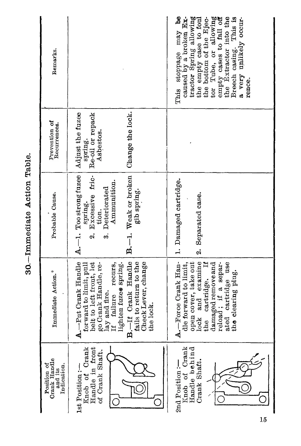
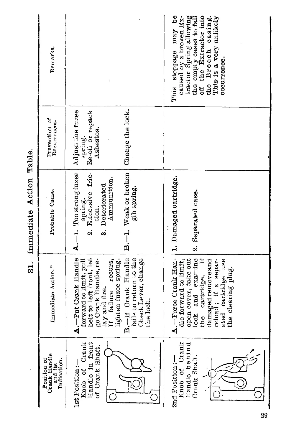
30—Immediate Action Table.
Position of Crank Handle and its Indication. Immediate Action.* Probable Cause. Prevention of Recurrences. Remarks.
Is t Position:— Knob of Crank Handle in front of Crank Shaft. bi A.—Put Crank Handle forward to limit, pull belt to left front, let go Crank Handle, re- lay and fire. If failure recurs, lighten fuze® spring. B.—If Crank Handle fails to return to the Check Lever, change the lock. A.—1. Too strong fuzee spring. 2. Excessive fric- tion. 3. Deteriorated Ammunition. B.—1. Weak or broken gib spring. Adjust the fuzee spring. Re-oil or repack Asbestos. Change the lock.
O]
2r id] К H Ci C c ?osition:— nob of Crank andle behind ’ank Shaft. , 4 !J x A.—Force Crank Han- dle forward to limit, open cover, take out lock and examine the cartridge. If damaged remove and reload ; if a separ- ated cartridge use the clearing plug. 1. Damaged cartridge. 2. Separated case. This stoppage may be caused by a broken Ex- tractor Spring allowing the empty case to foul the bottom of the Ejec- tor Tube, or allowing empty cases to fall off the Extractor into the Breech casing. This is a very unlikely occur- rence.
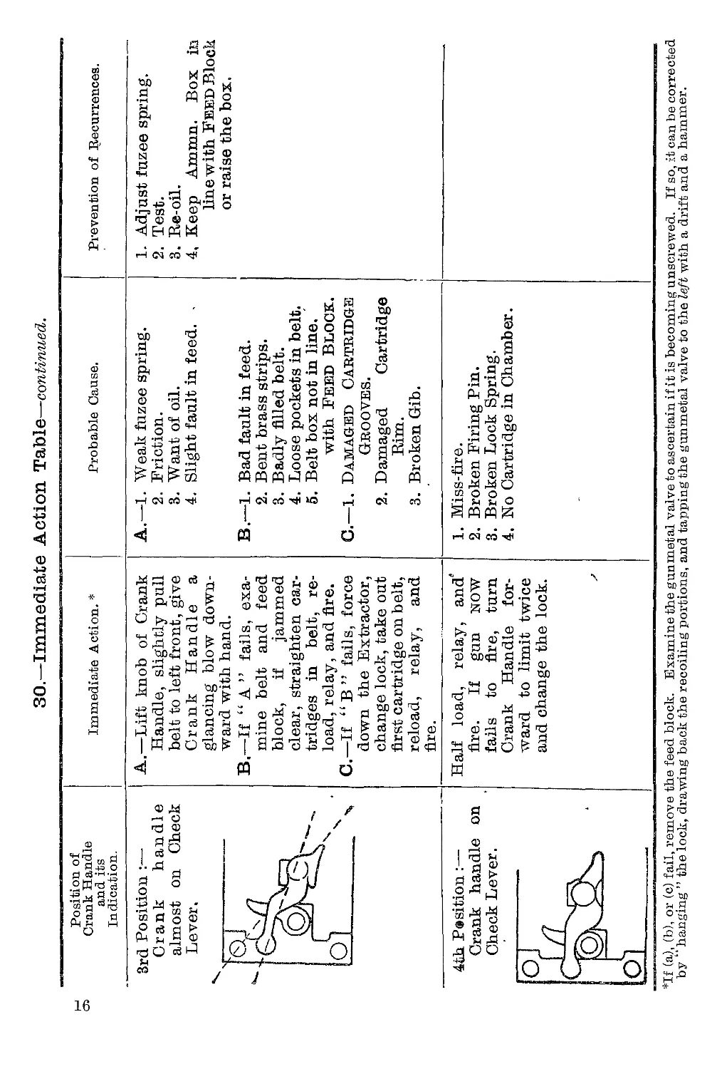
30.—Immediate Action Table—continued.
Position of
Crank Handle
and its
Indication.
Immediate Action. *
Probable Cause.
Prevention of Recurrences.
3rd Position :—•
Crank handle
almost on Check
Lever.
A.—Lift knob of Crank
Handle, slightly pull
belt to left front, give
Crank Handle a
glancing blow down-
ward with hand.
B.—If “A” fails, exa-
mine belt and feed
block, if jammed
clear, straighten car-
tridges in belt, re-
load, relay, and fire.
C.—If “B” fails, force
down the Extractor,
change lock, take out
first cartridge on belt,
reload, relay, and
fire.
A.—1. Weak fuzee spring.
2. Friction.
3. Want of oil.
4. Slight fault in feed. -
B.—1. Bad fault in feed.
2. Bent brass strips.
3. Badly filled belt.
4. Loose pockets in belt.
5. Belt box not in line,
with Feed Block.
G.—1. Damaged Cartridge
Grooves.
2. Damaged Cartridge
Rim.
3. Broken Gib.
1. Adjust fuzee spring.
2. Test.
3. Re-oil.
4, Keep Ammn. Box in
line with Feed Block
or raise the box.
4>th Pesition:—
Crank handle on
Check Lever.
Half load, relay, and’
fire. If gun NOW
fails to fire, turn
Crank Handle for-
ward to limit twice
and change the lock.
1. Miss-fire.
2. Broken Firing Pin.
3. Broken Lock Spring.
4. No Cartridge in Chamber.
*If (a), (b), or (c) fail, remove the feed block. Examine the gunmetal valve to ascertain if it is becoming unscrewed. If so, it can be corrected
by “hanging ” the lock, drawing back the recoiling portions, and tapping the gunmetal valve to the left with a drift and a hammer.
Setting the Sights.
31. It must be remembered that the tangent sight is
graduated in metres and not in yards. At close ranges no allowance
need be made for this, but at the longer ranges it may be necessary
to make a correction if the range has been ascertained in yards. It
will be sufficiently accurate to subtract one-tenth of the range in
yards in order to convert it into metres, e.g., range in yards = 2,000
yards; range in metres = 2,000—200 = 1,800 metres, to which
reading .the tangent sight should be set.
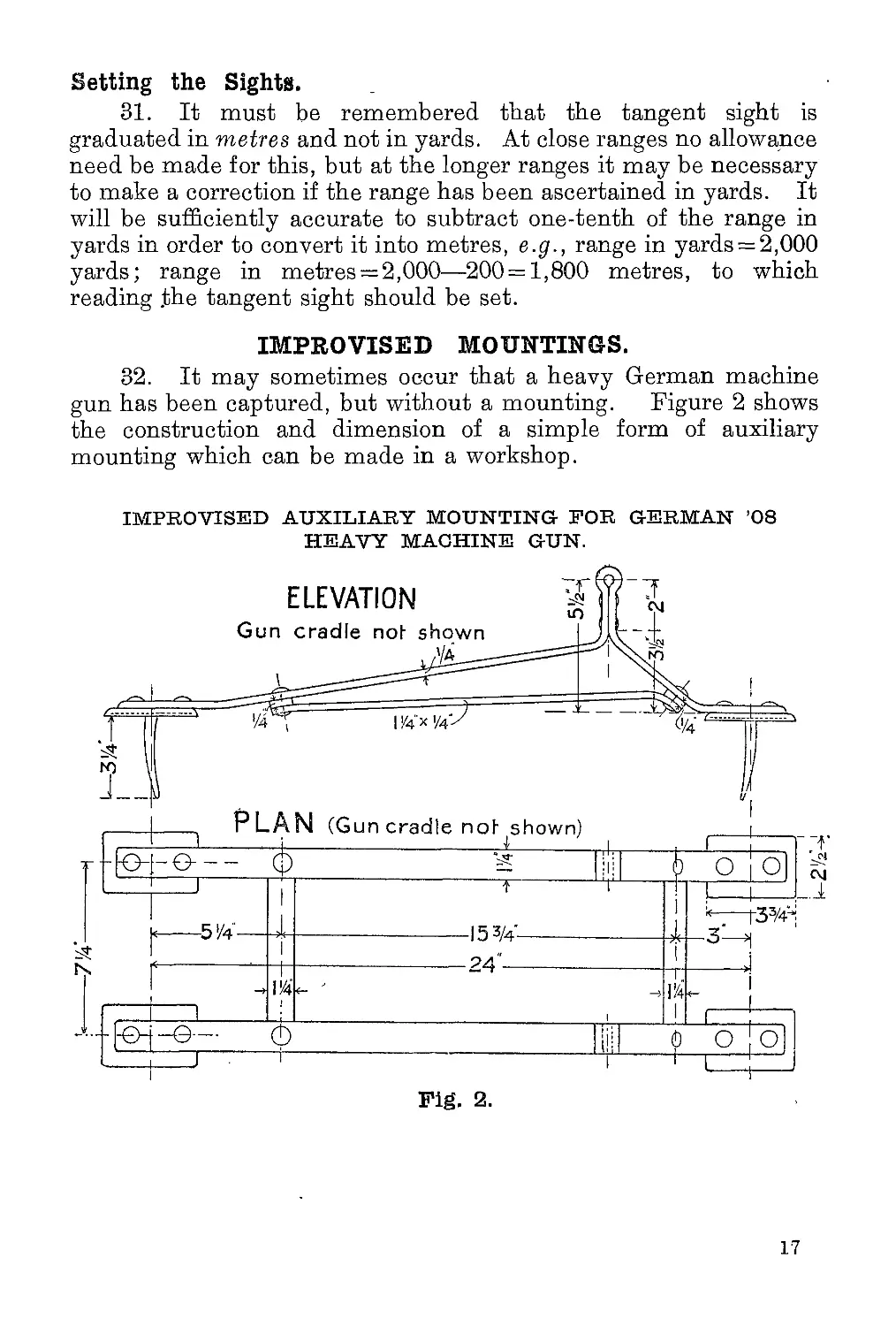
IMPROVISED MOUNTINGS.
32. It may sometimes occur that a heavy German machine
gun has been captured, but without a mounting. Figure 2 shows
the construction and dimension of a simple form of auxiliary
mounting which can be made in a workshop.
IMPROVISED AUXILIARY MOUNTING- FOR GERMAN ’08
HEAVY MACHINE GUN.
17
AUXILIARY MOUNTING FOR GERMAN ’08
HEAVY MACHINE GUN—continued.
Details o*f gun cradle.
Fig. 2.
THE TELESCOPIC SIGHT.
33. The telescopic sight for the ’08 machine gun is used for
the following purposes:—
1. To secure better definition of indistin'ct targets,
especially at the longer ranges, and in dull lights or moon-
light, when laying over the ordinary sights would not be
possible.
2. To meet special atmospheric conditions, such as mist,
fog, snow, or very brilliant sunshine. For this two yellow
glasses of different strengths are provided, which fit over the
front lens. The external features of the sight are: —
1. The eyepiece “ A ”• (see Figure 3).
2. The range drum “ В ”. This is graduated in hundreds
of metres, and is set to any required range by rotating it until
the correct reading is registered against the pointer which is
marked oh. the body of the sight.
3. The front lens “ C.” This is provided with a leather
cap, which protects it when not in use.
4. The dovetailed base “ D ” of the sight, which slides
into a special seating attached to the bree'ch casing of the gun.
The method of use is as follows: —
The sight being attached to the gun, the range drum is
first set to the estimated range to the target. On looking
through the eyepiece, the firer will see an arrow head. He
lays the gun so that this arrow head (the position of which is
controlled by the range drum) is aligned on the target, when
the gun will be correctly laid.
It must be remembered that the scale on the range drum is
graduated in metres, and not in yards. At close ranges no
allowance need be made for this, but at the longer ranges it may
be necessary to make a correction if the range has been ascertained
in yards. It will be sufficiently accurate to subtract one-tenth of
the range in yards in order to convert it into metres, e.g., range
in yards 2,000; range in metres 2,000—200 = 1,800 metres.
The telescopic sight must be treated carefully and protected
from jolts, blows, or falls. The cap should be placed over the
eyepiece when the sight is not being used.
SECTION II,—The ’08/’15 (Light)
German Machine Gun.
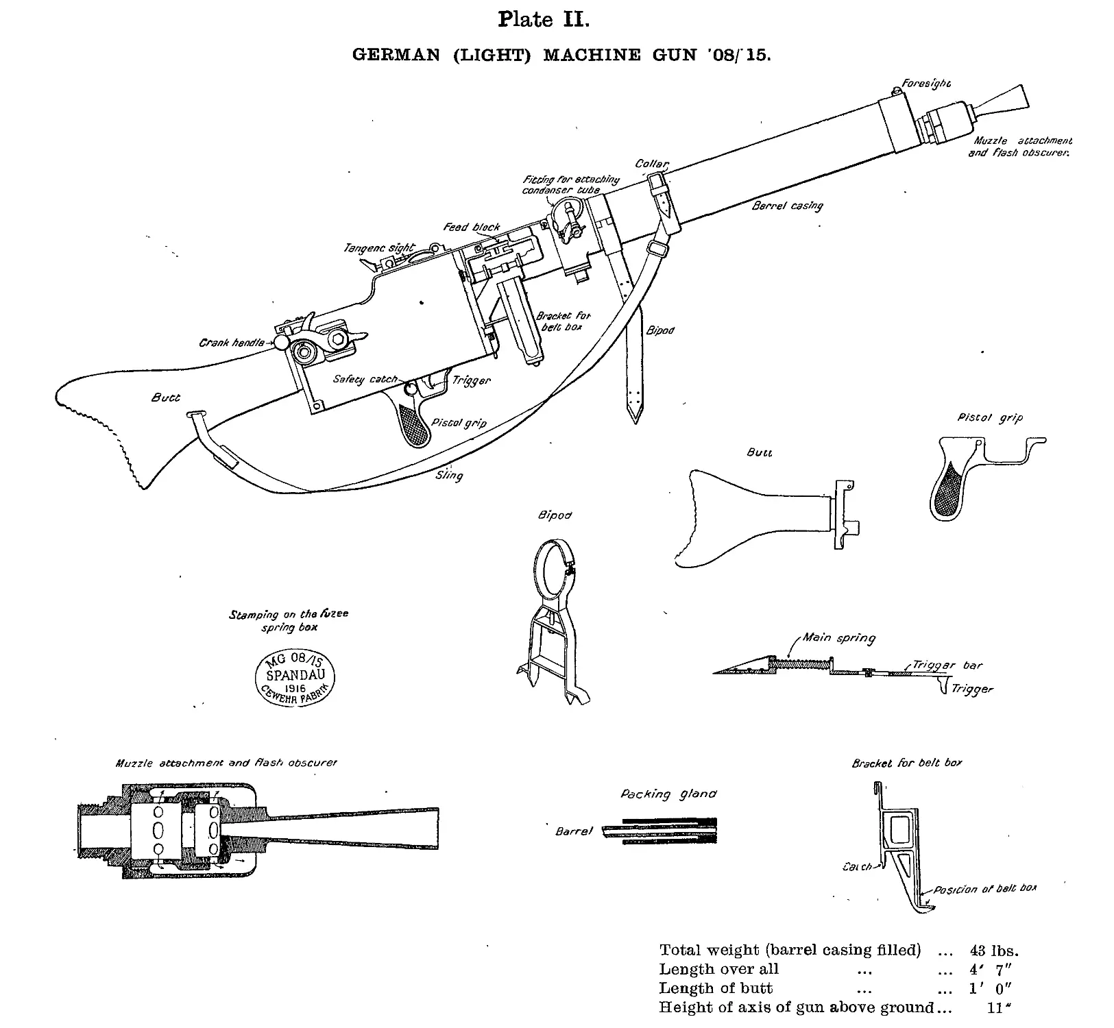
GENERAL DESCRIPTION.
(See Plate II.)
1.
Weight of gun (with 5 pints of water in
barrel casing) Weight of bipod Weight of belt drum holder complete with i belt drum and filled belt ... 34| lbs. lbs. 7 lbs.
Total weight ... 43 lbs.
Weight of belt drum with filled belt 4| lbs.
Length over all 4 ft. 7 ins.
Length of butt 1 ft. 0 ins.
Height of axis above ground 11 ins.
The gun is fitted with a rifle sling.
The gun is divided into two portions:—
(a) The non-recoiling portions.
(b) The recoiling portions.
How Operated.
2. It is recoil operated, and is worked by two forces—(a) The
force of explosion, which forces the recoiling portions backwards,
and (b) the fuzee spring, which carries them forward.
THE NON-RECOILING PORTIONS.
3. Barrel Casing consists of three parts:—
(a) The Front Cap which is screwed on to the body and
carries the foresight block and the foresight. The barrel
opening, which carries asbestos packing, is threaded to receive
the muzzle attachment or a packing gland when the muzzle
attachment is not in use.
(b) The Body which is closed by steel caps front and
rear. Underneath the body is a bracket to which the carrying
sling is connected.
20
(c) The Rear Cap which is screwed to the body. On the
left top side is a hole for filling purposes, closed by a screwed
plug. On the right top side is a fitting to which the steam
escape attachment is fitted. The steam escape attachment
is of metal and is secured by means of lugs; it is locked by
| turn. On the under side are projections into which the
tripod mounting fits, in the centre of which an opening is
bored to let out water. This opening is closed by a metal
plug. Below the feed block on the right side it is fitted with
a recess to take the belt drum holder. Below the feed block
opening is the barrel way, and on the right side is a fitting
to receive the ammunition. On the left side is a seating for
the fuzee spring box and catch.
The diameter of the barrel casing is 3| inches, and its
capacity about 5 pints.
4. Steam Tube.—Inside and running along the top of the
barrel casing is a steam tube. It consists of a fixed tube and an
outer tube termed the Slide Valve, so arranged as to slide freely
over the fixed tube.
The fixed tube has three holes, one near each end and one in
the threaded portion in front, connected with the steam escape
hole. :
It is retained in position by a keeper screw, which ensures
that the third hole coincides with the steam escape hole.
If the gun is elevated the valve slides backwards, closes up
the hole at the rear end preventing the escape of water, but leaves
the hole at the rear open to allow of the escape of steam. Vice
versa if the gun is depressed.
5. The Belt Drum Holder is connected to the casing below
the feed block and held in position by a spring catch, the belt drum
being kept in position by flanges and supported at the base.
6. The Breech Casing consists of two side plates, a bottom
plate, a cover, and a rear crosspiece. The breech casing is dove-
tailed into the rear extension of the barrel casing and secured by
rivets*. The empty cases are ejected through an aperture in the
front of the breech casing.
The left plate is fitted with an undercut projection at the rear
end to receive the fuzee spring box. Both plates are provided
with slots; these are partially closed by projections on the rear
crosspiece. The slots are reinforced to take the crank bearings.
On the inside of both sideplates are the cams and sideplate rests,
as in the heavier type of machine gun. At the top rear end of the
breech casing is fitted a lever catch actuated by a spiral spring.
21
7. Pistol Grip and Safety Catch.—On the bottom plate are
the pistol grips and trigger guards to which a safety catch is pivoted
on the left side. The safety catch consists of a milled thumb-piece,
which, on being pressed downwards, causes a projection to protrude
behind the trigger, thus preventing the trigger from being pressed.
8. The Cover is hinged in front to the barrel casing and rests
on the top of the breech casing. On the top is the backsight bed
with springs and ramps. The backsight is of radial pattern sighted
from 400 to 2,000 metres and adjusted by means of a slide with
spring catch. At the rear end a cover lock fits over a projection
and is held in position by means of a spring. On the under side of
the cover are two springs, which act on the horns of the extractor,
and a blo'ck, which holds the lock down when in the backward
position.
9. The Bottom Plate is riveted to the two outside plates and
carries the pistol grip and trigger; the trigger is connected to the
trigger bar, which lies along the inside bottom plate and is actuated
by a spiral spring. Near the front left corner of the bottom plate
two holes are bored to allow surplus oil and dirt to escape.
10. The Rear Crosspiece is hinged to the side plates at bottom
by a joint pin and is recessed to receive the rear ends of side plates,
so stiffening the breech casing.
It is fitted at the rear end with a butt which is hollowed to
carry an oil container. The butt is secured to the rear crosspiece by
two screws. Towards the top of the rear crosspiece are two
projections which, when in position, partially close the slots in rear
end of breech casing. The right projection carries a stud on which
the check lever, roller, collar and split pin are fitted. The left
projection carries an undercut lug to receive the rear end of the
fuzee spring box. When closed, the rear crosspiece is secured
by the cover catch at the top.
A recess is cut through the butt for the carrying sling, and the
shoulder-piece is milled and shaped to fit the shoulder.
11. Feed Block.—The feed block fits under the cover into a
recess cut for it in the breech casing. It has a slide to which is
attached a pawl and spring for the purpose of moving the cartridges
from right to left; the slide has a transverse motion given to it by
means of two levers which are fitted together at right angles; the top
lever fits between projections on the slide, and on the bottom lever
is a stud which engages in a recess in the prolongation of the left
inside plate. By this means the slide is connected with the
recoiling portions. It has two stationary pawls, both of which are
on a bar, which is operated by a lever at the right rear end of the
feed block.
22
These pawls are actuated by a coil spring. The pawls engage
under the belt and prevent it slipping out of the feed block during
firing.
Inside, at the front end, is a spring to position the cartridges.
At the rear end, and above the cartridge guides, is another spring
which engages in the groove at the base of the cartridge. There are
two stops inside, which prevent the cartridge from going too far to
the left.
Note.—Owing to the cover joint pin protruding, before the feed
block can be taken out the slide withdrawing the bottom lever must
be moved to the right.
12. The Dust Protector is of metal, and when in use covers
the opening of the feed block on the right side.
On the right top side of the feed block is a hole to receive the
pin of the dust protector. When in use the pin presses through the
dust protector and the recesses in the feed block, being held in
position by a plunger and spring.„
13. Fuzee Spring Box.—On the left of the breech casing is
a box which contains the Fuzee Spring, underneath the fore end
of which is a catch actuated by a spiral spring, which must be
pressed up before the box can be removed.
The Fuzee Spring is a strong spiral spring, the rear end of
which is connected to the fusee links by-means of a hook.
The Fuzee Spring is attached to the fuzee spring box by
means, of a long adjusting screw, which passes through the front
end of the fuzee spring box and screws into a gunmetal bush. The
strength of the spring is altered by means of a vice pin. On the
outside of the box is a scale reading from 0 to 70. The best
average setting is at 33.
BALL FIRING ATTACHMENT AND FLASH OBSCURER.
14. The muzzle attachment consists of a steel cylinder
which is connected to the barrel casing by a screwed thread. It is
unnecessary to remove the muzzle attachment when changing the
barrel.
The action of the attachment is as follows:—
As the gases escape from the barrel after the bullet, they
are partially confined in the cylinder and strike back on to the
muzzle, giving increased energy of recoil. The gases then
escape through holes in the inner cylinder, thus causing the
flash to be obscured by the outer cap.
23
15. The Belt Drum Carrier.—/The cartridge belt 'carrier is
a semi-circular metal box and fits oh the right side of the breech
casing near the feed block. The belt (holding 100 cartridges) is
wound around a drum, the holes in the brass tag engaging in pro-
jections on the spindle, which is wound from the outside, find is
prevented from unwinding by means of a ratchet and spring v hen
not in use. When firing, the handle which turns the drum must
be raised at right angles to allow it to revolve freely. The top
casing is hinged and secured by hooks actuated by a spiral spring.
16. The Mounting (bipod pattern) is of steel with double feet,
and has two legs about 12 inches in length. It is attached to the
gun by means of a circular band passing over the barrel casing
and held in position by a thumb screw. The circular band is
pivoted to permit the gun being traversed.
RECOILING PORTIONS.
The recoiling portions (which move inside the non-recoiling
portions) consist of the barrel, two side plates, the lock, the crank,
and everything the crank carries; i.e., crank handle, fuzee, etc.
17. The barrel is threaded at the muzzle to receive an outer
muzzle casing which is keyed to hold it in position. The outer
muzzle casing gives an enlarged diameter to the barrel, thereby
giving it a greater bearing surface at the front end of the barrel
casing. At the rear end is a cannelure which when packed with
asbestos prevents the escape of water at the rear end of the gun.
In front of the barrel block is a gun-metal valve which prevents the
escape of water when the barrel is at rest. The barrel block has
two trunnions which engage in two bearings in the side plates.
The inside side plates are each provided with holes or
bearings to engage the trunnions on the barrel.
The left inside plate is prolonged, and has a recess cut, in which
the lower lever of the feed block works.
Each side plate has a spring, which is called the side plate
spring. This ensures the extractor being at its highest when the
lock is fully home. Each side plate has guides in which the flanges
of the lock move, which are enlarged at the rear end to act as crank
stops; in addition each has a bearing through which the crank
passes; these bearings move in slots in the breech casing.
The crank is fitted with a 'connecting rod which is free to rotate
on the crank pin; on the left, screwed into the crank, is the fuzee
and links; on the right, fitted on to the crank shaft and secured
by a screwed pin, is the crank handle, which has a curved arm and
tail.
24
The connecting rod is attached to the crank by means of an
axis pin, called the crank pin, and takes the lock by means of an
interrupted screw, so connecting the lock and crank.
The lock is attached to the connecting rod by the screwed
head, and when in the firing position closes the breech. When
in this position it is held by the side levers, the conne'cting
rod, and the crank (which bears against the crank stops),
which are all slightly above the horizontal, to prevent a pre-
mature opening of the breech. The lock has a reciprocating
motion given to it by the rotation of the crank, and is kept in
position during its backward and forward movements by the lock
flanges working in the lock guides on the side plates, and when
clear of the guides by the steel block underneath the cover.
The extractor is moved upwards by means of the side and
extractor levers, and when in its highest position is retained there
by the side plate springs, so preventing the extractor from falling
until the horns have engaged on the cams.
The upward and downward movement of the extractor is
regulated by guide ribs and stops. The top stop is part of the lock
spring : the bottom stop is removable. On the face of the extractor
are firing pin hole and extractor or spring. On either side of the
latter, the extractor is cut away to facilitate the ejection of the
cartridges. At the top are horns for engaging on the cams (inside
the breech casing).
Inside the lock are the sear and spring, tumbler, firing pin,
lock spring and trigger. The lock spring is positioned by an axis
pin, which also acts as a keeper pin for the bracket on which the
extractor levers work.
The gun is supplied with cartridges from a belt which is
almost identical with the Vickers belts.
ACTION OF MECHANISM.
18. To Load.—Pass the tag end of the belt through the feed
block from the right, turn the crank handle as far forward as it will
go, pull the belt to the left as far as it will go, and let go the crank
handle. Repeat these motions and the gun will be loaded and
ready for firing.
19. To Unload.—Turn the crank handle forward as far as it
will go, but without touching the belt, and let go the crank handle.
Repeat the motion. Remove the belt by pressing towards the
gun the button on the rear end of the feed block and remove the
belt. Release the lock spring by pressing the trigger and then
pushing down the safety catch to “ S.”
25
20. To Fire.—Suppose the gun to be loaded: if the safety-
catch is drawn back to “ F ” and the trigger pressed, the gun
will fire and continue to fire until the belt is empty or the trigger
released. In the latter case, there will always be two live
rounds gripped in the extractor, one in the chamber and one in the
feed blo'ck, so that the gun will fire again by simply pressings the
trigger.
BACKWARD MOVEMENT OF THE RECOILING PORTIONS.
21. Action on Recoil.—Suppose the gun to have just fired:
the extractor will be gripping a live round in the feed block, and an
empty case, which has just been fired, in the chamber; the force of
explosion, assisted by the action of the muzzle attachment, forces
the recoiling portions backward through a distance of about 1 inch,
thereby causing the fuzee spring to be extended.
22. Action in the Feed Block.—As the recoiling portions move
backward, the re'cess in the prolongation of the left side plate carries
with it the stud on the bottom lever of the feed block. The bottom
lever, which is at right angles to the top lever, causes the top lever
slide and pawl to move from left to right, and the top pawl passes
over and engages behind a fresh cartridge, which has up to now been
held in place by the bottom pawls.
As soon as the extractor reaches its highest position, the two
side plate springs engage in slots in its side and so ensure the
extractor remaining at its highest until the horns engage on the
cams.
Asesoon as the lock is right home, and the extractor at its
highest, the screwed head rises slightly above the horizontal and
lifts the tail of the sear, thereby disengaging the bent of the sear
from the bent of the firing pin, which allows the lock spring to
carry the firing pin slightly forward till the bent of the tumbler is
engaged by the nose of the trigger.
23. Rotation of Crank.—The backward movement of the
recoiling portions causes the curved arm of the crank handle to
roll on the roller, which action rotates the crank. The rotation of
the crank withdraws the lock, and causes the fuzee to wind the
chain about itself, so causing a further extension of the fuzee spring.
As the lock comes back, the extractor brings with it a live round
from the feed block, and the empty case from the chamber. The
horns of the extractor engage upon the top surface of the cams and
ride along them until they get to the end, when they drop either
by their own weight or assisted by the action of the cover springs.
This places the live round opposite the chamber and the empty
26
case opposite the ejector tube. The live round is prevented from
falling off the face of the extractor by the bottom projection of the
gib, and the empty case by the extractor spring.
When the lock is right back the lock flanges are clear of the
lock guides and it is kept in position by the steel block on the
underside of the cover.
24. Cocking Action of the Lock.—As the lock comes back,
the rotation of the crank gives a downward motion to the connect-
ing rod and screwed head, the latter bearing on the tail of the
tumbler, causing it to rotate on its axis; and as the head of the
tumbler is engaged in a recess in the rear end of the firing pin, it
causes the firing pin to be forced to the rear.
The long arm of the lock spring is engaged in a recess in the
front end of the firing pin, while the short arm bears against the
upper part of the trigger, so that as the firing pin is drawn back
the lock spring is compressed by the longer arm being drawn
towards the short arm.
As the tumbler rotates, the nose of the trigger is forced under
the bent of the tumbler, but a continued motion of the tumbler
forces the firing pin still further back until the bent of the sear is
forced into the bent of the firing pin (the sear being actuated by the
sear spring). The lock spring is now fully compressed and the
firing pin prevented from flying forward.
FORWARD MOVEMENT OF THE RECOILING PORTIONS.
25. Action of the Fuzee Spring.—When the force of the recoil
is spent, the fuzee spring, which is extended, comes into play, and
carries the whole of the recoiling portions forward again.
26. Action in the Feed Block.—As the recoiling portions
travel forward the recess in the prolongation of the left side plate
carries forward the stud on the bottom lever. This causes the top
lever, slide and pawl and fresh cartridges to move from right to
left. The fresh cartridge is placed in position in the face of the
feed block, ready to be gripped by the extractor, and against the
cartridge and bullet stops, ^whilst the groove of the cartridge is
engaged by the spring on the undersurface of the top of the feed
block. The belt as it passes to the left causes the bottom pawls
to be depressed, which, when the cartridge has passed over them,
rise behind it, so holding the belt in position when the first cartridge
is withdrawn.
27. Rotation of Crank.—The fuzee spring, assisted by the
rebound of the tail of the crank handle from the roller pulling on
27
the chain of the fuzee, causes them to unwind from the fuzee; this
rotates the fuzee, which causes the crank to rotate, which lifts up
the connecting rod and screwed head. This causes the lock to
move forward, placing the live round in the chamber, and the
empty case in the ejector tube; when the lock is almost home the
extractor is forced upwards by the side levers bearing on the
extractor levers, the extractor spring passes over the base of the
empty case in the ejector tube, where it is held by the ejector
tube spring until it is pushed out by the next empty case.
The bottom projection of the gib passes over the base of the
live round in the chamber. The cap of the cartridge is thus placed
opposite the firing pin hole, and the fresh cartridge, which has been
fed up into the feed block is engaged by the extractor, by the top
proje'ction of the gib passing over its base.
FIRING ACTION.
28. First Shot.—If the safety 'catch is pulled back to “ F ”
and the firing trigger pressed the trigger bar is slightly withdrawn,
and the projection on it, engages and draws back the tail of the
trigger. This releases the nose of the trigger from the bent of the
tumbler, the lock spring carries the firing pin forward, thus
firing the cartridge.
29. -Subsequent Shots.—If the pressure is maintained on the
firing trigger, the trigger bar is held back, so that each time
the lock goes- forward the tail of the trigger is tripped, which
prevents the nose of the trigger from engaging under the bent
of the tumbler. When the lock is right home, and the extractor
at its highest, the screwed head rises above the horizontal, lifts
the tail of the sear, disengages the bent of the sear from
the bent of the firing pin, and as there is nothing further to
prevent it, the lock spring carries the firing pin forward and
explodes the charge. This continues as long as pressure is main-
tained on the firing button. The lifting of the sear is so timed that
the firing pin cannot be released until the lock is in the firing
position.
30. Cease Fire.—If the pressure on the firing trigger is
released, the trigger bar is forced forward; therefore, when the lock
goes forward the tail of the trigger is not tripped. When the bent
of the sear is released from the bent of the firing pin, the firing pin
cannot go right forward, because the short arm of the lock spring
forces the nose of the trigger under the bent of the tumbler.
28
31.—Immediate Action Table.
Position of Crank Handle and its Indication. Immediate Action. * Probable Cause. Prevention of Recurrences. Remarks.
1st Position:— Knob of Crank Handle in front of Crank Shaft. ol ft- Igllp ot_—_ A.—Put Crank Handle forward to limit, pull belt to left front, let go Crank Handle, re- lay and fire. If failure recurs, lighten fuzee spring. B.—If Crank Handle fails to return to the Check Lever, change the lock. A.—1. Too strong fuzee spring. 2. Excessive fric- tion. 3. Deteriorated Ammunition. B.—1. Weak or broken gib spring. Adjust the fuzee spring. Re-oil or repack Asbestos. Change the lock. -
2nd Position:— Knob of Crank Handle behind Crank Shaft. окЯ Д 25. A.—Force Crank Han- dle forward to limit, open cover, take out lock and examine the cartridge. If damaged remove and reload ; if a separ- ated cartridge use the clearing plug. 1. Damaged cartridge. 2. Separated case. This stoppage may be caused by a broken Ex- tractor Spring allowing the empty cases to fall off the Extractor into the Breech casing. This is a very unlikely occurrence.
31.—Immediate Action Table—continued.
Position of
Crank Handle
and its
Indication.
Immediate Action. *
Probable Cause.
Prevention of Recurrences.
3rd Position :—
Crank handle
almost on Check
Lever.
A.—Lift knob of Crank
Handle, slightly pull
belt to left front, give
Crank Handle a
glancing blow down-
ward with hand.
B.—If “ A ” fails, exa-
mine belt and feed
block, if jammed
clear, straighten car-
tridges in belt, re-
load, relay, and fire.
C.—If “B” fails; force
down the Extractor,
change lock, take out
first cartridge on belt,
reload, relay, and
fire.
A.—1. Weak fuzee spring.
2. Friction.
3. Want of oil.
4. Slight fault in feed.
1. Adjust fuzae spring.
2. Test.
3. Re-oil.
4, Keep Ammn. Box in
line with Feed Block
or raise the box.
B.—1. Bad fault in feed.
2. Bent brass strips.
3. Badly filled belt.
4. Loose pockets in belt.
5. Belt box not in line,
with Feed Block.
C.—1. Damaged Cartridge
Grooves.
2. Damaged Cartridge
Rim.
3. Broken Gib.
4th Position:—
Crank hafidle on
Check Lever.
Half load, relay, and
fire. If gun now
fails to fire, turn
Crank Handle for-
ward to limit twice
and change the loci.
1. Miss-fire.
2. Broken Firing Pin.
3. Broken Lock Spring.
4. No Cartridge in Chamber.
If (a), (b), or (c) fail, remove the feed block. Examine the gunmetal valve to ascertain if it is becoming unscrewed. If so, it can be corrected
by “hanging ’’ the lock, drawing back the recoiling portions, and tapping the gunmetal valve to the left with a drift and a hammer.
APPENDIX.
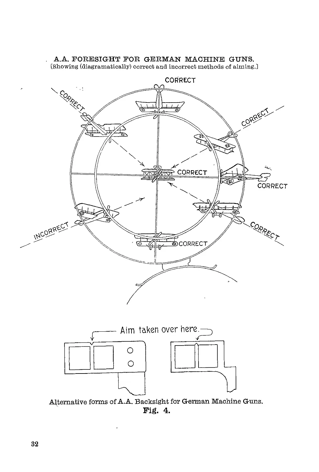
ANTI-AIRCRAFT SIGHTS.
A similar pattern of anti-aircraft sight is used for both the
heavy and the light German machine guns. It consists of a
foresight and a backsight (see Figure 4). The foresight is con-
structed of two metal rings with vertical and horizontal cross wires,
and is attached to the gun by means of a circular-hinged metal
strap, registration being secured by the portion which fits over
the foresight of the gun. The ba'cksight consists of a rectangular
metal frame, divided down the centre by a thin strip. In the case
of the heavy gun, this backsight is attached to the stem of the
tangent sight, which must be raised and set at its lowest reading,
i.e., 400 metres. For the light gun, however, the tangent sight
must not be raised; the backsight is attached by simply passing it
over the front end of the backsight on the gun, and sliding it to the
rear, when a spring clip secures it in position.
The method of use is as follows: —
The outer ring is not used at all; aim is always taken
using the inner ring on the foresight.
The aeroplane must always appear to be flying towards
the intersection of the cross wires (see Figure 4).
Aim is taken over the V of the backsight, through the point
on.the inner ring where the propeller of the aeroplane appears
to cut it, on to the propeller of the aeroplane.
The target will only come within the dispersion of the
cone of fire when and so long as the propeller appears to cut the
inner ring, and fire should be continuous as long as this is the
case.
If it is not possible to maintain this condition when
firing, short bursts should be fired and a fresh aim taken
between bursts, fire being opened dire'ctly the propeller of the
aeroplane appears to cut the inner ring.
If the target is flying approximately horizontally, and
towards the gun, the lowest point of the inner ring should
be used. If away from the gun, the highest point of the inner
ring should be used.
If the aeroplane is diving straight towards the gun, aim
should be taken through the intersection of the cross wires.
31
A.A. FORESIGHT FOR GERMAN MACHINE GUNS.
[Showing (diagramatically) correct and incorrect methods of aiming.]
Alternative forms of A.A. Backsight for German Machine Guns.
Fig. 4.
32
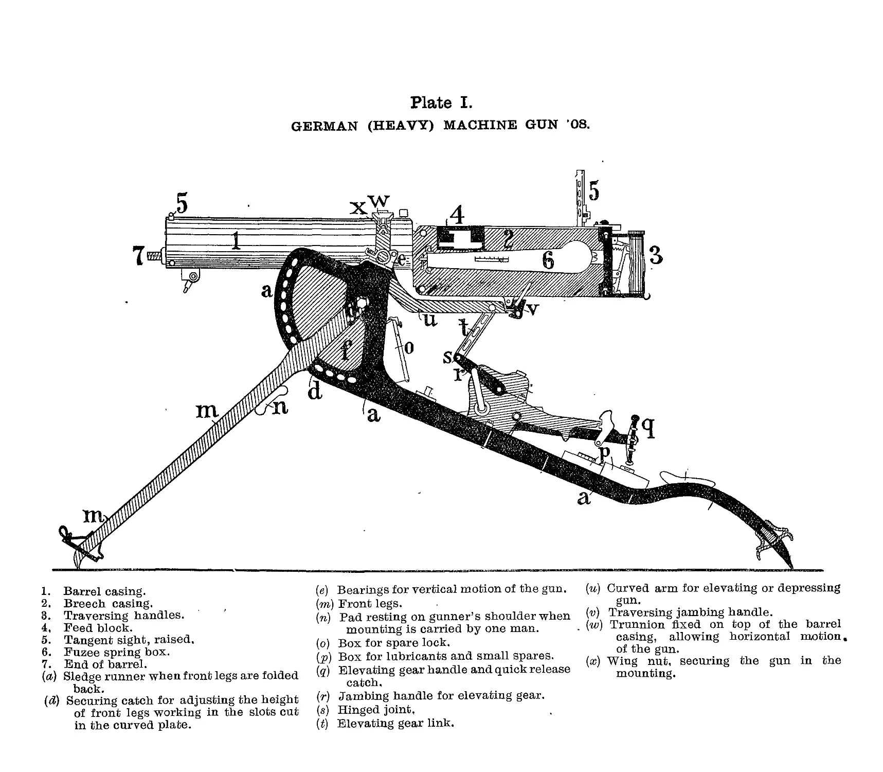
Plate I.
GERMAN (HEAVY) MACHINE GUN ’08.
1. Barrel casing.
2. Breech casing.
3. Traversing handles.
4, Feed block.
5. Tangent sight, raised,
6. Fuzee spring box.
7. End of barrel.
(a) Sledge runner when front legs are folded
back.
(d) Securing catch for adjusting the height
of front legs working in the slots cut
in the curved plate.
(e) Bearings for vertical motion of the gun.
(m) Front legs.
(n) Pad resting on gunner’s shoulder when
mounting is carried by one man.
(o) Box for spare lock.
(p) Box for lubricants and small spares.
(q) Elevating gear handle and quick release
catch,
(r) Jambing handle for elevating gear.
(s) Hinged joint,
(t) Elevating gear link.
(w) Curved arm for elevating or depressing
gun.
(v) Traversing jambing handle.
. (w) Trunnion fixed on top of the barrel
casing, allowing horizontal motion,
of the gun.
(ж) Wing nut, securing the gun in the
mounting.
Plate II.
Muzzle attachment and flash obscurer
Barrel
Packing gland
Total weight (barrel casing filled) ... 43 lbs.
Length over all ... ... 4' 7"
Length of butt ... ... 1' 0"
Height of axis of gun above ground... 11"