/


Теги: weapons military affairs machine gun patent
Год: 1918
Текст
Apr. 10, 1923.
1,451,443
E. FOWLER
MACHINE GUN
Original Filed Dec. 4, 1918
5 sheets-sheet 1
Apr. 10, 1923.
1,451,443
E. FOWLER
MACHINE GUN
Original Filed Dec. 4, 1918 5 sheets-sheet 3
Apr. 10, 1923.
1,451,443
E. FOWLER
MACHINE GUN
Original Filed Dec. 4, 191b 5 sheets-sheet 3
Apr. 10, 1923.
1,451,443
E. FOWLER
MACHINE GUN
Original Filed Dec. 4, 1918
5 sheets-sheet 4
Apr. 10, 1923.
1,451,443
E. FOWLER
MACHINE GUN
Original Filed Dec. 4, 1918
5 sheets-sheet 5
Patented Apr. 10, 1923. 1,451,443
UNITED STATES PATENT OFFICE.
EGBERT EOWIiER, OE BALTIMORE, MARYLAND.
GUN.
Application, filed December 4, 1918, Serial No. 265,239. Renewed December 21, 1922.
To dll whom it may concern:
Be it known that I, Elbert Fowler, cap-
tain, Ordnance Department, U. S. A., a citi-
zen of the United States, residing at Balti-
& more, Maryland, have invented an Improve-
ment in Machine Guns, of which the follow-
ing is a specification.
This invention relates, generally, to auto-
matic machine guns of that description in
10 which all operations of the mechanism are
automatically effected by the energy of the
recoil of the movable parts, and is of the
same general class as the Vickers machine
gun, model of 1915, and the Browning ma-
le chine gun, model of 1917.
The invention relates, particularly, to
novel improvements in recoil-operated ma-
chine guns in which the barrel and breech
parts recoil together, while interlocked, a
20 limited distance and are then unlocked,,
the movement of the barrel being thereupon
arrested, and the breech bolt continuing its
recoil, during which energy is stored in a
reaction spring, by which all parts are re-
25 turned to the forward firing position.
One object of the invention is to produce
an improved firearm of this class which is
especially adapted for military service by
reason 9f its reliability, accuracy, strength,
30 absolute safety under all conditions, light
weight, and extreme simplicity of construc-
tion, and because the parts are not likely to
get out of order.
Another object is to provide a novel im-
35 proved construction of machine gun in
which certain parts of the mechanism per-
form several distinct functions, thereby re-
ducing the number of the component parts
and reducing the time and labor of assem-
-0 bling the parts and the cost of the gun as an
entirety. For instance, in my construction,
I have devised a single instrumentality of
peculiar form, which serves the dual func-
tion of extracting the cartridge from the
45 feed-belt and of cocking the firing-pin, this
single member thus performing functions
which are usually performed by two pants
in machine guns as heretofore constructed.
Another object relates to the provision
50 of a cartridge-extractor movable on an in-
stant pivot, whereby the front end of said
extractor moves downward in substantially
a straight line, which construction is an im-
provement over other well known construc-
55 tions, in which the front end of the extrac-
tor describes an arc in its movement,
necessitating a special contour of the front
end of the breech-bolt.
Another object relates to the manner of
mounting the cartridge-extractor on the во
breech-bolt, whereby it may be removed
from said bolt without withdrawing the lat-
ter from the gun, which construction is an
improvement over other constructions, in
which it is necessary to withdraw the 85
breech-bolt from the gun before the car-
tridge-extractor can be removed.
Another object relates to the novel con-
struction of the ejector which obviates the
use of springs and whereby the cam-pin To
carried by the extractor constitutes, also,
the support for the ejector.
Another object relates to the provision of
novel and improved mechanism for locking
the breech-bolt, against the breech through 75
the recoil plates of the barrel trunnion piece,
whereby the barrel and breech-bolt recoil
together, while interlocked, a limited dis-
tance, and are then automatically unlocked.
And a complemental object is the peculiar 80
construction of the breech-bolt locking mem-
ber whereby it serves the additional func-
tion of a breech-bolt accelerator, thus com-
bining in a single instrumentality functions
which are usually performed by two parts, 85
in machine guns as heretofore constructed.
Another object relates to the provision of
novel and improved trigger-sear mechanism.
Another object relates to the provision of
a buffer carried by the recoil-plates, against 90
which the breech-bolt recoils during the lat-
ter portion of its rearward movement so
that no strain is imposed in the rear end
plate, as in other constructions.
Another object, relates to the provision 95
of novel and improved cartridge-belt feed-
ing mechanism.
Another object relates to the provision of
novel and improved mechanism for extract-
ing the cartridges from the belt. 100
Another object relates to the provision
of novel and improved safety locking means
for the trigger.
The accompanying drawings disclose an
exemplary embodiment of the underlying 105
principles of my invention. Like reference
characters denote corresponding parts
throughout the several views. The different
figures of the drawings may be briefly de-
scribed as follows: 110
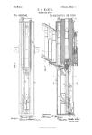
Fig. 1 is a central, vertical, longitudinal,
sectional view through the gun, showing the
2
1,461,443
breech mechanism in its forward firing po-
sition ;
Fig. 2 is a top plan view of the gun, show-
ing the position of the parts corresponding
5 to the position thereof shown in Fig. 1, the
cover being removed to display the interior
parts;
Fig. 3 is a view similar to Fig. 1, but show-
ing the position immediately after firing the
10' gun and the breech-bolt moved rearward by
recoil a short distance;
Fig. 4 is a view similar to Fig. 2, but
showing the position of the parts corre-
sponding to the position thereof shown in
15 Fig. 3;
Fig. 5 is a view similar to Fig. 1, but
showing the position of the parts when the
breech-bolt has reached the point of maxi-
mum recoil;
20 Fig. 6 is a top plan view of the gun, the
bolt being removed to sliow the underlying
parts;
Figs. 7, 8, and 9 are sectional views through
the feed-slide and its operating mechanism,
25 showing the relative positions of the feed-
slide and feed pawl at different stages in the
operation of the gun;
Fig. 10 is a horizontal sectional, view
through the cover;
30 Figs. 11, 12, 13 are detail views of the ex-'
tractor and ejector;
Fig. 14 is a sectional detail view of the
safety locking mechanism for the trigger;
Fig. 15 is a transverse section on the line
зб 15—15, Fig. 14; and
Fig. 16 is a sectional view on the line
16—16, Fig. 4.
Referring now in detail to the drawings:
The barrel I passes lengthwise through
40 the cooling-jacket Ia, from the front of
which its muzzle projects some distance;
while the rear portion of the barrel is sup-
ported in a seat provided for it in the trun-
nion block 2. The breech end of the barrel
45 is screwed into the transverse barrel trun-
nion piece 3, on the trunnions 3', 3' of which
are journaled the forward ends of right and
left hand recoil plates 4, 4. Suitable means
are provided for locking the breech-bolt 17
50 against the breech during the combined rear-
ward movement of the barrel, the barrel
trunnion piece, the breech-bolt and the recoil
plates, and, in this instance, the following
described means are used:
55 The rear ends of the recoil plates 4, 4 are
provided with bearings 6, 6, in which cranks
8, 8 are free to swing through an angle of
approximately 60%. The cranks 8, 8 are
connected by a member 7, operable to lock
*50 the breechTbolt 17 against the breech through
the recoil plates 4, 4, as shown in Fig. 1.
The breech-bolt locking-member 7 is pro-
vided with an arcuate cam surface or face 19,
which, in the movement of said member to
155 releasing position, bears upon the vertical
face 18' of a depending projection 18t:art,ied
at the rear of the breech-bolt 17, and acts as
an accelerator for the breech bolt 17.
As the breech bolt 17 moves from the
position thereof shown’in Fig. 1, to its rear- 70
most position, as shown in Fig. 5, mecha-
nism about to be described is operative to •,
swing the cranks 8, 8 on the arc of a circle,
so that the cam surface 19 of the locking
member 7 rolls and slides in contact with 75
the vertical face 18', of the depending pro-
jection 18 of the breech-bolt, to throw the
breech bolt rearward. The locking member
7 is provided, opposite the inclined cam face
19, with a beveled locking face 20, which, in 80
the raised or locking position of the mem-
ber 7, bears against the corresponding -wall
21 of a recess in the under surface of the
breech-bolt 17.
It will thus be seen that the member 7 is 85
a combined breech-bolt locking member and
accelerator.
The locking member 7 is positively forced
into its upper locking position by suitable
means. In this instance, the means shown in 90
the drawing is given as an example, and
will now be described. Projecting through
a longitudinally,extending slot in the side
plate 77, is a boss 9 (Fig. 16), which en-
gages a correspondingly-shaped socket in 95
the adjacent crank 8. Fast on this boss 9, is
an arm 10 for actuating the cranks 8, 8 and,
consequently, the locking member 7. The
arm or lever 10 is disposed in a casing 10я se-
cured to one of the side plates 77 (see Figs. 100
2, 4, 6 and 16). The inner surface of the
wall of said casing carries a locking cam 14
and an unlocking cam 12. In the forward
and rearward movements of the recoil
plates, the lever 10 strikes against said cams, 105
thus swinging the cranks 8,8 on their pivots
6, 6, and throwing the locking member 7
into and out of locking position with respect
to the breech bolt 17. The lever 10 with the
cam 12 serves to limit the rearward move- 110
ment of the barrel and the plates 4 due to
recoil and the force required to operate the
lever serves to absorb tlie shock of recoil of
these parts.
Carried by the recoil plates 4, 4 are ribs 115
15, 15, which fit in corresponding grooves
in the sides of the breech-bolt 17, these ribs
thus forming tracks on which the breech-
bolt reciprocates.
On the front face of the bolt 17 is a 120
flangeway 22 for receiving and guiding the
heads of cartridges, as usual, and for ex-
tracting the cartridge shell after the car-
tridge has been fired. (See more particu-
larly Fig. 5.) 125
Extending longitudinally through said
breech-bolt 17, near the top thereof, is an
opening 23. In said opening is a coiled re-
action spring 24, for returning the breech-
bolt 17 to forward firing position, after re- 130
1,451,443
8
б
10
16
20
25
30
35
40
45
50
55
60
05
coil thereof and restoring the barrel and
plates 4 to normal position. The reaction
spring is, in this instance, shown as encir-
cling a rod 25 having at its forward end, a
head 42, against the rear face of which one
end of said spring is seated.
Projecting into the rear end of said open-
ing 23, is a trigger-tube 26, into which the
rod 25 projects. Said trigger-tube is pro-
vided, on its bottom, with a depending lug
27, having an inclined rear face, as shown,
constituting a sear releasing member (as
presently appearing).
The trigger-tube 26 extends rearward and
projects (see more particularly Fig. 14), at
its rear end, through an aperture provided
therefor in the handle block or plate 79, and
into a trigger-casing 79b. The trigger-tube
is provided, at the point where it projects
through the plate 79, with two longitudinally
extending, diametrically opposed longitudi-
nal slots 26a, 26a, through which projects
a pin 83, against which the rear end of the
spring 24 bears. The rear face of said han-
dle block 79 carries an annular, internally-
threaded nipple 79a, in which is threaded a
tubular open-ended trigger-casing 79b, hav-
ing a longitudinally extending groove 79c in
its inner face, a longitudinally extending slot
79е diametrically opposite the groove 79°,
and an intumed annular flange 79d at its
rear end.
The trigger 79f is provided with a head
79g annular in cross section and having a rib
79” diametrically opposite the trigger finger
piece 79f, for a purpose presently appearing.
The head 79s is elongated so as to project
forwardly of the trigger piece 79f and nor-
mally rests, at its forward end, against the
outer face of the plate 79, as shown in Fig.
14. The head 79s is provided with an axial
recess 79‘ extending from the end thereof
farthest from the finger trigger piece 791 and
terminating short of the other end thereof,
in which recess is seated the rear end of the
trigger tube 26. Suitable means are pro-
vided for securing the trigger-head 79s to
the trigger-tube 26 and, in this instance, a
cotter pin 79j is shown as projecting trans-
versely through the slot 79е and through said
head and trigger-tube. Any other securing
means may, however, be used, as this is an
unimportant detail, in the nature of a mere
mechanical expedient.
Suitable mechanism may be provided for
normally maintaining the trigger in safe
position against unpremeditated release of
the sear by the trigger-tube controlled by
the trigger. The exemplary means shown in
the drawing will now be described:
зА rotatable locking annulus 79k is dis-
posed between the rear face of the head 79s
of the trigger and the flange 79d of the trig-
ger-casing 79b. The annulus is provided
with diametrically-opposite, longitudinally-
extending slots 79m, 79m extending from the
front end thereof, which, in the rotation of
the ring, are adapted to be brought into reg-
istry with the projection 79”, and with the
upper end of the trigger finger-piece 79f. 70
Means are provided for normally holding
the ring in such position that said slots are
out of registry with the projection 79” and
with the upper end of the trigger finger-
piece 79f, ana for returning said ring, after 75
rotation thereof, to normal position. The
trigger-casing 79b is provided with a longi-
tudinally-extending slot 79' in which slides
a pin 79” carried by a button 79° slidably
disposed within said annulus 79k, the latter 80
having a cam slot 79p, into which said pin
projects. It will thus be seen that the but-
ton moves along a rectilinear path and has
no rotatable movement, and that the annulus
79k rotates and has no rectilinear movement. 85
Consequently, in view of the construction
described, it will be apparent that, by press-
ing upon the button 79°, so as to move the
same toward the head 79b of the trigger, the
slots 79m, 79m will be brought into registry 90
with the projection 79*\ and with the upper
end of the trigger finger-piece 79f, so that
said trigger may be moved rearward, said
projection 79h and the upper end of the trig-
ger finger-piece moving in said slots. The 95
means for automatically returning the but-
ton 79° and the annulus 79k to normal posi-
tion, after actuation thereof, comprises a
coiled spring 79°, one end thereof being se-
cured to the button 79° and the other end ’u
thereof to the head 79g.
By virtue of the relative arrangement of
the trigger and its safety locking means, the
operator may press with the thumb of one
hand upon the button 79°, and with a finger Ю5
of the same hand against the trigger 79t.
The sear 29, carried by the breech-bolt 17,
is movable to swing through a slight angle
in a recess 29a communicating with the chan-
nel 23, and is pivoted on a pin 33. The in- По
dined face 28 of the sear, in the cocked po-
sition of the gun, is in engagement with the
inclined face of the lug 27 at the forward
end of the trigger tube 26.
Forwardly of the pivotal point of said П5
sear, the latter is provided with a bearing
face 37a, at the top of which is a forwardly-
extending arm 37b. At the bottom of said
arm is a recess 30, forming the locking recess
for the head 31 of the firing pin 32. 120
The firing pin 32 is seated in a longitudi-
nally extending recess 32' in the breech-bolt,
and is provided, toward its forward end,
with a longitudinally-extending slot 38 and
with a longitudinally-extending recess 35 125
extending from the rear end of the firing-
pin and terminating short of the slot 38. In
said recess 35 is disposed a coiled spring 34,
constituting a driving spring for the firing
pin. The rear end of the spring bears upon 130
4
1,451,443
a plunger 37 projecting through the rear
end of said firing pin and contacting with
the bearing face 37a of the sear 29, thereby
constantly tending to force the rear end of
б the sear upward.
The combined cocking lever and extractor
40 is disposed in a vertical recess 40d, in the
breech-bolt 17, and is provided with a rear-
ward-projecting tail 39 depending into the
10 slot 38 of the firing-pin 32; at the upper end,
with a forwardly extending arm 40f, termi-
nating in an arcuate edge engageable with
the groove я in a cartridge; on its rear face,
with a shoulder 43, against which the head
15 42 of the driving spring rod 25 constantly
engages; also on its rear face, with a knuckle
40' projecting into a socket 40я in the
breech-bolt 17; and with a forwardly-ex-
tending link 40b pivotally supported at one
20 end thereof, on the pivoted pin 41 disposed
intermediate the ends of the extractor, the
other end of the link having a bearing in a
socket 4Г in the wall 41е of the recess 40d in
the breech-bolt.
25 It will be noted by the construction de-
scribed that the extractor may be removed
from the breech-bolt without removal of
the latter from the gun, which is a distinct
and material advantage over well-known
30 constructions, in which it is necessary to
remove the breech-bolt from the gun in
order to remove the extractor. It will be
also noted, by the construction described,
that the extractor swings on an instant cen-
35 ter.
The cartridge extractor 40 carries the de-
pending shell-ejector 80. The ejector com-
prises a curved beak, as shown, and the
strap 81, which embraces the forward end
40 of the arm 40f of the extractor 40, and is
secured thereto by a cam pin 82 which ex-
tends through the strap and through said
forward end of the arm 40f and projects
beyond the same on each side thereof, to
45 form as it were, horns. The ejector 80 is
constructed of spring material and may be
stamped up from sheet metal. It will be
noted that the pin 82 is a combined cam-pin
and supporting pin for the ejector. The
50 cam-pin, while having a tight fit in the
transverse hole in the arm 40f, is removable
therefrom; so that, should the ejector break
it may be easily removed and a perfect
ejector substituted therefor.
55 The cam pin 82 is adapted to guide the
extractor 40 in extracting a cartridge, and
in properly positioning the same, and for
this purpose, the side plates 77, 77 are pro-
vided with cam plates 83, 83, each having
00 an upper edge which is straight for the
greater portion of its length and thence
gradually downwardly inclined toward its
rear end, as shown at 85. The cams are also
provided with a straight lower edge and
05 oppositely inclined sides as shown. At the
bottom and inclined sides of the cam-plates
is a groove 86.
On top of the breech-bolt 17 is secured a
feed-cam connector 48, comprising, in this
instance, two converging arms 48', 48', as 70
shown in Fig. 2, and a lateral, upstanding
lug 48a which engages a corresponding
groove 50' in the rear end of the feed cam
50. Said rear end of the cam is provided
with a beveled face 61. The feed cam 50 75
is provided with longitudinal side tongues
51, 51, which engage and slide in corre-
sponding grooves 53, 53 in the cover 57.
Thus; the feed cam 50, under the compul-
sion of the connector 48, which is secured 80
to the breech bolt 17, slides front and rear,
as the breech bolt reciprocates.
The feed cam is provided, on its' under
face, with a cam-groove 60, in which is
seated a lug 66 carried on the upper sur- 85
face of the feed slide 62.
The feed-slide 62 comprises a top plate
which carries the lug 66, and sides 62', 62',
carrying transverse tongues or ribs, which
engage and slide in corresponding trans- 90
versely extending grooves 65. 65 in the trans-
versely-disposed, dependent brackets 65a, 65a
carried by the cover 57, whereby the feed-
slide moves transversely with respect to
said cover and to the feed cam 50, and 95
whereby a backward and forward movement
of the latter causes a movement of the feed
slide transversely thereof.
The sides 62', 62', of the feed-slide 62
carry lateral, depending arms 62a, 62a, con- 100
nected, at their lower ends, by a pin 70,
constituting a pivot for a cartridge feed
pawl, 74 provided with a ramp 67, which
causes the feed pawl to rise up over a car-
tridge which may not have been extracted 105
on the previous rearward movement of the
pawl due to mal-function. This prevents
the feed pawl from engaging the succeeding
cartridge, thus automatically preventing the
succeeding cartridge from being moved over HO
into interference with the preceding car-
tridge which the extractor failed to with-
draw from the cartridge belt A, and elimi-
nating the possibility of the occurrence of
one of the worse types of jams known in 115
machine gun work. In this connection, at-
tention is directed to the fact that this re-
sult is accomplished without the use of an
extension finger, as in other machine guns.
A coiled spring 75, one end thereof bear- 120
ing against the end face of the top of the
feed slide 62 and the other end against the
feed pawl 74, serves to normally actuate
the latter downward toward the cartridges
in the cartridge belt A. 125
The feed pawl 74 is provided, at the end
thereof opposite the pivotal end, with a
serrated, cartridge-engaging face 74'.
At the inlet end of the cartridge feed
channel is a cartridge feed-box, which, in 130
1,461,443
a
this instance, comprises the flaring upper
and lower portions 76 and 77, respectively.
Pivoted in the lower portion 77 at 71, and
projecting through an aperture 71a in said
portion, is a dog 69, with its upper end
yieldingly held, by a spring 72, in the path
of the cartridge belt A in the feed channel.
This dog prevents, in the usual manner, the
cartridge belt moving in the wrong direction.
This dog does not require the usual finger
piece for moving it at will out of the path
of the feed-belt, in case of a stoppage of the
same; since the belt may, if necessary, be in-
stantly and readily moved, raised, or adjust-
ed in the feed-channel by simply opening
the cover 57, which gives free access to the
feed belt.
At their rear, the recoil plates 4, 4 are
bent toward each other, forming a carrier
for the buffer 73. It will be noted by this
construction that the rear end plate of the
gun is relieved of all strain, as the buffer is
not seated thereagainst, as in other construc-
tions.
The operation of the belt-feeding mecha-
nism is as follows:
As the breech-bolt 17 moves to the rear
under recoil, the feed cam 50, which is con-
nected to the bolt through the connector 48,
moves with it/ Since the stud 66 on the feed-
slide 62 operates in the cam groove 60 of the
feed cam 50, this rearward movement of the
bolt causes a movement from right to left
of the feed slide, during which movement
the feed-pawl 74 rises over a cartridge in the
belt A, against the resistance of the feed-
pawl spring 75, and hence is in a position to
engage this cartridge and move it from left
to right when the bolt 17 again moves for-
ward.
After having reached its limit of rearward
travel, the bolt 17 moves forward, under im-
petus of the reaction spring 24, and forces
the feed-cam 50 forward, which, since the
stud- 66 of the feed cam 50 works in the cam-
groove 60 of the cam 50, causes the feed-
slide to move from left to right, thus bring-
ing the next cartridge into the ready-to-feed
position.
Attention is called to the fact that the
movement of the belt feeding mechanism is
not derived from the sudden and short move-
ment of the barrel-recoil, as in one well
known type of gun; nor is it transmitted
through tne belt feed lever (which is easily
bent) operating on a belt-feed lever pivot
(which easily works loose). In my con-
struction, the force necessary to feed the
belt is applied directly at the point at which
the energy is required.
As the breech-bolt 17 moves to the rear,
the extractor 40, which is in engagement
with a cartridge, drags the same from the
belt A and moves it ,to the rear, without any
downward movement, until the horns 82, 82
pf the extractor strike the downward curved
surfaces 85 of the cams 83, which causes a
downward swing of the extractor, since the
reaction spring 24 exerts a constant pressure,
through the head 42, on the upper shoulder 70
43 of the extractor. When the horns 82, 82
reach the switch point of the cams 83, that is,
when they reach the lower end of the down-
ward curved portion 85 (as shown in Fig.
5), the extractor is being acted upon by 76
the breech-bolt spring 24 and by the firing-
pin spring 34. At this instant, the bolt-
spring 24 is fully compressed and lies en-
tirely within the trigger-tube 26, while the
firing-pin spring 34 is partially compressed. 80
Since the breech-bolt spring 24 is working
through a longer lever arm than the firing
pin spring 34, said spring 24 exerts the
greater pressure and, consequently, causes
the extractor to swing downward, which 85
does away with the use of any kind of switch.
As the bolt 17 moves forward, the down-.
wardly and forwardly sloping rear end sur-
face of the cams 83 permit the extractor to
move farther downward, thus increasing the 9Q
pressure against the rear wall of the slot 38
of the firing pin and moving the firing pin
32 farther rearward, so that the head 31 of
the firing-pin is brought into registry with
the locking recess 30 of the sear, whereupon 95
the sear rocks slightly, so that the head
locks in said recess. This same downward
movement of the extractor causes the ejector
80 to kick the empty shell, which has been
extracted upon rearward movement of the loo
bolt by reason of its head being engaged in
the flange way 22, out of place. Simulta-
neously the cartridge which is engaged by
the extractor 40 is lowered into line with
the barrel. Upon the breech bolt moving 1°3
forward, said cartridge is inserted in the
barrel.
For the purpose of manually moving the
breech bolt rearward and forward, a handle
90, as shown in Figs. 2, 4, 6, is inserted into 110
the bottom slide plate 91 pear its front end,
the rear end of the slide being provided with
an upturned flange in position to be engaged
by lug 18 of the bolt 17 upon rearward
movement thereof. A spring catch 92 on the 116
upper face of the bottom slide plate 91 is in
the path of lug 18, so -that, when the slide is
manually moved rearwardly said catch will
engage the lug 18 to move the bolt also rear-
wardly. An unlocking cam, such as 93, is 120
positioned adjacent the rear limit of travel
of catch 92, in position to force catch 92
downward when the slide has reached the ex-
treme rearward position.
With the foregoing description of its con- 125
struction the operation of the breech mecha-
nism will be readily understood. After
a feed-belt, with cartridges in the pockets
thereof, has been inserted into the feed-
channel from the left side to the right, the 130
1,451,443
в
breech bolt is moved twice by hand to the
rear. By the second motion a cartridge is
withdrawn from the feed belt, and, when
the handle is released, the breech-bolt is re-
5 turned forward by the reaction spring 24
and the cartridge, properly lowered by the
feed-extractor, is inserted into the barrel,
while the next step of the feed-belt brings
another cartridge above the barrel within
10 reach of the feed-extractor. On pulling the
trigger and releasing the same, the first car-
tridge is fired and the operation of the brebch
bolt is automatically repeated, and the next
cartridge is seated in the barrel ready for
15 firing. In this manner, single shots may be
fired at will, the pulling of the trigger
rocking the sear each time to release the
firing pin, the sear thereupon returning to
locking position to hold the firing pin
20 again in a cocked position.
If it is desired to fire a succession of
shots, or a burst, the trigger is pulled and
held by the finger of the operator, which
tilts tlie sear, so that the upper end there-
25 of bears against the lug 27 of the trigger-
tube 26. Since the trigger is held in the
rear position, the bevel on the sear comes
into engagement with the bevel on the lug
under the driving spring tube, thus auto-
30 matically tripping the sear and releasing
the firing pin each time the bolt approaches
the extreme forward and locked position,
thus constituting a safety provision which
prevents any movement of the trigger tube
35 from being communicated to the sear pre-
. maturely.
It is evident that various changes in the
form and arrangement of the parts may be
made without departing from the spirit of
t0 the invention.
Having thus fully described my inven-
tion, what I claim as new and desire to se-
cure by Letters Patent is:
1. In a machine gun or the like, a com-
15 bined firing-pin cocking-member, cartridge-
extractor and shell ejector.
2. In a machine gun or the like, a com-
bined firing-pin cocking member and car-
tridge extractor in one piece and a shell
50 ejector carried thereby.
3. In a machine gun or the like, a com-
bined tiltable firing, pin cocking member,
and cartridge extractor.
A. In a machine gun or the like, a com-
55 bined tiltable firing pin cocking member
and cartridge extractor, and spring means
for tilting said combined firing pin cock-
ing member and cartridge extractor.
5. In a machine gun or the like, a feed-
60 ing. mechanism for successively feeding
cartridges in a cartridge belt to a position
above and in line with the barrel, a firing
pin, and a combined firing-pin cocking
member and cartridge extractor engageable
65 with said firing pin to cock the same, and
with the cartridges in the cartridge belt to
extract the same successively therefrom.
6. In a machine gun or the like, feeding
mechanism for successively feeding car-
tridges in a cartridge belt to a position above 70
and in line with the barrel, a firing pin,
and a combined firing-pin cocking member
and cartridge extractor engageable with
said firing pin to cock the same and with
the cartridges in the cartridge belt to ex- 75
tract the same successively therefrom, and
means yieldingly bearing against said com-
bined firing pin cocking member and car-
tridge extractor for tilting the same.
7. In a machine gun or the like, feeding 80
mechanism for successively feeding car-
tridges in a cartridge belt to a position
above and in line with the barrel, a car-
tridge extractor engageable with the car-
tridges in the cartridge belt to extract the 85
same successively therefrom, and trigger
mechanism comprising a trigger, a tube,
movable with said trigger, and a spring
projecting into said tube and bearing
against said cartridge extractor for tilting 00
the same.
8. In a machine gun or the like, feeding
mechanism for successively feeding car-
tridges in a cartridge belt to a position
above and in line with the barrel, a car- 05
tridge-extractor engageable with the car-
tridges in the cartridge belt to extract the
same successively therefrom, a breech bolt
carrying said cartridge extractor, and a re-
action spring for returning said breech bolt 100
to firing position after the recoil thereof,
said spring constantly bearing against said
extractor to tilt the same.
9. In a machine gun or the like, feeding
mechanism for successively feeding car- Ю5
tridges in a cartridge belt to a position above
and in line with the barrel, a firing pin
provided with a recess, a cartridge extractor
engageable with the cartridges in the car-
tridge belt to extract the same successively, HO
and projecting into said recess of the firing
pin to cock the latter.
10. In a machine gun or the like, a breech
bolt having a recess for the reception of a
cartridge extractor, one wall of said recess H5
being cut away to form a pocket, a car-
tridge extractor projecting into said recess
and having a knuckle projecting into said
pocket, and means yieldingly engaging said
cartridge extractor to tilt the same. 120
11. In a machine gun or the like, a breech
bolt having a recess for the reception of a
cartridge extractor, one wall of said recess
being cut away to form a pocket, a car-
tridge-extractor projecting into said recess 125
and having a knuckle projecting into said
pocket, and a link connecting said extractor
with the front wall of said recess, and means
for yieldingly engaging the said extractor
to tilt the same. 130
1,461,443
7
12. In a machine gun or the like, trigger
mechanism, a firing pin having a longi-
tudinally extending recess, a sear lor holding
the firing pin in cocked position and a
5 firing pin driving spring housed in said re-
cess and maintaining said sear in constant
contact with said trigger mechanism.
13. In a machine gun or the like, trigger
mechanism, a firing pin, a sear for holding
10 the firing pin in cocked position, said firing
pin having a longitudinally extending re-
cess, a plunger projecting into said recess
at one end thereof and bearing against said
sear, and a firing-pin driving-spring housed
15 in said recess and bearing against the inner
end of said plunger for constantly main-
taining the same in forcible contact with said
sear.
14. In a machine gun or the like, the com-
20 bination, with the recoil plates of the bar-
rel, of a breech bolt having a recess in its
bottom surface, and a swinging locking
member for locking said breech-bolt against
the breech through said recoil plates, said
25 locking member having a curved face bear-
ing against the flat rear wall of said recess.
15. In a machine gun or the like, the com-
bination with the recoil plates of the barrel,
of a breech bolt having a recess in its bottom
30 surface, and a swinging locking member
for locking said breech bolt, against the
breech bolt through said recoil plates, said
locking member having a curved face bear-
ing against the rear wall of said recess, and
a straight face bearing against the front
wall of said recess.
16. In a machine gun or the like, the com-
bination with the recoil plates of the barrel,
of a breech bolt, swinging cranks carried
40 by said recoil plates, and a locking member
carried at the lower ends of said cranks and
movable into and out of locking relation
with said breech bolt.
17. In a machine gun or the like, the com-
® bination with the recoil plates of the barrel,
of a breech bolt, swinging cranks carried by
said recoil plates, a locking member carried
at the lower ends of said cranks and movable
into and out of locking relation with said
breech bolt,- and an operating arm connected 60
with said cranks for moving the same.
18. In a machine gun or the like, the com-
bination, with the recoil plates of the barrel,
of a breech-bolt, swinging cranks carried
hy said recoil plates, a locking member car- 65
ned at the lower ends of said cranks and
movable into and out of locking relation
with said breech bolt, an operating arm
connected with said cranks for moving the
same, and cams in the path of movement of 60
said operating arm for moving the same to
throw the locking member into and out of
locking relation with respect to said breech
bolt.,
19. In a machine gun or the like, a breech 65
bolt, a combined firing pin cocking mem-
ber and cartridge extractor carried thereby
and movable on an instant center and means
for moving said combined cocking member
and cartridge extractor whereby the front 70
end of said member moves vertically in sub-
stantial parallelism with the front face of
the breech bolt.
20. In a machine gun or the like, the com-
bination, with a breech-bolt, of a combined 75
spring-tilted firing-pin cocking-member and
cartridge-extractor carried thereby and re-
movable therefrom, without withdrawal of
said bolt from the gun, by manual move-
ment rearward of said member, against the So
tension of its spring.
21. In a machine gun,'a cartridge-ex-
tractor carrying a removable cam-pin, and
an ejector supported upon said pin and com-
prising a strap-portion bent over said ex- 85
tractor and through which said pin projects,
and a longitudinally-curved, depending
beak.
In testimony whereof I affix my signature.
ELBERT FOIVLER.