/


Текст
LIGHT MACHINEGUN
ZB 26
Manufactured by
Ceskoslovenska Zbrojovk
a, akciova spolecnosi v Brne
(Czechoslovak Arms Manufacturing Works Ltd. in Brno)
Brno, Czechoslovakia
LIGHT MACHINE GUN ZB 26
TABLE OF CONTENTS
1 Introduction 5
II Tactical Tasks of the Light Machine Gun 7
III General Information 7
IV Measurements and Weights 10
V General Description 11
VI General Action 14
VII Magazine and Magazine Filling Machine 16
VIII Dismounting and Assembling 19
IX Special Equipment 19
X Principal Advantages 19
XI Manufacture of Light Machine Gun ZB 22
1 INTRODUCTION
Ceskoslovenska Zbrojovka akciova spolecnost v Brne (Czechoslovak
Arms Manufacturing Works Ltd. in Brno) was developed from a
branch of the Vienna arsenal and had, therefore, the benefit of the
concentrated manufacturing experience of arms factories of the for-
mer Central Powers. This experience ivas supplemented by the latest
technical methods and the factory’s own system of tolerances created
specially for the manufacture of arms. It rapidly attracted the atten-
tion of military experts and was invited to participate at the arms
competitions held by different countries after the War. In these com-
petitions the firm was able lo demonstrate arms which within a few
years have gained it a world-wide reputation.
To a great extent the success of Zbrojovka’s arms is due to the fact
that during its organization period after the War the entire machinery
and equipment were purchased at just the time when rhe best tech-
nical advantages could be derived from the extraordinary develop-
ment and progress made in machine tools. The best obtainable mate-
rials are used by the factory (let us mention here Poldi steels only)
which constitutes an additional guaranty of the quality of Zbrojovka’s
arms.
Zbrojovka’s factory
5
Though Zbrojovka manufactures peace-time articles also, its principal
activity lies in the manufacture of the following military arms: service
rifles Mauser of different models, automatic rifles, light machine guns,
machine guns, “aircraft’5 machine guns (the calibre of all these arms
can be made for almost any kind of ammunition); heavy machine
guns and extra-heavy machine guns.
Zbrojovka's factory
6
11 TACTICAL TASKS OF THE LIGHT MACHINE GUN
Soon after the War started it was discovered that the equipment of
the infantry with normal rifles and machine guns did not fully answer
the requirements of the new field tactics already developed in the
first months of that greatest struggle in man’s history. It took but
a short time to find out that the machine guns when intended to
advance in line with the first waves met such difficulties that their
full use was impossible. As a result of this handicap urgent need was
felt for a light automatic weapon which would have a high capacity
for fire.
All arms factories were so overloaded with urgent mass production,
replenishing losses of arms on the battlefields, that they could not
proceed systematically with work in this entirely new field of arms
technique.In order, however, to satisfy at least partially these require-
ments, they tried to reduce the weight of heavy machine guns but
it was only when the war ended that they had full opportunity to
make intensive efforts towards creating an efficient light machine
gun. The demand for such a weapon being large, the first stages of
its development succeeded each other with great rapidity, so that
already in the year 1924 the military experts had in hand a light ma-
chine gun that to a high degree satisfied the technical and tactical
requirements of the field.
In the following text is described light machine gun ZB 26 which,
after being submitted to rigorous tests at a large number of inter-
national arms competitions, was introduced with complete success
in the armies of several countries.
Ill GENERAL INFORMATION
Light machine gun ZB 26 is an automatic fire-arm. The energy for
the operation of the gun is furnished by the expanding powder gases.
The perfect locking of the mechanism at the moment the shot is
7
Light Machine Gun ZB 26. Left side view
00
Light Machine Gun ZB 26. Right side view
being fired and the fixed,air-cooled barrel which can be easily changed
are outstanding features of this gun. After the gun is fired and
the bullet has passed the gas port near the muzzle, the live powder
gases expand through the gas port into the gas cylinder setting into
motion the piston which is connected with the slide.
Feeding is accomplished from a magazine holding 20 rounds in two
rows placed vertically into the top of the receiver. Empty shells are
thrown out down in a forward direction. After the last shot has been
fired the breech remains open allowing continuation of fire without
manipulating the mechanism as soon as a new magazine has been
inserted into the receiver.
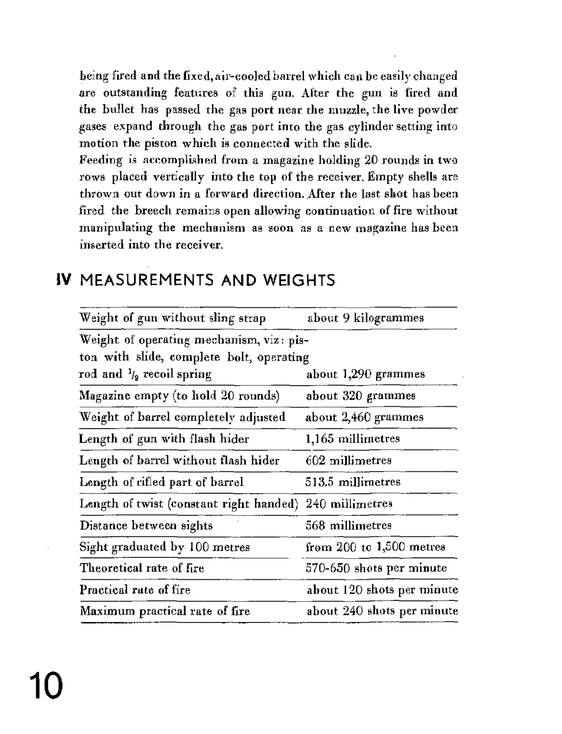
IV MEASUREMENTS AND WEIGHTS
Weight of gun without sling strap about 9 kilogrammes
Weight of operating mechanism, viz: pis-
ton with slide, complete bolt, operating
rod and % recoil spring about 1,290 grammes
Magazine empty (to hold 20 rounds) about 320 grammes
Weight of barrel completely adjusted about 2,460 grammes
Length of gun with flash hider 1,165 millimetres
Length of barrel without flash hider 602 millimetres
Length of rifled part of barrel 513.5 millimetres
Length of twist (constant right handed) 240 millimetres
Distance between sights 568 millimetres
Sight graduated by 100 metres from 200 to 1,500 metres
Theoretical rate of fire 570-650 shots per minute
Practical rate of fire about 120 shots per minute
Maximum practical rate of fire about 240 shots per minute
10
Weight of magazine filling machine about 525 grammes
Weight of live cartridge Mauser .,S'1 calibre 7.92 mm 24.6 grammes
Weight of 5 cartridges set in strip about 135 grammes
As light machine gun ZB 26 can be supplied to suit any kind of cur-
rent rifle ammunition, calibres 6.5 to 8 millimetres, several of the
above values had to be shown in approximate figures only,
V GENERAL DESCRIPTION
The barrel (10) surface of light machine gun ZB 26 is designed to
form circular cooling ribs. It has a spring-jointed, adjustable handle
with a wooden grip. The handle is mounted on the barrel by means
of a collar which allows it to be tipped around the barrel. This
handle facilitates easy and quick changing of the barrel, even when
hot, helps in quick transportation of the gnu and gives a firm grip of
the weapon during fire.
The surface of the rear end of the barrel is threaded, the thread being
three times interrupted to correspond to a similar arrangement in
the barrel locking nut (16). By lifting the barrel locking nut finger
the barrel is unlocked and comes easily out of the nut when pulled
forward. When inserting the barrel the operation is reversed.
On the front end of the barrel is mounted the gas deriver (33) with
front sight (18) and the flash hider (55). The gases which set the ope-
rating mechanism into motion pass through the gas port in the bar-
rel and the gas deriver canal into the gas cylinder tube (34) where
the gas impinges upon the head of the gas piston and drives it back-
ward.
On special order the barrel may be provided with a gas regulator by
which the gas port diameter can be adjusted and the quantity of gas
penetrating into the gas cylinder regulated, thus regulating the rate
of fire.
11
In the gas cylinder tube (34) moves a piston (32) which is joined to
the slide (23). The top side of the rear half of the slide has beveled
surfaces on which glide the lugs of the bolt (72) causing it to rise or
descend. The bottom of the slide is beveled in such a way as to per-
mit action of the trigger mechanism. Against the rear end of the slide
presses the operating rod (45) which transfers the backward move-
ment of the elide to the recoil spring (135) compressing it, and trans-
fers the accumulated force of the recoil spring (135) to the slide when
the latter moves forward.
The front end of the bolt forms a bed for the base of the cartridge.
Into this bed engages a spring-loaded extractor (64). In the center of
the bed is a small hole for the point of the firing pin (68). This point
is dull.
The inner surfaces of the walls of the receiver (42) serve as guides to
the breech mechanism. An opening is cut in the top of the receiver
to admit the mouth of a magazine, which is hooked into place and
secured by a spring magazine catch (66). The bottom of the receiver
has an opening through which the empty cartridge cases are ejected.
Both openings can be closed by sliding dust covers.
The rear sight is dovetailed into the left side wall of the receiver.The
rear sight bracket (13) into which the sighting notch is cut turns on
a pivot, tire desired position being obtained by means of a spiral
shaped cam (57) m oved by the range drum (3) to which it is solidly se-
cured. The outside surface of the range drum (3) bears range scale
figures which appear large and distinct through an opening cut in the
rear sight housing.
The trigger guard (41), in one group with the trigger guard piece (50)
and the butt stock (31), is joined to the receiver by 2 trigger guard
pins (5). The trigger gnard (41) houses the trigger mechanism which
is designed to allow automatic or single fire as well as “safety*,
When the rear trigger guard pin (5) is pushed out, it is possible to
fold down the trigger gnard together with butt stock, pivoting on the
front trigger guard pin (5). In this position the bolt mechanism can
12
Method of stripping breech mechanism
со
easily be removed, If both trigger guard pins are pushed out,the trigger
guard (41) together with the butt stock can be stripped from the re-
ceiver.
To the trigger guard is attached the butt stock (31) which houses the
spring tube (56) with the recoil spring (135). The bottom of the butt
stock is enclosed in a spring butt plate (2) which carries an adjustable
shoulder piece (47).
About the middle of the gas cylinder tube is attached the bipod which
has legs of telescopic design permitting adjustment to suit any irre-
gularities of the ground. During transport the legs are folded against
the gas cylinder tube.
VI GENERAL ACTION
Forward movement:
Before firing the first shot, the gun is cocked by pulling the operating
handle (49) hackward until the sear (52) engages on the slide. When
trigger (51) is pulled, the sear declines and releases the slide (23),
which is forced forward by the operating rod (45) set into motion by
the recoil spring (135). As the bolt (72) carried on the slide moves
forward, the lug on its upper part strikes the back of the next cartridge
in the magazine and strips it out and into the chamber. The extractor
(64) engages on the rim of the base of the cartridge.
Towards the end of the forward movement of the slide the bolt rises
on the beveled lugs of the slide, comes to a gradual stop and becomes
locked between the rear end of the barrel and the bolt locking plate
(28). The bolt is completely locked but tire slide continues forward;
its hammer strikes the firing pin (68) and primes the cartridge.
Backward movement:
When the charge explodes and the bullet passes the gas port near the
muzzle, the expanding powder gases pass through the gas port in the
barrel and the canal of the gas deriver (33) into the gas cylinder (34).
14
These gases impinge upon the head of the gas piston, which drives the
mechanism backward effecting the unlocking of the holt, opening of
lhe breech and extraction of the empty sheik The empty shell being
held by the extractor (64) is drawn from the chamber with the bolt
and remains in its face until its side strikes the ejector (63), when it
is thrown out through an opening in the bottom of the receiver. The
energy of the rearward movement of the breech mechanism accumu-
lates in the recoil spring, compressing it. Whentherearward movement
has been arrested the accumulated energy of the recoil spring starts to
act and forces the mechanism to repeat the forward movement,
After the last cartridge has been fired the mechanism remains open
and in its cocked position which allows immediate continuation of
fire as soon as a new magazine has been inserted into the receiver.
The above describes the action of the gun during automatic fire. If
the safety catch (37) is set into position for single fire, the breech me-
chanism is arrested by the sear (52) in its cocked position after each
shot so that it is nece.ssaryto release and pull the trigger to fire a new
shot.
If the safety catch (37) is set to “O’ (safe) the trigger does not engage
on the sear and the gun cannot be fired.
filling machine, folded
VII MAGAZINE AND MAGAZINE FILLING MACHINE
The magazine far light machine gun ZB 26 is de.signed to hold 20
rounds in two rows. This magazine contains a zigzag shaped plate,
spring, one end of which is fixed to the bottom plate of the magazine
On its other end the spring carries a follower which forces die cart-
ridge against the lips of the magazine tube and holds it in place until
stripped out by the lug on the top of the bolt
The magazines'are filled by a crank-operated filling machine made
of silumine.
Method of filling magazine
16
Method of changing barrels
ZB 26 stripped for cleaning
VIII DISMOUNTING AND ASSEMBLING
Tbe gun can be dism о Tinted and assembled with great ease and rapidity,
its construction being such that the parts are combined into assembling
groups. Such design not only facilitates dismounting of the gun but
also diminishes danger of loss of small parts. Partial dismounting and
assembling of the gun for cleaning can be accomplished with a cart-
ridge. Complete dismounting necessitates the use of a special combi-
nation wrench, Stripping of the gun for cleaning purposes and making
it ready for fire are so simple that they can easily be accomplished
even in complete darkness.
IX SPECIAL EQUIPMENT
If desired, the gun may be provided with the following additional
equipment which will considerably increase its utility1, viz: third leg
traversing mechanism, anti-aircraft sight and tripod.
The telescopic third leg which can be inserted into the butt stock is
found very convenient when it isdesired to keep tbe range undisturbed
during fire. By manipulating the grip of the third leg different
elevations are obtained. The traversing median ism on which the third
leg glides permits application of swinging traverse fire. The desired
width of traverse is adjustable by two stops.
An anti-aircraft sight can easily be attached to this gun.
A tripod can be supplied with this light machine gun to be used either
for normal or anti-aircraft fire.
X PRINCIPAL ADVANTAGES
The gas port is situated near the muzzle and the action of the gases
on the piston begins only when the bullet has left the rifled pare of
the barrel. This eliminates the danger of having 2 bullets in the barrel.
Tire changing of a hot barrel for a fresh one requires only 2 seconds
ao that continuity of fire does not suffer.
19
Telescopic third (rear) teg
The gun is superior to all other light machine guns of its type in the
ingenious simplicity of its design and only the best materials are used,
guaranteeing a high durability of all parts.
No manipulating of the operating handle during fire being necessary
and the feeding arrangement being very simple, a high practical rate
of fire can be obtained. The construction of light machine gun ZB 26
is such that it will fire even if the mechanism is not lubricated or is
dirty, a feature which makes it suitable for even the worst conditions
of service in the field,
20
ZB 26 with anti-aircraft sights mounted
The training of gunners does not require much time as the handling
of the gun is not complicated.
The factory guarantees absolute interchangeability of all parts, which
can he effected without any adjustments.
XI MANUFACTURE OF LIGHT MACHINE GUN ZB
Each part is carefully controlled during the process of its manufacture
and after its completion it must pass a severe control for size and
thermal treatment at the central control department of the factory.
The factory guarantees that only guns assembled of parts in every
respect perfect and fully interchangeable leave its Works.
NOTE
As it is necessary that the spiral shaped cam be adjusted to the
characteristics of ammunition and atmospheric conditions of different
countries, it is requested that buyers when ordering light machine
guns ZB supply the following inform a tion: muzzle velocity and pressure
of ammunition, average barometric pressure, average humidity and
average atmospheric temperature in the country of destination.
The factory will adjust the spiral shaped cam accordingly,
22
Printed by Obchxjdnicka tiak^ina, В1апвко, CeechualovaUia.