/


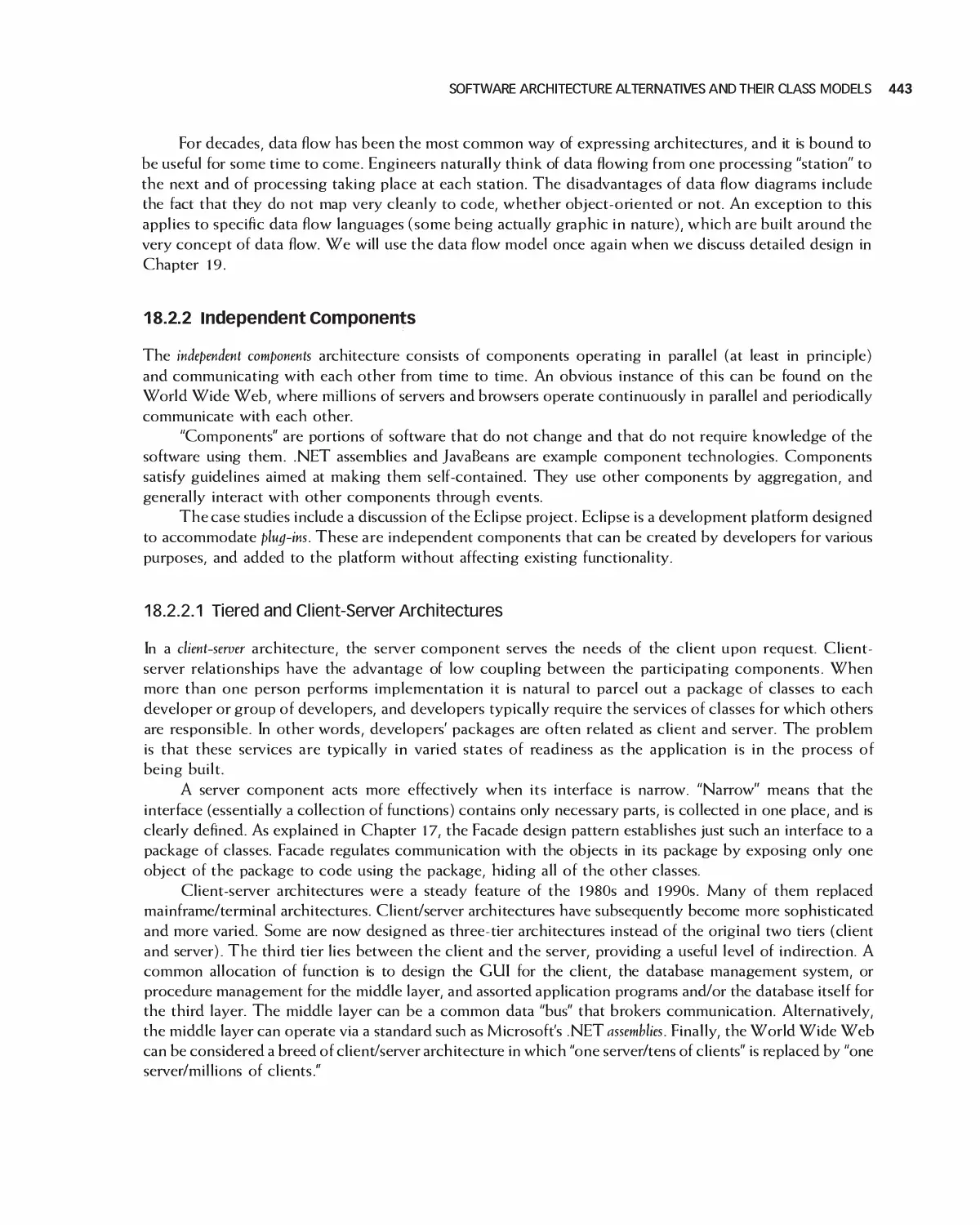


Автор: Braude E. J. Bernstein M. E.
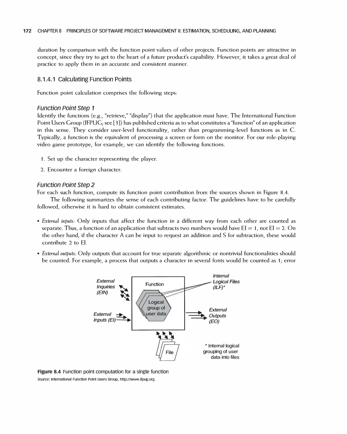
Теги: programming computer science approaches waveland press software engineering
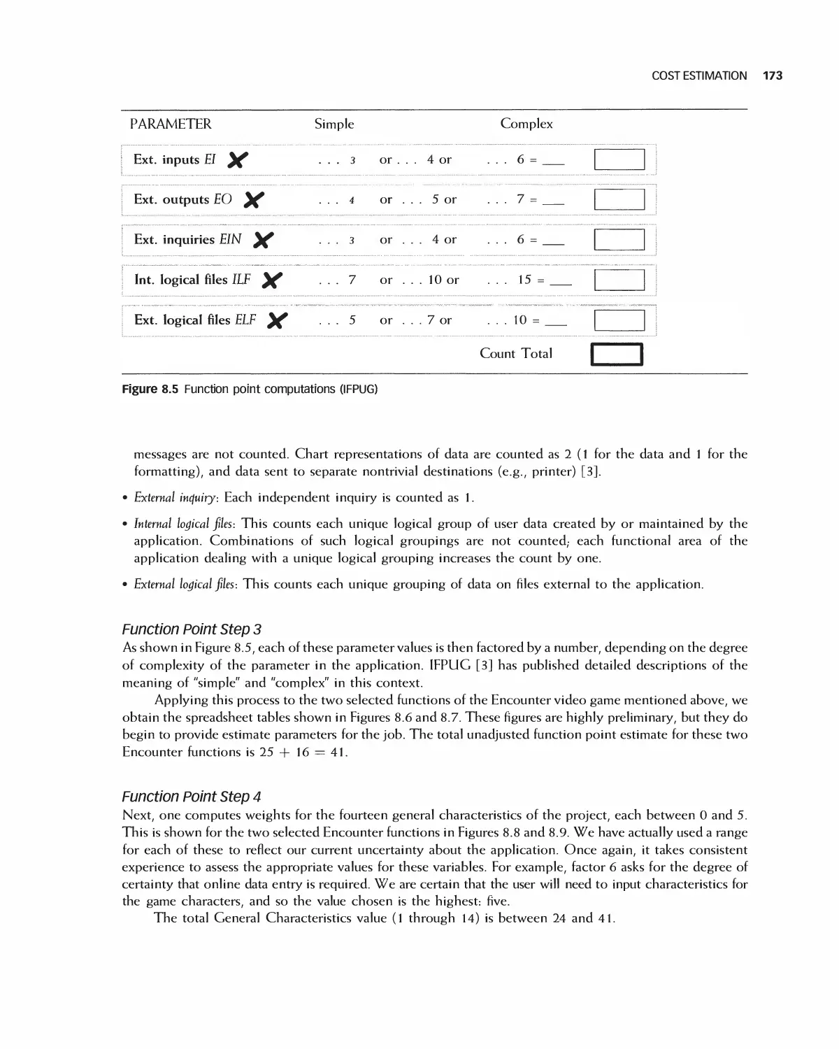
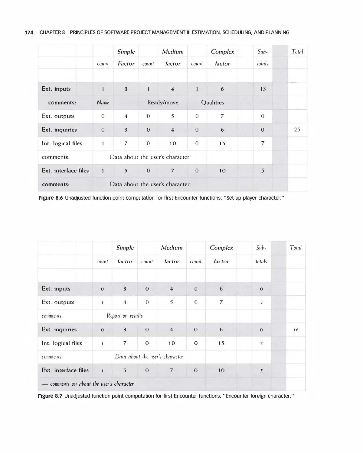
ISBN: 1-4786-3230-5
Год: 2016
Похожие


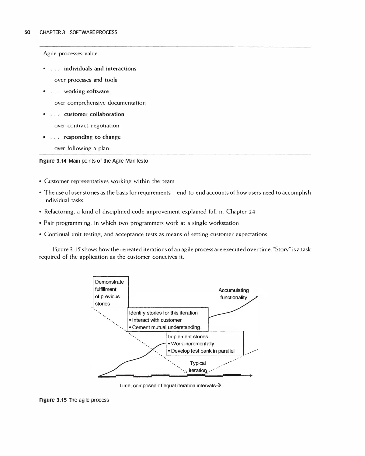
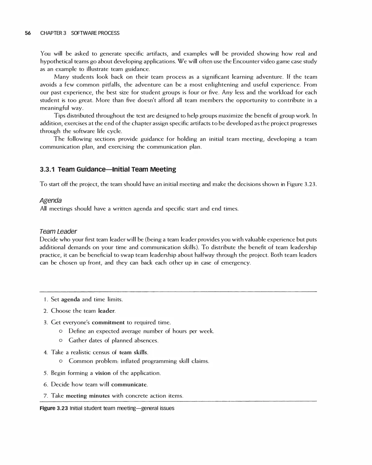
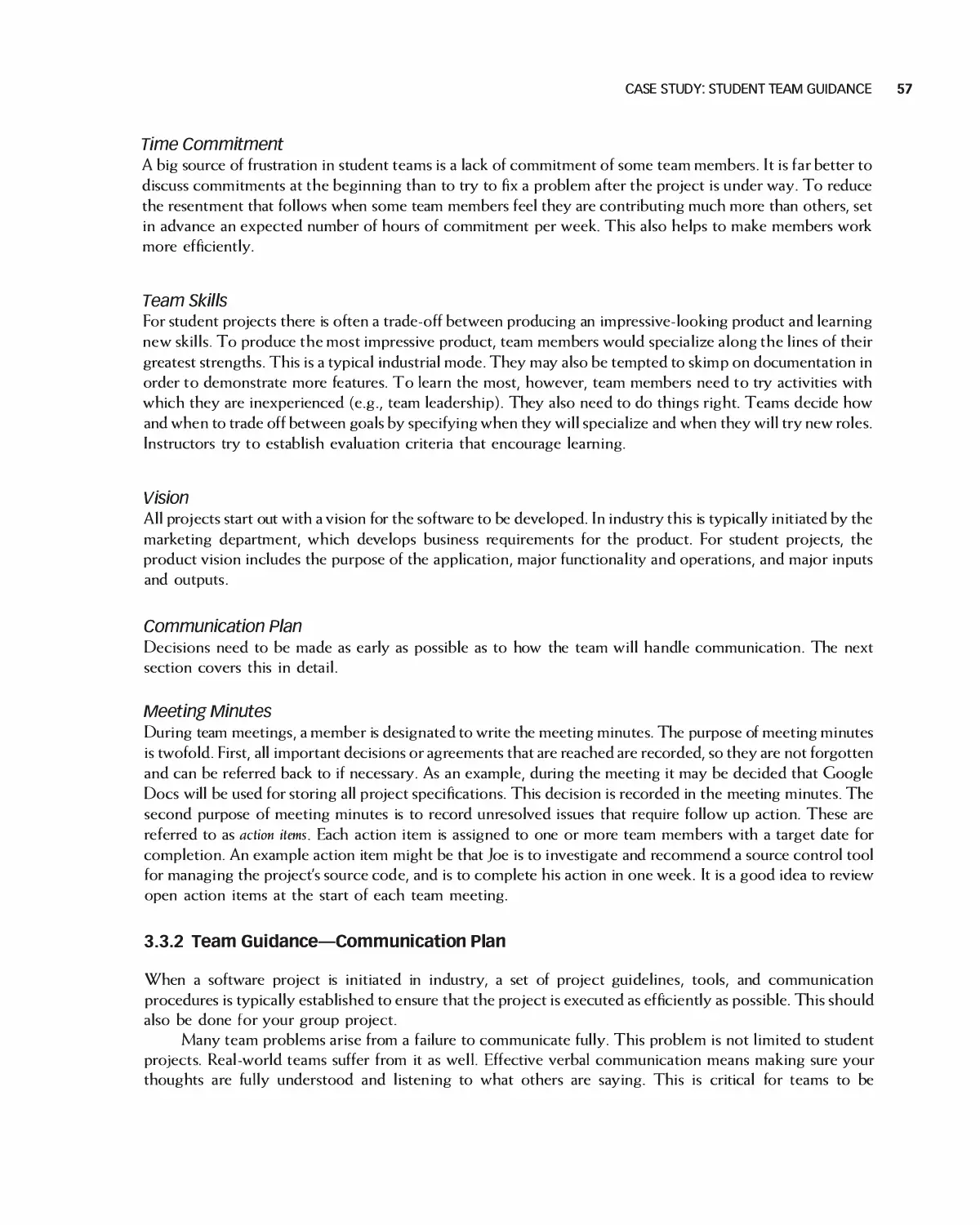
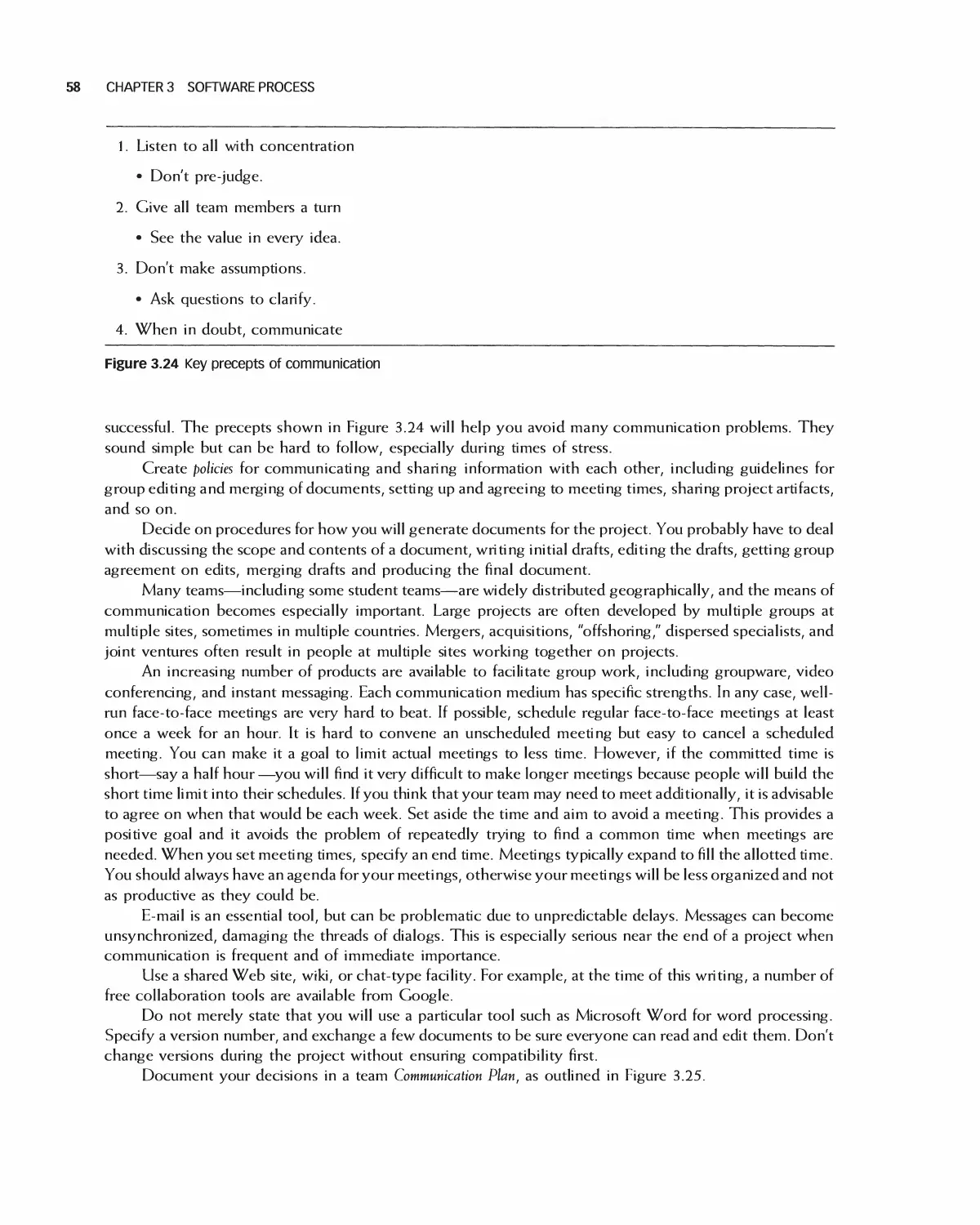
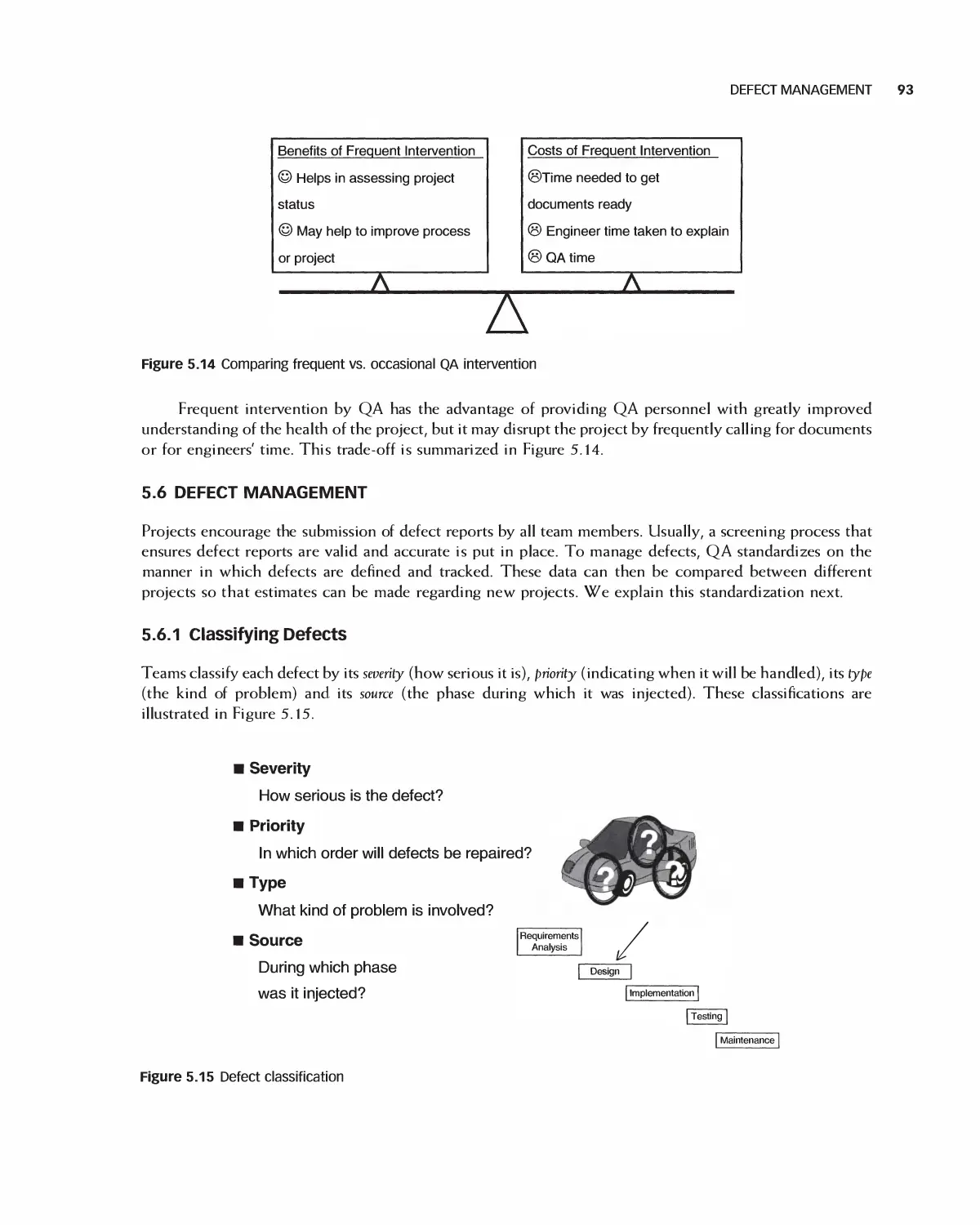
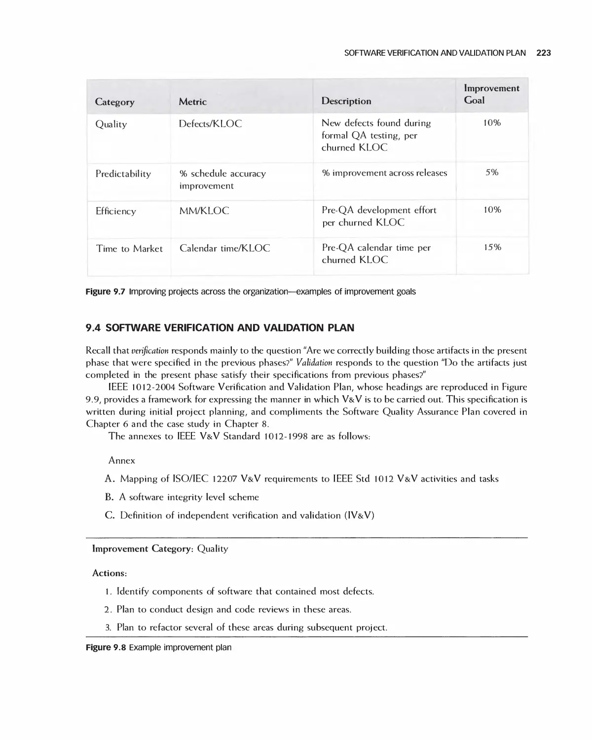
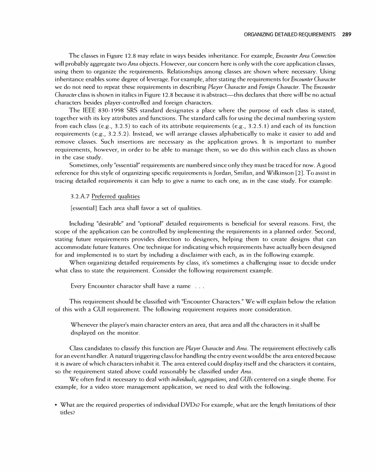
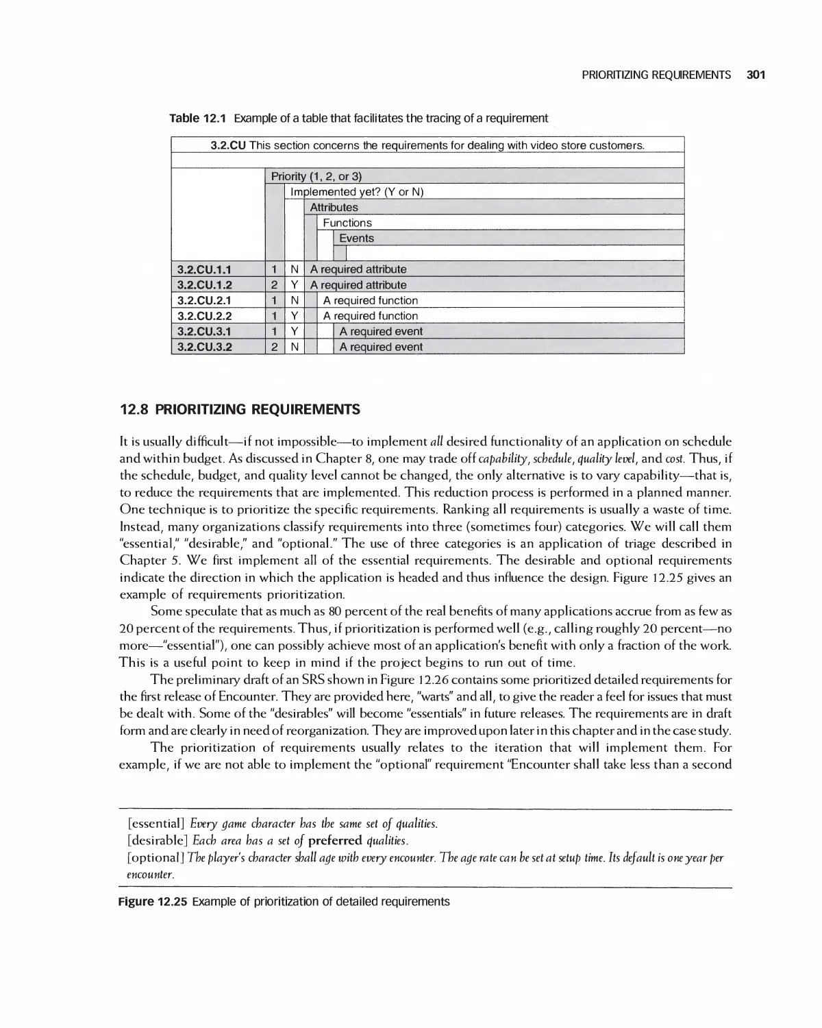
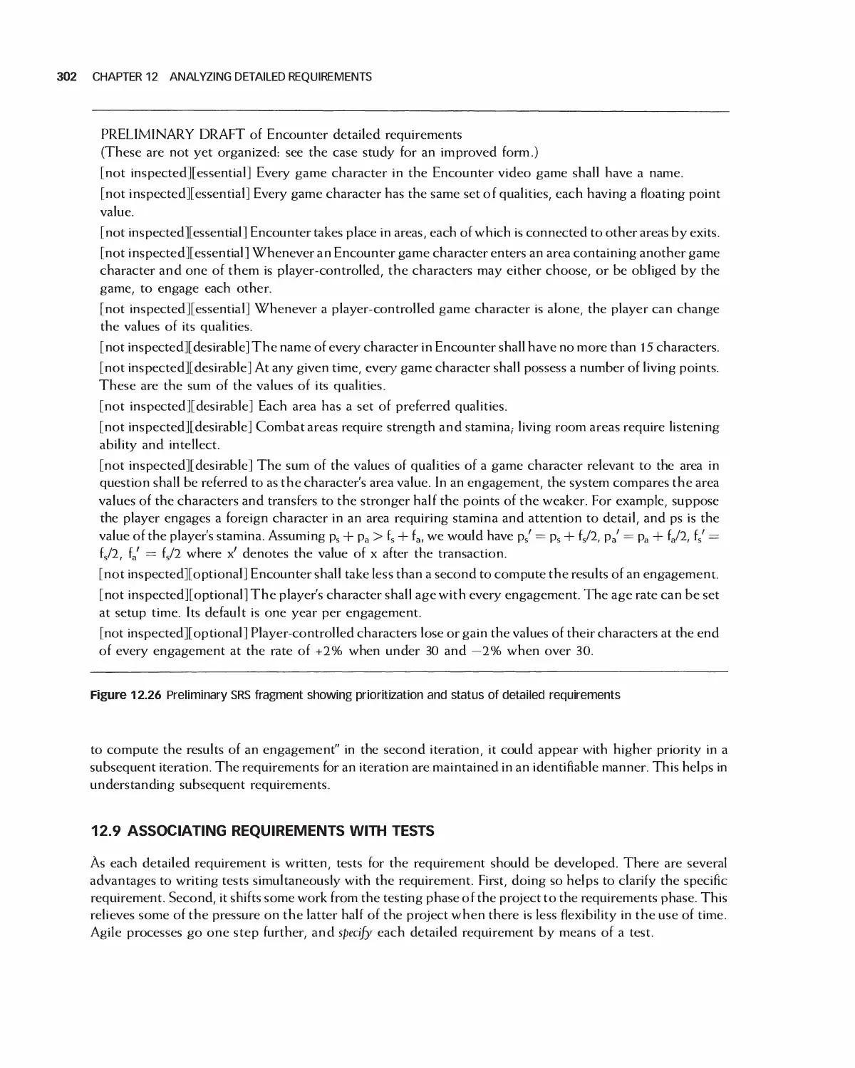
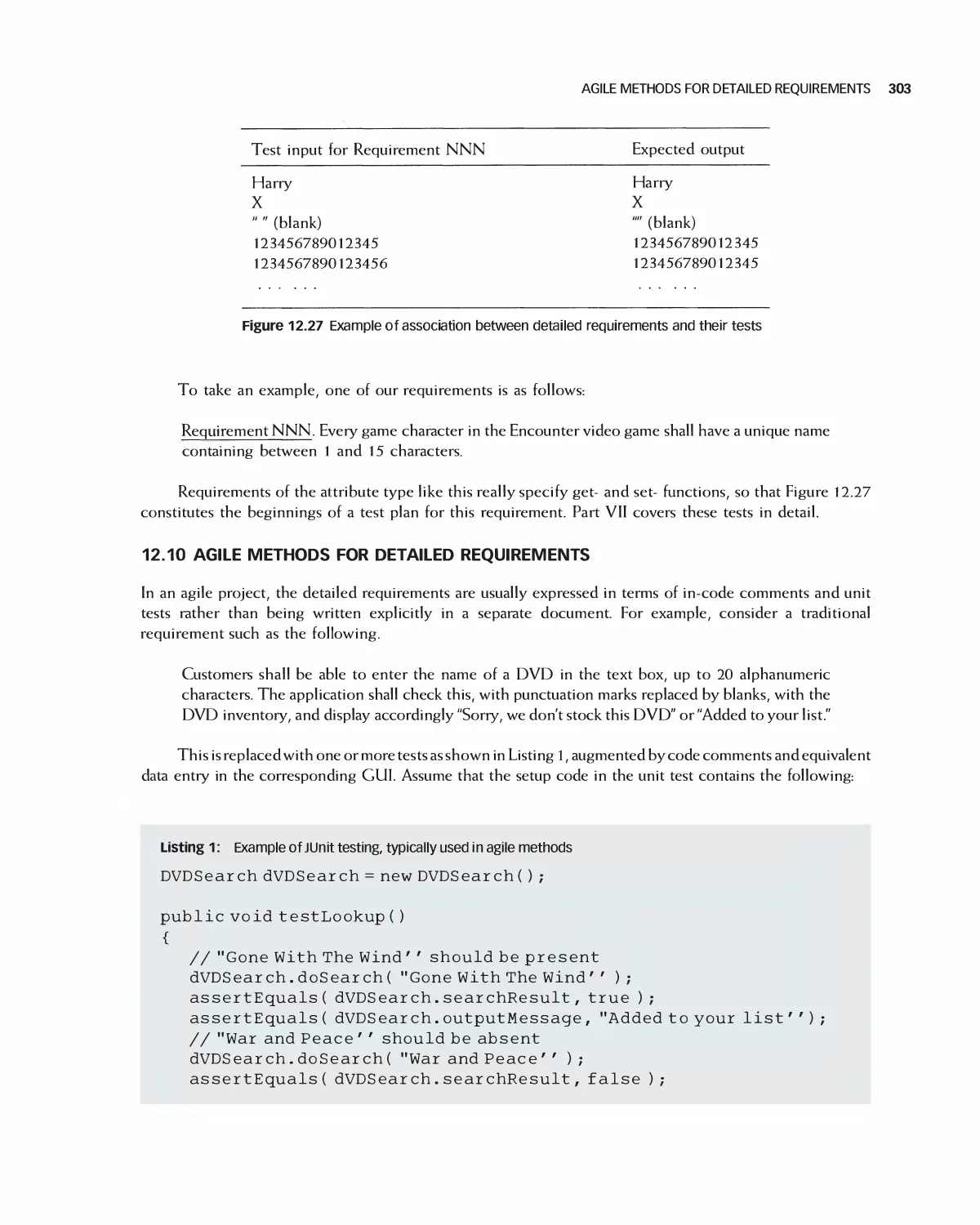
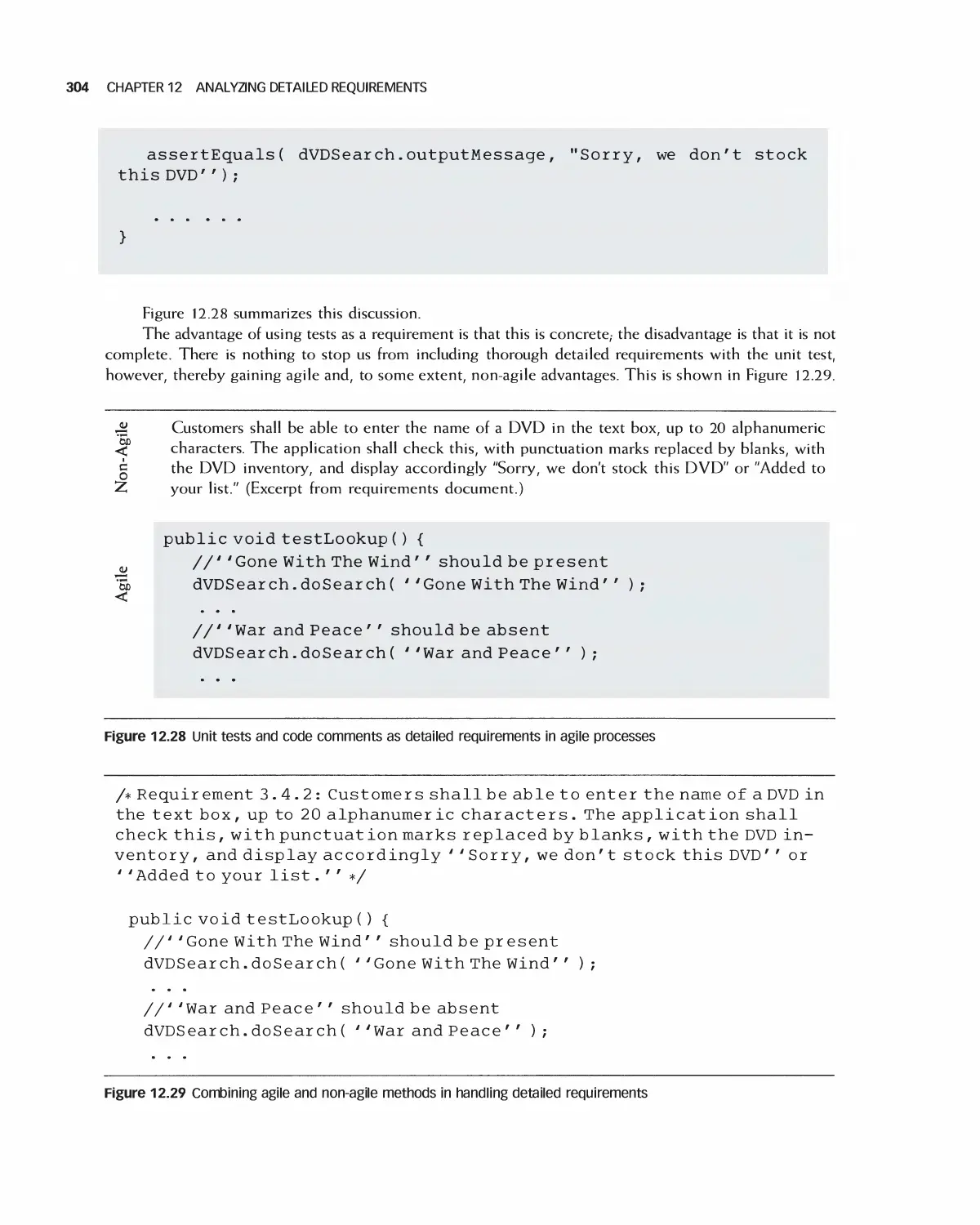
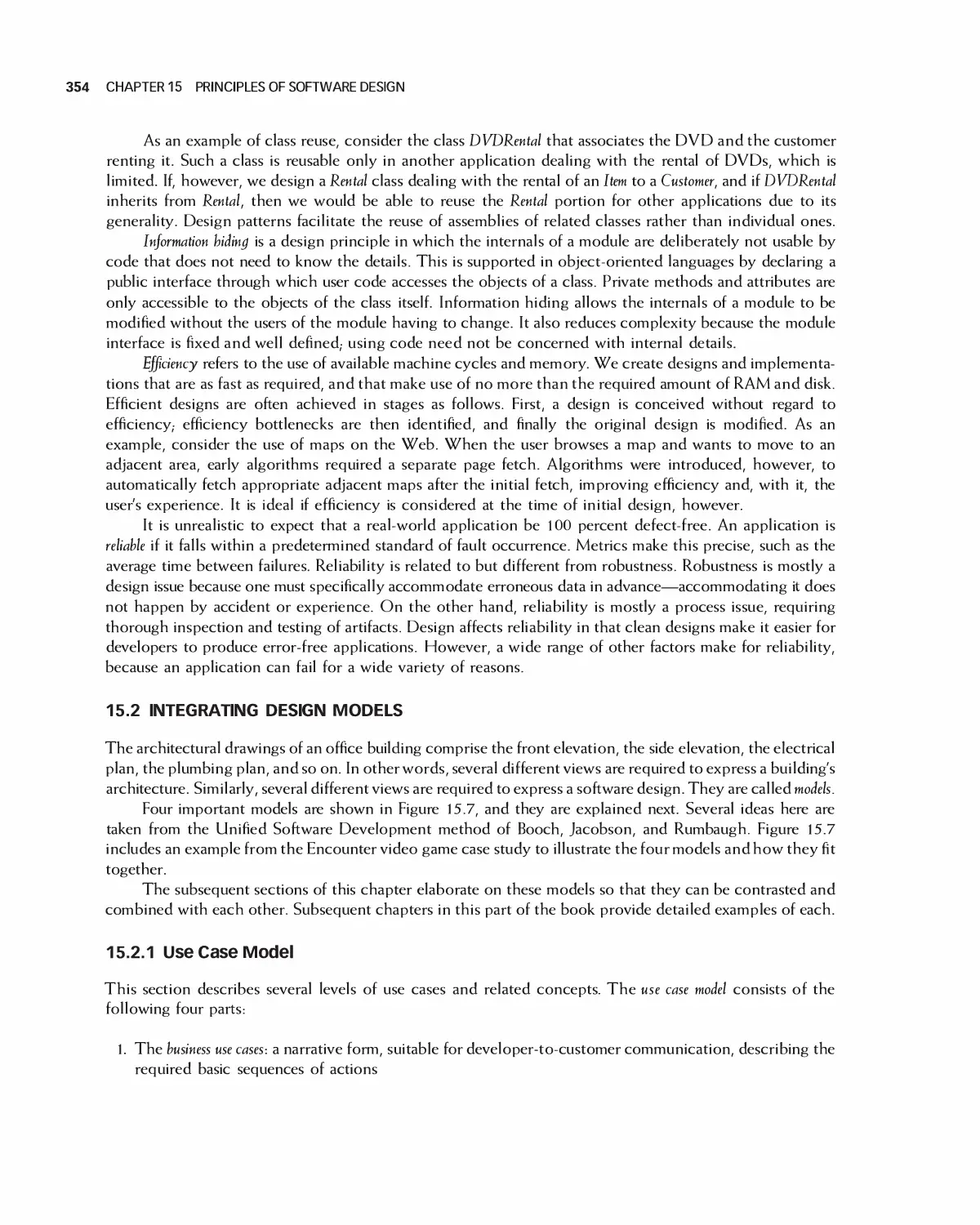
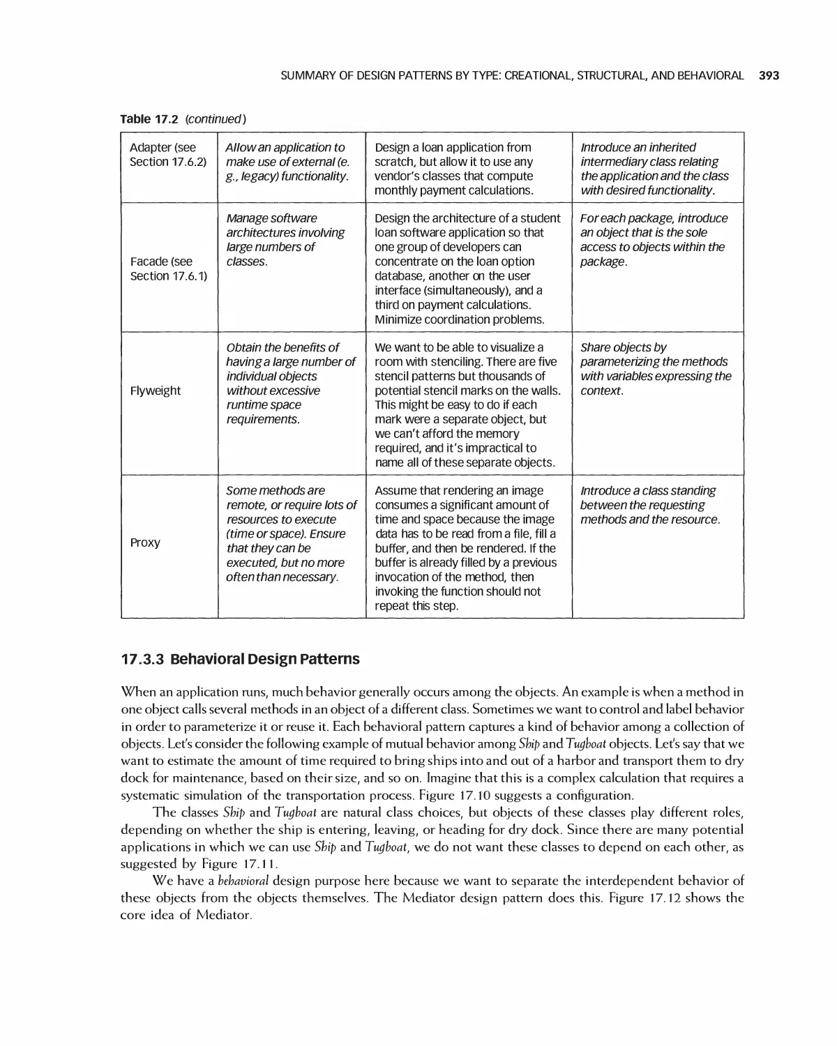
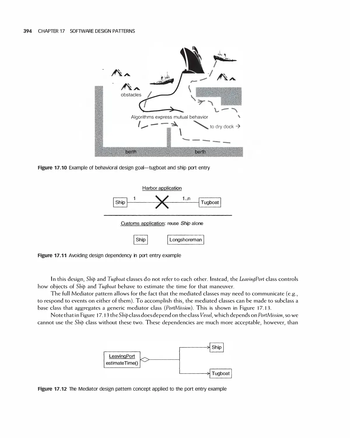
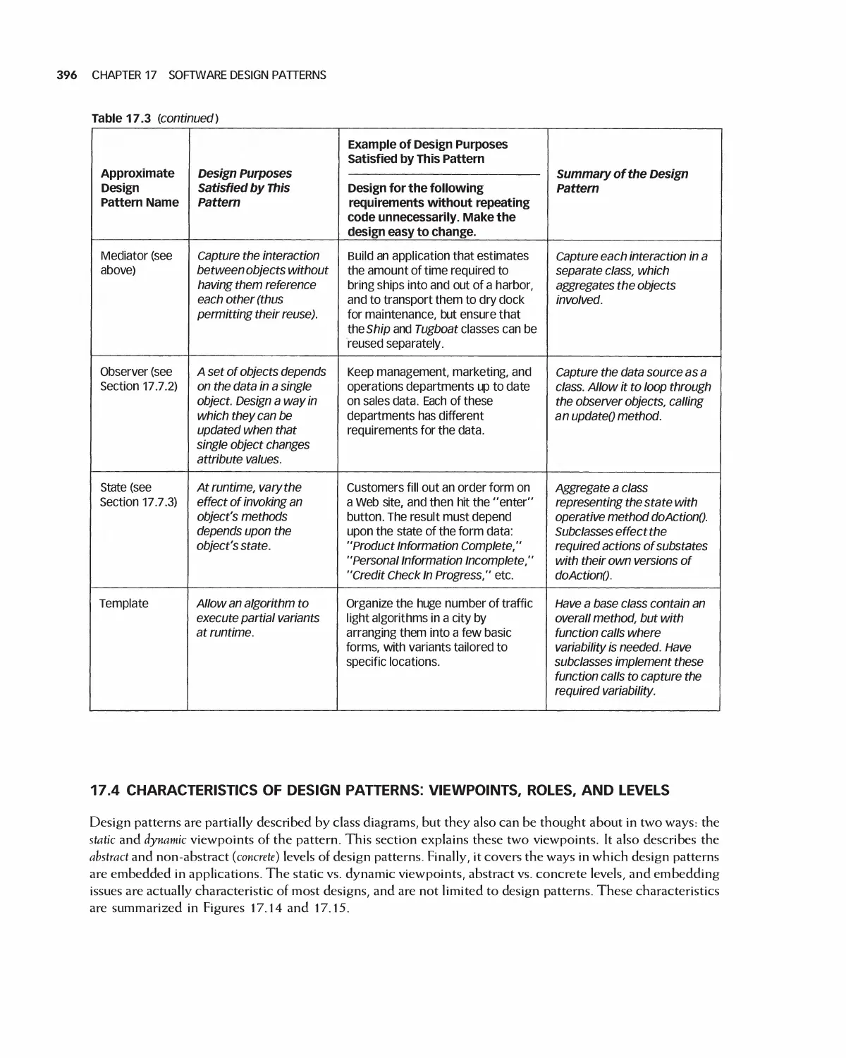
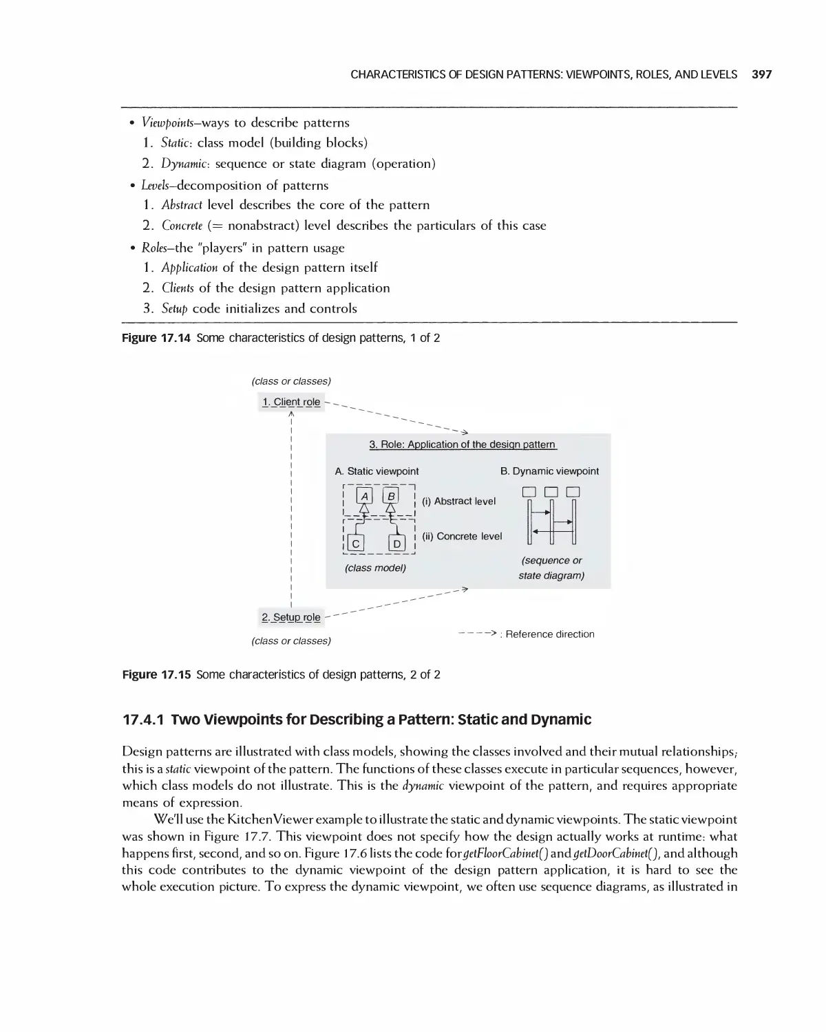
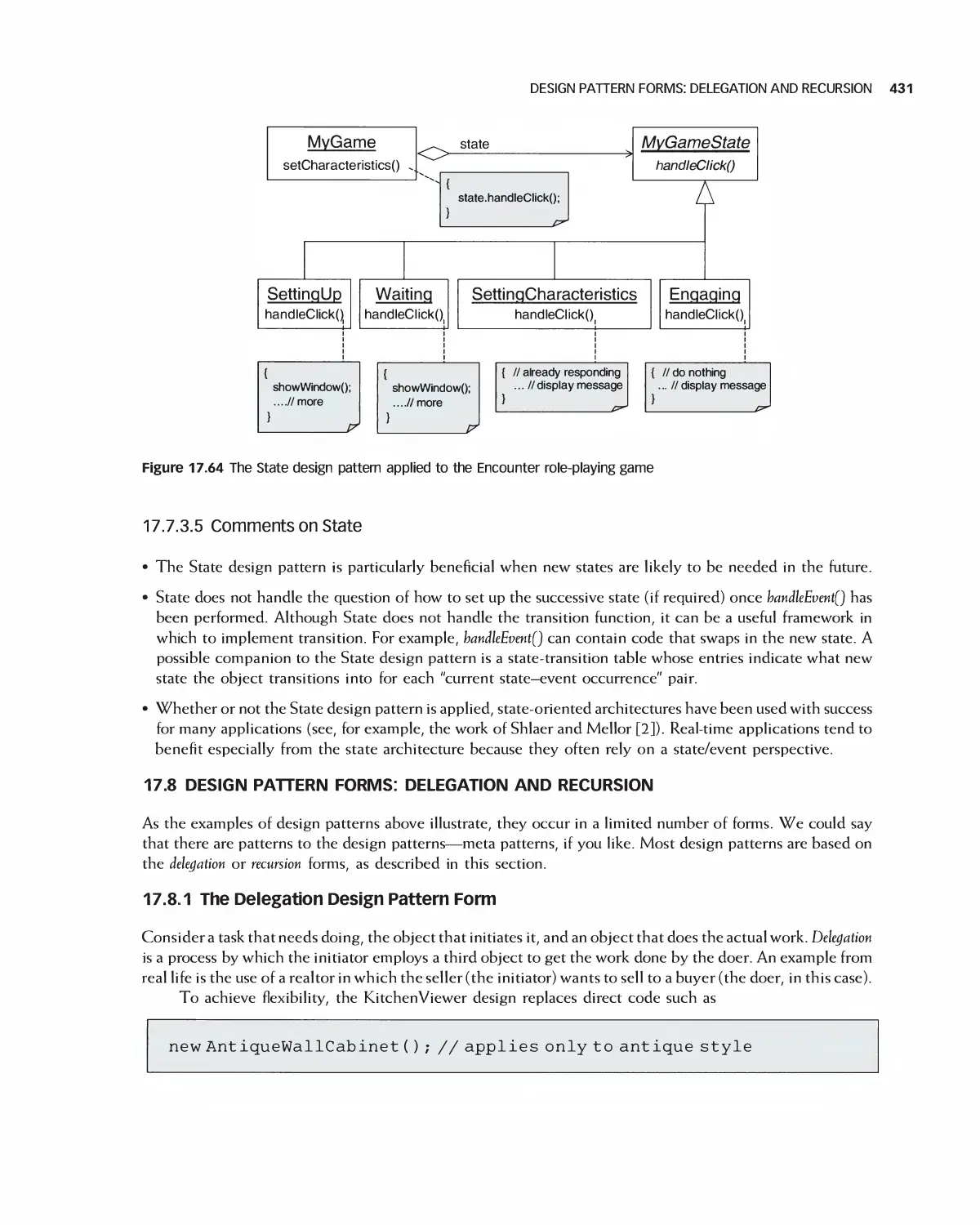
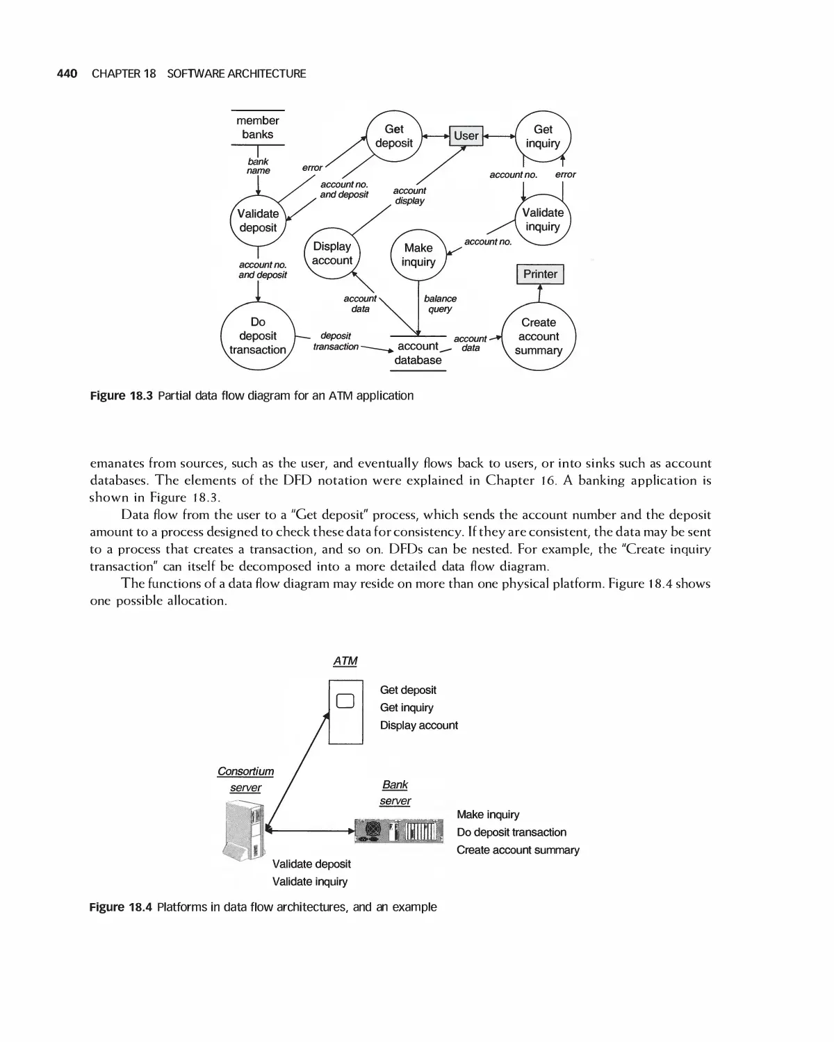
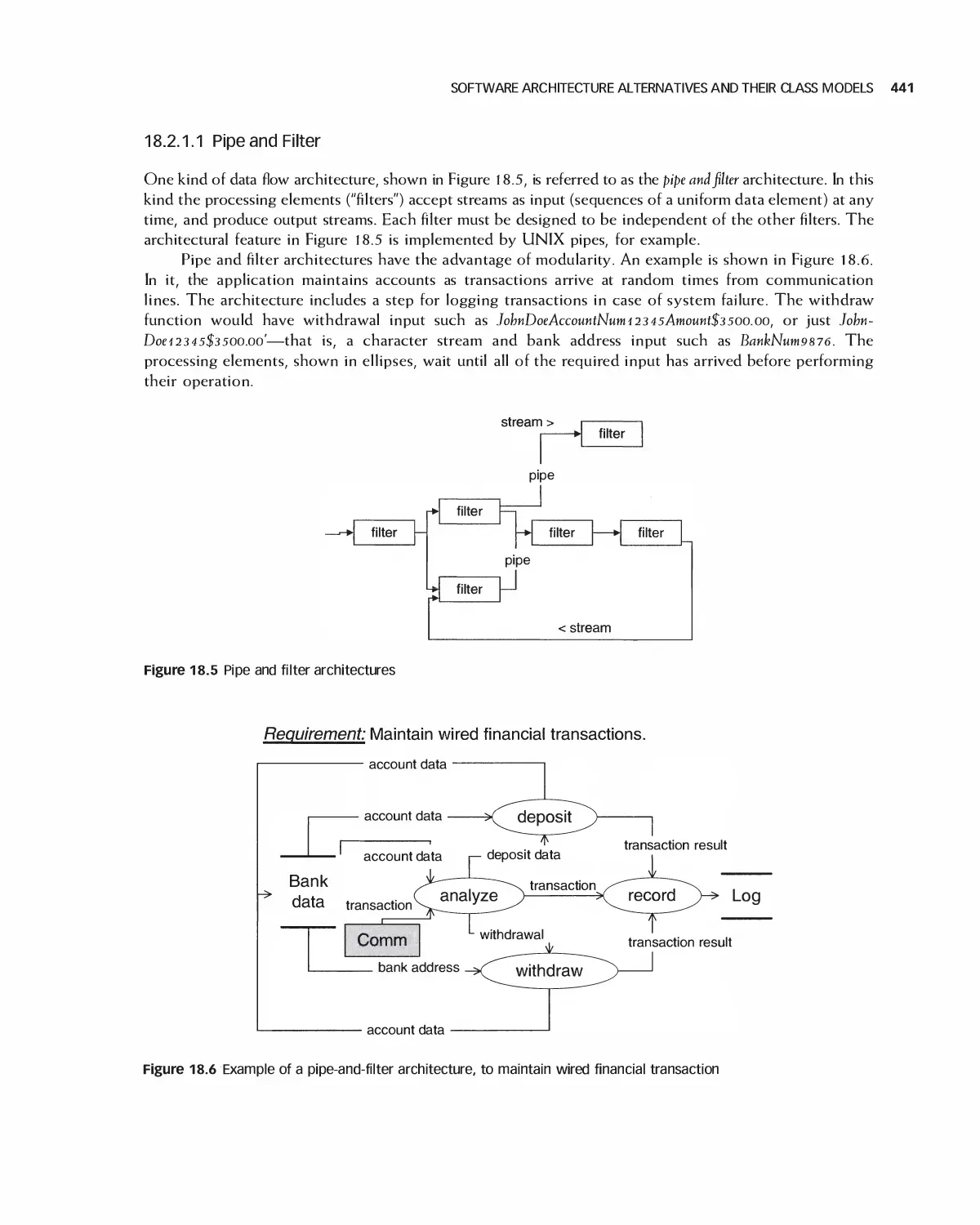
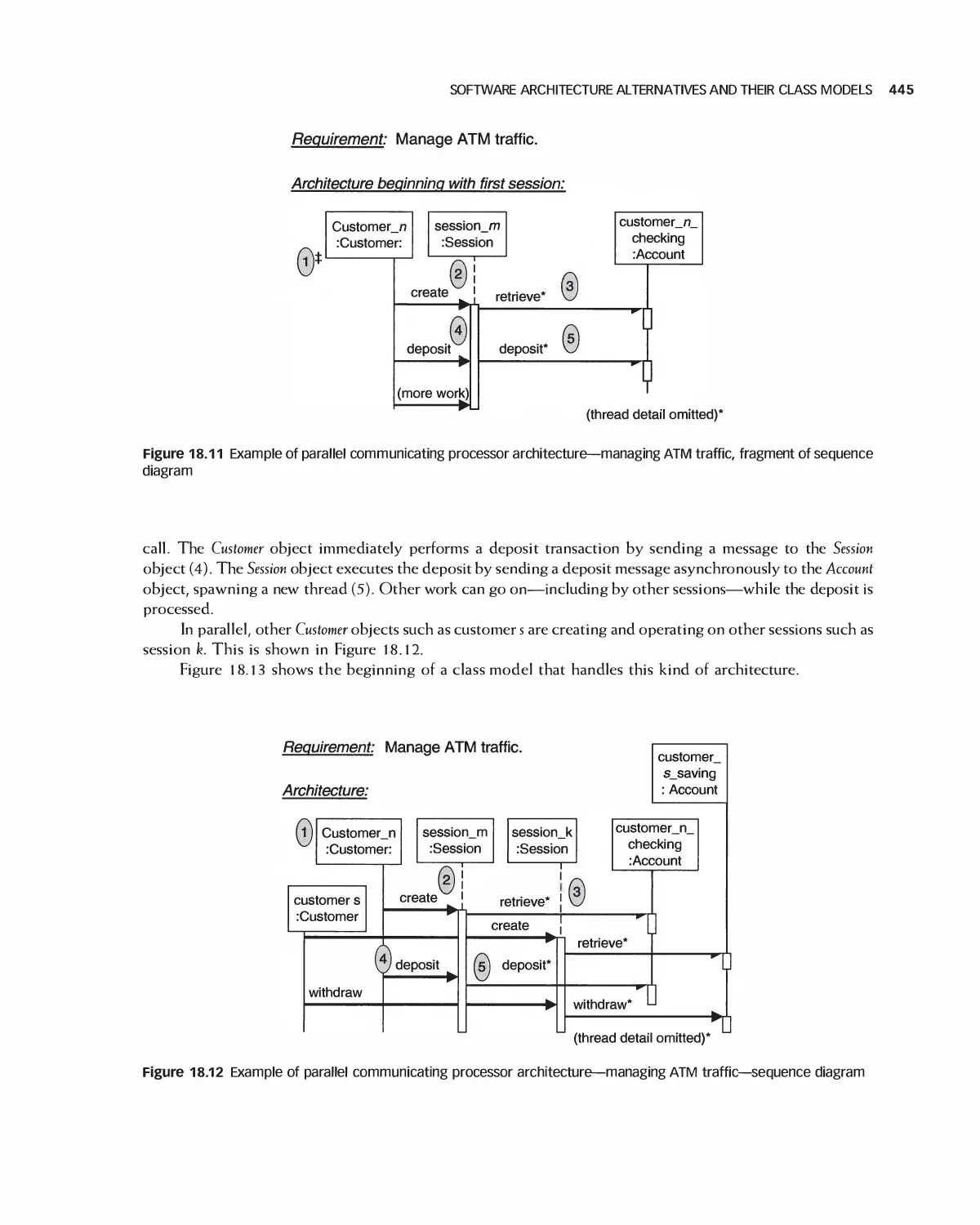
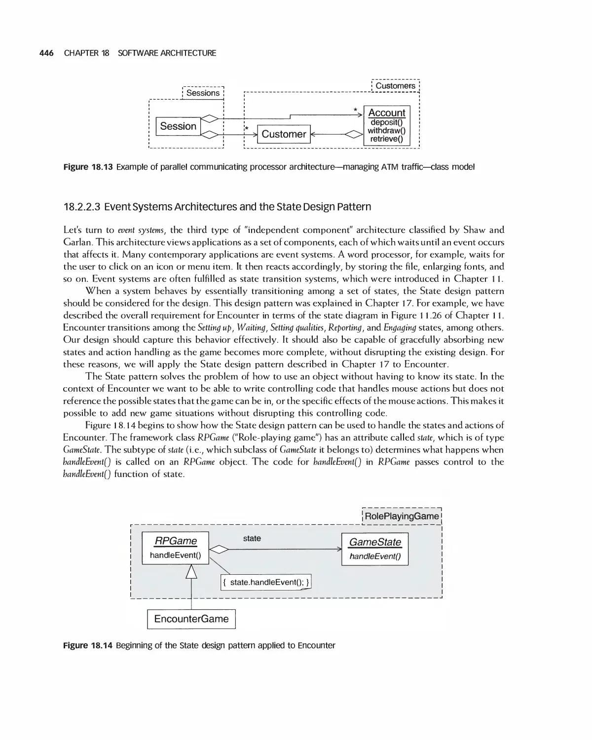
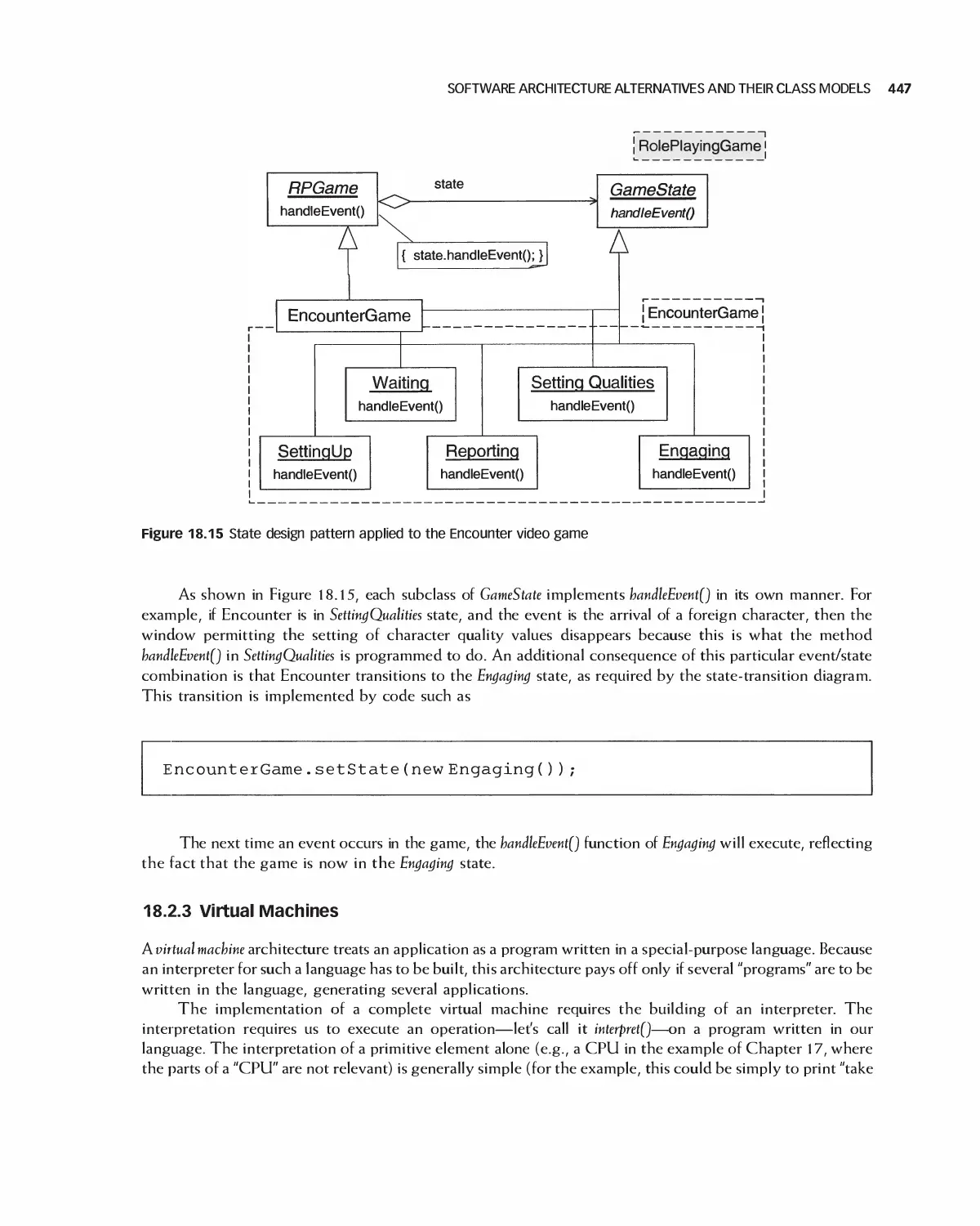
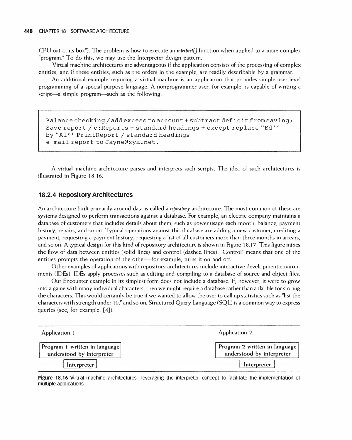
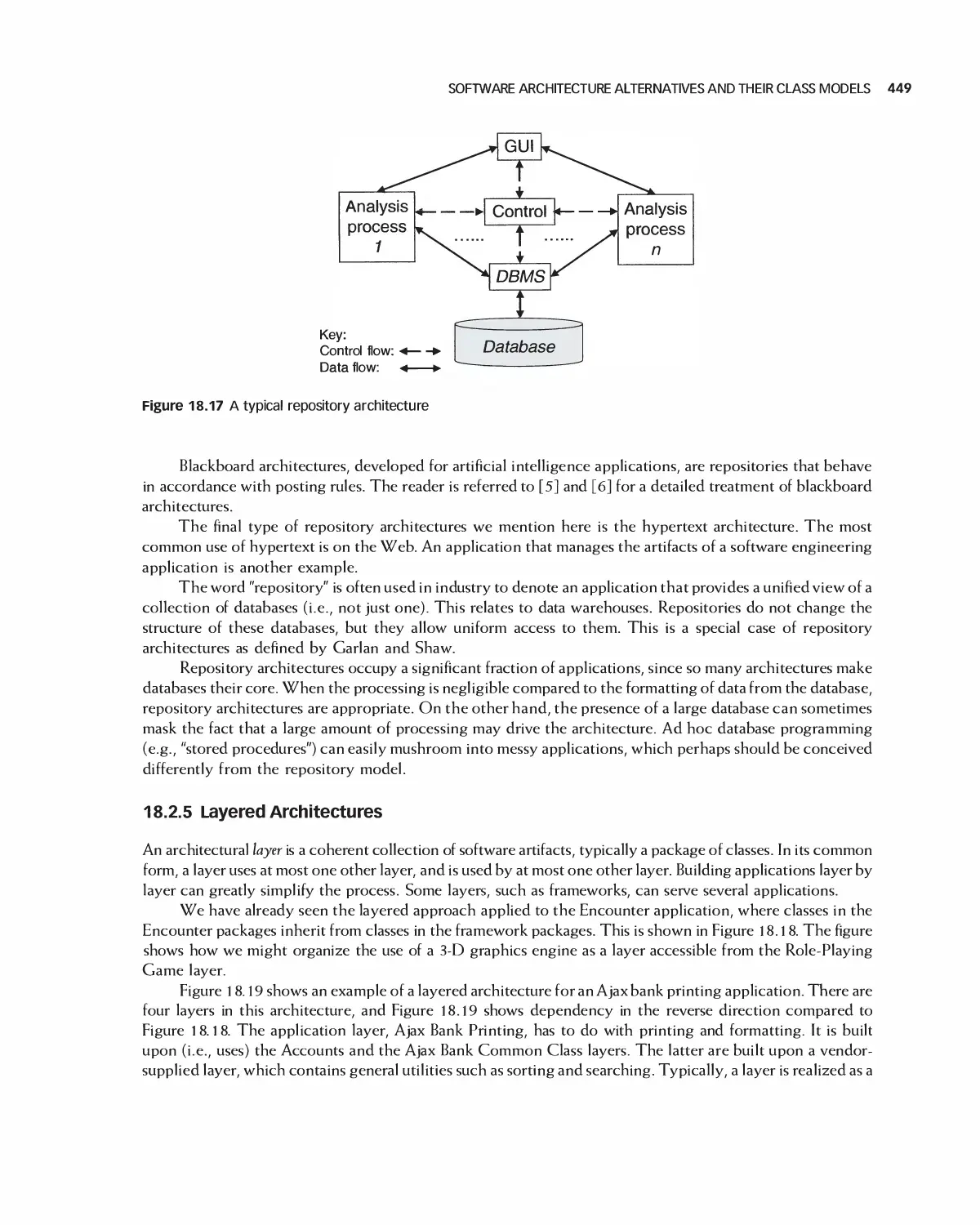
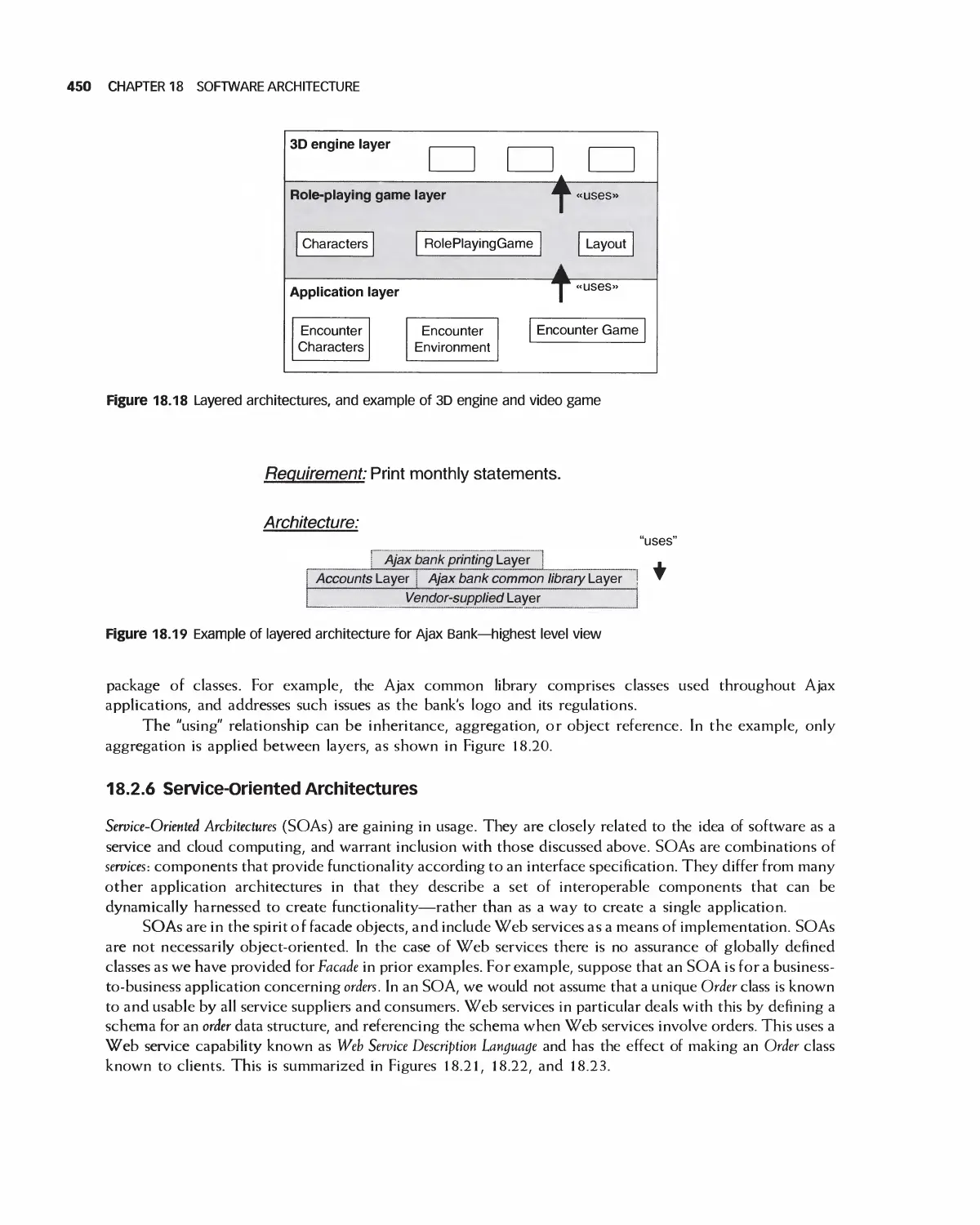
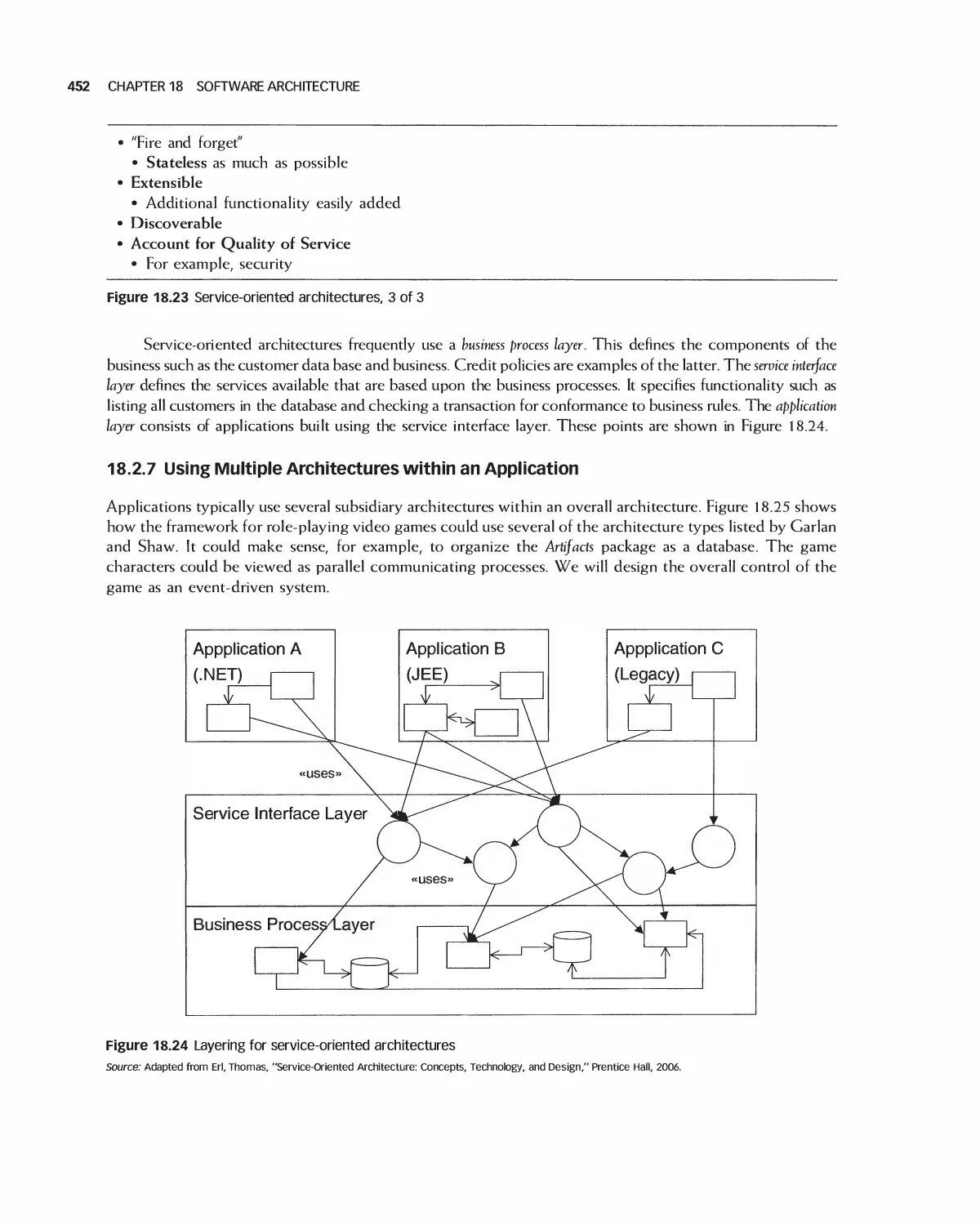
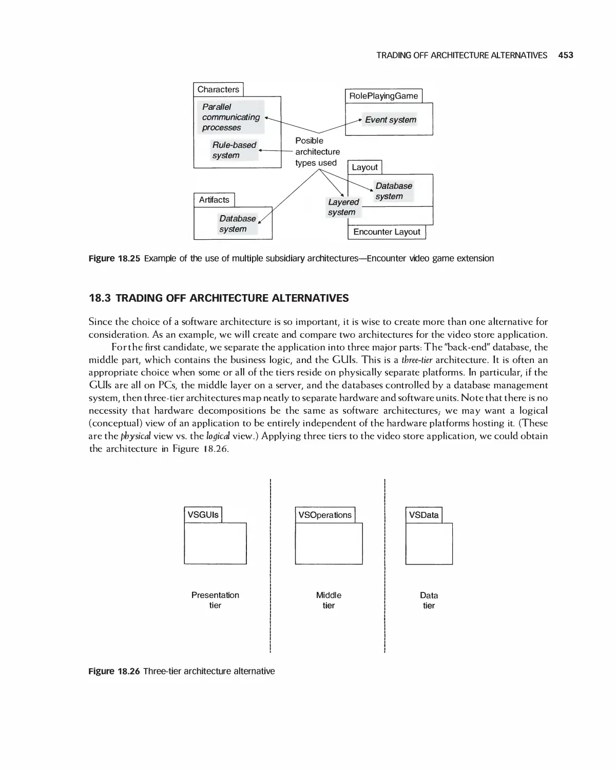
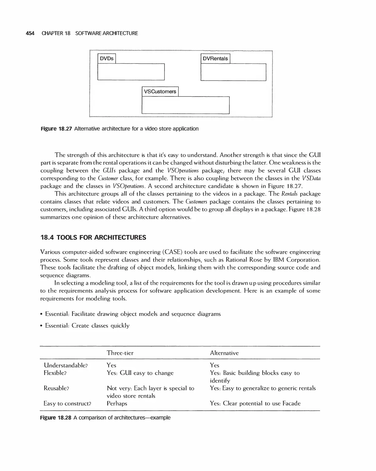
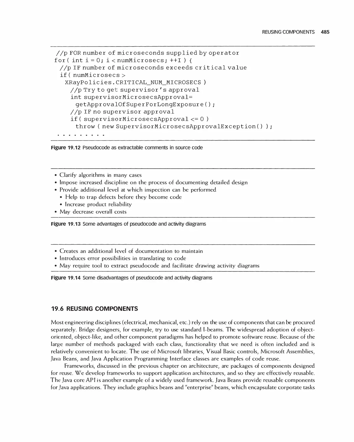
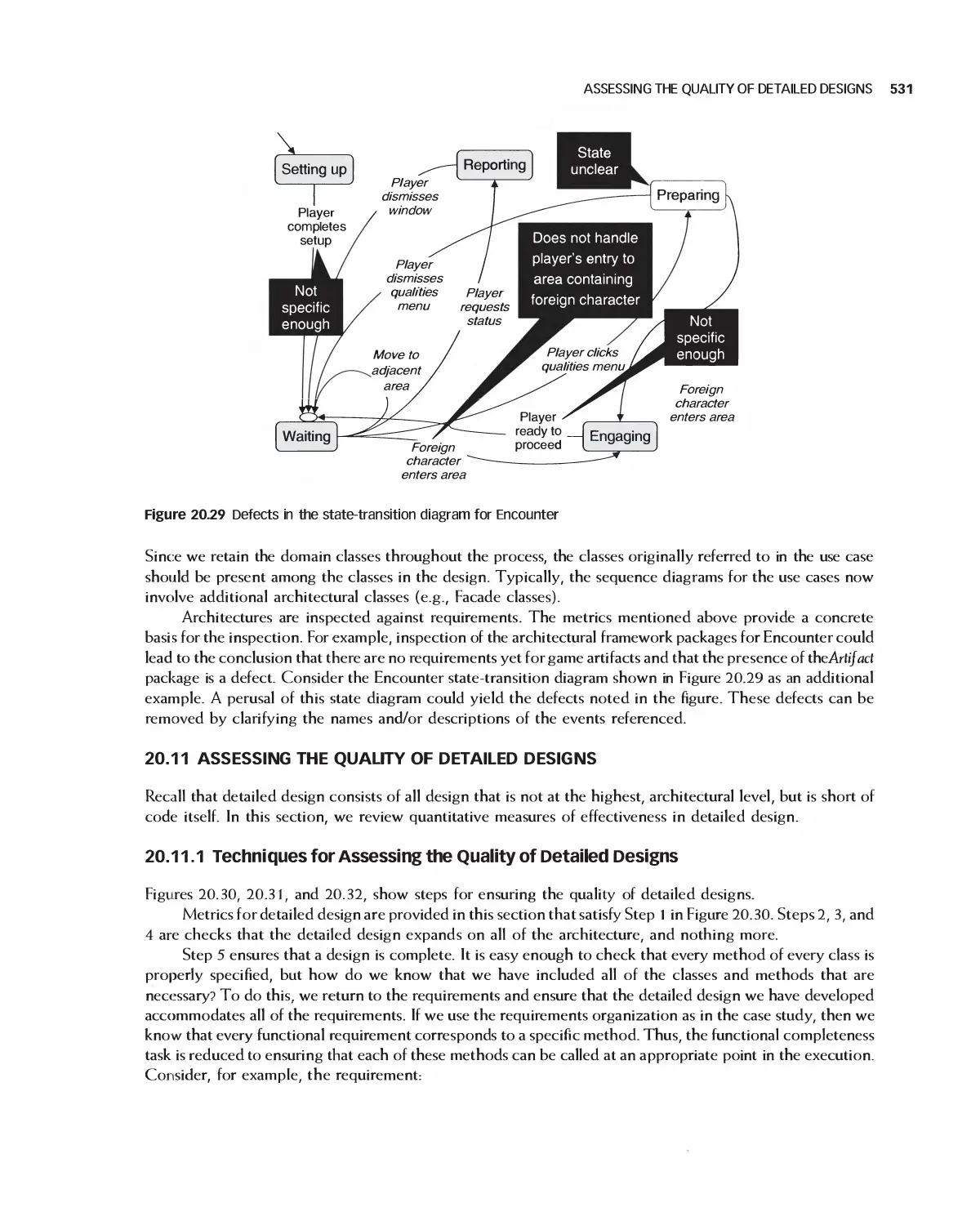
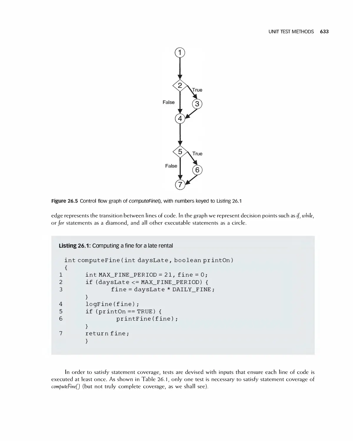
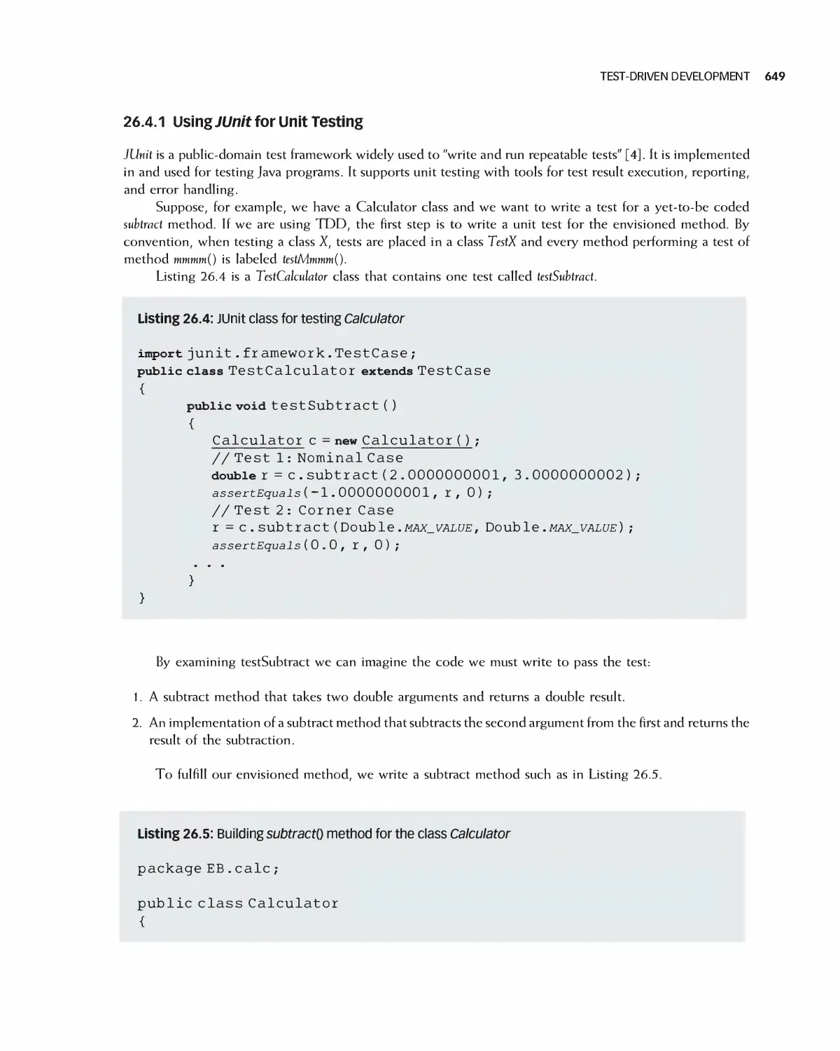
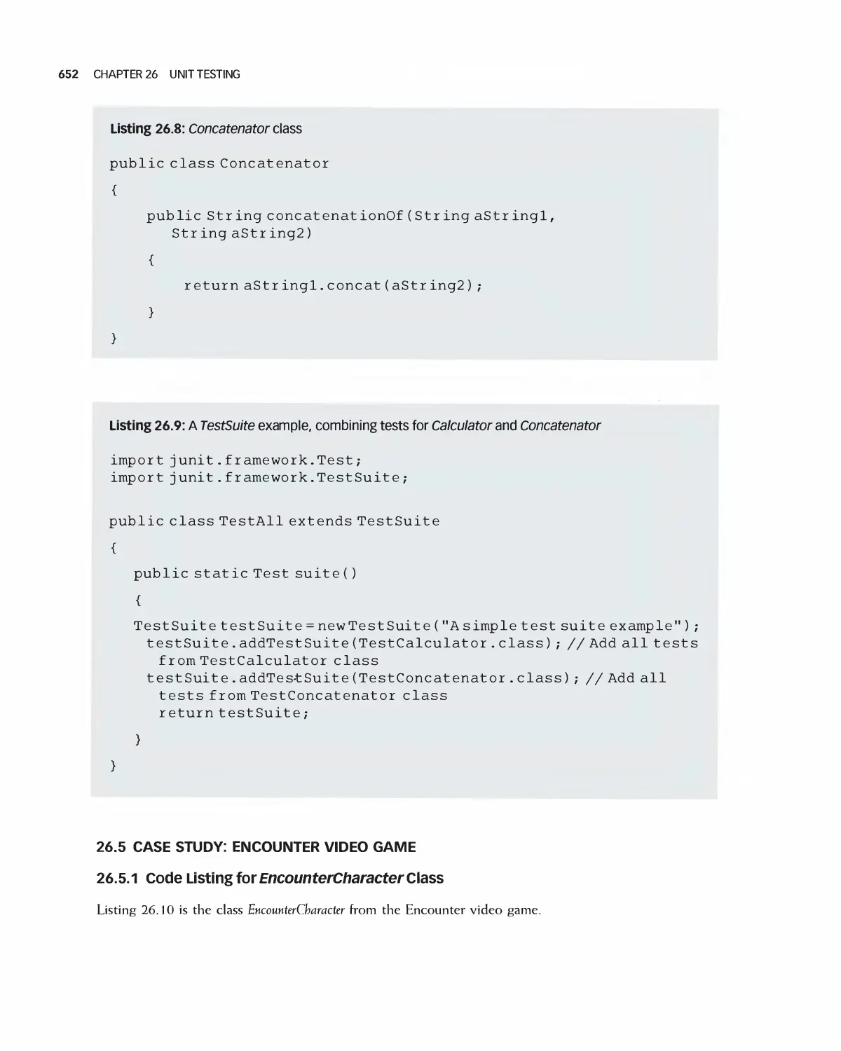
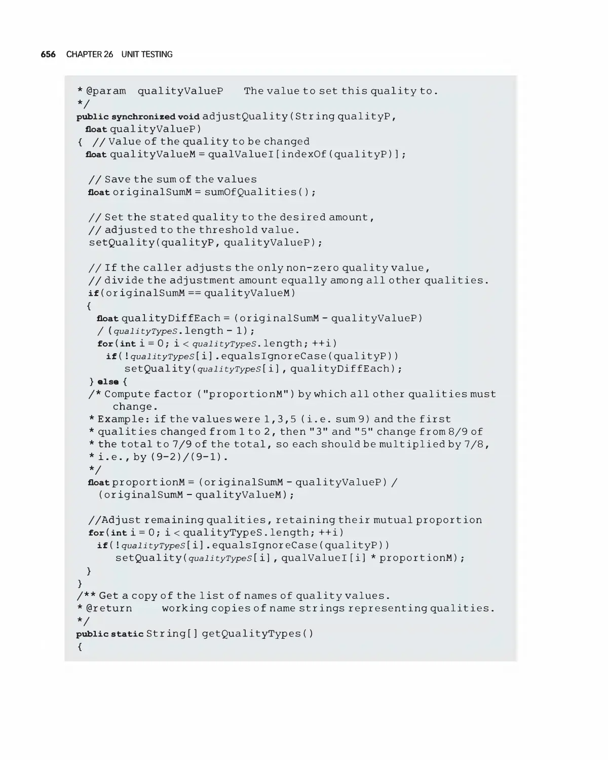
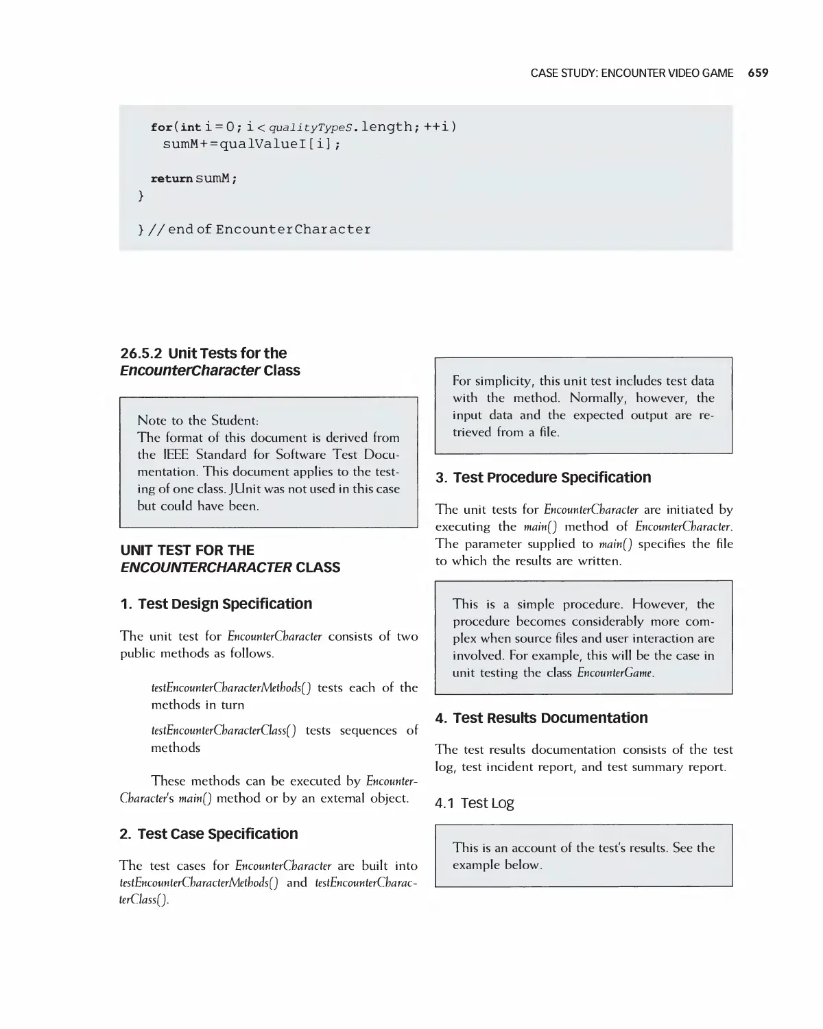
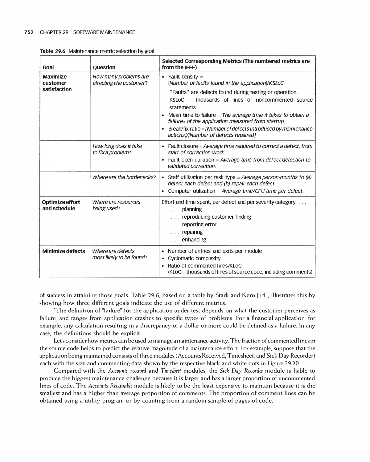
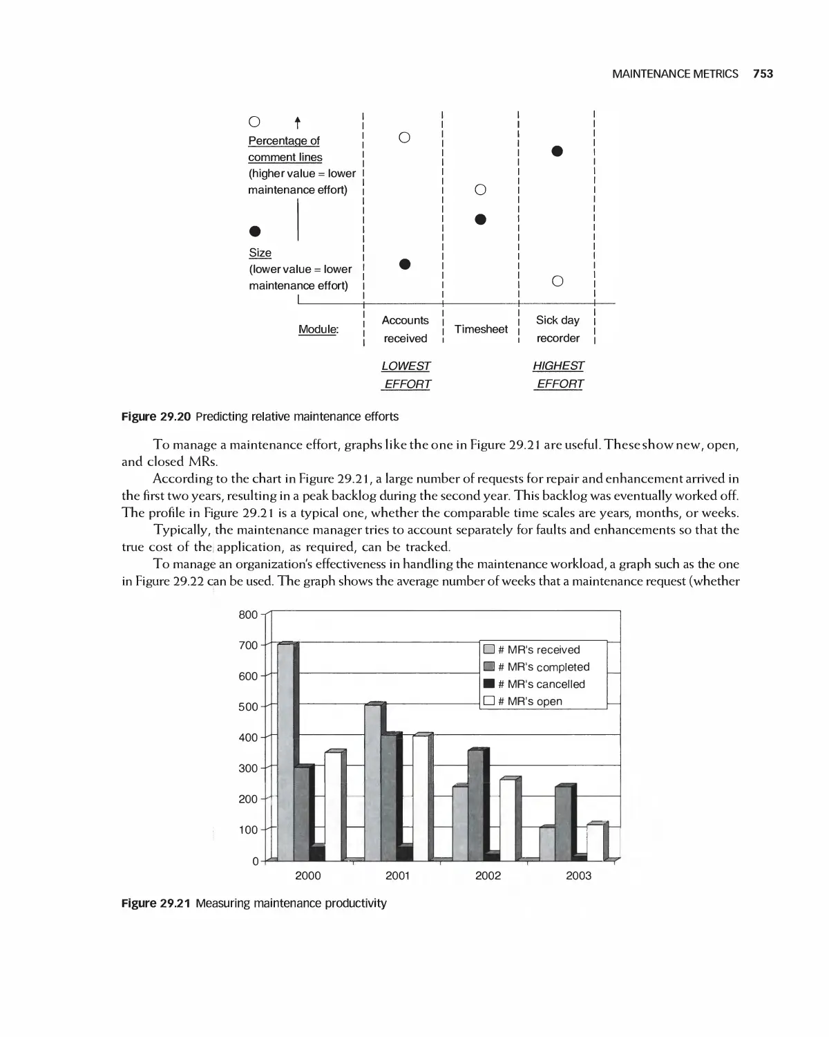
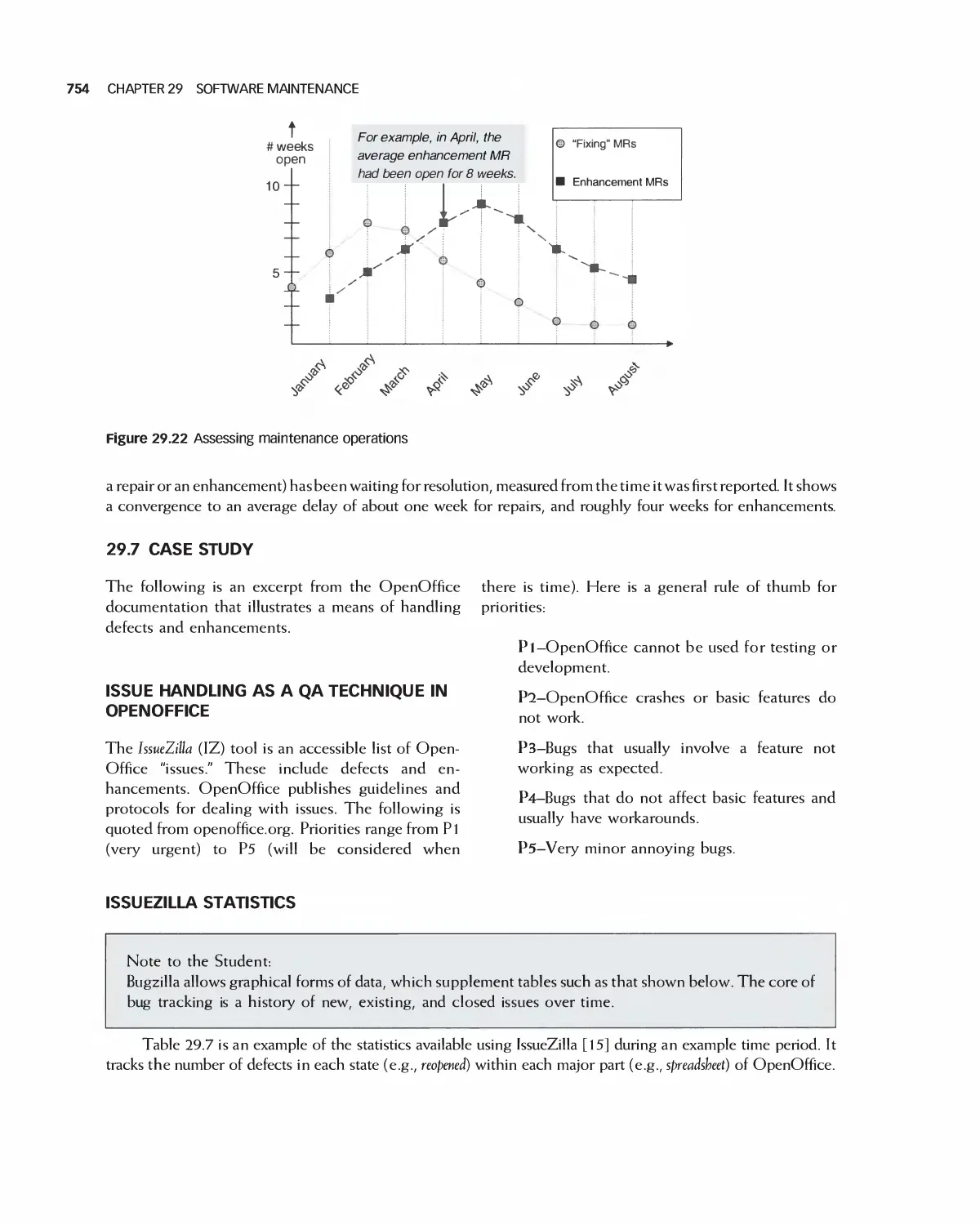
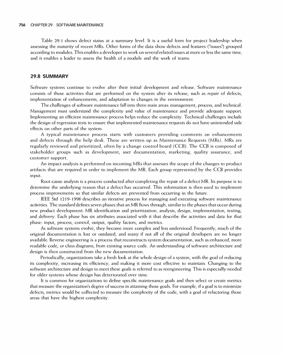
Текст
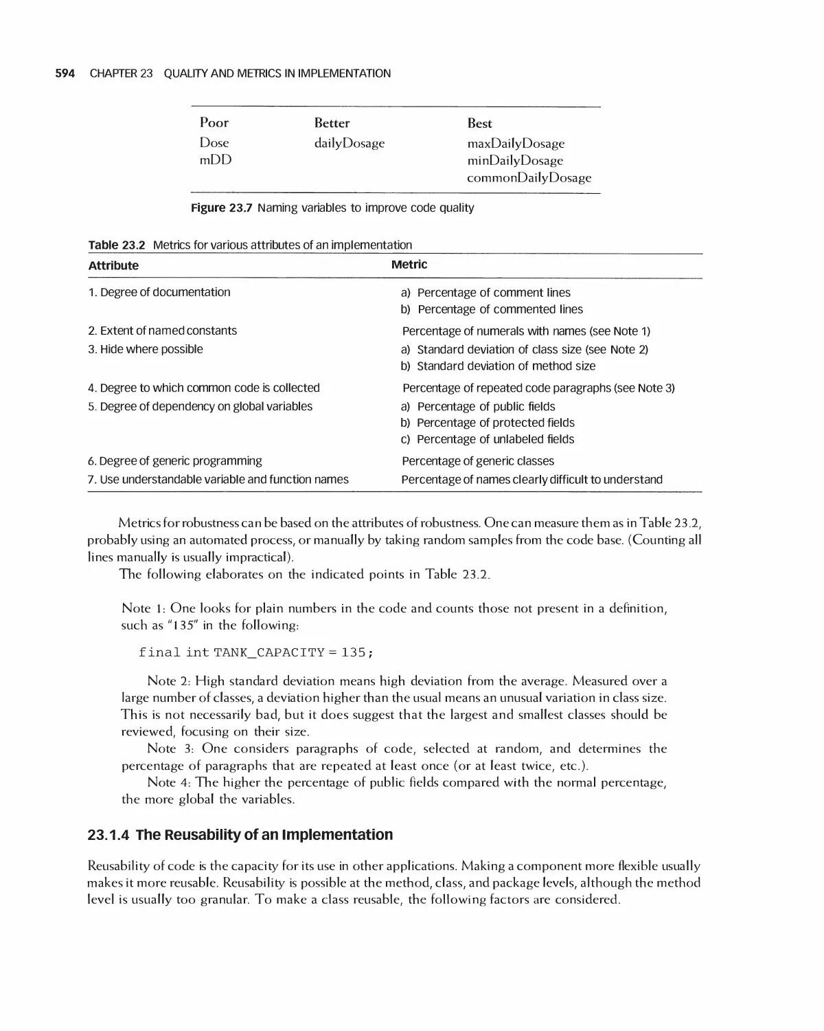
^ '
S FT A'E
E I EE»I
Modern Approaches Second Edition
•v
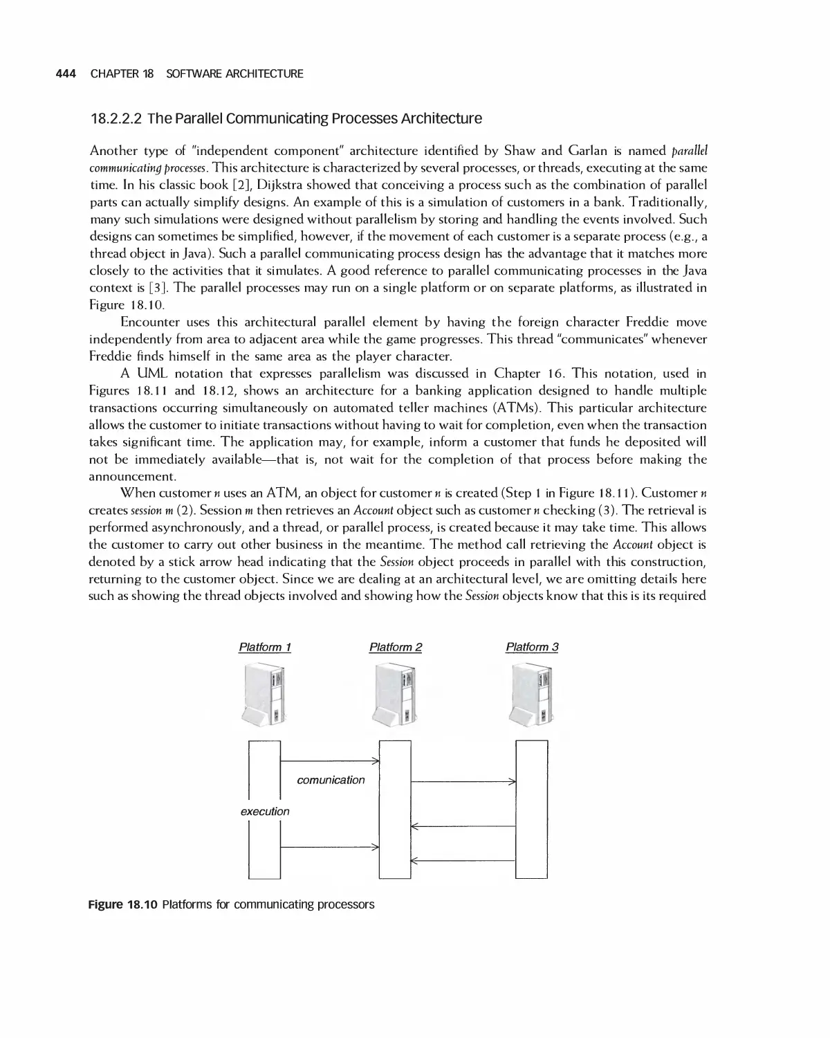
V
J \
\\ ) A*
( '
r
(
(
^
)
Eric J. Braude
Michael E. Bernstein
\
SOFTWARE
ENGINEERING
Modern Approaches Second Edition
Eric J. Braude
Boston University Metropolitan College
Michael E. Bernstein
Boston University Metropolitan College
waveland!
PRESS, INC.
* _ y
Long Grove, Illinois
For information about this book, contact:
Waveland Press, Inc.
4180 IL Route 83, Suite 101
Long Grove, IL 60047-9580
(847) 634^0081
info@wave1and.com
www. waveland. com
Copyright © 2011 by Eric J. Braude and Michael E. Bernstein
Reissued 2016 by Waveland Press, Inc.
10-digit ISBN 1-4786-3230-5
13-digit ISBN 978-1-4786-3230-6
All rights reserved. No pari of this book may be reproduced, stored in a retrieval system, or transmitted
in any form or by any means without permission in writing from the publisher.
Printed in the United States of America
7 6 5 4 3 2 1
For Judy [Eric J. Braude)
To Bamhi, Garrett and Reid,
for all their love and support [Michael E. Bernstein)
Brief Contents
Preface xiv
Acknowledgments xvii
Part I Introduction to Software
Engineering
Part II Software Process
Part III Project Management
Part IV Requirement Analysis
Part V Software Design
Part VI Implementation
Part VII Testing and
Maintenance
1 The Goals and Terminology of Software Engineering 1
2 Introduction to Quality and Metrics in Software
Engineering 21
3 Software Process 32
4 Agile Software Processes 63
5 Quality in the Software Process 80
6 Software Configuration Management 120
7 Principles of Software Project Management I 140
8 Principles of Software Project Management II 168
9 Quality and Metrics in Project Management 213
10 Principles of Requirements Analysis 230
1 1 Analyzing High-Level Requirements 245
12 Analyzing Detailed Requirements 278
13 Quality and Metrics in Requirements Analysis 3 31
14 Formal and Emerging Methods in Requirements Analysis
(Online chapter) 349
15 Principles of Software Design 350
16 The Unified Modeling Language 361
17 Software Design Patterns 383
18 Software Architecture 438
19 Detailed Design 476
20 Design Quality and Metrics 508
21 Advanced and Emerging Methods in Software Design
(Online chapter) 538
22 Principles of Implementation 539
23 Quality and Metrics in Implementation 584
24 Re factoring 601
25 Introduction to Software Testing 621
26 Unit Testing 630
27 Module and Integration Testing 666
28 Testing at the System Level 694
29 Software Maintenance 730
Glossary 759
Index 767
Contents
Preface xiv
The Issue of Scale xiv
This Edition Compared with the First xiv
How Instructors Can Use This Book xv
Acknowledgments xvii
PART I Introduction to Software Engineering
1 The Goals and Terminology of Software Engineering 1
1.1 What is Software Engineering 2
1.2 Why Software Engineering Is Critical: Software Disasters 3
1.3 Why Software Fails or Succeeds 4
1.4 Software Engineering Activities 5
1.5 Software Engineering Principles 10
1.6 Ethics in Software Engineering 12
1.7 Case Studies 14
1.8 Summary 19
1.9 Exercises 19
Bibliography 20
2 Introduction to Quality and Metrics in Software Engineering 21
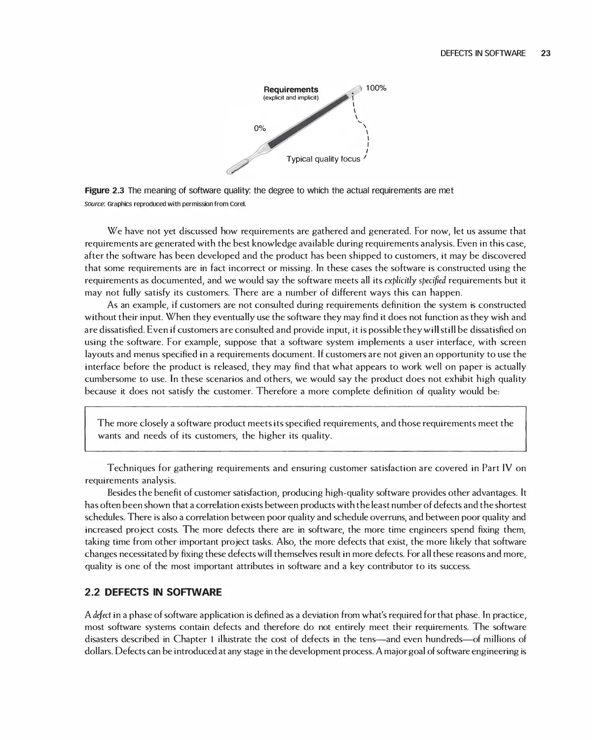
2.1 The Meaning of Software Quality 22
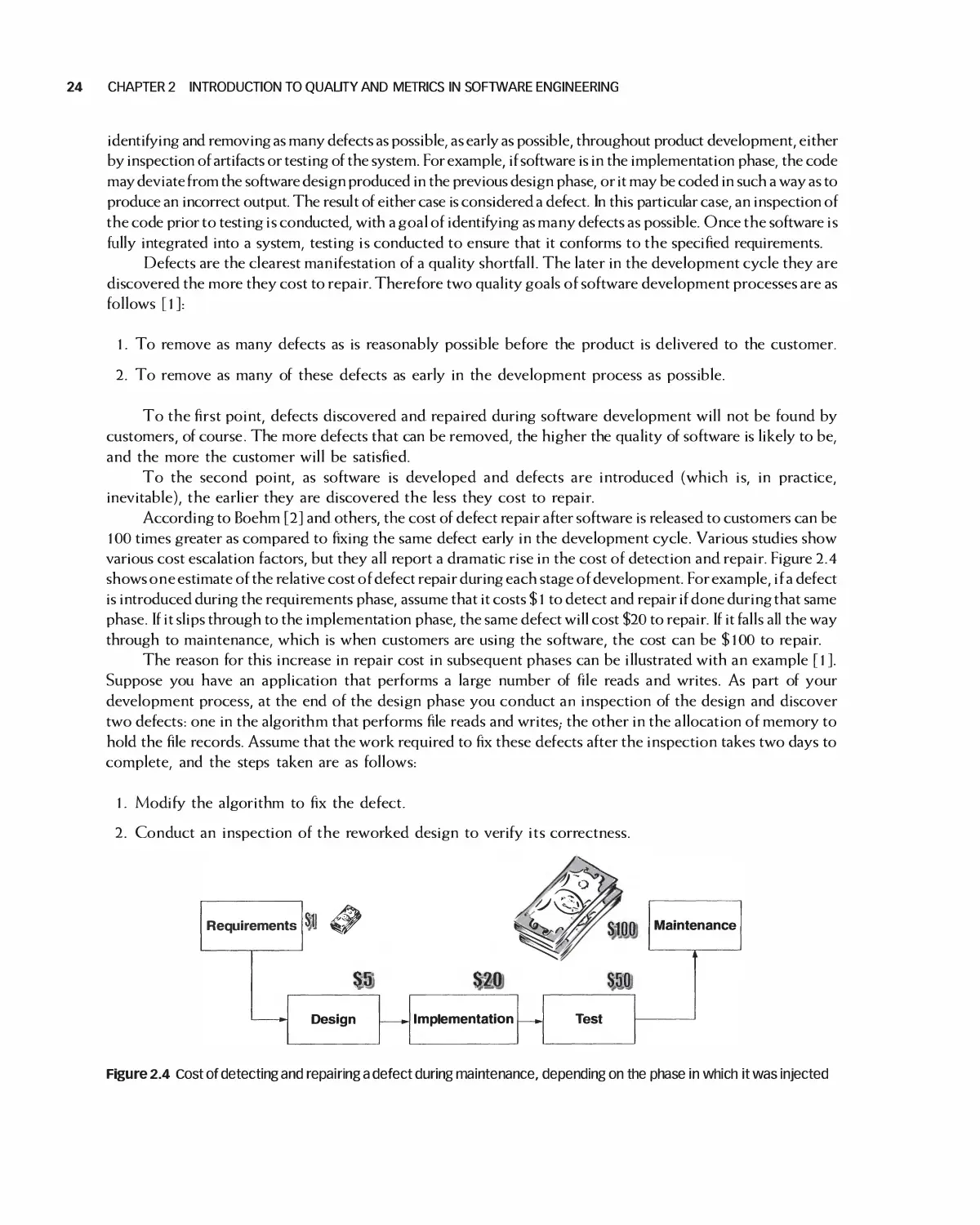
2.2 Defects in Software 23
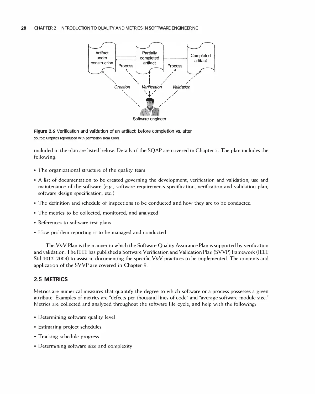
2.3 Verification and Validation 25
2.4 Planning for Quality 27
2.5 Metrics 28
2.6 Summary 30
2.7 Exercises 31
Bibliography 31
PART II Software Process
3 Software Process 32
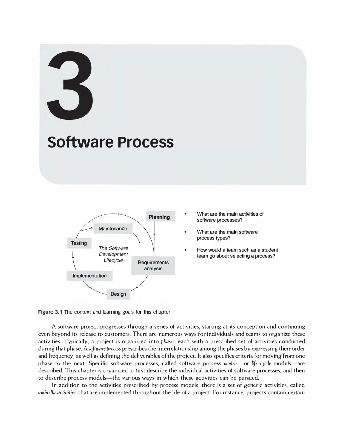
3.1 The Activities of Software Process 33
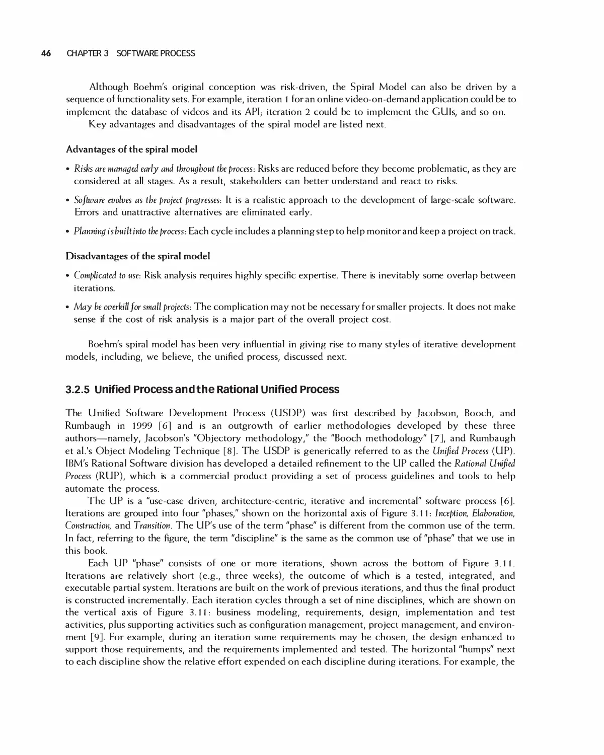
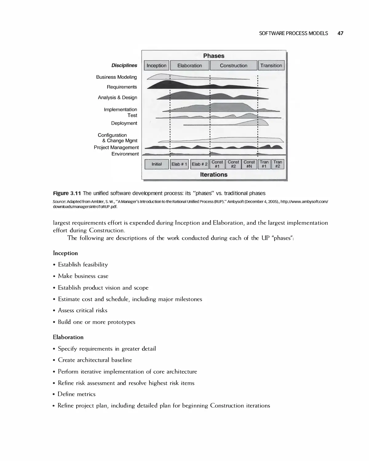
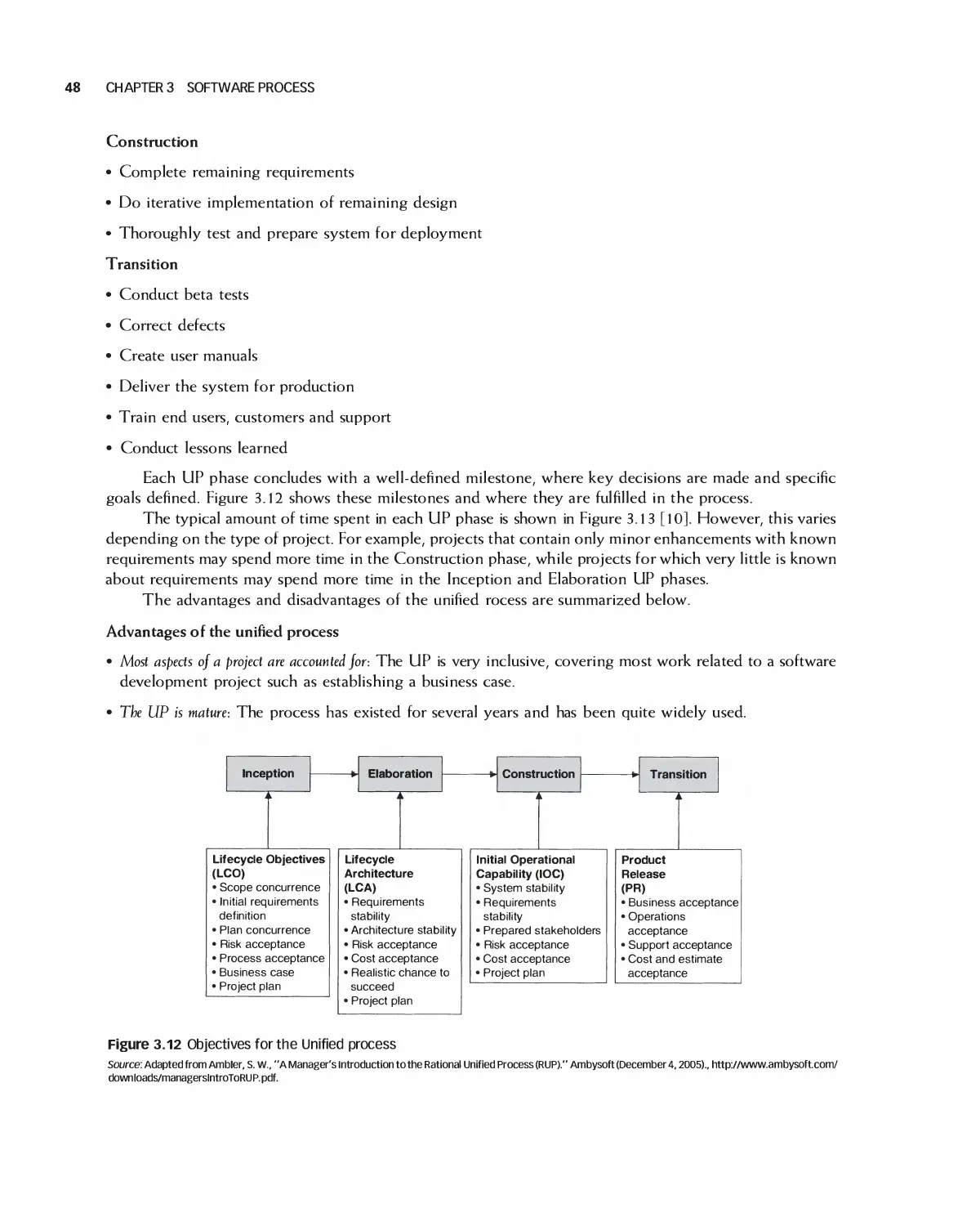
3.2 Software Process Models 37
3.3 Case Study: Student Team Guidance 55
Vi CONTENTS
3.4 Summary 59
3.5 Exercises 60
Bibliography 62
4 Agile Software Processes 63
4.1 Agile History and Agile Manifesto 64
4.2 Agile Principles 65
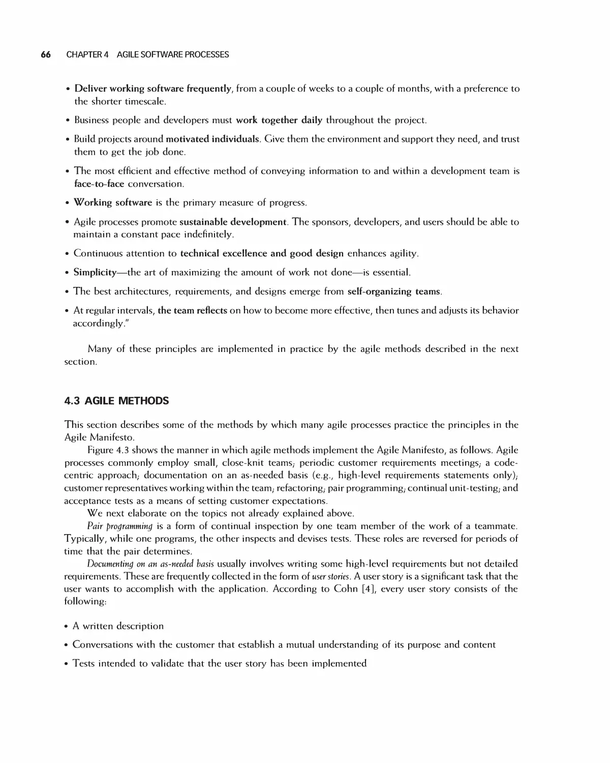
4.3 Agile Methods 66
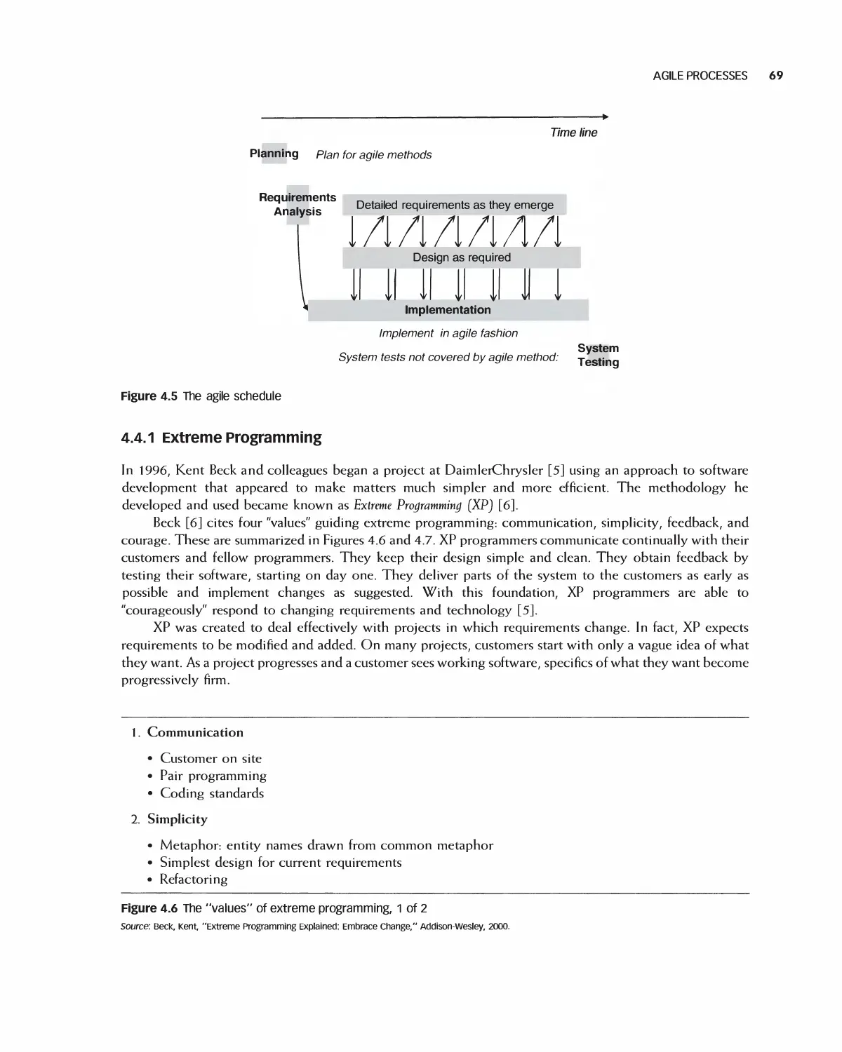
4.4 Agile Processes 68
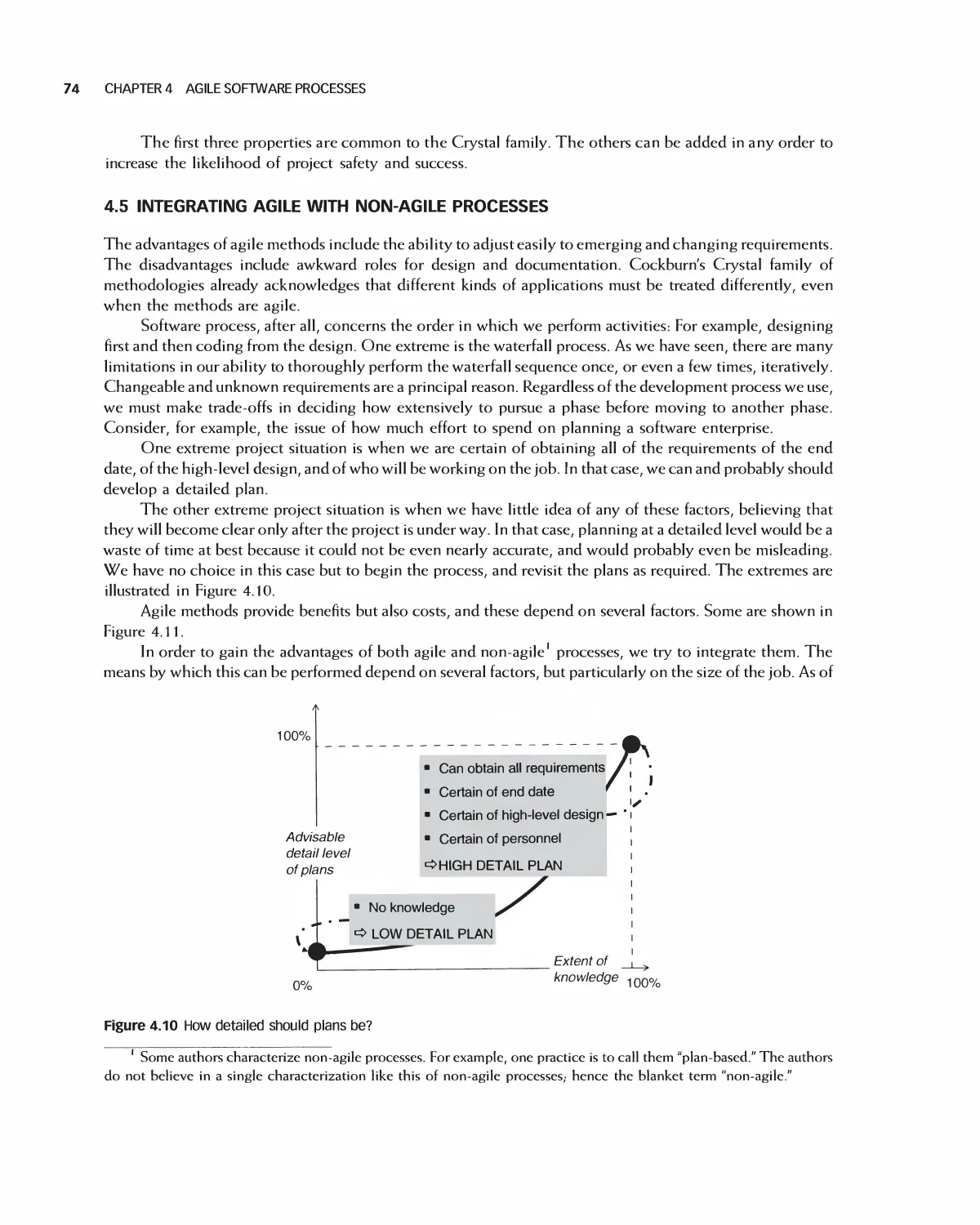
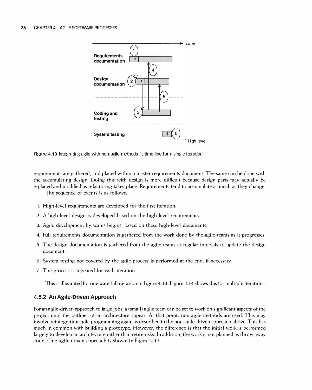
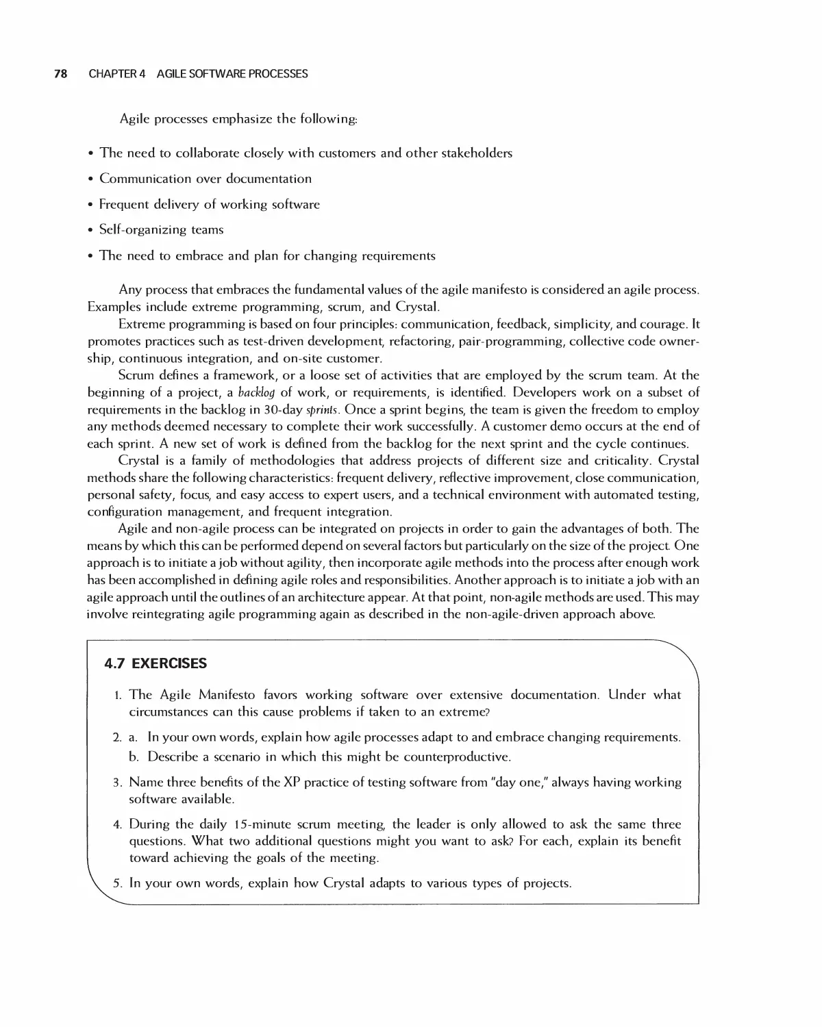
4.5 Integrating Agile with Non-Agile Processes 74
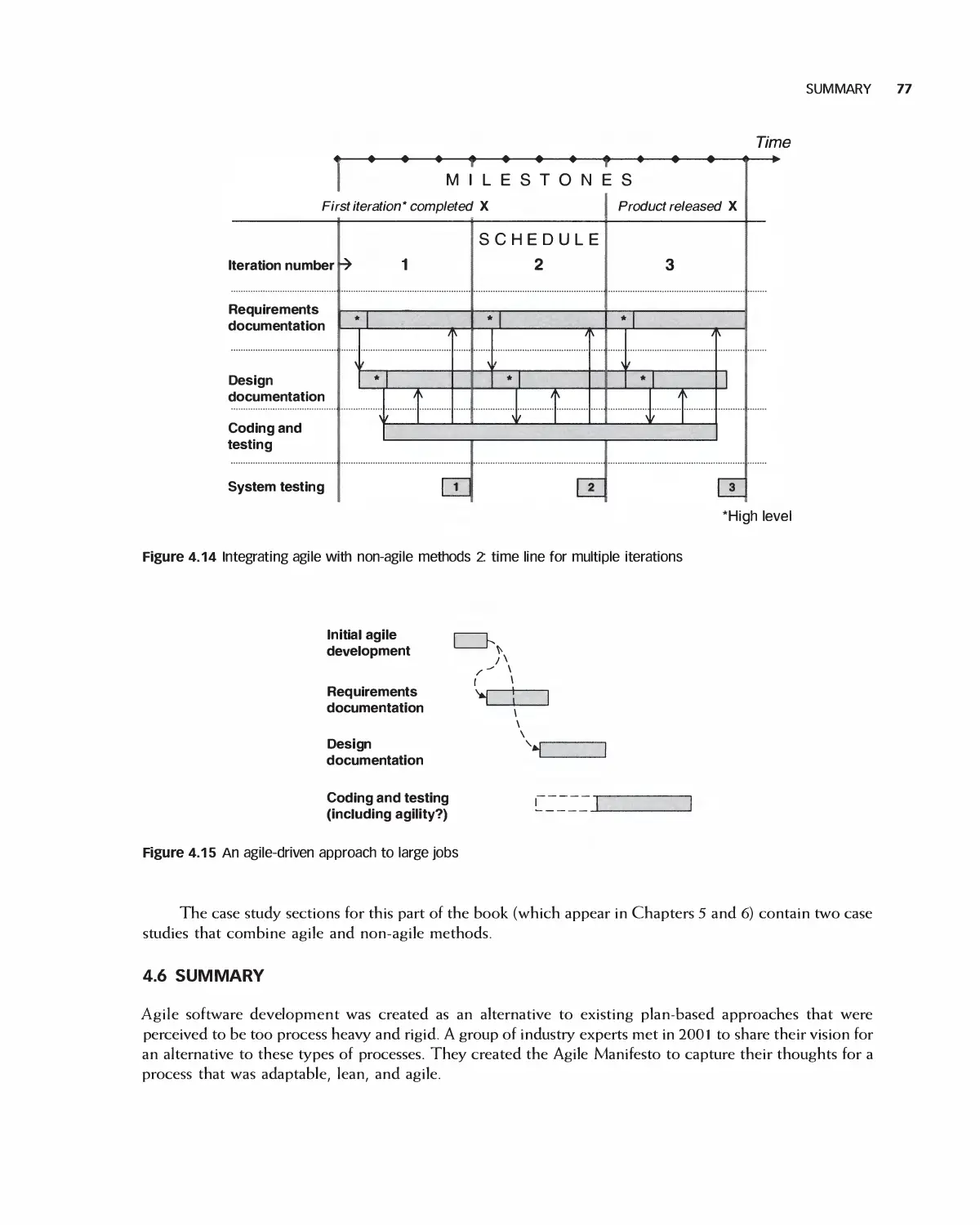
4.6 Summary 77
4.7 Exercises 78
Bibliography 79
5 Quality in the Software Process 80
5.1 Principles of Managing Quality 81
5.2 Managing Quality in Agile Processes 82
5.3 Quality Planning 83
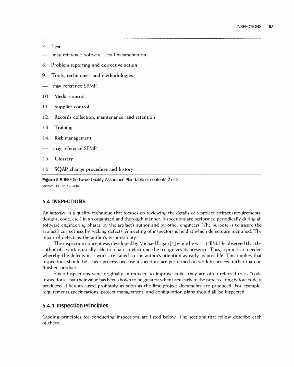
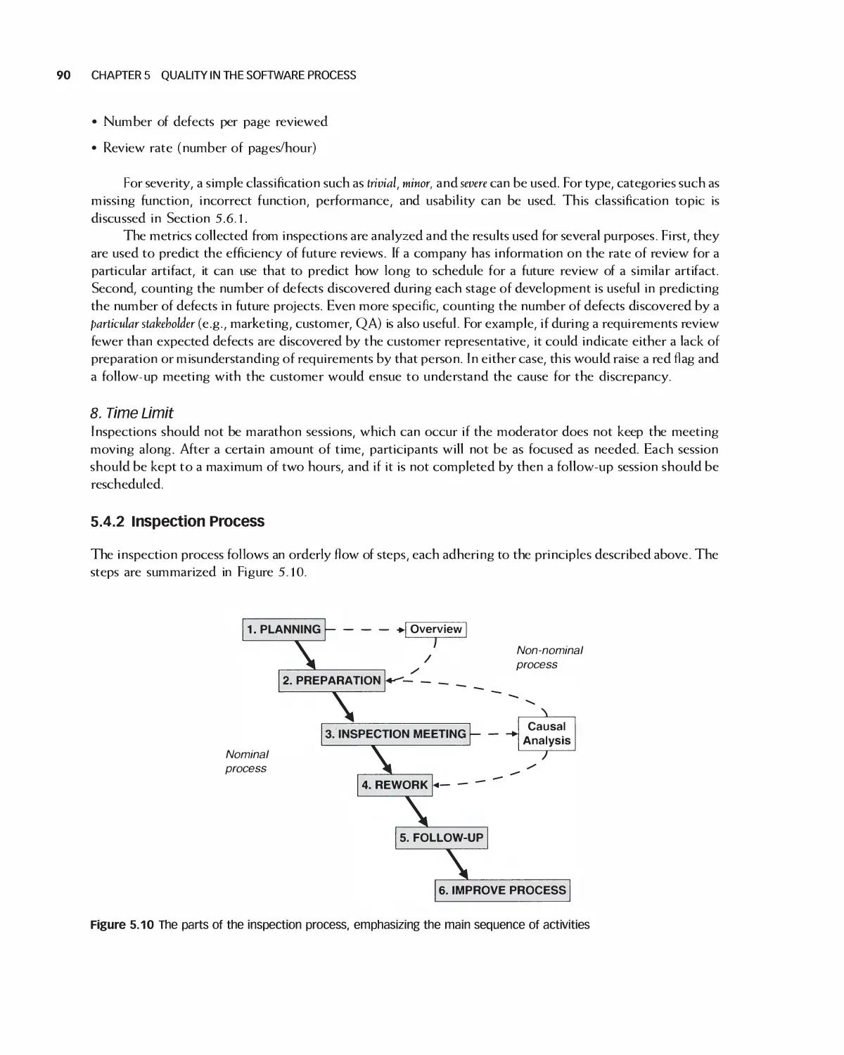
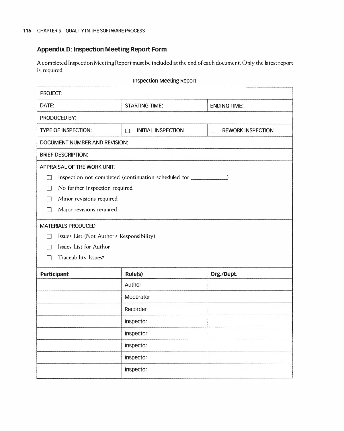
5.4 Inspections 87
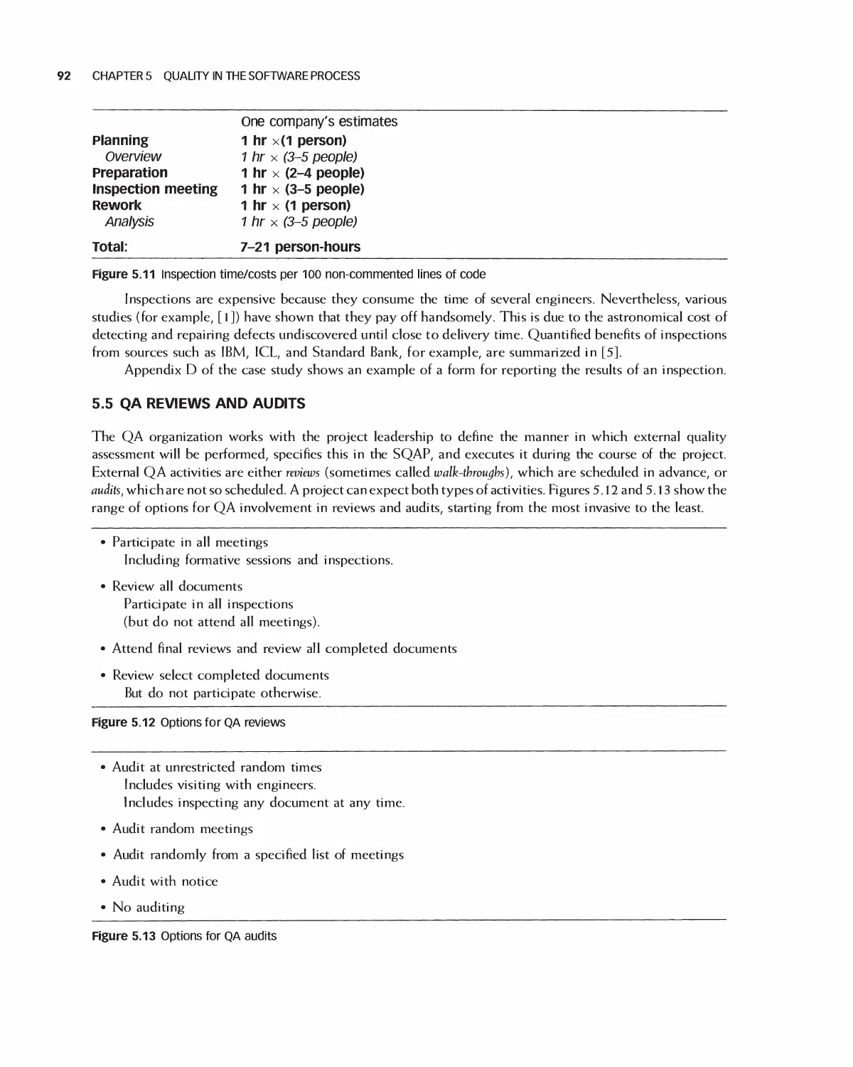
5.5 QA Reviews and Audits 92
5.6 Defect Management 93
5.7 Process Improvement and Process Metrics 96
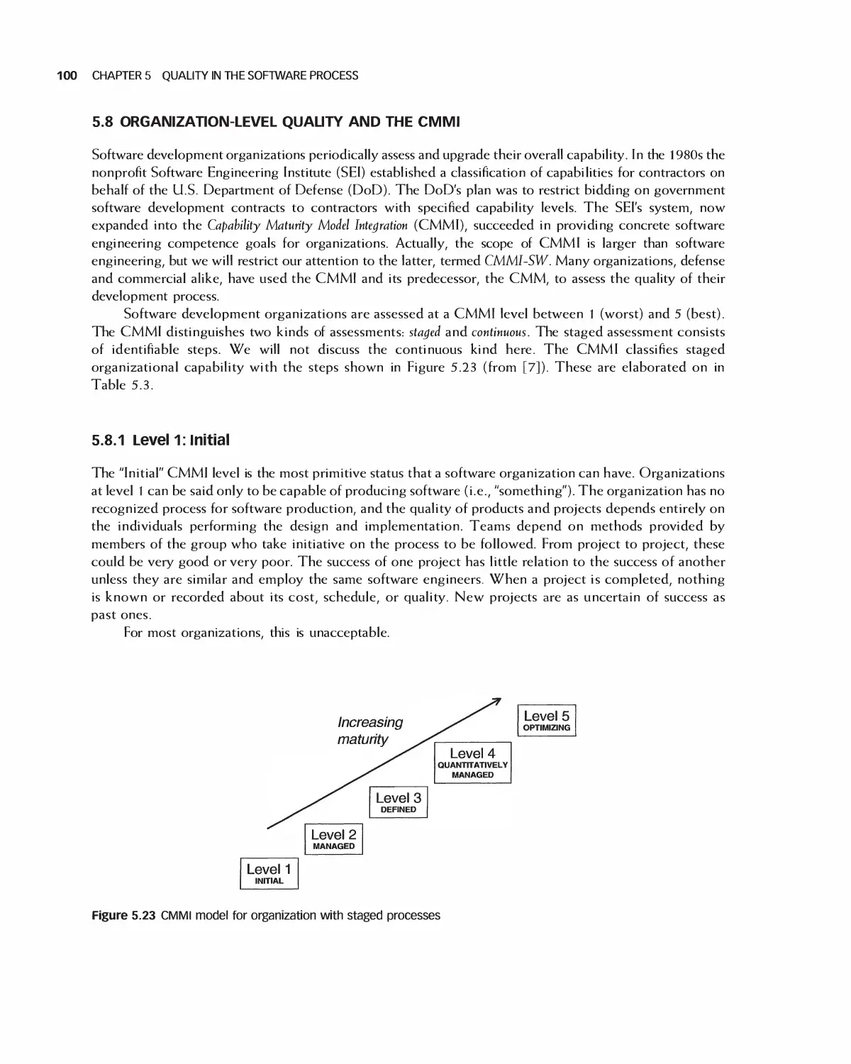
5.8 Organization-Level Quality and the CMMI 100
5.9 Case Study: Software Quality Assurance Plan for Encounter 103
5.10 Summary 118
5.11 Exercises 118
Bibliography 119
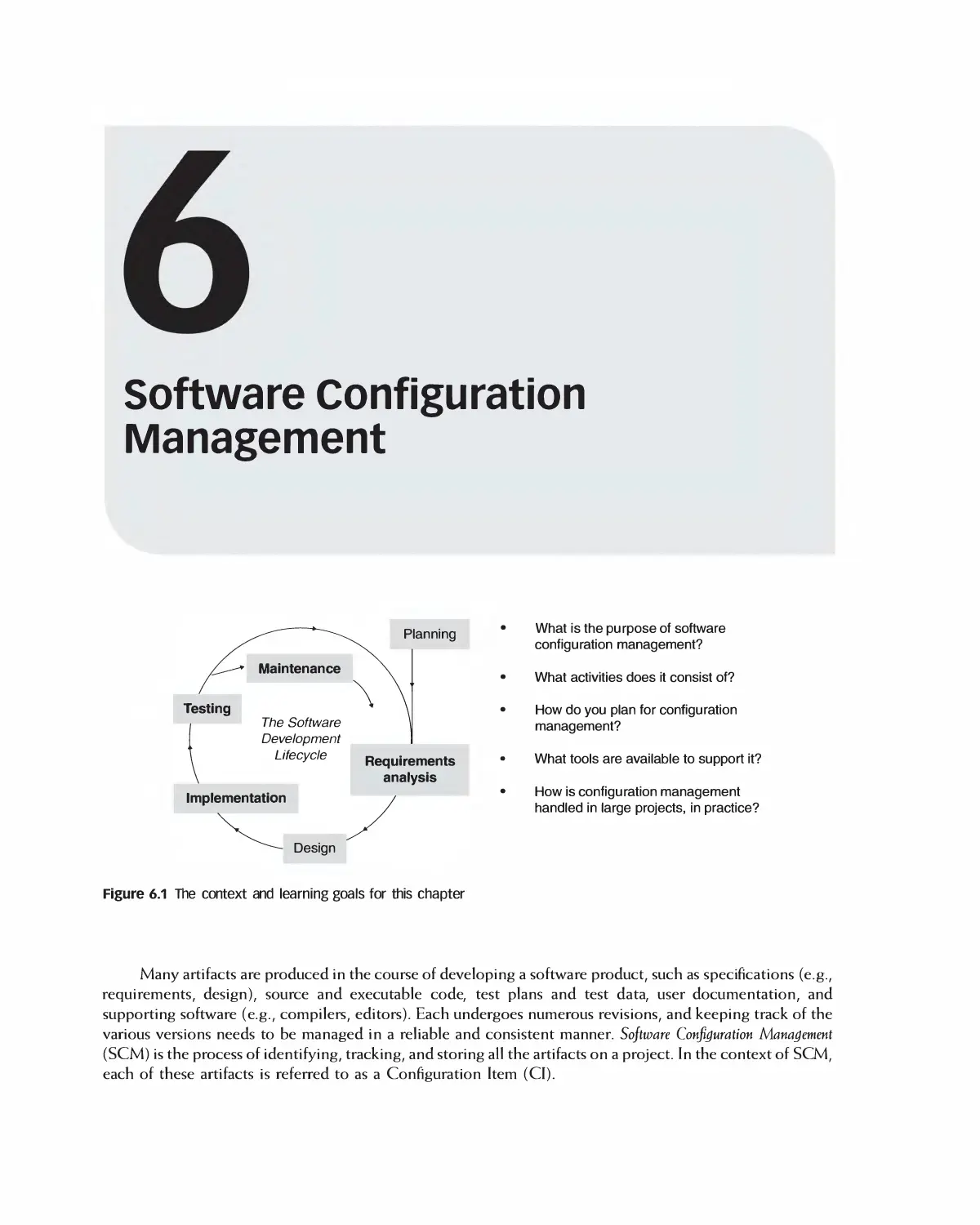
6 Software Configuration Management 120
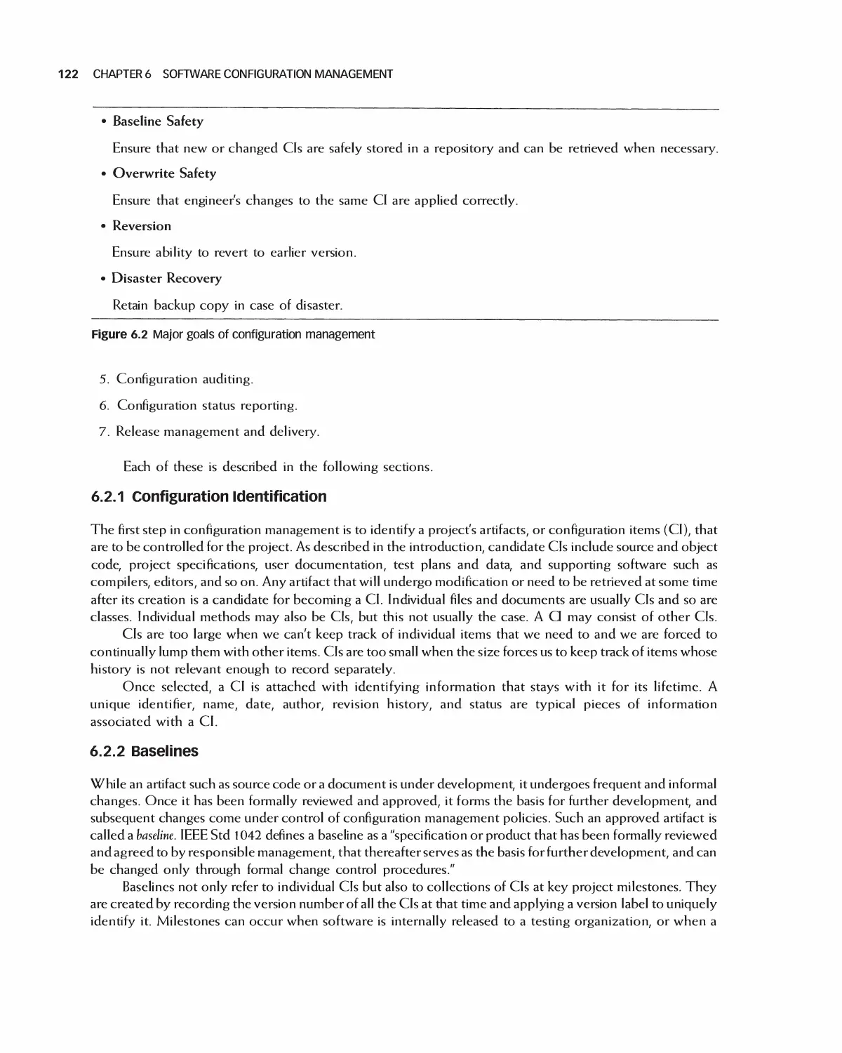
6.1 Software Configuration Management Goals 121
6.2 SCM Activities 121
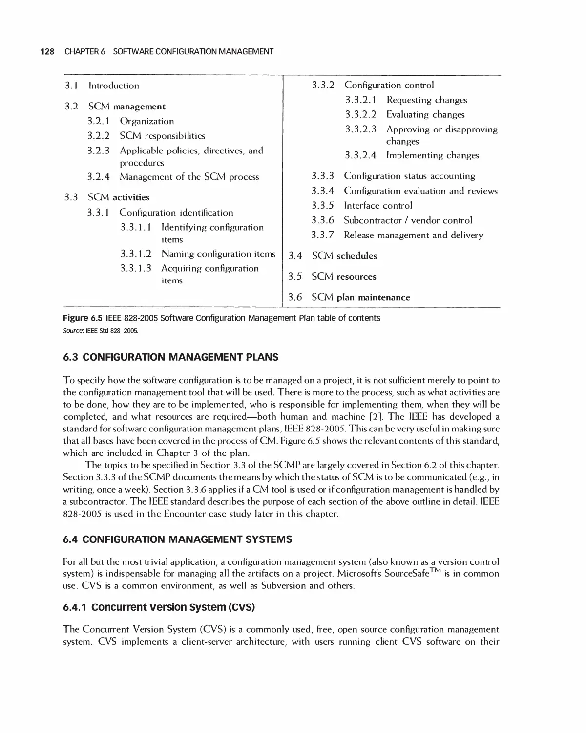
6.3 Configuration Management Plans 128
6.4 Configuration Management Systems 128
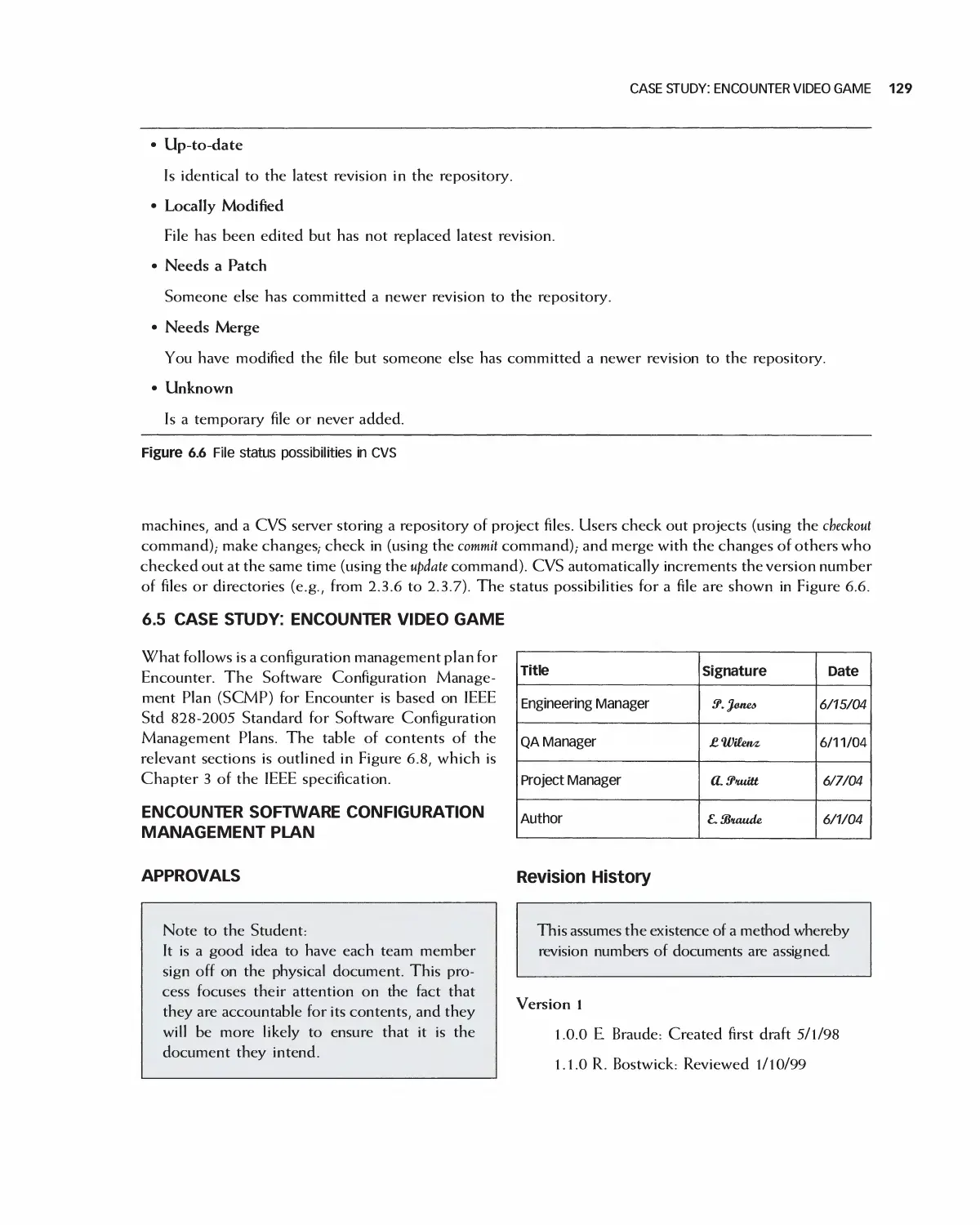
6.5 Case Study: Encounter Video Game 129
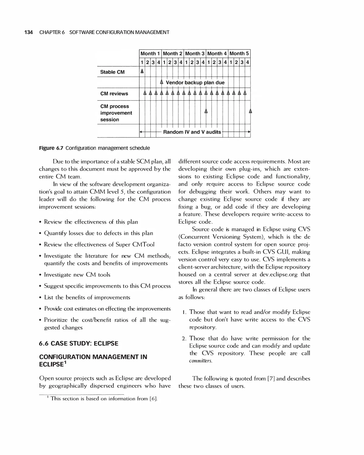
6.6 Case Study: Eclipse 134
6.7 Student Team Guidance: Configuration Management 136
6.8 Summary 137
6.9 Exercises 138
Bibliography 139
PART III Project Management
7 Principles of Software Project Management 1: Organization, Tools, and Risk Management . . 140
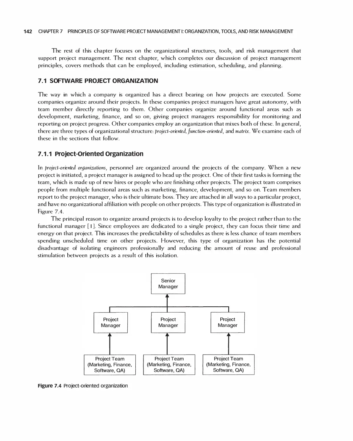
7.1 Software Project Organization 142
7.2 Team Size 144
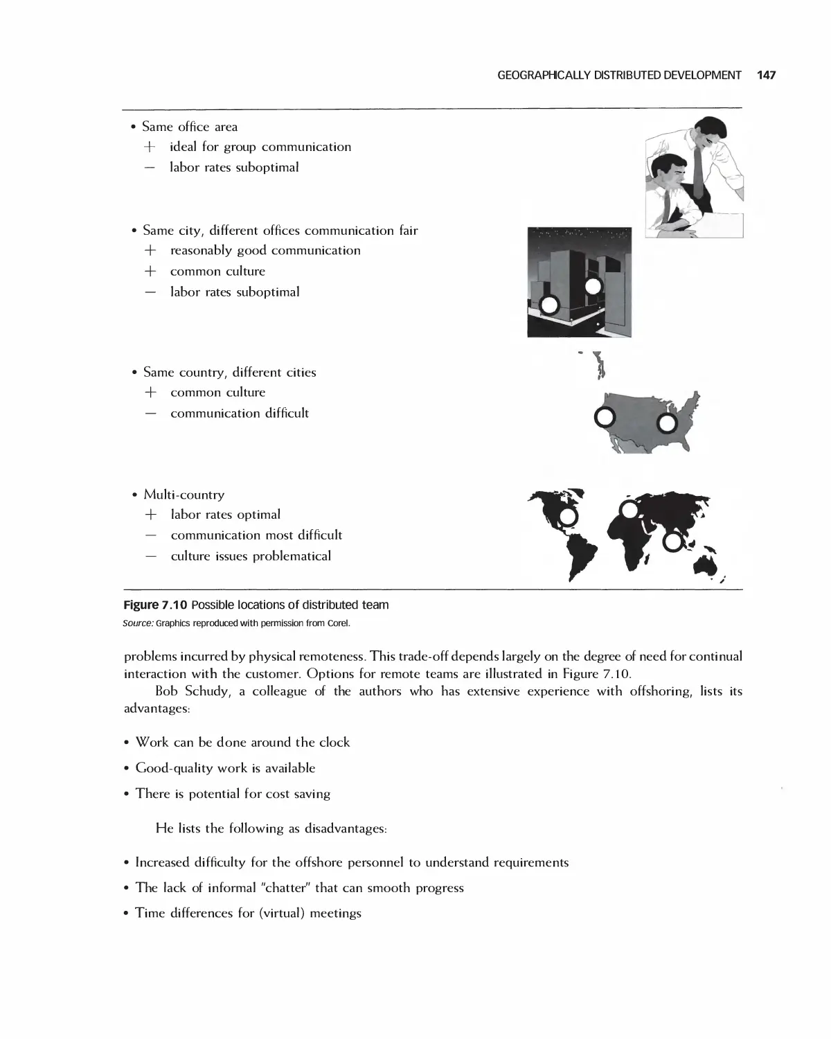
7.3 Geographically Distributed Development 146
7.4 The Team Software Process 151
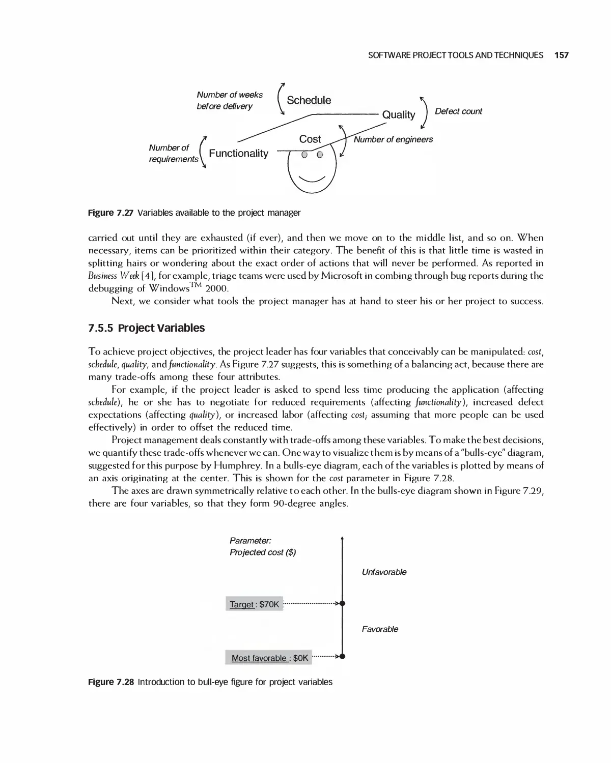
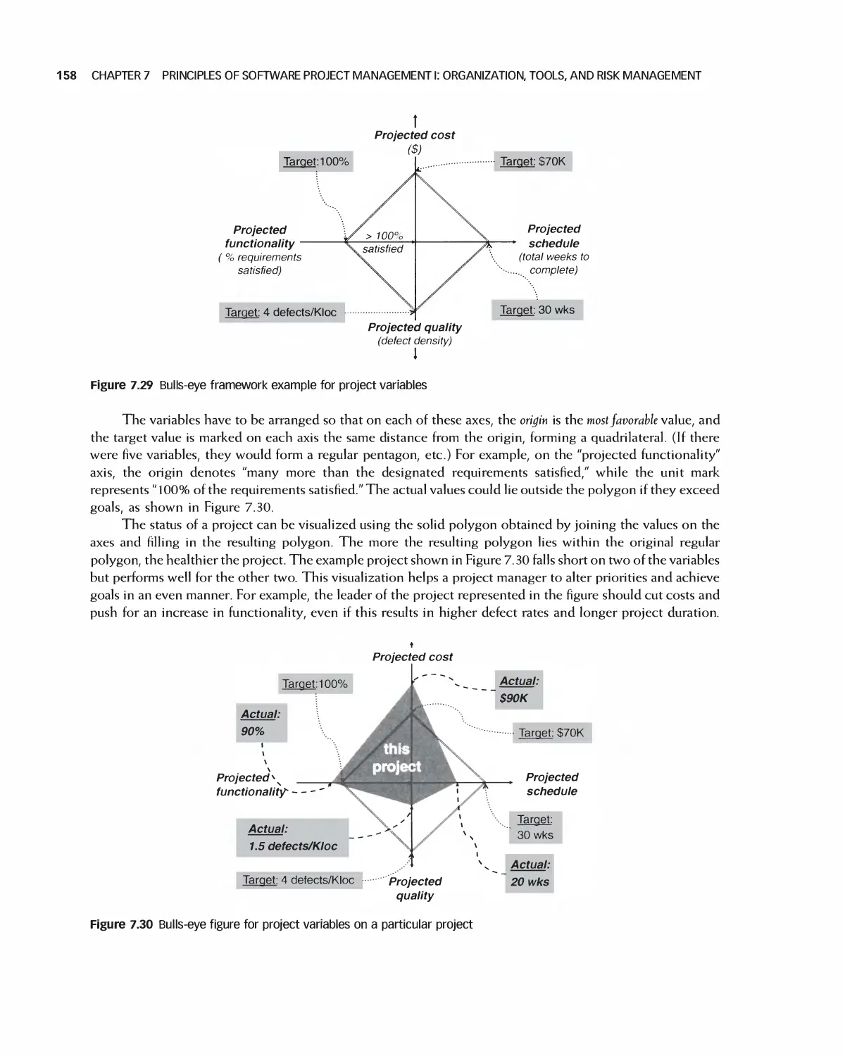
7.5 Software Project Tools and Techniques 153
CONTENTS Vii
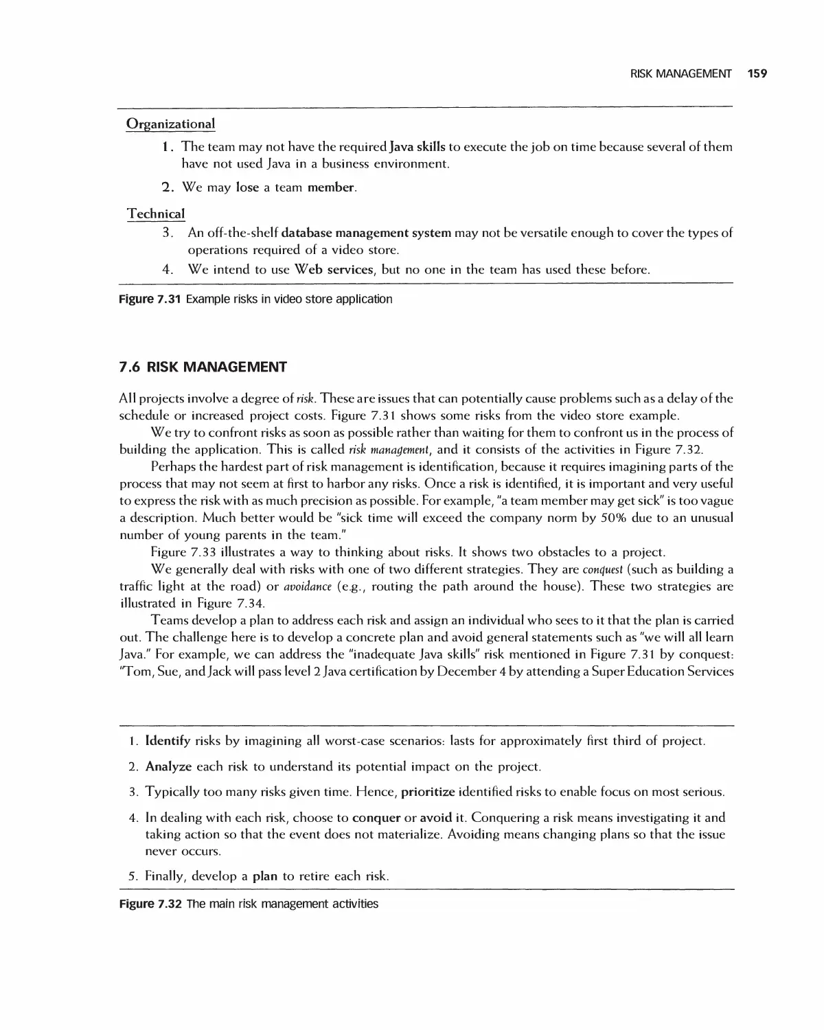
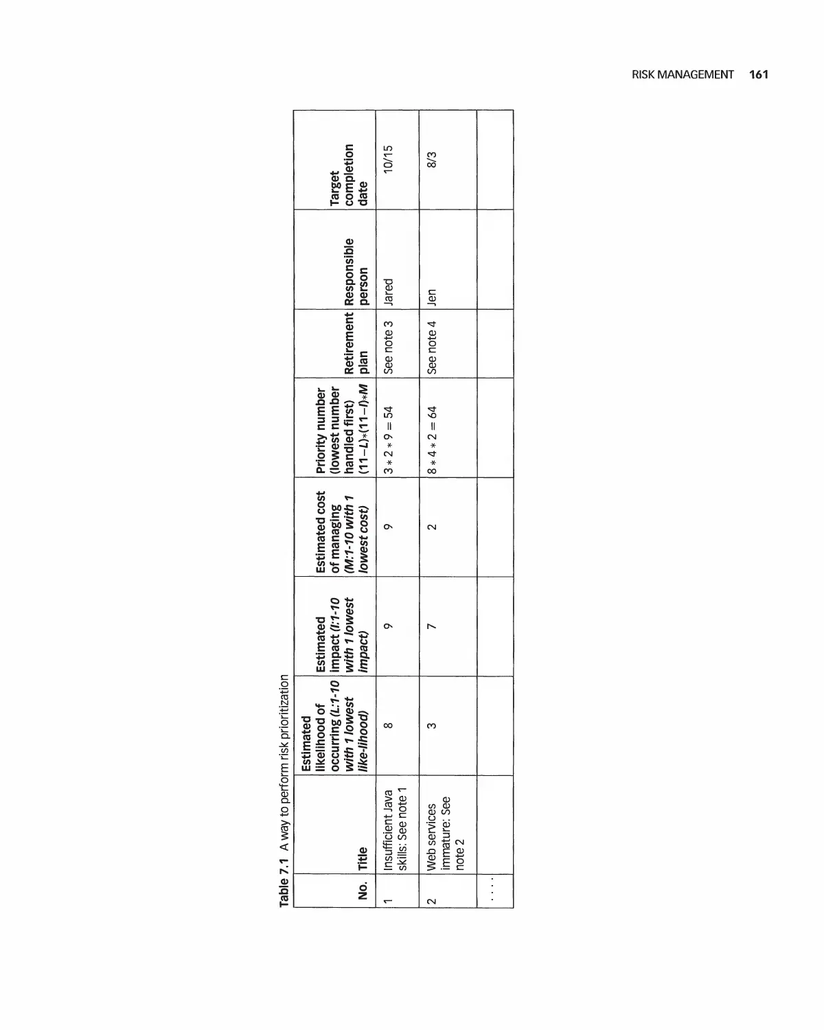
7.6 Risk Management 159
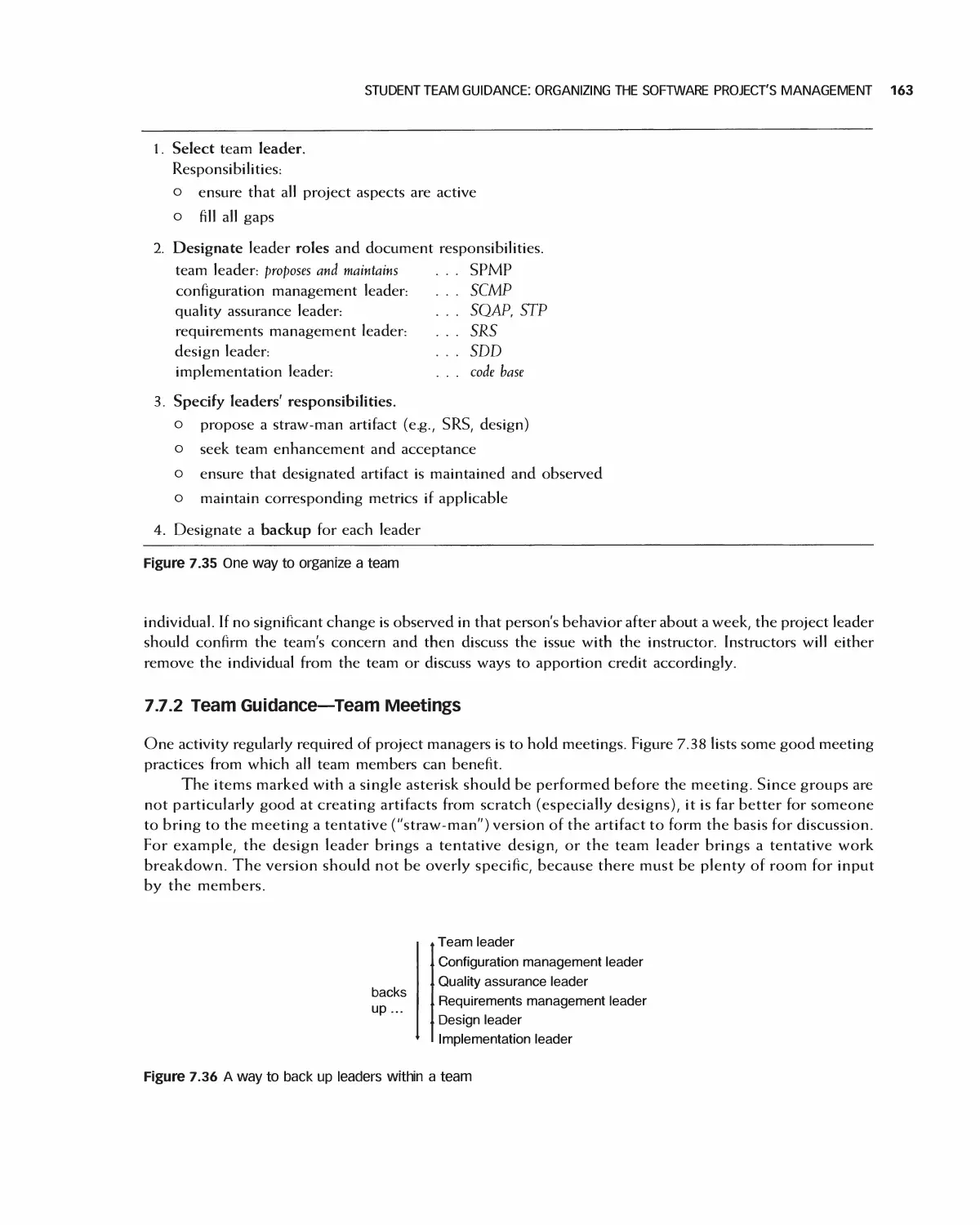
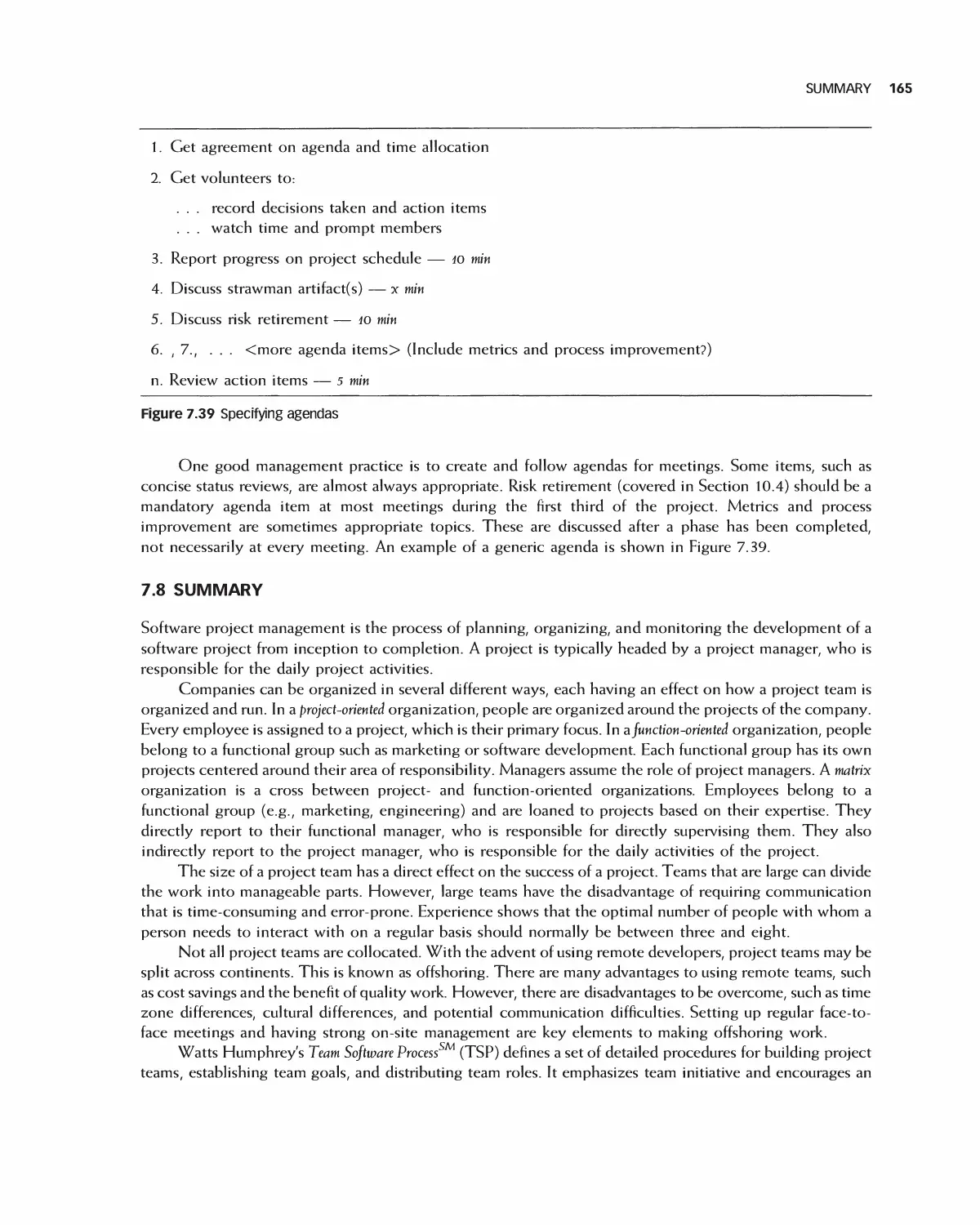
7.7 Student Team Guidance: Organizing the Software Project's Management 162
7.8 Summary 165
7.9 Exercises 166
Bibliography 167
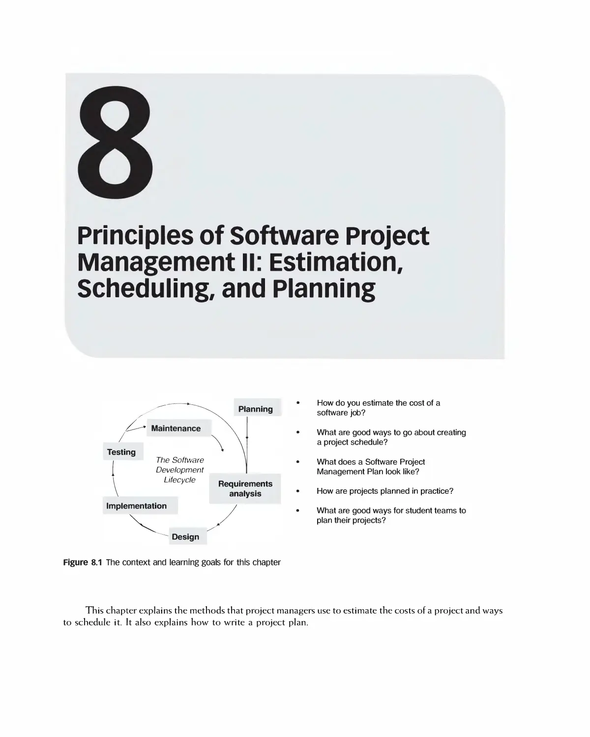
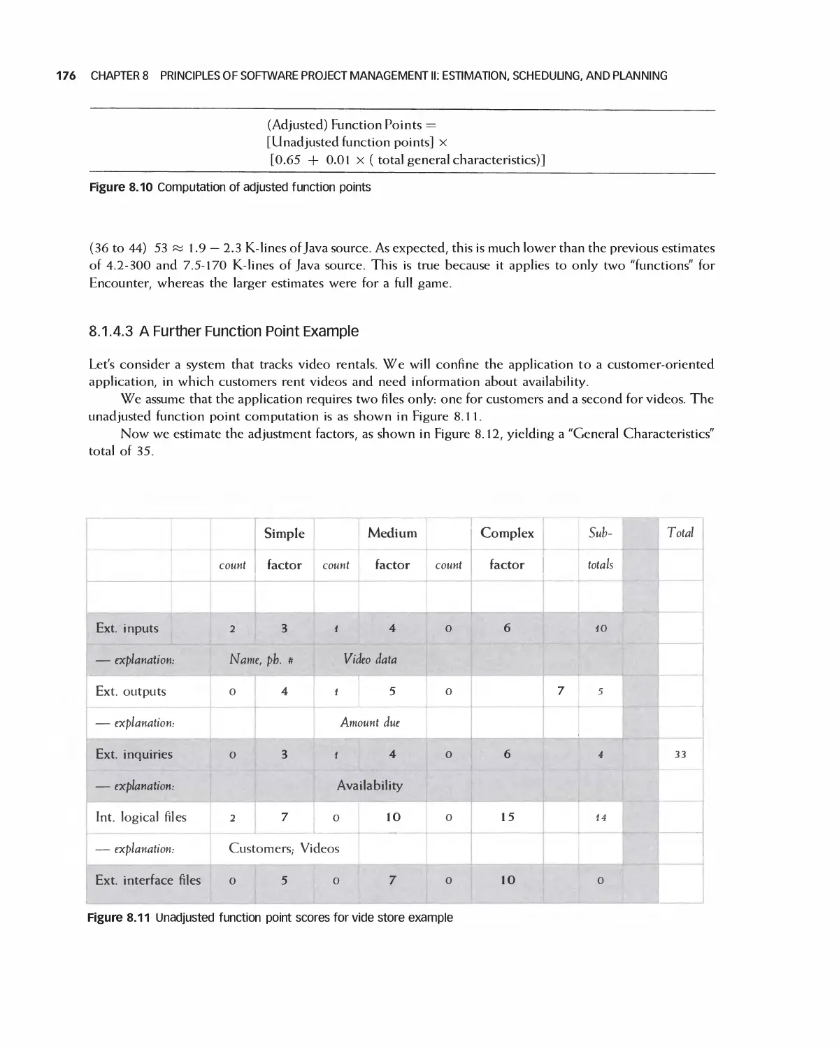
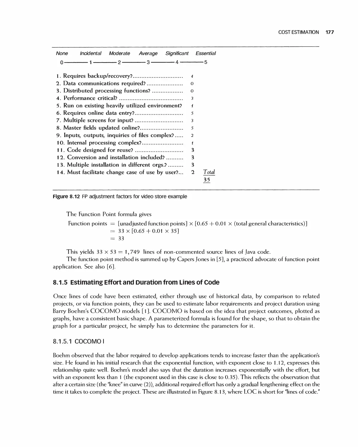
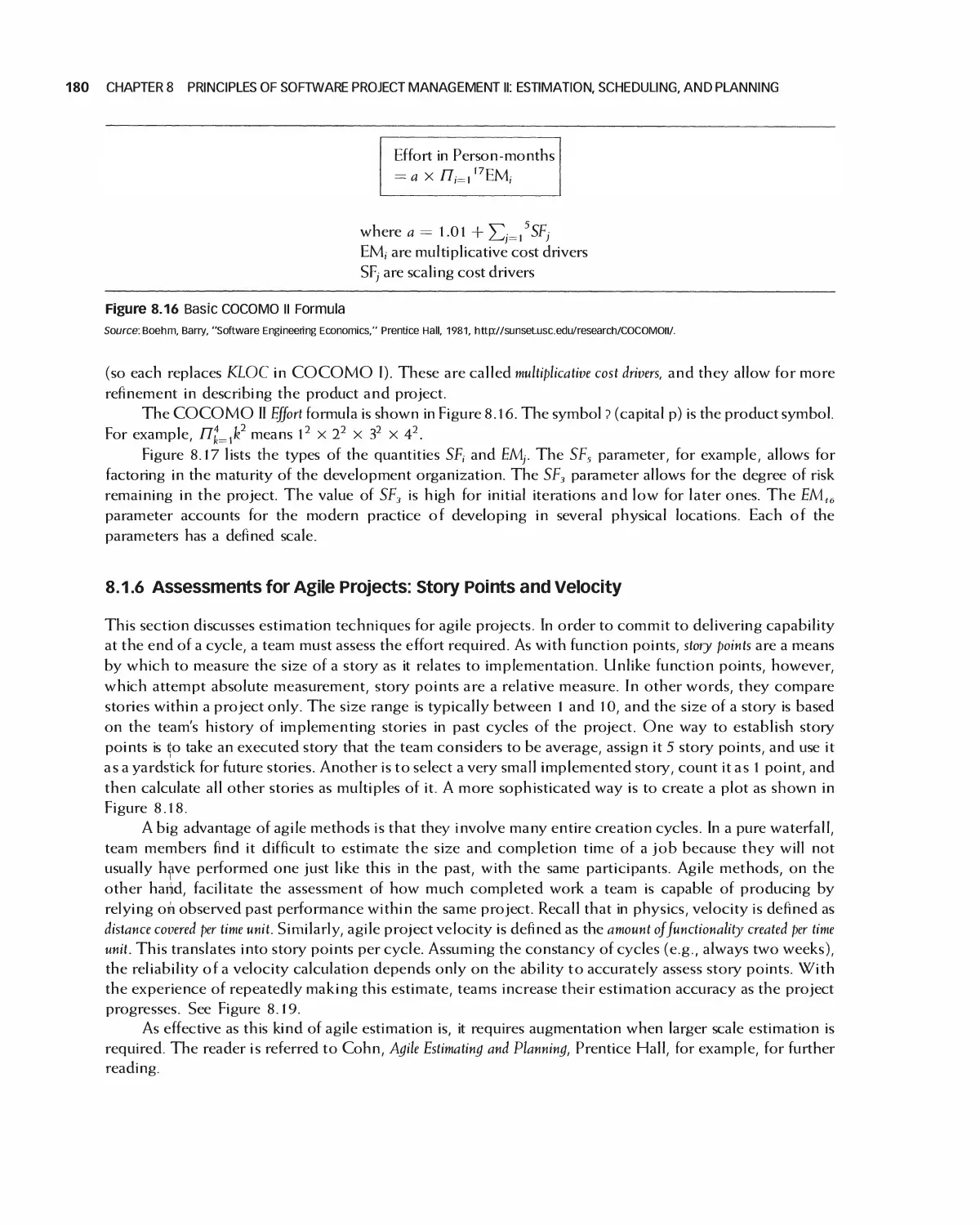
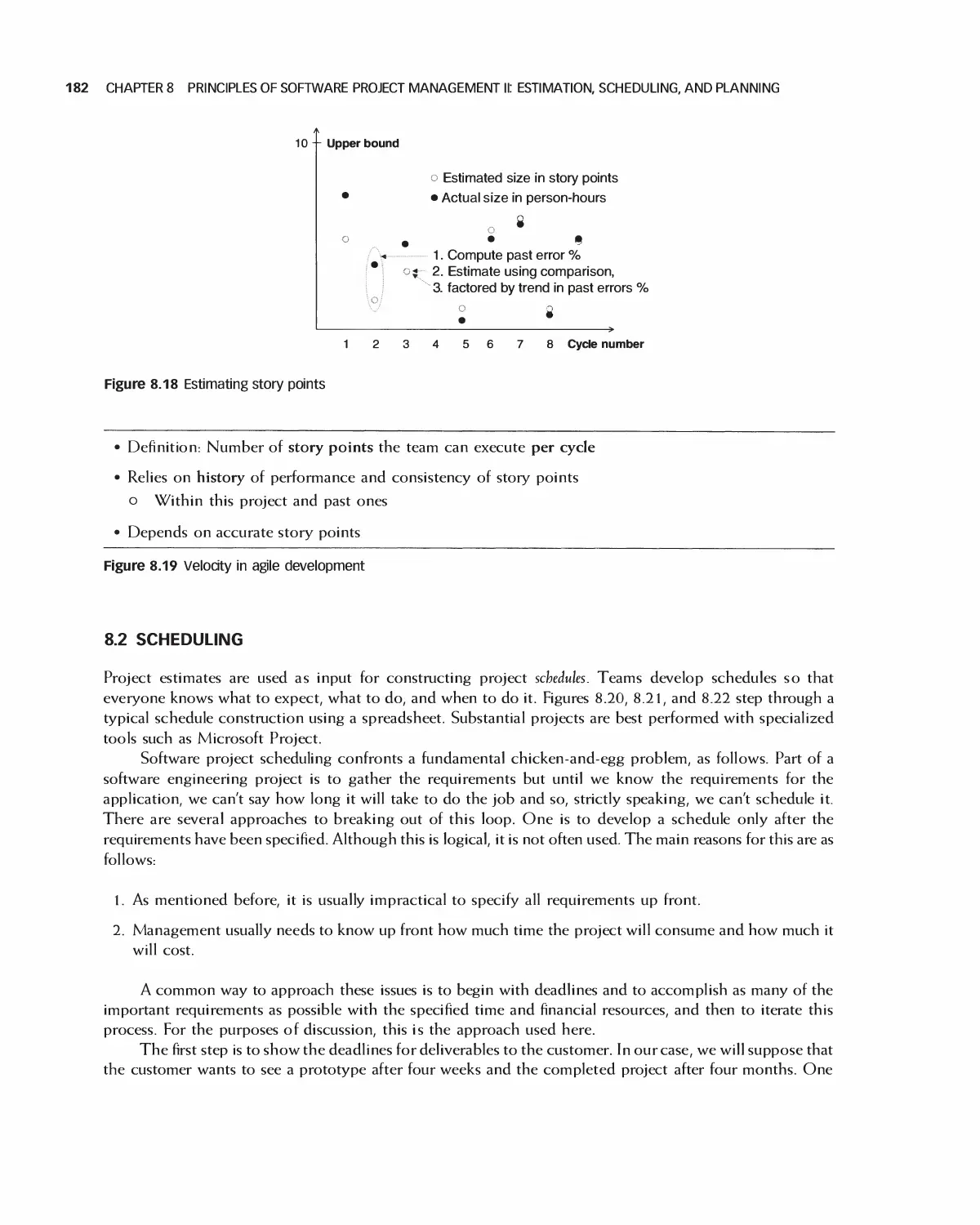
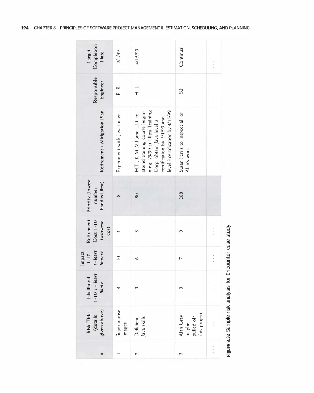
8 Principles of Software Project Management 11: Estimation, Scheduling, and Planning 168
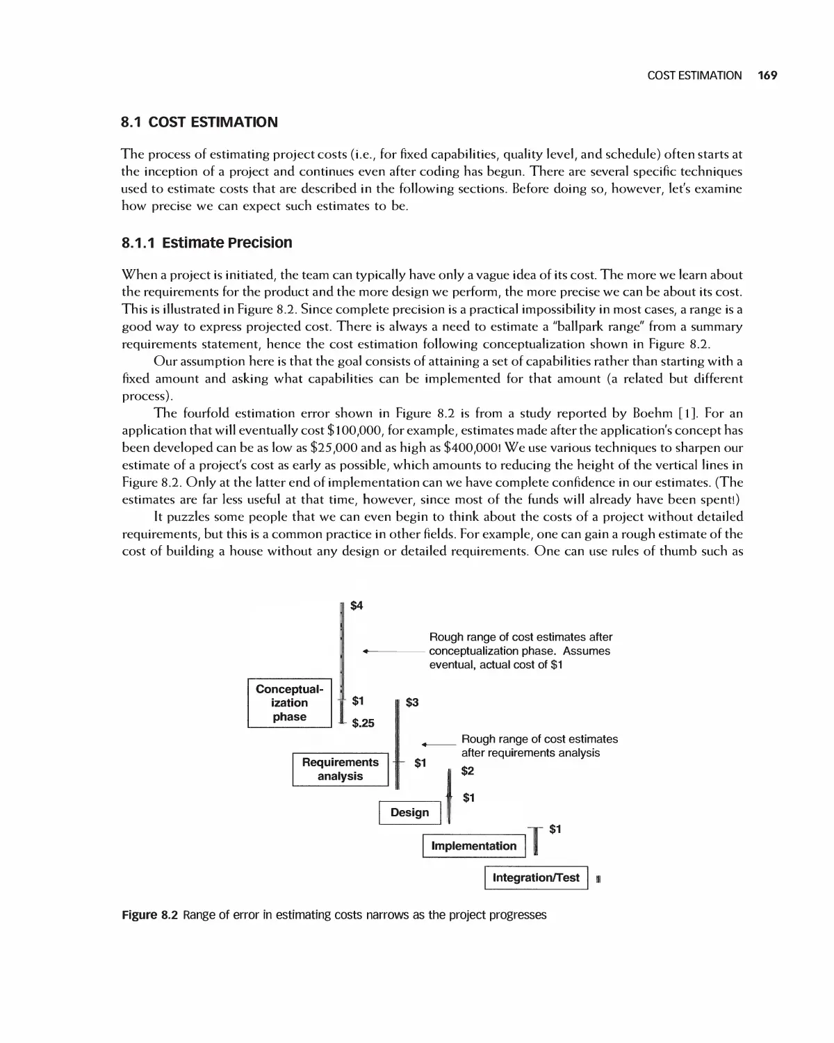
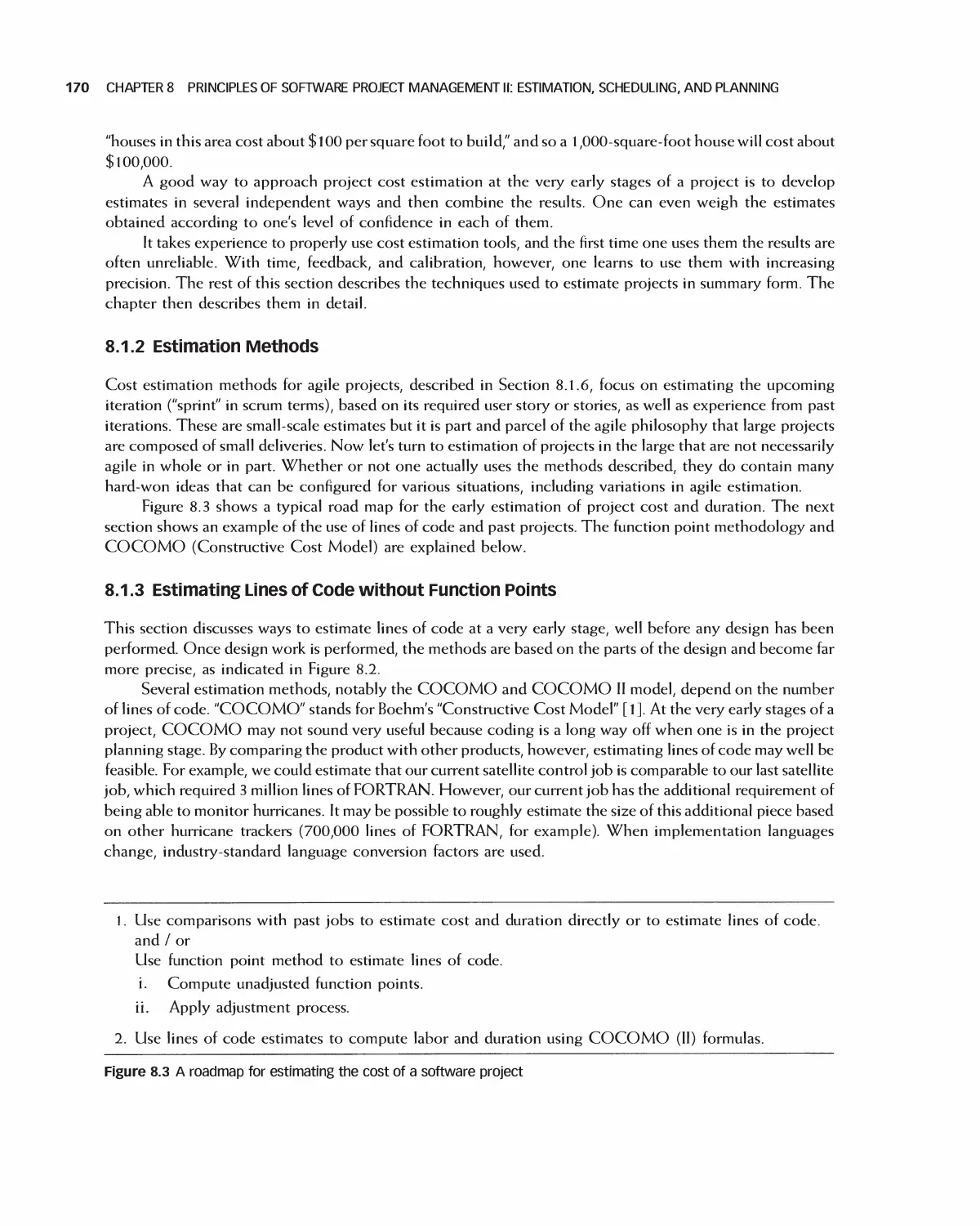
8.1 Cost Estimation 169
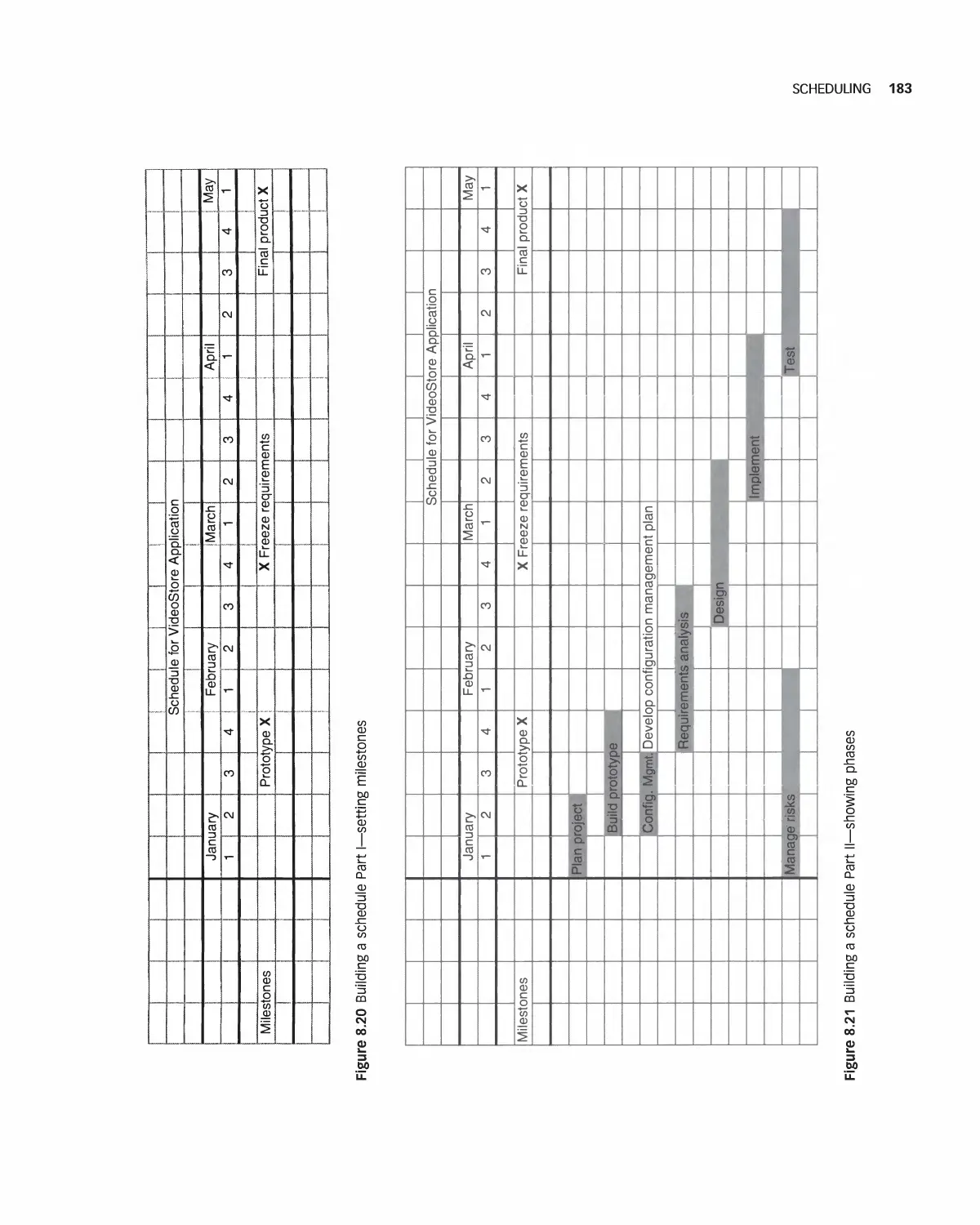
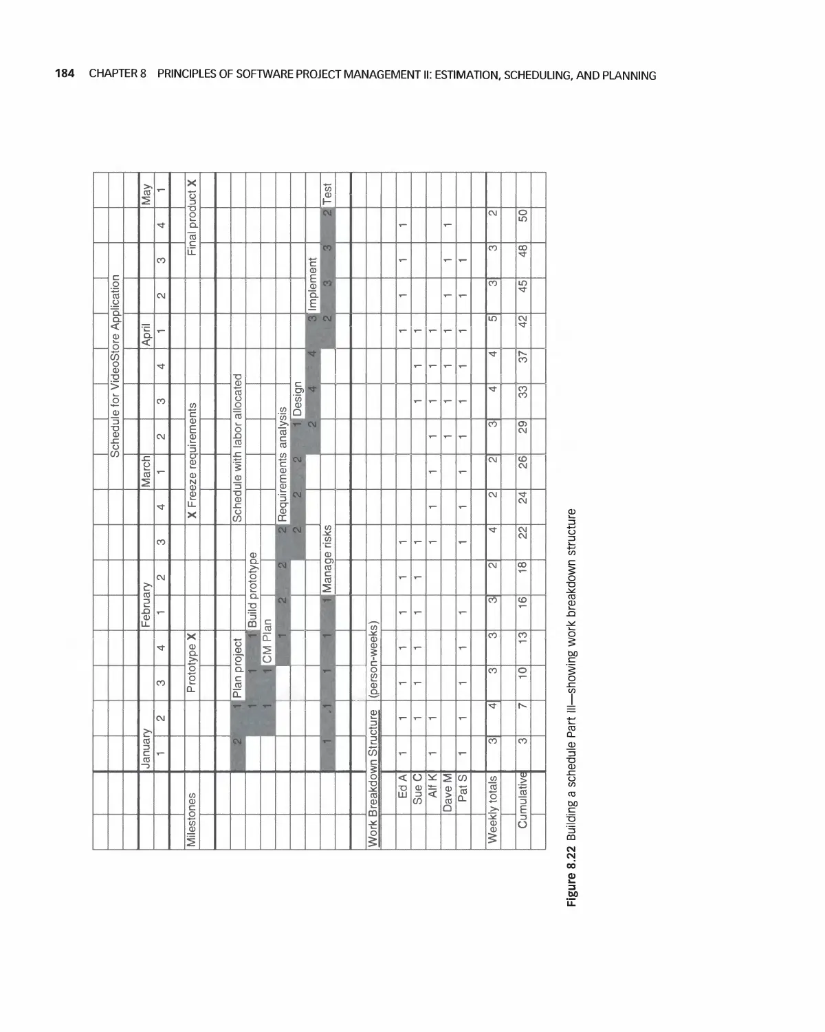
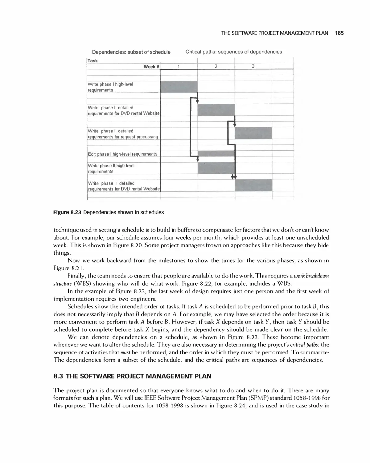
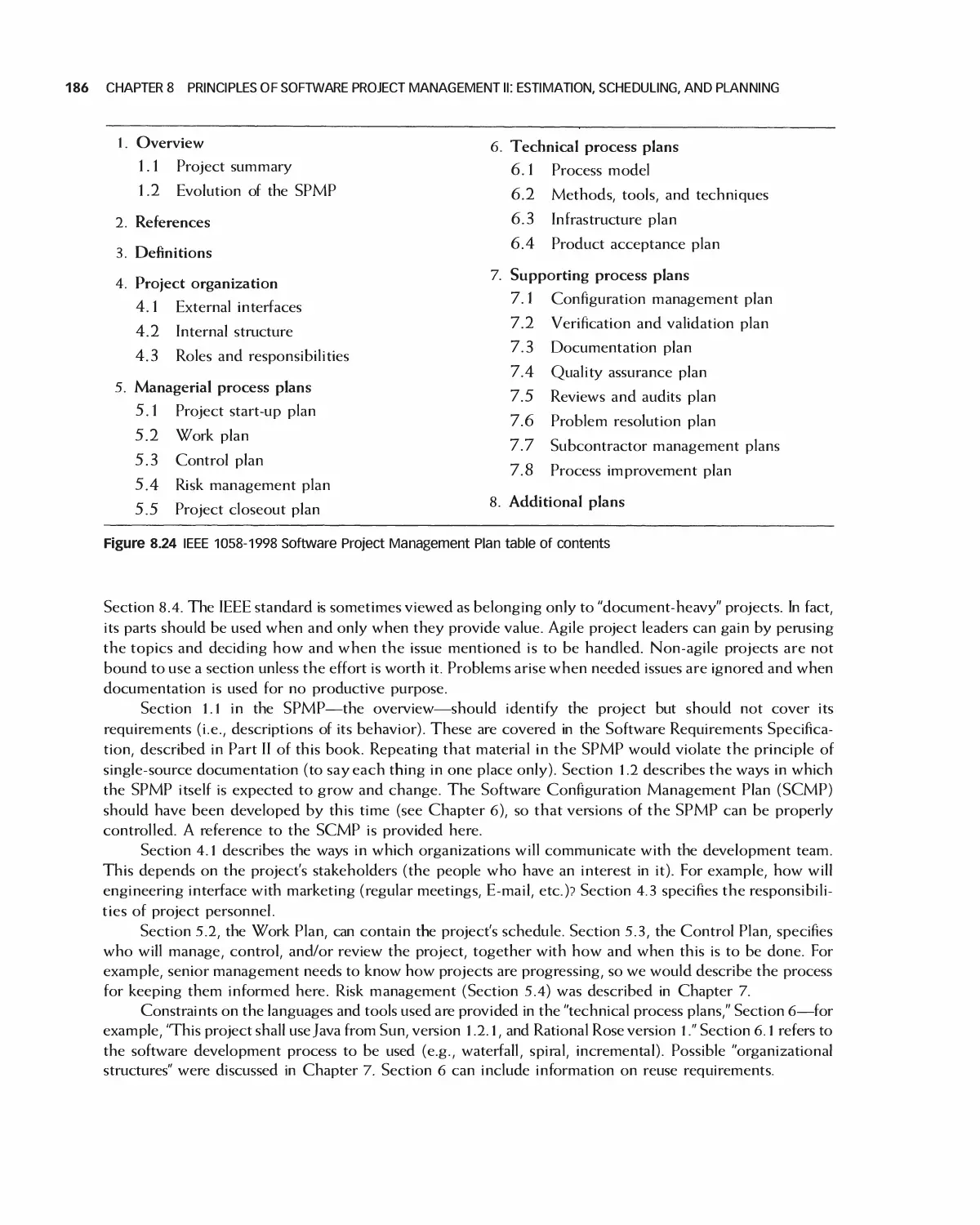
8.2 Scheduling 182
8.3 The Software Project Management Plan 185
8.4 Case Study: Encounter Project Management Plan 187
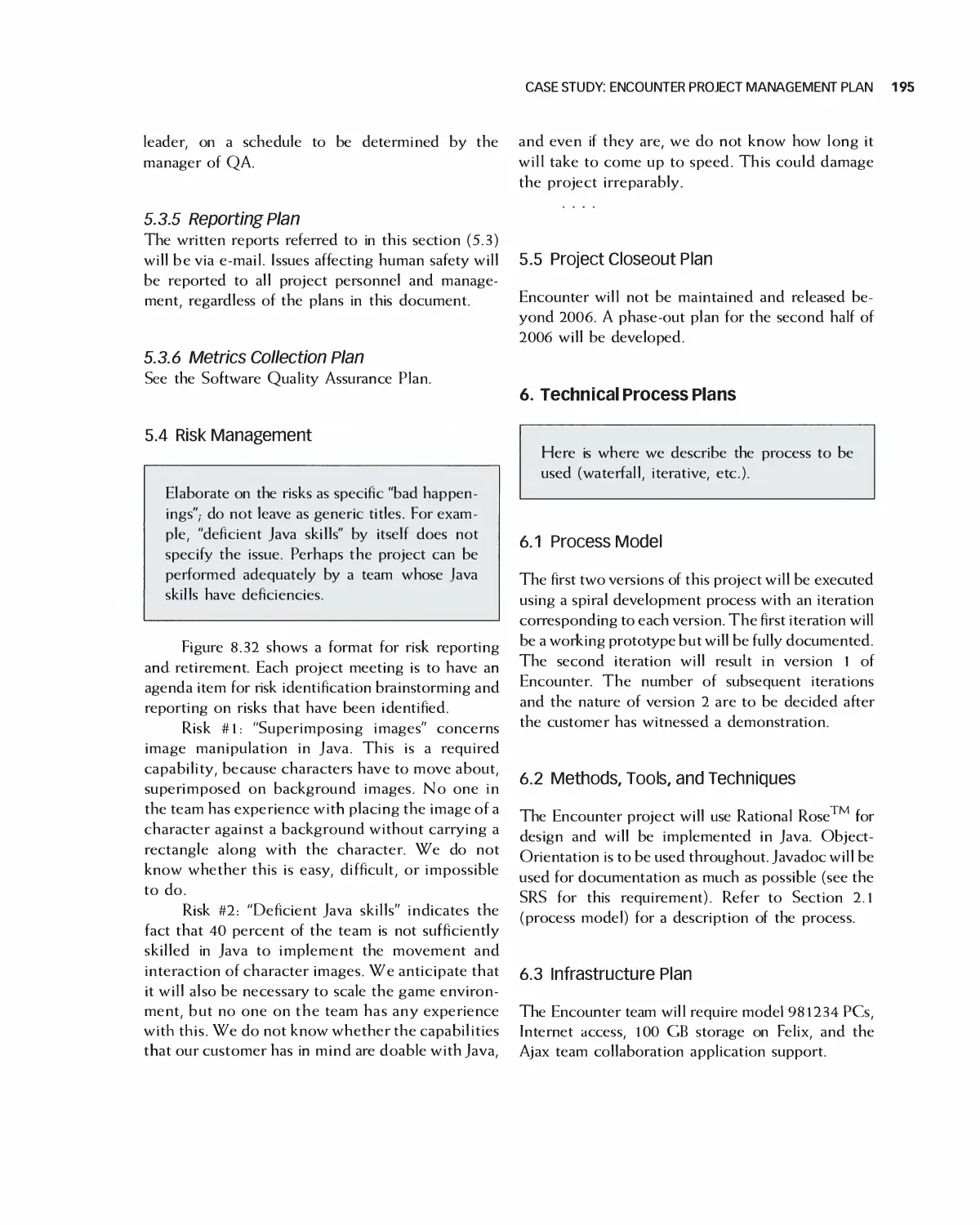
8.5 Case Study: Project Management in Eclipse 196
8.6 Case Study: Project Management for OpenOffice 205
8.7 Case Study: Student Team Guidance 208
8.8 Summary 210
8.9 Exercises 211
Bibliography 212
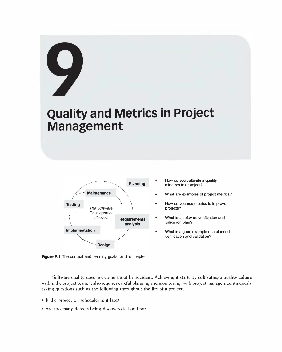
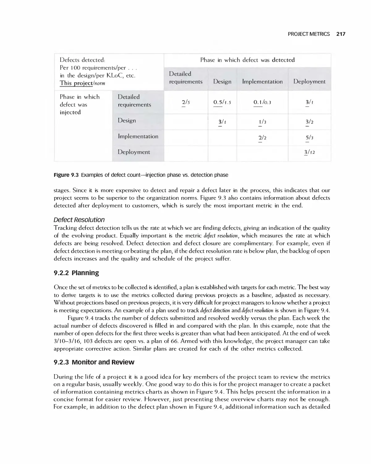
9 Quality and Metrics in Project Management 213
9.1 Cultivating and Planning Internal Qualify 214
9.2 Project Metrics 215
9.3 Using Metrics for Improvement 219
9.4 Software Verification and Validation Plan 223
9.5 Case Study: Software Verification and Validation Plan for Encounter 225
9.6 Summary 228
9.7 Exercises 228
Bibliography 229
PART IV Requirement Analysis
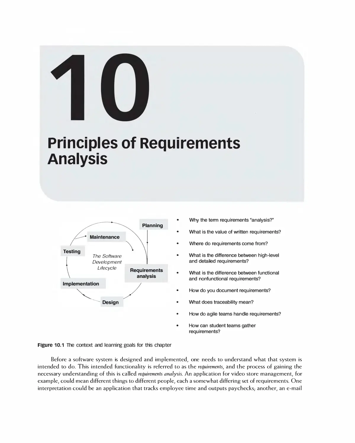
10 Principles of Requirements Analysis 230
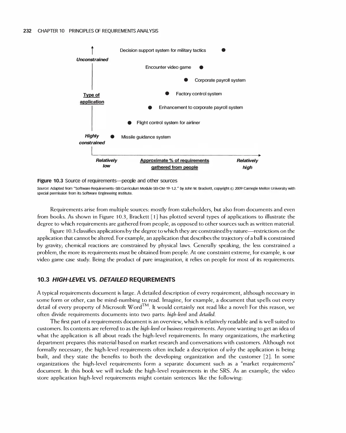
10.1 The Value of Requirements Analysis 231
10.2 Sources of Requirements 231
10.3 High-level vs. Detailed Requirements 232
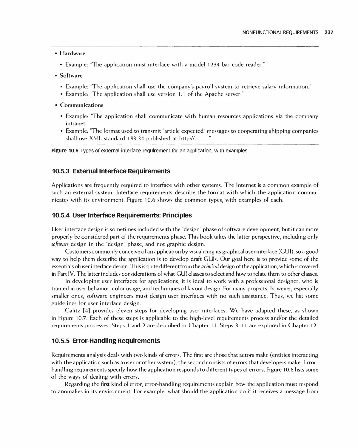
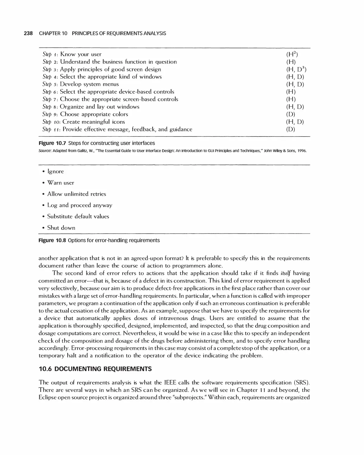
10.4 Types of Requirements 233
10.5 Nonfunctional Requirements 233
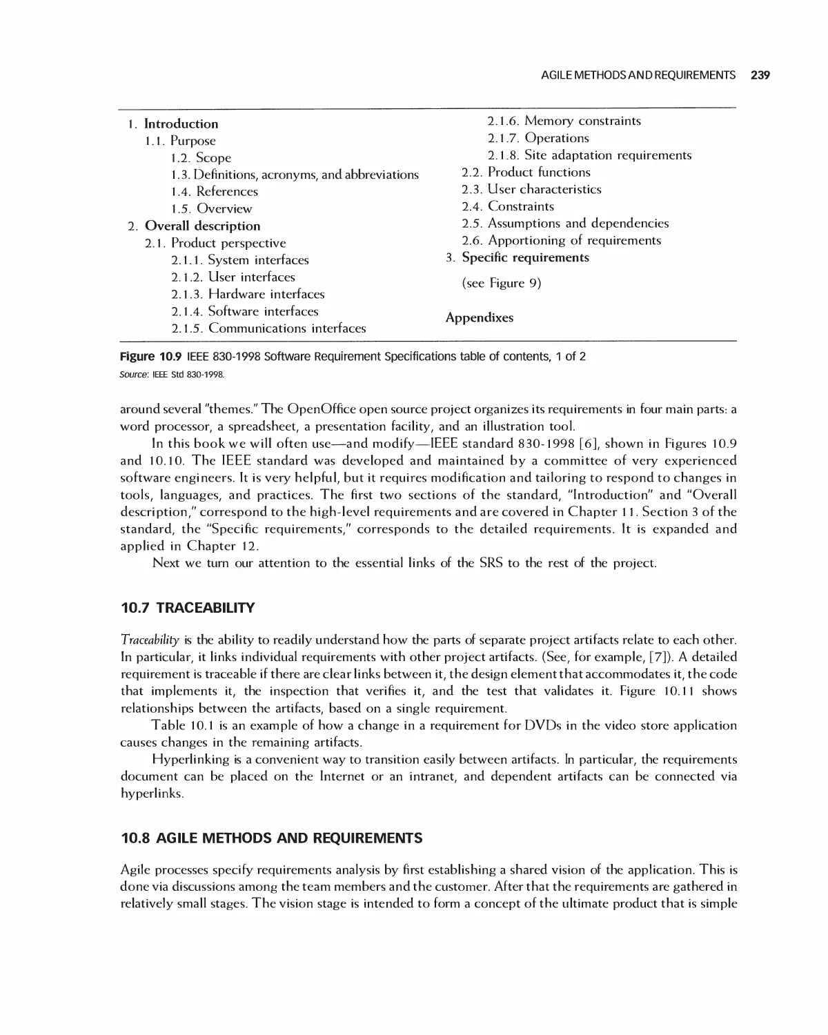
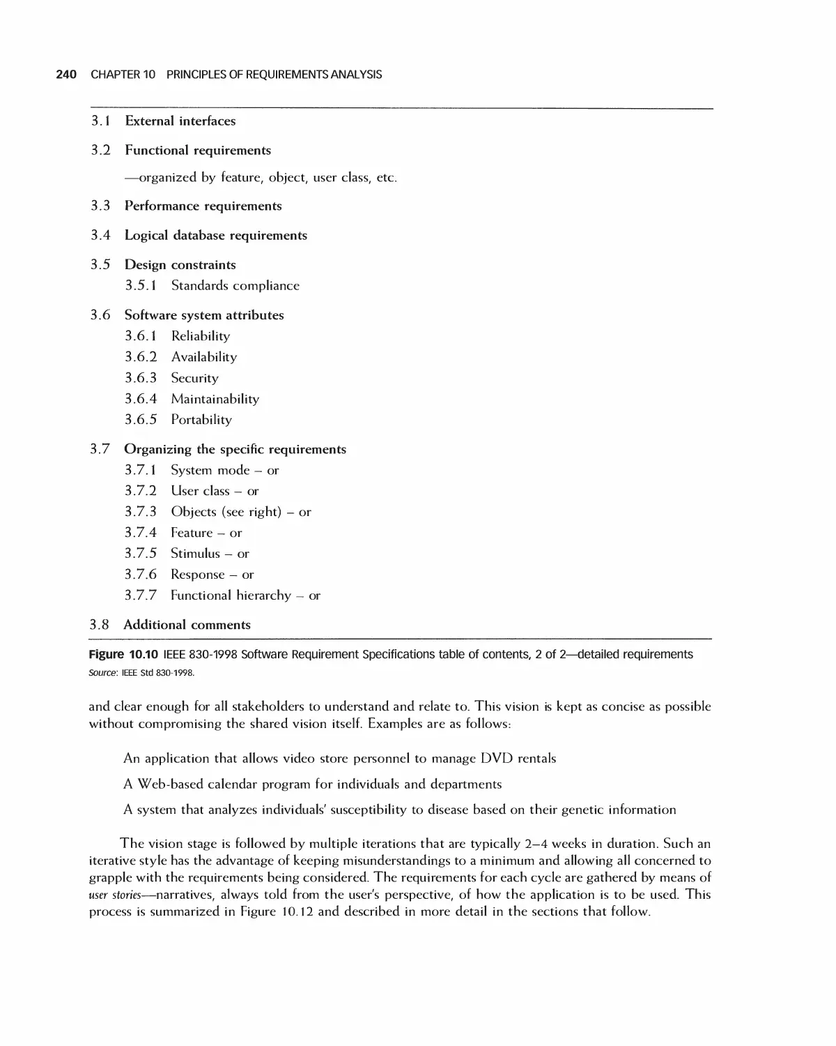
10.6 Documenting Requirements 238
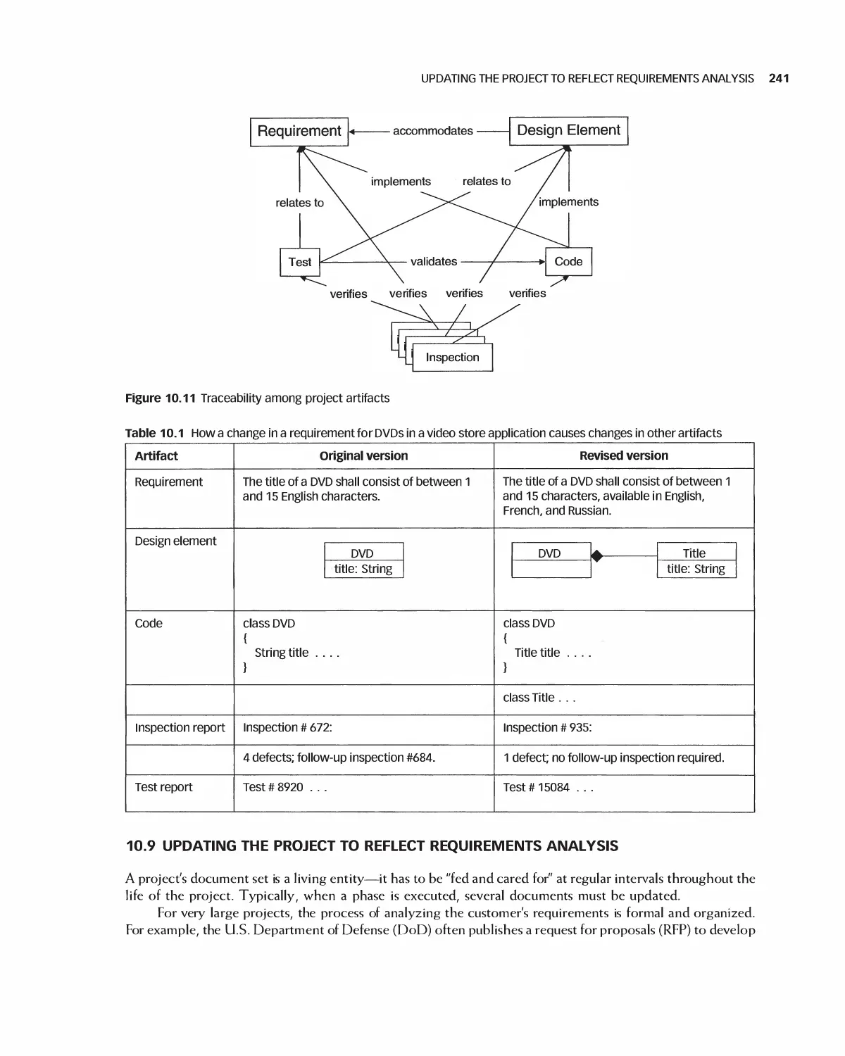
10.7 Traceability 239
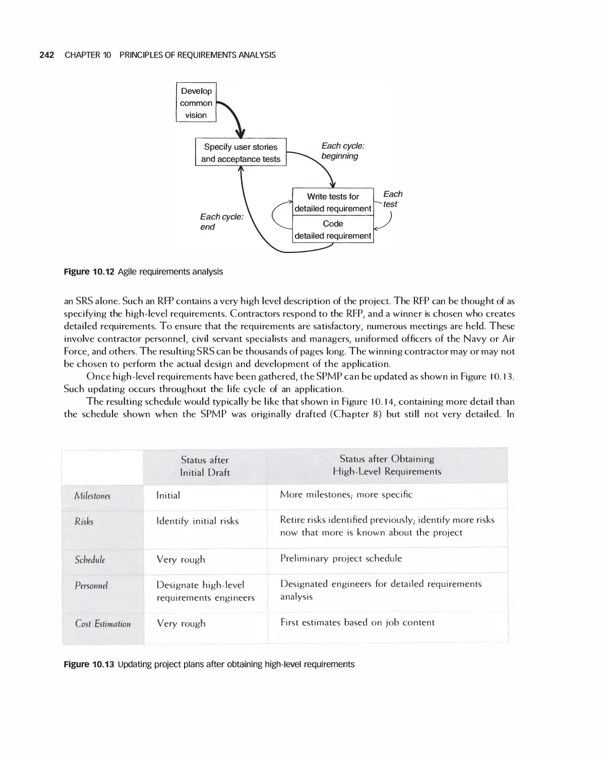
10.8 Agile Methods and Requirements 239
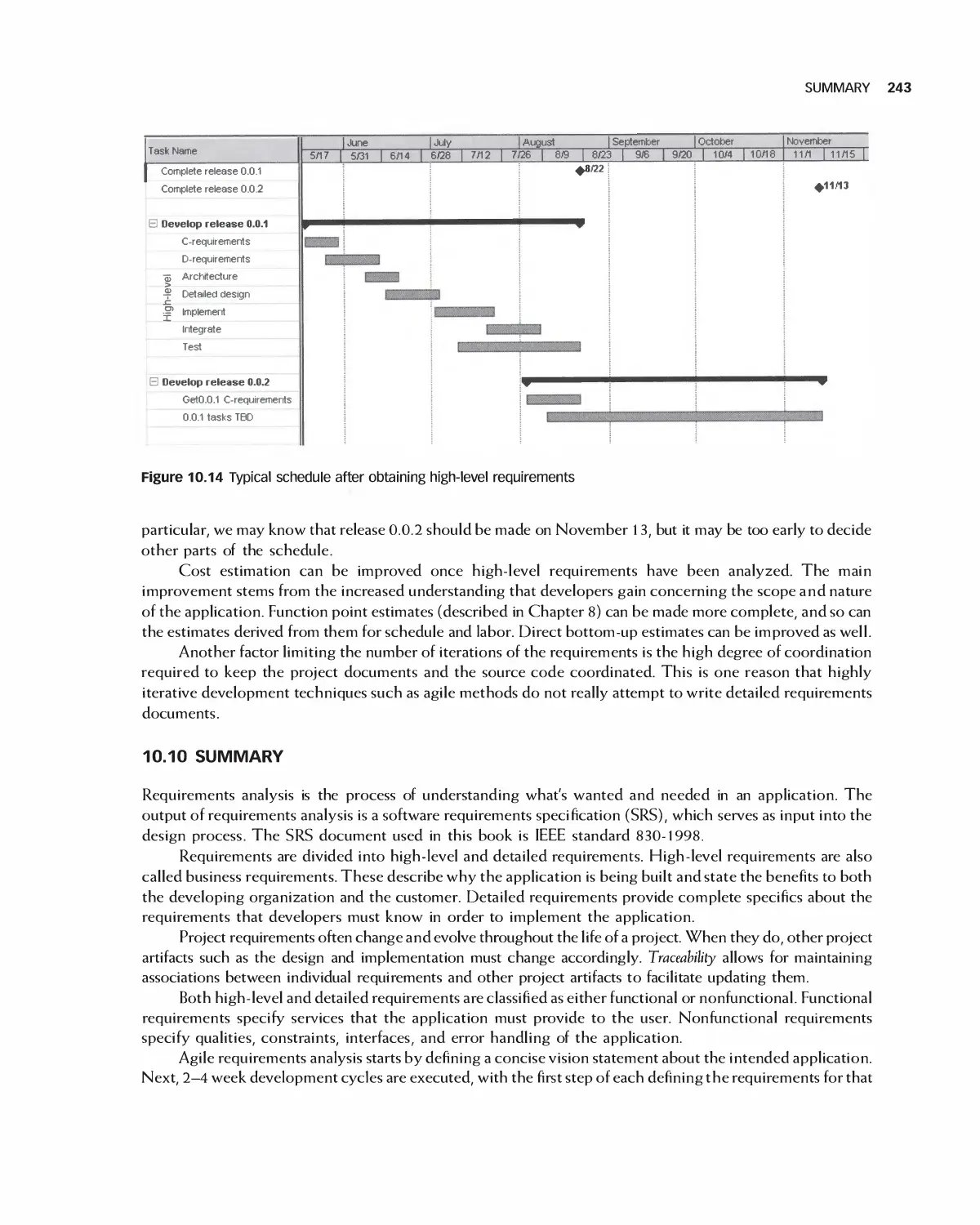
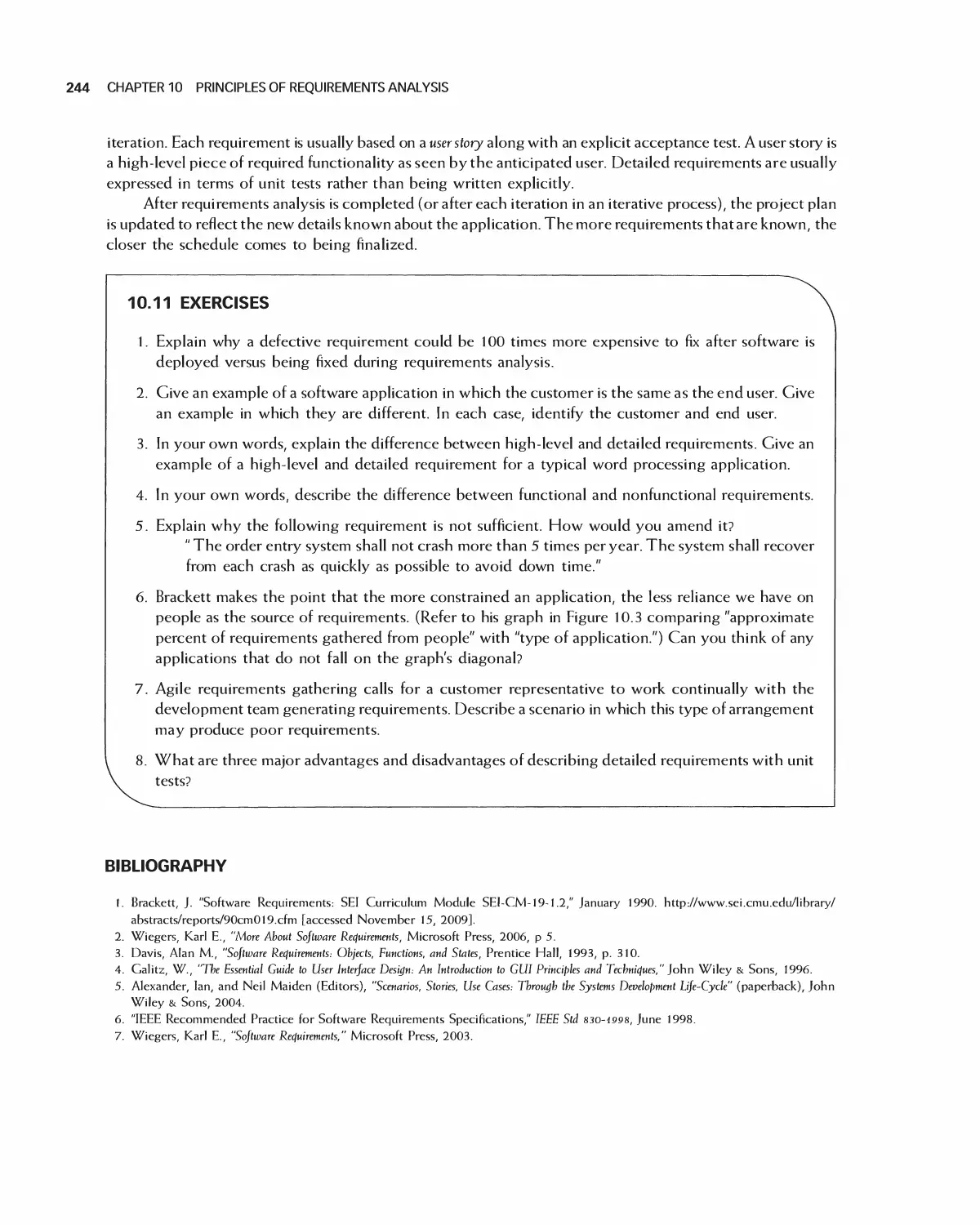
10.9 Updating the Project to Reflect Requirements Analysis 241
10.10 Summary 243
10.11 Exercises 244
Bibliography 244
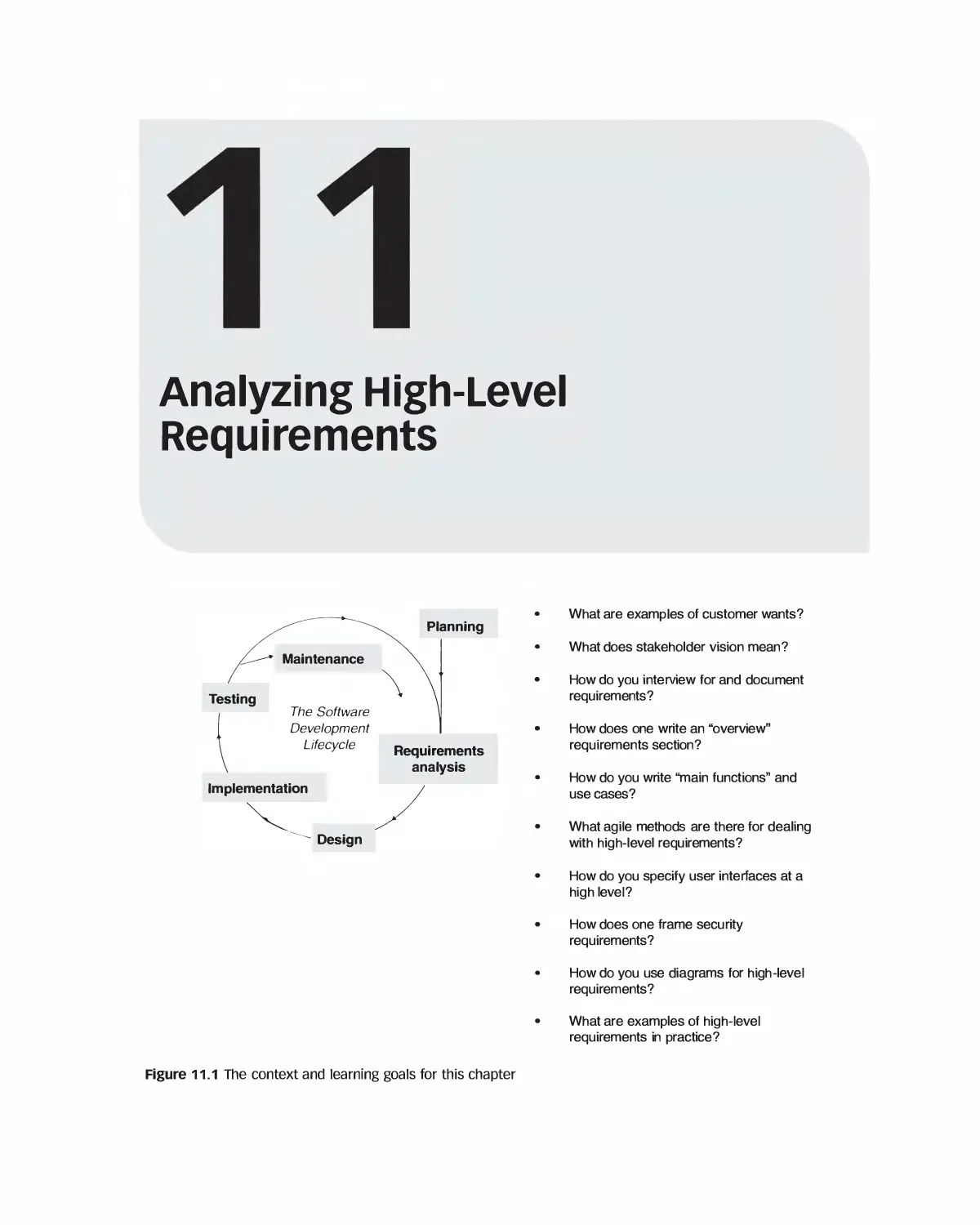
11 Analyzing High-Level Requirements 245
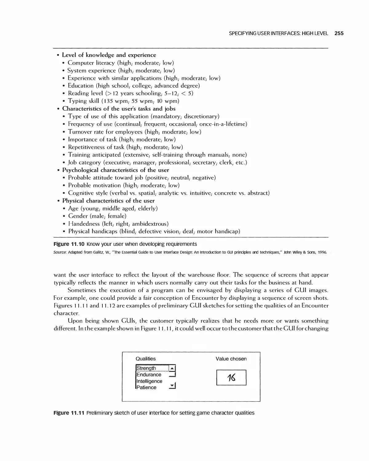
11.1 Examples of Customer Wants 246
1 1.2 Stakeholder Vision 247
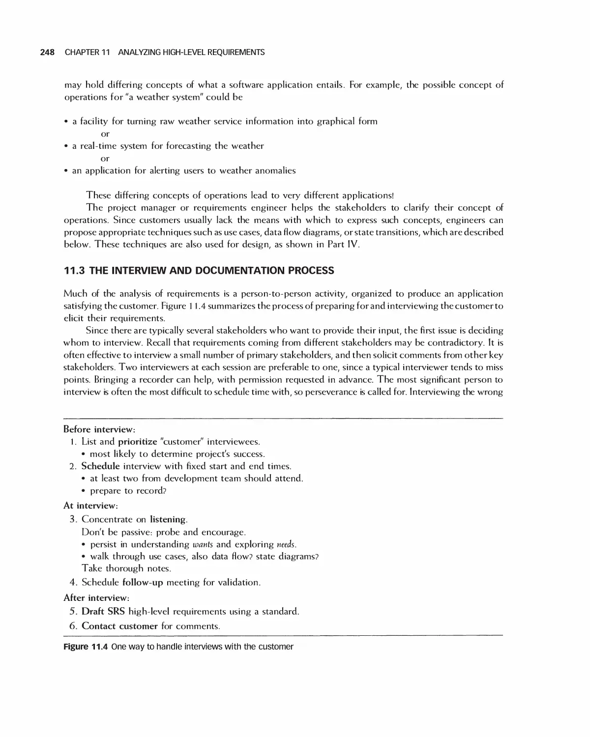
11.3 The Interview and Documentation Process 248
Viii CONTENTS
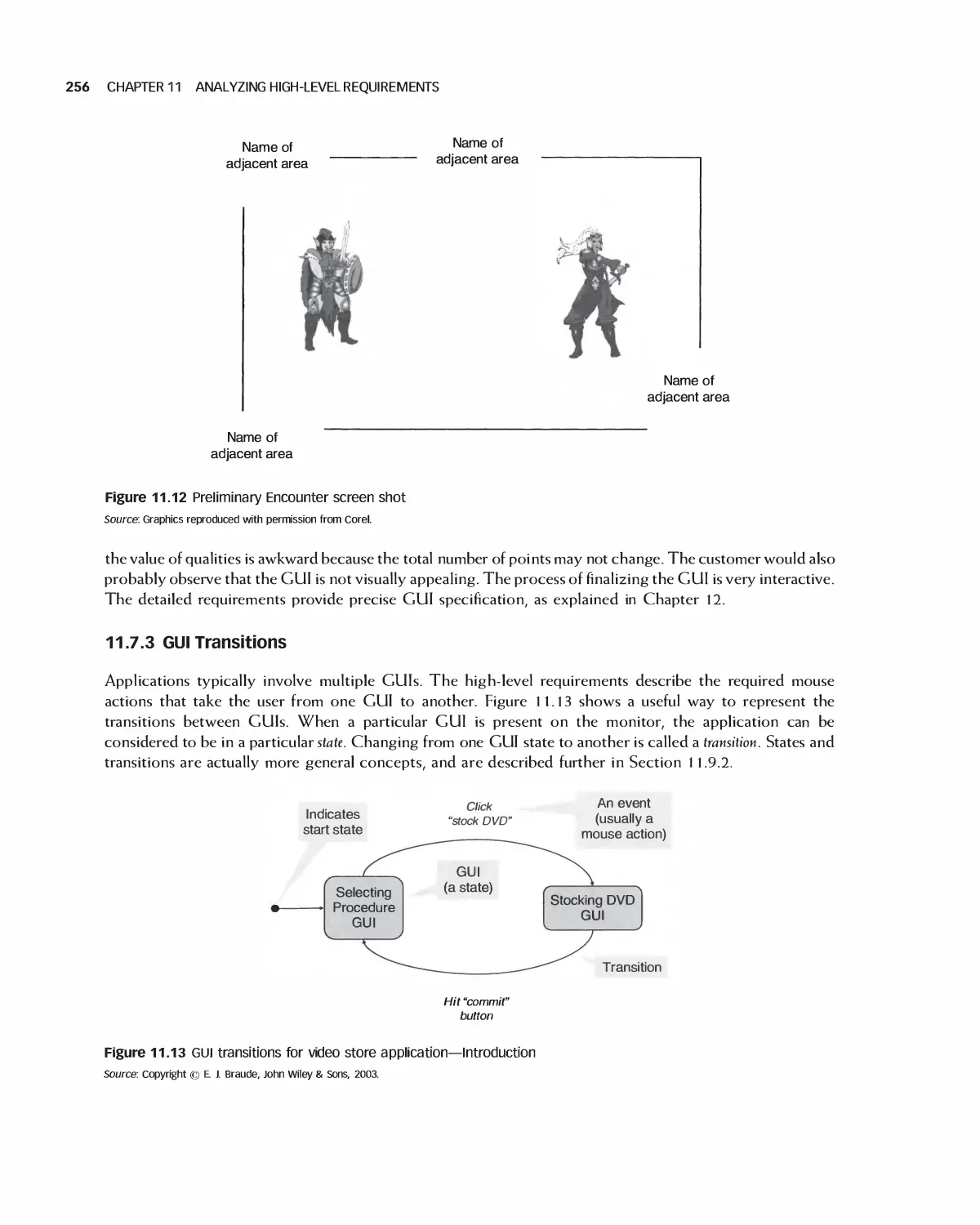
11.4 Writing an Overview 249
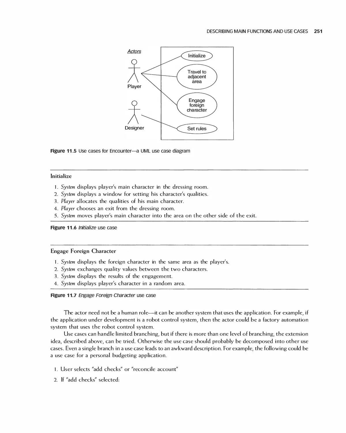
11.5 Describing Main Functions and Use Cases 249
11.6 Agile Methods for High-Level Requirements 252
11.7 Specifying User Interfaces: High Level 254
11.8 Security Requirements 258
11.9 Using Diagrams for High-Level Requirement 260
11.10 Case Study: High-Level Software Requirements Specification
(SRS) for the Encounter Video Game 264
11.11 Case Study: High-Level Requirements for Eclipse 268
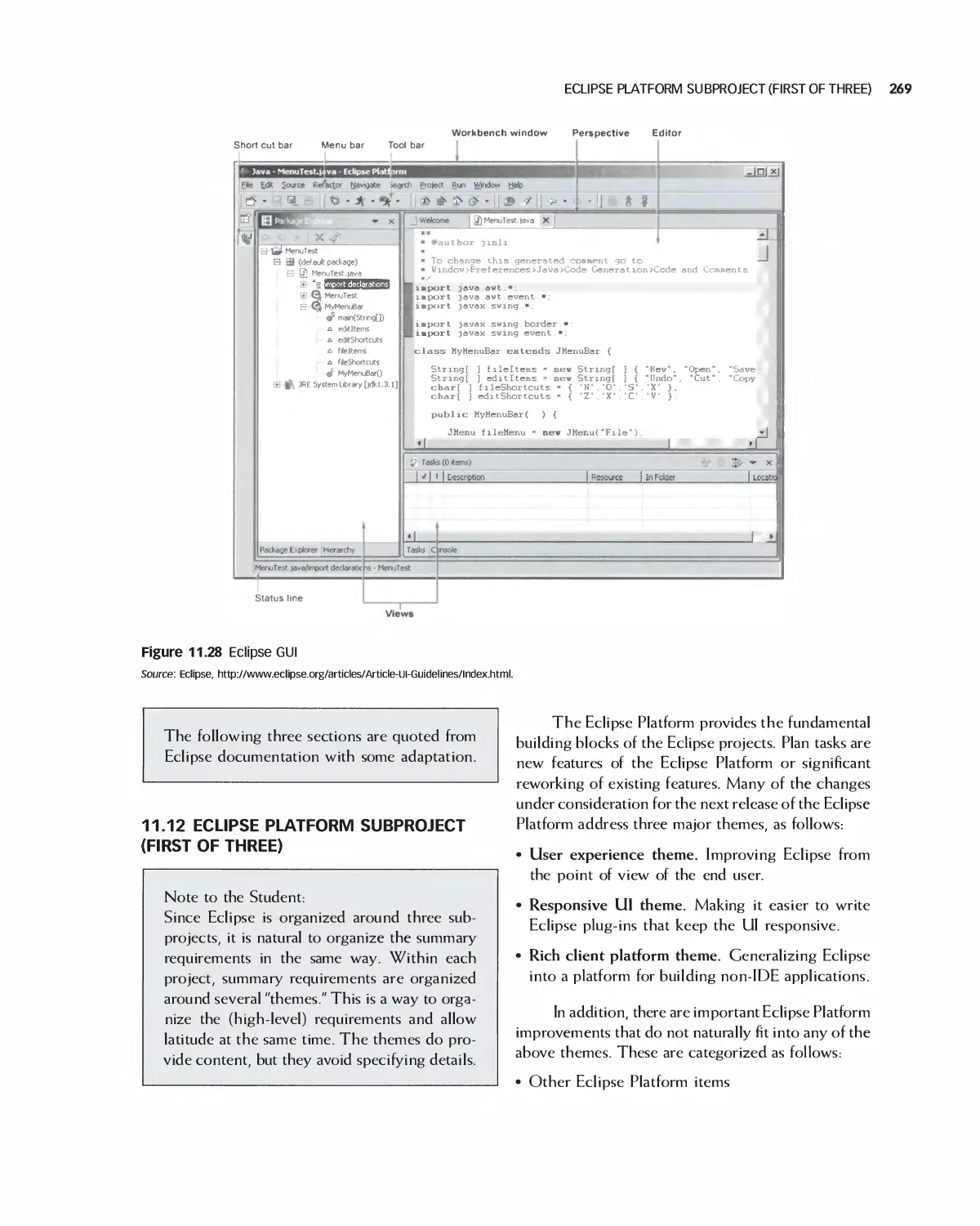
11.12 Eclipse Platform Subproject (First of three) 269
11.13 Case Study: High-Level Requirements for OpenOffice 273
1 1.14 Summary 275
11.15 Exercises 275
Bibliography 276
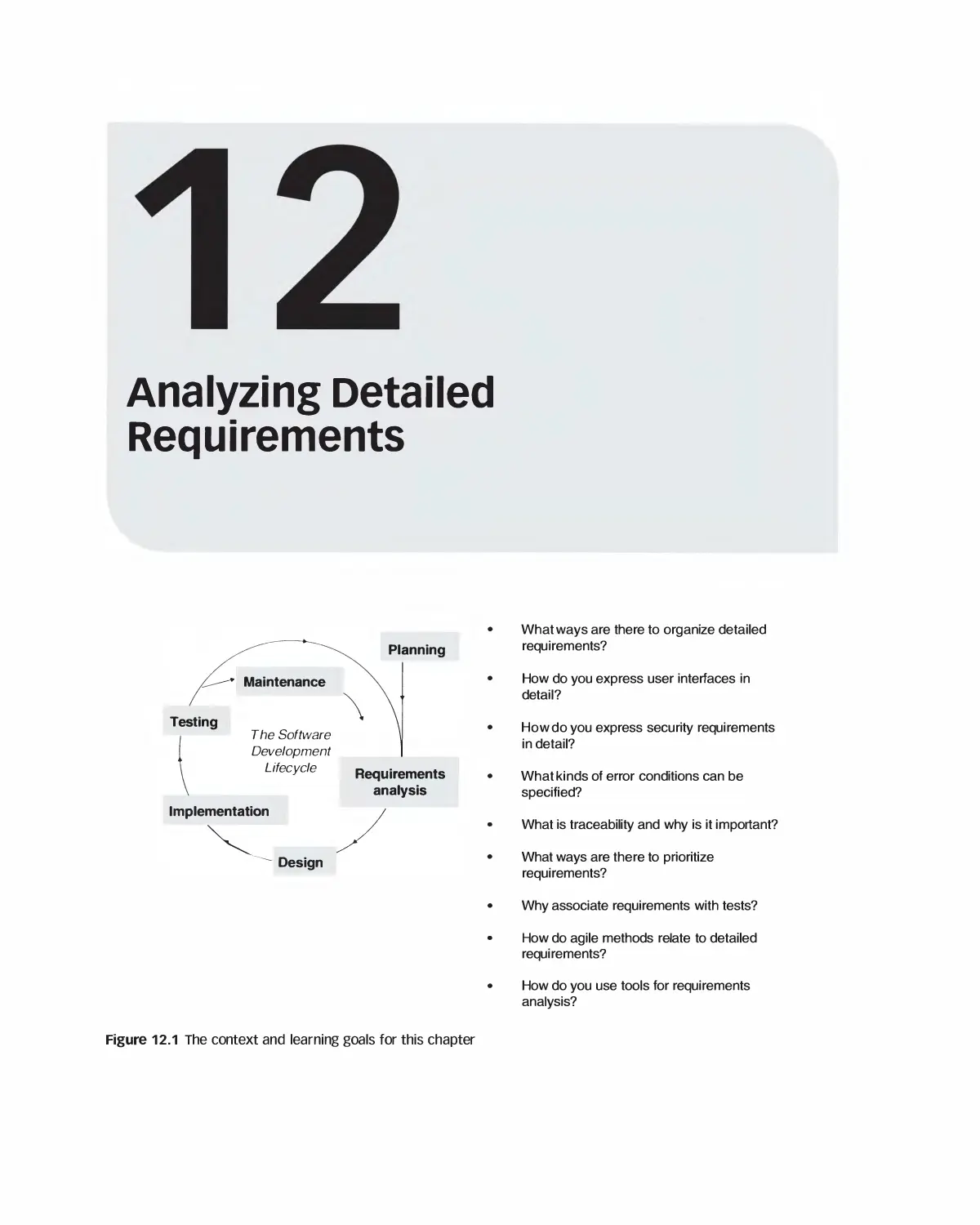
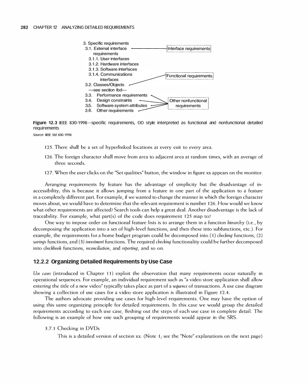
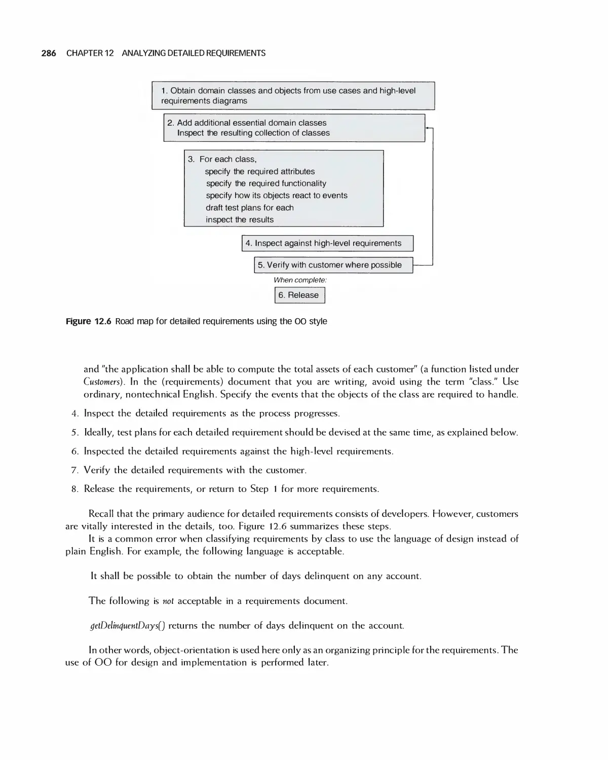
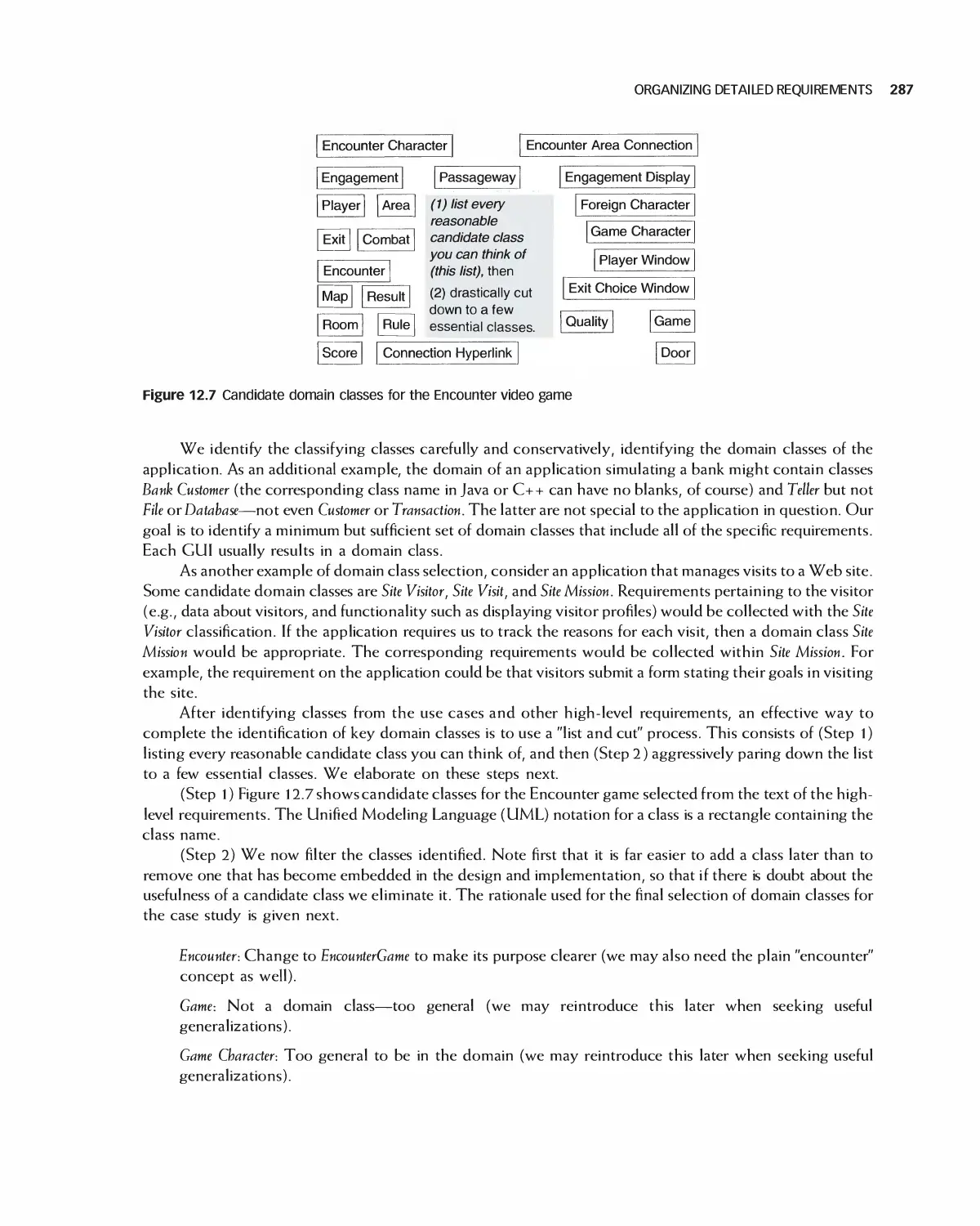
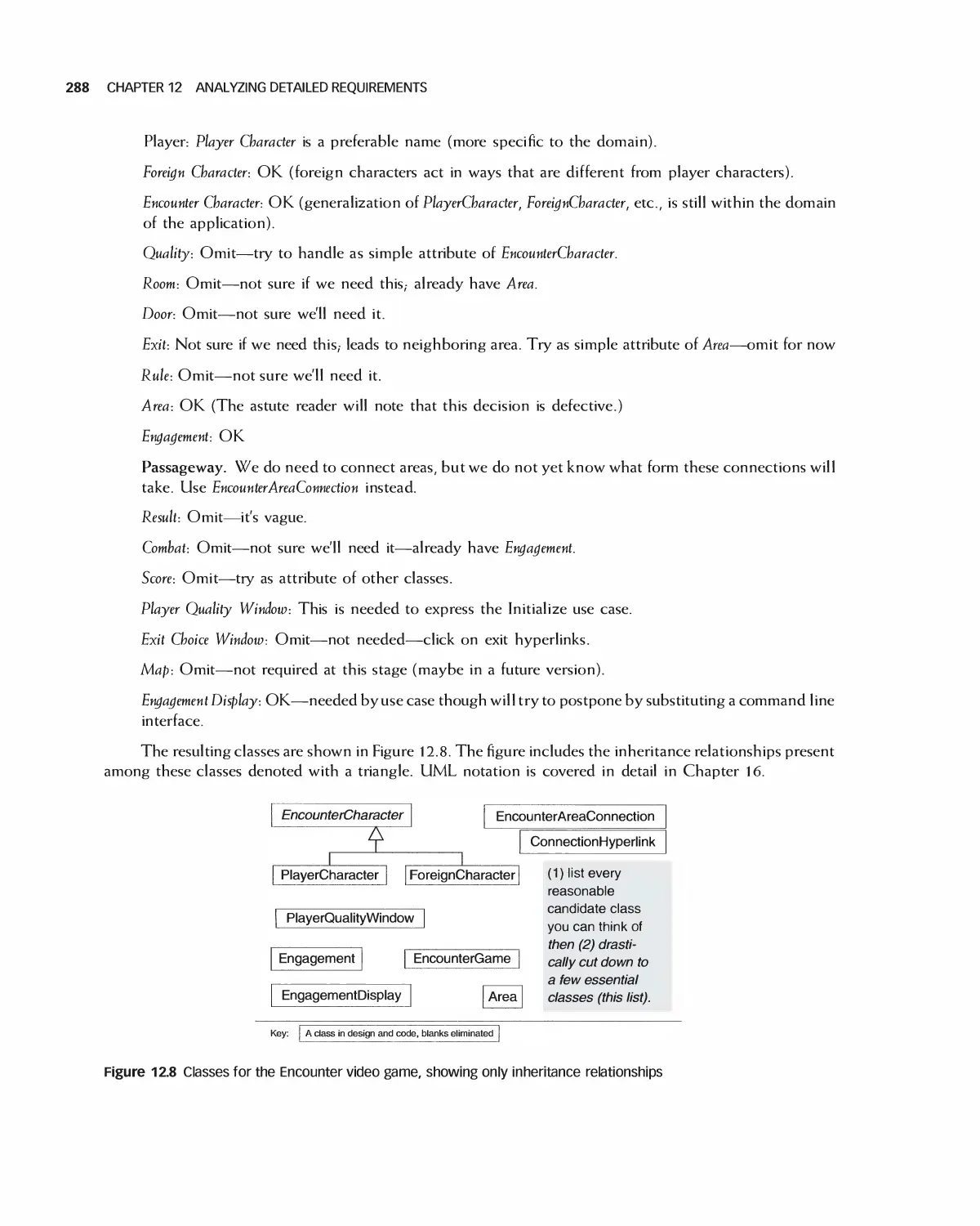
12 Analyzing Detailed Requirements 278
12.1 The Meaning of Detailed Requirements 279
12.2 Organizing Detailed Requirements 280
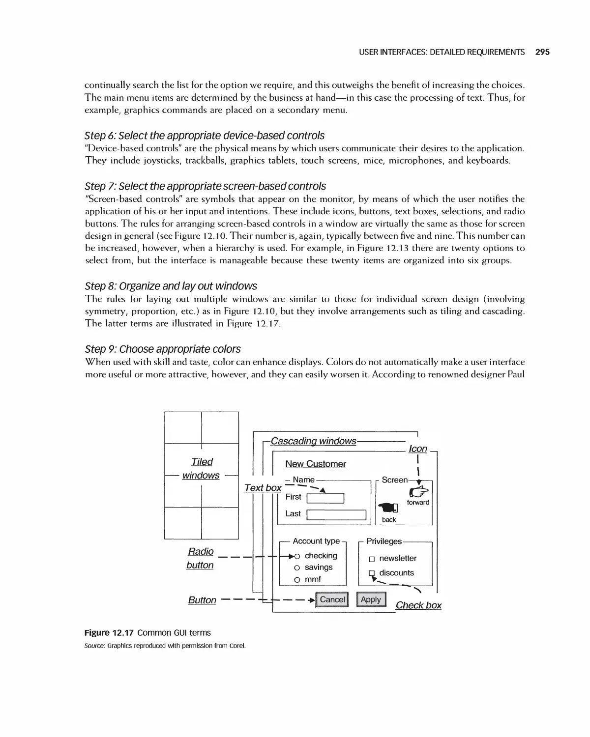
12.3 User Interfaces: Detailed Requirements 291
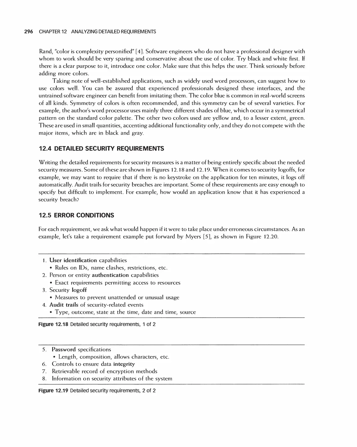
12.4 Detailed Security Requirements 296
12.5 Error Conditions 296
12.6 Traceability of Detailed Requirements 297
12.7 Using Detailed Requirements to Manage Projects 300
12.8 Prioritizing Requirements 301
12.9 Associating Requirements with Tests 302
12.10 Agile Methods for Detailed Requirements 303
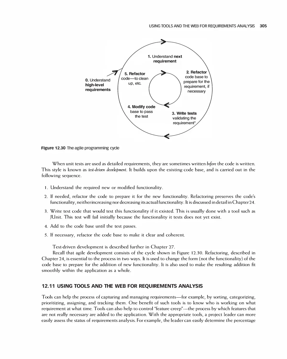
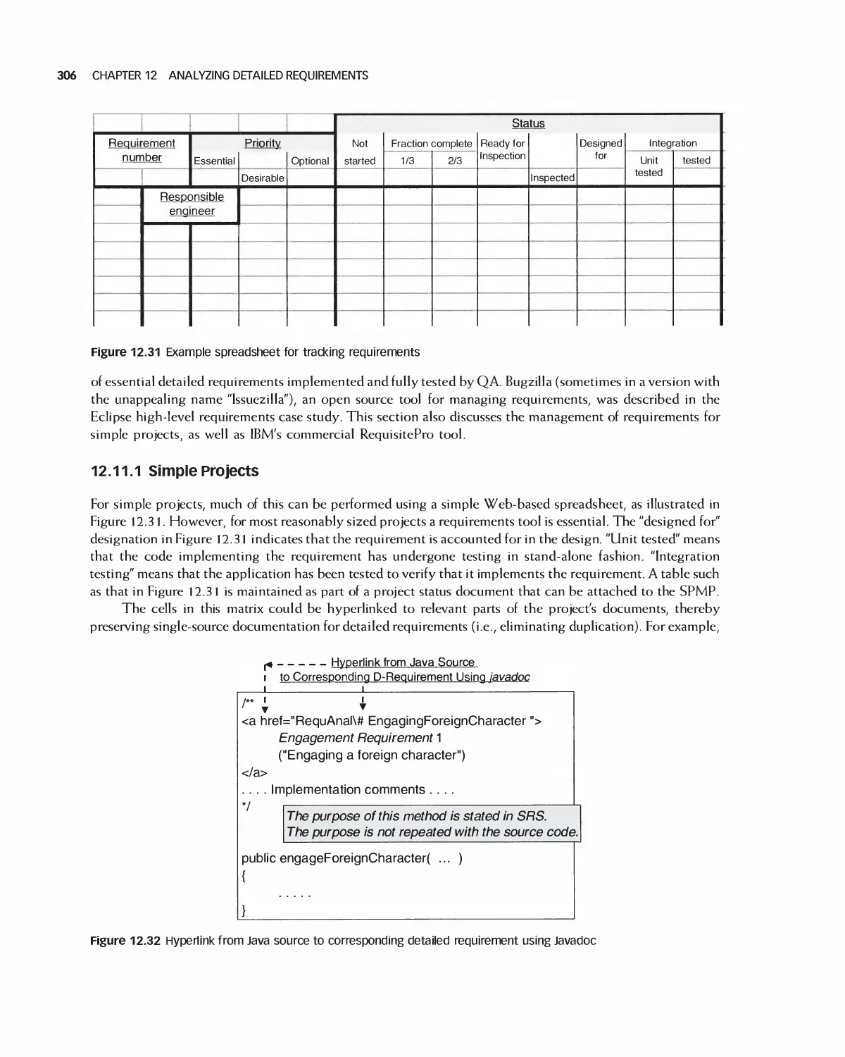
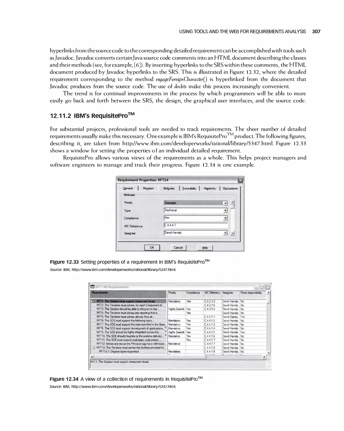
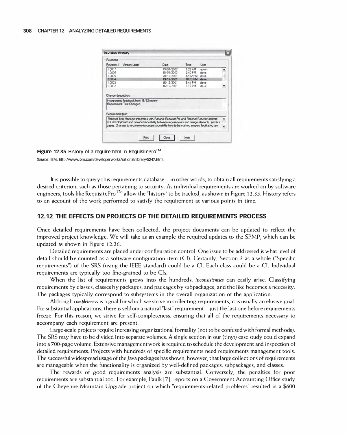
12.11 Using Tools and the Web for Requirements Analysis 305
12.12 The Effects on Projects of the Detailed Requirements Process 308
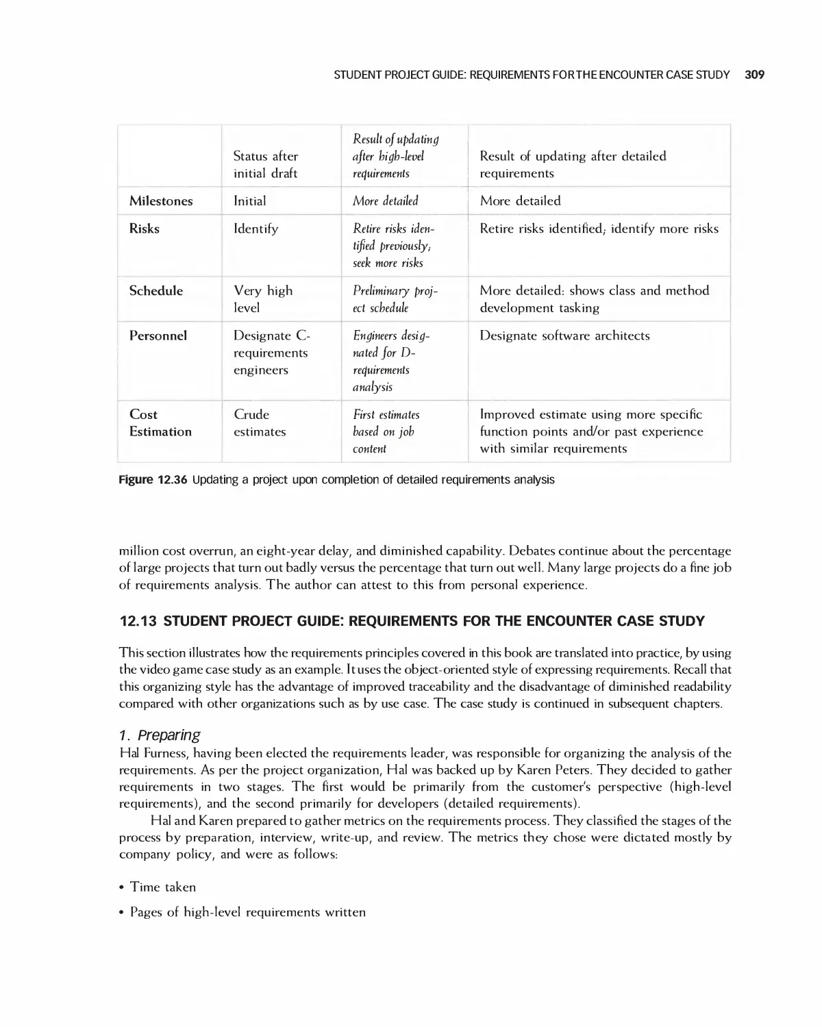
12.13 Student Project Guide: Requirements for the Encounter Case Study 309
12.14 Case Study: Detailed Requirements for the Encounter Video Game 315
12.15 Summary 328
12.16 Exercises 329
Bibliography 330
13 Quality and Metrics in Requirements Analysis 331
13.1 Quality of Requirements for Agile Projects 332
13.2 Accessibility of Requirements 332
13.3 Comprehensiveness of Requirements 333
13.4 Understandability of Requirements 335
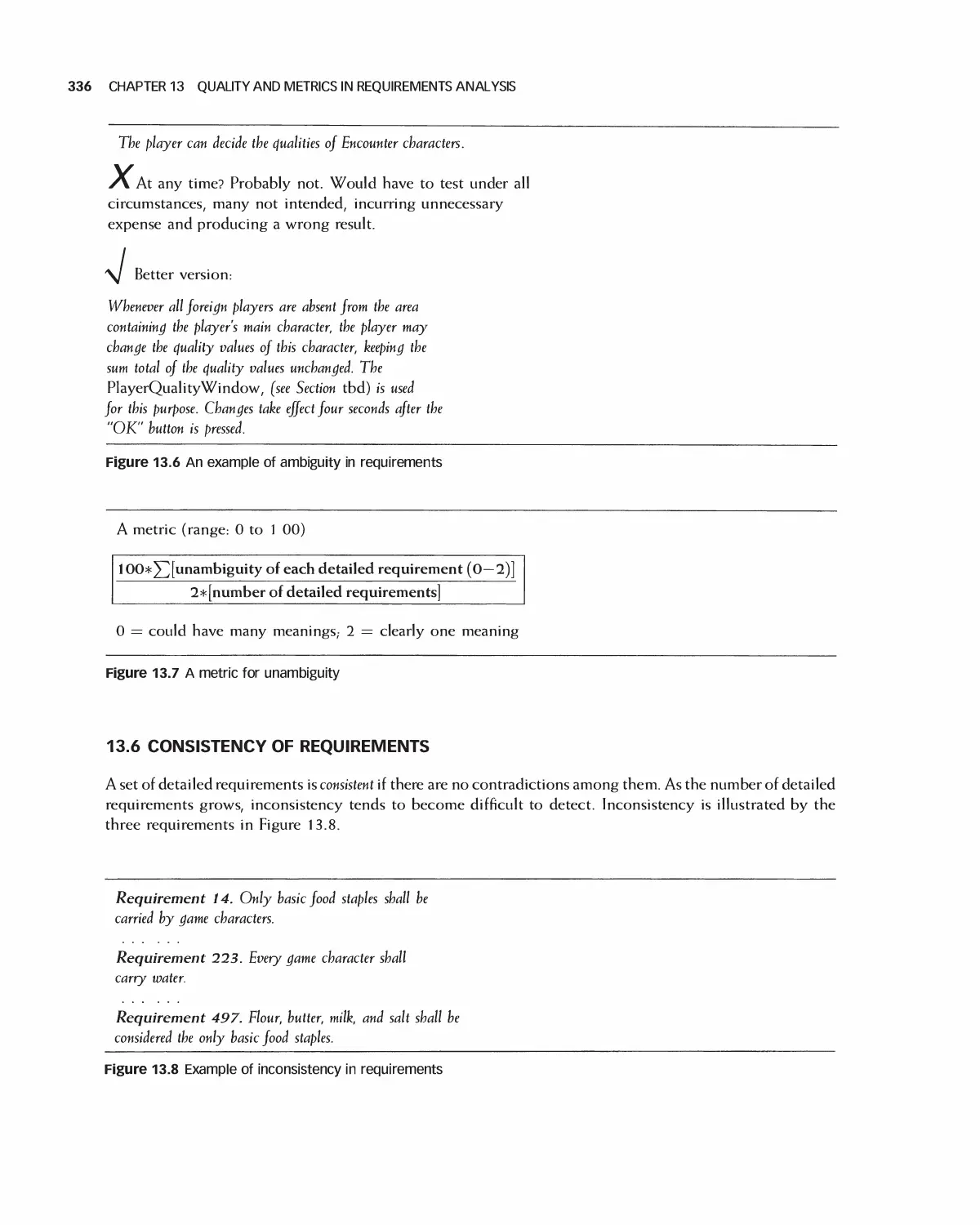
13.5 Unambiguity of Requirements 335
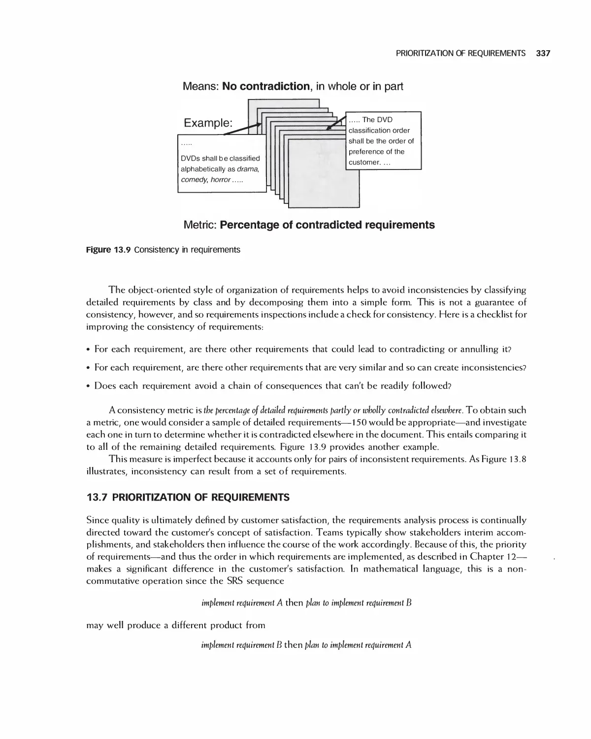
13.6 Consistency of Requirements 336
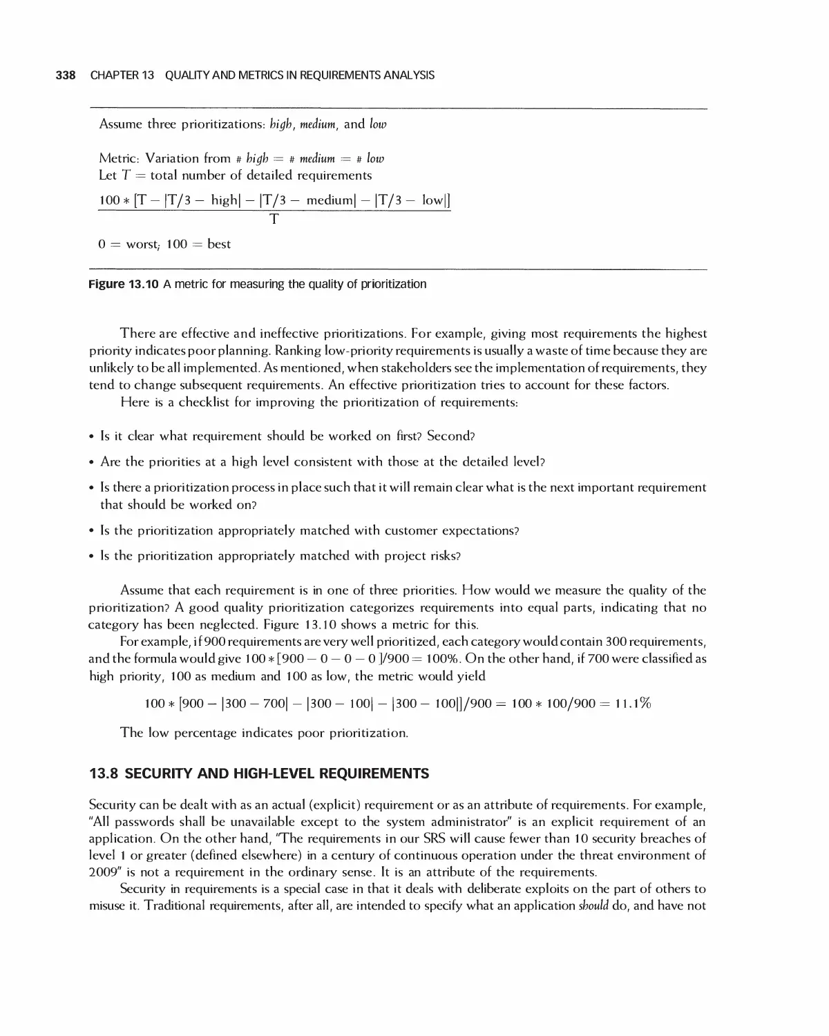
13.7 Prioritization of Requirements 337
13.8 Security and High-Level Requirements 338
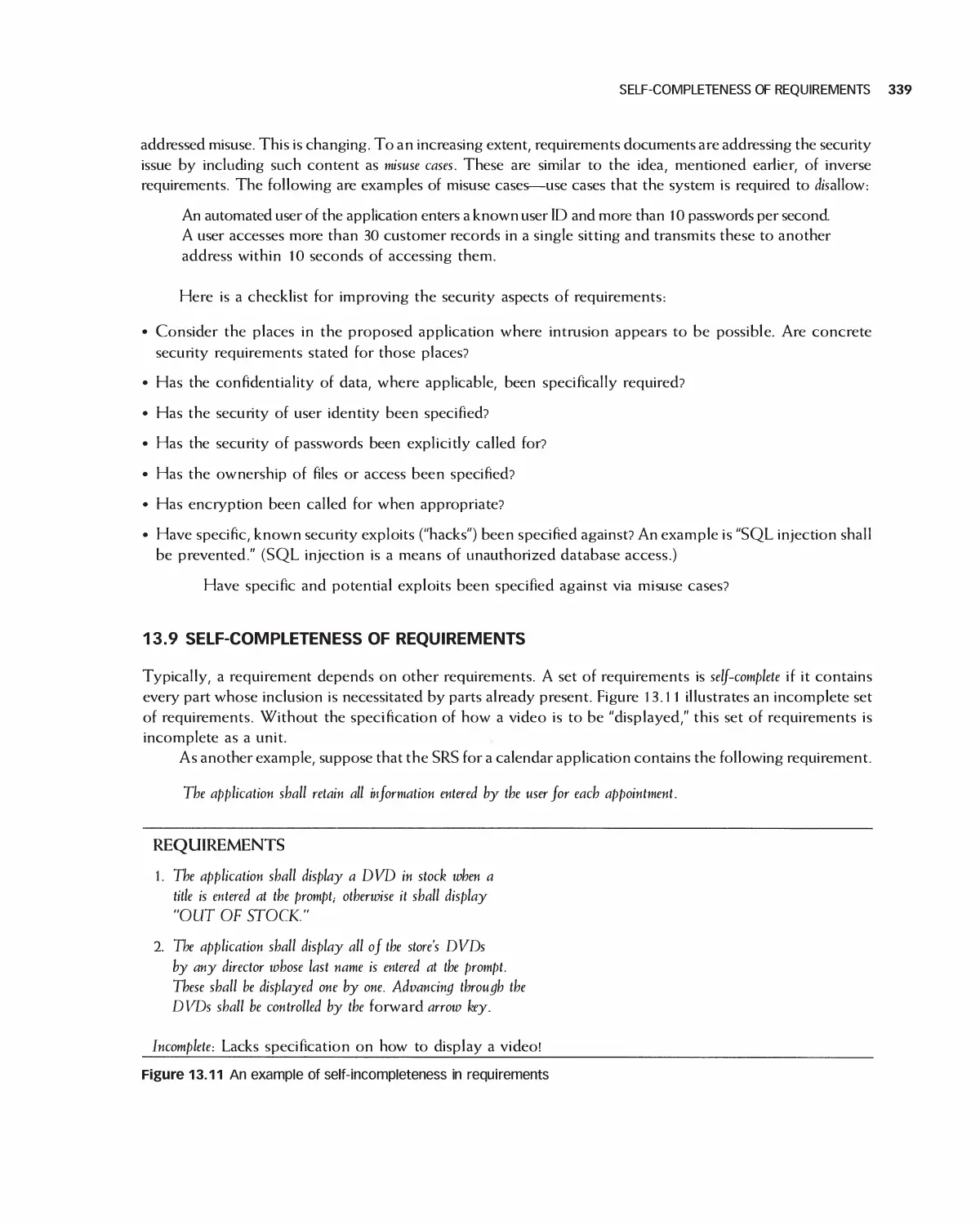
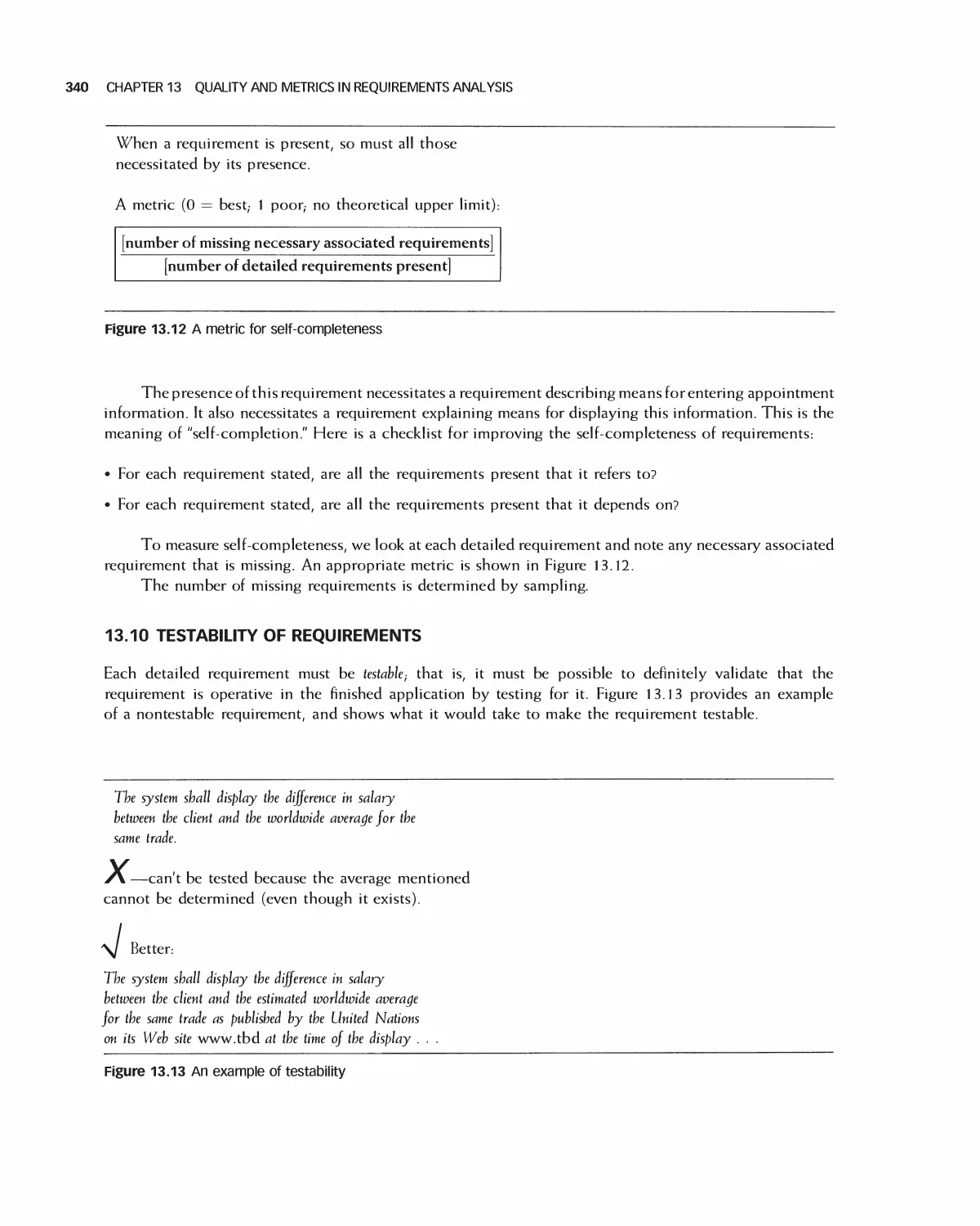
13.9 Self-Completeness of Requirements 339
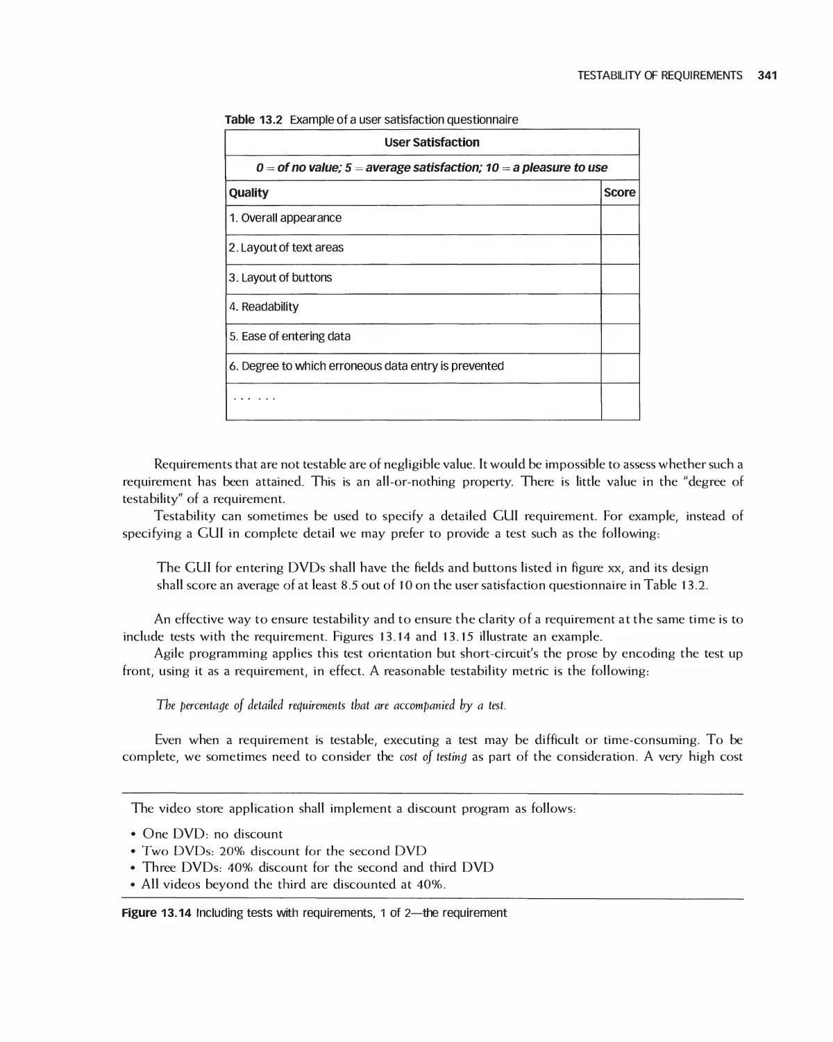
13.10 Testability of Requirements 340
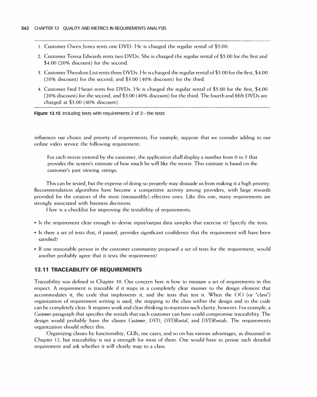
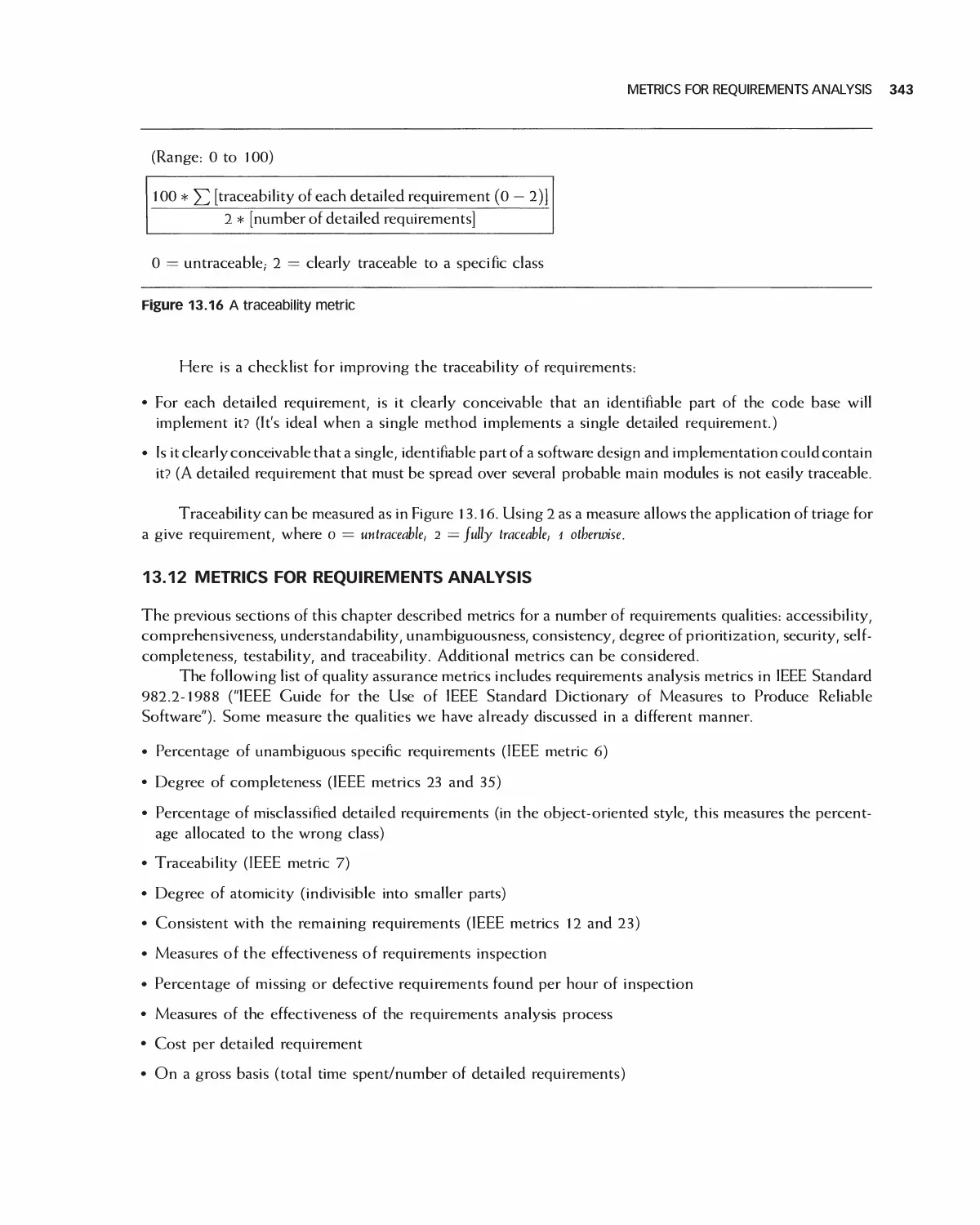
13.11 Traceability of Requirements 342
13.12 Metrics for Requirements Analysis 343
CONTENTS iX
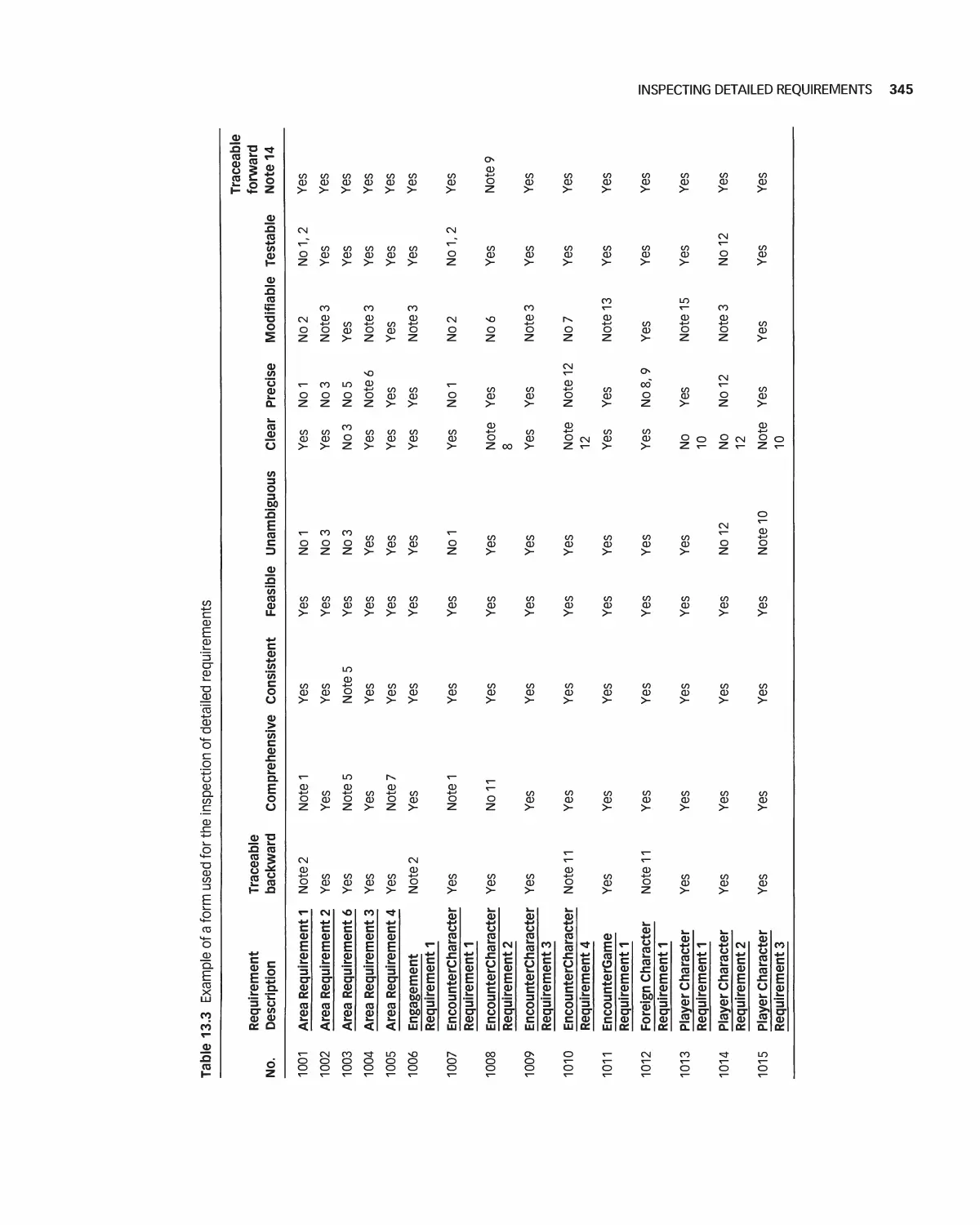
13.13 Inspecting Detailed Requirements 344
13.14 Summary 347
13.15 Exercises 348
14 Formal and Emerging Methods in Requirements Analysis: An Introduction
(Online Chapter) 349
14.1 Provable Requirements Method
14.2 Introduction to Formal Methods
14.3 Mathematical Preliminaries
14.4 The 2-Specification Language
14.5 The B Language System
14.6 Trade-offs for Using a B-like system
14.7 Summary
14.8 Exercises
Bibliography
PART V Software Design
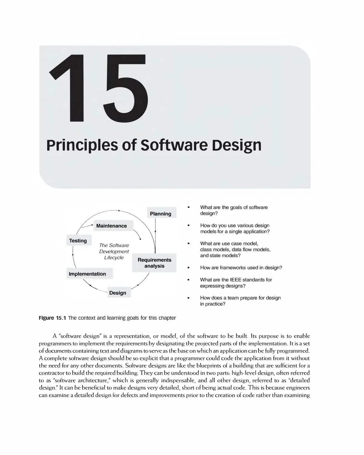
15 Principles of Software Design 350
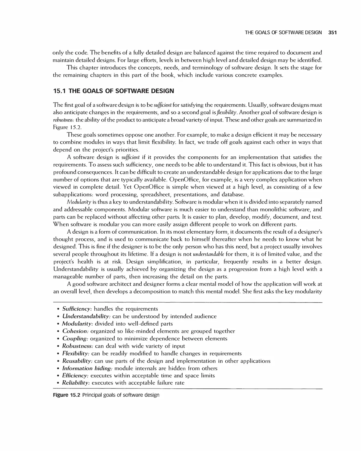
15.1 The Goals of Software Design 351
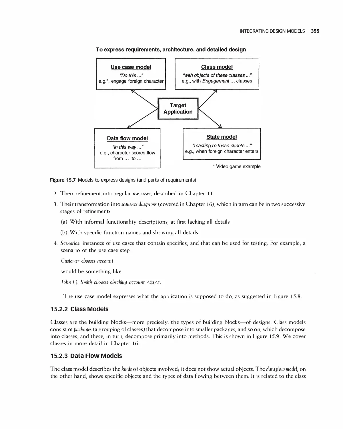
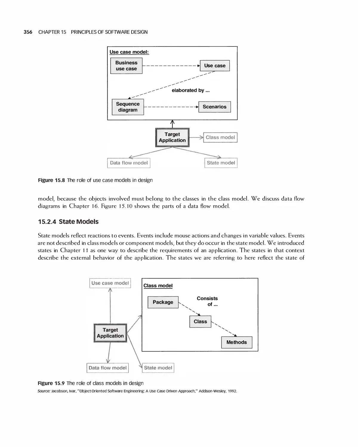
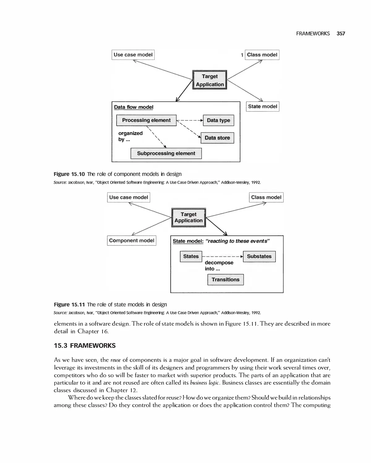
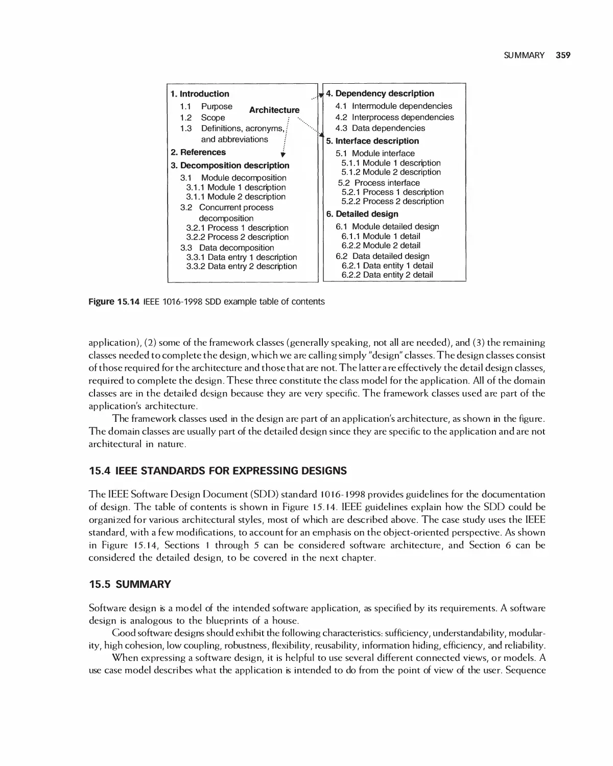
15.2 Integrating Design Models 354
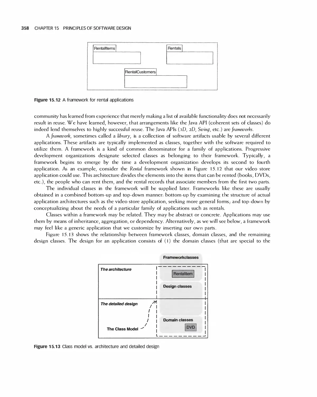
15.3 Frameworks 357
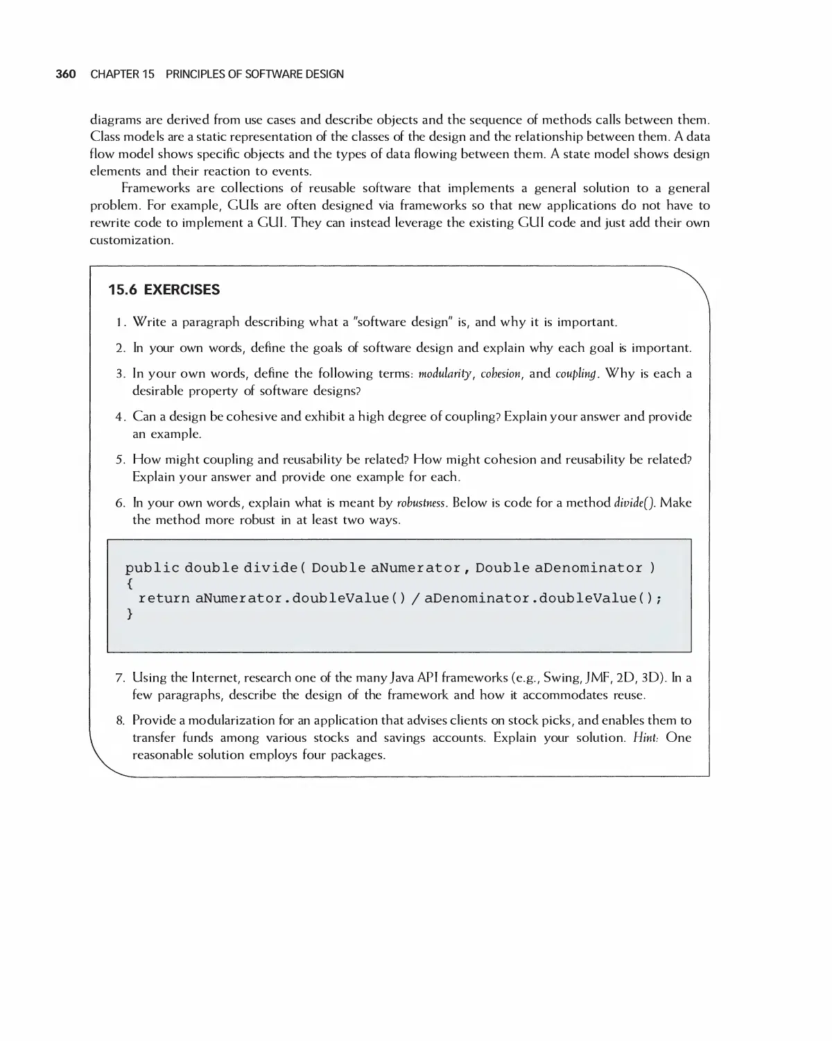
15.4 IEEE Standards for Expressing Designs 359
15.5 Summary 359
15.6 Exercises 360
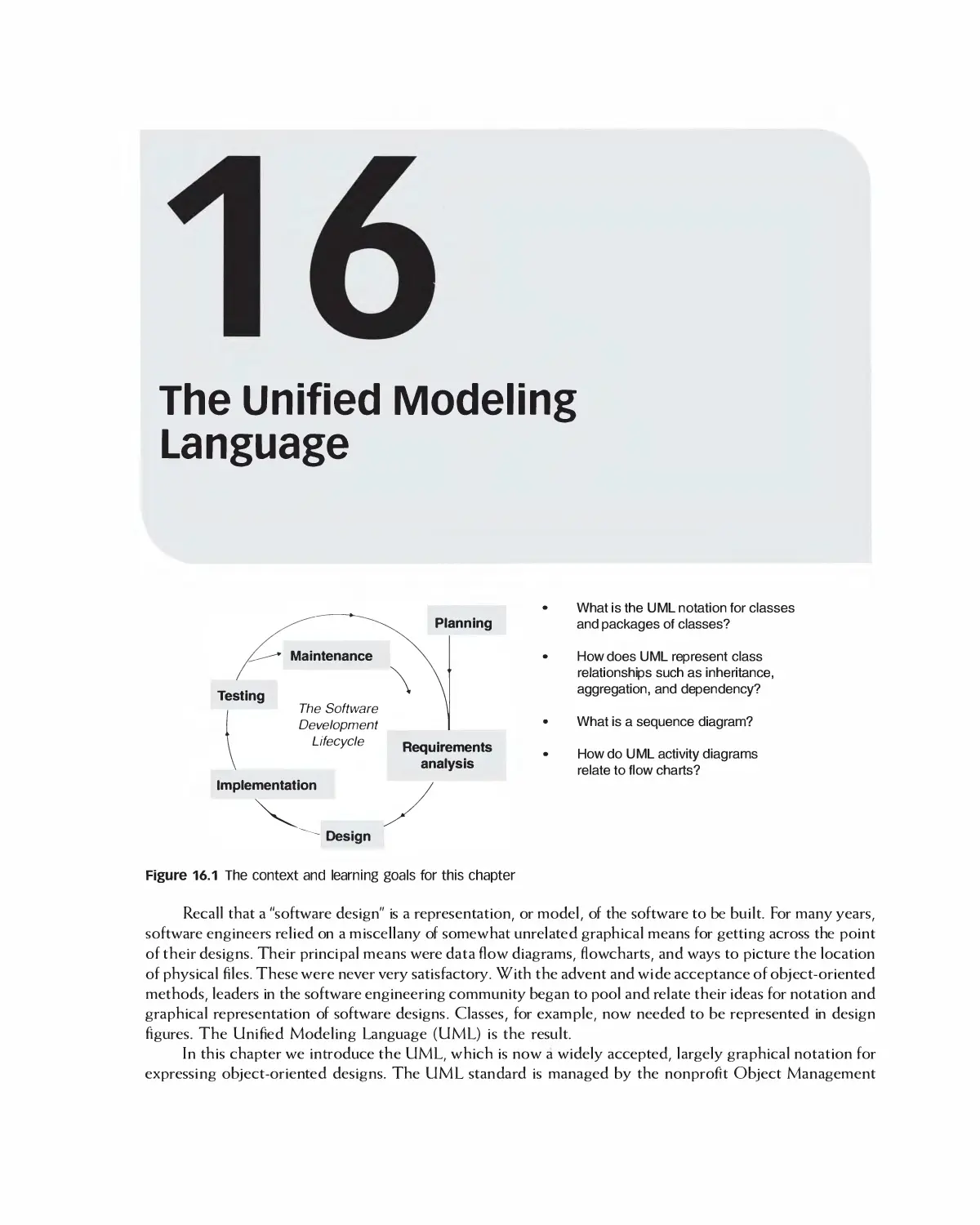
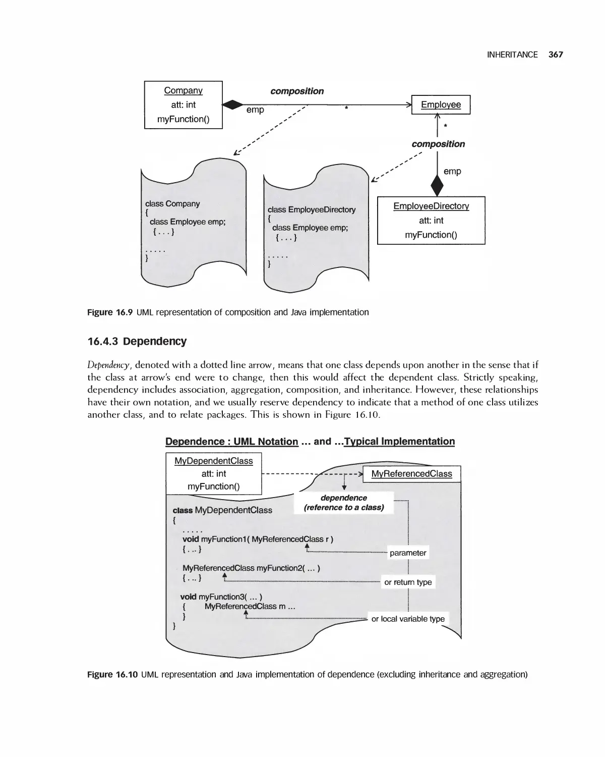
16 The Unified Modeling Language 361
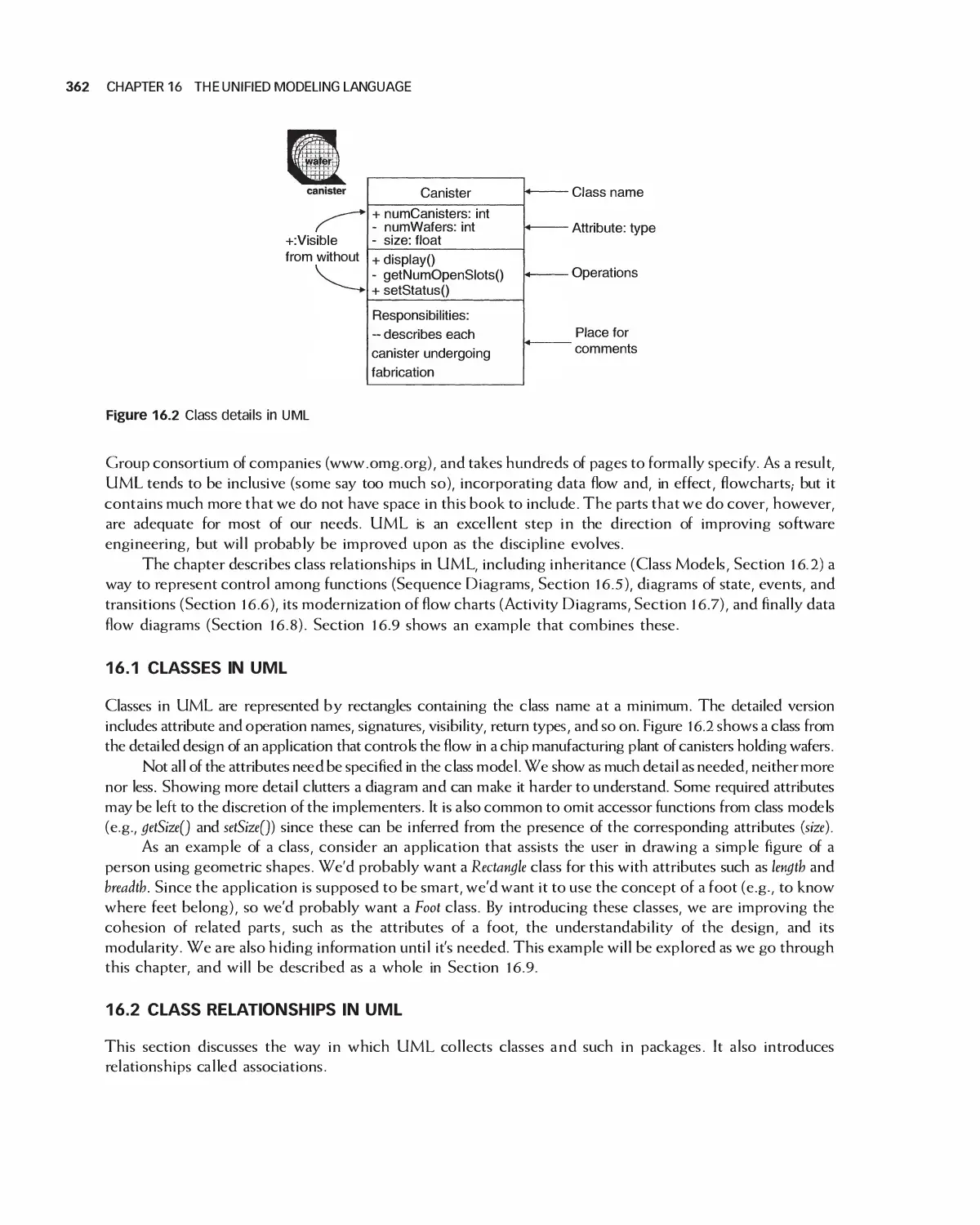
16.1 Classes in UML 362
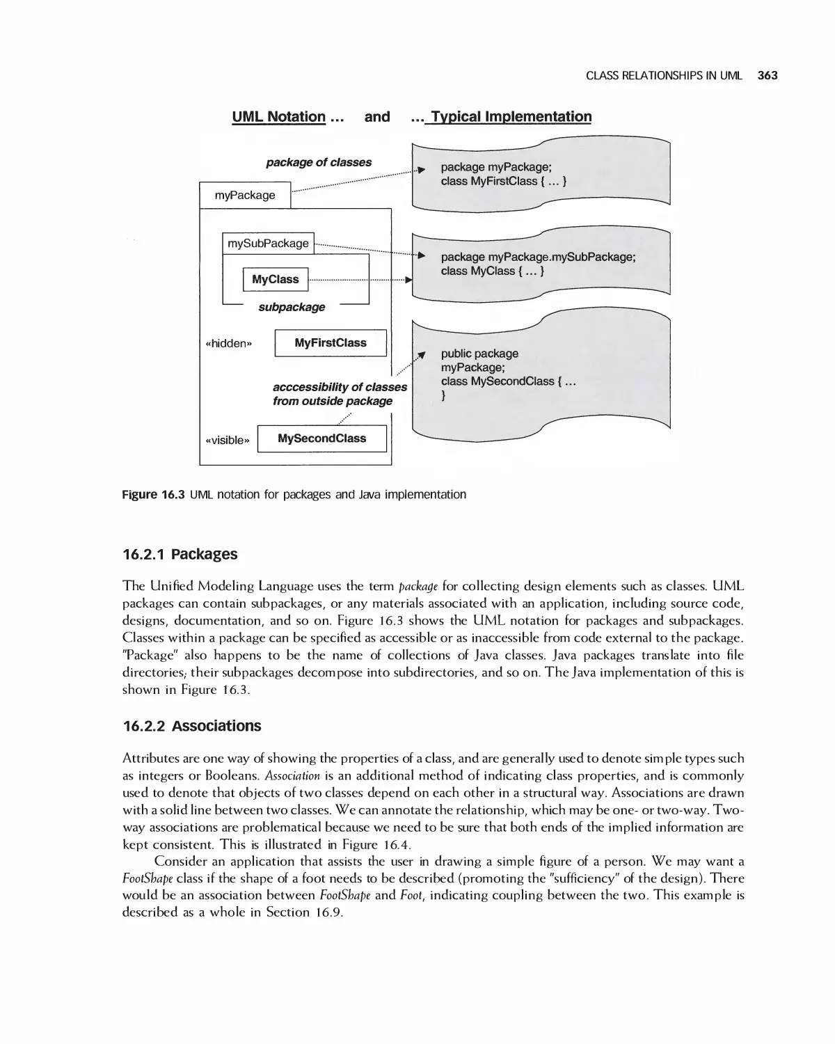
16.2 Class Relationships in UML 362
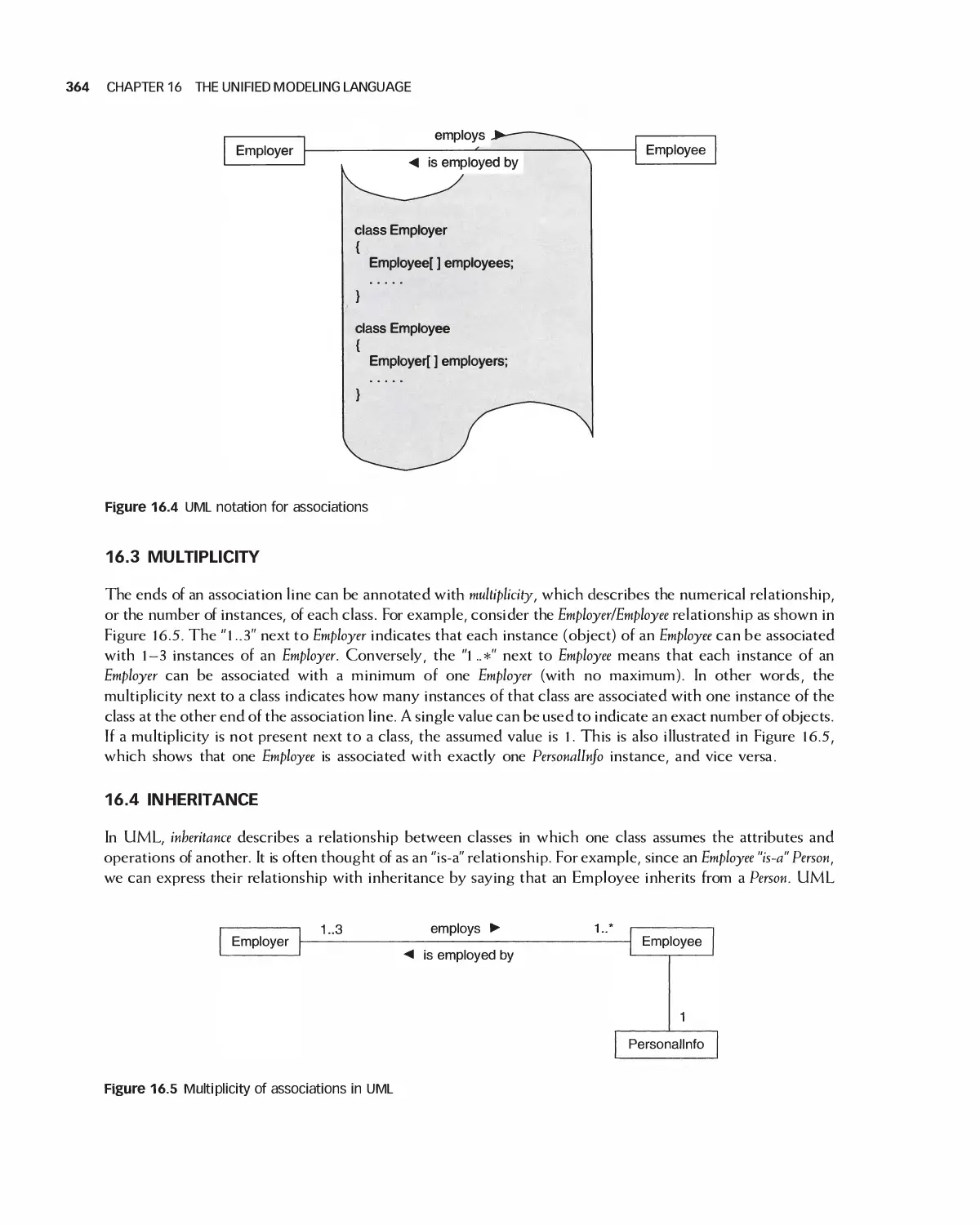
16 3 Multiplicity 364
16.4 Inheritance 364
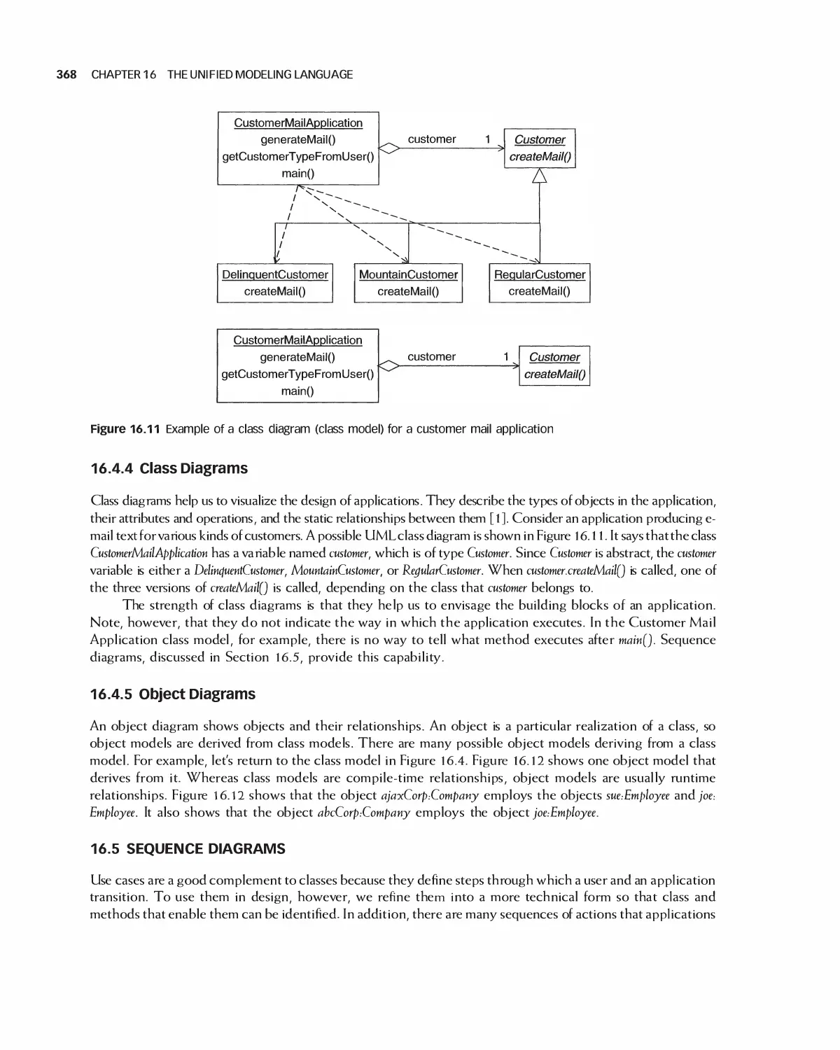
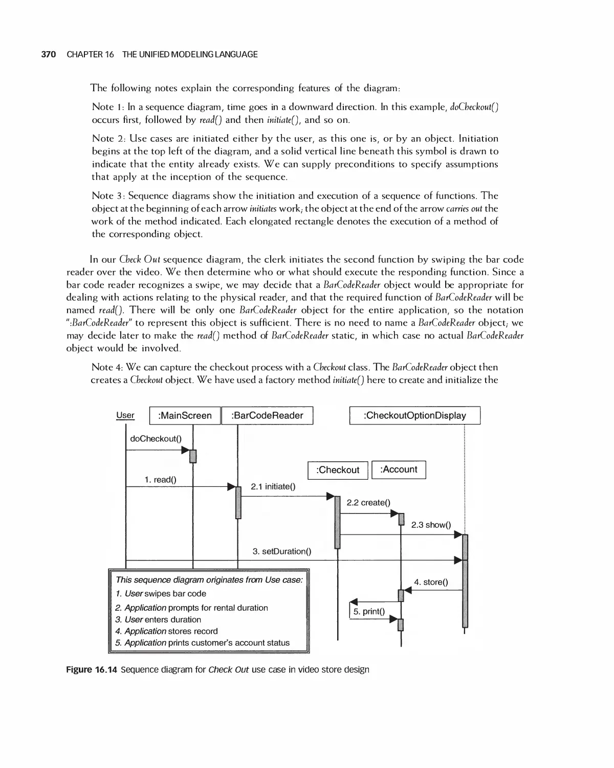
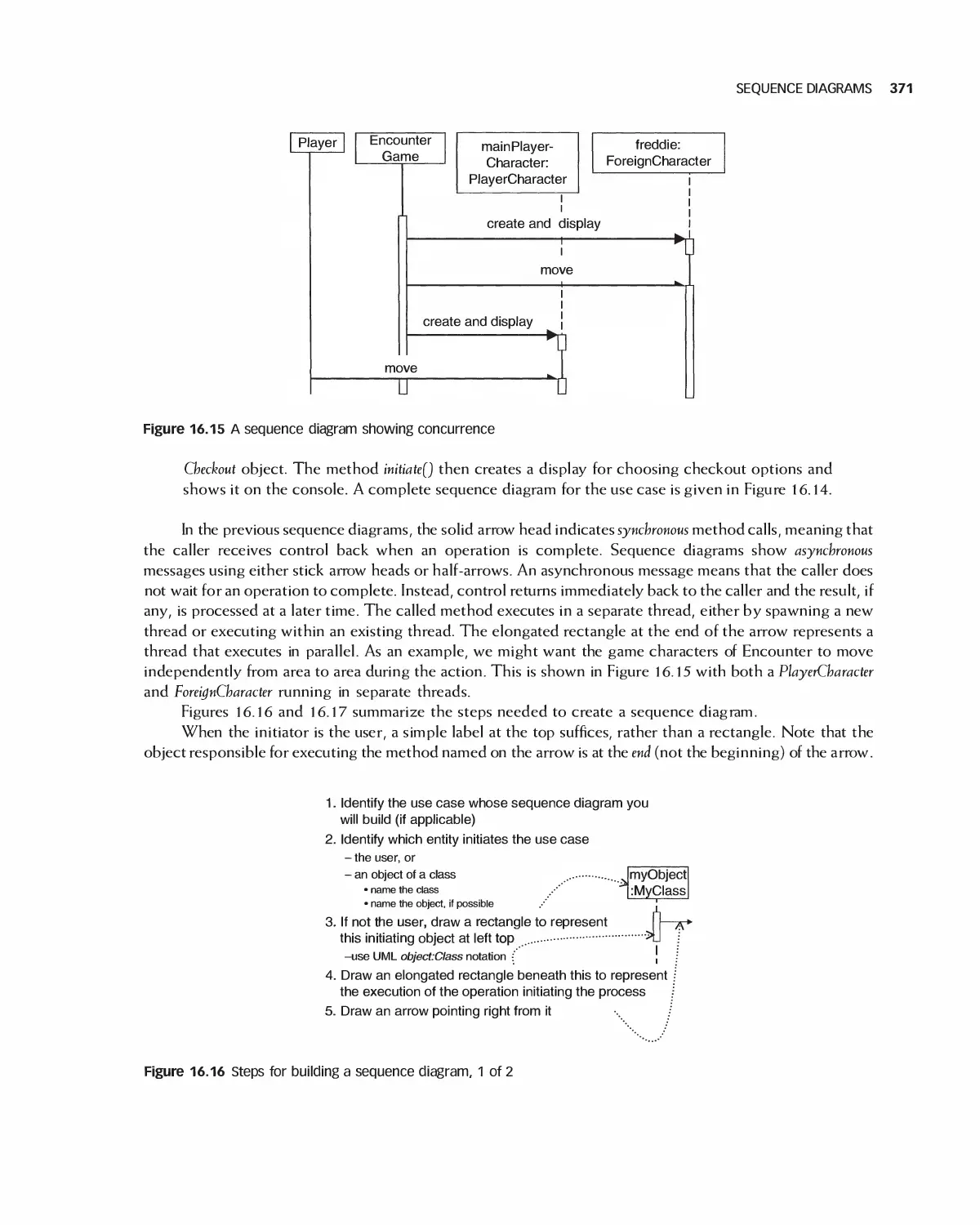
16.5 Sequence Diagrams 368
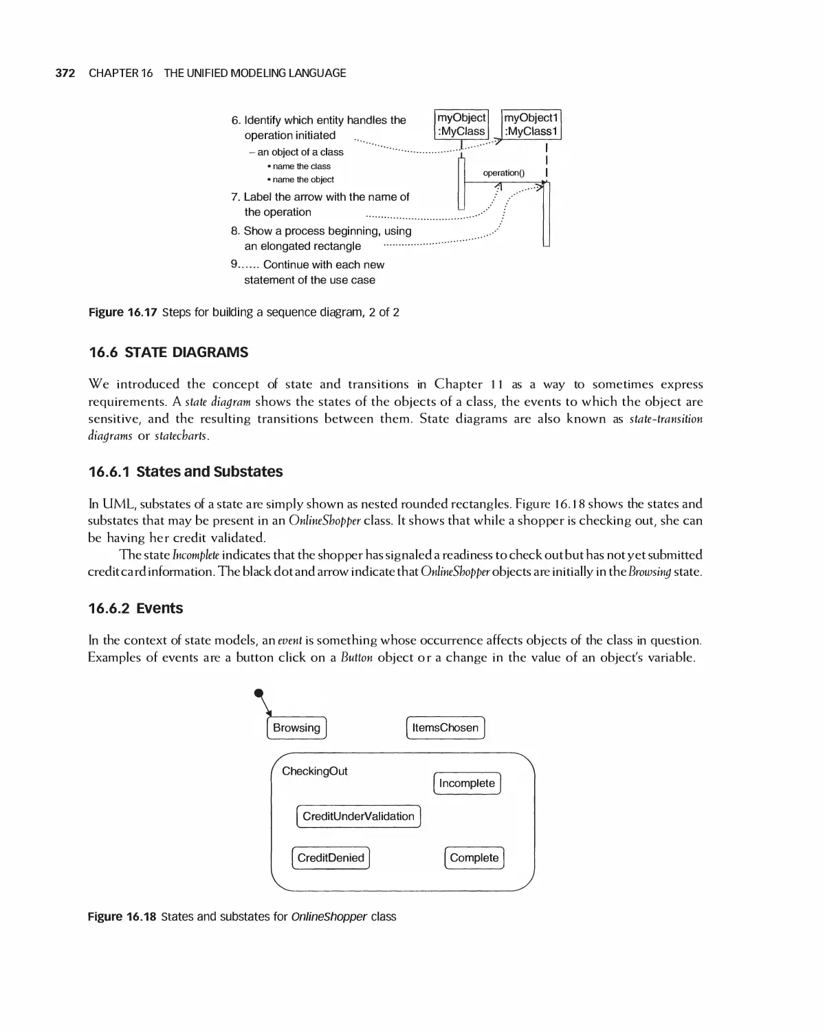
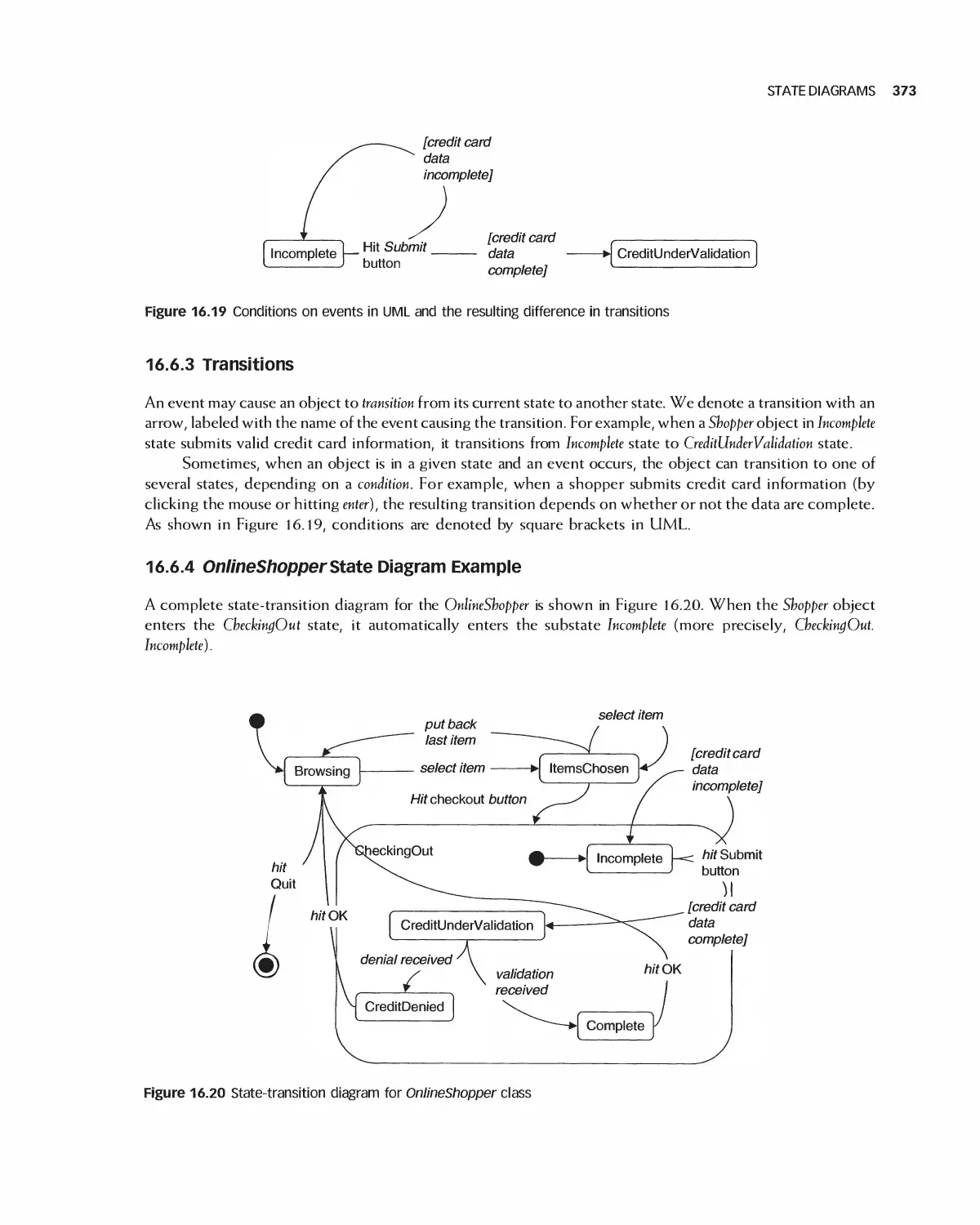
16.6 State Diagrams 372
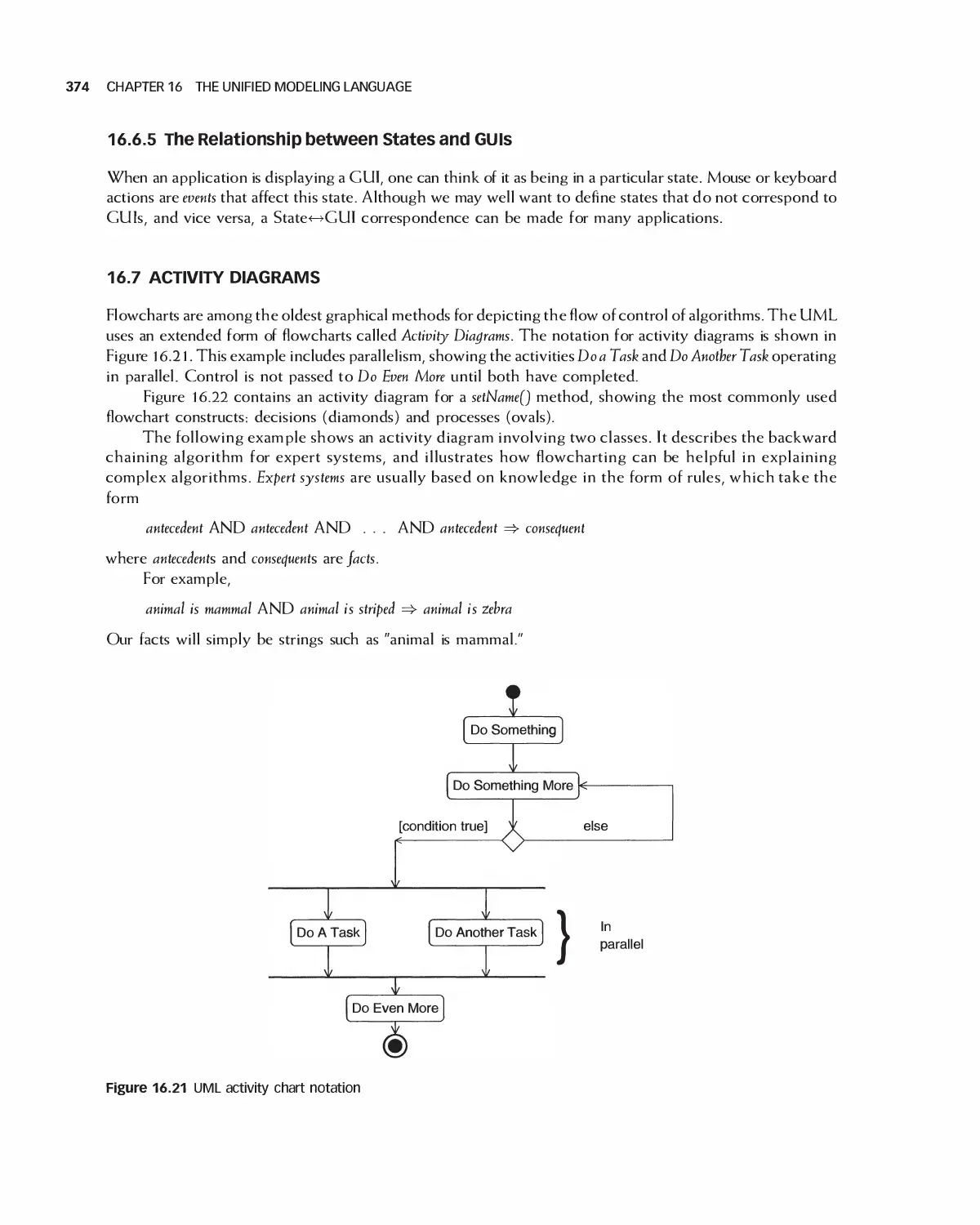
16.7 Activity Diagrams 374
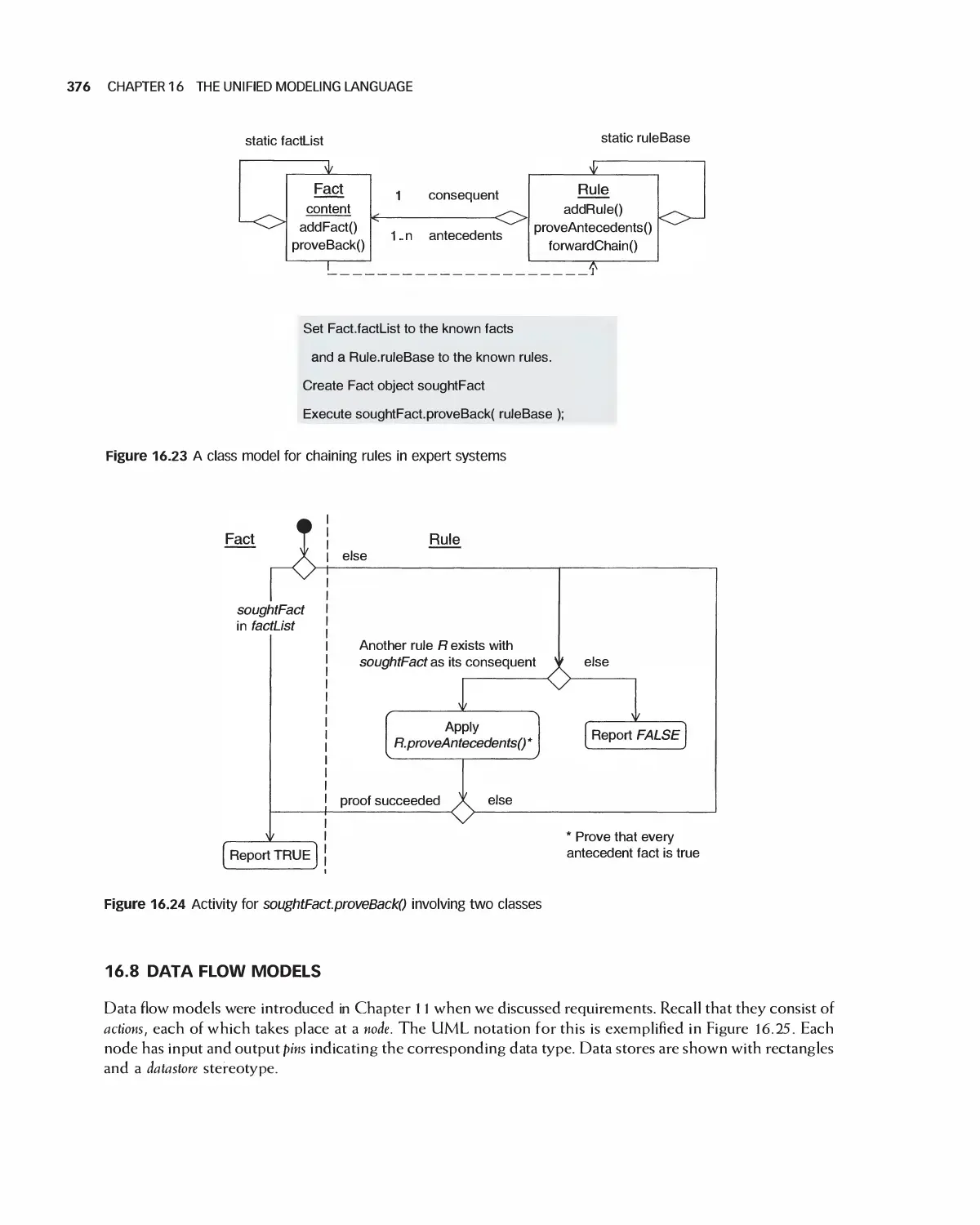
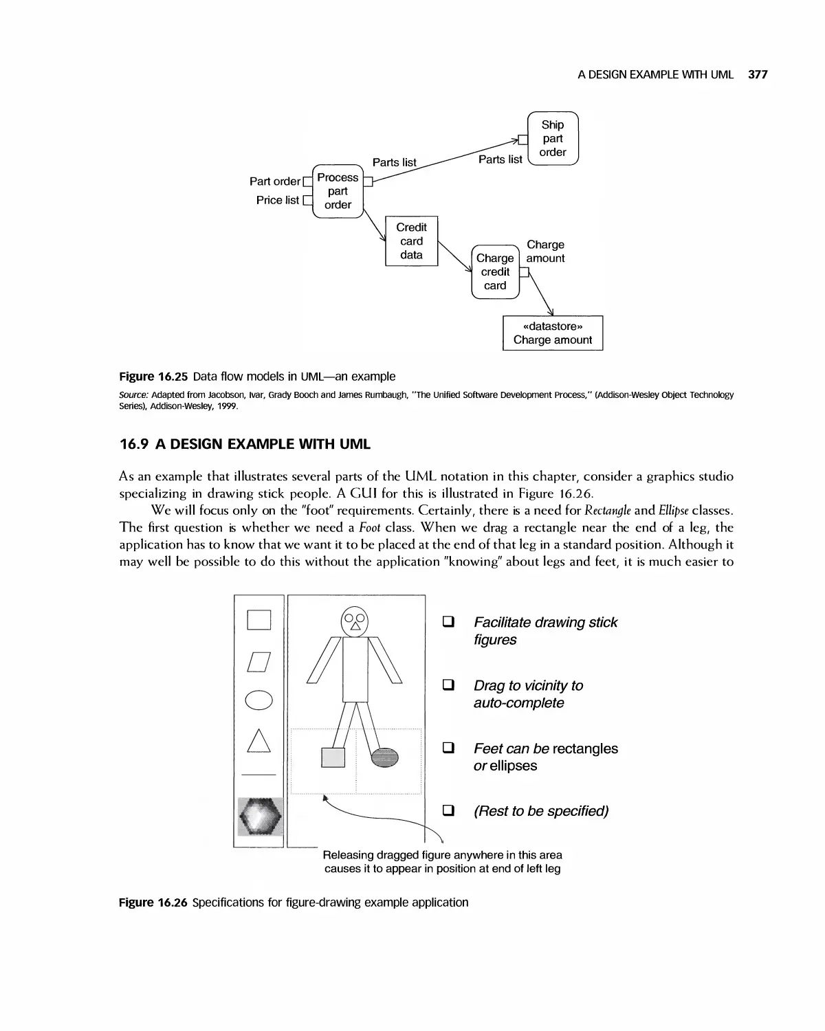
16.8 Data Flow Models 376
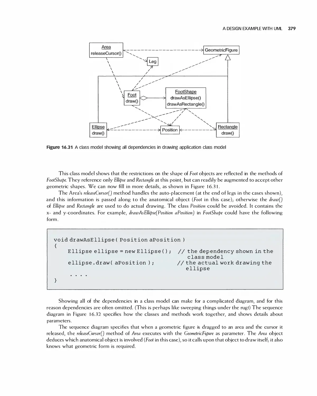
16.9 A Design Example with UML 377
16.10 Summary 380
1 6.11 Exercises 381
Bibliography 382
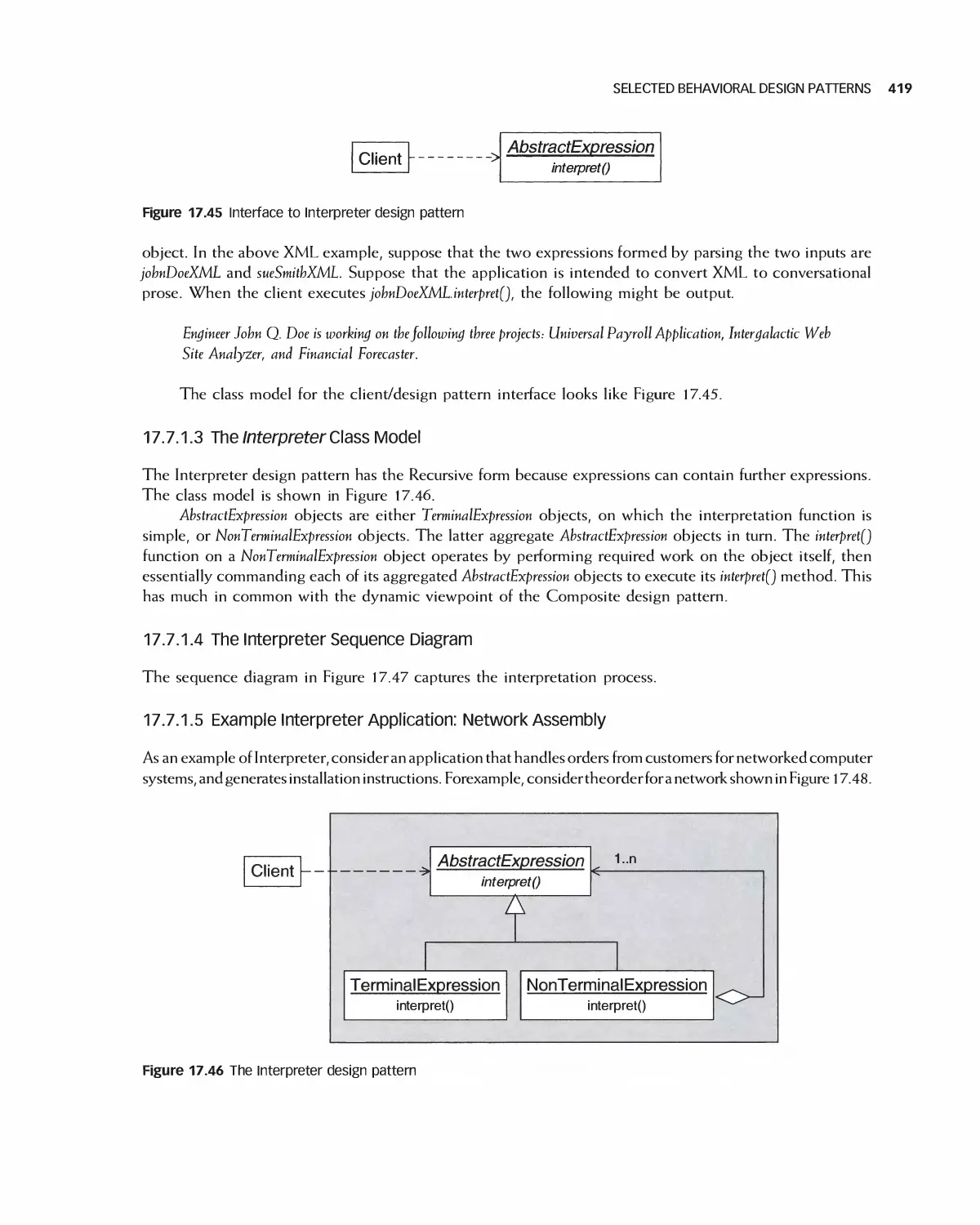
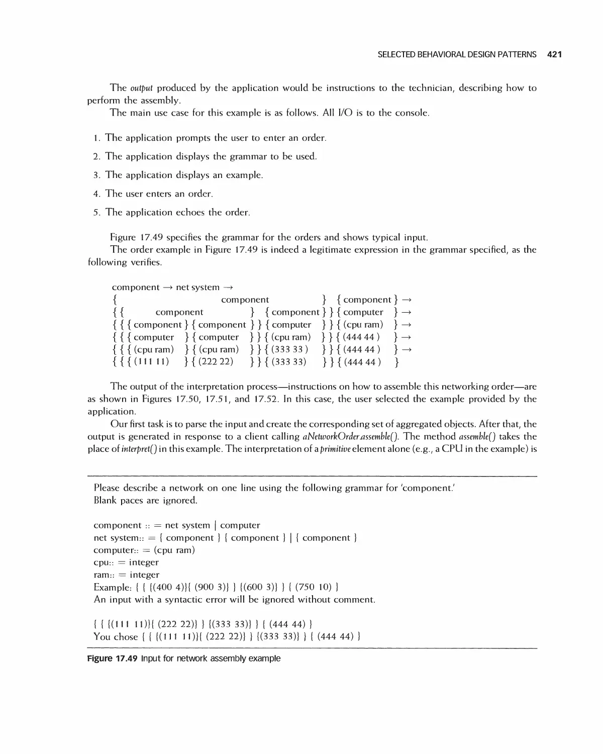
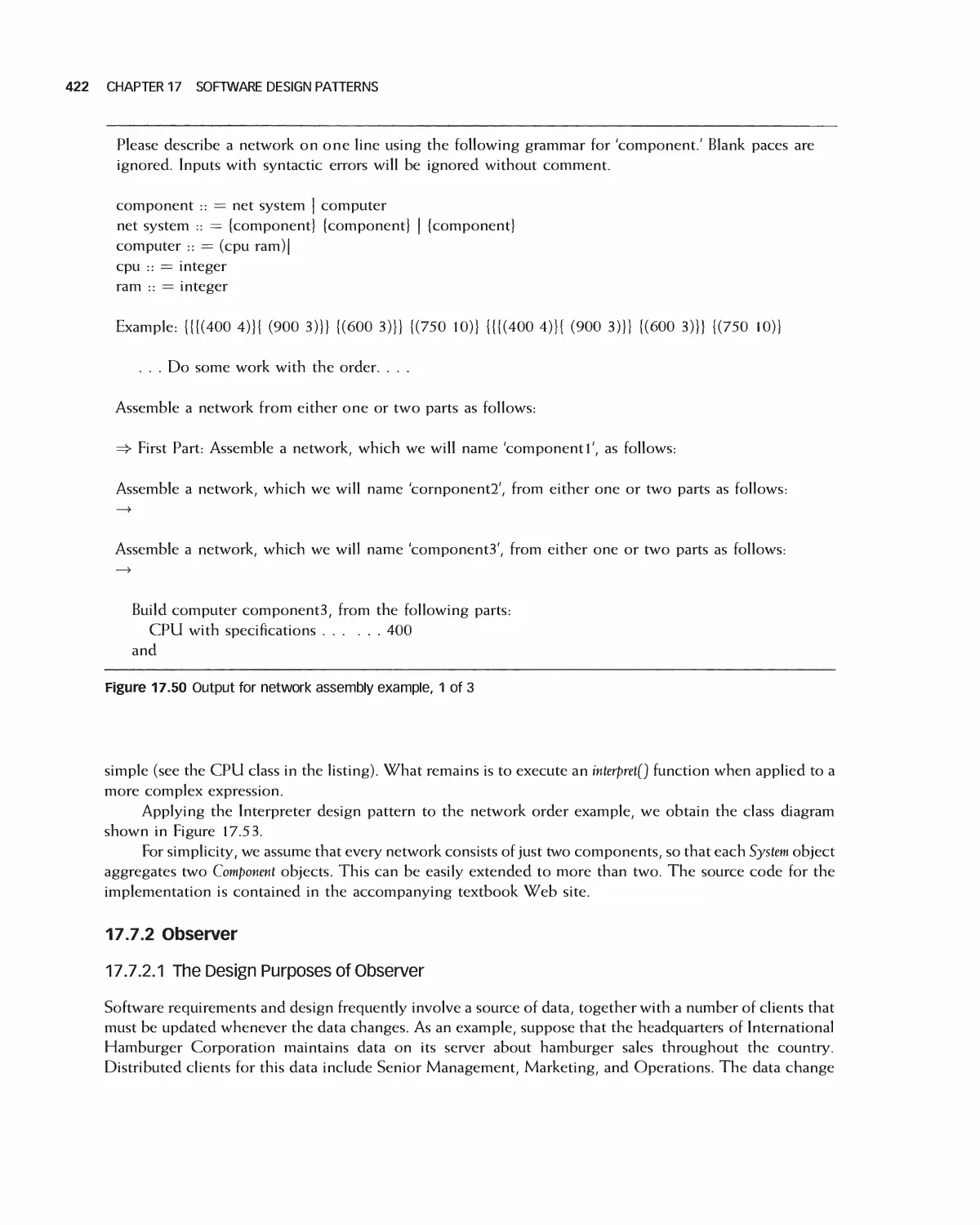
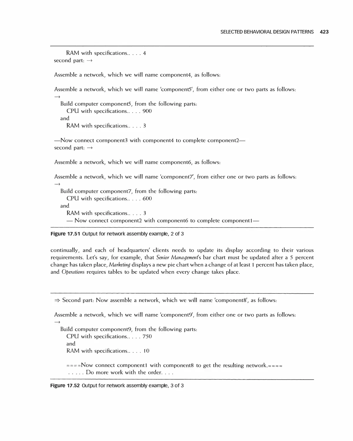
1 7 Software Design Patterns 383
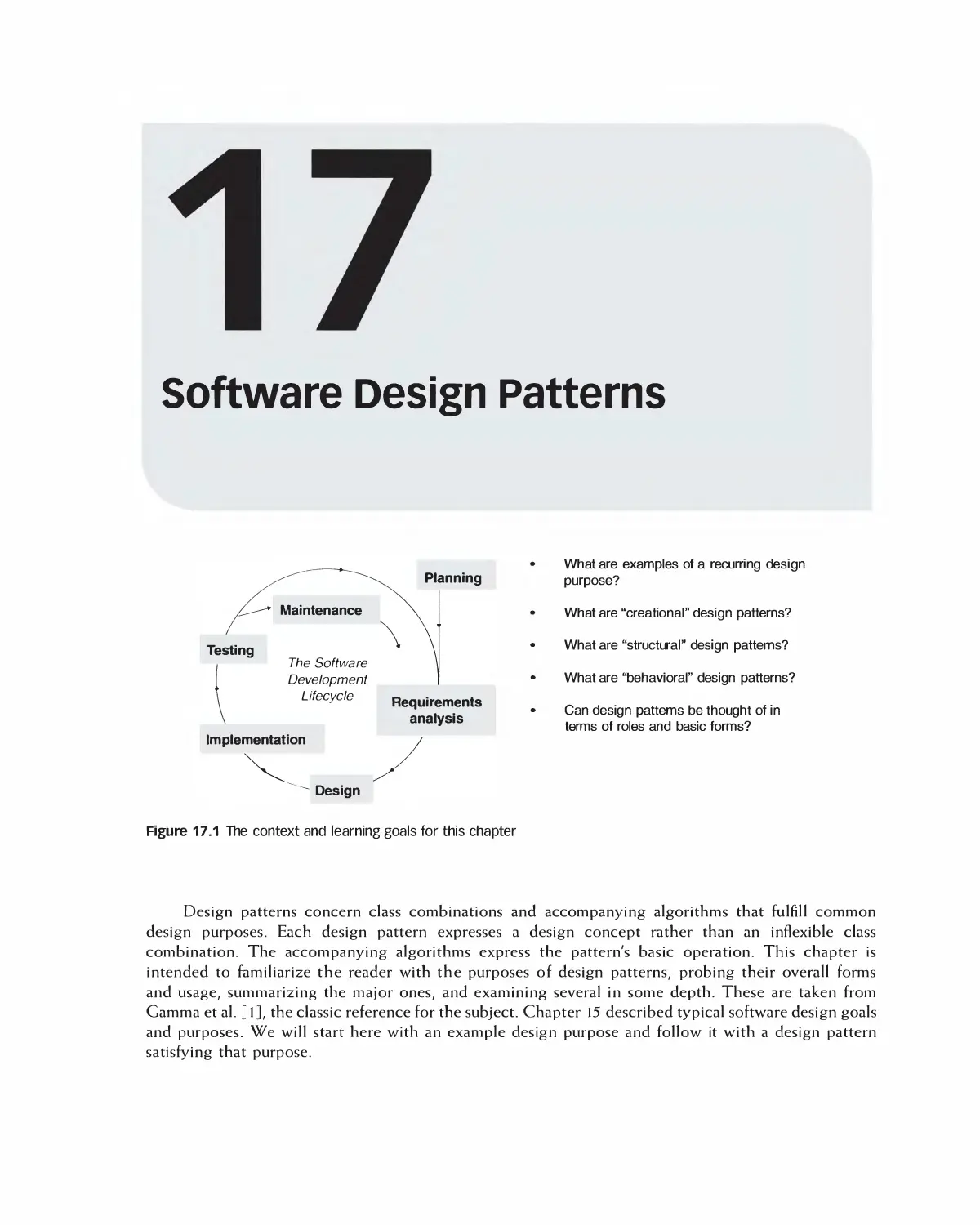
17.1 Examples of a Recurring Design Purpose 384
17.2 An Introduction to Design Patterns 386
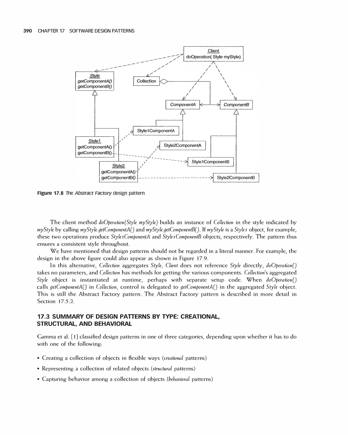
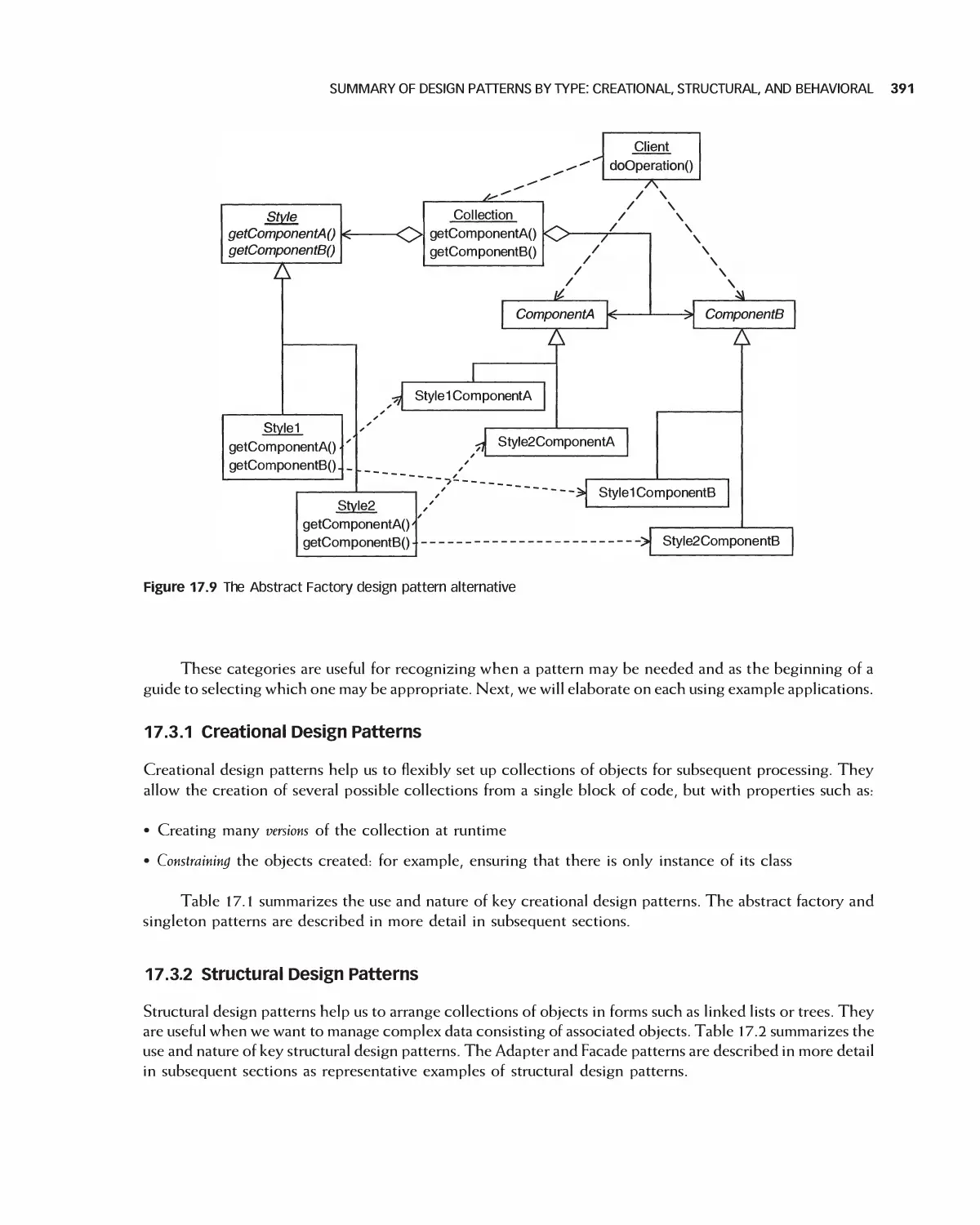
17.3 Summary of Design Patterns by Type: Creational,
Structural, and Behavioral 390
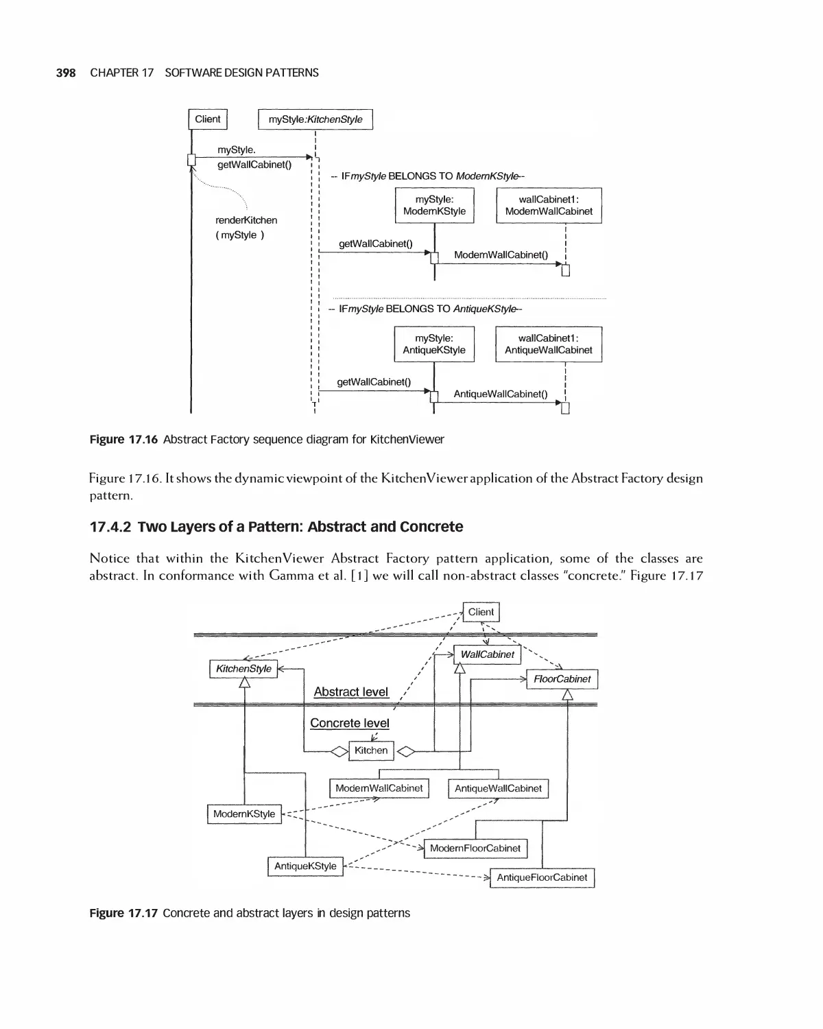
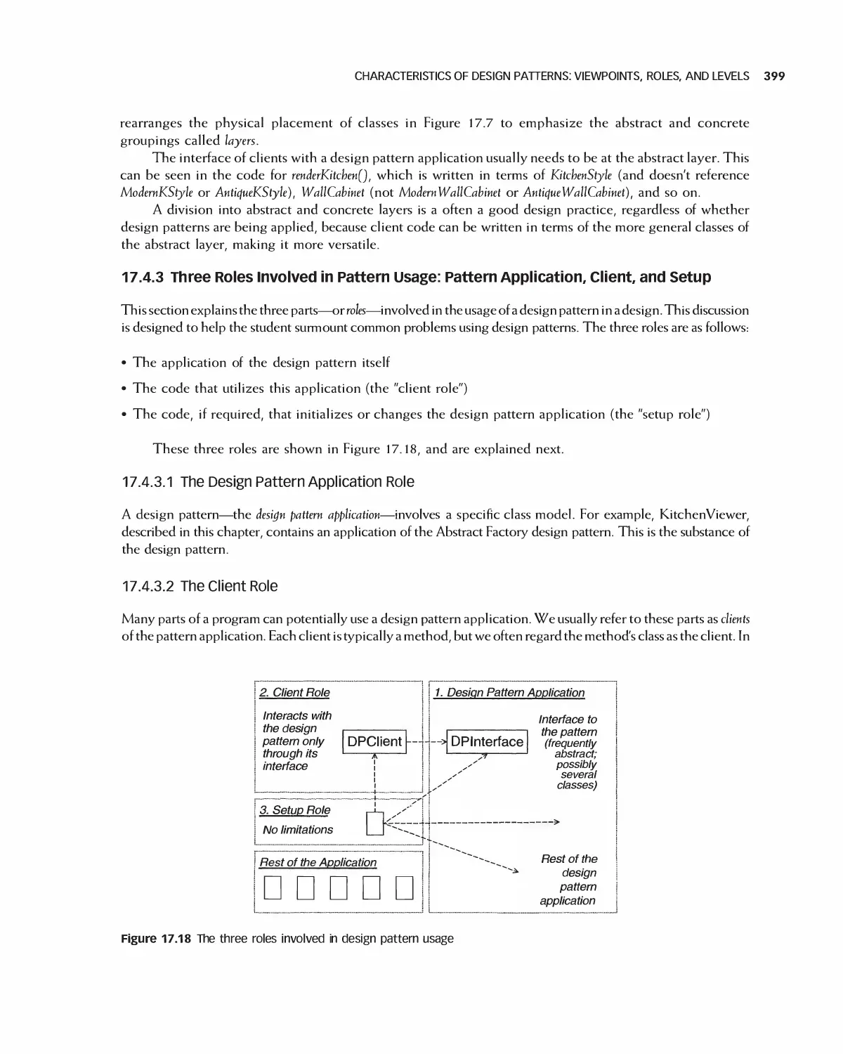
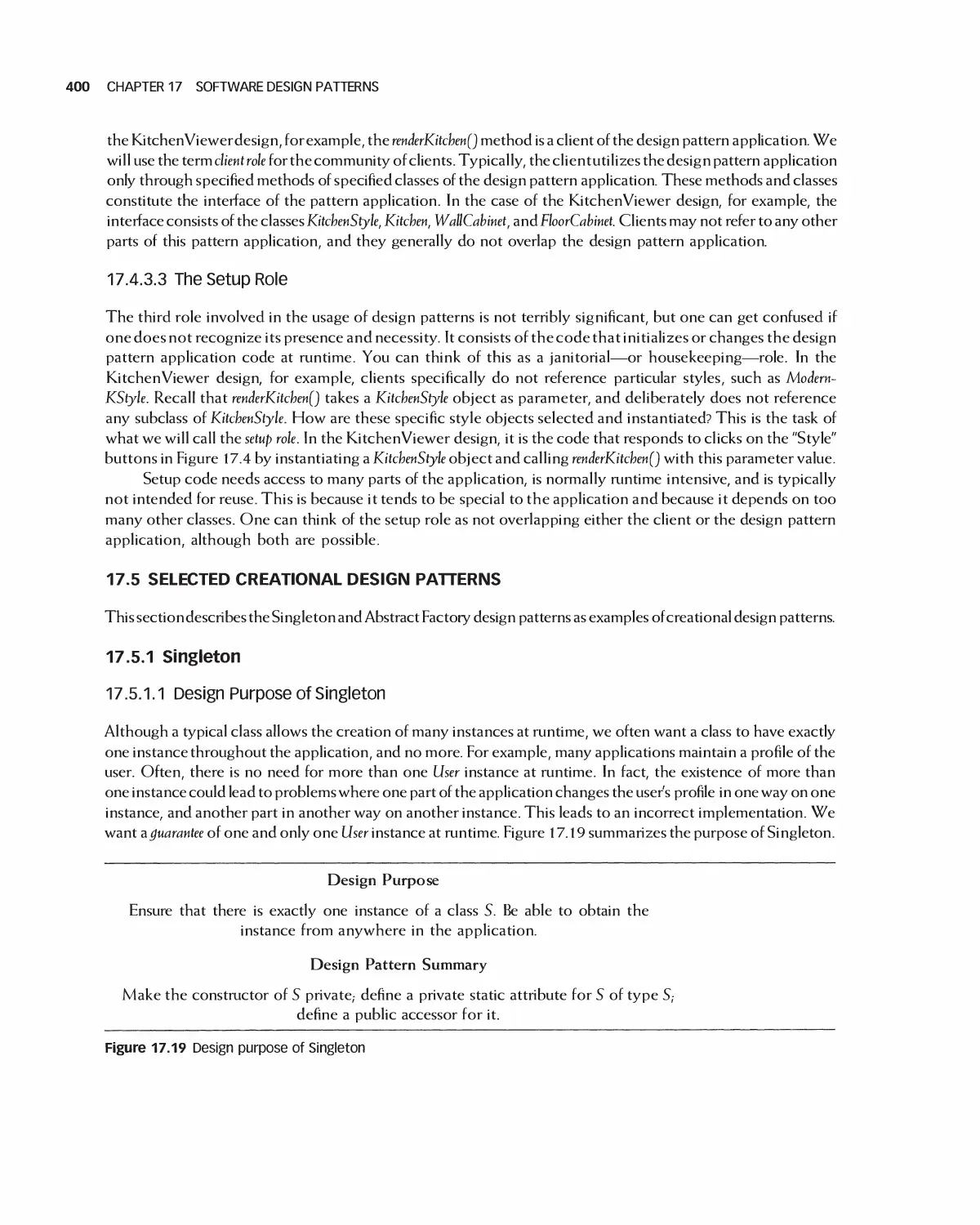
17.4 Characteristics of Design Patterns: Viewpoints, Roles, and Levels 396
17.5 Selected Creational Design Patterns 400
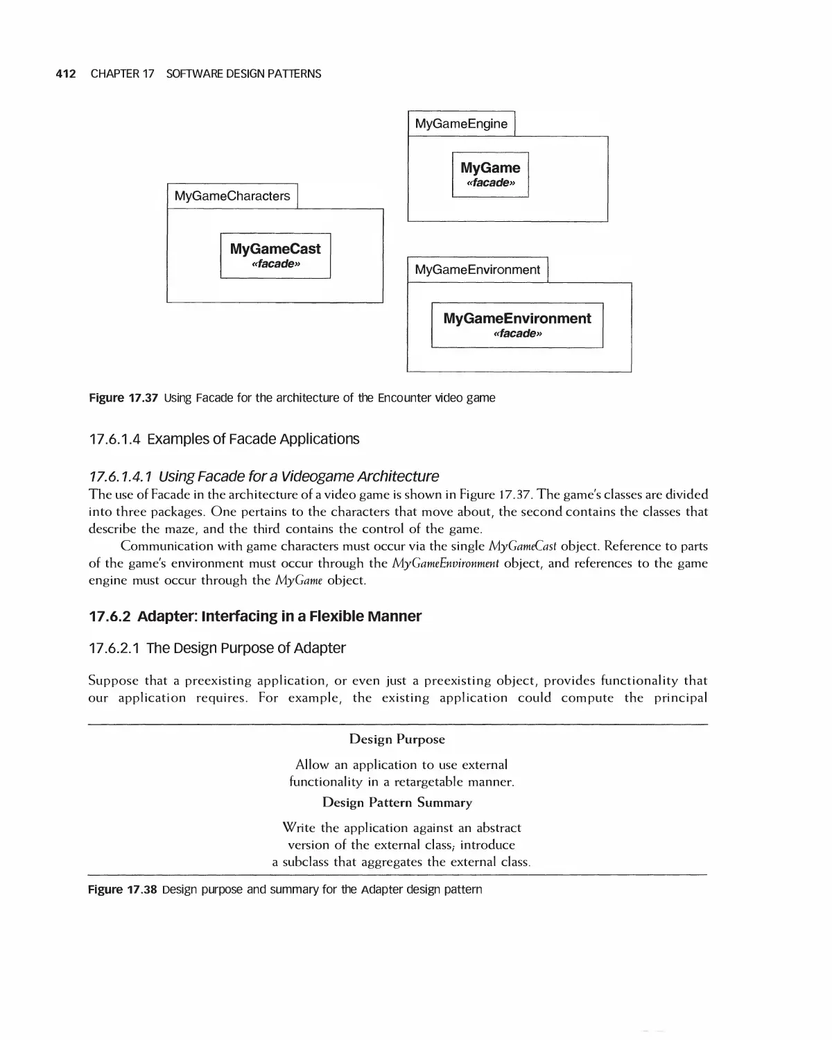
17.6 Selected Structural Design Patterns 408
X CONTENTS
17.7 Selected Behavioral Design Patterns 417
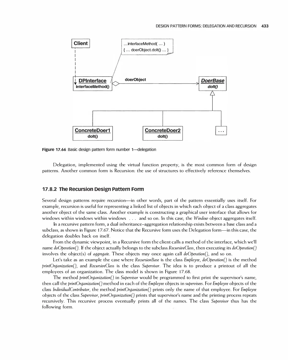
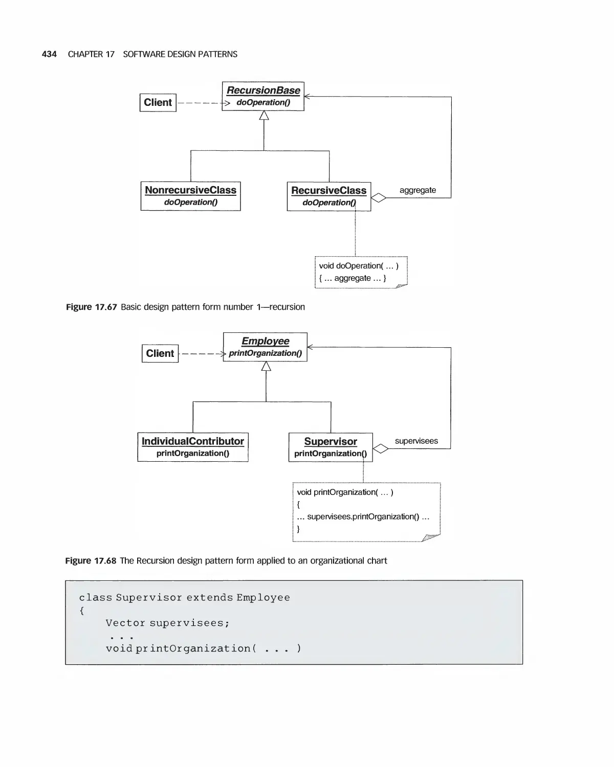
17.8 Design Pattern Forms: Delegation and Recursion 431
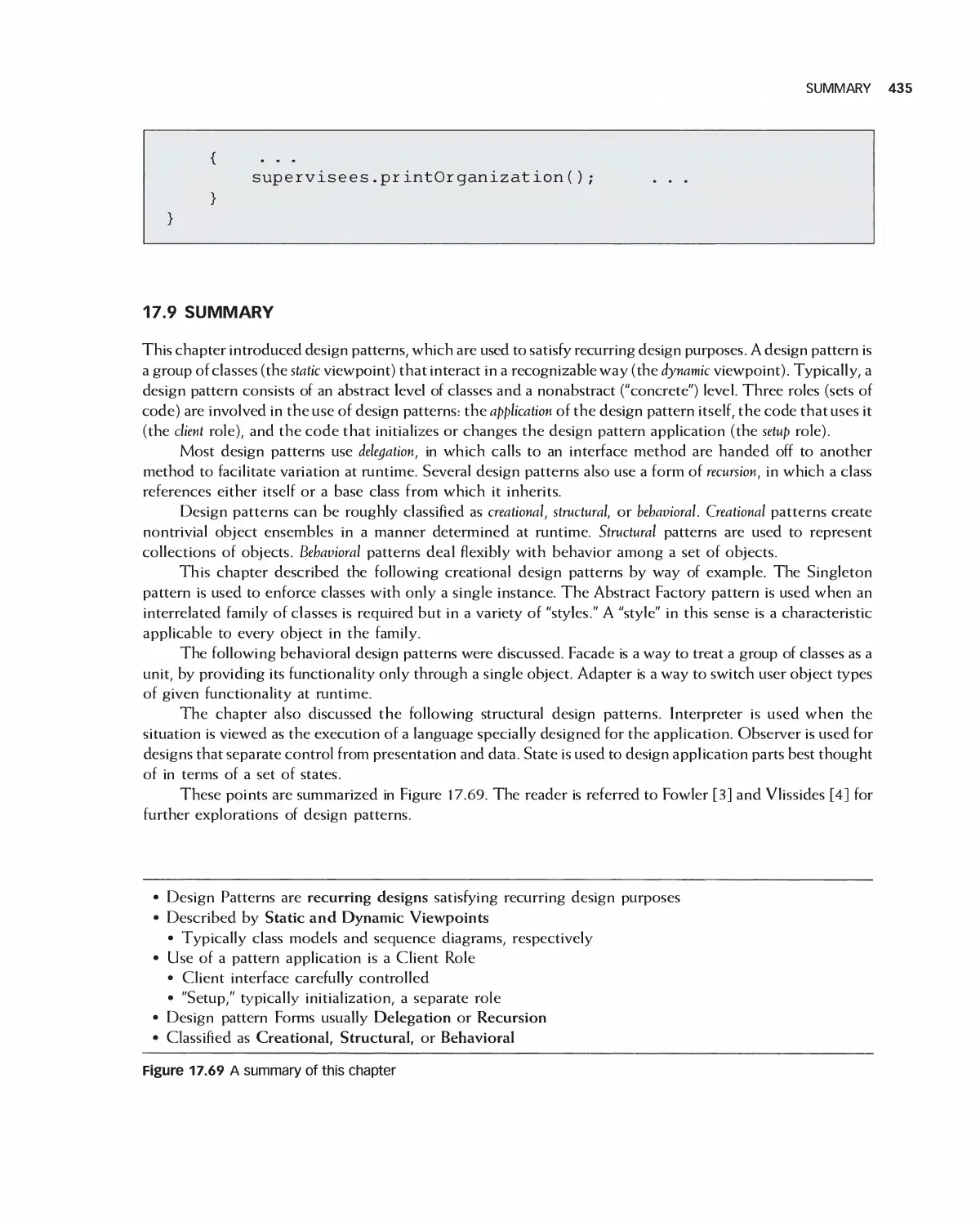
17.9 Summary 435
17.10 Exercises 436
Bibliography 437
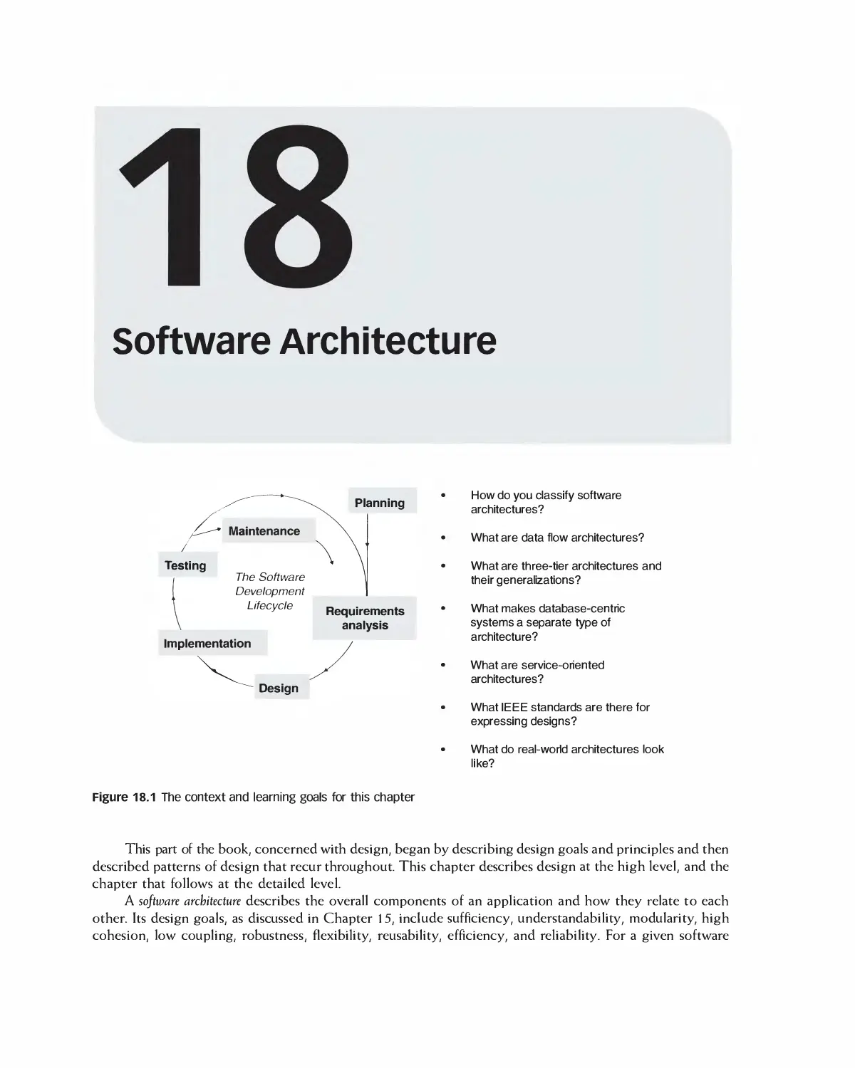
18 Software Architecture 438
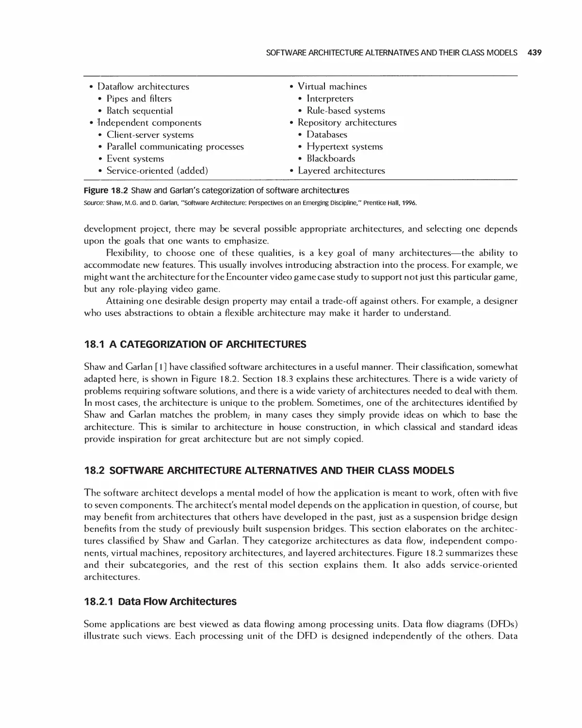
18.1 A Categorization of Architectures 439
18.2 Software Architecture Alternatives and Their Class Models 439
18.3 Trading Off Architecture Alternatives 453
1 8.4 Tools for Architectures 454
18.5 IEEE Standards for Expressing Designs 455
18.6 Effects of Architecture Selection on the Project Plan 455
18.7 Case Study: Preparing to Design Encounter (Student Project Guide continued) 457
18.8 Case Study: Software Design Document for the Role-Playing Video Game Framework .... 460
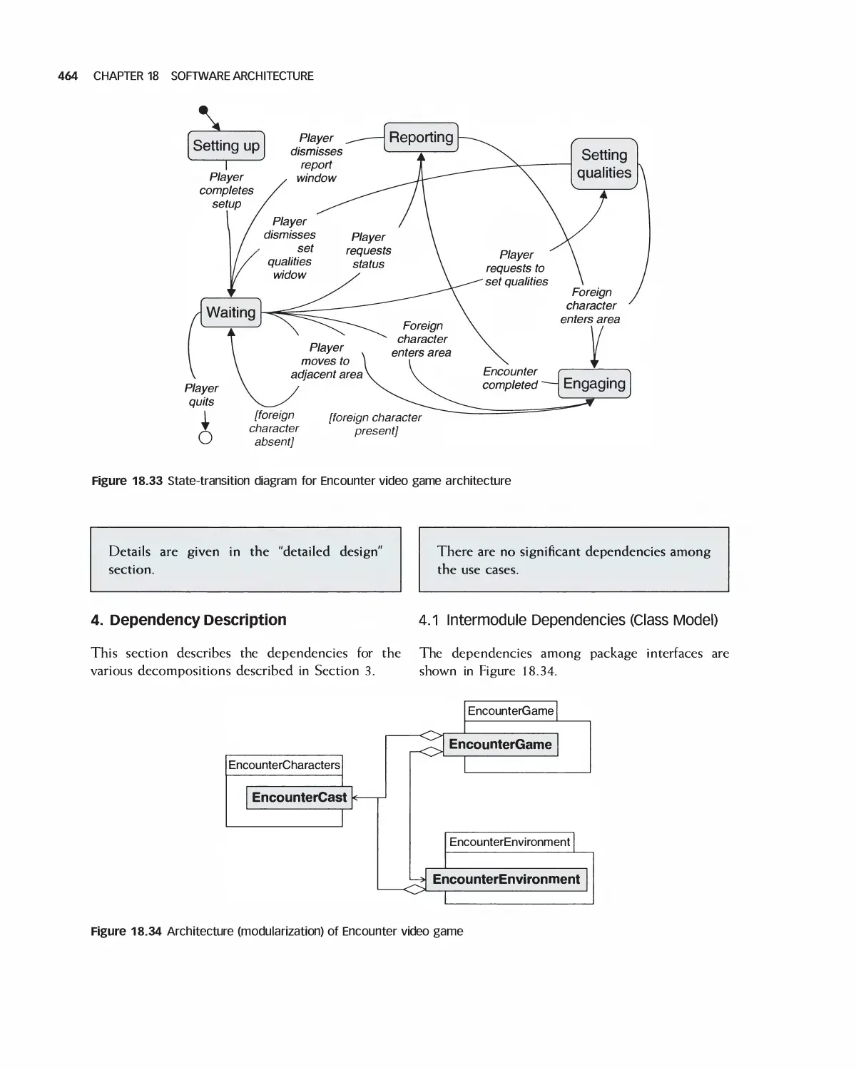
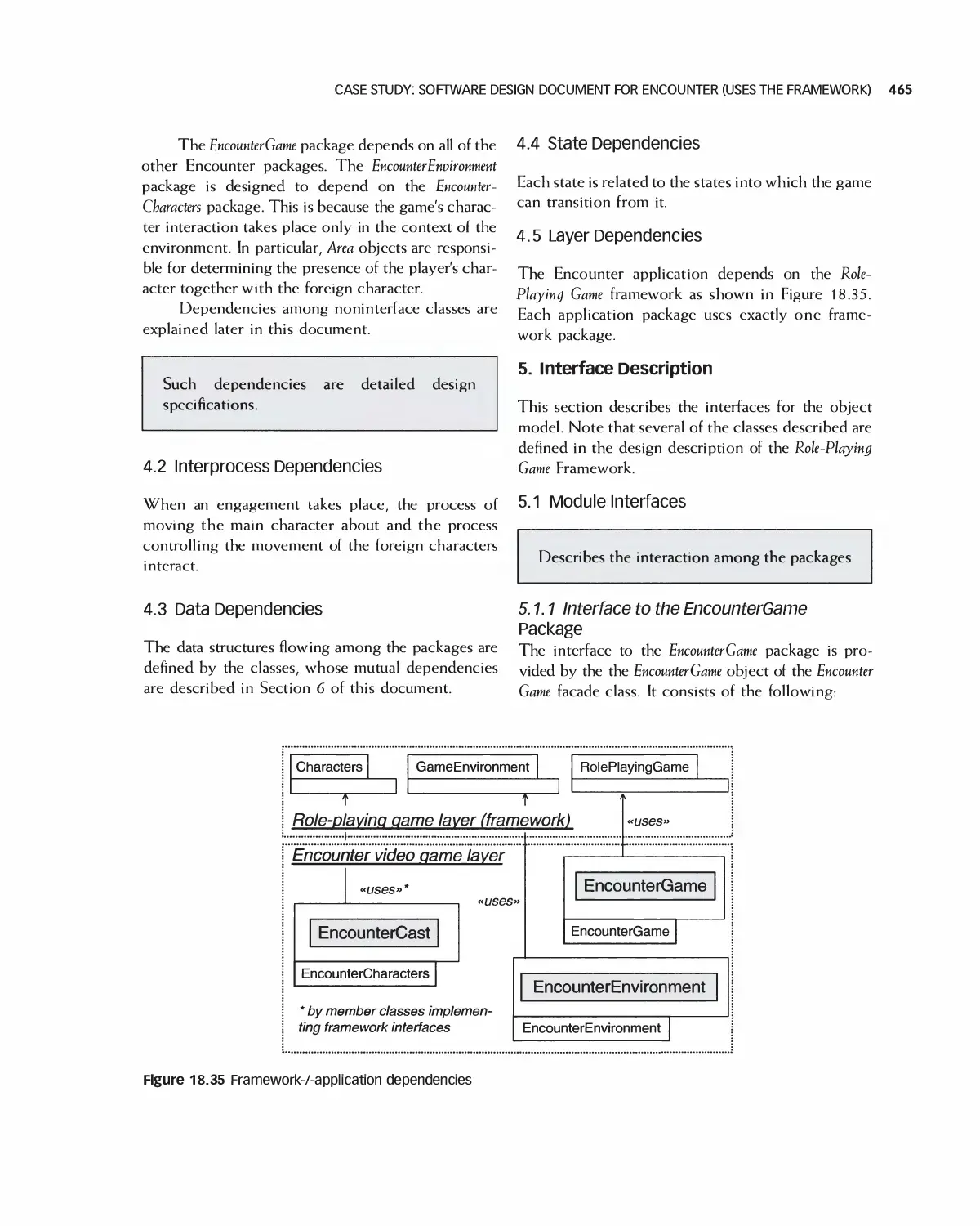
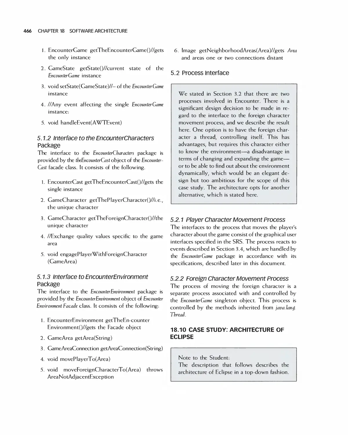
18.9 Case Study: Software Design Document for Encounter (Uses the Framework) 462
18.10 Case Study: Architecture of Eclipse 466
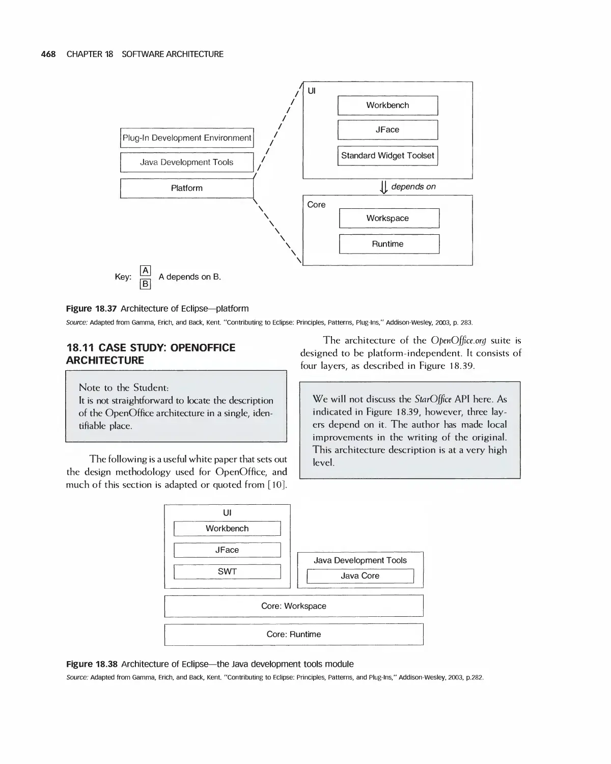
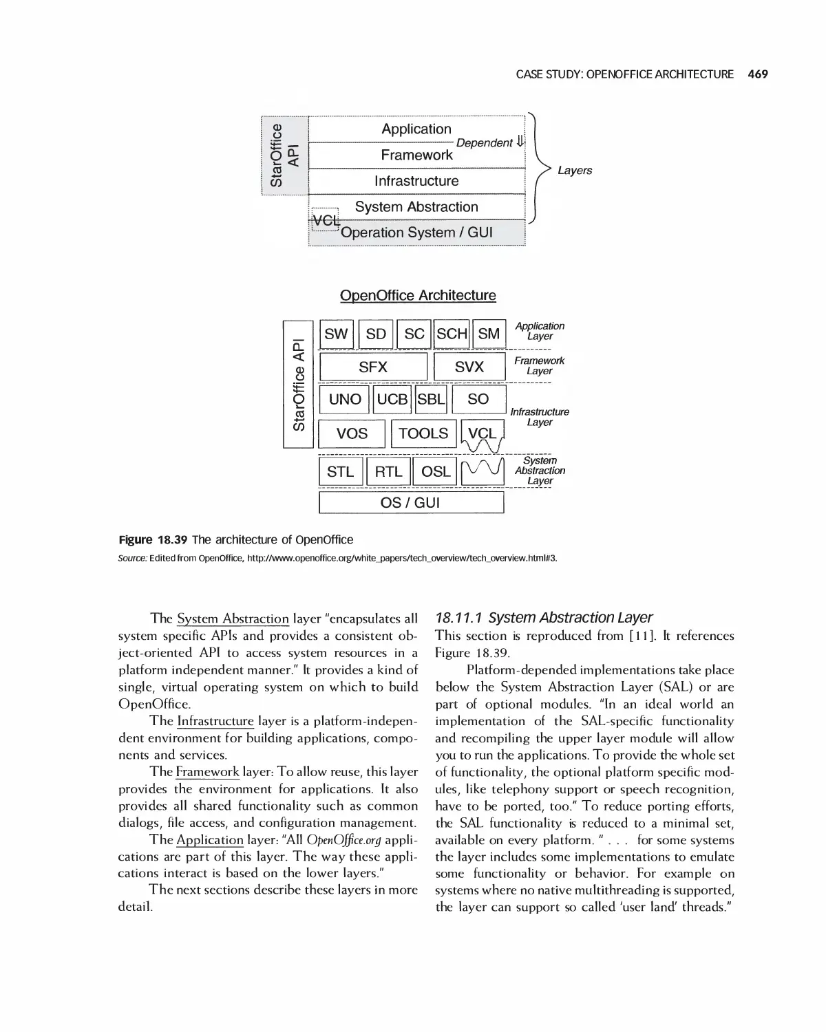
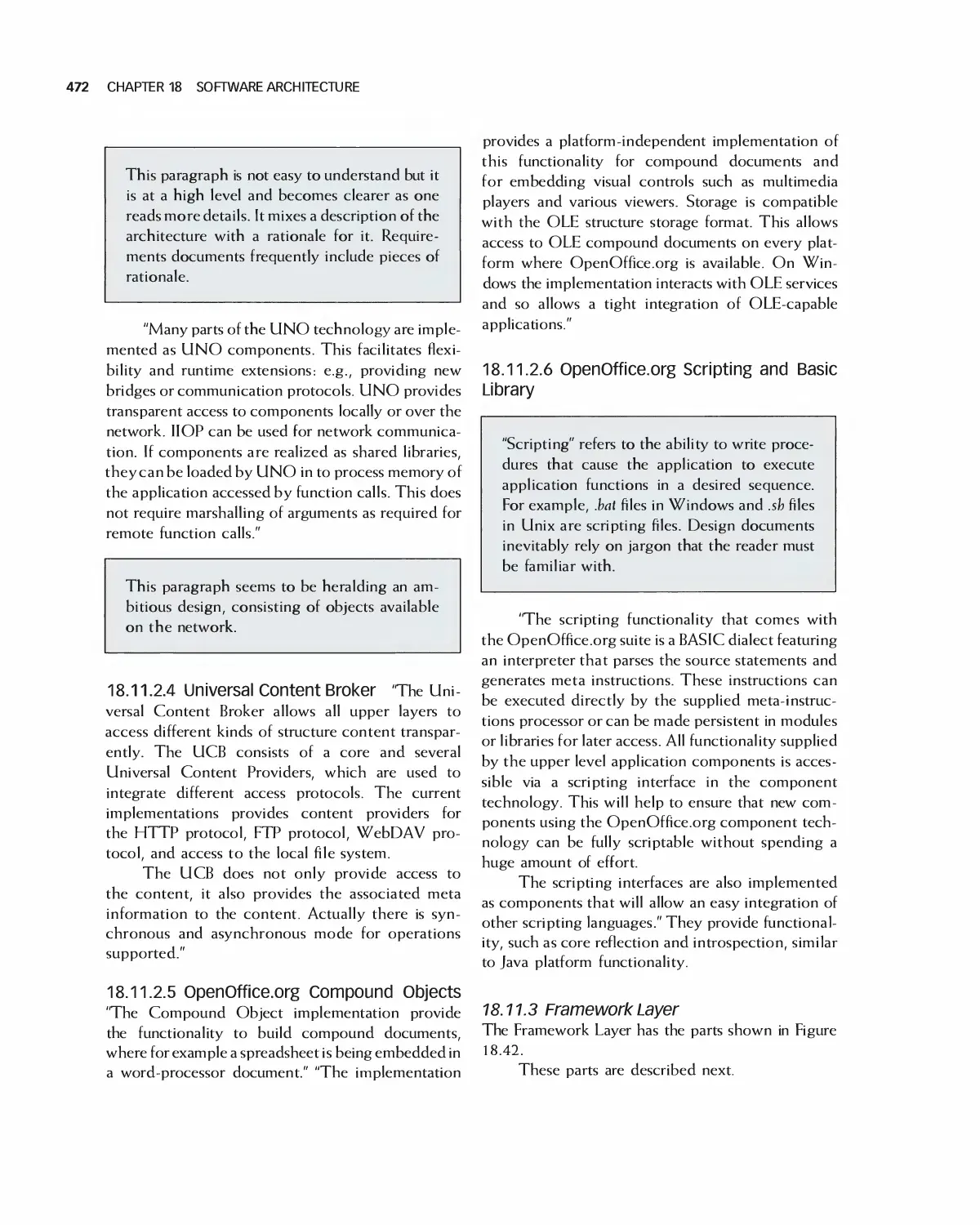
18.11 Case Study: OpenOffice Architecture 468
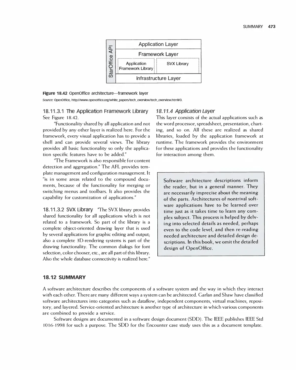
18.12 Summary 473
18.13 Exercises 474
Bibliography 475
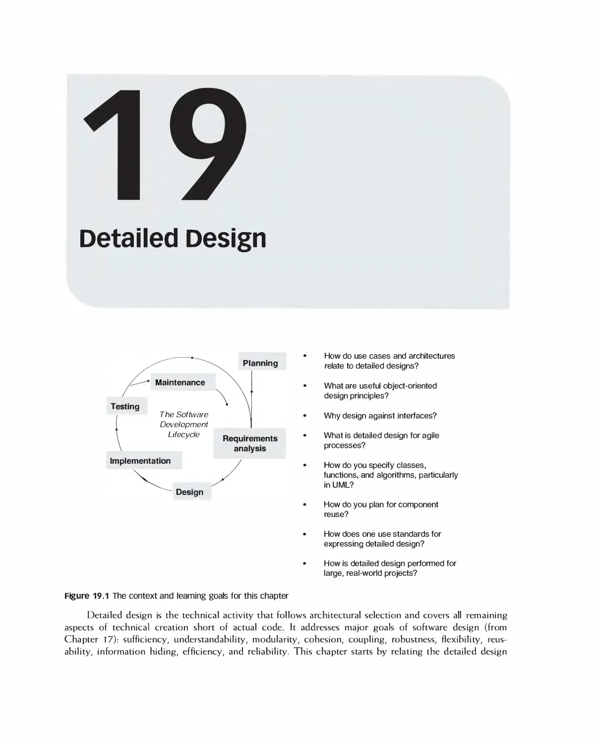
19 Detailed Design 476
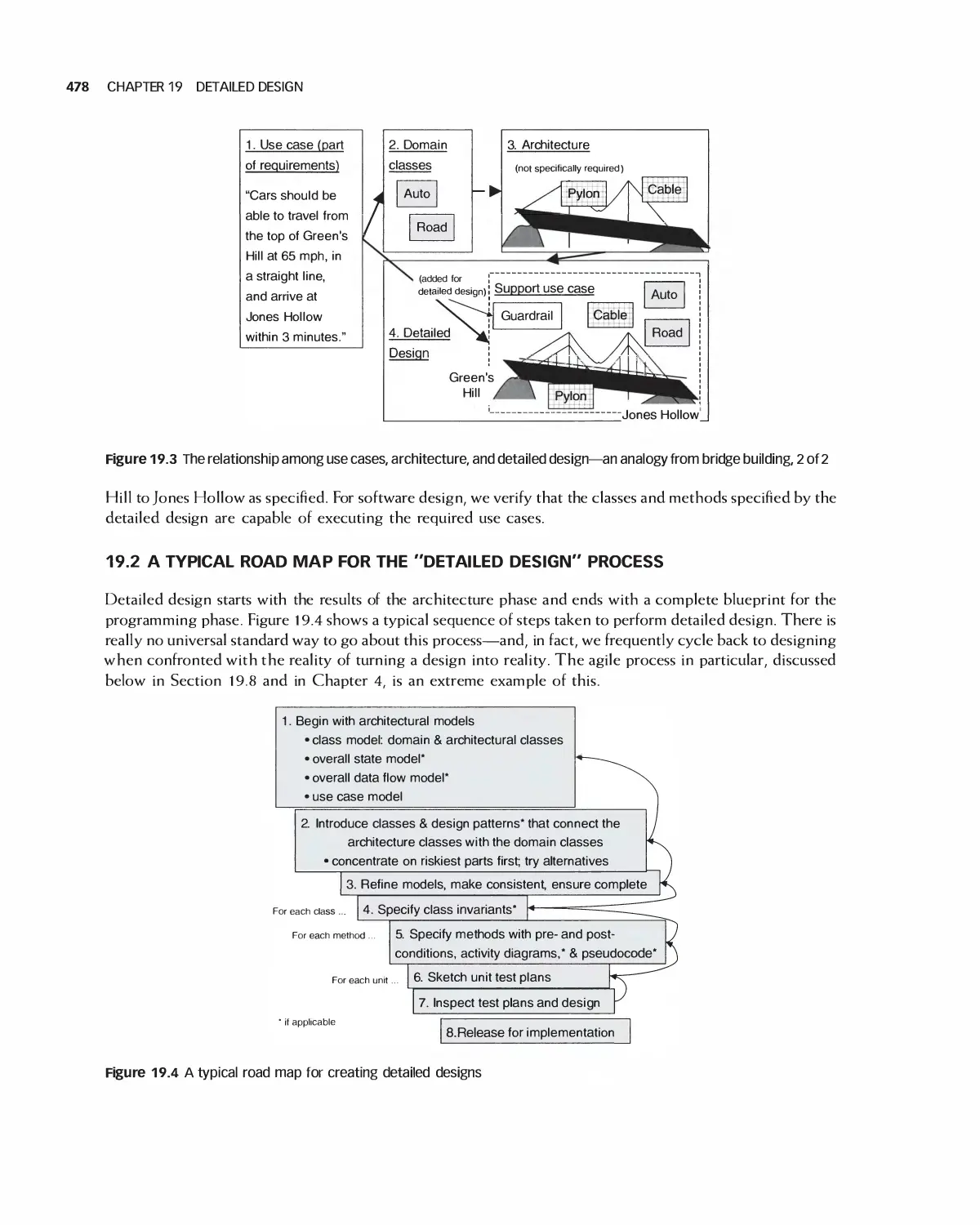
19.1 Relating Use Cases, Architecture, and Detailed Design 477
19.2 A Typical Road Map for the "Detailed Design" Process 478
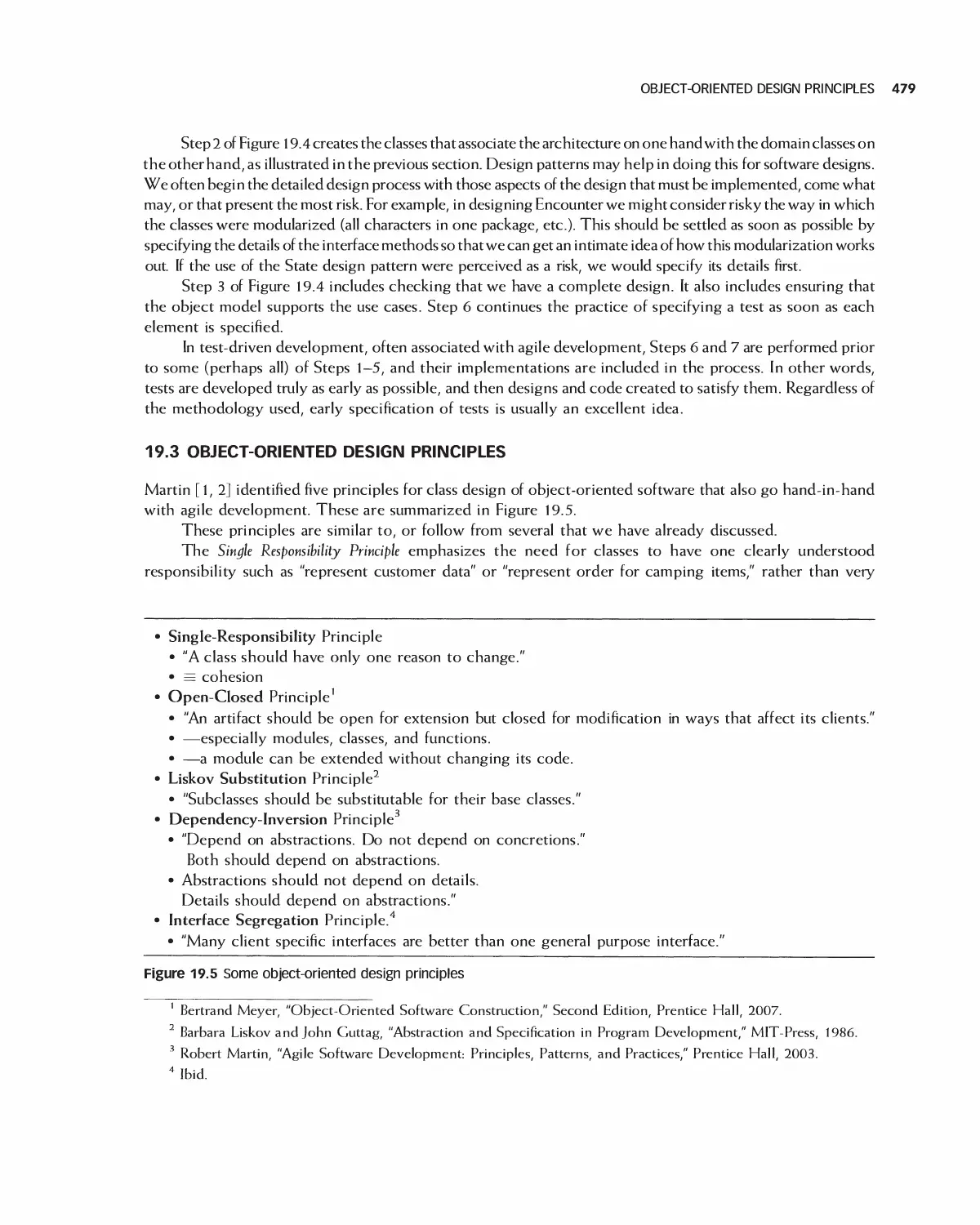
19.3 Object-Oriented Design Principles 479
19.4 Designing against Interfaces 481
19.5 Specifying Classes, Functions, and Algorithms 482
19.6 Reusing Components 485
19.7 Sequence and Data Flow Diagrams for Detailed Design 486
19.8 Detailed Design and Agile Processes 490
19.9 Design in the Unified Development Process 490
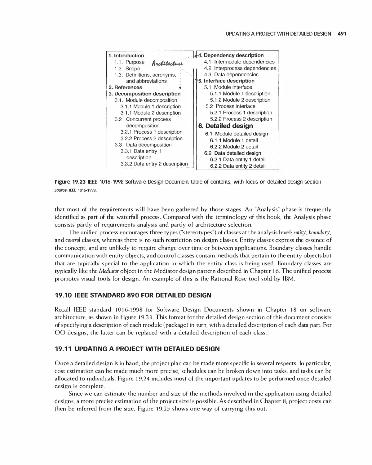
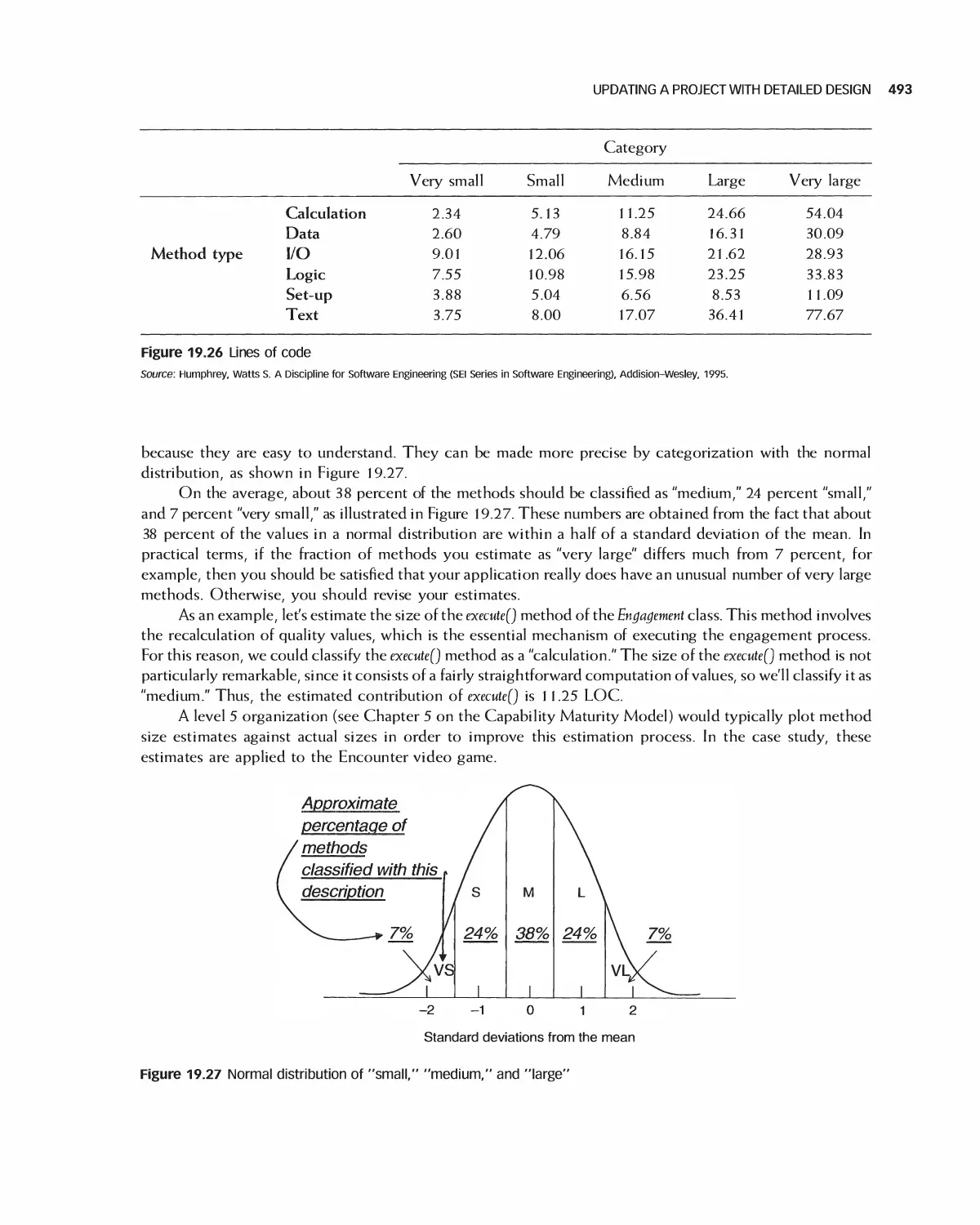
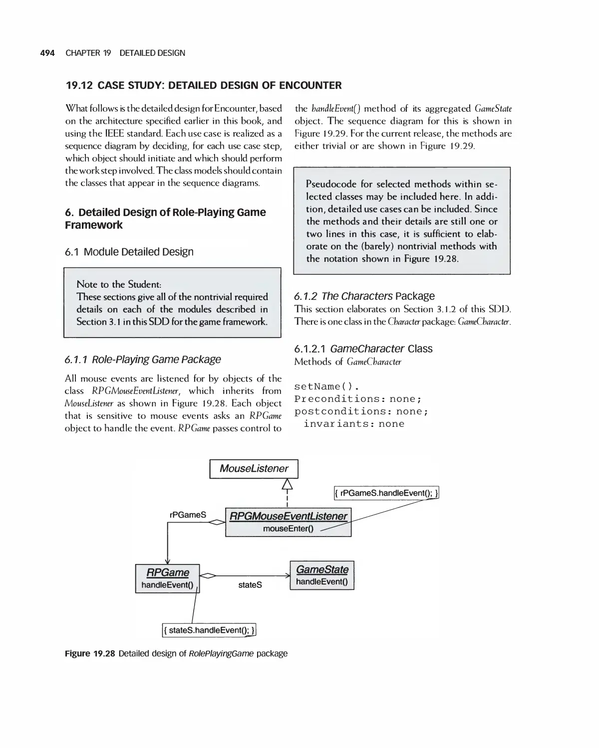
19.10 IEEE Standard 890 for Detailed Design 491
19.11 Updating a Project with Detailed Design 491
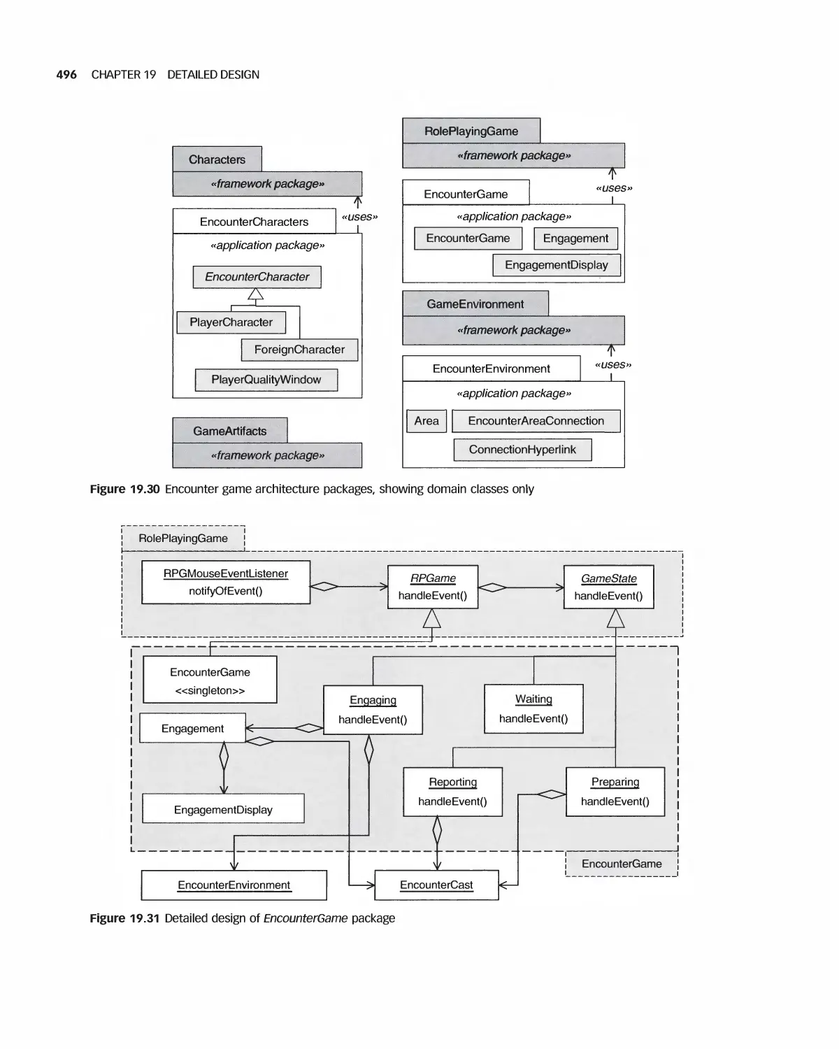
19.12 Case Study: Detailed Design of Encounter 494
19.13 Case Study: Detailed Design of Eclipse 503
19.14 Summary 505
19.15 Exercises 505
Bibliography 507
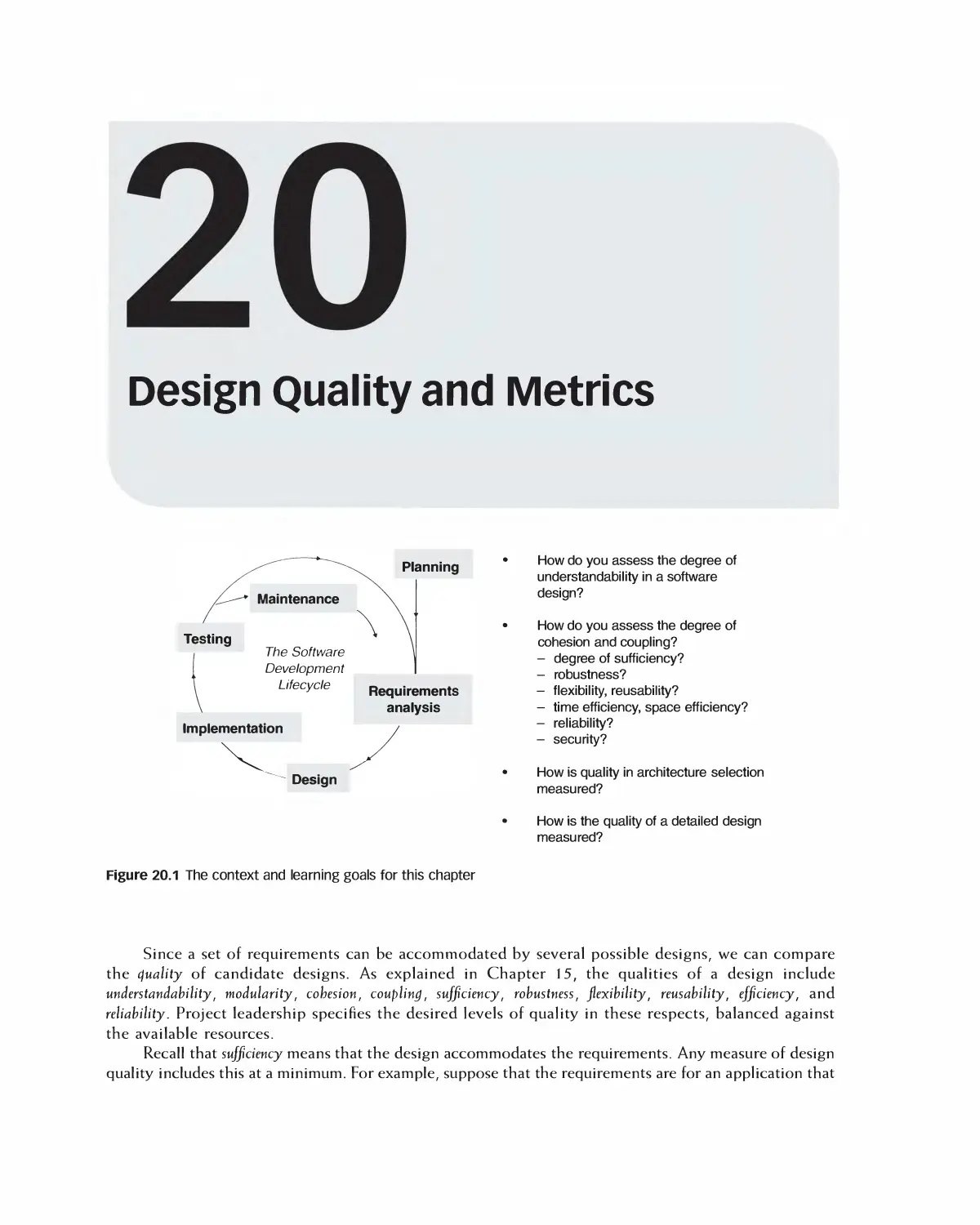
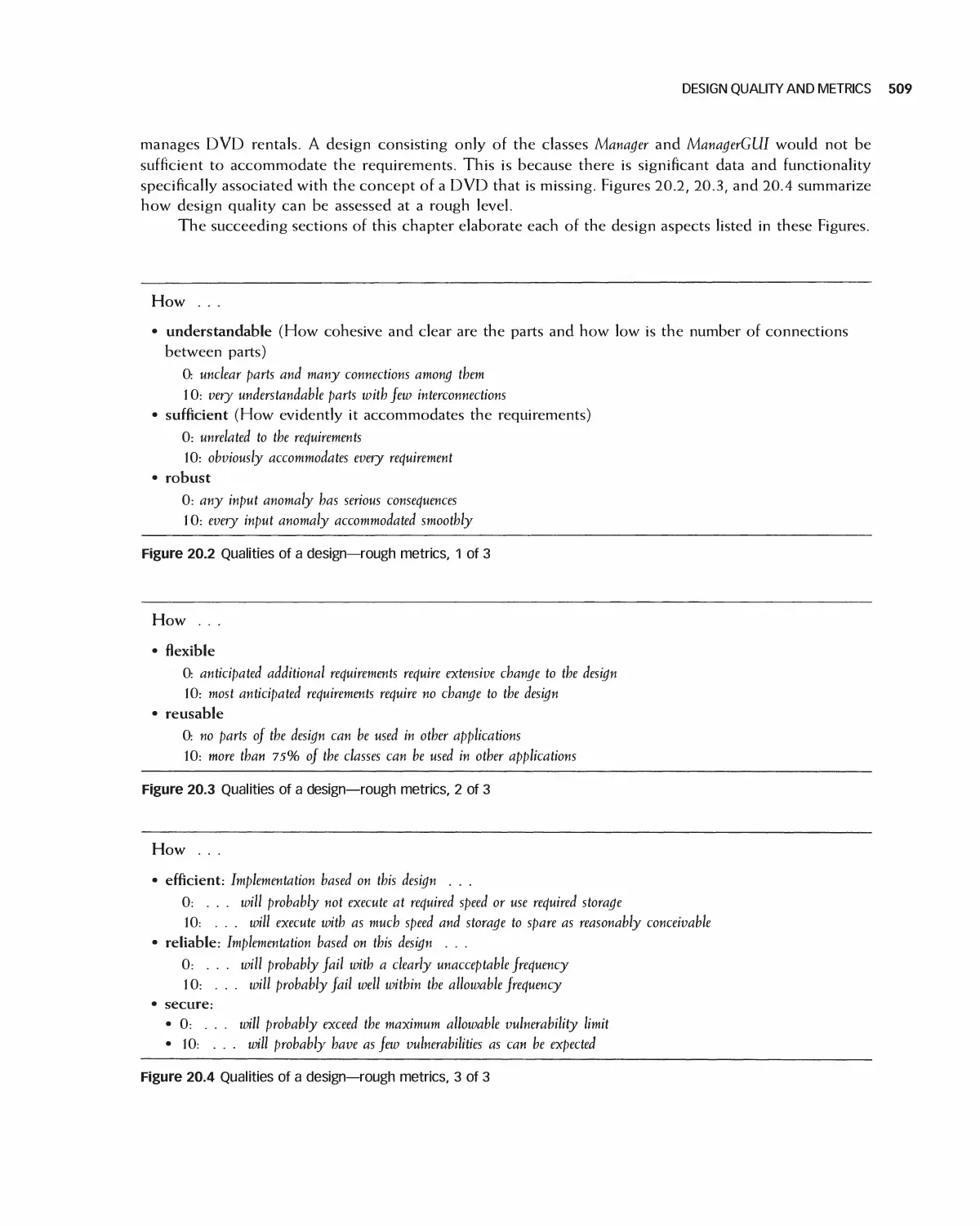
20 Design Quality and Metrics 508
20.1 Degree of Understandability, Cohesion, and Coupling 510
20.2 Degree of Sufficiency as a Quality Goal 510
20.3 Degree of Robustness as a Quality Goal 511
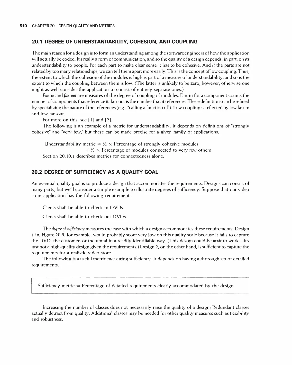
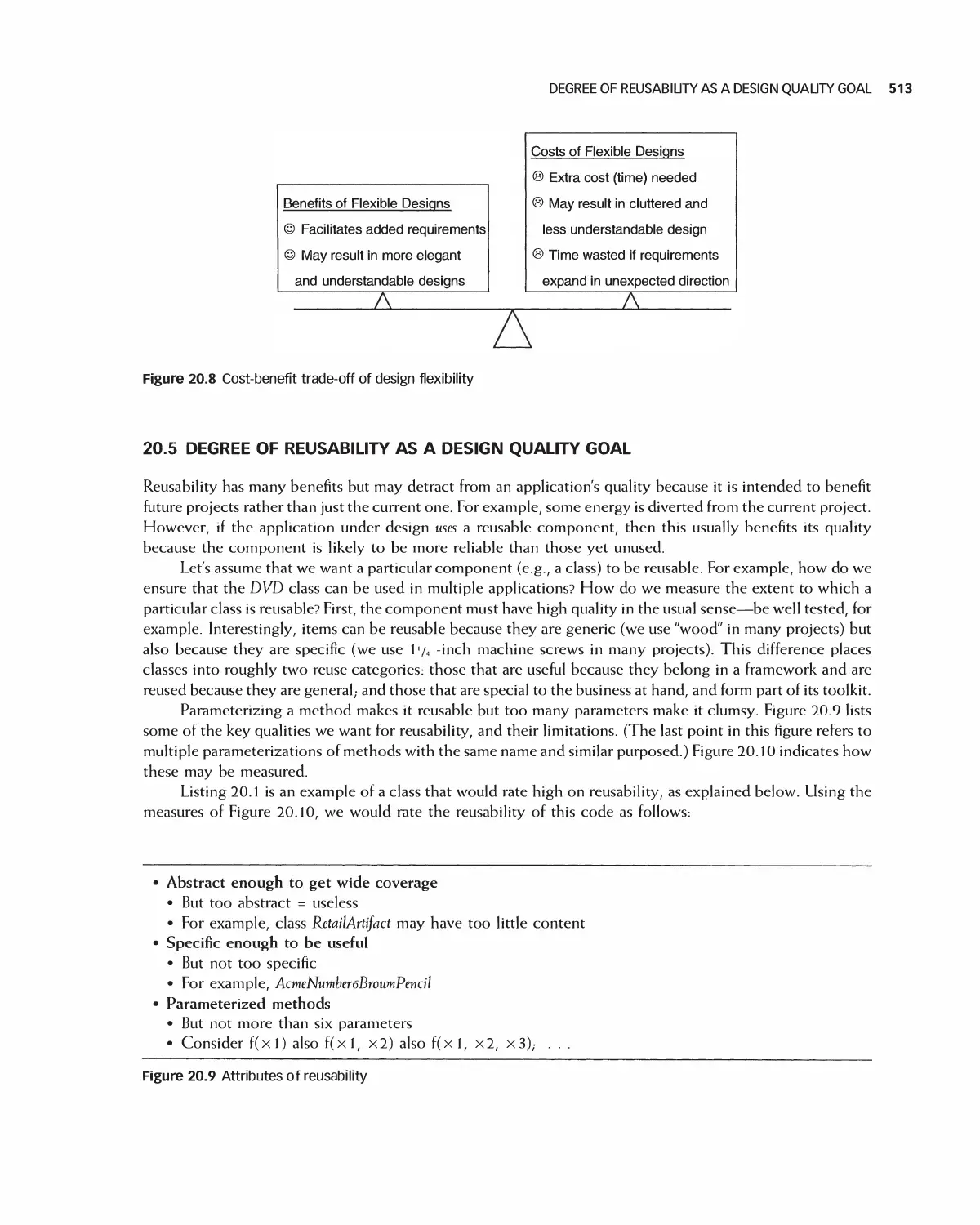
20.4 Degree of Flexibility as a Design Quality Goal 512
20.5 Degree of Reusability as a Design Quality Goal 513
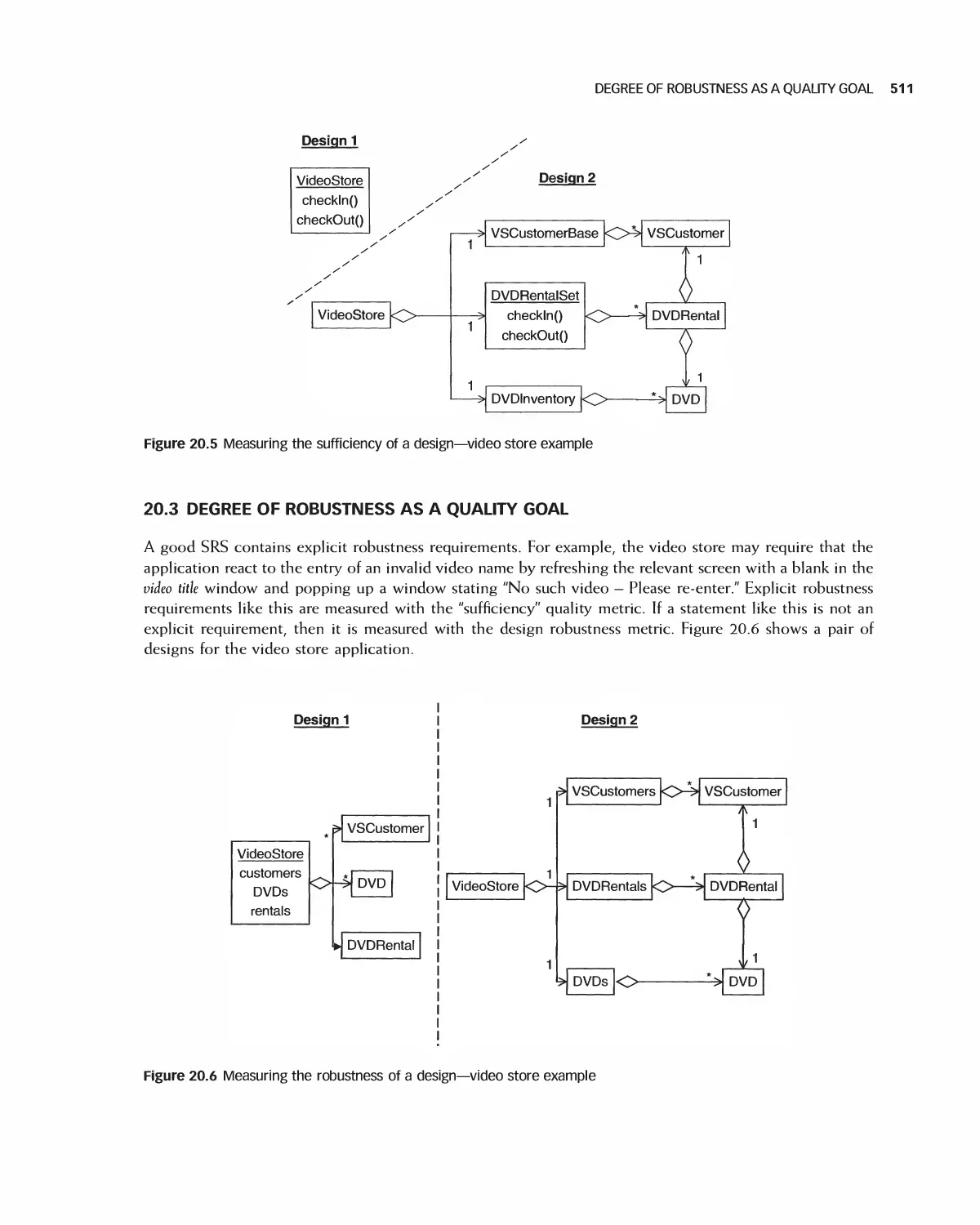
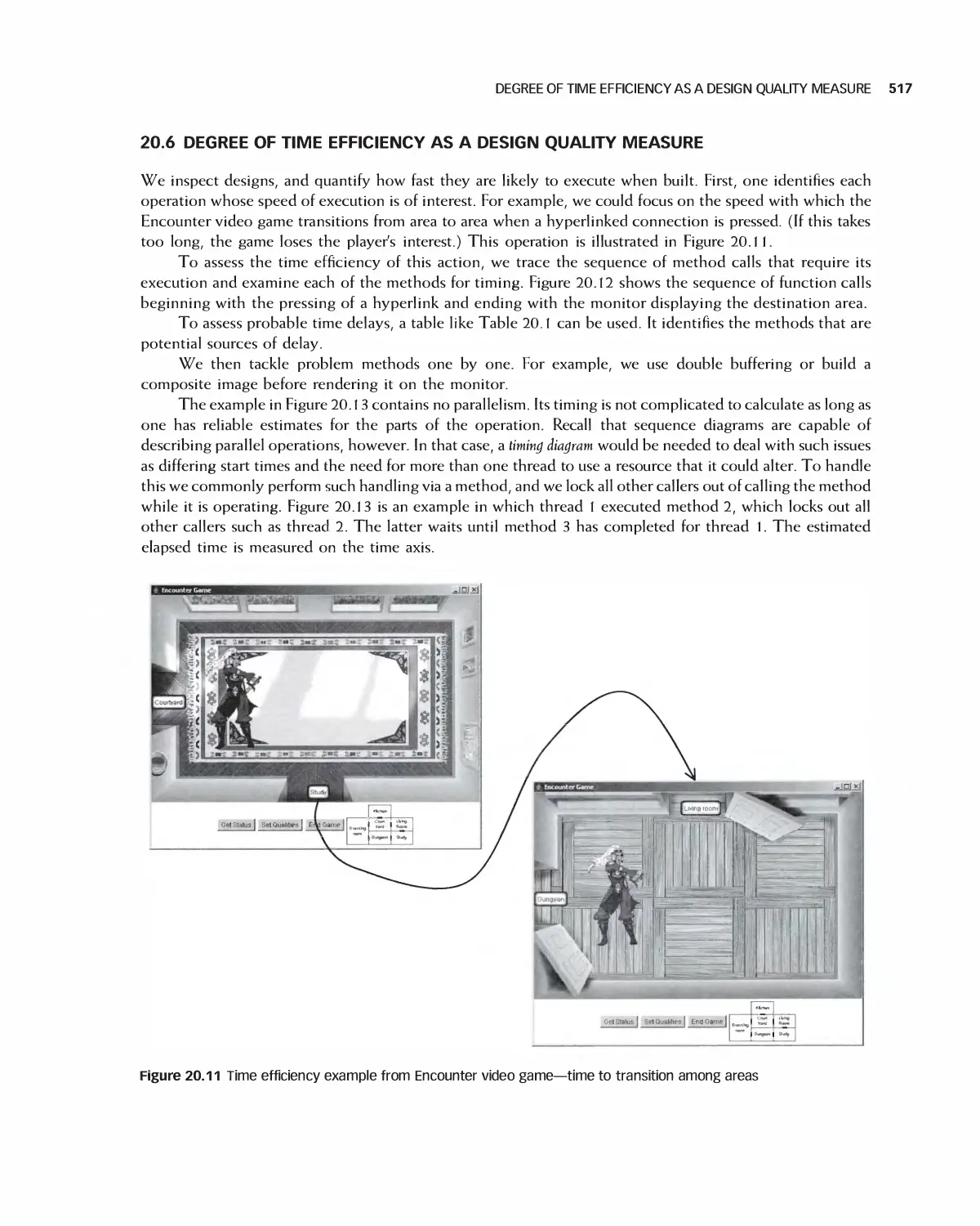
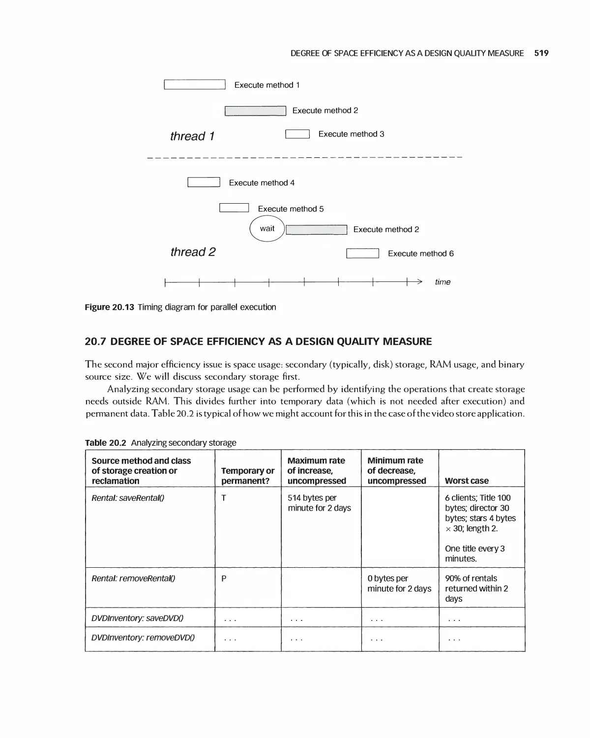
20.6 Degree of Time Efficiency as a Design Quality Measure 517
CONTENTS Xi
20.7 Degree of Space Efficiency as a Design Quality Measure 519
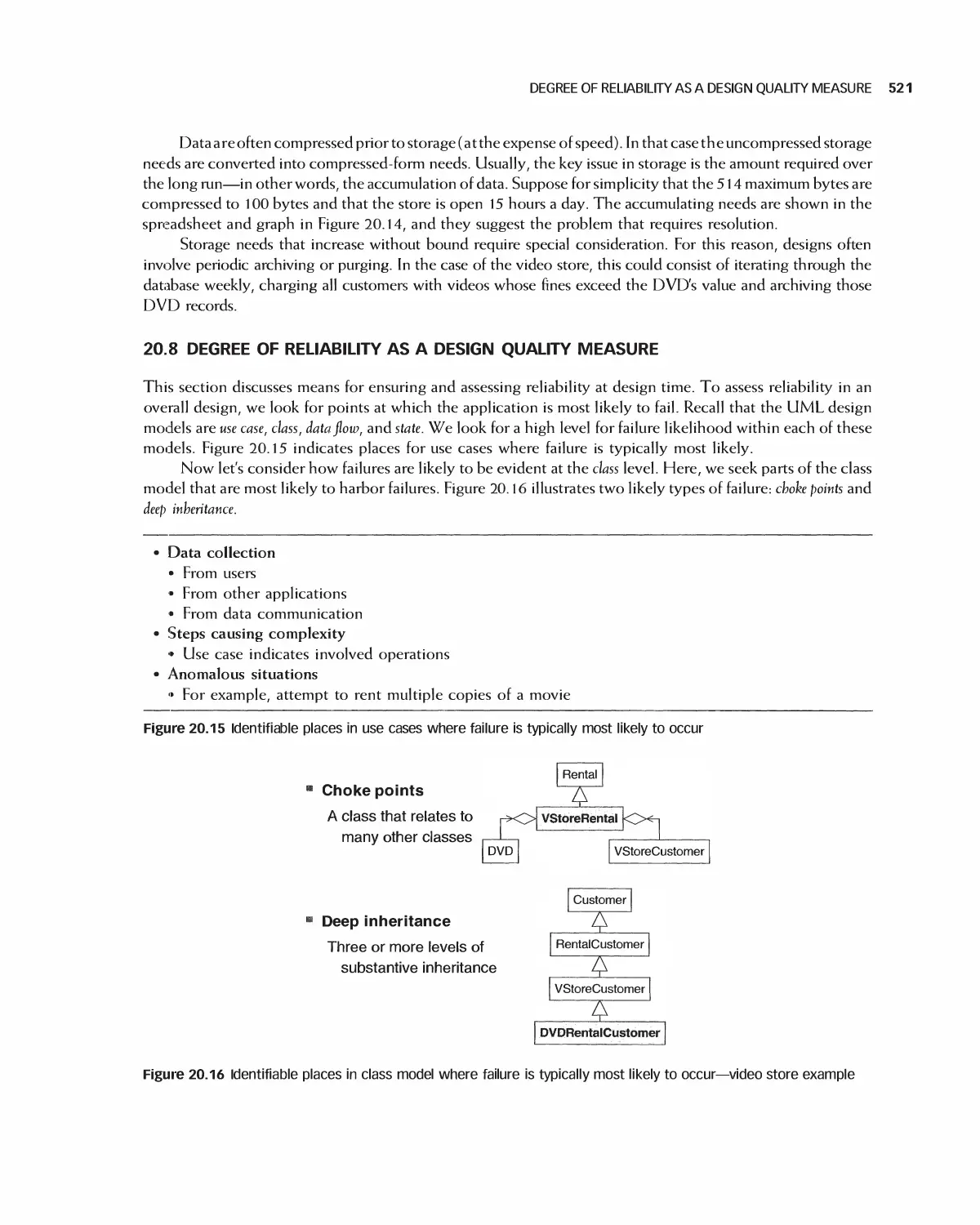
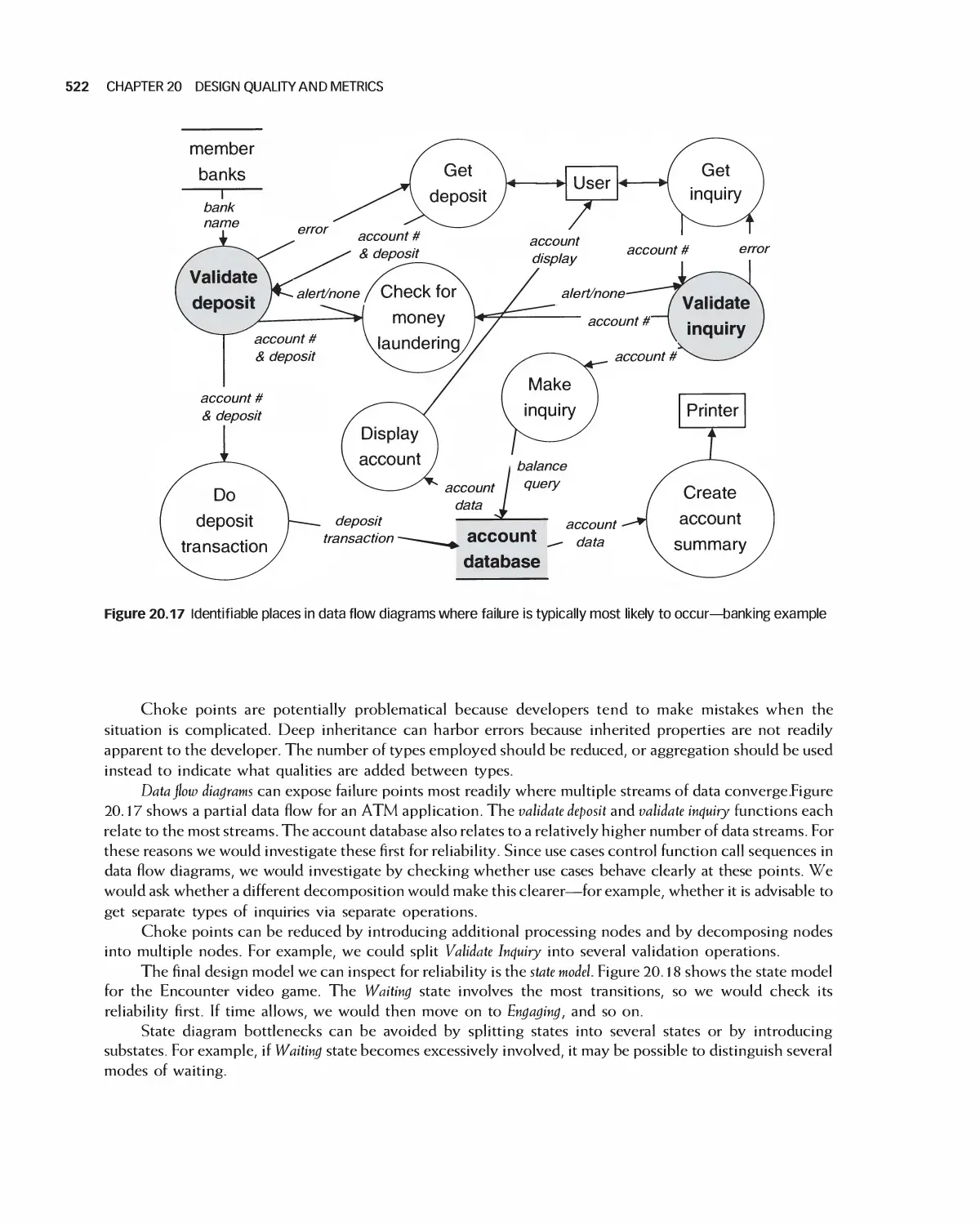
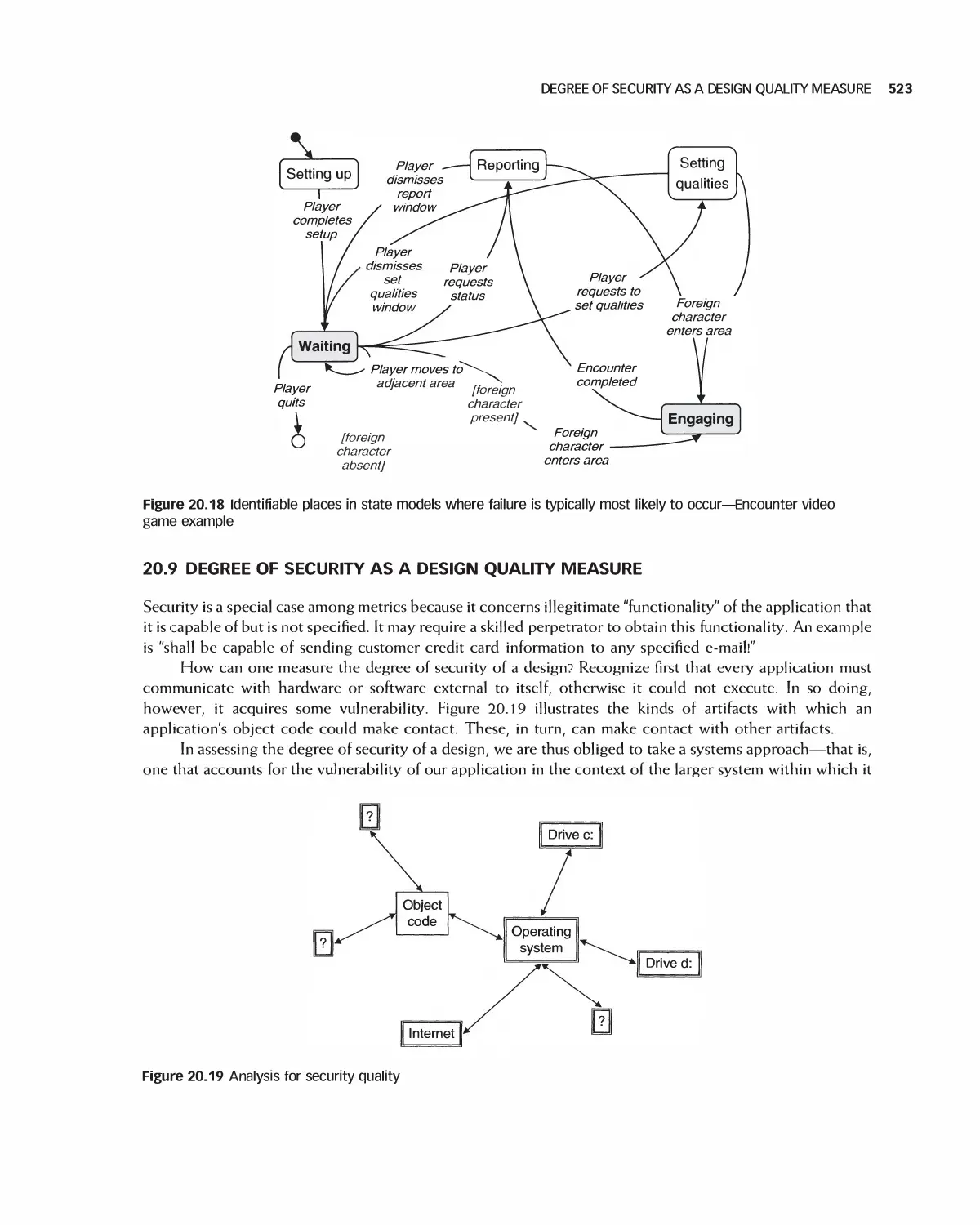
20.8 Degree of Reliability as a Design Quality Measure 521
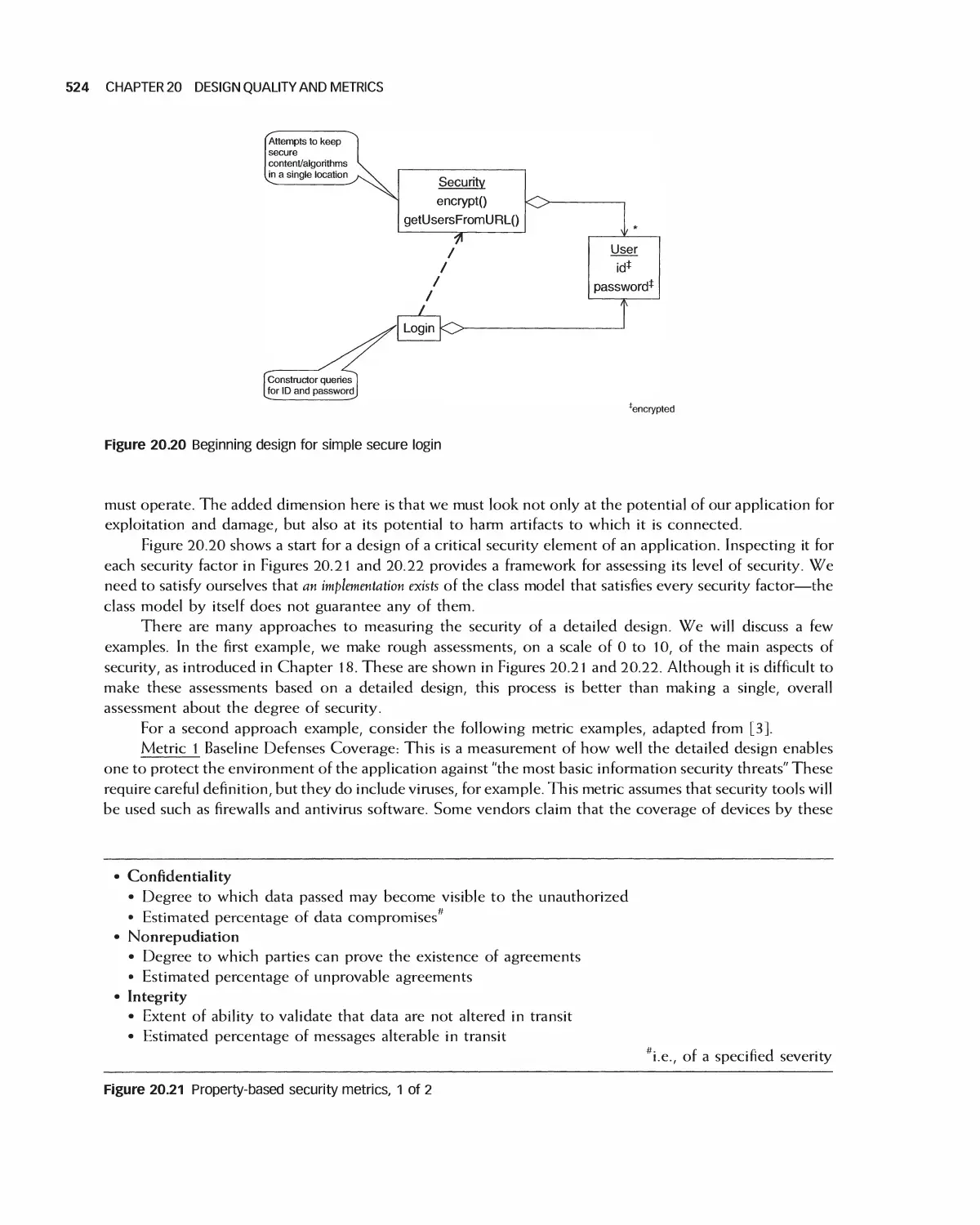
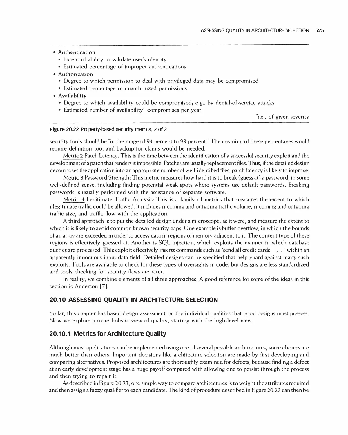
20.9 Degree of Security as a Design Quality Measure 523
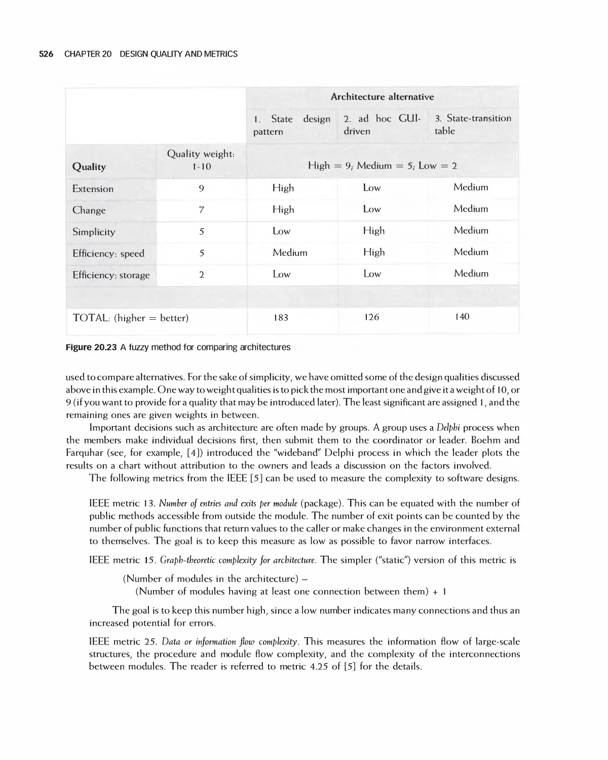
20.10 Assessing Quality in Architecture Selection 525
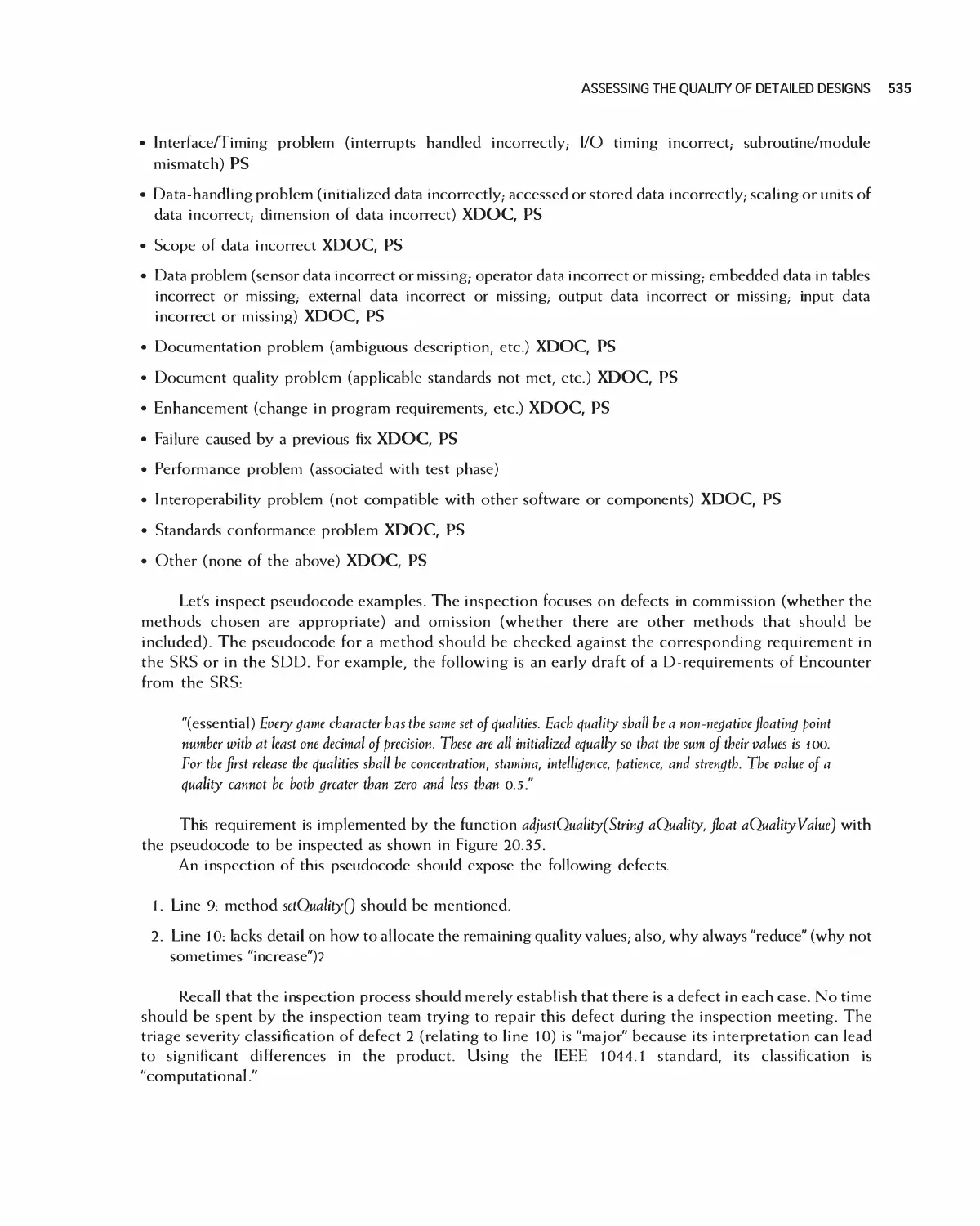
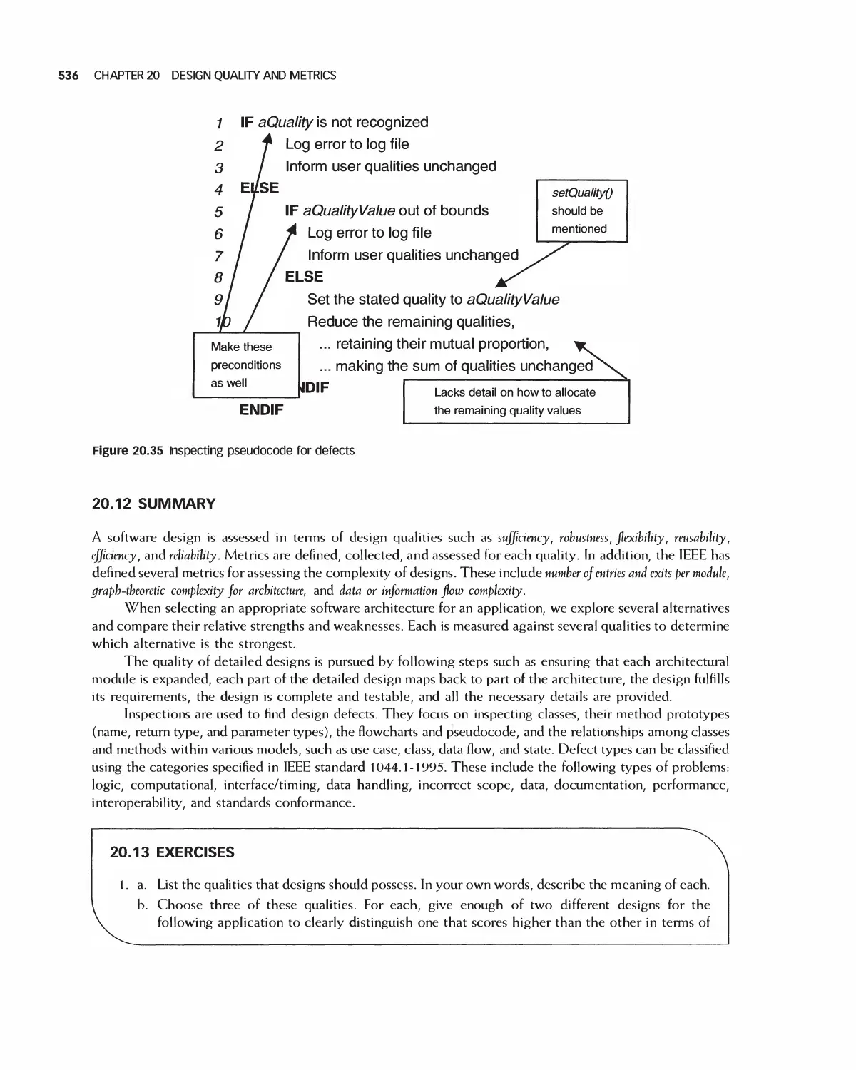
20.11 Assessing the Quality of Detailed Designs 531
20.12 Summary 536
20.13 Exercises 536
Bibliography 537
21 Advanced and Emerging Methods in Software Design (Online Chapter) 538
21.1 Designing in a Distributed Environment
21.2 Introduction to Aspect-Oriented Programming
21.3 Designing for Security with UMLsec
21.4 Model-Driven Architectures
21.5 The Formal Design Process in B
21.6 Summary
21.7 Exercises
Bibliography
PART VI Implementation
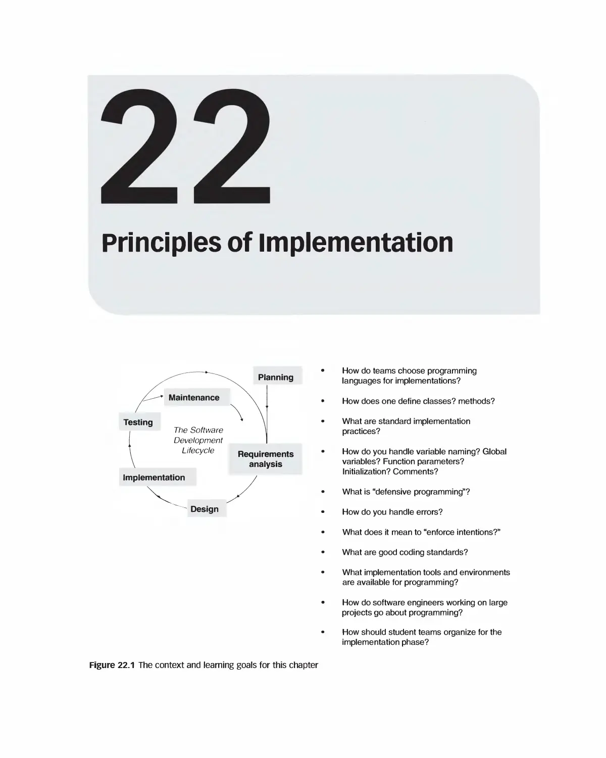
22 Principles of Implementation 539
22.1 Agile and Non-Agile Approaches to Implementation 540
22.2 Choosing a Programming Language 540
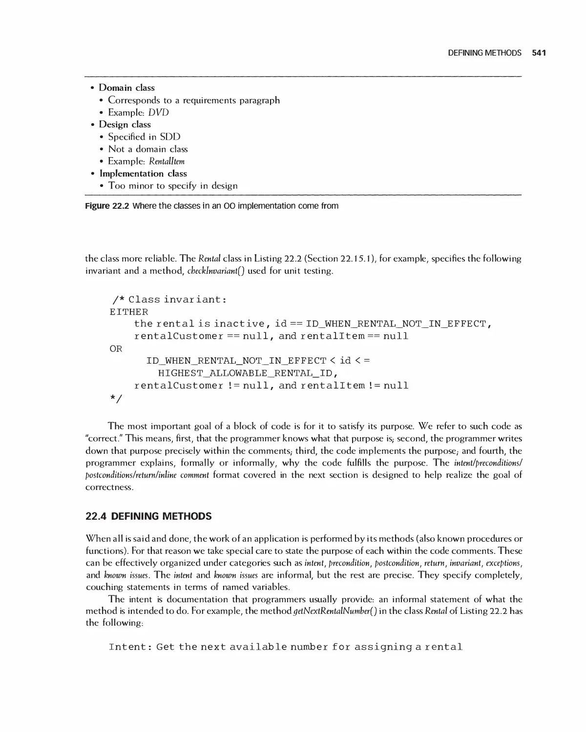
22.3 Identifying Classes 540
22.4 Defining Methods 541
22.5 Implementation Practices 544
22.6 Defensive Programming 548
22.7 Coding Standards 552
22.8 Comments 554
22.9 Tools and Environments for Programming 555
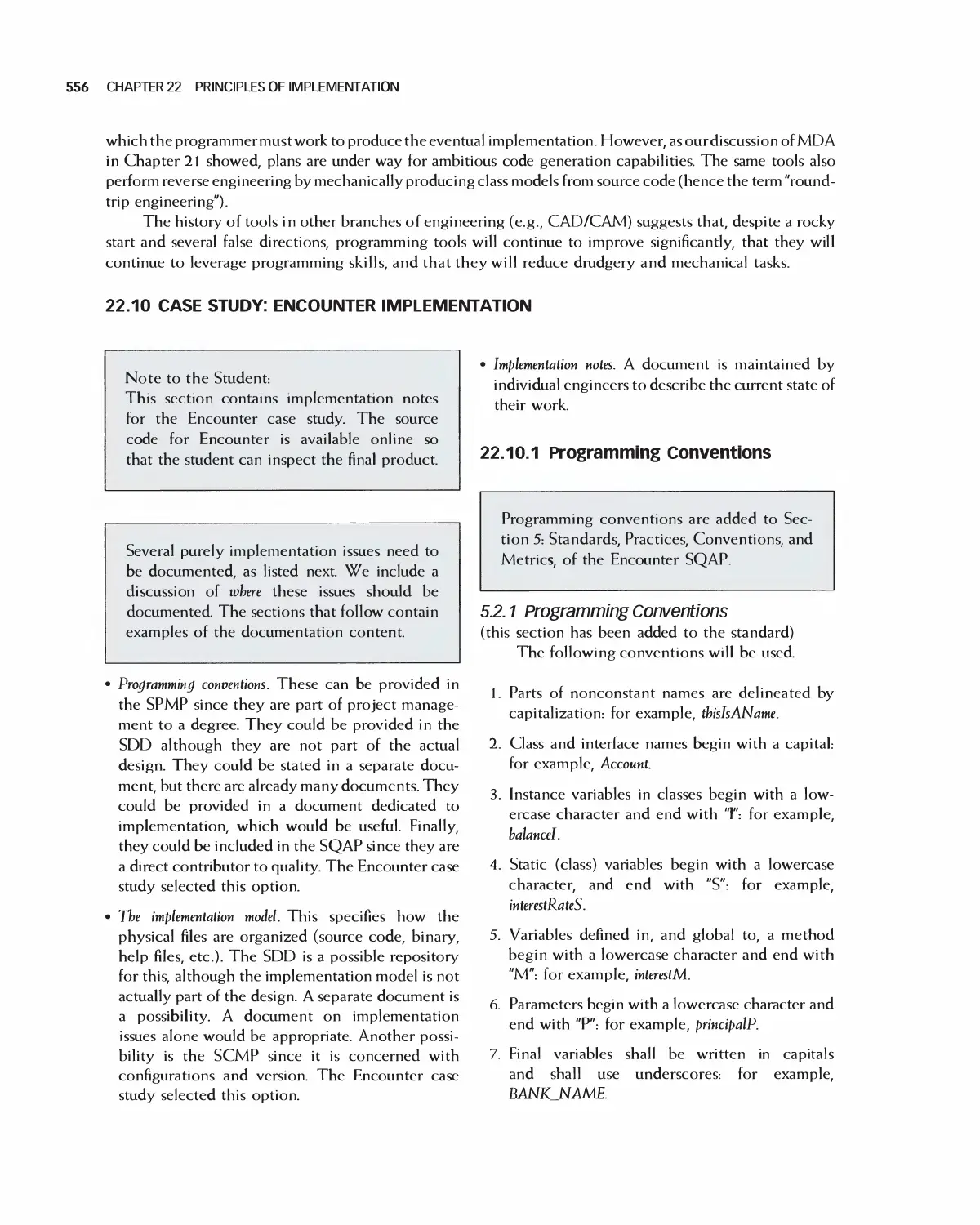
22.10 Case Study: Encounter Implementation 556
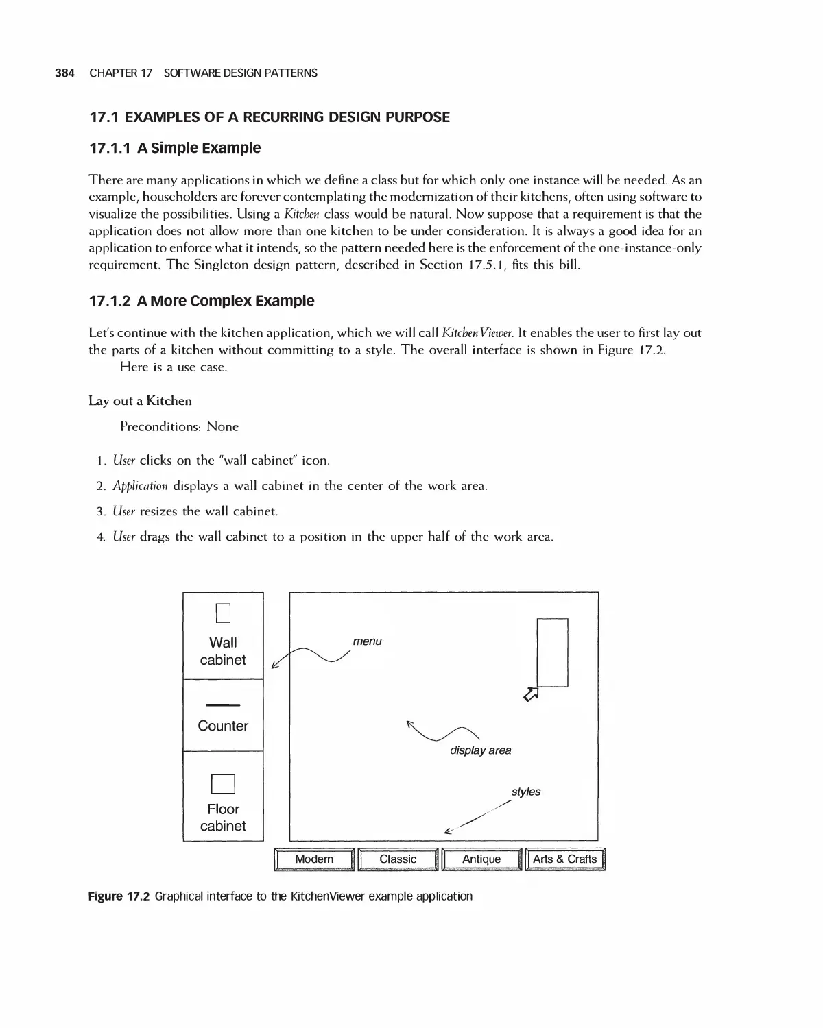
22.11 Case Study: Eclipse 559
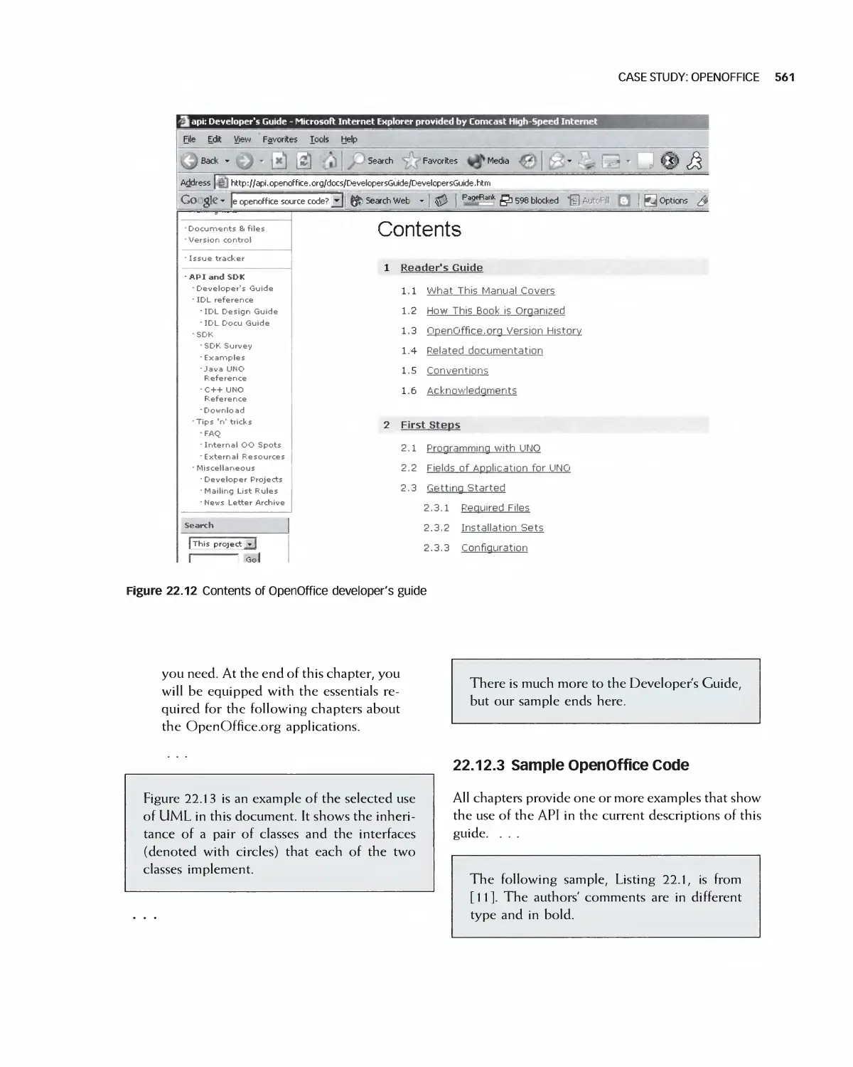
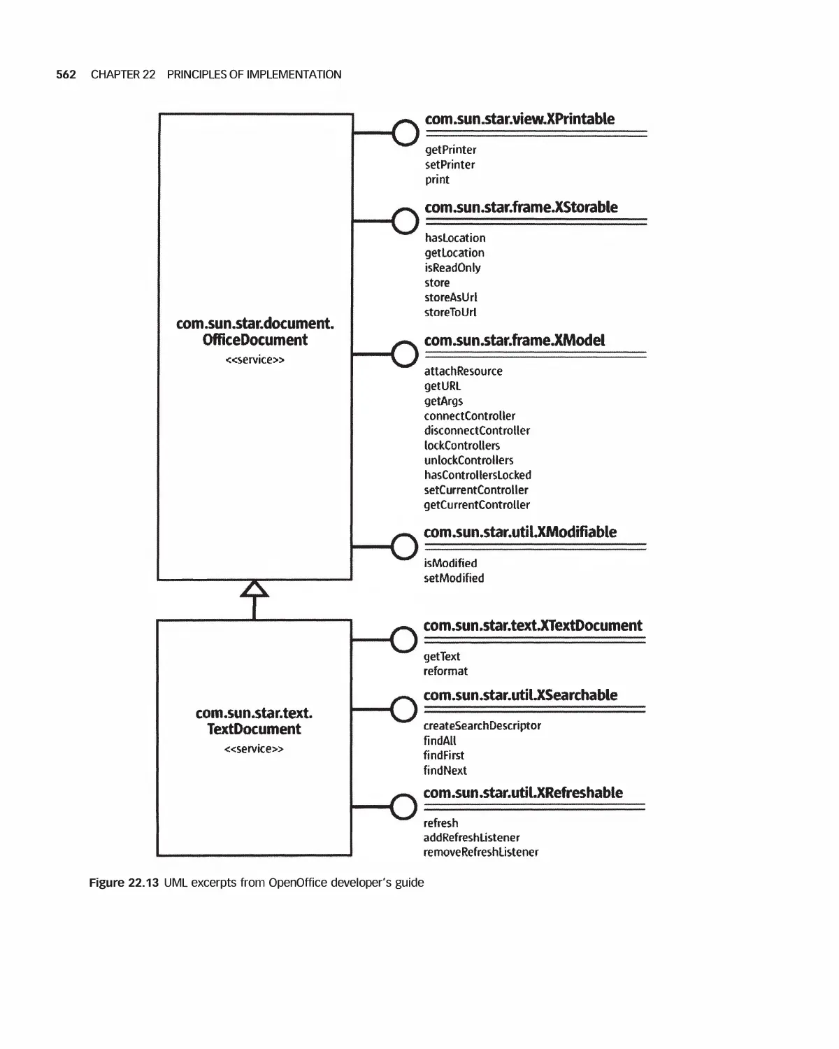
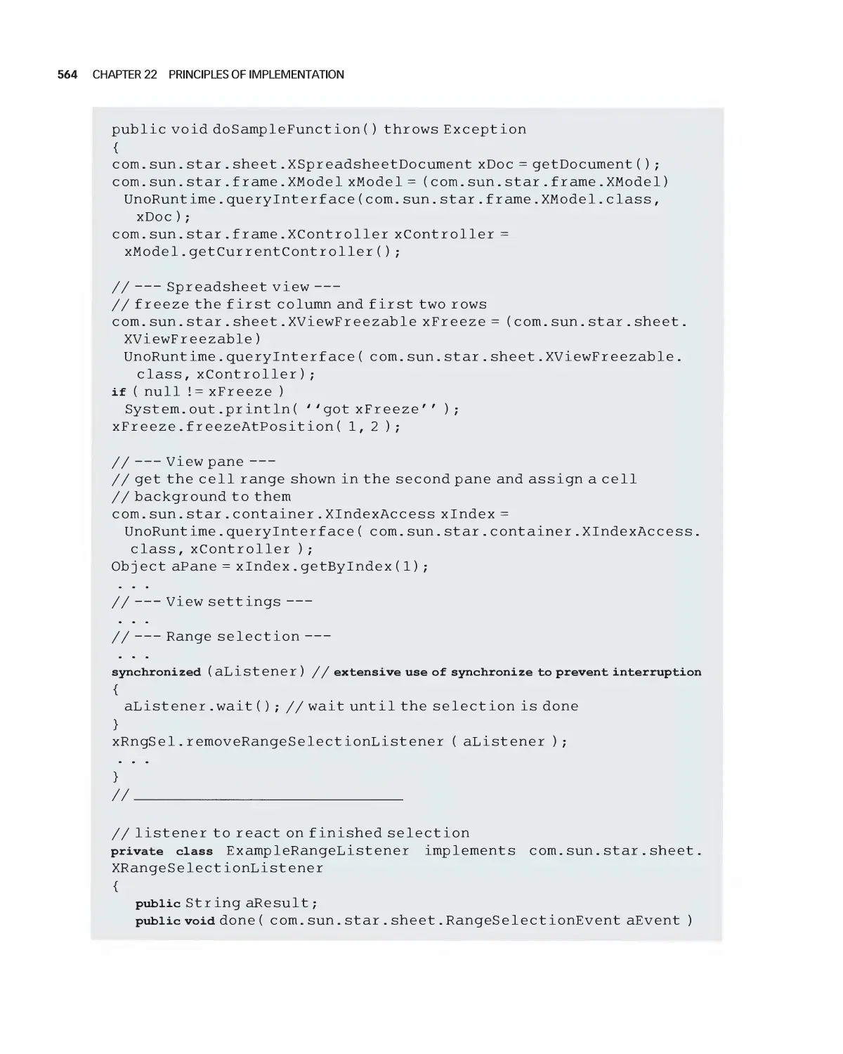
22.12 Case Study: OpenOffice 559
22.13 Student Team Guidance for Implementation 565
22.14 Summary 566
22.15 Code Listings Referred to in this Chapter 566
22.16 Exercises 581
Bibliography 583
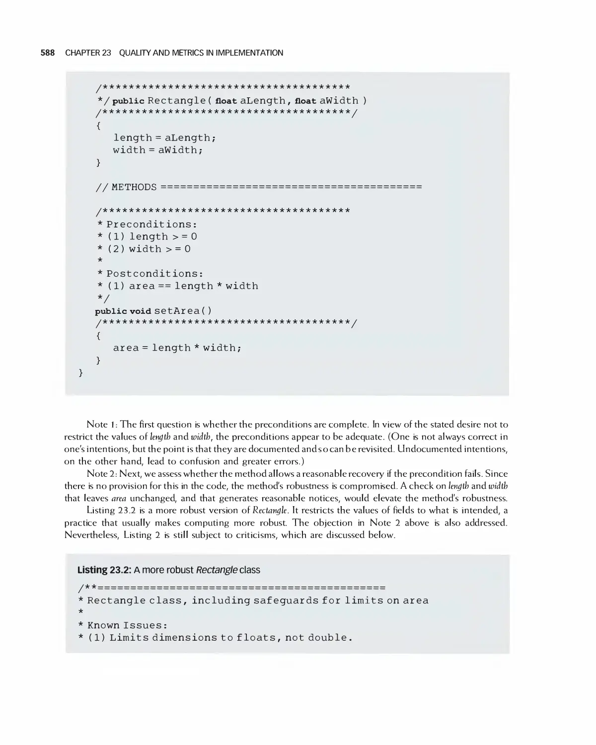
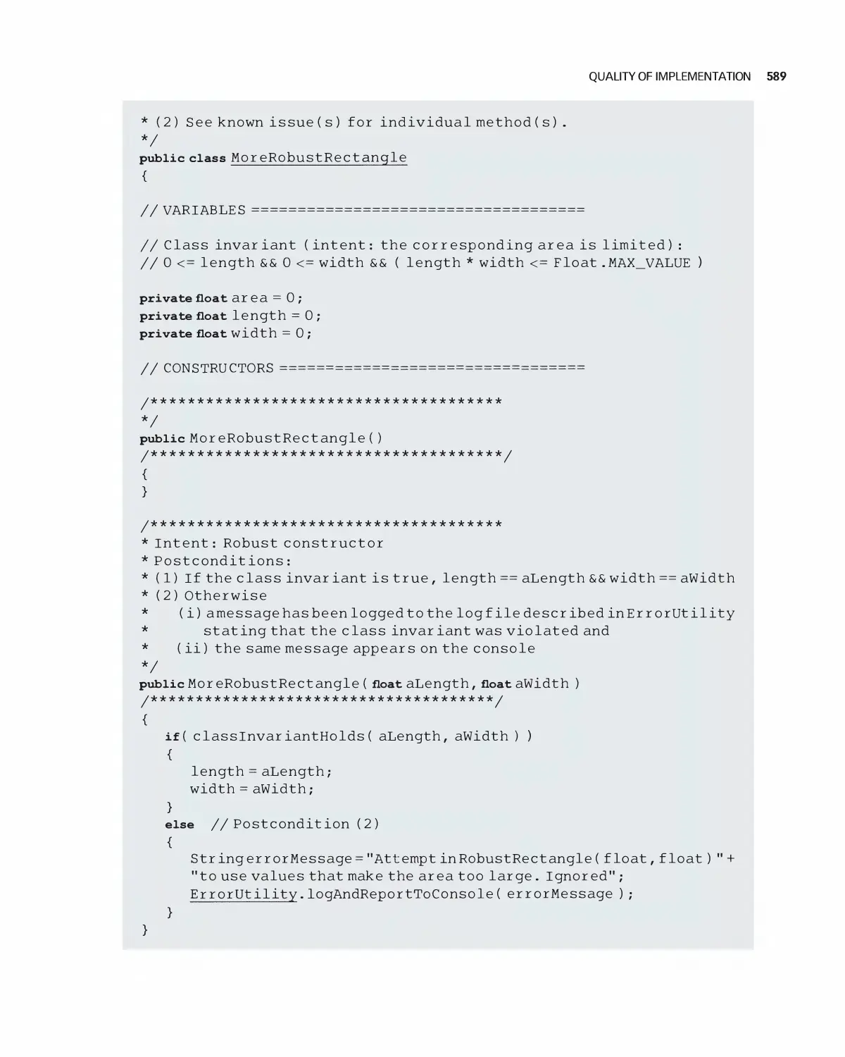
23 Quality and Metrics in Implementation 584
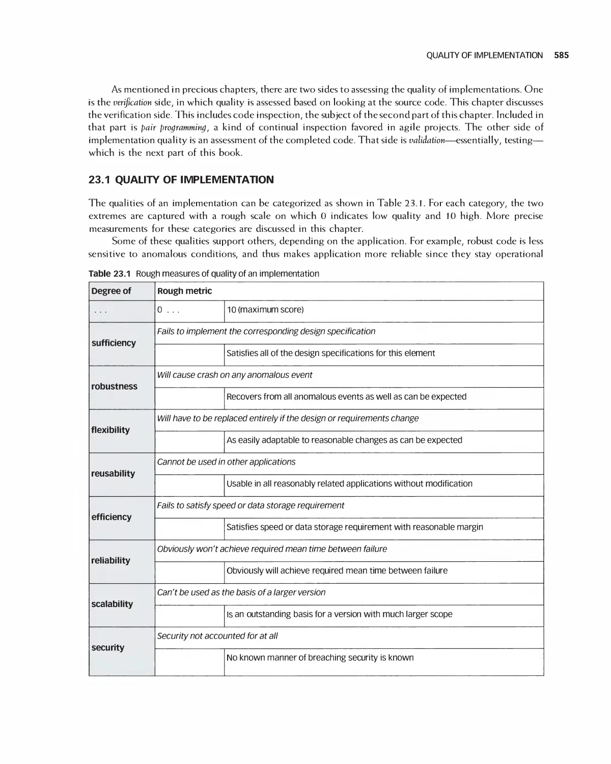
23.1 Quality of Implementation 585
23.2 Code Inspections and Related Quality Procedures 597
23.3 Summary 599
23.4 Exercises 599
Xii CONTENTS
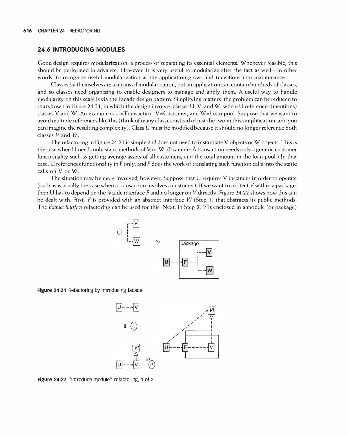
24 Refactoring 601
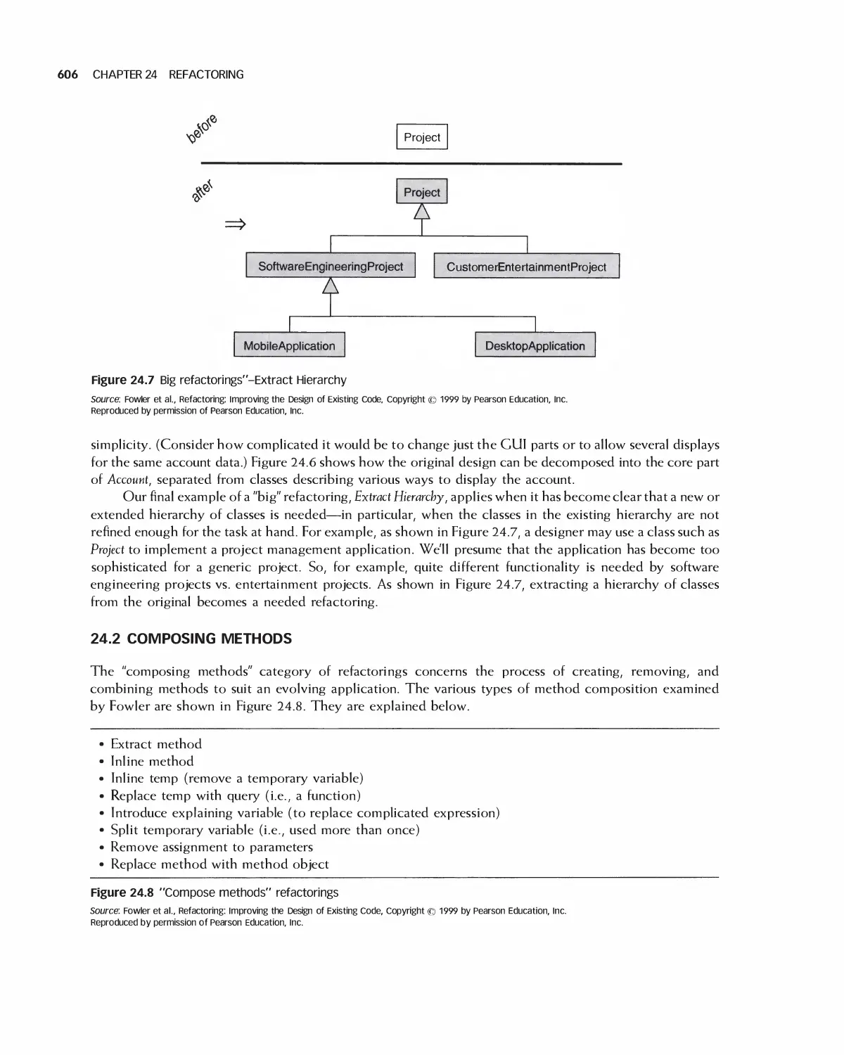
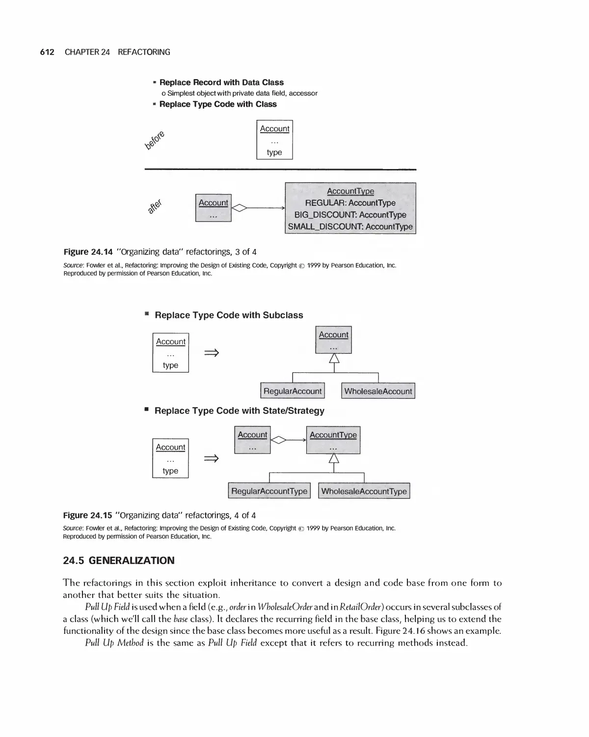
24.1 Big Refactorings 604
24.2 Composing Methods 606
24.3 Moving Features between Objects 608
24.4 Organizing Data 609
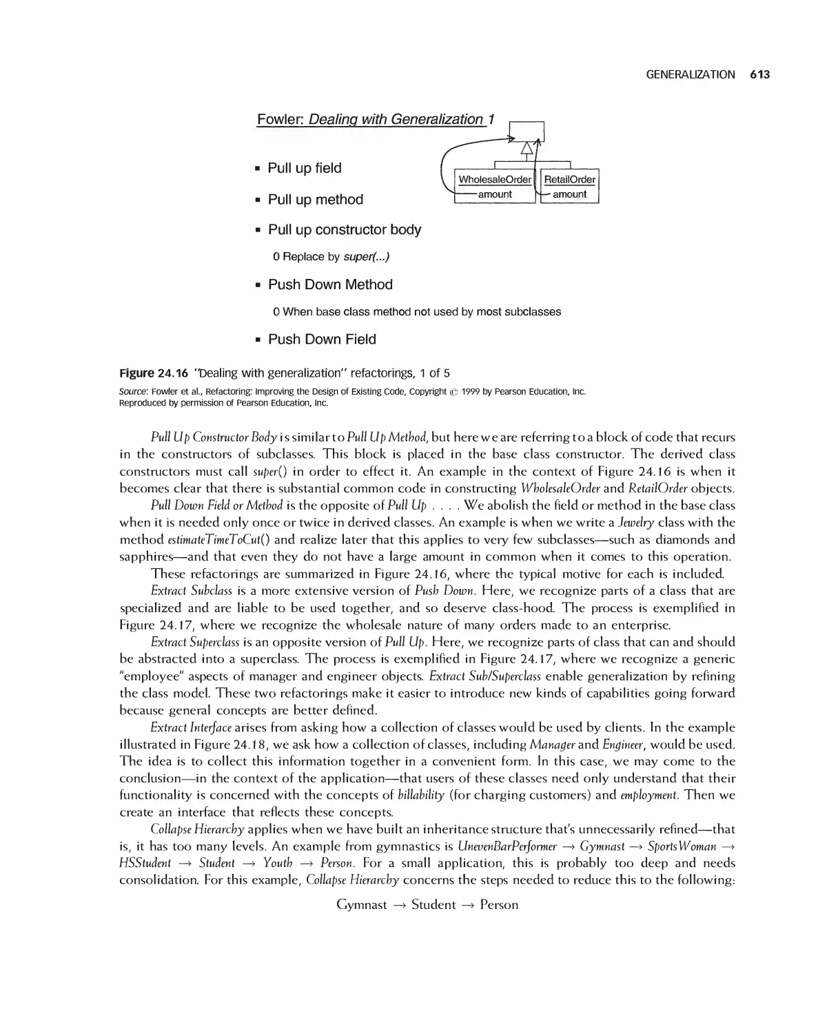
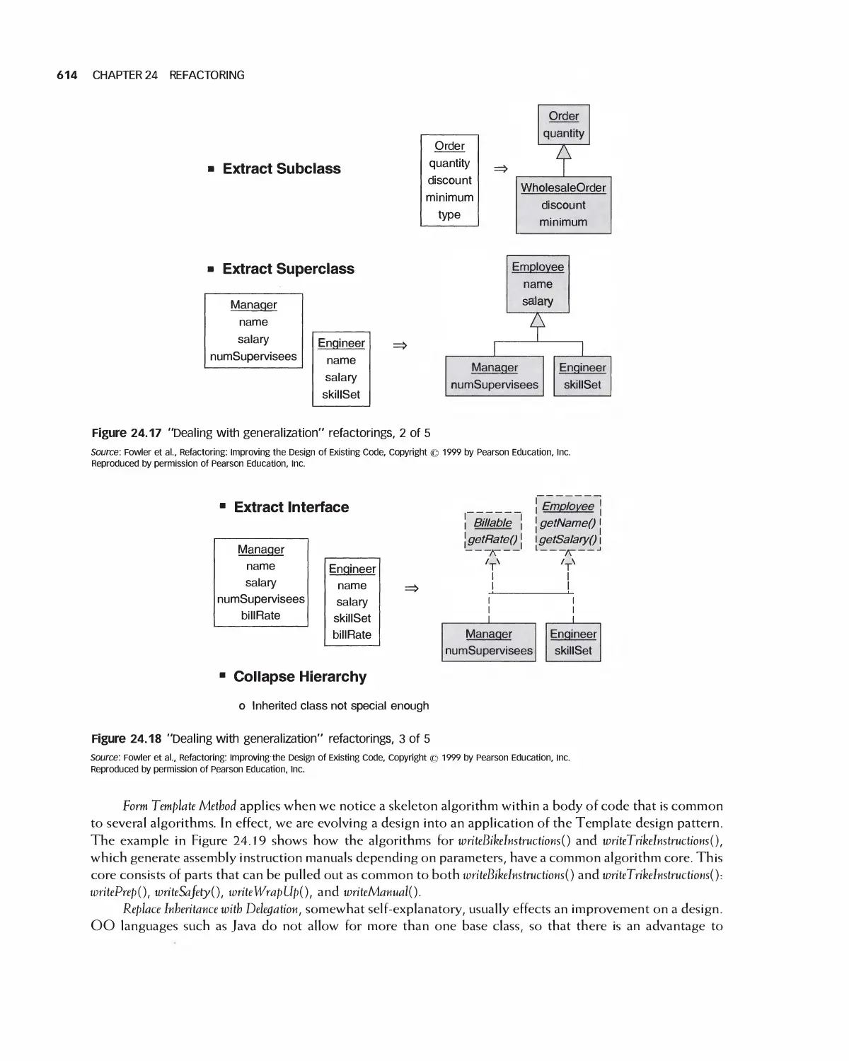
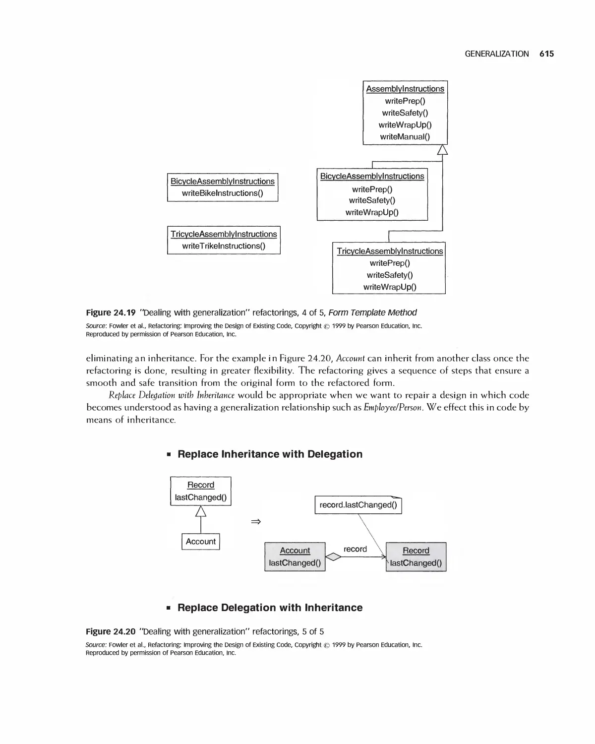
24.5 Generalization 612
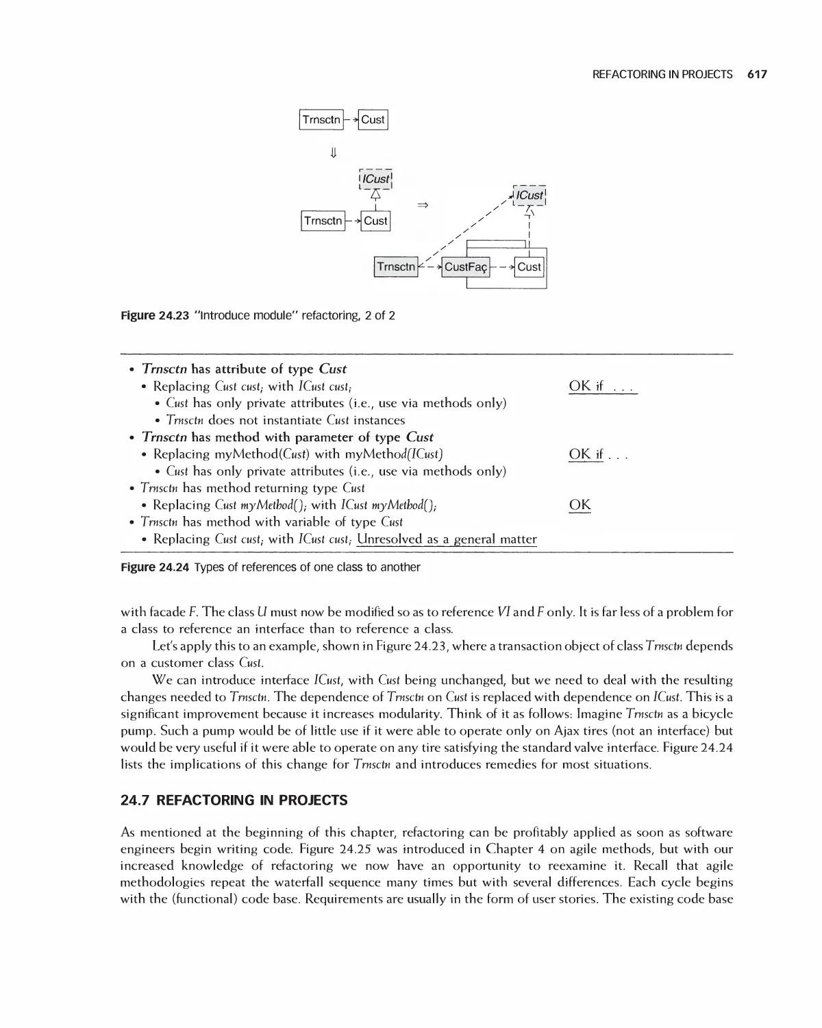
24.6 Introducing Modules 616
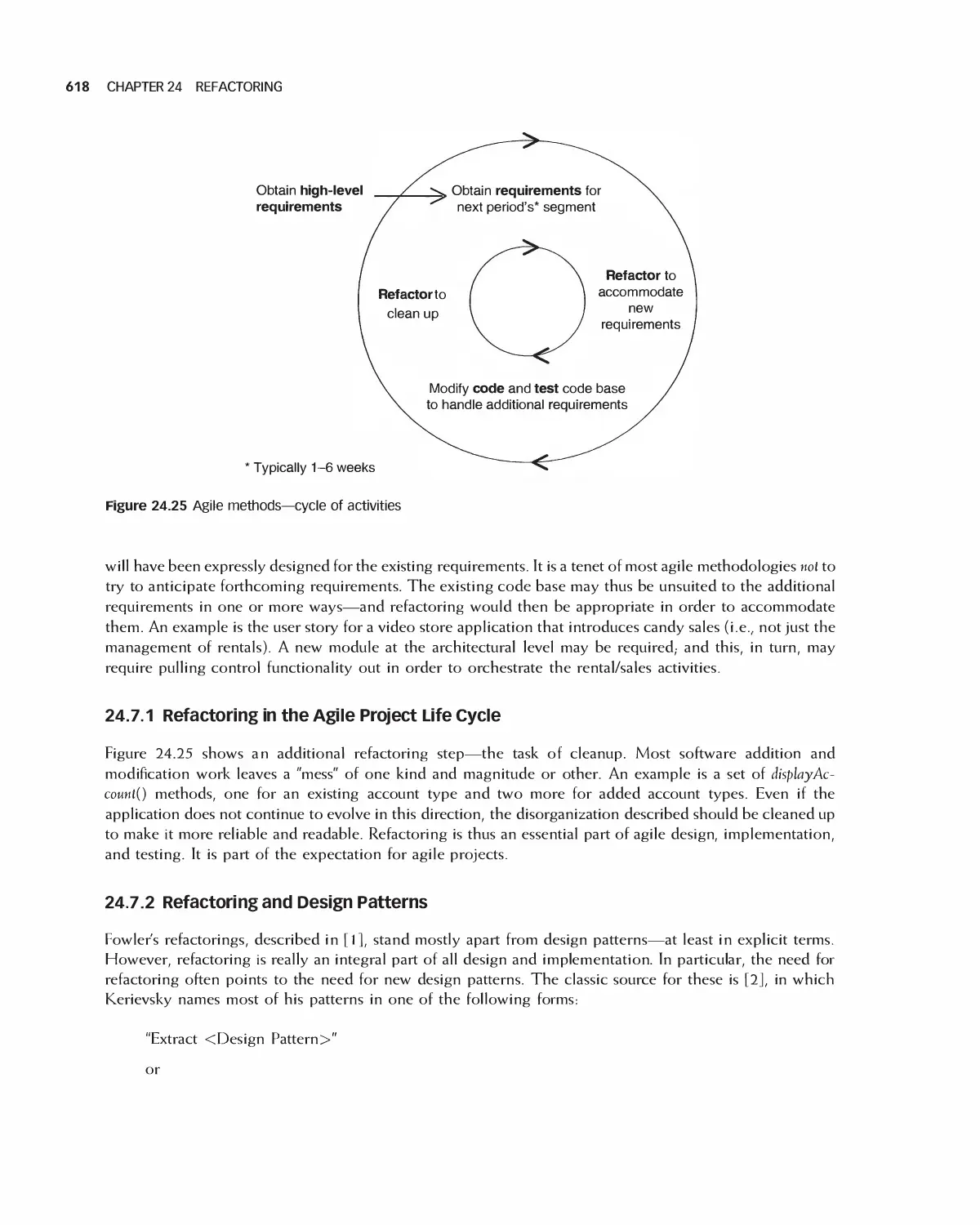
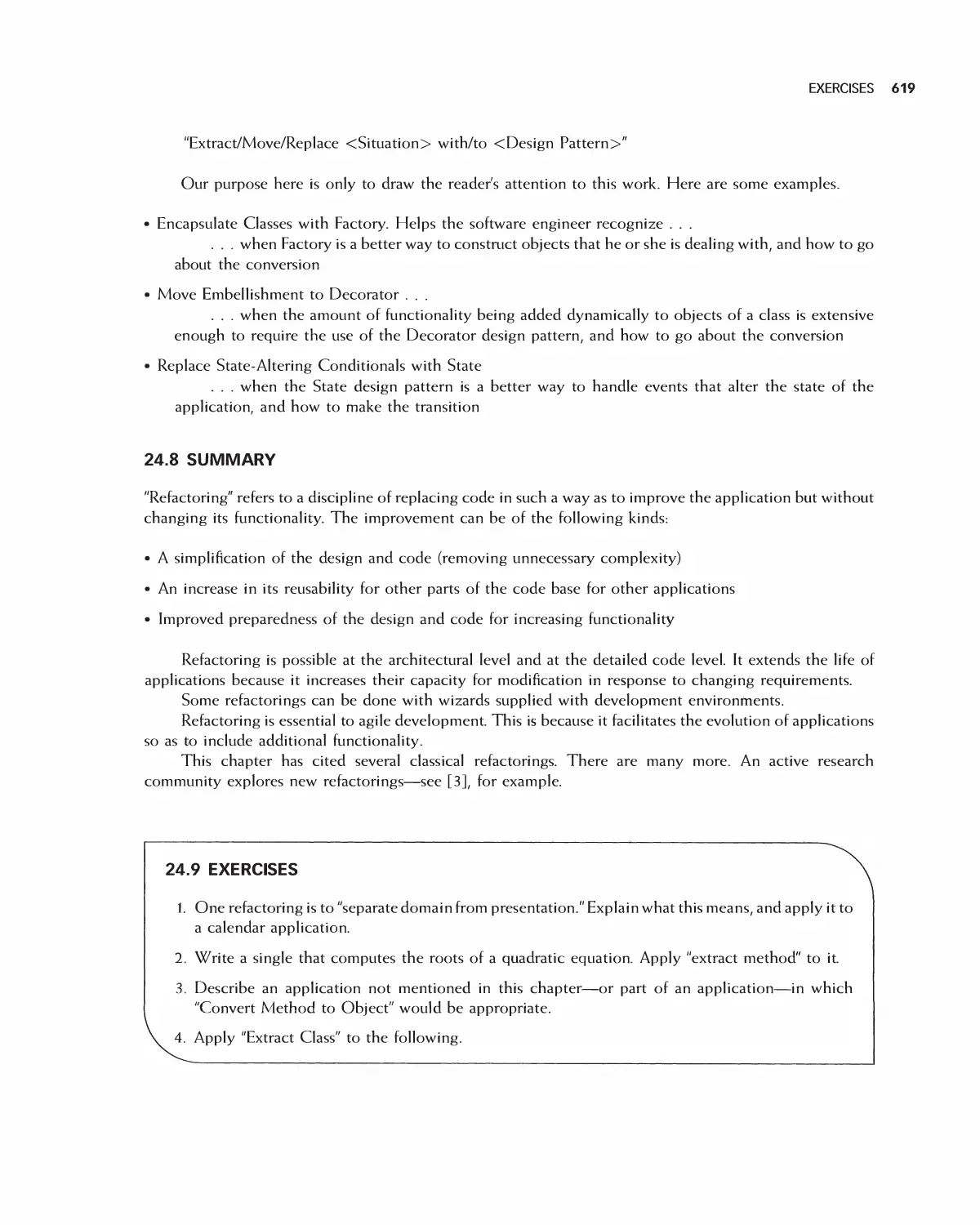
24.7 Refactoring in Projects 617
24.8 Summary 619
24.9 Exercises 619
Bibliography 620
PART VII Testing and Maintenance
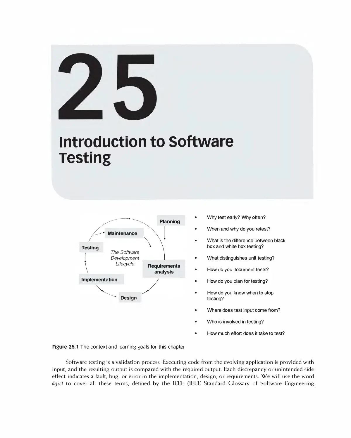
25 Introduction to Software Testing 621
25.1 Testing Early and Often,- and the Agile Connection 622
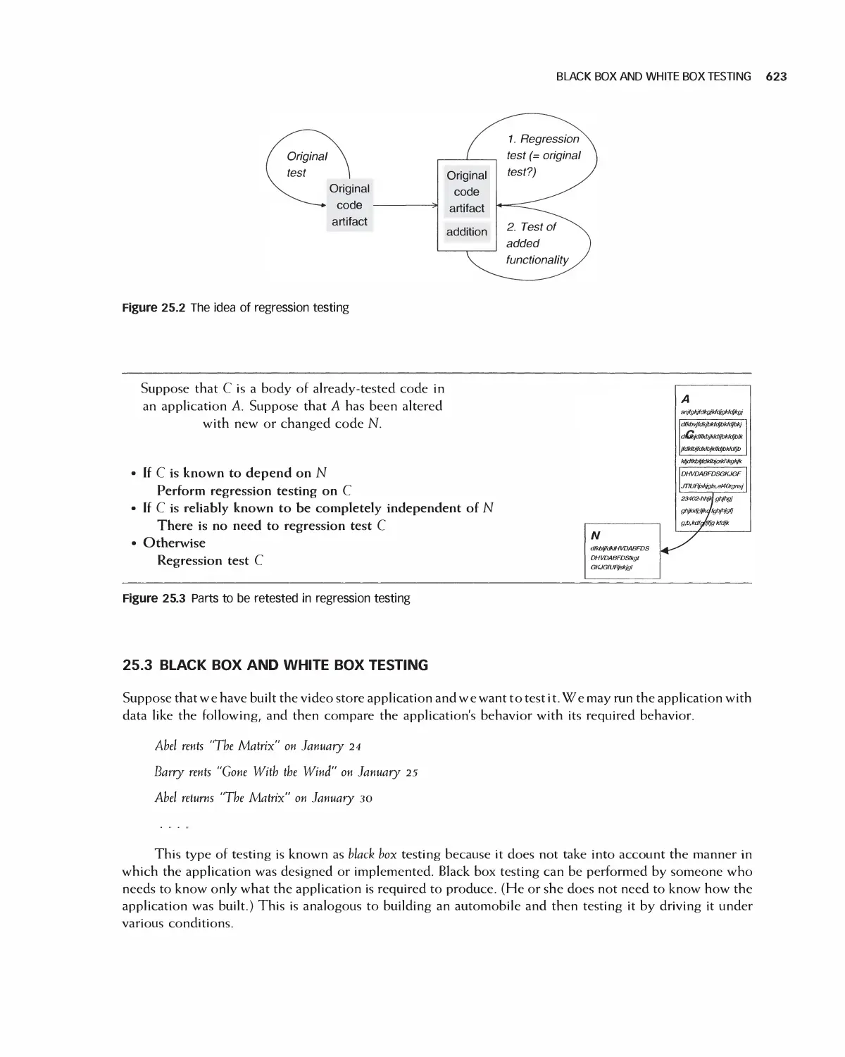
25.2 Retesting: Regression Testing 622
25.3 Black Box and White Box Testing 623
25.4 Unit Testing vs. Post-Unit Testing 624
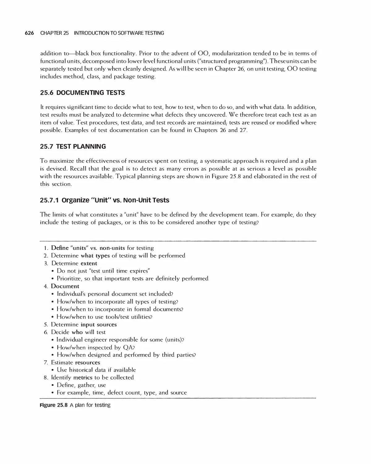
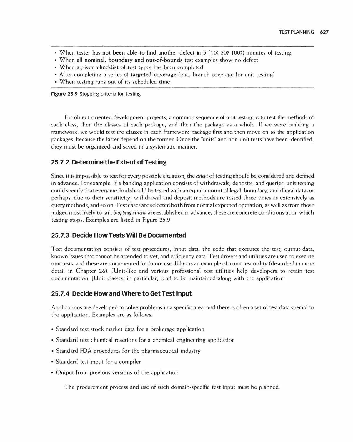
25.5 Testing Object-Oriented Implementations 625
25.6 Documenting Tests 626
25.7 Test Planning 626
25.8 Testing Test Suites by Fault Injection 628
25.9 Summary 628
25.10 Exercises 629
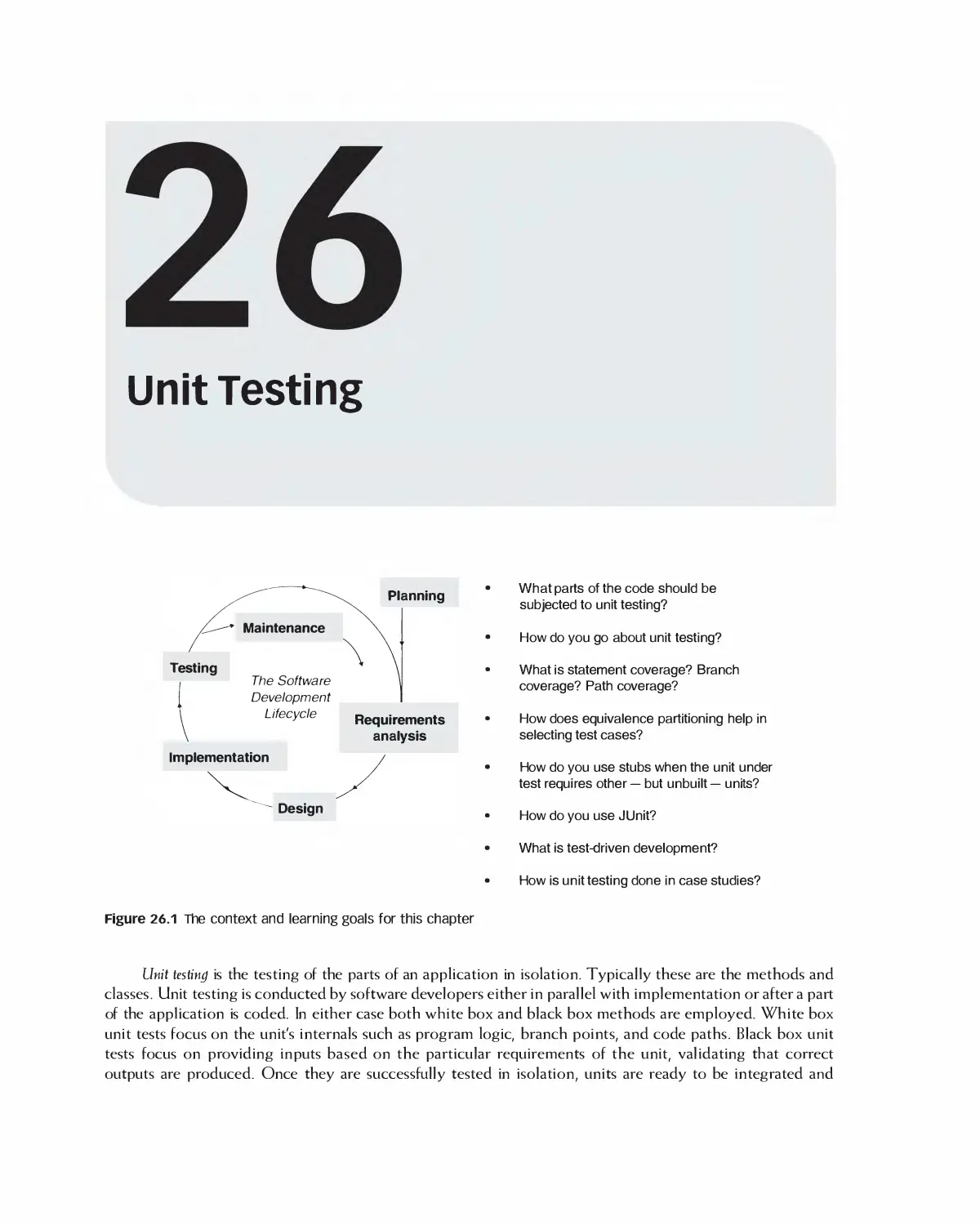
26 Unit Testing 630
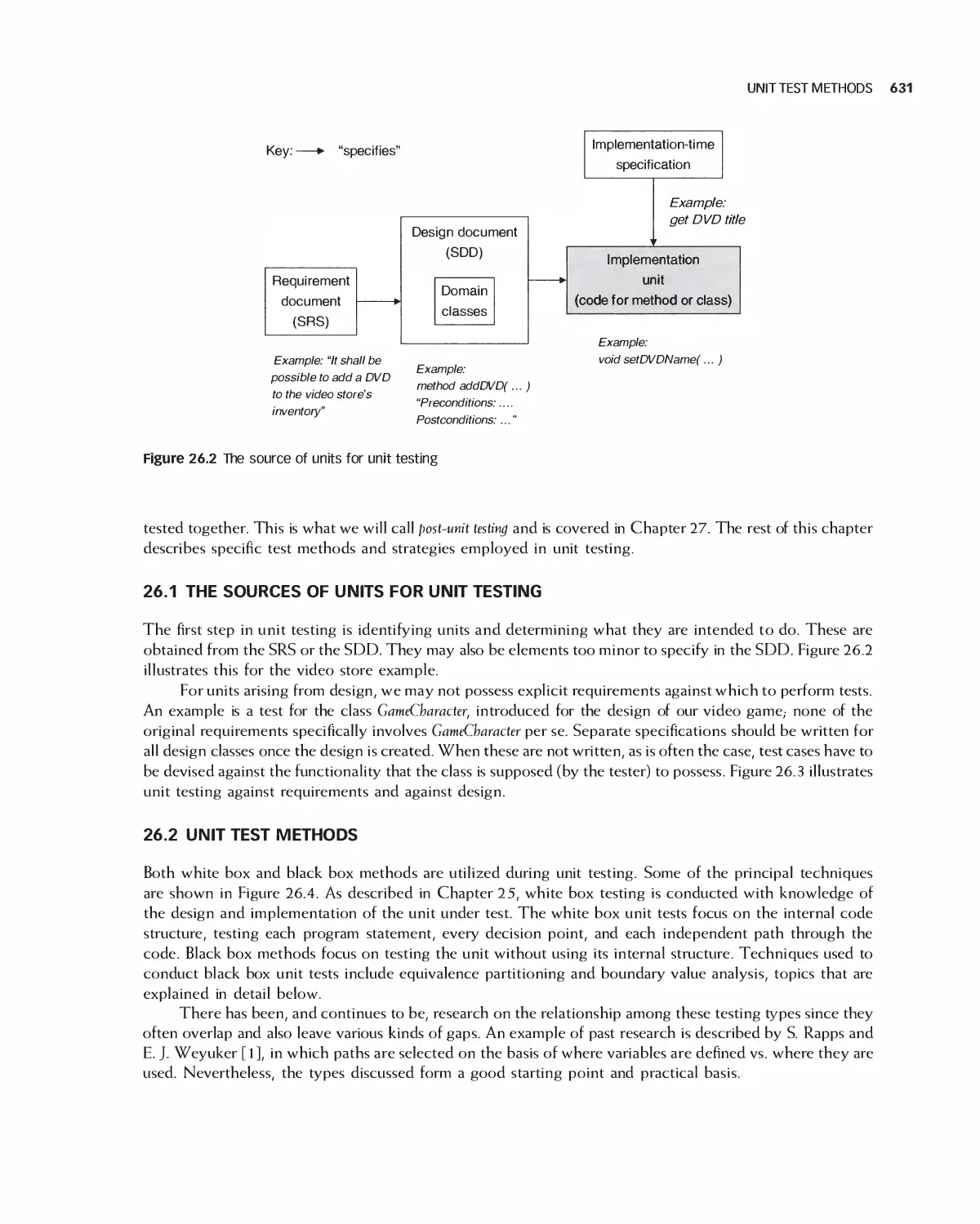
26.1 The Sources of Units for Unit Testing 631
26.2 Unit Test Methods 631
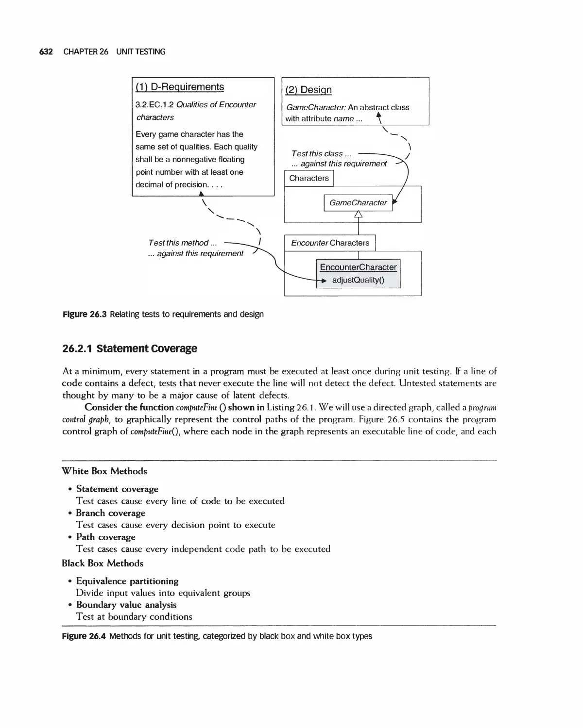
26.3 Testing Methods 642
26.4 Test-Driven Development 647
26.5 Case Study: Encounter Video Game 652
26.6 Summary 662
26.7 Exercises 663
Bibliography 665
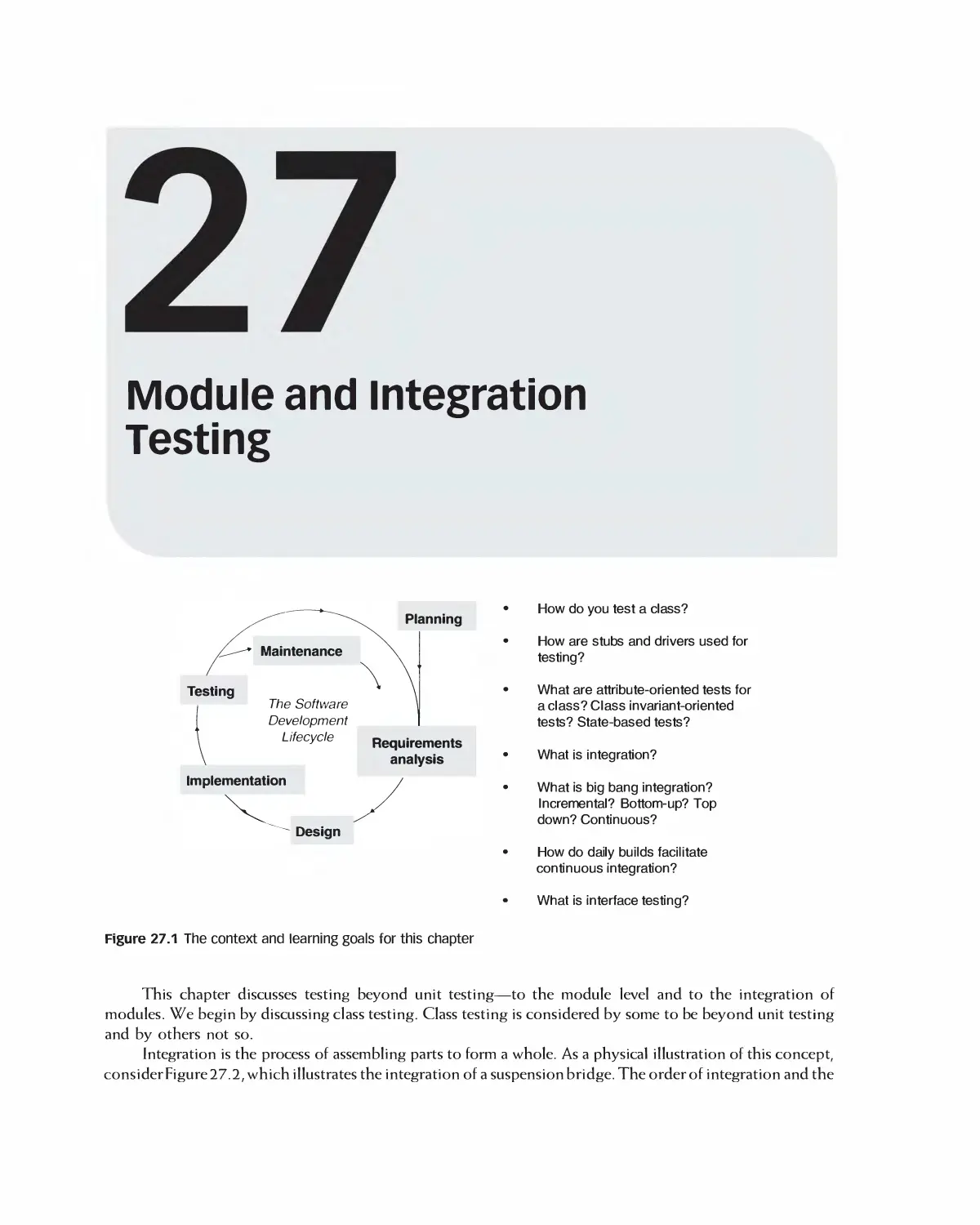
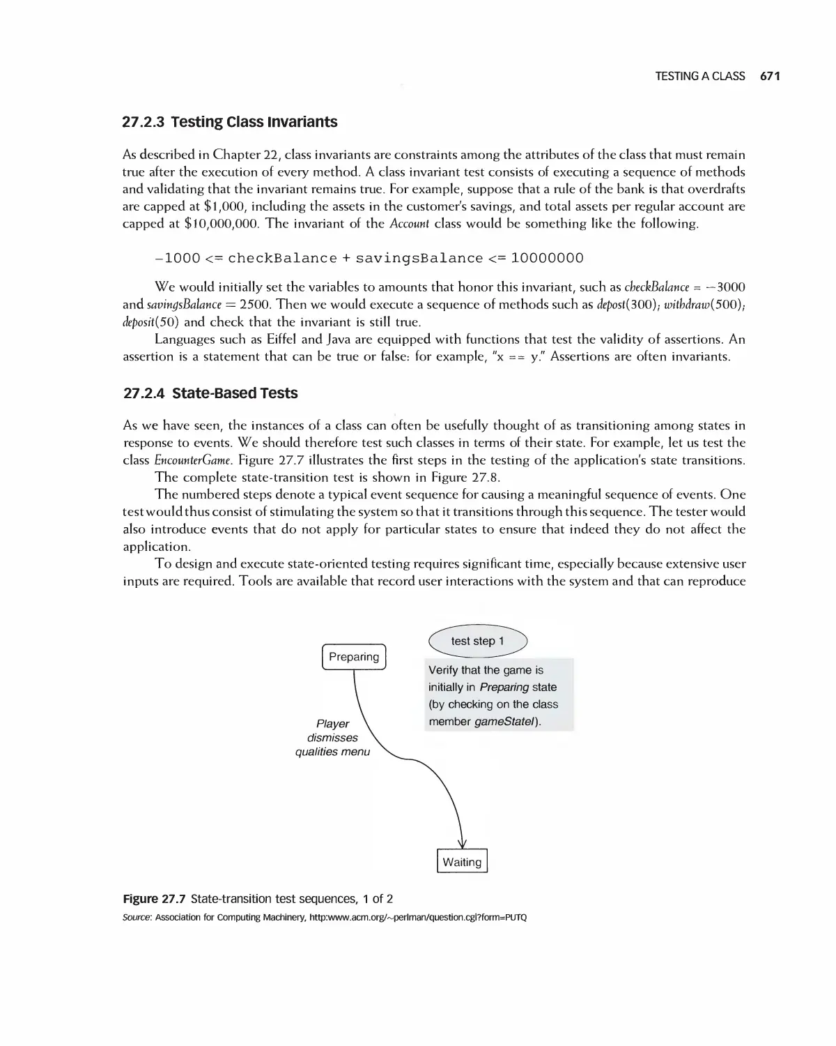
17 Module and Integration Testing 666
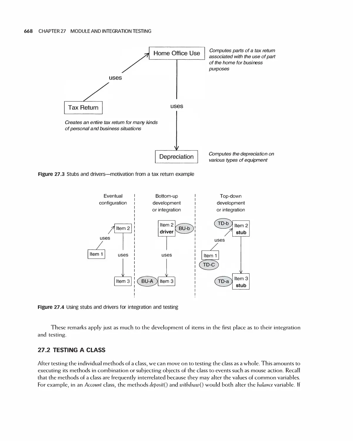
27.1 Stubs and Drivers 667
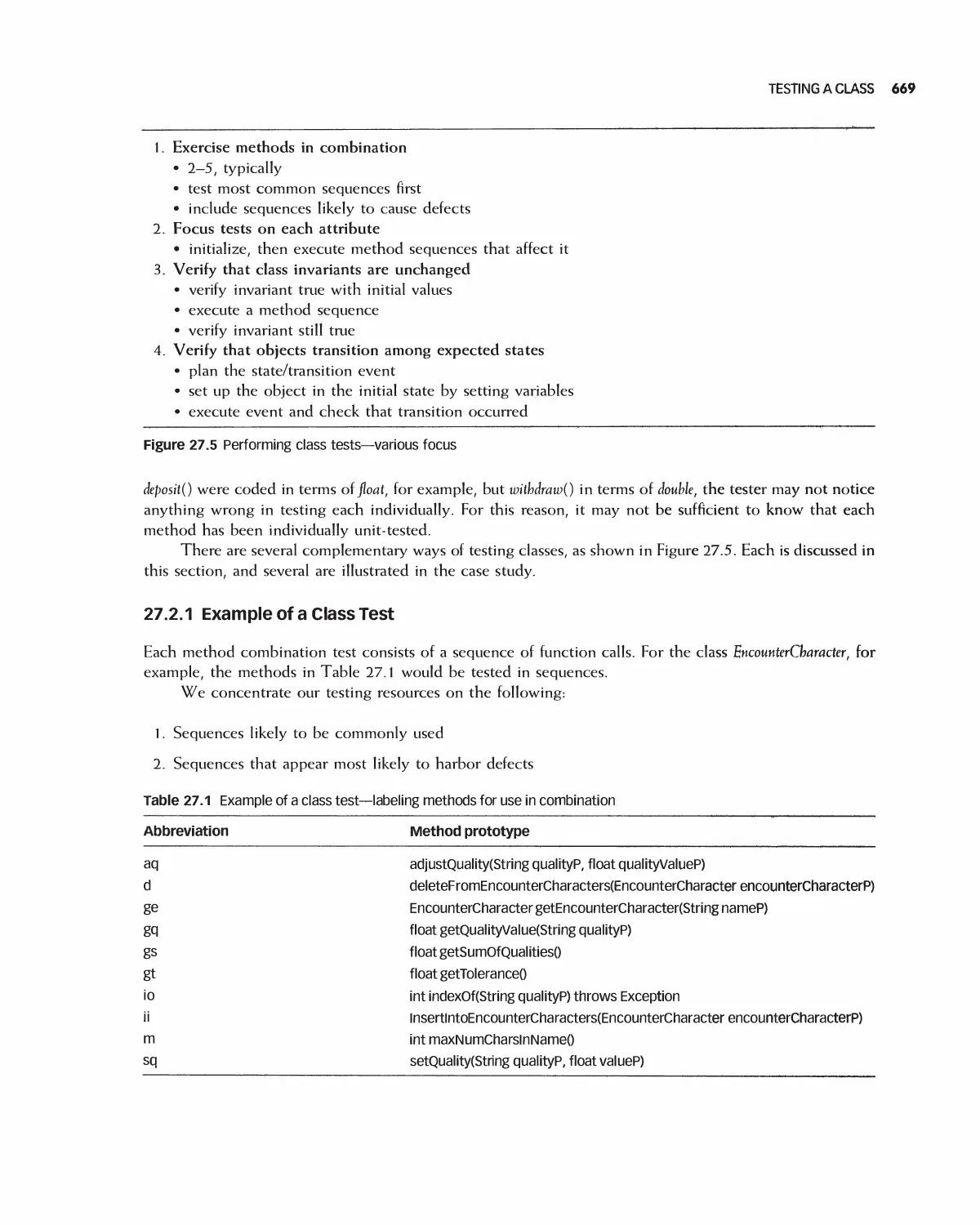
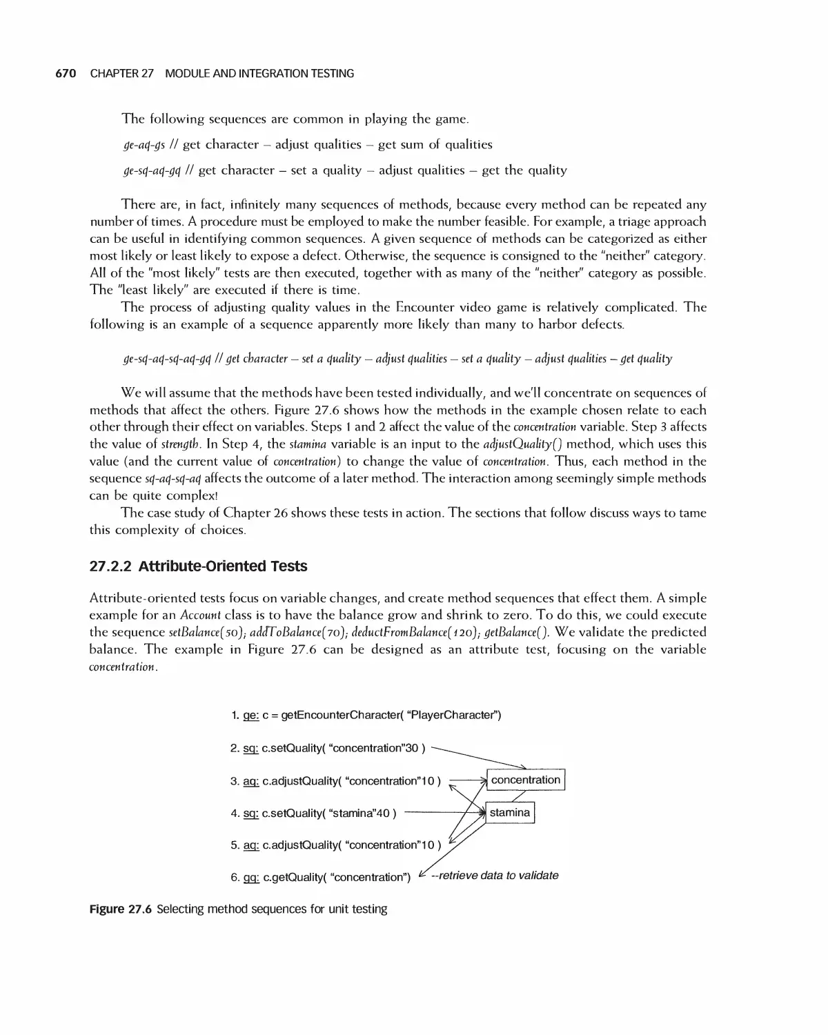
27.2 Testing a Class 668
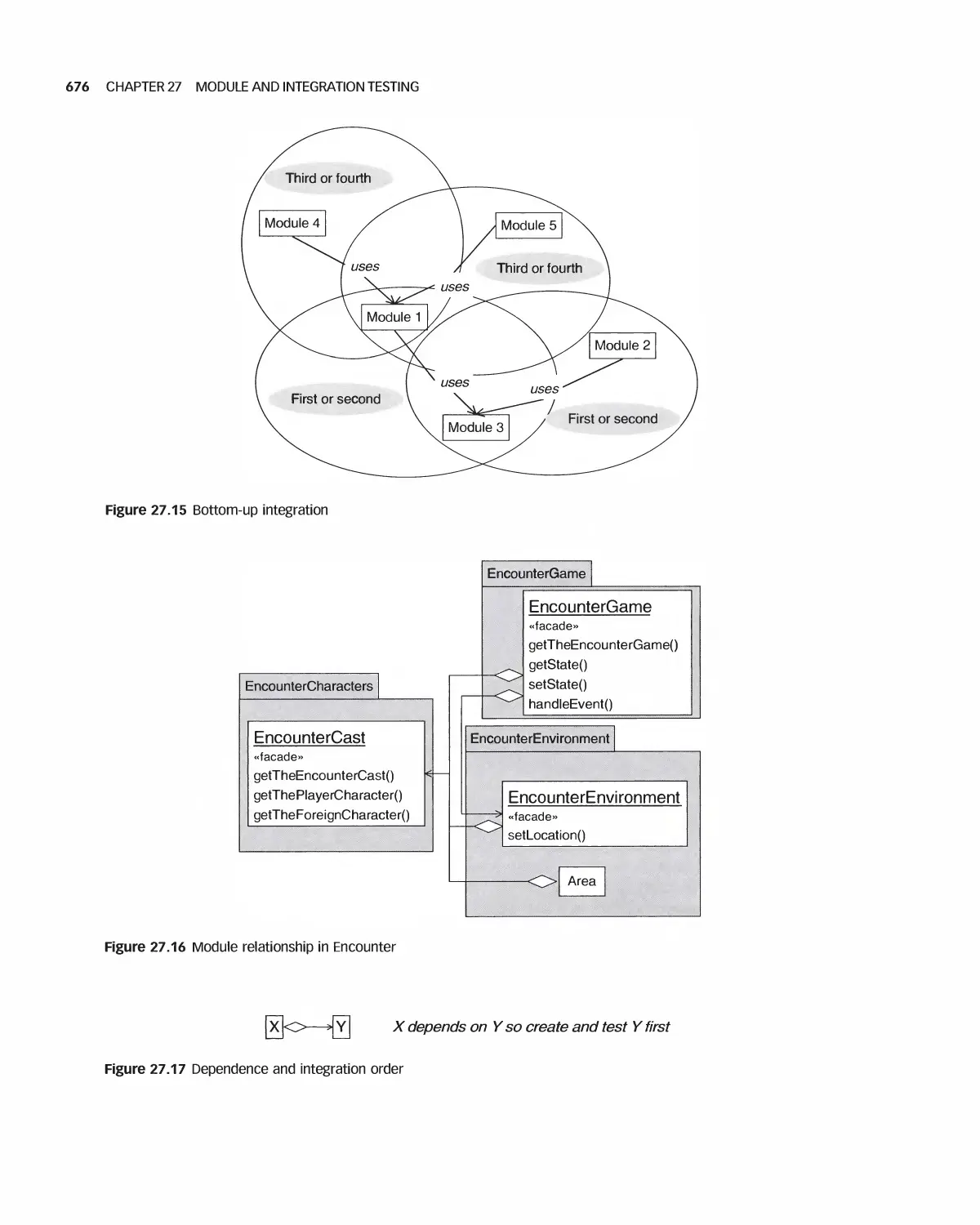
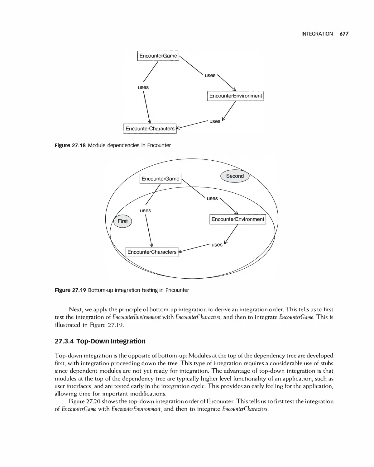
27.3 Integration 672
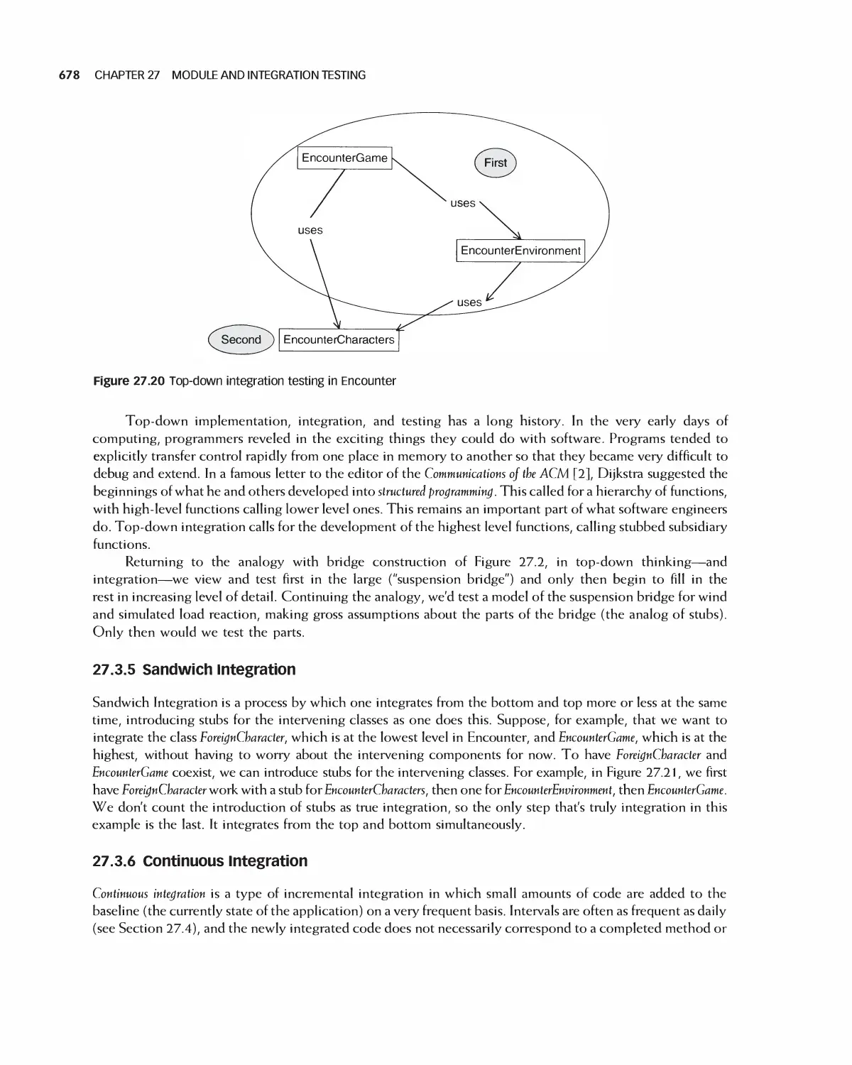
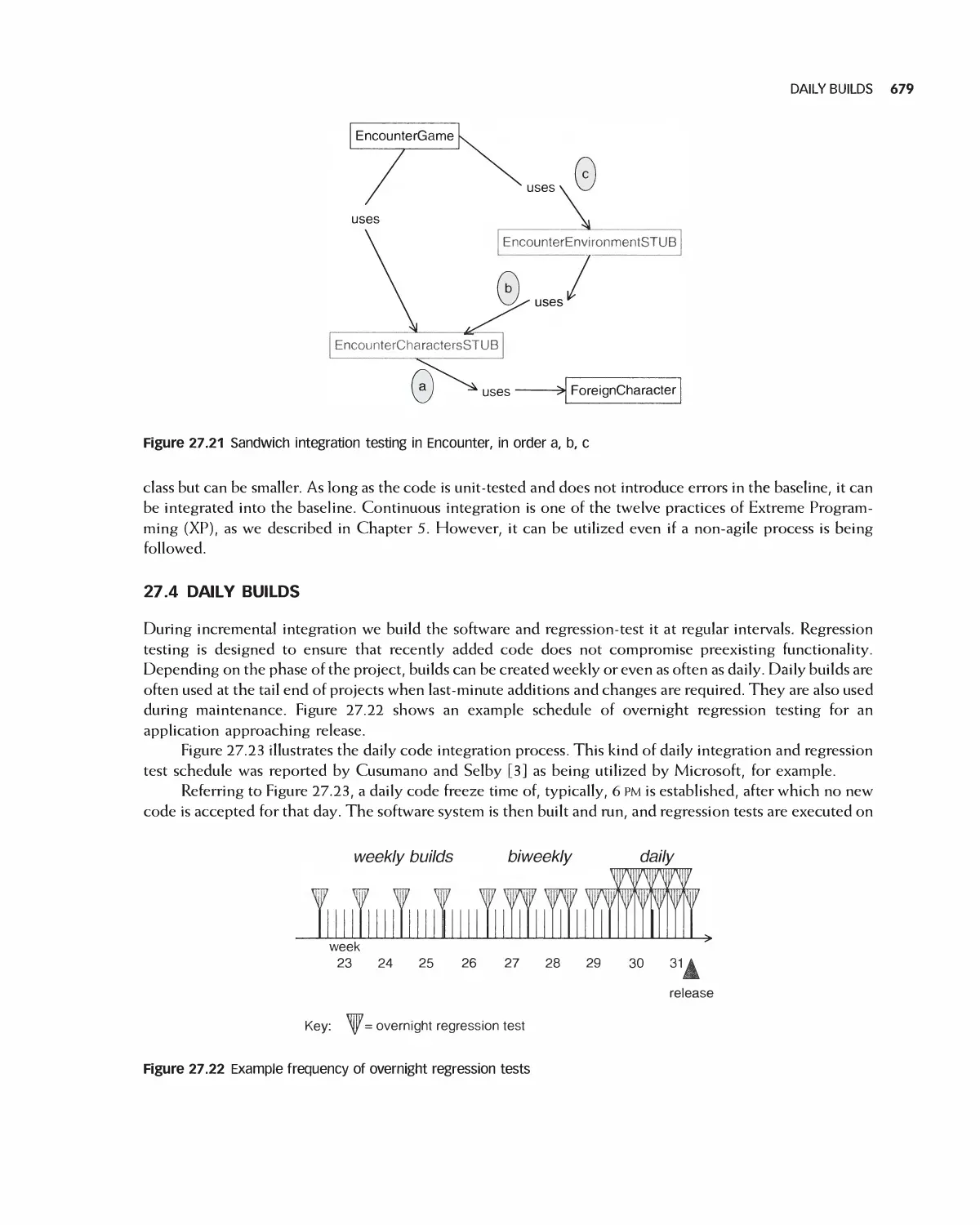
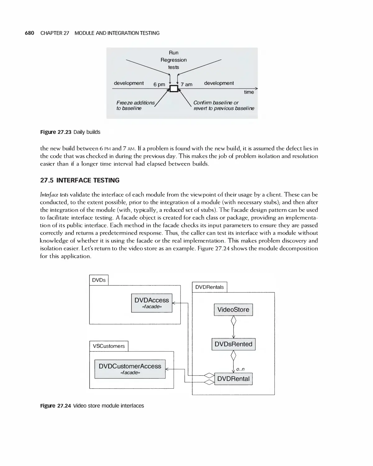
27.4 Daily Builds 679
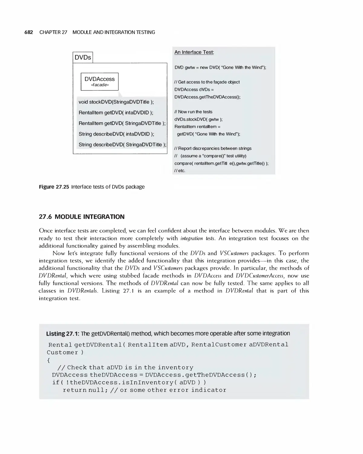
27.5 Interface Testing 680
27.6 Module Integration 682
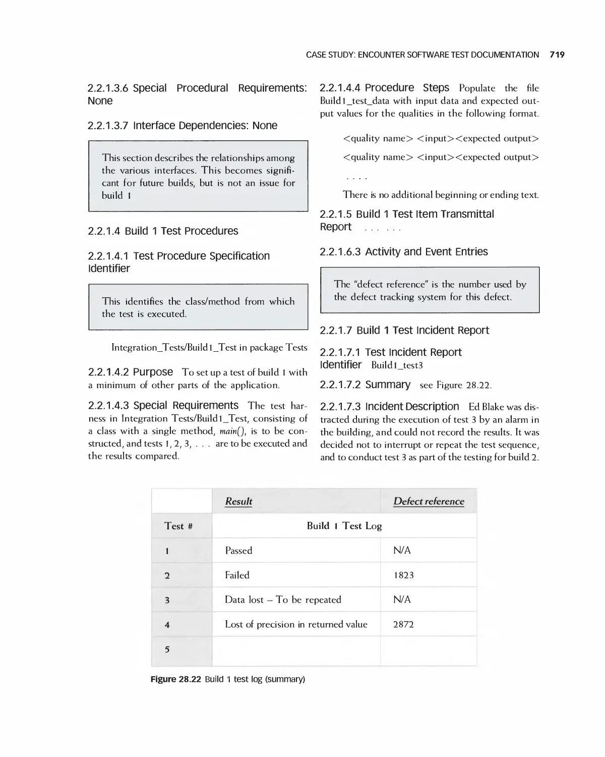
27.7 Case Study: Class Test for Encounter 683
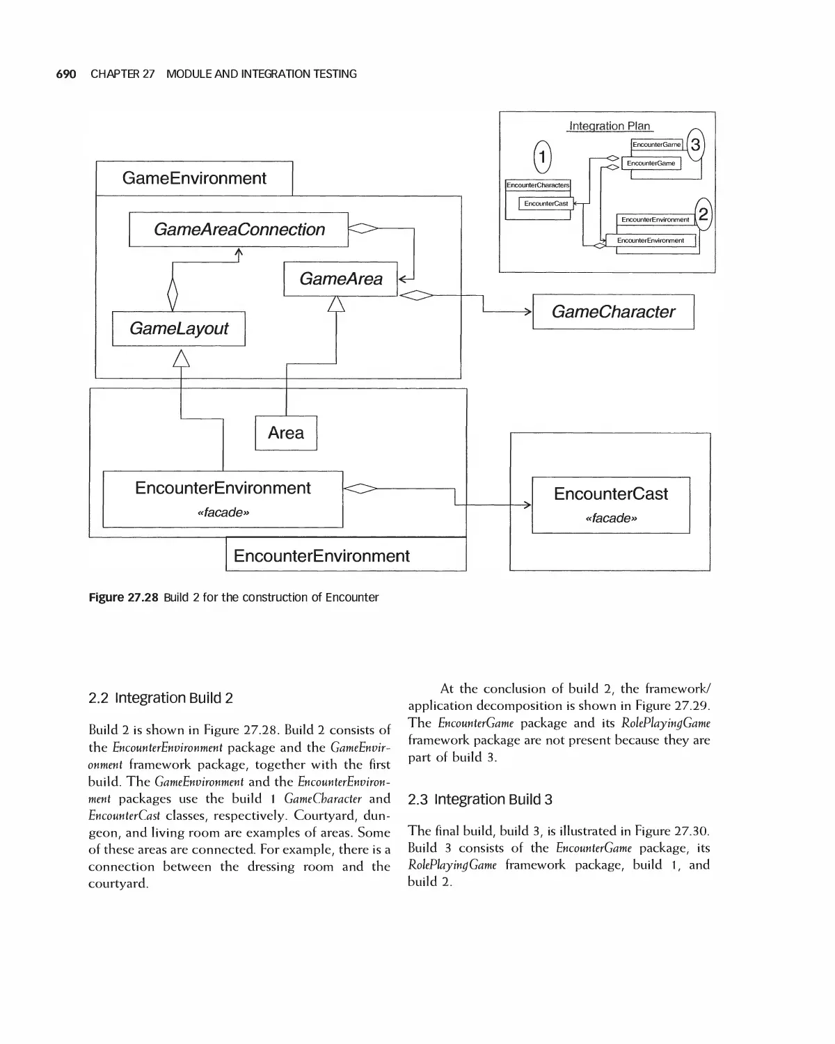
27.8 Case Study: Encounter Integration Plan 688
27.9 Summary 692
27.10 Exercises 692
Bibliography 693
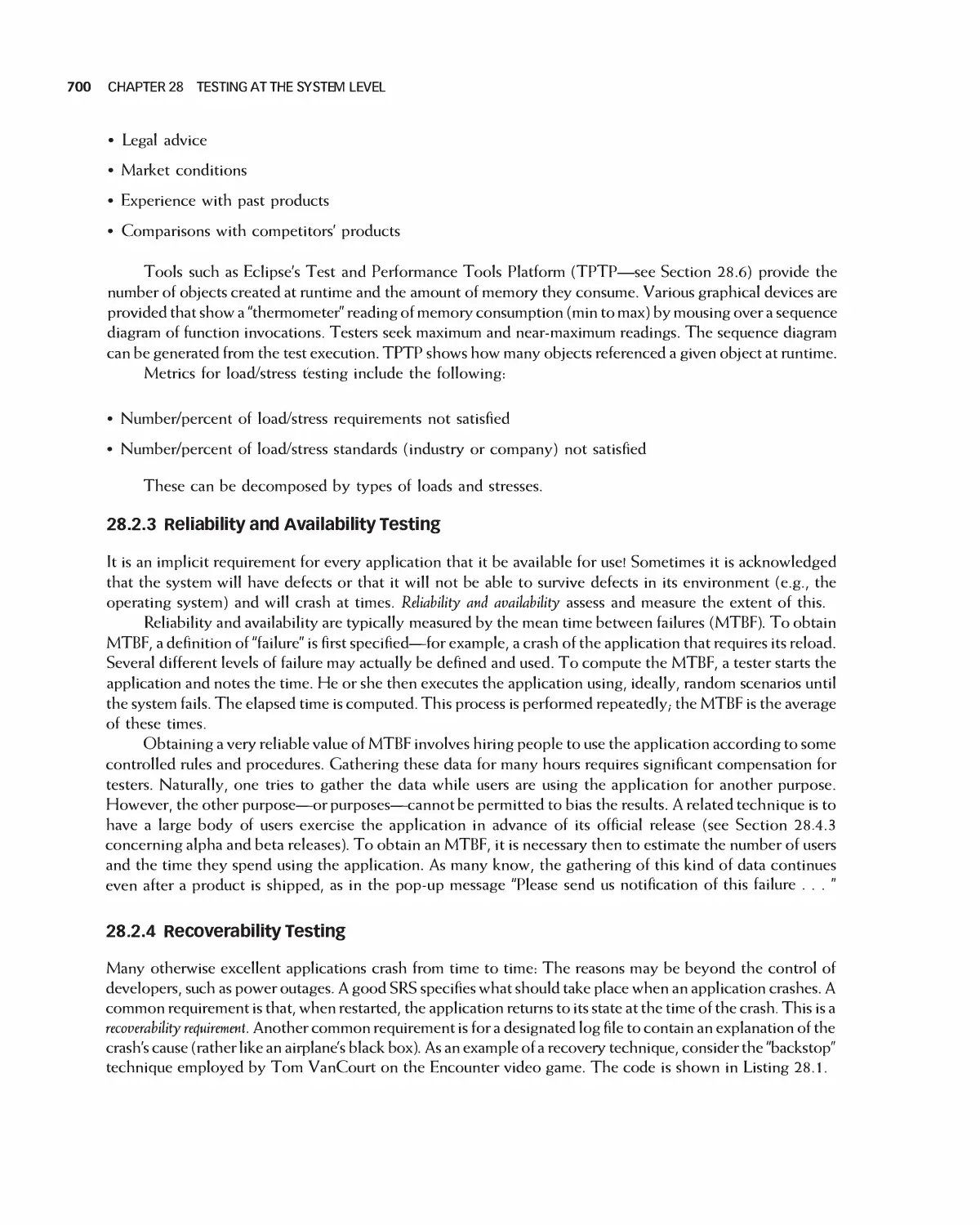
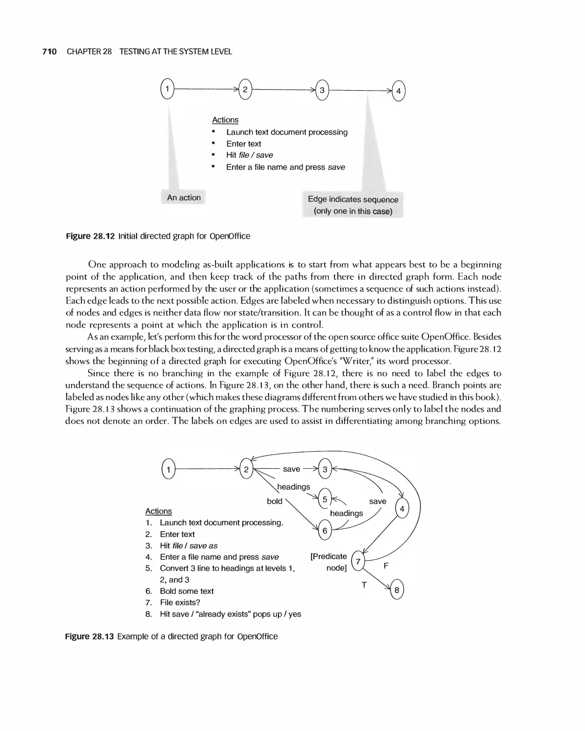
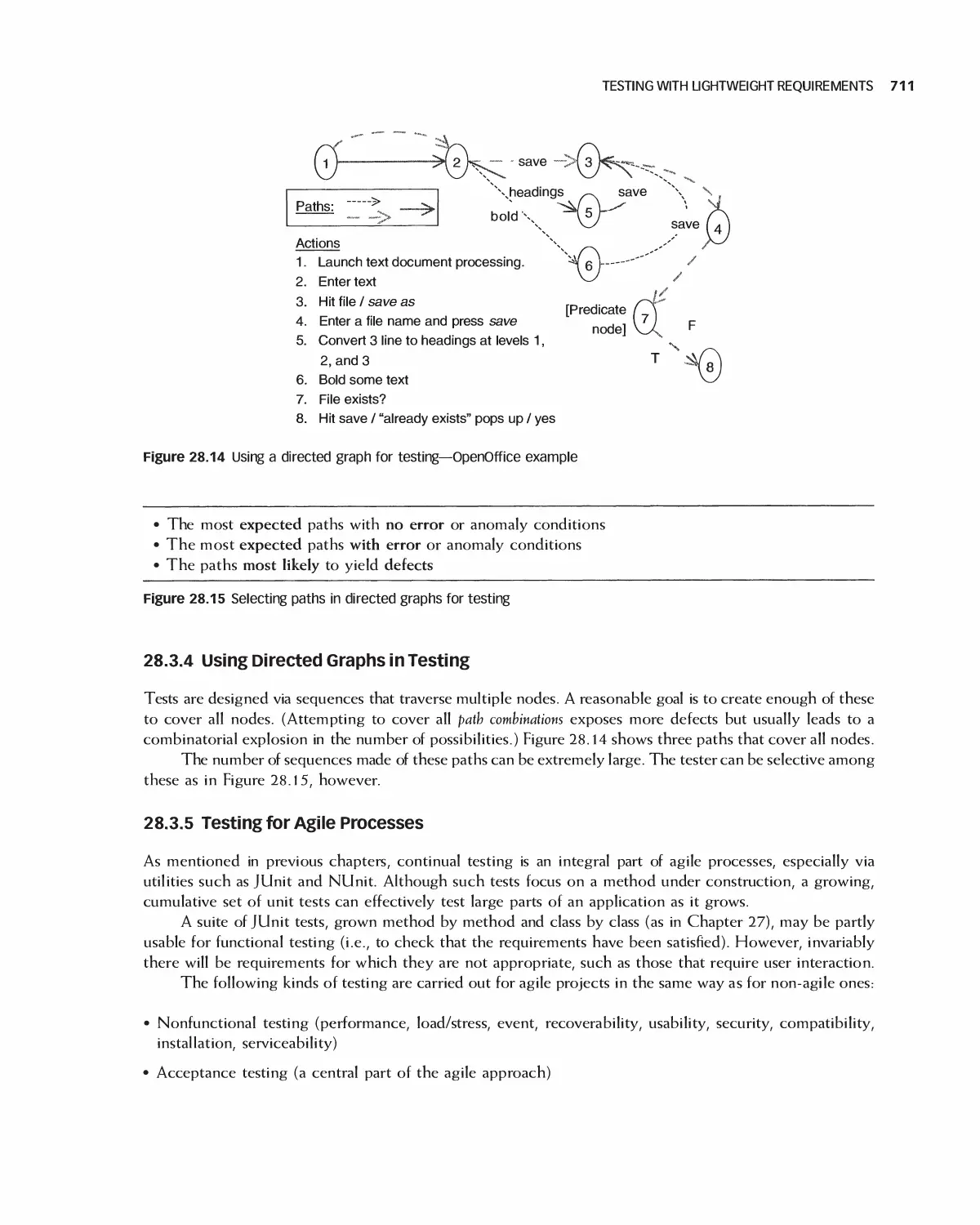
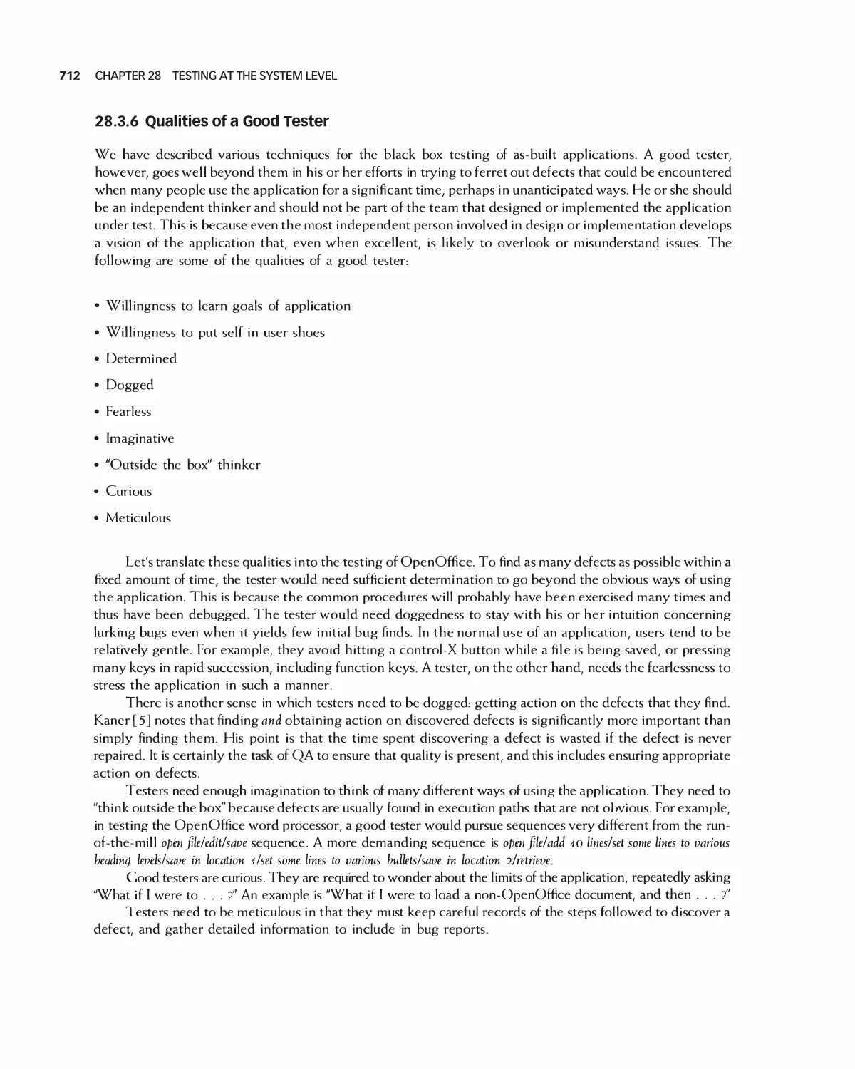
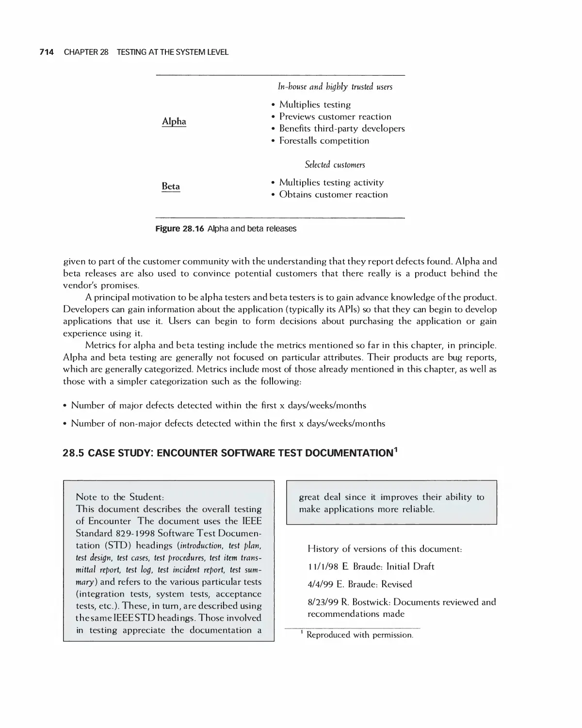
28 Testing at the System Level 694
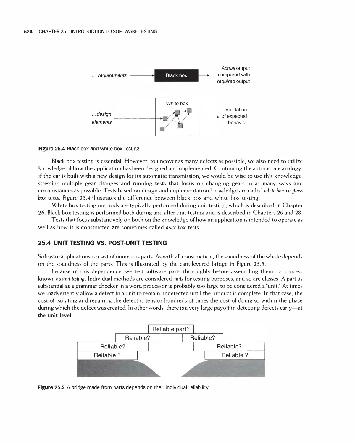
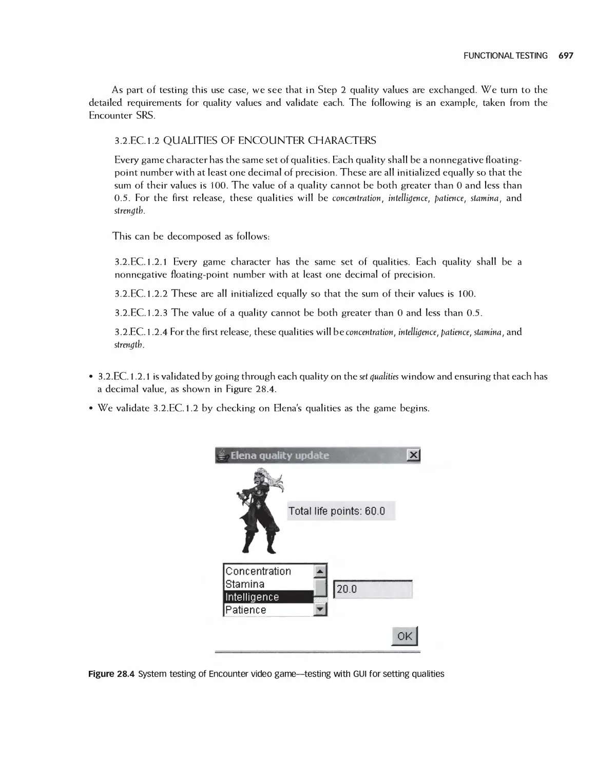
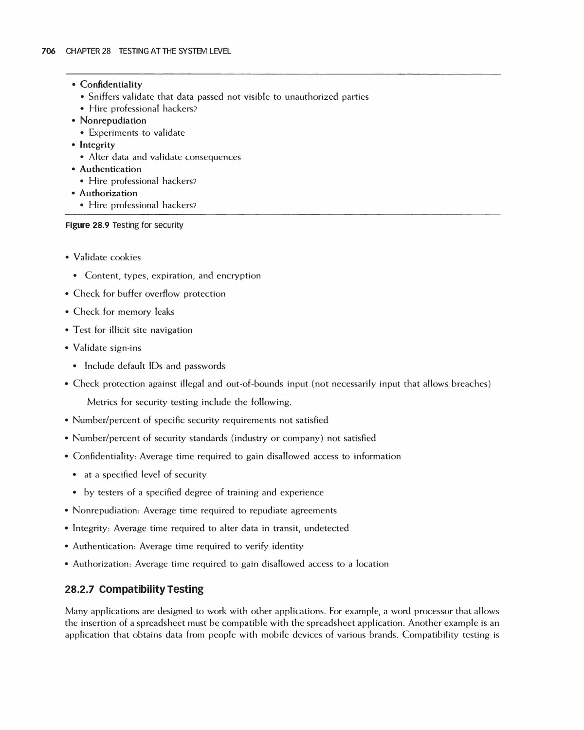
28.1 Functional Testing 696
28.2 Nonfunctional Testing 698
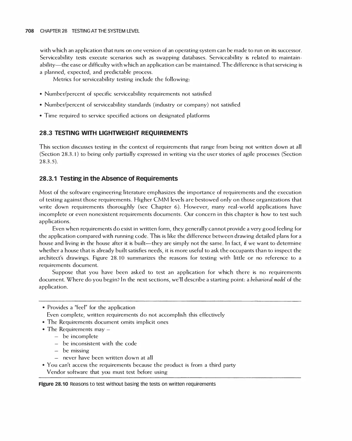
28.3 Testing with Lightweight Requirements 708
28.4 Testing Shortly Before Release 71 3
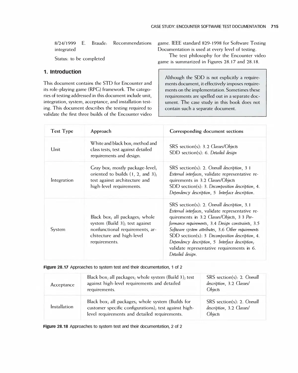
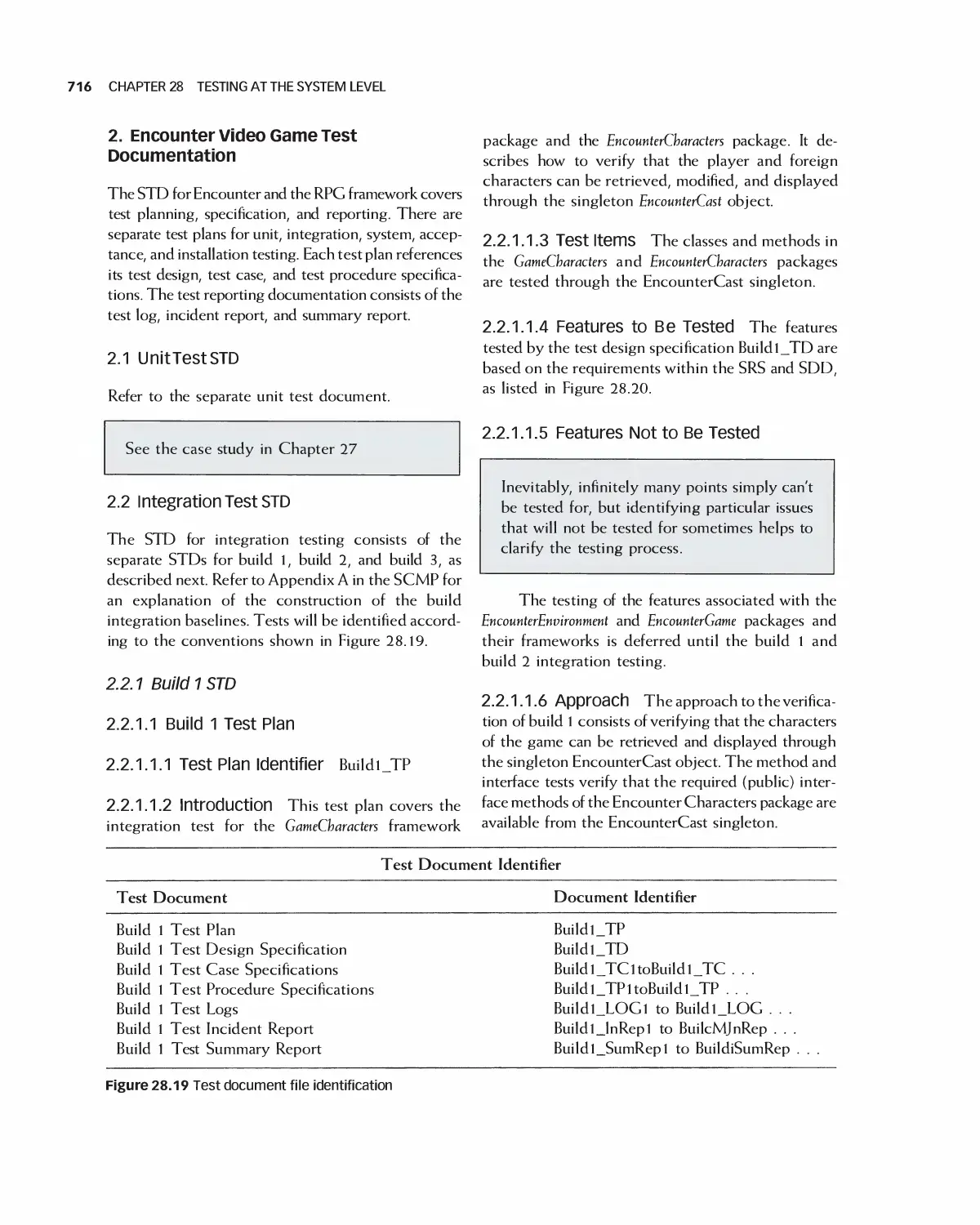
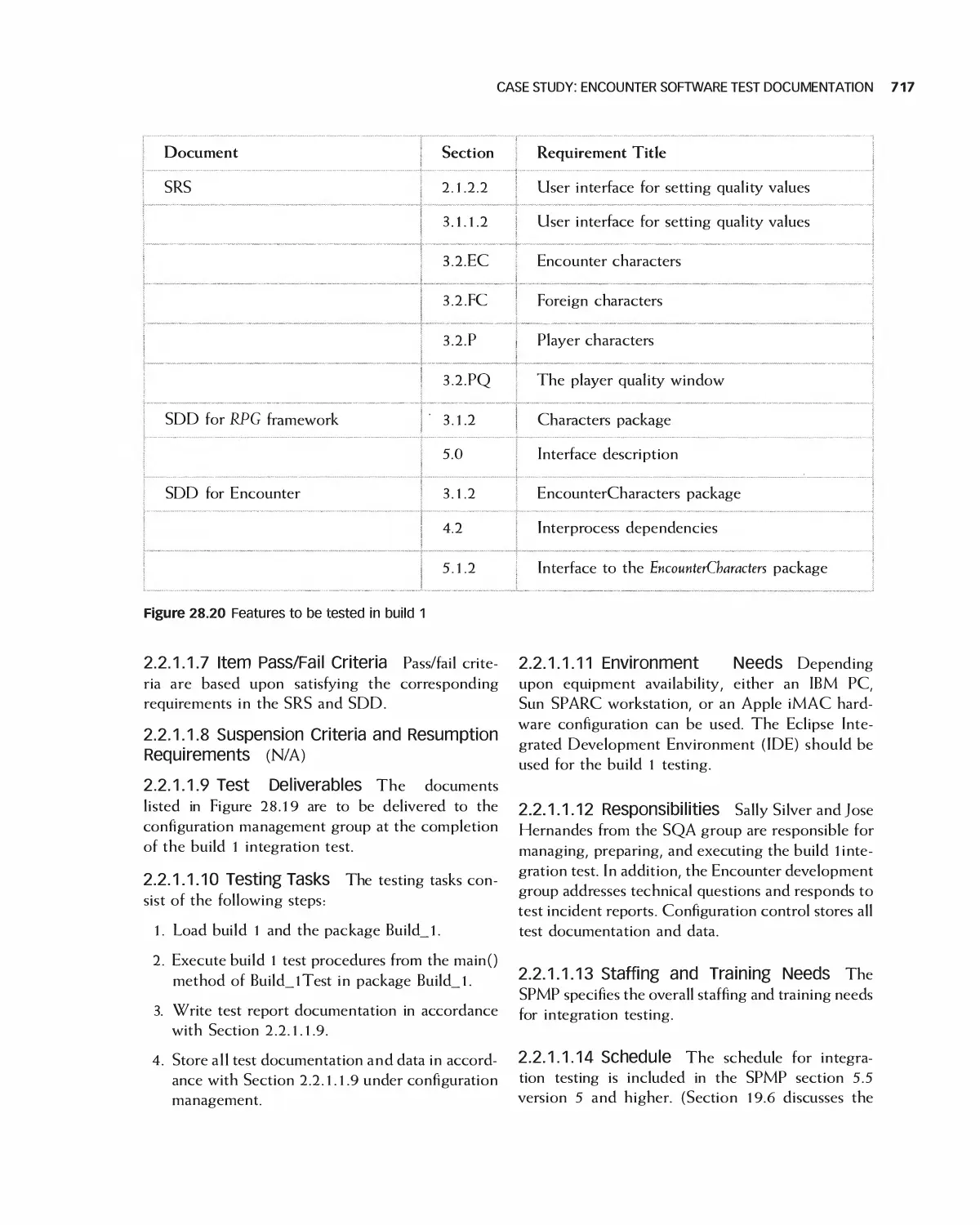
28.5 Case Study: Encounter Software Test Documentation 714
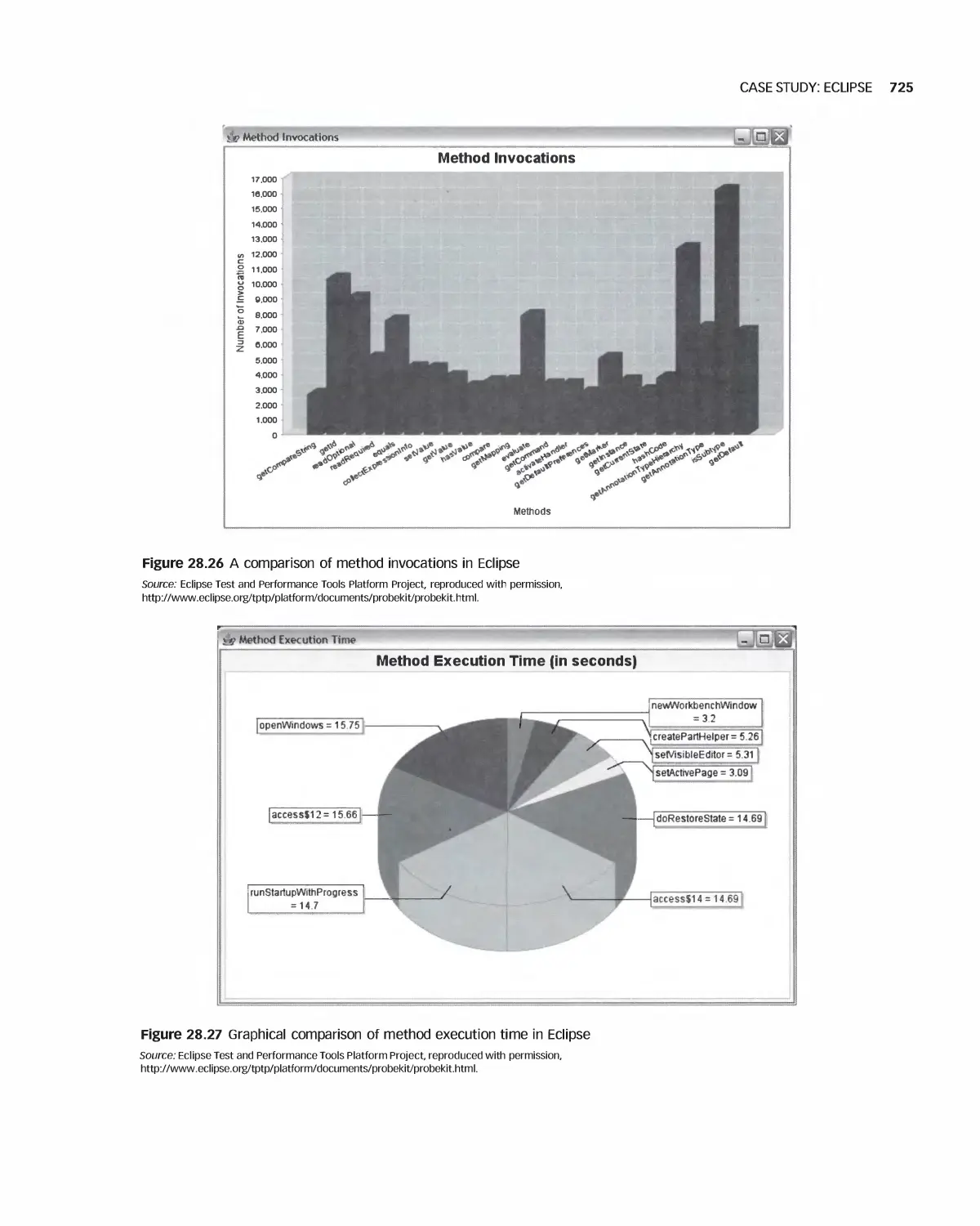
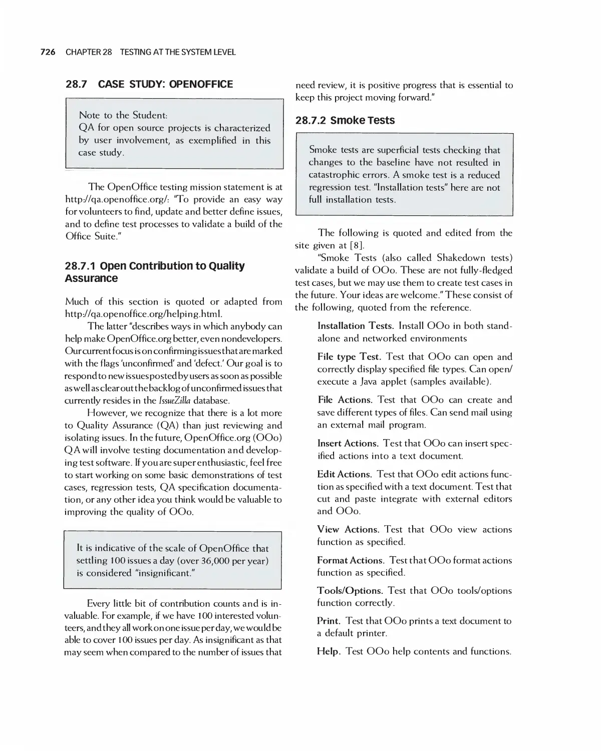
28.6 Case Study: Eclipse 723
28.7 Case Study: OpenOffice 726
28.8 Summary 728
28.9 Exercises 728
Bibliography 729
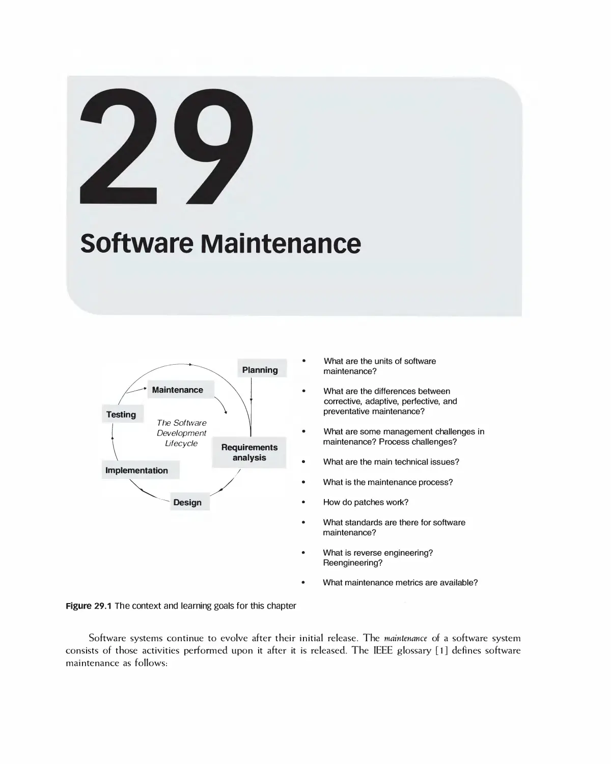
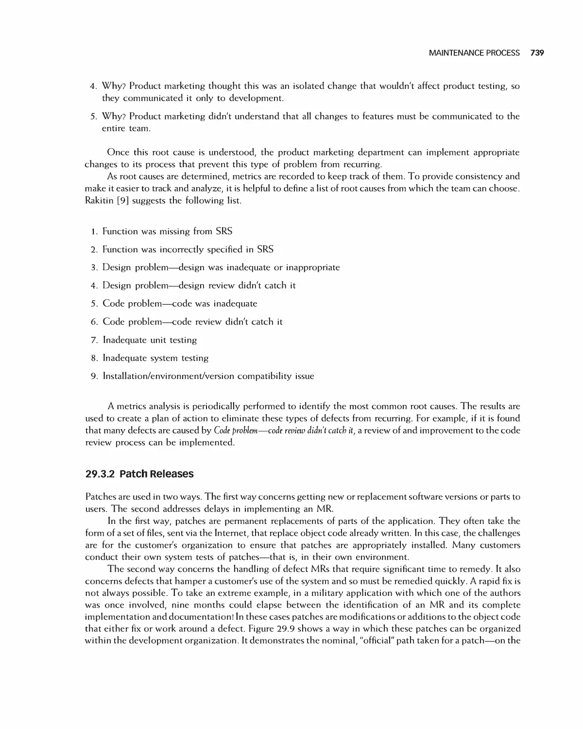
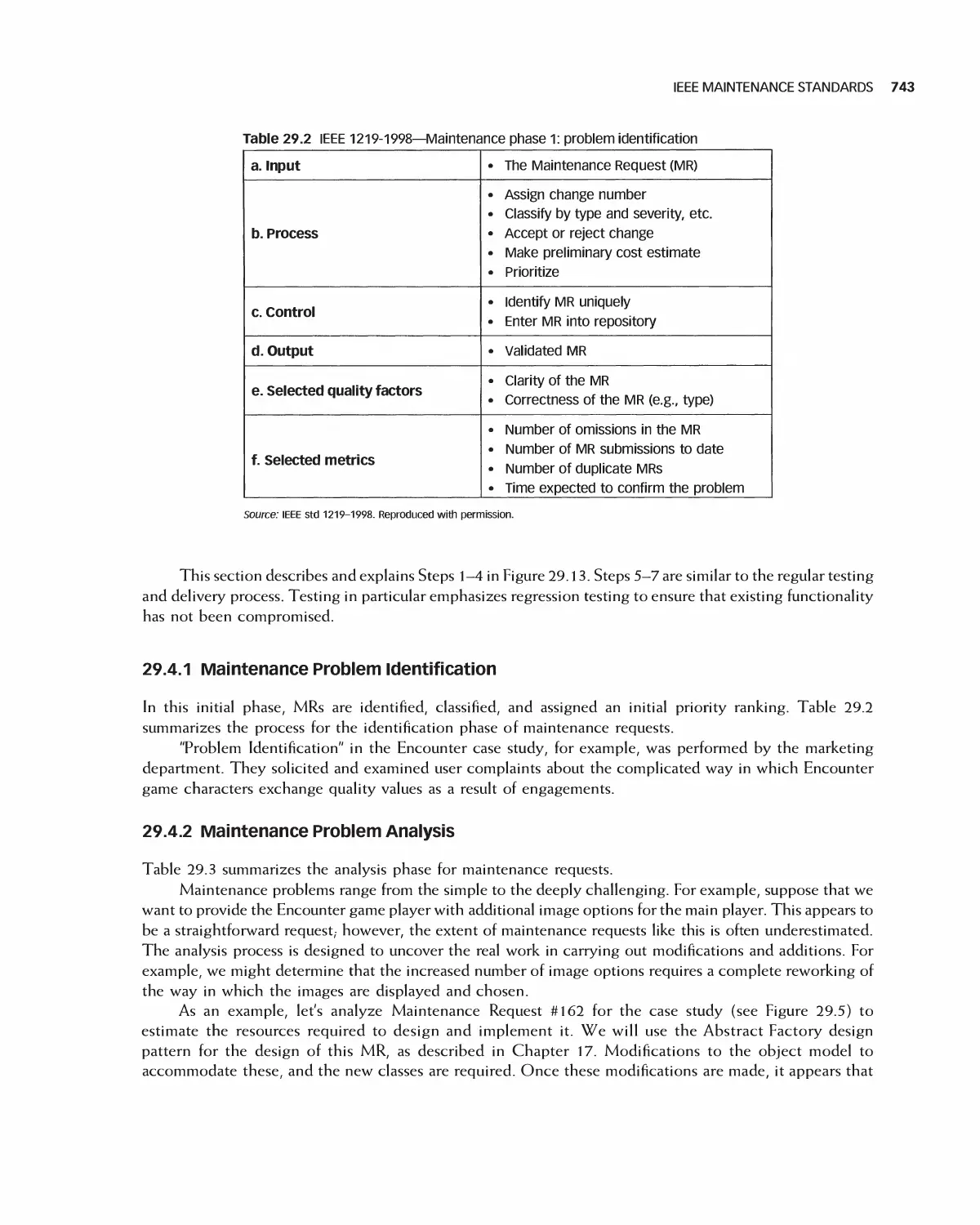
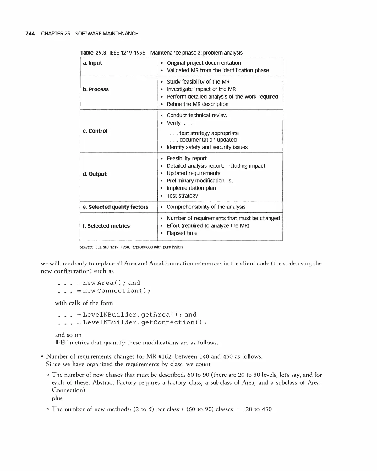
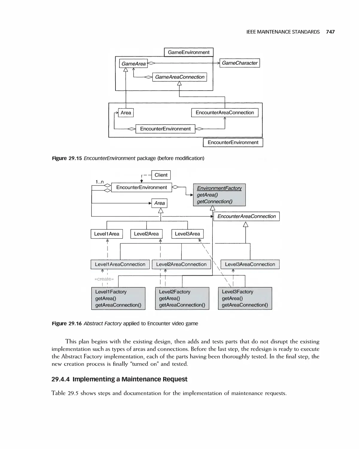
29 Software Maintenance 730
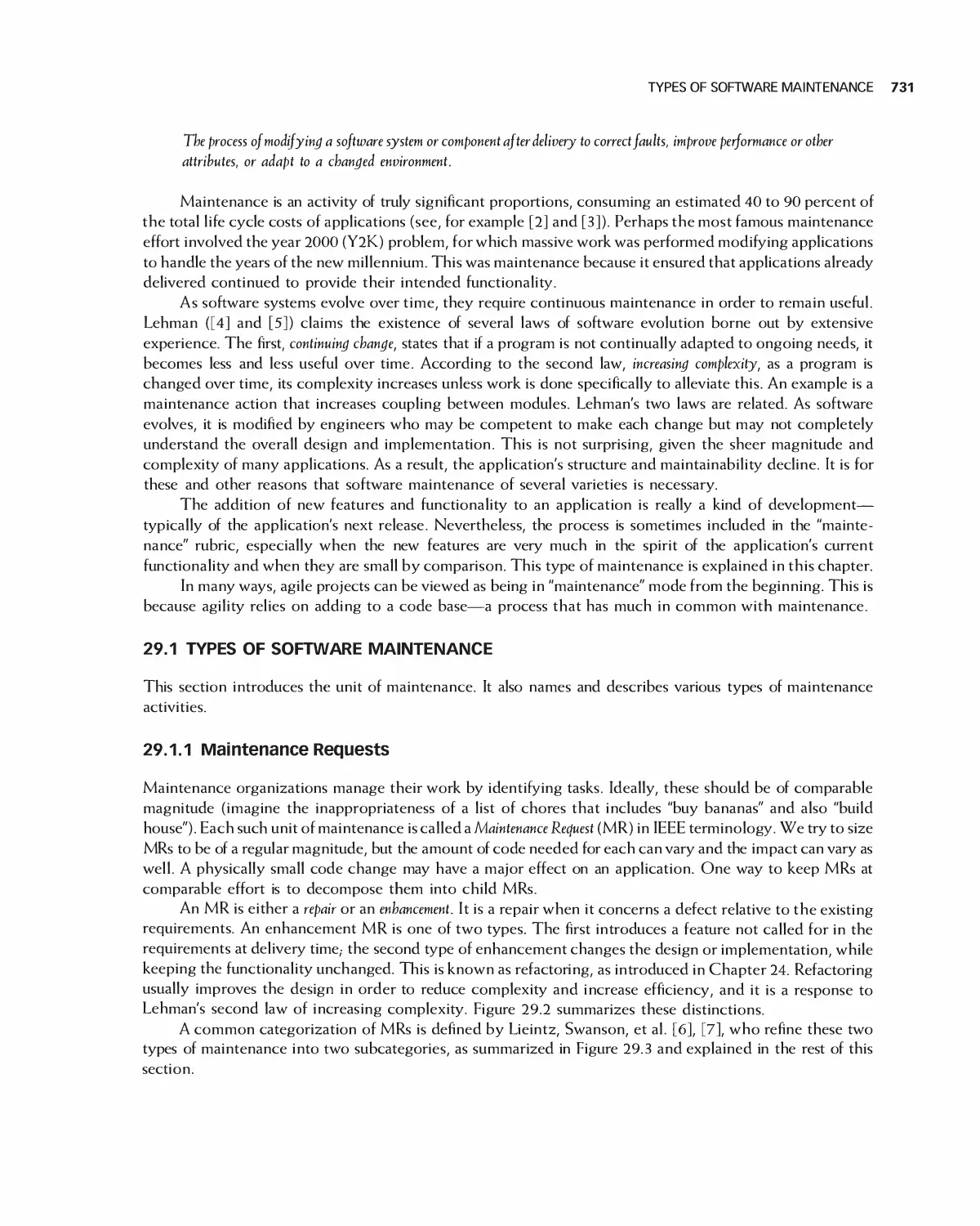
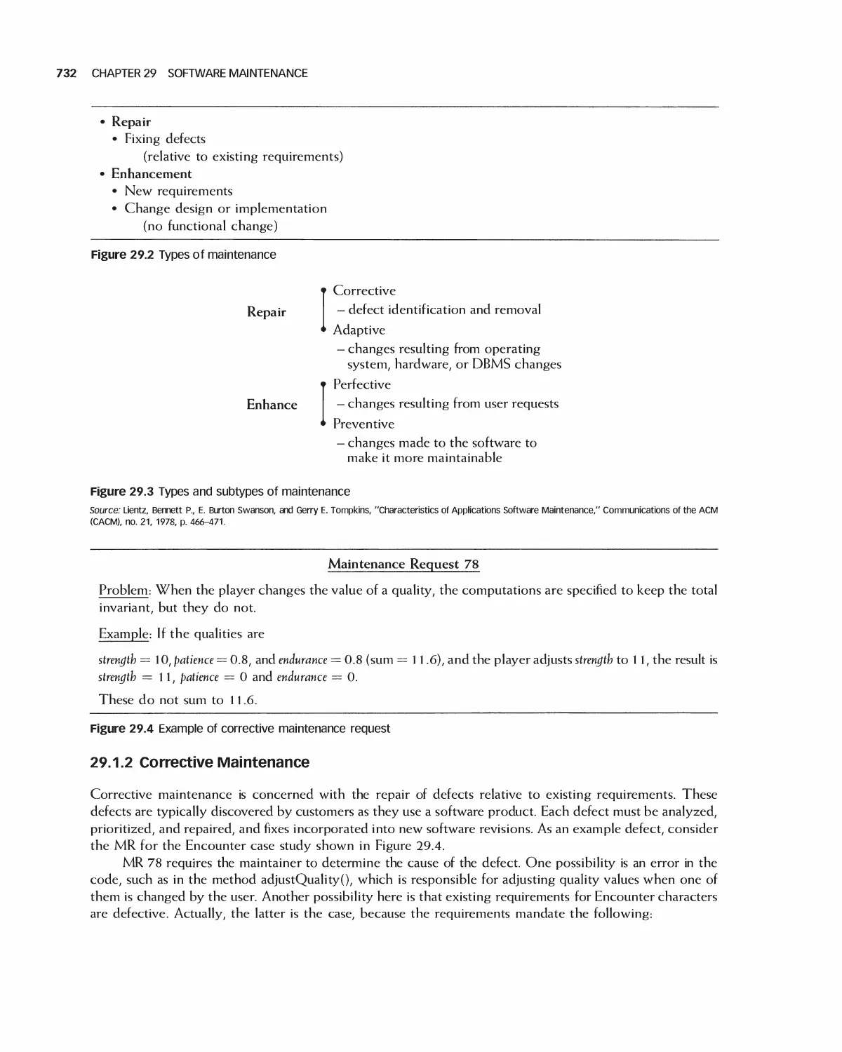
29.1 Types of Software Maintenance 731
29.2 Issues of Software Maintenance 734
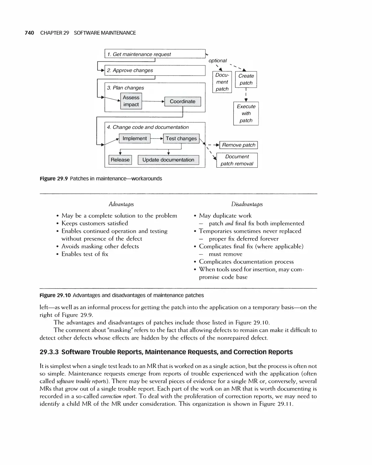
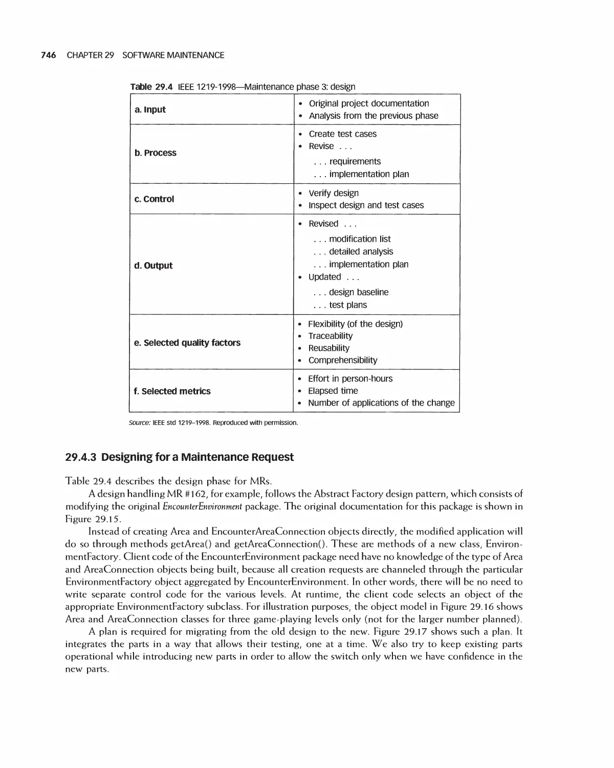
29.3 Maintenance Process 736
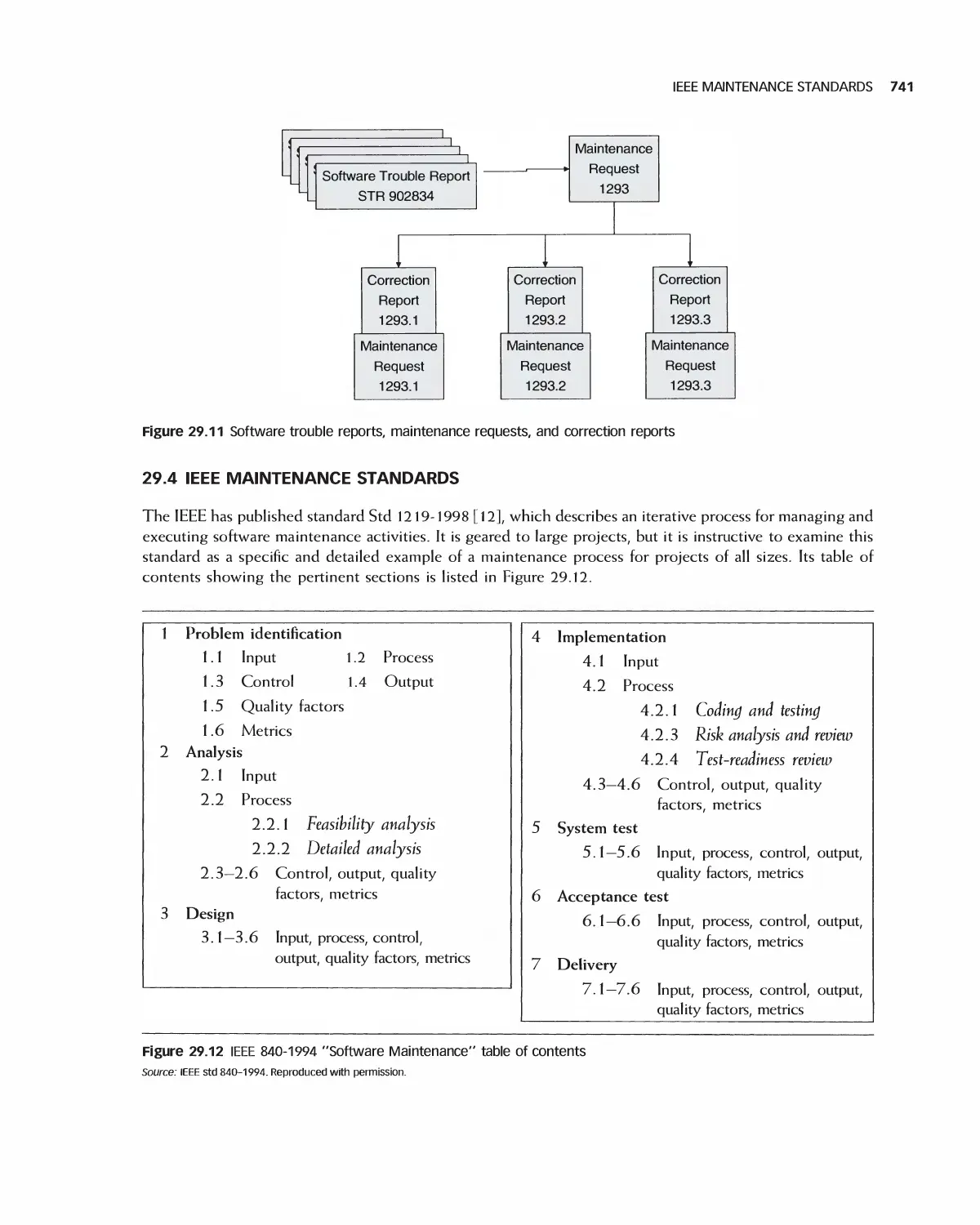
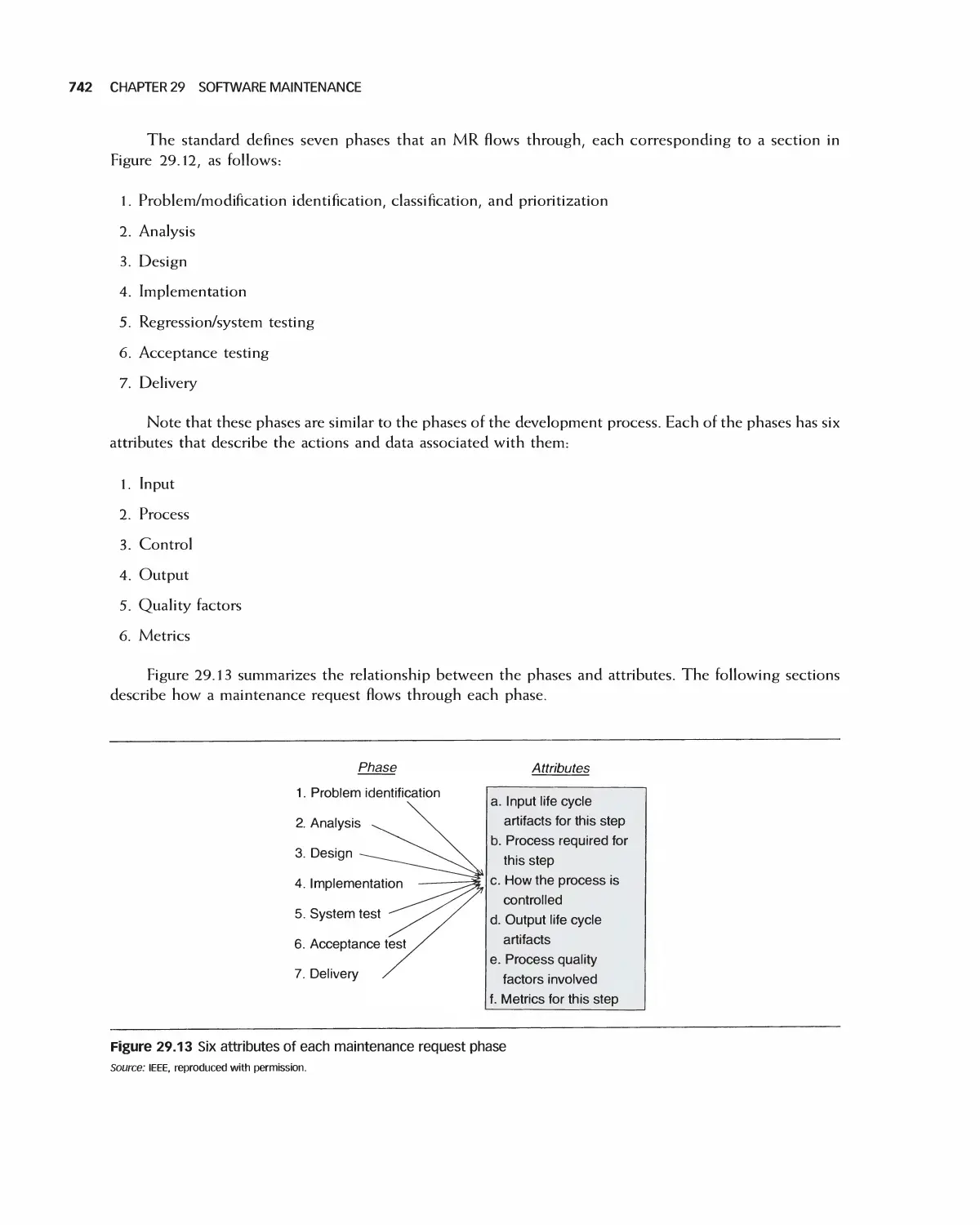
29.4 IEEE Maintenance Standards 741
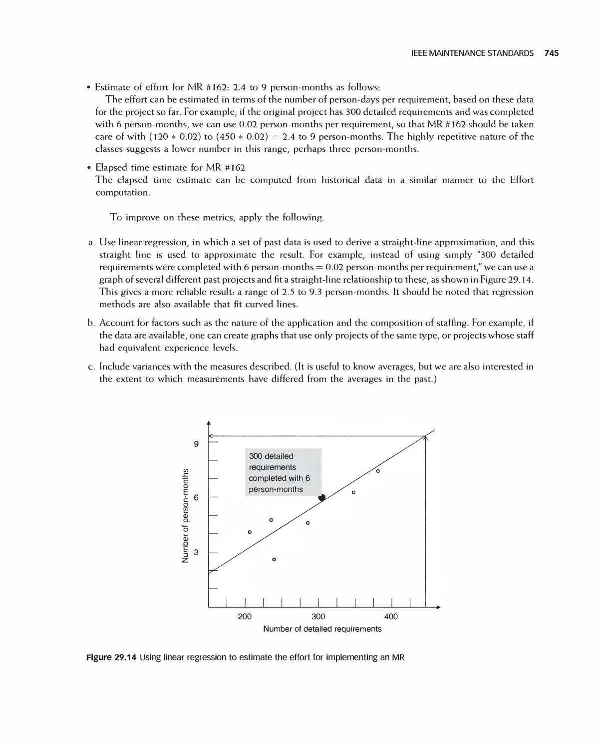
29.5 Software Evolution 749
29.6 Maintenance Metrics 751
29.7 Case Study 754
29.8 Summary 756
29.9 Exercises 757
Bibliography 758
Glossary 759
Index 767
Preface
Much of the modern world runs on software. As a result, software engineers are entrusted with significant
responsibility. Although it is a biomedical engineer, for example, who designs heal th monitoring systems, it is
a software engineer who creates its actual control functions. A marketing professional develops ways to reach
customers online but it is a software engineer who makes the system a reality.
Today's software engineer must be able to participate in more than one kind of software process, work in
agile teams, deal with customers, express requirements clearly, create modular designs, utilize legacy and
open source projects, monitor quality, incorporate security, and apply many types of tests.
THE ISSUE OF SCALE
A software application consists of tens, hundreds, even thousands of classes. This is very different from
managing three or four of them, and results in the dragon of complexity suggested by this book's cover. As
also suggested there, however, this dragon can be subdued. Indeed, to deal with numerous and complex
classes, software engineers have at their disposal a wide variety of tools and techniques. These range from the
waterfall process to agile methodologies, from highly integrated tool suites to refactoring and loosely coupled
tool sets. Underlying this variety is continuing research into reliable approaches, and an acknowledgment of
the fact that one size does not fit all projects.
THIS EDITION COMPARED WITH THE FIRST
The first edition of this book emphasized the object-oriented approach, which has subsequently
become widespread. It was also designed to help student teams carry out hands-on term projects through
theory, examples, case studies, and practical steps. Object-orientation and hands-on continue to be major features
of this edition. However, we have widened the scope of the first edition, especially by including extensive
coverage of agile methods and refactoring, together with deeper coverage of quality and software design.
Readers of the first edition made extensive use of the complete video game case study—an example that
they could follow "from soup to nuts" but which was significantly more comprehensive than a toy. This edition
retains and updates that case study, but it adds the exploration of a simpler example on one hand (a DVD rental
store) and large, real, open source case studies on the other. In particular, to provide students a feeling for the
scope and complexity of real-world applications, this book leads them through selected requirements, design,
implementation, and maintenance of the Eclipse and OpenOffice open source projects. The size, complexity,
and transparency of these projects provide students a window into software engineering on a realistic scale.
Every book on software engineering faces a dilemma: how to reconcile the organization of the topics
with the organization of actual software project phases. An organization of chapters into process/project
management/requirements analysis/design/implementation/test/maintenance is straightforward but is liable
to be misinterpreted as promoting the waterfall development process at the expense others. Our approach has
been to use this organization in the seven parts of the book but to demonstrate throughout that each phase
PREFACE XV
typically belongs to a cycle rather than to a single waterfall sequence. In particular, our approach integrates
agile methodologies consistently.
This edition also introduces somewhat advanced influential ideas, including model-driven
architectures and aspect-oriented programming. Nowadays, formal methods are mandated by government
agencies for the highest levels of security, and this book aims to educate readers in their possibilities. Due
to print space limitations, some of this material is to be found in the online extension of this book.
In summary, specific features of this edition compared with the first are as follows:
• A sharpening and standardization of the material from the first edition
• A strong agile thread throughout, including a chapter on agility alone and one devoted to refactoring.
• A separate chapter on quality in six of the book's seven parts
• Real-world case studies, taken from the Eclipse and OpenOffice open source projects
• Greatly expanded coverage of software design and design patterns
• New chapters on advanced, influential software engineering ideas
• An organization of many of the book's seven parts as follows:
• Principles
• Details
• Quality
• Advanced Methods
HOW INSTRUCTORS CAN USE THIS BOOK
This book has been designed to accommodate multiple approaches to the learning and teaching of software
engineering. Most instructors teach the fundamentals of software process, project management, requirements
analysis, design, testing, implementation, and maintenance. Beyond this common ground, however,
instructors employ a wide variety of styles and emphases. The following are major approaches, together
with the sequence of chapters that support each of them.
A. Process emphasis, concentrating on how applications are developed
All of Parts I through IV; and Chapters 15, 22, and 25 (the remaining principles and introduction
chapters)
B. Design emphasis, which teaches software engineering primarily as a design activity
Principles and introduction: Chapters 1, 3, 7, and 10; all of Part V; and Chapters 22 and 25 (principles
and introduction)
C. Programming and agile emphasis, which emphasizes software engineering as a code-oriented activity that
satisfies requirements, emphasizing agile approaches
Principles and introduction: Chapters 1, 3, 7, 10, and 15; all of Part VI; and Chapters 25 and 26
D. Two-semester course, which enables the instructor to cover most topics and assign a substantial hands-on
project
XVi PREFACE
Di. All of the chapters in the book, either in sequence from beginning to end
or
D2. In two passes as follows:
(i) Principles and introduction chapters in the first semester: Chapters 1, 3, 7, 15, 22, and 25
(ii) The remaining chapters in the second semester
E. Emphasis on a hands-on projects and case studies, which relies mostly on an active team or individual project as
the vehicle for learning theory and principles
Principles and introduction chapters: Chapters 1, 3, 7, 15, 22, 25, and 26, and all case study sections in
the remaining chapters
F. Theory and principles emphasis, concentrating on what one can learn about software engineering and its
underpinnings
Principles and introduction chapters: Chapters 1, 2, 3, 7, 15, 22, and 25, followed, as time allows, by
Chapters 14 and 21 (emerging topics)
G. Quality assurance and testing emphasis
Principles and introduction: Chapters 1, 3, 7, and 10; Chapters 2, 5, 9, 13, 20, 23 (quality); and Chapters
25, 26, 27, and 28 (testing).
The web site for this book, including review questions and the Encounter game case study, is
waveland.com/Extra_Material/32306/.
Eric Braude
Michael Bernstein
Boston, MA
January 2010
Acknowledgments
We owe a debt of gratitude to our students at Boston University's Metropolitan College. Working in myriad
industries and businesses, they have given us invaluable feedback. The College itself has provided a model place
for the teaching and learning of software engineering. Our thanks go to Dick Bostwick and Tom VanCourt,
much of whose work in the first edition carries over to this one. We are grateful to the people who worked with
us through the painstaking process of writing and publishing this book. We are particularly appreciative of the
help from our editors, Dan Sayre and Jonathan Shipley,- from Georgia King, Yee Lyn Song, and the indefatigable
staff. We thank the reviewers of our manuscript, whose feedback has been invaluable:
Arvin Agah, University of Kansas
Steven C. Shaffer, Pennsylvania State University
Stephen M. Thebaut, University of Florida
Aravinda P. Sistla, University of Illinois, Chicago
James P. Purtilo, University of Maryland
Linda M. Ott, Michigan Technological University
Jianwei Niu, University of Texas, San Antonio
William Lively, Texas A&M University
Chung Lee, California State University, Pomona
Sudipto Ghosh, Colorado State University
Max I. Fomitchev, Pennsylvania State University
Lawrence Bernstein, Stevens Institute of Technology
John Dalbey, California Polytechnic University
Len Fisk, California State University, Chico
Ahmed M. Salem, California State University, Sacramento
Fred Strauss, New York University
Kai H. Chang, Auburn University
Andre van der Hoek, University of California, Irvine
Saeed Monemi, California Polytechnic University
Robert M. Cubert, University of Florida
Chris Tseng, San Jose State University
Michael James Payne, Purdue University
Carol A. Wellington, Shippensburg University
Yifei Dong, University of Oklahoma
Peter Blanchfield, Nottingham University
Desmond Greer, Queen's University Belfast
WeiQi Yan, Queen's University Belfast
Zaigham Mahmood, Derby University
Karel Pieterson, Hogeschool Van Amsterdam
This book would not have been possible without the constant love, patience, and encouragement of our families.
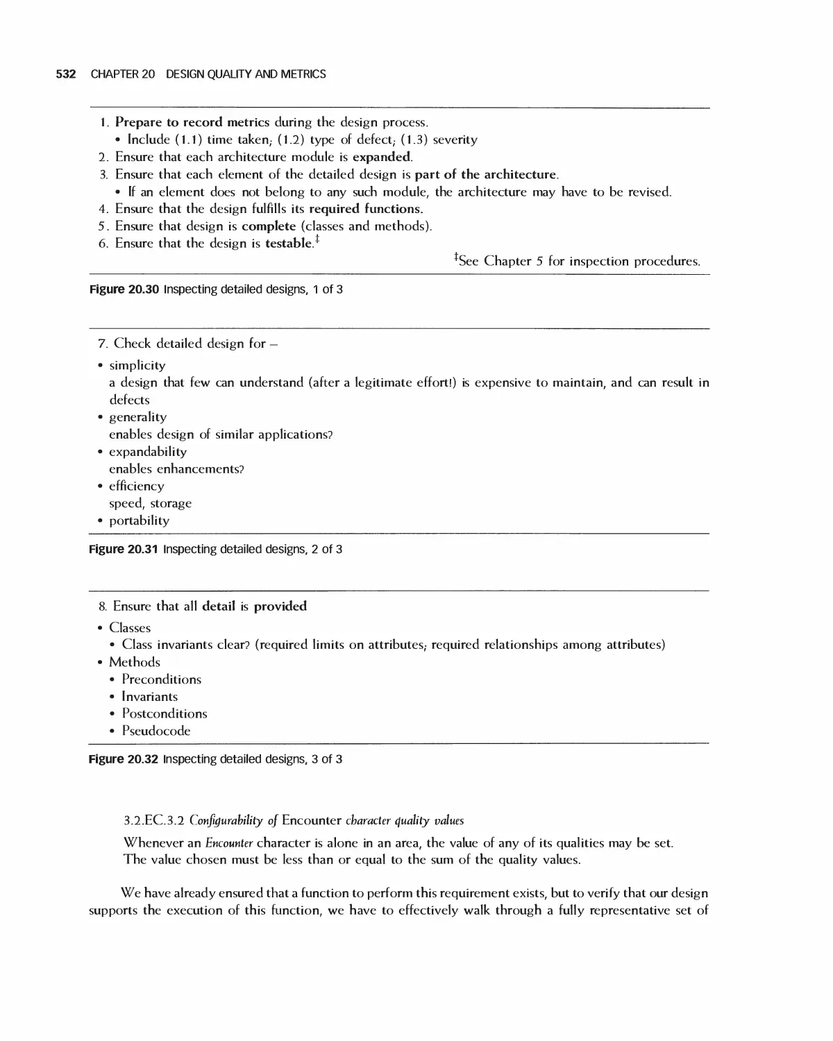
The Goals and Terminology
of Software Engineering
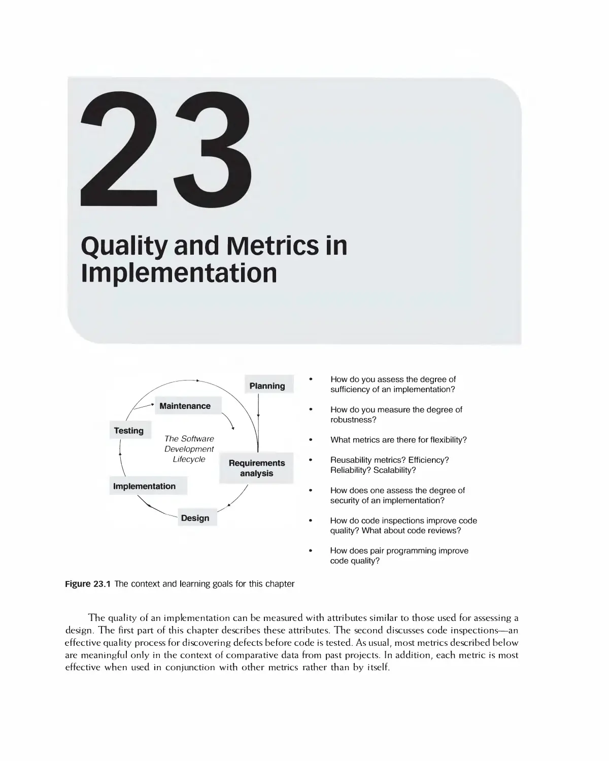
Planning
Testing
The Software
Development
Lifecycle
Requirements
analysis
Implementation
Design
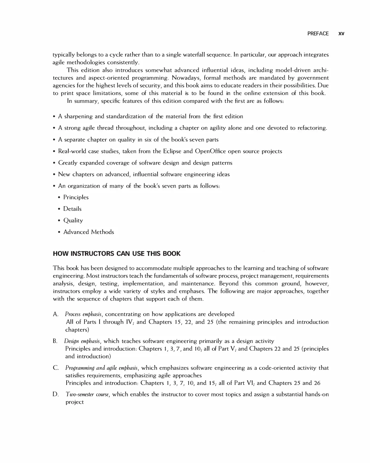
Figure 1.1 The context and learning goals for this chapter
Why is software engineering
important?
Who and what does is consist of?
What are its main activities?
What are the principles of software
engineering?
What ethics are involved?
What sorts of case studies will be
used to illustrate the subject?
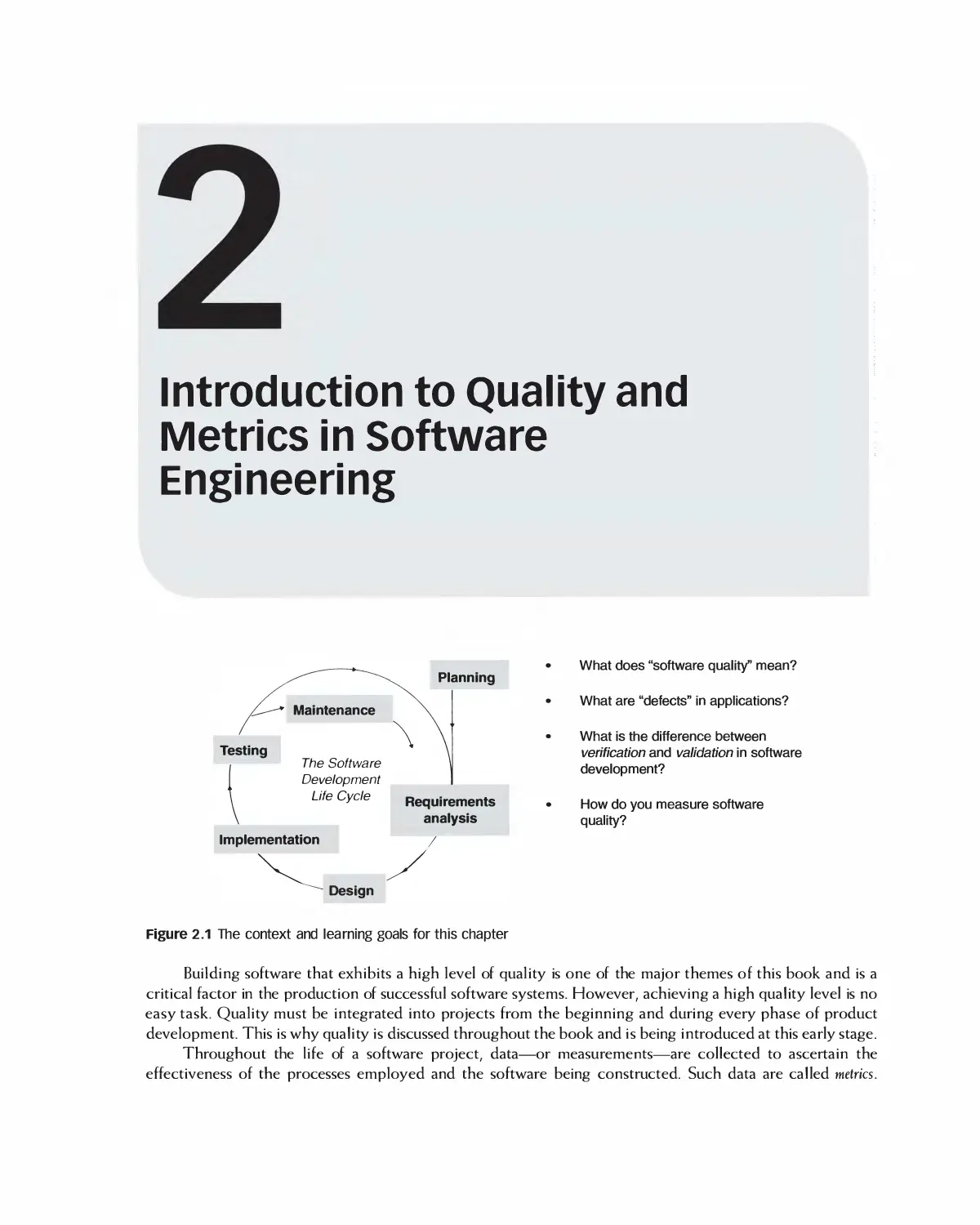
The goal of software engineering, and the theme of this book, is the creation of software systems that
meet the needs of customers and are reliable, efficient, and maintainable. In addition, the system should be
produced in an economical fashion, meeting project schedules and budgets. This is no easy task, especially
for large, complex applications. This chapter introduces the field of software engineering and explains how
it addresses these goals. We first explain the term "software engineering," showing that it consists of many
parts.
2 CHAPTER 1 THE GOALS AND TERMINOLOGY OF SOFTWARE ENGINEERING
1.1 WHAT IS SOFTWARE ENGINEERING?
Software engineering is an engineering discipline that involves all aspects of developing and maintaining a
software product. Engineering disciplines such as civil, mechanical, and electrical involve the design, analysis,
and construction of an artifact for some practical purpose. Software engineering is no exception to this—
software products certainly have practical purposes.
The IEEE defines Software Engineering [l] as follows:
1. The application of a systematic, disciplined, quantifiable approach to the development, operation and
maintenance of software,- that is, the application of engineering to software.
2. The study of approaches as in (l).
As this definition suggests, it's not only what is produced that's important but also how it is produced.
Engineering disciplines employ an established set of systematic, disciplined, and Quantifiable approaches to the
development of artifacts. By thoroughly applying an analogous set of approaches to the development of software,
we can expect the production of software that is highly reliable, is maintainable, and meets specified
requirements. A disciplined approach is particularly important as the size of a software project grows. With
increased size comes greatly increased complexity, and applying a systematic and disciplined approach is critical.
One of the first uses of the phrase "software engineering" was in 1968, by a NATO Study Group on
Computer Science [2]. A conference was organized at that time, motivated by the "rapidly increasing importance
of computer systems in many activities of society." The Study Group focused their attention on the problems
with software, and held a working conference on Software Engineering that turned out to see far into the future.
The following are some quotes from the conference that summarize the cause for their concern:
The basic problem is that certain classes of systems are placing demands on us which are beyond
our capabilities and our theories and methods of design and production at this time ... It is large
systems that are encountering great difficulties. We should not expect the production of such
systems to be easy.
Particularly alarming is the seemingly unavoidable fallibility of large software, since a
malfunction in an advanced hardware-software system can be a matter of life and death.
Programming management will continue to deserve its current poor reputation for cost and schedule
effectiveness until such time as a more complete understanding of the program design process is achieved.
One of the problems that is central to the software production process is to identify the nature of
progress and to find some way of measuring it.
Today we tend to go on for years, with tremendous investments to find that the system, which was
not well understood to start with, does not work as anticipated. We build systems like the Wright
brothers built airplanes—build the whole thing, push it off the cliff, let it crash, and start over again.
The Study Group discussed possible techniques and methods that might lead to solving these problems.
They deliberately and provocatively used the term "software engineering," with an emphasis on engineering,
as they wanted to "imply the need for software manufacture to be based on the types of theoretical
foundations and practical disciplines that are traditional in the established branches of engineering." They
believed that if these foundations and discipline were applied to building software systems, the quality of the
resulting systems would be vastly improved.
Today, many of the issues they identified are addressed by evolving software engineering techniques
and practices even as the scope of applications has increased dramatically. Throughout this book we examine
these practices and explain how they contribute to producing high-quality software. Before doing that,
WHY SOFTWARE ENGINEERING IS CRITICAL: SOFTWARE DISASTERS 3
however, it is instructive to begin examining why software fails in the first place, and how some failures can
even lead to catastrophic results.
1.2 WHY SOFTWARE ENGINEERING IS CRITICAL: SOFTWARE DISASTERS
Even with the best of intentions, a large number of software projects today are unsuccessful, with a large
percentage never completed. Worse, quite a few software projects still end in disaster, causing a loss of
money, time, and tragically, even lives. We review some representative samples here as cautionary tales. In all
cases, the methods employed were inadequate for the complexity of the required application. Failures such as
these motivate us to continually ask: How can we apply software engineering methodologies to ensure the
appropriate level of quality in software applications?
1.2.1 The Virtual Case File Project
The FBI's Virtual Case File system was intended to automate the FBI's cumbersome paper-based case system, allow
agents to share investigative information, and replace obsolete systems. Instead, after an expenditure of $170
million, the result did not accomplish these objectives at all. The effect has been to inhibit the FBI from growing its
crime-fighting mission despite the growth in terrorism and the increased sophistication of many criminal
organizations. All of 700,000 lines of code, costing $100 million, had to be abandoned. Poorly defined requirements,
networking plans, and software development plans were cited by investigators as causes for this disaster.
1.2.2 The Ariane Project
"On 4 June 1996, the maiden flight of the Ariane 5 launcher ended in failure. Only about 40 seconds after initiation of
the flight sequence, at an altitude of about 3700 m, the launcher veered off its flight path, broke up and exploded." [3]
The cost of developing Ariane during the preceding decade has been estimated at $7 billion. A significant fraction of
this was wasted on June 4, 1996. Ariane 5 itself, including its specific development, has been valued at $500 million.
The source of the problem was described in the official report [3] as follows (italics added):
The internal Inertial Reference System software exception was caused during execution of a data
conversion from 64-bit floating point to 16-bit signed integer value. The floating-point number
which was converted had a value greater than what could be represented by a 16-bit signed
integer. This resulted in an Operand Error. The data conversion instructions (in Ada code) were
not protected from causing an Operand Error. . . . The error occurred in a part of the software that only
performs alignment of the strap-down inertial platform. This software module computes
meaningful results only before lift-off. As soon as the launcher lifts off, this function serves no purpose.
In other words, the data conversion code itself was "correct" but was called upon to execute when it should
not have been. The defect lay within controlling code. This kind of problem is easy to describe but not easy to
avoid because many people are involved in large projects. Large projects become extraordinarily complex.
Development efforts like Ariane call for extensive education and coordination within project management, quality
assurance, configuration management, architecture, detailed design, programming, and testing organizations.
Depending on how the project was organized and designed, any one of these organizations could have been
partly responsible for seeing to it that the code in question was not called after liftoff.
1.2.3 Radiation Overdose
As software controls an ever-increasing number of devices, its reliability is coming under increasingly intense
scrutiny. In the project management magazine Baseline, Debbie Gage, John McCormick, and Berta Ramona wrote
4 CHAPTER 1 THE GOALS AND TERMINOLOGY OF SOFTWARE ENGINEERING
of a lawsuit alleging "massive overdoses of gamma rays partly due to limitations of the computer program that
guided use of" a particular radiation-therapy machine. They reported the following: "The International Atomic
Energy Agency said in May 2001 that at least five of the deaths were probably from radiation poisoning (from the
machine) and at least 15 more patients risked developing 'serious complications' from radiation." [4] The defect
did not show up until a significant time after release, and only after certain sequences of operator actions.
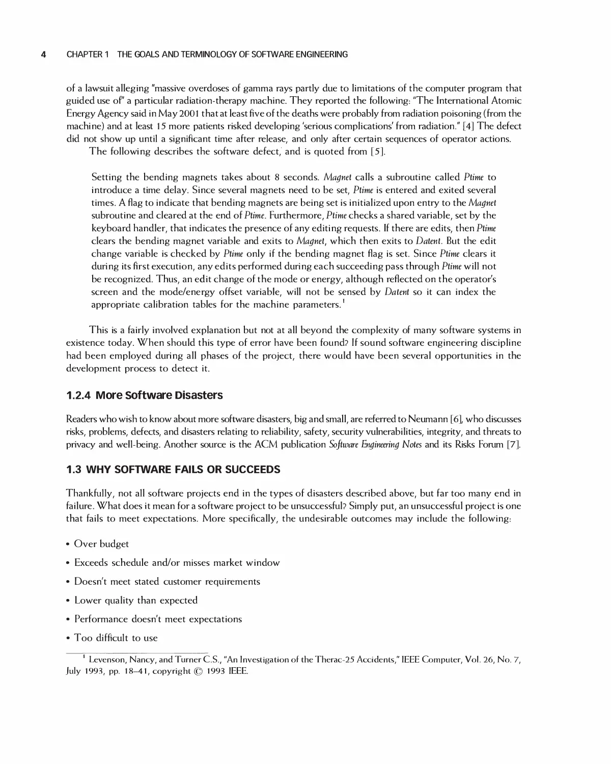
The following describes the software defect, and is quoted from [5].
Setting the bending magnets takes about 8 seconds. Magnet calls a subroutine called Ptime to
introduce a time delay. Since several magnets need to be set, Ptime is entered and exited several
times. A flag to indicate that bending magnets are being set is initialized upon entry to the Magnet
subroutine and cleared at the end of Ptime. Furthermore, Ptime checks a shared variable, set by the
keyboard handler, that indicates the presence of any editing requests. If there are edits, then Ptime
clears the bending magnet variable and exits to Magnet, which then exits to Datent. But the edit
change variable is checked by Ptime only if the bending magnet flag is set. Since Ptime clears it
during its first execution, any edits performed during each succeeding pass through Ptime will not
be recognized. Thus, an edit change of the mode or energy, although reflected on the operator's
screen and the mode/energy offset variable, will not be sensed by Datent so it can index the
appropriate calibration tables for the machine parameters.
This is a fairly involved explanation but not at all beyond the complexity of many software systems in
existence today. When should this type of error have been found? If sound software engineering discipline
had been employed during all phases of the project, there would have been several opportunities in the
development process to detect it.
1.2.4 More Software Disasters
Readers who wish to know about more software disasters, big and small, are referred to Neumann [6], who discusses
risks, problems, defects, and disasters relating to reliability, safety, security vulnerabilities, integrity, and threats to
privacy and well-being. Another source is the ACM publication Software Engineering Notes and its Risks Forum [7].
1.3 WHY SOFTWARE FAILS OR SUCCEEDS
Thankfully, not all software projects end in the types of disasters described above, but far too many end in
failure. What does it mean for a software project to be unsuccessful? Simply put, an unsuccessful project is one
that fails to meet expectations. More specifically, the undesirable outcomes may include the following:
• Over budget
• Exceeds schedule and/or misses market window
• Doesn't meet stated customer requirements
• Lower quality than expected
• Performance doesn't meet expectations
• Too difficult to use
Levenson, Nancy, and Turner C.S., "An Investigation of the Therac-25 Accidents," IEEE Computer, Vol. 26, No. 7,
July 1993, pp. 18-41, copyright © 1993 IEEE.
SOFTWARE ENGINEERING ACTIVITIES 5
Failing to meet just one of these objectives can cause a project to be deemed unsuccessful. For example,
if a project is completed under budget, meets all requirements and functionality, has high quality, good
performance and is easy to use, it still may not be successful if the schedule was missed and no customers are
willing to purchase it as a result.
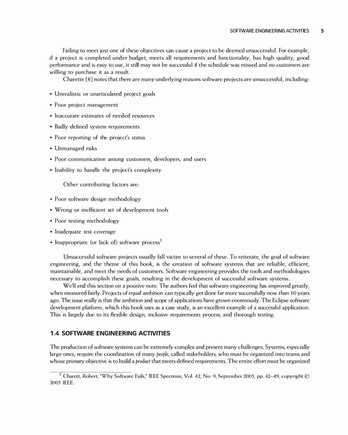
Charette [8] notes that there are many underlying reasons software projects are unsuccessful, including:
• Unrealistic or unarticulated project goals
• Poor project management
• Inaccurate estimates of needed resources
• Badly defined system requirements
• Poor reporting of the project's status
• Unmanaged risks
• Poor communication among customers, developers, and users
• Inability to handle the project's complexity
Other contributing factors are:
• Poor software design methodology
• Wrong or inefficient set of development tools
• Poor testing methodology
• Inadequate test coverage
• Inappropriate (or lack of) software process
Unsuccessful software projects usually fall victim to several of these. To reiterate, the goal of software
engineering, and the theme of this book, is the creation of software systems that are reliable, efficient,
maintainable, and meet the needs of customers. Software engineering provides the tools and methodologies
necessary to accomplish these goals, resulting in the development of successful software systems.
We'll end this section on a positive note. The authors feel that software engineering has improved greatly,
when measured fairly. Projects of equal ambition can typically get done far more successfully now than 10 years
ago. The issue really is that the ambition and scope of applications have grown enormously. The Eclipse software
development platform, which this book uses as a case study, is an excellent example of a successful application.
This is largely due to its flexible design, inclusive requirements process, and thorough testing.
1.4 SOFTWARE ENGINEERING ACTIVITIES
The production of software systems can be extremely complex and present many challenges. Systems, especially
large ones, require the coordination of many people, called stakeholders, who must be organized into teams and
whose primary objective is to build a product that meets defined requirements. The entire effort must be organized
2 Charett, Robert, "Why Software Fails," IEEE Spectrum, Vol. 42, No. 9, September 2005, pp. 42-49, copyright ©
2005 IEEE.
6 CHAPTER 1 THE GOALS AND TERMINOLOGY OF SOFTWARE ENGINEERING
• People
• Project stakeholders.
• Product
• The software product plus associated documents.
• Project
• The activities carried out to produce the product.
• Process
• Framework within which the team carries out the activities necessary to build the product.
Figure 1.2 The four "P's" that constitute software engineering
into a cohesive project, with a solid plan for success. Finally, to successfully develop the product, the activities of
the people must be organized through use of an orderly and well-defined process. Collectively, these activities are
known as the 4 Ps of software engineering: people, product, project, and process. Successful software projects
must adequately plan for and address all of them. Sometimes, the needs of each of the P's conflict with each other,
and a proper balance must be achieved for a project to be successful. Concentrating on one P without the others
can lead to a project's failure. For example, if people are organized into efficient teams and given the resources
they need to perform their roles, a project can still be unsuccessful if there's no defined software process to follow,
as chaos can ensue. The 4 P's are summarized in Figure l .2 and are discussed in the sections that follow.
1.4.1 People
People are the most important resource on a software project. It is through their efforts that software is
successfully constructed and delivered. Competent people must be recruited, trained, motivated, and
provided with a growth path, which is no easy task. They are the lifeblood of any successful project.
Software development is often dictated by tight, market-driven deadlines and demanding lists of required
product features. Because of this, only well-organized groups of engineers, educated and experienced in the
methods of software engineering, are capable of consistently carrying out these activities to everyone's
satisfaction. The alternative is often chaos and, all too frequently, disaster.
Typically, several groups of people are involved with and have a stake in a project's outcome. These are
called its stakeholders. They include business management, project management, the development team,
customers, and end users. Although each group is motivated to see the project succeed, given their diverse
roles each has a different perspective on the process. This is discussed next, for each of the groups cited.
Business Management
These are people responsible for the business side of the company developing the software. They include senior
management (e.g., V.P. Finance), marketing (e.g., Product Manager), and development managers. Their primary
focus is on business issues including profit, cost effectiveness, market competitiveness, and customer satisfaction.
They are typically not particularly knowledgeable about or involved in the technical aspects of the project.
Project Management
Project managers are responsible for planning and tracking a project. They are involved throughout,
managing the people, process, and activities. They continuously monitor progress andproactively implement
necessary changes and improvements to keep the project on schedule and within budget.
SOFTWARE ENGINEERING ACTIVITIES 7
Development Team
Software engineers are responsible for developing and maintaining the software. Software development
includes many tasks such as requirements gathering, software architecture and design, implementation,
testing, configuration management, and documentation. This book will have much to say about each of these
topics. Software engineers are motivated by many factors including technical innovation, low overhead (e.g.,
a minimum of business-type meetings), and having the time and support to stay involved in technology.
Customers
Customers are responsible for purchasing the software. They may or may not actually use the software.
Customers may be purchasing it for use by others in their organization. They are primarily interested in
software that is cost-effective, meets specific business needs, and is of high quality. They are typically
involved in some aspect of specifying requirements, and since they are paying for the project, they have the
ultimate say in defining the requirements.
End Users
End users are people who interact with and use software after it is finished being developed. End users are
motivated by software that's easy to use and helps them perform their jobs as efficiently as possible. For
example, once they become accustomed to and are effective using a particular user interface, they are
typically reluctant to accept major changes to it.
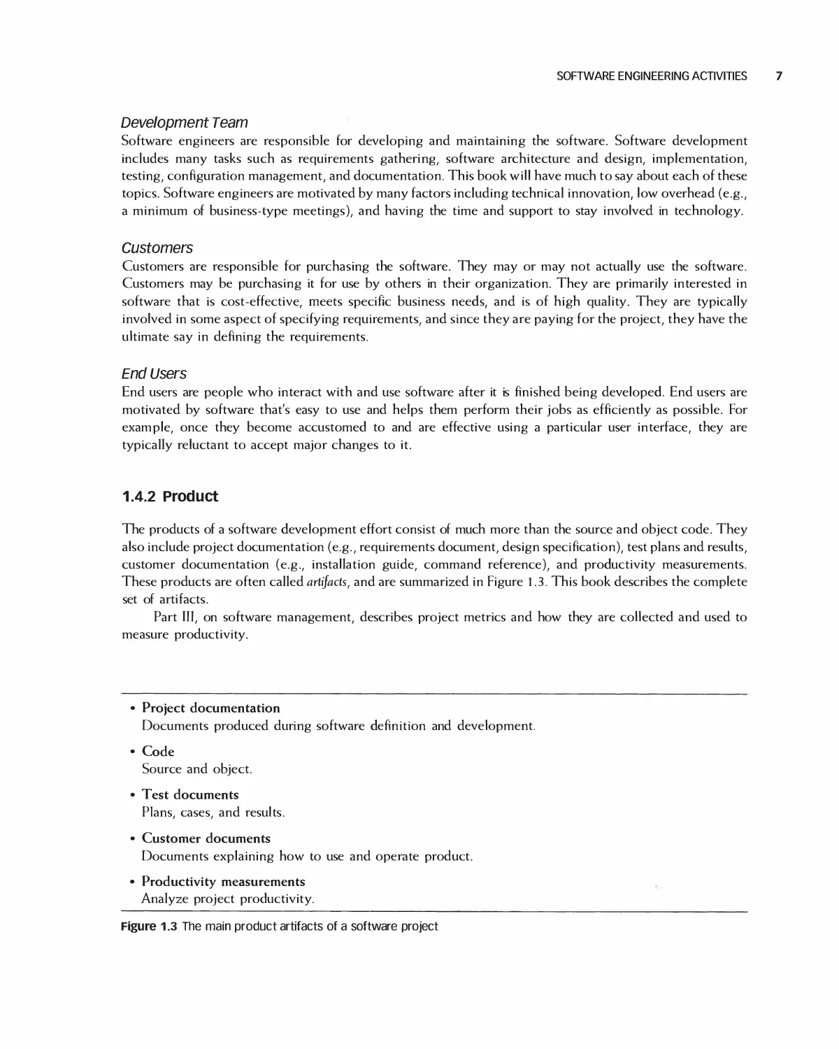
1.4.2 Product
The products of a software development effort consist of much more than the source and object code. They
also include project documentation (e.g., requirements document, design specification), test plans and results,
customer documentation (e.g., installation guide, command reference), and productivity measurements.
These products are often called artifacts, and are summarized in Figure 1.3. This book describes the complete
set of artifacts.
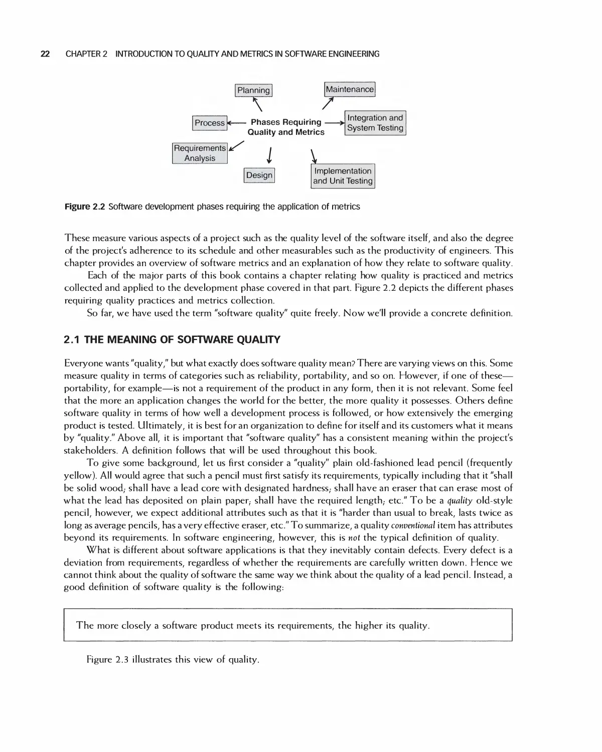
Part III, on software management, describes project metrics and how they are collected and used to
measure productivity.
• Project documentation
Documents produced during software definition and development.
• Code
Source and object.
• Test documents
Plans, cases, and results.
• Customer documents
Documents explaining how to use and operate product.
• Productivity measurements
Analyze project productivity.
Figure 1.3 The main product artifacts of a software project
8 CHAPTER 1 THE GOALS AND TERMINOLOGY OF SOFTWARE ENGINEERING
Part IV, on requirements analysis, explains how to produce requirements that specify what the product
is intended to be.
Part V explains how to specify software designs. Chapter 20 describes software architectures. Chapter
21 describes how to specify the detailed designs. Design patterns, a standard means of communicating
intelligently with each other about design, are described in Chapter 19.
Part VI discusses implementation (programming), emphasizing standards and precision. A major goal is
to help developers to write programs that are much easier to verify for correctness.
Part VII describes how to test the parts of an application, as well as the whole. It includes test procedures
that specify how tests are conducted and the test cases that specify the input data for tests. Part VII also
describes the types of customer documentation artifacts that are produced and their purpose.
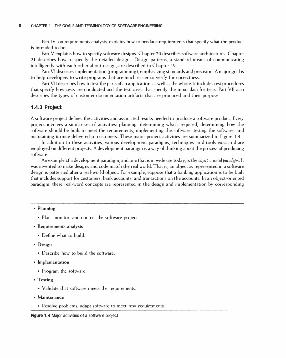
1.4.3 Project
A software project defines the activities and associated results needed to produce a software product. Every
project involves a similar set of activities: planning, determining what's required, determining how the
software should be built to meet the requirements, implementing the software, testing the software, and
maintaining it once delivered to customers. These major project activities are summarized in Figure 1.4.
In addition to these activities, various development paradigms, techniques, and tools exist and are
employed on different projects. A development paradigm is a way of thinking about the process of producing
software.
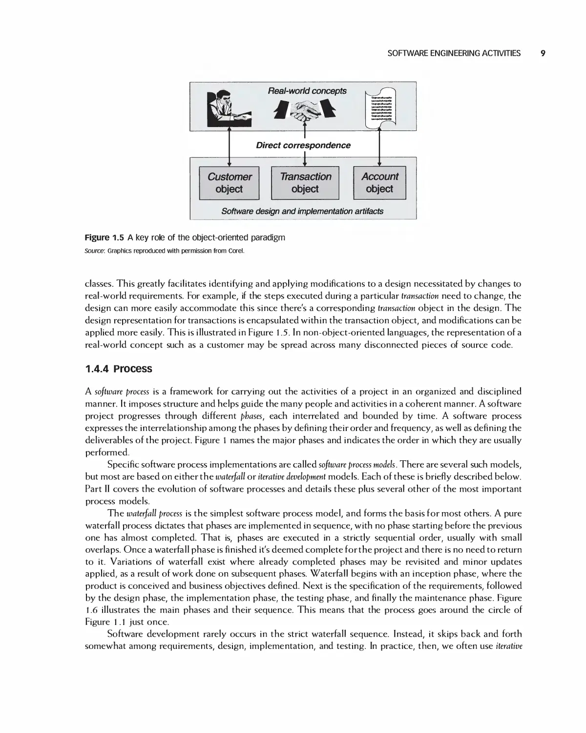
An example of a development paradigm, and one that is in wide use today, is the object-oriented paradigm. It
was invented to make designs and code match the real world. That is, an object as represented in a software
design is patterned after a real-world object. For example, suppose that a banking application is to be built
that includes support for customers, bank accounts, and transactions on the accounts. In an object-oriented
paradigm, these real-word concepts are represented in the design and implementation by corresponding
• Planning
• Plan, monitor, and control the software project.
• Requirements analysis
• Define what to build.
• Design
• Describe how to build the software.
• Implementation
• Program the software.
• Testing
• Validate that software meets the requirements.
• Maintenance
• Resolve problems,- adapt software to meet new requirements.
Figure 1.4 Major activities of a software project
SOFTWARE ENGINEERING ACTIVITIES 9
Real-world concepts
Direct correspondence
Transaction
object
Software design and implementation artifacts
Figure 1.5 A key role of the object-oriented paradigm
Source: Graphics reproduced with permission from Corel.
classes. This greatly facilitates identifying and applying modifications to a design necessitated by changes to
real-world requirements. For example, if the steps executed during a particular transaction need to change, the
design can more easily accommodate this since there's a corresponding transaction object in the design. The
design representation for transactions is encapsulated within the transaction object, and modifications can be
applied more easily. This is illustrated in Figure l .5. In non-object-oriented languages, the representation of a
real-world concept such as a customer may be spread across many disconnected pieces of source code.
1.4.4 Process
A software process is a framework for carrying out the activities of a project in an organized and disciplined
manner. It imposes structure and helps guide the many people and activities in a coherent manner. A software
project progresses through different phases, each interrelated and bounded by time. A software process
expresses the interrelationship among the phases by defining their order and frequency, as well as defining the
deliverables of the project. Figure 1 names the major phases and indicates the order in which they are usually
performed.
Specific software process implementations are called software process models. There are several such models,
but most are based on either the waterfall or iterative development models. Each of these is briefly described below.
Part II covers the evolution of software processes and details these plus several other of the most important
process models.
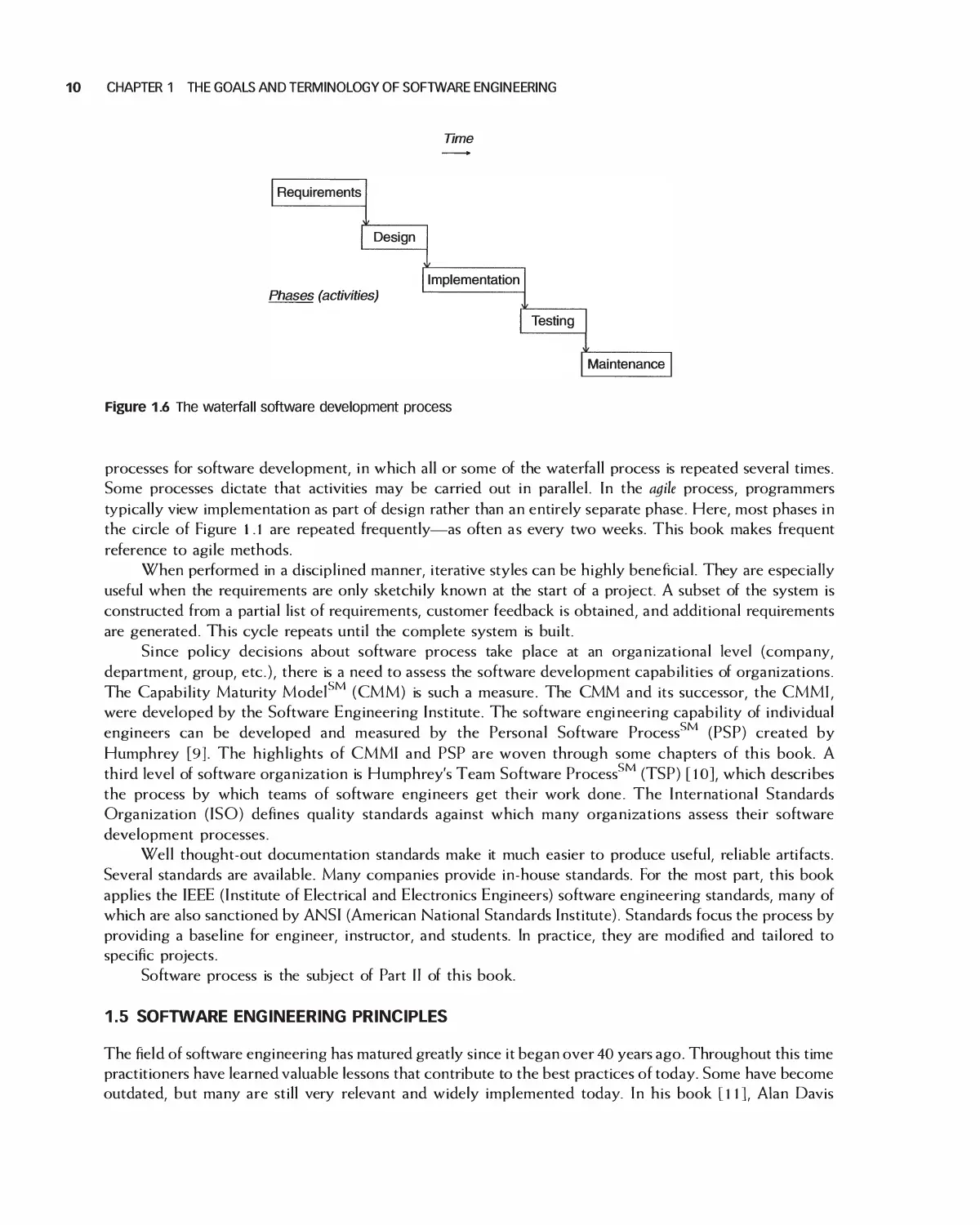
The waterfall process is the simplest software process model, and forms the basis for most others. A pure
waterfall process dictates that phases are implemented in sequence, with no phase starting before the previous
one has almost completed. That is, phases are executed in a strictly sequential order, usually with small
overlaps. Once a waterfall phase is finished it's deemed complete for the project and there is no need to return
to it. Variations of waterfall exist where already completed phases may be revisited and minor updates
applied, as a result of work done on subsequent phases. Waterfall begins with an inception phase, where the
product is conceived and business objectives defined. Next is the specification of the requirements, followed
by the design phase, the implementation phase, the testing phase, and finally the maintenance phase. Figure
1.6 illustrates the main phases and their sequence. This means that the process goes around the circle of
Figure 1.1 just once.
Software development rarely occurs in the strict waterfall sequence. Instead, it skips back and forth
somewhat among requirements, design, implementation, and testing. In practice, then, we often use iterative
10 CHAPTER 1 THE GOALS AND TERMINOLOGY OF SOFTWARE ENGINEERING
Time
Requirements
V
Design
,
Phases (activities)
V
Implementation
V
Testing
V
Maintenance
Figure 1.6 The waterfall software development process
processes for software development, in which all or some of the waterfall process is repeated several times.
Some processes dictate that activities may be carried out in parallel. In the agile process, programmers
typically view implementation as part of design rather than an entirely separate phase. Here, most phases in
the circle of Figure l .1 are repeated frequently—as often as every two weeks. This book makes frequent
reference to agile methods.
When performed in a disciplined manner, iterative styles can be highly beneficial. They are especially
useful when the requirements are only sketchily known at the start of a project. A subset of the system is
constructed from a partial list of requirements, customer feedback is obtained, and additional requirements
are generated. This cycle repeats until the complete system is built.
Since policy decisions about software process take place at an organizational level (company,
department, group, etc.), there is a need to assess the software development capabilities of organizations.
The Capability Maturity ModelSM (CMM) is such a measure. The CMM and its successor, the CMMI,
were developed by the Software Engineering Institute. The software engineering capability of individual
engineers can be developed and measured by the Personal Software Process (PSP) created by
Humphrey [9]. The highlights of CMMI and PSP are woven through some chapters of this book. A
third level of software organization is Humphrey's Team Software Process (TSP) [10], which describes
the process by which teams of software engineers get their work done. The International Standards
Organization (ISO) defines quality standards against which many organizations assess their software
development processes.
Well thought-out documentation standards make it much easier to produce useful, reliable artifacts.
Several standards are available. Many companies provide in-house standards. For the most part, this book
applies the IEEE (Institute of Electrical and Electronics Engineers) software engineering standards, many of
which are also sanctioned by ANSI (American National Standards Institute). Standards focus the process by
providing a baseline for engineer, instructor, and students. In practice, they are modified and tailored to
specific projects.
Software process is the subject of Part II of this book.
1.5 SOFTWARE ENGINEERING PRINCIPLES
The field of software engineering has matured greatly since it began over 40 years ago. Throughout this time
practitioners have learned valuable lessons that contribute to the best practices of today. Some have become
outdated, but many are still very relevant and widely implemented today. In his book [11], Alan Davis
SOFTWARE ENGINEERING PRINCIPLES 11
1. Make Quality Number l
2. High-Quality Software Is Possible
3. Give Products to Customers Early
4. Use an Appropriate Software Process
5. Minimize Intellectual Distance
6. Inspect Code
7. People Are the Key to Success
Figure 1.7 Major principles of software engineering
gathered 201 principles that form the foundation of software engineering. Figure 1.7 highlights some of the
most important, and we explore each of them.
Make Quality Number 1
There is nothing more important than delivering a quality product to customers—they simply will not
tolerate anything less. However, different people have different ideas of what quality means, and it therefore
must be specified and measured. Prime examples of quality are how closely software meets the customer's
requirements, how many (or few) defects it has, and how much it costs to produce. Quality measures need to
be specified in advance to ensure the correct targets are being pursued and met. This book contains several
chapters devoted to quality but, more important, the notion of quality is behind most of its content.
High-Quality Software Is Possible
Although it may be difficult to produce high-quality software, following modern software engineering
methods and techniques has proven to meet reasonable quality goals. Examples include involving the
customer, prototyping, conducting inspections, and employing incremental software processes.
Give Products to Customers Early
Many software projects fail because customers are given their first look at software too late in the development
cycle. This was a major motivation for the introduction of agile methods. It's virtually impossible to know all the
requirements in advance, and involving customers as early as possible is critical to getting the requirements right.
Their early involvement in helping to specify requirements is very important, but giving them working software
and having them use it is critical to understanding what they really need. Customers may think they want a
particular feature, or think they want a user interface to look a certain way, but until they get a version of software
to work with you can never be sure. Employing techniques such as agile processes, prototyping, or incremental
processes allow customers to get software into their hands early in the development cycle.
Use an Appropriate Software Process
There are many software process models, and no single one is appropriate for every type of project. For
example, the waterfall process works well for projects where all of the requirements are well known up front.
Conversely, agile and other iterative processes are called for when few requirements are known in advance.
Good software engineers and project leaders take the time to understand the type of project being undertaken
and use an appropriate model.
12 CHAPTER 1 THE GOALS AND TERMINOLOGY OF SOFTWARE ENGINEERING
Minimize Intellectual Distance
This principle says that for any software solution to a real-world problem, the structures of both the software
solution and real-world problem should be as similar as possible. This was illustrated in Figure 5, showing how
object-orientation can achieve this objective. The closer the structures are to each other, the easier it is to
develop and maintain the software.
Inspect Code
This should be extended to read "Inspect All Artifacts," where artifacts are defined as any product of
the software development process including technical specifications, test plans, documentation, and
code. Inspections have been proven to find errors as early as possible, increase quality, and decrease overall
project cost.
People Are the Key to Success
Highly skilled, motivated people are probably the most important factor contributing to the success of a
software project. Good people can make up for a variety of obstacles including poor tools, insufficient
processes, and unforeseen problems. Good people will figure out a way to overcome these obstacles and make
the project a success. Poor performers without any of these obstacles will probably still fail. Hiring and
retaining the best people is critical to producing high-quality and successful software.
So far, we have discussed the parts, principles, and activities of software engineering. Assuming that these
are understood and assembled, we need to understand the societal responsibilities of software engineers.
1.6 ETHICS IN SOFTWARE ENGINEERING
Reliance on the ethics of software engineers has become an essential part of contemporary culture. To take an
example, it is simply not possible for a car driver to verify and validate the code for his car's cruise control or
for a patient or radiologist to verify the correctness of the code controlling the X-ray machine pointing at his
head. At some point, there is no choice but to assume that the software created and installed in these and
other systems has been implemented correctly, and in a manner consistent with the public interest. This is a
matter of ethics.
The Merriam-Webster [12] online dictionary defines ethics as:
1. the discipline dealing with what is good and bad and with moral duty and obligation
2. a set of moral principles
Most disciplines operate under a strict set of ethical standards, as published in a corresponding code of
ethics, and software engineering is no exception. The ACM and IEEE have jointly developed a Software
Engineering Code of Ethics and Professional Practice [13]. The ACM/IEEE-CS Joint Task Force on Software
Engineering Ethics and Professional Practices has recommended the document, and the ACM and
the IEEE-CS have jointly approved the standard for teaching and practicing software engineering. The
code includes a short and long version, with the short version listed in Figure 1.8. The short version describes
the code at a high level of abstraction. The long version contains a number of clauses corresponding to each
of the eight principles in the short version, with each clause providing more details and examples. Both
versions are contained in [13].
ETHICS IN SOFTWARE ENGINEERING 13
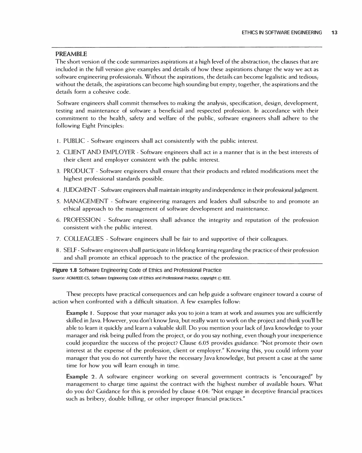
PREAMBLE
The short version of the code summarizes aspirations at a high level of the abstraction,- the clauses that are
included in the full version give examples and details of how these aspirations change the way we act as
software engineering professionals. Without the aspirations, the details can become legalistic and tedious,-
without the details, the aspirations can become high sounding but empty,- together, the aspirations and the
details form a cohesive code.
Software engineers shall commit themselves to making the analysis, specification, design, development,
testing and maintenance of software a beneficial and respected profession. In accordance with their
commitment to the health, safety and welfare of the public, software engineers shall adhere to the
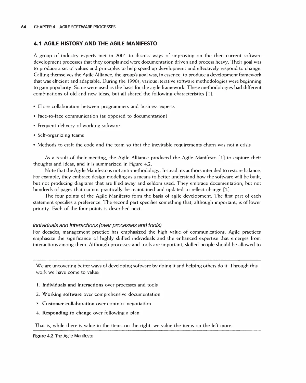
following Eight Principles:
1. PUBLIC - Software engineers shall act consistently with the public interest.
2. CLIENT AND EMPLOYER - Software engineers shall act in a manner that is in the best interests of
their client and employer consistent with the public interest.
3. PRODUCT - Software engineers shall ensure that their products and related modifications meet the
highest professional standards possible.
4. JUDGMENT - Software engineers shall maintain integrity and independence in their professional judgment.
5. MANAGEMENT - Software engineering managers and leaders shall subscribe to and promote an
ethical approach to the management of software development and maintenance.
6. PROFESSION - Software engineers shall advance the integrity and reputation of the profession
consistent with the public interest.
7. COLLEAGUES - Software engineers shall be fair to and supportive of their colleagues.
8. SELF - Software engineers shall participate in lifelong learning regarding the practice of their profession
and shall promote an ethical approach to the practice of the profession.
Figure 1.8 Software Engineering Code of Ethics and Professional Practice
Source: ACM/IEEE-CS, Software Engineering Code of Ethics and Professional Practice, copyright © IEEE.
These precepts have practical consequences and can help guide a software engineer toward a course of
action when confronted with a difficult situation. A few examples follow:
Example 1. Suppose that your manager asks you to join a team at work and assumes you are sufficiently
skilled in Java. However, you don't know Java, but really want to work on the project and think you'll be
able to learn it quickly and learn a valuable skill. Do you mention your lack of Java knowledge to your
manager and risk being pulled from the project, or do you say nothing, even though your inexperience
could jeopardize the success of the project? Clause 6.05 provides guidance: "Not promote their own
interest at the expense of the profession, client or employer." Knowing this, you could inform your
manager that you do not currently have the necessary Java knowledge, but present a case at the same
time for how you will learn enough in time.
Example 2. A software engineer working on several government contracts is "encouraged" by
management to charge time against the contract with the highest number of available hours. What
do you do? Guidance for this is provided by clause 4.04: "Not engage in deceptive financial practices
such as bribery, double billing, or other improper financial practices."
14 CHAPTER 1 THE GOALS AND TERMINOLOGY OF SOFTWARE ENGINEERING
Example 3. You are asked to develop a complex, critical piece of software for a commercial product
you're working on. You discover a public domain version of the source code. You're tempted to use the
source code as it will save much time and effort and allow you to move onto the development of another
important part of the system sooner than expected. However, it's not licensed to be used for commercial
purposes. What do you do? Clause 2.02 provides guidance: "Not knowingly use software that is
obtained or retained either illegally or unethically."
These are just a few examples of how software engineers can be confronted with ethical dilemmas.
Having a set of guidelines greatly assists the engineer in making the right decisions.
1.7 CASE STUDIES
Reading about software engineering concepts alone
is insufficient for gaining a thorough understanding
of the subject. The best way to unify and reinforce
the many topics presented in this book is to (l) learn
how they are applied to the development of real
software applications and (2) gain hands-on
experience developing a software application as part of a
team. To meet the first objective, case studies have
been developed or described and are presented
throughout the book. They serve as concrete
examples of software applications, and include
appropriate artifacts as they are discussed and presented in
the text. The case studies are introduced in the next
few sections. To meet the second objective, students
working in teams are provided guidance as they
apply software engineering concepts to the
development of a group project. As they progress,
students will generate project artifacts and working
code. Artifacts generated as part of the case studies
can also be used as guidance in developing artifacts
for the group project.
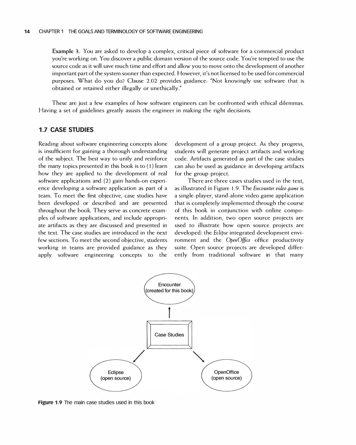
There are three cases studies used in the text,
as illustrated in Figure l .9. The Encounter video game is
a single-player, stand-alone video game application
that is completely implemented through the course
of this book in conjunction with online
components. In addition, two open source projects are
used to illustrate how open source projects are
developed: the Eclipse integrated development
environment and the OpenOffice office productivity
suite. Open source projects are developed
differently from traditional software in that many
Figure 1.9 The main case studies used in this book
CASE STUDIES 15
different people, from various organizations,
develop features and functions and then contribute
them back to the base software application. In this
way an open source application grows in
functionality and all new features are freely available for
others to use and build on.
Various other examples are used in this book,
including a video store application.
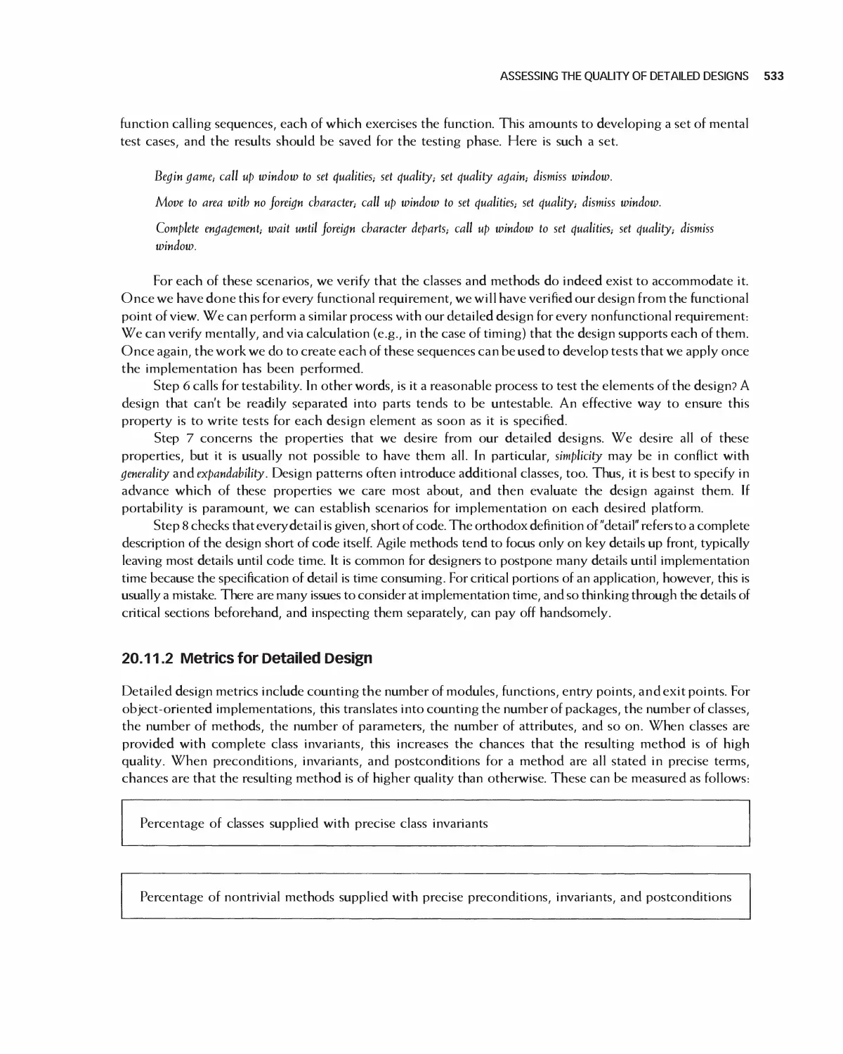
1.7.1 Encounter Video Game
The Encounter video game is a single-player,
standalone video game application. A player is assigned a
main character, and Encounter simulates all or part of
the lifetime of that character. Success in playing the
game is measured by attaining a life points goal for the
player or by the ability of the player to survive for a
given time limit. Figure 1.10 shows a typical screen
shot: the courtyard area containing a player-
controlled character, Elena.
Game characters begin with a fixed number of
points allocated equally among qualities including
concentration, stamina, intelligence, patience, and strength.
The game consists of movement among a set of
areas. The main character moves between them,
encountering a game-generated character called
the foreign character. Characters engage each other
when they are in the same area at the same time. The
result of an engagement depends on the values of the
characters' qualities and on the location where it
occurs. Once an engagement is complete, the
player's character is moved to a random area. Players can
set the values of their qualities except while engaging
a foreign character. The new quality values take
effect only after a delay.
1.7.2 Eclipse Open Source Project
The second case study is Eclipse. Eclipse [14] is an
extensible, highly configurable open source IDE
(integrated development environment). An IDE
provides an environment and set of tools for the
development of software applications. It provides tools to
build, run, and debug applications, the ability to
share artifacts such as code and object with a
team, and support for and integration with version
control. Because Eclipse is open source, its source
code and design are freely available and readily
extensible by third parties through the use of
plug-ins. In fact, Eclipse is considered a platform. It
isn't a "finished" product, and is intended for
continuous and indefinite extension [15]. Numerous open
-* /
Courtyard ,
[ Mnn room j
Get Status | Set Qualities End Game
Drecsnu
room
Kitchen
Court
Yard
ungeon
Living
Rcom
Study
Figure 1.10 Snapshot from the Encounter case study video game: Elena in the courtyard
16 CHAPTER 1 THE GOALS AND TERMINOLOGY OF SOFTWARE ENGINEERING
source extensions can be found at the home of the
Eclipse project, www.eclipse.org.
Eclipse has been successfully used as a tool for
wide-ranging application types such as Java
development, Web services, embedded device programming,
and game programming contests. The Eclipse
platform itself provides a programming language-agnostic
infrastructure. Support for specific languages is
provided by plug-ins, and each plug-in must adhere to the
same rules as all the other plug-ins that use the
platform [15]. Support for the Java programming
language is provided by the Java Development Tools
(JDT), which is built on the Eclipse platform and
provides a full-featured Java IDE.
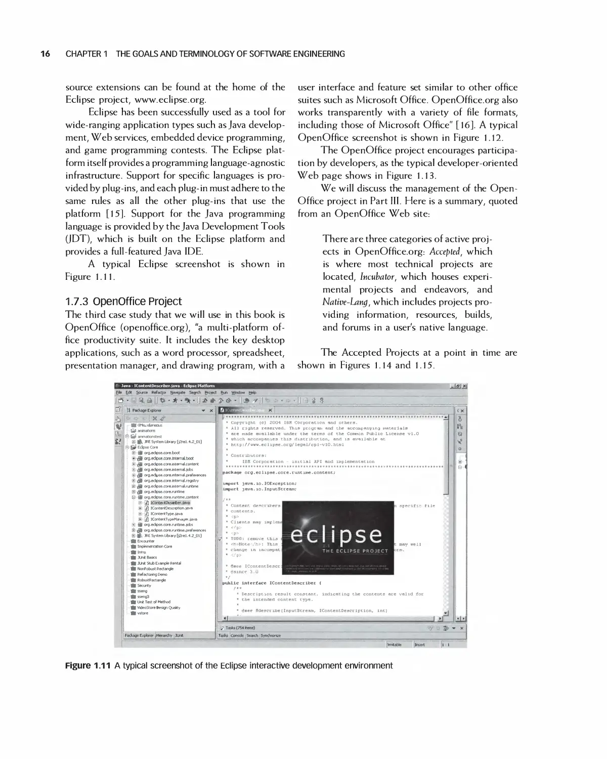
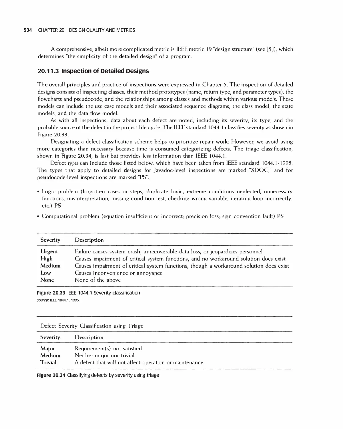
A typical Eclipse screenshot is shown in
Figure 1.11.
1.7.3 OpenOffice Project
The third case study that we will use in this book is
OpenOffice (openoffice.org), "a multi-platform
office productivity suite. It includes the key desktop
applications, such as a word processor, spreadsheet,
presentation manager, and drawing program, with a
user interface and feature set similar to other office
suites such as Microsoft Office. OpenOffice.org also
works transparently with a variety of file formats,
including those of Microsoft Office" [16]. A typical
OpenOffice screenshot is shown in Figure 1.12.
The OpenOffice project encourages
participation by developers, as the typical developer-oriented
Web page shows in Figure 1.13.
We will discuss the management of the Open-
Office project in Part III. Here is a summary, quoted
from an OpenOffice Web site:
There are three categories of active
projects in OpenOffice.org: Accepted, which
is where most technical projects are
located, Incubator, which houses
experimental projects and endeavors, and
Native-Lang, which includes projects
providing information, resources, builds,
and forums in a user's native language.
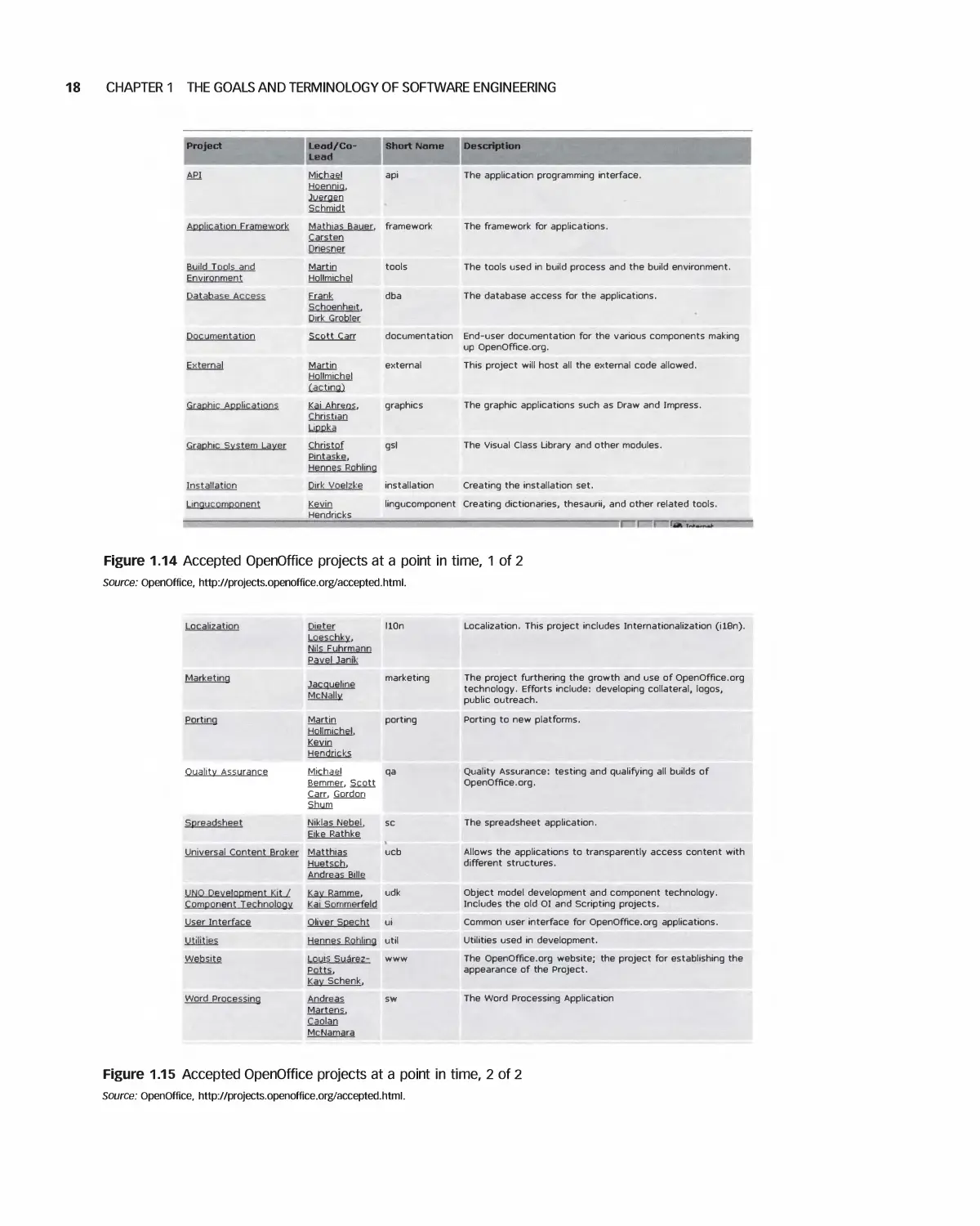
The Accepted Projects at a point in time are
shown in Figures 1.14 and 1.15.
Java - IContentDescriber.fava - Ecfipse Platform
Fte £dt Source Refaetor {tovqate Search Prpect Run Window Heb
—» fl Package Explorer ■*■
JLS12U
& -/
il - * *
.y|
it
' X ^
■■ laV animationstest
IB ft JRE System Library [)2rel.1.2_0l]
' Eclpse Core
S- 9 org.eckpse.core.boot
* 0 org.edipse.core.ln(ernal.boot
* t*8 org.ectpse.core.internal.content
♦' (J$| org.eclpse.core.nternal.jobs
(J$| org.edtrta.core.nternal.preferences
A- (0 org.eckpse.core.interrwI.regBtry
j£ jB org.ec(pse.core.intemal.runhrne
33 j} wg.edbse.core.runtirne
El 9 org.eclpse.core.rurtme.content
$! 3l ICootertffcjaAer.lava
♦ \j\ ICor*entOesCTOton.java
^ IContentType.iave
.* j$) ICor*entTypeM*«geT,iava
.♦ 9 org.eclpse.core.rvjitine.iobs
iS <$ org.ectpse.core.rurtine.preferences
SI tfo JRE System Library [}2reJ.4.2_01]
ft Encounter
ft Irnpiementatioo Core
ft Intro
ft JUr* Basics
ft JUn* Stub Example Rental
ft NonRobust Rectangle
ft Ref actoring Demo
ft RobustRectangJe
ft Security
ftsseng
ftsseng3
ft Ur* Test of Method
ft VideoStore »esign Quatty
ft vstore
Package Explorer [tterarchy Xlr*
' Copyright (c) 2004 IBM Corporation and others.
■ ill rights reserved. This pre-grant and the acconsfanyiiva irtaterials
1 are made available under the terms of the Common Public License vl.O
> which accompanies this distribution, and is available at
' http://Lrnv.eclipse.orB/legal/cpl-vlO.hta>!
' Contributors:
' IBH CorporatK
initial API and implementatn
package org. eel ipse. core. 1
it line.content;
uqport java. io. IOException;
u^tirt java.10.InputStream;
* Clients may inrpler
« </p:
* •?> -*•
* * TOOO: remove this
* <r»Note--/b>: This
« change in incompat
* </p>
* 6«ce IContentDescr ■"■
* esince 3.0 "- *~*< ""-*■
»/
pubiic interface IContentDescriber (
sperifi- file
[ipse
THE ECLIPSE PROJECT
Description result constant, indicating the contents are valid tor
1 the intended content type.
■ gsec ^describe(InputStream, IContentDescription, int)
j Tasks (7S4 items)
Tasks Console i Search Syncnronge
u
Figure 1.11 A typical screenshot of the Eclipse interactive development environment
§jj Untitled^ - OpenOmce.org 1.1.0
File fEdrt View insert Format Tools Window Help
[Default
IS ±\
e
ZllHc»H|iK!aa|*qgiiS|^^|'fj-rt>| ±j
"3F
Times New Roman
^ |12 jj B i u||i|sSSligI<r t= ] £ 6? £
This is an OpenOffice Text document ....
Figure 1.12 A typical screenshot of the OpenOffice word processor
OpenOffice.org
Source Project
Surveys Home
User Survey (en)
Consultants Survey
OpenOffice.org:
An Introduction
About Us
Documentation
OpenOffice oiq
in a Nutshell
By any use of this
Website, you agree
to be bound by
these Policies and
Terms of Use.
Project Project Home | News | Files | Members
Resources: Mailing Lists | Documentation I Source Code
Thank you!
Survey processed succesfully Your help is appreciated.
Where to go from here
We invite you to further visit the OpenOffice.org website to get acquainted with our community, our
projects and our way of being. You should consider visiting An Introduction to OpenOffice.org, the
About Us page, the Documentation, the OpenOffice org in a Nutshell page, and the Projects page.
Then you might consider participating
Our community is open for anyone to participate. No matter if you are not a programmer or a
technical oriented person, there is a place for you in one or more of our projects to help the
development, improvement or promotion of the OpenOffice. org free office suite.
The first step into the participation is by subscribing to one or more of our mailing lists inside the
project(s) you feel you can have a contribution to.
Below are some of our mailing lists that might be of interest. For a full listing please visit the Mailing
Lists page on OpenOffice org website.
Recommended Mailing Lists
I
Suh^rnhp I InRulnsrrihft
users@openoffice.org
Have a question about the OpenOtfice.org suite (not project)?
Submit your question here: you may find an answer. A very
'•iQ http: //markecng .openomce. or ■ /ser vlets/Pt ojecthome
Search , Browse
Archives ; Archives
I Browse
■■ nrrhivps
Figure 1.13 Typical OpenOffice communication with development
18 CHAPTER 1 THE GOALS AND TERMINOLOGY OF SOFTWARE ENGINEERING
Project
API
Application Framework
Build Tools and
Environment
Database Access
Documentatipn
External
Graphic Applicatigns
Graphic Svstem Layer
Installation
Lingqcpmponent
Lead/Co-
Michael
Hoennia.
Juerqen
Schmidt
Mathias Bauer.
Carsten
Driesner
Martin
Hollmichel
Frank
Schoenheit.
Dirk Grobler
ScoU qarr
Martin
Hollmichel
(acting^
Kai Ahrens.
Christian
Lippka
Christof
Pintaske.
Hennes Rphling
Dirk Voelzke
Kevin
Hendricks
Short Name Description
api The application programming interface.
framework The framework for applications.
tools The tools used in build process and the build environment,
dba The database access for the applications.
documentation End-user documentation for the various components making
up OpenOffice.org.
external This project will host all the external code allowed.
graphics The graphic applications such as Draw and Impress.
gsl The Visual Class Library and other modules.
installation Creating the installation set.
lingucomponent Creating dictionaries, thesaurii, and other related tools.
Figure 1.14 Accepted OpenOffice projects at a point in time, 1 of 2
Source: OpenOffice, http://projects.openoffice.org/accepted.html.
Localization
Marketing
Porting
Quality Assurance
Spreadsheet
Universal Content Broker
Dieter
Loeschky.
Nils Fuhrmann
Pavel Janik
Jacqueline
McNally
Martin
Hollmichel.
Kevin
HendricKs
Michael
Bemmer. Scott
Carr. Gordon
Shum
Niklas Nebel.
Eike Rathke
marketing
porting
Matthias
Huetsch.
Andreas Bille
UNO Development Kit /
Component Technology
User Interface
Utilities
Website
Word Processing
udk
Kai Sornmerfeld
Oliver Specht ui
Hennes Rohling util
Louis Sua>ez- www
Potts.
Kay Schenk.
Andreas sw
Martens.
Caolan
McNamara
Localization. This project includes Internationalization (il8n).
The project furthering the growth and use of OpenOffice.org
technology. Efforts include: developing collateral, logos,
public outreach.
Porting to new platforms.
Quality Assurance: testing and qualifying all builds of
OpenOffice.org.
The spreadsheet application.
Allows the applications to transparently access content with
different structures.
Object model development and component technology.
Includes the old 01 and Scripting projects.
Common user interface for OpenOffice.org applications.
Utilities used in development.
The OpenOffice.org website; the project for establishing the
appearance of the Project.
The Word Processing Application
Figure 1.15 Accepted OpenOffice projects at a point in time, 2 of 2
Source: OpenOffice, http://projects.openoffice.org/accepted.html.
EXERCISES 19
1.8 SUMMARY
Developing complex software systems in a successful manner has historically been very difficult. The goal of
software engineering is to define a framework for creating software systems that are reliable, efficient, and
maintainable, and meet the needs of customers. As illustrated in Section 1.2 on software disasters, producing
software that is unreliable can have catastrophic consequences. Although most software does not end in
disaster, care must be taken to avoid the many common pitfalls and mistakes that can plague a software project.
The 4 P's of software engineering—people, product, project, and process—encompass the different
aspects of defining, building, and managing software. The people are the most important part, as they not
only create the software but also are the customers for who the work is being done. The work products
include not only source and object code, but also a complete set of artifacts describing the system. A software
process model defines a framework for carrying out the different phases of a software project. It imposes order
and structure to a project.
Underlying software engineering is a set of time-tested principles. Knowing these principles helps to
understand the motivation for the software engineering methodology presented in this book.
Software engineering is a profession that carries with it certain ethical responsibilities. The ACM and
IEEE have jointly published a code of ethics to help guide software professionals in their work.
This book uses three main case studies throughout as realistic examples of software projects.
1.9 EXERCISES
1. Besides those listed in this chapter, what additional expectations do you think software products
may fail to meet?
2. Research a recent real-world "software disaster." In your own words, describe the underlying cause
of the problem. What could have been done to avoid it?
3. What are the four P's of software engineering? (Recall them without consulting the book.) Briefly
describe each.
4. In a paragraph, name at least two of the most important deficiencies you can think of in the reporting
of project progress that contribute to an unsuccessful project outcome.
5. Explain in your own words why people are invariably the most important resource on a project.
6. For the stakeholder groups listed in the text, give an example of a project motivation for each.
7. You are developing a second-generation custom order entry application for a particular customer.
Explain and give examples of at least two types of problems that can arise if the customer is not
involved in defining the new application, and their first use of the application is after it is completed.
8. Why does the use of standards make it easier to generate useful, reliable documents? Why isn't
their use a guarantee that high-quality documents will be produced?
9. Explain the difference between a software process and a software process model.
10. Figure 8 lists the ACM/IEEE Software Engineering Code of Ethics and Professional Practice. Drawing either
from your own experience or from a hypothetical situation, describe a scenario that adheres to one
of the eight principles. Now describe a scenario that violates one of the principles.
20 CHAPTER 1 THE GOALS AND TERMINOLOGY OF SOFTWARE ENGINEERING
BIBLIOGRAPHY
1. "IEEE Standard Glossary of Software Engineering Terminology," IEEE Std 610.12-1990, December 1990, p. 67.
2. Naur, Peter, and Randell, Brian, (Editors), "Software Engineering, Report on a conference sponsored by the NATO Science
Committee," Garmisch, Germany, 7th to 11th October 1968, Brussels, Scientific Affairs Division, NATO, January 1969, pp. 8-10.
3. Lions J. L., (Chairman of the Inquiry Board), "Ariane 5 Flight 501 Failure, Report by the Inquiry Board," Paris, July 1996, http://www.
ima.umn.edu/~arnoId/disasters/ariane5rep.htmI [accessed November 1, 2009 ].
4. McCormick, John, and Thayer, Berta Ramona, "We Did Nothing Wrong," Baseline, March 2004, p. 1, http://www.baselinemag.
com/c/a/Projects-Processes/We-Did-Nothing-Wrong/[accessed November 1, 2009 ].
5. Levenson, Nancy, and Turner C.S., "An Investigation of the Therac-25 Accidents," IEEE Computer, Vol. 26, No.7, July 1993, pp. 18—41.
6. Neumann, P. G., "Computer Related Risks", Addison-Wesley/ACM Press, 1995, p. 384.
7. Neumann, Peter G. (moderator), 'The Risk Digest, ACM Committee on Computers and Public Policy." http://catless.ncl.ac.uk/
Risks/ [accessed November 1, 2009 ].
8. Charette, Robert, "Why Software Fails," IEEE Spectrum, vol. 42, no.9, September 2005, pp. 42—49.
9. Humphrey, W. S., "PSP: A Self-Improvement Process for Software Engineers," 2005, Addison-Wesley, p. 368.
10. Humphrey, W. S., "Introduction to the Team Software Process," 2000, Addison-Wesley, p. 368.
11. Davis, Alan, "204 Principles of Software Engineering," 1995, McGraw Hill.
12. Merriam-Webster Online Dictionary, http://www.merriam-webster.com/home.htm [accessed November 1, 2009 ].
13. "Software Engineering Code of Ethics and Professional Practice (Version 5.2) as recommended by the ACM/IEEE-CS Joint Task
Force on Software Engineering Ethics and Professional Practices, 1999. http://www.acm.org/about/se-code [accessed November 1,
2009].
14. E.O.S. Project. Eclipse Open Source Project, http://www.eclipse.org/.
15. The Eclipse Project Wiki. http://wiki.ecIipse.org/Main_Page.
16. OpenOffice Project, http://www.openoffice.org/.
Introduction to Quality and
Metrics in Software
Engineering
Maintenance
Testing
Planning
The Software
Development
Life Cycle
Requirements
analysis
What does "software quality" mean?
What are "defects" in applications?
What is the difference between
verification and validation in software
development?
How do you measure software
quality?
Implementation
Desi n
Figure 2.1 The context and learning goals for this chapter
Building software that exhibits a high level of quality is one of the major themes of this book and is a
critical factor in the production of successful software systems. However, achieving a high quality level is no
easy task. Quality must be integrated into projects from the beginning and during every phase of product
development. This is why quality is discussed throughout the book and is being introduced at this early stage.
Throughout the life of a software project, data—or measurements—are collected to ascertain the
effectiveness of the processes employed and the software being constructed. Such data are called metrics.
CHAPTER 2 INTRODUCTION TO QUALITY AND METRICS IN SOFTWARE ENGINEERING
Planning
Maintenance
7
Process
- Phases Requiring -
Quality and Metrics
Integration and
System Testing
Requirements
Analysis
s
Design
Implementation
and Unit Testing
Figure 2.2 Software development phases requiring the application of metrics
These measure various aspects of a project such as the quality level of the software itself, and also the degree
of the project's adherence to its schedule and other measurables such as the productivity of engineers. This
chapter provides an overview of software metrics and an explanation of how they relate to software quality.
Each of the major parts of this book contains a chapter relating how quality is practiced and metrics
collected and applied to the development phase covered in that part. Figure 2.2 depicts the different phases
requiring quality practices and metrics collection.
So far, we have used the term "software quality" quite freely. Now we'll provide a concrete definition.
2.1 THE MEANING OF SOFTWARE QUALITY
Everyone wants "quality," but what exactly does software quality mean? There are varying views on this. Some
measure quality in terms of categories such as reliability, portability, and so on. However, if one of these—
portability, for example—is not a requirement of the product in any form, then it is not relevant. Some feel
that the more an application changes the world for the better, the more quality it possesses. Others define
software quality in terms of how well a development process is followed, or how extensively the emerging
product is tested. Ultimately, it is best for an organization to define for itself and its customers what it means
by "quality." Above all, it is important that "software quality" has a consistent meaning within the project's
stakeholders. A definition follows that will be used throughout this book.
To give some background, let us first consider a "quality" plain old-fashioned lead pencil (frequently
yellow). All would agree that such a pencil must first satisfy its requirements, typically including that it "shall
be solid wood; shall have a lead core with designated hardness,- shall have an eraser that can erase most of
what the lead has deposited on plain paper, shall have the required length; etc." To be a quality old-style
pencil, however, we expect additional attributes such as that it is "harder than usual to break, lasts twice as
long as average pencils, has a very effective eraser, etc." To summarize, a quality conventional item has attributes
beyond its requirements. In software engineering, however, this is not the typical definition of quality.
What is different about software applications is that they inevitably contain defects. Every defect is a
deviation from requirements, regardless of whether the requirements are carefully written down. Hence we
cannot think about the quality of software the same way we think about the quality of a lead pencil. Instead, a
good definition of software quality is the following:
The more closely a software product meets its requirements, the higher its quality.
Figure 2.3 illustrates this view of quality.
DEFECTS IN SOFTWARE 23
Requirements A 100°/o
(explicit and implicit) I
\
\
\
0% "\
I
I
^^ Typical quality focus J
Figure 2.3 The meaning of software quality: the degree to which the actual requirements are met
Source: Graphics reproduced with permission from Corel.
We have not yet discussed how requirements are gathered and generated. For now, let us assume that
requirements are generated with the best knowledge available during requirements analysis. Even in this case,
after the software has been developed and the product has been shipped to customers, it may be discovered
that some requirements are in fact incorrect or missing. In these cases the software is constructed using the
requirements as documented, and we would say the software meets all its explicitly specified requirements but it
may not fully satisfy its customers. There are a number of different ways this can happen.
As an example, if customers are not consulted during requirements definition the system is constructed
without their input. When they eventually use the software they may find it does not function as they wish and
are dissatisfied. Even if customers are consulted and provide input, it is possible they will still be dissatisfied on
using the software. For example, suppose that a software system implements a user interface, with screen
layouts and menus specified in a requirements document. If customers are not given an opportunity to use the
interface before the product is released, they may find that what appears to work well on paper is actually
cumbersome to use. In these scenarios and others, we would say the product does not exhibit high quality
because it does not satisfy the customer. Therefore a more complete definition of quality would be:
The more closely a software product meets its specified requirements, and those requirements meet the
wants and needs of its customers, the higher its quality.
Techniques for gathering requirements and ensuring customer satisfaction are covered in Part IV on
requirements analysis.
Besides the benefit of customer satisfaction, producing high-quality software provides other advantages. It
has often been shown that a correlation exists between products with the least number of defects and the shortest
schedules. There is also a correlation between poor quality and schedule overruns, and between poor quality and
increased project costs. The more defects there are in software, the more time engineers spend fixing them,
taking time from other important project tasks. Also, the more defects that exist, the more likely that software
changes necessitated by fixing these defects will themselves result in more defects. For all these reasons and more,
quality is one of the most important attributes in software and a key contributor to its success.
2.2 DEFECTS IN SOFTWARE
A defect in a phase of software application is defined as a deviation from what's required for that phase. In practice,
most software systems contain defects and therefore do not entirely meet their requirements. The software
disasters described in Chapter 1 illustrate the cost of defects in the tens—and even hundreds—of millions of
dollars. Defects can be introduced at any stage in the development process. A major goal of software engineering is
24 CHAPTER 2 INTRODUCTION TO QUALITY AND METRICS IN SOFTWARE ENGINEERING
identifying and removing as many defects as possible, as early as possible, throughout product development, either
by inspection of artifacts or testing of the system. For example, if software is in the implementation phase, the code
may deviate from the software design produced in the previous design phase, or it may be coded in such a way as to
produce an incorrect output. The result of either case is considered a defect. In this particular case, an inspection of
the code prior to testing is conducted, with a goal of identifying as many defects as possible. Once the software is
fully integrated into a system, testing is conducted to ensure that it conforms to the specified requirements.
Defects are the clearest manifestation of a quality shortfall. The later in the development cycle they are
discovered the more they cost to repair. Therefore two quality goals of software development processes are as
follows [1]:
1. To remove as many defects as is reasonably possible before the product is delivered to the customer.
2. To remove as many of these defects as early in the development process as possible.
To the first point, defects discovered and repaired during software development will not be found by
customers, of course. The more defects that can be removed, the higher the quality of software is likely to be,
and the more the customer will be satisfied.
To the second point, as software is developed and defects are introduced (which is, in practice,
inevitable), the earlier they are discovered the less they cost to repair.
According to Boehm [2] and others, the cost of defect repair after software is released to customers can be
100 times greater as compared to fixing the same defect early in the development cycle. Various studies show
various cost escalation factors, but they all report a dramatic rise in the cost of detection and repair. Figure 2.4
shows one estimate of the relative cost of defect repair during each stage of development. For example, i f a defect
is introduced during the requirements phase, assume that it costs $ 1 to detect and repair if done during that same
phase. If it slips through to the implementation phase, the same defect will cost $20 to repair. If it falls all the way
through to maintenance, which is when customers are using the software, the cost can be $100 to repair.
The reason for this increase in repair cost in subsequent phases can be illustrated with an example [1 ].
Suppose you have an application that performs a large number of file reads and writes. As part of your
development process, at the end of the design phase you conduct an inspection of the design and discover
two defects: one in the algorithm that performs file reads and writes,- the other in the allocation of memory to
hold the file records. Assume that the work required to i\x these defects after the inspection takes two days to
complete, and the steps taken are as follows:
1. Modify the algorithm to f\x the defect.
2. Conduct an inspection of the reworked design to verify its correctness.
Requirements
$>
LSCaiLJII
W-
szo
Implementation
—►
saa
Test
Maintenance
i
i
Figure 2.4 Cost of detecting and repairing a defect during maintenance, depending on the phase in which it was injected
VERIFICATION AND VALIDATION 25
Suppose, instead, that the defects went undetected and passed through to the implementation phase.
The defects would be harder to detect and could now affect several hundred lines of code. If the defects are
detected during a code inspection, the work required to fix them could take a week to complete. The step
required would be as follows:
1. Modify the algorithm to fix the defect.
2. Conduct an inspection of the reworked design to verify its correctness.
3. Recode the affected portion of the code.
4. Conduct an inspection of the reworked code to verify it is correct and conforms to the reworked design.
Suppose now that the defects went undetected and passed through to the testing phase. The defects
would be even harder to detect and now take more time to fix. In addition to the one week required if found
during code inspection, the following additional work would be required:
5. Assistance from the tester to recreate the defects.
6. Discovery of the exact cause of the defect within the software.
7. Dedicated machine time to support debugging.
8. Retesting the fix to ensure it works correctly.
These activities can take an additional week to a month, depending on how difficult it is to isolate and
repair the defect. This example illustrates the cost of not detecting and repairing defects as close to their
injection as possible and why every effort must be made to detect and repair defects as early as possible.
2.3 VERIFICATION AND VALIDATION
Software verification and validation (V&V) is a process implemented throughout the software life cycle to
ensure the following.
1. Each step in the development process is carried out correctly. This is called verification.
2. Each artifact produced meets its requirements as specified in prior phases. This is called validation.
The IEEE Glossary [3] defines these terms as follows:
Verification: "The process of evaluating a system or component to determine whether the
products of a given development phase satisfy the conditions imposed at the start of that phase."
For example, is the software design sufficient to implement the previously specified requirements?
Does the code fully and correctly implement the design?
Validation: "The process of evaluating a system or component during or at the end of the
development process to determine whether it satisfies specified requirements." In other words,
does the implemented system meet the specified user requirements?
Verification is comparable to keeping your balance current in your checkbook based on your daily activity.
As you write checks and make deposits, you enter the amount in the checkbook register and update the balance.
26 CHAPTER 2 INTRODUCTION TO QUALITY AND METRICS IN SOFTWARE ENGINEERING
Each time you make an entry you check that your arithmetic is correct and your new balance is right. This is
analogous to ensuring that each phase in the software development process is carried out correctly.
Validation is comparable to balancing your checkbook when the bank's statement arrives. You match all
the transactions in the monthly statement with those in your register, ensuring that none have been omitted
or entered incorrectly and that the transaction amounts in your register match those in the statement. In
addition, you validate that the ending balance in your register matches that in the statement. Even though
you kept your balance up-to-date, mistakes may have been made. Validation catches those mistakes and
ensures the correctness of your balance. This is analogous to testing of a software system.
The two main activities involved during V & V are inspections and software testing. Inspections, and
also reviews, are verification activities and involve peer examination of project artifacts (requirements, design,
code, etc.) to discover defects. The idea is to find as many defects as possible as early as possible. Inspections
are covered in greater detail in Chapter 5. Testing is the principal part of validation.
Software testing is primarily a validation activity, occurring at the end of a development cycle to ensure
that software satisfies its user requirements. Testing involves providing the system with a set of inputs, and
validating that the system behavior and output match what is expected. Any deviation from an expected
outcome is considered a defect. Testing is covered in detail in Part VII.
Note that it is a combination of verification—primarily in the form of inspections—and validation—
primarily in the form of testing—that consistently produces high-quality software. Testing alone is not
sufficient. No matter how talented software engineers are at fixing defects, if the quality level is low
entering validation, as measured by latent defects (those present but not necessarily known), there is a high
probability that validation will take significantly longer than expected and the quality level will remain
lower than desired. As many defects as possible must be removed from the artifacts before validation
begins.
V&V and quality practices, as they relate to each major software phase and activity, is included in the
quality chapter near the end of each part of this book. Figure 2.5 summarizes these V&V concepts.
To reinforce the verification/validation distinction, let us perform V&V on a simple example. Suppose
that the customer wants an application that "solves linear equations of the form ax + b — c." We translate this
into user requirements such as:
1. The user shall be able to input numbers a, b, and c up to 10 digits each, with up to four places following
the decimal point.
2. The application shall produce a solution to the equation ax + b = c that is within 1/1000 of the
mathematically exact answer.
Then we implement a program to satisfy these requirements.
• Verification: Ensuring that each artifact is built in accordance with its specifications
- "Are we building the product right?"
- Mostly inspections and reviews.
• Validation: Checking that each completed artifact satisfies its specifications.
- "Are we building the right product?"
- Mostly testing.
Figure 2.5 verification vs. validation
PLANNING FOR QUALITY 27
It is our responsibility to ensure that we have built the application correctly by checking that we
proceeded appropriately from the beginning of the process to the end. This is the verification process. For
convenience, we will number the development phases as follows.
1. Get the customer's requirements.
2. Write down the requirements in detail.
3. Obtain the customer's approval of the requirements statement.
4. Code the application. (For simplicity, we have omitted a design phase.)
5. Test the application.
Verification checks the following questions:
1. Do the requirements express what the customer really wants and needs? Some verification issues here are
as follows: Is ax + b — c the correct form? What are the precision requirements? What if 0 is entered for a?
2. Are we carrying out the process of obtaining the customer's approval in an appropriate manner? Some
verification issues here are as follows: Are we allowing the customer adequate time? Are we explaining all
needed terms to the customer?
3. Does the code implement the written requirements in every respect? This requires an inspection of the
code itself, in which the requirements are considered one at a time and the matching code is perused.
This could include a mathematical proof. (Strictly speaking, verification does not call for executing the
code.)
4. Do the proposed tests adequately cover the application? For an application of realistic size, this would
include an inspection of the test plans, test cases, and test procedures. This is separate from testing itself,
a validation step discussed below.
Validation of this product consists of obtaining the customer's approval of the written, completed
requirements and executing a set of tests on the completed code. For example, we enter a = 1, b = 1, and
c = 1, and validate that the program produces x = 0.
To summarize our discussion of the V&V process, at any given moment a software engineer is either
creating an artifact, verifying it as he does so, or validating a completed artifact. This is illustrated in
Figure 2.6.
2.4 PLANNING FOR QUALITY
Since quality practices are implemented throughout the software life cycle, it is important to express quality
approaches and goals in writing early in a project—in other words, well before the goals are used in tracking
the project's quality.
Agile projects emphasize the attainment of quality through continual interaction with the customer in
person, early implementation, and continual, cumulative testing. The IEEE has published several standards to
help meet this objective. These, and standards like them, tend to be employed in larger projects that are not
agile or that employ agile methods only partially.
The Software Quality Assurance Plan (SQAP) (IEEE Std 730-2002) is a document for expressing an
overall approach to quality that is conducted throughout the entire software life cycle. Major topics
28 CHAPTER 2 INTRODUCTION TO QUALITY AND METRICS IN SOFTWARE ENGINEERING
Figure 2.6 Verification and validation of an artifact: before completion vs. after
Source: Graphics reproduced with permission from Corel.
included in the plan are listed below. Details of the SQAP are covered in Chapter 5. The plan includes the
following:
• The organizational structure of the quality team
• A list of documentation to be created governing the development, verification and validation, use and
maintenance of the software (e.g., software requirements specification, verification and validation plan,
software design specification, etc.)
• The definition and schedule of inspections to be conducted and how they are to be conducted
• The metrics to be collected, monitored, and analyzed
• References to software test plans
• How problem reporting is to be managed and conducted
The V&V Plan is the manner in which the Software Quality Assurance Plan is supported by verification
and validation. The IEEE has published a Software Verification and Validation Plan (SVVP) framework (IEEE
Std 1012-2004) to assist in documenting the specific V&V practices to be implemented. The contents and
application of the SVVP are covered in Chapter 9.
2.5 METRICS
Metrics are numerical measures that quantify the degree to which software or a process possesses a given
attribute. Examples of metrics are "defects per thousand lines of code" and "average software module size."
Metrics are collected and analyzed throughout the software life cycle, and help with the following:
• Determining software quality level
• Estimating project schedules
• Tracking schedule progress
• Determining software size and complexity
METRICS 29
• Determining project cost
• Process improvement
When goals such as software quality level and project cost are not expressed specifically enough, they
may be subject to differing interpretations. These differences can cause confusion and conflict. For example, a
goal stated as "The application should crash very seldom" is not specific. How do you measure "very seldom"? Is
it once per day? Per week? Per year? A more precise goal would be "The application should crash no more
than 3 times per year." Stated this way, the goal is not open to interpretation and is measurable.
Without quantifiable, objective measures to provide visibility into a project it is difficult to measure a
project's progress in terms of whether it is on schedule, whether it is meeting its quality goals, and whether it
is ready to ship to customers. In addition, "you can't improve what you don't measure." Continuous
improvement of an organization's processes and software is predicated on collecting metrics and setting
quantitative improvement goals for future projects.
To be successfully utilized, metric collection commences at the onset of a project and continues
throughout the entire life cycle, through maintenance. Metric collection and analysis can take a significant
amount of managerial and engineering effort, but the payoff is well worth it.
Software metrics can be classified into two broad categories: product metrics and process metrics. Product
metrics measure characteristics of the software product, or system, including its size, complexity,
performance, and quality level. For example, size can be expressed in the number of lines of code, performance as the
number of transactions per second, and quality level as number of defects per thousand lines of code, which is
commonly referred to as defect density.
Process metrics measure attributes of the software processes, methods, and tools employed during
software development and maintenance of a software system. Process metrics include project effort, schedule
adherence, defect repair rate, and productivity. For example, project effort can be expressed as the number of
person months of development, and defect repair rate as the number of defects repaired per week. Many other
metrics can be collected, and they are discussed in greater detail in the quality and metrics chapters later in
the book. Chapter 9 describes metrics collection and utilization in more detail. The next section discusses
metrics and their use in measuring quality.
2.5.1 Quality Metrics
Since quality is the degree to which software satisfies its requirements, we must be able to measure this degree
of compliance. It is useful to identify a set of software quality metrics, which are a subset of the total metrics
collected for a project. These metrics are specifically focused on the quality characteristics of software and of
the processes employed during the software life cycle.
As described by Kan [4], important quality metrics include the following:
• Defect density
• Mean time to failure
• Customer problems
• Customer satisfaction
Defect density is the number of defects relative to the software size. Size is typically expressed in thousands
of lines of code (KLOC), so defect density is expressed as defects/KLOC. Remember that a defect is defined
as a deviation from user requirements, so defect density is one of the most basic metrics used to measure
30 CHAPTER 2 INTRODUCTION TO QUALITY AND METRICS IN SOFTWARE ENGINEERING
quality. In general, the higher the defect density, the lower the quality. Organizations typically characterize
defects by type or by severity, to distinguish their relative importance. The following is an example of how a
high-severity defect would be defined and of a quality goal based on the definition:
A class 1 defect is defined as a requirement listed in section 3 of the Software Requirements
Specification that the application fails to satisfy. The application shall have no more than 5 class 1
defects reported per 1,000 users during the first month of operation.
Note that this definition and goal are very specific and measurable. Again, when goals are not expressed
in a quantifiable form, they may be subject to differing interpretations. For example, consider an alternative
definition to the one above: "there should be very few class 1 defects reported in the first few months of
operation." There is no way to measure "very few" and therefore to validate compliance.
A common indicator of software quality is the reliability of a system, as measured by its availability or
the frequency of system crashes over a period of time. The typical metric used is mean time to failure (MTTF) and
is the amount of elapsed time between system crashes. The MTTF metric is often used with safety-related
systems such as the airline traffic control systems, avionics, and weapons. For instance, the U.S. government
mandates that its air traffic control system cannot be unavailable for more than three seconds per year [4].
Another example can be seen in many telecommunications switches, such as those used in cellular networks.
Large network providers mandate that this equipment must have "f\vc 9's" availability, which is an uptime of
99.999% per year. This translates to a total yearly downtime of 5 minutes, 15 seconds. The reader may well
ask, "Why not make the required MTTF 100%?" The answer is that this is generally not attainable, and so no
development organization would sign up to do the job.
Customer problems are classified as the total number of problems encountered by customers while using the
product. Some of the problems may be caused by valid defects in the software. Others may be caused by non-
defects, such as a confusing user interface, poorly written documentation, or duplicate defects (i.e., defects that
were already reported and/fixed but not known by the reporting party). Duplicates can be an important indicator
as to how widespread a defect is, based on the number of times the same defect is reported by different users. In
all these cases, whether a problem is caused by a defect or not, customers are encountering perceived usability
problems and as a result may not be satisfied with the software. This makes the customer problems metric an
important indicator of quality. This metric is typically expressed as problems/user/month. It and other metrics
collected after a software product is released are discussed in Part VII on testing, release, and maintenance.
Customer satisfaction metrics are commonly collected through the administration of customer satisfaction
surveys. Companies such as Cisco Systems [5] collect feedback from their customers, with satisfaction
measured on a 5-point scale (5 = Very Satisfied,- 1 = Very Dissatisfied). IBM includes the CUPRIMDSO
categories (Capability/functionality, Usability, Performance, Reliability, Installability, Maintainability,
Documentation/information, Service, and Overall). Hewlett-Packard uses the FURPS categories
(Functionality, Usability, Reliability, Performance, and Service) [4]. Results of these surveys are used to drive
improvement initiatives in their respective organizations.
2.6 SUMMARY
Quality software is a major theme of this book. Quality can be defined as "the more closely a software product
meets the wants and needs of its customers." There are many advantages to producing quality software including
increased customer satisfaction, reduced development schedules, and reduced project cost. Quality practices are
implemented at the beginning of the software life cycle and last through product release into maintenance.
Defects in software are deviations from requirements. As many defects as possible should be removed
during product development, so these defects will not be delivered to customers. The earlier in the life
BIBLIOGRAPHY 31
cycle defects are detected, the easier they are to repair and the less they cost to fix. Studies have shown that
defects detected and repaired after software is released to customers can cost up to 100 times as much as if the
same defects were repaired shortly after they were introduced.
Verification and validation (V&V) is a process for verifying that artifacts produced during the life cycle
contain as few defects as possible and validating that software satisfies its requirements. Verification answers
the question, "Are we building the product right?" Validation answers the question, "Are we building the
right product?"
Metrics are numerical measures collected throughout the software life cycle, and quantify the degree to
which software and processes possess certain attributes. They help with determining quality level, estimating
schedules, tracking schedule progress, determining software size and complexity, determining project cost,
and improving processes. Metrics related to quality include defect density, mean time to failure, customer
problems, and customer satisfaction.
2.7 EXERCISES
1. In addition to the reasons stated in this chapter, name at least two other advantages to producing
quality software.
2. It has been noted that the later in the life cycle defects go undetected, the harder they are to
discover and repair. In your own words, describe two reasons why this is true.
3. (a) Describe in your own words the difference between verification and validation.
(b)What are the advantages and disadvantages of specifying a V&V plan before a plan for
conducting your specific project?
4. (a) What are metrics?
(b) Give a reason why you understand metrics to be important.
5. (a) In your own words, describe the difference between product and process metrics.
(b) For each of the following objectives, state a metric you would use to help in achieving the
objective, state whether it is a product or process metric, and explain how it would be applied.
i. Avoid project schedule delays.
ii. Measure continuous quality improvement from one project to the next,
iii. Identify software parts that are exhibiting quality problems,
iv. Establish a baseline for improving schedule accuracy.
BIBLIOGRAPHY
1. Whitten, Neal, "Managing Software Development Projects," John Wiley & Sons, p. 195, 1995.
2. Boehm, Barry, "Software Engineering Economics," Prentice-Hall, 1981.
3. "IEEE Standard Glossary of Software Engineering Terminology," IEEE Std 610.12-1990, December 1990, pp. 80-81.
4. Kan, Stephen N., 2003, "Metrics and Models in Software Quality Engineering, Second Edition, Addison-Wesley, Pearson Education Inc.,
pp. 86-100.
5. Cisco Systems, Customer Satisfaction Metrics, http://www.cisco.com/web/about/ac50/ac208/about_cisco_approach_to_quality_
customer_sat_survey.html [accessed Nov 4, 2009].
Software Process
Planning
Testing
The Software
Development
Lifecycle
Requirements
analysis
What are the main activities of
software processes?
What are the main software
process types?
How would a team such as a student
team go about selecting a process?
Implementation
Design
Figure 3.1 The context and learning goals for this chapter
A software project progresses through a series of activities, starting at its conception and continuing
even beyond its release to customers. There are numerous ways for individuals and teams to organize these
activities. Typically, a project is organized into phases, each with a prescribed set of activities conducted
during that phase. A software process prescribes the interrelationship among the phases by expressing their order
and frequency, as well as defining the deliverables of the project. It also specifies criteria for moving from one
phase to the next. Specific software processes, called software process models—or life cycle models—are
described. This chapter is organized to first describe the individual activities of software processes, and then
to describe process models—the various ways in which these activities can be pursued.
In addition to the activities prescribed by process models, there is a set of generic activities, called
umbrella activities, that are implemented throughout the life of a project. For instance, projects contain certain
THE ACTIVITIES OF SOFTWARE PROCESS 33
risks that if they come to pass can affect the successful outcome of the software. Risks need to be identified,
monitored, and managed throughout the life of a project. This is an umbrella activity known as risk
management. Other umbrella activities include project management, configuration management, and quality
management. Project management is covered in Part III, configuration management in Chapter 6, and quality
management throughout, but especially in Part VII.
People sometimes associate process with overhead, unnecessary paperwork, longer schedules, and so
on. In other words, they feel that process doesn't add value, or worse, that it adversely affects the success of a
project. When implemented incorrectly, software processes can indeed lead to undesirable results. However,
as we explain in this chapter, if processes are applied with a degree of flexibility and adaptability, they are of
great benefit and invaluable to the successful outcome of projects.
In certain situations, a version of working software containing a subset of the overall product
functionality is required early in the overall schedule. This version of the emerging product, called a
prototype, typically implements functionality that is deemed a risk to the project. Typical reasons to build
prototypes include proving technical feasibility and validating the usability of a user interface. Prototypes are
covered in detail in Section 3.2.3.1.
To reinforce the contents of this chapter and to provide guidance to students at the same time, this
chapter ends with a section devoted to getting student teams started with a term project.
3.1 THE ACTIVITIES OF SOFTWARE PROCESS
Most software process models prescribe a similar set of phases and activities. The difference between models
is the order and frequency of the phases. Some process models, such as the waterfall, execute each phase only
once. Others, such as iterative models, cycle through multiple times. This section describes the phases that
are prevalent in most software process models, and is summarized in Figure 3.2. The phases in Figure 3.1 and
Figure 3.2 are identical, except that Figure 3.1 combines inception and planning. The parts are explained
below. Specific process models and how they implement the phases are covered in Section 3.2.
1. Inception
Software product is conceived and defined.
2. Planning
Initial schedule, resources and cost are determined.
3. Requirements Analysis
Specify what the application must do; answers "what?"
4. Design
Specify the parts and how they fit; answers "how?"
5. Implementation
Write the code.
6. Testing
Execute the application with input test data.
7. Maintenance
Repair defects and add capability.
Figure 3.2 The main phases of a software project, showing inception as a separate phase
34 CHAPTER 3 SOFTWARE PROCESS
Inception
This is the phase where initial product ideas are formulated and a vision of the software is conceived. Whether
it is a brand new product or an improvement to existing software, every project starts with an idea of what is to
be built. Major functionality and project scope is defined. Target customers and market segments are
identified. Customers and stakeholders may be consulted for high-level input into software functionality.
However, stakeholder involvement at this stage is different from that during the subsequent requirements
analysis phase. During inception, the goal is to gather very high level feedback. As an example, suppose a
company is considering building a video store application. A market analysis may be conducted to determine
the existence of competing video store applications. A summary of their features and an analysis of their
strengths and weaknesses is compiled. The commercial success of the proposed application is determined by
identifying potential new customers and contacting them for information concerning:
• Their satisfaction with their current application
• Ideas for needed functionality and features
• Their likelihood of adopting a new product
As an example, suppose that a currently deployed system requires custom hardware, but potential
customers would prefer using standard Windows PCs. Based on this analysis and feedback, the need for and
viability of the proposed application is determined. If it is deemed promising, high-level functionality for the
application is defined based on the feedback received, and the project proceeds to the planning phase.
Planning
Once a high-level idea for the application is developed, a plan is formulated to produce it. Since this is still
very early in the overall life cycle and detailed information is not yet available, the plan will be a rough
estimate. However, some plan must be in place to understand the scope and cost of the project. A project plan
that identifies the high-level activities, work items, schedule, and resources is developed. From this
information a cost estimate can be developed. This step is very important to determine the feasibility of
a project. For example, if the cost is deemed to be too high, a reduction in features may necessary. If the
product release date is too late, more resources may be added. It is critical that these types of problems be
identified as early as possible so corrective action can be taken.
The results of this phase are typically captured in a Software Project Management Plan (SPMP). The
SPMP and project management are covered in Part IV. Because the plan is only a rough one at this stage, it is
necessary to modify and adapt it throughout the life of the project. For example, suppose that during
subsequent requirements analysis potential new customers are identified and additional functionality is
requested. Using the video store application as an example, suppose a request is received to add additional
workstations to stores so customers can retrieve detailed movie information, such as release date, movie
studio, cast, director, producer, genre, and so on. This new functionality may require additional project
resources and changes to the schedule. The SPMP would be updated as a result. Some life cycle models, such
as the spiral model described below, prescribe specific points in the process where planning information is
revisited and updated when required. Agile projects, as will be seen, keep planning to a minimum.
In addition to the activities described above, a plan is developed for managing project artifacts such as
technical specifications and source code. This is known as configuration management, and includes tasks such as
tracking changes to artifacts and handling multiple versions. Configuration management is planned at this
early project stage, before the first project artifacts are generated. Configuration management is covered in
detail in Chapter 6.
TH E ACTIVITIES OF SOFTWARE PROCESS 35
Requirements Analysis
During this phase, detailed information regarding customer wants and needs, and problems the software is
intended to solve are gathered. Information gathered and documented is in much greater detail than it was in
the inception phase. During inception, only enough information is required to start planning the project.
During requirements analysis, specific product functions and features are defined along with requirements
such as performance, reliability, and usability. Requirements are generated in a form that is completely
readable and understandable by customers. High-level requirements in particular are typically expressed in
ordinary English (or the local language). Various techniques are used to obtain this information, including
customer interviews and brainstorming sessions. Requirements describe what the application is intended to
accomplish. They are specified in sufficient detail so they can be used as input for the subsequent design
phase, which defines how the software will be built. The results of the analysis are typically captured in a
formal Software Requirements Specification (SRS), which serves as input to the next phase.
Software Design
The purpose of software design is to define how the software will be constructed to satisfy the requirements.
That is, the internal structure of the software is defined. The two main levels of software design are software
architecture and detailed design. Software architecture is analogous to the overall blueprints of a house as a
whole. Blueprints specify the number of rooms and their layout, door and window locations, number of floors,
and so on. Software architecture specifies how the software is broken into subsystems or modules and the
software interfaces between them. For example, the architecture for a video store application may consist of
components such as a user interface module, a problem domain module, and a database module. Agile
projects generally perform design, implementation, and much testing in an interweaved fashion rather than
calling out design as a separate phase.
The detailed design is analogous to the details contained in a house blueprint. In house plans, details
such electrical wiring and plumbing are specified. In software, details such as algorithms and data structures
are specified. Other aspects of software design include user interface design and database design. The output
of software design is specified in a Software Design Document (SDD) and is used as input to the
implementation phase. Software design is covered in detail in Part V.
Implementation
This phase consists of programming, which is the translation of the software design developed in the previous
phase to a programming language. It also involves integration, the assembly of the software parts. The output
consists of program code that is ready to be tested for correctness. For agile techniques, design
implementation and much testing are performed in tandem.
Testing
In this phase, the code produced during the implementation phase is tested for correctness. Testing is
performed at three levels. First, individual modules are tested by developers. Second, modules are integrated
and tested to ensure that they interface properly. Third, once all the modules have been integrated, the entire
system is tested to ensure that it meets the user requirements. System testing is typically conducted by an
independent quality assurance (QA) team. Recall from Chapter 2 that this testing process is called validation.
Once system testing has been completed, several levels of customer testing are conducted. During beta testing
the software is as close to the final release as possible, and is given to part of the customer community with the
understanding that they report any defects they find. The goal is to uncover a set of problems that could only
be discovered with this type of "real-world" testing. Once beta testing is complete, acceptance testing is
36 CHAPTER 3 SOFTWARE PROCESS
conducted on the "final" release of software. Acceptance tests are comprised of a subset of system tests, and are
conducted by either the customer or a representative of the customer to ensure that it meets the customer's
criteria for release. Sometimes a round of acceptance testing is conducted prior to beta testing, to make sure
that the system meets certain criteria before it is given to customers for beta testing.
Maintenance
After the software is officially released to customers, the maintenance phase commences. During
maintenance, modifications are made to the software that arise through one of the following:
• The repair of software defects that are discovered during normal customer use of the system
• Customer requests for enhancements
• A desire to improve attributes of the system such as performance or reliability
Modifications to the software are bundled together, and new versions of the software with these
modifications are released. Maintenance is discussed in detail in Chapter 29.
Figure 3.3 shows exam pies of artifacts produced during each phase forourexample video store application.
• Inception
"... An application is needed to keep track of video rentals ..."
• Planning (Software Project Management Plan)
"... The project will take 12 months, require 1 0 people and cost $2M ..."
• Requirements Analysis (Product: Software Requirements Spec.)
"... The clerk shall enter video title, renter name and date rented. The system shall ..."
• Design (Software Design Document: Diagrams and text)
"... classes DVD, VideoStore, . . . , related by ... "
• Implementation (Source and object code)
. . . class DVD( String title, ... } . . .
• Testing (Software Test Documentation: test cases and test results)
"... Ran test case: Rent "The Matrix" on Oct 3,- rent "SeaBiscuit" on Oct 4; return "The Matrix" on Oct 40 . . .
Result: "SeaBiscuit" due Oct 4, 2004 balance of $8. (correct] ..."
• Maintenance (Modified requirements, design, code, and text)
Defect repair: "Application crashes when balance is $10 and attempt is made to rent "Gone With the
Wind" ..."
Enhancement: "Allow searching by director."
Figure 3.3 The main phases applied to a video store application
SOFTWARE PROCESS MODELS 37
3.2 SOFTWARE PROCESS MODELS
Software process models define the order and frequency of phases in a project. The following sections
describe the most important process models, starting with the classical waterfall process.
3.2.1 The Waterfall Process Model
One of the oldest software process models was defined by Royce [ l ] and is called the waterfall process. Despite
its many weaknesses (described later in the section), the waterfall process is still in widespread use today and
is the basis for many other more effective processes.
Figure 1.6 in Chapter 1 illustrates the phases of the waterfall process. Note that Royce's model begins
with the requirements phase—he did not include inception and planning phases. In practice, organizations
implementing a waterfall process would typically start with these phases. The waterfall executes in a
sequential manner through each phase, concluding with maintenance. The output from one phase is used as
input for the next, implying that a phase is not started until the previous one has completed. It is accepted in
waterfall processes that there is a small overlap between adjacent phases. As an example, some personnel will
be performing the last part of requirements analysis while others will have already started the design phase.
The waterfall process is characterized by documents generated by the time each phase is completed.
These include requirements specification and design specification, for example. Also, there are usually
entrance and exit criteria between phases to ensure that a phase is completed successfully before moving on.
In practice, an iterative relationship between successive phases is usually inevitable. For example, after
the requirements are completed, unforeseen design difficulties may arise. Some of these issues may result in
the modification or removal of conflicting or non-implementable requirements. This may happen several
times, resulting in looping between requirements and design. Another example of feedback is between
maintenance and testing. Defects are discovered by customers after the software is released. Based on the
nature of the problems, it may be determined there is inadequate test coverage in a particular area of the
software. Additional tests may be added to catch these types of defects in future software releases. A general
guideline, often accepted to still be within the waterfall framework, is that feedback loops should be restricted
to adjacent phases. This minimize potentially expensive rework if the feedback were to span multiple phases.
An modified model illustrating this iterative relationship is shown in Figure 3.4.
time
Requirements
i
i
1
Design
i
Phases (activities)
k
i
r
M Implementation
| ■
r
' Testing
i
i
"
r
\ Maintenance
Figure 3.4 The waterfall software development process in practice: feedback is inevitable
38 CHAPTER 3 SOFTWARE PROCESS
A major limitation of the waterfall process is that the testing phase occurs at the end of the development
cycle—the first time the system is tested as a whole. Major issues such as timing, performance, storage, and so
on can be discovered only then. Even with thorough up-front analysis, these kinds of factors are difficult to
predict until encountered during testing. Solutions may require either complex design changes or
modifications to the requirements that the design is based on, necessitating iteration beyond adjacent phases.
Discovering and repairing these types of defects so late in the development cycle can jeopardize the project
schedule.
Major advantages and disadvantages of the waterfall process are summarized below.
Advantages
• Simple and easy to use: Phases are executed and completed serially, with specific entrance and exit criteria for
moving between phases. Orderly execution of phases is easy to comprehend.
• Practiced for many years and people have much experience with it: The process is well understood, and many people
are comfortable with its execution.
• Easy to manage due to the rigidity of the model Each phase has specific deliverables and a review process.
• Facilitates allocation of resources (due to sequential nature of phases): Distinct phases facilitate allocation of
personnel with distinct skills.
• Works well for smaller projects where requirements are very well understood: It isn't necessary to add complexity of
iteration if requirements are well known up front.
Disadvantages
• Requirements must he known upfront: It's difficult to imagine every detail in advance. Most projects start out with
some uncertainty, and more details are learned as the project progresses.
• Hard to estimate reliably-. To gain confidence in an estimate, there may be the need to design and implement
parts, especially riskier ones. Estimates become more precise as the project progresses.
• No feedback of system by stakeholders until after testing phase: The process does not facilitate intermediate versions.
Stakeholders often need reassurance of progress and confirmation that what is being developed meets
requirements.
• Major problems with system aren't discovered until late in process: The testing phase is where these problems are
found, but it leaves very little time for correction, resulting in potentially disastrous effects on project
schedule and cost.
• Lack of parallelism-. Each phase is executed to completion. Disjointed parts of the system could otherwise be
completed in parallel.
• Inefficient use of resources-. Team members can be idle while waiting for others to complete their dependent tasks
or for phases to complete. Also, someone good at requirements analysis is not necessarily good at
programming.
Because of factors like these, alternative (but related) processes are often employed, and these are
covered in subsequent sections.
SOFTWARE PROCESS MODELS 39
3.2.2 Iterative and incremental Development
The waterfall process is characterized by a sequential execution through the phases. It is generally agreed that
the order of the phases dictated by the waterfall is fundamental: gather requirements, create a software design
to realize the requirements, implement the design, and test the implementation. The problem arises,
however, when this is scaled up to gather all the requirements, do all of the design, implement all of the code,
and test all of the system in a linear fashion [2]. Except for the smallest of projects this is impractical. As the
system is developed and refined, more is learned and a need arises to revisit each of the phases. That is,
software is more naturally developed in a cyclical manner, where a part of the system is developed and tested,
feedback is gathered, and based on the feedback more of the system is developed. This reflects the fact that
not everything is understood at the start of a project. Iterative processes accept this cyclical nature and are
discussed in the rest of this section. Figure 3.1 is drawn in a way that reflects this.
An iterative process is typified by repeated execution of the waterfall phases, in whole or in part, resulting
in a refinement of the requirements, design, and implementation. An iterative process is incremental if each
iteration is relatively small. At the conclusion of such an iteration, a piece of operational code is produced that
supports a subset of the final product functionality and features. Project artifacts such as plans, specifications,
and code evolve during each phase and over the life of the project. Artifacts are considered complete only
when the software is released.
As defined by Cockburn [3], incremental development is "a scheduling and staging strategy that allows
pieces of the system to be developed at different times or rates and integrated as they are completed." This
implies that iterations need not be executed serially, but can be developed in parallel by separate teams of
people. Successive increments implement an increasing set of functionality and features until the final
iteration, which produces the final product. Figure 3.5 illustrates this concept for a project with three
iterations. Note that the output of each testing phase is a working subset of the final product that
incrementally contains more functionality.
An iteration other than an incremental one is sometimes defined as "a self-contained mini-project, with a
well-defined outcome: a stable, integrated and tested release" [2]. That is, each iteration is a self-contained
time
I I I Ml LES T ON E S^ * I
First iteration completed X ! ! ! I Product released X
Iteration # ->
Requirements
analysis
Design
Coding
Testing
i i
i i
i i
1
t i
i i
to
i i
i i
i i
i en
i i C
I SCHEDULE 1
: 2 ■ ' 3
i ' i i ' i i i
1 |
i i i
i i i
i i i
EEf i
i i i
i i i
' N
i i i
i t i
• ^i • ■
I 3 | | ;
i i i
i t t
i i
UD! i
i i
i i
dri
i OZ
r
Software t Software t Final
Subset Subset Version
Figure 3.5 The iterative software development process: an example with three iterations
Source: Cockburn, Alistair. "Unraveling incremental Development." January 1993, http://alistair.cockburn.us/Unraveling+incremental+development.
40 CHAPTER 3 SOFTWARE PROCESS
project with its own set of activities, plan, objectives, and measurable evaluation criteria. The "release" is a
working version of software that is either used internally by the project team or externally by stakeholders
and customers. Types of releases can be [2]:
• A proof oj concept, or feasibility study, that is used to demonstrate or investigate feasibility of a particular aspect
of the software. This includes producing software or simulations. These are covered in Section 3.2.3.2.
• A prototype that is a working version of software demonstrating a particular capability that is deemed high
risk. Prototypes are covered in Section 3.2.3.1.
• An "internal" release that is only used by the development team and is used to ensure that development is on
track, elicit feedback, and provide a basis for further development and additional capabilities.
• An "external" release that is shipped to customers for evaluation.
Treating each iteration as a self-contained project allows clear and manageable objectives to be set, and
reduces overall project complexity by breaking it down into smaller pieces. By producing working software at
the end of each iteration, project progress can more easily be monitored and planned, and feedback can be
elicited to ensure that its capabilities are meeting stakeholder requirements. Typically, early iterations
generate software releases that address aspects of the project with the highest risk. In this way, as the project
progresses the overall project risk level is reduced.
An example of an iterative and incremental process that is used within parts of Microsoft is reported by
Cusumano and Selby [4], to which they give the name "synch-and-stabilize." Product features are defined at a
high level during the initial phase of a project, with the idea that many will evolve as product development
proceeds. The product is divided into parts, each consisting of a set of features, with small teams assigned to
each part. The project is also divided into parts, or iterations, each with its own completion milestone. Each
iteration includes several features. Feature teams employ incremental synchronization by combining their
work and stabilizing the resulting system on a daily or weekly basis. In this way the evolving software
application is continually kept in a "working" state.
3.2.3 Prototyping, Feasibility Studies, and Proofs of Concept
Prototypes and feasibility studies are important techniques in software development, and are explicitly
included as formal steps, or phases, in several process models. We discuss them now in more detail.
3.2.3.1 Prototyping
On beginning a software project, we are usually faced with factors that we do not yet fully understand. The
look and feel of graphical user interfaces (GUIs) that will satisfy the customer is one common example.
Timing is another. For example, suppose that we plan to build a Java application to control an airplane. A
critical issue to pin down very early would be: Will the Java Virtual Machine be fast enough? Each unknown
factor or risk is best confronted as soon as possible so that its severity can be assessed and a plan developed to
deal with it. Risk management is dealt with in detail in Chapter 8. Prototyping is an important risk management
technique. It is a partial implementation of the target application useful in identifying and retiring risky parts
of a project. Prototyping can also be a way to obtain ideas about the customers requirements. An increase in
one's understanding of what is to come can save expensive rework and remove future roadblocks before they
occur. Agile processes contain some of the benefits of prototyping because they deal at all times with working
code. However, they do not have all of the benefits, since prototypes proceed in parallel with the main thread
of the project, whether agile or not.
SOFTWARE PROCESS MODELS 41
Prototype
timeline /
Prototype implements
risky parts of this
activity
5 } I I
first
m
J-4-
Project
beginning Mam ProJect timeline time
Key:(n) = end of a unit of time H = Activity with risk
Figure 3.6 An illustration of prototyping in the context of a development project
As Figure 3.6 shows, work on a prototype typically progresses in parallel with regular work on the
project. The risks are prioritized and the prototype is geared toward as many of the most important ones as
time allows. In the example shown in Figure 3.6, the prototype ignores the large risk near the beginning of the
project because it will be dealt with early in the ordinary course of the project in any case.
Large programs, such as billion dollar defense projects, utilize extensive prototyping to retire risks and
to guide the requirements and design of the real thing. For example, before the U.S. Navy built the Aegis
generation of shipboard systems, it built an entire scaled-back version, complete with software and hardware,
installed on a ship for the purpose. This prototype served to indicate to the Navy what the main problems
might be with the eventual systems. It also helped the Navy to develop the requirements and design of the
eventual system.
Simple graphics showing GUIs using paint-type tools may be sufficient if the prototype's goal is to
envision the interfaces. The more extensive the prototype, the more risks can be retired with it and the more
easily a customer's requirements can be understood. On the other hand, prototypes are themselves software
applications, so extensive prototypes are expensive. A rough assessment as to whether or not to build a
prototype is shown in Figure 3.7. The table in the figure illustrates, for example, that a relatively inexpensive
prototype with high value should probably be built. "High value" means that building the prototype helps the
(Calculate payoff
i in detail
Perceived value
of prototype
Calculate payoff
in detail
Figure 3.7 A rough calculation of whether developing a prototype would be worth it
42 CHAPTER 3 SOFTWARE PROCESS
Payoff from building
prototype ($'s saved
per $1 spent)
optimal
expenditure
on
prototype
full
project
expenditure
waste of resources!
100%
Figure 3.8 Concept of when it is worthwhile to build a prototype (near the beginning)
customer understand better what kind of product is likely to emerge, helps the engineers understand better
what kind of product should emerge, and/or retires a development risk.
Many cases fall into the "maybe" category of the table in Figure 3.7, and more detailed analysis is
required to assess the value of prototyping. We are seeking an optimal level of effort to be spent on a
prototype, as suggested by Figure 3.8. As the expenditure on a prototype increases, its usefulness increases,
but so does its drain on the project's budget. As a result, there is a point at which the payoff is optimal (the
maximum point for the curve), and some point beyond which funds are actually being squandered (where the
curve drops below the horizontal axis).
As an example, consider an e-commerce application in which a clothing company wants to sell goods
online, retain customer profiles, and allow customers to obtain pictures of themselves wearing clothing from
the catalog. A typical calculation about prototypes factors the cost of prototyping features and the potential
for using prototype code in the final product. Figure 3.9 gives financial estimates for prototyping four parts of
the clothing vendor application:
1. GUI screenshots
2. Transaction security
3. Complete transaction
4. Customer tries on clothing
For each of the four application features considered for the prototype, several estimates can made.-
the cost of building the feature, the percentage of the feature's implementation that will be reused in the
application itself (i.e., not discarded), and the "gross benefit" from the effort. The gross benefit here
estimates the gain from prototyping the feature, excluding reuse of the code and excluding all expenses.
For example, as shown in Figure 3.9, we have estimated that if the "Customer tries on clothing" feature
were to be prototyped, it would save a minimum $20,000 in development costs. This estimate is based on
factors such as the following:
SOFTWARE PROCESS MODELS 43
Prototype
feature
1. GUI
screenshots
2.
Transaction security
3. Complete
transaction
4. Customer
tries on
clothing
Estimated
cost
B
$10,000
$50,000
$80,000
$120,000
Gross Benefit
excluding code
reuse
min max
D E
$10,000 $80,000
$10,000 $300,000
$10,000 $400,000
$20,000 $140,000
Percentage
of prototype
code reused
in application
C
50%
80%
50%
30%
min
D-(i-QB
$5,000
$0
-$30,000
-$64,000
Net Payoff
max
E-(i-C)B
$75,000
$290,000
$200,000
$56,000
average
$40,000 1
1
$145,000
$85,000
,' -$4,000
Figure 3.9 Payoff calculation example for building a prototype for a clothing application
• Preventing time wasted on proposed requirements that the prototype shows are not really needed (e.g.,
minimum of three unneeded requirements out of 100; $300,000 budgeted for the requirements phase =
$9000 saved)
• Implementing a software design for the "trying on clothes" feature, thereby retiring some development risks
(e.g., estimate that this will save a minimum of one person-week of design time = $2000)
• Rework that would have resulted from the customer changing requirements only after seeing the developed
product (e.g., rework minimum of three requirements at $3000 each = $9000)
The minimum savings therefore is $9000 + $2000 + $9000 = $20, 000. Estimating the cost of building
the prototype can use approximation techniques like those described in Chapter 8. An estimation of code
reuse can be performed by identifying the classes of the prototype and determining which are likely to be
usable in the actual application.
This type of estimation often consists of adding up the estimation of smaller parts, which is often more
feasible. Bracketing each estimate between a minimum and a maximum can help to make this process a little
easier for the estimator.
Once these estimates are made, the best- and worst-case scenarios for each feature can be computed.
This is shown in Figure 3.9. The minimum payoff value is obtained by taking the most pessimistic
combination: the highest costs, the lowest gross benefits, and the lowest reuse percentages. The maximum
payoff is calculated correspondingly. For example, the maximum payoff (the most optimistic alternative) for
the "GUI screenshot" prototype feature is as follows:
[maximum estimated benefit] — [ minimum estimated costs]
= $80, 000 — [(minimum estimated cost) X (percent not reusable)]
= $80, 000 - [ $ 10,000 X 50% ] = $75,000
44 CHAPTER 3 SOFTWARE PROCESS
Averaging is one way to deal with the spread between best and worst cases. The result suggests a
positive payoff for all proposed prototype features except for the "trying on clothes" feature, which projects
—$4000: an overall waste of $4000. The latter negative result is due to relatively low payoff, high
development cost, and low reuse.
It may be advisable for the prototype to evolve into the application itself, but this should be planned for,
not accidental. By their nature, prototypes are rapidly constructed and rarely documented. They can be
implemented using languages that get results quickly but may be unsuitable for the application itself.
3.2.3.2 Feasibility Studies
It is sometimes uncertain whether proposed requirements can actually be implemented in practice. In other
words, an entire project is at risk rather than a few specific requirements. In addition, the project would not be
feasible if the risk were to be realized. In such cases, feasibility studies may be advisable. These are partial
implementations or simulations of the application. For example, consider the feasibility of a Java Internet-
based Encounter video game, and let's say we suspect performance will be so slow that the game would be of
negligible interest to anyone. A feasibility study could consist of setting up a message-passing simulation at
the anticipated rate from a number of players, but with dummy content. Delays could then be estimated by
clocking the simulation.
Simulations can be expensive to create since they are applications in themselves, sometimes requiring
software engineering artifacts of their own such as a requirements specification! The authorwas once involved
with a simulation of a large system under development. The simulation grew into a large program, which was
needed while engineers developed the real system. No one took the requirements for the simulation seriously
because it was not "the real thing." As a result, even though the development community relied on the
simulation, the cost of maintaining and using it became astronomical. Making changes required tracking
down an employee who "knew the system." Feasibility simulations are common in large defense programs that
involve extensive software and hardware.
3.2.4 Spiral Model
One of the earliest and best known iterative processes is Barry Boehm's Spiral Model [5]. It is called a spiral
because Boehm conceptualized development iterating as an outward spiral, as shown in Figure 3.10.
Boehm's spiral model is a risk-driven process in which iterations have the specified goals shown in
Figure 3.10. (Recall that risks are potential events or situations that can adversely affect the success of a project.)
A project starts at the center, as it were, and each cycle of the spiral represents one iteration. The goal of each
cycle is to increase the degree of system definition and implementation, while decreasing the degree of risk. Risk
management is built into the process in that very early in each iteration, project risks are identified and analyzed
and a plan for the iteration is created that includes mitigating some or all of the risks. As an example, suppose that
at the beginning of a cycle a risk is identified with the screen layout of a portion of the user interface. Software
could be developed to implement part of the user interface so feedback can be elicited from stakeholders. Doing
this mitigates risk early in a project and leaves ample time to implement necessary changes. Thus the overall
project risk reduces the further along you are in the process. After the major risks are addressed and mitigated,
the project transitions to a waterfall model, as shown in the outer spiral of Figure 3.10.
Each iteration in Boehm's spiral model consists of the following steps:
1. Identification of critical objectives and constraints of the product.
2. Evaluation of project and process alternatives for achieving the objectives.
SOFTWARE PROCESS MODELS 45
Figure 3.10 Boehm's spiral model for software development
Source: Boehm, B. W., "A Spiral Model of Software Development and Enhancement." Computer, vol. 21, No. 5, May 1988, pp. 61-72.
3. Identification of risks.
4. Cost-effective resolution of a subset of risks using analysis, emulation, benchmarks, models, and
prototypes.
5. Development of project deliverables including requirements, design, implementation, and testing.
6. Planning for next and future cycles—the overall project plan is updated, including schedule, cost, and
number of remaining iterations.
7. Stakeholder review of iteration deliverables and their commitment to proceed based on their objectives
being met.
Each traversal of the spiral results in incremental deliverables. Early iterations produce either models,
emulations, benchmarks, or prototypes, and later iterations follow a more waterfall-like process and
incrementally produce more complete versions of the software. This implies that early iterations may
exclude step 5, and later iterations may exclude step 4. Although Figure 3.10 shows four iterations, the process
does not prescribe a set number of cycles. The number is dictated by the size of a project, the number of risks
identified, and their rate of retirement.
46 CHAPTER 3 SOFTWARE PROCESS
Although Boehm's original conception was risk-driven, the Spiral Model can also be driven by a
sequence of functionality sets. For example, iteration 1 for an online video-on-demand application could be to
implement the database of videos and its API,- iteration 2 could be to implement the GUIs, and so on.
Key advantages and disadvantages of the spiral model are listed next.
Advantages of the spiral model
• Risks are managed early and throughout the process: Risks are reduced before they become problematic, as they are
considered at all stages. As a result, stakeholders can better understand and react to risks.
• Software evolves as the project progresses: It is a realistic approach to the development of large-scale software.
Errors and unattractive alternatives are eliminated early.
• Planning ishuilt into the process: Each cycle includes a planning step to help monitor and keep a project on track.
Disadvantages of the spiral model
• Complicated to use: Risk analysis requires highly specific expertise. There is inevitably some overlap between
iterations.
• May he overkill for small projects: The complication may not be necessary for smaller projects. It does not make
sense if the cost of risk analysis is a major part of the overall project cost.
Boehm's spiral model has been very influential in giving rise to many styles of iterative development
models, including, we believe, the unified process, discussed next.
3.2.5 Unified Process and the Rational unified Process
The Unified Software Development Process (USDP) was first described by Jacobson, Booch, and
Rumbaugh in 1999 [6] and is an outgrowth of earlier methodologies developed by these three
authors—namely, Jacobson's "Objectory methodology," the "Booch methodology" [7], and Rumbaugh
et al.'s Object Modeling Technique [8]. The USDP is generically referred to as the Unified Process (UP).
IBM's Rational Software division has developed a detailed refinement to the UP called the Rational Unified
Process (RUP), which is a commercial product providing a set of process guidelines and tools to help
automate the process.
The UP is a "use-case driven, architecture-centric, iterative and incremental" software process [6].
Iterations are grouped into four "phases," shown on the horizontal axis of Figure 3.11: Inception, Elaboration,
Construction, and Transition. The UP's use of the term "phase" is different from the common use of the term.
In fact, referring to the figure, the term "discipline" is the same as the common use of "phase" that we use in
this book.
Each UP "phase" consists of one or more iterations, shown across the bottom of Figure 3.11.
Iterations are relatively short (e.g., three weeks), the outcome of which is a tested, integrated, and
executable partial system. Iterations are built on the work of previous iterations, and thus the final product
is constructed incrementally. Each iteration cycles through a set of nine disciplines, which are shown on
the vertical axis of Figure 3.11: business modeling, requirements, design, implementation and test
activities, plus supporting activities such as configuration management, project management, and
environment [9]. For example, during an iteration some requirements may be chosen, the design enhanced to
support those requirements, and the requirements implemented and tested. The horizontal "humps" next
to each discipline show the relative effort expended on each discipline during iterations. For example, the
SOFTWARE PROCESS MODELS 47
Disciplines
Business Modeling
Requirements
Analysis & Design
Implementation
Test
Deployment
Configuration
& Change Mgmt
Project Management
Environment
Phases
Inception
Elaboration
Construction
Transition
IX.
-T*
Initial
1 Elab # 11
Elab # 2
I Const II Const
I #1 || #2
Const
#N j
| Tran
#1
Tran
#2
Iterations
Figure 3.11 The unified software development process: its "phases" vs. traditional phases
Source: Adapted from Ambler, S. W., "A Manager's Introduction to the Rational Unified Process (RUP)." Ambysoft (December 4,2005)., http:/A/vww.ambysoft.com/
down loads/managerslntroToRUP. pdf.
largest requirements effort is expended during Inception and Elaboration, and the largest implementation
effort during Construction.
The following are descriptions of the work conducted during each of the UP "phases":
Inception
• Establish feasibility
• Make business case
• Establish product vision and scope
• Estimate cost and schedule, including major milestones
• Assess critical risks
• Build one or more prototypes
Elaboration
• Specify requirements in greater detail
• Create architectural baseline
• Perform iterative implementation of core architecture
• Refine risk assessment and resolve highest risk items
• Define metrics
• Refine project plan, including detailed plan for beginning Construction iterations
48 CHAPTER 3 SOFTWARE PROCESS
Construction
• Complete remaining requirements
• Do iterative implementation of remaining design
• Thoroughly test and prepare system for deployment
Transition
• Conduct beta tests
• Correct defects
Create
user manuals
• Deliver the system for production
• Train end users, customers and support
• Conduct lessons learned
Each UP phase concludes with a well-defined milestone, where key decisions are made and specific
goals defined. Figure 3.12 shows these milestones and where they are fulfilled in the process.
The typical amount of time spent in each UP phase is shown in Figure 3.1 3 [10]. However, this varies
depending on the type of project. For example, projects that contain only minor enhancements with known
requirements may spend more time in the Construction phase, while projects for which very little is known
about requirements may spend more time in the Inception and Elaboration UP phases.
The advantages and disadvantages of the unified rocess are summarized below.
Advantages of the unified process
• Most aspects of a project are accounted for: The UP is very inclusive, covering most work related to a software
development project such as establishing a business case.
• The UP is mature: The process has existed for several years and has been quite widely used.
Inception
Lit ecycle Objectives
(LCO)
• Scope concurrence
• Initial requirements
definition
• Plan concurrence
• Risk acceptance
• Process acceptance
• Business case
• Project plan
Elaboration
Lit ecycle
Architecture
(LCA)
• Requirements
stability
• Architecture stability
• Risk acceptance
• Cost acceptance
• Realistic chance to
succeed
• Project plan
Construction
Initial Operational
Capability (IOC)
• System stability
• Requirements
stability
• Prepared stakeholders
• Risk acceptance
• Cost acceptance
• Project plan
Transition
Product
Release
(PR)
• Business acceptance
• Operations
acceptance
• Support acceptance
• Cost and estimate
acceptance
Figure 3.12 Objectives for the Unified process
Source: Adapted from Ambler, S. W., "A Manager's Introduction to the Rational Unified Process (RUP)." Ambysoft (December 4,2005)., http://www.ambysoft.com/
down loads/managerslntroToRU P. pdf.
SOFTWARE PROCESS MODELS 49
UP Phases - Typical Time Distribution
Transition Inception
10% 10%
Elaboration
25%
Construction \ /
55% ^-^_ _^^
Figure 3.13 Typical time distribution of the rational unified process's "phases"
Source: Adapted from Ambler, S. W.f "A Manager's Introduction to the Rational Unified Process (RUP)." Ambysoft (December 4,2005)., http://www.ambysoft.com/
downloads/managerslntroToRUP.pdf.
Disadvantages of the unified process
• The UP was originally conceived of for large projects-. This is fine, except that many modern approaches perform
work in small self-contained phases.
• The process may he overkill for small projects-. The level of complication may not be necessary for smaller projects.
Practitioners and vendors of the unified process have modified it to be more like an agile process,
discussed next.
3.2.6 Agile Processes
This section introduces agile processes. Chapter 4 is devoted entirely to agile methods, and agility is
referenced and compared throughout this book.
In 2001, a group of industry experts, disillusioned with some commonly held software engineering
beliefs and practices, met to discuss ways to improve software development. Their goal was to produce a set of
values and principles to help speed up development and effectively respond to change. The group called
themselves the Agile Alliance, in essence to capture their goal or producing a methodology that was efficient
and adaptable. The result of their work was the Manifesto for Agile Software Development [ll], also known as the
Agile Manifesto, which contains the values and principles they defined. An agile software process is one that
embraces and conforms to the Agile Manifesto, which is summarized in Figure 3.14.
Agile processes are highly iterative and incremental. They commonly employ the following:
• Small, close-knit teams
• Regular, frequent, disciplined customer requirements meetings
• A code-centric approach, documentation on an as-needed basis (e.g., high-level requirements statements
only)
50 CHAPTER 3 SOFTWARE PROCESS
Agile processes value . . .
• . . . individuals and interactions
over processes and tools
• ... working software
over comprehensive documentation
• ... customer collaboration
over contract negotiation
• ... responding to change
over following a plan
Figure 3.14 Main points of the Agile Manifesto
• Customer representatives working within the team
• The use of user stories as the basis for requirements—end-to-end accounts of how users need to accomplish
individual tasks
• Refactoring, a kind of disciplined code improvement explained full in Chapter 24
• Pair programming, in which two programmers work at a single workstation
• Continual unit-testing, and acceptance tests as means of setting customer expectations
Figure 3.15 shows how the repeated iterations of an agile process are executed overtime. "Story" is a task
required of the application as the customer conceives it.
Demonstrate
fulfillment
of previous
stories
Identify stories for this iteration
• Interact with customer
• Cement mutual understanding
Accumulating
functionality
Implement stories
• Work incrementally
• Develop test bank in parallel
Time; composed of equal iteration intervals-^
Figure 3.15 The agile process
SOFTWARE PROCESS MODELS 51
Key advantages and disadvantages of agile processes are summarized below.
Advantages of an agile process
• The project always has demonstrable results-. The end product of each iteration is working software.
• Developers tend to he more motivated: Developers prefer to produce working artifacts and tend not to like creating
documentation.
• Customers are ahle to provide better requirements because they can see the evolving product.
Disadvantages of an agile process
• Problematical jor large application-. Agile methods are more readily used for smaller projects. There is debate
about their utility for large projects.
• Documentation output is questionable: Since documentation takes second place, there is a question as to whether
necessary documentation will ever be produced.
3.2.7 Open-Source Processes
Open-source software is developed and maintained by people on a volunteer basis. All project artifacts, from
requirements documents through source code, are available to anyone. There are several open-source
software development Web sites on the Internet that aggregate and reference open source projects, including
SourceForge. net and Freshmeat.net. As of 2009, SourceForge.net hosted more than 100,000 projects and had
over 1,000,000 registered users. Hosting sites provide source code repositories and utilities for project
management, issues discussion, and source control. The case studies in this book illustrate two well known
open source projects: Eclipse and OpenOffice.
Open-source projects typically get started when someone develops an application and posts it to a host
Web site. Virtually anyone can propose new requirements, and since the source code is freely available,
anyone can implement requirements that are not part of the official baseline. There is a process by which
proposals and implementations are elevated in priority and a process for accepting new code and capability
into the baseline. If defects are found, they are reported and others may work on fixing them. This process is
repeated, and the application grows in capability and stability. In this way, open-source projects are
developed in an iterative manner. In addition, by exercising an application many times, the open-source
community affects a huge testing process.
Some reasons why an individual or company makes a project open source are listed in Figures 3.16 and
3.17, and reasons why they may not are listed in Figure 3.18. A primary reason to make a project open source
is to leverage a large number of resources that might not otherwise be available. A principal reason to not
make software open source is to keep artifacts hidden from current and prospective competitors. Some (e.g.,
Ferguson [12] and Kapor) believe that open source may become the dominant process for producing
software.
An interesting article written by Alan Joch illustrates how the bank Dresdner Kleinwort Wasserstein
(DrKW) turned its internally developed back-end Java integration tool, OpenAdapter, into open source and
how it benefited from the decision. The following is an excerpt from that article.
Samolades et al. [13] studied open-source development and compared it with closed-source
software. Using common metrics, OSS code quality was found roughly equal to that of CSS, and found
to be superior for maintainability, or at worst equal. Some of their results are shown in Figures 3.19
and 3.20.
52 CHAPTER 3 SOFTWARE PROCESS
Open-source users find rewards in collaborative development
By Alan Joch
2/1 /2005 http://www.adtmag.com/article.aspx7id:: 10544
Banks pride themselves on playing things close to the vest. So, when Dresdner Kleinwort Wasserstein's IT
group shared the code of OpenAdapter, an internally developed tool, with the development community,
it caused a sensation. "It was astonishing," recalls Steve Howe, DrKWs global head of open-source
initiatives. 'They found it difficult to believe a bank was open sourcing something."
OpenAdapter, a back-end Java integration tool that helps integrate bank apps with little or no
custom programming, had become "a famous piece of software within DrKW," Howe says. "Half of the
decision to open source it into the wider financial community was to try to replicate that enthusiasm."
DrKWs motive for releasing the tool was hardly altruistic. By releasing the tool to the wider
financial community, the investment bank hoped to benefit from the bug fixes and refinements other
programmers in Europe and North America might make.
However, Howe and other open-source experts warn that corporations' code-sharing projects
require a number of safeguards to protect intellectual property and keep companies from becoming
unwitting victims or distributors of destructive code. Some companies believe such risks outweigh the
potential benefits and resist open-source business applications. DrKW and other firms believe careful
open-source collaboration gives them a competitive advantage.
Banking on open source
Dresdner Kleinwort Wasserstein (DrKW) believes it found development success with OpenAdapter by
creating a variation on the collaborative model the open-source community pioneered "We
open sourced the tool within DrKW and told people that if they needed to change OpenAdapter
slightly, they were free to do that," Howe says. "A lot of developers decided they could make a name for
themselves by contributing to the software." Today, more than 100 applications in the bank use the
integration tool.
To tap similar expertise outside DrKW, the bank turned to CollabNet, a commercial project-
development platform from CollabNet in Brisbane, California. CollabNet provides a number of
services, including version control tools and discussion forums common in free open-source
clearinghouses such as SourceForge. . . . CollabNet helped the bank establish a separate legal entity called the
Software Conservancy, which owns the intellectual rights to OpenAdapter.
The site publishes the latest stable build of the software, which anyone can download. Users can
also send in complaints and error reports and suggest bug fixes. So far, DrKW has received input from
developers at competing banks and from companies outside the financial industry. Collaboration
consists of technical subjects, not information that involves trade secrets or confidential customer data.
Developers interested in becoming more involved in OpenAdapter's evolution can gain access to
the source code by signing a legal agreement that assigns the intellectual property rights of their code
to the Software Conservancy. About 20 developers now hold such status.
Companies mix and match open-source and proprietary processes according to business needs.
Figure 3.21 suggests that the proportion of open-source or proprietary software used is a business decision,
taken in the context of expenses and revenues over time. An important factor is the expense of tailoring and
maintaining open source.
SOFTWARE PROCESS MODELS 53
© Leveraging large number of resources
© Professional satisfaction
© To enable tailoring and integration
© Academic and research
© To gain extensive testing
© To maintain more stably
Figure 3.16 Some reasons for making a project open source, 1 of 2
© To damage the prospects of a competitor's product
© To gain market knowledge
© To support a core business
© To support services
Figure 3.17 Some reasons for making a project open source, 2 of 2
© Documentation inconsistent or poor
© No guarantee that developers will appear
© No management control
© No control over requirements
© Visibility to competitors
Figure 3.18 Some reasons against making a project open source
Project
I Mnemonic
Code
OSSPrA
CSSPrA
Application
Type
Operating
system application
Operating system
application
Total Code
Size
(KLOCs)
343
994
No, of
releases
measured
13
13
Project
Evolution 1
Path
OSS project that gave
birth to a CSS project
while still evolving as OSS
CSS project initiated from
an OSS project and
evolved as a commercial
counterpart of OSSPrA
Figure 3.19 Maintainability index comparing OSS and CSS for the same application, 1 of 2
Source: Samoladas, loannis, I. Stamelos, L Angelis, and A. Oikonomou. "Open source software development should strive for even greater code maintainability."
Communications of the ACM, Vol. 47, No. 10, October 2004, copyright © 2004. Association for Computing Machinery, inc. Reprinted by permission.
54 CHAPTER 3 SOFTWARE PROCESS
80
70
60
50
Ml 40
30
20
10
OSS PrA vs. CSS PrA
H Jr—
-—*- -As*
^
^K.
M
~"""~,-~»-
- Tk— A A 'W
T 1 1 1 1 1 1 1 1
-»- OSS PrA
-a- CSS PrA
T 1 1 1
1 2 3 4 5 6 7 8 9 10 11 12 13
successive versions
Figure 3.20 Maintainability index comparing OSS and CSS for the same application, 2 of 2
Source: Samoladas1 loannis, I. Stamelos. L Angelis, and A. Oikonomou. "Open source software development should strive for even greater code maintainabilrty."
Communications of the ACM, vol. 47, no. 10, October 2004, copyright (D 2004. Association for Computing Machinery, Inc. Reprinted by permission.
Various tools and environments are available to facilitate open-source development. Figure 3.22 shows a
schematic diagram of one such tool, Collabnet. "Subversion" is an open-source version control system used
for many open-source projects.
Key advantages and disadvantages of open-source processes are summarized below.
Advantages of open source
• The work of many may be obtained free: For projects that motivate others, work can be obtained from motivated
•utsiders.
• Developers tend to be more motivated, because they choose to work on it.
• Open-source applications are very well tested, because they are continually exercised by many and usually have
efficient testing processes.
Cumulative
revenue
Cumulative
expense
Release
Sales, service,
productivity, ...
/
Proprietary
Time
Figure 3.21 Hybrid open-source/proprietary processes
CASE STUDY: STUDENT TEAM GUIDANCE 55
CollabNet TeamForge: Structure & Features
1
1
1
-
My Workspace
z—r~
3=
My Page
Dashboard
Pro ts
Monitonng
My -tings
V "
User's personal
workspace
Per-project:
task, tracker &
resource status
List existing, and
create new, project
Manage monitored
artifacts and tools
by project
Personalization
settings
CommL
—
|
i
-i^n.
r .. .
Non-Developers
CotabNet Desktop
Microsoft Window*
Edrtton
inity
•rr
1
4
i
& Projects
TTTT rTTTTTT"
IS
4>V
k
♦
Developers
CottabNetDesMop:
EcllpM Edition
Visual Studio Edition
t t t t t t t t t t t
Project Adrmrt
Tasks
Source Code
racker
Bu.W8.Test
Lab Manage t
File Releases
Report
Discussions
Wikl
User and Project 1
Admin I
Alert mechanism
BrowseSCM, tracker
- SCM integration
Bugs, Artifacts
Integrated Hudson
On-demand servers in
public or private clouds
Collect, archive &
release packages
Real-time reports
& Status
Discussion forums
Project-based Wiki
Indexed objects
300 + File types
COLLABi^T
www.collab.net
Figure 3.22 CollabNet TeamForge: Structure and Features
Source: CollabNet, http://www.open.collab.net/products/sfee/capabilities.html.
Disadvantages of open source
• They are available to one and all. This is part of the bargain.
• Documentation is Questionable-. Developers are not consistent in what they produce
• Design documentation tends to be poor-. It seems that the open-source process has especially great trouble keeping
designs and code synchronized, and so design documents are often poor or even nonexistent.
To reinforce the concepts on processes described in this chapter, we continue with case studies.
3.3 CASE STUDY: STUDENT TEAM GUIDANCE
To reinforce the many software engineering concepts and practices introduced in this book, it's best if you are
developing a software project in parallel. You will gain the most if the project is a team effort, as this is how
most real-world software projects are executed. At the end of most major parts of the book, a section (such as
this one) entitled Team Guidance can be found, guiding you through the different phases of your group project.
56 CHAPTER 3 SOFTWARE PROCESS
You will be asked to generate specific artifacts, and examples will be provided showing how real and
hypothetical teams go about developing applications. We will often use the Encounter video game case study
as an example to illustrate team guidance.
Many students look back on their team process as a significant learning adventure. If the team
avoids a few common pitfalls, the adventure can be a most enlightening and useful experience. From
our past experience, the best size for student groups is four or five. Any less and the workload for each
student is too great. More than five doesn't afford all team members the opportunity to contribute in a
meaningful way.
Tips distributed throughout the text are designed to help groups maximize the benefit of group work. In
addition, exercises at the end of the chapter assign specific artifacts to be developed as the project progresses
through the software life cycle.
The following sections provide guidance for holding an initial team meeting, developing a team
communication plan, and exercising the communication plan.
3.3.1 Team Guidance—Initial Team Meeting
To start off the project, the team should have an initial meeting and make the decisions shown in Figure 3.23.
Agenda
All meetings should have a written agenda and specific start and end times.
Team Leader
Decide who your first team leader will be (being a team leader provides you with valuable experience but puts
additional demands on your time and communication skills). To distribute the benefit of team leadership
practice, it can be beneficial to swap team leadership about halfway through the project. Both team leaders
can be chosen up front, and they can back each other up in case of emergency.
1. Set agenda and time limits.
2. Choose the team leader.
3. Get everyone's commitment to required time.
o Define an expected average number of hours per week.
o Gather dates of planned absences.
4. Take a realistic census of team skills.
o Common problem: inflated programming skill claims.
5. Begin forming a vision of the application.
6. Decide how team will communicate.
7. Take meeting minutes with concrete action items.
Figure 3.23 Initial student team meeting—general issues
CASE STUDY: STUDENT TEAM GUIDANCE 57
Time Commitment
A big source of frustration in student teams is a lack of commitment of some team members. It is far better to
discuss commitments at the beginning than to try to fix a problem after the project is under way. To reduce
the resentment that follows when some team members feel they are contributing much more than others, set
in advance an expected number of hours of commitment per week. This also helps to make members work
more efficiently.
Team Skills
For student projects there is often a trade-off between producing an impressive-looking product and learning
new skills. To produce the most impressive product, team members would specialize along the lines of their
greatest strengths. This is a typical industrial mode. They may also be tempted to skimp on documentation in
order to demonstrate more features. To learn the most, however, team members need to try activities with
which they are inexperienced (e.g., team leadership). They also need to do things right. Teams decide how
and when to trade off between goals by specifying when they will specialize and when they will try new roles.
Instructors try to establish evaluation criteria that encourage learning.
Vision
All projects start out with a vision for the software to be developed. In industry this is typically initiated by the
marketing department, which develops business requirements for the product. For student projects, the
product vision includes the purpose of the application, major functionality and operations, and major inputs
and outputs.
Communication Plan
Decisions need to be made as early as possible as to how the team will handle communication. The next
section covers this in detail.
Meeting Minutes
During team meetings, a member is designated to write the meeting minutes. The purpose of meeting minutes
is twofold. First, all important decisions or agreements that are reached are recorded, so they are not forgotten
and can be referred back to if necessary. As an example, during the meeting it may be decided that Google
Docs will be used for storing all project specifications. This decision is recorded in the meeting minutes. The
second purpose of meeting minutes is to record unresolved issues that require follow up action. These are
referred to as action items. Each action item is assigned to one or more team members with a target date for
completion. An example action item might be that Joe is to investigate and recommend a source control tool
for managing the project's source code, and is to complete his action in one week. It is a good idea to review
open action items at the start of each team meeting.
3.3.2 Team Guidance—Communication Plan
When a software project is initiated in industry, a set of project guidelines, tools, and communication
procedures is typically established to ensure that the project is executed as efficiently as possible. This should
also be done for your group project.
Many team problems arise from a failure to communicate fully. This problem is not limited to student
projects. Real-world teams suffer from it as well. Effective verbal communication means making sure your
thoughts are fully understood and listening to what others are saying. This is critical for teams to be
58 CHAPTER 3 SOFTWARE PROCESS
1. Listen to all with concentration
• Don't pre-judge.
2. Give all team members a turn
• See the value in every idea.
3. Don't make assumptions.
• Ask questions to clarify.
4. When in doubt, communicate
Figure 3.24 Key precepts of communication
successful. The precepts shown in Figure 3.24 will help you avoid many communication problems. They
sound simple but can be hard to follow, especially during times of stress.
Create policies for communicating and sharing information with each other, including guidelines for
group editing and merging of documents, setting up and agreeing to meeting times, sharing project artifacts,
and so on.
Decide on procedures for how you will generate documents for the project. You probably have to deal
with discussing the scope and contents of a document, writing initial drafts, editing the drafts, getting group
agreement on edits, merging drafts and producing the final document.
Many teams—including some student teams—are widely distributed geographically, and the means of
communication becomes especially important. Large projects are often developed by multiple groups at
multiple sites, sometimes in multiple countries. Mergers, acquisitions, "offshoring," dispersed specialists, and
joint ventures often result in people at multiple sites working together on projects.
An increasing number of products are available to facilitate group work, including groupware, video
conferencing, and instant messaging. Each communication medium has specific strengths. In any case, well-
run face-to-face meetings are very hard to beat. If possible, schedule regular face-to-face meetings at least
once a week for an hour. It is hard to convene an unscheduled meeting but easy to cancel a scheduled
meeting. You can make it a goal to limit actual meetings to less time. However, if the committed time is
short—say a half hour —you will find it very difficult to make longer meetings because people will build the
short time limit into their schedules. If you think that your team may need to meet additionally, it is advisable
to agree on when that would be each week. Set aside the time and aim to avoid a meeting. This provides a
positive goal and it avoids the problem of repeatedly trying to find a common time when meetings are
needed. When you set meeting times, specify an end time. Meetings typically expand to fill the allotted time.
You should always have an agenda for your meetings, otherwise your meetings will be less organized and not
as productive as they could be.
E-mail is an essential tool, but can be problematic due to unpredictable delays. Messages can become
unsynchronized, damaging the threads of dialogs. This is especially serious near the end of a project when
communication is frequent and of immediate importance.
Use a shared Web site, wiki, or chat-type facility. For example, at the time of this writing, a number of
free collaboration tools are available from Google.
Do not merely state that you will use a particular tool such as Microsoft Word for word processing.
Specify a version number, and exchange a few documents to be sure everyone can read and edit them. Don't
change versions during the project without ensuring compatibility first.
Document your decisions in a team Communication Plan, as outlined in Figure 3.25.
SUMMARY 59
1. Meetings: Team will meet each Monday from ... to ... in ...
Caveat: do not replace face-to-face meeting with remote meetings unless remote meetings are
clearly effective.
2. Meeting alternative: Team members should keep Fridays open from ... to ... in case an additional
meeting is required.
3. Standards: Word processor, spreadsheet, compiler, ....
4. E-mail: Post e-mails?; require acknowledgement?
Caveat: e-mail is poor for intensive collaboration
5. Collaboration: Tools for group collaboration and discussion —
e.g. Yahoo Groups, Wiki tool, Google tools, . . .
6. Other tools: Microsoft Project (scheduling), Group calendar, . . .
Figure 3.25 Communication planning—forms of communication
3.3.3 Team Guidance—Test Communication Plan
It is important to test the methods specified in your Communication Plan so you can make necessary
adjustments as early as possible in the project. This will avoid scrambling for alternatives as the project
workload increases.
Search the Web for the latest information on a topic determined by the instructor. Note at least four of
its basic goals and at least five of the techniques it uses. Have everyone in the group contribute some
information. Create a document containing your group's results, and practice how you will utilize your
procedures for group editing and reviews. How will you organize this random activity? How can you obtain a
useful result instead of a conglomeration of unconnected text?
3.4 SUMMARY
A software project progresses through a series of activities, starting at its conception and continuing all the
way through its release. Projects are organized into phases, each with a set of activities conducted during that
phase. A software process prescribes the interrelationship among the phases by expressing their order and
frequency, as well as defining the deliverables of the project. Specific software processes are called software
process models or life cycle models.
Most software process models prescribe a similar set of phases and activities. The difference between
models is the order and frequency of the phases. The phases include planning, requirements analysis, design,
implementation, testing, and maintenance.
The waterfall process is one of the oldest and best known software process models. Projects following the
waterfall process progress sequentially through a series of phases. Work transitions to a phase when work on
the previous phase is completed.
Iterative and incremental processes are characterized by repeated execution of the waterfall phases, in whole
or in part, resulting in a refinement of the requirements, design, and implementation. At the conclusion of an
iteration, operational code is produced that supports a subset of the final product's functionality. Project
artifacts such as plans, specifications, and code evolve during each phase and over the life of the project.
Examples of iterative processes include the spiral model, the unified process, and agile processes.
60 CHAPTER 3 SOFTWARE PROCESS
Agile processes are highly iterative, and emphasize working code throughout, as well as frequent
interactions with the customer.
A prototype is a partial implementation of the target application useful in identifying and retiring risky
parts of a project. It can sometimes be a way to obtain ideas about the customer's requirements. An increase in
understanding what is to come can save expensive rework and remove future roadblocks before they occur.
Many iterative process models incorporate prototypes in one or more of their iterations.
Sometimes, it is unclear whether certain requirements can be implemented in practice, placing the
entire project at risk. In such cases, feasibility studies may be advisable, which are partial implementations or
simulations of the application.
In open-source processes, software is developed and maintained by people on a volunteer basis. Source
code is open to all, and there is a process for virtually anyone to suggest and implement enhancements and
submit and repair defects. This process is repeated and the application grows in capability and stability. In this
way, open-source projects are developed in an iterative manner. In addition, by exercising an application
many times, the open-course community functions as a huge testing process.
3.5 EXERCISES
1. During which process phase(s) would each of the following activities occur?
a. Creating a project schedule
b. Determining the need for a bar code reader
c. Requesting the addition of a file backup capability
d. Performing a feasibility analysis
e. Documenting the software interface to an SQL database
f. Acceptance of the software application by the customer
2. Give an example of a software project that would benefit much more from using the waterfall
process than from using most of the alternative processes. Explain your reasoning.
3. Describe the difference between iterative and incremental development. Describe the ways in which
they are related.
4. Give an example of a software project that would benefit more from using an iterative and
incremental process than from using most of the alternative processes. Explain your reasoning.
5. a. In your own words, explain how the spiral model utilizes risk analysis and risk mitigation,
b. Explain why the outer spiral of the spiral model utilizes the waterfall process, and how the
spiral model mitigates the inherent disadvantages of the waterfall process.
6. Give an example of a software project that would benefit much more from using the spiral process
than from using most of the alternative processes. Write a paragraph explaining your answer.
7. How do the phases of the unified process (UP) differ from the phases usually defined for software
processes?
8. Describe the pros and cons of each value listed in the Agile Manifesto (see Figure 3.14).
TEAM EXERCISES
Communication
For the following exercises, consider as a group how you will perform them, check the hints below,
then carry out the assignments.
Tl. Decide who your team leader(s) will be. Note that being team leader provides you with
practice that may be hard to get otherwise.
T2. Decide how your team will communicate, specify your communication tools and methods,
and test your communication methods. Be specific: you may change the specifics later.
T3. Search the Web for the latest information on a topic determined by the instructor (e.g., the
TSP). Note at least four of its basic goals and at least five of the techniques it uses. Post the
references to the course forum or Web site if there is one, and annotate your posting with the name
of your group. State individual or group opinions of the topic or issue.
Your team response should be 4—7 pages long.
Hints for Team Exercises
Tl hints: To distribute the benefits of team leadership practice, it can be beneficial to swap team
leadership about halfway through the semester. Both team leaders can be chosen up front, and they
can back each other up in case of emergency. Such backing up is a good practice in any case, because
the probability of a team leader having to quit a project or a class can be high. Note that the second
half of a project typically requires the team leader to make decisions more quickly than the first half.
T2 hints: Examples are telephone, meetings, e-mail, forums, chat facilities, and Web sites.
1. Schedule regular face-to-face meetings at least once a week, if possible. It is hard to convene an
unscheduled meeting but easy to cancel a scheduled one.
2. E-mail is an essential tool, but can be problematic due to unpredictable delays. Messages can
become unsynchronized, damaging the threads (subjects) of dialogs. This is especially serious
near the end of a project when communication is frequent and of immediate importance.
3. Use a shared Web site or chat-type facility. Free services are available at http://groups.yahoo,
com/, for example.
4. Do not merely state, "We will use Superword for word processing." Specify a version number,
and exchange a few messages to be sure. Don't change versions during the project without
ensuring compatibility first.
5. Try out all the standards and methods you have chosen.
Throughout this program of study, validate your plans and intentions with practical tests
whenever possible. Try to use at least two independent tests. In general, assume that your project
will be much more demanding in the future than it is at the beginning.
T3 hints: Use this activity to stress your communication system. For example, you may want to set
up a Web site to which team members are to add new TSP information. How will you organize this
random activity? How can you obtain a useful result instead of a conglomeration of unconnected
text?
62 CHAPTER 3 SOFTWARE PROCESS
BIBLIOGRAPHY
1. Royce, W. W., "Managing the Development of Large Software Systems: Concepts and Techniques," IEEE WESCON i970, August
1970, pp. 1-9.
2. Bittner, Kurt, and Spence, I., 2007, "Managing Iterative Software Development Projects," Addison-Wesley, Pearson Education, Inc.
3. Cockburn, Alistair. "Unraveling Incremental Development," January 1993. http://alistair.cockburn.us/Unraveling+incremental
+ development [accessed November 5, 2009].
4. Cusumano, Michael, and R. W. Selby. "How Microsoft Builds Software." Communications of the ACM, Vol. 40, No. 6( 1997), pp.53-61.
5. Boehm, B. W. "A Spiral Model of Software Development and Enhancement." IEEE Computer, Vol. 21, No. 5 (May 1988), pp.61-72.
6. Jacobson, Ivar, J. Rumbaugh, and G. Booch. The Unified Software Development Process, Addison-Wesley, 1999.
7. Booch, Crady. Object-Oriented Analysis and Design with Applications, Addison-Wesley, 1994.
8. Rumbaugh, James, M. Blaha, W. Premerlani, F. Eddy, and W. Lorenson, "Object-Oriented Modeling and Design," Prentice Hall, 1990.
9. Larman, Craig, "Applying UML and Patterns: An Introduction to Object-Oriented Analysis and Design and Iterative Development," Prentice Hall,
2005.
10. Ambler, S. W., "A Manager's Introduction to the Rational Unified Process (RUP)." Ambysoft (December 4,2005). http://www.ambysoft.com/
uninedprocess/ruplntroduction.html [accessed November 5, 2009].
11. Beck, Kent, Mike Beedle, Arie van Bennekum, and Alistair Cockburn, "Manifesto for Agile Software Development," Feb 2001. http://
agilemanifesto.org/ [accessed November 5, 2009].
12. Ferguson, Charles, "How Linux Could Overthrow Microsoft," Technology Review (June2005). http://www.technologyreview.com/
computing/14504/ [accessed November 5, 2009].
13. Samoladas, loannis, I. Stamelos, L. Angelis, and A. Oikonomou, "Open source software development should strive for even greater
code maintainability." Communications of the ACM, Vol. 47, No. 10, October 2004.
Agile Software Processes
How did agile methods come about?
What are the principles of agility?
How are agile processes carried out?
Can agile processes be combined
with non-agile ones?
Figure 4.1 The context and learning goals for this chapter
In the 1990s, agile software development came into being as an alternative to the existing classical
approaches to software engineering that were perceived to be too "process-heavy." These classical
approaches emphasize the need to plan projects in advance, express requirements in writing, provide
written designs satisfying the requirements, write code based on these designs satisfying the written
requirements, and finally to test the results. As we discussed in Chapters 1 and 3, however, many projects
following these steps exhibit major problems. A primary reason is that stakeholders do not usually know at the
inception of a project entirely what they require. Agile processes address this shortcoming. This chapter
defines what is meant by agile development, describes several specific software processes that adhere to agile
principles and are thus considered agile processes, and discusses how agile and non-agile processes can be
combined.
Testing
The Software
Development
Lifecycle
Implementation
Planning
Requirements
analysis
64 CHAPTER 4 AGILE SOFTWARE PROCESSES
4.1 AGILE HISTORY AND THE AGILE MANIFESTO
A group of industry experts met in 2001 to discuss ways of improving on the then current software
development processes that they complained were documentation driven and process heavy. Their goal was
to produce a set of values and principles to help speed up development and effectively respond to change.
Calling themselves the Agile Alliance, the group's goal was, in essence, to produce a development framework
that was efficient and adaptable. During the 1990s, various iterative software methodologies were beginning
to gain popularity. Some were used as the basis for the agile framework. These methodologies had different
combinations of old and new ideas, but all shared the following characteristics [1].
• Close collaboration between programmers and business experts
• Face-to-face communication (as opposed to documentation)
• Frequent delivery of working software
• Self-organizing teams
• Methods to craft the code and the team so that the inevitable requirements churn was not a crisis
As a result of their meeting, the Agile Alliance produced the Agile Manifesto [1] to capture their
thoughts and ideas, and it is summarized in Figure 4.2.
Note that the Agile Manifesto is not anti-methodology. Instead, its authors intended to restore balance.
For example, they embrace design modeling as a means to better understand how the software will be built,
but not producing diagrams that are filed away and seldom used. They embrace documentation, but not
hundreds of pages that cannot practically be maintained and updated to reflect change [2].
The four points of the Agile Manifesto form the basis of agile development. The first part of each
statement specifies a preference. The second part specifies something that, although important, is of lower
priority. Each of the four points is described next.
Individuals and Interactions (over processes and tools)
For decades, management practice has emphasized the high value of communications. Agile practices
emphasize the significance of highly skilled individuals and the enhanced expertise that emerges from
interactions among them. Although processes and tools are important, skilled people should be allowed to
We are uncovering better ways of developing software by doing it and helping others do it. Through this
work we have come to value:
1. Individuals and interactions over processes and tools
2. Working software over comprehensive documentation
3. Customer collaboration over contract negotiation
4. Responding to change over following a plan
That is, while there is value in the items on the right, we value the items on the left more.
Figure 4.2 The Agile Manifesto
AGILE PRINCIPLES 65
adapt the process and modify the tools as appropriate to get their job done as efficiently as possible. As
suggested in [3], agile methods offer generative values rather than prescriptive rules: a minimum set of values,
observed in all situations, that generate appropriate practices for special situations. Individuals and teams use
these rules when problems arise as a basis for generating solutions that are appropriate for the project.
Creativity is emphasized as a major means for problem solving. This is in contrast to more rigid software
processes, which prescribe a set of predetermined rules and force teams to adapt themselves to these rules.
Agile practices suggest that the latter approach is not effective and actually adds to the risk of project failure.
Working Software (over comprehensive documentation)
Working software is considered the best indicator of project progress and whether goals are being met.
Teams can produce pages of documentation and supposedly be on schedule, but these are really promises of
what they expect to produce. Agile practices emphasize producing working code as early as possible. As a
project progresses, software functionality is added in small increments such that the software base continues
to function as an operational system. In this way team members and stakeholders always know how the real
system is functioning.
Although significant, working software is of greatly diminished value without reasonable
documentation. Agile practices emphasize that project teams determine for themselves the level of documentation that is
absolutely essential.
Customer Collaboration (over contract negotiation)
This statement emphasizes the fact that development teams are in business to provide value to customers.
Keeping as close as possible to your customer is a long-established maxim of good business practice. Many
programmers are disconnected from the customer by organizational layers and intermediaries,- it is highly
desirable to remove this barrier. All stakeholders, including customers, should work together and be on the same
team. Their different experiences and expertise should be merged with goodwill that allows the team to change
direction quickly as needed to keep projects on track and produce what is needed. Contracts and project charters
with customers are necessary, but in order to adapt to inevitable change, collaboration is also necessary [3].
Responding to Change (over following a plan)
Producing a project plan forces team members to think through a project and develop contingencies.
However, change is inevitable, and agile practitioners believe that change should not only be planned for but
also embraced. Very good project managers plan to respond to change, and this is a requirement for teams
operating at the most effective levels, as you will see when we discuss the highest capability levels of the
CMMI in Section III of this book. As changes to the plan occur, the team should not stay focused on the
outdated plan but deal instead with the changes by adapting the plan as necessary [3]. Agile practices rely on
short iterations of one to six weeks to provide timely project feedback and information necessary to assess
project progress and respond as necessary.
4.2 AGILE PRINCIPLES
In addition to the values described in Figure 4.2, the authors of the Agile Manifesto outlined a set of guiding
principles that support the manifesto. These are quoted from [ 1 ] (bold added).
• "Our highest priority is to satisfy the customer through early and continuous delivery of valuable software.
• Welcome changing requirements, even late in development. Agile processes harness change for the
customer's competitive advantage.
66 CHAPTER 4 AGILE SOFTWARE PROCESSES
• Deliver working software frequently, from a couple of weeks to a couple of months, with a preference to
the shorter timescale.
• Business people and developers must work together daily throughout the project.
• Build projects around motivated individuals. Give them the environment and support they need, and trust
them to get the job done.
• The most efficient and effective method of conveying information to and within a development team is
face-to-face conversation.
• Working software is the primary measure of progress.
• Agile processes promote sustainable development. The sponsors, developers, and users should be able to
maintain a constant pace indefinitely.
• Continuous attention to technical excellence and good design enhances agility.
• Simplicity—the art of maximizing the amount of work not done—is essential.
• The best architectures, requirements, and designs emerge from self-organizing teams.
• At regular intervals, the team reflects on how to become more effective, then tunes and adjusts its behavior
accordingly."
Many of these principles are implemented in practice by the agile methods described in the next
section.
4.3 AGILE METHODS
This section describes some of the methods by which many agile processes practice the principles in the
Agile Manifesto.
Figure 4.3 shows the manner in which agile methods implement the Agile Manifesto, as follows. Agile
processes commonly employ small, close-knit teams,- periodic customer requirements meetings,- a code-
centric approach; documentation on an as-needed basis (e.g., high-level requirements statements only),-
customer representatives working within the team,- refactoring,- pair programming,- continual unit-testing; and
acceptance tests as a means of setting customer expectations.
We next elaborate on the topics not already explained above.
Pair programming is a form of continual inspection by one team member of the work of a teammate.
Typically, while one programs, the other inspects and devises tests. These roles are reversed for periods of
time that the pair determines.
Documenting on an as-needed basis usually involves writing some high-level requirements but not detailed
requirements. These are frequently collected in the form of user stories. A user story is a significant task that the
user wants to accomplish with the application. According to Cohn [4], every user story consists of the
following:
• A written description
• Conversations with the customer that establish a mutual understanding of its purpose and content
• Tests intended to validate that the user story has been implemented
AGILE METHODS 67
MANIFESTO
1. Individuals and interactions over processes and
tools
2. Working software over comprehensive
documentation
3. Customer collaboration over contract
negotiation
RESPONSES:
a. Small, close-knit team of peers y
b. Periodic customer requirements meetings y y
c. Code-centric y
d. High-level requirements statements only y
e. Document as needed y
f. Customer reps work within team y
g. Refactor
h. Pair programming and no-owner code y
i. Unit-test-intensive; Acceptance-test-driven y y
j. Automate testing y y
4. Responding to change over following
a plan
y
y
y
y
y
y
y
Figure 4.3 Ways to address the principles of the Agile Manifesto
Examples of user stories for a video store application are as follows:
• 'The user can search for all DVDs by a given director."
• "The user can establish an account that remembers all transactions with the customer."
• 'The user can view all available information on any DVD."
Continual interaction and contact with the customer is achieved in two ways. First, the work periods (1—6
weeks, usually) in which the each batch of requirements are to be fulfilled are specified with a team that
involves the customer. Second, a customer representative is encouraged to be part of the team.
The emphasis on working software is realized by means of coding versions of the application and showing
them to the customer. These are usually closely tied to corresponding tests. Indeed, test-driven development, an
agile approach, actually has developers write tests even before developing the code.
68 CHAPTER 4 AGILE SOFTWARE PROCESSES
Obtain high-level
requirements
/ \ Refactor to
Refactorto / \ accommodate
clean up I J new
\ J requirements
Modify code and test code base
to handle additional requirements
* Typically 1-6 weeks
Figure 4.4 A typical agile development iteration
Refactoring is a process of altering the form of a code base while retaining the same functionality. The
usual goal of a refactoring is to make the design amenable to the addition of functionality, thereby satisfying
the agile desire to respond well to change. The very fact that the discipline of refactoring has been developed
is a major factor making agile methods possible. This book covers refactoring in Chapter 24. Although
refactoring is discussed later in the book, much of it will be useful before then and can be referred to
throughout the book.
Agile methods employ the development cycle shown in Figure 4.4. Typically, the requirements
are expressed in terms of user stories. Past experience in the project allows the team to assess its
velocity-, an assessment of the relative difficulty of stories and the rate at which it is able to implement
them.
The schedule effects of agile methods can be seen in Figure 4.5. Planning is attenuated because there is
less to plan. Requirements analysis, design, and testing are often confined to high levels. The emphasis is
mostly code centered.
4.4 AGILE PROCESSES
"Agile development" isn't itself a specific process or methodology. Instead, it refers to any software process
that captures and embraces the fundamental values and principles espoused in the Agile Manifesto. The
following sections illustrate and describe three agile processes as representative examples.
• Extreme programming (XP)
• Crystal
• Scrum
AGILE PROCESSES 69
Time line
Plann' ig Plan for agile methods
^ . Detailed requirements as they emerge
I/1/l/l/M/l
Design as re uired
\ II II II II IN I
* Imnlpmpntatinn
Implementation
Implement in agile fashion
System
System tests not covered by agile method: jestina
Figure 4.5 The agile schedule
4.4.1 Extreme Programming
In 1996, Kent Beck and colleagues began a project at DaimlerChrysler [5] using an approach to software
development that appeared to make matters much simpler and more efficient. The methodology he
developed and used became known as Extreme Programming [XP] [6].
Beck [6] cites four "values" guiding extreme programming: communication, simplicity, feedback, and
courage. These are summarized in Figures 4.6 and 4.7. XP programmers communicate continually with their
customers and fellow programmers. They keep their design simple and clean. They obtain feedback by
testing their software, starting on day one. They deliver parts of the system to the customers as early as
possible and implement changes as suggested. With this foundation, XP programmers are able to
"courageously" respond to changing requirements and technology [5].
XP was created to deal effectively with projects in which requirements change. In fact, XP expects
requirements to be modified and added. On many projects, customers start with only a vague idea of what
they want. As a project progresses and a customer sees working software, specifics of what they want become
progressively firm.
1. Communication
• Customer on site
• Pair programming
• Coding standards
2. Simplicity
• Metaphor: entity names drawn from common metaphor
• Simplest design for current requirements
• Refactoring
Figure 4.6 The "values" of extreme programming, 1 of 2
Source: Beck, Kent, "Extreme Programming Explained: Embrace Change," Addison-Wesley, 2000.
70 CHAPTER 4 AGILE SOFTWARE PROCESSES
1. Feedback always sought
• Continual testing
• Continuous integration (at least daily)
• Small releases (smallest useful feature set)
2. Courage
• Planning and estimation with customer user stories
• Collective code ownership
• Sustainable pace
Figure 4.7 The "values" of extreme programming, 2 of 2
Source: Beck, Kent, "Extreme Programming Explained: Embrace Change," Addison-Wesley, 2000.
XP projects are divided into iterations lasting from one to three weeks. Each iteration produces
software that is fully tested. At the beginning of each, a planning meeting is held to determine the contents
of the iteration. This is "just-in-time" planning, and it facilitates the incorporation of changing
requirements.
As code is developed, XP relies on continual integration rather that assembling large, separately
developed modules. In the same spirit, releases are modest in added capability. The idea is to bite off a small
amount of new capability, integrate and test it thoroughly, and then repeat the process.
Extreme programming recognizes the all-too-frequent breakdown in customer developer
relationships, where each party develops a separate concept of what's needed and also how much the features
will cost to develop. The result of this mismatch is, all too often, a mad dash for deadlines, including
long working hours and an unsustainable pace. In response, extreme programming promotes a modus
vivendi that's sustainable in the long term. In addition, it requires every developer to acknowledge up
front that all code is everyone's common property, to be worked on as the project's needs require. In
other words, no code "belongs" to a programmer. This is in keeping with engineering practice, where a
bridge blueprint, for example, is the product of an organization and not the personal property of
one designer.
XP is unique in using twelve practices that dictate how programmers should carry out their daily jobs.
These twelve practices are summarized next [7].
1. Planning Process. Requirements, usually in the form of user stories, are denned by customers and given a
relative priority based on cost estimates provided by the XP team. Stories are assigned to releases, and the
team breaks each story into a set of tasks to implement. We described user stories in Section 4.3.
2. Small Releases. A simple system is built and put into production early that includes a minimal set of
useful features. The system is updated frequently and incrementally throughout the development
process.
3. Test-Driven Development. Unit tests are written to test functionality, before the code to implement
that functionality is actually written.
4. Refactoring. Code is regularly modified or rewritten to keep it simple and maintainable. Changes are
incorporated as soon as deficiencies are identified. We introduced refactoring in Section 4.3 and cover it
in detail in Chapter 24.
5. Design Simplicity. Designs are created to solve the known requirements, not to solve future
requirements. If necessary, code will be re factored to implement future design needs.
AGILE PROCESSES 71
6. Pair Programming. This was described in Section 4.3.
7. Collective Code Ownership. All the code for the system is owned by the entire team. Programmers can
modify any part of the system necessary to complete a feature they're working on. They can also improve
any part of the system.
8. Coding Standard. For a team to effectively share ownership of all the code, a common coding standard
must be followed. This ensures that no matter who writes a piece of code, it will be easily understood by
the entire team.
9. Continuous Integration. Code is checked into the system as soon as it's completed and tested. This can
be as frequent as several times per day. In this way the system is as close to production quality as possible.
10. On-Site Customer. A customer representative is available full-time to determine requirements, set
priorities, and answer questions as the programmers have them. The effect of being there is that
communication improves, with less hard-copy documentation—often one of the most expensive parts of
a software project.
11. Sustainable Pace. XP teams are more productive and make fewer mistakes if they're not burned out and
tired. Their aim is not to work excessive overtime, and to keep themselves fresh, healthy, and effective.
12. Metaphor. XP teams share a common vision of the system by denning and using a common system of
describing the artifacts in the project.
4.4.2 Scrum
Scrum is an agile methodology developed in the early 1990s. It is named after the part of a rugby game that, in
U.S. football terms, is a cross between the kickoff and a quarterback snap. As denned by the Merriam Webster
dictionary, a scrum is "a rugby play in which the forwards of each side come together in a tight formation and
struggle to gain possession of the ball using their feet when it is tossed in among them." In other words, scrum
is a process that follows "organized chaos." It is based on the notion that the development process is
unpredictable and complicated, and can only be denned by a loose set of activities. Within this framework,
the development team is empowered to define and execute the necessary tasks to successfully develop
software.
The flow of a typical scrum project is shown in Figure 4.8.
A project is broken into teams, or scrums, of no more than 6-9 members. Each team focuses on a self-
contained area of work. A scrum master is appointed and is responsible for conducting the daily scrum
meetings, measuring progress, making decisions, and clearing obstacles that get in the way of team progress.
The daily scrum meetings should last no more than 15 minutes. During the meeting the scrum master is
allowed to ask team members only three questions [8]:
1. What items have been completed since the last scrum meeting?
2. What issues have been discovered that need to be resolved?
3. What new assignments make sense for the team to complete until the next scrum meeting?
At the beginning of a project, a list of customer wants and needs is created, which is referred to as the
"backlog." The scrum methodology proceeds by means of agile 30-day cycles called "sprints." Each sprint
takes on a set of features from the backlog for development. While in a sprint, the team is given complete
72 CHAPTER 4 AGILE SOFTWARE PROCESSES
Sprint Backlog of
assigned features
}
Backlog
Items
expanded
by team
every 24 \ \
hours
15-minute daily meetings
1) Done since last meeting?
2) Have any obstacles?
3) What will you do before next
meeting?
O
Product Backlog
Prioritized product features desired by
customer
New Functionality
Demonstrated
at end of sprint
Figure 4.8 The scrum work flow
Source: Quoted and edited from http://www.controlchaos.com/about.
control of how they are to successfully complete the sprint. At the end of a sprint a customer demonstration is
conducted for the customer. It serves several purposes, including [8]:
1. Demonstrating to the customer what has been accomplished.
2. Giving the developers a sense of accomplishment.
3. Ensuring that the software is properly integrated and tested.
4. Ensuring that real progress is made on the project.
At the conclusion of the demonstration, the leftover and new tasks are gathered, a new backlog is
created, and a new sprint commences.
4.4.3 Crystal
Crystal is a family of agile methods developed by Alistair Cockburn. Each Crystal method shares common
characteristics of "frequent delivery, close communication, and reflective improvement" [9]. Not all projects
are the same, so different Crystal methodologies were created to address differences in project size and
criticality. Figure 4.9 shows the different methodologies and the size project they are best suited to. Crystal
methods are characterized by a color, starting at clear for small teams and progressing through to orange, red,
and so on as the number of people increases. For example, Crystal Clear is geared for small teams of
approximately 6 people,- Yellow for teams of 10-20 people,- Orange for teams of 20^0 people, and so on. The
other axis defines the criticality of a project, where L is loss of life, E is loss of essential monies, D is loss of
discretionary monies, and C is loss of comfort. Note that the row for loss of life is not shaded in Figure 4.9.
This is because Cockburn had no experience applying Crystal to these types of projects when he created the
AGILE PROCESSES 73
L6
: E6 i
IID6 J
L20-
|E20
|D20
L40 |
1 E40
J D40
L80
|E80
|D80
C6 C20 C40 C80
L = loss of life
E = loss of essential monies
D = loss of discretionary monies
C = loss of comfort
Figure 4.9 Coverage of various Crystal methodologies
Source: Adapted from Cockburn, Alistair, "Crystal Clear: A Human-Powered Methodology for Small Teams," Addison-Wesley, 2005.
chart. Crystal Clear doesn't explicitly support the E6 box, although Cockburn notes that teams may be able to
adapt the process to accommodate such projects. Another restriction of Crystal is that it is applicable only to
colocated teams.
Cockburn believes that developers do not readily accept the demands of any process (documentation,
standards, etc). He strongly recommends accepting this by introducing the most limited amount of process
needed to get the job done successfully, maximizing the likelihood that team members will actually follow the
process.
All Crystal methodologies are built around three common priorities [9]:
1. Safety in the project outcome.
2. Efficiency in development.
3. Habitability of the conventions (i.e., the ability of developers to abide by the process itself).
Crystal projects exhibit seven properties to varying degrees [9]:
1. Frequent delivery.
2. Reflective improvement.
3. Close communication.
4. Personal safety.
5. Focus.
6. Easy access to expert users.
7. Technical environment with automated testing, configuration management, and frequent integration.
74 CHAPTER 4 AGILE SOFTWARE PROCESSES
The first three properties are common to the Crystal family. The others can be added in any order to
increase the likelihood of project safety and success.
4.5 INTEGRATING AGILE WITH NON-AGILE PROCESSES
The advantages of agile methods include the ability to adjust easily to emerging and changing requirements.
The disadvantages include awkward roles for design and documentation. Cockburn's Crystal family of
methodologies already acknowledges that different kinds of applications must be treated differently, even
when the methods are agile.
Software process, after all, concerns the order in which we perform activities: For example, designing
first and then coding from the design. One extreme is the waterfall process. As we have seen, there are many
limitations in our ability to thoroughly perform the waterfall sequence once, or even a few times, iteratively.
Changeable and unknown requirements are a principal reason. Regardless of the development process we use,
we must make trade-offs in deciding how extensively to pursue a phase before moving to another phase.
Consider, for example, the issue of how much effort to spend on planning a software enterprise.
One extreme project situation is when we are certain of obtaining all of the requirements of the end
date, of the high-level design, and of who will be working on the job. In that case, we can and probably should
develop a detailed plan.
The other extreme project situation is when we have little idea of any of these factors, believing that
they will become clear only after the project is under way. In that case, planning at a detailed level would be a
waste of time at best because it could not be even nearly accurate, and would probably even be misleading.
We have no choice in this case but to begin the process, and revisit the plans as required. The extremes are
illustrated in Figure 4.10.
Agile methods provide benefits but also costs, and these depend on several factors. Some are shown in
Figure 4.11.
In order to gain the advantages of both agile and non-agile1 processes, we try to integrate them. The
means by which this can be performed depend on several factors, but particularly on the size of the job. As of
,
00%
!!!
\'
0%
V
table
I level
ns
A
■ Can obtain all requirements /
■ Certain of end date '
■ Certain of high-level design — *
■ Certain of personnel
«=>HIGH DETAIL PLAN
■ No knowledge
«=> LOW DETAIL PLAN
Extent of _j
knowledge ^
*\
1
s
00%
Figure 4.10 How detailed should plans be?
Some authors characterize non-agile processes. For example, one practice is to call them "plan-based." The authc
do not believe in a single characterization like this of non-agile processes; hence the blanket term "non-agile."
INTEGRATING AGILE WITH NON-AGILE PROCESSES 75
Benefits of Agile
© Motivates developers
©Thoroughly tested, usually
©Easier to estimate each cycle
©Responsive to customer
©Always demonstrable software
21
Costs of Agile
©Hard for new participants
©Sensitive to individuals
©Hard to estimate full job
©Limits team size
7^
21
Figure 4.11 Trade-offs between agile and non-agile processes
2009, the conventional wisdom concerning the agile/non-agile split is shown roughly in Figure 4.12: The
larger the job, the more non-agile process is required.
Agile processes emphasize code first, whereas non-agile ones advocate coding only from well-
documented designs and designing only from well-documented requirements. These approaches appear
to be almost contradictory, so combining them requires substantial skill and care. We will concentrate on
methods for doing this in large jobs, where the challenges are greatest. We will call the two options non-agile-
driven and agile-driven and will compare them.
4.5.1 A Non-Agile-Driven Approach
A common non-agile-driven approach is to initially approach the job without agility, then fit agile methods
into the process after sufficient work has been done to define the agile roles and portions. We develop a plan,
create a careful high-level design, and decompose the work into portions that can be implemented by teams
in the agile manner. One can superimpose upon each agile team a process by which the accumulating
Percent
agile vs.
non-agile
100%
Small
Large
Job size
Figure 4.12 Conceptual agile/non-agile combination options: some conventional wisdom, circa 2009
76 CHAPTER 4 AGILE SOFTWARE PROCESSES
Q
-► Time
Requirements | r-
documentation I—U-
Design
documentation
Ot
B
Coding and
testing
&
&
System testing
m0
* High level
Figure 4.13 Integrating agile with non-agile methods 1: time line for a single iteration
requirements are gathered, and placed within a master requirements document. The same can be done with
the accumulating design. Doing this with design is more difficult because design parts may actually be
replaced and modified as refactoring takes place. Requirements tend to accumulate as much as they change.
The sequence of events is as follows:
1. High-level requirements are developed for the first iteration.
2. A high-level design is developed based on the high-level requirements.
3. Agile development by teams begins, based on these high-level documents.
4. Full requirements documentation is gathered from the work done by the agile teams as it progresses.
5. The design documentation is gathered from the agile teams at regular intervals to update the design
document.
6. System testing not covered by the agile process is performed at the end, if necessary.
7. The process is repeated for each iteration.
This is illustrated for one waterfall iteration in Figure 4.13. Figure 4.14 shows this for multiple iterations.
4.5.2 An Agile-Driven Approach
For an agile-driven approach to large jobs, a (small) agile team can be set to work on significant aspects of the
project until the outlines of an architecture appear. At that point, non-agile methods are used. This may
involve reintegrating agile programming again as described in the non-agile-driven approach above. This has
much in common with building a prototype. However, the difference is that the initial work is performed
largely to develop an architecture rather than retire risks. In addition, the work is not planned as throw-away
code. One agile-driven approach is shown in Figure 4.15.
SUMMARY 77
Time
# ♦ ♦ ♦ f ♦ ♦ ♦ f ♦ ♦ • i
\ MILESTONES
First iteration* completed X | Product released X
Iteration number
Requirements
documentation
Design
documentation
Coding and
testing
System testing
■» 1
*l
>
T
*l
\
A
f
SCHEDULE
2
•I
\
T
•I
A
V
3
*l
\
A
•I
A
\t
U2
LX
1
CE
i ►
*High level
Figure 4.14 Integrating agile with non-agile methods 2: time line for multiple iterations
Initial agile
development
Requirements
documentation
—■ v
Design
documentation
x:
Coding and testing
(including agility?)
Figure 4.15 An agile-driven approach to large jobs
The case study sections for this part of the book (which appear in Chapters 5 and 6) contain two case
studies that combine agile and non-agile methods.
4.6 SUMMARY
Agile software development was created as an alternative to existing plan-based approaches that were
perceived to be too process heavy and rigid. A group of industry experts met in 2001 to share their vision for
an alternative to these types of processes. They created the Agile Manifesto to capture their thoughts for a
process that was adaptable, lean, and agile.
78 CHAPTER 4 AGILE SOFTWARE PROCESSES
Agile processes emphasize the following
• The need to collaborate closely with customers and other stakeholders
• Communication over documentation
• Frequent delivery of working software
• Self-organizing teams
• The need to embrace and plan for changing requirements
Any process that embraces the fundamental values of the agile manifesto is considered an agile process.
Examples include extreme programming, scrum, and Crystal.
Extreme programming is based on four principles: communication, feedback, simplicity, and courage. It
promotes practices such as test-driven development, refactoring, pair-programming, collective code
ownership, continuous integration, and on-site customer.
Scrum defines a framework, or a loose set of activities that are employed by the scrum team. At the
beginning of a project, a backlog of work, or requirements, is identified. Developers work on a subset of
requirements in the backlog in 30-day sprints. Once a sprint begins, the team is given the freedom to employ
any methods deemed necessary to complete their work successfully. A customer demo occurs at the end of
each sprint. A new set of work is defined from the backlog for the next sprint and the cycle continues.
Crystal is a family of methodologies that address projects of different size and criticality. Crystal
methods share the following characteristics: frequent delivery, reflective improvement, close communication,
personal safety, focus, and easy access to expert users, and a technical environment with automated testing,
configuration management, and frequent integration.
Agile and non-agile process can be integrated on projects in order to gain the advantages of both. The
means by which this can be performed depend on several factors but particularly on the size of the project One
approach is to initiate a job without agility, then incorporate agile methods into the process after enough work
has been accomplished in defining agile roles and responsibilities. Another approach is to initiate a job with an
agile approach until the outlines of an architecture appear. At that point, non-agile methods are used. This may
involve reintegrating agile programming again as described in the non-agile-driven approach above.
4.7 EXERCISES
1. The Agile Manifesto favors working software over extensive documentation. Under what
circumstances can this cause problems if taken to an extreme?
2. a. In your own words, explain how agile processes adapt to and embrace changing requirements,
b. Describe a scenario in which this might be counterproductive.
3. Name three benefits of the XP practice of testing software from "day one," always having working
software available.
4. During the daily 15-minute scrum meeting, the leader is only allowed to ask the same three
questions. What two additional questions might you want to ask? For each, explain its benefit
toward achieving the goals of the meeting.
In your own words, explain how Crystal adapts to various types of projects.
BIBLIOGRAPHY 79
BIBLIOGRAPHY
1. Beck, Kent, Mike Beedle, Arie van Bennekum, and Alistair Cockburn, "Manifesto for Agile Software Development," Feb 2001. http://
agilemanifesto.org/ [accessed November 5, 2009].
2. Highsmith, Jim, "History-. Agile Manifesto," 2001. http://www.agilemanifesto.org/history.html [accessed November 5, 2009].
3. Highsmith, Jim, and A. Cockburn, "Agile Software Development: The Business of Innovation," IEEE Computer, Vol. 34, No. 9,
September 2001, pp. 120-122.
4. Cohn, Mark, "User Stories Applied: For Agile Software Development," Addison-Wesley, 2004.
5. Wells, Don, "Extreme Programming: A Gentle Introduction " http://www.extremeprogramming.org/taccessedNovember 15, 2009].
6. Beck, Kent, "Extreme Programming Explained: Embrace Change," Addison-Wesley, 2000.
7. Jeffries, Ron, "XProgramming.com-. An Agile Software Development Resource." http://xprogramming.com [accessed November 15, 2009].
8. Beedle, Mike, Martine Devos, Yonat Sharon, and Ken Schwaber, "SCRUM: An extension pattern language for byperproductive software
development." http://jeffsutherland.com/scrum/scrum_plop.pdf [accessed November 15, 2009],
9. Cockburn, Alistair, "Crystal Clear: A Human-Powered Methodology for Small Teams," Addison-Wesley, 2005.
Quality in the Software
Process
Planning
Testing
The Software
Development
Life Cycle
Implementation
Design
Requirements
analysis
What are the principles of managing
quality?
How do you plan for "quality?"
What are inspections and how do you
carry them out?
How do you carry out
reviews and audits?
How do you measure and improve
software processes?
In what way does CMMI assess
organizational quality?
What does a software quality plan
look like?
Figure 5.1 The context and learning goals for this chapter
This chapter discusses the manner in which we integrate and manage quality throughout the software
development process. This is an integral part of project planning, and it affects every phase of development.
As part of planning, documents are produced detailing the quality approach to be taken, including specific
quality goals, techniques to be employed, metrics to be collected, tests to be run, and the manner in which
PRINCIPLES OF MANAGING QUALITY 81
• Quality principles
—overarching quality guidelines
• Quality planning
—quality plan defines overall approach to quality
• Inspections
—peer processes focused on quality
• Reviews and audits
—external quality assessment
• Defect management
—identification, tracking, and resolution of defects
• Process improvement
—continuous upgrading of process effectiveness
• Organizational quality
—engineering competence levels (e.g., CMMI)
Figure 5.2 Quality in the software process
defects are to be handled. All of these contribute to an effective development process with a focus on quality,
resulting in the development of a high-quality software product. The integration of quality in the software
process is summarized in Figure 5.2. Each topic mentioned in the figure is described in this chapter.
5.1 PRINCIPLES OF MANAGING QUALITY
An overall approach to quality is guided by several principles. The planning and practices described in this
chapter are implemented with these principles in mind, as follows.
First and foremost, quality is something the entire development team is responsible for, not just the
quality assurance team. This is the meaning of the first point in Figure 5.3: focusing "continuously on quality."
It is thus an integral part of the development process, and each phase must incorporate quality practices. For
example, peer inspections are carried out for each artifact when it is generated. Depending on the artifact
under review, stakeholders from different functions such as marketing, customer service, software
development, customers, and so on participate in the inspection. Inspections are discussed in detail in Section 5.4.
Another example is test-driven development (TDD), which is prevalent in various agile processes. It dictates
1. Focus continuously on quality.
2. A quality assurance process must be defined.
3. The organization must follow its quality assurance process.
4. Find and repair defects as early in the development process as possible.
Figure 5.3 Key principles of managing quality
82 CHAPTER 5 QUALITY IN THE SOFTWARE PROCESS
Reason (by one estimate):
Hours to ..
.. detect
.. repair
Total
If defect found .
... soon after creation
0.7 to 2
0.3 to 1.2
1.0 to 3.2
. at integration time
0.2 to 10
9+
9.2 to 19+
Figure 5.4 Cost to repair a defect, depending on time elapsed since injection
that developers write tests before coding, and then write code to pass their tests. TDD is discussed in more
detail in Chapter 27.
Quality assurance (QA) refers to actions taken to assure that a product under construction attains
required levels of quality. The second and third principles listed in Figure 5.3 state that a QA process must
be denned and followed. This is how so much quality has been encouraged by the International Standards
Organization (ISO) standard 9001 "Quality Systems—Model for quality assurance in design,
development, production, installation, and servicing." Many companies have created documents describing their
official QA process. ISO insists on the existence of such documents for companies seeking its certification.
However, ISO recognized that a documented procedure is only a part of quality assurance. In practice,
documented quality procedures are often ignored with impunity,- hence ISO's second principle, which
ensures that employees actually following quality procedures. Quality planning is discussed in more detail
in Section 5.3.
The fourth software quality principle listed in Figure 5.4 is to find and fix defects as early as possible: i.e.,
to prevent them from persisting for more than a single phase. Figure 5.4 provides data from one of the author's
clients on the relative cost of allowing a defect to persist. Many organizations have tried to measure the
difference in cost, and it is always found to be very large. A rule of thumb sometimes used is that a defect
costing a dollar to find and repair soon after its creation costs a hundred dollars to find and repair if delivered
to the customer. The main consequence of this principle is that it most often pays to spend significant
resources finding and fixing defects as early as possible rather than allowing them to remain undetected and
active.
5.2 MANAGING QUALITY IN AGILE PROCESSES
Agile and non-agile projects are equally concerned with producing quality products, but agile methods go
about this in different ways. In particular, agile responses to the principles of Section 5.1 are as follows:
1. Focusing continuously on quality
Agile processes fulfill this principle by creating increments from close customer contact, by testing them
during development, and via prearranged customer acceptance tests.
QUALITY PLANNING 83
2. Defining a quality assurance process
Agile processes rely on the activities just listed for a QA process, rather than on documentation such as
the IEEE standards discussed in this chapter. Whether this is sufficient, especially for large projects,
remains a subject of debate.
3. Following the organization's quality assurance process
Whether or not one doubts the adequacy of agility for quality in large projects, team members are
generally well motivated, and they usually follow agreed-upon methods very faithfully.
4. Finding and repairing defects as early in the development process as possible
Here, agile methods show their greatest strength, since they are code centric and thus try out
implementation and testing of the pieces as soon as it is possible.
5.3 QUALITY PLANNING
We begin planning for quality early in the development life cycle. Documents are written that define an
overall approach, including quality goals and techniques for every development phase (the Software
Quality Assurance Plan), how the product will be verified and validated (the Software Verification and
Validation Plan), and how testing is planned, specified, and reported (the Software Test Documents). The
Software Quality Assurance Plan (SQAP) is described below, the Software Verification and Validation
Plan (SVVP) is described in Chapter 9, and the Software Test Documents (STD) are described in the
testing chapters of Part VII.
5.3.1 Software Quality Assurance Plan
The Software Quality Assurance Plan (SQAP) specifies the overall quality plan, policies, and procedures that
will be followed by the team. It provides guidelines so that quality actions are not an afterthought but
something consciously and deliberately striven for and practiced throughout the development process. It
orients the project toward prevention—defining procedures for proactively monitoring and improving
processes and quality, ensuring that quality practices are defined and implemented, and ensuring that
problems are identified and resolved as early as possible. To do this, the SQAP answers the questions posed in
Figure 5.5.
The rest of this section addresses these questions in turn.
1. Who will be Responsible for Quality?
An individual or group is identified as being responsible for assuring quality on a project. The individual or
group is tasked with ensuring that quality is integrated into all activities: their existence does not alter the
principle that quality is everyone's responsibility. For very small projects, there may be no explicit QA
organization, making QA the responsibility of the project management plan. Large projects require several
QA people, led by a QA manager. Sometimes an organization's QA manager is the QA lead on several
projects. For truly large projects, the QA function has its own management hierarchy. In the author's
experience, a project requires roughly one QA person-month for every 3 to 7 developer person-months. This
excludes developer testing, which is usually considered internal because it requires intimate knowledge of the
design and implementation. An example of estimated QA requirements is summarized in Figure 5.6.
2. What Quality Documentation is Generated?
The SQAP specifies the documents to be generated for a project and how they are to be checked for accuracy.
Examples of documents are the Software Requirements Specification (SRS), Software Design Document
84 CHAPTER 5 QUALITY IN THE SOFTWARE PROCESS
1. Who will be responsible for quality?
A person, a manager, a group, an organization, etc.
2. What documentation will be generated to guide development, verification and validation, use and
maintenance of the software?
3. What standards will be used to ensure quality?
Documentation standards, coding standards, etc.
4. What metrics will be used to monitor quality?
Product and process metrics
5. What procedures will be used to manage the quality process?
Meetings, audits, reviews, etc.
6. What kind of testing will be performed?
7. What quality assurance techniques will be used?
Inspections, proofs of correctness, tests, etc.
8. How will defects be handled?
Figure 5.5 What's needed from a quality plan
(SDD), Software Verification and Validation Plan (SVVP), User Documentation, and the Software
Configuration Management Plan (SCMP). The SRS defines the requirements for the software, and the
SDD describes how the software is designed to meet the requirements. The SRS and requirements are
covered in Part IV. The SDD and software design are covered in Part V.
The SVVP describes methods used to verify that the requirements specified in the SRS are the right set
of requirements, that the requirements are correctly implemented by the SDD, and that the design in the
SDD is correctly implemented by the code. Verification methods include inspection, analysis, and testing.
Inspection is described in detail in Section 5.4. User documentation describes how the software shall be
successfully and correctly used. It also describes error messages and corrective actions to take as a result. The
SCMP details how changes to software and documents are managed, and is described in greater detail in
Chapter 7.
• 1 QA person per 3-7 developers
• Excludes developer testing counted as developer time
• Includes post-developer testing
• Ideally performed by external QA personnel
Figure 5.6 Typical estimate of QA requirements per developer
QUALITY PLANNING 85
3. What Standards will be Used to Ensure Quality?
Adopting consistent document templates contributes to the production of quality documentation. The use of
IEEE standard documents—as outlined in this text, for example—ensures that documents contain all the
necessary content and can be easily read and understood by team members.
Coding standards dictate such things as variable and module naming, commenting, and logic structure.
Consistently developed code aids in different team members being able to better understand it and make
updates.
4. What Metrics will be Used to Monitor Quality?
The SQAP defines the quality metrics to be collected and analyzed. Examples of quality metrics include
defect density, mean time to failure, customer problems, and customer satisfaction. Metrics are discussed in
detail in Chapters 3 and 9, among others.
5. What Procedures will be Used to Manage the Quality Process?
Meetings, audits, and reviews are some of the techniques employed to manage the quality process. They are
described in more detail in Section 5.5.
6. What Kind of Testing will be Performed?
Both the Software Verification and Validation Plan and the Software Test Documents specify the tests to be
executed.
7. What Quality Assurance Techniques will be Used?
Inspections, proofs of correctness, tests, and so on are all techniques used to assure product quality. Section
5.4 in particular describes the inspection process in greater detail. Proofs of correctness and testing are
described in this book as well.
8. How will Defects be Handled?
As defined in Chapter 2, defects are deviations from requirements. Procedures for identifying and managing
them are defined in the SQAP. Defect management is covered in detail in Section 5.6.
5.3.2 IEEE Quality Documents
The IEEE has published several standards related to software quality, as follows:
• IEEE 730-2002: Standard for Software Quality Assurance Plans
• IEEE 1012-2004: Standard for Software Verification and Validation
• IEEE 829-1998: Standard for Software Test Documentation
These documents relate to the software development phases as shown in Figure 5.7.
Figures 5.8 and 5.9 summarize the contents of IEEE Standard 730-2002 Standard for Software Quality
Assurance Plans. The case study section near the end of this chapter contains a sample SQAP for the
Encounter video game.
86 CHAPTER 5 QUALITY IN THE SOFTWARE PROCESS
Project Management
QA Plan 730 —
Requirements
Analysis
/I
^Explains quality policies
-iJ ' X,
V&VPIan1012r / |
Explains verification
and validation procedures
Design
\
Implementation
Testing 829
Explains plans, procedures,
and test cases
Figure 5.7 The main IEEE software quality documents
1. Purpose
2. Referenced documents
3. Management
3.1 Organization
3.2 Tasks
3.3 Responsibilities
3.4 QA estimated resources
4. Documentation
4.1 Purpose
4.2 Minimum documentation requirements
4.3 Other
5. Standards, practices, conventions, and
metrics
5.1 Purpose
5.2 Content
6. Reviews
6.1
6.2
Purpose
Minimum requirements
6.2.1
6.2.2
6.2.3
6.2.4
6.2.5
6.2.6
6.2.7
6.2.8
6.2.9
6.2.10
Software specifications review
Architecture design review
Detailed design review
V&V plan review
Functional audit
Physical audit
In-process audits
Managerial review
SCMP review
Post-implementation review
6.3 Other reviews and audits
7.—15. See next figure
Figure 5.8 IEEE Software Quality Assurance Plan table of contents 1 of 2
Source: IEEE Std 730-2002.
INSPECTIONS 87
7. Test
— may reference Software Test Documentation.
8. Problem reporting and corrective action
9. Tools, techniques, and methodologies
— may reference SPMP.
10. Media control
1 1. Supplier control
12. Records collection, maintenance, and retention
1 3. Training
14. Risk management
— may reference SPMP.
15. Glossary
1 6. SQAP change procedure and history
Figure 5.9 IEEE Software Quality Assurance Plan table of contents 2 of 2
Source: IEEE Std 730-2002.
5.4 INSPECTIONS
An inspection is a quality technique that focuses on reviewing the details of a project artifact (requirements,
designs, code, etc.) in an organized and thorough manner. Inspections are performed periodically during all
software engineering phases by the artifact's author and by other engineers. The purpose is to assure the
artifact's correctness by seeking defects. A meeting of inspectors is held at which defects are identified. The
repair of defects is the author's responsibility.
The inspection concept was developed by Michael Fagan [ 1 ] while he was at IBM. He observed that the
author of a work is usually able to repair a defect once he recognizes its presence. Thus, a process is needed
whereby the defects in a work are called to the author's attention as early as possible. This implies that
inspections should be a peer process because inspections are performed on work in process rather than on
finished product.
Since inspections were originally introduced to improve code, they are often referred to as "code
inspections," but their value has been shown to be greatest when used early in the process, long before code is
produced. They are used profitably as soon as the first project documents are produced. For example,
requirements specifications, project management, and configuration plans should all be inspected.
5.4.1 inspection Principles
Guiding principles for conducting inspections are listed below. The sections that follow describe each
of these:
88 CHAPTER 5 QUALITY IN THE SOFTWARE PROCESS
1. Peer process
2. Specified roles
3. Defect detection instead of defect repair
4. Use of checklists
5. Artifact readiness
6. Adequate preparation
7. Metrics collection
8. Time limit
1. Peer Process
Inspections are conducted by a group of individuals who are familiar with the artifact under review. They may
be software engineers, members of other departments such as software quality assurance, marketing, sales, or
customers. The inspection is a peer process with an overriding goal of discovering defects. The work in
progress is under inspection, not the performance of the author, and therefore it is not a supervisor-
subordinate process. An author is responsible mainly for the product he or she submits after inspection, not
before. The work brought to the inspection should be the authors best effort, not a draft.
2. Specified Roles
Inspections work best when specific roles are assigned to each participant.
The moderator is responsible for leading the inspection and seeing that it is conducted in a productive and
efficient manner. The moderator schedules the meeting and ensure that it starts and ends on time, with the
latter being accomplished by maintaining an appropriate pace throughout. It is very easy for participants to
get bogged down in details and to try to solve problems during the meeting. It is the job of the moderator to
prevent this from happening and to keep the meeting moving along. However, the moderator must also
ensure that the pace is not too fast as to miss defects. When defects are identified, the moderator is
responsible for ensuring that there is consensus from the team. Thus, to be effective a moderator should be
technically competent. The moderator is also an inspector. The job can sometimes involve sensitive issues,
such as having to moderate among hostile participants with differing opinions. As described by Wiegers,
"Moderators should be trained in how to conduct inspections, including how to keep participants with strong
technical skills but low social skills from killing each other." [2]
The author is the person responsible for the work product itself, and repairs all defects found (offline).
The author is also an inspector, looking for defects along with other inspectors. In order to avoid bias, the
author should not serve in any other role. Authors must remain objective throughout the inspection and not
become defensive. This can be hard as others are finding "faults" with their work.
The recorder is responsible for writing down descriptions and classifications of the defects found,
and for recording the action items. If the inspection team is very small, the moderator could also take on
this role, but it usually is best to have someone else assume this responsibility. The recorder is also an
inspector.
A reader is responsible for leading the team through the work in an appropriate and thorough manner.
This person selects the most effective sequence for presenting the work product and answer questions posed
by the inspection team. The reader is also an inspector. In many cases, the role of the reader is handled by the
moderator or author.
An inspector is a participant who attempts to identify defects in the artifact under review.
INSPECTIONS 89
All participants in an inspection act as inspectors, in addition to any other responsibilities they may
have. It is important to invite people who can make a significant contribution and have the expertise to
identify defects to the inspection. Examples of people who should attend are other project members, those
responsible for testing or maintaining the product, and depending on what artifact is being developed,
customer and business representatives. Depending on the artifact being inspected, there may be a
requirement for specialized inspectors. For example, a focused inspector inspects for a specific criterion
(e.g., reliability). A specialized inspector is a specialist in the area covered by the artifact under inspection
(e.g., a radar expert for a radar control application).
3. Defect Detection, not Defect Repair
Inspections should focus on identifying defects, and specifically exclude any discussion of their repair. The repair
process is left to the author, and no time should be spent during inspections even suggesting repairs. All repair
suggestions should be made offline. This is typically one of the hardest things to control—many participants love
to discuss potential solutions and it is quite easy to fall into interminable technical discussions regarding the best
approach. This is where a strong moderator is essential. It is key to not let this type of discussion continue and
instead to remind people that the goal of the meeting is to identify defects, not repair them.
4. Checklists
A checklist can be very useful in providing guidance to inspectors, describing specific areas to pay attention
to. Each type of artifact such as project plan, requirements specification, design specification, configuration
management plan, source code, and so on should have its own checklist, as each requires different areas of
focus. Example questions to ask when examining a requirements specification might be as follows: Is each
requirement verifiable by testing? Is each requirement uniquely identified? For code inspections, questions to
ask might be: Are there any variables that are unused or redundant? Is the code adequately commented? Good
examples of checklists can be found in [3].
5. Artifact Readiness
The artifact under review should be in the best state of readiness that the author is capable of. For documents
there should not be many, if any, sections with "to be determined." Code should compile cleanly. When a
group of people takes time to identify a defect that the author would have found with reasonable effort, a
significant amount of time is wasted.
6. Adequate Preparation
Inspections are not the same as reviews, management overviews, or education sessions. Inspectors have to
work at the same level of detail as the author. (This is what makes inspections time-consuming and thus
expensive.) The artifact under review is distributed several days before the meeting, allowing inspectors
adequate time to study the material, identify defects, and prepare questions to ask at the inspection.
Inspection-aiding software can save time by allowing inspectors to enter descriptions of defects they discover
while preparing. The recorder accesses and edits these at inspection meetings.
7. Metrics Collection
During inspections, metrics are collected and analyzed. Examples of metrics to collect are as follows:
• Number of defects discovered, by severity and type
• Number of defects discovered by each category of stakeholder inspecting the artifact
90 CHAPTER 5 QUALITY IN THE SOFTWARE PROCESS
• Number of defects per page reviewed
• Review rate (number of pages/hour)
For severity, a simple classification such as trivial, minor, and severe can be used. For type, categories such as
missing function, incorrect function, performance, and usability can be used. This classification topic is
discussed in Section 5.6.1.
The metrics collected from inspections are analyzed and the results used for several purposes. First, they
are used to predict the efficiency of future reviews. If a company has information on the rate of review for a
particular artifact, it can use that to predict how long to schedule for a future review of a similar artifact.
Second, counting the number of defects discovered during each stage of development is useful in predicting
the number of defects in future projects. Even more specific, counting the number of defects discovered by a
particular stakeholder (e.g., marketing, customer, QA) is also useful. For example, if during a requirements review
fewer than expected defects are discovered by the customer representative, it could indicate either a lack of
preparation or misunderstanding of requirements by that person. In either case, this would raise a red flag and
a follow-up meeting with the customer would ensue to understand the cause for the discrepancy.
8. Time Limit
Inspections should not be marathon sessions, which can occur if the moderator does not keep the meeting
moving along. After a certain amount of time, participants will not be as focused as needed. Each session
should be kept to a maximum of two hours, and if it is not completed by then a follow-up session should be
rescheduled.
5.4.2 Inspection Process
The inspection process follows an orderly flow of steps, each adhering to the principles described above. The
steps are summarized in Figure 5.10.
X
1. PLANNING -►Overview
T
2. PREPARATION
\
Non-nominal
process
3. INSPECTION MEETING H
Nominal
process
X
Causal
Analysis
4. REWORK
X
5. FOLLOW-UP
X
6. IMPROVE PROCESS
Figure 5.10 The parts of the inspection process, emphasizing the main sequence of activities
INSPECTIONS 91
1. Planning. The process begins with planning. This includes deciding which inspection metrics to collect,
identifying tools to be used in recording and analyzing these data, deciding who will participate in
inspections and when they will take place, and distributing the materials several days prior to the
meeting. Typically, the moderator is responsible for these tasks.
1A. Overview meeting. If necessary, an overview meeting can be organized to explain the artifact
under inspection. Since meetings are expensive, this should be avoided unless obviously necessary.
2. Preparation. The next step for each inspection consists of preparation. Here, inspectors review the work
in complete detail at their own workstations (e.g., checking that the code under inspection correctly
implements the detailed design), possibly using checklists provided for guidance. What makes the
inspection process valuable, but also expensive, is the fact that this time-consuming process is performed
by several people in complete detail. The process is not a "review," because inspectors work at the same
level of detail as the author. Inspectors frequently enter the defects they find into a database (e.g., Web-
accessible) together with descriptions and classifications. This helps to prevent duplication, and it
minimizes unnecessary meeting time. Some prefer to use paper to record their defects, and some consider
the number of inspectors who recognize a given defect to be a useful metric.
3. Inspection meeting. When every participant is prepared, the inspection meeting takes place. During this
meeting, the participants honor their designated roles. Of particular importance is to not try and solve
problems that are raised, but instead to ensure that they are recognized as defects, to record them as
action items only, and to move on.
4. Rework. Normally, the author is able to repair all defects, working alone. This is the rework phase. If the
inspection meeting decides, however, that the defects are so pervasive that a reinspection is required,
then the item is recycled through the process.
4A. Causal analysis. If the defects are due to a misunderstanding or widespread misconception, it may
be necessary to call a separate meeting at which these causes are analyzed and discussed. Again,
since meetings are expensive, these should not be scheduled casually.
5. Follow-up. After the author repairs the defects identified during the inspection meeting, a brief follow-up
meeting is conducted at which the moderator and the author confirm that the defects have indeed been
repaired. This is not intendedto be a detailedreviewb y the moderator. The onus for repair is on the author, who
is responsible for the work. If the number of defects repaired is high, a follow-up inspection may be required.
6. Improve process. Organizations should always analyze the efficacy of their processes and strive to
improve them. For inspections, the group meets from time to time to review the inspection process itself,
and decides how it can be improved. They examine the metrics collected, including the list of defects,
and decide how the development process can be improved to reduce and/or prevent the same types of
defects in the future.
Figure 5.11 shows the average relative times for each inspection process step, used as reference data by
one of the authors clients.
The inspection meeting time in Figure 5.11 is shown as one hour for the sake of reference. Individual
companies or development groups record inspection times and quantities inspected, and they estimate future
inspections based on these historical data. The times shown in Figure 5.11 may disturb the uninitiated, who
may wonder whether it really does take that long to check code. Producing professional-quality products
does indeed take a substantial amount of time, and any failure to recognize the true costs ends up consuming
far more time in the end. Inspections have been estimated by Gehani and McGettrick [4] to consume as much
as 10-15 percent of the development budget.
92 CHAPTER 5 QUALITY IN THE SOFTWARE PROCESS
One company's estimates
Planning 1 hr x(1 person)
Overview 1 hr x (3-5 people)
Preparation 1 hr x (2-4 people)
Inspection meeting 1 hr x (3-5 people)
Rework 1 hr x (1 person)
Analysis 1 hr x (3-5 people)
Total: 7-21 person-hours
Figure 5.11 Inspection time/costs per 100 non-commented lines of code
Inspections are expensive because they consume the time of several engineers. Nevertheless, various
studies (for example, [ 1 ]) have shown that they pay off handsomely. This is due to the astronomical cost of
detecting and repairing defects undiscovered until close to delivery time. Quantified benefits of inspections
from sources such as IBM, ICL, and Standard Bank, for example, are summarized in [5].
Appendix D of the case study shows an example of a form for reporting the results of an inspection.
5.5 QA REVIEWS AND AUDITS
The QA organization works with the project leadership to define the manner in which external quality
assessment will be performed, specifies this in the SQAP, and executes it during the course of the project.
External QA activities are either reviews (sometimes called walk-tbrougks), which are scheduled in advance, or
audits, which are not so scheduled. A project can expect both types of activities. Figures 5.12 and 5.13 show the
range of options for QA involvement in reviews and audits, starting from the most invasive to the least.
• Participate in all meetings
Including formative sessions and inspections.
• Review all documents
Participate in all inspections
(but do not attend all meetings).
• Attend final reviews and review all completed documents
• Review select completed documents
But do not participate otherwise.
Figure 5.12 Options for QA reviews
• Audit at unrestricted random times
Includes visiting with engineers.
Includes inspecting any document at any time.
• Audit random meetings
• Audit randomly from a specified list of meetings
• Audit with notice
• No auditing
Figure 5.13 Options for QA audits
DEFECT MANAGEMENT 93
Benefits of Frequent Intervention
© Helps in assessing project
status
© May help to improve process
or project
2L
Costs of Frequent Intervention
©Time needed to get
documents ready
© Engineer time taken to explain
© QA time
7^
.£.
Figure 5.14 Comparing frequent vs. occasional QA intervention
Frequent intervention by QA has the advantage of providing QA personnel with greatly improved
understanding of the health of the project, but it may disrupt the project by frequently calling for documents
or for engineers' time. This trade-off is summarized in Figure 5.14.
5.6 DEFECT MANAGEMENT
Projects encourage the submission of defect reports by all team members. Usually, a screening process that
ensures defect reports are valid and accurate is put in place. To manage defects, QA standardizes on the
manner in which defects are denned and tracked. These data can then be compared between different
projects so that estimates can be made regarding new projects. We explain this standardization next.
5.6.1 Classifying Defects
Teams classify each defect by its severity (how serious it is), priority (indicating when it will be handled), its type
(the kind of problem) and its source (the phase during which it was injected). These classifications are
illustrated in Figure 5.15.
I Severity
How serious is the defect?
I Priority
In which order will defects be repaired?
Type
What kind of problem is involved?
Source
During which phase | DeSign |
Was it injected? [implementation"]
J
n w
Requirements
Analysis
Figure 5.15 Defect classification
94 CHAPTER 5 QUALITY IN THE SOFTWARE PROCESS
No more than two decisions are required.
o
else v Defect seventy is major
O
else y Defect seventy is trivial
V
Classify as "major"
Classify as "medium"
Classify as "trivial"
Figure 5.16 The triage decision method applied to defect severity classification
A single severity classification scheme can be used for all artifacts. It is possible to be very discriminating
among levels of severity, but this consumes time. The results should be worth the time. One of the authors has
frequently encountered teams using discriminating classification schemes that consume significant
decisionmaking time and yet the data that they produce are not utilized by the organization.
Deciding the severity level of a defect falls into can sometimes be difficult. Triage is a useful and simple
decision-making technique when confronted with a large number of possibilities, a situation occurring often
in software engineering. Utilizing triage for defect classification has the advantage of being fast to perform
because each classification requires answering just one or two questions as shown in Figure 5.16. Once a list of
defects develops, the team approaches the major ones first (they can be placed in order with the "major"
category if necessary). Once they have been attended to, the medium severity defects can be handled. The
team gets to the trivial ones only after this, if time allows.
A simple way to classify the severity of defects when using triage is shown in Figure 5.17.
Although triage is fast, the three-category classification lumps together all defects that fail requirements,
whether serious or not. Thus, "name field is not purple, as required" and "system crashes every minute" (a
"showstopper" since its effects are catastrophic for the application) are given the same severity, which i s rather
extreme. Showstoppers usually need to be separated. To address this, the IEEE has defined a more refined
classification of defect severity as shown in Figure 5.18. The "None" category is added to collect unprioritized
defects.
Major
Causes a requirement to be unsatisfied.
Medium
Neither major nor trivial.
Trivial
Defect doesn't affect operation or maintenance.
Figure 5.17 Classifying defect severity by triage
DEFECT MANAGEMENT 95
• Urgent
Failure causes system crash, unrecoverable data loss, or jeopardizes personnel.
• High
Causes impairment of critical system functions, and no workaround solution exists.
• Medium
Causes impairment of critical system functions, though a workaround solution does exist.
• Low
Causes inconvenience or annoyance.
• None
None of the above.
Figure 5.18 IEEE 1044.1 Severity classification
A defect's priority is the order in which the team plans to address it. This is somewhat aligned with the
defect's severity but is not identical. For example, a defect can be classified as "urgent" but it may not be
necessary to repair it immediately. For the sake of project efficiency, for example, its repair may be batched
with a set of repairs to the same part of the product.
Different phases use different defect type classifications. For example, a defect in the requirements may
concern ambiguity but "ambiguity" does not apply very well to code. On the other hand, code may have a
logic defect but "logic" does not apply to requirements in the same way. Some types of defects are common to
all artifacts, as listed in Figure 5.19.
The source of a defect is the phase in which it was introduced (or injected). For example, you may discover
while testing a video store application that it does not—but should—accept the video It's A Mad, Mad, Mad,
Mad World because the requirements document stated that no word in a title should be repeated more than
once (supposedly to prevent bad data entry). Even though the defect may have been discovered during the
testing phase, its source phase was requirements analysis.
5.6.2 Tracking Defects
Table 5.1 shows a typical way to track known defects. The information is used to manage ongoing work and
to record defect history for postmortem and estimation purposes.
• Omission
Something is missing.
• Unnecessary
The part in question can be omitted.
• Nonconformance with standards
• Inconsistency
The part in question contradicts other part(s).
• Unclassified
None of the above.
Figure 5.19 Common defect types across all artifacts
96 CHAPTER 5 QUALITY IN THE SOFTWARE PROCESS
Many bug-tracking programs are indispensable in tracking and managing defects. Bugzilla is an example
of an open source defect-tracking system. It was originally written by Terry Weissman. Bugzilla features
include the following:
inter-bug dependencies, dependency graphing, advanced reporting capabilities extensive
configurability, a very well-understood and well-thought-out natural bug resolution protocol, email,
XML, console, and HTTP APIs. (It is) available integrated with automated software configuration
management systems, including CVS [6].
Appendix B of the case study contains an example of the way in which defects can be reported, and
Appendix A contains an example of the way in which they can be tracked.
5.7 PROCESS IMPROVEMENT AND PROCESS METRICS
Even a very good process has to adapt to changes such as new technology and new kinds of requirements. For
these reasons, very effective software development organizations include a meta-process with every software
process: a process for improving the process itself. This usually takes the form of meetings at the end of phases
to review the effectiveness of the process used with a view to improving it for future projects. A meta-process
is outlined in Figure 5.20.
To measure the effectiveness of a process, an organization has to use it for several projects and then
compare the project metrics. Table 5.2 gives an example.
These results suggest that process U is the most effective, since it produces the best results in every
category. Process V is the worst for the opposite reasons. Matters are not often so simple, however. For
example, suppose that we had to choose between Waterfall and "Waterfall + Incremental." The latter process
is superior in defect count, developer cost, and customer satisfaction, but it scores worse in the other
categories. Making the call depends on the relative importance of the factors to the organization.
Figure 5.21 lists a sequence of actions that can be taken throughout the life of a project in order to
continually improve the process.
Figure 5.22 is an example of the kind of data that can be collected about the process. It is applied to the
process of collecting detailed requirements, which is covered in Part IV, but the table is applicable to most
phases. The numbers are illustrative only, and should not be regarded as industry standards. A comparison
with the organization's normative (typical) data reveals deficiencies in the team's meeting process and in their
individual execution (i.e., the actual writing process). This exposes problems in meetings, for example, which
were subjectively evaluated 2 out of 10 by the team. It was determined (though not visible in the data) that the
meeting process would improve if the straw man proposal brought to the meeting was more complete i.e. an
explicit proposal that can be used as a basis for discussion.
The other problem observed in the example shown in Figure 5.22 seems to occur during the execution
step, where the actual work of writing the requirements is performed. The defect rate is higher than normal
(5 versus 3) and the self-assessed quality is a little below average (4). Compared with company norms, there
appears to be room to spend more time executing the work (i.e., as individuals), thereby reducing the defect
count and improving the subjective self-assessment. You can observe from this process that a standard for
counting the parts of the phase is fundamental to our ability to measure it. In this case, we are counting
"detailed requirements," a concept that will be explained in Chapter 4.
Even in the absence of historical data, the team predicts what the values of the metrics should and will
be. With these advance predictions, teams tend to work better, and they tend to remember results. The data
collected become the basis for future historical data. Managing all of this is not technically difficult, but it has
Table 5.1 A typical way to track known defects
Defect Tracking
NO.
1
2
Name
Checkout flicker
Bad fine
Description
Checkout screen 4
flickers when old
DVDs are checked
out by hitting the
Checkout button.
Fine not correct for
first-run DVDs
checked out for 2
weeks, as
displayed on
screen 7.
Discovering
engineer
Kent Bain
Fannie Croft
Responsible
engineer
Fannie Croft
April Breen
Date
openedj
1/4/04
1/4/06
Source
Integration
Requirements
Severity
Med
High
Type
GUI
Math
Status
Being worked;
begun 2/10/04
Not worked yet
Tested with suite
9023
Resolved
>
o
-D
TO
O
o
2
o
CO
98 CHAPTER 5 QUALITY IN THE SOFTWARE PROCESS
Input
Output
Current
process
Metric data
on multiple
projects
using the
process
Figure 5.20 The process improvement meta-process
to be done at the same time as many other urgent activities. For this reason, the assignment of clear
responsibilities and the regular review of the metric data are worked out at this early stage in the process. As
you will see in the next section, process improvement feedback separates great development organizations
from merely good ones.
Table 5.2 Data from multiple projects used to compare processes
Process ->
Average over 10 projects:
Major defects identified within first 3 months per 1000SLOC
in delivered product
Development cost per detailed requirement
Developer satisfaction index (1 to 10 = best)
Customer satisfaction index (1 to 10 = best)
Cost per maintenance request
Variance in schedule on each phase :
actual duration - projected duration
projected duration
Variance in cost:
actual cost - projected cost
x projected cost
Design fraction:
total design time
total programming time
Humphrey: Should be at least 50%.
Waterfall
1.3
$120
4
4
$130
+20%
+20%
23%
Waterfall +
Incremental
0.9
$100
3
6
$140
+70%
+65%
51%
Process U
0.7
$85
4
6
$95
-10%
-5%
66%
Process V
2.1
$135
3
2
$165
+80%
+66%
20%
PROCESS IMPROVEMENT AND PROCESS METRICS 99
1. Identify and define metrics team will use by phase.
Include . . . time spent on research, execution, and review
. . . size (e.g., lines of code)
. . . number of defects detected per unit (e.g., lines of code)
include source
. . . quality self-assessment of each on scale of 1—10
maintain bell-shaped distribution
2. Document these in the SQAP.
3. Accumulate historical data by phase.
4. Decide where the metric data will be placed.
As the project progresses SQAP? SPMP? Appendix?
5. Designate engineers to manage collection by phase.
QA leader or phase leaders (e.g., design leader)
6. Schedule reviews of data for lessons learned.
Specify when and how to feed back improvement.
Figure 5.21 A process for gathering process metrics
Requirements Document:
200 detailed requirements
Hours spent
% of total time
% of total time: norm for the
organization
Self-assessed quality 1-10
Defects per 100
Defects per 100: organization
norm
Meeting
0.5 x 4
10%
15%
2
N/A
N/A
Research
4
20%
15%
8
N/A
N/A
Execution
5
25%
30%
5
N/A
N/A
Personal
Review
3
15%
15%
4
5
3
inspection
6
30%
25%
6
&
4
Hours spent per detailed
requirement
0.01
0.02
0.025
0.015
0.03
Hours spent per detailed
requirement: organization norm
0.02
0.02
0.04
0.01
0.03
improve strawman
Process improvement brought to meeting
Spend 10%
more time
executing
Summary Productivity: 200/22 = 9.9 detailed requirements per hour
Figure 5.22 Collecting project metrics for phases
100 CHAPTER 5 QUALITY IN THE SOFTWARE PROCESS
5.8 ORGANIZATION-LEVEL QUALITY AND THE CMMI
Software development organizations periodically assess and upgrade their overall capability. In the 1980s the
nonprofit Software Engineering Institute (SEI) established a classification of capabilities for contractors on
behalf of the U.S. Department of Defense (DoD). The DoD's plan was to restrict bidding on government
software development contracts to contractors with specified capability levels. The SEI's system, now
expanded into the Capability Maturity Model Integration (CMMI), succeeded in providing concrete software
engineering competence goals for organizations. Actually, the scope of CMMI is larger than software
engineering, but we will restrict our attention to the latter, termed CMMI-SW. Many organizations, defense
and commercial alike, have used the CMMI and its predecessor, the CMM, to assess the quality of their
development process.
Software development organizations are assessed at a CMMI level between 1 (worst) and 5 (best).
The CMMI distinguishes two kinds of assessments: staged and continuous. The staged assessment consists
of identifiable steps. We will not discuss the continuous kind here. The CMMI classifies staged
organizational capability with the steps shown in Figure 5.23 (from [7]). These are elaborated on in
Table 5.3.
5.8.1 Level 1: initial
The "Initial" CMMI level is the most primitive status that a software organization can have. Organizations
at level 1 can be said only to be capable of producing software (i.e., "something"). The organization has no
recognized process for software production, and the quality of products and projects depends entirely on
the individuals performing the design and implementation. Teams depend on methods provided by
members of the group who take initiative on the process to be followed. From project to project, these
could be very good or very poor. The success of one project has little relation to the success of another
unless they are similar and employ the same software engineers. When a project is completed, nothing
is known or recorded about its cost, schedule, or quality. New projects are as uncertain of success as
past ones.
For most organizations, this is unacceptable.
Increasing
maturity
Level 5
OPTIMIZING
Level 4
QUANTITATIVELY
MANAGED
Level 3
DEFINED
Level 2
MANAGED
Level 1
INITIAL
Figure 5.23 CMMI model for organization with staged processes
ORGANIZATION-LEVEL QUALITY AND THE CMMI 101
Table 5.3 SEI specifications of capabilities required for each level (see [7] for a full description)
Level, Title, and Summary
1. INITIAL
Undefined; ad hoc
2. MANAGED
Measurement and control
3. DEFINED
Processes standardized
4.QUANTITATIVELY MANAGED
Processes measured
5. OPTIMIZING
Improvement meta-process
Expected Outcome
Unpredictable; depends entirely on
team individuals
Preceding level plus:
Project outcomes are qualitatively
predictable
Preceding level plus:
Projects consistent across the
organization; qualitatively predictable
Preceding level plus:
Metrics available on process;
quantitatively predictable
Preceding level plus:
Processes improved and adapted
using process metrics
Characteristics
Organizations often produce
products, but they are frequently over
budget and miss their schedules.
Respect organizational policies
Follow established plans
Provide adequate resources
Establish responsibility and authority
Provide training
Establish configuration management
Monitor and control: Take corrective
action
Evaluate process and product relative
to plans: address deviations
Establish process objectives
Ensure process objectives met
Establish orderly tailoring
Describe processes rigorously
Be proactive
Set quantitative goals for key
subprocesses
Control key subprocesses with
statistical techniques
Identify and remedy variants
Establish quantitative process
improvement objectives
Identify and implement innovative
process improvements
Identify and implement incremental
process improvements
Evaluate process improvements
against quantitative objectives
102 CHAPTER 5 QUALITY IN THE SOFTWARE PROCESS
5.8.2 Level 2: Managed
The "Managed" CMMI level applies to organizations capable of tracking projects as they unfold. Such
organizations make plans, manage configurations, and maintain records of project costs and schedules. They
also describe the functionality of each product in writing. It is therefore possible to predict the cost and
schedule of very similar projects performed by a very similar team.
Although level 2 organizations track projects, no standard development process for the organization is
guaranteed.
5.8.3 Level 3: Defined
The "Defined" CMMI level applies to organizations that document and enforce a standard process. Such a
process is typically one of those described in the previous chapters (waterfall, spiral, etc.). Some
organizations adopt existing standards such as IEEE's, while others define their own. Roughly speaking, as long as
management enforces coordinated, professional standards, and engineers implement them uniformly, the
organization is at level 3. Training is typically required for an organization to reach level 3. Teams are allowed
flexibility to tailor the organization's standards for special circumstances. Level 3 includes organization-wide
standards for project management, complete configuration management, inspections, design notation, and
testing.
Level 3 organizations lack general predictive capability. They are able to make predictions only for
projects that are very similar to ones performed in the past.
5.8.4 Level 4: Quantitatively Managed
The "Quantitatively Managed" CMMI level applies to organizations that can predict the cost and schedule of
jobs. A common way to do this is to use statistical techniques and historical data. Such an organization
classifies jobs and their components,- it measures and records the cost and time to design and implement these,
then it uses these metric data to predict the cost and schedule of subsequent jobs. As Humphrey has pointed
out, this is not "rocket science," but it does require a significant amount of organization, as well as an ability to
analyze the data. Level 4 requires a complete, metric-oriented quality plan.
Even though level 4 is a high level of capability, it is not the highest. Software engineering changes rapidly.
Forexample, the object-oriented paradigm made rapid inroads in the 1990s: reuse and new component concepts
are having a growing impact. Future improvements and paradigms are unpredictable. Thus, the capabilities of a
level 4 organization that does not adapt and improve may actually decline over time.
5.8.5 Level 5: Optimizing
Rather than trying to predict future changes, it is preferable to institute permanent procedures for seeking and
exploiting new and improved methods and tools. Level 5 organizations, at the "Optimizing" CMMI level,
build in process improvement. In other words, their process (actually a meta-process) includes a systematic
way of evaluating the organization's process itself, investigating new methods and technologies, and then
improving the organization's process. Many organizations aspire to this impressive capability.
5.8.6 Relationship of the CMMI to the PSPf TSP
As we have seen, the CMMI is a measure of capability at the organizational/corporate level. Watts Humphrey
and the Software Engineering Institute have also defined coordinated process models at the team level and at
CASE STUDY: SOFTWARE QUALITY ASSURANCE PLAN FOR ENCOUNTER 103
the individual engineer level. These are called the Team Software Process (TSP) and the Personal Software Process
(PSP), respectively. The PSP, TSP, and CMMI frameworks form a relatively coordinated set of capabilities
and procedures at the individual, team, and organizational levels, respectively. We will describe the TSP in
the project management chapters and the PSP in the implementation chapters.
5.8.7 Relationship of the CMMI to Agile Methods
CMMI appears to be almost contradictory to agility because it is process heavy. However, CMMI and agility
are at different levels. CMMI is used to assess the capability of organizations as a whole to produce good
applications. Those that use agile methods are just as interested in such an assessment as those that are not,
and it is reasonable to assume that CMMI will evolve to assess development organizations of all kinds.
5.9 CASE STUDY: SOFTWARE QUALITY ASSURANCE PLAN FOR ENCOUNTER
The Software Quality Assurance Plan (SQAP) for
Encounter is based on IEEE Std 730-2002 Standard for
Software Quality Assurance Plans. The table of contents
was outlined in Figures 5.8 and 5.9.
The table of contents of this SQAP follows that
of IEEE standard 730-2002 in most essentials.
Revision History
ENCOUNTER SOFTWARE QUALITY
ASSURANCE PLAN
The author is indebted to bis students for inspections of this
document and for their improvements to the original.
Note to the Student:
Organizations usually have a standard quality
assurance procedure. The SQAP for each
project relies on this and provides project-
specific QA plans. We will effectively combine
two such documents here.
This assumes the existence of a method
whereby revision numbers of documents are
assigned.
Version 1
1.0.0 E. Braude: created 1/17/99
1.1.0 R. Bostwick: reviewed 5/30/99, added
substance to Sections 7 through end
1.1.1 E. Braude: integrated and revised contents
5/31/99
Approvals:
Title
Engineering Manager
QA Manager
Project Manager
Author
Signature
P.pnea
£Wilen*
d-PiuM
&$naude
Date
6/15/04
6/11/04
6/7/04
6/1/04
Version 2
2.0.0 E. Braude: significant edits of Section 5.2
1/18/04
2.0.1 E. Braude: edits 1/23/04
2.1.0 E. Braude: edits in many sections
responding to reviews by students 6/17/04
Table of Contents
1. Purpose
2. Referenced Documents
104 CHAPTER 5 QUALITY IN THE SOFTWARE PROCESS
3. Management
3.1 Organization
3.2 Tasks
3.3 Responsibilities
3.4 QA Estimated Resources
4. Documentation
4.1 Purpose
4.2 Minimum documentation requirements
4.3 Other
5. Standards
5.1 Purpose
5.2 Content
6. Reviews
6.1 Purpose
6.2 Minimum requirements
6.3 Other reviews and audits
7. Test
7.1 Unit Test
7.2 Integration Test
7.3 System Test
7.4 User Acceptance Test
8. Problem Reporting and Corrective
Action
9. Tools, Techniques, and
Methodology
10. Media Control
11. Supplier Control
12. Records Collection, Maintenance,
and Retention
13. Training
14. Risk Management
15. Glossary
16. Sqap Change Procedure and
History
Appendix A - Metric History for this
Project
Appendix B - Problem Reporting Form
Appendix C - Change Reporting Form
Appendix D - Inspection Meeting
Report Form
Appendix E - Document Baselining
Checklist
Typically, most of the content of a SQAP are
common to all of the organization's projects.
Engineers would need simply to tailor parts to
the project in question.
1. Purpose
This document describes the means by which the
Encounter project will produce and maintain a high-
quality product. It is also intended to describe
mechanisms for improving the quality assurance process
itself. "Quality" is defined as the degree to which the
application satisfies its requirements.
There is no separate "scope" section in the
IEEE standard, so we have inserted it here.
"Scope" contains vital information such as
whether this document applies to the first
release only or to maintenance as well.
The scope of this document comprises the
artifacts of all releases.
2. Referenced Documents
See Section 4.2.
3. Management
3.1 Organization
State the roles that are involved in ensuring
quality. Actual names are provided in Section
3.3. The process described in this case is a mix
of internal and external quality assurance.
This section assumes the description of the
organizational structure of the Encounter project
in 4.2 of the SPMP.
This document will refer to the quality work of
developers as "internal." In addition, for the first three
iterations of Encounter, a quality assurance engineer
CASE STUDY: SOFTWARE QUALITY ASSURANCE PLAN FOR ENCOUNTER 105
will be designated who will be responsible to the
manager of QA. The QA leader will take the lead for
project-wide quality issues. QA tasks will be referred
to as "external."
3.2 Tasks
Summarize what needs to be done.
External QA tasks shall include, for all iterations:
• Maintaining this document
• Documenting the quality of the evolving product
and associated artifacts
• Managing external review meetings
• Ensuring that verification takes place and logging
verification
• Preparing for and attending all inspections
• Post-unit testing as per the Software Test
Documentation
• Engaging in activities designed to improve the
quality assurance process itself
• Keeping the project leader apprised of QA
progress through weekly written reports
• Carrying out the audits specified in Section 6 of
this document
• Providing the development team with feedback
from QA's activities
• Assign defect repair to software engineers
• Identifying methods and tools for collecting and
maintaining metrics
Internal QA tasks shall include, for all iterations:
• Each team member responsible for the quality of
his or her work, as defined in this document
• Maintaining an issue database
• Collecting the metrics designate by this and other
project documents
• Carrying out the reviews and inspections specified
in Section 6 of this document
• Unit testing as per GCI manual 023.2
3.3 Responsibilities
State what roles will fulfill what job functions.
It is the quality assurance leader's responsibility
to see to it that the tasks in Section 3.2 are performed
and to ensure that the prescriptions in this document
are followed, including scheduling the reviews
specified. For the first three iterations, the QA leader will
perform all of the quality control (QC) functions.
For subsequent iterations, the QC team,
appointed by the QA department manager, will
take over this function. The quality leader and the
QC team are responsible for all non-unit testing.
(See Part VII of the book for background information
on these types of tests). A description of the QC
team will be supplied.
The project leader will be responsible for
ensuring that inspections and unit tests are
performed. The schedules are to be placed in the SPMP.
No names are assigned to these roles here
because they are in the Software Project
Management Plan, which is their proper place.
Duplicating a name here would require us to
update more than one document when there
are changes.
The leaders designated in the SPMP are
responsible for the quality of their respective areas
(requirements, design, etc.). They shall ensure that
the designated metrics are collected and that the
quality self-assessments as outlined in Section 5.2 of
this document are conducted.
Each member of the Encounter development
team is responsible for quality as specified in Section
4.5 of the company document "Quality
responsibilities of engineers at GCI." This includes testing
individual methods and combinations of methods
in a class ("unit testing").
106 CHAPTER 5 QUALITY IN THE SOFTWARE PROCESS
3.4 QA Estimated Resources
The estimated resources required for QA on
Encounter are as follows:
• One engineer working half time for the first third
of the project
• One engineer working full time for the second
third of the project
• One engineer working full time for the last third of
the project
• An additional engineer working half time for the
last third of the project
4. Documentation
4.1 Purpose
The purpose of this section is to identify the
documentation that will be used to ensure quality.
4.2 Minimum Documentation
Requirements
This section lists all of the project
documentation, since the documentation is a major
factor ensuring the quality of the product.
Note that the User's Manual is excluded: it
is a deliverable rather than a project document.
The following documents will be produced:
• Software Quality Assurance Plan (SQAP, this
document)
• Software Configuration Management Plan (SCMP)
• Software Project Management Plan (SPMP)
• Software Requirements Specifications (SRS)
• Software Design Document (SDD)
• Software Test Documentation and the test
document that it refers to (STD)
• Software Verification and Validation Plan (SVVP)
• Software Verification and Validation Report
(SVVR) (Note: This book does not cover the
SVVR.)
• Maintenance Plan
In addition to these documents, the Java source
code will utilize Javadoc to generate package-, class-,
and function-level documentation. (See http://java.
sun.com/j2se/javadoc/ for Javadoc specifications.)
4.3 Other
—intentionally left blank
It is customary to make a comment like this so
that no one wastes time looking for what may
be missing.
5. Standards, Practices, Conventions, and
Metrics
5.1 Purpose
This section describes the standards, practices,
conventions, and metrics to be used for the Encounter
project. These are intended not only to ensure
quality of the Encounter product but also to obtain
quantitative metric data on the SQA process itself.
These data are to be used to help elevate the CMMI
level of Gaming Consolidated Industries (GCI) from
level 2 to level 3.
5.2 Content
Describe the standards, practices,
conventions, and metrics to be used. Organization-
wide quality goals can be supplied here or in a
separate appendix. The contents of this
section should be as specific as possible. For
example, statements such as "quality should
be as high as possible" should be avoided.
CASE STUDY: SOFTWARE QUALITY ASSURANCE PLAN FOR ENCOUNTER 107
Standards:
The IEEE documentation standards as of July l,
2004, with appropriate modifications, are to be
used for all documentation. The standards for Jav-
adoc commenting will be followed as found at http://
java.sun.com/j2se/javadoc/writingdoccomments/
index.html and http://java.sun.com/j2se/javadoc/
writingapispecs/index.html. Documentation
standards or templates developed by the company may
supersede these at the discretion of management.
Unified Modeling Language standards, as
specified in . . . shall be used in this project.
Refer to the Conventions section below for
additional standards.
Practices:
1. Because delaying quality is expensive, GCI Inc.
strongly encourages engineers to apply quality
precepts while working, rather than as an
afterthought. This is referred to in the company as
"internal quality." It includes all unit testing.
2. GCI Inc.'s policy is that the QA department
provides independent, external testing. The QA
department at GCI also has a role in educating
engineers in the practice of internal quality and
working with project mangers to ensure that it
takes place.
3. All project artifacts are inspected and are made
easily available to the team once released by the
developer.
4. All project artifacts are placed under
configuration management, where the contents can be
seen by anyone in the team at any time (see the
Software Configuration Management Plan for
details).
5. The development process is to be reviewed at
least once for improvement, and the written
results forwarded to the software engineering
laboratory (see Section 6.2.10).
Conventions:
Where feasible, writing conventions should conform
to the suggestions in Writing for Computer Science: The
Art of Effective Communication by Justin Zobel (Springer
Verlag.
The coding conventions as found at http://java.
sun.com/docs/codeconv/html/CodeConventions.doc
.html will be followed.
Metrics:
This section is liable to be extensive. The
numbers used here would be based on
historical data obtained from the group that is
developing Encounter.
GCI's list of standard metrics, found at http://
xxx, should be gathered as specified there. The
following includes some of them.
For every process and document, metrics shall
include the following:
We would specify all metrics to be collected
on this project. Possible metrics are described
in Chapter 6.
The standard for defect classification is given in
Section 8 of this document.
Quality Goals:
GCI quality goals for delivered products are as
follows, measured in terms of defects detected within
two months of delivery.
1. Time spent by individuals on preparation and
review.
2. Number of defects per unit (e.g., lines of code),
classified per Section 8 of this document.
3. Quality self-assessment of the QA process and
performance on a scale of 1 through 10,
approximately in a bell-shaped distribution,- self-
assessment scores will not be used for the
evaluation of personnel by management,- failure
to produce them, however, may negatively
affect the evaluation of an engineer by
management, however.
108 CHAPTER 5 QUALITY IN THE SOFTWARE PROCESS
• No known "critical" or "serious" defects remain in
any delivered artifact.
In addition:
• Requirements: No more than one "medium," and
no more than three "trivial" defective detailed
requirements per 100
• Design: No more than one "medium" defect per
five diagrams. A "diagram" is any figure that uses
about a page of easily legible parts.
• Pseudocode: No more than two "medium" defects per
1000 lines pseudocode is described in Chapter 19.
• Code: No more than two "medium" defects per
KLoC (1000 lines of non-commented code)
The data from this project are to be reported as
Appendix 1 to this document.
6. Reviews and Audits
6.1 Purpose
The purpose of reviews and audits is to continually
focus engineers' attention on the quality of the
application as it develops. Reviews effect this in a
scheduled and thorough manner. Audits do so on the
basis of random sampling with short notice.
6.2 Minimum Requirements
6.2.1 Software Requirements Reviews
These are walkthroughs of all proposed
requirements in the presence of the entire team and at least
one responsible customer representative. They will
be led by the requirements leader, who will
determine their frequency and scope.
6.2.1A Software Requirements inspections
After they have been reviewed, all requirements will
be inspected in accordance with GCI, Inc.'s
document GCI 345678 "Inspections and Review
procedures at GCI." Requirements sections must be
completed and signed within a week of beginning
the design.
6.2.2 Architecture Design Reviews
This is a review of alternative architectures with the
entire team. The review will be led by the design
leader in accordance with GCI 345678 on a
frequency to be determined. The team will provide
feedback, which will be reflected in the final design.
6.2.2A Architecture Design Inspections
After they have been reviewed, architectures will be
inspected in accordance with GCI, Inc.'s inspection
process manual, document GCI 345678.
Architecture sections must be completed and signed off
within a week of beginning detailed design.
6.2.3 Detailed Design Reviews
These are reviews of all proposed detailed designs in
the presence of the entire development team. They
will be led by the design leader, who will determine
their frequency and scope, but at least one design
review will be conducted per iteration. If possible,
the architecture will be decomposed into detailed
designs of its parts, and these will undergo separate
detailed design reviews.
6.2.3A Detailed Design inspections
After they have been reviewed, detailed designs will be
inspected in accordance with GCI, Inc.'s inspection
process manual, document GCI 345678. Detailed
design sections must be completed and signed off
within a week of beginning implementation.
6.2.3 Test Plan Reviews
These are reviews of all proposed test plans in the
presence of the entire team. They will be led by the
Large projects require the full set of reviews
and audit listed here. Student teams should try
to conduct reviews and inspections of
requirements and design, as well as postmortem
reviews. "Reviews" are discussions of proposed
artifacts. "Inspections" are conducted on
completed artifacts presented to the team. The
SQAP does not call out inspections as a
heading, so the author has inserted section "A'"s for
this purpose.
CASE STUDY: SOFTWARE QUALITY ASSURANCE PLAN FOR ENCOUNTER 109
QA leader, who will determine their frequency and
scope. The test plan will be decomposed into parts,
and these will undergo separate reviews.
6.2.3A Test Plan inspections
After they have been reviewed, test plans will be
inspected in accordance with GCI, Inc.'s inspection
process manual, document GCI 345678. Test plan
sections must be completed and signed off within a
week of beginning testing.
6.2.4 Verification and Validation Plan Review
V&V is to be conducted by an independent team
(i.e., not associated with QA), following the process
detailed in GCI 345678. The QA engineer will
review the SVV plan prior to its execution.
6.2.5 Functional Audits
The QA leader shall be responsible for auditing the
product relative to the SRS. The audit will follow
company guidelines in "GCI 8902: Release
Procedures."
6.2.6 Physical Audits
Prior to each delivery, the QA leader is responsible
for checking that the physical software and its
documentation designated for delivery are complete
and the correct version.
6.2.7 in-Process Audits
Project personnel should expect random audits of
their work. These will consist of visits to the work
site by individuals or teams designated by division
management. A day's notice shall usually be given for
all visits, but audits without notice shall take place as
well. The subject of these audits will be the current
work of teams and individuals that has been allocated
to the project. All project artifacts will be made freely
available to all team members and auditors at all
times. It will be organized in a clear, standard
fashion, so that audits will be possible without any
notice.
6.2.8 Managerial Review
The Encounter project shall be reviewed by the VP
for Engineering during the first week of every month:
exceptions are at the discretion of the VP for
Engineering. It is the project leader's responsibility to
schedule this review and provide the appropriate
documentation and software demonstrations.
6.2.9 SCMP Review
The QA leader shall review the status of
configuration management on a monthly basis in a manner
independent of the procedures specified in the
SCMP.
6.2.10 Post-Implementation Review
As with all GCI projects, the Encounter team shall
conduct post-implementation reviews to provide
data for future projects. These will include reviews
of the project phase just completed and reviews of
the QA process itself. The QA team or QA leader
shall file a process improvement report for every
phase, and for the QA process itself, with the
manager of the software engineering laboratory.
6.3 Other Reviews and Audits
—intentionally left blank
7. Test
This section describes how testing is to be
managed. The text here should refer to, but
not duplicate, the software test documentation.
The responsibilities for testing were described
in Section 3.3. Refer to the Software Test
Documentation for details on testing Encounter.
8. Problem Reporting and Corrective
Action
This section explains how defects come to be
recognized, described, and repaired. They do
not follow the details of IEEE standards. The
reader is referred to the IEEE standards, as well
as to Humphrey [8] for additional defect
severity and type classifications.
110 CHAPTER 5 QUALITY IN THE SOFTWARE PROCESS
The team will use the Bugzilla defect
management system.
Instead of describing Bugzilla, we will
describe a hypothetical manual defect system
for the sake of clarity, even though a
software-based system is common practice and
far preferable. Such systems also allow for a
dialog thread involving, typically, testers and
developers.
The Problem Reporting Form to be used by the
Encounter development team in response to a
software problem report generated by QA is shown in
Appendix B.
To use this form, engineers should retrieve the
form from www.a.b.c.d. The defect number will
appear automatically, and the site will ensure that
the appropriate fields are filled in.
The values for severity are as follows:
• Critical: Causes the application to crash with
significant frequency
• Serious: Causes at least one documented
requirement to be unmet
• Trivial: Could be allowed to stand ad infinitum
without impeding the user from exercising a
required feature
• Medium -. Is neither serious nor trivial
The documentation defect types are as follows:
• Incorrect
• Missing material
• Unclear
• Ambiguous
• Incomplete
• Redundant (within or between documents)
• Contradictory
• Obsolete
The code and pseudocode defects types are as
follows:
• Syntax
• Logic
• Data (i.e., allows a wrong variable value)
• Insecure (allows unacceptable security breach)
The workflow of a defect status is:
1. Open: defect found by tester
2. Assigned: defect assigned to an engineer
3. Corrected: defect fixed by engineer
4. Closed: defect closed by tester
If the defect is reopened, the defect will move
from the Corrected state to an Open state.
The QA leader will create and the QA team will
maintain a database of problem reports that describe
the deficiencies, discrepancies, and anomalies for
Encounter. They will ensure that defects are
consistently recorded on this form and that they are
routed and repaired in a consistent manner. Problem
reports shall be routed in accordance with the
SCMP. Full traceability as to their effects and status
shall be maintained, including after they are repaired.
After iteration three, when a problem is
encountered, the QA manager will distribute the
problem report to the members of the Change
Control Board (CCB). For the first three releases,
the configuration specialist will carry out the
functions of the QA team, and the project leader will
perform all of the CCB functions in accordance with
the SPMP. The CCB evaluates the problem report
and then assigns a priority to the report of either
immediate, to be done, or optional. The problem report is
then assigned by the CCB to the Encounter
development team, QA, or CM for resolution. The CCB
determines the schedule for problem report
resolution based on problem report priority and analysis
report results. After the problem in the report is
corrected, the QA team reviews the results and the
QA manager reports on the review to the CCB. If
necessary, the process is repeated.
CASE STUDY: SOFTWARE QUALITY ASSURANCE PLAN FOR ENCOUNTER 111
9. Tools, Techniques, and Methodologies
SQA techniques include the auditing of standards,
requirements tracing, design verification, software
inspections, and the verification of formal methods.
The SQA tools consist of software verification
programs, checklists, media labels, and acceptance
stamps. Checklists will be obtained from the
company's software engineering laboratory, and tailored
for Encounter. These are augmented by NASA
checklists at [9]. Checklists include the following:
• Review checklists are used at formal meetings, for
document reviews, and for inspections.
• Checklists will be used for verifying the quality of
the following activities and documents:
Preliminary Design Review, Critical Design Review, Test
Readiness Review, Functional Configuration Audit,
Physical Configuration Audit, SRS, SDD, SPMP,
and Software Development Folders.
• Separate checklists and forms are used for software
audit purposes.
This
book contains
These checklists
tion
begin
them
their
procedures,
checklists
throughout.
involve meeting and inspec-
for
with published
example.
checklists,
Teams often
and augment
according to additional specific needs of
projects.
Additional SQA tools, techniques, and
methodologies for configuration management are
described in the SPMP.
10. Media Control
Describe the means by which disks, tapes, and
so on will be managed.
The SQA team verifies that the software media
are built and configured per the SCMP and that
authorized changes have been installed and tested. In
addition, the SQA team verifies that the software
media are duplicated using only the procedures
identified in the SCMP. SQA acceptance is indicated
by an SQA stamp on the media label. The SQA audit
reports for media control are intended as further
evidence that QA procedures have been followed.
All backup media will be stored offsite as described in
the SCMP.
11. Supplier Control
This section concerns relationships with
suppliers of software and hardware. It describes
how and by whom these relationships are to be
handled.
The SQA team verifies all commercial third-
party products provided by the suppliers during
incoming inspection by reviewing the packing slips that
identify the products and their version numbers. The
QA manager is responsible for ensuring that all third-
party software and hardware meets the expected
requirements. The products will be validated by the
QA manager through installation and acceptance tests.
A QA representative will be responsible for testing all
new versions. He will also be responsible for the
relationship with the external vendor.
12. Records Collection, Maintenance,
and Retention
This section describes how physical records
will be handled and who will be responsible
for them. Include disk files that are not under
configuration control.
The SQA records collected and archived shall
include the following:
• Task reports
• Anomaly reports nothandledbytheregularproblem-
reporting mechanism
112 CHAPTER 5 QUALITY IN THE SOFTWARE PROCESS
• Memos, including recommendations to
responsible parties
• Logbooks of SQA activities
• Audit reports
• Signed-off checklists from reviews and audits
• Minutes of inspections
• Metrics for the QA process itself
Besides verifying the archive procedures
specified in the SCMP, SQA shall separately archive its
own records at least once a week. These records are
retained throughout the operation and maintenance
phase.
13. Training
Includes SQA training specific to this project.
The SQA organization will conduct an initial
four-hour orientation on quality for the development
team. This will include a presentation on the metrics
to be used and a workshop on how to use tools for
recording metrics. SQA will also conduct monthly
three-hour classes for development team members to
keep them informed of quality goals, tools, and
techniques. Team members can waive attendance
at these meetings by scoring perfectly on a multiple-
choice quiz available at GCI/monthly/SQA/quiz.
Each team member is required to attend a
three-hour course on writing styles and conventions
conducted by QA.
14. Risk Management
SQA team members are encouraged to identify risks
as early as possible and direct them to the project
leader. The procedures for risk management are
specified in Section 5.4 of the SPMP.
15. Glossary
16. SQAP Change Procedure and History
(The material in the following appendices was
supplied by Jane Dyson.)
CASE STUDY: SOFTWARE QUALITY ASSURANCE PLAN FOR ENCOUNTER 113
Appendix A: Metric History for This Project
Product
I SCMP
SPMP
SQAP
I SRS
I SDD
I STP
SWP
SWR
Requirements
Design
Pseudocode
Code
Defects
Defect
Unit
Section
Section
Section
Section
Section
Section
Section
Section
D-Requirement
Diagram
KLOC
KLOC
Expected
Rate
1 minor defect
per section
1 minor defect
per section
1 minor defect
per section
1 minor defect
per section
1 minor defect
per section
1 minor defect
per section
1 minor defect
per section
1 minor defect
per section
1 medium and
3 trivial defects
per 100
1 minor defect
per 5
2 medium
defects
2 medium
defects
Actual
Rate
Preparation
Time
Expected
Time
Actual
Time
Review
Time
Expected
Time
Actual
Time
Code Defects
A free online tool called "Refactorlt" from http://www.refactorit.com shall used by the Project Manager to
estimate LOC, NCLOC, and CLOC.
114 CHAPTER 5 QUALITY IN THE SOFTWARE PROCESS
Appendix B: Problem Reporting Form
1. Defect number:
2. Proposed by:
3. Documents / sections affected:
4. Document defect type:
a. Missing material
b. Unclear
c. Ambiguous
d. Incomplete
e. Redundant (within or between documents)
f. Contradictory
g. Obsolete
Source code affected (for source code defects):
5. Package(s)
6. Class(es)
7. Method(s)
8. Severity:
a. High
b. Medium
c. Low
9. Code defect type:
a. Syntax
b. Logic
c. Data (i.e., allows a wrong variable value)
d. Insecure (allows unacceptable security breach)
CASE STUDY: SOFTWARE QUALITY ASSURANCE PLAN FOR ENCOUNTER 115
10. Phase injected (earliest phase with the defect):
a. Requirements
b. Architecture
c. Detailed design
d. Code
e. Implementation
11. Detailed description:
12. Priority: a. Immediate b. Intermediate c. Deferred
13. Resolution:
14. Status: a. Closed b. Open
Sign-off:
15. Description and plan inspected:
16. Resolution code and test plan inspected:
17. Change approved for incorporation:
Appendix C: Change Reporting Form
1. Change number:
2. Proposed by:
3. Documents/sections affected:
4. Reason for change or addition:
5. Enhancement:
6. Details:
Signatures:
Description and plan inspected (QA team leader)
Resolution code and test plan inspected (QA team leader)
Change approved for incorporation (Team leader)
116 CHAPTER 5 QUALITY IN THE SOFTWARE PROCESS
Appendix D: Inspection Meeting Report Form
A completed Inspection Meeting Report must be included at the end of each document. Only the latest report
is required.
Inspection Meeting Report
PROJECT:
DATE:
STARTING TIME:
ENDING TIME:
PRODUCED BY:
TYPE OF INSPECTION:
□ INITIAL INSPECTION
□ REWORK INSPECTION
DOCUMENT NUMBER AND REVISION:
BRIEF DESCRIPTION:
APPRAISAL OF THE WORK UNIT:
|~~| Inspection not completed
(continuation scheduled for )
□ No further inspection required
□ Minor revisions required
□ Major revisions required
MATERIALS PRODUCED
□ Issues List (Not Author's Responsibility)
□ Issues List for Author
□ Traceability Issues?
Participant
Role(s)
Author
Moderator
Recorder
Inspector
Inspector
Inspector
inspector
Inspector
Org./Dept.
CASE STUDY: SOFTWARE QUALITY ASSURANCE PLAN FOR ENCOUNTER 117
Inspection Meeting Report Issues List
ISSUES, NOT FOR AUTHOR
issue
1.
2. etc.
Issue must be resolved prior to Document
Baseline? Y/N
Assigned To
Response
ISSUES FOR AUTHOR
issue
1.
2. etc.
Response
Appendix E: Document Baselining Checklist
Document Baselining Checklist
□
□
□
□
□
□
Item
Inspection Meeting Report completed and all issues resolved.
Revised document sent out for consensus after inspection.
All comments accepted via Word's Track Changes. Track changes feature
then turned off.
Check for clean requirements traceability completed. {SRS only)
All high-level requirements have been allocated to detailed requirements.
{SRS only)
Final traceability report generated and stored. {SRS only)
Comment / Initials
118 CHAPTER 5 QUALITY IN THE SOFTWARE PROCESS
5.10 SUMMARY
Quality practices are integrated throughout the development process. They start with planning, when
specific documents such as the Software Quality Assurance Plan (SQAP) and the Software Verification and
Validation Plan (SVVP) are produced, describing the quality policies, procedures, and practices to be
implemented.
The SQAP is the master quality plan and specifies the people and organizations responsible for quality,
the project documentation to be produced, the metrics to be collected, the procedures to be practiced, and
the techniques to be implemented. It is an important document as it sets the expectations regarding quality
early in a project and helps guide its implementation.
Inspections are an important quality technique that involve peer review of all project artifacts including
documents, test plans, and code. Their goal is to identify defects as close to their introduction as possible so
that they can be repaired quickly. Considerable research has shown that the cost to repair a defect increases
dramatically the longer it is allowed to persist in the software.
Quality reviews and audits by a quality assurance (QA) organization are beneficial. An external QA
group is independent of the people developing the software and other artifacts and can objectively assess
quality. Again, assessing quality and addressing it throughout the development process helps identify
problems as early as possible.
Problems are identified by team members throughout the development process and are submitted as
defects. A screening process is implemented to ensure that the defects are accurate and valid. A classification
system is employed to understand the severity of each defect and priority for its repair. In addition,
maintaining metrics such as number of defects, time to repair, and so on is useful for comparison with other
projects and in making estimates for future projects.
Improving the effectiveness of the overall software process is accomplished through implementation of
a meta-process. This includes the collection of process metrics, and meetings at the end of projects phases to
analyze the metrics. In addition, lessons-learned meetings are conducted at the end of a project to analyze
project successes and identify areas of improvement.
The Software Engineering Institute has developed a comprehensive meta-process for assessing an
organization's overall capability. The process is called the Capability Maturity Model Integration (CMMI),
and it defines several levels of capability and maturity an organization can measure itself against. The levels
range from the lowest, Level 1 Initial, to the highest, Level 1 Optimizing. At the Initial level an organization
can produce software but has no recognized process. At the Optimizing level, an organization implements a
meta-process for process improvement.
5.11 EXERCISES
1. In a paragraph, explain why it is important to document quality procedures at the beginning of a
project rather than later on.
2. The number of people attending an inspection can have a direct impact on the effectiveness of the
review. List the disadvantages of having either too few or too many people attend an inspection.
3. Give two advantages and two disadvantages to using standards for documentation of the various
software phases.
4. Why is it generally a good idea to have a cross-functional group be part of an inspection team?
What type of review (that is, during what development phase) might it not be a good idea?
BIBLIOGRAPHY 119
5. Your instructor will pair up student project teams. Conduct an inspection of an artifact produced
by the other team, such as a SCMP or SPMP. Use an inspection checklist, such as one found in [3],
to guide your inspection.
6. Give an example of a defect that might be classified with a high severity but a low priority. Be
specific with your answer.
7. (a) In your own words, describe each of the CMMI levels.
(b) How does applying the CMMI levels promote organizational quality? Explain this in a
paragraph or two, using your own words.
BIBLIOGRAPHY
1. Fagan, M. "Design and Code Inspections to Reduce Errors in Program Development." IBM Systems Journal, Vol. 15, No. 3, 1976,
pp. 182-211.
2. Wiegers, Karl, "Improving Quality Through Software Inspections," Process Impact, 1995. http://www.processimpact.com/articles/
inspects.html [accessed November 15, 2009].
3. Wiegers, Karl, "Goodies for Peer Reviews," Process Impact, "http://www.processimpact.com/pr_goodies [accessed November 15,
2009].
4. Gehani, Narain, and A. McGettrick, "Software Specification Techniques," International Computer Science Series, Addison-Wesley, 1985.
5. Gilb, T., and D. Graham, "Software Inspection," Addison-Wesley, 1993.
6. Bugzilla. http://bugzilla.org/about.html [accessed December 10, 2009].
7. Capability Maturity Model® Integration (CMMI M), Version 1.1, http://www.sei.cmu.edu/pub/documents/oz-reports/pdf/
02trf012.pdf [accessed December 8, 2009].
8. Humphrey, Watts S., "A Discipline for Software Engineering," SEI Series in Software Engineering, Addison-Wesley, 1995.
9. NASA Goddard Space Flight Center Software Assurance Web site, http://sw-assurance.gsfc.nasa.gov/disciplines/quality/index.php
(2006) [accessed November 15, 2009].
Software Configuration
Management
Planning
Testing
The Software
Development
Lifecycle
Requirements
analysis
Implementation
Design
Figure 6.1 The context and learning goals for this chapter
What is the purpose of software
configuration management?
What activities does it consist of?
How do you plan for configuration
management?
What tools are available to support it?
How is configuration management
handled in large projects, in practice?
Many artifacts are produced in the course of developing a software product, such as specifications (e.g.,
requirements, design), source and executable code, test plans and test data, user documentation, and
supporting software (e.g., compilers, editors). Each undergoes numerous revisions, and keeping track of the
various versions needs to be managed in a reliable and consistent manner. Software Configuration Management
(SCM) is the process of identifying, tracking, and storing all the artifacts on a project. In the context of SCM,
each of these artifacts is referred to as a Configuration Item (CI).
SCM ACTIVITIES 121
SCM contributes to overall software quality in that it supports a reliable way to control a project's
artifacts. For example, the SCM process ensures that the proper source files are included when building the
software system and that the correct project documentation is retrieved when required.
Many activities contribute to configuration management, including identification of artifacts as
configuration items, storage of artifacts in a repository, managing changes to artifacts, tracking and reporting
these changes, auditing the SCM process to ensure it's being implemented correctly, and managing software
builds and releases. Many of these activities are labor intensive, and SCM systems help automate the process.
6.1 SOFTWARE CONFIGURATION MANAGEMENT GOALS
We first define the overall goals of software configuration management: baseline safety, overwrite safety, reversion,
and disaster recovery.
Baseline safety is a process of accepting new or changed CIs for the current version of the developing
product (the baseline), and safely storing them in a common repository so that they can be retrieved when
needed later in a project.
Overwrite safety means that team members can safely work on CIs simultaneously, and changes can be
applied so they do not overwrite each other. Overwrite safety is needed when the following kind of sequence
occurs.
1. A. Engineer Alan works on a copy of CI X from the common repository.
B. Brenda simultaneously works on an identical copy of X.
2. Alan makes changes to X and puts the modified X back in the repository.
3. Brenda also makes changes to X and wants to replace the version of X in the common repository with the
new version.
Overwrite safety assures that Brenda's changes don't simply replace Alan's, but instead are added
correctly to Alan's.
Reversion occurs when a team needs to revert to an earlier version of a CI. This is typically required
when mistakes transition a project to a bad state—for example, when it is found that a new version of a CI
turns out to cause so many problems that it is preferable to revert to a previous version. Reversion requires
knowing which version of each CI makes up a previous version of the project.
Disaster recovery is a stronger form of reversion—it is the process of retaining older versions of an
application for future use in case a disaster wipes out a newer version.
These four goals, fundamental for configuration management, are summarized in Figure 6.2.
6.2 SCM ACTIVITIES
There are several SCM activities and best practices that are implemented to successfully meet the goals just
described. They are mainly the following:
1. Configuration identification.
2. Baseline control.
3. Change control.
4. Version control.
122 CHAPTER 6 SOFTWARE CONFIGURATION MANAGEMENT
• Baseline Safety
Ensure that new or changed CIs are safely stored in a repository and can be retrieved when necessary.
• Overwrite Safety
Ensure that engineer's changes to the same CI are applied correctly.
• Reversion
Ensure ability to revert to earlier version.
• Disaster Recovery
Retain backup copy in case of disaster.
Figure 6.2 Major goals of configuration management
5. Configuration auditing.
6. Configuration status reporting.
7. Release management and delivery.
Each of these is described in the following sections.
6.2.1 Configuration Identification
The first step in configuration management is to identify a project's artifacts, or configuration items (CI), that
are to be controlled for the project. As described in the introduction, candidate CIs include source and object
code, project specifications, user documentation, test plans and data, and supporting software such as
compilers, editors, and so on. Any artifact that will undergo modification or need to be retrieved at some time
after its creation is a candidate for becoming a CI. Individual files and documents are usually CIs and so are
classes. Individual methods may also be CIs, but this not usually the case. A CI may consist of other CIs.
CIs are too large when we can't keep track of individual items that we need to and we are forced to
continually lump them with other items. CIs are too small when the size forces us to keep track of items whose
history is not relevant enough to record separately.
Once selected, a CI is attached with identifying information that stays with it for its lifetime. A
unique identifier, name, date, author, revision history, and status are typical pieces of information
associated with a CI.
6.2.2 Baselines
While an artifact such as source code or a document is under development, it undergoes frequent and informal
changes. Once it has been formally reviewed and approved, it forms the basis for further development, and
subsequent changes come under control of configuration management policies. Such an approved artifact is
called a baseline. IEEE Std 1042 defines a baseline as a "specification or product that has been formally reviewed
and agreed to by responsible management, that thereafter serves as the basis for further development, andean
be changed only through formal change control procedures."
Baselines not only refer to individual CIs but also to collections of CIs at key project milestones. They
are created by recording the version number of all the CIs at that time and applying a version label to uniquely
identify it. Milestones can occur when software is internally released to a testing organization, or when a
SCM ACTIVITIES 123
A baseline is an individual or group of CIs
labeled at a key project milestone.
Each version below is a baseline.
Figure 6.3 Transitioning from one baseline to the next
version of software is packaged for release to a customer. For example, a new software version is created and a
set of source files and documentation that constitute software release 1.0 are grouped together, given a unique
label such as "version 1.0," and are recorded as belonging to the same baseline. This allows all the files
constituting software release 1.0, and their correct versions, to always be correctly identified and grouped
together. If files belonging to a baseline are added, deleted, or modified, an updated baseline is created with a
new version number. Figure 6.3 illustrates this concept.
Once baselines are created and labeled, they are utilized in a project for three primary reasons [1]:
1. Reproducibility
2. Traceability
3. Reporting
These are explained next.
1. Reproducibility means that you can reproduce a particular software version or set of documentation
when necessary. This is required during product development as well as during maintenance. For
example, software is shipped to customers, and different customers may use different versions. In the
meantime, the project team is developing a new software release, and as a result is updating many of the
CIs used in previous software releases. If a problem is reported by a customer running an older software
version, because it was saved as a baseline the older version can by resurrected by the project team and
used to identify and repair the source of the problem.
2. Traceability means that relationships between various project artifacts can be established and
recognized For example, test cases can be tied to requirements, and requirements to design.
3. Reporting means that all the elements of a baseline can be determined and the contents of various
baselines can be compared. This capability can be utilized when trying to identify problems in a new
release of software. Instead of performing a lengthy debugging effort, differences in source files between
the previous and current software versions can be analyzed. This may be enough to identify the source of
the problem. If not, knowing exactly what changes occurred can point to potential root causes, speeding
up the debugging effort and leading to faster and easier problem resolution. Baselines are also useful to
ensure that the correct files are contained in the executable file of a software version. This is used during
configuration audits, and is covered in Section 6.2.5.
124 CHAPTER 6 SOFTWARE CONFIGURATION MANAGEMENT
6.2.3 Change Control
Configuration items undergo change throughout the course of development and maintenance, as a result of
error correction and enhancement. Defects discovered by testing organizations and customers necessitate
repair. Releases of software include enhancements to existing functionality or the addition of new
functionality. Change control, also known as configuration control, includes activities to request, evaluate,
approve or disapprove, and implement these changes to baselined CIs [2].
The formality of these activities varies greatly from project to project. For example, requesting a change
can range from the most informal—no direct oversight for changing a CI—to a formal process—filling out a
form or request indicating the CI and reason for change, and having the request approved by an independent
group of people before it can be released. Regardless of the formality of the process, change control involves
identification, documentation, analysis, evaluation, approval, verification, implementation, and release as
described next [2].
Identification and documentation
The CI in need of change is identified, and documentation is produced that includes information such as the
following:
• Name of requester
• Description and extent of the change
• Reason for the change (e.g., defects fixed)
• Urgency
• Amount of time required to complete change
• Impact on other CIs or impact on the system
Analysis and evaluation
Once a CI is baselined, proposed changes are analyzed and evaluated for correctness, as well as the potential
impact on the rest of the system. The level of analysis depends of the stage of a project. During earlier stages
of development, it is customary for a small group of peer developers and/or the project manager to review
changes. The closer a project gets to a release milestone, the more closely proposed changes are scrutinized,
as there is less time to recover if it is incorrect or causes unintended side effects. At this latter stage, the
evaluation is often conducted by a change control board (CCB), which consists of experts who are qualified to
make these types of decisions. The CCB is typically comprised of a cross-functional group that can assess the
impact of the proposed change. Groups represented include project management, marketing, QA, and
development. Issues to consider during the evaluation are as follows:
• Reason for the change (e.g., bug fix, performance improvement, cosmetic)
• Number of lines of code changed
• Complexity
• Other source files affected
• Amount of independent testing required to validate the change
Changes are either accepted into the current release, rejected outright, or deferred to a subsequent
release.
SCM ACTIVITIES 125
Approval or disapproval
Once a change request is evaluated, a decision is made to either approve or disapprove the request. Changes
that are technically sound may still be disapproved or deferred. For example, if software is very close to being
released to a customer, and a proposed change to a source file requires many complex modifications, a
decision to defer repair may be in order so as to not destabilize the software base. The change may be
scheduled for a future release.
Verification, implementation, and release
Once a change is approved and implemented, it must be verified for correctness and released.
6.2.4 Version Control
Version control supports the management and storage of CIs as they are created and modified throughout the
software development life cycle. It supports the ability to reproduce the precise state of a CI at any point in
time. A configuration management system (also known as a version control system) automates much of this
process and provides a repository for storing versioned CIs. It also allows team members to work on artifacts
concurrently, flagging potential conflicts and applying updates correctly.
A good version control system supports the following capabilities:
1. Repository
2. Checkout/Checkin
3. Branching and merging
4. Builds
5. Version labeling
These are explained in the following sections.
6.2.4.1 Repository
At the heart of a version control system is the repository, which is a centralized database that stores all the
artifacts of a project and keeps track of their various versions. Repositories must support the ability to locate
any version of any artifact quickly and reliably.
6.2.4.2 Checkout and Checkin
Whenever a user needs to work on an artifact, they request access (also known as checkout) from the repository,
perform their work, and store the new version (also known as checkin) back in the repository. The repository is
responsible for automatically assigning a new version number to the artifact.
Files can usually be checked out either locked or unlocked. When checking out locked, the file is held
exclusively by the requester and only that person can make modifications to the file and check in those
changes. Others may check out the file unlocked, which means it is read-only and they only receive a copy.
Concurrent write privileges can be achieved by branching, which is explained in the next section.
When checking in a file, version control systems record the user making the change and ask the person
to include an explanation of why the file was changed and the nature of the changes. This makes it easier to
see how a file has evolved over time, who has made the changes, and why they were made.
126 CHAPTER 6 SOFTWARE CONFIGURATION MANAGEMENT
File A
(a) John branches
v1.2 of file A
(b) John modifies
his copy of v1.2 of
file A
(e) John merges his
changes to file A
(c) Sally branches
v1.2 of file A
(d) Sally modifies
her copy of v1.2 of
file A
(f) Sally merges her
changes to file A
(g) v1.4 contains both
sets of changes
Figure 6.4 Branching and merging changes
6.2.4.3 Branching and Merging
Projects are most often developed by teams of people. Version control systems provide mechanisms to allow
team members to work on the same set of files concurrently (branching) and correctly apply changes to
common files so that none are lost or overwritten (merging). This is also known as overwrite safety.
Figure 6.4 depicts an example, in which John creates a branch by checking out version 1.2 of file A. A
branch is a private work area in a version control system that allows you to make changes to baselined files
without conflicting with other team members. John maintains a private copy of the file on his branch and
makes his changes. Concurrently, Sally also needs to work on file A, so she creates her own branch and checks
out version 1.2. Her copy starts out the same as John's since he has not yet checked in his updates. Once John
finishes his changes, he checks in his files to the repository, and the file is given a new version number 1.3.
Later, Sally finishes her modifications to A and wants to check in the file. If the version control system allowed
her to just replace the current copy of file A (version 1.3, which now includes John's changes) with her copy,
John's changes would be lost. Instead, the version control system supports merging, which intelligently applies
Sally's changes to version 1.3 and creates a new version 1.4 with both of their changes applied correctly. If the
set of changes are made to various parts of the same file, the system can usually perform the merge operation
automatically. If the changes conflict with each other, as when the same lines of code are changed, the system
will ask the user to merge the changes manually. In this case the system will show the user which lines overlap
so that person can apply the changes correctly.
6.2.4.4 Builds
Version control systems provide support so as to reliably and reproducibly compile and build the latest
version of software files into an executable, usable file. A user can specify which branch of code to build from,
allowing concurrent development. In addition to the executable file, builds produce logs containing the file
versions comprising the build.
SCM ACTIVITIES 127
6.2.4.5 Version Labeling
Versions are created by applying a label to all files comprising a software build. The label is usually a version
number, such as "version 1.0". This allows software versions to easily be referenced and reconstructed if
necessary, and supports the construction of baselines.
6.2.5 Configuration Audits
As defined by IEEE 1028-2008 [3], a software audit is "an independent examination of a software product,
software process, or set of software processes performed by a third party to assess compliance with
specifications, standards, contractual agreements, or other criteria." In the context of configuration
management, the goals of a configuration audit are to accomplish the following:
• Verify that proper procedures are being followed, such as formal technical reviews.
• Verify that SCM policies, such as those defined by change control, are followed.
• Determine whether a software baseline is comprised of the correct configuration item. For example, are
there extra items included? Are there items missing? Are the versions of individual items correct?
Configuration audits are typically conducted by the quality assurance group.
6.2.6 Configuration Status Reporting
Configuration status reporting supports the development process by providing the necessary information
concerning the software configuration. Other parts of the configuration process, such as change and version
control, provide the raw data. Configuration status reporting includes the extraction, arrangement, and
formation of reports according to the requests of users [4]. Configuration reports include such information as
the following:
• Name and version of CIs
• Approval history of changed CIs
• Software release contents and comparison between releases
• Number of changes per CI
• Average time taken to change a CI
6.2.7 Release Management and Delivery
Release management and delivery define how software products and documentation are formally
controlled. As defined in IEEE 12207-1998 [5], "master copies of code and documentation shall be
maintained for the life of the software product. The code and documentation that contain safety or
security critical functions shall be handled, stored, packaged and delivered in accordance with the
policies of the organizations involved." In other words, policies must be implemented to ensure that
once software and documentation is released it must be archived safely and reliably, and can always be
retrieved for future use.
128 CHAPTER 6 SOFTWARE CONFIGURATION MANAGEMENT
3.1 Introduction
3.2 SCM management
3.2.1 Organization
3.2.2 SCM responsibilities
3.2.3 Applicable policies, directives, and
procedures
3.2.4 Management of the SCM process
3.3 SCM activities
3.3.1 Configuration identification
3.3.1.1 Identifying configuration
items
3.3.1.2 Naming configuration items
3.3.1.3 Acquiring configuration
items
3.3.2 Configuration control
3.3.2.1 Requesting changes
3.3.2.2 Evaluating changes
3.3.2.3 Approving or disapproving
changes
3.3.2.4 Implementing changes
3.3.3 Configuration status accounting
3.3.4 Configuration evaluation and reviews
3.3.5 Interface control
3.3.6 Subcontractor / vendor control
3.3.7 Release management and delivery
3.4 SCM schedules
3.5 SCM resources
3.6 SCM plan maintenance
Figure 6.5 IEEE 828-2005 Software Configuration Management Plan table of contents
Source: IEEE Std 828-2005.
6.3 CONFIGURATION MANAGEMENT PLANS
To specify how the software configuration is to be managed on a project, it is not sufficient merely to point to
the configuration management tool that will be used. There is more to the process, such as what activities are
to be done, how they are to be implemented, who is responsible for implementing them, when they will be
completed, and what resources are required—both human and machine [2]. The IEEE has developed a
standard for software configuration management plans, IEEE 828-2005. This can be very useful in making sure
that all bases have been covered in the process of CM. Figure 6.5 shows the relevant contents of this standard,
which are included in Chapter 3 of the plan.
The topics to be specified in Section 3.3 of the SCMP are largely covered in Section 6.2 of this chapter.
Section 3.3.3 of the SCMP documents the means by which the status of SCM is to be communicated (e.g., in
writing, once a week). Section 3.3.6 applies if a CM tool is used or if configuration management is handled by
a subcontractor. The IEEE standard describes the purpose of each section of the above outline in detail. IEEE
828-2005 is used in the Encounter case study later in this chapter.
6.4 CONFIGURATION MANAGEMENT SYSTEMS
For all but the most trivial application, a configuration management system (also known as a version control
system) is indispensable for managing all the artifacts on a project. Microsoft's SourceSafe is in common
use. CVS is a common environment, as well as Subversion and others.
6.4.1 Concurrent Version System (CVS)
The Concurrent Version System (CVS) is a commonly used, free, open source configuration management
system. CVS implements a client-server architecture, with users running client CVS software on their
CASE STUDY: ENCOUNTER VIDEO GAME 129
• Up-to-date
Is identical to the latest revision in the repository.
• Locally Modified
File has been edited but has not replaced latest revision.
• Needs a Patch
Someone else has committed a newer revision to the repository.
• Needs Merge
You have modified the file but someone else has committed a newer revision to the repository.
• Unknown
Is a temporary file or never added.
Figure 6.6 File status possibilities in CVS
machines, and a CVS server storing a repository of project files. Users check out projects (using the checkout
command),- make changes,- check in (using the commit command); and merge with the changes of others who
checked out at the same time (using the update command). CVS automatically increments the version number
of files or directories (e.g., from 2.3.6 to 2.3.7). The status possibilities for a file are shown in Figure 6.6.
6.5 CASE STUDY: ENCOUNTER VIDEO GAMI
What follows is a configuration management plan for
Encounter. The Software Configuration
Management Plan (SCMP) for Encounter is based on IEEE
Std 828-2005 Standard for Software Configuration
Management Plans. The table of contents of the
relevant sections is outlined in Figure 6.8, which is
Chapter 3 of the IEEE specification.
ENCOUNTER SOFTWARE CONFIGURATION
MANAGEMENT PLAN
APPROVALS
Note to the Student:
It is a good idea to have each team member
sign off on the physical document. This
process focuses their attention on the fact that
they are accountable for its contents, and they
will be more likely to ensure that it is the
document they intend.
Title
Engineering Manager
QA Manager
Project Manager
Author
Signature
P. Jane*
ZWdewz
(LPvuitt
{LSZiaudz
Date
6/15/04
6/11/04
6/7/04
6/1/04
Revision History
This assumes the existence of a method whereby
revision numbers of documents are assigned
Version 1
1.0.0 E Braude: Created first draft 5/1/98
1.1.0 R. Bostwick: Reviewed 1/10/99
130 CHAPTER 6 SOFTWARE CONFIGURATION MANAGEMENT
1.1.1 E. Braude: Expanded 3.2 1/18/99
1.2.0 E. Braude: Reviewed for re lease 5/18/99
1.2.1 E. Braude: Final editing4/30/99
Version 2
2.0.0 E. Braude: significant edits of section xx
5/2/99
2.0.1 E. Braude: edits 5/13/04
The table of contents of this SCMP follows that
of IEEE standard 828-2005.
3.1. Introduction
This Software Configuration Management Plan
(SCMP) describes how the artifacts for the
Encounter video game project are to be managed.
3.1.1 Definitions
Approved CIs: CIs signed off by project management
Artifact: A final or interim product of the
project (e.g., a document, source code, object
code, test result)
Master file: A particular designated file for this
project, defined in Section 3.3.1.2
3.7.2 Acronyms
CI: configuration item—an item tracked by the
configuration system
CM: configuration management—the process of
maintaining the relevant versions of the project
SCMP: the Software Configuration Management
Plan (this document)
3.2. SCM Management
3.2.7 Organization
State how this is to be managed. Supply role
(s), but no names or responsibilities. Names
are supplied in a later section.
A specific engineer, provided by the QA
organization, will be designated as the "configuration
leader" for the duration of the project.
3.2.2 SCM Responsibilities
State the tasks that each role must carry out. If
this is not stated, essential activities will not be
done, and some activities will be done by more
than one team member. Include backup
responsibilities in case the main individual is
incapacitated.
3.2.2.1 Configuration Leader
"Responsible" does not
the individual does all
that he or she organizes
that the
work is done.
necessarily imply that
of the
work-
the work and
—merely
sees to it
The configuration leader shall be responsible
for organizing and managing configuration
management (CM). Whenever possible, the configuration
leader shall discuss CM plans with the development
team prior to implementation. He or she will
maintain this document (the SCMP). The configuration
leader is responsible for the installation and
maintenance of the configuration management tool(s)
specified in Section 3.2.3. Archiving is to be
performed in accordance with department policies
12345.
The SCM leader shall be responsible for
acquiring, maintaining, and backing up the
configuration tools used. He or she shall also develop a plan of
action if tools become unsupported (e.g., by
discontinuance of the vendor). Additional
responsibilities of the configuration leader are stated in Sections
3.1-3.6.
3.2.2.2 Project Leader The project leader and
his or her manager will take over the configuration
leader's function only under exceptional
circumstances. They are responsible for knowing all the
CASE STUDY: ENCOUNTER VIDEO GAME 131
relevant means of access to documents throughout
the life of the project. The project leader shall ensure
that archiving is performed in accordance with the
policies in Section 3.2.3 below.
Additional responsibilities of the managers are
stated in Sections 3.3.3 and 3.3.4.
3.2.2.3 Engineers It is the responsibility of each
engineer to abide by the CM rules that the
configuration leader publishes. Engineers are also referred to
"Standard Engineering Responsibilities," document
56789.
Additional responsibilities of the engineers are
stated in Section 3.3 below.
3.2.3 Applicable Policies, Directives, and
Procedures
Activities such as CM are generally conducted
in accordance with group or corporate
guidelines. Student teams should identify and list
their policies in this section. Policy 3 should
be included.
1. Configuration management for this project shall
be carried out in accordance with the corporate
guidelines for configuration management,
corporate document 7890 version 6 (8/15/98).
2. In accordance with division software improvement
policies, midstream and post-project review
sessions are required, where improvements to these
guidelines are to be documented for the benefit of
the organization. These sessions are required to
help prepare the division for level 5 CMM
certification. The self-assessment results are to be sent to
the manager of Software Self-Assessment within
three weeks of the assessment session. All "room
for improvement" sections are to contain
substantive material, with specific examples.
3. All current and previously released versions of
CIs will be retained.
4. The master file (defined in Section 3.3.1.2) can be
accessed only by the configuration leader and, in
his or her absence, the department manager.
5. CM passwords should be changed i n accordance
with corporate security practices, with the
following addition: No password shall be changed
until the project leader, his manager, and the
manager of QA have all been notified and have
acknowledged the notification.
6. The project leader and department manager are
to have complete access to all documents under
configuration at all times. Access verification
form www.ultracorp.division3.accessVerification
is to be submitted every two weeks by the project
leader to his or her manager.
7. The Encounter project will use SuperCMTool
release 3.4, a configuration management product
by SuperCMTool.
These are fictitious names.
8. Archiving is to be performed in accordance with
department policies 123456.
3.3. SCM Activities
3.3.1 Configuration Identification
This section states how configuration items
(CIs) come into being and how they get their
names. Without such procedures being stated
and followed, chaos results.
3.3.1.1 Identifying Configuration Items The
project leader shall be responsible for identifying all
CIs. Engineers wishing to propose CIs shall secure his
or her agreement, via e-mail or otherwise. If the project
leader is unavailable for one business day following the
engineers e-mailed proposal for inclusion, the
configuration leader shall have the authority to accept the
proposed item.
3.3.1.2 Naming Configuration Items The
configuration leader shall have the responsibility for
132 CHAPTER 6 SOFTWARE CONFIGURATION MANAGEMENT
labeling all Cls. The file conventions shall be as
follows:
Root directory: Encounter
Subdirectory: SRS or SDD or . . .
File N-N-N.xxx corresponding to version N.N.N
For example, version 2.4.8 of the SRS will be on
file Encounter/SRS/2_4_8.txt.
The text file Master in the root directory states
the versions of the Cls that comprise the current and
prior states of the project. For example, Master could
include information such as:
The current version of Encounter is 3.7.1. It
comprises version 2.4.8 of the SRS, version 1.4
of the SDD.
The previous version of Encounter was 3.6.11.
It comprised version 2.4.8 of the SRS, version
1.3 of the SDD.
This information shall be maintained in a table
of the following form.
Encounter SRS version SDD version. . . .
Release
3.3.1.3 Acquiring Configuration Items
In specifying this section, imagine the most
stressful part of the project, which is the
implementation phase, involving several
people in parallel. The process has to be very
orderly, but it also has to allow engineers
reasonable access to the parts of the project
so that they can start work quickly.
Engineers requiring Cls for modification shall
check them out using SuperCMTool's checkout
procedure. Note that SuperCMTool prompts the
user with a form requesting an estimate of how
long the checkout is anticipated, and stores this
information for all requesters of the CI. Anyone
requiring a CI that is currently checked out should
negotiate with the current owner of the CI to transfer
control through SuperCMTool. A read-only version
of the CI is available to all engineers. Under no
circumstances may an engineer transfer a CI directly
to anyone.
3.3.2 Configuration Control
This section spells out the process whereby
configuration items are changed. This process
should be flexible enough to allow quick
changes, but controlled enough to keep
changes very orderly so that they improve
the application, not damage it.
3.3.2.1 Requesting Changes As specified in the
Software Project Management Plan (see Part III), the
team will designate an "inspector" engineer who is
allocated to each team member. Before requesting a
change, engineers must obtain an inspection of the
proposed change from an inspection team or, if this
is not possible, from their inspector engineer. To
request the incorporation of a changed CI into the
baseline, form www.ultracorp.division3.Encounter
.submitCI must be submitted to the configuration
leader and the project leader, along with the changed
CI and the original CI.
3.3.2.2 Evaluating Changes
For larger projects, a group of people, often
called the Change Control Board, evaluates
and approves changes. Student teams must
make this process reasonably simple.
The project leader or designee will evaluate
all proposed changes. The project leader must
also specify the required quality standards for
incorporation.
3.3.2.3 Approving or Disapproving Changes
The project leader must approve proposed changes.
If the project leader is unavailable for three business
days following the submission of a proposed change,
the configuration leader shall have the authority to
approve changes.
CASE STUDY: ENCOUNTER VIDEO GAME 133
3.3.2.4 Implementing Changes
To avoid chaos, it is natural to give to the CM
leader the responsibility for incorporating
changes- this can create a bottleneck at
implementation time, however. Before this "crunch"
occurs, the CM leader should find ways to
remove this bottleneck by distributing as
much work as feasible to the engineers making
the changes.
Once a CI is approved for incorporation into
the baseline, the configuration leader shall be
responsible for coordinating the testing and
integration of the changed CI. This should be performed in
accordance with the regression test documentation
described in the Software Test Documentation. In
particular, the configuration leader shall coordinate
the building of a version for testing. Version releases
must be cleared with the project leader, or with the
manager if the project leader is absent.
3.3.3 Configuration Status Accounting
The configuration leader shall update the
configuration summary at least once a week on the project
configuration Web site www.ultracorp.division 3/
Encounter/Configuration. SuperCMTool's status
report will be a sufficient format for the summary.
3.3.4 Configuration Audits and Reviews
In industry, random audits are often employed.
They are not commonly conducted by student
teams due to a lack of resources, although
some teams have carried them out successfully.
Periodic reviews, as part of the regular team
meetings, do not take much time, and they are
recommended.
The project manager shall schedule a review by
the CM leader of the configuration at least once
every two weeks, preferably as an agenda item for a
regularly scheduled weekly project meeting. The
CM leader shall review CM status, and report on
the proposed detailed procedures to be followed at
code and integration time.
Configuration efforts will be subject to random
audits throughout the project's life cycle by the
IV&V team.
3.3.5 Interface Control
The CM system interfaces with the project Web site.
This interface shall be managed by the configuration
leader.
3.3.6 SubcontractorA/endor Control
The configuration leader shall track upgrades and bug
reports of SuperCMTool. He or she should be prepared
with a backup plan in case the maintenance of
SuperCMTool is discontinued. This plan is to be sent to the
project leader within a month of the project's inception.
3.4 SCM Schedules
The SCM schedule
combined with the
SPMP. In the latter
can be provided here
project schedule
case, this
not repeat the schedule, but
point to the SPMP.
section
would
in
or
the
would
merely
The schedule for configuration management
reporting, archiving, and upgrading is shown in
Figure 6.7.
3.5 SCM Resources
The configuration leader will require an estimated
average of six hours a week to maintain the system
configuration for the first half of the project, and
twelve hours a week for the second half. We have
chosen not to call out separately the time spent by
the other team members on configuration
management.
3.6 SCM Plan Maintenance
All project documents undergo change
throughout the duration of the project. The
SCMP is especially sensitive to change,
however, because it controls change itself.
Stable CM
CM reviews
CM process
improvement
session
Month 1
1
A
2
3
4
A A A i
«—
Month 2
1
'
2
3
4
Month 3
1
2
3
4
Month 4
1
2
3
4
/endor backup plan due
Month 5
1
2
3
4
^AAAAAAAAAAAAAAA
A
Random IV and V audits
^
-*■
134 CHAPTER 6 SOFTWARE CONFIGURATION MANAGEMENT
Figure 6.7 Configuration management schedule
Due to the importance of a stable SCM plan, all
changes to this document must be approved by the
entire CM team.
In view of the software development
organization's goal to attain CMM level 5, the configuration
leader will do the following for the CM process
improvement sessions:
• Review the effectiveness of this plan
• Quantify losses due to defects in this plan
• Review the effectiveness of Super CMTool
• Investigate the literature for new CM methods,-
quantify the costs and benefits of improvements
• Investigate new CM tools
• Suggest specific improvements to this CM process
• List the benefits of improvements
• Provide cost estimates on effecting the improvements
• Prioritize the cost/benefit ratios of all the
suggested changes
6.6 CASE STUDY: ECLIPSE
CONFIGURATION MANAGEMENT IN
ECLIPSE1
Open source projects such as Eclipse are developed
by geographically dispersed engineers who have
different source code access requirements. Most are
developing their own plug-ins, which are
extensions to existing Eclipse code and functionality,
and only require access to Eclipse source code
for debugging their work. Others may want to
change existing Eclipse source code if they are
fixing a bug, or add code if they are developing
a feature. These developers require write-access to
Eclipse code.
Source code is managed in Eclipse using CVS
(Concurrent Versioning System), which is the de
facto version control system for open source
projects. Eclipse integrates a built-in CVS GUI, making
version control very easy to use. CVS implements a
client-server architecture, with the Eclipse repository
housed on a central server at dev.eclipse.org that
stores all the Eclipse source code.
In general there are two classes of Eclipse users
as follows:
1. Those that want to read and/or modify Eclipse
code but don't have write access to the CVS
repository.
2. Those that do have write permission for the
Eclipse source code and can modify and update
the CVS repository. These people are call
committers.
The following is quoted from [7] and describes
these two classes of users.
This section is based on information from [6].
CASE STUDY: ECLIPSE 135
Anonymous CVS
For people who actually want to change Eclipse code but who do not have the required commit rights
in that area, all elements of the Eclipse project are available via anonymous access to the development
CVS repository. Using anonymous access you can checkout code, modify it locally, but cannot write it
back to the repository. This is handy if you would like to fax a bug or add a feature. Get the code via
anonymous access, do your work, and then pass the work on to a committer for inclusion in the
repository. . . .
All committers must use SSH (Secure SHell) to access the CVS repository if they wish to use their
user id and password (i.e., if they want to write to the repository).
Full CVS
Developers with commit rights have individual user ids and passwords in the Eclipse project
development repository. As a committer you can use SSH (Secure SHell) to connect to the CVS
repository as follows Once your information is authenticated, you can browse the repository and
add projects to your workspace. If you do some changes that you'd like to contribute, after testing and
ensuring that you have followed the contribution guidelines, you are free to release your changes to the
repository. Of course, you can only release changes to projects for which you have commit rights.
Note that you can use the SSH protocol and your Eclipse user id to access projects for which you
are not a committer, but you will not be able to release changes.
These points are summarized in Figure 6.8.
VERSION NUMBERING
Eclipse plug-ins use a version-numbering scheme
that captures the nature of the changes implemented
by the plug-in. Version numbers are composed of
four parts as follows:
Major, minor, service, and qualifer. Major, minor,
and service are integers, and Qualifier is a string.
• Major—this number is incremented each time
there is a breakage in the API
• Minor—this number is incremented for "externally
visible" changes
• Service—this indicates a bug fax or other change
not visible through the API
• Qualifier—this indicates a particular build
Read-only^
access
General
User
Write access
with password
£ Q
Committer
Figure 6.8 Eclipse configuration management
136 CHAPTER 6 SOFTWARE CONFIGURATION MANAGEMENT
First development stream
1.0.0
Second development stream
1.0.100 (indicates a bug fax)
1.1.0 (a new API has been introduced)
The plug-in ships as 1.1.0
Third development stream
1.1.100 (indicates a bug fax)
2.0.0 (indicates a breaking change)
The plug-in ships as 2.0.0
Maintenance stream after 1.1.0
1.1.1
The plug-in ships as 1.1.1
Figure 6.9 Eclipse plug-in version numbering 1 of 2
Source: Eclipse Wiki, http://wiki.eclipse.org/Version_Numbering.
The example shown in Figure 6.9 and 6.10,
taken from http://wiki.eclipse.org, shows how the
version number changes as a result of plug-in
development. The description shows that bug fixes, new
application programming interfaces, and shipping to
the community are reflected in the numbering in
particular ways.
6.7 STUDENT TEAM GUIDANCE: CONFIGURATION MANAGEMENT
Student teams should create a Software Configuration Management Plan (SCMP) for their project using IEEE
Std 828-2005 as a template and the Encounter SCMP in Section 6.5 guidance. The rest of this section
describes how to organize for this task.
1.00
03
CD
DC
1.0.100 1.1.0
—I r—
03
(D
CD
DC
1.1.1
03
_CD
CD
DC
Maintenance stream after 1.1.0
1.1.100 2.0.0
1 1—
First dev stream
-+* Second dev stream
-►Third dev stream
Figure 6.10 Eclipse plug-in version numbering 2 of 2
Source: Eclipse Wiki, http://wiki.eclipse.orgA/ersion_Numbering.
SUMMARY 137
1. Roughly sketch out your SCMP
o Determine procedures for making changes.
o Omit tool references unless already identified one.
o See the case study for an example.
2. Specify what you need from a CM tool
o For class use, maybe only locking and backup.
3. Evaluate affordable tools against needs and budget
o Commercial tools are in wide use.
o For class use, try free document storage Web sites,- simple method of checking out, e.g., renaming,
can be too simple.
4. Finalize your SCMP
Figure 6.11 Planning configuration management
Figure 6.11 shows how teams can go about deciding their configuration management methods.
When there is insufficient time to learn a CM environment, teams have succeeded reasonably well with
simple Web sites, such as www.yahoogroups.com, that allow document storage. A simple checkout system is
needed, one of which is to change the document type. For example, when the SQAP is checked out to Joe,
the file is changed from sc\ap.txt to sqapjw. Although configuration management applies to both documents
and source code, the file-naming convention usually has to be planned separately. For example, we cannot
change myClass.java to myClass.joe without disrupting compilation. Some groups maintain two directories. One
contains the current baseline, which cannot be changed without a formal process. The other directory
contains versions that are currently being worked on.
Trial CM tools or free ones such as CVS and Subversion are available. Google supports free document
hosting with Google Docs and has support for version control. Be sure that your process does not rely on
excessive manual intervention, and that it does not result in a bottleneck where one person is overloaded. If
you are considering using a tool, be sure that the length of the learning curve justifies its use. There are many
other software engineering aspects to learn besides using a particular CM tool. Whatever system you select,
try it out first on an imagined implementation. Make sure that the process is smooth. You do not want to
worry about your CM process during the implementation phase, when time is limited. In the work world,
however, professional CM tools are a necessity.
6.8 SUMMARY
Software configuration management (SCM) is a process for managing all the artifacts produced on a software
project, including source code, specifications, and supporting software. Planning for SCM starts early in a
project, starting with the Software Configuration Management Plan. It specifies the SCM activities to be
implemented throughout development and software maintenance, such as identification, change control,
version control, audits, status reporting, and release management.
Early in a project, artifacts are identified as configuration items (CI) to be stored in a repository and
managed. After a CI is reviewed and approved it becomes part of a baseline and is officially managed by SCM
policies. Artifacts go through inevitable change, being newly created or modified due to either error
correction or enhancement. SCM defines activities to request, evaluate, approve or disapprove, and
implement changes to baselined CIs.
138 CHAPTER 6 SOFTWARE CONFIGURATION MANAGEMENT
A key requirement of SCM is the ability to reproduce the precise state of all CIs at any point in time. A version
control system (also known as a configuration management system) automates much of this process and provides a
repository for storing versioned CIs. It also allows team members to work on artifacts concurrently, flagging
potential conflicts and applying updates correctly. Version control systems include functionality for checking in
and checking out files, branching and merging, building the software, and creating software versions.
Configuration audits, which are typically conducted by the quality assurance group, are used to ensure
that agreed upon SCM procedures and policies are being followed, and that software being produced is
comprised of the correct components.
Configuration status reports support the audit process by providing a detailed history for each CI
including when it was created and modified, how it was modified, and by whom.
6.9 EXERCISES
1. In your own words, define the term configuration item and describe its purpose.
2. Why is it necessary for compilers to be identified as configuration items? Describe a scenario that
illustrates when this is necessary.
3. Describe the four goals of configuration management in your own words, and explain why each is
important.
4. If you are developing a software application using an incremental process, at what points would
you minimally create baselines?
5. Explain the difference between change control and version control.
6. Agile processes promote continuous integration, which results in branching and merging at very
frequent intervals (as often as every few hours). Describe one advantage and disadvantage of
branching and merging so frequently. Describe one advantage and disadvantage of branching and
merging less frequently.
7. As mentioned in the Team Guidance section (Section 6.6), for small teams it may not be necessary
to utilize an automated configuration management system. Describe the process you would follow
to perform branching and merging without such a system.
8. Research a configuration management system such as Subversion or CVS. Describe how it
implements the seven SCM activities listed in Section 6.2.
TEAM EXERCISE
For the team exercise, consider as a group how you will perform it, check the hints below, and then
carry out the assignment.
CM Plan
Produce a software configuration management plan for your team project using IEEE standard 828-
1990. The case study should guide your team, but your document will be more specific, reflecting the
BIBLIOGRAPHY 139
particular resources available to you. Do not include material unless it contributes to the document's
goals. Avoid bottlenecks and unnecessary procedures. Include procedures for what to do if people
cannot be reached and deadlines loom.
Before you begin, estimate the number of defects per page the team thinks it will discover during
the final review. Keep track of and report the time spent on this effort by individual members and by
total team effort. State the actual defect density (average number of defects per page). Assess your
team's effectiveness in each stage on a scale of 0 to 10. Summarize the results using the numerical
results, and state how the team's process could have been improved.
Criteria:
1. Practicality: How well does the plan ensure that documents and their versions will be secure,
coordinated, and available? (A = plan very likely to ensure coordination and availability)
2. Specifics: How specific is the plan in terms of suitably naming places and participants? (A = no
doubt as to what engineers must do)
3. Process assessment and improvement: To what degree did the team understand the strengths and
weaknesses of its process, and how specific are its plans for improvement? (A = full, quantitative
understanding, with plans for improvement very specific and realistic)
Hints for Team Exercise
Do not fill in sections that are as yet unknown,- add only parts that you are confident of being able to
implement within the semester. Make your plan realistic. For example, don't state that "all other team
members will review each contributor's work" unless you are reasonably sure that this can be done
within the probable constraints of your project. It is too early to make any assumptions about the
architecture and design of the application.
BIBLIOGRAPHY
1. Bellagio, David, and T. Milligan, "Software Configuration Management Strategies and IBM Rational Clearcase: A Practical
Introduction," IBM Press/Pearson pic, 2005, p. 7.
2. "IEEE Standard for Software Configuration Management Plans," IEEE Std 828-2005, August 2005.
3. "IEEE Standard for Software Reviews and Audits," IEEE Std 1028-2008, August 2008.
4. Hass, Anne M. ]., "Configuration Management Principles and Practice," Addison-Wesley, 2003, p. 25.
5. "Systems and software engineering—Software life cycle processes," IEEE Stci 42207-2008 Second edition, January 2008, p. 69.
6. Eclipse, http://www.eclipse.org [accessed August 13, 2009].
7. Eclipse, http://www.eclipse.org/eclipse/ [accessed August 13, 2009].
Principles of Software Project
Management I: Organization,
Tools, and Risk Management
Planning
Testing
The Software
Development
Lifecycle
Requirements
analysis
Implementation
Design
Figure 7.1 The context and learning goals for this chapter
How are software development
projects organized?
What is an appropriate team size?
What happens when teams are
geographically distributed?
What tools and techniques are
available to support projects?
How do you handle risks?
How are projects managed in
practice? In student teams?
Software project management is the process of planning, organizing, and monitoring the development of a
software project from its inception to its completion. It incorporates a set of tools and techniques practiced by
the person or people responsible for a project during every phase of development. The person responsible is
the project manager (a term usually used for larger projects) or team leader (a term typically used for smaller
PRINCIPLES OF PROJECT MANAGEMENT I: ORGANIZATION, TOOLS, AND RISK MANAGEMENT 141
• Customers are seldom sure of what they want.
• Customers change their requirements and plans may not be updated.
• It is hard to estimate up front the magnitude of the effort required.
• It is hard to coordinate the many requirements, the design elements corresponding to each requirement,
and the corresponding code.
• There may be unforeseen technical difficulties to overcome.
• It is not easy to maintain constructive interpersonal team dynamics. Time pressures cause stress, and team
members have differing opinions.
But these obstacles can all be overcome!
Figure 7.2 Some challenges of software project management
projects or teams). Sometimes the person responsible is called the project manager and has one or more
subordinate team leaders. In all cases, these people practice project management. Critical to the success of a
project is the organization of the project team. Many different organizational structures are possible, each
with a set of strengths and weaknesses.
It is very difficult to deliver a quality, fully accepted software application on time and within budget.
Figure 7.2 gives some of the main reasons. Software project management addresses these issues by
incorporating a range of activities and structure into a project, including project organization, tools, and
support, management of project risks, project estimation and scheduling, project documentation and
tracking. These are summarized in Figure 7.3 and explained in this chapter.
• Organization
o How is the project team structured?
• Project Management Tools
o What tools are available to support project management?
• Risk Management
o How are risks to the project's success identified and mitigated?
• Estimation
o How long will the project take to complete and how many resources are required?
• Scheduling
o What are the different parts of the project, in what order will they be completed, and who will work
on each part?
• Documentation and Monitoring
o How is a project plan created, and how is the plan monitored to ensure that the project is progressing
on time and within budget?
Figure 7.3 What does software project management address?
142 CHAPTER 7 PRINCIPLES OF SOFTWARE PROJECT MANAGEMENT I: ORGANIZATION, TOOLS, AND RISK MANAGEMENT
The rest of this chapter focuses on the organizational structures, tools, and risk management that
support project management. The next chapter, which completes our discussion of project management
principles, covers methods that can be employed, including estimation, scheduling, and planning.
7.1 SOFTWARE PROJECT ORGANIZATION
The way in which a company is organized has a direct bearing on how projects are executed. Some
companies organize around their projects. In these companies project managers have great autonomy, with
team member directly reporting to them. Other companies organize around functional areas such as
development, marketing, finance, and so on, giving project managers responsibility for monitoring and
reporting on project progress. Other companies employ an organization that mixes both of these. In general,
there are three types of organizational structure: project-oriented, junction-oriented, and matrix. We examine each of
these in the sections that follow.
7.1.1 Project-Oriented Organization
In project-oriented organizations, personnel are organized around the projects of the company. When a new
project is initiated, a project manager is assigned to head up the project. One of their first tasks is forming the
team, which is made up of new hires or people who are finishing other projects. The project team comprises
people from multiple functional areas such as marketing, finance, development, and so on. Team members
report to the project manager, who is their ultimate boss. They are attached in all ways to a particular project,
and have no organizational affiliation with people on other projects. This type of organization is illustrated in
Figure 7.4.
The principal reason to organize around projects is to develop loyalty to the project rather than to the
functional manager [l]. Since employees are dedicated to a single project, they can focus their time and
energy on that project. This increases the predictability of schedules as there is less chance of team members
spending unscheduled time on other projects. However, this type of organization has the potential
disadvantage of isolating engineers professionally and reducing the amount of reuse and professional
stimulation between projects as a result of this isolation.
Project
Manager
A
L
Project Team
(Marketing, Finance,
Software, QA)
Senior
Manager
Project
Manager
Project Team
(Marketing, Finance,
Software, QA)
Project
Manager
Project Team
(Marketing, Finance,
Software, QA)
Figure 7.4 Project-oriented organization
SOFTWARE PROJECT ORGANIZATION 143
Finance
Finance
Managers
Finance
Personnel
President
A
I
Marketing
Marketing
Managers
Marketing
Personnel
I
Development
I
Software
Managers
Software
Engineers
QA
QA
Managers
QA
Engineers
Figure 7.5 Function-oriented organization
7.1.2 Function-Oriented Organization
Function-oriented organizations are a very common type of structure. A company is organized into groups based on
their functions, such as marketing, finance, development, QA, and so on. This type of structure is illustrated in
Figure 7.5.
In this form, functional organizations have projects, but the scope of their projects is limited to the
boundaries of their group responsibilities. As an example, if a software functional group is working on the user
interface (UI) software of a larger software product, only the UI software being developed is considered the
current project for that group.
Functional managers in this kind of organization act as project managers, responsible for their projects
as well as the hiring, firing, and salary of their team members. Managers may be responsible for multiple
projects. This structure has the advantage of clear and responsible decision-making channels. However,
because managers are responsible for multiple projects, their knowledge of projects is necessarily limited by
their available time. In addition, they must weigh carefully the needs of each and ensure that they don't favor
one over the other. If one of their projects is falling behind schedule, for example, they may shift personnel
from another project to the lagging project. This may cause a delay in the other project.
7.1.3 Matrix Organization
Matrix organizations are a cross between project- and function-oriented organizations. They try to gain the
advantages of both project-oriented and function-oriented organizations. In a matrix organization,
employees belong to a functional group (e.g., marketing, engineering) but are loaned to projects based on their
expertise. Thus, a software engineer's supervisor—who is responsible for evaluating that person—would be a
member of the software engineering functional unit. Within each project on which the person is working,
however, he or she would be supervised by a project leader. Engineers are usually involved on a regular basis
with one project, sometimes two, but seldom more.
Figure 7.6 illustrates the reporting structure of a matrix organization. In this structure, a project manager is
assigned to each project. For example, Oscar Mart is a member of the marketing department and assigned to the
airline reservation project, headed by Al Pruitt. For all project-related activities, Oscar reports directly to Al.
144 CHAPTER 7 PRINCIPLES OF SOFTWARE PROJECT MANAGEMENT I: ORGANIZATION, TOOLS, AND RISK MANAGEMENT
Project
Matrix Organization
Project
management
dept
'E
-^ Marketing
1 dept (Julia
£ Pitt, mgr)
c
3
Engineering
dept (Joe
Roth, mgr)
Figure 7.6 Matrix organization
However, Oscar's boss is Julia Pitt, a manager in the marketing department. Julia would consult with Al when
doing performance appraisals.
An advantage to this approach is that project managers maintain focus and have responsibility for the
success of their projects. Functional managers are focused on the content of their functional area and can
more easily coordinate the efforts of their group members, some of whom may work on multiple projects. For
example, the software manager of a database group might recognize that multiple projects have similar
requirements for accessing a database. The manager can coordinate a software design that is general enough
to be used by multiple projects. We will consider team size next.
7.1.4 Agile Organization
Agile teams consist of technical people. Their principal nontechnical contact is with the customer. Still,
functions of the kind mentioned above continue to be required. An example is finance. Every organization
needs to understand the costs and benefits of projects. Agile teams become adept at estimation, and so finance
people—who are not part of the agile team itself—have good short-term data and forecasts but are required
to be agile as well. This is because agile teams are not plan-driven. The upshot is that the nontechnical people
must base their work on good but relatively short-term data. They perform their work by interacting with the
customer and with the development team.
7.2 TEAM SIZE
To be precise, a "team" is a group of people who work closely together on a daily basis. One might imagine
that the appropriate size of a team depends strongly on the size of the application (large teams for large
applications, etc.) but this is not so. Large teams (not necessarily groups—keep the definition of "team" in
mind) have the advantage of dividing the work into many parts but the disadvantage of communication that is
Airline
reservation
project
Al Pruitt
Full time
Oscar Mart
Full time
Hal Egberts
Bank
accounting
project
Quinn
Parker
Full time
Pete Merrill
Full time
Ben Ehrlich
Molecular
analysis
project
Ruth Pella
Full time
Sue More
Half time
Mary
Ericson
Fluid
mechanics
project
Fred
Parsons
Full time
Elton
Marston
Full time
Len Engels
TEAM SIZE 145
Effectiveness
per developer
i i i
Developer communicates
regularly with 11 people.
Developer
- communicates
regularly with no one.
i i i
Number of people with whom
developer must interact frequently
Key: O = engineer
Figure 7.7 Options for team size showing extremes
time-consuming and error-prone. A significant aspect of such communication is the need for team members
to explain what they are doing. Having to keep forty people up-to-date on a daily basis, for example, requires
a lot of meeting time. In his classic work, The Mythical Man-Month [2], Fred Brooks pointed out that adding
people to a failing project invariably makes matters worse. In other words, for many projects the disadvantage
of increased communication channels, which are particularly heavy during the learning process of new team
members, may often outweigh the advantage of division-of-labor.
What is the optimal size of a team? This is a matter of trading off the benefit of having many helping
hands against the cost of communication among them. The optimal size depends on the nature of the project:
Routine projects can usually benefit from larger team sizes because a lot is understood about what each person
should do. Let's consider extremes for a typical project, shown in Figure 7.7. The vertical axis reflects the
effectiveness per developer.
Experience of the authors and others shows that the number of developers with whom each developer needs
to interact on a regular basis should normally be between three and seven. (Humphrey [3] suggests four to eight.).
Formal studies on the effect of team size on performance are rare. At one extreme shown in Figure 7.7, the developer
works without interacting regularly with anyone on an individual basis. Although no time is spent on
communication, such isolation typically results in misunderstandings of what is required of that developer, leading
to a relatively low level of effectiveness. At the other extreme, the developer has to interact regularly with so many
individuals that there is not enough time left to perform development itself, again resulting in relative
ineffectiveness. In particular, true "regular communication" could entail speaking with someone for an average
of approximately two hours a week. If an engineer were in regular communication with ten others, then fully one
half of his time would be spent communicating, leaving only half of the week for his individual contribution. Project
organizers, whether planning twenty-person or hundred-person projects, have to account for this. Figure 7.8
illustrates these points as follows. If you pick a team size—such as three—and draw a vertical line, it intersects the
blue area between two values of "effectiveness per developer." The inexactness of this measure leads us to talk in
terms of ranges rather than absolutes. We are interested in picking a team size that yields the most efficient work on
a per-developer basis. Figure 7.8 shows this occurring between team sizes of about three and seven.
As the number of participants in a project grows, an organization where everyone is a peer becomes
impossible to use because the number of communication links (between all of the pairs) grows with the square
of the number of participants. Three people entail three lines of communication, four people entail six, five
people ten, six people fifteen: n people require (n - 1) + (« - 2) + ■ ■ • + 1 = n (n - l)/2 lines of communication.
This grows with the square of n. One hundred people would have to participate regularly in 4,950 lines of
communication! One alternative for large projects is the organization shown in Figure 7.9, in which peer
146 CHAPTER 7 PRINCIPLES OF SOFTWARE PROJECT MANAGEMENT I: ORGANIZATION, TOOLS, AND RISK MANAGEMENT
Effectiveness
per developer
Approximate
optimal range
«=k
Developer communicates
regularly with no one.
No communication time is
lost, but developer is too
isolated and has no help.
I I
Number of people with whom
developer must interact frequently
Developer communicates
regularly with 11 people.
Communication time
outweighs benefits of
interaction.
engineer
Figure 7.8 Range of optimal size for beneficial interaction
A
Team of leaders
f>—O
/
Figure 7.9 A peer organization arrangement for larger projects
groups remain small, and one member of each group is designated the communicator with the other peer
groups. This type of organization tries to preserve the benefits of small teams, but it harnesses the large
number of people to build a large application. Note that team leaders have double the amount of
communication time than non-team leaders.
7.3 GEOGRAPHICALLY DISTRIBUTED DEVELOPMENT
Independent of whether a team is project-oriented, function-oriented, or matrixed, team members may be
either collocated or geographically distributed. The latter presents a unique set of challenges.
Managers naturally try to make use of worldwide programming talent to optimize costs and improve
quality, a process sometimes called offshorincj. The Internet and collaboration tools have made offshoring
increasingly practical. The per-hour costs of remote programmers are traded off against the communication
GEOGRAPHICALLY DISTRIBUTED DEVELOPMENT 147
• Same office area
+ ideal for group communication
— labor rates suboptimal
• Same city, different offices communication fair
+ reasonably good communication
+ common culture
— labor rates suboptimal
• Same country, different cities
+ common culture
— communication difficult
• Multi-country
+ labor rates optimal
— communication most difficult
— culture issues problematical
Figure 7.10 Possible locations of distributed team
Source: Graphics reproduced with permission from Corel.
problems incurred by physical remoteness. This trade-off depends largely on the degree of need for continual
interaction with the customer. Options for remote teams are illustrated in Figure 7.10.
Bob Schudy, a colleague of the authors who has extensive experience with off shoring, lists its
advantages:
• Work can be done around the clock
• Good-quality work is available
• There is potential for cost saving
He lists the following as disadvantages:
• Increased difficulty for the offshore personnel to understand requirements
• The lack of informal "chatter" that can smooth progress
• Time differences for (virtual) meetings
,, * V
<,.
^ /<
Vfc,
o
#&*
148 CHAPTER 7 PRINCIPLES OF SOFTWARE PROJECT MANAGEMENT I: ORGANIZATION, TOOLS, AND RISK MANAGEMENT
Benefits of Offshoring
© Lower offshore labor rates
© Work continues during U.S.
night time
S
Costs of Offshoring
© Communications hampered
© Cultural differences
© Increased project
management costs
7K
2L
Figure 7.11 To offshore or not to offshore
• Surprises in skill sets
• Traveling ills, especially for westerners in the East
Schudy includes the following in his remedies for these disadvantages.
• Meet face-to-face initially and periodically.
• Use various media (chat, VOIP, conference calls, etc.).
• Make sure there is strong onsite management.
Some of the trade-offs that are accounted for in deciding whether and how much to offshore are shown
in Figure 7.11.
Figure 7.12 is an example of how a project can be distributed among "near-shore" (same country,- remote
location) and offshore. Figure 7.13 shows how tasks could be allocated in a distributed development project.
The particular allocations are shown as examples only, and were quoted by a group at IBM.
IBM lists the methods in Figures 7.14, 7.15, and 7.16 for dealing with distributed development. The word
"requirements" in the figures refers to what is needed about the process, not the requirements of any one application.
GDD stands for geographically distributed development. UML is a design notation covered in this book.
£ V>
2
"8
o
O
o
O
O
Nearshore
(Kansas City
Onsite
30%
70%
100%
40%
60%
IU
i 1
80%
1
40%
60%
i 1
100%
[ J
100%
Figure 7.12 Example of how tasks can be allocated in a distributed development project.
Source: IBM, copyright © International Business Machines Corporation, reprinted with permission, http://www3.software.ibrn.com/ibrndl/pub/software/rational/
web/guides/GC34-2500-oo. pdf.
GEOGRAPHICALLY DISTRIBUTED DEVELOPMENT 149
In-house team
Remote subcontractor
Business analysis
New feature development and related testing
Requirements: capturing, documenting, and
managing
System architecture, modeling
Project management
• Testing on pre-release builds
• Testing maintenance releases of current version
• Build and deployment
• Selected project management
• Maintaining current version
• Unit testing components modified during
maintenance
• Creating and modifying requirements for
maintenance
Figure 7.13 An allocation of tasks
Source: IBM, copyright© International Business Machines Corporation, reprinted with permission, http://www-128.ibm.com/developerworks/rational/library/
apr05/cammarano/index.html.
REQUIREMENTS
United teams despite
diverse languages and
cultures
Reduction in work
transfer issues
Easy-to-navigate
process that is not
overwhelming for users
Demonstrated progress
toward expected return
on investment for GDD
projects
Ability to assess and
manage distributed
resources efficiently
IBM RESPONSE
• Enable browser-based access to the same knowledge base for all teams
• Provide easy access to guidelines, template and tool mentors based on
underlying best practices
• Visually communicate discipline workflow and interactions with the Unified
Modeling Language (UML)
• Implement a framework based on core process workflows from business
modeling through deployment
• Use a phased approach to software development that details execution for
each discipline
• Jump-start planning and get new team members up to speed fast with
knowledge assets and guidance
• Allow users to create personal process views that are central to individual
needs
• Provide intuitive navigation with a browser-based interface
• Track metrics throughout the project life cycle
• Report on variance measurements and adjust process to achieve desired results
• Track project progress and quality through quantitative analysis
• Maintain a broad and deep understanding of an organization's capacity, skills
inventory, total workload and resource demand
• Optimize skill usage with resource planning to align mission-critical resources
with high-priority projects
Figure 7.14 Tools and methods for distributed development, IBM, 1 of 3
Source: IBM, copyright © International Business Machines Corporation, reprinted with permission, http://www3.software.ibm.com/ibmdl/pub/software/rational/
web/guides/GC34-2500-oo. pdf.
150 CHAPTER 7 PRINCIPLES OF SOFTWARE PROJECT MANAGEMENT I: ORGANIZATION, TOOLS, AND RISK MANAGEMENT
Demonstrated progress
toward expected return
on investment for GDD
projects
Ability to assess and
manage distributed
resources efficiently
Scalable project
management solution
Consistently executed
processes
Accurately tracked
labor costs for in-house
or external resources
• Track metrics throughout the project life cycle
• Report on variance measurements and adjust process to achieve desired results
• Track project progress and quality through quantitative analysis
• Maintain a broad and deep understanding of an organization's capacity, skills
inventory, total workload and resource demand
• Optimize skill usage with resource planning to align mission-critical resources
with high-priority projects
• Centralize sensitive schedule, budget and resource data while allowing
secure, high-performance access anywhere in the world
• Implement native scheduling, resource loading and "what-if" scenarios that avoid
performance issues by integrating with third-party scheduling products
• Capture and reuse successful GDD engagement models, work breakdown
structures and workflows to ensure execution against IT governance
requirements and best practices
• Enable reusable project templates and task guidance based on a proven
process, so teams never have to start planning from scratch
• Accurately track labor expenses and budget for time and materials or fixed-
bid resources
Figure 7.15 Tools and methods for distributed development, IBM, 2 of 3
Source: IBM, copyright © International Business Machines Corporation, reprinted with permission, http://www3.software.ibm.com/ibmdl/pub/software/rational/
web/guides/GC34-2500-oo. pdf.
REQUIREMENTS
Quick and easy
Implementation to start
collaborating in days, not
months
Consolidated work area
where teams can more
effectively
communicate and collaborate on
project issues
IBM RESPONSE
Facilitate discussions, set up chat rooms and combine team calendars with
ready-to-use templates
Leverage out-of-the box functionality that users can customize themselves
Centralize installation on one server
Create a centralized location to post and share project documents that can
be viewed and modified by other team members
Share team member project calendars
Track feedback from other team members
Enable the creation of forums and participation in threaded discussions
• Allow team members to share files in real time via Web conferencing
Figure 7.16 Tools and methods for distributed development, IBM, 3 of 3
Source: IBM, copyright © International Business Machines Corporation, reprinted with permission, http://www3.software.ibm.com/ibmdl/pub/software/rational/
web/guides/GC34-2500-oo. pdf.
THE TEAM SOFTWARE PROCESS 151
REQUIREMENTS
On demand
communication options for
distributed team members
Ability for all disparate
project members to
securely connect to the
team workplace
through the intranet,
Internet or mobile
devices
Figure 7.16 {Continued)
7A THE TEAM SOFTWARE PROCESS
Teams avoid reinventing procedures that are common to several software development projects:
Organizations create procedures or guidelines in advance for teams to apply. Watts Humphrey's Team Software Process
(TSP) [3] does this in a detailed manner. The TSP provides guidance to groups on each of the project
development phases after requirements analysis. Humphrey has reported encouraging results in establishing
maturity goals and procedures for software teamwork. The objectives of the TSP are shown in Figures 7.17
and 7.18. Whether or not a team uses the TSP, much can be learned from it. TSP shares several characteristics
with agile teams, such as the autonomy of teams. TSP is heavily metric-oriented, and although agile methods
are not, they do take seriously the velocity measure.
The TSP's emphasis on team initiative and bottom-up interaction encourages an increased degree of
professionalism among software engineers. For example, Humphrey states that it is unprofessional for
engineers to provide management with schedules that cannot be accomplished, even when requested to
do so. He counsels negotiation in such a situation. The philosophy here is similar to that for agile projects.
• Build self-directed teams
• 3-20 engineers
• establish own goals
• establish own process and plans
• track work
• Show managers how to manage teams
• coach
• motivate
• sustain peak performance
Figure 7.17 Objectives of the Team Software Process, 1 of 2
Source: Graphics reproduced with permission from Corel.
IBM RESPONSE
• Let users know which team members are available for collaboration through
integrated presence awareness
• Provide instant messaging for real-time, person-to-person communication
• Leverage browser-based conferencing to share presentations and meeting
materials
• Enable full-featured browser-based and mobile access to presence, instant
messaging and team spaces
i :
152 CHAPTER 7 PRINCIPLES OF SOFTWARE PROJECT MANAGEMENT I: ORGANIZATION, TOOLS, AND RISK MANAGEMENT
• Accelerate CMM improvement
• make CMM 5 "normal"
• "Provide improvement guidelines to high-maturity organizations"
• "Facilitate university teaching of industrial-grade teams"
Figure 7.18 Objectives of the Team Software Process, 2 of 2
Professionalism, Humphrey reminds us, involves an obligation to serve society responsibly, in addition to
serving employers. Also noteworthy is the TSP's emphasis on "coaching" by management external to the team.
Management is expected not simply to give orders and specify deadlines, but to provide guidance, tools, and
other required resources. In this respect, TSP is better able to handle teams with varying degrees of experience
and skills. TSP is organized around iterations of the waterfall sequence,- it requires that the team "launch" each
iteration at a meeting where a number of predefined issues are addressed. Humphrey provides numerous
detailed scripts and checklists to support the TSP. Figure 7.19 summarizes these points regarding TSP.
The phases can be iterated several times, requiring several launches. Launch issues to be settled are
shown in Figure 7.20.
Humphrey recommends that the items listed in Figure 7.21 be produced by each phase launch. Much of
this is covered by procedures and IEEE documents discussed in this book.
7.4.1 introductory Team Software Process (TSPi)
Formal training for TSP is beyond the scope of a student team working together during a software
engineering course. For example, it requires the already extensive Personal Software Process. The TSPi is
a scaled-down version of the TSP designed to fit in an academic semester. The TSPi roles are team leader,
development manager, planning manager, quality/process manager, and support manager. In the TSPi the "support manager"
is responsible for obtaining and supplying all the tools and environments, such as compilers, for example.
Humphrey describes a specific semester-long schedule for the TSPi, consisting of three iterations (he
calls them "cycles") as shown in Figure 7.22.
The idea of this schedule template is that data obtained from each cycle is used to estimate the metrics
for the next cycle. Cycle 1 is comparatively long because it includes the team's first progression through the
stages. It is intended to be a "minimal function working subset of the final product." Cycle 3 is long enough to
• Team initiative
• Bottom-up interaction
• Professionalism among software engineers
• Negotiate schedules
• Emphasis on "coaching" by management Provide guidance, tools, and other required resources
• Participants required to be PSP trained
• Organized around iterations Each requires a "launch"
• Numerous detailed scripts
Figure 7.19 TSP practices
SOFTWARE PROJECT TOOLS AND TECHNIQUES 153
l~~l Process to be used
|~~| Quality goals
[~| Manner of tracking quality goals
l~~l How team will make decisions
□ What to do if quality goals not attained
o fallback positions
|~~| What to do if plan not approved
o fallback positions
□ Define team roles
l~l Assign team roles
Figure 7.20 issues to settle at TSP launch
Source: Humphrey, watts S.f "Introduction to the Team Software Process (The SEI Series in Software Engineering)," Addison-wesley, 2000, p. 496. Graphics
reproduced with permission from Corel.
wrap up the job completely. This leaves a relatively short middle cycle. "Strategy" (phase 1 of an Iteration in
Figure 7.22) refers to the overall way in which the team will go about building the cycle in question. This
requires a high-level discussion of the requirements, a conceptual design, and an overall assembly plan for the
components. The results are then made into the concrete plan (phase 2), the written requirements (phase 3),
and so on.
7.5 SOFTWARE PROJECT TOOLS AND TECHNIQUES
Project managers and teams use a variety of tools and techniques to manage a software project, such as CASE
tools, build vs. buy decisions, language selection, decision making with triage, and the use of project
variables. Each is described in the sections that follow.
1. Written team goals
2. Defined team roles
3. Process development plan
4. Quality plan
5. Project's support plan computers, software, personnel, etc.
6. Overall development plan and schedule
7. Detailed plans for each engineer
8. Project risk assessment
9. Project status report
Figure 7.21 Artifacts to be produced at launch
Source: Humphrey, watts S.f "Introduction to the Team Software Process (The SEI Series in Software Engineering)," Addison-wesley, 2000, p. 496.
V'\' r
154 CHAPTER 7 PRINCIPLES OF SOFTWARE PROJECT MANAGEMENT I: ORGANIZATION, TOOLS, AND RISK MANAGEMENT
Week
1
2 3
4
5
6
7
8
9
1
0
1
1
1
2
1
3
1
4
1
5
A Cycle 1 launch ' Delivery l
Milestones
Iteration 1
Iteration 2
Iteration 3
1 1 ▲ Cycle 2 launch
Cvcle 3 launch A
1. Strategy
2. Plan
3. Requirements
4. Design
5. Implementation
6. Test
7. Postmortem
i
i
1
1. Strategy....
1. Strategy....
Figure 7.22 TSPi cycle structure (Humphrey)
Source: Humphrey, watts S., "Introduction to the Team Software Process (The SB Series in Software Engineering)," Addison-Wesley, 2000, p. 496.
7.5.1 Tool Selection
A number of vendors sell tools and environments for helping engineers to develop software applications.
These are sometimes referred to as computer-aided software engineering (CASE) tools, and sometimes as
"integrated tools." Many are packaged with or connected with development environments such as Microsoft's
Visual Studio. They may also be a collection of tools obtained from unrelated sources. Figure 7.23 lists some
possible tools. They include scheduling tools such as Microsoft Project, configuration management tools
such as SourceForge or CVS, requirements management tools such as Rational's RequisitePro, design
representation, typically with UML tools such as Borland's Together, code-building tools like Ant, and
testing support tools such as Rational's TestManager. Large projects simply cannot be managed without at
least some of these components,- in particular, configuration management tools are indispensable.
Scheduling
Configuration management
Managing requirements
Drawing designs especially UML
Code builds
Testing test case management automation
Figure 7.23 Potential CASE tool components
Source: Graphics reproduced with permission from Corel.
SOFTWARE PROJECT TOOLS AND TECHNIQUES 155
Build cost
(in thous
Supplies
First-person perspective
3-D
Light reflection
TOTALS (
$ 0
$ 5
$10
$15
$30
Buy cost
ands)
$40
$ 0
$ 1
$10
^ $51
Comments
multi-year costs not accounted for
Purchase Ajax engine
Ajax has this feature
Customize Ajax application
Customize Ajax application
Build, do not buy
Figure 7.24 Example of build vs. buy decision making for a video game graphics engine
7.5.2 Build or Buy Decisions
Tools and applications that promise to help or form the basis for new applications are often available. For
example, in planning for a Web-based auction application, we would compare the purchase of ready-made
auction software with developing our own application from scratch. Typically, we delay these decisions until
the requirements are known, but they are discussed here since they are a part of project management.
A rational manner for approaching this kind of decision is to make a list of expenses and to estimate the
magnitude of each alternative. An example is shown in Figure 7.24, which illustrates the decision-making
process concerning the purchase of the (hypothetical) Ajax graphics software that would help us enhance the
graphics of our video game.
Figure 7.24 reduces the decision to a comparison of numbers, which is a common way of deciding among
alternatives. In other words, it computes the bottom line with and without purchasing Ajax's software. It breaks out
the relevant desired graphics features and estimates the cost of each. Ajax implements Feature 1, first-person
perspective, completely (i.e., continually displays the view of the scene from the player's perspective). On the other
hand, Ajax does not do a complete job of handling 3-D (Feature 2), so we will have to program to compensate for
this. Finally, we need light reflection (Feature 3), where the scene gives the impression of a light source shining onto
it from a single direction. Ajax helps here, but we will have to perform considerable programming to make it work.
The table in Figure 7.24 could be an appendix to the project plan or the Software Design Document. A more
realistic version of the table would compare the costs on a multiyear basis, and would include maintenance
expenses. The more features we are required to implement ourselves, the less attractive the purchase.
Many decisions can be framed in a cost comparison form like this. Maintaining a written record of
decisions such as quantitative build-or-buy trade-offs helps in communicating these decisions to the team and
others. The form can be refined and updated as more information becomes known, and it aids postmortems
and process improvement.
7.5.3 Language Selection
Although the identification of an implementation language or languages is frequently a design decision,
languages are often identified near the beginning of the project. Sometimes this decision is straightforward, as
when the organization mandates a language, or when a language is the only one capable of implementing the
156 CHAPTER 7 PRINCIPLES OF SOFTWARE PROJECT MANAGEMENT I: ORGANIZATION, TOOLS, AND RISK MANAGEMENT
Factor
Internet-friendly
Weight
(1-10)
Benefit of
Language 1
to 10 = best
8
Benefit of
Language 2
/ to 10 = best
Familiarity to
development team
Compilation speed
Runtime speed on
processor p
1
5
i_
3 9
L
2 8
7 ' 3 '
Score 3*8 + 8*3 + 5*2+
1 * 7 = 65
3*2 + 8*9 + 5*8+
1*3 = 121
Figure 7.25 Example of method for deciding language choice
requirements. Sometimes, however, the implementation must be chosen from several alternatives. A common
way to decide among alternatives is to first list the factors involved, and then to give factor each a weight
(measure of importance). After that, each alternative is scored relative to each factor. Calculations are then
made that produce a total score for each alternative. Figure 7.25 shows examples of factors and weights that
could enter into such a determination. The weights are factors in arriving at the bottom line. For example, the
score for language 1 isj$*8 + £*3 + .5*2 + l*7 (weights underlined).
Decision-making tables such as this are not substitutes for making judgments: they merely decompose
large decisions (e.g., what language to choose) into smaller ones (e.g., Java is more Web-friendly than C++).
Such decompositions provide more stability, but the conclusions that they provide are sensitive to the
weighting chosen, the factors selected, and the judgments made. Their results should be compared with
common sense conclusions.
7.5.4 Decision Making with Triage
Executing projects is frequently an overwhelming experience. For example, a "to do" list of wants and needs
accumulates quickly, grows during the project more than it shrinks, and can easily induce a feeling of futility.
The natural way to deal with this is to prioritize. A complete prioritization is frequently overwhelmed by
events, however. For example, if we have a list of 100 things to do, and time for probably only 20 of them,
then it is a waste of time to meticulously order all 100. Triage can be useful for situations like this.
Instead of a lengthy decision process, triage requires one to make no more than two decisions about
each item, as shown in Figure 7.26. Once this has been performed, items from the "do at once" category are
• Among top items in importance?
If so, place it in
lido at
category
• Otherwise,could we ignore without substantially affecting project?
If so, place it in
last to do!
category
• Otherwise (do not spend decision time on this)
Place in
middle I category
Figure 7.26 Using triage in project management
SOFTWARE PROJECT TOOLS AND TECHNIQUES 157
Number of weeks
before delivery
Number of I
requirementsy
Functionality
Quality ) Defect count
Number of engineers
Figure 7.27 Variables available to the project manager
carried out until they are exhausted (if ever), and then we move on to the middle list, and so on. When
necessary, items can be prioritized within their category. The benefit of this is that little time is wasted in
splitting hairs or wondering about the exact order of actions that will never be performed. As reported in
Business Week [4], for example, triage teams were used by Microsoft in combing through bug reports during the
debugging of Windows™ 2000.
Next, we consider what tools the project manager has at hand to steer his or her project to success.
7.5.5 Project Variables
To achieve project objectives, the project leader has four variables that conceivably can be manipulated: cost,
schedule, Quality, and functionality. As Figure 7.27 suggests, this is something of a balancing act, because there are
many trade-offs among these four attributes.
For example, if the project leader is asked to spend less time producing the application (affecting
schedule), he or she has to negotiate for reduced requirements (affecting functionality), increased defect
expectations (affecting quality), or increased labor (affecting cost; assuming that more people can be used
effectively) in order to offset the reduced time.
Project management deals constantly with trade-offs among these variables. To make the best decisions,
we quantify these trade-offs whenever we can. One way to visualize them is by means of a "bulls-eye" diagram,
suggested for this purpose by Humphrey. In a bulls-eye diagram, each of the variables is plotted by means of
an axis originating at the center. This is shown for the cost parameter in Figure 7.28.
The axes are drawn symmetrically relative to each other. In the bulls-eye diagram shown in Figure 7.29,
there are four variables, so that they form 90-degree angles.
Parameter:
Projected cost ($)
Target: $70K
Unfavorable
Favorable
Most favorable : $0K >*
Figure 7.28 Introduction to bull-eye figure for project variables
158 CHAPTER 7 PRINCIPLES OF SOFTWARE PROJECT MANAGEMENT I: ORGANIZATION, TOOLS, AND RISK MANAGEMENT
Target: 100%
Projected cost
($)
Projected
functionality
(% requirements
satisfied)
Target: 4 defects/Kloc >f
Projected quality
(defect density)
1
Figure 7.29 Bulls-eye framework example for project variables
Target: * 70K
Projected
schedule
(total weeks to
complete)
Target: 30 wks
The variables have to be arranged so that on each of these axes, the origin is the most favorable value, and
the target value is marked on each axis the same distance from the origin, forming a quadrilateral. (If there
were hve variables, they would form a regular pentagon, etc.) For example, on the "projected functionality"
axis, the origin denotes "many more than the designated requirements satisfied," while the unit mark
represents "100% of the requirements satisfied." The actual values could lie outside the polygon if they exceed
goals, as shown in Figure 7.30.
The status of a project can be visualized using the solid polygon obtained by joining the values on the
axes and filling in the resulting polygon. The more the resulting polygon lies within the original regular
polygon, the healthier the project. The example project shown in Figure 7.30 falls short on two of the variables
but performs well for the other two. This visualization helps a project manager to alter priorities and achieve
goals in an even manner. For example, the leader of the project represented in the figure should cut costs and
push for an increase in functionality, even if this results in higher defect rates and longer project duration.
Target: 100%
Actual:
90%
i
\
\
\
Projected\ :
functionality* ---" V
Actual:
1.5 defects/Kloc
Target: 4 defects/Kloc
Projected cost
"----
proj^ \
..•■"
qu
\
\
\
\
^v
ected
ality
Actual:
~ $90K
Projected
schedule
Target:
0 wks
Actual:
20 wks
Figure 7.30 Bulls-eye figure for project variables on a particular project
RISK MANAGEMENT 159
Organizational
1. The team may not have the required Java skills to execute the job on time because several of them
have not used Java in a business environment.
2. We may lose a team member.
Technical
3. An off-the-shelf database management system may not be versatile enough to cover the types of
operations required of a video store.
4. We intend to use Web services, but no one in the team has used these before.
Figure 7.31 Example risks in video store application
7.6 RISK MANAGEMENT
All projects involve a degree of risk. These are issues that can potentially cause problems such as a delay of the
schedule or increased project costs. Figure 7.31 shows some risks from the video store example.
We try to confront risks as soon as possible rather than waiting for them to confront us in the process of
building the application. This is called risk management, and it consists of the activities in Figure 7.32.
Perhaps the hardest part of risk management is identification, because it requires imagining parts of the
process that may not seem at first to harbor any risks. Once a risk is identified, it is important and very useful
to express the risk with as much precision as possible. For example, "a team member may get sick" is too vague
a description. Much better would be "sick time will exceed the company norm by 50% due to an unusual
number of young parents in the team."
Figure 7.33 illustrates a way to thinking about risks. It shows two obstacles to a project.
We generally deal with risks with one of two different strategies. They are conquest (such as building a
traffic light at the road) or avoidance (e.g., routing the path around the house). These two strategies are
illustrated in Figure 7.34.
Teams develop a plan to address each risk and assign an individual who sees to it that the plan is carried
out. The challenge here is to develop a concrete plan and avoid general statements such as "we will all learn
Java." For example, we can address the "inadequate Java skills" risk mentioned in Figure 7.31 by conquest:
"Tom, Sue, and Jack will pass level 2 Java certification by December 4 by attending a Super Education Services
1. Identify risks by imagining all worst-case scenarios: lasts for approximately first third of project.
2. Analyze each risk to understand its potential impact on the project.
3. Typically too many risks given time. Hence, prioritize identified risks to enable focus on most serious.
4. In dealing with each risk, choose to conquer or avoid it. Conquering a risk means investigating it and
taking action so that the event does not materialize. Avoiding means changing plans so that the issue
never occurs.
5. Finally, develop a plan to retire each risk.
Figure 7.32 The main risk management activities
160 CHAPTER 7 PRINCIPLES OF SOFTWARE PROJECT MANAGEMENT I: ORGANIZATION, TOOLS, AND RISK MANAGEMENT
Risk 1: Road blocks path
Project
start
Figure 7.33 Retirement by conquest or avoidance—risk examples
Source: Graphics reproduced with permission from Corel.
Intermediate Java course." Alternatively, the risk can be retired by avoidance: "Use C++ instead of Java"
(assuming that the team is skilled in C+ + ). A retirement strategy for the "Web services knowledge immature"
risk is to set up a couple of sample Web services and write access code for key video store functions that use
them. If the results are satisfactory, we will have employed risk retirement by conquest.
Table 7.1 illustrates one way to perform risk prioritization. First, the risks themselves should be
described fully. The priority depends on factors such as the likelihood of the risk and the seriousness of its
impact on the project. A high-priority task has a low-priority number because people usually refer to their
"highest priority" as priority number 1. The more expensive it is to deal with a risk, the lower its priority. In
particular, when managing a risk becomes a very large amount of work, we may be better off not working on it
1. Retirement by
conquest
2. Retirement by
avoidance
Figure 7.34 Retirement by conquest or avoidance
Source: Graphics reproduced with permission from Corel.
Table 7.1 A way to perform risk prioritization
NO.
1
2
Title
Insufficient Java
skills: See note 1
Web services
immature: See
note 2
Estimated
likelihood of
occurring (L1-10
with 1 lowest
like-lihood)
8
3
Estimated
impact (1:1-10
with 1 lowest
impact)
9
7
Estimated cost
of managing
(M.1-10 with 1
lowest cost)
9
2
Priority number
(lowest number
handled first)
(11-L)*(11-/)*/W
3 * 2 * 9 = 54
8 * 4 * 2 = 64
Retirement
plan
See note 3
See note 4
Responsible
person
Jared
Jen
Target
completion
date
10/15
8/3
162 CHAPTER 7 PRINCIPLES OF SOFTWARE PROJECT MANAGEMENT I: ORGANIZATION, TOOLS, AND RISK MANAGEMENT
in advance at all, but simply dealing with the issue involved when it actually arises. For example, if the only
way to anticipate a risk is to construct an expensive simulation, then we may simply have to accept the risk.
Note 1. The risk is that the team does not have enough skill in Java to handle the programming required
by this project within the time required.
Note 2. The risk is that although Web Service technology is a good choice, technically speaking, it is
new to the industry at the time of this project, and its immaturity may create difficulties.
Note 3. Jen, Oscar, and Alf should pass level two Java certification by October 15 by attending an Ajax
Education Services Intermediate Java course.
Note 4. Jen will install three Web services typical of DVD inventory management, and run 1,000 typical
transactions against these, gathering timing data.
Not every risk can be dealt with earlier than its natural occurrence. To take an extreme example, suppose
that the team has a week to add significant functionality to an application. The goal would be: Add the
capability to show future investment growth graphically for a financial application. There is probably little to
be gained from performing risk analysis and retirement in this case. Since the time frame is so short, the team's
time may be better spent simply starting the design at once. Doing so takes a chance, but the time required for
risk analysis may not leave enough time to do the job.
7 J STUDENT TEAM GUIDANCE: ORGANIZING THE SOFTWARE PROJECT'S MANAGEMENT
This section describes how the student team organizes for the development task, provides a hypothetical
account of interactions among students, and guides students in producing a Software Project Management Plan.
7.7.1 Team Guidance—Student Team Organization
Student teams are usually organized as peers. To make peer teams effective, the team leader encourages
consensus but keeps the schedule firmly in mind, making clear and timely decisions when required. In student
teams, team leaders tend to intervene too little. Meetings drag on unreasonably in the quest for consensus or
agreement, and the team leader is not experienced enough to make a resolution. Being firm without alienating
team members is a valuable skill. A key to this is ensuring that team members' opinions are respected—
whether adopted or not.
Figure 7.35 lists the steps for organizing a team, particularly a student team.
One effective management arrangement for a team is to pair up developers by having them work
together some—or even all—of the time. The latter is called pair programming. Another way is to designate
team members as leads for the project phases with a backup for each. Typically, the lead and the backup work
together, or the backup serves as a continual inspector, ready to take over the lead role if necessary. The
project arrangement shown in Figure 7.36 is designed to make each person the backup for the activity on
which his or her primary activity is dependent.
Once a project leader has settled the procedural aspects of team organization, it is time to consider what
really counts with team members: how they feel about what they are doing. If a person belongs to a motivated
and well-organized team, he will probably enjoy his work and the team will probably produce a good
product. People are motivated when they are respected and are engaged in an activity that they feel enriches
them. Part of each member's job is to create those conditions for himself and others. The project leader
creates a well-organized project by setting schedules and limits, with the team's agreement. In particular,
when it comes to meetings the issues in Figure 7.37 can be useful.
In the case of student teams, uneven contribution is often a major problem: some team members may feel
that a member is not contributing enough. A team member who feels this way should discuss the issue with
the project leader. If there is general agreement about this, the project leader should speak privately to the
STUDENT TEAM GUIDANCE: ORGANIZING THE SOFTWARE PROJECT'S MANAGEMENT 163
1. Select team leader.
Responsibilities:
o ensure that all project aspects are active
o fill all gaps
2. Designate leader roles and document responsibilities.
team leader: proposes and maintains
configuration management leader:
quality assurance leader:
requirements management leader:
design leader:
implementation leader:
SPMP
SCMP
SQAP, STP
SRS
SDD
code base
3. Specify leaders' responsibilities.
o propose a straw-man artifact (e.g., SRS, design)
o seek team enhancement and acceptance
o ensure that designated artifact is maintained and observed
o maintain corresponding metrics if applicable
4. Designate a backup for each leader
Figure 7.35 One way to organize a team
individual. If no significant change is observed in that person's behavior after about a week, the project leader
should confirm the team's concern and then discuss the issue with the instructor. Instructors will either
remove the individual from the team or discuss ways to apportion credit accordingly.
7.7.2 Team Guidance—Team Meetings
One activity regularly required of project managers is to hold meetings. Figure 7.38 lists some good meeting
practices from which all team members can benefit.
The items marked with a single asterisk should be performed before the meeting. Since groups are
not particularly good at creating artifacts from scratch (especially designs), it is far better for someone
to bring to the meeting a tentative ("straw-man") version of the artifact to form the basis for discussion.
For example, the design leader brings a tentative design, or the team leader brings a tentative work
breakdown. The version should not be overly specific, because there must be plenty of room for input
by the members.
backs
up...
Team leader
Configuration management leader
Quality assurance leader
Requirements management leader
{Design leader
Implementation leader
Figure 7.36 A way to back up leaders within a team
164 CHAPTER 7 PRINCIPLES OF SOFTWARE PROJECT MANAGEMENT I: ORGANIZATION, TOOLS, AND RISK MANAGEMENT
• Develop an agenda in advance of meeting, with everyone's agreement.
• Set time limits for meeting as a whole and for each agenda item. Allow extra ten or fifteen minutes for
unanticipated items.
• Designate someone to take minutes, at least for action items.
• At meeting, begin by briefly reviewing the agenda and time limits.
• Designate someone to watch time and warn of time limits.
• Insist on one person speaking at a time. Listen to people, even if their ideas seem outrageous. (Probably
aren't.)
• Move unproductive discussions offline.
Figure 7.37 Planning and conducting meetings
Many meeting participants, but especially students, complain that meetings last too long without
accomplishing enough. When the approximate time for discussions is agreed to in advance, however,
members tend to focus on the issues to be resolved, and meetings can be quite effective. Deciding when to
allow further discussion and when to break it off is a duty of the team leader. The keys to doing this are
whether the discussion is productive, and whether the discussion of the present topic is preventing the
discussion of more important ones, given the time remaining. It is also the leader's task to ensure that the
discussion remains focused and that a conclusion is reached. At times, the leader must step in and make a
decision, because consensus is not always possible. The member recording action items also records decisions
taken. This should generally be done in a crisp form—minutes are meant primarily to remind everyone of the
decisions made.
1. *Distribute start time, end time, and agenda with approximate times.
o List important items first.
2. *Ensure that "straw-man" items are prepared.
3. Start on time.
4. Have someone record action items.J
5. Have someone track time and prompt members.
6. Get agreement on the agenda and timing.
7. Watch timing throughout, and end on time.
o Allow exceptions for important discussion.
o Stop excessive discussion,- take offline.
8. Keep discussion on the subject.
9. **E-mail action items and decision summary.
*in advance of meeting ^actions members must perform **after meeting
Figure 7.38 Team guidance—team meetings
SUMMARY 165
1. Get agreement on agenda and time allocation
2. Get volunteers to:
. . . record decisions taken and action items
. . . watch time and prompt members
3. Report progress on project schedule — io min
4. Discuss strawman artifact(s) — x min
5. Discuss risk retirement — io min
6. , 7., ... <more agenda items> (Include metrics and process improvement?)
n. Review action items — 5 min
Figure 7.39 Specifying agendas
One good management practice is to create and follow agendas for meetings. Some items, such as
concise status reviews, are almost always appropriate. Risk retirement (covered in Section 10.4) should be a
mandatory agenda item at most meetings during the first third of the project. Metrics and process
improvement are sometimes appropriate topics. These are discussed after a phase has been completed,
not necessarily at every meeting. An example of a generic agenda is shown in Figure 7.39.
7.8 SUMMARY
Software project management is the process of planning, organizing, and monitoring the development of a
software project from inception to completion. A project is typically headed by a project manager, who is
responsible for the daily project activities.
Companies can be organized in several different ways, each having an effect on how a project team is
organized and run. In a project-oriented organization, people are organized around the projects of the company.
Every employee is assigned to a project, which is their primary focus. In a function-oriented organization, people
belong to a functional group such as marketing or software development. Each functional group has its own
projects centered around their area of responsibility. Managers assume the role of project managers. A matrix
organization is a cross between project- and function-oriented organizations. Employees belong to a
functional group (e.g., marketing, engineering) and are loaned to projects based on their expertise. They
directly report to their functional manager, who is responsible for directly supervising them. They also
indirectly report to the project manager, who is responsible for the daily activities of the project.
The size of a project team has a direct effect on the success of a project. Teams that are large can divide
the work into manageable parts. However, large teams have the disadvantage of requiring communication
that is time-consuming and error-prone. Experience shows that the optimal number of people with whom a
person needs to interact with on a regular basis should normally be between three and eight.
Not all project teams are collocated. With the advent of using remote developers, project teams may be
split across continents. This is known as offshoring. There are many advantages to using remote teams, such
as cost savings and the benefit of quality work. However, there are disadvantages to be overcome, such as time
zone differences, cultural differences, and potential communication difficulties. Setting up regular face-to-
face meetings and having strong on-site management are key elements to making offshoring work.
Watts Humphrey's Team Software Process (TSP) defines a set of detailed procedures for building project
teams, establishing team goals, and distributing team roles. It emphasizes team initiative and encourages an
166 CHAPTER 7 PRINCIPLES OF SOFTWARE PROJECT MANAGEMENT I: ORGANIZATION, TOOLS, AND RISK MANAGEMENT
increased degree of professionalism among software engineers. As an example, Humphrey states that it is
unprofessional for engineers to provide management with schedules that cannot be accomplished, even when
requested to do so.
Project managers and teams carry out many tasks as part of their job, including project scheduling,
configuration management, requirements management, drawing designs, building code, and testing. As much
as possible, they utilize automated tools to support their work. These tools are sometimes called computer-
aided software engineering (CASE) tools.
When planning and developing an application, existing software may be available that can form the
basis for the new application. In order to determine whether it makes sense to build from scratch or leverage
existing software, project teams make a rational decision by comparing the costs of each option.
Another decision to make is the use of programming language. A decision-making table helps to
determine the pros and cons of different language choices.
Project managers have several variables at their disposal that are manipulated as they manage a project:
cost, schedule, cluality, and functionality. Changing one variable has a direct effect on the others. For example, a
project manager may want to speed up a project by pulling in the completion date (schedule). In that case,
one or more of the other variables must be adjusted—you cannot pull in a schedule unless you change
something else. The manager must reduce functionality, add resources (cost), or reduce cjuality. Bulls-eye figures
can be useful in visualizing these variables in a project and as an aid in seeing how each variable affects the
others.
All projects contain some amount of risk, which are issues that can potentially cause problems such as a
delay of the schedule or increased project costs. Risks are of two basic types. Organizational risks are primarily
caused by people's behavior, such as resigning from the company. Technical ones are caused primarily by errors
in hardware or software, such as a defect in a third-party application. Early in a project risks are identified and
mitigation strategies created. Each risk is actively managed throughout the project.
7.9 EXERCISES
a. Describe in your own words the structure of a project-based organization, and explain how it
promotes the successful delivery of software.
b. Name two long-term disadvantages of a project-based organization.
a. Describe in your own words the structure of a function-based organization, and explain how
it promotes the successful delivery of software.
b. Name two long-term disadvantages of a function-based organization.
a. Describe in your own words the structure of a matrix organization, and explain how it
promotes the successful delivery of software.
b. Name two long-term disadvantages of a matrix organization.
Write a paragraph explaining why adding people to a project does not necessarily improve its
schedule—and may worsen it.
Consider a project team you have been a member of, either as part of a student team or in industry.
Describe the organization of the team, and describe in sufficient detail two aspects that worked
well and two that did not work well.
Consider a software project under development, with half of the engineers in one time zone and
the other half in another time zone twelve hours away. How would you recommend the project
BIBLIOGRAPHY
team be organized? Describe two challenges that need to be overcome due to the time-zone
difference.
7. a. Explain how a bulls-eye diagram can help visualize the progress of a software project,
b. Suppose you are managing a project that has the following goals:
-Cost: 100K
-Schedule: 12 months
-Quality: 12 defects/Kloc
-Functionality: 90% requirements implemented
Draw a bulls-eye diagram that shows only one of these goals being met or exceeded.
8. Why plan for risk identification and retirement when developing a project plan? In a paragraph or
two, answer this in your own words.
9. Describe a kind of project under which risk identification and retirement would probably not pay
off. Explain.
10. Suppose that your team is tasked to implement a system that provides Web-based books. The
application is intended to execute on desktops, be downloadable, and be automatically upgraded
over time via the Internet. You are to assume the following:
i. The team includes employees who are based at a new offshore site,
ii. The application is to be ready in a month.
iii. Preliminary plans call for a Java implementation on a PC model that is due to arrive in two
weeks. No one in the team is well versed in Java. They all know C++ well.
You are concerned about the risks associated with items (i) and (iii) above. Explain the kinds of
risks these are, your specific responses, and the kind of solutions you are proposing.
11. You have been tasked to build a system for managing online DVD rentals. Describe four plausible
risks and indicate how you would retire them. Be as concrete as possible in describing the risks.
BIBLIOGRAPHY
1. Heldman, Kim, "PMP Project Management Professional Exam: Study Guide," Sybex/Wiley Publishing Inc., 2007, p. 17.
2. Brooks, Frederick P., "The Mythical Man-Month: Essays on Software Engineering, Anniversary Edition, Addison-Wesley, 1995.
3. Humphrey, Watts. S., "Introduction to the Team Software Process (The SEI Series in Software Engineering]," Addison-Wesley, 2000, p. 496.
4. "The Mother of All Software Projects," Business Week, February 22, 1999.
Principles of Software Project
Management ll: Estimation,
Scheduling, and Planning
Testing
Maintenance
The Software
Development
Lifecycle
Implementation
Planning
Requirements
analysis
^ Design
Figure 8.1 The context and learning goals for this chapter
How do you estimate the cost of a
software job?
What are good ways to go about creating
a project schedule?
What does a Software Project
Management Plan look like?
How are projects planned in practice?
What are good ways for student teams to
plan their projects?
This chapter explains the methods that project managers use to estimate the costs of a project and ways
to schedule it. It also explains how to write a project plan.
COST ESTIMATION 169
8.1 COST ESTIMATION
The process of estimating project costs (i.e., for fixed capabilities, quality level, and schedule) often starts at
the inception of a project and continues even after coding has begun. There are several specific techniques
used to estimate costs that are described in the following sections. Before doing so, however, let's examine
how precise we can expect such estimates to be.
8.1.1 Estimate Precision
When a project is initiated, the team can typically have only a vague idea of its cost. The more we learn about
the requirements for the product and the more design we perform, the more precise we can be about its cost.
This is illustrated in Figure 8.2. Since complete precision is a practical impossibility in most cases, a range is a
good way to express projected cost. There is always a need to estimate a "ballpark range" from a summary
requirements statement, hence the cost estimation following conceptualization shown in Figure 8.2.
Our assumption here is that the goal consists of attaining a set of capabilities rather than starting with a
fixed amount and asking what capabilities can be implemented for that amount (a related but different
process).
The fourfold estimation error shown in Figure 8.2 is from a study reported by Boehm [1]. For an
application that will eventually cost $ 100,000, for example, estimates made after the application's concept has
been developed can be as low as $25,000 and as high as $400,000! We use various techniques to sharpen our
estimate of a project's cost as early as possible, which amounts to reducing the height of the vertical lines in
Figure 8.2. Only at the latter end of implementation can we have complete confidence in our estimates. (The
estimates are far less useful at that time, however, since most of the funds will already have been spent!)
It puzzles some people that we can even begin to think about the costs of a project without detailed
requirements, but this is a common practice in other fields. For example, one can gain a rough estimate of the
cost of building a house without any design or detailed requirements. One can use rules of thumb such as
$4
Conceptualization
phase
1 $1
' $.25
Requirements
analysis
Rough range of cost estimates after
conceptualization phase. Assumes
eventual, actual cost of $1
III $3
f" $1
Design
Rough range of cost estimates
after requirements analysis
$2
t $1
Implementation
r
Integration/Test
Figure 8.2 Range of error in estimating costs narrows as the project progresses
170 CHAPTER 8 PRINCIPLES OF SOFTWARE PROJECT MANAGEMENT II: ESTIMATION, SCHEDULING, AND PLANNING
"houses in this area cost about $ 100 per square foot to build," and so a 1,000-square-foot house will cost about
$100,000.
A good way to approach project cost estimation at the very early stages of a project is to develop
estimates in several independent ways and then combine the results. One can even weigh the estimates
obtained according to one's level of confidence in each of them.
It takes experience to properly use cost estimation tools, and the first time one uses them the results are
often unreliable. With time, feedback, and calibration, however, one learns to use them with increasing
precision. The rest of this section describes the techniques used to estimate projects in summary form. The
chapter then describes them in detail.
8.1.2 Estimation Methods
Cost estimation methods for agile projects, described in Section 8.1.6, focus on estimating the upcoming
iteration ("sprint" in scrum terms), based on its required user story or stories, as well as experience from past
iterations. These are small-scale estimates but it is part and parcel of the agile philosophy that large projects
are composed of small deliveries. Now let's turn to estimation of projects in the large that are not necessarily
agile in whole or in part. Whether or not one actually uses the methods described, they do contain many
hard-won ideas that can be configured for various situations, including variations in agile estimation.
Figure 8.3 shows a typical road map for the early estimation of project cost and duration. The next
section shows an example of the use of lines of code and past projects. The function point methodology and
COCOMO (Constructive Cost Model) are explained below.
8.1.3 Estimating Lines of Code without Function Points
This section discusses ways to estimate lines of code at a very early stage, well before any design has been
performed. Once design work is performed, the methods are based on the parts of the design and become far
more precise, as indicated in Figure 8.2.
Several estimation methods, notably the COCOMO and COCOMO II model, depend on the number
of lines of code. "COCOMO" stands for Boehm's "Constructive Cost Model" [ 1 ]. At the very early stages of a
project, COCOMO may not sound very useful because coding is a long way off when one is in the project
planning stage. By comparing the product with other products, however, estimating lines of code may well be
feasible. For example, we could estimate that our current satellite control job is comparable to our last satellite
job, which required 3 million lines of FORTRAN. However, our current job has the additional requirement of
being able to monitor hurricanes. It may be possible to roughly estimate the size of this additional piece based
on other hurricane trackers (700,000 lines of FORTRAN, for example). When implementation languages
change, industry-standard language conversion factors are used.
1. Use comparisons with past jobs to estimate cost and duration directly or to estimate lines of code,
and / or
Use function point method to estimate lines of code,
i. Compute unadjusted function points,
ii. Apply adjustment process.
2. Use lines of code estimates to compute labor and duration using COCOMO (II) formulas.
Figure 8.3 A roadmap for estimating the cost of a software project
COST ESTIMATION 171
Organizations working above Capability Maturity Models level 1 must be able to record the person-
hours and duration of the parts of jobs. In the absence of such data, we would have to compare our Encounter
video game, for example, with other games. It is difficult, impossible even, to obtain data directly from
companies other than one's own, although trade publications and general industry studies sometimes provide
partial data. For example, we may know from industry announcements that "BugEye Inc." has worked on its
new game for two years: The announcement may even mention a number of programmers. Such data is
suspect, however, since companies regard their development knowledge as a corporate asset, and commonly
exaggerate or underreport numbers as the case may be.
In the absence of historical data, it may be necessary to compare the project with related projects,
(simulations, for example, in the case of our video game). Let's say that we have very little experience
programming games, and some experience programming simulations and Java. Our lines-of-code estimation
may have to be something like the following:
I once wrote a nongraphical simulation of a simple queue in C++, which required about 4-8 pages
of code. At about 30-50 non-comment lines per page, this totals 120—400 lines. We will assume
that Java requires the same number of lines. The first commercial release of Encounter has 4-15
such queues and 30—90 additional components of comparable size to make it interesting, so that
yields between [(120 lines) X (34 components)] minimum and [(400 lines) X (105 components)]
maximum as our range, or approximately 5,000 to 42,000 lines of code. The use of graphics
multiplies the effort by 1.5 to 4, depending on the degree of sophistication, so this gives us a range
of 1.5 X 5,000 to 4 X 42,000 = 7.5 to 170 K-lines (thousands of lines) of code. (Note: The case
study in this book encompasses a prototype, which is far less ambitious than the version on which
this estimate is based.)
By documenting such data on a spreadsheet, we establish a baseline, and we can then sharpen our
estimates as the project goes forward. Note that the range 7.5 to 170 K-lines is consistent with Figure 8.2, in
which a 16-fold range in estimates is expected at the conceptualization stage. The preceding calculation is a
bottom-up approximation, since it estimates the cost of the whole from the cost of the parts.
An example of a top-down approximation follows, using industry data (or, preferably, historical data
from the organization performing the work). Suppose we know that a very good video game required the
services of 5—20 expert programmers for 1—2 years. Since we can invest only 1/10 of the amount that was
invested in that game, we will assume that ours will have about 1/10 of its capability. Assuming 5—25 lines of
(fully tested!) Java code per day, this yields
(1/10 capability of the famous game) X (5 — 25 lines per day) X (5 — 20 programmers) X (1 — 2 years)
x(48 — 50 weeks per year) X (35 — 60 hours per week)
9* 4.2 - 300 K - lines of code
This range is different from the bottom-up estimate obtained previously, but it helps to ground our ideas
about the job's magnitude, since the method used this time is quite different.
Free estimation tools, such as those at www.construx.com, are also available on the Web.
8.1.4 Function Points
Starting in 1979 with Albrecht [2], the more fundamental notion offunction points was developed to assess the
size of a project without having to know its design and without having to make any a priori assumptions about
code size. The function point technique is a means of calibrating the capabilities of an application in a
uniform manner, as a single number. This number can then be used to estimate lines of code, cost, and
172 CHAPTER 8 PRINCIPLES OF SOFTWARE PROJECT MANAGEMENT II: ESTIMATION, SCHEDULING, AND PLANNING
duration by comparison with the function point values of other projects. Function points are attractive in
concept, since they try to get to the heart of a future product's capability. However, it takes a great deal of
practice to apply them in an accurate and consistent manner.
8.1.4.1 Calculating Function Points
Function point calculation comprises the following steps:
Function Point Step 1
Identify the functions (e.g., "retrieve," "display") that the application must have. The International Function
Point Users Group (IFPUG,- see [3]) has published criteria as to what constitutes a "function" of an application
in this sense. They consider user-level functionality, rather than programming-level functions as in C.
Typically, a function is the equivalent of processing a screen or form on the monitor. For our role-playing
video game prototype, for example, we can identify the following functions.
1. Set up the character representing the player.
2. Encounter a foreign character.
Function Point Step 2
For each such function, compute its function point contribution from the sources shown in Figure 8.4.
The following summarizes the sense of each contributing factor. The guidelines have to be carefully
followed, otherwise it is hard to obtain consistent estimates.
• External inputs-. Only inputs that affect the function in a different way from each other are counted as
separate. Thus, a function of an application that subtracts two numbers would have EI = 1, not EI = 2. On
the other hand, if the character A can be input to request an addition and S for subtraction, these would
contribute 2 to EI.
• External outputs-. Only outputs that account for true separate algorithmic or nontrivial functionalities should
be counted. For example, a process that outputs a character in several fonts would be counted as 1; error
External
Inquiries ^^
(EIN) J*
External -
Inputs (El)z
Function
...-;::-T"^-'*^
Internal
■ Logical Files
(ILF)*
External
d&
File
-Ev Outputs
(EO)
* Internal logical
grouping of user
data into files
Figure 8.4 Function point computation for a single function
Source: international Function Point Users Group, http://www.ifpug.org.
COST ESTIMATION 173
PARAMETER
Ext.
: Ext.
l
] Ext.
Int.
Ext.
inputs EI )(
outputs eo yf
inquiries EIN }{
logical files III X
logical files ELF ){
Simple
... 3
... 4
... 3
... 7
... 5
or . .
or .
or .
or .
or .
. 4 or
. . 5 or
. . 4 or
. . 10 or
. . 7 or
Complex
... 6 =
... 7 =
... 6 =
... 15 =
... 10 =
Count Total
.,
\Z
u
„
Z3
Zl
Figure 8.5 Function point computations (IFPUG)
messages are not counted. Chart representations of data are counted as 2 (1 for the data and 1 for the
formatting), and data sent to separate nontrivial destinations (e.g., printer) [3].
• External incjuirj: Each independent inquiry is counted as 1.
• Internal logical files: This counts each unique logical group of user data created by or maintained by the
application. Combinations of such logical groupings are not counted,- each functional area of the
application dealing with a unique logical grouping increases the count by one.
• External logical files: This counts each unique grouping of data on files external to the application.
Function Point Step 3
As shown in Figure 8.5, each of these parameter values is then factored by a number, depending on the degree
of complexity of the parameter in the application. IFPUG [3] has published detailed descriptions of the
meaning of "simple" and "complex" in this context.
Applying this process to the two selected functions of the Encounter video game mentioned above, we
obtain the spreadsheet tables shown in Figures 8.6 and 8.7. These figures are highly preliminary, but they do
begin to provide estimate parameters for the job. The total unadjusted function point estimate for these two
Encounter functions is 25 + 16 = 41.
Function Point Step 4
Next, one computes weights for the fourteen general characteristics of the project, each between 0 and 5.
This is shown for the two selected Encounter functions in Figures 8.8 and 8.9. We have actually used a range
for each of these to reflect our current uncertainty about the application. Once again, it takes consistent
experience to assess the appropriate values for these variables. For example, factor 6 asks for the degree of
certainty that online data entry is required. We are certain that the user will need to input characteristics for
the game characters, and so the value chosen is the highest: f\VG.
The total General Characteristics value (1 through 14) is between 24 and 41.
174 CHAPTER 8 PRINCIPLES OF SOFTWARE PROJECT MANAGEMENT II: ESTIMATION, SCHEDULING, AND PLANNING
Simple Medium Complex Sub-
count Factor count factor count factor totals
Total
Ext. inputs
comments:
Ext. outputs
Ext. inquiries
Int. logical files
comments:
Ext. interface files
comments:
1
Namt
0
0
1
1
Data
3
4
3
7
about tr
5
Data about tr
1 4
Ready/move
0 5
0 4
0 10
le user's character
0 7
le user's character
1
0
0
0
0
Quali
6
ties
7
6
15
10
13
0
0
7
5
25
Figure 8.6 Unadjusted function point computation for first Encounter functions: "Set up player character."
Simple Medium Complex Sub-
count factor count factor count factor totals
Total
Ext. inputs
Ext. outputs
comments:
Ext. inquiries
Int. logical files
comments-.
Ext. interface files
0
\
0
i
1
3 0
4 0
Report on results
3 0
7 0
Data about the user's
5 0
4
5
4
10
character
7
0
0
0
0
0
6
7
6
15
1C
— comments on about the user's character
Figure 8.7 Unadjusted function point computation for first Encounter functions: "Encounter foreign character.'
COST ESTIMATION 175
Incidental Average Essential
0 1 2 3 4 5
None Moderate Significant
Case Study
1. Requires backup/recovery? 0-2
2. Data communications required? o-i
3. Distributed processing functions? o
4. Performance critical? 3-4
5. Run on existing heavily utilized environment? o-i
6. Requires online data entry? 5
7. Multiple screens for input? 4—5
(continued)
Figure 8.8 General characteristics for function point adjustment, numbers 1-7
Function Point Step 5
Finally, the (adjusted) function point total is calculated by the formula shown in Figure 8.10. This equation
states that if there are no special demands at all on the application (total general characteristics = 0 ), then the
function point measure should be scaled down from the unadjusted (raw) score by 35% (which explains the
"0.65"). Otherwise the measure should be scaled up from the unadjusted amount by one percentage point for
each general characteristic unit.
For the case study, a reasonable allocation of general characteristics is shown in Figures 8.8 and 8.9. The
total value of these is between 24 and 43, so the final (i.e., adjusted) function point computation is
41 X [0.65 + 0.01 X (24 to 41)] = 41 X [0.89 to 1.06] « 36 to 43
8.1.4.2 Converting Function Points to Lines of Code
Once accurately obtained, function points are very useful. For example, they can be used as comparison
metrics, allowing organizations to estimate jobs based on function point metrics of previous jobs. They can be
converted to lines of code using standard tables. Lines of code can then be used to estimate total effort in
person-months as well as duration (see the next section on COCOMO). For example, [4] estimates 53 lines
of Java source per function point. Using this factor for the Encounter example, we anticipate
Incidental Average Essential
0 1 2 3 4 5
None Moderate Significant
Case Study
8. Master fields updated online? 3-4
9. Inputs, outputs, inquiries of files complex? 1—2
10. Internal processing complex? 1—3
11. Code designed for reuse? 2—4
12. Conversion and installation included? o-2
13. Multiple installation in different organizations? 1-3
14. Must facilitate change and ease of use by user? 4-5
Figure 8.9 General characteristics for function point adjustment, numbers 8-14
176 CHAPTER 8 PRINCIPLES OF SOFTWARE PROJECT MANAGEMENT II: ESTIMATION, SCHEDUUNG, AND PLANNING
(Adjusted) Function Points =
[Unadjusted function points] X
[0.65 + 0.01 X ( total general characteristics)]
Figure 8.10 Computation of adjusted function points
(36 to 44) 53 « 1.9 — 2.3 K-lines of Java source. As expected, this is much lower than the previous estimates
of 4.2-300 and 7.5-170 K-lines of Java source. This is true because it applies to only two "functions" for
Encounter, whereas the larger estimates were for a full game.
8.1.4.3 A Further Function Point Example
Let's consider a system that tracks video rentals. We will confine the application to a customer-oriented
application, in which customers rent videos and need information about availability.
We assume that the application requires two files only: one for customers and a second for videos. The
unadjusted function point computation is as shown in Figure 8.11.
Now we estimate the adjustment factors, as shown in Figure 8.12, yielding a "General Characteristics"
total of 35.
Ext inputs
— explanation:
Ext. outputs
— explanation:
Ext. inquiries
— explanation:
Int. logical files
— explanation-.
Ext. interface files
count
Simple
factor
2 3
Name, ph. #
o 4
o 3
2 7
Customers,- Vi
0
5
Medium
count factor
i 4
Video data
1 5
Amount due
1 4
Availability
o 10
1
deos
o 7
count
0
0
0
0
0
Complex
factor |
6
6
15
10
Subtotals
40
7 5
4
14
0
Total
33
Figure 8.11 Unadjusted function point scores for vide store example
COST ESTIMATION 177
None Incidental Moderate Average Significant Essential
0 1 2 3 4 5
1. Requires backup/recovery? 4
2. Data communications required? o
3. Distributed processing functions? o
4. Performance critical? 3
5. Run on existing heavily utilized environment? i
6. Requires online data entry? 5
7. Multiple screens for input? 3
8. Master fields updated online? 5
9. Inputs, outputs, inquiries of files complex? 2
10. Internal processing complex? l
11. Code designed for reuse? 3
\2. Conversion and installation included? 3
13. Multiple installation in different orgs.? 3
14. Must facilitate change case of use by user?... 2 Total
35
Figure 8.12 FP adjustment factors for video store example
The Function Point formula gives
Function points = [unadjusted function points] X [0.65 + 0.01 X (total general characteristics)]
= 33 x [0.65 + 0.01 x 35]
= 33
This yields 33 X 53 = 1,749 lines of non-commented source lines of Java code.
The function point method is summed up by Capers Jones in [5], a practiced advocate of function point
application. See also [6].
8.1.5 Estimating Effort and Duration from Lines of Code
Once lines of code have been estimated, either through use of historical data, by comparison to related
projects, or via function points, they can be used to estimate labor requirements and project duration using
Barry Boehm's COCOMO models [1]. COCOMO is based on the idea that project outcomes, plotted as
graphs, have a consistent basic shape. A parameterized formula is found for the shape, so that to obtain the
graph for a particular project, he simply has to determine the parameters for it.
8.1.5.1 COCOMO I
Boehm observed that the labor required to develop applications tends to increase faster than the application's
size. He found in his initial research that the exponential function, with exponent close to 1.12, expresses this
relationship quite well. Boehm's model also says that the duration increases exponentially with the effort, but
with an exponent less than 1 (the exponent used in this case is close to 0.35). This reflects the observation that
after a certain size (the "knee" in curve (2)), additional required effort has only a gradual lengthening effect on the
time it takes to complete the project. These are illustrated in Figure 8.13, where LOC is short for "lines of code."
178 CHAPTER 8 PRINCIPLES OF SOFTWARE PROJECT MANAGEMENT II: ESTIMATION, SCHEDULING, AND PLANNING
(2) Duration for
increasing
Effort*
(y-2.5x0-35)
(1) Effort* for
increasing LOC
(y-3x1-12)
Applies to design through integration and testing
'Effort = total person-months required
Figure 8.13 Meaning of the COCOMO formulas
Source: Boehm, Barry, "Software Engineering Economics," Prentice Hall, 1981.
Using data from numerous projects, Boehm estimated the parameters for these relationships, assuming
an exponential relationship. His formulas are illustrated in Figure 8.14. In this system, organic applications are
stand-alone applications such as classical (i.e., non-Web-enabled) word processors—or our Encounter case
study. Embedded applications are integral to hardware-software systems (e.g., an antilock braking system).
Semidetached applications are in between. A Web-enabled Encounter, for example, is semi-detached: it is not
organic, but neither is it as heavily embedded as the code in an antilock braking system, for example.
Encounter would communicate with the Internet via signals that are only occasional when compared with the
frequency of CPU instruction execution.
Boehm's model says first that the required effort and duration have separate models (formulas) for each
type of application (differing in factors a and h). For example, a stand-alone job with 20,000 lines of code
would take 2.4 X 201.05 » 51 person-months duration if organic (stand-alone) but about 3.6 X 201.2 ^ 76
person-months if embedded.
The duration formula can be expressed directly in terms of line of code (KLOC) as follows:
Duration = c x Effort = c x {a x KLOC^ = c x ad x KLOCW
At first glance, Boehm's duration formula may appear strange because the relationship between effort
and duration seems to be simpler than his formula indicates. For example, if we know that a job requires 120
Effort in Person-months = a X KLOCh
Duration = c X Effort*
Software Project a_
Organic 2.4
Semi-detached 3.0
Embedded 3.6
1.05
1.12
1.20
c
2.5
2.5
2.5
d
0.38
0.35
0.32
Figure 8.14 Original COCOMO I formulas
Source: Boehm, Barry, "Software Engineering Economics," Prentice Hall, 1981.
COST ESTIMATION 179
person-months, and we putten people onto it, won't it get done in 12 months? This would indeed be the case
if we could usefully and consistently employ all 10 people on the project from day 1 through day 365, but this
is not usually possible. Consider, for example, day 1. Since all the engineers can't know much about the
project (it has just begun), what useful activities could all ten engineers do that day? It follows that if we
allocate 10 engineers from the first day, the 120 person-month job will actually take longer than 12 months.
Boehm's duration formula has the strange property of being independent of the number of people put on
the job! It depends only on the size of the job. Actually, the formula assumes that the project will have roughly
an appropriate number of people available to it at any given time (for example, one on day 1, thirty on day
100, assuming that is what's needed).
Boehm's model, which has been tested extensively and is widely respected, has been refined over time,
and has been largely updated with the more complex COCOMO II, described next. A great deal of practice is
required to use even COCOMO I effectively. It is best used along with an independent method and a healthy
dose of common sense (sometimes called a "sanity check"). Using Boehm's basic formula on the prototype
version of Encounter (consisting of two basic functions), with 4-300 K-lines of code, we obtain 10 to 1,000
person-months of effort, and 6 to 35 months in duration, as shown in Figure 8.15.
8.1.5.2 COCOMO II
COCOMO (I) is somewhat identified with the Waterfall process because it does not specifically account for
iterative development. It must be used anew for each iteration, and does not account for factors such as
whether the iteration is early or late in the process. For this reason and others, Boehm updated it to
COCOMO II. (See, for example, http://sunset.usc.edu/research/COCOMOII/.) The a of COCMO I can be
interpreted as a scaling factor. COCOMO II replaces it with a product of various scaling factors SFt, SF2/ SF3,
SF4, and SF5. This allows for a more refined set of parameters. The b parameter i n COCOMO I expressed the
number of times KLOC is multiplied. COCOMO II replaces this with a product of seventeen quantities EMj
a K b approx.
Effort aK%
LO 2.4 4.2 1.05 10
i
HI 2.4 300 1.05 1000
c P d approx.
Duration cPAd
LO 2.5 10 0.38 6
HI 2.5 1000 0.38 35
Figure 8.15 Using COCOMO I to estimate the magnitude of the Encounter effort
180 CHAPTER 8 PRINCIPLES OF SOFTWARE PROJECT MANAGEMENT II: ESTIMATION, SCHEDULING, AND PLANNING
Effort in Person-months
= a x/7,=l,7EM,
where a =1.01 l^,5^
EM, are multiplicative cost drivers
SFj are scaling cost drivers
Figure 8.16 Basic C0C0M0 II Formula
Source: Boehm, Barry, "Software Engineering Economics," Prentice Hall, 1981, http://sunset.usc.edu/research/COCOMOll/.
(so each replaces KLOC in COCOMO I). These are called multiplicative cost drivers, and they allow for more
refinement in describing the product and project.
The COCOMO II Effort formula is shown in Figure 8.16. The symbol ? (capital p) is the product symbol.
For example, /7^=1fe2 means l2 X 22 X 32 X 42.
Figure 8.17 lists the types of the quantities SF, and EMj. The SF5 parameter, for example, allows for
factoring in the maturity of the development organization. The SF3 parameter allows for the degree of risk
remaining in the project. The value of SF3 is high for initial iterations and low for later ones. The EMi6
parameter accounts for the modern practice of developing in several physical locations. Each of the
parameters has a defined scale.
8.1.6 Assessments for Agile Projects: Story Points and Velocity
This section discusses estimation techniques for agile projects. In order to commit to delivering capability
at the end of a cycle, a team must assess the effort required. As with function points, story points are a means
by which to measure the size of a story as it relates to implementation. Unlike function points, however,
which attempt absolute measurement, story points are a relative measure. In other words, they compare
stories within a project only. The size range is typically between 1 and 10, and the size of a story is based
on the team's history of implementing stories in past cycles of the project. One way to establish story
points is to take an executed story that the team considers to be average, assign it 5 story points, and use it
as a yardstick for future stories. Another is to select a very small implemented story, count it as 1 point, and
then calculate all other stories as multiples of it. A more sophisticated way is to create a plot as shown in
Figure 8.18.
A big advantage of agile methods is that they involve many entire creation cycles. In a pure waterfall,
team members find it difficult to estimate the size and completion time of a job because they will not
usually have performed one just like this in the past, with the same participants. Agile methods, on the
other hand, facilitate the assessment of how much completed work a team is capable of producing by
relying on observed past performance within the same project. Recall that in physics, velocity is defined as
distance covered per time unit. Similarly, agile project velocity is defined as the amount of functionality created per time
unit. This translates into story points per cycle. Assuming the constancy of cycles (e.g., always two weeks),
the reliability of a velocity calculation depends only on the ability to accurately assess story points. With
the experience of repeatedly making this estimate, teams increase their estimation accuracy as the project
progresses. See Figure 8.19.
As effective as this kind of agile estimation is, it requires augmentation when larger scale estimation is
required. The reader is referred to Cohn, Agile Estimating and Planning, Prentice Hall, for example, for further
reading.
Sym.
SF,
SF2
SF3
SF4
SF5
EM,
EM2
EM3
EM4
EM5
EM6
EM7
EM8
EM9
EM,o
EM,,
EM, 2
EM, 3
EM,4
EM,5
EM,6
EM,7
Abr.
PREC
FLEX
RESL
TEAM
PMAT
RELY
DATA
CPLX
■
RUSE
DOCU
TIME
STOR
PVOL
ACAP
PCAP
AEXP
PEXP
LTEX
PCON
TOOL
SITE
SCED
Name
Precendentedness
Development Flexibility
Architecture and Risk Resolution
Team cohesion
Process Maturity
Required Software
Data Base Size
Product Complexity
Required Reusability
Documentation Match to Life-cycle Needs
Time Constraint
Storage Constraint
Platform Volatility
Analyst Capability
Programmer Capability
Applications Experience
Platform Experience
Language and Tool Experience
Personnel Continuity
Use of Software Tools
Multi-Site Development
Required Development Schedule
Figure 8.17 Basic COCOMO II cost drivers
Source: Boehm, Barry, "Software Engineering Economics," Prentice Hall, 1981, http://sunset.usc.edu/research/COCOMOll/.
182 CHAPTER 8 PRINCIPLES OF SOFTWARE PROJECT MANAGEMENT II: ESTIMATION, SCHEDULING, AND PLANNING
A
10 4- Upper bound
o Estimated size in story points
• • Actual size in person-hours
° • • *
V 1 • Compute past error %
o« 2. Estimate using comparison,
3. factored by trend in past errors %
\o;
1 2 3 4 5 6 7 8 Cycle number
Figure 8.18 Estimating story points
• Definition: Number of story points the team can execute per cycle
• Relies on history of performance and consistency of story points
o Within this project and past ones
• Depends on accurate story points
Figure 8.19 Velocity in agile development
8.2 SCHEDULING
Project estimates are used as input for constructing project schedules. Teams develop schedules so that
everyone knows what to expect, what to do, and when to do it. Figures 8.20, 8.21, and 8.22 step through a
typical schedule construction using a spreadsheet. Substantial projects are best performed with specialized
tools such as Microsoft Project.
Software project scheduling confronts a fundamental chicken-and-egg problem, as follows. Part of a
software engineering project is to gather the requirements but until we know the requirements for the
application, we can't say how long it will take to do the job and so, strictly speaking, we can't schedule it.
There are several approaches to breaking out of this loop. One is to develop a schedule only after the
requirements have been specified. Although this is logical, it is not often used. The main reasons for this are as
follows:
1. As mentioned before, it is usually impractical to specify all requirements up front.
2. Management usually needs to know up front how much time the project will consume and how much it
will cost.
A common way to approach these issues is to begin with deadlines and to accomplish as many of the
important requirements as possible with the specified time and financial resources, and then to iterate this
process. For the purposes of discussion, this is the approach used here.
The first step is to show the deadlines for deliverables to the customer. In our case, we will suppose that
the customer wants to see a prototype after four weeks and the completed project after four months. One
Milestones
January
1
2
* 3
] j | | | |
Schedule for VideoStore Application
f February
4 I 1
i
Prototype X j
j
i
- —|
2
| 3
I
|March
4 I 1
"|
2
, 3
X Freeze requirements
| April
4 I 1
2
3
I
j May
4 j 1
!
Final product X
Figure 8.20 Building a schedule Part I—setting milestones
Milestones
Jani
1
jary
2
3
4
Prototype X
I
Plan project
^uildp
>rototype
Config. Mgmt. Develc
February
1
2
3
4
XFr
| | | [ | |
Schedule for VideoStore Application
March
1
eeze re
)p configuration management plan
j J I
Requirements
Manage"risks ^^^^^^^^H
s analysis
2
quirerr
3
4
April
1
2
ents
—
Design
Implement
3
4
May
1
Final product X
Test ^^^HI^^H
Figure 8.21 Building a schedule Part ll—showing phases
Milestones
January
1
2
3 4
Prototype X
2 1 Plan project
1 1 1
February
1
2
3
Build prototype
1 1 CM Plan
4
I I I I I I
Schedule for VideoStore Application
March
1
2
3
X Freeze requirements
4
April
1
Schedule with labor allocated
^^H 1 2 2 2'Requirements analysis
^^M 2 2 2 1 Design
2
2 4 4 3 Implen
11111
^^M
Work Breakdown Structure .(person-week
Ed A
SueC
Alt K
Dave M
PatS
Weekly totals
|
Cumulative
1
1
1
1
3
3
1
1
1
1
4
7
1
1
1
3
10
1
1
1
3
13
s)
1
1
1
3
16
Manage risks
1
1
2
18
1
1
1
1
4
22
1
1
2
24
1
1
2
26
2
1
1
1 1
1 1
1 1
1 1 1
3 4 4
29
33 37
5
42
1
1
1
3
45
3
4
May
1
Final product X
nent
3
1
1
1
3
48
2 Test
—
1
1
2
50
Figure 8.22 Building a schedule Part III—showing work breakdown structure
THE SOFTWARE PROJECT MANAGEMENT PLAN 185
Dependencies: subset of schedule Critical paths: sequences of dependencies
Write phase I high-level
requirements
Write phase I detailed
requirements for DVD rental Website
Write phase I detailed
requirements for request processing
Edit hase I high-level requirements
Write phase II high-level
requirements
Write phase II detailed
requirements for DVD rental Website|
Figure 8.23 Dependencies shown in schedules
technique used in setting a schedule is to build in buffers to compensate for factors that we don't or can't know
about. For example, our schedule assumes four weeks per month, which provides at least one unscheduled
week. This is shown in Figure 8.20. Some project managers frown on approaches like this because they hide
things.
Now we work backward from the milestones to show the times for the various phases, as shown in
Figure 8.21.
Finally, the team needs to ensure that people are available to do the work. This requires a work breakdown
structure (WBS) showing who will do what work. Figure 8.22, for example, includes a WBS.
In the example of Figure 8.22, the last week of design requires just one person and the first week of
implementation requires two engineers.
Schedules show the intended order of tasks. If task A is scheduled to be performed prior to task B, this
does not necessarily imply that B depends on A. For example, we may have selected the order because it is
more convenient to perform task A before B. However, if task X depends on task Y, then task Y should be
scheduled to complete before task X begins, and the dependency should be made clear on the schedule.
We can denote dependencies on a schedule, as shown in Figure 8.23. These become important
whenever we want to alter the schedule. They are also necessary in determining the project's critical paths-, the
sequence of activities that must be performed, and the order in which they must be performed. To summarize:
The dependencies form a subset of the schedule, and the critical paths are sequences of dependencies.
8.3 THE SOFTWARE PROJECT MANAGEMENT PLAN
The project plan is documented so that everyone knows what to do and when to do it. There are many
formats for such a plan. We will use IEEE Software Project Management Plan (SPMP) standard 1058-1998 for
this purpose. The table of contents for 1058-1998 is shown in Figure 8.24, and is used in the case study in
1
186 CHAPTER 8 PRINCIPLES OF SOFTWARE PROJECT MANAGEMENT II: ESTIMATION, SCHEDULING, AND PLANNING
1. Overview
1.1 Project summary
1.2 Evolution of the SPMP
2. References
3. Definitions
4. Project organization
4.1 External interfaces
4.2 Internal structure
4.3 Roles and responsibilities
5. Managerial process plans
5.1 Project start-up plan
5.2 Work plan
5.3 Control plan
5.4 Risk management plan
5.5 Project closeout plan
6. Technical process plans
6.1 Process model
6.2 Methods, tools, and techniques
6.3 Infrastructure plan
6.4 Product acceptance plan
7. Supporting process plans
7.1 Configuration management plan
7.2 Verification and validation plan
7.3 Documentation plan
7.4 Quality assurance plan
7.5 Reviews and audits plan
7.6 Problem resolution plan
7.7 Subcontractor management plans
7.S Process improvement plan
8. Additional plans
Figure 8.24 IEEE 1058-1998 Software Project Management Plan table of contents
Section 8.4. The IEEE standard is sometimes viewed as belonging only to "document-heavy" projects. In fact,
its parts should be used when and only when they provide value. Agile project leaders can gain by perusing
the topics and deciding how and when the issue mentioned is to be handled. Non-agile projects are not
bound to use a section unless the effort is worth it. Problems arise when needed issues are ignored and when
documentation is used for no productive purpose.
Section 1.1 in the SPMP—the overview—should identify the project but should not cover its
requirements (i.e., descriptions of its behavior). These are covered in the Software Requirements
Specification, described in Part II of this book. Repeating that material in the SPMP would violate the principle of
single-source documentation (to say each thing in one place only). Section 1.2 describes the ways in which
the SPMP itself is expected to grow and change. The Software Configuration Management Plan (SCMP)
should have been developed by this time (see Chapter 6), so that versions of the SPMP can be properly
controlled. A reference to the SCMP is provided here.
Section 4.1 describes the ways in which organizations will communicate with the development team.
This depends on the project's stakeholders (the people who have an interest in it). For example, how will
engineering interface with marketing (regular meetings, E-mail, etc.)? Section 4.3 specifies the
responsibilities of project personnel.
Section 5.2, the Work Plan, can contain the project's schedule. Section 5.3, the Control Plan, specifies
who will manage, control, and/or review the project, together with how and when this is to be done. For
example, senior management needs to know how projects are progressing, so we would describe the process
for keeping them informed here. Risk management (Section 5.4) was described in Chapter 7.
Constraints on the languages and tools used are provided in the "technical process plans," Section 6—for
example, 'This project shall use Java from Sun, version 1.2.1, and Rational Rose version 1." Section 6.1 refers to
the software development process to be used (e.g., waterfall, spiral, incremental). Possible "organizational
structures" were discussed in Chapter 7. Section 6 can include information on reuse requirements.
CASE STUDY: ENCOUNTER PROJECT MANAGEMENT PLAN 187
In Section 7, the "Supporting Process Plans" references or describes activities that support the
development process, such as configuration management and quality assurance. If the support function is
described in separate documents (e.g., the configuration management plan or the quality plan), we reference
those documents. Otherwise, we describe the support function in full. These and other aspects of the SPMP
are explained further in the case study at the end of this part of the book.
The reader will find a sample SPMP for the Encounter cases study in Section 8.4 of this chapter, which
conforms to IEEE standard 1058-1998. Excerpts from management documentation for the Eclipse and
OpenOffice open source projects can be found in Sections 8.5 and 8.6 respectively. In comparing them, the
reader will notice the benefits of using a standard but also some of the limitations in flexibility.
8.4 CASE STUDY: ENCOUNTER PROJECT MANAGEMENT PLAN
The Software Project Management Plan for
Encounter shown in this section is based on IEEE
Std 4058-4 998 Standard for Software Project Management
Plans. Figure 8.24 is the table of contents for the
document.
Approvals
Title
i Engineering Manager
QA Manager
Project Manager
Author
Signature
P.fonM
£Wi£ewz
CttPuiUt
£,.$*aude
Date
7/15/04
7/11/04
7/7/04
7/1/04
Revision History
Version 1
1.0.0 E. Braun: Created first draft 6/1/98
1.1.0 R. Chadwick: Reviewed 1/11/99
1.1.1 E. Braun: Expanded 3.2 1/19/99
1.2.0 R. Chadwick: Reviewed for release 5/19/99
1.2.1 V. Brahms: Final editing 4/30/99
Version 1
2.0.0 E. Braun: Updated to 1998 standard
5/18/2004
1. Overview
1.1 Project Summary
Note to the Student:
This should be at a high enough level that it
does not need to change much over time.
Details should appear in subsequent sections,
not this one. This summary should not
substitute for any part of the requirements document.
This project is organized to produce a role-
playing video game called Encounter. This game
will be developed in several stages since the customer
intends to specify the requirements in stages, with
each stage following the demonstration of each
version. The early versions are intended for educational
purposes, as examples of software engineering
practice, and as legacy systems on which students may
build their own video games. The later versions are
expected to be either freeware games or commercial
products marketed by a game marketing organization.
1.2 Evolution of the SPMP
Explains how and by whom this document will
be maintained. It will have to be modified in
several ways (e.g., with a more detailed
schedule as more is known about the requirements).
If a concrete plan is not put in place to
maintain this document, it will be worked
on sporadically or not at all.
188 CHAPTER 8 PRINCIPLES OF SOFTWARE PROJECT MANAGEMENT II: ESTIMATION, SCHEDULING, AND PLANNING
This document will be maintained on a
weekly basis by the project leader. It is subject
to configuration management by means of the
SCMP. It is the project leader's responsibility to
submit this document as a CI, and to keep it up to
date. This SPMP mainly follows the format of IEEE
1058.1-1998.
SPMP = Software Project Management
Plan (this document)
SRS = Software Requirements
Specification
SDD = Software Design Document
STP = Software Test Plan
tbd = to be decided
2. References
[IEEE] The applicable IEEE standards are published
in "IEEE Standards Collection," 1997 edition.
[MPACL5] This document is to conform to the
company's "Master Plan for the Attainment of CMM
Level 5."
[Braude] The principal source of textbook
reference material is Software Engineering: An
Object-Oriented Perspective by E. Braude (Wiley, 2000).
3. Definitions
CI = Configuration Item
CMM = Capability Maturity Model, the
SEI's model for organizational
improvement
IEEE = Institute of Electrical and
Electronics Engineers
QA = Quality Assurance
SEI = Software Engineering Institute,
Pittsburgh, PA
SCMP = Software Configuration
Management Plan
4. Project Organization
4.1 External Interfaces
Name the people and organizations with
whom the team should communicate.
The project team will interface with the
following individuals and organizations: VP, Engineering
(for technical and standards direction), Marketing
(for requirements), Came Laboratory (for advanced
game features), and the quality assurance engineer.
4.2 Internal structure
Figure 8.25 shows the organization of the Encounter
project within Gaming Industries Consolidated.
The project will be organized as a team of peers
with designated roles. The roles are team leader,
configuration management leader, quality assurance
leader, requirements management leader, design
President
IV&V
VP Marketing I I VP Engineering {-!
Game Lab
Software
Engineering
Labs
Game 123
Encounter
SQA
Figure 8.25 Organization of Gaming Industries Consolidated
CASE STUDY: ENCOUNTER PROJECT MANAGEMENT PLAN 189
Member
Team
leader
CM
Leader
QA
leader
Requirements
Management
Leader
Design
Leader
Implementation
Leader
Liaison VP
Responsibility Engineering
Document
Responsibility
SPMP
SCMP SQAP
STP
Marketing
SRS
Figure 8.26 Encounter project responsibilities
Software
engineering
lab
SDD
Code
base
leader, and implementation leader. In addition, there
are liaison roles to marketing and to the software
engineering laboratory.
4.3 Roles and Responsibilities
The responsibilities of the participants in the project
are shown in Figure 8.26.
Being responsible for a document includes the
following:
• Making sure that the document is created on time
• Having the team leader identify the writers of the
document
• Keeping the document up-to-date throughout the
project life cycle
5. Managerial Process Plans
5.1 Project Startup Plan
5.1.1 Estimation Plan
This section specifies the planning activities that
will be conducted once the project is underway.
It is a plan to conduct planning—a meta-plan, if
you like.
As a project progresses, our ability to estimate
its cost and duration improve (but also become
progressively less useful). This section explains
when and how we intend to perform these
estimations.
Estimations of project cost and duration will be
made following the specification of high-level
requirements (using function points), detailed
requirements (using a method to be determined), and after
high-level design. The latter estimates will be made
by comparison with past projects.
Before beginning requirements analysis, we
have estimated the size of this effort in three
different ways:
1. Using an informal top-down estimate based on
the experience of team members with somewhat
similar projects.
2. Using a top-down approximation with industry
game development data.
3. Using function points on two known functions,
extrapolating to the entire application.
The results are shown in Figure 8.27.
190 CHAPTER 8 PRINCIPLES OF SOFTWARE PROJECT MANAGEMENT II: ESTIMATION, SCHEDULING, AND PLANNING
Method*
(«)
(2)
(3)
Mini
7.5**
4.2
11.4
Max
170
300
46
Comment
46 1.9-2.3 for two identified functions: 6-20 times as many in
complete application
Most conservative
Least conservative
Widest range
Narrowest range
11.4
4.2
4.2
11.4
300
46
300
46
Maximum of minimums and maximum of maximums
Minimum of minimums and minimum of maximums
Minimum of minimums and maximum of maximums
Maximum of minimums and minimum of maximums
Figure 8.27 Very rough estimate of application size prior to requirements analysis
There are many ways of presenting this data,
depending on the needs of management and the
development staff. Some of these are shown in
Figure 8.27. In the absence of written
requirements, estimates are necessarily very rough. The
estimates themselves can be an appendix to this
document instead of here within the body, and
updated as the project progresses.
The reason for the very wide range is that the
figures have been obtained with negligible
interaction with the customer.
5.7.2 Staffing Plan
The roles will be filled as follows.
5.1.3 Resource Acquisition Plan
This section indicates how resources will be
obtained other than staff (computers,
software, etc.)
The implementation leader will ensure that all
team members are supplied with the selected
development environment within two weeks of project
start.
5.1.4 Project Staff Training Plan
All staff members whose Java proficiency level is less
than "advanced," as defined by the Ajax certification,
will be trained by Universal Training Inc. courses
within the first month of the project. The objective
will be to attain advanced-level proficiency.
5.2 work Plan
5.2.7 work Activities
This section specifies how the work will be
subdivided.
The work on this project will be divided into
configuration management, quality assurance
(including testing), requirements analysis, design, and
Responsibilty
CASE STUDY: ENCOUNTER PROJECT MANAGEMENT PLAN 191
Leader Facilitator Marketing QA Game lab Risk
liaison liaison liaison retirement
Report at weekly meeting
Circulate weekly report
Circulate biweekly report
Circulate monthly report
2*
X
3*
*Report formats
1
2
3
4
see CI 34: "monthly project status form"
see CI 87: "monthly marketing status form"
see CI 344: "weekly QA status form"
see CI 48: "biweekly game lab result form"
Figure 8.28 Program monitoring and control
Name
Ed Braun
Al Pruitt
Fern Tryfill
Hal Furnass
Karen Peters
Liaison with
Team
Leader
CM
Leader
QA
Leader
Requ.
Mngmnt
Leader
Design
Leader
Implementation
Leader
VP Eng.
Marketing Soft. Eng. Lab
Figure 8.29 Staffing plan for Encounter
192 CHAPTER 8 PRINCIPLES OF SOFTWARE PROJECT MANAGEMENT II: ESTIMATION, SCHEDULING, AND PLANNING
SCMP complete
Milestones
Iteration 1
Risk identification
and retirement
Month 1 Month 2 Month 3 Month 4 Month 5
12341234123412341234
A Begin system testing A
A SQAP complete Delivery A
A SPMP rel. 1 complete
Freeze requirements A
Iteration 2
Prep, for maintenance
Figure 8.30 High-level chart of tasks with fixed delivery date, ordered by completion
implementation. The project roles and
responsibilities are shown in Figure 8.26.
5.2.2 Schedule Allocation
If we are given a fixed completion date and
have identified the process that we will use, we
may have enough information to provide a
high-level schedule. We increase the amount
of detail in the schedule as more becomes
known about the design.
The schedule is shown in Figure 8.30. Refer to
the SQAP for the schedule of quality activities.
5.2.3 Resource Allocation
The work breakdown structure is shown in Figure
8.31. The bottom line shows the person-months
available for each month.
We have not yet performed any design, so it is
too early to name the engineers who will work
on specific parts. These names will be added
here after the designs for the various
configurations have been determined.
5.2.4 Budget Allocation
The budget allocation, shown in Table 8.1, matches
the work breakdown structure shown in Figure 8.32,
and includes an additional 10 percent to cover
unanticipated costs. Loaded1 labor rates are $4,000
per week.
5.3 Control Plan
The IEEE describes this section as "metrics,
reporting mechanisms, and control procedures
necessary to measure, report, and control the
product requirements, the project schedule,
budget, resources, and the quality of work
processes and work products."
It is usually advisable to schedule regular
team meetings (typically weekly,- sometimes
short daily stand-up meetings). When there
is no business to conduct, such meetings can
easily be canceled. On the other hand,
scheduling a meeting on short notice may be difficult
when team members have other commitments.
Even teams that work together every day need
to schedule regular review meetings to avoid
drifting. The meeting convener should
normally cancel a meeting if there are no agenda
items.
i.e., including benefits
Milestones
Tasks
I E. Braude
J. Pruitt
F. Tryfill
H. Furnass
K. Peters
F. Smith (tech support)
TOTAL
Month 1
1
2
3
4
I
1
^ SCMP
| /\ SQAP
A SPMPrel. 1
Month 2
2
3
4
1
Iteration 1
Riskl&R
.5
5.5
1 j 1 | 1
1 "; 1 | 1
11:1
1 ■ 1 ! 1
11:1
.5 .5 ; .5
5.5 5.5 5.5
1
1
1
1
1
.5
5.5
.5
5.5
.5
5.5
Month 3
2
3
4
1
Month 4
2
3
4
1
Month 5
2
3
Complete testing A
A Freeze requirements Delivery
Iteration 2
1 I 1 | 1
1 | 1 ! 1
1 j 1 j 1
1 | 1 ! 1
.5 j.5 !.5
5.514.5; 4.5
1
1
1
1
.5
4.5
1
1
1
1
.5
4.5
1
1
1
.5
4.5
1 : 1 | 1
1 ; 1 1
i i
1 | 1 j 1
1 j 1 | 1
.5 I .5 : .5
4.5 "4.5; 4.5
1
1
1
1
.5
4.5
1
1
1
1
.5
4.5
1
1
1
.5
3.5
4
A
1
II
1
1
.5
3.51
Figure 8.31 Work breakdown structure, excluding clerical work
The entire team will meet at the beginning of
each phase (requirements, design, and
implementation) within each iteration. There will be weekly
project meetings on Tuesdays from 10:00 a.m. to
noon. Team members are requested to keep Friday
mornings from 9:00 a.m. to 11:00 a.m. open for an
additional meeting, in case such a meeting becomes
Table 8.1 Budget allocation
Month Number
1
2
3
4
5
Total
Allocation
$96,800
$96,800 I
$87,120
$87,120
$77,440
$445,280
CASE STUDY: ENCOUNTER PROJECT MANAGEMENT PLAN 193
necessary. The team leader will inform the team by
Thursday at 4:30 p.m. if the latter meeting is to take
place.
5.3.1 Requirements Control Plan
The requirements leader will report to the project leader
on the status of the SRS in writing each Tuesday.
5.3.2 Schedule Control Plan
The project leader will report to the team on the
status of the schedule in writing each Monday.
5.3.3 Budget Control Plan
The project leader will report to management on the
status of the budget in writing every second Monday.
5.3.4 Quality Control Plan
The QA representative will provide written reports
to the manager of QA, with copies to the project
Risk Title
(details
given above)
Superimpose
images
Deficient
Java skills
Likelihood
1-10 / = least
likely
3
9
Impact
1-10
/ =least
impact
10
6
Retirement
Cost 1-10
1 = lowest
cost
1
8
Priority (lowest
number
handled first)
8
80
Retirement / Mitigation Plan
Experiment with Java images
H.T., K.M.,V.I.,and L.D. to
attend training course
beginning 1/5/99 at Ultra Training
Corp, obtain Java level 2
certification by 3/1/99 and
level 3 certification by 4/15/99
Alan Gray
maybe
pulled off
this project
288 Susan Ferris to inspect all of
Alan's work
Figure 8.32 Sample risk analysis for Encounter case study
CASE STUDY: ENCOUNTER PROJECT MANAGEMENT PLAN 195
leader, on a schedule to be determined by the
manager of QA.
5.3.5 Reporting Plan
The written reports referred to in this section (5.3)
will be via e-mail. Issues affecting human safety will
be reported to all project personnel and
management, regardless of the plans in this document.
5.3.6 Metrics Collection Plan
See the Software Quality Assurance Plan.
5.4 Risk Management
Elaborate on the risks as specific "bad
happenings",- do not leave as generic titles. For
example, "deficient Java skills" by itself does not
specify the issue. Perhaps the project can be
performed adequately by a team whose Java
skills have deficiencies.
Figure 8.32 shows a format for risk reporting
and retirement. Each project meeting is to have an
agenda item for risk identification brainstorming and
reporting on risks that have been identified.
Risk #1: "Superimposing images" concerns
image manipulation in Java. This is a required
capability, because characters have to move about,
superimposed on background images. No one in
the team has experience with placing the image of a
character against a background without carrying a
rectangle along with the character. We do not
know whether this is easy, difficult, or impossible
to do.
Risk #2: "Deficient Java skills" indicates the
fact that 40 percent of the team is not sufficiently
skilled in Java to implement the movement and
interaction of character images. We anticipate that
it will also be necessary to scale the game
environment, but no one on the team has any experience
with this. We do not know whether the capabilities
that our customer has in mind are doable with Java,
and even if they are, we do not know how long it
will take to come up to speed. This could damage
the project irreparably.
5.5 Project Closeout Plan
Encounter will not be maintained and released
beyond 2006. A phase-out plan for the second half of
2006 will be developed.
6. Technical Process Plans
Here is where we describe the process to be
used (waterfall, iterative, etc.).
6.1 Process Model
The first two versions of this project will be executed
using a spiral development process with an iteration
corresponding to each version. The first iteration will
be a working prototype but will be fully documented.
The second iteration will result in version 1 of
Encounter. The number of subsequent iterations
and the nature of version 2 are to be decided after
the customer has witnessed a demonstration.
6.2 Methods, Tools, and Techniques
The Encounter project will use Rational Rose for
design and will be implemented in Java. Object-
Orientation is to be used throughout. Javadoc will be
used for documentation as much as possible (see the
SRS for this requirement). Refer to Section 2.1
(process model) for a description of the process.
6.3 Infrastructure Plan
The Encounter team will require model 981234 PCs,
Internet access, 100 GB storage on Felix, and the
Ajax team collaboration application support.
196 CHAPTER 8 PRINCIPLES OF SOFTWARE PROJECT MANAGEMENT II: ESTIMATION, SCHEDULING, AND PLANNING
The hardware resources required are ....
6.4 Product Acceptance Plan
Management and investor representatives will
finalize acceptance criteria within three weeks of project
start. Acceptance tests will take place at the MGC
offices within a week of the project completion date.
7. Supporting Process Plans
This section references plans supporting
processes that span the duration of the software
project such as the SCMP, SVVP, and SQAP.
8. Additional Plans
None
8.5 CASE STUDY: PROJECT MANAGEMENT
IN ECLIPSE
The material in this section is quoted, edited, or
adapted from the Eclipse Web sites as they existed at
various points in time. It is not a formal SPMP but
rather a description of how project management is
implemented for Eclipse. The shaded material
consists of the authors' comments.
ECLIPSE DOCUMENTATION
The home page for Eclipse documentation is at
http://www.eclipse.org/eclipse/index.php —
"documentation." This includes user manuals.
Documentation is classified as a subproject in itself.
Note to the Student:
Documentation is so substantial that it is
designated as a (sub)project unto itself.
ORGANIZATION OF THE ECLIPSE PROJECT
The Eclipse project consists of several 'Top-
Level Projects." A management committee is
responsible for each of these. Each top-level
project consists of several (non-top-level)
projects. Each project has a project lead, the
project plans, and the development team. The
development team consists of developers and
"committers." Only the latter have the
authority to commit artifacts to the baseline. These
are explained later in this section. This is
largely special to open source projects.
See Figure 8.33 for the project structure.
Proposed Eclipse Project Structure and Roles
Top Level Project A Top Level Project B Top Level Project C
Project 3 Project Management Committee (PMC)
PMC Lead
- Arch Council Rep
- Planning Council Rep
Project Lead Development Team Subsystem(s)
t Committers
Developers
Project Plan
\- Task 1
h Task 2
*- Task 3
Figure 8.33 Eclipse project—proposed structure and roles
Source: Eclipse Project. http://www.eclipse.org/org/documents/Eclipse%20Development%20Process%202003_l l_.09%20FINAL.pdf.
CASE STUDY: PROJECT MANAGEMENT IN ECLIPSE 197
CHARTER FOR THE ECLIPSE TECHNOLOGY
(TOP-LEVEL) PROJECT
Overview
This is a good overview. It includes the overall
motivation for the project and, as with all good
overviews, does not attempt to provide
complete descriptions. It starts by providing the
motivation for Eclipse.
The Eclipse Technology Top-Level Project
(the "Eclipse Technology Project") is an open source
software research and development project, which
encapsulates three related activity streams, each of
which is based on or uses the Eclipse Platform and/or
Eclipse Tools:
1. Academic research projects and other
exploratory investigations ("Research Stream"),-
2. Development of educational materials, teaching
aids, and courseware ("Education Stream"),-
3. Incubation of small-scale, innovative platform
and tools projects ("Incubators Stream").
Mission
The mission of the Eclipse Technology Project is to
provide a home within the Eclipse Foundation for
small, informally structured projects that add new
capabilities to the Eclipse software base (Incubators
Stream), foster greater community awareness and
understanding of Eclipse (Education Stream), or
explore research issues in Eclipse-relevant domains
such as programming languages, tools, and
development environments (Research Stream). The Eclipse
Technology Project is intended to:
1. Provide the open source community with a
lighter-weight alternative to the larger scale,
more structured development activities carried
out by other PMCs, and
2. Create opportunities for researchers, academics,
and educators to play a significant role within
the Eclipse community.
Scope
A "Scope" section in a document often refers to
the scope of the document itself,- that is, the
extent that the document is intended to cover.
That is not the case here. This section
describes the scope of the actual Eclipse
Technology Project.
The scope of the Eclipse Technology Project
will encompass a wide variety of small projects rather
than a few large ones. Although anticipating
enormous diversity in the content of these activities, from
a process-oriented viewpoint they will all share
important common characteristics, which argues
for a common management envelope:
• Focus on precompetitive development and research
• Use of informal development processes
• Fluid project tracking due to frequent plan changes
• Flexible milestones that adapt based on partial
results
• Small teams
• Resource commitments tentative, due to volunteer
labor or lack of sponsor funding
The "Eclipse Technology Project" differs from
the "Eclipse Project." The following document
includes a description of project management
in Eclipse. It is found at http://eclipse.org/
technology/technology-charter.html and has
been reformatted and annotated by the author.
As described below, a project can migrate from
being an "Eclipse Technology Project" to
being an "Eclipse Project." This "charter"
document mainly describes organization and
management. Without committing this kind
of thing to paper, there would be little chance
of a successful outcome.
198 CHAPTER 8 PRINCIPLES OF SOFTWARE PROJECT MANAGEMENT II: ESTIMATION, SCHEDULING, AND PLANNING
• Development often cross-cuts the scope of several
other Eclipse Foundation Projects
The Eclipse Technology Project serves as a
single point of focus for such teams, and provides
them with a home within the Eclipse community
... In many cases successful Research Projects will
evolve into incubators, and incubators in turn may
migrate to other Project Management Committees
(PMCs), either by merging into an existing project,
or by forming the basis for a new one. . . .
Project Management Committee
This section specifies the Eclipse project
management by specifying the responsibilities of
the project management committees.
The projects under this charter are managed by
a group known as the Project Management
Committee. PMCs are expected to ensure that:
• Each project operates effectively by providing
leadership to guide the project's overall direction
and by removing obstacles, solving problems, and
resolving conflicts.
• All project plans, technical documents, and reports
are publicly available.
• All projects operate using open source rules of
engagement: meritocracy, transparency, and
open participation. These principles work
together. Anyone can participate in a project. This
open interaction, from answering questions to
reporting bugs to making code contributions to
creating designs, enables everyone to recognize
and utilize the contributions.
The PMC has the following responsibilities:
• Providing the leadership and vision to guide the
project's overall direction in a manner consistent
with the Eclipse Foundation Architectural Roadmap.
• Providing assistance and support to the developers
and researchers working on the project by
removing obstacles, solving problems, and
resolving conflicts.
• Ensuring that project plans are produced.
• Working with the Eclipse Management
Organization (the EMO) to establish the development
processes and infrastructure needed for the
development team to be effective.
Documents should explain abbreviations the
first time they are introduced, like this, but
also include them in a glossary so that the reader
knows where to look for an explanation. The
reader is expected to know the meaning of "the
Eclipse Management Organization." This is
normal: the project management for a software
development effort typically reports to a higher-
level person or body within the company.
(This is the overall controlling body for
Eclipse.)
regarding contributions proposed under licenses
other than the standard one used by Eclipse.
• Recommending new projects to the EMO.
• Recommending the initial set of project
committers for each new project overseen by the PMC,
and establishing the procedures consistent with
this charter for voting in new committers.
• Helping to ensure that the projects overseen by the
PMC have enough contributors, and working to fill
vacancies in roles.
• Producing "how to get involved" guidelines to help
new potential contributors get started.
• Coordinating relationships with other Eclipse
Foundation Projects.
• Facilitating code or other donations by individuals
or companies.
• Making recommendations to the Eclipse
Foundation Board
CASE STUDY: PROJECT MANAGEMENT IN ECLIPSE 199
• Working with the EMO and committers to ensure
that in-bound contributions are made in
accordance with the Eclipse Foundation IP.
(Intellectual Property)
Policy.
• Acting as a focal point for the community in
representing the projects it oversees.
Since Eclipse is open source, this
documentation has to include procedures that ensure the
continued existence and health of the Project
Management Committees (PMCs) themselves.
The PMC lead is appointed by the Board. The
initial PMC is selected by the PMC lead. Thereafter,
to become a member of the PMC, an individual must
be nominated by another member of the PMC and
unanimously approved by all PMC members.
In the unlikely event that a member of the PMC
becomes disruptive to the process or ceases to
contribute for an extended period, the member
may be removed by unanimous vote of remaining
PMC members. PMC members may resign at any
time by delivering notice of their resignation to the
PMC lead.
The PMC is responsible for producing and
maintaining the project charter. Development
must conform to any rules or processes outlined in
the charter, so a change to the development process
may necessitate a change to the charter. Changes to
the charter are approved by the board.
The work of the PMC is shared by the PMC
members. All PMC members are expected to
contribute actively. In particular, PMC members are
expected to take responsibility for overseeing certain
areas of work in the project, and reporting to the
PMC on these areas.
Active participation in the user newsgroups and
the appropriate developer mailing lists is a
responsibility of all PMC members, and is critical to the
success of the project. PMC members are required to
monitor the main roject mailing list and the
developer mailing lists for all projects and components
they are overseeing.
Roles
Many roles in an open source development are
typically different from commercial
development roles. They depend on volunteers and
not paychecks. For that reason, there is
increased potential for participants to come and
go. This document describes policies to deal
with this.
The projects under this charter are operated as
meritocracies: the more you contribute, and the
higher the quality of your contribution, the more
you are allowed to do. However, with this comes
increased responsibility.
Users
Users are the people who use the output from the
project. Output will typically consist of software and
research. Software in this context means intellectual
property in electronic form, including source and
binary code, documentation, courseware, reports,
and papers.
Developers
Users who contribute software or research become
developers. Developers are encouraged to
participate in the user newsgroup(s), and should monitor
the developer mailing list associated with their area
of contribution. When appropriate, developers may
also contribute to development design discussions
related to their area of contribution. Developers are
expected to be proactive in reporting problems in the
bug tracking system.
Committers
Developers who give frequent and valuable
contributions to a project, or component of a project (in the
200 CHAPTER 8 PRINCIPLES OF SOFTWARE PROJECT MANAGEMENT II: ESTIMATION, SCHEDULING, AND PLANNING
case of large projects), can have their status promoted
to that of a "committer" for that project or component
respectively. A committer has write access to the source
code repository for the associated project (or
component), and gains voting rights allowing them to affect
the future of the project (or component).
The following paragraph describes a formal
process, which is essential to the smooth
running of the Eclipse project.
In order for a developer to become a committer
on a particular project overseen by the PMC, another
committer for the same project (or component as
appropriate) can nominate that developer, or the
developer can ask to be nominated. Once a developer is
nominated, the committers for the project (or
component) will vote. If there are at least three positive votes
and no negative votes, the developer is recommended
to the PMC for commit privileges. If the PMC also
approves, the developer is converted into a committer
and given write access to the source code repository for
that project (or component). Becoming a committer is a
privilege that is earned by contributing and showing
discipline and good judgment. It is a responsibility that
should be neither given nor taken lightly.
A good management document anticipates
negative circumstances like the following.
At times, committers may go inactive for a
variety of reasons. The decision-making process of
the project relies on active committers who respond
to discussions and votes in a constructive and timely
manner. The PMC is responsible for ensuring the
smooth operation of the project. A committer that is
disruptive, does not participate actively, or has been
inactive for an extended period may have his or her
commit status removed by the PMC.
Active participation in the user newsgroup and
the appropriate developer mailing lists is a
responsibility of all committers, and is critical to the success
of the project. Committers are required to monitor
and contribute to the user newsgroup.
Committers are required to monitor the
developer mailing list associated with all projects and
components for which they have commit privileges.
This is a condition of being granted commit rights to
the project or component. It is mandatory because
committers must participate in voting (which in
some cases requires a certain minimum number of
votes) and must respond to the mailing list in a timely
fashion in order to facilitate the smooth operation of
the project. When a committer is granted commit
rights he or she will be added to the appropriate
mailing lists. A committer must not be unsubscribed
from a developer mailing list unless their associated
commit privileges are also removed.
Committers are required to track, participate in,
and vote on relevant discussions in their associated
projects and components. There are three voting
responses: +1 (yes), —1 (no, or veto), and 0 (abstain).
Committers are responsible for proactively
reporting problems in the bug tracking system,
and annotating problem reports with status
information, explanations, clarifications, or requests for more
information from the submitter. Committers are
responsible for updating problem reports when
they have done work related to the problem.
Projects
The work under this Top-Level Project is further
organized into projects. New projects must be
consistent with the mission of the Top-Level Project, be
recommended by the PMC, and confirmed by the
EMO. Projects can be discontinued by decision of
the board.
When a new project is created, the PMC
nominates a project lead to act as the technical
leader and nominates the initial set of committers
for the project, and these nominations are approved
by the EMO. Project leads are accountable to the
PMC for the success of their project.
Project Organization
This section describes the organization of
projects within Eclipse.
CASE STUDY: PROJECT MANAGEMENT IN ECLIPSE 201
Given the fluid nature of Eclipse Technology
Projects, organizational changes are possible, in
particular: dividing a Project into components,- dividing a
Project into two or more independent Projects,- and
merging two or more Projects into a single Project. In
each case the initiative for the change may come
either from within the Project or from the PMC, but
the PMC must approve any change, and approval
must be confirmed by the EMO.
If a project wishes to divide into components,
commit privileges are normally granted at the
component level, and the committers for a given
component vote on issues specific to that component.
Components are established and discontinued by the
PMC. When the PMC creates a component it
appoints a component lead to act as the technical
leader and names the initial set of committers for
the component. The component lead is designated
as a committer for the project and represents the
component in discussions and votes pertaining to the
project as a whole. Component committers do not
participate in votes at the level of the project as a
whole, unless they are also the component lead.
In cases where new projects are being created,
either by splitting or by merging, the usual
procedures as set forth in this charter are followed. In
particular, developers will not necessarily have the
same rights after an organizational change that they
enjoyed in the previous structure.
infrastructure
This section is a useful checklist for most
software projects.
The PMC works with the EMO to ensure the
required infrastructure for the project. The project
infrastructure will include, at minimum:
• Bug Database—Bugzilla database for tracking bugs
and feature requests.
• Source Repository —One or more CVS
repositories containing all the software for the projects.
• Web Site—A Web site will contain information
about the project, including documentation,
reports and papers, courseware, downloads of
releases, and this charter.
• General Mailing List—Mailing list for
development discussions pertaining to the project as a
whole or that cross projects. This mailing list is
open to the public.
• Project Mailing List—Development mailing list for
technical discussions related to the project. This
mailing list is open to the public.
• Component Mailing List—Development mailing
list for technical discussions related to the
component. This mailing list is open to the public.
The Development Process
In this section, the phrase "release cycle" will refer to
a significant block of project activity, which
corresponds to an actual release cycle in the case of
incubators or Education Projects, or to a major stage
of a phased Research Project.
This assumes an interactive development
process. However, each iteration is actually released,
and so must be a usable version of the product.
Each project lead must produce a development
plan for the release cycle, and the development plan
must be approved by a majority of committers of the
project. The plan must be submitted to the PMC for
review. The PMC may provide feedback and advice on
the plan, but approval rests with the project committers.
The document mandates here that each project
provide a requirements document. It would
have been better to be more specific about
where such documents are deployed: it is not
easy to find Eclipse requirements documents in
practice, and it is questionable that they exist in
many cases. Even for non-open source projects,
it can be difficult to understand the extent of
documentation. This is greatly clarified when
an organization standardizes on
documentation types (e.g., selected IEEE standards).
202 CHAPTER 8 PRINCIPLES OF SOFTWARE PROJECT MANAGEMENT II: ESTIMATION, SCHEDULING, AND PLANNING
Each project must identify, and make available
on its Web site, the requirements and prioritizations
it is working against in the current release cycle. In
addition, each project must post a release plan
showing the date and content of the next major
release, including any major milestones, and must
keep this plan up to date.
The committers of a project or component
decide which changes may be committed to the
master code base of a project or component,
respectively. Three +1 ("yes" votes) with no — 1 ("no" votes
or vetoes) are needed to approve a code change.
Vetoes must be followed by an explanation for the
veto within 24 hours or the veto becomes invalid. All
votes are conducted via the developer mailing list
associated with the project or component.
Special rules may be established by the PMC
for projects or components with fewer than three
committers. For efficiency, some code changes
from some contributors (e.g., feature additions,
bug fixes) may be approved in advance, or
approved in principle based on an outline of the
work, in which case they may be committed first
and changed as needed, with conflicts resolved by
majority vote of the committers of the project or
component, as applicable.
The master copy of the code base must reside
on the project Web site, where it is accessible to
all users, developers, and committers. Committers
must check their changes and new work into the
master code base as promptly as possible (subject to
any check-in voting rules that may be in effect) in
order to foster collaboration among widely
distributed groups and so that the latest work is always
available to everyone. The PMC is responsible for
working with the Eclipse Foundation to establish a
release engineering and build process to ensure that
builds can be reliably produced on a regular and
frequent basis from the master code base and made
available for download from the project Web site.
Builds in this context are intended to include not
only code but also reports, documentation, and
courseware.
Each project is responsible for establishing test
plans and the level of testing appropriate for the
project.
This document does not establish quality
goals. As a result, there is significant variation
in the quality of Eclipse projects. A
commercial effort would be much more specific in this
respect.
All development technical discussions are
conducted using the development mailing lists. If
discussions are held offline, then a summary must be posted to
the mailing list to keep the other committers informed.
Licensing
All contributions to projects under this charter must
adhere to the Eclipse Foundation Intellectual
Property Policy."
Eclipse is organized into the Platform, JDT,
and PDE subprojects as follows [7].
Platform
'The platform project provides the core frameworks
and services upon which all plug-in extensions are
created. It also provides the runtime in which plug-
ins are loaded, integrated, and executed. The primary
purpose of the platform subproject is to enable other
tool developers to easily build and deliver integrated
tools."
JDT
'The JDT (Java Development Tools) project provides the
tool plug-ins that implement a Java IDE supporting the
development of any Java application, including Eclipse
In describing the management of a project, it
may be necessary, as here, to refer to particular
requirements or design issues. Otherwise, we
try to separate project processes from
requirements. Requirements are not known during the
first iteration of project management
documents but they do become known more during
subsequent iterations.
plug-ins. It adds a Java project nature and Java
perspective to the Eclipse Workbench as well as a
number of views, editors, wizards, builders, and code
merging and refactoring tools. The JDT project
allows Eclipse to be a development environment for
itself."
PDE
"The PDE (Plug-In Development Environment) project
provides a number of views and editors that make
is easier to build plug-ins for Eclipse. Using the PDE,
you can create your plug-in manifest file (plugin.
xml), specify your plug-in runtime and other required
plug-ins, define extension points, including their
specific markup, associate XML Schema files with
the extension point markup so extensions can be
validated, create extensions on other plug-in
extension points, etc. The PDE makes integrating plug-ins
easy and fun."
These subprojects are further decomposed. For
example, the Platform subproject is broken down
into components. Each component operates like a
project unto its own, with its own set of
committers, bug categories, and mailing lists. These are as
follows [8]:
Project Name Description
Ant Eclipse/Ant integration
Compare Universal compare facility
DRAFT PROJECT PLAN FOR ECLIPSE
RELEASE 3.0
The following is excerpted and quoted from the
project plan for release 3 of Eclipse [9]. It provides
an example of a specific project plan when compared
with the charter.
Last revised Friday, January 30, 2004 (' marks
interesting changes since the previous draft of October 27,
2003J.
CASE STUDY: PROJECT MANAGEMENT IN ECLIPSE 203
A method of providing some short-term
document history.
Please send comments about this draft plan to the
eclipse-dev@eclipse.org developer mailing list.
As an application
platform, Eclipse
means for interfac
extending it.
, Eel
has
ipse
to
ng with
has
nave
it for
fea
an
lures.
API
As a
set: a
programmers
This document lays out the feature and API set
for the next feature release of Eclipse after 2.1,
designated release 3.0 (Why Eclipse "3.0"?).
A hyperlinked table of contents like the
following is useful. Notice the emphasis here on
deliverables and schedule, expressed in the
first item.
Release deliverables
Release milestones
Target operating environments
Compatibility with previous releases
Eclipse Platform subproject
Java development tools (JDT) subproject
Plug-in development environment (PDE)
subproject
This part is a scope statement. It also specifies
the management of this document and
provides an overview.
Plans do not materialize out of nowhere, nor are
they entirely static. To ensure that the planning process
204 CHAPTER 8 PRINCIPLES OF SOFTWARE PROJECT MANAGEMENT II: ESTIMATION, SCHEDULING, AND PLANNING
is transparent and open to the entire Eclipse
community, we (the Eclipse PMC) post plans in an embryonic
form and revise them throughout the release cycle.
PMC = Project Management Committee.
The first part of the plan deals with the
important matters of release deliverables, release
milestones, target operating environments, and release-
to-release compatibility. These are all things that
need to be clear for any release, even if no features
were to change.
The remainder of the plan consists of plan items
for the various Eclipse subprojects. Each plan item
covers a feature or API that is to be added to Eclipse,
or some aspect of Eclipse that is to be improved. Each
plan item has its own entry in the Eclipse bugzilla
database, with a title and a concise summary (usually
a single paragraph) that explains the work item at a
suitably high enough level so that everyone can
readily understand what the work item is without
having to understand the nitty-gritty detail.
A series of dots, as here (an "ellipsis"), indicates
that the author omitted material from the
original in the interest of brevity. The
activities listed in the next paragraph are considered
"maintenance," the topic covered in the last
part of this book.
With the previous release as the starting point,
this is the plan for how we will enhance and improve
it. Fixing bugs, improving test coverage,
documentation, examples, performance, usability, and so on,
are considered routine ongoing maintenance
activities and are not included in this plan unless they
would also involve a significant change to the API or
feature set, or involve a significant amount of work.
All interesting feature work is accounted for in this
plan.
This provides more on the scope of this
document. The activities listed are considered
"maintenance," covered in the last part of
this book. A three-part scheme for
requirements priority is used, with the added
"rejected" category. This merely keeps track of
requirements that were proposed at some
point and rejected.
The current status of each plan item is noted:
Committed plan item—A committed plan item
is one that we have decided to address for the
release.
Proposed plan item—A proposed plan item is
one that we are considering addressing for the
release. Although we are actively investigating
it, we are not yet in a position to commit to it or
to say that we won't be able to address it. After
due consideration, a proposal will either be
committed, deferred, or rejected.
Deferred plan item—A reasonable proposal
that will not make it in to this release for
some reason is marked as deferred with a brief
note as to why it was deferred. Deferred plan
items may resurface as committed plan items at
a later point.
Rejected plan item—Plan items that were
proposed but judged unworkable are marked as
rejected plan items, with an accompanying
summary of why they were dismissed. Keeping track
of rejected items avoids repeating the discussion.
Note that, in place of a detailed requirements
document, the detailed requirements are
effectively provided via the Bugzilla database, where
there is no real distinction between required
features and a bug in what's been implemented.
Bugzilla is an open source defect tracking
application. See http://www.bugzilla.org/. A
reference on Eclipse's specific use of Bugzilla is at
https://bugs.eclipse.org/bugs/docs/html
CASE STUDY: PROJECT MANAGEMENT FOR OPENOFFICE 205
This is more or less a triage classification,
except that items considered and rejected
are maintained for reference.
Release Deliverables
The release deliverables have the same form as
previous releases, namely:
• Source code release for Eclipse Project, available as
versions tagged "R3 0" in the Eclipse Project
CVS repository.
Release Milestones
Release milestones occurring at roughly six-week
intervals exist to facilitate coarse-grained planning
and staging. The milestones are as follows.
There is an attempt here to pace milestones at
regular intervals to facilitate regular
communication. Otherwise, long gaps would occur in
which no communication is guaranteed, which
is undesirable.
• Friday June 6, 2003—Milestone 1 (3. 0 Ml), stable
build reflecting progress
• Friday July 18, 2003—Has been tested and
validated in the target operating configurations listed
below.
The remainder of the material at http://www.
eclipse
project
ments,
.org/ec
_plan_^
and are
Requirements
lipse/development/eclipse_
i_0.html
consists of require-
excerpted in Chapter 18, the
Analysis
part of this book.
8.6 CASE STUDY: PROJECT MANAGEMENT
FOR OPENOFFICE
The case study in this section provides excerpts from
the OpenOffice project management plan. For the
most part, we will use the same headings as found in
the official OpenOffice documentation.
OPENOFFICE PROJECT GUIDELINES
Note to the Stu
The following is
office.org/dev_
minor editing. It
dent:
taken from http://www.
docs/guidelines, html
open-
with
is titled "Guidelines for Partici-
pating in OpenOffice.org" and constitutes a
project management
subject.
OpenOffice.org is an open source project
through which Sun Microsystems has released the
technology for the StarOffice productivity suite.
Sun sponsors and participates in OpenOffice.org,-
CollabNet hosts and helps manage the project. The
overall name of the Project is OpenOffice.org, as is
the name of the software product.
OpenOffice.org's main features include the
following:
• Downloadable sources and information
• Community and communication mechanisms,
such as mailing lists and forums
OpenOffice.org has established the necessary
facilities to make this open-source technology
available to all interested participants. Principal project
objectives are as follows:
• Establishment of open, XML-based standards for
office productivity file formats and
language-independent bindings to component APIs
• Open access to the source code via CVS version-
ing to enable innovation for building the next
generation of open-network productivity services
206 CHAPTER 8 PRINCIPLES OF SOFTWARE PROJECT MANAGEMENT II: ESTIMATION, SCHEDULING, AND PLANNING
GOVERNANCE
For a
spond
proprietary
project,
this
to a management section
would
corre-
OpenOffice.org is governed by the Community
Council, which is constituted by members from the
OpenOffice.org community. They created the charter
establishing the Council. The Council holds periodic
meetings by IRC as well as conducting business via
discuss@council.openoffice.org mail list. Both IRC
records and mail-list archives are public. Agenda items
may be proposed by any member and should be sent to
agenda@council.openoffice.org. For more
information, go to the Council Web site.
The following sections describe guidelines
regarding technical roles and responsibilities at
OpenOffice.org and handling of source code.
Substantial enhancements or modifications of these
guidelines need approval of the Community Council.
For guidelines on the protocols for proposing
projects to OpenOfflce.org, please see Protocols for
Project Proposal.
ROLES AND RESPONSIBILITIES
Everybody can help no matter what their role. The
more a person gets involved in the project, the more
he or she develops a trusting relationship with
others. Those who have been long-term and valuable
contributors to the project earn the right to commit
directly to the source repository.
OpenOffice.org respects the rights of its
community to post messages and use the mailing lists to
further the aims of the project. In fact, we
encourage people to use the mailing lists. To this end, we
will do our best to limit "spam" and to ensure that
communication among community members is
carried out politely and efficiently. We have posted
some "Mail-List Guidelines" that detail our
commitment.
We would state here something like the
following: 'There are several categories of
OpenOffice participant: members, developers,
and project leads. These are explained next."
MEMBERS
"Members" refers to those persons who have joined
the project by registering with OpenOffice.org and
have a username. A member may not have subscribed
to a mailing list, and a subscriber to a mailing list who
is using the project may not have registered; only
those who have registered are members. It is strongly
encouraged that all members join the general and
relevant specific project lists as well as joining a
particular project. Initially, one can only join as an
observer, a role that allows one to contribute to the
project and otherwise participate in it.
DEVELOPERS
Written rules like these are essential for
getting the job done. Without them, there would
be chaos and no OpenOffice.
Project members who give frequent and
valuable contributions to a project can have their status
promoted to that of a "developer" for that project. A
developer has write access to the source code
repository. A "content developer" has write access to a
project's documentation but not to the source code.
In order for a contributor to become a developer,
another developer has to nominate that contributor.
The project lead may convert the contributor into a
developer and give write access to the source code
repository for the project.
At times, developers may go inactive for a
variety of reasons. A developer who has been
inactive for six months or more may lose his or her
status as a developer. In this case or if the value of a
developer's contributions diminishes, write access
may be revoked by the responsible project lead.
A committed change must be reversed if this is
requested by the responsible project lead or by the
Community Council or its delegates and the conditions
cannot be immediately satisfied by the equivalent of a
CASE STUDY: PROJECT MANAGEMENT FOR OPENOFFICE 207
"bug fix" commit. The situation must be rescinded
before the change can be included in any public release.
This paragraph belongs in a location where
specific rules are given for committing code to
OpenOffice.
PROJECT LEADS
There are three main categories of public projects in
OpenOffice.org:
• Accepted projects ("projects")
• Incubator
• Native-lang
All accepted projects must have two leads. It is
up to each project to determine the actual content of
the roles each lead will take on. Native-lang and
incubator projects may have one lead. Size and
complexity are the determining factors: a large
project requires two leads.
Presumably, the requirement for two
committed project leads minimizes the risk that a lead
becomes unavailable, thereby threatening the
health of the project. This is a facet of risk
management.
A project lead is responsible for giving
guidance and directions for his or her project and its part
in the OpenOffice.org effort. The lead especially
should make sure that questions about his or her
project are answered and that a friendly and
supportive environment is created. Contributions, mail-
list discussions, and forum interchanges, as well as
issues and other administrative duties should be
handled in an encouraging and productive fashion.
Loss of project lead status may occur not only
due to contribution inactivity (as described for
developers) but also because of missing fulfillment of
responsibilities for the project the project lead is in
charge of. Any member of the affected project may
ask for the Community Council to reconsider a
project lead, or to intervene in disputes or questions
concerning project leadership. A decision by the
Community Council is required to revoke project
lead status.
Any member of a project is eligible for election
to project lead of that project. Elections are arranged
by the project concerned. A list of our current
project leads can be found in the list of projects.
SCHEDULE
See http://development.openoffice.org/releases/OOo_
2__0_timetable.html.
SOURCES
This section is effectively a Software
Configuration Management Plan.
The codebase is maintained in shared
information repositories using CVS. Only developers and
project leads have write access to these repositories.
Everyone has read access via anonymous CVS or the
Web front end.
All source code committed to the project's
repositories must be covered by LGPL and SISSL.
Files in the repository must contain a header
according to the OpenOffice.org templates
(available for code and makefiles). Contributors of
source code larger than small changes must have
signed the joint copyright assignment form before
their contribution can be committed to the
repository.
Straightforward patches and feature
implementations can be committed without prior notice or
discussion. Doubtful changes and large-scale
overhauls need to be discussed before committing them
into the repository. Any change that affects the
semantics of an existing API function, configuration
data, or file formats or other major areas must receive
approval. A project lead may informally approve
changes within his or her project. There are three
different types of changes:
208 CHAPTER 8 PRINCIPLES OF SOFTWARE PROJECT MANAGEMENT II: ESTIMATION, SCHEDULING, AND PLANNING
Info Informational notice about an API
change; no developer action necessary.
Recommended Use the new API as soon as possible.
The old API is obsolete and might go
away in the near future. New code
should always use the new API.
Required Not complying with the new API will
break the build or cause runtime failure.
Developer action is mandatory.
This gives a great deal of discretion to project
leads. A more formal process, involving more
people, may be impractical for an open source
project like this.
Proposals for interproject changes of type
"recommended" or "required" must be published with the
suggested change date to the interface discussion
mailing list. After one week of review, a change
announcement must be published to the interface
announce mailing list. During this announcement
period, depending projects have to prepare their
projects for the changes so that the following build
will not break. They are responsible for reflecting the
change in their project, not the requester. Within the
two weeks of discussion/announcement, project leads
may raise a flag, and project leads majority has to
decide about cancellation of the change request.
These documents provide a flavor for the
management of the OpenOffice project. They are
not intended to be complete.
8.7 CASE STUDY: STUDENT TEAM
GUIDANCE
This section describes a hypothetical account of
interactions among students as they prepare and conduct a
project planning meeting, and guides students in
producing a Software Project Management Plan.
8.7.1 Team Guidance: Steps to a Project
Management Plan for Encounter
Note to the Student:
This section explains how the principles
explained in this part of the book are translated
into practice by a hypothetical student project
team, using the Encounter case study as an
example.
Before beginning the Software Project
Management Plan (SPMP), the team met at least once to
discuss the project in general terms, and Ed Braun
was selected as team leader. The configuration
management plan (SCMP) and quality plan (SQAP) were
written.
PREPARING FOR THE PROJECT PLANNING
MEETING
Well before the meeting, Ed looked through the
IEEE SPMP headings (refer to Figure 8.24) for the
major issues, and drafted material for each of them. In
the case of the Encounter video game, he considered
these to be the project organization (primary and
backup roles, and their responsibilities) (Section 4.3
in Figure 8.1), risk management (5.4), and the
schedule (5.2). Ed also drafted a brief paragraph for
Section 1.1 (project summary). He left the staffing
plan blank (i.e., who fills what role) because he felt it
best to have members volunteer for roles at the
meeting. He planned for the remaining issues to
be filled in after the meeting. Via e-mail, Ed asked
for a volunteer to perform cost estimation, since this
is a technical task that requires significant lead time,
and is best done by one or at most two people.
Ed wrote up options for objectives and
priorities rather than selecting the top priority, since he did
not want the group to feel railroaded into a decision.
He included "attaining quality goals," "developing
something that the members can use" (a favorite of
his), and "complete project on schedule" as options
for the top priority. He was pretty sure that the group
would agree to a flat role-based organization as
described in Section 9.4, so he wrote this into the
straw man document.
Via e-mail, Ed asked team members to think
about the risks that they consider threatening to
the project, and to send write-ups to him 48 hours
before the meeting, in the form of Table 8.1 in
Section 10.4. Karen was concerned about the
group's Java capabilities. She communicated with
the rest of the team about their knowledge of Java,
CASE STUDY: STUDENT TEAM GUIDANCE 209
and described this risk as specifically as she could.
She also researched companies that provide on-site
training at short notice. Her step-by-step risk
retirement plan was included in the material she
sent to Ed. Hal Furnass had a concern about
superimposing images in Java, and he sent his risk
identification and retirement write-up to Ed. The
latter collected these in the straw man SPMP, and
listed them in priority.
Ed then drafted the following agenda for the
meeting.
Meeting to be held in Engineering 397 at 10:00
a.m. to 11:30 a.m. Friday, September 1
1. Appoint record keeper and time keeper (5
minutes, 10:05)
2. Approve agenda and times for this meeting (5
minutes, 10:10)
3. Review SPMP sections supplied by Ed (25
minutes, 10:35)
4. Allocate remaining SPMP section to writers (20
minutes, 10:55)
5. Arrange review process (via e-mail and/or
meeting) (5 minutes, 11:00)
6. Brainstorm for additional risks (10 minutes,
11:10)
7. Review action items (5 minutes, 11:15)
8. Miscellaneous business (10 minutes, 11:25)
Ed e-mailed the agenda and his straw man
SPMP to the team members two days before the
meeting, and asked them to read it over before the
meeting. His version of the SPMP contained all of
the IEEE headings.
THE INITIAL PROJECT PLANNING MEETING
At the meeting, Ed asked Fern to record action
items and major decisions, and asked Al to watch
the time and remind the team if it exceeded
planned limits. It was understood that these two
roles would rotate among the members in future
meetings. Most of Ed's ideas were accepted.
Several changes to Ed's proposed schedule were
suggested. Hal pushed very hard for a buffer
week in which no tasks are assigned. Karen
pointed out that no work should be assigned
during the week before the midterm. There was
also a discussion of using a simple waterfall to
avoid the complications of revisiting document,
but this was dismissed as not reflecting the real
world. Fern pushed for incremental development
because she wanted to begin coding as soon as
possible, but there was little support for this
because the team did not even have architecture
yet. Members felt that "quality" was an area they
needed the most practice with.
After considerable debate about building an
exciting computer game, the team decided that
"the attainment of the specified quality parameters"
would be its top priority. It was recognized that a
quality game worth playing was out of the question
in the time available, and that the actual capabilities
would be have to be minimal. When the team arrived
at role allocation, Karen volunteered immediately for
the "design leader" role. There were three volunteers
for "implementation leader" and none for QA leader.
Ed compromised by suggesting that two of the three
people split roles as QA and implementation leaders,
switching halfway through the semester. The other
roles were filled, and Ed reminded them of their
responsibilities, and of their additional backup roles,
as stated in the SPMP.
The discussion of how to allocate the writing
of the SPMP went over its planned limit, but the
discussion was productive and to the point, so Ed
did not try to curtail it. It was decided that only
two team members besides Ed would write the
SPMP, and the rest would review their writing,
since it would be too difficult in a short time to
manage more people writing. After 1 0 minutes,
the team found itself discussing very small
sections, and Ed cut off discussion, promising to
resolve the small differences offline, and e-mail
the two members concerned a detailed allocation
of the sections. The team decided that the writers
would complete their sections by Friday at 6:00
p.m., and Ed would create the document from
these and circulate the results to the team by
Saturday at 3:00 p.m. Everyone would provide
comments to Ed by Sunday at 3:00 p.m., and Ed
would take all of these comments into account to
210 CHAPTER 8 PRINCIPLES OF SOFTWARE PROJECT MANAGEMENT II: ESTIMATION, SCHEDULING, AND PLANNING
finalize the document. A tentative meeting was set
for Monday at 1 1:00 a.m. in Arts 283 in case it was
necessary, and Ed was tasked with informing the
team by Sunday night at 8:00 p.m. whether the
meeting would be required or not.
Fern reviewed the decisions made, who was to
write what sections, and when the due dates were.
The meeting adjourned.
COMPLETING THE PROJECT MANAGEMENT
PLAN
In writing the document details, the team realized that
various issues had not been discussed at the meeting,
including the details of "monitoring and controlling"
(Section 5.3 in Figure 8.24). Hal's initial write-up of
this section spoke of many meetings at which the
project was to be reviewed, but most of the other
members felt that many of the meetings were
unnecessary. After reading several proposals, Ed tried to
resolve the e-mail discussion by proposing that project
monitoring be accomplished at weekly meetings,
supplemented by meeting at the inception of each phase
(which he would try to fold into weekly meetings as
well). The team agreed. To allow for the possibility
that more project meetings would be needed, a second
weekly time was selected which members would keep
available, but would be used only if required.
The case study contains material concerning
liaison activities. These are shown for
illustration purposes, and would not normally be the
responsibility of student teams. Some teams
might want to designate a member as liaison to
the instructor. This is usually best performed
by the team leader. If the project has a true
customer (i.e., the project is not just an
invention of the team itself), then a liaison to the
customer would be required: the requirements
leader would normally have this task. If the
project were an agile one, a customer
representative would be part of the team.
8.7.2 Team Guidance—Software Project
Management Plan
Student teams should create a Software Project
Management Plan (SPMP) for their project using
IEEE Std 1058-1998 as a template, the Team
Guidance in the previous section, and the Encounter
SPMP in Section 8.4 as guidance.
8.8 SUMMARY
Project costs are estimated as early as project initiation, well before the requirements are defined. The earlier
the estimate is made the greater the margin of error, and we therefore use ranges as a way to calculate
estimates. For example, during conceptualization, cost estimates can have a fourfold estimation error,- after
design, a twofold error.
Project estimates are done by first finding something objective to measure, such as lines of code (LOC).
Since this is done before any code is written, the application is compared to the LOC of similar or related
software produced in the same company, and the LOC of the new application is extrapolated from that.
Another way to produce LOC is to compute junction points, which objectively measure the intended
functionality of the new software. The function point calculation produces a single number that is then
converted to lines of code using a standard conversion. Once LOC are calculated, the COCOMO model can
be used to compute an effort estimate.
Agile projects can be estimated by the use of story points, which are assigned based on a comparison of
new stories to existing stories. For example, an average story is given a score of 5, and all new stories are
compared to that story.
Once an estimate is made, a detailed schedule is constructed that lists all the tasks, their duration, their
dependence on each other, and the resources assigned.
EXERCISES 211
A project plan is created that includes all project information including project organization, roles and
responsibilities, project estimate, schedule, and risks. It also includes references to such documents as
configuration management, and verification and validation plans.
8.9 EXERCISES
1. Describe in at least one paragraph at least two consequences of failing to develop a written project plan.
2. Suppose you are tasked with computing the number of function points for a small application.
Assume the application implements the following functionality measures, all of which can be
characterized as having medium complexity:
- number of external inputs: 4
- number of external outputs: 5
- number of external queries: 2
- number of internal logical files-. 2
- number of external files: 3
- Suppose also that the application has the following general characteristics:
- requirements backup: 0
- data communications: 0
- distributed processing: I
- performance critical: 2
- heavily utilized: l
- online entry: 4
- multiple screens: 3
- master fields: 3
- file inquiries: 2
- internal processing: 3
- reuse: 2
- conversion and installation: l
- multiple installations: 0
- change and ease of use: 5
Compute the number of function points for this application.
3. Cost estimation is important, but can you cite a circumstance under which it is probably not
worthwhile performing at all? Explain your answer.
4. Give one major advantage and one major disadvantage to the use of function points in estimation.
5. List a part of the SPMP that your student team is probably unable to supply at this stage of the project.
This refers to a part you will have to return to after more work has been performed on the project.
6. Explain why project planning is considered one of the phases in the software life cycle and also an
umbrella activity that stretches across several phases.
212 CHAPTER 8 PRINCIPLES OF SOFTWARE PROJECT MANAGEMENT II: ESTIMATION, SCHEDULING, AND PLANNING
TEAM EXERCISE
SPMP
Develop a Software Project Management Plan for your project. Use (or tailor, or improve upon) the
IEEE standard, as shown in the case study below. Include at least two iterations in the schedule. Obtain
a rough estimate of the size of the product.
Before you begin, estimate the number of defects per page the team thinks it will discover during
its final review. Keep track of, and report the time spent by individual members and by total team
effort in the following stages: research, document preparation, review (including inspections). Show
the actual defect density (average number of defects per page). Assess your team's effectiveness in
each stage in a scale of 0 to 10. Summarize in a narrative, using the numerical results, and state how
the team's progress could have been improved. The team is encouraged to use additional metrics if
they contribute to effectiveness in this and future efforts.
Criteria:
1. Degree of clarity of the plan and addendum. (A = very clear writing; all specifics included,
especially of risk retirement)
2. Degree of realism of the plan and addendum. (A = sets realistic goals and procedures (neither too
ambitious nor too modest))
3. Extent to which the plan and addendum include all relevant specifics. (A = > 95% of knowable,
relevant specifics included)
4. Extent to which the plan and addendum exclude irrelevant material. (A = < 5% if details supplied
irrelevant)
5. Usefulness of your self-assessment.
BIBLIOGRAPHY
1. Boehm, Barry, "Software Engineering Economics," Prentice Hall, 1981.
2. Albrecht, A. J., "Measuring Application Development Productivity," Proceedings of the Joint SHAkE/GUIDE/IBM Application Development
Symposium, October 1979, pp. 83—92.
3. International Function Point Users Group (December 1999). http://www.ifpug.org [accessed November 15, 2009]
4. "Function Point Languages Table Version 3.0," Quantitative Software Management, April 2005. http://www.qsm.com/?q=resources/
function-point-languages-table/index.html [accessed November 15, 2009]
5. Jones, Capers, "Applied Software Measurement: Global Analysis of Productivity and Quality," 3rd edition, McGraw-Hill Osborne Media, 2008.
6. Dorfman, M., and R. A. Thayer (eds and contributors), "Software Engineering," IEEE Computer Society, November 1999.
7. Eclipse, http://www.eclipse.org/eclipse/index.php [accessed December 10, 2009].
8. Eclipse, http://www.eclipse.org/platform/index.php.
9. Eclipse, http://www.eclipse.org/eclipse/development/eclipse_project_plan_3_0.html.
Quality and Metrics in Project
Management
Planning
Testing
The Software
Development
Lifecycle
Requirements
analysis
Implementation
How do you cultivate a quality
mind-set in a project?
What are examples of project metrics?
How do you use metrics to improve
projects?
What is a software verification and
validation plan?
What is a good example of a planned
verification and validation?
Design
Figure 9.1 The context and learning goals for this chapter
Software quality does not come about by accident. Achieving it starts by cultivating a quality culture
within the project team. It also requires careful planning and monitoring, with project managers continuously
asking questions such as the following throughout the life of a project.
• Is the project on schedule? Is it late?
• Are too many defects being discovered? Too few?
214 CHAPTER 9 QUALITY AND METRICS IN PROJECT MANAGEMENT
• Are defects being fixed too slowly?
• Is testing progressing at the desired pace?
Agile teams become adept at answering these questions for team-level work. Continual interaction with
the customer, short, mutually defined sprints, and continual testing mean that questions like these are being
continually asked and answered in the context of the team and customer representative. On the other hand,
the scope of the project can exceed a single group, in which case various non-agile techniques are applied as
well.
As introduced in Chapter 2, the answers to these and similar questions are provided by metrics, which
are data collected and analyzed throughout a project.
Examples of project metrics are dejects per KLOC (thousand lines of code), lines coded per man-month (MM),
and test case execution rate. Each provides an objective measure of a project and its processes. Metrics are an
important tactical tool of the project manager. They allow the manager to continuously assess project quality
and schedule, identify problem areas, and gain insights into the project that allow him or her to make
proactive decisions to head off problems. As an example, if during the testing of the software an unusually
high number of defects are discovered in a particular software module, action can be taken to proactively
remedy the root cause, such as conducting a code inspection, redesigning the module, or executing unit tests.
Without metrics, it is difficult to know how a project is executing and the quality level of the software. Metrics
help not only current projects but also future ones. This is because future projects base metric targets on past
ones.
Targets must be established to effectively utilize the metrics collected. For example, if 50 test cases are
executed during the first week of system testing, is the testing team making good progress or poor progress?
The answer depends on the test case execution goal defined during project planning. If the plan called for
executing 100 test cases, then the answer is poor progress,- if the plan was 20 test cases, then the answer is
good progress. This also assumes a standard for "test case." The goals are established by analyzing metrics
collected during prior projects and using them as baselines.
9.1 CULTIVATING AND PLANNING INTERNAL QUALITY
Internal quality refers to the quality activities undertaken by the development team itself. This calls for
cultivating a quality culture among the development team, an attribute of good leadership. The essential goal
here is a sense of shared responsibility and pride among the team members. Fundamental gains in a quality
attitude accrue when the project leader continuously ensures that the work is very orderly, and that the team's
efforts are focused on appropriate priorities.
We plan for the management of a project and its internal quality assurance procedures at the same time.
Internal quality procedures, standards, and habits are active throughout the project management plan, the
requirements, the design, and the code.
External provision for quality is specified in a separate set of documents: the quality assurance plan, the
verification and validation plan, and the test documentation. The relationship of internal and external quality
activities is illustrated in Figure 9.2.
The internal management of quality is as much a mind-set as a document set. It begins with a
configuration management plan that ensures consistent and safe documentation. (For example, if we were to
implement the wrong version of the design document, the code would not match the requirements for the
implementation, and thus would hardly be a high-quality product!)
Most project management plans designate team members with specific responsibilities. Table 9.1 shows
an example of responsibility designation in which each member also has a backup responsibility. Each activity
PROJECT METRICS 215
Internal quality activities
Introduce continuous quality attitude
Plan project
Perform
requirements
analysis
Include tests for each requirement
Create
design
Include tests for each unit
Perform unit tests
Implement
Perform inspections
Plan QA, V&V
External quality activities
Perform quality assurance
Perform system testing
Figure 9.2 Managing quality—internal and external activities to promote quality in projects
leader promotes an attitude of quality for his activity. The backup members can act as pair inspectors for each
leader.
9.2 PROJECT METRICS
Project metrics are those that apply across the board or have broad implications during a project rather than
being very focused. The metrics process starts by identifying which metrics to collect, setting target goals for
each, and regularly monitoring and reviewing them throughout the project. This is described in detail in the
sections that follow.
Table 9.1 Example of responsibilities for documentation, with backup
Name
Alice Jarman
Bruce Stern
Bob Crowder
Sarah Fournier
Hans Lightman
Vladimir Norsk
John Green
Susan Klein
Primary Responsibility
Team leader
Configuration management
Internal quality
Security
Requirements
Design
Implementation
Release
Backup Responsibility
Configuration management
Security
Team leader
Internal quality
Release
Requirements
Design
Implementation
216 CHAPTER 9 QUALITY AND METRICS IN PROJECT MANAGEMENT
9.2.1 Identification
During project planning, the metrics to be collected are identified. Some are applicable to all phases (e.g.,
defects) while others only apply to a specific phase (e.g., test case execution). While there are many metrics to
chose from, some of the most useful are as follows [l]:
• Project milestones
• Testing progress
• Defect detection and defect injection per phase
• Defect resolution
We discuss each of these next.
Project Milestones
A plan is created early in a project that contains a detailed schedule, including milestones, which are concrete
objectives that must be achieved at specific times. A project manager monitors the progress of a project
against these milestones to determine whether it is on schedule. Project scheduling and the establishment of
milestones were covered in Chapter 10. The obvious metric here is the number of days between a milestone's
schedule and the day on which it was actually reached.
Testing Progress
A test plan is usually constructed before any formal testing commences. It includes information regarding the
types of test cases to run and detailed information regarding each test case. The most common metrics to
collect during formal testing are the rate of test case execution and the number of passed test cases. With these two
metrics, project managers can determine whether testing is proceeding on schedule.
Defect Injection and Detection
Defect metrics are probably the most common type of metric collected. Defects occur during each
development phase, but such defects may have been incurred (or "injected") during a previous phase.
The defect detection rate is measured for a given detection phase and a given injection phase. For example, a
"defect detection rate of 0.2 per 100 requirements defects at the implementation phase" means that one defect
in the requirements is detected, on average, when implementing a set of 500 requirements. Figure 9.3 shows
an example project in which these data have been collected. It also shows the longevity of defects: phase of
injection vs. phase of detection. For the sake of simplicity, we have omitted the test and post-delivery phases,
which would complete the picture.
Let's focus on the detailed requirements part of Figure 9.3. It shows that two defects per 100 were
detected during the requirements phase (assessed by means of inspections). This compares favorably with the
organization's norm of 5 per 100. Looking across the "detailed requirements" row, we observe that our process
detected fewer than the normal rate of requirements defects during subsequent phases. This seems to tell us
that our project, and possibly the process we are using, is comparatively effective when it comes to producing
quality requirements. However, it is also possible that our detection process is worse than usual! This bears
investigation. To complete the table, we would include similar defect data collected during testing, and
during a specific time (e.g., three months) after product delivery.
The results for design defects in Figure 9.3 are as follows. We detected more than the usual number of
design defects during inspections at the time they were injected, but recognized fewer design defects at later
PROJECT METRICS 217
Defects detected:
Per 1 00 requirements/per . . .
in the design/per KLoC, etc.
This project/norm
Phase in which defect was detected
Phase in which
defect was
injected
Detailed
requirements
Design
Implementation
Deployment
Detailed
requirements Design Implementation
lis
Deployment
0.5/1.5
3/i
0.1/0.3
1/3
2/2
3/1
3/2
5/3
3/12
Figure 9.3 Examples of defect count—injection phase vs. detection phase
stages. Since it is more expensive to detect and repair a defect later in the process, this indicates that our
project seems to be superior to the organization norms. Figure 9.3 also contains information about defects
detected after deployment to customers, which is surely the most important metric in the end.
Defect Resolution
Tracking defect detection tells us the rate at which we are finding defects, giving an indication of the quality
of the evolving product. Equally important is the metric defect resolution, which measures the rate at which
defects are being resolved. Defect detection and defect closure are complimentary. For example, even if
defect detection is meeting or beating the plan, if the defect resolution rate is below plan, the backlog of open
defects increases and the quality and schedule of the project suffer.
9.2.2 Planning
Once the set of metrics to be collected is identified, a plan is established with targets for each metric. The best way
to derive targets is to use the metrics collected during previous projects as a baseline, adjusted as necessary.
Without projections based on previous projects, it is very difficult for project managers to know whether a project
is meeting expectations. An example of a plan used to track deject detection and deject resolution is shown in Figure 9.4.
Figure 9.4 tracks the number of defects submitted and resolved weekly versus the plan. Each week the
actual number of defects discovered is filled in and compared with the plan. In this example, note that the
number of open defects for the first three weeks is greater than what had been anticipated. At the end of week
3/10-3/16, 103 defects are open vs. a plan of 66. Armed with this knowledge, the project manager can take
appropriate corrective action. Similar plans are created for each of the other metrics collected.
9.2.3 Monitor and Review
During the life of a project it is a good idea for key members of the project team to review the metrics
on a regular basis, usually weekly. One good way to do this is for the project manager to create a packet
of information containing metrics charts as shown in Figure 9.4. This helps present the information in a
concise format for easier review. However, just presenting these overview charts may not be enough.
For example, in addition to the defect plan shown in Figure 9.4, additional information such as detailed
218 CHAPTER 9 QUALITY AND METRICS IN PROJECT MANAGEMENT
2/17-2/23
2/24 - 3/02
3/03 - 3/09
3/10-3/16
3/17-3/23
3/24 - 3/30
3/31 - 4/07
4/08-4/14
4/15-4/21
4/22 - 4/28
4/29 - 5/05
5/06-5/12
Build
44
45
46
47
48
49
50
51
52
53
54
55
Submitted
40
40
40
40
30
20
10
10
5
3
3
Plan
Resolved
40
40
40
40
54
44
28
10
5
3
3
0»en
66 1
66
66
66
66
42
18
0
0
0
0
o I
| Submitted
52
I 48
I 56
i (
i
Actual
Resolved
42
42
35
0»-n
66
6
:
103
I
TROUBLE
' ^ I
^
I
Figure 9.4 Example of tracking defect resolution—recognizing problems with defects remaining open
defect reports may be included to better understand the source of the problems being discovered. If this
is done for each of the metrics included in the report, the amount of information can become
overwhelming. Although it is still a good idea to include it all, it is common to create a summary,
sometimes in the form of a project dashboard. A dashboard presents a concise, graphical summary of
essential information regarding the general health of a project. This is analogous to an automobile
dashboard, which contains gauges such as fuel level, odometer, and engine temperature, to quickly
ascertain the general status and health of a car. Figure 9.5 shows an example dashboard from the
PROGRESS
From To
9/5/1999 ll 10/5/1999~
Reporting Period
Earned Value
(BCWP)
$ Millions
Actual Cost
(ACWP)
$ Millions
Elapsed Time
Months
p:
0
0
0
1
2.75
2.75
3
i
5.5
5.5
6
8.25
8.25
9
1
1
11
12
■^1.3 07>^|"
■ J:M.!II.U'JU'J
Cost To-Complete Time
Performance Performance Total Program Perfomance
Index (CPI) Index (TCPI)
Efficiency
[ Total Due [_
| Completed Late |
Completed On Time 1
I Total Over Due 1
v 1—
^^
iJ
2|
=L
Task Status This Period
Tasks Completed
i.o15204:b3o
, _ 1.52.0 2.5__
1 0 3.0
3.5 0.5 - 3.5
Configuration Management Requiremen s Change
Churn Pt . Month (c.) Per Month ('.'
Risk Exposure
« _ 1.5 2.0 «!.b0 n nn 30 40 50 „
1.0 ^ 3.0 20 60
0.5 ' ^ - 3.5 10
\.
/— Voluntary urnover Overtime Hours
* P< r Month (M Per Month (M
■»♦* * *
«/> ■ Reserve Exposure
Rish Reserve
o
Metrics Anonymous Channel
Problem Unresolved Warning
DOpen □ Closed
Reqts Design Code Test
Defects by Activity
Figure 9.5 Example of a project management dashboard
Source: Software Program Managers Network (SPMN). http://www.spmn.com. Provided by AMERICAN SYSTEMS with permission.
USING METRICS FOR IMPROVEMENT 219
Software Program Manager's Network [2]. The type of information contained in a dashboard includes the
following:
• Milestone completion
• Requirements changes
• Configuration changes
• Staff turnover
• Staff overtime hours
• Quality metrics such as defects per phase
• Risk analysis
With this concise project information, stakeholders can focus their attention only on those metrics not
conforming to plan. For example, it can be noted from Figure 9.5 that the plan calls fortwo requirements changes
per month, but in the period covered by the dashboard three requirements changed. Stakeholders can now look
at more detailed information regarding the requirements that changed to determine whether they pose a risk to
the project. Other metrics that are meeting or beating the plan need not be examined in great detail.
9.3 USING METRICS FOR IMPROVEMENT
Companies strive to improve their project execution in two ways:
• By improvement within a project, from one phase to the next
• By improvement across projects, from one project to the next
But how do you identify what needs improvement? There is a wise saying that "you can't improve what
you don't measure." Metrics provide the measures that allow project managers to identify how a project is
performing, the areas requiring the most improvement, and the objective data needed to measure the rate of
improvement. The next two sections describe how this is accomplished within and across projects.
9.3.1 improvement within a Project
The first step to improve quality from one development phase to the next is to collect metrics during each
phase. Table 9.2 shows a summary chart that can be used, which includes provisions for comparison with past
projects. The data can be used in two ways:
1. To assess the health of each phase's artifacts.
For example, if the defect rate for our requirements is 0.7 per page and the company's average is 0.3
per page, then we have identified an issue with our requirements. (The concept of a defect in a page of
documentation has to be carefully defined to ensure consistency.)
2. To assess our management of this project.
For example, if our defect rates are lower than the company's norms for most phases so far, then we
are probably managing our project well. A final judgment on this would depend on the defect rate of the
delivered project compared with the norm.
220 CHAPTER 9 QUALITY AND METRICS IN PROJECT MANAGEMENT
Table 9.2 Data on activities relating to document creation and error rates
TimeL1
' %Time
(Average % time/-2
Quantity13
Productivity
(Average productivity)
Self-assessed quality1-4
Defect rateL5
(Average defect rate)
Process improvement
note#
Research
120
18%
-14%
N/A
TBDn
TBD11
3
N/A
N/A
(1)
Meeting
30
5%
-7%
N/A
TBD11
TBD11
5
N/A
N/A
Drafting10
210
32%
-15%
22
6.3
TBD11
2
1.513
(1.1)
(2)
Reviewing71
130
15%
-30%
N/A
TBD11
TBD11
1
N/A
N/A
(3)
Finalizing72
140
21%
-16%
N/A
TBD11
TBD11
5
TBD'4
TBD
Post-mortem
30
10%
-18%
N/A
N/A
TBD11
9
N/A
N/A
(4)
TOTAL
660
N/A
N/A
28
2.512
18.312
N/A
N/A
N/A
The information in Table 9.2 is examined, column by column, identifying data that are different from
par. For each datum below par, we devise concrete actions that the team will perform differently for the
next phase. For each datum above par, we look for beneficial techniques that may be applied in future
phases. "Self-assessments" are comparative, subjective scores that the team assigns various activities. One
way to collect them for four activities, let us say, is to ask each team member to allocate 5 x 4 = 20 points
among the four activities, each score being between 0 and 10. The averages indicate how well the team as a
whole thinks it performed on each activity. This is a subjective measure that can be profitably compared
with other metrics.
Here is an explanation of the superscripts in Table 9.2.
Left-Hand Column
1 Spent by entire team, in person-hours
2 The average amount of time spent on these activities in one of the following (select one): entire
organization on all projects, entire organization on similar projects (the ideal), this department on all
projects, this department on similar projects, this team on prior phases.
3 For documents: total number of pages produced in the case of documents. For code: x 1000 lines of
non-commented code. A line of non-commented code is defined as <A precise definition is provided
here, perhaps showing examples of how to count lines for common constructs such as/or loops. >
4 This is a judgment that the team makes about the quality of the activity's product. It is subjective but
can be very useful. A good way to obtain self-criticism is to force the average of these numbers to be
five on a scale of 0 to 10.
USING METRICS FOR IMPROVEMENT 221
5 This is a key metric. It is necessary to define the following:
• What severity of defects will be counted (usually any besides trivial)
• When in the process these are counted (so as to be consistent for the sake of comparison)
Top Row
0 Spent by team members preparing the artifact to the best of their ability,- before submitting artifact to
the rest of the team for review
Includes inspections
After review,- responding to comments from the rest of the team
Interior of Table
Measuring productivity for these activities is a more advanced concept and is covered later.
Pages per hour = (total pages)*60/(total time in minutes)
Found during the "finalizing" stage
This metric is determined by the end of the project—or even during maintenance—when defects are
detected that were injected during this phase.
The following notes correspond to the last row in Table 9.2 and are examples of specific process
improvement actions.
1. Our self-assessed quality measure on research was 3. The team spent a percentage of time on this activity
that is close to the norm, so the remedy is not to spend more time on research. If there were known
reasons why research was on the poor side (e.g., a new procedure or very unfamiliar type of application)
then the data here may not be a cause for alarm. Otherwise, the team would discuss how to improve the
research process in the future.
2. The drafting of the artifact was poor in several respects. It took more than twice as long to draft a page than
is usual,- the product of drafting was significantly poorer than the self-assessed average of five,- and the
defect rate was significantly higher than the norm. The table by itself provides no explanations or
tradeoffs to deal with this, it merely indicates the problem. The team considers the particular circumstances of
the activity and decides what went wrong and how to fix it. For example, perhaps the main reviewer was
Ed and his mother became ill during the activity. The team may conclude that there was not enough
backup for lead writers, for example.
3. The next problematical activity was reviewing, where the score was lowest: l. Since the team spent 20
percent of its time reviewing compared with the norm of 30 percent, the team's first conclusion is
probably to spend more time reviewing. This has to come at the expense of another activity. The team
would probably take the time from the postmortem activity, where its score was very high, and finalizing,
where it spent more than the usual amount of time.
4. To capture beneficial practices for the future, the team notes areas where it performed well. This applies
to the postmortem activity, where it performed highly to its satisfaction and used less time than is usual. The
team must identify the reasons. An example is any unusual activity, such as team members bringing to the
postmortem prepared statements of process improvement.
222 CHAPTER 9 QUALITY AND METRICS IN PROJECT MANAGEMENT
Our self-evaluation gives scores of 3 to review and 8 to research out of a forced average of 5. We spent
15% of our time on review and 25% on research. We will spend 20% on each of these activities for the
next phase.
Our defect rate declined steadily except for this phase, when it rose. This seemed to be due to a lack of
common vision prior to dividing the writing. In past phases, we succeeded in establishing a common vision
of what we wanted to do before beginning to write our parts. Before beginning to write the next document
we will confirm a shared vision.
The ratio of requirements time to design time was 1.2, which is lower than this ratio from past successful
projects in the company. Our design self-evaluation was 6, more than average. On our next project, we
plan to spend 10% more time on requirements analysis at the expense of design time.
Figure 9.6 Using project metrics to improve software development processes
Teams set aside time at the end of each phase to assess the conclusions drawn from metrics, and to write down
how it will improve its process during the next phase. Figure 9.6 shows examples of improvement conclusions.
9.3.2 improvement across Projects
Companies strive to improve their performance from project to project. No matter how efficient they are, the
best organizations know they can always improve. They identify areas for improvement and specify actions
that will lead to the desired improvements in those areas on subsequent projects.
Steps that can be taken to achieve these improvements are as follows:
1. Identify several areas for improvement that are important to the company. Examples include cjuality,
schedule predictability, and efficiency.
2. Identify and collect metrics that measure performance in each of these areas. These metrics are used as
baselines for setting goals in future projects.
3. As part of project planning for a future project, establish goals for improvement in each of the identified
areas, using metrics from prior projects as a baseline.
4. Identify specific actions to implement that will support achievement of the goals.
As an example, Figure 9.7 lists four areas that have been identified for improvement: schedule, predictability,
efficiency, and time-to-market. A metric is identified to accurately measure project performance in each area. Note
that there may be several appropriate metrics to use in each area, but for simplicity we are only identifying
one. An improvement goal is identified for each category, and specific actions are defined to be implemented
in the next project in order to reach the targeted improvement goal.
Figure 9.8 contains a generic set of actions to be implemented in order to reach the first quality
improvement goal listed in Figure 9.7: reducing defects/KLOC by 10 percent. Note that in this example we are
only focusing on the defects/KLOC as a measure of quality,- in practice there are others we would focus on as well.
The first of the improvement steps is to identify those parts of the software that contained the most
defects during the prior release. The areas are then targeted for additional design and code reviews to
understand why they contained a high number of defects, and a plan is devised to refactor those areas during
the subsequent project to improve their quality. Provisions are made in the planning of the subsequent project
to incorporate these actions.
SOFTWARE VERIFICATION AND VALIDATION PLAN 223
Category
Quality
Predictability
Efficiency
Metric
Defects/KLOC
% schedule accuracy
improvement
MM/KLOC
Time to Market Calendar time/KLOC
Description
New defects found during
formal QA testing, per
churned KLOC
% improvement across releases
Pre-QA development effort
per churned KLOC
Pre-QA calendar time per
churned KLOC
Improvement
Goal
10%
5%
10%
15%
Figure 9.7 Improving projects across the organization—examples of improvement goals
9.4 SOFTWARE VERIFICATION AND VALIDATION PLAN
Recall that verification responds mainly to the question "Are we correctly building those artifacts in the present
phase that were specified in the previous phases?" Validation responds to the question "Do the artifacts just
completed in the present phase satisfy their specifications from previous phases?"
IEEE 1012-2004 Software Verification and Validation Plan, whose headings are reproduced in Figure
9.9, provides a framework for expressing the manner in which V&V is to be carried out. This specification is
written during initial project planning, and compliments the Software Quality Assurance Plan covered in
Chapter 6 and the case study in Chapter 8.
The annexes to IEEE V&V Standard 1012-1998 are as follows:
Annex
A. Mapping of ISO/IEC 12207 V&V requirements to IEEE Std 1012 V&V activities and tasks
B. A software integrity level scheme
C. Definition of independent verification and validation (IV&V)
Improvement Category: Quality
Actions:
1. Identify components of software that contained most defects.
2. Plan to conduct design and code reviews in these areas.
3. Plan to re factor several of these areas during subsequent project.
Figure 9.8 Example improvement plan
224 CHAPTER 9 QUALITY AND METRICS IN PROJECT MANAGEMENT
1. Purpose
2. Referenced documents
3. Definitions
4. V&V overview
4.1 Organization*
4.2 Master schedule
4.3 Software integrity level scheme
4.4 Resource summary
4.5 Responsibilities
4.6 Tools, techniques, and methodologies
5. V&V processes
5.1 Management of V&V
5.2 Acquisition V&V
5.3 Development V&V
5.4 Operation V&V
5.5 Maintenance V&V
6. V&V reporting requirements
6.1 Reporting
6.2 Administrative
6.3 Documentation
7. V&V administrative requirements
7.1 Anomaly reporting and resolution
7.2 Task iteration policy
7.3 Deviation policy
7.4 Standards, practices, and conventions
8. V&V documentation requirements
*Subheadings are typical examples (IEEE)
Figure 9.9 IEEE 1012-2004 Software Verification and Validation Plan—table of contents
Source: IEEE Std 1012-2004.
C.l Technical independence
C.2 Managerial independence
C.3 Financial independence
C.4 Forms of independence
C.4.1 Classical IV&V
C.4.2 Modified IV&V
C.4.3 Internal IV&V
C.4.4 Embedded V&V
D. V&V of reusable software
E. V&V metrics
E.l Metrics for evaluating software development processes and products
E.2 Metrics for evaluating V&V tasks and for improving the quality and coverage of V&V tasks
F. Example of V&V organizational relationship to other project responsibilities
G. Optional V&V task descriptions
H. Other references
I. Definitions from existing standards (normative)
Copyright © IEEE 2003
An ideal procedure is for an outside group to perform V&V. This is called Independent Verification and
Validation (IV&V).
CASE STUDY: SOFTWARE VERIFICATION AND VALIDATION PLAN FOR ENCOUNTER 225
The next section in the chapter gives an example of a SVVP case study.
9.5 CASE STUDY: SOFTWARE VERIFICATION AND VALIDATION PLAN FOR ENCOUNTER
Note to the Student:
This section shows an example of Software
Verification and Validation Plan for the
Encounter video game project, organized in accordance
with IEEE 1012-2004. In the interests of space,
various sections have been omitted.
4.3 Resource Summary
1. Purpose
This document provides the verification and
validation procedures that will be followed for the
development of the Encounter video game.
2. Referenced Documents
Software Project Management Plan
Software Configuration Management Plan
3. Definitions
None
4. v&v Overview
4.1 Organization
This section describes how the V&V effort will
be organized (in terms of roles) and how it
relates to the development phases.
The verification and validation of Encounter is
coordinated with each phase of every iteration.
4.2 Master Schedule
Because of the organization of V&V as described in
Section 4.1, the V&V schedule follows directly to the
project schedule as defined in the SPMP.
This section describes the person-hours
required for V&V or the amount required to
fund an external organization for IV&V.
Verification will be performed internally.
Validation will be performed partly by project engineers. The
costs of this internal work are built into the SPMP.
Validation will also be performed by one external QA
engineer. This person will consume four person-months.
4.4 Software Integrity Level Scheme
The integrity level of software expresses how
critical it is. Software components that potentially
threaten safety have the highest integrity level.
The IEEE standard describes four levels: high,
major, moderate, and low. A tool supporting
informal research, for example, would probably
be required to have only a low integrity level.
The Encounter application is required to have
moderate integrity.
4.5 Responsibilities
The development team members will
• Perform verification activities throughout the
project, including inspections within all phases
• Perform and document all unit testing using JUnit
• Validate requirements documents with the
marketing manager
The QA engineer will
• Verify that the team has followed its documented
procedures, including those described in this document
226 CHAPTER 9 QUALITY AND METRICS IN PROJECT MANAGEMENT
• Perform all post-unit testing
• Report the results to the team and management
• Maintain this document
4.5 Tools, techniques, and methodologies
To be supplied
5. Life Cycle v&v
5.1 Management of V&V
The V&V effort on Encounter (internal and external) will
be supervised by the manager of Quality Assurance.
Each of the following sections describes how
V&V of every process will be conducted.
When this is to be performed internally, it
can be included in the corresponding
document (SPMP, SRS, etc.), and this V&V
document can refer to those.
5.2 Acquisition V&V
"Acquisition" is the process by which an
organization obtains software. Using third-party
software relieves the development
organization of having to reinvent the wheel. However,
it places a burden on the organization to
certify the quality of such software. Many
disasters have been experienced because this
step was avoided.
Each vendor-supplied tool used for the
development of Encounter will be validated by the Q A engineer.
5.3 Development V&V
5.3.1 concept v&v
Conceptual work on the Encounter game concept
will be verified by answering the following questions:
• Are all critical marketing factors identified?
• Does any concept imply a significant risk to project
completion? If so, should that concept be mitigated?
5.3.2 Requirements V&V
The Encounter SRS will be verified by answering the
following questions:
• Are all critical requirements that were identified
during the concept phase specified?
• Is the SRS organized in a way that facilitates
traceability?
• Does the SRS account for all required interfaces
with other systems?
• Does any requirement imply a significant risk to
project completion? If so, should that requirement
be mitigated?
The Encounter SRS will be validated by
exposing it to the marketing department and to a sample of
30 game players.
5.3.3 Design v&v
The Encounter SDD will be verified by answering
the following question:
• Are all requirements accommodated by the design?
5.3.4 implementation V&V
The implementation of Encounter will be verified by
answering the following questions:
• Are all requirements fully verified?
• Is the code organized in a way that facilitates
traceability back to design and requirements?
• Is all code documented according to standards?
• Is all code thoroughly documented?
5.3.2 Test V&V
The test documentation of Encounter will be verified
by answering the following verification questions,
and the validation questions that follow.
CASE STUDY: SOFTWARE VERIFICATION AND VALIDATION PLAN FOR ENCOUNTER 227
• Are all critical requirements intended to be fully
tested at every level of detail (e.g., human safety)?
• Is the test philosophy adequate for the
requirements?
• Are the test plans complete as specified in the test
philosophy?
• Are the test cases complete as specified in the test
philosophy?
For the test plans and procedures, the reader is
referred to the Software Test Documentation. These
plans and procedures are designed to accommodate
the following validation questions.
• Do the defect count, defect rate, outstanding
defects, and defect severity attest to an acceptable
product?
• If not, what success rate will be required to attain
acceptability?
• Do they account for all of the metrics specified in
the SQAP?
5.8 Operation V&V
This part verifies that the application is
appropriately supported after deployment to users.
To be supplied
5.9 Maintenance V&V
The maintenance plan shall be verified against
company maintenance criteria, specified in the
company's maintenance requirements and procedures,
document 890.23.
6. Reporting Requirements
This includes who reports the results of the
V&V effort and to whom do they provide
these reports.
6.1 Reporting
The QA person attached to the project reports the
status of V&V weekly to the manager of QA and
copies the team leader.
6.2 Administrative
This describes who is responsible for the V&V
reporting effort.
The project leader is responsible for ensuring
that all V&V reporting is performed.
6.3 Documentation
A single report that includes all versions of the results of
the tasks described in this document is maintained.
7. v&v Administrative Requirements
This describes who is responsible for the V&V
effort.
7.1 Anomaly Reporting and Resolution
The QA engineer attached to the Encounter project
will maintain the current state and the history of each
defect found. The QA engineer will maintain all
metrics identified in the SQAP on a Web site and
will e-mail a list of all anomalies (including defects)
that he or she deems to have excessive repair
timelines. This includes defects with no repair duration
estimates and those that have exceeded their planned
completion date. The Bugzilla facility will be used.
7.2 Task Iteration Policy
This section explains the circumstances under
which V&V tasks are repeated because of
results obtained or because of changes in
the project.
228 CHAPTER 9 QUALITY AND METRICS IN PROJECT MANAGEMENT
V&V tasks will be repeated at the discretion of
the QA representative, but these will include the
following criteria.
• An inspection whose defects count is more than 20
percent greater than the norm.
• A test whose defects count is more than 20 percent
greater than the norm.
• An entire phase if the previous phase changes by
more than 20 percent.
7.3 Deviation Policy
Describes the procedures required to deviate
from this plan.
Any proposal to deviate from this plan requires
the approval of the QA manager and the project
manager.
7.4 Standards, Practices, and Conventions
These are set down for all company projects at http://
8. V&V Documentation Requirements
Section 6 described what should be reported.
Section 8 covers the means for noting in
writing the results of V&V. It specifies the
form that all V&V documentation must take.
For example, it could be organized as an
appendix to this document.
9.6 SUMMARY
Quality in project management begins by cultivating a quality culture within the project team. Members
develop a shared responsibility and pride. Many projects designate team members with specific
responsibilities, and each activity leader promotes an attitude of quality for his activity.
Ensuring quality requires careful planning and monitoring throughout. Metrics are collected and
analyzed, providing means of concretely assessing how well a project is executing. There are many useful
metrics,- some of the most basic are project milestone planned vs. fulfilled, deject counts, and test execution.
After identifying the metrics to be collected, a plan is created with goals for each. Targets are created by
analyzing previous projects and using metrics from those as a baseline. If targets aren't established, project
managers will not know whether a project is on track.
During the course of a project, the team meets regularly to review the metrics. In addition to the detailed
data, a graphical summary often known as a project dashboard is created. The dashboard presents the key metrics
in a clear, concise manner, allowing the team to quickly ascertain how each is aspect of the project is
performing against the plan.
Successful companies strive to improve the overall quality of their performance, both during the course
of a project and between successive projects. Metrics are analyzed in each case to identify areas requiring the
most improvement. Specific actions are then enacted, and metrics objectively measure whether the
improvements are providing the anticipated results.
The Software Verification and Validation Plan is an important part of project quality. It specifies a plan
for generating artifacts based on specifications of previous phases (verification), and for building software that
meets customer's wants and needs (validation). IEEE 1012-2004 provides a framework for this document.
9.7 EXERCISES
1. In your own words, define "project metrics" and explain how they are used in managing a project.
2. The defect plan in Figure 9.3 shows the number of open defects falling behind plan starting in week
1. Assuming you are the project manager, at what point would you start taking corrective action?
BIBLIOGRAPHY 229
Would it be after the first week, or would you wait a number of weeks to see whether the situation
improves? Are there any other metrics you might collect to help you decide? Write a paragraph to
explain your answer.
3. Describe in your own words how a project manager could utilize a project dashboard in managing
a project.
4. What metrics related to software testing might you include in a weekly project metrics report to
provide insight into the status of the testing process? Explain your choices.
5. For each of the remaining categories in Figure 9.7 (predictability, efficiency, time to market),
create an action plan to reach the stated improvement goals. Use Figure 9.8 as a template for your
plans. Include a minimum of three actions to take for each category.
TEAM EXERCISE
V&V Plan
Tl. Produce the relevant parts of a V&V plan using IEEE standard 1012-1986. Measure and report on
the metrics described in Team Exercise Tl in Chapter 6.
Criteria:
1 Practicality: How well does the plan ensure that the work will be adequately verified and validated?
(A = completely practicable in the environment of the project)
2 Specifics: How specific is the plan in terms of suitably naming places and participants? (A = spells
out exactly how V&V will be performed in the environment of the development)
3 Team participant perception: To what degree are participants likely to perceive your plan as a help
to them? (A = written in a way that respects the time and efforts of engineers)
SQAP
T2. Produce a realistic software quality assurance plan for your project. Measure the time spent on this
effort by individual members and by the complete team. Provide the corresponding metric data and
self-assessment for this assignment, as described in Team Exercise in Chapter 8.
Criteria: as for Team Exercise in Chapter 8.
BIBLIOGRAPHY
1. Laird, Linda M., and M. Carol Brennan, "Software Measurement and Estimation: A Practical Approach," Wiley-Interscience, 2006,
pp. 181-192.
2. Software Program Managers Network (SPMN). http://www.spmn.com.
Principles of Requirements
Analysis
Planning
Testing
The Software
Development
Lifecycle
Requirements
analysis
Implementation
Why the term requirements "analysis?"
What is the value of written requirements?
Where do requirements come from?
What is the difference between high-level
and detailed requirements?
What is the difference between functional
and nonfunctional requirements?
How do you document requirements?
What does traceability mean?
How do agile teams handle requirements?
How can student teams gather
requirements?
Figure 10.1 The context and learning goals for this chapter
Before a software system is designed and implemented, one needs to understand what that system is
intended to do. This intended functionality is referred to as the recjuirements, and the process of gaining the
necessary understanding of this is called recjuirements analysis. An application for video store management, for
example, could mean different things to different people, each a somewhat differing set of requirements. One
interpretation could be an application that tracks employee time and outputs paychecks,- another, an e-mail
Design
SOURCES OF REQUIREMENTS 231
• The process of understanding what's wanted and needed in an application. For example, you may know
that you want a colonial house in New England, but you may not know that you will probably need a
basement for it.
• We express requirements in writing to complete our understanding and to create a contract between
developer and customer.
Figure 10.2 The meaning of requirements analysis
application that processes customer rental requests,- a third, an application that records rented videos and
computes charges,- and so on. As in most business endeavors, the reliable and professional way to specify what
is agreed upon is to express it in writing. Therefore the output of requirements analysis is a software
requirements specification (SRS). These points are summarized in Figure 10.2.
A requirement specifies what the customer wants. This normally does not include anything about how the
application is designed or programmed. Specifying a requirement is like telling a contractor that you want a
12 foot by 15 foot room added to your house. You generally do not specify how you want the contractor to
build the addition—that is a design and construction issue.
10.1 THE VALUE OF REQUIREMENTS ANALYSIS
A defective requirement (i.e., one not repaired before the requirements document is finalized) turns out to be
very expensive. It is an estimated 20 to 100 times more expensive to repair if allowed to slip through the
development process compared with repairing it soon after it is incurred. In financial terms, if the cost of
finding and repairing a defect at requirements time is $1, then the cost of finding and fixing that same defect at
the end of the development process is $20 to $100. The damage that results from the customer's poor
experience with the application is a factor additional to the expense involved.
Given the tremendous benefit of detecting and repairing defects at requirements time, why are so many
projects damaged by poor or nonexistent requirements analysis? A principal reason is that customers usually
do not know at the beginning of a project all that they want or need. Instead, they learn to understand what
they themselves want only while the project progresses. The Encounter case study is an example of this
uncertainty,- it has a purpose, but one whose details are still in formation. This book emphasizes iterative
development and the close alignment between the requirements, design, and implementation. Agile methods
are a prime example. Engineers using a well-organized iterative process gather requirements, design for those
requirements, and implement for them in coordinated iterations.
10.2 SOURCES OF REQUIREMENTS
We usually think of customers as the source of requirements since applications are built for them. In practice,
matters are rarely simple here because the people paying for an application, the people who will be using the
application, and the people designated to work out the requirements may be different. It is wisest to consider
the wishes and needs of a spectrum of people. All of the people with an interest in an application's outcome are
known as its stakeholders. To simplify matters in this chapter, however, we will usually use the term "customer."
There are two main requirements analysis challenges. First, as already mentioned, customers rarely
know exactly what they want when a project begins. The complexity of modern applications makes such
completeness all but impossible. Second, customers rarely know all that they need, either. Sometimes, they are
not equipped to know it. To return to the house addition analogy, it may take time for a homeowner to realize
that for the addition he wants, he will desire windows on all walls. He may have to be educated to understand
that he needs to support the addition with piers rather than with a regular foundation.
232 CHAPTER 10 PRINCIPLES OF REQUIREMENTS ANALYSIS
Decision support system for military tactics •
Encounter video game •
• Corporate payroll system
Type of * Factory control system
application
I • Enhancement to corporate payroll system
• Flight control system for airliner
Highly 9 Missile guidance system
constrained
Relatively Approximate % of requirements Relatively
low gathered from people high
Figure 10.3 Source of requirements—people and other sources
Source: Adapted from "Software Requirements-SEI Curriculum Module SEl-CM-19-1.2." by John W. Brackett, copyright © 2009 Carnegie Mellon University with
special permission from its Software Engineering institute.
Requirements arise from multiple sources: mostly from stakeholders, but also from documents and even
from books. As shown in Figure 10.3, Brackett [1] has plotted several types of applications to illustrate the
degree to which requirements are gathered from people, as opposed to other sources such as written material.
Figure 10.3 classifies applications by the degree to which they are constrained by nature—restrictions on the
application that cannot be altered. For example, an application that describes the trajectory of a ball is constrained
by gravity,- chemical reactions are constrained by physical laws. Generally speaking, the less constrained a
problem, the more its requirements must be obtained from people. At one constraint extreme, for example, is our
video game case study. Being the product of pure imagination, it relies on people for most of its requirements.
10.3 HIGH-LEVEL VS. DETAILED REQUIREMENTS
A typical requirements document is large. A detailed description of every requirement, although necessary in
some form or other, can be mind-numbing to read. Imagine, for example, a document that spells out every
detail of every property of Microsoft Word . It would certainly not read like a novel! For this reason, we
often divide requirements documents into two parts: high-level and detailed.
The first part of a requirements document is an overview, which is relatively readable and is well suited to
customers. Its contents are referred to as the high-level or business requirements. Anyone wanting to get an idea of
what the application is all about reads the high-level requirements. In many organizations, the marketing
department prepares this material based on market research and conversations with customers. Although not
formally necessary, the high-level requirements often include a description of why the application is being
built, and they state the benefits to both the developing organization and the customer [2]. In some
organizations the high-level requirements form a separate document such as a "market requirements"
document. In this book we will include the high-level requirements in the SRS. As an example, the video
store application high-level requirements might contain sentences like the following:
t
Unconstrained
NONFUNCTIONAL REQUIREMENTS 233
The Video Store application shall enable clerks to check DVDs in and out.
The following shows a sketch of the main user interface: . . .
The second part of a complete requirements document consists of the complete particulars. They are
especially useful for developers, who need to know precisely what they have to build. These are the detailed
requirements. Although detailed requirements are used frequently by developers, they should be understandable
to the customer, and should not contain developer jargon where possible. Here are some examples from the
video store application.
The daily late charge on a DVD shall be computed at half the regular two-day rental rate, up to
the value of the DVD listed in the "Intergalactic Video Catalog." When the amount owed reaches
this value, the total late charge is computed as this amount plus $5.
When the "commit" button is pressed on GUI 37, the GUI shall disappear and GUI 15 shall
appear with a superimposed green border (RGB = 6, 32, 8) and the name and address fields filled
with the data for the customer.
One challenge of writing the high-level and detailed requirements is to ensure that they remain
consistent over time. This is facilitated by keeping the high-level requirements at a high enough level—for
example, "Clerks can enter customer particulars." This kind of statement tends not to change very much. On
the other hand, the details are provided in full in the detailed requirements and are much more liable to
evolve. A corresponding example is, "Clerks can enter the customer's first name of 1 to 10 alphabetical
characters in the text field shown in figure 34, a second name of 1 to 15 alphabetical characters . . . ."
10.4 TYPES OF REQUIREMENTS
Requirements are commonly classified as either junctional or nonfunctional. This classification applies to both
high-level and detailed requirements. Each type is described in the sections that follow.
10.4.1 Functional Requirements
Functional requirements, also known as behavioral requirements, specify services that the application must provide
(e.g., "The application shall compute the value of the user's stock portfolio."). An application allows entities
interacting with it (typically users) to accomplish tasks. Such an entity is frequently a person, but it can also be
a machine or even another program. Afunctional requirement specifies something specific that the application
allows such an entity to accomplish. In our video store application, for example, the following are functional
requirements.
The application allows clerks to check out DVDs.
The application allows clerks to display the customer's account status.
10.5 NONFUNCTIONAL REQUIREMENTS
Any requirement that does not specify functionality provided by the application is nonfunctional. For example,
a requirement such as "the application shall display a customer's account status in less than two seconds" is not
functional, because it does not specify a specific service. Instead, it Qualifies a service or services (specifies
234 CHAPTER 10 PRINCIPLES OF REQUIREMENTS ANALYSIS
something about them). Nonfunctional requirements need to be specific, quantifiable, and testable. Consider
a nonfunctional requirement that reads:
The system shall retrieve user information quickly.
This requirement is vague (e.g., what does retrieve mean?), not quantifiable (e.g., how fast is quickly?), and
therefore not able to be tested. An improved version of the requirement would be as follows.
Once the OK button is pressed on the "Retrieve Account Information" screen, the user's account
information shall be displayed in less than 3 seconds.
This requirement is specific (because it identifies a specific button on a specific screen), quantifiable
(because of the specific response time), and testable. The documentation should make it clear exactly what
"the OK button" refers to.
Major nonfunctional categories are: qualities (e.g., reliability, availability, maintainability, etc.), constraints
(on the application or its development), external interfaces (hardware, software, communication) and error
conditions. These are summarized in Figure 10.4 and elaborated upon in succeeding sections.
10.5.1 Quality Attributes
Reliability requirements specify "the ability of the software to behave consistently in a user-acceptable manner
when subjected to an environment in which it was intended to be used." [3]. In other words, it is the extent to
which defects will be detected by users during normal operation. This kind of requirement recognizes that
applications are unlikely to be perfect, but limits the extent of imperfection in quantified terms. The following
is an example, and assumes that a definition of "level one faults" has been provided.
The Airport Radar Application (ARA) shall experience no more than two level-one faults per
month.
• Quality attributes
• Reliability and availability (observed faults, average uptime)
• Performance (speed, throughput, storage)
• Security (malicious and nonmalicious compromise of data or functionality)
• Maintainability (cost to maintain)
• Portability (move to a different operating environment)
• Constraints on the application or its development
• External interfaces that the application "talks to"
• Hardware
• Other software
• Communication with external agents
• User interfaces
• Error handling
Figure 10.4 Nonfunctional requirement categories
NONFUNCTIONAL REQUIREMENTS 235
Availability, closely related to reliability, quantifies the degree to which the application is to be available
to its users. The following is an example.
ARA shall be available at level one on either the primary or the backup computer 100% of the
time.
ARA shall be unavailable on one of these computers at level one or two for no more than 2% of
the time in any 30-day period.
Often, high-availability requirements are specified in terms of "the nines." For example, five-nines, or
99.999% availability, means that a system can only have a yearly downtime of 5.256 minutes. This type of
requirement might be documented as follows.
The system shall support "five-nines" availability.
Performance requirements specify timing constraints that the application must observe. These include
elapsed time for computations (speed), throughput, and storage (e.g., RAM usage, secondary storage usage,
etc). The following is an example.
The Stress Analyzer shall produce a stress report of type five in less than a minute of elapsed time.
Performance requirements are a critical part of real-time applications, where actions must complete within
specified time limits. Examples include collision avoidance software, flight control applications, and antilock
brake controls. The following is an example.
The computation of brake fluid pressure shall complete within one millisecond.
Security requirements concern malicious intent toward a system. This makes security different from other
requirements, which specify application behavior when used by well-intentioned people. One can specify
requirements that contribute towards security. These call for concrete measures, such as login procedures,
password lengths, and so on, that contribute to making the product more secure. On the other hand, implicit
security requirements are far more difficult to deal with. Implicitly, no one wants an application that is vulnerable
to attack, so the requirement exists in the abstract. However, the nature of many future attacks is not predictable,
and so there is no way to specify a requirement for their defense except in general terms that are of little value.
Maintainability requirements specify how easy or difficult it is to modify the software, as a result of fixing a
defect or implementing an enhancement. For example, the easier it is to understand the software, the easier it
is to maintain. Maintainability can be measured by the time it takes to repair defects. The following is an
example of a maintainability requirement.
The average time for a maintenance engineer to repair a severity-2 defect shall be no greater than
8 person-hours.
Portability requirements identify those parts of the software that may need to run in different operating
environments, as well as how easy or difficult it is for those parts to be ported. The following is an example.
The graphics subsystem shall be designed so it can run in both the Windows and Linux operating
systems.
236 CHAPTER 10 PRINCIPLES OF REQUIREMENTS ANALYSIS
• Platform
• Example: The application must execute on any lGH Linux computer.
• Development Media
• Example: The application must be implemented in Java.
• Example: Rational Rose must be used for the design.
Figure 10.5 Examples of constraints
The maximum amount of effort to port the graphics subsystem from Windows to Linux shall not
exceed 2 person-months.
10.5.2 Constraints
A constraint on an application is a requirement that limits the available options for developing it. Recall that
requirements are generally "what" statements. "How" is usually left to the design. Constraints can be thought
of as exceptions to this. Figure 10.5 shows some examples.
Design or implementation constraints describe limits or conditions on how the application is to be
designed or implemented. These (nonfunctional) requirements are not intended to replace the design
process—they merely specify conditions imposed upon the project by the customer, the environment, or
other circumstances. They include accuracy, as in the following example.
The damage computations of the Automobile Impact Facility (AEF) shall be accurate to within
one centimeter.
Tool and language constraints are often imposed. These include historical practices within the organization,
compatibility, and programmer experience. Here is an example.
The AEF is to be implemented in Java and developed on the Eclipse platform.
Design constraints are imposed on the project because stakeholders require them. They can be specified in
the requirements document or the design document. Such constraints restrict the design freedom of
developers. The following requirement is an example.
The AEF shall utilize the Universal Crunch Form to display impact results.
The constraint of having to follow certain standards is often determined by company or customer
policies. Here are examples.
Documentation for AEF shall conform to Federal Guideline 1234.56.
The AEF code is to be documented using company code documentation guidelines version 5.2.
Projects are frequently constrained by the hardware platforms they must use. The following is an
example.
AEF shall run on Ajax 999 model 12345 computers with at least 128 megabytes of RAM and 12
Gigabytes of disk space.
NONFUNCTIONAL REQUIREMENTS 237
• Hardware
• Example: "The application must interface with a model 1234 bar code reader."
• Software
• Example: "The application shall use the company's payroll system to retrieve salary information."
• Example: "The application shall use version 1.1 of the Apache server."
• Communications
• Example: "The application shall communicate with human resources applications via the company
intranet."
• Example: "The format used to transmit "article expected" messages to cooperating shipping companies
shall use XML standard 183.34 published at http://. ..."
Figure 10.6 Types of external interface requirement for an application, with examples
10.5.3 External interface Requirements
Applications are frequently required to interface with other systems. The Internet is a common example of
such an external system. Interface requirements describe the format with which the application
communicates with its environment. Figure 10.6 shows the common types, with examples of each.
10.5.4 User interface Requirements: Principles
User interface design is sometimes included with the "design" phase of software development, but it can more
properly be considered part of the requirements phase. This book takes the latter perspective, including only
software design in the "design" phase, and not graphic design.
Customers commonly conceive of an application by visualizing its graphical user interface (GUI), so a good
way to help them describe the application is to develop draft GUIs. Our goal here is to provide some of the
essentials of user interface design. This is quite different from the technical design of the application, which is covered
in Part IV. The latter includes considerations of what GUI classes to select and how to relate them to other classes.
In developing user interfaces for applications, it is ideal to work with a professional designer, who is
trained in user behavior, color usage, and techniques of layout design. For many projects, however, especially
smaller ones, software engineers must design user interfaces with no such assistance. Thus, we list some
guidelines for user interface design.
Galitz [4] provides eleven steps for developing user interfaces. We have adapted these, as shown
in Figure 10.7. Each of these steps is applicable to the high-level requirements process and/or the detailed
requirements processes. Steps 1 and 2 are described in Chapter 11. Steps 3-11 are explored in Chapter 12.
10.5.5 Error-Handling Requirements
Requirements analysis deals with two kinds of errors. The first are those that actors make (entities interacting
with the application such as a user or other system),- the second consists of errors that developers make. Error -
handling requirements specify how the application responds to different types of errors. Figure 10.8 lists some
of the ways of dealing with errors.
Regarding the first kind of error, error-handling requirements explain how the application must respond
to anomalies in its environment. For example, what should the application do if it receives a message from
238 CHAPTER 10 PRINCIPLES OF REQUIREMENTS ANALYSIS
Step i: Know your user
Step 2: Understand the business function in question
Step 3: Apply principles of good screen design
Step 4: Select the appropriate kind of windows
Step 5: Develop system menus
Step 6: Select the appropriate device-based controls
Step 7: Choose the appropriate screen-based controls
Step 8: Organize and lay out windows
Step 9: Choose appropriate colors
Step 10: Create meaningful icons
Step 11: Provide effective message, feedback, and guidance
(H2)
(H)
(H, D3)
(H, D)
(H, D)
(H)
(H)
(H,D)
(D)
(H, D)
(D)
Figure 10.7 Steps for constructing user interfaces
Source: Adapted from Galitz, W., "The Essential Guide to User interface Design: An introduction to GUI Principles and Techniques," John Wiley & Sons, 1996.
• Ignore
• Warn user
• Allow unlimited retries
• Log and proceed anyway
• Substitute default values
• Shut down
Figure 10.8 Options for error-handling requirements
another application that is not in an agreed-upon format? It is preferable to specify this in the requirements
document rather than leave the course of action to programmers alone.
The second kind of error refers to actions that the application should take if it finds itself having
committed an error—that is, because of a defect in its construction. This kind of error requirement is applied
very selectively, because our aim is to produce defect-free applications in the first place rather than cover our
mistakes with a large set of error-handling requirements. In particular, when a function is called with improper
parameters, we program a continuation of the application only if such an erroneous continuation is preferable
to the actual cessation of the application. As an example, suppose that we have to specify the requirements for
a device that automatically applies doses of intravenous drugs. Users are entitled to assume that the
application is thoroughly specified, designed, implemented, and inspected, so that the drug composition and
dosage computations are correct. Nevertheless, it would be wise in a case like this to specify an independent
check of the composition and dosage of the drugs before administering them, and to specify error handling
accordingly. Error-processing requirements in this case may consist of a complete stop of the application, or a
temporary halt and a notification to the operator of the device indicating the problem.
10.6 DOCUMENTING REQUIREMENTS
The output of requirements analysis is what the IEEE calls the software requirements specification (SRS).
There are several ways in which an SRS can be organized. As we will see in Chapter 11 and beyond, the
Eclipse open source project is organized around three "subprojects." Within each, requirements are organized
AGILE METHODS AN D REQUIREMENTS 239
Introduction 2.1.6. Memory constraints
1.1. Purpose 2A.7. Operations
1.2. Scope 2.1.8. Site adaptation requirements
1.3. Definitions, acronyms, and abbreviations 2.2. Product functions
1.4. References 2.3. User characteristics
1.5. Overview 2.4. Constraints
Overall description 2.5. Assumptions and dependencies
2.1. Product perspective 2.6. Apportioning of requirements
2.1.1. System interfaces 3. Specific requirements
2.1.2. User interfaces
2.1.3. Hardware interfaces
2.1.4. Software interfaces
2.1.5. Communications interfaces
(see Figure 9)
Appendixes
Figure 10.9 IEEE 830-1998 Software Requirement Specifications table of contents, 1 of 2
Source: IEEE Std 830-1998.
around several "themes." The OpenOffice open source project organizes its requirements in four main parts: a
word processor, a spreadsheet, a presentation facility, and an illustration tool.
In this book we will often use—and modify—IEEE standard 830-1998 [6], shown in Figures 10.9
and 10.10. The IEEE standard was developed and maintained by a committee of very experienced
software engineers. It is very helpful, but it requires modification and tailoring to respond to changes in
tools, languages, and practices. The first two sections of the standard, "Introduction" and "Overall
description," correspond to the high-level requirements and are covered in Chapter 11. Section 3 of the
standard, the "Specific requirements," corresponds to the detailed requirements. It is expanded and
applied in Chapter 12.
Next we turn our attention to the essential links of the SRS to the rest of the project.
10.7 TRACEABILITY
Traceability is the ability to readily understand how the parts of separate project artifacts relate to each other.
In particular, it links individual requirements with other project artifacts. (See, for example, [7]). A detailed
requirement is traceable if there are clear links between it, the design element that accommodates it, the code
that implements it, the inspection that verifies it, and the test that validates it. Figure 10.11 shows
relationships between the artifacts, based on a single requirement.
Table 10.1 is an example of how a change in a requirement for DVDs in the video store application
causes changes in the remaining artifacts.
Hyperlinking is a convenient way to transition easily between artifacts. In particular, the requirements
document can be placed on the Internet or an intranet, and dependent artifacts can be connected via
hyperlinks.
10.8 AGILE METHODS AND REQUIREMENTS
Agile processes specify requirements analysis by first establishing a shared vision of the application. This is
done via discussions among the team members and the customer. After that the requirements are gathered in
relatively small stages. The vision stage is intended to form a concept of the ultimate product that is simple
240 CHAPTER 10 PRINCIPLES OF REQUIREMENTS ANALYSIS
3.1 External interfaces
3.2 Functional requirements
—organized by feature, object, user class, etc.
3.3 Performance requirements
3.4 Logical database requirements
3.5 Design constraints
3.5.1 Standards compliance
3.6 Software system attributes
3.6.1 Reliability
3.6.2 Availability
3.6.3 Security
3.6.4 Maintainability
3.6.5 Portability
3.7 Organizing the specific requirements
3.7.1 System mode - or
3.7.2 User class - or
3.7.3 Objects (see right) - or
3.7.4 Feature - or
3.7.5 Stimulus - or
3.7.6 Response - or
3.7.7 Functional hierarchy - or
3.8 Additional comments
Figure 10.10 IEEE 830-1998 Software Requirement Specifications table of contents, 2 of 2—detailed requirements
Source: IEEE Std 830-1998.
and clear enough for all stakeholders to understand and relate to. This vision is kept as concise as possible
without compromising the shared vision itself. Examples are as follows:
An application that allows video store personnel to manage DVD rentals
A Web-based calendar program for individuals and departments
A system that analyzes individuals' susceptibility to disease based on their genetic information
The vision stage is followed by multiple iterations that are typically 2-4 weeks in duration. Such an
iterative style has the advantage of keeping misunderstandings to a minimum and allowing all concerned to
grapple with the requirements being considered. The requirements for each cycle are gathered by means of
user stories—narratives, always told from the user's perspective, of how the application is to be used. This
process is summarized in Figure 10.12 and described in more detail in the sections that follow.
UPDATING THE PROJECT TO REFLECT REQUIREMENTS ANALYSIS 241
Requirement
< accommodates -
Design Element
implements relates to
relates to \ ><^ /Implements
Test
Figure 10.11 Traceability among project artifacts
Table 10.1 How a change in a requirement for DVDs in a video store application causes changes in other artifacts
Artifact
Requirement
Design element
Code
Inspection report
Test report
Original version
The title of a DVD shall consist of between 1
and 15 English characters.
DVD
title: String
class DVD
{
String title
}
Inspection # 672:
4 defects; follow-up inspection #684.
Test #8920 . . .
Revised version
The title of a DVD shall consist of between 1
and 15 characters, available in English,
French, and Russian.
DVD
+
Title
title: String
class DVD
{
Title title
}
class Title . ..
Inspection # 935:
1 defect; no follow-up inspection required.
Test #15084 ...
10.9 UPDATING THE PROJECT TO REFLECT REQUIREMENTS ANALYSIS
A project's document set is a living entity—it has to be "fed and cared for" at regular intervals throughout the
life of the project. Typically, when a phase is executed, several documents must be updated.
For very large projects, the process of analyzing the customer's requirements is formal and organized.
For example, the U.S. Department of Defense (DoD) often publishes a request for proposals (RFP) to develop
242 CHAPTER 10 PRINCIPLES OF REQUIREMENTS ANALYSIS
Develop
common r^
Specify user stories
and acceptance tests
Each cycle:
end
Each cycle:
beginning
Write tests for
detailed requirement
Code
detailed requirement
Each
-test
Figure 10.12 Agile requirements analysis
an SRS alone. Such an RFP contains a very high level description of the project. The RFP can be thought of as
specifying the high-level requirements. Contractors respond to the RFP, and a winner is chosen who creates
detailed requirements. To ensure that the requirements are satisfactory, numerous meetings are held. These
involve contractor personnel, civil servant specialists and managers, uniformed officers of the Navy or Air
Force, and others. The resulting SRS can be thousands of pages long. The winning contractor may or may not
be chosen to perform the actual design and development of the application.
Once high-level requirements have been gathered, the SPMP can be updated as shown in Figure 10.13.
Such updating occurs throughout the life cycle of an application.
The resulting schedule would typically be like that shown in Figure 10.14, containing more detail than
the schedule shown when the SPMP was originally drafted (Chapter 8) but still not very detailed. In
Milestones
Risks
Schedule
Personnel
Cost Estimation
Status after
Initial Draft
Initial
Identify initial risks
Very rough
Designate high-level
requirements engineers
Very rough
Status after Obtaining
High-Level Requirements
More milestones,- more specific
Retire risks identified previously,- identify more risks
now that more is known about the project
Preliminary project schedule
Designated engineers for detailed requirements
analysis
First estimates based on job content
Figure 10.13 Updating project plans after obtaining high-level requirements
SUMMARY 243
Task Name
Complete release 0.0.1
Complete release 0.0.2
3 Develop release 0.0.1
C-requirements
D-requirements
a. Architecture
>
-? Detailed design
~ Implement
Integrate
Test
El Develop release 0.0.2
GetO.0.1 C-requirements
0.0.1 tasks TBD
I | June | July | August | September | October
5/17 | 5/31 | 6/14 | 6/28 | 7/12 | 7/26 | 8/9 | 8/23 | 9/6 | 9/20 | 10/4 | 10/18
1
r^^^^^
48/22 i
-
9
1 1
1 j
^^■™^"^^™—■■
| j
November
11/1 | 11/15 |
411/13
"■■^V
Figure 10.14 Typical schedule after obtaining high-level requirements
particular, we may know that release 0.0.2 should be made on November 13, but it may be too early to decide
other parts of the schedule.
Cost estimation can be improved once high-level requirements have been analyzed. The main
improvement stems from the increased understanding that developers gain concerning the scope and nature
of the application. Function point estimates (described in Chapter 8) can be made more complete, and so can
the estimates derived from them for schedule and labor. Direct bottom-up estimates can be improved as well.
Another factor limiting the number of iterations of the requirements is the high degree of coordination
required to keep the project documents and the source code coordinated. This is one reason that highly
iterative development techniques such as agile methods do not really attempt to write detailed requirements
documents.
10.10 SUMMARY
Requirements analysis is the process of understanding what's wanted and needed in an application. The
output of requirements analysis is a software requirements specification (SRS), which serves as input into the
design process. The SRS document used in this book is IEEE standard 830-1998.
Requirements are divided into high-level and detailed requirements. High-level requirements are also
called business requirements. These describe why the application is being built and state the benefits to both
the developing organization and the customer. Detailed requirements provide complete specifics about the
requirements that developers must know in order to implement the application.
Project requirements often change and evolve throughout the life of a project. When they do, other project
artifacts such as the design and implementation must change accordingly. Traceability allows for maintaining
associations between individual requirements and other project artifacts to facilitate updating them.
Both high-level and detailed requirements are classified as either functional or nonfunctional. Functional
requirements specify services that the application must provide to the user. Nonfunctional requirements
specify qualities, constraints, interfaces, and error handling of the application.
Agile requirements analysis starts by defining a concise vision statement about the intended application.
Next, 2-4 week development cycles are executed, with the first step of each defining the requirements for that
244 CHAPTER 10 PRINCIPLES OF REQUIREMENTS ANALYSIS
iteration. Each requirement is usually based on a user story along with an explicit acceptance test. A user story is
a high-level piece of required functionality as seen by the anticipated user. Detailed requirements are usually
expressed in terms of unit tests rather than being written explicitly.
After requirements analysis is completed (or after each iteration in an iterative process), the project plan
is updated to reflect the new details known about the application. The more requirements that are known, the
closer the schedule comes to being finalized.
10.11 EXERCISES
1. Explain why a defective requirement could be 100 times more expensive to fix after software is
deployed versus being fixed during requirements analysis.
2. Give an example of a software application in which the customer is the same as the end user. Give
an example in which they are different. In each case, identify the customer and end user.
3. In your own words, explain the difference between high-level and detailed requirements. Give an
example of a high-level and detailed requirement for a typical word processing application.
4. In your own words, describe the difference between functional and nonfunctional requirements.
5. Explain why the following requirement is not sufficient. How would you amend it?
" The order entry system shall not crash more than 5 times per year. The system shall recover
from each crash as quickly as possible to avoid down time."
6. Brackett makes the point that the more constrained an application, the less reliance we have on
people as the source of requirements. (Refer to his graph in Figure 10.3 comparing "approximate
percent of requirements gathered from people" with "type of application.") Can you think of any
applications that do not fall on the graph's diagonal?
7. Agile requirements gathering calls for a customer representative to work continually with the
development team generating requirements. Describe a scenario in which this type of arrangement
may produce poor requirements.
8. What are three major advantages and disadvantages of describing detailed requirements with unit
tests?
BIBLIOGRAPHY
1. Brackett, J. "Software Requirements: SEI Curriculum Module SEI-CM-19-1.2," January 1990. http://www.sei.cmu.edu/library/
abstracts/reports/90cm019.cfm [accessed November 15, 2009].
2. Wiegers, Karl E., "More About Software Requirements, Microsoft Press, 2006, p 5.
3. Davis, Alan M., "Software Requirements-. Objects, Functions, and States, Prentice Hall, 1993, p. 310.
4. Galitz, W., "The Essential Guide to User Interface Design. An Introduction to GUI Principles and Techniques," John Wiley & Sons, 1996.
5. Alexander, Ian, and Neil Maiden (Editors), "Scenarios, Stories, Use Cases: Through the Systems Development Life-Cycle" (paperback), John
Wiley & Sons, 2004.
6. "IEEE Recommended Practice for Software Requirements Specifications," IEEE Std 830-4998, June 1998.
7. Wiegers, Karl E., "Software Requirements," Microsoft Press, 2003.
Analyzing High-Level
Requirements
Testing
Planning
The Software
Development
Lifecycle
Requirements
analysis
Implementation
Design
What are examples of customer wants?
What does stakeholder vision mean?
How do you interview for and document
requirements?
How does one write an "overview"
requirements section?
How do you write "main functions" and
use cases?
What agile methods are there for dealing
with high-level requirements?
How do you specify user interfaces at a
high level?
How does one frame security
requirements?
How do you use diagrams for high-level
requirements?
What are examples of high-level
requirements in practice?
Figure 11.1 The context and learning goals for this chapter
246 CHAPTER 11 ANALYZING HIGH-LEVEL REQUIREMENTS
High-level requirements describe the purpose of an application and its intended functionality. They can
also describe the application's benefits to both the customer and the developing organization. This chapter
describes the process whereby we collect, analyze, and specify the requirements at a high level. It is helpful to
express high-level requirements using both text and diagrams, in order to convey a complete understanding
of the intended application. High-level requirements are of great interest to all stakeholders, particularly
customers, who purchase and ultimately use the application based on its requirements.
11.1 EXAMPLES OF CUSTOMER WANTS
Typically, at the time that requirements analysis commences, the customer is still forming concepts of what
he or she wants and needs. This is analogous to the requirements-gathering phase between an architect and a
client. For example, a client may want a house with four bedrooms and a large living room, but nevertheless
relies on the architect to help clarify what he wants and needs (e.g., a ranch house with a living room with
seating for ten).
As an example, consider the Encounter case study. The following is a fragment of customer thinking
obtained by a mythical marketing department.
Encounter is to be a role-playing game that simulates all or part of the player's lifetime. It should
be of interest to both male and female game players.
Figures 1 1.2 and 11.3 summarize the high-level requirements for the Encounter case study. The complete
description of Encounter high-level requirements is contained in Section 2 of the SRS: Overall Description. The
requirements statements in Figures 11.2 and 11.3 are at a very high level with detail purposely omitted. For
example, the requirement "Each quality has a value" does not specify what those values are. Specific values are
documented in the detailed requirements of Section 3 of the SRS.
• Role-playing game that simulates all or part of the lifetime of the player's character.
• Game characters not under the player's control called "foreign" characters.
• Game characters have a number of qualities such as strength, speed, patience, etc.
• Each quality has a value.
• Characters "encounter" each other when in the same area, and may then "engage" each other.
Figure 11.2 High-level requirements for Encounter, 1 of 2
• The result of the engagement depends on the values of their qualities and on the area in which the
engagement takes place.
• Player characters may reallocate their qualities, except while a foreign character is present.
• Reallocation takes effect after a delay, during which the player may be forced to engage.
• Success is measured . . .
° by the "life points" maximum attained by the player - or -
° by living as long as possible.
Figure 11.3 High-level requirements for Encounter, 2 of 2
STAKEHOLDER VISION 247
At this stage in requirements analysis, there are usually unresolved issues such as whether there is to be
one or several characters under the control of the player, what should occur when two characters interact, and
whether the game can be played over the Internet. It is the task of the development team to work with
customers to clarify their wants and needs. A common process is to interview the customer, which is
described in Section 11.3.
Customer needs can be subtler to classify than their wants, since customers are typically less conscious of
them. For example, a customer may want a music application that allows computer novices to write music but
may need a periodic auto-save function to avoid losing work. Whether such a feature is a requirement or part of
the design depends on what is agreed between the developer and the customer. If the customer, having
understood auto-saving, wants this feature, then it becomes a requirement. The customer may be content,
however, to leave it to the designer as to how to accommodate the computing needs of novice users. In that
case, auto-saving would not be a requirement, but a design element.
11.2 STAKEHOLDER VISION
The people who have some interest in the outcome of the product are called its stakeholders. As an example,
consider the creation of an e-commerce Web site. One set of stakeholders consists of the site's visitors.
Typically, their primary requirement is the ease with which they can find and purchase needed items. The
company's owners are stakeholders, too. Their primary requirement may be profit, short- or long-term. For
this reason, they may want the site to emphasize high-margin items. Marketing, another group of
stakeholders, may require the Web site to track visitors. The application's developers are stakeholders, too. For
example they may want to use new development technology to keep up to date.
In the case of packaged (shrink-wrapped) applications such as word processors, spreadsheets, and
development environments, as well as their equivalents (such as downloaded applications), the development
team pays a great deal of attention to the acceptability of the application by as many users as possible.
Although this can be a difficult marketing problem, it is clear that the users are the most significant
stakeholders. For many large projects, identifying the most important stakeholders is complex. The
"customer" is often the party paying to have the application developed, but even this is not clear-cut.
For example, the Navy may be paying for an application, but the developers' day-to-day customer may be a
civil servant rather than a naval officer. Then again, are not the taxpayers the "customers," since they are
actually paying for the application? The customer of a subcontractor is the prime contractor. The customer
for shrink-wrapped applications is a composite of potential customers established by the marketing
department. When an application is intended for internal company use, such as claims processing within
an insurance company, the customer is an internal organization.
Conflicting stakeholder interests can easily result in inconsistent requirements. An example of this
occurs when two different groups within a company, with different motivations, apparently want the "same"
application built. When requirements cannot be reconciled, projects tend to flounder and are frequently
canceled. Even when stakeholders' requirements are consistent, they may be too expensive to satisfy entirely.
Developers—yet another stakeholder community—are subject to professional responsibilities, which can
profoundly affect requirements. Suppose, for example, that developers are asked to build software for a medical
device with a fixed budget, but they come to understand that the required features cannot all be adequately tested
within that budget. Unless the budget is changed, they would need to eliminate features for professional reasons.
A good deal of stakeholder identification and management involves managing the scope of the
requirements to make them buildable within given budgetary and schedule constraints. The good project
leader surmounts these difficulties—a process that requires managerial, personal, business, and political skills.
Customers develop a vision—sometimes unconscious or incomplete—of how their application will
operate. This vision is sometimes referred to as the application's model or concept ojoperations. Different people
248 CHAPTER 11 ANALYZING HIGH-LEVEL REQUIREMENTS
may hold differing concepts of what a software application entails. For example, the possible concept of
operations for "a weather system" could be
• a facility for turning raw weather service information into graphical form
or
• a real-time system for forecasting the weather
or
• an application for alerting users to weather anomalies
These differing concepts of operations lead to very different applications!
The project manager or requirements engineer helps the stakeholders to clarify their concept of
operations. Since customers usually lack the means with which to express such concepts, engineers can
propose appropriate techniques such as use cases, data flow diagrams, or state transitions, which are described
below. These techniques are also used for design, as shown in Part IV.
11.3 THE INTERVIEW AND DOCUMENTATION PROCESS
Much of the analysis of requirements is a person-to-person activity, organized to produce an application
satisfying the customer. Figure 11.4 summarizes the process of preparing for and interviewing the customer to
elicit their requirements.
Since there are typically several stakeholders who want to provide their input, the first issue is deciding
whom to interview. Recall that requirements coming from different stakeholders may be contradictory. It is
often effective to interview a small number of primary stakeholders, and then solicit comments from other key
stakeholders. Two interviewers at each session are preferable to one, since a typical interviewer tends to miss
points. Bringing a recorder can help, with permission requested in advance. The most significant person to
interview is often the most difficult to schedule time with, so perseverance is called for. Interviewing the wrong
Before interview:
1. List and prioritize "customer" interviewees.
• most likely to determine project's success.
2. Schedule interview with fixed start and end times.
• at least two from development team should attend.
• prepare to record?
At interview:
3. Concentrate on listening.
Don't be passive: probe and encourage.
• persist in understanding wants and exploring needs.
• walk through use cases, also data flow? state diagrams?
Take thorough notes.
4. Schedule follow-up meeting for validation.
After interview:
5. Draft SRS high-level requirements using a standard.
6. Contact customer for comments.
Figure 11.4 One way to handle interviews with the customer
DESCRIBING MAIN FUNCTIONS AND USE CASES 249
people can result in wasted time and effort. The scrum agile process in particular insists that the customer
community supply just one representative for requirements. This puts the onus on the stakeholders to provide
consistent requirements rather than having developers adjudicate among differing customer communities.
Although it is important to listen carefully to the customer at the interview, one usually cannot obtain
requirements by one-way listening alone. Typically, the customer formulates some of the requirements as he
goes along, and needs help. Although the vision created is primarily the customer's, the interviewer and the
customer develop a vision jointly to an extent. Customers usually require some prompting to fill out their
vision, a little (but not too much!) like a witness on the stand. Dennis [1] suggests asking three types of
questions: close-ended, open-ended, and probing. Close-ended questions, such as, "How many videos do you
expect to keep in stock?" provide important detailed information about the system. Open-ended questions,
such as, "What are the shortcomings of your current video store system?" allow the interviewee to elaborate
on his requirements. Probing questions, such as "Can you give me an example of why the user interface is
difficult to use?" are follow-up questions designed to gather more detailed information.
Use cases, described in Section 11.5 are an effective way to obtain and express requirements for a wide
variety of applications. Some requirements need to be diagrammed, and ways to do this are described in Section
11.9. To validate the requirements as written out, the interviewers follow up via e-mail, holding a subsequent
meeting if necessary. Recall that the detailed requirements have yet to be gathered and require additional meeting
time.
After the meeting, the high-level requirements are drafted in a format such as the IEEE standard. The
draft should be provided to the customer community for comments, and successive interviews are conducted
until there is satisfaction with the high-level requirements.
The great challenge we face is expressing clearly what customers want and need. Words alone can be
appropriate, but for many applications, narrative text needs to be supplemented by figures of various kinds.
The following sections describe how to express high-level requirements.
11.4 WRITING AN OVERVIEW
An overview is intended to allow readers to quickly understand the main purpose of the intended application.
Otherwise, it should be as short as possible and should seldom need alteration when project details change.
The challenge of writing a good overview is usually underestimated, probably because it is often thought that
if one knows what a subject is about then summarizing it should not be difficult.
The following is an example for the video store application,- in this case, a single sentence suffices.
VStore is intended to help video stores manage DVD inventory and rentals.
It is tempting to add more details to this, but good requirements documents are organized to provide
details in orderly stages, so adding more details here would result in duplication and could reduce readability.
"Manage DVD inventory and rentals" provides substantive information but is general enough so that changes
in requirements details are unlikely to force it to change.
11.5 DESCRIBING MAIN FUNCTIONS AND USE CASES
Following an overview section, high-level requirements usually list the major functions such as "enter new
video" and "rent video." Since users typically utilize applications through a relatively small number of
common back-and-forth interactions, this can be a good way to summarize functionality. An effective way to
document these interactions is through writing use cases, originally coined by Jacobson [2]. Use cases describe
the typical sequence of interactions between users of an application and the application itself, and provide a
250 CHAPTER 11 ANALYZING HIGH-LEVEL REQUIREMENTS
narrative of how the application is used [3]. They have become a very effective way to express many
functional high-level requirements. As an example, when using a word processor, we usually (1) retrieve a file,
(2) change and add text, and then (3) store the result. Functional high-level requirements are often naturally
expressed as an interaction between the application and agencies external to it, such as the user.
Agile projects tend to employ the idea of user stories. These are similar to use cases but are broader in
scope and have distinct criteria. User stories are described in Section 11.6.
A use case is identified by its name andby the type of user of the application, called the actor. The main part
of a use case documents a typical interaction between an actor and the application, often called a scenario. A
scenario consists of a numbered list of steps. Each step should be simply described and include who is carrying out
the step. A good way to start writing a use case is to list the main success scenario, which is the sequence of steps that
lead to a successful outcome. A single use case should not attempt to account for a significant number of branches.
Other scenarios of the use case, such as error conditions, are typically documented as extensions. For example,
Retrieve a File would be a typical use case for a word processor, with the user as actor. The main success scenario
contains the following sequence of seven steps. Note that each step starts with the entity that executes the step. In
the case of an error in opening the selected file, an alternative is documented in the Extensions section.
Retrieve a File
Main Success Scenario
1. User clicks File menu
2. System displays options new and open
3. User clicks open
4. System displays file window
5. User enters directory and file name
6. User hits open button
7. System retrieves referenced file into word processor window Extensions
7a.System displays error indicating file could not be opened
It is possible for a single person to use a system in several different ways, adopting the roles of different actors.
In UML, a use case diagram shows the actors, the use cases, and the relationship between them. A use case diagram
is a useful tool for diagrammatically summarizing the set of actors and use cases without having to show all the
details of the use cases. Figure 11.5 is an example of a use case diagram, with the names of the use cases shown in the
ovals, and the actors drawn outside the rectangle with lines connecting them to the use cases they interact with.
As further examples of use cases, Figures 11.6 and 11.7 contain examples of use case scenarios for the
Initialize and Engage Foreign Character use cases for the Encounter case study.
The actor in each of these use cases is the player of Encounter. Each use case is a sequence of actions taken
by the player and the Encounter game, as shown for the Initialize use case. The Engage Foreign Character use case is a
typical sequence of actions by Encounter and the player, whenever the player's main character and a foreign
character are in the same area at the same time. The actor in the Set Rules use case is a game designer. The actor
describes the ability of Encounter to support the editing of rules for character interaction. The Travel to Adjacent
Area use case is explained in the case study accompanying this book. The Set Rules use case is not included in the
case study requirements.
DESCRIBING MAIN FUNCTIONS AND USE CASES 251
Actors
Designer
Figure 11.5 Use cases for Encounter—a UML use case diagram
Initialize
1. System displays player's main character in the dressing room.
2. System displays a window for setting his character's qualities.
3. Player allocates the qualities of his main character.
4. Player chooses an exit from the dressing room.
5. System moves player's main character into the area on the other side of the exit.
Figure 11.6 Initialize use case
Engage Foreign Character
1. System displays the foreign character in the same area as the player's.
2. System exchanges quality values between the two characters.
3. System displays the results of the engagement.
4. System displays player's character in a random area.
Figure 11.7 Engage Foreign Character use case
The actor need not be a human role—it can be another system that uses the application. For example, if
the application under development is a robot control system, then the actor could be a factory automation
system that uses the robot control system.
Use cases can handle limited branching, but if there is more than one level of branching, the extension
idea, described above, can be tried. Otherwise the use case should probably be decomposed into other use
cases. Even a single branch in a use case leads to an awkward description. For example, the following could be
a use case for a personal budgeting application.
I. User selects "add checks" or "reconcile account"
2. If "add checks" selected:
252 CHAPTER 11 ANALYZING HIGH-LEVEL REQUIREMENTS
3. One action happens
4. Another action happens
5 (one or more steps)
6. If "reconcile account" selected:
7. One action happens
8. Another action happens
9
This would be better decomposed into "select options," "add checks," and "reconcile account" use cases.
Use cases are like stories and so they provide excellent insight into applications. They can be expressed
at differing levels of generality. The Unified Software Development Process [4] recommends using detailed
use cases to specify a large fraction of the requirements.
A use case that is similar to an existing one yields little additional value. Use cases should be sequential,
or else orthogonal to each other. Two use cases are sequential if one can follow the other. Orthogonal is not a
precisely defined term, but orthogonal use cases take completely different views or options. For example,
in a warehouse application, use cases based on a foreman actor and a financial analyst actor would typically
be orthogonal. In the Encounter case study, Set Rules is orthogonal to Engage Foreign Character. Chapter 14
shows how use cases are combined to produce new use cases,- it also introduces inheritance among use
cases.
Jacobson's [2] inspiration for the idea of use cases was that, despite the huge number of potential
executions, most applications are conceived of in terms of a relatively small number of typical interactions.
He suggests starting application design by writing use cases, then using them to drive class selection. This
technique is demonstrated in Chapter 12. Use cases are also the basis for system-level test plans.
Many established documentation standards, including the IEEE's, predate use cases and they must be
augmented to accommodate them. The Encounter case study describes them in Section 2.2 "Product Functions"
of the SRS, as this is the section that describes the functional high-level requirements. Although use cases are
often identified with object-oriented methods, they can be used with any development methodology.
11.6 AGILE METHODS FOR HIGH-LEVEL REQUIREMENTS
High-level requirements for agile projects are collected and understood in a manner similar to that for non-agile
methods except that the requirements process operates in pieces and continues continuously through most of
the life of the project. Non-agile processes require a time when requirements are frozen (i.e., beyond which the
customer has no right to change them). Agile processes, on the other hand, accept frequent changes in
requirements as a necessity. How can one of these be a valid approach without the other being invalid? The
difference lies in the level of trust engendered by very close customer contact. If the customer's trusted
representative works continually as part of the development team, it is unlikely that he will suddenly ask for
unreasonable requirements. In agile processes, selected high-level requirements are elaborated upon within
each iteration. Each is usually based on a user story or stories, each accompanied by an explicit acceptance test. A
user story is a high-level piece of required functionality as seen by the anticipated user. According to Beck and
West [5] a user story must be discrete, estimable, testable, and prioritized, as described in Figure 11.8.
Compared with use cases, user stories are described less by their form than by these qualities. Having to be
estimable is one difference, and this is illustrated in the example below. User stories can also be more extensive
than use cases.
AGILE METHODS FOR HIGH-LEVEL REQUIREMENTS 253
1. From user's perspective
2. Discrete
• Single functionality, feature, or expectation.
• Not necessarily precise.
3. Estimable
• Developers can estimate required effort.
4. Testable
5. Prioritized
• By customer, in consultation.
6. Can be fit in a single cycle.
Figure 11.8 Required qualities of a user story
Beck and West [5] give an example of how to gather user stories. The customer starts with the following
story.
0.0 Will outperform all other vending machines
This is fine except that it's not estimable—there is no way to estimate the effort required to carry out this
job. Consequently, the developer probes for more specific stories to obtain estimable ones, a process known
as splitting.
l.O Payment. Will accept all kinds ojpayments
2.0 Freshness. Will sell no stale or outdated merchandise
3.0 Restocking. Will automatically request restocking oj items selling best in the area
4.0 Communication. Will communicate with the customer to prevent transaction errors
This is an improvement, but these are still not estimable, so further splitting is required. Recall that
prioritization is also called for. The agile programmer then requests more specifics concerning the highest
priority story. If this were i.o Payment, the user might provide the following:
l. I Accept coins
1.2 Accept currency
l. 3 Accept debit card
l .4 Accept credit card
1.5 Accept debit or credit card via Web transaction
1.6 Accept foreign coins and currency;■ at least euros for sales in Europe
l. 7 Convert currencies
1.8 Ensure that payment meets or exceeds the cost of the selected product
l .9 Make change
254 CHAPTER 11 ANALYZING HIGH-LEVEL REQUIREMENTS
0.0 Will
outperform all
other vending
machines
Not estimable
Split
1.0 Payment. Accept
all kinds of payments
2.0 Freshness. Sell
no stale or outdated
merchandise
3.0 Restocking.
Automatically request
restocking of items
selling best in the
area
4.O....
Not estimable
Needs prioritization
Split
\Sp//l
1.1 Accept coins
1.2 Accept currency
1.3 Accept debit card
1.4 Accept credit card
1.5 Accept debit or credit
card via Web transaction
1.6 Accept foreign coins
Figure 11.9 Splitting user stories
The splitting process is illustrated in Figure 11.9.
11.7 SPECIFYING USER INTERFACES: HIGH LEVEL
The specification of a user interface at a high level is often included in the high-level requirements. Recall
from Section 10.6.4 the following steps in specifying user interfaces.
Step 1. Know your user
Step 1. Understand the business function in question
Step 3. Apply principles of good screen design
Step 4
We will discuss Steps 1 and 2 in this chapter as they apply only to high-level requirements. The
remaining steps are described the next chapter, on detailed requirements.
11.7.1 Step 1: Know Your User
This step involves understanding the nature of the application's eventual users. Figure 11.10 outlines some of
the factors involved. The checklist is a way of ensuring that we know the basic characteristics of the
anticipated users, and that we document our assumptions. These characteristics determine the nature of the
user interface. In general, users with less education, training, skill, and motivation require greater simplicity,
more explanation, and more help. This may have to be traded off against efficiency and speed. It is often
desirable to provide several levels of user interface, depending on the level of the user.
11.7.2 Step 2: Understand the Business Function
This step requires the designer to understand the purpose of the particular proposed user interface in terms of
the application's overall purpose. For example, if the business purpose is the stocking of a warehouse, we may
SPECIFYING USER INTERFACES: HIGH LEVEL 255
• Level of knowledge and experience
• Computer literacy (high; moderate,- low)
• System experience (high; moderate,- low)
• Experience with similar applications (high,- moderate,- low)
• Education (high school,- college,- advanced degree)
• Reading level (>12 years schooling,- 5-12,- < 5)
• Typing skill (135 wpm,- 55 wpm,- 10 wpm)
• Characteristics of the user's tasks and jobs
• Type of use of this application (mandatory,- discretionary)
• Frequency of use (continual,- frequent,- occasional,- once-in-a-lifetime)
• Turnover rate for employees (high,- moderate,- low)
• Importance of task (high,- moderate,- low)
• Repetitiveness of task (high,- moderate,- low)
• Training anticipated (extensive,- self-training through manuals,- none)
• Job category (executive,- manager,- professional,- secretary,- clerk, etc.)
• Psychological characteristics of the user
• Probable attitude toward job (positive,- neutral,- negative)
• Probable motivation (high,- moderate,- low)
• Cognitive style (verbal vs. spatial,- analytic vs. intuitive,- concrete vs. abstract)
• Physical characteristics of the user
• Age (young,- middle aged,- elderly)
• Gender (male,- female)
• Handedness (left,- right,- ambidextrous)
• Physical handicaps (blind,- defective vision,- deaf,- motor handicap)
Figure 11.10 Know your user when developing requirements
Source: Adapted from Galitz, W.f "The Essential Guide to User Interface Design: An Introduction to GUI principles and techniques," John Wiley & Sons, 1996.
want the user interface to reflect the layout of the warehouse floor. The sequence of screens that appear
typically reflects the manner in which users normally carry out their tasks for the business at hand.
Sometimes the execution of a program can be envisaged by displaying a series of GUI images.
For example, one could provide a fair conception of Encounter by displaying a sequence of screen shots.
Figures 11.11 and 11.12 are examples of preliminary GUI sketches for setting the qualities of an Encounter
character.
Upon being shown GUIs, the customer typically realizes that he needs more or wants something
different. In the example shown in Figure 11.11, it could well occur to the customer that the GUI for changing
Qualities
{Strength
[Endurance
Intelligence
Patience
Value chosen
l
d
%
Figure 11.11 Preliminary sketch of user interface for setting game character qualities
256 CHAPTER 11 ANALYZING HIGH-LEVEL REQUIREMENTS
Name of
adjacent area
Name of
adjacent area
*■■ *'
Name of
adjacent area
Name of
adjacent area
Figure 11.12 Preliminary Encounter screen shot
Source: Graphics reproduced with permission from Corel.
the value of qualities is awkward because the total number of points may not change. The customer would also
probably observe that the GUI is not visually appealing. The process of finalizing the GUI is very interactive.
The detailed requirements provide precise GUI specification, as explained in Chapter 12.
11.7.3 GUI Transitions
Applications typically involve multiple GUIs. The high-level requirements describe the required mouse
actions that take the user from one GUI to another. Figure 11.13 shows a useful way to represent the
transitions between GUIs. When a particular GUI is present on the monitor, the application can be
considered to be in a particular state. Changing from one GUI state to another is called a transition. States and
transitions are actually more general concepts, and are described further in Section 11.9.2.
Indicates
start state
r >
Selecting
Procedure
GUI
^ J
Click
"stock DVD"
GUI
(a state)
Hit "commit"
button
An event
(usually a
mouse action)
Stocking DVD
GUI
Transition
Figure 11.13 GUI transitions for video store application—Introduction
Source: Copyright © E. J. Braude, John Wiley & Sons, 2003.
SPECIFYING USER INTERFACES: HIGH LEVEL 257
Select
"stock DVD"
*Hit
"commit'
button
Stocking DVD
Select "register
customer"
Figure 11.14 GUI transitions for video store application
Source: Copyright © E. J. Braude, John Wiley & Sons, 2003.
A typical GUI/transition diagram for the video store example is shown in Figure 11.14.
While a particular GUI is being displayed, an application is said to be in a particular state. We explore
states further in Section 11.9.2.
Figures 11.15-11.19 show rough sketches of the GUIs referenced in Figure 11.14. The detailed
requirements provide compete detail.
Select Procedure
Stock DVD
Register customer
Check out DVD
Check in DVD
pp|
®
®
®
®
Figure 11.15 Rough sketch of "Select Procedure GUI" referenced in Figure 11.14
Stock DVD
Title
Number of copies
T
| commit |
'
Figure 11.16 Rough sketch of "Sketch of Stock DVD GUI" referenced in Figure 11.14
258 CHAPTER 11 ANALYZING HIGH-LEVEL REQUIREMENTS
Register Customer
First name
Last name
Commit and check out DVD
HI commit I
Figure 11.17 Rough sketch of "Register Customer GUI" referenced in Figure 11.14
Check Out DVD
DVD name
Customer
Register customer I commit I
Figure 11.18 Rough sketch of "Check out DVD GUI" referenced in Figure 11.14
Check In DVD
DVD name
A
| commit |
Figure 11.19 Rough sketch of "Check in DVD GUI" referenced in Figure 11.14
11.8 SECURITY REQUIREMENTS
Many security requirements can be effectively expressed at a high level because we can express security goals
without having to anticipate all of the specific breaches that can occur. Here is an example from the Eclipse
project.
The Eclipse Platform should provide the basic framework for a security mechanism that can be
used by all plug-ins, including a simple credentials store and user authentication. Additionally,
SECURITY REQUIREMENTS 259
• Confidentiality "C"
• Data passed not visible to the unauthorized.
• Nonrepudiation
• Parties can prove the existence of agreements.
• Integrity "\"
• Ability to validate not/altered in transit.
• Authentication "A"
• Ability to validate user's identity.
• Authorization
• Permission to deal with the subject.
• Availability
• For example, as compromised by denial-of-service attacks.
Figure 11.20 Common security requirements
key parts of the Platform itself should be secured, such as the ability to install plug-ins, which
might need to be restricted in certain products or for certain users.1
Standard classifications for high-level security requirements are shown in Figure 11.20. They are
sometimes collected into the acronym "CIA," which stands for "Confidentiality, Integrity, and
Authentication." Figure 11.20 adds nonrepudiation, which is the ability for parties to a contract to prove reliably that the
contract was indeed made. It also adds authorization, which specifies who may access what particular
information, and availability, which specifies reaction to denial-of-service attacks. Denial-of-service attacks
are activities, such as flooding a Web site automatically with requests, that make is difficult for anyone else to
access it.
We ensure that these properties are satisfied by suitable corresponding requirements at the detailed level.
However, ill-meaning perpetrators devise ways to compromise systems by exploiting combinations of
properties that the system does not possess. To explain this, consider a (non-software) set of requirements
that were already devised to ensure that the funds in a prominent Irish bank were secure. These required that two
bank managers, each possessing a different key, were required to unlock a major safe. They also required
constant guards for the managers. Both procedures were faithfully observed. It is important to understand that
for perpetrators, existing security measures simply constitute a set of constraints within which they work, setting
them to seek opportunities that the constraints do not cover. In the case of the bank example, there was no
requirement for guards on the families of these two officials. Observing this combination of properties that the
system did not possess, criminals took hostage the families of both managers and by this means coerced the
officers into obtaining the bank's cash on their behalf.
Privacy is often linked with or considered part of security. This is because the purpose of many exploits is
to gain access to data to which the perpetrator is not entitled, thereby compromising its privacy.
One example of privacy regulations is the Health Insurance Portability and Accountability Act of 1996
(HIPAA), which regulates health information created or maintained by health care providers who engage in
designated electronic health care transactions. The Department of Health and Human Services is responsible
for implementing and enforcing HIPAA. The act took effect in April 2003.
The main thrust of HIPAA is to ensure that an individual's health information is used for health purposes
alone. 'The final rules for security protect the confidentiality, integrity, and availability of individual health
information and will provide a standard level of protection in an environment where health information
1 https://bugs. eclipse. org/bugs/show_bug.cgi?id= 37692.
260 CHAPTER 11 ANALYZING HIGH-LEVEL REQUIREMENTS
• The Health Insurance Portability and Accountability Act passed
in 2000 and 2002,- 2003 compliance
• Regulates health information created or maintained by health
care providers
• U.S. Department of Health and Human Services responsible for
implementing and enforcing
• Main thrust: Ensure that an individual's health information is used
only for health purposes
• Ensures confidentiality, integrity, and availability
• Mandates safeguards for physical storage, maintenance,
transmission, and access
Figure 11.21 Main points of HIPAA
Source: HIPAA Act of 1996.
pertaining to an individual is housed electronically and/or is transmitted over telecommunications systems/
networks. The standard mandates safeguards for physical storage and maintenance, transmission, and access to
individual health information. Entities required to comply with the standard include any health care provider,
health care clearinghouse, or health plan that electronically maintains or transmits health information pertaining
to an individual." Figure 11.21 summarizes these points.
11.9 USING DIAGRAMS FOR HIGH-LEVEL REQUIREMENTS
According to Davis [6] and Wiegers [7], no single view of requirements gives a complete understanding, and
it is often helpful to represent high-level requirements using diagrams. What is often needed is a combination
of text and diagrams to convey a complete picture of the intended application. We introduce two types of
diagrams used to describe high-level requirements: dataflow and state transition diagrams. We are using them
here to express requirements. They are often used to express designs as well, and this can be confusing. The
difference to watch for is not so much the form of expression as whether the attempt is to express "what"
(requirements) or "how" (design).
11.9.1 Data Flow Diagrams
Some requirements are naturally described as the flow of data among processing elements. For example, imagine
that our customer is trying to explain what he wants from an ATM banking application, starting with deposits
and affecting accounts at several locations. In a data flow diagram, the nodes, shown as circles or rectangles,
represent processi ng units. The arrows between nodes denote the flow of data. The arrows are annotated with the
data's type. Data stores—places where data reside, such as databases—are denoted by a pair of horizontal lines
enclosing the name of the data store. External agencies such as the user and printers are represented by rectangles.
For the ATM application, the deposit functionality might get the deposit from the user and check the
deposit transaction to ensure that it is legitimate. These functions are represented by circles in Figure 11.22.
Next, the type of data flowing between the functions is noted on the figure—the account number and the
deposit amount. The user is involved, too, and so is represented. A function to create a summary of accounts,
to give another example, requires input from a store, as shown.
A more complete data flow diagram for the ATM requirements would be as shown in Figure 11.23.
USING DIAGRAMS FOR HIGH-LEVEL REQUIREMENTS 261
Processing
element
Figure 11.22 Data flow diagram—explanation of symbols
The complete diagram of Figure 11.23 includes the "member banks" data store, which is a list of banks
allowing a deposit at this ATM. It also shows the data flow for the response to a query, in which details about
an account are displayed. Expressing these requirements in text form only would be more difficult than using a
data flow diagram to help describe them. Notice that data flow diagrams do not show control. For example,
the ATM application does not indicate what function occurs first. Standards used for the symbols differ
among organizations (e.g., rectangles can be used for the processing elements rather than circles).
Whether or not data flow diagrams are helpful for expressing requirements depends upon the
application. For example, the ATM data flow diagram in Figure 11.23 clarifies for many readers what
behavior the application is meant to exhibit, whereas video game requirements would probably not be
Figure 11.23 Partial data flow diagram for ATM application
262 CHAPTER 11 ANALYZING HIGH-LEVEL REQUIREMENTS
described well using a data flow diagram. When using these diagrams for requirements specification, there is a
significant danger of slipping into performing design instead of analyzing requirements. For example, if an
application is required to track the flow of orders within a company, then a data flow diagram (DFD) showing
this process at a high level would be an appropriate form for high-level requirements because the DFD is
needed to express the outcomes. On the other hand, consider an application that is required to apply a
complex formula. A DFD explaining the calculation process would be part of the design, but not the
requirements—the formula would be sufficient for expressing the requirements. We will revisit data flow
diagrams in Part IV, the design section of the book.
11.9.2 State Transition Diagrams
Sometimes, an application, or part thereof, is best thought of as being in one of several states. The state of an
application is its situation or status. States are sometimes called "phases" or "stages." Although a state often
corresponds to a GUI and vice versa, the state concept is more general than GUIs. The idea is to divide the
application into states so that the application is always in one of these states. Note that the states we are
defining are based on the requirements of the application—not its software design. For example, it might be
useful to think of an online shopper at a bookselling site as being either in "browsing" state (looking at book
information) or in "purchasing" state (providing credit card information, etc.). A diagram that depicts the
different states and the transitions between states is called a state transition diagram.
There are several possible Encounter states:
• Setting up: the state during which the game is being set up
• Preparing equipping the player's character with qualities such as "strength" and "intelligence" can be
performed as long as no foreign character is present
• Waiting.- nothing is happening in the game that is experienced by the user
• Engaging: the state in which the player's character and the foreign character are exchanging quality values
These states are shown in a UML state transition diagram in Figure 11.24. For event-driven applications,
diagrams like this can be an effective way for the customer and developer to obtain a shared concept of how
the application is meant to work.
After identifying the states, the transitions between states are added. Transitions, denoted by arrows, are
each labeled with the name of the event that causes the object to change from one state to another. Events are
Setting up
(initial state)
Complete
setup
(final state)
Player
clicks
qualities
menu
Foreign
character
enters
area
Preparing
Engaging
Figure 11.24 Partial Encounter state transition diagram
USING DIAGRAMS FOR HIGH-LEVEL REQUIREMENTS 263
State
Event
Player
moves to
adjacent
area
[foreign
character
absent]
Condition
Condition
[foreign
character
present]
Engaging
State
Figure 11.25 Using conditions in state transition diagrams
occurrences that can cause a change in the object's state. A typical event on a GUI is a mouse click. The solid
circle denotes the starting state. The final state is depicted by the solid circle inside another circle.
States and transitions can apply to entities at many levels. For example, a ship can be in one of several
states, such as Sailing, Docking, or Docked. Parts of the ship can be in several states: For example, a cabin can be
in Occupied or Unoccupied state.
Sometimes, when an object is in a given state and an event occurs, the object can transition to one of
several states, depending on a condition. For example, when the player decides to move her character to an
adjacent area, the game transitions from the Waiting state into one of two states. One possibility is to
transition back to Waiting state (if the foreign character is absent from the entered area),- the other is to
transition to theEngaging state (if the foreign character is present in the entered area). In UML, conditions are
denoted by square brackets, as shown in Figure 11.25.
The complete state transition diagram for Encounter is shown in Figure 11.26. Once the player has finished
setting up the Encounter game, the latter transitions from Setting Up state into Waiting state. If Encounter is in
Player
quits
Figure 11.26 Encounter state transition diagram
264 CHAPTER 11 ANALYZING HIGH-LEVEL REQUIREMENTS
Waiting state and a foreign character enters, then Encounter transitions into Engaging state. Figure 11.26 indicates
that the process of setting quality values and the process of reporting the results of an encounter can be
interrupted by the arrival of the foreign character. The latter causes a new encounter to commence immediately.
A state transition model is a good way to explain the concept of operations of Encounter. State
transition models are commonly used as design tools as well (see Chapter 16). Whether or not they should be
used to express high-level requirements, as we are doing here, depends on the application in question and
how helpful doing so is for the customer. This may require some education of the customer.
For many applications, each state corresponds to a GUI. However, there is a wide variety in what we may
define as a state. The state diagram in Figure 11.26 corresponds roughly to the presence of visual artifacts on the
monitor, but these are not GUIs. For example, when the foreign character Freddie appears on the monitor, the
application transitions to Engaging state, but Freddie is just an additional graphical element, not a separate GUI.
11.10 CASE STUDY: HIGH-LEVEL SOFTWARE REQUIREMENTS SPECIFICATION (SRS) FOR
THE ENCOUNTER VIDEO GAME
Note to the Student:
Using a standard to write the SRS helps one to
cover all of the aspects of requirements that
readers need to know about, and provides a
recognized structure. Several standards are
available, but we will concentrate on the IEEE
standard. The complete IEEE 830-1998 standard can
be found in [8]. Most organizations allow
modification of the standard to tailor it for their own
use. In fact, the template used below modifies the
standard by omitting some less important
sections and by adding sections on concept of
operations and use cases. The reader can
compare the case study headings with the standards
shown in Figures 8 and 9 of Chapter 10.
In the case study portion of this chapter,
Sections l and 2 cover the high-level
requirements. The remainder of the document, Sections
3 and 4, containing the detailed requirements, is
provided in the case study at the end of Chapter
12. Recall that customer requirements are not
intended to be detailed enough to develop the
design and implementation—this is the purpose
of the detailed requirements.
History of versions of this document:
1/19/98 Hal Furness: Initial draft
1/29/98 Karen Peters: Reviewed for technical
accuracy,- changes made throughout
2/1/98 Hal Furness: Entire document reviewed
for small improvements
2/19/98 Karen Peters: Document reviewed and
suggestions made
2/29/98 Karen Peters: Moved use cases to
Section 2.2
3/1/98 Hal Furness: Improved wording
throughout,- sense not changed
5/20/04 Eric Braun: Updated to 830-1998
standard
14/20/08 Eric Brannen: Edited to improve
assorted clarifications
1. introduction
1.1 Purpose
The purpose of this entire document (not the
purpose of the application).
This document provides all of the requirements
for the Encounter video game. Parts 1 and 2 are
intended primarily for customers of the application,
but will also be of interest to software engineers
building or maintaining the software. Part 3 is
intended primarily for software engineers, but will also
be of interest to customers.
CASE STUDY: HIGH-LEVEL SOFTWARE REQUIREMENTS SPECIFICATION (SRS) FOR THE ENCOUNTER VIDEO GAME 265
1.2 Scope
(The aspects of the application this document
is intended to cover.)
This document covers the requirements for
release 0.0.1 of Encounter. Mention will be made
throughout this document of selected probable
features of future releases. The purpose of this is to
guide developers in selecting a design that will be
able to accommodate the full-scale application.
1.3 Definitions, Acronyms, and Abbreviations
See Table 3.3.
1.4 References
Software Configuration Management Plan (SCMP)
for Encounter version 1.0
Software Design Description (SDD) for Encounter
version 1.2
Software Project Management Plan (SPMP) for
Encounter version 1.2
Software Quality Assurance Plan (SQAP) for
Encounter version 1.0
Software User Documentation Plan (SUDP) for
Encounter version 1.0
Software Test Documentation (STD) for Encounter
version 1.0
1.5 Overview
Intentionally omitted.
The author of this document felt no need for
this section, and intends to cover the overview
in Section 2.
2. Overall Description
Make this general enough so that it is unlikely
to change much in future versions. Avoid
statements that are repeated in later sections.
Encounter is to be a role-playing game that
simulates the lifetime of the player's main character. It should
be of interest to both men and women. The measure of
"success" in playing Encounter is up to the player.
Typically, success will be measured by the "life points"
maximum attained by the player or by the ability of the
player to live as long a life as possible.
Some game characters are to be under the
control of the player. The rest, called "foreign"
characters, are to be under the application's control.
Game characters will have a fixed total number of
points allocated among qualities such as strength,
stamina, patience, and so on. Characters encounter
each other when they are in the same area at the
same time, and may then engage each other. The
result of the engagement depends on the values of
their qualities and on the environment in which the
engagement takes place. Engagements are not
necessarily violent or adversarial. Players have restricted
opportunities to reallocate their qualities. One of the
player-controlled characters will be referred to as the
"main" player character.
In early versions of this game, there will be only
one player-controlled character and one foreign
character.
The eventual nature of the characters is to be
determined from insights gained from surveys and
focus groups. It is expected that initial releases will
not have animation. Encounter should eventually be
highly customizable, so that users can either start
with predefined games, substitute predesigned
characters and rules of engagement, or devise their own
characters and rules of engagement.
The design should support expansion into a
family of games, including Internet-based multiple-
player versions.
2.1 Product Perspective
In this section, Encounter is compared with
other related or competing products. This is a
useful way to provide perspective on the
application. Subheading 2.1.1 of this section has
been changed from the IEEE standard to
accommodate "concept of operations."
266 CHAPTER 11 ANALYZING HIGH-LEVEL REQUIREMENTS
Encounter is intended to fulfill the need for
programmers to have a greater influence over the
contents of video games with additional
programming. It is also intended for a somewhat mature
clientele. Encounter is intended to appeal to both
genders. The design and documentation for
Encounter will make it convenient to expand and modify the
game. It is anticipated that Encounter will be used as
a legacy application for expansion into applications
such as office interaction simulations.
2.7.7 Concept of Operations
This section conveys the overall concept of
the application by whatever means are most
natural for doing so. In the case of Encounter,
the requirements developers decided that
state/transitions best convey the concept.
Encounter can be in one of the following states
(also shown in Figure 11.26):
• Setting up. The state in which the game is being
set up by the player
• Reporting. The system is displaying a window
showing the status of the player's character(s).
• Setting qualities. Equipping the player's character
with qualities. This process consumes arbitrary
amounts of time, and can be performed as long
as no foreign character is present.
• Engaging. The state that applies whenever a
foreign character and the player's main character are
present in an area at the same time.
• Waiting. The player and the foreign character(s)
are not active.
This state/transition is tested by integration test
<to be supplied>.
2.7.2 User interface Concepts
The following figures are preliminary sketches of
key user interfaces only, used to provide
perspective on the product. All the user interfaces are
specified in detail in Section 3. We have modified
the standard IEEE heading "user interfaces" to
emphasize that these are not the detailed GUIs.
2.1.2.1 Area User Interface Concept The areas
in which encounters take place shall have an
appearance very roughly like that shown in Figure 11.12.
2.1.2.2 User Interface Concept for Setting
Quality Values When setting the values of game
characters under his control, the player uses an interface
of the form sketched approximately in Figure 11.11.
The scroll box is used to identify the quality to be set,
and the text box is used for setting the value.
2.7.3 Hardware interfaces
None. Future releases will utilize a joystick.
2.1.4 Software Interfaces
None.
2.7.5 Communications interfaces
None. Future releases will interface with the Internet
via a modem.
2.7.6 Memory Constraints
Encounter shall require no more than 16 MB of RAM
and 20 MB of secondary storage (see test plan <test
reference to be supplied>).
2.7.7 Operations
Normal and special operations required by the
user, such as modes of operation, data
processing support functions, and backup and
recovery operations.
It shall be possible to save and retrieve a game.
2.7.8 Site Adaptation Requirements
Requirements for execution on a particular
installation,- versions in various languages
(e.g., French, Japanese, Spanish).
None.
CASE STUDY: HIGH-LEVEL SOFTWARE REQUIREMENTS SPECIFICATION (SRS) FOR THE ENCOUNTER VIDEO GAME 267
2.2 Product Functions
Summary of the major functions of the
application. This section is more detailed than Section
1.5, but does not attempt to supply all details, as
done in Section 3. The writers of this SRS
decided that use cases are an appropriate
manner in which to specify the overall functionality
of Encounter.
This section specifies the required overall
functionality of the application, but is not intended to
provide the complete specifications. Section 3
provides the requirements in complete detail.
2.2.1 initialize Use Case
Actor: Player of Encounter
Use case: Figure 11.27 gives the text of the
Initialize use case. The use case is shown in context
with the Encounter foreign character use case and the Set
rules use case. Initialize is the typical sequence users
execute at the beginning of a session.
This use case corresponds to test <test reference
to be supplied> in the Software Test Documentation.
2.2.2 Travel to Adjacent Area Use Case
Actor: Player of Encounter
Use case:
1. Player hits hyperlink connecting displayed area
to adjacent area
2. System displays the indicated adjacent area
including player's character
2.2.3 Encounter Foreign Character Use Case
Actor: Player of Encounter
Use case:
1. System moves a foreign game character into the
area occupied by the player, or Player moves
into an area containing a foreign character
2. System causes the two characters to engage
3. System displays the result of the engagement
4. If either the player's character or the foreign
character has no points, the game terminates
5. Otherwise, System moves the player's character
to a random area different from that in which the
encounter took place, and displays it there
2.3 User Characteristics
Indicate what kind of people the typical users
are likely to be. Examples: novice, software
professional, accountant with five years of
computer usage, etc.
Actors
Encounter
Designer
Initialize
Use case details
1. System displays player's
main character in the
dressing room.
2. System displays a window
for setting his character's
qualities.
3. Player allocates the
qualities of his main
character.
4. Player chooses an exit
from the dressing room.
5. System moves player's
main character into the area
on the other side of the exit.
Figure 11.27 Initialize use case for Encounter
268 CHAPTER 11 ANALYZING HIGH-LEVEL REQUIREMENTS
The user is expected to be approximately 20-
35 years of age.
2.4 Constraints
These are all conditions that may limit the
developer's options. They can originate from
many sources.
Encounter shall operate on PCs running
Windows XP or later at a minimum speed of 500
MHz. Java shall be the implementation language.
2.5 Assumptions and Dependencies
(Any assumptions being made—for example,
future hardware.)
None
2.6 Apportioning of Requirements
(Order in which requirements are to be
implemented.)
The requirements described in Sections 1 and 2
of this document are referred to as "customer
requirements"/ those in Section 3 are referred to as "detailed
requirements." The primary audience for customer
requirements is the customer community, and the
secondary audience is the developer community.
The reverse is true for the detailed requirements.
These two levels of requirements are intended to be
consistent. Inconsistencies are to be logged as
defects. In the event that a requirement is stated within
both the customer requirements and the detailed
requirements, the application shall be built from
the detailed requirement version since it is more
detailed.
"Essential" requirements (referred to in Section
3) are to be implemented for this version of
Encounter. "Desirable" requirements are to be implemented
in this release if possible, but are not committed to by
the developers. It is anticipated that they will be part
of a future release. "Optional" requirements will be
implemented at the discretion of the developers.
11.11 CASE STUDY: HIGH-LEVEL
REQUIREMENTS FOR ECLIPSE
Note to the Student:
This section discusses published requirements for
Eclipse. There is no single requirements
document for Eclipse—the requirements are spread
over multiple documents. The authors have
reconstructed a partial requirements document
from these sources at a single poi nt in time, placing
them roughly in IEEE format for the sake of
comparison. The result is necessarily incomplete,
and illustrates a shortcoming of many open source
projects. Most of the material below is quoted
directly (but selectively, of course) from the
Eclipse documentation online at the time.
"The Eclipse Project is an open source software
development project dedicated to providing a robust,
full-featured, commercial-quality, industry platform for
the development of highly integrated tools. The
mission of the Eclipse Project is to adapt and evolve the
eclipse technology to meet the needs of the eclipse tool
building community and its users, so that the vision of
eclipse as an industry platform is realized."2
"The Eclipse workbench consists of windows. Each
window contains parts. Each part can be a view or an
editor. A perspective is a physical configuration of parts.
Figure 11.28 shows a typical Eclipse screenshot." This
example is a Java perspective (as indicated in the
shortcut bar). This perspective consists of a Windows
Explorer-type of view, an editor, and other parts,
including the console view.
This particular window is used merely as an
example, to make the specification more
understandable—not as a detailed specification.
2 From http://www.eclipse.org/projects/index.html.
3 Ibid.
ECLIPSE PLATFORM SUBPROJECT (FIRST OF THREE) 269
Workbench window
Short cut bar
Menu bar
I
Perspective
I
Java - MenuTest JJJgSZSSEE'
Fie Edit Source Redactor Navigate 'Search Fjoiect Bun Window Help
^jnjj<]
it*- *
| j\ \ ^ N . || -/|l .
Ij * *
K ^
-J W MenuTest
B 9 (default package)
B [J] MenuTest.java
♦ 'n import declarations
*. Q MenuTest
E ($ MyMenuBar
^ main(String[])
^ editltems
^ editShortcuts
a Heltems
a fileShortcuts
^ MyMenuBar()
, JRE System Library [jdkl .3.1]|
Package Explorer Hierarchy
Welcome I J] MenuTest.java X I
* iauthor jinli
» To change this generated comment go to
» Window>Preferences>Java>Code Generation>Code and Comments
K /
11aport java avt *
uport java avt event «;
iapart javax swing *
uport ]avax sving border »
iaport javax swing event.*.
J
class MyMenuBar extends JMenuBar {
String[ ] fileltems » new String[
String[ ] editltems = new Stnng[
char[ ] fileShortcuts - { "N" '0'
charf ] editShortcuts - { 'Z' "X"
] { "Kew". "Open". "Save
] { "Undo". "Cut". "Copy
•s-.-x- }.
•c- -v }
public MyMenuBar(
JMenu fileMenu ■
) {
new JMenu("File").
J" Tasks (0 items)
I •* | ! | Description
(in Folder
Tasks Cbnsole
JL
Uocat
MenuTest.)ava/impcirt declarators - MenuTest
Figure 11.28 Eclipse GUI
Source: Eclipse, http://www.eclipse.org/articles/Article-Ul-Guidelines/lndex.html.
The following three sections are quoted from
Eclipse documentation with some adaptation.
11.12 ECLIPSE PLATFORM SUBPROJECT
{FIRST OF THREE)
Note to the Student:
Since Eclipse is organized around three sub-
projects, it is natural to organize the summary
requirements in the same way. Within each
project, summary requirements are organized
around several "themes." This is a way to
organize the (high-level) requirements and allow
latitude at the same time. The themes do
provide content, but they avoid specifying details.
The Eclipse Platform provides the fundamental
building blocks of the Eclipse projects. Plan tasks are
new features of the Eclipse Platform or significant
reworking of existing features. Many of the changes
under consideration for the next release of the Eclipse
Platform address three major themes, as follows:
• User experience theme. Improving Eclipse from
the point of view of the end user.
• Responsive UI theme. Making it easier to write
Eclipse plug-ins that keep the UI responsive.
• Rich client platform theme. Generalizing Eclipse
into a platform for building non-IDE applications.
In addition, there are important Eclipse Platform
improvements that do not naturally fit into any of the
above themes. These are categorized as follows:
• Other Eclipse Platform items
270 CHAPTER 11 ANALYZING HIGH-LEVEL REQUIREMENTS
Below are examples elaborating upon these.
User Experience Theme
This theme includes improving both the "out of the
box" experience so that new users are productive
faster, and finding better ways to scale up to large
numbers of plug-ins without overwhelming the user.
Committed Items (Eclipse Platform subproject.
User Experience theme)
The requirements here are grouped by
priority. "Committed" is the highest priority. The
others are "proposed" and "deferred."
Completion of a requirement is denoted with a green
check mark.
Improve UI scalability
"Despite efforts to ensure UI scalability with a large
base of available tools, the Eclipse workbench still
intimidates many users with long menus, wide
toolbars, and lengthy flat lists of preferences. This
problem is acute in large Eclipse-based products. The
Platform should provide additional ways for
controlling workbench clutter, such as further menu and
toolbar customizability, distinguishing between
novice and advanced functions, supporting different
developer roles, and more specific object contributions
for particular file types . . . (37929)"
The number given above in parentheses is a link
to the following bug entered in Eclipse's Bugzilla
bug database: https://bugs.eclipse.org/bugs/
show_bug.cgi?id=37929. This and other
requirements are managed in the same way as defects.
The reason is that both define work to be done on
an existing application. Each Bugzilla location
contains extensive discussion about the
requirement and the progress made implementing it.
This amounts to the detailed specification—a
common way of specifying detailed requirements
in open source projects. The beginning of
Bugzilla item 37929 is shown in Figure 11.29 and
Figure 11.30. We will return to the subject of
requirements tools in Chapter 12.
Ajdrw )^] Ktps://tKjg5.edpse.orWbiJ0i/show_bug.cg?id-37929~
5'
.Cos -f
"3 e*5e**Web . 0 p«9-*"*gJ993bloel*d £]/ Q I &J<***«
eclipse
Bugzilla Bug 37929 [Plan Item] Improve UI scalability
Bug List: First Last (This bug is not in your hst) Showjhft Query page Enter new bug
eclipse bugs
bug to bug d»mt»M»
Product: | Platform 3
Component: |UI j»]
Status: RESOLVED
Resolution: FIXED
» ■ ,T chns mclaren@c a ibm.com (Chns
Assigned To: _ .- .
McLaren)
Platform: \m 3 Reporter: f1-*"-««««©» *» com (Jim des
OS: [AH 3 Add CC: I
Version:
„. . nr:—i [debbie wilsonQco-ibm com |
P™gSrp*3 edbumetleQsascom J
Seventy. J enhancement jj 9 wegenknecht@plenet-wegenknecht de
|hudsonr(s>us ibm com ^J
r Remove selected CCs
Summary: |[Ran hem] Improve UI scalability
Keywords: [plan
'Attachment [Type Modified Status Actions
Create a New Attachment (proposed patch, testcase. etc ) I
Bug 37929 depends on: 3&M 36968 (33018 36968
Bug 37929 blocks: |
Votes: 1 Show votes for this bug Vote for this bug
_ Show drprndrirytrfe
Figure 11.29 using Bugzilla in Eclipse to track bugs and detailed requirements, 1 of 2
ECLIPSE PLATFORM SUBPROJECT (FIRST OF THREE) 271
<? Leave as RESOLVED FIXED
O E.eopenbug
C Mark bug as VERIFIED
H Mark bug as CLOSED
Commit
View Bug Activity | Format For Printing
Description:
Improve UI scalability- Despite efforts to ensure UI scalability with a large
base of available tools, the Eclipse workbench still intimidates many users
with long menus, wide toolbars, and lengthy flat lists of preferences. This
problem is acute in large Eclipse-based products. The Platform should provide
additional ways for controlling workbench clutter, such as further menu and
toolbar customizability, distinguishing between novice and advanced functions,
supporting different developer roles, and more specific object contributions
for particular file types. [Platform UI, Platform Debug, JDT UI] [Theme: User
experience]
Additional Comment M_ From Jim des Rivieres 2003-05-22 22:28
*** Bug 3 6954 has been marked as a duplicate of this bug. ***
Additional Comment #2 From MorPheus 2003-06-08 24:40
Hi,
I am glad after reading the Eclipse Project Draft 3.0 plan that in eclipse
3.i that this bug going to be addressed, but I also want the people who is
going to address this bug to provide api's to do the menu and toolbar
customization [i.e, allow us to remove unwanted menu items prograiratiatically) . If
unn «=*r*» iu^f- nrnviflinrt 1rTr,f* nnfinn tri nidfnraiqp 1- V\f* mpnnVinr fnnlhsr tvi(=inii« 1 1 xj
Figure 11.30 Using Bugzilla in Eclipse to track bugs and detailed requirements, 2 of 2
Improve initial user experience
Users who are new to an Eel ipse-based product can
find their first experiences with it overwhelming,
even daunting. The initial experience would be
improved if a product could preconfigure the
workbench to show only the subset of function that a new
user really needs,- welcome pages could be
personalized for particular users roles or levels of experience.
. . . (37664)
Improve ill affordances
. . . (37671) Work completed
This is a way of tracking the status of
requirements.
Proposed Items (Eclipse Platform subproject,
User Experience theme)
The "proposed" category is the second most
important priority. Note that these requirements are
expressed in an exploratory, less specific, manner.
Requirements analysis still has to be performed to
transform these into committed items.
The following work items are being actively
investigated, but we are not yet able to promise any
solution for this release.
Allow editors to open files outside workspace
A common request is to be able to use Eclipse to open a
file that is not part of the workspace, or perhaps even
one on a remote system. In addition, applications
272 CHAPTER 11 ANALYZING HIGH-LEVEL REQUIREMENTS
would like to provide file extension associations so
that double-clicking on a file in the OS desktop would
open the associated Eclipse editor. The operations
and capabilities available on these "outside of the
workspace" files would need to be defined. (37935)
Improve workspace synchronization with file
system....
Details omitted
Content-type-based editor lookup... .
Details omitted
Deferred Items (Eclipse Platform subproject,
User Experience theme)
The Eclipse project tracks requirements that
may never be implemented. This enables them
to be revived, provides history, and
discourages them from being proposed again. It helps
to clarify the project's direction.
These items are next in line for this release. As
committers complete their assigned tasks or
additional help becomes available, some of these items
may be committed for this release:
Add table of contents support to wizards
(36947) . . .
Details omitted
Add project templates (36960)... 7
(- recently de-committed item) Aid ongoing
learning (37666)
More tracking the status of requirements. "De-
committed" means, effectively, "dropped."
(i recently deferred item) Provide a general
purpose navigator (36961). ..
These are just a few examples that illustrate the
organization of these documents.
Other Eclipse Platform Items
The following are examples from the Eclipse
Platform subproject within this "theme."
Design Constraints: Compatibility of Release
3.0 with 2.0 and 2.1
This section is quoted from note4. It consists of
nonfunctional requirements, and one example
is expanded here. A "breaking" change is one
that prevents some applications from
executing on the new version that did execute on the
old one. Note also that this paragraph contains
policy elements for requirements rather than
requirements themselves.
"Eclipse 3.0 will be compatible with Eclipse 2.0 and
2.1 to the greatest extent possible. The nature and scope
of some of the key plan items are such that the only
feasible solutions would break compatibility. Since
breaking changes are a disruption to the Eclipse
community, they cannot be taken lightly. We (the Eclipse
PMC) will have an open discussion with the community
before approving a proposed breaking change for
inclusion in 3.0. In other regards, Eclipse 3.0 will be
compatible with 2.0 and 2.1. We also aim to minimize the effort
required to port an existing plug-in to the 3.0 APIs. We
will provide a comprehensive Eclipse 3.0 Porting Guide that
covers all areas of breaking API changes and describes
how to port existing 21 plug-ins to 3.0. Up-to-date drafts
of the Eclipse 3.0 Porting Guide will be included with
milestone builds so that it's possible to climb aboard
the 3.0 release wagon at the early stages, or to estimate
the amount of effort that will be involved in eventually
porting existing plug-ins to 3.0."
http://www.eclipse.org/eclipse/development/
eclipse_project_plan_3_0_200401 30.html.
CASESTUDY: HIGH-LEVEL REQUIREMENTS FOROPENOFFICE 273
11.13 CASE STUDY: HIGH-LEVEL
REQUIREMENTS FOR OPENOFFICE
This section is intended to give the reader an idea of
the OpenOffice requirements.
Note to the Student:
The prose below has been adapted by the
authors from http://www.openoffice.org/prod-
uct/ which was written with a partially
marketing flavor. For example, we have replaced
"WRITER is a powerful tool ..." with
"WRITER is a tool ..." "You can easily
integrate images" has been replaced by "It facilitates
integrating images." OpenOffice requirements
are decomposed at this top level as shown next.
OpenOffice consists of the following:
• WRITER is a tool for creating professional
documents, reports, newsletters, and brochures. It
facilitates integrating images and charts in documents,
creating everything from business letters to
complete books with professional layouts, as well as
creating and publish Web content.
• CALC is a spreadsheet that facilitates the absorption of
numerical information. It enables users to calculate,
analyze, and visually communicate data. Advanced
spreadsheet functions and decision making facilitate
sophisticated data analysis. Charting tools generate
2D and 3D charts.
• IMPRESS is used for the creation of multimedia
presentations. It allows special effects, animation,
and drawing tools.
• DRAW facilitates the production of everything
from simple diagrams to dynamic 3D illustrations
and special effects.
• The Database User Tools facilitates day to day
database work in a simple spreadsheet-like form.
They support dBASE databases and ODBC or JDBC.
High-Level Requirements for WRITER
It appears that the only high-level description
of WRITER is written in a style to attract users
rather than to specify its requirements. The
following is found at http://www.openoffice.
org/product/wri ter. html.
"WRITER has everything you would expect
from a modern, fully equipped word processor. It's
simple enough for a quick memo, powerful enough
to create complete books with contents, diagrams,
indexes, etc. You're free to concentrate on your
message, while WRITER makes it look great.
The Auto-Pilot takes all the hassle out of producing
standard documents such as letters, faxes, agendas,
minutes. You are of course free to create your own templates.
The Stylist puts the power of style sheets into
the hands of every user.
You're free to add words and phrases to the
AutoCorrect dictionary, which can check your spelling
as you type.
AutoComplete suggests common words and
phrases to complete what you are typing.
AutoFormat takes care of the formatting as you
write, leaving you free to concentrate on your message.
Text frames and linking mean you are free to lay
out newsletters, flyers, etc. exactly the way you want
them to be.
Increase the usefulness of your long, complex
documents by generating a table of contents or
indexing terms, bibliographical references, illustrations,
tables, and other objects. You are free to choose your own
email software—WRITER offers direct connection to
email software. Make your documents freely available
with WRITER'S HTML export to the Web, or publish
in Portable Document Format (.pdf) to guarantee that
what you write is what your reader sees. Of course, you
are free to use old Microsoft Word documents, or save
your work in Word format for sending to people who
are still locked into Microsoft products."
We would express these more like the
following.
WRITER shall be a full-featured word
processor. It shall allow the creation of simple documents
and complete books with contents, diagrams,
indexes, etc. An example is shown in Figure 11.31.
v OOoa /_ -O. jOfT «v
Ble £dit View insert Format lools Window Help
jAiomejjohn/wirVfiles/OOoytlverl.l/OOoFlverll.sxwjjl J$ & Q
Default - LuxiSans - jlO.S
rja a ^cj^^l^B^lfj
u @3
6- . -7 ■
AI v Paragraph Styles X
I]® DO ED »«iffl
H
[_agel/2
I Tm <••-•*•* 1
"3
Addressee
Caption
Heading
Highlights
Applied Styles
OpenOHce.org 1.1 owes you at toe office t?ofc you need in one
easy-to-use sure
A new appr •
productivity)
When OpenOfJ
launched, no-a
that software tH
free. I
An estimated 6 million people
worldwide downloaded the
software, installed it from CDs, or
just acquired it from friends,
colleges, etc.
The OpenOffice.org cpmmnuity
have listened to their feedback,
fixed their bug reports, and are
proud to announce version 1.1.
Our world dass software package
has got even better - and it's still
free'
Highlights
The all-in-one office
software package for
beginners and power users
alike.
Four best-in<lass tools:
CALC (spreadsheet);
Available in 30 languages
today and another 30 In
development, including
complex text languages
Runs on Microsoft
Windows 95/98/2000/XP,
Exports to .pdt format, and 1
graphics Sles in, swf (Flash)
format with no additional
software required
Integrated Database User
Tools give you
[96% INSRT STD HYP f~
requirements in an application called (rather
unpoetically) Issuezilla. Issuezilla consists of
"issues." An issue could be a bug but it could
also be a task. This is similar to Eclipse's
use of Bugzilla. Some OpenOffice projects
have created more careful requirements
documents. For example, the OpenOffice
PROJECT Management Toolset (draft at 5)
and the OpenOffice Bibliographic module
(draft at 6).
274 CHAPTER 11 ANALYZING HIGH-LEVEL REQUIREMENTS
Figure 11.31 Example of document open in WRITER
Source: OpenOffice, http://www.openoffice.org/product/pix/writer-big.png.
WRITER'S Auto-Pilot feature shall facilitate the
creation of standard documents such as letters, faxes,
agendas, minutes. The Stylist feature shall allow the
user to easily vary the style of a document. The
AutoCorrect dictionary feature shall check spelling
during or after test entry. The AutoComplete feature shall
suggests common words and phrases to complete a
partially typed sentence. The AutoFormat feature shall
handle formatting while the user enters text. The text
frames and linking features shall allow the user to
flexibly format newsletters, flyers, etc.
WRITERshall generate a table of contents, indexes,
bibliographical references, illustrations, and tables. It
shall provide direct connection to e-mail software, export
HTML to the Web, publish in Portable Document
Format, and save work in Microsoft Word format.
We will skip additional requirements for
OpenOffice. It carries many of its detailed
5 http://oopm.openoffice.Org/files/documents/l 77/
1843/OOPM_Requirements_Discussion_Draft_Ala.pdf as
of 2005.
6 http://www.geocities.com/manish_k_agrawal/Biblio_
req.html as of 2005.
EXERCISES 275
11.14 SUMMARY
This chapter has described the process whereby the high-level requirements for a product are obtained and
recorded in a manner clear to the customer and developing organization. High-level requirements describe
the purpose of an application, its intended functionality, and its benefits. The high-level requirements are
documented in a form such as Sections 1 and 2 of IEEE 830-1993 Software Requirements Specifications.
Various techniques for eliciting and recording high-level requirements are used. One way to gather
requirements is to interview stakeholders and potential customers.
A combination of text and diagrams is used to document the requirements. The following guidelines can
be used to choose the appropriate form.
• If a requirement is simple and stands alone, express it in clear sentences within an appropriate section of
the SRS.
• If a requirement is an interaction between the user and the application, express it via a use case.
• If the requirement involves process elements, each taking inputs and producing outputs, use a data
flow diagram.
• If a requirement involves states that the application can be in (or parts can be in), use a state transition
diagram. States often correspond to GUIs.
Use cases are widely applicable for describing customer requirements because they capture user
application interactions. If a state transition diagram expresses what the customer wants and needs and the
customer understands the diagram, then its use is appropriate. The same holds for data flow diagrams.
User interfaces are specified as part of the high-level requirements. Two important principles for
defining high-level user interfaces are to (1) know your user and (2) understand the business function in
question.
High-level requirements for agile projects are collected continuously through most of the life of the
project. Each requirement is expressed with a user story. A user story is a high-level piece of required
functionality as seen by the anticipated user.
11.15 EXERCISES
1. Describe in your own words the difference between customer wants and customer needs. Provide an
example that illustrates the difference.
2. List four of what you consider to be the most important high-level requirements for an application
that tracks bar-coded invoices within a company.
3. Interview two separate people about their high-level requirements for the bar-code application
specified in Exercise 2. Compare the requirements gathered from each interviewee. How similar or
different an application did each of them envision? How did it compare with the high-level
requirements you generated? Write a paragraph summarizing the similarities and differences, the
importance of interviewing different stakeholders for their vision of a software application, and
how you might reconcile the differences.
276 CHAPTER 11 ANALYZING HIGH-LEVEL REQUIREMENTS
4. What is a use case? Is the following a use case? Why or why not?
'The system shall provide advice for the beginning Windows user on how to execute
Windows operations."
5. Write a use case for one of the high-level requirements listed in Exercise 2.
6. Why is it important to show customers preliminary sketches of GUIs as early in the development
cycle as possible? Give what you consider to be one or two of the most important reasons.
7. Your customer needs to specify user interfaces. Discuss two or three of each of the pros and cons of
the following means for doing this in the context of the application (large or small) and the nature
of the GUI (complex or simple).
a. Sketching using hand drawings, your own or drawn by a graphic artist
b. Sketching using graphics tools, such as Paint or PowerPoint
c. Using the GUI-building features of the target language of the application
8. Draw a data flow diagram to express the high-level requirements of an application that tracks the
flow of orders within a company.
9. Consider an application that manages patients in a doctor's office. Patients call for an appointment
and their information is entered into the application. Patients can call to reschedule or cancel
appointments. After a patient is seen by a doctor, the patient may be referred to another doctor for
treatment if necessary. Draw a state-transition diagram to express the high-level requirements for
this application.
TEAM EXERCISES
Tl 1.1 Write the high-level requirements for an application decided upon by the team. Follow the form of
IEEE830-1993. Track the amount of time spent doing this exercise. Decide what fraction of the requirements
are understood by the team. Estimate how long it would take to obtain 95 percent of the requirements. State
how the process you used could have been improved. Be specific, and provide examples.
Tll.2
a. Identify an individual outside the team who needs a modest application. You will be gathering high-
level requirements from this individual, then showing them to him or her.
b. With your "customer," identify metrics for how he or she will evaluate your high-level
requirements. Also determine the time limit for an interview (e.g., a half hour).
c. Interview the customer, and write the high-level requirements.
d. Have the customer evaluate and comment on your high-level requirements in accordance with the
chosen metrics.
BIBLIOGRAPHY
1. Dennis, Alan, Barbara Wixom, and David Tegarden, "Systems Analysis and Design with UML Version 2.0: An Object-Oriented Approach, "John
Wiley & Sons, p. 1 39, 2005.
BIBLIOGRAPHY 277
2. Jacobson, Ivar, "Object Oriented Software Engineering: A Use Case Driven Approach," (Addison-Wesley Object Technology Series), Addison-
Wesley, 1994.
3. Fowler, Martin, "UML Distilled Third Edition: A Brief Guide to the Standard Object Modeling Language,"Addison- Wesley, p. 99, 2004.
4. Jacobson, Ivar, Grady Booch and James Rumbaugh, "The Unified Software Development Process," (Addison-Wesley Object Technology
Series), Addison-Wesley, 1999.
5. Alexander, Ian, and Neil Maiden (Editors), "Scenarios, Stories, Use Cases.- Through the Systems Development Life-Cycle", John Wiley & Sons,
2004.
6. Davis, Alan, "204 Principles of Software Engineering," McGraw Hill, 1995.
7. Wiegers, Karl, "Software Requirements," Microsoft Press, pp. 193-4, 2003.
8. "IEEE Recommended Practice for Software Requirements Specifications," IEEE Std 830-1998, June 1998.
Analyzing Detailed
Requirements
Planning
Testing
The Software
Development
R(
analysis
Lifecycle Requirements
Implementation
^^ Design
Figure 12.1 The context and learning goals for this chapter
What ways are there to organize detailed
requirements?
How do you express user interfaces in
detail?
How do you express security requirements
in detail?
What kinds of error conditions can be
specified?
What is traceability and why is it important?
What ways are there to prioritize
requirements?
Why associate requirements with tests?
How do agile methods relate to detailed
requirements?
How do you use tools for requirements
analysis?
THE MEANING OF DETAILED REQUIREMENTS 279
After high-level requirements are specified, typically for an iteration, the next step in requirements
analysis is to define the detailed requirements. The purpose of detailed requirements is to provide the reader
with absolutely all that's required of the application. With one exception, there is nowhere else for the team
to state exactly what this consists of. For example, if we do not state here that the title of a video must appear in
a 16-point font on the monitor, then we assume that this will not appear in the product.
The "exception" mentioned above refers to the possibility of either stating each detailed requirement as
a comment in the source code or of expecting source code and its unit tests to effectively specify the
requirement. This tends to be the approach of agile projects, which we discussed previously. Agile projects do
not rule out the kind of documentation that we discuss in this chapter, but they value working code ahead of
such separate documentation.
This chapter concentrates on written detailed requirements. However, whether one writes down
detailed requirements in these ways or not, there is no choice but to eventually think them through. In fact,
they form a common currency of applications, as it were. Detailed requirements are usually divided into
sections, including functional requirements, nonfunctional requirements, and GUI details.
12.1 THE MEANING OF DETAILED REQUIREMENTS
Detailed requirements provide software engineers with a basis for design and implementation. They are
sometimes called "specific requirements," "functional specifications," or "developer requirements." Detailed
requirements consist of a complete list of specific properties and functionality that the application must
possess, expressed in complete detail. Each of these requirements is labeled, and tracked through
implementation. Detailed requirements are consistent with, and elaborate upon, the high-level requirements. They
are intended to be read primarily by developers—however, customers are interested in them as well, and
should be able to understand and comment on them with few exceptions. Recall that the primary audience for
the high-level requirements consists of customers.
As the case studies in this book demonstrate, when it comes to software engineering, "the devil is in the
details." For example, in 1999 NASA lost a weather satellite worth a reported1 $125 million, reportedly
because control data they had assumed to be in metric form was not [1].
. . . the root cause for the loss of the MCO spacecraft was the failure to use metric units in the
coding of a ground software file, "Small Forces," used in trajectory models. Specifically, thruster
performance data in English units instead of metric units was used in the software application
code titled SM_FORCES (small forces). A file called Angular Momentum Desaturation (AMD)
contained the output data from the SM_FORCES software. The data in the AMD file was
required to be in metric units per existing software interface documentation, and the trajectory
modelers assumed the data was provided in metric units per the requirements.
This description implies that the requirements stated the need for metric units but the software did not
implement the requirements correctly. A fascinating fact is that this defect was identified within mere days after
the disaster. This means that it may not be hard to locate a defect once we know it is present. The problem is often
our ignorance of its presence. The detailed requirements form the first line of defense against the corruption or
omission of details. Far from being the mindless activity that it might first appear, getting all the requirements
down in complete detail involves the difficult tasks of organizing people and their thought process. To
understand this challenge, imagine the task of organizing a 20-volume requirements document set so effective
1 http://news.bbc.co.uk/l/hi/sci/tech/514763.stm.
2 ftp://ftp.hq.nasa.gov/pub/pao/reports/! 999/MCO_report.pdf.
280 CHAPTER 12 ANALYZING DETAILED REQUIREMENTS
that a NASA engineer, for example, would know exactly where to add or look for a specific requirement. Storing
and maintaining these requirements in a searchable database helps a great deal, but the task remains difficult
indeed.
12.2 ORGANIZING DETAILED REQUIREMENTS
Requirements change constantly, and so written requirements should be well-organized and easy to update.
To appreciate the value of carefully organizing detailed requirements, consider the following rather random
attempt at writing detailed requirements for the Encounter game. Note that these requirements are still raw
and are not inspected.
Every character in the Encounter video game shall have a name.
Every game character has the same set of qualities, each with a floating point value.
Encounter shall take less than a second to compute the results of an engagement.
Each area has a specific set of "qualities needed." For example, combat areas require strength and
stamina,- living rooms require sensitivity and intellect.
When two Encounter game characters are in the same area at the same time they may either choose or
be obliged by the game to engage each other.
Every game character shall have an amount of life points.
The sum of the values of qualities of a game character relevant to the area in question shall be referred to
as the character's area value. In an engagement, the system compares the area values of the characters
and computes the result of the engagement.
The name of any character in Encounter shall have no more than 15 letters.
As it grows, an unorganized list like the one above quickly becomes unmanageable.
• Its very size makes it hard to understand as a unit even before it grows into the hundreds, if not thousands.
• The requirements are of mixed types: performance requirements must be dealt with differently from
functional requirements, for example.
• Some requirements naturally belong with related ones.
• It is difficult to locate a specific requirement.
Functional detailed requirements can be organized according to several classifications, including by
feature, use case, GUI, state, and class. We describe each method in more detail in subsequent sections. Tools for
managing requirements can help a great deal. Nevertheless, the decision as to how to organize detailed
requirements in the first place is important because teams refer to them continually if the document is well done.
The IEEE standard 830-1998 provides document templates for several ways to classify the detailed
requirements. Figure 12.2 shows the conventional and the object-oriented classification templates of the IEEE
830-1998 standard. The object-oriented classification uses classes/objects as a method of organizing the
functional requirements. The SRS is often tailored to corporate or team needs by adding or modifying
sections as appropriate. For example, the OO organization lacks a section equivalent to 3.4 in the non-OO
organization "logical database requirements." The Encounter case study uses a modified form of the IEEE OO
ORGANIZING DETAILED REQUIREMENTS 281
3. Specific requirements (non-QQ)
3.1
3.2
3.3
3.4
3.5
3.6
3.7
3.8
External interfaces
Functional requirements
Performance requirements
Logical database requirements
Design constraints
3.5.1 Standards compliance
Software system attributes
3.6.1 Reliability
3.6.2 Availability
3.6.3 Security
3.6.4 Maintainability
3.6.5 Portability
Organizing specific requirements
3.7.1 System mode - or
3.7.2 User class — or
3.7.3 Objects (see right) — or
3.7.4 Feature — or
3.7.5 Stimulus - or
3.7.6 Response — or
3.7.7 Functional hierarchy — or
Additional comments
3. Specific requirements (OO)
3.1
3.2
3.3
3.4
3.5
3.6
External interface requirements
3.1.1 User interfaces
3.1.2 Hardware interfaces
3.1.3 Software interfaces
3.1.4 Communications interfaces
Classes/Objects
3.2.1 Class/Object 1
3.2.1.1 Attributes
3.2.1.2 Functional requirements
3.2.1.3 Events . . .
Performance requirements
Design constraints
Software system attributes
Other requirements
Figure 12.2 IEEE 830-1998—specific requirements, 00 and non-00 organizations
Source: IEEE Std 830-1998.
style and includes a section for use cases. Figure 12.3 maps the detailed requirements sections of Section 3 to
the requirements category it describes.
It may be advisable to organize detailed requirements into a combination of classifications. For example, a
feature-based organization could be used within the configuring, executing, and backing up states of an accounting
application. The requirements for a factory automation system could be organized at the highest level by
function (intake, part manufacturing, and assembly),- they could then be organized by class within each.
This means the method of organizing detailed requirements is sometimes related to the probable
architecture or implementation of the application. For example, if the design is to be object-oriented, detailed
requirements organized by use case or class should be considered because they facilitate traceability. If the
application lends itself to an obvious functional breakdown, then organizing the requirements by feature hierarchy
may be appropriate.
12.2.1 Organizing Detailed Requirements by Feature
The oldest manner of organizing detailed requirements is by feature. This amounts to providing a simple list
of functionality such as the following, for the Encounter video game. Many features are denned by a stimulus-
and-response pair, as for requirement 127.
282 CHAPTER 12 ANALYZING DETAILED REQUIREMENTS
3. Specific requirements
3.1. External interface <—
requirements
3.1.1. User interfaces
3.1.2. Hardware interfaces
3.1.3. Software interfaces
3.1.4. Communications
interfaces
3.2. Classes/Objects
—see section tbd—
3.3. Performance requirements
3.4. Design constraints
3.5. Software system attributes
3.6. Other requirements
Interface requirements
Functional requirements
Other nonfunctional
requirements
Figure 12.3 IEEE 830-1998—specific requirements, 00 style interpreted as functional and nonfunctional detailed
requirements
Source: IEEE Std 830-1998.
125. There shall be a set of hyperlinked locations at every exit to every area.
126. The foreign character shall move from area to adjacent area at random times, with an average of
three seconds.
127. When the user clicks on the "Set qualities" button, the window in figure xx appears on the monitor.
Arranging requirements by feature has the advantage of simplicity but the disadvantage of
inaccessibility,- this is because it allows jumping from a feature in one part of the application to a feature
in a completely different part. For example, if we wanted to change the manner in which the foreign character
moves about, we would have to determine that the relevant requirement is number 126. How would we know
what other requirements are affected? Search tools can help a great deal. Another disadvantage is the lack of
traceability. For example, what part(s) of the code does requirement 125 map to?
One way to impose order on functional feature lists is to arrange them in a function hierarchy (i.e., by
decomposing the application into a set of high-level functions, and then these into subfunctions, etc.). For
example, the requirements for a home budget program could be decomposed into (1) checking functions, (2)
savings functions, and (3) investment functions. The required checking functionality could be further decomposed
into checkbook functions, reconciliation, and reporting, and so on.
12.2.2 Organizing Detailed Requirements by use Case
Use cases (introduced in Chapter ll) exploit the observation that many requirements occur naturally in
operational sequences. For example, an individual requirement such as "a video store application shall allow
entering the title of a new video" typically takes place as part of a sequence of transactions. A use case diagram
showing a collection of use cases for a video store application is illustrated in Figure 12.4.
The authors advocate providing use cases for high-level requirements. One may have the option of
using this same organizing principle for detailed requirements. In this case we would group the detailed
requirements according to each use case, fleshing out the steps of each use case in complete detail. The
following is an example of how one such grouping of requirements would appear in the SRS.
3.7.1 Checking in DVDs
This is a detailed version of section xx. (Note 1, see the "Note" explanations on the next page)
ORGANIZING DETAILED REQUIREMENTS 283
1. L/ser hits any key
2. System displays main menu
1. User swipes bar code
2. System displays due data
3....
1
2.
1. User obtains "stock" screen
2. User enters name of DVD
3....
Figure 12.4 Organizing requirements by use case for the video store example
The application shall provide the following capability to interact with store clerks. These
requirements assume that the main screen is on the monitor. (Note 2)
3.7.1.1 Step 1: Check In button (Note 3)
The clerk shall be able to hit the Check In button, whereupon the Check In screen will appear
(described in section xx above).
3.7.1.2 Step 2: Filling in fields (Note 4)
The clerk shall be able to fill in the following text fields in the Check In screen ....
3.7.1.2.1 Video name field
This field shall allow for 30 alphanumeric characters, including blanks.
Note 1: This paragraph corresponds to the Checking in DVD use case described in the high-level
requirements.
Note 2: This section introduces the use case and states preconditions, if any. A precondition is a fact
assumed true at the inception of the use case.
Note 3: This corresponds to the first step of the use case.
Note 4: Since these are the detailed requirements, they must specify the requirements completely. The
details will not be specified elsewhere.
The Unified Software Development Process favors organizing all requirements by use cases. Agile
methods de-emphasize detailed requirements in favor of working code, but they emphasize organization of
requirements by user story.
12.2.3 Organizing Detailed Requirement by GUI
Applications display GUIs, and these are the means by which users think of them, so it can be natural to
provide requirements organized in this way. Using this style, the requirements for the Encounter video game
would be something like the following:
284 CHAPTER 12 ANALYZING DETAILED REQUIREMENTS
1. Area GUIs
Area GUIs shall have the appearance shown in figure xx. When the user clicks on the "Set qualities"
button, the window in figure xx appears on the monitor. When the user clicks on ....
2. Dungeon GUI . . .
3. Living Room GUI . . .
4. Set Quality GUI
5. View Qualities Window . . .
The advantage of organizing requirements by GUI is its direct connection with the use of the application.
Another advantage is traceability: we have a good chance of tracking the requirements associated with a given
GUI class. One disadvantage of this means of organization is that it often fails tocoverall of the requirements. In
the Encounter example, we need to describe the requirements for the interaction of the player's character and
the foreign character. No GUI paragraph is a natural container for this. Perhaps the closest is "Area GUIs."
However, this is not a suitable place for specifying the manner in which characters exchange points. Another
disadvantage is that given functionality is often associated with several GUIs.
As an example, Figure 12.5 illustrates an organization of the video store requirements by GUI.
Specification of individual GUIs is discussed further in Section 12.3.
3.1 Selecting Procedures
The GUI for selecting procedures shall be as shown in
Figure 1. It shall be possible to select from the
following procedures by clicking on a radio button,
followed by the "go" button. ...
Figure 1
Select Procedure
Stock DVD
Register customer
Check out DVD
Check in DVD
H
®
®
©
®
3.2 Stocking DVDs
The GUI for stocking DVDs shall be as shown in
Figure 2. It shall be possible to enter a DVD into the
system using the GUI in figure ... The application
shall save the title—expressed in up to 30
alphanumeric characters—and the number of copies.
The latter shall range between 1 and 100, inclusive.
Stock DVD
Number of copies
| *| II commit I
Figure 2
3.3 Checking out DVDs
The GUI for checking out DVDs shall be as
shown in Figure 3. It shall be possible to ...
Check Out DVD
DVD name
Figure 3
3.4 Registering Customers
Register Customer
First name
Commit and check out DVD I commit
Figure 4
Figure 12.5 Organizing requirements by GUI, for the video store example
ORGANIZING DETAILED REQUIREMENTS 285
12.2.4 Organizing Detailed Requirements by State
This style consists of collecting in one place the detailed requirements that apply to each state. For example,
the requirements for an application that controls a chemical process might be best classified by the states in
which the process can find itself (starting up, reacting, cooling, etc.). Within each state classification, the events that
affect the application while in that state are listed. Classification by state can be appropriate when the
requirements for each state are quite distinct. For example, an accounting system may be required to behave
entirely differently depending on whether it is in the configuring, executing, or backing up state. Although the
Encounter case study requirements could be organized by state, we decided that there are more advantages to
organizing them by class, which we describe next.
12.2.5 Organizing Requirements by Class
In the object-oriented (or "class") style for organizing requirements, a categorization is first performed
equivalent to selecting classes,- then the individual requirements are placed into the resulting classes. Classes
used to categorize the requirements are known as domain classes. Domain classes represent real-world objects
or concepts in the application. For example, a banking application would have domain classes such as bank
customer, checking account, and savings balance. A common first step in identifying domain classes is to gather the
nouns or their equivalent used in the high-level requirements. We then make each functional detailed
requirement correspond to a function in the target language. This promotes one-to-one traceability from
detailed requirements to methods. Agile methods use a similar approach in that detailed requirements are
organized by tests of classes.
One disadvantage of organizing requirements by classes is the risk that we later change the classes,
thereby breaking the correspondence between requirements and design. This is discussed by Jordan, Smilan,
and Wilkinson in [2]. In fact, some developers use classes for organizing the requirements but do not seriously
aim to use these classes for the design. In this case, traceability is compromised, but there is less pressure to
identify lasting classes very early in the process. Another disadvantage of this classification is that it requires
us to select classes very early in the development cycle, and many argue that we are effectively performing
design in doing so. Let's look at the Encounter game case study as an example. Picking classes such as
PlayerCbaracter and Area at requirements time is harmless since the implementation is very likely to use these
classes. On the other hand, it can be reasonably argued that having the AreaConnection objects reference the
Area objects that they connect is a design decision.
The great advantage to organizing requirements by classes that will be used in the design is that it
promotes tight correspondence between requirements, design, and implementation. This is a key benefit for
using the OO paradigm in any case. In addition, classes that correspond to real-world concepts are much
more likely to be reused than those that do not. For many applications, the benefits of using a class-oriented
classification method outweigh its drawbacks in the authors' opinions.
A typical sequence for obtaining functional detailed requirements using the OO style is as follows:
1. List the concepts mentioned in the use cases and other high-level requirements (usually, many of the
nouns).
2. The resulting collection of classes is typically incomplete. Try to uncover remaining "domain" classes.
This process is explained below. Inspect this collection of classes.
3. For each of the classes obtained, write down all of the required functionality of the application primarily
pertaining to that class, as shown in the Encounter case study. This is done in the form of attributes and
functions. For example, "every customer shall have a name" (an attribute listed under paragraph Customers)
286 CHAPTER 12 ANALYZING DETAILED REQUIREMENTS
1. Obtain domain classes and objects from use cases and high-level
requirements diagrams
2. Add additional essential domain classes
Inspect the resulting collection of classes
3. For each class,
specify the required attributes
specify the required functionality
specify how its objects react to events
draft test plans for each
inspect the results
4. Inspect against high-level requirements
5. Verify with customer where possible
When complete:
6. Release
Figure 12.6 Road map for detailed requirements using the 00 style
and "the application shall be able to compute the total assets of each customer" (a function listed under
Customers). In the (requirements) document that you are writing, avoid using the term "class." Use
ordinary, nontechnical English. Specify the events that the objects of the class are required to handle.
4. Inspect the detailed requirements as the process progresses.
5. Ideally, test plans for each detailed requirement should be devised at the same time, as explained below.
6. Inspected the detailed requirements against the high-level requirements.
7. Verify the detailed requirements with the customer.
8. Release the requirements, or return to Step 1 for more requirements.
Recall that the primary audience for detailed requirements consists of developers. However, customers
are vitally interested in the details, too. Figure 12.6 summarizes these steps.
It is a common error when classifying requirements by class to use the language of design instead of
plain English. For example, the following language is acceptable.
It shall be possible to obtain the number of days delinquent on any account.
The following is not acceptable in a requirements document.
(jetDelmcjuentDaysQ returns the number of days delinquent on the account.
In other words, object-orientation is used here only as an organizing principle for the requirements. The
use of OO for design and implementation is performed later.
ORGANIZING DETAILED REQUIREMENTS 287
Encounter Character
Engagement
Player
Area
Exit
Combat
Encounter
Map
Result
Room
Rule
Score
Encounter Area Connection
Passageway
(1) list every
reasonable
candidate class
you can think of
(this list), then
(2) drastically cut
down to a few
essential classes.
Connection Hyperlink
Engagement Display
Foreign Character
Game Character
Player Window
Exit Choice Window
Quality
Game
Door
Figure 12.7 Candidate domain classes for the Encounter video game
We identify the classifying classes carefully and conservatively, identifying the domain classes of the
application. As an additional example, the domain of an application simulating a bank might contain classes
Bank Customer (the corresponding class name in Java or C++ can have no blanks, of course) and Teller but not
File or Database—not even Customer or Transaction. The latter are not special to the application in question. Our
goal is to identify a minimum but sufficient set of domain classes that include all of the specific requirements.
Each GUI usually results in a domain class.
As another example of domain class selection, consider an application that manages visits to a Web site.
Some candidate domain classes are Site Visitor, Site Visit, and Site Mission. Requirements pertaining to the visitor
(e.g., data about visitors, and functionality such as displaying visitor profiles) would be collected with the Site
Visitor classification. If the application requires us to track the reasons for each visit, then a domain class Site
Mission would be appropriate. The corresponding requirements would be collected within Site Mission. For
example, the requirement on the application could be that visitors submit a form stating their goals in visiting
the site.
After identifying classes from the use cases and other high-level requirements, an effective way to
complete the identification of key domain classes is to use a "list and cut" process. This consists of (Step 1)
listing every reasonable candidate class you can think of, and then (Step 2) aggressively paring down the list
to a few essential classes. We elaborate on these steps next.
(Step 1) Figure 12.7 shows candidate classes for the Encounter game selected from the text of the high-
level requirements. The Unified Modeling Language (UML) notation for a class is a rectangle containing the
class name.
(Step 2) We now filter the classes identified. Note first that it is far easier to add a class later than to
remove one that has become embedded in the design and implementation, so that if there is doubt about the
usefulness of a candidate class we eliminate it. The rationale used for the final selection of domain classes for
the case study is given next.
Encounter-. Change to EncounterGame to make its purpose clearer (we may also need the plain "encounter"
concept as well).
Game-. Not a domain class—too general (we may reintroduce this later when seeking useful
generalizations).
Game Character-. Too general to be in the domain (we may reintroduce this later when seeking useful
generalizations).
288 CHAPTER 12 ANALYZING DETAILED REQUIREMENTS
Player: Player Character is a preferable name (more specific to the domain).
Foreign Character-. OK (foreign characters act in ways that are different from player characters).
Encounter Character-. OK (generalization of PlayerCharacter, ForeignCharacter, etc., is still within the domain
of the application).
Quality-. Omit—try to handle as simple attribute of EncounterCharacter.
Room-. Omit—not sure if we need this,- already have Area.
Door-. Omit—not sure we'll need it.
Exit-. Not sure if we need this,- leads to neighboring area. Try as simple attribute of Area—omit for now
Rule-. Omit—not sure we'll need it.
Area: OK (The astute reader will note that this decision is defective.)
Engagement: OK
Passageway. We do need to connect areas, but we do not yet know what form these connections will
take. Use EncounterAreaConnection instead.
Result-. Omit—it's vague.
Combat: Omit—not sure we'll need it—already have Engagement.
Score-. Omit—try as attribute of other classes.
Player Quality Window-. This is needed to express the Initialize use case.
Exit Choice Window-. Omit—not needed—click on exit hyperlinks.
Map: Omit—not required at this stage (maybe in a future version).
Engagement Display-. OK—needed by use case though will try to postpone by substituting a command line
interface.
The resulting classes are shown in Figure 12.8. The figure includes the inheritance relationships present
among these classes denoted with a triangle. UML notation is covered in detail in Chapter 16.
EncounterCharacter
X
£
EncounterAreaConnection
ConnectionHyperlink
PlayerCharacter ForeignCharacter
PlayerQualityWindow
Engagement
EncounterGame
EngagementDisplay
Area
(1) list every
reasonable
candidate class
you can think of
then (2)
drastically cut down to
a few essential
classes (this list).
Key: A class in design and code, blanks eliminated
Figure 12.8 Classes for the Encounter video game, showing only inheritance relationships
ORGANIZING DETAILED REQUIREMENTS 289
The classes in Figure 12.8 may relate in ways besides inheritance. For example, Encounter Area Connection
will probably aggregate two Area objects. However, our concern here is only with the core application classes,
using them to organize the requirements. Relationships among classes are shown where necessary. Using
inheritance enables some degree of leverage. For example, after stating the requirements for Encounter Character
we do not need to repeat these requirements in describing Player Character and Foreign Character. The Encounter
Character class is shown in italics in Figure 12.8 because it is abstract—this declares that there will be no actual
characters besides player-controlled and foreign characters.
The IEEE 830-1998 SRS standard designates a place where the purpose of each class is stated,
together with its key attributes and functions. The standard calls for using the decimal numbering system
from each class (e.g., 3.2.5) to each of its attribute requirements (e.g., 3.2.5.1) and each of its function
requirements (e.g., 3.2.5.2). Instead, we will arrange classes alphabetically to make it easier to add and
remove classes. Such insertions are necessary as the application grows. It is important to number
requirements, however, in order to be able to manage them, so we do this within each class as shown
in the case study.
Sometimes, only "essential" requirements are numbered since only they must be traced for now. A good
reference for this style of organizing specific requirements is Jordan, Smilan, and Wilkinson [2]. To assist in
tracing detailed requirements it can help to give a name to each one, as in the case study. For example:
3.2.A.7 Preferred qualities
[essential] Each area shall favor a set of qualities.
Including "desirable" and "optional" detailed requirements is beneficial for several reasons. First, the
scope of the application can be controlled by implementing the requirements in a planned order. Second,
stating future requirements provides direction to designers, helping them to create designs that can
accommodate future features. One technique for indicating which requirements have actually been designed
for and implemented is to start by including a disclaimer with each, as in the following example.
When organizing detailed requirements by class, it's sometimes a challenging issue to decide under
what class to state the requirement. Consider the following requirement example.
Every Encounter character shall have a name . . .
This requirement should be classified with "Encounter Characters." We will explain below the relation
of this with a GUI requirement. The following requirement requires more consideration.
Whenever the player's main character enters an area, that area and all the characters in it shall be
displayed on the monitor.
Class candidates to classify this function are Player Character and Area. The requirement effectively calls
for an event handler. A natural triggering class for handling the entry event would be the area entered because
it is aware of which characters inhabit it. The area entered could display itself and the characters it contains,
so the requirement stated above could reasonably be classified under Area.
We often find it necessary to deal with individuals, aggregations, and GUIs centered on a single theme. For
example, for a video store management application, we need to deal with the following.
• What are the required properties of individual DVDs? For example, what are the length limitations of their
titles?
290 CHAPTER 12 ANALYZING DETAILED REQUIREMENTS
• What are the required properties of the collection of DVDs? For example, what is the requirement for
stocking new GUIs?
• What are the specifications of a GUI that displays information about DVDs? For example, what are the
limitations on the text shown? (GUI specifications often change frequently.)
Thinking ahead, we recognize that these will be separate classes when we come to design time, so we
organize the requirements document paragraphs to anticipate this. It is usually best to begin with the
paragraph that describes the requirements on the individuals-, in this case, DVD. This specifies the required
degree of detail that the application is required to store. It is referenced by other paragraphs.
3.2.DV DVDs
3.2.DV.1 Attributes of DVDs
3.2.DV. 1 .X Director s Name The application shall retain the name of the director of
each DVD. This shall consist of the director's last name, in a form of between 1 and
30 characters, which can consist of a-z, A-Z, and a hyphen. In the case of multiple
directors, only the first—alphabetically—shall be retained.
3.2.DG DVD GUI
The GUI displaying a DVD shall have the appearance of figure xx.
3.2.DG.1 Attributes of DVDs
3.2.DG.1.X Directors Name Appearance The director's name shall be displayed in
the location shown in figure xx, in accordance with requirement 3.2.DV.1.X, but
limited to the first 20 characters. . . .
3.2.DG.3 Events Pertaining to the DVD GUI
3.2.DG.3.X OK Button When the "OK" button is pressed
3.2.DI DVD Inventory
3.2.DI.2 Functionality of DVD Inventory
3.2.DI.2.X Stocking a DVD The application shall allow new DVDs to be added to
the inventory, up to a maximum of one million. . . .
USER INTERFACES: DETAILED REQUIREMENTS 291
Organizing
principle
Advantages
Disadvantages
By Feature
By Use Case
By GUI
By State
By Class
© Maps well to why we are
building the application
© Easy to understand
© Easy to understand
© Easy to understand
© Easy to understand
© Design thinking begins early
© Easy to trace to code
© Easy to locate random
requirement
© Design thinking begins early
© Does not map well to OO code
© Hard to locate random requirement
© Use cases may overlap
© Hard to trace to design and code
© Coverage is limited
© Not every function appears in a GUI
© Functionality of GUIs overlap
© Hard to trace to design and code
© Classification can be unclear to the
customer
© Hard to allocate requirements to state
© Classification can be unclear to the
customer
Figure 12.9 Ways to organize detailed requirements—advantages and disadvantages
12.2.6 Classification Methods: Advantages and Disadvantages
Figure 12.9 summarizes the different ways to organize functional detailed requirements that we discussed in
the previous sections, along with their relative advantages and disadvantages.
12.3 USER INTERFACES: DETAILED REQUIREMENTS
Recall the following steps in specifying user interfaces.
Step 1: Know your user
Step 2: Understand the business function in question
Step 3: Apply principles of good screen design
Step 4: Select the appropriate kind of windows
Step 5: Develop system menus
Step 6: Select the appropriate device-based controls
Step 7: Choose the appropriate screen-based controls
Step 8: Organize and lay out windows
Step 9: Choose appropriate colors
Step 10: Create meaningful icons
Step 11: Provide effective message, feedback, and guidance
292 CHAPTER 12 ANALYZING DETAILED REQUIREMENTS
• Ensure consistency among the screens of designated applications, and among screens within each
• conventions,- procedures,- look-and feel,- locations
• Anticipate where the user will usually start
• frequently upper left—place "first" element there
• Make navigation as simple as possible
• align like elements
• group like elements
• consider borders around like elements
• Apply a hierarchy to emphasize order of importance
• Apply principles of pleasing visuals—usually:
• balance,- symmetry,- regularity,- predictability
• simplicity,- unity,- proportion,- economy
• Provide captions
Figure 12.10 Principles of good screen design
Source: Galitz, W., "The Essential Guide to User Interface Design: An Introduction to GUI Principles and Techniques," John Wiley & Sons, 1996.
Steps 1 and 2 were described in the previous Chapter 11 since they apply primarily to high-level
requirements. We now describe the remaining steps for specifying detailed user interface requirements,
which are essentially a detailed description of each GUI screen.
Step 3: Apply the principles of good screen design
Figure 12.10 lists some major elements of good screen design. The figure includes several factors that often
apply to making an interface pleasing. Although these serve only to introduce the subject of visual effects,
they are nevertheless usable by the average software engineer.
As an example, we apply some of these principles to an example of a screen used to input information about
customers and their accounts. An initial attempt at a GUI is shown in Figure 12.11. To improve the interface, we
start at the top left, placing the most important elements first, and grouping like elements. Figure 12.12 illustrates
Type: checking o savings o mmf o
Branch: Main St. o Elm St. o High St. o
Privileges newsletter □ discounts □ quick loans □
First name | |
Middle name | |
Last name | |
Street | |
City | ~1
State/county I I
CDo
OK
Apply
Cancel
Help
Figure 12.11 Applying principles of good screen design—"Before"
Source: Galitz, W.f "The Essential Guide to User Interface Design: An Introduction to GUI Principles and Techniques," John Wiley & Sons, 1996.
USER INTERFACES: DETAILED REQUIREMENTS 293
New Customers
Name
First
Middle
Last
i- Branch
O Main St.
O Elm St.
O High St.
E5JD
r- Address .
Street | |
City | |
State/county 1 1
r- Account type ■
O checking
O savings
O mmf
O CD
.- Privileges .
D
D
□
newsletter
discounts
quick loans
I OK | | Apply | | Cancel
Figure 12.12 Applying principles of good screen design—"After"
the improvement that the application of these principles can bring. Figure 12.13 shows where some of the
principles of good screen design were applied.
Step 4: Select the appropriate kind of windows
Each user interface purpose can be served most effectively by one or two particular types of windows. Figures 12.14
and 12.15 list five common GUI purposes and a window type that satisfies each of them. The window types employ
Windows terminology, but are typical.
*New Customers — Anticipate start
Expected position Help
Name -
First
M Align like elements
Last I
'i-^dcTress — -- -*» jf ^ —
Street
+- -k City
State/co
Ensure consitency zi
:
:
Border around like elements
Branch - Use Captions Account type -
O Main St.
O Elm St.
O High St.
Group
like elements
O checking
O
O r..
O CD
Symmetry
r- Privileges .
□ newsletter
□ disc< Balance
□ quick loans
OK
Proportion
Apply Cancel
Figure 12.13 How principles of good screen design were applied
294 CHAPTER 12 ANALYZING DETAILED REQUIREMENTS
1. Purpose: display properties of an entity
-- property window
Properties of automobile 189
Property
Brand
Model
ID
Value
Toyota
Camry
893-8913-789014
2. Purpose: obtain additional information so as to carry
out a particular task or command
- dialog window
Figure 12.14 Types of windows, 1 of 2
Step 5: Develop system menus
Some rules for the creation of main menus, provided by Galitz [3], are shown in Figure 12.16.
Users require a stable, comprehensible anchor for applications, hence the need for a constant main
menu. The number of items on this menu should usually be between five and nine, because most of us feel
comfortable with choices of this size. For example, the word processor with which this book is being typed
has nine main menu items: File, Edit, View, Insert, Format, Tools, Table, Window, and Help. The number of items
could have been far higher, since there is plenty of space for more. However, we would probably have to
3. Purpose:
provide information
- message window
ABC alert message
Caution: "age" must be < 120
[ok]
4. Purpose:
present a set of controls
-palette window
5. Purpose:
amplify information
- pop-up window
ABC controls
File Edit View Format Tools Help
M
monitor
hi
m
disk
s&z-
keyboard
*^»
modem
3
r1
This is a pop-up
window, designed to
provide on-the-fly
amplification
Figure 12.15 Types of windows, 2 of 2
Provide a main menu
Display all relevant alternatives (only)
Match the menu structure to the structure of the application's task
Minimize the number of menu levels
Figure 12.16 Developing system windows
USER INTERFACES: DETAILED REQUIREMENTS 295
continually search the list for the option we require, and this outweighs the benefit of increasing the choices.
The main menu items are determined by the business at hand—in this case the processing of text. Thus, for
example, graphics commands are placed on a secondary menu.
Step 6: Select the appropriate device-based controls
"Device-based controls" are the physical means by which users communicate their desires to the application.
They include joysticks, trackballs, graphics tablets, touch screens, mice, microphones, and keyboards.
Step 7: Select the appropriate screen-based controls
"Screen-based controls" are symbols that appear on the monitor, by means of which the user notifies the
application of his or her input and intentions. These include icons, buttons, text boxes, selections, and radio
buttons. The rules for arranging screen-based controls in a window are virtually the same as those for screen
design in general (see Figure 12.10. Their number is, again, typically between five and nine. This number can
be increased, however, when a hierarchy is used. For example, in Figure 12.13 there are twenty options to
select from, but the interface is manageable because these twenty items are organized into six groups.
Step 8: Organize and lay out windows
The rules for laying out multiple windows are similar to those for individual screen design (involving
symmetry, proportion, etc.) as in Figure 12.10, but they involve arrangements such as tiling and cascading.
The latter terms are illustrated in Figure 12.17.
Step 9: Choose appropriate colors
When used with skill and taste, color can enhance displays. Colors do not automatically make a user interface
more useful or more attractive, however, and they can easily worsen it. According to renowned designer Paul
Tiled
windows
Radio m
button
Button
r-Cascading windows-
—i
Icon _
Text box
New Customer
^JMame
First 1 A |
Last I
Account type
checking
O savings
O mmf
r Screen
back
Privileges
□ newsletter
n discounts
Cancel I I Apply
Check box
Figure 12.17 Common GUI terms
Source: Graphics reproduced with permission from Corel.
296 CHAPTER 12 ANALYZING DETAILED REQUIREMENTS
Rand, "color is complexity personified" [4]. Software engineers who do not have a professional designer with
whom to work should be very sparing and conservative about the use of color. Try black and white first. If
there is a clear purpose to it, introduce one color. Make sure that this helps the user. Think seriously before
adding more colors.
Taking note of well-established applications, such as widely used word processors, can suggest how to
use colors well. You can be assured that experienced professionals designed these interfaces, and the
untrained software engineer can benefit from imitating them. The color blue is common in real-world screens
of all kinds. Symmetry of colors is often recommended, and this symmetry can be of several varieties. For
example, the author's word processor uses mainly three different shades of blue, which occur in a symmetrical
pattern on the standard color palette. The other two colors used are yellow and, to a lesser extent, green.
These are used in small quantities, accenting additional functionality only, and they do not compete with the
major items, which are in black and gray.
12.4 DETAILED SECURITY REQUIREMENTS
Writing the detailed requirements for security measures is a matter of being entirely specific about the needed
security measures. Some of these are shown in Figures 12.18 and 12.19. When it comes to security logoffs, for
example, we may want to require that if there is no keystroke on the application for ten minutes, it logs off
automatically. Audit trails for security breaches are important. Some of these requirements are easy enough to
specify but difficult to implement. For example, how would an application know that it has experienced a
security breach?
12.5 ERROR CONDITIONS
For each requirement, we ask what would happen if it were to take place under erroneous circumstances. As an
example, let's take a requirement example put forward by Myers [5], as shown in Figure 12.20.
1. User identification capabilities
• Rules on IDs, name clashes, restrictions, etc.
2. Person or entity authentication capabilities
• Exact requirements permitting access to resources
3. Security logoff
• Measures to prevent unattended or unusual usage
4. Audit trails of security-related events
• Type, outcome, state at the time, date and time, source
Figure 12.18 Detailed security requirements, 1 of 2
5. Password specifications
• Length, composition, allows characters, etc.
6. Controls to ensure data integrity
7. Retrievable record of encryption methods
8. Information on security attributes of the system
Figure 12.19 Detailed security requirements, 2 of 2
TRACEABILITY OF DETAILED REQUIREMENTS 297
A function that tells whether three numbers produce an equilateral triangle (all sides equal), an isosceles triangle (exactly
two sides equal), or a scalene triangle (all sides different).
Figure 12.20 Requirement example, without necessary errors
A function that tells whether a triplet of numbers produces:
1. an ecjuilateral triangle (whose sides are all greater than zero and ecjual), in which case it outputs 'E' at the prompt, or
2. an isosceles triangle (whose sides are greater than zero, exactly two of which are ecjual, and that form a triangle), in which
case it outputs T at the system, or
3. a scalene triangle (whose sides are all greater than zero, which form a triangle, and that is neither equilateral nor isosceles), in
which case it outputs 'S' at the prompt, or
4. m triangle, in which case it outputs 'N' at the prompt.
Figure 12.21 A more complete version, accounting for errors
This requirements specification is not complete because it does not account for error conditions. The
version in Figure 12.21 is more complete. A lack of error conditions in requirements specifications becomes
especially glaring when the function is tested, since the tester forces error conditions and needs to know what
the required output is.
Sound requirements analysis does not turn a blind eye to "illegal" input: it deals with them directly. For
example, it is tempting to assume that a GUI for the triangle requirement does not permit the input of negative
numbers, and so the function does not have to deal with erroneous data. Such an assumption is unwise because it
transfers the "legality" part of the triangle requirement to requirements on code clients of our triangle function.
This increases the dependence among parts of the application, whereas we always try to obtain independent
parts. Although it is good practice to trap invalid user input at the GUI level and to oblige the user to enter only
legal values, this does not substitute for good requirements and error recognition elsewhere. The authors
recommend requiring the trapping of incorrect data at many, if not all, possible points. This is equivalent to a
long-established engineering practice of practicing redundancy to promote safety.
12.6 TRACEABILITY OF DETAILED REQUIREMENTS
Chapter 13 discusses the qualities that we want requirements to possess, and metrics for measuring them.
We will call out one property here because it is fundamental to how we think about requirements:
traceability.
Imagine an application with 1,000 specific requirements. Without a clean trace from each requirement
through the design of the application to the actual code that implements it, it is very difficult to ensure that
such an application remains in compliance with the requirements. When the requirements change, which is
safe to assume, this becomes even more difficult. The capacity to map each detailed requirement to its
relevant part(s) of the design and implementation is called traceability. We first discuss the traceability of
functional requirements, then nonfunctional requirements.
One way to help accomplish traceability is to map each functional detailed requirement to a specific
function of the target language. This technique is used in the Encounter case study. Figure 12.22 shows parts
298 CHAPTER 12 ANALYZING DETAILED REQUIREMENTS
My-D-Requirement**
-^*-
d
Requirement inspection report incorporating My-D-Requirement
V^--
Design segment incorporating My-D-Requirement
1 s ■ /
Design inspection report incorporating My-D-Requirement
jfcf
Code implementing My-D-Requirement
Code inspection report incorporating My-D-Requirement
Test plan incorporating My-D-Requirement
1 / ■ ~
Test plan inspection report incorporating My-D-Requirement
* '
: 1 * key traces
Test report incorporating My-D-Requirement | ** D_ _ ^q^hq^
Figure 12.22 A thorough trace of an invidivual detailed requirement
of the project that we would like to keep linked to have complete traceability. Achieving and maintaining this
degree of traceability during development is a major challenge.
As an example, consider the following functional requirement for the Encounter video game case study.
When a foreign game character enters an area containing the player's main character, or vice
versa, they engage each other.
The meaning of this statement is clear. What remains to be seen, however, is what part or parts of the
design and code will be responsible for implementing this requirement. When using the OO paradigm we
can link this requirement to a specific function of a specific class. The issue of what class is responsible for a
function is not trivial, and it arises repeatedly when using the OO style. For the above example, Area
objects would be able to recognize that an engagement is to take place since they would presumably be
aware of their inhabitants. In particular, this requirement will be traceable to specific event-handling code
for the Area class.
As the project proceeds, the requirements document should be kept consistent with the design and the
implementation. When requirements are hard to trace through design and code, however, developers tend to
avoid updating the requirements document when making changes to the source code because of the extensive
effort required. Ultimately, such a deterioration of documents results in escalating development and
maintenance expenses. This phenomenon is illustrated by the following example.
Developer Bill is asked to make changes to the implementation. Bill finds it difficult to connect the code he is modifying
to the corresponding parts of the requirements document-, consequently, he fails to update the documentation.
Developer Carmen is tasked to make new modifications. She implements new code, tests it, and begins updating the
requirements document. However, everyone tells her not to bother, pointing out that the requirements document is out of
date in several places and no one trusts it very much. They tell her it makes m sense to take the time to perfect her part
when no one will read the document anyway. So Carmen moves on to do other programming. The discrepancies
between the requirements document and the code continue to widen.
TRACEABILITY OF DETAILED REQUIREMENTS 299
Module 1 Module 2 Module 3
Requirement
1783 getlnterest() computeBal() showName()
1784 showAccountQ showAddress() showName()
Figure 12.23 Example of a requirements traceability matrix
When a requirements document as a whole is untrustworthy, even the most conscientious developer
balks at properly updating his or her particular part. On the other hand, when the documents are clearly
cross-referenced, and management makes documentation a job performance requirement, engineers do keep
them in very good professional shape. In other words, the system used to match detailed requirements with
the designs, and code that implement them, must be very clear and concrete.
When the code implementing a requirement needs to exist in several parts of the implementation,
tracing is achieved by means of a requirements traceability matrix of which Figure 12.23 is an example. Here,
requirement 1783 is implemented by the action of functions (jetlnterestQ in module 1, computeBalQ in module 2,
and sbowNameQ in module 3. A change in this requirement necessitates a change in one or more of these
functions. This must be carefully managed because these functions may participate in satisfying other
requirements (e.g., sbowNameQ is used to implement requirement 1784 as well). As a result, changes made to
satisfy one requirement may compromise another. Since many-to-many relationships are difficult to manage,
we try to make the mapping between requirement and function one-to-one.
We want each detailed requirement to be traceable forward and backward. The preceding discussion
concerns forward traceability of functional requirements from detailed requirement to implementation.
Backward traceability of a detailed requirement means that the requirement is a clear consequence of one
or more high-level requirements. For example, the detailed requirement
Foreign characters should move from area to area at intervals averaging 5 seconds
can be traced back to the following high-level requirement, which was part of Section 2.0 in the SRS.
The rest [of the characters], called "foreign" characters, are to be under the application's control.
This backward traceability is a basis for the inspection of detailed requirements. Complete traceability is
obtained when each detailed requirement is linked to a specific element of design, and to a unit test, as suggested
by Figure 12.22. It indicates the advantage of a tight trace (correspondence) between each individual functional
requirement, the part of the design intended to handle the requirement, and the part of the code that implements
it. These are coupled with the focused test for the requirement, called a unit test. Unit tests are the subject of
Chapter 26.
The preceding discussion concerned functional requirements, but how do we trace nonfunctional
requirements? This can be difficult because more than one part of the design and implementation may
contribute to satisfying a nonfunctional requirement. For example, a requirement that every Encounter
engagement complete in less than one second could involve code in an Engagement class, and/or a GameCharacter
class, and/or an Area class. Our objective at requirements time is to specify nonfunctional requirements as
clearly as possible. In order to clarify nonfunctional requirements, we will also touch on design and
implementation issues.
300 CHAPTER 12 ANALYZING DETAILED REQUIREMENTS
Inspect
Design Component
5
/
/
/
/
Implementation
Relevant
components
Implemented by
whole application
II
t
i
i
i
tests.
i
i
i
i
i
Nonfunctional Requirement tested by -► System Test
Figure 12.24 Tracing and testing functional vs. nonfunctional requirements
One goal of the design phase is to isolate each nonfunctional requirement in a separate design element.
In the case of performance requirements, an attempt is made to isolate time-critical processing units.
Appropriate, inspectable, nonfunctional comments accompany each function that is affected by performance
requirements. Preferably, these are quantitative, as in "must complete in less than one millisecond in the worst
case." Similarly, in cases where storage constraints are specified, we identify functions that generate the most
storage.
Experience shows that a relatively small percentage of functions in an application account for most of
the processing, so searching for a few principal time-consuming ones can be fruitful. Let's return to the "one-
second" performance requirement example for Encounter engagements mentioned above. At design and
implementation time, we seek typical time-consuming components in the computation of engagements.
These components include loops, graphics displays, and network communication. Loops and communication
are not involved in computing engagements, and a test is implemented to ensure that the graphics and GUIs
required for an engagement execute fast enough. Probably, the function that consumes most of the time is
either the function to "engage a foreign character" of the Engagement class, or the function to display
engagement results.
To validate nonfunctional requirements we therefore tie each of them to a test plan, preferably at the time of
writing the requirement. Figure 12.24 illustrates the typical relationship of functional and nonfunctional
requirements to implementation and testing, discussed above. It illustrates the fact that several elements
may contribute to nonfunctional requirements, and that system or integration testing is typically required to
validate nonfunctional requirements because verifying them (i.e., prior to execution) can be difficult.
12.7 USING DETAILED REQUIREMENTS TO MANAGE PROJECTS
Detailed requirements can be considered the "currency" of a project because they track the amount that's been
accomplished. For example, a project manager can track the project as in Table 12.1. Recall that it's important
for developers to quickly find relevant requirements sections to enable them to easily keep a requirements
document up-to-date. In the IEEE requirements format, functional requirements are in Section 3.2. If we were
to number the paragraphs 3.2.1, 3.2.2, . . . , it would be time-consuming to locate the paragraph pertaining
to a Customer class, for example. For this reason, the authors use an alphanumeric labeling such as 3.2.CU for
Customers, 3.2.DV for DVDs, etc.
PRIORITIZING REQUIREMENTS 301
Table 12.1 Example of a table that facilitates the tracing of a requirement
3.2.CU This section concerns the requirements for dealing with video store customers.
3.2.CU.1.1
3.2.CU.1.2
3.2.CU.2.1
3.2.CU.2.2
3.2.CU.3.1
3.2.CU.3.2
Priority (1,2, or 3)
1
2
1
1
1
2
Implemented yet? (Y or N)
N
Y
N
Y
Y
N
Attributes
Functions
Events
|
A required attribute
A required attribute
A required function
A required function
A required event
A required event
12.8 PRIORITIZING REQUIREMENTS
It is usually difficult—if not impossible—to implement all desired functionality of an application on schedule
and within budget. As discussed in Chapter 8, one may trade off capability, schedule, Quality level, and cost. Thus, if
the schedule, budget, and quality level cannot be changed, the only alternative is to vary capability—that is,
to reduce the requirements that are implemented. This reduction process is performed in a planned manner.
One technique is to prioritize the specific requirements. Ranking all requirements is usually a waste of time.
Instead, many organizations classify requirements into three (sometimes four) categories. We will call them
"essential," "desirable," and "optional." The use of three categories is an application of triage described in
Chapter 5. We first implement all of the essential requirements. The desirable and optional requirements
indicate the direction in which the application is headed and thus influence the design. Figure 12.25 gives an
example of requirements prioritization.
Some speculate that as much as 80 percent of the real benefits of many applications accrue from as few as
20 percent of the requirements. Thus, if prioritization is performed well (e.g., calling roughly 20 percent—no
more—"essential"), one can possibly achieve most of an application's benefit with only a fraction of the work.
This is a useful point to keep in mind if the project begins to run out of time.
The preliminary draft of an SRS shown in Figure 12.26 contains some prioritized detailed requirements for
the first release of Encounter. They are provided here, "warts" and all, to give the reader a feel for issues that must
be dealt with. Some of the "desirables" will become "essentials" in future releases. The requirements are in draft
form and are clearly in need of reorganization. They are improved upon later in this chapter and in the case study.
The prioritization of requirements usually relates to the iteration that will implement them. For
example, if we are not able to implement the "optional" requirement "Encounter shall take less than a second
[essential] Every game character has the same set of (fualities.
[desirable] Each area has a set oj preferred cjualities.
[optional] The player's character shall age with every encounter. The age rate can be set at setup time. Its default is one year per
encounter.
Figure 12.25 Example of prioritization of detailed requirements
302 CHAPTER 12 ANALYZING DETAILED REQUIREMENTS
PRELIMINARY DRAFT of Encounter detailed requirements
(These are not yet organized: see the case study for an improved form.)
[not inspected][essential] Every game character in the Encounter video game shall have a name.
[not inspected][essential] Every game character has the same set of qualities, each having a floating point
value.
[not inspected][essential] Encounter takes place in areas, each of which is connected to other areas by exits.
[not inspected][essential] Whenever an Encounter game character enters an area containing another game
character and one of them is player-controlled, the characters may either choose, or be obliged by the
game, to engage each other.
[not inspected][essential] Whenever a player-controlled game character is alone, the player can change
the values of its qualities.
[not inspected][desirable] The name of every character in Encounter shall have no more than 15 characters.
[not inspected][desirable] At any given time, every game character shall possess a number of living points.
These are the sum of the values of its qualities.
[not inspected][desirable] Each area has a set of preferred qualities.
[not inspected][desirable] Combat areas require strength and stamina,- living room areas require listening
ability and intellect.
[not inspected][desirable] The sum of the values of qualities of a game character relevant to the area in
question shall be referred to as the character's area value. In an engagement, the system compares the area
values of the characters and transfers to the stronger half the points of the weaker. For example, suppose
the player engages a foreign character in an area requiring stamina and attention to detail, and ps is the
value of the player's stamina. Assuming ps + pa > fs + fa, we would have ps' = ps + fs/2, pa' = pa + fa/2, fs' =
fs/2, fa' — fs/2 where x' denotes the value of x after the transaction.
[not inspected][optional] Encounter shall take less than a second to compute the results of an engagement.
[not inspected][optional] The player's character shall age with every engagement. The age rate can be set
at setup time. Its default is one year per engagement.
[not inspected][optional] Player-controlled characters lose or gain the values of their characters at the end
of every engagement at the rate of +2% when under 30 and —2% when over 30.
Figure 12.26 Preliminary SRS fragment showing prioritization and status of detailed requirements
to compute the results of an engagement" in the second iteration, it could appear with higher priority in a
subsequent iteration. The requirements for an iteration are maintained in an identifiable manner. This helps in
understanding subsequent requirements.
12.9 ASSOCIATING REQUIREMENTS WITH TESTS
As each detailed requirement is written, tests for the requirement should be developed. There are several
advantages to writing tests simultaneously with the requirement. First, doing so helps to clarify the specific
requirement. Second, it shifts some work from the testing phase of the project to the requirements phase. This
relieves some of the pressure on the latter half of the project when there is less flexibility in the use of time.
Agile processes go one step further, and specify each detailed requirement by means of a test.
AGILE METHODS FOR DETAILED REQUIREMENTS 303
Test input for Requirement NNN Expected output
Harry Harry
X X
" " (blank) "" (blank)
123456789012345 123456789012345
1234567890123456 123456789012345
Figure 12.27 Example of association between detailed requirements and their tests
To take an example, one of our requirements is as follows:
Requirement NNN. Every game character in the Encounter video game shall have a unique name
containing between 1 and 15 characters.
Requirements of the attribute type like this really specify get- and set- functions, so that Figure 12.27
constitutes the beginnings of a test plan for this requirement. Part VII covers these tests in detail.
12.10 AGILE METHODS FOR DETAILED REQUIREMENTS
In an agile project, the detailed requirements are usually expressed in terms of in-code comments and unit
tests rather than being written explicitly in a separate document. For example, consider a traditional
requirement such as the following.
Customers shall be able to enter the name of a DVD in the text box, up to 20 alphanumeric
characters. The application shall check this, with punctuation marks replaced by blanks, with the
DVD inventory, and display accordingly "Sorry, we don't stock this DVD" or "Added to your list."
This is replaced with one or more tests as shown in Listing 1, augmented by code comments and equivalent
data entry in the corresponding GUI. Assume that the setup code in the unit test contains the following:
Listing 1: Example of JUnit testing, typically used in agile methods
DVDSearch dVDSearch = new DVDSearch( ) ;
public void testLookup ( )
{
// "Gone With The Wind' ' should be present
dVDSearch. doSearch( "Gone With The Wind'f );
assertEquals( dVDSearch.searchResult, true );
assertEquals( dVDSearch.outputMessage, "Added to your list''
// "War and Peace' ' should be absent
dVDSearch. doSearch( "War and Peace ' ' );
assertEquals( dVDSearch.searchResult, false );
304 CHAPTER 12 ANALYZING DETAILED REQUIREMENTS
assertEquals( dVDSearch.outputMessage, "Sorry, we don't stock
this DVD' ' ) ;
Figure 12.28 summarizes this discussion.
The advantage of using tests as a requirement is that this is concrete,- the disadvantage is that it is not
complete. There is nothing to stop us from including thorough detailed requirements with the unit test,
however, thereby gaining agile and, to some extent, non-agile advantages. This is shown in Figure 12.29.
J2 Customers shall be able to enter the name of a DVD in the text box, up to 20 alphanumeric
< characters. The application shall check this, with punctuation marks replaced by blanks, with
g the DVD inventory, and display accordingly "Sorry, we don't stock this DVD" or "Added to
2 your list." (Excerpt from requirements document.)
public void testLookup ( ) {
0 //' 'Gone With The Wind' ' should be present
B dVDSearch.doSearch( ' 'Gone With The Wind' ' ) ;
//' 'War and Peace' ' should be absent
dVDSearch.doSearch( ''War and Peace'' );
Figure 12.28 Unit tests and code comments as detailed requirements in agile processes
/* Requirement 3.4.2: Customers shall be able to enter the name of a DVD in
the text box, up to 20 alphanumeric characters. The application shall
check this, with punctuation marks replaced by blanks , with the DVD
inventory, and display accordingly ' 'Sorry, we don't stock this DVD' ' or
' 'Added to your list. ' ' */
public void testLookup ( ) {
//' 'Gone With The Wind' ' should be present
dVDSearch.doSearch( ''Gone With The Wind'' );
//' 'War and Peace' ' should be absent
dVDSearch.doSearch( ''War and Peace ' ' );
Figure 12.29 Combining agile and non-agile methods in handling detailed requirements
USING TOOLS AND THE WEB FOR REQUIREMENTS ANALYSIS 305
0. Understand
high-level
requirements
Figure 12.30 The agile programming cycle
When unit tests are used as detailed requirements, they are sometimes written before the code is written.
This style is known as test-driven development. It builds upon the existing code base, and is carried out in the
following sequence.
1. Understand the required new or modified functionality.
2. If needed, refactor the code to prepare it for the new functionality. Refactoring preserves the code's
functionality, neither increasing nor decreasing its actual functionality. It is discussed in detail in Chapter 24.
3. Write test code that would test this functionality if it existed. This is usually done with a tool such as
JUnit. This test will fail initially because the functionality it tests does not yet exist.
4. Add to the code base until the test passes.
5. If necessary, refactor the code base to make it clear and coherent.
Test-driven development is described further in Chapter 27.
Recall that agile development consists of the cycle shown in Figure 12.30. Refactoring, described in
Chapter 24, is essential to the process in two ways. It is used to change the form (not the functionality) of the
code base to prepare for the addition of new functionality. It is also used to make the resulting addition fit
smoothly within the application as a whole.
12.11 USING TOOLS AND THE WEB FOR REQUIREMENTS ANALYSIS
Tools can help the process of capturing and managing requirements—for example, by sorting, categorizing,
prioritizing, assigning, and tracking them. One benefit of such tools is to know who is working on what
requirement at what time. Tools can also help to control "feature creep"—the process by which features that
are not really necessary are added to the application. With the appropriate tools, a project leader can more
easily assess the status of requirements analysis. For example, the leader can easily determine the percentage
306 CHAPTER 12 ANALYZING DETAILED REQUIREMENTS
I
Requirement
number
I
I i
Priority
Essential
Responsible
I engineer
Desirable
Optional
Not
started
Fraction complete
1/3
2/3
Status
Ready for
Inspection
Inspected
Designed
for
Integration |
Unit
tested
tested
Figure 12.31 Example spreadsheet for tracking requirements
of essential detailed requirements implemented and fully tested by QA. Bugzilla (sometimes in a version with
the unappealing name "Issuezilla"), an open source tool for managing requirements, was described in the
Eclipse high-level requirements case study. This section also discusses the management of requirements for
simple projects, as well as IBM's commercial RequisitePro tool.
12.11.1 Simple Projects
For simple projects, much of this can be performed using a simple Web-based spreadsheet, as illustrated in
Figure 12.31. However, for most reasonably sized projects a requirements tool is essential. The "designed for"
designation in Figure 12.31 indicates that the requirement is accounted for in the design. "Unit tested" means
that the code implementing the requirement has undergone testing in stand-alone fashion. "Integration
testing" means that the application has been tested to verify that it implements the requirement. A table such
as that in Figure 12.31 is maintained as part of a project status document that can be attached to the SPMP.
The cells in this matrix could be hyperlinked to relevant parts of the project's documents, thereby
preserving single-source documentation for detailed requirements (i.e., eliminating duplication). For example,
r* Hyperlink from Java Source
i to Corresponding D-Requirement Using javadoc
_i i
1 T ▼
<a href="RequAnal\# EngagingForeignCharacter ">
Engagement Requirement 1
("Engaging a foreign character")
</a>
.. . . Implementation comments ....
7
The purpose of this method is stated in SRS.
The purpose is not repeated with the source code.
public engageForeignCharacter( ... )
{
Figure 12.32 Hyperlink from Java source to corresponding detailed requirement using Javadoc
USING TOOLS AND THE WEB FOR REQUIREMENTS ANALYSIS 307
hyperlinks from the source code to the corresponding detailed requirement can be accomplished with tools such
asjavadoc. Javadoc converts certain Java source code comments into an HTML document describing the classes
and their methods (see, for example, [6]). By inserting hyperlinks to the SRS within these comments, the HTML
document produced by Javadoc hyperlinks to the SRS. This is illustrated in Figure 12.32, where the detailed
requirement corresponding to the method engageForeignCbaracterQ is hyperlinked from the document that
Javadoc produces from the source code. The use of doclets make this process increasingly convenient.
The trend is for continual improvements in the process by which programmers will be able to more
easily go back and forth between the SRS, the design, the graphical user interfaces, and the source code.
12.11.2 IBM's RequisitePro
TM
For substantial projects, professional tools are needed to track requirements. The sheer number of detailed
requirements usually make this necessary. One example is IBM's RequisitePro product. The following figures,
describing it, are taken from http://www.ibm.com/developerworks/rational/library/5347.html. Figure 12.33
shows a window for setting the properties of an individual detailed requirement.
RequisitePro allows various views of the requirements as a whole. This helps project managers and
software engineers to manage and track their progress. Figure 12.34 is one example.
Requirement Properties: RFT24
general
Atitxies
| Pnorty
Type
Compfcance
WC Reference
tagnee
Revewo tributes | J/aceaMty | He/archy | Djscussoos
Desrabie
|Techn*al
|Yes
3
3
3
|C44 7
David Hanafcp
3 J
JC^J.
Figure 12.33 Setting properties of a requirement in IBM's RequisitePro™
Source: IBM, http://www.ibm.com/developerworks/rational/library/5247.html.
T.
| *
| RTT2 V*lw*)mwmM*>*m foreecfCo^ow*«f
RFT3 -*t • rt*gr**to
RFT4 1fe«Y«nd*w «*****• any ^k**?***
WTS T>» Tender M «0«t ettocfr «t
RFT6 Th» SOE **M **©c* •» fatoung tMkt
RTT7 T>» S0€ «** mtxxA •>• idw m*c**4 w> *»• Bum
RFTf $01 «** «4*x" 4**+sswt cf wptcmxr* n
RfTS TN>SOE»cUdb»h^yog^Jaoo*ilh« *
Rrrn ih»$0£«**«4xx»i p*pa
RFT12 ^Mivy«4ir«Pirapii h#v«»i«h6wp<i
- EFTIS Th> Tytin. «mi «*— f«ctee»p>9wdv*«cy
n
H/#yO«anO Y«
1 **
U^ttor Y«
HgrryOMrA YM
*•*
K»Oi«y
C<21
C* H
C4352
C44I1
C4412
C441J
C44I4
C4415
C44U
C441
C44I7
C44U
C44II
&•*) Y«
DawSHvvto Ym
JRTT1 Tht SoUcn »u< fcgoort unwt mm
Figure 12.34 A view of a collection of requirements in RequisitePro™
Source: IBM, http://www.ibm.com/developerworks/rational/library/5247.html.
308 CHAPTER 12 ANALYZING DETAILED REQUIREMENTS
I
I
I
?vfek>n History
Revwons —
^evaion VervonLabei
10007
10006
10005
10004
10003
10002
>»ange djescnpbon
— -1
Date Tme User
19/01/2002 8 22 AM edmn *
10/01/2002 240 PM dave H
20/12/2001 12 32 PM dave
19/12/2001 1001PM deve L_
16/12/2001 644 PM dave
16/12/2001 612 PM dave v
Incorporated feedback from 18/12re\
Retirement Tert Changed .
Requirement t«l
Rabonal Test Manager rtegrates wth Rj
test development and provide traceabfcy
_ase» Changes to reqi#e»nents cause tra
*onal RequdePro and Rational Rose to facilitate *
>etween reo>*emarts and de»gr» etamerts. and tetf
ceabttylrfcs to be marked msped facJtatmg test v
| Owe | fc*Jp |
Figure 12.35 History of a requirement in RequisitePro™
Source: IBM, http://www.ibm.com/developerworks/rational/library/5247.html.
It is possible to query this requirements database—in other words, to obtain all requirements satisfying a
desired criterion, such as those pertaining to security. As individual requirements are worked on by software
engineers, tools like RequisitePro allow the "history" to be tracked, as shown in Figure 12.35. History refers
to an account of the work performed to satisfy the requirement at various points in time.
12.12 THE EFFECTS ON PROJECTS OF THE DETAILED REQUIREMENTS PROCESS
Once detailed requirements have been collected, the project documents can be updated to reflect the
improved project knowledge. We will take as an example the required updates to the SPMP, which can be
updated as shown in Figure 12.36.
Detailed requirements are placed under configuration control. One issue to be addressed is what level of
detail should be counted as a software configuration item (CI). Certainly, Section 3 as a whole ("Specific
requirements") of the SRS (using the IEEE standard) could be a CI. Each class could be a CI. Individual
requirements are typically too fine-grained to be CIs.
When the list of requirements grows into the hundreds, inconsistencies can easily arise. Classifying
requirements by classes, classes by packages, and packages by subpackages, and the like becomes a necessity.
The packages typically correspond to subsystems in the overall organization of the application.
Although completeness is a goal for which we strive in collecting requirements, it is usually an elusive goal.
For substantial applications, there is seldom a natural "last" requirement—just the last one before requirements
freeze. For this reason, we strive for self-completeness: ensuring that all of the requirements necessary to
accompany each requirement are present.
Large-scale projects require increasing organizational formality (not to be confused with formal methods).
The SRS may have to be divided into separate volumes. A single section in our (tiny!) case study could expand
into a 700-page volume. Extensive management work is required to schedule the development and inspection of
detailed requirements. Projects with hundreds of specific requirements need requirements management tools.
The successful widespread usage of the Java packages has shown, however, that large collections of requirements
are manageable when the functionality is organized by well-defined packages, subpackages, and classes.
The rewards of good requirements analysis are substantial. Conversely, the penalties for poor
requirements are substantial too. For example, Faulk [7], reports on a Government Accounting Office study
of the Cheyenne Mountain Upgrade project on which "requirements-related problems" resulted in a $600
STUDENT PROJECT GUIDE: REQUIREMENTS FORTHE ENCOUNTER CASE STUDY 309
Milestones
Risks
Schedule
Personnel
Cost
Estimation
Status after
initial draft
Initial
Identify
Very high
level
Designate C-
requirements
engineers
Result of updating
after high-level
requirements
More detailed
Result of updating after detailed
requirements
More detailed
Retire risks
identified previously,-
seek more risks
Preliminary
project schedule
Engineers
designated for D-
recfuirements
analysis
Retire risks identified,- identify more risks
More detailed: shows class and method
development tasking
Designate software architects
Crude
estimates
First estimates Improved estimate using more specific
based on job function points and/or past experience
content with similar requirements
Figure 12.36 Updating a project upon completion of detailed requirements analysis
million cost overrun, an eight-year delay, and diminished capability. Debates continue about the percentage
of large projects that turn out badly versus the percentage that turn out well. Many large projects do a fine job
of requirements analysis. The author can attest to this from personal experience.
12.13 STUDENT PROJECT GUIDE: REQUIREMENTS FOR THE ENCOUNTER CASE STUDY
This section illustrates how the requirements principles covered in this book are translated into practice, by using
the video game case study as an example. It uses the object-oriented style of expressing requirements. Recall that
this organizing style has the advantage of improved traceability and the disadvantage of diminished readability
compared with other organizations such as by use case. The case study is continued in subsequent chapters.
7. Preparing
Hal Furness, having been elected the requirements leader, was responsible for organizing the analysis of the
requirements. As per the project organization, Hal was backed up by Karen Peters. They decided to gather
requirements in two stages. The first would be primarily from the customer's perspective (high-level
requirements), and the second primarily for developers (detailed requirements).
Hal and Karen prepared to gather metrics on the requirements process. They classified the stages of the
process by preparation, interview, write-up, and review. The metrics they chose were dictated mostly by
company policy, and were as follows:
Time taken
• Pages of high-level requirements written
310 CHAPTER 12 ANALYZING DETAILED REQUIREMENTS
• Self-assessment of the artifacts on a scale of 1-10 (not mandated by company policy)
• Defects found during inspections, as applicable
The reader is referred to Section 4 of this guide to see these metrics arranged in tabular form.
Karen made sure that the system for logging and tracking defects was in place, and that Hal was
equipped with the documentation of how to use it.
The company's investors considered video games a promising area, and were willing to provide seed money
for requirements analysis and a prototype. It was now Hal and Karen's task to determine with whom to speak to
get high-level requirements. Hal understood that none of the team knew much about video games. He decided to
interview people who frequently play games and are interested in giving their time for a modest fee. He made
contact with Betty Sims, President of Amateur Gamers International, an enthusiastic game player who saw a
bright future for video games as vehicles for fun, community involvement, and education. Betty also knew many
gamers. Hal and Karen decided to write up requirements specifications based on Betty's input and then show the
specifications to others. The rest of the team was to investigate other avenues for input at the same time.
At a weekly meeting, Hal presented a plan for requirements analysis, as follows:
Week 1:
Hal and Karen: Interview Betty,- begin drafting high-level requirements.
Fern and Al: Seek other candidates for requirements input.
Week 2:
Fern and Al: Report candidates to weekly meeting.
Team: Select one or two additional people to supply requirements.
Hal and Karen: Complete draft of high-level requirements, e-mail to Betty for comments,- arrange to
interview the designated additional people,- e-mail existing specification to them,- create a complete
requirements document for iteration 1,- place under configuration control.
Week 3:
Team: Approve the SRS for iteration 1.
Hal and Karen: Interview designated people,- edit and expand the specification,- e-mail to all
interviewees,- collate responses,- edit document, leaving selected issues for team resolution,- plan detailed
requirements analysis (see the Part V of this book).
Week 4:
Team: Provide input on the draft SRS,- approve plan for detailed requirements analysis (see Part V of this book).
Hal and Karen: Write up SRS and e-mail to all interviewees.
Week 5:
Hal and Karen: Resolve issues raised by interviewees,- write up results,- e-mail to team,- begin
implementing detailed requirements process (see Chapter 13).
Team: Inspect high-level requirements.
STUDENT PROJECT GUIDE: REQUIREMENTS FOR THE ENCOUNTER CASE STUDY 311
Despite the expense, Hal felt it important to have the entire team inspect the high-level requirements
because of the document's importance. In general, the team planned to use three-person inspection teams.
Hal scheduled the first interview with Betty in Room 1428 of the Stewart Building from 10:00 a.m. to
11:30 a.m. He e-mailed her a brief write-up of the project's history, and created the following very simple
agenda.
10:00 a.m.-10:15 a.m. Hal: motives for the project
10:15 a.m.-l 1:30 a.m. Interview of Betty: customer requirements
Hal decided not to introduce more details because he wanted Betty's requirements to influence the rest
of the meeting.
2. Interviewing the Customer
Hal and Karen arrived at the interview with Betty, equipped with good sound recording equipment. Betty could
not understand why anyone would want to build a video game unless it competed with the best available. Hal
explained that this was just a first step, to provide the team with experience in this kind of programming, to get an
idea of the scope of work required, and to show the investors what could be accomplished with a given amount
of funding. Other motives were to determine whether there was any merit to the ideas that video games have
potentially wide appeal, and are applicable to education. After this, the meeting became more focused. The tape
recorder was turned on and Hal and Karen began to take detailed notes.
Betty's contention was that role-playing games (not action games) held the most promise for broadening
the player community. She discussed the minimum capability that a prototype would need. This included
areas where the game characters would engage, ways to get from one area to the other, ways to cause
interactions among characters, and what would happen when the characters engaged. Hal and Karen tried to
separate the issues and features as they arose, into "crucial for the first iteration," "can be postponed," and
"other" (i.e., they used a triage method). The importance of the requirements listed in "other" would be
determined later.
Given the script-like nature of the requirements Betty described, Hal focused on obtaining use cases
from her. He asked her to describe typical scenarios for the game. Betty described what happens when two
characters interact. Karen took notes and expressed this as a use case—a sequence of actions taken by the
player and/or the game—and then read it back to Betty.
Betty couldn't think of any other scenarios. Hal felt that there must be more, and asked how the game gets
started. This resulted in a second use case. The third use case that they recognized explained how the player
moves his character from one area to another. These three use cases seemed to be a satisfactory beginning. Hal
and Karen felt that there might be additional essential use cases, but they would have to gather them later.
Betty, Karen, and Hal sketched a few screens together. One showed a typical encounter, and another
showed a screen for entering the qualities of game characters. There was considerable discussion of the
perspective that the player would have. Betty wanted a player perspective where the view shown on the monitor
is the view seen by the player. Karen felt that the required complexity for that view would take the project well
beyond their modest initial budget. It was agreed that a modified from-above view would be adequate for the
prototype. The screen sketches reflected this. They agreed that considerable refinement of the user interface
would be required.
Because of the interfaces that they sketched, Karen felt that the game could really be understood only by
means of states. Betty was not familiar with this term, but she was comfortable describing what she called the
"modes" of a typical role-playing game, which turned out to be the same concept. Karen and Hal then sketched
out the required states of the game, and reviewed with Karen how the game gets from one state to another.
312 CHAPTER 12 ANALYZING DETAILED REQUIREMENTS
Hal briefly considered clarifying the game further by analyzing the flow of data, but soon realized that
the data flow perspective added little value.
Karen reviewed her notes with the others. A few points needed correcting, but there was general
agreement on the description.
3. Writing Up the Software Requirements Specification
Hal and Karen divided the task of writing up the SRS by sections. They used the IEEE SRS standard, Sections 1
and 2 (Section 3 consists of the detailed requirements, the process for which is discussed in the Student Project
Guide for Chapter 4). To avoid conflicting write-ups, they made sure that their sections were as independent as
possible. Hal remembered his previous project, where the team spent so much time reconciling pieces written by
different people that it would have been quicker for one person to perform the entire task alone.
They discussed how to prioritize the requirements, because it was becoming clear that otherwise the list
of requirements would become far larger than the team could handle. Hal wanted to rank them all, but Karen
pointed out that the effort involved would be largely wasted—most of the top-ranking requirements would
get done anyway, so their exact order would not be important. Almost none of the bottom ones would get
done, so the time spent ranking them also would be wasted. They decided to use a triage method to rank
requirements into essential at one extreme, optional at the other, and desirable for the middle category
(which simply means neither essential nor optional). They felt that it might be necessary to rank the desirable
requirements later. This saved a great deal of useless debating time. They described their classification
scheme in Section 2.6 of the SRS ("Apportioning of requirements").
Section 2.1.1 (concept of operations, containing the state diagram for the game) took Hal the longest time to
write because he had to translate Betty's informal comments into a concrete form. They tried to cross-reference
appropriate sections of the SRS with corresponding tests even though the tests were still sketchy. This helped to
clarify the requirements themselves, however. When Betty looked at the test for Section 2.1.1, she recognized that
Hal and Karen did not understand some of the issues. In particular, when the game is in Reporting state and the
foreign character enters the area containing the player's character, the test did not expect anything to happen.
Betty saw this as detrimental and as a way for the player to effectively halt the game. The defect was added to the
list of defects with a "major" categorization.
Karen sketched the user interfaces using PowerPoint as a drawing tool, rather than building them
with Java, the target language. She considered PowerPoint adequate because the UIs in this part of the SRS
are meant to be sketches—the detailed UIs are specified in Section 3—and, in any case, they were liable to be
changed a great deal. This helped Hal and Karen to show the sketches to Betty and the others, obtain
feedback, and then specify the UIs exactly for the detailed requirements.
4. Following Up
The SRS Sections 1 and 2 were e-mailed to Betty. She realized that Hal and Karen had included only two of
the three use cases, and the third use case describing movement of the player's character was absent. This
defect was logged with a high priority.
Betty was surprised to see that the SRS did not reflect several issues that she thought she had made clear
were important, and was humbled to see that the SRS reflected "requirements" that she had offhandedly
mentioned but now realized would be a waste of time. The latter included the ability of the player to change
outfits while an engagement is progressing. She had numerous comments, most of which Hal and Karen
responded to, and some of which were added to the list of defects. Hal e-mailed the SRS Sections 1 and 2 to
the team to enable them to prepare for an inspection.
Team leader Ed had learned about Arlan Howard, a marketing executive who was very familiar with the
video game industry. The financial backers were willing to fund further requirements analysis at the customer
level, and Hal and Karen prepared to meet with Howard. The latter was not able to grant them more than half
STUDENT PROJECT GUIDE: REQUIREMENTS FOR THE ENCOUNTER CASE STUDY 313
This project //
organization
norm
Time spent
(minutes)
% Time spent
Quantity
produced
Productivity
(= Time/
quantity)
Self-assessed
quality
(1-10)
Defect rate
Process
improvement
Preparation
200 minutes
250/890 =
28%//20%
9
Spend -20%
less time
preparing
Interview
170 minutes
170/890 =
19%//23%
5
Spread
interview time
more evenly
among people
Write-up
(results of
inspection)
270 minutes
270/890 =
30%//27%
15 pages
15/14.8 =
1.01 pgs/hr//
0.95
9
1.3 per page//
1.01 per page
Check
material more
thoroughly prior to
inspection
Review
250 minutes
200/890 =
22%//29%
2
Spend ±30%
more time
reviewing
Total
14 8 hours
Figure 12.37 Example of postmortem data and analysis
an hour since he was very busy. Karen developed a prioritized list of questions and topics and mailed them
and the existing draft of SRS Chapters 1 and 2 to Howard. They planned to wrap up the high-level
requirements with Howard. The team also planned the process of developing the detailed requirements.
5. Metrics and Postmortem for High-Level Requirements
The high-level requirements were subjected to an inspection by the entire team and the defects were
recorded. For the next weekly meeting, Hal and Karen summarized the metrics as shown in Figure 12.37. The
team agreed on the postmortem observations shown.
6. Preparing for Detailed Requirements
Hal and Karen had completed their write-up of the high-level requirements, based on discussions and
interviews with Betty Sims and Arlan Howard. They used the IEEE standard, whose headings prompted them
for the nonfunctional requirements such as GUIs, performance, and hardware platforms. Now they had to
identify the manner in which they would organize the functional Detailed Requirements. They anticipated
having to revisit and update the SRS many times, coordinating the design and code with it: they wanted this
process to be as simple as possible. As a result, their major criterion was the ability to easily maintain
consistency between the SRS, the design, and the code.
314 CHAPTER 12 ANALYZING DETAILED REQUIREMENTS
They first discussed organizing the detailed requirements by states and actions, based on the state-
transition diagram described in the high-level requirements. This organization method would consist of a list
of the actions that a player would take, such as clicking an exit hyperlink on an area, followed by the effects of
this action. They both agreed that this would be an understandable organization, but decided that it would
not trace to the implementation as well as they wanted. They began searching for other ways in which to
organize the detailed requirements.
Hal was in favor of organizing the functional detailed requirements by use case, especially since he
wanted to follow the Unified Software Development Process. He said that, at this stage, the video game could
most easily be thought of in terms of the setting up use case, the moving among the game areas use case, and the
engaging the foreign character use case. He pointed out how convenient it would be to use just these three use cases
as the total extent of the functional requirements. He was also excited about the prospect of perhaps being
able to reuse these use cases for specifying future games.
Karen agreed that the requirements would be quite easy to understand if organized by use case, but she
had several objections. The first was that some requirements would be part of more than one use case. An
example is what happens when an exit from a room is clicked. This could be part of all of the three use cases
they had identified, and so it would not be clear where to look for it. Karen's other objection was the fact that
mapping from the use cases to the code would not be as clean as the organization she had in mind. Finally, she
pointed out that the organization was not yet equipped to properly archive use cases for future reuse.
Karen wanted to organize functional use cases by class, which, she said, facilitated traceability from
requirements to implementation. She wanted to pick them carefully enough to ensure that they would be used as
part of the design (and implementation). Hal pointed out a disadvantage of this approach: the fact that it forced
them to decide very early on some of the classes that they would use in implementing the application. He was
worried about the possibility that they may later change their minds about the selection. After further
discussion, they decided that organizing the detailed requirements by class had more benefits than drawbacks,
and they committed to this method. They decided to be very conservative about class selection, however.
7. Classifying the Detailed Requirements
Hal and Karen first took each use case, and identified what object of what class initiated the action and what
object has the responsibility for carrying out the action. This process prompted them to create and/or identify
classes. They found it necessary to call Betty and Arlan several times to clarify use case steps they thought
they had understood but really didn't.
Hal listed the classes and objects mentioned in the use cases. They then brainstormed, scouring every
aspect of Encounter they could reasonable imagine for additional possible classes. As a final step in the class
selection process, they drastically cut the list down to an essential few, but taking care to preserve all of the
classes referred to in the use cases. The final list consisted of Area, EncounterCharacter, Encounter Game, Engagement,
EngagementDisplay, ConnectionHyperlink, ForeignCharacter, PlayerCharacter, and PlayerQualityWindow.
They now finalized the headings of the SRS in Section 3.2 ("Specific requirements"). They collected the
detailed requirements related to areas in Subsection 3.2.A, corresponding to the Area class. They ordered these
subsections alphabetically because they anticipated adding classes later. They surmised that if they were to have
ordered topics by number (e.g., PlayerCharacter being 3.2.14), then locating an individual requirement would
have been more difficult, because the user of the SRS would have to search many of the 3.2.N subsections before
finding the one applicable. The next class being EncounterAreaConnection, they numbered the next subsection 3.2.
EAC, and so on. Within each classification, they created subsections for attributes, entities, functionality, and events.
8. Writing the Detailed Requirements
Karen and Hal wrote Section 3.1 on user interfaces by filling in details on the sketches they had made for the high-
level requirements, then asking Betty, as well as the human factors department, to review them. Knowing that this
would be the final document from which these were to be built, they had the customer agree on every detail.
CASE STUDY: DETAILED REQUIREMENTS FOR THE ENCOUNTER VIDEO GAME 315
They checked their interview notes with Betty and Arlan as to the properties ("attributes") of each
classification (class). For example, they asked what properties were required for the connections between
two Encounter areas. (One property of such connections was "the first area" connected, and another was
"the second area.") For each class, they asked themselves what entities (instances of the class) were
required for the game. For example, there would have to be a dressing room area and a courtyard area. They
then asked what functionality the class had to possess. For example, a functionality of each Encounter
character is the ability to configure the values of its qualities (requirement 3.2.EC.3.2). Finally, they listed
all of the events that instances of the class were required to respond to (for example, clicking on an exit
from an area).
One aspect that disturbed them was the time required for new values to take effect. They realized that
this was a key aspect to the game: if no time were to elapse, the player would simply set the qualities
pertaining to the current area to a maximum, and little skill would be required to play the game. The delay
made the game interesting, but the problem was, how much delay should there be? They considered stating
"to be decided" for the duration, but finally concluded that this would not help. They decided to specify four
seconds, feeling that changing this amount should be straightforward.
Karen was concerned about the imprecision of some of the requirements, especially those concerning
the manner in which quality points should be exchanged when two characters engage each other. She felt
that programmers could easily misunderstand the requirements. This would waste time on defects and
produce a defective game. She suggested using Z-specifications. H al made the point that no one except Karen
would understand them well enough, since the rest of the team did not have the required education.
They compromised by agreeing to use appropriate mathematics in specifying this requirement, but not the
Z-specification format. Karen made a mental note that if she ever taught software engineering, she would
insist that all students to be completely comfortable with Z-specifications.
Prompted by the section headings in the IEEE SRS standard, Karen and Hal made sure to cover all of the
performance requirements and checked them with Betty and Arlan, mostly pertaining to the speed that the
game would have to possess to be interesting. They also thought through the memory requirements (RAM
and disk). They then completed the document.
9. Following Up: Metrics and Postmortem on Detailed Requirements
The requirements analysis team asked Betty, Arlan, and the rest of the team to inspect the detailed requirements.
They performed this inspection primarily against the high-level requirements by ensuring that every part of the
high-level requirements were elaborated upon by detailed requirements. They also employed a checklist like the
one described in Table 13.3 of Chapter 13. Several defects were found, which Hal and Karen recorded and
repaired. The results of this process were similar to those described in Figure 12.37.
12.14 CASE STUDY: DETAILED REQUIREMENTS FOR THE ENCOUNTER VIDEO GAME
This section completes the requirements specifica- 3.1 External Interface Requirements
tion of the Encounter video game in IEEE format.
3.1.1 User Interfaces
Section 2.1.2 in the SRS for the Encounter video
game showed only sketches of user interfaces in
order to provide product perspective. It lacked
detai Is and should not be regarded as the last word.
If user interfaces are not completely
specified later in this document, then all details should
3. Detailed Requirements
Note to the Student:
The IEEE term used in this heading is "specific"
requirements. We have substituted the term
"detailed" to be consistent with the text.
316 CHAPTER 12 ANALYZING DETAILED REQUIREMENTS
dressing
room
Get status
Set qualities
End game I
kitchen
COURTYARD
User Interface for Status
Elena
Strength
Endurance
Intelligence
Patience
Current life
points: 56.38
Value
16.18
Note: Each part
of this figure is
specified
' separately in
Section 3.
living
room
Dressing
room
I Dungeon I Study
Living
room
Figure 12.38 Detailed requirement for Encounter courtyard GUI
Source: Graphics reproduced with permission from Corel.
be given in this section. Since we are using the
object style of specification in this case study, the
details of each window are packaged with their
classes in Section 3.2.2 in the SRS. In any case,
this section should explain the physical
relationships among graphical elements (e.g., cascading,
tiled, superimposed).
Encounter takes place in areas. Figure 12.38
shows a typical screen shot of the courtyard area,
with a player-controlled character, a foreign
character, and the results of an engagement. This interface
takes up the entire monitor screen. Areas have
connections to adjacent areas, labeled by hyperlinks.
Clicking on one of these hyperlinks moves the
player's character into the corresponding area.
The entire set of interfaces is as follows:
a. One user interface for each area, specified in
Section 3.2AR below.
b. A user interface for setting the quality values of the
player's character, specified in Section 3.2.PQ.
c. A user interface for displaying the results of an
engagement, specified in Section 3.2.ED. The
same user interface is used to show the status
of the player's character.
An interface of type a above will always be present on
the monitor. When called for by these requirements,
interfaces of type b or c will be superimposed.
This requirement is tested in Software Test
Documentation (STD). <test reference goes here>.
3.1.2 Hardware interfaces
The hardware that Encounter (which is a
software application) deals with
None
(In a future release, Encounter will be
controllable by a joystick.)
3.1.3 Software interfaces
Other software with which Encounter must
interface: an example would be a printer driver
None
CASE STUDY: DETAILED REQUIREMENTS FOR THE ENCOUNTER VIDEO GAME 317
(In a future release, Encounter will be playable
from Intergalactic Internet Gaming Site.)
3.1.4 Communication Interfaces
None
(In a future release, Encounter shall interface
with the Internet via a modem with at least 56 Kb/s.)
3.2 Detailed Requirements by Category
The IEEE uses the heading "Classes/objects" for
Section 3.2. This assumes an audience that
knows object orientation. It is necessary to
understand OO to create this section but it is
not necessary in order to read and understand it.
Since we are classifying the detailed
requirements by class, we first list the classes that we
have (very carefully!) chosen. These are not all
of the classes that will be used by the
application—merely the core classes pertaining to the
domain of the application, which are adequate
for organizing all of the requirements. In this
case, for example, all of them are aspects of the
Encounter video game.
Categories for the Encounter video game
sufficient for expressing the requirements are Area,
EncounterCharacter, EncounterGame, Engagement,
EngagementDisplay, ForeignCharacter, PlayerChar-
acter, and PlayerQualityWindow.
The numbering "3.2.Area.N.N . . . ," etc. used
in Section 3.2 makes it easier for us to insert,
remove, and locate requirements by
organizing alphabetically the classes that contain
them. Think in terms of hundreds of
requirements. If we were to number the classes using
"3.2.1 . . . ", "3.2.2 . . . ," etc., then inserting
new classes would have to be done at the end
of the list, since existing numbering, already
referred to elsewhere in the project, could not
be disturbed. The requirements would not be
alphabetically ordered. As a result, one would
have to go through the requirements one by
one to locate a particular one.
3.2.AR Areas
First, we describe what the class (i.e., this
classification of requirements) refers to.
An area is a place viewable on the monitor. All
activities of Encounter (including engagements) take
place in areas. Rooms, gardens, and courtyards are
examples of areas.
3.2.AR.1 Attributes of Areas
Here we tell what properties each object
(specific entity) of the class must possess.
3.2.AR.1.1 Area Name (essential; not yet
implemented)
Every Encounter area will have a unique name
consisting of 1 to 15 characters. Acceptable
characters shall consist of blanks, 0 through 9, a through z,
and A through Z only.
The statement above in parentheses indicates
the priority and the status of the requirement.
Once the requirement is coded and tested, the
statement "not yet implemented" is either
deleted or changed to "implemented." "Essential"
requirements are implemented first. Once a
requirement has been designed for and
implemented, "essential" can be removed. This is
one technique for tracking the state of the
application and its relationship with this SRS.
Another technique is to specify the iteration to
which the requirement applies.
318 CHAPTER 12 ANALYZING DETAILED REQUIREMENTS
Test plan < reference to test goes here>.
Each attribute-type requirement maps to a pair of
get- and set- functions. This document suggests
how each requirement can be hyperlinked to a
unit test in the Software Test Documentation.
3.2.AR. 1.2 Area Image (essential; not yet
implemented) There shall be an image to display
each Area object on the entire monitor. The image
shall fill the entire monitor.
3.2.AR. 1.3 Area-Specific Qualities (essential;
not yet implemented) Only some game character
qualities shall be applicable in each area. The specific
qualities required for each area are specified in Section
3.2.AR.2.
3.2.AR.2 Area Entities
We designate specific area objects that must
exist within the application. This section has
been added to the IEEE standard. The
alternative would have been to express these
requirements as functions: for example,
"Encounter shall be capable of displaying
XYZ area with the following characteristics."
3.2.AR.2.1 Courtyard Area (essential; not yet
implemented) There shall be an Area object
with the name "courtyard" requiring the qualities
stamina and strength. The preliminary courtyard
image shown in Figure 12.39 includes a map of
nearby areas.
3.2.AR.2.2 Dressing Room Area (essential; not
yet implemented) There shall be an area with
name "dressing room" requiring no qualities. Its
preliminary image, shown in Figure 12.40, includes
a map of nearby areas.
3.2.AR.2.3 Dungeon Area (essential; not yet
implemented) There shall be an area with name
"dungeon" requiring the qualities stamina and
patience. Its preliminary image shown in Figure 12.41
includes a map of nearby areas.
kitchen
COURTYARD
dressing
room
living
room
Get status
Set qualities
End game
Dressing
room
Courtyard I
I Dungeon ■ Study
Living
room
Figure 12.39 Encounter courtyard image
CASE STUDY: DETAILED REQUIREMENTS FOR THE ENCOUNTER VIDEO GAME 319
Get status
DRESSING ROOM courtyard
dungeon
I Set qualities
I End game I
Dressing
room
■ Courtyard I
I Dungeon I Study
Living
room
Figure 12.40 Encounter dressing room image
Source: Copyright © E. J. Braude, John Wiley & Sons, 2001.
3.2.AR.2.4 Kitchen Area (essential; not yet
implemented) There shall be an area with name
"kitchen" requiring the quality concentration. The
preliminary kitchen image shown in Figure 12.42
includes a map of nearby areas.
3.2. AR.2.5 Living Room Area (essential; not yet
implemented) There shall be an area with name
"livingroom" requiring the qualities concentration and
stamina. Its preliminary image shown in Figure 12.43
includes a map of nearby areas.
dressing
room
Get status
I Set qualities I
I End game I
DUNGEON
study
■Courtyard I
I Dungeon I Study
Living
room
Figure 12.41 Encounter dungeon image
320 CHAPTER 12 ANALYZING DETAILED REQUIREMENTS
KITCHEN
Get status
Set qualities
Courtyard
I End game I
I
Dressing
room
I
Kitchen
iCourtyardl giving
| Dungeon 1 Study
Figure 12.42 Encounter kitchen image
Source: Copyright © E. J. Braude, John Wiley & Sons, 2001.
3.2.AR.2.6 Study Area (essential; notyet imple- 3.2.AR.3 Area Functionality
mented) There shall be an area with the name
"study" requiring the quality concentration. Its
preliminary image shown in Figure 12.44 includes a map
of nearby areas.
This is the required functionality that pertains
specifically to areas. Every functional
LIVING ROOM
courtyard
I Get status I
I Set qualities I
[ End game |
study
Dressing
room
ICourtyardl
I Dungeon I Study
Living
room
Figure 12.43 Encounter living room image
CASE STUDY: DETAILED REQUIREMENTS FOR THE ENCOUNTER VIDEO GAME 321
Dungeon
Get status
Set qualities I
J End game I
Living
room
STUDY
Dressing
room
■ Courtyard I
I Dungeon I Study
Living
room
Figure 12.44 Encounter study image
capability of the application should belong to
one of these sections.
None
3.2.AR.4 Events Pertaining to Areas
We separate the events that pertain to areas
from the attributes, objects, and methods. An
event is an action that occurs to the
application and is instigated from outside of the
application.
3.2.AR.4.1 Display on Entry of Player Character
(essential; not yet implemented) Whenever the
player's main character enters an area, that area and
the characters in it shall be displayed on the monitor,
filling the monitor.
3.2.AR.4.2 Handling Engagements (essential;
not yet implemented) When a foreign game
character enters an area containing the players
main character, or vice versa, they engage each other.
3.2.AR.4.3 interrupting Engagements
(optional; not yet implemented) Players are able
to interrupt engagements on a random basis. On
average, the player can stop one of every ten
engagements by executing the procedure to set qualities.
The user tries to interrupt an engagement by
attempting to set the player's qualities. If the game does
not allow this, no indication is given: the game
proceeds as if the attempt had not been made.
3.2.AR.4.4 Pressing the Set qualities Button
(essential; not yet implemented) When the
user presses the Set Qualities button, a window for setting
the values of qualities appears superimposed on the
area, provided that there is no foreign character in the
area. See 3.2.PQ for the specifications of this window.
3.2.AR.4.5 Pressing the End game Button
(optional; not yet implemented) When the user
presses the End game button, the game terminates.
No additional screens appear.
The previous sentence, an inverse
requirement, was felt to be necessary because games
often do display a summary of a session.
322 CHAPTER 12 ANALYZING DETAILED REQUIREMENTS
3.2.AR.4.6 Pressing the Get status Button
(optional; not yet implemented) When the user
presses the Get status button, an engagement display
window appears showing the status of the player's
character before and after the last engagement.
3.2.CH Connection Hyperlinks
Between Areas Connection hyperlinks are hyperlinks
placed at each area exit, showing the area to which it
is connected.
3.2.CH.1 Attributes of Connections Hyperlinks
3.2.CH.1.1 Connection (essential; not yet
implemented) Each connection hyperlink
corresponds to an area connection.
3.2.CH.2 Connection Hyperlink Entities
(essential; not yet implemented) There are two
connection hyperlinks corresponding to each area
connection, one in each area of the connection.
3.2.CH.3 Functionality of Connection
Hyperlinks None
3.2.CH.4 Events Pertaining to Connection
Hyperlinks
3.2.CH.4.1 User Clicks on a Connection
Hyperlink The effect of clicking a connection hyperlink
is that the player's character is displayed in the area
on the other side of the area connection.
3.2.CO Connections between Areas
Characters travel from area to adjacent area by means of
connections. Each of these connects two areas.
Figure 12.45 shows the required connections among the
areas.
3.2.C0.1 Attributes of Connections between
Areas
3.2.C0.1.1 First and Second Areas (essential;
not yet implemented) Each connection shall
connect a pair of areas, which we will call the "first"
and "second" areas.
Kitchen
Dressing ■■
room I I
■ Dungeon I Study
Key: | = connection
Figure 12.45 Encounter area configuration requirement
3.2.C0.2 Connections Entities
3.2.C0.2.1 Dressing Room-Courtyard
(essential; not yet implemented) There shall be a
connection between the dressi ng room and the courtyard.
3.2.C0.2.2 Dungeon-Study (essential; not yet
implemented) There shall be a connection
between the dungeon and the study.
3.2.C0.2.3 Study-Living Room (essential; not
yet implemented) There shall be a connection
between the study and the living room.
3.2.C0.2.4 Courtyard-Living Room (essential;
not yet implemented) There shall be a
connection between the courtyard and the living room.
3.2.C0.2.5 Dressing Room-Dungeon
(essential; not yet implemented) There shall be a
connection between the dressing room and the dungeon.
3.2.C0.2.6 Courtyard-Kitchen (essential; not
yet implemented) There shall be a connection
between the courtyard and the kitchen.
3.2.C0.3 Functionality of Area
Connections None
3.2.C0.4 Events Pertaining to Area
Connections
3.2.C0.4.1 Moving a Character through a
Connection (essential; not yet implemented)
Connections are displayed as hyperlinks at the borders of
CASE STUDY: DETAILED REQUIREMENTS FOR THE ENCOUNTER VIDEO GAME 323
areas whenever the player's character is in the area.
When the user clicks such a hyperlink, the linked
area is displayed with the character in this area.
3.2.EC Encounter Characters
3.2.EC.1 Attributes of Encounter Characters
3.2.EC.1.1 Names of Encounter Characters
(essential; not yet implemented) Every game
character in the Encounter video game shall have a
unique name. The specifications for names shall be
the same as those for Area names, specified in 3.2.
AR.l.
3.2.EC.1.2 Qualities of Encounter Characters
(essential; not yet implemented) Every game
character has the same set of qualities. Each quality
shall be a nonnegative floating point number with at
least one decimal of precision. These are all
initialized equally so that the sum of their values is 100.
The value of a quality cannot be both greater than 0
and less than 0.5.
For the first release the qualities shall be
concentration, intelligence, patience, stamina, and strength.
3.2.EC.1.2 image of Encounter Characters
(essential; not yet implemented) Every game
character shall have an image.
3.2.EC.2 Encounter Character Entities The
characters of the game are described among the
types of Encounter characters.
3.2.EC.3 Functionality of Encounter
Characters
3.2.EC.3.1 Living Points (essential; not yet
implemented) The Encounter game shall be
able to produce the sum of the values of any
character's qualities, called its living points.
3.2.EC.3.2 Configurability of Encounter
Character Quality Values (essential; not yet
implemented) Whenever an Encounter character is
alone in an area, the value of any of its qualities
may be set. The value chosen must be less than or
Elena ? . ^ Current life
points: 56.68
Strength
| Endurance
Intelligence
Patience
A
It
Figure 12.46 Required user interface for status
Source: Graphics reproduced with permission from Corel.
equal to the sum of the quality values. The values of
the remaining qualities are automatically adjusted so
as to maintain their mutual proportions, except for
resulting quantities less than one, which are replaced
by quality values of zero.
3.2.ED Engagement Displays (essential; not
yet implemented)
There shall be a window displaying the result of
engagements. The format is shown in Figure 12.46.
3.2.ED.4 Engagement Display Events
3.2.ED.4.1 Dismissing the Display (essential;
not yet implemented) When the user hits OK,
the display disappears.
3.2.EG The Encounter Game
The requirements in this section pertain to the game
as a whole.
3.2.EG.1 Attributes of the Encounter Game
3.2.EG.1.1 Duration (optional; not yet
implemented) A record shall be kept of the duration of
each game, timed from when the player begins the game.
3.2.EG.2 Entities of the Encounter Game
3.2.EG.2.1 Single Game (essential; not yet
implemented) There shall be a single game.
Future releases will allow several versions of
the game to run at the same time.
324 CHAPTER 12 ANALYZING DETAILED REQUIREMENTS
3.2.EN Engagements
An engagement is the interaction between a game
character controlled by the player and a foreign
character.
3.2.EN.1 Attributes of Engagements None
3.2.EN.2 Engagement Entities There are no
permanent engagement entities.
3.2.EN.3 Functionality of Engagements
3.2.EN.3.1 Engaging a Foreign Character
(essential; not yet implemented)
This particular requirement is mathematical in
nature and so there is no attempt to replace the
mathematics with natural language, which
would risk compromising its precision. The
use of natural language to explain the
mathematics is a good practice, however.
When an engagement takes place, the "stronger"
of the two characters is the one whose values of area-
specific qualities sum to the greater amount. The
system transfers half the values of each area-specific
quality of the weaker to the stronger. No transfer of
points takes place if neither character is stronger.
If either character has no points after the value
reallocations are made, the game ends. If the game
does not end, the player's character is moved to a
random area and the results of the engagement are
displayed.
As an example of the value reallocations, suppose
that the player engages a foreign character in an area
preferring stamina and concentration. If ps is the value
of the player's stamina, and assuming ps + pc > js + jc,
we would have p' = ps +//2, f>c' = pc +Jc/2#//=/s/2, and//
= /A
The reader will recognize the defect in the last
equation, which should be // = /c/2. We will
leave the defect intact as an example.
To take a numerical example of an engagement
in this area: If the player's stamina value is 7 and
concentration value is 19, and Freddie the foreigner's
stamina is 11 and concentration 0.6, then the player
is stronger. The result of the engagement would be:
Player: stamina 7 + 11/2= 12.5,- concentration
19 + (0.6)/2 = 19.3[0]
Freddie: stamina
11/2 = 5.5-, concentration 0 because (0.6)/2 is
less than 0.5
3.2.FC Foreign Characters
A foreign character is an Encounter character not
under the player's control.
3.2.FC.1 Attributes of Foreign Characters See
Encounter character requirements. These are
initialized to be equal.
In future releases, foreign characters may
mutate into new forms.
3.2.FC.2 Foreign Character Entities
This section tells that there is only one foreign
character.
3.2.FC.2.1 Freddie Foreign Character
(essential; not yet implemented) There shall be a
foreign character named "Freddie," whose image is
shown in Figure 12.47. This character shall initially
have a total of 100 points that are distributed equally
among its qualities.
3.2.FC.3 Functionality of Foreign Characters
3.2.FC.3.1 Foreign Character Movement
(essential; not yet implemented) As long as it
is alive, a foreign character should move from area to
adjacent area at random intervals averaging two
seconds. After being present in an area for a random
CASE STUDY: DETAILED REQUIREMENTS FOR THE ENCOUNTER VIDEO GAME 325
Figure 12.47 Foreign character Freddie image
requirement
Source: Graphics reproduced with permission from Corel.
amount of time averaging one second, all of the
character's life points are divided among the qualities
relevant to the area, such that the values of each
quality are as close to equal as possible.
3.2.PC Player Characters
These are Encounter characters under the control of
the player.
3.2.PC.1 Attributes of Player Characters See
Encounter character attributes. Player character images
can be selected from one of the images in Figure 12.48.
3.2.PC.2 Player Character Entities
called the "main" character. The nature of this
control is subject to the restrictions specified in the
remaining requirements. This character shall initially
have a total of 100 points that are distributed equally
among its qualities.
3.2.PC.2.2 Additional Characters under the
Control of the Player (optional; not yet
implemented) The player shall be able to introduce
characters other than the main character that the
player controls. Details are to be decided.
3.2.PC.3 Player Character Functionality
3.2.PC.3.1 Configurability of the Player
Character Quality Values (essential; not yet
implemented) Whenever all foreign players are absent
from the area containing the player's main character,
the player may set the value of any quality of the
main character using the Player Quality window
shown in Figure 12.49. The value chosen must be
less than or equal to the sum of the quality values.
The values of the remaining qualities are
automatically adjusted so as to maintain their mutual
proportions, except for resulting quantities less than 0.5,
which are replaced by quality values of zero.
3.2.PC.3.2 Configurability of the Player
Character Images (desirable; not yet
implemented) The player shall have the option to
choose the image representing his or her main
character from at least two images. These options
are shown in Figure 12.48.
3.2.PC.3.3 Aging of the Player Character
Images (optional; not yet implemented) The main
player character shall automatically increase each
quality by a percentage for the first half of his or her
life, then decrease each quality by the same
percentage for the second half. Details are to be decided.
3.2.PQ The Player Quality Window
This is a window from which the player may allocate
the values of his or her characters.
3.2.PC.2.1 Player's Main Character The player 3.2.PQ.1 Attributes of the Player Quality
shall have control over a particular game character WindOW The window for setting the qualities of
326 CHAPTER 12 ANALYZING DETAILED REQUIREMENTS
-<r\
>4« .
^
\ sx
#,
v',/'
^
Elena
Sean
Boris
Figure 12.48 Player character image options
Source: Graphics reproduced with permission from Corel.
a player character in Encounter is shown by means of
a typical example in Figure 12.49. The game
character icon appears in the center, and its name appears at
the left top of the screen. The character's life points
appear in the center. On the left center is a list box
displaying four of the qualities at a time. Clicking on
one of these qualities allows the player to select a
value for it in the text box on the right. An
explanation of how the arithmetic is performed is shown in
a pale yellow box in the lower part of the screen.
Shawn
Current life points: 100.0
Choose the quality
you wish to set
Strength
Endurance
Intelligence
Patience
g
d
Image
r7
Choose the value of
the quality selected
16.3
_ Explanation
The values of the qualities not specifically chosen remain in the same
proportion to each other. Values less than 1.0 are counted as zero. E.g.,
before: strength = 10.0, endurance = 60.0, intelligence = 30.0, patience = 0.0
(current life points 10.0 + 60.0 + 30.0 + 0 = 100.0)
change: strength from 10.0 to 20.0
after: strength = 20, endurance = 53.33, intelligence = 26.66
Figure 12.49 User interface required GUI for setting quality values
Source: Graphics reproduced with permission from Corel.
CASE STUDY: DETAILED REQUIREMENTS FOR THE ENCOUNTER VIDEO GAME 327
Color backgrounds for the name, life points, and
value boxes are to be pale turquoise.
3.2.PQ.2 Player Quality Window Entity
3.2.PQ.2.1 window for Allocating Qualities
(essential; not yet implemented) A window
shall be available under the conditions described
above to allocate the values of the player character.
The window shall have the appearance of the GUI
shown in Section 3.1.1.2 of this specification.
3.2.PQ.3 Player Quality Functionality
3.2.PQ.3.1 initiating the Display (essential; not
yet implemented) The player quality menu shall
be able to display itself.
3.2.PQ.4 Player Quality Window Events
3.2.PQ.4.1 Displaying the Value of a Quality
(essential; not yet implemented) When the
player clicks on a quality in the list box on the
left, the value of that quality shall be displayed in
the text box on the right.
3.2.PQ.4.2 Setting the value of a Quality
(essential; not yet implemented) When the
user enters a legitimate value for a quality and hits
the "enter" button, the value of that quality is set to
the amount entered. If the value is invalid, an error
window shall appear stating "invalid value: try again."
3.2.PQ.4.3 Dismissing the Window (essential;
not yet implemented) When the user hits the
OK button, a time of four seconds elapses, after
which the window disappears. At the end of this time
period (i.e., if there are no interruptions) the value
allocations are made.
3.2.PQ.4.4 Interruption (essential; not yet
implemented) Upon interruption of the display
of the quality value window, the window vanishes.
Note that interruptions shall be caused by a
foreign character entering the area. Note also in this
case that the quality values are not changed and that
an engagement takes place.
3.3 Performance Requirements
Performance requirements include required
speeds and/or time to complete. Unless
documented in a different section of the SRS, they
may also include memory usage (RAM and/or
disk), noted either statically or dynamically
(i.e., memory required at runtime).
The application shall load and display the
initial image in less than a minute.
Engagements should execute in less than one
second.
These requirements are tested in STD <
reference to test goes here>.
3.4 Design Constraints
This section specifies restrictions on design. If
there is no material in this section, designers
are free to create any (good) design that
satisfies the requirements. For example, we
can add the design constraint "one-story" to
the following: "A house with four bedrooms,
all of which are less than a thirty-second walk
from the family room."
Encounter shall be designed using UML and
object-oriented design. It shall be implemented in
Java. The software shall run as a Java application on
Windows 95. It shall be designed in a way that makes it
relatively easy to change the rules under which the
game operates so that others can customize the game.
3.5 Software System Attributes
3.5.1 Reliability
Encounter shall fail not more than once in every
1,000 encounters. Test documentation < reference
to test goes here>.
3.5.2 Availability
Encounter shall be available for play on any PC
running Windows 95 only (i.e., no other applications
328 CHAPTER 12 ANALYZING DETAILED REQUIREMENTS
simultaneously). Test documentation < reference to
test goes here>.
3.5.3 Security
Future releases will allow access to saved
games only with a password.
3.5.4 Maintainability
3.5.4.1 Changing Characters and Areas
(essential) It shall be straightforward to change
characters and areas.
3.5.4.2 Globally Altering Styles (desirable) It
shall be straightforward to globally alter the style of
the areas and connections. (Style changes reflect
different levels of game play in the same environment.)
3.5.4.3 Altering Rules of Engagement
(optional) Rules of engagement should be relatively
easy to change.
3.6 Other Requirements
None
12.15 SUMMARY
Detailed requirements ("developer" or "detailed" requirements) are written primarily with designers and
developers in mind. They are created from high-level requirements, as well as from continued customer
interaction. Detailed requirements must be testable, traceable, and consistent. Since they become numerous,
they must be classified systematically. There are several ways to organize detailed requirements including by
feature, use case, GUI, state, and domain class.
Agile projects tend not to create documents—separate from the code and tests—with detailed requirements.
Detailed requirements must be traceable to the design and implementation that realize them and to the
tests that validate them. Without a clean trace from each requirement through the design of the application to
the actual code that implements it, it is very difficult to ensure that such an application remains in compliance
with the requirements. When the requirements change, which is safe to assume, this becomes even more
difficult. Detailed requirements must also be traceable in the other direction, to the high-level requirements
they are derived from, to ensure that all are fully specified.
Since it is difficult to implement all desired functionality, requirements are often prioritized. Categories
such as essential, desirable, and optional are used to designate priorities. Organizations commit to delivering
essential functionality, and if there is time they implement desirable and then optional features.
4. Supporting information
None
4.1 Table of Contents and index
Not included.
4.2 Appendixes
Not included.
Appendices may include
(a) Sample I/O formats, descriptions of
cost analysis studies, or results of
user surveys
(b) Supporting or background
information that can help the readers of the
SRS
(c) A description of the problem to be
solved by the software
(d) Special packaging instructions for
the code and the media to meet
security, export, initial loading, or
other requirements
State explicitly whether or not each appendix
is to be an official part of the SRS.
EXERCISES 329
Once detailed requirements have been collected, the project documents are updated to reflect the
improved project knowledge. For example, schedules are updated with more accurate dates and risks are
retired and more information is learned.
12.16 EXERCISES
1. To what audience are detailed requirements primarily targeted?
2. Name five ways of organizing detailed requirements.
3. What is wrong with the following Detailed requirements? Explain how you would fix them.
a. HomeBudget shall display a convenient interface for entering personal data.
b. SatControl shall compute the predicted time it takes to circle the Earth on the current orbit,
and the actual time taken to circle the Earth on the previous orbit.
c. InvestKing shall determine the best investment strategy.
4. What are three advantages and three disadvantages of organizing detailed requirements by class
rather than by feature?
5. Suppose that you are defining the requirements for an application that simulates the movement of
customers in a bank. List five classes that can be used to organize the requirements.
6. Provide detailed requirements foreach class identified in Exercise 3 by describing one attribute and
one function corresponding to each class.
7. When identifying domain classes (as in Figure 12.8), why is it useful to denote the relationship
between them (i.e., inheritance, aggregation)?
8. Applying the principle of good screen design outlined in Step 3 of Section 12.3 sketch good GUI
screens for a home finance application that:
a. displays a summary of a user's financial holdings, organized by type of holding, and
b. allows a user to input the details for a new holding
9. For each detailed requirement listed in Exercise 6, assign a priority (e.g., essential, desirable,
optional) and explain why you chose them.
10. Create a chart similar to Figure 12.27 that specifies test input and output for one of the attributes
identified in Exercise 6.
TEAM EXERCISE
SRS
Write the SRS for your application. Use or modify the IEEE standard. If you are using an iterative
approach, try to indicate what requirements are to be implemented in each iteration.
330 CHAPTER 12 ANALYZING DETAILED REQUIREMENTS
Track the time spent on this by individuals and by the group. Break this time into appropriate
activities. Measure the effectiveness of your effort. (Feel free to develop your own metrics,- see also
team exercises in previous chapters.) Indicate how the process you used to develop the SRS could
have been improved.
Evaluation criteria:
(1) Degree of clarity
(2) Extent to which the plan includes all relevant details and excludes irrelevant material
(3) Effectiveness of your self-measurement and process improvement description
BIBLIOGRAPHY
1. Booch, Crady, "Object-Oriented Analysis and Design with Applications, "Addison-Wesley, 1994.
2. Jordan, Richard, Ruth Smilan, and Alex Wilkinson, "Streamlining the Project Cycle with Object-Oriented Requirements," OOPSLA
Conference Proceedings (1994), pp. 287-300.
3. Calitz, W., "The Essential Guide to User Interface Design: An Introduction to GUI Principles and Techniques," John Wiley & Sons, 1996.
4. Rand, Paul, "A Designer's Art," Yale University Press, 1985.
5. Myers, Clenford. J., "The Art of Software Testing," John Wiley & Sons., 1979.
6. Java SE 6 Platform Documentation, 2006.
7. Faulk, Stuart,"Software Requirements: A Tutorial," 1997, http://www.cs.umd.edu/class/spring2004/cmsc838p/Requirements/
Faulk_Req_Tut.pdf [accessed November 29, 2009].
8. Mars Climate Orbiter Mishap Investigation Board Phase 1 Report, November 1999, ftp://ftp.hq.nasa.gov/pub/pao/reports/1999/
MCO_report.pdf [accessed November 29, 2009].
Quality and Metrics
in Requirements Analysis
Planning
Testing
I The Software
I Development
\ Llfecyc,e Requirements
\ analysis
Implementation
Design
What is meant by the accessibility
of requirements?
Comprehensiveness?
Understandability?
How do you assess the degree of
ambiguity of requirements?
Consistency?
Prioritization?
What is meant by the degree of security
in requirements?
In what sense can requirements be complete?
Testable?
Traceable?
What metrics are suitable for these qualities?
Figure 13.1 The context and learning goals for this chapter
This chapter describes measures of quality in requirements. The more a requirements document
expresses what the customer wants and needs, the higher its quality. We usually think of details as being far
less important than the "big picture/' but a missing requirements detail can seriously affect projects, as
numerous case studies show. Recall, for example, the overlooked detail of metric-to-nonmetric distance
conversion that dispatched a $125 million spacecraft to oblivion.
332 CHAPTER 13 QUALITY AND METRICS IN REQUIREMENTS ANALYSIS
How . . . accessible is each requirement?
. comprehensive is the SRS?
. understandable is each requirement?
. unambiguous is each requirement?
. consistent is the SRS?
. effectively prioritized are the requirements?
. secure is the requirement?
. self-complete is the SRS?
. testable is each requirement?
. traceable is each requirement?
Figure 13.2 Attributes of requirements analysis that promote quality
To help ensure that the requirements are indeed covered, we focus on qualities that requirements should
possess. They should be complete and consistent,- each one should be capable of being traced through to the
design and implementation, tested for validity, and implemented according to a rational priority. Figure 13.2
lists these attributes and tells what we should look for in good requirements. We can systematically review
and inspect requirements based on this list. For example, a set of consistent requirements is far more likely to
express what stakeholders want and need than a set with contradictions.
This chapter discusses how each of these qualities can be measured. "Target values" refers to the numerical
goals set in the project relative to various metrics. Metrics are most useful when their target values are specified in
advance. For example, we could state in advance that, based on experience on past projects, requirements will be
considered "complete" when the rate of modification and addition is less than 1 percent per week.
Projects are greatly improved when the QA organization is involved in the requirements analysis stage.
In particular, QA verifies that the intended development process is being executed in accordance with plans.
QA should participate in inspections of requirements documents. They tend to have a healthy perspective
because they understand that they will have to validate the product based on the requirements. In poorly
organized projects, QA may be handed an application with little or no requirements documentation and
asked to test it. This begs the question, "what is the application supposed to do?"
13.1 QUALITY OF REQUIREMENTS FOR AGILE PROJECTS
Before discussing the attributes of requirements analysis quality listed above, let us discuss the quality of
requirements for agile processes. The primary process for requirements here consists of eliciting user stories
from the customer, along with acceptance tests, and then subjecting the implementation to those tests upon
completion. In addition, the customer must feel satisfied with the result. This may or may not be supported by
significant documentation. Quality has to be assessed, if not measured according to this standard. This entails
computing the fraction of acceptance tests passed and making an assessment of the customer's reaction,
possible via a questionnaire. Since the customer—usually in the form of a team member representative—is
part of the development effort, requirements assessment includes the performance of the customer. Given the
nature of requirements analysis, this is all to the good.
13.2 ACCESSIBILITY OF REQUIREMENTS
To deal with a set of requirements, we should be able to access the ones we want, when we want them. This is the
quality of accessibility. The first property we need in this respect is a means of identifying the detailed requirements.
COMPREHENSIVENESS OF REQUIREMENTS 333
• Ease of getting to statement of detailed requirements.
• Metric:
0: extremely long average access time [compared with the organization's norm)
10: average access time as fast as can be expected
Figure 13.3 The accessibility of requirements
We do this by numbering them in some way. A good numbering system allows us to know whether the
requirement has been implemented, for example, and to trace it to the code that actually carries it out.
A project's requirements change continually throughout its life cycle. For example, when a programmer tries
without success to implement a requirement and explains this to the customer, the latter frequently finds missing
parts in the requirement. The SRS must then be accessed to ascertain whether these missing requirements were
present, and included if they were not. Taking an example from the video store case study, the customer (in this
case, the video store) may question why a DVD's play time does not appear on the monitor. The developers and
the customer will want to know whether this was specified in the SRS. Where in that document should they look to
determine this? Rummaging through poorly organized documents is time-consuming and therefore expensive.
Here is a checklist for improving the accessibility of requirements:
• Do you know where the high-level requirements are stated?
• Do you know where the detailed requirements are listed?
• Are the detailed requirements organized in groups, preferably with each group corresponding to a high-
level requirement?
• Are all of the detailed requirements organized into a list, or a clearly understood list of lists?
• Can you look up requirements by keyword? By subject matter? By use case? By GUI? By user type?
• Can you look up requirements by other criteria relevant to the particular application or project?
One accessibility metric is the average time taken to access a detailed requirement. To measure this, a sample
would be taken of existing and missing requirements, and several people would be timed finding these or
ascertaining that they are absent. Statistically speaking, 150 is a good sample size. Smaller sample sizes are
unreliable but are probably better than nothing. In selecting a sample, one uses a process that is as random as
time allows. For example, one could ask each of a group of people familiar with the proposed application to
contribute ten potential detailed requirements, then pick at random from the combined list to obtain samples
to seek. Accessibility is summarized in Figure 13.3.
13.3 COMPREHENSIVENESS OF REQUIREMENTS
A quality SRS expresses all of the requirements for a product. By comprehensiveness, we mean the extent to which
the customer's wants and needs are included. An appropriate metric would thus be percentage of the customer's
requirements appearing in the SRS. An obvious way to ensure this is to have the customer validate it, but this is not a
simple matter, as the points in Figure 13.4 suggest.
The comprehensiveness of requirements forms an elusive and vague goal, and yet the completeness of
requirements is key to the successful completion of a project and the tracking of progress. Each iteration
334 CHAPTER 13 QUALITY AND METRICS IN REQUIREMENTS ANALYSIS
• Not enough resources to satisfy every customer wish
• Prioritize so that comprehensive within each batch of requirements
• Customer can't/won't read entire SRS
• Make SRS easy to follow
• Use a standard
• "Read" SRS to customer
• Limitations of self-inspections
• Subject to peer inspection
• Contradictory stakeholder requirements need to be satisfied
• Apply diplomatic skills and expect compromise
Figure 13.4 Issues in attaining comprehensive requirements
makes the requirements more comprehensive. One way to deal with the evolving set of requirements is to
include requirements of future iterations and of all priorities in measuring completeness. An example is shown
in Table 1 3.1. This perspective helps us to assess how close our plans are to satisfying the customers wants
and needs.
A more tractable measure is self-completeness, in which the requirements contain all materials that its parts
reference. However, this is somewhat different, and is discussed below.
Here is a checklist for improving the comprehensiveness of requirements:
• Summarize, or give a very short preliminary description of needed requirements that have not been
included yet.
• Is the customer satisfied that the requirements reflect all of his or her needs and wishes?
• What fraction of the listed requirements are slated for implementation in the current release? Future
releases?
Figure 13.5 shows two useful comprehensiveness metrics.
The IEEE defines a rather complex measure of completeness in 982.2-1988 A35.1. This is a formula
involving 18 observed quantities (e.g., "number of condition options without processing") and 10 weights
(e.g., the relative importance of "defined functions used"). It measures the degree to which there are loose
ends within a set of detailed requirements.
Table 13.1 Including future requirements
Requirement
No.
780
781
^82
Description
Every DVD record shall contain the title, up to 60 alphanumeric characters
Every customer record shall include the customer's credit card number, consisting of
16 digits.
Priority
2
1
Iteration
3 I
2
UNAMBIGUITY OF REQUIREMENTS 335
Let T = total number of documented detailed requirements
(all priorities,- all iterations)
METRIC: % Requirements implemented =
100 * [no. of requirements implemented]
T
METRIC: % Requirements Currently Targeted =
100 * [(no. of requirements implemented) +
(no. of top priority requirements in current iteration)]
T
Figure 13.5 Two useful comprehensiveness metrics
13.4 UNDERSTANDABILITY OF REQUIREMENTS
Understandability appears to be a highly subjective quality because it depends on peoples' opinion.
However, it can be measured. For example, a random set of people from an appropriate population can be
asked to express on a form their opinion of a requirements document. Table 13.2 is an example of an
opinion form—in this case applied to a user interface. Here is a checklist for improving the
comprehensiveness of requirements.
• Are the requirements written in language that its typical reader would understand?
• Do they use the vocabulary of the client problem domain?
• Do the requirements describe only external behavior—that is, as seen from the user's point of view? ("User"
can include external systems rather than just people.)
• Do the requirements avoid stating how the problem is to be solved, what techniques are to be used, or how the
application is to be designed? (The exceptions to this are when such specification are indeed required up front.)
13.5 UNAMBIGUITY OF REQUIREMENTS
Unless a detailed requirement is written clearly and unambiguously, we won't be able to determine whether it
has been properly implemented Figure 13.6 illustrates an example of an ambiguous requirement, followed by
an improved version. The original requirement seems to allow the player to change the qualities of a game
character at any time during the game. This would take the fun out of the game, because the player would
simply set quality values to their largest possible relevant values and there would be little room for trying
various strategies.
Here is a checklist for improving the nonambiguity of requirements:
• For each requirement, is there only one way that a typical reader would interpret it?
• For each requirement, are terms avoided that could be understood in more than one way?
Figure 13.7 shows a metric for ambiguity that depends on a triage measurement: decide whether the
detailed requirement has exactly one clear meaning (score of 2),- or many meanings (score 0),- otherwise give it
a score of 1.
336 CHAPTER 13 QUALITY AND METRICS IN REQUIREMENTS ANALYSIS
The player can decide the Qualities of Encounter characters.
any time? Probably not. Would have to test under all
circumstances, many not intended, incurring unnecessary
expense and producing a wrong result.
\J Better version:
Whenever all foreign players are absent from the area
containing the player's main character, the player may
change the quality values of this character, keeping the
sum total of the Quality values unchanged. The
PlayerQualityWindow, [see Section tbd) is used
for this purpose. Changes take effect four seconds after the
"OK" button is pressed.
Figure 13.6 An example of ambiguity in requirements
A metric (range: 0 to l 00)
100*^[unambiguity of each detailed requirement (0—2)]
2* [number of detailed requirements]
0 = could have many meanings,- 2 = clearly one meaning
Figure 13.7 A metric for unambiguity
13.6 CONSISTENCY OF REQUIREMENTS
A set of detailed requirements is consistent if there are no contradictions among them. As the number of detailed
requirements grows, inconsistency tends to become difficult to detect. Inconsistency is illustrated by the
three requirements in Figure 13.8.
Requirement 14. Only basic food staples shall be
carried by game characters.
Requirement 223. Every game character shall
carry water.
Requirement 497. Flour, butter, milk, and salt shall be
considered the only basic food staples.
Figure 13.8 Example of inconsistency in requirements
PRIORITIZATION OF REQUIREMENTS 337
Means: No contradiction, in whole or in part
Example:
DVDs shall be classified
alphabetically as drama,
comedy, horror
Metric: Percentage of contradicted requirements
Figure 13.9 Consistency in requirements
The object-oriented style of organization of requirements helps to avoid inconsistencies by classifying
detailed requirements by class and by decomposing them into a simple form. This is not a guarantee of
consistency, however, and so requirements inspections include a check for consistency. Here is a checklist for
improving the consistency of requirements:
• For each requirement, are there other requirements that could lead to contradicting or annulling it?
• For each requirement, are there other requirements that are very similar and so can create inconsistencies?
• Does each requirement avoid a chain of consequences that can't be readily followed?
A consistency metric is the percentage of detailed requirements partly or wholly contradicted elsewhere. To obtain such
a metric, one would consider a sample of detailed requirements—150 would be appropriate—and investigate
each one in turn to determine whether it is contradicted elsewhere in the document. This entails comparing it
to all of the remaining detailed requirements. Figure 13.9 provides another example.
This measure is imperfect because it accounts only for pairs of inconsistent requirements. As Figure 13.8
illustrates, inconsistency can result from a set of requirements.
13.7 PRIORITIZATION OF REQUIREMENTS
Since quality is ultimately denned by customer satisfaction, the requirements analysis process is continually
directed toward the customer's concept of satisfaction. Teams typically show stakeholders interim
accomplishments, and stakeholders then influence the course of the work accordingly. Because of this, the priority
of requirements—and thus the order in which requirements are implemented, as described in Chapter 12—
makes a significant difference in the customer's satisfaction. In mathematical language, this is a non-
commutative operation since the SRS sequence
implement requirement A then plan to implement requirement B
may well produce a different product from
=5q
The DVD
classification order
shall be the order of
preference of the
customer. ...
implement requirement B then plan to implement requirement A
338 CHAPTER 13 QUALITY AND METRICS IN REQUIREMENTS ANALYSIS
Assume three prioritizations: high, medium, and low
Metric: Variation from # high = # medium = # low
Let T = total number of detailed requirements
100 * [T - |T/3 - high| - |T/3 - medium| - |T/3 - low|]
T
0 = worst,- 100 = best
Figure 13.10 A metric for measuring the quality of prioritization
There are effective and ineffective prioritizations. For example, giving most requirements the highest
priority indicates poor planning. Ranking low-priority requirements is usually a waste of time because they are
unlikely to be all implemented. As mentioned, when stakeholders see the implementation of requirements, they
tend to change subsequent requirements. An effective prioritization tries to account for these factors.
Here is a checklist for improving the prioritization of requirements:
• Is it clear what requirement should be worked on first? Second?
• Are the priorities at a high level consistent with those at the detailed level?
• Is there a prioritization process in place such that it will remain clear what is the next important requirement
that should be worked on?
• Is the prioritization appropriately matched with customer expectations?
• Is the prioritization appropriately matched with project risks?
Assume that each requirement is in one of three priorities. How would we measure the quality of the
prioritization? A good quality prioritization categorizes requirements into equal parts, indicating that no
category has been neglected. Figure 13.10 shows a metric for this.
For example, if 900 requirements are very well prioritized, each category would contain 300 requirements,
and the formula would give 100 * [900 - 0 - 0 - 0 ]/900 = 100%. On the other hand, if 700 were classified as
high priority, 100 as medium and 100 as low, the metric would yield
100* [900- |300-700| - |300- 100| - |300- 100|]/900 = 100* 100/900= 11.1%
The low percentage indicates poor prioritization.
13.8 SECURITY AND HIGH-LEVEL REQUIREMENTS
Security can be dealt with as an actual (explicit) requirement or as an attribute of requirements. For example,
"All passwords shall be unavailable except to the system administrator" is an explicit requirement of an
application. On the other hand, "The requirements in our SRS will cause fewer than 10 security breaches of
level 1 or greater (defined elsewhere) in a century of continuous operation under the threat environment of
2009" is not a requirement in the ordinary sense. It is an attribute of the requirements.
Security in requirements is a special case in that it deals with deliberate exploits on the part of others to
misuse it. Traditional requirements, after all, are intended to specify what an application should do, and have not
SELF-COMPLETENESS OF REQUIREMENTS 339
addressed misuse. This is changing. To an increasing extent, requirements documents are addressing the security
issue by including such content as misuse cases. These are similar to the idea, mentioned earlier, of inverse
requirements. The following are examples of misuse cases—use cases that the system is required to disallow:
An automated user of the application enters a known user ID and more than 10 passwords per second
A user accesses more than 30 customer records in a single sitting and transmits these to another
address within 10 seconds of accessing them.
Here is a checklist for improving the security aspects of requirements:
• Consider the places in the proposed application where intrusion appears to be possible. Are concrete
security requirements stated for those places?
• Has the confidentiality of data, where applicable, been specifically required?
• Has the security of user identity been specified?
• Has the security of passwords been explicitly called for?
• Has the ownership of files or access been specified?
• Has encryption been called for when appropriate?
• Have specific, known security exploits ("hacks") been specified against? An example is "SQL injection shall
be prevented." (SQL injection is a means of unauthorized database access.)
Have specific and potential exploits been specified against via misuse cases?
13.9 SELF-COMPLETENESS OF REQUIREMENTS
Typically, a requirement depends on other requirements. A set of requirements is self-complete if it contains
every part whose inclusion is necessitated by parts already present. Figure 13.11 illustrates an incomplete set
of requirements. Without the specification of how a video is to be "displayed," this set of requirements is
incomplete as a unit.
As another example, suppose that the SRS for a calendar application contains the following requirement.
The application shall retain all information entered by the user for each appointment.
REQUIREMENTS
1. The application shall display a DVD in stock when a
title is entered at the prompt; otherwise it shall display
"OUT OF STOCK."
2. The application shall display all of the store's DVDs
by any director whose last name is entered at the prompt.
These shall be displayed one by one. Advancing through the
DVDs shall be controlled by the forward arrow key.
Incomplete-. Lacks specification on how to display a video!
Figure 13.11 An example of self-incompleteness in requirements
340 CHAPTER 13 QUALITY AND METRICS IN REQUIREMENTS ANALYSIS
When a requirement is present, so must all those
necessitated by its presence.
A metric (0 = best,- 1 poor,- no theoretical upper limit):
[number of missing necessary associated requirements]
[number of detailed requirements present]
Figure 13.12 A metric for self-completeness
The presence of this requirement necessitates a requirement describing means for entering appointment
information. It also necessitates a requirement explaining means for displaying this information. This is the
meaning of "self-completion." Here is a checklist for improving the self-completeness of requirements:
• For each requirement stated, are all the requirements present that it refers to?
• For each requirement stated, are all the requirements present that it depends on?
To measure self-completeness, we look at each detailed requirement and note any necessary associated
requirement that is missing. An appropriate metric is shown in Figure 13.12.
The number of missing requirements is determined by sampling.
13.10 TESTABILITY OF REQUIREMENTS
Each detailed requirement must be testable; that is, it must be possible to definitely validate that the
requirement is operative in the finished application by testing for it. Figure 13.13 provides an example
of a nontestable requirement, and shows what it would take to make the requirement testable.
The system shall display the difference in salary
between the client and the worldwide average for the
same trade.
x —can't be tested because the average mentioned
cannot be determined (even though it exists).
\J Better:
The system shall display the difference in salary
between the client and the estimated worldwide average
for the same trade as published by the United Nations
on its Web site www.tbd at the time of the display . . .
Figure 13.13 An example of testability
TESTABILITY OF REQUIREMENTS 341
Table 13.2 Example of a user satisfaction questionnaire
User Satisfaction
O = ofno value; 5 = average satisfaction; 10 = a pleasure to use
Quality
1. Overall appearance
2. Layout of text areas
3. Layout of buttons
4. Readability
5. Ease of entering data
6. Degree to which erroneous data entry is prevented
Score
Requirements that are not testable are of negligible value. It would be impossible to assess whether such a
requirement has been attained. This is an all-or-nothing property. There is little value in the "degree of
testability" of a requirement.
Testability can sometimes be used to specify a detailed GUI requirement. For example, instead of
specifying a GUI in complete detail we may prefer to provide a test such as the following:
The GUI for entering DVDs shall have the fields and buttons listed in figure xx, and its design
shall score an average of at least 8.5 out of 10 on the user satisfaction questionnaire in Table 13.2.
An effective way to ensure testability and to ensure the clarity of a requirement at the same time is to
include tests with the requirement. Figures 13.14 and 13.15 illustrate an example.
Agile programming applies this test orientation but short-circuit's the prose by encoding the test up
front, using it as a requirement, in effect. A reasonable testability metric is the following:
The percentage of detailed requirements that are accompanied by a test.
Even when a requirement is testable, executing a test may be difficult or time-consuming. To be
complete, we sometimes need to consider the cost of testing as part of the consideration. A very high cost
The video store application shall implement a discount program as follows:
• One DVD: no discount
• Two DVDs: 20% discount for the second DVD
• Three DVDs: 40% discount for the second and third DVD
• All videos beyond the third are discounted at 40%.
Figure 13.14 Including tests with requirements, 1 of 2—the requirement
342 CHAPTER 13 QUALITY AND METRICS IN REQUIREMENTS ANALYSIS
1. Customer Owen Jones rents one DVD. He is charged the regular rental of $5.00.
2. Customer Teresa Edwards rents two DVDs. She is charged the regular rental of $5.00 for the first and
$4.00 (20% discount) for the second.
3. Customer Theodore List rents three DVDs. He is charged the regular rental of $5.00 for the first, $4.00
(20% discount) for the second, and $3.00 (40% discount) for the third.
4. Customer Fred Harari rents five DVDs. He is charged the regular rental of $5.00 for the first, $4.00
(20% discount) for the second, and $3.00 (40% discount) for the third. The fourth and fifth DVDs are
charged at $3.00 (40% discount).
Figure 13.15 including tests with requirements 2 of 2—the tests
influences our choice and priority of requirements. For example, suppose that we consider adding to our
online video service the following requirement:
For each movie entered by the customer, the application shall display a number from 0 to 5 that
provides the system's estimate of how much he will like the movie. This estimate is based on the
customer's past viewing ratings.
This can be tested, but the expense of doing so properly may dissuade us from making it a high priority.
Recommendation algorithms have become a competitive activity among providers, with large rewards
provided for the creators of the most (measurably) effective ones. Like this one, many requirements are
strongly associated with business decisions.
Here is a checklist for improving the testability of requirements:
• Is the requirement clear enough to devise input/output data samples that exercise it? Specify the tests.
• Is there a set of tests that, if passed, provides significant confidence that the requirement will have been
satisfied?
• If one reasonable person in the customer community proposed a set of tests for the requirement, would
another probably agree that it tests the requirement?
13.11 TRACEABILITY OF REQUIREMENTS
Traceability was defined in Chapter 10. Our concern here is how to measure a set of requirements in this
respect. A requirement is traceable if it maps in a completely clear manner to the design element that
accommodates it, the code that implements it, and the tests that test it. When the OO (or "class")
organization of requirement writing is used, the mapping to the class within the design and to the code
can be completely clear. It requires work and clear thinking to maintain such clarity, however. For example, a
Customer paragraph that specifies the rentals that each customer can have could compromise traceability. The
design would probably have the classes Customer, DVD, DVDRental, and DVDRentals. The requirements
organization should reflect this.
Organizing classes by functionality, GUIs, use cases, and so on has various advantages, as discussed in
Chapter 12, but traceability is not a strength for most of them. One would have to peruse each detailed
requirement and ask whether it will clearly map to a class.
METRICS FOR REQUIREMENTS ANALYSIS 343
(Range: 0 to 100)
100 * ^2 [traceability of each detailed requirement (0 — 2)]
2 * [number of detailed requirements]
0 = untraceable,- 2 = clearly traceable to a specific class
Figure 13.16 A traceability metric
Here is a checklist for improving the traceability of requirements:
• For each detailed requirement, is it clearly conceivable that an identifiable part of the code base will
implement it? (It's ideal when a single method implements a single detailed requirement.)
• Is it clearly conceivable that a single, identifiable part of a software design and implementation could contain
it? (A detailed requirement that must be spread over several probable main modules is not easily traceable.
Traceability can be measured as in Figure 13.16. Using 2 as a measure allows the application of triage for
a give requirement, where o = untraceable) 2 — fully traceable; l otherwise.
13.12 METRICS FOR REQUIREMENTS ANALYSIS
The previous sections of this chapter described metrics for a number of requirements qualities: accessibility,
comprehensiveness, understandability, unambiguousness, consistency, degree of prioritization, security, self-
completeness, testability, and traceability. Additional metrics can be considered.
The following list of quality assurance metrics includes requirements analysis metrics in IEEE Standard
982.2-1988 ("IEEE Guide for the Use of IEEE Standard Dictionary of Measures to Produce Reliable
Software"). Some measure the qualities we have already discussed in a different manner.
• Percentage of unambiguous specific requirements (IEEE metric 6)
• Degree of completeness (IEEE metrics 23 and 35)
• Percentage of misclassified detailed requirements (in the object-oriented style, this measures the
percentage allocated to the wrong class)
• Traceability (IEEE metric 7)
• Degree of atomicity (indivisible into smaller parts)
• Consistent with the remaining requirements (IEEE metrics 12 and 23)
• Measures of the effectiveness of requirements inspection
• Percentage of missing or defective requirements found per hour of inspection
• Measures of the effectiveness of the requirements analysis process
• Cost per detailed requirement
• On a gross basis (total time spent/number of detailed requirements)
344 CHAPTER 13 QUALITY AND METRICS IN REQUIREMENTS ANALYSIS
• On a marginal basis (cost to get one more)
• Rate at which specific requirements are . . .
- modified
- eliminated
- added
• Measure of the degree of completeness of the requirements. This can be estimated from the rate, after the
official end of detailed requirements collection, at which specific requirements are . . .
- modified
- added
13.13 INSPECTING DETAILED REQUIREMENTS
The reader is referred to Chapter 5 for a description of the inspection process in general.
Detailed requirements are the first software process documents that can be inspected against prior
documentation (the high-level requirements). Inspectors prepare for the inspection by reading over the high-
level requirements and comparing the detailed requirements with them. It can be very productive to inspect
requirements against each of the qualities and metrics listed above.
The rest of this section provides an example of a detailed requirements inspection. Here is an uninspected
version of detailed requirements for the Encounter video game case study on which we will perform an example
inspection, entering the results in a table (see Table 13.3). We employ the technique of automatically adding the
"not inspected yet" comment to each. It is removed when the inspection takes place. The final version of these
requirements, resulting from the inspection, is shown in the accompanying Encounter case study.
Area Requirement l ("Area name"). (Not inspected yet) Every area shall have a name of up to 15 characters.
Area Requirement 2 ("Area image"). (Not inspected yet) There shall be an image in gif form to display each
Area object.
Area Requirement 3 ("Display area method"). (Not inspected yet) Whenever a player character enters an
area, that area and the characters in it shall be displayed.
Area Requirement 4 ("Courtyard object"). (Not inspected yet) There shall be an Area object with name
"courtyard." Its image shall be that shown in Figure xx on page xx.
Area Requirement 5 ("Dressing room object"). (Not inspected yet) There shall be an Area object with name
"dressing room" and blank background image. The dressing room shall be adjacent to the courtyard area.
Encounter Requirement l ("Engaging a foreign character"). (Not inspected yet) When an engagement takes
place, the following computation is performed: The sum of the values of qualities of a game character
relevant to the area in question shall be referred to as the character's area value. (In this release, all qualities
will count as equal.) In an engagement, the system compares the area values of the characters and transfers
to the stronger, half of the points of the weaker. For example, suppose the player engages a foreign character
in an area requiring stamina and attention span, and ps is the value of the player's stamina, etc. Assuming ps
+ Pa > fs + fa,we would have ps' = ps + fs/2, pa' = pa + fa/2, fs = fs/2, fa' = fs/2 where x' is the value of x after
the transaction.
Table 13.3 Example of a form used for the inspection of detailed requirements
NO.
1001
1002
1003
1004
1005
1006
1007
1008
1009
1010
1011
1012
1013
1014
1015
Requirement
Description
Area Requirement 1
Area Requirement 2
Area Requirement 6
Area Requirement 3
Area Requirement^
Engagement
Requirement 1
EncounterCharacter
Requirement^
EncounterCharacter
Requirement 2
EncounterCharacter
Requirement 3
EncounterCharacter
Requirement 4
EncounterGame
Requirement 1
Foreign Character
Requirement 1
Player Character
Requirement 1
Player Character
Requirement 2
Player Character
Requirement 3
Traceable
backward
Note 2
Yes
Yes
Yes
Yes
Note 2
Yes
Yes
Yes
Note 11
Yes
Note 11
Yes
Yes
Yes
Comprehensive
Notel
Yes
Note 5
Yes
Note 7
Yes
Notel
NO 11
Yes
Yes
Yes
Yes
Yes
Yes
Yes
Consistent
Yes
Yes
Note 5
Yes
Yes
Yes
Yes
Yes
Yes
Yes
Yes
Yes
Yes
Yes
Yes
Feasible
Yes
Yes
Yes
Yes
Yes
Yes
Yes
Yes
Yes
Yes
Yes
Yes
Yes
Yes
Yes
unambiguous
N0 1
NO 3
NO 3
Yes
Yes
Yes
N0 1
Yes
Yes
Yes
Yes
Yes
Yes
NO 12
Note 10
Clear
Yes
Yes
NO 3
Yes
Yes
Yes
Yes
Note
8
Yes
Note
12
Yes
Yes
NO
10
NO
12
Note
10
Precise
N0 1
NO 3
NO 5
Note 6
Yes
Yes
N0 1
Yes
Yes
Note 12
Yes
NO 8, 9
Yes
NO 12
Yes
Modifiable
NO 2
Note 3
Yes
Note 3
Yes
Note 3
NO 2
NO 6
Note 3
NO 7
Note 13
Yes
Note 15
Note 3
Yes
Testable
NO 1,2
Yes
Yes
Yes
Yes
Yes
NO 1,2
Yes
Yes
Yes
Yes
Yes
Yes
NO 12
Yes
Traceable
forward
Note 14
Yes
Yes
Yes
Yes
Yes
Yes
Yes
Note 9
Yes
Yes
Yes
Yes
Yes
Yes
Yes
346 CHAPTER 13 QUALITY AND METRICS IN REQUIREMENTS ANALYSIS
EncounterCbaracter Requirement i ("Name of game character"). (Not inspected yet) Every game character in
the Encounter video game shall have a unique name of up to 15 characters.
EncounterCbaracter Requirement 2 ("Qualities of game characters"). (Not inspected yet) Every game
character has the same set of qualities, each having a floating point value. These are initialized to
100/n, where n is the number of qualities. The qualities are attention span, endurance, intelligence,
patience, and strength.
EncounterCbaracter Requirement 3 ("Image of game character"). (Not inspected yet) Every game character
will be shown using an image that takes up no more than 1/8 of the monitor screen.
EncounterChatacter Requirement 4 ("Engagement with foreign character"). (Not inspected yet) Whenever an
Encounter game character enters an area containing another game character and one of them is player-
controlled, the player character may either choose or be obliged by the game to engage the other
character. Whether there is a choice or not is controlled by the game in a random way on a 50% basis.
EncounterGame Requirement i ("Encounter game object"). (Not inspected yet) There shall be a single
EncounterGame object.
ForeignCbaracter Requirement l ("Freddie foreign character object"). (Not inspected yet) There shall be a
foreign character named "Freddie," all of whose qualities have equal values and whose image is shown in
Figure 4.57.
PlayerCbaracter Requirement l ("Configurability"). (Not inspected yet) Whenever all foreign players are
absent from an area, the player may set the values of his or her qualities using the PlayerQuality-
Window, as long as the sum of the quality values remains the same.
PlayerCbaracter Requirement 2 ("Main player character"). (Not inspected yet) The player shall have
complete control over a particular game character called the main character.
PlayerCbaracter Requirement 3 ("Living points") (Not inspected yet). Encounter shall produce the sum of the
values of the character's qualities, called its living points.
We will show typical results of an inspection of these requirements. One inspection comment about this
set as a whole is that the requirements do not support enough expansion of the game into a competitive
product. A more particular defect is that the requirements do not properly specify the delay involved in
setting a player's quality values,- during the delay the player is subjected to an engagement in an unprepared
state. (If the delay is too small, the player simply sets the qualities required for the area as high as possible and
the game is not much of a challenge.) Let's inspect the list of proposed detailed requirements one at a time.
Table 13.3 is an example of a form that can be used for the inspection of detailed requirements, applied
to the above list. Most of the metrics previously described in this chapter can be computed from this table.
The table contains "Notes" and "No" notes.
Here are the "No" notes:
1. Can a game character or area have a name with no characters?
2. The number 15 is rigid.
3. Only one?
4. If the player controls several characters, are all of their areas to be displayed or does this have to do only
with the main player character?
SUMMARY 347
5. Filling the entire monitor screen?
6. It should be easier to add new qualities or remove them.
7. When is there a Freddie? When does he appear?
8. In future releases, characters may mutate.
9. Clarify what stays the same.
10. Can the value of a quality be negative?
11. Ambiguous, because the player can't control everything that happens to the main character at all times.
12. Refine "complete control."
The "Notes" are as follows:
1. Is any keyboard character acceptable?
2. Check validity with the customer.
3. It is unclear how modifiable this should be.
4. It is hard to answer "complete" because it is unclear. See the note referenced in the "Clear" column for the issue.
5. We assume that the customer has some leeway in exactly what the "courtyard" will look like.
6. Are there dressing room exits to any other area?
7. This is somewhat clumsily written: could lead to misunderstanding.
8. It is usually preferable to have a single requirement match each attribute. This does not appear necessary,
as the qualities will be treated alike.
9. Produce at any time? On request? Show at all times?
10. These details are not mentioned in the high-level requirements: check with customer.
11. Clarify "50% basis," if possible.
12. For Internet versions, it may become necessary to have more than one instance of an EncounterGame
object. We will not exclude this possibility in future iterations.
13. It is not clear in what directions this could be modified.
14. Is the requirement written in such a way that it will be possible to trace it through to the code that
implements it?
13.14 SUMMARY
The quality of a requirements document is reflected in how well it expresses customer wants and needs. To
help ensure that requirements are of high quality, we focus on attributes they should possess. They include
the following:
• Accessible
• Comprehensive
348 CHAPTER 13 QUALITY AND METRICS IN REQUIREMENTS ANALYSIS
• Understandable
• Unambiguous
• Consistent
• Prioritized
• Secure
• Self-complete
• Testable
• Traceable
Requirements are inspected after they are written. They are the first software process documents that
can be inspected against prior documentation (the customer requirements). It can be very productive to
inspect requirements against each of the attributes listed above.
13.15 EXERCISES
1. (This is intended to be a closed book exercise.) List the qualities that requirements should possess
(one example: precise). In your own words, describe the meaning of each.
2. Explain why the following requirement for a book sales site is ambiguous. Modify the requirement
to make it unambiguous.
"Orders that include special edition books and overnight delivery or exceed $100 must be
processed over the phone."
3. Provide an example of three requirements for an order entry system that are inconsistent. How
would you modify them to make them consistent?
4. For the order entry system in Exercise 3, provide three requirements that are not testable, and
explain why each is not testable. Provide a modified version of each requirement to make it
testable.
5. Your instructor will pair up student project teams. Conduct an inspection of the other team's
detailed requirements. Evaluate the requirements against the list of metrics described in this
chapter. Prepare a table such as Table 13.3 to summarize your results.
Formal and Emerging Methods
in Requirements Analysis: An
introduction (Online Chapter)
14.1 PROVABLE REQUIREMENTS METHODS
14.2 INTRODUCTION TO FORMAL METHODS
14.3 MATHEMATICAL PRELIMINARIES
14.4 THE Z-SPECIFICATION LANGUAGE
14.5 THE B LANGUAGE SYSTEM
14.6 TRADE-OFFS FOR USING A B-LIKE SYSTEM
14.7 SUMMARY
14.8 EXERCISES
To access this online chapter please visit waveland.com/Extra_Material/32306/.
Principles of Software Design
Planning
Testing
The Software
Development
Lifecycle
Requirements
analysis
Implementation
Design
What are the goals of software
design?
How do you use various design
models for a single application?
What are use case model,
class models, data flow models,
and state models?
How are frameworks used in design?
What are the IEEE standards for
expressing designs?
How does a team prepare for design
in practice?
Figure 15.1 The context and learning goals for this chapter
A "software design" is a representation, or model, of the software to be built. Its purpose is to enable
programmers to implement the requirements by designating the projected parts of the implementation. It is a set
of documents containing text and diagrams to serve as the base on which an application can be fully programmed.
A complete software design should be so explicit that a programmer could code the application from it without
the need for any other documents. Software designs are like the blueprints of a building that are sufficient for a
contractor to build the required building. They can be understood in two parts: high-level design, often referred
to as "software architecture," which is generally indispensable, and all other design, referred to as "detailed
design." It can be beneficial to make designs very detailed, short of being actual code. This is because engineers
can examine a detailed design for defects and improvements prior to the creation of code rather than examining
THE GOALS OF SOFTWARE DESIGN 351
only the code. The benefits of a fully detailed design are balanced against the time required to document and
maintain detailed designs. For large efforts, levels in between high level and detailed design may be identified.
This chapter introduces the concepts, needs, and terminology of software design. It sets the stage for
the remaining chapters in this part of the book, which include various concrete examples.
15.1 THE GOALS OF SOFTWARE DESIGN
The first goal of a software design is to be sufficient for satisfying the requirements. Usually, software designs must
also anticipate changes in the requirements, and so a second goal is flexibility. Another goal of software design is
robustness-, the ability of the product to anticipate a broad variety of input. These and other goals are summarized in
Figure 15.2.
These goals sometimes oppose one another. For example, to make a design efficient it may be necessary
to combine modules in ways that limit flexibility. In fact, we trade off goals against each other in ways that
depend on the project's priorities.
A software design is sufficient if it provides the components for an implementation that satisfies the
requirements. To assess such sufficiency, one needs to be able to understand it. This fact is obvious, but it has
profound consequences. It can be difficult to create an understandable design for applications due to the large
number of options that are typically available. OpenOffice, for example, is a very complex application when
viewed in complete detail. Yet OpenOffice is simple when viewed at a high level, as consisting of a few
subapplications: word processing, spreadsheet, presentations, and database.
Modularity is thus a key to understandability. Software is modular when it is divided into separately named
and addressable components. Modular software is much easier to understand than monolithic software, and
parts can be replaced without affecting other parts. It is easier to plan, develop, modify, document, and test.
When software is modular you can more easily assign different people to work on different parts.
A design is a form of communication. In its most elementary form, it documents the result of a designer's
thought process, and is used to communicate back to himself thereafter when he needs to know what he
designed. This is fine if the designer is to be the only person who has this need, but a project usually involves
several people throughout its lifetime. If a design is not understandable for them, it is of limited value, and the
project's health is at risk. Design simplification, in particular, frequently results in a better design.
Understandability is usually achieved by organizing the design as a progression from a high level with a
manageable number of parts, then increasing the detail on the parts.
A good software architect and designer forms a clear mental model of how the application will work at
an overall level, then develops a decomposition to match this mental model. She first asks the key modularity
• Sufficiency: handles the requirements
• Understandability: can be understood by intended audience
• Modularity: divided into well-defined parts
• Cohesion: organized so like-minded elements are grouped together
• Coupling: organized to minimize dependence between elements
• Robustness: can deal with wide variety of input
• Flexibility: can be readily modified to handle changes in requirements
• Reusability: can use parts of the design and implementation in other applications
• Information hiding: module internals are hidden from others
• Efficiency: executes within acceptable time and space limits
• Reliability: executes with acceptable failure rate
Figure 15.2 Principal goals of software design
352 CHAPTER 15 PRINCIPLES OF SOFTWARE DESIGN
High cohesion Low coupling
(parts belong together) (minimal contact)
Figure 15.3 High cohesion and low coupling—bridge example
question such as: What five or six modules should we use to decompose a personal finance application? What
four or five modules neatly encompass a word processing application? After deciding this, she turns to
decomposing the components, and so on. This process is sometimes called "recursive design" because it
repeats the design process on design components at successively fine scales. Software decomposition itself
involves consideration of cohesion and coupling.
Cohesion within a module is the degree to which the module's elements belong together. In other
words, it is a measure of how focused a module is. The idea is not just to divide software into arbitrary parts
(i.e., modularity), but to keep related issues in the same part. Coupling describes the degree to which modules
communicate with other modules. The higher the degree of coupling, the harder it is to understand and
change the system. To modularize effectively, we maximize cohesion and minimize coupling. This principle helps to
decompose complex tasks into simpler ones.
Software engineering uses Unified Modeling Language (UML) as a principal means of explaining
design. Understanding software design concepts by means of analogous physical artifacts is helpful to some,
and we will employ this means on occasion. Figure 15.3, for example, suggests coupling/cohesion goals by
showing an architecture for a bridge, in which each of the six components has a great deal of cohesion and
where the coupling between them is low. The parts of each bridge component belong together (e.g., the
concrete and the embedded metal reinforcing it)—this is high cohesion. On the other hand, each component
depends on just a few other components—two or three, in fact. This is low coupling.
The "Steel truss" in Figure 15.4, on the other hand, shows many components depending on each other at
one place. We would question this high degree of coupling.
Component
High coupling X
Figure 15.4 A questionable architecture—high coupling in a truss
THE GOALS OF SOFTWARE DESIGN 353
• Obtaining more or less oj what's already present
Example: handle more kinds of accounts without needing to change the existing design or code
• Adding new kinds oj functionality
Example: add withdraw to existing deposit function
• Changing functionality
Example: allow withdrawals to create an overdraft
Figure 15.5 Aspects of flexibility: ways in which an application may be required to change
Low coupling and high cohesion are particularly important for software design because we typically
need to modify applications on an ongoingbasis. Compare the life cycle of a typical software application with
that of the bridge in Figure 15.3: the likelihood that the software will require modification is many times
greater. Low coupled/high cohesion architectures are far easier to modify, since they tend to minimize the
effects of changes.
The number of top-level packages in an architecture should be small so that people can comprehend the
result. A range of "7 ± 2" is a useful guideline, although specific projects can vary greatly from this range for
special reasons. As an example, OpenOffice would be hard to understand if we decomposed it into 100 parts
instead of four as follows: "word processing, spreadsheet, presentations, and database." The mind has much
trouble thinking of 100 separate things at more or less the same time. The difference between small- and
large-scale projects (such as OpenOffice) is the amount of nesting of modules or packages. Projects typically
decompose each top-level package into subpackages, these into subsubpackages, and so on. The "7 ± 2"
guideline applies to each of these decompositions.
A design or implementation is robust if it is able to handle miscellaneous and unusual conditions. These
include bad data, user error, programmer error, and environmental conditions. A design for the video store
application is robust if it deals with attempts to enter DVDs with wrong or inconsistent information, or
customers who don't exist or who have unusually long names, or if it handles late rental situations of all kinds.
Robustness is an important consideration for applications that must handle communication.
The requirements of an application can change in many ways, and as a result a design must be flexible to
accommodate these changes. Figure 15.5 illustrates ways in which an application may change.
A set of previously used design patterns is a useful resource for flexible designs. Design patterns are
discussed in Chapter 17. We design so that parts of our own applications can be reused by others and ourselves.
Figure 15.6 lists the types of artifacts that often can be reused.
We can reuse ....
• Object code (or equivalent)
Example: sharing dlls between word processor and spreadsheet
• Classes—in source code form
Example: Customer class used by several applications
Thus, we write generic code whenever possible
• Assemblies of related classes
Example: the java.awt package
• Patterns of class assemblies
Figure 15.6 Types of reuse
354 CHAPTER 15 PRINCIPLES OF SOFTWARE DESIGN
As an example of class reuse, consider the class DVDRental that associates the DVD and the customer
renting it. Such a class is reusable only in another application dealing with the rental of DVDs, which is
limited. If, however, we design a Rental class dealing with the rental of an Item to a Customer, and if DVDRental
inherits from Rental, then we would be able to reuse the Rental portion for other applications due to its
generality. Design patterns facilitate the reuse of assemblies of related classes rather than individual ones.
Information hiding is a design principle in which the internals of a module are deliberately not usable by
code that does not need to know the details. This is supported in object-oriented languages by declaring a
public interface through which user code accesses the objects of a class. Private methods and attributes are
only accessible to the objects of the class itself. Information hiding allows the internals of a module to be
modified without the users of the module having to change. It also reduces complexity because the module
interface is fixed and well defined,- using code need not be concerned with internal details.
Efficiency refers to the use of available machine cycles and memory. We create designs and
implementations that are as fast as required, and that make use of no more than the required amount of RAM and disk.
Efficient designs are often achieved in stages as follows. First, a design is conceived without regard to
efficiency,- efficiency bottlenecks are then identified, and finally the original design is modified. As an
example, consider the use of maps on the Web. When the user browses a map and wants to move to an
adjacent area, early algorithms required a separate page fetch. Algorithms were introduced, however, to
automatically fetch appropriate adjacent maps after the initial fetch, improving efficiency and, with it, the
user's experience. It is ideal if efficiency is considered at the time of initial design, however.
It is unrealistic to expect that a real-world application be 100 percent defect-free. An application is
reliable if it falls within a predetermined standard of fault occurrence. Metrics make this precise, such as the
average time between failures. Reliability is related to but different from robustness. Robustness is mostly a
design issue because one must specifically accommodate erroneous data in advance—accommodating it does
not happen by accident or experience. On the other hand, reliability is mostly a process issue, requiring
thorough inspection and testing of artifacts. Design affects reliability in that clean designs make it easier for
developers to produce error-free applications. However, a wide range of other factors make for reliability,
because an application can fail for a wide variety of reasons.
15.2 INTEGRATING DESIGN MODELS
The architectural drawings of an office building comprise the front elevation, the side elevation, the electrical
plan, the plumbing plan, and so on. In other words, several different views are required to express a building's
architecture. Similarly, several different views are required to express a software design. They are called models.
Four important models are shown in Figure 15.7, and they are explained next. Several ideas here are
taken from the Unified Software Development method of Booch, Jacobson, and Rumbaugh. Figure 15.7
includes an example from the Encounter video game case study to illustrate the four models and how they fit
together.
The subsequent sections of this chapter elaborate on these models so that they can be contrasted and
combined with each other. Subsequent chapters in this part of the book provide detailed examples of each.
15.2.1 Use Case Model
This section describes several levels of use cases and related concepts. The use case model consists of the
following four parts:
1. The business use cases: a narrative form, suitable for developer-to-customer communication, describing the
required basic sequences of actions
INTEGRATING DESIGN MODELS 355
To express requirements, architecture, and detailed design
Use case model
"Do this..."
e.g.*, engage foreign character
Class model
"with objects of these classes..."
e.g., with Engagement... classes
Target
Application
Data flow model
"in this way..."
e.g., character scores flow
from ... to ...
State model
"reacting to these events..."
e.g., when foreign character enters
* Video game example
Figure 15.7 Models to express designs (and parts of requirements)
2. Their refinement into regular use cases, described in Chapter 11
3. Their transformation into sequence diagrams (covered in Chapter 16), which in turn can be in two successive
stages of refinement:
(a) With informal functionality descriptions, at first lacking all details
(b) With specific function names and showing all details
4. Scenarios-, instances of use cases that contain specifics, and that can be used for testing. For example, a
scenario of the use case step
Customer chooses account
would be something like
John Q. Smith chooses checking account 12345.
The use case model expresses what the application is supposed to do, as suggested in Figure 15.8.
15.2.2 Class Models
Classes are the building blocks—more precisely, the types of building blocks—of designs. Class models
consist of packages (a grouping of classes) that decompose into smaller packages, and so on, which decompose
into classes, and these, in turn, decompose primarily into methods. This is shown in Figure 15.9. We cover
classes in more detail in Chapter 16.
15.2.3 Data Flow Models
The class model describes the kinds of objects involved,- it does not show actual objects. The dataflow model, on
the other hand, shows specific objects and the types of data flowing between them. It is related to the class
356 CHAPTER 15 PRINCIPLES OF SOFTWARE DESIGN
Use case model:
Business
use case
Use case
elaborated by...
Sequence
diagram
Scenarios
T
Target
Application
~H Class model
Figure 15.8 The role of use case models in design
model, because the objects involved must belong to the classes in the class model. We discuss data flow
diagrams in Chapter 16. Figure 15.10 shows the parts of a data flow model.
15.2.4 State Models
State models reflect reactions to events. Events include mouse actions and changes in variable values. Events
are not described in class models or component models, but they do occur in the state model. We introduced
states in Chapter 11 as one way to describe the requirements of an application. The states in that context
describe the external behavior of the application. The states we are referring to here reflect the state of
Use case model |
— ~7fT """
Target
Application
Data flow model
Class model
Package
Consists
of...
Class
Methods
State model
Figure 15.9 The role of class models in design
Source: Jacobson, ivar, "Object Oriented Software Engineering: A Use Case Driven Approach," Addison-wesley, 1992.
FRAMEWORKS 357
Data flow model
Processing element
\
^ h Datatype
organized \ \ i
by... \ ^
*
Subprocessing element
Data store
State model
Figure 15.10 The role of component models in design
Source: Jacobson, Ivar, "Object Oriented Software Engineering: A Use Case Driven Approach," Addison-wesley, 1992.
Use case model
Class model
Target
Application
Component model
State model: "reacting to these events
States
decompose
into...
Substates
Transitions
Figure 15.11 The role of state models in design
Source: Jacobson, Ivar, "Object Oriented Software Engineering: A Use Case Driven Approach," Addison-Wesley, 1992.
elements in a software design. The role of state models is shown in Figure 15.11. They are described in more
detail in Chapter 16.
15.3 FRAMEWORKS
As we have seen, the reuse of components is a major goal in software development. If an organization can't
leverage its investments in the skill of its designers and programmers by using their work several times over,
competitors who do so will be faster to market with superior products. The parts of an application that are
particular to it and are not reused are often called its business logic. Business classes are essentially the domain
classes discussed in Chapter 12.
Where do we keep the classes slated for reuse? How do we organize them? Should we build in relationships
among these classes? Do they control the application or does the application control them? The computing
358 CHAPTER 15 PRINCIPLES OF SOFTWARE DESIGN
Rentalltems
RentalCustomers
Rentals
Figure 15.12 A framework for rental applications
community has learned from experience that merely making a list of available functionality does not necessarily
result in reuse. We have learned, however, that arrangements like the Java API (coherent sets of classes) do
indeed lend themselves to highly successful reuse. The Java APIs {3D, 2D, Swing, etc.) are frameworks.
A framework, sometimes called a library, is a collection of software artifacts usable by several different
applications. These artifacts are typically implemented as classes, together with the software required to
utilize them. A framework is a kind of common denominator for a family of applications. Progressive
development organizations designate selected classes as belonging to their framework. Typically, a
framework begins to emerge by the time a development organization develops its second to fourth
application. As an example, consider the Rental framework shown in Figure 15.12 that our video store
application could use. This architecture divides the elements into the items that can be rented (books, DVDs,
etc.), the people who can rent them, and the rental records that associate members from the first two parts.
The individual classes in the framework will be supplied later. Frameworks like these are usually
obtained in a combined bottom-up and top-down manner: bottom-up by examining the structure of actual
application architectures such as the video store application, seeking more general forms,- and top-down by
conceptualizing about the needs of a particular family of applications such as rentals.
Classes within a framework may be related. They may be abstract or concrete. Applications may use
them by means of inheritance, aggregation, or dependency. Alternatively, as we will see below, a framework
may feel like a generic application that we customize by inserting our own parts.
Figure 15.13 shows the relationship between framework classes, domain classes, and the remaining
design classes. The design for an application consists of (1) the domain classes (that are special to the
Frameworkclasses
The architecture ■
I Desi
Rental Item
gn classes
The detailed design .^ 1
1 1 1
1 1
/ | Domain classes
/ |
The Class Model ~^ ■
L
DVD
_ _.
Figure 15.13 Class model vs. architecture and detailed design
SUMMARY 359
1. Introduction
1.1 Purpose Architecture
1.2 Scope
1.3 Definitions, acronyms,
and abbreviations
2. References r
3. Decomposition description
3.1 Module decomposition
3.1.1 Module 1 description
3.1.1 Module 2 description
3.2 Concurrent process
decomposition
3.2.1 Process 1 description
3.2.2 Process 2 description
3.3 Data decomposition
3.3.1 Data entry 1 description
3.3.2 Data entry 2 description
*[ 4. Dependency description
4.1 Intermodule dependencies
4.2 Interprocess dependencies
4.3 Data dependencies
5. Interface description
5.1 Module interface
5.1.1 Module 1 description
5.1.2 Module 2 description
5.2 Process interface
5.2.1 Process 1 description
5.2.2 Process 2 description
6. Detailed design
6.1 Module detailed design
6.1.1 Module 1 detail
6.2.2 Module 2 detail
6.2 Data detailed design
6.2.1 Data entity 1 detail
6.2.2 Data entity 2 detail
Figure 15.14 IEEE 1016-1998 SDD example table of contents
application), (2) some of the framework classes (generally speaking, not all are needed), and (3) the remaining
classes needed to complete the design, which we are calling simply "design" classes. The design classes consist
of those required for the architecture and those that are not. The latter are effectively the detail design classes,
required to complete the design. These three constitute the class model for the application. All of the domain
classes are in the detailed design because they are very specific. The framework classes used are part of the
application's architecture.
The framework classes used in the design are part of an application's architecture, as shown in the figure.
The domain classes are usually part of the detailed design since they are specific to the application and are not
architectural in nature.
15.4 IEEE STANDARDS FOR EXPRESSING DESIGNS
The IEEE Software Design Document (SDD) standard 1016-1998 provides guidelines for the documentation
of design. The table of contents is shown in Figure 15.14. IEEE guidelines explain how the SDD could be
organized for various architectural styles, most of which are described above. The case study uses the IEEE
standard, with a few modifications, to account for an emphasis on the object-oriented perspective. As shown
in Figure 15.14, Sections 1 through 5 can be considered software architecture, and Section 6 can be
considered the detailed design, to be covered in the next chapter.
15.5 SUMMARY
Software design is a model of the intended software application, as specified by its requirements. A software
design is analogous to the blueprints of a house.
Good software designs should exhibit the following characteristics: sufficiency, understandability,
modularity, high cohesion, low coupling, robustness, flexibility, reusability, information hiding, efficiency, and reliability.
When expressing a software design, it is helpful to use several different connected views, or models. A
use case model describes what the application is intended to do from the point of view of the user. Sequence
360 CHAPTER 15 PRINCIPLES OF SOFTWARE DESIGN
diagrams are derived from use cases and describe objects and the sequence of methods calls between them.
Class models are a static representation of the classes of the design and the relationship between them. A data
flow model shows specific objects and the types of data flowing between them. A state model shows design
elements and their reaction to events.
Frameworks are collections of reusable software that implements a general solution to a general
problem. For example, GUIs are often designed via frameworks so that new applications do not have to
rewrite code to implement a GUI. They can instead leverage the existing GUI code and just add their own
customization.
15.6 EXERCISES
1. Write a paragraph describing what a "software design" is, and why it is important.
2. In your own words, define the goals of software design and explain why each goal is important.
3. In your own words, define the following terms: modularity, cohesion, and coupling. Why is each a
desirable property of software designs?
4. Can a design be cohesive and exhibit a high degree of coupling? Explain your answer and provide
an example.
5. How might coupling and reusability be related? How might cohesion and reusability be related?
Explain your answer and provide one example for each.
6. In your own words, explain what is meant by robustness. Below is code for a method divideQ. Make
the method more robust in at least two ways.
public double divide ( Double aNumerator, Double aDenominator )
{
return aNumerator.doubleValue() / aDenominator.doubleValue();
}
7. Using the Internet, research one of the many Java API frameworks (e.g., Swing, JMF, 2D, 3D). In a
few paragraphs, describe the design of the framework and how it accommodates reuse.
8. Provide a modularization for an application that advises clients on stock picks, and enables them to
transfer funds among various stocks and savings accounts. Explain your solution. Hint: One
reasonable solution employs four packages.
The unified Modeling
Language
Testing
The Software
Development
Lifecycle
Implementation
Planning
Requirements
analysis
What is the UML notation for classes
and packages of classes?
How does UML represent class
relationships such as inheritance,
aggregation, and dependency?
What is a sequence diagram?
How do UML activity diagrams
relate to flow charts?
^^ Design
Figure 16.1 The context and learning goals for this chapter
Recall that a "software design" is a representation, or model, of the software to be built. For many years,
software engineers relied on a miscellany of somewhat unrelated graphical means for getting across the point
of their designs. Their principal means were data flow diagrams, flowcharts, and ways to picture the location
of physical files. These were never very satisfactory. With the advent and wide acceptance of object-oriented
methods, leaders in the software engineering community began to pool and relate their ideas for notation and
graphical representation of software designs. Classes, for example, now needed to be represented in design
figures. The Unified Modeling Language (UML) is the result.
In this chapter we introduce the UML, which is now a widely accepted, largely graphical notation for
expressing object-oriented designs. The UML standard is managed by the nonprofit Object Management
362 CHAPTER 16 THE UNIFIED MODELING LANGUAGE
i|l|
Class name
Attribute: type
m Operations
Place for
comments
Figure 16.2 Class details in UML
Group consortium of companies (www.omg.org), and takes hundreds of pages to formally specify. As a result,
UML tends to be inclusive (some say too much so), incorporating data flow and, in effect, flowcharts,- but it
contains much more that we do not have space in this book to include. The parts that we do cover, however,
are adequate for most of our needs. UML is an excellent step in the direction of improving software
engineering, but will probably be improved upon as the discipline evolves.
The chapter describes class relationships in UML, including inheritance (Class Models, Section 16.2) a
way to represent control among functions (Sequence Diagrams, Section 16.5), diagrams of state, events, and
transitions (Section 16.6), its modernization of flow charts (Activity Diagrams, Section 16.7), and finally data
flow diagrams (Section 16.8). Section 16.9 shows an example that combines these.
16.1 CLASSES IN UML
Classes in UML are represented by rectangles containing the class name at a minimum. The detailed version
includes attribute and operation names, signatures, visibility, return types, and so on. Figure 16.2 shows a class from
the detailed design of an application that controls the flow in a chip manufacturing plant of canisters holding wafers.
Not all of the attributes need be specified in the class model. We show as much detail as needed, neither more
nor less. Showing more detail clutters a diagram and can make it harder to understand. Some required attributes
may be left to the discretion of the implementers. It is also common to omit accessor functions from class models
(e.g., (JetSizeQ and setSizeQ) since these can be inferred from the presence of the corresponding attributes (size).
As an example of a class, consider an application that assists the user in drawing a simple figure of a
person using geometric shapes. We'd probably want a Rectangle class for this with attributes such as length and
breadth. Since the application is supposed to be smart, we'd want it to use the concept of a foot (e.g., to know
where feet belong), so we'd probably want a Foot class. By introducing these classes, we are improving the
cohesion of related parts, such as the attributes of a foot, the understandability of the design, and its
modularity. We are also hiding information until it's needed. This example will be explored as we go through
this chapter, and will be described as a whole in Section 16.9.
16.2 CLASS RELATIONSHIPS IN UML
This section discusses the way in which UML collects classes and such in packages. It also introduces
relationships called associations.
/--*
+:Visible
from without
^-^
Canister
+ numCanisters: int
- numWafers: int
- size: float
+ display()
- getNumOpenSlots()
+ setStatus()
Responsibilities:
- describes each
canister undergoing
fabrication
CLASS RELATIONSHIPS IN UML 363
UML Notation
and
Typical Implementation
package of classes
myPackage
> package myPackage;
class MyFirstClass {...}
mySubPackage
«hidden »
"+ package rnyPackage.rnySubPackage;
class MyClass{...}
accessibility of classes
from outside package
visible» MySecondClass
* public package
myPackage;
class MySecondClass {.
}
Figure 16.3 UML notation for packages and Java implementation
16.2.1 Packages
The Unified Modeling Language uses the term package for collecting design elements such as classes. UML
packages can contain subpackages, or any materials associated with an application, including source code,
designs, documentation, and so on. Figure 16.3 shows the UML notation for packages and subpackages.
Classes within a package can be specified as accessible or as inaccessible from code external to the package.
"Package" also happens to be the name of collections of Java classes. Java packages translate into file
directories- their subpackages decompose into subdirectories, and so on. The Java implementation of this is
shown in Figure 16.3.
16.2.2 Associations
Attributes are one way of showing the properties of a class, and are generally used to denote simple types such
as integers or Booleans. Association is an additional method of indicating class properties, and is commonly
used to denote that objects of two classes depend on each other in a structural way. Associations are drawn
with a solid line between two classes. We can annotate the relationship, which may be one- or two-way. Two-
way associations are problematical because we need to be sure that both ends of the implied information are
kept consistent. This is illustrated in Figure 16.4.
Consider an application that assists the user in drawing a simple figure of a person. We may want a
FootShape class if the shape of a foot needs to be described (promoting the "sufficiency" of the design). There
would be an association between FootShape and Foot, indicating coupling between the two. This example is
described as a whole in Section 16.9.
364 CHAPTER 16 THE UNIFIED MODELING LANGUAGE
class Employer
{
Employee! ] employees;
}
class Employee
{
Employer! ] employers;
Figure 16.4 UML notation for associations
16.3 MULTIPLICITY
The ends of an association line can be annotated with multiplicity, which describes the numerical relationship,
or the number of instances, of each class. For example, consider the Employer/Employee relationship as shown in
Figure 16.5. The "1 ..3" next to Employer indicates that each instance (object) of an Employee can be associated
with 1-3 instances of an Employer. Conversely, the "1 ..*" next to Employee means that each instance of an
Employer can be associated with a minimum of one Employer (with no maximum). In other words, the
multiplicity next to a class indicates how many instances of that class are associated with one instance of the
class at the other end of the association line. A single value can be used to indicate an exact number of objects.
If a multiplicity is not present next to a class, the assumed value is 1. This is also illustrated in Figure 16.5,
which shows that one Employee is associated with exactly one Personallnjo instance, and vice versa.
16.4 INHERITANCE
In UML, inheritance describes a relationship between classes in which one class assumes the attributes and
operations of another. It is often thought of as an "is-a" relationship. For example, since an Employee "is-a" Person,
we can express their relationship with inheritance by saying that an Employee inherits from a Person. UML
Employer
1..3
employs ►
^ is employed by
1..*
ElTlpiuyee i
1
Personallnfo
Figure 16.5 Multiplicity of associations in UML
INHERITANCE 365
UML Inheritance ... and ... Typical Implementation
MyPackage
abstract class
MyAbstractClass
TV
inheritance
package MyPackage;
abstract class MyAbstractClass.
package MyPackage;
class MyDerivedClass extends MyAbstractClass
+•
► intatt;
void rnyFunction( ReferencedClass r)
MyDerivedClass
att: int attribute
myFunction() operation ,
Figure 16.6 Inheritance in UML and Java implementation
indicates inheritance with an open triangle. We refer to the class being inherited from (e.g., Person) as a base
class- the class doing the inheriting (e.g., Employee) is a derived class.
Figure 16.6 shows an example of a package consisting of two classes: MyAbstractClass and MyDerivedClass,
with MyDerivedClass inheriting from MyAbstractClass.
Abstract classes—that is, those classes that cannot be instantiated into objects—are denoted with italics. Interfaces
are collections of method prototypes (name, parameter types, return types, and exceptions thrown). Classes realize
interfaces by implementing the methods that the interface promises. The UML notation is shown in Figure 16.7.
It is customary to arrange class models so that base classes are physically above derived classes.
However, this positioning is not necessary in any technical sense.
UML Notation Typical Java Implementation
interface
Mylinterface
myMethodQ
interface MyAbstractClass
class MyClass implements Mylnterface
Figure 16.7 Interfaces in UML and Java implementation
366 CHAPTER 16 THE UNIFIED MODELING LANGUAGE
Consider again the application that assists the user in drawing a simple figure of a person. Since it deals
with various geometric shapes, we may introduce a GeometricShape class from which Rectangle and such inherit.
This saves us from having to repeat code common to Rectangle, Circle, Triangle, and so on, thereby promoting
modularity, flexibility, and reusability in the design. This example is described as a whole in Section 16.9.
16.4.1 Aggregation
Aggregation is a type of association that can be thought of as a whole-part relationship. It is denoted with an
open diamond next to the aggregator (whole). Aggregation indicates the structural inclusion of objects of
one class by another, and is usually implemented by means of a class (whole) having an attribute whose
type is the included class (part). Aggregation is shown in Figure 16.8, with both Company and Employ-
eeDirectory each considered a "whole," and each consisting of multiple Employees, the "parts." The label "emp"
next to the diamond denotes the reference in Company and Employer to the aggregated Employee. The use of
aggregation implies that if a particular Employee is both a part of the Company and part of the Employ-
eeDirectory, then the two aggregators "share" the Employee instance that is part of both. That is, if "Jane
Doe" is an Employee, then one instance of her Employee record is created, and both Company and
EmployeeDirectory reference that instance.
Returning to the application that assists the user in drawing a simple figure of a person, the association
between Foot and FootShape probably turns out, more specifically, to be an aggregation of FootShape by Foot.
This example is described as a whole in Section 16.9.
16.4.2 Composition
Composition is a stronger form of aggregation in which the aggregated object exists only during the lifetime
(and for the benefit of) the composing object—no other object may reference it. The composed object is
created and destroyed whenever the composing object is created and destroyed. Composition implies that
the composed instance is not shared. For example, Figure 16.9 shows that Employee instances are structurally
part of Company and EmployeeDirectory. For any given employee such as "Jane Doe," a separate instance of her
Employee object is created as part of Company and EmployeeDirectory.
Company
att: int
myFunction()
K>
class Company
{
Employee emp;
int att;
aggregation
' emp ,'' *
..--'
s
Employee
)
\
*
class
EmployeeDirectory
{
Employee emp;
int att;
aggregation
emp
EmployeeDirectory
att: int
myFunction()
Figure 16.8 UML representation of aggregation and Java implementation
INHERITANCE 367
Company
att: int
myFunction()
composition
emp ^' *
*
?
Employee
A
*
class Company
{
class Employee emp;
class EmployeeDirectory
{
class Employee emp;
composition
emp
k
EmployeeDirectory
att: int
myFunction()
Figure 16.9 UML representation of composition and Java implementation
16.4.3 Dependency
Dependency, denoted with a dotted line arrow, means that one class depends upon another in the sense that if
the class at arrow's end were to change, then this would affect the dependent class. Strictly speaking,
dependency includes association, aggregation, composition, and inheritance. However, these relationships
have their own notation, and we usually reserve dependency to indicate that a method of one class utilizes
another class, and to relate packages. This is shown in Figure 16.10.
Dependence : UML Notation ... and ...Typical Implementation
MyDependentClass
att: int
myFunction()
class MyDependentClass
{
dependence
(reference to a class)
void myFunction1( MyReferencedClass r)
{.-} t
MyReferencedClass myFunction2(...)
{.-.} t
■ parameter
or return type
void myFunction3(...)
{ MyReferencedClass m .
or local variable type
Figure 16.10 UML representation and Java implementation of dependence (excluding inheritance and aggregation)
368 CHAPTER16 THE UNIFIED MODELING LANGUAGE
CustomerMailApplication
generateMail()
getCustomerTypeFromUser()
main()
/
/
/
DelinquentCustomer
createMail()
^ customer 1
s/ >
Customer
createMailQ
A
^
^^^
MountainCustomer
createMailQ
CustomerMailApplication
generateMail()
getCustomerTypeFromUserO
main()
^-^
^^<s
RegularCustorner
createMailQ
_ customer 1
v^> ■>
Customer
createMailQ
Figure 16.11 Example of a class diagram (class model) for a customer mail application
16.4.4 Class Diagrams
Class diagrams help us to visualize the design of applications. They describe the types of objects in the application,
their attributes and operations, and the static relationships between them [1]. Consider an application producing e-
mail text for various kinds of customers. A possible UML class diagram is shown in Figure 16.11. It says that the class
CustomerMailApplication has a variable named customer, which is of type Customer. Since Customer is abstract, the customer
variable is either a DelincjuentCustomer, MountainCustomer, or RegularCustorner. When customer.createMailQ is called, one of
the three versions of createMailQ is called, depending on the class that customer belongs to.
The strength of class diagrams is that they help us to envisage the building blocks of an application.
Note, however, that they do not indicate the way in which the application executes. In the Customer Mail
Application class model, for example, there is no way to tell what method executes after mainQ. Sequence
diagrams, discussed in Section 16.5, provide this capability.
16.4.5 Object Diagrams
An object diagram shows objects and their relationships. An object is a particular realization of a class, so
object models are derived from class models. There are many possible object models deriving from a class
model. For example, let's return to the class model in Figure 16.4. Figure 16.12 shows one object model that
derives from it. Whereas class models are compile-time relationships, object models are usually runtime
relationships. Figure 16.12 shows that the object aja-xCorp:Company employs the objects sue:Employee and joe.-
Employee. It also shows that the object abcCorp:Company employs the object joe:Employee.
16.5 SEQUENCE DIAGRAMS
Use cases are a good complement to classes because they define steps through which a user and an application
transition. To use them in design, however, we refine them into a more technical form so that class and
methods that enable them can be identified. In addition, there are many sequences of actions that applications
Class Model
SEQUENCE DIAGRAMS 369
Employer
1..3
1..n
Employee
One Particular Derived Object Model
ajaxCorp:Employer kC>
abcCorp:Employer K>
■^ sue:Employee
joe: Employee
Figure 16.12 Example of a class model and a particular object model in UML derived from it
need to be designed for but are not use cases. The number of possible sequences of function calls—even
common ones—is very large, whereas the number of use cases is kept relatively small (4-20 for small jobs and
at most hundreds for extremely large ones). Sequence diagrams are graphical representations of control flow,
and are particularly useful for describing executions that involve several objects, as found in the scenario of a use
case. Sequence diagrams require us to think in terms of objects and functions. The lifetime of each object
involved is shown as a solid vertical line, with the name of the object and its class at the top. Each interaction
between objects is shown by means of a horizontal arrow from the object initiating the service to the object
supplying the service. As an example we develop a sequence diagram for the Check Out use case for the video
store application. Figure 16.13 shows a beginning sequence diagram for the use case.
Originates from use case:
1. User swipes bar code
2. Application prompts
for rental duration
3. User enters duration ...
JSIotej;
order
:CheckoutOptionDisplay
:Checkout
show()
T
Figure 16.13 Beginning of a sequence diagram for Check Out use case in video store design
370 CHAPTER 16 THE UNIFIED MODELING LANGUAGE
The following notes explain the corresponding features of the diagram:
Note 1: In a sequence diagram, time goes in a downward direction. In this example, doCheckoutQ
occurs first, followed by readQ and then initiateQ, and so on.
Note 2: Use cases are initiated either by the user, as this one is, or by an object. Initiation
begins at the top left of the diagram, and a solid vertical line beneath this symbol is drawn to
indicate that the entity already exists. We can supply preconditions to specify assumptions
that apply at the inception of the sequence.
Note 3: Sequence diagrams show the initiation and execution of a sequence of functions. The
object at the beginning of each arrow initiates work,- the object at the end of the arrow carries out the
work of the method indicated. Each elongated rectangle denotes the execution of a method of
the corresponding object.
In our Check Out sequence diagram, the clerk initiates the second function by swiping the bar code
reader over the video. We then determine who or what should execute the responding function. Since a
bar code reader recognizes a swipe, we may decide that a BarCodeReader object would be appropriate for
dealing with actions relating to the physical reader, and that the required function of BarCodeReader will be
named readQ. There will be only one BarCodeReader object for the entire application, so the notation
"•.BarCodeReader" to represent this object is sufficient. There is no need to name a BarCodeReader object,- we
may decide later to make the readQ method of BarCodeReader static, in which case no actual BarCodeReader
object would be involved.
Note 4: We can capture the checkout process with a Checkout class. The BarCodeReader object then
creates a Checkout object. We have used a factory method initiateQ here to create and initialize the
User :MainScreen :BarCodeReader
doCheckoutQ
+t)
1.read()
:CheckoutOptionDisplay
:Checkout
:Account
2.1 initiateQ
3. setDurationQ
2.2 createQ
*n
2.3 showQ
This sequence diagram originates from Use case:
1. User swipes bar code
2. Application prompts for rental duration
3. User enters duration
4. Application stores record
5. Application prints customer's account status
4. storeQ
5. printQ
i
Figure 16.14 Sequence diagram for Check Out use case in video store design
SEQUENCE DIAGRAMS 371
Player
Encounter
Game
main Player-
Character:
PlayerCharacter
freddie:
ForeignCharacter
create and display
create and display |
move
TJ
Figure 16.15 A sequence diagram showing concurrence
Checkout object. The method initiateQ then creates a display for choosing checkout options and
shows it on the console. A complete sequence diagram for the use case is given in Figure 16.14.
In the previous sequence diagrams, the solid arrow head indicates synchronous method calls, meaning that
the caller receives control back when an operation is complete. Sequence diagrams show asynchronous
messages using either stick arrow heads or half-arrows. An asynchronous message means that the caller does
not wait for an operation to complete. Instead, control returns immediately back to the caller and the result, if
any, is processed at a later time. The called method executes in a separate thread, either by spawning a new
thread or executing within an existing thread. The elongated rectangle at the end of the arrow represents a
thread that executes in parallel. As an example, we might want the game characters of Encounter to move
independently from area to area during the action. This is shown in Figure 16.15 with both a PlayerCharacter
and ForeignCharacter running in separate threads.
Figures 16.16 and 16.17 summarize the steps needed to create a sequence diagram.
When the initiator is the user, a simple label at the top suffices, rather than a rectangle. Note that the
object responsible for executing the method named on the arrow is at the end (not the beginning) of the arrow.
myObject|
:MyClass
1. Identify the use case whose sequence diagram you
will build (if applicable)
2. Identify which entity initiates the use case
- the user, or
- an object of a class
• name the class
• name the object, if possible
3. If not the user, draw a rectangle to represent
this initiating object at left top
-use UML object:Class notation ■" ]
4. Draw an elongated rectangle beneath this to represent
the execution of the operation initiating the process
5. Draw an arrow pointing right from it
Jtr
Figure 16.16 Steps for building a sequence diagram, 1 of 2
372 CHAPTER 16 THE UNIFIED MODELING LANGUAGE
6. Identify which entity handles the
operation initiated
- an object of a class
• name the class
• name the object
7. Label the arrow with the name of
the operation
8. Show a process beginning, using
an elongated rectangle
9 Continue with each new
statement of the use case
myObject
:MyClass
myObject 1
:MyClass1
operation() |
—?! ~
Figure 16.17 steps for building a sequence diagram, 2 of 2
16.6 STATE DIAGRAMS
We introduced the concept of state and transitions in Chapter 11 as a way to sometimes express
requirements. A state diagram shows the states of the objects of a class, the events to which the object are
sensitive, and the resulting transitions between them. State diagrams are also known as state-transition
diagrams or statecharts.
16.6.1 States and Substates
In UML, substates of a state are simply shown as nested rounded rectangles. Figure 16.18 shows the states and
substates that may be present in an OnlineShopper class. It shows that while a shopper is checking out, she can
be having her credit validated.
The state Incomplete indicates that the shopper has signaled a readiness to check out but has not yet submitted
credit card information. The black dot and arrow indicate that OnlineShopper objects are initially in the Browsing state.
16.6.2 Events
In the context of state models, an event is something whose occurrence affects objects of the class in question.
Examples of events are a button click on a Button object or a change in the value of an object's variable.
\
Browsing
ItemsChosen
CheckingOut
Incomplete
CreditUnderValidation
CreditDenied
Complete
Figure 16.18 States and substates for OnlineShopper class
STATE DIAGRAMS 373
[credit card
data
incomplete]
[credit card
data
complete]
CreditUnderValidation
Figure 16.19 Conditions on events in UML and the resulting difference in transitions
16.6.3 Transitions
An event may cause an object to transition from its current state to another state. We denote a transition with an
arrow, labeled with the name of the event causing the transition. For example, when a Shopper object in Incomplete
state submits valid credit card information, it transitions from Incomplete state to CreditUnderValidation state.
Sometimes, when an object is in a given state and an event occurs, the object can transition to one of
several states, depending on a condition. For example, when a shopper submits credit card information (by
clicking the mouse or hitting enter), the resulting transition depends on whether or not the data are complete.
As shown in Figure 16.19, conditions are denoted by square brackets in UML.
16.6.4 OnlineShopper State Diagram Example
A complete state-transition diagram for the OnlineShopper is shown in Figure 16.20. When the Shopper object
enters the CheckingOut state, it automatically enters the substate Incomplete (more precisely, CheckincjOut.
Incomplete).
select item
hit OK
denial received
[credit card
data
incomplete]
- hit Submit
button
)\
[credit card
data
complete]
validation
received
hit OK
CreditDenied
Figure 16.20 State-transition diagram for OnlineShopper class
374 CHAPTER 16 THE UNIFIED MODELING LANGUAGE
16.6.5 The Relationship between States and GUIs
When an application is displaying a GUI, one can think of it as being in a particular state. Mouse or keyboard
actions are events that affect this state. Although we may well want to define states that do not correspond to
GUIs, and vice versa, a State<->GUI correspondence can be made for many applications.
16.7 ACTIVITY DIAGRAMS
Flowcharts are among the oldest graphical methods for depicting the flow of control of algorithms. The UML
uses an extended form of flowcharts called Activity Diagrams. The notation for activity diagrams is shown in
Figure 16.21. This example includes parallelism, showing the activities Do a Task and Do Another Task operating
in parallel. Control is not passed to Do Even More until both have completed.
Figure 16.22 contains an activity diagram for a setNameQ method, showing the most commonly used
flowchart constructs: decisions (diamonds) and processes (ovals).
The following example shows an activity diagram involving two classes. It describes the backward
chaining algorithm for expert systems, and illustrates how flowcharting can be helpful in explaining
complex algorithms. Expert systems are usually based on knowledge in the form of rules, which take the
form
antecedent AND antecedent AND . . . AND antecedent => consequent
where antecedents and consequents are facts.
For example,
animal is mammal AND animal is striped => animal is Zebra
Our facts will simply be strings such as "animal is mammal."
l
Do Something
Do Something More k
[condition true]
else
Do A Task
Do Another Task
}
In
parallel
Do Even More
¥
Figure 16.21 UML activity chart notation
ACTIVITY DIAGRAMS 375
else
*
Parameter and settings make sense
Set name to
"defaultName"
Output notification to console
Nominal path
else
Parameter
name too long
protected final void setNamef StringaName)
{
// Check legitimacy of parameter and settings
if( (aName == null) II (maxNumCharslnNameQ <= 0) II
(maxNumCharslnNameQ >allti meLimitOfNameLengthQ))
{ name = new String( "defaultName");
System, outprintln
("defaultName selected byGameCharacter.setName()");
}
else
// Truncate ifaName too long
if(aName.length() >maxNumCharslnName())
name = new String
(aName.getBytesQ, 0, maxNumCharslnNameQ);
else //assign the parameter name
name = new String(aName);
}
Set name
to parameter
Truncate
name
Figure 16.22 Activity diagram example
The problem is to build a program that, given the following:
• a list of facts, such as A, B, Q, and
• a list of rules, such as A&R=>L, A&B=>C, and B&C=>R
determines whether or not a given fact, such as I, can be deduced. The answer is "yes" for this example,
because
A(known)&B(known) => C;
B(known)&C(just deduced) => R;
A(known)&R(just deduced) => L.
We will store the current list of known facts as a static Vector otFact called jtfctlist, and the list of known
rules as a static Vector of Rule called ruleBase. We will simplify the setup of these lists by hard coding the
example given above in the Fact and Rule classes. This is shown in Figure 16.23.
Our emphasis is on the harder part: the "backchaining" algorithm proveBackQ for establishing whether or
not a given fact, which we will name soughtFact, can be deduced from the given facts and rules. A flowchart for
this algorithm is shown in Figure 16.24.
This activity diagram helps to simplify an otherwise complex algorithm. An inspection of the activity
diagram might uncover the fact that it fails to terminate if there is a circular chain in the rule base such as
X => Y and Y =» X.
376 CHAPTER 16 THE UNIFIED MODELING LANGUAGE
static factList
static ruleBase
Fact
content
addFact()
prove Back()
1
consequent
-o
1..n antecedents
Rule
addRule()
proveAntecedents()
forwardChain()
T
Set Fact.factList to the known facts
and a Rule.ruleBase to the known rules.
Create Fact object soughtFact
Execute soughtFact.proveBack( ruleBase );
Figure 16.23 A class model for chaining rules in expert systems
Fact
soughtFact
in factList
Rule
else
Another rule R exists with
soughtFact as its consequent \k else
-O
Apply
R.proveAntecedentsQ *
Report FALSE
proof succeeded
V
<>
else
Report TRUE
* Prove that every
antecedent fact is true
Figure 16.24 Activity for soughtFactproveBackO involving two classes
16.8 DATA FLOW MODELS
Data flow models were introduced in Chapter 11 when we discussed requirements. Recall that they consist of
actions, each of which takes place at a node. The UML notation for this is exemplified in Figure 16.25. Each
node has input and output pins indicating the corresponding data type. Data stores are shown with rectangles
and a datastore stereotype.
A DESIGN EXAMPLE WITH UML 377
Part order H Process
~\ part
Price list d order
Parts list
Charge
amount
Figure 16.25 Data flow models in UML—an example
Source: Adapted from Jacobson, Ivar, Grady Booch and James Rumbaugh, "The Unified Software Development Process," (Addison-Wesley Object Technology
Series), Addison-Wesley, 1999.
16.9 A DESIGN EXAMPLE WITH UML
As an example that illustrates several parts of the UML notation in this chapter, consider a graphics studio
specializing in drawing stick people. A GUI for this is illustrated in Figure 16.26.
We will focus only on the "foot" requirements. Certainly, there is a need for Rectangle and Ellipse classes.
The first question is whether we need a Foot class. When we drag a rectangle near the end of a leg, the
application has to know that we want it to be placed at the end of that leg in a standard position. Although it
may well be possible to do this without the application "knowing" about legs and feet, it is much easier to
□ Facilitate drawing stick
figures
□ Drag to vicinity to
auto-complete
□ Feet can be rectangles
or ellipses
(Rest to be specified)
Releasing dragged figure anywhere in this area
causes it to appear in position at end of left leg
Figure 16.26 Specifications for figure-drawing example application
378 CHAPTER 16 THE UNIFIED MODELING LANGUAGE
Figure 16.27 Bad attempt at class model for "A foot is either an ellipse of a rectangle"
Ellipse
j.
Foot
55
Rectangle
j
EllipseFoot
/ \
/ n^ RectangleFoot
Figure 16.28 Better attempt at class model for "A foot is either an ellipse of a rectangle"
carry out if Leg and Foot classes are used. (For example, a Leg object would aggregate a Foot object). The next
question is how to relate the classes Foot, Rectangle, and Ellipse. Consider the possibility shown in Figure 16.27.
This class model says that a Foot object is both an ellipse and a rectangle, which is not correct. A better
option is the class model in Figure 16.28.
This model is at least not incorrect as the first attempt was. It is a little clumsy, however, in that it
proliferates classes {EllipseFoot, RectangleFoot, etc.). This is not tenable (do we need ReactangleEar, etc.?). It also
uses multiple inheritance, which is problematical in general, and not available in Java. Now consider the
option shown in Figure 16.29.
This is a reasonable solution except for one very awkward issue: it makes every Ellipse in our application a
kind of FootShape, and likewise for every Rectangle. For one thing, this certainly limits the reusability of the
Ellipse class. For another, it is rather strange to think of ellipses as FootShapes in any case. Finally, if we continue
with this, Ellipse may also have to be a HandShape object etc. One way to deal with these problems is for
FootShape to depend only "lightly" on Ellipse and Rectangle as shown in Figure 16.30.
Footk>
*\ FootShape
J2
Ellipse
Rectangle
Figure 16.29 Another attempt at class model for "A foot is either an ellipse of a rectangle"
Foot
draw()
K>
FootShape
drawAsEllipse()
l/drawAsRectangle()i
Ellipse
draw()
Rectangle
draw()
Figure 16.30 Best attempt so far at class model for "A foot is either an ellipse of a rectangle"
A DESIGN EXAMPLE WITH UML 379
Area
releaseCursor()
->| GeometricFigure
—-^r
Leg
~K
\r^
Foot
draw()
s>
FootShape
drawAsEllipse()
drawAsRectangle()
7^7
Ellipse
draw()
K*— -H Position k-
^
Rectangle
draw()
Figure 16.31 A class model showing all dependencies in drawing application class model
This class model shows that the restrictions on the shape of Foot objects are reflected in the methods of
FootShape. They reference only Ellipse and Rectangle at this point, but can readily be augmented to accept other
geometric shapes. We can now fill in more details, as shown in Figure 16.31.
The Area's releaseCursorQ method handles the auto-placement (at the end of legs in the cases shown),
and this information is passed along to the anatomical object (Foot in this case),- otherwise the drawQ
of Ellipse and Rectangle are used to do actual drawing. The class Position could be avoided. It contains the
x- and y-coordinates. For example, drawAsEllipse(Position aPosition) in FootShape could have the following
form.
voi
{
}
d drawAsE
Ellipse
ellipse
llipse( Position aPosition )
ellipse = new Ellipse ( ) ,-
.draw( aPosition ) ,-
//
the dependency
class model
shown in
// the actual work drawing
ellipse
the
the
Showing all of the dependencies in a class model can make for a complicated diagram, and for this
reason dependencies are often omitted. (This is perhaps like sweeping things under the rug!) The sequence
diagram in Figure 16.32 specifies how the classes and methods work together, and shows details about
parameters.
The sequence diagram specifies that when a geometric figure is dragged to an area and the cursor it
released, the releaseCursorQ method of Area executes with the GeometricFigure as parameter. The Area object
deduces which anatomical object is involved (Foot in this case), so it calls upon that object to draw itself- it also
knows what geometric form is required.
380 CHAPTER 16 THE UNIFIED MODELING LANGUAGE
:Area
releaseCursor
( GeometricFigure
aGeometricFigure)
:Foot
draw
( Leg aLeg,
GeometricFigure
aGeometricFigure)
:FootShape :Ellipse
' or drawAsRectangle()...
drawAsEllipse*
( Position aPosition)
draw( aPosition)
Figure 16.32 Sequence diagram for figure drawing application
16.10 SUMMARY
The Unified Modeling Language (UML) is a widely accepted graphical notation for expressing object-
oriented designs. UML defines several ways classes can be related. These are summarized in Figure 16.33.
UML models are diagrams that show either the classes of a software design and how they are related, or
the flow of control of a design. Figure 16.34 summarizes the UML models covered in this chapter.
• Package
• Group of related classes
• Inheritance
• Take on attributes and operations from other classes
• "is-a" relationship
• For example, an Employee "is-a" Person
• Association
• Structural relationship between classes
• Aggregation
• Structural inclusion of object on one class by another
• "whole-part" relationship
• Composition
• Stronger form of aggregation
• Included object is created and destroyed when including object is created and destroyed
• Dependency
• One class depends on another
• Changes to depended-on class affect dependent class
Figure 16.33 Various relationships between classes that can be shown in UML class diagrams
EXERCISES 381
• Class Models
• classes of a design and their relationship
• Object Model
• objects of a design and their relationship
• Sequence Diagrams
• sequence of method calls among objects
• usually corresponds to a use case
• State Diagrams
• states of a design element
• transitions among states caused by events
• Activity Diagrams
• flow of control
• similar to flow charts
• Data Flow Model
• show processing elements and the data that flow between them
Figure 16.34 UML models
16.11 EXERCISES
1. Name three major relationships that could exist between classes A and B. Describe them in your
own words. Express each in UML and in a typical Java implementation.
2. Explain the difference between aggregation and composition. Give an example to support your
answer.
3. Which of the following classes inherit from which? Explain your reasoning.
Worm, Ellipse, Animal, iDFigure, Circle
4. Draw the class diagram for the following code. Explain the correspondence between the code and
the diagram.
abstract class A ( )
class B
(
B( ) ( )
)
class C extends A
(
B b = new B ( ) ;
)
5. A library has a collection of items (books and magazines) available to loan patrons. For each item in
the collection, the system maintains data about its title, author, and unique id. In addition, the
382 CHAPTER 16 THE UNIFIED MODELING LANGUAGE
copyright year is maintained for books, and the edition number is maintained for magazines. Draw
a UML class diagram representing the library items. Be sure to include the required attributes. Hint-.
Use inheritance in your model.
6. Show a class diagram for an application that displays automobiles. Depending on the user's request, it
displays a typical Ford, Toyota, or Chevy, together with interactive pages of information about each.
We want to be able to easily add new automobile brands to the application in the future and to reuse
parts of the design where possible.
7. Suppose that your car has a built-in application that displays the status of the engine parts at all
times. Draw a UML state diagram for the Starter class that describes the automobile's starter only.
Explain your reasoning.
Note that the starter is sometimes connected to and sometimes disengaged from the car's
motor. The starter reacts to actions involving the car key. The key can be in one of three positions:
vertical, 90°, and 180°.
8. Consider an application used at a doctor's office. The application schedules patient appointments
and maintains patient medical histories. Suppose the application design contains an Appointment
class to track appointments, and a MedicalHistory class for each patient. How would you draw the
UML class relationship between these two classes?
9. Consider the following use case for a web e-commerce application:
Use Case Name: "Select Item"
Actor: Shopper
Precondition: Actor has requested product list
Scenario:
1. Application displays product list
2. User selects item on product list
3. User clicks "add item to shopping cart" button
4. System acknowledges item placed in shopping cart
Draw a UML sequence diagram for this use case. Explain your reasoning.
Draw a UML activity diagram for the "Select Item" use case in Exercise 9. Explain your reasoning.
BIBLIOGRAPHY
1. Fowler, Martin, "UML Distilled: A Brief Guide to the Standard Object Modeling language," 3rd ed. Addison-Wesley, p. 99, 2004.
1. Jacobson, Ivar, Grady Booch and James Rumbaugh, "The Unified Software Development Process," (Addison-Wesley Object Technology
Series), Addison-Wesley, 1999.
Software Design Patterns
Planning
Testing
The Software
Development
Lifecycle
Requirements
analysis
Implementation
What are examples of a recurring design
purpose?
What are "creational" design patterns?
What are "structural" design patterns?
What are "behavioral" design patterns?
Can design patterns be thought of in
terms of roles and basic forms?
^^ Design
Figure 17.1 The context and learning goals for this chapter
Design patterns concern class combinations and accompanying algorithms that fulfill common
design purposes. Each design pattern expresses a design concept rather than an inflexible class
combination. The accompanying algorithms express the pattern's basic operation. This chapter is
intended to familiarize the reader with the purposes of design patterns, probing their overall forms
and usage, summarizing the major ones, and examining several in some depth. These are taken from
Gamma et al. [1], the classic reference for the subject. Chapter 15 described typical software design goals
and purposes. We will start here with an example design purpose and follow it with a design pattern
satisfying that purpose.
384 CHAPTER 17 SOFTWARE DESIGN PATTERNS
17.1 EXAMPLES OF A RECURRING DESIGN PURPOSE
17.1.1 A Simple Example
There are many applications in which we define a class but for which only one instance will be needed. As an
example, householders are forever contemplating the modernization of their kitchens, often using software to
visualize the possibilities. Using a Kitchen class would be natural. Now suppose that a requirement is that the
application does not allow more than one kitchen to be under consideration. It is always a good idea for an
application to enforce what it intends, so the pattern needed here is the enforcement of the one-instance-only
requirement. The Singleton design pattern, described in Section 17.5.1, fits this bill.
17.1.2 A More Complex Example
Let's continue with the kitchen application, which we will call KitchenViewer. It enables the user to first lay out
the parts of a kitchen without committing to a style. The overall interface is shown in Figure 17.2.
Here is a use case.
Lay out a Kitchen
Preconditions: None
1. User clicks on the "wall cabinet" icon.
2. Application displays a wall cabinet in the center of the work area.
3. User resizes the wall cabinet.
4. User drags the wall cabinet to a position in the upper half of the work area.
□
Wall
cabinet
Counter
□
Floor
cabinet
&
display area
styles
Figure 17.2 Graphical interface to the KitchenViewer example application
EXAMPLES OF A RECURRING DESIGN PURPOSE 385
5. User releases the cursor.
6. Application places the wall cabinet in the nearest conforming position.
7. User clicks on the "floor cabinet" icon.
8. Application displays a floor cabinet in the center of the work area.
9
Once the layout process is complete, the kitchen appears as in the example shown in Figure 17.3.
After a kitchen has been sketched in the above manner, Kitchen Viewer allows the user to try various
styles for the wall cabinets, floor cabinets, and countertops. When the user selects "Antique," for example, the
design appears as in Figure 17.4.
^v
f&
'V
c<^/>
o
o
1
Countertop
♦
o
~'rt
O
1
**\
/
o
o
o
o
o
o
z Modern ^||] Classic j[j Antique |[| Arts & Crafts^
Figure 17.3 An example of a kitchen being designed with KitchenViewer
• •
Modern ~|[| Classic l[[ Antique l[| Arts & Crafts j
Figure 17.4 Selecting an antique style using KitchenViewer
386 CHAPTER 17 SOFTWARE DESIGN PATTERNS
What are our specific design purposes for KitchenViewer? The procedure of rendering the various styles
is basically the same, regardless of the style, and we should not have more than one copy of this procedure in
our application. In particular, we should avoid code such as the following.
Counter counter = new Counter ( ) ;
draw( counter ) ;
This is because no amount of added code will enable this to draw variable types of counters at runtime.
Better design thinking than this is required, and it is usually set up to allow polymorphism: a single block of code
that executes in several possible ways, depending on the context. One approach is to design the kitchen
application so as to provide a method such as renderKitchen(myStyle), somehow parameterizing the rendering
procedure with a required style. We would need to figure out what kind of a thing myStyle should be, and how
renderKitchenQ uses it. This kind of design purpose recurs, and we can describe it as follows.
An application must construct a family ojobjects at runtime: The design must enable choice among several families of styles.
This purpose can be approached with the Abstract Factory design pattern, which is discussed in
Section 17.5.2.
17.2 AN INTRODUCTION TO DESIGN PATTERNS
To illustrate how patterns express ideas, think about how you might describe your housing preferences to a
realtor. The term "ranch style," for example, denotes a useful house pattern. It conveys an idea rather than a
completely specific design.
17.2.1 Example Application: Without Applying Design Patterns
As an example of a software design pattern, let's return to the KitchenViewer example. Recall that we want
to be able to provide a method such as renderKitchen(myStyle). Now we need to elaborate on what myStyle
means.
The method renderKitchenQ uses the classes Kitchen, WallCabinet, and so on, and we will make it a member
of a class called Client. If we temporarily forget our purpose of parameterizing the style, the method
renderKitchenQ would look something like Listing 17.1.
This code would have to be repeated for every style, resulting in more error-prone and far less
maintainable code. (Sooner or later, code that is supposed to be duplicated becomes different in different
places.) A class diagram for this would look like Figure 17.5.
The result i s repetitive and complicated. Asa result, i t i s inflexible, hard to prove correct, and hard to reuse.
17.2.2 Example Application: Applying a Design Pattern
Now let's fulfill our KitchenViewer design purpose by applying the Abstract Factory design pattern. We'll
assume that some object will have the responsibility for creating the kitchen. Here is the key: Instead of that
object directly creating AnticjueWallCabinet objects, for example, a parameterized version of renderKitchenQ
AN INTRODUCTION TO DESIGN PATTERNS 387
Listing 17.1: The method renderKitchenf) in KitchenViewer
// VERSION IGNORING OUR DESIGN PURPOSES
// Determine the style
... // case statement?
// Assume that the antique style was selected.
// Create the antique wall cabinets
AntiqueWallCabinet antiqueWallCabinetl = new AntiqueWallCabinet () ;
AntiqueWallCabinet antiqueWallCabinet2 = new AntiqueWallCabinet () ;
// Create the antique floor cabinets
AntiqueFloorCabinet antiqueFloorCabinet 1 = new AntiqueFloorCabinet
();
AntiqueFloorCabinet ant iqueFloorCabinet2 = new AntiqueFloorCabinet
();
// Create the kitchen object, assuming the existence of add() methods
Kitchen antiqueKitchen = new Kitchen( ) ;
antiqueKitchen.add( antiqueWallCabinetl, . . . ); //rest of
parameters specify location antiqueKitchen. add
( antiqueWallCabinet2, . . . );
antiqueKitchen.add( antiqueFloorCabinetl, ... );
antiqueKitchen.add( antiqueFloorCabinet2, ... );
//Render antiqueKitchen
delegates their creation, replacing phrases such as the following:
new AntiqueWallCabinet ( ); //applies only to antique style : Replace ! with the following.
myStyle.getWallCabinet(); //applies to the style chosen at runtime
At runtime, the class of myStyle determines the version of getWallCabinetQ executed, thereby producing
the appropriate kind of wall cabinet. To carry out this delegation of responsibility, we introduce a new class,
which we'll call KitchenStyle, supporting methods (JetWallCabinetQ, (JetFloorCabinetQ, and so on. KitchenStyle will
388 CHAPTER 17 SOFTWARE DESIGN PATTERNS
Client
renderKitchenQ
<--r
Kitchen K>
_-_-- ->%
^ /1 \
/—L i-
WallCabinet
2 V
•
S /
/
/ /
/
y
ModernWallCabinet
/
/
/
t _ _
AntiqueWallCabinet
'' / \
/ »
/
FloorCabinet
A
ModernFloorCabinet
AntiqueFloorCabinet
Figure 17.5 A design for KitchenViewer without design patterns
have subclasses, which we'll name ModernKStyle, AnticlueKStyle, and so on, each supporting separate
implementations of (JetWallCabinetQ, getFloorCabinetQ, and so on. This is shown in Figure 17.6.
Recall that, due to polymorphism, executing myStyle.cjetFloorCabinetQ has different effects when myStyle is an
object of ModernKStyle versus an object of AnticjueKStyle. The class model in Figure 17.7 is a more complete version.
Notice that the client code references Kitchen, KitchenStyle, WallCabinet, and FloorCabinet, but does not
reference specific wall cabinet styles or floor cabinet styles. For example, the class AnticjueWallCahinet does not
appear in the client code. To see how this works, let's assume that at runtime, myStyle is an object of the class
ModernStyle. In this case, when the method renderKitchenQ executes a statement such as
WallCabinet wallCabinet7 = myStyle . getWallCabinet ( ) ;
KitchenStyle
getWallCabinetQ
getFloorCabinetQ
A
ModernKStyle
getWallCabinet()
getFloorCabinetQ getFloorCabinetQ
WallCabinet
7T
AntiqueWallCabinet
FloorCabinet
A"
AntiqueFloorCabinet
ZP7
AntiqueKStyle t
getWallCabinetQ/
FloorCabinet getFloorCabinetQ
{ return new ModernFloorCabinetQ;}
FloorCabinet getFloorCabinetQ
{ return new AntiqueFloorCabinetQ;}
Figure 17.6 The idea behind the Abstract Factory design pattern
AN INTRODUCTION TO DESIGN PATTERNS 389
' 1
▼
KitchenStyle 1
getWallCabinetQ
getFloorCabinetQ
a
A
▼
Client
renderKitchen( KitchenStyle)
Kitchen
getWallCabinet()
{return new ModernCabinetO:
}
ModernKStyle
getWallCabinet()
getFloorCabinet()
r
d
—
^N_^ '' ^
v^"
/ \
\
WallCabinet
f
' \
► ;
1 1
ModernWallCabinet
T
FloorCabinet
A
AntiqueWallCabinet
^w
""""*"•
AntiqueKStyle
getWallCabinet()
getFloorCabinet()
^ ' ' ' "" **
^
r
H ModemFloorCabinet
AntiqueFloorCabinet
Figure 17.7 The Abstract Factory design pattern applied to KitchenViewer
the method getWallCabinetQ is the version defined in the class ModernStyle, and so it actually returns a
ModernWall object.
The method renderKitchen(KitchenStyle myStyle) looks like Listing 17.2.
This version of renderKitchenQ is much more versatile than the previous version since it is not written for
any particular style. Figure 17.8 describes the Abstract Factory design pattern in general.
Listing 17.2: The method renderKitchen(KitchenStyle myStyle) in KitchenViewer
// Create the wall cabinets: Type determined by the class of myStyle
WallCabinet wallCabinetl = myStyle .getWallCabinet () ;
WallCabinet wallCabinet2 = myStyle . getWallCabinet () ;
// Create the floor cabinets: Type determined by the class of myStyle
// Create the kitchen object (in the style required)
FloorCabinet floor Cab inetl =.myStyle . getFloor Cabinet () ;
FloorCabinet floor Cabinet 2 = myStyle .getFloor Cabinet () ;
Kitchen kitchen = new Kitchen () ;
kitchen.add( wallCabinetl, ... );
kitchen.add(wallCabinet2, ... );
kitchen.add( floorCabinetl, ... );
kitchen.add(floorCabinet2, ... );
390 CHAPTER 17 SOFTWARE DESIGN PATTERNS
Client
doOperation( Style myStyle)
Style
getComponentAQ
getComponentBQ
IV
Stvlel
getComponentA()
getCom ponentB() -I
Collection k^>
/
/ \
/ \
ComponentA
7T
-A Stylel ComponentA
A Style2ComponentA
Stvle2
getComponentA()
getComponentBQ
\
A_
Components
~K
~ ~>\ Stylel ComponentB
--> Style2ComponentB
Figure 17.8 The Abstract Factory design pattern
The client method doOperation[Style myStyle) builds an instance of Collection in the style indicated by
myStyle by calling myStyle .getComponentAQ and myStyle.getComponentBQ. If myStyle is a Style i object, for example,
these two operations produce Style i Component A and Style i ComponentB objects, respectively. The pattern thus
ensures a consistent style throughout.
We have mentioned that design patterns should not be regarded in a literal manner. For example, the
design in the above figure could also appear as shown in Figure 17.9.
In this alternative, Collection aggregates Style, Client does not reference Style directly, doOperationQ
takes no parameters, and Collection has methods for getting the various components. Collection's aggregated
Style object is instantiated at runtime, perhaps with separate setup code. When doOperationQ
calls getComponentAQ in Collection, control is delegated to getComponentAQ in the aggregated Style object.
This is still the Abstract Factory pattern. The Abstract Factory pattern is described in more detail in
Section 17.5.2.
17.3 SUMMARY OF DESIGN PATTERNS BY TYPE: CREATIONAL,
STRUCTURAL, AND BEHAVIORAL
Gamma et al. [1] classified design patterns in one of three categories, depending upon whether it has to do
with one of the following:
Creating a collection of objects in flexible ways (creational patterns)
Representing a collection of related objects (structural patterns)
Capturing behavior among a collection of objects {behavioral patterns)
SUMMARY OF DESIGN PATTERNS BY TYPE: CREATIONAL, STRUCTURAL, AND BEHAVIORAL 391
Style
getComponentAQ
getComponentBQ
7V
Stvlel
getComponentA() |'
getComponentB()J
o
Client
doOperation()
A
*»^' / \
/ \
/ \
getComponentA() K^> -/- N
getComponentB()
Collection
/
J*L_
ComponentA
~&
J Style 1 ComponentA
A Style2ComponentA
Style2
getComponentA()
getComponentB()
\
Components
7T
>J StylelComponentB
■> Style2ComponentB
Figure 17.9 The Abstract Factory design pattern alternative
These categories are useful for recognizing when a pattern may be needed and as the beginning of a
guide to selecting which one may be appropriate. Next, we will elaborate on each using example applications.
17.3.1 Creational Design Patterns
Creational design patterns help us to flexibly set up collections of objects for subsequent processing. They
allow the creation of several possible collections from a single block of code, but with properties such as:
• Creating many versions of the collection at runtime
• Constraining the objects created: for example, ensuring that there is only instance of its class
Table 17.1 summarizes the use and nature of key creational design patterns. The abstract factory and
singleton patterns are described in more detail in subsequent sections.
17.3.2 Structural Design Patterns
Structural design patterns help us to arrange collections of objects in forms such as linked lists or trees. They
are useful when we want to manage complex data consisting of associated objects. Table 17.2 summarizes the
use and nature of key structural design patterns. The Adapter and Facade patterns are described in more detail
in subsequent sections as representative examples of structural design patterns.
392 CHAPTER 17 SOFTWARE DESIGN PATTERNS
Table 17.1 A summary of key creational design patterns
Design
Pattern Name
Factory
Abstract
Factory (see
Section 17.5.2)
Prototype
Singleton (see
Section 17.5.1)
Approximate Design
Purpose Satisfied by
This Pattern
Create objects at
runtime with flexibility
that constructors alone
cannot provide.
Create coordinated
families of objects at
runtime, chosen from a
set of styles.
Create an aggregate
object in which selected
parts are essentially
copies.
Ensure that a class has
at most one
instantiation, accessible
throughout the
application.
Example Application Purpose
Satisfied by This Pattern
Design for the following
requirements without repeating
code unnecessarily. Make the
design easy to change.
From a single version of control
code, generate mail messages
tailored to various customers.
Display a kitchen layout allowing
the user to select a style at runtime.
(See Section 17.2.2.)
Display a kitchen layout, allowing
the user to select at runtime a type
of wall cabinet, or a type of floor
cabinet etc.
Build an application to evaluate the
results of a lab experiment. Ensure
that there is exactly one Experiment
object at runtime, and ensure that it
can be accessed by any method in
the application. (See Section 17.5.1.4.)
Outline of the Design
Pattern
Create desired objects by
using methods that return l
the objects.
Encapsulate each family in a
class whose methods return
objects in that style.
Create the objects of the type
by cloning a prototype.
Make the constructor private
and obtain the unique object
by means of a public method
that returns it.
Table 17.2 A summary of key structural design patterns
Design
Pattern Name
Composite
Decorator
Approximate Design
Purposes Satisfied by
This Pattern
Represent a tree of
objects.
Allow client code to
access uniform
functionality distributed
in the subtree rooted by
any node.
Allow objects and
functionality to be added
to an object at runtime.
Example of Design Purposes
Satisfied by This Pattern
Design for the following
requirements without repeating
code unnecessarily. Make the
design easy to change.
Represent the organization chart of
a company. Allow client code to call
printOrganizationO on any Employee
object, printing the names of the
employee and all subordinates, if
any. Allow the addition and removal
of subtrees at runtime.
Allow the user of an online clothing
store to see his or her image
dressed in a variety of clothes.
Summary of the Design
Pattern i
Have composite objects
aggregate other composite
objects.
Link the objects using
aggregation.
(continued)
SUMMARY OF DESIGN PATTERNS BY TYPE: CREATIONAL, STRUCTURAL, AND BEHAVIORAL 393
Table 17.2 {continued)
Adapter (see
Section 17.6.2)
Facade (see
Section 17.6.1)
Flyweight
Proxy
Allow an application to
make use of external (e.
g., legacy) functionality.
Manage software
architectures involving
large numbers of
classes.
Obtain the benefits of
having a large number of
individual objects
without excessive
runtime space
requirements.
Some methods are
remote, or require lots of
resources to execute
(time or space). Ensure
that they can be
executed, but no more
often than necessary.
Design a loan application from
scratch, but allow it to use any
vendor's classes that compute
monthly payment calculations.
Design the architecture of a student
loan software application so that
one group of developers can
concentrate on the loan option
database, another on the user
interface (simultaneously), and a
third on payment calculations.
Minimize coordination problems.
We want to be able to visualize a
room with stenciling. There are five
stencil patterns but thousands of
potential stencil marks on the walls.
This might be easy to do if each
mark were a separate object, but
we can't afford the memory
required, and it's impractical to
name all of these separate objects.
Assume that rendering an image
consumes a significant amount of
time and space because the image
data has to be read from a file, fill a
buffer, and then be rendered. If the
buffer is already filled by a previous
invocation of the method, then
invoking the function should not
repeat this step.
Introduce an inherited
intermediary class relating
the application and the class
with desired functionality.
For each package, introduce
an object that is the sole
access to objects within the
package.
Share objects by
parameterizing the methods
with variables expressing the
context.
Introduce a class standing
between the requesting
methods and the resource.
17.3.3 Behavioral Design Patterns
When an application runs, much behavior generally occurs among the objects. An example is when a method in
one object calls several methods in an object of a different class. Sometimes we want to control and label behavior
in order to parameterize it or reuse it. Each behavioral pattern captures a kind of behavior among a collection of
objects. Let's consider the following example of mutual behavior among Ship and Tugboat objects. Let's say that we
want to estimate the amount of time required to bring ships into and out of a harbor and transport them to dry
dock for maintenance, based on their size, and so on. Imagine that this is a complex calculation that requires a
systematic simulation of the transportation process. Figure 17.10 suggests a configuration.
The classes Ship and Tugboat are natural class choices, but objects of these classes play different roles,
depending on whether the ship is entering, leaving, or heading for dry dock. Since there are many potential
applications in which we can use Ship and Tugboat, we do not want these classes to depend on each other, as
suggested by Figure 17.11.
We have a behavioral design purpose here because we want to separate the interdependent behavior of
these objects from the objects themselves. The Mediator design pattern does this. Figure 17.12 shows the
core idea of Mediator.
394 CHAPTER 17 SOFTWARE DESIGN PATTERNS
/k*
obstacles
Algorithms express mutual behavior *
■ ^ "**" "^ ^^v> to dry dock ->
berth
berth
Figure 17.10 Example of behavioral design goal—tugboat and ship port entry
Harbor application
Ship
^_^
Tugboat
Customs application: reuse Ship alone
Ship
Longshoreman
Figure 17.11 Avoiding design dependency in port entry example
In this design, Ship and Tugboat classes do not refer to each other. Instead, the LeavingPort class controls
how objects of Ship and Tugboat behave to estimate the time for that maneuver.
The full Mediator pattern allows for the fact that the mediated classes may need to communicate (e.g.,
to respond to events on either of them). To accomplish this, the mediated classes can be made to subclass a
base class that aggregates a generic mediator class (PortMission). This is shown in Figure 17.13.
Note that in Figure 17.13 the Ship class doesdepend on the class Vessel, which depends on PortMission, so we
cannot use the Ship class without these two. These dependencies are much more acceptable, however, than
LeavingPort
estimateTime()
K>
^Ship
-H Tugboat
Figure 17.12 The Mediator design pattern concept applied to the port entry example
SUMMARY OF DESIGN PATTERNS BY TYPE: CREATIONAL, STRUCTURAL, AND BEHAVIORAL 395
PortMission 1
estimateTime() |
L
x
■"
O) Vessel
^ ""-A
Mediator base class
EnteringPort
estimateTimeO
Leaving Port
estimateTime()
BeingMaintained
estimateTime()
k
o-
r~
Ship
_4_
A
o
\
s>
1
Tugboat
—TF—
Figure 17.13 Applying the Mediator design pattern to the port entry example
havingShip depend for all time on Tugboat. Ships are always vessels, and they usually have missions, but they are
only sometimes associated with tugboats. Table 17.3 summarizes the use and nature of key behavioral design
patterns. The Interpreter, Observer, and State patterns are described in more detail in subsequent sections as
examples of structural design patterns.
Table 17.3 A summary of key behavioral design patterns
Approximate
Design
Pattern Name
Chain of
Responsibility
Command
Interpreter
(see Section
17.7.1)
Design Purposes
Satisfied by This
Pattern
We want a collection of
objects to exhibit
functionality. At design
time we want to be able
to easily add or delete
objects that handle all or
part of the responsibility.
Make the execution of
operations more flexible.
For example, enable
"undoing."
Parse an expression.
Example of Design Purposes
Satisfied by This Pattern
Design for the following
requirements without repeating
code unnecessarily. Make the
design easy to change.
Design a GUI for a Web application
to view automobiles with requested
color, etc. The display is dynamic,
depending on the model, etc.
chosen. Reuse the GUI parts among
the displays.
Allow users of an application to
retract their last four decisions at
any time (the "undo" problem).
Design an application that takes as
input an order for a network of PCs,
expressed in a standard syntax. The
output consists of instructions for
assembling the network. (See
Section 17.7.1.5.)
Summary of the Design
Pattern
Link objects to each other via
aggregation. Each performs
some of the work, and then
calls on the next object in the
chain to continue the work.
Capture each command in a
class of its own.
Introduce a class to capture
expressions, and allow
expression classes to
aggregate expression
classes.
(continued)
396 CHAPTER 17 SOFTWARE DESIGN PATTERNS
Table 17.3 {continued)
Approximate
Design
Pattern Name
Mediator (see
above)
Observer (see
Section 17.7.2)
State (see
Section 17.7.3)
Template
Design Purposes
Satisfied by This
Pattern
Capture the interaction
between objects without
having them reference
each other (thus
permitting their reuse).
A set of objects depends
on the data in a single
object. Design a way in
which they can be
updated when that
single object changes
attribute values.
At runtime, vary the
effect of invoking an
object's methods
depends upon the
object's state.
Allow an algorithm to
execute partial variants
at runtime.
Example of Design Purposes
Satisfied by This Pattern
Design for the following
requirements without repeating
code unnecessarily. Make the
design easy to change.
Build an application that estimates
the amount of time required to
bring ships into and out of a harbor,
and to transport them to dry dock
for maintenance, but ensure that
the Ship and Tugboat classes can be
reused separately.
Keep management marketing, and
operations departments up to date
on sales data. Each of these
departments has different
requirements for the data.
Customers fill out an order form on
a Web sitef and then hit the "enter"
button. The result must depend
upon the state of the form data:
"Product Information Complete,"
"Personal Information Incomplete,"
"Credit Check In Progress," etc.
Organize the huge number of traffic
light algorithms in a city by
arranging them into a few basic
forms, with variants tailored to
specific locations.
Summary of the Design
Pattern
Capture each interaction in a
separate class, which
aggregates the objects
involved.
Capture the data source as a
class. Allow it to loop through
the observer objects, calling
an updateO method.
Aggregate a class
representing the state with
operative method doActionQ.
Subclasses effect the
required actions ofsubstates
with their own versions of
doActionQ.
Have a base class contain an
overall method, but with
function calls where
variability is needed. Have
subclasses implement these
function calls to capture the
required variability.
17.4 CHARACTERISTICS OF DESIGN PATTERNS: VIEWPOINTS, ROLES, AND LEVELS
Design patterns are partially described by class diagrams, but they also can be thought about in two ways: the
static and dynamic viewpoints of the pattern. This section explains these two viewpoints. It also describes the
abstract and non-abstract (concrete) levels of design patterns. Finally, it covers the ways in which design patterns
are embedded in applications. The static vs. dynamic viewpoints, abstract vs. concrete levels, and embedding
issues are actually characteristic of most designs, and are not limited to design patterns. These characteristics
are summarized in Figures 17.14 and 17.15.
CHARACTERISTICS OF DESIGN PATTERNS: VIEWPOINTS, ROLES, AND LEVELS 397
• Viewpoints—ways to describe patterns
1. Static class model (building blocks)
1. Dynamic: sequence or state diagram (operation)
• Levels—decomposition of patterns
1. Abstract level describes the core of the pattern
1. Concrete (= nonabstract) level describes the particulars of this case
• Ro/es-the "players" in pattern usage
1. Application of the design pattern itself
2. Clients of the design pattern application
3. Setup code initializes and controls
Figure 17.14 Some characteristics of design patterns, 1 of 2
(class or classes)
l-_PJiepLrole - ^,
A
3. Role: Application of the design pattern
A. Static viewpoint
l|C| | D|
(class model)
(i) Abstract level
(ii) Concrete level
B. Dynamic viewpoint
□ □ □
—H
—H
u—[j—
(sequence or
state diagram)
2._Setup_role - ~~"
(class or classes)
-> : Reference direction
Figure 17.15 Some characteristics of design patterns, 2 of 2
17.4.1 Two Viewpoints for Describing a Pattern: Static and Dynamic
Design patterns are illustrated with class models, showing the classes involved and their mutual relationships,-
this is a static viewpoint of the pattern. The functions of these classes execute in particular sequences, however,
which class models do not illustrate. This is the dynamic viewpoint of the pattern, and requires appropriate
means of expression.
We'll use the KitchenViewer example to illustrate the static and dynamic viewpoints. The static viewpoint
was shown in Figure Ml. This viewpoint does not specify how the design actually works at runtime: what
happens first, second, and so on. Figure 17.6 lists the code for (JetFloorCabinetQ and (JetDoorCabinetQ, and although
this code contributes to the dynamic viewpoint of the design pattern application, it is hard to see the
whole execution picture. To express the dynamic viewpoint, we often use sequence diagrams, as illustrated in
398 CHAPTER 17 SOFTWARE DESIGN PATTERNS
Client
my Sty le :KitchenStyle
D-
myStyle.
getWallCabinet()
renderKitchen
(myStyle )
- \FmyStyle BELONGS TO ModernKStyle--
my Style:
ModernKStyle
getWallCabinet()
wallCabinetl:
ModernWallCabinet
ModernWallCabinet()
■*TJ
\FmyStyle BELONGS TO AntiqueKStyle--
myStyle:
AntiqueKStyle
getWallCabinetQ
wallCabinetl:
AntiqueWallCabinet
*p] AntiqueWallCabinetQ
D
Figure 17.16 Abstract Factory sequence diagram for KitchenViewer
Figure 17.16. It shows the dynamic viewpoint of the KitchenViewer application of the Abstract Factory design
pattern.
17.4.2 Two Layers of a Pattern: Abstract and Concrete
Notice that within the KitchenViewer Abstract Factory pattern application, some of the classes are
abstract. In conformance with Gamma et al. [l] we will call non-abstract classes "concrete." Figure 17.17
Client
KitchenStyle
&
Abstract level /
WallCabinet
ft
"^
FloorCabinet
S"
ModernKStyle
Concrete level
<^\ Kitchen <>
ModernWallCabinet
—^.^js,
AntiqueWallCabinet
AntiqueKStyle
~~M Modern FloorCabinet
$\ AntiqueFloorCabinet
Figure 17.17 Concrete and abstract layers in design patterns
CHARACTERISTICS OF DESIGN PATTERNS: VIEWPOINTS, ROLES, AND LEVELS 399
rearranges the physical placement of classes in Figure 17.7 to emphasize the abstract and concrete
groupings called layers.
The interface of clients with a design pattern application usually needs to be at the abstract layer. This
can be seen in the code for renderKitchenQ, which is written in terms of KitchenStyle (and doesn't reference
ModemKStyle or AnticjueKStyle), WallCabinet (not ModernWallCabinet or AnticjueWallCabinet), and so on.
A division into abstract and concrete layers is a often a good design practice, regardless of whether
design patterns are being applied, because client code can be written in terms of the more general classes of
the abstract layer, making it more versatile.
17.4.3 Three Roles involved in Pattern Usage: Pattern Application, Client, and Setup
This section explains the three parts—or roles—involved in the usage of a design pattern in a design. This discussion
is designed to help the student surmount common problems using design patterns. The three roles are as follows:
• The application of the design pattern itself
• The code that utilizes this application (the "client role")
• The code, if required, that initializes or changes the design pattern application (the "setup role")
These three roles are shown in Figure 17.18, and are explained next.
17.4.3.1 The Design Pattern Application Role
A design pattern—the design pattern application—involves a specific class model. For example, KitchenViewer,
described in this chapter, contains an application of the Abstract Factory design pattern. This is the substance of
the design pattern.
17.4.3.2 The Client Role
Many parts of a program can potentially use a design pattern application. We usually refer to these parts as clients
of the pattern application. Each client is typically a method, but we often regard the method's class as the client. In
2. Client Role
Interacts with
the design
pattern only
through its
interface
3. Setup Role
No limitations
DPCIient
1. Design Pattern Application
Interface to
the pattern
(frequently
abstract;
possibly
several
classes)
DPInterface
\y^v
'• Rest of the Application
DDDDD
Rest of the
design
pattern
application
Figure 17.18 The three roles involved in design pattern usage
400 CHAPTER 17 SOFTWARE DESIGN PATTERNS
the KitchenViewerdesign, for example, the renderKitchenQ method is a client of the design pattern application. We
will use the term client role for the community of clients. Typically, the clientutilizes the design pattern application
only through specified methods of specified classes of the design pattern application. These methods and classes
constitute the interface of the pattern application. In the case of the KitchenViewer design, for example, the
interface consists of the classes KitchenStyle, Kitchen, WallCabinet, and FloorCabinet. Clients may not refer to any other
parts of this pattern application, and they generally do not overlap the design pattern application.
17.4.3.3 The Setup Role
The third role involved in the usage of design patterns is not terribly significant, but one can get confused if
one does not recognize its presence and necessity. It consists of the code that initializes or changes the design
pattern application code at runtime. You can think of this as a janitorial—or housekeeping—role. In the
KitchenViewer design, for example, clients specifically do not reference particular styles, such as Modern-
KStyle. Recall that renderKitchenQ takes a KitchenStyle object as parameter, and deliberately does not reference
any subclass of KitchenStyle. How are these specific style objects selected and instantiated? This is the task of
what we will call the setup role. In the KitchenViewer design, it is the code that responds to clicks on the "Style"
buttons in Figure 17.4 by instantiating a KitchenStyle object and calling renderKitchenQ with this parameter value.
Setup code needs access to many parts of the application, is normally runtime intensive, and is typically
not intended for reuse. This is because it tends to be special to the application and because it depends on too
many other classes. One can think of the setup role as not overlapping either the client or the design pattern
application, although both are possible.
17.5 SELECTED CREATIONAL DESIGN PATTERNS
This section describes the Singleton and Abstract Factory design patterns as examples of creational design patterns.
17.5.1 Singleton
17.5.1.1 Design Purpose of Singleton
Although a typical class allows the creation of many instances at runtime, we often want a class to have exactly
one instance throughout the application, and no more. For example, many applications maintain a profile of the
user. Often, there is no need for more than one User instance at runtime. In fact, the existence of more than
one instance could lead to problems where one part of the application changes the user's profile in one way on one
instance, and another part in another way on another instance. This leads to an incorrect implementation. We
want a guarantee of one and only one User instance at runtime. Figure 17.19 summarizes the purpose of Singleton.
Design Purpose
Ensure that there is exactly one instance of a class S. Be able to obtain the
instance from anywhere in the application.
Design Pattern Summary
Make the constructor of S private,- define a private static attribute for S of type S;
define a public accessor for it.
Figure 17.19 Design purpose of Singleton
SELECTED CREATIONAL DESIGN PATTERNS 401
We refer to the desired unique instantiation as the singleton of the class, and the class as a Singleton class.
17.5.1.2 The Singleton interface for Clients
As an example, if an application has a User class as described above, client methods such as verifyAccessQ and
sendEmailToUserQ would require a reference to the singleton of User. To get the singleton, they would contain a
statement such as the following:
User user = User.getTheUser( ) ;
This requires that (JetTheUserQ is a static method of User. Notice again that a statement such as the
following:
User user = new User () ;
would create a truly new User object, failing to guarantee the requirement that there be only one User
instance.
17.5.1.3 The Singleton Class Model
The first issue is: where do we put the single instance of our class? We will name the class in question S. A
good place is within S itself, as a static variable. So far so good— but the problem is, what's to stop another
part of the application from including the following statement?
S myVeryOwnlnstanceOfS = new S ( ) ;
We prevent this by making the constructor SQ private. The only remaining issue is a way to obtain the
singleton,- to do this we include in S a public static accessor method.
The Singleton design pattern is actually a special case of Factory in which the object returned is the one and
only instance of the class with the Factory method. Singleton is thus in the Delegation form: the method getting
the singleton delegates its creation to the constructor. The class model for Singleton is shown in Figure 17.20.
Let's sum up this discussion. Suppose that S is a class for which we require one and only one instance.
The Singleton design pattern consists of the steps shown in Figure 17.21.
Making the constructor of the class MyClass private prevents the creation of MyClass objects except by
methods of MyClass itself. MyClass is given a static data member of type MyClass that will be the singleton.
Let's name this object singletonOjMyClass. A public static factory method of MyClass, getSingletonOjMyClass{), is
defined that returns singletonO]MyClass. Thus, to get this one and only element of MyClass, we merely invoke
My Class.getSingletonOfMyClassQ.
Our discussion on Singleton does not automatically extend to clients operating in parallel threads,
needing access to a singleton object.
402 CHAPTER 17 SOFTWARE DESIGN PATTERNS
Client
Singleton Design Pattern
I MvClass
getSingletonOfMyClass(): MyClass
1
Figure 17.20 Singleton class model
1. Define a private static member variable of MyClass of type MyClass
private static MyClass singletonOfMyClass = new MyClass ( ) ;
2. Make the constructor of MyClass private
private MyClass ( ) { /* .... constructor code . . . . */ };
3. Define a public static method to access the member
public static MyClass getSingletonOfMyClass ( )
{
return singletonOfMyClass;
}
Figure 17.21 The Singleton design pattern, applied to MyClass
17.5.1.4 Example Singleton Application: "Experiment"
Let's look at the following example:
An application evaluates the results of lab experiments. The application for this phase does no
substantive evaluation, takes no input, and always prints the following message to the console:
The analysis shows that the experiment was a resounding success
There is to be exactly one Experiment object at runtime, and it can be accessed by any method in the
application. Each time the method is called, it displays the following message on the console to verify it was
called:
Noting that the Experiment singleton referenced n times so jar
The output would have the appearance shown in Figure 17.22.
The simple class model for this experiment example is shown in Figure 17.20.
singletonOfMyClass
k>——
| «static»
SELECTED CREATIONAL DESIGN PATTERNS 403
Output
Noting that the Experiment singleton referenced 1 times so far
The analysis shows that the experiment was a resounding success.
Figure 17.22 Output for Singleton Experiment example
Client
Experiment
theExperiment: Experiment
analyzeQ
getTheExperimentf): Experiment
reportResultsQ
W
O
theExperiment
«static»
Figure 17.23 Application of Singleton to Experiment example
17.5.2 Abstract Factory
Now we turn our attention to the creation of families of objects. This kind of problem was discussed in Section
17.1 using the KitchenMaster example.
17.5.2.1 Design Purpose of Abstract Factory
Our design purpose here is to create a family of related objects, chosen at runtime from several possible
families. You can often think of a "family" here as a "style" choice. We want to be able to write code that
applies to these families without committing to one particular family.
As an example, consider a word processor requirement that allows the user to view a document in several
styles. Modern word processors allow users to view documents in a variety of ways: for example, in outline
form, showing only the headings. We will simplify this for illustration. Typical input to our primitive word
processor is shown in Figure 17.24.
—> Enter title :
My Life
—> Enter Heading or "-done":
Birth
—> Enter text:
I was born in a small mountain hut ....
—► Enter Heading or "done":
Youth
—> Enter text:
I grew up playing in the woods . . .
—> Enter Heading or "-done":
Adulthood
—> Enter Heading or "-done":
-done
(continued)
Figure 17.24 Word processor interaction, 1 of 2—input
404 CHAPTER 17 SOFTWARE DESIGN PATTERNS
» Enter the style you want displayed:
big
Option 1
-Title: MY LIFE-
Section 1.- BIRTH —
I was born in a mountain hut....
Section 2. —YOUTH —
I grew up sturdy ...
Section 3. — ADULTHOOD —
» Enter the style you want displayed:
small
Option 2
My Life
Birth
I was born in a mountain hut....
Youth
I grew up sturdy ...
Adulthood
Figure 17.25 Word processor interaction, 2 of 2—output options
The application prints the document in a variety of styles. For simplicity, we will use small and big styles.
In small style output, all headings are in left-justified lowercase and end with a colon. In big style they are
capitalized with section numbering, and so on. The title and the various subheadings appear differently in
these two styles. We can assume that more styles will be required in the future. The output for "small" and
"big" styles is shown in Figure 17.25.
We want a design with a clean separation into the word manipulation part and the style choice part. We
capture the various kinds of headings with classes. In general, a "style" involves a family of classes. For
example, CapitalStyle involves the classes CapitalTitle, CapitalLeveUHeading, CapitalLevehHeading, and so on, so
the problem is to be able to change the family at run time. The purpose of Abstract Factory, as expressed by
Gamma et al., is as shown in Figure 17.26.
The rest of this section explains the pattern that fulfills this purpose.
Design Purpose
"Provide an interface for creating families of
related or dependent objects without specifying
their concrete classes."1
Design Pattern
Capture family creation in a class containing a
factory method for each class in the family.
Figure 17.26 Design purpose of Abstract Factory
'Erich Gamma et al.; "Design Patterns, Elements of Renseable Object-Oriented Software," Addison-Wesley, 1995.
SELECTED CREATIONAL DESIGN PATTERNS 405
Ensemble
setAbstractFactory()
doAFunction()
Client
'/ \ ^
/ \ \
^ /
/
\
\
AbstractFactory
getAPart10bject()
getAPart20bject()
\
Abstract Factory*
JL
StyleAFactory
Jl
StyleBFactory
Style....
* relationships within pattern application not shown
Figure 17.27 The interface to Abstract Factory
17.5.2.2 The Abstract Factory interface for Clients
Client code has access to the entity to be constructed with the families. We will name this class Ensemble in
general. The class AbstractFactory encapsulates the style of the Ensemble parts. The interface for the client has
the appearance of Figure 17.27.
For a discussion on a narrower interface alternative using the Facade design pattern, see Section
17.6.1.1. For our word processor example, the role of Ensemble would be held by a class such as Document, which
supports methods dependent upon Style (our Abstract Factory). First the client—or setup code—has to
determine the required style, typically depending on user input as in the following.
Style currentStyle;
. . . // interact with the user
currentStyle = new SmallStyle ( ) ;
... or
currentStyle = new LargeStyle( );
document.setStyle ( currentStyle );
Once the style has been set, the client makes calls to Document such documentJisplayQ. A class model for
this would have the appearance of Figure 17.28.
But what does a "style" class look like, and how does it achieve our purposes?
17.5.2.3 The Abstract Factory class Model
The Abstract Factory design pattern uses a class to collect coordinated factory methods in one place, one
class per "style." In the standard pattern, the base class for these style classes is named AbstractFactory. The
idea is that each AbstractFactory subclass interprets its factory methods to produce objects of a single style.
Abstract Factory is in the delegation form, delegating the "getters" of objects to constructors all in the
desired style.
406 CHAPTER 17 SOFTWARE DESIGN PATTERNS
A
Client
/
/
/ /
Document
setStyle()
displayQ
/ /
//
|o—% Sfy,e
SmallStyle
~~z^
LargeStyle
y
Application of Abstract Factory
Figure 17.28 The interface of Abstract Factory applied to word processor example
For the sake of simplicity we will illustrate this with just one style to begin with. Let's call the class whose
complex objects are to be constructed, Ensemble. Figure 17.29 shows how Ensemble objects are constructed in a
style encapsulated as StyleA. Ensemble consists of parts: Parti objects, Parte objects, and so on. The attribute
ahstractFactory of Ensemble is instantiated with a StyleAFactory object in this case. When a Parti object is required,
the (JetAPartiObjectQ method of ahstractFactory is called. The virtual function property implies that the
(JetAPartiObjectQ method of StyleAFactory is actually called, and it returns a PartiStyleA object. Similarly, when
getPart20bject() of Ensemble is called, it returns a PartiStyleA object. Thus, all of the parts obtained are in the
same style. The partial class model is shown in Figure 17.29.
The full Abstract Factory class model, with two styles (AhstractFactory subclasses) is shown i n Figure 17.30.
As discussed in the section above on client interfaces, the client may interface with the AhstractFactory
and PartX classes but specifically not with the subclasses of Parti, Parti, and so on.
Ensemble K>
setAbstractFactory() L^>
doAFunction()
abstractFactory
Parti
AbstractFactory
getAPart10bject() \z\
getAPart20bject()
Part2
51 _5
Parti StyleA | | Part2StyleA
^~
«create»
StyleAFactory
|getAPart10bject()
jgetAPart20bject()
£
I
JciientL
Figure 17.29 The idea of the Factory design pattern
SELECTED CREATIONAL DESIGN PATTERNS 407
Ensemble
doAFunction()
abstractFactory
1..n
Parti
TV
1..n
AbstractFactory
getAPart10bject()
getAPart20bject()
Part2
TV
Part..
7X
Part1StyleA| | Parti StyleB | | Part2StyleA | | Part2StyleB
^~—
«create»
StyleAFactory
<;=^:—
l^L
StyleBFactory
7K
Style.
^.^■7
Client
Figure 17.30 Abstract Factory
17.5.2.4 The Abstract Factory Sequence Diagram
A sequence diagram for Abstract Factory, including the setting up of the particular "style" (the Abstract Factory
object), is shown in Figure 17.31.
17.5.2.5 Example Abstract Factory Application: Word Processor
We now show the design of our Word Processor example using the Abstract Factory design pattern. The
following use cases describe the application:
View a Document
Preconditions: none
1. Application requests the title of the document
2. User provides the title
3. The "Heading/Text" use case (see below) is executed until the user enters "done"
4. Application requests a style from a list
5. User enters a style from the list
6. Application outputs the document to the monitor in the style requested
The following is the "Heading/Text" use case referenced above.
408 CHAPTER 17 SOFTWARE DESIGN PATTERNS
:Client
abstractFactory
:StyleXFactory
StyleXFactorffil
0
setAbstractFactory
(abstractFactory)
I
doAFunction()
T
Assume that
this method
requires a
PartJ object
:Ensemble
i
abstractFactory
-.AbstractFactory
Selecting
a style
getAPartJO
getAPartJO
Part_iStyleX()
Figure 17.31 Sequence diagram for Abstract Factory
Virtual
function
property
:Part_iStyleX
Creating a PartJ
object in
required style
T]
Provide Heading/Text
Preconditions: user has provided the title
1. Application requests a header
2. User provides header text
3. Application requests text
4. User provides text to fit with the header
The class model is shown in Figure 17.32.
Typical output is shown in Figure 17.33.
17.6 SELECTED STRUCTURAL DESIGN PATTERNS
This section describes the Facade and Adapter design patterns as examples of structural design patterns.
17.6.1 Facade: Interfacing with a Collection of Classes
17.6.1.1 The Design Purpose of Facade
In building applications we parcel out sets of classes to separate developers. This requires the clear
modularization of the design. Developers typically require the services of classes that others are responsible
SELECTED STRUCTURAL DESIGN PATTERNS 409
Document
getAHeading()
getATitle()
grtDocumentFromUserO
K>
style
Text
value
0..n
-o
Displayable
0..n
Heading
value
X
SmallHeading
;:::::::i displayQ r::;.1
«create»
I Displayable I
] display() [
'A
Style
getAHeadingQ \^ -
getATitleQ
Title
value
£
LarqeHeading
display()
SmallTitle
display() p
z^?
LargeTitle
display()
—_^
7---^---^ --^^L~
SmallStyle
getAHeading()
;;;] getATrtte() ;
^_
LargeStyle
getAHeading()
getATitle()
<^
Client
getStyleFromUser()
displayDocument()
Figure 17.32 Abstract Factory applied to word processor
—> Enter the title of your document:
MY LIFE
—► Enter heading or '-done':
Birth
—> Enter the text:
I was born in a mountain hut ....
—> Enter heading or —done':
Youth
—■» Enter the text:
I grew up sturdy ....
—■» Enter heading or '—done':
-done
—> Enter the style you want displayed ('small' or 'large'):
large
-Title: MY LIFE-
-BIRTH-
Section 1.
I was born in a mountain hut
Section 2. Youth
I grew up sturdy ....
Figure 17.33 Interaction for word processor application
410 CHAPTER 17 SOFTWARE DESIGN PATTERNS
Design Purpose
Provide an interface to a package of classes.
Design Pattern Summary
Define a singleton that is the sole means for
obtaining functionality from the package.
Note: The classes need not be organized as a package,-
more than one class may be used for the facade.
Figure 17.34 Design purpose of Facade
for developing, so that classes and packages often relate to each other as client and server. The client and server
portions are developed relatively independently—the problem is that services are typically in various states of
completion as the project progresses. Complexity is greatly reduced when there is just one object providing
access to the functionality of a collection of classes.
A component acts effectively as a server when its interface is narrow. "Narrow" means that the interface
(i.e., a collection of functions) contains no unnecessary parts, is collected in one place, and is clearly defined.
The Facade design pattern establishes just such an interface to a package of classes. Facade regulates
communication with the objects in its package by exposing only one object of the package to client code of
the package, hiding all of the other classes. This helps organize development because the programmers
responsible for a package can publicize the services offered by a Facade object and stub them while the
package is under development. ("Stubbing" is temporarily substituting the real content with very simplistic
content, or perhaps with none at all.)
Clients of the package have a concrete representation of the package's functionality to use during
development. This advantage extends to maintenance. If maintainers can upgrade the way in which
functionality is coded without disturbing the facade, they can be assured that all clients of the package
are not affected. The Facade object is a typically a singleton. Figure 17.34 summarizes the design purpose and
technique of Facade.
17.6.1.2 Interface for Clients of Facade
Suppose that a package contains a collection of classes and that the client code, external to the package, requires
a service myCMethodQ provided by a class C in the package. The client may interface only with the Facade
object, which we will call theFacadeObject. Thus, the client code calls a method such as cMethodOjFacadeQ
of theFacadeObject in order to accomplish this purpose.
17.6.1.3 The Facade Class Model
The Facade class model shows clients interfacing with a single class of a package, but with no others. Actually,
there is nothing to stop us from designating more than one class as a Facade class. The non-Facade classes are
not accessible to code external to the package. The Facade structure is in the Delegation form since the Facade
object delegates commands to classes internal to its package. This is illustrated in Figure 17.35.
SELECTED STRUCTURAL DESIGN PATTERNS 411
Client
0
\
\
\\
This call
replaced
by 1 and 2.
Client can't
reference C
Fagade
«exposed»
cMethodOfFacadeQ
«notexposed"
I
\
\
©
\
V
I
C
«not exposed"
myCMethodQ
«not exposed »\
«not exposed*
«not exposed*
<not exposed*
Figure 17.35 Facade design pattern structure
A call that would otherwise refer to an object of a class within the package is replaced by a call to a
method of the Facade object. This method can then reference the object in question. The sequence diagram is
shown in Figure 17.36.
:Client
singleton
: Facade
cMethodOfFacadeQ
(return if any)
:C
T
myCMethodO
(return if any)
Figure 17.36 Sequence diagram for Facade
412 CHAPTER 17 SOFTWARE DESIGN PATTERNS
MyGameEngine
MyGame
«facade»
MyGameCharacters
MyGameCast
«facade»
MyGameEnvironment
MyGameEnvironment
«facade»
Figure 17.37 Using Facade for the architecture of the Encounter video game
17.6.1.4 Examples of Facade Applications
77.6.1.4.1 Using Facade for a Videogame Architecture
The use of Facade in the architecture of a video game is shown in Figure 17.37. The game's classes are divided
into three packages. One pertains to the characters that move about, the second contains the classes that
describe the maze, and the third contains the control of the game.
Communication with game characters must occur via the single MyGameCast object. Reference to parts
of the game's environment must occur through the MyGameEnvironment object, and references to the game
engine must occur through the MyGame object.
17.6.2 Adapter: Interfacing in a Flexible Manner
17.6.2.1 The Design Purpose of Adapter
Suppose that a preexisting application, or even just a preexisting object, provides functionality that
our application requires. For example, the existing application could compute the principal
Design Purpose
Allow an application to use external
functionality in a retargetable manner.
Design Pattern Summary
Write the application against an abstract
version of the external class,- introduce
a subclass that aggregates the external class.
Figure 17.38 Design purpose and summary for the Adapter design pattern
SELECTED STRUCTURAL DESIGN PATTERNS 413
obtained from investing a given amount for a given number of years in a special type of investment, and
we want to use this functionality. In using this functionality, however, we want to modify our own
application as little as possible. We also want to be able to easily switch to alternative
implementations of the required functionality. Figure 17.38 summarizes these purposes and the basic
Adapter technique.
17.6.2.2 Interface for Clients of Adapter
The "client" is the application that must use the existing functionality. We create a design in which the client
does not directly interface with the existing functionality, however. Instead, it interfaces with an abstract
method of an appropriately named abstract class. The latter must be instantiated at runtime with an object of a
concrete subclass, as explained next.
Let's call the abstract class AbstractClass, and its relevant method we need standinForRecjuiredMethodQ.
Client code would be something like the following.
AbstractClass anAbstractClassObject;
// setup code instantiates anAbstractClassObject
anAbstractClassObject.clientNameForRequiredMethod() ; //usetheexternalfunctionality
Setup code, typically executed at initialization, must instantiate anAbstractClassObject at runtime in
something like the following manner.
if ( ... ) // e . g. , from a setup file
{ anAbstractClassObject = new ConcreteSubclassOfAbstractClass( );
17.6.2.3 The Adapter Class Model
The class model for Adapter is based on the delegation form because an Adapter object delegates the command
to the targeted command, as shown in Figure 17.39.
17.6.2.4 The Adapter Sequence Diagram
Adapter works by handing off function calls to clientNameForRecjuiredMethodQ as shown in Figure 17.40.
414 CHAPTER 17 SOFTWARE DESIGN PATTERNS
AbstractClass
clientNameForRequiredMethod()
Client
RequiredClass
requiredMethod()
A
adaptee
Adapter
clientNameForRequiredMethodQ
{ adaptee.requiredMethod();}
Figure 17.39 The Adapter class model
:Client
AbstractClass | | :Adapte
Figure 17.40 Sequence diagram for Adapter
17.6.2.5 Example Applications of Adapter
Let's consider a financial application that needs to use the method
computeValue ( float years, float interest, float amount
of a legacy class Principle. We want to be able to easily switch to other implementations of this functionality if
necessary. We write our application by giving our own names to the function of interest, and the class/object
that owns the function. For example, we can name a method as follows:
amount( float originalAmount, float numYears, float intRate )
in the class Financial. This class is made abstract, as illustrated in Figure MAX.
Application
Financial
amountQ
I
Client
SELECTED STRUCTURAL DESIGN PATTERNS 415
Adaptation
FinancialAdapter
amount() >.
Legacy system
Principle
computeValue()
rO-
legacyAdaptee
\
_^_
{ legacyAdaptee.computeValue();}
Figure 17.41 An application of the Adapter design pattern
The Adapter design pattern in this case consists of a class, which we will name FinancialAdapter here,
which inherits from the application's class {Financial in our case), and which aggregates the legacy class
Principal. This could be implemented as follows.
class FinancialAdapter extends Financial
{
Principal legacyAdaptee = null;
// Constructors go here . . .
/** This method uses the legacy computeValue ( ) method */
float amount ( float originalAmount, float numYears, float intRate
{
return legacyAdaptee. computeValue
( originalAmount, numYears, intRate ) ;
}
The new application is written against the class Financial, but executed at runtime with a FinancialAdapter
object. Setup code instantiates the Financial object as a Financial Adaper instance. For example, the client could
be written with a method parameterizing Financial, such as the following:
void executeFinanceApplication ( Financial aFinancial ) ;
It could then be executed with the following setup statement that utilizes the appropriate adapter object.
executeFinanceApplication( new FinancialAdapter( ) ) ;
416 CHAPTER 17 SOFTWARE DESIGN PATTERNS
actionListener
A
MyButton
add Acti on Listener()
ActionListener
7T
Adaptation
MyListener
actionPerformed()
Result of button press
MyClass
myMethod()
Figure 17.42 Adapter and the Java API
All calls to the amountQ method of Financial are passed to the legacy method computeValueQ.
It is easy to adapt the application to an implementation of amountQ in a new class. We would only have to
change the code in FinancialAdapter. The rest of the application would not be affected. Being able to retarget
code by making localized changes like this is valuable for development and maintenance. The alternative is
making changes in multiple locations, which is error-prone.
17.6.2.6 Adapter and the Java API
Java Listeners are adapters for the following reason. Suppose that we want myMethodQ in MyClass to execute
whenever myButton is pressed. To do this, we introduce a class MyListener that implements the ActionListener
interface. The class model is shown in Figure 17.42.
The class MyListener is the adapter class in this case. At runtime we can instantiate actionListener with an
ActionListener subclass instance such as MyListener, according to the effect we require when the button is clicked.
The code in MyButton references only ActionListener, not any particular subclass.
17.6.2.7 Comments on Adapter
• Instead of aggregating RecluiredClass in Figure 17.39, we could inherit from it, as long as the language allows
multiple inheritance. This is shown in Figure 17.43.
AbstractClass
StandinForRequiredMethodQ
Client
RequiredClass
requiredMethod()
Adapter
StandinForRequiredMethodQ
{ requiredMethod();}
Figure 17.43 Adapter example—inheritance version
SELECTED BEHAVIORAL DESIGN PATTERNS 417
We may be satisfied to make AbstractClass an Interface if the language does not support multiple
inheritance (e.g., Java).
• Adapter is often used when we create an application using library classes, but where we want to retain the
flexibility to select other library classes. For example, we might use Vector in a Java application to store a
collection, but find that it is somewhat awkward for the purpose in question. We could then design and code
the application so that it uses an ideal class of our invention to store a collection (e.g., Automobiles with methods
storeAutoQ etc.): Then we would incorporate an adapter to fit this to Vector. When a more suitable collection
management class appears, we could then easily retarget to it, needing to change only the adapter.
• Returning to the financial example, to preserve the option to retarget at runtime, we could retain
Financial Adapter, but introduce a new Adapter class FinancialAdapteri, inheriting from Financial. Whenever
we want to target the application to the second legacy system, we would execute the application with the
following.
executeFinanceApplication( new FinancialAdapter2() );
17.7 SELECTED BEHAVIORAL DESIGN PATTERNS
This section describes the Interpreter and Observer design patterns as examples of particular behavioral
design patterns.
17.7.1 interpreter: Parsing Expressions
17.7.1.1 Interpreter Design Purposes and Examples
Applications must sometimes deal with expressions written in ^grammar. A compiler, for example, must deal with
expressions written in the grammar of a programming language. Compilers are the most common example,
but there are many other needs for the interpretation of grammars. The following XML, for example, is an
expression, and the grammar (called a schema, not explicitly given here) specifies the permissible form for the
XML used in this context.
<<engineer>>
<<name>>
John Q. Doe
<</name>>
<<task>>
Universal payroll
<</task>>
<<task>>
Application
Interglactic Web Site Analyzer
<</task>>
<<task>>
418 CHAPTER 17 SOFTWARE DESIGN PATTERNS
Financial Forecaster
<</task>>
<</engineer>>
Our purpose is to design an interpreter for grammars. In the XML example, our interpreter should be
able to interpret the following expression as well.
<<engineer>>
<<name>>
Sue W. Smith
<</name>>
<<task>>
Friendly Server
<</task>>
<<task>>
Application
Intergalactic Web Site
<</task>>
<</engineer>>
Analyzer
There are two parts relating to the Interpreter design pattern: parsing and interpreting. Parsing is the
process of converting an input—usually a string—into a tree of objects consistent with the class model. In the
XML example, this would include picking out individual pieces such as the engineer's name. Interpreting
consists of performing useful functionality with the result of the parsing phase. The purpose and basic
technique of Interpreter are summarized in Figure 17.44.
17.7.1.2 interpreter interfaces for Clients
Once an expression has been parsed and represented using the Interpreter class model, clients interface with an
AbstractExpression object that is the root of the parse tree. The client typically calls an interpretQ method on this
Design Purpose
Interpret expressions written in a formal grammar.
Design Pattern Summary
Represent the grammar using a
recursive design pattern form:
Pass the interpretation to
aggregated objects.
Figure 17.44 Design purpose and summary of interpreter
SELECTED BEHAVIORAL DESIGN PATTERNS 419
Client
AhstractExpression
interpretQ
Figure 17.45 Interface to Interpreter design pattern
object. In the above XML example, suppose that the two expressions formed by parsing the two inputs are
johnDoeXML and sueSmithXML. Suppose that the application is intended to convert XML to conversational
prose. When the client executes johnDoeXMLinterpretQ, the following might be output.
Engineer John Q. Doe is working on the following three projects: Universal Payroll Application, Inter galactic Web
Site Analyzer, and Financial Forecaster.
The class model for the client/design pattern interface looks like Figure 17.45.
17.7.1.3 The Interpreter Class Model
The Interpreter design pattern has the Recursive form because expressions can contain further expressions.
The class model is shown in Figure 17.46.
AhstractExpression objects are either TerminalExpression objects, on which the interpretation function is
simple, or NonTerminalExpression objects. The latter aggregate AhstractExpression objects in turn. The interpretQ
function on a NonTerminalExpression object operates by performing required work on the object itself, then
essentially commanding each of its aggregated AhstractExpression objects to execute its interpretQ method. This
has much in common with the dynamic viewpoint of the Composite design pattern.
17.7.1.4 The Interpreter Sequence Diagram
The sequence diagram in Figure 17.47 captures the interpretation process.
17.7.1.5 Example Interpreter Application: Network Assembly
As an example of Interpreter, consider an application that handles orders from customers for networked computer
systems, and generates installation instructions. Forexample, consider theorder for a network shown in Figure 17.48.
Client
j ^j
AhstractExpression
interpretQ
1..n
TerminalExpression
interpretQ
NonTerminalExpression
interpretQ
Figure 17.46 The Interpreter design pattern
420 CHAPTER 17 SOFTWARE DESIGN PATTERNS
:Client AbstractExpression
interpret)
:NonterminalExpression NonterminalExpression
create and
interpret)
Terminal Expression
create and
interpret)
Figure 17.47 The Interpreter sequence diagram
It consists of a 700 Mhz system with 512 MB of RAM connected to a system that consists of the following two
connected computers:
a 800Mhz system with 768MB of RAM
a 500Mhz system with 512MB of RAM
This is illustrated in Figure 17.48.
This order can be expressed using the following expression.
{ ( 700 512) } { { (800 768 ) } { (500 512) } }
assemble ...
P
i
— J§^
700 Mhz and 512 MB
t^
w
800 Mhz and 768 MB
r
I
*
\
ramn
D
4
\ am i» u t if i • ■ ir-HN .> ,
r - ——=—=j
500 Mhz and 512 MB
Figure 17.48 Example of a virtual machine "program"
Source: Graphics reproduced with permission from Corel.
SELECTED BEHAVIORAL DESIGN PATTERNS 421
The output produced by the application would be instructions to the technician, describing how to
perform the assembly.
The main use case for this example is as follows. All I/O is to the console.
1. The application prompts the user to enter an order.
2. The application displays the grammar to be used.
3. The application displays an example.
4. The user enters an order.
5. The application echoes the order.
Figure 17.49 specifies the grammar for the orders and shows typical input.
The order example in Figure 17.49 is indeed a legitimate expression in the grammar specified, as the
following verifies.
component —> net system —►
{ component } {component
{ { component } { component } } { computer
{ { { component } { component } } { computer } } { (cpu ram)
{ { { computer } { computer } } { (cpu ram) } } { (444 44 )
{ { { (cpu ram) } { (cpu ram) } } { (333 33 ) }}{ (444 44 )
{{{(111 11) }{(22222) }}{(33333) } } { (444 44 )
The output of the interpretation process—instructions on how to assemble this networking order—are
as shown in Figures 17.50, 17.51, and 17.52. In this case, the user selected the example provided by the
application.
Our first task is to parse the input and create the corresponding set of aggregated objects. After that, the
output is generated in response to a client calling aNetworkOrderassembleQ. The method assembleQ takes the
place of interpretQ in this example. The interpretation of a primitive element alone (e.g., a CPU in the example) is
Please describe a network on one line using the following grammar for 'component.'
Blank paces are ignored.
component :: = net system | computer
net system:: = { component } { component ) | { component }
computer:: = (cpu ram)
cpu- = integer
ram:: = integer
Example: { { {(400 4)}{ (900 3)} ) {(600 3)) } { (750 10) )
An input with a syntactic error will be ignored without comment.
(( 1(111 11)}{ (222 22)) ) {(333 33)) } { (444 44)}
You chose ({{(111 11)}{ (222 22)} } ((333 33)} } { (444 44) }
Figure 17.49 Input for network assembly example
422 CHAPTER 17 SOFTWARE DESIGN PATTERNS
Please describe a network on one line using the following grammar for 'component.' Blank paces are
ignored. Inputs with syntactic errors will be ignored without comment.
component :: = net system | computer
net system :: = {component} {component} | {component}
computer :: = (cpu ram)|
cpu :: = integer
ram :: = integer
Example: {{{(400 4)}{ (900 3)}} {(600 3)}} {(750 10)} {{{(400 4)}{ (900 3)}} {(600 3)}} {(750 10)}
. . . Do some work with the order. . . .
Assemble a network from either one or two parts as follows:
=> First Part: Assemble a network, which we will name 'component 1', as follows:
Assemble a network, which we will name 'cornponent2', from either one or two parts as follows:
Assemble a network, which we will name 'component3', from either one or two parts as follows:
Build computer component3, from the following parts:
CPU with specifications 400
and
Figure 17.50 Output for network assembly example, 1 of 3
simple (see the CPU class in the listing). What remains is to execute an interpretQ function when applied to a
more complex expression.
Applying the Interpreter design pattern to the network order example, we obtain the class diagram
shown in Figure 17.53.
For simplicity, we assume that every network consists of just two components, so that each System object
aggregates two Component objects. This can be easily extended to more than two. The source code for the
implementation is contained in the accompanying textbook Web site.
17.7.2 Observer
17.7.2.1 The Design Purposes of Observer
Software requirements and design frequently involve a source of data, together with a number of clients that
must be updated whenever the data changes. As an example, suppose that the headquarters of International
Hamburger Corporation maintains data on its server about hamburger sales throughout the country.
Distributed clients for this data include Senior Management, Marketing, and Operations. The data change
SELECTED BEHAVIORAL DESIGN PATTERNS 423
RAM with specifications 4
second part: —»
Assemble a network, which we will name component^ as follows:
Assemble a network, which we will name 'components', from either one or two parts as follows:
Build computer components, from the following parts:
CPU with specifications 900
and
RAM with specifications 3
—Now connect cornponent3 with component4 to complete component^—
second part: —>
Assemble a network, which we will name component^, as follows:
Assemble a network, which we will name 'component/, from either one or two parts as follows:
—>
Build computer component^, from the following parts:
CPU with specifications 600
and
RAM with specifications 3
— Now connect component^ with component^ to complete componentl —
Figure 17.51 Output for network assembly example, 2 of 3
continually, and each of headquarters' clients needs to update its display according to their various
requirements. Let's say, for example, that Senior Management's bar chart must be updated after a 5 percent
change has taken place, Marketing displays a new pie chart when a change of at least l percent has taken place,
and Operations requires tables to be updated when every change takes place.
=> Second part: Now assemble a network, which we will name 'component8', as follows:
Assemble a network, which we will name 'component^, from either one or two parts as follows:
Build computer component^, from the following parts:
CPU with specifications 750
and
RAM with specifications 10
= = = =Now connect componentl with components to get the resulting network. = = = =
Do more work with the order. . . .
Figure 17.52 Output for network assembly example, 3 of 3
424 CHAPTER 17 SOFTWARE DESIGN PATTERNS
Client
Component
_> assembleQ
Computer
assembleQ
K>
cpu
I 0..1
JO
ram
RAM
describe()
_L
NetSystem
K>
componentl
assembleQ |^~^ component2
k>-
n
CPU
describe()
Setup
getlnputFromUser()
parse()
Figure 17.53 Application of Interpreter design pattern
The Observer design pattern is intended to address these requirements. Its purposes and basic technique
are summarized in Figure 17.54.
17.7.2.2 Observer Interfaces for Clients
Suppose that the abstract class Source is aware of the data source. Whenever a client wants all observers to
take notice (typically, of a change in the data), it calls a designated method of Source. In the model below,
this method is named notifyQ. The client is shielded from the manner in which Observer carries out this
process.
17.7.2.3 The Observer Class Model
The parties in the Observer design pattern requiring updating are known as observers, and are subclasses of a
single abstract class, which we will call Observer. This pattern is in the Delegation form since Source delegates
the updating process to the Observer objects. The pattern is shown in Figure 17.55.
Design Purpose
Arrange for a set of objects to
be affected by a single object.
Design Pattern Summary
The single object aggregates the set, calling
a method with a fixed name on each member.
Figure 17.54 The design purpose and summary of the Observer pattern
SELECTED BEHAVIORAL DESIGN PATTERNS 425
Server part
Client part
Client 1-0—J
Source
notifyQ
k>-
■©,.
1..n
Observer
updateQ
A
for all Observer's o:
o.updateQ;
ConcreteSource
state
.©=
ConcreteObserver
observerState
- updateQ
Figure 17.55 The Observer design pattern
We will follow a sequence of steps to show how Observer operates.
Step 1 The client references a known interface object, requesting that the observers be notified. For
example, the client could be a process programmed to notice that the data has changed, or it could
be a clock-driven task. In the model, this is shown as a Client object telling the Source object to
execute its notifyQ function.
Step 2 The notifyQ method calls the updateQ function on each of Observer object that it aggregates.
Step 3 The implementation of updateQ depends on the particular ConcreteObserver to which it belongs.
Usually, updateQ compares the ConcreteObserver object's state (variable values) with that of the
central data source on the server, then decides whether or not to change its variable values
accordingly. It probably performs other actions such as creating a new display.
The class model tells us that every Observer references a Source object. In fact, the ConcreteObservers will
reference the ConcreteSource object at runtime. How do the ConcreteOberver objects know to reference the
ConcreteSource object? We could pass a reference to it in the parameters of updateQ, as is done in the Java API
(see Section 17.7.2.5).
17.7.2.4 Example Observer Applications
17.7.2.4.1 "Hamburgers" Observer Example
Applying Observer to our International Hamburger Corporation problem, we obtain a model such as that
shown in Figure 17.56.
17.7.2.4.2 Mutual Funds Observer Example
We will take as another example application of Observer the updating of mutual fund portfolios. Mutual funds
invest in multiple stocks, so that when a particular stock's price changes, it affects the values of all the mutual
funds that invest in it. Normally, such changes in a stock's price are transmitted electronically. In our example,
426 CHAPTER 17 SOFTWARE DESIGN PATTERNS
Server part
Client part
Client
Source
notify()
~7T~
1..n
\<^
Observer
update()
iv
Headquarters
demand
X
SeniorManaqement
forecast
updateQ
Marketing
marketinqDemand
... update()
if( abs( hq.demand - marketingDemand) > 0.01 ) doDisplay()
{ marketingDemand = hq.getDemand();
doDisplay();
}
Figure 17.56 Observer applied to International Hamburger Corporation
we will make the change to Awesome Inc/s stock by hand. The application will then display the resulting
changes in the mutual funds carrying Awesome stock. We will use the Observer/Observable Java API to carry out
this design and implementation.
The main use case is as follows:
1. The application reports the status of mutual funds that invest in Awesome Inc.
2. The following repeats until the user signifies quitting.
2.1. The application prompts the user to supply a price for Awesome stock.
2.2. The user enters a price in decimal form.
2.3. The application reports the status of mutual funds that invest in Awesome Inc.
Figure 17.57 shows a typical scenario.
The class model is shown in Figure 17.58.
This class model uses Observer classes in the Java API, which are discussed next.
17.7.2.5 Observer in the Java API
Many of the design patterns discussed in this book are present in the Java API. However, one recognizes them
by their form rather than by name. Observer is one of the few patterns explicitly called out by name in the
Java API. The Java API Observer class model is shown in Figure 17.59.
The Java API uses virtually the same terms as Gamma et al. Notice that update( ... J is a callback
method in the sense that it provides Observer objects a reference to its source, thereby enabling them to
compare their data and so on with the Observable object in executing update(). Because update is
implemented as a callback, there is this no need for concrete Observer classes to maintain references
to the Observable object.
SELECTED BEHAVIORAL DESIGN PATTERNS 427
Note: HiGrowthMutualFund starts with 3 shares of Awesome, assumes price of 1.0, and has non-Awesome
holdings totalling 400.0
Note: MedGrowthMutualFund starts with 2 shares of Awesome, assumes price of 1.0, and has non-
Awesome holdings totalling 300.0
Note: LoGrowthMutualFund starts with 1 shares of Awesome, assumes price of 1.0, and has non-Awesome
holdings totalling 200.0
Enter 'quit': Any other input to continue.
go on
Enter the current price of Awesome Inc. in decimal form.
32.1
Value of Lo Growth Mutual Fund changed from 201.0 to 232.1
Value of Med Growth Mutual Fund changed from 302.0 to 364.2
Value of Hi Growth Mutual Fund changed from 403.0 to 496.3
Enter 'quit': Any other input to continue.
go on
Enter the current price of Awesome Inc. in decimal form.
21.0
Value of Lo Growth Mutual Fund changed from 232.1 to 221.0
Value of Med Growth Mutual Fund changed from 364.2 to 342.0
Value of Hi Growth Mutual Fund changed from 496.3 to 463.0
Enter 'quit': Any other input to continue.
Figure 17.57 I/O example for mutual fund application
Setup
Observable
notifyObserversQ
K>
Observer
\,
i updatef Observable, Object) \
— —
MutualFund
value
numAwesomeShares
T
*
Client
Key:
Awesumeinc
price i
Java API Class
Developer Class
LongTermMutualFund
MediumTermMutualFund
HiGrowthMutualFund
update(...)
Figure 17.58 Observer example class diagram—mutual funds example
428 CHAPTER 17 SOFTWARE DESIGN PATTERNS
Observable
notifyObserversQ
A
K>
MyObservable
Observer
updatef Observable, Object)
A
subject
MyConcreteObserver
observerState
update(...)
Key:
Java API Class
Developer Class
Figure 17.59 Observer in the Java API
17.7.2.6 Comments on Observer
• Observer also goes by the widely used name of "Model-View-Controller" (MVC), although there are slight
differences in emphasis. The "Model" in MVC is the Source in Figure 17.55 (the Observable in the Java API).
The "Views" are the Observer objects, and the "Control" is client and possibly setup code. MVC emphasizes
the fact that the model is data and the views are GUIs, whereas Observer is conceived with broader
application.
• Observer allows the addition and removal of observers without disrupting existing observer code. Only the
loop in Observable.notify() must be augmented. Sometimes the process of adding and removing observers is
considered part of the pattern (rather than being a "setup" function).
• Observer may be disadvantageous if very few of the observers need to react to changes (in which case the
numerous notifications waste resources).
• Observer is disadvantageous when update is more naturally implemented centrally, or when update policies
among observers have very little in common.
• Observer can't work if the observable cannot have a reference to all of the observers. For example, we would
not use it in a client/server situation unless we were willing for the server to maintain references to all
clients.
• In general, having the observers update themselves (as opposed to external software performing it) is good
object-oriented design because it keeps related functionality together.
17.7.3 State
17.7.3.1 The Design Purposes of State
Many contemporary applications are "event-driven." A word processor, for example, waits for the user to click
on an icon or menu item, and only then reacts. Event-driven applications are often designed as state-transition
systems. When a system behaves by essentially transitioning among a set of states, the State design pattern can
be helpful. For example, we can describe the Encounter video game at runtime in terms of the state it is in—it
could transition among the Setting-up, Waiting, Setting-characteristics, and Characters-interacting states, among
others. A design should capture this behavior effectively. As the game becomes better defined, the design
SELECTED BEHAVIORAL DESIGN PATTERNS 429
Design Purpose
Cause an object to behave in a
manner determined by its state.
Design Pattern Summary
Aggregate a State object
and delegate behavior to it.
Figure 17.60 The design purpose for the State pattern
shouldalso be capable of gracefully absorbing new states and action handling without disrupting the existing
design. Figure 17.60 summarizes the purpose and basic technique of the State design pattern.
17.7.3.2 State Interfaces for Clients
To use the State pattern, theclientsimplymakesacall on a specific method of a specific object. The client is
shielded from the various possible effects of calling the method, which depend on the object's state.
17.7.3.3 The State Class Model
In general terms, suppose that we want to use a method doRecjuestQ of an object target of class Target, where
doRecjuestQ can behave in different ways, according to target's state at the time of the call. This is solved by
introducing a class, which we will call TargetState, and giving Target an attribute (we'll call it targetState) of type
TargetState. We ensure that targetState properly represents the Target object's current state at all times. This is
ensured by targetState being an object of the appropriate TargetState subclass. Figure 17.61 shows this. Note that
the State design pattern is in the Delegation form.
The method doRecjuestQcaWs targetState.handleRecjuestQ, so the call to doRecjuestQ is translated by the virtual
function property into the particular version of handleRecjuestQ appropriate to the state of target. The client does
not need to know the state of target. The full class model is shown in Figure 17.62.
17.7.3.4 Example State Applications
The Encounter video game can typically be in a variety of states. When you start to play the game, you may
have the opportunity to set your characteristics ("Setting Up" state). When you are in the midst of interacting
with other characters, your state is different ("Engaging" state, perhaps). It is reasonable to expect that you
can't change your characteristics in the midst of an engagement because the game would not be much fun to
Client
{ targetState.handleRequest();}
| Target
doRequest()
K>
targetState
TargetState
handleRequest()
Figure 17.61 The basic structure of the State design pattern
430 CHAPTER 17 SOFTWARE DESIGN PATTERNS
Client
{ targetState.handleRequestQ; }|
' Target
doRequest()
K>
targetState
TargetStateA
handleRequest()
TargetState
handleRequestQ
TargetStateB
handleRequestQ
Figure 17.62 The State design pattern: doRequestQ behaves according to the state of Target
play in that case. If the game interface had the appearance in Figure 17.63, the effect of pressing the Set
Characteristics button would depend on the state of the game at the time.
Figure 17.64 shows how the State design pattern can be used to handle the states and actions of Encounter.
The class MyGame has an attribute called state of type MyGameState. The type of the state object (i.e.,
which subclass of MyGameState it belongs to) determines what happens when setCharacteristicsQ is called on a
MyGame object.
The code for setCharacteristicsQ in MyGame passes control to the handleClickQ function of state. Each
subclass of MyGameState implements handleClickQ in its own manner. For example, if MyGame is in Waiting state,
then the effect of clicking on the "Set Characteristics" button is that a window appears through which the
player can change his characteristics. On the other hand, if MyGame is in SettingQualities state, then nothing
happens because the user is already setting his characteristics.
Set Characteristics
WWVV.HIlllH
2*
11 &"■
1 % ,¥..f J
II v
it \
1 1 '
1 1 v'
[••*"__• -
i'
\
*~ V
Figure 17.63 GUI for Encounter role-playing game
Source: Courtesy of Tom vanCourt and Corel.
~i
\ \—i
l
\\\\\\\ \\V
W
DESIGN PATTERN FORMS: DELEGATION AND RECURSION 431
MyGame
setCharacteristicsQ J
SettingUp
handleClickQ
showWindow();
....//more
O
state
state.handleClick();
MyGameState
handleClickQ
Waiting
handleClick()
SettingCharacteristics
handleClick()
showWindow();
....//more
{ // already responding
... //display message
7\
Engaging
handleClick()
[ //donothing
... // display message
Figure 17.64 The State design pattern applied to the Encounter role-playing game
17.7.3.5 Comments on State
• The State design pattern is particularly beneficial when new states are likely to be needed in the future.
• State does not handle the question of how to set up the successive state (if required) once handleEventQ has
been performed. Although State does not handle the transition function, it can be a useful framework in
which to implement transition. For example, hcmdleEventQ can contain code that swaps in the new state. A
possible companion to the State design pattern is a state-transition table whose entries indicate what new
state the object transitions into for each "current state-event occurrence" pair.
• Whether or not the State design pattern is applied, state-oriented architectures have been used with success
for many applications (see, for example, the work of Shlaer and Mellor [2]). Real-time applications tend to
benefit especially from the state architecture because they often rely on a state/event perspective.
17.8 DESIGN PATTERN FORMS: DELEGATION AND RECURSION
As the examples of design patterns above illustrate, they occur in a limited number of forms. We could say
that there are patterns to the design patterns—meta patterns, if you like. Most design patterns are based on
the delegation or recursion forms, as described in this section.
17.8.1 The Delegation Design Pattern Form
Consider a task that needs doing, the object that initiates it, and an object that does the actual work. Delegation
is a process by which the initiator employs a third object to get the work done by the doer. An example from
real life is the use of a realtor in which the seller (the initiator) wants to sell to a buyer (the doer, in this case).
To achieve flexibility, the KitchenViewer design replaces direct code such as
new AntiqueWallCabinet ( ) ; // applies only to antique style
432 CHAPTER 17 SOFTWARE DESIGN PATTERNS
. clientFunction(...)
. intermediaryFunction(...) .
. intermediaryFunction( ...)
... requiredFunctionQ ...
/-'"'
Client
clientFunction() k
!}
intermediaryFunction()
replace
\
\
\
^ requiredFunction()
Figure 17.65 The idea of delegation
with a version that delegates construction to an intermediary method
myStyle . getWallCabinet (); //applies to whatever style is chosen at runtime
The Abstract Factory design pattern replaces several direct method calls (constructor calls, actually)
with delegated calls to separate methods, which call the desired methods in turn. The basic idea of delegation
is shown in Figure 17.65.
A common way in which design patterns put delegation into practice is through a class that delegates
functionality to the methods of an abstract class. When we apply Abstract Factory in Figure 17.7, for example,
the work of creating a WallCabinet object is delegated to the methods of a KitchenStyle object.
A common form of Delegation is illustrated in Figure 17.66, where an abstract class is aggregated and
acts as a base class for several concrete subclasses.
The client calls the method interjaceMethodQ of the interface class DPInterjace. In turn, interjaceMethodQ
delegates the required functionality to its aggregated DoerBase object, doerOhject. The functionality is carried
out by having doerOhject execute a method that we have named doItQ. At runtime doerOhject is an object of
either the class ConcreteDoeri, ConcreteDoen, andso on. Since the effect of doItQ depends on runtime conditions,
so does the effect of interjaceMethodQ. The class DPInterjace thus has the following form.
class DPInterf ace
{ DoerBase doerObject;
public void interfaceMethod()
{ doerObject.dolt();
}
DESIGN PATTERN FORMS: DELEGATION AND RECURSION 433
Client
...interfaceMethod( ...)
| {... doerObject.dolt() ...} j
.-1 &**"*
DPInterface
r '
interfaceMethod()
K>
doerObject
DoerBase
dolt()
7T
ConcreteDoerl
dolt()
ConcreteDoer2
dolt()
Figure 17.66 Basic design pattern form number 1—delegation
Delegation, implemented using the virtual function property, is the most common form of design
patterns. Another common form is Recursion: the use of structures to effectively reference themselves.
17.8.2 The Recursion Design Pattern Form
Several design patterns require recursion—in other words, part of the pattern essentially uses itself. For
example, recursion is useful for representing a linked list of objects in which each object of a class aggregates
another object of the same class. Another example is constructing a graphical user interface that allows for
windows within windows within windows . . . and so on. In this case, the Window object aggregates itself.
In a recursive pattern form, a dual inheritance-aggregation relationship exists between a base class and a
subclass, as shown in Figure 17.67. Notice that the Recursive form uses the Delegation form—in this case, the
delegation doubles back on itself.
From the dynamic viewpoint, in a Recursive form the client calls a method of the interface, which we'll
name doOperationQ. If the object actually belongs to the subclass RecursiveClass, then executing its doOperationQ
involves the object(s) of aggregate. These objects may once again call doOperationQ, and so on.
Let's take as an example the case where RecursionBase is the class Employee, doOperationQ is the method
printOrganizationQ, and RecursiveClass is the class Supervisor. The idea is to produce a printout of all the
employees of an organization. The class model is shown in Figure 17.68.
The method printOrganizationQ in Supervisor would be programmed to first print the supervisor's name,
then call the printOrganizationQ method in each of the Employee objects in supervisees. For Employee objects of the
class IndividualContributor, the method printOrganizationQ prints only the name of that employee. For Employee
objects of the class Supervisor, printOrganizationQ prints that supervisor's name and the printing process repeats
recursively. This recursive process eventually prints all of the names. The class Supervisor thus has the
following form.
434 CHAPTER 17 SOFTWARE DESIGN PATTERNS
Client
RecursionBase
-> doOperationQ
7T
NonrecursiveClass
doOperationQ
RecursiveClass
doOperationQ
K>
aggregate
void doOperation(...)
{...aggregate...}
Figure 17.67 Basic design pattern form number 1—recursion
Client
Employee
-S> printOrganizationQ
7T
IndividualContributor
printOrganizationQ
Supervisor
pri ntOrgan izationQ
k>
supervisees
void printOrganization(...)
{
... supervisees.printOrganization()...
}
Figure 17.68 The Recursion design pattern form applied to an organizational chart
class Supervisor extends Employee
{
Vector supervisees;
void printOrganization( . . .
SUMMARY 435
}
{
}
supervisees.printOrganization();
. . .
17.9 SUMMARY
This chapter introduced design patterns, which are used to satisfy recurring design purposes. A design pattern is
a group of classes (the static viewpoint) that interact in a recognizable way (the dynamic viewpoint). Typically, a
design pattern consists of an abstract level of classes and a nonabstract ("concrete") level. Three roles (sets of
code) are involved in the use of design patterns: the application of the design pattern itself, the code that uses it
(the client role), and the code that initializes or changes the design pattern application (the setup role).
Most design patterns use delegation, in which calls to an interface method are handed off to another
method to facilitate variation at runtime. Several design patterns also use a form of recursion, in which a class
references either itself or a base class from which it inherits.
Design patterns can be roughly classified as creational, structural, or behavioral. Creational patterns create
nontrivial object ensembles in a manner determined at runtime. Structural patterns are used to represent
collections of objects. Behavioral patterns deal flexibly with behavior among a set of objects.
This chapter described the following creational design patterns by way of example. The Singleton
pattern is used to enforce classes with only a single instance. The Abstract Factory pattern is used when an
interrelated family of classes is required but in a variety of "styles." A "style" in this sense is a characteristic
applicable to every object in the family.
The following behavioral design patterns were discussed. Facade is a way to treat a group of classes as a
unit, by providing its functionality only through a single object. Adapter is a way to switch user object types
of given functionality at runtime.
The chapter also discussed the following structural design patterns. Interpreter is used when the
situation is viewed as the execution of a language specially designed for the application. Observer is used for
designs that separate control from presentation and data. State is used to design application parts best thought
of in terms of a set of states.
These points are summarized in Figure 17.69. The reader is referred to Fowler [3] and Vlissides [4] for
further explorations of design patterns.
• Design Patterns are recurring designs satisfying recurring design purposes
• Described by Static and Dynamic Viewpoints
• Typically class models and sequence diagrams, respectively
• Use of a pattern application is a Client Role
• Client interface carefully controlled
• "Setup," typically initialization, a separate role
• Design pattern Forms usually Delegation or Recursion
• Classified as Creational, Structural, or Behavioral
Figure 17.69 A summary of this chapter
436 CHAPTER 17 SOFTWARE DESIGN PATTERNS
17.10 EXERCISES
1. Which of the following are applications of design patterns? Explain your conclusions.
(a) An object-orientated design
(b) The ability to vary the order in which a printQ method is applied to the elements of a Vector
(c) Varying the order in which a method is applied to the elements of a collection of objects by
introducing a class whose methods include a method like (joToNextElementQ
(d) Capturing the mutual behavior of a pair of objects of two classes
(e) Capturing the mutual behavior of a pair of objects of two classes by introducing a third class
aggregating the two classes
2. Characterize the following design purpose as creational, structural, or behavioral. Explain your
conclusion clearly.
We must build an application with 15 different screens involving various combinations of 6
user interface controls (e.g., list boxes) arranged in a simple grid. Performing a mouse action or text
entry on a control (e.g., a button) in a screen affects other controls on the same screen. In all other
respects the screens are not related and are not similar in appearance. The composition of these
screens is very unlikely to change.
3. Characterize the following design purpose as creational, structural, or behavioral. Explain your
conclusion clearly.
We must build a human resources application dealing with the management structure at a
large company. We need to represent the organization chart within the application.
4. Characterize the following design purpose as creational, structural, or behavioral. Explain your
conclusion clearly.
We must build an application that allows users to build and change their stock portfolio with a
various kinds of mutual fund picks from specified subcategories. The mutual fund categories are
technology, old industries, utilities, real estate, and mining. The application allows users to pick categories. It
then makes portfolio recommendations depending on the user's choice. For example, the user can
ask for a low-risk portfolio of utilities and mining stocks, and the application describes its
recommendations within these constraints.
5. Consider the following two statements.
(a) Observer consists of an object of a class that reflects a data source, together with objects of
classes that depend on the data source.
(b) When the data changes value, a method with the name updateQ is called on each observing
object.
Which of these two statements takes a static viewpoint and which a dynamic viewpoint?
6. The following figure shows the Observer design pattern class model. Group the classes to
show abstract and concrete levels. Group the classes to show the three roles described in this
chapter.
7. (a) What two design pattern forms are mentioned in this chapter?
BIBLIOGRAPHY 437
(b) Which of the two forms is more likely to use virtual functions? Explain your answer and give
an example.
(c) Which of the two forms is a linked list of objects likely to be? Explain your answer.
(d) Which of the two forms is the Observer pattern in Exercise 6?
8. Research the Java Swing software architecture, such as Java Swing, and describe in a few
paragraphs how it makes use of the Observer pattern. Draw a class diagram as part of your answer.
9. Research the Java EE platform and describe in a few paragraphs how it makes use of the Facade
design pattern. Draw a class diagram as part of your solution.
BIBLIOGRAPHY
1. Gamma, Erich, Richard Helm, Ralph Johnson, and John Vlissides, "Design Patterns, Elements of Reusable Object-Oriented Software," Addison-
Wesley, 1995.
2. Shlaer, Sally, and Stephen Mellor. "Object lifecycles: Modeling the World in States," Yourdon Press, 1991.
3. Fowler, Martin. "Pattern Hatching-. Design Patterns Applied," Addison-Wesley, 1998.
4. Vlissides, John M., "Patterns of Enterprise Application Architecture," Addison-Wesley, 2002.
Software Architecture
/
Testing
Planning
The Software
Development
Lifecycle
Requirements
analysis
Implementation
Design
How do you classify software
architectures?
What are data flow architectures?
What are three-tier architectures and
their generalizations?
What makes database-centric
systems a separate type of
architecture?
What are service-oriented
architectures?
What IEEE standards are there for
expressing designs?
What do real-world architectures look
like?
Figure 18.1 The context and learning goals for this chapter
This part of the book, concerned with design, began by describing design goals and principles and then
described patterns of design that recur throughout. This chapter describes design at the high level, and the
chapter that follows at the detailed level.
A software architecture describes the overall components of an application and how they relate to each
other. Its design goals, as discussed in Chapter 15, include sufficiency, understandability, modularity, high
cohesion, low coupling, robustness, flexibility, reusability, efficiency, and reliability. For a given software
SOFTWARE ARCHITECTURE ALTERNATIVES AND THEIR CLASS MODELS 439
• Dataflow architectures • Virtual machines
• Pipes and filters • Interpreters
• Batch sequential • Rule-based systems
• Independent components • Repository architectures
• Client-server systems • Databases
• Parallel communicating processes • Hypertext systems
• Event systems • Blackboards
• Service-oriented (added) • Layered architectures
Figure 18.2 Shaw and Garlan's categorization of software architectures
Source: Shaw, M.G. and D. Garlan, "Software Architecture: Perspectives on an Emerging Discipline," Prentice Hall, 1996.
development project, there may be several possible appropriate architectures, and selecting one depends
upon the goals that one wants to emphasize.
Flexibility, to choose one of these qualities, is a key goal of many architectures—the ability to
accommodate new features. This usually involves introducing abstraction into the process. For example, we
might want the architecture for the Encounter video game case study to support not just this particular game,
but any role-playing video game.
Attaining one desirable design property may entail a trade-off against others. For example, a designer
who uses abstractions to obtain a flexible architecture may make it harder to understand.
18.1 A CATEGORIZATION OF ARCHITECTURES
Shaw and Garlan [l] have classified software architectures in a useful manner. Their classification, somewhat
adapted here, is shown in Figure 18.2. Section 18.3 explains these architectures. There is a wide variety of
problems requiring software solutions, and there is a wide variety of architectures needed to deal with them.
In most cases, the architecture is unique to the problem. Sometimes, one of the architectures identified by
Shaw and Garlan matches the problem,- in many cases they simply provide ideas on which to base the
architecture. This is similar to architecture in house construction, in which classical and standard ideas
provide inspiration for great architecture but are not simply copied.
18.2 SOFTWARE ARCHITECTURE ALTERNATIVES AND THEIR CLASS MODELS
The software architect develops a mental model of how the application is meant to work, often with five
to seven components. The architect's mental model depends on the application in question, of course, but
may benefit from architectures that others have developed in the past, just as a suspension bridge design
benefits from the study of previously built suspension bridges. This section elaborates on the
architectures classified by Shaw and Garlan. They categorize architectures as data flow, independent
components, virtual machines, repository architectures, and layered architectures. Figure 18.2 summarizes these
and their subcategories, and the rest of this section explains them. It also adds service-oriented
architectures.
18.2.1 Data Flow Architectures
Some applications are best viewed as data flowing among processing units. Data flow diagrams (DFDs)
illustrate such views. Each processing unit of the DFD is designed independently of the others. Data
440 CHAPTER 18 SOFTWARE ARCHITECTURE
Figure 18.3 Partial data flow diagram for an ATM application
emanates from sources, such as the user, and eventually flows back to users, or into sinks such as account
databases. The elements of the DFD notation were explained in Chapter 16. A banking application is
shown in Figure 18.3.
Data flow from the user to a "Get deposit" process, which sends the account number and the deposit
amount to a process designed to check these data for consistency. If they are consistent, the data may be sent
to a process that creates a transaction, and so on. DFDs can be nested. For example, the "Create inquiry
transaction" can itself be decomposed into a more detailed data flow diagram.
The functions of a data flow diagram may reside on more than one physical platform. Figure 18.4 shows
one possible allocation.
ATM
Get deposit
Get inquiry
Display account
Validate deposit
Validate inquiry
Make inquiry
Do deposit transaction
Create account summary
Figure 18.4 Platforms in data flow architectures, and an example
SOFTWARE ARCHITECTURE ALTERNATIVES AND THEIR CLASS MODELS 441
18.2.1.1 Pipe and Filter
One kind of data flow architecture, shown in Figure 18.5, is referred to as the pipe and filter architecture. In this
kind the processing elements ("filters") accept streams as input (sequences of a uniform data element) at any
time, and produce output streams. Each filter must be designed to be independent of the other filters. The
architectural feature in Figure 18.5 is implemented by UNIX pipes, for example.
Pipe and filter architectures have the advantage of modularity. An example is shown in Figure 18.6.
In it, the application maintains accounts as transactions arrive at random times from communication
lines. The architecture includes a step for logging transactions in case of system failure. The withdraw
function would have withdrawal input such as JohnDoeAccountNumi23 45Amount$3500.oo, or just John-
Doe i23 45$3500.oo'—that is, a character stream and bank address input such as BankNum9876. The
processing elements, shown in ellipses, wait until all of the required input has arrived before performing
their operation.
stream >
filter
pipe
filter
r>
filter
filter
pipe
p
1
J
filter
—►
< stream
filter
Figure 18.5 Pipe and filter architectures
Requirement: Maintain wired financial transactions.
account data
account data
account data
L
deposit
deposit data
Bank ^- ^ transaction^
data transaction X*-^ y _
Comm
withdrawal
bank address
withdraw
account data
transaction result
1
transaction result
Figure 18.6 Example of a pipe-and-filter architecture, to maintain wired financial transaction
442 CHAPTER 18 SOFTWARE ARCHITECTURE
Transaction
analyze()
recordQ
\o-
1..n
Bankk
■<>
Account
withdraw()
deposit()
Figure 18.7 Obtaining a class model from a data flow architecture—bank account example
There is no absolutely uniform way to map data flow diagrams (DFDs) onto class models,- however,
functional units of the DFD can frequently map directly onto methods of classes, as shown in Figure 18.7.
The increasing use of distributed computing is accelerating the application of stream-oriented
computing because remote function calling is often implemented by converting the call to a stream of
characters. This is done in Web services, for example. These use serialization, which converts objects to XML
character streams. In addition, I/O is often implemented using streams, and performing I/O in a language such
as Java often amounts to a filtering process of the kind we have discussed.
18.2.1.2 Batch Sequential
In the special case where the processing elements are only given batches of data, the result is a batch sequential
form of data flow. As an example, consider a banking application that computes the amount of money
available for mortgage loans (secured by properties) and the amount available for unsecured loans. A data flow
diagram (DFD) is suggested by Figure 18.8.
This DFD is batch sequential because the functions are executed using all of the input data of a given
run, taken together. For example, we collect the funds available for mortgage loans by using all of the account
data. This is in contrast with the transaction example in Figure 18.6, in which there are many "virtually
continuous" transactions, each using selected data from their sources.
Figure 18.9 shows one mapping into a class model in which the functions of the data flow are realized as
methods of the Bank class. The "batches" of processing are executed by running the relevant methods of this class.
Requirement: Manage bank funds available for
mortgages
Architecture:
Account
balances
and unsecured lending.
S^ Collect ~*^X_
^v^nriortgage funds^~
Mortgage
pool
/^^^"Collect ^x
^^jjnsecured funds^X
Unsecured
pool
Figure 18.8 Example of a batch-sequential data flow architecture—creating a mortgage pool
Customer
i Accounts package
Account
^^
S^
: Bank package
Bank
getMtgPool()
getUnsecurePoolQ
Figure 18.9 Class model for batch sequential data flow—creating a mortgage pool example
SOFTWARE ARCHITECTURE ALTERNATIVES AND THEIR CLASS MODELS 443
For decades, data flow has been the most common way of expressing architectures, and it is bound to
be useful for some time to come. Engineers naturally think of data flowing from one processing "station" to
the next and of processing taking place at each station. The disadvantages of data flow diagrams include
the fact that they do not map very cleanly to code, whether object-oriented or not. An exception to this
applies to specific data flow languages (some being actually graphic in nature), which are built around the
very concept of data flow. We will use the data flow model once again when we discuss detailed design in
Chapter 19.
18.2.2 independent Components
The independent components architecture consists of components operating in parallel (at least in principle)
and communicating with each other from time to time. An obvious instance of this can be found on the
World Wide Web, where millions of servers and browsers operate continuously in parallel and periodically
communicate with each other.
"Components" are portions of software that do not change and that do not require knowledge of the
software using them. .NET assemblies and JavaBeans are example component technologies. Components
satisfy guidelines aimed at making them self-contained. They use other components by aggregation, and
generally interact with other components through events.
The case studies include a discussion of the Eclipse project. Eclipse is a development platform designed
to accommodate plug-ins. These are independent components that can be created by developers for various
purposes, and added to the platform without affecting existing functionality.
18.2.2.1 Tiered and Client-Server Architectures
In a client-server architecture, the server component serves the needs of the client upon request. Client-
server relationships have the advantage of low coupling between the participating components. When
more than one person performs implementation it is natural to parcel out a package of classes to each
developer or group of developers, and developers typically require the services of classes for which others
are responsible. In other words, developers' packages are often related as client and server. The problem
is that these services are typically in varied states of readiness as the application is in the process of
being built.
A server component acts more effectively when its interface is narrow. "Narrow" means that the
interface (essentially a collection of functions) contains only necessary parts, is collected in one place, and is
clearly defined. As explained in Chapter 17, the Facade design pattern establishes just such an interface to a
package of classes. Facade regulates communication with the objects in its package by exposing only one
object of the package to code using the package, hiding all of the other classes.
Client-server architectures were a steady feature of the 1980s and 1990s. Many of them replaced
mainframe/terminal architectures. Client/server architectures have subsequently become more sophisticated
and more varied. Some are now designed as three-tier architectures instead of the original two tiers (client
and server). The third tier lies between the client and the server, providing a useful level of indirection. A
common allocation of function is to design the GUI for the client, the database management system, or
procedure management for the middle layer, and assorted application programs and/or the database itself for
the third layer. The middle layer can be a common data "bus" that brokers communication. Alternatively,
the middle layer can operate via a standard such as Microsoft's .NET assemblies. Finally, the World Wide Web
can be considered a breed of client/server architecture in which "one server/tens of clients" is replaced by "one
server/millions of clients."
444 CHAPTER 18 SOFTWARE ARCHITECTURE
18.2.2.2 The Parallel Communicating Processes Architecture
Another type of "independent component" architecture identified by Shaw and Garlan is named parallel
communicating processes. This architecture is characterized by several processes, or threads, executing at the same
time. In his classic book [2], Dijkstra showed that conceiving a process such as the combination of parallel
parts can actually simplify designs. An example of this is a simulation of customers in a bank. Traditionally,
many such simulations were designed without parallelism by storing and handling the events involved. Such
designs can sometimes be simplified, however, if the movement of each customer is a separate process (e.g., a
thread object in Java). Such a parallel communicating process design has the advantage that it matches more
closely to the activities that it simulates. A good reference to parallel communicating processes in the Java
context is [3]. The parallel processes may run on a single platform or on separate platforms, as illustrated in
Figure 18.10.
Encounter uses this architectural parallel element by having the foreign character Freddie move
independently from area to adjacent area while the game progresses. This thread "communicates" whenever
Freddie finds himself in the same area as the player character.
A UML notation that expresses parallelism was discussed in Chapter 16. This notation, used in
Figures 18.11 and 18.12, shows an architecture for a banking application designed to handle multiple
transactions occurring simultaneously on automated teller machines (ATMs). This particular architecture
allows the customer to initiate transactions without having to wait for completion, even when the transaction
takes significant time. The application may, for example, inform a customer that funds he deposited will
not be immediately available—that is, not wait for the completion of that process before making the
announcement.
When customer n uses an ATM, an object for customer n is created (Step 1 in Figure 18.11). Customer n
creates session m (2). Session m then retrieves an Account object such as customer n checking (3). The retrieval is
performed asynchronously, and a thread, or parallel process, is created because it may take time. This allows
the customer to carry out other business in the meantime. The method call retrieving the Account object is
denoted by a stick arrow head indicating that the Session object proceeds in parallel with this construction,
returning to the customer object. Since we are dealing at an architectural level, we are omitting details here
such as showing the thread objects involved and showing how the Session objects know that this is its required
Platform 1
Platform 2
Platform 3
comunication
execution
Figure 18.10 Platforms for communicating processors
SOFTWARE ARCHITECTURE ALTERNATIVES AND THEIR CLASS MODELS 445
Requirement: Manage ATM traffic.
Architecture beginning with first session:
&
Customer_/7
iCustomer:
session_/7?
:Session
create
©
retrieve1
. ®
deposit
(more work)
deposit
r®
customer_n_
checking
:Account
11
l
(thread detail omitted)*
Figure 18.11 Example of parallel communicating processor architecture—managing ATM traffic, fragment of sequence
diagram
call. The Customer object immediately performs a deposit transaction by sending a message to the Session
object (4). The Session object executes the deposit by sending a deposit message asynchronously to the Account
object, spawning a new thread (5). Other work can go on—including by other sessions—while the deposit is
processed.
In parallel, other Customer objects such as customer s are creating and operating on other sessions such as
session k. This is shown in Figure 18.12.
Figure 18.13 shows the beginning of a class model that handles this kind of architecture.
Reguirement: Manage ATM traffic.
Architecture:
0
Customer_n
iCustomer:
customer s
iCustomer
session_m
iSession
session_k
iSession
§:
create '
►
retrieve*
v) deposit
withdraw
create
customer.
s_saving
: Account
customer_n_
checking
lAccount
(5) deposit*
withdraw1
TO
T
-A
(thread detail omitted)*
Figure 18.12 Example of parallel communicating processor architecture—managing ATM traffic—sequence diagram
retrieve*
446 CHAPTER 18 SOFTWARE ARCHITECTURE
; Sessions
Customers
Session
Customer k
O
Account
deposit()
withdraw()
retrieved
Figure 18.13 Example of parallel communicating processor architecture—managing ATM traffic—class model
18.2.2.3 Event Systems Architectures and the State Design Pattern
Let's turn to event systems, the third type of "independent component" architecture classified by Shaw and
Garlan. This architecture views applications as a set of components, each of which waits until an event occurs
that affects it. Many contemporary applications are event systems. A word processor, for example, waits for
the user to click on an icon or menu item. It then reacts accordingly, by storing the file, enlarging fonts, and
so on. Event systems are often fulfilled as state transition systems, which were introduced in Chapter 1 1.
When a system behaves by essentially transitioning among a set of states, the State design pattern
should be considered for the design. This design pattern was explained in Chapter 17. For example, we have
described the overall requirement for Encounter in terms of the state diagram in Figure 1 1.26 of Chapter 11.
Encounter transitions among the Setting up, Waiting, Setting Qualities, Reporting, and Engaging states, among others.
Our design should capture this behavior effectively. It should also be capable of gracefully absorbing new
states and action handling as the game becomes more complete, without disrupting the existing design. For
these reasons, we will apply the State design pattern described in Chapter 17 to Encounter.
The State pattern solves the problem of how to use an object without having to know its state. In the
context of Encounter we want to be able to write controlling code that handles mouse actions but does not
reference the possible states that the game can be in, or the specific effects of the mouse actions. This makes it
possible to add new game situations without disrupting this controlling code.
Figure 18.14 begins to show how the State design pattern can be used to handle the states and actions of
Encounter. The framework class RPGame ("Role-playing game") has an attribute called state, which is of type
GameState. The subtype of state (i.e., which subclass of GameState it belongs to) determines what happens when
handleEventQ is called on an RPGame object. The code for handleEventQ in RPGame passes control to the
handleEventQ function of state.
I RolePlayingGame
RPGame
handleEvent()
state
K>^
GameState
handleEventQ
{ state.handleEventQ;}]
EncounterGame
Figure 18.14 Beginning of the State design pattern applied to Encounter
SOFTWARE ARCHITECTURE ALTERNATIVES AND THEIR CLASS MODELS
! RolePlayingGame'
RPGame
handleEvent()
state
\o
GameState
handleEventQ
{ state.handleEventQ;}]
A
EncounterGame
Waiting
handleEventQ
SettingUp
handleEventQ
EncounterGame
Setting Qualities
handleEventQ
Reporting
handleEventQ
Engaging
handleEventQ
Figure 18.15 State design pattern applied to the Encounter video game
As shown in Figure 18.15, each subclass of GameState implements handleEventQ in its own manner. For
example, if Encounter is in Setting Qualities state, and the event is the arrival of a foreign character, then the
window permitting the setting of character quality values disappears because this is what the method
handleEventQ in Setting Qualities is programmed to do. An additional consequence of this particular event/state
combination is that Encounter transitions to the Engaging state, as required by the state-transition diagram.
This transition is implemented by code such as
EncounterGame . setState (new Engaging() ) ;
The next time an event occurs in the game, the handleEventQ function of Engaging will execute, reflecting
the fact that the game is now in the Engaging state.
18.2.3 Virtual Machines
A virtual machine architecture treats an application as a program written in a special-purpose language. Because
an interpreter for such a language has to be built, this architecture pays off only if several "programs" are to be
written in the language, generating several applications.
The implementation of a complete virtual machine requires the building of an interpreter. The
interpretation requires us to execute an operation—let's call it interpretQ—on a program written in our
language. The interpretation of a primitive element alone (e.g., a CPU in the example of Chapter 17, where
the parts of a "CPU" are not relevant) is generally simple (for the example, this could be simply to print "take
448 CHAPTER 18 SOFTWARE ARCHITECTURE
CPU out of its box"). The problem is how to execute an interpretQ function when applied to a more complex
"program." To do this, we may use the Interpreter design pattern.
Virtual machine architectures are advantageous if the application consists of the processing of complex
entities, and if these entities, such as the orders in the example, are readily describable by a grammar.
An additional example requiring a virtual machine is an application that provides simple user-level
programming of a special purpose language. A nonprogrammer user, for example, is capable of writing a
script—a simple program—such as the following:
Balance checking/add excess to account + subtract deficit f romsaving;
Save report / c :Reports + standard headings + except replace "Ed' '
by "Al' ' PrintReport / standard headings
e-mail report to Jayne@xyz.net.
A virtual machine architecture parses and interprets such scripts. The idea of such architectures is
illustrated in Figure 18.16.
18.2.4 Repository Architectures
An architecture built primarily around data is called a repository architecture. The most common of these are
systems designed to perform transactions against a database. For example, an electric company maintains a
database of customers that includes details about them, such as power usage each month, balance, payment
history, repairs, and so on. Typical operations against this database are adding a new customer, crediting a
payment, requesting a payment history, requesting a list of all customers more than three months in arrears,
and so on. A typical design for this kind of repository architecture is shown in Figure 18.17. This figure mixes
the flow of data between entities (solid lines) and control (dashed lines). "Control" means that one of the
entities prompts the operation of the other—for example, turns it on and off.
Other examples of applications with repository architectures include interactive development
environments (IDEs). IDEs apply processes such as editing and compiling to a database of source and object files.
Our Encounter example in its simplest form does not include a database. If, however, it were to grow
into a game with many individual characters, then we might require a database rather than a flat file for storing
the characters. This would certainly be true if we wanted to allow the user to call up statistics such as "list the
characters with strength under 10;" and so on. Structured Query Language (SQL) is a common way to express
queries (see, for example, [4]).
Application
Application 2
Program 1 written in language
I understood by interpreter |
1 Interpreter |
Program 2 written in language
understood by interpreter |
I Interpreter [
Figure 18.16 Virtual machine architectures—leveraging the interpreter concept to facilitate the implementation of
multiple applications
SOFTWARE ARCHITECTURE ALTERNATIVES AND THEIR CLASS MODELS 449
Analysis
process
1
Analysis
process
n
Key:
Control flow:
Data flow:
Figure 18.17 A typical repository architecture
Blackboard architectures, developed for artificial intelligence applications, are repositories that behave
in accordance with posting rules. The reader is referred to [5] and [6] for a detailed treatment of blackboard
architectures.
The final type of repository architectures we mention here is the hypertext architecture. The most
common use of hypertext is on the Web. An application that manages the artifacts of a software engineering
application is another example.
The word "repository" is often used in industry to denote an application that provides a unified view of a
collection of databases (i.e., not just one). This relates to data warehouses. Repositories do not change the
structure of these databases, but they allow uniform access to them. This is a special case of repository
architectures as defined by Garlan and Shaw.
Repository architectures occupy a significant fraction of applications, since so many architectures make
databases their core. When the processing is negligible compared to the formatting of data from the database,
repository architectures are appropriate. On the other hand, the presence of a large database can sometimes
mask the fact that a large amount of processing may drive the architecture. Ad hoc database programming
(e.g., "stored procedures") can easily mushroom into messy applications, which perhaps should be conceived
differently from the repository model.
18.2.5 Layered Architectures
An architectural layer is a coherent collection of software artifacts, typically a package of classes. In its common
form, a layer uses at most one other layer, and is used by at most one other layer. Building applications layer by
layer can greatly simplify the process. Some layers, such as frameworks, can serve several applications.
We have already seen the layered approach applied to the Encounter application, where classes in the
Encounter packages inherit from classes in the framework packages. This is shown in Figure 18.18. The figure
shows how we might organize the use of a 3-D graphics engine as a layer accessible from the Role-Playing
Game layer.
Figure 1 8.19 shows an example of a layered architecture for an Ajax bank printing application. There are
four layers in this architecture, and Figure 18.19 shows dependency in the reverse direction compared to
Figure 1 8.1 8. The application layer, Ajax Bank Printing, has to do with printing and formatting. It is built
upon (i.e., uses) the Accounts and the Ajax Bank Common Class layers. The latter are built upon a vendor-
supplied layer, which contains general utilities such as sorting and searching. Typically, a layer is realized as a
450 CHAPTER 18 SOFTWARE ARCHITECTURE
3D engine layer
Role-playing game layer
«uses»
Characters
RolePlayingGame
Layout
Application layer
Encounter
Characters
Encounter
Environment
Encounter Game
Figure 18.18 Layered architectures, and example of 3D engine and video game
Requirement: Print monthly statements.
Architecture:
uses
Ajax bank printing Layer
Accounts Layer j Ajax bank common library Layer
Vendor-supplied Layer
Figure 18.19 Example of layered architecture for Ajax Bank—highest level view
package of classes. For example, the Ajax common library comprises classes used throughout Ajax
applications, and addresses such issues as the bank's logo and its regulations.
The "using" relationship can be inheritance, aggregation, or object reference. In the example, only
aggregation is applied between layers, as shown in Figure 18.20.
18.2.6 Service-oriented Architectures
Service-Oriented Architectures (SOAs) are gaining in usage. They are closely related to the idea of software as a
service and cloud computing, and warrant inclusion with those discussed above. SOAs are combinations of
services: components that provide functionality according to an interface specification. They differ from many
other application architectures in that they describe a set of interoperable components that can be
dynamically harnessed to create functionality—rather than as a way to create a single application.
SOAs are in the spirit of facade objects, and include Web services as a means of implementation. SOAs
are not necessarily object-oriented. In the case of Web services there is no assurance of globally defined
classes as we have provided for Facade in prior examples. For example, suppose that an SOA is for a business-
to-business application concerning orders. In an SOA, we would not assume that a unique Order class is known
to and usable by all service suppliers and consumers. Web services in particular deals with this by defining a
schema for an order data structure, and referencing the schema when Web services involve orders. This uses a
Web service capability known as Web Service Description Language and has the effect of making an Order class
known to clients. This is summarized in Figures 18.21, 18.22, and 18.23.
SOFTWARE ARCHITECTURE ALTERNATIVES AND THEIR CLASS MODELS 451
Architecture:
Ajax bank printing Layer
Accounts Layer
Ajax bank common library Layer
Vendor-supplied Layer
Class model:
(relationships within
packages not shown)
Ajax bank printing
Printer
Accounts
Account
Customer
Formatter
Page
Ajax bank common library
Vendor-supplied
layer not shown
^
AjaxLogo
AjaxDisclaimer
Regulations
Figure 18.20 Layered architecture example using aggregation
Based on components that provide functionality according to an interface spec.
• Principally via Web services
• In the spirit of facade objects
• Not necessarily OO
Example: An application concerning orders.
• Wouldn't assume an Order class known to all
• Instead: Define an order schema- reference when Web services involve orders
Figure 18.21 Service-oriented architectures, 1 of 3
Service-oriented architectures envisage a network (mostly an Internet)-dominated environment in
which applications (and parts of applications) are not permanently wedded to each other. Rather, SOAs
seek to allow dynamic linking of services. For example, suppose that you want to write an application that
orders stationery for a company. You would want the application to identify all qualified vendors, check
prices and availability, call for bids and terms, select a vendor, and place the order. To do this, the application
can't be permanently wedded to a set of vendors. For this reason, SOAs are built around a registration system.
Figure 18.23 illustrates the four steps involved in publishing and accessing a service. "Querying" is like looking
up a business in a telephone book. "Binding" means contacting the service in order to invoke it.
(The reference for Figures 18.21, 18.22, and 18.23 is [7].)
• "Fire and forget"
• Stateless as much as possible
• Extensible
• Additional functionality easily added
• Discoverable
• Account for Quality of Service
• For example, security
Figure 18.22 Service-oriented architectures, 2 of 3
452 CHAPTER 18 SOFTWARE ARCHITECTURE
• "Fire and forget"
• Stateless as much as possible
• Extensible
• Additional functionality easily added
• Discoverable
• Account for Quality of Service
• For example, security
Figure 18.23 Service-oriented architectures, 3 of 3
Service-oriented architectures frequently use a business process layer. This defines the components of the
business such as the customer data base and business. Credit policies are examples of the latter. The service interface
layer defines the services available that are based upon the business processes. It specifies functionality such as
listing all customers in the database and checking a transaction for conformance to business rules. The application
layer consists of applications built using the service interface layer. These points are shown in Figure 18.24.
18.2.7 Using Multiple Architectures within an Application
Applications typically use several subsidiary architectures within an overall architecture. Figure 18.25 shows
how the framework for role-playing video games could use several of the architecture types listed by Garlan
and Shaw. It could make sense, for example, to organize the Artifacts package as a database. The game
characters could be viewed as parallel communicating processes. We will design the overall control of the
game as an event-driven system.
Apppllcation A
(■NET)
Application B
(JEE)
Appplication C
(Legacy)
Service Interface Layer
Business Process
Figure 18.24 Layering for service-oriented architectures
Source: Adapted from Erl, Thomas, "Service-Oriented Architecture: Concepts, Technology, and Design," Prentice Hall, 2006.
TRADING OFF ARCHITECTURE ALTERNATIVES 453
Characters
Parallel
communicating
processes
Rule-based
system
Artifacts
Database M
system
Posible
- architecture
types used
RolePlayingGame
Event system
Layout
Layered
system
Database
system
Encounter Layout
Figure 18.25 Example of the use of multiple subsidiary architectures—Encounter video game extension
18.3 TRADING OFF ARCHITECTURE ALTERNATIVES
Since the choice of a software architecture is so important, it is wise to create more than one alternative for
consideration. As an example, we will create and compare two architectures for the video store application.
Forthe first candidate, we separate the application into three major parts: The "back-end" database, the
middle part, which contains the business logic, and the GUIs. This is a three-tier architecture. It is often an
appropriate choice when some or all of the tiers reside on physically separate platforms. In particular, if the
GUIs are all on PCs, the middle layer on a server, and the databases controlled by a database management
system, then three-tier architectures map neatly to separate hardware and software units. Note that there is no
necessity that hardware decompositions be the same as software architectures,- we may want a logical
(conceptual) view of an application to be entirely independent of the hardware platforms hosting it. (These
are the physical view vs. the logical view.) Applying three tiers to the video store application, we could obtain
the architecture in Figure 18.26.
Presentation
tier
Middle
tier
Data
tier
Figure 18.26 Three-tier architecture alternative
454 CHAPTER 18 SOFTWARE ARCHITECTURE
DVDs
DVRentals
VSCustomers
Figure 18.27 Alternative architecture for a video store application
The strength of this architecture is that it's easy to understand. Another strength is that since the GUI
part is separate from the rental operations it can be changed without disturbing the latter. One weakness is the
coupling between the GUIs package and the VSOperations package,- there may be several GUI classes
corresponding to the Customer class, for example. There is also coupling between the classes in the VSData
package and the classes in VSOperations. A second architecture candidate is shown in Figure 18.27.
This architecture groups all of the classes pertaining to the videos in a package. The Rentals package
contains classes that relate videos and customers. The Customers package contains the classes pertaining to
customers, including associated GUIs. A third option would be to group all displays in a package. Figure 18.28
summarizes one opinion of these architecture alternatives.
18.4 TOOLS FOR ARCHITECTURES
Various computer-aided software engineering (CASE) tools are used to facilitate the software engineering
process. Some tools represent classes and their relationships, such as Rational Rose by IBM Corporation.
These tools facilitate the drafting of object models, linking them with the corresponding source code and
sequence diagrams.
In selecting a modeling tool, a list of the requirements for the tool is drawn up using procedures similar
to the requirements analysis process for software application development. Here is an example of some
requirements for modeling tools.
• Essential: Facilitate drawing object models and sequence diagrams
• Essential: Create classes quickly
Three-tier
Alternative
Understandable?
Flexible?
Reusable?
Easy to construct?
Yes
Yes: GUI easy to change
Not very: Each layer is special to
video store rentals
Perhaps
Yes
Yes: Basic building blocks easy to
identify
Yes: Easy to generalize to generic rentals
Yes: Clear potential to use Facade
Figure 18.28 A comparison of architectures—example
EFFECTS OF ARCHITECTURE SELECTION ON THE PROJECT PLAN 455
• Essential: Edit classes easily
• Desirable: Should cost no more than $X per user
• Desirable: Zoom into parts of the model
• Desirable: Possible to jump directly from the object model to the source code
• Optional: Reverse engineering available (i.e., create object models from source code)
• Optional: Use color coding for status of class implementation
Tool packages frequently try to span architecture, detailed design, and implementation. Various
vendors are developing the capability to hyperlink from source code to documentation and vice versa.
Implementation-oriented tools such as Javadoc can sometimes be useful to supplement the design process.
Javadoc is useful for navigating packages because it provides an alphabetical listing of classes and the parent
hierarchy of each class.
Interactive development environments (IDEs) are delivered with compilers and are widely used as
partial modeling tools. Object-Oriented IDEs generally show inheritance in graphical form, and developers
are frequently attracted to these tools because of their closeness to the compilation and debugging process.
Eclipse, used as a successful software engineering case study itself in this book, is an example of a widely
used IDE.
Component assembly tools create applications by dragging and dropping icons that represent
processing elements. Java Bean environments are typical of these. Within such environments, beans (Java objects
whose classes conform to the Java Beans standard) can be obtained from libraries, customized, and related to
each other by means of events. The Java Beans standard was created with the express purpose of facilitating
such simple assemblies by means of graphical tools.
A disadvantage of using modeling tools is the project's dependence on a third-party vendor. In addition
to the complications of the application and the project itself, engineers must be concerned with the viability
of the tool's vendor. Suppose that the vendor goes out of business or tool upgrades become too expensive:
How will the project be affected? Despite these issues, the use of design and development tools has increased
steadily. The right tools leverage productivity, and economic factors favor their usage.
18.5 IEEE STANDARDS FOR EXPRESSING DESIGNS
The IEEE Software Design Document (SDD) standard 1016-1998 provides guidelines for the documentation
of design. The table of contents is shown in Figure 18.29. IEEE guidelines explain how the SDD could be
written for various architectural styles, most of which are described above. The case study uses the IEEE
standard with a few modifications to account for an emphasis on the object-oriented perspective. As shown in
the figure, Sections 1 through 5 can be considered software architecture, and Section 6 can be considered the
detailed design, to be covered in the next chapter.
18.6 EFFECTS OF ARCHITECTURE SELECTION ON THE PROJECT PLAN
Once an architecture has been selected, the schedule can be made more specific and more detailed. In
particular, the order in which parts are built can be determined. For example, in the case study it makes sense
to first develop the Characters framework package, followed by the specific EncounterCharacters application
package. Since these packages will not be completed in the first iteration of the spiral, we name the
456 CHAPTER 18 SOFTWARE ARCHITECTURE
Architecture
1. Introduction
1.1 Purpose
1.2 Scope
1.3 Definitions, acronyms,
and abbreviations
2. References y
3. Decomposition description
3.1 Module decomposition
3.1.1 Module 1 description
3.1.1 Module 2 description
3.2 Concurrent process
decomposition
3.2.1 Process 1 description
3.2.2 Process 2 description
3.3 Data decomposition
3.3.1 Data entry 1 description
3.3.2 Data entry 2 description
4. Dependency description
4.1 Intermodule dependencies
4.2 Interprocess dependencies
4.3 Data dependencies
5. Interface description
5.1 Module interface
5.1.1 Module 1 description
5.1.2 Module 2 description
5.2 Process interface
5.2.1 Process 1 description
5.2.2 Process 2 description
6. Detailed design
6.1 Module detailed design
6.1.1 Module 1 detail
6.2.2 Module 2 detail
6.2 Data detailed design
6.2.1 Data entity 1 detail
6.2.2 Data entity 2 detail
Figure 18.29 The architecture parts of IEEE 1016-1998—SDD table of contents
source: IEEE Std 1016-1998.
corresponding tasks "Characters I" and "EncounterCharacters I." Arrows indicate dependence of packages on
others. For example, "EncounterCharacters I" cannot be completed without the completion of "Characters I,"
as shown in Figure 18.30. The schedule shows that "Integration and Test I" cannot begin until all of the other
tasks in Iteration I have been completed.
Milestones
Iteration 1
Month 1
Month 2
2 3 4 12 3 4 1
Month 3
Freeze requirements
Characters I
b
I [Encounter
iCharacters I
Integration
land Test I
iRolePlayingl
iGame I \\
[Characters II |—i
I ^[Encounter
KBamel
Layout 11—|
jRolePlaying
bame I
■•E
ncounter
avoutI
Month 4
4 12 3 4 12
Month 5
Complete testing |A
Release to production
I ^[Encounter
^Characters II
Integration
and Test II
I [Encounter
Kaame II
.ayout I
Iteration 2
^Encounter
Layout II
Figure 18.30 Schedule following architecture selection
CASE STUDY: PREPARING TO DESIGN ENCOUNTER (STUDENT PROJECT GUIDE CONTINUED) 457
18.7 CASE STUDY: PREPARING TO DESIGN ENCOUNTER (STUDENT PROJECT GUIDE
CONTINUED)
This section describes a scenario of how the
Encounter project team may have gone about the creation of
the Encounter architecture.
18.7.1 Preparing
In accordance with the SPMP, Karen Peters was the
design leader, with Ed Braun backing her up and
inspecting all of the design work. Karen aimed to
develop two thoroughly prepared alternative
architectures for the Encounter project and bring them to
the team's preliminary design review. She was
determined to avoid unpleasant haggling over architectures
that were devised by different engineers. She felt that
ego rather than technical issues predominated in such
cases. She had even worse memories of architecture
"compromises" that were created to reconcile
competing architectures. These frequently resulted in poor
designs that everyone had to live and work with daily
for months, if not years. On the other hand, Karen did
not want to produce an architecture in isolation. She
decided that she and Ed would select architecture
candidates together, research them thoroughly, and
present the choices to the team.
18.7.2 Selecting Architectures
Al Pruitt had been thinking about the design of the
game application, and he gave Karen a sketch of an ad
hoc GUI-driven architecture. He pointed out that it
was simple and would be quick to implement. Ed and
Karen reviewed Garlan and Shaw's classification of
architectures to determine whether Encounter
appeared to match any of the architecture alternatives.
They first asked whether Encounter could be
described as the flow of data from one processing
element to another. The data would have to be the
positions of the game characters and/or their quality
values. This view did not seem to them to match their
conception of the game.
Next, they turned to Garlan and Shaw's
"independent components" architectures, the first of
which was "parallel communicating processes." To
Karen this seemed to be a possible match because
each game character could be considered one of the
processes. Each could be run on a separate parallel
thread, and these threads would communicate
whenever the characters encountered each other. They
noted this as a candidate architecture.
They considered "client server" next, but it was
unclear to them what the "client" and "server" roles
would be, so they dismissed this alternative. "Event
systems," the next type listid, appeared to be a
candidate architecture since j the game responded
to either user-initiated events, such as the pressing
of an area hyperlink to enter an area, or to the arrival
of the foreign character in the same area as the player
character. They noted this as another candidate
architecture.
Next, Ed and Karen considered "virtual
machines," asking whether each game execution
consisted essentially of the interpretation of a script.
This did not appear to them to be the case.
They considered whether the game could be
thought of as built around a repository of data (a
"repository system"). The data could be the values of
the characters and the status of the game. They
decided that this might indeed be a possibility if there
were many characters and many artifacts, because in
that case, the manipulation of large amounts of data
might predominate. Since Encounter was not to be
data-centric, however, they rejected this candidate.
Finally, they considered a layered architecture.
The question here was whether Encounter could be
viewed as a series of class groupings with each
grouping using one or two of the others. Karen
felt that there would indeed be at least two useful
layers: one for role-playing games in general, and
one for Encounter. They made a note of this
candidate architecture, and ended their consideration of
Garlan and Shaw's options.
Now they listed the architecture candidates.
Al Pruitt's GUI-driven architecture
Parallel communicating processes
Event systems
Layered
458 CHAPTER 18 SOFTWARE ARCHITECTURE
They discussed which of these described the
overall architecture and which were subsidiary to the
overall architecture. To decide among these
candidates they evaluated them in terms of the qualities
described in this chapter. Their scheme gave 2 as
the highest value and 0 as the lowest. In the case of
close scores, the team would have questioned their
scores closely. In addition, as they learned more
about the application, they understood the need
to revisit this table up to the time that they had
to commit to architecture. One advantage of the
table (Table 18.1) is that it allowed them to more
easily reevaluate their reasoning.
Their conclusion was that layering was the
primary architectural principle since there was a
generic role-playing game layer and the Encounter
layer itself. They envisaged the "event systems"
architecture as subsidiary to the layers. They
postponed a detailed discussion of parallel
communicating processes for the game characters. Conceptually,
Table 18.1 Evaluation of architecture candidates by means of design qualities
Candidates
Qualities
Sufficiency: handles the
requirements
Understandability: can be
understood by intended audience
Modularity: divided into well-defined
! parts
Cohesion: organized so like-minded
elements are grouped together
Coupling: organized to minimize
dependence between elements
Robustness: can deal with wide
variety of input
Flexibility: can be readily modified to
handle changes in requirements
Reusability: can use parts of the
design and implementation in other
applications
information hiding: module internals
are hidden from others
Efficiency: executes within
acceptable time and space limits
Reliability:
TOTALS
Al
Pruitt's
1
0
0
1
0
1
1
0
1
1
0
6
Parallel
communicating
processes
1
2
0
0
1
0
0
0
1
2
1
8
Event
systems
2
1
1
2
0
2
1
1
2
0
1
13
Layered
2
2
2
2
1
1
1
2
2
1
2
18
CASE STUDY: PREPARING TO DESIGN ENCOUNTER (STUDENT PROJECT GUIDE CONTINUED) 459
their main architecture selection is reflected in
Figure 18.35
They decided to express the "event systems"
architecture by means of states and transitions. Then
they debated whether to use the State design pattern
or a state/action table to describe the
event/transitions, and decided to apply metrics to assist in
choosing from the architectures under consideration,
including Al Pruitt's.
They used e-mail to try to get agreement on the
weighting of criteria for architectures (extension,
change, etc.,—see Table 18.1 i.e., "Evaluation of
architecture candidates by means of design
qualities.") in advance of the meeting, without mentioning
the architecture candidates themselves. They then e-
mailed Al a draft of the comparison table in advance
of the meeting to make sure that they had not missed
any aspects of his proposal. Al pointed out that the
choice of architecture was heavily dependent on the
weighting, but was willing to accept the team's
weighting. Karen and Ed drew up the spreadsheet
Table 18.1, comparing Al Pruitt's architecture
(alternative 2) and two others they had developed, and
mailed it to the team members so that they would be
prepared for the meeting.
18.7.3 Team Meeting (Preliminary Design
Review)
At the meeting, Karen and Ed first confirmed
agreement on the weighting of criteria. Because of their
use of e-mail prior to the meeting, the team did not
take long to iron out the few remaining
inconsistencies. No mention was made yet of the architectures
themselves. They presented the architecture
alternatives to the team, showing the spreadsheet results.
After some discussion and modification of their
assessments, the team confirmed their selection of
the layered architecture and the use of the State
design pattern. Karen and Ed's thought process and
presentation had been thorough. The team's
discussion focused on how to improve the architecture
selected. They solicited ideas for refining the
architecture, but Karen did not try to rank the ideas or
create a single refined version of the architecture at
the meeting. She wanted to think through the
suggestions offline.
18.7.4 Refining the Architecture
Karen and Ed were now faced with the task of
decomposing each layer. They performed this by
placing the two additional architectural elements in
separate packages. In the role-playing game layer they
formed a package for the state machine called Role-
Playing Game. To handle the game characters, which
move around in parallel, they created a Characters
package. They also created a GameEnvironment package
to contain classes describing the places in which the
characters would move. Finally, they envisaged an
Artifacts package for the future to describe the
miscellaneous items such as shields and swords that would be
involved. This package, postponed for future releases,
would have a Repository architecture.
Their decomposition of the Encounter
application layer was analogous since many of its classes had
to inherit from the generic game level. They decided
to create narrow access paths to the packages of this
layer to prevent a situation in which any class could
reference any other class. They felt that such
unrestricted references would soon become impossible
to manage during development and maintenance. To
accomplish this narrow access they used the Facade
design pattern for each application package. Ed had
some reservations about doing this because it
increased the amount of code the team would have to
create and manage. Methods would not be called
directly, he pointed out, but only through special
methods of the facade objects, thereby increasing
the total number of methods. It also introduced
complications in that internal classes could not
even be mentioned by objects external to the package
(although their generic base classes could be), but
Karen convinced him that the price was worth the
benefit of having a clear interface for each package.
They obtained approval for their architecture
at a subsequent team meeting.
18.7.5 Documenting the Architecture
Ed and Karen used Sections 1 through 5 of the IEEE
standard 1016 to express the architecture in a Software
Design Document (SDD). Since they had divided the
application into two layers, one of which was slated
for reuse, they decided to document the framework
"role-playing game" layer in a separate SDD.
460 CHAPTER 18 SOFTWARE ARCHITECTURE
18.8 CASE STUDY: SOFTWARE DESIGN
DOCUMENT FOR THE ROLE-PLAYING VIDEO
GAME FRAMEWORK
We have two designs to describe. The first is that of
the Role-Playing Video Game framework,- the second is
that of the Encounter role-playing game. The SDDs
for both designs are split into two parts. The first
parts, SDD Sections 1 through 5, shown below,
consist of the architectural aspects of the designs.
The second part, SDD section six, appearing at the
end of Chapter 19, consists of the detailed designs.
The dependence of Encounter on the framework is
specified in the Encounter case study.
History of versions of this document:
x/yy/zzz K. Peters: initial draft
x/yy/zzz K. Peters: revised, incorporating
comments by R. Bostwick
x/yy/zzz K. Peters: moved details of classes to
Section 3
1. introduction
1.1 Purpose
This document describes the packages and classes of
a framework for role-playing video games.
1.2 Scope
This framework covers essentials of role-playing
game classes. Its main intention is to provide an
example of a framework for educational purposes.
It is not intended as a framework for commercial
games since its size is kept small to facilitate learning.
1.3 Definitions, Acronyms, and Abbreviations
Framework: a collection of interrelated classes used,
via inheritance or aggregation, to produce families of
applications
RPG, Role-playing game: a video game in
which characters interact in a manner that depends
on their characteristics and their environment
2. References
Software Engineering-. An Object-Oriented Perspective, by
E.J. Braude (Wiley, 2001).
UML: The Unified Modeling Language User Guide, by
G. Booch, J. Rumbaugh, and I. Jacobson (Addison-
Wesley.
IEEE standard 1016-1987 (reaffirmed 1993)
guidelines for generating a Software Design Document.
3. Decomposition Description
Note to the Student:
This section specifies how the framework
classes for role-playing video games are to be
grouped. This reflects the top-level
decomposition: the detailed decomposition into
methods, for example, is left for the detailed design
(see case study at the end of the next chapter).
3.1 Module Decomposition
This section shows the decomposition then
explains each part in a subsection.
The framework consists of the RolePlayingGame,
Characters, Artifacts, and Layout packages. These are
decomposed into the classes shown in Figure 18.31.
The classes in these packages are explained below.
Unless otherwise stated, all classes in these packages
are public. As indicated by the (UML) italics
notation, all of the framework classes are abstract.
3.1.1 RolePlayingGame Package
This package is designed as a state-transition
machine. The concept is that a role-playing game is
always in one of several states. This package makes it
possible to describe the possible states of the game
and the actions that can take place in response to
events. It implements the State design pattern (see
[8]). The state of the game is encapsulated
CASE STUDY: SOFTWARE DESIGN DOCUMENT FOR THE ROLE-PLAYING VIDEO GAME FRAMEWORK 461
RolePlayingGame
RPGame
handleEvent()
t
state
{ state.handleEventQ;}
RPGEvent
GameState
handleEventQ
Artifacts
>d
For future
releases
Characters
GameCharacter
0..n
GameEnvironment
GameLayout
l
i
GameArea ki
GameAreaConnection
Figure 18.31 RPG framework for role-playing video games
(represented) by the particular GameState object
aggregated by the (single) RPGame object. This
aggregated object is named state. In other words, state is
an attribute of RPGame of type GameState.
The function handleEventQ of RPGame is called to
handle each event occurring on the monitor (mouse
clicks, etc.). It executes by calling the handleEventQ
function of state. The applicable version of
handleEventQ depends on the particular subclass of GameState
that state belongs to.
3.1.2 Characters Package
It may seem strange to have a package
containing just one class, but most artifacts in
software design have a tendency to grow.
Even if the pacakge does not grow, this
does not disqualify its usefulness. For another
example of a package with just one class, see
java.applet, whose only class is Applet (but it also
contains a few interfaces).
3.1.3 GameEnvironment Package
This package describes the physical environment of
the game. The class GameLayout aggregates
connection objects. Each connection object aggregates the
pair of GameArea objects that it connects. This
architecture allows for multiple connections between two
areas. Each GameArea object aggregates the game
characters that it contains (if any) and can detect
encounters among characters.
3.1.4 Artifacts Package (Not Implemented—
for Future Releases)
This package is intended to store elements to be
located in areas, such as trees or tables, and entities
possessed by characters, such as shields and briefcases.
3.2 Concurrent Process Decomposition
The framework does not involve concurrent processes.
4. Dependency Description
This package contains the GameCharacter class,
which describes the characters of the game.
This section describes all the ways in which
the modules depend on each other.
462 CHAPTER 18 SOFTWARE ARCHITECTURE
The only dependency among the framework
modules is the aggregation by GameArea of
GameCharacter.
5. interface Description
All classes in these packages are public, and thus the
interfaces consist of all of the methods in their classes.
18.9 CASE STUDY: SOFTWARE DESIGN
DOCUMENT FOR ENCOUNTER (USES THE
FRAMEWORK)
History of versions of this document:
x/yy/zzz K. Peters: initial draft
x/yy/zzz K. Peters: added decomposition by
use case model and state model
1. introduction
1.1 Purpose
This document describes the design of the Encounter
role-playing game.
1.2 Scope
This design is for the prototype version of
Encounter, which is a demonstration of architecture,
detailed design, and documentation techniques. The
architecture is intended as the basis for interesting
versions in the future. This description excludes
the framework classes, whose design is provided in
the SDD entitled "Role-Playing Game Architecture
Framework."
1.3 Definitions, Acronyms, and Abbreviations
None
2. References
"Role-Playing Game Architecture Framework,"
section in Software Engineering: An Object-Oriented Perspective,
by E. J. Braude (Wiley, 2001).
UML The Unified Modeling Language User Guide, by
G Booch, J. Rumbaugh, and I. Jacobson (Addison-
Wesley.
IEEE standard 1016-1987 (reaffirmed 1993)
guidelines for generating a Software Design Document.
3. Decomposition Description
The Encounter architecture is described using three
models: use case, class (object) model, and state. In
addition, the relationship between the domain
packages of Encounter and the framework described in
the SDD entitled "Role-Playing Game Architecture
Framework" will be shown.
The IEEE standard is extended using Sections
3.4 and 3.5 in order to describe these models.
Recall that the other possible model is data
flow, which we have not considered useful in
this case. In the particular case of this video
game, we chose to use the state description as
part of the requirement as well as the design.
3.1 Module Decomposition (Object Model)
This section should not duplicate the "detailed
design" section described in the next chapter.
We do not go into detail here regarding the
contents of the packages.
The package architecture for Encounter is
shown in Figure 18.32. The three packages are
EncounterGame, EncounterCharacters, and Encounter-
Environment. These have facade classes EncounterGame,
EncounterCast, and EncounterEnvironment respectively.
The facade class of each package has exactly one
instantiation, and is an interface through which all
dealings with the package take place. The
remaining classes are not accessible from outside the
package. (See Section 17.7.1 in Chapter 17 and
[1] for a complete description of the Facade design
pattern.)
CASE STUDY: SOFTWARE DESIGN DOCUMENT FOR ENCOUNTER (USES THE FRAMEWORK) 463
EncounterCharacters
EncounterCast
«facade»
EncounterGame
EncounterGame
«facade»
EncounterEnvironment
EncounterEnvironment
«facade»
Figure 18.32 Architecture and modularization of Encounter game
3.1.1 EncounterGame Package
The EncounterGame package consists of the classes
controlling the progress of the game as a whole. The
package is designed to react to user actions (events).
3.1.2 EncounterCharacters Package
The EncounterCharacters package encompasses the
characters involved in the game. These include
character(s) under the control of the player together
with the foreign characters.
3.1.3 EncounterEnvironment Package
The EncounterEnvironment package describes the
physical layout of Encounter, including the areas and the
connections between them. It does not include
moveable items, if any.
3.2 Concurrent Process Decomposition
There are two concurrent processes in Encounter. The
first is the main visible action of the game, in which the
player manually moves the main character from area to
adjacent area. The second consists of the movement of
the foreign character from area to adjacent areas.
3.3 Data Decomposition
Describes the structure of the data within the
application
The data structures flowing among the
packages are defined by the Area, EncounterCharacter, and
EncounterAreaConnection classes.
3.4 State Model Decomposition
Encounter consists of the states shown in
Figure 18.33.
This state diagram was provided in the SRS,
Section 2.1.1, where it was used to describe
the requirements for Encounter. The
remaining states mentioned in the requirements will
be implemented in subsequent releases.
3.5 Use Case Model Decomposition
This section is added to the IEEE specification,
which does not address the use case concept. It
has been added at the end of this section so as
not to disturb the standard order.
Encounter consists of three use cases: Initialize,
Travel to Adjacent Area, and Encounter Foreign Character.
These use cases are explained in detail in the SRS,
Section 2.2, and are detailed in sections later in this
document.
464 CHAPTER 18 SOFTWARE ARCHITECTURE
Setting
qualities
i\
Foreign
character
enters area
completed — Engaging
[foreign
character
absent]
[foreign character
present]
Figure 18.33 State-transition diagram for Encounter video game architecture
Details are given in the "detailed design"
section.
There are no significant dependencies among
the use cases.
4. Dependency Description
4.1 Intermodule Dependencies (Class Model)
This section describes the dependencies for the The dependencies among package interfaces are
various decompositions described in Section 3. shown in Figure 18.34.
EncounterCharacters
EncounterCast k
Or
EncounterGame
EncounterGame
-<>
EncounterEnvironment
EncounterEnvironment
Figure 18.34 Architecture (modularization) of Encounter video game
CASE STUDY: SOFTWARE DESIGN DOCUMENT FOR ENCOUNTER (USES THE FRAMEWORK) 465
The Encounter Game package depends on all of the
other Encounter packages. The EncounterEnvironment
package is designed to depend on the Encounter-
Characters package. This is because the game's
character interaction takes place only in the context of the
environment. In particular, Area objects are
responsible for determining the presence of the player's
character together with the foreign character.
Dependencies among noninterface classes are
explained later in this document.
Such dependencies
specifications.
are detailed design
4.2 Interprocess Dependencies
When an engagement takes place, the process of
moving the main character about and the process
controlling the movement of the foreign characters
interact.
4.3 Data Dependencies
The data structures flowing among the packages are
defined by the classes, whose mutual dependencies
are described in Section 6 of this document.
4.4 State Dependencies
Each state is related to the states into which the game
can transition from it.
4.5 Layer Dependencies
The Encounter application depends on the Role-
Playing Game framework as shown in Figure 18.35.
Each application package uses exactly one
framework package.
5. interface Description
This section describes the interfaces for the object
model. Note that several of the classes described are
defined in the design description of the Role-Playing
Game Framework.
5.1 Module Interfaces
Describes the interaction among the packages
5.1.1 Interface to the EncounterGame
Package
The interface to the EncounterGame package is
provided by the the EncounterGame object of the Encounter
Game facade class. It consists of the following:
Characters
T~
GameEnvironment
T~
RolePlayingGame
Role-playing game layer (framework)
«uses»
Encounter video game layer
EncounterCast
EncounterCharacters
EncounterGame
EncounterGame
* by member classes
implementing framework interfaces
EncounterEnvironment
EncounterEnvironment
Figure 18.35 Framework-Aapplication dependencies
466 CHAPTER 18 SOFTWARE ARCHITECTURE
1. EncounterGame getTheEncounterGame()//gets
the only instance
2. GameState getState()//current state of the
EncounterGame instance
3. void setState(GameState)//— of the EncounterGame
instance
4. //Any event affecting the single EncounterGame
instance:
5. void handleEvent(AWTEvent)
5.1.2 Interface to the EncounterCharacters
Package
The interface to the EncounterCharacters package is
provided by the theEncounterCast object of the Encounter-
Cast facade class. It consists of the following.
1. EncounterCast getTheEncounterCast()//gets the
single instance
2. GameCharacter getThePlayerCharacter()//i.e.,
the unique character
3. GameCharacter getTheForeignCharacter()//the
unique character
4. //Exchange quality values specific to the game
area
5. void engagePlayerWithForeignCharacter
(GameArea)
5.1.3 Interface to EncounterEnvironment
Package
The interface to the EncounterEnvironment package is
provided by the EncounterEnvironment object of Encounter
Environment Facade class. It consists of the following:
1. EncounterEnvironment getTheEn-counter
Environment)//gets the Facade object
2. GameArea getArea(String)
3. GameAreaConnection getAreaConnection(String)
4. void movePlayerTo(Area)
5. void moveForeignCharacterTo(Area) throws
AreaNotAdjacentException
6. Image getNeighborhoodAreas(Area)//gets Area
and areas one or two connections distant
5.2 Process Interface
We stated in Section 3.2 that there are two
processes involved in Encounter. There is a
significant design decision to be made in
regard to the interface to the foreign character
movement process, and we describe the result
here. One option is to have the foreign
character a thread, controlling itself. This has
advantages, but requires this character either
to know the environment—a disadvantage in
terms of changing and expanding the game—
or to be able to find out about the environment
dynamically, which would be an elegant
design but too ambitious for the scope of this
case study. The architecture opts for another
alternative, which is stated here.
5.2.1 Player Character Movement Process
The interfaces to the process that moves the player's
character about the game consist of the graphical user
interfaces specified in the SRS. The process reacts to
events described in Section 3.4, which are handled by
the EncounterGame package in accordance with its
specifications, described later in this document.
5.2.2 Foreign Character Movement Process
The process of moving the foreign character is a
separate process associated with and controlled by
the EncounterGame singleton object. This process is
controlled by the methods inherited from java.lang.
Thread.
18.10 CASE STUDY: ARCHITECTURE OF
ECLIPSE
Note to the Student:
The description that follows describes the
architecture of Eclipse in a top-down fashion.
CASE STUDY: ARCHITECTURE OF ECLIPSE 467
18.10.1 Scope
[This paragraph makes specific the scope of this
document (the title "Architecture of Eclipse" seems
clear enough until we read in this paragraph that it is
qualified).]
As of April 2004, there were three Eclipse
releases. We will provide an overall description of
the architecture of release 3.
18.10.2 Overview
The Eclipse architecture has been described by
Gamma and Beck [9] as shown in Figure 18.36.
Figure 18.36 has just three parts—a
manageable number to comprehend. Eclipse is a large
and very complex product, however. Together
with the brief explanations below, this
decomposition is helpful. One has to search for a
while to find a description like this by looking
through http://www.eclipse.org.
• The Platform is the infrastructure of Eclipse and is
independent of languages with which Eclipse can
be used and independent of all plug-ins.
• The Java Development Tools utilize the Platform and is
class model for a Java interactive development
environment.
Plug-In Development Environment
H depends on
Java Development Tools
Platform
Figure 18.36 Very high-level architecture of Eclipse
Source: Adapted from Gamma, Erich, and Back, Kent. "Contributing to Eclipse: Principles, Patterns, Plug-Ins." Addison-Wesley, 2003, p.5.
Gamma and Beck [9], p. 6
• The Plug-In Development Environment allows
developers to create and add plug-ins. It uses the Java
development tools.
18.10.3 Platform Module
The platform decomposes as shown in Figure 18.37.
The modules in Figure 18.37 are as follows:
• Runtime handles the available plug-ins at runtime.
• Workspace manages projects, which consist of files
and folders.
• Standard Widget Toolset (SWT) provides graphics
elements
• J Face is a set of UI frameworks using SWT, used for
common UIs
• Workbench "defines the Eclipse UI paradigm. This
involves editors, views, and perspectives."
18.10.4 Java Development Tools
The design philosophy of Eclipse is to e able to build
any language environment on top of the Platform. The
Java Development Tools (JDT) module is the Java
environment. It consists of the Java Core module. This
is shown in Figure 18.38.
We won't pursue this module or further parts
of the Eclipse architecture in this case study.
468 CHAPTER 18 SOFTWARE ARCHITECTURE
Piug-fn Development Environment
Java Development Tools
Platform
[A]
Key: == A depends on B.
/
/
/
\
\
Ul
Core
Workbench
J Face
Standard Widget Toolset
H depends on
Workspace
Runtime
Figure 18.37 Architecture of Eclipse—platform
Source: Adapted from Gamma, Erich, and Back, Kent. "Contributing to Eclipse: Principles, Patterns, Plug-Ins," Addison-wesley, 2003, p. 283.
18.11 CASE STUDY: OPENOFFICE
ARCHITECTURE
Note to the Student:
It is not straightforward to locate the description
of the OpenOffice architecture in a single,
identifiable place.
The following is a useful white paper that sets out
the design methodology used for OpenOffice, and
much of this section is adapted or quoted from [10].
The architecture of the OpenOjjlce.org suite is
designed to be platform-independent. It consists of
four layers, as described in Figure 18.39.
We will not discuss the StarOffice API here. As
indicated in Figure 18.39, however, three
layers depend on it. The author has made local
improvements in the writing of the original.
This architecture description is at a very high
level.
Ul
Workbench
J Face
SWT
Java Development Tools
Java Core
Core: Workspace
Core: Runtime
Figure 18.38 Architecture of Eclipse—the Java development tools module
Source: Adapted from Gamma, Erich, and Back, Kent. "Contributing to Eclipse: Principles, Patterns, and Plug-Ins," Addison-wesley, 2003, p.282.
CASE STUDY: OPENOFFICE ARCHITECTURE 469
(D
o
CO
CO
Application
Framework
Dependent ii\
Infrastructure
Pvm-
System Abstraction
'Operation System / GUI
Layers
OpenOffice Architecture
StarOffice API
Iswll
SD
sc
| SFX
1 UNO
1 ucb;
SCH SM
| SVX
|SBL |~
vos
TOOLS
| STL
1 RTL1
OSL
SO
Lvcl/
Application
Layer
Framework
Layer
Layer
v/ \j
[W
| OS/GUI
System
Abstraction
Layer
Figure 18.39 The architecture of OpenOffice
Source: Edited from OpenOffice, http://www.openoffice.Org/white_papers/tech_overview/tech_overview.html#3.
The System Abstraction layer "encapsulates all
system specific APIs and provides a consistent
object-oriented API to access system resources in a
platform independent manner." It provides a kind of
single, virtual operating system on which to build
OpenOffice.
The Infrastructure layer is a
platform-independent environment for building applications,
components and services.
The Framework layer: To allow reuse, this layer
provides the environment for applications. It also
provides all shared functionality such as common
dialogs, file access, and configuration management.
The Application layer: "All OpenOjfice.org
applications are part of this layer. The way these
applications interact is based on the lower layers."
The next sections describe these layers in more
detail.
18.11.1 System Abstraction Layer
This section is reproduced from [11]. It references
Figure 18.39.
Platform-depended implementations take place
below the System Abstraction Layer (SAL) or are
part of optional modules. "In an ideal world an
implementation of the SAL-specific functionality
and recompiling the upper layer module will allow
you to run the applications. To provide the whole set
of functionality, the optional platform specific
modules, like telephony support or speech recognition,
have to be ported, too." To reduce porting efforts,
the SAL functionality is reduced to a minimal set,
available on every platform. "... for some systems
the layer includes some implementations to emulate
some functionality or behavior. For example on
systems where no native multithreading is supported,
the layer can support so called 'user land' threads."
470 CHAPTER 18 SOFTWARE ARCHITECTURE
This description is not very clear. In fact, it is
difficult to write meaningfully and clearly at a
high level. What follows next, however, is
indeed clear and meaningful.
As shown in Figure 18.40, the SALconsists of the
Operating System Layer (OSL) the Runtime Library
(RTL), the Standard Template Library (STL), and the
platform-independent part of the Visual Class Library
(VCL). These are described next.
18.11.1.1 Operating System Layer "The
operating system layer (OSL) encapsulates all the
operating system specific functionality for using
and accessing system specific resources like files,
memory, sockets, pipes, etc. The OSL is a very
thin layer with an object-oriented API. In contrast
to the upper layer this object-oriented API is a C-
API." The reason for this is to allow easy porting to
various platforms using different implementation
languages. "For embedded systems or Internet
appliances, for example, an assembler language can be
used to realize the implementation."
18.11.1.2 Runtime Library "The runtime library
provides all semi platform independent functionality.
There is an implementation for string classes
provided. Routines for conversion of strings to different
character sets are implemented. The memory
management functionality resides in this module."
The last sentence is useful and appropriate at
this level. The meaning of "semi platform
independent" is unclear. The second sentence
is not clear but is presumably explained in the
more detailed sections.
18.11.1.3 Standard Template Library "As a
generic container library the standard template library
is used. It supplies implementations for list, queues,
stacks, maps, etc."
The relationship with the Standard Template
Library that comes with C+ + should be clarified.
18.11.1.4 Visual ClaSS Library "The VCL
encapsulates all access to the different underlying GUI
systems. The implementation is separated into two
major parts. One is platform-independent and
includes an object-oriented 2D graphics API with
metafiles, fonts, raster operations and the widget
set use by the OpenOffice.org suite. This approach
virtually guarantees that all widgets have the same
behavior independently of the GUI system used. As a
result, the look-and-feel and the functionality of the
widgets on all platforms are the same."
This explains the squiggly lines in Figure 18.39
that separate the two parts of the VCL.
Infrastructure Layer
System Abstraction Layer
Operating
System
Layer
(OSL)
Runtime
Library
(RTL)
Standard
Template
Library
(STL)
Operation System / GUI
Figure 18.40 OpenOffice architecture—system abstraction layer
Source: Edited from OpenOffice, http://www.openoffice.Org/white_papers/tech_overview/tech_overview.html#3.
CASE STUDY: OPENOFFICE ARCHITECTURE 471
The platform-dependent part implements a
2D-graphic drawing canvas that is used by the
platform-independent parts. This canvas redirects
functionality directly to the underlying GUI system.
Currently, there exist implementations for the
Win32, X-Windows, OS/2, and Mac. The access
to the printing functionality, clipboard and drag-
and drop is also realized inside the VCL."
18.11.2 Infrastructure Layer
The Infrastructure layer consists of the parts shown
in Figure 18.41. These are each explained next.
The figure implies that Compound Objects (for
example) depends on the SAL and that the
Infrastructure layer depends on it. It implies no
dependence between Compound Objects, UCB,
and SBL.
18.11.2.1 Virtual Operating System Layer The
purpose of this layer is "to make the usage of system
resources like files, threads, sockets, etc. more
convenient the virtual operating system layer encapsulates all
the functionality of the operating system layer into C+ +
classes. The C++ classes here offer an easy to use access
to all system resources in an object-oriented way."
18.11.2.2 TOOlS Libraries "The tool
functionality of OpenOffice consists of various small tool
libraries. This includes a common implementation
for handling date and time related data, an
implementation of structured storages, a generic registry,
typesafe management, and persistence of property
data."
18.11.2.3 Universal Network Objects Universal
Network Objects is the component technology used
within OpenOjjice.org. "It . . . is heavily based on
multithreading and network communication capabilities."
This paragraph says something important
about the architecture of OpenOffice.
"The system consists of several pieces. An IDL-
Compiler, which generates out of the specified
definition of an interface a binary representation and
the associated C-Header or Java technology files.
The binary representation is platform and language
independent and is at runtime used to marshal
argument for remote function calls or to generate code on
the fly for a specific language to access the
implementation provided by the interface. This technique
reduced the amount of generated code for the
different language binding tremendously. The
drawback is that not only for every language binding a
specific backend for the code generation is needed, it
is that for every specific compiler a bridging module
is needed at runtime."
Framework Layer
Virtual
Operating
System
Layer
(VOS)
Infrastructure Layer
j Tools
j Libraries
I (TOOLS)
Universal
Content
Broker
(UCB)
| Compound
| Objects
Scripting
and Basic
Library
(SBL)
System Abstraction Layer
Figure 18.41 OpenOffice architecture—infrastructure layer
Source: Edited from OpenOffice, http://www.openoffice.Org/white_papers/tech_overview/tech_overview.html#3.
472 CHAPTER 18 SOFTWARE ARCHITECTURE
This paragraph is not easy to understand but it
is at a high level and becomes clearer as one
reads more details. It mixes a description of the
architecture with a rationale for it.
Requirements documents frequently include pieces of
rationale.
"Many parts of the UNO technology are
implemented as UNO components. This facilitates
flexibility and runtime extensions: e.g., providing new
bridges or communication protocols. UNO provides
transparent access to components locally or over the
network. HOP can be used for network
communication. If components are realized as shared libraries,
they can be loaded by UNO in to process memory of
the application accessed by function calls. This does
not require marshalling of arguments as required for
remote function calls."
This paragraph seems to be heralding an
ambitious design, consisting of objects available
on the network.
18.11.2.4 Universal Content Broker "The
Universal Content Broker allows all upper layers to
access different kinds of structure content
transparently. The UCB consists of a core and several
Universal Content Providers, which are used to
integrate different access protocols. The current
implementations provides content providers for
the HTTP protocol, FTP protocol, WebDAV
protocol, and access to the local file system.
The UCB does not only provide access to
the content, it also provides the associated meta
information to the content. Actually there is
synchronous and asynchronous mode for operations
supported."
18.11.2.5 OpenOffice.org Compound Objects
"The Compound Object implementation provide
the functionality to build compound documents,
where for example a spreadsheet is being embedded in
a word-processor document." "The implementation
provides a platform-independent implementation of
this functionality for compound documents and
for embedding visual controls such as multimedia
players and various viewers. Storage is compatible
with the OLE structure storage format. This allows
access to OLE compound documents on every
platform where OpenOffice.org is available. On
Windows the implementation interacts with OLE services
and so allows a tight integration of OLE-capable
applications."
18.11.2.6 OpenOffice.org Scripting and Basic
Library
"Scripting" refers to the ability to write
procedures that cause the application to execute
application functions in a desired sequence.
For example, .bat files in Windows and .sh files
in Unix are scripting files. Design documents
inevitably rely on jargon that the reader must
be familiar with.
"The scripting functionality that comes with
the OpenOffice.org suite is a BASIC dialect featuring
an interpreter that parses the source statements and
generates meta instructions. These instructions can
be executed directly by the supplied
meta-instructions processor or can be made persistent in modules
or libraries for later access. All functionality supplied
by the upper level application components is
accessible via a scripting interface in the component
technology. This will help to ensure that new
components using the OpenOffice.org component
technology can be fully scriptable without spending a
huge amount of effort.
The scripting interfaces are also implemented
as components that will allow an easy integration of
other scripting languages." They provide
functionality, such as core reflection and introspection, similar
to Java platform functionality.
18.11.3 Framework Layer
The Framework Layer has the parts shown in Figure
18.42.
These parts are described next.
SUMMARY 473
a.
<
CD
O
o
03
CO
Application Layer
Application
| Framework Library j
Framework Layer
SVX Library
Infrastructure Layer
Figure 18.42 OpenOffice architecture—framework layer
Source: OpenOffice, httpy/www.openoffice.org/white_papers/tech_overview/tech_overview.html#3.
18.11.3.1 The Application Framework Library
See Figure 18.42.
"Functionality shared by all application and not
provided by any other layer is realized here. For the
framework, every visual application has to provide a
shell and can provide several views. The library
provides all basic functionality so only the
application specific features have to be added."
"The Framework is also responsible for content
detection and aggregation." The AFL provides
template management and configuration management. It
"is in some areas related to the compound
documents, because of the functionality for merging or
switching menus and toolbars. It also provides the
capability for customization of applications."
18.11.3.2 SVX Library The SVX library provides
shared functionality for all applications which is not
related to a framework. So part of the library is a
complete object-oriented drawing layer that is used
by several applications for graphic editing and output,-
also a complete 3D-rendering systems is part of the
drawing functionality. The common dialogs for font
selection, color chooser, etc., are all part of this library.
Also the whole database connectivity is realized here."
18.11.4 Application Layer
This layer consists of the actual applications such as
the word processor, spreadsheet, presentation,
charting, and so on. All these are realized as shared
libraries, loaded by the application framework at
runtime. The framework provides the environment
for these applications and provides the functionality
for interaction among them.
Software architecture descriptions inform
the reader, but in a general manner. They
are necessarily imprecise about the meaning
of the parts. Architectures of nontrival
software applications have to be learned over
time just as it takes time to learn any
complex subject. This process is helped by
delving into selected details as needed, perhaps
even to the code level, and then re-reading
needed architecture and detailed design
descriptions. In this book, we omit the detailed
design of OpenOffice.
18.12 SUMMARY
A software architecture describes the components of a software system and the way in which they interact
with each other. There are many different ways a system can be architected. Garlan and Shaw have classified
software architectures into categories such as dataflow, independent components, virtual machines,
repository, and layered. Service-oriented architecture is another type of architecture in which various components
are combined to provide a service.
Software designs are documented in a software design document (SDD). The IEEE publishes IEEE Std
1016-1998 for such a purpose. The SDD for the Encounter case study uses this as a document template.
474 CHAPTER 18 SOFTWARE ARCHITECTURE
For large software projects, it is important to modularize the software design. Modularization facilitates
different groups of developers working on the different parts simultaneously. To make this work as efficiently
as possible, the Facade design pattern can be used to provide a clean interface for each module. The Facade
pattern is typically appropriate when developers are collocated. In distributed environments, Web services
can often be used.
Once an architecture is selected, the project schedule is updated to reflect the order in which the parts
are to be developed.
18.13 EXERCISES
1. In a paragraph, explain the purpose of a software architecture and how it relates to design.
2. Suppose that you are designing a batch simulation of customers in a bank. Being a batch simulation,
the characteristics of the simulation are first set, then the simulation is executed without
intervention. How could you describe this as a data flow application? Use a simple skeleton
consisting of four parts to the diagram. (Identify your four parts, and then look at how you could
describe this application as a state-transition diagram.) Which perspective offers more value in
describing the architecture?
3. When designing a client-server architecture, there are generally two alternatives: thin and thick
clients. A thin client implies that client functionality is kept to a minimum, most of the processing
is performed via the server. A thick client implies that much of the functionality is contained in the
client,- the functionality on the server is kept to a minimum. Discuss the one or two major
advantages and disadvantages to each of these approaches.
4. Operating systems are frequently designed using a layered architecture. Research the Linux
operating system on the Internet, and explain how it utilizes a layered architecture. What are the
benefits of such an architecture?
5. Consider a word processing application with which you are familiar. Sketch the software
architecture of that program using one of the architectures described in this chapter. Describe
the purpose of each of the components of your architecture.
6. Select an alternative software architecture for the word processing application of Exercise 5.
Compare both architectures you selected and describe their relative merits.
7. Some design patterns are particularly relevant at the architectural level. Name two of these and
explain their relevance.
8. Which software architecture is the best candidate for each of the following applications?
a. An application for reordering auto parts from hundreds of stores
b. A real-time application that shows the health of an automobile
c. An application that provides advice to stock customers. It uses a multi-platform design
consisting of several Web sites. One site continually collects and stores prices and other
information about stocks,- a second site continually collects stock advice from analysts,- a third
recommends portfolio suggestions to users.
A scientific instrument company builds equipment for analyzing molecular structures. The
application you are to design analyzes the structure of DNA molecules, which are very large.
BIBLIOGRAPHY 475
TEAM EXERCISE
Architecture
Develop the architecture for your project. Describe your architecture using the IEEE standard, as in the
case study accompanying this chapter. Make it clear what type of architecture and design patterns
are being applied. Show at least one other architecture that you considered, and explain why you chose
the alternative described. Include the use of metrics. It is not required that you automatically choose the
architectures via metrics alone.
Track the time you spend doing this exercise in increments of five minutes, and include a time sheet
showing the time spent by individuals and by the team. Use or improved upon the form in Table 18.2
that records the time spent per person on each module. Give your opinion on whether your tracking of
time paid off, and whether your time could have been better managed.
Table 18.2 Form showing time spent per module
Team member
Smith
Jones
Brown
1
10
2
2
4
5
Module
3
12
4
14
BIBLIOGRAPHY
1. Shaw, M. C, and D. Garlan, "Software Architecture: Perspectives on an Emerging Discipline," Prentice Hall, 1996.
2. Dijkstra, E., A Discipline of Programming, Prentice Hall, 1976.
3. Lea, D., Concurrent Programming in Java-. Design Principles and Patterns (Java Series), Addison-Wesley, 1996.
4. Kaluzniacky, E. K., and V. Kanabar. Xbase Programming for the True Beginner-. An Introduction to theXbase Language in the Context of dBase I//+,
Iv, 5, Foxpro, and Clipper, McGraw Hill Professional, 1996.
5. Jagannathan, V., Rajendra Dodhiawala, and Lawrence S. Baum, editors. Blackboard Architectures and Applications. Academic Press, 1989.
6. Engelmore, Robert, and Anthony Morgan (Editors), Blackboard Systems (The Insight Series in Artificial Intelligence), Addison-Wesley, 1988.
7. Erl, Thomas, "Service-Oriented Architecture: Concepts, Technology, and Design," Prentice Hall, 2006.
8. Gamma, Erich, Richard Helm, Ralph Johnson, and John Vlissides. Design Patterns: Elements of Reusable Object-Oriented Software, Addison-
Wesley, 1999.
9. Gamma, Erich, and Beck, Kent. "Contributing to Eclipse: Principles, Patterns, and Plug-Ins," Addison-Wesley, 2003.
10. OpenOffice Project, http^/www.openoffice.org/white_papers/tech_overview/tech_overview.html#3 [accessed November 29, 2009].
Detailed Design
Planning
Testing
The Software
Development
Lifecycle
Requirements
analysis
Implementation
Design
How do use cases and architectures
relate to detailed designs?
What are useful object-oriented
design principles?
Why design against interfaces?
What is detailed design for agile
processes?
How do you specify classes,
functions, and algorithms, particularly
in UML?
How do you plan for component
reuse?
How does one use standards for
expressing detailed design?
How is detailed design performed for
large, real-world projects?
Figure 19.1 The context and learning goals for this chapter
Detailed design is the technical activity that follows architectural selection and covers all remaining
aspects of technical creation short of actual code. It addresses major goals of software design (from
Chapter 17): sufficiency, understandability, modularity, cohesion, coupling, robustness, flexibility,
reusability, information hiding, efficiency, and reliability. This chapter starts by relating the detailed design
RELATING USE CASES, ARCHITECTURE, AND DETAILED DESIGN 477
process to the artifacts that have already been developed by the time we get to this point, especially the use
cases of the requirements analysis process and the high-level design—the architecture (Section 19.1).
With regard to sufficiency, detailed design provides enough particulars for developers to implement the
requirements of the application. As for understandability and modularity, object-oriented designs specify classes,
their attributes, and their methods. Principles of detailed object-oriented designs are introduced in Section 19.3.
This form of the application allows us to inspect designs for strong cohesion among grouped components and
weak coupling with others. Flexibility, the reuse of components, and information hiding are discussed in Sections
19.4 and 19.6. Detailed design entails the development of sequence diagrams from use cases (Section 19.7), which
are principal sources for the specification of classes and methods. The chapter ends with case studies.
The agile method, discussed in Chapter 4, begins coding without a full detailed design, and perhaps
without any detailed design at all. This means that the detailed design essentially forms in the minds of the
programmers and is generally documented within the code. Nevertheless, detailed design continues to exist
for agile developers. We discuss this further in Section 19.8.
19.1 RELATING USE CASES, ARCHITECTURE, AND DETAILED DESIGN
The relationship between use cases, architecture, and detailed design can be understood by analogy with the
process of designing a bridge. Use cases would be part of the requirements for the bridge (see the use case
example in Figure 19.2). Based on the requirements, engineers would then select an architecture by stepping
back, as it were, and looking at the big picture. Usually, more than one architecture suffices. In this case, a
suspension architecture was selected. This process is illustrated by Figure 19.2.
Once the architecture has been selected, engineers may develop the detailed design to enable the
required use cases with the architecture selected. This is suggested by Figure 19.3.
In the software analogy to the bridge example, each corresponding stage accumulates additional classes,
which are shown in Figures 19.2 and 19.3. In Step 1, use cases are specified as part of the requirements. In Step
2, these, together with other sources, are used to identify the domain classes. In Step 3, we develop the
software architecture, as described in Chapter 18. In Step 4 we develop the detailed design by defining design
classes. We start with the domain classes (e.g., Auto, Road) and add additional design classes (e.g., Guardrail,
Cable) to complete the design. We then verify that the architecture and detailed design support the required
use cases. For the bridge analogy, we verify that cars can indeed use the bridge design to travel from Green's
1. Use case (part
of requirements)
"Cars should be
able to travel from
the top of Green's
Hill at 65 mph, in
a straight line,
and arrive at
Jones Hollow
within 3 minutes."
\^ ' ' Cable
Figure 19.2 The relationship among use cases, architecture, and detailed design—an analogy from bridge building, 1 of 2
—►
2. Domain
classes
Auto
Road
3. Architecture
Pylon
478 CHAPTER 19 DETAILED DESIGN
1. Use case (part
of requirements)
"Cars should be
able to travel from
the top of Green's
Hill at 65 mph, in
a straight line,
and arrive at
Jones Hollow
within 3 minutes."
lA
2. Domain
classes
Auto
Road
hH
3. Architecture
(not specifically required)
•Pylon
Cable
Support use case
Guardrail
Cable
Auto
Road
Green's
Hill
Pylon
"Jones Hollow
Figure 19.3 The relationship among use cases, architecture, and detailed design—an analogy from bridge building, 2 of 2
Hill to Jones Hollow as specified. For software design, we verify that the classes and methods specified by the
detailed design are capable of executing the required use cases.
19.2 A TYPICAL ROAD MAP FOR THE "DETAILED DESIGN" PROCESS
Detailed design starts with the results of the architecture phase and ends with a complete blueprint for the
programming phase. Figure 19.4 shows a typical sequence of steps taken to perform detailed design. There is
really no universal standard way to go about this process—and, in fact, we frequently cycle back to designing
when confronted with the reality of turning a design into reality. The agile process in particular, discussed
below in Section 19.8 and in Chapter 4, is an extreme example of this.
1. Begin with architectural models
• class model: domain & architectural classes
• overall state model*
• overall data flow model*
• use case model
2. Introduce classes & design patterns* that connect the
architecture classes with the domain classes
• concentrate on riskiest parts first; try alternatives
3. Refine models, make consistent, ensure complete
For each class .
4. Specify class invariants*
For each method ...
5. Specify methods with pre- and
postconditions, activity diagrams,* & pseudocode*
For each unit...
6. Sketch unit test plans
7. Inspect test plans and design
* if applicable
8.Release for implementation
Figure 19.4 A typical road map for creating detailed designs
OBJECT-ORIENTED DESIGN PRINCIPLES 479
Step 2 of Figure 19.4 creates the classes that associate the architecture on one hand with the domain classes on
the other hand, as illustrated in the previous section. Design patterns may help in doing this for software designs.
We often begin the detailed design process with those aspects of the design that must be implemented, come what
may, or that present the most risk. For example, in designing Encounter we might consider risky the way in which
the classes were modularized (all characters in one package, etc.). This should be settled as soon as possible by
specifying the details of the interface methods so that we can get an intimate idea of how this modularization works
out. If the use of the State design pattern were perceived as a risk, we would specify its details first.
Step 3 of Figure 19.4 includes checking that we have a complete design. It also includes ensuring that
the object model supports the use cases. Step 6 continues the practice of specifying a test as soon as each
element is specified.
In test-driven development, often associated with agile development, Steps 6 and 7 are performed prior
to some (perhaps all) of Steps 1-5, and their implementations are included in the process. In other words,
tests are developed truly as early as possible, and then designs and code created to satisfy them. Regardless of
the methodology used, early specification of tests is usually an excellent idea.
19.3 OBJECT-ORIENTED DESIGN PRINCIPLES
Martin [1,2] identified five principles for class design of object-oriented software that also go hand-in-hand
with agile development. These are summarized in Figure 19.5.
These principles are similar to, or follow from several that we have already discussed.
The Single Responsibility Principle emphasizes the need for classes to have one clearly understood
responsibility such as "represent customer data" or "represent order for camping items," rather than very
• Single-Responsibility Principle
• "A class should have only one reason to change."
• = cohesion
• Open-Closed Principle1
• "An artifact should be open for extension but closed for modification in ways that affect its clients."
• —especially modules, classes, and functions.
• —a module can be extended without changing its code.
• Liskov Substitution Principle2
• "Subclasses should be substitutable for their base classes."
• Dependency-Inversion Principle
• "Depend on abstractions. Do not depend on concretions."
Both should depend on abstractions.
• Abstractions should not depend on details.
Details should depend on abstractions."
• Interface Segregation Principle.4
• "Many client specific interfaces are better than one general purpose interface."
Figure 19.5 Some object-oriented design principles
1 Bertrand Meyer, "Object-Oriented Software Construction," Second Edition, Prentice Hall, 2007.
2 Barbara Liskov and John Guttag, "Abstraction and Specification in Program Development," MIT-Press, 1986.
3 Robert Martin, "Agile Software Development: Principles, Patterns, and Practices/' Prentice Hall, 2003.
4 Ibid.
480 CHAPTER 19 DETAILED DESIGN
broad topics such as "all there is to know about customers and their habits" or "camping preferences." In other
words, classes should exhibit a high level of cohesion. When classes have only one responsibility, they are
easier to maintain and reuse.
The Open-Closed Principle (OCP) states that modules should be open for extension but closed for
modification. That is, if an existing module needs to support additional requirements, then the existing,
working code would remain intact. It would not need modification. In other words, new functionality should
be implemented with new code. Consider the example shown in Listing 19.1, as described in [1]. The code
satisfies the requirement to draw a set of shapes consisting of circles and squares. However, this code violates
the OCP because shapes other than circles and squares cannot be drawn without modifying—not simply
adding to—the body of the function.
Listing 19.1: drawAIIShapesQ—adding functionality causes erasures
void drawAHShapes ( Vector<Shape>someShapes ) {
for( i=0 ; i<someShapes.length(); ++i ) {
if (someShapes.get(i).type() == "circle"
drawCircle(someShapes.get(i));
else if ((someShapes.get(i).type() == "square"
drawSquare(someShapes.get(i));
}
}
A common way to avoid modification and conform to the OCP is by utilizing inheritance and
polymorphism. Listing 19.2 shows how this is accomplished in a new version of drawAIIShapesQ. In this new
version, shapes such as Circles and Squares inherit from the base class Shape. As a Shape is extracted from the
vector, its polymorphic drawQ method is called to draw that shape. This means that each type of shape is
responsible for knowing how to draw itself. If new shapes need to be supported, drawAIIShapesQ does not need
to be modified—it automatically calls the drawQ method of that new shape when it is removed from
the vector.
Listing 19.2: drawAIIShapesQ - improved version now open for addition
void drawAHShapes ( Vector<Shape> someShapes ) {
for ( i=0 ; i < someShapes . length ( ) ; ++i )
someShapes.get(i).draw();
}
The Liskov Substitution Principle states that any code referencing an instance of a base class must also work
correctly if, instead, it is passed an instance of a derived class. In other words, a derived class must honor the
semantics of a base class. If this principle were to be violated, then every time a new derived class is created,
code would have to be modified to reference the new class, violating the OCP.
DESIGNING AGAINST INTERFACES 481
w
Read
Keyboard
Copy
w
Write
Printer
Figure 19.6 Dependency inversion
<CA Copy k>
Reader
3E
Read
Keyboard
Writer
i
Write
Printer
Figure 19.7 Avoiding dependency inversion using abstraction
The Dependency Inversion Principle [DIP] is concerned with hiding details. It asks us to design high-level
modules in such a way that they do not depend on low-level modules. Instead, each should depend on
abstractions. This makes the modules understandable and usable in themselves. Consider the example
described by Martin [3].
The Copy module is dependent on the lower level modules-Read Keyboard and Write Printer, making
it difficult to reuse as a general purpose copy module. By applying the DIP, we abstract the read and write
modules, as shown in Figure 19.7. Now, Copy depends only on the abstract Reader and Writer, making it
more flexible and portable. If new types of Readers and Writers are created, Copy is unaffected.
The Interface Segregation Principle tells us to collect related methods into separate interfaces rather than
mixing unrelated methods (even when needed as a whole group). It draws from lessons of component design
(e.g., Microsoft's COM) where we learned to package sets of methods in relatively small, manageable sets. By
keeping interfaces small, we increase their cohesion.
19.4 DESIGNING AGAINST INTERFACES
The idea of designing against interfaces is like employing a contract. The program element supplying
functionality (e.g., the Customer class) guarantees to provide interface functions with specified names, parameter
types, and return types (e.g., void bill(void) and boolean printAccounts(String accountType)). The program elements
using the functionality can then be designed without having to know how the functionality is implemented—
all they need to know is how to use the interface. We have discussed this concept in the context of design
482 CHAPTER 19 DETAILED DESIGN
Client code
Used code
BillingClient
listCustomersO
billCustomersO
- written in terms of
Customer (not
specific types of
Customer)
----
Customer
biii()
printAccountsQ
A
Abstract layer l-
RegularCustomer
biii()
printAccounts()
Concrete (non-abstract) layer =
Figure 19.8 Designing against interfaces—an example of designing against Customer rather than RegularCustomer
patterns where patterns have clients. Also, the Facade design pattern is a way of providing a clean interface to
a package of classes.
Designing against interfaces takes many forms. One is the use of abstraction. For example, if code is to
be written about Mammal objects, then we try to write it so as to mention only Animal objects. In other words,
we try to use only the Animal interface. This allows greater applicability and greater flexibility for our design.
As a further example, suppose that we are writing code about customers. This can be understood as
writing against the Customer interface. We can actually consider using an abstract class Customer, which may
have nonabstract subclasses such as RegularCustomer, as shown in Figure 19.8. This design is more flexible than
writing against a concrete (nonabstract) class RegularCustomer because we can easily add other types of
customers, such as SavingsCustomer objects, with specialized versions of billQ, without having to change the
code that uses Customer objects. The division into an abstract and a concrete layer is characteristic of many
design patterns.
For Java in particular, one tries to use Java-specific "Interfaces" for the interface role described above.
These specify method signatures (name, return type, and parameters types) only. Unlike Java inheritance,
classes can implement any number of interfaces. The UML notation for an interface is a dotted-line rectangle,
and a dotted line triangle is used instead of a solid one.
19.5 SPECIFYING CLASSES, FUNCTIONS, AND ALGORITHMS
The goal of complete detailed design is to provide a complete blueprint from which a program can be
constructed. A good house blueprint leaves the builder with as few doubts as possible about the intentions of
the designer, and the same is true for detailed software design. Figure 19.9 describes typical steps in carrying
out detailed design for each class, and the succeeding text explains the steps in detail.
A fully detailed class diagram includes all attribute and operation names, signatures, visibility, return
types, and so on. Accessor methods are commonly omitted. It is customary to omit accessor functions (e.g.,
getSizeQ and setSizeQ), since these can be inferred from the presence of the corresponding attributes (e.g., size).
UML tools have the benefit of allowing designers to suppress (i.e., to not show) certain elements of the
figure—for example, the "responsibilities" section or the variable types. Many tools allow designers to view
only the classes and their relationships, in order to get the big picture.
SPECIFYING CLASSES, FUNCTIONS, AND ALGORITHMS 483
1. Gather the attributes listed in the SRS.
• if the SRS is organized by class
2 Add additional attributes required for the design.
3 Name a method corresponding to each of the requirements for this class.
• easy if the SRS is organized by class
4. Name additional methods required for the design.
5 Show the attributes and methods on the object model.
6 State class invariants.
Figure 19.9 Fully specifying a class
One language-independent manner in which to specify classes is through the CORBA Interface
Definition Language (IDL). This is a standard, textual format for specifying the interfaces provided by
collections of classes, their attributes, and their functions. For the specification of IDL, see [4].
In some organizations, detailed designs are specified by providing code without function bodies rather
than UML. This is sometimes true of agile developers. The advantage of this procedure is that there is no need to
translate detailed specifications into code. A disadvantage is that a code form is somewhat less readable than
ordinary prose. The functions in the code form are then filled out at implementation time by programmers.
19 5.1 Preconditions, Postconditions, and invariants
An effective way to specify functions is by means of preconditions and postconditions. Preconditions specify the
relationships among variables and constants that are assumed to exist prior to the functions execution,-
postconditions specify the required relationships after the function's execution. For example, the function
withdraw(int withdrawalAmountP) of an Account class could be specified as shown in Figure 19.10. Another
Invariant of withdrawQ:
balancel>= -OVERDRAFT-MAX AND
availableFundsl = balancel + OVERDRAFT_MAX
Precondition*:
withdrawalAmountP >= 0 AND
balancel - withdrawalAmountP
>= OVERDRAFT_MAX
Postcondition*:
balancel'= balancel - withdrawalAmountP
Conventions used:
xl denotes an
attribute;
xP denotes a
function parameter;
x' is the value of x
after execution;
X denotes a class
constant
*The function invariant is an additional pre- and postcondition
Figure 19.10 Example of specifying functions precisely—specifying withdrawQ in Account
484 CHAPTER 19 DETAILED DESIGN
example of a precondition is an age parameter that a method assumes is greater than zero. The effects of a
method are its postconditions. They are the very reason for the method, and must be specified as well. In the
experience of the authors, software engineers require significant training in the capacity to specify
preconditions and postconditions with precision, as in Figure 19.10.
Invariants of a method are assertions that are both preconditions and postconditions. They are a way to
maintain intellectual control over the behavior of functions. They specify relationships that do not change,
which is welcome in the environment of an application, where complex change is so often difficult to manage.
An example from Encounter is the following possible invariant for the adjustQualityQ method.
Invariant: the sum of the values of the qualities.
In other words, when the value of one quality is changed with adjustQualityQ, the values of the remaining
qualities change in a way that leaves their sum unchanged.
19.5.2 Expressing Algorithms with Activity Diagrams and Pseudocode
It is helpful to specify nontrivial algorithms at detailed design time. The advantage of doing this is that
engineers can inspect the algorithms separately without the intrusion of programming complexities, thereby
trapping many important defects before they magnify into code defects. The more critical the method, the
more important this activity. Methods with complicated branching are candidates for activity diagrams
("advanced flowcharts"). Activity diagrams were described in Chapter 16.
Pseudocode is a means of expressing an algorithm textually without having to specify programming
language details. As an example, pseudocode for a hypothetical automated X-ray controller is shown in
Figure 19.1 1. An advantage of pseudocode is that it is easy to understand but can also be made precise enough
to express algorithms. Another advantage is that algorithms can be inspected for correctness independently
of the clutter of a programming language. A third advantage is that defect rates in pseudocode can be
collected and used as a predictor for defect rates in the product, using historical defect data.
Some organizations use inspected pseudocode as annotated comments in the source code listing. Tools
are then able to extract the pseudocode from the source. For example, using "//p" to preface pseudocode
statements, the code could implement the pseudocode cited above—see Figure 19.12.
Activity diagrams and pseudocode each have the advantages listed in Figures 19.13 and 19.14. The
decision whether to use them or not depends on factors particular to the application. Some developers shun
activity diagrams as old-fashioned, but activity diagrams and pseudocode can be worth the trouble for
selected parts of applications, where they help to produce better quality products.
FOR number of microseconds supplied by operator
IF number of microseconds exceeds critical value
Try to get supervisor's approval
IF no supervisor's approval
abort with "no supervisor approval
for unusual duration" message ENDIF ENDIF
IF power level exceeds critical value
abort with "power level exceeded" message ENDIF
IF (patient properly aligned & shield properly placed & machine self-test passed)
Apply X-ray at power level p ENDIF . . . ENDFOR
Figure 19.11 Specifying algorithms with pseudocode—a critical x-ray example
REUSING COMPONENTS 485
//p FOR number of microseconds supplied by operator
for ( int i = 0; i < numMicr osecs ; ++I ) {
//p IF number of microseconds exceeds critical value
if ( numMicrosecs>
XRayPolicies.CRITICAL_NUM_MICROSECS )
//p Try to get supervisor ' s approval
int supervisorMicrosecsApproval=
getApprovalOfSuperForLongExposure();
//p IF no supervisor approval
if ( supervisorMicrosecsApproval <= 0 )
throw ( new SupervisorMicrosecsApprovalException( ) ) ;
Figure 19.12 Pseudocode as extractable comments in source code
• Clarify algorithms in many cases
• Impose increased discipline on the process of documenting detailed design
• Provide additional level at which inspection can be performed
• Help to trap defects before they become code
• Increase product reliability
• May decrease overall costs
Figure 19.13 Some advantages of pseudocode and activity diagrams
• Creates an additional level of documentation to maintain
• Introduces error possibilities in translating to code
• May require tool to extract pseudocode and facilitate drawing activity diagrams
Figure 19.14 Some disadvantages of pseudocode and activity diagrams
19.6 REUSING COMPONENTS
Most engineering disciplines (electrical, mechanical, etc.) rely on the use of components that can be procured
separately. Bridge designers, for example, try to use standard I-beams. The widespread adoption of object-
oriented, object-like, and other component paradigms has helped to promote software reuse. Because of the
large number of methods packaged with each class, functionality that we need is often included and is
relatively convenient to locate. The use of Microsoft libraries, Visual Basic controls, Microsoft Assemblies,
Java Beans, and Java Application Programming Interface classes are examples of code reuse.
Frameworks, discussed in the previous chapter on architecture, are packages of components designed
for reuse. We develop frameworks to support application architectures, and so they are effectively reusable.
The Java core API is another example of a widely used framework. Java Beans provide reusable components
for Java applications. They include graphics beans and "enterprise" beans, which encapsulate corporate tasks
486 CHAPTER 19 DETAILED DESIGN
such as database access. In addition to the advantages afforded by being classes, beans obey standards that
make them capable of manipulation within development environments. Web-based programs (i.e., not
components) such as JavaScript and CGI scripts are often reused.
At a different level, the Standard Template Library (STL) provides mix-and-match capability of
standard algorithms such as sorting and searching. STL is applicable to a variety of data structures and
to objects of virtually any class. In summary, a component marketplace has emerged and is growing
continually.
The Encounter video game case study presented at the end of this chapter contains examples of reuse
within an enterprise: in this case, a game development business. To be cost-effective—and thus competitive—
the company leverages its software as much as possible among projects. For example, rather than invest the
resources to develop a class for the character in Encounter alone, it tries to separate the development into a game
character class, and use a subclass for Encounter's character. The game character class can be reused for other
games. This idea is extended in the case study to a game framework consisting of several related classes, which is
the common context for reuse.
Having found an existing component that could possibly be used in an application, should it be used? The
following factors are typical in making this decision, and they suggest factors that should be accounted for in
creating one's own components slated for reuse.
• Is the component documented as thoroughly as the rest of the application? If not, can it be?
• How much customization of the component and/or the application is required?
• Has the component been tested to the same level as, or more extensively than, the rest of the application? If
not, can it be?
To decide on reuse of components with significant size, a table comparing the costs can be developed,
similar to the one in Chapter 8 where a make vs. buy example was shown.
19.7 SEQUENCE AND DATA FLOW DIAGRAMS FOR DETAILED DESIGN
Some detailed designs are best communicated via detailed sequence diagrams or detailed data flow
diagrams. Figures 19.15 and 19.16 provide guidance on what needs to be done with sequence diagrams and
data flow diagrams to complete the corresponding detailed design. The text that follows provides details
and examples.
1. Begin with the sequence diagrams constructed for detailed requirements and/or architecture (if any)
corresponding to the use cases.
2. Introduce additional use cases, if necessary, to describe how parts of the design typically interact with
the rest of the application.
3. Provide sequence diagrams with complete details.
• be sure that the exact objects and their classes are specified
• select specific function names in place of natural language
(calls of one object to another to perform an operation)
Figure 19.15 Refining models for detailed designs, 1 of 2—sequence diagrams
SEQUENCE AND DATA FLOW DIAGRAMS FOR DETAILED DESIGN 487
1. Gather data flow diagrams (DFDs) constructed for detailed requirements and/or architecture (if any).
2. Introduce additional DFDs, if necessary, to explain data and processing flows.
3. Indicate what part(s) of the other models the DFDs correspond to.
• for example, "the following DFD is for each Account object"
4. Provide all details on the DFDs.
• indicate clearly the nature of the processing at each node
• indicate clearly the kind of data transmitted
• expand processing nodes into DFDs if the processing description requires more detail
Figure 19.16 Refining models for detailed designs, 2 of 2—data flow diagrams
19.7.1 Detailed Sequence Diagrams
Recall that use cases can be utilized to express requirements, and that we also use them to determine the key
domain classes for the application. For the detailed design phase, we provide classes with the methods
referenced in the sequence diagrams.
As an example, the sequence diagram for the "Encounter Foreign Character" is shown in Figure 19.1 8,
showing the messages between objects in the software design. The reasoning behind the functions chosen is
as follows:
1. ForeignCharacter is to have a display function. We will implement this with a method displayQ. (Since all
characters will need to be displayed, we can actually ensure this requirement by giving the base class
GameCharacter a displayQ method.) The sequence diagram shows EncounterGame creating the foreign character
(Step 1.2) and also an Engagement object, and then calling displayQ. An engagement is to take place, and a
good design is to capture this by creating an Engagement object. This is illustrated in Figure 19.17.
2. This step in the use case indicates that we need an executeQ method in Engagement.
2.1 This step requires that Freddie and the main player character be able to change their quality values.
Since this capability is common to all Encounter characters, we provide the base EncounterCharacter class
with a setQualityQ method.
.Encounter
game
.Encounter
Cast
freddle:
Foreign
Character
1.1 displayForeignChar()
1.2 display()
H
1.3 new Engagement)
engagement:
Engagement
Figure 19.17 Beginning of sequence diagram for Encounter Foreign Character use case
488 CHAPTER 19 DETAILED DESIGN
:Encounter
Cast
~~I
1.1 displayForeignChar()
:Encounter
game
freddie:
Foreign
Character
1.2display()
engagement:
Engagement
"0
1.3 new Engagement)
2. execute()
Engagement
Display
2.1 setPlayerQuality()
2.2 setQuality()
2.3 setForeignQuality()
2.4 setQuality()
Player's
main
character
"0
3.1 new EngagementDisplayO
3.2 displayResult()
Figure 19.18 Sequence diagram for Encounter Foreign Character use case
3. This step requires that the result of the engagement be shown. The following two substeps constitute one
way to do this.
3.1 First Engagement creates an EngagementDisplay object.
3.2 Now we show the engagement display by calling its displayResultQ method.
Since the methods required to execute this use case are now known, we can include them on the class
model, as in Figure 19.19. Continuing this process, the class model and the use case model (in the form of
sequence diagrams) are completed in detail, as shown in the case study. The state model (if applicable)
must also be completed in detail. A data flow diagram is yet another possibly useful model, and is discussed
next.
Engagement
execute()
EngagementDisplav
displayResultQ
EncounterGame
EncounterCast
displayForeignChar()
setPlayerQuality()
setForeignQualityO
PlaverCharacter
setQuality()
ForeianCharacter
setQuality()
Figure 19.19 Classes for Encounter Foreign Character use case
SEQUENCE AND DATA FLOW DIAGRAMS FOR DETAILED DESIGN 489
19.7.2 Detailed Data Flow Diagrams
To relate data flow models to classes, we can map each processing element to a method of a class. Figure 19.20
shows a high-level view of a data flow diagram for an ATM banking application. Data flow models can be
telescoped. For example, Figure 19.21 expands processing elements from the DFD in Figure 19.20.
Telescoping allows us to show a high-level view, followed by successive stages containing as much
detail as we wish. This avoids overwhelming the viewer. Each processing element is expanded into a more
detailed DFD, and this expansion process is continued until the lowest level processing elements are reached.
The latter are typically individual functions, possibly of different classes. For example, the getDepositQ function
is expanded into three functions (getting the password, verifying it, and making a display). Two of these
interact with data stores (a local log of transactions, a list of problem users, and a template for screen displays)
that were not shown in the high-level DFD. Note that the data entrances and exits from the detailed
expansions match those in the versions from which they are expanded.
Balance
Account.
getDeposit()
U>
User
Customer
-■d
Customer.
getDetails()
Logical function
(software or hardware)
Figure 19.20 Detailed data flow diagram for banking application, 1 of 2—high level
Balance
* P
Account.
getDeposit()
£ Expand details J
"^^■^^■^■^'
Customer.
getDetails()
b
Balance
«datastore»
Screen template
Deposit-
display()
«datastore»
Local log
■"-****»««**
^>*_..
Customer
«datastore»
Unacceptable
ATM users
*^
Account.
screen. r> M verify Pass- N^ M getPass
word()
status
Password
Account.
word()
Figure 19.21 Detailed data flow diagram for banking application, 2 of 2—with details
490 CHAPTER 19 DETAILED DESIGN
Each processing element is expanded into a more detailed DFD, and this expansion process is
continued until the lowest-level processing elements are reached. The latter are typically individual functions,
possibly of different classes. For example, the getDepositQ function is expanded into three functions (getting the
password, verifying it, and making a display). Two of these interact with data stores (a local log of transactions, a
list of problem users, and a template for screen displays) that were not shown in the high-level DFD. Note that the
data entrances and exits from the detailed expansions match those in the versions from which they are expanded.
DFDs are not helpful for all applications. For example, they do not add much to the Encounter case study.
19.8 DETAILED DESIGN AND AGILE PROCESSES
Agile processes, described in Chapter 4 and referred to throughout this book, emphasize working code and
place documentation at a lower priority. The latter includes detailed designs. An extreme interpretation of this is
that detailed design counts for very little, but a more measured interpretation is that an agile process would
create detailed designs for only those parts of applications where the effort to produce them is worth the benefi t.
An example is a complicated but important algorithm. A non-agile development effort, on the other hand, may
document every method. For large development efforts, leaving it to the judgment of hundreds of software
engineers as to whether design details should be documented or not may not be favored by project managers.
It is obvious that software engineers should not engage in activities with insufficient benefits. One issue
that makes this less than clear, however, is whether one assesses benefits in the short term or the long term.
Good, detailed design documentation of a class that supports the code (possibly as comments) would help
maintainers. It would also have to be kept up-to-date by maintainers. This is probably a long-term benefit that
is not as clear in the short term.
19.9 DESIGN IN THE UNIFIED DEVELOPMENT PROCESS
Recall that the unified development approach of Jacobson et al., described in Chapter 3, groups iterations into
the "Inception," "Elaboration," "Construction," and "Transition" categories (see Figure 19.22). Design takes
place primarily somewhat during "Elaboration" but mostly during the "Construction" iterations. The idea is
Figure 19.22 Unified software development method process—design
Source: Jacobson, Ivar, J. Rumbaugh, and G. Booch. The Unified Software Development Process, Addison-Wesley, 1999.
UPDATING A PROJECT WITH DETAILED DESIGN 491
1. introduction
1.1. Purpose fatxubj*
1.2. Scope :%
1.3. Definitions, acronyms, 1 * ♦
and abbreviations
2. References y
3. Decomposition description
3.1. Module decomposition
3.1.1 Module 1 description
3.1.1 Module 2 description
3.2 Concurrent process
decomposition
3.2.1 Process 1 description
3.2.2 Process 2 description
3.3 Data decomposition
3.3.1 Data entry 1
description
3.3.2 Data entry 2 description
[+4. Dependency description
4.1 Intermodule dependencies
4.2 Interprocess dependencies
4.3 Data dependencies
■5. interface description
5.1 Module interface
5.1.1 Module 1 description
5.1.2 Module 2 description
5.2 Process interface
5.2.1 Process 1 description
5.2.2 Process 2 description
6. Detailed design
6.1 Module detailed design
6.1.1 Module 1 detail
6.2.2 Module 2 detail
6.2 Data detailed design
6.2.1 Data entity 1 detail
6.2.2 Data entity 2 detail
Figure 19.23 IEEE 1016-1998 Software Design Document table of contents, with focus on detailed design section
Source: IEEE 1016-1998.
that most of the requirements will have been gathered by those stages. An "Analysis" phase is frequently
identified as part of the waterfall process. Compared with the terminology of this book, the Analysis phase
consists partly of requirements analysis and partly of architecture selection.
The unified process encourages three types ("stereotypes") of classes at the analysis level: entity, boundary,
and control classes, whereas there is no such restriction on design classes. Entity classes express the essence of
the concept, and are unlikely to require change over time or between applications. Boundary classes handle
communication with entity objects, and control classes contain methods that pertain to the entity objects but
that are typically special to the application in which the entity class is being used. Boundary classes are
typically like the Mediator object in the Mediator design pattern described in Chapter 16. The unified process
promotes visual tools for design. An example of this is the Rational Rose tool sold by IBM.
19.10 IEEE STANDARD 890 FOR DETAILED DESIGN
Recall IEEE standard 1016-1998 for Software Design Documents shown in Chapter 18 on software
architecture, as shown in Figure 19.23. This format for the detailed design section of this document consists
of specifying a description of each module (package) in turn, with a detailed description of each data part. For
OO designs, the latter can be replaced with a detailed description of each class.
19.11 UPDATING A PROJECT WITH DETAILED DESIGN
Once a detailed design is in hand, the project plan can be made more specific in several respects. In particular,
cost estimation can be made much more precise, schedules can be broken down into tasks, and tasks can be
allocated to individuals. Figure 19.24 includes most of the important updates to be performed once detailed
design is complete.
Since we can estimate the number and size of the methods involved in the application using detailed
designs, a more precise estimation of the project size is possible. As described in Chapter 8, project costs can
then be inferred from the size. Figure 19.25 shows one way of carrying this out.
492 CHAPTER 19 DETAILED DESIGN
1. Make sure the SDD reflects latest version of detailed design, as settled on after inspections.
2. Give complete detail to the schedule (SPMP).
3. Allocate precise tasks to team members (SPMP).
4. Improve project cost and time estimates (see below).
5. Update the SCMP to reflect the new parts.
6. Review process by which the detailed design was created, and determine improvements. Include . . .
• time taken, broken down to include
• preparation of the designs
• inspection
• change
• defect summary
• number remaining open, found at detailed design, closed at detailed design
• where injected; include previous phases and detailed design stages
Figure 19.24 Bringing the project up-to-date after completing detailed design
The COCOMO model can now be used again to refine the estimate of job duration. It is best to use
personal data to estimate the LOC for very small, small, and such jobs. In the absence of these data,
department, division, or corporate data can be used. Otherwise, Humphrey's table (Figure 19.26) [6] may be
usefully applied. Figure 19.26 applies to C++ LOC per method. On the average, Java and C++ require the
same number of LOC to implement similar functionality [7, 8].
Calculation methods perform numerical computation,- data methods manipulate data (e.g.,
reformatting),- logic methods consist mainly of branching,- setup methods initialize situations,- text methods
manipulate text. Estimates for methods that combine several of these can be computed by averaging. For
example, an unexceptional ("medium") method that performs calculations but also has a substantial logic
component can be estimated as having (11.25 + 15.98)/2 = 13.62 lines of code.
Descriptors such as Very Small and Small are "fuzzy" in that they describe ranges rather than precise
amounts. These ranges can overlap, in which case an average of the corresponding table values can be used.
(This is actually a simplification of fuzziness, but adequate for our purpose.) Fuzzy descriptors are practical
1. Start with the list of methods.
• ensure completeness, otherwise underestimate will result
2. Estimate the lines of code (LOC) for each.
• classify as very small, small, medium, large, very large
• normally in ± 7%/24%/38%/24%/7% proportions
• use personal data to covert to LOC
• otherwise use Humphrey's table below
3. Sum the LOC.
4. Covert LOC to person-hours.
• use personal conversion factor, if possible
• otherwise use published factor
5. Ensure that your estimates of method sizes and time will be compared and saved at project end.
Figure 19.25 Estimating size and time-to-complete from detailed designs
UPDATING A PROJECT WITH DETAILED DESIGN 493
Method type
Calculation
Data
I/O
Logic
Set-up
Text
Very small
2.34
2.60
9.01
7.55
3.88
3.75
Small
5.13
4.79
12.06
10.98
5.04
8.00
Category
Medium
11.25
8.84
16.15
15.98
6.56
17.07
Large
24.66
16.31
21.62
23.25
8.53
36.41
Very large
54.04
30.09
28.93
33.83
11.09
77.67
Figure 19.26 Lines of code
Source: Humphrey, Watts S. A Discipline for Software Engineering (SEI Series in Software Engineering), Addision-Wesley, 1995.
because they are easy to understand. They can be made more precise by categorization with the normal
distribution, as shown in Figure 19.27.
On the average, about 38 percent of the methods should be classified as "medium," 24 percent "small,"
and 7 percent "very small," as illustrated in Figure 19.27. These numbers are obtained from the fact that about
38 percent of the values in a normal distribution are within a half of a standard deviation of the mean. In
practical terms, if the fraction of methods you estimate as "very large" differs much from 7 percent, for
example, then you should be satisfied that your application really does have an unusual number of very large
methods. Otherwise, you should revise your estimates.
As an example, let's estimate the size of the executeQ method of the Engagement class. This method involves
the recalculation of quality values, which is the essential mechanism of executing the engagement process.
For this reason, we could classify the executeQ method as a "calculation." The size of the executeQ method is not
particularly remarkable, since it consists of a fairly straightforward computation of values, so we'll classify it as
"medium." Thus, the estimated contribution of executeQ is 1 1.25 LOC.
A level 5 organization (see Chapter 5 on the Capability Maturity Model) would typically plot method
size estimates against actual sizes in order to improve this estimation process. In the case study, these
estimates are applied to the Encounter video game.
Approximate
percentage of
' methods
classified with this
-2-10 1 2
Standard deviations from the mean
Figure 19.27 Normal distribution of "small," "medium," and "large"
494 CHAPTER 19 DETAILED DESIGN
19.12 CASE STUDY: DETAILED DESIGN OF ENCOUNTER
What follows is the detailed design for Encounter, based
on the architecture specified earlier in this book, and
using the IEEE standard. Each use case is realized as a
sequence diagram by deciding, for each use case step,
which object should initiate and which should perform
the work step involved. The class models should contain
the classes that appear in the sequence diagrams.
6. Detailed Design of Role-Playing Game
Framework
6.1 Module Detailed Design
Note to the Student:
These sections give all of the nontrivial required
details on each of the modules described in
Section 3.1 in this SDD for the game framework.
6.1.1 Role-Playing Game Package
All mouse events are listened for by objects of the
class RPGMouseEventListener, which inherits from
MouseListener as shown in Figure 19.28. Each object
that is sensitive to mouse events asks an RPGame
object to handle the event. RPGame passes control to
the handleEventQ method of its aggregated GameState
object. The sequence diagram for this is shown in
Figure 19.29. For the current release, the methods are
either trivial or are shown in Figure 19.29.
Pseudocode for selected methods within
selected classes may be included here. In
addition, detailed use cases can be included. Since
the methods and their details are still one or
two lines in this case, it is sufficient to
elaborate on the (barely) nontrivial methods with
the notation shown in Figure 19.28.
6.1.2 The Characters Package
This section elaborates on Section 3.1.2 of this SDD.
There is one class in the Character package: GameCharacter.
6.1.2.1 GameCharacter Class
Methods of GameCharacter
setName().
Preconditions: none;
postconditions: none;
invariants: none
MouseListener
{rPGameS.handleEventQjJ
rPGameS
RPGMouseEventListener
mouseEnterQ
RPGame
handleEventQ
states
GameState
handleEventQ
{stateS.handleEventQ;}
Figure 19.28 Detailed design of RolePlayingGame package
CASE STUDY: DETAILED DESIGN OF ENCOUNTER 495
User
i
eventTarget
1. mouse
action
:RPGame
.RPGMouseEventListener
2. mouseClicked()
3. handleEvent
(Event)
:GameState
4. handleEvent
(Event)
Figure 19.29 Sequence diagram for handling mouse events
Pseudocode:
IF aName parameter OR
maxNumCharsInName() make no sense
Set name to default value and show
this in system window
ELSE
IF parameter string too long
truncate at maxNumCharsInName()
ELSE assign the parameter name
6.1.3 The GameEnvironment Package
This package is described completely by Figure 19.31
in Section 3.1 of this SDD (Chapter 18).
6.1.4 The Artifacts Package
Not applicable in this iteration.
6. DETAILED DESIGN OF ENCOUNTER
The overall architecture, showing the relationships
among the packages and the domain classes
described in this section, is shown in Figure 19.30.
6.1 Module Detailed Design for Encounter
These sections give all of the required details
on each of the modules described in Section
3.1 in this SDD (i.e., for Encounter).
6.1.1 The EncounterGame Package
This section gives all of the required details on
Section 3.1.1 in this SDD. It describes
completely the classes of the EncounterGame
package, and all of their nontrivial behavior. Most
of this is described by the state transition
diagram. In the interests of keeping the class
model free of clutter, we do not show all object
references.
The state diagram for Encounter is shown in
Section 2.1.1 of the SRS (Figure 11.26 of Chapter 11).
To realize these states and transitions, the EncounterGame
package class model is designed as in Figure 19.31.
496 CHAPTER 19 DETAILED DESIGN
Characters
«framework package*
EncounterCharacters
f
«uses»
I
«application package*
EncounterCharacter
^
l ,
PlayerCharacter
ForeignCharacter
PlayerQualityWindow
GameArtifacts
«framework package*
RolePlayingGame
«framework package*
EncounterGame
T
«uses»
l_
«application package*
EncounterGame
Engagement
EngagementDisplay
GameEnvironment
"framework package*
EncounterEnvironment
f
«uses»
I
«application package*
Area
EncounterAreaConnection
ConnectionHyperlink
Figure 19.30 Encounter game architecture packages, showing domain classes only
RolePlayingGame ]
RPGMouseEventListener
notifyOfEvent()
RPGame
handleEvent()
GameState
handleEvent()
:i£z
ZY"
EncounterGame
«singleton»
Engagement
EngagementDisplay
EncounterEnvironment
Engaging
handleEvent()
J
Waiting
handleEvent()
Reporting
handleEvent()
EncounterCast
Preparing
handleEvent()
EncounterGame
Figure 19.31 Detailed design of EncounterGame package
CASE STUDY: DETAILED DESIGN OF ENCOUNTER 497
There is exactly one instance of the EncounterGame
class. The states of this object reflect the states and
substates shown in the above state-transition diagram.
The Encountering state aggregates an Engagement object
that encapsulates the engagement of the game
characters. The Engagement class aggregates a display called
EngagementDisplay. The latter is mouse-sensitive,
registering with an RPGMouseEventListener object. When the
Encounter game is executed, this listener object
references the EncounterGame object (an RPGame object). This
enables EncounterGame to handle all events according to
the game's state, using the State design pattern. The
EncounterGame package has the responsibility of
directing the movement of the foreign character over time.
This is performed by methods of the class Character-
Movement, which is a thread class.
State classes need to reference other packages in
order to implement handleEventQ, and this is done through
the Facade objects EncounterCast and EncounterEnvironment.
QualValueDispl is a read-only text box for
displaying the value of a quality.
SetQualValueDispl is an editable text box for
setting the value of a quality.
EncounterDisplayltem abstracts the properties and
methods of displayable Encounter items such as
these.
EngagementDisplay is designed to display the
current value of any selected quality.
SetQualityDisplay is designed to enable the
player to set the value of any quality.
EncounterDisplay abstracts the properties of these
displays, and is a mediator base class.
This document does not provide further details
of the design of these classes.
6.1.1.1 The EncounterGameDisplays
Subpackage of the EncounterGame Package Displays
corresponding to some of the states are handled by a
separate subpackage, EncounterGameDisplays, which is
shown in Figure 19.32.
QualListDispl is a list box consisting of the
qualities of Encounter characters.
6.1.1.2 Sequence Diagrams for Event Handling
6.1.1.2.1 Player Dismisses Report Window
Event Figure 19.33 shows the sequence involved
in dismissing the engagement display. (This
dismissal event is shown on the state-transition
diagram.)
MouseListener
^F
EncounterGameDisplays
o—
EncounterDisplayltem
7\
EncounterDisplay
j
QualListDispl
SetQualValueDispl
QualValueDispl
|—| EngagementDisplay [^
SetQualityDisplay [^
io-
EncounterCast
Reporting
-OH handleEvent()
<^
Preparing
handleEventQ
Figure 19.32 Detailed design of EncounterGameDisplays subpackage
498 CHAPTER 19 DETAILED DESIGN
User
:EngagementDisplay
1. hit
dismiss
button
X-
:RPGMouse
EventListener
2. mouseClicked()
:ReportingEncounter
:EncounterGame
3. handleEvent()
5. setVisible( false)
4. handleEvent()
r
6. setState
(new WaitingO)
Figure 19.33 Sequence diagram for dismissing engagement display
6.1.1.2.2 Player Completes Setup Event Fig- connection hyperlink. (This dismissal event is shown
ure 19.34 shows the sequence involved when the on the state-transition diagram.)
player completes the setup. (This dismissal event is
shown on the state-transition diagram.)
6.1.1.2.4 Sequence Diagrams for Remaining
6.1.1.2.3 Player MOVeS tO Adjacent Area Event Events The remaining events are handled very
Figure 19.35 shows the sequence when the player similarly to those described in Sections 6.1.1.1
moves to an adjacent area by clicking on a through 6.1.1.3.
User PlayerQualityWindow
l.hit
dismiss
button
:SettingUp
:RPGMouse
EventListener
2. mouseClicked()
:EncounterGame
3. handleEvent()
X*-
5. setVisible( false)
4. handleEvent()
6. setState
u
(new WaitingO)
Figure 19.34 Sequence diagram for Player Completes Setup use case
CASE STUDY: DETAILED DESIGN OF ENCOUNTER 499
User
1- hit
area
:AreaConnectionHyperlink
connection
hyperlink
:EncounterCast
:RPGMouse
EventListener
2. mouseClicked()
X4-
5. setVisible( false)
:Waiting
:EncounterEnvironment
3. handleEvent()
4. handleEvent()
6. displayArea()
fr*—i
7. displayPlayerCharacter()
££ 1_L
8. disp
a*—r
Figure 19.35 Sequence diagram for Player Moves to Adjacent Area use case
:EncounterGame
! If foreign character present j
displayForeignCharacter()
9. setState
L-1 (new EngagingQ)
6.1.1. CM The CharacterMovement Class
As in the SRS, we are using an alphabetical
"numbering" scheme to make it easier to find
and insert classes. There is also a benefit in
being able to trace the requirements to the
SRS.
This class controls the movement of the foreign
character.
Inheritance
This class inherits from Java.lang. Thread.
Methods of Character Movement
public static EncounterGame run( ) ;
Starts the foreign character in the dungeon.
Moves the foreign character from area to area
via area connections, changing areas to a
randomly selected neighbor, at random times
averaging every two seconds.
6.1.2. EG The EncounterGame Class This is
the facade singleton for the EncounterGame package.
Inheritance
This class inherits fromRPGame in the framework.
Attributes of EncounterGame:
EncounterGame encounterGameS:
This is the singleton EncounterGame object.
Constructors of EncounterGame-.
private EncounterGame ( ) :
Preconditions: none
Postconditions: creates an EncounterGame instance
Methods of EncounterGame
public static EncounterGame
getTheEncounterGame();
Preconditions: none
Postconditions: encounterGameS not null
Returns: encounterGameS
500 CHAPTER 19 DETAILED DESIGN
6.1.3. EN The Engagement Class This class
encapsulates engagements between the player's
character and the foreign character, and corresponds to
requirement 3.2.EN.
Methods
public void engage () ; //
corresponds to requirement 3.2.EN.3.1
Preconditions: The player's character and the
foreign character are in the same area.
Postconditions: The values of the characters'
qualities are as required by SRS requirement
3.2.EN.3.1; the player's character and the
foreign character are in random but different areas.
6.1.4. ZZTheEngaging, Waiting, Preparing, and
Reporting Classes
The "ZZ" numbering is used to collect classes
that are not specified individually.
Inheritance
These classes inherit from
framework package.
GameState in the
Each of these classes implements its handleEventQ
method in accordance with the sequence diagrams of
Section 6.1.1.1.
6.1.2 The EncounterCharacters package
This section elaborates on Section 3.1.2 in this
SDD.
The design of the EncounterCharacters package is
shown in Figure 19.36. It is implemented by the
Facade design pattern, with EncounterCast as the
facade object.
6.1.5. EC The EncounterCharacter Class This
class encapsulates the requirements for Encounter
characters that are not covered by RPGameCharacters.
It satisfies requirements SRS 3.2.EC.
Class invariant: The values of cjualValuel are
nonnegative (see "attributes" below for the
definitions of cjualValuel).
Inheritance
This class inherits from GameCharacter in the
framework package.
Characters
«framework package»
GameCharacter
A
EncounterCharacters
«application package»
EncounterCharacter
i
«facade»
EncounterCast
I
PlayerCharacter
* ForeignCharacter
Figure 19.36 Detailed design of EncounterCharacters package
CASE STUDY: DETAILED DESIGN OF ENCOUNTER 501
Attributes of EncounterCharacter
These satisfy requirement SRS 3.2.EC.1
private static final String[ ]
qualityTypeS
This represents the qualities that Encounter
characters possess. These are concentration,
stamina, intelligence, patience, and strength.
private float [] qualValuel
This is an array containing the values of the
qualities.
Constructors of EncounterCharacter
These satisfy requirements 3.2.EC.3 of the SRS.
Null constructor
Postcondition: The qualities are all equal
fractions of 100.
protected EncounterCharacter
( String nameP )
Postconditions:
(1) the qualities are all equal fractions of 100.
(2) the character's name is NameP
Methods of EncounterCharacter
public synchronized void
adjustQuality
( String qualityP, float
qualityValueP )
This method satisfies requirement 3.2.EC.3.2.
Invariants: none
Preconditions:
qualityP is in qualityTypesS[]
AND qualityValueP >=0
AND qualityValueP <= the sum of the
quality values
Postconditions:
qualityP has the value qualityValueP
AND
the remaining quality values are in the same
proportion as
prior to invocation, except that values less
than 0.5 are zero.
The following is the pseudocode for
the method adjustQualityQ.
Set the stated quality to the desired amount.
IF the caller adjusts the only nonzero
quality value, divide the adjustment amount
equally among all other qualities.
ELSE change the remaining qualities,
retaining their mutual proportion,
Set each quality whose value is now less
than 0.5 to zero.
public float getQualityValue
( String qualityP )
Preconditions: qualityP is a valid quality string
Returns: the value of qualityP
public float getTolerance ( )
Returns: the value below which quality values
cannot go
protected int maxNumCharslnName ( )
Returns: the maximum number of characters in
the names of Encounter characters
public float sumOfQualities ( )
Returns: the sum of the values of the qualities
This method satisfies requirement 3.2.EC.3.2.
public void showCharacter
( Component componentP,
Graphics drawP, Point posP, int
heightPixP, booleanfaceLeftP )
Displays the character in componentP, with
center at posP, with height heightPixP, facing left if
faceLeftP true
This method satisfies requirements 3.2.PC.1
and 3.2.PQ.1.
private void setQuality( String
qualityP, float valueP )
Preconditions: cjualityP is a valid quality string.
Sets the quality indicated by the parameter to
valueP if the latter is >= 0.5, otherwise sets
valueP to zero.
This method satisfies requirement 3.2.
EC.2 (lower limit on nonzero quality values).
502 CHAPTER 19 DETAILED DESIGN
6.1.6. ES The EncounterCast Class The
method specifications for this singleton, interface
class are given in Section 5 of this document.
6.1.7. FC The ForeignCharacter Class This
class is analogous to PlayerCharacter, described
next, and is designed to satisfy the SRS 3.2.FC.
6.1.8. PC The PlayerCharacter Class This class
is designed to satisfy the requirements 3.2.PC.
Inheritance
This class inherits from EncounterCharacter.
Attributes:
private static final Player
Character playerCharacterS ;
This is the singleton object representing the
players character.
Methods:
public static final Player
Character getPlayerCharacter ( ) ;
This method returns playerCharacterS,
6.1.7 The EncounterEnvironment Package
The classes of this package describe the environment
in which the game takes place. It is shown in
Figure 19.37.
6.1.8. AR Area ClaSS This class encapsulates the
places in which the characters exist, and corresponds
to requirement 3.2.AR.
Inheritance
This class inherits from Game Area.
Attributes:
private String namel; //
corresponding to requirement
3.2.AR.1.1
private Image imagel; //
corresponding to requirement
3.2.AR.1.2
private String[] qualitiesl; //
corresponding to requirement
3.2.AR.1.3
private Vector connection
Hyper linksI;
Methods
public void display! ) //
shows the area object's image on the monitor.
public static AreagetArea
(String areaNameP)
returns the area corresponding to areaNameP
according to requirement 3.2.AR.2.2.
public static AreaConnection
getAreaConnection ( S t r ing area
ConnectionNameP)
GameEnvironment
Game Area
7TT
Game AreaConnection
7T
^ GameCharacter
Area k
EncounterEnvi ronment
EncounterAreaConnection
ConnectionHyperlink
EncounterEnvironment
Figure 19.37 EncounterEnvironment package
CASE STUDY: DETAILED DESIGN OF ECLIPSE 503
returns the area Connection object corresponding
to areaConnectionNameP according to
requirement 3.2.AR.2.2.
6.1.9. CO EncounterAreaConnection Class
This class encapsulates the ways to get from areas to
adjacent areas. It inherits from AreaConnection and
corresponds to requirement 3.2.CO.
Inheritance
This class inherits from GameAreaCon-
nection in the framework package.
Attributes:
private Area f irstAreal;
//corresponding to requirement 3.2.CO.1.1
private Area secondAreal ;
//corresponding to requirement 3. 2.CO. 1.1
Methods: These are accessors for the attributes
above.
6.1.10. EE EncounterEnvironment Class This
is the facade class for the EncounterEnvironment package.
Attributes:
private EncounterEnvironment
encounter Environments,-
//the singleton Facade object
//[Area name] [Area connect ion
//name][''North'' \ ''South''
//| ''East'' | ''West'' ] :
privateString[3] layouts,-
Methods:
public static EncounterEnvironment
getEncounterEnvironment ( )
Returns: encounterEnvironmentS
public static String[3] getLayout()
Returns:layouts
The remaining methods are specified in Section
5 of this document.
6.1.11. CH ConnectionHyperlink Class This
class encapsulates the ways to get from areas to
adjacent areas. It corresponds to requirement 3.2.
CH. This class implements the MouseListener
interface.
Attributes:
private Connection connectionl;//
the corresponding connection
Methods:
The only meaningful method is
mouseClick( ) .
6.2 Data Detailed Design
There are no data structures besides those mentioned
as part of the classes in Section 6.1.
19.13 CASE STUDY: DETAILED DESIGN OF
ECLIPSE
References: The JavaDoc for Eclipse is at http://
www.eclipse.org/documentation/html/plugins/org.
eclipse.platform.doc.isv/doc/reference/api/
overview-summary.html
Platform. Core.Runtime
Ideally, this section could be traced to the Eclipse
requirements. Although the reader of the Eclipse
documentation can understand the trace in
general terms, it is not straightforward to locate the
exact references to requirements sections.
Note to the Student:
Eclipse is a large project, and this case study
does not attempt to describe its design in
detail—merely to provide excerpts from a small
example of how detailed design is sometimes
specified in the case of Eclipse. The complete
document would be based on the architecture
decomposition described previously. It would
have a section on each of the Platform, the Java
Development Environment, and the Plugin Development
Environment. Within the Platform section, it would
have a Workspace and a Core section. Within the
Core section, it would have a Runtime section.
Part of the latter is shown next.
504 CHAPTER 19 DETAILED DESIGN
[ singleton I
A
V
I
Plugin
=— getlnstance()
getPluginPreferencesf)
A
/ \
/ \
/ \
/ \
/ \
/ \
_J^
K"
Platform
getCommandLineArgs()
getPluginQ _
Preferences
Path
Figure 19.38 Core classes of Eclipse
Platjorm.Core.Runtime is organized around a small
set of core classes, as shown in Figure 19.38.
The classes in Figure 19.38 are described next.
PLATFORM CLASS
The following is from the Eclipse javadoc (as
edited by the author). An alternative would be
to provide the skeleton of the class itself in the
following form.
//The central class of the Eclipse Platform
//Runt ime
public final class Platform extends Object
{
public static getlnstance () { } <— no content
}
public final class Platform extends Object
The central class of the Eclipse Platform Runtime:
This class cannot be instantiated or subclassed by
clients,- all functionality is provided by static methods.
If a class is to have no instances, all its methods
are made static.
Features include:
• the platform registry of installed plug-ins
• the platform adapter manager
• the platform log
• the authorization info management
The platform is in one of two states, running or
not running, at all times. The only ways to start the
platform running, or to shut it down, are on the
bootstrap BootLoader class.
In other words, the methods that start or shut
down the platform are found in the class
BootLoader.
Code in plug-ins will only observe the platform
in the running state. The platform cannot be
shutdown from inside (code in plug-ins have no access to
BootLoader).
public static Plugin getPlugin(String id)
Returns the plug-in runtime object for the
identified plug-in or null if no such plug-in can be
found. If the plug-in is defined but not yet activated,
the plug-in will be activated before being returned.
SUMMARY 505
Parameters: id - the unique identifier of the
desired plug-in (e.g., "com.example.acme").
Returns: the plug-in runtime object, or null
We have provided just a taste of the beginning
of the Eclipse design. This example provides a
sense of how documentation reads that is
generated (via Javadoc) from source code
comments. An advantage of using Javadoc is
that it tends to remain up-to-date as long as the
programmer comments the code according to
the standard.
19.14 SUMMARY
Detailed design is an activity in which components such as classes and methods are defined in enough detail
so that implementation can commence. We start with the domain classes from requirements analysis and add
the necessary design classes to complete the design. Design patterns are introduced as required, to implement
any commonly recurring design problems.
During detailed design, interface functions with specified names, parameter types, and return types are
defined. The program elements using these functions can then be designed without having to know how
the functionality is implemented—all they need to know is how to use the interface. This facilitates the
development of each design element separately. The Facade design pattern is one way of providing an
interface to a package of classes.
When designing object-oriented software, several well-established design principles help ensure a
robust and extensible design: single-responsibility, open-closed, Liskov substitution, dependency-inversion,
and interface segregation.
When specifying the details of a class, we start with the domain classes defined during requirements. We
gather the attributes already defined and add additional attributes required for design. We also define class
and method invariants, and method pre- and postconditions. Pseudocode is written to describe how each
method is to be implemented. We then add addition classes necessary to complete the design and draw a class
model showing the static relationship between classes. An activity diagram can also be drawn to graphically
describe nontrivial algorithms. Some detailed designs are best communicated via detailed sequence diagrams
or detailed data flow diagrams. Sequence diagrams show the objects associated with a particular use case, and
the messages (i.e., function calls) that flow between them. Data flow diagrams show processing elements (i.e.,
methods) in a program and the data that flow between them.
The detailed design is documented in a software design specification. We have introduced IEEE
standard 1016-1998 for Software Design Documents as an example of such a document.
Detailed design concludes by updating the schedule in the SPMP to reflect the details learned. The
process should also be reviewed with respect to the amount of time taken and the number defects discovered.
Improvements can be planned based on how these metrics compare against the plan.
19.15 EXERCISES
Explain the following:
(a) The purpose of detailed design
(b) How it differs from
(c) Why it is generally
(list three
software architecture
a questiona
ble idea to
benefits)
go directly from
architecture
to
implementation.
CHAPTER 19 DETAILED DESIGN
2. Your company produces software that controls a robot arm for manufacturing. Name four classes
that would be appropriate members of your company's software framework. Explain your
reasoning.
3. Estimate the number of lines of Java code for the following set of methods. The methods are
ordered from smallest to largest. Assume that there is nothing unusual about the job except as
indicated in the information below.
Method 1: I/O,- Method 2: Text,- Method 3: Calculation,- Method 4: Logic,-
Method 5: Data,- Method 6: Calculation,- Method 7: Text,- Method 8: Data,-
Method 9: Set-up,- Method 10: Calculation,- Method 1 1: Text; Method 12: Data
4. Complete the following, explaining under what circumstances you would use the following in
detailed design.
(a) Use activity diagrams when the logic .
(b) Use pseudocode for a method when .
5. Define appropriate interfaces that the following class exhibits (or "implements" in Java terms).
Assume that additional methods will be required as the application grows. Explain your reasoning.
Hint: The interfaces indicate what kind of transaction this is.
6. Describe in your own words the advantages of specifying preconditions, postconditions, and
invariants. How, specifically, do they help to increase the quality of functions?
7. Perform a design (both architectural and detailed) for a check-balancing application with the
following requirements. Fix defects in the requirements if you find them. You can play the role of
customer if and when the customer's input is required. Report the time you spent on significant
activities to the nearest five minutes.
1. The system shall display the current balance in the system window.
2. The system permits the user to record deposits of up to $10,000.
3. The system permits the user to withdraw any amount from the current balance. An error
message "This withdrawal amount exceeds your balance" is displayed when the user attempts to
withdraw an amount exceeding the balance.
8. A classic Liskov substitution principle example consists of two classes, Square and Rectangle. Since a
square is-a rectangle, the relationship between the two can be modeled using inheritance, with Square
deriving from Rectangle. Suppose that Rectangle has methods to set/get the width, and set/get the length.
Explain how this relationship between Square and Rectangle violates the Liskov substitution principle.
TEAM EXERCISES
SDD
Provide an SDD for your project. Use, or improve uponthe IEEE standard. Please enclose the latest version of
your SRS.
BIBLIOGRAPHY 507
Report the time spent by the individuals and the group on the parts of this assignment. Break this down into
activities, including architecture, inspection, review, and detailed design. Comment on how the time spent
could have been better allocated.
BIBLIOGRAPHY
1. Martin, Robert, "Agile Software Development: Principles, Patterns, and Practices," Prentice Hall, 2003.
2. Martin, Robert, "Design Principles and Design Patterns," 2000, www.objectmentor.com/resources/articles/Principles_and_Patterns.pdf
[accessed November 29, 2009].
3. Martin, Robert, "The Dependency Inversion Principle," C++ Report, May 1996, http://www.objectmentor.com/resources/articles/dip.pdf
[accessed November 29, 2009].
4. The Object Management Group, www.omg.org (1999).
5. Jurjens, Jan, "Secure Systems Development with UML," Springer, 2005.
6. Humphrey, Watts S., A Discipline for Software Engineering (SEI Series in Software Engineering), Addison-Wesley, 1995.
7. Jones, Capers, "Applied Software Measurement: Assuring Productivity and Quality," 2nd edition, New York: McGraw-Hill, 1996.
8. QSM Function Point Languages Table, (April 2005, Version 3.0) http://www.qsm.com/resources/function-point-languages-table/
index.html [access November 29, 2009].
9. Meyer, Bertrand, "Object-Oriented Software Construction," Second Edition, Prentice Hall, 2007.
10. Liskov, Barbara, and John Guttag, "Abstraction and Specification in Program Development," MIT-Press, 1986.
Design Quality and Metrics
Testing
Planning
The Software
Development
Lifecycle
Implementation
Design
Requirements
analysis
How do you assess the degree of
understandability in a software
design?
How do you assess the degree of
cohesion and coupling?
- degree of sufficiency?
- robustness?
- flexibility, reusability?
- time efficiency, space efficiency?
- reliability?
- security?
How is quality in architecture selection
measured?
Figure 20.1 The context and learning goals for this chapter
How is the quality of a detailed design
measured?
Since a set of requirements can be accommodated by several possible designs, we can compare
the cjuality of candidate designs. As explained in Chapter 15, the qualities of a design include
understandability, modularity, cohesion, coupling, sufficiency, robustness, flexibility, reusability, efficiency, and
reliability. Project leadership specifies the desired levels of quality in these respects, balanced against
the available resources.
Recall that sufficiency means that the design accommodates the requirements. Any measure of design
quality includes this at a minimum. For example, suppose that the requirements are for an application that
DESIGN QUALITY AND METRICS 509
manages DVD rentals. A design consisting only of the classes Manager and ManagerGUI would not be
sufficient to accommodate the requirements. This is because there is significant data and functionality
specifically associated with the concept of a DVD that is missing. Figures 20.2, 20.3, and 20.4 summarize
how design quality can be assessed at a rough level.
The succeeding sections of this chapter elaborate each of the design aspects listed in these Figures.
How . . .
• understandable (How cohesive and clear are the parts and how low is the number of connections
between parts)
0: unclear parts and many connections among them
10: very understandable parts with few interconnections
• sufficient (How evidently it accommodates the requirements)
0: unrelated to the requirements
10: obviously accommodates every requirement
• robust
0: any input anomaly has serious consequences
10: every input anomaly accommodated smoothly
Figure 20.2 Qualities of a design—rough metrics, 1 of 3
How . . .
• flexible
0: anticipated additional requirements require extensive change to the design
10: most anticipated requirements require no change to the design
• reusable
0: no parts of the design can be used in other applications
10: more than 75% of the classes can be used in other applications
Figure 20.3 Qualities of a design—rough metrics, 2 of 3
How . . .
• efficient: Implementation based on this design . . .
0: . . . will probably not execute at required speed or use required storage
10: ... will execute with as much speed and storage to spare as reasonably conceivable
• reliable: Implementation based on this design . . .
0: . . . will probably fail with a clearly unacceptable frequency
10: ... will probably fail well within the allowable frequency
• secure:
• 0: ... will probably exceed the maximum allowable vulnerability limit
• 10: ... will probably have as few vulnerabilities as can be expected
Figure 20.4 Qualities of a design—rough metrics, 3 of 3
510 CHAPTER 20 DESIGN QUALITY AND METRICS
20.1 DEGREE OF UNDERSTANDABILITY, COHESION, AND COUPLING
The main reason for a design is to form an understanding among the software engineers of how the application
will actually be coded. It's really a form of communication, and so the quality of a design depends, in part, on its
understandability to people. For each part to make clear sense it has to be cohesive. And if the parts are not
related by too many relationships, we can tell them apart more easily. This is the concept of low coupling. Thus,
the extent to which the cohesion of the modules is high is part of a measure of understandability, and so is the
extent to which the coupling between them is low. (The latter is unlikely to be zero, however, otherwise one
might as well consider the application to consist of entirely separate ones.)
Fan-in and fan-out are measures of the degree of coupling of modules. Fan-in for a component counts the
number of components that reference it; fan-out is the number that it references. These definitions can be refined
by specializing the nature of the references (e.g., "calling a function of"). Low coupling is reflected by low fan-in
and low fan-out.
For more on this, see [1] and [2].
The following is an example of a metric for understandability. It depends on definitions of "strongly
cohesive" and "very few," but these can be made precise for a given family of applications.
Understandability metric = Vi X Percentage of strongly cohesive modules
+ Vi X Percentage of modules connected to very few others
Section 20.10.1 describes metrics for connectedness alone.
20.2 DEGREE OF SUFFICIENCY AS A QUALITY GOAL
An essential quality goal is to produce a design that accommodates the requirements. Designs can consist of
many parts, but we'll consider a simple example to illustrate degrees of sufficiency. Suppose that our video
store application has the following requirements.
Clerks shall be able to check in DVDs
Clerks shall be able to check out DVDs
The degree of sufficiency measures the ease with which a design accommodates these requirements. Design
1 in, Figure 20.5, for example, would probably score very low on this quality scale because it fails to capture
the DVD, the customer, or the rental in a readily identifiable way. (This design could be made to work—it's
just not a high-quality design given the requirements.) Design 2, on the other hand, is sufficient to capture the
requirements for a realistic video store.
The following is a useful metric measuring sufficiency. It depends on having a thorough set of detailed
requirements.
Sufficiency metric = Percentage of detailed requirements clearly accommodated by the design
Increasing the number of classes does not necessarily raise the quality of a design: Redundant classes
actually detract from quality. Additional classes may be needed for other quality measures such as flexibility
and robustness.
DEGREE OF ROBUSTNESS AS A QUALITY GOAL 511
Design 1
VideoStore
checkln()
checkOutQ
Design 2
VideoStore K>
VSCustomerBase K>M VSCustomer
1
DVDRentalSet
checkln()
checkOut()
k>—H
DVDRental
->| DVDInventory |<> ^
DVD
Figure 20.5 Measuring the sufficiency of a design—video store example
20.3 DEGREE OF ROBUSTNESS AS A QUALITY GOAL
A good SRS contains explicit robustness requirements. For example, the video store may require that the
application react to the entry of an invalid video name by refreshing the relevant screen with a blank in the
video title window and popping up a window stating "No such video — Please re-enter." Explicit robustness
requirements like this are measured with the "sufficiency" quality metric. If a statement like this is not an
explicit requirement, then it is measured with the design robustness metric. Figure 20.6 shows a pair of
designs for the video store application.
Design 1
VideoStore
customers
DVDs
rentals
hO
p\ VSCustomer
^Idvd
J DVDRental I
VideoStore
Design 2
1
^| VSCustomers |<>-H VSCustomer
fi
DVDRentals
6
DVDRental
y DVDs O-
1
-NDVD
Figure 20.6 Measuring the robustness of a design—video store example
512 CHAPTER 20 DESIGN QUALITY AND METRICS
Degree to which the
design reacts ideally
to anomalous input
Application will crash
without a trace if it
encounters any wrong or
unanticipated input
Application will crash half
the time when it
encounters any wrong or
unanticipated input:
Will recover ideally half
the time
Application will recover
ideally from any wrong or
unanticipated input
Figure 20.7 A rough robustness metric
In Design 1, the VideoStore class contains a collection of VSCustomer objects, a collection of DVD objects,
and a collection of rentals. Each rental can be maintained as a pair consisting of a Customer object and a DVD
object. Design 2 was discussed above. To assess the robustness of Design 1, we think about how to handle
anomalous situations such as attempts to enter data for a nonexistent customer. This is more easily
accommodated with a class containing all customers—similarly for DVDs. The design should also
accommodate erroneous rental entries—for example, a customer forgetting to take his video rental with
him from the store. This is more easily accommodated with a separate DVDRentals class than with a vector
attribute of VideoStore, because the latter is less visible and because it occurs among several other, differing
attributes.
A metric for the robustness of a design is shown in Figure 20.7. It uses the phrases "reacts ideally" and
"recovers ideally." These have to be defined in the context of the application.
20.4 DEGREE OF FLEXIBILITY AS A DESIGN QUALITY GOAL
It is common to assume that the more flexible a design, the higher its quality. Recall, however, that flexibility
may come with a price in terms of design, development, and maintenance time required. For these reasons, it is
not always pursued. Agile programming, for example, aims for designs that satisfy clear requirements and no
more. Nevertheless, a judicious choice of flexibility in a design can save time by facilitatingchange. Figure 20.8
shows the trade-offs of creating flexibility in designs.
To measure the degree of flexibility of a design, one can count the levels of class inheritance and the
number of design patterns used. Although these give some indication, they can also encourage poor qualities
in other respects if pursued simply to make a metric become favorable. Extensibility is one facet of flexibility.
And so another way to measure extensibility, in part, is to make a list of reasonable additions to the
application's requirements and to evaluate the design's ability to extend and cover them.
DEGREE OF REUSABILITY AS A DESIGN QUAUTY GOAL 513
Benefits of Flexible Designs
© Facilitates added requirements
© May result in more elegant
and understandable designs
:k
Costs of Flexible Designs
© Extra cost (time) needed
© May result in cluttered and
less understandable design
© Time wasted if requirements
expand in unexpected direction
A
7V
Figure 20.8 Cost-benefit trade-off of design flexibility
20.5 DEGREE OF REUSABILITY AS A DESIGN QUALITY GOAL
Reusability has many benefits but may detract from an application's quality because it is intended to benefit
future projects rather than just the current one. For example, some energy is diverted from the current project.
However, if the application under design uses a reusable component, then this usually benefits its quality
because the component is likely to be more reliable than those yet unused.
Let's assume that we want a particular component (e.g., a class) to be reusable. For example, how do we
ensure that the DVD class can be used in multiple applications? How do we measure the extent to which a
particular class is reusable? First, the component must have high quality in the usual sense—be well tested, for
example. Interestingly, items can be reusable because they are generic (we use "wood" in many projects) but
also because they are specific (we use l'/4 -inch machine screws in many projects). This difference places
classes into roughly two reuse categories: those that are useful because they belong in a framework and are
reused because they are general; and those that are special to the business at hand, and form part of its toolkit.
Parameterizing a method makes it reusable but too many parameters make it clumsy. Figure 20.9 lists
some of the key qualities we want for reusability, and their limitations. (The last point in this figure refers to
multiple parameterizations of methods with the same name and similar purposed.) Figure 20.10 indicates how
these may be measured.
Listing 20.1 is an example of a class that would rate high on reusability, as explained below. Using the
measures of Figure 20.10, we would rate the reusability of this code as follows:
• Abstract enough to get wide coverage
• But too abstract = useless
• For example, class RetailArtiJact may have too little content
• Specific enough to be useful
• But not too specific
• For example, AcmeNumber6BrownPencil
• Parameterized methods
• But not more than six parameters
• Consider f(xl) also f(xl, x2) also f(x 1, x2, x3); ...
Figure 20.9 Attributes of reusability
514 CHAPTER 20 DESIGN QUAUTY AND METRICS
• Degree of coverage
0 = negligible coverage of different applications
2 = as wide as can be expected
• Degree of content
0 = negligible content or substance
2 = very rich content or associations
• Parameterization of methods—allows method reuse
0 = very restrictive methods,- very narrow scope
2 = widely applicable methods
Figure 20.10 Measuring reusability
Degree of coverage: VideoProduct covers any video item that a video store could possess, so "coverage"
would rate 2.
Degree of content: The complete version of this class does not have extensive content, but nor does it
have negligible content, so we can rate this as 1.
Parameterization of methods: The names are about as complete as one can expect so this would rate 2.
Its reusability index is thus 5 out of a possible 6.
Listing 20.1: A detailed design example to be rated for reusability
/*
* Example of a class design highly rated for reuse
*
* Intent: Capture all of the properties and functionality of video
products
* that companies can deal with.
*
* Examples of potential subclasses: DVD, Video
V
public abstract class VideoProduct
{
// CONSTANTS ===========================================
private final static int MAXIMUM_TITLE_LENGTH = 100;
private final static int MAXIMUM_NAME_LENGTH = 100;
private final static int MAXIMUM_NUM_STARS = 20;
// METHODS ============================================
* Returns: The copy number
* Example : 3 ; if title is"GoneWith the Wind,"thenthiswouldbe the
DEGREE OF REUSABILITY AS A DESIGN QUALITY GOAL 515
* third copy of this video product.
v
public abstract int getCopyNumber ( ) ;
* Returns: duration of this video product in minutes — if > 0;
* otherwise 0
V
public abstract int getDurationlnMinutes ( ) ;
* Returns: Title of this video product in English
V
public abstract String getEnglishTitle ( ) ;
* Intent: Enter the title of this product in English
*
* Preconditions:
* (1) aTitle !=null
* (2) aTitle has between 1 and MAXIMUM_TITLE_LENGTH characters
V
public abstract void setEnglishTitle (String aTitle) ;
* Returns: Name of the director of this video product, if known;
* "unknown" if not
* Example: Returns "Stanley S. Kubrik IV"
V
public abstract String getDirector ( ) ;
* Intent: Enter the name of the director of this video product
* Example: setDirector("Stanley S. Kubrik IV") ;
* Preconditions:
* (1) aDirectorName !=null
* (2) aDirectorName has between 1 and MAXIMUM_NAME_LENGTH
* characters
* (3) aDirectorName is the name in the form first/last, first/Ml/
* last,
* or first/MI/last/suffix
V
public abstract void setDirector (String aDirectorName) ;
* Intent: Enter the name of the director of this video product
* Example: setDirector ( "Stanley", 'S', "Kubrik", "III" );
* Preconditions:
516 CHAPTER 20 DESIGN QUALITY AND METRICS
* (1) aDirectorFirstName !=null
* (2 ) aDirectorFirstName has between 1 and MAXIMUM_NAME_LENGTH
* characters
* (3) aDirectorLastName !=null
* (4) aDirectorLastName has between 1 and MAXIMUM_NAME_LENGTH
* characters
* (5) aDirectorSuffix !=null
* (2 ) aDirector Suffix has between 1 and MAXIMUM_NAME_LENGTH
* characters
V
public abstract void setDirector (
String aDirectorFirstName,
char aDirectorMiddlelnitial,
String aDirectorLastName,
String aDirectorSuff ix) ;
/***********************************************
* Returns: Title of this video product
V
public abstract String getTitle () ;
* Intent: Enter the title of this product in characters as close as
* possible to the orginal
* Preconditions:
* (1) aTitle !=null
* (2) aTit le has between land MAXIMUM_TITLE_LENGTH characters
V
public abstract void setTitle (String aTitle) ;
* Returns: Stars of this video product if known; otherwise
* a single object "unknown"
V
public abstract String [ ] getStars () ;
* Intent: Enter the stars of this video product if known; otherwise
* a single object "unknown"
*
* Preconditions:
* (1) someStars !=null
* (2) someStars has between land MAXIMUM_NUM_STARS objects
V
public abstract void setStars (String[ ] someStars) ;
}
DEGREE OF TIME EFFICIENCY AS A DESIGN QUALITY MEASURE 517
20.6 DEGREE OF TIME EFFICIENCY AS A DESIGN QUALITY MEASURE
We inspect designs, and quantify how fast they are likely to execute when built. First, one identifies each
operation whose speed of execution is of interest. For example, we could focus on the speed with which the
Encounter video game transitions from area to area when a hyperlinked connection is pressed. (If this takes
too long, the game loses the player's interest.) This operation is illustrated in Figure 20.1 I.
To assess the time efficiency of this action, we trace the sequence of method calls that require its
execution and examine each of the methods for timing. Figure 20.12 shows the sequence of function calls
beginning with the pressing of a hyperlink and ending with the monitor displaying the destination area.
To assess probable time delays, a table like Table 20.1 can be used. It identifies the methods that are
potential sources of delay.
We then tackle problem methods one by one. For example, we use double buffering or build a
composite image before rendering it on the monitor.
The example in Figure 20.1 3 contains no parallelism. Its timing is not complicated to calculate as long as
one has reliable estimates for the parts of the operation. Recall that sequence diagrams are capable of
describing parallel operations, however. In that case, a timing diagram would be needed to deal with such issues
as differing start times and the need for more than one thread to use a resource that it could alter. To handle
this we commonly perform such handling via a method, and we lock all other callers out of calling the method
while it is operating. Figure 20.13 is an example in which thread 1 executed method 2, which locks out all
other callers such as thread 2. The latter waits until method 3 has completed for thread 1. The estimated
elapsed time is measured on the time axis.
i A
{ ivino momj |
Hn-
Get Statusj
Set Qualities |
End Game j
—
P^ ,
sisal
«»-i»-»~j
Figure 20.11 Time efficiency example from Encounter video game—time to transition among areas
518 CHAPTER 20 DESIGN QUALITY AND METRICS
User :AreaConnectionHyperlink :EncounterCast
1. press
area
connection
hyperlink
:RPGMouse
EventListener
2. mouseClicked()
Waiting
:EncounterEnvironment
:EncounterGame
x<-
5. setVisible( false)
:Area
7. displayQ
iPlayerCharacter
3. handleEventQ
4. handleEventQ
r
6. displayArea()
8. displayPlayerCharacter()
9. showCharacter()
r^ 1 Y
Figure 20.12 Assessing time efficiency—example using a sequence diagram from Encounter video game
Metrics for time efficiency include the following:
Averaged elapsed time for operation X.
Maximum elapsed time for operation X.
Table 20.1 Identifying methods that are highest potential source of delay
Step
1
2
3
4
5
6
7
8
9
Function
Press area connection hyperlink
mouseClickedO
handleEventO
handleEventO
setVisible(false)
displayAreaO
displayO
displayPlayerCharacterO
showCharacterO
TOTAL
Relative speed
0 = negligible
1 = neither
2 = significant
0
0
0
0
1
2
1
2
1
7/12
DEGREE OF SPACE EFFICIENCY AS A DESIGN QUALITY MEASURE 519
I Execute method 1
| I Execute method 2
ttirGSd 1 I l Execute method 3
] Execute method 4
I I Execute method 5
] Execute method 2
thread 2 I I Execute method 6
I 1 1 1 1 1 1 H> time
Figure 20.13 Timing diagram for parallel execution
20.7 DEGREE OF SPACE EFFICIENCY AS A DESIGN QUALITY MEASURE
The second major efficiency issue is space usage: secondary (typically, disk) storage, RAM usage, and binary
source size. We will discuss secondary storage first.
Analyzing secondary storage usage can be performed by identifying the operations that create storage
needs outside RAM. This divides further into temporary data (which is not needed after execution) and
permanent data. Table 20.2 istypicalofhowwe might account for this in the case ofthevideo store application.
Table 20.2 Analyzing secondary storage
Source method and class
of storage creation or
reclamation
Rental: saveRentalQ
Rental: removeRentalQ
DVDInventory: saveDVDQ
DVDInventory: removeDVDQ
Temporary or
permanent?
T
P
Maximum rate
of increase,
uncompressed
514 bytes per
minute for 2 days
Minimum rate
of decrease,
uncompressed
0 bytes per
minute for 2 days
Worst case
6 clients; Title 100
bytes; director 30
bytes; stars 4 bytes
x 30; length 2.
One title every 3
minutes.
90% of rentals
returned within 2
days
( wait J
OQ
3*|n
1*
IUJ
l^
-*
M
llJJ
ILU
?l
UJ
en
l*
IUJ
KJ
__*
r-j
V".
.."■
1
1—1—
ji
1
T^
-^-^roNJCoco-Ck-Ck 1
CTlOCTlOCTlOCTlOCri
ooooooooo
oooooooooo 1
-* T
NJ
CO
*"
CTi [
-j
CO
-H
oo 1
<£> 1
"j
o
=t 1
NJ *
71
CO
0)
(5 1
0)
f
\
\
K
\
^
1
ft
rc
\
',
\
1
t
\
1 ' 1
-1
CO
O i
5
CD
en
o
Oi
i—
NJ!'
en
o
.—p
ro!"
en
en
■ O.
NJ
-v4
-v4
en,
!
CO
en
en.
(jj!
o
en
• 1
1
LO
to
.&*
i ■=>
i
LO
LO
1 CD
i O
UJ
**
CD
L "y
LO
en
~"-i
ol
i
LO'
CD
-v4,
en
LO
^
CD
o4
LO
CO
CO
■^
j
r^f
Ul
~
^
ISJ
-*.
_-»
r_r
l ;
r
r:
{'.. r
1 1 i 1 1 1 1 1 I 1 'CD
wT
i
J^
..
,
^
'cD
a.
o
^
LO KJl-^'O'CDC0'-^J'CD en^'LJNJ -*
■ 1
—1—
I
T^
1
en
o
1
en
o
en
,o
•vj
o'en
jCDjO
en
-^•.t*
o'en en
o
-v4
,o
h±
o
tn r n -vj
i o o o en
en -^ -k .
a ai tJi n *>.
^o 0,0 en,en
en -^ .t*
o en en
-^
o.o.o'tn
HHH "+ 1
III
■■I en <i i.
i> CO
CTi O
- - 1
■■■ o en U-1--4 -t-'oj'^
MMi o o o en en o en
■MM
III!
■■■■ -••
■■■■ en ---i -t- . . . , ,
■■■■ o en en ---i -t- lo ^ —
MHHH oooencnoenen
en -^4 ^
o en en -^ .&» lo ^ ^ ^
__ o o
en -^'^.
o
cn!cn
o en
o en aii-v4'^ lo -* -^
o, o.o'en en o en en
,
en Ka
i>
cd Cn en-vj
i
■&>• LO -^
I
— U*
en
en
cjro
o o o en en o en en en o o
-I.I.I 1II' 11II
en -v4 *J . . 1 . . I.
oencn-va'^ejol^-^l-*! 1 1
°J
CD,
o en, cti p^cnjjuji loj o^o
en -v4'^' .
O CTl tJi N *» L0'—»
o o o en en o en
r
]
1
1
1
n
M
F
. i .
en en o o
rn
r.i
o o
'1
r.
l: r
L I
|Ol
la>
*■< 1
retu
=3
2i
CD j
en
—M
o |
o£
CO
NJI
CD |
o£ Lol
S£ -fc*l
LO
c£ en[
ro
£l
CD
o£ ^ll
-J-
o£ col
c£ Col
Q 1
*5j
Q
Ol
o? ^[
o
o^J
CD
JNJI
o^.Lol
1
SDmi3IAIQNVAinvnDN9IS3a 02d31dVHD 02S
DEGREE OF RELIABILITY AS A DESIGN QUALITY MEASURE 521
Data a re often compressed prior to storage (at the expense of speed). In that case th e uncompressed storage
needs are converted into compressed-form needs. Usually, the key issue in storage is the amount required over
the long run—in other words, the accumulation of data. Suppose for simplicity that the 514 maximum bytes are
compressed to 100 bytes and that the store is open 15 hours a day. The accumulating needs are shown in the
spreadsheet and graph in Figure 20.14, and they suggest the problem that requires resolution.
Storage needs that increase without bound require special consideration. For this reason, designs often
involve periodic archiving or purging. In the case of the video store, this could consist of iterating through the
database weekly, charging all customers with videos whose fines exceed the DVD's value and archiving those
DVD records.
20.8 DEGREE OF RELIABILITY AS A DESIGN QUALITY MEASURE
This section discusses means for ensuring and assessing reliability at design time. To assess reliability in an
overall design, we look for points at which the application is most likely to fail. Recall that the UML design
models are use case, class, dataflow, and state. We look for a high level for failure likelihood within each of these
models. Figure 20.15 indicates places for use cases where failure is typically most likely.
Now let's consider how failures are likely to be evident at the class level. Here, we seek parts of the class
model that are most likely to harbor failures. Figure 20.16 illustrates two likely types of failure: choke points and
deep inheritance.
• Data collection
• From users
• From other applications
• From data communication
• Steps causing complexity
• Use case indicates involved operations
• Anomalous situations
» For example, attempt to rent multiple copies of a movie
Figure 20.15 Identifiable places in use cases where failure is typically most likely to occur
Choke points
A class that relates to
many other classes
Rental
r*
^
VStoreRental
DVD
^
VStoreCustomer
u Deep inheritance
Three or more levels of
substantive inheritance
Customer
!£
RentalCustomer
VStoreCustomer
3:
DVDRentalCustomer
Figure 20.16 Identifiable places in class model where failure is typically most likely to occur—video store example
522 CHAPTER 20 DESIGN QUALITY AN D METRICS
Get
inquiry
Figure 20.17 Identifiable places in data flow diagrams where failure is typically most likely to occur—banking example
Choke points are potentially problematical because developers tend to make mistakes when the
situation is complicated. Deep inheritance can harbor errors because inherited properties are not readily
apparent to the developer. The number of types employed should be reduced, or aggregation should be used
instead to indicate what qualities are added between types.
Dataflow diagrams can expose failure points most readily where multiple streams of data converge .Figure
20.17 shows a partial data flow for an ATM application. The validate deposit and validate inquiry functions each
relate to the most streams. The account database also relates to a relatively higher number of data streams. For
these reasons we would investigate these first for reliability. Since use cases control function call sequences in
data flow diagrams, we would investigate by checking whether use cases behave clearly at these points. We
would ask whether a different decomposition would make this clearer—for example, whether it is advisable to
get separate types of inquiries via separate operations.
Choke points can be reduced by introducing additional processing nodes and by decomposing nodes
into multiple nodes. For example, we could split Validate Inquiry into several validation operations.
The final design model we can inspect for reliability is the state model Figure 20.18 shows the state model
for the Encounter video game. The Waiting state involves the most transitions, so we would check its
reliability first. If time allows, we would then move on to Engaging, and so on.
State diagram bottlenecks can be avoided by splitting states into several states or by introducing
substates. For example, if Waiting state becomes excessively involved, it may be possible to distinguish several
modes of waiting.
DEGREE OF SECURITY AS A DESIGN QUALITY MEASURE 523
Player
quits
[foreign
character
absent]
Foreign
character
enters area
Figure 20.18 Identifiable places in state models where failure is typically most likely to occur—Encounter video
game example
20.9 DEGREE OF SECURITY AS A DESIGN QUALITY MEASURE
Security is a special case among metrics because it concerns illegitimate "functionality" of the application that
it is capable of but is not specified. It may require a skilled perpetrator to obtain this functionality. An example
is "shall be capable of sending customer credit card information to any specified e-mail!"
How can one measure the degree of security of a design? Recognize first that every application must
communicate with hardware or software external to itself, otherwise it could not execute. In so doing,
however, it acquires some vulnerability. Figure 20.19 illustrates the kinds of artifacts with which an
application's object code could make contact. These, in turn, can make contact with other artifacts.
In assessing the degree of security of a design, we are thus obliged to take a systems approach—that is,
one that accounts for the vulnerability of our application in the context of the larger system within which it
Figure 20.19 Analysis for security quality
524 CHAPTER 20 DESIGN QUALITY AND METRICS
Attempts to keep
secure
content/algorithms
in a single location
Security
encrypt()
getUsersFromURL()
K>-
Login K>~
User
id*
password*
*encrypted
Figure 20.20 Beginning design for simple secure login
must operate. The added dimension here is that we must look not only at the potential of our application for
exploitation and damage, but also at its potential to harm artifacts to which it is connected.
Figure 20.20 shows a start for a design of a critical security element of an application. Inspecting it for
each security factor in Figures 20.21 and 20.22 provides a framework for assessing its level of security. We
need to satisfy ourselves that an implementation exists of the class model that satisfies every security factor—the
class model by itself does not guarantee any of them.
There are many approaches to measuring the security of a detailed design. We will discuss a few
examples. In the first example, we make rough assessments, on a scale of 0 to 10, of the main aspects of
security, as introduced in Chapter 18. These are shown in Figures 20.21 and 20.22. Although it is difficult to
make these assessments based on a detailed design, this process is better than making a single, overall
assessment about the degree of security.
For a second approach example, consider the following metric examples, adapted from [3].
Metric 1 Baseline Defenses Coverage: This is a measurement of how well the detailed design enables
one to protect the environment of the application against "the most basic information security threats" These
require careful definition, but they do include viruses, for example. This metric assumes that security tools will
be used such as firewalls and antivirus software. Some vendors claim that the coverage of devices by these
Confidentiality
• Degree to which data passed may become visible to the unauthorized
• Estimated percentage of data compromises
Nonrepudiation
• Degree to which parties can prove the existence of agreements
• Estimated percentage of unprovable agreements
Integrity
• Extent of ability to validate that data are not altered in transit
• Estimated percentage of messages alterable in transit
i.e., of a specified severity
Figure 20.21 Property-based security metrics, 1 of 2
ASSESSING QUALITY IN ARCHITECTURE SELECTION 525
• Authentication
• Extent of ability to validate user's identity
• Estimated percentage of improper authentications
• Authorization
• Degree to which permission to deal with privileged data may be compromised
• Estimated percentage of unauthorized permissions
• Availability
• Degree to which availability could be compromised; e.g., by denial-of-service attacks
• Estimated number of availability* compromises per year
i.e., of given severity
Figure 20.22 Property-based security metrics, 2 of 2
security tools should be "in the range of 94 percent to 98 percent." The meaning of these percentages would
require definition too, and backup for claims would be needed.
Metric 2 Patch Latency: This is the time between the identification of a successful security exploit and the
development of a patch that renders it impossible. Patches are usually replacement files. Thus, if the detailed design
decomposes the application into an appropriate number of well-identified files, patch latency is likely to improve.
Metric 3 Password Strength: This metric measures how hard it is to break (guess at) a password, in some
well-defined sense, including finding potential weak spots where systems use default passwords. Breaking
passwords is usually performed with the assistance of separate software.
Metric 4 Legitimate Traffic Analysis: This is a family of metrics that measures the extent to which
illegitimate traffic could be allowed. It includes incoming and outgoing traffic volume, incoming and outgoing
traffic size, and traffic flow with the application.
A third approach is to put the detailed design under a microscope, as it were, and measure the extent to
whiich it is likely to avoid common known security gaps. One example is buffer overflow, in which the bounds
of an array are exceeded in order to access data in regions of memory adjacent to it. The content type of these
regions is effectively guessed at. Another is SQL injection, which exploits the manner in which database
queries are processed. This exploit effectively inserts commands such as "send all credit cards . . . "within an
apparently innocuous input data field. Detailed designs can be specified that help guard against many such
exploits. Tools are available to check for these types of oversights in code, but designs are less standardized
and tools checking for security flaws are rarer.
In reality, we combine elements of all three approaches. A good reference for some of the ideas in this
section is Anderson [7].
20 10 ASSESSING QUALITY IN ARCHITECTURE SELECTION
So far, this chapter has based design assessment on the individual qualities that good designs must possess.
Now we explore a more holistic view of quality, starting with the high-level view.
20.10.1 Metrics for Architecture Quality
Although most applications can be implemented using one of several possible architectures, some choices are
much better than others. Important decisions like architecture selection are made by first developing and
comparing alternatives. Proposed architectures are thoroughly examined for defects, because finding a defect
at an early development stage has a huge payoff compared with allowing one to persist through the process
and then trying to repair it.
As described in Figure 20.23, one simple way to compare architectures is to weight the attributes required
and then assign a fuzzy qualifier to each candidate. The kind of procedure described in Figure 20.23 can then be
526 CHAPTER 20 DESIGN QUALITY AND METRICS
Quality
Extension
Change
Simplicity
Efficiency:
Efficiency:
speed
storage
Quality weight:
1-10
9
7
5
5
2
Architecture alternative
1. State design 2. ad hoc GUI- 3. State-transition
pattern driven table
High = 9; Medium = 5; Low = 2
High Low Medium
High Low Medium
Low High Medium
Medium High Medium
Low Low Medium
TOTAL: (higher = better) 183 126 140
Figure 20.23 A fuzzy method for comparing architectures
used to compare alternatives. For the sake of simplicity, we have omitted some of the design qualities discussed
above in this example. One way to weight qualities is to pick the most important one and give it a weight of 10, or
9 (if you want to provide for a quality that may be introduced later). The least significant are assigned 1, and the
remaining ones are given weights in between.
Important decisions such as architecture are often made by groups. A group uses a Delphi process when
the members make individual decisions first, then submit them to the coordinator or leader. Boehm and
Farquhar (see, for example, [4]) introduced the "wideband" Delphi process in which the leader plots the
results on a chart without attribution to the owners and leads a discussion on the factors involved.
The following metrics from the IEEE [5] can be used to measure the complexity to software designs.
IEEE metric 1 3. Number oj entries and exits per module (package). This can be equated with the number of
public methods accessible from outside the module. The number of exit points can be counted by the
number of public functions that return values to the caller or make changes in the environment external
to themselves. The goal is to keep this measure as low as possible to favor narrow interfaces.
IEEE metric 15. Graph-theoretic complexity Jor architecture. The simpler ("static") version of this metric is
(Number of modules in the architecture) —
(Number of modules having at least one connection between them) + 1
The goal is to keep this number high, since a low number indicates many connections and thus an
increased potential for errors.
IEEE metric 25. Data or information flow complexity. This measures the information flow of large-scale
structures, the procedure and module flow complexity, and the complexity of the interconnections
between modules. The reader is referred to metric 4.25 of [5] for the details.
ASSESSING QUALITY IN ARCHITECTURE SELECTION 527
Figure 20.24 An architecture for a simulation
A connection between modules A and B is dependence in either direction. As an example, we can apply
metric 15 to the architecture of a bank simulation shown in Figure 20.24.
The architecture divides the simulation into the following packages.
SimConfiguration—which describes the way in which the stations are laid out within the bank
Simltems—which describes the entities that move about within the bank (primarily customers)
SimEvents—which handles the present and future simulated events that take place in the bank (e.g., a
customer arriving at a teller window)
Simulation—the mechanism that drives the simulation (primarily by selecting the next event to execute,
executing it, then orchestrating the consequences, including the generation of resulting events, and
queuing them in the ScheduledEvents object)
Random—the package that handles the generation of random numbers according to various distributions
(for example, producing the duration of service for the next transaction)
This architecture is designed using the Facade design pattern, and we will suppose that the only
interfaces between packages are those shown. There are five nodes (packages), and there are five pairs of
modules between which there are function calls (either way). Thus, the graph-theoretic architecture
complexity is 5 — 5 + 1 = 1. This suggests an uncomplicated architecture, which is generally good.
Metrics like those listed above provide quantification, but how do we use the resulting numbers?
Typically, this has to do with historical data. For example, we can easily tell that the EncounterGame package
has four public functions at this point (see the case study on the book Web site). Perhaps we can forecast that
this number will grow to between 10 and 15. These numbers are compared with the corresponding average
numbers for past projects. If the average number is 10 and we have been satisfied with the modularization of
past projects, then this value causes no alarm. However, if the average number for past projects is 8 and we are
headed toward 15, then a closer look at the architecture and such is needed.
528 CHAPTER 20 DESIGN QUALITY AND METRICS
RolePlayingGame
RPGame
handleEventQ
7T
state
\o-
GameState
{ state.handleEventQ;} |
A
EncounterGame
Waiting
handleEvent()
SettinqUp
handleEvent()
EncounterGame '
Setting Qualities
handleEvent()
Reporting
handleEventQ
Engaging
handleEventQ
Figure 20.25 An architecture for Encounter: State design pattern applied to the video game
20.10.2 Choosing an Architecture among Alternatives
We resist the urge to commit immediately to one architecture by comparing alternatives. As an example, let's
consider the architecture of the Encounter case study.
Alternative 1 for the Encounter case study: State design pattern.
As shown in Figure 20.25, the State design pattern is a possible architecture for Encounter, and we will
trade it off against other candidates.
Alternative 1 for the Encounter case study: ad hoc GUI-driven architecture.
A second architecture might dispense with the idea of state altogether and build separate event-
handling code into each GUI object that is sensitive to mouse or keyboard actions. Such an architecture is
shown in Figure 20.26, where selected methods are included to clarify it.
Area
display()
0 0
I
AreaConnector
areal
area2
transition()
ForeignCharacter
PlayerCharacter k
^cH
■ 1
\ActionListener,
_L
PlaverCharacterWindow
set( Quality, float)
exit()
Figure 20.26 A second alternative architecture for Encounter
ASSESSING QUALITY IN ARCHITECTURE SELECTION 529
Key: ij this-+
event occurs
while Encounter
is in this j
state, then
Perform the
corresponding
action in the
table.
Click on
exit
Go to
indicated area
Request
quality
change
Show quality
window
Event
Dismiss
quality
window
Remove quality
window, and
Transition to
Waiting state
Foreign
character
enters
Show both
characters, and
transition to
Engaging state
Foreign character leaves
Current
State
Engaging
Setting
qualities
(do nothing)
Transition to
Waiting state
Transition to
Engaging state
Compute
results of
engagement,
and transition
to Waiting
state
Transition to
Waiting state
Figure 20.27 A third alternative architecture for Encounter: table-driven state-transitions
In this architecture the hyperlinks at the exits to areas are (GUI representations of) AreaConnector
objects,- and each has event-handling code. For example, clicking on an exit to the dungeon should cause
the screen to display the dungeon area. The resulting design is GUI-driven, somewhat ad hoc, and
language-specific. There is no clear connection, however, between the code for this design and the
conception of the game as a series of state transitions. As a benefit, however, the class model contains fewer
classes.
Alternative 3 for the Encounter case study: state-transition table.
A third architectural alternative is to retain the idea of states, but express the state transitions by means
of a table. Table-driven state transitions are emphasized by Shlaer and Mellor [6], for example. Figure 20.27 is
an example of such a table. This architecture uses the State concept, but it does not use the State design
pattern.
Here is a list of pros and cons contrasting the State design pattern with the table-driven approach. A
fuller comparison of the three architectures follows.
Pros of using the State design pattern:
• Can easily add or modify states to accommodate change in game design
• Clarifies what actions can be done in various circumstances
• Classifies all mouse events that can affect Encounter
Cons of using the State design pattern:
• Class model is more involved and initially more difficult to understand.
• Duplicate data: The state of Encounter could be deduced from variables other than the state object,
incurring the possibility of programmer error if these variables and the state object become inconsistent.
530 CHAPTER 20 DESIGN QUALITY AND METRICS
Fuzzy methoi
archi
Quality
Extension
Change
Simplicity
Efficiency: speed
Efficiency: storage
TOTAL: (higher =
d for comparing
tectures
Quality weight:
110
= better)
9
7
5
5
2
1. State design
pattern
High
High
Low
Medium
Low
183
High
Architecture
alternative
2. ad hoc GUI-
driven
= 9; Medium
Low
Low
High
High
Low
126
= 5;
Low
3. State-transition
table
= 2
Medium
Medium
Medium
Medium
Medium
140
Figure 20.28 Fuzzy method for comparing architectures for Encounter
Pros of using a table for describing state:
• The table is easy to understand and the contents are easy to change.
• This architecture can be implemented in a non-object-oriented language.
• Documentation on this approach is available using the Shlaer—Mellor method.
Cons of using a table for describing state:
• It requires a data structure that is virtually global (the table).
• Augmenting the table with new states and actions may disrupt existing code and design.
Figure 20.28 shows a comparison of the three architectures using the pros/cons technique described
above. Given the weighting shown, which favors extensibility and change, the architecture based on the
State design pattern comes out ahead.
Regardless of the systematic means one uses to evaluate alternatives, engineers also perform "sanity
checks," using holistic perspectives and the intuition and experience of team members. This may concern the
number of classes involved or even subjective factors such as elegance. If the result disagrees with that of the
more objective process we have described, engineers may re-examine the process and the results.
20.10.3 Verifying Architectures
Use cases are developed to express customer requirements. They can't take into account the application's
architecture since it will not yet have been determined. Once the architecture has been selected, however, it
is essential to revisit the use cases to check that the architecture supports them adequately. For example, the
Engage Foreign Character use case shown in Chapter 11 must execute upon the architecture we have developed.
ASSESSING THE QUALITY OF DETAILED DESIGNS 531
enters area
Foreign
character
enters area
Figure 20.29 Defects in the state-transition diagram for Encounter
Since we retain the domain classes throughout the process, the classes originally referred to in the use case
should be present among the classes in the design. Typically, the sequence diagrams for the use cases now
involve additional architectural classes (e.g., Facade classes).
Architectures are inspected against requirements. The metrics mentioned above provide a concrete
basis for the inspection. For example, inspection of the architectural framework packages for Encounter could
lead to the conclusion that there are no requirements yet for game artifacts and that the presence of theArti/drt
package is a defect. Consider the Encounter state-transition diagram shown in Figure 20.29 as an additional
example. A perusal of this state diagram could yield the defects noted in the figure. These defects can be
removed by clarifying the names and/or descriptions of the events referenced.
20.11 ASSESSING THE QUALITY OF DETAILED DESIGNS
Recall that detailed design consists of all design that is not at the highest, architectural level, but is short of
code itself. In this section, we review quantitative measures of effectiveness in detailed design.
20.11.1 Techniques for Assessing the Quality of Detailed Designs
Figures 20.30, 20.31, and 20.32, show steps for ensuring the quality of detailed designs.
Metrics for detailed design are provided in this section that satisfy Step 1 in Figure 20.30. Steps 2, 3, and
4 are checks that the detailed design expands on all of the architecture, and nothing more.
Step 5 ensures that a design is complete. It is easy enough to check that every method of every class is
properly specified, but how do we know that we have included all of the classes and methods that are
necessary? To do this, we return to the requirements and ensure that the detailed design we have developed
accommodates all of the requirements. If we use the requirements organization as in the case study, then we
know that every functional requirement corresponds to a specific method. Thus, the functional completeness
task is reduced to ensuring that each of these methods can be called at an appropriate point in the execution.
Consider, for example, the requirement:
532 CHAPTER 20 DESIGN QUALITY AND METRICS
1. Prepare to record metrics during the design process.
• Include (1.1) time taken,- (1.2) type of defect,- (1.3) severity
2. Ensure that each architecture module is expanded.
3. Ensure that each element of the detailed design is part of the architecture.
• If an element does not belong to any such module, the architecture may have to be revised.
4. Ensure that the design fulfills its required functions.
5. Ensure that design is complete (classes and methods).
6. Ensure that the design is testable.
*See Chapter 5 for inspection procedures.
Figure 20.30 Inspecting detailed designs, 1 of 3
7. Check detailed design for —
• simplicity
a design that few can understand (after a legitimate effort!) is expensive to maintain, and can result in
defects
• generality
enables design of similar applications?
• expandability
enables enhancements?
• efficiency
speed, storage
• portability
Figure 20.31 Inspecting detailed designs, 2 of 3
8. Ensure that all detail is provided
• Classes
• Class invariants clear? (required limits on attributes,- required relationships among attributes)
• Methods
• Preconditions
• Invariants
• Postconditions
• Pseudocode
Figure 20.32 Inspecting detailed designs, 3 of 3
3.2.EC.3.2 Configurability oj Encounter character quality values
Whenever an Encounter character is alone in an area, the value of any of its qualities may be set.
The value chosen must be less than or equal to the sum of the quality values.
We have already ensured that a function to perform this requirement exists, but to verify that our design
supports the execution of this function, we have to effectively walk through a fully representative set of
ASSESSING THE QUALITY OF DETAILED DESIGNS 533
function calling sequences, each of which exercises the function. This amounts to developing a set of mental
test cases, and the results should be saved for the testing phase. Here is such a set.
Begin game; call up window to set Qualities; set Quality-, set Quality again-, dismiss window.
Move to area with no foreign character; call up window to set Qualities; set Quality; dismiss window.
Complete engagement; wait until foreign character departs; call up window to set Qualities; set Quality; dismiss
window.
For each of these scenarios, we verify that the classes and methods do indeed exist to accommodate it.
Once we have done this for every functional requirement, we will have verified our design from the functional
point of view. We can perform a similar process with our detailed design for every nonfunctional requirement:
We can verify mentally, and via calculation (e.g., in the case of timing) that the design supports each of them.
Once again, the work we do to create each of these sequences can be used to develop tests that we apply once
the implementation has been performed.
Step 6 calls for testability. In other words, is it a reasonable process to test the elements of the design? A
design that can't be readily separated into parts tends to be untestable. An effective way to ensure this
property is to write tests for each design element as soon as it is specified.
Step 7 concerns the properties that we desire from our detailed designs. We desire all of these
properties, but it is usually not possible to have them all. In particular, simplicity may be in conflict with
generality and expandability. Design patterns often introduce additional classes, too. Thus, it is best to specify in
advance which of these properties we care most about, and then evaluate the design against them. If
portability is paramount, we can establish scenarios for implementation on each desired platform.
Step 8 checks that every detail is given, short of code. The orthodox definition of "detail" refers to a complete
description of the design short of code itself. Agile methods tend to focus only on key details up front, typically
leaving most details until code time. It is common for designers to postpone many details until implementation
time because the specification of detail is time consuming. For critical portions of an application, however, this is
usually a mistake. There are many issues to consider at implementation time, and so thinking through the details of
critical sections beforehand, and inspecting them separately, can pay off handsomely.
20.11.2 Metrics for Detailed Design
Detailed design metrics include counting the number of modules, functions, entry points, and exit points. For
object-oriented implementations, this translates into counting the number of packages, the number of classes,
the number of methods, the number of parameters, the number of attributes, and so on. When classes are
provided with complete class invariants, this increases the chances that the resulting method is of high
quality. When preconditions, invariants, and postconditions for a method are all stated in precise terms,
chances are that the resulting method is of higher quality than otherwise. These can be measured as follows:
Percentage of classes supplied with precise class invariants
Percentage of nontrivial methods supplied with precise preconditions, invariants, and postconditions
534 CHAPTER 20 DESIGN QUALITY AND METRICS
A comprehensive, albeit more complicated metric is IEEE metric 19 "design structure" (see [5]), which
determines "the simplicity of the detailed design" of a program.
20.11.3 inspection of Detailed Designs
The overall principles and practice of inspections were expressed in Chapter 5. The inspection of detailed
designs consists of inspecting classes, their method prototypes (name, return type, and parameter types), the
flowcharts and pseudocode, and the relationships among classes and methods within various models. These
models can include the use case models and their associated sequence diagrams, the class model, the state
models, and the data flow model.
As with all inspections, data about each defect are noted, including its severity, its type, and the
probable source of the defect in the project life cycle. The IEEE standard 1044.1 classifies severity as shown in
Figure 20.33.
Designating a defect classification scheme helps to prioritize repair work: However, we avoid using
more categories than necessary because time is consumed categorizing defects. The triage classification,
shown in Figure 20.34, is fast but provides less information than IEEE 1044.1.
Defect types can include those listed below, which have been taken from IEEE standard 1044.1-1995.
The types that apply to detailed designs for Javadoc-level inspections are marked "XDOC," and for
pseudocode-level inspections are marked "PS".
• Logic problem (forgotten cases or steps,- duplicate logic,- extreme conditions neglected,- unnecessary
functions,- misinterpretation,- missing condition test,- checking wrong variable,- iterating loop incorrectly,
etc.) PS
• Computational problem (equation insufficient or incorrect,- precision loss,- sign convention fault) PS
Severity Description
Urgent Failure causes system crash, unrecoverable data loss,- or jeopardizes personnel
High Causes impairment of critical system functions, and no workaround solution does exist
Medium Causes impairment of critical system functions, though a workaround solution does exist
Low Causes inconvenience or annoyance
None None of the above
Figure 20.33 IEEE 1044.1 Severity classification
Source: IEEE 1044.1,1995.
Defect Severity Classification using Triage
Severity Description
Major Requirement(s) not satisfied
Medium Neither major nor trivial
Trivial A defect that will not affect operation or maintenance
Figure 20.34 Classifying defects by severity using triage
ASSESSING THE QUALITY OF DETAILED DESIGNS 535
• Interface/Timing problem (interrupts handled incorrectly,- I/O timing incorrect,- subroutine/module
mismatch) PS
• Data-handling problem (initialized data incorrectly,- accessed or stored data incorrectly,- scaling or units of
data incorrect,- dimension of data incorrect) XDOC, PS
• Scope of data incorrect XDOC, PS
• Data problem (sensor data incorrect or missing,- operator data incorrect or missing,- embedded data in tables
incorrect or missing,- external data incorrect or missing,- output data incorrect or missing,- input data
incorrect or missing) XDOC, PS
• Documentation problem (ambiguous description, etc.) XDOC, PS
• Document quality problem (applicable standards not met, etc.) XDOC, PS
• Enhancement (change in program requirements, etc.) XDOC, PS
• Failure caused by a previous fix XDOC, PS
• Performance problem (associated with test phase)
• Interoperability problem (not compatible with other software or components) XDOC, PS
• Standards conformance problem XDOC, PS
• Other (none of the above) XDOC, PS
Let's inspect pseudocode examples. The inspection focuses on defects in commission (whether the
methods chosen are appropriate) and omission (whether there are other methods that should be
included). The pseudocode for a method should be checked against the corresponding requirement in
the SRS or in the SDD. For example, the following is an early draft of a D-requirements of Encounter
from the SRS:
"(essential) Every game character has the same set of qualities. Each Quality shall he a non-negative floating point
number with at least one decimal of precision. These are all initialized equally so that the sum of their values is 400.
For the first release the Qualities shall he concentration, stamina, intelligence, patience, and strength. The value of a
Quality cannot he both greater than Zero and less than 0.5."
This requirement is implemented by the function adjustQuality(String aQuality, float aQuality Value] with
the pseudocode to be inspected as shown in Figure 20.35.
An inspection of this pseudocode should expose the following defects.
1. Line 9: method setQualityQ should be mentioned.
2. Line 10: lacks detail on how to allocate the remaining quality values, also, why always "reduce" (why not
sometimes "increase")?
Recall that the inspection process should merely establish that there is a defect in each case. No time
should be spent by the inspection team trying to repair this defect during the inspection meeting. The
triage severity classification of defect 2 (relating to line 10) is "major" because its interpretation can lead
to significant differences in the product. Using the IEEE 1044.1 standard, its classification is
"computational."
536 CHAPTER 20 DESIGN QUALITY AND METRICS
setQualityQ
should be
mentioned
IF aQuality is not recognized
Log error to log file
Inform user qualities unchanged
SE
IF aQualityValue out of bounds
Log error to log file
Inform user qualities unchanged
ELSE
Set the stated quality to aQualityValue
Reduce the remaining qualities,
... retaining their mutual proportion,
... making the sum of qualities unchanged
Make these
preconditions
as well
MDIF
ENDIF
Lacks detail on how to allocate
the remaining quality values
Figure 20.35 Inspecting pseudocode for defects
20.12 SUMMARY
A software design is assessed in terms of design qualities such as sufficiency, robustness, flexibility, reusability,
efficiency, and reliability. Metrics are defined, collected, and assessed for each quality. In addition, the IEEE has
defined several metrics for assessing the complexity of designs. These include number of entries and exits per module,
graph-theoretic complexity for architecture, and data or information flow complexity.
When selecting an appropriate software architecture for an application, we explore several alternatives
and compare their relative strengths and weaknesses. Each is measured against several qualities to determine
which alternative is the strongest.
The quality of detailed designs is pursued by following steps such as ensuring that each architectural
module is expanded, each part of the detailed design maps back to part of the architecture, the design fulfills
its requirements, the design is complete and testable, and all the necessary details are provided.
Inspections are used to find design defects. They focus on inspecting classes, their method prototypes
(name, return type, and parameter types), the flowcharts and pseudocode, and the relationships among classes
and methods within various models, such as use case, class, data flow, and state. Defect types can be classified
using the categories specified in IEEE standard 1044.1 -1995. These include the following types of problems:
logic, computational, interface/timing, data handling, incorrect scope, data, documentation, performance,
interoperability, and standards conformance.
20.13 EXERCISES
1. a. List the qualities that designs should possess. In your own words, describe the meaning of each,
b. Choose three of these qualities. For each, give enough of two different designs for the
following application to clearly distinguish one that scores higher than the other in terms of
BIBLIOGRAPHY 537
the quality. The application takes as input the academic record of a high school student and
produces as output three careers to which the student appears to be well-suited. An
explanation is provided as well.
2. Consider an application that helps manage a fabric store. Assume that the stores sell fabrics and
associated items such as buttons and ribbons. Give three to four robustness issues specific to this
application. Explain your choices.
3. Below is code for a method divideQ. Make the method more robust in at least two ways.
public double divide ( Double aNumerator , Double aDenominator )
{
return aNumerator .doubleValue() / aDenominator .doubleValue() ;
}
4. Consider a design for a video store application.
a. Suppose that we use just one class VideoStore, which allows the entry and removal of a video
name assigned to a customer, stored via a telephone number as key. What exactly is inflexible
about this design?
b. Give an alternative UML class model that would accommodate the inclusion of additional
operations.
c. Which of the classes that you introduced are likely to be reusable in other applications?
d. How can you make more reusable the classes that reference Video?
e. Which classes are unlikely to be reusable in other applications in any case?
5. Your instructor will pair up student project teams. Conduct an inspection of the other team's
software design. Evaluate the classes specified in the design and score them using the list of
qualities and metrics described in this chapter. How would you rate the overall design?
BIBLIOGRAPHY
1. Henry, S., and D. Kafura, "Software Structure Metrics Based on Information Flow," IEEE Transactions on Software Engineering, Volume SE-7,
No. 5, pp. 510-518, September 1981.
2. Shepperd, Martin, "Design metrics: an empirical analysis," IEEE Software Engineering Journal, Vol. 5, No. 1, January 1990, pp. 3-10.
3. Berinato, Scott. "A Few Good Information Security Metrics," July 2005, http://www.csoonline.com/article/220462/A_Few_Good_lnfoniiation_
Securityjvtetrics?page=l) [accessed November 29, 2009].
4. Boehm, Barry, "Software Engineering Economics," Prentice Hall, 1981.
5. "IEEE Std 982.1-2005 IEEE Standard Dictionary of Measures of the Software Aspects of Dependability," IEEE Std 982.1-2005.
6. Shlaer, Sally, and Stephan Mellor, "Object Lifecycles. Modeling the World in States," Prentice Hall, 1992.
7. Anderson, Ross, "Security Engineering," John Wiley & Sons, 2001.
Advanced and Emerging
Methods in Software Design
(Online Chapter)
21.1 DESIGNING IN A DISTRIBUTED ENVIRONMENT
21.2 INTRODUCTION TO ASPECT-ORIENTED PROGRAMMING
21.3 DESIGNING FOR SECURITY WITH UMLsec
21.4 MODEL-DRIVEN ARCHITECTURES
21.5 THE FORMAL DESIGN PROCESS IN B
21.6 SUMMARY
21.7 EXERCISES
To access this online chapter please visit waveland.com/Extra_Material/32306/.
Principles of implementation
Testing
Planning
The Software
Development
Lifecycle
Requirements
analysis
Implementation
Design
How do teams choose programming
languages for implementations?
How does one define classes? methods?
What are standard implementation
practices?
How do you handle variable naming? Global
variables? Function parameters?
Initialization? Comments?
What is "defensive programming"?
How do you handle errors?
What does it mean to "enforce intentions?"
What are good coding standards?
What implementation tools and environments
are available for programming?
How do software engineers working on large
projects go about programming?
How should student teams organize for the
implementation phase?
Figure 22.1 The context and learning goals for this chapter
540 CHAPTER 22 PRINCIPLES OF IMPLEMENTATION
Code is created from design, whether the design is expressed in writing or not. In the OO case, this
means that many of the classes—and perhaps the methods as well—may already have been identified and
defined by the time programming begins. The main goal of the programmer is to translate the design into
code that is correct, bug free, and maintainable. Many techniques and guidelines exist to help the
programmer achieve these goals, and these are covered in this chapter.
Code listings are provided in Section 22.15 that illustrate several of the precepts discussed in this
chapter.
22.1 AGILE AND NON-AGILE APPROACHES TO IMPLEMENTATION
This book has reviewed the idea that agile and non-agile approaches differ but also support each other. If the
approach used on a project is agile, then implementation—the subject of this chapter—is begun just as soon
as the first user story has been understood. That is very early compared with non-agile approaches. For agile
projects, implementation is viewed not only as building the application but also as a process of understanding
the requirements. The very act of determining classes and methods is a process of fleshing out a realization
of the current user story. There is no other requirements analysis or design or documentation process unless
the team feels the need for these in the course of implementing each user story. As the implementation
progresses, the process of re factoring (see Chapter 24) is viewed as enabling developers to alter the design
and implementation to suit evolving requirements.
On the other hand, if the approach is non-agile, then requirements and a design (though not necessarily
of the entire application) are in place when implementation begins.
22.2 CHOOSING A PROGRAMMING LANGUAGE
The programming language selected for implementing a design is usually dictated by the company, the
customer, or the environment in which the application must run. For example, if the application is Web-
based, some JavaScript may be required. If the company is a Microsoft-only shop, then C# may be the only
choice. Given a programming language, it is then necessary to select an interactive development environment
such as Eclipse for Java or Visual Studio for C#. When the freedom exists to select a programming language,
an identification and weighting of selection criteria can be used to assist the decision. Features of languages
needed for the application constitute one set of criteria. Another criterion is the availability of useful libraries.
The degree of software engineers' expertise in a language is yet another factor, and its weight is usually high.
As of 2009, most languages used are object-oriented. Many of the principles discussed in this chapter
apply, whether the language is object-oriented or not,- others make sense only for OO applications.
22.3 IDENTIFYING CLASSES
Let us first look at the origin of classes, which is the basis for an implementation. Each class has one of three
origins. Domain classes refer back to the corresponding parts of the requirements for their intent,- design classes
refer to the Software Design Document (SDD). Inevitably, additional classes will be needed that were
not envisaged in the design. We can call these implementation classes. The origins of a class are summarized in
Figure 22.2.
A class should have a name that makes sense to its audience. For example, VideoStoreCustomer is such a
name, whereas StObsNobKl probably isn't. Class invariants should be stated and observed by all of the
methods of the class. These are concrete statements (e.g., limits on values) about the class attributes and their
relationships. The constructors and nonstatic methods of the class are designed to assume but also to enforce
the class invariants, thereby making their purpose within the class more explicit and, in consequence, making
DEFINING METHODS 541
• Domain class
• Corresponds to a requirements paragraph
• Example: DVD
• Design class
• Specified in SDD
• Not a domain class
• Example: Rentalltem
• Implementation class
• Too minor to specify in design
Figure 22.2 Where the classes in an 00 implementation come from
the class more reliable. The Rental class in Listing 22.2 (Section 22.15.1), for example, specifies the following
invariant and a method, checklnvariantQ used for unit testing.
/* Class invariant:
EITHER
the rental is inactive, id == ID_WHEN_RENTAL_NOT_IN_EFFECT/
rentalCustomer == null, and rentalltem == null
OR
ID_WHEN_RENTAL_NOT_IN_EFFECT < id < =
HIGHEST_ALLOWABLE_RENTAL_ID,
rentalCustomer i=null/ and rentalltem I = null
V
The most important goal of a block of code is for it to satisfy its purpose. We refer to such code as
"correct." This means, first, that the programmer knows what that purpose is,- second, the programmer writes
down that purpose precisely within the comments,- third, the code implements the purpose,- and fourth, the
programmer explains, formally or informally, why the code fulfills the purpose. The intent/preconditions/
postconditions/return/inline comment format covered in the next section is designed to help realize the goal of
correctness.
22.4 DEFINING METHODS
When all is said and done, the work of an application is performed by its methods (also known procedures or
functions). For that reason we take special care to state the purpose of each within the code comments. These
can be effectively organized under categories such as intent, precondition, postcondition, return, invariant, exceptions,
and known issues. The intent and known issues are informal, but the rest are precise. They specify completely,
couching statements in terms of named variables.
The intent is documentation that programmers usually provide: an informal statement of what the
method is intended to do. For example, the methodgetNextRentalNumberQ in the class Rental of Listing 22.2 has
the following:
Intent: Get the next available number for assigning a rental
542 CHAPTER 22 PRINCIPLES OF IMPLEMENTATION
This helps a lot in explaining the meaning of the method. Note that it is not a precise or thorough
definition. If the method corresponds to a documented detailed requirement or if it is specified in the design,
the intent statement may simply reference this.
The preconditions define the assumptions that the method makes about the value of variables external
to the method, including the parameters. This excludes local variables. The method setldQ in Listing 22.2,for
example, has the following preconditions:
anld > RENTAL_ID_WHEN_NOT_IN_EFFECT &&
anld <= HIGHEST_ALLOWABLE_RENTAL_ID
In other words, the method's code assumes that anld is within the legal bounds. Notice that the
specification of preconditions is precise—usually stated in terms of concrete, named variables. For all but the
"Intent" section, vague statements lead to ambiguity and should be avoided.
The postconditions specify the method's effects. Every method has a return or a postcondition. This is
because methods exist to have effects. There is no reason for their existence otherwise. The effect does not
have to be permanent. For example, a method that displays the acknowledgement "DVD Rental Completed"
has the following postcondition:
"DVD Rental Completed" is present on the monitor .
More commonly, postconditions refer to variables whose values could change. The constructor
public Rental
(int anld, RentalCustomer aRentalCustomer , RentalltemaRentalltem )
throws Exception
has the following postconditions:
(1) as for postconditions of setld( anld )
(2) RentalCustomer == aRentalCustomer
(3) Rentalltem == aRentalltem
When a method depends on another method from which preconditions or postconditions are to be
repeated, it is preferable not to literally repeat the preconditions, but merely to reference the methods on
which it depends. This practice is applied in precondition (1). The benefit of such a reference is that if the
preconditions in the called method change, it is not necessary to then update the preconditions in every
method using them. The postconditions in this example are pretty much what one would expect for a
constructor.
As another example, if we define a method
int weirdSum( int addendl, int addend2 )
so that addend2 is assigned the sum of addendi and addend2, then addend2 is mentioned in the postconditions as
follows:
Postcondition: addend2' = addendl + addend2
DEFINING METHODS 543
• Intent. An informal statement of what the method is intended to do
• Don't specify the details here: the other categories provide them.
• Preconditions. Conditions on nonlocal variables that the method assumes
• Includes parameters.
• Verification of these conditions not promised in method itself.
• Postconditions. Value of non-local variables after execution
• Includes parameters.
• Notation: x' denotes the value of variable x after execution.
Figure 22.3 Programming conventions—documenting methods, 1 of 2
The notation x' refers to the value of a variable x at the conclusion of a method.
The invariant specifies a relationship among the variables that the method does not alter. This
programmer may want to draw attention to an invariant. For example, he may want to stress that the class invariant is
honored by the method. Specifying an invariant is equivalent to stating it among the preconditions and the
postconditions.
The return specifies the exact nature of what the method is intended to return. Once again, this is
specified in precise terms.
Figures 22.3 and 22.4 summarize these points.
Figure 22.5 shows an example. Instead of postcondition 1, we could have specified that the original
elements of (JameBoard are invariant because moves already made should not be changed.
A method is purely junctional if it has a return, no postconditions, and its preconditions refer only to
parameters. In this case, Return describes the entire reason for the method's existence. We make methods
purely functional unless we want them to participate in an object-oriented design (which is often, however).
When there are objects of a class at runtime—which we want in most cases—we need methods that
manipulate the attributes of the objects and are thus not purely functional. Take, for example the method areaQ
in the class Rectangle. We could define areaQ purely functionally by passing the length and width, as in
class Rectangle { . . .
public double area( double aLength, double aWidth ) . . . .
}
• Invariant : Relationship among nonlocal variables that the method's execution leaves unchanged
(The values of the individual variables may change, however.)
• Equivalent to inclusion in both pre- and postconditions.
• There may also be invariants among local variables.
• Return :
• What the method returns.
• Known issues :
• Honest statement of what has to be done, defects that have not been repaired, etc.
• Exceptions:
• These are often thrown when the preconditions are not met because this indicates an abnormality in
execution.
Figure 22.4 Programming conventions—documenting methods, 2 of 2
544 CHAPTER 22 PRINCIPLES OF IMPLEMENTATION
/** Intent: Record anOorX at aRow/aCol if aRow/aCol blank; Return 'N' if
* not permitted; return anOorX if full row/column/diagonal
*
* Preconditions: anOorX='0' OR anOorX='X'; K=aRowO<=3; K=aCol<=3
*
* Postconditions (note use of x and x' )
* PostO. All preconditions are met OR Exception thrown
* Postl. gameBoard' contains all non-blank elements of gameBoard
* Post2. gameBoard [aRow-1] [aCol-1] = " OR return = 'N'
* Post3. gameBoard[aRow-1] [aCol-1] != '' OR
* gameBoard'[aRow-1][aCol-1] =anOorX
* Post4. There is no full line of anOorX in gameBoard' OR return = anOorX
*/
public static char makeMove ( char anOorX, int aRow, int aCol ) throws Exception{
Figure 22.5 Example of method documentation—tic-tac-toe
This has the property of being independent of the class it belongs to, and we would typically make it
static. We would invoke this version of areaQ as in
. . . Rectangle.area( 1, w) ....
Alternatively, we could define areaQ with preconditions on the instance variables length and width of
Rectangle, as in
class Rectangle { . . .
public double area() . . . . }
This leverages the object-oriented nature of Rectangle. We would invoke this version of areaQ as in
. . . rectangle.area() . . .
22.5 IMPLEMENTATION PRACTICES
Figures 22.6, 22.7, and 22.8 summarize good habits for implementing code. They are described in more detail
in the following sections, and many of them are put into practice in; Listing 22.2, found in Section 22.15.1,-
and also applied to the Rental class of our video store example.
22.5.1 Use Expressive Naming
When assigning names to variables, parameters, functions, classes, and so on, the most important criteria are
that the names are expressive and that they convey meaning. They should not include vague, ambiguous
terms. This helps the reader to understand their purpose (recall that our job includes producing maintainable
work). Consider the following piece of code:
IMPLEMENTATION PRACTICES 545
• Use expressive naming: the names of the function, the parameters, and the variables should indicate
their purpose
• ... manipulatefjloat aFloat, int anlnt) <— poor
• ... (JetBaseRaisedToExponentfjloat dBase, int anExponent) <— better
• Avoid global variables: consider passing parameters instead
• ... extract[int anEntry) { table = ....}<— replace?
• . extract[int anEntry, EmployeeTable anEmployeeTable) <— better
But not when the number of parameters exceeds ± 7
Figure 22.6 Good implementation practices, 1 of 3—naming variables; global variables
• Don't use parameters as method variables
myMethod(int i) { for(i=0; ... <— no!
• Limit number of parameters to 6 or 7
• Give names to numbers
for(i = 0; i < 8927; -Hi) <- poor: why 8927?
Instead:
int NUM_CELLS = 8927//
McellCounter = 0,- cellCounter < NUM CELLS; ++cellCounter)
• Introduce variables near their first usage
Figure 22.7 Good implementation practices, 2 of 3—parameters; no unnamed numbers
• Initialize all variables
• re-initialize where necessary to "reset"
• Check loop counters, especially for range correctness
• Avoid nesting loops more than 3 levels
• introduce auxiliary methods to avoid
• Ensure loop termination
• a proof is ideal—in any case, document reasoning
Figure 22.8 Good implementation practices, 3 of 3—initializing variables; handling loops
// Example of poor use of naming
int Dolt (int a, int b )
{
int C ;
c = a * b ;
return C;
}
What does this function do? It multiplies the two parameters and returns the result, but what exactly is
its purpose? It is hard to tell by the names of the function or the variables—they do not convey any meaning
Now consider this simple function rewritten using expressive names:
546 CHAPTER 22 PRINCIPLES OF IMPLEMENTATION
intComputeRectangleArea (intlength, int width)
{
int area;
area = length * width;
return area;
}
Even without comments, the purpose of the function is now clear: it computes the area of a rectangle,
using the length and width that are passed as parameters.
22.5.2 Global Variables
Global variables are data accessible from anywhere in a program. Using global variables compromises the
principle of information hiding, which we discussed in Chapter 15. Instead, we want to minimize their use to
reduce the dependence on other parts of the implementation and to hide implementation details.
22.5.3 Function Parameters
Don't use parameters as working variables—this is not their purpose. Parameters should only be used to pass
information into and out of a function. If a working variable is needed, it should be declared within the
function. Otherwise, unintended errors can be introduced. For example, if an input parameter is used as a
working variable, its original value may be modified. Then if the parameter is used later in the function with
the assumption that it contains its original value, an error will occur.
Limit the number of parameters to 6 or 7—it is hard to keep track of parameters and use them properly
if there are more than 6 or 7. Also, the more parameters are used, the more tightly coupled the calling function
is with the called function. If so much data need to be passed, reexamine the design and see whether the
coupled functions should be combined, or if they belong in the same class, with the parameters becoming
private class members.
22.5.4 Explicit Numbers
It is not good practice to use explicit numbers in code. Consider the following:
for( i = 0; i < 8927; ++i )
It is not clear what 8927 means. Why loop 8927 times? Using a number like this hides the true meaning
of the loop. Now consider the following:
const int NUM_CELLS = 8927; //....
for( cellCounter =0; cellCounter < NUM_CELLS; ++cellCounter )
This is much clearer—the program contains cells, there are 8927 of them, and we are looping through
all of them.
IMPLEMENTATION PRACTICES 547
The other problem with using explicit numbers, especially if used throughout the code, is that they are
very difficult to find and change correctly at a later time. Consider the example above, where 8297 is used
explicitly in the/or loop. Suppose 8297 is also used in many other places, and we want to increase the number
of cells to 9999. We would then need to locate all occurrences of 8927 and change them to 9999. What if the
number 8927 is also used for some other purpose—for example, the number of names in a list? You would
have to examine the code to determine whether a particular occurrence of 8927 means the number of cells or
the number of names. A better approach is to use a named constant such as NUM_CELLS, as in the example
above. Then, in order to change the number of cell to 9999, all that is required is to edit the one statement
where NUM_CELLS is defined, and all references to NUM_CELLS will use the new value.
22.5.5 initialization and Declaration
22.5.5.1 Variable Declaration
It is good practice to declare variables as close to their first use as possible. If you are reading a piece of code
you will then be more likely to find and understand the variables it references.
22.5.5.2 Variable initialization
The reason we initialize variables is to take control of them, avoiding default or garbage values that the system
assigns. This avoids potential errors where a variable is used and contains an unexpected value. It is good
practice to initialize a variable when it is declared, as in the following example:
float balance = 0; // Initialize balance to 0
22.5.6 Loops
Loops can be complicated and are common sources of serious failures. They are thus special targets of
verification. McConnell [1] suggests the following questions to be answered as guidelines to ensuring loop
correctness:
• Is a while loop being used instead of a for loop?
• Is the loop entered from the top?
• Does the loop body have something in it? Is it nonempty?
• Is the loop short enough to review all at once?
• Have long loop contents been moved into their own function?
• Is the loop limited to at most three levels?
• If the loop is a for loop, does the body of the loop avoid modifying the loop index variable?
• Does the loop always terminate?
• If break or continue are used, are they used correctly?
They are described in more detail in the following sections, and many of them are put into practice in
Listing 22.2, found in Section 22.15.1 and applied to the Rental class of our video store example.
548 CHAPTER 22 PRINCIPLES OF IMPLEMENTATION
22.6 DEFENSIVE PROGRAMMING
An effective practice for minimizing bugs is to anticipate potential errors and implement code to handle them.
This technique is called defensive programming. One of the most common error sources is illegal data, either from
a bad value in a function's input parameters, or from an external source such as a file, database, or data
communication line. In each case the bad data must be detected and a strategy employed to handle it. There
are a number of effective defensive strategies such as ignoring the error, substituting a default value, or if the
error is from an external source, waiting for valid data. These are discussed in more detail in the next section.
Exception handling is a mechanism that passes control to error handling code that knows how to respond
to the error. Many languages such as Java and C++ have built-in exception-handling facilities. Exception
handling is covered in Section 22.6.2.
Other methods of defensive programming include buffer overflow prevention and "enforcing
intentions." Each is discussed at the end of this section.
22.6.1 Error Handling
Developers are constantly faced with the issue of what to do with potentially illegal data. An example of
illegal data is an account number that does not correspond to an actual bank account. Although we try to
make implementations as simple as possible, the real world is not simple. A large fraction of programming
goes toward the handling of errors. A disciplined approach is essential: pick an approach, state it, and be sure
everyone on the team understands and abides by it.
Given that the possibility of errors must be dealt with, how does one program a method to handle illegal
input—for example, a method that gives the balance on an account number when the method's preconditions
clearly require that the account parameter be legal? If all of the aspects of the development process have been
properly practiced, the method's parameters will always be legal whenever the method is called. But should we
program a check of the parameter value in case our design or implementation is flawed? The answer depends on
the requirements. For example, suppose there is a system requirement that the continued execution of the
application is paramount, even if the execution is degraded or flawed. In this case, the programmer must deal
with all inputs, even those that make no sense. Techniques for handling illegal data are described below [1].
Wait for a legal data value. If the illegal data are from an external source such as a user interface, database,
or communication device, one possibility is to interact with the data source until the input is changed to a legal
one before the processing continues. This is possible for much of user interface programming, where we can
often ensure that only legal inputs are permitted. If the only allowable strings that can be entered in a text field
are "car," "truck," or "bus," it is easy to prevent the user from continuing until a legal entry is made. A list box is a
common way to do this. Even here, however, subtle errors may creep in. For example, the user may enter date of
birth as 1/1/80 and age (in 2000) of 30. It is possible to check consistencies, but the onus is on the designer to
handle all possible consistency and boundary checks (sometimes called "business rules").
Another example might be when data are transmitted over a faulty communication line. The receiving
method may be designed to expect certain data, but the application is often explicitly required to continue
execution, even when the data are not legal. Here, the data must be checked and errors processed in
accordance with the requirements (e.g., "If the signal is not between 3.6 and 10.9, discard the signal and listen
for the next signal . . . ").
Set a default value. Sometimes a default value can replace a bad data value. As an example, consider an
application that monitors heart functions and controls an oxygen supply to a patient. Let's suppose that we are
coding a method process (int measurementType, . . . ) where measurementType must be
positive. Let us assume that this application cannot afford to crash even when an internal method has
been given an illegal integer due to a development defect. To deal with this, the code would check the input
DEFENSIVE PROGRAMMING 549
and set safe default values if possible. If this is not possible, it may place the entire application in a default
mode of operation. In either case, some kind of alert would be raised indicating an internal error occurred.
Use the previous result. Some software continuously monitors the value of something—for example,
real-time stock quotes. If one time the software reads an illegal value, a possible reaction is to use the last legal
value that was read. This a good approach when the data values are read frequently enough that you don't
expect much deviation between reads. However, if illegal values are read consecutively, the program may
want to raise an alert or log an error to indicate the problem.
Log error. Many software applications implement a logging subsystem to store error information for
later use. Log information is typically written to nonvolatile storage such as a file, with data saved including an
error description, software function where error occurred, call stack at time of error, register values, and so on.
Throw an exception. Exceptions are a mechanism to handle unexpected program errors, including
illegal data values. Languages such as C++ and Java have built-in exception support. Exceptions are covered
in more detail in the next section.
Abort. In some applications any bad data are considered fatal and the system is aborted and reset. This is
most often the case in applications where safety is a concern and a bad value can cause harm. This can also
occur in embedded systems that manage their own memory and detect memory corruption. If logging is
available, error information is saved before the software resets.
In some of our previous examples, the action taken in response to illegal data is dictated by the
requirements: abort if safety-critical, use the previous result if it is not expected to change, and so on. Now let us
consider methods whose exceptional behavior is not determined by the requirements. First, their
preconditions must be thoroughly specified so that the conditions under which they are called are clear—but should
their parameter values be checked to ensure that the preconditions are met? We distinguish here between
execution during development and execution during deployment.
Executing during development allows test and verification code in many parts of an application, and we
might well want to insert code that checks preconditions, as in the following:
/** precondition: parameters are positive */
int sum( int intIP, int int2P ) {
// verification code for use in development: checkparameters positive
// now do the work
- - - }
Executing the delivered product requires a different perspective. If the method is called with negative
parameters, this indicates a defect in the application itself. We would like to protect ourselves against our own
mistakes, but the cure must be preferable to the illness.
/** precondition: parameters are positive */
int sum( int int IP, int int2P ) {
//verification code for deployed application: checkparameters
positive
// only if we have a clear philosophy of what to do if parameters
not positive
// now do the work
. . . }
550 CHAPTER 22 PRINCIPLES OF IMPLEMENTATION
Developers lose control of their application when they apply an arbitrary default whose
consequences are not known. This must be balanced against the continued execution of an application with
wrong values, however. It may be unethical to distribute, without warning, an application that handles
defective development with an incorrect continuation (i.e., a continuation not stated in the
requirements). A defect is a mistake, but an arbitrary default not explicitly specified in the requirements is a
cover-up. It is often preferable to relaunch an aborted application rather than have it execute incorrectly
(think of an application plotting airplane courses). Undisciplined error processing hides defects, and it
becomes expensive to find the defect compared with allowing the application to crash (hopefully at test
time).
22.6.2 Exception Handling
Exceptions are a mechanism to handle unexpected program errors. Languages such as C++ and Java have
built-in support for exceptions. For those languages without explicit support, developers sometimes design
and implement their own exception-handling code.
In general, when an error is detected an exception is thrown, meaning control is passed to that part of the
program that knows how to deal with the error. This is also known as catching the exception. As a general rule
you should catch those exceptions that you know how to handle. A method handling an exception looks like
ReturnType myMethocH ... ) { . . .
try{ . . .//call method throwing ExceptionX }
catch(ExceptionX e) ( . . . //handle it )
- - - }
A method not handling an exception (i.e., passing it to callers) looks like the following.
ReturnType myMethod( . . . ) throws ExceptionX{ . . . }
The following are some guidelines for implementing exceptions:
• If the present method cannot handle the exception, there has to be a handler in an outer scope that can
do so.
• If you can handle part of the exception, then handle that part and then rethrow the exception for handling
within an outer scope.
• Make reasonable expectations about the ability of callers to handle the exception you are throwing,-
otherwise, find an alternative design since unhandled exceptions crash applications.
• "If you must choose between throwing an exception and continuing the computation, continue if you can"
[2]. The point here is that the continuation of an application can be preferable to shutting it down in cases
when the consequences have been thought through.
As an example, the Encounter case study continues to perform with a default name when given a faulty
parameter string (e.g., null), since this is preferable to shutting down the game just because a name is illegal.
On the other hand, a banking transaction with an illegal amount would not be allowed to continue.
DEFENSIVE PROGRAMMING 551
There are differences of opinion concerning the use of exceptions when a method is called and does not
satisfy its preconditions. Some believe that this is a legitimate use for exceptions,- others disagree, and believe
that this is a matter for testing alone. The authors' opinion is that since code is naturally error-prone, a
consistent policy for throwing exceptions in such cases is a beneficial practice.
22.6.3 Buffer Overflow Prevention
Some languages, notably C and C++, allow writing to memory that exceeds the space declared in the code.
For example, the following C code declares an array within a method:
char myCharArray [10] ;
Clearly, we intend to write no more than 10 characters to myCharArray. However, the following code
will place new bits beyond the memory allocated to myCharArray if someCharArray happens to be longer than
10 characters:
strcpy( myCharArray, someCharArray ) ;
The effects of this overwriting can be benign, but they can also be catastrophic for the application,- if
exploited by a malicious hacker, they can produce a security breach. This can be prevented by checking
variable size at key points (e.g., when a user provides input).
22.6.4 "Enforce Intentions"
If you intendsomethingabouthowthecodeyouare constructing is to be used by other parts of the application,
then try to enforce this intention. The authors call this the "Enforce Intentions" principle. It is often evident in
user interfaces, where applications try to prevent the user from entering illegal data. We are stressing the
"Enforce Intentions" principle for internal processing here. The principle is analogous to constructing curbs and
islands on roadways to direct traffic along just those paths intended by traffic engineers, and no others. Such
enforcement of intentions makes roads safer,- it is commonly applied in many engineering disciplines. The
following includes examples of the "Enforce Intentions" principle in software engineering:
• Use qualifiers such as final, const in C++, and abstract to enforce the corresponding intentions, final classes
can't be inherited hom; final methods can't be overridden in inherited classes,- the value of final variables can't
be changed. If this causes compile-time errors, it means that you do not fully understand your own program
yet, and no harm has been done. What we especially seek to avoid are runtime errors.
• Make constants, variables, and classes as local as possible. For example, define loop counters within the
loop—don't give them wider scope if this is not your intention.
• Use the Singleton design pattern if there is to be only one instance of a class (see Chapter 17).
• Generally speaking, make members inaccessible if they are not specifically intended to be accessed
directly.
• Make attributes protected. Access them through more public accessor functions if required. (In Java,
making attributes protected gives objects of subclasses access to members of their base classes, which is
often undesirable.)
• Make methods private if they are for use only by methods of the same class.
552 CHAPTER 22 PRINCIPLES OF IMPLEMENTATION
Consider introducing classes to encapsulate legal parameter values that prevent bad data. For
example, if the intention for a method evaluateQ is to accept only "car," "truck," or "bus" as parameters, then
it might be worthwhile not to use String as a parameter because it introduces the possibility of illegal
parameters. It would be better to define a class such as SpecializedVehicle with a private constructor and
factory functions:
SpecializedVehicle createACar ( ) { . . . }
SpecializedVehicle createATruck ( ) { . . . }
SpecializedVehicle createABus ( ) { . . . }
The method in question can then take only a parameter of this type. In other words, instead of
evaluate ( String vehicle ) . . . //problem with illegal strings
use
evaluate ( SpecializedVehicle vehicle ) . . . //parameter value cannot
be illegal
When the possible parameter values are restricted but infinite, a separate class can still be valuable. For
example, a person's age is an integer between 0 and 105, let's say, and so a method
getYearOfBirth( int age )
may have to deal with errors. In fact, the same error processing would have to be repeated for all methods taking
age as a parameter. On the other hand, a class Age with a private constructor and a public factory method
Age get Age ( int ageP )
would handle erroneous input in a consistent manner, located in the same place as all the other aspects of age.
Some options for dealing with this error are described below. The disadvantage of this method is the
proliferation of additional classes, and the slight awkwardness of calls such as
. . . getYearOfBirth( getAge ( n ) ) ...
in place of such simpler calls as
. . . getYearOfBirth( n ) . . .
22.7 CODING STANDARDS
Applying coding standards across a team improves discipline, code readability, and code portability. We will
present one set of standards as an example. Some of these are adapted from Scott Ambler [3]. Other standards
CODING STANDARDS 553
can be found at Sun Corporation's Java site. The exact nature of a standard is not nearly as important as the
fact that the team uses one.
22.7.1 Naming Conventions
Use a naming convention for variables. Engineers tend to become emotional about their favorite conventions,
and true consensus is often impossible. Nevertheless, conventions are necessary. A limited time should be set
aside for deciding on conventions and a method for finalizing them. For example, a team member can be
designated to draft conventions, e-mail them to the other members for comments, then have the choices
finalized by the designated person with the approval of the team leader. There should be guidelines as to
when exceptions to conventions are to be allowed.
The following are examples of naming conventions in the Java tradition:
• Name entities with concatenated words as in lengthCylinder. These are easy to understand and they conserve
space. Exceptions may be permitted at the discretion of the programmer.
• Begin class names with capitals. This distinguishes them from variables. Some tools precede the name of
entities with standard letters or combinations of letters, such as C . . . for classes as in CCustomer. This is
useful when the importance of knowing the types of names exceeds the resulting awkwardness.
• Name variables beginning with lowercase letters. Constants may be excepted.
• Name constants with capitals as in l_AM_A_CONSTANT (use static final). IAMACONSTANT is hard to
read,- IamAConstant could be confused with a class,- iAmAName gives no indication that it is a constant.
• Some organizations distinguish between variables local to a method and those of the class ("instance
variables"). For example, begin (or end) the name of instance variables of classes with an underscore as in
_timeOjDay to distinguish them from other variables, since they are global to their object,- this is used by
Gamma et al. [4] but derided by Ambler [5]. A convention used in the case study is to append the suffix I to
indicate instance variables, as in UmeOjDayL Each instance variable is global to each class instance, and
when one is encountered in a block of code, it is useful to know this.
• Consider using a notation to distinguish the static variables of a class. The case study uses the suffix S, as in
numCarsEverBuiltS. Recall that a static variable is global to a class, and it is helpful to know that a variable
encountered in a block of code is one of these.
• Usenet . . . ,set . . . , and is . . . for accessor methods as \r\getName[)lsetName[)lisBox[){ where the latter returns
a boolean value). Alternatively use nameQ and name[String]f for attribute name (e.g., in CORBA—see [6]).
• Augment these with standardized additional "getters" and "setters" of collections, for example insertlntoNameQ,
removeFromNameQ, newNameQ.
• Consider a convention for parameters. One convention is to use the prefix a, as in sum[int anlntergeri, int
anlntergen). The case study uses the suffix P, as in sum[int numiP, int nutteP).
22.7.2 Other Conventions
Use a consistent standard for separation. Since single blank lines are useful for separating code sections within
methods, a consistent standard is to use double blank lines between methods. Within methods, consider
standards such as the following:
554 CHAPTER 22 PRINCIPLES OF IMPLEMENTATION
• Perform only one operation per line.
• Try to keep methods to a single screen.
• Use parentheses within expressions to clarify their meaning, even if the syntax of the language makes them
unnecessary. This is an application of "if you know it, show it."
In naming classes, use singular names such as Customer, unless the express purpose is to collect objects (in
which case Customers might be appropriate). To prevent the proliferation of classes, it is sometimes desirable to
have a class collect its own instances. This would be done with a static data member of the class.
22.8 COMMENTS
Comments are nonexecuted lines in a program whose purpose is to describe the intent of the program.
Effective use of comments is important to understanding code.
Good comments should not simply repeat what is obvious from reading the code. They should provide
meaning, explaining how and why a piece of code is doing something. For example,
i++; // increment i
The comment here provides no additional information regarding what the variable i means and why it is
being incremented.
Now consider this example, using the function do!t() we saw earlier in the chapter.
int dolt ( int a, int b)
{
int c;
c = a * b ;
return c ;
}
With no comments and poor naming of the function and parameters, the purpose of Dolt is not obvious.
By adding comments we can make its purpose clear.
// dolt - compute and return the area of rectangle given its length and
width
//a- length
//b-width
int do 11 ( int a, int b)
{
int C ;
c = a * b ;
return C ;
}
Even though the names of the function and parameters are still unclear, the comments clarify its purpose
and the meaning of the parameters.
TOOLS AND ENVIRONMENTS FOR PROGRAMMING 555
22.8.1 Documenting Attributes
For each class attribute, state its purpose and provide all applicable invariants. For example, in the class
Triangle, we would code somewhat like the following:
class Tr iangle {
private static final double DEFAULT_TRIANGLE_SIDE
// Invariant: 0 < lenl <= Double .MAX_VALUE
protected double lenl = DEFAULT_TRIANGLE_SIDE ;
// Invariant: 0 < len2 <= Double.MAX_VALUE
protected double len2 = DEFAULT_TRIANGLE_SIDE ;
// Invariant: 0 < len3 <= Double .MAX_VALUE
protected double len3 = DEFAULT_TRIANGLE_SIDE ;
//Invariant: lenx + leny > lenz f or (x, y, z) =
//and (2, 3, 1)
}
for example,
"1 <_age < 130 " or "36 < _length *_width < 193 " .
As a reviewer of this book has noted, one can write a separate private or protected method that is called
by other methods when the invariant needs checking.
22.9 TOOLS AND ENVIRONMENTS FOR PROGRAMMING
It has been said often that, as a species, we are toolmakers, and this is no less true of software developers. An
increasing number of tools are available that help developers.
Interactive development environments (IDEs) are widely used to enable programmers to produce more
code in less time. They include drag-and-drop facilities for forming GUI components, graphical
representation of directories, debuggers, "wizards," and refactoring facilities (discussed in Chapter 24).
Profilers such as JProbe can be used to accumulate statistics on code such as
• Cumulative CPU and elapsed time
• Time spent by each method
• Cumulative count of objects generated
• Number of calls
• Average method time
Reverse-engineering tools are available that take source code as input and produce limited
documentation. An example of a reverse-engineering source code tool is Javadoc. Reverse engineering is discussed
more fully in Chapter 24.
Several object-oriented tools (such as Rational Rose, Together/J/C++) generate source code from class
models. These forward-engineering tools cannot be expected to generate more than code skeletons within
=Double.MAX_VALUE;
(1, 2, 3) , (1, 3, 2)
556 CHAPTER 22 PRINCIPLES OF IMPLEMENTATION
which the programmer must work to produce the eventual implementation. However, as our discussion of MDA
in Chapter 21 showed, plans are under way for ambitious code generation capabilities. The same tools also
perform reverse engineering by mechanically producing class models from source code (hence the term "round-
trip engineering").
The history of tools in other branches of engineering (e.g., CAD/CAM) suggests that, despite a rocky
start and several false directions, programming tools will continue to improve significantly, that they will
continue to leverage programming skills, and that they will reduce drudgery and mechanical tasks.
22.10 CASE STUDY: ENCOUNTER IMPLEMENTATION
Note to the Student:
This section contains implementation notes
for the Encounter case study. The source
code for Encounter is available online so
that the student can inspect the final product.
Several purely implementation issues need to
be documented, as listed next. We include a
discussion of where these issues should be
documented. The sections that follow contain
examples of the documentation content.
• Programming conventions. These can be provided in
the SPMP since they are part of project
management to a degree. They could be provided in the
SDD although they are not part of the actual
design. They could be stated in a separate
document, but there are already many documents. They
could be provided in a document dedicated to
implementation, which would be useful. Finally,
they could be included in the SQAP since they are
a direct contributor to quality. The Encounter case
study selected this option.
• The implementation model. This specifies how the
physical files are organized (source code, binary,
help files, etc.). The SDD is a possible repository
for this, although the implementation model is not
actually part of the design. A separate document is
a possibility. A document on implementation
issues alone would be appropriate. Another
possibility is the SCMP since it is concerned with
configurations and version. The Encounter case
study selected this option.
• Implementation notes. A document is maintained by
individual engineers to describe the current state of
their work.
22.10.1 Programming Conventions
Programming conventions are added to
Section 5: Standards, Practices, Conventions, and
Metrics, of the Encounter SQAP.
52.1 Programming Conventions
(this section has been added to the standard)
The following conventions will be used.
1. Parts of nonconstant names are delineated by
capitalization: for example, thisIsAName.
2. Class and interface names begin with a capital:
for example, Account.
3. Instance variables in classes begin with a
lowercase character and end with T: for example,
halancel.
4. Static (class) variables begin with a lowercase
character, and end with "S": for example,
interestRateS.
5. Variables defined in, and global to, a method
begin with a lowercase character and end with
"M": for example, interestM.
6. Parameters begin with a lowercase character and
end with "P": for example, principalP.
7. Final variables shall be written in capitals
and shall use underscores: for example,
BANK_NAME.
CASE STUDY: ENCOUNTER IMPLEMENTATION 557
5.2.2 Notation for Showing the Location
of Files
We will use UML to describe the implementation [7].
5.2.3 Personal Software Documentation
Each engineer will maintain documentation of his
current work, which is referred to as his Personal
Software Documentation (PSD). This enables the
engineer to report status at all times, and it
becomes part of the project's archive. The team or
project leader will determine how to organize the
PSD of the team. Typically, a personal software
document set corresponds to a task that has been
allocated to the engineer and consists of a set of
classes.
22.10.2 implementation Model
A description of the implementation model,
which describes how the physical files are
organized, is added as an appendix to the
Encounter SCMP.
Appendix for Encounter SCMP:
implementation Model
A part of the Encounter implementation model is
shown in Figure 22.9.
22.10.3 Implementation Notes for
Encounter: Part 1 of 2
An example of PSD is provided in Section
22.10.3 below.
This document is maintained by individual
engineers to describe the current state of their
work. It should be complete enough to allow
Design model
RolePlayingGame !
RPGame
RPGEvent
GameState w - -
RPGMouseEventListener W--
FrameworkRPG.
Implementation model
RolePlayingGame
-I "l «file»
l—jj RPGame.java
«file»
RPGEvent.java
-I ji «file»
CZJ] RPGame.java
-I ji «file»
ezJrp....
Java
«file»
RPGame.class
«file»
RPGEvent.class
«file»
RPGame.class
«file»
RP class
Figure 22.9 Design model and implementation model for the Encounter video game
558 CHAPTER 22 PRINCIPLES OF IMPLEMENTATION
the engineer to report his or her status at
meetings, or to allow another engineer to
take over the work in a reasonable amount
of time if necessary.
3. Time Recording Log
1. introduction
This document describes the work of John Jones on the
class EncounterCharacter. It is under configuration
control with the file name PSD_EncounterCharacter.
The files referenced here are stored in the directory
Encounter\PSD\JJones on the Galaxy system.
2. Defect Recording Log
The log in Figure 22.10 is maintained in file dejectLog.
Engineers maintain records of how long it takes
them to perform the various activities required
by software engineering. These data are
essential for the project, and they provide the
engineer with a professional "toolkit." Timing data
can be collected via written forms or software
tools residing on desktop computers, hand-held
computers, and so on. Engineers have to
develop a common understanding of the degree of
precision required by the organization. Note
that approximate time measurements can easily
become too inconsistent for practical use.
These data are stored in file Time_Recording_Lo(j
and an example is shown in Figure 22.11.
Date
6/14/99
Number
142
Type
Interface
Phase Injected
Personal
detailed design
EncounterCharacter.
Code
Phase
Removed
Personal code
review
Personal code
review
Repair Time
(minutes)
10
4
Description: incorrect Javadoc description of EncounterCharacter.
This table concludes with defects found during unit test
Figure 22.10 Example of a defect recording log
Source: Humphrey, Watts S.f "Introduction to the Team Software Process." Addison-Wesley, 2000.
Date
6/99
6/99
7/99
Start
10:04
am
1:20
pm
Stop
10:25
am
4:34
pm
Interruptns.
4 + 6
15 + 20
Time
taken
11
159
Phase
Detailed Design
Personal Code
review
Comments
Consulted with
V.N.
Defect 14
Figure 22.11 A time recording log
CASE STUDY: OPENOFFICE 559
22.10.4 Source Code (without Test Code):
EncounterCharacter
The reader is referred to Section 22.15.2 for a listing
of this code.
22.11 CASE STUDY: ECLIPSE
Note to the
Student:
The implementation o
of code an
selects just
dards as an
d related
one very
f Eclipse
artifacts.
is a large body
This
small example
illustration.
section
of stan-
Eclipse development standards and resources
are listed at [8]. They are quoted from [8] as follows:
Conventions and Guidelines
These cover coding standards, naming conventions,
and other guidelines. For example, naming
conventions are decomposed as follows:
• Eclipse workspace projects
• Java packages
• Classes and interfaces
• Methods
• Variables
• Plug-ins and extension points . . .
Next, we give an example of one of the above.
Methods: Methods should be verbs, in mixed
case with the first letter lowercase, with the first letter
of each internal word capitalized. Examples:
run () ;
runFast () ;
getBackground() ;
Additional rules: The names of methods should
follow common practice for naming getters (getX()),
setters (setX())f and predicates (/sX(), hasX()). . . .
22.12 CASE STUDY: OPENOFFICE
[This section presents examples of OpenOffice
documentation that relates to implementation.]
22.12.1 OpenOffice Standards
Note
There
Open
small
to the Student:
are many standards associz
Office development. We
example.
will
ited
give
with
one
Each OpenOffice class must begin with the
following header from [9].
*0pen0ffice.org - a multi-platform
* office productivity suite
* $RCSfile: code,v $
* $Revision: 1.2 $
* last change: $Author: st $ $Date:
* 2005/09/02 16:31:54 $
*
* The Contents of this file are made
* available subject to the terms of
* GNU Lesser General Public License
* Version 2 . 1.
* GNU Lesser General Public License
* Version 2 .1
* ===============================
* Copyright 2005 by SunMicro-
* systems, Inc.
* 901 San Antonio Road, Palo Alto, CA
* 94303, USA
*
* This library is free software; you
* can redistribute it and/or modify
* it under the terms of the GNU Lesser
* General Public License version
560 CHAPTER 22 PRINCIPLES OF IMPLEMENTATION
* 2.1, as published by the Free
* Software Foundation.
*
* This library is distributed in the
* hope that it will be useful, but
* WITHOUT ANY WARRANTY ; without even
* the implied warranty of MERCHANT-
* ABILITY or FITNESS FOR A PARTICULAR
* PURPOSE . See theGNULesser General
* Public License for more details.
* You should have received a copy of
* the GNU Lesser General Public
* License alongwith this library ; if
* not, write to the Free Software
* Foundation, Inc ., 59 Temple Place ,
* Suite 330, Boston, MA 02111-1307
* USA
* ****************************** /
22.12.2 Developer's Guide
The following is quoted from [ 10]. Notice that
the term "guide" is used here instead of
"standards." Since many developers contribute to
OpenOffice, this is a useful document for
unraveling the implementation structure.
"The OpenOffice.org SDK contains now the
new Developer's Guide (PDF version). The goal of
the guide is to give developers and solution providers
the necessary means to use OpenOffice.org as com-
ponentware, using it in their own projects and
extending it according to their needs. The primary
target languages are Java and C++, although the use
of OpenOffice.org Basic, CLl (.NET), Python, and
MS Automation is treated as well.
The initial version of this guide was a
collaboration work of the OOo core developers and two
external authors. The developers have collected
their detailed knowledge about UNO1 and the
OpenOffice.org API The manual will cover
all important aspects of software development with
OpenOffice.org, including the base technology
UNO, the programming languages supported by
OpenOffice.org, the development of custom
components, and of course the office applications Writer,
Calc, Draw, Impress, Chart, and Base.
This Developer's Guide should be considered
as a growing document where all new API concepts
will be described in detail combined with a set of
UML diagrams and examples how to use these APIs.
This first version is an initial step for an ongoing
documentation task and Sun Microsystems will take
care of this project for the OpenOffice.org
community. ..."
The developer's guide title page and URL are
shown partially in Figure 22.12
Section 1 (Reader's Guide) begins to explain
the scope of this document. The idea is that to
add to OpenOffice, the developer creates
components using a set of standards. We
continue to quote directly from the
Developer's Guide with occasional, minor editing.
1.1 What This Manual Covers
This manual describes how to write programs using
the component technology UNO (Universal
Network Objects) with OpenOffice.org. Most examples
provided are written in Java. As well as Java, the
language binding for C++, the UNO access for
OpenOffice.org Basic and the OLE Automation
bridge that uses OpenOffice.org through Microsoft's
component technology COM/DCOM is described.
1.2 How This Book Is Organized
First Steps
The First Steps chapter describes the
setting up of a Java UNO development
environment to achieve the solutions
The component technology UNO (Universal Network Objects)
CASE STUDY: OPENOFFICE 561
api: Developer's Guide - Microsoft Internet Explorer provided by Comcast High-Speed Internet
File Edit View Favorites lools Help
Back
l) Ls3 'i
Search ^ Favorites
Media
*$&
Address j http: //api. openoffice. org/docs/DevelopersGuide/DevelopersGuide. htm
GO gle- |eopenoffice source code? jj| ^Search Web - | 0 | Pa9eRank gb 598blocked H] AutoFill - |gOptions $
| ■■-■■■ =
-Documents & files
-Version control
- Issue tracker
API and SDK
-Developer's Guide
- IDL reference
•IDL Design Guide
- IDL Docu Guide
-SDK
- SDK Survey
- Examples
-Java UNO
Reference
-C++UNO
Reference
-Download
-Tips 'n' tricks
-FAQ
- Internal OO Spots
- External Resources
- Miscellaneous
- Developer Projects
- Mailing List Rules
- News Letter Archive
Search
JThis project "\
I I Gol I
Contents
1 Reader's Guide
1.1 What This Manual Covers
1.2 How This Book is Organized
1.3 QpenQffice.org Version History
1.4 Related documentation
1.5 Conventions
1.6 Acknowledgments
2 First Steps
2.1 Programming with UNO
2.2 Fields of Application for UNQ
2.3 Getting Started
2.3.1 Required Files
2.3.2 Installation Sets
2.3.3 Configuration
Figure 22.12 Contents of OpenOffice developer's guide
you need. At the end of this chapter, you
will be equipped with the essentials
required for the following chapters about
the OpenOffice.org applications.
There is much more to the Developer's Guide,
but our sample ends here.
Figure 22.13 is an example of the selected use
of UML in this document. It shows the
inheritance of a pair of classes and the interfaces
(denoted with circles) that each of the two
classes implement.
22.12.3 Sample OpenOffice Code
All chapters provide one or more examples that show
the use of the API in the current descriptions of this
guide. . . .
The following sample, Listing 22.1, is from
[ll]. The authors' comments are in different
type and in bold.
562 CHAPTER 22 PRINCIPLES OF IMPLEMENTATION
1—o
\—o
com.sun.star.document.
OfficeDocument
«service»
5
com.sun.star.text.
TextDocument
«service»
\—o
h-o
com.sun.star.view.XPrintable
getPrinter
setPrinter
print
com.sun«sfar.frame.XStorable
hasLocation
getLocation
isReadOnly
store
storeAsUrl
storeTolM
com.sun.sterirame.XModel
attachResource
getURL
getArgs
connectController
disconneotController
lockControllers
unlockControllers
hasControllersLocked
setCurrentController
getCurrentController
com.sun.star.util.XModifiable
isModified
setModified
com.sun,star.textXTextDocument
getText
reformat
com.sun.star.utiLXSearchable
createSearch Descriptor
findAll
findFirst
findNext
com.sun.star.util.XRefreshable
refresh
addRefreshListener
removeRefreshlistener
Figure 22.13 UML excerpts from OpenOffice developer's guide
CASE STUDY: OPENOFFICE 563
Listing 22.1: Code excerpt from OpenOffice
* $RCSfile: ViewSample.Java,v $
* $Revision: 1.3 $
* last change: $Author: hr $ $Date: 2003/06/ 30 15:46:21 $
//there will be a list of these
*
import com.sun.star.uno.UnoRuntime;
// implementation
/** Create and modify a spreadsheet view.
v
public class ViewSample extends SpreadsheetDocHelper
{
//
public static void main ( String args[] )
{
try
{
ViewSample aSample — new View
Sample ( args ) ;
aSample.doSampleFunction();
}
catch (Exception ex)
{
System, out .println( "Sample caught except ion I " + ex ) ;
System.exit( 1 );
}
System, out .pr intln ( "\nSampLes done . ' ' ) ;
System.exit( 0 );
}
//
public ViewSample ( Stringf] args )
{
super( args ) ;
}
//
/** This sample function performs all changes on the view. */
// informal description
564 CHAPTER 22 PRINCIPLES OF IMPLEMENTATION
public void doSampleFunction ( ) throws Exception
{
com.sun.star.sheet.XSpreadsheetDocument xDoc = getDocument();
com.sun.star.frame.XModel xModel = (com.sun.star.frame.XModel)
UnoRuntime.querylnterface(com.sun.star.frame.XModel.class,
xDoc);
com.sun.star.frame.XController xController =
xModel.getCurrentController();
// Spreadsheet view
// freeze the first column and first two rows
com. sun. star . sheet .XViewFreezable xFreeze
XViewFreezable)
UnoRuntime.querylnterface( com.sun.star.
class, xController);
if ( null != xFreeze )
System.out.println( ''got xFreeze" );
xFreeze.freezeAtPosition( 1, 2 );
// View pane
// get the cell range shown in the second pane and assign a cell
// background to them
com.sun.star.container.XIndexAccess xIndex =
UnoRuntime.querylnterface( com.sun.star.container.XIndexAccess.
class, xController );
Object aPane = xlndex.getBylndex(1);
// View settings
// Range selection
synchronized ( aListener ) // extensive use of synchronize to prevent interruption
{
aListener .wait ( ) ; // wait until the selection is done
}
xRngSel.removeRangeSelectionListener ( aListener );
}
//
// listener to react on finished selection
private class ExampleRangeListener implements com.sun.star.sheet.
XRangeSelectionListener
{
public String aResult ;
public void done( com.sun.star.sheet.RangeSelectionEvent aEvent )
= (com.sun.star.sheet.
sheet.XViewFreezable.
STUDENT TEAM GUIDANCE FOR IMPLEMENTATION 565
{
aResult = aEvent.RangeDescr iptor;
synchronized (this)
{
notify() ;
}
}
public void abor t ed (com. sun. star . sheet .RangeSelectionEvent aEvent!
{
synchronized (this)
{
notify() ;
}
}
public void disposing( com. sun. star . lang.EventOb ject aObj )
{
}
}
//.
}
The following paragraph invites readers to
contribute to the developer's guide. This
kind of invitation helps to create a cooperative
atmosphere. Developers are less likely to feel
constricted by standards and guidelines when
they participate in establishing them.
Make a contribution
We would like to invite you to participate in this
effort, so as to cover the needs of the community and
to bring in the community's experience. Please let us
knov/ what you would expect from the Developer's
Guide, what might be missing in the current version,
which use cases the guide should cover and which
extensions you can think of. ...
12.13 STUDENT TEAM GUIDANCE FOR
IMPLEMENTATION
Before commencing with the implementation of
your student team project, you should produce the
The programming conventions need not be
extensive, but should provide enough detail so that code
produced by different students exhibit a consistent
style.
It is important to document your implementation
model so the entire team knows where files are to be
stored and from where they are to be retrieved.
An integration plan is written so you understand
the order of implementation and how modules will
be tested.
Once you have completed the documentation
listed above, use your detailed design as a guide and
implement your project. At a minimum you can
implement key portions of your application to
form a prototype.
566 CHAPTER 22 PRINCIPLES OF IMPLEMENTATION
22.14 SUMMARY
Program code is created from designs. In the object-oriented paradigm, classes form the basis of the design
and implementation. Classes are either domain classes, which originate from the requirements, design classes,
which originate from the SDD, or implementation classes, which are created during implementation.
Defensive programming is an approach to reducing errors. It involves anticipating errors such as illegal data
in function parameters and bad data from external sources such as data communication lines. There are several
effective strategies for dealing with the illegal data, including ignoring the error, substituting a default value,
or waiting for valid data. The philosophy of "enforcing intentions" is fundamental to good, defensive
programming.
There are a number of best practices to follow when implementing code, including using expressive naming,
avoid using global variables, not using parameters and method variables, limiting the number of function
parameters, using named constants, initializing variables, checking loop counters, and ensuring loop
termination. Each is intended to reduce the likelihood of introducing errors and make code more maintainable.
Programming standards are used to improve team discipline, code readability, and code portability.
Standards cover all aspects of coding including naming conventions, code layout, use of brackets, and use of
parentheses. Comments, especially those that observe programming standards, are an important aid to
understanding code. They should convey meaning, purpose, and intent, and not repeat what is obvious
from reading the code. In particular, a good way to define a method within a class is to explicitly specify in
comments its intent, preconditions, postconditions, invariants, exceptions, and known issues. Postconditions define a
method's purpose precisely. The result is an increased understanding of the method, which leads to a reduced
likelihood of errors.
22.15 CODE LISTINGS REFERRED TO IN THIS CHAPTER
22.15.1 Code Listing for Video Rental Example
The code in Listing T1.1 below illustrates some of the principles discussed in this chapter, applied to the Rental
class of our video store example.
Listing 22.2: Video store application code—Rental, Rentalltem classes
/**------------------------
* Describes a DVD
v
class DVD extends Rentalltem
{
}
* Intent: SDD for Rental Framework: http://
* Known issues:
* (1) This class is not complete for a first build
* (2) Relies on log( ) method to log development problems -- not yet
* created
* (3) Unit test to be moved f rommaint ) and upgraded to use JUnit.
V
CODE LISTINGS REFERRED TO IN THIS CHAPTER 567
import j ava. io . * ;
abstract class Rental
{
// CONSTANTS ============ =
private final static int HIGHEST_ALLOWABLE_RENTAL_ID = 99999999;
private final static int ID_WHEN_RENTAL_ NOT_IN_EFFECT = 0 ;
private final static int TOLERANCE_ON_RENTAL_ID = 1000 ;
private static String FILE_WITH_NEXT_USABLE_RENTAL_NUMBER =
"RentalNumber.txt'';
//VARIABLES =================== =
protected int id = ID_WHEN_RENTAL_NOT_IN_EFFECT; // rental
identification
protected RentalCustomer rentalCustomer =null; // customer rented to
protected Rentalltem rentalltem = null; // item rented
/* Class invariant:
EITHER
the rental is inactive, id == ID_WHEN_RENTAL_NOT_IN_EFFECT/
rentalCustomer == null, and rentalltem == null
OR
ID_WHEN_RENTAL_NOT_IN_EFFECT < id <= HIGHEST_ALLOWABLE_
RENTAL_ID,
rentalCustomer != null, and rentalltem ! = null
V
// CONSTRUCTORS =============== =
/^^^^^■k-k-k-k-k-k-k-k-k-k-k-k-k-k-k-k-k-k-k-k-k-k-k-k-k-k-k-k-k-k-k
* Intent: Satisfy class invariant with rental not in effect
* Postconditions: id == ID_WHEN_RENTAL_NOT_IN_EFFECT/
* rentalCustomer == null, and rentalltem == null
V
public Rental ()
{
id = ID_WHEN_RENTAL_NOT_IN_EFFECT ;
rentalCustomer =null;
rentalltem = null;
}
/kkkkkkkkkkkkkkkkkkkkkkkkkkkkkkkkkkkk
* Intent: Create a specific rental
* Preconditions:
* (1) anID > ID_WHEN_RENTAL_NOT_IN_EFFECT
* (2) anID <=HIGHEST_ALLOWABLE_RENTAL_ID
* (3) aRentalCustomer !=null
* (4) aRentalltem !=null
568 CHAPTER 22 PRINCIPLES OF IMPLEMENTATION
* Postconditions:
* (1) as for setld( anld )
* (2) rentalCustomer == aRentalCustomer
* (3) rentalltem == aRentalltem
* Known issues:
* (1) Exception not specific enough
* (2) No handling of violated preconditions
V
public Rental
( intanld, RentalCustomer aRentalCustomer, Rentalltem aRentalltem )
throws Exception
/^^^^■k-k-k-k-k-k-k-k-k-k-k-k-k-k-k-k-k-k-k-k-k-k-k-k-k-k-k-k-k-k-k/
{
setld( anld ) ;
rentalCustomer = aRentalCustomer;
rentalltem = aRentalltem;
checklnvariant();
}
// METHODS ======================
* Intent: A check that the class invariant is valid; present for
* demonstation only. It is possible that this method is not actually
* used.
* Exception: Thrown if the class invariant is violated
* Known issues: Exception not specific enough
V
public void checklnvar iant () throws Exception
{
if ( ( id == ID_WHEN_RENTAL_NOT_IN_EFFECT ) &&
( ( rentalCustomer i = null ) || ( rentalltem ! = null ) ) )
{
throw new Exception( "Invariant in 'Rental' violated" ) ;
}
if ( ( id > ID_WHEN_RENTAL_NOT_IN_EFFECT ) &&
( ( id > HIGHEST_ALLOWABLE_RENTAL_ID ) | |
( rentalCustomer == null ) || ( rentalltem == null ) ) )
{
throw new Exception ( "Invariant in 'Rental' "violated" );
}
}
/kkkkkkkkkkkkkkkkkkkkkkkkkkkkkkkkkkkk
* Intent: Get the next available number for assigning a rental
* Returns: The integer on the only line of the local file
CODE LISTINGS REFERRED TO IN THIS CHAPTER 569
* FILE_WITH_NEXT_USABLE_RENTAL_NUMBER
* Postcondition: The integer on the local file FILE_WITH_NEXT_
* USABLE_RENTAL_NUMBER has been incremented
* Exception that exits the application:
* If the file cannot be accessed or the data is not an integer
V
private static int getNextRentalNumber ()
{
String nextRentalNumberString = new String() ; //
String form int nextUsableRentalNumberReturn = -1000 ;
BufferedReader reader =null;
FileReader fileReader =null;
DataOutputStream writer =null;
try
{
// Prepare to read from the file
FileReader = new FileReader ( file_with_next_usable_rental_number ) ;
reader = new Buf f eredReader ( fileReader );
nextRentalNumberString = reader.readLine();
System, out.println( nextRentalNumberString ) ;
// Convert to integer
nextUsableRentalNumberReturn =
( new Integer( nextRentalNumberString ) ).intValue();
// Increment the next available number for assigning a rental
int incrementedNumber = 1 + nextUsableRentalNumberReturn;
Integer integerForm = new Integer ( incrementedNumber );
// and replace the existing record
writer = new DataOutputStream
(new FileOutputStream( file_with_next_usable_rental_number) ) ;
writer.writeBytes( integerForm.toString() );
}
catch( Exception e )
{
System, out.println( e ) ;
System, ou t. print In ( e. toString() ) ;
}
return nextUsableRentalNumberReturn;
}
570 CHAPTER 22 PRINCIPLES OF IMPLEMENTATION
* Intent: Self-test of this class
* Known issue: Not migrated to JUnit
V
public static void main ( String! ] args ) throws Exception
{
// Create concrete classes because all are abstract
class RentalTest extends Rental
{
public RentalTest () throws Exception
{ super() ;
}
public RentalTest
( intanld, RentalCustomer aRentalCustomer ,
Rentalltem aRentalltem )
throws Exception
{ super( anld, aRentalCustomer, aRentalltem ) ;
}
};
class ConcreteRentalCustomer extends RentalCustomer { } ;
class ConcreteRentalltem extends Rentalltem{ } ;
// Create objects
ConcreteRentalCustomer ConcreteRentalCustomer =
new ConcreteRentalCustomer();
ConcreteRentalltem concreteRentalltem = new ConcreteRentalItem() ;
// Test invariant checker first because it is used in testing
//
RentalTest r entalTestO = new RentalTest () ;
//Test 0. 1
rentalTestO.id = 0;
rentalTestO.rentalCustomer = null;
rentalTestO.rentalltem = null;
try
{ rentalTestO.checklnvariant();
System.out.println( "Test 0. 1 succeeded' ' );
}
catch( Exception e )
{ System, ou t. print In ( "Test 0. 1: Should be no exception' ' ) ; }
//Test 0.2
rentalTestO. id = 1 + highest_allowable_rental_id;
CODE LISTINGS REFERRED TO IN THIS CHAPTER 571
try
{
rentalTestO.checklnvariant();
System.out.println( "Test 0. 2 succeeded' ' );
}
catch( Exception e )
{ System, ou t. print In ( "Test 0.2: Exception as expected" ) ; }
//Test 0.3
rentalTestO.id =1;
rentalTestO.rentalCustomer = null;
rentalTestO.rentalltern = conereteRentalltern;
try{ rentalTestO. checklnvariant () ; System, out.println( "Test 0.3
succeeded'' ) ; }
catch( Exception e )
{ System, out.println( "Test 0.3: Exception as expected' ' ) ; }
//Test 0.4
rentalTestO.id =1;
rentalTestO.rentalCustomer = concreteRentalCustomer;
rentalTestO.rentalltem = null;
try
{
rentalTestO.checklnvariant();
System, out.println( "Test 0. 4 succeeded'' );
}
catch( Exception e )
{ System, out.println( "Test 0.4: Exception as expected' ' ) ; }
//Test constructors
//
//Test 1. 1: Empty constructor
RentalTest rentalTestl = new RentalTest ( ) ;
try
{
rentalTestl.checklnvariant();
System.out.println( "Test 1. 1 succeeded'' );
}
catch( Exception e )
{ System, ou t. print In ( "Test 1. 1: Should be no exception' ' ) ;
}
// Non-empty constructor
// Test 1.2: Legal construction
572 CHAPTER 22 PRINCIPLES OF IMPLEMENTATION
RentalTest rentalTest2 =
new RentalTest( 1, concreteRentalCustomer, concreteRentalltem);
try
{
rentalTest2.checklnvariant();
System, out.println( "Test 1. 2 succeeded' ' ); }
catch( Exception e )
{ System, ou t. print In ( "Test 1.2: Should be no exception' ' ) ;
}
//Test 1.2.1: Legal construction with warning
RentalTest rentalTest2point1 =
new RentalTest( 99999900, concreteRentalCustomer,
concreteRentalltem ) ;
try
{
rentalTest2point1.checklnvariant();
System.out.println( "Test 1. 2 succeeded'' );
}
catch( Exception e )
{
System, out.println( "Test 1. 2 : Should be no exception' ' );
}
// Illegal constructions
//Test 1.3
try
{
RentalTest rentalTest3 =
new RentalTest( 0, concreteRentalCustomer,
concreteRentalltem ) ;
}
catch( Exception e )
{ System, out.println( "Test 1. 3 : Exception as expected'' );
//Test 1.4
try
{
RentalTest rentalTest4 =
new RentalTest ( 1 + highest_allowable_rental_id,
concreteRentalCustomer, concreteRentalltem ) ;
}
catch( Exception e )
{ System, out. print In ( "Test 1.4 : Exception as expected' ' ) ; }
CODE LISTINGS REFERRED TO IN THIS CHAPTER 573
//Test 1.5
try
{
RentalTest rentalTest5 =
new RentalTest( 1, null, concreteRentalltem ) ;
}
catch( Exception e )
{ System, out. print In ( "Test 1.5 : Exception as expected' ' ) ; }
// Test 2 : of getNextRentalNumber ()
System, out.println( " current integer < — >" + getNextRentalNumber () );
}
* Intent: set the id if the parameter is legal; warn if the number
* of rentals is getting close to the maximum.
* Precondition:
* anld > RENTAL_ID_WHEN_NOT_IN_EFFECT &&
* an Id <= HIGHEST_ALLOWABLE_RENTAL_ID
* Postconditions:
* (1) id== anld
* (2) if the rental number is within TOLERANCE_ON_RENTAL_ID of
* HIGHEST_ALLOWABLE_RENTAL_ID, a warning is present on the console.
* Exception: if preconditions violated
* Known issue: method " log( )" tobe implemented
V
private void set Id ( int anld ) throws Exception
{
if ( ( ID_WHEN_RENTAL_NOT_IN_EFFECT < anld ) &&
( anld <= HIGHEST_ALLOWABLE_LRENTAL_ID ) )
{
id = anld;
if ( anld > highest_allowable_rental_id - 1000 )
{ /*tbs:
Log.log( "setNumber() in 'Rental' set 'id' " +
"within 1000 of highest allowed id' ' ) ;
V
System, out.println( "WARNING: Rental ID within " +
tolerance_on_rental_id + " of highest allowed value' ' ) ;
}
}
574 CHAPTER 22 PRINCIPLES OF IMPLEMENTATION
else // do not change id
{
throw new Exception ( " setNumber ( ) in Rental tried setting id " +
" out of bounds: " + anld ) ;
}
}
/**
*/ abstract class RentalCustomer
{
}
/**= = = == == == == == == == —-
V
abstract class Rent all tern
{
private String title = "Rentalltem title not assigned yet " ;
public float length = 0; // 'public' for demo purposes
// Static constants
private static final float MAX_RENTAL_ITEM_TITLE_LENGTH = 20 ;
/^^^■k-k-k-k-k-k-k-k-k-k-k-k-k-k-k-k-k-k-k-k-k-k-k-k-k-k-k-k-k-k-k-k
* Intent: Requirement http://tbd.tbd. tbd#3 . 2 .DVD. 1.1
* Postcondition:
* If 'aTitle' consists of English alphanumeric characters in lower
* or upper case, and punctuation marks !,:,", or ?, then title ==
* aTitle if length of 'aTitle' <= MAX_DVD_TITLE_LENGTH
* otherwise title == first MAX_DVD_TITLE_LENGTH characters of
* 'aTitle'
V
private void setTitle ( String aTitle )
{
// Check that ' aTitle ' consists of English alphanumeric characters in
// lower or upper case, or punctuation marks \ , : , ' , or ? .
boolean char act ersAcceptable = true; //make false when
unacceptable character found
char ch = 'x' ;
for( int i = 0; i < aTitle. length ( ) ; ++i )
{
CODE LISTINGS REFERRED TO IN THIS CHAPTER 575
ch = aTitle. charAt ( i ) ; // temporary name for clarity
//Make 'charactersAcceptable' false if '_ch' unacceptable
// true otherwise
charactersAcceptable = charactersAcceptable &&
(
( ( ch >= 'a' ) && ( ch <= 'z' ) ) | |
( ( ch >= 'A' ) && ( ch <= 'Z' ) ) | |
ch== ' » ' | | ch== ' : ' | | ch== "" | | ch== '?'
);
}
if ( charactersAcceptable )
{
title = aTitle;
} // (otherwise leave 'title' unchanged)
}
}
22.15.2 Code Listing for EncounterCharacter
Source code for the EncounterCharacter class in the Encounter video game (described in Section 22.10) is shown
in Listing 22.3. Source code for all of the Encounter case study is available online.
Listing 22.3: Sample code from the Encounter video game implementation
package Encounter. EncounterCharac ters ;
/* Class Name: EncounterCharacter
* Date: 01/13/2000
* Copyright Notice : copyright (c) 1999-2000 by Eric J. Braude
V
import java.awt.*;
impo r t java. io. * ;
import FrameworkRPG.Characters . * ;
import TestUtilities.* ;
/** Base class for the characters of the Encounter game. SDD reference :
* 6.2.1
* <p > Invariants : The values of quaivaiuei [] are >= 0
* @ author Eric Braude, Tom VanCourt
* Aversion 0. 2
V
576 CHAPTER 22 PRINCIPLES OF IMPLEMENTATION
public class EncounterCharacter extends GameCharacter
{
/** Total quality points at initialization. */
private static final float qual_total_init = lOO.Of;
// Symbols used when other classes refer to specific qualities .
/** Symbol for one of a character 's qualities */
public Static final String QUAL_CONCENTRAT ION = x x concentration' ' ;
/** Symbol for one of a character' s qualities */
public static final String QUAL_INTELLIGENCE = "intelligence" ;
/** Symbol for one of a character's qualities */
public static final String QUAL_PATIENCE = "patience'' ;
/** Symbol for one of a character 's qualities */
public static final String QUAL_STAMINA = "stamina" ;
/** Symbol for one of a character 's qualities */
public static final string qual_strength = "strength'' ; /** Qualities that
each Encounter character posesses <p>Req: 3.2.EC.1.2 */
private static final String[] qualityTypeS =
{ QUAL_CONCENTRATION,QUAL_STAMINA, QUAL_INTELLIGENCE, QUAL_PATIENCE,
QUAL_STRENGTH
}
/* INSTANCE VARIABLES */
/** Values of the qualities <p> Requirement 3.2.EC.1.2 */
private float [ ] qualValuel = new float [ qualityTypeS. length ] ;
/** Name of the GIF file containing the character 's image.
* The character in this image is assumed to be facing left.
* Select this character 's height, relative to heights of other
* characters, by padding the top and bottom with transparent pixels . No
* padding gives the tallest possible character .
V
private String imageFileNamel = null;
/* CONSTRUCTORS */
/** Allocate initial total quality points equally among the qualities .
* <p> Requirement: 3.2.EC.1.2 (quality value initialization)
V
protected EncounterCharacter ()
{ super() ;
for ( int i= 0; i < qualityTypeS.length; ++i )
qualValuel [i] = QUAL_TOTAL_INIT / qualityTypeS.length;
}
CODE LISTINGS REFERRED TO IN THIS CHAPTER 577
/** Construct a new character using the given name and image file.
* <p> Requirement: 3 . 2 .EC . 1.1 (character naming)
*@param nameP Printable name for the character .
* @param imageFileP Filename, relative to document base, .... for
* character image.
V
protected EncounterCharacter ( String nameP, String imageFileP )
{ this();
setName ( nameP ) ;
imageFileNamel = imageFileP;
}
/** Construct a new character using the given name.
* <p> Requirement: 3.2 .EC. 1.1 (character naming)
*@param nameP Printable name for the character .
V
protected EncounterCharacter ( String nameP )
{ this( nameP, null ) ;
}
/* METHODS */
/** Requirement 3 . 2 .EC . 3 . 2 : "Configurability of Encounter character
* quality values. ' '
* Synchronizationholds qualityValuel constanteven with other threads
* running.
* <p> SDDreference: 6.1.2.1.1
* <p> Invariants: see the class invariants
* <p> Preconditions: qualityP is in quaHtyTypesS[]
* AND qualityValueP >= 0
* AND qualityValueP <= the sum of the quality values
* <p> Postconditions: gualityP has the value qualityValueP
* AND the remaining quality values are in the same proportion as prior
* to invocation, except that values less than some tolerance are
* zero.
* @param qualityP Quality whose value is to be adjusted.
* @param qualityValueP The value to set this quality to.
*/ public synchronized void adjustQuality (String qualityP, float qualityValueP)
{
// Value of the quality to be changed
float qualityValueM = qualValueI[ indexOf ( qualityP ) ] ;
// Save the sum of the values
float original SumM = sumOfQualities () ;
// pc Set the stated quality to the desired amount, adjusted to the
// threshold value.
setQuality( qualityP, qualityValueP ) ;
// pc If the caller adjusts the only non-zero quality value,
// divide the adjustment amount equally among all other qualities.
578 CHAPTER 22 PRINCIPLES OF IMPLEMENTATION
if ( originalSumM== qualityValueM )
{
float qualityDif fEach = (originalSumM - qualityValueP) / (qualityTypeS.
length - 1);
f or ( int i = 0; i < qualityTypeS. length; ++i )
if ( ! qualityTypeS [i] . equalslgnoreCase ( qualityP ) )
setQuality( qualityTypeS [i] , qualityDif fEach ) ;
}
else {
/* Compute factor ( "proportionM' ' ) by which all other qualities must
* change.
* Example: if the values were 1,3,5 (i.e. sum 9) , and the first quality
* is changed
* from 1 to 2, then ""3' ' and "5' ' change from 8/9 of the total to 7/9
* of the total, so each should be multiplied by 7/8, i.e., by ( 9-2 )/
* (9-1).
V
float proportionM = (originalSumM- qualityValueP) / (originalSumM -
qualityValueM);
//pc Adjust the r emainingqualities , retaining their mutual proportion
f or ( int i = 0; i < qualityTypeS. length; ++i )
if ( !qualityTypeS[i].equalsIgnoreCase( qualityP ) )
setQuality( qualityTypeS [i] , qualValuel [i] * proportionM ) ;
}
}
/** Get a copy of the list of names of quality values.
* @return working copies of name strings representing qualities.
V
public Static String[] getQualityTypes()
{
String [] returnListM = new String[ qualityTypeS.length ] ; // Copy the
string array,
for ( int i = 0; i < qualityTypeS.length; i++ ) // Copy each string.
returnListM[i] = new String ( qualityTypeS [i] ) ;
return returnListM; // Return the copy.
}
/** Returns the value of the specified quality.
* <p>Precondition: qualityP is a valid member Of qualityTypeS[]
* @param qualityP The quality we want the value for .
* @return The value of the specified quality.
V
public float getQualityValue ( String qualityP )
{ return qualValueI[ indexOf ( qualityP ) ] ;
}
CODE LISTINGS REFERRED TO IN THIS CHAPTER 579
/** Quality values below this threshold are set to zero to avoid having
* the game go on for an indeterminate amount of time.
* <p> Requirement: e.g. 3.2.EC.1.2 (lower limit on non-zero quality
* values)
* @return Tolerance value
V
static final float getTolerance ()
{ return o.5f;
}
/** Returns the index of the specified quality.
* <p> Precondition: qualityP is in qualityTypeS[], give or take
* capitalization.
* @param qualityP The quality we are searching for .
* @return The quality index.
V
private static int indexOf ( String qualityP )
{
int returnlndexM = -1; // Default to "missing' ' value,
for ( int i = 0; i < qualityTypeS. length; ++i ) // Search quality name table .
if ( qualityTypeS[ i ] . equals IgnoreCase ( qualityP ) ) // Quality name match?
{
returnlndexM = i; // Note the index value.
break;
}
return returnlndexM ;
}
/** Set default maximum allowable number of characters in names of
* characters.
* <p>Requirement: 3.2 .EC. 1.1 (limit on character name length)
* @return Maximum number of characters allowed in a
character name
V
protected int maxNumCharsInName ()
{ return 15;
}
/** Set a quality value without regard to the values of other qualities.
* Truncate any value below the threshold value down to zero.
* Synchronization prevents changes to qualityValuel while other
* threads are using it.
* <p>Requirements : 3 . 2 .EC . 2 (lower limit on non-zero quality
* values),
* <p>Precondition: qualityP is a valid member Of qualityTypeS[]
580 CHAPTER 22 PRINCIPLES OF IMPLEMENTATION
* <p>Postcondition: Quality values are greater than tolerance
* or are 0.
* @param qualityP The quality to set the value of.
* @param valueP The value to set the quality to.
V
public synchronized void setQuality( String qualityP, float valueP )
{
if ( valueP < getTolerance () )
qualValueI[ indexOf ( qualityP ) ] = O.Of ;
else
qua lvalue I [ indexOf ( qualityP ) ] = valueP;
}
/** Display the character
* <p>Requirements: 2. 1.2.1 (character displayed in game Area) ,
* 3.2.PC.1 (character image selection),
* 3.2.PQ.1 (character image in quality update window)
* @param compP UI component in which to draw the character
* @param drawP Graphics context for doing the drawing.
* @param posP Pixel coordinates within compP for the center of
* the image.
*@param heightPixP Desired image height, in pixels.
* @param faceLeftP <tt>true</tt> if character faces left,
* <tt>false if faces right.
V
public void showCharacter (Component compP, Graphics drawP, Point posP,
int heightPixP, boolean faceLeftP)
{
if ( imageFileNamel == null)
{ // No image file name. Print the character name instead.
drawP.setColor(Color.magenta) ; // Normally a visible
color.
FontMetries fm = drawP.getFontMetries () ;
drawP.drawstring( getName() , // Print the name, centered
posP.x - fm.stringWidth(getName()) /2, //at the character location.
posP.y - fm.getHeight () / 2 ) ;
}
else // File name was provided. Draw the image file.
{ Image chlmage = compP.getToolkit() .getlmage( imageFileNamel ) ;
int imageWidth = chlmage.getWidth( compP ) ; // Raw size of the image.
int imageHeight = chlmage. getHeight ( compP ) ;
int scaledWidth= imageWidth * heightPixP / imageHeight; //Scale width same
as height.
// Assume that the normal image faces left. Decide whether to reverse
the image.
EXERCISES 581
if ( faceLeftP )
drawP.drawlmage( chlmage, // Draw the image as given,
posP.x - scaledWidth/2, posP.y - heightPixP/2, // scaled and centered.
posP.x + scaledWidth/2, posP.y + heightPixP/2,
0,0, imageWidth-1, imageHeight-1, compP ) ;
else
drawP. draw Image ( chlmage, // Draw the image reversed,
posP.x + scaledWidth/2, posP.y - heightPixP/2, // scaled and centered.
posP.x - scaledWidth/2, posP.y + heightPixP/2,
0,0, imageWidth-1, imageHeight-1, compP ) ;
}
} // End of showCharacter.
/** Computes the sum of the quality values.
* Synchronization makes sure that another thread won't change
* qualityValuel
* while this thread is part-way through computing the total.
*<p> Requirements: 3 .2 .EC. 3.2 (proportions among quality values )
* @return The sum of the player 's qualities, a value 0 or greater .
V
public synchronized float sumOfQualities()
{
float sumM= O.Of;
f Or ( int i = 0; i < qua lity Type S . length; ++i )
sumM += qualValuel [i] ;
return sumM;
}
} // end of EncounterCharacter
22.16 EXERCISES
1. In your own words, describe what is meant by code being "correct."
2. Suppose that you are about to code a method. What are the major sources describing for you what
this method is to do?
3. Provide an example of a domain class, a design class, and an implementation class that might be
used in the implementation of a bank ATM application. Explain why you chose each class.
4. Specify the intent, preconditions, and postconditions of a function that computes the square root
of an input parameter x.
CHAPTER 22 PRINCIPLES OF IMPLEMENTATION
5. Explain why the use of global variables works against the principle of information hiding. Give an
example of when this can lead to program errors.
6. The following function returns the correct value, but violates one of the implementation practices
described in this chapter. Which implementation practice is violated, and how might it lead to a
problem in the future? How would you fix the problem?
// compute amount of interest and return
float computelnterest (float balance, float interestRate)
{
// compute interest earned
balance = balance * interestRate;
return balance;
}
7. Describe two to four advantages and one or two disadvantages of enforcing coding standards.
8. For each of the error handling methods described in Section 22.6.1 give an example of when it is
sensible to use the method.
9. What does the following function compute? How would you modify the function using comments
and more descriptive variable names to make it easier to understand its purpose?
int compute ( int a )
{
int result = 1, num = 1;
while (num<=a) {
result *= 1;
num++;
}
return result ;
}
// Intent: Compute the factorial of the input parameter
// Precondition: 0 <= factorialNumber
// Postcondition: Return factorialNumberI
int computeFactorial (int factorialNumber )
{
int current = 1; factorial =1;
while (current <= factorialNumber) {
factorial *= current;
current-\—\-;
}
return factorial;
}
10. Describe how the principle of "Enforce Intentions" leads to improved code quality. Provide at least
three examples to support your answer.
BIBLIOGRAPHY 583
11. Choose three of the "good practices" listed in this chapter and describe exceptional situations in
which they would not apply.
12. Code is rarely perfect. Give three criticisms of the code in the case studies.
TEAM EXERCISE
Implementation
Implement key parts of your application to form a prototype.
BIBLIOGRAPHY
1. McConnell, Steve, "Code Complete: A Practical Handbook of Software Construction/' 2nd Ed, Microsoft Press, 2004.
2. Horstmann, Cay. S., "Practical Object-Oriented Development in C++ and Java," John Wiley & Sons, 1997.
3. Ambler, Scott, "The Object Primer-. The Application Developer's Guide to Object Orientation and the UML," Cambridge University Press, 2001.
4. Gamma, Erich, Richard Helm, Ralph Johnson, and John Vlissides, "Design Patterns: Elements of R eusable Object-Oriented Software," Addison -
Wesley, 1999.
5. Ambler, Scott, www.ambysoft.com (1999) [accessed 12/13/09].
6. Oman P., J. Hagemeister, and D. Ash, "A Definition and Taxonomy for Software Maintainability." University of Idaho, Moscow,
Software Engineering Test Laboratory Report #91-08-TR, ID 83843 (1992).
7. Booch, Grady, James Rumbaugh, Ivar Jacobson, "The Unified Modeling Language User Guide," Addison-Wesley Professional, 2005.
8. Eclipse Project, http://www.eclipse.org/eclipse/index.php [accessed 12/13/09].
9. OpenOffice Project, http://www.openoffice.org/dev_docs/source/templates/code [accessed 12/13/09].
10. OpenOffice Developers Guide. http://wiki.services.openoffice.org/wiki/Documentation/DevGuide/OpenOffice.org_Developers_
Guide [accessed 12/13/09].
11. OpenOffice Project. http://api.openoffice.org/source/browse/api/odk/examples/DevelopersGuide/Spreadsheet/ViewSample.java?
rev=l.3&content-type=text/vnd.viewcvs-markup [accessed 12/13/09].
Quality and Metrics in
Implementation
Planning
Testing
The Software
Development
Lifecycle
Requirements
analysis
Implementation
Design
How do you assess the degree of
sufficiency of an implementation?
How do you measure the degree of
robustness?
What metrics are there for flexibility?
Reusability metrics? Efficiency?
Reliability? Scalability?
How does one assess the degree of
security of an implementation?
How do code inspections improve code
quality? What about code reviews?
How does pair programming improve
code quality?
Figure 23.1 The context and learning goals for this chapter
The quality of an implementation can be measured with attributes similar to those used for assessing a
design. The first part of this chapter describes these attributes. The second discusses code inspections—an
effective quality process for discovering defects before code is tested. As usual, most metrics described below
are meaningful only in the context of comparative data from past projects. In addition, each metric is most
effective when used in conjunction with other metrics rather than by itself.
QUALITY OF IMPLEMENTATION 585
As mentioned in precious chapters, there are two sides to assessing the quality of implementations. One
is the verification side, in which quality is assessed based on looking at the source code. This chapter discusses
the verification side. This includes code inspection, the subject of the second part of this chapter. Included in
that part is pair programming, a kind of continual inspection favored in agile projects. The other side of
implementation quality is an assessment of the completed code. That side is validation—essentially, testing—
which is the next part of this book.
23.1 QUALITY OF IMPLEMENTATION
The qualities of an implementation can be categorized as shown in Table 23.1. For each category, the two
extremes are captured with a rough scale on which 0 indicates low quality and 10 high. More precise
measurements for these categories are discussed in this chapter.
Some of these qualities support others, depending on the application. For example, robust code is less
sensitive to anomalous conditions, and thus makes application more reliable since they stay operational
Table 23.1 Rough measures of quality of an implementation
Degree of
sufficiency
robustness
flexibility
reusability
efficiency
reliability
scalability
security
Rough metric
0 . . .
10 (maximum score)
Fails to implement the corresponding design specification
Satisfies all of the design specifications for this element
Will cause crash on any anomalous event
Recovers from all anomalous events as well as can be expected
Will have to be replaced entirely if the design or requirements change
As easily adaptable to reasonable changes as can be expected
Cannot be used in other applications
Usable in all reasonably related applications without modification
Fails to satisfy speed or data storage requirement
Satisfies speed or data storage requirement with reasonable margin
Obviously won't achieve required mean time between failure
Obviously will achieve required mean time between failure
Can't be used as the basis of a larger version
Is an outstanding basis for a version with much larger scope
Security not accounted for at all
No known manner of breaching security is known
586 CHAPTER 23 QUALITY AND METRICS IN IMPLEMENTATION
security
robustness
reliability
^•flexibility
t
• reusability
Key: usually competes:
usually supports:
Figure 23.2 Supporting and competing relationships among implementation qualities
longer. On the other hand, some of these goals compete. The goals of reliability and flexibility often compete
because flexibility tends to introduce increased opportunity for error. It is difficult, frequently impossible, for
a design to enjoy all of these qualities at once. Figure 23.2 shows common support and contradictions among
them. Software engineers trade off properties by prioritizing qualities. Agile development, for example,
places a lower priority on flexibility and reusability than on sufficiency and reliability.
The sections that follow elaborate upon each of these implementation qualities.
23.1.1 The Sufficiency of an implementation
The sufficiency of an implementation measures the percentage of the requirements and design specifications
actually implemented. Although we expect to implement all requirements, time limitations often force us to
implement in order of priority, omitting some. The sufficiency of an implementation can be calculated from
the following formula (which requires us to have a completely specified list of detailed requirements).
Percentage of detailed requirements that are implemented.
If the SDD is detailed, the design specifies classes and methods. Another measure for the sufficiency of
an implementation is as follows.
Percentage of methods specified in the design that are implemented.
A rougher metric is the following.
Percentage of classes specified in the design that are implemented.
A problem with the latter is how to account for classes specified in the SDD that are only partially
implemented.
QUALITY OF IMPLEMENTATION 587
1. Assess input to the method
a. Anomalous parameter values
b. Anomalous global variables
c. Anomalous event variables
2. Assess dependent methods
Measure extent of compromise
Figure 23.3 Assessing the robustness of a method
23.1.2 The Robustness of an implementation
An implementation's robustness is the extent to which it handles anomalous input (i.e., input whose form or
content is unexpected). In the final analysis, the work of an application is performed by its methods.
However, not every method needs to be robust in every way. For example, suppose that a medicine is highly
toxic when taken in large quantities. A method that computes doses for it must be as robust as possible. On
the other hand, a method that takes input and creates a string for displaying an automobile does not need to
be as robust. There are two avenues for assessing the robustness of a method, as listed in Figure 23.3.
To assess the robustness of a method relative to its potential inputs, we investigate the preconditions.
First, we assess their completeness. In other words, we ensure that every assumption made by the method is
expressed in the preconditions. We then assess whether the method defends against possible violations of
each precondition. Consider, for example, the Rectangle class in Listing 23.1.
How robust is the method setAreaQ? Let's assume that we do not want to restrict the size of the float
inputs.
Listing 23.1: A Rectangle class
V
public class Rectangle
{
//VARIABLES ===
float area = 0;
float length = 0;
float width = 0 ;
// CONSTRUCTORS
V
public Rectangle ( )
{
588 CHAPTER 23 QUALITY AND METRICS IN IMPLEMENTATION
*/ public Rectangle ( float aLength, float aWidth )
{
length =aLength;
width = aWidth;
}
// METHODS ================================
/•k-k-k-k-k-k-k-k-k-k-k-k-k-k-k-k-k-k-k-k-k-k-k-k-k-k-k-k-k-k-k-k-k-k-k-k-k-k
* Preconditions:
* (1) length > = 0
* (2) width > = 0
* Postconditions:
* (1) area == length * width
V
public void setArea( )
{
}
area = length * width;
Note 1: The first question is whether the preconditions are complete. In view of the stated desire not to
restrict the values of length and width, the preconditions appear to be adequate. (One is not always correct in
one's intentions, but the point is that they are documented and so can be revisited. Undocumented intentions,
on the other hand, lead to confusion and greater errors.)
Note 2: Next, we assess whether the method allows a reasonable recovery if the precondition fails. Since
there is no provision for this in the code, the method's robustness is compromised. A check on length and width
that leaves area unchanged, and that generates reasonable notices, would elevate the method's robustness.
Listing 23.2 is a more robust version of Rectangle. It restricts the values of fields to what is intended, a
practice that usually makes computing more robust. The objection in Note 2 above is also addressed.
Nevertheless, Listing 2 is still subject to criticisms, which are discussed below.
Listing 23.2: A more robust Rectangle class
* Rectangle class, including safeguards for limits on area
* Known Issues:
* (1) Limits dimensions to floats, not double.
QUALITY OF IMPLEMENTATION 589
* (2 ) See known issue ( s) for individual method ( s) .
V
public class MoreRobustRectangle
{
// VARIABLES ====================================
//Class invar iant (intent: the corresponding area is limited) :
// 0 <= length && 0 <= width && ( length * width <= Float .MAX_VALUE )
private float area = 0 ;
private float length = 0 ;
private float width = 0 ;
// CONSTRUCTORS =================================
V
public MoreRobustRectangle()
{
* Intent: Robust constructor
* Postconditions:
* (1) If the class invariant is true, length == aLength && width == aWidth
* (2) Otherwise
* (i) amessagehasbeenloggedto the logf iledescribed inErrorUtility
* stating that the class invariant was violated and
* ( ii) the same message appears on the console
V
public MoreRobustRectangle ( float aLength, float aWidth )
{
if ( classInvariantHolds( aLength, aWidth ) )
{
length = aLength;
width = aWidth;
}
else //Postcondition (2)
{
St r ing er r or Message = " At tempt in RobustRect angle ( float, float ) " +
"to use values that make the area too large. Ignored" ;
ErrorUtility.logAndReportToConsole( errorMessage ) ;
}
}
590 CHAPTER 23 QUALITY AND METRICS IN IMPLEMENTATION
// METHODS =====================================
* Intent: A single location for checking required class invariant.
* Returns: true if the class invariant would be valid after construction
* with length == aLength and width == aWidth; false otherwise
* Known issue: Does not deal with aLength > Double .MAX_VALUE or
* aWidth > Double.MAX_VALUE
V
private boolean classlnvar iantHolds ( float aLength, float aWidth )
{
// Create Double form to allow check on product of floats
double aLengthDouble = (new Double( aLength ) ).doubleValue();
double aWidthDouble = ( new Double ( aWidth ) ) . doubleValue ( ) ;
// double form of Float .MAX_VALUE
double f loatMaxValue = ( new Double ( Float .max_value ) ) .
doubleValue();
return
(
aLength >= 0 &&
aWidth >= 0 &&
aLengthDouble * aWidthDouble <= floatMaxValue
);
}
* Precondition: The class invariant
* Postcondition: area == length * width
V
public void setArea()
{
if ( classlnvariantHolds( length, width ) )
{
area = length * width;
}
else//Postcondition (2)
{
StringerrorMessage= "Attempt inMoreRobustRectangle . setArea( ) " +
"to use out-of-bound value ( s) . Ignored" ;
ErrorUtility.logAndReportToConsole( errorMessage ) ;
QUALITY OF IMPLEMENTATION 591
}
* Precondition: The class invariant
* Postcondition: length == aLength
V
public void setLength ( float aLength )
{
// Safety check on the precondition
if ( classInvariantHolds( aLength, width ) )
{
length = aLength;
}
else
{
StringerrorMessage="AttemptinMoreRobustRectangle.setLength()"+
"touseout-of-bound value for length. Ignored" ;
ErrorUtility.logAndReportToConsole(errorMessage ) ;
}
}
* Precondition: The class invariant
* Postcondition: width== aWidth
V
public void setWidth (float aWidth )
{
//Safetycheck onthe precondition
if(classInvariantHolds(length,aWidth) )
{
width = aWidth;
}
else
{
St ringer rorMessage= "Attempt inMor eRobustRectangle. setWidth () " +
"touseout-of-boundvalue for width.Ignored";
ErrorUtility.logAndReportToConsole(errorMessage ) ;
}
}
}
592 CHAPTER 23 QUALITY AND METRICS IN IMPLEMENTATION
A metric for each method: No robustness = 0, some = 0.5, complete = 1
A metric for classes
^2 (degree of method's robustness on scale of 0 to 1)
all method
Number of methods
Figure 23.4 A robustness metric for classes on a scale of 0 to 1
A metric for the robustness of a block of code is shown in Figure 23.4.
Let's calculate the robustness of MoreRobustRectancjle. This class has six methods (we include
constructors). The null constructor is guaranteed to leave all values zero, so it respects the class invariant, and is robust.
The checklnvariantQ method is robust. The rest of the methods check on the preconditions but do nothing if
the precondition is not valid. We can give these the score of Vi. The formula in Figure 23.4 thus yields the
following robustness measure for RobustRectangle.
(1 + 1 + 1/2 + 1/2 + 1/2 + l/2)/6 - 67%
It is considerably more robust than Rectangle, which has a low score.
23.1.3 The Flexibility of an Implementation
An implementation is flexible if it can easily accommodate new or changed requirements. Figures 23.5 and 23.6
list implementation techniques that increase flexibility.
1. Document precisely and thoroughly
• Reason: cannot adapt code that you don't understand
2. Name constants
• Reason: understandability
3. Hide where possible
• Variables and methods
• Reason: reducing complexity increases understanding
4. Collect common code
• As helper methods and classes
• Reason: reduce complexity
Figure 23.5 Factors in implementation that increase flexibility, 1 of 2
5. Reduce dependency on global variables
- and on any variables external to the method
• Parameterize methods
• Reason: allows method to be used in other contexts
6. Program at a general level
• Reason: applies to more situations
7. Use understandable variable and function names
Figure 23.6 Factors in implementation that increase flexibility, 2 of 2
QUALITY OF IMPLEMENTATION 593
We discuss these factors below and subject the code above for RobustRectangle to each factor.
1. Document. The idea is that the more effectively code is documented, the more easily it can be reused.
For example, we can still fault the overall class description in MoreRobustRectangle for lacking sufficient
description of the purpose of a class. One could possibly fault the "variables" section as lacking a
description, although none is needed where obvious.
2. Name Constants. When constants are named rather than being stated explicitly, the code becomes more
easily targeted to new uses. There are several places in the MoreRobustRectangle code where constants would
have improved its flexibility— for example, naming Float.MAX_VALUE as MAX_ALLOWABLE_AREA.
As another example, instead of the statements
private float length = 0 ;
private float width = 0;
we could state the following:
private static final float DEFAULT_LENGTH = 0;
private static final float DEFAULT _WIDTH = 0;
private float length = DEFAULT _LENGTH;
private float width = DEFAULT _WIDTH;
3. Hide Where Possible. In software engineering, our main adversary is complexity. One useful technique for
combating complexity is to hide from view the parts that are not relevant at the time. "Hiding" applies to
code that is not available to other code that should not need it. Class members that are not to be accessed
by methods of other classes are thus made private (or protected if inheritance is required). Classes that are
not to be accessed by methods of classes outside their package are not made public.
4. Collect Common Code. When common code is collected into a method, the result is greater flexibility,-
otherwise the common code would have to be changed in multiple places. RobustRectangle does a good job
of this by collecting the checking of the invariant in one place: classInvariantHoldsQ. In this respect, then,
the code is flexible.
5. Reduce Dependency on Global Variables. This means that each method and each class should be self-contained
so that they can be mixed and matched.
Perusing the methods of RobustRectangle, we see that the only method referring to an attribute of the
class is setAreaQ, which refers to area. In principle, we can eliminate area as a variable, eliminating setAreaQ
and introducing getAreaQ that returns the area. This is an improvement in flexibility, but it could collide
with another quality: efficiency. If the application requires very frequent use of area, it may be preferable
to compute it once and refer to it often.
6. Program Generically. Here we ask whether the code is at a sufficiently abstract level to be usable for
additional or changed requirements. It is possible to approach this at the design level by using abstract
classes, but our focus here is on implementation flexibility. Flexibility depends on the direction that an
application is taking. For example, if this class is to be part of a 3D application, we may want areaQ to
compute the area on the monitor of a rectangle in space, seen at an angle—that is, taking perspective into
account. This is a far more generic computation.
7. Use Understandable Variable and Function Names. In discussing flexibility, we indicated that variables and
methods must be understandable for the code to be flexible. In fact, the very name of a variable or method
is an important way of making it understandable. Names should be as explicit as possible without
becoming cumbersome. Figure 23.7 shows examples.
594 CHAPTER 23 QUALITY AND METRICS IN IMPLEMENTATION
Poor
Dose
mDD
Better
dailyDosage
Best
maxDailyDosage
minDailyDosage
commonDailyDosage
Figure 23.7 Naming variables to improve code quality
Table 23.2 Metrics for various attributes of an implementation
Attribute
Metric
1. Degree of documentation
2. Extent of named constants
3. Hide where possible
4. Degree to which common code is collected
5. Degree of dependency on global variables
6. Degree of generic programming
7. Use understandable variable and function names
a) Percentage of comment lines
b) Percentage of commented lines
Percentage of numerals with names (see Note 1)
a) Standard deviation of class size (see Note 2)
b) Standard deviation of method size
Percentage of repeated code paragraphs (see Note 3)
a) Percentage of public fields
b) Percentage of protected fields
c) Percentage of unlabeled fields
Percentage of generic classes
Percentage of names clearly difficult to understand
Metrics for robustness can be based on the attributes of robustness. One can measure them as in Table 23.2,
probably using an automated process, or manually by taking random samples from the code base. (Counting all
lines manually is usually impractical).
The following elaborates on the indicated points in Table 23.2.
Note 1: One looks for plain numbers in the code and counts those not present in a definition,
such as "135" in the following:
final int TANK_CAPACITY = 135 ;
Note 2: High standard deviation means high deviation from the average. Measured over a
large number of classes, a deviation higher than the usual means an unusual variation in class size.
This is not necessarily bad, but it does suggest that the largest and smallest classes should be
reviewed, focusing on their size.
Note 3: One considers paragraphs of code, selected at random, and determines the
percentage of paragraphs that are repeated at least once (or at least twice, etc.).
Note 4: The higher the percentage of public fields compared with the normal percentage,
the more global the variables.
23.1.4 The Reusability of an implementation
Reusability of code is the capacity for its use in other applications. Making a component more flexible usually
makes it more reusable. Reusability is possible at the method, class, and package levels, although the method
level is usually too granular. To make a class reusable, the following factors are considered.
QUALITY OF IMPLEMENTATION 595
Table 23.3 Metrics for reusability
Attribute Metric
1. The matching of classes to a real-world Percent of classes that clearly match an understandable concept
concept (see Note 1)
2. Level of abstraction Average number of inheritance levels from a class in the Java library
(see Note 2)
3. Degree of description Percent of classes that are clearly documented (see Note 3)
1. The matching of the class to a real-world concept is important, otherwise developers are unlikely to
understand it.
2. The level of abstraction should be high enough to cover many applications but low enough to allow
substance. For example, if a development organization creates insurance industry applications, the level
of a class CadillacEldoradoInsurancePolicy is probably too low and Policy too high, as far as reusability is
concerned. An AutomobilePolicy class, on the other hand, would be substantive and probably reusable.
3. The reliability of code promotes reusability, otherwise no one is likely to reuse the class. It should
contain complete error checking, for example. In a somewhat circular process, classes that are widely used
become trusted and understood, and thus more widely reused.
Metrics for reusability can be based on the attributes of reusability. One can measure them as in Table 23.3,
based on an automated process or by manual random samples taken from the code base. (Counting all lines
manually is usually impractical).
Note 1: This can be calculated on a random sample by taking a vote among inspectors, for example.
Note 2: The higher this number, the more likely the class can be reused.
Note 3: The better a class is described, the more likely it is to be reusable. Section 23.1.4 described
measures of documentation, and those can be used here too.
23.1.5 The Efficiency of an implementation
Recall that there are two kinds of efficiency: process speed and storage use. Efficiency requirements may or
may not be specified in the SRS. For example, suppose that one is specifying the requirements for a calendar
application,- one should specify time limits such as "the application will reset all calendars with new
appointments within Va second." When efficiency requirements are not specified, we apply common sense
limits as best we can. Neither space nor time is unlimited in practice. For example, a Web site shopping cart
application may not specify maximum delays, but it is common sense that the user should not wait more than
a minute for a credit card approval, excluding Internet delays.
An appropriate metric for speed efficiency is the fraction of the speed required. For example, if an
application is required to process a transaction in at most half a second but actually takes two seconds, we can
fairly say that its efficiency measure is Vi /2 =25%. If an application were faster than required, we would still
like to be able to measure its speed efficiency. The same formula applies. For example, if the application
processes transactions in one quarter second on average, then its efficiency measure would be Vi /]A — 200%.
It has high quality in this respect, with 100% being the success baseline.
An appropriate metric for space efficiency is similar. For example, if an application is required to use no
more than 2 MB of disk space but uses 5 MB, then we can fairly say that its space efficiency is 2/5 = 40%. Once
again, the formula applies even if usage exceeds requirements. For example, if the application were to use only
1 MB, we would rate its storage use efficiency as 2/1 = 200%.
596 CHAPTER 23 QUALITY AND METRICS IN IMPLEMENTATION
23.1.6 The Reliability of an implementation
Reliability is a quality that goes further than sufficiency and robustness. To "rely" on an application is to be
sure first that it does what it is supposed to,- this includes sufficiency, as described above. Reliability can be
considered sometimes to include robustness, where the application behaves appropriately in the presence of
anomalous input. An application that is sufficient and robust may still have defects and thus be less than
reliable, however. For example, an application may be required to add any pair of integers, each between -
100,000 and 100,000. It can be sufficient in that it does the job required and robust in that it displays an error
message for any input not an integer between -100,000 and 100,000. However, if the application crashes
after successfully computing additions for an hour (perhaps because of uncontrolled memory use), it is not
reliable. Defects affecting reliability are found by inspection and testing.
The most commonly used metric for reliability is the mean time between failure (MTBF). To measure MTBF,
one first defines "failure." Typically, this means that the application has to be restarted. Run the application
several times, for significant durations, and calculate MTBF as follows:
MTBF = (total time up and running)/(number of failures detected in that time)
23.1.7 The Scalability of an implementation
An implementation is scalable if it is sufficient for all reasonably anticipated homogeneous growth (i.e., growth
in the same general direction as its current capability). For example, a method that stores data may work well
for a data rate of one record per second. If the maximum anticipated data rate is 1,000 records per second, the
method's scalability is effectively its adequacy for this growth requirement. We inspect and test the method
with this in mind as soon as possible. Inspection and testing for scalability have limitations, however.
Scalability can be difficult to assess through inspections,- early testing at the required scale can be expensive or
even impractical because of the work required to create a scaled-up test structure.
Scalability metrics measure speeds and data storage in these simulated or accelerated environments.
23.1.8 The Degree of Security of an implementation
Applications often include or are connected to networked parts. The parts may be components of the
executing code (as with Web Services, for example), they may consist of distributed data, they may consist of
a downloaded Web site, or they may simply be accessible through the Internet or another network. Often,
some of the data are confidential. For these reasons, security is a significant consideration. Consider the
simple example of logging in. The application checks the user's ID and password before allowing access. We
will assume that these data must reside on a file situated remotely from the application. This scenario raises
many security questions, as listed in Figure 23.8.
Recall that security considerations can be divided into categories. We can base initial implementation
metrics on these, possibly weighted, as shown in Figure 23.9, measured for every unit of code—for example,
• Store IDs and passwords without allowing unauthorized access
• Ensure that data go only to authorized requesters
• Design so that security is easily maintained as application evolves
• Isolate security-affecting classes?
Figure 23.8 Security challenges for Simple Login example
CODE INSPECTIONS AND RELATED QUALITY PROCEDURES 597
• Confidentiality: Measure by degree of difficulty: gaining disallowed access to information
• Nonrepudiation: . . . repudiating agreement
• Integrity: . . . altering data in transit, undetected
• Authentication: . . . verifying identity
• Authorization: . . . gaining disallowed access to a location
o = easy-, i = not easy but conceivable; 2 = not conceivable
Figure 23.9 Metrics for security—high-level metric using security attributes
on classes and relevant methods. Although this categorization helps, the nontrivial part lies in assessing the
liability of the implementation to each kind of security breach.
The difficulty in assessing the degree of security of an implementation is conceiving of breaches. The
"not conceivable" category of Figure 23.9 does not necessarily imply that breaches are impossible—merely
that the evaluator cannot imagine one.
23.2 CODE INSPECTIONS AND RELATED QUALITY PROCEDURES
The topic of inspecting project artifacts was covered in general in Section 6.3. Now we will describe a specific
process for inspecting code.
Code inspections are an effective tool for producing high-quality code. As with other artifacts produced
during development, code is reviewed by a team of peers whose goal is to identify as many defects as possible
of as high a severity as possible. Inspections are typically conducted after a segment of code is written but
before it is unit tested.
Before code is inspected it should be desk-checked by its author. This entails the developer reading the
code looking for syntax and other obvious errors. There is no point in having others examine your code if you
haven't carefully looked through it yourself. The code should compile with no errors or even warnings,- if it
doesn't, there are obvious errors that need to be fixed before inspection.
Once desk-checking is complete, the inspection process commences: The author distributes the code to
a group of reviewers. Sometimes an overview meeting is held before the actual inspection. The goal of this
type of meeting is to present an overview of the code, presenting its layout and the overall design. This helps
orient the reviewers and provides perspective while they read the code.
The team next prepares for the inspection meeting by having each inspector read the code looking for
faults. Their first point of focus is to verify that the code exhibits the qualities listed in Table 23.1, to the
extent they are specified in the requirements. In addition, an effective method is to use a checklist, which
includes specific errors the inspector should be looking for as he or she reads the code. The following is an
example list of items found in a code review checklist.
Code Inspection Checklist
1. Variables
• Do variables have meaningful names?
• Are hard-coded numbers used instead of named constants?
• Is a variable value read-only? If so is it declared const or final?
• Are all variables used?
598 CHAPTER 23 QUALITY AND METRICS IN IMPLEMENTATION
2. Functions
• Do functions have meaningful names?
• Are all parameters used?
3. Correctness
• Are all parentheses properly matched?
• Are brackets properly matched?
• Does each case in a switch statement terminate with a break? Is there a default case?
4. Initialization
• Are variables initialized before their first use?
5. Loops
• Do all loops successfully terminate?
• If used, do break and continue statements work correctly?
• Does the body of the loop modify the loop variables?
6. Dynamic Allocation
• Is every dynamically allocated piece of memory properly de-allocated?
7. Pointers
• Can a NULL pointer be de-referenced?
8. Comments
• Is the code properly commented?
• Do the comments accurately describe the corresponding code?
9. Defensive Programming
• Are checks made to prevent errors such as divide by zero or illegal data?
Inspectors should read the code line by line, to fully understand what they are reading. For each line or
block of code, skim through the inspection checklist, looking for items that apply. For each applicable item,
determine whether the code correctly addresses the item. If not, write this down, as it is a potential defect.
This list is brought to the inspection meeting for further review. In order to make efficient use of people's time
during the inspection meeting, any syntax or trivial errors discovered can be forwarded to the author prior to
the meeting. This way the meeting can focus on more substantial errors.
During the inspection meeting the facilitator leads the group through the code. As a block of code is reached,
inspectors raise issues found during their prior code reading. If it is agreed that an issue is indeed a defect, it is duly
recorded. An important point is that the fault should only be recorded. It should not be solved, and new code
should not be written during the meeting. This is left to the author to execute at a time subsequent to the meeting.
During this and all other inspections, metrics should be collected. Example metrics are as follows:
• Number of defects discovered, by severity and type
• Number of defects discovered by each category of stakeholder inspecting the artifact
EXERCISES 599
• Number of defects per page reviewed
• Review rate (number of pages/hour)
The checklists and data referenced above can be arranged in a form or a GUI for software engineers' use
and for data collection.
23.2.1 Code Walkthroughs and Code Reviews
Many teams employ code walkthroughs or code reviews. The meaning of these terms differs from project to project,
but they always involve a meeting—perhaps only a synchronous online meeting. They cover some of the
ground of inspections but are less formal. For example, participants may not cover every line of code, and they
may not be required to prepare for the meeting. A detailed list of defects may not be compiled. A major
difference is that whereas inspections are dedicated to finding defects alone, walkthroughs and reviews are
not. In particular, suggesting and discussing alternatives is permitted—sometimes encouraged—at
walkthroughs but discouraged for inspections.
23.2.2 Pair Programming
Pair programming is a process by which programming is performed by two software engineers sitting side by
side and using a single computer. Typically, one of them enters code while the other inspects continuously—
essentially for quality. As a simple example, one engineer types a method for dividing two numbers while the
other continually thinks of things that could go wrong (e.g., division by zero) or that the first has missed (e.g.,
documentation giving the context or limits) or left unclear (e.g., why a standard library is not being used).
The pair switches roles periodically. It is clear that the quality of software produced via pair programming will
be higher than that produced by a single person. The trade-offs become more complex to assess when one
compares pair programming with single-person programming augmented by inspections.
23.3 SUMMARY
In order to assess the quality of an implementation, it is useful to categorize its qualities in the same way as for
a design. The qualities we considered in this chapter are sufficiency, robustness, flexibility, reusability,
efficiency, reliability, scalability, and security. Various metrics are available to measure the extent of each of
these in the application.
Code inspections are a specific type of artifact inspection that is conducted after a piece of code is
written but before it is unit tested. The goal is to detect and fix defects in the code as close to their injection
point as possible. Checklists are commonly used to guide reviewers to the types of errors they should look for
while reading the code.
23.4 EXERCISES
1. List the qualities that implementations should possess. In your own words, describe the meaning of
each quality.
2. Explain how efficiency and reusability can sometimes be competing implementation qualities. Provide
an example to support your answer.
600 CHAPTER 23 QUALITY AND METRICS IN IMPLEMENTATION
3. Describe six factors that increase the flexibility of an implementation, and provide an example of
how each contributes to increased flexibility.
4. The code inspection checklist in Section 23.2 is not an exhaustive list. Specify three additional
items you think would be useful to add to the checklist, and explain why you have added each.
5. Your instructor will pair up student project teams. Conduct a code inspection of the other team's
implementation. Use the code inspection checklist in Section 23.2 to guide your inspection.
6. Chapter 22 contains a code listing for a part of the Encounter video game. Where feasible, apply
the informal and formal metrics mentioned in this chapter to measure its robustness. Explain
whether the use of a relevant robustness metric is not feasible in this case and describe the
reliability of the metrics' use in this case.
7. Chapter 22 contains a code listing for a part of the Encounter video game. Where feasible, apply
the informal and formal metrics mentioned in this chapter to assess its flexibility. Explain whether
the use of a relevant flexibility metric is not feasible in this case and describe the reliability of the
metrics' use in this case.
8. Chapter 22 contains a code listing for a part of the Encounter video game. Where feasible, apply
the informal and formal metrics mentioned in this chapter to assess its reusability. Explain whether
the use of a relevant reusability metric is not feasible in this case and describe the reliability of the
metrics' use in this case.
9. Chapter 22 contains a code listing for a part of the Encounter video game. Where feasible, apply
the informal and formal metrics mentioned in this chapter to assess its reliability. Explain whether
the use of a relevant reliability metric is not feasible in this case and describe the reliability of the
metrics' use in this case.
10. Chapter 22 contains a code listing for a part of the Encounter video game. Where feasible, apply
the informal and formal metrics mentioned in this chapter to assess its scalability. Explain if the use
of a relevant scalability metric is not feasible in this case and describe the reliability of the metrics'
use in this case.
Refactoring
Planning
Testing
The Software
Development
Lifecycle
Requirements
analysis
Implementation
Design
Figure 24.1 The context and learning goals for this chapter
What is refactoring?
How does refactoring work at large scales?
How do you refactor at the method level?
Can you reorganize classes using
refactoring? Reorganize data?
Can you refactor at the module/package level?
In what way is refactoring essential for agile projects?
How is refactoring used in non-agile projects?
How does refactoring relate to design patterns?
Refactoring is a process of altering source code so as to leave its existing functionality unchanged.
Motives for refactoring vary, but a principal one is to improve maintainability, especially enhancement. It is
considered as soon as software engineers begin writing code, and is an essential part of most agile approaches.
Refactoring was introduced to a wide audience by Fowler in his classic book [l].
All design evolves, and this is especially true for software projects. In the past it has often not been
effective to modify code very much as needs evolve. However, object-orientation, improved development
environments, and, especially, refactoring, have made this increasingly effective.
Perhaps the simplest illustrative example of refactoring is renaming, in which the name of a variable—
including a class or package name—can be changed. Most development environments automate renaming, as
602 CHAPTER 24 REFACTORING
discussed below. When the name is changed, all references to it except for comments are automatically
changed at the same time. Before renaming became available, naming a variable was, in practice, an important
decision that became hard to alter once made and used for a time. If he or she wanted a new variable name, the
programmer was often obliged to alter so many occurrences of the name in multiple classes that it was seldom
worthwhile to carry out for a large program. Naming variables is just as important as in the past, but the ability
to rename virtually at will has freed some programmer time and allowed new flexibility.
What follows is a second example that demonstrates the flavor of refactoring. It is called "Promote
Attribute to Class," and is used to convert a simple attribute into a class. To accommodate the increased scope
of an application, we often need to introduce a new class to replace an attribute. For example, suppose that we
already have a class Automobile with integer attribute mileage.
class Automobile
{
int mileage ;
}
We may decide later that "mileage" for used automobiles, however, is substantially more involved than a
single int variable. For example, the auto's motor may be a replacement, resulting in a motor mileage different
from a chassis mileage. In addition, if our application is required to account for fraud, the reported "mileage"
would have to be modified by other attributes such as whether the car had ever been stolen. For these reasons,
we would consider the "Promote Attribute to a Class" refactoring. This would involve introducing a Mileage
class like
Listing 24.1: Mileage class—promotion of mileage field
class Mileage
{
int nominalMileageValue = 0; // shown on odometer
int chassisMileageValue- = 0 ; // best estimate
int engineMileageValue = 0; // best estimate, accounting for
replacement
public int computeEff ectiveMileage () { . . . } //to obtain estimate
}
class Automobile
{
Mileage mileage ;
}
REFACTORING 603
Rename Field
e.java - Eclipse SDK
lefactor Navigate Search Project Run V
D Employee.Java X —
public class Employee <
String n^une;
Shift/Alt/R
0 Update r eferences
□ Update textual occurrences in comments and strings (forces preview)
□ Rename getter method
□Rename setter method
[ Cancel
name Field
New name: name J
0 Update references
□ Update textual occurrences in comments and strings (forces preview)
l_, Rename getter method
d Rename setter method
[ Preview, > ~] [ OK j | Cancel ")
e.jdva - Eclipse SDK
lefactor Navigate Search Project Run Wi
■^ D Employee.java X
public class Employee <
String nanfc^;
Figure 24.2 Using a refactoring wizard—an Eclipse example
Depending on the progress of this application, even the class Mileage could be considered worthy of
further refactoring—for example, by extracting some of its properties into separate types of mileage classes.
Another direction for refactoring is to extract interfaces for it so that client code (code that uses it) can assume
that it possesses a given set; of method signatures such as computeEffectiveMileage().
Some refactorings are computer-assisted. This usually takes the form of a wizard that interacts with the
programmer. Almost all interactive development environments are equipped with several such refactoring
wizards. For example to use Rename in Eclipse, one can place the cursor on the variable (in this case name) and
press Shift/Alt/R. The user is then shown the window seen in Figure 24.2 for the entry of the new name (in
this case name_). The wizard automatically makes this change throughout the application except within
comments.
The rest of this chapter introduces many of the refactorings described by Fowler, as well as an additional
one, Introducing Methods. IDEs regularly include new refactorings, and it is a good idea to explore these besides
the refactorings in [1]. This chapter is intended to give the reader a substantive taste for refactoring and to
place it in a software engineering context.
Fowler organizes his refactoring as in Figure 24.3. This chapter does not attempt to explain all of
Fowler's refactorings. For example, Simplifying Conditional Expressions and Making Method Calls Simpler are not
elaborated in this book, and the reader is referred to [1].
604 CHAPTER 24 REFACTORING
1. Big Re factorings
2. Composing Methods
3. Move Features between Objects
4. Organize Data
5. Dealing with Generalization
6. Simplifying Conditional Expressions
7. Making methods Calls Simpler
Figure 24,3 Fowler's main refactoring taxonomy
Source: Fowler et al., Refactoring: Improving the Design of Existing Code, Copyright © 1999 by Pearson Education, Inc.
Reproduced by permission of Pearson Education, Inc.
24.1 BIG REFACTORINGS
The refactorings described in this section are mainly at the class level and have more of an architectural impact.
They are thus called "bigrefactorings." Fowler describes four: "Tease Apart Inheritance," "Convert Procedural
Design to Objects," "Separate Domain from Presentation," and "Extract Hierarchy." Each is described below.
Tease Apart Inheritance can be applied when subclasses of a class proliferate into multiple combinations, as
exemplified by Figure 24.4. Effectively, we want to factor the combinations as if converting a product such as
9 ( = 3x3) classes that describe every combination into a sum such as 6 (=3 + 3) classes. We do this by
identifying characteristics, which we encapsulate via inheritance and aggregation. These are Employee types
and Status types in the case of Figure 24.4.
The next "big" refactoring we'll consider, Convert Procedural Design to Objects, is appropriate for use when a
design has not fully leveraged object orientation by being unnecessarily procedural. This is common for
inexperienced programmers and even for experienced programmers working in a hurry. For example, as
*/
#
I
SoftwareEmp
£
FulltimeSoftwareEmp
ParttimeSoftwareEmp
RetiredSoftwareEmp
.S.0
^
& =>
I
MaintceEmp
£
Employee
4
FulltimeMaintceEmp
ParttimeMai ntceE m p
RetiredMaintceEmp
Employee V
$
^^
^*>
I I I
SoftwareEmp
MaintceEmp
ClericalEmp
r~
I
ClericalEmp
£
FulltimeClericalEmp
ParttimeClericalEmp
RetiredClericalEmp
■A Status
^
Fulltime
Parttime
1
Retired
Figure 24.4 Big refactorings, 1 of 4—Tease Apart Inheritance
Source: Fowler et al., Refactoring: Improving the Design of Existing Code, Copyright © 1999 by Pearson Education, Inc.
Reproduced by permission of Pearson Education, Inc.
BIG REFACTORINGS 605
JP
\P
Control
startGame()
displayCharacter()
moveCharacter()
VideoGame
GameCharacter
#
Vi#-# .m;
start()
Figure 24.5 Big refactormgs, ^ ot 4—convert i-roceaurai uesign to uojecis
Source: Fowler et al., Refactoring: Improving the Design of Existing Code, Copyright © 1999 by Pearson Education, Inc.
Reproduced by permission of Pearson Education, Inc.
shown in Figure 24.5, a designer may use a class such as Control to control a video game (i.e., to start and stop
various elements of the game). The problem with this is that control classes, when needed, should be used to
manage objects only by initiating their methods, not as a replacement for the work that should be performed
within an object. When an object is required to control, it should be kept to a minimum: usually a simple,
single call to a method in an appropriate object that sets off the entire process. Figure 24.5 shows how
elements of what used to be control, such as moveQ, have been relocated to the objects to which they properly
apply. The instances of GameCharacter now move themselves. Minimal control may still be needed outside
of VideoGame and GameCharacter, but it would initiate the work rather than doing it.
The next "big" refactoring we'll consider, Separate Domain from Presentation, is used when a design mixes
control with output formats—in particular, when GUI code occurs in the same class as the computational
algorithms or the data repository. For example, as shown in Figure 24.6, a designer may use a class such as
Account to perform computations but also to produce displays. Such a design lacks reusability and conceptual
^
#
^
Account.
name
balance
displayStandardO
displayHTML()
#
Account
name
balance
Oi
Standard AccountG UI
display ()
o\
HTMLAccountGUI
display ()
Figure 24.6 Bigrefactorings, 3 of 4—Separate Domain from Presentation
Source: Fowler et al., Refactoring: Improving the Design of Existing Code, Copyright © 1999 by Pearson Education, Inc.
Reproduced by permission of Pearson Education, Inc.
606 CHAPTER 24 REFACTORING
.«JP
4?
\P
Project
/
Project
SoftwareEngineerlngProject
I
I
CustomerEntertainmentProject
MobileApplicatlon
DesktopApplication
Figure 24.7 Big refactorings'-Extract Hierarchy
Source: Fowler et al., Refactoring: Improving the Design of Existing Code. Copyright © 1999 by Pearson Education, Inc.
Reproduced by permission of Pearson Education, Inc.
simplicity. (Consider how complicated it would be to change just the GUI parts or to allow several displays
for the same account data.) Figure 24.6 shows how the original design can be decomposed into the core part
of Account, separated from classes describing various ways to display the account.
Our final example of a "big" refactoring, Extract Hierarchy, applies when it has become clear that a new or
extended hierarchy of classes is needed—in particular, when the classes in the existing hierarchy are not
refined enough for the task at hand. For example, as shown in Figure 24.7, a designer may use a class such as
Project to implement a project management application. We'll presume that the application has become too
sophisticated for a generic project. So, for example, quite different functionality is needed by software
engineering projects vs. entertainment projects. As shown in Figure 24.7, extracting a hierarchy of classes
from the original becomes a needed refactoring.
24.2 COMPOSING METHODS
The "composing methods" category of refactorings concerns the process of creating, removing, and
combining methods to suit an evolving application. The various types of method composition examined
by Fowler are shown in Figure 24.8. They are explained below.
• Extract method
• Inline method
• Inline temp (remove a temporary variable)
• Replace temp with query (i.e., a function)
• Introduce explaining variable (to replace complicated expression)
• Split temporary variable (i.e., used more than once)
• Remove assignment to parameters
• Replace method with method object
Figure 24.8 "Compose methods" refactorings
Source: Fowler et al., Refactoring: Improving the Design of Existing Code, Copyright © 1999 by Pearson Education, Inc.
Reproduced by permission of Pearson Education, Inc.
COMPOSING METHODS 607
Extract Method refers to the process of identifying a block of code and creating a method that serves its
purpose. The block of code can then be replaced with a call to that method. One performs such a
replacement when the benefit of reducing clutter outweighs the penalty of having to look elsewhere for
code details. This depends on the sense of purpose of the code extracted, its relative complexity, its size,
and how frequently the functionality involved is needed. As a rough guide, note that the average length of
a method in an OO implementation is on the order of 10 lines (i.e., not 100 lines). If several methods call
the same block of code, that is strong reason for extracting it to a method. When there are three such
calling methods, we very often extract as a matter of course. Most IDEs are instrumented with Extract
Method.
Inline Method refers to the opposite of Extract Method. We replace a call to a method with the actual code
from that method. The occasion to consolidate is reflected by the opposite of the justification described in
Extract Method-, when a method is so short or inconsequential that it is simpler to include the code itself instead
of the method call. Another case is when the overhead (time or heap space used) of a method call must be
avoided.
Inline Temp refers to the process of replacing a temporary variable instead of using the whole expression
that it replaces. One considers this very strongly if, for example, the expression is complicated and has more
than two terms. An example is replacing y— (x—z)+x**y by a temporary variable in expression (24.1).
[x(j + z)-l]/[y-(x-z)+x**j] (24.1)
Replace Temp with Query refers to using a method call instead of a temporary variable. For example, we
might want to save expression (24.1) in a temporary variable v and then use v several times,- or we might want
to dispense with a temporary variable and call the method that evaluates this expression each time we need it.
This would make sense if the variable we use takes up a lot of space (true for a large data structure but not for a
floating point number like the one above). Another factor to consider here is whether or not the variables in
the expression change. The penalty for introducing Replace Temp with Query is the time it takes to make the
computation.
Introduce Explaining Variable is the opposite of Replace Temp with Query. It introduces temporary variables to
facilitate working with complicated expressions. Although the hiding quality of Replace Temp with Query is
usually beneficial, it is counterproductive when there is little to hide.
Split Temporary Variable applies when you use a temporary variable for purposes different from its original
one. It consists of introducing one or more additional variables instead. Generally speaking, it is good practice
to use a temporary variable only for a single purpose.
Remove Assignment to Parameters fixes the problem of changing the value of a parameter this is not expressly
designed to be an in/out variable. Generally speaking, it is poor practice to write to a parameter unless the
method is specifically designed for this, expecting and using the changed values. In fact, it is usually good
practice to make methods parameters final (in Java notation) to prevent their use other than for the values they
provide.
Replace Method With Method Object is the process of replacing a method such as doFinancialCalculation() with
a function call on a dedicated object of a specially designed class (FinancialCalculation) such as financialCalcu-
lation24.execute{). The effect of calling execute{) with object financialCalculation24 of a separate class gains
advantages when the functionality required has too many effects to be handled conveniently by a simple
function call alone. Another example is when we need to count the number of times that functionality such as
estimateProfit{) in class StockHelper is executed. Instead of simply making estimateProfit{) a method of StockHelper,
we create a class ProfitEstimalion that aggregates StockHelper, and we call the method execute{) of ProfitEstimation.
A final example is when we want an undo capability. If we store the object representing the function, there is a
possibility for undoing. Otherwise, we couldn't retrieve the function call that brought us to a current state and
would be unable to go back.
608 CHAPTER 24 REFACTORING
24.3 MOVING FEATURES BETWEEN OBJECTS
This category of refactoring concerns changes in the placement of class features. These are summarized in
Figures 24.9 and 24.10.
Move Method changes the location of a method from one class to another. For example, we may have
classes Customer, Book, and Order, as well as a method that performs ordering. The application could be built
with executeOrder(Book aBook), a method of Customer. However, this would usually be inappropriate,- and
executeOrder() can be moved with this refactoring to the more appropriate class Order.
Move Field is similar to Move Method. These refactorings are especially needed when we introduce new
classes and recognize better homes for existing variables.
Extract Class allows the software engineer to create a class from a collection of attributes and methods
that already exist within a class. We apply Extract Class when such a collection makes logical sense together
and stands out from its containing class. As an example, an application may be implemented with a Customer
class containing data about books—perhaps because favorite books were initially understood to be a
characteristic of a customer. However, if the application changes to one for which the book notion becomes
significant, then we would apply Extract Class to create a Book class.
Inline Class, the opposite of Extract Class, is the incorporation of a class A, let's say, into another, B,
deleting A in the process. In other words, there is really no need for A.
Hide Delegate is used when a class references classes that are supposed to use it, the effect being to remove
these references. Clients of a class need to reference the used class, but the reverse should be avoided. This is
expanded upon below.
Remove Middle Man is the opposite of Hide Delegate. Hide Delegate is accomplished by introducing a separate
class, as shown in Figure 24.11; reversing the process amounts to removing this "Middle Man."
Figure 24.1 1 shows Hide Delegates in some detail. Method(s) in Client call method2() in (server) class Class2.
However, method2() requires the use of Classi in a way that forces Client to reference Classi as well. An example
is the following:
• Move Method
• Trades off method holding vs. usage
• Move Field
• Trades off holding vs. usage
• Extract Class
• Encapsulate a set of attributes and methods of a class
• Inline Class
• Opposite of Extract Class
Figure 24.9 "Moving Features between Objects" refactorings, 1 of 2
Source: Fowler et al., Refactoring: Improving the Design of Existing Code, Copyright © 1999 by Pearson Education, Inc.
Reproduced by permission of Pearson Education, Inc.
• Hide Delegate Hide class dependencies from client classes
• Remove Middle Man
• Opposite of Hide Delegate
Figure 24.10 "Moving Features between Objects" refactorings, 2 of 2
Source: Fowler et al., Refactoring: Improving the Design of Existing Code, Copyright © 1999 by Pearson Education, Inc.
Reproduced by permission of Pearson Education, Inc.
ORGANIZING DATA 609
Client
u
Client
Classi
method 1()
>
>
Classi
Class2
method2 ()
delegate
Class2
method2()
Key: □ = changed
delegate. method2()
Figure 24.11 "Hide delegates" refactoring
Source: Fowler et al., Refactoring: Improving the Design of Existing Code, Copyright (
Reproduced by permission of Pearson Education, Inc.
1999 by Pearson Education, Inc.
Client. Tax preparation
Class2. Personal profile
Classi. Employer
method2(). Prepare summary tax page
In summary, Client has been saddled with unnecessary responsibility. Hide Delegates allows Client to depend
only on Class2 by aggregating Classi to Class2 (making a Classi object an attribute of Class2). As a result, Client
now depends only on Class2.
24.4 ORGANIZING DATA
In the refactorings of this section, Fowler lists those having to do with the location of data in a design or
implementation.
Self Encapsulate Field changes direct access of an attribute (e.g., public String name ;) to that via
accessors (e.g., private String name ; . . . String getName ( ) . . . ). One would use this
refactoring if one forgets to make or postpones making fields private, available only via accessor methods.
Using accessors in OO is generally good practice because it allows control such as checking an assigned value
to ensure that it is within bounds.
Replace Data Value with Object: As an example, change the attribute public String name to
pub lie Name name. One would apply Replace Data Value with Object here when the idea of a name becomes
too complex for String. An example is when it becomes necessary to track all parts of a name as well as aliases,
married names, and former unmarried ones.
Change Value to Reference is used when the value of an object's attribute is better obtained via a function
(typically, because obtaining the value is complex) rather than with an explicit instance or with null, as in the
following example. In the first version below, the attribute customer has the value null. In the second version, it
is a Customer object created by a static method of Customer. This has the advantage of centralizing the creation
of Customer objects, which is often desirable. This advantage becomes clear when several different classes need
610 CHAPTER 24 REFACTORING
Customer objects in a standard manner, such as when instantiating a default customer. The undesirable
alternative is to repeat the code that creates such objects for each of these classes.
class Order { . . .
Customer customer;
}
. . . replaced by . . .
class Order { . . .
Customer customer = Customer.getCustomer( String . . . .);
}
Change Reference to Value is the opposite of the previous refactoring. This would be needed when the
machinery of a reference is found to be unnecessary, perhaps because the program turns out to be less
complex than anticipated in this respect.
Replace Array with Object: Arrays have the benefit of being standard in form and of having random access.
However, they are not as flexible as specially built classes even though both may have essentially the same
contents. When the use of an array loses the balance of its advantages, this refactoring makes the conversion.
An example is the following.
Change Company [ ] companiesl .... to class Companies! . . . }. This
refactoring may be beneficial because there are better way to access companies (e.g., why should IBM be
companiesl [3] in particular?), whereas accessing a company by name (e.g., Companies compa-
nies2 . . . companies2 .get Company ( ' ' IBM '') ) may be much more appropriate.
The preceding refactorings are summarized in Figure 24.12.
Change Bidirectional Association to Unidirectional: We usually want the relationship between classes Ci and C2
to be one-way rather than two-way. For example, Ci refers to C2 but C2 does not also refer to Ci. Otherwise,
we cannot use one in another application without the other. Circular references are awkward in any case.
Employee and Employer is an example,- if the application is a corporate one, we would probably want Employer to
reference Employee, and there may be no need for the reverse. The result is as follows.
Employee <— Employer.
• Self Encapsulate Field
• Change direct access of an attribute to accessor use
• Replace Data Value with Object
• Change Value to Reference
class Order { Customer customer-, . . .
class Order { private Customer (jetCustomer(Strin(j ... J
• Change Reference to Value
• Replace Array with Object
Figure 24.12 "Organizing data" refactorings, 1 of 4
Source: Fowler et al., Refactoring: improving the Design of Existing Code, Copyright © 1999 by Pearson Education, Inc.
Reproduced by permission of Pearson Education, Inc.
ORGANIZING DATA 611
Change Unidirectional Association to Bidirectional is the opposite operation from the preceding refactoring. If
there is no clearway to eliminate the dual association direction entirely, we typically try to create a third class
to handle the relationship. An example is as follows.
Employee <— EmploymentRelationship —> Employer.
However, if this is not feasible, we apply Change Unidirectional Association to Bidirectional by establishing a
reference in Employee to Employer.
Replace "Magic Number" with Symbolic Constant is the process of using symbols for constants within code.
An example is NUM_WORKING_MONTHS instead of purely "10." This helps readability, since the
reader understands NUM__WORKING_MONTHS but not necessarily just 10. This process also helps
with maintenance, since it allows easy changes—for example, changing NUM_WORKING_MONTHS
to 11 instead of hunting lor all occurrences of 10, checking their context, and changing to 11 where
applicable.
Encapsulate Field is the process of changing accessible variables to private ones, supplying an accessor
method or methods. For convenience, we might intentionally make all variables public when first creating a
class and then apply this refactoring.
The preceding set of refactorings is summarized in Figure 24.13.
Replace Record with Data Class is used when we need to encapsulate the data of a class in a database record.
In other words, it suits the application better to deal with records as self-contained units. The records become
objects with private data fields and accessor methods. This is similar to the Replace Data Value with Object
refactoring mentioned above.
Replace Type Code with Class is used when a group of attributes of a class essentially specify what type an
instance of the class is. For example, in the class Shoe, the attributes countryOj manufacture, Quality, and
designerName would effectively indicate the type as high fashion, intermediate, or low fashion. This refactoring
applies when it becomes advisable to call out a specific type class (ShoeFashionType with at least three values for
the example). Typically, the type class is aggregated with the original class.
Replace Type Code with Subclass-. This refactoring implements the same problem as for Replace Type Code with
Class by using inherited classes, each a different type, as shown in Figure 24.15.
The preceding refactorings are summarized in Figure 24.14.
Replace Type Code with State/Strategy: This refactoring deals with the same type of issue as that described in
Replace Type Code with Class/Subclass but combines classes into a hierarchy, as shown in Figure 24.15. The result
is the aggregation of a type class, such as AcountType and inherited subclasses such as RegularAccountType and
WholesaleAccountType. At runtime, the AcountType attribute of Account is instantiated with an object of type
RegularAccountType or Wholesale AccountType.
• Change Unidirectional Association to Bidirectional
• (Only if necessary),- install backpointer
• Change Bidirectional Association to Unidirectional
• Find a way to drop,- consider third party.
• Replace "Magic Number" with Constant
• Encapsulate Field
• public attribute to private/accessor
Figure 24.13 "Organizing data" refactorings, 2 of 4
Source: Fowler et al., Refactoring: improving the Design of Existing Code, Copyright © 1999 by Pearson Education, Inc.
Reproduced by permission of Pearson Education, Inc.
612 CHAPTER 24 REFACTORING
» Replace Record with Data Class
o Simplest object with private data field, accessor
« Replace Type Code with Class
A°N
P
\F
Account
type
#
Account
ho^
AccountType
REGULAR: AccountType
BIGJDISCOUNT: AccountType
SMALLJDISCOUNT: AccountType
Figure 24.14 "Organizing data" refactorings, 3 of 4
Source: Fowler et al.. Refactoring: improving the Design of Existing Code, Copyright © 1999 by Pearson Education, Inc.
Reproduced by permission of Pearson Education, inc.
Replace Type Code with Subclass
Account
type
Account
I
RegularAccount
WholesaleAccount
■ Replace Type Code with State/Strategy
Account
type
Account
K>—H
AccountType
5
RegularAccountType
WholesaleAccountType
Figure 24.15 "Organizing data" refactorings, 4 of 4
Source: Fowler et al., Refactoring: Improving the Design of Existing Code, Copyright © 1999 by Pearson Education, Inc.
Reproduced by permission of Pearson Education, Inc.
24.5 GENERALIZATION
The refactorings in this section exploit inheritance to convert a design and code base from one form to
another that better suits the situation.
Pull Up Field is used when a field (e.g., order in WholesaleOrder and in RetailOrder) occurs in several subclasses of
a class (which we'll call the base class). It declares the recurring field in the base class, helping us to extend the
functionality of the design since the base class becomes more useful as a result. Figure 24.16 shows an example.
Pull Up Method is the same as Pull Up Field except that it refers to recurring methods instead.
GENERALIZATION 613
Fowler: Dealing with Generalization 1
a
I
WholesaleOrder I
amount [
I
RetailOrder
i— amount
Pull up field
Pull up method
Pull up constructor body
0 Replace by super(...)
Push Down Method
0 When base class method not used by most subclasses
Push Down Field
Figure 24.16 "Dealing with generalization" refactorings, 1 of 5
Source: Fowler et al., Refactoring: Improving the Design of Existing Code, Copyright © 1999 by Pearson Education, Inc.
Reproduced by permission of Pearson Education, Inc.
Pull Up Constructor Body is similar to Pull Up Method, but here we are referring to a block of code that recurs
in the constructors of subclasses. This block is placed in the base class constructor. The derived class
constructors must call super() in order to effect it. An example in the context of Figure 24.16 is when it
becomes clear that there is substantial common code in constructing WholesaleOrder and RetailOrder objects.
Pull Down Field or Method is the opposite of Pull Up ... . We abolish the field or method in the base class
when it is needed only once or twice in derived classes. An example is when we write a Jewelry class with the
method estimateTimeToCut{) and realize later that this applies to very few subclasses—such as diamonds and
sapphires—and that even they do not have a large amount in common when it comes to this operation.
These refactorings are summarized in Figure 24.16, where the typical motive for each is included.
Extract Subclass is a more extensive version of Push Down. Here, we recognize parts of a class that are
specialized and are liable to be used together, and so deserve class-hood The process is exemplified in
Figure 24.17, where we recognize the wholesale nature of many orders made to an enterprise.
Extract Superclass is an opposite version of Pull Up. Here, we recognize parts of class that can and should
be abstracted into a superclass. The process is exemplified in Figure 24.17, where we recognize a generic
"employee" aspects of manager and engineer objects. Extract Sub/Superclass enable generalization by refining
the class model. These two refactorings make it easier to introduce new kinds of capabilities going forward
because general concepts are better defined.
Extract Interface arises from asking how a collection of classes would be used by clients. In the example
illustrated in Figure 24.18, we ask how a collection of classes, including Manager and Engineer, would be used.
The idea is to collect this information together in a convenient form. In this case, we may come to the
conclusion—in the context of the application—that users of these classes need only understand that their
functionality is concerned with the concepts of billability (for charging customers) and employment. Then we
create an interface that reflects these concepts.
Collapse Hierarchy applies when we have built an inheritance structure that's unnecessarily refined—that
is, it has too many levels. An example from gymnastics is UnevenBarPerjormer —> Gymnast —> SportsWoman —>
HSStudent —> Student —> Youth —> Person. For a small application, this is probably too deep and needs
consolidation. For this example, Collapse Hierarchy concerns the steps needed to reduce this to the following:
Gymnast —> Student —> Person
614 CHAPTER 24 REFACTORING
■ Extract Subclass
Order
quantity
discount
minimum
type
■ Extract Superclass
Manager
name
salary
numSupervisees
Engineer
name
salary
skillSet
=»
=>
Order
quantity
t
WholesaleOrder
discount
minimum
Employee
name
salary
A
i ' I
Manager
numSupervisees
Engineer
skillSet
Figure 24.17 "Dealing with generalization" refactorings, 2 of 5
Source: Fowler et al., Refactoring: Improving the Design of Existing Code, Copyright £
Reproduced by permission of Pearson Education, Inc.
1999 by Pearson Education, Inc.
Extract Interface
Manager
name
salary
numSupervisees
billRate
Engineer
name
salary
skillSet
billRate
| Billable j
\getRate()\
._A__
| Employee ]
j getNameQ I
I getSalaryQ \
J_
Manager
numSupervisees
--/r-
I
Engineer
skillSet
■ Collapse Hierarchy
o Inherited class not special enough
Figure 24.18 "Dealing with generalization" refactorings, 3 of 5
Source: Fowler et al.f Refactoring: Improving the Design of Existing Code, Copyright © 1999 by Pearson Education, Inc.
Reproduced by permission of Pearson Education, Inc.
Form Template Method applies when we notice a skeleton algorithm within a body of code that is common
to several algorithms. In effect, we are evolving a design into an application of the Template design pattern.
The example in Figure 24.19 shows how the algorithms for writeBikehstructions() and writeTrikeInstructions(),
which generate assembly instruction manuals depending on parameters, have a common algorithm core. This
core consists of parts that can be pulled out as common to both writeBikeInstructions() and writeTrikeInstructions():
writePrepi), writeSafety(), writeWrapUp(), and writeManual().
Replace Inheritance with Delegation, somewhat self-explanatory, usually effects an improvement on a design.
OO languages such as Java do not allow for more than one base class, so that there is an advantage to
GENERALIZATION 615
Assembl vl nstructions
writePrepO
writeSafetyO
writeWrapUp()
writeManualQ
BicycleAssembl vl nstructions
writeBikelnstructionsQ
x
BicycleAssemblyl nstructions
writePrepO
writeSafetyO
writeWrapUp()
TricycleAssembl yl nstructions
writeTrikelnstructionsQ
7X
TricycleAssemblyl nstructions
writePrepO
writeSafetyO
writeWrapUp()
Figure 24.19 "Dealing with generalization" refactorings, 4 of 5, Form Template Method
Source: Fowler et al., Refactoring: Improving the Design of Existing Code, Copyright © 1999 by Pearson Education, Inc.
Reproduced by permission of Pearson Education, Inc.
eliminating an inheritance. For the example in Figure 24.20, Account can inherit from another class once the
refactoring is done, resulting in greater flexibility. The refactoring gives a sequence of steps that ensure a
smooth and safe transition from the original form to the refactored form.
Replace Delegation with Inheritance would be appropriate when we want to repair a design in which code
becomes understood as having a generalization relationship such as Employee/Person. We effect this in code by
means of inheritance.
Replace Inheritance with Delegation
Record
lastChangedO
t
Account
record.lastChangedO 1
Account
lastChangedO
record
K> *
Record
[•• lastChangedO
Replace Delegation with Inheritance
Figure 24.20 "Dealing with generalization" refactorings, 5 of 5
Source: Fowler et al., Refactoring: Improving the Design of Existing Code, Copyright © 1999 by Pearson Education, Inc.
Reproduced by permission of Pearson Education, Inc.
616 CHAPTER 24 REFACTORING
24.6 INTRODUCING MODULES
Good design requires modularization: a process of separating its essential elements. Whenever feasible, this
should be performed in advance. However, it is very useful to modularize after the fact as well—in other
words, to recognize useful modularization as the application grows and transitions into maintenance.
Classes by themselves are a means of modularization, but an application can contain hundreds of classes,
and so classes need organizing to enable designers to manage and apply them. A useful way to handle
modularity on this scale is via the Facade design pattern. Simplifying matters, the problem can be reduced to
thatshown in Figure 24.21, in which the design involves classes U, V, and W, where U references (mentions)
classes V and W. An example is U=Transaction, V=Customer, and W=Loan pool. Suppose that we want to
avoid multiple references like this (think of many classes instead of just the two in this simplification, and you
can imagine the resulting complexity). Class U must be modified because it should no longer reference both
classes V and W.
The refactoring in Figure 24.21 is simple if U does not need to instantiate V objects or W objects. This is
the case when U needs only static methods of V or W. (Example: A transaction needs only a generic customer
functionality such as getting average assets of all customers,- and the total amount in the loan pool.) In that
case, U references functionality in F only, and F does the work of translating such function calls into the static
calls on V or W.
The situation may be more involved, however. Suppose that U requires V instances in order to operate
(such as is usually the case when a transaction involves a customer). If we want to protect V within a package,
then U has to depend on the facade interface F and no longer on V directly. Figure 24.22 shows how this can
be dealt with. First, V is provided with an abstract interface VI (Step 1) that abstracts its public methods.
The Extract Interface refactoring can be used for this. Next, in Step 2, V is enclosed in a module (or package)
&-
r-0
W
Figure 24.21 Refactoring by introducing facade
iwl
Figure 24.22 "introduce module" refactoring, 1 of 2
REFACTORING IN PROJECTS 617
Trnsctn
\i
Trnsctn
— ■»
—*
Cust
ICust
l-£-
i
Cust
I
Trnsctn
J ICust \
=> // L I
/' ?
/
/
/
I
n
CustFac
— ->
i
Cust |
Figure 24.23 "Introduce module" refactoring, 2 of 2
• Trnsctn has attribute of type Cust
• Replacing Cust cust-, with ICust cust; OK if
• Cust has only private attributes (i.e., use via methods only)
• Trnsctn does not instantiate Cust instances
• Trnsctn has method with parameter of type Cust
• Replacing myMethod(CW) with myhAethod(ICust] OK if
• Cust has only private attributes (i.e., use via methods only)
• Trnsctn has method returning type Cust
• Replacing Cust myMethodQ; with ICust myMethodQ; OK
• Trnsctn has method with variable of type Cust
• Replacing Cust cust; with ICust cust; Unresolved as a general matter
Figure 24.24 Types of references of one class to another
with facade F. The class U must now be modified so as to reference VI and F only. It is far less of a problem for
a class to reference an interface than to reference a class.
Let's apply this to an example, shown in Figure 24.23, where a transaction object of class Trnsctn depends
on a customer class Cust.
We can introduce interface ICust, with Cust being unchanged, but we need to deal with the resulting
changes needed to Trnsctn. The dependence of Trnsctn on Cust is replaced with dependence on ICust. This is a
significant improvement because it increases modularity. Think of it as follows: Imagine Trnsctn as a bicycle
pump. Such a pump would be of little use if it were able to operate only on Ajax tires (not an interface) but
would be very useful if it were able to operate on any tire satisfying the standard valve interface. Figure 24.24
lists the implications of this change for Trnsctn and introduces remedies for most situations.
24.7 REFACTORING IN PROJECTS
As mentioned at the beginning of this chapter, refactoring can be profitably applied as soon as software
engineers begin writing code. Figure 24.25 was introduced in Chapter 4 on agile methods, but with our
increased knowledge of refactoring we now have an opportunity to reexamine it. Recall that agile
methodologies repeat the waterfall sequence many times but with several differences. Each cycle begins
with the (functional) code base. Requirements are usually in the form of user stories. The existing code base
618 CHAPTER 24 REFACTORING
Obtain high-level
requirements
Ref actor to
clean up
Modify code and test code base
to handle additional requirements
* Typically 1-6 weeks ^^
Figure 24.25 Agile methods—cycle of activities
will have been expressly designed for the existing requirements. It is a tenet of most agile methodologies not to
try to anticipate forthcoming requirements. The existing code base may thus be unsuited to the additional
requirements in one or more ways—and refactoring would then be appropriate in order to accommodate
them. An example is the user story for a video store application that introduces candy sales (i.e., not just the
management of rentals). A new module at the architectural level may be required,- and this, in turn, may
require pulling control functionality out in order to orchestrate the rental/sales activities.
24.7.1 Refactoring in the Agile Project Life Cycle
Figure 24.25 shows an additional refactoring step—the task of cleanup. Most software addition and
modification work leaves a "mess" of one kind and magnitude or other. An example is a set of displayAc-
couni{) methods, one for an existing account type and two more for added account types. Even if the
application does not continue to evolve in this direction, the disorganization described should be cleaned up
to make it more reliable and readable. Refactoring is thus an essential part of agile design, implementation,
and testing. It is part of the expectation for agile projects.
24.7.2 Refactoring and Design Patterns
Fowler's refactorings, described in [1], stand mostly apart from design patterns—at least in explicit terms.
However, refactoring is really an integral part of all design and implementation. In particular, the need for
refactoring often points to the need for new design patterns. The classic source for these is [2], in which
Kerievsky names most of his patterns in one of the following forms:
"Extract <Design Pattern>"
or
Refactor to
accommodate
new
EXERCISES 619
"Extract/Move/Replace <Situation> with/to <Design Pattern>"
Our purpose here is only to draw the reader's attention to this work. Here are some examples.
• Encapsulate Classes with Factory. Helps the software engineer recognize . . .
. . . when Factory is a better way to construct objects that he or she is dealing with, and how to go
about the conversion
• Move Embellishment to Decorator . . .
. . . when the amount of functionality being added dynamically to objects of a class is extensive
enough to require the use of the Decorator design pattern, and how to go about the conversion
• Replace State-Altering Conditionals with State
. . . when the State design pattern is a better way to handle events that alter the state of the
application, and how to make the transition
24.8 SUMMARY
"Refactoring" refers to a discipline of replacing code in such a way as to improve the application but without
changing its functionality. The improvement can be of the following kinds:
• A simplification of the design and code (removing unnecessary complexity)
• An increase in its reusability for other parts of the code base for other applications
• Improved preparedness of the design and code for increasing functionality
Refactoring is possible at the architectural level and at the detailed code level. It extends the life of
applications because it increases their capacity for modification in response to changing requirements.
Some refactorings can be done with wizards supplied with development environments.
Refactoring is essential to agile development. This is because it facilitates the evolution of applications
so as to include additional functionality.
This chapter has cited several classical refactorings. There are many more. An active research
community explores new refactorings—see [3], for example.
24.9 EXERCISES
1. One refactoring is to "separate domain from presentation." Explain what this means, and apply it to
a calendar application.
2. Write a single that computes the roots of a quadratic equation. Apply "extract method" to it.
3. Describe an application not mentioned in this chapter—or part of an application—in which
"Convert Method to Object" would be appropriate.
4. Apply "Extract Class" to the following.
620 CHAPTER 24 REFACTORING
class Rental{
String customer ;
String dvd;
int customerLicense;
String director ;
Date date ;
}
This chapter cites the following class diagram for Change Bidirectional Association to Unidirectional.
Employee < <> Employment Relationship <> > Employer
(see Section 24.4). Write code consistent with this model that allocates seven employees among
two employers and lists them.
Give an example in which the addition of a method to a calendar application would cause the
software engineer to apply Pull Up Method.
Explain where Introduce Facade was used in the Encounter video game case study.
Section 24.7 cited two stages at which refactoring is used in agile projects. Give examples of each
in the evolution of a calendar application.
The introductory section of this chapter refers to a class Mileage. Show how the refactoring of it
could progress usefully along the directions suggested there.
BIBLIOGRAPHY
1. Fowler, Martin, "Refactoring: Improving the Design of Existing Code," Addison-Wesley, 1999.
2. Kerievsky, Joshua, "Refactoring to Patterns," Addison-Wesley, 2004.
3. Refactoring. http://www.refactoring.com/taccessed 12/14/09].
introduction to Software
Testing
Planning
Testing
The Software
Development
Lifecycle
Requirements
analysis
Implementation
Why test early? Why often?
When and why do you retest?
What is the difference between black
box and white box testing?
What distinguishes unit testing?
How do you document tests?
How do you plan for testing?
How do you know when to stop
testing?
Where does test input come from?
Who is involved in testing?
How much effort does it take to test?
Figure 25.1 The context and learning goals for this chapter
Software testing is a validation process. Executing code from the evolving application is provided with
input, and the resulting output is compared with the required output. Each discrepancy or unintended side
effect indicates a fault, bug, or error in the implementation, design, or requirements. We will use the word
deject to cover all these terms, defined by the IEEE (IEEE Standard Glossary of Software Engineering
Design
622 CHAPTER 25 INTRODUCTION TO SOFTWARE TESTING
Terminology, IEEE Std 610.121990) as "an incorrect step, process, or data definition in a computer program."
"Incorrect" we will understand to mean something that causes a failure to satisfy the requirements in any way.
The goal of testing is to uncover as many defects, at the highest level of seriousness, as possible. It is not
possible to test an application with every possible input value due to the extraordinarily large number of
combinations of input values. For this reason, testing can establish the presence of defects but not their absence (as
so aptly put by Edsgar Dijkstra). In other words, for any practical application, the following is a false
statement: "It has been thoroughly tested and therefore has no defects." Thorough testing is nevertheless
indispensable.
This chapter describes essential principles of software testing. It also summarizes testing practices so
that the reader can understand testing types and their context without getting bogged down in details.
Chapters 26 and 27 provide details.
25.1 TESTING EARLY AND OFTEN; AND THE AGILE CONNECTION
Two basic principles of software testing are "test early" and "test often." These precepts have been respected
for many years and are a principal feature of agile methodologies.
'Testingearly" means testing parts as soon as they are implemented rather than waiting for the completion
of the units they are part of. In the video store application, for example, suppose that we are constructing a
method that stores rental information using Video and Customer objects as input parameters. 'Testing early"
implies testing this method alone as much as possible before constructing additional methods in the class.
"Testing often" means running tests at every reasonable opportunity, including after small additions or
changes have been made. For the video store example, suppose that we add functionality to the rental storage
method mentioned above. 'Testing often" translates here into first rerunning the prior tests and then testing
for the new functionality. One reason for testing often is that changes sometimes invalidate code already
implemented. We discuss this next.
A goal of modern development methods, and especially of agile methods, is for the application under
development to grow only—in other words, not to require any other kind of alteration such as erasures.
Accomplishing this (which is not always easy) means that existing tests continue to apply as new elements are
developed.
25.2 RETESTING". REGRESSION TESTING
Suppose that we thoroughly test part P of an application. PartP necessarily depends on other parts. (If part P
depends on no other parts, it can be treated like a separate application.) Now suppose that we add to or alter
part Q of the application. If P depends on Q, then P should be retested. Retesting software to ensure that its
capability has not been compromised is caUedregression testing. A regression test is designed to assure us that the
code added since the last test has not compromised the functionality that was present before the change(s)
were made. Such a test usually consists of a repeat or subset of the tests that were executed on the artifact
before changes were made.
As an example, we could find that adding functionality to DVDRental to estimate when a customer will
return the DVD (mysteriously!) changes the due date. This kind of occurrence is caused by an erroneous
addition, a poor design, or an incomplete understanding of the application. Figure 25.2 summarizes this.
A problem in regression testing is assessing whether or not added or changed code affects a given body
of already-tested code. Also, we may not always be able to retest every part of an application because this
sometimes becomes prohibitively time-consuming (an operating system is such an example). Figure 25.3
explains such situations by considering what regression testing is necessary after code N has been added or
changed.
BLACK BOX AND WHITE BOX TESTING 623
Figure 25.2 The idea of regression testing
Suppose that C is a body of already-tested code in
an application A. Suppose that A has been altered
with new or changed code N.
• If C is known to depend on N
Perform regression testing on C
• If C is reliably known to be completely independent of N
There is no need to regression test C
• Otherwise
Regression test C
N
dfkbljfdklHVDABFDS
DHVDABFDSIkgt
GKJGIURjskjgl
dfkbvjfdkjbkfdjbkfdjbkj
\jfdklbjfdklbjklfdjbkldfjb
ktjdfkbfldklbjoikhkgkjk
DHVDABFDSGKJGF
JTIURjskjgls. al40rgnsj
Figure 25.3 Parts to be retested in regression testing
25.3 BLACK BOX AND WHITE BOX TESTING
Suppose that we have built the video store application and we want to test i t. We may run the application with
data like the following, and then compare the application's behavior with its required behavior.
Abel rents "The Matrix" on January 24
Barry rents "Gone With the Wind" on January 25
Abel returns "The Matrix" on January 30
This type of testing is known as black box testing because it does not take into account the manner in
which the application was designed or implemented. Black box testing can be performed by someone who
needs to know only what the application is required to produce. (He or she does not need to know how the
application was built.) This is analogous to building an automobile and then testing it by driving it under
various conditions.
624 CHAPTER 25 INTRODUCTION TO SOFTWARE TESTING
requirements
Black box
Actual output
compared with
required output
... design
elements
□
White box
Validation
of expected
behavior
Figure 25.4 Black box and white box testing
Black box testing is essential. However, to uncover as many defects as possible, we also need to utilize
knowledge of how the application has been designed and implemented. Continuing the automobile analogy,
if the car is built with a new design for its automatic transmission, we would be wise to use this knowledge,
stressing multiple gear changes and running tests that focus on changing gears in as many ways and
circumstances as possible. Tests based on design and implementation knowledge are called white box or glass
box tests. Figure 25.4 illustrates the difference between black box and white box testing.
White box testing methods are typically performed during unit testing, which is described in Chapter
26. Black box testing is performed both during and after unit testing and is described in Chapters 26 and 28.
Tests that focus substantively on both on the knowledge of how an application is intended to operate as
well as how it is constructed are sometimes called gray box tests.
25.4 UNIT TESTING VS. POST-UNIT TESTING
Software applications consist of numerous parts. As with all construction, the soundness of the whole depends
on the soundness of the parts. This is illustrated by the cantilevered bridge in Figure 25.5.
Because of this dependence, we test software parts thoroughly before assembling them—a process
known as unit testing. Individual methods are considered units for testing purposes, and so are classes. A part as
substantial as a grammar checker in a word processor is probably too large to be considered a "unit." At times
we inadvertently allow a defect in a unit to remain undetected until the product is complete. In that case, the
cost of isolating and repairing the defect is tens or hundreds of times the cost of doing so within the phase
during which the defect was created. In other words, there is a very large payoff in detecting defects early—at
the unit level.
Reliable part?
Reliable? | Reliable?
Reliable?
Reliable
? 1
Reliable?
I Reliable ?
Figure 25.5 A bridge made from parts depends on their individual reliability
TESTING OBJECT-ORIENTED IMPLEMENTATIONS 625
• Interface testing
validates functions exposed by modules
• Integration . . .
. . . combinations of modules
• System
whole application
• Usability
user satisfaction
• Regression
changes did not create defects in existing code
• Acceptance
customer agreement that contract satisfied
• Installation
works as specified once installed on required platform
Robustness
ability to handle anomalies
Performance
fast enough,- uses acceptable amount of
memory
Figure 25.6 Some major types of post-unit tests
Unit
Unit
Application
on test bed
system testing
usability testing
Application
on final
platform
installation testing
acceptance testing
Module ^integration testing
Regression testing throughout
Figure 25.7 Various non-unit test types
Various types of post-unit tests are also administered. Figure 25.6 summarizes some of the major types
They are covered in Chapter 28.
Figure 25.7 is a summary of when each of the post-unit testing activities is performed during the process
of building an application.
25.5 TESTING OBJECT-ORIENTED IMPLEMENTATIONS
Object-oriented applications, when developed well, benefit from their organization into classes. Like any
modularization, this helps with testing because the classes can often be tested separately from—and in
626 CHAPTER 25 INTRODUCTION TO SOFTWARE TESTING
addition to—black box functionality. Prior to the advent of OO, modularization tended to be in terms of
functional units, decomposed into lower level functional units ("structured programming"). Theseunits can be
separately tested but only when cleanly designed. As will be seen in Chapter 26, on unit testing, OO testing
includes method, class, and package testing.
25.6 DOCUMENTING TESTS
It requires significant time to decide what to test, how to test, when to do so, and with what data. In addition,
test results must be analyzed to determine what defects they uncovered. We therefore treat each test as an
item of value. Test procedures, test data, and test records are maintained,- tests are reused or modified where
possible. Examples of test documentation can be found in Chapters 26 and 27.
25.7 TEST PLANNING
To maximize the effectiveness of resources spent on testing, a systematic approach is required and a plan
is devised. Recall that the goal is to detect as many errors as possible at as serious a level as possible
with the resources available. Typical planning steps are shown in Figure 25.8 and elaborated in the rest of
this section.
25.7.1 Organize "Unit" vs. Non-Unit Tests
The limits of what constitutes a "unit" have to be defined by the development team. For example, do they
include the testing of packages, or is this to be considered another type of testing?
1. Define "units" vs. non-units for testing
2. Determine what types of testing will be performed
3. Determine extent
• Do not just "test until time expires"
• Prioritize, so that important tests are definitely performed
4. Document
• Individual's personal document set included?
• How/when to incorporate all types of testing?
• How/when to incorporate in formal documents?
• How/when to use tools/test utilities?
5. Determine input sources
6. Decide who will test
• Individual engineer responsible for some (units)?
• How/when inspected by QA?
• How/when designed and performed by third parties?
7. Estimate resources
• Use historical data if available
8. Identify metrics to be collected
• Define, gather, use
• For example, time, defect count, type, and source
Figure 25.8 A plan for testing
TEST PLANNING 627
• When tester has not been able to find another defect in 5 (10? 30? 100?) minutes of testing
• When all nominal, boundary and out-of-bounds test examples show no defect
• When a given checklist of test types has been completed
• After completing a series of targeted coverage (e.g., branch coverage for unit testing)
• When testing runs out of its scheduled time
Figure 25.9 Stopping criteria for testing
For object-oriented development projects, a common sequence of unit testing is to test the methods of
each class, then the classes of each package, and then the package as a whole. If we were building a
framework, we would test the classes in each framework package first and then move on to the application
packages, because the latter depend on the former. Once the "units" and non-unit tests have been identified,
they must be organized and saved in a systematic manner.
25.7.2 Determine the Extent of Testing
Since it is impossible to test for every possible situation, the extent of testing should be considered and defined
in advance. For example, if a banking application consists of withdrawals, deposits, and queries, unit testing
could specify that every method should be tested with an equal amount of legal, boundary, and illegal data,- or
perhaps, due to their sensitivity, withdrawal and deposit methods are tested three times as extensively as
query methods, and so on. Test cases are selected both from normal expected operation, as well as from those
judged most likely to fail. Stopping criteria are established in advance,- these are concrete conditions upon which
testing stops. Examples are listed in Figure 25.9.
25.7.3 Decide How Tests Will Be Documented
Test documentation consists of test procedures, input data, the code that executes the test, output data,
known issues that cannot be attended to yet, and efficiency data. Test drivers and utilities are used to execute
unit tests, and these are documented for future use. JUnit is an example of a unit test utility (described in more
detail in Chapter 26). JUnit-like and various professional test utilities help developers to retain test
documentation. JUnit classes, in particular, tend to be maintained along with the application.
25.7.4 Decide How and Where to Get Test Input
Applications are developed to solve problems in a specific area, and there is often a set of test data special to
the application. Examples are as follows:
• Standard test stock market data for a brokerage application
• Standard test chemical reactions for a chemical engineering application
• Standard FDA procedures for the pharmaceutical industry
• Standard test input for a compiler
• Output from previous versions of the application
The procurement process and use of such domain-specific test input must be planned.
628 CHAPTER 25 INTRODUCTION TO SOFTWARE TESTING
25.7.5 Decide Who Will Be involved in Testing
Unit testing is usually performed by developers in a manner of their own choosing. Testing beyond the unit
level is planned and performed by people other than the developer—usually an internal QA organization.
Unit tests are made available for inspection and for possible incorporation into higher-level tests. Some post-
unit testing requires QA engineers to understand the design, but most organizations do not support this
capability, and so they assign QA to higher-level, black box testing only. Some of the independence of QA
can be captured by having development engineers unit-test each other's code. It can also be attained by QA
assuming an oversight responsibility, ensuring that unit testing is performed thoroughly by developers
25.7.6 Estimate the Resources Required
Unit testing is often bundled with the development process rather than being called out as a separate budget
item. Good leaders foster an attitude that the reliability of units is essential, and they allow developers
sufficient time to attain reliable units. Testing beyond the unit level is an identifiably separate item, usually
associated with the project's budget but sometimes a part of QA's whole budget. Employing a third party for
testing is sometimes used—including offshored resources—and must be budgeted for.
25.7.7 Arrange to Track Metrics
The development organization specifies the form in which engineers record defect counts, defect types, and
time spent on testing. The resulting data are used to assess the state of the application, to forecast the job's
eventual quality and completion date, and as historical data for future projects. The data also become part of
the organization's historical record.
25.8 TESTING TEST SUITES BY FAULT INJECTION
Suites of tests and test plans can be evaluated, and there are ways to improve them. Mutation testing, in
particular, validates testing suites rather than the code under test itself. Suppose that we have developed a
suite of tests for all or part of an application. Fault injection is the process of deliberately inserting faults into a
program. Mutation testing is a kind of fault injection whereby we change the source code in small, controlled,
and deliberately incorrect ways to determine whether the resulting injected errors are detected by the test
suite. Examples are changing a true to a false and a ">" to a ">=". If our tests continue to pass despite fault
injections, this exposes weakness in our current test suite. We can infer that the test suite is probably failing to
find defects that we did not insert. By working on fault insertion, it is possible to estimate the number of
defects that our test suite is failing to find.
Mutation is said to have originated by R. Lipton in a 1971 class. It is computationally intensive, which is
one reason it took some time to become active as an area of research and practice.
25.9 SUMMARY
Software testing is a validation process, the purpose of which is to detect as many defects of as high a level of
seriousness as possible. Defects are detected when the software under test is provided with input, and the
resulting output does not match the expected output.
Two basic principles of software testing are "test early" and "test often." "Test early" means that as soon as
a software part is implemented it should be tested. This ensures that defects are detected as close to their
introduction as possible, making them easier and cheaper to detect and correct. "Testing often" means
EXERCISES 629
running tests at every reasonable opportunity, including after additions or modifications have been made.
Updated code may adversely affect the existing code, and the errors should be found and repaired as quickly
as possible. The testing for capabilities already attained prior to update is known as regression testing and is
performed throughout the testing process.
There are two basic test methodologies: black box and white box. Black box testing does not take into
account the manner in which the software is designed or implemented. Test inputs are provided based on the
requirements of the application, and outputs are examined to ensure they match what is expected. White box
testing takes the design and implementation into consideration, and inputs are devised with these in mind.
Unit testing is performed on the methods and classes of the software. It employs both white box and
black box techniques. It ensures that the underlying structure of the software is sound. After some or all units
are tested, post-unit tests are run that test the larger system. These include interface, integration, system,
usability, regression, acceptance, and installation testing.
25.10 EXERCISES
1. Why not wait for many parts to be built, and then test them together? This seems to kill several
birds with one stone.
2. Suppose that you have a developing application, tested so far, to which you add code. Why not, as
the next step, test the combined result?
3. Explain why (a) white box testing, by itself, is not enough and (b) black box testing, by itself, is not
enough.
4. Why is unit testing most commonly performed by software engineers who program and post-unit
testing by QA personnel?
5. Why should test planning be specifically identified as an activity rather than being pursued
informally when the time comes?
Unit Testing
Testing
The Software
Development
Lifecycle
Planning
Requirements
analysis
Implementation
Design
What parts of the code should be
subjected to unit testing?
How do you go about unit testing?
What is statement coverage? Branch
coverage? Path coverage?
How does equivalence partitioning help in
selecting test cases?
How do you use stubs when the unit under
test requires other — but unbuilt — units?
How do you use J Unit?
What is test-driven development?
How is unit testing done in case studies?
Figure 26.1 The context and learning goals for this chapter
Unit testing is the testing of the parts of an application in isolation. Typically these are the methods and
classes. Unit testing is conducted by software developers either in parallel with implementation or after a part
of the application is coded. In either case both white box and black box methods are employed. White box
unit tests focus on the unit's internals such as program logic, branch points, and code paths. Black box unit
tests focus on providing inputs based on the particular requirements of the unit, validating that correct
outputs are produced. Once they are successfully tested in isolation, units are ready to be integrated and
UNIT TEST METHODS 631
Key:
"specifies"
Requirement
document
(SRS)
Example: "It shall be
possible to add a DVD
to the video store's
inventory"
Design document
(SDD)
Domain
classes
Example:
method addU/D( ... )
"Preconditions:....
Postconditions:..."
Implementation-ti me
specification
Example:
get DVD title
Implementation
unit
(code for method or class)
Example:
void setDVDName(... )
Figure 26.2 The source of units for unit testing
tested together. This is what we will call post-unit testing and is covered in Chapter 27. The rest of this chapter
describes specific test methods and strategies employed in unit testing.
26.1 THE SOURCES OF UNITS FOR UNIT TESTING
The first step in unit testing is identifying units and determining what they are intended to do. These are
obtained from the SRS or the SDD. They may also be elements too minor to specify in the SDD. Figure 26.2
illustrates this for the video store example.
For units arising from design, we may not possess explicit requirements against which to perform tests.
An example is a test for the class GameCharacter, introduced for the design of our video game,- none of the
original requirements specifically involves GameCharacter per se. Separate specifications should be written for
all design classes once the design is created. When these are not written, as is often the case, test cases have to
be devised against the functionality that the class is supposed (by the tester) to possess. Figure 26.3 illustrates
unit testing against requirements and against design.
26.2 UNIT TEST METHODS
Both white box and black box methods are utilized during unit testing. Some of the principal techniques
are shown in Figure 26.4. As described in Chapter 25, white box testing is conducted with knowledge of
the design and implementation of the unit under test. The white box unit tests focus on the internal code
structure, testing each program statement, every decision point, and each independent path through the
code. Black box methods focus on testing the unit without using its internal structure. Techniques used to
conduct black box unit tests include equivalence partitioning and boundary value analysis, topics that are
explained in detail below.
There has been, and continues to be, research on the relationship among these testing types since they
often overlap and also leave various kinds of gaps. An example of past research is described by S. Rapps and
E. J. Weyuker [1], in which paths are selected on the basis of where variables are defined vs. where they are
used. Nevertheless, the types discussed form a good starting point and practical basis.
632 CHAPTER 26 UNIT TESTING
(1) D-Requirements
3.2.EC. 1.2 Qualities of Encounter
characters
Every game character has the
same set of qualities. Each quality
shall be a nonnegative floating
point number with at least one
decimal of precision....
\
\
^
\
Test this method... —^ /
... against this requirement
(2) Design
GameCharacter: An abstract class
with attribute name ... \
Test this class ... -^^ y
... against this requirement
Characters
GameCharacter
Encounter Characters
EncounterCharacter
adjustQuality()
Figure 26.3 Relating tests to requirements and design
26.2.1 Statement Coverage
At a minimum, every statement in a program must be executed at least once during unit testing. If a line of
code contains a defect, tests that never execute the line will not detect the defect. Untested statements are
thought by many to be a major cause of latent defects.
Consider the function computeFine () shown in Listing 26.1. We will use a directed graph, called a program
control graph, to graphically represent the control paths of the program. Figure 26.5 contains the program
control graph of computeFine(), where each node in the graph represents an executable line of code, and each
White Box Methods
• Statement coverage
Test cases cause every line of code to be executed
• Branch coverage
Test cases cause every decision point to execute
• Path coverage
Test cases cause every independent code path to be executed
Black Box Methods
• Equivalence partitioning
Divide input values into equivalent groups
• Boundary value analysis
Test at boundary conditions
Figure 26.4 Methods for unit testing, categorized by black box and white box types
UNIT TEST METHODS 633
False
False
Figure 26.5 Control flow graph of computeFineQ, with numbers keyed to Listing 26.1
edge represents the transition between lines of code. In the graph we represent decision points such as if, while,
or/or statements as a diamond, and all other executable statements as a circle.
Listing 26.1: Computing a fine for a late rental
int computeFine ( int daysLate, boolean printOn]
{
1 int MAX_FINE_PERIOD = 21, fine = 0;
2 if (daysLate <=MAX_FINE_PERIOD) {
3 fine = daysLate * DAILY_FINE;
}
4 logFine(fine);
5 if (printOn==TRUE) {
6 printFine(fine);
}
7 return fine ;
}
In order to satisfy statement coverage, tests are devised with inputs that ensure each line of code is
executed at least once, As shown in Table 26.1, only one test is necessary to satisfy statement coverage of
computeFineQ (but not truly complete coverage, as we shall see).
634 CHAPTER 26 UNIT TESTING
Table 26.1 A test for computeFineQ
Test Case #
1
daysLate
1
printON
TRUE
Path
1-2-3-4-5-6-7
26.2.2 Branch Coverage
Statement coverage is satisfactory for determining whether a particular line of code has an error, but it will not
catch all types of errors by any means. In fact, computeFineQ does have a defect: the variable fine should be
initialized to MAX_FINE on line 1, not to 0. The defect will manifest if daysLate is input with a value greater
than MAX_FINE_PERIOD. This was not detected in the statement coverage test because, although the ij
statement on line 2 was executed, the branch for daysLate > MAX_FINE_PERIOD was not tested.
A stronger form of test coverage, one that includes statement coverage and detects this type of defect, is
branch coverage, which means that for every decision point in the code, every branch is executed at least once.
Listing 26.2 contains an updated computeFine() function, with the aforementioned defect repaired—the
variable fine is now initialized to MAX_FINE on line 1.
Listing 26.2: An updated computeFineQ function
int computeFine ( int daysLate, boolean printOn)
{
1 int MAX_FINE_PERIOD = 21, fine=MAX_FINE; //defect fixed
2 if (daysLate <= MAX_FINE_PERIOD) {
3 fine = daysLate * DAILY_FINE;
}
4 logFine(fine);
5 if (printOn==TRUE) {
6 printFine(fine);
}
7 return fine ;
}
To satisfy branch coverage, one or more tests are run with appropriate inputs to ensure that every
statement is executed at least once and every branch decision is executed at least once. The two test cases in
Table 26.2, for example, satisfy these conditions.
The execution path of each test case is shown in the program control graphs of Figure 26.6, with the
bold arrows depicting the control flow.
26.2.3 Path Coverage
An even stronger form of test coverage is path coverage, in which all distinct code paths are executed by at least
one test case. By distinct code paths we are referring to the complete set of sequences of branches and loop
UNIT TEST METHODS 635
Table 26.2 Tests sufficient to satisfy branch coverage
Test Case #
1
2
daysLate
1
60
printON
TRUE
FALSE
Path
1-2-3-4-5-6 7
1-2-4-5-7
Test Case #1
Test Case #2
False
False
False
False
Figure 26.6 Branch coverage of computeFineQ, with numbers keyed to Listing 26.1
traversals, even if they differ by just one small part of the path. This type of testing detects errors that only
occur if a specific path is executed. Path coverage subsumes statement and branch coverage. As an example,
computeFineQ contains two /(statements, each with two branch decisions: true and false. Therefore computeFineQ
has four distinct paths through the function as illustrated in Figure 26.7.
Four test cases would be required to test all the distinct paths of computeFineQ, one for each path, as
shown in Table 26.3.
As the number of branches and loops increase, the number of distinct paths grows exponentially. It
quickly becomes impractical to test them all. For example, if the number of decision points is 30, the number
of distinct paths is over 1 billion. It is therefore necessary to limit the number of paths to test. A commonly
used method of making the tests viable while gaining significant confidence is to compute the number of
linearly independent paths, or basis paths, through the code under test. This can be thought of as the minimum
number of paths that can be combined to generate every possible path, and is the minimum number of paths
that should be tested.
636 CHAPTER 26 UNIT TESTING
Path #2
Path #3
Path #4
False
False
False
False
False
False
False
Figure 26.7 Distinct paths of computerFineQ, with numbers keyed to Listing 26.1
The number of basis paths can be calculated by computing the cyclomatic complexity [2], which has its
roots in graph theory. The first step in computing the cyclomatic complexity is to represent the code with a
program control graph. Then the cyclomatic complexity (CC) is calculated with the following formula:
CC = e - n + 2
where e = the number of edges, and n = the number of nodes.
As an example, Listing 26.3 contains an updated version of computeFinesQ that has input an array
containing the number of days late for a list of DVDs. In order to process the list, a for loop is introduced,
adding an additional decision point in the function. Figure 26.8 shows the corresponding program control
graph for this computeFinesQ.
Table 26.3 Test cases for all the distinct paths of computeFineQ
Test Case #
1
2
3
4
daysLate
1
60
1
60
printON
TRUE
FALSE
FALSE
TRUE
Path
1-2-3-4-5-6 7
1-2-4-5--7
1-2-3-4-5-7
1-2-4-5-6-7
UNITTESTMETHODS 637
Figure 26.8 Program control graph for computeFinesO, with numbering keyed to Listing 26.3
Listing 26.3: Updated function—computeFinesO
int computeFines ( int daysLate [ ] , int numDVD, boolean printOn)
{
1 int MAX_FINE_PERIOD = 21, int cumFine = 0;
2 for (i=0; i<numDVD; i++) {
3
4
5
6
7
8
fine = MAX_FINE
if (daysLate[i] <= MAX_FINE_PERIOD) {
fine = daysLate [i] *DAILY_FINE;
}
logFine(fine);
if (printOn == TRUE) {
printFine(fine);
}
cumFine += fine;
}
10 return cumFine;
}
638 CHAPTER 26 UNIT TESTING
To calculate the cyclomatic complexity of computeFinesQ, we refer to the program control graph in
Figure 26.8 and note that there are 12 edges and 10 nodes. Therefore, CC is calculated as follows:
CC = 12 - 10 + 2 = 4
This tells us that there are four basis paths. To generate a specific set of basis paths, the following steps
can be followed.
1. Start with the straight path through the code (all conditions true).
2. Set the first condition to false, keeping all the rest true.
3. Reset the first condition to true, set the second condition to false, keeping all the rest true.
4. Continue, setting the next condition false with all the rest true.
5. Stop after the last condition has been set false.
That is, each basis path varies only one of the conditions at a time. Note that the condition nodes in this
function are 2, 4, and 7, which are the/or statement and the two if statements. Using this algorithm, the four
basis paths for computeFinesQ are as follows:
Basis Path #1: 1-2-3-4-5-6-7-8-9-10 all true
Basis Path #2: 1-2-10 for statement false
Basis Path #3: 1-2-3-4-6-7-8-9-10 first if statement false
Basis Path #4: 1-2-3-4-5-6-7-9-10 second ([statement false
The corresponding program control graphs are shown in Figure 26.9.
Four tests are then devised with appropriate inputs to ensure that each basis path is executed once, as
shown in Table 26.4.
26.2.4 Equivalence Partitioning
The challenge of testing is the selection of a test set. For example, a function such as computeFineQ,
which takes a simple integer parameter daysLate, has all of 232 = 4 billion possible input values. Any test
set is a truly tiny subset of the collection of all possibilities, and so we want it to be as representative as
possible.
Equivalence partitioning is a black box test method in which parameter values are divided into
nonoverlapping sets that constitute the complete set of possibilities ("partitions"), with the values in each
partition expected to produce similar test results. If we can identify such a partitioning, we can have some
confidence in a test that selects one value per equivalence partition as test input. Equivalence partitioning is
also used in system testing, which is discussed in Chapter 28.
The potential input values for a test can be thought of as points in parameter space-, an n-dimensional space
with one dimension per parameter. For example, if we are testing a method intended to compute the area of a
rectangle, the parameter space is two-dimensional,- each width/length pair is a point in two-dimensional space.
As another example, suppose we want to test that the video store function discussed above correctly
computes the fine on late movies. Suppose that the store's penalty depends on the number of days late—as
usual—but also on whether the movie is a new release, old release, or "one-of-a-kind." The parameter space
Basis Path #1
Basis Path #2
■-*®
Figure 26.9 Basis paths for computeFinesQ
Basis Paths #3 Basis Path #4
o
a
CO
640 CHAPTER 26 UNIT TESTING
Table 26.4 Tests that cover all basis paths
Test Case #
1
2
3
4
daysLateQ
[1,5,14]
[1,5,14]
[1,5,60]
[1,5,14]
numDVD
3
0
3
3
printON
TRUE
TRUE
TRUE
FALSE
Basis Path
1-2-3-4-5-6-7-8-9-10
1-2-10
1-2-3-4-6-7-8-9-10
1-2-3-4-5-6-7-9-10
can be thought of as consisting of the points shown in Figure 26.10. The parameter space is not limited to
legal values,- it includes values that are not permitted. Figure 26.10 suggests the shape of this parameter space.
Suppose that the store's fine calculation requirement is as follows:
The fine shall be $2 per day for the first 5 days and $1 per day after that, up to the value of the
movie. The value of all new releases shall be taken to be $20, one-of-a-kind releases $15, and old
releases $10.
The parameter space decomposes into corresponding regions such as "new release between 0 and 5 days
late," each having the following property.
The application behaves in a similar manner for all values in each region.
These are called equivalence partitions, or equivalence classes.
Creating equivalence classes can be demanding. To focus on one region in our video store example, we
expect that the algorithm behaves in the same way for all of the parameter points in the new release/6-15 days late
partition shown in Figure 26.11.
Each element represents a pair: (Days late, Movie name)
new releases /
old releases
one-of-a-kind \
e.g., (6 days late, "Casablanca")
Figure 26.10 Parameter space for computeFinesQ
UNIT TEST METHODS 641
new release B888888888
0 5
Days late
Figure 26.11 One equivalence partition of computeFinesQ
new release
old release
one-of-a-kind
88 88 88888^
888888
oooooo
ooooo
-5
88888 £
888
0
}m
5888 8
8888
Days late
' 88)
Ifesp
8888
10 W 15
y
New release DVDs
6-15 days late
Figure 26.12 Equivalence partitions of computeFineQ method
A full parameter space equivalence partition for this example is shown in Figure 26.12.
To identify equivalence partitions, determine the limits—or boundaries—on the individual variables or
combinations of variables. These limits can be seen either in the code itself or in the requirements that the
variables reflect. Often, the relevant requirements are in the form of business rules. The fine policy of the video
store example is a good example of a rule for doing the business of renting. Once the equivalence partitions
have been determined, we create test cases as in Figure 26.13.
26.2.5 Boundary Value Analysis
Many errors occur at the boundaries between equivalence classes. As an example, computeFineQ contains a
boundary between 5 and 6 days late, because at 6 days a fine starts accruing. A common coding error might be
Test . . .
• ... values strictly within each region
• ... values at region borders
Notes:
Include all illegal regions
Within each constraint, select randomly
• For example, with "new release" input, select lateness days at random between 6 and {5, excluding 6 and i5
Figure 26.13 Using equivalence partitions to create test cases
642 CHAPTER 26 UNITTESTING
to use ">=" instead of "=" when checking for a boundary condition. For example, the code that checks for the
new release/6-i 5 days late equivalence class in computeFineQ should read as follows.
if ((numDaysLate > 5) && (numDaysLate <= 15))
However, a common error is to write code like the following.
if ( (numDaysLate >= 5) && (numDaysLate <= 15) )
If we were to use only a value of 6 to test this equivalence class, the boundary error would not be
detected.
Values equal to and on either side of a boundary should be tested. In the example above, we are
interested in testing the equivalence class with values in the range [5.. 15], inclusive. Test cases should be
executed that include the following values for numDaysLate as input: 4, 5, 6, 10, 14, 15, 16.
In general, one identifies boundaries as follows, the principal sources for unit testing being class
invariants and method preconditions.
1. Identify all of the variables involved, global and local.
2. Identify their limits, individually and in combination (example: the condition 2<x+y<7 identifies 2 and
7 as boundaries for x+y).
3. Test for combinations of these variable/combination/values. Testing all combinations is ideal but when
this is impractical, we select those that appear most likely to fail or we select combinations at random or
both.
Note that 2 being a boundary for x+y implicates the straight line x+y=2 in the x-y plane as a boundary.
26.3 TESTING METHODS
Unit testing typically starts by testing the methods of a class. In this section we discuss how to carry this out in
an orderly way, incorporating the methodologies covered in the previous section.
26.3.1 Checklist for Testing Methods
Humphrey [3] recommends the checklists in Table 26.5 for performing method tests.
26.3.2 Organizing Test Cases
By now you may be overwhelmed by the sheer number of different types of tests. Several test types overlap.
For example, a test with normal inputs may have statement coverage, branch coverage, and path coverage.
One way to simplify and organize the unit tests is to list the testing types as in Table 26.6, and to number the
individual tests accordingly.
26.3.3 Stubs
A method frequently depends on classes other than the one containing it. This presents no problem if the
needed classes have already been built and tested. Otherwise, we use stand-ins with the same name but with
TESTING METHODS 643
Table 26.5 Humphrey's unit-testing checklist, categorized black box or white box in the context of a method test
Operation
1. Verify operation at normal parameter values
2. Verify operation at limit parameter values
3. verify operation outside parameter values
4. Ensure that all instructions execute
5. Check all paths, including both sides of all branches
6. Check the use of all called objects
7. Verify the handling of all data structures
8. Verify the handling of all files
9. Check normal termination of all loops
mcheck abnormal termination of all loops
11.Check normal termination of all recursions
12. Check abnormal termination of all recursions
13. Verify the handling of all error conditions
14. Check timing and synchronization
15. Verify all hardware dependencies
Comment
a black box test based on the unit's requirements
black box
black box
statement coverage
path coverage
white box
white box
white box
white box: part of a correctness proof
white box
white box
white box
gray box
gray box
gray box
just enough substance to support the method under test. These are called stubs. For example, suppose that we
want to test the rentQ method in the Rental class of the video store application framework. It depends on the
classes Rentalltem and RentalCustomer as shown in Figure 26.14. We therefore create stubs for these two classes as
shown.
Simple stubs like these are not sufficient beyond the method-testing level. As we will describe in
Chapter 27, in that case we require artifacts known as "drivers" as well.
26.3.4 Example of a Method-Level Unit Test
As an example of a unit test, we will test for the following detailed requirement for the Encounter case study.
3.2.EC. 1.2 Qualities of Encounter characters. Every game character has the same set of qualities.
Each quality shall be a nonnegative floating point number with at least one decimal of precision.
These are all initialized equally so that the sum of their values is 100. The value of a quality cannot
be both greater than zero and less than 0.5. For the first release the qualities shall be concentration,
stamina, intelligence, patience, and strength.
An appropriate test set for a method adjustQuality(Strinc) cjualityP, float valueP) is given next. This method
sets the quality named by cjualityP to valueP and adjusts the remaining qualities so that the proportion of
the remaining available points remains the same. Within each of the "on range boundaries," "outside range,"
644 CHAPTER 26 UNIT TESTING
Table 26.6 Checklist for unit tests—an example showing which
tests fulfilled each question
Test type
1. Within bounds?
2. On boundary?
3. Out of bounds?
4. Covers all statements?
5. Covers all branches?
6. Covers all paths?
7. Assertions tested?
8. Use all called objects?
9. verifies handling data structures?
10. Handles all files?
11. Tests all loops with normal terminations?
12. Tests loops with abnormal terminations?
13. Tests all normal recursions?
14. Tests all abnormal recursions?
15. Tests all error conditions?
16. Tests all synchronizations?
17. Tests all hardware dependencies?
Tests
1, 12,14, 15
12,3,5
6, 3, 4
9
1
1,10
12
6
8,7
12
12
7
N/A
N/A
11
N/A I
N/A
dependence
for testing
stubbed
Figure 26.14 Using stubs to test a method
TESTING METHODS 645
Unit test of
adjustQualityQl
_r
Within range On boundary Out of range
Figure 26.15 Partitioning adjustQualityQ at the top level
Within range
Does not result in zero
_£
concentration
Results in zero
stamina
concentration
stamina
Figure 26.16 Partitioning adjustQualityQ—"within range"
and "within range" categories, we try to obtain systematic coverage by seeking representatives of each
equivalence partition. Figure 26.15 is typical of a systematic decomposition of the input space into
equivalence partitions.
The next levels of partitioning are shown in Figures 26.16, 26.17, and 26.18, and the actual test cases are
listed below.
A resulting test suite is shown in Table 26.7.
On boundary
Parameter = zero
concentration
1
Parameter = total current points
stamina
concentration
stamina
Figure 26.17 Partitioning adjustQualityQ—"on boundary"
Out of range
I
Above upper limit
concentration stamina
X
Below lower limit
concentration stamina
Figure 26.18 Partitioning adjustQualityQ—"out of range"
646 CHAPTER 26 UNIT TESTING
Table 26.7 A test suite for adjustQualityQ
Key to unit tests of adjustQualityQ (Details for each test follow this table)
1. Within range
1.1 adjustQualityQ does not result in a zero value
1.1.1 quality parameter == "concentration"
1.1.2 quality parameter == "stamina"
1.2 adjustQualityQ does result in a zero value
1.2.1 quality parameter == "concentration"
1.2.2 quality parameter == "stamina"
2. Parameters at range boundaries
2.1 zero parameter
2.1.1 quality parameter == "concentration"
2.1.2 quality parameter == "stamina"
2.2 parameter value == current total points
2.2.1 quality parameter == "concentration"
2.2.2 quality parameter == "stamina"
3. Parameters outside range
3.1 Above upper limit of parameter values
3.1.1 quality parameter = "concentration"; total points = 100; parameter 101
3.2 Below lower limit of parameter values
3.2.1 quality parameter = "concentration"; total points = 100; parameter -101
The following are the details for each of the tests.
Test 1.1.1
Input: (Ideally, choose these at random between 0 and 100 to sum to an amount less than 100.)
Concentration 20; Stamina 20 [1/4 of the non-"concentration" points],- Intelligence 20,- Patience 20,- Strength 20,-
Execute-. adjustQualityCconcentration," 10) (Ideally, this value is chosen at random within bounds guaranteed
not to result in a zero "concentration" value.)
TEST-DRIVEN DEVELOPMENT 647
Expected output: Concentration 20+ 10 = 30; Stamina 70/4 = 17.5,- (Note: remains 1/4 of the non-
"concentration" points),- Intelligence 70/4 = 17.5,- Patience 70/4 = 17.5,- Strength 70/4 = 17.5;
Tests 1.1.2, 1.1.3, . . . are similar, using the other qualities instead of concentration.
Test 1.2.1
Input: Concentration 20; Stamina 20; Intelligence 20; Patience 20; Strength 20;
Execute: adjustQuality(" concentration", 99)
Expected output: Concentration 99; Stamina 0 (1/4 result replaced by zero),- Intelligence 0 (1/4 result
replaced by zero),Patience 0 (1/4 result replaced by zero),- Strength 0 (1/4 result replaced by zero),-
Tests 1.2.2, 1.2.3, . . . are similar, using the other qualities instead of concentration.
Test 2.1.1
Input: Concentration 0; Stamina 25; Intelligence 25; Patience 25; Strength 25;
Execute: adjustQuality("stamina", 74)
Expected output: Concentration 0; Stamina 99,- Intelligence 0 (result of 1/3 is set to zero); Patience 0 (result
of 1/3 is set to zero); Strength 0 (result of 1/3 is set to zero)
Tests 2.1..1.2, 2.1.1.3, ... are similar
Tests 2.2, 2.3, . . . pertain to other extremes. For example:
2.N adjustQualityQ called with parameter equaling a current value
Input: Concentration 0; Stamina 25; Intelligence 25; Patience 25; Strength 25;
Execute: adjustQuality(" stamina", -25)
Expected output: Concentration 0; Stamina 0; Intelligence 33; Patience 33; Strength 33;
Test 3.1.1
Input: Concentration 20; Stamina 20; Intelligence 20; Patience 20; Strength 20;
Execute-. adjustQuality(" concentration", 8i)
Expected output: Message to error log stating that adjustQualityQ was called with out-of-range inputs-
Concentration 100; (20+81 set to 100); Stamina 0; (after concentration is set, there are no remaining quality
points to distribute),- Intelligence 0; Patience 0; Strength 0
Tests 3.1.2, 3.1.3, ... are similar
Tests 3.2, 3.3, . . . are similar to test 3.1
Test 3.N.1
Input: Concentration 20; Stamina 20; Intelligence 20; Patience 20; Strength 20;
Execute: adjustQualityQ 'concentration", -2i)
Expected output: Message to error log stating that adjustQualityQ was called with out-of-range input,-
Concentration 0; (20-21 set to zero),- Stamina 25; (100/4); Intelligence 25 (100/4); Patience 25 (100/4);
Strength 25 (100/4).
The remaining test set is generated in a similar manner.
The relevant parts of the code for adjustQuality are part of the class EncounterCharacter, given in Listing
26.10 found in Section 5.1.
26.4 TEST-DRIVEN DEVELOPMENT
An effective method for performing unit testing is to conduct testing in parallel with implementation. In fact,
an effective way to build quality into an implementation is to specify the tests that an implementation must
pass before writing the code. After writing such a test, one adds to the implementation until the test succeeds.
648 CHAPTER 26 UNIT TESTING
This is called test-driven development (TDD). TDD is often associated with agile development, but it is useful
within any development process. The general steps involved in TDD are as follows:
1. Write a test case for some code that is yet to be implemented.
Envision what the code is supposed to do. Depending on how thoroughly this part of the code was
previously designed, a bit of detailed design may be required. Tests are typically created to test only a
relatively small amount of code—as little as several lines.
2. Run the test case to verify it, which fails.
The first run of the test should always fail, since the code to make it pass has yet to be written. If it does
pass, there is a bug in the test case and it needs to be fixed.
3. Write only as much code as necessary to make the test pass.
In this way a clean implementation emerges with minimal extraneous code.
4. Run the test case.
If it still fails, go back to Step 3 and fix the problem in the implementation. If it passes, the test case is
complete. If there is more implementation to be done, repeat these four steps.
Figure 26.19 summarizes this process.
There are many advantages to TDD, including the following:
Statement coverage—A natural by-product of TDD is that after the tests are written and pass, every line
of code is executed by at least one test. Thus statement coverage is satisfied.
Cleaner code—As we mentioned previously, only as much code as necessary is written to make a test
pass. This results in an implementation that tends to be clean and contains little extraneous code.
Rapid feedback—Once a section of code is written, it is immediately tested, providing instant feedback
as to its correctness. This leads to quicker development time as bugs are easier to identify and correct.
Suite of unit tests—After a test is written and passes, it is saved along with other tests being developed. In
this way a suite of unit tests is created and can be used for future testing activities such as regression testing.
It is common to perform TDD within a testing framework such as JUnit, which we describe next.
1
1, 2. Write a test
case (will fail)
Test fails
3. Write/fix code to
pass test
4. Run test case
Test passes, more
tests to be written
Test passes, no more
tests to be written
Figure 26.19 Test-drive development—the activities
TEST-DRIVEN DEVELOPMENT 649
26.4.1 Using JUnit for Unit Testing
JUnit is a public-domain test framework widely used to "write and run repeatable tests" [4]. It is implemented
in and used for testing Java programs. It supports unit testing with tools for test result execution, reporting,
and error handling.
Suppose, for example, we have a Calculator class and we want to write a test for a yet-to-be coded
subtract method. If we are using TDD, the first step is to write a unit test for the envisioned method. By
convention, when testing a class X, tests are placed in a class TestX and every method performing a test of
method mmmm{) is labeled testMmmmQ.
Listing 26.4 is a TestCalculator class that contains one test called testSubtract.
Listing 26.4: JUnit class for testing Calculator
import junit.framework.TestCase;
public class TestCalculator extends TestCase
{
public void test Subtract ( )
{
Calculator c =new Calculator();
//Test 1: Nominal Case
double r = c.subtract(2.0000000001, 3.0000000002);
assertEquals (-1.0000000001, r, 0) ;
//Test 2: Corner Case
r = c . subtract (Double.max_value, Double.max_value) ;
assertEquals (0.0, I , 0 ) ;
}
}
By examining testSubtract we can imagine the code we must write to pass the test:
1. A subtract method that takes two double arguments and returns a double result.
2. An implementation of a subtract method that subtracts the second argument from the first and returns the
result of the subtraction.
To fulfill our envisioned method, we write a subtract method such as in Listing 26.5.
Listing 26.5: Building subtracts method for the class Calculator
package EB . calc ;
public class Calculator
{
650 CHAPTER 26 UNIT TESTING
public double subtract (double nl, double n2)
{
return nl - n2 ;
}
JU JUnit
JUnit
Test class name:
.EB.calc.TestCalculator
[•j Reload classes every run
x Errors: 0
Results:
in
IV x Failures [ £ Test Hierarcrr
JFinished 0.04 seconds
*lalisl
Run
J U
Figure 26.20 Output of JUnit for a simple test
The result of running TestCalculator in JUnit is the window in Figure 26.20 showing a green bar (for
"passed").
To illustrate what happens when a test fails, we will force a defect with a new subtract that erroneously
converts to float, as in Listing 26.6.
Listing 26.6: Example of a test that will fail
package EB . calc ;
public class Calculator
{
public double subtract (double nl, double n2)
{
float subtraction = (float)nl - (float)n2;
return subtraction;
}
}
TEST-DRIVEN DEVELOPMENT 651
Jl.» JUnit
JUnit
Test class name:
EB.calc.TestCalculator
E Reload classes every run
Runs: 1/1
x Errors: 0
x Failures: 1
Results:
|x testSubtract(EB.calc.TestCalculator):expected:<-1.0000000001 > but was:<-1.0>
hi !►
I x Failures & Test Hierarchy
5
[junitframeworkAssertionFailedError: expected:<-1.0000000001 > butwas:<-1.0>
atEB.calc.TestCalculator.testSubtract(TestCalculator.java:11)
atsun.reflect.NativeMethodAccessorlmpl.invokeO(Native Method)
at sun.reflect.NativeMethodAccessorlmpl.invoke(Uriknowri Source)
<1
__i
£d
{Finished 0.0 seconds
£L*I
...
Run j
u
Run
Exit
Figure 26.21 JUnit display for a failed test
Re-executing the testSubtract unit test from
Listing 26.4 results in a JUnit response like that shown in Figure 26.21, with a red bar indicating failure.
In order to run multiple unit tests, JUnit implements the TestSuite class. Suppose that in addition to the
TestCalculator/Calculator pair we also have a TestConcatenator/Concatenator pair, as shown in Listings 26.7 and
26.8, respectively. If we run JUnit using the TestAll class shown in Listing 26.9, both of these tests will be
executed.
Listing 26.7: Test for Concatenator class
import junit.framework.TestCase;
public class TestConcatenator extends TestCase
{
public void testconcatenation( )
{
Concatenator c = new Concatenator();
String string = c . concatenationOf ( "abc" , "def" ) ;
assertEquals("abcdef", string);
}
}
652 CHAPTER 26 UNIT TESTING
Listing 26.8: Concatenator class
public class Concatenator
{
public String concatenationOf (String aStringl,
String aString2)
{
return aStr ingl. cone at (aStr ing2) ;
}
}
Listing 26.9: A TestSuite example, combining tests for Calculator and Concatenator
import junit.framework.Test;
import junit.framework.TestSuite;
public class TestAll extends TestSuite
{
public static Test suite ( )
{
TestSuite testSuite = new Test Suite ( "A simple test suite example" ) ;
testSuite.addTestSuite(TestCalculator.class); // Add all tests
f rom TestCalculator class
testSuite.addTes^Suite(TestConcatenator.class); // Add all
tests from TestConcatenator class
return testSuite;
}
26.5 CASE STUDY: ENCOUNTER VIDEO GAME
26.5.1 Code Listing for EncounterCharacter Class
Listing 26.10 is the class EncounterCharacter from the Encounter video game.
CASE STUDY: ENCOUNTER VIDEO GAME 653
Listing 26.10: EncounterCharacter class from the Encounter video game
/* Class Name: EncounterCharacter
*Date: 01/13/2000
* Copyright Notice: copyright (c) 1999-2000 by Eric J. Braude
* Edit history:
* 24 Dec 2003 Eric Braude Edited to simple stand-alone version
* to show unit test of adjustValue ( )
* 24 Jul 2000 Tom VanCourt Cached character image rather than
* recreating it on every repaint.
* 13 May 2000 Tom VanCourt Moved saveQualityValues , getOldValue
* and oldValuel f rom PlayerCharacter
V
import j ava. awt. * ;
import j ava. io . * ;
/** Base class for the characters of the Encounter game.
* <p> Requirements: SRS 3 . 2 .EC
* <p> Design : SDD 6.2.1
* <p> Invariants: <ol>
* <li> encounterCharacterS contains all objects of this class
* <li> The values of qualValuel [ ] are >= 0
* </ol>
* <p> Design issues: <ul>
* <li> Character images are switched freely between right- and
* left-handed forms. That means that sword fighters will switch
* hands; scabbards will swing back and forth; scars, tattoos, etc.
* will move around, hair styles will flop back and forth, etc.
* It's good enough for now, though.
* </ul>
* @author Eric Braude, Tom VanCourt
* (Aversion 0. 2
V
public class EncounterCharacter extends GameCharacter
{
/** Total quality points at initialization.
* <p> Requirement 3 . 2 . EC . 1. 2
V
public static final float QUAL_TOTAL_INIT = 100 . Of ;
// Symbols used when other classes refer to specific qualities.
/** Symbol for one of a character 's qualities */
public static final String qual_concentration = "concentration" ;
654 CHAPTER 26 UNIT TESTING
/** Symbol for one of a character 's qualities */
public static final String qual_intelligence = "intelligence" ;
/** Symbol for one of a character 's qualities */
public static final String qual_patience = "patience" ;
/** Symbol for one of a character 's qualities */
public static final String qual_stamina = "stamina" ;
/** Symbol for one of a character 's qualities */
public static final String qual_strength = "strength" ;
/** Qualities that each Encounter character possesses,
* <p>Req: 3.2.EC.1.2
V
protected static final Str ing [ ] qualityTypeS =
{ QUAL_CONCENTRATION, QUAL_STAMINA,
QUAL_INTELLIGENCE, QUAL_PATIENCE,
QUAL_STRENGTH
};
/** Root directory for graphics files. */
static final String file_root = " edu/bu/braud e/SWEngEx ample/" ;
/* INSTANCE VARIABLES */
/** Values of the qualities . <p> Requirement 3 . 2 .EC . 1. 2 */
protected float [ ] qualValuel = new float [quality Types. length] ;
/** Quality values before the last engagement
* <p> Requir ement: 3 . 2 . AR. 4 . 6
V
protected float [ ] oldValuel = new float [qualValuel. length] ;
/** Name of GIF file containing the character image.
* The character in this image is assumed to be facing left.
* Select this character 's height, relative to heights of other
* characters,
* by padding the top andbottomwith transparent pixels . No padding gives
* the tallest possible character .
V
protected String imageFileNamel = null;
/** Displayable image for the character. Initialized when used. */
private Image chlmagel = null;
/* CONSTRUCTORS */
CASE STUDY: ENCOUNTER VIDEO GAME 655
/** Allocate initial total quality points equally among the qualities .
* <p> Requirement: 3. 2. EC. 1.2 (quality value initialization)
V
protected EncounterCharacter ( )
{ super( ) ;
for(inti = 0; i < quality TypeS. length ; + + i)
qualValuel [i] = qual_total_init / quaiityTypes. length;
saveQualityValues();
}
/** Construct a new character using the given name.
* <p> Requirement: 3 . 2 .EC . 1.1 ( character naming)
* @param nameP Printable name for the character.
v
protected EncounterCharacter ( String nameP )
{ this (nameP , null) ;
}
/** Construct a new character using the given name and image file.
* <p> Requirement: 3. 2.EC. 1.1 ( character naming)
* @param nameP Printable name for the character .
* @param imageFileP Filename, relative to document base,
* for the character image file.
V
protected EncounterChar act er ( String nameP, String imageFileP )
{ this( ) ;
setName(nameP);
imageFileNamel = file_root + imageFileP;
}
/* METHODS */
/** Adjust quality values, normally retaining a constant total.
* Synchronization holds qualityValuel constant even with other
* threads running.
* <p> Invariants: see the class invariants
* <p> Preconditions : qualityP is in qualityTypesS [ ]
* AND qualityValueP >= 0
* AND qualityValueP <= the sum of the quality values
* <p> Postconditions: qualityP has the value qualityValueP
* AND the remaining quality values are in the same proportion as prior to
* invocation, except that values less than some tolerance are zero.
* <p> SDD: 6.1.2.1.1
* <p> SRS : 3 .2 .EC . 3 . 2 : "Configurability of Encounter character quality
* values."
* @param qualityP Quality whose value is to be adjusted.
656 CHAPTER 26 UNIT TESTING
* @param qualityValueP The value to set this quality to .
V
public synchronized void ad j us tQuality (String qualityP,
float qualityValueP)
{ // Value of the quality to be changed
float qualityValueM = qualValuel[indexOf(qualityP)] ;
// Save the sum of the values
float originalSumM=sumOfQualities();
// Set the stated quality to the desired amount,
// adjusted to the threshold value.
setQuality(qualityP, qualityValueP);
// If the caller adjusts the only non-zero quality value,
// divide the adjustment amount equally among all other qualities.
if(originalSumM == qualityValueM)
{
float qualityDif fEach = ( originalSumM - qualityValueP )
/ (qualityTypeS. length - 1) ;
f or ( int i = 0 ; i < qualityTypeS. length ; ++i)
if ( ! qualityTypeS [i] . equalslgnor eCase (qualityP ) )
setQuality(qualityTypes[i] , qualityDiffEach) ;
} else {
/* Compute factor ( "proportionM" ) by which all other qualities must
change.
* Example: if the values were 1,3,5 (i.e. sum 9) and the first
* qualities changed from 1 to 2, then "3" and "5" change from 8/9 of
* the total to 7/9 of the total, so each should be multiplied by 7/8,
* i.e. , by (9-2)/(9-l).
V
float proport ionM = (or iginalSumM - qualityValueP) /
(originalSumM - qualityValueM);
//Adjust remaining qualities , retaining their mutual proportion
for(int i = 0; i < qualityTypeS . length; ++i)
if ( ! qualityTypeS [i] . equalslgnor eCase (qualityP) )
setQuality(qualityTypeS[ i] , qualValuel [i] * proportionM) ;
}
}
/** Get a copy of the list of names of quality values.
* ©return working copies of name strings representing qualities.
V
publicstatic String! ] getQualityTypes ( )
{
CASE STUDY: ENCOUNTER VIDEO GAME 657
String[] returnListM= //Copy the str ing array.
new Str ing [qualityTypeS. length] ;
for(inti = 0; i < qualityTypeS. length; i++) // Copy each str ing.
returnListM [ i] = new Str ing (qua lity Types [ i] ) ;
return returnListM; // Return the copy.
}
/** Returns the value of the specified quality.
* <p>Precondition: qualityP is a valid member of qualityTypeS [ ]
* @param qualityP The quality we want the value for .
* ©return The value of the specified quality.
V
publicfloat getQualityValue( String qualityP)
{
return qua 1 Value I [ indexOf( qualityP ) ] ;
}
/** Quality values below this threshold are set to zero to
* avoid having the game go on for an indeterminate amount of time.
* <p>Requirement:e.g.3.2.EC.1.2(lowerlimitonnon-zeroqualityvalues)
*@return Tolerance value
v
static final float getTole ranee ( )
{ return 0 .5 f;
}
/** Returns the index o f the the spec if ied quality.
* <p> Precondition: qualityP is in quality Types [ ] ,
* give or take capitalization.
* @param qualityP The quality we are searching for .
*@return The quality index.
v
protected static int indexOf ( St r ing qual ityP)
{
//Default to "missing" value.
int r etur nlndexM = -1 ;
// Search quality name table and not e the index value.
for(inti = 0; i< qualityTypeS. length; ++i)
if (qualityTypeS [i] . equalslgnor eCase (qualityP) ) {
returnIndexM = i;
break;
}
return r eturnlndexM;
}
658 CHAPTER 26 UNIT TESTING
/** Set default maximum number of characters in names of characters.
* <p>Requirement: 3.2. EC. 1.1 (limit on character name length)
* @return Maximumnumber of characters allowed in a character name
V
protectedintmaxNumCharsInName( )
{ return 15 ;
}
/** Preserve the current quality values. */
public synchronizedvoidsaveQual ityValues ( )
{
for (inti = 0; i < qualValueI. length; i++)
oldValuelti] =qualValuel[i] ;
}
/** Set aquality value without regard to the values of other qualities.
* Truncate any value below the threshold value down to zero.
* Synchronizationprevents changes to qualityValuel while other
* threads are using it.
* <p>Requirements: 3 .2 .EC. 2 (lower limit onnon-zero quality values) ,
* <p>Precondition: qualityP is avalidmember of qualityTypeS [ ]
* <p>Postcondition: Quality values are greater thantolerance or are 0.
*@param qualityP The quality to set the value of.
* @param valueP The value to set the quality to.
V
public synchronizedvoidsetQual it y( String qualityP, float valueP)
{
if (ValueP < getTolerance ( ) )
qualValuel [indexOf(qualityP) ] =0.0f ;
else
qualValuel [indexOf(qualityP) ] =valueP;
}
/** Computes the sumof the quality values.
* Synchronizat ionmakes sure that another thread won' t change
* qualityValuel while this thread ispart-way through computing the
*total.
* <p> Requirements: 3.2.EC.3.2 (proportions among quality values) ,
* <br> SRS 3 .2 .EC. 3 .1 Li vingpoints
* @return The sumof theplayer 's qualities, avalue 0 or greater .
v
public synchronized float sumOf Qualities ()
{
float sumM = 0 . Of ;
CASE STUDY: ENCOUNTER VIDEO GAME 659
for(int i = 0; i< qualityTypeS. length; ++i)
sumM+ = qualValueI [ i] ;
return SumM;
} // end of EncounterCharacter
26.5.2 Unit Tests for the
EncounterCharacter Class
Note to the Student:
The format of this document is derived from
the IEEE Standard for Software Test
Documentation. This document applies to the
testing of one class. JUnit was not used in this case
but could have been.
UNIT TEST FOR THE
ENCOUNTERCHARACTER CLASS
1. Test Design Specification
The unit test for EncounterCharacter consists of two
public methods as follows.
testEncounterCharacterMethodsQ tests each of the
methods in turn
testEncounterCharacterClassQ tests sequences of
methods
These methods can be executed by Encounter-
Character's mainQ method or by an external object.
2. Test Case Specification
The test cases for EncounterCharacter are built into
testEncounterCharacterMethodsQ and
testEncounterCharacterClassQ.
For simplicity, this unit test includes test data
with the method. Normally, however, the
input data and the expected output are
retrieved from a file.
3. Test Procedure Specification
The unit tests for EncounterCharacter are initiated by
executing the mainQ method of EncounterCharacter.
The parameter supplied to mainQ specifies the file
to which the results are written.
This is a simple procedure. However, the
procedure becomes considerably more
complex when source files and user interaction are
involved. For example, this will be the case in
unit testing the class EncounterGame.
4. Test Results Documentation
The test results documentation consists of the test
log, test incident report, and test summary report.
4.1 Test Log
This is an account of the test's results. See the
example below.
660 CHAPTER 26 UNIT TESTING
This is contained in file EncounterCharacter_
Test_LocJ_day_month_year.doc
4.2 Test Incident Report
This includes any occurrences or noteworthy
events that occur during testing. See the
example below.
This is contained in file EncounterCharacter_Test_
Inciden t_day_month_yea r. doc
4.3 Test Summary Report
This is contained in file
EncounterCharacter_Test_Summary_Report_day_
month_year.doc
Example of a Test Log (Section 5 of the
Personal Software Documentation):
EncounterCharacter_Test_Log_
26jul_1999
Method tests:
>>>>GetCharacter Test 1: nominal value
<««
querty< Obtained
querty< Required
>>>>GetCharacter Test 2: Outside
parameter values <<<<<
defaultName< Obtained
defaultName< Required
>>>>EncounterCharacter Test 3: Limit
parameter values<<<<<
123456789012345< - - Obtained
123456789012345< - - Required
Expect one name for each character
querty
defaultName
123456789012345
>>>>indexOf() Test 1: valid quality name
Actual integer = expected integer.
>>>>indexOf() Test 2: valid quality name
Actual integer = expected integer.
>>>>setQuality() Test 1: nominal value
Actual float = expected float.
>>>>setQuality() Test 2: nominal value
Actual float = expected float.
>>>>adjustQuality() testO: verify that values
add to 100<<<«
Actual float = expected float.
>>>>adjustQuality() test 1: verify values sum
to 100 after adjusting<<<«
Actual float = expected float.
>>>>adjustQuality() test 2: verify values
adjusted as commanded<<<<<
Actual float = expected float.
>>>>adjustQuality() test 3: verify low value
reverts to zero<<<<<
Actual float = expected float.
>>>>adjustQuality() test 4: verify values sum
to 100 after adjusting<<<<<
Actual float = expected float.
Class test:
>>>>Class test ge-aq-so<<<<<
100.0< -- Obtained
100.0< -- Required
>>>>Class test ge-aq-aq-gq-so: part 1
<« <<
20.9876< - - Obtained
20.9876< - - Required
>>>>Class test ge-aq-aq-gq-so: part 2
<« <<
100.0< -- Obtained
100.0< -- Required
>>>>Class test for the invariant '_qual Value
true< Obtained
true< Required
The test log example does not show failed tests.
These can be detailed in the log, transmitted to
a separate file, and can generate monitor text.
Example of a Test Incident Report (Section 4.2
of the Personal Software Documention): Encounter
Character _Test_Incident_2 6_Jul_ i 9 99.doc
CASE STUDY: ENCOUNTER VIDEO GAME 661
E. Braude in version 6.5.2. They are due to be
expanded in later versions of EncounterCharacter.
Example of Unit Test Source Code;
The following code, for the EncounterCharacter
class, includes self-test methods.
The class TestExecution is used to execute the
unit test. It contains a static method printReportToFileQ
whose parameters, in Javadoc notation, are as
follows.
* @param - FileWriter - Destination of report
* output.
* @param - String - A description of the test.
* @param - int - The expected correct result.
* @param - int - The actual result.
* ©return — void
* ©exception — None
There are no preconditions. The
postconditions are that a file has been written to the
destination indicated by the FileWriter input parameter. It
contains the test description input, the expected
result, and the actual result, each clearly indicated.
The test code is shown in Listing 26.11.
Listing 26.11: Control for testing EncounterCharacter
/** To test this class
* @param argsP destination of method test log, class test log
* respectively
*/public static void main ( St r ing [ ] argsP)
{
// Default files on which to write test output & run tests
String methodOutputFileNameM = "methodOutput.txtM;
String classOutputFileNameM= "classOutput.txt";
if (argsP ! = null && argsP. length ==2) // use defaults if input
improper
{ methodOutputFileNameM = argsP[0] ;
classOutputFileNameM = argsP[1] ;
}
// 1. EXECUTE TESTS WHICH DO NOT REQUIRE HUMAN INTERVENTION
// Test methods individually, then test class
try
{ testEncounterCharacterMethods(methodOutputFileNameM);
The test was attempted with version 7.2.1 of
EncounterCharacter using version 2.3 of the TestUtilities
package. On the first try, the test failed to run.
We think that this was due to the fact that we did
not really have version 2.3 of TestUtilities. When
we reloaded this package, the test ran without
incident.
This is a good place to mention mistakes made
during testing. These are particularly prevalent
when user actions are required, and it is
impractical to rerun the entire test.
Example of a Test Summary Report (Section 4.3
of the Personal Software Documention): Encounter-
Cha racter_Test_Summary_2 6_Ju l_i999.doc
This test was executed by John Jones at 2:00
P.M. using release 1.1.6 of Sun's virtual machine.
Subject to the anomalies in the test incident report,
the results were 100 percent pass on the built-in unit
test methods. These methods were inserted by
662 CHAPTER 26 UNIT TESTING
testEncounterCharacterClass(classOutputFileNameM);
}catch (IOExcept ion eP )
{ System.out.println(eP);
}
// 2 . EXECUTE TESTS WHICH DO REQUIRE HUMAN INTERVENTION
Frame [] imageTests = { //Display test cases
new testCharacterImage ( // Missing image
new EncounterCharacter("GuyWithNoImage", null) ) ,
new testCharacter Image ( //Image is present
new EncounterCharacter("Elena", "elena.gif"))
};
for(inti = 0; i < imageTests . length; i++) {//Display each test window
imageTests [i] .set Size (400, 250) ;//Adequate size for character
imageTests[i].setVisible(true);
imageTests[i].show();
}
try { // Let user examine windows
Thread.currentThread().sleep(30*1000);
} catch (Except ion exc) {
}
for(inti = 0; i < imageTests . length; i++)
imageTests[i].dispose();
// Shut the windows
System.exit(0);
}
/** Tests this class by executing its methods in combination
* @param destination? Location to write results
*@exception IOException If there's a problem opening or accessing
* destination?
v
Class testing is covered systematically in
Chapter 27. It consists largely of testing
combinations of methods. The code testing
EncounterCharacter is given in the case study there.
26.6 SUMMARY
Unit testing is conducted by software developers either in conjunction with or immediately after implementing
a unit of code. Units are typically the methods and classes of the software. Both white box and black box
methods are utilized.
EXERCISES 663
The first step in unit testing is identifying units and determining what they are intended to do. This
comes from one of several sources: the SRS, the SDD, or else a motivation too minor to specify in the
SDD. For methods arising from design, we may not possess explicitly stated requirements against which to
perform tests.
A systematic approach is required to effectively implement unit testing. In this way, as many errors as
possible at as serious a level as possible can be discovered within a practical time period and using a practical
amount of labor. The first step is organizing the testing—typically methods are tested first, followed by
classes and packages.
The extent of testing should be considered and defined in advance. Test cases are selected from one or
more categories of tests, both from normal expected operation and those judged most likely to fail. Stopping
criteria are established in advance,- these are concrete conditions at which point this particular testing process
will be considered done.
Depending on the problem space of the software, there is often a set of test data that is specific to the
application. If applicable, obtaining and using this data must be planned.
Unit testing is typically conducted by developers, as they are the most familiar with the structure and
organization of the code under test. However, unit testing is sometimes conducted by a separate organization
such as QA because of their objectivity. This requires extra time for the new organization to learn the
software design so they can successfully executed the tests.
As with other phases of development, metrics are collected during unit testing. Metrics collected
include number of test cases, number of tests per test type, and percentage of failed tests.
There are several different types of white box and black box testing methodologies employed during
unit testing. White box methods include statement coverage, branch coverage, and path coverage. Black box
methods include equivalence partitioning and boundary value analysis.
When testing the methods of a class, a strategy is required to ensure proper test coverage. Humphrey
recommends using a checklist that includes items such as using normal parameters, parameters at their boundaries,
illegal values, handling of error conditions, path coverage, loop termination, timing, and hardware dependencies.
After the individual methods of a class are tested, the class as a whole is tested. All of the class methods
are tested in combination. This is because the methods of a class are frequently interrelated as they may alter
the values of common class attributes. Focus is placed on sequences likely to be commonly used and
sequences that appear most likely to contain defects. If an object of a class transitions through several states,
state-based testing is employed.
An effective method for performing unit testing, and to build quality into an implementation, is to
specify the tests that an implementation must pass before writing the code. After writing a test, one adds to the
implementation until the test succeeds. This is called test-driven development (TDD). TDD is often associated
with agile development, but it is useful for any development process.
26.7 EXERCISES
1. In your own words, describe the difference between white box and black box testing. Why is each
important and necessary?
2. Why do you think unit testing is usually conducted by the developer who implemented the unit?
3. a. What is equivalence partitioning? Why is it important to partition the test space into
equivalence classes? Please use your own words in responding.
Vb. For the following function, describe five different test cases and for each describe the type of
test case it represents. The application is based on Myers' triangle problem [5]:
664 CHAPTER 26 UNIT TESTING
//x t y and z are the lengths of the sides of a triangle . This function"
classifies the
//triangle and returns either ''scalene'' (all sides unequal),
"isosceles^ (two sides
//equal) or ' 'equilateral' ' (all sides equal) . If x, y and z don't
form a triangle
//(i.e. either (a) x, y or z is <= zero, or (b) (x+y) < z) the null
string is returned
//Assumption: x, y andz are in ascending order (i.e. x< = y <=z) so you
do not need
//to test for this
char * triangle (int x, int y, int z)
{
}
4. Explain why testing every line of code for correctness (i.e., 100 percent statement coverage) is
generally insufficient for ensuring that a program is bug-free. Give an example of a defect that can
go undetected by tests that have 100 percent statement coverage.
5. Why is path coverage a stronger form of testing than statement coverage? Give an example of a
defect that would be detected by path coverage but not by statement coverage.
6. Draw a program control graph for the method adjustQualityQ of Listing 26.4 in this chapter. What
is its cyclomatic complexity? Explain your response.
7. Write the code for a class Account with attribute balance, accessor methods, and method aii[). Assume
that Account has states Sound, Empty, and Arrears, and that these are implemented using the State
design pattern. Write a complete set of unit tests for Account, including state-oriented tests.
8. In test-first development, why is it important to execute a unit test to ensure that it fails before the
code it is testing is actually written?
9. You intend to implement a Rectangle class using test-first development. Suppose the class is defined
during design with the following characteristics:
• Constructor with parameters length and width
• Methods getLength() and getWidth() to retrieve length and width
• Method to calculate area of rectangle
V' Write a unit test class to test the as yet unwritten class Rectangle. Next, write the code to implement
the class.
BIBLIOGRAPHY 665
TEAM EXERCISE
Unit Tests
Perform full unit tests on two significant methods of your application. State how long individuals and
the whole team spent on developing each part of these tests, and how the process you used could have
been improved.
Evaluation criteria:
(1) Degree of clarity of the plan
(2) Extent to which the plan and test include all relevant aspects of the unit tests
(3) Realism of the self-evaluation data and improvement plan
BIBLIOGRAPHY
1. Rapps, Sandra and Elaine. J. Weyuker, "Selecting Software Test Data Using Data Flow Information," IEEE Transactions on Software
Engineering, Vol. 11, no. 4, 1985, pp. 367-375.
2. McCabe, T. J., "A Complexity Measure," IEEE Transactions on Software Engineering, SE-2, no. 4 (1976), pp. 308-320.
3. Humphrey, Watts S., "Managing the Software Process (SEl Series in Software Engineering)," Addison-Wesley, 1989.
4. Junit, org. www.junit.org [accessed 12/14/09].
5. Myers, Glenford J., "The Art of Software Testing," John Wiley & Sons, 1979.
Module and integration
Testing
Maintenance
Testing
Planning
The Software
Development
Lifecycle
Requirements
analysis
Implementation
Design
How do you test a class?
How are stubs and drivers used for
testing?
What are attribute-oriented tests for
a class? Class invariant-oriented
tests? State-based tests?
What is integration?
What is big bang integration?
Incremental? Bottom-up? Top
down? Continuous?
How do daily builds facilitate
continuous integration?
What is interface testing?
Figure 27.1 The context and learning goals for this chapter
This chapter discusses testing beyond unit testing—to the module level and to the integration of
modules. We begin by discussing class testing. Class testing is considered by some to be beyond unit testing
and by others not so.
Integration is the process of assembling parts to form a whole. As a physical illustration of this concept,
consider Figure 27.2, which illustrates the integration of a suspension bridge. The order of integration and the
STUBS AND DRIVERS 667
; AAAAAAAAAAAAAAAAAAA^AAAA
Figure 27.2 The meaning of "integration" —an analogy from bridge-building, steps 1 through 6
manner in which the parts are tested together is critical for the construction of the bridge. For example,
assembling it in the wrong order will lead to longer construction times, or worse, a defective bridge. Such
issues are equally important for the integration of software systems.
Like all engineering artifacts, software systems must be built from parts. Each part is developed and unit-
tested separately. The whole is then assembled. Integration is the process of assembling these parts and testing
the result to ensure that they work together correctly. A part of a software system to be integrated can consist
of several lines of code, a whole method, a class, or an entire subsystem.
Agile methodologies use continuous integration and daily builds as much as possible. We discuss these
in this chapter.
An example of a class test is provided in one case study section. In another, an integration plan is
described. Both of these apply to the video game example used in this book.
27.1 STUBS AND DRIVERS
Consider the coordination issues associated with integrating the parts of an application shown in Figure 27.3.
Several of the parts depend on each other yet must be put together in some order. We use stubs and drivers for
this purpose.
Simple stubs were introduced in Chapter 26. We examine them in more depth here for integration
testing, and we also introduce drivers. The left-hand column of Figure 27.4 starts the process by showing the
eventual, desired configuration of three items of an application that must be integrated. (The items can be
classes or packages of classes.)
If our goal is bottom-up integration (described in detail in Section 27.3.3) then we first create the Item 3
alone in step BU-A and test it thoroughly alone. However, a good set of tests tries to reproduce the manner in
which the item will be used. For that reason, we create a stub (step BU-h), which is substantial enough to
exercise Item 1 but is otherwise as modest as possible.
If our goal is top-down integration (described in detail in Section 27.3.4) then we first create stubs in
steps TD-a and TD-b. These are substitutes for the items that are substantial enough for Item 1 to be tested
(step TD-C) but otherwise require as little effort as possible.
668 CHAPTER 27 MODULE AND INTEGRATION TESTING
Home Office Use
uses
uses
Creates an entire tax return for many kinds
of personal and business situations
Depreciation
Computes parts of a tax return
associated with the use of part
of the home for business
purposes
Computes the depreciation on
various types of equipment
Figure 27.3 Stubs and drivers—motivation from a tax return example
Eventual
configuration
?7]ltem2
uses
Item 1 uses
Item 3
Bottom-up
development
or integration
Top-down
development
or integration
/
uses
/
| Item 1 |
ttmT)
®
Item 2
stub
\
i
Item 3
stub
Figure 27.4 Using stubs and drivers for integration and testing
These remarks apply just as much to the development of items in the first place as to their integration
and testing.
27.2 TESTING A CLASS
After testing the individual methods of a class, we can move on to testing the class as a whole. This amounts to
executing its methods in combination or subjecting objects of the class to events such as mouse action. Recall
that the methods of a class are frequently interrelated because they may alter the values of common variables.
For example, in an Account class, the methods deposit() and withdraw() would both alter the balance variable. If
TESTING A CLASS 669
Exercise methods in combination
• 2-5, typically
• test most common sequences first
• include sequences likely to cause defects
Focus tests on each attribute
• initialize, then execute method sequences that affect it
Verify that class invariants are unchanged
• verify invariant true with initial values
• execute a method sequence
• verify invariant still true
Verify that objects transition among expected states
• plan the state/transition event
• set up the object in the initial state by setting variables
• execute event and check that transition occurred
Figure 27.5 Performing class tests—various focus
deposit() were coded in terms of float, for example, but withdraw() in terms of double, the tester may not notice
anything wrong in testing each individually. For this reason, it may not be sufficient to know that each
method has been individually unit-tested.
There are several complementary ways of testing classes, as shown in Figure 27.5. Each is discussed in
this section, and several are illustrated in the case study.
27.2.1 Example of a Class Test
Each method combination test consists of a sequence of function calls. For the class EncounterCharacter, for
example, the methods in Table 27.1 would be tested in sequences.
We concentrate our testing resources on the following:
1. Sequences likely to be commonly used
2. Sequences that appear most likely to harbor defects
Table 27.1 Example of a class test—labeling methods for use in combination
Abbreviation Method prototype
aq adjustQuality(String qualityP, float qualityValueP)
d deleteFromEncounterCharacters(EncounterCharacterencounterCharacterP)
ge EncounterCharacter getEncounterCharacter(String nameP)
gq float getQualityValue(String qualityP)
gs float getSumOfQualitiesO
gt float getToleranceO
io int indexOf(String qualityP) throws Exception
ii insertlntoEncounterCharacters(EncounterCharacterencounterCharacterP)
m int maxNumCharslnNameO
sq setQuality(String qualityP, float valueP)
670 CHAPTER 27 MODULE AND INTEGRATION TESTING
The following sequences are common in playing the game.
cje-aq-cjs II get character - adjust qualities - get sum of qualities
ge-sq-aq-gq II get character - set a quality - adjust qualities — get the quality
There are, in fact, infinitely many sequences of methods, because every method can be repeated any
number of times. A procedure must be employed to make the number feasible. For example, a triage approach
can be useful in identifying common sequences. A given sequence of methods can be categorized as either
most likely or least likely to expose a defect. Otherwise, the sequence is consigned to the "neither" category.
All of the "most likely" tests are then executed, together with as many of the "neither" category as possible.
The "least likely" are executed if there is time.
The process of adjusting quality values in the Encounter video game is relatively complicated. The
following is an example of a sequence apparently more likely than many to harbor defects.
ge-sq-aq-sq-aq-gq IIget character — set a quality — adjust qualities — set a quality — adjust qualities —get quality
We will assume that the methods have been tested individually, and we'll concentrate on sequences of
methods that affect the others. Figure 27.6 shows how the methods in the example chosen relate to each
other through their effect on variables. Steps 1 and 2 affect the value of the concentration variable. Step 3 affects
the value of strength. In Step 4, the stamina variable is an input to the adjustQualityQ method, which uses this
value (and the current value of concentration) to change the value of concentration. Thus, each method in the
sequence sq-aq-sq-aq affects the outcome of a later method. The interaction among seemingly simple methods
can be quite complex!
The case study of Chapter 26 shows these tests in action. The sections that follow discuss ways to tame
this complexity of choices.
27.2.2 Attribute-Oriented Tests
Attribute-oriented tests focus on variable changes, and create method sequences that effect them. A simple
example for an Account class is to have the balance grow and shrink to zero. To do this, we could execute
the sequence setBalance{so)} addToBalance(7o]; deductFromBalance(i 20J,■ getBalanceQ. We validate the predicted
balance. The example in Figure 27.6 can be designed as an attribute test, focusing on the variable
concentration.
1. ge: c = getEncounterCharacter( "PlayerCharacter")
2. sgi c.setQuality( "concentration"30 )
3. acj! c.adjustQuality( "concentration" 10)
4. sgi c.setQuality( "stamina"40 )
5. agi c.adjustQuality( "concentration" 10 )
6. gg: c.getQuality( "concentration") *-retrieve data to validate
concentration
stamina
Figure 27.6 Selecting method sequences for unit testing
TESTING A CLASS 671
27.2.3 Testing Class invariants
As described in Chapter 22, class invariants are constraints among the attributes of the class that must remain
true after the execution of every method. A class invariant test consists of executing a sequence of methods
and validating that the invariant remains true. For example, suppose that a rule of the bank is that overdrafts
are capped at $1,000, including the assets in the customer's savings, and total assets per regular account are
capped at $10,000,000. The invariant of the Account class would be something like the following.
-1000 <= checkBalance + savingsBalance <= 10000000
We would initially set the variables to amounts that honor this invariant, such as checkBalance = —3000
and savingsBalance = 2500. Then we would execute a sequence of methods such as depost{300); withdraw{500);
deposit{50) and check that the invariant is still true.
Languages such as Eiffel and Java are equipped with functions that test the validity of assertions. An
assertion is a statement that can be true or false: for example, "x =- y." Assertions are often invariants.
27.2.4 State-Based Tests
As we have seen, the instances of a class can often be usefully thought of as transitioning among states in
response to events. We should therefore test such classes in terms of their state. For example, let us test the
class EncounterGame. Figure 27.7 illustrates the first steps in the testing of the application's state transitions.
The complete state-transition test is shown in Figure 27.8.
The numbered steps denote a typical event sequence for causing a meaningful sequence of events. One
test would thus consist of stimulating the system so that it transitions through this sequence. The tester would
also introduce events that do not apply for particular states to ensure that indeed they do not affect the
application.
To design and execute state-oriented testing requires significant time, especially because extensive user
inputs are required. Tools are available that record user interactions with the system and that can reproduce
Player
dismisses
qualities menu
test step 1
Verify that the game is
initially in Preparing state
(by checking on the class
member gameStatel).
Figure 27.7 State-transition test sequences, 1 of 2
Source: Association for Computing Machinery, http:www.acm.org/~perlman/question.cgi?form=PUTQ
672 CHAPTER 27 MODULE AND INTEGRATION TESTING
test step 2
Dismiss the quality
menu, and verify that
the game is in Waiting
state.
test step 3
Move the player
character to an
adjacent area, and
verify that the
game is still in
Waiting state.
Preparing
Player
dismisses
qualities
menu
Move to
adjacent
area
test step 1
Verify that the game is
initially in Preparing state
(by checking on the class
member gameStatel).
Figure 27.8 State-transition test sequences, 2 of 2
these actions. In addition, assertion checkers can be embedded in the code to verify that the system is in the
state it is supposed to be.
27.3 INTEGRATION
This section discusses and compares various types of integration, and is summarized in Figure 27.9. It starts by
comparing big bang integration with the incremental style that is generally recommended (when it's
possible). The extreme form of incremental integration is continuous integration. The last classification
discussed is between top-down and bottom-up styles. Projects often mix these integration and testing styles,
depending on the nature of the project.
Test
modules
individually
Big bang integration
Incremental Integration
Continuous?
Non-
continuous?
Integrate
modules
top-down
Integrate
> modules
sandwich-fashion
Integrate
modules
bottom-up
Figure 27.9 Module and integration testing
INTEGRATION 673
Figure 27.10 Big bang integration
27.3.1 Big Bang integration
Big bang integration consists of creating modules in parallel and then assembling them in one operation. A
form of this is illustrated in Figure 27.10. Although big bang testing reduces or eliminates the need for test
drivers and stubs, this benefit is usually far outweighed by the complexity and cost of fault isolation. Since
many modules are integrated at once, it is frequently difficult to locate the source of defects.
As an example, consider a system that monitors the health of at-risk patients as they go about their daily
lives. As illustrated in Figure 27.11, the application can be thought of as decomposed into a module that
Individual Health
Monitoring Application
30
Figure 27.11 Big bang integration of a health monitoring system
674 CHAPTER 27 MODULE AND INTEGRATION TESTING
Figure 27.12 Module self-dependency—consider its effect on integration
handles the collection of data from patients, one that analyzes data for specific diseases, one that handles
emergency notifications such as calls to the police, and so on. It makes a great deal of sense to develop these
modules separately. For example, why not develop the diabetic analysis in an organization specializing in that
field, and have emergency notification developed by a company with experience in writing such software
reliably? Some modules may be effectively written by skilled teams working anywhere, geographically
speaking. Although continual integration, described below, is preferable in general, it may not be practical in
a case like this. Each high-level module and its subsidiaries may have to be developed separately, and then
integrated in big bang fashion.
The integration and testing of modules illustrates the wisdom of designing so that dependencies are
noncyclic. In other words, we try to avoid architectures in which a module depends on itself. Figure 27.12
illustrates such an architecture. We can't fully test any pair of modules alone. Our only choice is to use stubs or
to test all of them together, which multiplies the potential for hard-to-find and hard-to-fix defects.
27.3.2 incremental integration
Nowadays, software integration typically proceeds in an incremental manner in which software modules are
developed and assembled into progressively larger parts of the system. This is known as incremental integration
[1]. Gradually building the system means complexity increases incrementally, making it easier to isolate
integration problems. Incremental integration commences when the first two parts of an application are
developed, and continues until all its parts have been integrated into a complete system, at which time system
testing commences. Stubs and drivers are employed during this process.
Throughout the integration process, software "builds" may be created that form the emerging system, as
illustrated in Figure 27.13. Before adding new modules, integration tests are executed against each build,
ensuring that the build works correctly. Figure 27.2 implies that modules are developed and integrated in
some order, but does not suggest how the order is determined. We usually determine the integration order by
basing it on the design of the system. Two common methods are bottom-up and top-down, and each must
account for dependencies between the modules making up the design.
27.3.3 Bottom-Up integration
Suppose that an application consists of the modules and dependencies as shown in Figure 27.14.
In bottom-up integration, modules that are most depended on are developed and integrated first. Then
the modules that depend on them are integrated next, and so on. In Figure 27.14, this implies that Module 3 is
developed first, since it is at the "bottom" of the dependency tree. Modules 1 and 2 are integrated next with
INTEGRATION 675
/
| Unit
Module
/j\
| Unit J
3
\
1 Unit J ...
Application
*
| Build
t
1 Build
Module
A
Figure 27.13 incremental integration with builds
Module 4
- uses
Module 1
uses
Module 5
Module 3
Module 2
Figure 27.14 Example of module dependencies
Module 3 since they depend on it. Modules 4 and 5 are integrated last. Integrating in this manner is illustrated
in Figure 27.15. An advantage to this approach is that it reduces the need for stubs since dependent modules
are available when needed for integration.
Let's consider how we might perform bottom-up integration testing on the Encounter video game.
Figure 27.16 shows the relationship among the objects of the Encounter architecture.
We have three modules (packages) to integrate, and need to determine which modules depend on
which. The direction of the aggregations suggests an appropriate order, as shown in Figure 27.17. Figure
27.18 shows the resulting "using" relationship between the packages.
676 CHAPTER 27 MODULE AND INTEGRATION TESTING
/ Third or fourth
Module 4
J uses
\ Module 1 W
v First or second \
Module 5
Third or fourth \
jses
Module 3
uses
Module 2
/ First or second
Figure 27.15 Bottom-up integration
EncounterCharacters
EncounterCast
«facade»
getTheEncounterCast()
getThePlayerCharacter()
getTheForeignCharacter()
EncounterGame
EncounterGame
«facade»
getTheEncounterGame()
getState()
setState()
handleEvent()
EncounterEnvironment
EncounterEnvironment
«facade»
setLocation()
<Z>\ Area
Figure 27.16 Module relationship in Encounter
[x|<>—^[y] X depends on Yso create and test Y first
Figure 27.17 Dependence and integration order
INTEGRATION 677
EncounterGame
' uses v
EncounterEnvironment
EncounterCharacters \
Figure 27.18 Module dependencies in Encounter
Figure 27.19 Bottom-up integration testing in Encounter
Next, we apply the principle of bottom-up integration to derive an integration order. This tells us to first
test the integration of EncounterEnvironment with EncounterCharacters, and then to integrate EncounterGame. This is
illustrated in Figure 27.19.
27.3.4 Top-Down integration
Top-down integration is the opposite of bottom-up: Modules at the top of the dependency tree are developed
first, with integration proceeding down the tree. This type of integration requires a considerable use of stubs
since dependent modules are not yet ready for integration. The advantage of top-down integration is that
modules at the top of the dependency tree are typically higher level functionality of an application, such as
user interfaces, and are tested early in the integration cycle. This provides an early feeling for the application,
allowing time for important modifications.
Figure 27.20 shows the top-down integration order of Encounter. This tells us to first test the integration
of EncounterGame with EncounterEnvironment, and then to integrate EncounterCharacters.
678 CHAPTER 27 MODULE AND INTEGRATION TESTING
Figure 27.20 Top-down integration testing in Encounter
Top-down implementation, integration, and testing has a long history. In the very early days of
computing, programmers reveled in the exciting things they could do with software. Programs tended to
explicitly transfer control rapidly from one place in memory to another so that they became very difficult to
debug and extend. In a famous letter to the editor of the Communications of the ACM [2], Dijkstra suggested the
beginnings of what he and others developed into structured programming. This called for a hierarchy of functions,
with high-level functions calling lower level ones. This remains an important part of what software engineers
do. Top-down integration calls for the development of the highest level functions, calling stubbed subsidiary
functions.
Returning to the analogy with bridge construction of Figure 27.2, in top-down thinking—and
integration—we view and test first in the large ("suspension bridge") and only then begin to fill in the
rest in increasing level of detail. Continuing the analogy, we'd test a model of the suspension bridge for wind
and simulated load reaction, making gross assumptions about the parts of the bridge (the analog of stubs).
Only then would we test the parts.
27.3.5 Sandwich integration
Sandwich Integration is a process by which one integrates from the bottom and top more or less at the same
time, introducing stubs for the intervening classes as one does this. Suppose, for example, that we want to
integrate the class ForeignCharacter, which is at the lowest level in Encounter, and EncounterGame, which is at the
highest, without having to worry about the intervening components for now. To have ForeignCharacter and
EncounterGame coexist, we can introduce stubs for the intervening classes. For example, in Figure 27.21, we first
have ForeignCharacter work with a stub for EncounterCharacters, then one for EncounterEnvironment, then EncounterGame.
We don't count the introduction of stubs as true integration, so the only step that's truly integration in this
example is the last. It integrates from the top and bottom simultaneously.
27.3.6 Continuous integration
Continuous integration is a type of incremental integration in which small amounts of code are added to the
baseline (the currently state of the application) on a very frequent basis. Intervals are often as frequent as daily
(see Section 27.4), and the newly integrated code does not necessarily correspond to a completed method or
DAILY BUILDS 679
Figure 27.21 Sandwich integration testing in Encounter, in order a, b, c
class but can be smaller. As long as the code is unit-tested and does not introduce errors in the baseline, it can
be integrated into the baseline. Continuous integration is one of the twelve practices of Extreme
Programming (XP), as we described in Chapter 5. However, it can be utilized even if a non-agile process is being
followed.
27.4 DAILY BUILDS
During incremental integration we build the software and regression-test it at regular intervals. Regression
testing is designed to ensure that recently added code does not compromise preexisting functionality
Depending on the phase of the project, builds can be created weekly or even as often as daily. Daily builds are
often used at the tail end of projects when last-minute additions and changes are required. They are also used
during maintenance. Figure 27.22 shows an example schedule of overnight regression testing for an
application approaching release.
Figure 27.23 illustrates the daily code integration process. This kind of daily integration and regression
test schedule was reported by Cusumano and Selby [3] as being utilized by Microsoft, for example.
Referring to Figure 27.23, a daily code freeze time of, typically, 6 PM is established, after which no new
code is accepted for that day. The software system is then built and run, and regression tests are executed on
weekly builds biweekly
week
23 24 25 26 27 28 29 30 31A
release
Key: yy = overnight regression test
Figure 27.22 Example frequency of overnight regression tests
680 CHAPTER 27 MODULE AND INTEGRATION TESTING
Run
Regression
Freeze additions
to baseline
7 am development
time'
Confirm baseline or
revert to previous baseline
Figure 27.23 Daily builds
the new build between 6 PM and 7 AM. If a problem is found with the new build, it is assumed the defect lies in
the code that was checked in during the previous day. This makes the job of problem isolation and resolution
easier than if a longer time interval had elapsed between builds.
27.5 INTERFACE TESTING
Interface tests validate the interface of each module from the viewpoint of their usage by a client. These can be
conducted, to the extent possible, prior to the integration of a module (with necessary stubs),- and then after
the integration of the module (with, typically, a reduced set of stubs). The Facade design pattern can be used
to facilitate interface testing. A facade object is created for each class or package, providing an
implementation of its public interface. Each method in the facade checks its input parameters to ensure they are passed
correctly and returns a predetermined response. Thus, the caller can test its interface with a module without
knowledge of whether it is using the facade or the real implementation. This makes problem discovery and
isolation easier. Let's return to the video store as an example. Figure 27.24 shows the module decomposition
for this application.
VSCustomers
DVDCustomerAccess
«facade»
DVDRentals
VideoStore
DVDsRented
j
Of
■ol
DVDRental
Figure 27.24 Video store module interfaces
INTERFACE TESTING 681
Now we will perform an interface test on the DVDs module. Its usage by clients (i.e., other parts of the
application) can be exercised by means of the facade object only. Thus, the interface tests consist of testing
the facade class DVD Access. It exposes methods such as the following:
void stockDVD( String aDVDTitle) ;
RentalItemgetDVD(int aDVDID) ;
Rentalltem getDVD( String aDVDTitle) ;
String describeDVD ( int aDVDID) ;
String describeDVD ( String aDVDTitle) ;
Note that the method cjetDVDQ returns a Rentalltem object. The Rentalltem class is a public framework
class, and so is accessible to all objects. The cjetDVDQ method cannot return a DVD object because the DVD
class is hidden from clients of the DVDs package. The interface test executes interface methods with test
cases. An example is the following:
DVD gwtw = new DVD ( "Gone With the Wind" ) ;
// Get access to the facade object
DVDAccess dVDs = DVDAccess . getTheDVDAccess ( ) ;
// Now run the tests
dVDs.stockDVD( gwtw );
Rentalltem rentalltem = getDVD( "Gone With the Wind" );
// Report discrepancies between strings (assume a "compare( ) ' ' test
utility)
compare( rentalltem.getTitle(),gwtw.getTitle() ) ;
//etc.
For the DVDRentals package, which does not use Facade, the interface is the collection of methods of
member classes. For example, the class DVDRentals exposes methods such as the following from the
DVDRental class.
DVDRental createDVDRental(RentalCustomer aDVDCustomer, Rentalltem
aDVD)
DVDRental[] getDVDRentals( RentalCustomer aDVDCustomer )
RentalCustomer getDVDRentalCustomer( int aDVDRentallD )
void removeDVDRental ( RentalCustomer aDVDCustomer, Rentalltem aDVD )
void removeDVDRental ( int aDVDRentallD )
float getFine( RentalCustomer aDVDCustomer, Rentalltem aDVD )
float getFine( int aDVDRentallD )
The interface test is summarized in Figure 27.25.
682 CHAPTER 27 MODULE AND INTEGRATION TESTING
DVDs
DVDAccess
«facade»
void stockDVD(StringaDVDTitle );
Rentalltem getDVD( intaDVDID);
Rentalltem getDVD( StringaDVDTitle);
String describeDVD( intaDVDID );
String describeDVD( StringaDVDTitle );
An Interface Test:
DVD gwtw = new DVD( "Gone With the Wind");
// Get access to the facade object
DVDAccess dVDs =
DVDAccess.getTheDVDAccess();
// Now run the tests
dVDs.stockDVD( gwtw);
Rentalltem rentalltem =
getDVD( "Gone With the Wind");
// Report discrepancies between strings
// (assume a "compare()" test utility)
compare( rentalltem.getTitl e(),gwtw.getTitle())
// etc.
Figure 27.25 Interface tests of DVDs package
27.6 MODULE INTEGRATION
Once interface tests are completed, we can feel confident about the interface between modules. We are then
ready to test their interaction more completely with integration tests. An integration test focuses on the
additional functionality gained by assembling modules.
Now let's integrate fully functional versions of the DVDs and VSCustomers packages. To perform
integration tests, we identify the added functionality that this integration provides—in this case, the
additional functionality that the DVDs and VSCustomers packages provide. In particular, the methods of
DVDRental, which were using stubbed facade methods in DVDAccess and DVDCustomerAccess, now use
fully functional versions. The methods of DVDRental can now be fully tested. The same applies to all
classes in DVDRentals. Listing 27.1 is an example of a method in DVDRental that is part of this
integration test.
Listing 27.1: The getDVDRentaK) method, which becomes more operable after some integration
Rental getDVDRentaK Rentalltem aDVD, RentalCustomer aDVDRental
Customer )
{
// Check that aDVD is in the inventory
DVDAccess theDVDAccess = DVDAccess . getTheDVDAccess ( ) ;
if ( !theDVDAccess.islnlnventory( aDVD ) )
return null; //or some other error indicator
CASE STUDY: CLASS TEST FOR ENCOUNTER 683
// Check that aDVDRentalCustomer is an actual customer
DVDCustomerAccess theDVDCustomerAccess =
DVDCustomerAccess.getTheDVDCustomerAccess();
if ( !theDVDCustomerAccess.verify( aDVDRentalCustomer) )
return null; // or some other error indicator
// Check that aDVD is rented to aDVDRentalCustomer
// Retrieve and return the rental
27.7 CASE STUDY: CLASS TEST FOR ENCOUNTER
Listing 27. 2, which follows, is a test for the EncounterCharacter class and completes the Encounter case study in
Chapter 26.
Listing 27.2: Tests for EncounterCharacter class
public static void t estEncount er Char act er Class ( String dest in at ionP )
throws IOException
{
/* Prepare for the test */
Pr intWr iter outM = new Pr intWr iter (new F ileOut put St r earn ( dest inat ionP) ) ;
System.out.println("\nEncounterCharacter class test results on "
+ destination? + "\n" ) ;
/*
* The following methods will be tested in sequences:
*
* a. adjustQuality ( String qualityP, float qualityValueP )
* d.deleteFromEncounterCharacters(EncounterCharacterencounterCharacterP)
* ge. EncounterCharacter getEncounterCharacter( String nameP )
* gq. float getQualityValue( String qualityP )
* gt. float getTolerance()
* io. int indexOf( String qualityP )
* ii.insertIntoEncounterCharacters(EncounterCharacter encounterCharacterP )
*m. int maxNumCharsInName( )
* sq. setQuality ( StringqualityP, float qualityValueP )
* so. float sumOf Qualities ( )
*
* The following sequences occur commonly:
684 CHAPTER 27 MODULE AND INTEGRATION TESTING
ge-aq-so
ge-sq-a-gq
* The following sequences have a high potential for defects:
* ge-aq-aq-gq-s
*
V
/* Test CI: ge-aq-so */
EncounterCharacter eClM = new
EncounterCharacter( "CharForTestCl" ) ; //method"ge"
eClM.adjustQuality(QUAL_STRENGTH, 40.Of ) ; // aq
TestExecution.printReportToFile( outM,
"Class test ge-aq-so", eClM.sumOfQualities() , 100. Of ); //so
/* Test C2 : ge-aq-aq-gq-so */
EncounterCharacter eC2M = new
EncounterCharacter( "CharForTestC2" ) ; // ge
eC2M.adjustQuality(QUAL_STRENGTH/ 40.Of ) ; // aq
eC2M.adjustQuality(QUAL_STAMINA/ 20.9876f ) ; // aq
TestExecution.printReportToFile ( outM, "Class test ge-aq-aq-gq-so: part 1" ,
eC2M. getQualityValue ( QUAL_STAMINA ) , 20.9876f ) ; // gq
TestExecution.printReportToFile ( outM, "Class test ge-aq-aq-gq-so: part 2" ,
eC2M.sumOfQualities() , 100.Of ) ; //so
/* INVARIANT-ORIENTED TESTS
* Check for the invariant "qualValuel [i] >=0"
* — after executing the sequences of methods executed above
V
boolean t r ut hM = true ;
for( int i = 0; i < qualityTypeS. length; ++i )
{ /* Set truthM false if any entry in eClM. qualValuel not >= 0 */
truthM = truthM&& ( eClM. qualValuel [ i] >>=0.0f ) ;
}
TestExecution.printReportToFile(outM, "Class test for the
invariant 'qualValuel[i] >=0'" , truthM, true ) ;
/*Conclude */
outM.close( );
System, out.print In ( "\nClass tests of EncounterChar class
concluded." ) ;
} //end of testEncounterCharacterClass
/** Tests all the methods of this class one at a time
CASE STUDY: CLASS TEST FOR ENCOUNTER 685
* @param destination? Location to write results.
* ^exception IOException If there'saproblemopeningor accessing destination?
V
public static void testEncounter Char act erMethods ( String destination? )
throws IOException
{
/* Prepare for the test */
FileWr iter outM = newFileWriter ( newFile ( destination? ) ) ;
System, out .println( "EncounterCharacter method test results on "
+ destinationP+ "\n" );
/* Tests for getEncounterCharacter () */
EncounterCharacter eCNorM = newEncounterCharacter ( "qwerty" ); //normal
TestExecution. reportToFile ( outM,
"GetCharacter Test 1: nominal value", eCNorM.getName () , "qwerty" ) ;
EncounterCharacter eCNullM = new EncounterCharacter (null) ; //null
TestExecution. reportToFile ( outM, "GetCharacter Test 2 : nullparameter" ,
eCNullM.getName( ) , GameCharacter . DEFAULT_NAME) ;
StringtooLongM= "1234567890123456789012345678901234567890" ;
EncounterCharacter eCTooLongM = new EncounterCharacter (tooLongM) ; // too long
TestExecution. reportToFile ( outM, "GetCharacter Test 3 : Limit parameter values, "
+ "max name len = " + eCTooLongM . maxNumCharsInName () ,
eCTooLongM.getName(),
tooLongM. substring(0, eCTooLongM.maxNumCharslnName () ) ) ;
EncounterCharacter eCZeroM = new EncounterCharacter ( "" ) ; //zero-len
TestExecution.reportToFile( outM, "GetCharacter Test 4 : zero-length",
eCZeroM . getName () , GameCharacter. DEFAULT_NAME) ;
EncounterCharacter eCPuncM = new EncounterCharacter ( "a+b" ) ; //bad chars
TestExecution. reportToFile ( outM, "GetCharacter Test 5: bad char ' + ' " ,
eCPuncM . getName () , GameCharacter. DEFAULT_NAME) ;
/* Tests for indexOf ( ) for every valid quality name. */
for(int i = 0; i < qualityTypeS. length; ++i )
try { TestExecution. reportToFile ( outM,
"indexOf () Test 1." + i + " : valid name: " + qualityTypeS [ i] ,
indexOf(qualityTypeS[i]), i ) ;
} catch( Exception eP )
{TestExecution. reportToFile (outM, "indexOf ()Testlivalidname:compare" ,
"indexOf('" + qualityTypeS [i] +"')", "with expected " + i ) ;
}
/* Tests for indexOf ( ) for an invalid quality name. */
try { TestExecution.reportToFile( outM,
'' indexOf () Test 2 : invalid name: zorch",
indexOf ( ' ' zorch" ) , —1 ) ;
686 CHAPTER 27 MODULE AND INTEGRATION TESTING
} catch( Exception eP )
{ TestExecution.reportToFile( outM,
''indexOf() Test 2 : valid name: compare ' ' ,
"indexOf (\"zorch\' ' ) " , "with expected -1'' );
}
/* Tests for setQualityO */
// Set up for test
EncounterCharacter hank = new EncounterCharacter( ''Hank'' );
// Nominal value
hank.setQuality(QUAL_STRENGTH , 10.3f );
TestExecution. reportToFile (outM, ' 'setQuality() Test 1: nominalvalue'',
hank.getQualityValue( QUAL_STRENGTH ), 10.3f );
// Out of range value
hank.setQuality( QUAL_PATIENCE, -6.2f );
TestExecution.reportToFile(outM, ' 'setQuality() Test2 : nominalvalue'',
hank.getQualityValue(QUAL_PATIENCE), O.Of );
// Value below close-to-zero threshold.
hank. setQuality(QUAL_STAMINA, getTolerance () *0.9f);
TestExecution.reportToFile(outM,''setQuality()Test3:valueclosetozero'',
hank.getQualityValue(QUAL_STAMINA), O.Of );
// Tests for adjustQuality().
// Set up for test and verify: Values should be 20 each.
EncounterCharacter harvey = new EncounterCharacter(''Harvey'');
TestExecution.reportToFile( outM, ''adjustQuality() test 0:
verify that values add to 100'', harvey.sumOfQualities(),
100.Of ) ; // Nominal adjustment
// strength 30 rest 70/4 each
harvey.adjustQuality(QUAL_STRENGTH , 30.Of );
TestExecution.reportToFile(outM, ''adjustQuality() test 1:
values sum to 100 after adjusting'',
harvey.sumOfQualities(), 100.Of );
TestExecution.reportToFile ( outM, ''adjustQuality() test 2:
values adjusted as commanded'',
harvey.getQualityValue(QUAL_STRENGTH ), 30.Of );
// Adjustment resulting in a zero value
harvey.adjustQuality( QUAL_STAMINA, 99.Of );
TestExecution.reportToFile(outM, ''adjustQuality() test 3:
verify low value reverts to zero' ' ,
harvey.getQualityValue( QUAL_STRENGTH ), O.Of );
CASE STUDY: CLASS TEST FOR ENCOUNTER 687
// Conclude
outM.close();
System.out.println( ''\nMethod tests of EncounterCharacter
class concluded.'' );
}
/** Class to test repainting of characters. Creates a window, which will contain *
* several copies of the character image.
V
private static class test Char act er Image extends Frame
{
/** Instance attribute that remembers which character image to
display. */
private EncounterCharacter character I;
/** Basic constructor — create a window for testing some character 's image .
* @param characterP Character whose image is to be tested.
*/ testCharacterlmage (EncounterCharacter characterP)
{
super(characterP.getName () ) ; //Do all normal Frame initialization,
characterI = characterP; //Remember which character we're testing.
}
/** Repaint the display areaof the frame.
* @param drawP Graphics context for drawing the character .
V
public void paint (Graphics drawP)
{
Dimension f rameSizeM = getSize () ; // Size of the window area.
int widthUnitM = f rameSizeM.width / 5; // Convenient divisions of window.
intheightUnitM = f rameSizeM.height / 5;
characterl.showCharacter (this, drawP, //Drawn small, facing right.
new Point (widthUnitM, heightUnitM) , heightUnitM, false) ;
characterl .showCharacter (this, drawP, //Drawn large, facing left.
new Point (widthUnitMM, heightUnitM*3) , heightUnitM*2, true) ;
characterl .showCharacter (this, drawP, // Drawn large, facing right.
new Point (widthUnitM*2, heightUnitM*2) , heightUnitM*2, false) ;
characterl. showCharacter (this, drawP, //Drawn small, facing left.
new Point (widthUnitM*3, heightUnitMM) , heightUnitM, true) ;
}
} // End of testCharacterlmage inner class
688 CHAPTER 27 MODULE AND INTEGRATION TESTING
27.8 CASE STUDY: ENCOUNTER INTEGRATION PLAN
APPENDIX FOR ENCOUNTER SCMP:
INTEGRATION PLAN
Note to the Student:
We need to describe the order in which the
application is to be integrated. The SCMP is
an appropriate location for this description,
since it describes configurations of the
iterations and builds. This could be placed in the
SPMP, but it contains design and
implementation detail, which are not really project
management items. It could be placed in the
SDD, but the integration plan is not a design
but a way to get to the implementation of the
design. A document on implementation issues
alone is a possibility. Another possibility is the
SCMP, since it is concerned with
configurations as the product comes together. The
Encounter case study selected this option.
History of versions of this document:
11/1/98 E. Braude: Initial Draft
4/4/99 E. Braude: Revised
8/23/99 R. Bostwick: Documents reviewed and
recommendations made
8/24/1999 E. Braude: Recommendations
integrated
8/26/1999 E. Braude: Reviewed, comments
expanded
1. Introduction
During the integration process, the software for
Encounter is constructed in stages or builds. This
appendix describes the configuration of the first
three builds. Integration testing is based on these
builds. The last build is the basis for system
testing.
The integration testing associated with this
integration plan assumes that the individual
classes have been tested (as above).
2. Construction of integration Baselines
Referring to the various integration techniques
discussed above, which one is this? It is largely
bottom-up if you take the uses relationship for
the hierarchy. The encounterGame package is then
at the top. If the integration process were to be
continuous, a description of a daily build
process would be provided, perhaps along with
some sense of the order of the integration. This
is normally associated with an agile process.
The three successive builds for release I of
Encounter are shown in Figure 27.26. The first
build consists of the GameCharacters framework
package and the EncounterCharacters package. The second
build uses the first build. It consists of the EncounterEn-
vironment package, its corresponding framework, and
the first build. The third build refers to builds I and 2.
It consists of the EncounterGame package,
its corresponding framework, build l, and build 2.
2.1 integration Build 1
Build 1 is illustrated in Figure 27.27. Build 1
implements the GameCharacters framework package and the
EncounterCharacters package.
Interface testing (see Section 27.5) is performed
on this module by identifying all of the methods
that its classes make public. (Methods not
needed by other modules should be made
private to avoid unneeded tests of this kind.)
The design is such that these methods are all
part of the EncounterCast class.
CASE STUDY: ENCOUNTER INTEGRATION PLAN 689
Build 3
X
Build 1
EncounterCharacters
V
EncounterCast
\
Figure 27.26 integration plan
EncounterGame
Or
EncounterGame
Build 2
EncounterEnvironment
fe>
y
EncounterEnvironment//]
GameCharacters
«framework package*
GameCharacter
A
Integration Plan
EncounterGame | ( 3
EncounterCharacters
EncounterGame
E ncounterE nvironment
E ncounterE nvironment
Encounter Characters
EncounterCharacter
TV
EncounterCast
«facade»
«singleton »
^ PlayerCharacter
ForeignCharacter
Figure 27.27 Build 1 for the Encounter game
690 CHAPTER 27 MODULE AND INTEGRATION TESTING
GameEnvironment
GameAreaConnection
GameLayout
GameArea
A
A
Integration Plan
[EncounterGame | ( -S J
EncounterCharacters
EncounterCast
UI
EncounterGame
EncounterEnvironment
EncounterEnvironment
GameCharacter
Area
EncounterEnvironment
«facade»
EncounterEnvironment
EncounterCast
«facade»
Figure 27.28 Build 2 for the construction of Encounter
2.2 Integration Build 2
Build 2 is shown in Figure 27.28. Build 2 consists of
the EncounterEnvironment package and the
GameEnvironment framework package, together with the first
build. The GameEnvironment and the
EncounterEnvironment packages use the build 1 GameCharacter and
EncounterCast classes, respectively. Courtyard,
dungeon, and living room are examples of areas. Some
of these areas are connected. For example, there is a
connection between the dressing room and the
courtyard.
At the conclusion of build 2, the framework/
application decomposition is shown in Figure 27.29.
The EncounterGame package and its RolePlayincjGame
framework package are not present because they are
part of build 3.
2.3 Integration Build 3
The final build, build 3, is illustrated in Figure 27.30.
Build 3 consists of the EncounterGame package, its
RolePlayincjGame framework package, build 1, and
build 2.
CASE STUDY: ENCOUNTER INTEGRATION PLAN 691
Characters
«framework package*
GameEnvironment
«framework package*
EncounterLay ou\
Figure 27.29 Status of Encounter after build 2
RolePlayingGame |
RPGMouseEventListener
notifyOfEventQ
RPGame
handleEvent()
I..
GameState
handleEvent()
7Y
£
~~i
EncounterGame
«singleton»
Engagement k
Engaging
handleEvent()
EngagementDisplay
Waiting
handleEventQ
Reporting
handleEvent()
Preparing
handleEventQ
EncounterGame I
Key: Domain class
Figure 27.30 Build 3 for Encounter (includes build 1 and build 2, not shown)
692 CHAPTER 27 MODULE AN D INTEGRATION TESTING
27.9 SUMMARY
Integration refers to the process of assembling the parts of an application and testing their interactions to
ensure that they work together correctly. The parts that are integrated can be as small as a few lines of code or
as large as a subsystem.
Two overall strategies for integrating the parts are incremental and big bang. In incremental integration, the
system is built step by step in relatively small increments. As soon as a part of the application is developed it is
integrated into the baseline. In big bang integration, the parts of the system are developed first and then
are integrated together in one step. This approach can lead to many problems and is usually avoided if at
all possible.
A commonly used technique is to build and test the entire code base on a regular basis. Early in projects the
interval can be weekly, but at the tail-end it can be daily. Conducting daily builds ensures that any problems that
are uncovered can be isolated to recently added code, simplifying defect isolation and resolution.
The Facade design pattern can be used to facilitate interface testing between modules. A facade stub
object is created that implements the public interface of a class or package. Other modules test their interface
with that module, and the facade object checks that it is being called correctly and returns a predetermined
response. Once the interface is tested, the facade is replaced with the real module and the modules are tested
further.
27.10 EXERCISES
1. In your own words, describe incremental integration. Name and explain two benefits of
incremental integration.
2. In your own words, explain how a project schedule is affected by the method of integration used on
the project.
2A. Consider the health monitoring application described in Figure 27.11. Describe with examples
how you would integrate it bottom-up and how you would test the integration process.
3. In your own words, describe how bottom-up integration works. List and explain two advantages
and disadvantages of bottom-up integration.
3A. The case study in Section 27.8 does not describe a continuous integration process—but
suppose that the document did prescribe one instead. What would that document say?
4. In your own words, describe how top-down integration works. List and explain two advantages and
disadvantages of top-down integration.
5. Consider a point-of-sale system that is under development. Assume that the hardware platform and
device drivers that control it are brand new. The rest of the software is being ported from an
existing system. What appropriate method of integration might you recommend be used, and
why?
6. In your own words, explain how daily builds facilitate the isolation of defects in a build.
7. Figure 27.31 shows the architecture outline of an application that simulates the movement of
customers in a bank. Provide a plan for building and integrating this application.
BIBLIOGRAPHY 693
BankSim
BankSim
«facade»
PendinqEvents
executeNextEventQ
BankCustomers
BankCustomer
BankLayout
BankLayout
«facade »
Teller
Queue
Number
BankSim
«facade»
getNumber()
BankEvent
BankEvent
«facade»
execute()
Figure 27.31 Architecture of bank simulation exercise
TEAM EXERCISE
integration
Obtain project specifications from two other teams in the class. Specify informally a new application
that contains significant elements of these applications. Specify an integration plan to build this new
application.
Evaluation criteria:
(1) Degree of clarity of the plan
(2) Degree to which the plan contains an appropriate order
BIBLIOGRAPHY
1. Pezze, Mauro, and Michal Young, "Software Testing and Analysis-. Process, Principles and Techniques," John Wiley & Sons, 2008.
2. Dijkstra, Edsger, "Go To Statement Considered Harmful," Communications of the ACM Vol. 11, no. 3, 1968, pp. 147—148.
3. Cusumano, M., and R.W. Selby, "How Microsoft Builds Software," Communications of the ACM, Vol. 40, no. 6, 1997, pp. 53-61.
Testing at the System Level
Planning
Testing
The Software
Development
Lifecycle
Requirements
analysis
Implementation
Design
How do functional and nonfunctional
testing differ?
How do you conduct performance tests?
What is load / stress event testing?
Reliability and availability testing?
Recoverability testing?
How do you test usability?
How do you validate security?
How do you test when requirements are
sparse or even nonexistent?
What is acceptance testing?
How does one test in agile processes?
What are compatibility, installation, and
serviceability testing?
How do alpha and beta releases relate to
testing?
When is testing automated?
Figure 28.1 The context and learning goals for this chapter
TESTING AT THE SYSTEM LEVEL 695
• Performance . . .
Test speed of application
• Load/Stress . . .
Test against heavy event traffic
• Reliability and Availability . . .
Determine percentage up-time
• Recoverability . . .
Test ease with which application recovers from crash
• Usability . . .
Determine degree of user satisfaction.
• Security . . .
Determine susceptibility to intended and unintended breaches
• Compatibility . . .
Application compatible with other systems as required
• Installability . . .
Test ease of installation
• Serviceability . . .
Test ease of keeping up-to-date at customer site
Figure 28.2 Principal system tests
System testing follows integration testing. It consists of black box tests that validate the entire system
against its requirements. Once all other system tests are successfully completed, the application is deemed
ready for the customer's acceptance testing (Section 28.4.2). These are related to the requirements and to
metrics in that each test measures one or more metrics.
System tests are most often conducted by an independent group such as Quality Assurance. During
system testing, compliance with both the functional and nonfunctional requirements is validated. Recall from
Chapter 10 that functional requirements specify services that an application must provide (e.g., "The
application shall compute the value of the user's stock portfolio."). Nonfunctional requirements, on the other
hand, describe a quality or behavior an application must possess. Examples of nonfunctional requirements
include performance, usability, and compatibility. Figure 28.2 summarizes various types of nonfunctional
systems tests. Since system tests ensure that the requirements have been met, they must systematically
validate each requirement specified in the SRS, including each of the use cases.
Whenever possible, system tests are performed on the application running in its required environment.
This is not terribly complicated for an application that is intended to run on a PC, such as a calendar program,
although even for simple platforms we still have to be concerned with complicating issues such as the versions
of the operating system. However, many applications cannot be fully tested in their eventual environments.
This certainly applies to space-based applications, for example, with sometimes disastrous consequences. The
Mars Climate Orbiter spacecraft is a case in point. It veered off course, resulting in a loss of hundreds of
millions of dollars. According to Cable Network News, the investigating board's chairman reported that
the root cause of the loss of the spacecraft was a failed translation of English units into metric
units and a segment of ground-based, navigation-related mission software.
Testing for this and other requirements had to take place on a ground-based test bed.
In analogy to the two principal forms of requirements, junctional tests test the functional requirements of
the system, and nonfunctional tests the qualities and behavior of the system. The acceptance tests, validating that
696 CHAPTER28 TESTING AT THE SYSTEM LEVEL
the requirements have been fulfilled, make up the main functional test set. The main nonfunctional tests are
included in the summary of Figure 28.2, and are discussed in the rest of this chapter.
This chapter provides a number of metrics associated with these tests. It also discusses smoke testing
(Section 28.7.2), a kind of rough regression test, and testing in the presence of lightweight (incomplete or
even nonexistent) requirements.
28.1 FUNCTIONAL TESTING
Functional system tests focus on how customers will use the product in real life. Use cases are a primary source
of functional requirements. As an example of testing a use case, recall the following Encounter use case, Engage
Foreign Character, from the customer requirements.
1. Encounter displays the foreign character in the same area as the player's.
2. Encounter exchanges quality values between the two characters.
3. Encounter displays the results of the engagement.
4. The user hits the "OK" button.
5. Encounter displays player's character in a random area.
To test this, we may begin playing the game until an engagement takes place and is observed, as in Figure 28.3.
Test Step 1
l\
»>tiasj:*f ..ft
<*>-,
~»~
*«s
£••'„
■im-' *mt -»SI
■•>>'.'*
■,JSa-aaa..J;,"d
Elena status
x}
Current life points: 57.5
Current value:
(Steps 2,3,
and 4
iConcentration •* 5.0
s Stamina
*" Intelligence
! > ; Patience j[j Before last encounter.
~- ** 10 0
Done
Get Status j
Set Qualities]
End Oame [
Dnwog
7^7]
5£ \££
ou^jsu*
Gel Status | Set Qualities j End Game j
Figure 28.3 System testing of Encounter video game—Engage Foreign Character use case
FUNCTIONAL TESTING 697
As part of testing this use case, we see that in Step 2 quality values are exchanged. We turn to the
detailed requirements for quality values and validate each. The following is an example, taken from the
Encounter SRS.
3.2.EC.1.2 QUALITIES OF ENCOUNTER CHARACTERS
Every game character has the same set of qualities. Each quality shall be a nonnegative
floatingpoint number with at least one decimal of precision. These are all initialized equally so that the
sum of their values is 100. The value of a quality cannot be both greater than 0 and less than
0.5. For the first release, these qualities will be concentration, intelligence, patience, stamina, and
strength.
This can be decomposed as follows:
3.2.EC. 1.2.1 Every game character has the same set of qualities. Each quality shall be a
nonnegative floating-point number with at least one decimal of precision.
3.2.EC. 1.2.2 These are all initialized equally so that the sum of their values is 100.
3.2.EC. 1.2.3 The value of a quality cannot be both greater than 0 and less than 0.5.
3.2.EC. 1.2.4 For the first release, these qualities will be concentration, intelligence, patience, stamina, and
strength.
• 3.2.EC. 1.2.1 is validated by going through each quality on the set cjualities window and ensuring that each has
a decimal value, as shown in Figure 28.4.
• We validate 3.2.EC. 1.2 by checking on Elena's qualities as the game begins.
-1 lena quality update J<l
t*V
■J
Total life points: 60.0
[Concentration j]
■Stamina (■
Intelligence
Patience zl
20.0
OK
Figure 28.4 System testing of Encounter video game—testing with GUI for setting qualities
698 CHAPTER 28 TESTING AT THE SYSTEM LEVEL
^ Elena quality update x|
- v-
Total life paints: 25.563635 1
|Concentration
Stamina
Intelligence
Patience
OK
i, Elena status
1
(Concentration
' IStamina
Intelligence
Patience
Current life points: 25.16364
Current value:
"^| 0.0
Zi Before last encounter
1.3454546
2£l|
Done I
Figure 28.5 System testing of Encounter video game—testing via GUI for setting and viewing qualities
• Validating 3.2.EC. 1.3 can be done by reducing Elena's points on a quality to less than 0.5. The result of
setting stamina to 0.4 and showing that Encounter actually sets this internally to 0 is seen in Figure 28.5.
• We validate requirement 3.2.EC. 1.2.4 by ensuring that all promised qualities are present and that there are
no additional qualities. We continue testing in this manner for the rest of the use cases and functional
requirements.
Metrics for functional testing are usually based on the requirements, and include the following:
• Number/percent of detailed requirements partially, and not fully realized
• Number/percent of detailed requirements not realized at all
• Number of high-level requirements not implemented, as perceived by the customer
• Number of detailed requirements not implemented, as perceived by the customer
28.2 NONFUNCTIONAL TESTING
This section describes several common types of nonfunctional testing: performance, load/stress, reliability
and availability, recoverability, usability, security, compatibility, installation, and serviceability testing.
28.2.1 performance Testing
Performance testing validates that a system meets its specified performance requirements by observing the
throughput, or speed of the system. Throughput refers to the number of transactions that can be processed in a
given amount of time. The meaning of a transaction depends on the type of application that is being tested. For our
video store application, speed could be measuredby the number of video rentals that can be processed per minute.
NONFUNCTIONAL TESTING 699
For a real-time communications system, speed might be measured by the number of data packets that can be
processed and forwarded per second. Good requirements will have avoided vague statements about performance
such as "customer responses should be acceptably fast." Such vagueness causes problems because the stakeholders
can harbor very different interpretations of "fast." For the video store application, a well-written performance
requirement is "The application shall be able to successfully handle a load of 1000 rental requests per minute."
Test environments such as Eclipse's Test and Performance Tools Platform (see Section 28.6) identify the
packages, classes, and methods with high execution times, as well as those invoked frequently.
Metrics for performance testing are usually based on performance requirements, and include the following:
• Number/percent of speed requirements not satisfied
• Number of memory use requirements not satisfied
• Number of speed requirements not satisfied, as perceived by the customer
• Number of memory use requirements not satisfied, as perceived by the customer
28.2.2 Load/Stress Event Testing
The purpose of load/stress testing is to subject a system to increasing loads and to stress it in various other ways to
determine its breaking point. Another way of stating this is "under what load does the system start to break?"
Examples of the types of loads used are maximum number of users supported, maximum number of transactions per
second, and maximum data transfer rate. Once the points of failure are determined we can understand whether the
system meets its load-related requirements. Knowing these limits also allows us to examine the system design to
understand those parts of the architecture that are susceptible to stress, and use this for future planning.
A good requirements document specifies the performance of the application under precisely stressed
circumstances. As an example, suppose we have the following performance requirement.
The site shall handle customer visits with a maximum oj 10 seconds wait time under the following conditions. Visits
occur in a Poisson (probability) distribution with an average oj 100 per minute. Each order is an average of 2
hooks, distributed normally with a standard deviation oj l.
An example of a load/stress test based on this requirement is the following.
Visit the site for 10 minutes with an average oj 100 customers per minute. Each orders an average of 2 books, with a
standard deviation oj l.
Recall that the Poisson distribution simulates arrival times at a queue,- the standard deviation measures the
extent to which data varies from the mean. For example, a variance of zero in the orders of the above
requirement would mean that exactly 100 customers call every minute. Once we validate the system can
handle this load, we increase the number of customer visits per minute to determine the point at which the
application exhibits a problem.
In many cases, loads and stress limits are not explicitly specified in a requirements document. In this case,
the project manager, QA, or management decides on the targets to be attained based on the following factors.
• User and customer expectations
• Technical limits
• Costs of improvement
700 CHAPTER 28 TESTING AT THE SYSTEM LEVEL
• Legal advice
• Market conditions
• Experience with past products
• Comparisons with competitors' products
Tools such as Eclipse's Test and Performance Tools Platform (TPTP—see Section 28.6) provide the
number of objects created at runtime and the amount of memory they consume. Various graphical devices are
provided that show a "thermometer" reading of memory consumption (min to max) by mousing over a sequence
diagram of function invocations. Testers seek maximum and near-maximum readings. The sequence diagram
can be generated from the test execution. TPTP shows how many objects referenced a given object at runtime.
Metrics for load/stress testing include the following:
• Number/percent of load/stress requirements not satisfied
• Number/percent of load/stress standards (industry or company) not satisfied
These can be decomposed by types of loads and stresses.
28.2.3 Reliability and Availability Testing
It is an implicit requirement for every application that it be available for use! Sometimes it is acknowledged
that the system will have defects or that it will not be able to survive defects in its environment (e.g., the
operating system) and will crash at times. Reliability and availability assess and measure the extent of this.
Reliability and availability are typically measured by the mean time between failures (MTBF). To obtain
MTBF, a definition of "failure" is first specified—for example, a crash of the application that requires its reload.
Several different levels of failure may actually be defined and used. To compute the MTBF, a tester starts the
application and notes the time. He or she then executes the application using, ideally, random scenarios until
the system fails. The elapsed time is computed. This process is performed repeatedly,- the MTBF is the average
of these times.
Obtaining a very reliable value of MTBF involves hiring people to use the application according to some
controlled rules and procedures. Gathering these data for many hours requires significant compensation for
testers. Naturally, one tries to gather the data while users are using the application for another purpose.
However, the other purpose—or purposes—cannot be permitted to bias the results. A related technique is to
have a large body of users exercise the application in advance of its official release (see Section 28.4.3
concerning alpha and beta releases). To obtain an MTBF, it is necessary then to estimate the number of users
and the time they spend using the application. As many know, the gathering of this kind of data continues
even after a product is shipped, as in the pop-up message "Please send us notification of this failure ..."
28.2.4 Recoverability Testing
Many otherwise excellent applications crash from time to time: The reasons may be beyond the control of
developers, such as power outages. A good SRS specifies what should take place when an application crashes. A
common requirement is that, when restarted, the application returns to its state at the time of the crash. This is a
recoverability requirement. Another common requirement is for a designated log file to contain an explanation of the
crash's cause (rather like an airplane's black box). As an example of a recovery technique, consider the "backstop"
technique employed by Tom VanCourt on the Encounter video game. The code is shown in Listing 28.1.
NONFUNCTIONAL TESTING 701
Listing 28.1 Recoverability in Encounter video game
public static void main ( String[] argv )
{
try {
// Create the main application window.
final GameMain gameFrameM = new GameMain ( ) ;
gameFrameM.addWindowListener( new WindowAdapter() {
public void windowClosed( WindowEvent e )
{ System.exit(0); }
public void windowClosing ( WindowEvent e )
{ gameFrameM.dispose(); }
}
// Set frame to a workable size. The size given here is only
// approximate, since the frame can be resized and the layout
// manager can adapt the content over a wide range of sizes.
// Add in approximate amounts for window frames, etc .
gameFrameM.resize( GAME_AREA_WIDTH + 25,
GAME_AREA_HEIGHT + THUMBNAIL_HEIGHT + 25 ) ;
gameFrameM. createGameUI ( ) ; // Set up the user interface .
gameFrameM. show( ) ; // Display the window.
gameFrameM. validate ( ) ; // Display the window contents .
gameFrameM. toFront ( ) ; // Start in front of other windows .
} catch ( Throwable thrownException ) {
// Backstop exception handler : Catch any exceptions not already
// handled elsewhere and try to get debug information from them.
//RuntimeException objects, in particular , can be thrown by
// any method without having been declared in a ' throws ' clause .
System.err.println( thrownException.getMessage() ) ;
thrownException.printStackTrace( System.err );
}
The effect of this code is to trap exceptions not handled elsewhere and report them before the
application stops. One can test for this at the system level by entering illegal values such as 10 for strength
value of a quality. Metrics for load/stress testing include the following:
• Number/percent of recoverability requirements not satisfied
• Number/percent of recoverability standards (industry or company) not satisfied
• Mean time to repair (i.e., to regain a given running status)
702 CHAPTER 28 TESTING AT THE SYSTEM LEVEL
• Frequency of auto-recovery compared with the desired auto-recovery frequency
• Mean recovery time
• Mean restart time
28.2.5 Usability Testing
Usability testing validates an application's acceptability to its users. The primary goal of usability testing is to
ensure that the application satisfies its stated usability requirements. These should be provided in the SRS in
quantified terms, together with the manner in which the desired quantities are to be measured. Kit [ 1 ] lists the
overall criteria in Figure 28.6 as essential for usability testing.
For example, we might require that a random sample of 30 users of our home finance application rate the
application on a scale of 0 to 10, as shown in Table 28.1. An inspection of the accessibility results shows that
our application scores about 12 percent lower than the industry average—some cause for concern. Our
variance is lower than that found in industry, however, which means that the sampled users agreed more on
• Accessibility
How easily can users enter, navigate, and exit?
• For example, measure by average time taken to . . .
• Responsiveness
How ready is the application to allow the user to accomplish specified goals?
• How often is GUI display accurate (percentage)?
• How quickly are user actions acknowledged?
• How often is the application ready for user action?
• Efficiency
Degree to which the number of required steps for selected functionality is minimal
• "Minimal" calculated theoretically
• For example, measure by minimal time/average time
• Comprehensibility
How easy is the product to understand and use with documentation and help?
• For example, measure time taken for standard queries
Figure 28.6 Key attributes sought in usability testing
Source: Kit, Edward, Software Testing in the Real World: Improving the Process, Addison-Wesley, 1995.
Table 28.1 An example of usability scores
Quality
Accessibility
Responsiveness
Efficiency
Comprehensibility
Score
8.1
9.3
5.6
2.3
variance
2.1
3.2
2.0
0.5
Industry
average
score
8.2
5.0
7.2
6.0
Industry
average
variance
3.5
3.0
1.1
0.3
NONFUNCTIONAL TESTING 703
this score than users typically agree on the usability of a UI. This tells us that a smaller percentage probably
actually dislike using our application than is usual.
The appropriate sample size depends on the desired probability of an erroneous conclusion. If we want a
smaller probability of error, we need a larger sample. Usability data can be collected in a controlled or
uncontrolled environment. In a controlled environment, subjects are observed and data like the following are
obtained:
• Average time for the user to complete designated functions
• The rate of user errors in designated interactions
• Average time taken to learn new functions
• Average time taken to complete designated tasks (e.g., create a letter in a word processor)
• The results are compared with required, company, and industry norms. Users are very sensitive to
applications with which their experience deviates much from what they are used to.
In designing usability questionnaires, the challenge is to obtain data that enable engineers to remedy the
most serious shortcomings without exceeding the limits of users' time and patience filling out questionnaires.
Usability data can be expensive to collect because users often expect compensation for the time and trouble of
providing detailed feedback. For example, a client of one of the authors develops software for a device used by
physicians. The company provides a free dinner and significant monetary compensation in return for viewing
and commenting on screen shots and demonstrations.
Turning now to uncontrolled environments, Figures 28.7 and 28.8 show the beginnings of the Purdue
Usability Testing Questionnaire [2], which provides useful data from which to assess the value of and
potential improvements in a set of GUIs.
28.2.6 Security Testing
Security testing consists of identifying security defects and measuring the extent of an application's security.
Recall that some principal aspects of security are those listed in Figure 28.9. We can base security testing on
these. The testing can be performed by using or simulating interception of traffic (called "sniffers"), using
software that attempts to break systems, such as scripts that repeatedly try password break-ins, and by using
people of varied skill levels to try deliberately breaching the designated security aspects. At the high end of
this spectrum of skills are people with experience "hacking." A high level of security clearance is required for
them. Using hackers can present major problems when an external consulting company is the only alternative
and especially when the experienced people have been involved in unauthorized activities in the past.
The Open Source Security Testing Methodology Manual (OSSTMM) is an open standard methodology for
performing security tests [3]. OSSTMM focuses on the technical details of which items need to be tested,
what to do during a security test, and when different types of security tests should be performed. A checklist
for confidentiality testing in information security, partly adapted from OSSTMM, includes the following
actions. Some are part of non-security testing as well, as one continues to recognize that many security
breaches simply exploit a defect in the software.
• Validate confidential database locations
• Screen all databases for confidential content
Purdue Usability Testing Questionnaire
based on: Lin, H.X. Choon& Y.-Y., and Salvendy, G. (1997) A Proposed Index of Usability: A Method for Comparing the Relative Usability of Different Software Systems. Behaviour
& Information Technology, 16:4/5,267-278. Abstract Reproduced by permission. (The ratings of importance are not included in this online version, but could be incorporated into the
C ommentS.) About qu»stiqn.cp
Please rate the usability of the system.
• Try to respond to all the items.
• For items that are not applicable, use: NA
• Make sure these fields are filled in: System: Email to:
• Add a comment about an item by clicking on its HP icon, or add comment fields for all items by clicking on Comment All.
• To mail in your results, click on: Mail Data
System | | Email to: [
Optionally provide comments and your email address in the box
I 3
I ii
Mail Data | CommentAII RETURN TO REFERRING PAGE
1. COMPATIBILITY
1 Is the control of cursor compatible with movement?
2. Are the results of control entry compatible with user expectations? 9
3. Is the control matched to user skill? IP
4. Are the coding compatible with familiar conventions? IP
5. Is the wording familiar? 9
Figure 28.7 Purdue usability questionnaire fragment, 1 of 2
Source: Purdue Usability Testing Questionnaire, http://www.acm.org/~perlman/question.cgi7formsPUTQ.
12 3 4
bad r r r r
bad r r r r
bad r r r r
bad r r r r
bad r r r r
5 6 7 NA
err good r
C C C good r
C C C good C
err good r
C C C good C
2. CONSISTENCY
6. Is the assignment of colour codes conventional?
7 Is the coding consistent across displays, menu options? D
8. Is the cursor placement consistent? D
9 Is the display format consistent? D
10. Is the feedback consistent? D
11 Is the format within data fields consistent? D
12. Is the label format consistent? D
13. Is the label location consistent? D
14 Is the labelling itself consistent? D
15. Is the display orientation consistent? -- panning vs. scrolling. D
16. Are the user actions required consistent? D
17 Is the wording consistent across displays? D
18. Is the data display consistent with entry requirements? D
19 Is the data display consistent with user conventions? D
20. Are symbols for graphic data standard? D
21 Is the option wording consistent with command language? D
22. Is the wording consistent with user guidance? D
Figure 28.8 Purdue usability questionnaire fragment, 2 of 2
Source: Purdue Usability Testing Questionnaire, http://www.acm.org/~perlman/question.cgi?form=PUTQ.
1 2
bad f C
bad r P
bad p C
bad r r
bad f C
bad r r,
bad r
bad r
bad r
bad
bad C p
bad
bad r r
bad C p
bad r
bad
bad C c
3 4 5 6
r c r r
r
r
r
r
r
r
r
r
r
c
r
r
r
r
r
r
r
r
r
r
r
r
r
r
r
r
r
r
r
r
r
r r
7 NA
r good r
c good r
good r
f good r
r go°d r
r good c
r good c
C good r
good
c
good r
good r
r good c
c good
r good
good
good r
_ good r
o
z
-n
(=
z
o
z
>
I—
H
m
z
o
en
706 CHAPTER 28 TESTING AT THE SYSTEM LEVEL
• Confidentiality
• Sniffers validate that data passed not visible to unauthorized parties
• Hire professional hackers?
• Nonrepudiation
• Experiments to validate
• Integrity
• Alter data and validate consequences
• Authentication
• Hire professional hackers?
• Authorization
• Hire professional hackers?
Figure 28.9 Testing for security
• Validate cookies
• Content, types, expiration, and encryption
• Check for buffer overflow protection
• Check for memory leaks
• Test for illicit site navigation
• Validate sign-ins
• Include default IDs and passwords
• Check protection against illegal and out-of-bounds input (not necessarily input that allows breaches)
Metrics for security testing include the following.
• Number/percent of specific security requirements not satisfied
• Number/percent of security standards (industry or company) not satisfied
• Confidentiality: Average time required to gain disallowed access to information
• at a specified level of security
• by testers of a specified degree of training and experience
• Nonrepudiation: Average time required to repudiate agreements
• Integrity: Average time required to alter data in transit, undetected
• Authentication: Average time required to verify identity
• Authorization: Average time required to gain disallowed access to a location
28.2.7 Compatibility Testing
Many applications are designed to work with other applications. For example, a word processor that allows
the insertion of a spreadsheet must be compatible with the spreadsheet application. Another example is an
application that obtains data from people with mobile devices of various brands. Compatibility testing is
NONFUNCTIONAL TESTING 707
similar to integration testing in that it tests the interactions between parts of an application. The difference is
that the interfaces are typically developed by different organizations, and developers normally can't change
the applications with which they must be compatible.
An important subfield of compatibility testing is assuring that the application operates with designated
past versions of software on which it depends. This includes versions of the operating system. An example is
an online learning environment, which must work with various versions of Windows as well as with UNIX.
Compatibility with future versions can be planned for to some extent, and it is sometimes possible to simulate
upcoming changes. Testing must include combinations of versions.
Metrics for compatibility testing include the following:
• Number/percent of specific compatibility requirements not satisfied
• Number/percent of compatibility standards (industry or company) not satisfied
28.2.8 installation and installability Testing
An installation test validates that an application can indeed be installed. An installability test is a more general
concept in that it tests via installation test cases whether an application can be installed on a variety of
configurations. Installation tests whether an application can be successfully installed on its target systems.
These are binary can/can't tests. Many types of errors can occur during installation, especially due to the
differences in hardware and software platforms. Applications are often required to execute on multiple
hardware and software platforms. Multiple platforms typically require separate tests. For example, if our video
store application were required to execute on Windows and Macs with Internet requirements, we would
devise tests that ensure the satisfaction of the requirements on each of these platforms. Although we try to
develop applications that are platform independent, this has limitations. For example, we may need to test
with separate bar code readers for Windows and Mac platforms. Installation tests would be identical for the
most part but would contain Windows-specific and Mac-specific parts.
Once we have tested that an application can be installed correctly, we run a second tier, consisting of
installability tests that measure the level of difficulty of installing the application. As computer users we are all
too familiar with how easy or how hard it is to install an application. Installability tests this process and the
aspects of the application that make this easy or difficult
Metrics for installation and installabilty testing include the following:
• Number/percent of specific installability requirements not satisfied
• Time required to install on designated platform by customers with designated amount of experience or
education
• Time required to confirm installation integrity via a standard test sequence
• Number of defects found during installation, with "defects" carefully defined
28.2.9 Serviceability Testing
Servicing an application is the process of repairing or enhancing it. This could include visiting the site and
sending a full or partial replacement over the Internet.
An application's serviceability refers to the ease or difficulty with which it can be kept operational in the
face of changes to its environment. For example, an expert system application relies on its knowledge base,
typically in the form of a set of rules, which may be straightforward to modify. Another example is the ease
708 CHAPTER 28 TESTING AT THE SYSTEM LEVEL
with which an application that runs on one version of an operating system can be made to run on its successor.
Serviceability tests execute scenarios such as swapping databases. Serviceability is related to
maintainability—the ease or difficulty with which an application can be maintained. The difference is that servicing is
a planned, expected, and predictable process.
Metrics for serviceability testing include the following:
• Number/percent of specific serviceability requirements not satisfied
• Number/percent of serviceability standards (industry or company) not satisfied
• Time required to service specified actions on designated platforms
28.3 TESTING WITH LIGHTWEIGHT REQUIREMENTS
This section discusses testing in the context of requirements that range from being not written down at all
(Section 28.3.1) to being only partially expressed in writing via the user stories of agile processes (Section
28.3.5).
28.3.1 Testing in the Absence of Requirements
Most of the software engineering literature emphasizes the importance of requirements and the execution
of testing against those requirements. Higher CMM levels are bestowed only on those organizations that
write down requirements thoroughly (see Chapter 6). However, many real-world applications have
incomplete or even nonexistent requirements documents. Our concern in this chapter is how to test such
applications.
Even when requirements do exist in written form, they generally cannot provide a very good feeling for
the application compared with running code. This is like the difference between drawing detailed plans for a
house and living in the house after it is built—they are simply not the same. In fact, if we want to determine
whether a house that is already built satisfies needs, it is more useful to ask the occupants than to inspect the
architect's drawings. Figure 28.10 summarizes the reasons for testing with little or no reference to a
requirements document.
Suppose that you have been asked to test an application for which there is no requirements
document. Where do you begin? In the next sections, we'll describe a starting point: a behavioral model of the
application.
• Provides a "feel" for the application
Even complete, written requirements do not accomplish this effectively
• The Requirements document omits implicit ones
• The Requirements may —
— be incomplete
— be inconsistent with the code
— be missing
— never have been written down at all
• You can't access the requirements because the product is from a third party
Vendor software that you must test before using
Figure 28.10 Reasons to test without basing the tests on written requirements
TESTING WITH LIGHTWEIGHT REQUIREMENTS 709
28.3.2 Models for Software Testing
To test an application in the absence of well-written requirements, the tester needs a sense of how the
application is meant to behave and how it actually behaves. This is called behavioral modeling. Most of us have
already had a behavioral modeling experience in dealing with an unfamiliar application. Although we may
read the manual or follow a tutorial, we often simply "play around" with the application. This section concerns
disciplined ways to "play around" with the goal of finding as many defects, as serious as possible, in as little
time as possible. This is not the black-and-white process of requirements-based testing, and it is sometimes
called an "art." Good artists, however, are extremely well-disciplined, and good testers are too.
One approach to forming the concepts of an as-built (already constructed) application is to use the
software design models that we covered in Chapter 15. These are the use case models, class models, dataflow models,
and state models. These are valuable for creating designs of applications yet unbuilt, but they are less so for
modeling already-built applications. Table 28.2 indicates when these design models could apply to
behavioral modeling of already-built applications.
This suggests that a different or modified model should be sought, as discussed next.
Table 28.2 Applicability of various design models to black box testing of as-built applications
Design Model Applicability to As-Built Black Box Testing
Use Case Model Apply use cases to identify the main, unbranching behavior
Class Model Typically not especially useful for black-box testing
Data Flow Model Possible if the tester recognizes principal functions
State Model Possible if the tester recognizes states that the application
transitions through
28.3.3 Constructing Directed Graphs for Black box Testing
We will use the concept of directed graphs in what follows. A directed graph is a figure consisting of nodes,
together with arrows between certain nodes, called edges, illustrated in Figure 28.11. The meaning of nodes
and edges depends on the context in which they are applied.
Figure 28.11 Directed graphs
710 CHAPTER 28 TESTING AT THE SYSTEM LEVEL
0 •© <5 K5
Actions
• Launch text document processing
• Enter text
• Hit file/save
• Enter a file name and press save
An action Edge indicates sequence
(only one in this case)
Figure 28.12 Initial directed graph for OpenOffice
One approach to modeling as-built applications is to start from what appears best to be a beginning
point of the application, and then keep track of the paths from there in directed graph form. Each node
represents an action performed by the user or the application (sometimes a sequence of such actions instead).
Each edge leads to the next possible action. Edges are labeled when necessary to distinguish options. This use
of nodes and edges is neither data flow nor state/transition. It can be thought of as a control flow in that each
node represents a point at which the application is in control.
As an example, let's perform this for the word processor of the open source office suite OpenOffice. Besides
serving as a means for black box testing, a directed graph is a means of getting to know the application. Figure 28.12
shows the beginning of a directed graph for executing OpenOffice's "Writer," its word processor.
Since there is no branching in the example of Figure 28.12, there is no need to label the edges to
understand the sequence of actions. In Figure 28.13, on the other hand, there is such a need. Branch points are
labeled as nodes like any other (which makes these diagrams different from others we have studied in this book).
Figure 28.13 shows a continuation of the graphing process. The numbering serves only to label the nodes and
does not denote an order. The labels on edges are used to assist in differentiating among branching options.
0 >
Actions
1. Launch text document
2. Enter text
3. Hit file I save as
4. Enter a file name and
5. Convert 3 line to head
2, and 3
6. Bold some text
7. File exists?
8. Hit save / "already exi
^2^-save
\headings
bold
processing.
press save
ings at levels 1,
[Predicate
sts" pops up / yes
Figure 28.13 Example of a directed graph for OpenOffice
TESTING WITH LIGHTWEIGHT REQUIREMENTS 711
save
->©^^.
Paths:
->
~>
\headings
bold \ ^ 5
Actions
1. Launch text document processing.
2. Enter text
3. Hit file / save as
4. Enter a file name and press save
5. Convert 3 line to headings at levels 1,
2, and 3
6. Bold some text
7. File exists?
8. Hit save / "already exists" pops up / yes
Figure 28.14 Using a directed graph for testing—OpenOffice example
[Predicate
• The most expected paths with no error or anomaly conditions
• The most expected paths with error or anomaly conditions
• The paths most likely to yield defects
Figure 28.15 Selecting paths in directed graphs for testing
28.3.4 Using Directed Graphs in Testing
Tests are designed via sequences that traverse multiple nodes. A reasonable goal is to create enough of these
to cover all nodes. (Attempting to cover all path combinations exposes more defects but usually leads to a
combinatorial explosion in the number of possibilities.) Figure 28.14 shows three paths that cover all nodes.
The number of sequences made of these paths can be extremely large. The tester can be selective among
these as in Figure 28.15, however.
28.3.5 Testing for Agile Processes
As mentioned in previous chapters, continual testing is an integral part of agile processes, especially via
utilities such as JUnit and NUnit. Although such tests focus on a method under construction, a growing,
cumulative set of unit tests can effectively test large parts of an application as it grows.
A suite of JUnit tests, grown method by method and class by class (as in Chapter 27), may be partly
usable for functional testing (i.e., to check that the requirements have been satisfied). However, invariably
there will be requirements for which they are not appropriate, such as those that require user interaction.
The following kinds of testing are carried out for agile projects in the same way as for non-agile ones:
• Nonfunctional testing (performance, load/stress, event, recoverability, usability, security, compatibility,
installation, serviceability)
• Acceptance testing (a central part of the agile approach)
712 CHAPTER 28 TESTING AT THE SYSTEM LEVEL
28.3.6 Qualities of a Good Tester
We have described various techniques for the black box testing of as-built applications. A good tester,
however, goes well beyond them in his or her efforts in trying to ferret out defects that could be encountered
when many people use the application for a significant time, perhaps in unanticipated ways. He or she should
be an independent thinker and should not be part of the team that designed or implemented the application
under test. This is because even the most independent person involved in design or implementation develops
a vision of the application that, even when excellent, is likely to overlook or misunderstand issues. The
following are some of the qualities of a good tester:
• Willingness to learn goals of application
• Willingness to put self in user shoes
• Determined
• Dogged
• Fearless
• Imaginative
• "Outside the box" thinker
• Curious
• Meticulous
Let's translate these qualities into the testing of OpenOffice. To find as many defects as possible within a
fixed amount of time, the tester would need sufficient determination to go beyond the obvious ways of using
the application. This is because the common procedures will probably have been exercised many times and
thus have been debugged. The tester would need doggedness to stay with his or her intuition concerning
lurking bugs even when it yields few initial bug finds. In the normal use of an application, users tend to be
relatively gentle. For example, they avoid hitting a control-X button while a file is being saved, or pressing
many keys in rapid succession, including function keys. A tester, on the other hand, needs the fearlessness to
stress the application in such a manner.
There is another sense in which testers need to be dogged: getting action on the defects that they find.
Kaner [5] notes that finding and obtaining action on discovered defects is significantly more important than
simply finding them. His point is that the time spent discovering a defect is wasted if the defect is never
repaired. It is certainly the task of QA to ensure that quality is present, and this includes ensuring appropriate
action on defects.
Testers need enough imagination to think of many different ways of using the application. They need to
"think outside the box" because defects are usually found in execution paths that are not obvious. For example,
in testing the OpenOffice word processor, a good tester would pursue sequences very different from the run-
of-the-mill open file/edit/save sequence. A more demanding sequence is open file/add 10 lines/set some lines to various
heading levels/save in location i/set some lines to various bullets/save in location 2/retrieve.
Good testers are curious. They are required to wonder about the limits of the application, repeatedly asking
"What if I were to . . . ?" An example is "What if I were to load a non-OpenOffice document, and then . . . ?"
Testers need to be meticulous in that they must keep careful records of the steps followed to discover a
defect, and gather detailed information to include in bug reports.
TESTING SHORTLY BEFORE RELEASE 713
28.4 TESTING SHORTLY BEFORE RELEASE
Every project has a history of testing lasting almost as long as the project itself. However, the period just prior
to releasing the application has special testing characteristics, which are described in this section.
28.4.1 Soak Testing
It is common to conduct soak testing near the end of the system testing phase. During soak testing the
application is executed in an environment that simulates as closely as possible the way a typical customer will
use the system under normal load. The soak test is conducted for an extended period of time—for example,
two weeks. Test scripts are used so that the testing can continue for the entire duration without interruption.
The purpose is to uncover problems such as memory leaks and timing-related issues that only manifest
themselves after the system is run for a substantial period of time. The goal of soak testing is to reduce, as
much as possible, initial customer complaints about problems—not necessarily serious but annoying ones—
encountered when they exercise the application in a manner not exercised before. Ideally, soak tests are run
by committed customers, otherwise by QA.
28.4.2 Acceptance Testing
In principle, the customer contracts with the developer to build an application. At some point, the developer
claims to have fulfilled his or her part of the contract, the customer validates this, and then pays for the
application if satisfied. The customer performs this validation by means of acceptance tests. In principle, these are
most important for all concerned. Acceptance tests can be executed by the customer, or by the development
organization—in some sort of clearly demonstrable manner—on behalf of the customer. Acceptance tests are
typically driven by the SRS. A subset of the system tests is selected that validate major functional
requirements and selected nonfunctional requirements.
It is a reality of software development that delivered applications contain defects. If a contract were to
state that software will not be paid for if a defect is found, very few companies would risk developing software.
Defects therefore have to be factored into contracts. There are several ways to deal with this, mostly legal in
nature, that relieve the development organization of a degree of responsibility.
Recall that software can meet all its requirements yet not meet the needs of the customer. Contracts
attempt to navigate the gap between customers, who want applications that are satisfactory to them (written
or not), and developers, who need to work with well-defined ends. Acceptance testing is planned and
conducted accordingly. Metrics for acceptance testing are a subset of those covered so far in this chapter, by
mutual agreement between the customer and developer, made in advance.
28.4.3 Alpha and Beta Releases
This section concerns applications intended for use by a large number of people. A software product version is
released when it is officially turned over to customers. This usually takes place directly after acceptance tests.
Qualified releases may take place prior to the final release. In many cases, internal prospective users, as well as
customers, are willing to participate in the system testing process. This process is controlled by alpha releases
and beta releases, as differentiated by Figure 28.16.
Alpha releases are given to in-house users or to a highly selective and trusted group of external users for
early prerelease use. The purpose of alpha releases is to provide the development organization feedback
and defect information from a group larger than the testers, without affecting the reputation of the
unreleased product. Following the dissemination of alpha releases, beta releases are given out. These are
714 CHAPTER 28 TESTING AT THE SYSTEM LEVEL
In-house and highly trusted users
• Multiplies testing
• Previews customer reaction
• Benefits third-party developers
• Forestalls competition
Selected customers
• Multiplies testing activity
• Obtains customer reaction
Figure 28.16 Alpha and beta releases
given to part of the customer community with the understanding that they report defects found. Alpha and
beta releases are also used to convince potential customers that there really is a product behind the
vendor's promises.
A principal motivation to be alpha testers and beta testers is to gain advance knowledge of the product.
Developers can gain information about the application (typically its APIs) so that they can begin to develop
applications that use it. Users can begin to form decisions about purchasing the application or gain
experience using it.
Metrics for alpha and beta testing include the metrics mentioned so far in this chapter, in principle.
Alpha and beta testing are generally not focused on particular attributes. Their products are bug reports,
which are generally categorized. Metrics include most of those already mentioned in this chapter, as well as
those with a simpler categorization such as the following:
• Number of major defects detected within the first x days/weeks/months
• Number of non-major defects detected within the first x days/weeks/months
28.5 CASE STUDY: ENCOUNTER SOFTWARE TEST DOCUMENTATION1
Note to the Student:
This document describes the overall testing
of Encounter The document uses the IEEE
Standard 829-1998 Software Test
Documentation (STD) headings (introduction, test plan,
test design, test cases, test procedures, test item
transmittal report, test log, test incident report, test
summary) and refers to the various particular tests
(integration tests, system tests, acceptance
tests, etc.). These, in turn, are described using
the same IEEE STD headings. Those involved
in testing appreciate the documentation a
Alpha
Beta
great deal since it improves their ability to
make applications more reliable.
History of versions of this document:
11/1/98 E Braude: Initial Draft
4/4/99 E. Braude: Revised
8/23/99 R. Bostwick: Documents reviewed and
recommendations made
Reproduced with permission.
CASE STUDY: ENCOUNTER SOFTWARE TEST DOCUMENTATION 715
8/24/1999 E. Braude: Recommendations
integrated
Status: to be completed
1. introduction
This document contains the STD for Encounter and
its role-playing game (RPG) framework. The
categories of testing addressed in this document include unit,
integration, system, acceptance, and installation
testing. This document describes the testing required to
validate the first three builds of the Encounter video
game. IEEE standard 829-1998 for Software Testing
Documentation is used at every level of testing.
The test philosophy for the Encounter video
game is summarized in Figures 28.17 and 28.18.
Although the SDD is not explicitly a
requirements document, it effectively imposes
requirements on the implementation. Sometimes these
requirements are spelled out in a separate
document. The case study in this book does not
contain such a separate document.
Test Type
Unit
Integration
System
Approach
White and black box,- method and
class tests,- test against detailed
requirements and design.
Cray box,- mostly package-level,-
oriented to builds (1,2, and 3),-
test against architecture and
high-level requirements.
Black box,- all packages,- whole
system (Build 3),- test against
nonfunctional requirements,
architecture and high-level
requirements.
Corresponding document sections
SRS section(s): 3.2 Classes/Objects
SDD section(s): 6. Detailed design
SRS section(s): 2. Overall description, 3 1
External interfaces, validate representative
requirements in 3.2 Classes/Objects
SDD section(s): 3. Decomposition description, 4.
Dependency description, 5 Interface description.
SRS section(s): 2. Overall description, 3.1
External interfaces, validate representative
requirements in 3.2 Classes/Objects, 3 3
Performance requirements, 3.4 Design constraints, 3.5
Software system attributes, 3.6 Other requirements
SDD section(s): 3 Decomposition description, 4.
Dependency description, 5 Interface description;
validate representative requirements in 6.
Detailed design.
Figure 28.17 Approaches to system test and their documentation, 1 of 2
Acceptance
Installation
Black box,- all packages,- whole system (Build 3),- test
against high-level requirements and detailed
requirements.
Black box,- all packages,- whole system (Builds for
customer specific configurations),- test against high-
level requirements and detailed requirements.
SRS section(s): 2. Overall
description, 3.2 Classes/
Objects
SRS section(s): 2. Overall
description, 3.2 Classes/
Objects
Figure 28.18 Approaches to system test and their documentation, 2 of 2
716 CHAPTER 28 TESTING AT THE SYSTEM LEVEL
2. Encounter Video Game Test
Documentation
The STD for Encounter and the RPG framework covers
test planning, specification, and reporting. There are
separate test plans for unit, integration, system,
acceptance, and installation testing. Each test plan references
its test design, test case, and test procedure
specifications. The test reporting documentation consists of the
test log, incident report, and summary report.
2.1 UnitTestSTD
Refer to the separate unit test document.
See the case study in Chapter 27
2.2 Integration Test STD
The STD for integration testing consists of the
separate STDs for build 1, build 2, and build 3, as
described next. Refer to Appendix A in the SCMP for
an explanation of the construction of the build
integration baselines. Tests will be identified
according to the conventions shown in Figure 28.19.
2.2.1 Build 1 STD
2.2.1.1 Build 1 Test Plan
2.2.1.1.1 Test Plan Identifier Buildi_TP
2.2.1.1.2 Introduction This test plan covers the
integration test for the GameCharacters framework
package and the EncounterCharacters package. It
describes how to verify that the player and foreign
characters can be retrieved, modified, and displayed
through the singleton EncounterCast object.
2.2.1.1.3 Test Items The classes and methods in
the GameCharacters and EncounterCharacters packages
are tested through the EncounterCast singleton.
2.2.1.1.4 Features to Be Tested The features
tested by the test design specification Build 1_TD are
based on the requirements within the SRS and SDD,
as listed in Figure 28.20.
2.2.1.1.5 Features Not to Be Tested
Inevitably, infinitely many points simply can't
be tested for, but identifying particular issues
that will not be tested for sometimes helps to
clarify the testing process.
The testing of the features associated with the
EncounterEnvironment and EncounterGame packages and
their frameworks is deferred until the build 1 and
build 2 integration testing.
2.2.1.1.6 Approach The approach to the
verification of build 1 consists of verifying that the characters
of the game can be retrieved and displayed through
the singleton EncounterCast object. The method and
interface tests verify that the required (public)
interface methods of the Encounter Characters package are
available from the EncounterCast singleton.
Test Document Identifier
Test Document
Document Identifier
Build 1 Test Plan
Build 1 Test Design Specification
Build 1 Test Case Specifications
Build 1 Test Procedure Specifications
Build 1 Test Logs
Build 1 Test Incident Report
Build 1 Test Summary Report
Buildl_TP
Buildl_TD
Build l_TCltoBuildl_TC . . .
Buildl_TPltoBuildl_TP . . .
Buildl_LOGl to Buildl_LOG . . .
Buildl JnRepI to BuilcMJnRep . . .
Buildl_SumRepl to BuildiSumRep
Figure 28.19 Test document file identification
CASE STUDY: ENCOUNTER SOFTWARE TEST DOCUMENTATION 717
Document
SRS
| SDD for RPG framework
SDD for Encounter
Section
2.1.2.2
3.1.1.2
3.2.EC
3.2.FC
3.2.P
3.2.PQ
3.1.2
5.0
3.1.2
4.2
5.1.2
— "
Requirement Title
User interface for setting quality values
User interface for setting quality values
Encounter characters
Foreign characters
Player characters
The player quality window
Characters package
Interface description
EncounterCharacters package
Interprocess dependencies
Interface to the EncounterCharacters package
Figure 28.20 Features to be tested in build 1
2.2.1.1.7 Item PaSS/Fail Criteria Pass/fail
criteria are based upon satisfying the corresponding
requirements in the SRS and SDD.
2.2.1.1.8 Suspension Criteria and Resumption
Requirements (N/A)
2.2.1.1.9 Test Deliverables The documents
listed in Figure 28.19 are to be delivered to the
configuration management group at the completion
of the build 1 integration test.
2.2.1.1.10 Testing TaSkS The testing tasks
consist of the following steps:
1. Load build 1 and the package Build_l.
2. Execute build 1 test procedures from the main()
method of Build_lTest in package Build_l.
3. Write test report documentation in accordance
with Section 2.2.1.1.9.
4. Store all test documentation and data in
accordance with Section 2.2.1.1.9 under configuration
management.
2.2.1.1.11 Environment Needs Depending
upon equipment availability, either an IBM PC,
Sun SPARC workstation, or an Apple iMAC
hardware configuration can be used. The Eclipse
Integrated Development Environment (IDE) should be
used for the build 1 testing.
2.2.1.1.12 Responsibilities Sally Silver and Jose
Hernandes from the SQA group are responsible for
managing, preparing, and executing the build 1
integration test. In addition, the Encounter development
group addresses technical questions and responds to
test incident reports. Configuration control stores all
test documentation and data.
2.2.1.1.13 Staffing and Training Needs The
SPMP specifies the overall staffing and training needs
for integration testing.
2.2.1.1.14 Schedule The schedule for
integration testing is included in the SPMP section 5.5
version 5 and higher. (Section 19.6 discusses the
718 CHAPTER 28 TESTING AT THE SYSTEM LEVEL
updating of the SPMP to reflect the architecture
selected.)
The case studies in this book do not include
the updated SPMP.
2.2.1.1.15 Risks and Contingencies iftheSQA
team is unable to execute tests, or the number of defects
causes an unacceptable number of system failures, then
Alfred Murray of the Encounter development team will
be assigned to the build 1 integration test.
2.2.1.1.16 Approvals The completion of this test
requires the approval of the SQA Manager, the
Encounter Development Manager, andtheCCB Representative.
2.2.1.2 Build 1 Test Design
2.2.1.2.1 Test Design Specification
Identifier .. .
2.2.1.2.2 Features to Be Tested The test for
build 1 will get the EncounterCast object and the player
and foreign characters, change the values of various
qualities, get these values, and then verify their
correctness.
Bl.5
Figure 28.21 Integration test inputs, outputs, and actions
2.2.1.2.3 Approach Refinements . ..
2.2.1.3.2 Test Items The functionality to be
tested is contained in the specifications for the
following public methods of EncounterCast.
EncounterCast cJetTheEncounterCastQ
GameCharacter (JetThePlayerCharacterQ
GameCharacter QetTheForeignCbaracterQ
void setPlayerCharacterQuality(StrincJ quality, float value)
void setForeicJnCharacterQuality(StrincJ Quality, float
value)
float (jetPlayerCharacterQualityQ
float (jetForeicJnCharacterQualityQ
These are tested in accordance with
Figure 28.21.
2.2.1.3.3 input Specifications: see Figure 28.21
2.2.1.3.4 Output Specifications: see
Figure 28.21
2.2.1.3.5 Environmental Needs This testing is
performed with the GameCharacters and EncounterChar-
acters packages alone.
Integration
Test #
Bl.l
Bl.2
Bl.3
Bl.4
Quality
N/A
N/A
Concentration
Stamina
Player
input
value
N/A
N/A
30
30
Foreign
input
value
N/A
N/A
40
40
Other
Get player
character
Get foreign
character
N/A
N/A
Action
Verify by name
Verify by name
Verify output values =
input values
Verify output values =
input values
CASE STUDY: ENCOUNTER SOFTWARE TEST DOCUMENTATION 719
2.2.1.3.6 Special
None
Procedural Requirements:
2.2.1.3.7 Interface Dependencies: None
This section describes the relationships among
the various interfaces. This becomes
significant for future builds, but is not an issue for
build 1
2.2.1.4 Build 1 Test Procedures
2.2.1.4.1 Test Procedure Specification
Identifier
This identifies the class/method from which
the test is executed.
Integration_Tests/Buildl_Test in package Tests
2.2.1.4.2 Purpose To set up a test of build 1 with
a minimum of other parts of the application.
2.2.1.4.3 Special Requirements The test
harness in Integration Tests/Buildl_Test, consisting of
a class with a single method, mainQ, is to be
constructed, and tests 1,2,3, . . . are to be executed and
the results compared.
2.2.1.4.4 Procedure Steps Populate the file
Build l_test_data with input data and expected
output values for the qualities in the following format.
<quality name> <input><expected output>
<quality name> <input><expected output>
There is no additional beginning or ending text.
2.2.1.5 Build 1 Test Item Transmittal
Report
2.2.1.6.3 Activity and Event Entries
The "defect reference" is the number used by
the defect tracking system for this defect.
2.2.1.7 Build 1 Test Incident Report
2.2.1.7.1 Test Incident Report
Identifier Buildt_test3
2.2.1.7.2 Summary see Figure 28.22.
2.2.1.7.3 Incident Description Ed Blake was
distracted during the execution of test 3 by an alarm in
the building, and could not record the results. It was
decided not to interrupt or repeat the test sequence,
and to conduct test 3 as part of the testing for build 2.
Test #
t
1
3
4
5
Result
Build 1 Test Log
Passed
Failed
Data lost — To be repeated
Lost of precision in returned value
Defect reference
N/A
1823
N/A
2872
Figure 28.22 Build 1 test log (summary)
720 CHAPTER 28 TESTING AT THE SYSTEM LEVEL
2.2.1.7.4 Impact It was decided that the incident(s)
reported above were not serious enough to require a
repetition of this test.
2.2.1.8 Build 1 Test Summary Report
2.2.1.8.1 Test Summary Report
Identifier . . .
2.2.1.8.2 Summary The build 1 test passed with
the exception of the defects noted. This will be
handled by the regular defect repair process.
2.2.1.8.3 Variances Seebuildl test incident report.
2.2.1.8.4 Comprehensive Assessment ....
Additional remarks supplying details can be
placed here.
2.2.1.8.5 Summary of Results
2.2.2 Build2STD
This format is similar to the format in the build
1 STD
2.2.2.1 Build 2 Test Plan These tests will verify
that the areas of the game can be retrieved and
EncounterCharacters
EncounterCast
«facade»
Figure 28.23 Architecture and modularization for
displayed through the EncounterEnvironment object,
and that the connections among them are consistent
with the SRS.
2.2.2.2 Build 2 Test Design These tests first will
verify that the correct EncounterEnvironment object can
be obtained, and then will show that the Area objects
and AreaConnection objects can be retrieved as required.
2.2.2.3 Build 2 Test Case The functionality to
be tested is contained in the following public
functions of EncounterEnvironment.
Game Area (JetTheDressincjRoomQ
Game Area (JeiTheDuncJeonQ
EncounterEnvironment (JeiTheEncounterEnvironmentQ
2.2.2.4 Build 2 Test Procedures: To be
supplied
2.3 System Test STD
2.3.1 System Test Plan
These tests are performed against the architecture, as
described in Figure 28.23.
The tests verify that the effects of game actions
in EncounterGame correctly manifest themselves as
EncounterGame
EncounterGame
«facade»
EncounterEnvironment
EncounterEnvironment
«facade»
video game
CASE STUDY: ENCOUNTER SOFTWARE TEST DOCUMENTATION 721
movements of Encounter characters within the
environment.
2.3.2 System Test Design
These system tests are designed to verify the
architecture by executing and verifying
sequences of interface methods.
2.3.3 System Test Cases
System Test 1
1. Move player character into dungeon.
2. Move foreign character into courtyard.
3. Move foreign character into dungeon.
4. Execute an encounter in the dungeon.
System Test 2
2.3.4 System Test Procedures
2.4 Acceptance Test STD
2.4.1 Acceptance Test Plan
The integration tests verify that the
requirements of Encounter as stated in the SRS, have
been satisfied.
The acceptance tests are stored in the Accept-
anceTest package, and include the use cases.
The Initialize use case is shown in Figure 28.24
and is executed by the mainQ method of the class
Initialize in the AcceptanceTest package.
The Encounter Foreign Character use case is shown
in Figure 28.25 and is executed by the mainQ method
of the class AcceptanceTest Initialize.
2.4.2 Acceptance Test Design
The use cases indicated in Section 2.4.1 are to be
executed in sequence several times, in accordance
with the test cases in Section 2.4.3.
2.4.3 Acceptance Test Cases
2.4.3.1 Test Cases for Initialize Use Case
The tests are instances of the Initialize use
case, also known as "scenarios."
: Encounter-
Game
User
main player
character:
Player Character
1b. «create»
Player
quality
window
1 a*. «create»
■*■?
2. «create»
i
3a. enter quality value
3b. setQualityQ
4. select exit for character
* Numbering keyed to use case
r
5. move()
dressing
room:
Area
*0
Figure 28.24 Sequence diagram for Initialize use case in Encounter
722 CHAPTER 28 TESTING AT THE SYSTEM LEVEL
:Encounter
game
: Encounter
Cast
1.1 displayForeignCharQ
freddie:
Foreign
Character
1.2 display()
*
D i.:
2. executeQ
3 «create»
2.1 setPlbyerQualityQ
2.2 setQuality()
1
2.3 setForeignQuality()
2.4 setQualityQ U
engagement:
Engagement
Player's
main
character
Engagement
Display
1
3.1 «create»
3.2 displayResultQ
1
Figure 28.25 Sequence diagram for Encounter Foreign Character use case in Encounter
2.4.3.1.1 Initialize Acceptance Test 1
1. Start up game.
2. Supply main character with the following
quality values, in the order shown:
Strength: 30, then Concentration: 20.
3. Move the main character to the courtyard.
2.4.3.1.2 Initialize Acceptance Test 2
1. Start up game.
2. Supply main character with the following
quality values, in the order shown:
Strength: 30, Concentration: 20, and
Patience: 30.
3. Move the main character to the courtyard.
2.4.3.1.3 initialize Acceptance Test 3
1. Start up game.
2. Supply main character with the following
quality values, in the order shown:
Strength: 30 and Concentration: 20
2.4.3.1.4 Initialize Acceptance Test 4 .. .
2.4.3.2 Test Cases for Encounter Foreign
Character Use Case
2.4.3.2.1 Encounter Foreign Character
Acceptance Test 1
1. Set the main character's "patience" value to 30.
2. Set the foreign character's "patience" value to 20.
3. Move the main character to the drawing room.
4. Cause the foreign character to enter the drawing
room.
5. Verify that an engagement has taken place.
6. Observe the engagement window showing the
results.
(The player's patience value should be 40, and
the foreign character's 10.)
2.4.3.2.2 Encounter Foreign Character
Acceptance Test 2
3. Move the main character to the dungeon.
1. Set the main character's "strength" value to 30.
CASE STUDY: ECLIPSE 723
2. Set the foreign character's "strength" value to 20.
3. Move the main character to the dungeon.
4. Cause the foreign character to enter the dungeon.
5. Verify that an engagement has taken place.
6. Observe the engagement window showing the
results.
(The player's strength value should be 40, and
the foreign character's 10.)
2.4.3.2.3 Encounter Foreign Character
Acceptance Test 3 ...
2.4.4 Acceptance Test Procedures
Acceptance tests shall be carried out with two
designated representatives of the customer present. These
representatives shall carry out all testing with the
assistance of the vendor. Whenever possible, events
should occur as a result of the random processes of the
game instead of being stimulated. An example of this is
the arrival of the foreign character in an area. A log of
all tests shall be maintained by the customer
representatives and signed by all parties,- any signatory can
enter dissenting statements in the log.
2.5 Installation Test STD
These are tests verifying that the application
executes correctly in its required hardware and
operating system environments.
The installation tests for Encounter consist of
executing the system tests on the following hardware
configurations.
1. IBM-compatible PC with at least 32 megabytes
of RAM and 100 megabytes of disk space.
2. SUN SPARC model mmm with at least 32
megabytes o f RAM and 100 megabytes o f disk
space.
3. Apple iMAC model 1234 or later with 32
megabytes of RAM and 100 megabytes of disk space.
The installation tests shall consist of the
acceptance tests conducted on all of the above platforms.
28.6 CASE STUDY: ECLIPSE
We continue to use Eclipse for a case study, as in past
chapters. There are many systems for automating
tests,- and to appreciate the kind of capabilities that
they provide, we focus on the Eclipse Test and
Performance Tools Platform (TPTP). The following
is quoted and adapted from the online
documentation for TPTP [6].
TPTP is a suite of "test, trace and monitoring
tools." It addresses the "test and performance life
cycle, from early testing to production application
monitoring, including test editing and execution,
monitoring, tracing and profiling, and log analysis
capabilities." TPTP addresses many of the issues
discusses in this chapter, including the collection
of metrics.
The TPTP profiling tool can be used to profile a
Web application, including memory use and
execution time (the two main performance metrics). The
size of the heap as the execution progresses is an
example. The profiling process allows the user to
select parameters as well as output formats such as
graphs.
TPTP can be used to record traffic at a Web
application. In particular, it enables loops within
which a test engineer can embed a test, test
parameters varying from pass to pass. TPTP has built-in
facilities for making logs of the test results—for
example, a graphical output showing requests that
take the longest time.
Several "agents" can be set to monitor various
aspects of the execution. These can be thought of as
processes acting in parallel with the execution of the
application under scrutiny. Besides heap and stack
usage data, TPTP can be used to view the usage of
objects from various classes. It can account for all of
the objects of a class that come into being during
execution, allowing a trace into the execution. This
can be displayed in the form of parts of a sequence
diagram. For example, it may happen that so many
instances of the String class exist at runtime that the
application's performance is compromised.
724 CHAPTER 28 TESTING AT THE SYSTEM LEVEL
The key to many analyses is the identification
of unusual parts, such as a use of memory by a process
that exceeds by far those used by others.
TPTP provides a means for programmers to
insert "fragments of Java code that can be invoked at
specified points in the Java class ..." This is called
instrumentation. It includes monitoring for "method
entry, method exit, catch/finally blocks, and class
loading." With static instrumentation, probes are
inserted before execution. These have to be
removed—often by hand—before the application
can be deployed. This can introduce errors via
probes inadvertently left in the code. With dynamic
instrumentation, modified classes can be substituted
for unmodified ones at runtime. This avoids the
manual clean-up process, but the application must
be executed in a special mode to use it. Listing 28.2 is
example output from a class Order that has been
statically instrumented with method entry and exit
probes [7].
Method invocations can be compared, as in
Figure 28.26. In this example, display parameters
have been chosen so as to avoid displaying methods
invoked a negligible number of times [7].
Method execution times can be displayed as in
Figure 28.27.
TPTP includes the ability to generate test cases
and test procedures from higher-level descriptions,
as well as the ability to record GUI interactions. In
other words, the application is executed and the user
interacts with GUIs. When the application is
executed again in playback mode, the user's same GUI
actions are automatically performed.
Tests are often organized in hierarchies. For
example, to test a word processor, we would test
"child" tests for file handling capabilities, editing
capabilities, display capabilities, and others. The file
handling tests break down into subsidiary tests, andso
on. Managing tests within such hierarchies is a
significant challenge, and tools like TPTP facilitate this.
Listing 28.2: TPTP output trace of entry and exit of Order class
Entered: Order.main
Start
Entered: Order.<init>
Exited: Order.<init>
Entered: Order.placeOrder
Entered: Order.getSupplierList
Exited: Order.getSupplierList
Entered: Order.connectWithSupplier
Exited: Order.connectWithSupplier
Entered: Order.sendOrder
Entered: Order.constructOrderForm
Entered: Order.checkProductAvailability
Exited: Order.checkProductAvailability
Exited: Order.constructOrderForm
Exception: Order . sendOrder ! Too many items requested.
Exited:Order.sendOrder
Exited:Order.placeOrder
Finish
Exited:Order.main
CASE STUDY: ECLIPSE 725
&> Method Invocations
Method Invocations
17.000
16.000
15.000
14.000
13.000
12.000
11.000
10.000
0.000
8.000
7.000
6,000
5.000
4.000
3.000
2.000
1.000
0
.y
y
^
Figure 28.26 A comparison of method invocations in Eclipse
Source: Eclipse Test and Performance Tools Platform Project, reproduced with permission,
http://www.eclipse.org/tptp/platform/documents/probekit/probekit.html.
r
i &? Method Execution Time
ooenWindows = 15 75
|access$12=l5 66[-
runStartupWithProgress
= 14.7
_ w
Method Execution Time (in seconds)
1 neWWorkbenchWindow
/ 1 -3*»
1 ' \ 3,-',.
vjcreateParlHelper= 5.26
^ N ^setVisibleEditor=5.3l[
^setActivePage = 3.091
"*~ — [doRestoreState = 14.6£
1
Figure 28.27 Graphical comparison of method execution time in Eclipse
Source: Eclipse Test and Performance Tools Platform Project, reproduced with permission,
http://www.eclipse.org/tptp/platform/documents/probekit/probekit.html.
726 CHAPTER 28 TESTING AT THE SYSTEM LEVEL
28.7 CASE STUDY: OPENOFFICE
Note to the Student:
QA for open source projects is characterized
by user involvement, as exemplified in this
case study.
The OpenOffice testing mission statement is at
http://qa.openoffice.org/: "To provide an easy way
for volunteers to find, update and better define issues,
and to define test processes to validate a build of the
Office Suite."
28.7.1 Open Contribution to Quality
Assurance
Much of this section is quoted or adapted from
http://qa.openoffice.org/helping.html.
The latter "describes ways in which anybody can
help make OpenOffice.org better, even nondevelopers.
Our current focus is on confirmingis sues that are marked
with the flags 'unconfirmed' and 'defect.' Our goal is to
respond to new is sues posted by users as soon as possible
as well as clear out the backlog of unconfirmed issues that
currently resides in the IssueZilla database.
However, we recognize that there is a lot more
to Quality Assurance (QA) than just reviewing and
isolating issues. In the future, OpenOffice.org (OOo)
QAwill involve testing documentation and
developing test software. If you are super enthusiastic, feel free
to start working on some basic demonstrations of test
cases, regression tests, QA specification
documentation, or any other idea you think would be valuable to
improving the quality of OOo.
It is indicative of the scale of OpenOffice that
settling 100 issues a day (over 36,000 per year)
is considered "insignificant."
Every little bit of contribution counts and is
invaluable. For example, if we have 100 interested
volunteers, and they all work on one issue per day, we would be
able to cover 100 issues per day. As insignificant as that
may seem when compared to the number of issues that
need review, it is positive progress that is essential to
keep this project moving forward."
28.7.2 Smoke Tests
Smoke tests are superficial tests checking that
changes to the baseline have not resulted in
catastrophic errors. A smoke test is a reduced
regression test. "Installation tests" here are not
full installation tests.
The following is quoted and edited from the
site given at [8].
"Smoke Tests (also called Shakedown tests)
validate a build of OOo. These are not fully-fledged
test cases, but we may use them to create test cases in
the future. Your ideas are welcome." These consist of
the following, quoted from the reference.
Installation Tests. Install OOo in both
standalone and networked environments
File type Test. Test that OOo can open and
correctly display specified file types. Can open/
execute a Java applet (samples available).
File Actions. Test that OOo can create and
save different types of files. Can send mail using
an external mail program.
Insert Actions. Test that OOo can insert
specified actions into a text document.
Edit Actions. Test that OOo edit actions
function as specified with a text document. Test that
cut and paste integrate with external editors
and OOo.
View Actions. Test that OOo view actions
function as specified.
Format Actions. Test that OOo format actions
function as specified.
Tools/Options. Test that OOo tools/options
function correctly.
Print. Test that OOo prints a text document to
a default printer.
Help. Test OOo help contents and functions.
CASE STUDY: OPENOFFICE 727
28.7.3 OpenOffice QA Priorities
The procedure described here is designed to
ensure that the most important issues are
worked on first. Its somewhat mechanical
form is necessary in an open-source
environment since no single manager is making
continual decisions.
Table 28.3 reflects the OpenOffice QA
priorities (taken, with minor editing, from the source given
in [9].
QA contributor procedures are given at the
source in [10].
28.7.4 Automated Product Source Code QA
This section describes a test harness for
executing OpenOffice tests.
The following is quoted and adapted from [11].
"The cfadevOOo project provides a test harness to
execute test cases written in different programming
languages, like C/C+ + , Java, Python, or Basic. These
test cases are responsible for validating the functionality
and reliability of specified APIs. The test harness
(written in Java) is responsible for setting up, running,
and controlling the test processes and threads."
"The test harness and a nearly complete set of Java
and Basic test cases for the OpenOffice.org API are at
[ 11 ] as well as the desired value set for the test runs and a
set of test documents used by the test cases."
28.7.5 Automated GUI Testing
"The automated GUI testing provides a test
framework with test scripts and an application (TestTool) to
test almost the whole office application
automatically. The TestTool scripts are written in BASIC with
some additional functions especially for the office.
The TestTool communicates via TCP/IP with the
office application." [8]
Table 28.3 Example of priorities in OpenOffice
Rank Task
issuezilla (IZ) Search Tips
1. New issues posted for the current month or today-
Follow up on unconfirmed defect issues with the "oooqa"
keyword. Ideally, start with the oldest "oooqa" issues and
work your way to the most current. If the issue is older
than 3 weeks and the issue does not follow the guidelines
listed in the "How you can help?" page, leave a comment
to the user indicating you are closing the issue for now,
but if they can provide more information to help
reproduce the issue, they can reopen the issue at their
convenience.
Close out issues reported against versions of OOo that
are no longer current.
Do a quick check to see whether the issue is verifable. If
the issue cannot be verified, send a message to the user
to see whether upgrading to the latest version of
OpenOffice.org resolves the issue. If upgrading to the
latest version resolves the problem, close the issue. If
the upgrade does not resolve the problem follow the
OOo QA "How you can help?" guidelines.
Look at the "Untouched" issues linked at
http://qa.openoffice.org/issuelinks.html
Also try searching IZ with Issue Type set to
"Defect" and Status set to "Unconfirmed,"
where the field(s) is set to "[Issue Creation]" .
Try searching IZ with only the following fields
set: Keywords set to "oooqa" .. . Limit the
search to a particular time frame....
Try searching IZ with Issue type set to "Defect,"
Status set to "Unconfirmed," and the
Component and Version fields set to your choice.
728 CHAPTER 28 TESTING AT THE SYSTEM LEVEL
28.8 SUMMARY
Once integration testing is completed, the application as a whole is tested. This is known as system testing.
System tests are black box tests that validate that the application meets its stated requirements. Both
functional and nonfunctional requirements are tested.
Applications are frequently distributed in-house for testing (alpha testing) and to participating
customers to try out with a clear understanding of its status as undergoing final testing. The latter is called
beta testing.
Acceptance tests are executed by the customer after system tests are successfully completed. Their
purpose is to demonstrate to the customer that the application runs satisfactorily on its target hardware and in
its intended software environment, such as the operating system. Acceptance tests are usually a subset of the
system tests.
Many real-world applications have incomplete or even nonexistent requirements documents. Testing in
the absence of well-written requirements requires the tester to obtain a sense of how the application behaves
and how it is meant to behave. This is called behavioral modeling. An approach to testing in this situation is to
start from what appears best to be a beginning point of the application, and then keep track of the functional
paths from there. Directed graphs are used to document these paths. Tests are devised to execute a set of
paths that attain a kind of coverage.
In order to be effective at finding defects, a good software tester must be determined, dogged, fearless,
imaginative, curious, meticulous, and must think "outside the box." The tester's goal is to discover defects that
can manifest when an application is used for a significant time by users, perhaps in unanticipated ways.
28.9 EXERCISES
Answer the following exercises in your own words.
1. Why are black box tests (rather than white box tests) used in system testing?
2 What is the purpose of acceptance testing and why is it necessary? Give an example of an
application and a defect that could go undetected in system testing yet be caught by acceptance
testing.
3. A company is developing an application, and thinks it has discovered a novel way to speed up its
testing cycle. It decides to dispense with system testing, and instead deliver the application to
customers just after integration testing is completed. The company will therefore rely on its
customers to discover problems in the application. What are the advantages and disadvantages of
this approach? Be specific and explain your answer.
4. What is the purpose of soak testing? Give an example of a defect this type of testing is likely to
uncover.
5. Load and stress testing is often conducted on individual units during unit and integration testing. In
this testing, units are subjected to high levels of stress to ensure that they do not exhibit any
problems. Why is it necessary to conduct system-level stress tests even if all of the unit stress tests
are successful?
6. Describe the various levels of testing to which you would subject the application described in
Exercise 7 in Chapter 27. Indicate which of the classes and packages (shown in the figure) would be
BIBLIOGRAPHY 729
involved in each. (Many more classes will be involved in building the complete application, but
you are not required to show these.)
7. For each of the black box tester qualities listed in Section 28.3.6, give an example of how that
quality could be counterproductive if taken to an extreme.
BIBLIOGRAPHY
1. Kit, Edward, Software Testing in the Real World: Improving the Process, Addison-Wesley, 1995.
2. Purdue Usability Testing Questionnaire, http://oldwww.acm.org/perlman/question.cgi?form=PUTQ [accessed 12/15/09].
3. Herzog, Peter, OSSTMM - Open Source Security Testing Methodology Manual http://www.isecom.org/projects/osstmm.shtml
[accessed 12/15/09].
4. Srinivasan Desikan, and Gopalaswamy Ramesh. Software Testing: Principles and Practices, Pearson Education, 2006.
5. Kaner, Cem, JackFalk, and Hung Quoc Nguyen, Testing Computer Software, John Wiley & Sons, 1999.
6. Eclipse Test & Performance Tools Platform Project, http://www.eclipse.org/tptp/ [accessed 11/11/2009].
7. Eclipse Test & Performance Tools Platform Project, http://www.eclipse.org/tptp/platform/documents/probekit/probekit.html
[accessed 11/11/2009].
8. OpenOffice Project. "Shakedown Test Suite." http://qa.openoffice.org/testcase/index.html [accessed 1 l/l 1/2009].
9. OpenOffice Project, "OOo QA Issue Review Priorities." http://qa.openoffice.org/priorities.html [accessed 1 l/l 1/2009].
10. OpenOffice Project. "A Quick Start Guide to contributing to this project." http://qa.openoffice.org/wwwstaging/tasks/quickstart.
html [accessed 1 l/l 1/2009].
11. OpenOffice Project. "Automated product source code QA." http://qa.openoffice.org/qadevOOo_doc/index.html [accessed 12/15/09].
Software Maintenance
Testing
The Software
Development
Lifecycle
Implementation
Design
Planning
Requirements
analysis
What are the units of software
maintenance?
What are the differences between
corrective, adaptive, perfective, and
preventative maintenance?
What are some management challenges in
maintenance? Process challenges?
What are the main technical issues?
What is the maintenance process?
How do patches work?
What standards are there for software
maintenance?
What is reverse engineering?
Reengineering?
What maintenance metrics are available?
Figure 29.1 The context and learning goals for this chapter
Software systems continue to evolve after their initial release. The maintenance of a software system
consists of those activities performed upon it after it is released. The IEEE glossary [1] defines software
maintenance as follows:
TYPES OF SOFTWARE MAINTENANCE 731
The process of modifying a software system or component after delivery to correct faults, improve performance or other
attributes, or adapt to a changed environment.
Maintenance is an activity of truly significant proportions, consuming an estimated 40 to 90 percent of
the total life cycle costs of applications (see, for example [2] and [3]). Perhaps the most famous maintenance
effort involved the year 2000 (Y2K) problem, for which massive work was performed modifying applications
to handle the years of the new millennium. This was maintenance because it ensured that applications already
delivered continued to provide their intended functionality.
As software systems evolve over time, they require continuous maintenance in order to remain useful.
Lehman ([4] and [5]) claims the existence of several laws of software evolution borne out by extensive
experience. The first, continuing change, states that if a program is not continually adapted to ongoing needs, it
becomes less and less useful over time. According to the second law, increasing complexity, as a program is
changed over time, its complexity increases unless work is done specifically to alleviate this. An example is a
maintenance action that increases coupling between modules. Lehman's two laws are related. As software
evolves, it is modified by engineers who may be competent to make each change but may not completely
understand the overall design and implementation. This is not surprising, given the sheer magnitude and
complexity of many applications. As a result, the application's structure and maintainability decline. It is for
these and other reasons that software maintenance of several varieties is necessary.
The addition of new features and functionality to an application is really a kind of development—
typically of the application's next release. Nevertheless, the process is sometimes included in the
"maintenance" rubric, especially when the new features are very much in the spirit of the application's current
functionality and when they are small by comparison. This type of maintenance is explained in this chapter.
In many ways, agile projects can be viewed as being in "maintenance" mode from the beginning. This is
because agility relies on adding to a code base—a process that has much in common with maintenance.
29.1 TYPES OF SOFTWARE MAINTENANCE
This section introduces the unit of maintenance. It also names and describes various types of maintenance
activities.
29.1.1 Maintenance Requests
Maintenance organizations manage their work by identifying tasks. Ideally, these should be of comparable
magnitude (imagine the inappropriateness of a list of chores that includes "buy bananas" and also "build
house"). Each such unit of maintenance is called a Maintenance Request (MR) in IEEE terminology. We try to size
MRs to be of a regular magnitude, but the amount of code needed for each can vary and the impact can vary as
well. A physically small code change may have a major effect on an application. One way to keep MRs at
comparable effort is to decompose them into child MRs.
An MR is either a repair or an enhancement. It is a repair when it concerns a defect relative to the existing
requirements. An enhancement MR is one of two types. The first introduces a feature not called for in the
requirements at delivery time,- the second type of enhancement changes the design or implementation, while
keeping the functionality unchanged. This is known as refactoring, as introduced in Chapter 24. Refactoring
usually improves the design in order to reduce complexity and increase efficiency, and it is a response to
Lehman's second law of increasing complexity. Figure 29.2 summarizes these distinctions.
A common categorization of MRs is defined by Lieintz, Swanson, et al. [6], [7], who refine these two
types of maintenance into two subcategories, as summarized in Figure 29.3 and explained in the rest of this
section.
732 CHAPTER 29 SOFTWARE MAINTENANCE
• Repair
• Fixing defects
(relative to existing requirements)
• Enhancement
• New requirements
• Change design or implementation
(no functional change)
Figure 29.2 Types of maintenance
Corrective
- defect identification and removal
Adaptive
- changes resulting from operating
system, hardware, or DBMS changes
Perfective
- changes resulting from user requests
Preventive
- changes made to the software to
make it more maintainable
Figure 29.3 Types and subtypes of maintenance
Source: Lientz, Bennett P., E. Burton Swanson, and Gerry E. Tompkins, "Characteristics of Applications Software Maintenance," Communications of the ACM
(CACM), no. 21, 1978, p. 466-471.
Maintenance Request 78
Problem: When the player changes the value of a quality, the computations are specified to keep the total
invariant, but they do not.
Example: If the qualities are
strength = 10, patience = 0.8, and endurance = 0.8 (sum = 1 1.6), and the player adjusts strength to 1 1, the result is
strength =11, patience = 0 and endurance = 0.
These do not sum to 11.6.
Figure 29.4 Example of corrective maintenance request
29.1.2 Corrective Maintenance
Corrective maintenance is concerned with the repair of defects relative to existing requirements. These
defects are typically discovered by customers as they use a software product. Each defect must be analyzed,
prioritized, and repaired, and fixes incorporated into new software revisions. As an example defect, consider
the MR for the Encounter case study shown in Figure 29.4.
MR 78 requires the maintainer to determine the cause of the defect. One possibility is an error in the
code, such as in the method adjustQualityO, which is responsible for adjusting quality values when one of
them is changed by the user. Another possibility here is that existing requirements for Encounter characters
are defective. Actually, the latter is the case, because the requirements mandate the following:
Repair
Enhance
TYPES OF SOFTWARE MAINTENANCE 733
• The user shall be permitted to set any quality to any value less than or equal to the current sum of the
qualities.
• The remaining qualities retain their mutual proportions.
• No quality shall have a value both greater than zero and less than 0.5.
• The sum of the qualities remains invariant.
As can be seen in the example in MR 78, these cannot all be satisfied. Since the defect is in the
requirements, it is the customer's prerogative to make or permit the change. One way to do this is to relax the
last requirement to the following.
|sum of qualities — 0.5 * (N — 1) | <= (sum of qualities) => sum of qualities
where N is the number of qualities and x' is the value of x after the adjustment process
This modification keeps the effect of discouraging the player from changing quality values too much or
too many times because points may be lost whenever this is done.
29.1.3 Adaptive Maintenance
Adaptive maintenance is concerned with adapting the software to changes in the operating environment such
as a new operating system release or a new version of hardware. As software systems evolve, it is inevitable
that changes in their external environment will take place. An example is if we were to port our Encounter
video game case study to an iPhone. It may seem awkward to classify adaptive maintenance as a kind of repair,
but this is appropriate if one views an application as a living entity. In order to remain legitimate, the
application must adapt to reasonable changes in its environment.
29.1.4 Perfective Maintenance
Perfective maintenance is the development and implementation of user requests such as new feature
enhancements. Recall Lehman's first law—that systems must continually adapt to ongoing needs or become
less and less useful.
As an example of a perfective maintenance request, suppose that the marketing department has decided
that to make the Encounter video game more attractive and marketable, players require more tangible reward
for their skill. They want the entire look of the game to be enhanced whenever the player achieves a new
level. The art department will supply the corresponding graphics, and the maintenance organization is tasked
with a modification to accommodate this additional requirement, as stated in Figure 29.5. A solution to this
MR is discussed later in this chapter.
Maintenance Request 162
Modify Encounter so that the game begins with areas and connections in a coordinated style. When the
player achieves level 2 status, all areas and connections are displayed in an enhanced coordinated style,
which is special to level 2. The art department will provide the required images.
Figure 29.5 Example of a perfective maintenance request
734 CHAPTER 29 SOFTWARE MAINTENANCE
29.1.5 Preventive Maintenance
Preventive maintenance consists of changing a software application in order to make it easier to maintain.
The need for preventive maintenance can be deduced from Lehman's second law. As a program evolves over
time, changes made through corrective, adaptive, and perfective maintenance requests cause the system to
become increasingly complex unless action is taken to prevent it. Preventive maintenance involves
proactively refactoring the system to reduce its complexity. It is always a good idea to perform preventive
maintenance on an ongoing basis.
An example of preventive maintenance is to recognize and anticipate industry trends. Suppose, for
example, that we sell a Windows-based word processor and that we recognize that word processors are likely
to migrate, in part, to the Web. A preventative maintenance action would be to alter the word processor's
architecture so that selected parts are more readily moveable to the Web.
Metrics can be used to identify areas that need improvement. For example, by examining defect metrics
it may be determined that a certain software module has a high number of defects reported against it. After
further investigation it may be determined that many of the defects are a result of changes made while prior
defects were repaired. This might lead to a conclusion that the design of that module is too complex, and thus
not easily modified. As a result, maintenance work may be performed to redesign the module to make it
simpler and more maintainable, without changing its functionality. Subsequently, we would expect fewer
defects to be filed against the refactored module.
29.2 ISSUES OF SOFTWARE MAINTENANCE
Software maintenance presents a unique set of challenges. Bennett [8] has categorized them as
management (what to do and who will do it), process (what procedures to follow), and technical (design and
implementation).
29.2.1 Management Challenges
Senior management tends to focus on delivering new products, which are a source of revenue (or cost
saving if internal) and provide a quantifiable return on investment. Funds spent on maintenance, however,
are usually not simple to justify. The cost of maintenance is high, and unless the maintenance organization
can charge for their services, the return on investment is much less clear than for delivering new products.
As a result, maintenance teams can often be understaffed and underfunded, making an already difficult job
even harder.
Sooner or later, the need for organized maintenance is recognized by management and resources are
allocated to it. Sometimes an individual or a group or is assigned to repair tasks and a separate group to
enhancements, incorporated in new updates or releases. As software moves from shrink-wrapped delivery and
big-bang integration to online delivery, continuous integration and security updates, the trend has been
toward more frequent version updates rather than major releases. The management of more frequent updates
is more demanding than that for major releases simply because the act of release is more frequent. This is
analogous to the difference between managing a daily newspaper and a monthly magazine.
The management of maintenance involves the assessment of benefits, the calculation of cost, and the
allocation of resources, mainly people. Table 29.1 shows examples of costs. MRs are prioritized based on
analyses like this. However, maintenance requests are often worked on in groups since maintainers save time
by concentrating on related MRs.
ISSUES OF SOFTWARE MAINTENANCE 735
Table 29.1 Example of an estimate for implementing a maintenance request
Activity
1. Understand the problem and
identify the functions that must be
modified or added.
2. Design the changes.
3. Perform impact analysis.
4. Implement changes in source
code.
5. Change SRS, SDD# STP, and
configuration status.
Estimate
(person-days)
2-5
1-4
1-4
1-4
2-6
Activity
6. Compile and integrate into
baseline.
7. Test functionality of
changes.
8. Perform regression testing.
9. Release new baseline and report
results.
TOTAL
Estimate
(person-days)
2-3
2-4
2-4
1
14-35
29.2.2 Process Challenges
Process issues—the procedures to be carried out—can also be a challenge. Extensive coordination is required
to handle the inflow of MRs. Typically, numerous maintenance requests flow continually through the
organization. Some economy of scale can be achieved, reducing the cost of each change, but a stream of
maintenance changes places a significant burden on the process. Programmers, testers, and writers have to be
coordinated. To take an example, should the SRS be updated as soon as the customer indicates a flaw in a
requirement, only after thorough testing, or only when grouped with other maintenance actions? Each of
these options leaves the documentation and source code in an inconsistent state for periods of time. Without
careful management, these supposedly short-lived inconsistencies can multiply and the documentation gets
out of control. The result is that it becomes difficult to know exactly what the application does.
If a single, focused change were the only one we had to handle, then our process problems would be
minor. However, source code changes in response to an MR typically cause a ripple effect in the design,
documentation, and test plans. An impact analysis (described in Section 20) determines the extent of the
ripple effect, and a cost analysis determines the cost of implementation. As an example of a cost analysis, let's
imagine that the Navy has informed us (a military contractor) that the algorithm for reconciling three
independent sources of shipboard navigation data is flawed. An estimate is needed of the cost of making this
repair. Our calculations could be performed as shown in Table 29.1, which shows that the cost of making this
change at $400-$800 per day of loaded labor (i.e., including benefits, etc.) is $5,600-$28,000.
29.2.3 Technical issues
Maintenance can be thought of as a repetition of the development process but with a major additional
constraint: that existing required functionality of an existing code base is preserved. This impels us to
either add onto the existing design or to redesign the application. Maintenance actions that are repairs
usually result in staying with the current design. An exception to this is where the existing design itself is
a source of the problem. Adding to an existing design has the advantage of not perturbing what
already works but the potential disadvantage of creating an unacceptable overall design. Redesign has
the opposite advantages and disadvantages. The redesign-or-not decision differs from project to project
and MR to MR.
736 CHAPTER 29 SOFTWARE MAINTENANCE
As an example, suppose that we want to enhance the Encounter video game with the presence of several
monsters rather than just one. We would probably keep the current overall design and add to it because the
overall game remains the same in spirit and because the current architecture is capable of absorbing the
additional capability. On the other hand, if we are required to turn Encounter into a real-time 3D game in
which our character engages in various ways with the monster using weapons and they are able to pursue each
other within areas and from area to area, we would reexamine—and probably alter—the existing architecture.
This is because the combat aspects would dominate the existing state aspects.
Testing is a significant technical issue. Simply focusing tests on changed or added parts takes time enough
because special test plans must often be devised for this purpose. But focused testing is not enough. The
possibility of ripple effects requires that we execute extensive regression testing to ensure that changes have not
compromised the application's preexisting functionality. This is a major factor in the high cost of maintenance.
29.3 MAINTENANCE PROCESS
A maintenance process defines the flow of MRs through an organization. Figure 29.6 illustrates a typical
maintenance process in a large project, where the thicker lines indicate the nominal path. The additional
(thin-lined) paths show other ways in which MRs can be generated and retired.
In the process shown in Figure 29.6, customers provide comments on enhancements and defects
through the help desk. These are written up as MRs. Organizations have a limited number of resources to
work on MRs, meaning that some of the proposed enhancements and reported defects are either delayed
or never implemented. Maintenance engineers must therefore prioritize MRs. A triacje process is often
employed [9] that includes the review of all proposed maintenance requests and the prioritization of their
importance to the business and to customers. Triage starts with an official organizational unit, which may be
e>
.&
Customer
nominal
path
Written
MRs
Maintenance ^"^ <j pi~
manager ^ -
Marketing
Figure 29.6 A typical maintenance process for a large project
Source: Graphics reproduced with permission from Corel.
MAINTENANCE PROCESS 737
a single person or a committee, deciding which MRs will be implemented and assigning them a relative
priority. This unit is often referred to as a Chancje Control Board (CCB) [10]. It consists of stakeholders,
selected from various organizations such as development, user documentation, marketing, quality assurance
(QA), and customer support. Each organization brings its own perspective, and collectively they decide on
MR priority.
The group conducts an impact analysis, which assesses the scope of the changes to the product's artifacts
that are necessary in order to implement the MR. Each group represented by the CCB provides input into the
impact analysis. Maintenance engineers prepare an estimate of how long it will take to implement the MR,
and its impact on the system, including code and system specifications. The user documentation group
determines which user manuals, if any, are affected and require updates. QA determines how much testing is
required to validate that the MR is implemented correctly, and also to validate that problems aren't
inadvertently introduced into other parts of the system. In the case of repair MRs, customer support
may need to determine the impact on customers of the MR and whether there are any possible workarounds
that can be employed in lieu of repairing the defect. Using all this information as input, the CCB estimates the
number of resources required, the cost, and the risk of implementing the MR. It then decides whether to
accept or reject it; and if accepted, assigns it a relative priority. MRs approved by the CCB are then retired by
technical maintenance staff. New software versions and documentation are generated and available for
customers. For efficiency reasons, multiple MRs are often grouped together and released as part of a single
maintenance release.
The number of artifacts affected by the implementation of an MR is variable. Figure 29.7 illustrates two
extremes. At one extreme, the defect is in a requirement that requires changes in the SRS, the architecture,
and so on, all the way through to the code that makes the system operable in its intended environment. At the
other extreme, a defect could be present in the code for a method and the MR could affect that method
implementation but nothing else.
The minimal-impact case occurs, for example, when the programmer has failed to follow a standard in
naming a local variable, or when an unused variable is removed. In the worst case, however, every part of the
process is affected. Even for a defect in the code only, the impact can range from minor to major. A seemingly
Maximal impact ,, . Minimal impact
— Maintenance:
Impact of
Requirements )
Defect injected here
f Architecture 1
Defect MR Requirements
Detailed design
[ Interface specs
[ Function code
[ Module (e.g., package) code
(System code)
( Architecture
( Detailed design )\
/ ( Interface specs ]
Function code
Defect injected here
Module (e.g., package) code
Key: Shading denotes
impacted phase
System code
Figure 29.7 The impact of a maintenance request—two extremes
738 CHAPTER 29 SOFTWARE MAINTENANCE
Requirements"^- - - _ _ _ Add: "change appearance when
player achieves new levels"
1 Architecture |» ^ Accommodate ability to change
Z^- global appearance: use Abstract
Factory design pattern
[ Interface specs j- --____ Add interface methods
for Layout package
[ Function code J- ^/_
^s. / ^^-^__ Add classes and methods
— ——-" ■ \ ^-"" as per detailed design
Module (e.g., package) code r
Modify gameplay
[ System code ) _ ~ ~ control code
Figure 29.8 The impact of a maintenance request—an example
simple change such as an increase in the size of a compile-time C++ array could have major ripple effects
throughout the application.
Maintenance Request 162, described in Figure 29.5, affects every aspect of the process, as shown in
Figure 29.8. Recall that this new requirement—the concept of multiple game levels—is a significant addition.
It leads to changes in every phase in the process.
When an application is designed with traceability in mind, the documentation of maintenance actions
can be manageable. Otherwise, the consequences can be extremely expensive.
29.3.1 Root-Cause Analysis
After a defect MR is repaired, a process sometimes known as root-cause analysis is sometimes conducted. This is
an iterative, problem-solving process aimed at determining the underlying reason that a defect has occurred.
Once the root cause is understood, process or other improvements can be implemented to prevent similar
defects from recurring in the future. Root-cause analysis is performed via the change control board or its
designee as part of the maintenance process. For each defect, the team asks a series of questions to narrow
down the root cause of the problem.
As an example, suppose that after an initial investigation it is determined that the reason for a particular
defect is due to a requirement being missed by the test plan. The root-cause analysis process is then invoked
to determine the underlying reason that the requirement was missed, and once determined, to ensure that
other requirements are not omitted in the future. The following series of questions illustrate the iterative
nature of root-cause analysis [9], [11].
1. The requirement is not tested for in the test plan.
2. Why? It appears that the requirement was changed after the SRS and test plans were completed.
3. Why? The customer communicated with the product marketing group their desire for the change, but
this was communicated only to development. The rest of the team was unaware and therefore didn't
update the SRS and test plan.
MAINTENANCE PROCESS 739
4. Why? Product marketing thought this was an isolated change that wouldn't affect product testing, so
they communicated it only to development.
5. Why? Product marketing didn't understand that all changes to features must be communicated to the
entire team.
Once this root cause is understood, the product marketing department can implement appropriate
changes to its process that prevent this type of problem from recurring.
As root causes are determined, metrics are recorded to keep track of them. To provide consistency and
make it easier to track and analyze, it is helpful to define a list of root causes from which the team can choose.
Rakitin [9] suggests the following list.
1. Function was missing from SRS
2. Function was incorrectly specified in SRS
3. Design problem—design was inadequate or inappropriate
4. Design problem—design review didn't catch it
5. Code problem—code was inadequate
6. Code problem—code review didn't catch it
7. Inadequate unit testing
8. Inadequate system testing
9. Installation/environment/version compatibility issue
A metrics analysis is periodically performed to identify the most common root causes. The results are
used to create a plan of action to eliminate these types of defects from recurring. For example, if it is found
that many defects are caused by Code problem—code review didn't catch it, a review of and improvement to the code
review process can be implemented.
29.3.2 Patch Releases
Patches are used in two ways. The first way concerns getting new or replacement software versions or parts to
users. The second addresses delays in implementing an MR.
In the first way, patches are permanent replacements of parts of the application. They often take the
form of a set of files, sent via the Internet, that replace object code already written. In this case, the challenges
are for the customer's organization to ensure that patches are appropriately installed. Many customers
conduct their own system tests of patches—that is, in their own environment.
The second way concerns the handling of defect MRs that require significant time to remedy. It also
concerns defects that hamper a customer's use of the system and so must be remedied quickly. A rapid fix is
not always possible. To take an extreme example, in a military application with which one of the authors
was once involved, nine months could elapse between the identification of an MR and its complete
implementation and documentation! In these cases patches are modifications or additions to the object code
that either fix or work around a defect. Figure 29.9 shows a way in which these patches can be organized
within the development organization. It demonstrates the nominal, "official" path taken for a patch—on the
740 CHAPTER 29 SOFTWARE MAINTENANCE
u
1—►
•—►
1. Get maintenance request
i
2. Approve changes
I
3. Plan changes
Assess
impact
Coordinate
4. Change code and documentation
-A
Implement
H
Test changes
1
Release
\
Update documentation
V
optional
4 -*
Docu- 1
ment
patch \
1
\
\
\
Create
patch
1
1
Execute
with
patch
►| Remove patch \
Document \
patch re*mn\/al \
Figure 29.9 Patches in maintenance—workarounds
Advantages
May be a complete solution to the problem
Keeps customers satisfied
Enables continued operation and testing
without presence of the defect
Avoids masking other defects
Enables test of fix
Disadvantages
May duplicate work
— patch and final fix both implemented
Temporaries sometimes never replaced
— proper fix deferred forever
Complicates final fix (where applicable)
— must remove
Complicates documentation process
When tools used for insertion, may
compromise code base
Figure 29.10 Advantages and disadvantages of maintenance patches
the
left—as well as an informal process for getting the patch into the application on a temporary basis-
right of Figure 29.9.
The advantages and disadvantages of patches include those listed in Figure 29.10.
The comment about "masking" refers to the fact that allowing defects to remain can make it difficult to
detect other defects whose effects are hidden by the effects of the nonrepaired defect.
29.3.3 Software Trouble Reports, Maintenance Requests, and Correction Reports
It is simplest when a single test leads to an MR that is worked on as a single action, but the process is often not
so simple. Maintenance requests emerge from reports of trouble experienced with the application (often
called software trouble reports). There may be several pieces of evidence for a single MR or, conversely, several
MRs that grow out of a single trouble report. Each part of the work on an MR that is worth documenting is
recorded in a so-called correction report. To deal with the proliferation of correction reports, we may need to
identify a child MR of the MR under consideration. This organization is shown in Figure 29.11.
IEEE MAINTENANCE STANDARDS 741
H_
H-
I Software Trouble Report
STR 902834
Correction
Report
1293.1
Maintenance
Request
1293.1
Maintenance
Request
1293
Correction
Report
1293.2
Maintenance
Request
1293.2
Correction
Report
1293.3
Maintenance
Request
1293.3
Figure 29.11 Software trouble reports, maintenance requests, and correction reports
29.4 IEEE MAINTENANCE STANDARDS
The IEEE has published standard Std 1219-1998 [12], which describes an iterative process for managing and
executing software maintenance activities. It is geared to large projects, but it is instructive to examine this
standard as a specific and detailed example of a maintenance process for projects of all sizes. Its table of
contents showing the pertinent sections is listed in Figure 29.12.
1 1
2
3
Problem identification
1.1
1.3
1.5
1.6
Input 1.2
Control 1.4
Quality factors
Metrics
Analysis
2.1
2.2
2.3-
Desigr
3.1-
Input
Process
2.2.1 Feasibility
Process
Output 1
analysis
2.2.2 Detailed analysis
2.6 Control, output
factors, metrics
i
:, quality
-3.6 Input, process, control,
output, quality factors, metrics
Implementation
4.1 Input
4.2 Process
4.2.1
4.2.3
4.2.4
Coding and testing
Risk analysis and review
Test-readiness review
4.3-4.6
System test
5.1-5.6
Control, output, quality
factors, metrics
Input, process, control, output,
quality factors, metrics
Acceptance test
6.1—6.6 Input, process, control, output,
quality factors, metrics
Delivery
7.1—7.6 Input, process, control, output,
quality factors, metrics
Figure 29.12 IEEE 840-1994 "Software Maintenance" table of contents
Source: IEEE std 840-1994. Reproduced with permission.
742 CHAPTER 29 SOFTWARE MAINTENANCE
The standard defines seven phases that an MR flows through, each corresponding to a section in
Figure 29.12, as follows:
1. Problem/modification identification, classification, and prioritization
2. Analysis
3. Design
4. Implementation
5. Regression/system testing
6. Acceptance testing
7. Delivery
Note that these phases are similar to the phases of the development process. Each of the phases has six
attributes that describe the actions and data associated with them:
1. Input
2. Process
3. Control
4. Output
5. Quality factors
6. Metrics
Figure 29.13 summarizes the relationship between the phases and attributes. The following sections
describe how a maintenance request flows through each phase.
Phase Attributes
a. Input life cycle
artifacts for this step
b. Process required for
this step
c. How the process is
controlled
d. Output life cycle
artifacts
e. Process quality
factors involved
f. Metrics for this step
Figure 29.13 Six attributes of each maintenance request phase
Source: IEEE, reproduced with permission.
1. Problem identification
2. Analysis
3. Design
4. Implementation
5. System test
6. Acceptance test
7. Delivery
IEEE MAINTENANCE STANDARDS 743
Table 29.2 IEEE 1219-1998—Maintenance phase 1: problem identification
a. Input
b. Process
c. Control
d. Output
e. Selected quality factors
f. Selected metrics
• The Maintenance Request (MR)
• Assign change number
• Classify by type and severity, etc.
• Accept or reject change
• Make preliminary cost estimate
• Prioritize
• Identify MR uniquely
• Enter MR into repository
• Validated MR
• Clarity of the MR
• Correctness of the MR (e.g., type)
• Number of omissions in the MR
• Number of MR submissions to date
• Number of duplicate MRS
• Time expected to confirm the problem
Source: IEEE std 1219-1998. Reproduced with permission.
This section describes and explains Steps 1—4 in Figure 29.13. Steps 5—7 are similar to the regular testing
and delivery process. Testing in particular emphasizes regression testing to ensure that existing functionality
has not been compromised.
29.4.1 Maintenance Problem identification
In this initial phase, MRs are identified, classified, and assigned an initial priority ranking. Table 29.2
summarizes the process for the identification phase of maintenance requests.
"Problem Identification" in the Encounter case study, for example, was performed by the marketing
department. They solicited and examined user complaints about the complicated way in which Encounter
game characters exchange quality values as a result of engagements.
29.4.2 Maintenance Problem Analysis
Table 29.3 summarizes the analysis phase for maintenance requests.
Maintenance problems range from the simple to the deeply challenging. For example, suppose that we
want to provide the Encounter game player with additional image options for the main player. This appears to
be a straightforward request, however, the extent of maintenance requests like this is often underestimated.
The analysis process is designed to uncover the real work in carrying out modifications and additions. For
example, we might determine that the increased number of image options requires a complete reworking of
the way in which the images are displayed and chosen.
As an example, let's analyze Maintenance Request #162 for the case study (see Figure 29.5) to
estimate the resources required to design and implement it. We will use the Abstract Factory design
pattern for the design of this MR, as described in Chapter 17. Modifications to the object model to
accommodate these, and the new classes are required. Once these modifications are made, it appears that
744 CHAPTER 29 SOFTWARE MAINTENANCE
Table 29.3 IEEE 1219-1998—Maintenance phase 2: problem analysis
a. Input
b. Process
c. Control
d. Output
e. Selected quality factors
f. Selected metrics
• Original project documentation
• Validated MR from the identification phase
• Study feasibility of the MR
• Investigate impact of the MR
• Perform detailed analysis of the work required
• Refine the MR description
• Conduct technical review
• Verify .. .
. .. test strategy appropriate
... documentation updated
• Identify safety and security issues
• Feasibility report
• Detailed analysis report, including impact
• Updated requirements
• Preliminary modification list
• Implementation plan
• Test strategy
• Comprehensibility of the analysis
• Number of requirements that must be changed
• Effort (required to analyze the MR)
• Elapsed time
Source: IEEE std 1219-1998. Reproduced with permission.
we will need only to replace all Area and AreaConnection references in the client code (the code using the
new configuration) such as
. . . = new Area( ) ; and
. . . = new Connection();
with calls of the form
. . . =LevelNBuilder.getArea(); and
. . . =LevelNBuilder.getConnection();
and so on
IEEE metrics that quantify these modifications are as follows.
• Number of requirements changes for MR #162: between 140 and 450 as follows.
Since we have organized the requirements by class, we count
° The number of new classes that must be described: 60 to 90 (there are 20 to 30 levels, let's say, and for
each of these, Abstract Factory requires a factory class, a subclass of Area, and a subclass of Area-
Connection)
plus
° The number of new methods: (2 to 5) per class * (60 to 90) classes = 120 to 450
IEEE MAINTENANCE STANDARDS 745
• Estimate of effort for MR #162: 2.4 to 9 person-months as follows:
The effort can be estimated in terms of the number of person-days per requirement, based on these data
for the project so far. For example, if the original project has 300 detailed requirements and was completed
with 6 person-months, we can use 0.02 person-months per requirement, so that MR #162 should be taken
care of with (120 * 0.02) to (450 * 0.02) = 2.4 to 9 person-months. The highly repetitive nature of the
classes suggests a lower number in this range, perhaps three person-months.
• Elapsed time estimate for MR #162
The elapsed time estimate can be computed from historical data in a similar manner to the Effort
computation.
To improve on these metrics, apply the following.
a. Use linear regression, in which a set of past data is used to derive a straight-line approximation, and this
straight line is used to approximate the result. For example, instead of using simply "300 detailed
requirements were completed with 6 person-months = 0.02 person-months per requirement," we can use a
graph of several different past projects and fit a straight-line relationship to these, as shown in Figure 29.14.
This gives a more reliable result: a range of 2.5 to 9.3 person-months. It should be noted that regression
methods are also available that fit curved lines.
b. Account for factors such as the nature of the application and the composition of staffing. For example, if
the data are available, one can create graphs that use only projects of the same type, or projects whose staff
had equivalent experience levels.
c. Include variances with the measures described. (It is useful to know averages, but we are also interested in
the extent to which measurements have differed from the averages in the past.)
9
CO
O
te
O
co
<D
Q.
*o
<D
n
|3
200 300 400
Number of detailed requirements
300 detailed
requirements
completed with 6
person-months
Figure 29.14 Using linear regression to estimate the effort for implementing an MR
746 CHAPTER 29 SOFTWARE MAINTENANCE
Table 29.4 IEEE 1219-1998—Maintenance phase 3: design
a. input
b. Process
c. Control
d. Output
e. Selected quality factors
f. Selected metrics
• Original project documentation
• Analysis from the previous phase
• Create test cases
• Revise . ..
. .. requirements
... implementation plan
• Verify design
• inspect design and test cases
• Revised ...
.. . modification list
. .. detailed analysis
... implementation plan
• Updated ...
. .. design baseline
... test plans
• Flexibility (of the design)
• Traceability
• Reusability
• Comprehensibility
• Effort in person-hours
• Elapsed time
• Number of applications of the change
Source: IEEE std 1219-1998. Reproduced with permission.
29.4.3 Designing for a Maintenance Request
Table 29.4 describes the design phase for MRs.
A design handling MR #162, for example, follows the Abstract Factory design pattern, which consists of
modifying the original EncounterEnvironment package. The original documentation for this package is shown in
Figure 29.15.
Instead of creating Area and EncounterAreaConnection objects directly, the modified application will
do so through methods getArea() and getAreaConnection(). These are methods of a new class, Environ-
mentFactory. Client code of the EncounterEnvironment package need have no knowledge of the type of Area
and AreaConnection objects being built, because all creation requests are channeled through the particular
EnvironmentFactory object aggregated by EncounterEnvironment. In other words, there will be no need to
write separate control code for the various levels. At runtime, the client code selects an object of the
appropriate EnvironmentFactory subclass. For illustration purposes, the object model in Figure 29.16 shows
Area and AreaConnection classes for three game-playing levels only (not for the larger number planned).
A plan is required for migrating from the old design to the new. Figure 29.17 shows such a plan. It
integrates the parts in a way that allows their testing, one at a time. We also try to keep existing parts
operational while introducing new parts in order to allow the switch only when we have confidence in the
new parts.
IEEE MAINTENANCE STANDARDS 747
GameEnvironment
GameArea
"TTT
GameAreaConnection
A
GameCharacter
rH Area
EncounterAreaConnection
EncounterEnvironment
EncounterEnvironment
Figure 29.15 EncounterEnvironment package (before modification)
1..n
-o
-ol
Client
EncounterEnvironment
Area
Level! Area
T
I
I
EnvironmentFactorv
getAreaf)
getConnectionQ
£
m EncounterAreaConnection
Level2Area
Level3Area
LeveH AreaConnection
—¥""!
Level2AreaConnection
« create »
i «
I
Level 1 Factory
getArea()
get AreaCon nection ()
A
Level3AreaConnection
*
\
T
Level2Factory
getArea()
get AreaCon nection ()
J^
Level3Factory
getArea()
getAreaConnectionO
Figure 29.16 Abstract Factory applied to Encounter video game
This plan begins with the existing design, then adds and tests parts that do not disrupt the existing
implementation such as types of areas and connections. Before the last step, the redesign is ready to execute
the Abstract Factory implementation, each of the parts having been thoroughly tested. In the final step, the
new creation process is finally "turned on" and tested.
29.4.4 implementing a Maintenance Request
Table 29.5 shows steps and documentation for the implementation of maintenance requests.
Start: Existing Model
EncounterEnvironment
Area
■A EncounterAreaConnection
Phase 2: Introduce Subclasses of Area and ...Connection
EncounterEnvironment
Area
3
EncounterAreaConnection
Level! Area Level2Area
Level3Area
Level lAreaConnection Level2AreaConnection Level3AreaConnection
Phase 3: Introduce The.Builder Class and Subclasses
P*Xl EncounterEnvironment
Area
I
EnvironmentFactory
getAreaQ
£
Level 1 Area
Level2Area
Level3Area
EncounterAreaConnection
A
Level lAreaConnection Level2AreaConnection Level3AreaConnection
Level 1 Factory
getArea()
Level2 Factory
getAreaQ
Level3Factory
getArea()
Final Phase: Activate buildAreaQ and buildAreaConnectionQ
K>
hol
EncounterEnvironment
Area
T-
EnvironmentFactory
getAreaQ
is
Level 1 Area Level2Area
Level3Area
EncounterAreaConnection
A
Level lAreaConnection Level2AreaConnection Kj_evel3AreaCbnnection
Level 1 Factory
getArea()
Level2Factory
getAreaQ
Level3Factory
getAreaQ
Figure 29.17 Migration plan for level-based graphics
SOFTWARE EVOLUTION 749
Table 29.5 IEEE 1219-1998—Maintenance phase 4: integration
a. input
b. Process
c. Control
d. Output
e. Selected quality factors
f. Selected metrics
• Original source code
• Original project documentation
• Detailed design from previous phase
• Make code changes and additions
• Perform unit tests
• Review readiness for system testing
• Inspect code
• Verify . ..
... CM control of new code
... Traceability of new code
• Updated . ..
... software i
... unit test reports
... user documents
• Flexibility
• Traceability
• Comprehensibility
• Maintainability
• Reliability
• Lines of code
• Error rate
Source: IEEE std 1219-1998. Reproduced with permission.
The response to maintenance requests can involve a significant amount of development, and this
may actually introduce new defects. The error rate is the number of defects created by this maintenance effort
per unit of effort (e.g., person-month). The measurement methodology for these new defects has to be
precisely defined—for example, "the number of defects of medium severity found within three months of
deployment." Suppose, for example, that the handling of MR # 162 described above consumes twenty person-
days and produces ten defects- then the error rate for this MR would be 10/20 = 0.5 defects per person-day.
The remaining maintenance steps are system testing, acceptance testing, and updating the project
documentation. The procedures followed for these are similar to those for regular development.
29.5 SOFTWARE EVOLUTION
Systems that have been maintained for a significant amount of time are referred to as legacy systems. This term is
often used, more particularly, for systems that most people would like to replace but would be expensive to
replace. As previously noted, software systems that are subjected to repeated maintenance activities become
larger and more complex, and maintaining them can be a challenge. Some of these challenges are as follows:
• Software complexity due to continuous maintenance—e.g., increased coupling
• Inefficiencies due to older technology
750 CHAPTER 29 SOFTWARE MAINTENANCE
• Lack of accurate documentation
• Original developers who fully understand the systems are no longer available
As the complexity of legacy systems increase, so does the cost of maintaining them. Organizations are
faced with the challenge of how to reduce costs by making systems more maintainable. A good approach,
especially for systems with little or no documentation or with outdated documentation, is to start with reverse
engineering. This is a technique in which a system is analyzed to identify its components and their
interrelationships. From this information its design and specifications are recreated. That is, we start with a low
level of abstraction (source code) and create a higher level of abstraction (design and documentation).
Another common technique is reengineering f where the system is restructured in order to improve its design and
maintainability. The reengineering process often starts with reverse engineering
29.5.1 Reverse Engineering
Software products under maintenance have a wide variety of possible histories,- many existing applications
are poorly or inconsistently documented, and not very well understood. This leads to inefficiencies as
maintenance engineers attempt to implement MRs on systems they don't fully understand. Reverse
engineering brings such a system to a consistent, documented, understood state. Two components of
reverse engineering are redocumentation and design recovery [13]. Redocumentation is typically the first step in
reverse engineering in which documentation describing the system is generated from existing source code.
Several commercial tools are available to assist in this purpose, which can, for example, reformat the source
code to make it more readable or extract comments to form documents.
Once the necessary documentation is available, the next step is design recovery. This is the process of
analyzing the available documentation and knowledge about a system in order to understand its design. Once
successfully completed, improvements to the design and the system can be implemented. Tools are available
to generate UML class diagrams from source code, for example. This usually produces a very complicated
diagram. The diagram can be used to build the key parts of the UML by hand or by erasures. Suppose, for
example, that we were to lose track of the UML for the Encounter video game. We could first generate the
UML for all of the code. After that we could start with a key class such as EncounterEnvironment, identify all
classes that it relates to, select some among those to retain, and then repeat the process with those or start
with other known classes.
29.5.2 Reengineering
The short-term goal of maintenance is to fix a problem or install a feature as soon as possible. The long-term
goal is to position the changing system so that it continues to work efficiently and with reasonable cost per
MR into the future. Due to increasing complexity and the escalation in cost per MR, we periodically take a
fresh look at the entire architecture and design of the system. Making changes to the architecture from the
top down is the main task of reengineering. As defined by Chikofsky and Cross [13], reengineering is the
"examination and alteration of a subject system to reconstitute it in a new form and the subsequent
implementation of the new form." Sometimes the reengineered system supports new requirements that the
older system was unable to implement. The overall goal of reengineering is to create a system that is less
complex, and ultimately, easier to maintain and less costly.
As an example of reengineering, suppose that the video store application is required to track the non-video
items that customers purchase at the store (candy, paraphernalia, etc.). In the absence of reengineering, we
might add variables to the Customer class so that when Customer objects are stored, these additional data are stored
at the same time. In all likelihood, this approach will eventually produce a hard-to-maintain application.
MAINTENANCE METRICS 751
DVDs
DVDAccess
«facade»
VSCustomers
DVDCustomerAccess
«facade»
DVDRentals
Or
DVDRental
□ D
Figure 29.18 Original video store architecture
VSCustomers
VSCustomerAccess
«facade»
K>
Key: reengineered parts: XX
DVDRentals
o
o
DVDRentalAccess
«facade»
nonVideoltems
NonVideoAccess
«facade»
videoStore
«to be completed*
Figure 29.19 Reengineered video store architecture
Now let's consider a reengineering approach. Recall the existing video store architecture, as shown in
Figure 29.18.
Tracking non-video purchases does not properly fit into any of the modules shown, and consequently a
nonVideoltems package is introduced. Since the business of the store now consists of more than rentals, a separate
management module is strongly indicated. We will label this module videoStore. In addition, it now becomes
appropriate to introduce a facade object for the DVDRentals package. This results in the reengineered
architecture shown in Figure 29.19.
29.6 MAINTENANCE METRICS
Since maintenance consumes a large fraction of life cycle costs, it is particularly important to quantify its costs
and benefits. Not all organizations have the same goals in pursuing maintenance. Organizations first
determine the maintenance goals for the application, then select or create metrics that measure their degree
752 CHAPTER 29 SOFTWARE MAINTENANCE
Table 29.6 Maintenance metric selection by goal
Goal
Maximize
customer
satisfaction
Optimize effort
and schedule
Minimize defects
Question
How many problems are
affecting the customer?
How long does it take
to fix a problem?
Where are the bottlenecks?
Where are resources
being used?
Where are defects
most likely to be found?
Selected Corresponding Metrics (The numbered metrics are
from the IEEE)
• Fault density =
[Number of faults found in the application]/KSLoC
"Faults" are defects found during testing or operation.
KSLoC = thousands of lines of noncommented source
statements
• Mean time to failure = The average time it takes to obtain a
failure* of the application measured from startup.
• Break/fix ratio=[Number of defects introduced by maintenance
actions]/[Number of defects repaired]
• Fault closure = Average time required to correct a defect, from
start of correction work.
• Fault open duration = Average time from defect detection to
validated correction.
• Staff utilization per task type = Average person-months to (a)
detect each defect and (b) repair each defect
• Computer utilization = Average time/CPU time per defect
Effort and time spent, per defect and per severity category ...
. . . planning
. . . reproducing customer finding
. . . reporting error
... repairing
.. . enhancing
• Number of entries and exits per module
• Cyclomatic complexity
• Ratio of commented lines/KLoC
(Kl_oC = thousands of lines of source code, including comments)
of success in attaining those goals. Table 29.6, based on a table by Stark and Kern [14], illustrates this by
showing how three different goals indicate the use of different metrics.
The definition of "failure" for the application under test depends on what the customer perceives as
failure, and ranges from application crashes to specific types of problems. For a financial application, for
example, any calculation resulting in a discrepancy of a dollar or more could be defined as a failure. In any
case, the definitions should be explicit.
Let's consider how metrics can be used to manage a maintenance activity. The fraction of commented lines in
the source code helps to predict the relative magnitude of a maintenance effort. For example, suppose that the
application being maintained consists of three modules (Accounts Received, Timesheet, and Sick Day Recorder)
each with the size and commenting data shown by the respective black and white dots in Figure 29.20.
Compared with the Accounts received and Timesheet modules, the Sick Day Recorder module is liable to
produce the biggest maintenance challenge because it is larger and has a larger proportion of uncommented
lines of code. The Accounts Receivable module is likely to be the least expensive to maintain because it is the
smallest and has a higher than average proportion of comments. The proportion of comment lines can be
obtained using a utility program or by counting from a random sample of pages of code.
MAINTENANCE METRICS 753
o t
Percentage of
comment lines
(higher value = lower
maintenance effort)
Size
(lower value = lower
maintenance effort)
I
Module:
o
Accounts
received
LOWEST
EFFORT
o
Timesheet
o
Sick day
recorder
HIGHEST
EFFORT
Figure 29.20 Predicting relative maintenance efforts
To manage a maintenance effort, graphs like the one in Figure 29.21 are useful. These show new, open,
and closed MRs.
According to the chart in Figure 29.21, a large number of requests for repair and enhancement arrived in
the first two years, resulting in a peak backlog during the second year. This backlog was eventually worked off.
The profile in Figure 29.21 is a typical one, whether the comparable time scales are years, months, or weeks.
Typically, the maintenance manager tries to account separately for faults and enhancements so that the
true cost of the: application, as required, can be tracked.
To manage an organization's effectiveness in handling the maintenance workload, a graph such as the one
in Figure 29.22 can be used. The graph shows the average number of weeks that a maintenance request (whether
800
700
600
500
400
300
200
100
0 p
□ # MR's received
□ # MR's completed |_|
■ # MR's cancelled
□ # MR's open
I I
- I
HI
2000 2001
Figure 29.21 Measuring maintenance productivity
I
2002
II
2003
754 CHAPTER 29 SOFTWARE MAINTENANCE
' . For example, in April, the
# weeks ,_
open average enhancement MR
had been open for 8 weeks.
10 "
L>s
© "Fixing" MRs
■ Enhancement MRs
-U O
O O
/VV / ^ / # /
Figure 29.22 Assessing maintenance operations
a repair or an enhancement) has been waiting for resolution, measured from the time it was first reported. It shows
a convergence to an average delay of about one week for repairs, and roughly four weeks for enhancements.
29.7 CASE STUDY
The following is an excerpt from the OpenOffice
documentation that illustrates a means of handling
defects and enhancements.
ISSUE HANDLING AS A QA TECHNIQUE IN
OPENOFFICE
The IssueZilla (IZ) tool is an accessible list of Open-
Office "issues." These include defects and
enhancements. OpenOffice publishes guidelines and
protocols for dealing with issues. The following is
quoted from openoffice.org. Priorities range from P1
(very urgent) to P5 (will be considered when
there is time). Here is a general rule of thumb for
priorities:
Pi-OpenOffice cannot be used for testing or
development.
P"2-OpenOffice crashes or basic features do
not work.
P3-Bugs that usually involve a feature not
working as expected.
P4-Bugs that do not affect basic features and
usually have workarounds.
P5-Very minor annoying bugs.
ISSUEZILLA STATISTICS
Note to the Student:
Bugzilla allows graphical forms of data, which supplement tables such as that shown below. The core of
bug tracking is a history of new, existing, and closed issues over time.
Table 29.7 is an example of the statistics available using IssueZilla [15] during an example time period. It
tracks the number of defects in each state (e.g., reopened) within each major part (e.g., spreadsheet) of OpenOffice.
Table 29.7 Examples of statistics available using IssueZilla
Defects
Project
Api
Api
Api
Api
api Result
Chart
Chart
Chart
Chart
chart Result
database access
database access
database access
database access
database access Result
State
reopened
started
unconfirmed
new
reopened
started
unconfirmed
new
reopened
started
unconfirmed
new
Changes
0
2
1
-4
0
0
1
0
-1
-1
6
-1
08/02/04
1
101
15
74
797
0
47
4
3
54
4
30
35
72
141
07/26/04 07/19/04 07/12/04 07/05/04
1
99
14
78
792
0
47
3
3
53
5
31
29
73
138
1
98
13
82
794
0
46
1
3
50
6
29
27
75
737
1
94
14
85
794
0
46
1
3
50
5
29
25
74
133
1
97
23
70
797
0
42
1
3
46
5
28
23
86
742
06/28/04
1
93
21
71
186
0
40
3
3
46
5
30
22
96
153
06/21/04 06/14/04 06/07/04 06/01/04
1
95
15
64
775
0
40
2
1
5
30
20
96
757
1
100
11
59
777
0
38
2
3
43
2
31
17
58
108
1
99
13
61
774
0
40
2
2
44
2
31
23
61
777
1
97
13
67
775
0
43
0
3
46
2
31
22
59
114
756 CHAPTER 29 SOFTWARE MAINTENANCE
Table 29.1 shows defect status at a summary level. It is a useful form for project leadership when
assessing the maturity of recent MRs. Other forms of the data show defects and features ("issues") grouped
according to modules. This enables a developer to work on several related issues at more or less the same time,
and it enables a leader to assess the health of a module and the work of teams.
29.8 SUMMARY
Software systems continue to evolve after their initial development and release. Software maintenance
consists of those activities that are performed on the system after its release, such as repair of defects,
implementation of enhancements, and adaptation to changes in the environment.
The challenges of software maintenance fall into three main areas: management, process, and technical.
Management must understand the complexity and value of maintenance and provide adequate support.
Implementing an efficient maintenance process helps reduce the complexity. Technical challenges include
the design of regression tests to ensure that implemented maintenance requests do not have unintended side
effects on other parts of the system.
A typical maintenance process starts with customers providing comments on enhancements
and defects through the help desk. These are written up as Maintenance Requests (MRs). MRs are
regularly reviewed and prioritized, often by a change control board (CCB). The CCB is composed of
stakeholder groups such as development, user documentation, marketing, quality assurance, and
customer support.
An impact analysis is performed on incoming MRs that assesses the scope of the changes to product
artifacts that are required in order to implement the MR. Each group represented by the CCB provides
input.
Root-cause analysis is a process conducted after completing the repair of a defect MR. Its purpose is to
determine the underlying reason that a defect has occurred. This information is then used to implement
process improvements so that similar defects are prevented from occurring in the future.
IEEE Std 1219-1998 describes an iterative process for managing and executing software maintenance
activities. The standard defines seven phases that an MR flows through, similar to the phases that occur during
new product development: MR identification and prioritization, analysis, design, implementation, testing,
and delivery. Each phase has six attributes associated with it that describe the activities and data for that
phase: input, process, control, output, quality factors, and metrics.
As software systems evolve, they become more complex and less understood. Frequently, much of the
original documentation is lost or outdated, and many if not all of the original developers are no longer
available. Reverse engineering is a process that reconstructs system documentation, such as enhanced, more
readable code, or class diagrams, from existing source code. An understanding of software architecture and
design is then constructed from the new documentation.
Periodically, organizations take a fresh look at the whole design of a system, with the goal of reducing
its complexity, increasing its efficiency, and making it more cost effective to maintain. Changing to the
software architecture and design to meet these goals is referred to as reengineering This is especially needed
for older systems whose design has deteriorated over time.
It is common for organizations to define specific maintenance goals and then select or create metrics
that measure the organization's degree of success in attaining those goals. For example, if a goal is to minimize
defects, metrics would be collected to measure the complexity of the code, with a goal of refactoring those
areas that have the highest complexity.
EXERCISES
29.9 EXERCISES
1. Define the term "software maintenance" in one sentence.
2. Describe in your own words four types of software maintenance. Is there an example of a
maintenance request that might overlap two of the categories?
3. Give examples of corrective, adaptive, perfective, and preventive changes for the Encounter case
study.
4. Suppose that a proposal is made to change the length of an array in an application to accommodate
requirements that were not previously satisfied. What activity is required before actual changes in
the code can be made?
5. Describe a practical scenario in which the rather lengthy maintenance flow illustrated in Figure
29.6 might need to be circumvented?
6. A proposal has been made to implement the following requirement for the Encounter case study,
which was initially designated optional.
PlayerCharacter Requirement [desirable] ("Player character image") The player shall have the
option to choose the image representing her main character from at least 4 GIF files
a. What type of maintenance request (MR) is this?
b. Provide an impact analysis for this MR.
7. Which of the following would require reengineering. Explain.
a. Convert a simulation of the operations of a bank into an automated bank security system.
b. Add to a simulation of the operations of a bank so that it handles the movements of security
personnel.
c. Modify an online tutoring system so that it can to provide multiple-choice quizzes at any time to
permit students to assess their understanding of what they are currently reading.
8. There are many commercial reverse engineering tools that automatically generate
documentation from source code. Using Internet research, identify two such tools and describe
the types of documentation they generate. Explain how the documentation clarifies the source
code.
TEAM EXERCISE
Maintenance
(a) Obtain project specifications from two other teams in the class. Propose at least one of each of the
following types of modifications: corrective, adaptive, perfective, and preventive.
(b) Another team will have proposed four such modifications to your project. Develop an impact
assessment on your project of each of these modifications.
758 CHAPTER 29 SOFTWARE MAINTENANCE
(c) Negotiate with the team proposing modifications to your project to make them reasonable in terms
of the resources required, then implement these modifications.
(d) Implement, test, and measure your modifications.
Evaluation criteria:
(1) Degree to which the proposed modifications are of the types specified
(2) Completeness of your impact assessments
(3) Degree to which the modifications have been tested
BIBLIOGRAPHY
1. "IEEE Standard Glossary of Software Engineering Terminology," IEEE Std 6i0.i2-i990, December 1990.
2. Foster, J., Cost Factors in Software Maintenance, Ph.D. thesis, University of Durham, NC, Computer Science Dept, 1994, as noted
in [9].
3. Pigoski, Thomas M., Practical Software Maintenance: Best Practices for Managing Your Software Investment, John Wiley & Sons, 1996.
4. Lehman, M., "Programs, Life Cycles, and the Laws of Software Evolution," Proceedings IEEE, No. 19, 1980, pp. 1060-1076.
5. Lehman, M., "Program Evolution Information Processing Management," Proceedings IEEE, No. 20, 1984, pp. 19-36.
6. Lientz, Bennett P., and E. Burton Swanson, "Software Maintenance Management," Addison-Wesley, 1980.
7. Lientz, Bennett P., E. Burton Swanson, and Gerry E. Tompkins, "Characteristics of Applications Software Maintenance,"
Communications of the ACM (CACM), No. 21, 1978, pp. 466-471.
8. Bennett, K.,"Software Maintenance: A Tutorial," Software Engineering, IEEE Computer Society, November 1999, as noted in [Dorfman
and Thayer, 1999].
9. Rakitin, Steven R., "Software Verification and Validation for Practitioners and Managers," Artech House Publishers, 2001,.
10. McConnell, Steve, "Rapid Development: Taming Wild Software Schedules," Microsoft Press, 1996.
11. Arthur, Lowell J., Improving Software Quality: An Insider's Guide to TQM, John Wiley & Sons, 1993.
12. "IEEE Standard for Software Maintenance," IEEE Std Hi9-i998, 1998.
13. Chikofsky, Elliott. J., and James H. Cross II, "Reverse Engineering and Design Recovery: A Taxonomy," IEEE Software, Vol. 7, no. 1,
1990, pp. 13-17.
14. Stark, George E., and Louise C. Kern, "A Software Metric Set for Program Maintenance Management," Journal of Systems and Software,
No. 24, 1994, pp. 239-249.
15. OpenOffice. http://qa.openoffice.org/iz_statistic.html [accessed November 18, 2009].
Glossary
Acceptance testing The process of testing an application on behalf of the customer to enable the customer
to validate that the requirements have been met.
Actor A particular role adopted by the user of an application while participating in a use case.
Agile development processes Highly iterative processes that emphasize working code and frequent
interaction with the customer.
Alpha release A preliminary version of an application given to highly trusted customers and/or internal
users to obtain feedback.
American National Standards Institute (ANSI) A widely recognized U.S. nonprofit standards and
accreditation organization.
Application Programming Interface (API) A set of classes and member function prototypes provided for
the benefit of programmers. The function information consists of its name, parameter types, return types,
and exceptions thrown.
Architecture, Software An overall design of an application, including its decomposition into parts.
Artifact Any kind of data, source code, or information produced or used by a participant in the
development process.
Association for Computing Machinery (ACM) An organization of professionals involved in the computing
enterprise, emphasizing software.
Attribute A variable of a class as a whole (not a variable local to a method). Also called a field.
B-language A formal, mathematical language for specifying and, in part, implementing an application.
Baseline A known and documented version, form, configuration, or implementation of an artifact.
Subsequent changed versions are compared with it.
Beta release A preliminary version of an application, given to selected customers to help detect defects, and
to obtain feedback.
Black box method A testing method, applied to implemented code, which takes into account input and
output only (i.e., not the internal manner in which the code operates).
Build A partial implementation of an application.
Business process reengineering (BPR) A systematic design of a business process, such as purchase order
handling, from beginning to end, including human and non-human aspects, typically performed from scratch.
Capability assessment A process by which the capability of an organization, group, or person to produce
software, is measured in a quantitative and objective manner.
Capability Maturity Model (CMM and CMM-I) A systematic manner of assessing the overall capability of
an organization to develop software,- developed by the Software Engineering Institute in Pittsburgh, PA.
CMM-I is a successor to CMM.
760 GLOSSARY
Change control board (CCB) A committee that decides whether or not a proposed enhancement or repair
to an application should be implemented.
Code inspection A process by which a team inspects a program to find defects.
Coding Another term for programming.
Commercial off-the-shelf (COTS) Commercially available software product. In this context, such software
is used to work with code built from scratch to create an application.
Common object request broker architecture (CORBA) A standard under which applications can invoke
functions residing on remote platforms, regardless of the language in which they are written.
Computer aided design/Computer aided manufacturing (CAD/CAM) Graphic-intensive software which
assists in the design and manufacturing of electronic, construction, or mechanical products.
Computer-aided software engineering (CASE) The software engineering process, when assisted by a
coordinated set of software tools. These tools are tailored to the various phases of software development.
Configuration item (CI) An artifact whose versions are specifically tracked from the beginning to the end of
a project.
Configuration management (CM) The process of maintaining and managing the various versions of various
artifacts of a software project.
Constraint A specified limitation.
Constructive Cost Model (COCOMO) Barry Boehm's formulas for computing the probable labor
requirements, in person-months, to build an application, and the probable elapsed time, based on the
estimated lines of code.
Critical design review (CDR) A process of deciding once and for all whether or not to proceed with a
proposed design. The process includes, or may consist entirely of, a meeting.
Data base management system (DBMS) A system for organizing and accessing data.
Data flow diagram (DFD) A diagram showing how data flows into, within, and out of an application. The
data flows among the application's user, the data stores, and internal processing elements of the application.
Defect A deviation from what is explicitly or implicitly required.
Design pattern A pattern of commonly occurring classes, relationships among them, and accompanying
algorithms.
Detailed requirements (also "Developer requirements") A form of requirements primarily suitable for
developers to work from, but also forming part of the requirements for customers.
Eclipse An open source software development environment.
Encounter The video game case study used in this book.
Event An occurrence affecting an object, initiated externally to the object.
Extreme Programming (XP) A widely used, early agile process pioneered by Kent Beck.
Formal methods Rigorous methods for specifying requirements, design, or implementation,- mathematical
and logical in nature.
Framework A collection of general classes that forms the basis for several applications. The classes of each
application aggregate or inherit from the framework's classes.
Function-oriented organization A managerial organization built around job functions such as
programming and marketing.
Function point (FP) A measure of an application's complexity.
GLOSSARY 761
Functional requirement A requirement expressing a function which an application must perform. This
contrasts with non-functional requirements such as processing speed.
Graphical user interface (GUI) A graphic display, often interactive, by means of which a user interacts with
an application.
Help desk A facility for providing help to users of an application.
High-level requirements Requirements stated in a summary form.
Incremental process An iterative software development process in which each iteration consists of small changes.
Independent verification and validation (IV&V) The process of performing verification and validation by a
third party (i.e., not by the organization performing the development or by the customer).
Institute of Electrical, and Electronics Engineers (IEEE) An organization of professionals, dedicated to
engineering involving electronics, electricity, and software.
Integration The fusing of application modules to form an application.
Integration testing The process of testing for the successful fusing of modules.
Interactive development environment (IDE) A software application that helps developers to create, edit,
compile, and execute code.
Interface An interface for a software system is a specification of a set of functions which the system
provides. This includes the names of the functions, their parameter types, return types, and exceptions.
International Standards Organization (ISO) A widely recognized international body that sets standards
such as quality standards.
Invariant A relationship among variables which, within a specified context, does not change (the values of
the individual variables may change, however).
Inverse requirement A specification which is specifically not required of an application.
Iteration The process of adding requirements, design, implementation, and testing to a partially built
application.
Iterative development A process that repetitively uses the requirements/design/implementation/test
sequence of phases.
Legacy application An application that has been delivered and used.
Legacy systems Existing computer systems that continue to have value.
Maintenance The process of repairing and enhancing an application that has been delivered.
Maintenance request (MR) A request to modify or add to an existing application.
Matrix organization A way to organize employees in which each manager formally supervises a group with
similar skill types (he is their line manager). Employees may work on one or more projects involving
personnel with different kinds of skill sets. Projects are managed by project managers.
Mean time between failures (MTBF) The quantity (Time an application is in use)/(number of occasions the
application failed during that time),- a definition of "failure" is made and used consistently.
Mean time to failure (MTTF) The average time elapsing between starting an application and its first failure.
Meta-process A process concerning processes.
Metric A means of measuring (assigning a number to) a software engineering artifact. For example, lines of
code is a metric for source code.
Model A view of an application's design from a particular perspective, such as the relationships between its
classes, or its event-driven behavior.
762 GLOSSARY
Non-comment lines of source code (NCSLOC) A line of source code which is not a comment.
Non-functional requirement A requirement placed upon an application that does not involve any specific
functionality. A constraint on memory is an example.
Object-oriented (OO) An organization of designs and code into classes and instances ("objects"). Every
object in a given class is provided with a set of functions specified for that class,- each object has a copy of a
set of variables specified for the class.
Object Management Group (OMG) A non-profit organization of companies, which establishes standards
for distributed object computing.
OpenOffice An open source office productivity software suite.
Open Source Project A project to produce a free software application in which the source code is available
free and which qualifies individuals to contribute.
Paradigm A way of thinking, such as the object-oriented paradigm.
Personal software documentation (PSD) Documentation that an individual maintains about the current
status of his or her code.
Personal Software Process*™ (PSP) A process, developed by Watts Humphrey at the Software
Engineering Institute, for improving and measuring the software engineering capability of individual software
engineers.
Phase See Software development phase.
Physical configuration audit (PCA) A systematic review of a project's physical artifacts on hand, including
the documents, source code, files, tapes, and disks.
Preliminary design review (PDR) A meeting at which an early draft of a design, of all or part of the project,
is presented and critiqued by engineers and managers.
Process A "software process" is a sequence of activities or phases in which development activities are
performed.
Project management The process of fulfilling the responsibility for the successful completion of a project.
Project-oriented organization A way to organize employees in which each reports to the manager of a
project.
Prototype An application that illustrates or demonstrates some aspect(s) of an application that is under
construction.
Provably correct program A program written in such a manner that a mathematical and logical proof can be
produced which proves that the program satisfies its requirements.
Pseudocode An English-like language which is formal enough to describe an algorithm.
Quality assurance (QA) The process of ensuring that a specified level of quality is being attained in the
execution of a project,- may also be used to refer to the organization performing this function, rather than
the function itself.
Rapid application development (RAD) The process of quickly developing an application, or part thereof,
typically sacrificing proper documentation, design, or extensibility.
Reengineering Given an existing application, this is a process of redesigning all or part of it and then
modifying the existing application to fit the new design.
Refactoring A process of changing the design and/or code of an application to improve it (e.g., to make it
easier to modify) while retaining its functionality.
GLOSSARY 763
Regression testing Validating that the addition of code to an application under development, or its
alteration, has not diminished the capability it possessed before the changes were made.
Requirements The wants and needs of the customer for a software application,- often in the form of a
written document.
Requirements analysis The process of obtaining a complete, typically written, statement of what
functionality, appearance, performance, and behavior are required of an application.
Reverse engineering The process of deducing the contents of a software development phase from the
artifacts of a subsequent phase (for example, deducing the design from the code).
Risk retirement The process of dealing with a perceived threat to the successful execution of a project (a
risk), either by finding a way to avoid the risk, or by taking action to eliminate its impact.
Roadmap A list of activities which result in attaining a specified goal.
Robustness The quality of an application in which it responds reasonably to improper input.
Role-playing game (RPG) A game, often a video game, in which the players assume roles and interact with
each other in those roles.
Scrum An agile process based on iterations known as sprints, developed by Ken Schwaber and others.
Security The property of an application that inhibits malicious exploits on it.
Sequence diagram A diagram involving objects of an application, showing a sequence of function calls
between the objects. Sequence diagrams usually elaborate upon use cases.
Software cost estimation The process of estimating the cost to produce an application based on partial
information (e.g., the requirements document alone).
Software configuration management plan (SCMP) A document that specifies how the code and documents
of a project, and all of their versions, are to be managed.
Software design document (SDD) A document describing the design of a software application.
Software development folder (SDF) A document specifying the current status of the code on which an
individual software engineer is working. This includes all details about the unit testing which the engineer
has performed to date.
Software development phase An identifiable and related set of activities that is part of the software
development process, such as requirements analysis.
Software engineering The discipline for creating software applications.
Software Engineering Institute (SEI) An institute initially founded to improve the quality of U.S. defense
software. Its work is used by many non-defense organizations as well.
Software maintenance See Maintenance.
Software project management plan (SPMP) A plan stating who will develop what parts of an application,
and in what order they will do so.
Software quality The degree to which an application satisfies its explicit and implicit requirements.
Sometimes defined as the degree to which an application exceeds requirements.
Software Quality Assurance Plan (SQAP) A document describing the manner in which quality is to be
attained in a software project.
Software requirements specification (SRS) A document stating what an application must accomplish.
Software test documentation (STD) A document that specifies all aspects of the testing process for an
application.
764 GLOSSARY
Software test plan (STP) Documentation stating what parts of an application will be tested, and the
schedule of when testing is to be performed.
Software Verification and Validation Plan (SWP) A document describing the manner in which a software
project is to be verified and validated.
Spiral Model An early iterative process, developed by Barry Boehm, in which several of the iterations have
identified purposes.
Stakeholder A person, group, or organization with a stake in the outcome of an application being developed.
State An object's status,- formally defined as set of values of the object's variables. For example, an Automobile
object can be defined as in "early" state if its mikacje value is less than 10,000 and in "late" state if greater than
150,000.
System engineering The process of analyzing and designing an entire system, including the hardware and
software.
System testing The process of testing an entire application (as opposed to testing its parts).
Team Software Process (TSP) A process, developed by Watts Humphrey at the Software Engineering
Institute, for assessing and improving the performance of teams developing software.
Testable An artifact (e.g., a requirement) for which it is possible to write a specific test validating that the
product is consistent with the artifact.
Test-driven development (TDD) A software development process in which each successive part is
developed by first creating a set of tests that validate it, then implementing the code that passes these
tests.
Traceable A requirement is traceable if the design and code fragments that implement it can be readily
identified,- a requirement is not traceable if it is unclear which parts of the design accommodate it, or which
parts of the code implement it.
Traceability The capacity of a software development process to enable developers to track each
requirement to the code that implements it and to track each part of the code base back to the corresponding
elements of design and requirement.
Transition (in a state diagram) The process under which an object changes from being in one state to being
in another.
TSPi A version of the Team Software Process tailored to the restrictions of university student teams.
Unified modeling language (UML) A graphical notation for expressing object-oriented designs.
Unified Process (UP) A software development process based on named iterations, developed by Booch,
Jacobson, and Rumbaugh and made popular by Rational (and then the IBM) Corporation.
Unified Software Development Process (USDP) A development process created by Booch, Jacobson, and
Rumbaugh, often considered most appropriate for large software projects.
Unit testing The process of testing a relatively small part of an application such as a method.
Use case A sequence of actions, some taken by an application and some by the user, which are common in
using an application,- the user assumes a particular role in this interaction, called an "actor" relative to the
use case.
User story An intended major usage of the application, told from the user's perspective, from beginning to
end.
Validation The process of ensuring that a software application or artifact of the development process
performs its intended functions in the manner specified for it.
GLOSSARY 765
Verification The process of ensuring that a software application is being built in the manner planned.
Waterfall process A software development process in which requirements are first collected, a design is
developed, the design implemented in code, and then the code tested. This is performed in a single
sequence, with a small amount of overlap between the successive phases.
White box process A method, typically testing, applied to implemented code, which takes into account the
manner in which the code is intended to operate.
Xtreme Programming See Extreme Programming.
Z-specifications A mathematical notation for expressing requirements precisely and formally.
index
A
Abstract classes, 365
Abstract Factory:
applied to Encounter, 747
design pattern, 388-390
design purpose of, 403—408
for word processing, 409
Abstractions, 482
Abstract layers, 398-399
Acceptance testing, 35—36, 713, 715
Accepted projects, 16
Accessibility, 332-333, 702
ACM/IEE-CS Joint Task Force, 12-13
Actions, 376
Activity diagrams:
for algorithms, 484—485
in unified language modeling, 374—
376
Actors, 250, 251
Adapter, 412-417
Adaptive maintenance, 733
Adequate preparation, 89
Adjusted function points, 175-176
Agendas, 56, 165
Aggregate class candidates, 289
Aggregation:
and inheritance, 433
in layered architectures, 451
in UML, 366
in unified language modeling,
366-368
Agile Alliance, 49, 64
Agile-driven approach, 76-77, 540
Agile Manifesto, 49-50, 64-66
Agile methods:
andCMMI, 103
cycle of activities in, 618
for detailed requirements, 303-305
for high-level requirements, 252—
254
for requirements, 239—240
with tests and testing, 622
Agile organizations, 144
Agile processes, 49—51, 63—78
code comments in, 304
crystal, 72-74
detailed design and, 490
development cycle in, 68
extreme programming, 69-71
history of, 64—65
manifesto of, 64-65
methods for, 66—68
with non-agile processes, 74—75
principles of, 65-66
process quality in, 82-83
re factoring, 601, 617-618
scrum, 71-72
testing for, 711
unit tests in, 304
Agile programming cycle, 305
Agile projects:
estimation with, 180-182
user stories in, 250
Agile requirements analysis, 242
Agile schedule, 69
Algorithm(s):
backward chaining, 374—376
in detailed design, 482-485
expression of, 484-485
Alpha releases, 713-714
Alternative architectures, 439—453,
528-530
American National Standards
Institute (ANSI), 10
Analysis, of configuration items, 124
Anomalous input, 587
Anonymous CVS, 135
ANSI (American National Standards
Institute), 10
Application framework library, 473
Application layer, 452
Applications, 178
Abstract Factory example, 407—408
Adapter example of, 414-416
as-built, 709
for ATMs, 260-261
crashes of, 30, 700
Eclipse, 5, 14-16, 51, 134-136,
196-205, 268-272, 466-468,
503-505, 559, 700, 723-724
Encounter, 14, 15, 103-117,
129-134, 187-196,225-228,
250-251, 264-268, 280,
283-284, 287-288, 315-328,
344-347, 456-459, 462-466,
494-503, 556-559, 575-581,
652-662, 683-687, 689-691,
696-698, 716-723
event-driven, 428
interactions with/within, 249-250
Interpreter example, 419—422
Observer example, 425-426
with other applications, 706—707
packaged, 247
Singleton example, 402-403
size estimate, 190
State example, 429-431
states of, 262
video store, 34-36, 67, 95, 159,
160, 177, 232-233, 239-241,
249, 256, 257, 282-284, 289,
333, 341, 353, 358, 369-370,
453-454, 510-516, 519-521,
544, 547, 566-575, 618, 622,
623, 631, 638, 640-641, 643,
680, 698-699, 707, 750-751
Approvals, of change requests, 125
Approximations, 171
Arbitrary defaults, 550
Architectural layers, 449—450,
469-473
Architecture(s), 350, 438-475
choosing between, 439, 528—530
comparison of, 526
data flow, 439-443
design document for, 459—466
design quality/metrics in, 525—531
in detailed design, 477-478
of Eclipse, 466-468
768 INDEX
for Encounter, 456-459, 496,
527-531, 720
GUI-driven, 528-529
IEEE standards for, 455
independent components
architecture, 443—447
layered, 449-450
multiple, within applications,
452-453
for OpenOffice, 468-473
and project plan, 455-456
repository, 448-449
service-oriented, 450—452
tools for, 454-455
trade-offs with, 453-454
verification of, 530-531
for videogames, 412
virtual machine, 447-448
Architecture design, 35
Architectures:
blackboard, 449
client-server, 443
event systems, 446-447
high-level, 467
mainframe, 443
pipe and filter, 441—442
subsidiary, 452
terminal, 443
tiered, 443, 453
Ariane project, 3
Artifacts, 7, 358
and detailed design, 476—477
and maintenance requests, 737-738
Artifact readiness, 89
As-built applications, 709
Assessment(s):
for agile projects, 180—1 82
continuous vs. staged, 100
of development capabilities, 10
Associations, 363-364
Assumptions, 268
Asynchronous messages, 371
ATM applications, see Automated
teller machine applications
Attributes, 363
in class models, 362
documentation of, 555
Attributes-oriented tests, 670
Audits:
quality assurance, 92—93
for software configuration
management, 127
Authentication, 259, 597, 706
Authors, 88
Authorization, 259, 597, 706
Automated GUI testing, 727
Automated teller machine (ATM)
applications, 260-261, 444-445,
489-490
Availability, 235, 259, 700
Avoidance strategy, 159-160
Axis(-es) (bulls-eye diagram),
157-158
B
Backlog, 71
Backward chaining algorithm,
374-376
Backward traceability, 299
Baselines, for software configuration
management, 122—123
Baseline defenses coverage, 524
Baseline safety, 121, 122
Basis paths, 635-636, 639-640
Batch sequential data flow, 442-443
Beans, 455, 485-486
Behavioral design patterns, 390,
393-396, 417-431
with Observer, 422-428
parsing expressions in, 417-422
with state design model, 428—431
Behavioral modeling, 708-709
Behavioral requirements, 233
Beta releases, 713—714
Beta testing, 35
Big bang integration, 673—674
Big style output, 404
Blackboard architectures, 449
Black box testing, 623-624, 631-632,
709
Boehm, Barry, 24, 44-46, 177-179.
See also Constructive cost model
(COCOMO)
Booch, Grady, 46
Bottom-up approximation, 171
Bottom-up integration, 667, 674—677
Boundary classes, 491
Boundary value analysis, 632,
641-642
Branch coverage, 632, 634, 635
Branching, 126, 251-252
Bridge building, 477-478
Budgets and budget allocation, 192,
193, 628
Buffer overflow prevention, 551
Bugzilla, 96, 270-271, 306, 754
Builds, 126, 674, 679-680, 689-691
Build or buy decision, 155
"Bulls-eye" diagram, 157-158
Business logic, 357
Business management, 6
Business process layer, 452
Business purpose, 254-256
Business requirements, 232
Business rules, 548
Business use cases, 354
C
Capability maturity model (CMM),
10, 708
Capability maturity model integration
(CMMI):
and agile methods, 103
and cost estimation, 171
and organization-level quality, 100
process quality levels in, 100-103
Case models, 356
Case studies, see Eclipse,- Encounter,-
OpenOffice
CASE (computer-aided software
engineering) tools, 154,
454-455
Catching (exceptions), 550
Causal analysis, 91
Ccode, 551
Changes:
branching of, 126
in class features, 608
in configuration, 219
implementation of, 125
merging of, 126
release of, 125
requests for, 125
in requirements, 219, 241
responding to, 65
and serviceability, 707—708
in source code, 735
verification of, 125
Change control, 124-125
Change control board (CCB), 124,
737
Change reporting form, 115
Charter (Eclipse open source),
196-203
Checklists, 89
document baselining, 117
Checkout/checkin, 125
Choke points, 521—522
CIs (configuration items), 120, 122,
124, 308
CIA (Confidentiality, Integrity, and
Authentication), 259
Class(es), 353-354
abstract, 365
boundary, 491
collection of, 408-412
control, 491
core, of Eclipse, 504
INDEX 769
Class(es), (continued)
in detailed design, 477—479,
482-485
development of, 408, 410
for Encounter foreign character,
488
entity, 491
within a framework, 358—359
and implementation, 540-541
as modularization, 616
module and integration testing of,
668-672
organization by, 291, 314,
625-626
organization of detailed
requirements by, 284-290
reusability of, 594-595
reuse of, 354
in unified language modeling,
362-363
Class diagram:
for Observer, 427
from source code, 750
in UML, 368
Classical approaches, 63
Classification(s):
combination of, 281
of defects, 93-95
of defect severity, 534-535
of detailed requirements, 314
in large-scale projects, 308
of methods, 493
object-oriented, 280-281
of severity, 95
Classification attributes, 315
Classification methods, 291
Class inheritance, 512
Class invariants, 540—541
Class invariants testing, 671
Class models, 355, 356
for Abstract Factory, 405-407
for Adapter, 413
attributes in, 362
for batch sequential data flow,
442-443
for black box testing, 709
for chaining rules, 376
from data flow architecture, 442
of dependencies, 379
Facade, 410-411
of Interpreter, 419
and object models, 368
of Observer, 424-425
of parallel communicating
processor architecture, 446
for Singleton, 401-402
for software architecture
alternatives, 439-453
for State, 429
in UML, 378
Class tests, 669-670
"Clean" code, 648
Client role, 399-400
Client-server architectures, 443
Close-ended questions, 249
CMM (capability maturity model),
10, 708
CMMI, see Capability maturity model
integration
CMMI-SW, 100
Coaching, 152
Cockburn, Alistair, 39, 72-73
COCOMO, see Constructive cost
model
Code. See also Source code
desk-checked, 597
documentation of, 593
and method composition, 607
from OpenOffice, 56\-565
with open-source projects, 51
Code base, 612-613, 617
Code comments, 303, 304
Code generation, 540. See also
Implementation
Code inspections, 7, 12, 87, 597-599
Code listings, 566-575
Code ownership, collective, 71
Code reviews, 599
Code walkthroughs, 599
Coding standards, 71, 552-554
Cohesion, 351-353, 510
CollabNet TeamForge, 55
Collaboration:
with customer, 65
tools for, 58
Collective code ownership, 71
Colors, 295-296
Comments:
extractable, 485
and implementation, 554—555
Committed plan item, 204
Common code, 592, 593
Communication:
e-mail, 58
as external interface requirement,
237
in extreme programming, 69
in teams, 144-146
verbal, 57-58
Communication plan, 57
Compatability, testing for, 706—707
Completeness, 308
Complete traceability, 299
Complexity, 592, 593, 731
Components, 410, 443
Component models, 357
Component reuse, 485-486
Composition, 366—367
Compound objects, 471
Comprehensibility, 702
Comprehensive documentation, 65
Comprehensiveness:
metrics for, 334—335
in requirements analysis, 333-334
Computer-aided software engineering
(CASE) tools, 154, 454-455
Concept of operations, 247-248
Concrete layers, 398-399
Concurrence, 371
Concurrent version system (CVS),
128-129, 135
Conditions, 263, 373
Confidentiality, 259, 597, 706
Confidentiality, Integrity, and
Authentication (CIA), 259
Configuration, 34, 122, 127. See also
Software configuration
management (SCM)
Configuration audits, 127
Configuration changes, 219
Configuration control, 124
Configuration identification, 122
Configuration items (CIs), 120, 122,
124, 308
Configuration status reporting, 127
Conquest strategy, 159—160
Consistency, 336—337
Constants, 593
Constraints, 232, 234, 236, 268, 327
Construction phase, 48
Constructive cost model
(COCOMO):
COCOMO I, 177-179
COCOMO II, 179-180
cost drivers, 181
formulas of, 178
for job duration, 492
Continual interaction, 66
Continuing change, 731
Continuous assessment, 100
Continuous integration, 71,
678-679
Contract negotiation, 65
Contradicted requirements, 337
Control classes, 491
Control flow, 369, 633
Controls, 295
Conventions, 553-554
770 INDEX
"Convert procedural design to
objects," 604-605
CORBA Interface Definition
Language (IDL), 483
Correct code, 541
Correction reports, 740—741
Corrective maintenance, 732-733
Cost(s):
of defect repair, 24—25, 82
inspection, 92
maintenance, 734—735
project, 491-492
as project variable, 157
of prototype development, 40-41
testing, 341-342
Cost drivers, 180, 181
Cost estimation, 169—182
agile projects, 180-182
effort/duration, 177-180
with function points, 171-177
methods, 170
without function points, 170-171
Coupling, 351-353, 510
Courage, 70
Crashes, 30, 700
Creational design patterns, 390, 391,
393, 400-408
with families of objects, 403—408
Singleton, 400-403
Critical paths, 185
Crystal methodologies, 72—74
CSS processes, 53-54
Customers, 7, 11
collaboration with, 65
and developers, 70
and high-level requirements,
246-247
needs vs. wants of, 247
on-site, 71
and requirements, 23
as source of requirements, 231
vision of, 247-248
Customer documents, 7
Customer interviews, 311—312
Customer problems metrics, 30
Customer satisfaction metrics, 30
CVS (concurrent version system),
128-129, 135
Cyclical development, 39
Cyclomatic complexity, 636, 638
D
Daily builds, module and integration
testing of, 679-680
Dashboard, 218-219
Data, location of, 609-612
Databases, 448-449
Data collection, 703
Data flow architectures, 439—443
Data flow diagrams (DFDs), 260-262,
522
batch sequential, 442-443
detailed, 489-490
for detailed design, 486-490
and processing units, 439-440
Data flow models, 355-356
for black box testing, 709
in unified language modeling,
376-377
Data stores, 260, 376
Data tier, 453
Data values, 548-549
"Dealing with generalization"
refactorings, 613—615
Decision making:
build/buy, 155
triage, 156-157
Declaration of variables, 547
Decompositions, 353
Deep inheritance, 521—522
Default values, 548-549
Defects, 23-25
black box testing for, 624
classification of, 93-95
cost to repair, 24—25, 82
count, 217
defined, 621-622
in design, 216—217
detection of, 24, 89, 216-217
goals with, 23-24
injection of, 216—217
location of, 279
in open-source projects,
51-52
per KLOC, 214
in proposed architectures, 525
in pseudocode, 536
and quality, 22
and quality assurance, 85
repair of, 24-25, 89
resolution of, 217
root causes of, 738-739
severity classification of, 94,
534-535
types of, 95
Defect density, 29-30
Defect management, 93-96
Defect metrics, 216—217
Defect recording log, 558
Defensive programming, 548—552
Defined CMMI level, 101, 102
Delay, sources of, 518
Delegation design pattern form,
431-433
Delivery (software configuration
management), 127
Delphi process, 526
Dependency(-ies), 268
in class models, 379
for Encounter, 464—465
and integration order, 676
of modules, 675
in schedules, 185
UML representation of, 367
Dependency Inversion Principle
(DIP), 481
Design, 8. See also Design patterns,-
Detailed design
constraints on, 236, 327
conversion of, 612—613
defects in, 216-217
for maintenance requests,
746-747
model for Encounter, 557
phase, 237
recursive, 352
of screens, 292—293
simplicity of, 70
technical, 237
and testing, 632
with unified development process,
490-491
with unified language modeling,
377-380
without design patterns, 386-388
Design classes, 359, 540, 541
Design dependency, 394
Design documents, 459-466
Design model integration, 354—357
Design patterns, 353, 383-437,
618-619
application of, 386—390
behavioral, 417—431
characteristics of, 396—400
creational, 400-408
and design purpose, 384—386
and flexibility, 512
forms of, 431-434
structural, 408-417
by type, 390-396
Design phase, 3 3, 35
Design principles, 350—360,
479-481
design model integration,
354-357
frameworks, 357—359
goals, 351-354
IEEE standards, 359
INDEX 771
Design purpose:
of Abstract Factory, 403-408
of Adapter, 412-413
and design patterns, 384-386
of Facade, 408-410
of Interpreter, 417-418
of Observer, 422-424
of Singleton, 400-401
of State, 428-429
Design quality and metrics, 458,
508-537
in architecture selection, 525—531
of detailed designs, 531-536
for flexibility, 512-513
for reliability, 521-523
for reusability, 513—516
for robustness, 511-512
for security, 523—525
for space efficiency, 519-521
for sufficiency, 510—511
for time efficiency, 516—519
for understandability/cohesion/
coupling, 510
Design recovery, 750
Design specifications, 586
Desirable requirements, 289
Desk-checked code, 597
Detailed design(s), 35, 350, 476-507
and agile processes, 490
architecture in, 477-478
classes/functions/algorithms in,
482-485
component reuse in, 485-486
design quality/metrics of, 531—536
of Eclipse, 503-505
of Encounter video game, 494-503
inspection of, 534—536
against interfaces, 481-482
metrics for, 533—534
object-oriented, 479—481
reusability example for, 514-516
road map for, 478-479
security of, 524-525
sequence and data flow diagrams
for, 486-490
in unified development process,
490-491
updates of project with, 491-493
use cases in, 477—478
Detailed requirements, 232-233,
278-330
agile methods for, 303-305
defined, 279-280
effects on project of, 308-309
for Encounter video game, 315-328
error conditions, 296-297
inspections process for, 344—347
organization of, 280—291
prioritization of, 301—302
and project management, 300
security, 296
tests for, 302-303
traceability of, 297-300
for user interfaces, 291-296
Web-based tools for, 305-308
writing of, 314-315
Developers:
as alpha/beta testers, 714
and customers, 70
as stakeholders, 247
and testing, 628
Developer requirements, 279
Developer's guide (OpenOffice),
560-561
Development:
Boehm's spiral model for, 44-46
test-driven, 66, 70
Development manager, 152
Development media, 236
Development processes, trade-offs in,
74-75
Development teams, 7
Device-based controls, 295
DFDs, see Data flow diagrams
DIP (Dependency Inversion
Principle), 481
Directed graphs, 709-711
Disasters, software, 3—5
Disaster recovery, 121, 1 22
Distinct paths, 635-636
Distributed teams, 146-151
Documentation, 141, 592
as-needed, 65-66
of attributes, 555
of code, 593
comprehensive, 65
of configuration items in need of
change, 124
for Eclipse project management,
196
for Encounter tests/testing,
716-723
for high-level requirements,
248-249
of method, 544
of quality, 83-84
of requirements, 238—239
for software architecture design,
459-466
of tests and testing, 626, 627
Document baselining checklist,
117
Document creation, 220
Domain classes, 285-290, 358-359,
479, 541
for Encounter, 287, 496
intent of, 540
Domain-specific test input, 627
Drafting, 221
Dresdner Kleinwort Wasserstein
(DrKW), 51-52
Drivers, module and integration
testing with, 667-668
Duration:
COCOMO I formula for, 178
estimation of, 177-180
of jobs, 171
Dynamic instrumentation, 724
Dynamic viewpoint, 396, 397—398
E
Eclipse (case study):
configuration management for,
134-136
detailed design of, 503-505
high-level architecture of, 467
high-level requirements for,
268-272
implementation of, 559
integrated development
environment, 14, 16
open source project, 15-16
platform architecture of, 468
platform subproject, 269-272
project management for,
196-205
Release 3.0 of, 203-205
software architecture of, 466-468
technology project charter,
196-203
Test and Performance Tools
Platform, 700, 723-724
Edges, 709-710
Efficiency, 354, 702
in development, 73
of implementation, 595
in software design, 351
Effort:
COCOMO II formula for, 180
in duration formula, 178
estimation of, 177-180
EI (external inputs), 172
EIN (external inquiries), 172, 173
Elaboration phase, 47, 48
ELF (external logical files), 173
E-mail communication, 58
Embedded applications, 178
Encapsulation, 552
772 INDEX
Encounter (case study), 14, 15
builds for, 689-691
candidate classes for, 287—288
class test for, 683-687
code listing from, 575—581
configuration management plan
for, 129-134
detailed design of, 494-503
detailed requirements in, 280,
283-284, 315-328
implementation model for,
556-559
inheritance relationships in, 288
integration plan for, 689
project management plan for,
187-196
quality assurance for, 103-117
requirements inspection for,
344-347
software architecture design for,
456-459
software design document for,
462-466
SRS for high-level requirements,
264-268
system testing for, 696—698
test documentation for, 716-723
unit testing for, 652-659
use case scenarios for, 250—251
verification and validation plan for,
225-228
EncounterCharacter, 500-502
class unit testing for, 659—662
code listings for, 575—581,
652-659
source code for, 559
unit test for, 659-662
End users, 7
"Enforce Intentions" principle,
551-552
Enhancement, 731-732
Enterprise beans, 485-486
Entity classes, 491
Environment(s):
and implementation, 555-556
network-dominated, 451
for programming, 555-556
and system tests, 695
EO (external outputs), 172-173
Equivalence classes, 640
Equivalence partitioning, 632,
638-641
Error conditions, 234, 296-297
Error handling, 109-110, 234,
237-238
Error rates, 220, 749
Essential requirements, 289
Estimability, 253
Estimation, 141. See also Cost
estimation
of MR efforts, 745
of MR implementation, 735
precision of, 169—170
of size, 492-493
of story points, 182
of time-to-complete, 492-493
Ethics, 12-14
Evaluation, o f configuration items,
124
Event(s), 372-374
Event-driven applications, 428
Event systems architectures, 446—447
Exception(s), 543, 549-551
Exception handling mechanism, 548
Execution time, 725
Expert systems, 374, 376
Explicit numbers, 546—547
Expressions, 417—422
Expressive naming, 544—546
Extensions, 250
External agencies, 260
External hardware/software, 523
External inputs (EI), 172
External inquiries (EIN), 172, 173
External interfaces, 188, 234, 237
External logical files (ELF), 173
External outputs (EO), 172-173
External quality, 214, 215
External release, 40
Extractable comments, 485
"Extract hierarchy," 606
Extreme programming (XP) method,
69-71
F
Facade, 408-412
design pattern, 527
design purpose of, 410
for Encounter, 412
objects in, 449, 680-681
refactoring by, 616
Face-to-face meetings, 58
Fagan, Michael, 87
Failed test, 650-651
Failure, of application, 752
Failure specification, 700
Families, object, 403-408
Fan-in measures, 509
Fan-out measures, 509
Fault injection, 628
Feasibility studies, 40, 44
Feature(s):
organization by, 281-282, 291
testing of, 717
Feature creep, 305
Feedback, 37, 70, 648
File identification, 716
Filters, 441-442
Flexibility, 351, 353
design quality/metrics for, 512-513
of implementation, 592-594
Focused inspectors, 89
Follow-up meetings, 91
Forward traceability, 299
Four "P's," 6
Framework(s), 485-486
decomposition of, in Encounter,
462-464
for role-playing game, 494—495
for software design, 357-359
Framework classes, 359
Framework layer, 472—473
Functions:
in detailed design, 482—485
hierarchy of, 678
names of, 593-594
precise specification of, 483—484
public, 527
in sequence diagram, 369, 370
verification of, 532—533
Functional groups, 143
Functionality, 157, 449-450, 481-482
Functional managers, 143, 144
Functional requirements, 233, 300
Functional specifications, 279
Functional tests, 695, 696
Function hierarchy, 282
Function-oriented organizations, 143
Function parameters, 546
Function points method:
adjusted, 175
calculation of, 172—175
computation with, 174
conversion to code, 175-176
estimation with, 171-177
estimation without, 170—171
Future requirements, 334
Fuzzy descriptors, 492—493
Fuzzy methods, 526, 530
G
Gage, Debbie, 3—4
Gaming Consolidated Industries
(GCI), 106-109
Garlan, D., 439
Generic computation, 593
Geographically distributed
development (GDD), 146-151
Geographically distributed teams, 58
Global variables, 545, 546, 592, 593
Goals:
of configuration management, 122
with defects, 23—24
for improvement, 223
for software configuration
management, 121
for software design, 351—354
of software engineering, 1
Grammars, 417-418
Graphics, level-based, 748
Graphical user interface (GUI):
automated testing of, 727
common terms for, 295
and customer, 237
for Encounter, 430
organization by, 283-284, 291
preliminary, 255-256
for prototypes, 40—41
requirements test for, 341
and states, 374
system testing with, 697—698
transitions of, 256-258
Graphic beans, 485-486
Graphs, directed, 709-711
GUI, see Graphical user interface
GUI-driven architecture, 528—529
GUI transitions, 256-258
H
Habitability, of conventions, 73
Hackers, 703
Hardware, as external interface
requirement, 237
Health Insurance Portability and
Accountability Act (HIPAA),
259-260
"Hide delegates" refactoring, 609
Hierarchy, 282
High cohesion, 352
High-level architecture, 467
High-level requirements, 232-233,
242, 245-276
agile methods for, 252—254
and customer wants, 246—247
diagrams for, 260-264
for Eclipse, 268-272
interview and documentation
process for, 248-249
main functions and use cases,
249-252
for OpenOffice, 273-274
overview for, 249
security requirements, 258—260
and stakeholder vision, 247-248
user interface specifications,
254-258
High-level task chart, 192
History of requirements, 308
Humphrey, W., 154, 643
Hybrid open-source/proprietary
processes, 54
I
IDE, see Integrated development
environment,- Interactive
development environment
IDL (Interface Definition Language),
483
IEEE quality documents, 85-87
IEEE standards:
master copies of code and
documentation, 127
severity classification, 534
software architecture, 455
software audits, 127
software configuration
management plan, 128
software design document, 359,
455-456, 491
software maintenance, 741-749,
752
software project management plan,
186, 187-196
software quality assurance plans,
27-28, 85-87, 103-104
software requirement
specifications, 239-240, 280,
282, 289
software test documentation, 659,
714
software verification and validation
plan, 223-224
Standard Dictionary of Measures of
the Software Aspects of
Dependability, 526
Standard Dictionary of Measures to
Produce Reliable Software,
343-344
Standard Glossary of Software
Engineering Terminology,
621-622
IFPUG (International Function Point
Users Group), 172—173
ILF (internal logical files), 172, 173
Illegal data, 548-549
"Illegal" input, 297
Impact analysis, 737
Implementation, 8, 539-583
agile/nonagile approaches to, 540
of changes, 125
and classes, 540—541
code listings for, 566-575
coding standards for, 552—554
and comments, 554-555
defensive programming,
547-552
of Eclipse, 559
of Encounter, 556-559, 565
EncounterCharacter code listings
for, 575-581
of maintenance request, 747—749
methods for, 541-544
object-oriented, 625—626
of OpenOffice, 559-565
practices, 544-547
programming language for, 540
and programming tools/
environments, 555-556
Implementation class, 541
Implementation languages, 155-156
Implementation phase, 33, 35
Implementation quality, 584-597
and code inspections, 597-599
and degree of security, 596-597
and efficiency, 595
and flexibility, 592-594
metrics for, 585, 592, 594-597
and pair programming, 599
and reliability, 596
and reusability, 594-595
and robustness, 587—592
and scalability, 596
and sufficiency, 586—587
Imprecision, of requirements, 315
Improvement:
across projects, 222—223
of inspection process, 91
meta-process for, 98
with metrics, 219-223
within project, 219-222
Inception phase, 33, 34, 47, 48
In-code comments, 303
Inconsistency, 308, 336
Incremental development, 39-40
Incremental integration, 674, 675
Incubator projects, 16
Independent components
architecture, 443—447
Independent verification and
validation, 224
Individual class candidates,
289-290
Individuals and interactions,
processes and tools vs., 64-65
Information hiding, 351, 354, 546
Infrastructure layer, 471
774 INDEX
Inheritance, 480, 612
in Adapter, 416-417
and aggregation, 433
in unified language modeling,
364-366
Initial CMMI level, 100-101
Initialization of variables, 545, 547
Input(s), 587, 627
Inspection(s), 12
code checklist for, 597-598
detailed, 108
of detailed designs, 532, 534-536
for detailed requirements, 344-347
process for, 90-92
for process quality, 87—92
and quality, 81
time/cost requirements for, 92
and V&V, 26
Inspection meetings, 91, 116-117
Inspectors, 88-89
Installation and instability, testing for,
707
Installation test, 715
Institute of Electrical and Electronics
Engineers (IEEE), 10. See also
IEEE standards
Instrumentation, 724
Integrated development environment
(IDE), 15
Integrated tools, 154
Integration. See also Module and
integration testing
continuous, 71
defined, 667
planning for, 565
testing for, 672-679, 715, 718
Integration baselines, 688—691
Integrity, 259, 597, 706
Intellectual distance, 12
Intent, 541-543
Interaction, continual, 66
Interactive development environment
(IDE), 448, 455
Interface, user, see User Interface (UI)
Interface Definition Language (IDL),
483
Interface functions, 481
Interface Segregation Principle, 481
Interfacing flexibility, structural
design patterns with, 412-417
Internal logical files (ILF), 172, 173
Internal processing, 551
Internal quality metrics, 214—215
Internal release, 40
International Function Point Users
Group (IFPUG), 172-173
International Standards Organization
(ISO), 10, 82
Interpretation, 421, 447-448
Interpreter, 417-422
Interventions, quality assurance, 93
Interviews:
with customers, 311-312
for high-level requirements,
248-249
with stakeholders, 248
"Introduce module" refactorings,
616-617
Introductory team software process
(TSPi), 152-154
Invariants, 483-484, 540-541, 543,
671
ISO (International Standards
Organization), 10, 82
Issuezilla (IZ), 274, 727, 754-755
Iterations:
of agile processes, 50
in Boehm's spiral model, 45
of unified process model, 46-47
Iterative development:
models for, 9
in software process, 39-40
IZ, see Issuezilla
j
Jacobson, Ivar, 46
Java API, 363, 365-367, 416,
426-428, 468, 482, 485, 553
Java Beans, 455
Java development tools (JDT),
202-203
Javadoc, 306, 307
JDT (Java development tools),
202-203
Joch, Alan, 51-52
JUnit, 648-652
JUnit tests, 627, 711
"Just-in-time" planning, 70
K
Keyboard actions, 374
Kitchen Viewer, 384-390
KLOC, see Line(s) of code
Known issues, 541, 543
L
Language issues, 155—156, 236, 286
Large-scale projects, 308
Launch issues, 153
Layered architectures, 449-450,
469-473
Legacy systems, 749—750
Legal data, 548-549
Legitimate traffic analysis, 525
Lehman, M., 731
Levels, 397
Libraries, 358, 470-473
Library classes, 417
Life cycle-.
of agile methods, 618
of Encounter V&V, 226-227
Life cycle models, 32
Lightweight requirements, testing
with, 708-712
Linear regression, 745
Line(s) of code (KLOC), 29-30, 178
conversion of function points to,
175-176
effort/duration estimation from,
177-180
Lines coded per man-month (MM),
214
Lines-of-code estimations:
with function points, 171-177
without function points, 170-171
Liskov Substitution Principle,
480-481
List and cut process, 287
Load testing, 699-700
Locally modified status, 129
Logging subsystems, 549
Login, secure, 524
Loops, 545, 547
Low coupling, 352
M
McCormick, John, 3—4
Magnitude, estimation of, 179
Mainframe architectures, 443
Main functions, high-level
requirements for, 249-252
Main menus, 294
Main success scenario, 250
Maintainability index, 53-54
Maintainability requirements, 235
Maintenance, 8. See also Software
maintenance
Maintenance efforts, 753
Maintenance metrics, 751—753
Maintenance phase, 3 3, 36
Maintenance problem analysis,
743-746
Maintenance processes, 736-740
Maintenance requests (MRs),
731-732
Major number, 135
Managed CMMI level, 101, 102
INDEX 775
Management, of maintenance
requests, 734-735
Management plan, 185-187
Managerial processes:
for Encounter video game, 189-195
for quality assurance, 104-106
Manifesto for Agile Software
Development, see Agile
Manifesto
Martin, Robert, 479
Matrix organizations, 143—144
Mean time between failures (MTBF),
596, 700
Mean time to failure (MTTF), 30
Mediator design pattern, 394-395
Meetings:
agendas for, 165
conducting, 164
face-to-face, 58
follow-up, 91
inspection, 91, 116-117
minutes for, 57
planning of, 164
project planning, 208-210
Menus, system, 294
Merging (of changes), 126
Metaphor, 71
Meta-processes, 96, 98
Methods:
for agile processes, 66—68. See also
Agile methods
classification of, 493
code standards for, 553-554
composition of, 606-607
for distributed development,
149-151
documentation of, 544
for estimation, 170
execution time of (Eclipse), 725
fuzzy, 526, 530
for implementation, 541-544
purely functional, 543
testing of, 642-647
Method invocations (Eclipse), 725
Metrics, 21-22, 28-31
for alpha/beta testing, 714
benefits of, 28-29
for comprehensiveness, 334-335
for consistency, 337
for detailed design, 533-534
on detailed requirements, 315
for high-level requirements, 313
for implementation quality, 585,
592, 594-599
for installation and instability
testing, 707
for internal quality, 214-215
for load/stress testing, 701-702
for monitoring quality, 85
for prioritization, 338
for process, 96—99
in project management, 213—223
quality, 29-30, 584-600
for requirements analysis, 332—348
for serviceability testing, 708
for software maintenance, 751-753
for traceability, 343
tracking of, 628
for unambiguity, 336
Metrics analysis, 734, 739
Metrics collection, 89-90
Metric history, 1 1 3
Middle tier, 453
Migration plan, 748
Milestone completion, 219
Minor number, 135
Missing requirements, 340
Misuse cases, 339
Model (application), 247
Modeling tools, 454-455
Model-View Controller (MVC),
428
Moderators, 88
Modularity, 351
Modules (modularization), 463, 464,
625-626, 676, 677, 720
Module and integration testing,
666-693
of classes, 668-672
class test, for Encounter, 683—687
of daily builds, 679-680
integration, module, 672—679,
682-683
of interfaces, 680-682
of module integration, 682-683
with stubbs and drivers, 667—668
Module dependencies, 675
Module interfaces, 680
Module self-dependency, 674
Mouse actions, 256, 374, 495
MRs (maintenance requests),
731-732
MTBF (mean time between failures),
596, 700
MTTF (mean time to failure), 30
Multiple platforms, tests for, 707
Multiple software architectures,
452-453
Multiple subsidiary architectures,
453
Multiplicative cost drivers, 180
Multiplicity, 363, 364
Mutation testing, 628
Mutual fund application, 427
MVC (Model-View Controller),
428
The Mythical Man-Month (Fred Brooks),
145
N
Naming:
consistency with, 592
expressive, 544—546
of functions, 593-594
of variables, 593-594, 602
Naming conventions, 553
Narrow interfaces, 410, 443
NASA, 279
Native-lang projects, 16
NATO Study Group on Computer
Science, 2
Near-shore team distribution, 148
Needs a patch (status), 129
Needs merge (status), 129
Negotiation, contract, 65
Network assembly, 419—423
Network-dominated environment,
451
Nodes, 260, 376
Non-agile approach(es), 75-76
with agile processes, 74-75
to detailed design, 490
for detailed requirements, 304
to implementation, 540
Nonambiguity, triage for, 335-336
Nonfunctional requirements,
233-238, 299-300
tracing and testing of, 300
verification of, 533
Nonfunctional testing, 695-696,
698-708
compatibility, 706-707
installation and instability, 707
with lightweight requirements,
708-712
load/stress event, 699-700
performance, 698—699
recoverability, 700—702
reliability and availability, 700
security, 703, 706
serviceability, 707—708
usability, 702-705
Nonrepudiation, 259, 597, 706
Nontrivial algorithms, 484
Non-unit tests, 626-627
Numbers (explicit), 546—547
Numbering system, for requirements,
333
776 INDEX
O
Objects, 369
Object diagrams, 368, 369
Objectives:
of team software process, 151 — 152
in UP model, 48
Object Management Group (OMG),
361-362
Object models, 368
Object-oriented (OO) programming:
classes in, 541
classification in, 280—281
detailed design, 479-481
functional requirements
organization of, 285—286
implementations and testing in,
625-626
interactive development
environments, 455
non-OO programming vs., 281
and OO style, 282
tools for, 555-556
Observer, 422-428
OCP (Open-Closed Principle), 480
Off shoring, 146-148
OMG (Object Management Group),
361-362
On-site customers, 71
OO programming, see Object-
oriented programming
Open-Closed Principle (OCP), 480
Open-ended questions, 249
OpenOffice (case study):
architecture of, 469
code from, 56\-565
communication screenshot, 17
directed graph for, 710—711
high-level requirements for,
273-274
implementation of, 559—565
infrastructure layer of, 471
office productivity suite, 14, 16, 18
project management for, 205-208
software architecture for, 468—473
software maintenance of, 753-756
student project, 16-18
system abstraction layer of, 470
word processing program in, 17
OpenOffice.org (OOo), 726
Open-source processes, 51—55
Open Source Security Testing
Methodology Manual
(OSSTMM), 703, 706
Operating systems, past versions of,
707, 708
Operating system layer (OSL), 470
Optimizing CMMI level, 101, 102
Optional requirements, 289
Organic applications, 178
Organization, 141. See also Project
management organization
CMMI model for, 100
of detailed requirements, 280—291
for Encounter video game, 188-189
method, for detailed requirements,
314
with staged processes, 100
and traceability, 342-343
Organizational level, process quality
at, 100-103
Organizational risks, 159
Organized chaos, 71
"Organizing data" refactoring,
610-612
Orthogonal use cases, 252
OSL (operating system layer), 470
OSS processes, 53-54
OSSTMM (Open Source Security
Testing Methodology Manual),
703, 706
Outputs, 404, 421-423
Output trace, 724
Overtime hours, 219
Overwrite safety, 121, 122
P
Packages, 355, 363
Packaged applications, 247
Pair programming, 65, 71, 162, 599
Parallel communicating processor
architectures, 444—446
Parallel operations, 517, 519
Parameters, 546
Parameterizing, 513—514
Parameter space, 638, 640
Parameter values, 552
Parsing expressions, 417-422
Partitions, 638
Partitioning, 645
Password strength, 525
Patch latency, 525
Patch releases, 739-740
Path coverage, 632, 634-638
Pattern application role, 399
Payoff calculation, 43-44
PDE (plug-in development
environment), 203
Peer organizational structure,
146
Peer process, for inspections,
88
Peer teams, 162
People management, 6-7, 12
Perfective maintenance, 733
Performance, testing for, 698—699
Performance requirements, 235
Personal Software Documentation
(PSD), 557
Personal Software ProcessSM (PSP),
10, 102-103
Person-hours, 171
Phases, 9
of maintenance requests, 741
and metrics, 22
in schedules, 183
in software process, 32
of software process, 33—36
of unified process model, 46—47
in video store example, 36
in waterfall process model, 37
Pipe and filter architectures,
441-442
Plans:
detail of, 74
following, 65
for software configuration
management, 127
Planning, 8
for inspection process, 91
"just-in-time," 70
for metrics, 217
process of, for XP, 70
for process quality, 83-87
for quality, 27—28
Planning manager, 152
Planning phase, 33, 34
Platform(s), 440, 444
as constraint, 236
Eclipse as, 15, 202
Plug-in development environment
(PDE), 203
Plug-in version numbering, 136
PMC (project management
committee), 198-199
Policies, 58
Polymorphism, 386, 480
Portability requirements, 235
Postconditions, 483-484, 542, 543
Postmortem activity, 221
Postmortem data and analysis, 313,
315
Post-unit testing, 624-625
PowerPointTM, 312
Precision, estimate, 169-170
Preconditions, 483-484, 542, 543,
587
Presentation tier, 453
Preventive maintenance, 734
INDEX 777
Prioritization:
of detailed requirements, 301—302
metric for, 338
and quality assurance, 727
in requirements analysis, 337—338
Priority (of defect), 93, 95
Privacy, 259
Problem reporting, 109-110,
114-115
Procedures, quality assurance, 85
Process(es), 6, 9-11, 32-61
agile, 49-51
and feasibility studies, 44
iterative/incremental processes,
39-40
maintenance, 736—740
open-source, 51-55
parallel communicating, 444-446
phases of, 33-36
and prototyping, 40-44
and spiral model, 44-46
unified process methodology,
46-49
waterfall process model, 37—38
Processes and tools, individuals and
interactions vs., 64—65
Process improvement, 96-99
Process metrics, 29
gathering, 99
quality in, 96-99
Process models, 32
Process quality, 80-119
in agile processes, 82—83
CMMI, 100-103
defect management, 93-96
Encounter video game, 103-112
inspections, 87-92
at organizational level, 100—103
planning for, 83-87
principles of, 81-82
and process improvement, 96-99
and process metrics, 96-99
reviews/audits, 92-93
Process speed, 595
Product, 6-8
Product artifacts, 7
Productivity, of maintenance, 753
Productivity measurements, 7
Product metrics, 29
Professionalism, 151 — 152
Profiling process, 723
Program control graph, 632, 637
Programming:
extreme, 69-71
and implementation, 555-556
pair, 65, 71, 162
Programming conventions, 543,
556-557, 565
Programming language, for
implementation principles, 540
Projects, 6
costs associated with, 491—492
documentation of, 7
effect of detailed requirements on,
308-309
large-scale, 308
roles and responsibilities in, 189
in software engineering, 8—9
Project dashboard, 218-219
Project management, 6, 140-161,
168-212
and detailed requirements, 300
for Eclipse open source project,
196-205
for Encounter project, 187—196
management plan for, 185-187
for OpenOffice project, 205-208
quality in, 213-215, 223-224
risk management in, 158—162
scheduling for, 182-185
tools and techniques for, 153—158
Project management committee
(PMC), 198-199
Project management estimation,
169-182
agile projects, 180-182
cost estimation, 169—170
effort/duration, 177-180
with function points, 171-177
methods for, 170
without function points, 170-171
Project management metrics,
213-222
identification of, 216—217
improvement with, 219-223
monitor/review for, 217-219
planning for, 217
Project management organization,
142-153
agile, 144
function-oriented, 143
geographically distributed
development, 146-151
matrix, 143—144
project-oriented, 142
team size, 144-146
team software process, 151-153
Project managers, 140-142, 300
Project milestones, 216
Project-oriented organizational
structure, 142
Project planning meetings, 208-210
Project status document, 306
Project teams, 142
Project variables, 157-158
Promotion, 602
Proofs of concept, 40—44
Property-based security metrics,
524-525
Prototypes (prototyping), 33
development costs of, 41—42
payoff calculation for, 43-44
release of, 40
in software process, 40-44
PSD (Personal Software
Documentation), 557
Pseudocode, 484-485, 535-536
PSP, see Personal Software ProcessSM
Public functions, 527
Purdue Usability Testing
Questionnaire, 704-705
Purely functional methods, 543
Purpose:
application, 254-256
design, see Design purpose
Q
QA, see Quality assurance
Qualifier number, 135
Qualities, 234
Quality, 11, 21-28, 30-31. See also
Metrics
for agile projects requirements
analysis, 332
attributes of, 234-236
defined, 22—23
of implementation, 584-597. See
also Implementation quality
internal, 214-215
planning for, 27-28
in project management, 214-215,
223-224
as project variable, 157
in requirements analysis, 332
and software defects, 23-25
in software process, 80—119. See also
Process quality
verification and validation for,
25-27
Quality assurance (QA), 35, 82
audits for, 92-93
with Encounter, 103—112
and engineers, 628
interventions for, 93
with OpenOffice, 754-756
priorities for, 727
for requirements analysis, 332-348
requirements of, 84
778 INDEX
reviews for, 92—93
standards for, 85
techniques for, 85
Quality metrics, 219
Quality/process manager, 152
Quantitatively managed CMMI level,
101, 102
Questionnaires, 703-705
R
Radiation overdose, 3-4
Ramona, Berta, 3-4
Range of error, 169
Ranking, of requirements, 301
Rational unified process (RUP), 46, 49
Readers, 88
Recorders, 88
Recoverability, testing for, 700-702
Recurring design purpose, 384—386
Recursion design pattern form,
433-434
Recursive design, 352
Redesign, 735-736
Redocumentation, 750
Reeengineering, 750—751
Refactoring(s), 68, 70, 305, 601-620
big, 604-606
composing methods as, 606—607
data organization as, 608-612
features placement as, 607-608
generalization as, 612-615
modularization as, 616-617
in projects, 617-619
renaming as, 601—603
Refactoring patterns, 618—619
Refactoring wizard, 603
Regression testing, 622-623, 679
Release(s), 713-714
of changes, 125
major, 734
of patches, 739-740
small, 70
types of, 40
Release deliverables, 205
Release management, 127
Release milestones, 205
Reliability, 354
design quality/metrics for, 521—523
in implementation, 596
in software design, 351
testing for, 700
Reliability requirements, 234
Remote teams, 147
Repair, 731-732
Reporting, 123, 127
Repository (term), 125
Repository architectures, 448-449
Reproducibility, 123
Request for proposal (RFP), 241-242
Requirements, 230-240, 243-244
agile methods for, 239-240
apportioning of, 268
changes in, 219, 241
contradicted, 337
data flow diagrams for specification
of, 262
desirable, 289
detailed, 232-233, 278-330
documentation of, 238-239
essential, 289
functional, 233
future, 334
generation of, 23
high-level, 232-233, 246
history of, 308
implemented, 586
imprecision of, 315
missing, 340
nonfunctional, 233—238
numbering system for, 333
in open-source projects, 51—52
optional, 289
for quality assurance, 84
ranking of, 301
and schedules, 182
sources of, 231—232
sufficiency in, 508-509
and system tests, 695
and testing, 632
testing in absence of, 708
tests with, 341-342
traceability matrix for, 299
traceability of, 239
written, 708
Requirements analysis, 8, 230-231,
241-244, 331-348. see also High-
level requirements
accessibility, 332—333
comprehensiveness, 333-334
consistency, 336—337
detailed, 278-330, 344-347
for detailed requirements, 278—330
metrics for, 343-344
prioritization, 337-338
and project updates, 241—243
and quality for agile projects, 332
quality in, 332
security, 338-339
self-completeness, 339—340
stakeholders in process of,
337-338
status of, 305-306
testability, 340-342
traceability, 342-343
unambiguity, 335-336
understandability, 335
Requirements analysis phase, 33, 35
Requirements document, 232-233,
298-299, 699
RequisitePro™, 307-308
Research, 221
Reset, of system, 549
Resources, for testing, 628
Responding to change, 65
Responsibility(-ies):
for documentation, 215
for quality, 83
Responsiveness, 702
Retesting, 622-623
Retirement by avoidance, 160
Retirement by conquest, 160
Return, 543
Reusability, 351, 353-354
of components, 357—358
design quality/metrics for, 513-516
in detailed design, 485—486
detailed design example to be rated
for, 514-516
in Encounter, 486
in implementation, 594-595
Reverse engineering, 750
Reverse-engineering tools, 555-556
Reversion, 121, 122
Reviews, 599
improvement for, 221
for metrics, 217—219
quality assurance, 92-93
Reworking, 91
RFP (request for proposal),
241-242
Risks, identification of, 159
Risk analysis, 194, 219
Risk management, 141, 158-162
Robustness, 351, 353
design quality/metrics for,
511-512
in implementation, 587—592
and reliability, 596
Roles, 88-89, 397
Role-playing game framework,
494-495
Root-cause analysis, 738-739
Rough metrics, 585
Royce, W. W., 37
RTL (runtime library), 470
Rumbaugh, James, 46
Runtime library (RTL), 470
RUP (rational unified process), 46, 49
INDEX 779
S
Safety, in project outcome, 73
SAL (system abstraction layer),
469-470
Sandwich integration, 678, 679
Satisfaction questionnaire, 341
SBL (scripting and basic library), 471,
472
Scalability, 596
Scaling cost drivers, 180
Scenarios, 250, 355
Schedules, 141
after architecture selection, 456
after high-level requirements, 243
dependence in, 185
as project variable, 157
and requirements, 182
showing phases in, 183
work breakdown structure in, 184
Schemas, 417-418
SCM, see Software configuration
management
SCMP (software configuration
management plan), 186
Screen-based controls, 295
Screen design, 292-293
Scripting and basic library (SBL), 471,
472
Scrum method, 71-72, 249
SDD, see Software design document/
documentation
Secondary storage, 519—520
Secure login, 524
Security, 235
design quality/metrics for, 523-525
for detailed requirements, 296
detailed requirements of, 296
high-level requirements, 258-260
of implementation, 596-597
in requirements analysis, 338—339
testing for, 703, 706
SEI (Software Engineering Institute),
100-102
SEI specifications, 101-102
Self-completeness, 334, 339-340
Self-dependency, 674
Semi-detached applications, 178
"Separate domain from presentation,"
604-606
Sequence diagrams, 355, 518
for Abstract Factory, 407, 408
for Adapter, 413-414
detailed, 487-488
for detailed design, 486-490
for Encounter, 487-488, 498-499,
721, 722
for Facade, 411
of figure drawing application, 380
functions in, 369
for Interpreter, 419, 420
for mouse events, 495
of parallel communicating
processor architecture, 444
in unified language modeling,
368-371
Sequential use cases, 252
Serviceability testing, 707-708
Service interface layer, 452
Service number, 135
Service-oriented architectures
(SOAs), 450-452
Setup role, 399, 400
Severity, 93-95
Shaw, M. C, 439
Simplicity, design, 70
Simulations, 44
Single Responsibility Principle,
479-480
Single-source documentation, 186,
307
Singleton, 400-403
Size estimation, 492-493
Small releases, 70
Small style output, 404
Smoke tests, 726
Sniffers, 703
SOAs (service-oriented
architectures), 450-452
Soak testing, 713
Software architecture, see Architecture
(s)
Software configuration management
(SCM), 84, 120-139
audits, 127
baselines for, 122-123
change control in, 124-125
configuration identification, 122
for Eclipse open source project,
134-136
goals of, 121, 122
plans for, 127
release management/delivery, 127
status reporting, 127
systems for, 128-129
version control, 125-127
Software configuration management
plan (SCMP), 186
Software design, see Design
Software design document/
documentation (SDD), 35,
83-84
Software disasters, 3-5
Software engineering, 1-19
defined, 2-3
Eclipse open source project, 15-16
Encounter video game project, 15
ethics in, 12-14
OpenOffice project, 16-18
people, 6—7
principles, 10—12
process, 9—10
product, 7—8
project, 8—9
unsuccessful projects, 3—5
Software Engineering Code of Ethics
and Professional Practice, 12, 13
Software Engineering Institute (SEI),
100-102
Software evolution, 749-751
Software maintenance, 730-758
IEEE standard for, 740-749
issues of, 734—736
metrics for, 751—753
of OpenOffice, 753-756
processes of, 736—740
and software evolution, 749-751
types of, 731-734
Software process, see Process(es)
Software process models, 9
Software program managers network
(SPMN), 218
Software project management, see
Project management
Software project management plan
(SPMP), 34, 185-187, 242-243
Software quality assurance plan
(SQAP), 27-28, 83-85, 103-117
Software requirements specification
(SRS), 35, 84, 231
for Encounter, 264-268
organization of, 238-239
preliminary, 302
robustness for, 511-512
usability requirements in, 702
Software system attributes, 327—328
Software Test Documentation (STD),
714-723
Software testing, see Tests (testing)
Software trouble reports, 740—741
Software verification and validation
plan (SVVP), 28, 84
for Encounter QA, 109
for quality, 223-224
Sources:
of defects, 93, 95
for OpenOffice project, 207-208
of requirements, 231—232
of testing units, 631
780 INDEX
Source code, 485
changes in, 735
class diagram from, 750
for EncounterCharacter, 559
Space efficiency, 519—521, 595
Specialized inspectors, 89
Specification(s):
of classes/functions/algorithms,
482-485
of failure, 700
of functions, 483-484
user interface high-level
requirements, 254—258
Specific requirements, 279, 281
Specified roles, for inspections, 88—89
Speed, 595, 698-699
Spiral process model, 44—46
SPMN (software program managers
network), 218
SPMP, see Software project
management plan
Spreadsheets, using, 306-307
Sprints, 71—72
SQAP, see Software quality assurance
plan
SQL (structured query language), 448
SQL injection, 339
SRS, see Software requirements
specification
Staffing plans, 190, 191
Staff turnover, 219
Staged assessment, 100
Stakeholders, 6, 231
and high-level requirements, 247-
248
interviews with, 248
in requirements analysis process,
337-338
Standards, quality-assurance, 85
Standard Template Library (STL),
470, 486
States, 372
of application, 262
classification of, 284
of graphical user interfaces, 256,
374
organization by, 291
State-based tests, 671-672
Statecharts, 372
State design model, 428—431,
528-530
State design pattern, 446-447
State diagrams:
bottlenecks in, 522-523
in unified language modeling,
371-374
Statement coverage, 632—633, 648
State models, 355-357, 709
State-transition diagrams, 262-264,
372, 464, 531. See also State
diagrams
State-transition table, 529
State-transition test sequences,
671-672
Static instrumentation, 724
Static viewpoint, 396, 397-398
Status reporting (software
configuration management), 127
STD (Software Test Documentation),
714-723
STL (Standard Template Library),
470, 486
Stopping criteria, 627
Storage needs, 519—520
Storage use, 595
Story points, 180, 182
"Straw man" version, 163
Stress events, testing for, 699-700
Structural design patterns, 390-393,
408-417
with collection of classes, 408—412
with interfacing flexibility,
412-417
Structured programming, 678
Structured query language (SQL), 448
Stubs, 642-644, 667-668
Stubbing, 410
Subpackages, 497
Subsidiary architectures, 452
Substates, 372
Sufficiency, 351
design quality/metrics for, 510-511
in implementation, 586-587
Supporting process plans, 186-187
Support manager, 152
Sustainable pace, 71
SVVP, see Software verification and
validation plan
SVX library, 473
Synchronous messages, 371
Systems, for software configuration
management, 128—129
System abstraction layer (SAL),
469-470
System menus, 294
System reset, 549
System tests (system testing),
694-729
for Eclipse, 723—725
for Encounter video game, 714—723
functional, 696-698
nonfunctional, 698-708
for OpenOffice, 726-727
shortly before release, 713—714
T
Table-driven approach, 529-530
Table-driven state transitions, 529
Target values, 332
Tasks:
allocation of, 149
order of, 185
TDD, see Test-driven development
Teams:
communication within, 144-146
development, 7
distributed, 146-151
near-shore distribution, 148
peer, 162
project, 142
remote, 147
size of, 144—146
student, 56
testers on, 712
uneven contributions in, 162—163
Team leaders, 56, 140-141, 152
Team skills, 57
Team Software Process
and CMMI, 102-103
organization in, 151—153
Team Software ProcessSM (Watts
Humphrey), 151-152
"Tease apart inheritance," 604
Technical issues, with maintenance
requests, 735—736
Technical processes, plans for, 186
Technical risks, 159
Telescoping, 489
Tentative version, 163
Terminal architectures, 443
Tests (testing), 8, 621-629. See also
Module and integration testing;
System tests,- Unit tests
agile methods with, 622
black box/white box, 623—624
for communication plan, 59
cost of, 341-342
for detailed requirements, 302—303
documentation of, 626
for Encounter QA, 109
of functional/nonfunctional
requirements, 300
for graphical user interfaces, 341
models for, 709
object-oriented implementations,
625-626
phase, 33, 35—36
planning for, 626-628
INDEX 781
Tests (testing) (continued)
for quality, 85
regression, 622-623
with requirements, 341-342
unit vs. post-unit, 624-625
for verification and validation, 26
in waterfall process model, 38
Testability, in requirements analysis,
340-342
Test and Performance Tools Platform
(TPTP), 700, 723-724
Test cases, 631
creation of, 641
organization of, 642-647
Test case execution rate, 214
Test documents/documentation, 7,
714-723
Test document identifier, 716
Test-driven development (TDD), 66,
70, 305
and quality, 81—82
and unit testing, 647—652
Testers, 712
Testing progress, 216
Test log, 719
Test scripts, 713
Test suites, 628, 646-647
Three-tier architectures, 453
Thrown exceptions, 550
Tiered architectures, 443
Time:
for inspections, 92
for remedies, 739-740
in sequence diagram, 370
Time commitment, 57
Time delays, 517, 518
Time distribution, 49
Time efficiency, design quality/
metrics for, 516—519
Time limits, 90
Time recording log, 558
Time-to-complete estimation,
492-493
Timing diagrams, 517, 519
Tools, 141
computer-aided engineering,
454-455
constraints on, 236
for distributed development,
149-151
object-oriented, 555-556
for project management, 153-158
reverse-engineering, 555
for software architecture, 454-455
Web-based, 305-308
Tool libraries (TOOLS), 471
Top-down approximation, 171
Top-down integration, 667, 677-678
TPTP, see Test and Performance Tools
Platform
Traces, 298
Traceability, 241
and baselines, 123
of detailed requirements, 297—300
metric for, 343
with OO style, 298
and organization, 342—343
of requirements, 239
in requirements analysis, 342—343
table for, 301
Traceability matrix, 299
Tracking defects, 95—97
Trade-offs, 74-75, 453-454
Training plans, 190
Transitions, 262-263, 373
Transition phase, 48
Triage:
and defect severity, 534-535
for defect severity, 94
for maintenance requests, 736—737
for non ambiguity, 335-336
for project management, 156-157
TSP, see Team Software Process
TSPi (introductory team software
process), 152—154
Type classifications, 95
U
UCB (universal content broker), 472
UI, see User Interface
Umbrella activities, 32—33
UML, see Unified modeling language
Unadjusted function point
computation, 174
for first Encounter functions, 174
for video store example, 176-177
Un ambiguity:
metric for, 336
in requirements analysis, 335—336
Understandability, 351, 592
design quality/metrics for, 510
in requirements analysis, 335
Uneven contributions, in teams,
162-163
Unified development process,
detailed design in, 490—491
Unified modeling language (UML),
352, 361-382
activity diagrams in, 374-376
aggregation in, 366-368
classes in, 362-363
data flow models in, 376—377
design example with, 377-380
design models, 521
inheritance in, 364-368
multiplicity in, 363
notation, 287-288, 363
from OpenOffice, 562
sequence diagrams in, 368-371
state diagrams in, 371—374
tools, 482
use case diagram (Encounter),
251
Unified processes (UPs), 46—49
Unified software development
process (USDP), 46, 283
Unit tests (unit testing), 299, 303,
304, 624-627, 630-631, 711,
715. See also Unit-testing
methods
checklists for, 643, 644
defined, 630
for EncounterCharacter class,
659-662
for Encounter video game, 652—659
post-unit vs., 624—625
sources of units for, 631
suites of, 648
and test-driven development,
647-652
testing of methods for, 642-647
Unit-testing methods, 631—642
boundary value analysis, 641-642
branch coverage, 634
equivalence partitioning, 638—641
path coverage, 634-638
statement coverage, 632—633
Universal content broker (UCB), 472
Universal network objects (UNO),
471-472
Unknown status, 129
UNO (universal network objects),
471-472
Unsuccessful projects, 3-5
UPs (unified processes), 46-49
Updates:
with detailed design, 491-493
and requirements analysis,
241-243
to requirements document,
298-299
Up-to-date status, 129
Usability testing, 702-705. See also
Reusability
Usability Testing Questionnaire
(Purdue), 704-705
USDP (unified software development
process), 46, 283
782 INDEX
Use case(s), 249, 354
and architecture, 530—531
in detailed design, 477-478
diagrams, 250
of Encounter foreign character, 488
high-level requirements for,
249-252
organization by, 282-283, 291, 314
in sequence diagrams, 370
Use case model, 354-355, 709
Users:
characteristics of, 267
and customer, 247
of Eclipse technology project,
199
nature of, 254, 255
satisfaction questionnaire for, 341
User experience theme (Eclipse
platform subproject), 270-272
User Interface (UI), 143
for Abstract Factory, 405, 406
for Adapter clients, 413
designing against, 481-482
detailed requirements for,
291-296
for Encounter, 315—317,
465-466
flexibility with, 412-417
for Interpreter, 418-419
module and integration testing of,
680-682
of modules, 680
narrow, 410, 443
as nonfunctional requirement
category, 234
for Observer, 424
requirements for, 237-238,
254-258
scalability of, 270-271
for Singleton clients, 401
for State clients, 429
steps for constructing, 238
testing of, 682
in UML, 365
window types for,
293-294
User story(-ies), 65—66
in agile projects, 250
with high-level requirements,
252-253
implementation of, 540
and requirements, 240
splitting of, 254
V
Validation, 25-26
for quality, 25—27
in testing phase, 35
verification vs., 26-27
"Values" (of extreme programming),
69-70
Variables, 592
avoiding global, 545
global, 545, 546, 592, 593
initializing, 545, 547
naming of, 593-594, 602
project, 157-158
Variable declaration, 547
VCL (visual class library), 470
Velocity, 68, 180, 182
Verbal communication, 57—58
Verification, 25—26
of architectures, 530—531
of changes, 125
of functions, 532—533
of nonfunctional requirements, 533
for quality, 25-27
validation vs., 26—27
Verification and validation (V&V):
for Encounter, 225-228
independent, 224
inspections and, 26
Version(s):
labeling of, 127
numbering, for Eclipse, 135
past, 707, 708
updates of, 734
Version control, in software
configuration management,
125-127
Video rental example code listing,
566-575
Viewpoints, 397
Virtual Case File project, 3
Virtual machine architectures,
447-448
Virtual machine programs, 420
Vision stage, 57, 239-240
Visual class library (VCL), 470
Visual operating system layer, 471
V&V, see Verification and validation
W
Walkthroughs, 599
Waterfall process model, 9—10,
37-38, 179
Watts, Humphrey, 492, 493
Web-based tools:
for detailed requirements, 305—308
spreadsheets, 306-307
Web Service Description Language,
449
White box testing, 623-624,
631-632
Wideband Delphi process, 526
Width/length pairs, 638
Windows:
layout of, 295
types of, 293-294
Word processor interaction,
403-404, 409
Workarounds, 740
Work breakdown structure (WBS),
184, 185, 193
Work flow, of scrum, 72
Working software, 65, 66
Work plan, 190-192
WRITER (OpenOffice), 273-274
Written requirements, 314-315,
708
X
XP (extreme programming) method,
69-71
Z
Z-specifications (Encounter video
game project), 315
S FT A»E
E I EE»I
Modern Approaches Second Edition
Today's software engineer must be able to employ more than one kind of software process,
ranging from agile methodologies to the waterfall process, from highly integrated tool suites to refac-
toring and loosely coupled tool sets. Braude and Bernstein's thorough coverage of software
engineering perfect the reader's ability to efficiently create reliable software systems, designed to meet
the needs of a variety of customers.
Topical highlights ...
• Process: concentrates on how applications are planned and developed
• Design: teaches software engineering primarily as a requirements-to-design activity
• Programming and agile methods: encourages software engineering as a
code-oriented activity
• Theory and principles: focuses on foundations
• Hands-on projects and case studies: utilizes active team or individual project examples to
facilitate understanding theory, principles, and practice
In addition to knowledge of the tools and techniques available to software engineers, readers will
grasp the ability to interact with customers, participate in multiple software processes, and express
requirements clearly in a variety of ways. They will have the ability to create designs flexible
enough for complex, changing environments, and deliver the proper products.
Waveland Press, Inc.
www.waveland.com
ISBN 13: 978-1-4786-3230-6
ISBN 10: 1-4786-3230-5
9"781478ll632306l