/


Теги: instructions technical description control systems
Год: 1983

Текст
@ BOSCH
Flexible Automation
System Description
Programmable Controller
Bosch PC 200
P.Nr. : 3592 El . 3/83
Programmable Controller System Description
Bosch PC 200
Index
1. Features 1
2. Applications 1
3. Description of the Component Parts
of the Unit ) 1
3.1 PC 200 Basic Unit 1
3.1.1 Module Rack 1
3.1.2 Power Supply Module 1
3.1.3 Central Unit 1
3.2 Options 2
3.2.1 Program Storage Modules 2
3.2.2 Input Modules 2
3.2.3 Output Modules 2
3.2^ Rower Supply Module 2
3.2f3nWeiTModul es' 2
3.3 PC 200 Extension Unit 2
4. Construction 2
4.1 Mechanical Construction 2
4.2 Single Rack Version 3
4.3 Multi-rack Version 3
4.4 Dimensions 3
4.5 Rules for Module Configuration 4
4.6 Connections 5
4.6.1 Input Module E24V=, 8-channel 5
4.6.2 Input Module E220V<v , 8-channel 5
4.6.3 Output Module A24V=/2A, 8-channel 5
4.6.4 Output Module-Relay AR, 8-channel 5
4.6.5 External Voltage Supply 5
5. Programming 6
5.1 Set of Operations 6
5.2 Programming Units 6
5.3 Programming Unit Connection Module 7
6. Technical Data 7
6.1 Input Modules 7
6.2 Output Modules 7
6.3 Timer Modules 8
6.4 Power Supply Module (aux. voltage) 8
6.5 PC 200 System 8
7. Order Details 9
Errors and technical
modifications excepted
?
Programmable Controller
Bosch PC 200
System Description
Compact Construction
Simple Extension
Fast Response
Easy Programming
Straightforward Archiving
Comfortable Production
of Documentation
Economical Application
3.1 PC 200 Basic Unit
1. Features
through 19" wide racking and connection of inputs and outputs
via plug connectors located at the front.
due to modular construction with 8 inputs/outputs per module.
through the use of a fast bit processor.
through direct input as ladder diagram or instruction list. Input
as function plan in preparation.
of proven programs with EPROM programming facility, or on disk
when using programming units PG3 and PG2.
With the progranming units PG3 and PG2 the programs can be printed
out as ladder diagrams or instruction lists.
due to low basic cost and the possibility of modular extension.
2. Applications
Typical Applications:
machine tools
packaging machines
The programmable controller PC200
is designed especially for small
controlling tasks.
The PC200 can be used to realise
controllers with binary functions
storage functions and timing
functions. Where contactor and
relay controls were previously
used for cost reasons, the
programmable controller PC200
represents an economical
al temative.
transfer lines
welding machines
automatic assembly machines
wood working machines. 3
3. Description of the Component Parts of the Unit
consisting of:
3.1.1 Module Rack - formax. 8 input/output/timer modules
3.1.2 Power Supply Module - It provides the internal supply
voltage. The module has the following elements on the front plate:
- terminal strip for mains connection (max. connector size: 1.5 mm2)
- mains switch
- LED display for 'pcwer supply ready' ('Netzteil bereit')
- fuse
3.1.3 Central Unit - This module contains a bit processor as well
as the storage facility for outputs and temporary stores.
Inputs and outputs are processed directly.
The response time can be reduced through multi-program use.
The temporary storage area can be chosen to be either remanent or
non-remanent by a switch. In the event of a pcwer failure the
information will remain stored. The buffer time is approx. 1 year.
The module has the following elements on the front plate:
- socket for the program storage module
- 'Run-Stop' switch ('Betrieb-Stop')
- 'Processor Stop' LED display ('ZE Stop')
- selector switch: temporary stores remanent (R) / non-remanent (NR)
1
Programmable Controller
Bosch PC 200
System Description
3.2 Options 3.2.1 Program Storage Module - The storage module is plugged into
the socket on the central unit. The maxinun storage capacity is 4 К words
(1 word = 1 instruction).
The following versions are available:
- EPROM storage module, storage capacity either 2К or 4К words
- RAM storage module, buffer time approx. 1 year; storage capacity 4 К words
3.2.2 Input Modules - Physical separation by opto-couplers.
LED display for signal status. Module with 8 inputs 24 V DC or
8 inputs 220 VAC.
3.2.3 Output Modules - Physical separation by opto-couplers.
LED display for signal status. Module with 8 outputs 24 VDC/2 A and
overload protection fuse, or 8 relay outputs up to 220 VAC/2 A; 30 VDC/2 A
without overload protection. This module requires an additional
24 VDC auxiliary voltage.
3.2.4 Power Supply Module 24V DC Auxiliary Voltage/0.6A -
This module is used in conjunction with the relay output module. It
provides the supply voltage for the relays.
3.2.5 Timer Modules-8 or 4 timer channels per module.
Time range: 0.07- 50 s. Coarse adjustment by a switch into two ranges:
Range I: 0.07 - 5 s5.rahgeili: 0.7 —50 s
Fine adjustment within the two ranges via potentiometer on front plate.
LED display for signal status.
3.3 PC200 Extension Unit consisting of:
Rack profile for up to 8 input, output or timer modules.
Connection cable for the connection of the extension unit to the
basic unit.
4. Construction
1 Rack profile with integral bus to accomodate the different modules
2 The module is mounted onto the rack profile.
3 LEDs indicate the signal status of the inputs, outputs and timers.
4 Plug connectors for the connection of the inputs and outputs.
This facilitates the exchange of modules without disturbing the
external wiring. Max. admissible cable size: 1.5 mm1 2 3 4. Max. load
per terminal: 6 A.
2
Programmable Controller
Bosch PC 200
System Description
4.2 Single Rack Version
rack profile with
integral bus caole^
pcwer supply module-
central uni t wi th
plugged in program
storage module EPROM
As single rack version the PC 200 controller is made up of a basic unit
plus up to 8 input, output or timer modules in any configuration.
4.3
Multi-Rack Version
basic unit with
input, output,
timer modules
connection cable
for the connection
of the extension unit
to the basic unit
exension unit
with input,
output, timer
nodules
If required the PC200 controller
can be constructed in multi-rack
configuration. The modular extension
of the single rack basic unit is
achieved by adding further rack
profiles, each of which has 8
slots to take input, output or
timer modules. The bus of the
different racks is connected
electrically by a connection cable.
Up to 3 extension units can be
connected to one basic unit.
When 3 or 4 racks are used,
certain rules about the module
configuration must be observed.
3
System Description
Programmable Controller
Bosch PC 200
4.5 Rules for Module
Configuration
Single and dual rack versions:
The input, output and timer
modules can be placed in any
configuration.
Versions with three or
four racks:
In these cases the follcwing
rules must be observed:
1. Slots with identical addresses
must not have the same types of
modules fitted.
2. When a timer module is used,
the second slot with the same
address must remain empty.
Examples:
If an input modules 'fitted in
the slot with address 0 in the
first rack, the slot with address
0 in the 3. rack can only accom-
odate an output module.
If the slots with addresses 8 and
9 in the 2nd rack have input
modules fitted, the slots with
addresses 8 and 9 in the 4th rack
can only be fitted with output
modules.
If there is a timer module fitted
in the slot with address 2 in the
1st rack, the slot with address 2
in the 3rd rack must remain empty.
08 09 10 11 12 13 14 15
For multi-rack versions the
power supply is always fitted
in the 2nd slot of the last
rack.
The central unit is always
placed in the 2nd slot of the
first rack.
The connection cable always
takes up the 1st / 2nd, slot
of the rack.
4
Programmable Controller
Bosch PC 200
System Description
4.6 Connections
4.6.1 Input Module E24V=,
8-channel
4.6.2 Input Module E220V^,
8-channel
1 ——1 0 0
• 0 — 1
• 0 2
• 0 3
• 0 4
• 0 5
• 0 6
1 0 7
0 N
N •— 0 N
0 —
0
0 knot
0 used
0
max. connector size 1.5 um2
The module must be connected
to@ .
4.6.3 Output Module A24V=/ 2 A, 8-channel
ov — 0 0 1 2 3 4 5 6 7_____
* • 9 0
0
0
0
0
0 0
24V - 24V — — 0 24V 24V ext nv load ov volt- ov agp
0 I
OV 0
0
max. connector size 1.5 mrr
Depending on the load (max.
admissible load per module
8A) it may be necessary to
make several + 24V connections.
4.6.4 Output Module, Relay AR, 8-channel
LO 0 0
NO -0 0 0
L1 0 1
N1 -0 0 1 2-pole 2
L2 0
N2 -pl 0 2
L3 0 3
N3 [/\— 0 3
N4 -0- 0 4
N5 0|— 0 5
N6 -0 0 6 1-pole
N7 [0— 0 7
L4-7 0 L
+ 24V 0 + 24V nv 3UX- ov volt- age
OV 0
max. connector size 1.5 mrr
The module must be connected
4.6.5 External Voltage Supply
The max. admissible load
per terminal is 6 A.
to@>.
The output module is supplied
by an auxiliary 24VDC voltage,
which must be provided
externally. Either the external
24V DC load voltage or the
auxiliary voltage paver supply
module can be used as supply
for this module.
The power supply module does not
provide the supply voltages for
the signal sources and the final
control elements. For this purpose
an additional load power supply
is required.
Load voltage: 24VDC
Max. ripple: 5%
adm. voltage fluctuation: +10%.
We recommend the use of an AC
bridge circuit as load paver supply.
The fol laving types are available:
- primary: 380 V/3-phase
- secondary: 24 VDC
- output current: 6A, ^0A, 20A, 40A
5
System Description
Programmable Controller
Bosch PC 200
5. Programming
5.1 Set of Operations
Program List Ladder Diagr.j Operand Description
и +--1 [- E, A, M AM) function with a normally open contact
UN +-] / [-- E, A, M AND function with a n closed contact ormal ly
0 +--] [- E, A, M OR function with a normally open contact
ON t--] / [-- E, A, M OR function with a normally closed contact
= +--( ) A, M result
s +-(s) A, M bti it logic runcnon result ll|ll u
R +--(R) A, M RESET if logic function result
SPB IdSPess -Conditional jump if logic function result "1"
NOP0 +-NOP O- no operation overwriting store contents
NOP 1 +-NOP 1- no operation keeping store locations free
PE 4—PE program end
Address range: inputs E 0.0...15.7 outputs A 0.0...15.7 temp. stores M 0.0...63.7
5.2 Programming Units Function PG 1 PG 2 PG 3
on line operation © • ©
off line operation 0 9
ladder diagram representation © 9
instruction list • •
function pl ar 9
programing with syit). addresses @
input of clear text comentary
editing, programing
test operation © 0 ©
EPROM programming ©
archiving onto disk © •
print-out of ladder diagram © ©
print-out of instruction list © ©
print-out of function plan* ©
print-out of assigner list w. comments ©
print-out of cross-reference list © ©
Ф in preparation ©only for jump instructions ©only in conjunction with EPROM programming unit
6
System Description
Programmable Controller
Bosch PC 200
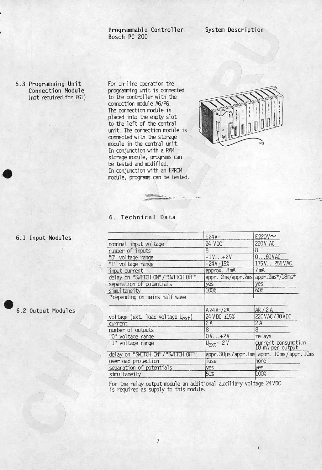
5.3 Programming Unit
Connection Module
(not required for PG1)
For on-line operation the
programming unit is connected
to the controller with the
connection module AG/PG.
The connection module is
placed into the empty slot
to the left of the central
unit. The connection module is
connected with the storage
module in the central unit.
In conjunction with a RAM
storage module, programs can
be tested and modified.
In conjunction with an EPROM
module, programs can be tested.
6. Technical Data
6.1 Input Modules E24V= E22OV~
nominal input voltage 24 VDC 220 V AC
' number of inputs 8 8
"0" voltaqe ranqe -1V...+2V 0... 60 VAC
"1" voltage range +24V£L5% 175V...255VAC
input current approx. 8mA 7 mA
delay on "SWITCH ON'V'SWITCH OF" appr. 2ms/appr.2ms appr.2ms*/18ms*
separation of potentials lyes yes
simul taneity 100% 60%
^depending on mains half wave
6.2 Output Modules A24V=/2A AR/2A
voltage (ext. load voltage UPXt) 24VDC ±15% 220VAC/30VDC
current 2A 12T-
number of outputs 8 F"
"0" voltaqe ranqe 0V...+2V relays
"1" voltage range Uexf current consumption 10 mA per output
delay on "SWITCH OtT/'^ITCH OF" appr. 30ps/appr. 1ms appr. 10ms/appr. 10ms
overload protection fuse none
separation of potentials yes yes
simultaneity 50% 100%
For the relay output module an additional auxiliary vol1 is required as supply to this module. age 24 VDC
7
System Description
Prograrrenable Controller
Bosch PC 200
6.3 Timer Modules
6.5 PC 200 System
6.4 Power Supply Module
(auxiliary voltage)
T T
nimber of timer channels 4 8
time range 0.07.Д >0 s 0.07...50 s
time adjustment coarse adjustment into two ranges: range I: 0.07 ... range II: 0.7 ... by a switch 5 s 50 s
fine adjustment by a potentiometer on the front plate. Connection of a tire measuring instrurent to set very short tires, via test points on the front plate.
connection voltages: as under 6.5 PC 200 System
output voltage: 24 VDC
output current: 0.6A
__ _
units: basic unit rack to take up to 8 modules
extension unit rack to take ' up to 8 modules
modules: input modules 24VDC, 8 inputs 220VAC, 8 inupts
output modul es 24 VDC/2 A, 8 outputs relay 220VAC/2A; 30VDC/2A; 8 outputs
timer modul es 8(4) timer analogue tire range: channels, 0.07...50s
program storage: RAM, storage capacity 4 К EPROM, storage capacity 2 К or 4 К
central unit: for up to 128 inputs and 128 outputs
cycle time: 10 ms / 1 К
temporary stores: 512, either all remanent / all non-remanent, selectable (outputs, which are not used, can be utilized as non-remanent taiiporary stores)
connection voltages - nominal value: - tolerance: - admissible frequency range: 220 V -15%, +10% 48 Hz - 63 Hz 110V or 115V -15%, +10% 48 Hz - 63 Hz with ПОV 58 Hz - 63 Hz with 115V
power conscription 15 VA
ambient temperature: 0°C to +55°0, without forced ventilation
storage temperature: -25°0 to +65°C
humidity: class F to DIN 40040
mechanical stress: mounting into stationary, not vibration-free equipment
protection standard: IP 20 to DIN 40050
8
Programmable Controller
Bosch PC 200
System Description
7. Order Details
Description Order No.
PC 200 Basic Unit For 220 VAC mains connection 247 041764 For 115 VAC mains connection 247 046425 Spares: Central unit 447 041762 Paver supply module for internal voltage supply (220 V) 447 038383 Paver supply module for internal voltage supply (115 V) 447 046434 Module rack 447 038382
PC 200 Extension Unit Spares : Module rack Connection cable 447 038385 447 038382 447 038386
Storage Modules 2 К EPROM proGraii storage module— 4 К EPROM program storage module 4 К RAM program storage module 447 041761 447 041610 447 041612
Modules Input module, E 24 V DC, 8 inputs Input module, E 220 VAC, 8 inputs Output module, A 24 VDC/2 A, 8 outputs Output module, relay, 8 outputs Timer module, 4 timer channels Timer module, 8 timer channels Programming unit connection module Paver supply module -/auxiliary voltage 447 038396 447 041193 447 038397 447 041192 447 038615 447 038398 447 041763 447 041577
Programming Units / Programming Unit PG 1 247 046200
Accessories Programming Unit PG 2 Programming Unit PG 3 UV eraser device for EPROM storage modules AC Load Power Supplies: Primary: 380V/ 3-phase Secondary: 24VDC - output current: 6 A - output current: 10 A - output current: 20 A - output current: 40 A 247 046516 247 043082 043475 EL 3000-6 EL 3000-10 EL 3000-20 EL 3000-40
9
@ BOSCH
Flexible Automation
Representative in Scandinavia
ROBCON OY
Ruosilankuja ЗА Telex 125316 robco sf
P.O.Box 9 Tel. (+358-0) 541144
SF -00391 Helsinki 39
Finland
Robert Bosch GmbH
Geschaftsbereich Industrieausriistung
Produktabteilung
Elektronische Steuerungen
Berliner StraBe 25
D-6120 Erbach/Odenwald
Telefon: (06062) 78-1
Telex: 419816-10 rbd
Produktabteilung
Maschinenbau und
Montagetechnik
KruppstraBe 1
D-7000 Stuttgart 30
Telefon: (0711) 811-1
Telex: 72527440-441
Produktabteilung
Automatisierungssysteme
Auf der Breit 4
D-7500 Karlsruhe 41
Telefon: (0721) 40091
Telex: 7826663 rb kh d
Produktabteilung
Entgrattechnik
KruppstraBe 1
D-7000 Stuttgart 30
Telefon: (0711) 8115309
Telex: 7213440