/


Похожие


Текст
Software Pioneers
Springer
Berlin
Heidelberg
New York
Barcelona
Hong Kong
London
Milan
Paris
Tokyo
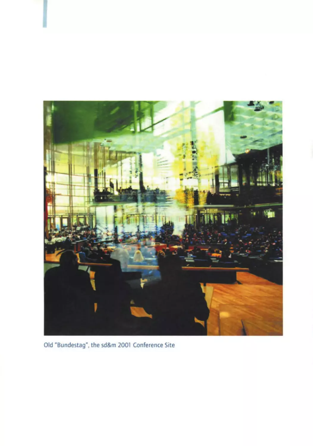
Old " Bundestag ", the sd&m 2001 Conference Site
Manfred Bray • Ernst Denert (Eds.)
Software Pioneers
Contributions to Software Engineering
Springer
4
Prof. Dr. Manfred Broy
Professor of Informatics
at Technische Universitat MOnchen
Prof . Dr. Ernst Denert
Chairman of the Supervisory Board
ofsd&m AG
Dr. rer. nat. in Informatics.
Technische Universitat MOnchen
• leibniz Award, Bundesverdienstkreuz
• Member European Academy of
Sciences, IEEE Board of Governors
• Major contributions : concurrent distributed systems, systematic development
of interactive systems
•
•
•
•
•
•
sd&m Conference Software Pioneers
took place at the old "Bundestag"
(parliament building) in Bonn, Germany,
28/29 June 2001
Dr. -Ing. in Informatics,
Technische Universitat Berlin
Honorary Professor at
Technische Universitat MOnchen
Cofounder, former managing director
and CEO ofsd&m AG
Software design and project
management for several large business
information systems
Major contributions: software architec ture for business information systems.
author of Software Engineering
sd&m AG, software design & management
Consulting and Software for Custom
Information Systems
sd&m develops customized software for
business information systems and Internet
applications supporting the customers'
core business processes, and provides IT
conSUlting. Based on its core competence
- software engineering - sd&m realizes
large projects for a broad variety of applications on all common system platforms.
For more information on facts and figures.
software engineering. projects, the team
and culture. see www.sdm.de.
M. 8to): E. Dencrt(Eds.):SoftwolePionem
o Springer-Verlogktlin
2002
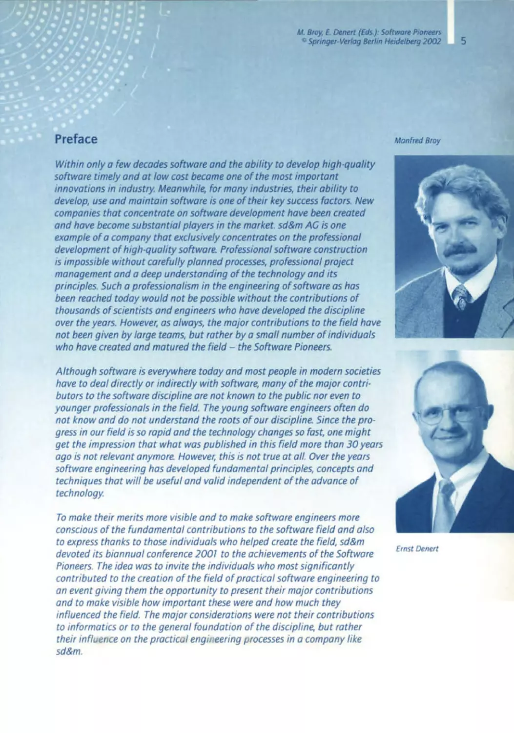
ManfredBroy
Within only a few decadessoftware and the ability to develop high-quality
software timely and at low cost became one of the most important
innovations in industry. Meanwhile, for many industries,their ability to
develop, use and maintain software is one of their key success factors. New
companiesthat concentrateon software developmenthave been created
and have becomesubstantial players in the market. sd&m AG is one
example of a company that exclusivelyconcentrateson the professional
developmentof high-quality software. Professionalsoftwareconstruction
is impossiblewithout carefully planned processes, professionalproject
managementand a deep understandingof the technologyand its
principles.Such a professionalismin the engineeringof software as has
been reached today would not be possiblewithout the contributions of
thousandsof scientistsand engineerswho have developedthe discipline
over the years. However, as always, the major contributions to the field have
not been given by large teams, but rather by a small number of individuals
who have createdand matured the field - the Software Pioneers.
Although software IS everywheretoday and most people in modern societies
have to deal directly or indirectly with software, many of the major contributors to the softwaredisciplineare not known to the public nor even to
younger professionalsin the field. The young softwareengineersoften do
not know and do not understand the roots of our discipline.Since the progress in our field is so rapid and the technologychangesso fast, one might
get the impression that what was published in this field more than 30 years
ago is not relevantanymore. However, this is not true at all. Over the years
software engineeringhas developedfundamental principles,conceptsand
techniquesthat will be useful and valid independentof the advance of
technology.
To make their merits more visible and to make software engineersmore
consciousof the fundamental contributions to the software field and also
to express thanks to those individuals who helped create the field, sd&m
devoted its biannual conference2001 to the achievementsof the Software
Pioneers. The idea was to invite the individuals who most Significantly
contributed to the creation of the field of practical software engineeringto
an event giving them the opportunity to present their major contributions
and to make visible how important these were and how much they
influencedthe field. The major considerations were not their contributions
to informatics or to the general foundation of the discipline, but rather
their influence on the practical englll eering processes in a ompany
c
like
sd&m.
Ernst Denert
5
6
We are glad and proud that most of the SoftwarePioneerswe invited
acceptedour invitation and thereforemade it possibleto have a conference
with such an impressivelist of speokers. The few that could not make it ond
turned down our invitation for good personalreasonsare acknowledged
at the end of the contribution by Ernst Denert. The conferencetook place in
Bonn, in the old -Bundestag-in June 2001. About 1200 people were in
attendonce- excitedand foscinatedby the presentationsof the Software
Pioneers.
To documentthe conferenceand the ever/ostingcontribution of the
pioneersthis volume wos put together after the conference.For each of the
pioneers, it contains a short contribution in which he looks back onto his
work from the perspectiveof today. In addition, it contains the most important historical publications of the SoftwarePioneers. The volumestarts
with a surveypaper by Ernst Denert in which he outlines the major contributions of each of the pioneersand puts their work into perspective.
The whole conferencewas recordedon video tapes. Therefore, we are glad
to put the lectures of the SoftwarePioneers in full length on four DVDs
together with a one hour excerptpreparedby Ernst Denertand some
impressionsfrom the conference. The DVDs supplementthis volume.
It is our pleasure to thank all of those who made the conferenceinto an
overwhelmingsuccess, first of all of course the SoftwarePioneers who not
only attended the conference,but helped us to prepare the selectionof the
historical papers and wrote their contribution for this volume in spite of
the fact that most of them are still very busy and engagedin many activi·
ties. In particular. we thank sd&m for sponsoringthe conference. We thank
the staff who helped to prepare the conference. in particular Ms. Carola
Lauber who did such an excellentjob in making sure that everythingran
smoothly both throughout the conferenceand afterwardsin preparing this
volume. We also thank the team of Springer·Verlag who was immediately
ready to publish first of all a conferencevolume, available directly at the
conferencewith all the historical contributions of the pioneers,and then
this volume after the conference. which puts everything into perspective.
Many thanks go also to those who helped to put this volume together.
We hope this volume shows very clearly the deep value of the contributions
of a small number of people to an emergingfield, which is changing and
maturing further even today and certainly will much more tomorrow. We
also hope that this volume is a contribution to the history of our young
disciplineand its documentation.
ManfredBroy
Ernst Denert
Munich, February2002
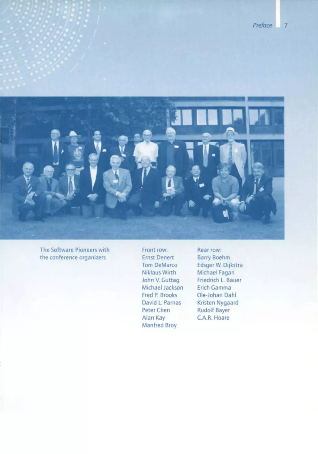
The Software Pioneerswith
the conferenceorganizers
Front row:
Ernst Denert
Tom DeMarco
Niklaus Wirth
John V. Guttag
Michael Jackson
Fred P. Brooks
David L Parnas
Peter Chen
Alan Kay
Manfred Broy
Rear row:
Barry Boehm
Edsger W. Dijkstra
Michael Fagan
Friedrich L. Bauer
Erich Gamma
Ole·Johan Dahl
Kristen Nygaard
Rudolf Bayer
CAR . Hoare
8
Manfred Broy
10 Software Engineering - From Auxiliary to Key Technology
Ernst Denert
14 The Relevance of the Software Pioneers for sd&m
Friedrich l. Bauer
26 From the Stack Principle to ALGOL
K.Samelson, F.L. Bauer
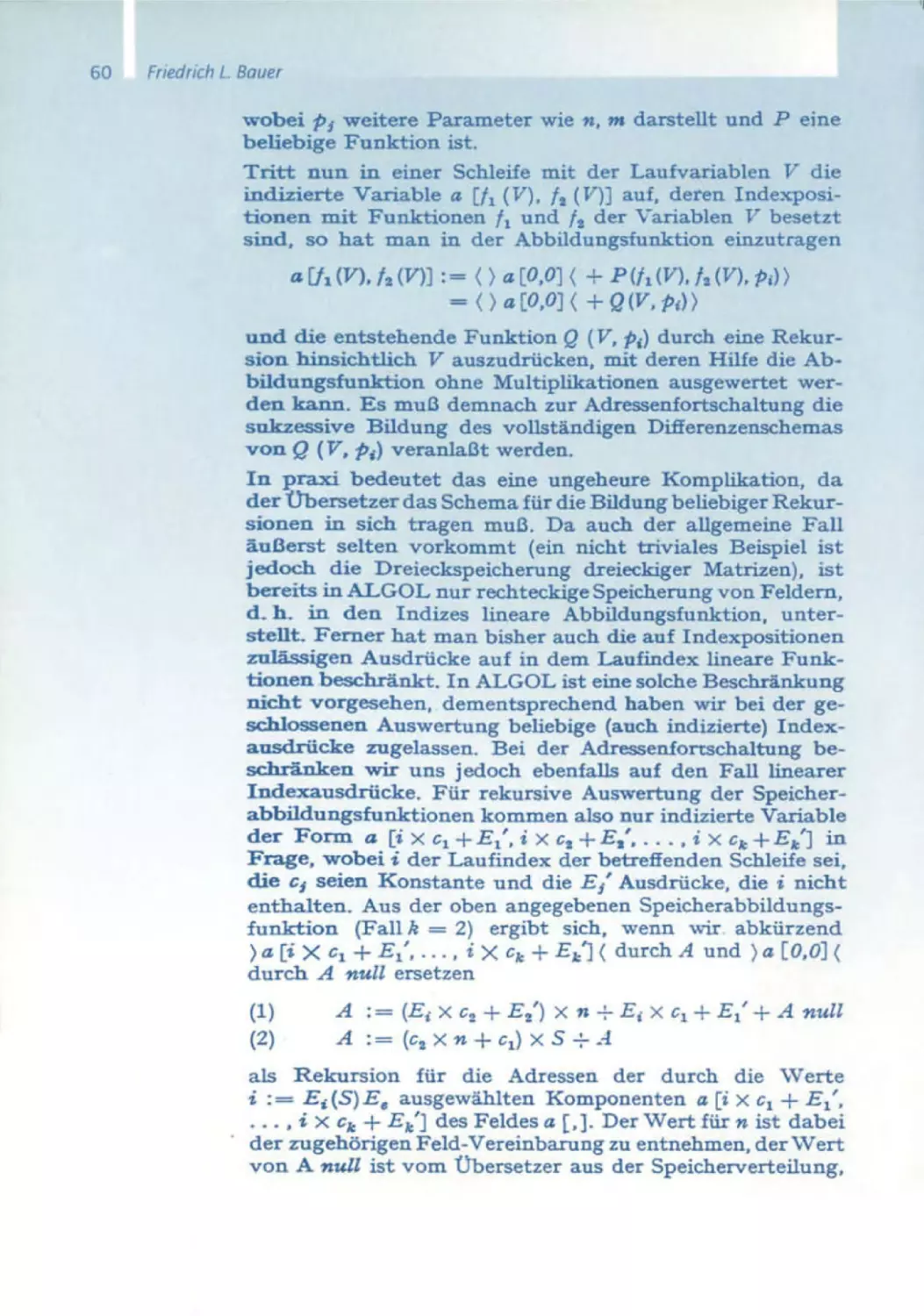
43 Sequentielle Formeliibersetzung
F.L. Bauer
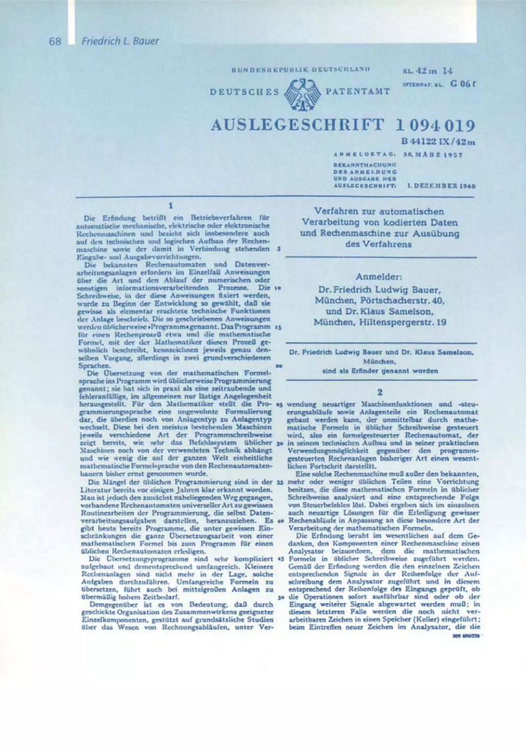
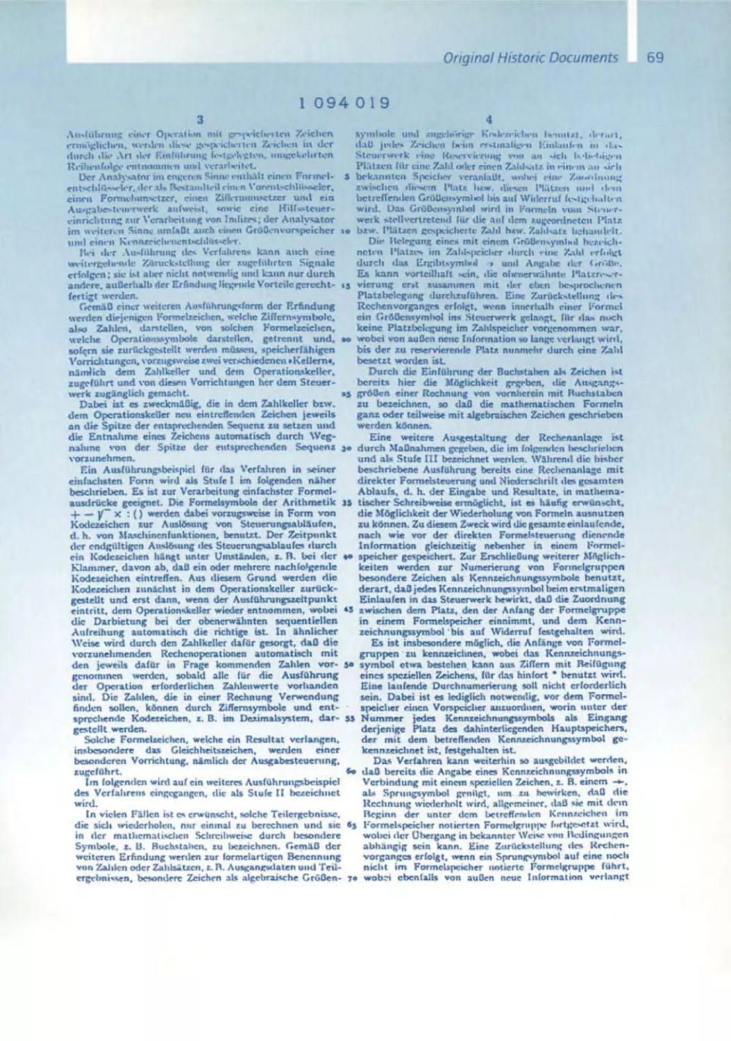
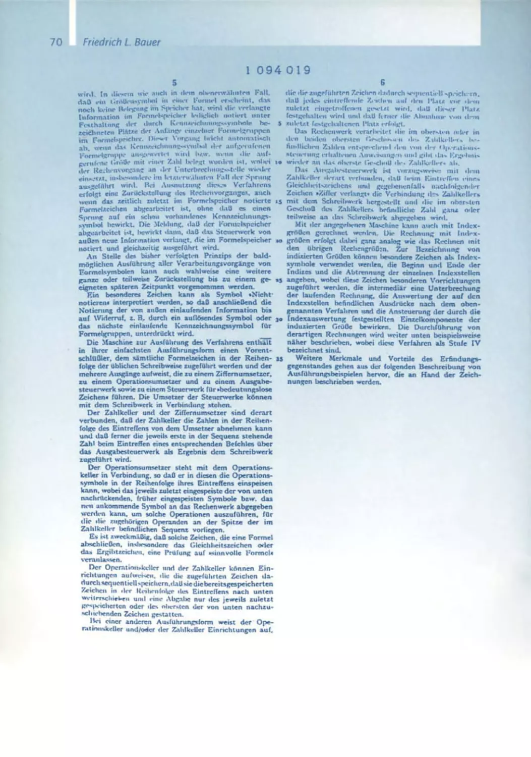
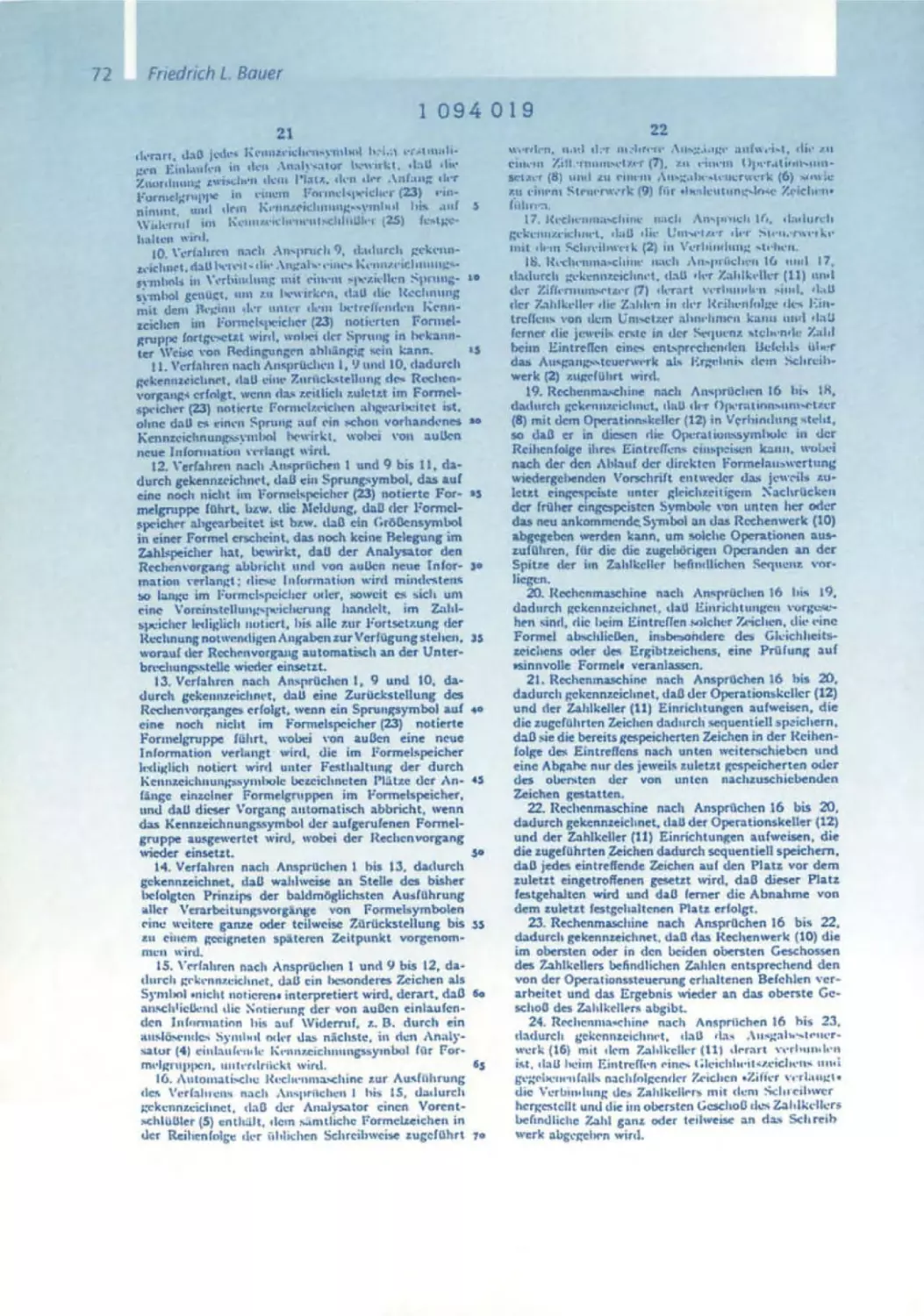
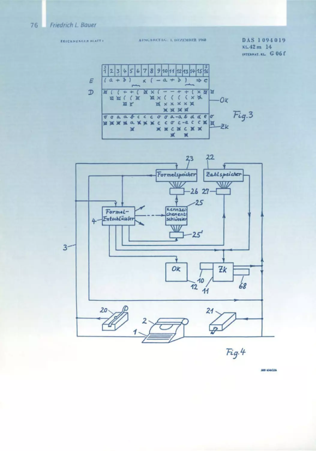
67 Verfahren zur automatischen Verarbeitung von kodierten Daten und
Rechenmaschinen zur Ausiibung des Verfahrens
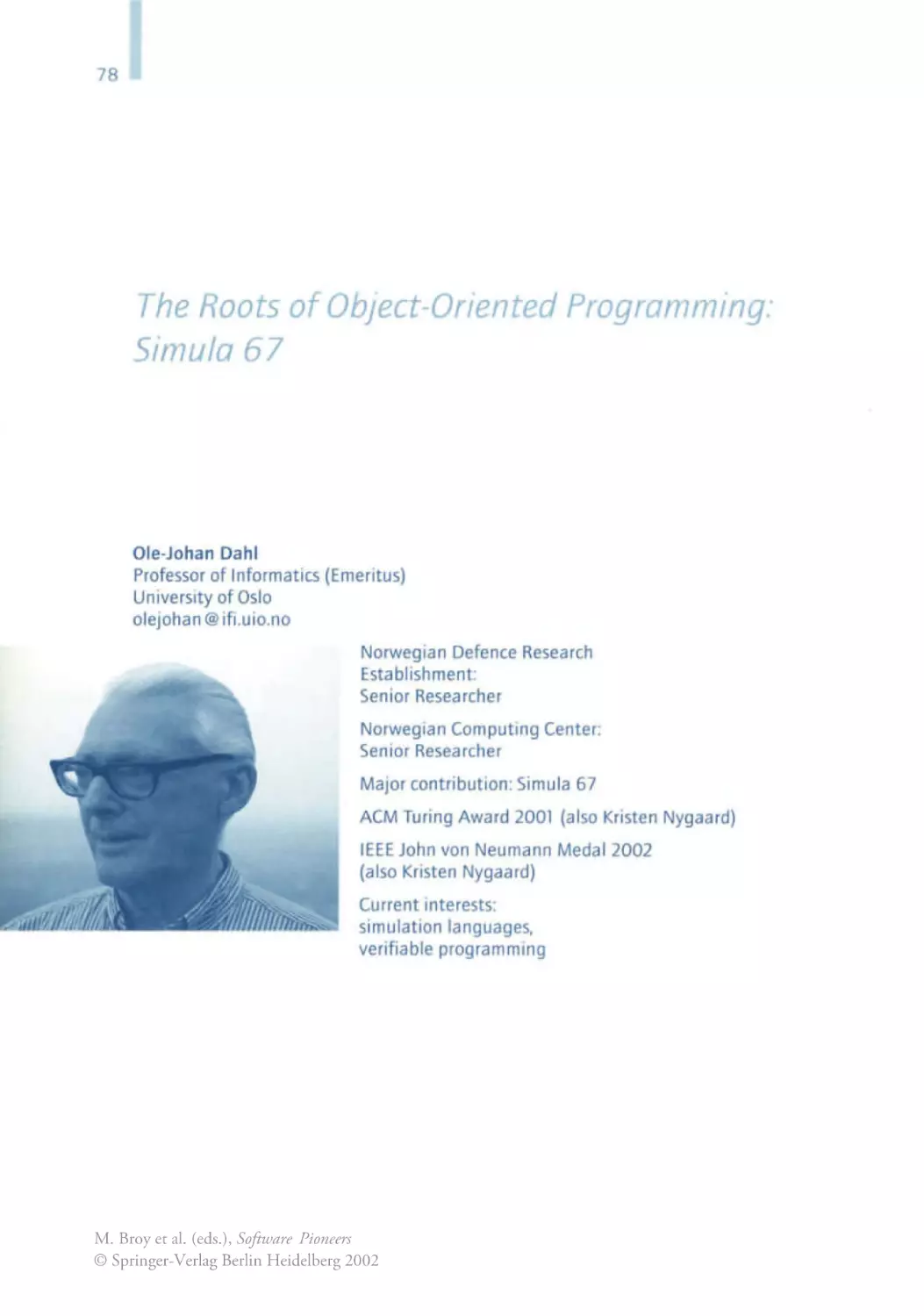
Ole-Johan Dahl
78 The Roots of Object Orientation : The Simuia language
Ole-Johan Dahl, Kristen Nygaard
91 Closs and Subclass Declarations
Niklaus Wirth
108 Pascal and Its Successors
1 21 The Programming Language Pascal
149 Program Development by Stepwise Refinement
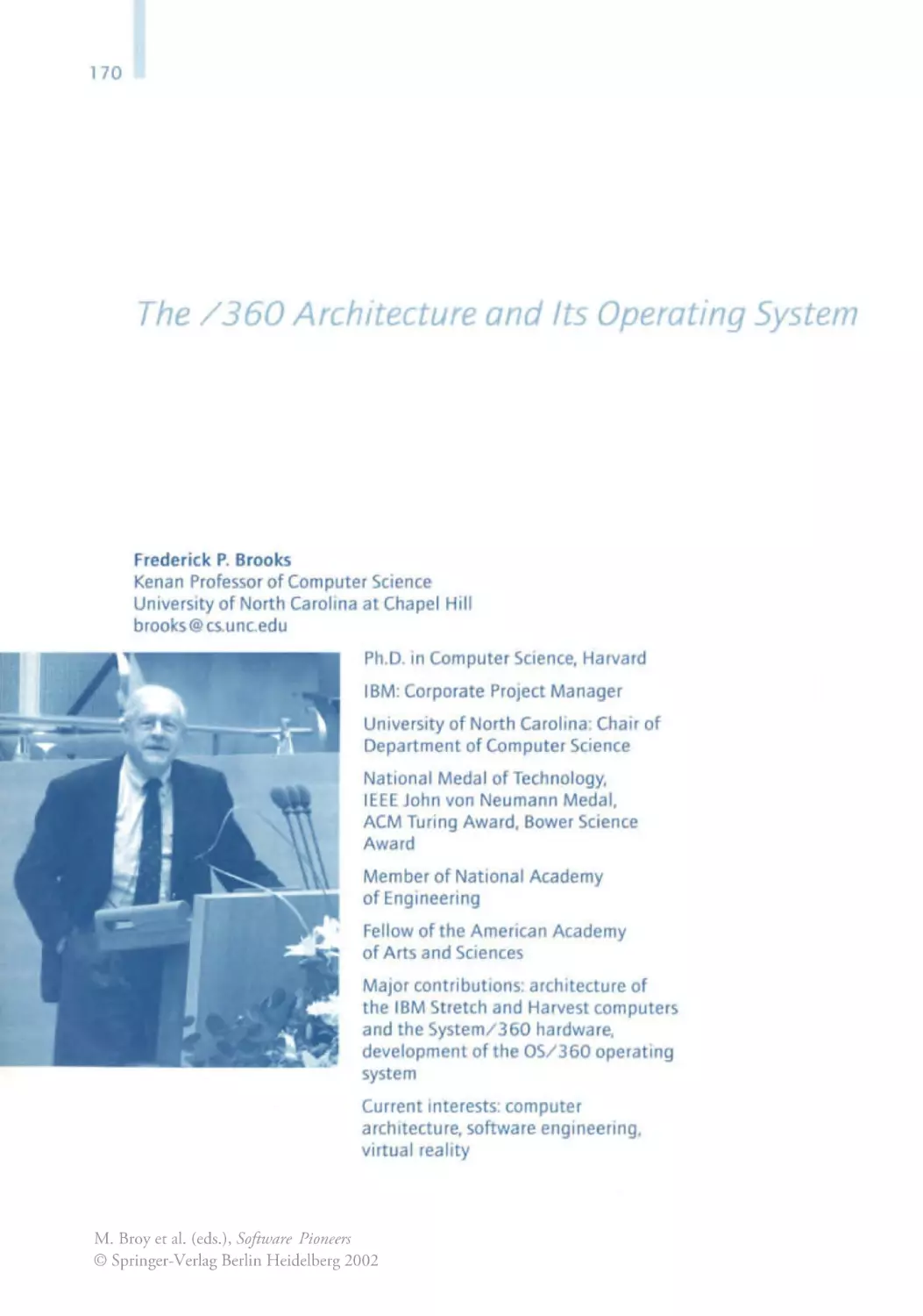
Frederick P. Brooks
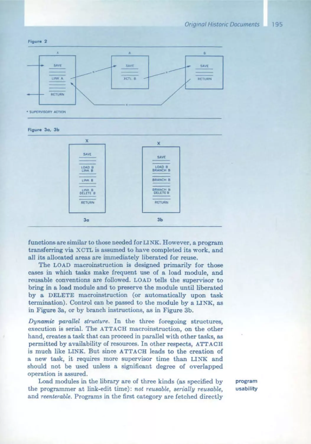
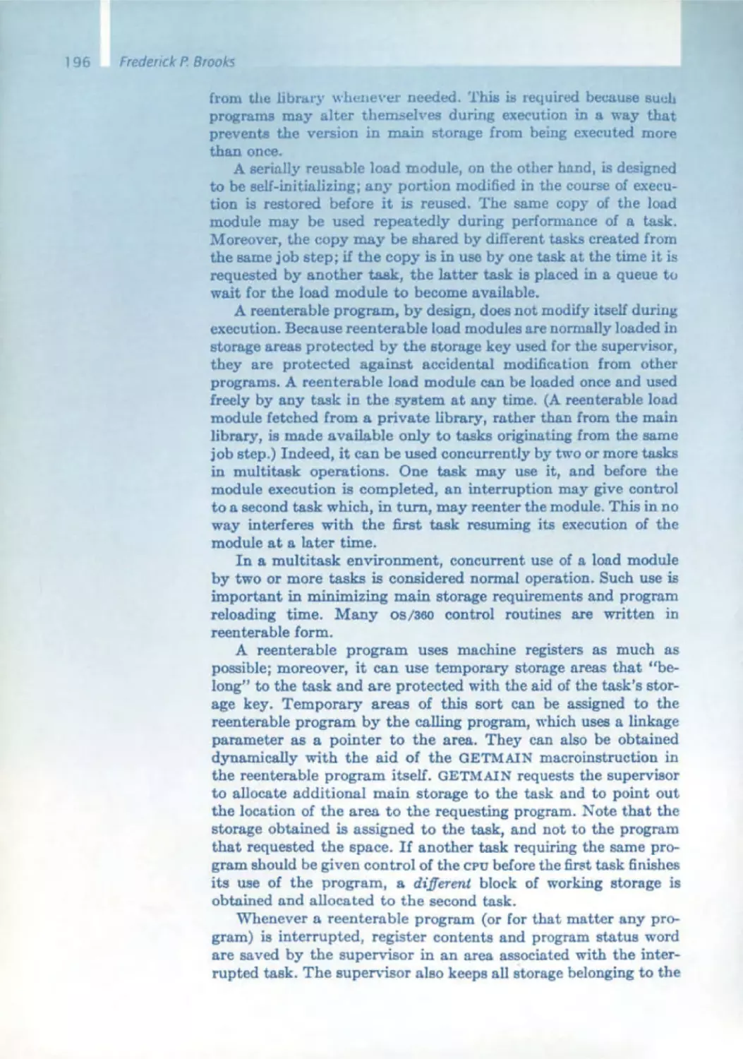
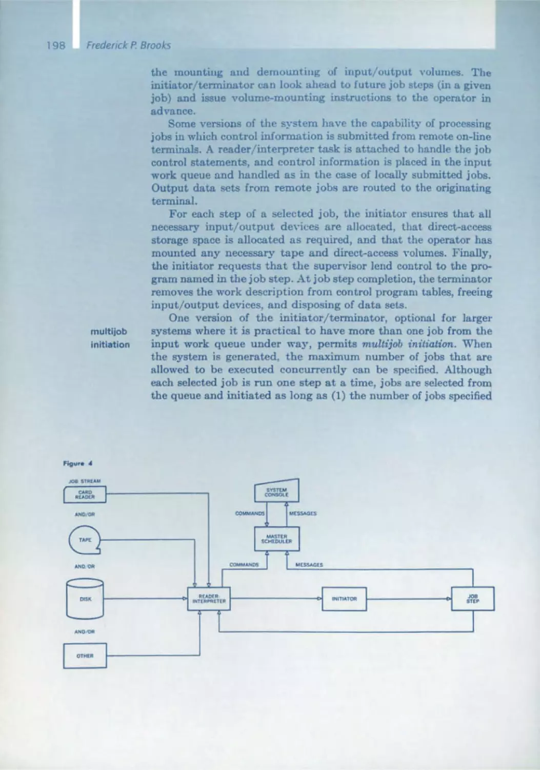
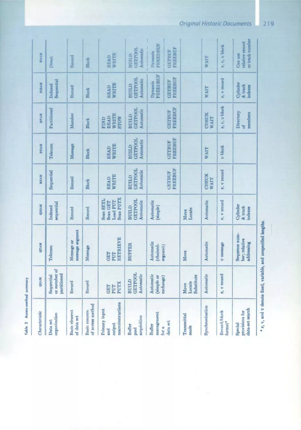
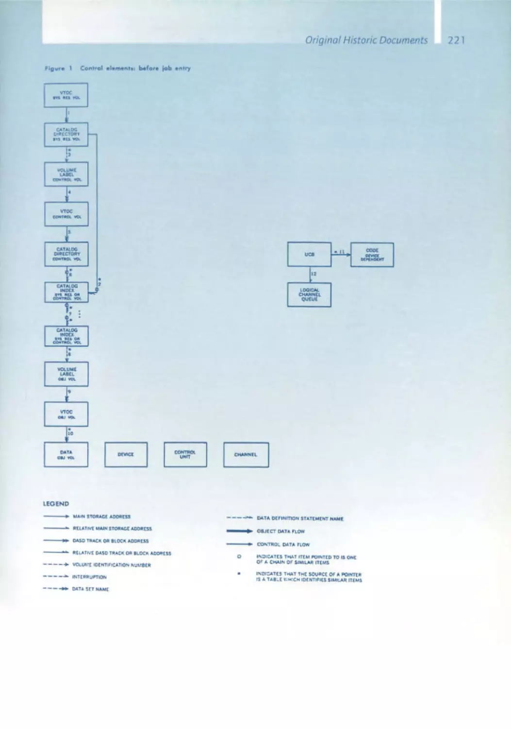
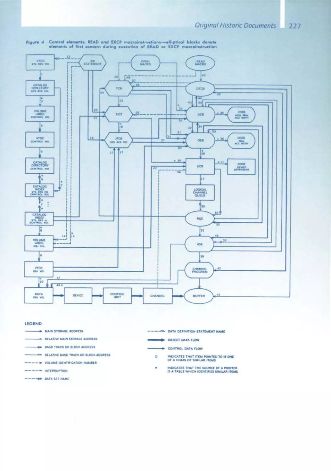
170 The IBM Operating System/360
C.H. Mealy, B.I. Witt, w.A. Clark
179 The Functional Structure of OSI360
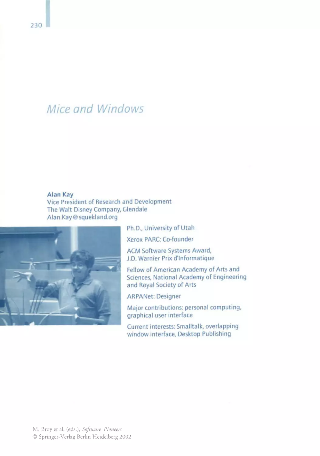
Alan Kay
230 Graphical User Interfaces
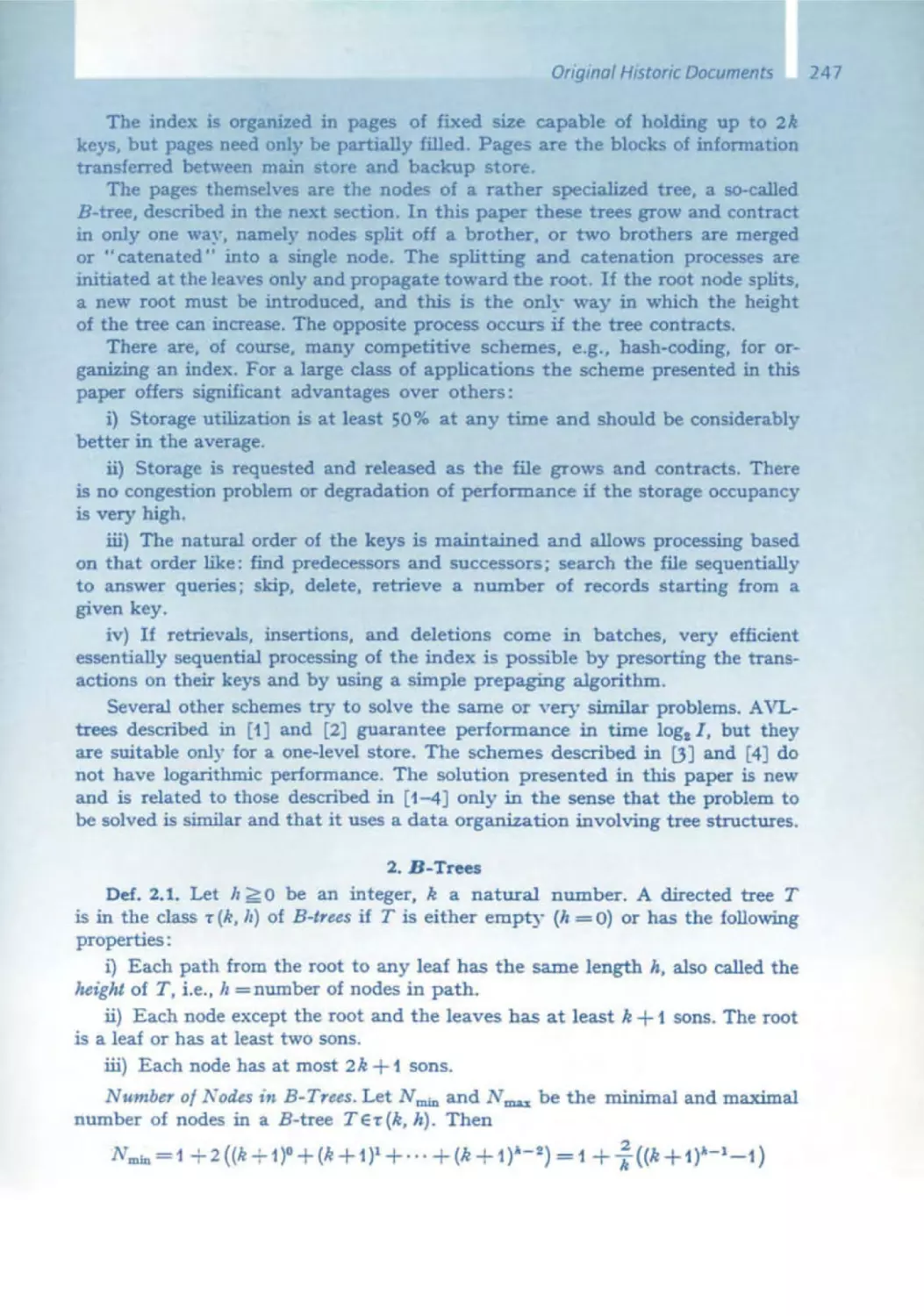
Rudolf Bayer
232 B-Trees and Databases, Past and Future
Rudolf Boyer, E. McCreight
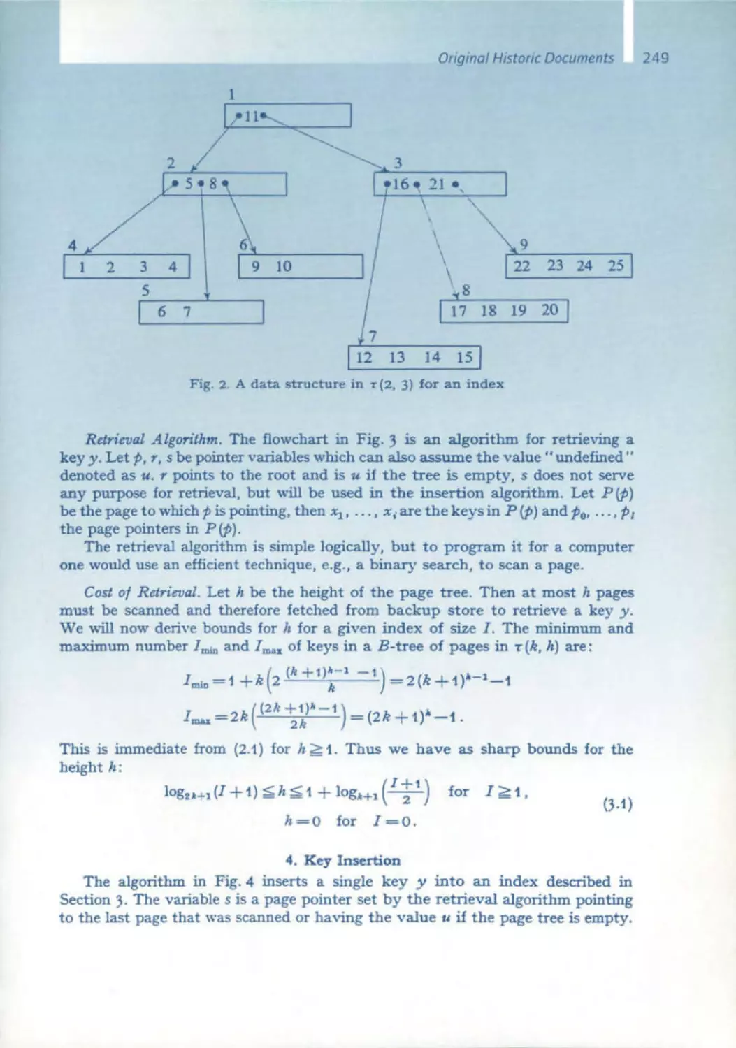
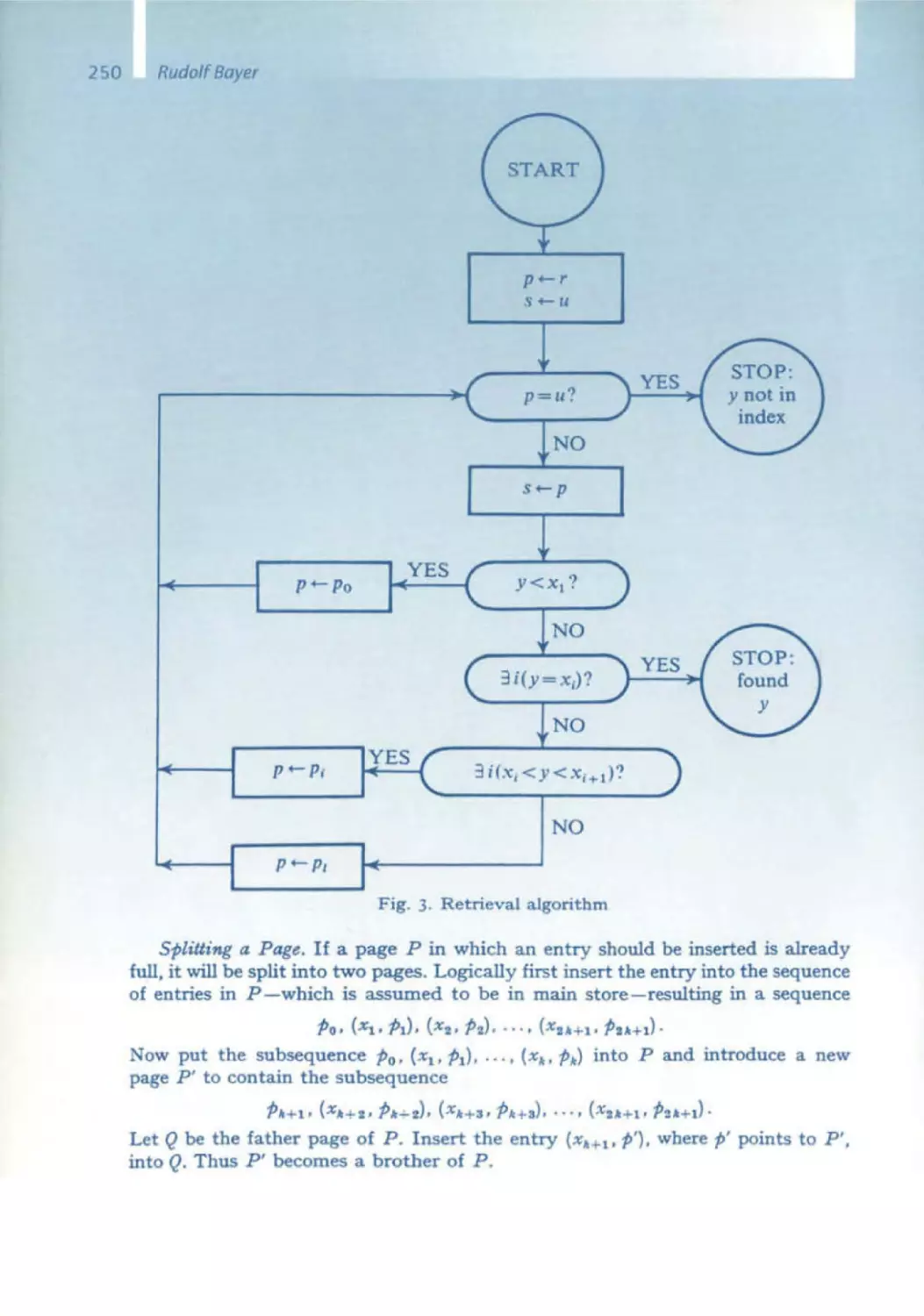
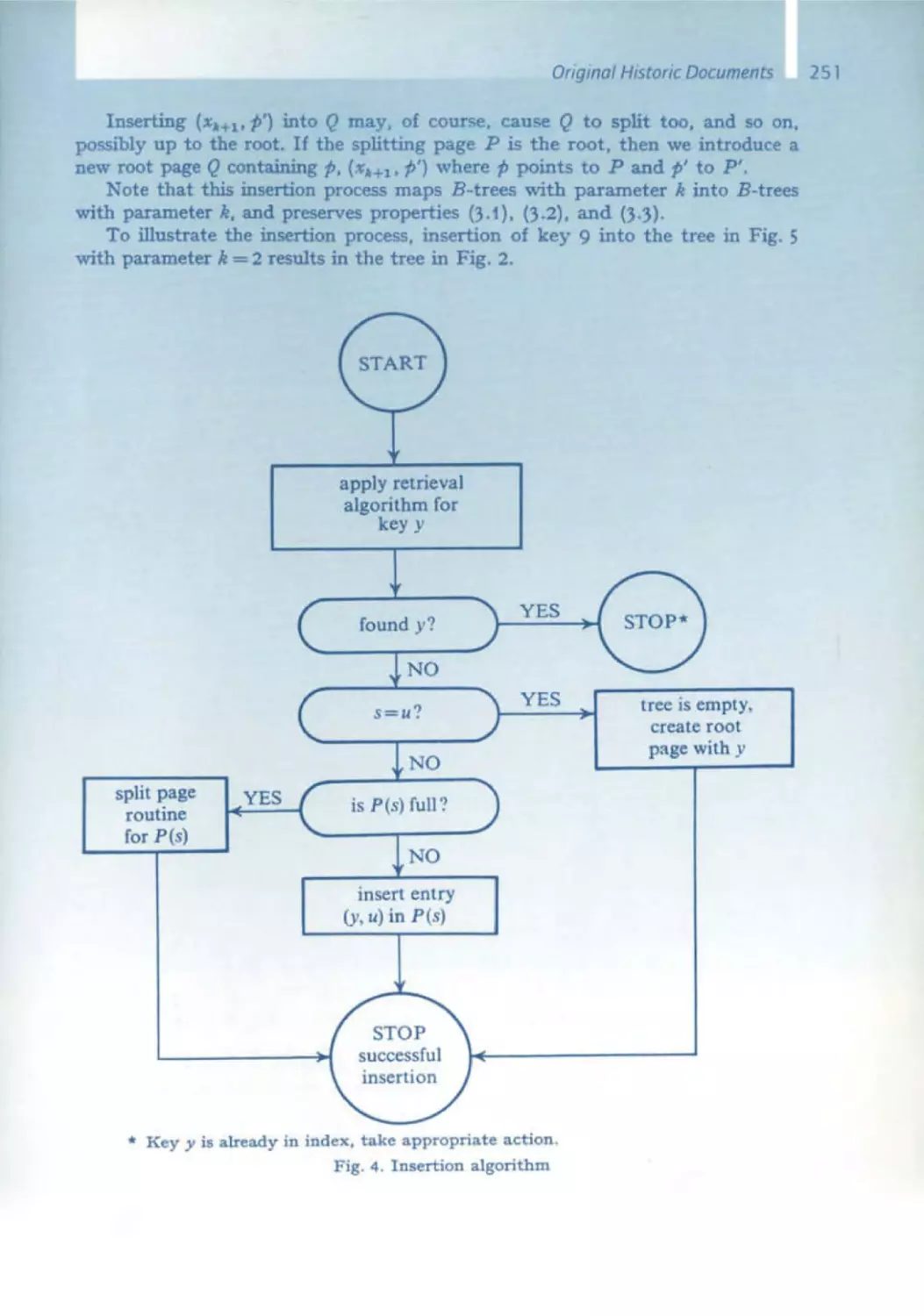
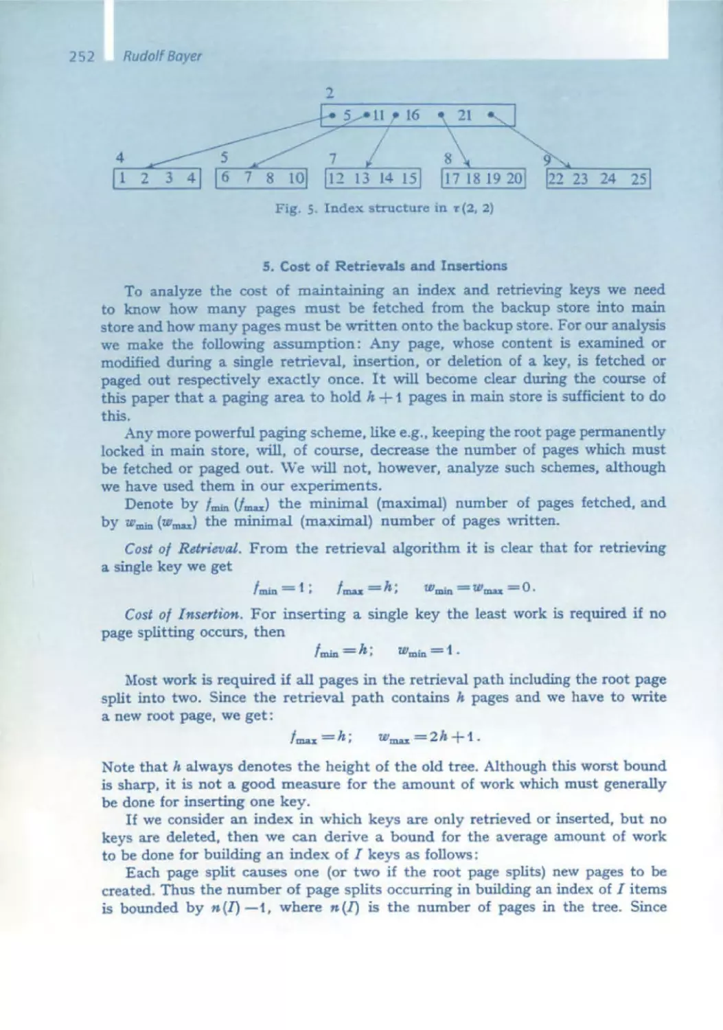
245 Organization and Maintenance of Lorge Ordered Indexes
E.F. Codd
263 A Relational Model of Data for Large Shored Data Bonks
9
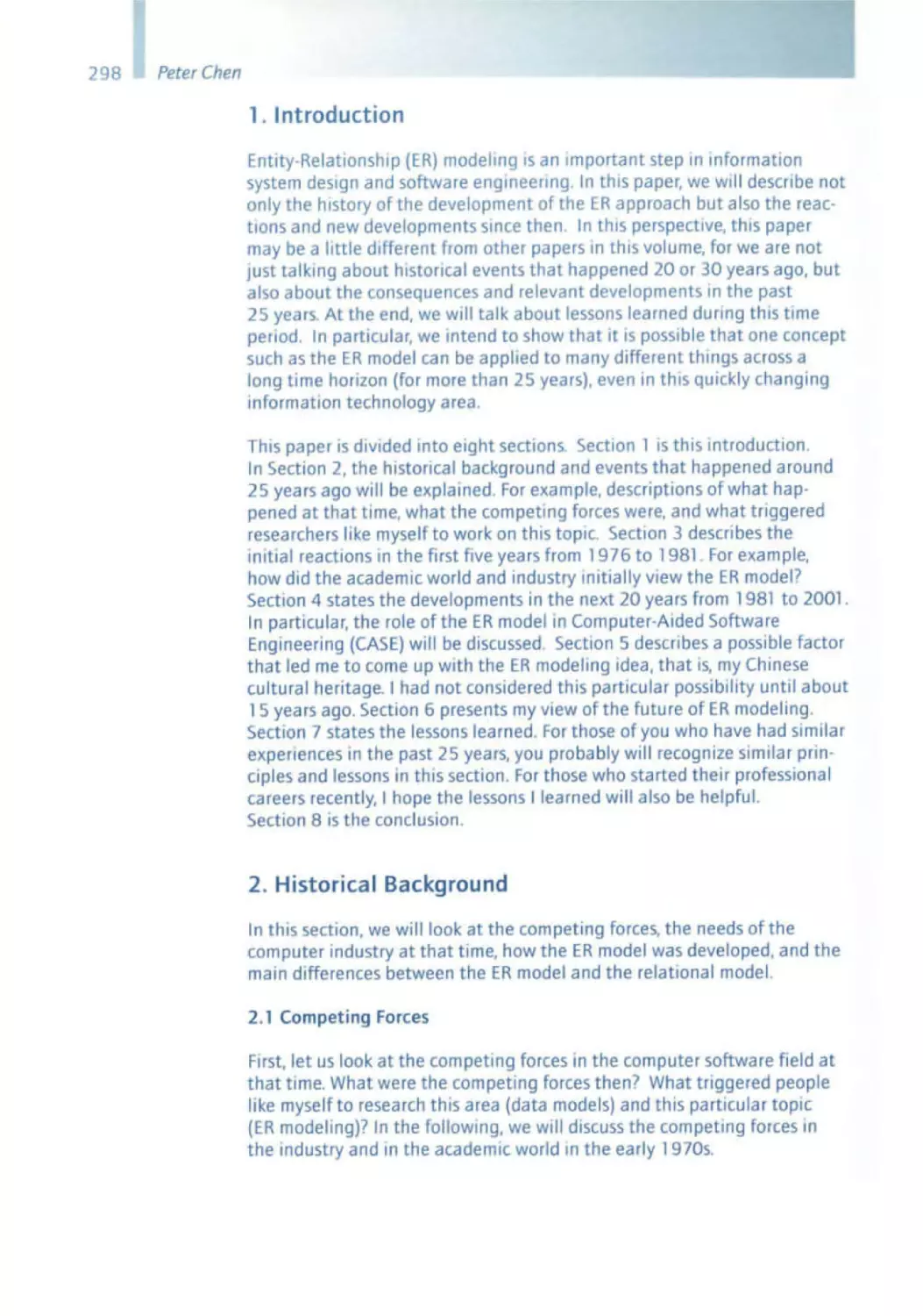
Peter Chen
296 Entity-Relationship Modeling: Historical Events.
Future Trends and Lessons Learned
311 The
Relationship Model- Toward a Unified View of Data
Edsger W. Dijkstra
340 EWD 1308: What Led to "Notes on Structured Programming"
347 Solution of a Problem in Concurrent Programming Control
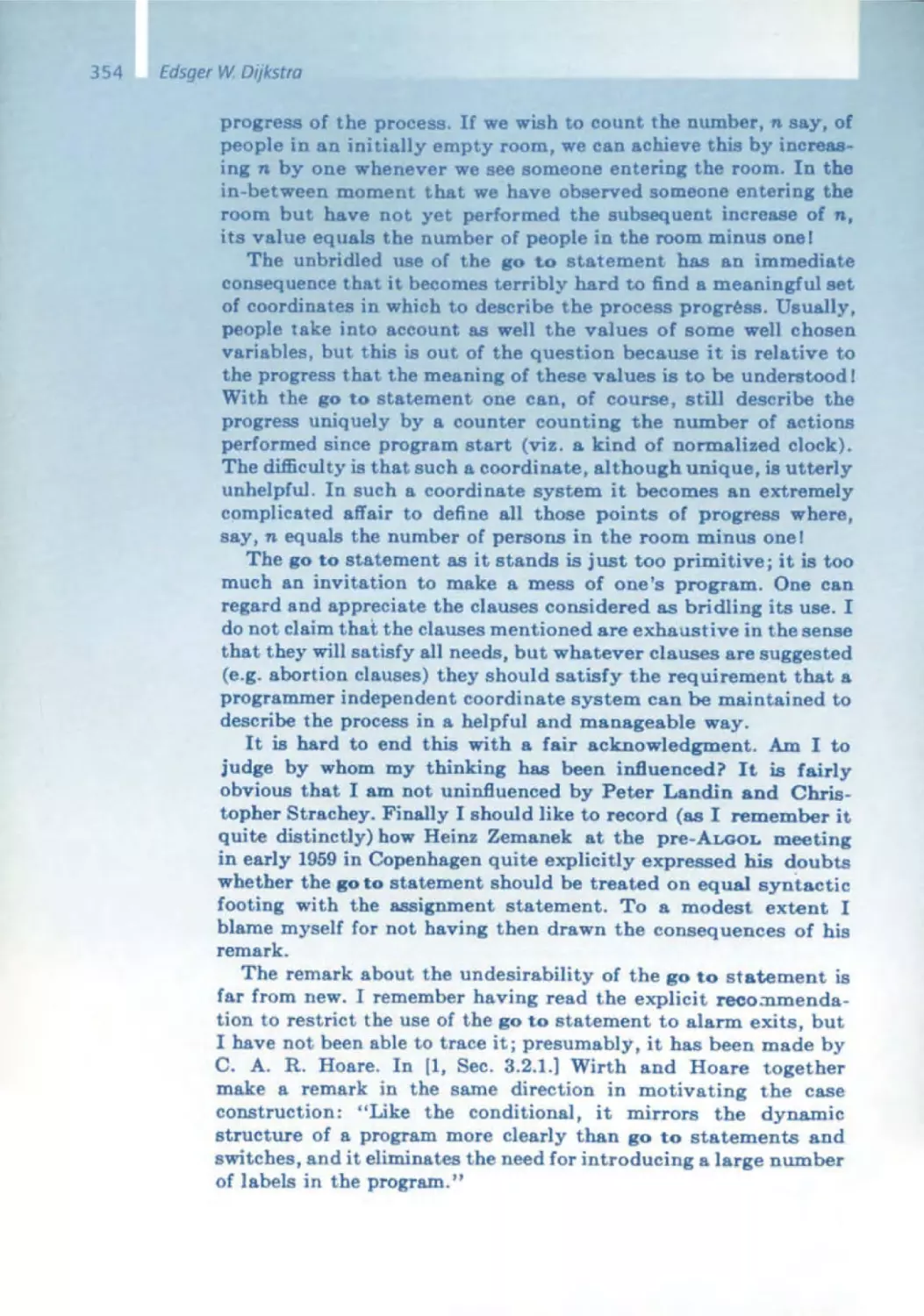
351 Go To Statement Considered Harmful
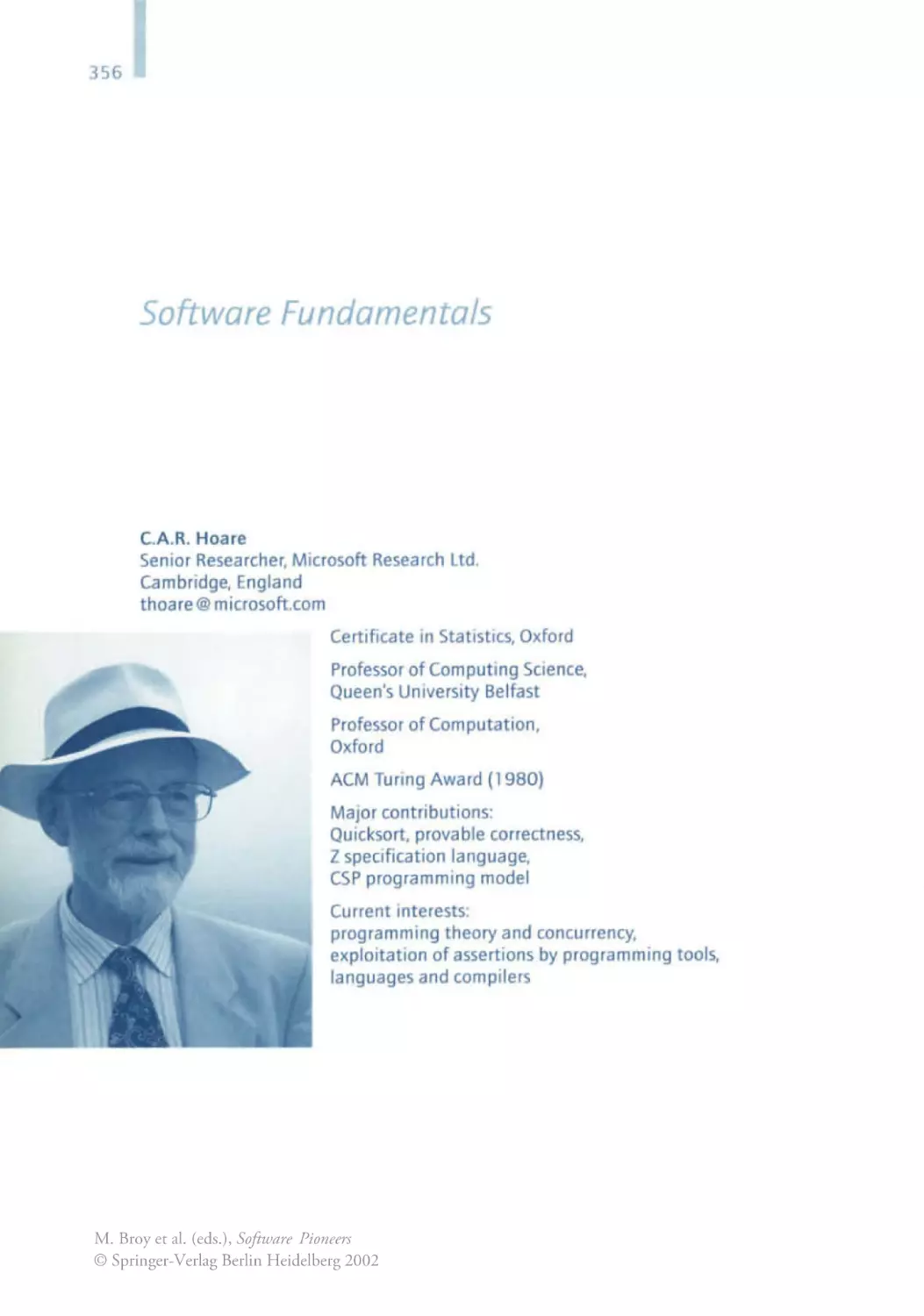
C.A.R. Hoare
356 Assertions: A Personal Perspective
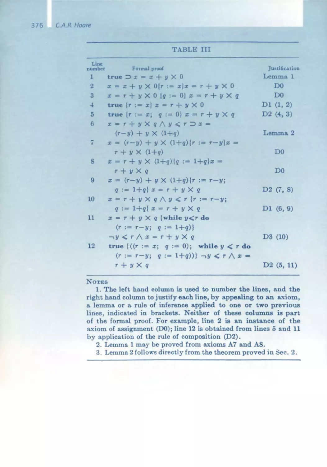
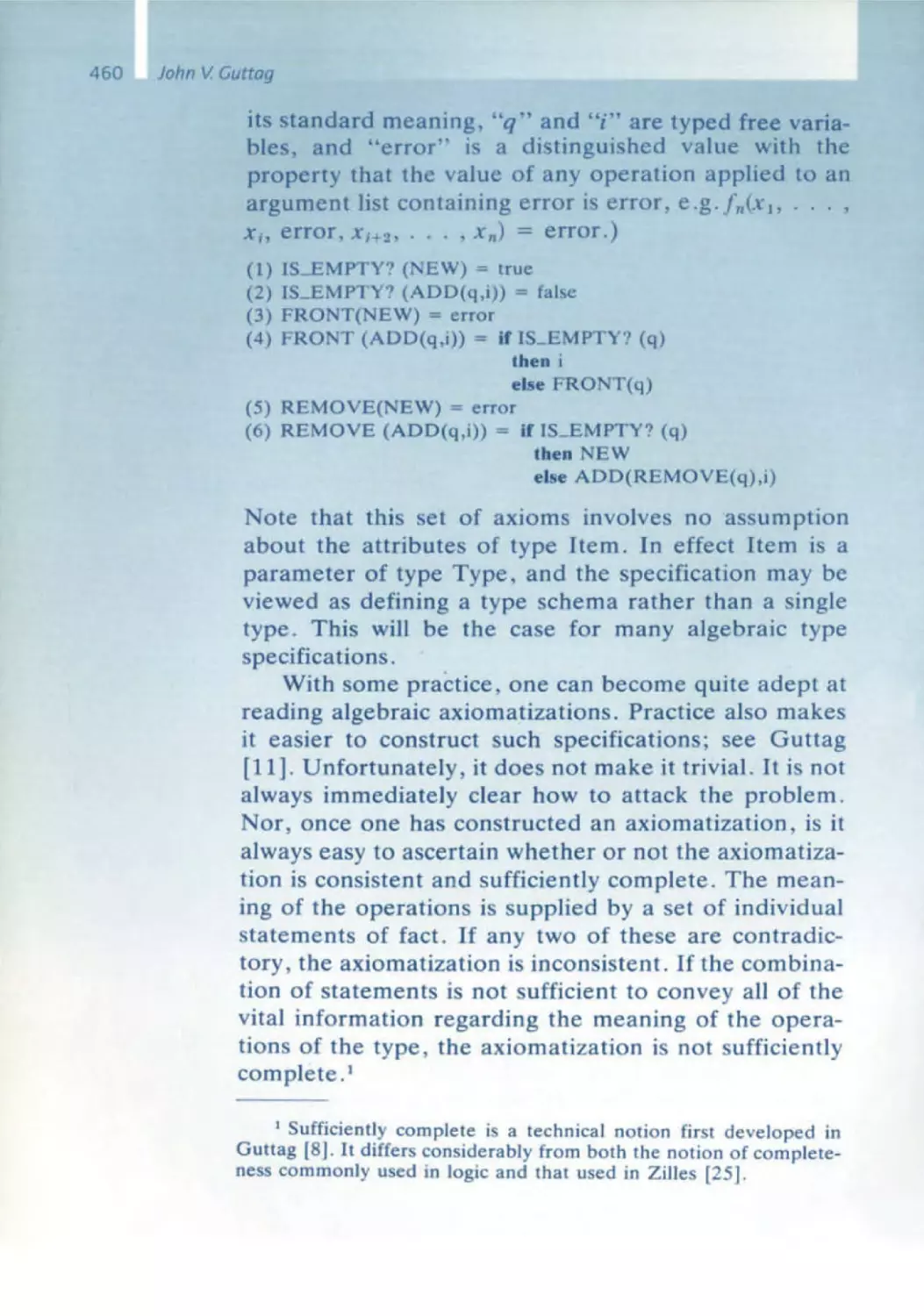
367 An Axiomatic Basis for Computer Programming
385 Proof of Correctness of Data Representations
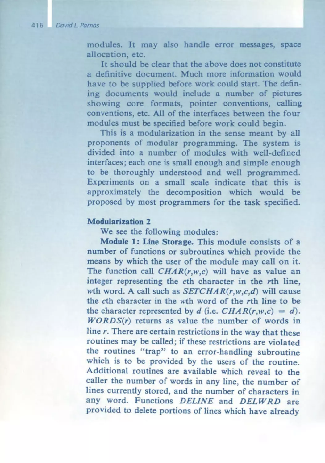
David l. Parnas
399 The Secret History of Information Hiding
411 On the Criteria to Be Used in Decomposing Systems into Modules
429 On a "Buzzword": Hierarchical Structure
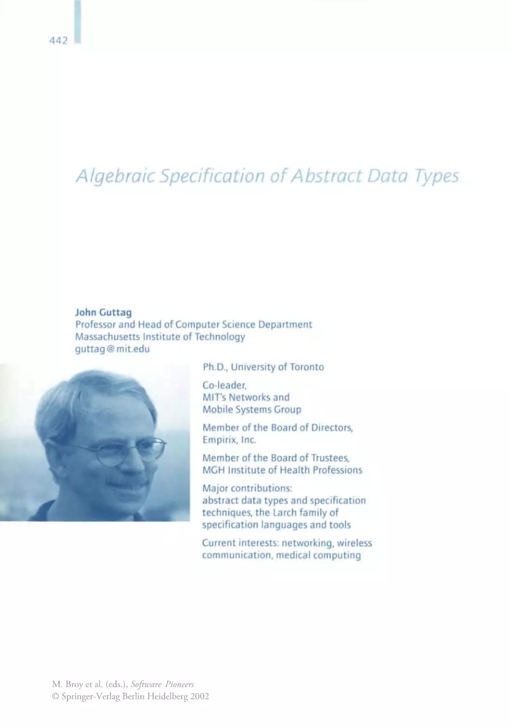
John V. Guttag
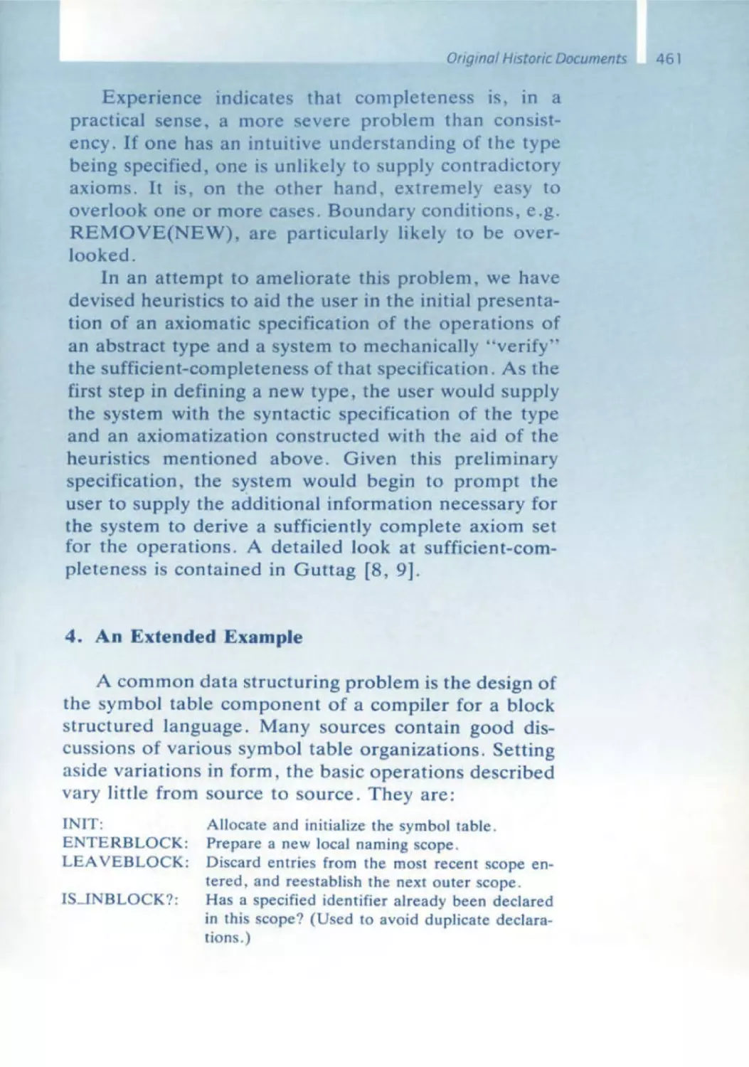
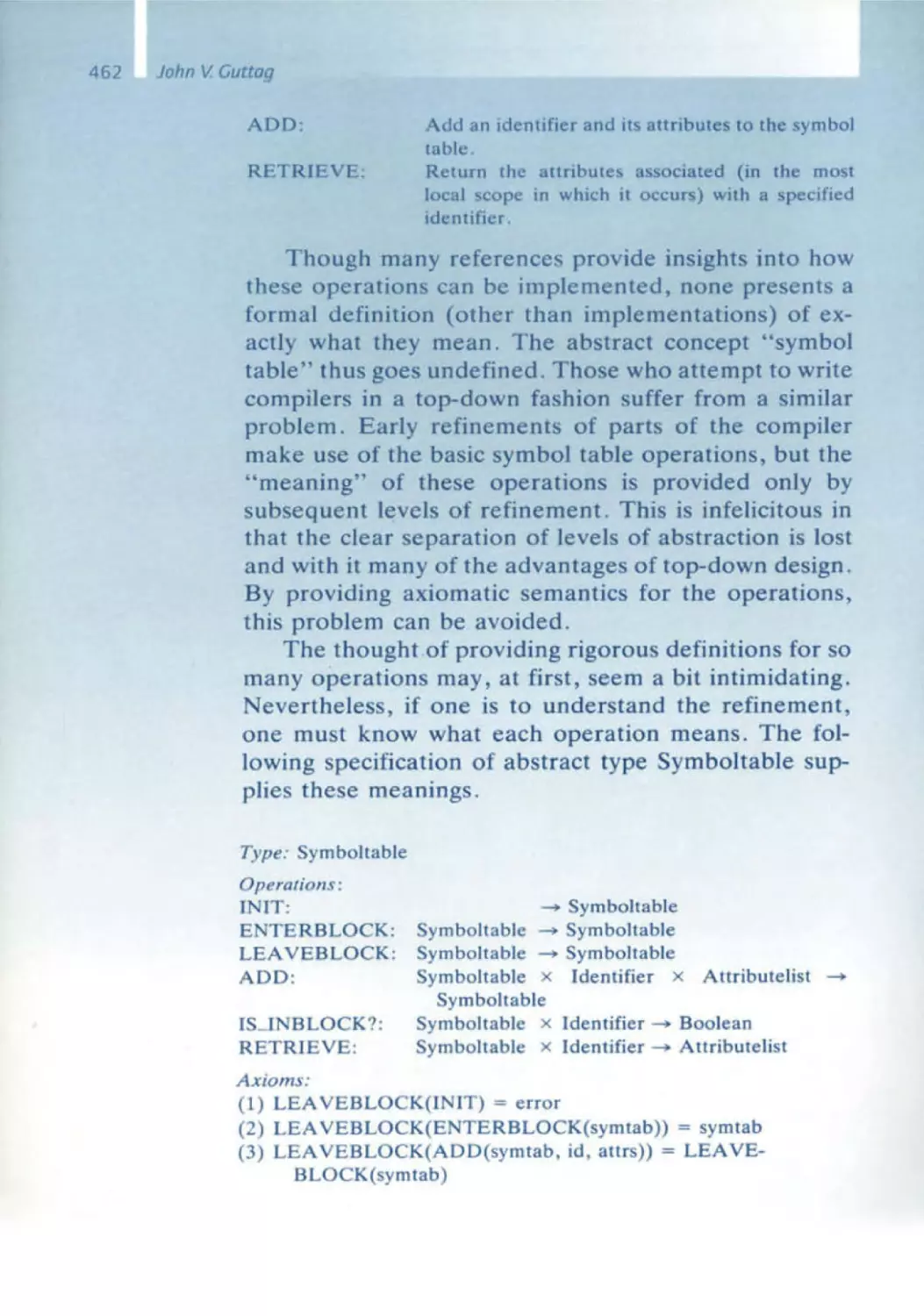
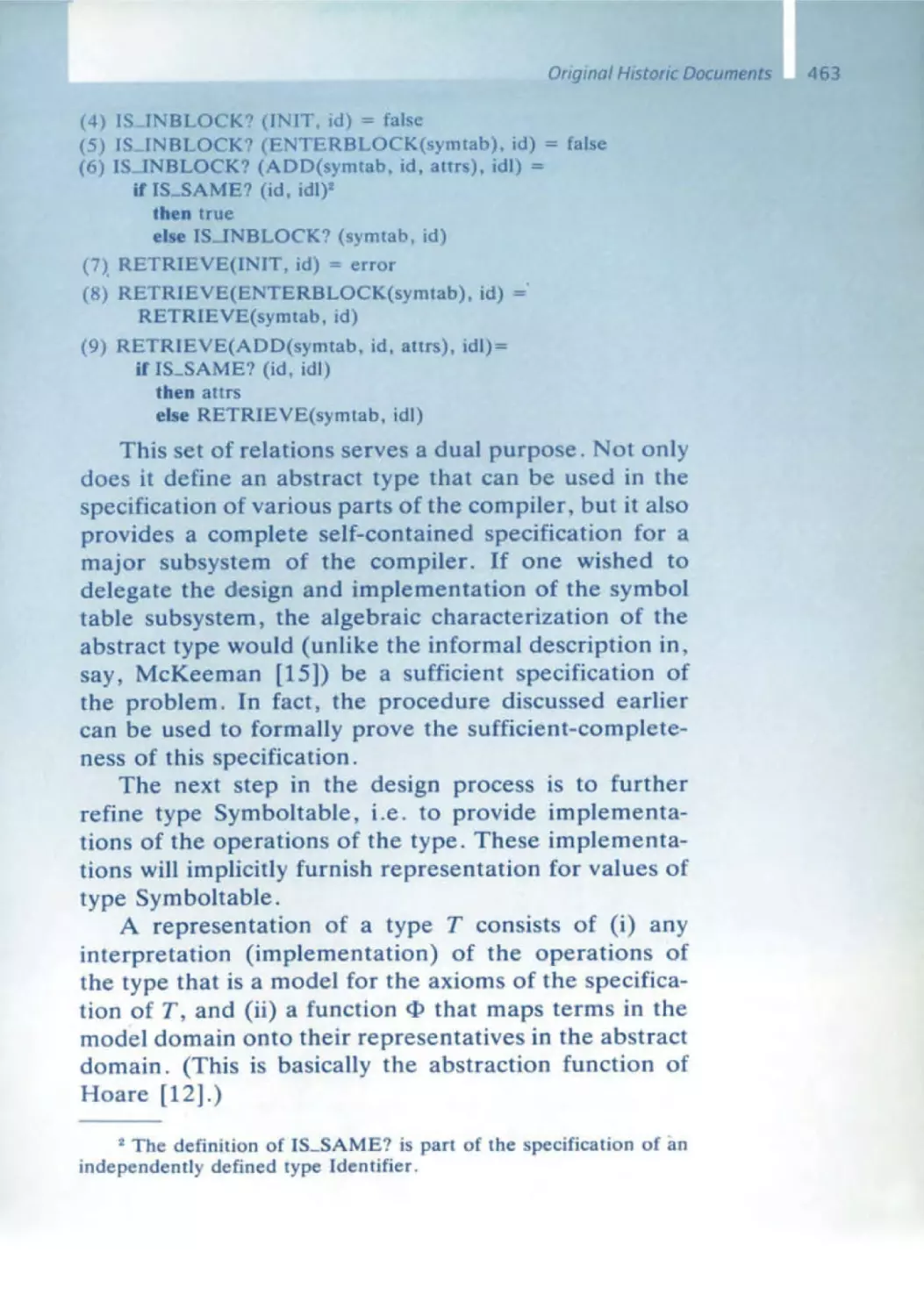
442 Abstract Data Types, Then and Now
453 Abstract Data Types and the Development of Data Structures
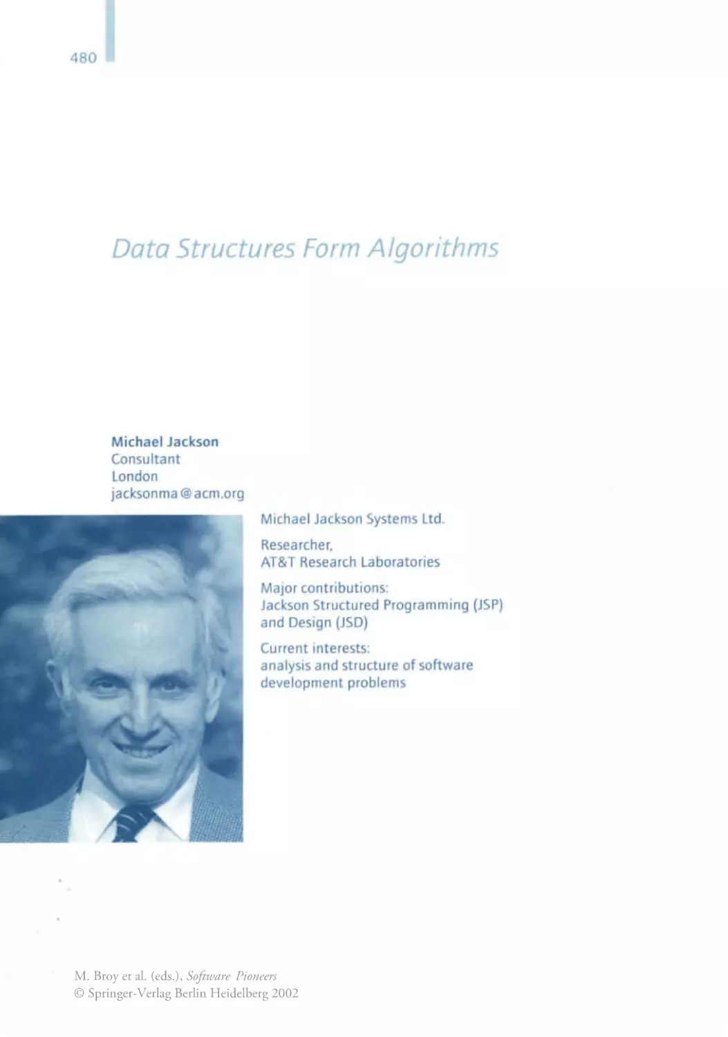
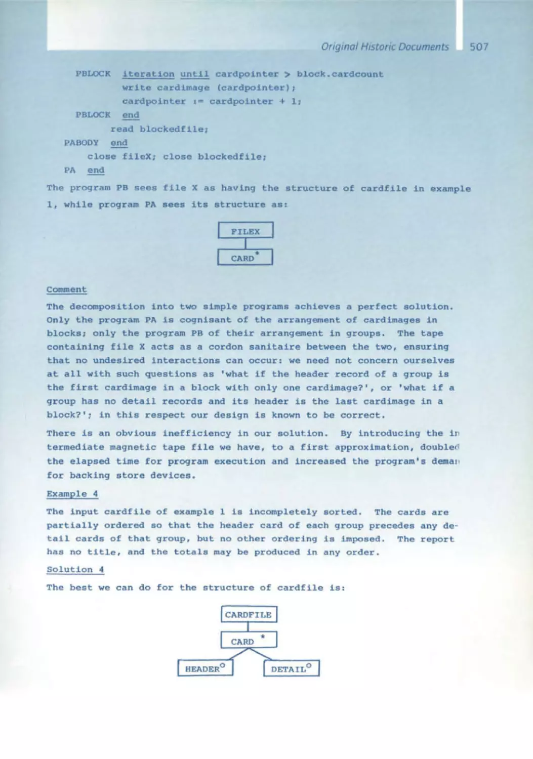
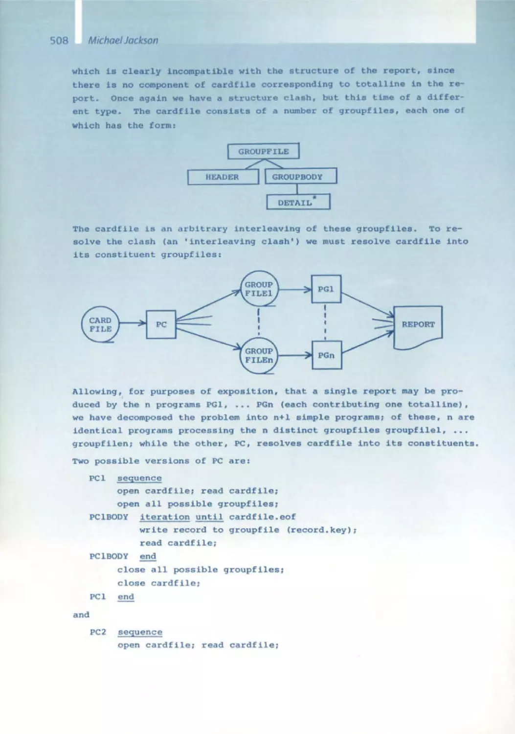
Michael Jackson
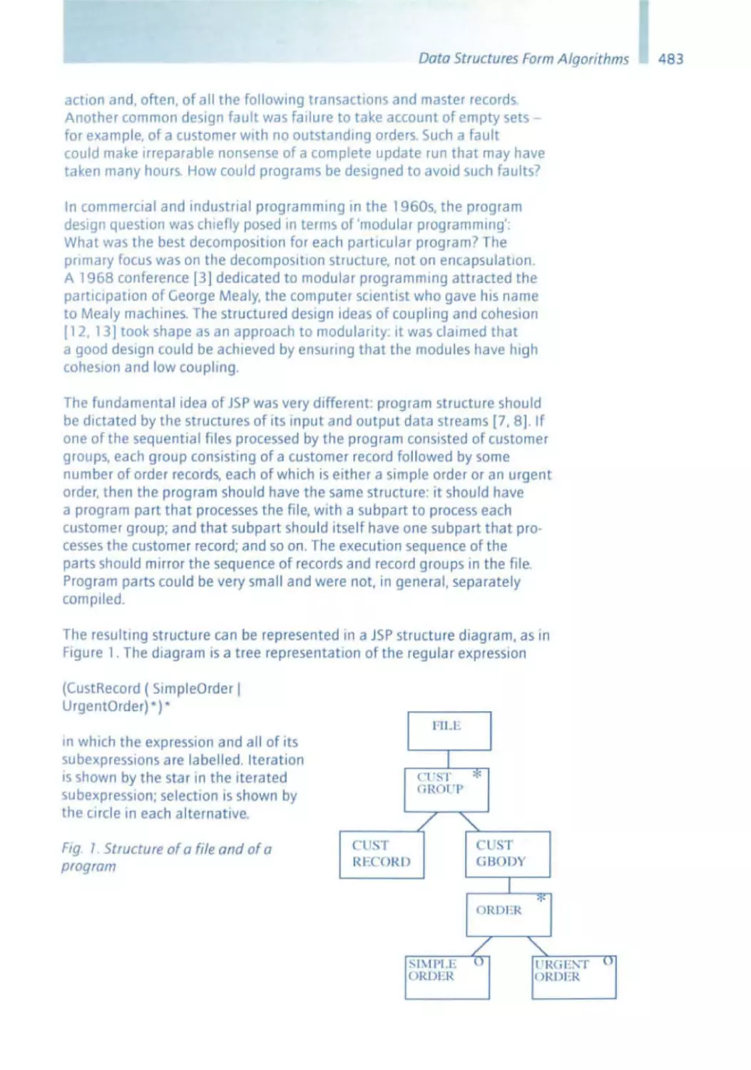
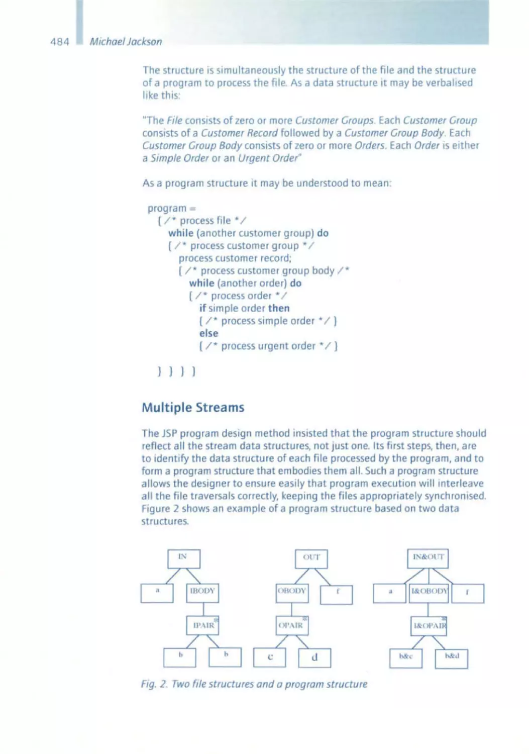
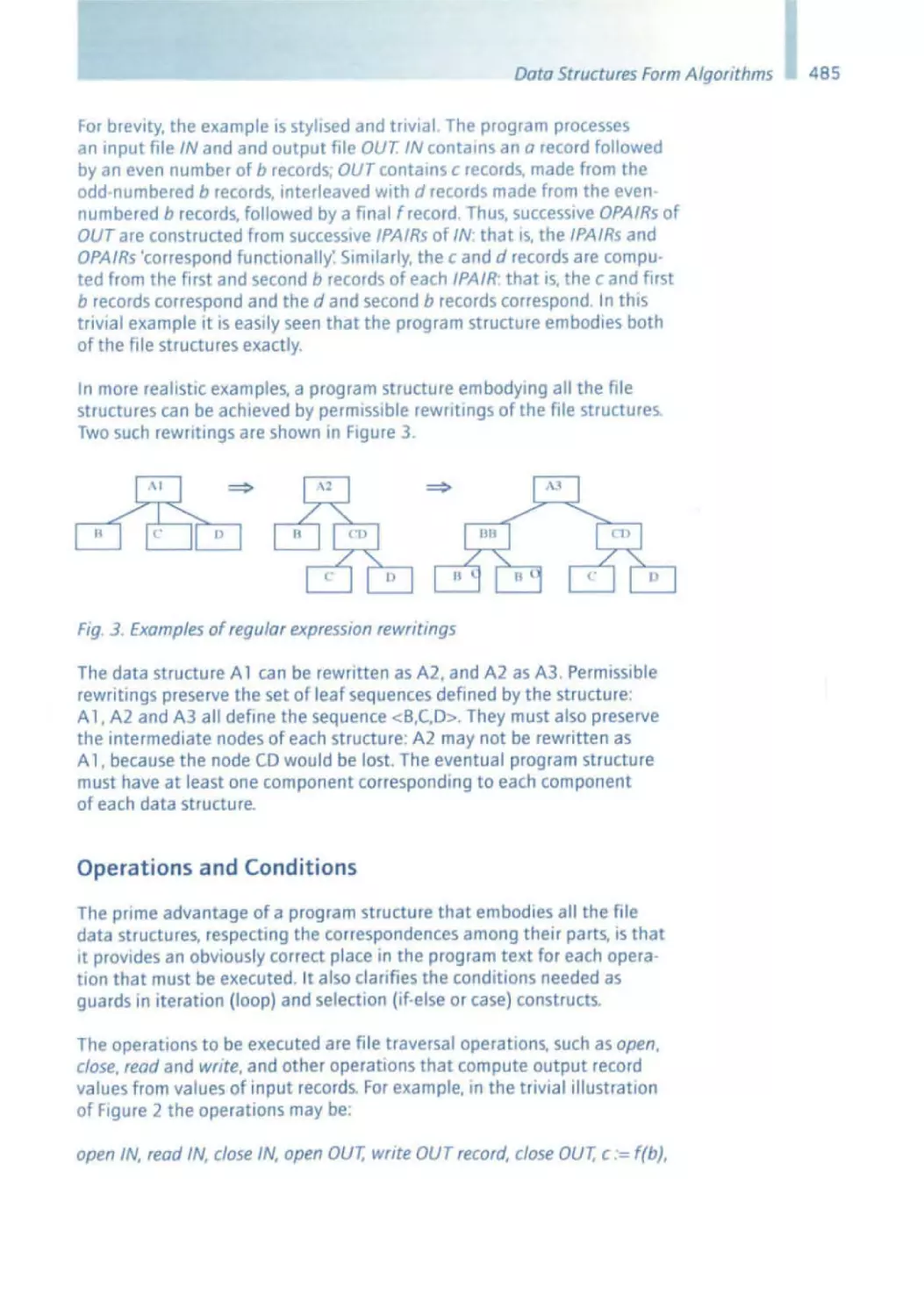
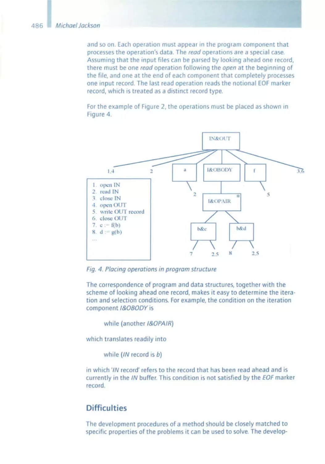
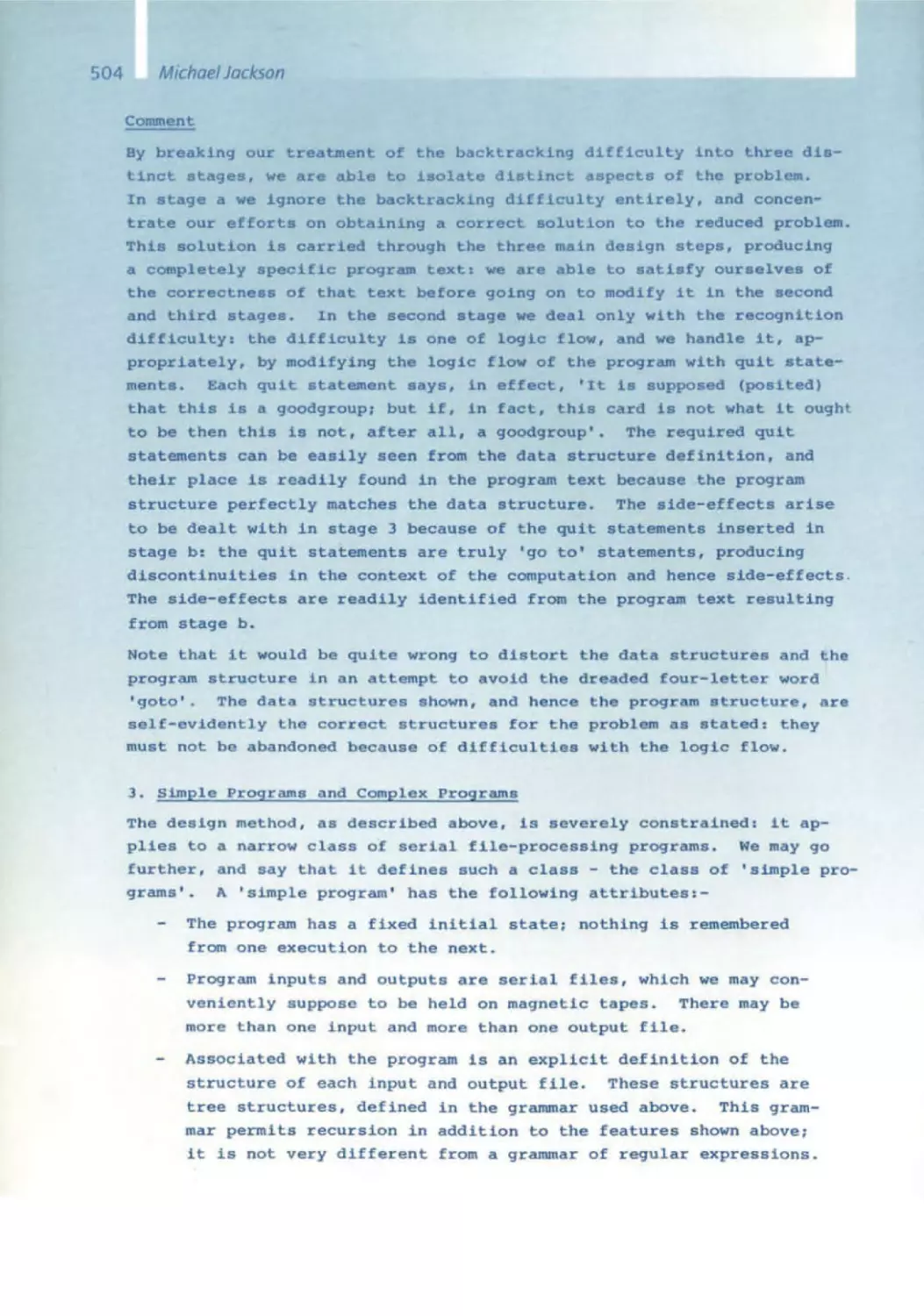
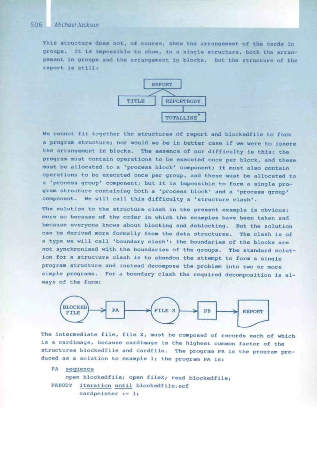
480 JSP in Perspective
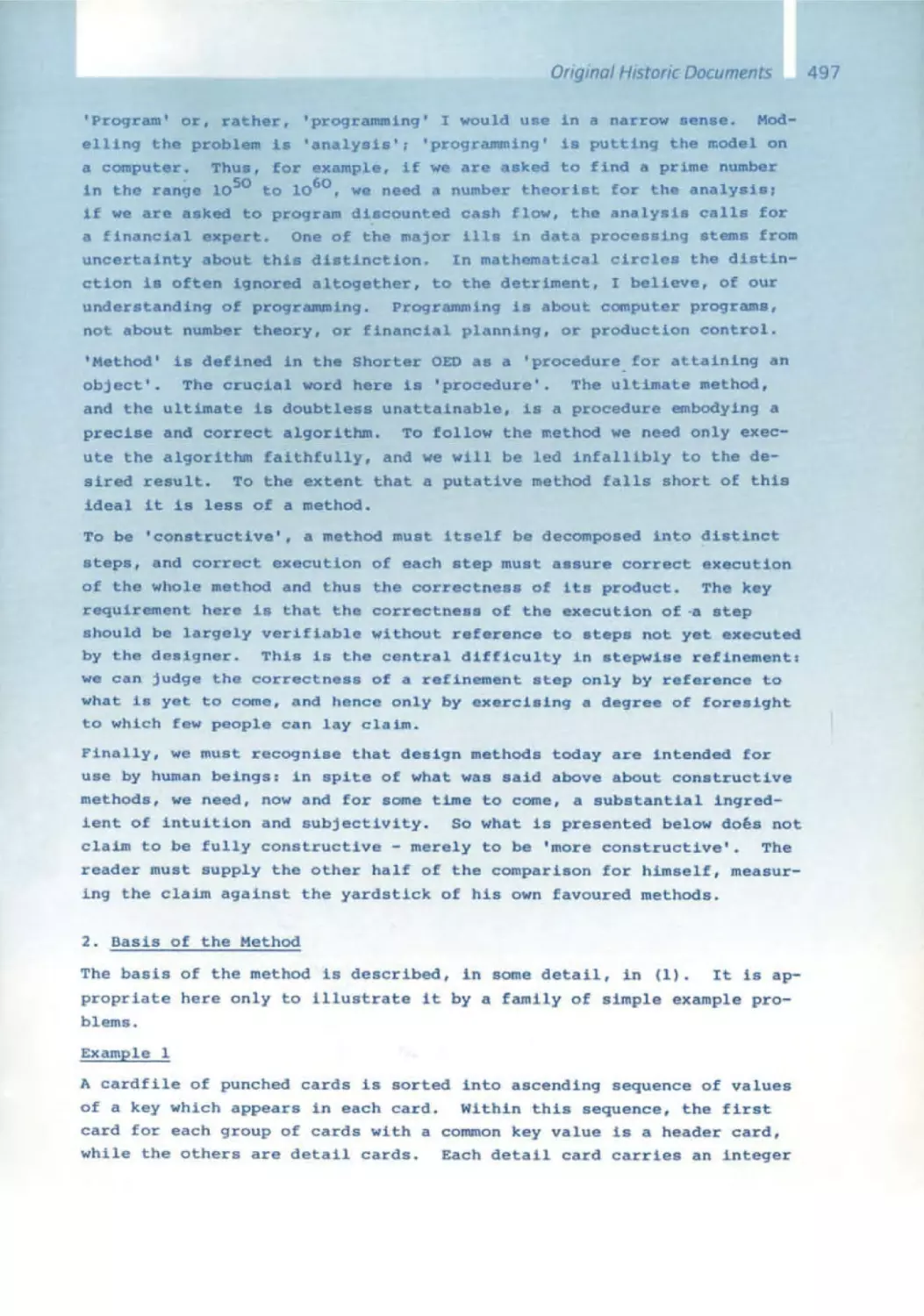
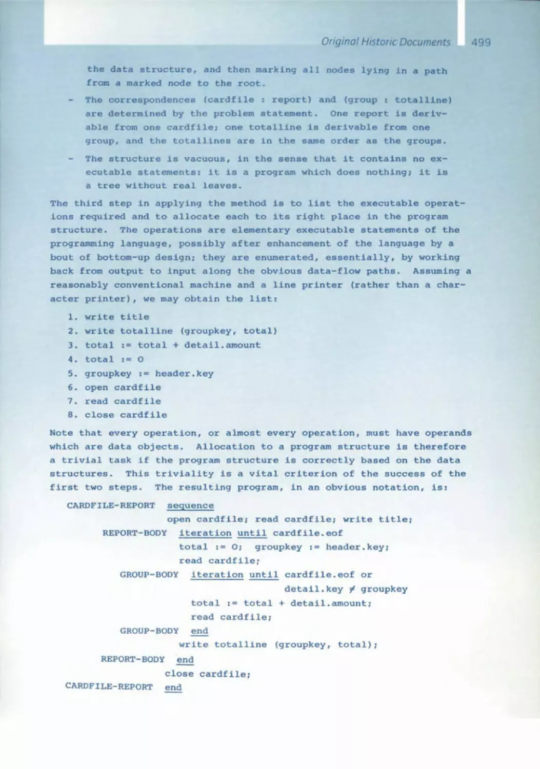
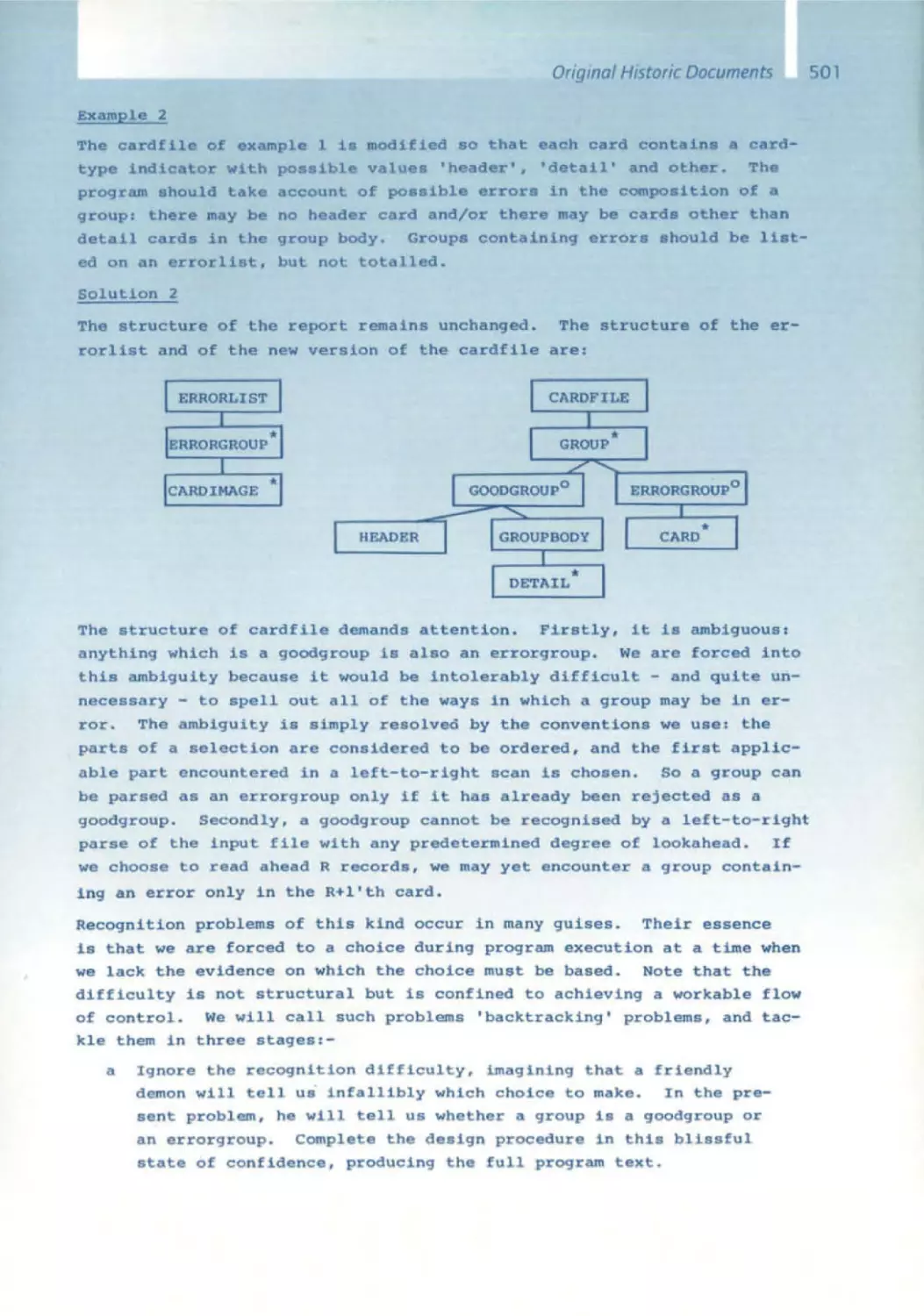
495 Constructive Methods of Program Design
Tom DeMarco
520 Structured Analysis: Beginnings of a New Discipline
529 Structure Analysis and System Specification
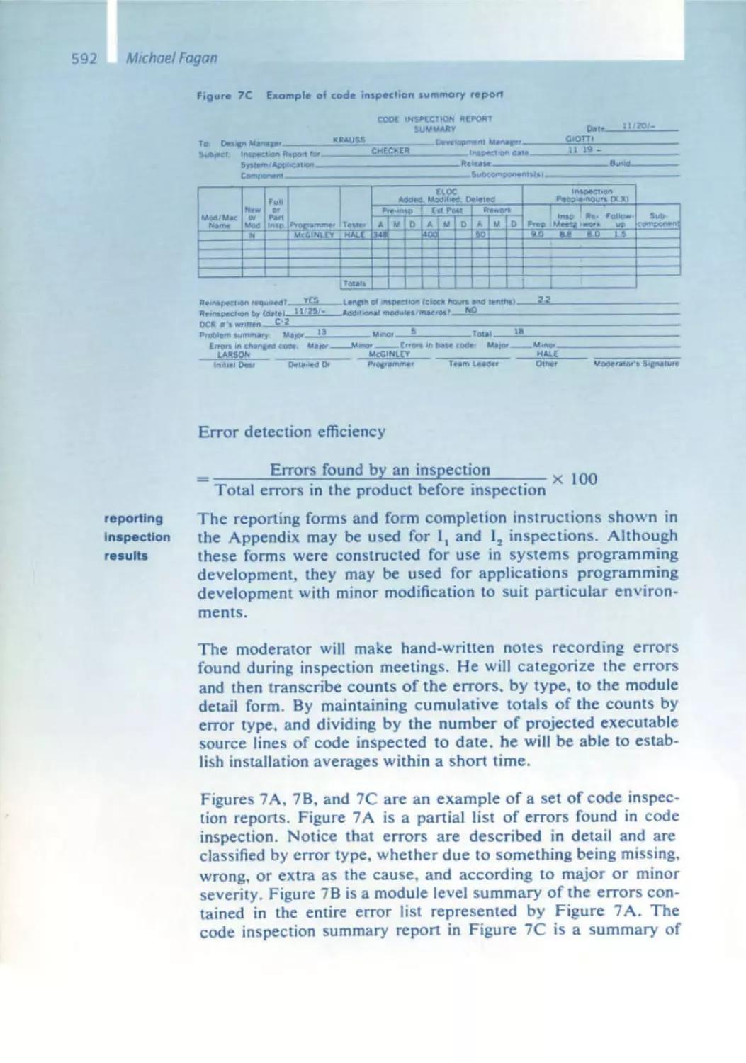
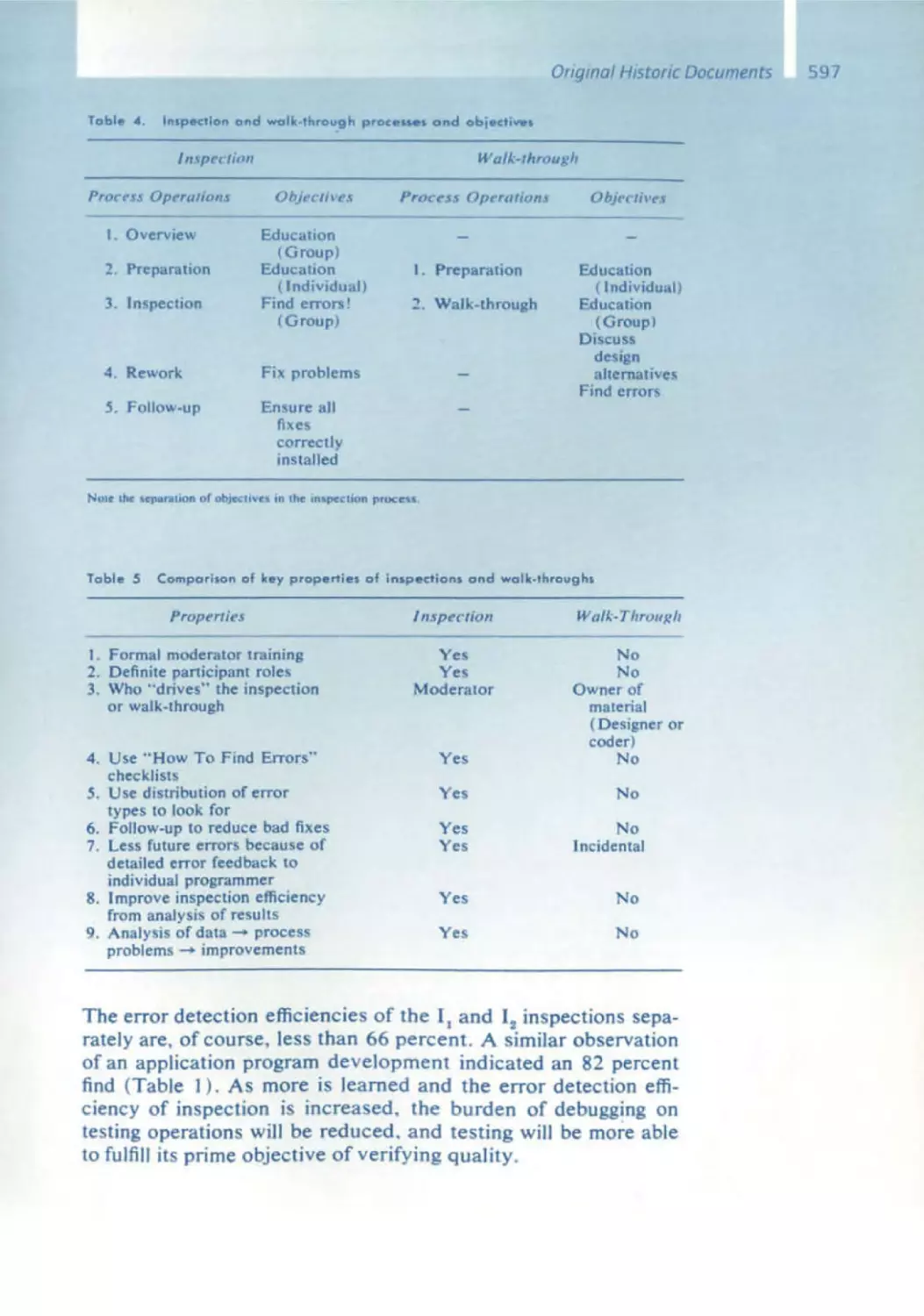
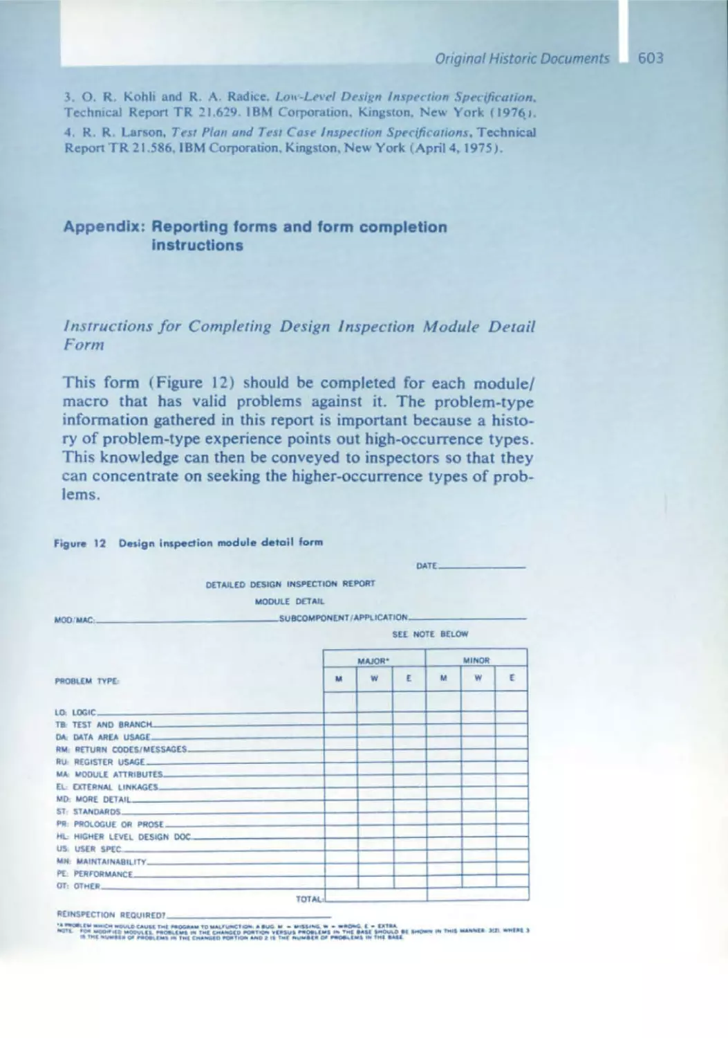
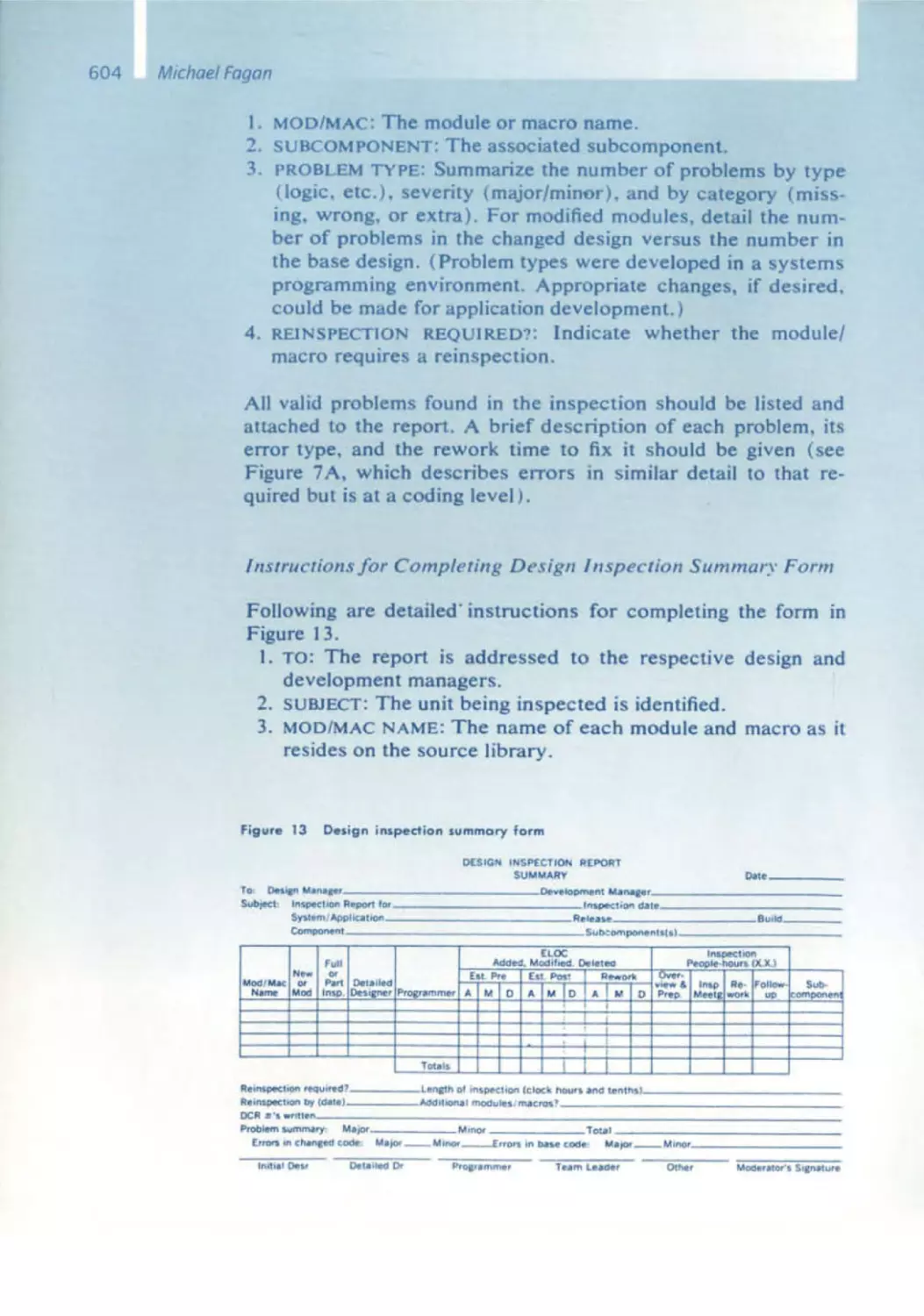
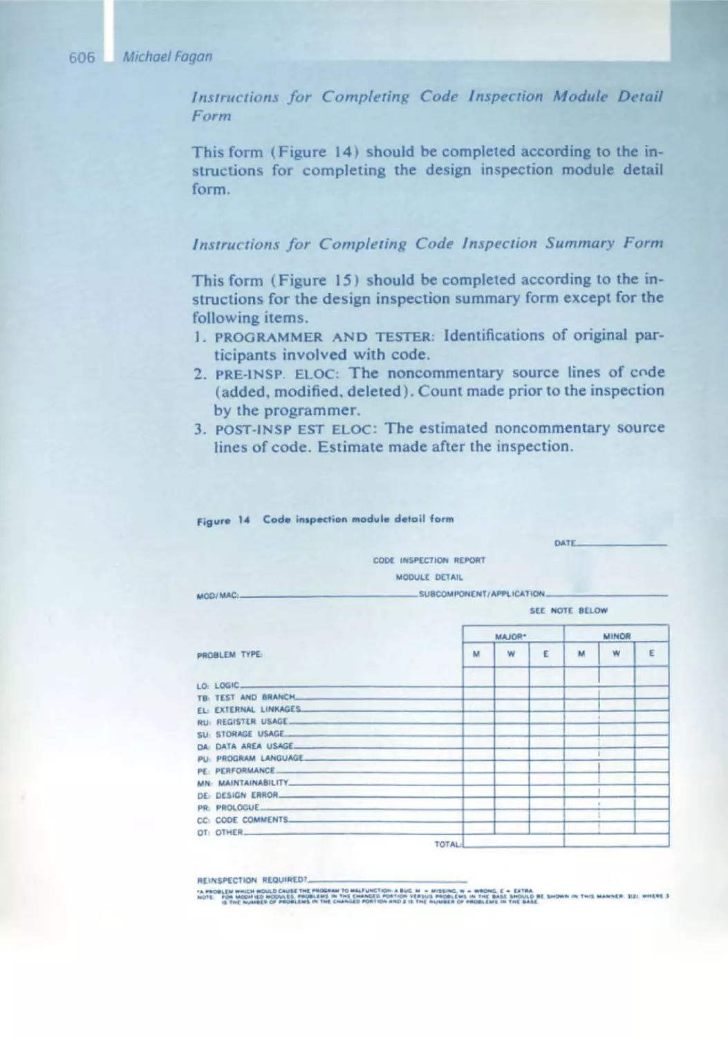
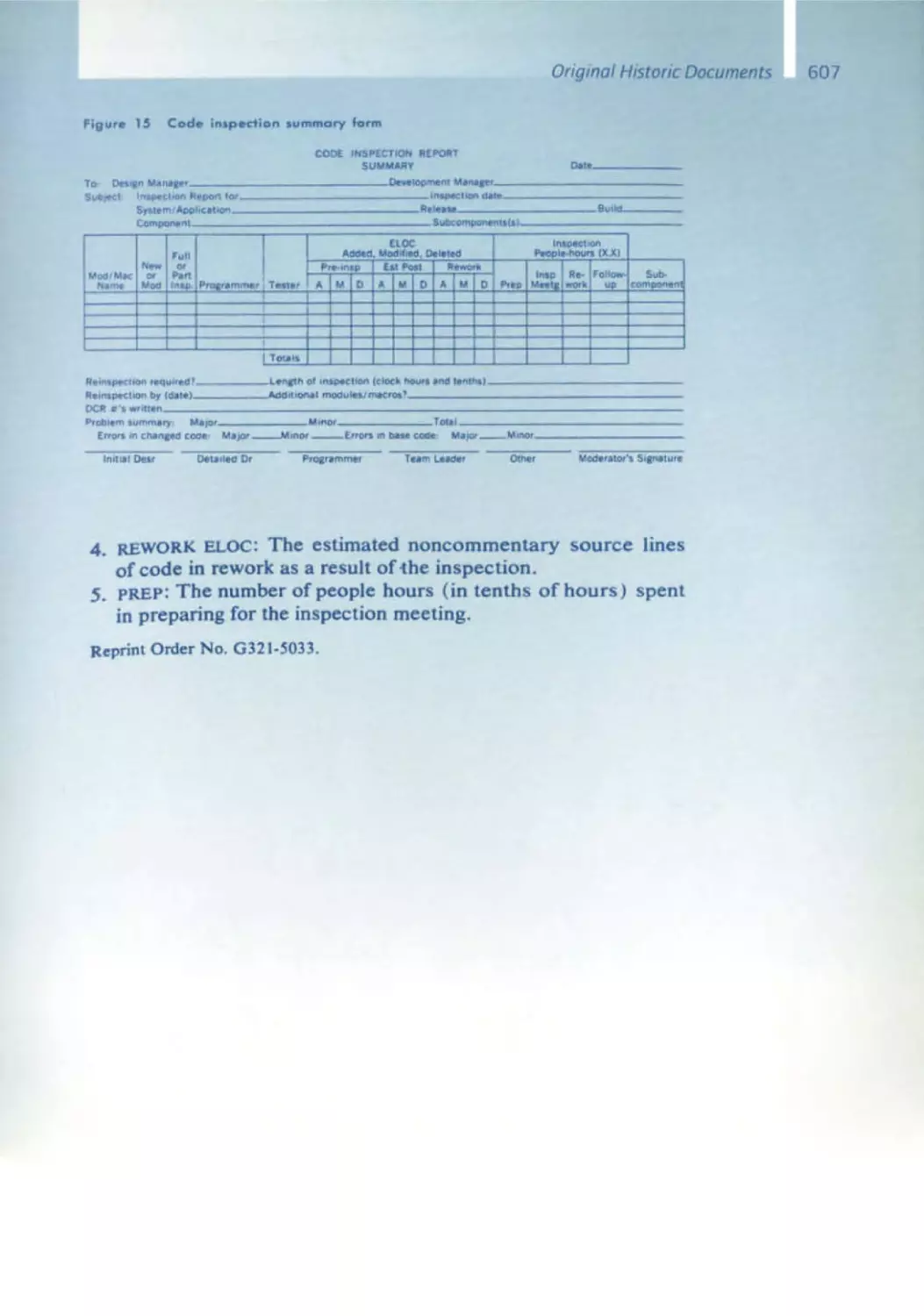
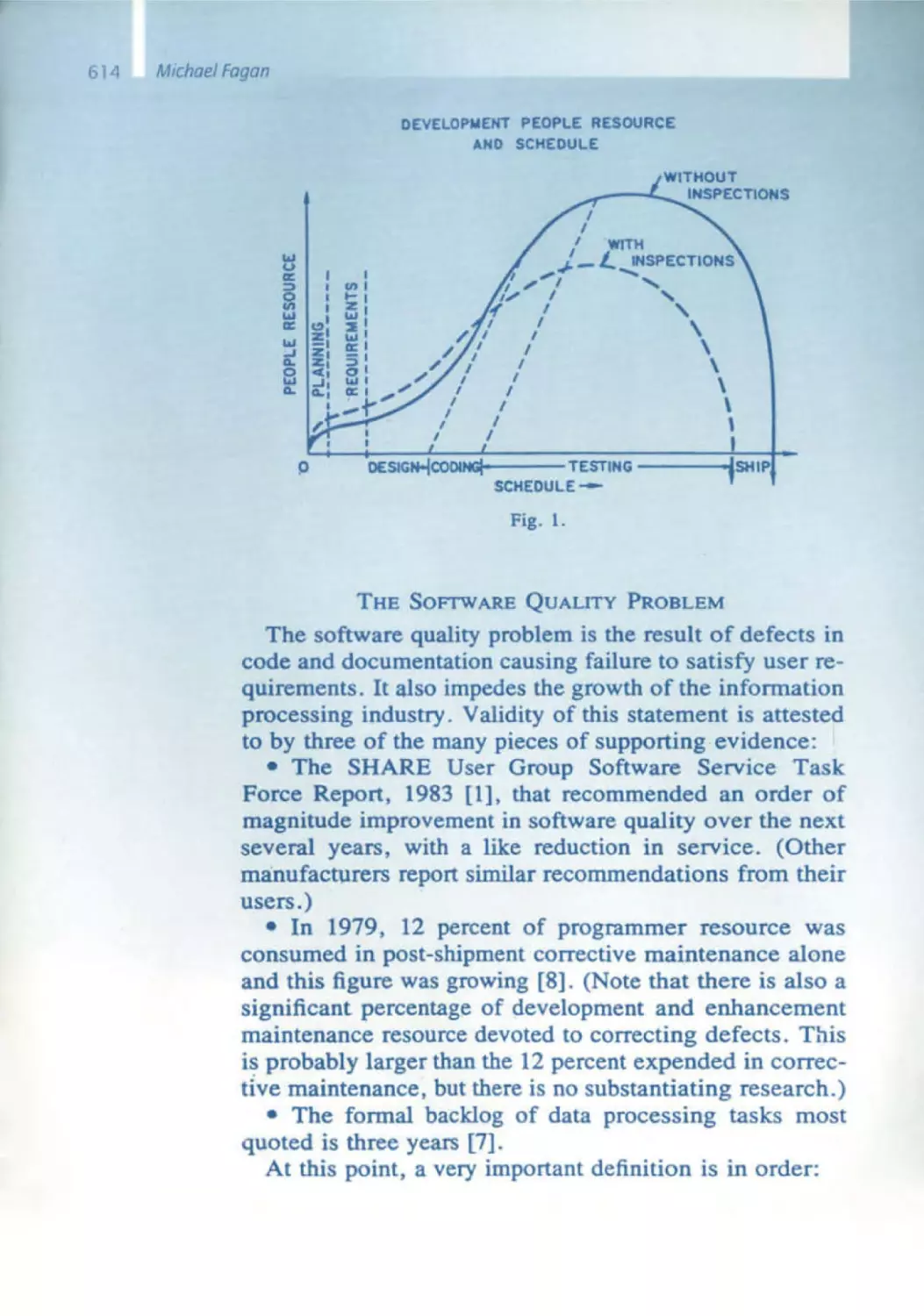
Michael Fagan
562 A History of Software Inspections
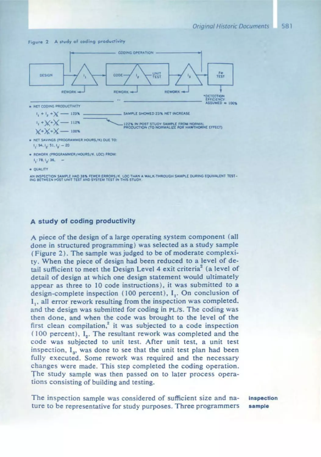
575 Design and Code Inspections to Reduce Errors in Program Development
609 Advances in Software Inspections
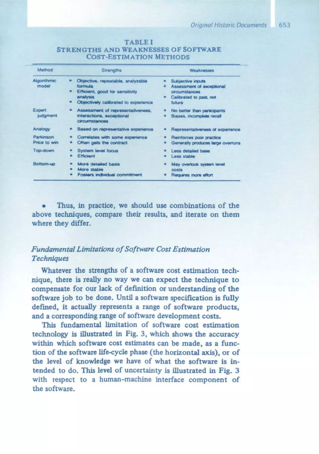
Barry Boehm
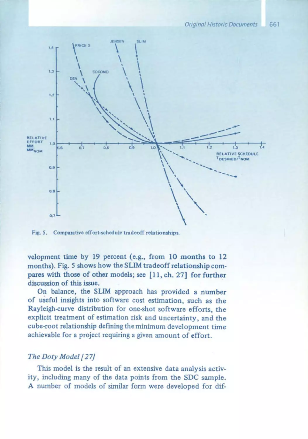
632 Early Experiences in Software Economics
641 Software Engineering Economics
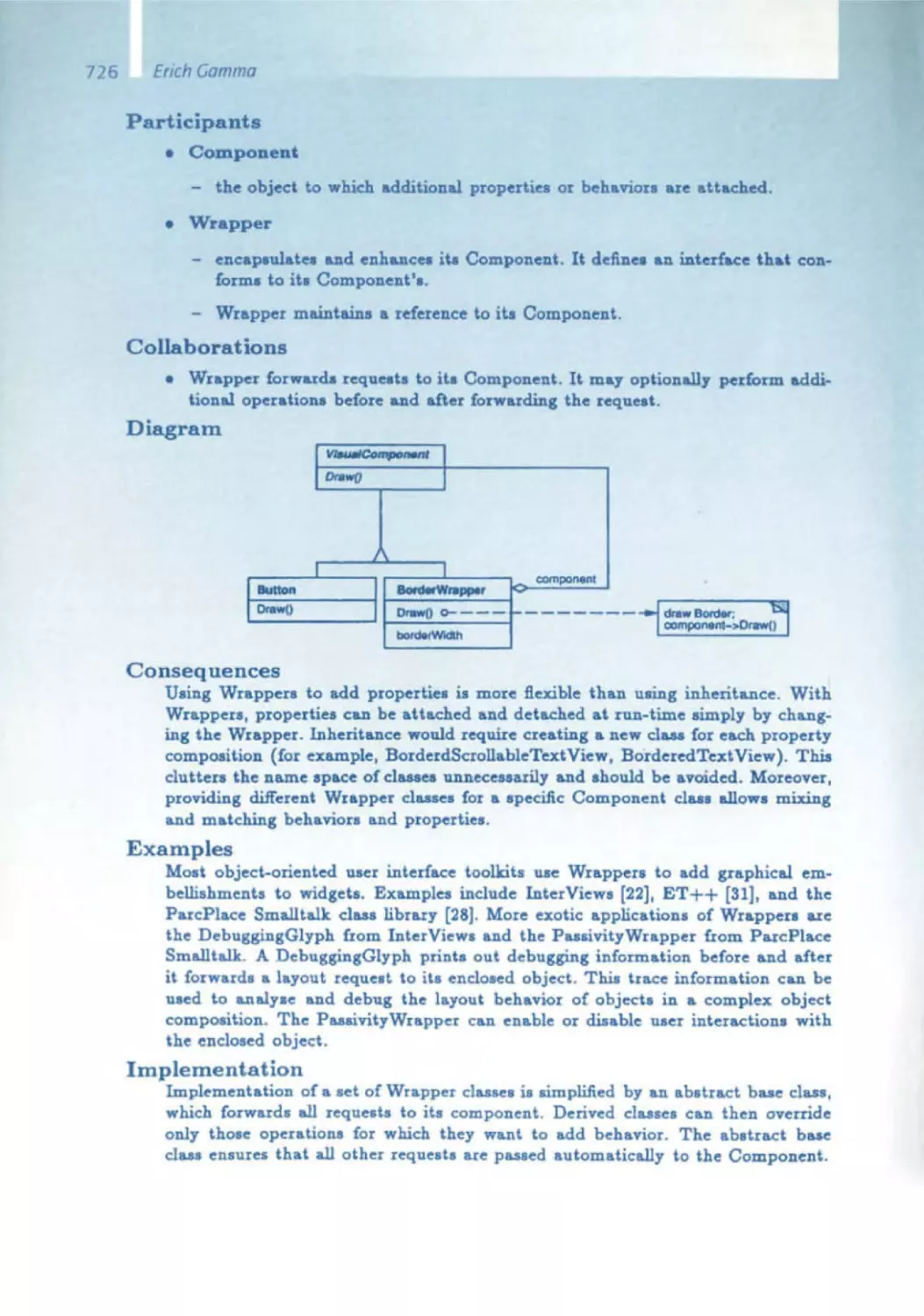
Erich Gamma
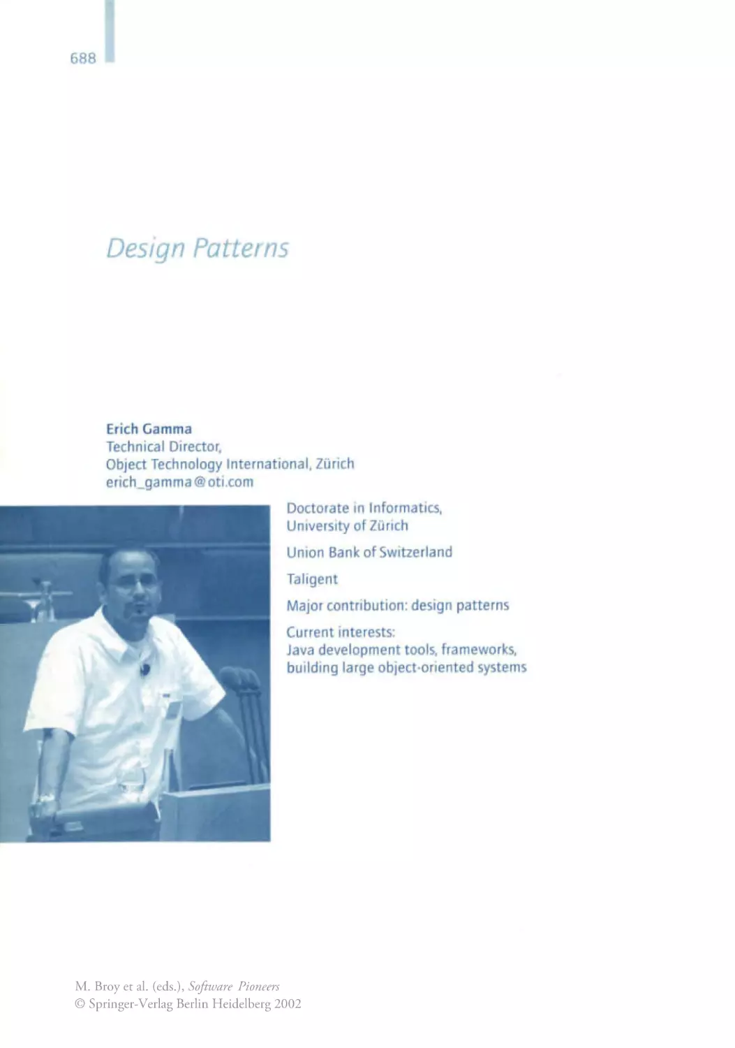
688 Design Patterns - Ten Years later
Erich Gamma, Richard Helm, Ralph Johnson, John Vlissides
701 Design Patterns: Abstraction and Reuse of Object-Oriented Design
10
Manfred Bray
Department of Computer Science
Technische Universitat MOnchen
broy@informatik.tu-muenchen .de
wwwbroy.lOformatik.tu-muenchen.de/-broyl
M. Broy et al. (eds.), Software Pioneers
© Springer-Verlag Berlin Heidelberg 2002
M. Bray. E Dener! (Eds) Software Pioneers
Sprmger· Verlag Berlm HeIdelberg2002
Manfred Broy
Software Engineering
From Auxiliary to Key Technology
Over the past years, computer applications have become a focus of public
attention . Spectacular innovations such as the Internet, the by-now-omnipresent personal computer, as well as numerous new developments in
almost all technical areas have drawn the general public's attention to
information technology . A considerable portion of this attention can be
attributed to the immense economic effect of informatIOn technology,
including the ups and downs of the stock exchanges, the often exaggerated hopes in connection with company start -ups, and the frenzy
with which a lot of companies are pursuing their orientation towards
e-com merce.
Less vIsible and not sufficiently noted by the public IS the role that software
and software development Issues play in thiS context. The reasons are
obvious: software is almost Intangible , generally invisible, complex, vast
and difficult to comprehend . Hardly anybody, with the exception of a few
experts, can truly grasp what software really is and what role It plays.
Probably the best way to give a lay person an idea of that role is through
numbers.
11
12
Manfred Broy
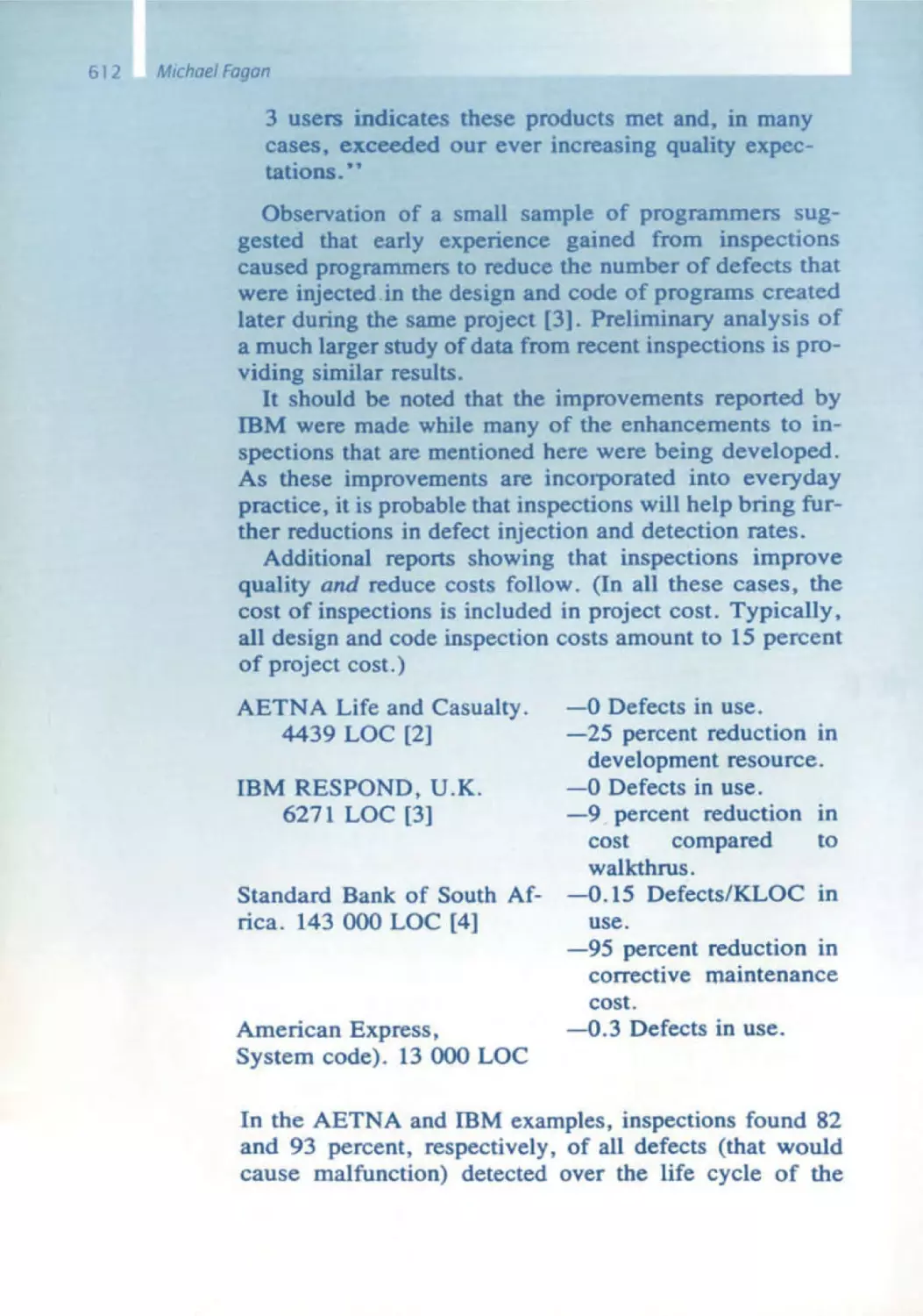
It is rather impressive that
• cellular phones nowadays are controlled by over one million
lines of program code,
• amodern luxury class vehicle has more onboard computer
power and software than an Apollo spacecraft .
These examples underscore the fundamental importance of software. One
can also read up on the subject In a study we prepared at the end of
last year for the Deutsche Forschungsmlnlstenum (German Federal Bureau
of Research) (or in the by-now-famous report to former US President
Clinton , the PITAC Report), which emphasizes the utmost importance of
software engineenng. The report states:
... that software demand exceeds the nation's capability to produce It, that
we must still depend on fragile software, that technology to build reliable
and secure software is Inadequate and that the nation is underinvesting in
fundamental software research.
Considering the extremely short period of time of only just over 40 years
in which software has gained this vast importance, it is not surprising that
there are still countless shortcomings and unsolved problems in the development of software . This will likely keep software engineers busy for
another good few years.
On the surface, scientific disciplines are often seen as objective fields that
are la rgely independent of human influences . This, of course, is deceiving .
Scientific and especially engmeering disciplines, such as software engineer Ing, are shaped and formed by the people who created these fields. Their
Ideas and beliefs form the basis of and give shape to the field . Therefore .
we will be able to gain a better understanding of software engineering
if we get to know the people who created and pioneered this field.
Software is complex, error -prone and difficult to visualize . Thus. It is not
surprising that many of the contributions of the software pioneers are
centered around the objective of making software easier to visualize and
understand, and to represent the phenomena encountered in software
development in models that make the often impliCit and intangible soft ware engineering tasks expliCIt. As software makes its way Into many areas
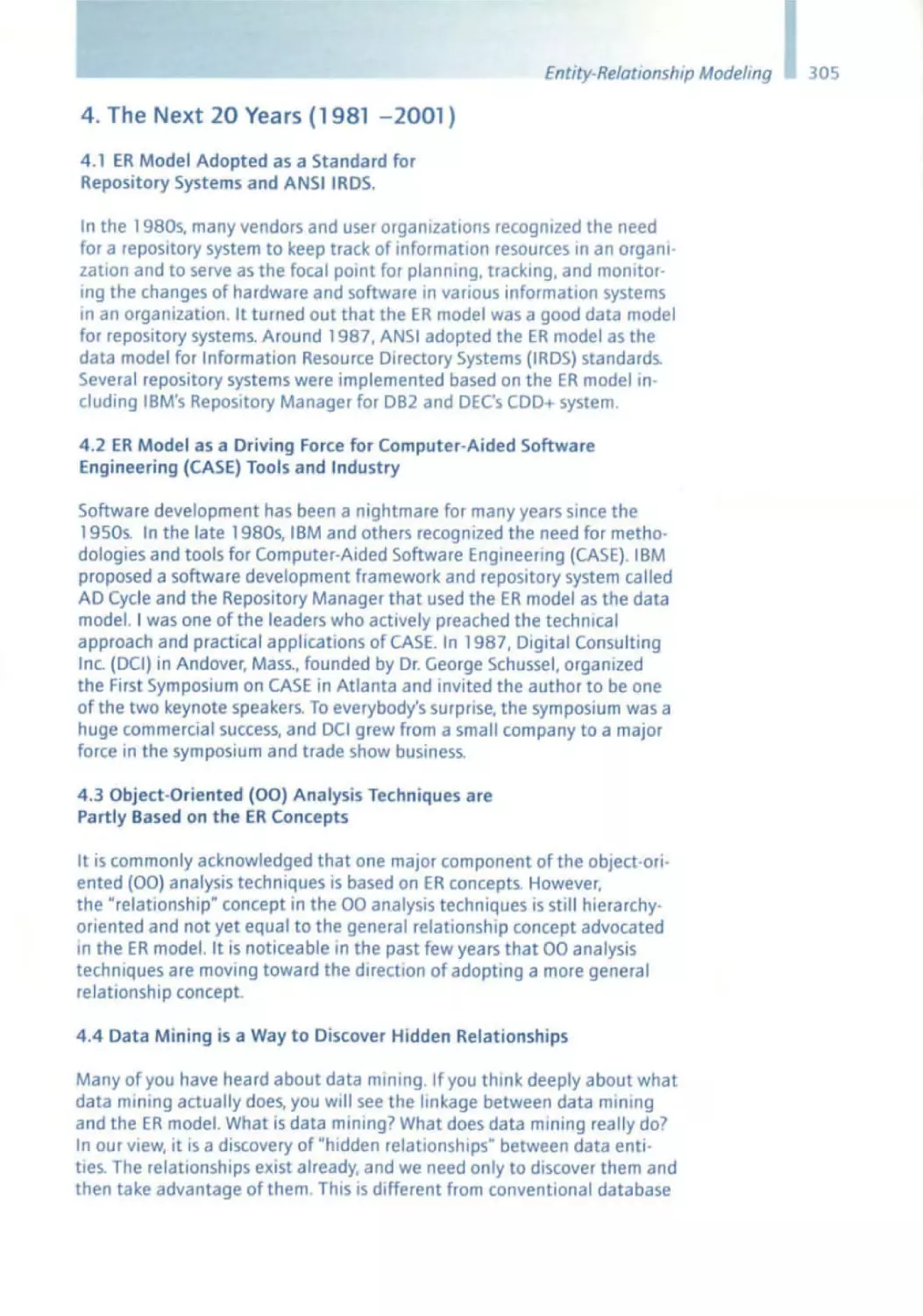
of our life. these models and methods also take hold there. In addition It
has become apparent that these models and procedures are not only of
great Interest and Importance for software development . but also for
a whole series of other questions in connection With complex systems.
Therefore . the contributions made by the software pioneers are of general
interest , even though they were usually motivated solely by problems related to software engineering . They form the basis for a new discipline of
model ing processes and sequences in dynamiC systems by means of logiC,
algebra and discrete structures .
In addition to the many still open , unsolved and exciting questions around
the topic of software, one should not forget how far we have already come
since the early days of computer science and software. It is well worth
casting a glance back onto some major contributions made over the past
SoftwareEngineering- From Auxiliary to Key Technology
40 years. One of the motives for doing so lies In the observation that computer sCience - more than any other discipline - suffers from a frequent
lack of sCientific standards and insuffic ient knowledge of the scientific
literature . In light of the quickly changing technology, many young computer scientists seem to be of the opinion that scientific work that was
done more than five years ago can no longer be relevant today. This is a
regrettable IJIlstake.
The work of the software pioneers, who with their contributions and Ideas
have given decisive Impulses to the development of computer sCience and
software engineering , IS as Significant today as It was then, and by no means
only of hlstorlcalmterest. Many of the Ideas are as useful today as they were
in the time when they emerged. But not only the results are exemplary. Possibly even more important and Impressive IS the attitude of the software
pioneers, their personalites and the mind-set in which their contributions
are rooted and explained. which offer many stimuli and Inspire awe.
The contributions of the software pioneers form the basis for the work and
procedures of many businesses in the software industry. In this context.
however, another thought bears importance. In addition to the very clearly
visible technical impact of these contributions on the practice of software
engineering, their elementary scientific significance must not be overlooked.
Each and everyone of the softwa re pioneers has made fundamental scientific contributions. These have not only changed our trade, they have also
provided essential cultural and scientific impulses for the fundamental step
from understanding the world in continuous functions to the understand ing of the world in discrete, digital models. namely the models used in soft ware engineering . The step from the number- based models of mathematics
to a qualitative , logic-oriented approach is one ofthe most significant
contributions of software engineering . We are only just starting to realize
its impact on education. on science and on our view of the world .
Also remarkable are the personalities of the software pioneers. As individ ual as each ofthem IS, it IS Incredible how many parallels one can find in
their frame of minds and general attitudes towards life . They are characterized by a critical awareness. often bordering on stubbornness, an
unwavering belief In the rightness of the chosen approach, a high measure
of discipline and an incredible amount of energy allowing them to critically
analyze the subject matter over and over again . This leads to a spIrited
frame of mind - critical, and sometimes inconvenient, but at the same time
always creative and stimulating , too . And here's another thing we can
learn from the software pioneers: individual , independent thinking , an
inSistence on clarity and an unWillingness to compromise, which are often
a much more Important starting pOint than the conformist pursuit of
repetitively Identical approaches and conventIOnal Ideas, and striVing to be
part of the mainstream .
The contributIOns of the software pioneers have led to methods that have
shaped our world In a way that exceeds their own expectations . It IS high
time that we Increase public awareness of their accomplishments and that
we lay the foundation for a long-term understanding of software engineer ing and its pioneers in our society.
13
14
sd&m Conference on Software Pioneers,
Bonn, June 28/29,2007
Ernst Denert
sd&mAG
Thomas -Dehler -Strasse 27
81737 Munchen
denert @sdm.de
M. Broy et al. (eds.), Software Pioneers
© Springer-Verlag Berlin Heidelberg 2002
M Bray. E. Denert (Eds.) SoftwarePioneers
Sponger·Verlag Berlm Heidelberg2002
Ernst Denert
Opening and Overview Speech
The Relevance of the
Software Pioneers for sd&m
HNew trends are often nothmg more than the bad memory of posterity. n
This is not only true of fashion, but also of software. The study of history.
especially the history of science and technology. is interesting in itself,
but not enough so to justify the high costs of an sd&m conference. which
brmgs together about 1200 employees and guests of our company for
two days - the topic of such a conference must certainly have relevance to
our daily work. So the question is, does an exploration of the software
pioneers' achievements have anything to do with our daily practice at
sd&m? The answer is a resounding yes. This overview demonstrates that
these pioneers not only have made key academic contributions, but also
have brought about enormous practical applications .
15
16
Ernst Denert
Friedrich L. Bauer - The Stack Principle
Friedrich l. Bauer invented the stack, the computer scientist's favorite data
structure, in order to be able to parse and evaluate algebraic formulas
using a computer. Nowadays, as the stack is hitting its mid 40s, we can
hardly Imagine a time when it did not exist. In today's software, the stack
is omnipresent - though stili used for analYZing formulas, it is primarily
used for syntax analysis in compilers and also in run time systems. Another
one of Bauer's epic contributions was his Involvement in defining Algol 60.
Though the language IS no longer used, it had a massive influence on
later programming languages that are still in use today, almost all of which
contain the Algol 60 gene. The discovery of the block principle and the
recursive procedure were also fundamental programming milestones and
would have been Impossible Without the stack principle .
Ole-Johan Dahl - Simula 67
Nowadays, object orientation IS quite rightly the epitome of design and
programming methodology. Much older than generally assumed, object
orientation did not first Originate with c++ in the mid -1980s, or Smalltalk
In the late 1970s, but almost two decades earlier with Simula 67, whICh
was developed by Ole-Johan Dahl and his colleagues, especially Kristen
Nygaard, in Norway. By lucky coincidence I came across Simula at the
beginning of the 1970s. A colleague had brought a compiler from Oslo
and installed it on the Computer Science Department's computer at the
Technical University of Berlin. That is how I came to be one of the very
early object-oriented programmers. It had a huge Influence on my later
project work and by extension also on sd&m. As the name suggests, Simula
was designed for, but was in no way limited to, programming simulations .
In terms of object -orientation, the language was fully equipped with data
encapsulation and inheritance . Simula also carried the Algol gene and has
passed on its object-oriented gene to all subsequent object-oriented programming languages. Istill clearly remember Brad Cox, the developer of
Objective C, asking me about Simula in the mid-1980s, as he was working
on this nvallanguage to C++. An understanding of Simuia was an Impor tant prerequisite when designing a new object -oriented language, in order
to avoid starting from scratch. Simula's strong impact on object-oriented
programming IS still enormously evident in our project work today .
Niklaus Wirth - Pascal
I Will now turn to the school of programming that Niklaus Wirth founded ,
not only, but most effectively With the programming language Pascal. He
wanted to create a programming language that one could use to teach
good programming effectively . Iwould also like to add that he had already
had an impact on me with his Pascal predecessor Algol W, whICh we also
had at the TU Berlin . Iused Algol W for my first lecture on data structures,
Simuia for the second, and finally Algol 68 10 our book titled Data
Opening and OverviewSpeech
Structures. You can write bad programs in a good language such as Pascal,
but you have to work hard to program well in a bad language such as C.
Wirth taught us how a good programming language makes it so much
easier to write good programs - structured, clear, simple. With Pascal, he
showed us how control structures and data structures work together,
especially in his ground breaking book Algorithms and Data Structures.
Wirth also taught us "program development by stepwise
from which an unfortunate and futile discussion developed concerning top down versus bottom ·up. The dogmatic programming war that ensued was
certainly not Wirth's fault. Programming is the foundation of all software
engmeermg . Wirth's school, based on Pascal. continues to have an Impact
on our work .
Fred Brooks - 05 / 360
Fred Brooks created the IBM mainframe, one of the most Important com·
puter systems of all time . Brooks first defined the architecture of the
IBM/360 by specifying the command set of this machine, or to be more
precise, this family of machines. The essential features of this command
set can stili be seen today In the /390 series. Brooks then managed the
development of the 0$/360 operating system for this machine series, a
gigantic IBM project with more than 1000 people - a pioneering achieve·
ment with far·reachlng consequences. After almost 40 years, the system
created by Fred Brooks and his team is still in operation In many thousands
of companies - and will remain so, even if the mainframe is often pronounced dead. Many, if not most, sd&m projects deal with this system in
one way or another . Fred Brooks recorded his experiences in the wonderful
book The Mythical Man Month, which culminates in statements such as
"Adding manpower to a late project makes it later" and "Thinkers are rare,
doers are rarer, thinker -doers are rarest." He came up with the last state ment in order to justify why it makes sense to separate the role of the proJect manager and that of the designer in larger projects. This realization
is one of the fundamentals on which sd&m was founded, even to the point
of influencing the name sd&m.
Alan Kay - Graphic User Interface
Alan Kay IS considered the Inventor of personal computing, and the graph IC user interface based on screen Windows and the mouse. Crediting him
With thiS achievement is in no way diminished by also recognizing Doug
Engelbart, who first publicly introduced his ideas on the graphic user inter·
face in 1968 . Iwould like to make a confession here. In my career as a
software engineer, never dId I underestimate a concept more than I did the
graphiC user Interface .
Alan Kay Invented the "Dynabook," an early model of what we now call the
laptop . In the 19705, he was working at Xerox PARC (Palo Alto Research
Center) where objectonented programming was pushed by the develop·
17
ft; ,
.- ..
.i') 18
-',
Ernst Denert
I
I
I
ment of Smalltalk . Smalltalk was also the impetus for creating a development environment with a graphic user interface . This was the model on
which Apple based its products starting in 1982, first the Lisa and then the
Mac. Not until 1990 did Microsoft with Windows enter the market, perhaps
late, but hugely successfully. Nowadays, very few can imagine - myself
included - using a computer without a graphic user interface; WIMP (windows, icons, menus, pointers) has become an integral part of our lives
and Alan Kay is its pioneer.
Rudolf Bayer - Relationa l Data Model and B-Trees
Now I will touch upon databases, for they are the main elements of the
bUSiness information systems that we build. We cannot accomplish anything without database systems. Icannot even talk about databases with out first mentioning Ted Codd and his relational data model. Unfortunately, due to health reasons, he IS no longer able to give presentations.
Rudolf Bayer, who worked closely with him, devoted part of his presentation to the relational model. According to mathematical principles, a
relation is a subset of the Cartesian product of n sets. At the beginning of
the 1970s when I first heard that this might be something useful and
involved storing data on disks, it seemed to be a strange concept . It also
took a while for relational database systems to come along . The first one
was the experimental System R from IBM. Commercial success did not start
until the 1980s, first with Oracle, then with OB/2, Ingres, and Informix . All
of a sudden, with subsets of the Cartesian product of sets, real-world, large,
and finally even high performance systems were built and a lot of money
has been made with them . Even the newer object-oriented DBMS have not
supplanted them ,
Rudolf Bayer invented the B-tree. The meaning of the letter B in the name
remains ambiguous: Does it stand for balanced or for Bayer? There can
be no database system without the B-tree, whether OB/2, Oracle, or any
other . The relational data model could not be integrated as a high performer without the ingenious concept of B-trees - they grow very slowly,
while they are also wide and even balanced as they grow. They are thus
able to host huge quantities of data , which can then be accessed by the
shortest routes possible. The B-tree concept was published shortly after
the relational data model; nevertheless both concepts were developed
separately from one another . A few years after their discovery, these two
congenial ideas came together in relational database systems, one of
the most important constructs in computer science.
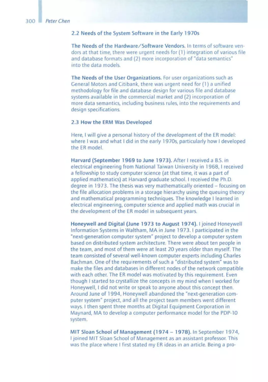
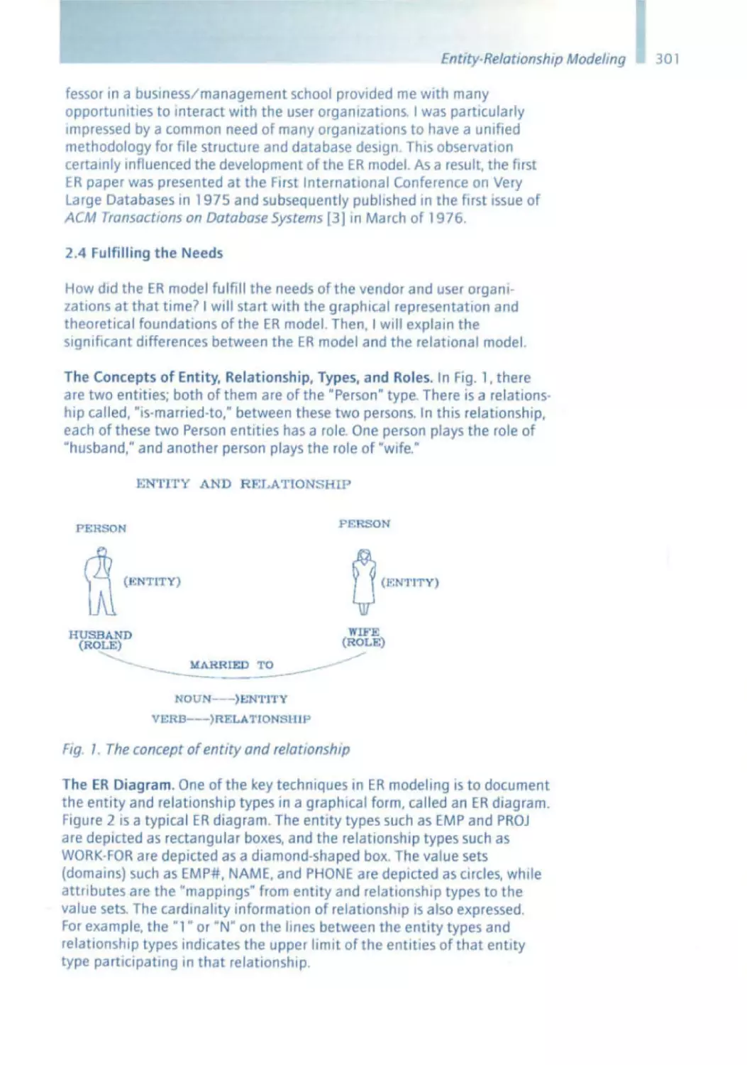
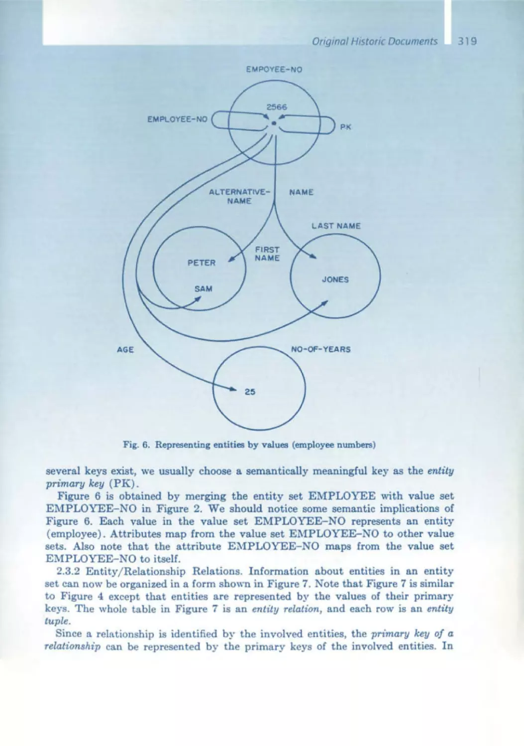
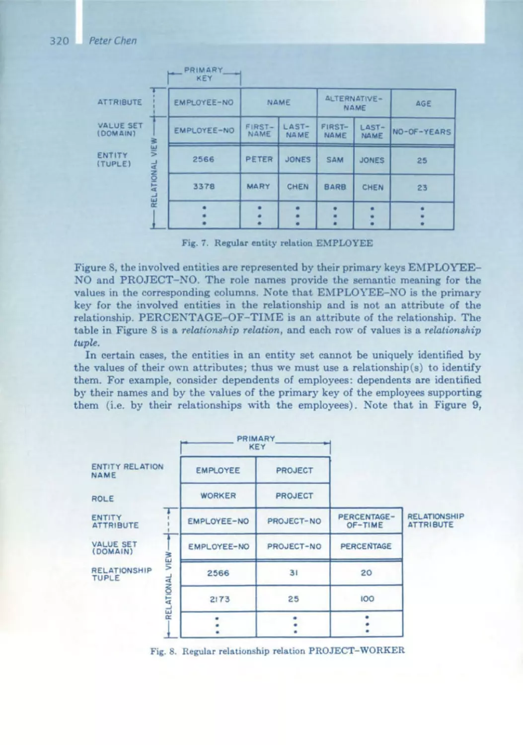
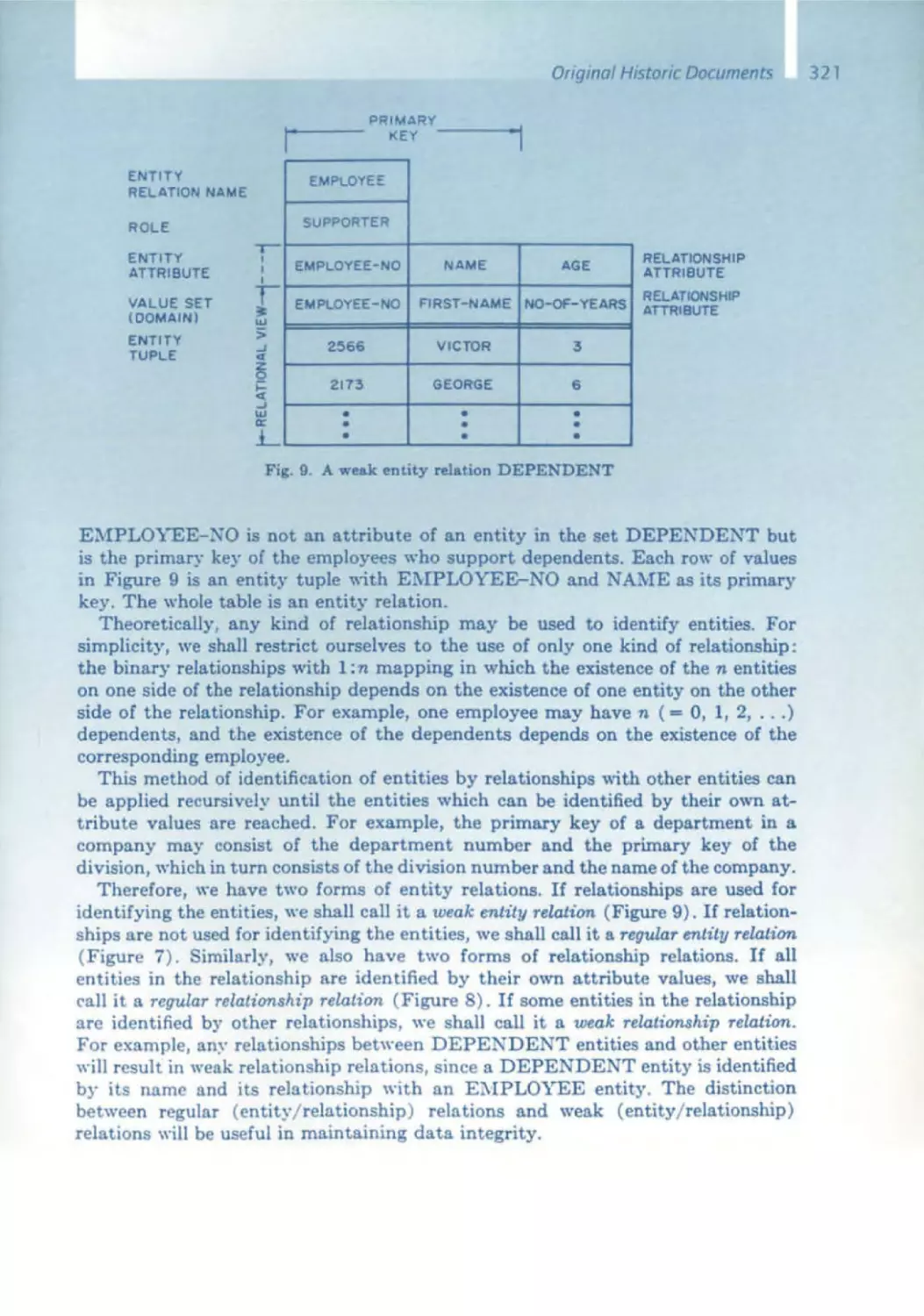
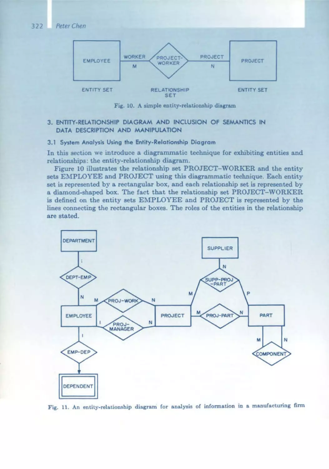
Peter Chen - Entity/Relationship
Model
In 1976 , Peter Chen introduced his entity/relationship (E/R) Model , a
method for modeling, specifying, and designing relational databases, From
It, we learned that the world, or at least the way it is represented in infor mation systems, consists of objects and relationships between them - such
Opening and OverviewSpeech
a s imple concept and yet so powerful. The E/ R model certainly lies to a
certain extent one semantic level above that of the relational model, Chen
showed us how to establish the mapping . Ifirst attempted E/ R modeling
back In 1983 when sd&m was just starting out. Afterwards, I asked myself
how we had modeled data previously, if at all . Of course, somehow every
software designer and developer establishes a model for his system's data;
since Chen, most use the E/ R form . Ihave heard people say, "We don't
have a data model." What they mean was that they do not have an E/R
model, or at least none that IS documented . ThiS shows that the E/ R
model has become synonymous with a data model , Just like Kleenex for
paper tissues.
Edsger W. Dijkstra - Structured Programming
Edsger W. DIJkstra has contributed a great deal. Including groundbreaklng
concepts, to the development of computer sCience. HIS most popular and
probably the most Significant contribution IS structured programming,
Introduced m 1968 In his short , two -page article entitled "Goto statement
considered ha rmful." ThiS article broke the spell of the goto statement,
which had been so widely used to produce spaghetti code. At the same
time the article was the Impetus for structured - or even better - structur Ing control mechanisms: sequence, case·by·case distinctions (If-then ·else,
case) and loops (while -do, repeat -until) .
A few years earlier, Bi:ihm and Jacoplnl had mathematICally proven that
the structured programming concept IS powerful enough to program every
algOrithm thereby rendermg goto's superfluous . When a colleague first told
me that at the beginning of the 1970s, I did not want to believe him. I had
Just written a program for my master's theSIS on the search for cycles In
graphs. It was real spaghetti code of which I was Incredibly proud It took
some convincing before I would accept that my masterpiece could work
without goto's. Structured programming then turned into a popular trend
that we are only too familiar With. It appeared in the graphic notion of
the Nassl/Shneiderman diagrams, for whICh my former company, Softlab,
Invented the name "Struktogramm." I did not like this graphiC notation .
Many of you know my motto : Software should be written , not drawn .
Nowadays, structured programmmg in the sense of Dijkstra is simply
standard practice - hopefully . It is hard to Imagine that thiS was once a
fundamental discovery and that I was Ignorant enough to believe was
not gOing to be practical.
Tony Hoare - Program Correctness
When addreSSingthe tOPIC of software correctness, you could say that the
name Tony Hoare IS synonymous with correctness. The title of hiS presenta tion "Assertions and Program Verification " deals With exactly that topic .
Like DIJkstra, he has also made substantial contributions to the progress
of computer science. Among them are the Quicksort algorithm and the
19
20
Ernst Denert
synchronization of parallel processes using monitors, which are a generali zation of Dilkstra's basIC semaphore concept. Hoare's most important
concept, however, IS the verification of program correctness. At first glance,
such program verification seems to hold little importance for our dally work
at sd&m - we will likely never formally prove that a program IS correct.
However, understanding the concept of program correctness IS very valu ·
able. Bill Wulf said It best when he wrote, "even If we are not gOing to
prove a program to be correct, we should write It as If we were going to ."
Simply thinking about the pre- and postconditions and asserttons necessary to do the proof IS more likely to lead to "correct" programming from
the outset. Hoare's school of thinking had a huge impact on generations
of software engineers.
David Parnas - Modularization
In this presentation , It IS not really appropriate to give prominence to any
Single pioneer. But I am gOing to do it anyway by acknowledging that
no one had such a fundamental influence on myself and my work as David
Parnas. Iwas lucky enough to meet him personally way back In 1972. At
that time we wanted to hire him as a professor at the Technical UniverSity
of Berlin . It is a well-known fact that we did not succeed. He did come to
Germany, but went to Darmstadt Instead. Iwas his gUide during his visit to
Berlin . At that time, he had just written two articles for Communications
of the ACM : "A technique for software module specification with examples"
as well as the famous "Criteria to be used 10 decomposing systems IOto
modules." He gave lectures on these two topics in Berlin . Iadmit that I did
not then understand their significance and believed it to be mostly superficial stuff . It was not until later. in my own development work in industry,
that their significance dawned on me. When designing the START appli ·
cation software. I could use the principle of data abstraction and encapsulation , i.e. information hiding, to full advantage . And it has paid off to thiS
day, not only in the START software, but above all at sd&m, where we
applied this modularizatlon principle right from the start . Modularization
IS the core of object orientation and one cannot imagine software
engineering Without it. The cOincidence that led Dahl's 51 mula compiler
and Dave Parnas to Berlin at the same time had a huge Impact ; it put
the "d" IOtO sd&m.
John Guttag - Abstrac t Data Type Specification
Dahl's 5lmula laid the foundation for object -oriented programming; Parnas'
concept of information hiding accomplished the same for modulanzatlon .
and, from John Guttag , we know how to specify abstract data types uSing
algebrai c formulas . The equation for the stack. pop(push(s,x)) = x, IS very
simple and easy to remember, though the same certainly cannot be said
for all algebraIC and other formal specifications . The hope that formal
speCification would create the basIs for correct, provable software was
never fulfilled in practice. Applying such a method to massive applications
Opening and OverviewSpeech
is too difficult and costly, and requires a qualification that only a few soft ware engineers have. Additionally, if you think out and structure a system
so extensively that you can specify it algebraically , you have understood it
so well that the algebraic specification is no longer worth it. So is abstract
data typing simply a nice theory without practical sigmficance? The
answer is no - there are applications In which the effort does payoff or IS
even essential. for example In safety -critical systems. However, sd&m does
not build such systems. What we have learned from John Guttag and other
researchers specializing in formal specifications is which questions a specification should answer : What does the module depend on? What precisely
is It supposed to achieve? What are Its pre- and postconditions? What
knowledge does it reveal? And what information does it hide? This way
of thinking IS very important to ensure correctness in our work .
Michael Jackson - Structured Programming
Back when It was first Introduced , MIChael Jackson's structured programm Ing (JSP) concept had often been limited and thereby trlvlalized to a type
of graphic notation for structured control flow, a kind of alternative to the
Nassl/Shneiderman diagrams. But hiS contribution goes much deeper
than that. He assumed that data and control structures should be deSigned
In accordance With each other or, to be more exact, that control should be
derived from the data structures, because the latter are the more fundamental concept. In the end, we are talking about data processing. Data IS
at the forefront of information systems. defining and structurtng the
system more than anything else, and it is more constant than the processes. Our work IS deeply affected by this understanding : object structure , the
algOrithms, and In some cases, even the business processes are derived
from the data model.
In the 1980s, I often came across Jackson's charts at sd&m. Customers used
them mostly when preparing specifications and technical concepts; however, they were scaled down to the previously mentioned control structure
charts.
Michael Jackson's ideas did not gain the popularity that they might have
deserved. His impact was more indirect, but not less significant for our work.
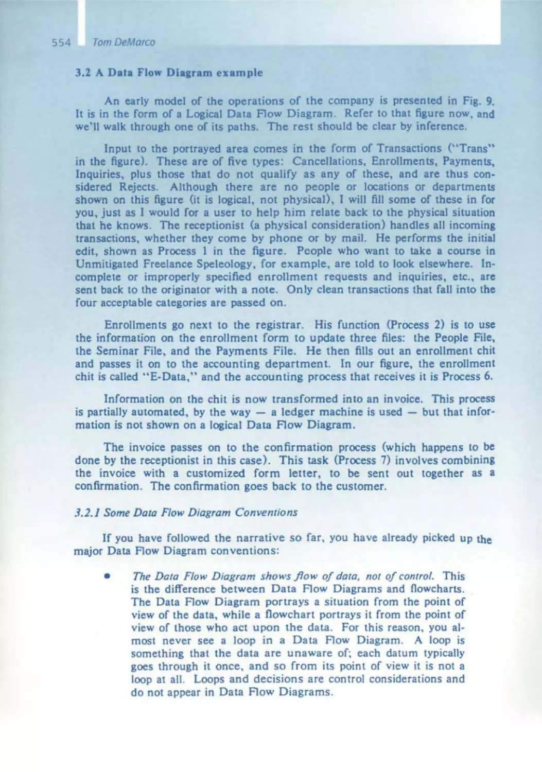
Tom DeMarco - Structured Analysis
Tom DeMarco's structured analysis had an extraordinary influence on
software deSign. In the mld-1970s, modeling information systems usmg
data flows had not yet hit the mainstream . Doug Ross' SADT publication
came out In 1977 ; Tom's book Structured AnalYSIS and System Specification
was published In 1978. Data flow charts are one of or even the central element of structured analYSIS. There was now a chOICe of two contrary para digms: data encapsulatIOn, on the one hand, and data flow, on the other
It is almost like the duality between wave and particle when explamlng the
21
22
Ernst Denert
physics of light ; both explain certain relevant physical features very well,
but rule each other out as an explanation model. I have already admitted
several times that I was always a believer in and a fan of data
tlon and therefore object orientation . So, I had a fundamental problem
with structured analysis and many a debate with its supporters, though
never with Tom personally.
Structured analysIs along with ItS data flow charts, supplemented by the
entity / relationship model, began its climb toward success with the CASE
tools In the later half of the 1980s . It lasted for about ten years. Do you
stili remember lEW, later called ADW, IEF, and Similar tool systems? The
"structured methods" were conSidered the standard - who knows how
far they really went? They played an Important role at sd&m in the form of
the CASE tools that clients Imposed on us. The schism between data
encapsulation and data flow has since disappeared; object orientation has
prevaIled . Nevertheless Tom DeMarco's structured analYSIS not only had
a
Impact on our work, it also contributed greatly to explaining
the methodology of software design.
Tom has always been Involved with project management as well, as can
be seen in hiS early book Controlling Software Projects and even more
so In Peopleware, which helped establish the soft factors in software
engineering . At the 1994 sd&m conference, he Impressed us with "Beyond
Peopleware:' which has had a sustained impact on us even today .
Michael Fagan - Inspections
Reviews and inspections,
and code reading are important
and
means for analytical quality assurance at sd&m. Even
before sd&m, we had already begun working on these issues in the second
half of the 1 970s for the START project at Softlab . There we performed
systematic reviews of module specifications and test cases, which we called
interface and test conferences, respectively . Michael Fagan had provided
the Impetus for this with his article published in 1976 in the IBM Systems
Journal on Design and Code Inspections. Reviews are easier said than done.
For example : someone reviews a document, such as a speCificatIOn, and
finds a mistake. The author should be pleased at haVing one less mistake.
But have you ever been pleased when someone finds a mistake in your
work? Such reviews require a good amount of "egoless attitude", as Gerald
Weinberg once called it.
Reviews and Inspections are highly practical and very useful actiVities .
They are therefore an integral part of sd&m's software engineering
process. Nowadays, it is barely conceivable that It was not normal practice
until Michael Fagan came up With the Idea of Inspections.
Opening and Overview Speech
Barry Boehm - Software Economics
sd&m's stand at the 1983 Systems Trade Fair was decorated with the cover
from Barry Boehm's book Software Engineering Economics. We presented
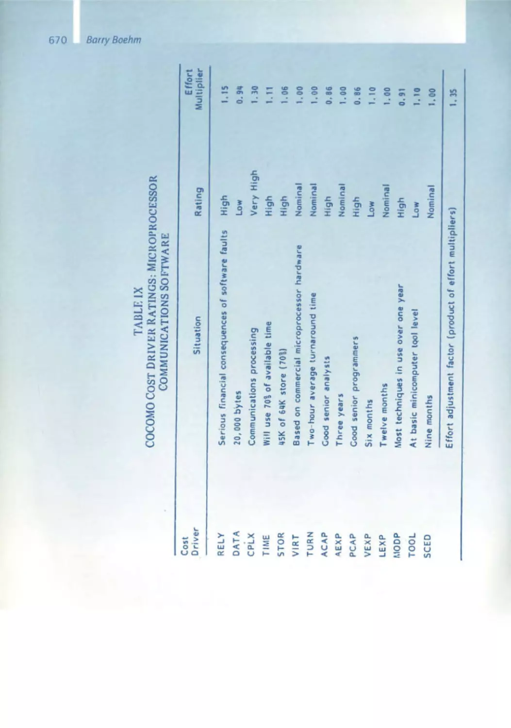
the t itle page picture showing the software cost drivers. Using the statistic
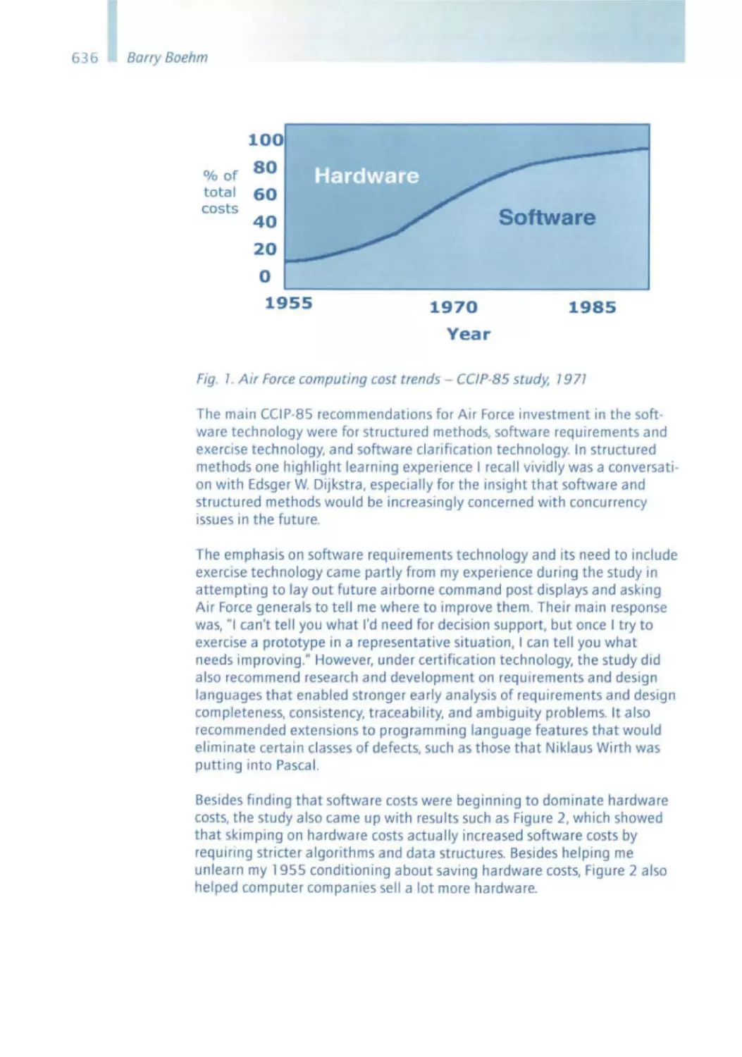
analyses that Boehm had performed at TRW, it demonstrated very trans parently whICh factors heavily influence the costs of software develop ment. The greatest influence - no surprise - was the team 's qualifications .
This gave us the SCientific proof for what we already instinct ively knew that sd&m had to be a top team .
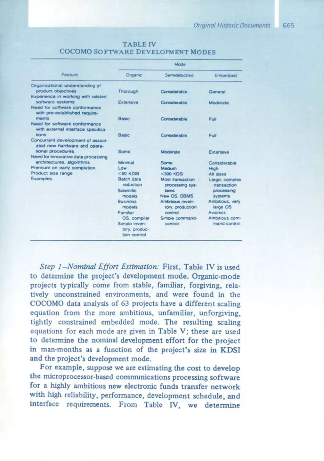
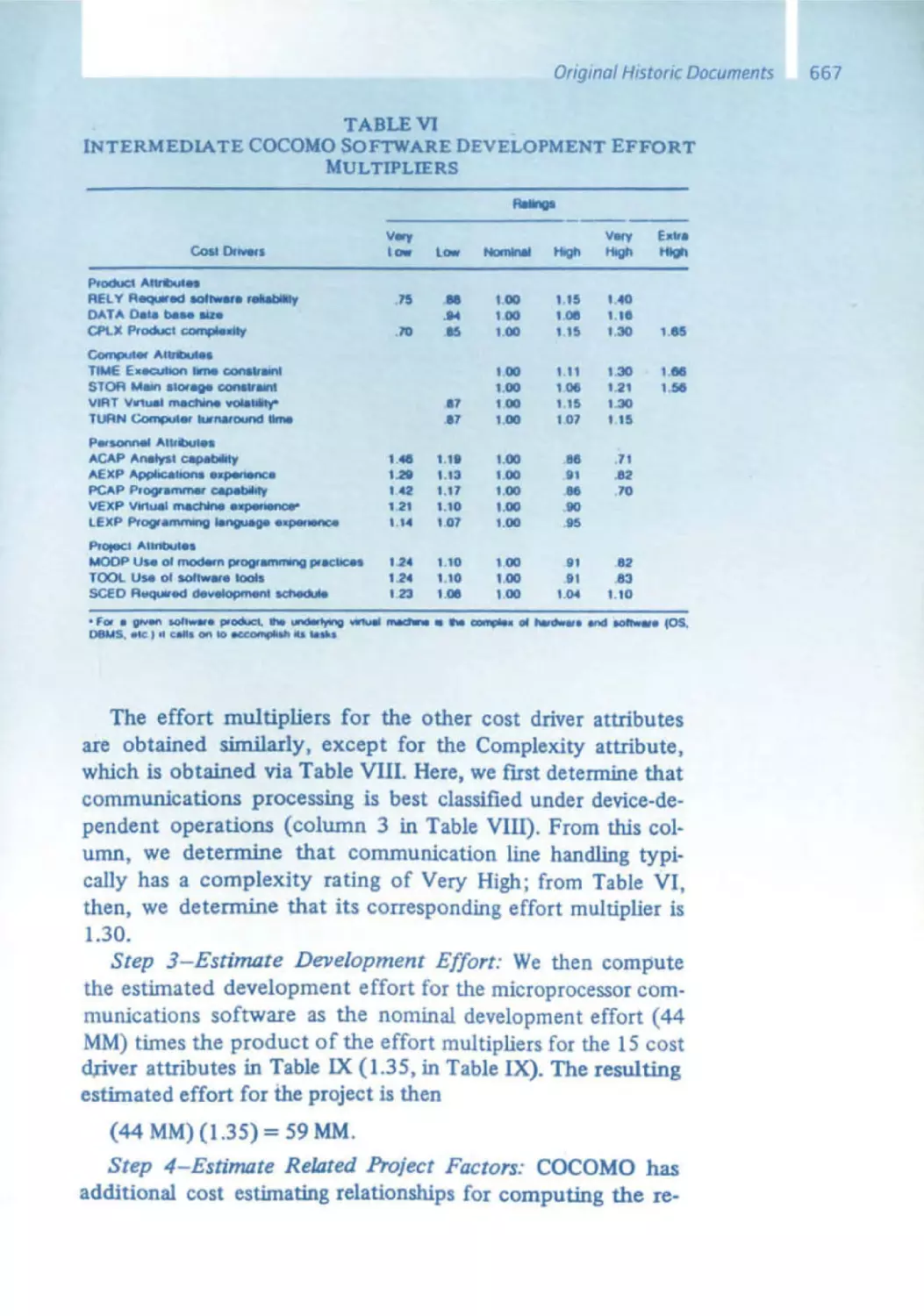
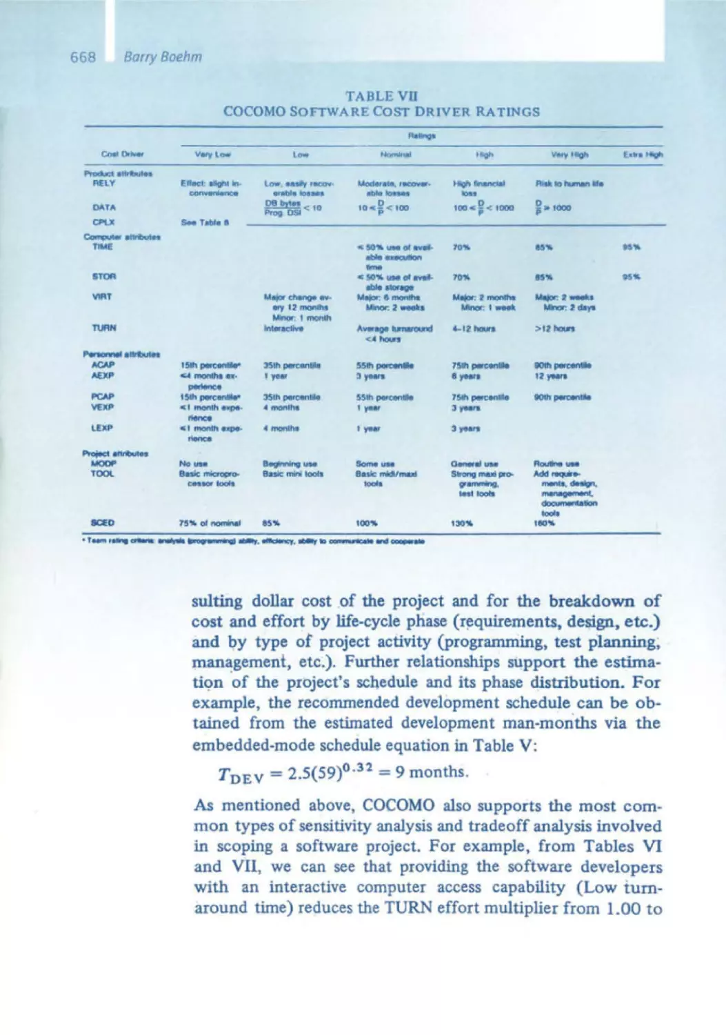
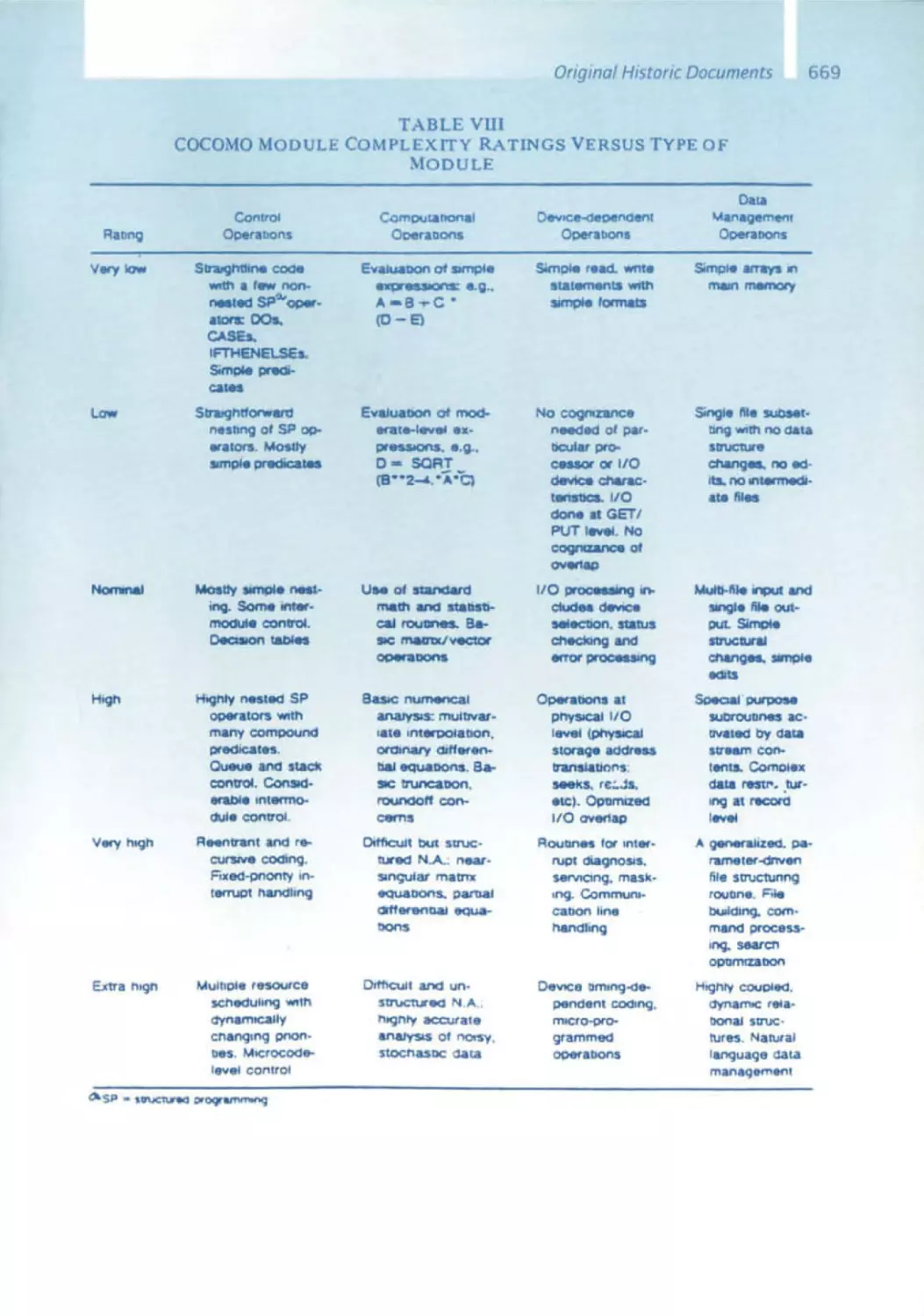
Barry Boehm's book introduced the concept of Cocomo, his constructive
cost model, whICh established the relationship between the size of a soft ware system, specified by the number of lines of code, and its development
expenses, measured In man days. From his TRW analyses, Boehm derived
precise formulas for his model. This was the first t ime a quantitative model
was established to solve the practical , highly relevant problem ofcalcula ting the costs of a software project . A drawback in this model is however
apparent : at the end of a project, it is easy to accurately count the number
of lines of code; however, at the beginning, such a calculation is hardly
possible. The function point method is an advantage here, but it is not with out its own set of problems .
Planning software projects remains a difficult task: effort estimation and
cost calculation , time and deadline scheduling, and team selection are
all complicated to execute correctly . Such planning is, however. critical for
each Individual project and for sd&m overall. Barry Boehm's concept of
software economics has contributed fundamental insights to project plan ning . Ishould not fail to mention the spiral model that Barry published in
1988 , which had a massive impact on discussions concerning the approach
to software engineering .
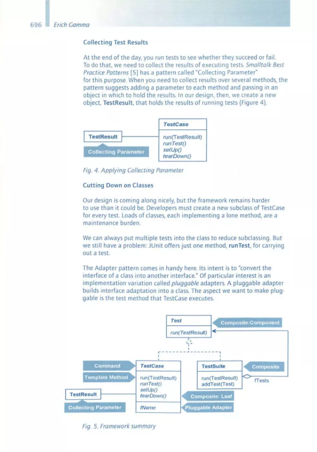
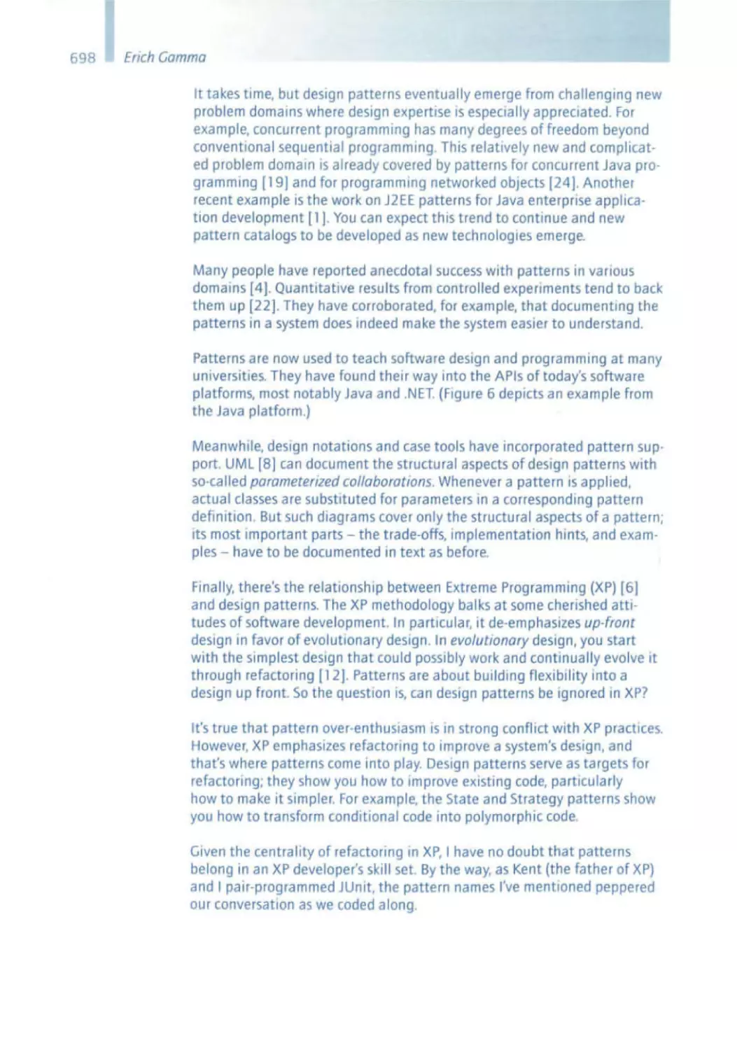
Erich Gamma - Design Patterns
Each designer, regardless whether he is deSigning a phySical product or
software , has a repertoire of solution patterns In hiS head - mostly intuitive
- each of whICh IS suited to solve a certain problem . Twenty years ago. the
architect Christopher Alexander had already collected dozens of such pat terns for architectural problems . He served as an example for Erich Gamma
and his colleagues . who established a school concerning software design
patterns in the mid-1990s . Based on object-oriented methodology, it super·
imposes concepts on constantly recurring patterns - on a higher level to
a certain extent. In other words: i f you consider the design of individual
classes or modules and operations as design -in-the-small, then you can
understand design patterns as a means for design -in-the-large . Such an
understanding is obviously very helpful in terms of the size and complexity
of the software systems that we build at sd&m. Our architecture blueprint
Quasar enables us to pursue the same objective, namely reusing good,
tried, and trusted concepts.
23
24
Some pioneers did not come
Not all the pioneers whom we had on our wish list could or wanted to
accept our Invitation . I have already mentioned Ted Codd, who could not
make It for health reasons - Rudolf Bayer spoke in his place. Others I wish
could have been present include John Backus, the developer of the first
higher programming language, Fortran, as well as Don Knuth, who worked
on VR Parsing. It is particularly disappointing that Unix was not addressed, especially because this operabng system is so significant today;
all three of ItS developers had to decline. Finally, Tim Berners-Lee,whose
report on the World Wide Web would have guided us into the newest era
in software history, turned us down . Though regrettable. their absence in
no way minimizes the program that we have put together .
"There is nothing more practical than a good theory."
Practitioners and managers in the IT industry tend to accuse the computer
scientists at universities of being bogged down by theory, and may regard
university -based research as essentially irrelevant. The Software Pioneers
here have taught us that the opposite is true. To a great extent, their
contributions originated from an academic-scientific environment. thus
substantiating the follOWing quote from Kant: "There is nothing more
practical than a good theory ."
26
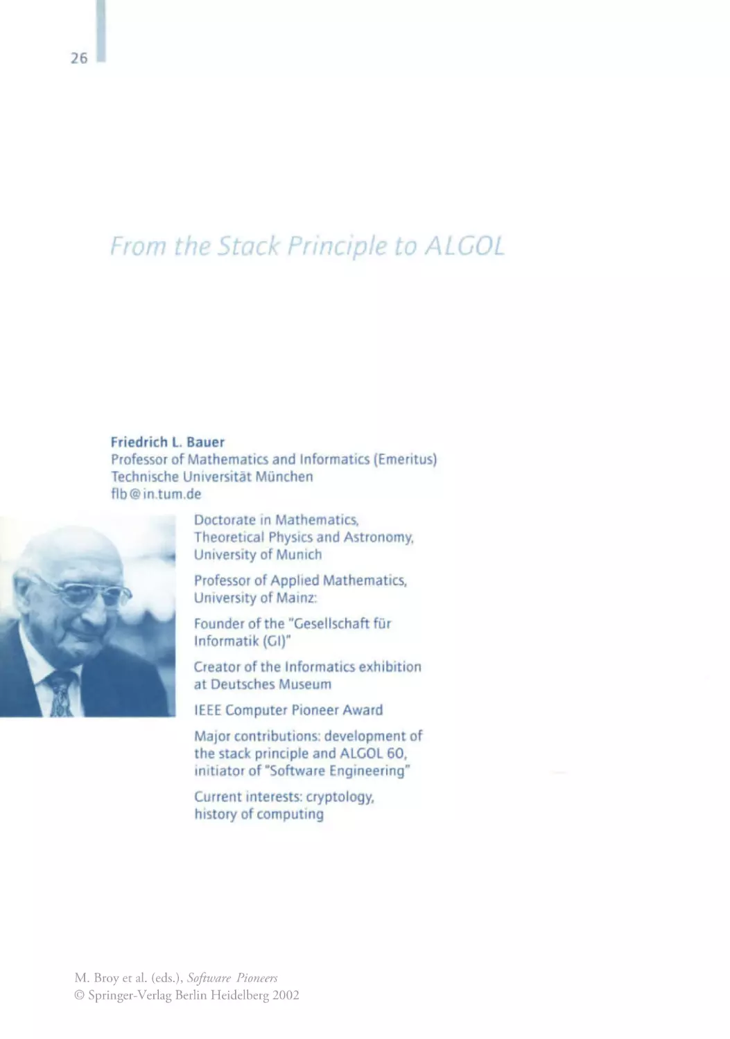
From the Stack Principle to ALGOL
Friedr ich l. Bauer
Professor of Mathematics and Informatics (Emeritus)
Technische Universitat Munchen
flb@ in.tum .de
Doctorate In Mathematics,
Theoretical Physics and Astronomy,
University of Munich
Professor of Applied Mathematics,
University of Mainz :
Founder of the "Gesellschaft fUr
Informatik (GIl"
Creator of the Informatics exhibition
at Deutsches Museum
IEEE Computer Pioneer Award
Major contributions: development of
the stack principle and ALGOL 60,
initiator of "Software Engineering"
Current interests: cryptology,
history of computing
M. Broy et al. (eds.), Software Pioneers
© Springer-Verlag Berlin Heidelberg 2002
M. Bray. E. Denert (Eds). SoftwareP,oneers
Springer·Verlag Berlm Heidelberg2002
Friedrich L. Bauer
From the Stack Principle
to ALGOL
Abstract
Certainly one of the most characteristic principles to organize computations with the help of appropriate data structures is the so-called stack
principle . It is used not only when expressions with parentheses are to
be evaluated. but even more importantly it is also the essential principle of organizing the data inside the memory when calling nested procedures. The stack principle also works for locally declared data within
scopes and is therefore the most prominent implemen tation idea when
dealing with high-level languages, scopes and block structures such
as the languages of the ALGOL family. The paper describes the early
ideas on using stacks starting from evaluating expressions and the development processes that have led to the ALGOL language family.
1. Britzlmayr and Angstl
The idea of what I later called the stack principle came into my mind
before I became seriously acquainted with what was dubbed programcontrolled calculators at that time. In the academic year 1948 -1 949
I was sittin g In a class of Wilhelm Bntzlmayr's, logician and honorary
27
28
Friedrich L. Bauer
professor at the Ludwlg-Maximlhans-Unlversitat in MUnich (his regular occupation was director of a bank). One day he spoke on the syntactic aspects (but this terminology was not used at that time) of the
parentheses-free notation that was advocated by Jan Lukasiewicz [1] .
Something stirred my interest, and thus I was not completely lost when
on June 27, 1949 In Bntzlmayr's seminar a man by the name of Konrad Zuse, while giving a survey of his PlankalkUl [4], used the checking
of the well-formedness of a propositional formula written In parenthesesfree notation as an example for a Plankalkul program (a Rechenplan,
as he called It). The discussion between Zuse and Britzlmayr brought to
light that it was an algorithm Zuse had learned from his colleague Hans
Lohmeyer, a mathematician working, like Zuse, at Henschel-FlugzeugWerke In Berlin. The algorithm originated in 1943 from the Berlin logician Karl Schroter [3], based on the 1938 work by the Viennese logician
Karl Menger [2]. While Zuse wanted to sell his Plankalkul, Britzlmayr was
interested only in the algorithm as such, and most of the discussion took
place in two different jargons, which was rather confusing.
One year later, around the end of August 1950, Bntzlmayr showed me a
sketch, made by my classmate Helmuth Angstl, for a wooden apparatus
that was intended for mechanizing the Schroter test for well-formedness
(Fig. 1).
FIg. 1
Cut from the drawing of Helmut Angstl, August 1950 (30)
Angstl's Device
The way it worked can be explained briefly, say for the propOSItIOnal
formula (p - -,q ) 1\ (-' p - (1), in the notation of Lukasiewicz
C 1p ' " 1 N lUI After a precise specification of the arity of the symbols
Involved:
.p .. q
o ll('-\'a hIN I. nullar y (:'o;{'ro ar g lllllc' lllS )
oJl(.... \'ulm·d . unury (OIl C arp,IlIUl'nl )
·C:. · f: rlllr .... \"al llr·d. hill a ry ( Iwo ar g ulIlI'lIts )
\'" ria bl!',
J1l'p,at ion .
('Ollj I 111(' \
ion . illlpikat i(lu,
the formula reads
. f': ./:
' [1
.N- .q ./ : . . '11 .q
and the outcome is a nexus such that, stepwise from right to left, the
exit of a symbol is always linked with the next not-yet-occupied entry to
a symbol:
From the Stack Principle to ALGOL
· C:
./:
·N
' ]1
./:
' (J
·N
'lJ
'J)
The formula is well-formed if all links can be accommodated under this
rule. Angstl checked this mechanically by using for each symbol a hinge
engaged in the first free position. The original draWing reflects this only
unclearly.
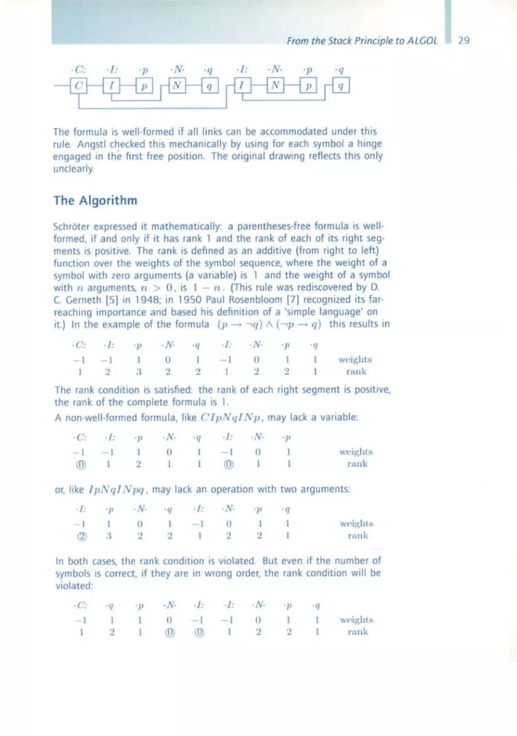
The Algorithm
Schroter expressed it mathematically : a parentheses-free formula is wellformed. If and only if it has rank 1 and the rank of each of its right segments is positive. The rank is defined as an additive (from right to left)
function over the weights of the symbol sequence. where the weight of a
symbol with zero arguments (a variable) is 1 and the weight of a symbol
with n arguments, " > O. is J - n . (This rule was rediscovered by D.
C. Gerneth [5] in 1948; in 1950 Paul Rosenbloom [7] recognized Its farreaching importance and based hiS definition of a s' imple language' on
it.) In the example of the formula (p -> -' (1 ) /\ (-' P - q) this results In
. ('.
.J:
- 1
'2
.p
.N-
1
0
2
:J
' 1/
1
2
./:
. v·
- I
1
(l
I
2
2
' /1
' 1/
I
1
wPlg hts
rank
The rank condition IS satisfied: the rank of each right segment IS positive.
the rank of the complete formula is 1.
A non-well-formed formula. like CJpNqI l p, may lack a variable:
·c:
./:
' J!
1
· N·
(J
@
2
I
' IJ
./ :
·N·
L
1
1
II
@
1
'J!
W(' ig ht :o;
n \llk
or. like TpN q/ Npq , may lack an operation with two arguments:
. /.
®
'IJ
'1'
L
:J
0
'2
. /:
'f!
1
()
'2
2
.q
1
2
rallk
In both cases, the rank condition is violated . But even If the number of
symbols IS correct, If they are in wrong order. the rank condition will be
violated :
.f':
'f}
' JI
.N-
/:
./:
N-
o
1
- I
o
@
@
'2
' IJ
l'/\IIk
29
30
Friedrich L. Bauer
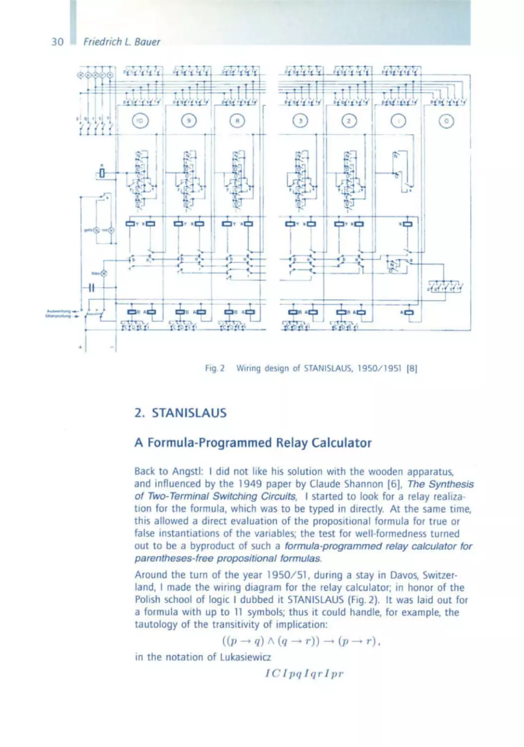
Fig. 2
WIring design of STANISLAUS, 1950 /1 951 (8)
2. STANISLAUS
A Formula-Programmed Relay Calculator
Back to Angstl: I did not like his solution with the wooden apparatus.
and influenced by the 1949 paper by Claude Shannon [6). The Synthesis
of Two-Terminal Switching Circuits. I started to look for a relay realization for the formula, which was to be typed in directly. At the same time.
this allowed a direct evaluation of the propositional formula for true or
false instantiations of the variables; the test for well-formedness turned
out to be a byproduct of such a formula-programmed relay calculator for
parentheses-free propositional formulas _
Around the turn of the year 1950/51 , dUring a stay in Davos. SWitzerland, I made the wiring diagram for the relay calculator; In honor of the
Polish school of logiC I dubbed It STANISLAUS (Fig. 2). It was laid out for
a formula with up to 11 symbols; thus it could handle. for example. the
tautology of the transitivity of Implication:
« p --+ q) 1\ (q --+
r»
--+
(p
in the notation of LukasiewIcz
I C lpqlq 1' Ipr -
--+
r ).
From the Stock Principle to ALGOL
- 1
- 1
- 1
I
2
:1
:l
- I
1
1
-I
1
2
:I
2
I
2
rank
Possibilities for instantiation were provided for five variables, designated
by 7>, fJ, ,', s, t. The operations I (negation), C (conjunction), D (disjunction), E (equivalence), I (implication) were realized by contact
switches and suitable combinations thereof, and the connections were
formed by two pyramids of relay contacts facing each other, where for example the prenex formula with six variables CCCCCpq rpq,. needed
the full depth of the rank:
- I
- 1
- I
- 1
- I
Ii
I
\wight,.
:1
rank
The Cellar
The staircase-like wiring for the two pyramids forming the connections
between the symbols suggested calling this part of the diagram a cellar
(German Keller) . In fact, the cellar was laid out for one additIOnal storey.
the bottommost wire serving the check for well-formedness. Thus the
original problem was solved as a byproduct.
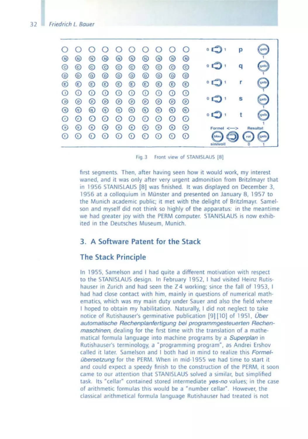
Figure 3 shows a front view of the logic calculator. The formula
TClpqlqrlp,. is typed in. A toggle switch serves, when in the left po·
sition, to check the well·formedness, and when in the right position, to
evaluate the formula. The truth values for the variables (1 for true, 0
for false) can be input as well by toggle switches. If the formula typed
in is well-formed, a blue signal will appear; the evaluation will produce a
yellow signal for true, a red one for false.
HaVing finished the wiring diagram, I started to collect matenal for the
construction of the device. In October 1951 I entered into a consulting
contract with the Siemens company in Munich; from time to time I could
now help myself from the surplus bin of the Siemens-HalskeAG Central
laboratory in the Munich HoffmannstraBe, where relays and keyboards
were to be found. Now and again, Britzlmayr urged me to start with the
actual construction, but I had too many other obligations. Towards the
end of 1951, I finished my dissertation under Fritz Bopp; in October 1952
I became an assistant to Robert Sauer, which led me, among other occupations, to work in the team that under Hans Piloty and Robert Sauer
constructed the PERM (Programmgesteuerte Elektronische Rechenan/age Miinchen, Programm-controlled computer Munich). In this respect,
I could hope for some support from Piloty's mechanical workshop. It was
only in 1954 that I started, under the attentive eyes of my colleague
and friend Klaus Samelson and helped by Heinz Schecher, to wire the
31
32
Friedrich L. Bauer
0 0 0 0 0 0 0 0 0 0
® ® ® @ ® ® ® ® ® ®
@
@
®
CD
@
®
0
@
CD
@
®
®
CD
®
®
0
®
<D
@
@
@
@
@
@
@
@
@
@
® ® ® ® ®
0) 0) 0) CD
® ® ® ® ®
® ® ® ® ®
(0 0 0 0 0
® @ ® ® 0
0 (!) CD CD <D
(!)
@
@
@
@
©
@
® ® ®
CD 0) CD
® ® ®
® ® ®
0 0 0
@ 0 ®
(!) CD CD
00 '
00 '
p
00 '
r
Front
view
1
q
1
1
00 '
0':> '
s
t
e,
e
1
Formel
<->
Resullal
9 e> 09
0
sinnvoll
Fig. 3
e
e
e
1
of STANISLAUS (8)
first segments. Then, after having seen how it would work, my interest
waned, and it was only after very urgent admonition from Britzlmayr that
in 1956 STANISLAUS [8] was finished. It was displayed on December 3,
1956 at a colloquium in Munster and presented on January 8, 1957 to
the Munich academic public; it met with the delight of Britzlmayr. Samelson and myself did not think so highly of the apparatus: in the meantime
we had greater JOY with the PERM computer. STANISLAUS is now exhibited in the Deutsches Museum, Munich.
3. A Software Patent for the Stack
The Stack Principle
In 1955, Samelson and I had quite a different motivation with respect
to the STANISLAUS deSign. In February 1952, I had visited Heinz Rutlshauser In Zunch and had seen the Z4 working; since the fall of 1953, I
had had close contact with him, mainly In questions of numerical mathematics, which was my main duty under Sauer and also the field where
I hoped to obtain my habilitation . Naturally, I did not neglect to take
notice of Rutlshauser's germinative publicatIOn [9] [10] of 1951, Uber
automatische Rechenplanfertigung bei programmgesteuerten Rechenmaschinen, dealing for the first time with the translation of a mathematical formula language Into machine programs by a Superplan in
Rutishauser's terminology, a "programming program", as Andrei Ershov
called it later Samelson and I both had in mind to realize this FormelObersetzung for the PERM When In mld-1955 we had time to start it
and could expect a speedy finish to the construction of the PERM, It soon
came to our attention that STANISLAUS solved a similar, but Simplified
task. Its cellar" contained stored intermediate yes-no values; In the case
of arithmetic formulas this would be a "number cellar" . However, the
classical arithmetical formula language Rutishauser had treated is not
H
From the Stock Principle to ALGOL
parentheses-free. Every opening parenthesis amounts to a delay in the
execution of the last arithmetical operation, until the corresponding clos,ng parenthesIs IS found. Thus, It was natural to provide next to the number cellar for intermediate results an "operation cellar" for delayed operation symbols. We had to rack our brains to find the interplay between
these two cellars, for this task Samelson made full use of his analytical
talent , a particular problem being the "invIsible parentheses" caused by
the precedence of certain operations like multiplication over others like
addition .
The total history of the operations delayed in such a way determined
the course of execution; the automaton that was suffiCient for the parentheses-free notatIOn was replaced by a Kellerautomat (push-down automaton) for the execution of formulas in languages with parenthetical
structure. The cellar had to be programmed Into what came to be called
a stack. Thus the idea of the stack principle (Kel/erprinzip) was bornfree of hardware and usable for a Wide class of languages-actually for
context-free languages.
x
y
1:
x
End ...
n
r
"
()
r
r
() Y
<1 X (
" X V
a X
I
I
r Y
TV
I
rvv
<1-1
a I (
() I. V
I
r ...
1''''
a(
r
0<
,
'I"
11;-
"
n
"
I
TVV.
ry
,, ((
I
,, (v
,,(X
I
I
T
Tlo'
"r
t
T
,, +X
n
r
r
r
nC
i-
"r
T
<1 V
I
--+
(/)
(.J .......
'iJ
I/J V
(11
v
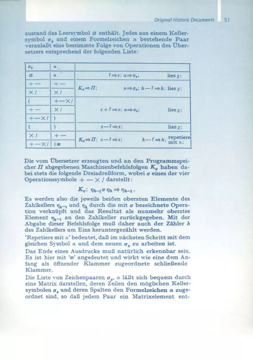
Flg.4 TranSition matrix for the stack automaton (infix notation with
and x ). [26)
For the concrete case of arlthmetics with precedence of x over + we
chose In [26] a description (Fig. 4) by a matrix with an entry line for the
next symbol read- where y stands for a number variable (numbers
included)- and an entry column containing pairs of number cellar and
operation cellar. rT stands for a sequence of operation symbols and T for
a sequence of number variables. In the matrix fields are found pairs of
resulting number cellar and operation cellar contents and between them
33
34
Friedrich L Bauer
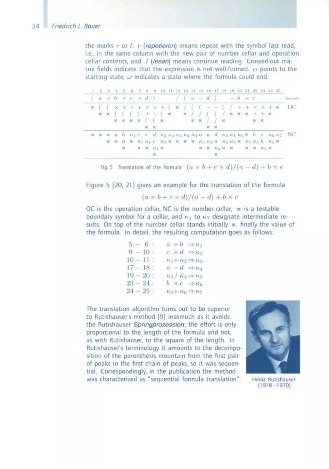
the marks I' or I : ,. (repetieren) means repeat with the symbol last read,
i e., In the same column with the new pair of number cellar and operation
cellar contents, and I (/esen) means contmue reading Crossed-out matriX fields indicate that the expression IS not well-formed. l\ pOints to the
starting state, w mdicates a state where the formula could end.
I
'2
].
I
r.
h
•
(
fI
X
b
...
t'
X d
X
X
+ +
(
(
(
(
JG
•
III
..
.. ..
(
III
X
I-
(
III
..
..
fI
(J
b
"I ('
•
IIC'
(I
..
Ie
fa
'"
+
1.'1 1 I
/
(
fI
/
(
..
+
(
12
II
II
..
d
"1-.
('
..
11
•
(
H1"'1"
II
10
..
1."'_ I h
(
/ /
..
•
":j "';\ "';\ "'\"
I '"
I fl :,W 11
1.2
b
('
..
- -
( /
(
(
"
d
"'I "I
x
"'r. 11 I. (' "" '"
;\ ('
II:
h':''''":,_
u+ (' X
II
O C'
r1)/( fl
..
Ie
H."t". b
....
(0
I.
+ •
"I_
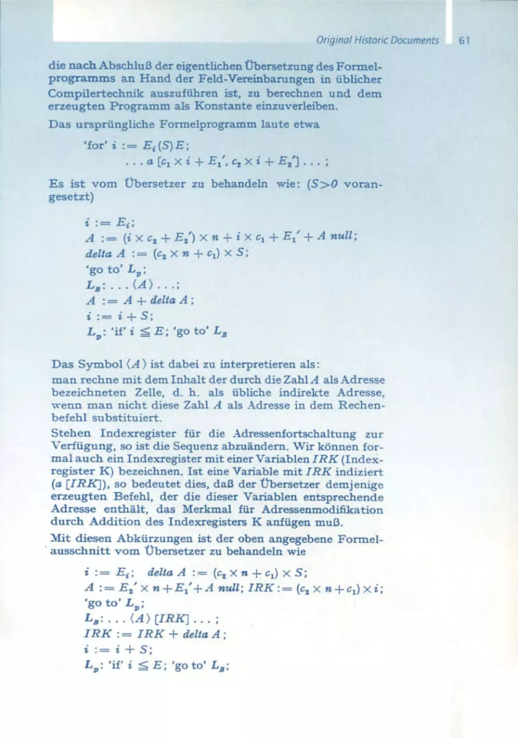
Fig 5 Translation or the rormul a
2 I :'::"1
I
..
,,':1"':'"
X
/
II
/ /
II
f(:/
I j"
d )
1:,._
"'6 III
r/) + b
x ('
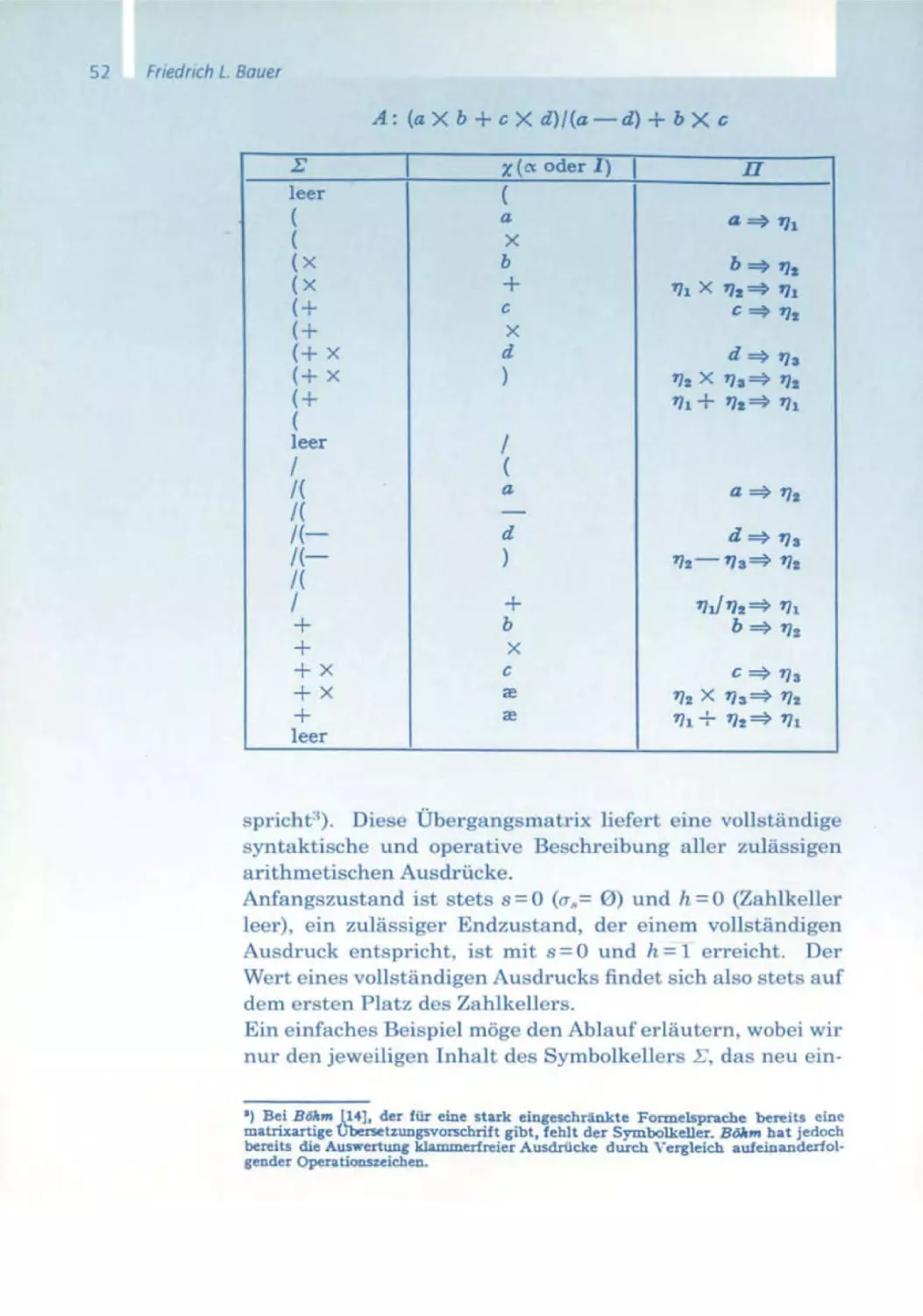
f igure 5 [20 , 21] gives an example for the translation of the formula
((I x b + ('
X
tl )/( a - cl) + b x ('
DC IS the operation cellar. NC IS the number cellar. III IS a testable
boundary symbol for a cellar. and" I to " 7 designate intermediate results. On top of the number cellar stands initially lI!! , finally the value of
the formula. In detail, the resulting computatIOn goes as follows:
5 - (j :
9 - 10 ,
10 - J 1 :
17 - I
19 - 20 :
23 - 21 :
2·1 - 25 :
(l x b =* "1
C x d =* " 'J.
"'+ =*
- d =* " ,1
":I / ,,-1=* " ',
1-;2
" :I
fI
b x (' =* lir,
" f,+ "n=* " 7
The translation algorithm turns out to be superior
to Rutishauser's method [9] inasmuch as it avoids
the Rutlshauser Springprozession; the effort is only
proportional to the length of the formula and not,
as with Rutishauser, to the square of the length . In
Rutishauser's terminology It amounts to the decomposItion of the parentheSIS mountain from the first pair
of peaks In the first chain of peaks, so It was sequential. Correspondingly, In the publication the method
was characterIZed as "sequential formula translation" ,
Heinz Rutishauser
(1918 - 1970)
From the Stack Principle to ALGOL
Hardware Stacks
We gave a report on our results to Sauer and Piloty. Piloty remarked that
the German Research Council (Deutsche Forschungsgemeinschaft) had
a tendency to make sure that patents were obtained for the projects It
supported; he urged us to examine whether this would be possible In our
case. We agreed, and he offered the prospect of providing the successor
machine of the PERM with a number cellar and operat ion cellar in hardware. This must have been in the summer or fall of 1955 .
For the patent applicatIOn we had to disgUise our
method as hardware, and for this purpose had to
become engineers. The elaboration of the patent
application therefore brought a lot of work and was
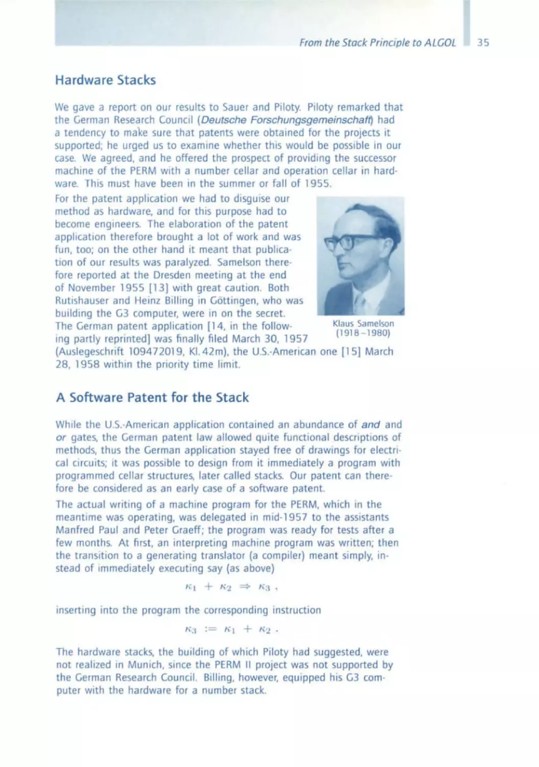
fun, too; on the other hand it meant that publication of our results was paralyzed. Samelson there fore reported at the Dresden meeting at the end
of November 1955 [13J with great caution. Both
Rutishauser and Heinz Billing in G6ttingen , who was
building the G3 computer, were in on the secret.
The German patent application [14. in the follow Ing partly reprinted] was finally filed March 30. 1957
(Auslegeschrift 109472019, KI. 42m), the U.s.-American one [15] March
28, 1958 within the priority time limit.
A Software Patent for the Stack
While the U.s.-American applicatIOn contained an abundance of and and
or gates, the German patent law allowed qUite functional deScriptions of
methods, thus the German application stayed free of drawings for electrical CIrcUIts; It was possible to deSign from it immediately a program With
programmed cellar structu res, later called stacks. Our patent can therefore be conSidered as an early case of a software patent.
The actual writing of a machine program for the PERM, which In the
meantime was operating, was delegated In mid-1957 to the assistants
Manfred Paul and Peter Graeff; the program was ready for tests after a
few months. At first, an Interpreting machine program was written; then
the transition to a generating translator (a compiler) meant Simply, instead of Immediately executing say (as above)
". I
+
"':1.
"' 2
inserting into the program the corresponding instruction
Ka := "" 1
+
1\.2 •
The hardware stacks, the bUilding of which Piloty had suggested, were
not realized in Munich, since the PERM II project was not supported by
the German Research Council. Billing, however, equipped his G3 computer with the hardware for a number stack.
35
36
Friedrich L. Bauer
4 . The ZMD Group and ALGOL
At a meeting In Darmstadt In October 1955. Rutishauser appealed for
an attempt to UnIfy programming languageS-FORTRAN had appeared
In the meantime. As a consequence. the German-Austrtan-Swlss Gesellschaff fur angewandte Mathematik und Mechanik (GaMM) established
a committee for programming, which for Interested people in Zunch. Munich. and Darmstadt became in 1956 the umbrella for jOint work towards
the development of a sUitable programming language. The ZMD (ZunchMUnich-Darmstadt) group. with Rutishauser. Samelson, myself. and Hermann Bottenbruch from Darmstadt as representatives. met in the fall of
1957 in Lugano in order to pass a first proposal for the intended programming language. This proposal was based on an extension of the
stack principle for arithmetics to the whole programming language and
was characterized by the catch phrase: • Postpone as long as necessary,
but not longer" _ Together with Bottenbruch. I travelled In summer 1957
through the United States and advocated the proposal to people mterested Alan Perlis. Bob Rich. Saul Gorn, and many others. John W. carr. at
that time president of the ACM, reacted with enthusiasm and arranged
for a U.s.-American committee. which met several times in January 1958 .
Comparison with the transmitted proposals of the ZMD group showed
some concord Thus the mutual wish for a jOint working meeting arose.
From the European side an invitation for participation also went to the
British Computer Society, but due to a mishap on the side of Maurice
Wilkes no reaction came from there. Therefore a U.s.-Amencan delegation, conSisting of John Backus. Charles Katz. Alan J. Perlis. and Joe Wegstein. met from May 27 to June 2, 1958 10 Zunch with the GaMM delegation Rutlshauser. Samelson. Bauer. and Bottenbruch [19a. b].
The Zurich Meeting
In the summer of 1957, Bottenbruch became initiated in the Munich Sequent ial formula Translator method [16], and at the Zurich meeting the
ZMD group not only presented a draft [17] for the language, whIch at
first was called International Algebraic Language. but also had a completed compiler design 10 the bag. Some U.s.-Amencan delegates had
experience with working compIlers (Backus with FORTRAN. Perils with IT.
Katz with MATH-MATIC}. An open discussion of the technical problems
of programming language translation Into machine code was left out, as
there would not have been enough time. Technically speaking, the state
of the art within the ZMD group was far more advanced: FORTRAN used
the method of parentheses completion. Introduced by P. B. Shendan [18]
and discussed as early as 1952 by Corrado Boehm (11) in his Zurich diSsertation. a method that like Rutishauser's reqUired an effort proportional
to 1)2; IT [12] used pure comparison of neighboring operators, enforcing
an oppressIve limitation to operator precedence grammars. This situation
led from time to time to a paralysis of the discussion, which was basically oriented towards progress. On the whole. ALGOL. as it was called
in the publication [19b]. was an incarnation of the cellar principle and
From the Stac/( Principle to ALGOL
thus particularly well suited for efficient translation, which was a main
concern of the impoverished European side. In Zurich, Samelson had particularly stressed the point that the block structure of storage allocation
(Cellar Principle of State Transition and Storage Allocation, [30]), following so naturally from the cellar pnnciple and becoming so tYPical in
the later development, became the dominant organizatIOn pnnciple of
the programming language. Storage allocation with complete parentheses
structure should be organized in a dynamic stack, which without further
complicatIOns allowed mastery of recursive definitions . The compromise
that was achieved In a struggle with the U.s.-Amencan Side did not reflect thiS Issue In the published report; thus, later the implementation of
recursive situations was reinvented by some people not present at the
Zunch meeting .
T he Preliminary ALGOL Report
The goals attempted by the ZMD group, to create a language widely
following mathema tical notation, readable without much ado, and suitable for publications and for mechanical translation, had been largely
reached. The publication was completed in 1959 in the first issue of the
new journal Numerische Mathematik of Springer-Verlag under the title
Report on the Algori thmic Language ALGOL.
5. Work at Mainz University
When In 1958 1 moved from Munich to Malnz. with Samelson soon following me. the ZMD group was widened to the ZMMD group. Emphasis
was on finishing compilers for ALGOl 58 . The common basis was the
method of a stack automaton developed in Munich. which was extended
without any difficulty to a full algorithmic language including statements.
declarations. block structure, indexed variables, and so on. It was pub·
lished in 1959 in the newly founded journal Elektronische Rechenanlagen ([20], in the following reprinted). and in 1960 in Communications
of the ACM [211 Manfred Paul. who had done most of the preparatory
work, finished a compiler for the Malnz Z 22 towards the end of 1958 .
Soon afterwards. H. R. Schwarz and P Uiuchh followed in Zurich for the
ERMETH and G. Seegmuller in Munich for the PERM.
ICiP Conference
A lot of work was caused by the preparatIons for ALGOL 60. At the International Conference on Information Processing (ICIP), arranged in
Pans. June 15-20, 1959 by UNESCO, John Backus [24] made a famous
proposal for the formal description of the syntax. The Backus notation
(Backus Normal Form). soon generally accepted, allowed one to attach
in an elegant way the semantics of the programming language to the
syntax of a context-free language. Manfred Paul, in his 1962 dissertation, clarified how from thiS description the transition matrix for the stack
automaton could be der'ved fr rmally.
37
38
Friedrich L. Bauer
Christopher Strachey. who- inadvertently - had not been invited to the
Zurich meeting. went into the trouble of criticizing ALGOL 58 and produced not only considerable stir, but also a lot of public attention . Thus,
it was not too difficult to convince the International Federation for Information Processing , founded in Paris, to orgaOlze a conference for the
"flnal ALGOL", later called ALGOL 60 The preparations were this time
much more Intensive; a European pre-conference was held in November
1959 in Paris; It nominated seven European delegates, who met again
in December 1959 in Malnz. The U.S.-Amencan side nominated its delegates In November 1959. This time, representatives from Great Botaln,
France, the Netherlands, and Denmark, besides representatives from the
U.S.A., Germany, and SWitzerland, were inVited.
Paris, 1960
The ALGOl conference took place
in Paris, January 11 - 16, 1960 under
the patronage of the newly founded
IFIP. It led to consolidations and completions of the Preliminary Report.
Characteristically, the introduction to
the report [25a, b] says "The present
report represents the union of the
committee's concepts and the inter section of its agreements". In this
way, contradictions could remain here
and there and solutions were omit ted. What made me particularly angry was that Samelson, who in 1958
Friedrich L Bauer and Klaus Samelson
regarding the question of the block
at the Pans ALGOL Conference. 1960
structure could not Win against Alan
PerilS, In 1960, when acceptance of recurSion was no longer an Issue, was
given no credit for the block structure; the editor Peter Naur, who was
not present in Zunch, was not aware of this.
In the short peflod of SIX days we also did not succeed In formalizing,
next to the syntax which now was formalized in BNF (Backus Normal
Form), the semantics as well; it was stili explained rather verbally, leading
later to exegetic quarrels. HeinZ Zemanek tried, with the IFIP TechOlcal
Committee 2 Working Conference Formal Language Description Language , held in 1964 In Baden near Vienna, to compensate for this lack.
Peter Landin [29] gave a complete formal description of ALGOL 60, but it
lacked the blessing of the authorities.
6. The AlCOR Group
After the ICIP Congress, June 1959 in Paris and particularly after the
publication of the ALGOl 60 report, the ZMMD group decided to widen
its membership and invited interested institutions in Europe and North
From the Stack Principle to ALGOL
America to participate 10 the efforts for propagation of ALGOL through
the construction of ALGOL compilers for various different machme configurations; the documents of the prevIous ZMMD group were made available for thiS purpose. The offer was accepted by sCientific mstltutlOns
(among the first were Regnecentralen Copenhagen, Bonn University, Zemanek's MailOfterl group in Vienna. Oak Ridge National Laboratory, Neher Laboratory Leidschendam) as well as by some computer companies
(Siemens and Halske AG for the 2002, Telefunken for the TR4, Standard
Elektrik Lorenz AG, IBM Germany). The resulting multitude of concrete
Implementations was unavoidable because of the differences in the machmes involved, but It was useful 10 its sCientific aspects. For example,
Albert A. Grau, Oak Ridge. introduced the concept of syntactic states and
described the compiler as a system of mutually recurSive subprograms
[31] . Peter lucas in Vienna went his own way [32] in generating, like
Paul In Mamz [33,34], the compiler from the syntax in BNf. JOrgen Eickel
and Manfred Paul. in 1964. studied the parsing and ambiguity problem
for Chomsky languages 10 general [39] .
After my return to Munich in 1963, the build-up of computer science
there became my main obligatIOn. leavmg less time to be spent on the
further development of ALGOl. The way It went became more and more
of a nightmare. leadmg to ALGOL 68 and to the ruin of the ALGOL Idea.
One after another, people left the IFIP Working Group 2.1 on ALGOL:
Peter Naur. Nlklaus Wirth. Tony Hoare, Edsger Dijkstra. Brian Randall,
Gerhard Seegmuller, WI ad Turski, Mike Woodger. Hans Bekic. and Fraser
Duncan.
Stacks in Hardware and Software-Worldwide
The use of cellar storage (stacks, pushd own stores) did not remain restricted to ALGOL compilers. Peter Deussen [35] used them for the trans·
latlon of Boolean expressions in disjunctive normal form, and Walter Petry
[36] for the translatIOn of formal languages in topological structures.
Conversely, familiarity with stacks did lead frequently to the systematic
use of fully parentheSIZed language structures. Donald Knuth built his
text programming system TEX in this way.
Hardware cellars, stacks, and pushdown stores have been discussed elsewhere, possibly as early as 1947 by Alan Turmg, certainly 10 1949 by
Harry D. Huskey 10 connection with the ZEPHYR (SWAC) computer and
10 1956 by Willem l. van der Poel in connection with the deSign of the
MINIMA computer; 10 all cases presumably for the treatment of return
Jumps in subroutines More generally. Charles L. Hamblin, 10 a December
1957 publication [371, recommended strongly the use of hardware stacks.
Hardware stacks were built 10 the Burroughs machlOes. B5000 onwards.
and in mml computers such as PDP-8 and PDP 11 (Fraser George Duncan
[38]) . Hewlett -Packard programmable pocket computers like the HP-" C,
which I still have 10 use, work with a 4-level number stack.
In time, however, It was discovered at many places that It was preferable
to Implement stacks 10 software by "linked memory techniques", for exampl e when A. Newell, J C. Shaw. and 1-1 A. Simon 10 1956 programmed
39
40
Friedrich L. Bauer
the" Heuristic Problem Solver" IPL-II. After 1960, chained storage structures became quite common.
Among the first to establish a connection between the theory of formal languages and our stack principle were S. Ginsburg and H. G.Rice
in 1961 The connection between formal languages and stacks was also
discussed 10 1961 by Y. Bar-Hillel, in 1962 by S. Ginsburg, and 10 1963
by B. A. Trachtenbrot . Theoretical studies on cellar automata (pushdown
automata) and context -free languages were done 10 1963 through an
Interplay of N. Chomsky and M. P.Schutzenberger.
None of the early full programming languages was so vigorously influ enced by the stack principle as ALGOl. Today, the stack principle IS so
ubiqUitous In software systems of all sorts that a denotatIOn for It IS
hardly needed or used.
References
II] J lukaslew icz. A Tarski Untersuchungen uber den Aussagenkalkul.
Soc. Sci. lett. Varsovie, CI. III, 23 (1930) 31 - 32
C R.
12) K. Menger: Elne elementare Bemerkung iJber die Struktur loglscher Formeln. In. K.
MengeL Ergebnisse elnes mathematlschen KollOQuiums 3, Deuticke, LeipZig (1935)
(3) K. 5chroter Axiomatisierung der Frege'schen AussagekalkOle. In Forsthungen zur
Loglk und zur Grundlegung der exakten Wissenschaften, N F.8.
J Symb LogiC 9 (1943) 69
14] K. Zuse Uber den Allgemelnen Plankalkul als Mittel zur Formullerung sthematlsth ·
komblnatlver Aufgaben. Arch Math . 1 (1948 / 49) 441 - 449
IS] D. C. Gerneth: Generalization of Menger's result on the structure of logical formulas.
Bulletin of the Amencan Mathematical Society 54 (1948) 803804 ;
J Symb LogiC 13 (1948) 224
[6] C. E. Shannon' The syntheSIS of two·termlnal SWitching CIrcuits.
Bell Syst. Tech J. 28 (1949) 59- 88
[7J P C. Rosenbloom: The Elements of Mathematical Logic. Dover, New York (1950)
[8J F L Bauer' The Formula·Controlied logical Computer · Stanlslaus·
Math . Tabl. Aids Compo 14 (1960) 64 - 67
[9J H. Rutlshauser Ober automatlsche Rechenplanfertlgung bel programmgesteuerten
Rechenanlagen Z. Angew. Math . Mech. 31 (1951) 255
10J H Rutlshauser Automatlsche Rechenplanfertlgung bel programmgesteuerten Rechen·
masthinen. Z. Angew Math . Mech. 32 (1952) 312- 313,
Mitt Inst r Angew Math . der ETH Zunch, Nr. 3, 1952
11] C. Boehm: calculatr ices dlgltales. Du
de formules
par la machine meme dans la conception du programme. Dissertation ZOnch (1952),
Ann. Matematlca Pura Appl. Ser. 4, 37 (1954) 5- 47
12) A J Periis, J W Smith, H. R. van Zooren Internal Translator (IT), a Compiler for the
650 . Lincoln lab. Div 6, Document 60·327 (1956)
13] K. Samelson. Probleme der Programmlerungstechnlk. Internatlonales Kolloqulum iJber
Probleme der Rechentechnlk Dresden 1955 . Berlin (1957) 61 - 68
From the Stack Principle to ALGOL
(14) Deutsches Patentamt, Auslegeschrlft 1094019 , B441221x/42m . Verfahren zur automauschen Verarbeltung von kodlerten Daten und Rechenmaschlne zur Ausubung des
Verfahrens. Anmeldetag 30 Marz 1957 Bekanntmachung der Anmeldung und Ausgabe der Auslegeschrift: 1 Oezember 1960
Dr FnedrlCH LudwIg Bauer und Dr. Klaus Samelson, MLinchen, sind als Erfinder genannt worden. Erterlt 12.81971 , OE-PS 1 094019
(15) United States Patent Office. Patent No. 3,047 ,228, Patented July 31, 1962
Friedrrch LudWig Bauer and Klaus Samelson Automatic Computing Machines and
Method of OperatIon. Filed March 28, 1958, Ser No. 724,770
(16) H Bottenbruc.h Ubersetzung von algomhmlschen Formelsprachen In die Programmlersprachen von Rechenmaschlnen Z. Math . Loglk Grundl. Math . 4 (1958) 180- 221
117) F L Bauer, H. Bottenbruc.h, H. Rutlshauser, K. Samelson: Proposal for a universal
language for the desc.rrptlon of computing processes. In: carr, J. W (ed.), Summer
School 1958 . University of MIChigan (1958) 355-373
118) P. B. Shendan: The anthmetlC translator-compiler of the IBM Fortran automatIC codIng system. Commun. ACM 2,2 (1959) 9- 21
Jl9a) A. J Perils, K. Samelson (eds.): Report on the algonthmlc language ALGOL by the
ACM committee on programming languages and the GAMM committee on program·
mlng. Num. Math 1 (1959) 41 - 60
[19b] A J Perlis, K. Samelson (eds.): Preliminary report - mtemational algebraiC language.
Commun. ACM 1 (1959) 8-22
(20J K. Samelson, F l. Bauer: Sequentlelle FormelLibersetzung.
Elektron. Rechenanlagen 1 (1959) 176 - 182
[21] K. Samelson, F. L Bauer. Sequential formula translation.
Commun. ACM 3 (1960) 76-83
(22) F L Bauer, K. Samelson The cellar principle for formula translation In Proceedings
Intematlonal Conference on Information Processing, UNESCO Paris 1959 Oldenburg,
MLinchen (1960) 154 - 155
(23] F L Bauer, K. Samelson' The problem of a common language. In: Proceedings In·
tematlonal Conference on Information Processing, UNESCO Pans 1959 . Oldenburg,
Munchen (1960) 120- 125
(24] J. W Backus The syntax and semantics of the proposed Intematlonal algebraiC Ian·
guage of the Zunch ACM·GAMM conference. In' Proceedings Internatronal Conference
on Information Processing, UNESCO Pans 1959 . Oldenburg, MLinchen (1960) 125 132
(2Sa) J W Backus. F L Bauer, J Green, C Katz, J Mccarthy, P Naur (ed.), A. J. Perlis,
H. Rutishauser, K. Samelson, B. Vauquois, J. H. Wegstein, A van Wijngaarden, M.
Woodger Report on the algorithmic language ALGOL 60.
Num. Math . 2 (1960) 106- 136
[25bJ J W Backus. F L Bauer, J Green, C. Katz. J Mccarthy, P Naur (ed.), A J Perils.
H Rutlshauser, K. Samelson, B. Vauqols, J H Wegsteln, A van WIJngaarden, M
woodger : Report on the algOrithmiC language ALGOL 60
Commun. ACM 3 (1960) 299314
41
42
Friedrich L. Bauer
(26) F L Bauer. K. Samelson: Maschlnelle Vera/beltung von Programmiersprachen, In:
W Hoffmann (ed,). Digitale Info/matlOnswandler Probleme der Informationsverarbeltung In ausgewahlten Beitragen Vieweg, Braunschweig (1962) 227-268
l27a) R Baumann. M. Paul: Pralctische Erfahrungen 1m ALGOL·Betneb. Elelctron. Datenver·
arbeltung. Belheft 2 (1961) 51 -5 6
[27b1 K. Samelson. F L Bauer The AlCOR project In: Symbolic Languages in Data Pro·
cessing. Proceedings of the Symposium, organized and edited by the International
Computation Centre Rome. March 26- 31. 1962
Gordon and Breach. New Yorl: (1962) 207- 217
[28a) J. W. Backus, F. l Bauer. J. Green, C Katz. J Mccarthy. P. Naur. A J Perlis. H, Ru
tlshauser, K, Samelson. B, Vauqols, J H. Wegsteln. A van Wilngaarden. M. Woodger:
ReVised report on the algollthmlc language ALGOL 60 , Num Math . 4 (1963) 420 453
[28b) J W. Backus. F. l. Bauer. J. Green, C Katz, J. Mccarthy. P Naur. A. J. Perhs. H. Rutishauser. K. Samelson. B Vauqols, J H. Wegsteln. A. van WiJngaa/den. M. Woodger:
ReVised report on the algorithmIC language ALGOL 60.
Commun. ACM 6 (1 963) 1- 17
(29) P J landin A formal description of ALGOL 60 In T B Steel. Jr (ed,), Formal language deswption languages for computer programming. Proceedings of the IflP
Working Conference on Formal Language DeScription Languages. Vienna September
15-18. 1964 Amsterdam (1966) 266-294
(30) F L Bauer' The cellar pnnClple of state transition and storage allocation
Ann. Hist. Compul. 12 (1990) 41-49
131) A A Grau Recursive processes and ALGOL translation .
Commun ACM 4 (1961) 10-15
(32) P. Lucas: Ole Strukturanalyse von Formelubersetzern.
Interner Bericht Mallufterl Wi en (1961)
(33) M, Paul: Zur Struktur formaler Sprachen Dissertation Malnz (l962)
(34) M. Paul: A general processor for certain formal languages. In: SymbolIC Languages In
Data Processing. Proceedings of the Symposium, organized and edited by the Interna·
tIOnal Computation Centre Rome, March 26-31, 1962
Gordon and Breach. New York (1962) 65- 74
[35J P Deussen: BerlCht uber ein Programm zur Ubersetzung Boolescher Ausdrucke in
dislunktlve Normalform. ColloqUium uber Schaltkrels- und Schaltwerk·Theorie.
Blfkhiluser. Basel (1961)
(36) W Petry' Ober5etzung formaler Sprachen In topologische Strukturen.
Dissertation Malnz (1962)
(37) Charles L. Hamblin: Computer languages.
Austral. 1. SCI. 20 (1957) 135
(38) F G . Duncan: Stack machine development. Australia. Great Britain, and Europe
Computer 10 (1977) SO-52
(39) J Elckel. M Paul The parsing and ambigUity problem for Chomsky languages. In'
T B Steel. Jr (ed.). Formal Language Descnptlon Languages for Computer Programming, Proceedings of the IFIP Working Conference on Formal Language DeSCrIption
Languages. Vienna. September 15- 18. 1964 . Amsterdam (1966) 52 75
Original Historic Documents
K .Samelson and Friedrich l. Bauer
Sequentielle Formelubersetzung
nne
,19 9
pp I /6 182
M. Broy et al. (eds.), Software Pioneers
© Springer-Verlag Berlin Heidelberg 2002
43
44
Friedrich L. Bauer
Seq u entielle Formeltibersetzung
Sequential Formula Translation
von K. SAMELSON und F. L . BAUER
Universitat Mainz
Elektronische Rechenanlagen 1 (1959), H.4 , S. 176-182
l\lanuskripteingang: 9. 9. 1959
Die Syntax einer FormeZsprache wie ALGOL lapt sich als
Folge von Zustanden beschreibe1z, die durch ein Keller genannies Element allge:eigt werden. Die Obergiinge werden
gesteuert dureh zuliissige Zustand-Zeiehen-Paare. die sich in
Form einer Obergangsmatrix da,'stellen lassen. Diese Beschreibung lie/crt gleichzeitig tine auperst ein/ache Vorschrift Z1O'
Obersetzung der Anweisltngen der Formelsprache in ftfaschinenprogramme. Lediglich Optimisierungsprozesse
wie die
rekursive A dressenfortschaltung eniziehen sich der sequentiellen
B ehandlt,ng.
The syntax 01 an algorithmic language such as ALGOL is
conveniently described as a sequence of states indicated by an
element called cellar. Transitions are controlled by admissable
state-symbol pairings fdich may be represented by a transition
matrix. This description at the same time furnishes an extremely simple rule tor translating statements of the algorithmic
language into machine programs. Sequential treatment, howtn:er,
is not feasible in the case of optimizing processes such as
recursive address calculation.
Verwendete Zeichen
Es gelten aile Bezeichnungen von [12]. Elektronische Rechenanlagen 1 (1959). 72 . Dariiber hinaus oder abweichend sind
verwendet:
Symbol :t. ...... I. N. 'go 10' etc.
Zeichen 0:
+ - X I ()
Ergibtzeichen :::9
Adresse von z
)z(
Inhalt einer Speicherzelle
('1')
mit der Adresse 'I'
AC Inbalt des Akkumulators
re En de des Ausdrucks
1']
Inhalt der Zahlkeileradresse
Original Historic Documents
Adresse
<II Adressenkeller
" Leersymbol beim Keller
"
Zahlerstand des Zahlkellers
H Zahlkeller
K Befeblsfolge
Programm
s Nummer des Kellersymbols
(J
Kellersymbol
J: Symbolkeller
qJ
n
1. Einleitung, Grund und Entwicklung der Forme1iibersetzung
Die schnelle Enhricklung des Baues programmgesteuerter
Rechenanlagen in den lenten zehn Jahren hat dazu gefUhrt,
daB heute eine betriichtliche Anzahl verschiedener Automatentypen hergestellt wird. Aile diese Maschinentypen haben
jedoch, trotz groBer unterschiede in Konstruktion und
Befehlscode, zwei Charakteristika gemeinsam, die nach allgemeiner (moglicherweise nicht vorurteilsfreier)
Ansicht
technisch bedingt sind, namlich
1. den in eine eindimensionale
Folge von Worten fester
ZeichenHinge zerlegten Speicher (...<\.rbeitsspeicher),
2. Das entsprechend in eine Folge fester unabhangiger Elemente (der Befehle) zerlegte Programm, das von del'
Steuerung Befehl fUr Befehl abgearbeitet wird. Dies
bedeutet, daB die einem ins Steuerwerk gelangenden
Maschinenbefehl
zukommende Operation unabhangig
ist von del' Befehlsvorgeschichte.
Diese beiden Merkmale stellen sich dem Benutzer del'
Rechenanlage. also dem Programmhersteller,
als Hindernisse entgegen, insofern sie veran'twortlich sind ftir die bekannte Unbequemlicbkeit
und Irrtumsanfalligkeit
des
Programmierens in Maschinencode. Denn sie erfordern das
Operieren mit Adressen und bedingen dartiber hinaus eine
vollige Atomisierung des Programms. Es ist wichtig festzustellen, daB diesel' Zwang unnattirlich ist: ein Problem
irgend welcher Art, das von einer Rechenanlage behandelt
werden soIl, entsteht in del' gedanlclichen Konzeption zunachst meist als Ablaufschema fUr gewisse groBere Operationseinheiten, die durch ihren Zweck umrissen und mehr
odeI' weniger vage durch die dem Problemkreis eigenttimlichen Bezeichnungen angegeben werden. Die Ausgestaltung des Problems fiihrt zu einer operativen Fixierung. die
in moglichst rationeller Form unter Benutzung gebrauchlicher Notation geschieht. vornehmlich unter Heranziehung
45
46
Friedrich L. Bauer
mathematischer Formeln und verbaler ErHiuterungen. Eine
Atomisierung in kleinste Einzeloperationen ist unokonomisch hinsichtlich der darauf zu yerwendenden Zeit und
des erforderlichen Platzes, vor allem ftihrt sie zur Untibersichtlicbkeit.
Die Hinzunahme der Adressen als vollig
ktinstlicher Elemente wiegt noch schwerer, sie erfordert
umfangreiche Buchfiihrung und tiberdies in rekursiven
Prozessen Adressenberechnungen, die sich der eigentlichen
Aufgabe Uberlagem. Die Verhaltnisse werden geradezu
paradox bei gewissen Grundaufgaben der Numerischen
Mathematik:
ein generell brauchbares Programm zur
Losung eines linearen Gleichungssystems
enthalt etwa
hundert einzelne Befehle. unter denen ein einziger Additions- und ein einziger Multiplikationsbefehl
der eigentlichen Aufgabe dienen. Insbesondere die mit der Einfiihrung
der Adressen verbundenen Arbeitsgange sind weitgehend
routinemaBiger Natur, und man hat daher schon friihzeitig
v ersucht, sie wenigstens teilweise dem Recheoautomaten
selbst zuzuschiebeo. der dabei als reiner Codeumsetzer
arbeitet [1]. [8]. [9].
Gewisse Erleichterungen verschaffte man sich femer durch
den Gebrauch vorgefertigter Bibliotheksprogramme
ftir
standardisierte Operationseinheiten,
die, mit Codeworten
bezeichnet. ebenfalls yom Rechenautomaten direkt aufgerufen. d. h. in den Ablauf eingeordnet werden. Derart aufgebaute Programmierungssysteme
waren ab 1954 in allgemeinem Gebrauch. wobei das Programm, das die Routinearbeiten der Programmierung (.. automatische Programmierung") erledigte, als Compiler bezeichnet wurde [10].
DaB man sich bei numerischen Aufgaben eine effektive
Losung des Problems der Programmierung erst erhoffen
kann. wenn man bei der automatischen Programmfertigung von den in konventioneller Schreibweise gescbriebenen Formeln ausgeht uDd aUe weiteren Phasen dem Automaten tiberHil3t, hat schon 1951
[4] erkannt.
Sein Yerwirklichungsvorschlag
[5] so'\'\ie die daran ankntipfende _-\rbeit von Bohm [14] blieb jedoch unbeachtet, und
1955 wurden mit PACT [3] uod FORTRAN [2] die
. ersten Programmieruogssysteme
mit Formeltibersetzungscharakter aufgebaut. ohne dal3 jedoch etwas tiber die dabei
verwendet:en Methoden publiziert worden ware. Etwa
gleichzeitig begannen in Kenntnis der Rutishauserschen
Ergebnisse ahnliche 'Oberlegungen am Rechenzentrum der
TH )Itinchen. wobei die Entwicklung solcher 'Obersetzungsmethoden im Vordergrund stand, die auch ftir Anlagen yon wesentlich geringerem Umfang und Leistungsfahigkeit als etwa der IBM 704 anwendbar sein soUten. Zu
Original Historic Documents
diesem Z'wecke wurde, auf unabhangigen Yorarbeiten basierend (6], [13], eine sequentielle 'Obersetzungstechnik
entwickelt:. Die Arbeiten wurden seit 1957 im Rahmen der
heutigen Arbeitsgruppe Ziirich-Miinchen-Mainz-Darmstadt (Z)'DID) fortgesetzt.
Inzwischen hatte sich jedoch eine prinzipielle Verschiebung
der Standpunkte angebahnt: die herkommlichen Programmierungssysteme waren noch vom Maschinencode als dem
Ziel der tibersetzung her aufgebaut, und die tJbersetzung
selbst war schrittweise aus einer 'Obertragung der bisher
von ")[enschen geleisteten Routinearbeit auf die Rechenanlage entstanden, wobei die Sprache des jeweiligen Provon der Struktur der Rechenanlage
her immer weniger bestimmt war. Mit der Beherrschung
der Technik des Obersetzungsvorganges gewann man nun
auch Freiheit in der Wahl der Programmierungssprache,
und die Aufstellung einer moglichst bequem handzuhabenden, iibersichtlichen, selbstverstiindlichen Sprache trat
als Aufgabe hervor, die gelost werden mutlte. bevor die
selbst programmiert werden konnten. Insbesondere entstand die verlockende Moglichkeit. fiir verschiedene Rechenanlagen.
zunachst innerhalb der Z:\IMDGruppe. dieselbe Programmierungssprache
zu verwenden.
Die Entwicklung fiihrte 1958 zum Vorschlag einer algarithmischen Formelsprache (ALGOL) durch ein gemeinsames ACM-GAMM-Kommittee [11], [12]. In der Zwischenzeit 'wurde, nunmehr auf der Basis von ALGOL. die Struktur des Formeliibersetzers der ZI.\IMD-Gruppe einheitlich
festgelegt und mit der Codierung fur die Rechenanlagen der
beteiligten Institute (ERMETH, PERM, Z 22. SIEMENS)
sm...rie fur die Rechenanlagen einiger befreundeter Institute
in Deutschland. USA. L>sterreich und Danemark nach dies em
ALCOR (ALGOL Converter) genannten System begonnen.
Da somit dieses Projekt seiner Yollendung entgegengeht.
erscheint es an der Zeit. einen t'berblick iiber die ibm zugrunde liegenden Prinzipien der sequentiellen L'bersetzung
zu geben, die sowohl von dem urspriinglichen Rutishauserschen Vorschlag [5] als auch von den kiirzlich verofientlicbten
des FORTR..-\N-Systems [7] wesentlich
abweichenl). Ausfiihrliche Strukturplane. die das ganze
Fonneliibersetzungsprogramm
in detaillierter Form ohne
Bezugnahme auf eine spezieUe Mascbine beschreiben, wurden im Institut fiir Angewandte Mathematik der UniverI) Einzelne
ZUge des Systems finden sich
in der erwlhnten Arbeit von
l 141, der jedoch starke Einschrllnkungen hinsichtllch der zullssigen Notation
macht.
47
48
Friedrich L. Bauer
sitat :\Iainz in reproduktionsfihige
Form gebracht; sie
bilden die Grundlage der oben ern-ahnten Zusammenarbeit
der ALCOR-Familie.
2. Sequentielle 'Obersetzung und das Kellerungsprinzip
Die in einer Formelsprache wie ALGOL niedergeschriebenen Anweisungen sind eine Folge von Symbolen, die sich
ihrerseits aus einem oder mehreren Charakteren zusammensetzen. Da der Aufbau von Symbolen aus Charakteren jedoch trivial (es handelt sich stets um liickenlose, eindeutig
abgegrenzte Folgen) und bis zu einem gewissen Grade von
tecbnischen Gegebenheiten wie dem verwendeten Schreibgerat abhangig ist, werden wir im folgenden den Unterschied zwischen Symbolen und Charakteren unterdriicken
und jedes Symbol X als Einheit betrachten. Dies gilt insbesondere fUr Identifier I, Zahlen N und verbal definierte
Begrenzer wie 'go to', 'if' usw.
Die Folge von Symbolen X des Formelprogramms stellt
nun (mit der tiblichen Interpretation der Symbole) eine
Arbeitsvorschrift dar. Dabei ist es jedoch nicht moglich.
die Symbole in der angegebenen Reihenfolge in orthodoxe
)Iaschinenoperationen
zu tibersetzen. Yielmehr erzwingen
bereits bestimmte arithmetische Symbole, die Klammern 0,
und Yorrangregeln (x vor +) eine ,"on der Symbolanordnung abweichende Reihenfolge der Operationen. So
heiBt a X b + eX d: multipliziere a mit b, multipliziere emit
tI, addiere die Produkte, wahr'end die sequentielle Auswerrung ergeben wtirde: multipliziere a mit b, addiere dazu
c und multipliziere das Resultat mit d.
Es is't also bei der Abarbeitung des Formelprogramms stindig non ..-endig. gelesene Symbole als nicht auswertbar zu
iibergehen und in einem spateren. von der weiteren Symbolfolge abhangigen Zeitpunkt wiederzutinden und auszuwenen. RutishauseY hat mit dem "Klammergebirge" die
grundsatzliche LOsung angegeben. Die von ihm vorgescblagene Ausftihrung, durch Vorw3.r'ts- und Rtickwartslesen
ausfiihrbare Operation einzukreisen. ist aber unbequem und (unnotig) zeitraubend. Daran andert sich
auch nicht viel, wenn man Rutishausers ::vIethode dahingehend variiert, daB man bereits lokale Gipfel abarbeitet.
Das Problem, die beim ersten Erscheinen als nicht auswert bar iibergangene Information im richtigen Augenblick
wieder greifbar zu haben. laBt sich aber mit Hilfe eines als
Kellerung bezeichneten Prinzips weitgehend vereinfachen. das immer anwendbar ist, wenn die Struktur der
Symbolfolge klammerartigen
Charal.-ter hat. ' Das soIl
heiBen. daB zwei verschiedene Paare A, A 'und B, B'
Original Historic Documents
zusammengehoriger
Elemente sich nur umassen, aber
nicht gegenseitig trennen konnen, daB also nur Anordnungen ABB'A' und nicht ABA'B' vorkommen.
Das Prinzip besagt: Man setze alle nicht sofort auswertbaren Infbrmationen in der Reihenfolge des Einlaufens in
einem besonderen Speicher, dem "Symbolkeller", ab, in
dem j eweils nur das zuletzt abgesetzte, im obersten GeschoB befindliche Element interessiert und damit unmittelbar zuganglich zu sein braucht. J edes neu gelesene Symbol
,tird mit dem obersten Kellersymbol verglichen. Die beiden
Symbole in Konjunktion legen fest, ob das Kellersymbol
in eine Operation umgesetzt werden kann, worauf es aus
dem Keller entfemt wird. Je nach den Umstanden wird
der Yergleich mit dem nunmehr obersten Symbol des
Kellers wiederholt und schlieBlich gegebenenfalls ein neues
Zustandssymbol im Keller abgesetzt.
In der Sprechweise der Theorie der Automaten kann das
Prinzip so formuliert werden: Durch die gesamte Besetzung
des Kellers wird ein Zustand (des t'bersetzungsvorgangs)
definiert, der effektiv in j edem Augenblick nur von dem obersten Kellerzeichen abhangt, und neu gelesene Information
plus Zustand bestimmen die Aktionen des 'Obersetzers, die
aus der Abgabe von Zeichen, namlich von Operationsanweisungen ftir das erzeugte Programm und der Festlegung
eines neuen Zustands bestehen. Das \Vesentliche ist aber
die dUTch die Besetzung des Kellers induzierte latente
Z ustandsstruktur.
3. Auswertung einfacber arithmetischer Ausdrfick.e
Den wichtigsten Fall der Symbolfolgen mit Klammerstruktur stellen die arithmetischen AusdrUcke dar, deren Behandlung wir daher als Beispiel ausfi.ihrlich besprechen
'vollen. U m aber den prinzipieUen Sachverhalt nicht mit
relativ unwichtigen Details zu belasten, werden wir einige
Yereinfachungen vornehmen.
Diese betre"ffen einmal die zulassigen Symbole. Wir werden
Funktionen I (P, ... , P) und indiziene Variable I [E, . . . ,EJ
vorHi.ufig ausschlieBen und die Additionssymbole ± nur a]s
zweistellige Operation (a ± b) und nicht als einstellige (± a)
zulassen.
V\Teiter werden wir zur ErUiuterung hinsichtlich der RechengroBen selbst unterstellen, daB dem Rechenwerk der
Maschine, ftir die das Programm hergestellt werden solI,
ein Schnellspeicher begrenzter Kapazitat zur Verftigung
steht, dessen Zugriffszeit vernachlassigbar
ist gegenuber
der Zugrifiszeit des Arbeitsspeichers, so daB fi.ir alle Zahlen,
die zur Verarbeitung dem Rechenwerk zur Verfugung ge-
49
50
Friedrich L. Bauer
stellt werden sollen. ein voriibergehendes
Absetzen im
Schnellspeicher keine Yerzogerung des Ablaufs des Resultatprogramms bedeutet.
Dieser Schnellspeicher habe nun dieselbe KellerstruktUJ
wie der Symbolkeller. d. h .• seine Pla.tze werden sukzessivE
belegt. und die jeweils zuletzt abgespeicherte (gekellerte)
Zahl ist als erste abrufbar. Der Speicher werde deshalb als
Zahlkeller H bezeichnet.
J eder unter den gemachten Voraussetzungen in einem Ausdruck auftretende Identifier stellt eine Variable dar. d. h.
den Decknamen fiir eine Zahl. und ist somit eine symbolische Adresse. die von dem tJbersetzer in irgendeiner Weise
auf eine echte Speicheradresse abgebildet wird. ,,-i.e dies
schon von allen mit symbolischen Adressen arbeitenden
Compilern getan wird 2). Zahlen N sind, gegebenenfalls
nach Konveriierung. in Zellen abzusetzen und ebenfalls
durch Adressen zu ersetzen. so daB wir sie weiterhin auBer
Betracht lassen konnen.
Die Auswertung eines arithmetischen Ausdrucks mit Hille
des Kellerungsprinzips geht nun in folgender Weise vox
sich:
a) J eder auftretende Identifier I veranlaBt die Oberfiihrung
des Inhalts der entsprechenden Speicherzelle in den jeweili
obersten Platz des Zahlkellers H. Das Wort "veranlaBt"
bedeutet bier, daB der "t'bersetzer die entsprechenden Be·
fehle an den bereits aufgebauten Tell des zu erzeugendeD
Maschinenprogramms anfUgt. Ein im tJbersetzer enthal·
tener Zahler h hat den jeweils obersten Platz des Zahlkeller.:
anzuzeigen und muB daher gleicbzeitig eine Eins aufzahlen
Bezeichnen wir den Speicher fUr das erzeugte PrograInJIl
mit II, die Inhalte der PIatze des Zahlkellers H mit '71&
wobei der Index h die Zihlgro6e darstellt, und die Maseru nenbefeblsfolge I
TIll' die die 'Oberftibrung in den Zahl
keller darstellt. mit K I , so sind die vom ' ''Obersetzer auszu ·
fiihrenden Operationen:
I: h + 1
h; KI
lies x.
'lies X· bedeutet bier. daB das niichste Zeichen Z des Aus
drucks zu lesen ist.
b ) Alle tibrigen Symbole (x, das sind +. -, x. /. (. ). wer
d en beim Einlaufen mit dem jeweils obersten. als (1. bezeich
neten Symbol des SymbolkeUers verglichen. der im Anfangs
") Die eiDfachste Moglichkeit ware etwa. die Zahl der zulll.ssigen Identifier $Owe
zu beschrlnken dIU) jeckm Identifier em fester oder wenigstens relativ zu dem el
zeugteu
fester SpeicherpJatz zugewiesen wird.
Original Historic Documents
zustand das Leersymbol 0 enthalt. J edes aus einem Kellersymbol a. und einem Formelzeichen IX bestehende Paar
veranlaBt eine bestimmte Folge von Operationen des "Obersetzers entsprechend der folgenden Liste:
u,
I'"
xl
xl
+-XI
XI
(
I
lies x;
"+-
0.
+-
++-X/
)
(
)
XI
..1._
+-XI
)z
lies x:
Ka==II:
lies x;
lies x;
I
h - 7 =} h' repetiere
•
Die vom tJbersetzer erzeugten und an den Programmspeicher II abgegebenen Maschinenbefehlsfolgen
Ka haben dabei stets die folgende DreiadreBform. 'wobei a eines der vier
Operationssymbole + - X I darstellt:
Ka:
1'/1a.-1a 1'/h:::::} 1'/1a.-1·
Es werden also die jeweils beiden obersten Elemente des
Zahlkellers 1'/"-1 und 1'/1a. durch die mit a bezeichnete Operation verknupft und das Resultat als nunmehr oberstes
Element 1'/11-1 an den Zahlkeller zurUckgegeben. Mit der
Abgabe dieser Befehlsfolge muB daher auch der Z3.hler h
des Zahlkellers um Eins heruntergezablt werden.
'Repetiere mit t).' bedeutet, daB im nachsten Schritt mit dem
gleichen Symbol 0; und dem neuen a .. zu arbeiten ist.
Das Ende eines Ausdrucks muB natiirlich erkennbar sein.
Es ist hier mit ';;e' angedeutet und v:irkt "ie eine dem Anfang als offnender Klammer zugeordnete schlieBende
Klammer.
Die Liste yon Zeichenpaaren a I' IX HiBt sich bequem durch
eine Matrix darstellen. deren Zeilen den moglichen Kellersymbolen a. und deren Spalten den Formelzeichen at zugeordnet sind, so daB jedem Paar ein Matrixelement ent-
51
52
Friedrich L. Bauer
A: (a X b
+cX
E
(
a
(+
c
1(1(I(
I
+
+
+X
+X
+
leer
c
II
tI
'11
'11 X '1.
'1.
FlJ.
Fl.
b
+
c
X
d
)
(
I
I(
I(
+bX
X
(+
lee r
d)
oder I)
leer
(
(
(x
(x
{+
(+ X
(+ X
d)/(a -
'1.
Fl2 X '1a
'1.
'11 + 'I. =9 '11
I
(
a
-
d
)
+
b
a =9 'I.
d =9 '1.
'12- '13=9 '1.
'1J'1. =9
'11
b =9 '12
X
c
re
re
c =9 f}s
'12 X "is =9 '12
'11 + f}. =9 '11
spricht :J). Diese Ubergangs matrix liefel't eine vol1standige
syntaktische und operative Besclll'eibung alIer zulassigen
arithmetischen Ausdrucke.
Anfangszustand ist stets s = 0 (0-...= 0) und h = 0 (Zahlkeller
leer), ein zuHissiger Endzustand, der einem vollstandigen
Ausdruck entspricht. ist mit s=O und h= 1 erreicht. Der
Wert eines vollstandigen Ausdrucks findet sich also stets auf
dem ersten Platz des Zahlkellers.
Ein einfacbes Beispiel mage den Ablauf erlautern, wobei wir
nul' den jeweiligen Inha lt des SymbolkeUer
• das neu einI) Bei B 611m 1141, der f iir eine stark eingescilrink te F oan elsp racbe bere.its eine
m atriJtart ige tl"bersetz ungsvorscbri ft gi b t, fehlt der Sym bolkeUer. BOIl". ha t jedoch
bereits die Auswertung kbmmedreier Ausdri1cke d urch ' -ergl eich aufeioanderfolgender Operationszeichen.
Original Historic Documents
laufendc Zeichen \ und das in 1/ aufgebaute Programm angeben.
A : «(I x II + (. d)/(C1 - r/) + " (:
Wie man aus der obigen Tabelle sieht, ist die Reihenfolge
der Operationen im entstehenden Programm durch das Formelprogramm vollig festgelegt. und es wird kein Verslich gemacht. etwa ZU1' Be chleunigung Umstellungen vorzunehmen. Denn die Wahl der Reihenfolge de)' Operationen muss
vollig in der Hand des das Programm entwerfenden Mathematiker liegen. Jede Umstellung kann wegen der Ungtiltigkeit des assoziativen Gesetzes (wenigstens beim Rechnen
mit gleitendem Komma) unerwunschte numerische Konsequenzen haben.
4. Vollstindige
arithmetische
Ausdrlicke
,\Vir haben nun zu diskutieren. wie das oben angegebene
Schema zu variieren ist, wenn wir die angegebenen Vereinfachungen fallen lassen. Betrachten wir zunachst die Behandlung der RechengroBen:
Das angegebene Beispiel zeigt deutlich. daB eine Anzahl
unnotiger Umspeicherungen vorgenommen wird. Tatsachlich sind aUe Operationen 1=9 '111 liberfltissig, und Variable
diirfen von ihrem Platz nur zur Ausfiihrung von Rechenoperationen ins Rechenwerk abgerufen werden. Wenn wir
uns, was weiterhin vorausgesetzt sein solI, auf den Fall der
EinadreBmaschine bescbranken, so fallen Ergebnisse stets
im _-\.kkumulator an. Der Zahlkeller dad nur nocb dazu
dienen, soIche (unbenannte)
Zwischenergebnisse
aufzuneh.m.en, deren Abspeicherung notwendig ist, um das
Rechenwerk flir die nachiolgenden Operationen freizumachen. Flir diese arbeitet er in der vorher beschriebenen
"\Veise.
1m iibrigen tritt aber an die Stelle des Zahlkellers ein von
dem tibersetzer auszuwertender (Variablen- oder) Adressen.;:eUer tl>. und alle liberfilissigen Transportoperationen sind
dUTch Eintragung der entsprechenden Adressen in cliesem
KE'ller zu ersetzen, die durch den Obersetzer vorgenommen
wird und die Programmerzeugung mitsteuert. Da nun auch
der Akkumulator als Zahlspeicher verwendet wird, ist es
zweckmaBig, auch ibm eine (identifizierbare) Pseudoadresse
zuzuweisen, die in den Adressenkeller eingetragen wird.
Notwendige Abspeicherungen von Zwischenresultaten ergeben sich dann daraus, daB eine offnende Klammer auf
ein arithmetisches Operationszeichen im SymbolkeUer I
53
S4
Friedrich L. Bauer
stoBt. dem als oberstes Element des AdressenkeIlers die
Adresse des Akkumulators entspricht. Eine solche Klammer wird impliziert auch durch ein einlaufendes X /, das
auf ein ± in E stoBt. Da zwischen diesen Symbolen ein
Identifier aufgetreten sein muB. ist in diesem Faile auch
die zweithOchste Position des AdressenkeIlers zu kontrollieren.
1st eine Zwischenspeicherung notwendig, so wird die Abspeicherung des AC in den gerade obersten Platz des ZahlkeIlers H veranlaBt, die Adresse des AC im AdreBkeller
durch die Adresse von 17h ersetrt und angemerkt. daB bei
Abruf der Adresse in das erzeugte Programm der Zahlkellerindex um Eins heruntergezahlt werden muB.
Die vom "Obersetzer in den Programmspeicher abzusetzenden Operationen KIS erhalten jetzt im ailgemeinen die Form
K . (fIJI-I)
IS· AC
a
AC
(fIJI)
AC.
Dabei ist jedoch stets zu priifen. ob eine der beiden Operandenadressen fIJ 1-1' fIJI den AC darstellt. In diesem Falle
fallt fur a gleich + oder x der erste Befehl aus, der zweite
erhalt die Adresse fIJ I oder qJ 1-1' die nicht den AC darstellt. Bei a gleich - oder / failt der erste Befehl weg. wenn
flJl - 1 den AC darstellt. 1m entgegengesetzten
Faile aber, also
fIJ I = AC, muB man fUr a = - setzen:
K.
_. AC
wahrend man fur
muB.
C1
+ (fIJI-I)
AC,
gleich / sogar zuerst den AC sicherstellen
K I : (fIJI-I)
AC/17h
AC
Die beiden Faile entsprechen Formeln vom Typ a- (b + c)
bzw. a/(b + c), die sich bequemer mit Maschinen behandeln
lieBen. die "vom Speicher subtrahieren" bzw ... in den Spei cher dividieren" konnen.
Die einstelligen Operation en + a, -b schlieBlich erledigen
sich begrifflich am einfachsten durch Hinzunahme eines
Leerelementes im Adressenkeiler, das anzeigt. daB der ent sprechende Linksoperand nicht existiert.
Die Behandlung Boolescher Ausdriicke Hiuft offensicbtlich
der Behandlung arithmetischer Ausdriicke parallel.
Die Hinzunahme von Funktionen und indizierten Variablen
bedeutet zunachst emmal, daB das Auftreten emes Identi-
Original Historic Documents
fiers unmittelbar von einer offnenden Klammer festgestellt
werden muO, da die Kombination I( die Funktionen und die
Kombination I[ die indizierten Variablen eindeutig kennzeichnet. Weiter, und das ist der wesentliche Punkt, stellen
beide Symbole, Funktion und indizierte Variable, einen
neuen Typ von Klammer mit besonderen Eigenschaften
dar. 'Yenn wir uns hinsichtlich der indizierten Variablen
zunachSt auf den Fall beschranken, daB die durch die der
Variablen zugehorige Feld- Vereinbarung (array declaration)
festgelegte Speicherabbildungsfunktion
(vgl. Abschnitt 7) fur
jedes Auftreten der Variablen vollstandig ausgewertet wird,
ist die Behandlung weitgehend einheitlich.
Zunachst ist der Reihe nach die Auswertung der auf den
einzelnen Argument- bzw. Indexpositionen stehenden Ausdriicke zu veranlassen, wobei das trennende Komma bzw.
die abschlieBende Klammer) oder] die Rolle des AbschluOzeichens iibernimmt. Die Werte der Ausdriicke sind abzuspeichern, konsequenterweise als Zwischenergebnisse
im
Zahlkeller. AnschlieBend an die Berechnung der Argumente
ist ein Sprung mit automatischer Ruckkehr zu setzen, der
in das durch die Funktions- bzw. Feld-Vereinbarung definierte Programm fiihrt. Dieses endet wie ublich mit der
Abgabe des ermittelten Wertes an den Akkumulator. Fur
indizierte Variable mit laufenden Indizes in Schleifen ist
eine solche Behandlung natiirlich zeitraubend ond ineffek·
tiv; sie muB durch rekursive _-\uswertung der Speicherabbildungsfunktion
ersetzt werden, bei der innerhalb der
Schleife nur Additionen auftreten, die z. B. durch Indexregister erledigt werden konnen.
kommen darauf noch
zuriick.
5. Anweisungen (statements)
Die Auswertung vollstandiger _-\.nweisungen verlauft nach
den gleichen Prinzipien wie die der Ausdriicke, die ja den
wesentlichsten Teil aller Anweisungen darstellen. Es muB
nor der Symbolkeller einige weitere Symbole aufnehmen
konnen.
Was die arithmetischen (und Booleschen) Anweisungen anbetrifft, handelt es sich bier im. wesentlichen um das : = ,
das stets als erstes im Symbolkeller abgesetzt wird ond
damit an Stelle des anfanglichen Leerzustands des Kellers
tritt. Ais SchluBzeichen im Informationseinlauf fungiert das
Anweisungstrennzeichen
; bZ"". das 'end' der zusammengesetzten Anweisungen, das jew-eils erst die Setzung der
letzten arithmetischen Operationen des Ausdrucks auslost
und bei Koinzidenz mit dem := anzeigt, daB dieses in den
abschlieBenden Speicherbefehl omgesetzt werden kann.
55
56
Friedrich L. Bauer
Die verbalen Klammern 'begin' ond 'end' fUr zusammengesetzte Anweisungen werden naturgemaB ebenso behandelt
me arithmetische Klammern: 'begin' wird in den Symbolkeller abgesetzt. Ein einlaufendes 'end' dient zunachst
als Sch1uBzeichen fUr die vorangegangene Anweisung und
lost die Veranlassung aller im Keller anstehenden Operationen aus, bis es auf das erste 'begin' stoBt, das noch geloscht
wird. Damit ist die Funktion des 'end' beendet. 1st das
nachste Zeichen wieder ein 'end', so wiederholt sich der
Vorgang, bis als SchluBzeichen das Trennzeichen ; eintrifft,
das die Abarbeitung des Kellers bis zum nachsten gekellerten
'begin' auslost, das nun aber natiirlich unangetastet bleibt.
Ahnlich ist die Situation bei der einfachen Sprunganweisung 'go to' L. Der fUhrende Begrenzer wird im Keller
abgesetzt, anschlieilend die MarkeL ausgewertet. Das Trennzeichen ; schlieilt die Auswertung ab und zeigt beim Auftreffen auf den Begrenzer im Keller, daB die zugehorige
Operation, ,Sprung nach dem durch L bezeichneten Speicherplatz" abgesetzt werden kann.
Die Behandlong der beiden Anweisungen 'if' B und 'for'
V : = I, wo , eine Liste entweder von Ausdrucken E oder
von Ausdruck-Tripeln E (E.> E. darstellt, ist zonachst 3hnlich wie die der Sprunganweisung. Der Begrenzer wird im
Keller abgesetzt und die anschlieBende Zeichenfolge B bzw.
V: = I ausgewertet. Das abschlieBende Symbol ; zeigt das
Ende der Auswertung an. In beiden Fallen ist j edoch die
Funktion des Begrenzers noch nicht abgeschlossen.
1m Falle des 'if' kann zwar die Absetzung des an die Aussage B anschlieBenden bedingten Sprnngbefehls durch das
; veranlaBt werden. J edoch ist die Sprungadresse noch unbekannt. Sie liegt erst fest, wenn die nachste Anweisung
voll ausgewertet ist. Daher muB das 'if' a1s transformiertes
'if t ' im Keller verbleiben, bis es auf das nachste einlaufende
Trennzeichen ; oder 'end' trifft, das das Ende der bedingten Anweisung markiert. Erst damit liegt das Sprungziel
im erzeugten Programm fest und kann eingetragen werden,
worauf das 'if I' endgiiltig geloscht wird .
Der Fall des 'for' ist wesentlich komplizierter . Besteht die
Liste I in 'for' V: = , ; E (wo E die qualifizierte Anweisung
darstellt ) aus Ausdriicken El bis E 1c , so ist die Anweisung
unter Einfiihrung einer zusatzlichen 1ndexvariablen HI
und einer indizierten Variablen V [HI] in die folgenden
Anweisungen umzusetzen:
.=
E 1 ; V [2] : = E 2 ; ••• ; V [k] := E k ;
'for' HI : = l(1)k;
'begin' V : = V [HI] ; E' end';
V [ 1]
OriginalHistoricDocuments
Damit ist dieser Fall auf den der Progression zuriickgeftihrt. A.hnlich hatte man vorzugehen, wenn die Elemente
der Liste I selbst Progressionen Ei (E,) E. sind.
Einfacher ist in diesem Fall sicher, die Anweisungen 'for'
V:= Ei g (E,g) E.g; I fUr jedes Listenelement getrennt
aufzuschreiben. In jedem Fall aber geniigt die Betrachtung
der einfachen Progression: 'for' V:= Ei (E,) E. ; X.
Nach Kel1erung des 'for' kann der erste Tell der folgenden
Symbolkette V: = Ei wie eine normale arithmetische Anweisung betrachtet werden, da ja hierdurch der erste Wert
von V festgelegt wird. Als SchluBzeichen, das auf das 'for'
im Keller trifit, wirkt die aftnende Klammer. Ihr Zusammentrefien mit 'for' besagt, daB sie zu ersetzen ist durch
S : =, was zusamm.en mit dem folgenden E, wieder als
arithmetische Anweisung ausgewertet werden kann. Die
schlieBende Klammer wirkt als SchluJ3zeichen und ist zu
ersetzen durch E: =, worauf wieder mit der Auswertung
von E, fortgeiahren werden kann. S und E sind dabei vom
tJbersetzer einzufiihrende Hilfsvariable fiir Schritt und
EndgraBe. Eine Vereinfachung ist maglich, wenn E, oder
E1c eine Zahl oder eine einzige Variable ist: In diesem Faile
geniigt es, wenn der 'Obersetzer die Hilfsvariablen S bzw.
E durch die betreffenden GraBenbezeichnungen
ersetzt&).
Da in der auf das 'for' folgenden Schleife die AbschluBbedingung von dem Vorzeichen des Wertes von E, abhangt,
muB dieses noch vor dem Eintritt in die Schleife getestet
werden. 1st E, eine Zahl, so kann dies der "Obersetzer iibernehmen. In anderen Fallen muB eine Priifung der Laufrichtung und eine entsprechende Festlegung der AbschluBbedingung im Programm erzeugt werden, wenn man nicht
dem Ubersetzer sehr unbequeme dynamische Kontrollen
aufbiirden will.
Die Funktion des 'for' .ist mit der durch das erste Semikolon angezeigten Abarbeitung der Progressionsangaben
nicht erledigt. Vielmehr muB noch die SchleifenschlieBung
einschliel3lich Z3.h.1ung und Priifung veranlaBt werden.
Daher ist auch das 'for' im Keller durch das erste Semikolon zu transformieren zu 'forl' . Beniitzt man als Standardschleife den normalerweise efiektivsten Typ mit Priifung am SchluB und SchlieBung durch bedingten Sprung,
so ist die Absetzung der entsprechenden Operationen bis
zum Ende der auf die 'for' -Anweisung folgenden Anwei-
0) Auf den dubiosen Fan. daB die Anweisung S : ... B. in die Sebleife selbst autge-nommen werd en muO,
ecwa E. von JI' abhll.ngt (etwa 'for' JI':_ 1 (Y) N, was die
Folge der ganz en PoteDUD VOD 2 liefert), soU bier nJcht welter eingegangen. wenleu.
S 1st also fUr die Scbleife fest und in sinnvoUen Flllen ungleich Null
57
58
Friedrich L. Bauer
sung zuriickzustellen.
Da man aber dem Fall der leeren
Schleife vom Typ 'for' V:= 1(1)0 Rechnung tragen muB,
ist vor dem Schleifenbeginn noch ein Sprung auf die Ausgangspriifung der Schleife zu setzen. Diesem muB noch eine
Marke folgen, die als Ziel flir den SchleifenschlieBungssprung dient.
AnschlieBend kann die dem 'for' unterliegende einfache
und zusam.mengesetzte
Anweisung abgearbeitet werden.
Das abschlieBende Symbol ; oder 'end' ftihrt beim Auftreffen auf das 'forl' im Keller zur Absetzung der SchlieBungsbefehle:
Insgesamt ist also die 'for' -Anweisung
'for' V:= Ei (E ..> Ee ; E;
vom tJ'bersetzer me die aufgeloste Anweisungsfolge
5:= E .. ; E:= Ee;
falls 5<0 .•
t'L. L.
:5: falls 5 > 0' go 0
II'
]I.
V:= E i
-;r • -
V:= V
;
+ 5;
'C".
L»: 'if' V 9t= E; 'go to' L]I
V:= V-S;
zu behandeln, wobei sich bei der zweiten, dritten und vierten Anweisung die diskutierten Vereinfachungen ergeben
konnen.
Die Prozeduranweisung
schlieBlich ist als Aufruf eines
Bibliotheksprogramms
von Standardform zu behandeln,
wobei die Parameter in der im Aunuf angegebenen Reihenfolge abgesetzt werden&). Da es sich hierbei um bekannte
Techniken handelt. sind weitere Ausfiihrungen unnotig.
Die Anweisung 'return' behandelt einen einfachen RUck ·
sprung anf eine eingebrachte RUckkehradresse. Die Anweisung 'stop' bedeutet (unwiderrufliches)
Ende des betreffenden Programmlaufs uod sol1 die Maschine in einen
Zustand versetzen, in dem sie weitere Auftriige annimmt.
6. Vereinbarungen
(declarations)
Von den Vereinbarungen sollen nur die Funktions-, Prozedur- nnd Feld-Vereinbarungen
kurz behandelt werden').
Funktions- nnd Prozedur- Vereinbarungen sowie Feld-Ver-
S) Insbesondere dart angenomJDen werden, daB Ein- und Ausgabetatigkeiten, die
weithin von den Mascbinencharakteristika
abhliDgig sind. in gene%eller Form als
Prozeduren aufgerufe.n werden konnen .
• ) Typo Vereinbanmgen sind in selbstverstandlicher Weise bei der Behandlung arithmetisc:her (ode .r Boolescber) AusdrUcke zu berUcksichtigen.
Original Historic Documents
einbarungen (solange man sich auf j eweils vollstandige Auswertung der Speicherabbildungsfunktion,
siehe 7., bescbrankt) definieren jeweils Unterprogramme. Funktionsund Feld- Vereinbarungen fiihren zu statischen Programmen,
die Prozedur-Vereinbarungen
dagegen zu dynamischen').
Dem aus der Auswertung der Vereinbarung resultierenden
Unterprogra.xmn ist also wie bei allen Unter- bzw. Bibliotheksprogrammen ein AnschluBteil voranzustellen, der die
Obernahme der Riickkehradresse und der Programmparameter durchfiihrt, im dynamischen Fall ist ein Adaptieren
zur Berechnung des benotigten Hilfsspeichers und zur
Adressierung der auf den Hilfsspeicher beziiglichen Befehle
(mit Hille eines speziellen Parameters, der den Beginn des
freien Speichers angibt) hinzuzufiigen. Auch bier handelt es
sich um. bekannte Techniken, auf die oicht naher eingegangen zu werden braucht.
7. Adressenfortschaltung
bei indizierten Vari.lblen
"\Vie bereits erwahnt, fiigen sich die indizierten Variablen
ohne 5chwierigkeiten in den Rahmen der diskutierten 'Obersetzungstechni.k., solange man die Speicherabbildungsfunktion im. Programmlauf jeweils in geschlossener Form aus'vertet. Tatsachlich ist ja etwa die GroBe a [i, k] mit zugehoriger Feld-Vereinbarung 'array' (a [1,1: n, m]) als Funktion
gegeben dnrch
a [i, k]
:= (k X
n
+ i + ) a [0,0] 0 .
Hier stellt die Variable )a( die Zahl dar, die die Adresse
des die Zahl a enthaltenden Speicherplatzes angibt. Die
Funktion (E) hat als Wert diejeoige Zabl, die auf dem
durch den (ganzzahligen) Wert von E adressierten SpeicherpIatz steht&).
Fiir Variable mit Laufindex in inneren Schleifen bedeutet
eine solche Auswertung jedoch einen unertraglichen Zeitverlust. weshalb die Adressenberechnung
stets rekursiv
vorgenommen wird, insbesondere in der innersten Rekursionsstufe mit Hille von Indexregistem.
Prinzipiell ist
auch bier klar, was getan werden muB, sagar bei Zulassung
allgemeinerer Speicherabbildungen:
a [i, k] := ( ) a [0,0] (
+ P(i,
k, Pi)
7) Die Proudurvereiobarung
liefert auch die Mogllchkeit. in ALGOL dyuamische
(Bibliotheb-) Propamme zu formulleren •
• ) Seide E1emente sind in ALGOL nicbt enthaiten, dUrlteD im Ubrigen nahezu
ausreicbea. am ALGOL in die oft diskutierte UDivenal computer language UNCOL
zu venrandelD..
59
60
Friedrich L. Bauer
wobei PI weitere Parameter wie n. m darstellt und Peine
beliebige Funktion ist.
Tritt nun in einer Schleife mit der Laufvariablen V die
indizierte Variable a [/1 (V). II (V)] auf, deren Indexpositionen mit Funktionen 11 und II der Variablen V besetzt
sind. so hat man in der Abbildungsfunktion einzutragen
0
aUl(V)./I(V)]:=
=
<>
a [0.0](
a [0,0](
+ P(!t(V)./I(V),P,»
+ Q(V. Pi»
und die entstehende Funktion Q (V. Pi) durch eine Rekursion hinsichtlich Vauszudriicken. mit deren Hille die Abbildungsfunktion ohne Multiplikationen ausgewertet werden kann. Es muB demnach zur Ad.ressenfortschaltung die
snkzessive Bildung des vollstandigen Difierenzenschemas
von Q (V. P.) veranlaBt werden.
In praxi bedeutet das eine ungeheure Komplikation, da
der tlbersetzer das Schema fUr die Bildung beliebiger Rekursionen in sich tragen muB. Da auch der allgemeine Fall
auBerst selten vorkommt (ein nicht triviales Beispiel ist
jedoch die Dreieckspeicherung
dreieckiger Matrizen), ist
bereits in ALGOL nur rechteckige Speicherung von Feldern.
d. h. in den Indizes lineare Abbildungsfunktion,
unterstellt. Ferner hat man bisher auch die auf Indexpositionen
zuIassigen Ausdriicke auf in dem Laufindex lineare Funktionen beschrii.nkt. In ALGOL ist eine solche Beschriinkung
Dicht vorgesehen. dementsprechend haben wir bei der geschlossenen Auswertung beliebige (auch indizierte) Indexausdriicke zugelassen. Bei der AdressenfortSchaltung
beschri.nken wir uns jedoch ebenfalIs auf den Fall linearer
Indexausdriick.e. FUr rekursive Auswertung der Speicherabbildungsfunktionen kommen also nur indizierte Variable
der Form a [i X C1 +E/. i X CI +E I ' ••••• i X Ck+Ek'] in
Frage, wobei i der Laufindex der betrefEenden Schleife sei.
die ci seien Konstante und die E/ Ausdriicke, die i nicht
enthalten. Aus der oben angegebenen Speicherabbildungsfunktion (Fall k = 2) ergibt sieh, wenn wir abktirzend
) a [i X c 1 + E/, ...• i X ck + E1:1 ( durch A und ) a [0.0] (
durch A null ersetzen
(1)
(2)
A : = (E j X c! + E 2') X n -+- Ei X c1
A : = (c 2 X n + c1 ) X 5 + A.
+ E/ + A
null
als Rekursion ftir die Adressen der durch die "Verte
i := E.(5)E. ausgewahlten Komponenten a [i X C1 + E 1 ',
...• i X c k
E k ' ] des Feldes a [.J. DerWert fur n ist dabei
der zugehorigen Feld- Vereinbarong zu entnehmen, der "Vert
von A null ist vom "Obersetzer aus der Speicherverteilung,
+
Original Historic Documents
die nach AbschluB der eigentlichen Obersetzung des Formelprogramms an Hand der Feld-Vereinbarungen in iiblicher
Compilertechnik auszufiihren ist, zu berechnen und dem
erzeugten Programm als Konstante einzuverleiben.
Das urspriingliche
Formelprogramm
'for'i:= EdS)E;
... a [c1 X i
Es ist vom Vbersetzer
gesetzt)
i:= E i
+ E 1 ', Ct
!aute etwa
+ E,']
xi
zu behandeln
... ;
wie: (S>O voran-
;
A:= (ixc 2 +E./)xn+ixc
delta A : = (ct X n + c1 ) x S;
1
+E 1'+Anull;
'go to' LJI;
LB:···(A)
... ;
A : = A + delta A ;
i:= i+S;
L p.. 'if' i ::;;:
E· 'go to' L B
_,
Das Symbol (A) ist dabei zu interpretieren als:
man rechne mit dem Inhalt der durch die ZablA als Adresse
bezeichneten Zelle, d. h. als iibliche indirekte Adresse,
wenn man nicht diese Zahl A als Adresse in dem Rechenbefehl su bstituiert.
Stehen Indexregister fur die Adressenfortschaltung
zur
Verfiigung, so ist die Sequenz abzuandern. Wir konnen formal auch ein Indexregister mit einer Variablen IRK (Indexregister K) bezeichnen. 1st eine Variable mit IRK indiziert
(a [IRK]), so bedeutet dies, daB der 'Obersetzer demjenige
erzeugten Befehl, der die dieser Variablen entsprechende
Adresse enthalt, das Merkmal fUr Adressenmodifikation
durch Addition des Indexregisters K anfiigen muB.
:Mit wesen Abkurzungen ist der oben angegebene Formel. ausschnitt vom Vbersetzer zu behandeln wie
i : = E.; delta A : = (ci X 11 + c1 ) X S;
A := E,: X n +E 1' +A null; IRK:= (ci X n +c 1 ) xi;
'go to' Lp;
L 1I : ••• (A) [IRK] ... ;
IRK:= IRK + deltaA;
i:=i+S;
L JI'·'if'i::;;:E·'goto'L·
-,
-,.
61
62
Friedrich L. Bauer
Das allgemeine Schema zeigt bereits, daB bei der Adressenfortschaltung das Kellerungsprinzip
durchbrochen wird.
Denn erst das Erscheinen der indizierten Variablen im
Inneren der Schleife zeigt dem 'Obersetzer, daB er in den
bereits erzeugten Tell des Programms noch Befehlsserien
einzuschieben hat. Er muLl also zwei Programmteile, die
Befehle der Schleife selbst und den fUr die Fortschaltungen
notwendigen Vorbereitungsteil, gleichzeitig nebeneinander
aufbauen und kann sie erst nach Absch1uB der Schleife
aneinanderfiigen, wobei die Reibenfolge Geschmackssache
ist. solange dem fur das erzeugte Programm erforderlichen
zeitlichen Ablauf Rechnung getragen wird.
Abgesehen davon liegt bier nun ein Fall vor, in dem die
Symbolfolge nicht mehr sequentiell mit einfacher Kellerung
abgearbeitet werden kann: Die auf den Indexpositionen
stehenden Ausdriicke mussen in mehrere parallele Zuge
auseinandergefahren
werden, da neben der vollstandigen
Auswertung zum Aufbau der Speicherabbildungsfunktion.
die den Anfangswert von A bZ\v . A und IRKfestlegt, noch
zur Festlegung des Programms fur die Berechnung von
delta A vom 'Obersetzer die Koeffizienten der Laufvariablen
i auf allen Indexpositionen zu sammeln und mit den richtigen Faktoren, die aus der Feld-Vereinbarung stammen,
zu versehen sind.
liIit der Fortschaltung verknupft sind eine Reihe von notwendigen Kontrollen und Vergleichen, die fUr den 'Obersetzer stets das Anlegen und Durchsehen von speziellen
Listen bedeuten. Zunachst ist, als Voraussetzung fur die
Fortschaltung, VOID 'Obersetzer die Linearitat der Indexausdriicke festzustellen. Vor allem muB sichergestellt sein •
. daB nicht etwa die Koeffizienten eines in der Laufvariablen
formal linearen Indexausdrucks Variable enthalten, die in
der Sch1eife umgerechnet werden und damit von den Werten der Laufvariablen abhangen. Das bedeutet aber, daB
alle in der betreffenden Schleife als Rechenergebnisse links
von dem Symbol : = in arithmetiscben Anweisungen auftretenden Variablen vom 'Obersetzer notiert werden mussen, um gegebeneofalls mit einer in einem Indexausdruck
auftretenden Variablen. die nicht als Laufvariable eines
'for'-Symbols definiert ist. verglichen werden zu konnen.
Diese Kontrolle ist unumganglich. da nichtlineare Indizes
zugelassen sind. aber nicht fortgeschaltet werden konnen.
Zur richtigen Behandlung der Indexausdriicke muB der
Dbersetzer in j edem Augenblick die Laufvariable der gerade
a bgearbeiteten Schleife greifbar haben. Dies wird erreicht
mit Hille eines neuen Kellers. des Scbleifenkellers. in dem
jed es Laufvariablensymbol beim Auftret e n nach dem zuge-
Original Historic Documents
horigen 'for' abgesetzt wird und aus dem es erst beirn
Schleifenende. das durch das Zusammentreffen des Endzeichens ; oder end mit dem transformierten 'for l ' angezeigt wird. meder entfemt wird.
Urn das erzeugte Programm so kurz und damit so effektiv
wie moglich zu machen, muB der Ubersetzer weiterhin
eine Reihe von Identitatspriifungen vornehmen. Zunachst
ist, beim Auftreten mehrerer indizierter Variablen in einer
Schleife. die mogliche Identitat der zugehorigen Fortschaltgroaen delta A festzustellen. Zwar ftihren solche Identitaten, solange ohne Indexregister gearbeitet winl, nur zur
Verkiirzung des Vorbereitungsteils
der Schleife und zur
Einsparung von Hilfsspeicherzellen.
Beim Einsatz von
Indexregistern aber gewinnt man roehr. Denn da mit den
delta A auch die Anfangseinstellungen
der IRK identisch
sind, kann der "Obersetzer aUe identischen Fortschaltungen
mit einem Indexregister ausfiihren lassen, und man spart
sowohl Fortschaltungsrechnungen
in der Schleife als auch
Indexregister ein. In den meisten vorkommenden Fallen
erscheint die Laufvariable i einer Schleife nur in Indexausdriicken. AuBerdem (und eben aus diesem Grunde) verfligen die meisten Maschinen mit Indexregistern tiber einen
speziellen bedingten Sprung. der vom Inhalt eines Indexregisters und evt!. einer anderen Speicherzelle abhangig ist.
Um dies auszuniitzen, mua der Ubersetzer kontrollieren,
ob die Laufvariablen auBerhalb von Indexausdriicken vorkommt. 1st dies nicht der Fall, dann kann die laufende Berechnung der Laufvariablen ganz entfallen und durch die
Indexregisterfortscbaltung
ersetzt werden. Entsprechend
ist die SchluBbedingung auf das Indexregister umzustellen,
weshalb im Vorbereitungsteil der Endwert Evon i mit
dem Koeffizienten von S in delta A zu multiplizieren ist.
Unser obiges Beispiel hat der Ubersetzer dann zu behandeln
wie:
delta A
IRK
:= c2 X n + c 1 ;
:= (E , ) X delta A;
E
: = E X delta A ;
delta A
: = 5 X delta A ;
A
:= E,/ X n
+ E/ + A
null;
'gata'L p'.
L B : ••• (A) [IRK] . .. (A') [IRK] ... ;
IRK
:= IRK + delta A;
L p'. 'if' IRK -,
:s;;: E' 'go to' L B'.
63
64
Friedrich L. Bauer
Die
zur Vereinfachung von Schleifen sind
damit natiirlich noch nicht erschopft. J edoch ist auf das
Wesentliche hingewiesen und die Diskussion solI damit abgeschlossen werden.
Wie bereits erwihnt. ist die Adressenfortschaltung
von
besonderer Bedeutung in den innersten Schleifen eines
Programms. und an diesen Stellen sol1ten die Indexregister
in erster Linie zur Fortschaltung eingesetzt werden. Die
Tatsache, daB eine Schleife innerste Schleife ist, ist jedoch
erst am Schleifenende festzustellen. Der 'Obersetzer muG
daher die endgiiltige Absetzung der entsprechenden Befehle bis zum Erscheinen des die Schleife abschlieGenden
Trennzeichens verschieben. "'·eiter ist im Schleifenkeller
eine Anmerkung "nicht innerste Schleife" bei jedem gekellerten Laufindex. fur den dies zutrifft. notwendig.
SchluBbemerkung
Die vorangegangene Darstellung zeigt, daB die U msetzung
des Formelprogramms in Maschinenoperationen durch den
Obersetzer mit Ausnahme der Behandlung der Adressenfortschaltung ziigig ohne Abspeicherung des Formelprogramms, also als reiner EingabeprozeB, durchgefiibrt werden kann. Denn die Fernzusammenhange im Programm
beschranken sich auf Adressen. die aus wahrend des Einleseprozesses
anzulegenden Listen entnommen werden
konnen. Dementsprechend ist es auch moglich. die Umsetzungsmethode zur sofortigen interpretativen Ausfiihrung der im Formelprogram.m. angegebenen Operationen,
auch mit Hilfe verdrahteter Schaltungen, anzuwenden .
Eine Adressenfortschaltung macht allerdings hierbei auBer ordentliche Schwierigkeiten.
Literatur
[1] H . Goldst ine and J. von Xelml4lln : Planning and Coding
for an Electronic Computing Instrument . Institute for
Advanced Stud y, Princeton. X. J., 1947 /48 .
[2] International Business Macmnes Corp .• FORTRAN Manual .
[3] W. S. Melahn: A description of a cooperative venture in
the production of an automatic coding system. J ourn .
Assoc. Comp o Mach. 3 (1956), S.266-271.
[4] H. Ruti shause, : ttber automatische Rechenplanfertigung
bei programmgesteuerten Rechenanlagen . Z. Angew . Math .
Mech . 31 (1951 ). 255.
OriginalHistoricDocuments
[5] H. Ruthisausn:
Automatische Rechenplanfertigung
bei
programmgesteuerten Rechenmaschinen, Mitt. lust. f. Angew. Math. der ETH ZUrich, Nr. 3, (1952).
[6] K. Samelson:
Probleme der Programmierungstechnik.
Intern. Kolloquium iiber Probleme der Rechentechnik,
Dresden 1955, S. 61-68.
[7] P. B. Sheridan: The arithmetic translator-compiler of the
Fortran automatic coding system, Com. ACM Bd. 2,
(1959) 2, S. 9-21.
[8]
V. Wilkes,' D. J. Wheeler; S. GiU: The preparation of
programmes for an electronic digital computer (Cambridge,
:\Iass., 1951).
(9]
V. Wilkes: The Use of a Floating Address System for
Orders in an Automatic Digital Camputer. Proc. Cambridge
Philos. Soc. 49, (1953) 84-89.
[10] Charles W. Adams and J. H. Laning ir.: The M. I. T.
System of Automatic Coding; Comprehensive. Summer
Session and Algebraic, in: Symposium on Automatic Programming for Digital Computers, {;S Department of Commerce.
[11] ACloI Committee on Programming Languages and GAMM
Committee on Programming: Report on the Algorithmic
Language ALGOL, edited by A. J. Perlis and K. Samelson.
Math. 1 (1959), S. 41-60.
[12] H. Zemanek: Die algorithmische Formelsprache ALGOL.
Elektron. Rechenanl. 1 (1959). S. 72-79 und S.
[13J F. L. Bauer: The Formula ControDed Logical Computer
Stanislaus, erscheint in Math. TabL Aids Comp.
[14] C. Boh",: Calculatrices digitaIes. Do
de formules logico-matbematiques
par la machine meme dans la
conception du programme (Dissertation,
Ziirich 1952)
Annali dei Matematica pura ed applicata. Ser.4. 37 (1954),
S.5--47.
65
Original Historic Documents
Ausschnitt aus der Patentschrift:
Verfahren zur automatischen Verarbeitung
von kodierten Daten und Rechenmaschinen
zur AusLibung des Verfahrens
Auslegeschrift 1 094 019
Anmeldetag: 30. Mdrz 1957
M. Broy et al. (eds.), Software Pioneers
© Springer-Verlag Berlin Heidelberg 2002
67
68
FriedrichL Bauer
€t
nUNDt::III':I'UUI.IK
DEUTSCIIES
1tL. 42m
I)EIJTSCIIL.\:-I1I
14-
11fR .... T . n.
C 06 r
PATENTAMT
AUSLEGESCIIRIFT
1 0911 019
n 44122IX/42m
""""LDIIT"C,
ell&AI'rrTNACllU,U:
D" ..... "III.nUNC
u"'o AU.lC" ... ulEa
.... ,UCK.cn.,FT,
I
Die Erlindunc ""Irilll
Betriebsvcdahren
fo.r
,,"IUlllaliKl ... mC'Cllllllt.che.
ode1' elektronische
lind
iR5beoondere .uch
aur d,m lII,e.hnisehen ,,"d I<>«Leel..,n Au(b;a" ""' RechmR>a.-chine 'IO,y;" d.... ,",mi. in V ....bind,,"C $Iehenden $
Eillf[:ahe- IIncl Au.-catw-·orrichlnnllen.
RC'ChenIlutonu.. en und DatenvcrDie hebnnl"n
:lrbeiluncunlll«m erfordcm im
Anweisungcn
Oller die Art und dm Abb.ur der numeTischm oder
... nsliccn infom1luioMvuvheitcnden
Die I.
Schreibwei>o:. il\ der diee An_tSuncen fixien werden,
wurdc &u 8eKinn der Entwicklunc 10 rcwWt, daO sie
als elementar ......d.lcle lechniseh .. Funktionen
ckr Ani.
Die so GC!!IChriebenenAnweisuncen
wenl.'Illlblichcf\\'eiJIC .P ....... mm.lI"n.nnl. DuProcnmm IS
fllr rinen Hceheftl'rouoO "I ...a IIml die matl,an.'\tische
Fom.d. n.il der da.T 11..
di........ ProuO ce"lIhnlic .h bo:ochrcibt. k"nnz ....chftCft je"'cils ",n .. u deft\'Orplll;. :aJlerdinr in &wci pundvenchiedenet\
Spnchen.
Die Obmoc!uunC von de. mathemari!cc:hm Formel"'"
wird Qblid.<1'WCiscProcrammierunc
genannt: oic h:at <ith in praxi als cine zeilraubende und
frhleranflllise. im :alljlef11rinennur Ibti",
FOr den lI .. du:m .. lil.:.... stcUt die Pro- 1$
gramm .......ngs..pracl>e cine .lI1f:C1vohntc Fonnulierllnc
d .. r. die Oberdies noeh von ,\nl;'l:Cf\typ zu AnJagcntyp
wo:chselt. Diex be; drn m ..istcn I,..,.tcl... nden :.tascllinm
jewriLo YftKhic:denc Art der Progr.t.mmschreibweise
w;" ... hr du nerchwystem
Oblicher J.
..n noeh von dc, vc..... ncktcft To:chnik
u"d ,y.e \\mil( dIe "u. dlT pnzero Welt ..inheiUiehe
nuuh<,m;,li>c:heForm<'t'l'rao:hc von den Ro:ch.......utom.tenbauI:m buh ..r emst c""ommen ,",,,<de.
D", MSngcl cle, nhlichcft ProcrammiC1'\lnc find in deY IS
Literatur ber"ib vOr ein4,'Cn
.... kl.r erk:t.nnt worden.
)1 .. " in jeduch d"n ,,,":ld,,,\ nahcliqcnden Wcc«q;angcn.
vorhandene Ro:chenantom .. tcn urUv...... U..r Arl1u CewisRn
Ro"tinearbeiten de, Progr:ammierunc. di" selbil Oatendant"U ..n.
Es
gibl heul .. bereil' Pflll:RlTlme. die untcr gew1.'\Se.ft Einschr!lnkunll"n die pnu:
von eiftc:r
m;,lhcm .. UKhrn Pormel bis 'Ulft Programm rOr elnen
..
I. DEZt:)IDER 1960
Verfahren zur automatismen
Verarbeitung von kodierten Daten
und Rec:benmaschine zur Ausubung
des Verfahrens
Anmelder:
Dr. Frledrim Ludwig Bauer,
Munmen, portsmamerstr. 40,
und Dr. Klaus Samelson.
Munchen. Hiltenspergerstr.19
Or. Friedrich Ludwig Bauar und
Kiaul S&malso ...
MllDch ....
Itnd als Erllruler genannl worden
2
,"",dunc neuartiger llo.schinenfunktionen
und -steuerunpabldufe sowie Anlagentei\e cin Rechen.utomat
sebaul Wft'den kann. dc:r unmittclbar durch mathernatischc FormcIn in Dblicher Scbreibweisc cesteuert
...ird. a1so tin (ormcIKeStCIICrt.... Recbcnautomal. der
in seinc:m technischm AuCbau und In 'Oeiner pRktischen
Vcrwmc1ungsm4jrtichkcit cccenDber deft pracrammKeSlcuertcn Recl...
bisheriCeY Art einen wescotlichen FortKhrH darslelltl.
Eine ..,khe Rcchmrnaschine muO auOcr den bekannlm.
mehr oder weniger Oblic:hcft Teilm eifte Vorrichtun,
be<ilzen. die dicoe mathem:alischcn Fomtcln In Oblicher
Schreibwc:ise anaJ)-.ic!rt und cine cntspro:chende Folp
von Sicuerbef"hlen Ills!. D;r.bei e"",ben sich im ei .. ,..,lnen
aueh ncuanige L6sungcn fOr die Ericcligunc gewisscr
Rechenabl:iufe in Anpu>ung an dicse baondere Art dcr
Vcrll1'beitunCd .... malh .... "ti!dtcft Fomtdn.
Die Erlindung beruht 1m wC5Cntlichen auf dem Ged .... I.:en. den Kompon"ntetl ,,;ne<' RecJ.cnnut...,hine cincn
An3lys:>tor
clem die mlllhemllli$chm
Ultlichen RrchC'nautOInQ.tcn C'rh."\li&en.
Oie
sind
kompli11ert 1$ Formeln in nblich.... Schrcibwci$c zugo:fllhrt werden .
Gem$O der
werden die den ..in..,ln"n
3Ufl:cb"m lind demclIlsprechcnd umr"nGreich . 1(lemere
nicht mehr in dor
solehe
enbprechmdcn 5i"....:IIe in ck.. Reihmfolg" dcr '\IIfRechell:anl'sen
.chmbunc dtm An:aJysalor zugcCOhrt und in di"""m
Aufp.ben durch&ufDhren. Umf .. nl{l'eid.e Fomteln zu
entsprecbend dOT Reihenfolce des Elnpnp geprilCt. ob
Obersct&en. IUhr! .. uell bcl mitteigroOen Anlacen zu
,. die OpeYAtionen sofort ..... IOIt.bar sind oder ob der
Obetm:lllig hohem Zcllbedarf.
Einpnlf weiler"r Sill"ale :ab&c_rtct wenS"n muO: in
DemJl... nUber ist COl von Dedc:ulung. daD dutch
dlesem let&tera\ Faile wcrdm die noch .. icht VcrCt'SCllicklcOrganisation des Zl1S8Iftmenwirken. seeicne1er
Zcichm in einen Speicher (Keller) elft«"CObrt:
£in..,lkomponcnlen. geslOt&t "uf gnrndslt&liehe Studien
beim Eintreffm IIOU'" Zeich"n im AftaJysator. die die
Ober d ... Wesetl Yon Ro:chnunpblduJen.
unler Ver-
brrei...
.0
--
Original Historic Documents
1 094019
3
4
.\".hlh ... nl: ........ OJ''''''I;'''' nlil J:r"\ ..-kl .... ' ..., 7"'ichc:n
s)'mhole un.I .."1:"1..·...;,:.- " ..... •.. ·kl" .... 1..•.... 1.1 •• 1'·1'... 1.
'''"1,,-..:1..:1
...... "·IT."·,, .1"",",h'n 7...·,.;b.:.. in dc-t
daU I"J&-,a 7.rid ....... I..oiln "!I4.In:di......... 1·:... 1.... 1.·.. III ,I .. ...
IU.- .\n _It.., F.inruhruut:
$trta ....""'"fk ,-inc l(c"rn'MT1111J; , ..... an ...teh h ·h.·I'I:':'o"
&1,... 1 \"enr',,"'''.·'.
'Ur cine 7..ahlnc\c-rc1M'n 7.-1.. 1....'11:. in .*in.'.. , .ut ...ida
n,-Hat..,' ••"'·
J.>er An:lh.".,tnr in,
... ,,,. Mula.: It C"i", .. , F'nflnC"l. I btok:..nnlc:n 5peic:1tM' \-er.\nbUt, wohM ri,te" Zlt'.r"n .. n;:
..n'.chln.....i.-r ...... r "'_ n.."".,,11...1ri,,,·n \·Dn....l...:hln."""Ier.
zwiooclK'n .. ;"....'n I.... 'x lI&w. oIit<Ic:n I'Li.u....1 ..... 1 .1,.."
cm"1 Fonnd"m""uc1', l'i"ClI Zill.-nlUlII"etzcr \In.I ein
bel","_1en GruUe.. _yrnhnl his 01,,1 Wic... rrull,-I ......·I,•• h.·"
",,1..... 001. ....ie eine Kilf""',,uer.
win!. 0 .... GrUIIo:o"'Y'nholwin! in I'IX'nK'In voni
werk "l<'lIvrrue,,,,,,I lur .. aul .\ern WI:C'OI'IInelell1'1", ..
,·inn.:htnllJ; lIIr \·cr:uhci, .. njl von lnolw..: der
im ",';Io:fe"
uml.DI ."ch "'IW!n Groo..'IIvonpeich.,,- •• haw. 1'Ult#n I:Opo:iehcrlr 7""hl haw. 7-"',1",1" h.."h;o... Irll.
111101 "ino'" ",·nn ...
... t.·",hl"•
Die- Ilrk1;unA d""" mil einc:m ('rUIJro...
Ik-",·ichn.·i ... ·r .\" ..lllhn"'1: ,"'" V... I,d,n-n< "'.. nn ,,"ch <'ine
"",,'11 I·L" .... im 7.:1hl"''''icI..... ,lurch ''1'''' 7..".1 ....1,,1&:\
""·il'·fl:.,I ...,,oIc 7.. lnlck.to:lhllll: 1\... lU£\'hlhrtrn Sil:nlll"
durch w.. ErJ:jbbyrnl...
? u",1 AnJl'lloe ...... (.r." ..•.
sic j,., ...... niehl nOlwo:nol;':lind ",.,In nur durch
Ea klann vortcilhall ......n •• Iie ol __ hnl" I .... ur'''·r·
aMC'ft. auOerhalb ctct EtlindulII; 1."..."oIe
'5 vierulIj( """ a_men mit •..". ehen ""'-1.......1"'......
'''''i;r werden.
PtaUbelqunc
Einc 7.uri1ck...t"II11n:;......
rin ...
... en AII-'llh","!:"''''"'' dc:r F..rf\ndun,
RechenvorpnJ:l"l
_nD in,,,,"""h riner I:Mmel
wcnlc:n
t·onno:lr,eichen. ,,·..Iehe Zmem<ymbole,
cin Gr&Oentoyrnhoii"" SIC!UCtWf'fIc ",,1Ant;\. 1n1' "L' noeh
Zah""'. ibrot"Uen. von ooIchen )o·onnelzcichen.
la:inc P1llUbcICI;WIICim
voo:e-men Wllr.
",('Iche Oper:l.tion... y.nbolc: da.-trllcn, se'rennl undo _ wobc:i yon &IIOrn neue Inlnnnation lIO Ianl;C \ ......1""1;\ ";nl.
sie lurOckG""tdlt ....,m.-n mOSlO<"tl,
his d.,.. zu rservierenolc PIau nun ..... hr durch ana 7-",.1
Vorridltunscn. "Ofzugfwci5e..Yci ver.chiedc:ne" °
baetzt wonlcn ist.
n.tmlicb dem ZaIII""""" unci dnn OperatiOftlllctollrr.
Durch die EinlOhrullj( der Buchsl ....... ak
i",
.r.ugt'IOhrt und '"On dieorll Vorrichlunccn Iter dem Steuerbcrcit.. hier die M6trlichkcit
.Iie A.L...:an::'·
WC'rIc ."tr.lnClich CemllCh!.
as graDen einer Rc:chnunc von vwnherein mit Ruchsuben
Dabei is! es
die in dc:m Zahlkc:llc:r bzw.
bezeichnen. 10 cIaII die rnatIoemati....hcn Fonneln
dem O".......lionskcller n..." eintn:lrcnclcn Zc:ic:hen jewci"
ode. leilweise mit
Zc:ichen I"I"hriebc:n
.. n die Spitzc der rntsl'n ..
Sequ ...nl &11 selZen lind
_rden kClnnen.
die.- Enl""'une eines 7... ichcIIs Ilitomahsch dllrch Wec'
EintO _itcre
der Rtchrnan\agt' ;"t
n .."me ,'On dcr Spit'" der fnlS}n-<:hcnden Sequenz,. durch
die im
Iwoehrirhen
\'Ot1unehmen.
und
Slul ... In bezeichnet werd"n. \V5hrenol die hi<her
Ein AusfClhrunrbo!i'p,el '111'
Ver'''''r"" in ",-"iner
baellriebcne AuslOhru"ll:
cine! Rcch"" .. nIa:;e mit
cinr:.chsten Fonn wi.d aJs Slu',,' im loIpndcn Idher
direkter Formebteueru"ll: unci Niedenchrill d""
bcschrieben. Es ist lur Vcrarbeitu"ll: cinfachster Fonnel·
Abl .. " ... d. h. der Einpbe unci Resultau,. in mlllhemll'
ausdrilckt: ceeicnet. Die Fonnelsyrnbole d.,. Arithmetik JS liscbcr Schreibweioe ermUsIicbt. isl lOS hI.IiC erwUn.chI,
+ - '1-)( : () werden dabei vonucs-isein Fonn von die Maclic:hkeit dc:r W'u:derbolll"ll:von Formeln aldnulZen
Kodez.eicbc:n au. AUIl&IunS von Sleuerunpal>l5.ulrn.
zu kOnncn. Zu diesem Zwedc Wlrd <lieCe$&n\leeinlaulcn<lc.
d. h. .....n M:\,.chin""f"nktioncn. henuut. Dc.. Zeilpllnkt
nach wle ¥Of der direkten Formel-leuenlnc dien ..n<Ie
01.,.. "nd,;IIIti",n AIL<\&.<"",ties SI""""'''f;''&blaul"" durcl.
Inlonnation &Ieich.zeitic ne",,"her in eincm I:nnnd·
rin Kodezcidl ....n hAnllt unler U"",Unclc:n, z. R. bei "e1' .. spei ...h.,,- "",peicbert. Zur EnchlleOun, wtiterrr )(IIj;Iic:h.
"""nmer • .a.....n .b. dall ein ocIcr mc:b",,,, n"chlo'l;Cnde
keiten -roen &"r :-Iumen""nc von Fonnclrrul'l"'n
Kodezeichen eintreRen. AIlS .Iiesem Grund wudc:n <lie
besondere Zc:ichen aJs KenlUeichnunpsyrnbole benutzl.
Kodacichcn 1uruiChst in dem Oper;otionsk...ller wtilckderart. da.O jedes Kennuichnunpsymbol beim V"'tmaligen
&estelll und erst dann, wenn der AomOhruncudlpunkt
Einlau'"" in du Sleuerwerk hewirk'. daO die ZUOfdnunC
einlrilt. clem Openo.lion'''"Uer wieder ""lnommen, wobel OS
dem Platz. den der Anla"ll: dc:r Fonn ...lcruppe
die Darbielun, bei der obcnrrwibn'en Kquentiellen
in einem Formelspeicher einnimmt. und dem Kenn·
Aulreihun, automuiseh die richlice is!. tn ihnlieher
uiehnunpsyrnbol · bis lluf \Viderruf festcehallen Wlrd.
Es
insbelOnde .... mll«lic:h. doe Anlln"", von FonnclWeise wird dut<:h d"n Zahlk"lI" dalDr cesorgt. daO die
"on:unehmenden
Rechenopera'ionrn automali!lc:h mit
cruppen &U kennuichnen. wobc:i cbs Kenoueichnungsden jcweils dalOr in F"I;" kommendcn Zahlen vor- ,. symbol "twa best"h"" Onn
Ziffem mil ReilOglln,
cenomlnen werden. lIObald "'Ie lOr die AuslOhrunc
eines spc:&iellen Zeichens. flIr d.u hinfort • benut&t wirrl.
UU Openo.tion erlorderlichen Zahlellwrrle .....rhlUlden
Eine laufende D..
soli nichl er'orderlic"
sin." Die Zahlen. die in elnfl' Rechnunc Verwendun;
sein. Dabc:i isl es lc:diClich nolwenc.liC. 1101' dem Fonnc:I·
unci entspeicher "inen Vonpcicher iUlzuon!lIen, worin IIlIler d .....
find,,,, sollen. kllnnen dureh
spn,chcnd ... Kodeuichcn. z. B. im De7.lmalsystem. dar· 5S Hummer jedes K......ueichnunpsymbols
m
ceotellt _rden.
derjenip PIau des dahinlHliqenden Kauptspeichen.
Solehe Fonnel",ichen. welche ein Rault .. , vc:rl.... getl.
cler mit dem bclreRenden Kennmchnunpsymbol
ceo
in._bcsonden: d... GI.ic:hheit,..,eichen. wenJ"" ciner
k"nn.eid,net lot. lestgeho.ltc:n is!.
D&.o Ver'.h ....n Onn writerhin lIO ..u_r;ebildct wer<le?
bcsondcnm Vonichl"",, nlnllid, def A""«,,bcsteuCTIlng.
.uceIOhrt .
'" daD berciu die Ancabe ein ... Kennuichnllnpsymbolo In
1m fo',endcJI win! au' ein ••eit ...rcs Ausfllhrunpbeispiel
Vcrbindunc mil einc:m "p""iellen Zc:ichen... . B. eincm -.
d"" Vcrf:\hrrlls .inr:"","G"". die om Sture II bcJ.c,chrrcl
..... l'ipnm""yrni>ol I:rnl1l:l. 11m zu hewirk ...n. ciaO clie
.. ird.
RcchnullC wicclerh<>1t .. im, alll:"mrlllC'l'•• L"\O <ie mit ..... n
In vi ...len
ist "" ...""lIn"""l. ""lche Teih'<JP:cbnis.......
I\q:inn d" un'er clem benellt'",k... Krlln •..,ichr" im
die li,d. wic:tlorholt!I1, nur einm::a.l l.U
und sie " l:ormcSJtpeicher nOliM'ten FonndJ:;'ttl't'tC
\\·in1.
in ,I"r m",locmMi<chclI SChrcih.. cl,.... durch besond ...re
woloei d ...r Obcrcang in bck""nlcr We'''' ""n
...n
Symbole, z. U. RuehAt"h.n.
I... ",ehn.n. r.em5.0 der
llbh IIgig 5em kann. Eine
d .... R...,h"nwd'n,m Erllndunc wenlen lur lormolarli!;"n Benennunc
vorg"nl:cs erlol". 'Yenn oin Sprunlt"ynlbol auf "in ... IIOC"
vOn 7....hl ...n oder ZahlUtzcn, z. n.
ulld TerJnicll' 1m Form.llpcichn' ,,"Ii"rle FormdlVUl'PC 11Ihtl.
Zcichrn "Is "I"rbro.i<chr GrUDen· 7ebenfalls von a"o.,n neue Inlorm ..,inn vrrl"nl:l
"""'t;!.
"dJem..
'''IS
69
70
Friedrich L Bauer
1 094 019
6
5
";r.I. In .Iio.,....n ,..;.. A ..eh .n ....... "'''""''"'":llInl .... F"II.
daD coin ,;ri\Uc-t."",nhnl in
lrunnrl C"I'lC"tlC"bu. da...
noeh ".-ill" Ilo-lc,:1inl:In, lOp.;.,...... hM. winl ,Ii .. ,..-n''''I:Ie
III(onn:uion 1m Form""'poicl".,. .... Iit:licll ,.. lIioort "ntff
FC'th:al'''''J:
clrt dnrch
he&eit:hnelen PlAIa! dN' .\nr.lnctItunftrls::r"l'PC"
im
Ili,....,.... \"t",:.u,,: h.icht ilutnn\:\,i-ch
dit' .1", &"I:C'llIlIrcrn7...icl...n .1 ...I"rch -1 ..nni.·11 ,po ieh··,n.
.L"IU j,.. k,.,. cill'rt"R"ulle 1.-"lf:lwn ;... , .h·u J' •• I(.I:. , ...... I,·u.
auk"t rlIII:'·Ir ..
1:'...•.. 1 wi,. I. .L,U .Iie.....•• 1'1..
'''''I ..
,rinl "n.I .I"U ("",",, .Iie- ."",;010,,11' ,..... ,h·tI,
I ant"ld
1'I.uK 1-,'.,11.,'1.
U.,. Rt.-chl...,wuk \"rarh"ill" .lir am (Jaw"'.",, n.h-r In
t! .." bc .. k1,
., .... Z,I.IL,·n ..·.... It.-.
ah ",",n .134 lo\.("tn'L\"1Chl1u..,:
... ,'ml .. ,. ..
..... ';:. ..... r,·",...
fiu.llic:h.· .. 7.,:\h.. ·" .·nt ..Ilf'.ocJ...... I .l,'u nu, .)t·r .. '1"r,,""l&v
"inl h,.w. ",,"U, ,Ii,· !\U':
" ......"'''";: rrh.d"·, ... n .\IIW,,·NlltJ;"1I tlllll":lltlll;\ .. I·:r;.:,·hll,"
.. U .a.... 7";IhUu-II,·,.
,i,.i&- mil '·m .... 7_,hl hdC"J:t ,,"ur,h'n L"I. "","I..., I. wi, ...,,·, "" .1..." nh"""It"
4k"1'
,In ,J,..,
w .....la-r
D...",
j"", '·HI''''..:;:...''''·...,? mil ...... ,
,1t..I...
...\· it" 1,'Uh,", ..,hll"'" ':..\11
7...d,I"-,·I"" '''·'.lFt ' ....,IHI...lrn. ,1:lU I.·i,n "':illtu·rr,·u'·m ....
...u.';::.:lllhrt wir.1. Rei .\'",,"U""I:
Glciclol"oil......-ic:ho:n. ",,01 J;1:l,,,,I,,,",,nl:.ll, II..clolnl::<:n.Io·,
Zcicllcn o7";R.,.. vrrl"lI;;t. die V.,..hintlu..,..
ZaI,lk .. llrr.
c:rfoll:t eine: Zurllcbt"UullC ."'"
""".n du ..,.tlicll
,m l'ormrkp:1Chcr notlCf'tO 'S mit dem Sd,n.-ilow.·tk IIcrJl""tdh unol .Ii" im .. her'l"n
FormC'lz..iehen .....j,'C""':;I ..1 •• 1. 0\0"" ,\.0.0 .... cjncn
GcN:huO ,\coo 7.:11,lIu·II",.,. .... r.n.llicl'" 7..a101 I:"IU ... lrr
:lui rift ",,11')0' yorl,,,n."""'" Kennu.ic:hnunl:""
teilweise an
Sc:lorcih..c:rk
winl.
.,.... 1101 l>eWlrkt. Die lfrlolo,n!:•• a..u ,Ier 1:......'<'I.palChc:r
Mit .Ier ""1.'l'1;l'i......... 11"""Ioine "".. n ,,"ch onil I ndex....1'I:""rbc.-ilc:t j,l. I","'irkl .l:wn. ,,,,0
SIC\ortWeI'k von
I(riIlk,n gcrecllno:t w.:nlrn. \)ir Rechnll"1: mil I",1M<.
auOtn
tn(or.naliun
die im FonneL.I ....ic\\ef' _ grIIOrn r.(olf;l
I:"n& ........Io!r wie ....... Ro:chncn ,nil
I1OIit'1't unci C\cidl&<:ilif,' " ....
w;rd.
den Dbri"", It<<loen(lf60m. 7.ur Dcuiehnnnr:
von
An Stelle 01... b"'Prinzip' der bald·
indi&ierten CrGOen k6nnrn '-wIere Zcichcn &I.. Inc\elcm&..lichen AuslUhrunl; :.Ilcr VerarbeitullpvotClnce
von
symhole verwendct wenIH. die Be;;inn unci Encle .Ier
Fo;;"et.ymbolen
""'nn auch wahlwede cine weit......
Intli&es und clie
...,.. ein..,1nen Indcxs\ellcft
«""&<I ocler tell...... Z"rlkulellllllC his &11 eincm ce- .s """,hen, -'>ci t1ieoe %cicIIen beooncIeren
cicncteft aplteren Zeitpunkt
wc:rden..
a"",(Ohrt wenJen. die
einc Unterbrechunr
F.ln bnondcn:t Zeid_ leann .. Symbol .Nicht·
der laufenden R«bnu"ll'. die Au.wcrtunc dcr aut clen
notieren. iDterptCtiert waden, ., daB anschUeOcnd die
Indexstcllcft ""lindlicllen Au.<drllclce """h clem obcnNot;"",n& der YOI1 a,,1Ien einlaufenden In(ormation bis
cenannlen
.1Ad die An.tc:uerunr: der clurch dic
auf Widcnuf. L B. durcl. nn aull60cndes Symbol oeSer Je lnciexauswertunr:
Einzdkomponente
dcr
daa nkhste rin""'fende
Kennuiclmunpsymbol
for
intllWcrten enlOe bewi.lcrn. Die O"rchfDhruftl; von
FonnelJcn.ppcn. unlffllNckt wire!..
Rrchnunjlnl ,YiN writer unten bcJspiclsweiM:
Die ){uchine &ur Au..'OII......C des Vetf:lhtcn5 enthil'i
nlher besch'ieben. wcbri dieoe Vetfahren als Stnle IV
in ilucr elnlachslen AuslOhrunplorm
eincn Vorentbacichnet sinli.
sehlnDlet'. clem
P'onn...1zeichen In cia- Reihen- IS
Weitere MerI<m:o.Je and Vortei'" d... ErfindDDplolp der Oblichcn Schrcibwei!oo a"",IOhrt werden und der
cecenstandes cehen aid der (olgenden
von
mchrcn: A""ItS"", aulwedt, die zu IIi""", Zilfcm_u.cr.
Au.,lilhru"«!'bei..pielen hCl'YOO'. die an Hand der Zeichn einem Opent.tlon.'umseucr und zu einom A.....,.,.
nunJfl!ft '-chricben -.den.
.teuerwcrk """"" zu c,nem Stcu..........k lOr ebedeutllnllslose
Zeichen. 10hren. Die UIftMI..". dc:r Steuerwerke kannen
mit d ..... Schrcibwerk in Verbindllnl: .\ehen.
ZahlkeU.,.. und dc:r Zine.num. ....tzer sind do:r:u-t
vcrbunden, d:o.B dcr z.-.hlkdler doc Zahlcn ,n dcr Reih ...nfolll<' des EinlrcR"", von clem Um.....a.e. abnehmen k:lnn
untl 01:0.0 lemer die
et"Itc in dcr SeqUCft& slehendc
Zahl beim Eintreffen eincs
Belehl ... Obcr
daa Au.opbesteuerwerk Ills Ercebnis clem Schmb""",k
&U!tCIOhrt wird.
Ocr Opcralionsurmeucr
steht mil drm Operaliol1.5keller in Vcrbindll",. so ol:o.O cr in diesen die Open.tionsin dcr Rcihenlolse ihres Einlrelfons nnspeisen
kNln, wcbei du leweils....lelLt eingespcistc dcr YOn unlen
n"cllrllclcenden. frUhcr einsespci.ten Symbole haw.
n,'" :lllkommende Symbol .... d:os Red,en_k
""nl,·" k;u,n. um solehc Operationen
fOr
dit' ,lie, xIII:CIo"riKen Oper:ondcn :In dc. Spitze der om
befin.Uich..... Sequent. yoriiegen.
£" i.<l ""l'Ckm .'iOill:. daB sold,c Zcieh"n. dic cine Formcl
:l",""hHellen, 1n<1...... """"' d"" GlcicJlI,eitueiehen
Oller
d;u
....
dnc
:luI .. illnvolle Form"l.
,£
'L...
c". .
l','"'"1t
""II"
""'''''1<1.
.Ia..
Dcr Ol"'r:\lin ...
.... lind drr 7.....hlkellcr "6nnen Einrichtunllcn nuh.ci-a ••• he dio: &ul:clOhrtclI Zc,chcn 01 ..•
du"," """uentiell'I"'icloem ••I.,U ,ie
7.elChc:u in tlt-' H:1,, IhrnrnlJ,."C" tit!' EintrcRe:nil!i na.ch unten
uml ,'IIlC t\bs;;\he nur tics jr:we:its
".......I...·icllcrten oder .Ie;. nh" ... len de, von untcn n .. ehzuZeiehcn ge<t"Uen.
11..-; eine. &oele",n AuslOhrunl:"form _isl de. Oper.uin .. ,kelh,. und(o<ic:, der 7.:,hlk"U.". Einnchluncen auf.
6
.""1I'i
Original Historic Documents
1094019
20
(4. 21), cl;" ,lie ,\" ..11111111111: ...., 01", ... li..n 11111 I.....
,....·..·"'·1'''...
c"'I1,t4Chch'.'1I.
...__.....,,·it'lwI"· ..
Z...ich,·u in .icr dun:" ,lie Art tlcr
.. ..:
1:t"1.,1:tm
Jf:....
rnU ... n......... un-'
'\'C'nul"'iu-, " ...·' ••1· ...
2. \' ...,foolhrrn n ••d. A .....,ruch J. d:ulurcit
a:c·k,·nu.
Fn'l1wll.rlt"I,,·n ........
,h,U un ,\nal\"'QtClr
zur,.,..,.vnlh" .... 1
1I11c1 O';.,r.ol ..........vlUl •• I.·o
.t!1I uckl:\.....h:lll "","nl. -"
t:,·tn·nnt "in.l IIm1.
mn""""",,. 1.\'\"("1 \",orM"lIh.,I",.-1I'11r.cI,,·r( ....l.. J-,'t"n V••.-ric:lahm ...",.. , (11. 12). '\·.,,,.I'I:'",·i
...· AWN \"'nl'"Ch....
.K.·I ..·..... lI.imlid, ,\0-.11 i'....hlk"U... (U) II no 1 ... ·,n
0,,"1'31
(12), zul....lilI," ,,,,,,,k:n.
"·.".·u
l. Vrrlahrrn n:u:h "n'('I'Uch,,,, I unci 2. cla.lnreh
.:ekennl.C!ic:hnel, rI.. u clio: in clem z..hlkcUcr (U) b&w.
cJ.,m Opcmliolblk"'It:r (IZ) nc:u einlrclT"",I .. n 7....;ch""
sicJ,
an die 5pitzc .Ier enhprecllClKkn Sc<Juen..
selZcn lind cJic Enln ..lune
aich.,,,,, ."lom"I;"':h
durch Wqnahmc Ynu ,In- !'"il&c: ,Irr rnl'('I'eel ... n<l....
Sc:q...
errolgt.
4. Vcrfahml nach Aft!Cpruchrn I und 2, daclurch
«ekcnl1J'.cic:hncl, "AU oolcl.., Formduic:IK'fI ...... kl ... cin
Re<\lIIAI \'erlanr:-:n, insbeoondcn: clu Colcichhcil5zcicllCn, cincr b.:Mnclcml "omehtun", nlimlich c1cr
AUlIjpbc<.lnacrunll (6), ""l;1'llIh" w.:relen, .laO I",·
ncr cladurc:h aulornati'lcll das Endercd>ni1Oder t'ormcl·
auswt:rlunrr lut
winl.
5. Vertahma IIIICh AmpriIchcn I bit 4, dadurc:h
cekenn&cichnet, claU 1111' lormel&tti!len Benennung
YOn Zahlen oder
Eo R.
und
Teilt:rgC!bnissen. bo:oJ,MMkn: 1.cic:hen. Eo Il.
all .. llCChraischcGrillJensymbolo unci 1'lIl"hlln,:e KOtle·
zeichen benulZt were""',
cbO jN\e< aiehcn
be.im "nol ...... i«C!n mul .. urell in ,k.... Analy_lor (4. 28)
eine Rc.ccrvicrull'; \'on ;ua
rulzen rUr
eine Zalll oder cinen 1""hlsll.t& in ein,,", 'UI .ieh be·
kannle" Spc:ichc:r Yemnlalll, wuhei Mne l.uorctnun;
Iwischen cli.,..,... I'lal& h1.w. dioc:n '·IllI ..... unci clem
bcln:lTenclen
i.n CoRlOcnYOf'IIpcicllCr(24)
bis IllII Widerru!
wird.
6. Vetlahren nada
5, claclurch II:Ckcnn.
zeiehnet. claD c\as Gr6llcn.')'tI.hnl in Fonneln yom
An .. I1""'lor (4, 28) "eUvcrlrelc:ncl IUr .Iie ,... 1 "em
Piau bL.... 1'11l7L... J:f"'l'richcrle Z.'\hl
b,w. i'... hl";;lze ""hancl"'l wi"L
1. Vc:rlnhrcn ...eh
t bill 6. dlldurch
.laJl r.ur IJer.clchIlUIIJ;von in,\;"ierl,,"
GroDen heoonden:Zc:id",n ..
.. l,, YC!rwcnclel
werden, clie
uncl J::ncJ., cl.,,- Intlixc:!' IIn,1 die
Abtrennunc d.,,- eiluelncn Index.lellt:n llnl:"lIC!n, WOO
bei diellC Zcichcn im ,\n .. I)-,.;,lor einer
e;nrichlllng (28) &USClllhrl we"l,," , .Iie inlennc-cJilir
eine Unterbrechnng dcr L'\ulendc:n R«hnunll:, die
cler Ilul den h,cl"""h:llen bclinclliehcn
Au... lrUcke "&eh elem nlle"J:CIu.nn<C!nVerlahren und
die
cte.. tllln:h eli" IntlC!X.&us.....rtunC
l!i"U'lkOtnp>n"nle cler incl";"rt,,n Grulle
bcwirken.
8. Verl .. h,,,n naeh An.<prOchen I. 5 und 6. clarlurch
gckcnn,.cicl.ncl,
cine ZlInlek"c:lllln,; 'IC!S Hl'Chcn·
vor ......ngcs erlolgl, welln in"e.halh cine. I'onnd eill
CrOlkn<)'mbol ill elen AII:1ly<... lo. (4. 28) II"I:lnl:l. 10.
ct.... noch kemc
illl
(22)
vOIl:C"nomn1cnwa.f. \VOIJC1 yon auUrn n .."c Inforllt:\tinn
10
''e.lan,:1 winl. hi. d .., nlllllneh. XII r......." ·."·
rlO\l& <Iurcll "i"e Zahl l,.,..,ul worden .. t .
9.
nad. An'''rfccl ..... I hi, 4. ":"Iurch
daU ZI1'
von r-urmcl ..
'-nclen:
•• '·m ·
holt: unci
itt'nnt1 .t ", ... !.""
n"""
.1cm.".
I. Verlahn:n .. ur .. u'om ..
V..r:lrheillln,; vOn
kOtlirrlen Da'rn.
R. :l.rillllll<"li>oeh"n Forn,,·I.. in U
Uhlicl,er Schreib_ise. die aIs kodiCrle Zcichen KI,,,n·
memo Operalion ...
z"lIlcn un. I Vari .. bl" 1:'"
mi:.cltl,
Intli."",. Enlochcidu",;.·
symbolc
Fonndnummcm enth.,1\cn. in cinc.
d:1trn,..,,,,rheiU·n,lcn M"""hine m.t tinrr "i"l; .. h". unci ..
cincr AlIs .....I"',·orriehtllng. ,!adureh cckennzeiehnct,
el:lIl die den cinl.cl" •.'Il z"icheo cnl." ..'Clocnd.·.. !>iJ:n:1le
in ,h'r 1("ihclllol,;c cler Aul,;chreibllnll: cine", A":lI) .......
lor (4. 28) &UflC'Ohrl unci in .10"""01 en!N,lrcchclld dr.
R..
cleo I!i"/,,,,,,I.'" i:c,crnft ,v,·relt:n. ob elie IS
O",,""ioncn -.010.1 :lusIUh.h" •• inel Otic. 010 dcr £in.
:::=tnt:: wciter ...."1' Siumalt: aUGc\V:Htet werden InIlU. claO
in cli"""m leiller"" 1"..11 ,lie """h lIieil!
7-"..,lIell ill "lIIell Sl'"iehcr (Kdl ..r) "inlCcfnllrl werden
UlU' \1.10 l",ill1 r:;:intrc((,,
'u
Zc.m:lu: n im
JO
71
72
Friedrich L. Bauer
1094019
21
.I.'flln . .b0 j •..Jco.<
....,.,,...h.,, h.-i."
...lir:<"R Y.in4.. I.·" in •..,,,
\"·..... "1 •• I"U .1 ..•
""ur.I" .... .: ."i<clh'fl .k·", l'Ltl" ..... " .1.., .\nl" .. ,; ......
I'n"".·I ..I..·ic ...... (23) rin.
.. I'1'" ill
nin,",t. tlltcl dC"'ln
.."'\..nh.. 1 h'- .. ul S
Wi.k.",,1 '111
.. ·...Io.....·III!<.. h.Uk'f (25) """10":hall.". wml.
10. \ ..·r/ah,rn nMh '\n-I",.tlo 9. 1I:.. I.. rch I:C'k"Ul"'.ich ....'.IbU 1..•....
.\II/o.':\I..·.·i ....,. ".·III>1,·icllllll"J:<"'ml>c>b ill ' ..·,bi.nlll"': ",il .·i...·",
:"I,nll,,' .e
"mhol
n'" &11 I......irkl'n. "aU llie 1t.."C"nllnl;
mil dcm ",,,:;nn ,1.'1' .. nl ..r ,1...11 ... ·1 rcofi.·"et,·" "mn·
lCichen im
(Z3l nolk'rlcn Fon.lel·
«",ppe IottC\"'CUt winl. ,mb<'i ckr SmUll; in hC'k:annter WC'ioIc ''OIl
ahhllnN Olein kann.
's
II. VC'rIahrC'nnaeh
I .... lind 10. dadurch
J;C'kcnnuic"nM. ,\aU ..-i'1<" 7.nrtiC""I.,lIn"lt d .... RecbC'n"orp'!f:'<
wenn dill< u-illich >:uk-II:I im FonnelspridM"f (Z3l IIOlicn" Fe>m\C'IzC'ichC'll
ohne claU "i ...... !'pn'n,; "ul <'in .chon
..
......;rkt. wollC'i
auUcn
neue Inlonnali ..n ' .....1a1\f:1 \\inl
12. "erlllhrm naeh ,'\,"'Jl'1lchenlund 9 bis II. cia·
dutch pkennU'ichllt'l. daD "ill Sprunl"ymbol. du auf
eiM noch nichl im
(23) notiC'rt" For- .s
meJcruppe IOhtt, Luw. llie atC'ldu",. daD der l:ormclj,t bzw. cbO cin r.r6Ocnaymbol
in eincr Formel crschcint. das noch kane Belegun, im
Zah\or.peicher hal. bcw\rkt. daO de. AnalyAtor den
R«hen''OtpIIg abbricht lind von auUen neue Inlor· 3.
malion ,·..rbnl.'l; ,Ii....: 'nlonn:Oliun ,.·i....1
... \;an"", im Furmcl,pcichet "dC'<. lIO\ocil Cl< .ich unl
...pcio:l"''f"Unlt h"",!rh. im Z:thlcine
:lllc 1-Ut F.. rucuunl;
....Iij:lich nulic.t.
lu:chnu"ll DOI""ndi!:en Anl;&benzur Ve.fllgung stehen. lS
woraul der Rc:chl'nvorp!'lIau tornatilch an der Unlerwicdc:r einsetzt.
13. V"rlahmt naelt An_rrocloen I. 9 und 10. cIadutch
..ich"'·I. d:aU ein" ZurUc1:slC'lIun, des
R«IICn''OI'I;UIge5
wenn ein Sprunjpymbol aul ..
eine n«h nicht 1m fonneLspeicher (23) nOliene
ronne\gruppe IUhrt. \\'Ol>ei "on
eine neue
Informntlon ver""',;1 wirel. die im FormelApeicher
noticrl winl unlC'. relllhAltllnlt det durch
Kcnn""lcllllun""",yn,huic lMouicllllcten PUltz\! del' .\n- . ,
Bnge einzc:lner Formcll"'ppen im fonne!speicher.
und claU dieter \'orpn,; alllomali<eh abbricht. wenn
das K.,nnuic:hnunguY"'bol de. aulprulenen Fonnelgruppe aU5p\\'C.lcl wird. \<'ObC'i der H«lo"nvorpn,
wieder cinselzt.
se
14.
naell Al1$prDehen I his 13. dadun:h
IIcken,,"ic:hnet. d.UI w;ahl.. ei.se an Sielle des bisher
Prinzi"" det bAldm6fllichst"n AlUlDhrunll
"net
von Formcl.ymbolen
..inc
canr.e odet
7.UrOeksl"lIun, bis l'
zn cincm
spilc",n Zeitpunkt vorgenom·
'·.Ii.·
,·Ot,
nacu wlrd.
15. \'C'flnh",n nach AnsprDehen I unll 9 bis 12. da.
ch.n:h ,;"k,·nnT,cichnd. dall "in
Zeiehcn A1s
Symhol ' IIIChlllolic",n . interprelierl wird, de"'''. daD '"
.Iie :\ol,cmnr; dc, von
C'inlaul"n·
d"n I"I .. m):"inn his aul Widcm,'. 7.. B. dureh ein
..d.,,. S)'I11.... 1 ",1.·1' .. "" naChl'iIC. in cI"n An:oly.
,.;alur (<I) "inl:OIlI.·".I" 1"'nn""icluIIIIIgnYlftbul fOt For·
mdt.:1 "1'1)CIt, IIIlh·rclnkL.t
winL
's
16. A.. lolllale ......." H.och.·111":>.
.....hin ... zur Au.li1htung
dCl'i
MCIo AII'I>riicloclII his IS. d;o.lurch
J.'Ck<:nnz.:.chnel. ciaO de. Amllys... tor "inc:n Vorc:nl·
""hllllll.r (5) "nlhilll •• lcOP ....n.lhehe I"ormcl.u:iehen in
dcr Rahc:nrolSc d"r !ohhchcn
zugelOhrl 70
"', .....h·n. ",1·1 .. .., ,..:hr .....• .\ ......;::.... ... ur"·"i .. t. ,lit'l.11
("it""" 7..iu
..
,·i...·ln Op'·felli- ......' .. ".
""cl tU .. , .... '" c\".:: ••I,.·... ·."'rWl·'k (6) ,..c\\;"
l'lr ........·.·tk (91 I"r .1..,lcnllln .....\n<c.o lI'...icl"., ••
li.lon·""
I'"'' m. ..
leU,'r (8,
1.\1 c·i".. n.
17.I(t-cI ...·lln.,il"Clim ..· nac" :\n .... l"nda U.,
J:\'k,,·lIu£«·idult'l •• I.. U ,Ii,·
·I!..·, .l,or !'\h·".·'"I"I...,·
nut _,,·u,
...... ih\\·c·lk (2) in V'·r .. i ..clu .. ..: ...te·I...'n.
Is.I( •..:II'''''":l-(III'',· ","'h I\II'I"'IIcI,,'" 16 111111 17.
cLadurch J."·k•..,,,,.cichn.·t. d:\ll cl.·. lI'.ahlk.·lk·r (11) n".1
e......
m
do'r Ziff.·nmm.... tzc·r
.k'l":ln ......In''' ... ·11 _i,"I. cL.U
clC't 7-"hll,,·I1.., .lico 2::ohl.·" ill d"r I( .. ilo,·nl"h:" .k... E",·
tn:" .... "on clc:m Um-cl>:C'l' :lhn"hnlC'lI kallll 1111.1 cl"U
'lie jc:wt'ils ,,",Ie: in der
lI'.a101
bC'itn EinlrC'"en "i...,. enL,prrc:I_k-n 0.:1".... ill" ...
cIaa AU'l:llIl/:"'I"UC'I"Wrfkat.
clcoln Sclltcih.
wetk (2) >:III:'C'Ililon wirtl
19. R«henma>chi..., naell An..prOcllC'1l 16
III.
clach,rch "oc:krnlUl'ielml.'i
•• 1IlU ......
(8) mil clem Operalinn.ok"l",," (12) in V"rhindun,; ,Id".
SO daB C't in clieIoen llio: OIICt:a1iuo....ymhuk- in clet
ci''''rc:;''''", bnll. ",., .....i
Re:ihmfolce ihl'C'o<
nach der den ,'hb ..1 de. dirc:klC'n
w1ederphendcn Vonehrift cnlwedc:r c1aa j"\\"l'il KUleut
unlC'< r;lC'ich>:C'ilir;c:m
del"
cinppeisten Symbulc ,'On untcon
od",
das neu anlcommcndc.Symbol :an c1as RC'CIIenwcrk(10)
\cann. om soIcIIC Opera-tionen aidzulllhrcn. fOt die die
Opcranden an del'
Spiue
im Zahlk"lI ..r helincllichm Set!n ..'1'z ,'nrI.n.
20. Rre.hennuaschine nach
16 hi. 19•
dadurch r;c:kcnnz"icI,net•• I.U
,·ofJ;t-.....
hfon ,in.l. llie IlC'im Einln:ncn ..,Io:h"r 7..Md,I...,.<Ii,· .·in"
Fonnel absc:hliC'Den.
des GI"ichhe,ts,",-,Ici,ens «Ie. cia
cine
aul
osinnvolle Formel . veranl,....,n.
21. Rc:chmlTWiChi.... ""eh Ansptllchen 16 his 20.
dadurch IIckenn""ichnel. daO del' Operatioru.k"lk:r (12)
und dcr Zallikeller (11) Elnriehtun",n oulweisC'n. die
die zugtllUhrten Zeic:hcn dad"reh
daD
die betcilS jft$pelChenen Zeichen in de. ltd hen·
foil{!! de< Einlreff"ns nach unten
\lnd
einc Ablfahe nn .. des jewe,l.
jlCSpcichetleo odeI'
des
der von unlco naehzuschicbcnden
Zeiehen gestatten.
22. Hechenmasc:hine naeh AnsprOchen 16 bis 20.
dadurch Ilekcnnuichncl. daU der Operationskeller (12)
und del' Zahll:eller (11) EinrichtulI!!en ulwcisen. die
die zuplUhrtcn Zeichen cladurch sequentiell speichem.
einlrcffende Ze,chcn aur den Platz VOl' dcm
zulelzt e.n,elroffenen
winl. daD dirser PIau
les'lehallen win! und daD lemer die Abnahme Yon
cJem zuletzt festgchalt,,",," Platz moiSt •
23 . Rechcnmaschine nach AnsprDehen 16 bi. 22.
Rechcnwerk (10) die
cladurch gekennJeichnet. daD
im oberst en oder in dcn \;eiden obent"" Gcschoswn
des ?.....hll:ellers bc:lindlichc:n ZIlhlcn c:nhpr«hend den
von del' Opet;llionsslc:uc:runC ctll:llten"n Belchlen , ·cr·
arheilet und das Ergebnis wiedcr an das obersle Ce·
schoO des
abgibt.
23.
24. Rrchcn ...:\....:hinr naeh Anspr1lchen 16
,,,,,,,«
"U
d:\durch
gekcnnU'iclnwt.
wcrk (16) mil .\com
. •1:lU helm 1!inlrcR"n
J;\.'f:toiJ(.·IIt·"fnU,
tL'\U ,1,:\... .\u"',;.::ah.....r ... ul·r(til .Irr:\.l ,·,·rl .. ,n,I,·1\
Ctlcu:hh,·" .., ...·icll ..·u un"
7..('ic.hcn .Zi(icr n·rl.ulJ:l.
di" V"rb .... llln,; c.Ic, ZIlhlkdlr ... mil dcn. St:lorc.hwcr
herR""lclll unc.l die i... o\;erstcn GcschoO cI '" Zahlk ..n"ts
pn& odet '1.',lweise an
Scloreih
wetk al>gCJ:ehf'n wi.d.
Original Historic Documents
1094019
24
23
:!S. R« ...... m" ..·hh... n"rh ;\"-rr...:"
.I,,,I,,r.:h
....·k .... nui.·I" ...I •• bU
T ... " ... I.·.. I (I) ,·i ...• "r!:\'b";"1:11'1",·oq:. ... ·I...n
•• Ii.· 1"""iI kl ..... U dit· ri"""'lncn
!'u·lI.... clno F.fJ:\...,,;,.....,. ;"", .•'" 1"';111 I\.L...:..... ' drr
Ta.'r I:C""<'hr;..·I..... w .......... '" ,laU in ..· ,:o.,.·.I"..:"le S
,\,,1:,"1
I!rJ:('h"''''''IIo'n
;..'<....;hr;,,·I,,·n \\', ukn
ka"n.
26. R•..:llMlm.,,,,,hi.k· "",'h .\n·I ...II<·I"... Ii. hj,o :!S.
,l ..dnrch }:d;t'1.n"·kh,,.'r •• 1..:,1 ;111 .1,.,. \''''''''h<hloU.
I..,. (5) ri .. im :'10-.".. ,,, ••.,, 1.. ·lin,lIicl ...,.';r;'u. ....... ''''' .. \lIU- ,.
\cor a" ....·.. ·hl ......... "' •• \cor I.. ·i", .·,.1"'''1;,..
..·..
..
';nllJcon"\,,,I,,,bo.uK/n;:""·"i",,- "«-..,' ,... ulilniuf'lbar aul rin .Erl:ihl7..-i<-ht,".,,,Ij;I•• Iio..... "
die l\:uann"" cilK'll I",it ... l'Ial&<'1' i", 7.ahlA,..·idt« dercan &uon'nCt. daB Irmrrhin ,\:weIhe Gr6Oemymbol 'S
brim £inla .. ',," in dm Gr6I\consp<'iclter IInmlllf'n ...
die .o\mlCUft'U"I ciao
&ur
7.ahlm IIlIS dent ZIlhlk"lI« bzw. clem
Auf.aahme
R«h ...........k odrr zur Abslabc ,_ ZAhIm in drn 7.Ah1·
kcoU... hz\\,. cIu Rc:chm .....'f'k I_·irl;.t.
'0. Rl'C'hconmuchinc: naclt Ans[ll1khcon 16 bill 26.
dadnrch jl\'k .... nuic:hnC't. ciaO an .1M' \'""",lJchIUOIer
"n illl
Kmnu1c:llft_tschIOoIn (25) ancad.-m iIlt. Uer bcim cntmalicm Eln·
\relJm cines Kennar.ichnuacwymbola
lOr Formd· as
cnappen clicIem die Numrnc:r dcsjenp Platzes im
&uWC'illt. auf den cIaa enle 5ymbol der
IIllChloJcmden Fomwlcnappe triIIt, ckBrt, daB ferner·
hin daaelbe Kft\nuidmunpymhel
in Verbindunc
mit cinnn
ullmitlelbRr die AnsteucnsnC a.
dn 'esllehallmen Plat&es des AnlllllP der Formel·
,",ppe im Fomwlspc:ichcr be1l·irkt. von wo aIL. die
FonnelmtschlOOllln, fortcnet&t \\'ird.
28. Rcchenmuchinc: nach Anspr1lChft\ 21 und 22.
dadurch pkmnzeichnel. daD cIer Zah.lkeUer (11) mit u
dem Rcchen ..-erk (10) derart
dafJ die
Oblic:he....-eM al. Mulliplilcanden. Divillor· Rqiater.
AkkumuJalor unci Multlplikalorrepter bezeichnc:ten
speicherllhicen
Einrichlun&m
dn Rcchenwerkn
pn& oder leil ...cise in den oben.tm P1i1&C1\ dn Z:t.hl· 4"
k ..Uen lieKCII.
29. RccMnmuchine nach AnsprOchm 16 bis 28.
dadutch
daD die P1lt,.., des bhl·
kellen auch im Faile des
von ?..ab' ..n
...cc ..... lnrler Ungc vol! an"f:C'nlll&lw('rclcn. wohcol die 45
ein,elnt''' bhl ..n C"£Cbcnc:nllllls durch Markic:nonpoder Sehllllhcichen ''Ofteinancler selrennt sein k611nen.
30. Rn:hcnmL<chine nach An.-proch 221. daclllrch
f:ekmn7,cichnel, daD cIer bhlkrller nach oh('11 :lis
lorlgeseut und andC'rers<'its mit
se
rinJ:16nni"",
IIhcT Vcr.lclliebceinrichlunR"n
Ycrhllncl""
d"""rt. daD die Durcl.IOhnlllJ: der
RccI,('nof'('""lioncn auf synchronc: VCf5Chic:bun!:C'lIim
Apl",ndl" und 1m rin,I6nnigen 5f'('ich ..r ullier j:1..lch • .
Zt'ilij:cr .t"l ...n....,iJiC'r Additi"n und Vc:nchicohnnj: in ss
d ... , Z:1hlkellc:r hincin %ur11ek,,,rnhrt ..-crdl'n k:lnn.
31.
.......hine naeh
28. d"dureh
!:l'k.. nnzeichnct.
c1er 7..,hlke\lf'r
d ..""rt au.'j:childet i1<t. daD er d .. rch Ver·
in Vt"'l'hinclunJ: "lit rillrm
..
''<'11 rillf:fI1rm;I.
....' ..·ich('r ..hl. so .lnO .lir. 1((..:h,·nop..-r... , if\III.. ' mal !Oynchronc
in (1('11
Sp";chrlu u.,lC"'r
.... I1,'",,·.·i.. ·r Adelil",".n .1....
hinC'in wrllck·
!:l'llIIlft wC'nll'n ki,.", ..".
's
32.
",ur
d"", Vcrl.hrcns
nnch A'''prOche" I hi. IS. d"dntCh
<lnO die
alo :o.nslc"erbafC'. "IJc:r nie.ht
not"..,ndi!: ycnchicbb.uc S,...iehc, llU51:chiidel
dC'rnrl. ciaO
p-'r:UIc1
Such";nnchtun. ,.
i".".."
,"Ut'
"it· OfM'l"'rM"'" ..
O"n:hlllh,""1: ......
"'-.....:ria....
.\;"IIIn ·h .Iie
a,,1 .... 1.",-1\'1:
"j"l. ",rI" ..i
dll £"'..·1"'.. ill •.;......... \cor 1..·i<!l'II O,...ra'''''''I,I .. I.:.:
wic'tlct' a"II:I·I.,,,1 .......... , kllnn.
33. 1(."I ...."" .. -.:h; ... · '''''''' A'''I,"leh 32. .1.. ,III,eh
j(C'k.."" .......I" .. ·I. "aU ' .... 7.;,hl... ·II.·r .11..1 "..,...·1.·...·,,'..11..
,Iia,.
.. jk'" ........ UI\·;...or·IC.·J:i,,C'tIlh IIn....... ·rl.lIr.
"h•., IIM"h. 'M'I",·u.1i.r: , ....."4·IIi.·.,I.., ...• ..,id ...·r ;,,, ........hi""'1 -i.,,1 ,,,,,I .laU "It "",clo"II'""1I: ....·r "ri,I" ... ·,i.
..-1,,'11 (II .......' ........ , ... ·r 7..1hll.,II ....
"inl.
3-1. 1(....I..·"'''''''''hi ... • "ilelo A".I ...."'I ..·,,:'2 .. lOll 33.
dlWnn:h I:"I;. .. n" ....·icl.... ·I •• bU ...... 7.a1,1I",1"·r(1111:"11&
od.... tril"'· ..... in 1'liilllC'.ko, an ..ic" \'CII'IIA ... Ie...... 7... 1,1.
alll:icb..-n (22), \-..nUIl"""';'" in ,lie
Ir""'" ''1il&c,
celetrt ..in!. ..,rI.oj .\cor p'C'ilil:c Siand tics fr'Cicn
SpricIMmO .....1
51and der SIMt&c cit.,. 7.Ah1·
Icellci'Kquenz durd. ""-tttrr..
r....tgchaltm werden Iwm.
35. Rechmnuurchinc: aur
,Irs Verlahrms
nach ArasprUcllft\' his IS. daclurch ..."kC'nnz..-ichnc:t.
daD .... 51..1... cIct 7.ahlkcllc:n ... 11
Iritt. in dcm ",,,,taU
in ,1m ?.ahlkC'llcr "'nz,,' .. b .......
den Zablal det'cn Plal&nummem im Ilauptuhl"po·icl,cr
lea'lCC!haIten unci bci ,\cor Fom",lllu'''''f'Inu"
.1.·11·
WlI'In:tend IDr clie durch sie an&U5.eoemdcn 7.:thlen
behandell wucIc:n.
36. Rec:ht:tunA.
... hine nach Anapnlc",," 32, 33 und 34.
daclurcb vJcmnr.,ichnct. cIa.D c1er Operand Ollrr die
heiden Opmutc\en
arithmc:tiachen O""rll'ion
miltels
die "on dm Inhallen dn
rin.:atcllt
ange·
stenert wmIen unci ,1alI die
do Rl'Sul.
tats von dent
in dnn cIcr jewt'iliJ!e
cIcr
Spitze der ZIlhlkel\cqeqUC'll& fes'f:"hAltcn ..'ireS. her
anCesteuert werden. wobei cIcr Stand cleo Regbters
.freier
&Uf Sinn\'OlItl'Stnnc
hefllnCtqen
werden kann.
37. Rechmmuchine nach AnsprOchen 3S und 36.
daO rnr Kn.rw:ichnunj: von
dlldurch
Zahlm ...c:chKlncIcr Llnge die MalUlumm"rn des
ZaI,lenan'''''RCII und die SleI ..... r.ahl im C;rGUc·n,'Or·
speicher (24)
..'e1'dcn.
38. Rcc",,"muchinc: nach Anspr1khen 29 ode.. 37
und 38, d.dllrch II"kennuichncl. ",,0 mit 7....hlen
wec:ltselnd.r und im J.'rinzip b(olic:higcr
,carheitet wird.
39. ncchenmuchine rur Aus.lohfllng des V"rl"hrcns
naeb AnsprUeh"" 1 bis 6 •• 1,,,llIr.." I:"kf'lln7."'ch",,',
ci......hlC'n K"rnpn"cn ..... \'Oft
daD a... Aullindun«
ZahLolil,..,n. die inclw.:,Ic:n CriiOo'1l
c.lie
Ph.tanummc:r lin AnlllllJ::"
7... 1.1",,17.('$ unrl die
J\cnnJ;T6l1en lOr d ..n Ind""I:",' ""wi .. ltC'Itcbenc,,':lIJs
die
im
.....
(24) I...
werden.
<40. Reche"'n",chine
,,"eh
...,...eh 39, dacl"rch
Il..
dAIl "inC' Zuwd.nnJ: \'on 5peic\wrpl!!I'-"" all C;tUDe... ymllo\con.
indiden"n
C;r...IlI·n'ymhnlcn. lI"';m .. r.... " Allhrl'lrn ein ..! .. xpli·
1:<'11
111M1
1(."""....I01n'i .." .. "
111,,111"'"'0('
"orr
"'"1'
7.itl"n
\ 'oq:rnonnIU"U
wirel. \\"0-
...·i ,·i",· .. dhllaltiJ:"n Vorrirhtllllj: .1.·, !'''"111 dH .In·i,·"
Sp. ·iclu.-rJC.t 4'f11"0IlUU('11 nlut ;'n \'UNI,, ·kht' r I",U("r clen,
RiuJ:"ns; ,h""S C,rlil,k·n"ymhul,.
J:"'....I"·idwrt
wire'
unct
\\,oh.·; 1,'1'1Ic, di.· I,,'''''!:'''"'''' IIII' .1,," /"", ·xln,,1. I!....
...
'·III""hli.·Ulid • .t,·r
dc' !'po·i("ntnnmmm ",'nlt"n ,
AlIl'rrllch"n 39 untl 40.
oil. nn:hC'nm:Lo,chinr:
".cI.
darlnrch gckt'nnze;cltnel. ,\aU .lie Inde: .. yn.bolc eincr
Hillssteuc:TeinrichtunG' u'I:"lIIhrl ....,..d .. n. di.. clt'n
.. lrll .. k"
U .... fI:'\'I, zur AU"""rrlllnJ: (lor
73
74
Friedrich L. Bouer
1 094019
..w..llIC'n Ind"x
28
25
1C'11an veranll1.Ot lind Illr die Ein.chiltbunc d", spczidletl Indcx-Auswertuncsoperationem, die mit dltR KClln,:rU1J.:ndes 1ndexl4u1. baw.
det ZahlI4ar uad dcr PlaUnum_ des AIIr&n£S
durcll&UlilbRft lind, _,;t WId mit dcr 10 enechnelcm S
PlaUllummef' det betreJfcnden KompoaeDte der indiden
4
dcrten GraDe dM.a im
der _icenm FormeJaaswenllllC
&W'
_laucbt WId lie
VerfOC-C ateliL
DnacbchrifteD:
In Betndlt
922 085:
Deutllehe Patenllchrifl
HoUerith-NKhr .. 74,1937. S. 10Z2.
Hien:u 2 Blatt ZeiwWIpD
Original Historic Documents
AIISCAPF:TAC . I. PIlZY.atPF.II 1_
5
_J _____ _
II-
DAS 10'·101'
XL4Zm 14
IIIftUAT . 1U. C 06£
8
I
I
A
I
I
I
I
0,'
I
IL
____ _
13
3
o,.-ti_UCcUcT
6
[J
'Rtdlc
"eric.
t
1
T4Jt&"fct.L
C
12
t
11
10
2.
.su....ciJ,w'r/(
Fi'J.1
B
1l
x
+
... f
f
f
k
I(
fer
f
ke
I(e
Ie ..
1("
I(
I(
I(
I(
I(
"
Q..
•
(
)( :
(
"
C.
:
"
or
T
Q..
or
or
y
0/
0,,'
lAAlICalar
75
76
Friedfl,h L. Bouer
D.'S 10',",019
ItL·I2m 14
urttaIIA1' . 1lL G 06 r
E
1>
.. (
+ +
)(
111
:.ar
--<4"",
l.()()()()()1(
)I( )I(
TI a A. 0.
•
)( )It "
)(lfll
x C C C (x'"
)I(.t
C Ceq tr A.-A.
c:t c( t tT'
0.. "It " JIC c C tT' C -Go ( (.
lit
)I( •
_c
!If ,J( lit JC
riq.3
, ...
3
--
Original Historic Documents
D,\S 109"019
KL."!m B
UI7UIIAT. A. C 06 r
"
"Fi.g.5
Of
..,.
'1-8
/
{
\
---
--1-82
J
""-
.-"'"
7=ig.6
-r--
81
/' -
(
\
'-----
-----
/'
--
77
78
The Roots of Object-OrientedProgramming:
Simula 67
Ole-Johan Dahl
Professor of Informatics (Emeritus)
University of Oslo
olejohan @ifi.uio .no
Norwegian Defence Research
Establishment:
Senior Researcher
Norwegian Computing Center :
Senior Researcher
Major contribution: Simula 67
ACM Turing Award 2001 (also Kristen Nygaard)
IEEE John von Neumann Medal 2002
(also Kristen Nygaard)
Current interests :
simulation languages,
verifiable programm ing
M. Broy et al. (eds.), Software Pioneers
© Springer-Verlag Berlin Heidelberg 2002
M Bray, E Denert (Eds) Softwore Pioneers
Sprmger -Verlag Berlm Heidelberg 2002
Ole-Johan Dahl
The Roots of Object Orientation:
The Simula language
The development of the programming languages Simula I and Simula 67
is briefly described. An attempt is made also to explain the cultural Impact
of the languages, in particular the object -oriented aspects.
1. Introduction
In 1962 Kristen Nygaard Initiated a project for the development of a
discrete event simulation language, to be called Simula. At the time
Nygaard was the director of research at the Norwegian Computing Center,
NCC, (a semi-governmental institution) . Nygaard also served as the
administrative leader for the duration of the proJect. This reqUired much
creative manipulation In an environment that outSide the NCC was
largely hostile. The proper language development was a result of a close
cooperatIOn between Nygaard and myself, whereas Implementation
conSiderations were mainly my responsibility .
79
80
Ole-Johon Dahl
We were both fostered at the Norwegian Defence Research Establishment
In the pioneering group headed by Jan V Garwick. the father of comput er
science In Norway But our backgrounds were nevertheless quite different
Nygaard had done Monte Ca rlo computations calibrating uranium rods for
a nuclear reactor and later operations research on military systems. Ihad
developed basic software together with Garwlck and designed and imple·
mented a high -level programming language . The differences In our backgrounds probably account for some of the success of the Simuia proJect.
The present paper mainly deals with language issues. including some
thoughts on their possible cultural impact. especially on later program ming languages. For other aspects of the project the reader IS referred
to [30) .
Two language versions were defined and implemented . The first one, later
called Simula I, was developed under a contract by UNIVAC. (UNIVAC
wanted us to provide also a Fortran-based version. but that was abandoned
because the block structure turned out to be essential to our approach .) It
was up and running by the end of 1964 . The second verSion, Simuia 67,
was sponsored by the NCC Itself . It was a generalization and refinement of
the former; it was fairly ambitious and was Intended mainly as a general
purpose programming language, but with simulation capabilities .
2. Simula I
It was decided at an early stage that our language should be based on a
well ·known one. ALGOL 60 was chosen for the following main reasons:
• block structure,
• good programming security,
• European patriotism .
We realised that in order to profit from block structure in simulation
models it would be necessary to break out of the strict LIFO regime of block
instances in Algol. Thus, a new storage management system was developed based on a list structured free store [3] . Then a useful simulation language could be defined by adding a few special·purpose mechanisms to
ALGOL 60:
•
Procedure-like activity declaration giving rise to so·called "processes".
Processes could range from record-like data structures to block·structured programs executing in a coroutine-like fashion [9,36] over a
simulated system time .
• Explicit process pointer s for dynamiC naming and referencing . (The
pointers were indirect through list -forming "element" records.)
•
A mechanism for accessing. from the outside, quantities local to the
outermost block level of processes,designed so that the access security
Inherent In Algol would be maintained (the inspect construct) .
The Roots of Object-Oriented Programming
: Simu/a 67
•
A few run time mechanisms for the scheduling and sequencing of processes In system time, such as hold( ...), suspending the calling process
for a specified amount of system time.
1,\1
LA hegill H. tlvity
(""a ••
hegln rl'H.i XO .TO \ -:
nml pr
' duro X \" := .\"0+ \ ' . (tiftW - '1TI):
dun' II f'U ,",( VIlt'I/'); rl'al ".' /If w ;
b gin XO = X ; "TO: tIme; \/ := \ 'new
Car be/lrlvlOur' • • • •• • ; II old ( <:lrS\' J timE!»'
)1rl>C
' nel of Car,
Rell
Poll et:..
h gin
..• ; IllbP c:t <:procel>S> Wbcll Car do
11 X <1 with in citY.> nnd V >.30 (hell
hegln nell'V(50l :
fi nt!> !'lId
'nc1 01 PoliN'"
matn progmm : <Initialise> : hold( <sunWa uo n period>
nd of Simulation model :
1
The skeleton example could be a small fragment of a road traffic
simulation . It IS taken from the Simula I manual [4), but IS slightly
extended. It may serve to indicate the flavour of the language .
The example shows that the idea of data objects with associated operators
was under way already in 1965 . According to a comment In [4) it was a
pity that the variable attributes of a Car process could not be hidden away
in a subblock. It would have required the accessing procedures to be hid·
den similarly .
New processes were generated explicitly. For programming security
reasons, however. process deletions had to be implicit, in our implementation through reference counts and a last resort garbage collector . The bulk
of the implementation effort therefore consisted in writing a new run time
system for the Algol system provided by UNIVAC; the compiler extensions,
on the other hand, were minimal. The "block prefix" SIMUlA served to
introduce the Simula I additions to Algol. Consequently any Algol program
not containing that keyword would execute normally on our compiler . That
was an important consideration in those days.
A paper on Simula I was published in CACM 196615] . It was also the
main topic of lectures given by myself at the NATO Summer School at
Vilard-de-Lans the same year. The lectures were wr itten up and published
as a chapter of (6) .
The language was used for simulatIOn purposes as well as for teaching at
several locations at home and abroad, also withm the UNIVAC orgamza tion . A modified version was used for Burroughs computers. This was
through the advocacy of Don Knuth and J. McNeley, the authors of SOL,
another Algol ·like Simulation language .
81
82
Ole-lohan Dahl
3. Simula 67
In spite of the success ofSlmula I as a practical tool It became Increasingly
clea r that the activ ity/ process concepts. if stripped from all references to
simulated time, would be useful for programming and system design in
general. If possible the special purpose simulation facilities should be
definable within the new language . Also the list processing facilities of
Simula I would be useful. although we felt that the referencing mechanism
should be simplified
At the Vilard ·de·Lans Summer School Tony Hoare had put forth a proposal
for "record handling" With record classes and subclasses, as well as record
references restricted to, or "qualified by", a given class or subclass by
declaration . Attribute accessing was by dot notation, see [19), as well as
[171 and [l8] .
We chose the terms "class" and "objects" of classes for our new Simuia The
notion of subclass was especially appealing to us, since we had seen many
cases of objects belonging to different classes having common properties .
It would be useful to collect the common properties In a separate class, say
C to be specialised differently for different purposes, possibly in different
programs. The solution came with the idea of class prefixing : using C as a
prefix to another class, the latter would be taken to be a subclass of C
inheriting all properties of C.
Technically the subclass would be seen as a "concatenated" class in which
the parameter parts, the block heads, and the block tails of the two classes
were juxtaposed . (The block tail of the prefixing class could be separated
into initial actions and final actions, that of the prefixed class sandwiched
between them .) The attributes of a compound object would be accessible
by dot notation down to the prefix level of the qualifying class of the reference used. Access to deeper levels could be achieved by class discriminati on as in Simula I.
The breakthrough happened in January of 1967 . An IFIP-sponsored work Ing conference on simulation languages had been approved to take place
In Oslo in May. Some hectic winter months followed, during which our new
concepts were explored and tested . A paper was ready Just In time for
advanced distribution to the invitees Pl. The new language was to be
called Simula 67 [8) . The paper appearing 10 the proceed lOgs was mended
by the addition of "vlrtuar specifications, see below.
One way of uSlOg a class, which appeared Important to us, was to collect
concepts in the form of classes, procedures, etc. under a single hat. The
resulting construct could be understood as a kind of "application language"
defined on top of the basIC one. It would typically be used as a prefix to an
in·line block making up the application program .
We illustrate this idea by showing a s implified version of a SIMULATION
class defining the simulat ion-oriented mechanisms used in our Simula I
example.
'- ______
____ The Roots of Object-OrientedProgramming: Simu/a 67
I ,Hcr ATIOV
b gin clUb" proccs£I
nd
h gin renl Et'enlTlm t, Nf':ItEv ent : _, _'"
rcf(p"occss) current ;
operating proc(!lo.,..,
CUlI1l11 lit CUTT nt pointb to the curr
It ib the head of the "time Ut.t" of
one:.,
hOrtcd wiLh ra pact to nondec-rE'&bing El'l?;nt 'Timrs;
r '81 proc c1 l1r
timf
timf'. := c:urr e nt EI'f'llrTimr. ;
proc 'dul' hold(d liaT) , r a1 d ltaT
bCJ1:ln CUI Tcnt.EvcntTime := time t del raT:
If t,me
currrnt NntEt'cnt ElltmtTimc thcn
beg in rcf(process)P; P. current; current : P.• eItEl'ent;
<lJIOVEI P to the dgllt pasilion in the time Ii:.t> :
Tesume(cuTrl!nt) end end of old,
'I
end of SJ.HUL"lTJON '
...·JJIl·L. ·\TJO.V h gUJ
cia"" Car
h 'gill r 'al _\ O. TO.
I'
'aJ pruc 'liul'
X
X
: .\"0 + \' ('''11(
(l J'u
/I w\ -(\ -"cu')
nml
l>'glIlXO,
X: TO,
lim£:. : ,.
('ar behar/ow"
'lid of
In'ON ' .ql'
TO) :
\ ' /If"' tI'f'lId :
.. ... : hold(<t.fm ·e1 llnll.'
) . ..... .
'(lr:
PoII(:-c;
1It-'gIlI .. . .. III"p
t.
.. wh 'II ('or do
It .\" <:1 withm
flilci \. > 50 LhclI
h >gi ll II1U' \ -C1lO). q,in> 11111'> c.'lId : , ..•••
'ltd of Police ;
main pl'ogram' <jnit!nJi e>; horde <Simulation period»
n ei of .9Imulatton model;
Thus, the "block prefix" ofSimula I is now an ordinary class declared within
the new language, and the special purpose act ivi ty declarator is replaced
by process class.
We chose to introduce a special set of operators for references. in order to
make it c1ea r that the Item In question IS a reference, not (the contents of)
the referenced object, The resume operator is a basic coroutine call. defined for the whole language.
Notice that the class SIMULATIONis completely selfcontained. If some
necessary initializing operations were added, it could be separately compiled and then used repeatedly In later programs. In fact a somewhat more
elaborate class IS predefined in Simula 67, providing an application
language for Simulation modelling. That class IS Itself prefixed by one
containing mechanisms for the management of CIrcular lists.
It IS fair to say that Simula 67 Invites bottom-up program deSign, especially
through the possibility of a separate compilatton of classes. As a last
83
84
O/e-Johan Dahl
minute extension, however, weIntrodu ced a top -down -oriented mechanism
through a concept of "virtual procedures':
In general , attribute Identi fiers may be redeclared In subclasses, as IS the
case of Inner blocks. The Identity of an attribute IS determined by the prefix level of the accessing occurrence, or, If the access IS remote, by the class
qualifying the object reference in question . In this way any ambiguity of
identifier binding is resolved textually , I.e at compile time ; we call It static
binding .
On the other hand, If a procedure P is specified as virtual In a class C the
binding scheme is semidynamic. Any call for P occurring In C or in any subclass of C will bind to that declaration of P which occurs at the innermost
prefix level of the actual object containing such a declaration (and similar ly for remote accesses). Thus, the body ofthe procedure P may, at the prefix level of C, be postponed to occur in any subclass of C. It may even be
replaced by more appropriate ones in further subclasses.
This binding scheme is dynamic in the sense that it depends on the class
membership of the actual object . But there IS nevertheless a degree of
compiler control; the access can be implemented indirectly through a table
produced by the compiler for C and for each of its subclasses.
AS a concrete example the "fine giving" operation of the above example
could be formalised as a virtual procedure, as follows : Redefine the head of
the prefixed block as a subclass RoodTrofflCof SIMULATION . In addition to
the classes Car and Police declarations introduce the follOWing specification :
virtual Pl""OC(!Chlr(! Fin e(cr): ref(Car )cr :
If appropriate the RoadTraffic class may be separately complied . Using
that class as a block prefix at some later time, a sUitable fining procedure
can be defined In that block head.
There is an alternative, more Implementation -oriented view of virtual procedures. As mentioned in connection with Simula I, deletIOn of objects
would have to be implicit (in Simula 67 by garbage collector alone) . But
then there is a danger of flooding the memory with useless data . especially
if there are Implicit pOinters between block instances. In Algol 60 there
must be a pointer from a procedure activation back to Its caller In order to
implement procedure parameters and parameters "called by name': Such
pointers from objects back to their generating block instance would have
been destructive . So, it was decided that parameters to objects must be
called by "value " {including object references}. The absence of procedure
parameters , however, was felt to be a nuisance. Fortunately the virtual procedure mechanism provided a solution to the dilemma : avirtual procedure
can be seen as a parameter , where the actual parameter is a procedure
residing safely Within the object Itself , at an appropriate prefix level. There
IS the additional advantage that the procedure has direct access to attri butes ofthe object containing It.
The Roots of Object-OrientedProgramming.'Simula 67
Similar considerations led to forbidding class prefixlOg across block levels.
Fortunately this would not prevent the use of separately compiled, "external" classes. Since there is no reference to nonlocal quant ities in such a class,
It can be called 10 as an external one at any block level of a user program
4 . Language Finalisation and Distribution
A couple of weeks after the I FI P Conference a private "Slmu!a Common
Base Conference" (CBC) was organised, attended by severa! IOterested persons. The objective was to agree on the definition of a common core language. We made a proposal to the CBC to extend the language by "classlike" types glVlOg rise to permanently named objects, directly accessed, thus
extendlOg the Algol variable concept. The proposal was prudently voted
down, as not sufficiently worked through. However, a Pascal-like whi le statement was added, and the virtual mechanism was slightly revised.
A "Simula Standards Group", SSG, was established and consisted of repre sentatives from the NCC and various Implementation groups. Five
compliers were Implemented initially . It was decided that the NCC would
propose mechanisms for text handl ing, liD, and file handllOg. Our good
colleague Bj0rn Myhrhaug of the NCC gave three alternatives for text
handhng and liD. The ones chosen by the SSG would have reqUired classlike types in order to be defina ble within the common base.
The class concept as It was formulated originally was too permissive for
t he purpose of developing large systems. There was no means of enforcing
a programming discipline protecting local class invariants (such as those
expressed verbally for the Simulation class example) . This was pointed out
by Jacob Palme of the Swedish defence research institute . He proposed
hiding mechanisms for protecting variab le attributes from unaut horised
updating The proposal was approved by t he SSG as the last addition ever
to the language . The authors toyed with the Idea of class-like types for
some time, but it was never Implemented .
The first compilers were operative already in 1969, three for Control Data
computers. Then came implementa tions for UNIVAC and IBM machines.
The general distribution of the compilers was, however, greatly hampered
by the high prices asked for the compliers by the NCC, very unwisely enforced by the NTNF (Norwegian Council for SCientific and TechnICal Research)
statlOg that programmlOg languages only had a lifetime of 3- 5 years and
thus had to proVide profits within this time span However, a nice compiler
for the DEC 10 system, Implemented by a Swedish team 10 the early 1970s,
contributed conSiderably to the spreading of the language . lectures I gave
at NATO Summer Schools, as well as a chapter 10 [9] must have made the
new concepts better known 10 academic CIrcles.
The most Important new concept IOtroduced by Simuia 67 was surely the
Idea of data structures with associated operators (and with or without own
actions), called objects. There IS an Important difference, except In tnvlal cases,
between
85
86
Ofe-Johon Dohl
• the ins/de view of an object , understood
In terms of local variables, possibly init ialising operat ions establishing an invariant , and implemented
procedures operating on the variables malntainmg the invariant , and
• the outside view, as presented by the remotely accessible procedures,
inc:Judingsome generating mechanism, dealing with more "abstract "
entitles .
ThiS difference, as indICated by the Cor example In Simuia I and the asso·
clated comments, underlies many of our program designs from an early
time on, although not usuaJly conSCIOuslyand certainly not explicitly
formulated . (There is, for example, an intended invariant of any Car object
vaguely stating that its current pOSition X is the nght one In view of the
past history of the obJect.)
It was Tony Hoare who finaJlyexpressed mathematically the relationship
of the two views 10 terms of an
functIOn", see (20) . He also
expressed reqUirements for the concrete operations to correctly represent
the corresponding abstract ones. Clearly, in order to enforce the use of
abstract object views, read access to variable attributes would also have to
be prevented .
S, Cultural Impact
The main impact ofSimula 67 has turned out to be the very wide acceptance of many of its basic concepts: objects, but usuaJly without own
actions, classes, inheritance, and virtuals, often the default or only way of
binding "methods" (as well as pointers and dynamic object generation) .
There is universal use of the term "object orientation", 00. Although no
standard definition exists, some or all of the above ideas enter into the 00
paradigm of system development. There is a large flora of 00 languages
around for programming and system specification . Conferences on the
theory and practice of 00 are held regularly . The importance of the 00
paradigm today is such that one must assume something Similar would
have come about also without the Simula effort The fact remains, however, that the 00 principle was introduced in the mid-1960s through these
languages.
Srmula 67 had an Immediate success as a Simulation language, and was,
for Instance, extensively used in the design of VLSI chips, e.g. at INTEL
As a general programming language, its Impact was enhanced by lectures
I gave at NATO Summer Schools, materlahslng as a chapter in a book on
structured programm ing (9). The latter has Influenced research on the use
of abstract data types, e.g.the CLU language
as well as research on
momtors and operating system deSign 121].
A major new Impact area opened With the introduction of workstations
and personal computers. Alan Kay and tllS team at Xerox PARC developed
The Roots of Object-OrientedProgramming.·5imula 67
Smalltalk [15]. an interactive language building upon Simula's objects.
classes. and inheritance. It is oriented towards organising the cooperation
between a user and her/his personal computer .
An important step was the integration of 00 with a graphical user interface. leading the way to the Macintosh Operating System. and then to
Windows.
In the larger workstation field. LISp was (and in some places still is) an
important language, spawning dialects such as MACLISP [16) at MIT. and
InterLisp at Xerox PARe. Both obtained 00 faCilities. MACLISP through
Zeta Lisp also introducing multiple Inheritance. [2). and InterLisp through
LOOPS (Lisp Object·Oriented Programming System). The obJect-orrented
component of the merged effort. Common LIsp. IS called CLOS (Common
LISp Object System) (25].
With the general acceptance of object orientation. object-oriented data·
bases started to appear in the 19805. The demand for software reuse also
pushed 00 tools. and In the 1990s 00 tools for system deSIgn and development became dominant In that field . UML (Unified Modeling Language)
[1] is very widely used, and CORBA (Common Object Request Broker
Architecture) is a widely accepted tool for interfacing 00 systems. The
Microsoft Component Object Model, COM [28] IS an important common
basis for programming languages such as C#. as well as other tools.
A large number of 00 programming languages have appeared. We list
below some of the more interesting or better known languages. in addition
to those mentioned above.
•
BETA is a compilable language built around a single abstraction mechanism, that of patterns, which can be specialised to classes, singular
objects. and types. as well as procedures. It was developed in the later
1970s by Kirsten Nygaard and colleagues in Denmark [26. 27].
•
Bjarne Stroustrup extended the Unix·related language C with several
Simula·inspired mechanisms. The language. called C++. has been widely
used and has contributed important ly to the dissemination of the 00
ideas (34). Since C is fairly close to machine code. security aspects are
not the best. As a result. comp lex systems may be difficult to implement
correctly . C++ has been revised and extended, e.g. by multiple inheritance.
•
Eiffel [29] IS an 00 programming language deSIgned by Bertrand Meyer
in the 1980s, well known and qUite Widely used. It has pre- and postconditions and invariants .
• SELF [351 is an 00 language exploring and using object cloning Instead
of object generation from a class declaration .
87
88
Ole-Johon Dahl
• JAVA [22] is a recent Simula -, Beta-, and C++-inspired language , oWing
much of Its popular ity to Its Inte gration with the Internet . Its syntax IS
unfortunately rather close to that of C++ and thus C (but with secure
pOinters). It contain s Beta-like Singular objects and nested classes, but
not general block structure . Parallel , "multi -threaded ", execution is intro duced, but outside compiler control. As a reSUlt, much of the program ming security otherwise inherent In the language IS lost. The synchroni sation mechanisms invite ineffi cient programming and do not faCilitate
good control of process sequencing , see (14] .
Kirsten Nygaard and I believed that the use of class declarations for the
definition of uapplicatlon languages " as natural extensions of a basIc one
would be of special importance In practice. However, although various
kinds of packages or modules are defined for many languages, they are not
consequences of a general class declaration as in Simula 67.
The coroutine -like sequencing of Simula has not caught on as a general purpose programming tool. A natural development, however, would have
been objects as concurrent processes, e.g. as in COM.
One may fairly ask how it could happen that a team of two working in the
periphery of Europe could hit on programming principles of lasting impor
tance. No doubt a bit of good luck was involved . We were designing a language for simulation modelling, and such models are most easily conceived
in terms of cooperating objects . Our approach , however, was general
enough to be applicable to many aspects of system development.
Kirsten Nygaard oriented his activities for some years to trade union work ,
as well as system development and description, see [24] . In 1976 he
turned back to programming language design, see BETA above. In [33] he
introduced new constructs for 00 layered distributed systems.
I was professor of Informatics at Oslo University for the period 1968-1999,
developing curricula including 00 programming . Iexplored the concept of
time sequences to reason about concurrent systems [10,11] . In (13]1 apply
techniques, such as Hoare logic and Guttag -Horning axiomatisation of
types and subtypes [32] , to the specification and proof of programs, includ ing 00 ones. See also [12] .
Of the Simula authors Kirsten Nygaard especially has conSistently promoted the 00 paradigm for system development .
Acknowledgemen t s
I am greatly Indebted to Kristen Nygaard for his help to explain the impact
of object orientation in various areas of programming and system work .
Olaf Owe has contributed as well.
The Roots of Object-Oriented Programming.'Simula 67
References
(1 J
J. Rumbaugh . I.Jacobson: The Umfled Modeling Language User GUide. Addison ·
G Booch,
.
Wesley. 1998 .
[2J
H Cannon:
1982 .
[3J
O.·J Dahl The Simula Storage Allocation Scheme. Norwegian Computing Center
Doc 162 , 1963
[41
O..J. Dahl, K Nygaard SIMULA A language for programming and description of discrete
event systems. Introduction and user's manual Norwegian Computing Center Publ
no. 11 , 1965
[5]
OJ. Dahl. K Nygaard. SIMULA - an ALGOL·based simulation language . CACM 9(9). 671 678.1966.
161
O.·J Dahl : Dlsc.rete event simulation languages . In F. Genuys, ed : Programming
Languages Academic Press, pp 349 -394 , 1968 .
[7]
O.·J. Dahl, K Nygaard Class and subclass declarations In J Bu)(ton, ed.: SimulatIOn
Programming Languages. Proceedings from the IFIP Working Conference In Oslo, May
1967 North Holland. 1968 .
(8]
O.·J Dahl, B. Myhrhaug , K. Nygaard : SIMULA 67 Common Base Language. Norwegian
Computing Center. 1968 .
[9J
O.·J Dahl, CAR. Hoare: Hierarchical program structures In O.·J Dahl , EW. Dijkstra , CAR.
Hoare, eds. Structured Programming . Academic Press. pp . J 75 ·220. 1972 .
A Non·hlerarchlCal Approach to ObJect·Ollented Programming . Draft
[10] O.·J Dahl: Can program proving be made practICal? In M. Amlrchahy . 0 Neel. eds.: Les
Fondements de la Programmation . IRIA. pp. 57 ·114, 1977
[111 O.·J Dahl: Time sequences as a tool for descllblng process behaViour. In D. Blorner, ed ..
Abstract Software Specifications. Lecture Notes in Computer Sc.lence 86. Springer,
pp. 273 ·290 , 1980
(12) O.·J Dahl ., 0 Owe: Formal development With ABEL In VOM91 . Leaure Notes In
Computer SCience 552, Springer. pp 320·363 .
(13) O.·J Dahl Venfiable Programming Hoare Series. Prentice Hall, 1992
(14] O.-J. Dahl A note on monitor versIOns In Proceedings of Symposium in the Honour of
C.A It Hoare at his resignation from the University of Oxford . Oxford UniverSity. 1999
Also available at wwwlfi .uio.n%lelohan (Institute of Informatics, Oslo University)
[151 A. Goldberg. D. Robson: Smalltalk· 80 . The Language and Its Implementation . Addison
Wesley, 1984
[16] BS Greenberg The Multlcs MACLISP Compiler. The Basic Hackery - A Tutorial . MIT Press.
1977 . 1988,1996 .
[171 CAR . Hoare' Record Handling In ALGOL Bulletin no. 21 , 1965
[18] CAR . Hoare Further Thoughts on Record Handling. In ALGOL Bullelln no 23. 1966 .
[19] CAR . Hoare Record handling In F Genuys, ed. Programming languages AcademIC
Press, pp 291 · 346, 1968 .
[20] CAR . Hoare Proof of the correctness of data representations. Acta Inf 1, 271 281 1972
121] CAR . Hoare: Momtors : an operating system structUring concept Comm. ACM 17(10).
pp. 549 ·557 1974 .
(22] J Gosling, Bill Joy, C. Steele. The Java Language SpeCification Java(tm) Series. AddIson·
Wesley. 1989 .
(23} J Gosling. B Joy, G Steele: The Java Language Speclflcalion . Java(lm) Selles. Addisson·
Wesley. 1996
[241 ? Handlykken . K Nygaard The DELTA system descrtptlon language : mOtiVation, main
concepts and experience from use. In H Hunke. ed : Software Engtneertng Envllonments
GMD, North ·Holland . 1981 .
89
90
Ole-Johan Dahl
[25[ S E Keene' Objeu ·Oriemed Programming
111 COMMON LlSp·A
GUide to
CLOS Addison ·Wesley, 19a9
[2S[ B.B
D.L. Madsen, B.M01Ier·Pedersen. K Nygaard Abstraction
the BETA programming language In Proceedings of the Tenth ACM SymposIUm on
Prln(lples of Programming L,lIlguages, Austin .
1983
(27) D.L. Madsen , 6.Millier Pedersen, K.Nygaard : ObJenOriented Programmrng
Programming language Addison ·Wesley/ ACM Press. 1993
In
In
the BHA
[28] FI.C Martin : Design PrincipiI'S and Design PaLterns. Miuosoft . www ,obJectmernor.(om ,
[29] 6. Meyer. Eiflel The language Prentice Hall , 1992
[30] 6 Liskov. A Snyder. R. Atkinson , c. Schaffert : Abstraction mechanisms
ACM 20(8), 564 576, 1977
In
CLU. Comm.
[31] K. Nygaard. O.·J. Dahl : SIMULA session In R Wexelblal!, ed,' History of Programming
Languages ACM, 1981
(3]] 0, Owe, O.·J Dahl Generato, induction in order sorted algebras , Formal aspects Comput ,
3:2·20. 1991
[33] K. Nygaard : GOODS to appear on the stage, In Proceedmgs of the 11 th European
Conference on ObJect·Ollented Programming Sprrnger. 1997
134] B Strousbup The C .... Programming Language . Addlson .Wesley. 1986 ,
[35 ]
o Ung;n, R,B, Smith : SELF Ihe power of
[36 ] A Wang. O.-J. Dahl : Coroutine sequencing in
<125· 449. 1971
In SIGPLAN Notices 22(12), 1987
a block structured
environment . In BIT 11,
Originol Historic Documents
Ole-Johan Dahl, Kristen Nygaard
Class and Subclass Declarations
Simulation Programming Languages,
ed. by J.N. Buxton,
North HoI/and, Amsterdam, 7967
pp. 758-774
M. Broy et al. (eds.), Software Pioneers
© Springer-Verlag Berlin Heidelberg 2002
91
92
Ole·Johon Dahl
CLASS
AND SUBCLASS
DECLARATIONS
OLE-JOHAN DAHL and KRISTEN NYGAARD
No,.,vegi4n Compliling Cel/ter.
Oslo,
NO'1C'Q)
1. INTRODUCTION
A central idea of some programming languages [28.57.58] is to
. provide protection for the user against (inadvertantly) making
meaningless data references. The effects of such errors are implementation dependent and can not be determined by reasoning
within the programming language itself. This makes debugging difficult and impractical.
Security in this sense is particularly important in a list processing environment, where data are dynamically allocated and de-allocated, and the user has explicit access to data addresses (poinfers. reference
element ,·alues). To provide security it is
necessary to have an automatic de-allocation mechanism (reference count, garbage collection). It is convenient to restrict operations on pointers to storage and retrieval. New pointer "alues are
generated by allocation of storage space. pointing to the allocated
space. The problem remains of correct interpretation of data referenced relative to user specified pointers, or checking the validity
of assumptions inherent in such referencing. E.g. to speak of
"A of X" is meaningful, only if there is an A among the data pOinted
to by X.
The record concept proposed by Hoare and Wirth [58) provides
full security combined with good runtime efficiency. Most of the
necessary checking can be performed at compile time. There is,
however. a considerable expense in flexibility. The values of reference variables and procedures must be restricted by declaration
to range over records belonging to a stated class. This is highly
impractical.
The connection mechanism of SIMULA combi;}es full security
with greater flexibility at a certain e),.-pense in convenience and run
time efficiency. The user is forced. by the syntax of the connection
statement. to determine at run time the class of a referenced data
structure (process) before access to the data is possible .
The subclass concept of Hoare [59] is an attempt to O\'ercome
the difficulties mentioned above. and to facilitate the manipulation
of data structures, which are partly similar, partly distinct. This
paper presents another approach to subclasses, and some applications of this approach.
Original Historic Documents
2. CLASSES
The class concept introduced is a remodelling of the record
class concept proposed by Hoare. The notation is an extension of
the ALGOL 60 syntax. A prefix notation is introduced to define
subclasses organized in a hierarchical tree structure. The members of a class are called objects. Objects belonging to the same
class have similar data structures. The members of a subclass
are compound objects. which have a prefix part and a main part.
The prefix part of a compound object has a structure similar to objects belonging to some higher level class. It can itself be a compound object.
The figure below indicates the structure of a class hierarchy
and of the corresponding objects. A capital letter denotes a class.
The corresponding lower case letter denotes the data comprising
the main part of an object belonging to that class.
Classes
Objects
A
A
/
E
B
c
/\
D
B
GtE
B . C. D. E are subclasses
IJ
C
D
E
a
a
I>
IJ
tB
C
d
of A; C and Dare sublasses of B .
2.1. Syntax
(class id. ) :: = (identifier )
(prefix ) :: = (class id.)
(class body ) :: = (statement )
(main part ) :: = class (class id.) (formal parameter part);
(specification part) (class body)
(class declaration ) :: = ( main part) (prefix ) (main part )
2.2. Semantics
An object is an instance of a class declaration. Different instances of the same declaration are said to belong to class C. where
C is the class identifier. If the class body does not take the form of
an unlabelled block, it acts as if enclosed in an implicit block. The
parameters and the quantities declared local to the outermost block
of the class body are called the attributes of an object. The attributes can be referenced locally from within the class body. or nonlocally by a mechanism called remote acessing (5).
The parameters are transmitted by value. One possible use of
the statements of the class body may be to initialize attribute values.
93
94
Ole-Johan Dahl
A prefixed class declaration represents the result of concatenating the declaration referenced by the prefix and the main part.
The concatenation is recursively defined by the following rules.
1) The formal parameter lists of the former and the latter are
concatenated to form one parameter list.
2) The specification parts are juxtaposed.
3) A combined class body is formed, which is a block, whose
block head contains the attribute declarations of the prefix body and
the main body. The block tail contains the statements of the prefix
body followed by those of the main body.
The attributes of the main part are not accessible from within
the prefix body, except by remote accessing. The attributes of the
prefix are acesslble as ordinary local quantities from within the
body of the main part.
The object class represented by a prefixed class declaration is
a subclass of the class denoted by the prefix. Subclasses can be
nested to any depth by using prefixed class identifiers as prefixes
to other class declarations.
Let AO be any class. If A8 is prefixed. we will denote this prefix by AI' The prefix of At if any) will be denoted by A2 etc. The
sequence
will be called the "prefix sequence" of AO' It follows from the syntax that if Ai and Aj both have Ak as prefix, they have identical prefix sequences .
It will be required that all prefix sequences are finite. (This excludes multiple occurrence of any class Ai in a prefix sequence.)
Let
be the prefix sequence of AO' We shall say that the class Ai is
"included in
if 0
i j .;; n.
Ai"
3. OBJECT REFERENCES
Reference values in the sense of [59] are introduced,
ly modified form.
3.1. Reference types
3.1.1. Syntax
(type ) :: =(ALGOL type ) Iref Iref (qualification )
(qualification ) :: = {(class id. »
in a slight-
Origmal Historic Documents
3.1.2. Semantics
Associated with each object is a unique value of type ref, which
A reference value may.
by qualifying a declaration or specification by a class identifier, be
required to refer to objects belonging to either this class or any of
its subclasses. In addition the value of any item of type reference
1s restricted to objects belonging to classes whose declarations
are statically visible from (he declaration or specification of the
item.
The reference value
is a permissible value for any reference item, regardless of its qualification.
is said to reference or point to the object.
3.2. Reference Expressions
3.2.1. Syntax
!(variable) I(function designator)
(object designator) I(local reference)
(ref. expr.) :: = (simple ref. expr.) I U (Boolean expr.) then
(simple ref. expr.) else (ref. expr.)
(object designator):: =(class id.) (actual parameter part)
(local reference):: = this (class id. )
(simple ref. expr.) :: =
3.2.2. Semantics
A reference expression is a rule for computing a reference
value. Thereby reference is made to an object, except if the value
is
which is a reference to "no object".
i) Qualification. A variable or function designator is qualified
according to its declaration or specification. An object designator
or local reference is qualified by the stated class identifier. The
expression none is not qualified.
No qualification will be regarded as qualification by a universal
class, which includes all declared classes.
ii} Object generation. As the result of evaluating an object designator an object of the stated class is generated. The class body
is executed. The value of the object deSignator is a reference to
the generated object. The life span of the object is limited by that
of its reference value .
iii} Local refe rence. A local reference "this C" is a meaningful
expression within the class body of the class C or of any subclass
of C. Its value is a reference to the current instance of the class
declaration (object) .
Within a connection block (5.2 ) connecting an object of class C
or a subclass of C the expression "this C" is a reference to the
connected object .
The general rule is that a local reference refers to the object,
whose attributes are local to the smallest enclosing block, and
which belongs to a class included in the one specified. If there is
no such obje ct , the expression is illegal.
I
95
96
Ole·JohonDahl
4. REFERENCE OPERATIONS
4.1. Assignment
4.1.1. Syntax
(reference assignment) :: = (variable>:
(variable):
ment)
=(reference
expr.)
I
= (reference assign-
4.1.2. Semantics
Let the left and right hand sides be qualified by CI and Cr. respectively. and let the value of the right hand side be a reference to
an object of class Cv. The legality and effect of the statement depends on the relations that hold between these classes.
Case 1. CI includes Cr: The statement is legal, and the assignment is carried out.
Case 2. CI is a subclass of Cr: The statement is legal, and the
assignment is carried out if CI includes Cv, or if the value is none.
If CI does not include Cv. the effect of the statement is undefined
(cL 6.1).
Case 3. Cl and Cr satisfy neither of the above relations: The
statement is Illegal.
The following additional rule is considered: The statement is
legal only if the declaration of the left hand item (variable, array
or (type ) procedure) is within the scope of the class identifier Cr
and all its subclasses. (The scope is in this case defined after having effected all concatenations implied by prefixes.)
This rule would have the following consequences.
1) Accessible reference values are limited to pOinters to objects,
whose attributes are accessible by remote referenCing (5).
2) Classes represented by declarations local to different instances of the same block are kept separate.
3) Certain security problems are simplified.
4.2. Relations
4.2.1. Syntax
(relation ) :: = (ALGOL relation) I
(reference expr.) = (reference expr.) I
(reference expr. ) "" (reference expr'> I
(reference expr.) is (class id.)
4.2.2 . Semantics
Two reference values are said to be equal if the point to the
same object, or if both are none. A relation "X is C" is true if
the object referenced by X belongs to the class C or to any of its
subclasses.
Original Historic Documents
4.3.
F01"
statements
4.3.1. Syntax
(for list element)::
= (ALGOL for list element) I{reference expr.) 1
(reference expr.) while (Boolean expr.)
4.3.2. Semantics
The extended for statement will facilitate the scanning of list
structures.
5. ATTRIBUTE REFERENCING
An attribute of an object is identified completely by the following
items of information:
1) the value of a (reference expr.) identifying an object,
2) a (class id.) specifying a class. which includes that of the
object. and
3) the (identifier) of an attribute declared for objects of the
stated class.
The class identification. item 2. is implicit at run time in a
reference value, however. in order to obtain runtime efficiency
it is necessary that this information is available to the compiler.
For a local reference to an attribute, i.e. a reference from
within the class body, items 1 and 2 are defined impliCitly. Item 1
is a reference to the current instance (1.e. object), and item 2 is
the class identifier of the class declaration.
Non-local (remote) referencing is either through remote identifiers or through connection. The former is an adaptation of the
technique proposed in [57], the latter corresponds to the connection mechanism of SIMULA (28].
5.1. Remote Identifiers
5.1.1. Syntax
(remote identifier) :: =(reference expr.). (identifier)
(identifier 1):: = (identifier) !(remote identifier)
Replace the meta-variable (identifier) by (identifier 1) at appropriate places of the ALGOL syntax.
5.1.2. Semantics
A remote identifier identifies an attribute of an individual object.
Item 2 above is defined by the qualification of the reference expression. If the latter has the value!!Qillt. the meaning of the remote
identifier is undefined (cf. 6.2).
97
98
Ole·Johan Dahl
5.2. Connection
5.2.1. S:mlax
block 1) :: =(statement)
block 2) :: = (statement)
clause):: = when (class id.) do (connection block 1)
clause):: = (empty) ' otherwise (connection block 2)
part ) :: = (connection clause) I
(connection part) (connection clause)
(connection statement):: = inspect (reference expr.) do
(connection block 2) I
inspect (reference expr.)
(connection part) (otherwise clause)
(connection
(connection
(connection
(otherwise
(connection
5.2.2. Semalllics
The connection mechanism serves a double purpose:
1) To define item 1 above implicitly for attribute references
within connection blocks. The reference expression of a connection
statement is evaluated once and its value is stored. Within a connection block this value is said to reference the connected object.
It can itself be accessed through a (local reference) (see section
3.2.2).
2) To discriminate on class membership at run time, thereby
defining item 2 implicitly for attribute references within alternative connection blocks. Within a (connection block 1) item 2 is defined by the class identifier of the connection clause. Within a
(connection block 2) it is defined by the qualification of the reference expression of the connection statement.
Attributes of a connected object are thus immediately accessible
through their respective identifiers. as declared in the class declaration corresponding to item 2. These identifiers act as if they
were declared locf.l to the connection block. The meaning of such
an identifier is undefined, if the corresponding (local reference)
has the value none. This can only happen within a (connection
block 2).
6. UNDEFINED CASES
In defining the semantics of a programming language the term
"undefined" is a convenient stratagem for postponing difficult decisions concerning special cases for which no obvious interpretation exists. The most difficult ones are concerned with cases,
which can only be recognized by runtime checking.
One choice is to forbid offending special cases. The user must
arrange his program in such a way that they do not occur. if necessary by explicit checking. For security the compiled program
must contain impliCit checks, which to some extent will duplicate
the former. Failure of a check results in program termination and
Origmal Hlstonc Documents
an error message. The implicit checking thus represents a useful
debugging aid, and, subject to the implementor's foresight, it can
be turned of! for a "bugfree" program (li such a thing exists).
Another choice is to define ad hoc. but "reasonable" standard
behaviours in difficult special cases. This can make the language
much more easy to use. The programmer need not test explicitly
for special cases. provided that the given ad hoc rule is appropriate
in each situation. However. the language then has no implicit debugging aid for locating unforeseen special cases (for which the
standard rules are not appropriate).
In the preceding sections the term undefined has been used three
times in connection with two essentially different special cases.
6.1.
"e!e,-ence assignment
Section 4.1.2, case 2, Cl does not include Cv: The suggested
standard behaviour is to assign the yalue !lQ!!!.
6.2. Non-existing allributes
Sections 5.1.2 and 5.2.2: The evaluation of an attribute reference. whose item 1 is equal to none, should cause an error printout and program termination. Notice that this trap will ultimately
catch most unforeseen instances of case 6.1.
7. EXAMPLES
The class and subclass concepts are intended to be general aids
to data structuring and referencing. However, certain widely used
classes might well be included as specialized features of the programming language.
As an example the classes defined below may serve to manipulate circular lists of objects by standard procedures. The objects
of a list may have different data structures. The "element" and
"set" concepts of SIMULA will be available as special cases in a
slightly modified form.
linkage; begin ref (linkage) suc, pred; end linkage;
linkage class link; begin
procedure out; !! suc :#
then
begin pred. SUC: = suc: suc. pred: =pred;
sue: =pred: =
end out;
procedure into (L); ref (list) L;
begin if suc :# none then out;
suc: = L; pred: = suc. pred;
suc. pred: =pred. suc: = this linkage end into;
end link;
linkage class list;
begin suc: = pred: = this linkage end list;
Any object prefixed by "link" can go in and out of circular lists. If
X is a reference expression qualified by link or a subclass of link,
whose value is different from none. the statements
99
100
Ole·JohonDohl
X. into (L)
and
X. out
are meaningful, where L is a reference to a list.
Examples of user defined subclasses are:
link class car (license number. weight);
integ;r license number: real weight; ... ;
car class truck (load); ref (list) load; ... ;
car class bus (capacity): integer capacity;
begin ref (person)
passenger [1 : capacity] .•. end;
list class bridge; begin real load: ... end;
Multiple list memberships
iary objects.
may be implemented by means of auxil-
link class element (X); ref X:;
A Circular I1st of element objects is analogous to a "set" in SIMULA.
The declaration "set 5" of SIMULA is imitated by "ref (list) 5" followed by the statement "5: = 11st".
The following are examples of procedures closely similar to the
corresponding ones of SIMULA.
procedure include (X. 5): value X; ref X; ref (list) S;
if X '" none then element CA.1. into (S)j
ref (linkage) procedure suc (X): value X; ref (linkage) X;
suc: = if X", none then X. suc else none;
ref (link)
(S): ref (list)
s;-
first: = S. SUCj
Boolean procedure empty (S): value S; ref (list) Sj
empty: = 5. suc = Sj
Notice that for an empty list 5 "sue (S)" is equal to S. whereas
"first (S)" is equal
This is a result of rule 6.1 and the
fact that the two functions have different qualifications.
8. EXTENSIONS
8.1. Prefixed Blocks
8.1.1. Syntax
(prefixed block ) :: = (block prefix ) (main block )
(block prefix ) :: = (object designator )
(main block :: = (unlabelled block )
(block) :: = (ALGOL block ) I (prefixed block )
(label):(prefixed block)
8.1.2. Semantics
A prefixed block is the result of concatenating (2 .2) an instance
of a class declaration and the main block. The formal parameters
of the former are given initial values as specified by the actual pa-
Original Historic Documents
rameters of the block prefix.
the prefixed block.
The latter are evaluated at entry into
8.2. Cmlcaienolion
The following extensions of the concepts of class body and concatenation give increased flexibility.
8.2.1. Syntax
(class body):: =(statement) !(split body)
body):: = (block head);(part 1) inner; (part 2)
(part 1) :: = (empty) !(statement);(part 1)
(part 2):: =(compound tan)
8.2.2. Semantics
If the class body of a prefix is a split body, concatenation
Is defined as follows: the compound tail of the resulting class body consists of part 1 of the prefix body, followed by the statements of the
main body, followed by part 2 of the prefix body. If the main body
is a split body, the result of the concatenation is itself a split body.
For an object, whose class body is a split body, the symbol
inner represents a dummy statement. A class body must not be a
prefixed block.
8.3. Vi,"tual quantities
The parameters to a class declaration are called by value. Call
by name is difficult to implement with full security and good efficiency. The main difficulty is concerned with the definition of the
dynamic scope of the actual parameter corresponding to the formal
name parameter. It is felt that the cost of an unrestricted call by
name mechanism would in general be out of proportion to its gain.
The virtual quantities described below represent another approach to call by name in class declarations. The mechanism provides access at one prefix level of the prefix sequence of an object
to quantities declared local to the object at lower prefix levels.
8.3.1. Syntax
(class declaration ) ::
=(prefix)(class
declarator)(class id. )
(formal parameter part);
(specification part ) (virtual part)
(class body)
(virtual part ) :: = (empty ) !virtual: (specification part )
8.3.2. Semantics
The identifiers of a (virtual part ) should not otherwise occur in
the heading or in the block head of the class body. Let A 1 , ... , An
be the prefix sequence of AO and let X be an identifier occurring in
the (virtual part ) of Ai ' If X identifies a parameter of Aj or a quantity declared local to the body of A ' J j < i , then for an object of
class AO identity is established between the virtual quantity X and
the quantity X local to Aj .
101
102
Ole·johan Dahl
If there is no Aj' j < 2, for which X is local, a reference to the
virtual quantity X of the object constitutes a run time error (in analogy with 6.2).
8.3.3. Example
class A; virtual:
A class B(X. Y);
A class C(Y. Z);
A class D(Z, X);
ref (A) Q;
real
real
real
real
-
X. Y.Z; . .. ;
X. Y; . .. ;
Y.Z; . .. ;
Z.X; . .. ;
The attribute reference Q. X is meaningful if Q refers to an object
of class B or D. Notice that all three subclasses contain objects
with only two attributes.
8.4. Example
As an example on the use of the extended class concept we shall
define some aspects of the SIMULA concepts "process". "mail"
program". and "SIMULA block".
Quasi-parallel sequencing is deCined in terms of three basic
procedures. which operate on a system variable SV. SV is an implied and hidden attribute of every object. and may informally be
characterized as a variable of "type label". Its value is either null
or a program point [5]. SV of a class object initially contains the
"exit" information which refers back to the object designator. SV
of a prefixed block has the initial value null. The three basic procedures are:
1) detach. The value of SV is recorded, and a new value. called
a reactivation point. is assigned referring to the next statement in
sequence. Control proceeds to the point referenced by the old value
of SV. The effect is undefined if the latter is null.
2) resume(X)i ref X. A new value is assigned to SV referring to
the next statement in sequence. Control proceeds to the point referenced by SV of the object X. The effect is undefined if X. SV is
null or if X is D.Q.!!g. null is assigned to X. SV.
3) goto(X); ref X. Control proceeds to the point referenced by
SVof the object X. The effect is undefined if X.SV is null or if X
is none. null is assigned to X. S V.
class SIMULAi begin
re(process)current;
class process; begin ref(process)nextev; real evtime;
detach; inner; current: =nextev; goto(nextev)end;
procedure schedule(X , T); ref(process)X; real T;
begin X. evtime: = T;
end;
process class main program:
L: resume(this SIMULA); go to L end;
schedule(main program, O)end SIMULA;
uuu_u_u
Orig£nalHlstOfiC Documents
The "sequencing set" of SIMULA is here represented by a simple chain of processes, starting at "current", and linked by the attribute "nextev". The "schedule" procedure will insert the referenced process at the correct position in the chain, according to the
assigned time value. The details have been omitted here.
The "main program" object is used to represent the SIMULA ob. ject within its own sequencing set.
Most of the sequencing mechanisms of SIMULA can. except for
the special syntax. be declared as procedures local to the SIMULA
class body.
Examples:
procedure passivate; begin current: = current. nexte\';
resume(current)end;
procedure activate(X); ref X; inspect X when process do
!! nextev =
then
begin nextev: = current; evtime: =current. evtime;
current: =this process; resume(current}end:
procedure hold(T); real T; inspect current do
begin current: =nextev; schedule(this process. evtime+T);
resume(current)end;
Notice that the construction "process class" can be regarded as a
definition of the symbol "activitv" of SIMULA. This definition is
not entirely satisfactory. because one would like to apply the prefix mechanism to the activity declarations themselves.
9. CONCLUSION
The authors have for some time been working on a new version
of the SIMULA language. tentatively named SIMULA 67. A compiler
for this language is now being programmed and others are planned.
The first compiler should be working by the end of this year.
As a part of this work the class concept and the prefix mechanism have been developed and explored . The original purpose was
to create classes and subclasses of data structures and processes.
Another useful possibility is to use the class concept to protect
whole families of data. procedures. and subordinate classes . Such
families can be called in by prefixes. Thereby language "dialects"
oriented towards special problem areas can be defined in a convenient way . The administrative problems in making user defined
classes generally available are important and should not be overlooked.
Some areas of application of the class concept have been illustrated 1n the preceding sections. others have not yet been explored.
An interesting area is input / output . In ALGOL the procedure is the
only means for handliRg I/ O. However . a procedure instance is generated by the call. and does not survive this call. Continued existence. and existence in parallel versions is wanted for buffers and
data defining external layout. etc. System classes, which include
the declarations of local I/ O procedures. may prove useful .
103
1 04
Ole·johan Dahl
The SIMULA 67 will be frozen in June this year. and the current
plan is to include the class and reference mechanisms described in
sections 2-6. Class prefixes should be permitted for activity declarations. The "element" and "set" concepts of SIMULA will be replaced by appropriate system defined classes. Additional standard
classes may be included.
SIMULA is a true extension of ALGOL 60. This property will
very probably be preserved in SIMULA 67.
DISCUSSION
Gandek:
This language has been designed with a very specific line of
thought just as GPL has been designed with a very specific line.
Dahl's line is different from mine. His overriding consideration
has been security. My effort has always been security but not to
the same degree. I think that Dahl has gone too far in this respect
and thereby lost quite a number of facilities. especially a thing like
the "call by name". He can of course use a reference to a variable;
this corresponds very closely to the FORTRAN type of "call by address". as opposed to the call by name in ALGOL and so for instance he can not use Jensens device. As you know in GPL. I use
pOinters. A pointer is not the same as a reference; it is a more
general concept. So I think the loss of facilities here is a little too
much to take for the sake of security.
The "virtuals" seem to be very closely corresponding to the
"externals" in FORTRAN or assembly languages. But you see first
of all you can only access things which belong to the same complex
structure and secondly it seems to me that it is pretty hard to get
type declarations for these procedures. You have to have declared
the type of the value of the procedure and the type of parameters. In
the example given the procedures seem to be parameterless and
they do not deliver any value for the function. So I would like to
know how Dahl would take care of that.
Dahl :
We think of SIMULA as an extension of ALGOL 60. We therefore
provide exactly the same kind of specification for a virtual quantity
as you would do for a formal parameter. You can write procedure
P; real
Q; array A; and so forth.
I would much have preferred to specify the formal parameters
of P within the virtual specification of P itseU. Then, of course,
alternative actual declarations in subclasses could have been simplified by omitting much of the procedure heading. This would have
made it possible to check at compile time the actual parameters of
a call for a virtual procedure. But in order to be consistent with
ALGOL 60. we decided not to do it in this way.
Original Historic Documents
The virtual quantities are in many ways similar to ALGOL's
name parameters, but not quite as powerful. It turns out that there
Is no analogy to Jensen's device. This, I feel, is a good thing, because I hate to implement Jensen's device. It is awful.
If you specify a virtual real X, then you have the option to provide an actual declaration real X in a subclass. But you cannot declare a real expression for X. So, if you specify a quantity which
looks like a variable, you can only provide an actual quantity which
is a variable. This concept seems more clean to me than the call
by name of ALGOL.
To begin with, the whole concept of virtual variables seemed to
be superfluous because there was nothing more to say about a virtual variable than what had already been said in the
But there is: you can say whether or not it actually exists. A virtual
variable X takes no space in the data record of an object if there is
no actual declaration of X at any subclass level of the object.
Therefore you can use the device for saving space, or for increasing the flexibility in attribute referencing without wasting space. If
you access any virtual quantity out of turn, the implementation can
catch you and give a run time error message. It is a problem similar to the "null" problem.
Sh-achey:
Supposing you had classes C and D, could you then define procedures P in both and if so. if you defined one in C and one in D,
both being called P, which one would win? Do the scopes go the reverse way from the ordinary scopes or do they go the same way?
Dahl:
Thank you (or reminding me of the problem which exists here.
The concatenation rule states that declarations given at different
prefix levels are brought together into a single block head. Name
conflicts in a concatenated block head are regarded as errors of
the same kind as redeclarations in an ordinary ALGOL block head.
However, if there is a "name conflict" between a declared quantity
and a virtual one, identity is established between the two. if
declaration and specification "match".
Strachey:
The other thing I was going to ask about is whether you have
. thought about the question of achieving security. not by making it
impossible to refer to any thing which has gone away but by making
it impossible to cause anything which is referred to. to go away.
That is to say, by keeping an account of the number of pOinters or
references to .each record, which is one of the methods of garbage
collection and only letting it go away when this count reaches zero.
The curious thing is this is generally faster than garbage collection.
105
106
Ole·JohanDahl
Dahl:
We have made some experiments on that recently which suggest
that it may not be faster.
Strachey:
Anyway, have you thought of this as an alternative method for
providing security?
Dahl:
Evidently an actual parameter called by name is represented at
run-time by a pointer of some kind, and you could achieve security
by instructing the garbage collector to follow such pOinters in addition to stored reference values. But then the price you pay for the
call by name is much higher than for instance in ALGOL, where
data referenced by any parameter has to be retained for other reasons. In my view. a call by name mechanism for classes would be
a convenient device which would invite a programmer to entirely
misuse the computer - by writing programs where no data can ever
be de-allocated and without realizing it.
Petrone:
My first question was covered by Strachey but I now have another
question which has arisen from his question. I am asking you whether the call by name mechanism was already present in the old
SIMULA in the array case. And did you use it in garbage collection
on arrays?
Dahl:
That is quite correct. There is a pointer from the object to the
array. and the garbage collector will follow it. The reason why we
did that is that an array is usually a big thing. which it is reasonable to regard as a separate object.
It is not reasonable to give a small thing like a real variable an
independent existence. because that may cause very severe fragmentation of the store. Fragmentation is a disaster if you do not
have a compacting scheme. and if you have one the fragmentation
will tend to increase the time for each garbage collection and also
the frequency of calling for it.
Petrcme:
Your concatenation mechanism expresses the possibility of generating families of activity declarations - I am speaking now in
terms of your old SIMULA - and the virtual mechanism seems to
be a restricted call by name of quantities declared within such a
family. Maybe it would be better to restrict the call by name to
within an activity block, so that an activity block is equivalent to
an ALGOL program with the full call by name mechanism available
for procedures .
Original Historic Documents
Dahl:
SIMULA in new and old versions has the complete call by name
mechanism for parameters to procedures. You could also have
name parameters to classes at no extra cost if you restricted any
actual parameter called by name to be computable within the block
enclosIng the referenced class declaration. That is. it must only
reference quantities which are local to that block or to outer blocks.
But this is a rather unpleasant restriction considering that an actual parameter may be part of a generating expression occurring
deep down in a block hierarchy.
107
108
Teaching Programming Principles: Pascal
Niklaus Wirth
Professor of Informatics (Emeritus)
ETH ZOrich
wirth @ inf.ethz .ch
Electronics Engineer. ETH ZOrich.
Ph.D.• University of California. Berkeley
Stanford Untversity : Assistant Professor
IEEE Emanuel Piore Prize.
IEEE Computer Pioneer Award,
ACM Turing Award
Major contributions:
PL360. ALGOL W. Pascal.
Modula -2. Oberon
Current interests :
CIrCUit design with programmable
devices. language Lola
M. Broy et al. (eds.), Software Pioneers
© Springer-Verlag Berlin Heidelberg 2002
M Bray. E. Denert (Eds.). Software Pioneers
C Springer·Verlag Berlm Heidelberg 2002
Niklaus Wirth
Pascal and Its Successors
The programming language Pascal was desIgned In 1969
In
the spint
of Algol 60 with a concisely defined syntax representing the paradIgm of
structured programming . Seven years later, with the advent of the micro computer, it became widely known and was adopted In many schools and
universities . In 1979 it was followed by Modula -2 whIch catered to the
needs of modular programming in teams. This was achieved by the module
construct and the separate compilation facility. In an effort to reduce
language complexity and to accommodate object -oriented programming.
Oberon was designed in 1988. Here we present some aspects of the evolu
tion of this family of programming languages .
1_ Introduction
Many times I have been asked how one "Invents " a programming langua ge. One cannot really tell , but It certa in ly IS a matter of experien ce With
the subject of programming , and of careful del iberation Sometimes I
answered: "Like one designs an airplane . One must ident ify a number of
109
1 10
Niklaus Wirth
necessary building blocks and mater ials. and then assemble and combine
them properly to a fun cti oning whole .HTh is answer may not be entirely
satisfactory , but at least in both cases the result either flies or crashes.
Programming languages were one of the first tOPICS that established computing sCience a s adiscipline with ItS own Identity . The topic belonged
neither to mathematics nor to electrical engineering . It was ALGOL 60 that
Introduced rigor and precISion to the subject through ItS formal definition
of syntax . A flurry of activities began In academia to investigate language
properties , to find faults and inconsistencies, to devise powerful algonthms
of syntax analysIs, and to cope with the challenges of compilers . Soon
the range of application of Algol was felt to be too narrow. A new, better
language was required. perhaps a successor to Algol. Committees were
established and hot controversies raged, some protagonists dreaming of
grandiose formal systems. some thinking more modestly of a practical
improvement. It was this enVIronment that bred Pascal.
2. Structured Programmingand Pascal
Pascal was born In 1969 out of an act of liberation [1] - In more than one
sense. Confronted with the duty to teach programming, I had been faced
with the dire options of Fortran and Algol. The former did not appeal to my
taste as a scientist , the latter not to those of the practical engineer . Ilibe rated myself from this jail by designing Pascal, convinced that an elegant
style and an effective implementation were not mutually exclusive. I
felt strongly - and still do - that a language used in teaching must display
some style. elegance. consistency. while at the same time also reflecting
the needs (but not necessanly bad habits) of practice . Iwanted to design
a language for both my classroom and my "software factoryH.
The second liberation alluded to the design constraint imposed by
committee work . In 1966 , Algol W [2] was a compromise bowing to many
divergent opinions and requests from both an Algol committee and an
Algol community . Surely, many of them were inspiring and beneficial, but
others were incompatible and hindering . Some members had high
ambitions of creating a language With novel features whose consequences
were to be the subject of further research, whereas I, haVing brought up
as an engineer, felt uneasy With proposals whose realization was stili the
subject of speculatIOn. Iwanted to have at least a concrete idea of how a
construct was to be represented on available computers, and these, let me
add, were rather iii -SUited for any feature not already present in Fortran.
The general idea dominating the deSign of Pascal was to prOVide a langua ge appealing to systematic thinking , mirroring conventional mathematical
notation , satisfying the needs of practical programming, and encouraging
a structured approach . The rules governing the language should be intui tive and simple, and freely combinable . For example, if x+y stands for an
expression. x+y should be usable as asUbexpression. in assignments , as a
procedure parameter , or as an Index. For example. If a widely established
Teaching Programming Principles. Pascal
convention Interprets x-y-z to mean (x-y)-z, we should not redefine this to
denote x-(y-z). Or if x=y has been used for centuries to denote equality of
x and y, we should refrain from the arrogance of replacing It with x=y .
Clearly, Pascal was to bUIld upon the notational grounds established by
mathematics and Algol Pascal and Its successorswere therefore called
Algol-like.
Today, It is hard to Imagine the circumstances prevailing in the 1960s. We
must recall that the computing community was strictly split Into two
professional camps. The scientists and engineers used Fortran for their programming large-scale, word-oriented, binary computers, whereas the bUSIness community used Cobol for their smaller, character-oriented, deCimal
machines. System programmers were labouring Within computer companies using proprietary machine-code assemblers. There were attempts
to unite the two worlds, such as the highly Innovative Burroughs B-5000
computer, or IBM's programming language PL/I. Both were III·fated
and devoured considerable budgets. Pascal was another such attempt, al·
though less ambitious and without budget or industrial support. It applied
the idea of recursively defined structu res not only to executable statements, but also to data types. As elements, it adopted arrays (vectors,
matrices) from Fortran and Algol, as well as records and files from Cobol.
It allowed them to be freely combined and nested.
The other fact about the 1960s that is difficult to Imagine today is the
scarcity of computing resources. Computers with more than 8K of memory
words and less than 1OIJS for the execution of an instruction were called
super·computers. No wonder it was mandatory for the compiler of a new
language to generate at least equally dense and efficient code as its
Fortran competitor. Every instruction counted, and, for example, generating
sophisticated subroutine calls catering to rarely used recursion was
considered an academic pastime. Index checking at run-time was judged
to be a superfluous lUXUry. In this context, It was hard if not hopeless to
compete against highly optimized Fortran compilers.
Yet, computing power grew with each year, and with it the demands on
software and on programmers. Repeated failures and blunders of industrial
products revealed the inherent difficulties of intellectually mastering the
ever increasing complexity of the new artefacts. The only solution lay in
structuring programs, to let the programmer Ignore the internal details of
the pieces when assembling them Into a larger whole. This school of
thought was called structured programmmg [3], and Pascal was deSigned
expliCitly to support thiS discipline. Its foundations reached far deeper than
simply "programming Without go to statements" as some people believed.
It is more closely related to the top-down approach to problem solving.
BeSides structured statements, the concept of data types characterized
Pascal profoundly. It implies that every object, be it a constant, a variable,
a function, or a parameter has a type. Data tYPing Introduces redundancy,
and thiS redundancy can be used to detect inconSistencies, that is, errors.
If the type of all objects can be determined by merely reading the program
111
112
Niklaus Wirth
text, that IS, without executing the program , then the type IS called statIC,
and checking can be performed by t he complier. Surely error s detected by
the compiler are harmless and cheap compared to those detected dUring
program execut ion In t he field by the customer. Thus statIC typ ing became
an Important concept In software engineering , the discipline emerging in
the 19705 to cope with the construction of large software complexes.
A parti cularly successful concept was the integratIOn of pOinters Into statIC
typing as suggested by Hoare [4] and adopted In Pascal. The simple Idea IS
to attribute a fixed type not only with every data object , but also With
every pOinter, such that a pointer variable can at any time only refer to an
object of the type to which it is bound (or to none at all) . Programming
with pointers , then called list processing,notoriously fraught with pitfalls ,
now became as safe as programming Without pointers .
Yet, Pascal also suffered from certain deficiencies, more or less significant
depending on personal perception and application . One of them had its
origin in a too-dogmatic interpretation of static typing, requiring that the
type of every procedure parameter be known at compile -time . Since this
included index bounds in the case of array types, the frequently convenient
dynamic arrays were excluded . In hindsight, this rigidity was silly and kept
many Algolites from adopting Pascal. Arrays are typically passed by a
reference, and for dynamic arrays only the array bounds must be added to
this information. The limited additional complexity of the compiler would
certainly have been outweighed by the gained language fleXibility .
Certain other defiCiencies were due to the author's lack of courage to
throw some rules inherited from Algol overboard, In fear of antagonizing
influential Algol programmers . The prime entry In thiS list IS the famed
go to statement, retained although, In prinCiple, always replaceable by an
if, while, or repeat construct . Another retained mistake was the lack of full
type specification of parameters of formal procedures, through which, In
principle, the entire type system could be undermined . This is illustrated by
the following condensed, artificial example. Incidentally, it may also serve
as an example of programming puzzles popular at the time .
PROCEDURE P(b: BOOLEAN; q:PROCEDURE);
VAR i: INTEGER;
PROCEDURE Q; BEGIN i := i+ 1 END Q;
BEGIN i := 0;
IF b THEN P(FALSE, Q) ELSE q;
Print(i)
END P
The puzzle: Which sequence of numbers will be printed by the
call P(TRUE. P)? Note that no parameter types need be specified for q!
Teaching ProgrammingPrinciples. Pascal
We a re here confronted with a case where a certain combination of concepts leads to difficulties in interpretation, although each concept In Isolation is harmless and well-defined Here It is the combination of nested procedures, local scopes. and recursion that causes the problem It IS one of the
outstanding challenges of language design to exclude unexpected effects.
Last but not least. Pascal adopted from Algol a few syntactic ambigUities a deadly Sin. I refer to the lack of an explicit closing symbol for nestable
constructs. The prime example is the conditional statement. As a consequence, the nested if statement
IF bO THEN IF b 1 THEN 50 ELSE 51
can be interpreted as
IF bO THEN [IF b1 THEN 50 ELSE 51]
or alternatively as
IFbOTHEN [IFb1 THEN 50] EL5E51
This case demonstrates that one should not commit a mistake simply
because everybody else does. particularly if there exists a known, elegant
solution to eliminate the mistake. A thorough account of the development
of Pascal is contained in [5}.
3. Modular Programming and Modula -2
With various defects clearly identified and new challenges in programming
emerging. the time seemed ripe for a fresh start, for a successor language.
The two foremost novel challenges were multiprogramming and information hiding. For me personally. a third. qUite practical challenge became an
ambition: to create a language adequate for describing entire systems.
from storage allocator to document editor, from process manager to compiler, and from display driver to graphics editor. I perceived that many problems in software development stemmed from the mixing of parts written
in different languages. The challenge became real within our project to
design and build the workstation Lilith In 1978 [7]. Its precursor was Xerox
PARe's pioneering workstation Alto [6]. Alto's software was mostly written
In Mesa; Lilith's software entirely In Modula-2. It would have been
prohibitive to implement more than one language. EVidently, Modula was
born out of an act of necessity [81.
The cornerstone of Modula-2 was the module construct. Whereas Pascal
had served to build monolithiC programs, Modula-2 was SUitable for
systems consisting of a hierarchy of units With properly defined interfaces.
5uch a unit was called module. and later package in Ada. In short. a module is like a Pascal program with the addition of an explicit Interface specification to other modules. This is obtained as follows : Modules are described
11 3
1 14
Niklaus Wirth
by two , distinct texts, adefinit ion part and an implementation part . In the
former all objects are defined wh ich are visible by other modules. typically
types and procedure signatures . They are said to be exported . The latter
part contain s all local, hidden objects, and th e bodies of procedure s, i .e.
their implementations. Hence the term information hiding The heading
contains lists of identifiers to be imported from other modules. A small
example follows :
DEFINITION MODULE Flies;
TYPE File; ("opaque type "')
Rider = RECORD eof: BOOLEAN END . ("' other fields hidden " )
PROCEDURE Set(VAR r- Rider; r File; pos. INTEGER);
PROCEDURE Read(VAR f" Rider; VAR ch CHAR),
PROCEDURE Write(VAR r: Rider; ch CHAR),
PROCEDURE Length(f : File): INTEGER;
END Files,
ThiS key feature catered to the urgent demands of programming in teams.
Now It became possible to determine JOintly a modular decomposition of
the task and to agree on the interfaces of the planned system. Thereafter,
the team members could proceed Independently In implementing the parts
assigned to them . ThiS style is called modular programmmg . The concept
of module arose earlier in work by Parnas and. in conjunction with multi '
programming by Hoare and Bnnch Hansen, where the module construct
was called a monitor [9. 10). The module was also present In a concrete
form in Mesa. which in Modula was Simplified and generalized .
The module construct would. however. have remained of mostly academic
interest only. were it not for the technique of separate compIlation. which
was from its inception combined with the modu le. By separate compilation
we understand that (l) ful l type checking is performed by the compiler
not only within a module. but also across module interfaces. and (2) that
compatibility (or version) checking between modules to be joined is
achieved by a simple key comparison when the modules are linked and
loaded . We refrain from expounding technical details. but emphasize that
this is a crucial requirement for the design of complex systems. yet still
poorly handled by most systems of commercial provenance .
Besides the successful feature of the module with separate compilation.
the language also had some drawbacks. Surely. the evident deficiencies of
Pascal had been mended . The syntax was now unambiguous. type specifi ·
cations were complete. and the set of basic data types were adequately
comprehensive . But as a result . the language . and with it the compiler . had
become relatively large and bulky. although stili orders of magnitude less
than comparable commercial ventures . The goal of making the language
powerful enough to describe ent ire systems was achieved by introducing
certain low ·level features. mostly for accessing particular machine resour·
ces (such as I/ O device registers) and for breaching or overriding the rigid
type system. Such facilit ies. like type casting , are inherently contrary to the
Teaching Programming Principles: Pascal
notion of abstraction by high-level language , and should be avoided . They
were called loopholes, because they allow breakmg the rules imposed
by the abstraction . But sometimes these rules appear too rigid , and use of
a loophole becomes unavoidable . The dilemma was resolved through the
module facility which would allow one to confine the use of such "naughty '
tricks to specific. low-level server modules. It turned out that this was
a naive view ofthe nature of programmers. The lesson: If you Introduce a
feature that can be abused, then it will be abused, and frequently SOl
4. Object-Oriented Programming and Oberon
The advent of the personal computer around 1980 dramatically changed
the way in whICh computers were used. Direct, immediate Interaction
replaced remote access and batch processing. User interfaces became an
important Issue. They were shaped by the novel mouse and the high-resolution display, replacing the 24 -lines-by-80·characters screens. They established the paradigm of windows and multitasking This paradigm was
pioneered by the Xerox Alto workstation, and in particular the Smalltalk
project [11]. Along with it came the object-oriented style of programming .
Object-oriented design emerged from the specialized subject of discrete
event simulation and its language Simuia [121. whose authors Dahl and
Nygaard had realized that its concepts had a scope far beyond simulation .
Some of the proponents of object -oriented programming even suggested
that all of programming should be converted to the new view of the world.
We felt that a revolution was undesirable to cure the lamented ills of the
software profession. and we considered evolution as the wiser approach .
Tempted to design a version of Modula stripped down to essentials, we also
wanted to identify those features that were indispensable to encompass
object orientation. Our findings were revealing : asingle feature would suffice. all othe r ingredients were already present in Modula . The one feature
to be added had to allow the construction of data type hierarchies, called
subclassing in Smalltalk. Our own term was type extension: The new type
adds attributes to those of the old type. Type extension had the welcome
side effect of practically eliminating all needs for loopholes.
The absence of loopholes is the acid test for the qualIty of a language.
After all, a language constitues an abstractIOn, a formal system, determined by a set of consistent rules and aXioms. loopholes serve to break
these rules and can be understood only 10 terms of another, underlying
system. an implementation. The principal purpose of a language. however,
IS to shield the programmer from implementation details, and to let him
think exclusively In terms of the higher-level abstractIOn. Hence, a lan guage should be fully defined Without reference to any Implementation
or computer .
The language Oberon was born out of the ambition to Simplify language
to the essentials. The result turned out to be a considerably more powerful
and more elegant language than its predecessors. The definmg report of
11 5
11 6
Nikfaus Wirth
Pascal required 30 pages. that of Modula grew to 45 pages, Oberon's could
do with 16[13]. Not surprisingly . implementations profited substantially
from this achievement after 25 years of experience In language design from a continuous evolution .
One of the simplifications was the reUnification of the definition and imple mentation parts of modules. An Oberon module IS again defined by a
single text. Its heading contains a single list of server modules (rather than
of Individual. Imported objects) . Declarations of objects that are to be
accessible In client modules are specially marked. Unmarked. local objects
remain hidden . From a didactic point of view this reunification may be
regrettable, because ideally definition parts are designed among team
members and form contracts between them, whereas implementation
parts can thereafter be designed by individual members without regard for
the others. as long as the definition part remains untouched . However, the
proliferation of files and the bu rden of keeping corresponding parts
consistent was considered a drawback. Moreover, reunification eliminated
the compiler's duty to check for consistency between definition and
implementation parts. Also, a definition part can readily be extracted from
the module text by a simple tool.
5. Conclusionsand Outlook
In his article about Oberon, M. Franz wrote In [14]: "The world will remember Niklaus Wirth primarily as 'that language guy' and associate his name
with Pascal." His observation is accurate; also the invitation to speak at
this conference hinted that I should concentrate on Pascal. My disobedient
digression stems from my conviction that its successorsModula and
Oberon are much more mature and refined designs than Pascal. They form
a family. and each descendant profited from experiences with its ancestors.
At the end, the time span was 25 years.
Why, then, did Pascal capture all the attention, and Modula and Oberon
got so little? Again I quote Franz: "ThiS was, of course, partially of Wirth's
own making ." He continues : "He refrained from ... names such as Pascal-2,
Pascal+, Pascal 2000, but Instead opted for Modula and Oberon." Again
Franz IS right . To my defense I can plead that Pascal-2 and Pascal+ had
already been taken by others for their own extensions of Pascal, and that I
felt that these names would have been misleading for languages that
were, although Similar, syntactICally distinct from Pascal. I emphasized progress rather than contlnUJty, evidently a poor marketing strategy .
But of course the naming is by far not the whole story. For one thing , we
were not sufficiently active - today we would say aggressive - in making
our developments Widely known . Instead of asking what went wrong with
Modula and Oberon, however, let us rather ask what went right with
Pascal. In my own perception, the following factors were decisive:
Teaching Programming Principles: Pascal
1. Pascal, incorporating the concepts of structured programming, was sufficiently different and progressIve from Fortran to make a SWItch worth
whale. Particularly so in America , where Algol had remained virtually
unknown .
2. In the early 1970s. an organization of users (Pascal User Group PUG)
was formed and helped to make Pascal widely known and available.
It also published a newsletter .
3. Pascal was ported just in time for the first micro computers (UCSO) [15],
and thereby reached a large population of newcomers unconstrained
by engrained habits and legacy code.
4. Pascal was picked up by start-up companies. Borland's Pascal implemen tation was the first compiler to be available for less than $50, turning it
into a household article.
5. UCSO as well as Borland properly integrated the compiler into a complete development tool, including a program editor, a file system, and a
debugging aid. This made Pascal highly attractive to schools and to
beginners. It changed the manner in which programs were '·written". A
fast write-compile-test-correct cycle and interactivity were the new
attractions.
6. Shortly after the initial spread, an ever growing number of text books
on programming in Pascal appeared . They were as Important as the
compiler for Pascal's popularity In schools and universities. Text books
and software entered a symbiotic partnership.
Perhaps it is worth observing that this chain reaction started around 1977,
fully seven years after Pascal had been published and implemented on a
CDC mainframe computer. Meanwhile, Pascal had been ported to numer ous other large computers, but remained largely within univerSIties. ThIS
porting effort was significantly faCIlitated by our project resulting In the
Pascal P-compiler generating P-code, the predecessor of the later M·code
(for Modula) and Java byte·code.
In contrast to Pascal, Modula and Oberon did not appear at a time when
computing reached new segments of the population . The module concept
was not perceived in teaching as sufficiently significant to warrant a change
to a new, albeit similar language . Text books had been selected, investments In learning had been made, time was not rtpe for a change. Industry
did not exactly embrace Modula either, With a few exceptions, mainly in
Britain . A more palatable solution was to extend Pascal, retaining upward
compatibility and old shortcomings . And competition appeared In the form
of C++ and Ada with powerful industrial backing .
Oberon fared even worse. It was virtually ignored by industry . This is astounding , as not only the elegant and powerful language was presented in
1988 , but also a compact and fast compiler in 1990 , along with a modern,
1 17
1 18
Niklaus Wirth
flexible development environment for workstations, complete with window
system, network, document and graphics editor, neatly fittlOg IOto about
200 Kbytes of memory. the compiler alone taklOg less than 50 Kbytes. The
entire system was fully described 10 a single, comprehensive book, IOcluding its source code (16]. It earned the proof that such a system could be
built uSlOg only a small fraction of manpower typically allotted to such
endeavors. if proper methods and tools were employed.
One is tempted to rationalize thiS history With recent, deep-set changes
10 the computing field. Computing resources are no longer at a premium,
memory is counted in megabytes rather than kilobytes as was done
15 years ago, instruction cycles in nanoseconds instead of microseconds,
and clock frequencies in gigahertz instead of megahertz The incentive to
economize has dwindled alarmingly. The only scarce resource IS manpower,
competent manpower. Industry has difficulties even in finding good
C programmers, those of finding Oberon programmers are insurmountable .
So how could one reasonably expect companies to adopt Oberon?
We recognize a deadlock: the adoption of new tools and methods is
impracticable, yet the retention of the old ones Implies stagnation. Are we
therefore condemned to eternally produce an ever growing mountain of
software of ever growing complexity, software that nobody fully understands, although everybody IS well aware of ItS defects and defiCiencies? In
order to avert this highly unpleasant Vision of the future, some fresh starts
will have to be undertaken now and then. They reqUire the courage to
discard and abandon, to select simplicity and transparency as design goals
rather than compleXity and obscure sophistication.
In the field of programming languages two fresh starts have been attempted recently. I refer to Java and C#. Both tend to restrrct rather than
augment the number of features, trYing to suggest a certain programming
diSCipline. Hence they move In the fight direction. This IS encouraging.
But there still remains a long way to reach Pascal, and even longer to
Oberon.
References
[1)
N. Wirth The programming language Pascal. Acta In' 1,35 · 63 (1971 J.
[2)
N. Wirth and CAR Hoare. A contribution to the development of ALGOL Comm ACM 9,
6.413 - 432 (June 1966).
131
E. W. Dijkstra Notes on structured programming In O.-J. Dahl, E. W DIJkstra and
C.A R Hoare. eds.. Structured Programming . AUldemlc Press. 1972
[4)
C.A R. Hoare. Notes on data structuring In O.·J. Dahl, E W. DIJkstra and CAR . Hoare, eds ,
Structured Programmmg AcademiC Press, 1972 ; and
C.A R Hoare. Record handling In F. Genuys. ed .. Proglammlng Languages. AcademiC
Press, 1968 .
151
N. Wirth . Recollections about the development of Pascal. In TJ. Bergin. R GGibson, eds.,
History of Programming Longuages /I Addlson ·Wesley, 1996 , ISBN 0·201 ·89502 · 1,
16]
c.P. Thacker et al . Alto : apersonal computer Tech. Report, Xerox PARCo CSL· 79 ·11 .
Teaching Programmmg Principles : Pascal
[7 J
N .Wirth . The personal computer Lilith . In Proc. Stl! International Conf on Software
Engineering, IEEE Computer Society Press, 1981
!81
N. Wi rth . Programming In Modulo ·] Spri nger, I974 , ISBN O· 387 ·501 50-9.
191
(A.R Hoarl!. An operating system stru cturing concept Comm ACM, 548 - 557
(Oct. 1974) .
[101
Hansen. Operatmg System Prmciples. Prentke -Hdll, 1973 , ISBN 0· 13-637843·9 .
[11] A Goldberg a nd A.. Kay. eds. Smalltalk -72 Instruction Ma n ual. Tech. Report. Xerox PARC,
1976 .
[1 21 O.-J . Dahl and CAR . Hoare. Hierarchical progra'm structures _In o.-J Dah I. E. W. Dljksrra
and CAR Hoare, eds., Structured Programming. AcademiC Press. 1972 ,
[131 N. Wirth . The programmrng language Oberon . Software - Practiceand ElCperience, 18, 7,
571 - 690 . (July 19881.
[14] M_Franz Oberon : the overlooked jewel . In L
J GutkneCht and G. Pomberger,
eds., The School 01 Nitlous Wlflll . D-Punkt Verlag, 2000, IS8N 3-932588 -85 -1 and
Morgan Kaufman Pub., 2000, ISBN 1-55860 -723-4 .
[15] UCSD Pascal Users Manual . SoFrech, 1981
11 5[
N. Wirth and J. Gutknecht . Project Oberon. Addison -Wesley, 1992 , ISBN 0 -201 -544 2B·8.
1 19
OriginalHistoric Documents
The ProgrammingLanguage Pascal
ActalnformaticG,
Vol. 7, Fase. 7, 7977
pp.35-63
M. Broy et al. (eds.), Software Pioneers
© Springer-Verlag Berlin Heidelberg 2002
121
122
Niklaus Wirth
Acta Infonnatica 1.35-63 (1971)
cO by Springer-Verlag 1971
The Programming Language Pascal
N. WIRTH'*'
Received October 30. 1970
SUMma,.y. A programming language called Pascal is described which was developed
on the basis of Al.GOL 60. Compared to ALGOL 60. its range of applicability is considerably increased due to a variety of data stTucturiDg facilities. In view of its
intended usage both as a convenient basis to teach programming and as an efficient
tool to write large programa. emphasia was placed OD keeping the number of fundamental concepts reasonably small. on a simple and systematic language structure.
and on efficient implementability. A one-pass compiler has been constructed for the
CDC 6000 computer family: it is expressed entirely in terms of Pascal itself.
1. Introduction
The development of the language Pascal is based on two principal aims. The
first is to make available a language suitable to teach programming as a systematic
discipline based on certain fundamental concepts clearly and naturally reflected
by the language. The second is to develop implementations of this language which
are both reliable and efficient on presently available computers, dispelling the
commonly accepted notion that useful languages must be either slow to compile
or slow to execute, and the belief that any nontrivial system is bound to contain
mistakes forever.
There is of course plenty of reason to be cautious with the introduction of yet
another programming language, and the objection against teaching programming
in a language which is not widely used and accepted has undoubtedly some justification -at least based on short-tenn commercial reasoning. However, the choice
of a language for teaching based on its widespread acceptance and availability,
together with the fact that the language most widely taught is thereafter going
to be the one most widely used, forms the safest recipe for stagnation in a subject
of such profound paedagogical influence. I consider it therefore well worth-while
to make an effort to break this vicious circle.
Of course a new language should not be developed just for the sake of novelty;
existing languages should be used as a basis for development wherever they meet
the chosen objectives, such as a systematic structure. flexibility of program and
data structuring. and efficient implementability. In that sense ALGOL 60 was used
as a basis for Pascal, since it meets most of these demands to a much higher
degree than any other standard 1anguage [1] . Thus the princip1es of structuring.
and in fact the form of expressions, are copied from ALGOL 60. It was, however,
not deemed appropriate to adopt ALGOL 60 as a subset of Pascal; certain construction principles, particularly those of declarations, would have been incom• Fachgruppe
Schweiz .
Computer-Wissenschaften,
M. Broy et al. (eds.), Software Pioneers
© Springer-Verlag Berlin Heidelberg 2002
Eidg . Techn.iscbe
Hochschule,
ZUrich,
Original Historic Documents
patible with those allowing a natural and convenient representation of the additional features of Pascal. However, conversion of ALGOL 60 programs to Pascal
can be considered as a negligible effort of transcription, particularly if they obey
the rules of the IFIP ALGOL Subset [2].
The main extensions relative to ALGOL 60 lie in the domain of data structuring
facilities, since their lack in ALGOL 60 was considered as the prime cause for its
relatively narrow range of applicability. The introduction of record and file
structures should make it possible to solve commercial type problems with Pascal,
or at least to employ it successfully to demonstrate such problems in a programming course. This should help erase the mystical belief in the segregation
between scientific and commercial programming methods. A first step in extending
the data definition facilities of ALGOL 60 was undertaken in an effort to define
a successor to ALGOL in 1965 [3]. This language is a direct predecessor of Pascal,
and 'was the source of many features such as e.g. the while and case statements
and of record structures.
Pascal has been implemented on the CDC 6000 computers. The compiler is
written in Pascal itself as a one-pass system which will be the subject of a subsequent report. The .. dialect" processed by this implementation is described by
a few amendments to the general description of Pascal. They are included here
as a separate chapter to demonstrate the brevity of a manual necessary to
characterise a particular implementation. Moreover, they show how facilities are
introduced into this high-level, machine independent programming language,
which permit the programmer to take advantage of the characteristics of a
particular machine,
The syntax of Pascal has been kept as simple as possible. Most statements and
declarations begin with a unique key word. This property facilitates both the
understanding of programs by human readers and the processing by computers.
In fact, the syntax has been devised so that Pascal texts can be scanned by the
simplest techniques of syntactic analysis. This textual simplicity is particularly
desirable, if the compiler is required to possess the capability to detect and
diagnose errors and to proceed thereafter in a sensible manner.
2. Summary of the Language
An algorithm or computer program consists of two essential parts, a description
of actions which are to be perfonned, and a. description of the data. which are
manipulated by these actions. Actions are described in Pascal by so-called statements, and data are described by so-called declaralions and definitions.
The data are represented by values of variables. Every variable occuring in
a statement must be introduced by a variable dl!.claration which associates an
identifier and a data type with that variable. The data type essentially defines
the set of values which may be assumed by that variable. A data type may in
Pascal be either directly described in the variable declaration, or it may be
referenced by a type identifier, in which case this identifier must be described
by an explicit type dl!./initiOtJ.
The basic data types are the scalar types. Their definition indicates an ordered
set of values, i.e. introduces an identifier as a constant standing for each value
123
124
Nlklaus Wirth
in the set. Apart from the definable scalar types, there exist in Pascal four
slImdtutl scalar types whose values are not denoted by identifiers, but instead
by numbers and quotations respectively, which are syntactically distinct from
identifiers. These types are: integer, real, char, and alia.
The set of values of type char is the character set available on the printers
of a particular installation. Alia type values consist of sequences of characters
whose length again is implementation dependent, i.e . is the number of characters
packed per word. Individual characters are not directly accessible, but alia quantities can be unpacked into a character array (and vice-versa) by a standard
procedure.
A scalar type may also be defined as a su/wange of another scalar type by
indicating the smallest and the largest value of the subrange.
Strudureti types are defined by describing the types of their components and
by indicating a structuring mdlwtl. The various structuring methods differ in the
selection mechanism serving to select the components of a variable of the structured type. In Pascal, there are five structuring methods available: array structure, record structure, powerset structure, file structure, and class structure.
In an array structure, all components are of the same type. A component is
selected by an array selector, or computable inile%, whose type is indicated in
the array type definition and which must be scalar. It is usually a programmerdefined scalar type, or a subrange of the type integer.
In a recortl structure, the components (called fields) are not necessarily of the
same type. In order that the type of a selected component be evident from the
program text (without executing the program), a record selector does not contain
a computable value, but instead consists of an identifier uniquely denoting the
component to be selected. These component identifiers are defined in the record
type definition.
A record type may be specified as consisting of several variants. This implies
that different variables, although said to be of the same type, may assume
structures which differ in a certain manner. The difference may consist of a
different number and different types of components. The variant which is assumed
by the current value of a record variable is indicated by a component field which
is common to aD variants and is called the tag field. Usually, the part common
to all variants will consist of several components, including the tag field.
A pOlJ:erset strudure defines a set of values which is the powerset of its base
type, i.e. the set of all subsets of values of the base type. The base type must
be a scalar type, and will usually be a programmer-defined scalar type or a
subrange of the type integer.
A lile strudure is a sequence of components of the same type. A natural
ordering of the components is defined through the sequence . At any instance,
only one component is directly accessible . The other components are made accessible through execution of standard file positioning procedures. A file is at any
time in one of the three modes called inpu.t, ompu.l, and neutral . According to
the mode, a file can be read sequentially, or it can be written by appending
components to the existing sequence of components. File positioning procedures
may influence the mode. The file type definition does not detennine the number
of components , and this number is variable during execution of the program .
Original Historic Documents
The cUuS
defines a class of components of the same type whose
number may alter during execution of a program. Each declaration of a variable
with class structure introduces a set of variables of the component type. The set
is initially empty. Every activation of the standard procedure alkJc (with the class
as implied parameter) will generate (or allocate) a new component variable in the
class and yield a. value through which this new component variable may be accessed. This value is called a Pointer, and may be assigned to variables of type
pointer. Every pointer variable, however, is through its declaration bound to a
fixed class variable. and because of this binding may only assume values pointing
to components of that class. There exists a pointer value nil which points to no
component whatsoever, and may be assumed by any pointer variable irrespective
of its binding. Through the use of class structures it is possible to construct data
corresponding to any finite graph with pointers representing edges and component variables representing nodes.
The most fundamental statement is the tl$signmenl stalement. It specifies that
a newly computed value be assigned to a variable (or component of a variable).
The value is obtained by evaluating an expression. Pascal defines a fixed set of
operators, each of which can be regarded as describing a mapping from the
operand types into the result type. The set of operators is subdivided into
groups of
1. Qmhmdic operalQrs of addition, snbtraction, sign inversion, multiplication,
division, and computing the remainder. The operand and result types are the
types integer and real, or subrange types of integer.
2. Boolean operalQrs of negation, union (or). and conjunction (and). The
operand and result types are Boolean (which is a standard type).
3. set operalqrs of union, intersection, and difference. The operands and
results are of any powerset type.
4. relational operalQrs of equality, inequality, ordering and set membership.
The result of relational operations is of type Boolean. Any two operands may
be compared for equality as long as they are of the same type. The ordering
relations apply only to scalar types.
The assignment statement is a so-called si.mple stalement, since it does not
contain any other statement within itself. Another kind of simple statement is
the procedure staUment, which causes the execution of the designated procedure
(see below). Simple statements are the components or building blocks of stn4dur"
statemenls. which specify sequential, selective. or repeated execution of their
components. Sequential execution of statements is specified by the compound
conditional or selective execution by the i.1 stalement and the Ctl$e
sllltement, and repeated execution by the repeal, statement, the while statement,
and the lor statement. The if statement serves to make the execution of a statement
dependent on the value of a Boolean expression. and the case statement allows
for the selection among many statements according to the value of a selector.
The for .statement is used when the number of iterations is known beforehand,
and the repeat and while statements are used otherwise .
A statement can be given a name (identifier), and be referenced through that
identifier . The statement is then called a procedure, and its declaration a procedure
1 25
126
Niklous Wirth
decla,at«m.Such a declaration
may additionally contain a set of variable declarations, type definitions and further procedure declarations. The variables, types
and procedures thus defined can be referenced only within the procedure itself,
and are therefore called local to the procedure. Their identifiers have significance
only within the program text which constitutes the procedure declaration and
which is called the scope of these identifiers. Since procedures may be declared
local to other procedures, scopes may be nested.
A procedure may have a fixed number of parameters, which are classified
into constant-, variable-, procedure-, and function parameters. In the case of a
variable parameter, its type has to be specified in the declaration of the formal
parameter. If the actual variable parameter contains a (computable) selector,
this selector is evaluated before the procedure is activated in order to designate
the selected component variable.
Functions are declared analogously to procedures. In order to eliminate sideeffects, assignments to non-local variables are not allowed to occur within the
function.
3. Notation, Terminology,
and Vocabulary
According to traditional Backus-Naur form, syntactic constructs are denoted
by English words enclosed between the angular brackets (and). These words
also describe the nature or meaning of the construct, and are used in the accompanying description of semantics. Poss ible repetition of a construct is indicated
by an asterisk (0 or more repetitions) or a circled plus sign (1 or more repetitions).
If a sequence of constructs to be repeated consists of more than one element,
it is enclosed by the meta-brackets {and}.
The basic VOUlbulary consists of basic symbols classified into letters, digits,
and special symbols.
(letter) :: = A IBI C ID IEIFI GI HI III IKI L IMI NI 01 PI QIRI51TIUIVIWIXIYIZI
al b I cI die III g I hi iii I kill min 10 1pi q IT lsi t 1141 vi 101.% Iy 1z
(digit)
(special
::=0/11213141516171819
symbol) : : = + I -1·111 v I A 1'1 = I -!-I < I > 1;:;; 1 I (1) I [I) I{I} I := I
101·1·1;1: 1'1 t I div I mod 1nil l in I
if I th e n 1e lse 1case 1of 1re peat I unt il 1 while 1do I
for I to I downto 1begin 1end I wit h I goto I
var I typ e 1a rr ay 1record 1pow e rset Ifile I class
fu ncti o n I pro ce du re I con st
I
The construct
{ (any sequence of symbols not containing "}"> )
may be inserted between any two identifiers, numbers (d. 4), or special symbols .
It is called a comment and may be removed from the program text without
altering its meaning .
Origmal Historic Documents
4. Identifiers and Numbers
Identifiers serve to denote constants, types, variables, procedures and functions. Their association must be unique within their scope of Validity, i.e. within
the procedure or function in which they are declared (d. 10 and 11).
(identifier) ::= (letter) (letter or digit)"'
(letter or digit) ::= (letter), (digit)
The decimal notation is used for numbers, which are the constants of the data
types inkger and real. The symbol 10 preceding the scale factor is pronounced
as .. times 10 to the power of".
<number) :: .... <integer)' <real number)
(integer) ::= (digit)(real number) :: = (digit)- . (digit)-,
(digit)- . (digit)-lo (scale factor) , (integer)10 (scale factor)
(scale factor) ::= (digit)-, (sign) (digit)(sign) ::= + ,Examples:
1
100
0.1
5. Constant Definitions
A constant definition introduces an identifier as a synonym to a constant.
(unsigned constant) ::= (number) ,'(character)-', (identifier),
(constant) ::= (unsigned constant) I (sign) (number)
(constant definition) ::= (identifier) = (constant)
nil
6. Data Type Definitions
A data type determines the set of values which variables of that type may
assume and associates an identifier with the type. In the case of structured
types, it also defines their structuring method.
(type) ::= (scalar type) I (subrange type), (array type) I (record type)
(powerset type) I (file type) I (class type) I (pointer type) I
(type identifier)
(type identifier) ::= (identifier)
(type definition) :: = (identifier) = (type)
I
6.1. Scalar Types
A scalar type defines an ordered set of values by enumeration of the identifiers
which denote these values.
(scalar type) :: = «identifier) {. (identifier)}")
127
128
Niklaus Wirth
Examples:
(red, OI'aage, yellouJ, grun, blue)
(club, tlu,morul, hearl, sptuk)
(MtmIlay, Tuntlay, WedftUlla", Tlturstla", Fritlay, Saturtla", S't,fttlay'
Functions applying to all scalar types are:
succ the succeeding value (in the enumeration)
pred the preceding value (in the enumeration)
6.1.1. Standard Scalar Types
The following types are standard in Pascal, i.e. the identifier denoting them
is predefined:
integer
the values are the integers within a range depending on the particular
implementation. The values are denoted by integers (d. 4) and not by
identifiers.
the values are a subset of the real numbers depending on the particular
real
implementation. The values are denoted by real numbers as defined in
paragraph 4.
Boole4n Ualse, true)
cJuu
the values are a set of characters depending on a particular implementation. They are denoted by the characters themselves enclosed within
quotes.
alia
the values are sequences of n characters, where n is an implementation
dependent parameter. If « and p are values of type alfa
... a .. ... a ..
/J = bl
...
bit ... b",
then
«=p,
«</J.
«>/J,
if and only if
a;= b. for
if and only if a.=b i for
if and only if Il,= bi for
i=1 ... n.
i=1 ... k-1
and
a,,<b ...
i=1 ... k-1
and
Il,,> bi .
Alfa values are denoted by sequences of (at most) n characters enclosed
in quotes. Trailing blanks may be omitted . Alfa quantities may be
regarded as a packed representation of short character arrays (d. also
10.1.,.).
6.1.2. Subrange Types
A type may be defined as a subrange of another scalar type by indication
of the least and the highest value in the subrange. The first constant specifies
the lower bound, and must not be greater than the upper bound.
(subrange type) : := (constant ) .. ( constant )
Original Historic Documents
Examples:
1..100
-10 .. +10
M tmday . . Friday
6.2. Structured Types
6.2.1. Array Types
An array type is a structure consisting of a fixed number of components
which are all of the same type, called the component type. The elements of the
array are designated by indices, values belonging to the so-called index type.
The array type definition specifies the component type as weU as the index type.
(array type)::= array [(index type) {, (index type))-] o f (component type)
(index type) ::= (scalar type) I (subrange type) I (type identifier)
(component type) ::= (type)
If 1J index types are specified, the array type is called n-dimensional, and a
component is designated by n indices.
Examples:
array
array
array
array
[ 1. . 100] ofT eal
[ 1. . 10, 1 .. 20] of 0 .. 99
[-10 .. + 10] of Boolean
[Boolean] of Color
6.2.2. Record Types
A record type is a structure consisting of a fixed number of components,
possibly of different types. The record type definition specifies for each component,
called field, its type and an identifier which denotes it. The scope of these socalled field identifiers is the record definition itself, and they are also accessible
within a field designator (d. 7.2) reiering to a record variable of this type.
A record type may have several variants, in which case a certain field is
designated as the tag field, whose value indicates which variant is assumed by
the record variable at a given time. Each variant structure is identified by a
case label which is a constant of the type of the tag field.
(record type) :: = record (field list) end
(field list) ::= (fixed part) I (fixed part); (variant part) I (variant part)
(fixed part) :: = (record section) {; (record section)}(record section) :: = (field identifier) {, (field identifier))-: (type)
(variant part) ::= c a se (tag field): (type identifier) o f (variant) {; (variant)}(variant) ::= {(case label) :}e (field list» I {(case label)}(case label) :: = (unsigned constant)
(tag field ) : : = (identifier)
1 29
130
Niklaus Wirth
Examples:
record day: 1 •• 31;
month: 1. .12;
yuu: 0 .. 2000
end
record _me, lirstflame: alIa;
ace: o.. 99;
end
record
%. y: real;
area: real;
case s: SJuJpe of
triangle: (side: real;
i1iClift4ltion,angle1. a"tle2: Angle);
recl4ngle: (sidel. side2: real;
skew, angleJ: Angle);
circle:
(diameter: real)
end
6.2.3. Powerset Types
A powerset type defines a range of values as the powerset of another scalar
type. the so-called base type. Operators applicable to all powerset types are:
union
intersection
set difference
in membership
(powerset type) :: = powerset (type identifier)
v
1\
I powerset
(subrange type)
6.2.4. File Types
A file type definition specifies a structure consisting of a sequence of components, all of the same type. The number of components. called the length of
the file. is not fixed by the file type definition. i.e. each variable of that type
may have a value with a different, varying length.
Associated with each variable of file type is a file position or file pointer
denoting a specific element. The file position or the file pointer can be moved
by certain standard procedures, some of which are only applicable when the file
is in one of the three modes: input (being read), output (being written), or neutral
(passive). Initially. a file variable is in the neutral mode.
(file type) ::= file of (type)
6.2.5. Class Types
A class type definition specifies a structure consisting of a class of components,
all of the same type. The number of components is variable; the initial number
Original Historic Documents
upon declaration of a variable of class type is zero. Components are created
(allocated) during execution of the program through the standard procedure alloc.
The maximum number of components which can thus be created, however, is
specified in the type definition.
(class type) ::= cla ss (maxnum) of (type)
(maxnum> ::= (integer>
6.2.6. Pointer Types
A pointer type is associated with every variable of class type. Its values are
the potential pointers to the components of that class variable (d. 7.S), and the
pointer constant nil , designating no component. A pointer type is said to be
bound to its class variable.
(pointer type) ::= t(class variable)
(class variable) :: = (variable)
Examples of type definitions:
Color
= (red, yellow,
Sex
= (male, female)
=
of char
= (mangle, rectangle, circle)
= array [ 1 .. 80] of char
= record realparl, imagpart: real, end
= record name, lirslname: alia;
age: integer;
tnarried: Boolean;
lilJlsM, youngestchild, eldersibling:
cas e s: Sex of
male: (enlisted, bold: Boolean);
lemale: (pregnant: Boolean;
size: array [1 .. 3] of integer)
end
Charfile
Shape
Card
Complex
Person
green, blue)
me
t family;
7. Declarations and Denotations of Varia bles
Variable declarations consist of a list of identifiers denoting the new variables,
followed by their type.
(variable declaration) :: = (identifier ) {, (identifier»-:
(type)
Two standard lile variables can be assumed to be predeclared as
input, output: file of char
The file input is restricted to input mode (reading only), and the file output is
restricted to output mode (writing only). A Pascal program should be regarded
as a procedure with these two variables as formal parameters . The corresponding
131
132
Ntklaus Wirth
actual parameters are expected either to be the standard input and output media
of the computer installation. or to be specifyable in the system command activating
the Pascal system.
Examples:
". y. z: ruzJ
N, v: Complu
i. i: itlkger
k: 0 .. 9
P. q: BookIJ"
operator: (plus, times, absval)
a: array [0 .. 6)) of ruzl
b: arra y [Color. Boolean] of
record occurrmce: itlkger;
appuzl: ruzl
end
c: Color
I: fi le of Card
htlel, hue2: po we rset Color
lamily: d a ss too of Person
PI, p2: tlami1y
Denotations of variables either denote an entire variable or a component of a
variable.
(variable) ::= (entire variable)
I (component
variable)
7.1. Entire Variables
An entire "ariable is denoted by its identifier.
(entire variable) ::= (variable identifier)
(variable identifier) ::= (identifier)
7.2. Component Variables
A component of a variable is denoted by the denotation for the variable
followed by a selector specifying the component. The fonn of the selector depends
on the structuring type of the variable.
(component variable) :: = (indexed variable) I (field designator) I
(current file component) I (referenced component)
7.2.1. Indexed Variables
A component of an n-dimensional array variable is denoted by the denotation
of the variable followed by n index expressions.
(indexed variable) :: = (array variable) (expression) {. (expression»·]
(array variable) :: = (variable)
Original Histonc Documents
The types of the index expressions must correspond with the index types
declared in the definition of the array type.
Examples:
a [t2)
ali +iJ
b [red. true]
b [$"" (c), P"f)
IHi]
7.2.2. Field Designators
A component of a record variable is denoted by the denotation of the record
variable followed by the field identifier of the component.
(field designator) :: = (record variable). (field identifier)
(record "ariable) :: = (variable)
(field identifier) :: = (identifier)
Examples:
... realparl
v.realpart
b [red, true]. appeal
P2t. size
7.2.). Current File Components
At any time, only the one component detennined by the current file position
(or file pointer) is directly accessible.
(current file component) :: = (file variable) t
(file variable) ::= (variable)
7.2.4. Referenced Components
Components of class variables are referenced by pointers.
(referenced component) ::= (pointer variable)t
(pointer variable) ::= (vari .able)
Thus, if 1>1 is a pointer variable which is bound to a class variable v, PI denotes
that variable and its pointer value, whereas PI t denotes the component of v
referenced by pl.
Examples:
pI t.
laJher
PI t· ddersibling t. youngest.child
133
134
Niklous Wirth
8. Expressions
Expressions are constructs denoting rules of computation for obtaining values
of variables and generating new values by the application of operators. Expressions
consist of operands, i.e. variables and constants, operators, and functions.
The rules of composition specify operator FeuUnus according to four classes
of operators. The operator , has the highest precedence, followed by the socalled multiplying operators, then the so-called adding operators, and finally.
with the lowest precedence, the relational operators. Sequences of operators of
the same precedence are executed from left to right. These rules of precedence
are reflected by the following syntax:
constant) I (function designator) I
(set) I «expression») I' (factor)
(set) ::= (expression) {. (expression»-] I ( ]
(term) ::= (factor) I (term) (multiplying operator) (factor)
(simple expression) ::= (term) I
(simple expression) (adding operator) (term) I
(adding operator) (term)
(expression) ::= (simple expression) I
(simple expression) (relational operator)
(simple expression)
(factor)::
= (variable) I (unsigned
Expressions which are members of a set must all be of the same type, which
is the base type of the set. [] denotes the empty set.
Examples:
Factors:
%
15
(%+y+z)
sin(% +y)
[rd, c, green)
,p
Terms:
%-y
i/(i -i)
PAq
(% ;:i y)
Simple expressions:
%
+y
A
(y
< z)
Ongmal Hlstortc Documents
9.1. t. Assignment Statements
The assignment statement serves to replace the CUTTent value of a variable
by a new value indicated by an expression. The assignment operator symbol
is : =, pronounced as .. becomes".
(assignment statement) ::= (variable) := (expression) I
(function identifier):= (expression)
The variable (or the function) and the expression must be must be of identical
type (but neither class nor file type), with the following exceptions pennitted:
1. the type of the variable is real, and the type of the expression is inkger
or a subrange thereof.
2. the type of the expression is a subrange of the type of the variable.
Examples:
,,:= y+2.S
p:=
i:= sqr(k) - (i -,)
hue:= [blue, S""(c)]
9.1.2. Procedure Statements
A procedure statement serves to execute the procedure denoted by the procedure identifier. The procedure statement may contain a list of actual parameters
which are substituted in place of their corresponding formal parameters defined
in the procedure declaration (d. 10). The correspondence is established by the
positions of the parameters in the lists of actual and formal parameters respective1y. There exist four kinds of parameters: variable-. constant-, procedure
parameteB (the actual parameter is a procedure identifier), and function parameters (the actual parameter is a function identifier).
In the case of variable parameters, the actual parameter must be a variable.
If it is a variable denoting a component of a structured variable, the selector
is evaluated when the substitution takes place, i.e. before the execution of the
procedure. If the parameter is a constant parameter, then the corresponding
actual parameter must be an expression.
(procedure statement) :: = (procedure identifier) I
(procedure identifier) «actual parameter)
{. (actual parameter)}-)
(pro.cedure identifier) :: = (identifier)
(actual parameter) ::= (expression) I (variable) I
(procedure identifier) I (function identifier)
Examples:
ne:iCt
Transpose (a, n, m)
Bised (sift, -1, + 2, ", q)
135
136
Nlklous Wirth
9.1.3. Goto Statements
A goto statement serves to indicate that further processing should continue
at another part of the program text. namely at the place of the label. Labels
can be placed in front of statements being part of a compound statement (d. 9.2.1.).
(goto statement) ::= goto (label)
(label) ::= (integer)
The following restriction holds concerning the applicability of labels:
The scope (d. 10) of a label is the procedure declaration within which it
is defined. It is therefore not possible to jump into a procedure.
9.2. Structured StaUmmts
Structured statements are constructs composed of other statements which
have to be executed either in sequence (compound statement). conditionally
(conditional statements), or repeatedly (repetitive statements).
(structured statement) ::= (compound statement)
(conditional statement)
(with statement)
I
I (repetitive
statement)
I
9.2.1. Compound Statements
The compound statement specifies that its component statements are to be
executed in the same sequence as they are written. Each statement may be
preceded by a label which can be referenced by a goto statement (d. 9.1.3.).
(compound statement) ::=
begin (component statement) {; (component statement)}· end
(component statement) : : =
(statement) I (label definition) (statement)
(label definition) :: = (label) :
Example:
begln::=%;
%:=y;
y:=zend
9.2.2. Conditional Statements
A conditional statement selects for execution a single one of its component
statements.
(conditional statement) ::= (if statement)
I <case statement)
9.2.2.1. If Statements
The if statement specifies that a statement be executed only if a certain
condition (Boolean expression) is true. If it is false. then either no statement is
to be executed. or the statement following the symbol else is to be executed.
then (statement) I
if (expression) then (statement) else (statement)
(if statement) :: = If (expression)
The expression between the symbols if and then must be of type Boolean.
Original Historic Documents
Note: The syntactic ambiguity arising from the construct
If (expression-t) then if (expression-2)
el.e (statement-2)
then (statement-t)
is resolved by interpreting the construct as equivalent to
if (expression - t) then
begin if (expression-2)
then (statement-i)
el.e (statement-2)
end
Examples:
if %< t.5 then %:= %+y el.e %:= 1.5
if
P nil then p:= Pt./atMr
9.2.2.2. Case Statements
The case statement consists of an expression (the selector) and a list of statements, each being labeled by a constant of the type of the selector. It specifies
that the one statement be executed whose label is equal to the current value of
the selector.
(case statement) : : = ca.e (expression) of
(case list element) {; (case list element)}* end
(case list element) :: = {<case label) :}e (statement) I{<case label) :}.
Example:
ca.e opera/Qr of
plus: %:= %+y;
times: %:= %* y;
absval: if %<0 then x:= -x
end
9.2.3. Repetitive Statements
Repetitive statements specify that certain statements are to be executed
repeatedly. If the number of repetitions is known beforehand, i.e. before the
repetitions are started, the for statement is the appropriate construct to express
this situation; otherwise the while or repeat statement should be used.
(repetitive statement) :: = (while statement) I
(repeat statement) I (for
9.2.}.1. While Statements
(while statement) ::= while (expression) do (statement)
The expression controlling repetition must be of type Boolean. The statement is
repeatedly executed until the expression becomes false. If its value is false at
the beginning, the statement is not executed at all. The while statement
while e do S
137
138
Niklous Wirth
is equivalent to
If e then
begin S;
while e do 5
end
Examples:
whUe(a[iJ=F%')I\(i<nl doi:=i+t
while i> 0 do
begtn If odd (i) then z:= z-%';
i:= i dlv 2;
x:= sgr(x)
end
9.2.,.2. Repeat Statements
<repeat statement) ::=
repeat <statement) {; <statement)}·
until <expression)
The expression controlling repetition must be of type Boolean. The sequence of
statements between the symbols repeat and until is repeatedly (and at least
once) executed until the expression becomes true. The repeat statement
repeat S until e
is equivalent to
begin 5;
If,e then
repeat 5 until e
end
Examples:
repeat k:= i mod f;
until
f
i:=f;
f:= k
= 0
repeat gden
until (It = a) veo/(/)
9.2.,.,. For Statements
The for statement indicates that a statement is to be repeatedly executed
while a progression of values is assigned to a variable which is called the etmtrol
variable of the for statement.
<for statement) ::= for <control variable) := <for list) do <statement)
<for list) :: = (initial value) to (final value) I
(initial value) downto (final value)
Original Historic Documents
(control variable) ::= (identifier)
(initial value) ::= (expression)
(final value) ::= (expression)
The control variable, the initial value. and the final value must be of the same
scalar type (or subrange thereof).
A for statement of the form
for v : = e1 to e2 do S
is equivalent to the statement
if e1 e2 then
begin v:= el; S;
for v:= succ(v) to e2 do S
end
and a for statement of the form
for v : = e1 downto e2 do S
is equivalent to the statement
if el e2 then
begin v:= el; S;
for v : = prell(v) downto e2 do S
end
Note: The repeated statement S must alter neither the value of the control
variable nor the final value.
Examples:
for i:= 2 to 100 do if a [i) > max then max:= a [i]
for i : = i to n do
for i := t to n do
begin x:= 0;
for k:= 1 to n do x:= x +a[i, k]*b[k. i];
e[i,iJ:=x
end
for e : = red to blue do try (e)
9.2.4. With Statements
(with statement) :: = with (record variable) do (statement)
Within the component statement of the with statement. the components (fields)
of the record variable specified by the with clause can be denoted by their field
identifier only. i.e. without preceding them with the denotation of the entire
record variable. The with clause effectively opens the scope containing the field
identifiers of the specified record variable. so that the field identifiers may occur
as variable identifiers.
139
1 40
Nlklous Wirth
Example:
with dale do
begin
If montA-= i2 then
begin month : == 1; year: = year
end else month: = month + 1
end
+1
This statement is equivalent to
begin
If dale . month = 12 then
begin dale. mtmlh : = 1; dille. year: = date. year
end else tlIIk. month : = tlaJe . month + 1
end
+1
10. Proc:eclure Declarations
Procedure declarations serve to define parts of programs and to associate
identifiers with them so that they can be activated by procedure statements.
A procedure declaration consists of tbe following parts, any of which, except
the first and the last, may be empty:
(procedure declaration) : : =
(procedure beading)
(constant definition part) (type definition part)
(variable declaration part)
(procedure and function declaration part) (statement part)
The procedure beading specifies tbe identifier naming the procedure and the
formal parameter identifiers (if any). The parameters are either constant-,
variable, procedure-, or function parameters (d. also 9.1.2.).
(procedure beading) :: = procedur e (identifier) ; ,
procedure (identifier) (formal parameter section)
{; (formal parameter section)}*) ;
(formal parameter section) :: =
(parameter group) I
canst (parameter group) {; (parameter group)}- ,
va r (parameter group) {: (parameter group))-,
fu ncti on (parameter group) I
p roc e dur e (identifier) {. (identifier)}(parameter group) :: = (identifier) {. (identifier»*: (type identifier)
A parameter group without preceding specifier implies constant parameters.
The constant definition part contains all constant synonym definitions local
to the procedure.
(constant definition part) :: = (empty) I
const (constant definition) {, (constant definition))*;
Dngmal Hlstonc Documents
The type definition part contains all type definitions
procedure declaration.
which are local to the
<type definition part) ::= <empty) I
type (type definition) {; (type definition))-;
The variable declaration part contains all variable declarations local to the
procedure declaration.
(variable declaration part) ::= (empty) I
var (variable declaration) {; (variable declaration»-;
The procedure and function declaration part contains all procedure and function
declarations local to the procedure declaration.
<procedure and function declaration part) :: =
{(procedure or function declaration) ;}*
(procedure or function declaration) :: =
<procedure declaration) I <function declaration)
The statement part specifies the algorithmic actions to be executed upon an
activation of the procedure by a procedure statement.
(statement
part> ::=
(compound statement)
All identifiers introduced in the fonnal parameter part, the constant definition
part, the type definition part, the variable-, procedure or function declaration
parts are loUJl to the procedure declaration which is called the sct1>e of these
identifiers. They are not known outside their scope. In the case of local variables,
their values are undefined at the beginning of the statement part.
The use of the procedure identifier in a procedure statement within its
declaration implies recursive execution of the procedure.
Examples of procedure declarations:
procedure ruuiinleger (var x: integer);
var i. i: integer;
begin i:= 0;
while (inputt
') 1\ ("'putt
') do
begin i:= int(inputt) -intrO');
i:= i-10+i;
gd(input)
end;
,,:= i
end
procedure Bisect (function /: real; const low. high: real;
var, zero: real; p: Boolea,,);
yar a. b, m: real;
begin a: = low; b: = high;
if (f(a) 0) \I (f(b) 0) then p:= false else
141
142
Niklous Wirth
begln,,:= 1n4e;
while us (/I - 6) > e;s do
begin m:= (/I +6)/2;
If /(m) > 0 then 6:= m else /1:= '"
end;
uro:= /I
end
end
proced ure GCD(m. ,,:
var,.%, y, z: iffkger); {m iii: 0,
var al, 112, 61, 62, c, d, q,":
begi n (Greatest Common Divisor .% of m and ",
Extended Euclid's Algorithm, d. [4], p. 14)
c:= m; d:= ,,;
al : = 0; a2 : = 1 ; 61 : = 1 ; 62 : = 0;
while d 9= 0 do
begi n {al*m + 61*" = d, 42*m + "2*,, = c,
gctl (c, tl) = ged (m, ,,)}
q:= c d lv d; ,.:= c mod tI;
{c=q*d+,., ged(d, r) =ged(m, ,,)}
112:=II2-q*41; 62:= 62-q*61;
{a2*m 62*" = r, 41*m
61*" = tI}
c:=d; d:=,.;
,.:= 41; 41:= 42; 112:=,.;
,.:=61; 61:=b2; 62:=,.;
{al*m + 61*" = d, 42*m + 62*" = c,
gctl(c, tI) =gctl(m, n)}
end ;
{ged(c, o} =c =ged(m, ,,)}
.% : = c; y: = a2; z : = 62
{" = gctl(m, n), y*m +z*" =ged(m, ,,)}
e nd
+
,,> o}
+
10.1. Standard p,.ocedures
Standard procedures are supposed to be predeclared in every implementation
of Pascal. Any implementation may feature additional predeclared procedures.
Since they are, as all standard quantities, assumed as declared in a scope sur·
rounding the Pascal program, no conflict arises form a declaration redefining
the same identifier within the program. The standard procedures are listed and
explained below.
10.1.1. File Positioning Procedures
put (I)
advances the file pointer of file I to the next file component. It is
only applicable, if the file is either in the output or in the neutral
mode. The file is put into the output mode.
Original HistoricDocuments
get (f)
advances the file pointer of file I to the next file component. It is
only applicable, if the file is either in the input or in the neutral mode.
H there does not exist a next file component, the end-of-file condition
arises, the value of the variable denoted by It becomes undefined. and
the file is put into the neutral mode.
reset (f)
the file pointer of file
into the neutral mode.
I is reset to its beginning, and the file is put
10.1.2. Oass Component Allocation Procedure
alloc(P)
allocates a new component in the class to which the pointer variable p
is bonnd, and assigns the pointer designating the new component to p.
If the component type is a record type with variants, the form
alloc 1.jJ, t) can be used to allocate a component
of the variant whose tag field
value is t. However, this allocation does not imply an assignment to
the tag field. If the class is already compleate1y allocated. the value
nil will be assigned to p.
10.1.3. Data Transfer Procedures
Asswning that a is a character array variable, z is an alia variable. and i is
an integer expression, then
pack (a, i, z)
n characters a [i] ... a [i
(for n cf. 6.1.1.). and
packs the
unpack (z, a, i) unpacks the alia value
%
+n -1)
into the alfa variable
%
into the variables a [iJ ... a (i +n -1].
11. Function Declarations
Function declarations serve to define parts of the program which compute a
scalar value or a pointer value. Functions are activated by the evaluation of a
function designator (cf. 8.2) which is a constituent of an expression. A function
declaration consists of the following parts, any of which, except the first and
the last. may be empty (cf. also 10.).
(function declaration) :: =
(function heading)
(constant definition part) (type definition part)
(variable declaration part)
(procedure and function declaration part) (statement part)
The function beading specifies the identifier naming the function. the formal
parameters of the function (note that there must be at least one parameter).
and the type of the (result of the) function.
(function heading::
(result type) :: =
=
function (identifier) «formal parameter section)
{; (formal parameter section) }*) : (result type);
(type identifier)
143
144
Niklaus Wirth
The type of the function must be a scalar or a subrange type or a pointer type.
Within the function declaration there must be at least one assignment statement
assigning a value to the function identifier. This assignment determines the
result of the function. Occurrence of the function identifier in a function designator
within its declaration implies recursive execution of the function. Within the
statement part no assignment must occur to any variable which is not local to
the function. This rule also excludes assignments to parameters.
Examples:
function Sqrl(%: real): real;
var ,,0, xl: real;
begin %1:= %; {%>1, Newton's method}
repeat xo:= d; d:= (%O+%/%O)·O.s
{,,(}t-2·d·%O+x=
o}
untllllbs(d -%0) -;ieps;
{(%o -eps) -;i
(" - 2·eps·%0) :ii
Sqrl:= ,,0
(%0
,,(}t
+ eps).
+ 2·eps·"O)}
-;i ("
end
function Mil" (II: vector; n: integer): real;
var ,,: real; i: integer;
begin ,,:= 11[1];
for i : = 2 to n do
begin {" =
... a,_J}
If ,,<a[i] then,,:= a (11
{" = 17141%
•••
a,)}
end;
(" =
... II..)}
Ma,,:= "
end
function CeD(m. n: integer): integer;
begin if n = 0 then GCD : = m else GCD : = GCD (n, m mod n)
end
func:tion FOUler(,,: real; y: integer): real; {y
var w. %: real; i: integer;
beginw:=x;
z:=1; i:=y;
while i*O do
begin {Z-w' = ,,:I'}
If odd (i) then % : = z·w;
i := i div 2; {z.w2i = ,,:I'}
w := sqr(w)
end ;
{i = O. z = ,,:I'}
FOUler: = %
end
{z·wi = x:l'}
0}
Original Historic Documents
11.1. SlMstllutl FNMUms
Standard functioDs are supposed to be predeclared in every implementation
of Pascal Any implementation may feature additional predeclared functions
(d. also 10.1.).
The standard functions are listed and explained below:
it .1.1. Arithmetic Functions
abs (%)
stp'
(%)
sin(%)
cos(%)
uP(%)
In{%)
computes the absolute value of x. The type of % must be either rull
or inkger, and the type of the result is the type of %.
computes %'. The type of % must be either rull or inkger, and the
type of the result is the type of %.
the type of
%
must be either f'ull or integer, and the type of the result
is rull
sqrlts)
ard/lft(:r)
11.1.2. Predicates
otld(x)
wi (f)
the type of % must be integer, and the result is % mod 2 =1
indicates, whether the file I is in the end-of-file status.
ii.i.3. Transfer Functions
trNftC
(%)
int(%)
cllr(%)
% must be of type rull, and the result is of type integer,
abs (%)
such that abs (x) -1 < trune (abs (%»
% must be of type char, and the result (of type imeger) is the ordinal
number of the character % in the defined character set.
% must be of type integer, and the result (of type char) is the character
whose ordinal number is %.
11.1.4. Further Standard Functions
succ (%) % is of any scalar or subrange type, and the result is the successor
value of % (if it exists).
P,.ed(%) % is of any scalar or subrange type, and the result is the predecessor
value of % (if it exists).
12. Programs
A Pascal program has the form of a procedure declaration without heading
(d. also 7.4.).
( program > :: = ( constant definition part > ( type definition part >
( variable declaration part)
( procedure and function declaration part ) ( statement part ) .
145
146
Nlklaus Wirth
13. Pascal 6000
The version of the language Pascal which is processed by its implementation
on the CDC 6000 series of computers is described by a number of amendments
to the preceding Pascal language definition. The amendments specify extensions
and restrictions and give precise definitions of certain standard data types. The
section numbers used hereafter refer to the corresponding sections of the language
definition.
3. Vocabulary
Only capital letters are available in the basic vocabulary of symbols. The
symbol eol is added to the vocabulary. Symbols which consist of a sequence
of underlined letters are called word-delimiters. They are written in Pascal 6000
without underlining and without any surrounding escape characters. Blanks or
end-ot-lines may be inserted anywhere except within :=, word-delimiters, identifiers, and numbers. The symbol 10 is written as '.
4. Identifiers
Only the 10 first symbols of an identifier are significant. Identifiers not
differing in the to first symbols are considered as equal. Word-delimiters must
not be used as identifiers. At least one blank space must be inserted between
any two word-de1imiters or between a word-delimiter and an adjacent identifier.
6. Data Types
6.1.1. Standard Scalar Types
integer is defined as
t ype integer = -:zt' + 1 .. :zt' - 1
real
is defined according to the CDC 6000 floating point fonnat specifications.
Arithmetic operations on real type values imply rounding.
char
is defined by the CDC 6000 display code character set. This set is incremented by the character denoted by e ol , signifying end-of-line.
The ordered set is:
eol A
J
T
3
I
]
:i!
alIa
K
U
4
(
C
B
L
V
M
W
5
6
)
$
,=1=
{
D
N
X
7
E
0
Y
8
F
G
p
H
Q
R
I
S
Z
0
1
2
9
+
•
[
u
V
1\
t
}
<
>
(Note that the characters' { } are special features on the printers of the
ETH installation, and correspond to the characters == i
at standard
CDC systems .)
the number n of characters packed into an alfa value is 10 (d. 6.1.1.).
Of/ginal Historic Documents
6.2.3. Powerset Types
The base type of a powerset type must be either
1. a scalar type with less than 60 values. or
2. a subrange of the type integer. with a minimum element min (T)
a maximum element max (T) < 59. or
:3. a subrange of the type char with the maximum element
mQX
ii: 0 and
(T)
< .>'.
6.2.4. and 6.2.5. File and Class Types
No component of any structured type can be of a file type or of a class type.
7. Variable Declarations
File variables declared in the main program may be restricted to either input
or output mode by appending the specifiers
[in]
or
[out]
to the file identifier in its declaration. Files restricted to input mode (input files)
are expected to be Permanent Files attached to the job by the SCOPE Attach
command, and files restricted to output mode may be catalogued as Permanent
Files by the SCOPE Catalog command. In both commands, the file identifier is
to be used as the Logical File Name [5].
10. and 11. Procedure and FWlction Declarations
A procedure or a function which contains local file declarations must Dot be
activated recursively.
actual parameter
adding operator
array type
array variable
assignment statement
case label
case list element
case statement
class type
class variable
component statement
component type
component variable
compound statement
conditional statement
constant
constant definition
constant definition part
control variable
current file component
digit
entire variable
expression
factor
field designator
9·1 .2.
8.1.3.
6.2.17.2.1.
9.1.1.
6.2.2.
9.2.2.2.
9·2.2.2.
6.2.5.
6.2.6.
9.2.1.
6.2.1.
7.29.2.1.
9.2.2 .
5·
5·
10.
9·2.3 .3.
7.2.3·
3.
7.18.
S.
7.2.2.
14. Glossazy
field identifier
field list
file type
file variable
6.na.l value
fixed part
for list
for statement
formal parameter
section
function declaration
function designator
function heading
function identifier
goto statement
identifier
if statement
index type
indexed variable
initial value
integer
label
label definition
letter
letter or digit
7.2.2.
6.2.2.
6.2 .•.
7·2.3·
9.2.3.3.
6.2.2 .
9·2.3.3.
9.2.3.3.
10.
11 .
8.2.
1t.
8.2 .
9.1.3.
4.
9.2.2 .1.
6.2.17.2.19.2.3.3.
4.
9.1.3.
9·2.1.
3·
4.
147
148
Niklous WIrth
Dl&XDum
multiplying operator
Dumber
parameter group
poiDter type
poiDter variable
powenet type
procedure aDd fUDction
declaration part
procedure declaration
procedure heading
procedure identifier
procedure or function
declaration
procedure statement
program
real number
record leCtion
record type
record variable
referenced component
relational operator
repeat statement
repetitive statement
result type
scalar type
scale factor
set
sign
simple expressioD
simple statement
special symbol
statement
statemeDt part
structured statement
tag field
6.2.5.
8.1.2.
4.
10.
6.2.6.
7.2.4.
6.2.3.
10.
10.
10.
9.1.2.
term
type
type definitioD
type definition part
type identifier
uJlSigued constant
variable
variable declaration
variable declaration part
variable identifier
variant
variant part
with statement
while statement
10.
9·1.2.
12.
4.
6.2.2.
6.2.2.
7.2.2.
7.2.4.
8.1.4.
9·2·3·2.
9.2.3.
11.
6.1.
4.
8.
4.
8.
9·1.
3.
9·
10.
9.2.
6.2.2.
8.
6.
6.
10.
6.
5.
7.
7.
10.
7-1.
6.2.2.
6.2.2.
9.2.4.
9.2.3.1.
The author gratefully acknowledges his indeptec1ness to C. A. R. Hoare for his many
valuable suggestions concerning overall design strategy as well as details, aDd for his
critical scrutiny of this paper.
References
1. Naur, P.: Report on the algorithmic
language ALGOL 60. Comm ACM 3, 299-314
(1960).
2. Report on Subset ALGoL 60 (IFIP): Comm. ACM. 7. 626-628 (1964).
3. Wirth, No. Hoare, C. A. R.: A contribution to the development of ALGOL. Comm.
ACM 9. 413-432 (1966).
4. Knuth. n. E.: The art of computer programming. Vol. 1. Addison-Wesley 1968.
5. Control nata 6000 Computer Systems, SCOPE Reference Manual, Pub. No.
60189400.
Prof. Dr. N. Wirth
EidgenOssische Tecbnische Hochschule
Fachgruppe Computer- Wissenschafteu
ClausiusstraBe 55
CH-8006 Ziirich
Schweiz
Origmal Historic Documents
Program Development by
Stepwise Refi nement
Communications of the ACM,
Vol. 74(4), 7977
pp.227-227
M. Broy et al. (eds.), Software Pioneers
© Springer-Verlag Berlin Heidelberg 2002
149
1 50
Niklous Wlfth
Program
Development by
Stepwise
Refinement
Niklaus Wirth
. Eidgenossische Technische Hochschule
Ziirich. Switzerland
The creative activity of programming-to be distinguished
from coding-is usually taught by examples serving to
exhibit certain techniques. It is here considered as a
sequence of design decisions concerning the
decomposition of tasks into subtasks and of data into
data structures. The process of successive refinement of
specifications is illustrated by a short but nontrivial
example, from which a number of conclusions are drawn
regarding the art and the instruction of programming.
Key Words and Phrases: education in programming,
programming techniques, stepwise program construction
CR Categories: 1.50,4.0
1. Introduction
Programming is usually taught by examples. Experi ence shows that the success of a programming course
critically depends on the choice of these examples. Unfortunately, they are too often selected with the prime
intent to demonstrate what a computer can do. Instead,
a main criterion for selection should be their suitability
to exhibit certain widely applicable techniques. Further more, examples of programs are commonly presented as
finished " products " followed by explanations of their
purpose and their linguistic details. But active programming consists of the design of new programs, rather than
Original Historic Documents
contemplation of old programs. As a consequence of
these teaching methods, the student obtains the impres. sion that programming consists mainly of mastering a
language (with all the peculiarities and intricacies so
abundant in modern PL's) and relying on one's intuition
to somehow transform ideas into finished programs.
Clearly, programming courses should teach methods of
design and construction, and the selected examples
should be such that a gradual development can be nicely
demonstrated.
This paper deals with a single example chosen with
these two purposes in mind. Some well-known techniq ues are briefly demonstrated and motivated (strategy
of preselection, stepwise construction of trial solutions,
introduction of auxiliary data, recursion), and the program is gradually developed in a sequence of refinement
steps.
In each step, one or several instructions of the given
program are decomposed into more detailed instructions. This successive decomposition or refinement of
specifications terminates when all instructions are expressed in terms of an underlying computer or programming language, and must therefore be guided by the
facilities available on that computer or language. The result of the execution of a program is expressed in terms
of data, and it may be necessary to introduce further
data for communication between the obtained subtasks
or instructions. As tasks are refined, so the data may
have to be refined, decomposed, or structured, and it is
natural to refine program and data specifications in
parallel.
Every refinement step implies some design decisions.
It is important that these decision be made explicit, and
that the programmer be aware of the underlying criteria
and of the existence of alternative solutions. The possible solutions to a given problem emerge as the leaves of
a tree, each node representing a point of deliberation
and decision. Subtrees may be considered as families of
151
152
Nlklous Wirth
solutions with cenain common characteristics and structures. The notion of such a tree may be particularly
helpful in the situation of changing purpose and environ ment to which a program may sometime have to be
adapted.
A guideline in the process of stepwise refinement
should be the principle to decompose decisions as much
as possible, to untangle aspects which are only seemingly
interdependent, and to defer those decisions which con cern details of representation as long as possible. This
will result in programs which are easier to adapt to different environments (languages and computers), where
different representations may be required.
The chosen sample problem is formulated at the beginning of section 3. The reader is strongly urged to try
to find a solution by himself before embarking on the
paper which-of course-presents only one of many
possible solutions.
2. Notation
For the description of programs, a slightly augmented Algol 60 notation will be used. In order to express
repetition of statements in a more lucid way than by use
of labels and jumps, a statement of the form
repeat (statement sequence )
until (Boolean expression )
is introduced, meaning that the statement sequence is to
be repeated until the Boolean expression has obtained
the value true.
Original Histoflc Documents
3. The 8-Queens Problem and an Approach to Its
SolutioDl
Given are an 8 X 8 chessboard and 8 queens which are hostile
to each otber. Find a position for each queen (a configuration) such
that no queen may be taken by any other queen (i.e. such that every
row, column, and diagonal contains at most one queen) .
This problem is characteristic for the rather frequent
situation where an analytical solution is not known,
and where one has to resort to the method of trial and
error. Typically, there exists a set A of candidates for
solutions. among which one is to be selected which
satisfies a certain condition p. Thus a solution is characterized as an x such that (x E A) A p(x).
A straightforward program to find a solution is:
repeat Generate tbe next element of A and call it x
until p (x ) V (no more elements in A);
if p (x) then x = solution
The difficulty with this sort of problem usually is the
sheer size of A , which forbids an exhaustive generation
of candidates on the grounds of efficiency considerations. In the present example,
A consists
of
64 1/(56 X 81)
232 elements (board configurations ). Under the assumption that generation and
test of each configuration
consumes 100 p's, it
would roughly take 7 hours to find a solution. It is
obviously necessary to invent a "shortcut," a method
which eliminates a large number of "obviously" disqualified contenders. This strategy of preselection is
characterized as follows: Find a representation
of p in the form p = q /\ r. Then let Br =
I x I (x E A ) /\ r(x ) }. Obviously Br C A. Instead of
generating elements of A, only elements of B are pro duced and tested on condition q instead of p. Suitable
candidates for a condition r are those which satisfy
the following requirements:
J
Thi s problem was investigated by C. F. Gauss in 1850.
153
1 54
Ntklous W"th
1. Br is much smaller than A.
2. Elements of Br are easily generated.
3. Condition q is easier to test than condition p.
The corresponding program then is:
repeat Generate the next element of B and call it x
untU q(x) V (no more elements in B) i
If q(x) then x = solution
A suitable condition r in the 8-queens problem is the
rule that in every column of the board there must be
exactly one queen. Condition q then merely specifies
that there be at most one queen in every row and in
every diagonal, which is evidently somewhat easier
to test than p. The set Br (configurations with one queen
in every column) contains "only" 88 = 224 elements.
They are generated by restricting the movement of
queens to columns. Thus all of the above conditions
are satisfied.
Assuming again a time of 100 #.IS for the generation
and test of a potential solution, finding a solution
would now consume only 100 seconds. Having a powerful computer at one's disposal, one might easily be
content with this gain in performance. If one is less
fortunate and is forced to, say, solve the problem by
hand, it would take 280 hours of generating and testing
configurations at the rate of one per second. In this
case it might pay to spend some time finding further
shortcuts. Instead of applying the same method as
before, another one is advocated here which is characterized as follows: Find a representation of trial
solutions x of the form [Xl, X2, ••• , x..], such that
every trial solution can be generated in steps which
produce [Xl], [Xl, X2], ••• , [Xl, X2 , ••• , x..l respectively. The decomposition must be such that:
1. Every step (generating Xj) must be considerably
simpler to compute than the entire candidate x.
2. q(x) :) q(XI ... Xj) for all j < n.
Original HIstoric Documents
Thus a full solution can never be obtained by extending a partial trial solution which does not satisfy
the predicate q. On the other hand, however, a partial
trial solution satisfying q may not be extensible into a
complete solution. This method of stepwise construction of trial solutions therefore requires that trial solutions failing at step j may have to be "shortened"
again in order to try different extensions. This technique
is called backtracking and may generally be characterized by the program:
j:= 1;
repeat trystep j;
if successfuJ then advance else regress
until U < 1) V U > n)
In the 8-queens example, a solution can be constructed by positioning queens in successive columns
starting with column 1 and adding a queen in the next
column in each step. Obviously, a partial configuration
not satisfying the mutual nonaggression .condition may
never be extended by this method into a full solution.
Also, since during the jth step only j queens have to be
considered and tested for mutual nonaggression, finding
a partial solution at step j requires less effort of inspection than finding a complete solution under the condition that all 8 queens are on the board all the time. Both
stated criteria are therefore satisfied by the decomposition in which step j consists of finding a safe position for
the queen in thejth column.
The program subsequently to be developed is based
on this method; it generates and tests 876 partial configurations before finding a complete solution. Assuming
again that each generation and test (which is now more
easily accomplished than before) consumes one second,
the solution is found in 15 minutes, and with the computer taking 100 J.'s per step, in 0.09 seconds.
155
1 56
Nlklaus Wirth
4. Development of the Program
We now formulate the stepwise generation of partial
solutions to the 8-queens problem by the following first
version of a program:
variable board , pointer, safe ;
considerfirstcolumn;
repeat trycolumn;
if safe then
begin setqueen; considernextcolumn
end else regress
until lastcoldone V regressoliloffirsicol
This program is composed of a set of more primitive instructions (or procedures) whose actions may be described as follows:
considerfirslcolumn. The problem essentially consists of inspecting the safety of squares. A pointer variable designates the currently
inspected square. The column in which this square lies is called the
currently inspected column. This procedure initializes the pointer to
denote the first column.
trycolumn. Starting at the current square of inspection in the
currently considered column, move down the column either until a
safe square is found, in which case the Boolean variable safe is set
to true , or until the last square is reached and is also unsafe, in
which case the variable safe is set to false.
setqueen. A queen is positioned onto the last inspected square .
considernexlcolumn. Advance to the next column and initialize
its pointer of inspection .
regress. Regress to a column where it is possible to move the
positioned queen further down , and remove the queens positioned
in the columns over which regression takes place. (Note that we
may have to regress over at most two columns . Why? )
The next step of program development was chosen to
refine the descriptions of the instructions trycolumn and
regress as follows:
procedure trycolumn ;
repeat adllancepointer; tes/square
until saft V las/square
procedure regress;
begin reconsiderpriorcolumn
Ongmol HIstone Documents
if - regressouto./firstcol then
begin removequeen;
If lastsquare tben
begin reconsiderpriorcolumn;
if ..., regressouto./firslcol then
removequeen
end
end
end
The program is expressed in terms of the instructions:
considerjirstcolumn
considernextcolumn
reconsiderprioreolumn
advancepointer
teslsquare (sets the variable sa/e)
selqueen
removequeen
and of the predicates:
lastsquare
lasteoldone
regressoutoJfirstcol
In order to refine these instructions and predicates further in the direction of instructions and predicates available in common programming languages, it becomes
necessary to express them in terms of data representable
in those languages. A decision on how to represent the
relevant facts in terms of data can therefore no longer be
postponed. First priority in decision making is given to
the problem of how to represent the positions of the
queens and of the square being currently inspected.
The most straightforward solution (i.e. the one most
c]osely reflecting a wooden chessboard occupied by marble pieces) is to introduce a Boolean square matrix with
B [i, j] = true denoting that square (i, j) is occupied. The
success of an algorithm, however, depends almost always on a suitable choice of its data representation in
the light of the ease in which this representation allows
the necessary operations to be expressed. Apart from
157
1 58
Nlklous Wirth
this, consideration regarding storage requirements may
be of prime importance (although hardly in this case).
A common difficulty in program design lies in the unfortunate fact that at the stage where decisions about data
representations have to be made, it often is still difficult
to foresee the details of the necessary instructions operating on the data, and often quite impossible to estimate
the advantages of one possible representation over
another. In general, it is therefore advisable to delay decisions about data representation as long as possible
. (but not until it becomes obvious that no realizable solution will suit the chosen algorithm).
In the problem presented here, it is fairly evident
even at this stage that the following choice is more
suitable than a Boolean matrix in terms of simplicity
of later instructions as well as of storage economy.
j is the index of the currently inspected column;
(Xj, j) is the coordinate of the last inspected square;
and the position of the queen in column k < j is given
by the coordinate pair (Xk, k) of the board. Now the
variable declarations for pointer and board are refined
into:
integer j (0 j
9)
integer array x [I :8J (05 x; 5 8)
and the further refinements of some of the above instructions and predicates are expressed as:
procedure eOllsiderfirsteolumn
j
begin j := ] j xll] := o end
procedure cOflsidernexleolumn j
begin- j := j + 1 j xUJ : = 0 end
procedure reeollsiderprioreo/umll j j : = j - l
procedure ad"al7cepoimer;
x UJ := x(j ] + I
Boolean procedure lastsquar ej
/asf square : = xU ] = 8
Boolean procedure lasteo/done j
last eo/done : = j > 8
Historic Documents
Boolean procedure regressoulo/firslco/;
regressollto/firslco/ : = j < 1
At this stage, the program is expressed in terms of the
instructions:
. teslsquare
selqueell
removequeel1
As a matter of fact, the instructions setqueen and
removequeen may be regarded as vacuous, if we decide
that the procedure testsquare is to determine the
value of the variable safe solely on the grounds of the
values Xl •.. Xj-l which completely represent the positions of the j - 1 queens so far on the board. But
unfortunately the instruction testsquare is the one
most frequently executed, and it is therefore the one
instruction where considerations of efficiency are Dot
only justified but essential for a good solution of the
problem. Evidently a version of restsquare expressed
only in terms of Xl ••• X;_l is inefficient at best. It
should be obvious that testsquare is executed far more
often than setqueen and removequeen. The latter procedures are executed whenever the column {j) is changed
(say m times). the former whenever a move to the next
square is undertake,. (i.e. Xj is changed " say n times).
However , setqueen and removequeen are the only
procedures which affect the chessboard. Efficiency
may therefore be gained by the method of introducing
auxiliary variables V(Xl . .. X i) such that:
1. Whether a square is safe can be computed more
easily from Vex ) than from X directly (say in u
units of computation instead of ku units of com putation ).
2. The computation of V ex ) from x (whenever x
changes ) is not too complicated (say of v units of
computation ).
The introduction of V is advantageous
consid erations of storage economy ), if
(apart from
159
1 60
Niklous Wirth
n(k -
1)u> mu
or
n
-
m
(k -
1)
v
u
> -,
i.e. if the gain is greater than the loss in computation
units.
A most straightforward solution to obtain a simple
version of restsquare is to introduce a Boolean matrix
B such that B[i, j] = true signifies that square (i, j)
is not taken by another queen. But unfortunately, its
recomputation whenever a new queen is removed (v)
is prohibitive (why?) and will more than outweigh
the gain.
The realization that the relevant condition for.safety
of a square is that the square must lie neither in a
row nor in a diagonal already occupied by another
queen, leads to a much more economic choice of V.
We introduce Boolean arrays a, b, c with the meanings:
ak - true : no queen is positioned in row k
bk = true : no queen is positioned in the I-diagonal
Ck = true : no queen is positioned in the \-diagonal
k
k
The choice of the index ranges of these arrays is made
in view of the fact that squares with equal sum of
their coordinates lie on the same I-diagonal, and
those with equal difference lie on the same \-diagonal.
With row and column indices from 1 to 8, we obtain:
Boolean array arl :8), b[2: 161, c[ -7:7)
Upon every introduction of auxiliary data, care has
to be taken of their correct initialization. Since our
algorithm starts with an empty chessboard, this fact
must be represented by initially assigning the value
'true to all components of the arrays a. b, and ·c. We
can now write:
testsquarej
o[xUIl A bU+xU)] /\ cU-xUlJ
setqueenj
:= b[j+x(j]] := x[j-x[j)) := false
procedure removequeenj
a[x[jJ) := blj+xUJJ := c[j-x[jJ] := true
procedure
safe: =
procedure
a[xUlJ
Original Historic Documents
The correctness of the latter procedure is based on the
fact that each queen currently on the board had been
positioned on a safe square, and that all queens positioned after the one to be removed now had already
been removed. Thus the square to be vacated becomes safe again.
A critical examination of the program obtained so
far reveals that the variable xU) occurs very often, and
is not taken by another queen. But unfortunately, its
recomputation whenever a new queen is removed (11)
is prohibitive (why?) and will more than outweigh
the gain.
The realization that the relevant condition for safety
of a square is that the square must lie neither in a
row nor in a diagonal already occupied by another
queen, leads to a much more
choice of V.
We introduce Boolean arrays a, b, c with the meanings:
ak
=
hk
=
Ck
true : no queen is positioned in row k
true : no queen is positioned in the I -diagonal k
= true : no queen is positioned in the \ -diagonal k
The choice of the index ranges of these arrays is made
in view of the fact that squares with equal sum of
their coordinates lie on the same I-diagonal. and
those with equal difference lie on the same \-diagonal.
With row and column indices from 1 to 8, we obtain:
Boolean arraya[l:B J. b[2:16) . c[-7:7)
Upon every introduction of auxiliary data, care has
to be taken of their correct initialization. Since our
algorithm starts with an empty chessboard, this fact
must be represented by initially assigning the value
true to all components of the arrays a, b, and c. We
can now write:
procedure testsquarej
SQfe : = a[xUJJ /\ bU+xUJJ /\ cU- xfj]]
procedure setquun j
a[xUJ] : = bli+xUJJ := xU - xU]] := false
161
162
Niklous Wirth
procedure removequeenj
a[xU11 :- bU+xUJJ :- cU-x[j)) := true
The correctness of the latter procedure is based on the
fact that each queen currently on the board bad been
positioned on a safe square, and that all qlllCens pontioned after the one to be removed now had already
been removed. Thus the square to be vacated becomes safe again.
A critical examination of the program obtained so
far reveals that the variable xU] occurs very often, and
in particular at those places of the program which are
also executed most often. Moreover, examination of
xU] occurs much more frequently than reassignment of
values to j. As a consequence, the principle of introduction of auxiliary data can again be applied to increase
efficiency: a new variable
integer i
is used to represent the value so far denoted by xU].
Consequently x{j] : = i must always be executed before
j is increased, ·and i : = xU] after j is decreased. This
final step of program development leads to the reformulation of some of the above procedures as follows:
procedure lestsquarej
safe := o/i] 1\ bfi+jJ 1\ c[i-jj
procedure selqueenj
o/il := bli+jJ := c{i-j] := false
procedure removequeen;
ali] := b[i+jj := c[i-jJ:= true
procedure cOllsiderjirslcolumn;
beginj:= Ij i:= oend
procedure odvollcepoinler; i: = i+l
procedure considernexlcolumnj
beginxUJ:= i; j :=j+l; i:=
Boolean procedure lostsquare;
lastsquare : = i = 8
o end
The final program, using the procedures
Of/gmal Historic Documents
leslsquare
selqueen
regress
and with the other procedures directly substituted, now
has the form
j := 1;
i:= 0;
repeat
repeat i : = ;+ 1; leslsquare
until safe V (i = 8) ;
if safe then
begin setqueen; xfj) : = ; ; j ; = j+ 1;
end else regress
until U > 8) V (j < 1);
if J > 8 then PRINT(x) else FAILURE
; := 0
It is noteworthy that this program still displays the
structure of the version designed in the first step. Natu rally other, equally valid solutions can be suggested and
be developed by the same method of stepwise program
refinement. It is particularly essential to demonstrate this
fact to students. One alternative solution was suggested
to the author by E. W. Dijkstra. It is based on the view
that the problem consists of a stepwise extension of the
board by one column containing a safely positioned
queen, starting with a null -board and terminating with
8 columns. The process of extending the board is formulated as a procedure, and the natural method to obtain
a complete board is by recursion of this procedure . It can
easily be composed of the same set of more primitive
in structions which were used in the first solution.
procedure Trycolumn (j) ;
begin integer i ; i : = OJ
repeat i : = i 1; res/squarej
if safe then
begin selq ueen j xUJ:= i i
if j < 8 then Tryc olumn U+ 1);
if ..., safe then remo vequeen
+
end
until safe V (i = 8)
end
163
164
Niklaus Wirth
The program using this procedure then is
Trycolumn(1) ;
if safe then PRINT(x) else FAILURE
(Note that due to the introduction of the variable i local
to the recursive procedure, every column has its own
pointer of inspection i. As a consequence, the procedures
lestsquare
selqwen
remollequeen
must be declared locally within Trycolumn too, because
they refer to the i designating the scanned square in the
current column.)
s.
The Generalized 8-Queens Problem
In the practical world of computing, it is rather uncommon that a program, once it performs correctly and
satisfactorily, remains unchanged forever. Usually its
users discover sooner or later that their program does
not deliver all the desired results, or worse, that the results requested were not the ones really needed. Then
either an extension or a change of the program is called
for, and it is in this case where the method of stepwise
program design and systematic structuring is most valuable and advantageous. If the structure and the program
components were well chosen, then often many of the
constituent instructions can be adopted unchanged.
Thereby the effort of redesign and reverification may be
drastically reduced. As a matter of fact, the adaptability
of a program to changes in its objectives (often called
maintainability) and to changes in its environment
(nowadays called portability) can be measured primarily
in terms of the degree to which it is neatly structured.
Of/ginal Historic Documents
It is the purpose of the subsequent section to demonstrate this advantage in view of a generalization of the
original 8-queens problem and its solution through an
extension of the program components introduced before.
The generalized problem is formulated as follows:
Find all possible configurations of 8 hostile queens on an 8 X 8
chessboard, such that no queen may be taken by any other queen.
The new problem essentially
consists of two parts:
1. Finding a method to generate further solutions.
2. Determining whether all solutions were generated
or not.
It is evidently necessary to generate and test candidates for solutions in some systematic manner. A
common technique is to find an ordering of candidates
and a condition to identify the last candidate. If an
ordering is found, the solutions can be mapped onto
the integers. A condition limiting the numeric values
associated with the solutions then yields a criterion for
termination of the algorithm, if the chosen method
generates solutions strictly in increasing order.
It is easy to find orderings of solutions for the present
problem. We choose for convenience the mapping
8
M(x) =
L xjloi- 1
;-1
An upper bound for possible solutions is then
M(xmu.) = 88888888
and the "convenience" lies in the circumstance that our
earlier program generating one solution generates the
minimum solution which can be regarded as the starting
point from which to proceed to the next solution. This is
due to the chosen method of testing squares strictly pro ceeding in increasing order of M (x ) starting with
00000000. The method for generating further solutions
1 65
166
Nlklous Wirth
must now be chosen such that starting with the configuration of a given solution, scanning proceeds in the same
order of increasing M, until either the next higher solution is found or the limit is reached.
6. The Extended Program
The technique of extending the two given programs
finding a solution to the simple g-queens problem is
based on the idea of modification of the global structure
only, and of using the same building blocks. The global
structure must be changed such that upon finding a solution the algorithm will produce an appropriate indication-e.g. by printing the solution-and then proceed to
find the next solution until it is found or the limit is
reached. A simple condition for reaching the limit is the
event when the first queen is moved beyond row 8, in
which case regression out of the first column will take
place. These deliberations lead to the following modified
version of the nonrecursive program:
considerfirstcolumn j
repeat trycolumnj
if safe then
begin setqueenj considernextcolumn;
if lastcoldone tben
begin PRINT(x); regress
end
end else regress
until re gressouroffirstcol
Indication of a solution being found by printing it now
occurs directly at the level of detection, i.e. before leaving the repetition clause. Then the algorithm proceeds
to find a next solution whereby a shortcut is used by
directly regressing to the prior column; since a solution
places ODe queen in each row, there is no point in further
moving the last queen within the eighth column.
The recursive program is extended with even greater
ease following the same considerations:
Original Historic Documents
procedure Trycolumn(Jl;
begin integer I;
(declarations of procedures testsquare, advaneequeen,
setqueen, removequeen, laslsquare)
i:= 0;
repeat advaneequeen; teslsquare;
if safe then
begin setqueen; xlj]: = I;
if ..., lasteo/done then Tryeo/umnU+ 1) else PRINT(x);
removequeen
end
until/astsquare
end
The main program starting the algorithm then consists
(apart from initialization of a, b, and c) of the single
statement Trycolumn(l).
In concluding, it should be noted that both programs
represent the same algorithm. Both determine 92 solutions in the same order by testing squares 15720 times.
This yields an average of 171 tests per solution; the maximum is 876 tests for finding a next solution (the first
one), and the minimum is 8. (Both programs coded in
the language Pascal were executed by a CDC 6400 computer in less than one second.)
7. Conclusions
The lessons which the described example was supposed to illustrate can be summarized by the following
points.
1. Program construction consists of a sequence of
refinement steps. In each step a given task is broken up
. into a number of subtasks. Each refinement in the description of a task may be accompanied by a refinement
of the description of the data which constitute the means
of communication between the subtasks. Refinement of
the description of program and data structures should
proceed in parallel.
167
168
Niklous Wirth
2. The degree of modularity obtained in this way will
determine the ease or difficulty with which a program
can be adapted to changes or extensions of the purpose
or changes in the environment (language, computer) in
which it is executed.
3. During the process of stepwise refinement, a notation which is natural to the problem in hand should be
used as long as possible. The direction in which the notation develops during the process of refinement is determined by the language in which the program must ultimately be specified, i.e. with which the notation ultimately becomes identical. This language should therefore allow us to express as naturally and clearly as possible the structures of program and data which emerge
during the design process. At the same time, it must give
guidance in the refinement process by exhibiting those
basic features and structuring principles which are natural to the machine by which programs are supposed to
be executed. It is remarkable that it would be difficult to
find a language that would meet these important requirements to a lesser degree than the one language still used
most widely in teaching programming: Fortran.
4. Each refinement implies a number of design decisions based upon a set of design criteria. Among these
criteria are efficiency, storage economy, clarity, and reguJarity of structure. Students must be taught to be conscious of the involved decisions and to critically examine
. and to reject solutions, sometimes even if they are correet as far as the result is concerned; they must learn
to weigh the various aspects of design alternatives in the
light of these criteria. In particular, they must be taught
to revoke earlier decisions, and to back up, if necessary
even to the top. Relatively short sample problems will
often suffice to illustrate this important point; it is not
necessary to construct an operating system for this
purpose.
5. The detailed elaborations on the development of
even a short program form a long story, indicating that
Original Historic Documents
careful programming is not a trivial subject. If this paper
has helped to dispel the widespread belief that programming is easy as long as the programming language is
powerful enough and the available computer is fast
enough, then it has achieved one of its purposes.
Acknowledgments. The author gratefully acknowl edges the helpful and stimulating influence of many discussions with C.A.R. Hoare and E. W. Dijkstra.
References
The following articles are listed for further reference on tbe subject
of programming.
1. Dijkstra, E. W. A constructive approach to the problem of
program correctness. BIT 8 (1968), 174-186.
2. Dijkstra, E. W. Notes on structured programming. EWO 249,
Technical U. Eindhoven, The Netherlands, 1969.
3. Naur, P. Programming by action clusters. BIT 9 (1969) 250-258.
4. Wirth, N. Programming and programming languages. Proc.
Internat. Comput . Symp., Bonn, Germany, May 1970.
1 69
170
The /360 Architecture and Its Operating Systeln
Frederick P. Brooks
Kenan Professor of Computer Science
University of North Carolina at Chapel Hil l
brooks@cs.unc.edu
Ph.D. in Computer Science, Harvard
IBM: Corporate Project Manager
University of North Carolina : Chair of
Depa rtment of Computer Science
National Medal of Technology,
IEEE John von Neumann Medal.
ACM Turing Award. Bower SCience
Award
Member of National Academy
of Engineering
Fellow of the American Academy
of Arts and SCiences
Major contributions : architecture of
the IBM Stretch and Harvest computers
and the Systeml360 hardware.
development of the OS/360 operating
system
Current Interests: computer
architecture, softwa re engineering.
virtual reality
M. Broy et al. (eds.), Software Pioneers
© Springer-Verlag Berlin Heidelberg 2002
M Broy, f. Dener' (Eds)' Software Pioneers
o Springer Verlag Bellm Heidelberg 2002
FrederickP. Brooks
The IBM Operating System/360
The System/360 Computer Family
From its Inception in 1961 until mid-1965, I had the once-in-a-lifetime
opportunity to manage the IBM System/360 Computer Family Project first the hardware and then the Operating System/ 360 software. This computer family, announced on April 7, 1964 , and first shipped in February,
1965 , defined
computers and introduced (semi-)inte grated -circuit technology into off -the-shelf computer products.
Context
Since many of my audience weren't born then, let me briefly set the context and. In particular, IBM's computer product situation as of 1961 IBM's
first -generation (vacuum-tube technology) computers - the 701 large
scientific machine, the 702 large commercial machine, and the 650 small
universal machine had each evolved a whole family of successors, by 1961
all second-generation (dlscrete-translstor -technology) 701 7094 ,
702 7080 III,
707 4,
1620 . These had been JOined by new
second-generation sibling families the 1401 small commercial and fast
17 1
172
Frederick P. Brooks
I/ O machine and successors, 1401 1410-7010, and the Stretch (7030)
supercomputer . Eachof th ese famIlies hadreached an end-of-th e-hne
architecturally , chIefly because the instructIon formats could not address
as much memory as users needed and could afford
Therefore IBM decided in 1961 to define and build a single new product
family intended ultimately to replace all six of the extant families . The
family would be the carrier of a new and substantially cheaper circuit technology - wafer -fabrtcated transistors and dIodes. Seven SImultaneously
engineered models, ranging from the cheapest and slowest to a competi tive supercomputer , were undertaken, along with a host of new I/O
devices.
A radical conceptual innovatIon was that all of these models (except the
cheapest, Model 20) would be logically identical , upward-ond-downwordcompatible implementations of a single archItecture . In software enginee ring terms, a computer architecture is an abstract data type. It defines
the set of valid data, their abstract representatIons, and the syntax and
semantIcs of the set of operations proper to that type. Each Implementa tion then is an instance of that type. In practIce, our first implementatIons
ranged from 8 to 64 bits WIde and had vartous memory and circuit speeds.
Since a computer architecture defines exactly what programs will run and
what results they will produce, the product family's strict compatibility enabled us to design a single software support package that would support
the whole product family, and could be cost-shared across the entire family,
with its large combined market forecast. This in turn enabled building a
software support package of unprecedented richness and completeness.
In those days, manufacturers gave away operating systems and compilers
to stimulate the sale and use of hardware . Within this context , the atta ·
ched set of slides gives a great amount of detail about this undertaking .
Rather than restate all this in prose, Iprovide elaborating comments keyed
to the slides.
The /360 Architecture and Its Operatmg System
IBM Operating Systeml360
Announcecl1964;
Shipped 1965
Fred Brooke
Systeml'36O Manager . 1981-65
OSl36O Manager. 1984-65
This figure is essentially the table of
contents for what follows. The concepts
marked with an asterisk are the most
Important and novel.
Basic Concepts
.an. OS for. whole c:ornputIer ..... 11y
.SeconcI-geI....uonOS: for broed spectrum
Control program ph.. Iota of compI ...... etc_
. ... ndatory dlak for ay.... reaIdence
· Multl-taaldng of Indepelldent jobe
Soun:e-level debugging with lillie recompile
No operator manual Intervention
Remote job aubmlaelon. edlUng
·DeYlc:e-lndependent 11'0. teIeproceaeIRg- .
One OS for A Computer Family
Modular; veraIona opUmized by memory aID
32 K, ... K. 2111 K
Six computera In flrat balch
ModeIa 30. 40. 50, II. 71, 11
Today'a MV8. backbone of E.......... OS
Events occuIoned other os. for SI380
DItIk 0per.tIng 8yetemI3IO - D08I3IO
TIme st.tng 8yeIImI3IO far Model 17 - T8S.I3IO
VIrtueI MechlIW3IO - VMI3IO
Just as the first -generation operating
systems were developed for second-generation computers. so 05/360 IS the first of
the second-generation operating systems.
and it was developed for the first of the
third -generation computers. First-genera tion operating systems were sharply differ entiated by the application areas; 05/360
was designed to cover the entire spectrum
of applications .
Second-Generatlon;
Spectrum
2""-generatIo compur.,. ueed
l ..... ....uon operating ayatema
MIlch..,. : 7010, 70lI0 . 7074, 1410. 7010. 8tNtch
oe.: aoe. I88Va.
141C1f701008, 8tNtch 08.
SAGE, Mercury . 8A8AE
IJIdepetIdenl noIuIIon of Int8rrupI-hendIe
end 11'0 conIroI
Dtn-t _ etyIee for
com ....... eoIenIIIIc. ....... me conIroI
...... .--.
1 73
174
Frederick P. Brooks
The nameOperatmg 5ystem /3 60 IS someti mes used todescribe the entire software
Control progrllm
support set The same name ISalso used,
GelIeI'III8IIN In v.-Ioua memory IIIzee
more properly, to describe the control
Languege compliers, for multiple sizes
program alone. We shall use It hereafter
FORTRAN (3), COBOL (2). PUI. APG.
only in this more restrictive sense. Ilike
Algol , 1IIIIcra•••• millers (2)
t o think of the entire set as one big peach
UtlIItIe8
(the control program) and a bowl full of
UnII8ge editor , __ ... .."., epooIeN. etc.
Independent cherries (the compliers and
About $ 350 mlHIon (1863 $1. 2001 16)
utilities) . OS/ 360 IS modular ; at system
generation one can configure it to contain
va rlOUS functions. and to fit various resident memory sizes and resident disk sizes.
Full Software Support
Several Fortran and Cobol compilers. optimized for different memory sizes.
were built concurrently. Fortran H (fo r 256K configurations) was an exceptionally fine optimizing compiler , setting new standards for the quality
of global optimization . The team was coherent and super-experiencedI think this was their fourth Fortran compiler .
Mandatory Disk
The moet cruc... new concept
Prototyped In 8INICh 08 .xl
Ted Codd'. 8INICh IIuIIIprogrMmIlng 08
Concurrent with MuItIoa, 011.- T-8
arat-
SyatenI residence with short eccea
time, Cllbliogued elida IIbrIIry
Unlimited OS ...
The new availability of an inexpensive
disk drive, the IBM 2311 , with its then immense capacity of 7 MB, meant that we
could design the operating system to assume operating system residence on a
device rather than on
magnetic ta pe, as in most first -generation
operating systems. This made the biggest
single difference in the design concepts.
Late-first -generation IBM operating systems provided for Simultaneous Peripheral
Kilburn (Au..) .nd Codd (Stretch) hIId PIMMI
Operation On Line (SPOOL), so that at any
WIly In 1851-410
given time a second-generation computer
SPOOL. unlverul WIlY of life
could be executing one main application
and several card-to -tape. tape -to -card,
MultltMklng of IncMpe..dent Jobe
poqlble beceu.. of 380 1IIIIChIne....... ,..
tape -to -printer utilities. The latter were
"trusted
programs: carefully wntten so
Multiple ftxed tasks with I"MOUfCe .... rlng
as not to corrupt or Intrude on the main
Multiple 'Ie .... .,.. tasks-dynemlc .llocatIon
application, whICh usually ran tape -to tape. OS/ 360 made the big leap to concurrent operation of Independent. untrust ed programs - a leap made pOSSible by the architectural supervisory capabilitie s of the System/ 360 computers . Early OS/ 360 versions supported
multiple tasks of fixed sizes for which memory allocation was straightfor ward. With in two years the MVS version supported multiprogramming in
full generality .
Full Multiprogramming
The /360 Architecture and Its Operating System
A key new concept. now routine. IS that
the 05, not the operator. controls the computer, As late as 1987, some supercomputers, such as the CDC-ETA 10, were stili
running under operator manual control.
A corollary of 05 control, pioneered in
Stretch and routine today, is that the keyboard or console is just another I/O
device, with very few buttons (e.g. Power,
Restart) that directly do anything .
05/ 360 was designed from the ground
up as a te leprocessing system, but not
really a terminal -based time -sharing
system. This concept contrasts with that of
the contemporary MIT Multics System.
05/360 was designed for industrial strength high-volume scientific and data
processing applications; Multics was designed as an exploratory system. primarily
for program development .
Although strict program compatibi lity was
the most distinctive new concept of the
System/360 computer family, the rich set
of I/O devices was its most important
system attribute in terms of market
breadth and performance enhancement.
The single standard I/O interface radically
reduced the engineering cost for new I/O
devices. radically simplified system configuration, and radically eased configura tion growth and change.
No Operator Intervention
Operator I. OS'. hand. and .... only :
Mounting .. ".., dI8ke, c.d8
OS tel •• openIor wt.t to do
All tlCheduling automatic ,
but operator can override
TIme-out and aborting automatic:
catastrophe det8ction automatic
ConaoIe I. a terminal
._-
Terminal Operation
Remote
Job eubm lilion
Job""""'"
Job editing
So an IntarectIve batch ayat.em,
not really
..... MuItIcs
vo: Support
New Hardware
144 new products on April 7, 1114
Big ahltt: 8-bIt
EBCDIC char. set
New:
New.,..:
fIICtoiy cIId84oqulrwra,
IIIIIIIMIIcatrIp blne
Single at.ndard InterfIIce for
alrdevIcM on all compulltra
The check sorters, cUriously enough, posed the most rigid constraint on
operating system performance, since they alone of all I/O devices rigidly
demanded a quick response - the time of flight between the reading
head and the pocket gate is fixed.
175
1 76
FrederickP Brooks
Device-Independent Data Mgt
OSl36O'. major Innovation
Acroea IMtlll IIItIona 8nd conflgumlon upd8*
o.tII manllgelMnt Is 40% of control program
Includ88 dWIce drIwra, --..,.ld lers
All ........ mounted or not,
.,. known to 08 - hlerM'ChlClllcntIog
The crucial software innovation correspondtng to the standard hardware I/O
Int erface was a single system of I/O
cont rol and data management for all
kinds of I/O devices. This was a radICal
departure from earlier operating systems.
I consider it the most Important innova tion In 05 / 360
Automatic bIocldng and buffering
Deferred Dataset Binding
Program '. dIItaet na..... not bound to
.............
dsvIcss
...... schsduIIng lima
Job Control Language (JCL) and
DIIta DsftnIIIon(DO)
SPOOLIng • trivial spscIIII CIIM
(............,..
......... opsndIon
on-lIne)
Dada Acceu Method.
0pIImIad for dIsIc perfarmsnoe
.............-A-M( ....... .......,
.... tor-ena
.....................
block........,
DnCtA ... (,...NnCIom_)
... 1lii0i... A-M (filii
......,... ...1' _
05/360 , more explicitly than any of ItS
predecessors, recognized scheduling time
as a binding occasion distinct from compile time and run time. Not only were
program modules bound to each other
at schedule time, dataset names were
bound to particular datasets on particular
devices at scheduling time . This binding
was specified by the Job Control Language, which was executed by the
scheduler.
Four access methods were designed
especially for exploitation of the fleet of
new disk types, across the range of disk
applications . Two other access methods
were designed especially to provide full
flexibility and ease of use for telecommunications .
IncIIad ........ A-M
(.....................
wIIh.-y)
...........,.....
OverallStructure of 0SI'J80
In 05/360, three independent streams of
control program evolution come together.
The system structure mirrors this diverse
ancestry. The Supervisor evolved from early interrupt-handling routines; the Data
Management System from earlier packages of 110 subroutines; the Scheduler
from earlier tape -based job schedulers.
The /360 Architecture and Its Operating System
The Job Control Language is the worst
programming language ever designed by
anybody anywhere - it was designed under
my management The very concept is
wrong; we did not see it as a programming
language but as "a few control cards to
precede the Job.ff I have elaborated on Its
flaws in my Turing lecture [2].
051360 Should Have Been Different
Job Control Language - wrong concept
But not time sharing- Not our market
Fixed-length blocks on all disks , etc .
One channel. control unit per device
One sequential access method
Only Interactive debugging
Streamline function ruthlessly
We should have cut loose from the keySysgen-optlmlzed standard
count-data va riable-length block structure
established for 18M's earlier disks and
designed for one or two sizes of fixed-length blocks on all random-access
devices.
The liD device-control unit-channel attachment tree IS unnecessarily complex (3). We should have specified one (perhaps virtual) channel and one
(perhaps virtual) control Unit per device. I believe we could have invented
one sequential disk access method that would have combined the optimizations of the three: SAM, PAM, ISAM.
Two radically different debugging systems are provided, one conceived
for Interactive use from terminals with rapid recompilation, the other
conceived for batch operation. It was the best batch debugging system
ever designed, yet totally obsolete from birth.
OS/360 is too rich. Systems residence on a disk removed the size constraint that had disciplined earlier OS designers - we put in many
functional goodies of marginal usefulness [4, Chap. 5]. Featuritis is even
now not yet dead in the software community.
The system-generation process for 05/360 is wondrously flexible and wondrously onerous. We should have configured a small number of standard
packages to meet the needs of most users, and offered these to supplement the fully flexible configuration process.
I have treated this topic at length in The
Mythical Man-Month [4]. Here I will only
elaborate a little. I am firmly convinced
that if we had built the whole thing in
PL/I. the best high-level language available at the time, the OS would have been
just as fast, far cleaner and more reliable,
and built more swiftly. In fact, it was built
in PLS, a syntactically sugared assembler
language. Using Pl/I would have reqUired careful training of our force In how to
write good PL/ I code, code that would
compile to fast run-time code.
Proceu Should Hwe Been Different
Rigid erchltecturlll control over ." 1nterf8ces
1noI1MMd........ vertabIe dlel ......
BuI" In PlA, not PLS-Auembler
Tr.lned: "How to ...... goodPUl "
Hidden the control bIocka
but __
SUrglc8l ......
.... ntalned • performenc:e model
1 77
178
FrederickP Brooks
We should have maintained rigid architectural control over all the inter faces. insisting that all declarations of external variables be mcluded from
libraries. not crafted anew m each instance.
Key Players
Labs: Poughkeepsie . Endicott, San Jose .
New York City, Huraley (England) .
La GIIude (France)
0SI380 Architect - Martin Belsky
Key- a.nte WItt, 0-,.. ..... v. Wlillem Clark
Control Program Manager - Scott Locken
Compilers, utilities Manager - Dick ea_
0SI380 Aut. Project Manager - Dick C...
0SI380 Manager from 1965 - Fritz Trapnell
About 1000 people worked on the entire
05/360 software package. Here I Identify
both the teams and those mdivlduals
who contributed most to the conceptual
structure .
References
PI
IBM Systems Journal. S. 1(1966)
[21
Brooks. F.P Jr.. "The Desi9n of Design." ACM 1999 TUllng Award lecture.
Communications of the ACM. to appear.
131
Blaauw, GA , and FP Brooks, Jr., 1997 Computer Architecture : Concepts and Evolution.
Add,son·Wesley, Boston. Section B 22
(41
Brooks, F.P Jr., 1995 The Mythical Man·Month : Essays on Software Engineering. 20th
Anniversary Edition Addison·Wesley, Boston
Original Historic Documents
G.H. Mealy, B.1. Witt, W.A. Clark
The Functional Structure of 05/360
IBM Systems Journal,
Vol. 5 (7), 7966
pp.2-57
M. Broy et al. (eds.), Software Pioneers
© Springer-Verlag Berlin Heidelberg 2002
179
1 80
FredeflckP. Brooks
In 1M duign of 08/360, a modular operating ayBlem being implemenUd
for a range of SYSTZM/360 configurations, 1M fundamental
haa been 10 bring a vCU'ia.y of application clauu under 1M domain
of one coherent ay8Um. The conceptual framework of 1M ayatem as
a whole, as weU as the mo8t
atructural fetJturu of the
control program, are hecwily injltJ.e'llUd by thia objctive.
The PUrp0a8 of this paper ilr to presenl the planned 8lIatem in a
unified perspective by di8cu8Bing duign objectives, historical background, and 8trudtlral concepts and functi0n8. The scope of the
ay8Um ia aurveyed in Part 1, whereas the rut of the paper ilr tkvoted
10 the control program. Design feahtru relevant 10 job acheduling
and task management are treated in Part II. The third part di8cuue8
the principal adivitie8 involved in cataloging, storing, and retrieving
data and programs.
The funotional structure of 08/360
P art I
Introductory
by G. H.
su.rvey
P art
n
Job and task :manaceD1en t
byB. I. Witt
Part
m
Data :mana c eD1ent
by W. A. Clark
Individual acknowledgements cannot feasibly be given. Contributing to OS/360
are sever&l IBM programming centers in America and Europe. The authors
participated in the design or the control program.
Original Historic Documents
A
britlJ outline oj 1M avuctural elements of 08/380 i8 gwen in prepara-
tion for 1M BUbaequmt 8eCtiona on control-progra.m functiona.
Empluuia i8 placed on the functional acope oj the Bl/8Um, on the
a.nd on the duign
motivating objeclivea and basic deaign
approach to modularity.
The functional structure of OS/380
Part I
Introducto ry survey
by G. H. Mealy
The environment that may confront an operating system has
lately undergone great change. For example, in its several compatible models, SYSTEM/360 spans an entire spectrum of applications
and offers an unprecedented range of optional devices. 1 It need
come as no surprise, therefore, that OS/360--the Operating System
for SYSTEM/aeo-evinces more novelty in its scope than in its functional objectives.
In a concrete sense, OS/360 consists of a library of programs.
In an abstract sense, however, the term 05/360 refers to one articulated response to a composite set of needs. With integrated vocabularies, conventions, and modular capabilities, 08/360 is designed to answer the needs of a SYSTEM/360 configuration with a
standard instruction set and thirty-two thousand or more bytes
of main storage. 2
The main purpose of this introductory survey is to establish
the scope of 06/360 by viewing the subject in a. number of different
perspectives: the historical background, the design objectives, and
the functional types of program packages that are provided.
An effort is made to mention problems and design compromises,
i.e., to comment on the forces that shaped the system as a whole.
BasIc objectives
The notion of aD operating system dates back at least to 1953 and
181
182
FrederickP. Brooks
MIT's Summer Sessiou Computer aud Utility System.' Then,
now, the operating system aimed at non-8top operation over a
span of many jobs and provided a computer-accessible library
of utility programs. A number of operating systems came into use
during the last half of the decade.· In that a.ll were oriented toward
overlapped setup in a sequentially executed job batch, they may be
termed "first generation" operating systems.
A significant characteristic of batched-job operation has been
that each job has, more or less, the entire machine to itself, save
for the part of the system permanently resident in main storage.
During the above-mentioned period of time, a number of large
systems-typified by S..\GE, MERCURY, and SABRE-were developed
along other lines; these required total dedication of machine resources to the requirements of one "real-time" application. It is
interesting that one of the earliest operating systems, the Utility
Control Program developed by the Lincoln Laboratory, was
developed solely for the checkout of portions of the SAGE system.
By and large, however, these real-time systems bore little resemblance to the first generation of operating systems, either
from the point of view of intended application or system structure.
Because the basic structure of 08/360 is equally applicable to
batched-job and real-time applications, it may be viewed as one
of the first instances of a "second-generation" operating system.
The new objective of such a system is to accommodate an environment of diverse applications and operating modes. Although not
to be discounted in importance, various other objectives are not
new-they have been recognized to some degree in prior systems.
Foremost among these secondary objectives are:
• Increased throughput
• Lowered response time
• Increased programmer productivity
• Adaptability (of programs to changing resources)
• Expandability
OS/360 seeks to provide an effective level of machine throughput
in three ways. First, in handling a stream of jobs, it assists the
operator in accomplishing setup operations for a given job while
previously scheduled jobs are being processed. Second, it pennits
tasks from a number of different jobs to concurrently use the resources of the system in a mu1tiprogramming mode , thus helping
to ensure that resources are kept busy. Also, recognizing that the
productivity of a shop is not solely a function of machine utilization, heavy emphasis is placed on the variety and appropriateness
in source languages , on debugging facilities, and on input
convenience.
Response time is the lapse of time from a request to completion of the requested action. In a batch processing context, response
time (often called" turn-nround time" ) is relatively long: the user
gives a deck to the computing center and later obtains printed re8.8
throushput
response
time
Original Historic Documents
suIts. In a mixed environment, however, we find a whole spectrum
of response times. Batch turn-around time is at the" red" end of the
spectrum, whereas real-time requirements fall at the "violet" end.
For example, some real-time applications need response times in
the order of milliseconds or lower. Intennediate in the spectrum
are the times for simple actions such as line entry from a keyboard
where a response time of the order of one or two seconds is desirable. Faced with a mixed environment in terms of applications
and response times, 08/380 is designed to lend itself to the whole
spectrum of response times by means of control-program options
and priority conventions.
For the we of programmer productivity and convenience,
08/360 aims to provide a novel degree of versatility through a
relatively large set of source languages. It also provides macroinstruction capabilities for its assembler language, as well as a
concise job-control language for assistance in job submission.
A second-generation operating system must be geared to change
and diversity. 8Y8TEM/360 itself can exist in an almost unlimited
variety of machine configurations: different installations will
typically have different configurations as well as different applications. Moreover, the configuration at a given installation may
change frequently. If we look at application and configuration
as the environment of an operating system, we see that the operating system must cope with an unprecedented number of environments. All of this puts a premium on system modularity and
flexibility.
Adaptability is also served in 08/360 by the high degree to which
programs can be device-independent. By writing programs that
a.re relath'ely insensitive to the actual complement of input/output
devices, an installation can reduce or circumvent the problems
historically associated with device substitutions.
As constructed, 08/360 is "open-ended" i it can support new
hardware, applications, and programs as they come along. It can
readily handle diverse currency conventions and character sets.
It can be tailored to commuru('.a.te with operators and programmers
in languages other than English. 'Whenever so dictated by changing circumstances, the operating system itself can be expanded in
its functional capabilities.
Design concepts
In the notion of an "extended machine," a computing system is
viewed as being composed of a number of layers, like an onion.···
Few programmers deal with the innermost layer, which is that
provided by the hardware itself. A FORTRAN programmer, for
instance, deals with an outer layer defined by the FORTRAN Janguage. To a large extent, he acts as though he were dealing with
directly.
hardware that accepted and executed FORTR.o\N
The SYSTEM / 360 instruction set represents two inner layers, one
when operating in the supervisor state, another when operating in
the problem state.
productivity
adaptability
expandability
183
1 84
FrederickP. Brooks
The supervisor state is employed by OS/34IO for the .upervi8or
portion of the control program. Because all other prograID8operate
in the problem state and must rely upon unprivileged instructions,
they use 81IBtem macroinaiructiornJ for invoking the supervisor.
These macroinstructions gain the attention of the supervisor by
means of Bve. the supervisor-call instruction.
All OS/800 programs with the exception of the supervisor operate
in the problem state. In fact, one of the fundamental design tenets
is that these programs (compilers, sorts, or the like) are. to all intents and purposes, problem programs and must be treated as such
by the supervisor. Precisely the same set of facilities is ofJered to
system and problem programs. At any point in time, the system
consists of its given supervisor plus all programs that are available
in on-line storage. Inasmuch as an installntion may introduce new
compilers, payroll programs, etc .• the extended machine may grow.
In designing a method of control for a second-generation
system, two opposing viewpoints must be reconciled. In the firstgeneration operating systems, the point of view was that the
machine executed an incoming stream of programs; each program
and its associated input data corresponded to one application
or problem. In the first-generation real-time systems, on the other
hand, the point of view was that incoming pieces of data were
routed to one of a number of processing programs. These attitudes
led to quite dilTerent system structures; it was not recognized
that these points of view were matters of degree rather than
kind. The basic consideration, however, is one of emphasis:
programs are used to process data in both cases. Because it is
the combination of program and data that marks a unit of work
for control purposes, OS/360 takes such a combination as the
distinguishing property of a task. As an example, consider a transaction processing program and two input transactions, A and B.
To process A and B, two tasks are introduced into the system,
one consisting of A plus the program. the second consisting of
B plus the program. Here, the two tasks use the same program
but different sets of input data. As a further illustration, consider
a master file and two programs, X and Y, that yield different
reports from the master file. Again. two tasks are introduced
into the system, the first consisting of the master file plus x,
and the second of the master file plus Y. Here the same input
data join with two different programs to form two different tasks.
In laying down conceptual groundw9rk, the 05/360 designers
have employed the notion of multi task operation wherein, at
a.ny time, a number of tasks may contend for and employ system
resources. The term multiprogramming is ordinarily used for
the case in which one CPU is shared by a. number of tasks, the
term multiproce8sing, for the case in which a eparate task is
assigned to each of several cpu's. Multitask operation, as a concept,
gives recognition to both terms. If its work is structured entirely
in the form of tasks, a job may lend itself without change to either
environment.
Original Historic Documents
In 08/880, any named collection of data is termed a daI4 aet.
A data set may be an accounting file, a statistical array, a 80urce
progrom, an object program, a set of job control statements, or
the like. The system provides for a cataloged library of data sets.
The library is very useful in progrnm preparation as well as in
production activities; a programmer can store, modify, recompile,
link, and execute programs with minimal handling of card decks.
Syatem. element.
AB seen by a user, 08/880 will consist of a set of language translators,
a set of service programs, and a control program. Moreover, from
the viewpoint of system management, a BY8TEM/380 installation
may look upon its own application programs as an integral part of
the operating system.
A variety of tr3.nslators are being provided for FORTRAN,
co DOL, and npOL (a Report Program Generator Language). Also
to be provided is a translator for PL/I, a new generalized language.7
The programmer who chooses to employ the assembler language
can take advantage of macroinstructions; the assembler program
is supplemented by a macro generator that produces a suitable set
of assembly language statements for each macroinstruction in the
source program.
Groups of individually tmnslated programs can be combined
into n single executnbJe progrnm by a linlmge editor. The linkage
editor m3.kes it possible to cha.nge a program without re-translating
more than the affected segment of the program. Where a program
is too large for the a"nilable mnin-storage area, the function of
handling program segments and overlays falls to the linkage
editor.
The sort/merge is a genernlized program that can arrange the
fuced- or varinble-Iength records of a data set into ascending or
descending order. The process can employ either mngnetic-tape or
direct-access storage devices for input, output, and intermediate
storage. The program is adnptable in the sense that it takes advantnge of all the input/output resources allocated to it by the
control progrnm. The sort/merge can be used independently of
other programs or can be invoked by them directlYi it can also
be used via COBOL and PL / I.
Included in the service programs are routines for editing,
arranging, and updating the contents of the library; revising the
index structure of the library catalogi printing an inventory list
of the catalog; and moving and editing data from one storage
medium to another.
RoughJy speaking, the control program subdivides into master
scheduler, job scheduler, and supervisor. Central control lodges
in the supervisor, which has responsibility for the storage allocation, task sequencing, and input/output monitoring functions.
The master scheduler handles all communications to and from the
operator, whereas the job scheduler is primarily concerned with
translators
service
programs
the control
program
185
186
FrederickP. Brooks
supervisor
job
scheduler
master
scheduler
job-stream analysis, input/output device allocation and setup, and
job initiation and termination.
Among the activities performed by the supen·isor are the
following:
• Allocating main storage
• Loading prograIIUI into main storage
• Controlling the concurrent execution of tasks
• Providing clocking sen'ices
• Attempting recoveries from exceptional conditions
• Logging errors
• Providing summary information on facility usage
• Issuing and monitoring input/output operations
The supervisor ordinarily gains control of the central processing
unit by way of an interruption. Such an interruption may stem
from an explicit request for services, or it may be implicit in
SYSTEM/360 conventions. such as in the case of an internlption
that occurs at the completion of an input/output operation.
Normally, a number of data-access routines required by the data
management function are coordinated with the superyisor. The
access routines available at any given time are determined by the
requirements of the user's program, the structure of the given data
sets, and the types of input/output devices in use.
As the basic independent unit of work, a job consists of one or
more steps. Inasmuch as each job step results in the execution of a
major program, the system fonnalizes each job step as a task,
which may then be inserted into the task queue by the initiatorterminator (a functional element of the job scheduler). In some
cases, the output of one step is passed on as the input to another.
For example, three successive job steps might involye file maintenance, output sorting, and report tabulation.
The primary activities of the job scheduler are as follows:
• Reading job definitions from source inputs
• Allocating input/output deYices
• Initiating program execution for each job step
• Writing job outputs
In its most general form. the job scheduler allows more than one
job to be processed concurrently. On the basis of job priorities
and resource availabilities, the job scheduler can modify the order
in which jobs are processed. Jobs can be read from e'"eral input
devices and results can be recorded on several output devices-the
reading and recording being performed concurrently "ith internal
processing.
The master scheduler serves as a communication control
link between the operator and the system. By command, the
operator can alert the system to a change in the status of an
input/output unit, alter the operation of the system, and request
status information. The master scheduler is a]so used by the
operator to alert the job scheduler of job sources and to initiate
the reading or
of job!>.
Of/gmal Historic Documents
The control program as a whole performs t.href> main functions:
job management, task management, and data management. Since
Part II of this paper discusses job and task management, and
Part III is devoted entirely to data management, we do not further
pursue these functions here.
SyRem. m.odularlt)'
Two distinguishable, but by no means independent, design problems arise in creating a system such as OS/360. The first one is to
prescribe the range of functional capabilities to be provided;
essentially, this amounts to defining two operating systems, one
of maximum capability and the other a nucleus of minimum
capability. The second problem is to ascertain a set of building
blocks tha.t will answer reasonably well to the two predefined
operating systems as well as to the diverse needs bounded by the
two. In resolving the second problem, which brings us to the
subject of modularity, no single consideration is more compelling
than the need for efficient utilization of main storage.
As stated earlier, the tangible 08/360 consists of a library of
program modules. These modules are the blocks from which actual
operating systems can be erected. The 08/360 design exploits
three basic principles in designing blocks that provide the desired
degree of modularity. Here, these wen-known principles arc termed
parametric generality, functional redundancy, and functional
optionality.
The degree of generality required by varying numbers of
input/output devices, control units, and channels can be handled
to a large extent by writing programs that lend themselves to
variations in parameters. This has long been practiced in sorting
and merging programs, for example, as well as in other generalized
routines. In OS/360, this principle also finds frequent application in
the process that generates a specific control program.
In the effort to optimize perfonnance in the face of two or more
conflicting objectives, the most practical solution (at least at the
present state of the art) is often to write two or more programs
tha.t exploit dissimilar programming techniques. This principle is
most relevant to the program translation function, which is especially sensitive to conflicting performance measures. The same
installation may desire to effect one compilation with minimum
use of main storage (even at some expense of other objectives)
and another compilation with maximum efficacy in terms of
object-program running time (again at the expense of other objectives). Where conflictiug objectives could not be reconciled by
other means, the OS / 360 designers have provided more than one
program for the same general translation or service function.
For the COBOL language, for example, there are t-wo translation
programs.
For the llucleus of the control program that resides in main
storage, the demand for efficient storage utiJjzation is especinlly
parametric
generality
functional
redundancy
187
1 88
Fredef/ckP. Brooks
functional
optlonallty
pressing. Hence, each functional capability that is likeJy to be
unused in some installations is treated as a separable option.
When a control program is generated, each omitted option yields a
net saving in the main-storage requirement of the control program.
The most signilicnnt control program options are those required to support various job scheduling and multitask modes
of operation. These modes carry with them needs for optional
functions of the following kinds:
•
•
•
•
•
system
generation
Task synchronization
Job-input and job-output queues
Distinctive methods of main-storage allocation
Main-stornge protection
Priority-governed selection among jobs
In the absence of any options, the control program is capable
of ordinary stacked-job operation. The activities of the central
processing unit and the input/output channels are overlapped.
Many error checking and recovery functions are provided, interruptions are handled automatically, and the standard datamanagement and service functions are included. Job steps are
processed sequentitlUy through single task opcmtions.
The span of operating modes permitted· by options in the
control program can be suggested. by citing two limiting cases
of multitask operation. The first and least complicated permits
a scheduled job step to be processed concurrently with an initialinput wk, say A, and a result-output task, say D. Because A
and n are governed by the control progrom, they do not correspond
to job steps in the usual sense. The major purpose of this connguration is to reduce deJays between the processing of successive job
steps: tnsks A and D are devoted entirely to input/output functions.
In the other limiting case, up to n jobs may be in execution
on a concurrent basis, the parameter n being fixed at the time
the control program is gencrated. Contending tasks may arise
from different jobs, and a given task can dynamically define
other tasks (see the description of the A TT A CB macroinstruction
in Part II) and assign task priorities. Provision is made for
removal of an entire job step (from the job of lowest priority)
to auxiliary storage in the event that main storage is exhausted.
The affected job step is resumed as soon as the previously occupied
main-storage area becomes available again.
In selecting the options to be included in a control program,
the user is expected to avail himself of detailed descriptions and
accompanying estimates of storage requirements.
To obtain a desired operating system, the user documents his
machine configuration, requests a complement of translators and
service programs, and indicates desired control-program optionsall via a set of macroinstructions provided for the purpose. Once
this has been done, the fabrication of a specific operating system
from the OS/360 systems library reduces to a process of two stages.
Original Historic Documents
First, the macroinstructions are analyzed by a special program and
formulated into a job stream. In the second stage, the assembler
program, the linkage editor, and the catalog service programs
join in the creation of a resident control program and a desired
set of translators and service programs.
Summa.,. colDJDent
Intended to serve a wide variety of computer applications and to
support a broad range of hardware configurations, 08/360 is a
modular operating system. The system is not only open-ended
for the class of functions discussed in this paper, but is based
on a conceptual framework that is designed to lend itself to additional functions whenever warranted by cumulative experience.
The ultimate purpose of an operating system is to increase
the productivity of an entire computer installntionj personnel
productivity must be considered as well as machine productivity.
Although many avenues to increased productivity are re1lected
in 08/360, each of these avenues typically involves a marginal
investment on the part of an installation. The investment may
take the form of additional personnel training, storage requirements, or processing time. It repays few installations to seek added
productivity through every possible avenue; for most, the economies of installation management dictate a well-chosen balan('e
between investment and return. Much of the modularity in 08/360
represents a design attempt to permit each installation to strike
its own economic balance.
CITED REFERENCES AND FOOTNOTES
1. For an introduction to STSTEM/3M, see G. A. Blaauw and F. P. Brooks,
Jr., "The structure of STSTEU/3M, Part I, outline of the logical structure,"
IBM 811stema JournaZ 3, No.2, 119-135 (1964).
2. The restrictions exclude MODEL 44, as well as MODEL 20. The specialized
operat.ing systems that support t hese excluded models are not discussed
here.
3. C. W. Adams and J. H. Laning, Jr. , "The MIT systems of automatic
coding: Comprehensive, Summer Session, Algebraic," 8ymponum on Autonwtic Coding lor Digital Computer8, Office of Naval Research, Department
of the Navy (May 1954 ).
4. In the case of the IBY 109 and 11M computers , the earliest developments were
largely due to the individual and group efforts of SKARE inst.allations . The
first operating systems developed jointly by IBY and SKARE were the SHARE
Operating System (sos ) and the FORTRAN Monitor Sys tem (nrs).
5. G. F. Leonard and J. R. Goodroe, "An environment for an operating system," Procudings 01 the 19th National ACM Con/erma (August 1964).
6. A. W. Holt and W. J. Turanski, "Man to machine communication and
automatic code translation ," Procudings Wute:m Joint Compuhr Con/e:renu (1900).
7. G. Radin and H . P . Rogoway, " NPL: highlights of a new programming
language ,"
0/ the A CM 8, N o.1 , 9-17 (January 1965 ).
189
190
FrederickP. Brooks
Thia part of the paper di8CU8us the
cloMlll related to job and ta8k management.
functi0n8 moat
EmphalJiud are duign features that facilitate diver8itll in application
environment8 as well as those that support multitaak operation.
The functional structure of 08/380
Partll
Job and task management
by B. I. Witt
One of the basic objectives in the development of 05/360 has been
to produce a general-purpose monitor that can jointly serve the
needs of real-time environments, multiprogramming for peripheral
operations, and traditional job-shop operations. In view of this
objective, the designers found it necessary to develop a more
generalized framework than that of previously reported systems.
After reviewing salient aspects of the design setting, we wil1
discuss those elements of OS/360 most important to an understanding of job and task management.
Baclqround
Although the conceptual roots of 05/360 task management are
numerous and tangled, the basic notion of a task owes much to
the systems that have pioneered the use of on-line terminals for
inventory problems. This being the case, the relevant characteristics of an on-line inventory problem are worthy of review.
We may take the airline seat-reservation application as an example: a reservation request reduces the inventory of available
seats, whereas a cancellation adds to the inveutory. Because a
reply to a ticket agent must be sent within a matter of seconds,
there is no opportunity to collect messages for later processing .
In the contrasting environment where files are updated and reports made on a daily or weekly basis, it suffices to collect and
sort transactions before posting them against a master file.
Original Historic Documents
Three significant consequences of the oll-liue environment can
ue recognized:
• Each message must be processed as an independent task
• Because there is no opportunity to batch related requests,
each task expends a relatively large amount of time in references to the master file
• Many new messages may be received by the system before
the task of processing an older message is completed
What is called for, then, is a control program that can recognize
the existence of a number of concurrent tasks and ensure that
whenever one task cannot use the CPl1, because of input/output
delays, another task be allowed to use it. Hence, the CPl1 is COIlsidered a resource that is allocated to a task.
Another major consideration in on-line processing is the size
and complexity of the required programs. Indeed, the quantity
of code needed to process a transaction can conceivably exceed
main storage. Furthermore, subprogram selection and sequence
depend upon the content of an input message. Lastly, subprograms brought into main storage on behalf of one transaction
may be precisely those needed to process a subsequent transaction. These considerations dictate that subprograms be co.1.lable
by name at execution time and relocatable at load time (so that
they may be placeEl in any available storage area) i they also
urge that a single copy of a subprogram be usable by more than
one transaction.
The underlying theme is that a task-the work required to
process a message-should be an identifiable, controllable element.
To perform a task, a Yariety of system resources are required:
the CPU itself, subprograms, space in main and auxiliary storage,
data paths to alL"tiliary storage (e.g., a channel and a control unit),
in terval timer and others.
Since a number of tasks may be competing for a resource,
an essential control program function is to manage the system's
resources, i.e., to recognize requests, resolve conBicting demands,
and allocate resources as appropriate. In this vein, the general
purpose multitask philosophy of the OS/360 control program
design has been strongly influenced by task-management ideas
that have already been tested in on-line systems. I But there
is no reason to limit the definition of "task" to the context of
real-time inventory transactions. The notion of a task may be
extended to any unit of l'o'ork required of a computing system,
such as the execution of a compiler, a payroll program, or a dataconversion operation.
Basic defl.n.ltlons
In the interests of completeness, this section briefly redefines
terms introduced in Part 1. Familiarity with the general structure
of SYSTEM / 3GO is assumed. 2
From the standpoint of instn.llo.tion accounting and machine
191
192
Frede"'K P. 8roo/(s
job
step
task
room operations, the basic unit of work hi the job. The esse.utial
characteristic of a job is its independence from other jobs. There is
no way for one job to abort another. There is also no way for
the programmer to declare that one job must be contingent upon
the output or the satisfactory completion of another job. Job
requirements are specified by control statements (usually punched
in cards), and may be grouped to form an input job stream.
For the sake of convenience, the job stream may include input
data, but the main purpose of the job stream is to define and
characterize jobs. Because jobs are independent, the way is open
for their concurrent execution.
By providing suitable control statements, the user can divide a
job into job step8. Thus, a job is the sum of all the work associated
with its component job steps. In the current 05/360, the steps of a
given job are necessarily sequential: only one step of a job can be
processed at a time. Furthermore, a step may be conditional upon
the successful completion of one or more preceding steps; if the
specified condition is not met, the step in question can be bypassed.
Whenever the control program recognizes a job step (as the
result of a job control statement), it formally designates the step
as a taak. The task consists, in part or in whole, of the work to
be accomplished under the direction of the program named by
the job step. This program is free to invoke other programs in
two ways, first within the con1ines of the original task, and second
within the con1ines of additionally created tasks. A task is created
(except in the special case of initial program loading) as a consequence of an ATTACH macroinstruction. At the initiation of
8. job step, ATTACH is issued by the control program; during
the course of a job step, ATTACH's may be issued by the user's
programs.
From the viewpoint of the control system, all tasks are independent in the sense that they may be performed concurrently.
But in tasks that stem from one given job (which implies that
they tLre from the same job step), dependency relationships may
be inherent because of program logic. To meet this possibility, the
system provides means by which tasks from the same job can be
synchronized and confined within a hierarchical relationship. As a
consequence, one task can await a designated point in the execution of another task. Similarly, a task can wait for completion of a
subtask (a. task lower in the hierarchy). Also, a ta.sk can abort a
subtask.
Although a job stream may designate many jobs, each of which
consists of many job steps and, in tum, leads to many tasks, a
number of quite reasonable degenerate cases may be imagined;
e.g., in an on-line inventory environment, the entire computing
facility may be dedicated to a single job tha.t consists of a single job
step. At tLny one time, this job step may be comprised of many
tasks, one for each terminal transaction. On the other hand, in
many installations, it is quite reasonable to expect almost all jobs
to consist of several steps (e.g., compile / link-edit/execute) with
Original Historic Documents
no step consisting of more than one task.
In most jobs, the executable programs and the data to be
processed are not new to the system-they are carried over from
earlier jobs. They therefore need not be resubmitted for the new
job; it is sufficient that they be identified in the control statements
submitted in their place as part of a job stream. A job stream consists of such control statements, and optionally of data that is
new to the system (e.g., unprocessed keypunched information).
Control statements are of six types; the three kinds of interest
here are job, execute, and dat4 defi:nilion statements.
The first statement of each job is a job statement. Such a
statement can provide a job name, an account number, and a programmer's name. It can place the job in one of fifteen priority
classes; it can specify various conditions which, if not met at the
completion of each job step, inform the system to bypass the
remaining steps.
The first statement of each job step is an execute statement.
This statement typically identifies a program to be executed, although it can be used to call a previously cataloged procedure into
the job stream. The first statement can designate accounting
modes, conditional tests that the step must meet with respect to
prior steps, permissable execution times, and miscellaneous operating modes.
A data definition statement permits the user to identify a data
set, to state needs for input/output devices, to specify the desired
channel relationships among data sets, to specify that an output
data set be passed to a subsequent job step, to specify the final
disposition of a data set, and to incorporate other operating details.
In 08/360, a ready-for-execution program consists of one or
more subprograms called load modulu; the first load module to be
executed is the one that is named in the execute control statement.
At the option of the programmer, a program can take one of
the following four structures:
Simple 8tructure. One load module, loaded into main storage as an
entity, contains the entire program.
Planned overlay 8tructure. The program exists in the library as a
single load module, but the programmer has identified program
segments that need not be in main storage at the same given
time. As a consequence, one area of storage can be used and reused
by the different segments. The OS/860 treatment of this structure
follows the guide lines previously laid down by Heising and Lamer.a
A planned overlay structure can make very effective use of main
storage. Because the control system intervenes only once to find a
load module, and linkages from segment to segment are aided by
symbol resolution in advance of execution, this structure also
serves the interest of execution efficiency.
Dynamic 8erial structure. The advant.nges of planned overlay tend
to diminish as job complexity increases, particularly if the selection
control
statements
program
structure
193
194
FrederickP. Brooks
flgur. 1
A
SAVl
S-A\:E:
LIp..jK.. A
Llt.K b
lUfK 8
RE'URN
.--
B
SAVE
R[lUR'N
RETuR"I
B
SAltl
RnVRN
• SVP[ RVISOIIY ACTION
of segments is data dependent (as js the case in most on-line inventory problems). For this situation, OS/360 provides means for
calling load modules dynamically, i.e., when they are named during
the execution of other load modules. This capability is feasible because main storage i allocated as requests arise, and the conventions permit any load module to be executed as a subroutine.
It is consistent with the philosophy that tasks are the central
element of control, and that all resources required by a task
for its successful performance-the cPu, storage, and programsmay be requested whenever the need is detected. In the dynamic
serial structure, more than one load module is called upon during
the course of program execution. Following standard linkage conventions, the control system acts as intermediary in establishing
subroutine entry a.nd return. Three macroinstructions are provided
whereby one load module can invoke another: LINK, XCTL (transfer control), and LOAD.
The action of LINK is illustrated in Figure 1. Of the three
programs (i.e., load modules) involved, X is the only one named at
task-creation time. One of the instructions generated by LINK is a
supervisor call (SVC), and the program name (such as A or B in
the figure) is a linkage parameter. When the appropriate program
of the control system is called, it finds, allocates space for, fetches,
and branches to the desired load module. Upon return from the
module (effected by the macroinstruction RETURN) , the occupied
space is liberated but not reused unless necessary. Thus, in the
example, if program B is still intact in main storage at the second
call, it will not be fetched again (assuming that the user is operating under "I'eusa.hle" progro.mming conventioDs, as discussed
below).
As suggested by Figure 2, XCTL can be used to pass control to
successive phases of a program. Standard linkage conventions are
observed, parameters are passed explicitly, aDd the supervisor
Original Historic Documents
Figure 2
II
SAVE
LINK A
'U1URN
R£TURN
_______ • ________ J
• SUP£IIVISOIIY ACTION
figure 30. 3b
x
SAil(
X
SAVE
LOAD B
LINK 8
LOAD B
BRANCH B
LI"K B
BRANCH B
LINK B
BRA"CH 8
Dtl£TE B
DEl£T[1I
RETURN
RETURN
3a
3b
funct ions are similar to those needed for LINK. However, a p rogram
transferring via XCTL is assumed to have completed its work, and
all its allocated areas a re immediately liberated for reuse.
The LOAD macroinstruction is designed primarily for those
cases in which tasks make frequent use of a load module, and
reusable conventions are followed. LOAD tells the supervisor to
bring in a load module and to preserve the module until liberated
by a DELETE ma.croinstruction (or automatically upon task
termination). Control can be passed to the module by a
as
in Figure 3a, or by branch instructions, as in Figure ab.
Dynamic parallel structure. In the three foregoing structures,
execution is serial. The ATTACH macroinstruction, on the other
hand, creates a. task that can proceed in parallel with other tasks, as
permitted by availability of resources. In other respects, ATT A OH
is much like LINK. But since ATTACH leads to the creation of
a new task, it requires more supervisor time than LI!\"K and
should not be used unless a significant degree of overlapped
operation is assured.
Load modules in the library are of three kinds (as specified by
the programmer at link-edit time): not reusable, sert"ally reusable,
and reenlerable. Programs in the first category are letched directly
p rogram
usability
195
196
Fredefl,k P. Brooks
from the libnl.ry whelle\'er needed. This hi required because such
programs may alter themselves during execution in a way that
prevents the version in main storage from being executed more
than once.
A serinlly reusable load module, on the other hand, is designed
to be self-initializing; any portion modified in the course of execution is restored before it is reused. The same copy of the load
module may be used repeatedly during performance of a task.
Moreover, the copy may be shared by different tasks created from
the same job step; if the copy is in use by one task at the time it is
requested by another task, the latter task is placed in a queue to
wait for the load module to become available.
A reenterable program, by design, does not modify itself during
execution. Because reenterable load modules are normally loaded in
storage areas protected by the storage key used for the supervisor,
they are protected against accidental modification from other
programs. A reenterable load module can be loaded once and used
freely by any task in the system at any time. (A reenterable load
module fetched from a private library, rather than from the main
library, is made available only to tasks originating from the same
job step.) Indeed, it can be used concurrently by two or more tasks
in multitask operations. One task may use it, and before the
module execution is completed, an interruption may give control
to a second task which, in turn, may reenter the module. This in no
way interferes with the first task resuming its execution of the
module at a later time.
In a multitask environment, concurrent use of a load module
by two or more tasks is considered normal operation. Such use is
important in minimizing main storage requirements and program
reloading time. Many 08/360 control routines are written in
reenterable form.
A reenterable program uses machine registers as much as
possible; moreover, it can use temporary storage areas that "belong" to the task and are protected with the aid of the task's storage key. Temporary areas of this sort can be assigned to the
reenterable program by the calling program, which uses a linkage
parameter as a pointer to the area. They can also be obtained
dynamically with the aid of the OETMAIN macroinstruction in
the reenterable program itself. GETMAIN requests the supervisor
to allocate additional main storage to the task and to point out
the location of the area to the requesting program. Note that the
storage obtained is assigned to the task, and not to the program
that requested the space. If another task requiring the same program should be given contro1 of the CPU before the first task finishes
its use of the program, a different block of working storage is
obtained and allocated to th e second task.
Whenever a reenterable program (or Cor that matter any program) is interrupted , register contents and program status word
are saved by the supervisor in an area associated with the interrupted task. The supervisor also keeps all storage belonging to the
Original Historic Documents
task inw.ct-m particulul', the working stonlge beiug u:Sed by the
reenterable program. X 0 matter how many intervening tasks use
the program, the original task can be allowed to resume its use of
the program by merely restoring the saved registers and program
status word. The reenterable program is itself unaware of which
task is using it at any instant. It is only concerned with the contents of the machine registers and the working storage areas
pointed to by designated registers .
.Job manapment
The primary functions of job management are
•
•
•
•
Allocation of input/output devices
Analysis of the job stream
Overall scheduling
Direction of setup activities
In the interests of efliciency, job management is also empowered
to transcribe input data onto, and user output from, a directaccess device.
In discussing the functions of OS/360, a distinction must be made
between job management and task management. Job management
turns each job step o\'er to task management as a formal task, and
then has no further control over the job step until completion or
abnormal termination. Job management primes the pump by delining work for task management; task management controls the
flow of work. The functions of task management (and to some
degree of data management) consist of the fetching of required
load modules; the dynamic allocation of CPU, storage space,
channels, and control units on behalf of competing tasks; the
services of the inten"al timer; and the synchronization of related
tasks.
Job management functions are accomplished by a job scheduler
and a master 8cheduler. The job scheduler consists mainly of control programs with three types of functions: read/interpret ,
initiate/terminate, and write. The master scheduler is limited in
function to the handling of operator commands and messages to
the console operator.
In its most general form, the job scheduler permits priority
scheduling as well as sequential scheduling. The sequential scheduling SY8tem is suggested by Figure 4. A reader / interpreter scans
the control statements for one job step at a time. The initiator
allocates input/output devices, notifies the operator of the physical
volumes (tape reels, removable disks, or the like) to be mounted ,
and then turns the job step over to task management.
In a priority 8cheduling 8ystem, as suggested by Figure 5, jobs
are not necessarily executed as encountered in an input job stream.
Instead , control information associated with each job enters an
input work queue , which is held on a direct-ac cess dedce. Use of
this queue , which can be fed by more than one input job stream ,
permits the system to react to job priorities and delays caused by
schedulers
197
198
FrederickP. Brooks
m ultijob
initiation
I'lgur . ..
ANI) DR
the mounting aud demountiug uf iuput/output volumes. The
initiator/tenninator can look ahead to future job steps (in a given
job) and issue volume-mounting instructions to the operator in
advance.
Some versions of the system have the capability of processing
jobs in which control information is submitted from I'emote on-line
terminals. A reader/interpreter task is attached to handle the job
control statements, and control information is placed in the input
work queue and handled as in the case of locally submitted jobs.
Output data sets from remote jobs are routed to the originating
terminal.
For each step of a selected job, the initiator eusures that all
necessary input/output de\'ices are allocated, that direct-access
storage space is allocated as required, and that the operator has
mounted any necessary tape and direct-access volumes. Finally,
the initiator requests that the supervisor lend control to the program named in the job step. At job step completion, the terminator
removes the work description from control program tables, freeing
input/output devices, and disposing of data sets.
One version of the initiator/terminator,
optional for larger
systems where it is practical to ha.ve more than one job from the
input work queue under way, pennits multi;ob initiation. V\7ben
the system is generated, the maximum number of jobs tha.t are
allowed to be executed concurrently can be specified. Although
each selected job is run one step a.t a. time, jobs are selected from
the queue and initiated as long as (1) the number of jobs specified
Original Historic Documents
by the user is not exceeded; (2) enough input/output devices are
availablej (3) enough main storage is availablej (4) jobs are in the
input work queue ready for executionj and (5) the initiator has not
been detached by the operator .
Multijob initiation may be used to advantage where a series of
local jobs is to run simultaneously with an independent job requiring input from remote terminals. Typically, telecommunication jobs have periods of inactivity, due either to periods of low
traffic or to delays for direct-access seeks . During such delays, the
locally available jobs may be executed.
During execution. output data sets may be stored on a directaccess storage device. Later, an output writer can transcribe the
data to a system output device (normally a printer or punch). Each
system output device is controlled by an output writer task. Moreover, output devices can be grouped into usage classes. For
example, a single printer might be designated as 8 class for highpriority, low-volume printed output, and two other printers as a
class for high-volume printing. The data description statement
allows output data sets to be directed to a class of devices; it also
allows a specification that places a reference to the data on the
output work queue. Because the queue is maintained in priority
sequence, the output writers can select data sets on a priority
basis.
In systems with input and output work queues , the output
writer is the final link in a chain of control routines designed to
ensure low turn-around time, i.e., time from entry of the work
Flgur. 5
...... ""
"'DOI!
",,,,"
OI/[U[
"'DOI!
199
200
Frederick P. Brooks
statement to a usable output. At two intermediate stages of the
work flow, data are accessible as 800n as prepared, without any
requirement for batching; and at each of these stages, priorities
are used to place important work ahead of less important work
that may have been previously prepared. These stages occur
when the job has just entered the input work queue, and when the
job is completed with its output noted in the output work queue.
Note that a typical priority scheduling system, even one
that handles on1y a single job at a time, may require multitask
facilities to manage the concurrent execution of a reader, master
scheduler, and a single user's job.
Task ID8.D&cement
single-task
operation
multitask
operation
As stated earlier, job management turns job steps over to task
management, which is implemented in a number of supervisory
routines. All work submitted for processing must be formalized as
a task. (Thus, a program is treated as data until named as an
element of a task.) A task may be performed in either a single-task
or multilask environment. In the single task environment, only
one task can exist at any given time. In the multitask environment, several tasks may compete for available resources on a
priority basis. A program that is written for the single-task
environment and follows normal conventions will work equally
well in the multitask environment.
In a single-task en\-i.ronment, the job scheduler operates as a
task: that entered the system when the system was initialized. Each
job step is executed as part of this task, which, as the only task in
the system, can ha"e all available resources. Programs can have a
simple, overlay, or dynamic serial structure.
The control program first finds the load module named in the
EXEC statement. Then it allocates main storage space according
to program attributes st.ated in the library directory entry for the
load module, and loads the program into main storage. Once the
load module (or root segment, in the case of overlay) is available in
main storage, control is passed to the entry point. If the load
module fetched is the £rst subprogram of a dynamic serial progrs.m,
the subsequent load modules required are fetched in the same
way as the first, with one exception: if the needed module is
reusable and a copy is already in main storage, that copy is used
for the new requirement.
When the job step is completed, the supervisor informs the
job scheduler, noting whether completion was normal or abnormal.
By clearly distinguishing among tasks, the control system can
allow tasks to share facilities where advantageous to do so.
Although the resource allocation function is not absent in a
single-task system. it comes to the fore in a IDultitask system. The
system must assign resources to tasks, keep track of all assignments, and ensure that resources are appropriately freed upon
task completion. If seyersl tasks are waiting for the same resource,
queuing of requests is required.
Orlgmal Historic Documents
Each kind of resource is managed by a separate part of the
control system. The CPU manager, called the I48k dispatcher, is
part of the supen'isori the queue on the CPU is calloo the la8k queue.
The task queue consists of task control blocks ordered by priority.
There- is one task control block for each task in the system. Its
function is to contain or point to all control information associated
with a task, such as register and program-status-word contents
following an interrupt, locations of storage areas allocated to the
task, and the like. A task is ready if it can use the CPO, and waiting
if some event must occur before the task again needs the CPO.
A task can enter the waiting state directly via the W .4..IT macroinstruction, or it may lapse into a waiting state as a result of
other macroinstructions. An indirect wait may occur, for example,
as a result of a GET macroinstruction, which requests the next
input record. If the record is already in a main storage buffer
area, the control program is not invoked and no waiting occurs;
otherwise, a WAIT is issued by the GET routine and the task
delayed until the record becomes available.
Whenever the task dispatcher gains control, it issues the Load
Program Status Word instruction that passes control to the ready
task of highest priority. If none of the tasks are ready, the task
dispatcher then instructs the CPU to enter the hardware waiting
condition.
By convention, the completed use of a resource is always
signaled by an interruption, whereupon the appropriate resource
manager seizes control.
Let subtaak denote 3. task attached by an existing task within
a. job step. Subtasks can share some of the resources allocated
to the attaching task-notably the storage protection key, main
storage areas, serially reusable progra.ms (if not already in use),
reenterable programs, and data sets (as well as the devices on
which they reside). Data sets for a job step are initially presented to the job scheduler by data definition statements. When
the job scheduler creates a task for the job step, these data sets
become available to all load modules operating under the task,
with no restriction other than that data-set boundaries be heeded.
When the task attaches a subtask, it may pass on the location
of any data control block: using this. the subtask gains access
to the da.ta set.
We have mentioned the ways by which an acti\"e task can enter
a waiting state in anticipation of some specific event. After the
event has occurred, the required notification is effected with the
aid of the POST macroinstruction. If the event is governed by the
control program, as in the instance of a read operation, the supervisor issues the POST; for events unknown to the supervisor, a
user's program (ob,iously not part of the waiting task) must issue
n. POST.
A task progra .m may issue several requests and then await the
completion of a giyen number of them. For example, a task may
specify by READ, WRITE, and ATTACH macroinstructions that
synchronized
events
201
202
Frederick P. Brooks
three asynchronou activities be performed, but that 8S soon as
two have been completed, the task be placed in the ready condii initially made to the control
tion. When each of these r que
program, the location of a one-word event control block is stated.
The event control block pro"ides communicntion between the task
and the "ub equent WAIT)
(which issued the original
nnd the posting agency-in tlli' 'a e, the cOJltrol program. When
the WAIT macroin truction i issued, i pnrumeters supply the
addresses of the rele"ant event control block'" A\:o upplied is n
wait count that specifies how many of the event must O<'cur before
the task is ready to continue.
When an event occurs, a complete flng in the appropriate
event control block is set by the POST macroin truction, and the
number of complete flag is tested against the wait count. If they
match, the task is placed in the ready condition. A post codl'
specified in the POST macroinstruction is al 0 placed in the event
control block; this code gives information regarding the manner
in which completion occurred. After the ta k agaiu gains control,
the user program can determine which event occurred and ill
what manner.
Requests for services may result in waits of no direct concern
to the programmer, as, for example, in the case of the GET macroinstruction previously mentioned. In all such instances, event
control blocks and wait specifications are handled entirely by the
supervisor.
Another form of synchronization alJows cooperating tasks to
share certain resources in a "serially reusable" way. The idea.
(already invoked in the discussion of progranls) may be applied
to any shared facility. For example, the facility may be a table
that has to be updated by many tasks. In order to produce the
desired result, each task must complete its use of the table before
another task gains access to it (just as each task had to complete
its use of a self-initiating program before another task was allowed
to use the program). To control access to such a facility, the programmer may create a queue of all tasks requiring access, and
limit access to one task at a time. Queuing capabilities are provided by two macroinstructions: enqueue (EXQ) and dequeue
(DEQ). The nature of the facility, known only to the tasks that
require it, is of no concern to the operating ystem so long as a
queue control block associated with the facility is provided by the
programmer. ENQ causes a request to be placed in a queue associated with the queue control block. If the bU$fJ indicator in
the control block is on, t he task issuing the EX Q is placed in the
wait condition pending its t urn at the facility. If the busy indicator is off, the issuing task becomes first in the queue, the busy
indicntor is turned on , and control is returned to the task . W11E'n
finished with the facility , a ta sk liberates th e facility and posts the
next task on the queue by issuing DEQ .
In a multi task operation , competing rcqu e t for service or
resources must be resoh -ed. In orne cases , choices are mad e by
Original Historic Documents
considering h:!.rdware optimization, as, for example, servicing
requests for access to n disk in a fashion that minimizes disk seeking time. In most cases, however, the system relies upon a priority
number prO\·ided by the user. The reason for this is that the user
can best select priority criteria. He may reconcile !ouch factors
as the identification of the job requestor, response-time requirements, the nmowlt of time already allocated to a task, or the
length of time that a job has been in the system without being
processed. The net result is stated in a priority number ranging
from 0 to 14 in order of increasing importance.
Initial priorities, specified in job statements, affect the sequence
in which jobs nre selected for execution. The operator is free to
modify such priorities up to the time that the job is actually
selected. Chnnges to priorities mny be made dynamically by the
change priority (CHAP) macroinstruction, which allows a program
to modify the priority of either the active task or of any of its
subtnsks. Means nre provided whereby unauthorized modification can be prevented.
When the job scheduler initiates a job step, the current priority
of the job is used to establish a dispalch prion·ly and 11 limit priority. The fonner is used by the resource managers, where applicable, to resolve contention for a resource. The limit priority, on the
other hand, seryes to control dynamic priority assignments. CHAP
pennits each t:J.sk to change its dispatching priority to any point
in the range between zero and its limit. Furthermore, when a task
attaches a subtask. it is free to set the subtask's dispatching and
limit priorities nt any point in the range between zero and the
limit of the !lttacher; the subtask's dispatching priority can however exceed that of the nttacher. For example, were task A, with
limit and dispatching priorities both equal to 10, to attach subtask B with n higher relative dispatching priority than itself,
it could use CHAP to lower its own dispatching priority to 7 and
attach B with limit and dispatching priorities set to S.
It is expected that most installations ,,""ill ordirulrily use three
levels of priority for batch-processing jobs.
orDl!ll work will
automatically be assigned a median priority . A higher number will
be used for urgent jobs, and a lower one for low-priority work.
K ormalIy, programs are expected to signal completion of their
execution by RET1:nx or XCTL. If the program at the highest
control level within the task executes a HETL"RX, the supervisor
treAts it as an end-of-task signal. 'Whenever RET1""RN is used,
one of the general registers is used to transmit a return code to
the caller. The return code at task termination may be inspected
by the attaching task , and is used by the job scheduler to evaluate
the condition parnmeters in job control statements. It mny, for
example, find that all remaining steps are to be skipped.
In addition , any program operating on behalf of a task ('an
execute a macroinstruction to discontinue task execution abnormally. The control program then takes appropriate action to
liberate resources, dispose of data sets, nnd remoye the task con-
task
priority
task
termination
203
204
FredeflckP. Brooks
trot block. Although abnornuU termination of a task caU8e8 ab-
main
storas·
allocat ion
normal termination of all subtasks, it is possible for abnormal BUbtasks to terminate "ithout causing tennination of the attaching
task.
The supervisor is designed to allocate main storage dynamically, when space is demanded by a task or the control program itself. An implicit request is generated internally within the control
program, on behalf of some other control program service. An
example is LINK, in which the supervisor finds a program, allocates
space, and fetches it. To make explicit requests for additional
main storage areas, a user program may employ the GETMAIN
or GETPOOL macroinstructions.
Also provided are means for dynamic release of main storage
areas. Implicit release may take place when a program is no longer
in use, as signaled by RETURN, XCTL, or DELETE. Explicit
release is requested by the FREEMAIN or FREEPOOL macroinstructions.
Explicit allocation by GETMAIN can be for fixed or variable
areas, and can be conditional or unconditional:
•
•
•
•
stOrBse
protection
Fixed area. The amount of storage requested is explicitly given.
Variable area. A minimum acceptable amount of storage is
specified, as well as a larger amount preferred. If the larger
amount is not available, the supervisor responds to the request
with the largest available block that equals or exceeds the
stated minimum.
Conditional. Space is requested if available, but the program
can proceed without it.
Unconditional. The task cannot proceed without the requested
space.
The operating system uses the SYSTEM/360 storage protection
feature to protect storage areas controlled by the supervisor
from damage by user jobs and to protect user jobs from each other.
This is done by assigning different protection keys to each of
the job steps selected for concurrent execution. However, if
multiple tasks result from a single job step (by use of the ATl'ACH
macroinstruction), all such tasks are given the same protection
key to allow them to write in common commucication areas.
Each job step is assigned two logically different pools, each
consisting of one or more storage blocks. The first of these is used
to store non-reusable and serially-reusable programs from any
source, and reenterable programs from sources other than the main
library. This pool is not designated by number. The
numbered 00, is used for any task work areas obtained by the
supervisor and for filling all GETMAIN or GETPOOL requests-unless a Don-zero pool number is specified.
When the highest-Ieyel task of a job step is terminated, all
storage pools are released for reassignment. However, when a
task attar-he a subtnsk , ::md makes storage areas available to the
Ongmal Histone Documents
subtask, it may suit the purposes of the task not to have the
storage areas released upon completion of the subtask. To provide
programs may call for the creation of pools
for this
numbered 01 or higher. Such a pool may be Irulde available to a
subtask in either of two ways-that is, by pa.ssing or sharing. If a
pool cre!l.ted by a task is passed to a subtnsk, termination of the
subtask results in release of the pool. On the other hand, subtask
termination does not result in the release of a shared pool. In
both cases, the subtask that receives a pool may add to the pool,
delete from it, or release it in the same way as the originating task.
Because Pool 00 refers to the same set of storage blocks for all
tasks in a job step, it need not be passed or shared, and is not
released until the job step is completed.
If two or more job steps are being executed, and one requires
more additional main storage than is available for allocation, the
control program intervenes. First, the supervisor attempts to free
space occupied by a program tha.t is neither in use nor reserved
by a task. Failing that, it may suspend the e..'\:ecution of one or
more tasks by storing the associa.ted information in auxiliary
storage. The storage and retrieval operations occasioned by competing demands for main-storage space are termed Toll-out and
ToU-in.
The decision to roll out one or more tasks is made on the basis
of task priorities. A main storage demand by a task can cause as
many lower-priority tasks to be rolled out as necessary to satisfy
the demand. II the lowest-priority task in the system needs more
spa.ce to continue, it is placed in a wait state pending main storage
ava.ilability.
During roll-out, all tasks operating under a single job step are
removed as 3. group. Input/output operations under way at the
time of the roll-out are allowed to reach completion.
Roll-in takes place a.utomatically as soon as the original space
is again a.yailable, and execution continues where it left off. Since
its task control block remains in a wait status and its input/output
units are not altered, a task may still be comidered in the system
after roll-out .
SiguUicance of m.ultltask operations
It may be expected that multi task operations will not only provide
powerful capabilities for many existing emironments, but will
also sen·e as a foundation for more complex environments for
some time to come.
Fast turnaround in job-shop operations is achieved by allowing
concurrent operation of input readers, output writers, and user's
programs . It is possible to ha.ndle a wide ,·uriety of telecommunication actj\'ities, each of which is characterized by many tasks
(most of them in wait conditions) .•&\.1so, complex problems can
be programmed in segments that concurrently share system
resources a.nd hence optimize the use of those resources. With
some versioru of the job scheduler, multitask opera.tions permit
paulna
and
shari,..
roll-out
and
roll-in
205
206
FredeflckP. Brooks
job steps from several different jobs to be established 88 concurrent tasks. To serve such current multitask needs, the structure
of the control system consists of two primary classes of elements:
(1) queues representing unsatisfied requirements of tasks for certain resources, and (2) tables identifying available resources. Some
of the control information i_ in main storage; some is in auxiliary
storage. This structure facilitates dynamic configuration changes,
such as addition or removal of programs in main storage, and
attached input/output devices.
Perhaps more important for future systems. the structure
may prove adaptable in the management of additional cpu's.
For example, if multiple cpe's were given access to the job queue
(now stored on a disk), each CPU could queue new jobs 88 well
as initiate jobs already on the queue. Similarly, if multiple cpu's
were given access to main storage, each CPU could add tasks to
the task queue and dispatch tasks already on the task queue.
That is, a system could be designed wherein, by executing the
task-dispatcher control routine (which itself is in the shared main
storage), any OPU could be assigned a ranking task on the queue;
and while executing a task, any CPU could add new tasks to the
queue by means of the A TT A CH macroinstruction.
S umm a ry
In OS/360, for which the basic unit of work is the task, resources
are allocated onJy to tasks. In general, resources are allocated
dynamically to permit easier planning on the part of the programmer, achieve more efficient utilization of storage space, and
open the way for concurrent execution of a number of tasks.
Users notify the system of work requirements by defining each
job as a sequence of job-control statements. The number of tasks
entailed by a. job depends upon the nature of the job. The system
permits job definitions to be cataloged, thereby simplifying the
job resubmittal process. Reading of job specifications and source
data, printing of job results, and job execution can occur simultaneously for different jobs. Job inputs and outputs may be queued
in direct-access storage, thereby avoiding the need for external
batching and permitting priority-governed job execution . In its
multijob-initiation mode, the system can process a. number of
jobs concurrently.
CITED ItEFERENCES AND FOOTXOTE
1. An historic review of operating systems, with emphasis on t/o control and
job scheduling, appears in Reference 4. Operating systems that provided
for multiprogramm.i.ng are described in References 5, 6, and 7. One on-line
inventory application is described in Reference 8, and IIOme indication of
techniques used in its solution are given in References 9 and 10.
2. G. A. BlaauW' and F. P. Brooks , Jr., "The structure of Bl'STEM/380: Part
I-outline of the logical structure ," IBM SlIstenu Journal 3, No.2. 119135 (1964 ).
3.
v..r. P.
Heising and R . A. Lamer , "A semi-aulomati c storage allocation
Original Historic Documents
0/ the AC.U4, So. 10,
(October 1961).
4. T. B. Steel, Jr., "Operat.inc IIYSI.ems," Dolomtltion 10, No. So 2&-28 (May
1I)'ICl.em at Ioadiuc time," Commuaia,tio" ..
lQ6ol).
5. E. S. McDonoucb,.
6.
7.
S.
U.
10.
"8ft&'I'CIl experiment in mult.ipfOFamming."
Digat
oj T«hnicGl PCpt!f'., ACM 62 National Confeftlnce, 28 (1962).
E. F. Codd, "Mult.i-pl'Op'lUlUllinc," AdIItmca irs CompuUn, Volume 3,
Edited by Fraru L. An and Mom. Rubinofl'.
O. F. Leonard, "Control t.echnlquea in the
Prop1UD.Jlling System,"
Digfllll of TecJmiml PtJpt!f'., ACM 62 National Confeftlnce, 29 (1962).
M. N. Perry and W. R. Plugp, "American Airlines aA.IUlE electronic
reservation lIystem," WJCC
593-601 (May 1961).
M. N. Perry, "Handling of very 1arp programs," Proceedi1lll11oj IFIP
Con.gra.a 85, Volume I, 243-247 (1965).
W. B. Elmore and G. J. Evana, Jr., "Dynamic control of core memory
in a real-time lI}'8tem," Proct!«Jing.o/IF1P Congrua fl5, "olume 1, 261-
266 (1965).
207
208
FredeflckP. Brooks
Concept. underlying the dal4-ma,w,gemeRl C4pabililiu 0/ 08/8CIO are
inlrodtlCtld; distinctive feature. of tM GCCaI fIUtJuxU, C4talog, and
releucmt 8lI.tem f'TUJ,Croinstructionaare diacu.a«l.
To illustrate the way in which the control program adapl.8 to actual
input/output requirements. a read operation is uamined in conaiderable detail.
The functional structure of OS/880
Part m
Data management
by W. A. Clark
The typical computer installation is confronted today with an
imposing mass of data and programs. Moreover, with the applicable technologies deVeloping at a rapid pace, the current trend
is toward increasing diversity and change in input/output and
auxiliary storage devices. Together, these factors dictate that the
so-called "input/output" process be viewed in new perspective.
Whereas the support provided by a conventional input/output
control system is usually limited to data transfer and label processing, the current need is for a data. management system that encompasses identification, storage, slUVey, and retrieval needsfor programs as well as data. Not only should the system employ
the capabilities of both direct-access and serial-access devices ,
but idea11y should be able to satisfy a storage or input/output
requirement with any storage device that meets the functional
specifications of the giyen requirement.
Our purpose here is to discuss the main structural aspects of
OS/860 from the standpoint of data management. In identifying ,
storing, and retrieying programs and data via OS/360, a programmer
normally reckons with device classes rather than specific devices.
Because actual devices are not assigned until job-step execution
time , a novel degree of device independence is achieved. Moreover,
as befits a system intended for a wide range of applications, OS/ 360
Origmal HIstoric Documents
provides for se\'cral datu ul'gallizatiuns Aud :search schclIl
ous buffering and transmittal options are pro\·ided.
'Il.
Vari-
Background
Although the data management services provided by 05/360 nre
delibera.tely similar to those provided by predecessor systems, the
system breaks with the past in the manner in which it adapts
to specific needs.
For mobilizing the input/output routines needed in a given
job step, one well-known scheme places these routines into the
user's program during the compilation process ... -0 post-assembly
program fetching or editing is then required; a complete, executable program results. This scheme has significant disadvantages.
It requires that a fairly complete description of device types and
intended modes of operation be stated in the source program.
Compilation is made more difficult by having to concern itself
with details of the input/output function, and compiled programs
can be made obsolete by environmental changes that affect the
input/output function.
These disadvantages led the designers of some prior operathlg
systems, for example, IBSYS/IBJOB, to circumvent the inclusion of
input/output routines in assembled programs by providing a
set of input/output "packages" that could be mobilized at program-loading time.' Designed to operate interpretively, these
optional packages permitted a source program to be less specific
about devices and operating modes; moreover, they permitted
change in the input/output environment without program reassembly. On the other hand, interpretive execution tends to reduce
the efficiency of packages and limit the feasibJe degree of system
complexity and expand ability .
Faced with unprecedented diversity in storage devices and
potential applications in addition to the complexities of multitask
operation, the OS/360 designers have carried the IBSYS/IBJOB
philosopby further, but with a number of significant tactical
differences. Data-management control facilities are not obtained
at program-loading time; instead, they are tailored to current
needs during the very course of program execution (wherever the
programmer uses an OPEN macroinstruction). The data-access
routines are reenterable, and different tasks with similar needs
may share the same routines. Because routines do not act interpretively, they can be highly specialized as well as economical of
space. A program chooses one of the available access methods and
requests input/output operations using appropriate macroinstructions. Device types, buffering techniques, channel affinities, and
data attributes are later specified via d!l.ta-ciefin.ition statements in
the job stream. In fllct, the 05/360 job stream permits final specification of nearly every data or processing attribute that does not
require re-resolution of main-storage addresses in an assembled
program. These attributes include blocking factors, buffering
techniques, error cbecks, number of buffers, and the like.
compiled
I/O routines
interpretive
I/O routines
generated
I/O routines
209
21 0
FrederickP Brooks
Syllteln de1lnlt.lolU
volume
An operating system deals with many different categories of information. Examples from a number of categories are a source program, an assembled program, a set of related subroutines, a message queue, a statistical table, and an accounting file. Each of
these examples consists of a collection of related data items. In the
OS/360 context, such a collection is known as a data set. In the
operational sense, a data set is defined by a data-set label that
contains a name, boundaries in physical storage, and other parameters descriptive of the data set. The data-set label is normally
stored with the data set itself.
A standard unit of auxiliary storage is culled u
Each
direct-access volume (disk pack, data cell, drum, or disk area
served by one access mechanism) is identified by a volume label.
This lo.bel always contains a volume serial number; in the case of
direct-access devices, it also includes the location of n volume
table 01 contents (YToe) that contains the labels of each data set
stored in the corresponding volume. A label to describe the VToe
and an additional label to account for unused space are created.
Before being used in the system, each direct-access volume is
initialized by a utility program that generates the volume label
and, for direct-access de\;ces, constructs the table of contents.
This ta.ble is designed t.o hold labels for the data sets to be written
on the volume.
Given the volume serial number and data-set name, the control
program can obtain enough information from the lnbel to access
the data set itself.
A job step can place a data set in direct-access storage via n
data definition
statement that requests space, specifies the
kind of volume, and gh'es the data-set name. At job-step initiation,
the system allocates space and creates a label for each area requested by a DO statement. Finally, during job-step execution, the
label is completed and updated via OPEN and CLOSE macroinstructions.
Each reel of magnetic tape is considered a "olome. In view of
the serial properties of tape, the method used for identifying
volumes and data sets departs somewhat from the method used
for direct-access de,-ices. The standard procedure still employs
volume labels and data-set labels; but each data-set label exists ill
two parts: a header label preceding its data set, and a trailer label
that follows it. The location of a da.ta. set in a tape volume is represented by a sequence number that fn.cilitates tape searching.
Although the system includes a generalized labeling procedure,
it permits a user to employ his own tape-mbel conventions and
label-checking routines if so desired. Unlabeled tapes may be
used, in which case the responsibility for mounting the right
volumes reverts to the operator.
To free the programmer of the need to maintain inventories
of his data sets, the sy tem provides a data-set catalog. Held in
Original Historic Documents
direct-access storage, this catalog consists of a tree-organized set of
indexes. To best serve the needs of individual installations the organization of the tree structure is lett to the ul'ler. Each qualifier of
a data-set name corresponds to an additional level in the tree. For
example, the data set PAYROLL.MASTER.SEGlIEXTl
i found by
searching a master index for PAYROLL, a second-Ic,·el index for
)I.-\STER, and a third-level index for SEOMEXTI. Stored with the
latter argument are entries that identify the volume containing
the data set and the device type; in the case of serial-acees!' devices,
a sequence number is also stored.
A volume containing all or part of the catalog is called a control
volume. ::\"ormally, the operating system resides in a control volume
known as the system rcBidence volume. The use of a distinctive
control yolume for n group of related data sets makl's it com"enient
to move the portion of the catalog that is relevant to the group.
This is particularly important in planning for the possibility that
groups of data sets may be moved from one computer to another.
A data-set search stnrts in a system residence yolume and
continues, level by le,·el. until a volume identification number is
obtained. If the required volume is not already mounted, a message
is issued to the operator. Then, if the data set is stored in a directaccess device, the senrch for the data-set location resumes with
the volume label of the indicated volume, continues in the volume
table of contents, and proceeds from there to the data set's starting
location. On the other hand, jf the data set is held on a serialaccess device, the search continues using a sequence number as
an argument.
To simplify DD (data definition) statements for recurrent updating jobs, data sets related by name and cataloging sequence
can be identified ru: a generation group. In applications that
regularly use the 11 010 t pI'ior generations of a group to produce
a new generation, the ne\\' generation may be named (and later
referred to) relath'e to the most recent generation. Thus, the
DD statement need not be cbanged from run to Tun. \Then the
index for the generation group j e tabli hed, the programmer
specifies n. As each new generation i. cataloged, the olde"'t generation i deleted from the catalog. Provi iOll i aJ!':o made for the
special case in ""weh 71 varies sYl'ltematieally, l';tarting at 1 and
increasing by 1 until it reache.c; a user- pe('ified number N, at
which time it starts over at l.
To safeguard ensitive data, any data set may be flagged in its
label as "protected. " Thi protection flag i tested a, a con . equence
of the OPE!,; instruetiollj if the flag is on, n correct pas$u.'ord mu t
be entered from the console, The data. set name and appended
password serve as an argument for searching a control tuble. The
OPEK routine is not permitted to continue lInle a matching entry
is found in the table .
Becnu e the control tabl e ha ' it:; own ",ecul"ity fbg nnd master
password , it can be reached only by the control program :llld tho e
programmers prh'j]eged to know the master po. _word .
catalOi
control
volume
generation
gro up
password
21 1
21 2
rredeflck P. Brooks
record
and block
buffer
transmittal
modes
In discussing the internal structure and disposition of a data
set, it is necessary to distinguish betweell the record, an applicationdefined entity, and the blocl:, which has hardware-deflned boundaries and is gm'erned by operational considerations. Let b denote
block length (in
amI B B. maximum bloek l('ngth. Although
OS/300 requires that B be :=:pccifioo for euch givell data set, conventions permit three block-format
cat('gorics: unspecified,
variable, and fixed. The
category
that b ::5 B for all
blocks. The s('('ond is similar to the first, except that ('ach b is stored
in a count field at the beguulillg of its block. The third category
dictates that all blocks be of length R.
A fixed or \'ariable block may contain multiple rl."cords. A fixed
block contains records of fi:\:ed size. In the variable block, records
may vary in size, and each T(,COI-d is preceded by a field that records
its size. For storage
that employ interblock gaps, it is well
known that record blocking can inerea e effecth'e data rates, conserve storage, and reduce the lleeded llumber of input/output
operations ill processing D. data set. For dattl sets of unspecified
block format, the
makes 110 distiuctioll between block and
record; any applica.ble hlm·king and deblockillg must be done by the
user's progrnm. The uJlspedfied format is intended for use with
peripheral equipment, such us transmission deyices, address label
printers, and the like.
A bu.ffer is a main storage area allocated to the U1PUt/output
function. The portion of u buffer that holds one record is called a
buffer segment . .A group of butTers in an area of storage formatted
by the system is ('alled a buffer paal; a data set as 'ociated with
a buffer pool is as."igned buffers fl'om the pool. Cnless a programmer
assigns a buffer pool to a data set, OS/300 does so; unless buffer
size is specified by the programmer, OS/360 sets the size to B.
In processing records from magnetic tape, it is customary to
read and process re("ords from one or more data sets, and to create
one or more new data set-. A number of buffering considerations
come into play. It may suffice to process a record withjn a buffer;
it may be preferable to moye the input record to a work area and
the updated record from the work area into an output buffer;
other possibj)jties ma.'· E'uggest themselves. IVloreo"er, in processing
records from direct-n('eess storage, the same data set may be
accessed for Ulput Ilnd au tPllt.
To
flexibility in buffer usage, the os /aoo record-trllnsfE"r
routines invoked by the GET Rlld PUT ll11l.croinstnlctiol1s permit
tru'ee lransmillai71lodf!8. In the "move" mode, each record is moved
from an ulpuf . buffer to 0. work area and finAlly to an output buffer.
In the "locate" mode, 11 record is never actually moved, but a
pointer to the record's buffer segment is made ayailahle to the
application program . In the "substitute" mode , which also uses
pointers, the application pl'Ogl'llm provi.des a work area equal in
size to a record , and the buffer segment and work area effecth'ely
change rolc)';.
To supplement the tr::msmittal modes in !'=peC'ial (,,',lses, three
Original Historic Documents
methods of buffer alJocatiull are defined. Simple bu.fferm{J, the
most general method, alJocates one or more buffers to each data set.
Ezcl&ange buJJering, used with fixed-length records, utilizes datachaining facilities to effect record gather and record scatter operationa. Buffer eegments from an input data set are exchanged with
buffer segments of an output data set or work area.
only can
each butTer segment be treated, in tum, as an input area, work
area, and output area, but chaining allows noncontiguoU!; segments
t.o simulate a block. Exchange buffering is particularly useful in
updating sequential files, merging, and array manipulation.
Chairwl-segmmt buJIering is designed for messages of nriable
size. Segments are established dynamically, with chaining being
used to relate physically separate segments. This method is
designed to circum'·ent the need for a static allocation of space to a
remote terminal: of the many terminals that can be present in a
system, only a fraction are ordinarily in use at a given time.
buffer
allocation
AcOetl8 principle.
To fall within the OS/ 360 data-management framework. a data
set must belong to ODe of five organizational categories. As will
be seen, the classification is based mainly on search considerations.
Data sets consisting of record held in serial-access storage
media (such as magnetic tapes, paper tapes, card decks, or printed
listings) are said to possess sequential organization. If so desired, a
data set held in a direct-access device may also be organized
seq uentially.
Three of the 6\"e categories apply solely to direct-access
devices. The inde:red sequential organization stores records in
sequence on a key (record-contained identifier). Because the
system maintains an index table that contains the locations of
selected records in the sequence, records can be accessed randomly
as well as sequentially. A direct organization is similar, but di penses with the index table and leaves record addressing entirely
up to the programmer. A partitioned organization dhides a sequentially organized data set into member8; member names and
locations are held in a directory for the data set. A member consists simply of one or more blocks. Included primarily for data
sets consisting of programs or subroutines, this organization is
suitable for any data set of randomly retrieved sequences oC
blocks.
A telecommunications organization is provided for queues oC
messages received from or enroute to remote on-line terminals.
Provision is made for fonning message queues and for retrieving
messages from queues. Queues ma.y be held in direct-access storage as well as in mnin storage.
A broad distinction is ma.de between two classes of datamanagement languages. Designed for programming simplicity,
the queued access languages apply only to organizations with
sequential properties. The programmer typically uses the ma.cro-
data·set
categories
language
categories
213
214
FrederickP. Brooks
Tabl. 1
Organ ual iOTl
Sequential
Indexed Sequentie.I
Direct
Partitioned
Telecommunication
access
methods
QSAM
BaAM
QISAM
DIUM
DDAM
DPAM
QTAM
BTAM
instructiolll;i GET and PUT to retrieve and store records, and buffers are managed. automatically by the system. On the other hand,
the basU: acce88 languages provide for automatic device control,
but not for automatic buffering and
Typica.lly, the READ
and WIUTE macroinstructions are used to retrieve and store
blocks of data. Because the programmer retains control over
device-dependent operations (such as card reader or punch-stacker
selection, tape backspacing, and the like), he may use any desired searching, buffering, or blocking methods.
Of the ten possible combinations of data-set and language
categories, eight are recognized by the system as access tnethads.
These eight methods bear the mnemonic names given in Table 1:
QSAM denotes "queued sequential access method," and so on. For
each access method, .a vocabulary of suitable macroinstructions is
provided.
To employ a given access method, a programmer resorts to
the vocabulary of macroinstructions provided for that method.
Vocabularies for six of the methods are sWlllDarized in Table 2.
Although six macroinstructions a.re common to all of these methods, the parameters to be specified in a macroinstruction may
vary from method to method. If so desired for specialized applications, a programmer can circumvent the system-supported a.ccess
methods and employ theexecule channel program (EXCP) macroinstruction in fashioning his own access method. In this case, he
must prepare his own channel program (sequence of channel command words).
A few words on each vocabulary element of Table 2 help
to clarify access principles. At assembly time, the DCB macroinstruction reserves space for a data controZ block and fills in control
block fields that designate the desired access method, name a
relevant DD statement, and select some of the possible options.
The application progranmler is expected to provide symbolic
addresses of any applicable supplementary routines, as for example, . special label-processing routiDes.
The programmer issues an OPEN macroinstruction for each
data control block. At execution time, OPEN supplies information
not declared in tbe DCB macroinstruction, selects access routines
and establishes linkages, issues volume mounting messages to the
operator, verifies labels, allocates buffer pools, and positions
Original Histofle Documents
Tobl. 2
Ac:ceu-m.'hod
_bulorl ••
Q
Q
B
B
B
B
"(aero-
8
I
a
p
I
D
in.atruclion
A
8
A
A
8
A
A
U
II
4
II
H
II
}.f acroinatrucLion
Junction in brUJ
U
DCB
OPEN
CLOSE
BUILD
GETPOOL
FREEPOOL
Generate a data control block
Open a data control block
Close '" data control block
St.ructure named area as a buffer pool
Allocate space to and format buffer pool
Liberate buffer-pool space
GET
PUT
PUTX
Obtain a record from an input. data set.
Include a record in an output. data set
Include an input record in an output
data set
Force end of input block
Force end of output block
Force end of volume
Control reader or printer OperatiOD
Test (or printer carriage over6ow
Set. lower limit for scan
Postpone letching during scan
Wait for I/O completion and verify
proper opera.tion
Note where s block is read or written
Point to a. designated block
Obtain the address of a IllLmed member
Build a special directory in main store
Upda.te t.he direct()ry
Release exclusive control of a block
Free dyntl.mically obtained buffer
Assign a buffer from the pool
Return a butTer to the pool
Wait for I / O completion
Read a block
Write a block
REISE
TRUNC
FEOV
CNTRL
PRTOV
SETL
ESETL
CHECK
NOTE
POINT
FIND
BLDL
STOW
RELEX
FREEDBUF
GETBUF
FREEBUF
WAlT
READ
WRITE
volumes_ The programmer may free a data control block and
return associated buffers to the pool by the CLOSE macroinstruction ; if he omits CLOSE, the system performs the corresponding
functions at task termination.
The programmer can request the system to allocate and format
a buffer pool at execution time by issuing a GETPOOL macroinstruction, which specifies the address of the data control block,
the buffer length, and the desired number of buffers. When a
pool area is no longer needed, it can be returned to the system
by FREEPOOL.
Where the programmer's knowledge permits him to allocate
space more wisely than the control program, he may choose to
designate the area to be set aside for a buffer pool. The area may,
21 5
21 6
FrederickP. Brooks
QSAM
QISAM
BISAM
for example, supplant a subroutine that is no longer needed. By
issuing a BUILD macroinstruction, he can request the system to
employ the reserved a.rea as a butTer pool, the details being similar
to GETPOOL. "Tjth subsequent BUILD's, moreo\'er, he can restructure the area again and again.
QSAM corresponds closely to the schemes most favored in previous input/output systems. QSAM yields a great deal of service to
the programmer for a minimum investment in programming effort.
Retrieval is afforded by GET, which supplies one record to the
program; disposition of an output record is afforded by PUT or
PUTX. PUT transfers a record from a work area or buffer to a data
set; PUTX transfers a record from one data set to another. In consequence, PUT involves one data control block, whereas PUTX
involves two.
To aid the programmer in creating short blocks and in disposing
of a block before all records therein have been processed, two
macroinstructions permit intervention in buffer control. RELSE
requests the system to release the remaining buffer segments in an
input butTer, i.e., to view the buffer as empty. Analogously, TRUNC
asks the system to view an output butTer as full, and to go on to
another butTer.
FEO\' requests the system to force an end-of-volume status
for a designated data set, and thereupon to undertake the normal
volume-switching procedure. CNTRL provides for specialized cardreader, printer, or tape control functions.
The QTSAM scheme is closely akin to QSAM, but the macroinstructions provide the additional functions required of indexed
sequential data sets and direct-access devices. Records are arranged in logical sequence on the key, a field that is part of each
record. Record keys are related to physical addresses by indexes.
For a record with a given data key, a cylinder index yields cylinder
address, and a track index yields track-within-eylinder address.
To facilitate in-channel searches, the key of the last record in
each block is placed in a hardware-defined control field.
In the initial creation of a data set, PUT's are used in the
"load" mode to store records and generate indexes. Successive
GET's in the "scan" mode retrieve records sequentially; SETL (set
lower limit) may be issued to designate the first record obtained.
Unless a SETL is issued, retrieval starts from the first record of
the data set. In scan mode, PUTX may follow a GET to return an
updated record to the data set. ESETL (end of scan) halts any
anticipatory buffering on the part of the system until issuance of a
subsequent GET.
BISAM applies to the same sequential data organization a
QISAM; but selective reading and writing is permitted through
the READ and WRITE macroinstructions. Using BISAM, new records can be inserted without destroying sequence. If an insertion
does not fit into the intended track, the system moves one or more
records from the track to an overflow area and then reflects this
overflow statu in the appropriate indexes. (The existence of over-
Original Historic Documents
flows does not alter the ability of QISAM to scan reeords in logical
sequence.)
To permit other operations to be synchronized with BlSAIoI
input/output operations, a WAlT macroinstruction supplements
READ and WRITE. (Because WAlT scrves a general function in
synchronizing tasks, it is discussed in Part II.)
In a multitask em-rronment, it is possible that one task may
want to use or update a record while the record is being updated
by another task. To forestall confusion in the order that updating
operations are accomplished, READ can request exclush-e control
of the record during updating. For a record being updated in place,
WnITE releases exclusive control. If the record is not updated in
place, the RELEX macroinstruction can be used to release control.
Because record im<ertions may lead to overflows, and oyerflows
tend to reduce input {output performance, the system is designed
to provide statistics that can help a programmer in determining
when data-set reorganization is desirable. Held in the data control
block are the nwnber of unused tracks in an independent oyerflow
area and, optionally, the number of full cylinder areas, ns weB as
the number of accesses to overflow records not appearing at the
head of overflow chains. Reorg8Jlization can be accomplished via
the QlSA1>1 load mode, using the existing data set as input.
As implied by the above discussion, QIS.Ut and BIS_UI complement one another and may be used together where the user needs
to access a data. set randomly as welJ as sequentialJy _ For the sake
of convenience, a data control block for an indexed sequential
da.ta set C8Jl be opened jointly for QJ5AM and BIS.Uf.
BSAM assumes B !>equentiaJly organized data set and deals with
blocks rather than records. A block is called into a specified buffer
by READ. Unless program execution is
suspended
during the retrie'-al period by .a CHECK macroinstruction, the
program may continu .e during reading. Similarly, after an output
operation is initiatro, CHECK can be used to
further
processing until the operation iscompleted. z Following a READ
or WRITE, the macroinstruction NOTE saves the applicable block
address in a standard register; subsequently, tile preseryed address
may be helpful in logically repositioning the yolume b:-- POINT .
Of the access methods for direct-access devit'es , BDAlI offers
the greatest variety of access possibilities . Using """RITE and
READ, the programmer can store or retrieve a block from a data
set by specifying a track address 8Jld block number. Optionally,
he may specify a number relative to the dataset itseH, either (1)
a relative track number at which a search should start for a given
key or (2) a relative block number. The relative numbers, which
help to isolate application programs from dc..-ice peculia.rities, are
converted to actual track addresses and block numbers by the
system.. Gl!."TBUF and FREEBUF are the means by which buffers
can be explicitly requested and released. A dynamic buffer option,
requested in the DCB macroinstruction,eoabJes the programmer to
obtain automatic buffer mana.gement (BUILD and CETPOOL are
BSAM
BDAM
21 7
21 8
Fredeflck P. Brooks
BPAM
not used in conjunction with the option). The FREEDBUF macrooption.
instruction pennits release of a buffer under the
BPAM is designed for storing and retrieving members of a
partitioned data set held on a direct-access device. Associated with
the data set is a directory that relates member name to track
address. To prepare for access. Ii FIND perfonns the directory
search. A located member can be retrieved using one or more
READ's, as required by the number of blocks in the member.
New members can be placed by one or moreWRlTE's, followed by Ii
STOW that enters the member's name and location in the directory.
CHECI( again serves to synchronize the program with datatransmission operations.
A summary of the main characteristics of the eight accessmethods appear in Table 3.
Control e1em.ents and sy8tem. operation
data
control
block
With general definitions and access methods in mind, w(> turn to
the internal structure of OS/360 as it pertains to data management.
Associated with each data set of a problem program is a data
control block (DeB), which must be opened before any data transfer
takes place . However, some data sets, e.g., the catalog data set,
are opened automatically by the control program, and may be
indirp.ctly referred to or used in a. problem program without additiona.1 opening or closing. Data-access macroinstructions, such
as GET and PUT, logically refer to a da.ta set, but actual reference
is always via a data. control block.
The data control block is generated and partially filled when
the DCB macroinstruction is encountered at compilation time.
The routine called at execution time by OPEK completes the
data control block with information gained principally from a
job-stream DD statement or cataloged procedure. For input data
sets, a final source of such information is the data-set label. In
the case of an output data set where the label ha.':1 yet to be created,
the final source can be the label of another data set or another
DD statement.
In addition to completing the data control block, the OPEN
routine ensures tha.t needed access routines are loaded and address
relations are completed. The routine prepares buffer areas and
generates channel command word lists; it initializes data sets by
reading or writing labels and performs a number of other housekeeping operations.
The selection of access routines is governed by choices in data
organization, buffering technique, access language, input/output
unit characteristics, and other factors. The selection is relayed to
the supervisor, which allocates main storage space and performs
the loading.
In operation, some access routines are treated as part of the
user's program and are entered directly rather than through a
supervisor-call interruption. These routines block and deblock
Sequential
or member 01
partitioned
orgnnilnlion
• P,
P,
v recortl
I1\C!I!Ini1I
ber; relative
addl'elllin,
Sequence num·
U
AulomRlic
Move
v ",corti
Cylinder
'" lrnck
indexee
P,
Automatic
Move
Locale
v, and u denote fixed, variable, and ulllIpecifiedIenctbL
SpeciAl
provisiol\lllor
dala .. t seo.rch
IIrronl/hlMk
lormnl·
Aulnmlllie
Synchronillllinn
Anlnmnlic
AnLomnlic
Dr
t'xrhnllJ(C)
Move
Locnle
Substitule
An l<!R1I1lie
AlIlnmAlic
Aulnmlllie
(rhninrtl.
"...IIlCllt)
BUILt>
GETPOOL
AnltliMlic
BUILD
GETPOOL
BUFFEIt
P,
"record
WAn'
CIIECK
.'REEBU.'
ug-rum'
WRITE
BUILD
OETPOOL
Tl1lllllmitllll
mode
I"r n
.IRlIIIII'L
n"Rcr
DutTer
pool
ac:qlli,ilinll
ScanPUTX
Lo4dPUT
PUT
RETRIEVE
PUT
PUTX
READ
GET
Scan BETL
Scan GET
Reconl
Block
II1H'0ni
M_geor
Sequential
Reconl
Indexed
aequenlinJ
QISAIl
Tdecom
QTAII
(lET
IIcronl
URlIic to"rt'n.
of nreea method
Primnry inpliL
and
output
macroillllLrueliollll
lIeronl
1In..ie rlemtnt
of
01114 set
Q!lAIi
CharllClen.lie
robl. 3 Ac.. "· .... 'hocl .ummo'T
II
block
WAIT
U..."Uu.'
FREEBUF
AutolMtic
GETPOOL
DUiLD
READ
WRITE
Block
M-ce
Telecom
ITAII
membe,.
'" trark
indesa
Cylinder
Oi_lory
01
P, Y
record
WAIT
FREEBUF
-----GETBU.'
Dynllmic
.'IIEEUUU.'
BUILD
GETPOOI.
Automatie
r, Y, U block
WAIT
CIIF.cK
Gb"UU.'
FREEIIUF
BUILl>
GETrOOL
AlilurMlie
READ
WRITE
Block
--Block -FIND
READ
WRITE
STOW
Record
Indexed
8equeulial
IlSAIl
Membc-r
Partitioned
IPAIl
_-
...
'''Ut·
bloek
-
-
-
Can \lie
relativerecord
or track number
P, ", U
WAIT
..
- -.-GI':TJlUIo'
FHEEBUF
--
Ilynllmic
- ...
JlUIW
GJo:Trool.
AlilorMtir
READ
WRITE
Block
lIecord
Dired
IDAII
Q
ID
.....,
tt
§
i=\'
o....
t;;-
::r:
t5:;
220
FrederickP. Brooks
I/O supervisor
catalog
organization
records, control
buffen:;, and
input/output :lupervillor
when a request for data input or output is needed. Other routines,
treated as part of the I / O supervisor and therefore executed in the
privileged mode. perform error checks, prepare user-oriented
completion codes, post interruptions, and bridge discontinuities in
the storage areas assigned to a data set .
The input/output supervisor performs all actual device control
(as it must if contending programs are not to coufiict in device
usage); it accepts input/output requests, queues the
if
necessary, and issues instructions when a path to the desired
input/output unit becomes available. The I / O :!upervisor also
ensures that input / output requests do not exceed the storage areau.
allocated to a data set. The completion of each input/output
operation is posted and, where necessary, standard input/output
error-recovery procedures are performed. EXCP, the execute
channel program macroinstruction, is employed in all communication between access routines and the input/output supervisor.
To portray the mechanics of data management, let us consider
one job step and the data-mallAgement operations that support a
READ macroinstruction
for a cataloged data set in the BSAM
context.
To begin with, we observe the state of the system just before
the job is introduced; of interest at this point are the devices,
control blocks, programs, and catalog elements that exist prior to
job entry. Next to be considered are the data-management activities involved in DD-statement processing, and in establishment
by the job scheduler of a task for the given job step. Third, we
consider the activities goyerned by the OPE_- macroinstruction;
these activities tailor the system to the requirements of the job
step . Finally, operation of the READ macroinstruction is considered, with special attention to the use of the EXCP macroinstruction. Essential to the four stages of the discussion are four
cumulative displays . Frequent reference to numbered points within
the figures is made by means of parenthetical superscripts in the
text. The description refers more often to the objects generated
and manipulated by the system than to the functional programs
that implement the system.
The basic nspects of catalog implementation become apparent
when we consider the manner in which the system finds a volume
containing a cataloged data set. Recall that each direct-access
volume contains a ,·o]ume label that locates its VTOC (volume
table of contents ) and that the VTOC contains a data-set b.bel for
each volume-contained data set. Identified by data-set ruune, the
data-set label holds attributes (such as record length) and specifies
the location in the yolume of the data set.
Search for a data set begins (see Figure 1) in the VTOC of the
system residence Yolume, where a data-set label identifying the
portion of the catalog in this volume lll appears . This part of the
catalog is itself organized as a partitioned data set whose directory
is the highest le'"el (most significant) index of the catalog. For
Original Historic Documents
Figur.'
Contr.,a .I.rnentlt
befare job entry
lEGEND
_
OIlJ.cr DAT> fLOW
o
II\";lICATU TH,I,T iTtM JIIOW'lD TO is OHt
Dr ,. CHAI:N or StlwlU",AR 111M,
IN'Dl :"1U iKAT TIi([
IS.I:, T.I._;,,:[ ' '''.H!(:tt
01 It.
Inw
221
222
FrederickP. Brooks
unit
control
block
DD·statement
processing
data sets cataloged on the system residence volume, entries in this
directory cont.ain the addre "e of 10wcI'-levcl indexeR;(2) for data
sets CAtaloged 011 other control volumes,
dire('tory e>ntries contain the appropl·iate ,·olume identification numuer,..
Assume for the moment that thc search i!l fOI' a data set cataloged on ('ontrol volume 1" and that V is not the "y"'tem residence
the location of
volume. III thi.· ell e, the yolumc label of V'
1"s VToe. (., ('·olume label and "TOC arc re<'orded eparately to
allow for devi('c peculiarities.) One of the
labels in thUs
VTOC identifiE'.s the part of the catalog on 1,;'3' jU5lt llS in the CAse
of the resideJl('e "oIume, this part is organized 851 a. pa.rtitioned
data set. Inasmu('h as the directory of this partitioned data set is
the subset of the highe. t-len>l index governing that part of the
catalog reeorded on T·. directory entries contain the addresses of
the next-level indexe!-' on r. 'Ill It should he added that all index
levels needed to ('ntalog a data set appear on n single control
volume; the P81't of the catalog on any given ('ontrol volume is
known to other ('onlrol volume!', because the directory entries
of the given ('ontrol ,·olume appear in the direl'torie" of thc others.
helow the directory(7) i!l used to resolve onc
Euch index
qualificn.tion in the nume of a da.ta set. For example, were the
namc of a data. set A.B.C, a directory entry A would locate an index
containing an entry B, which in turn would lo('atc an indcx containing the entry c. Thb
t entry identifie the \"oIume (8 ) that
holds the data set named .-\.B.C. 3
During the !'ystem I!eneration process, one ttnit control block
(uen) is created for eac·h 10 device attached to the system (each
tapc drive. di k drh·e. drum. ('ard reader/punch, etc). Each ueB
contains de\'ice- tatus infornlatioll, the releva.nt deyice address or
addresses, the locations of the input/output supervisor subroutines (Ill that treat de,·ic·e peculiaritics (such as , tart-J /0, qucmcmanipulation, and er1'01' routines), and the location of the logical
channel queue(l2) u cd with the device.'
The principal
of the DD statement (Figure 2) is to
supply the (variable) name of a data set to be located via the
catalog, (131 and to rela.tc the data set to thc (con tallt) name of the
DD statement. Howe\"er, a great amount of additional information
may be supplied if the
de ires. This information may include:
the device type together with a list of volume identifica.tion numbers which . cn·e to locate the data set without recourse to the
catalog; II 4 .1& ) label information used to create ne,,·label ; attl'ibllte
that deternline the nature of the data et created or pl'oce cd;
and processing option , that modify the operation of the program.
After being encoded by the job scheduler, most of this information
is included in n job file control block (JFCB) liS ) that i used in lieu of
the original DD statement.
As was suggested above , a data set can be located either by all
explicit list of volume identification number and an indicn.tion of
the device type (if this infornlation is given on the DD statement),
or by data-set nume !l1011€' . In the> Intter
a Jist of volume
Origmal Historic Documents
•• ogo .. ol block. deno ••
C.... "ol .I ..... nll, lob
• 1..... ntI of fin, .0 ....... 01 II.... lob Is .cheduled
L.EGEND
.---..
MAIN' T-oAACt ADOAUS
----+
VOI-..... l iDlNTI'OJlON HU...
-----
IN'tl''"UfrTJOprI
----
D
--- ...... OATA StT
'1t
0.1. DrfUoolrllON "A'lMCHT HAM[
INtlCATts lMA.l ITtM POIHTtO TO lS 0Nt
Of' A t;1"W1o. 0' SIMILAR nlMJ.
INOIC..:tts 114&T lHt IOU'tCI Of It. POIHTDI
lSI. 1 .... Lt "'-HAtH IOCM.'lll SlJULAIIII n'IU'
223
224
FrederickP. Brooks
OPEN
identification Humber:; is e.xtructed from the catalog and plBced
in the JFCD. cm
Prior to establishing a task for the job step, the job scheduler
assigns devices to the step. To represent this assignment, the job
scheduler construct. a task input/output table (TJOT). An entry
is made in this table for each DO statement supplied by the userj
each entry relates a Do-statement name to the location of the
corresponding JFCB CI .) and the unit or units assigned to the data
set. (III) The ac;signment of a specific de,·ice derives from the
specification of de,;ce type supplied through the DO statement C2D1
or the catalog, (21) together with a table of Il"ailable units maintained by the job scheduler.
The job scheduler then assures that all volumes initially required by the step are mounted. As each volume is mounted, its
volume label is read; the volume identification number and the
locatioll of its VTOC are placed in the corre pondillg UCB for future
reference. (22) FinaUy, the job scheduler "attaches" a task for
the step. In the proces,., the supervisor COil tructs a task control
block (TCB). The TCD i' used by the supervisor as au area in which
to store the general registers and program status word of a task
at a point of interruption i it contains the address of the TIOT. (21 1
Execution of the OPEX macroinstruction (Figure 3) identifi&>
one or more data control blocks (DCD'S) to be initialized: cw since
an svc interruption results, the TCB of the calling task(26) is al 0
identified. The name of the DD statement, contained in the DCB,
is used to locate the entry in the TJOT corresponding to the data
set to be processed.
The related JFCB is then retrieved. (I8)
After assuring that the required volumes are mounted, (lV) the
open subroutines read the data-set label(s) and place in the JFCD
all data-set attributes that were not specified (or overridden)
by the DO statement.
_"u this point, the DeD aud JFCB comprise a
complete specification of the attributes of the data set and the
access method to be used. Xext, data-set attributes and processing
options not specified by the DCB macroinstruction are passed from
the JFCD to the DCB. ( 26 )
The system then constructs a data extent blocl: (DEB), logically a
protected extension of the OCB. This block contains a description
of the extent (de"ices and track boundaries) of the data. set, C2'.30 )
flags which indicate the
of channel commands that may be used
with the data set, (3 . and a priority indicator. (311 The DEB is normally located via the OCB ; ( 32) but in order to purge a failing task
or close the DCB upon ta k termination, it may he located via
the TeB. (33) If the data set is to be retrie\'ed sequentially, the
address of the first block of the data set is mo\'ed to the DCB. ( 341
Kext, the ncce s-method routines are selected and loaded. The
addresses of these routines are placed in the OCB. ( m If privileged
interrupt-hundling or error routines are required, they are loaded
and their addresses recorded in the DEB. ( 3e ) Finally, the charule)
programs whi ch will later he u ed to acce the data set are generated. For each chnllllel pl'ogl'am , an input output block (JOn) is
Original Historic Documents
' .... 3
Conlrol ......... OPIN
,,_to
"'.1 -..
of
..........
__
durlfttl •• -'oft of OPEN lftaC.o lnolnlCtioft
..
LEGEND
- -- ......
o
INT[JtItU..nQN
--- ....
OAtA
sn HAM(
DATA O(',N1'I'.oN"STATlMtHT
tN'DCATU lHAT "'MI'OlN'UD TO II ONt
01 A OWN Dr SIMIlA't ITt ...
IHDlCATU THAT THt SOURCI or A PCMHft R
tS A TAlI ... ! WHICH 1DrH1.nlS ILMJlM ftIMI
225
226
FrederickP. Brooks
READ
EXCP
created. (HI The lOB is the major interface between the problem
program (or the access-method routines) and the I/O supervisor.
It contains flags that govern the channel program, the location
of the DCB, ,aliI the location of an event control block used with
the channel program, the location of the channel program itself,
the "seek address," and an area into which the I/O supervisor
can move the channel status word at the completion of the channel
program. lOB'S are linked in a chain originating at the DCB. (1111
The READ macroinstruction (see Figure 4) identifies a parameter list, called the dato. event control block (DEeB), '401 that is prepared either by the user or the REAl> macroinstruction.
block contains the address of a buffer, 1m the length of the block
to be read (or the length of the buffer), the address of the DCli
associated with the data set, (41) an event control block, and the
like. Buffer address and block or buffer length are obtained from
the DCB if not supplied by the user. (44) Using an address previously
placed in the DCB, 'U) the READ macroinstruction branches to an
access-method routine that assigns an lOB and a channel program
to the DECB. Subsequently, the routine modifies the channel
program to reflect the block length and the location of the
bu1Jerj(U) it then records the address of the DECB in the lOB. '4"
In addition, the routine computes the track and block addresses
of the next block and updates the lOB and channel program using
the results. (42 .4•. 41 .n) The access method routine then issues the
EXCP macroinstruction.
The EXCP macroinstruction causes an sve interruption UII ,
that calls the I/O supervisor and passes to it the addresses of the
lOB and, indirectly, the DCB. (all) Using the DCB, the address of
the DEB is obtained and yerified. (32) Next, assuming that other
requests for the device are pending, the lOB is placed in a seek
queue to await the availability of the access mechanism. Queue
maintained by the lOS take the form of chains of request queue
elements (RQE'S) which identify the lOB'S in queue<.:.16I' An RQE
contains a priority byte obtained from the DEB, tim the addre
of the DEB, (831 and the address of the TCB of the requesting task(1I4)
(used,to purge the system of the JOB'S upon task termination).
Seek queues originate from UCB'S, ( 60) and are (optionally) maintained in ascending sequence by cylinder address to reduce
average seek time.
When, as a result of the completion of other requests, the
access mechanism becomes available to the current lOB, a seek
operation is initiated using the track address in the lOB. Just prior
to this, the track address is ,·erified (using the contents of the DEB)
to ensure that the seek address lies within the extent of the data
set. Assuming that the seek operation was not immediately completed, seek commands to other devices are i "ued; the channel is
then used for other operations jf po sible. At the ('ompletion of the
relevant eek operation, ( 66 ) the RQE is removed from the top of the
seek queue and placed in the appropriate logical channel queue ( II)
in priority sequence. For the performance of all of these functions,
Original Historic Documents
blocka eI __ ..
COftltol _,-,,11 : RfAD and (XC, mo .. oinlltUCIionl_lliplical
_I_nil of , ... 1 co"cetn elut ing .. eculion of .EAD a t vecp mocra inlltucliaft
r;·-=-I
,
r--
'-- __ .J
r.i-------------
II
I
,........................
I
,
I
j
I
II
II
I,
I'
I!, ,
,
to
I
II
!I
Ii,I '
11
n
,I
I
I
I
I
••
LEGEN D
fI(L,ATM: fUJN STOIlAGt
o
----+
\tOI"UM[ tOfHTI'ICA'.oN HUMlf_
TOI41 IUM POIHTlD 10 IS OHt
Of A OWN or S' MI""'" ITtMS
tNOICATtS 1 ti11T THE SOUfIC[ 01 A IIOtNTtlt
tS A TAI &-IE WHICH IDlH1'II1U S'M.n.1Jll 1TUIS
--- __ OATA UT NAML
227
228
FrederickP. Brooks
device-dependent routines addressed by the UCBIIJ) are executed
by the I/O supervisor.
When the JOB reaches the top of the logical channel queue and a
related channel is free, the channel program associated with the
lOB is logicn.lly prefixed with a short supen-i80ry channel program
and the result executed. The control unit is initialized by the
supervisory channel program to inhibit the channel program from
executing commands that might destroy information outside of
the extent of the data set, leave the channel and control unit unused
for significant periods, or attempt to write in a data set that is
to be used in a read-only manner.' When the channel program
finishes, (68) its {'ompletion is posted in the event ('ontrol block
within the DECO. (411
At any time after
a READ macroinstruction, the program may issue a WAIT or CHECK macroinstruction which refers
to the same DECD as the READ macroinstruction. Either of the. e
macroinstructions suspends the task"'-··" until the READ operation bas been completed, i.e., until the I/O upen-isor posts
the completion of the operation in the DECD.
AIUlough the foregoing discussion applies specifically to the
READ macroiru;truction in the DSA),f context and to the use of a
direct-access de\;ce, the first three displays (Figures I, 2, and 3)
are a.pplicable to other operations as well. In fact, the discussion
introduces most of the control elements that bear on data-management operations in
context.
Summary
The design of 05 / 360 assures that data sets of all kinds can bE':
systematically identified, stored, retrieved, and sun-eyed. Versatility is served by a variety of techniques for structuring data sets,
catalogs, buffers, and data transfers. In the int.erest of operational
adaptabilit .y, the !':ystem tailors itself to actual needs on a dynamic
basis. For programming efficiency, source programs
be de\.j{'eindependent to a noyel degree.
CITED REFEREXCE Al\"D FOOTNOTES
1. A. S. Noble, Jr., "Design of an integrated
programming and operating
system, Part I, system considerations and the monitor," IBJI SYBtems
Journal 2, 153-161 (June 1963).
2. Although the CHECK macroinstruction includes the efJect of the WAIT
macroinstruction, the latter may also be used prior to CHECK.
3. OrdinD.Tily, the result s of a catalog search include the device type, the
identification number of the desired volume, and label verification information. U the data set is a generation of a generation group (a case not
considered in the main discussion), the results are the location of an index
of generations and an archetype data-set label.
4. Genernlly, "logical channel" and physical channel nre indistinguishable .
The logical channel b taken to be the set of physical channels by which
a device is Accessible. AU devices (independent of their type ) tha.t share
exactly the same set of phy sical channels are associated with the same logical
channel queue. For example, a set of tape drives attached to physical
channels 1 and 2 would share a logical channel distinct from that of a
printer attached
to physical channel 1.
Original HistoricDocuments
5. In general, the control UDiL is init.ialiJed to inhibit. seek operations that
move the accesa mechanism. More stringent. restrictions are placed aD
channel programs that. aetually refer to cylindel'1l shared by two or more
data seta. This is not to I&y that. int.er-cylinder seek operations are disallowed; rather, the I/O supervisor verifies tha.t these operations refer to
areas wit.hin the extent of the data set. During inter-cylinder seek operations, the channel and control unit are Creed for other uses.
229
230
Mice and Windows
Alan Kay
Vice President of Research and Development
The Walt Disney Company, Glendale
Alan .Kay@squekland .org
Ph.D., University of Utah
Xerox PARC: Co-founder
ACM Software Systems Award,
JD Warnier Prrx d'informatique
Fellow of American Academy of Arts and
Sciences, National Academy of Englneerrng
and Royal Society of Arts
ARPANet: Designer
Major contrrbutions : personal computing,
graphical user Interface
Current interests : Smalltalk, overlapping
window interface, Desktop Publishing
M. Broy et al. (eds.), Software Pioneers
© Springer-Verlag Berlin Heidelberg 2002
M. Bray. E Denert (Eds.)' Software Pioneers
Spflnger Verlag Berlm Heidelberg 2002
Alan Kay
Graphical User Interfaces
Alan Kay presented the history of man-machine Interfaces, i nparticular
graphical user Interfaces. His lecture gained Its vIvidness mainly {rom
1emonstratlons and several hlstoflcal videos. This IS hardly reproducible
;n a paper Therefore, we refer the reader to the OVO recording of Alan Kay's
talk (OVO No. 2) .
23 1
232
8-Trees and Relational Database Systems
Rudolf Bayer
Professor of Informatics.
Technische Universitat Munchen
www3.in.tum.de
bayer@ in.tum .de
Ph.D. m Mathematics,
University of illinoIs
Research Scientist,
Boeing Scientific Research
Laboratories
Associate Professor,
Purdue University
ACM SIGMOD Innovations Award 2001
Major contribution :
B-tree data structure
Current mterests:
multimedia databases. parallel
and distributed database systems,
information retrieval,
expert systems
M. Broy et al. (eds.), Software Pioneers
© Springer-Verlag Berlin Heidelberg 2002
M Broy. E. Denert (Eds) Software Pioneers
CI Springer Verlog Berlm Heldelbelg 2002
Rudolf Bayer
8-Trees and Databases,
Past and Future
B-Trees are a data structure for organizmg and managing very large data
volumes on peripheral computer stores. B-Trees were developed in 1969 by
R. Bayer and E. McCreight; they have superb properties with respect to
performance and scalability In multiuser environments .
The relational database model was developed by E.F. Codd also in 1969 .
Its revolutionary design IS based an the mathematical theories of relations,
relational algebra, and predicate logic .
Durmg the 1970s it turned out (project System R at IBM) that B-Trees and
relational database systems form a perfect symbIosis; therefore, all
relational database systems are based on B-Trees today Since the first
commercial introduction of relational database systems in the 1980s
they have grown mto a multibillion dollar commerCial success. The talk
will also discuss UB-Trees, a new multidimensional variant of B-Trees
for the next generation of databases .
233
234
Rudolf Bayer
Storage Technology
This paper descnbes the development of B-Trees and ItS relationship to
databases, In particular to relational databases. Both technologies were
developed In the fall of 1969 . At that t ime computing technology was in
Its infancy as the follOWing comparison of technological characteristics
shows:
1969
Main memory
Cache
cache pages
Disk size
Disk/memory size
Transfer rate
Random access
Scanning full disk
200
20
20
7.5
40
150
50
130
KB
KB
MB
KB/ s
ms
s
2001
200
20
5000
20
100
15
5
1300
MB
MB
GB
MB/ s
ms
s
Factor
103
103
< 103
3 * 103
-25
102
10
-10
In 1969 backup store was mainly magnetic tape; magnetic disk was an
immature, emerging technology . Observe that disk capacity grows slightly
faster than main memory capacity . However, accessibility, I.e. the time
it takes to completely scan the contents of a full disk, has been decreasing
steadily . Therefore. good indexing techniques are more and more
important, whereas main storage databases are quite elUSive.
In 1969 the challenge of applications came from a few fields like the space
industry (engineering computations for the Supersonic Transport SST, CSA,
Boeing 747) and manufacturing (parts explOSion. parts management) .
All business applications (bank cheque management. credit card manage ment) were back office batch processing. so there was not much push from
the commercial side, in particular there were no ATMs. no online booking
of flights. no EC card payments . Since all data were managed on magnetic
tapes, algorithms (like for parts explOSion) had to be speCIfically deSigned
under the constraint of reading the data sequentially .
B-Tree Basics
But disk technology and other storage media like magnetIC bubbles were
developing fast. Random access stores emerged and brought With them
a viSion of interactive, online databases. ThiS raised the fundamental
question of how to manage data on peripheral stores. Let me quote from
the summary of the original B-Tree paper:
Organization and maintenance of an Index for a dynamIC random access file
are considered. It IS assumed that the Index must be kept on some pseudo
random access backup store like a dISC or a drum . Expeflments have been
performed with Indexes of up to 100,000 keys.
8- Trees and Relational Database Systems
To solve this problem , we, I.e. myself and Ed McCreight , developed B-Trees.
Figures 1 and 2 show the insertion process, In particular those pages of a
B-Tree that are affected by a leaf split and the corresponding path split all
th e way back to the root if key 9 is Inserted into the B Tree of Fig 1
Fig. 1. A two -level 8 - Tree
Fig. 2. Leaf spltt and 8-Tree transformation upon Insertion of key 9 into the
8 -Tree of FIg. 1, transformed pages are shaded
I remember Vividly that this splitting process with its recursive propagation
towards the root including a split of the root itself was the key algorithmic
and structural insight for developing B-Trees. This guaranteed dynamic
height balancing without the periodic reorganization which was required
at that time for other data organizations . Today the idea of B-Trees may
seem simple. but In 1969 there were several mental hurdles to take :
• Until then, all trees used in Informatics grew like natural trees, I.e. growing new leaves at the end of a branch instead of splitting leaves into
two at the same level.
• Splitting branches all the way back to the root ; thiS usually kills a tree
Instead of supporting growth .
• The danger of wasting up to 50% of the available extremely scarce
storage seemed like a sacrilege in 1969 . ThiS could be corrected qUIckly
and easily, but the spectre was there at the moment of invention ,
and there was the temptation of dumping the idea Without further
reflection . Fortunately, I resisted.
235
236
Rudolf Boyer
This idea of growing the tree by splrttlng, as simple as it might look today,
seemed to be difficult to digest . Even In 1984, long after the paper of
Doug Comer in the Computmg Surveys [5]. another description of S-Trees
In SCientIfic American got the idea completely wrong and grew new leaves
out of branches instead of splitting leaves.
The tree transformations associated with the elementary operations insert
and delete Yield some of the fundamental properties of B·Trees:
• Time and 110 complex ity both are ofO(log k n) where n is the number
of tree nodes or data pages and k is the branching factor of the tree,
(tYPICallyk > 400 for today's technology) for all elementary operatIOns.
• Storage utilizat ion is about 83% with a simple page overflow technique between brother pages.
The following table shows the growth behaviour of a B-Tree, i.e. its height,
the number of nodes and the corresponding file size for pages of 8 KB.
Height
Nodes
1
2
400
3
4
16* 104
64<1106
1
Size inbytes
8
3.2
1.3
512
KB
MB
GB
GB
In practical terms this means that increasing your database size by a factor
of about 400 adds only one level to the B-Tree. At the same time main
memory probably increases enough to cache one additional layer of the
intermediate nodes, and therefore there IS no slowdown in accessing thiS
vastly increased database. Remember: almost all B-Trees reqUIre less than
4 log/ca///O per elementa ry o peration .
The top part of a B·Tree Index excluding the two lowest levels reqUires less
than 0.01 % of the total file size, and this can easily be cached. Therefore,
all elementary operations require at most 2 physical I/O today!!
Databases
In 1969 there were three competing database models:
IMS: IS stili today the commercially very successful product of IBM. Its hierarchical structure favours depth first left to right processing by lineari ·
zation of a hierarchy in order to map It to sequential magnetic tape. The
data manipulation language is Dl/l embedded into host languages like
COBOL, FORTRAN or Pl/i.
CODASYL: allows an arbitrary network to get rid of the asymmetry in the
hierarchical model. The DB-language is based on very low level procedural
pOinter chasing, which leads to terrible spaghetti code, usually embedded
Into COBOl.
8-Trees and Relational Database Systems
Relational model: This very high level model IS based on the theory of
mathematical relations . It uses nonprocedural searching and matching of
values instead of chasing pointers (addresses). Neither the relational nor
the CODASYL models are suitable for processing from tape, and disks were
stili up 10 the sky!
The re latio nal DB-model [6} was developed by Ted Codd In 1969 and
published 10 1970 In the CACM. It is based on the Relational Algebra, consisting of tables and a small set of generic operators . Today the usual set of
operators are projection, product, selection and set operators. This algebra
allows algebraic laws to improve expressIOns(algebraic query optimi zation). Surprisingly, however, Codd does not mention this aspect. In his
oraginal paper Codd only describes a quite restricted set of relational
algebra :
•
•
•
Proj ect ion p.
Lossless natural join i.
Tie: matching the last column of a relation with the first column,
obViously in order to mirror the so-called set construct of the CODASYL
model, which was so popular at the time and the main competition for
Codd's model. Bachmann basically received the 1974 Turing Award for
promoting the CODASYL model.
• Restriction by table RL/ MS. not by a general predicate with tuple varia bles. This was probably motivated by the puristic algebraic approach
and forces one to think in terms of a restricting relation. which seems
somewhat unnatural.
It seems that Codd was more motivated by theoretical aspects than the
practical relevance of the operations of his algebra .
• He spends much time on cyclic joins .
• He defines composition, which he discards later as dispensable.
• He spends very little effort on restriction and defines it as an operat ion
between two relations allowing only equality for comparison with an
existential quantifier, but not e.g. apredicate like divisible by 3 or greater than 3 since this would require an Infinite relation to specify the
expression.
In proposing his relational model Ted Codd showed tremendous courage
and foresight : he stood up as a single researcher against two powerful
establishments. the commerCially very successfullMS group withlO his own
company (IBM) and the politically very powerful CODASYL lobby, which
was already standardizing Its own network database model.
At the time of writ 109 Codd does not seem to recognize the relevance of
logIC (predICate calculus) for relational systems as a query language .
He discusses the notion of defivabllity of a relation from a given set of
relations together With a set of operations (expressIOns). Codd only
discusses 1 NF with the goal to map typical hierarchical constructs and
seems extremely conscious that he had to be able to map IMS hierarchies
237
238
Rudolf Bayer
to relations. 3NF IS mentioned under the concept of strong redundancy, but
not treated In detail. Codd makes the questionable statement that strong
redundancy Increasesstorage space and CPU load . This lead to a normali zatIOn euphoria in the 1980s and 1990s which sold a lot of disks and CPU
power for IBM, but which IS a bad idea In many cases.
Codd discusses the idea of consistency and consistency constraints. As
options he proposes to
1. check for consistency at every insertion, deletion and update;
2. tolerate inconsistency for some reasonable time interval, then either
the user or someone responsible for the security and integrity of the
data is notified; or
3. conduct consistency checking as a batch operation once a day or less
frequently .
Obvious ly, despite his revolutionary approach Codd did not have the vision
of relational OLTP systems supporting thousands of transactions per
second for many simultaneous users, or he would have realized that there
is a serious problem with his proposals to deal with consistency. The key
notion of transaction is missing here, and all proposals above are quite
inadequate for OLTP. This problem was later solved by the System R team.
in particular by Jim Gray, and it won him the Turing Award .
Codd quoted Church: An Introduction to Mathematical Logic. but did
not see predicate calculus as a query language yet. or maybe Intentionally
did not mention it. This very important idea was taken up in his later
DSL/ Alpha paper [7] .
Thus. there were two alternatives for query languages :
• An imperative. procedural language using algebraic expressions
• A declarative, nonprocedural language based on applied predicate
calculus, D5L/Alpha [71
But there was no implementation of acceptable efficiency in sight for
either of those two approaches!
System R
From 1969 until 1974 there were several hard questions :
• Which database model?
• Which query language?
• WhICh ImplementatIOn?
At that time Leonard Uu was heading a failing OS project at IBM Watson
Research Lab. So he redirected work Into a promising new field : databases.
A member of hiS group, Don Chamberlin, was a speCialist and a fan of
8- Trees and Relational Database Systems
the CODASYL approach at that time. However, Codd converted Chamberlin
with DSL/ Alpha and relational algebra to his approach.
lIu and Frank King moved to San Jose, Chamberlin and others followed .
They pursued both CODASYL and relational work Then there was this
showdown panel at the 1974 SIGMOD conference in Ann Arbor; relatIOnal
versus CODASYL or Codd versus Bachmann respectively, which developed
IOtO an almost religiOUS schism 10 the database community.
It seems that there was also considerable IOfightlOg withlO IBM, between
Mike Senko, Ted Codd and other groups (IMS) Codd finally moved to
the Systems Department . Of course, management did not know what to do
at all. So they came up with a very wise decision, namely, to defer the hard
decisions and to build a low level storage system that could hopefully support all models and languages. This system was originally named Research
Storage System and later became the Relational Storage System (RSS).
In the meantime there was very controversial but serious work being done
on a relational system under King. The reaction of the people in the
Systems Department to Codd's paper was: "We do not understand, there's
too much math."
Then there was a workshop in the tiny and obscure village cargese on
the mediterranean island of Corsica: the I FI P-TC2 conference on database
management (April 1-5,1974). Codd presented his paper "Seven Steps to
Rendezvous with the Casual User" [8]. There I met King, who knew my
B-Tree work and understood that it was vital for a successful implementation of relational systems. Frank invited me to San Jose to join his System
R group to help them with the design of B-Trees for the RSS system.
At the time I was a rathe r young full professor of IOformatlcs at Technische
Universitat in Munich, frustrated by the bureaucracy at a German university. I took a leave of absence from the UniverSity, and went back to the
US for one year, certainly one of the happiest and most productive years of
my professiona l career.
Let me return to the hard questions: which model, which language, which
implementation?
There were the following eight languages from the Indicated authors in
the running:
DL/ I:
CODASYl :
Relationa l Algebra :
DSl/ Alpha :
SQUARE:
SEQUEl:
QBE:
Rendezvous:
IMS group 10 IBM
COBOL + pOinter chasing and
currency IOdicators, Senko, Bachmann
Codd
Codd
Chamberlin, et al
Chamberlin, Boyce, Reisner
Moshe Zloof
Codd
239
240
Rudolf Bayer
There are three survivors today : OL/I, SQL, and Relational Algebra .
Ol/ I was and still IS the language of IMS to traverse and to manipulate
hierarch ies Everybody was convinced t hat Ol/ I had to be supported even
by a relatIOnal system. SQL is well known RelatIonal Algebra is the inter national level for algebraic optimization and the target language for SQL
compilers.
For me the language issue was not critical , because all of them would need
S-Trees to reach acceptable efficiency . There was never any competition
for S-Trees, although there were a lot of open research issues about them ,
like concurrency. Note: none of these languages was computationally
complete : there were no conditional statements , no iteration or recursion;
this would be left to the field of deduct ive databa ses in the 1980s .
The question of the language level needed by the non-programmer
was hotly disputed and investigated . Here is a quote from a System R
meeting [9) .
Glenn Sacon, who had the System Department, used to wonder
how Ted could justify that everybody would be able to write this
language that was based on mathematical predicate calculus, with
universal quantifiers and existential quantifiers and variables and
really, really hairy stuff .
Well. Chamberlin and Soyce got rid of the "hairy stuff ' of predicate calculus and transformed it into SEQUEL or SQL. Sut this is a different story, and
as far as I know Codd had no hand m this.
A reaction of the IMS people to Codd's revolutionary and Visionary proposals was: "It will take 10 years before we see anythmg ." They were
exactly rrght.
In contrast to several other scientifically ambitious approaches in
Informatics , relational database systems became a spectacular success.
Let me look at what I judge to be the essential factors of this success story.
•
•
•
•
•
•
•
A simple, highly formalized model as proposed by Codd, which allows
mathematical analysis and formal treatment of central questions
Declarative SQl instead of an algorithmic programming interface . Yet
SQL never became the simple end-user interface it was intended to be
Relational algebra w ith laws for optimization
S-Trees, which guarantee excellent worst -case performance of crucial
algorithms [1), [4]
Multiuser support : transactions and concurrency on S-Trees [3]
Robustness: transaction s plus recovery and self-organization of S-Trees
Scalability : S-Trees with logar ithmic growth and high potential for
parallelism
Certainly most admirable was the courage ofTed Codd to propose a very
Simple and clean model for databases, which was based on sound mathe -
8- Trees and Relational Database Systems
matical foundations, even without being sure that It could be implemented
reasonably well.
Most of these success factors are understood and well known by now.
So let me Just elaborate on performance, scalability and concurrency, in
that order.
Performa nce: Performance can be substantially improved by so-called
Prefix B-Trees. Again the basIc Idea IS not difficult: when splitting a leaf
page e.g. between the keys (Smith, Bernie) and (Smith, Henry), it suffices to
store a shortest separator - here (Smith, C) - in the father page to guide
the future search process correctly. Storing shortest separators In inter mediate nodes leads to the concept of simple Prefix B-Trees. An additional
Improvement is to trim common prefixes from all entries in a subtree; this
results In genuine Prefix B-Trees [4] .
The overall effect is a higher degree of branching of Interior nodes, thus, a
lower tree and less I/O . This of course leads to higher overall performance
with respect to both I/O and CPU load. B-Trees, particularly Prefix B-Trees,
reduce I/O and improve overall performance to a level where a DBMS
typically becomes CPU bound. A showdown comparison between QBE and
System R gave System R the advantage primarily because of overall performance in query processing.
Scalability : The scalability of relational systems is ideal thanks to B-Trees.
Increasing a database by a factor of about 400 adds only one level to a
B-Tree and as argued before, does not degrade performance at all.
Concurrency on 8-Trees: But much more difficult and important than performance and scalability was the question of concurrent usage of B-Trees.
We had to cope somehow with the phenomenon that every access to a
B-Tree passes through the root, therefore the root is a hotspot and restrictive root locking was not acceptable . On the other hand the root seldom
changes, but still it sometimes changes, and algorithms had to take care of
this correctly.
The solution we came up with is deScribed in the well-known joint paper
With Mario Schkolnick: Concurrency of Operations on 8- Trees [3]. The
interesting point about this paper IS not so much the final reSUlt, but the
story of how it was developed:
• There are many straightforward, correct, but hopelessly inefficient
protocols.
• We needed a protocol that works effiCiently for thousands of parallel
transactions.
• Ithink we developed more than ten algorithms, showed them to colleagues like Jim Gray, who worked on transactions and on concurrency,
Mike Blasgen, who actually wrote the B-Tree code In System R, and
several other colleagues. We received a lot of recognition, encouragement, praise and moral support from our colleagues. Every time it
241
242
Rudolf Bayer
turned out - reflectrng the protoco l in the wee hours of the morning that it was wrong .
Finally, Schkolni ck and I and everyb ody else were convin ced that we had
the solution It was clear there was absolutely no pornt in implementing
and testing, we would never be able to generate the critICal cases In a
concurrent environment ; we could not not even build up a tree of height 5,
the min imal reasonable general test bed. Remember that a B -Tree of
height 4 might have about 500 GB or 5 . 10" Bytes. An extremely fast
- ree, so loading 500 GB would take at
loader might load 1 MB/s into a B T
least 6 days, building a tree of height 5 about 2400 days.
We wrote down the algorithm and wrote up a paper to submit it for
publication . And we decided, we must have a correctness proof We tried ,
tried harder and harder, we had to conSIder more and more cases, and the
proof approached the length of the paper Itself . To understand the proof
approach better, we tried to construct counter examples, and we found one
which showed that our protocol was wrong! But by then. trying proofs and
counter examples. we had such a good grasp of the problem that the right
solution became easy and the correctness proof fell out as an aside.
This paper triggered a whole branch of research, and my latest count In
the bibliography of Michael Ley [11] produced 28 papers published In hIgh
quality Journals and conferences between 1977 and 1996. most of them
between 1980 and 1994 .
The Issue here really IS "shared access to a database by many users" or
"concurrent multiuser support". Codd talked of "shared data banks" In the
title of his paper, but he really meant a simple model and a simple language for non-programmers, primarily in a read only mode for casual users.
To support this he used the notion of consistency constraints and proposed
that consistency be checked once a day or even less frequently by a batch
program, which should notify the DB-administrator if it finds consistency
violations.
It was essentially the Turing Award winning work of Jim Gray to invent a
suitable transaction model which allows fully automatic concurrency
control at very high rates of more than 1000 transactions/s or roughly
100 million transactions/day .
Several critical success factors - namely performance. concurrency.
robustness and scalability - could be met by B-Trees and so it turned out
that relational DB-systems and B-Trees are a near perfect match . which
created a multibillion dollar commercial market
Relational systems would probably not have made it in the market with out B· Trees, and vice versa, B-Trees would not have gained that much
popular ity without relational DBMS.
8-Trees and Relational Database Systems
The following list shows some commercial products that were all built on
th e basis of B·Trees:
•
•
•
•
•
•
•
•
•
IBM System R, 1976 / 77 (prototype)
Oracle 1979
IBM SQL/ DS
Ingres, later versions
IBM DB2
Informlx
Sybase
Microsoft, SQL-Server
MS Windows file system
UB-Trees: Multidimensional Variants of B-Trees
Now, was that it? What about the future? First let me make some very
general remarks:
• Present tre nds are likely to continue for some time.
• The ratIo of peripheral storage to main memory capacity will remain
Invariant or even increase. Just think of networked comp uters In your
LAN or even In the Internet. Their total storage can be conSidered as
peripheral to your computer .
The bottom line of t his is that good indexing techniques will become not
less important, but more important in the future
So much about plain st orage of data , but what about future applications?
Let me stress a simple observation, of which only a few seem to be aware :
All databases are multIdimensional!
This is obvious for geographic databases and datawarehousmg, even for
XML databases. Even more. all relational databases are multidimensional.
To explain this claim. Just take E/R modelling and two entities, connected
by an n:m relationship . This n:m relationship is turned into a 2-dimensional
relational table, with the 2 dimensions corresponding to the 2 foreign keys.
In general. every tuple in a relation with n attributes can be considered
as a point in an n-dimensional space, for which the n attribute values cor·
respond to the n coordinates.
To index such data one needs multidimensIOnal indeXing techOlques.
ClassICal B-Trees in combination with space filling curves are a truly superb
multidimenSional index I call them UB-Trees and we have investigated
this approach m the MISTRAL project In my research group in Munich . The
issue here IS not the absolute optimal performance of the Index. but the
engineering problem of Integrating such an Index Into an eXlstmg DBMS.
243
244
Rudolf Bayer
This is the main goal of the MISTRAL project , and we reported our first
commercial success at VLDB 2000 in Cairo [10J For details, look up my
home page http ://www3 .intum .deorhttp :/ /mistrol.in .tum.de
Trees in nature have a long life. Our performance results with UB-Trees are
so superb that I am convinced that after 30 years of B-Trees the multidimensional variant UB-Trees will enter commercial usage quickly and
I hope, of course, that they will have a long life and a great future ahead
of them, too.
References :
(1)
R Bayer. E.McCreight Organization and maintenance of large ordered Indexes Acta
InformatICa I , 173·189 (1972) .
(2)
R Bayer Symmetllc binary B·Trees. data structure and maintenance algorithms. Acta
Informatica 1, 290 ·306 (1972) .
(3)
R Bayer, M.Sc.hkolnlck: Concurrency of operallons on B·Trees. IBM Res. Report R5 1791
(May 1976), and Acta InformatICa 9. 121 (1977) .
[4J
R Bayer, K.Unterauer : Prefix BTrees.
TODS2,l1 -26(1977) , ACM.
JSJ
D. Comer The ubiqUitous B·Tree· Computing Surveys 11 , 121 -137 (1979)
[6J
E F Codd. A relational model of data for large shared data banks. CommUnications of the
ACM, 13, 6 (June 1970)
I7J
E. FCodd: Adata base sublanguage founded on the relational calculus. In: Proceedings.
1971 ACM SIGFIDETworkshop on Data Descllption , ACtess and Control, ACM.
ISJ
E F Codd' Seven steps to rendezvous With the casual user. In Proceedlngs. IFIP-TC2
Conference on Database Management (Aplil 1 ·5.1974). 179 ·200, Cargese. Corsica.
(9)
System R Reunion http :// ftp .d,gltal.com / pub/ DEClSRCltechnlcal ·noteslSRC · 1997 ·
0IS ·html/sqlr9S .html
[101 F Ramsak, v Markl, R fenk , M.Zirkel, K. Elhardt. R Bayer Integrating the US-Tree Into a
database system kernel. In: Proceedings,VlDB 2000 (Sept 2000),263 ·272, cairo, Egypt.
1111 M. ley ' http:/ / wwwmformatlk.unl-tller .de/- Iey/db / lndex.html
Original Historic Documents
R. Bayer, E. McCreight
Organizationand Maintenance
of Large Ordered Indexes
Acta Inforn1atica, Vol. 7, Fase. 3, 7972
pp. 773-789
M. Broy et al. (eds.), Software Pioneers
© Springer-Verlag Berlin Heidelberg 2002
245
246
Rudolf Bayer
Acta Informatica 1.173-189 (19;2)
1972
<C by Springer-Verlag
Organization and Maintenance of Large Ordered Indexes
R.
and E. MCCREIGHT
Receh'ed September 29. 1971
Summary. Organization and maintenance of an index for a dynamic random
access file is considered. It is assumed that the index must be kept on some pseudo
random access backup store like a disc or a drum. The index organization described
allows retrieval. insertion. and deletion of keys in time proportional to log. I where I
is the size of the index and k is a device dependent natural number such that the performance of the scheme becomes near optimal. Storage utilization is at least 50 %
but generally much higher. The pages of the index are organized in a special datastructure. so-called B-trees. The scheme is analyzed. performance bounds are obtained.
and a near optimal k is computed. Experiments have been performed with indexes
up to 100000 keys. An index ohize 15000 (100000) can be maintained with an average
of 9 (at least 4) transactions per second on an IBM 360/44 with a 2311 disc.
1. Introduction
In this paper we consider the problem of organizing and maintaining an
index for a dynamically changing random access file. By an index we mean a
collection of index elements which are pairs (x, «) of fixed size physically adjacent
data items, namely a key .'1: and some associated information 0:. The key x identifies
a unique element in the index, the associated information is typically a pointer
to a record or a collection of records in a random access file. For this paper the
associated information is of no further interest.
\Ve assume that the index itself is so voluminous that only rather small
parts of it can be kept in main store at one time. Thus the bulk of the index must
be kept on some backup store. The class of backup stores considered are pseudo
random access devices which have a rather long access or wait time-as opposed
to a true random access device like core store-and a rather high data rate once
the transmission of physically sequential data has been initiated. Typical pseudo
random access devices are: fixed and moving head discs, drums, and data cells.
Since the data file itself changes, it must be possible not only to search the
index and to retrieve elements, but also to delete and to insert keys-more
accurately index elements-economically.
The index organization described
in this paper always allows retrieval, insertion, and deletion of keys in time
proportional to log. lor better, where I is the size of the index, and k is a device
dependent natural number which describes the page size such that the performance of the maintenance and retrieval scheme becomes near optimal.
In more illustrative tenns theoretical analysis and actual experiments show
that it is possible to maintain an index of size 15000 with an average of 9 retrievals,
insertions, and deletions per second in real time on an IBM 360/44 with a 2311
disc as backup store. According to our theoretical analysis, it should be possible
to maintain an index of size 1 ;00000 with at least two transactions per second
on such a configuration in real time.
Original Historic Documents
The index is organized in pages of fixed size capable of holding up to 2k
keys, but pages need only be partially filled. Pages are the blocks of information
transferred between main store and backup store.
The pages themselves are the nodes of a rather specialized tree, a so-called
B-tree, described in the next section. In this paper these trees grow and contract
in only one way, namely nodes split off a brother, or two brothers are merged
or catenated" into a single node. The splitting and catenation processes are
initiated at the leaves only and propagate toward the root. If the root node splits,
a new root must be introduced, and this is the only way in which the height
of the tree can increase. The opposite process occurs if the tree contracts.
There are, of course, many competitive schemes, e.g., hash-coding, for organizing an index. For a large class of applications the scheme presented in this
paper offers significant advantages over others:
i) Storage utilization is at least 50% at any time and should be considerably
better in the average.
ii) Storage is requested and released as the file grows and contracts. There
is no congestion problem or degradation of performance if the storage occupancy
is very high.
iii) The natural order of the keys is maintained and allows processing based
on that order like: find predecessors and successors; search the file sequentially
to answer queries; skip, delete, retrieve a number of records starting from a
given key.
iv) If retrievals, insertions, and deletions come in batches, very efficient
essentially sequential processing of the index is possible by presorting the transactions on their keys and by using a simple prep aging algorithm.
Several other schemes try to solve the same or ,·ery similar problems. A VLtrees described in [1) and [2) guarantee performance in time log, I, but they
are suitable only for a one-level store. The schemes described in (3) and (4) do
not have logarithmic performance. The solution presented in this paper is new
and is related to those described in [1-4] only in the sense that the problem to
be solved is similar and that it uses a data organization involving tree structures.
II
2. B-Trees
De!. 2.1. Let
be an integer, k a natural number. A directed tree T
is in the class t"(k, il) of B-tt'ees if T is either empty (II =0) or has the following
properties :
i) Each path from the root to any leaf has the same length h, also called the
height of T. i.e., 11 = number of nodes in path.
ii) Each node except the root and the leaves has at least k 1 sons. The root
is a leaf or bas at least two sons.
iii) Each node has at most 2k 1 sons.
+
+
Number 01 JI"odes in B-Tt'ees. Let NmbJ and Nmu be the minimal and maximal
number of nodes in a B-tree TE-r(k, h). Then
NmJn = 1 +2((k + 1)o+(k+1)1+ . .. +(k+1)/O-2)=1
+ : (k+1)"-1_1)
247
248
Rudolf Boyer
for h !l: 2. This also holds for /, = 1. Similarly one obtains
Upper and lower bounds for the number N(T) of nodes of TeT(k, h) are given by:
N(ll =0
1
+ ! «k + 1}·-1_t)
Note that the classes
T
S:N (T)
if TeT(k. 0);
2t" (2k
+ 1}.II-l)
(2.1)
otherwise.
(k. h) need not be disjoint.
3. The Data Structure and Retrieval Algorithm
To repeat, the pages on which the index is stored are the nodes of a B-tree
TeT(k, la) and can hold up to 2k keys. In addition the data structure for the
index has the following properties:
i) Each page holds between k and 2k keys (index elements) except the root
page which may hold between 1 and 2k keys.
ii) Let the number of keys on a page P, which is not a leaf, be t. Then P has
I +1 sons.
iii) Within each page P the keys are sequential in increasing order: Xl' XI'
.... X ,; k s;;.l s;;. 2 k except for the root page for which 1 s;;.l s;;. 2 k. Furthermore,
P contains I + 1 pointers Po, PI' .... P, to the sons of P. On leaf pages these
pointers are undefined. Logically a page is then organized as shown in Fig. 1.
Fig. 1. Organization of a page
The «Xi are the associated information in the index element (Xi. «x,). The triple (Xi.
«Xi. Pi) or-omitting «Xi-the pair (x,. Pi) is also called an entry.
iv) Let PCP,) be the page to which Pi points. let K(Pi' be the set of keys on
the pages of that maximal subtree of which P (p;) is the root. Then for the B-trees
considered here the following conditions shall always hold:
xJ.
<y < %H l);
(VyeK(Po» (y <
(VyeK(Pi»)(xi
(VyeK(p,» (x , <y).
(3.1)
i = 1.2, ... ,1-1,
(3·2)
(3 ·3)
Fig. 2 is an example of a B-tree in T(2. 3) satisfying all the above conditions.
In the figure the «Xi are not shown and the page pointers are represented graphically. The boxes represent pages and the numbers outside are page numbers to
be used later.
Original Historic Documents
23 24 25\
5
6
.,8
17 18 19 20
7
13
Fig . 2 . A data structure in
T
14
15
(2. 3) for an index
Retrieval Algorithm. The flowchart in Fig. 3 is an algorithm for retrieving a
key y. Let p, 1', S be pointer variables which can also assume the value" undefined"
denoted as u. ,. points to the root and is u if the tree is empty, s does not serve
any purpose for retrieval, but will be used in the insertion algorithm. Let P(P)
be the page to which Pis pointing, then
. .. , Xi are the keys in P (P) and Po, ... , P,
the page pointers in P(P).
The retrieval algorithm is simple logically, but to program it for a computer
one would use an efficient technique, e.g., a binary search, to scan a page.
Cost of Retrieval. Let h be the height of the page tree . Then at most h pages
must be scanned and therefore fetched from backup store to retrieve a key y.
We will now derive bounds for h for a given index of size 1. The minimum and
maximum number 1mm and 1mu of keys in a B-tree of pages in -r(k, Il) are:
lmla = 1 + k (2 (k + 1l:- 1 -1 ) =2(k+1)·-1_1
1mu, =2k ( 2k
= (2k
This is immediate from (2.1) for h
height h:
+ 1)10-1.
1. Thus we have as sharp bounds for the
log2H l(1 + 1) !S:: h !S:: 1 + 10gH
h = O for
+1)
1
1 (- 2 -
for
(3.1)
1 = 0.
4. Key Insertion
The algorithm in Fig. 4 inserts a single key y into an index described in
Section 3. The variable s is a page pointer set by the retrieval algorithm pointing
to the last pag e that was scann ed or having the value u if the page tree is empty.
249
250
Rudolf Boyer
P+-Po
NO
p+-p,
Fig. 3. Retrieval algorithm
Splitting a Page. If a page P in which an entry should be inserted is already
full. it will be split into two pages. Logically first insert the entry into the sequence
of entries in P-which is assumed to be in main store-resulting in a sequence
Po. (Xt. PI). (X2. 1'2). ...• (XU+1' PU+1) .
Now put the subsequence Po. (Xl. Pl)' ... , (Xk • Pk) into P and introduce a new
page P' to contain the subsequence
PHI' (XH 2, Pk+t). (X.t+3. PH3). ... , (XU +1. P:.t+l)·
Let Q be the father page of P. Insert the entry (x"+1> P'), where P' points to P ' ,
into Q. Thus P' becomes a brother of P.
Original Historic Documents
Inserting (xHl' fl) into Q may, of course. cause Q to split too. and so on.
possibly up to the root. If the splitting page P is the root. then we introduce a
new root page Q containing P. (XA+1' P') where p points to P and P' to P'.
Note that this insertion process maps B-trees with parameter k into B-trees
with parameter k, and preserves properties (3.1). (3.2), and (3.3).
To illustrate the insertion process, insertion of key 9 into the tree in Fig. 5
with parameter k = 2 results in the tree in Fig. 2.
apply retrieval
algorithm for
key y
YES
split page
routine
for pes)
YES
insert entry
(y, u) in pes)
*
Key y is already in index, take appropriate action .
Fig . 4. Insertion algorithm
tree is empty,
create root
page with y
251
252
Rudolf Bayer
2
23 24 2S
Fig. 5. Index structure in T(2. 2)
5. Cost of Retrievals and Insertions
To analyze the cost of maintaining an index and retrieving keys we need
to know how many pages must be fetched from the backup store into main
store and how many pages must be written onto the backup store. For our analysis
we make the following assumption: Any page, whose content is examined or
modified during a single retrieval, insertion, or deletion of a key, is fetched or
paged out respectively exactly once. It will become clear during the course of
this paper that a paging area to hold h + t pages in main store is sufficient to do
this.
Any more powerful paging scheme, like e.g., keeping the root page permanently
locked in main store, will, of course, decrease the number of pages which must
be fetched or paged out. \Ve will not, however, analyze such schemes, although
we have used them in our experiments.
Denote by fmJn (fmaz) the minimal (maximal) number of pages fetched, and
by Wmia (WIIWI\) the minimal (maximal) number of pages written .
Cost of Retrieval. From the retrieval algorithm it is clear that for retrieving
a single key we get
fmJn = t;
=h;
Wmln =Wmaz =0.
Cost of Inserlion. For inserting a single key the least work is required if no
page splitting occurs, then
fmJn =h;
WmJn = 1.
Most work is required if all pages in the retrieval path including the root page
split into two. Since the retrieval path contains h pages and we have to write
a new root page, we get:
Wmaz =2h +1.
/maz =h;
Note that h always denotes the height of the old tree. Although this worst bound
is sharp, it is not a good measure for the amount of work which must generally
be done for inserting one key.
If we consider an index in which keys are only retrieved or inserted, but no
keys are deleted, then we can derive a bound for the average amount of work
to be done for building an index of I keys as follows:
Each page split causes one (or two if the root page splits) new pages to be
created. Thus the number of page splits occurring in building an index of I items
is bounded by n(1) -1, where n(1) is the number of pages in the tree. Since
Original Historic Documents
each page has at least k keys, except the root page which may have only 1, we
1-;
get: n (1)
t + 1. Each single page split causes at most 2 additional pages
to be written. Thus the average number of pages written per single key insertion
due to page splitting is bounded by
2
2
(n (J) -1) . T < Ii .
A page split does not require any additional page retrie,°a1s. Thus in the average
for an index without deletions we get for a single insertion:
I.=h;
6. Deletion Process
In a dynamically changing index it must be necessary to delete keys. The
algorithm of Fig. 6 deletes one key Y from an index and maintains our data
structure properly. It first locates the key, say Yi' To maintain the data structure
properly, Y i is deleted if it is on a leaf. otherwise it must be replaced by the
smallest key in the subtree whose root is P (Pi)' This smallest key is found by
going from P (Pi) along the Po pointers to the leaf page. say L, and taking the
first key in L. Then this key, say X:t, is deleted from L. As a consequence L may
contain fewer than k keys and a catenation or underflow between L and an
adjacent brother is perfonned.
Catenation. Two pages P and P' are called adiaccJl.t brothers if they have the
same father Q and are pointed to by adjacent pointers in Q. P and P' can be
catenated, if together they have fewer than 2k keys, as follows: The three
pages of the fonn
Q
I·
"1
()Ii-I'
Pl. (Yi'
P'). (Yi-l' Pi- 1_) ·_·_·•....1...1_
P'
..
can be replaced by two pages of the form:
Q
,. , " (Yi - l'
P). (Yi+l' Pi Tt) ....
IF
I
_
_
253
254
Rudolf Boyer
As a consequence of deleting the entry (Yf' 1") from Q it is now possible that Q
contains fewer than k keys and special action must be taken for Q. This process
may propagate up to the root of the tree.
UnderlloUJ. If the sum of the number of keys in P and P' is greater than 2k,
then the keys in P and P' can be equally distributed, the process being called
an underflow, as follows:
apply retrieval
algorithm for y
NO
YES
retrieve pages
down to leaf
along Po pointers
replace y by
first key on
leaf page
delete first
key on leaf
*
if necessary,
perform
catenations
and underflow
The key to be deleted is not in index, take appropriate action.
Fig . 6. Deletion algorithm
Original Historic Documents
Perform the catenation between P and P' resulting in too large a P. This
is possible since P is in main store. Now split P ., in the middle" as described in
Section 4 with some obvious minor modifications.
Note that underflows do not propagate. Q is modified, but the number of
keys in it is not changed.
To illustrate the deletion process consider the index in Fig. 2. Deleting key 9
results in the index in Fig. 5.
7. Cost of Deletions
For a successful deletion, i.e., if the key y to be deleted is in the index, the
least amount of work is required if no catenations or underflows are performed
and y is in a leaf. This requires:
Imin =h;
U'mlJ>
= 1.
If y is not in a leaf and no catenations or underflows occur, then
I=h;
w =2.
A maximal amount of work must be done if all but the first two pages in the
retrieval path are catenated, the son of the root in the retrieval path has an
underflow, and the root is modified. This requires:
ImJI.:r. =2h -1;
Wmu
=Ir
+1 .
As in the case of the insertion process the bounds obtained are sharp, but very
far apart and assumed rarely except in pathological examples. To obtain a more
useful measure for the average amount of work necessary to delete a key. let us
consider a pure deletion process" during which all keys in an index 1 are deleted,
but no keys are inserted.
Disregarding for the moment catenations and underflows we may get 11 =h
and WI = 2 for each deletion at worst. But this is the best bound obtainable if
one considers an example in which keys are always deleted from the root page.
Each deletion causes at most one underflow, requiring 12=1 additional
fetches and W 2 = 2 additional writes.
The total number of possible catenations is bounded by 'If, (I) -1, which is
If
at most 1
Each catenation causes 1 additional
writes, which results in an average
!
13 = ;
2(12'
Wa =y
- k- 1)</l
Thus in the average we get :
1
1. 5::. fl + /2 + fa < h + 1 +T
fetch and 2 additional
255
256
RudolfBoyer
8. Pqe Overflow and Storace Utilization
In the scheme described so far utilization of back-up store may be as low as
50% in extreme cases-disregarding the root page-if all pages contain only k
keys. This could be impro"·ed by avoiding certain page splits.
An ov,,-/loul between two adjacent brother pages P and P' can be performed
as follows: Assume that a key must be inserted in P and P is already full, but P'
is not full. Then the key is inserted into the key-sequence in P and an underflow
as described in Section 6 between the resulting sequence and P' is performed.
This avoids the need to split P into two pages. Thus a page will be split only if
both adjacent brothers are full, otherwise an overflow occurs.
In an index without deletions overflows will increase the storage utilization
in the worst cases to about 66%. If both insertions and deletions occur, then
the storage utilization may of course again be as low as 50%. For most practical
applications, however, storage utilization should be improved appreciably with
overflows.
One could, of course, consider a larger neighborhood of pages than just the
adjacent brothers as candidates for overflows, underflows, and catenations and
increase the minimal storage occupancy accordingly.
Bounds for the cost of insertions for a scheme with overflows are easily derived
as:
trriliJ.=h;
wmIn=1;
iaaz. =)h-2;
Wawr:
=2h+1.
For a pure insertion process one obtains as bounds for the average cost:
It is easy to construct examples in which each insertion causes an overflow,
thus these bounds cannot be improved very much without special assumptions
about the insertion process.
9. Maintenance Cost for Index with Insertions and Deletions
The main purpose of this paper is to develop a data structure which allows
economical maintenance of an index in which retrievals, insertions, and deletions
must be done in any order. \Ve will now derive bounds on the processing cost
in such an environment.
The derivation of bounds for retrieval cost did not make any assumptions
about the order of insertions or deletions , so they are still valid. Also, the minimal
and maximal bounds for the cost of insertions and deletions were derived without
any such assumptions and are still valid. The bounds derived for the average
cost, however , are no longer valid if insertions and deletions are mixed.
The following example shows that the upper bounds for the average cost
cannot be improved appreciably over the upper bounds of the cost derived for
a single retrieval or deletion.
Origmol Historic Documents
Example. Consider the trees T. in Fig. 2 and Ta in Fig. 5. Deleting key 9 from
T. leads to Tal and inserting key 9 in Ta leads back to T •. Consider a sequence
of alternating deletions and insertions of key 9 being applied starting with T•.
Case 1. No page overflows. but only page splits occur:
i) Each deletion of key 9 from T. requires:
3 retrievals to locate key 9. namely pages 1. 2, 6.
1 retrie\-al of brother 5 of page 6 to find out that pages 5 and 6 can be
catenated.
2 pages. namely 5 and 2 are modified and must be written. Pages 6 and 3
are deleted from the tree T•.
Thus/=; andw=2. But/ = S =2k -1 =/_ andw =2 =k-1 =wmu -2.
ii) Each insertion of key 9 into Ta requires:
2 retrievals to locate slot for 9 in page 5.
5 pages must be written. namely 1. 2, 3. 5, 6.
Thus
/=2=k=/mu
w=5 =2h
+1 =1£'_.
Case 2. Consider a scheme with page overflows.
i) Deletion of key 9 leads to the same results as in Case 1.
ii) Insertion of key 9 requires:
2 retrievals to locate slot for 9 on page 5·
2 retrie\'als of brothers 4 and 7 of 5 to find out that 5 must be split.
5 pages must be written as in Case 1.
Thus:
/=4 =3 h -2 =/maz.
w=5 =2h+1 =w mu '
Analogous examples can be constructed for arbitrary h and k.
From the analysis it is clear that the performance of our scheme depends
on the actual sequence of insertions and deletions. The interference between
insertions and deletions may degrade the performance of the scheme as opposed
to doing insertions or deletions only. But even in the worst cases this interference
degrades the performance at most by a factor of 3.
It is an open question how important this interference is in any actual applications and how rele"ant our worst case analysis is. Although the derivable cost
bounds are worse, the scheme with overflows performed better in our experiments
than the scheme without overflows.
10. Choice of k
The performance of our scheme depends on the parameter k. Thus care should
as good as possible.
To obtain a very rough approximation to the performance of the scheme we
make the following assumptions:
be taken in choosing k to make the performance
257
Rudolf Bayer
258
Retrieval
min
/-1
w-o
Aven.ge as
derived in
w ... o
paper
max
/_11
w-o
Insertion
in index
without
deletions
and
without
overflows
Deletion
in Index
without
insertions.
with or
without
overflows
Insertion
in index
without
deletions.
but with
overflow
Insertion
in index
with
deletions.
without
overflow
/-/1
/-h
w-l
/-=11
W-I
/-11
w-=1
t
1<II+t+T
2
1:;;1I+2+T
2
w:;;3+T
w-I
I-"
2
2
w<I+T w<4+T
I-"
W-2h+l
/-211-1
W=II+l
I ... number of pages fetched
w ... number of pages written
/ - size of index set
t= 311-2
w- 211 T I
Deletion
in index
with
insertions.
with or
without
overflows
Insertion
in index
with
deletion.
with
overflow
I-It
I-It
w-I
w-l
I-"
..
:;;11 +1
/-11
W-211+1
/-21a-1
w-It+t
/- 311-2
w-21a +1
h .... height of S-tree
" = parameter of S-tree of pages
u z= best upper bound ohtainable for w
Fig. 7. Table of costs for a single retrieval, insertion, or deletion of a key
i) The time spent for each page which is written or fetched can be expressed
in the form:
a. +fJ(2k +1) +y In(vk +1)
at fixed time spent per page, e.g., average disc seek time plus fixed CPU
overhead, etc.
fJ transfer time per page entry.
y constant for the logarithmic part of the time, e.g., for a binary search .
." factor for average page occupancy, 1 v 2.
\Ve assume that modifying a page does not require moving keys within a
page, but that the necessary channel subcommands are generated to write a
page by concatenating several pieces of information in main store. This is the
reason for our assumption that fetching and writing a page takes the same time.
i) The average number of pages fetched and written per single transaction
in an environment of mixed retrievals, insertions, and deletions is approximately
proportional-see Fig. 7-to h, say
The total time T spent per transaction
can then be approximated by:
T
t=::J 6h
(at + fJ(2k +1)
+y In(vk +1».
Approximating h itself by: h F'::::S 10g.1+1(I +1) where 1 is the size of the index.
we get: TF'::::S T" =61ogp ...,..dl +1) (a. +fJ(2k +1) +y In(vk +1)}.
Now one easily obtains the minimum of T" if k is chosen such that:
; = 2 ( (.k .+1) In (vk +1))- (2k +1) =f(k,.,,).
Original Historic Documents
Neglecting CPU time, k is a number which is characteristic for the device
used as backup store. To obtain a near optimal page size for our test examples
we assumed ex = 50 ms and p = 90 JLS. According to the table in Fig. 8 an acceptable
choice should be 64 < k < 128. For reasons of programming convenience we chose
k = 60 resulting in a page size of 120 entries.
k
Ilk, 1)
I(k, 1.5)
I(k, 2)
2.00000E -700
4.oooooE + 00
8.oooooE + 00
1.60000E + 01
3.20000E + 01
6.4ooooE -701
1.28000E + 02
2.56000 E + 02
5.12000E +02
1.02400 E -+- 03
1.59167E + 00
7.09437E+00
2.255ooE + 01
6.33292E + 01
1.65769E+02
4.13670E + 02
9.96831 E + 02
2·33922E + 03
5.37752E + 03
1.21625E + 04
2.71506E + 04
2.39356E -:- 00
9.16182E+00
3.04718E + 00
1.07750E + 01
3.11646E+01
8.23847 E 01
2.06334 E + 02
4.97915E+02
1.16911 E + 03
2.68826E + 03
6.08075 E + 03
2.048ooE -:- 03
4.09600 E ..:... 03
8.19200E -:- 03
1.63840£ 7 04
3.27680E - 04
6.5536oE 7 04
2.74591 £
7.42958£
1.89265£
4.62662£
-:- 01
-:- 01
+02
-;- 02
1.09726E...1.. 03
2·54299£ -:- 03
5.78842£ -;- 03
1.29881 E -:- 04
2.88062£ ...1.. 04
6.32806£
04
1.37906E
05
2.98514£ -i- 05
6.42442£ 7 05
1.37572£ -;- 06
-+
-+
5.99647£+04
1.31269E + 05
2.85235E + 05
6.15877E+ 05
1.32258E + 06
+
1.35748£ + 04
2.99818£ + 04
6.56343E
04
1.42617£+05
3.07938£ + 05
+
6.61292E+05
1.41342E+06
Fig. 8. The function f (k. v) for optimal choice of k
The size of the index which can be stored for k = 60 in a page tree of a certain
height can be seen from Fig. 9.
Height of
page tree
Minimum
index size
2
121
7441
453961
1
3
4
Maximum
index size
120
14640
1771560
214358880
Fig. 9. Height of page tree and index size
11. Experimental Results
The algorithms presented here were programmed and their performance
measured during various experiments. The programs were run on an IBM 360/44
computer with a 2311 disc unit as a backup store. For the index element size
chosen (14 8-bit characters) and index size generally used (about 10000 index
elements), the average access mechanism delay for this unit is about 50 ms,
after which information transfer takes place at the rate of about 90 JLS per index
element. From these two parameters, our analysis predicts an optimal page
size (2k) on the order of 120 index elements.
259
260
Rudolf Bayer
The programming included a simple demand paging scheme to take advantage of available core storage (about 1250 index elements' worth) and thus to
attempt to reduce the number of physical disc operations. In the following
section by virtual disc read we mean a request to the paging scheme that a certain
disc page be available in core; a virtual disc read will result in a physical disc
read only of there is no copy of the requested disc page already in the paging
area of core storage. A VirllUll disc write is defined analogously.
At the time of this writing ten experiments had been performed. These experiments were intended to give us an idea of what kind of performance to expect,
what kind of storage utilization to expect, and so forth. For us the specification
of an experiment consists of choosing
t) whether or not to permit overflows on insertion,
2) a number of index elements per page, and
3) a sequence of transactions to be made against an initially empty index.
At several points during the performance of an experiment certain performance
variables are recorded. From these the performance of the algorithms according
to various performance measures can be deduced; to wit
1) % storage utilization
2) average number of virtual disc reads/transaction
3) average number of physical disc reads/transaction
average number of virtual disc writes/insertion or deletion
;) average number of physical disc writes/insertion or deletion
6) average number of transactions/second.
We now summarize the experiments. Each experiment was divided into
several phases, and at the end of each of these the performance variables were
measured. Phases are denoted by numbers within parentheses.
E 1: 25 elements/page, overflow permitted.
(1) 10000 insertions sequential by key,
(2) 50 insertions, 50 retrievals, and 100 deletions unifonnly random in
the key space.
E 2: 120 elements/page; otherwise identical to E 1.
E 3: 250 elements/page; otherwise identical to E 1.
E 4: 120 elements/page, overflow permitted.
(1) 10000 insertions sequential by key,
(2) 1 000 retrievals uniformly random in key space,
(3) 10000 sequential deletions.
E 5: 120 elements/page, overflow not permitted.
(1) 5000 insertions uniformly random in key space,
(2) 1000 retrievals uniformly random in key space,
(3) 5000 deletions uniformly random in key space.
E 6: Overflow permitted; otherwise identical to E 5.
E7: 120 elements/page, overflow permitted.
(1) 5000 insertions sequential by key,
(2) 6000 each insertions, retrievals, and deletions uniformly random in
key space.
Original Historic Documents
E 8: 120 elements/page, overflow pennitted.
(1) 15000 insertions uniformly random in key space,
(2) 100 each insertions, deletions, and retrievals uniformly
key space.
random in
E9: 250 elements/page; otherwise identical to E8.
E10: 120 elements/page, overflow permitted.
(1) 100000 insertions sequential by key,
(2) 1 000 each insertions, deletions, and retrievals uniformly random in
key space,
(3) 100 group retrievals uniformly random in ke:r space, where a group is
a sequence of 100 consecutive keys (statistics on the basis of 10000
transactions) ,
(4) 10000 insertions sequential by key, to merge uniformly with the
elements inserted in phase (1).
El
E1
E2
E2
E3
E3
E4
E4
E4
ES
E5
E5
E6
E6
E6
E7
£7
E8
E8
E9
E9
E10
EtO
El0
El0
(1)
(2)
(t)
(2)
(1)
(2)
(1)
(2)
(3)
(1)
(2)
(3)
(1)
(2)
(3)
(1)
(2)
(1)
(2)
(1)
(2)
(1)
(2)
(3 )
(4)
% Storage used
VR/T*
PR/T
VW/I
orD
PW/I
or D
T/see
99.8
91 ·5
99·2
87 .3
97-6
84·7
99·2
99·2
2.2
4 .4
t .O
2·5
1 .0
2.4
1.0
2.0
2.0
1.0
2.0
4.0
a
2·3
2 .7
1.0
1.3
1.0
1.3
1.0
0.04
1.S
0.008
1.1
0.004
1.1
0 .008
2 .0
1 .0
0
0·56
2.2
1.1
0 .65
0 . 54
2 .2
1.0
1.8
0.62
0.008
0 .88
0.85
1.00
0.82
0.96
0.008
1. 54
2 .2
0 . 11
66 .1
6.6
94 ·5
6·7
100 .0
5·2
94 . 5
19·5
74.1
17·0
18.2
12-4
17.1
24·3
13.4
111.9
13 ·1
10.1
9· 5
8. 5
8.2
91.7
4.2
75 ·7
38.0
67.1
67 .1
86.7
1I6.7
96·9
76.8
84 ·5
83 .9
86-4
85.2
99.8
82 .1
82 .1
83 .8
1.1
2 .0
4 .0
1.0
2·3
1.3
3. 7
1.1
2 .3
1.9
4 .1
4.0
2 .2
1.62
0
1.15
0
1.08
0
0.01
0 . 55
0.83
0.68
0·55
0.79
0.65
0
0.83
0. 87
1.00
0 .84
0 ·94
0
1.94
0.0)
0 .10
1.)
1.3
3.0
1.0
1.t
1.9
* This sta tistic is unnecessarily lar ge for deletions, due to the way deletions were programmed . To find the necessary number of virtual reads , for sequential deletions subtract
one from the Dumber sbown, and for random deletions subtract one and multiply the result
by about 0. 5.
261
262
Rudolf Boyer
References
Adelson-Velskii,
G. M., Landis, E. M.: An infonnation organization algorithm.
DA...'I"SSSR, 146, 263-266 (1962).
2. Foster, C. C.: Information storage and retrieval using A VL trees. Proc. ACM
20th Nat'I. Conf. 192-205 (1965).
3. Landauer. W. I.: The ba.1anced tree and its utilization in information retrieval.
IEEE Trans. on Electronic Computers. Vol. EC-12, No.6, December 1963.
4. Sussenguth. E. R., Jr.: The use of tree structures for processing files. Comm..
ACM, 6, No.5, May 1963.
I.
Prof. Dr. R. Bayer
Dept. of Computer Science
Purdue University
Lafayette, Ind. 47907
U.S.A.
Dr. E M. McCreight
Palo Alto Research Center
3 t 80 Porter Drive
Palo Alto. Calif. 94304
U.S.A.
Of/gina' Historic Documents
E.F. Codd
A Relational Model of Data for
Large Shared Data Banks
Communications of the ACM, Vol. 13 (6), 1970
pp.377-387
M. Broy et al. (eds.), Software Pioneers
© Springer-Verlag Berlin Heidelberg 2002
263
264
E. F. Codd
A Relational
of Data for
Large Shared Data Banks
· E. F. CODD
IBM Research Laboratory, San Jose, Califqrnia
Future users of large data banks must be protected from
having to know how the data is organized in the machine (the
internal representation). A prompting service which supplies
such information is not a satisfactory solution. Activities of users
at terminals and most application programs should remain
unaffected when the internal representation of data is changed
and even when some aspects of the external representation
are changed. Changes in data representation will often be
needed as a result of changes in query, update, and report
traffic and natural growth in the types of stored information.
Existing noninferential, formatted data systems provide users
files or slightly more general network
with tree-structured
models of the data. In Section 1, inadequacies of these models
are discussed. A model based on n-ary relations, a normal
form for data base relations, and the concept of a universal
data sUblanguage are introduced. In Section 2, certain operations on relations (other than logical inference) are discussed
and applied to the problems of redundancy and consistency
in the user's model.
KEY WORDS AND PHRASES, data bank, data bose, dato stTuctvre, data
argoni%ation, hierarchies of data, networks of data, relation., derivability,
redundancy, consistency,
composition,
join, retrieval language, predicate
calculus, security, data integrity
CR CATEGORIES: 3.70, 3.73, 3.75, 4.20, ".22, 4.29
Original Historic Documents
1.
Relationall\lodel
1.1.
and Nonnal Form
INTBODUCTIOX
This paper is concerned with the application of elementaIJ' relation theory to systems which provide shared
access to large bSDh of formatted data. Except for a paper
by Childs [1], the principal application of relations to data
systems has been to deductive question-answering systems .
. Levein and Maron {2] provide numerous references to work
in this &rea.
In contrast, the problems treated here are those of data
independence-the independence of application programs
and terminal activities from growth in data. types and
changes in data representation-and certain kinds of data
inc0nsi8tency which are expected to become troublesome
even in nondeducth-e systems.
The relational view (or model) of data. described in
Section 1 appears to be superior in several
to the
graph or network model [3,4] presently in vogue for noninferential systems. It provides a means of describing data
with its natural structure only-that is, without superimposing any additional structure for machine representation
purposes. Accordingly, it provides a basis for a high level
data language which will yield maximal independence between programs on the one hand and machine representation and organization of data on the other.
A further advantage of the relational view is that it
forms a sound ba.sis for treating derivability, redundancy,
and coru;istency of relations-these are discussed in Section
2. The network model, on the other hand, has spawned a
number of confusions, not the least of which is mistaking
the deriyation of connections for the deriyation of relations (see remarks in Section 2 on the "connection trap").
Finally, the relational view permits a clearer evaluation
of the scope and logical limitations of present formatted
data systems, and also the relative merits (from a logical
standpoint) of competing representatioDS of data within a
single system. Examples of this clearer perspective are
cited in various parts of this paper. Implementations of
systems to support the relational model are not discussed.
265
266
E. F. Codd
1.2. DATA DEPENDENCIES IN PREsENT SYSTEMS
The provision of data description tables in recently de·
yeloped information systems represents a major advance
toward the goal of data independence [5,6, 7]. Such tables
facilitate changing certain characteristics of the data representation stored in a data bank. However, the variety of
data representation characteristics which can be changed
toithout logically impairing some application programs is
still quite limited. Further, the model of data with which
users interact is still cluttered with representational properties, particularly in regard t.o the representation of collections of data (as opposed t<> individual items). Three of
the principal kinds of data dependencies which still need
to be removed are: ordering dependence, indexing dependence, and access path dependence. In some systems these
dependencies are not clearly separable from one another.
1.2.1. Ordering Dependence. Elements of
in a
data bank may be stored in a yariety of ways, some involving no concern for ordering, some permitting each element
to participate in one ordering only, others permitting each
element to participate in several orderings. Let us consider
those existing systems which either require or permit data
elements to be stored in at least one total ordering which is
closely associated with the hardware-detennined ordering
of addresses. For example, the records of a file concerning
parts might be stored in ascending order by part serial
number. Such systems normally permit application programs to assume that the order of presentation of records
from such a file is identical t.o (or is a subordering of) the
stored ordering. Those application programs which take
advantage of the stored ordering of a file are likely to fail
to operate correctly if for some reason it becomes necessary
to replace that ordering by a different one. Similar remarks
hold for a stored ordering implemented by means of
pointers.
It is unnecessary to single out any system as an example,
. because all the well-known. information systems that are
marketed today fail to make a clear distinction between
order of presentation on the one hand and stored ordering
on the other. Significant implementation problems must be
soh-ed to provide this kind of independence.
Original Historic Documents
1.2.2. Indexing Dependence. In the context of formatted data, an
is usually thought of as a purely
perfonnance-oriented component of the data representation. It tends to improve response to queries and updates
and, at the same time,
down response to insertions
and deletions. From an informational standpoint, an index
is a. redundant component of the data representation. If a
sYEtem uses indices at all and if it is to perform well in an
em-ironment with changing patterns of activity on the data
bank, an ability to create and destroy indices from time to
time will probably be necessary. The question then arises:
Can application programs and terminal activities remain
invariant as indices come and go?
Present formatted data systems take widely different
approaches to indexing. TDMS [7] unconditionally provides indexing on all attributes. The presently released
ven-ion of IMS [5] provides the UEer ",ith a choice for each
file: a choice between no indexing at all (the hierarchic sequential organization) or indexing on the primary key
only (the hierarchic indexed sequential organiza.tion). In
neither case is the user's application logic dependent on the
existence of the unconditionally provided indices. IDS
[8], however, permits the file designers to select a.ttributes
to be indexed and to incorporate indices into the file structure by means of additional chains. Application programs
taking advantage of the performance benefit of these indexing chains must refer to those chains by name. Such programs do not operate correctly if these chains are later
removed.
1.2.3. Access Path Dependence. Many of the existing
. formatted data systems provide users with tree-structured
files or slightly more general network models of the data.
Application programs developed to work ,dth these systems tend to be logically impaired if the trees or
are changed in structure. A simple example follows.
Suppose the data bank contains information about parts
and projects. For each part, the part number, part name,
part description, quantity-on-hand, and quantity-on-order
are recorded. For each project, the project number, project
name, project description are recorded. Wheneyer a project
makes use of a certain part, the quantity of that part com-
267
268
E. F. Codd
mitted to the gi,·en project is also recorded. Suppose that
the system requires the user or file designer to declare or
define the data in terms of tree structures. Then, anyone
of the hierarchical structures may be adopted for the information mentioned above (see Structures 1-5).
Structure 1.
Projects Subordinate to P&rta
Fa.
F
FWdJ
PART
PROJECT
Structure 2.
part'
part name
part description
quantity-on-hand
quantity-on-order
project ,.
project name
project description
quantity committed
Parts Subordinate to Projects
Fa.
s.f1'I4'IJ'
FUUs
F
PROJECT
proj ect i
project name
project description
part (j.
part name
part description
quantity-an-hand
quanti ty-on-order
quantity committed
PART
Structure 3. Parts and Projects as Peers
Commitment Relationship Subordinate to Projects
PiZ,
F
PART
G
PROJECT
PART
part (I.
pan name
part description
qu&ntity-on-hand
qu&nti ty-on-order
project f
project name
proj ect description
part'
quantity committed
Original Historic Documents
Structure 4. Parts and Projects as Peers
Commitment Relationship Subordinate to Parts
Pill
s.,.,...,
IIWld.
F
PART
part if
part. description
quantity-on-hand
quanti ty-on-order
project fcommitted
project fa
project name
project description
PROJECT
G
PROJECT
Structure 5. Parts, Projects, and
Commitment Relationship as Peers
Pill
$.""".,
F
PART
G
PROJECT
H
COMMIT
PUld.
part name
part description
quantity-on-hand
quantity-on-order
project,
project name
project description
part .,
project .,
qua.ntity committed
Now, consider the problem of printing out the part
number, part name, and quantity committed for every part
used in the project whose project name is "alpha." The
following observations may be made regardless of which
available tree-oriented information system is selected to
tackle this problem. If a program P is developed for this
problem assuming one of the five structures above-that
is, P makes no test to determine which structure is in effect-then P will fail on at least three of the remaining
structures. More specifically, if P succeeds with structure 5,
it will fail with all the others j if P succeeds with structure 3
or 4, it will fail with at least 1, 2, and 5; if P succeeds with
1 or 2, it will fail with at least 3, 4, and 5. The reason is
simple in each case. In the absence of a test to determine
269
270
E. F. Codd
which structure is in effect, P fails because an attempt is
made to exceute a reference to a nonexistent file (available
systems treat this as an error) or no attempt is made to
execute a reference to a file containing needed iniom18.tion.
The reader who is not convinced should develop ::;ample
programs for this simple problem.
Since, in general, it is not practical to develop application programs which te::.--t for all tree structurings permitted
by the system, these programs fail when a change in
structure becomes necessary.
Systems which proTIde users with a network model of
the data. run into similar difficulties. In both the tree and
network cases, the user (or bis program) is required to
. exploit a collection of user access paths to the data. It does
not matter whether these paths are in close correspondence
with pointer-defined paths in the stored representation-in
IDS the correspondence is extremely simple, in TDMS it is
just the opposite. The consequence, regardless of the stored
representation, is that terminal activities and programs become dependent on the continued existence of the u<:er
access paths.
One solution to this is to adopt the policy that once a
user access path is defined it will not be made obsolete until all application programs using that path have become
obsolete. Such a policy is not practical, because the number
of access paths in the total model for the community of
users of a data bank 'Would eventually become e.,cessh-ely
large.
1.3. A RELATlON.ll. VIEW OF DATA
The term relation is used here in its accepted mathematical sense. Given sets SI , S:!, ... , S.,. (not
distinct), R i'5 a relation on these n sets if it L a set of ntuples each of which has its first element from Sl, its
second element from S:!, and so on. 1 We shall refer to Sj as
the jth dmnain of R. As defined above, R is said to have
deg1'ee n. Relations of degree 1 are often called unary, degree 2 binary, degree 3 ternary, and degree n n-ary.
1
More concisely, R is a subset of the Cartesian product Sl X
8 2 X ... X B...
Of/ginal Hlstof/c Documents
For expository
we shall frequently make use of
an array representation of relations, but it must be remembered that this particular representation is not an essential part of the relational view being expounded. An array which represents an n-ary relation R has the following
properties :
(1) Each row represents an n-tuple of R.
(2) The ordering of rows is immaterial.
(3) All roW's are distinct.
(4) The ordering of columns is significant-it corresponds to the ordering 8 1 , 8" ... , 8ra of the domains on which R is defined (see, however, remarks
below on domain-ordered and domain-unordered
relations) .
(5) The significance of each column is partially conveyed by labeling it with the name of the corresponding domain.
The example in Figure 1 illustrates a relation of degree
4, called supply, which reflects the shipments-in-progress
of parts from specified suppliers to specified projects in
specified quantities.
supply
(supplier
1
1
2
2
4
FIG.
1.
part
2
3
3
7
1
project
5
5
7
5
1
quantity)
Ii"
23
9
-I:
12
A. rela.tion of degree 4
One might ask: If the columns are labeled by the name
of corresponding domains, why should the ordering of columns matter? .\.5 the e."(ample in Figure 2 shows, two columns may baye identical headings (indicating identical
domains) but pos..:ess distinct meanings with respect to the
relation. The relation depicted is caned compan.ent. It is a.
ternary relation, whose first two domains are called part
and third domain is called quantity. The meaning of component (x, y, z) is that part x is an immediate component
(or subassembly) of part y, and z units of part x are needed
to assemble one unit of part y. It is a relation which plays
a critical role in the parts explosion problem.
271
272
E. F. Codd
component
(parl
1
2
3
2
3
4
6
FIG.
2.
part
5
5
5
6
6
;;-
quantity)
9
7
2
12
3
1
1
A relation with t'Wo identical domains
It is a remarkable fact that seyeral existing information
(chiefly those based on tree-structured files) fail
to pro\;de data representations for relations which have
two or more identical domains. The present version of
[5] is an example of such a system.
The totality of data in a data bank may be viewed as a
collection of time-varying relations. These relations are of
assorted degrees. As time progresses, each n-ary relation
may be subject to insertion of additional n-tuples, deletion
of existing ones, and alteration of components of any of its
existing n-tuples.
In many commercial, governmental, and scientific data
banks, however, some of the relations are of quite high degree (a degree of 30 is not at all uncommon). Users should
not normally be
with remembering the domain
ordering of any relation (for example, the ordering supplier,
then part, then project, then f.]Uantityin the relation supply).
Accordingly, we propose that users deal, not with relations
which are domain-ordered, but with relationships which are
their domain-unordered counterparts. 2 To accomplish this,
domains must be uniquely identifiable at least within any
given relation, without using position. Thus, where there
are two or more identical domains, we require in each case
that the domain name be qualified by a distinctive role
name, which serves to identify the role played by that
domain in the given relation. For example, in the relation
. component of Figure 2, the first domain part might be
In mathema tical terms , a relationship is an equivalence class of
those relations that are equivalent under permutation of domains
(see Section 2.1.1).
I
anginal HIstoric Documents
qualified by the role name sub, and the second by super, so
that users could deal with the relationship component and
its domains-BUb.part super.part, quantity-without regard
to any ordering between these domains.
To sum up, it is proposed that most users should interact
with a relational model of the data consisting of a collection
of time-varying relationships (rather than relations). Each
user need not know more about any relationship than ita
name together with the names of ita domains (role qualified whenever necessary).1 Even this information might be
offered in menu style by the system (subject to security
and privacy constraints) upon request by the user.
There are usually many alternative ways in which a relational model may be established for a data bank. In
order to discuss a preferred way (or normal form), we
must first introduce a few additional concepts (active
domain, primary key, foreign key, nonsimple domain)
and establish some links 'with terminology currently in use
in information systems programming. In the remainder of
this paper, we shall not bother to distinguish between relations and relationships except where it appears advantageous to be explicit.
Consider an
of a data bank which includes relations concerning parts, projects, and suppliers. One relation called part is defined on the following domains:
(1) part number
(2) part name
(3) part color
(4) part weight
(5) quantity on hand
(6) quantity on order
and possibly other domains as well. Each of these domains
is, in effect, a pool of values, some or all of which may be
represented in the data. bank at any instant. 'While it is
conceivable that, at some instant, all part colors are present, it is unlikely that all possible part weights, part
names, and part numbers are. We shall ca.ll the set of
• Naturally, as with any dat a put int o and ret rieved from a computer system , the user will normally make far more effective use
of t he data if he is aware of its meaning.
273
274
E. F. Codd
values represented at some instant the active doma,n at that
instant.
Normally, one domain (or combination of domains) of a
given relation has values which uniquely identify each element (n-tuple) of tha.t relation. Such a domain (or combination) is called a primary key. In the example above,
part number would be a primary key, while part color
would not be. A primary key is nonredundant if it is either
a simple domain (not a combination) or a combination
such that none of the participating simple domains is
superfluous in uniquely identifying each element. A relation may possess more than one nonredundant primary
key. This would be the case in the example if different parts
were always given distinct names. Whenever a relation
has two or more nonredunds.nt' primary keys, one of them
is arbitrarily selected and called the primary key of that relation.
A common requirement is for elements of a relation to
cross-reference other elements of the same relation or elements of a different relation. Keys provide a user-oriented
means (but not the only means) of expressing such crossreferences. We shall call a domain (or domain combination) of relation R a foreign key if it is not the primary key
of R but its elements are ,alues of the primary key of some
. relation S (the possibility that Sand R are identical is not
excluded). In the relation supply of Figure 1, the combination of supplier, part, project is the primary key, while each
of these three domains taken separately is a foreign key.
In previous work there has been a strong tendency to
treat the data. in a data bank as consisting of two parts, one
part consisting of entity descriptions (for example, descriptions of suppliers) and the other part consisting of relations between the various entities or types of entities (for
example, the supply relation). This distinction is difficult
to maintain when one may have foreign keys in any relation whatsoever. In the user's relational model there appears to be no advantage to making such a distinction
(there may be some ad'\antage, however, when one applies
relational concepts to machine representations of the user's
set of relationships).
Original Historic Documents
So far, we have discussed examples of relations which are
defined on simple domains-dom.a.ins whose elements are
atomic (nondecomposable) va.lues. Nona.tomic va.lues can
be discussed within the relationa.1 framework. Thus, some
domains may have relations as elements. These relations
may, in turn, be defined on nonsimple domains, and so on.
For example, one of the domains on which the rela.tion empluyee is defined might. be salary history. An element of the
salary history domain is a binary relation defined on the domain date and the domain salary. The salary history domain
is the set of a.ll such binary relations. At any instant of time
there are as many instances of the salary history relation
in the data bank as there are employees. In contrast, there
is only one instance of the employee relation.
The terms attribute and repeating group in present. data.
base terminology are roughly ana.1ogous to simple domain
and nonsiropJe domain,respectively. Much of the confusion
in present terminology is due to failure to distinguish between type and instance (as in "record") and between
. components of a user model of the data on the one hand
and their machine representation counterparts on the
other hand (again, we cite "record" as an example).
1.4. NORMAL FolUl
A relation whose domains are a.ll simple can be represented in storage by a two-dimensional column-homogeneous array of the kind discussed above. Some more
complicated data structure is necessary for a relation with
one or more nonsimple domains. For this reason (and others
to be cited below) the possibility of eliminating nonsimple
domains appears worth investigating." There is, in fact, a
very simple elimination procedure, which we shall call
normalization.
Consider, for example, the collection of relations exhibited in Figure 3(80). Job history and ch1,"ldren are nonsimple domains of the rela.tion employee. Salary history is a
nonsimple domain of the relation iob history. The tree in
Figure 3 (a) shows just these interrelationships of the nonsimple domains.
M. E. Sanko of IBM. Sa.n Jose, independently ' recognized the
desirability of elimina.ting nonsim.ple domains.
4
275
276
E. F. Codd
employee
J
I
jobhistory
I
children
I
salaryhistory
employee (manl, name, birthdate, jobhistory, children)
jobhistory (jobdau, title, salaryhistory)
salaryhistory (,alarJ/dau, salary)
children (childnafM, birthyear)
FIG.3(a).
Unnormalized set
employee' (manl, name, birthdate)
jobhistory' (manl, jobdau, title)
salaryhistory' (manl, jobdau, ,alaryclate, salary)
children' (manl, childnafM, birthyear)
FIG. 3(b).
Normalized set
K ormwation proceeds as follows. Starting with the relation at the top of the tree, take its pri.m.a.ry key and expand each of the immediately subordinate relations by
inserting this primary key domain or domain combination.
The primary key of each expanded relation consists of the
primary key before expansion augmented by the primary
key copied down from the parent relation. Now, strike out
from the parent relation all nonsimple domains, remove the
top node of the tree, and repeat the same sequence of
operations on each remaining subtree.
The result of normalizing the collection of relations in
Figure 3 (a) is the collection in Figure 3 (b). The primary
key of each relation is italicized to show how such keys
are expanded by the normalization.
If normalization as described above is to be applicable,
the unnormalized collection of relations must satisfy the
following conditions:
(1) The graph of interrelationships of the nonsimple
doma.i.ns is a collection of trees.
(2) X 0 primary key has a component domain which is
nonsimple.
Original Historic Documents
The writer knows of no application whieh would require
any reia."{ation of these conditions. Further operations of a
normalizing kind are pOB8ible. These are not discussed in
this paper.
The simplieity of the array representation whieh becomes
feasible when all relations are east in normal form is not
only an advantage for storage purposes but also for communication of bulk data between systems which use widely
different representations of the data. The communication
form would be a suitably compressed version of the array
representation and would have the following advantages:
(1) It would be devoid of pointers (address-valued or
displacement-valued) .
(2) It would avoid all dependence on hash addressing
schemes.
(3) It would contain no indices or ordering lists.
If the user's relational model is set up in normal form,
names of items of data in the data bank can take a simpler
form than would otherwise be the case. A general name
would take a form such as
R (g).r.d
where R is a relational name; g is a generation identifier
(optional); r is a role name (optional); d is 3. domain name.
Since g is needed only when several generations of a given
relation exist, or are anticipated to exist, and r is needed
only when the relation R has two or more domains named
d, the simple form R.d will often be adequate.
1.5. SOME LINGUISTIC AsPECTS
The adoption of a relational model of data, as described
above, permits the development of a universal data sublanguage based on an applied predicate calculus. A firstorder predicate calculus suffices if the collection of relations
is in normal form. Such a language would provide a yardstick of linguistic power for all other proposed data languages, and would itself be a strong candidate for embedding (with appropriate syntactic modification) in a. va.riety
of host languages (programming, command- or problemoriented). While it is not the purpose of this paper to
describe such a language in detail, its salient features
would be as follows.
277
27 8
E. F. Codd
Let US denote the data sublanguage by R and the host
language by H. R permits the declaration of relations and
their domains. Each declaration of a relation identifies the
primary key for that relation. Declared relations are added
to the system catalog for use by any members of the user
community who have appropriate authorization. H permits supporting declarations which indicate, perhaps less
permanently I how these relations are represented in storage. R permits the specification for retrieval of any subset
of data from the data bank. Action on such a retrieval request is subject to security COll.5tl':l.ints.
The univer.:;ality of the data sUblanguage lies in its
descriptive ability (not its computing ability). In a large
data bank each subset of the data has a very large number
of possible (and sensible) descriptions, even when we assume (as we do) that there is only a finite set of function
subroutines to which the system has access for use in
qualifying data for retrieval. Thus, the class of qualification
which can be u_ed in a set specification must
have the descriptive power of the class of well-formed
formulas of an applied predicate cnlculus. It is well known
that to preserve this descriptive power it is unnecessary to
express (in whatever syntax is cho en) every formula of
the selected predicate calculus. For example, just those in
prenex normal form are adequate [9J .
.-\..rithmetic functions may be needed in the qualification
or other parts of retrieva.l statements. Such functions can
be defined in H and invoked in R.
A set so specified may be fetched for query purposes
only, or it may be held for possible changes. Insertions take
the forro of adding new elements to declared relations without regard to any ordering that may be present in their
machine representation. Deletions which are effective for
the community (as opposed to the individual user or subcommunities) take the form of remoying elements from declared relations. Some deletions and updates may be triggered by others, if deletion and update dependencies between specified relations are declared in R.
One important effect that the view adopted toward data
bas on the language used to retrieve it is in the naming of
Of/ginol Historic Documents
data elements and sets. orne aspects of this have been discussed in the previous section. With the usual network
'view, users will often be burdened with coining and using
more relation names than are absolutely necessary, since
names are fi'50ciated with paths (or path types) rather
than with relations.
Once a m·er is aware that a certain relation is stored, he
will expect to be able to exploit& it using any combination
of its arguments as "knowns" and the remaining arguments ae:: "unknowns," becau e the information (like
Everest) is there. This is a system feature (missing from
many current information systems) which we shall call
(logically) symmetric exploitation of relatioru:. X aturally,
symmetry in performance is not to be expected.
To support symmetric exploitation of a single binary relation, two directed paths are needed. For a relation of degree n, the number of paths to be named and controlled is
n factorial.
Again, if a relational view is adopted in which every nary relation (n > 2) has to be expressed by the user as a
nested expression involving only binary relations (see
Feldman's LEAP System [10], for example) then 2n - 1
names have to be coined instead of only n + 1 with direct
n-ary notation as described in Section 1.2. For
the
4-ary relation supply of Figure I, which entails 5 names in
n-ary nota.tion, would be represented in the form
P (supplier, Q (part, R (project, quantity)))
in ne-ted binary notation and, thus, employ 7 names.
--\. further disadvantage of this kind of expression is its
asymmetry. Although this asymmetry does not prohibit
symmetric exploitation, it certainly makes some bases of
interrogation very awkward for the user to express (consider, for example, a query for those parts and quantities
related to certain given projects via. Q and R).
1.6.
NAMED, A...""D STORED RELATIONS
A.550ciated with a data bank are two collections of relations: the named set and the expressible set. The named set
• Exploiting a relation includes query, update, and delete.
279
280
E. F. Codd
is the collection of all those relations that the community of
users can identify by means of a simple name (or identifier).
A relation R acquires membership in the named set when a
suitably authorized user declares R; it loses membership
when a suitably authorized user cancels the declaration of
R.
The expressible set is the total collection of relations that
can be de:::ignated by expressions in the data language. Such
expressions are constructed from
names of relations
in the named set; names of generatIons: roles and domains;
logical connectives; the quantifiers of the predicate calculus: 6 and certain constant relation symbols such as =, >.
The named set is 0. subset of the e:\.-pressible set-usually a
yery small subset.
Since some relations in the named set may be time-independent combinations of others in that set, it is useful to
con.sider associating with the named set a collection of
statements that define these time-independent constraints.
"e shall postpone further discussion of this until we have
introduced several operations on relations (see Section 2).
. One of the major problems confronting the designer of a
data system which is to support a relational model for its
m:er::: is that of determining the class of stored representations to be supported. Ideally, the variety of permitted
data representations should be just adequate to cover the
spectrum of performance requirements of the total collection of installations. Too great a variety leads to unnecessary overhead in storage and continual reinterpretation of descriptions for the structures currently in effect.
For any selected class of stored representations the data.
system must provide a means of translating user requests
expressed in the data language of the relational model into
corresponding-and
efficient--actions
on the current
stored representation. For a high level data language this
presents a challenging design problem.
it is a
problem which must be solved-as more users obtain con• Because each relation in a practical data bank is a finite set at
every instant of time, the existential and universal quantifiers
can be expressed in terms of a function that counts the number of
elements in any finite set .
Origmal Historic Documents
current access to a large data bank, responsibility for pro'riding efficient response and throughput shifts from the
indhidual user to the data system.
2.
Redundancy
and Consistency
2.1. OPERATIO);,S 0);' RELATIONS
Since relations are set:s, all of the usual set operations are
applicable to them. Nevertheless, the result may not be a.
relation; for example, the union of a binary relation and a
ternary relation is not a relation.
The operations discU5sed below are specifically for relations. These operations are introduced because of their key
role in deriving relations from other relations. Their
principal application is in noninferential information systems-systems which do not provide logical inference
services-although
their applicability is not nece5sarily
destroyed when such services are added.
Most users would not be directly concerned with these
Information systems designers and people concerned with data bank control should, however, be thoroughly familiar with them.
2.1.1. Perm:utatWn. A binary relation has an array
representation l\;,th two columns. Interchanging these columns yields the converse relation. More generally, if a
permutation is applied to the columns of an n-ary relation,
the resulting relation is said to be a permutation of the
given relation. There are, for example, 41 = 24 permutations of the relation supply in Figure 1, if we include the
identity permutation which leaves the ordering of columns
unchanged.
Since the user's relational model consists of a collection
of relationships (domain-unordered relations), permutation is not relevant to such a model considered in isolation.
It is, however, relevant to the consideration of stored
representations of the model. In a system which provides
symmetric exploitation of relations, the set of queries
answerable by a stored relation is identical to the set
answerable by any permutation of that relation. Although
it is logically unnecessary to store both a relation and some
permutation of it, performance considerations could make
it advisable.
281
282
f . F. Codd
2.1.2. Projection. Suppose now we select certain columns of a relation (striking out the others) and then remove from the resulting array any duplication in the rows.
The final array represents a relation which is said to be a
projection of the given relation.
A selection operator 1r is used t.o obtain any desired
pemlUtation, projection, or combination of the two operations. Thus, if L is a list of 1c indices; L = i l , i z , ••• , it
and R is an n-ary relation (n > k), then To L (R) is the k-ary
relation whose jth column is column i; of R (j = 1,2, ... ,k)
except that duplication in resulting rows is removed. Consider the relation supply of Figure 1. A permuted projection
of tIm relation is exhibited in Figure 4. _- ote that, in this
particular case, the projection has fewer n-tuples than the
relation from which it is derived.
2.1.3. Join. Suppose we are giyen two binary relatioIl5, which have some domain in common. Under what
circumstances can we combine these relations to form a
ternary relation which preserves all of the information in
the given rela.tions?
The e."{8.mplein Figure 5 shows two reiatioll5 R, S, which
are joinable without loss of information, while Figure 6
shows a join of R with 8. A binary relation R is joinable
with a binary relation 8 if there exists a ternary relation U
such that 7C! (U) = Rand 1r28 (U) = 8. Any such ternary
relation is called a join of R with 8. If R, 8 are binary relations such that 72 (R) = 1rl (8), then R is joinable with 8.
One join that always exists in such a case is the natural
join of R with S defined by
R.S = {(a, b, c):R(a, b) 1\ S(b, c)l
where R (a, b) has the value true if (a, b) is a member of R
and similarly for S (b, c). It is immediate that
1r12(R.8) = R
and
When dealing with rela.tionships, we use domain na.mes (rolequalified whenever necessary) instead of domain positions.
1
Of/ginal Hlstof/e Documents
IIu (supply)
(project
suppliu)
5
5
1
7
FIG.
1
2
4
2
4.
A permuted projection of the relation in Figure 1
R
(supplier
part)
1
2
2
FIG.
5.
2
2
2
FIG.
6.
project)
(part
1
1
1
1
2
1
2
2
1
Two joinable relations
(supplier
1
1
S
part
1
project)
1
1
1
1
2
1
2
2
1
The natural join of R with S (from Figure 5)
u
(supplier
1
2
2
FIG.
7.
part
1
1
2
project)
2
1
1
Another join of R with S (from Figure 5)
Note that the join shown in Figure 6 is the natural join
of R with S from Figure 5. Another join is shown in Figure
7.
Inspection of these relations reveals an element (element 1) of the domain part (the domain on which the join
is to be made) with the property that it possesses more
tha.n one relative under R and also under S. It is this element which gives rise to the plurality of joins. Such an ele·
ment in the joining domain is called a point of ambiguity
with respect to the joining of R with S.
283
284
E. F. Codd
If either 1r21 (R) or S is a function,' no point of ambiguity
can occur in joining R with S. In such a case, the natural
join of R with S is the only join of R with 8. Note that the
reiterated qua.lification "of R with 8" is necessary, because
S might be joinable with R (as well as R with S), and this
join would be an entirely separate consideration. In Figure
5, none of the rela.tions R, 1I":u (R ), 8, "'21 (8) is a function.
Ambiguity in the joining of R with 8 can sometimes be
resolved by means of other rela.tions. Suppose we are given,
or can derive from sources independent of Rand 8, a relation T on the domajns project and supplier with the following properties:
(1) 1f"l(T) =
(2) 1r1(T) = 1rl(R),
(3) T(j, s)
-to
(4) R (s, p)
-to
(5) 8(p, j)
-to
3p(R(S, p) /\ S(p,j»,
3j (8 (p, j) /\ T (i,
8»,
3s(T(j, s) /\ RCs, p»,
then we ma.y form a three-way join of R, S, T; tha.t is, a
ternary relation such that
1I"11(U) = R,
1I"23(U) = 8,
1I"31(U) = T.
Such a join will be ca.lled a cyclic 3-join to distinguish it
from a linear 3-jCYin which would be a quaternary relation
V such that
11"11 (V) = R,
1I"23(V) = S,
1I"H(V) = T.
While it is possible for more than one cyclic 3-join to exist
(see Figures 8, 9, for an example), the circumstances under
which this can occur entail much more severe constraints
than those for a plurality of 2-joins. To be specific, the relations R, S, T must possess points of ambiguity with
respect to joining R with 8 (say point x), S with T (say
y), and T with R (say z), and, furthermore, y must be a.
relative of x under S, z a relative of y under T, and x a
rel3.tive of z under R. Note that in Figure 8 the points
x = a; y = d; z = 2 have this property.
• A function is a binary relation, which is one -one or many-one,
but not one-many.
Original HIstone Documents
R
(a
S
p)
1 a
2 a
2 b
(p
j)
a
a
b
b
d
e
d
e
T
d 1
d 2
e 2
e 2
Flo. 8. Binary relations with a plurality
U (.
FIo.9.
p
i)
1 a
2 a
2 b
2 b
d
e
d
e
.)
(j
of cyclic 3-joins
U' (. p j)
1 a
2 a
2 a
2 b
2 b
d
d
e
d
e
Two cyclic 3-joins of the relations in Figure 8
The natural linear 3-join of three binary relations R, S,
T is given by
R.S.T = {(a, b, c, d):R(a, b) A S(b, c) A T(c, d)}
where parentheses are not needed on the left-hand side because the natural 2-join (.) is associative. To obtain the
cyclic counterpart, we introduce the operator 'Y which produces a relation of degree n - 1 from a rela.tion of degree n
by tying its ends together. Thus, if R is an n-ary relation
(n > 2), the tie of R is defined by the equation
'Y (R) =
{( al, CI2, ••• , a...-l): R (at , CI2, ••• , a-l , a..)
A al = a,,}.
We may now represent the natural cyclic 3-join of R, S, T
by the expression
Extension of the notions of linear and cyclic 3-join and
their natural counterparts to the joining of n binary relations (where n > 3) is obvious. A few worda may be appropria.te, however, regarding the joining of relations which
a.re not necessa.rily binary. Consider the case of two relations R (degree r) , S (degree s ) which are to be joined on
285
286
E. F Codd
p of their domains (p < r, p < 8). For simplicity, suppose these p domains are the last p of the r domains of R,
and the first p of the 8 domains of S.1f this were not so, we
could always apply appropriate permutations to make it
so. Now, take the Cartesian product of the first r-p domains of R, and call this new domain A. Take the Cartesian product of the last p domains of R, and call this B.
Take the Cartesian product of the last 8-p domains of S
and call this C.
We can treat R as if it were a binary relation on the
domains A, B. Similarly, we can treat S as if it were a bina.ry relation on the domains B, C. The notions of linear
and cyclic 3-join are now directly applicable. A similar approach can be taken with the linear and cyclic n-joins of n
relations of assorted degrees.
2.1.4. CompoBitiun. The reader is probably familiar
with the notion of composition applied to functions. We
shall discuss a generalization of that concept and a.pply it
first to binary relations. Our definitions of composition
and composability are based very directly on the definitions
of join and joinability given aboye.
Suppose we are given two relations R, S. T is a C01npositiun of R with S if there exists a join U of R with S such
that T = '11"13 (U). Thus, two relations are composable if
and only if they are joinable. However, the existence of
more than one join of R with S does not imply the existence
of more than one composition of R with S.
Corresponding to the natural join of R with S is the
natural compoBiti,qn' of R with S defined by
R·S = 'If'lI(R.S).
Taking the relations R, S from Figure 5, their natural composition is exhibited in Figure 10 and another composition
is exhibited in Figure 11 (derived from the join exhibited
in Figure 7) .
• Other writers tend to ignore compositions other than the natural one, and accordingly refer to this particular composition as
the composition-see, for example, Kelley 's "General Topology."
Original Historic Documents
R· S
(project
aupplw)
1
1
1
2
1
2
2
2
The natural composition of R with S (from Figure 5)
FIG. 10.
T
(project
supplier)
1
2
FIG.
11.
1
Another composition of R with S (from Figure 5)
R
(supplier
1
1
1
2
2
2
FIG. 12.
part)
S (part
a
b
c
c
d
e
Many joins, only one
project)
g
a
f
b
f
c
g
c
g
d
f
e
composition
When two or more joins exist, the number of distinct
compositions may be as few as one or as many as the number of distinct joins. Figure 12 sho'W5 an exa.mple of two
relations which have several joins but only one composition.
?\'ote that the ambiguity of point c is lost in composing R
with S, because of unambiguous associations made via the
points a, b, d, e.
Extension of composition to pairs of relations which are
not necessarily binary (and which may be of different degrees) follows the same pattern as extension of pairwise
joining to such relations.
--\. lack of understanding of relational composition has led
several systems designers into what may be called the
ccmnectiun trap. This trap may be described in terms of the
following example. Suppose each supplier description is
linked by pointers to the descriptions of each part supplied
by that supplier, and each part description is similarly
linked to the descriptions of each project which uses that
part. _-\. conclusion is now drawn which is, in general, er-
287
288
£. F. Codd
roneous: namely that, if all possible paths are followed from
a given supplier via the parts he supplies to the projects
using those parts, one will obtain a valid set of all projects
supplied by that supplier. Such a conclusion is correct
only in the very special case that the target relation between projects and suppliers is, in fact, the natural composition of the other two relations-and we must normally
add the phrase "for all time," because this is usually implied in claims concerning path-following techniques.
2.1.5. Restriction. A subset of a relation is a relation.
One way in which a relation 8 may act on a relation R to
generate a subset of R is through the operation restriction
of R by 8. This operation is a generalization of the restriction of a function to a subset of its domain, and is defined
as follows.
Let L, IvI be equal-length lists of indices such that
L = il ,
... , i. , M = il, i" ... , ill where k degree
of R and k S degree of 8. Then the L, M restriction of R by
8 denoted RLI.Jl8 is the maximal subset R' of R such that
1rL
(R') =
7rJl
(8),
The operation is defined only if equality is applicable between elements of r'A (R) on the one hand and riA (8) on
the other for all h -- 1, 2, ... , k.
The tbxee relations R, 8, R' of Figure 13 satisfy the equation R' - R l2 ,S,I(l,s,8.
R
(a
p
j)
a A
a A
2 a B
2 b A
2 b B
FIG, 13.
S
(p j)
A
1
&
2
c B
b B
R'
(a
p
j)
1 a.A
2 & A
2 b B
Example of restriction
We are now in a. position to consider va.rious applications
of these operations on relations.
REDUNDANCY
Redundancy in the named set of relations must be distinguished from redundancy in the stored set of representations . We are primarily concerned here with the former.
Original Historic Documents
To begin with, we need a precise notion of derivability for
relations.
Suppose 8 is a collection of operations on relations and
each operation has the property that from its operands it
yields a unique relation (thus natural join is eligible, but
join is not). A relation R is 8-dlJrivablefrom a set S of relations if there exists a sequence of operations from the collection 8 which, for all time, yields R from members of B.
The phrase "for all time" is present, because we are dealing
with time-varying relations, and our interest is in derivability which holds over a significa.nt period of time. For the
named set of relationships in noninferential systems, it appears that an adequate collection 81 contains the following
operations: projection, natural join, tie, and restriction.
Permutation is irrelevant and natural composition need
not be included, because it is obta.ina.ble by taking a natural
join and then a projection. For the stored set of representations, an adequate collection 8, of operations would include
permutation and additional operations concerned with subsetting and merging relations, and ordering and connecting
their elements.
2.2.1. Strang Redundancy.
A set of relations is 8lrtm(Jl1l
redundant if it contains at least one relation that possesses
a projection which is derivable from other projections of
relations in the set. The following two examples are intended to explain why strong redundancy is defined this
way, and to demonstrate its practical use. In the first example the collection of relations consists of just the following relation:
employee (serial #, name, manager#, managername)
with serial# as the primary key and manager# as a foreign
key. Let us denote the active domain by A" and suppose
that
A,(manager!l) C A,(serial#)
and
A, (managername) C A, (name)
for all time t. In this case the redundancy is obvious: the
domain managername is unnecessary. To see that it is a
289
290
E. F. Codd
strong redundancy
88
defined above, we observe that
11'14 (employee) = 1r'12 (employee )1/111'J(employee).
In the second example the collection of relations includes a
relation 8 describing suppliers with primary key 8#, a relation D describing departments with primary key GI, a
relation J describing projects with primary key ii, and the
following relations:
P (8{1, GI, •.. ),
Q(sI, ii,
... ),
R (dl, ii,
... ),
where in each case .•. denotes domains other than sf, dI,
US suppose the following condition C is known to
hold independent of time: supplier 8 supplies department
d (relation P) if and only if supplier 8 supplies some project
j (relation Q) to which cl is assigned (relation R). Then, we
can write the equation
jl. Let
1I'12(P) = ru(Q)'1r'21(R)
and thereby exhibit a strong redundancy.
An important reason for the existence of strong redundancies in the named set of relationships is user convenience. A particular case of this is the retention of semiobsolete relationships in the named set so that old progra.ms that refer to them. by name can continue to run correctly. Knowledge of the existence of strong redundancies
in the named set enables a system. or data base administrator greater freedom in the selection of stored representations to cope more efficiently with current traffic. If the
strong redundancies in the named set are directly reflected
in strong redundancies in the stored set (or if other strong
redundancies are introduced into the stored set), then, generally speaking, extra storage space and update time are
consumed with a potential drop in query time for some
queries and in load on the central processing units.
2.2.2. Weak Redundancy. A second type of redundancy may exist. In contrast to strong redundancy it is not
characterized by an equation. A collection of relations is
weakly redundant if it contains & relation that has a projection which is not derivable from other members but is at
all times a projection of 8071IIJ join of other projections of
relations in the collection.
Original Historic Documents
We can exhibit a weak redundancy by taking the second
example (cited above) for a strong redundancy, and assuming now that condition C does not hold at &1.l times.
The rela.tions 1r12(P), 1r12(Q),1r12(R) are oomplexlOrelations
with the possibility of points of ambiguity occurring from
time to time in the potential joining of any two. Under
these circumstances, none of them is derivable from the
other two. However, constraints do exist between them,
since each is a projection of some cyclic join of the three of
them. One of the weak redundancies can be characterized
by the statement: for all time, 1r12 (P) is BOme composition
of 11"12 (Q) with 11"11 (R ). The composition in question might
be the natural one at some instant and a nonnatural one at
another instant.
Generally speaking, weak redundancies are inherent in
the logical needs of the community of users. They are not
removable by the system or data base administrator. If
they appear at all, they appear in both the named set and
the stored set of representations.
2.3. CoNSISTENCY
Whenever the named set of relations is redundant in
either sense, we shall associate with that set a collection of
statements which define all of the redundancies which hold
independent of time between the member relations. If the
information system lacks-and it most probably will--detailed semantic information about each named relation, it
cannot deduce the redundancies applicable to the named
set. It might, over a period of time, make attempts to
induce the redundancies, but such attempts would he fallible.
Given a collection C of time-varying relations, an associated set Z of constraint statements and an instantaneous
value V for C, we shall call the state (C, Z, V) consistent
or inc0nsi8tent according as Y does or does not satisfy Z.
For example, given stored relations R, 8, T together with
the constraint statement "11"12 (T) is a composition of
11"12 (R) with 71'"12 (8)", we may check from time to time that
10 A binary relation is complex if neither it nor its converse is a
function.
291
292
E. F. Codd
the values stored for R, S, T satisfy this constraint. An algorithm for making this check w-ould examine the first two
columns of ea.ch of R, S, T (in w-batever wa.y they are represented in the system) and determine whether
(I) 'Jrt{T) = 'll"l{R),
(2) 'II",{T) = 'II",{S),
(3) for every element pair (a, c) in the rela.tion
there is an element b such that (a, b) is in
and (b, c) is in '11"12 (S).
'11"12
'11"12
(T)
(R)
There are practical problems (w-hich we sha.ll not discuss
here) in taking an insta.ntaneous sna.pshot of a collection
of relations, some of which ma.y be very large and highly
va.ria.ble.
It is important to note that consistency as defined above
is a property of the insta.ntaneous state of a data bank, and
is independent of how that state ca.me about. Thus, in
particular, there is no distinction made on the basis of
whether a user generated an inconsistency due to an act of
omission or an act of commission. Examination of a simple
example will show the reasonableness of this (possibly unconventional) approach to consistency.
Suppose the named set C includes the relations S, J, D,
P, Q, R of the example in Section 2.2 and that P, Q, R
possess either the strong or weak redundancies described
therein (in the particular case now under consideration, it
does not matter which kind of redundancy occurs). Further,
suppose that at some time t the data bank state is consistent
and contains no project i such that supplier 2 supplies
. project i and i is assigned to department 5. Accordingly,
there is no element (2, .5) in 1I"l2 (P ). Now, a user introduces
the element (2, 5) into 1T'12 (P) by inserting some appropriate element into P. The data bank state is now inconsistent.
The inconsistency could have arisen from an act of
sion, if the input (2, .5) is correct, and there does exist a
project i such that supplier 2 supplies i and j is assigned to
department 5. In thi s case, it is very likely that the user
intends in the near future to insert elements into Q and R
which will have the effect of introducing (2, i) into 1r12 (Q)
and (5, j) in '11"12 (R). On the other hand, the input (2, .5)
Of/ginol Historic Documents
might have been faulty. It could be the case that the user
intended to insert some other element into P-an element
whose insertion would transform a consistent state into
a consistent state. The point is that the system will
norms.lly have no way of resolving this question without
interrogating its environment (perhaps the user who created the inconsistency).
There are, of course, several possible ways in which a
system can detect inconsistencies and respond to them.
In one approach the system checks for possible inconsistency whenever an insertion, deletion, or key update occurs.
N aturs.lly, such checking will slow these operations down.
If an inconsistency has been generated, details are logged.
interns.lly, and if it is not remedied within some reasonable
time interval, either the user or someone responsible for
the security and integrity of the data is notified. Another
approach is to conduct consistency checking as a batch
operation once a day or less frequently. Inputs causing the
inconsistencies which remain in the data bank state at
checking time can be tracked down if the system maintains a journal of all state-changing transactions. This
latter approach would certainly be superior if few nontransitory inconsistencies occurred.
2.4. SUMMARY
In Section 1 a relational model of data is proposed as a
basis for protecting users of formatted data systems from
the potentially disruptive changes in data representation
caused by growth in the data bank and changes in traffic.
A normal form for the time-varying collection of relationships is introduced.
In Section 2 operations on relations and two types of
redundancy are defined and applied to the problem of
maintaining the data in a consistent state. This is bound to
become a serious practical problem as more and more different types of data. are integrated together into common
data banks.
Many questions are raised and left Wl8.IlSWered. For
example, only a few of the more important properties of
the data sub1a.nguage in Section 1.4 are mentioned. Neither
the purely linguistic deta.ils of such a language nor the
293
294
E. F. Codd
implementation problems are discussed. Nevarthelesa, the
material presented should be adequate for aperienced
systems programmers to visualize several approaches. It
is also hoped that this paper can contribute to greater precision in work on formatted data systems.
Ac1mor.okdgment. It was C. T. Davies of IBM Poughkeepsie who convinced the author of the need for data
independence in future information systems. The author
wishes to thank him and also F. P. Palermo, C. P . Wang,
E. B. Altman, and M. E. Senko of the IBM San Jose Research Laboratory for helpful discussions.
SJ:PTZKSJ:B,
1969;
lUIVISU
F.sRO'
AllY,
1970
REFERENCES
1.
2.
3.
4.
S.
6.
7.
8.
9.
10.
D . L. Feasibility of a set-theoretioal data struoture
-a general structure based on a recolUltituted definition of
relation. Proc. IFIP Cong., 1968. North Bolland Pub. Co .•
Amsterdam, p. 162-172.
I..vmN, R. E . , &ND MARON. M. E.
A computer system for
inference execution and data retrieval. Comm. ACM 10,
11 (Nov. 1967), 715-721.
BAOBVAN. C. W.
Software for random access processing.
Da.UJma,lUm (Apr. 1966). 36-41.
MoGEE. W. C. Generalised file prooessing. In AnnU4l &Piew in A uUma.alic Programming 6, 13, Perpmon Press,
New York, 1969, pp. 77-149.
Information Management Syatem/360, Application Description Manual
IBM Corp., White Plains, N. Y .•
July 1968.
GIS (Generalized Information System). Application Description Manual
IBM Corp •• White Plains. N. Y.,
1965.
BLZU1B. R. E. Treating hierarchical. data structures in the
aDC time-ehared data manapment system (TDMS).
Proc. ACM 22nd Nat. Conf .• 1967. MDI PubllcatiolUl.
Wayne. Pa., pp. 41-49.
IDS Reference Manual GE 625/635, GE Inform. BY'll. Div.,
Pheonix, Ariz .• CPB 1093B. Feb. 1968.
CauBca, A. An Introduction to MGt1unn4lic4l Logic 1. Princeton U. Press, Princeton, N.J., 1956.
hLDKAN, J. A.. AND ROVNER, P. D. An Algol-based 888Oci&tiv8 language. Stanford Arti.6.cial Intellipnc8 Rep . AI-66,
Aug. 1, 1968.
CHILDS.
296
Entity-RelationshipModeling
Peter Chen
Foster Professor of Computer SCience
LouIsiana State University
chen @ blt.csc.lsu.edu
Ph.D. in Computer Science, Harvard
Individual Achievement Award
from DAMA International,
Data Resource Management
Technology Award, Stevens Award 2001
Fellow of ACM, IEEE, AAAS
Major contribution:
entity-relationship model
Current interests : databases, software engineering,
I nternet security, XMl
M. Broy et al. (eds.), Software Pioneers
© Springer-Verlag Berlin Heidelberg 2002
M Broy. E Denert (Eds). Softwore PIoneers
Spflnger.Verlog Berlin HeIdelberglOOl
Peter Chen
Entity -Relationship Modeling:
Historical Events, Future Trends,
and lessons learned
This paper describes the historical developments of the Entity -Relationship
(ER) model from the 1970s to recent years. It starts with a discussion of the
motivations and environmental factors in the early days. Then, the paper
points out the role of the ER model in the Computer -Aided Software
Engineering (CASE) movement in the late 1980s and early 1990s . It also
describes the possible role of the author's Chinese cultural heritage in the
development of the ER model. In that context, the relationships between
natural languages (including Ancient Egyptian hieroglyphics) and ER
concepts are explored. Finally, the lessons learned and future directions are
presented.
297
..•
! •
. ,
298
Peter Chen
1. Introduction
Entity -Relationship (ER) modeling is an important step In Information
system design and software engineering . In this paper, we will describe not
only the history of the development of t he E Rapproa ch but also the reactions and new developments since then . In th is perspective, thiS paper
may be a little different from other papers in this volume, for we are not
just talking about historical events that happened 20 or 30 years ago, but
also about the consequences and relevan t developments in the past
25 years. At the end. we will talk about lessons learned during this time
period . In particular, we intend to show that it IS possible that one concept
such as the ER model can be applied to many different things across a
long time hOrizon (for more than 25 years). even In thiS quickly changing
information technology area.
ThiS paper is diVided Into eight sections. Section 1 IS this introduction .
In Section 2, the histOrical background and events that happened around
25 years ago Will be explained . For example, descriptIOns of what happened at that time, what the competing forces were. and what triggered
researchers like myself to work on thiS tOpIC. Section 3 describes the
initial reactions In the first five years from 1976 to 1981 . For example.
how did the academiC world and industry initially view the ER model?
Section 4 states the developments in the next 20 years from 1981 to 2001 .
In particular. the role of the ER model In Computer -Aided Software
Engineering (CASE) will be discussed. Section 5 describes a possible factor
that led me to come up with the ER modeling idea, that is. my Chinese
cultural heritage . Ihad not considered this particular possibility until about
15 years ago. Section 6 presents my view of the future of ER modeling .
Section 7 states the lessons learned. For those of you who have had similar
experiences in the past 25 years. you probably will recognize similar prin ciples and lessons In this section . For those who started their professional
careers recently, I hope the lessons I learned will also be helpful.
Section 8 is the conclusion.
2. Historical Background
In this section, we will look at the competing forces, the needs ofthe
computer industry at that time. how the ER model was developed, and the
main differences between the ER model and the relational model.
2.1 Competing Forces
First. let us look at the competing forces in the computer software field at
that time. What were the competing forces then? What triggered people
like myself to research this area (data models) and this particular topic
(ER modeling)? In the following , we will discuss the competing forces In
the industry and in the academic world in the early 1970s.
Entity-Relationship Modeling
Competing Forces in Industry. There were several competing data models
that had been Implemented as commercial products In the early 1970s:
the file system model, the hierarchical model (such as IBM's IMS database
system), and the network model (such as Honeywell's IDS database
system) The network model (also known as the CODASYL model) was
developed by Charles Bachman, who received the ACM TUring Award In
1973 Most organizations at that time used file systems, and not too many
used database systems. Some people were working on developing better
data or index structures for storing and retrieving data such as the B+-tree
by Bayer and McCreight [1].
Compet ing Forces in t he A
cademic World. In 1970, the relational model
was proposed, and it generated considerable interest in the academic
community. It is correct to say that in the early 1970s, most people in the
academic world performed research on the relational model instead of
other models. One ofthe main reasons is that many professors had a difficult time understanding the long and dry manuals of commercial database management systems. and Codd's relational model paper [2] was
written in a much more concise and scientific style. For his contributions in
the development of the relational model, Codd received the ACM Turing
Award in 1981.
Most people were worki ng on DBMS Prototypes. Many people at that time
In the academiC world or in industry worked on the implementation of
database management system prototypes. Most of them were based on
the relational model.
Most people in academia were investigating the definitions and algorithms
for the normal forms of relations. Many academic people worked on
normalization of relatio ns because only mathematical skills were needed
to work on this subject. They could work on the improvement of existing
algorithms for well-defined normal forms, or they could work on new normal forms. The speed of research moved very fast in the development
of normal forms and can be illustrated by the following scenario. let us say
that several people were ready to publish their results on normal forms.
Assuming that one person published a paper on 4th normal form and
another person had written a paper on 4th normal form but had not
published it yet, the 2nd person would have changed the title of the paper
from 4th normal form to 5th normal form. Then. the rest would work on the
6th normal form. This became an endless game till one day somebody
wrote a paper claiming that he had an infinity·th normal form and arguing
that it did not make any sense to continue this game. Most practitioners
also said loudly that any relational normal form higher than 3rd or 4th
won't have practical significance. As a result, the game of pursuing the
next normal form finally ran out of steam.
299
300
Peter Chen
2.2 Need s of t he System Softwa re in the Early 1970 s
The Needs of the Hardware/Soft ware Vendor s. In terms of software vendors at that time. there were urgent needs for (1) Integration of various file
and database formats and (2) more incorporation of "data semantics·
into the data models.
The Needs of t he U serOrganizat io ns. For user organizations such as
General Motors and Citlbank, there was urgent need for (1) a unified
methodology for file and database deSign for various file and database
systems available In the commercial market and (2) incorporation of
more data semantics. including bUSiness rules, Into the requirements and
design specifications.
2.3 How the ERM Was Deve lop ed
Here. I will give a personal history of the development of the ER model:
where I was and what I did in the early 1970s. particularly how I developed
the ER model
Harvard (Septembe r 1969 to June 1973) . After I received a B.s. in
electrical engineering from National Taiwan University in 1968. I received
a fellowship to study computer science (at that time, it was a part of
applied mathematics) at Harvard graduate school. I received the Ph.D.
degree in 1973 . The thesis was very mathematically oriented - focusing on
the file allocation problems in a storage hierarchy uSing the queuing theory
and mathematical programming techniques. The knowledge I learned In
electrical engineering. computer science and applied math was crucial m
the development of the ER model in subsequent years.
Honeywell and Digital (June 1973 to August 1974) . I Joined Honeywell
Information Systems m Waltham, MA m June 1973. I participated m the
"next-generation computer system" project to develop a computer system
based on distributed system architecture . There were about ten people in
the team, and most of them were at least 20 years older than myself. The
team conSisted of several well-known computer experts includmg Charles
Bachman. One of the requirements of such a "distributed system" was to
make the files and databases In different nodes of the network compatible
with each other. The ER model was motivated by this reqUirement. Even
though I started to crystallize the concepts In my mind when I worked for
Honeywell. I did not write or speak to anyone about thiS concept then .
Around June of 1994. Honeywell abandoned the "next-generation computer system" proJect. and all the project team members went different
ways. I then spent three months at Digital EqUipment Corporation in
Maynard, MA to develop a computer performance model for the PDP-lO
system
MIT Sloan School of Management (1974 - 1978) . In September 1974,
I Jomed MIT Sloan School of Management as an assistant professor. ThiS
was the place where I first stated my ER ideas in an article. Bemg a pro-
Entity -Relationship Modeling
fessor In a business/management school provided me with many
opportunities to interact with the user organizatIOns. Iwas particularly
impressed by a common need of many organizations to have a unified
methodology for file structure and database design. This observation
certainly Influenced the development of the ER model. As a result, the first
ER paper was presented at the First International Conference on Very
large Databases In 1975 and subsequently published in the first Issue of
ACM Transactions on Database Systems [3] in March of 1976 .
2.4 Fulfilling the Needs
How did the ER model fulfill the needs ofthe vendor and user organi zations at that time? I will start with the graphical representation and
theoretical foundations of the ER model. Then, I will explain the
Significant differences between the ER model and the relational model.
The Concepts of Entity , Relationsh ip, Types, and Roles. In Fig. 1, there
are two entities; both of them are of the "Person" type . There IS a relationship called, "is-married-to," between these two persons. In this relationship,
each of these two Person entities has a role. One person plays the role of
"husband," and another person plays the role of "wife."
EN1.'I'l'Y AND RELATIONSHIP
PERSON
o
PERSON
(ENTITY)
(ENTITY)
HUSBAND
(ROLE)
WIFE
(ROLE)
__
NOUN -
)ENTITY
-----
YERB-)RELA TrONSHIP
Fig. 1. The concept of entity and relationshIp
The E RDiagram . One of the key techniques In ER modeling is to document
the entity and relationship types in a graphical form, called an ER diagram.
Figure 2 is a typical ER diagram. The entity types such as EMP and PROJ
a re depicted as rectangula r boxes, and the relationship types such as
WORK-FOR are depicted as a diamond-shaped box. The value sets
(domainS) such as EMP#, NAME, and PHONE are depicted as circles, while
attributes are the "mappings" from entity and relationship types to the
value sets. The cardinality information of relationship IS also expressed.
For example, the "1" or "N" on the lines between the entity types and
relationship types indicates the upper limit of the entities of that entity
type participating In that relationship .
301
302
Peter Chen
ATTRIBUTE
t.
ENTITY RELATIONSHIP
TYPE
) \
ATTRIBUTE
VALUETYPE
Fig. 2. An ER diagram
ER Mode l is Based on Stro ng Mathematical Foundations. The ER model
is based on (1) set theory. (2) mathematical relations, (3) modern algebra,
(4) logic, and (5) lattice theory. A formal definition of the entity and
relationship concepts can be found in Fig. 3.
SET THEORY (DEFINITIONS)
ENTITY
ENTITY SET
VALUE
VALUE SET
RElATIONSHIP
RElATIONSHIP SET
A RElATIONSHIPSET DEFINED AS A
"MATHEMATICALRELATION" ON ENTITY SETS
e
E; eEE
v
Vj vEV
r
Rj r ER
R
=
{r., f,1"'"
r.
=
[eMIe. I •,'I e. JIe" fE" ' , 'Ie (E.
r.}
Fig. 3. Formal defimtions of entity and relationship concepts
Significant Differe nces Between t he E R m
odel and the Relational
Model. There are several differences between the ER model and the
Relational Model:
ER model uses the mathematical relation construct to express the relation ships between entities . The relational model and the ER model both use the
mathematical structure called Cartesian product . In some way, both models
look the same - both use the mathematical structure that utilizes the
cartesian product of something. As can be seen In Fig. 3, a relationship in
the ER model IS defined as an ordered tuple of "entities ." In the relational
model, acartesian product of data "domainS" IS a "relation," while in the
ER model a cartesian product of "entities" is a "relationship ." In other
words. in the relational model the mathematical relation construct IS used
to express the "structure of data values," while In the ER model the same
construct IS used to express the "structure of entities ."
Entity-Relationship Modelmg
ER model contains more semantic mformatlOn than the relational model.
By the onginal definition of relation by Codd, any table IS a relation There
IS very little in the semantics of what a relation IS or should be. The ER
model adds the semantiCS of data to a data structure . Several years later,
Codd developed a data model called RM/ T, whICh Incorporated some of
the concepts of the ER model.
ER model has explicit linkage between entitles . As can be seen In
Fig 2 and 4, the linkage between entities is explicit in the ER model
while in the relational model it is implicit. In addition, the cardinality
information is explicit in the ER model, and some of the cardinality
information is not captured in the relational model.
DEPT
0#
PROJECT
NAME
-
-
BUDGET
-
NAME
-
NAME
EMP-PROJ
EMPLOYEE
E#
P#
AGE
D#
E#
P#
- -
Fig. 4. Relational model of data
3 . Initial Reactions and Reactions in the First Five Years
(1976 - 1981)
3.1 First Paper Published and Codd's Reactions
As stated before, the first ER model paper was published in 1976 . Codd
wrote a long letter to the editor of ACM Transactions on Database Systems
criticizing my paper. Iwas not privileged to see the letter . The editor of the
journal told me that the letter was very long and single-spaced. In any
case, Dr. Codd was not pleased with the ER model paper. Ironically, several
years later, Codd proposed a new version ofthe relational data model
called RM/T, which incorporated some concepts ofthe ER model. Perhaps,
the first paper on the ER model was not as bad as Codd initially thought.
Furthermore, in the 1990s, the Codd and Date consulting group invited me
to serve as a keynote speaker (together with Codd) several times in their
database symposia in London. This indicates that the acceptance of the
ER model was so widespread so that initial unbelievers either became
convinced or found it difficult to ignore.
303
304
Peter Chen
3.2 Ot her Initial Reactions and Advice
DUring that time. a "religious war " emerged between different camps of
data models. In parti cular. th ere was a bigdebate between the supporters
of the relat ional model and that of the network model. Suddenly. this
young assistant professor had written a paper talking about a "unified
data modeL" In some sense. I was a "new kid on the block" thrown Into the
midst of a battle between two giants . An example of the type of advice I
received at that time was: "Why don't you do research on the n-th normal
form like most other researchers do? It would be much easier to get your
normal form papers published ." Even though this advice was based on
good intentions and wisdom , Idid not follow that type of advice because
I believed that I could make a more significant contribution to the field by
continuing to work on this topic (for example , [4-13]) . It was a tough
choice for a person just starting his career. You can imagine how many
problems or attacks I received in the first few years after publishing the
first ER paper. It was a very dangerous but a very rewarding decision that
had a significant impact not only on my career, but also on the daily
practices of many information -model ing professionals.
3.3 IDEF, ICAM , and Oth er Beli evers
There was a small but growing number of believers in the ER or similar
data models. For example. Mike Hammer, who was an assistant professor at
the EECS department of MIT, developed the Semantic Data Model with
his student , Dennis McCleod. Later on, Hammer applied the idea of reverse
engineering in the IT field to organization restructuring and became a
management guru . Outside ofthe academic world, the industry and government agencies began to see the potential benefits of ER modeling . In the
late 1970s, I served as a consultant In a team that developed the data
modeling methodology for the ICAM (Integrated Computer -Ai ded
Manufacturing) project sponsored by the U.s. Air Force. One of the
objectives was to develop at least two modeling methodologies for
modeling the aircraft manufacturing processesand data : one methodology
for process modeling and one for data modeling . The data modeling
methodology was called IDEF1 methodology and has been used widely in
U.s. military projects.
3.4 St arti ng a Series of ER Conf erenc es
The first ER conference was held at UCLA in 1979 . We were expecting
50 people, but 250 - 300 people showed up. That was a big surprise.
Initially , the ER conference was a bi-annual event, but now it is an annual
event held in different parts of the world [14] . In November of this year
(Year 2001), it will be held in Japan [15J. and next year (Year 2002) it will
be held in Finland. This series of conferences has become a major annual
forum for exchanging ideas between researchers and practitioners in conceptual modeling.
Entity-Relationship Modeling
4 . The Next 20 Years (1981 -2 001 )
4 .1 ER Mo del Ado pt ed as a Standard for
Repository Systems and A NSI IRDS.
I n the 1980s, many vendors and user organizations recognized the need
for a repository system to keep track of information resources in an organization and to serve as the focal point for planning , tracking , and mOnitoring the changes of hardware and software In various information systems
in an organization . It turned out that the ER model was a good data model
for repository systems. Around 1987, ANSI adopted the ER model as the
data model for Information Resource Directory Systems (IRDS) standards.
Several repository systems were implemented based on the ER model including IBM's Repository Manager for DB2 and DEC's CDD+ system.
4 .2 ER Model as a Driving Force for Comput er-Aided Softwar e
Engineering (CASE) Tools and Industry
Software development has been a nightmare for many years since the
195 05. In the late 198 05, IBM and others recognized the need for metho dologies and tools for Computer -Aided Software Engineering (CASE). IBM
proposed a software development framework and repository system called
A D Cycle and t heRepository Manager that used the ER model as the data
model. I was one of t he leaders who actively preached the technical
approach and practical applications of CASE. In 1987, Digital Consulting
Inc. (DCI) in A ndover, Mass., founded by Dr. George Schussel, organized
the First Symposium on CASE in Atlanta and invited the aut hor to be one
of the two keynote speakers. To everybody's surprise, the symposium was a
huge commercial success, and DCI grew from a small company to a major
force in the symposium and trade show business.
4.3 Object-Oriented (00) Analysis Techniques are
Partly Based on the ER Concepts
It is commonly acknowledged that one major component of the object-oriented (0 0 ) analysis techniques is based on ER concepts. However,
the "relationship" concept in the 00 analysis techniques is still hierarchy oriented and not yet equal to the general relationship concept advocated
in the ER model. It is noticeable in the past few years that 00 analysis
techniques are moving toward the direction of adopting a more general
relationship concept.
4 .4 Data Mining is a Way to Discover Hidden Relationships
Many of you have heard about data mining . If you think deeply about what
data mining actually does, you will see the linkage between data mining
and the ER model. What is data mining? What does data mining really do?
In our view, It IS a discovery of "hidden relationships " between data enti ties. The relationships eXist already, and we need only to discover them and
then take advantage of them . This is different from conventional database
305
306
Peter Chen
design In which th e database designers identify the relationships In data
mining. algorithms Instead of humans are used to discover the hidden relatIOnships.
5. In Retrospect: Another Important Factor Chinese Cultural Heritage
5. 1 Chinese Cult ural Herita ge
Many people asked me how I derived the idea of the ER model. After
receiving many questions of this nature. I hypothesized that It might be
related to something that many people in western culture may not have.
After some soul searching . Ithought it could be related to my Chinese
cultural heritage . There are some concepts In Chinese character develop ·
ment and evolutIOn that are closely related to modeling of things In the
real world .
Here IS an example. Figure 5 shows the Chinese characters of "sun", "moon,"
and "person". As you can see, these characters closely resemble the real
world entitles . Initially, many of the lines in the characters were made of
curves. Because it was easier to cut straight lines on oracle bones. the
curves became straight lines. Therefo re, the current forms of the Chinese
characters are of different shapes.
Original PO!"lll
0
CurrmrForna
8
)
MeagjgC
Sua
Moon
'-.
A
Penon
Fig. 5. Chinese charactersthat representthe real-world entities
Chinese characters also have several principles for "composition': For
example. Fig. 6 shows how two characters, sun and moon, are composed
into a new character . How do we know the meaning of the new character?
Let us first think : what do sun and moon have in common? If your answer
is: both reflect lights, it is not difficult to guess that the meaning of the
new character is "brightness" . There are other principles of composing
Chinese characters (10) .
B (sun) +
(mooll) -
f3.,ij (Briabt/Brightnessby Iigbt)
Fig. 6. Compositionof two chinesecharactersinto a new chinesecharacter
Entity-Relationship Modeling
What does the Chinese character construction principles have to do with
ER modeling7 The answer is: both Chinese characters and the ER model are
trying to model the world - trying to use graphics to represent the entities
In the real world Therefore, there should be some similarities in their constructs.
5.2 Ancient Egyptian Hieroglyphics
Besides Chinese characters, there are other languages having graphic characters. AnCIent Egyptian IS one of them . It turns out that there are several
ancient Egyptian characters that are virtually the same as the Chinese
characters. One IS "sun", another IS "mouth", and the third one IS "water ."
It IS amazing that both the Egyptian people and the Chinese people
developed very Similar characters even though they were thousands of
miles away and had virtually no communicat ion at that time. Ancient
Egyptian hieroglyphics also have the concept of composition. Interested
readers should refer to (11).
Hiero I phics meanin
Hiero I phics meanin
ma n
(a)
.......-0
lowe r arm
(f)
(b)
--=--
m outh
(9)
J
woman
(c)
viper
(h)
0
s un
(d)
owl
(i)
s ie ve
(j)
(e)
e
L"J
house
w ater
Fig. 7 Ancient Egyptian hieroglyp hics
6. The Future
6.1. XMl and ER Model
In the past few years, I have been invo lved in developing the "standards"
for XML. I have participated in two XML Working Groups of the World Wide
Web Consortium (W3C) as an Invited expert. During this IOvolvement,
some similarities between XML and the ER model were discovered including the foliowlOg:
RDF and the ER Model. There are several components 10 the XML family .
One of them IS RDF. whICh stands for Resource Definition Framework. This
IS a technology that Tim Berners-Lee, the Director of W3C, pushes very
307
308
Peter Chen
hard as a tool for describing the meta -data of the web. There are some
similarities and differences between RDF and the ER model . and Mr.
Berners·Lee has written several articles discussing thiS Issue. In a jOint
meeting of th e RDF and Schema Working Groups In 1999 . they Issued
t he Cambr idge Communique [16] th at states : "RDF can be viewed as a
member ofthe Entity -Relationship model family . .. "
XLink and the ER model. Most of us are familiar with the hyperlink In
HTML The XLink Working Group of W3C has been trying to develop a new
klOd of hyperllOk for XML In HTML, the hyperllOk is basically a ·physlcal
pointer " because It specifies the exact URL of the target. In XUnk, the new
IlOk IS one step closer to a "logical pointer ." In the evolutIOn of operatlOg
systems, we have been moving from physical pointers to logica l pOinters.
The XUnk Working Group proposed a new structure ca lled, "extended link ."
For example, Fig. 8 is an extended link for five remote reSOurces.The exten ded link concept in XML is very similar to the n·ary relationship concept
10 the ER model. Figure 8 can be viewed as a relationship type defined on
five entity types.
locato r t o
r e m ote
re s o ur ce
locato r t o
re mot e
reso ur ce
locetor t o
re mot e
reso u rce
locato r t o
re mot e
reso ur ce
loceto rt o
r e mot e
reso ur ce
Fig. 8. "Extended link" in XMl is similar to the n-ary relationship concept in
the ER model
6 .2. Theory of the Web
One thing that is stili missing today is the theory of the Web. The ER model
could be one of the foundations for the theory of the Web. Iplan to work
on that topic and would encourage the readers to work on the subject, too .
7, Lessons Learned
7.1 Reflections on Career Choices
In the past 25 years, I made some tough career choices as some of the
other authors 10 this volume did . It IS my hope that our experience will be
useful to some other people who Just started their professional careers and
Entity-Relationship Modeling
are makin g their ca reer c hoices. Here a resome reflecti ons based on my
own experience:
Right idea, ri ght place, right time, and believe in yourself. In order to
have your idea be accepted by other people, you need not only to have the
right idea but also to present it at the right place and right time. You also
need "persistence." In other words, you need to believe in yourself . This IS
probably the most difficult part because you have to endure some unnecessary pressures and criticisms when you are persistent about your idea
and try to push It forward . Hopefully, some day In the future , you will be
proven right. At that time , you will be happy that you persisted.
Getting Fresh Ideas from Unconventional Places. After working on a part Icular area for a while , you may run out of "big" ideas. You may stili have
some "good" Ideas to get you going, but those ideas are not "earth -shatter ing." At that time, you need to look for ideas in different subject areas and
to talk to new people. For example, most of us are Immersed In western
culture, and learning another culture may trigger new ways of thinking .
Similarly, you may look into some fields outside of information technology
such as physics, chemistry, biology , or architecture to find fresh ideas. By
looking at the theories. techniques, and approaches used in other fields,
you may get very innovative ideas to make a breakthrough in the IT field .
7.2 Implicat ions of the Similar it ies and Differences Bet ween the
Chinese Characters and Ancient Egyptian Hieroglyph ics on Software
Engineering and Systems Development Methodologies
As we pointed out earlier, there are several Chinese characters that are almost the same as their counterparts in ancient Egyptian hieroglyphics .
What does this mean? One possible answer is that human beings think
alike even though there was virtually no communication between ancient
Chinese people and ancient Egyptian people. It is very likely that the way
to conceptualize basic things in the real world is common across races
and cultures . As was discussed earlier, the construction and development
of other characters are different in Chinese and in Ancient Egyptian
hieroglyphics. It is valid to say that the language developments were
dependent on the local environment and culture . What is the implication
of the simi larities and differences in character developments on the
development of softwa re engineering and information system develop ment methodologies? The answer could be: some basic concepts and
guidelines of software engineering and system development methodologies can be uniformly appl ied to all people in the world while some other
parts of the methodologies may need to be adapted to local cultures and
customs.
309
3 10
Peter Chen
8 . Conclusions
I was very fortunate to have the opportunity to meet the right people and
to be given the opportunity to develop the Entity -Relationship (ER) model
at the time and environment such a model was needed. Iam very grateful
to many other researchers who have continued to advance the theory of
the ER approach and to many software professionals who have practiced
ER modeling in their daily jobs in the past 25 years. Ibelieve that the
concepts of entity and relationship are very fundamental concepts in
software engineering and information system development . In the future .
we will see new applications of these concepts in the Web and other
frontiers of the softwa re world .
References
[ 1]
Bayer, R and McCleight , E., "Organ izat ion and Maintenan ce of Lalge Ordered Indexes:
Acta Informatica , Vol I , Fast 3, 1972 , pp . 173- 189 .
(2(
Codd, E. F The
" Relat iona l Model of Data for Large Shared Data Banks," Communication s
of the ACM, Vol. 13, No 6, 1970 . pp . 377 -387
(31
Chen, P.P., "The Ent,ty ·Relat,onsh,p Model. Toward a Unified View of Data ,' ACM Trans.
on Database Systems, Vol. I , No. 1, Marth 1976 , pp. 1·36 .
(4)
Chen, P. P.,An
" Algebra for a DirectIOnal Binary EntltY' Relationshlp Model : IEEE F"st
International Conference on Data Engmeermg , Los Angeles, April 1984, pp. 37·40
\5]
Chen, P p, "Database DeSign USing Entities and Relationships, " In: 5 B. Yao (ed.),
Prrnclple.5of Data Brue DeSIgn, PrentiCe·Hall , NJ, 19B5 , pp. 174 210.
[6]
Chen, P P "The
,
Time ·Dlmension In the Entlty ·Relatlonship Model ," In : H .J. Kugler (ed),
Informat/on Processing '86, North ·Holiand , Amsterdam , 1986 , pp . 387 ·390 .
[7]
Chen, P P and ZVle", A., "Entlty ·Relatlonshlp Modehng of Fuzzy Data ," Proceedings of 2nd
International Conference on Dota Engrneerrng, Los Angeles, February 1986 , pp 320·327 ,
IBJ
Chen, P P and Lt, M., "The LattICe Concept In Entity Set," In: S Spac:capletra (ed.), Entity ·
Relationship Approach , North ·Holiand, Amsterdam , 1987 , pp . 311 -326 .
19]
Chandrasekaran, N , Iyengar, 5.5., and Chen, P P., "The Denotatlonal Semantics of the
Entlty ·Relatlonshlp Model: International Journal of Computer MathematiCS, 1988 , pp. 1· 1 5
1101 Chen, P P., "English, Chinese and ER Diagrams ," Data and Knowledge Engrneering,
Vol. 23, No. I , June 1997 , pp. 5·16 .
(11] Chen, P P., "From AnCient Egyptian Language to Future Conceptual Modeling ," In . Chen,
P.P., et al. (eds), Conceptual Modeling . Current Issues and Future Dlfeetions , Lecture Notes
in Computer Science. No. 1565, Springer, Berlin, 1998 , pp. 57 ·66 .
(12] Yang, A . and Chen, P P., " Efficient Data Retrieval and Manipulation using Boolean Entity
Lattice ," Data and Knowledge Engrneering, Vol. 20, 1996 , pp. 211 ·226 .
(13J http :// www.tsc.lsu.edu/ -<:hen/
]14 J http :// www.er2000 .byu .edu/
(151 http :// wwworislob .dniynu .aqp / ER2001
]1 6] http :// www.w3 .org / TRlschema·arch
Origmal Historic Documents
The Entity Relationship Model Toward a Unified View of Data
ACM Transactions on Database Systems
Vol. 7 (7), 7976
M. Broy et al. (eds.), Software Pioneers
© Springer-Verlag Berlin Heidelberg 2002
31 1
3 12
Peter Chen
The Entity-Relationship Model-Toward
Unified View of Data
a
PETER PIN·SHAN CHEN
Massachusetts Institute of Technology
A data model, called the entity-relationship model, is proposed. This model incorporates some of
the important semantic information about the real world. A special diacrammatic technique is
introduced as a tool ror database design. An example or database desi", and description using
the model and the diagrammatic technique is given. Some implications for data integrity, information retrieval, and data manipulation are discussed.
The entity-relationship model can be used as a basis for unification or different. views of data:
the network model, the relational model, and the entity set. model. Semantic ambiguities in these
models are analyzed. Possible ways to derive their views or data from the entit.y.relationship
model are presented.
Key Words and Phrases: database design, logical view or data, semantics or data, data models,
entity-relationship model, relational model, Data Base Task Group, network model, entit.y set
model, data definition and manipulation, data integrity and consistency
CR Categories: 3.50,3.70,4.33, 4.34
1. INTRODUCTION
The logical view of data. has been an important issue in recent years. Three major
data models have been proposed: the network model [2, 3, 7], the relational model
[8J, and the entity set model [25]. These models have their own strengths and
weaknesses. The network model provides a more natural view of data by sepa.rating
entities and relationships (to a oertain extent), but its capability to achieve data.
independence has been challenged [8]. The relational model is based on relational
theory and can achieve a high degree of data independence, but it may lose some
important semantic information about the real world [12, 15, 23]. The entity set
model, which is based on set theory, also achieves a high degree of da.ta independence, but its viewing of values such as "3" or "red" may not be natural to
some people [25].
This paper presents the entity-relationship model, which has most of the advantages of the above three models. The entity-relationship model adopts the
more natural view that the real world consists of entities and rela.tionships. It
Copyright © 1976, Association for Computing Machinery, Inc . General permission to republish,
but not. for profit, all or part of this material is granted provided that ACM's copyright notice is
given and that reference is made to the publication, to its date of issue, and to the fact that
reprinting privileges were granted by permission of the Association ror Computing Machinery.
A version of this paper was presented at the International Conference on Very Large Data Bases,
Framingham, Mass., Sept. 22- 24, 1975.
Author 's address : Center for Information System Research, Alfred P. Sloan School of Management, Massachusetts Institute of Technology, Cambridge, MA 02139.
Original Histofle Documents
incorporates some of the important semantic information about the real world
{other work in database semantics can be found in [I, 12, 15, 21, 23, and 29]).
The model can achieve a high degree of data independence and is based on set
theory and relation theory.
The entity-relationship model can be used as a basis for a unified view of data.
)Iost work in the past has emphasized the difference between the network model
nnd the relational model [22]. Recently, several attempts have been made to
reduce the differences of the three data models [4, 19,26,30,31]' This paper uses
the entity-relationship model as a framework from which the three existing data
models may be derived. The reader may view the entity-relationship model as a
generalization or extension of existing models.
This paper is organized into three parts (Sections 2-4). Section 2 introduces
the entity-relationship model using a framework of multilevel views of data.
Section 3 describes the semantic information in the model and its implications for
data description and data manipulation. A special diagrammatric technique, the
entity-relationship diagram, is introduced as a tool for database design. Section 4
analyzes the network model, the relational model, and the entity set model, and
describes how they may be derived from the entity-relationship model.
2. THE ENTITY-RELATIONSHIPMODEL
2.1 Multilevel Views of Data
In the study of a data model, we should identify the levels of logical views of data
with which the model is concerned. Extending the framework developed in [18, 25J,
we can identify four levels of views of data (Figure 1) :
(1) Information concerning entities and relationships which exist in our minds.
(2) Information struct .ure-organization of information in which entities and
relationships are represented by data.
(3) Access-path-independent data structure-the data structures which are not
involved with search schemes, indexing schemes, etc.
(4) Access-path-dependent data structure.
In the following sections, we shall develop the entity-relationship model step by
step for the first two levels. As we shall see later in the paper, the network model,
as currently implemented, is mainly concerned with level 4; the relational model is
mainly cOllcerned with levels 3 and 2; the entity set model is mainly concerned
with levels 1 and 2.
2.2 Information Concerning Entities and Relationships (Levell)
At this level we consider entities and relationships. An entity is a "thing" which
can be distinctly identified . A specific person, company, or event is an example of
an entity . A rela17'onship is an llSSociation among entities. For instance, "father-son"
is a relationship between two "person" entities.'
'II is possi ble that some people may view something (e.g. marringe) as nn
while other
people may vie .... it lIS n relationship . We thjnk that this is a decision \vhich has to be made by
the enterprise admin istrator [21]. He should define what are
and what ore relationships
so that tho diRtincti on is suitable for his environment.
31 3
314
Peter Chen
MODELS
LEVELS OF LOGICAL VIEWS
ENTITY-RELATIONSHIP
NETWORK RELATIONAL ENTITY-SET
LEVEL I
INFORMATION CONCERNING
ENTITIES AND
RELATIONSH I PS
LEVEL 2
INFORMATION STRUCTURE
ENTITIES
ENTITY SETS
RELATIONSHIPS
RELATIONSHIP SETS
ENTITIES
RELATIONSHIPS
ATTRIBUTES
VALUES
VALUE SETS
ROLES
VALUES
l
l
ACCESS-PATHIN DEPENDENT
DATA STRUCTURE
LEVEL 4
ACCESS-PATHDEPENDENT
DATA STRUCTURE
ATTRIBUTES
1
I
I
I
ENTITY/RELATIONSHiP........
I
3NF - -""ENTITY
RELATION ..
SIMILAR-RELATIONS
DESCRIPTION
ENTITY-RELATIONSHIP
DIAGRAM
LEVEL 3
ENTITIES
ENTITY SETS
ROLES
TABLE
I
:
I
:
I
1
SETS
DECOMPOSITION
APPROACH
RELATIONS
(TABLES)
I
I
RECORDS
DATA-STRUCTURESETS
DATA-STRUCTUREDIAGRAM
Fig. 1. Analysis or data models usiDg multiple levels or logical views
The database of an enterprise contains relevant information concerning entities
and relationships in which the enterprise is interested. A complete description of
an entity or relationship may not be recorded in the database of an enterprise.
It is impossible (and, perhaps, unnecessary) to record every potentially available
piece of information about entities and relationships. From now on, we shall
consider only the entities and relationships (and the information concerning them)
which are to enter into the design of a. database.
2.2.1 Entity and Entity Set. Let e denote an entity which exists in our minds.
Entities are classified into different ent£ty sets such as EMPLOYEE, PROJECT,
and DEPARTMENT. There is a predicate associated with each entity set to test
whether an entity belongs to it. For example, if we know an entity is in the entity
set EMPLOYEE, then we know that it has the properties common to the other
entities in the entity set EMPLOYEE. Among these properties is the aforementioned test predicate. Let Ei denote entity sets . Note that entity sets may not
be mutually disjoint. For example, an entity which belongs to the entity set MALEPERSO .• also belongs to the entity set PERSON. In this case, MALE-PERSON
is a. subset of PERSON.
2.2.2 Relationship , Role, and Relationship Set . Consider associations among
entities . A relationship sel, R" is a mathematical rela.tion [5J among n entities,
Original Historic Documents
each taken from an entity set:
{[ell e2, ... ,en]
I el EEl, e: EEl, ... , en E E .. }.
and each tuple of entities, [el, e2 • ... , e.. ], is :l relationship. Xote that the Ei in the
above definition may not be distinct. For example, a "marriage" is a relationship
between two entities in the entity set
The role of an entity in a relationship is the function that it performs in the
relation!!hip. "Husband" and "wife" are roles. The ordering of entities in the
definition of relationship (note that square brackets were used) can be dropped if
roles of entities in the relationship are explicitly stated as follows: (rJell rt/el •...•
r ../e .. ), where r; is the role of ei in the relationship.
2.2.3 Attribute, Value, and Value Set. The infonnation about an entity or a
relationship is obtained by observation or measurement, and is expressed by a set
of attribute-value pairs. "3", "red". "Peter", and "Johnson" are values. Values
are classified into different value sets, such as FEET, COLOR, FIRST-NAME,
and LAST-NAME. There is a predicate associated with each value set to test
whether 0. value belongs to it. A value in a value set may be equivalent to another
value in a different value set. For example, "12" in value set INCH is equivalent
to "I" in value set FEET.
An attribute can be formally defined as a function which maps from an entity
set or a relationship set into a value set or a Cartesian product of value sets:
f: E. or R i
-
Vi or Via X
Vii
X . . • X Vi".
Figure 2 iUustrates some attributes defined on entity set PERSON. The attribute
AGE maps into val ue set NO-OF-YEARS. An attribute can map into a Cartesian
product of value sets. For example, the attribute NAME maps into value sets
FIRST-NAME, and LAST-NAME. Note that more than one attribute may map
from the same entity set into the same value set (or same group of value sets).
For example, NAME and ALTERNATIVE-NAME map from the entity set
EMPLOYEE into value sets FIRST-NAME and LAST-NAME. Therefore, attribute and value set are different concepts although they may have the same name
in some cases (for example, EMPLOYEE-NO maps from E:L\IPLOYEE to value
set
This distinction is not clear in the network model and in
many existing data management systems. Also note that an attribute is defined as
a. function. Therefore, it maps a given entity to a single value (or a single tuple of
values in the case of a Cartesian product of value sets).
Note that relationships also ha.ve attributes. Consider the relationship set
PROJECT-WORKER (Figure 3). The attribute PERCENTAGE-OF-TIME,
which is the portion of time a particular employee is committed to a particular
project, is an attribute defined on the relationship set PROJECT-WORKER. It
is neither an attribute of EMPLOYEE nor an attribute of PROJECT. since its
meaning depends on both the employee and project involved. The concept of
attribute of relationship is important in understanding the semantics of data and
in determining the functional dependencies among data.
2.2.4 Conceptual Information Structure. We are now concerned with how to
organize the information associated \\;th entities and relationships. The method
proposed in this paper is to separate the information about entities from the infor-
3 15
31 6
Peter Chen
ENTITY SET
ATTRIBUTES
VALUE SETS
E(
(EMPL.OYEE-NO)
(EMPLOYEE)
FI
(EMPOYEE-NO)
VII
V3
(LAST-NAME)
Fig. 2. Attributes defined on the entity set. PERSON
mation about relationships. We shall see that this separation is useful in identifying
functional dependencies among data.
Figure 4 illustrates in table Conn the informa.tion about entities in an entity set.
Each row of values is related to the sa.me entity, and each colwnn is related to a
value set which, in turn, is related to an attribute. The ordering of rows and columns
is insignificant .
Figure 5 illustrates information about relationships in a relationship set. Note
that each row of values is related to a relationship which is indicated by a group
of entities, each having a specific role and belonging to a specific entity set.
Note that Figures 4 and 2 (and also Figures 5 and 3) are different forms of the
same information. The table form is used for easily relating to the relational model.
Onginal Hlstonc Documents
ENTITY SETS
RELATIONSHIP
SETS
ATTRIBUTE
VALUE SET
EI(
(EMPLOYEE)
VI(
(PERCENT)
F
(PERCENTAGE-OFTIMEI
Fig. 3. Att.ributes defined on the relationship set P ROJECT-WORKER
2. 3 Inform a tion StnJcture {Level 21
The entities, relationships, and values at level 1 (see Figures 2-5) are conceptual
objects in our minds (Le. we were in the conceptual realm [18, 27J). At level 2,
we consider representations of conceptual objects. We assume that there exist
direct representations of values. In the following, we shall describe how to represent
entities and relationships.
2.3.1 Primary Key. In Figure 2 the values of attribute EMPLOYEE-NO can
be used to identify entities in entity set EMPLOYEE if each employee has a
different employee number. It is possible that more than one attribute is needed
to identify the entities in an entity set. It is also possible that several groups of
attributes may be used to identify entities. Basically, an entity key is a group of
attributes such that the mapping from the entity set to the corresponding group
of value sets is one-to-one. If we cannot find such one-to-one mapping on available
data , or if simplicity in identifying entities is desired, we may define an artificial
attribute and a value set so that such mapping is possible. In the case where
3 17
3 18
Peter Chen
ATTRIBUTE
,,-I
ENTITY SET
r-----T-----,-----,-----,
,
'
"
""""" ,
AND VALUE SET" (EMPLOYEE-NOli
I
I
I
I
'I
EI
'2
,
,
(NAME)
I,
I V2
I
V,
:
,
I
F3
I (ALTERNATIVE,
NAME)
I
(AGEl
I
I
I
I
V4
I
V2
,
'4
I
V3
j----I
8,
I
I
I
V,I
(2566)
V21
(PETER)
V31
(JONES)
(SAM)
v31
(JONES)
v 41
(25)
v ,2
V23
V32
V24
v33
v4 2
(CHEN)
(BARB)
(CHEN)
(23)
V22
r---I
I
I
I
82
(MARY)
(3378)
J..----I
•
-
•
•
•
•
•
•
•
•
I
•
I
•
I ____
•
L
_
•
•
•
•
•
•
•
•
Fig. 4. Information about entities in an entity set (table fonn)
r-----r----'
I
ROLE
----1..,
I
WORKER
,L _____
,
I
'PROJECT
I _______ ,
I ____
I
I
I
F
(PERCENTAGE-DFTIME)
II RELATIONSHIP
I ATTRIBUTE
r- --- -T - - - -+--------1
ENfiTY
SET
I
,
'
I
I
,
I
I
I
'(EMPLoYEE-NOli (FIRST-,(LAST-,(FIRST-,(LASTI(NO-OF-YEARS)I
I
, NAMEI I NAME) I NAME) , NAME) ,
I
I,'
I
(EMPLOYEE)
V3
,
I
E,
(EMPLOYEE I
I
I
,
- - - 8 11
I
EJ
: (PROJECT) I
,
I
I
eJI
- -
I
•
I·
I
•
I
L __
•
=- __
VALUE
SET
- -- - +---------1
,
,
.- - - - -r- ,
VK
(PERCENTAGE)
I·
-I--------i
•
•
__
:
.J... ______ ---i
Fig . 5. Information about relationships in a relationship set (table form)
Origmal Historic Documents
EMPOYEE-NO
EMPLOYEE-NO
Fig. 6. Representing entities by values (employee numbers)
several keys exist, we usually choose a semantically meaningful key as the entity
primary key (PK).
Figure 6 is obtained by merging the entity set EMPLOYEE with value set
EMPLOYEE-NO in Figure 2. We should notice some semantic implications of
Figure 6. Each value in the value set EMPLOYEE-NO represents an entity
(employee). Attributes map from the value set EMPLOYEE-NO to other va.lue
sets. Also note that the attribute EMPLOYEE-NO maps from the value set
EMPLOYEE-NO to itself.
2.3.2 Entity / Relationship Relations. Information about entities in an entity
set can now be organized in a form shown in Figure 7. Note that Figure 7 is similar
to Figure 4 except that entities are represented b)' the values of their primary
keys . The whole table in Figure 7 is an entity relation, and each row is an entity
tuple.
Since a rell\tionship is identified by the involved entities, the primary key of 0.
relationship can be represented by the primary keys of the involved entities. In
31 9
320
Peter Chen
t-- PRIMARY--t
I
I
KEY
0f
ATTRIBUTE
VALUE SET
(DOMAIN)
ENTITY
(TUPLE)
I
t•
ALTERNATlVENAME
NAME
EMPLOYEE-NO
I
AGE
EMPLOYEE-NO
FIRSTNAME
LASTNAME
FIRSTNAME
LASTNAME
NO-OF-YEARS
2566
PETER
JONES
SAM
JONES
25
3378
MARY
CHEN
BARS
CHEN
23
•
•
•
•
•
•
•
•
•
••
•
•
•
•
....
:;
..J
cr
z
Q
0-
cr
..J
....
II:
L
••
•
Fig. 7. Regular entity relation EMPLOYEE
Figure 8, the involved entities are represented by their primary keys EMPWYEENO and PROJECT-NO. The role names provide the semantic meaning for the
values in the corresponding columns. Note that EMPLOYEE-NO is the primary
key for the involved entities in the relationship and is not an attribute of the
relationship. PERCENTAGE-OF-TIME is an attribute of the relationship. The
table in Figure 8 is a relationship relation, and each roW' of values is a relationship
tuple.
In certain cases, the entities in an entity set cannot be uniquely identified by
the values of their own attributes; thus we must use a relationship{s) to identify
them. For example, consider dependents of employees: dependents are identified
by their names and by the values of the primary key of the employees supporting
them (i.e. by their relationships with the employees). Note that in Figure 9,
1------
ENTITY RELATION
NAME
ROLE
ENTITY
ATTRIBUTE
VALUE SET
(DOMAIN)
RELATIONSHIP
TUPLE
.I
I
t
PRIMARY ___ ---.toj
KEY
EMPLOYEE
PROJECT
WORKER
PROJECT
EMPLOYEE-NO
PROJECT-NO
PERCENTAGEOF-TIME
EMPLOYEE-NO
PROJECT-NO
PERCE/IlTAGE
2566
31
20
2173
25
100
·••
•
•
•
··•
3:
....
:;
..J
cr
w
a:
1.
Fig . 8. Regular relation ship rela tion PROJECT-WORKER
RELATIONSHIP
ATTRIBUTE
Original Historic Documents
......--ENTITY
RELATION NAME
ROLE
ENTITY
ATTRIBUTE
VALUE SET
(DOMAIN)
ENTITY
TUPLE
PRIMARY
KEY --- ......·--41
EMPLOYEE
.I
I
SUPPORTER
EMPLOYEE-NO
NAME
AGE
EMPLOYEE-NO
FIRST-NAME
NO-oF-YEARS
I
T
I&J
:;
;;i
!;i
..J
I&J
ac
L
VICTOR
3
2113
GEORGE
6
••
•
••
•
••
•
RELATIONSHIP
ATTRIBUTE
RELATIONSHIP
ATTRIBUTE
Fig. 9. A weak entity relation DEPENDENT
E!\IPLOYEE-NO is not an attribute of an entity in the set DEPENDENT but
is the primary key of the employees who support dependents. Each row of values
in Figure 9 is an entity tuple ,,;th EMPLOYEE-NO and NAME as its primary
key. The whole table is an entity relation.
Theoretically, any kind of relationship may be used to identify entities. For
simplicity, we shall restrict ourselves to the use of only one kind of relationship:
the binary relationships with 1: n mapping in which the existence of the n entities
on one side of the relationship depends on the existence of one entity on the other
side of the relationship. For example, one employee may have n (= 0, 1, 2, ... )
dependents, and the existence of the dependents depends on the existence of the
corresponding employee.
This method of identification of entities by relationships with other entities can
be applied recursively until the entities which can be identified by their own attribute values are reached. For example, the primary key of a department in a
company may consist of the department number and the primary key of the
division, which in turn consists of the division number and the name of the company.
Therefore, we have two forms of entity relations. If relationships are used for
identifying the entities, we shall call it a weak entity relation (Figure 9). If relationships are not used for identifying the entities, we shall call it a regular entity relation
(Figure 7) . Similarly, we also have two forms of relationship relations. If all
entities in the relationship Rre identified by their own attribute values, we shall
('all it a regular relationship relation (Figure 8) . If some entities in the relationship
are identified by other relationships , we shall call it a weak relati0n8hip relation.
F or example, any relationships between DEPENDENT entities and other entities
will result in weak relationship relations , since a DEPENDENT entity is identified
by its nam e and lts relationship with an EMPLOYEE entity . The distinction
bet ween regular (entity / relationship ) relations and weak (entity / relationship)
relations will be useful in maintaining data integrity.
321
322
Peter Chen
WORKER
PROJECT
M
N
EMPLOYEE
PROJECT
ENTITY SET
RELATIONSHIP
SET
ENTITY SET
Fig. 10. A simple entity-relatiooship
diagram
3. ENTITY-RELATIONSHIPDIAGRAM AND INCLUSION OF SEMANTICS IN
DATA DESCRIPTION AND MANIPULATION
3.1 System Analysis Using the Entity-Relatiomhip Diagram
In this section we introduce a diagrammatic technique for exhibiting entities and
relationships: the entity-relationship diagram.
Figure 10 illustrates the relationship set PROJECT-WORKER and the entity
sets EMPLOYEE and PROJECT using this diagrammatic technique. Each entity
set is represented by a rectangular box, and each relationship set is represented by
a diamond-shaped box. The fact that the relationship set PROJECT-WORKER
is defined on the entity sets EMPLOYEE and PROJECT is represented by the
lines connecting the rectangular boxes. The roles of the entities in the relationship
are stated.
DEPARTMENT
SUPPLIER
N
PROJECT
PART
E1
Fig. 11. An entity-relat.ionship
diagram Cor analysis of inronnation
in a manuracturing
finn
Of/ginal Historic Documents
Figure 11 illustrates a more complete diagram of some entity sets and relationship
to a mallufacturing company. DEPART:\IEXT,
sets which might be of
E:\IPLOYEE, DEPEXDEXT, PROJECT, SGPPLIER, and P.\RT are entity
sets.
E:\IPLOYEE-DEPEXDEXT, PROJECT\VORKER, PRO.JECT-:\IAXAGER,
SCPPLIER-PROJECT-PART,
PROJECT-PART, and COl\IPOXEXT are relationship sets. The CO:\IPOXENT
relationship describes what subparts (and quantities) are needed in making superparts. The meaning of the other relationship sets need not be explained.
Several important characteristics about relationships in general can be found in
Figure 11:
(1) A relationship set may be defined on more than two entity sets. For example,
the SUPPLIER-PROJECT-PART relationship set is defined on three entity sets:
SUPPLIER, PROJECT, and PART.
(2) A relationship set may be defined on only one entity set. For example, the
relationship set COMPONENT is defined on one entity set, PART.
(3) There may be more than one relationship set defined on given entity sets.
For example, the relationship sets PROJECT-WORKER and PROJECTMANAGER are defined on the entity sets PROJECT and EMPLOYEE.
(4) The diagram ean distinguish between 1: n, m: n, and 1: 1 mappings. The
relationship set DEPARTl\JENT-E:\IPLOYEE
is a l:n mapping, that is, one
department may have n (n = 0, I, 2, ... ) employees and each employee works for
only one department. The relationship set PROJECT-WORKER is an m:n
mapping, that is, eaeh project may have zero, one, or more employees assigned to
it and each employee may be assigned to zero, one, or more projects. It is also
possible to express 1: 1 mappings such as the relationship set MARRIAGE. Information about the number of entities in each entity set whieh is allowed in a relationship set is indicated by specifying "1", "m", "n" in the diagram. The relational
model and the entity set model 2 do not include this type of information; the network
model cannot express a 1: 1 mapping easily.
(5) The diagram can express the existence dependency of one entity type on
another. For example, the arrow in the relationship set EMPLOYEE-DEPENDEKT indicates that existence of an entity in the entity set DEPENDENT depends on the corresponding entity in the entity set EMPLOYEE. That is, if an
employee leaves the company, his dependents may no longer be of interest.
Note that the entity set. DEPEN DENT is shown as a special rectangular box.
This indicates that A.t level 2 the information about entities in this set is organized
as a. weak entity relation (using the primary key of EMPLOYEE as a part of its
primary key)
o
0
3.2 An Example of a Database Design and Description
There are four steps in designing a database using the entity-relationship model:
( 1) identify the entity sets and the relationship sets of interest; (2) identify
semantic information in the relationship sets such as whether a certain relationship
, This mapping information is included in DIAl\1 II [24].
323
324
Peter Chen
set is nn l:n mapping; (3) define the value sets and attribures; (4) organize data
into entity/relationship relations and decide primary keys.
Let us use the manufacturing company discussed in Section 3.1 as an example.
The results of the first two steps of databa e design are expressed in an entityrelationship diagram as shown in Figure 11. The third step is to define value sets
and attributes (see Figures 2 and 3). The fourth step is to decide the primary
keys for the entities nnd the relationships and to organize data as entity/relationship relations. Note that each entity/relationship set in Figure 11 has a corresponding entity/relationship relation. We shall use the names of the entity sets
(at level 1) I1S the names of the corresponding entity/relationship relations (at
level 2) as long as no confusion will result.
At the end of the section, we illustrate a schema (data definition) for a small
part of the database in the above manufacturing company example (the syntax
of the data definition is not important). Note that value sets are defined with
specifications of representations and allowable values. For example, values in
E:\IPLOYEE-NO are represented as 4-digit integers and range from 0 to 2000.
We then declare three entity relations: EMPLOYEE, PROJECT, and DEPENDENT. The attributes and value sets defined on the entity sets as well as
the primary keys are stated. DEPENDENT is a weak entity relation since it uses
E)IPLOYEE.PK as part of its primary key. We also declare two relationship
The roles
relations: PROJECT-WORKER and EMPLOYEE-DEPENDENT.
and involved entities in the relationships are specified. We use EMPLOYEE.PK
to indicate the name
the entity relation (EMPLOYEE) and whatever attributevalue-set pa.irs are used as the primary keys in that entity relation. The maximum
number of entities from nn entity set in a relation is stated. For example, PROJECTWORKER is an m:n mapping. We may specify the values of m and n. We may
also specify the minimum number of entities in addition to the maximum number.
EMPLO'\:"EE-DEPENDEKT
is a weak relationship relation since one of the
related entity relations, DEPENDENT, is a weak entity relation. Note that the
existence dependence of the dependents on the supporter is a.lso stated.
DECLARE
VALUE-SETS
EMPLOYEE-NO
FIRST-N AME
LAST-NAME
NO-OF-YEARS
PROJECT-NO
PERCENTAGE
REPRESENTATION
INTEGER (4)
CHARACTER (8)
CHARACTER (10)
INTEGER (3)
INTEGER (3)
FIXED (5.2)
ALLOWABLE-VALUES
(0,2000)
ALL
ALL
(0,100)
(1,500)
(0,100.00)
DECLARE
REGULAR ENTITY RELATION EMPLOYEE
ATI'RIBUTE/VALUE-SET:
NAME/(FIRST-SAME, LAST-NAME)
ALTERNATlVE-N AME/(FIRST-NAME,LAST-NAME)
AGE/NO-OF- YEARS
PRIMARY KEY:
EMPLOYEE-XO
Original Historic Documents
DECLARE
REGULAR ENTITY RELATIOX PROJECT
ATTRIBUTE/\'ALUE-SET:
PROJECT-NO PHOJECT-NO
PRI:\IARY KEY:
PROJECT-NO
DECLARE
REGULAR RELATIONSHIP RELATION PROJECT-WORKER
ROLE/ENTITY-RELATION. PK/MAX-NQ-OF-ENTITIES
WORKEH/E!\IPLOYEE.PK/m
PROJECT/PROJECT.PK/n
(m:o mappin,)
ATTRIBUTE/VALUE-SET:
PERCENTAGE-OF-TIME/PERCENTAGE
DECLARE
WEAK RELATIONSHIP RELATION EMPLOYEE-DEPENDENT
ROLE/ENTITY-BELA TION.PK/MAX-NO-OF-ENTITIES
SUPPORTER/E:\-IPLOYEE.PK/l
DEPENDENT IDEPENDENT.PK/n
EXISTENCE OF DEPENDENT DEPENDS ON
EXISTENCE OF SUPPORTER
DECLARE
WEAK ENTITY RELATION DEPENDENT
ATTRIBUTE/V ALUE-8ET:
NAME/FIRST-NAME
AGE/NO-OF- YEARS
PRIMARY KEY:
NAME
EMPLOYEE.PK THROUGH EMPLOYEE-DEPENDENT
3 .3 Implication s on Data Integrity
Some work has been done on data integrity for other models [8, 14, 16, 28]. With
explicit concepts of entity and relationship, the entity -relationship model will be
useful in understanding and specifying constraints for maintaining data integrity.
For example, there are three major kinds of constraints on values:
(1) Constraints on allowable values for a value set. This point was discussed in
defining the schema in Section 3.2.
(2) Constraints on permitted values for a certain attribute. In some cases, not
all allowable values in a value set are permitted for some attributes. For example,
we may have n restriction of ages of employees to between 20 and 65. That is,
AGE(e) E (20,65), where e E EMPLOYEE.
Xote that we u e the level 1 notations to clarify the semantics. Since each entity/
relationship set has 0. corresponding entity / relationship relation, the above expression can be easily translated into level 2 notations.
(3 ) Constraints on exisling ualues in the database. There are two types of
constrain ts:
(i ) Constraints between sets of existing values. For example,
INAi\IE (e) l e E MALE-PERSOXI
C INAME(e) l eE PERSON).
325
326
Peter Chen
(ii) Constraints between particular values. For example,
SALARY(e), e E E:\lPLOYEE
or
BUDGET(e,) - I:nUDGET(ej), ,,·here e, 0;
e, E DEPARTMENT
and [e"t,) E COMPANY-DEPARTMENT.
TAXCe)
3.4 Semantics and Set Operations of Information Retrieval Requests
The semantics of information retrieval requests become very clear if the requests
are based on the entity-relationship model of data. For clarity, we first discuss
the situation at level 1. Conceptually, the information elements are organized as
in Figures 4 and 5 (on Figures 2 and 3). Many information retrieval requests can
be considered as a combination of the following basic types of operations:
(1) Selection of a subset of values from a value set.
(2) Selection of a subset of entities from an entity set (Le. selection of certain
rows in Figure 4). Entities are selected by stating the values of certain attributes
(i.e. subsets of value sets) and/or their relationships with other entities.
(3) Selection of a subset of relationships from a relationship set (i.e. selection
of certain rows in Figure 5). Relationships are selected by stating the values of
certain a.ttribute(s) a.nd/or by identifying certain entities in the relationship.
(4) Selection of a subset of attributes (Le. selection of columns in Figures 4
and 5).
An information retrieval request like "What are the ages of the employees whose
weights are greater than 170 and who are assigned to the project with PROJECTNO 2541"' can be expressed as:
IAGE(e) leE EMPLOYEE, WEIGHT(e) > 170,
[e, e,] E PROJECT-WORKER, tl E PROJECT,
PROJECT-NO(ej) - 2541;
or
(AGE(EMPLOYEE) I WEIGHT(EMPLOYEE) > 170,
[EMPLOYEE, PROJECT] E PROJECT-WORKER,
PROJECT-NO(EMPLOYEE) - 2541.
To retrieve information as organized in Figure 6 at level 2, "entities" and
"relationships" in (2) and (3) should be replaced by "entity PK" and "relationship
PIC" The above information retrieval request can be expressed as:
fAGE(EMPLOYEE.PK) I WEIGHT(EMPLOYEE.PK) > 170
(WORKER / EMPLOYEE.PK,PROJECT IPROJECT.PK) E IPROJECT-WORKER.PK
PROJECT-NO (PROJECT.PK) - 2541.
I.
T o retrieve information as organized in entity / relationship relations (Figures 7,
8, and 9) , we can express it in a SEQC'EL-likelanguage [6J:
SELECT
FROM
WHEnE
AGE
EMPLOYEE
WEIGHT> 170
Original Histoflc Documents
Table I. Insertion
level 2
level 1
opD'lJ/ion:
create an entity tuple with a certain entity-PK
OpD'ohon:
insert an entil)" to an entity set
check:
whether PK already exists or is acceptable
operation:
insert a relationship in a relationship set
operatUm:
create a relationship tuple with given entity
PKs
clteck:
check:
whether the entity PKs exist
whether the entities exist
opna/ion:
insert properties of an entity or a relationship
operolion:
insert values in an entity tuple or a relationship tuple
check:
whether the value is acceptable
check:
whether the values &re acceptable
AND
EMPLOYEE.PK SELECT
WORKERjEMPLOYEE.PK
FROM
PROJECT-WORKER
WHERE
PROJECT-NO - 254.
It is possible to retrieve information about entities in two different entity sets
without specifying a relationship between them. For example, an information
retrieval request like "List the names of employees and ships which have the same
Table II. Updating
level 2
level 1
opera/ion:
• change the value or an entity attribute
operotion:
• update a value
con&equma:
• if it is not part of an entity PK, no conse-
quence
• if it is part of an entity PK,
•• chB.nge the entity PKs in all related
relationship relations
•• change PKs of other entities which use
this value as part of their PKs (for
example, DEPENDENTS' PKs use
EMPLOYEE'S PK)
operahon :
• change the vallie of a relation ship attribute
opera/ion:
• update a value (note that 1\ relationship
attribute will not be a relationship PK)
327
328
Peter Chen
Table III. Deletion
level 2
level 1
opera/ion:
• delete an entity
cOMequencu:
• delete any entity whose existence depench
on this entitv
• delete
involving this entity
• delete aU related properties
opera/ion:
• delete an entit.y tuple
COMequence, (applied recursively):
• delete any entity tuple whose existence depends on this entit.y tuple
• delete relationship tuples associated with
this entity
operation :
• delete a relationship
cOMequencu:
• delete all related properties
opera/ion:
• delete a relationship tuple
age" can be expressed in the level 1 notation as:
I (NAME(e;),NAME(e;»
Ie, E E:\IPLOYEE,ei
E SHIP, AGE(ed - AGE(e,)
J.
We do not further discuss the language syntax here. What we \\;sh to stress is
that informa.tion requests may be expressed using set notions and set operations
[17J, and the request semantics are very clear in adopting this point of view.
3.5 Semantics and Rules for Insertion, Deletion, and Updating
It is always a difficult problem to maintain data consistency following insertion,
deletion, and updating of data in the database. One of the major reasons is that
the semantics and consequences of insertion, deletion, and updating operations
usually are not clearly defined; thus it is difficult to find a set of rules which can
enforce data consistency. We shall see that this data consistency problem becomes
simpler using the entity-relationship model.
In Tables I-III, we discuss the semantics and
for insertion, deletion, and
updating at both levelland level 2. Levell is used to clarify the semantics.
4. ANALYSIS OF OTHER DATA MODELS AND THEIR DERIVAnON FROM THE
ENTITY-RELATIONSHIPMODEL
4.1 The Relational Model
4.1.1 The Relational View of Data. and Ambiguity in Semantics. In the relational model, relation, R, is a mathematical relation defined on sets Xl, X:, ... ,
X,,:
R = {(Xl, Xs, ... , x .. ) I Xl E Xl, XI E XI, ... , x" E X .. I·
The sets Xl, X 2• ••• I X,. are called domains, and (Xl, X2, •.• , X,.) is called a tuple.
The domains in the relation
Figure 12 illustrates a relation called
a Our main purpose is to illustrate
the semantics of data manipulation operations. Therefore,
these rules may not be complete . Note that the consequence of operations stated in the tables
can be performed by the system instead of by the users.
Origjnal Historic Documents
ROLE
LEGAL
LEGAL
ALTERNATIVE ALTERNATIVE
DOMAIN
EMPLOYEENO
FIRSTNAME
LASTNAME
FIRSTNAME
LASTNAME
NO-OFYEARS
TUPLE
2566
PETER
JONES
SAM
JONES
25
3378
MARY
CHEN
BARB
CHEN
23
Fig. 12. Relation EMPLOYEE
are
FIRST-XA::\IE, LAST-NAME, FIRST-NAME, LASTNO-OF-YEAR. The ordering of rows and columns in the relation has
no significance. To avoid ambiguity of columns with the same domain in a relation,
domain names are qualified by roles (to distinguish the role of the domain in the
relation). For example, in relation E::\lPLOYEE, domains FIRST-NAl\1E and
LAST-NAME may be qualified by roles LEGAL or ALTERNATIVE. An attribute
name in the relational model is a domain name concatenated with a role name [10].
Comparing Figure 12 with Figure i, we can see that "domains" are basically equivalent to value sets. Although "role" or "attribute" in the relational model seems to
serve the same purpose as "attribute" in the entity-relationship model, the semantics of these terms are different. The "role" or "attribute" in the relational
model is mainly used to distinguish domains with the same name in the same
relation, while "attribute" in the entity-relationship model is a function which
maps from an entity (or relationship) set into value set(s).
Using relational operators in the relational model may cause semantic ambiguities. For example, the join of the relation EMPLOYEE with the relation
E:\1PLOYEE-PROJECT (Figure 13) on domain EMPLOYEE-NO produces the
PROJECT-NO
EMPLOYEE-NO
7
2566
3
2566
7
3378
Fig. 13. Relation E)'IPLOYEE - PROJECT
329
330
Peter Chen
LEGAL
LEGAL
FIRSTNAME
LASTNAME
FIRSTNAME
LASTNAME
7
PETER
JONES
SAM
JONES
3
PETER
JONES
SAM
JONES
25
MARY
CHEN
BARB
CHEN
23
PROJECTNO
7
EMPLOYEENO
3378
ALTERNATIVE ALTERNATIVE
No-OFYEARS
Fig. 14. Relation EMPLOYEE-PROJECT' as a "join" of relations EMPLOYEE and
EMPLOYEE-PROJECT
relation EMPLOYEE-PROJECT'
(Figure 14). But what is the meaning of a
join between the relation
with the relation SHIP on the domain
NO-QF-YEARS (Figure 15)? The problem is that the same domain name may
hAve different semantics in different relations (note that a role is intended to distinguish domains in a given relation, not in all relations). If the domain NO-QFYEAR of the relation EMPLOYEE is not allowed to be compared with the domain
NQ-OF-YEAR of the relation SHIP, different domain names have to be declared.
But if such a comparison is acceptable, can the database system warn the user?
In the entity-relationship model, the semantics of data are much more apparent.
For example, one column in the example stated above contains the values of AGE
of EMPLOYEE and the other column contains the values of AGE of SHIP. If
this semantic information is exposed to the user, he may operate more cautiously
(refer to the sample information retrieval requests stated in Section 3.4). Since
the database system contains the semantic information, it should De able to warn
the user of the potential problems for a proposed "join-like" operation.
4.1.2 Semantics of Functional Dependencies Among Data. In the relational
model, "attribute" B of a relation is jU'TIclifYfUlily dependent on "attribute" A of the
same relation if each value of A has no more than one value of B associated with
it in the rela.tion. Semantics of functional dependencies among data become clear
SHIP-NO
NAME
NO-OF-YEARS
037
MISSOURI
25
056
VIRG I NIA
10
Fig. 15. Relation SHIP
Original Historic Documents
in the entity-relationship model. Basically, there art' two major types of functional
dependencies:
(1) Functional dependencies related to description of entities or relationships.
Since an attribute is defined as a. function, it maps an entity in an entity set to a
single value in a value set (see Figure 2). At level 2, the values of the primary key
are used to represent entities. Therefore, nonkey value sets (domains) are functionally dependent on primary-key value sets (for example, in Figures 6 and 7,
NO-OF-YEARS is functionally dependent on EMPLOYEE-NO). Since a relation
may have severa.l keys, the nonkey value sets will functionally depend on any key
value set. The key value sets \\;11 be mutually functionally dependent on each
other. Similll.rly, in a relationship relation the non key value sets will be functionally
dependent on the prime-key value sets (for example, in Figure 8, PERCENTAGE
is functionally dependent on
and
(2) Functional dependencies related to entities in a relationship. Note that
in Figure 11 we identify the types of mappings (1 :n, m:n, etc.) for relationship
is a l:n mapping. Let us assume that
sets. For example,
PROJECT-NO is the primary key in the entity relation PROJECT. In the relationship relation PROJECT-MAXAGER, the value set EMPLOYEE-NO will
be functionally dependent on the value set PROJECT-NO (i.e. each project has
only one manager).
The distinction between level 1 (Figure 2) and level 2 (Figures 6 and 7) and
the separation of entity relation (Figure 7) from relationship relation (Figure 8)
clarifies the semantics of functional dependencies among data.
4.1.3 3KF Relations Versus Entity-Relationship Relations. From the definition
of "relation," any grouping of domains can be considered to be a relation. To avoid
undesirable properties in maintaining relations, a normalization process is proposed
to transform arbitrary relations into the first normal form, then into the second
normal form, and finally into the third normal form (3NF) [9, 11J. We shall
show that the entity and relationship relations in the entity-relationship model
are similar to 3NF relations but \\;th clearer semantics and without using the
transformation operation.
Let us use a simplified version of an example of normaliza.tion described in [9].
The following three relations are in first normal form (that is, there is no domain
whose elements are themselves relations) :
EMPLOYEE (EMPLOYEE-NO)
PART (PART-NO, PART-DESCRIPTION, QUANTITy-oN-HAND)
PART-PROJECT (PART-NO, PROJECT-NO, PROJECT-DESCRIPTION,
PROJECT-MANAGER-NO, QUANTITY-COMMITTED)
.
·ote that the domain PROJECT-MANAGER-NO
actually contains the
of the project manager. In the relations above, primary keys
are underlined.
Certain rules are applied to transform the relations above into third normal
form :
.i.
EMPLOYEE' (EMPLOYEE-NO )
PART' (PART - >JO, PART-DESCRIPTION,
QUANTITY - ON-HAND )
331
332
Peter Chen
PROJECT' (PROJECT-NO, PROJECT-DESCRIPTIO!li, PROJECT-)IA. "AGER-. ·0)
PART-PROJECT' (PART-NO, PROJECT-:,\O. QUANTITY-COMMITTED).
Using the entity-relationship diagr:lm in Figure II, the following entity and
relationship relations can be easily derived:
entity
relations
(PART-NO. PART-DESCRIPTION, QUANTITY-ON-HAND)
PROJECT" (PROJECT-NO, PROJECT-DESCRIPTION)
EMPLOYEE '
relationship
relations
PART-PROJECT' , (PART/PART-NO, PROJECT !PROJECT-NO,
QU IL"'JTITY-COMMITTED)
PROJECT-MAN AGER' , (PROJECT/PROJECT-NO,
MAN AGER/EMPWYEE-NO).
The role mlmes of the entities in relationships (such as MANAGER) are indicated.
The entity relation names associated with the PKs of entities in relationships and
the value set names have been omitted.
Note that in the example above, entity/relationship relations are similar to the
3NF rel3.tions. In the 3NF approach. PROJECT-MANAGER-NO is included in
the relation PROJECT' since PROJECT-MANAGER-NO
is assumed to be
functionally dependent on PROJECT-XO. In the entity-relationship model,
PROJECT-MAKAGER-NO
(i.e. K\IPLOYEE-NO of a project manager) is
included in a relationship relation PROJECT-rvIA.."l'AGER since
is considered as an entity PI{ in this case.
Also note that in the 3NF approach, changes in functional dependencies of data
may cause some relations not to be in 3NF. For example, if we make a new assumption that one project may have more than one manager, the relation
PROJECT' is no longer a 3NF relation and has to be split into two relations as
PROJECT" and PROJECT-MANAGER". Using the entity-relationship model,
no such change is necessary. Therefore, we may say that by using the entityrelationship model we can arrange data in a form similar to 3NF relations but with
clear semantic meaning.
It. is interesting to note that the decomposition (or transformation) approach
described above for normalization of relations may be viewed as a bottom-up
approach in database design.4 It starts with arbitrary relations (level 3 in Figure 1)
and then uses some semantic information (functional dependencies of data) to
transform them into 3N'F rela.tions (level 2 in Figure 1). The entity-relationship
model adopts a top-down approa.ch, utilizing the semantic information to organize
data in entity / relationship relations.
4.2 The Network Model
4.2.1 Semantics of the Data-Structure Diagram. One of the best ways to explain
the network model is by use of the data-structure diagram [3]. Figure 16(a) illustr3.tes a d:lta-structure diagram . Each rectangular box represents a record type.
• Although the decompO!lition approach
emphasiz:ed in the relational model literature, it is
a procedure to obto.in 3NF and may Dot be an intrinsic property of 3NF .
Origmal Historic Documents
Cal
DEPARTMENT
(a
(Dl
Df:PARTMENT
EIwIPI.OYEE
Cbl
I
PROJECT
EIwIPLOYEE
EMPLOYEE
EMPLOYEE
Fig. 16. Relationship DEPARTMENT-EMPLOYEE
(a) data structure diagram
(b) entity-relationship diagram
PROJECT
Fig. 17, Relationship PROJECT-WORKER
(a) data. structure diagram
(b) entity-relationship diagram
The arrow represents a data-structure-set in which the DEPARTMENT record
is the ou:ner-record. and one owner-record may own n (n = 0, 1, 2, ... ) memberrecords, Figure 16 (b) illustrates the corresponding en tity-rela tionship diagram.
One might conclude that the arrow in the data-structure diagram represents a
relationship between entities in two entity sets. This is not ahYays true. Figures
17(a) and 17(b) are the data-structure diagram and the entity-relationship diagram
expressing the relationship PROJECT-WORKER between two entity types
K\1PLOYEE and PROJECT. We can see in Figure 17(Il) that the relationship
PROJECT-WORKER becomes another record type and that the arrows no
longer represent relationships between entities. What are the real meanings of the
arrows in data-structure diagrams? The answer is that an arrow represents an 1: 11,
relationship between two record (not entity) types and also implies the existence
of an access path from the owner record to the member records. The data-structure
diagram is a representation 01 the organizat,ion of records (level 4 in Figure 1)
and is not an exact representation of entities and relationships.
4.2.2 Deriving the Data-Structure Diagram. Under what conditions does an
arrow in a data-structure diagram correspond to a relationship of entities? A close
comparison of the data-structure diagrams with the corresponding entity-relationship diagrams reveals the following rules:
1. For l:n binary relationships an arrow is used to represent the relationship
(see Figure 16(a »,
2. For m:n binary relationships a "relationship record Jl type is created to represent the relationship and arrows are dra\Yll from the "entity record" type to the
" relationship record" type (see Figure 17 (a) ).
3. For k-ary ( k
3) relationships, the same rule as (2) applies (i.e. creating a
" relation ship record" type ) .
Sin ce DBTG [7J does not allow a data-structure-set to be defined on a single
record type (i.e. Figure 18 is not allowed although it has been implemented in
[13J ) , a " relationship record" is need ed to implement such relationships (see
333
334
Peter Chen
PERSON
(0)
(b)
PERSON
PERSON
HUSBAND
WIFE
MARRIAGE
Fig. 18. Data-structure-set defined on the same- record type
Fig. 19. Relationship MARRIAGE (a) data structure diagram (b) entity-relationship diagram
Figure 19(0.» [20J. The corresponding entity-relationship diagram is shown in
Figure 19(b).
It is clear now that arrows in a data-structure diagram do not always represent
relationships of entities. Even in the case that an arrow represents a l:n relationship, the arrow only represents a unidirectional relationship [2OJ (although it is
possible to find the owner-record from a member-record). In the entity-relationship
model, both directions of the relationship are represented (the roles of both entities are specified). Besides the semantic ambiguity in its arrows, the network
model is awkward in handling changes in semantics. For example, if the relationship
between DEPARTMENT and
changes from a l:n mapping to an
m: n mapping (i.e. one employee may belong to several departments), we must
crea.te a relationship record DEPART)'fENT-EMPLOYEE in the network model.
DEPARTMENT
EMPLOYEE
PROJECT
SUPPLIER
PART
PROJECTPART
COMPONENT
DEPENDENT
Fig . 20. The data structure diagram derived from the entity-relationship
diagram in Fig. 11
Original Historic Documents
DEPT
DEP
EMP
PROJ
PROJMAGR
supp
PART
PROJ-
COMP
PART
Fig. 21. The "disciplined" data structure diagram derived from the entity-relationship
in Fig. 11
diagram
In the entity-relationship model, all kinds of mappings in relationships are handled
uniformly.
The entity-relationship model can be used as a tool in the structured design of
da.tabases using the network model. The user first draws an entity-relationship
diagram (Figure 11). He may simply translate it into a data-structure diagram
(Figure 20). using the rules specified above. He may also follow a discipline that
every entity or relationship must be mapped onto a record (that is, "relationship
records" are created for all types of relationships no matter that they are 1; n or
m: n mappings). Thus, in Figure 11, all one needs to do is to change the diamonds
to boxes and to add arrowheads on the appropriate lines. Using this approach
three more boxes-DEPART:vIENT-EMPLOYEE,
EMPLOYEE-DE PENDEl"T, nod
be added to Figure 20 (see Figure 21).
The validity constraints discussed in Sections 3.3-3.5 will also be useful.
4.3 The Entity Set Model
4.3.1 The Entity Set View. The basic element of the entity set model is the
entity. Entities have names (entity names) such as "Peter Jones", "blue", or
" 22" . Entity na.mes having some properties in common are collected into an
entily-name-sel, which is referenced by the entity-name-set-name such as "NAME",
" COLOR", and "QUANTITY".
An entity is represented by the entity-na.me-set-name / entity-name pair such as
NA}'1E/ Peter Jones, EMPLOY'EE-XO/2566, and NO-OF-YEARS/20. An entity
is described by its associa.tion ,,;th other entities. Figure 22 illustrates the entity
se t vie\\' of data. The "DEPART:\IE).!'T" of entity EMPLOYEE-NO/2566 is the
entity
In other words, "DEPARTMENT" is the role
that th e entity DEPART:\1:EXT - XO / 405 plays to describe the entity EMPLOYEE - ::\,O/2566 . Similarly, the
•'ALTERNATIVE-NAME",
or
IIAG E" of
PLOYEE - X 0 i 2566 is It Al\lE / Peter Jones", " NAME / Sam Jones" ,
or " XO- OF- YEARS / 20", respectively. The description of the entity El\lPLOYEE-
335
336
Peter Chen
NO/2566 is a collection of the related entities and their roles (the entities and
roles circled by the dotted line). An example of the entity description of "E:\IPLOYEE-. ·0/2566" (in its full-blown, unfactored form) is illustrated by the set
of role-name/entity-name-.set-nnme ,'entity-nnme triplets shown in Figure 23. Conceptually, the entity set model differs from the entity-relationship model in the
following ways:
(1) In the entity set model, everything is treated as an entity. For example,
"COLOR/BLACK" and "NO-OF-YEARS/45" are entities. In the entity-relationship model, "blue" and "36" are usually treated as values. Note treating values as
entities may cause semantic problems. For example, in Figure 22, what is the
difference between "EMPLOYEE-NO/2566",
"NAME/Peter
Jones", and
"NAME/Sam Jones"? Do they represent different entities?
(2) Only binary relationships are used in the entity set model,' while n-ary
relationships may be used in the entity-relationship model.
.--
- - - - - - - - - - - ------
----,
NO-OF-YEARS/20
NAME/PETER JONES
NAME/SAM JONES
NAME/ACCOUNTING
Fig. 22. The entity-set view
• In DIAM
n
[24] , n-ary relationship s may be treated
RS
special cases of j·lentifiers.
Original HIstoric Documents
THE ENTlTYRELATIONSHIP
MODEL TERMINOLOGY
ATTRIBUTE
OR ROLE
THE ENTITY SET
MODEL TERMINOLOGY
"ROLE-NAME"
VALUE
VALUE SET
"ENTITY-NAMESET-NAME"
"ENTITY-NAME"
IDENTIFIER
EMPLOYEE-NO
2566
NAME
NAME
PETER JONES
NAME
NAME
SAM JONES
AGE
NO-OF-YEARS
25
DEPARTMENT
I
DEPARTMENT-NO
337
I
40'
Fig. 23. An "entity description" in the entit.y-set model
4.3.2 Deriving the Entity Set View. One of the main difficulties in understanding the entity set model is due to its worl$! view (i.e. identifying values with
entities). The entity-relationship mode l proposed in this paper is useful in und erstanding and deriving the entity set view of data. Consider Figures 2 and 6. In
Figure 2, entities are represented by e,'s (which exist in our minds or are pointed
at with fingers). In Figure 6, entities are represented by values. The entity set
model works both at levelland level 2, but we shall explain its view at level 2
(Figure 6). The entity set model treats all value sets such as NQ-OF-YEARS
as "entity-name-sets" and all values as "entity-names." The attributes become
role names in the entity set model. For binary relationships, the translation is
simple: the role of an entity in a relationship (for example, the role of "DEPARTMENT" in the relationship DEPARTMENT-EMPLOYEE)
becomes the role
name of the entity in describing the other entity in the relationship (see Figure
22). For n-ary (n > 2) relationships, we must create artificial entities for relationships in order to handle them in a binary relationship world.
ACKNOWLEDGMENTS
The author wishes to express his thanks to George Mealy, Stuart Madnick, Murray
Edelberg, Susan Brewer, Stephen Todd, and the referees for their valuable sug-
338
Peter Chen
gestions (Figure 21 was suggested by one of the referees). This paper was motivated
by a series of discussions with Charles Bachman. The author is also indebted to
E.F. Codd and :\I.E. Senko for their valuable comments and discussions in revising
this paper.
REFERENCES
1. ABRI.\L, J.R. Data semantics. In Data Bale Management, J.W. Klimbie and K.L Koft'emaa,
Eels., North-Holland Pub. Co., Amsterdam, 1974, pp. 1-60.
2. BACHYAN, C.W. Software for random access processin,. Dat4mation 11 (April 1965), 3S.....U.
3. B.\CUMAN, C.W. Data structure diagrams. Data Brue I, 2 (Summer 1969),4-10.
4. BAcHM.\!I:. C.W. Trends in database management-1975. Proc., AFIPS 1975 NCC. Vol. 4of,
AFIPS Press. Montvale, N.J., pp. 569-5;6.
5. BIRKHO", G., AND BARTEE, T.C. Modern Applied Algebra. McGraw-Hill, New York, 1970.
6. CH.UoIBEBLIN, D.O., AND RAYMOND. F.B. SEQUEL: A structured English query language.
Proc. ACM-SIGMOD 1974, Workshop, Ann Arbor, Michigan, May, 1974.
7. CODASYL. Data base task group report. ACM, New York, 1971.
8. CODD, E.F. A relational model of data for large shared data banks. Comm. ACM IS, 6 (June
1970). 377-387.
9. CODD. E.F. Normalized data base structure: A brief tutorial. Proc. ACM-SIGFIDET 1971,
Workshop, San Diego, CaliC., Nov. 1971, pp. 1-18.
10. CoDD, E.F. A data base sublanguage {ounded on the relational calculus. Proc. ACM-SIGFIDET 1971, Workshop, San Diego, Calif., Nov. 1971, pp. 35-68.
11. Co DO, E.F. Reeent invtatigations in relational data base systems. Proc. IFIP Congress
1974, North-Holland Pub. Co., Amsterdam, pp. 1017-1021.
12. DEHENEFFE, C., HZNNEBERT, H., AND PAULUS, W. Relational model {or data base. Proc.
IFIP Congress 1974, North-Holland Pub. Co., Amsterdam, pp. 1022-1025.
13. DODD, G.G. APL-a language {or associate data handling in PL/I. Proc. AFIPS 1966
FJCC, Vol. 29, Spartan Books, New York, pp. 677-684.
14. ESWARAN, K.P., AND CHAMBERLIN, D.D. Functional specifications o( a subsystem (or data
base integrity. Proc. Very Large Data Base Conr., Framingham, Mass., Sept. 1975, pp.
48-68.
15. HAIN.\tJT, J.L., AND LECBARLtER, B. An extensible semantic model of data base and its
data language. Proc. IFIP Congress 1974, North-Holland Pub. Co., Amsterdam, pp. 1026-
w_
.
16. HAMMEll, :M.M., AND McLEOD, D.J. Semantic integrity in a relation data base system. Proc.
Very Large Dato. Base ConI., Framingham, Mass., Sept. 1975, pp. 25-47.
17. LINDGREEN, P. Basic operations on information as a basis {or data base design. Proc. IFIP
Congress 1974, North-Holland Pub. Co., Amsterdam, pp. 993-997.
18. MEALY, G.H. Another look a.t data base. Proc. AFIPS 1967 FJCC, Vol. 31, AFIPS Press,
Montvale, N.J., pp. 525-534.
19. NUSSEN, G.M. Data structuring in the DDL and the relational model. In Data Brue Managemenl, J.W. Klimbie and K.L. Koffeman, Eds., North-Holland Pub. Co., Amsterdam, 1974,
pp. 363-379.
20. OLLE. T .W. Current a.nd futUre trends in data base management systems. Proc. IFIP Congress 1974, North-Holland Pub. Co., Amsterdam, pp. 998-1006.
21. RoUSSOPOtJLOS, N., AND MYLOPOtJLOS, J. Using semantic networks (or data base management . Proc . Very Large Data Bsse Conf., Framingham, Mass., Sept. 1975, pp. 144-172.
22. RUSTIN, R. (Ed.). Proc. ACM-SOGMOD 1974-debate on data models. Ann Arbor, Mich.,
May 1974.
23. ScmuD, H.A ., AND SWENSON, J .R. On the semantics o( the relational model. Proc. ACMSIGMOD 1975, Conference, San Jose, Calil., May 1975, pp. 211-233.
24. SENKO, M .E. Data description language in the concept or multilevel structured description:
DIAM II with FORAL. In Data Brut Dtscription, B.C .M. Dougue, and G.M. Nijssen, Eds.,
North-Holland Pub. Co., Amsterdam, pp. 239-258.
Original Historic Documents
25. SESKO, M.E., ALTM.\N, E.B.,
AND FEKDER, P.L. Data structures
and
accessing in data-base systems. IBM Sy8t. J. If, 1 (19i3), 30-93.
26. SIBLE1', E.H. On tbe equivalence of data base systems. Proc. ACM-SIGMOD 19;4 debate
on data models, Ann Arbor, Mich., May 19;4, pp. 43-76.
27. STEEL, T.B. Data base standardization-a status report. Proc. ACM-SIGMOD 1975, Conference, San Jose, Calil., .May 19i5, pp. 65-78.
28. STONEBRA.Ii:ER,M. Implementation of integrity constraints and views by query modification.
Proc. ACM-SIGMOD 1975, Conference, San Jose, Calif., May 1915, pp. 65-78.
29. SVNDGRES, B. Conceptual foundation of the infological approach to data bases. In Dol4
BtlBt Management, J.W. Klimbie and K.L. Koffeman, Eds., North-Holland Pub. Co., Amsterdam, 1974, pp. 61-95.
30. T.nLoR, R. W. Observations on the attributes of database sets. In DaJa Base Daeriptil:m.
B.C.M. Dougue and G.M. Nijssen, Eds., North-Holland Pub. Co., Amsterdam, pp. 73-84.
31. TSICHRITZIS, D. A network framework for relation implementation. In Data Base Dacriptitm,
B.C.M. Douge and G.M. Nijssen, Eds., North-Holland Pub. Co., Amsterdam, pp. 269-282.
339
340
From "eoto Considered Hannfu/" to Structured
Programming
Edsger W. Dij kstra
Department of Computer Sciences
The University of Texas at Austin
Austm, TX 78712 -1188, USA
dijkstra @cs.utexas.edu
Ph.D. in Computing Science,
University of Amsterdam
Professor of Mathematics ,
Eindhoven University of Technology :
ACM Turing Award.
AFIPS Harry Good Memorial Award
Member of the Royal Netherlands
Academy of Arts and SCiences
Distinguished Fellow ofthe
British Computer Society
Major contributions : Implementation
of ALGOL 60, THE operating system,
structured programming
Current interests : formal derivation
of proofs and programs, streamlining
of the mathematical argument
M. Broy et al. (eds.), Software Pioneers
© Springer-Verlag Berlin Heidelberg 2002
M 8roy. f Oenert (Eds) Softwa re P,of/eers
Spllnger Verlag 8erlm Heidelberg 2002
Edsger W. Dijkstra
EWD 1308: What led to
"Notes on Structured Programming"
The purpose of this historical note is to describe the experiences which with
hindsight seem to have influenced me when I wrote EWD 249 "Notes on
Structured Programm1Og"in 1969 The note is based on what I remember;
I am sure my memory has been selective and hence don't claim the obJectIvity of a professional historian .
I was Introduced to programming at the 1951 Summer School, given In
Cambridge by Wilkes, Wheeler and Gill, and in 1952 became on a part -time
basis - initially two days per week - the programmer of the Mathematical
Centre In Amsterdam ; the rest of the week I studied theoretical physIcs 10
Leyden.
My only model was the program organization for the EDSAC In Cambridge;
I followed It closely when deSigning program notation , Input, output and
library organisation for the ARRA in Amsterdam For the next machines,
the FERTA, the ARMAC and the Xl , program notation and Input would
very much follow the same pattern : Iclearly was a conservative program mer Add to this the ARMAC's instruction buffer with a capacity of one
34 1
342
Edsger W Dijkstro
track of the drum having destroyed the store's homogeneity, then you will
understand that I did not embark on adventurers like "autocoders".
In 1955 I made the decision not to become a theoretical physicist, but to
become a programmer Instead. I made that decision because I had conclu ded that of theoret ical physIcs and programming , programming embodied
the greater intellectual challenge . You see, in those days I did not suffer
from intellectual modesty. It was a difficult deCISion, for I had been
groomed as a first -class SCientist and becoming a programmer looked
like a farewell from sCience. When I explamed my dilemma to A van
Wyngaarden , then my boss, he told me that computers were here to stay
and that 10 the world of programmmg I could very well be the one to
create the science that was stllilacktng . Getting my physics degree in
leyden became a formality to be done as qUickly as possible. (As a matter
of fact I no longer felt welcome m Leyden the physIcists conSidered me a
deserter and the mathematicians , one of whom openly prtded himself on
"of course knOWing nothing about computers" , were Just contemptuous .)
In the meantime, a pattern emerged for the co-operation between me and
my hardware colleagues Sram J. Loopstra and Carel S. Scholten. After
the functIOnal speCIfication of the next machine had been written down
(usually by me), that document served as a kind of contract between us:
It told them what machrne to deSign and construct, while I knew what I
could count on while wrttrng all the baSIC software for the machine. The
aim of this divISion of labour was that my programs would be ready by the
time the construction of the machine had been completed .
LooklOg back I now observe that the above arrangement has had a profound influence on how I grew up as a programmer: I found it perfectly
normal to program for not yet existing machines. As a byproduct it became
firmly Ingrained in my mind that I p rogrammed for the abstract machine as
specified 10 the original document, and not for the actual piece of hardware: the original document was not a description but a prescription, and
in the case of a discrepancy, not the text but the actual hardware would
be at fault.
At the time I regarded this division of labour and the resulting practice
of programming for non-existing machines as perfectly normal. Later I read
an American article on why software was always late; I remember berng
very amazed when I read that limited availability of the hardware was a
main cause, and I concluded that the Circumstances under which I had
learned programmrng had been less common than I had assumed
Of course I could not exclude from my deSigns typographical errors and
similar blemishes, but such shortcomtngs did not matter as long as the
machtne was not ready yet , and after the completion of the machtne they
could be readily Identified as soon as they manifested themselves, but this
last comforttng thought was denied to me in 1957 with the introduction
of the real-time Interrupt When Loopstra and Scholten suggested this
feature for the X 1, our next machine, I had vIsions of my program causing
irreprodUCIble errors and I panicked .
From "Coto Considered Harmful to Structured Programming
N
Eventually, loopstra and Scholten flattered me out of my reSistance and I
studied their proposal. The first thing I investigated was whether I could
demonstrate that the machine state could be saved and restored in such a
way that Interrupted programs could be continued as If nothing had happened. I demonstrated Instead that it could not be done and my friends
had to chan ge their proposal. Admittedly, the scenarios under which the
original proposal would fali were very unlikely, but this could have only
strengthened my conviction that I had to rely on arguments rather than on
experiments At the time that conviction was apparently not so Widespread, for up to seven years later I would find flaws in the Interrupt hardware of new commercial machines.
I had a very illuminating experience In 1959, when I had posed the
follOWing problem to my colleagues at the Mathematical Centre. ConSider
two programs that can communicate via atomic reads and writes In a
shared store. Can they be programmed In such a way that the executions
of their CrItical sections exclude each other In time) Solutions came
pouring In, but all wrong, so people tried more complicated "solutions"
As these required more and more elaborate counter examples for their
refutation, I had to change the rules: beSides the programs they had to
hand In an argument why the solution was correct Within a few hours
T j Dekker handed In a true solution with Its cOlrectness argument.
Dekker had first analysed the proof obligations, then chosen the shape
of an argument that would meet them, and then constructed the program
to which thiS argument was applicable. It was a very clear example of how
much one loses when the role of mathematiCs is confined to a posteriOri
verification; In 1968 I would publish a paper titled "A constructive
approach to the problem of program correctness".
And then there was ALGOL 60. We saw It coming In 1959 and implemented
it in the first half of 1960. I was terribly afraid, this implementation was
then by far my most ambitious project: ALGOL 60 was so far ahead of Its
time that even its designers did not know how to Implement It. I had never
written a compiler and had to achieve my goal with a machine that had
only 4096 words of storage. (The latter constraint was of course a bleSSing
In disguise, but I don't remember seeing that when we started.)
By today's standards we did not know what we were doing; we did not dream
of giving any guarantee that our implementation would be correct because we knew full well that we lacked the theoretical knowledge that
would be needed for that. We did the only thing we could do under the
circumstances, namely, to keep our design as simple and systematic as we
could and to check that we had avoided all the mistakes we could think
of. Eventually we learned that we had made mistakes we had not thought
of, and after all the repairs the compiler was no longer as clean as we
had Original ly hoped (F.E.J. Kruseman Aretz still found and repaired a number of errors after I had left the Mathematical Centre In 1962) .
Right from the sta rt we expected two very different types of errors, writing
errors, whose repair IS triVial, and thinking errors that would send us back
to the draWing board, and the dIstinction has helped us because one com-
343
344
Edsger W Dijkstra
bats them with different techniques. JA Zonneveld and I combatted the
writing errors by coding together, each with his own text In front of him
When we were done, both our texts were punched independently, the two
tapes were compared mechanically and about two dozen discrepancies - If
I remember correctly - showed up. The thinking errors we had tried to prevent by convincing each other why the proposed section would work . With
this reasoning we would mainly discuss the workings of the compiler while
the program compiled was treated as data, and this experience was helpful
for later, as it made us accustomed to non-operational considerations of
program texts .
The whole experience made me receptive to what later would be called
modularization or divide-and-rule or abstraction . It also sensitized me to
the care with which interfaces have to be chosen and to the potential
scope of the programming challenge in general. It heavily contributed to
my subsequent opinion that creating confidence in the correctness of the
design was the most important but hardest aspect of the programmer's
task. In a world obsessed with speed, this was not a universally popular
notion.
I remember from those days two deSign principles that have served me well
ever since:
(i) before really embarking on a sizeable project, in partICular before
starting the large investment of coding, try to kill the project first, and
(ii) start with the most difficult, most risky parts first.
My first test program was almost the empty block, say
begin real x end,
not the most difficult example, but my 4th test was a double summation
in which the nested calls of the summation routine were introduced via the
parameter mechanism, while the summation routine itself had been defi ned recursively. In passing we had demonstrated the validity of what became known as Jensen's Device.
After this implementation interlude I returned in fairly general terms to
the still open problem ofthe proper coordination of, in principle, asynchronous components. Without being directly involved I had witnessed a few
years earlier the efforts of coupling all sorts of punched card equipment to
the Xl and had been horrified by the degree of complication introduced
by the inclusion of real-time commitments. For the sake of simplicity I
therefore insisted on "timeless" designs, the correctness of which could be
established by discrete reasoning only.
Almost unavoidably the model of Cooperating Sequential Processes
emerged : sequential processes with (by definition!) undefined relative
speeds and hence, for the sake of their cooperation, equipped with
some primitives for synchronization .
'-- ______
From "Goto ConsideredHormfur to Structured Programming
Another opportunity for simplification was presented when we recognized
that the timing aspects between a piece of communication eqUIpment and
the program that used It were completely symmetrical and Independent of
whether we had an input or output deVICe. Needless to say, thIs unification
helped a lot.
When we got Involved In the deSign of the THE Multiprogramming System,
scaling up slowly became a more and more explICit concern. It had to.
Within IBM, and possibly elsewhere as well, CIrculated the concept as a
supposed law of nature that "system complexity" in some Informal sense
would grow as the square of the number of components; the reasoning
behind It was simple - each component could interfere with every other
component - but if it were true it would de facto rule out systems beyond
a certain size. This evoked my Interest In systems structured 10 such a way
that "system compleXity" in the same Informal sense would not grow more
than linearly with the size In 1967, the expression "layers of abstraction"
entered the computer lingo.
Let me close the discussion of thiS episode by quoting the last two sentences of EWD 123 "Cooperating Sequential Processing" (September 1965):
If this monograph gives any reader a clearer indication of what kind
of hierarchical ordering can be expected to be relevant, I have
reached one of my clearest goals. And may we not hope that a
confrontation with the intricacies of Multiprogramming gives us a
clearer understanding of what Uniprogrammlng IS all about?
In 1968 I suffered from a deep depression, partly caused by the Department, which did not accept Informatics as relevant to its calling and disbanded the group I had built up, and partly caused by my own hesitation
about what to do next. I knew that in retrospect, the ALGOL Implementation and the THE Multiprogramming System had only been agility
exercises and that now I had to tackle the real problem of How to Do
Difficult Things. In my depressed state It took me months to gather the
courage to write (for therapeutIC reasons) EWD 249 "Notes on Structured
Programming" (August 1969); it marked the beginning of my recovery.
EWD 249 tries to syntheSize the above mentioned ingredients of the
preceding decade. It mentions on an early page "the program structure in
connection with a convinCing demonstratIon of the correctness of the
program", mentions as our mental aids "(1) EnumeratIOn, 82) MathematlCallnductlOn, (3) Abstraction", and about the first and the last I
quote (from EWD 249-14):
Enumerative reasoning IS all right as far as It goes, but as we are rather
slow-witted It does not go very far. Enumerative reasoning IS only an
adequate mental tool under the severe boundary condition that we
only use it very moderately. We should appreciate abstraction
as our main mental technique to reduce the demands made upon
enumerative reasoning.
345
346
Edsger W Dljkstra
I had had two external stimuli : the 1968 NATO Conference on "Software
Engineering" in GarmlschPartenklrchen and the founding of the IFIP
Workmg Group on "Programmmg Methodology': Thanks to the ubiquitous
Xerox machine, my typewritten text could spread like wildfire, and It did so,
probably because people found It refreshmg m the prevailing culture characterized by the 1968 I BM advertisement m Datamation, whICh presented
m full colour a beammg Susie Mayer who had solved all her programmmg
problems by sWltchmg to Pl/1. Apparently, IBM did not like the popularity
of my text; It stole the term "Structured Programmmg" and under ItS auspices Harlan D. Mills tnvlaltzed the ongmal concept to the abolishment of
the goto statement
Lookmg back I cannot fat! to observe my fear of formal mathematics at the
time. In 1970, I had spent more than a decade hopmg and then arguing
that programmmg would and should become a mathematICal activity; I
had (re}arranged the programmmg task so as to make it better amenable
to mathematical treatment, but carefully avoided creating the required
mathematics myself. Ihad to walt for Bob Floyd, who laid the foundation,
for JIm Kmg, who showed me the first example that convinced me, and for
Tony Hoare, who showed how semantics could be defined m terms of the
axioms needed for the proofs of properties of programs, and even then I
did not see the significance of their work Immediately. I was really slow.
Finally a short story for the record. In 1968, the Communtcatlons of the
ACM published a text of mine under the title "The goto statement conside-
red harmful", which in later yea rs would be most frequently referenced,
regrettably, however, often by authors who had seen no more of it than its
title. This text became a cornerstone of my fame by becoming a template:
we would see all sorts of articles under the title "X considered harmful" for
almost any X, including one titled "Dijkstra considered harmful': But what
had happened? I had submitted a paper under the title "A case against the
goto statement", which, in order to speed up its publication, the editor had
changed into a "Letter to the Editor", and in the process he had given it a
new title of his own invention I The editor was Niklaus Wirth.
Original Historic Documents
Solution of a Problem
in Concurrent Programming Control
Communications of the ACM,
Vol. 8 (9), 7965
pp.S69
M. Broy et al. (eds.), Software Pioneers
© Springer-Verlag Berlin Heidelberg 2002
347
348
£dsger W. Dijkstra
Solution of a Problem in
Concurrent Programming Control
E. W. DIJKSTR.-\.
Technological Un 'iversity, Einclhoven, The Netherlands
A number of mainly independent sequential-cyclic processes
with restricted means af communication with each other can
be made in such a way that at any moment one and only one
of them is engaged in the "critical section" of its cycle.
Introduction
Given in this paper is a solution to a problem for -which,
to the knowledge of the author, has been an open question
since at least 1962, irrespective of the solvability. The
paper consists of three parts: the problem, the solutioD,
and the proof. Although the setting of the problem might
seem somewhat academic at first, the author trusts that
anyone familiar 'With the logical problems that ari...c:e in
computer coupling will appreciate the significance of the
fact that this problem indeed can be solved.
The ProblelD
To begin, consider N computers, each engaged in a
process which, for our aims, can be regarded as cyclic. In
each of the cycles a so-called "critical section" occurs and
the computers have to be programmed in such a way that
at any moment only one of these N cyclic processes is in
its critical section. In order to effectuate this mutual
exclusion of critical-section execution the computers can
communicate with each other via a common store. Writing
a word into or nondestructively reading a word from this
store are undividable operations; i.e., when two or more
computers try to communicate (either for reading or for
writing) simultaneously with the same common location,
the e conununications will take place one after the other,
but in an unknown order.
Original Historic Documents
The solution must satisfy the following requirements.
(a) The solution must be symmetrical between the N
computers; as a result we are not allowed to introduce a
.static priority.
(b) _-othing may be assumed about the relative speeds
of the N computers; we may not even assume their speeds
to be constant in tinle.
(c) If any of the computers is stopped well outside its
critical section, this is not allowed to lead to potential
blocking of the others.
(d) If more than one computer is about to enter its
critical section, it must be impossible to devise for them
such finite speeds, that the decision to determine which
one of them will enter its critical section first is postponed
until eternity. In other words, constructions in which
"After you" -"After you" -blocking is still possible, although
improbable, are not to be regarded as valid solutions.
We beg the challenged reader to stop here for a while
and have a try himself, for this seems the only way to get
a feeling for the tricky consequences of the fact that each
computer can only request one one-way message at a time.
And only this will make the reader realize to what extent
this problem is far from trivial.
The Solution
The common store consists of:
"Boolean array b, c[l :NJj
integer k"
The integer k will satisfy 1 < k < N, b[-z] and c[ij
will only be set by the ith computer; they will be inspected
by the others. It is assumed that all computers are started
well outside their critical sections with all Boolean arrays
mentioned set to true; the starting value of k is immaterial.
The program for the ith computer (1 < i < N) IS:
"in teger j;
LiO:
Lil:
Li2:
Li3:
b[iJ : ... false;
if k ¢ i then
begin c[i] := true;
if b[k] then k : ... i;
go to Lil
end
el e
349
350
Edsger W. Dijkstra
Li4:
begin c[i) := false;
for j :- 1 tep 1 until N do
if j F- i and not c[jl then go to Lil
end;
critical section;
c[iJ :=- true; b[i):- true;
remainder of the cycle in which stopping is allowed;
go to LiO"
The Proof
'\\I-e start by observing that the solution is safe in the
sense that no two computers can be in their critical section
simultaneously. For the only way to enter its critical
section is the performance of the compound statement
Li4 mthout jumping back to Lil, i.e., finding all other
c's true after having set its own c to false.
The second part of the proof must show that no infinite
"After you"-"After you"-blocking can occur; i.e., when
none of the computers is in its critical section, of the
computers looping (Le., jumping back to Lil) at least
one--and therefore exactly one-will be allowed to enter
its critical section in due time.
If the kth computer is not among the looping ones,
bfk] will be true and the looping ones will all find k r£ i.
As a result one or more of them will find in Li3 the Boolean
b[k] true and therefore one or more will decide to assign
"k : = itt. After the first assignment Uk : = i", b(k] becomes false and no new computers can decide again to
assign a new value to k. When all decided assignments to
k have been performed, k will point to one of the looping
computers and
not change its value for the time being,
i.e., until b[k] becomes true, viz., until the kth computer
has completed. its critical section. As soon as the value of
k does not change any more, the kth computer will wait
(via the compound statement Li4) until all other c's are
true, bu t this situation will certainly arise, if not already
presen t, because all other looping ones are forced to set
their c true, as they will find k r£ i. And this, the author
believes, completes the proof.
Origmal Historic Documents
Letters to the Editor
Go To Statement Considered Harmful
Communications of the ACM,
Vol. 77 (2), 7968
pp. 747-748
M. Broy et al. (eds.), Software Pioneers
© Springer-Verlag Berlin Heidelberg 2002
351
352
Edsger W. Dijkstro
Go To StatelDent Considered Hannful
Key Words and Phrases: go to statement, jump instruction,
branch instruction, conditional clause, alternative clause, repetitive clause, program intelligibility, prol1'am sequencing
CR Categories: 4.22, 5.23, 5.24
EDITOR:
For a number of years I have been familiar with the observation
that the quality of programmers is a decreasing function of the
density of 80 to statements in the programs they produce. More
recently I discovered why the use of the 80 to statement has such
disastrous effects, and I became convinced that the 80 to statement should be abolished from all "higher level" programming
languages (i.e. everything except, perhaps, plain machine code).
At ·that time I did not attach too much importance to this discovery; I now submit my considerations for publication because
in very recent discussions in which the subject turned up, I have
been urged to do so.
My first remark is that, although the programmer's activity
ends when he has constructed a correct program, the process
taking place under control of his program is the true subject
matter of his activity, for it is this process that has to accomplish
the desired effect; it is this process that in its dynamic behavior
baa to satisfy the desired specifications. Yet, once the program has
been made, the "making" of the corresponding process is delepted to the machine.
My second remark is that our intellectual powers are rather
leared to master static relations and that our powers to visualize
processes evolving in time are relatively poorly developed. For
that reason we should do (as wise programmers aware of our
limitations) our utmost to shorten the conceptual gap between
the static program and the dynamic process, to make the correspondence between the program (spread out in text space) and
the process (spread out in time) as trivial as possible.
Let us now consider how we can characterize the progress of a
process. (You may think about this question in a very concrete
lIl&DDer: suppose that a process, considered as a time succession
of actions, is stopped after an arbitrary action, what data do we
have to fix in order that we can redo the process until the very
sau:ae point?) If the program text is a pure concatenation of, say,
assignment statements (for the purpose of this discussion regarded
as the descriptions of single actions) it is sufficient to point in the
Of/ginal Historic Documents
procram text to a point between two successive action descriptions. (In the absence of 110 to 8tatements I can permit myself the
syntactic ambicuity in the last three words of the previous sentence: if we parse them as "8uccessive (action descriptions)" we
mean successive in text space; if we parse as "(successive action)
descriptions" we mean successive in time.} Let us call such a
pointer to a suitable place in the- text a "textual index."
When we include conditional clauses (if B then A). alternative
claWJe8 (if' B then Al ebe A2), choice clauses as introduced by
C. A. R. Hoare (case(iJ of (AI, A2, ... , An»,or conditional expressions as introduced by J. McCarthy (Bl - El. B2 - E2, ... ,
h - En), the fact remains that the progress of the process remains characterized by a single textual index.
As BOOn as we include in our language procedures we must admit
that a Bingle textual index is no longer sufficient. In the case that
a textual index points to the interior of & procedure body the
dynamic progress is only characterized when we also give to which
call of the procedure we refer. With the inclusion of procedures
we can characterize the progress of the process via a sequence of
textual indices, the length of this sequence being equal to the
dynamic depth of procedure calling.
Let us now consider repetition clauses (like, while B repeat A
or repeat A until B). Logically speaking, 8uch clausee are now
superfiuous, because . we can express repetition with the aid of
recursive procedures. For reasons of realism I don't wish to exclude them: on the one hand, repetition clauses can be implemented quite comfortably with present day finite equipment; on
the other hand, the reasoning pattern known as "induction"
makes us well equipped to retain our intellectual grasp on the
processes generated by repetition clauses. With the inclusion of
the repeti tion clauses textual indices are no longer sufficient to
describe the dynamic progress of the process. With each entry into
a repetition clause, however. we can associate a so-called "dynamic index," inexorably counting the ordinal number of the
corresponding current repetition. As repetition clauses (just as
procedure calls) may be applied nestedly, we find that now the
progress of the process can always be uniquely characterized by a
(mixed) sequence of textual and/or dynamic indices.
The main point is that the values of these indices are outside
programmer's control; they are generated (either by the write-up
of his program or by the dynamic evolution of the process) whether
he wishes or not. They provide independent coordinates in which
to describe the progress of the process.
Why do we need such independent coordinates? The reason
is- and this seems to be inherent to sequential processes-that
we can interpret the value of a va.riable onJy with respect to the
353
354
£dsger W. Dijkstra
progress of the process. If we wish to count the number, n say, of
people in an initially empty room, we can achieve this by increasing n by one whenever we see someone entering the room. In the
in-between moment that we have observed someone entering the
room but have not yet performed the subsequent increase of n,
its value equals the number of people in the room minus onel
The unbridled use of the 80 W statement has an immediate
consequence that it becomes terribly hard to find a meaningful set
of coordinates in which to describe the process
Usually,
people take into account as well the values of some well chosen
variables, but this is out of the question because it is relative to
the progress that the meaning of these values is to be understood I
With the go to statement one can, of course, still describe the
progress uniquely by a counter counting the number of actions
performed since program start (viz. a kind of normalized clock).
The difficulty is that such a coordinate, although unique, is utterly
unhelpful. In such a coordinate system it becomes an extremely
complicated affair to define all those points of progress where,
say, n equals the number of persons in the room minus onel
The go to statement as it stands is just too primitive; it is too
much an invitation to make a mess of one's program. One can
regard and appreciate the clauses considered as bridling its use. I
do not claim that the clauses mentioned are exhaustive in the sense
that they will satisfy all needs, but whatever clauses are suggested
(e.g. abortion clauses) they should satisfy the requirement that a
programmer independent coordinate system can be maintained to
describe the process in a helpful and manageable way.
It is bard to end this with a fair acknowledgment. Am I to
judge by whom my thinking has been influenced? It is fairly
obvious that I am not uninfluenced by Peter Landin and Christopher Strachey. Finally I should like to record (as I remember it
quite distinctly) how Heinz Zemanek at the pre-ALGOL meeting
in early 1959 in Copenhagen quite explicitly expressed his doubts
whether the go to statement should be treated on equal syntactic
footing with the assignment statement. To a modest extent I
blame myself for not having then drawn the consequences of his
remark.
The remark about the undesirability of the go to statement is
far from new. I remember having read the explicit
tion to restric t the use of the go to statement to alarm exits, but
I have not been able t o trace it; presumably, it has been made by
C. A. R. Hoare. In II, Sec . 3.2.1.) Wirth and Hoare together
make a remark in the same direction in motiva t ing t he case
construction: " Like the conditional, it mirrors the dynamic
structure of a program more clearly t han go to statements and
switches, and it eliminates the need for introducing a large number
of labels in tbe program. "
Original Historic Documents
In 12] Guiseppe Jacopini seems to have proved the (logical)
8uperfiuousness of the go to statement. The exercise to translate
an arbitrary fio,," diagram more or lees mechanically into a jumpless one, however, is not to be recommended. Then the resulting
flow diagram cannot be expected to be more transparent than the
original one.
REFERENCES:
1.
2.
C. A. R. A contribution to the
development of ALGOL. Comm. A eM 9 (June 1966), .U3--432 .
BOliM, CORRADO, AND JACOPINI, GUISEPPE. Flo,," diagrams,
Turing machines and languages with only two formation
rules. Comm. _-tCM 9 (May 1966), 366-371.
EDSGER W. DUKSTR .."Technological University
Eindhoven, The ]It etherlands
WIRTH, NIKLAt:"S, ."-ND HOARE,
355
356
Software Fundamentals
CAR. Hoare
Senior Researcher, Microsoft Research ltd .
Cambridge, England
thoare@microsoft.com
Certificate in Statistics, Oxford
Professor of Computing Science,
Queen's University Belfast
Professor of Computation,
Oxford
ACM Turing Award (1980)
Major contributions:
Quicksort, provable correctness,
Z specification language,
CSP programming model
Current interests:
programming theory and concurrency,
exploitation of assertions by programming tools,
languages and compilers
M. Broy et al. (eds.), Software Pioneers
© Springer-Verlag Berlin Heidelberg 2002
M. Bray. E. Denert (Eds.)· Softwore PIoneers
CI Springer.Verlag Berlin Heidelberg2002
C.A.R. Hoare
Assertions:
A Persona I Perspective
It was my early experiencein industrythat triggeredmy interestin asser-
tions and their in-program proofs; and my subsequentresearch at univerSIty
extendedthe idea mto a methodologyfor the specificationand design of
programs. Now that I have returnedto work in industry, I have looked into
the currentrole of assertionsin industrialprogram development.My personal
perspectiveillustratesthe complementaryroles of pure research, aimed at
academicideals of excellence,and the unexpectedways m which the results
of such research contributeto the gradualimprovementof engineering
practice
1. Early Days in Industry, 1960 - 1968
It IS a pleasure and a privilege to talk to such a large audience of successful
programmers in the modern software industry . My first job was In industry,
as a programmer for a small British computer manufacturer , Elliott
Brothers of London at Borehamwood . My task was to write library programs in decimal machine code [11 for the company's new 803 computer.
357
358
C.A.R. Hoare
After a preliminary exercise which gave my boss confidence in my skill, I
was entrusted with the task of implementing a new sorting method recent·
Iy Invented and publish ed by Shell [2].1 really enjoyed optimizing the Inner
loops of my program to take advantage of the most ingeniOUSinstructIOns
of the machine code. I a
lso enjoyed document ing the code according to
the standards laid down for programs to be delivered to customers as part
of our library. Even testing the program was fun; tracing the errors was
like solving mathematical puzzles. How wonderful that programmers get
paid for that too l In fairness, surely the programmers should pay back to
their employers the cost for removal oftheir own mistakes.
But not such fun was the kind of error that caused my test programs to run
wild (crash); quite often , they even overwrote the data needed to diagnose
the cause of the error. Was the crash due perhaps to a lump into the data
space, or to an instruction overwritten by a number? The only way to find
out was to add extra output instructions to the program , tracing ItS be·
havlour up to the moment of the crash. But the sheer volume of the output
only added to the confusion . Remember, in those days the lucky program ·
mer was one who had access to the computer Just once a day. Even
40 years later, the problem of crashing programs IS not altogether solved.
When 1 had been in my job for six months, an even more important task
was given to me: that of designing a new high·level programming language
for the projected new and faster members of the company's range of com·
puters. By great good fortune, there came into my hands a copy of Peter
Naur's 'report on the algorithmic language ALGOL 60' [3] , which had
recently been designed by an international committee of experts; we deci·
ded to implement a subset of that language, which I selected with the
goal of efficient imp lementation on the Elliott computers. In the end, I
thought of an efficient way of implementing nearly the whole language .
An outstanding merit of Peter Naur's report was that it was only 21 pages
long . Yet it gave enough accurate information for an imp lementer to
compile the language without any communication with the language
designers. Furthermore, a user could program in the language without any
communication either with the implementers or with the designers. Even
so the program worked the very first time it was submitted to the compiler .
Apart from a small error in the character codes, this is what actually
happened one day at an exhibition of an Elliott 803 computer in eastern
Europe. Few languages deSigned since then have matched such an
achievement.
Part of the credit for this success was the very compact yet precise notation
for defining the grammar or syntax of the language, the class of texts that
are worthy of consideration as meaningful programs. This syntactic nota ·
tion was due originally to the great linguist, psychologist and philosopher
Noam Chomsky [4] . It was first applied to programming languages by John
Backus [51, in a famous article on 'The syntax and the semantics of the
proposed international algorithmic language of the Zurich ACM-GAMM
conference', Paris, 1959 . After dealing with the syntax, the author looked
forward to a continuation article on the semantics. It never appeared : 10
Software Fundamentals
fact It laid down a challenge of finding a precise and elegant formal
definition of the meaning of programs, which inspired good research in
computer science right up to the present day.
The syntactic definition of the language served as a pattern for the structure of the whole of our ALGOL comptier, which used a method now known
as recursive descent. As a result, it was logically Impossible (almost) for
any error In the syntax of a submitted program to escape detection by the
compiler If a successfully compiled program went wrong, the programmer
had com plete confidence that thiS was not the result of a mIsprint that
made the program meanmgless. Chomsky's syntactic definitIon method
was soon more widely applied to earlier and to later programming languages, WIth results that were rarely as attractIve as for ALGOL 60. I thought
that thiS failure reflected the Intrinsic irregularity and ugliness of the
syntax of these other languages. One purpose of a good formal definition
method is to gU Ide the deSigner to Improve the quality ofthe language
it IS used to define.
In designing the machine code to be output by the Elliott ALGOL compiler
[6), I took it as an over-riding principle that no program compiled f rom
the high-level language could ever run wild. Our customers had to accept a
Significant performance penalty, because every subSCripted array access
had to be checked at run time against both upper and lower array bounds;
they knew how often such a check fails in a production run, and they
told me later that they did not even want the option to remove the check.
As a result, programs written in ALGOL would never run wild, and debugging was relatively simple. because the effect of every program could be
inferred from the source text of the program Itself. without knowing
anything about the compiler. and knOWing only a little or nothIng about
the machine on which it was runOlng. If only we had a formal semantIcs to
complement the formal syntax of the language, perha ps the compiler
would be able to help in detecting and averting other kinds of programming errors as well.
Interest In semantiCSwas WIdespread. In 1964, a conference took place
In VIenna on Formal Language Description Languages for Computer
Programmmg [7J. It was attended by 51 scientists from 12 natIOns. One of
the papers was entItled 'The definItIon of programmrng languages by therr
compilers' [8). by Jan GarwlCk, pIoneer of computing science In Norway.
The title horrified me. because It suggested that the meaning of any pro·
gram IS determrned by selecting a standard implementation of that language on a particular machine. So If you wanted to know the meaning of a
Fortran program, for example. you would run it on an IBM 709, and see
what happened. Such a proposal seemed to me grossly unfair to all computer manufacturers other than IBM, at that tIme the world-dominant
computing company. It would be Impossibly expenSIve and counter-productive on an EllIott 803, WIth a word length of 39 bits, to gIve the same
numencal answers as the IBM machine, whICh had only 36 bits In a wordwe could more effiCIently give greater accuracy and range. Even more
unfair was the consequence that the IBM compiler was by definition
correct, but any other manufacturer would be compelled to reproduce all
359
360
CA.R Hoare
of its errors - they would have to be called just anomalies, because errors
would be logically impossible. Since then , Ihave always avoided operatio nal approaches to programming language semantics. The prinCIple that 'a
program IS what a program does' is not a good basIs for exploration of the
concept of program correctness.
I did not make a presentation at the Vienna conference, but I did make
one comment: I thought that the most Important attribute of a formal defi nition of semantics should be to leave certain aspects of the language
carefully undefined . As a result , each Implementation would have carefully
wcumsCflbed freedom to make efficient choices in the interests of its
users and In the light of the characteristics of a particular machine archi tecture. I was very encouraged that thiS comment was applauded, and
even Garwlck expressed hiS agreement. In fact , Ihad misinterpreted hiS
title : his paper called for an abstract complier for an abstract machine,
rather than selection of an actual commercial product as standard
The inspiration of my remark In Vienna dates back to 1952 , when I went
to Oxford University as an undergraduate student . Some of my neighbours
in college were mathematicians, and I jOined them in a small unofficial
evening reading party to study mathematical logic from the text book
by Quine [9] . Later, acourse in the philosophy of mathematics pursued
more deeply this interest in axioms and proofs, as an explanation of the
unreasonable degree of certainty which accompanies the contemplation of
mathematical truth . It was this background that led me to propose the
axiomatic method for defining the semantics of a programming language ,
while preserving a carefully controlled vagueness In certain aspects. Idrew
the analogy with the foundations of the various branches of mathematics,
like projective geometry or group theory; each branch IS in effect defined
by the set of axioms that are used without further justification in all proofs
of the theorems of that branch. The axioms are written in the common
notations of mathematics, but they also contain a number of undefined
terms, like lines and POints In projective geometry, or units and products
in group theory; these constitute the conceptual framework of that branch.
I was convinced that an axiomatic presentation of the basic concepts of
programming could be much simpler than any runnable compiler of any
language for any computer, however abstract.
My first proposal for such an aXiom set took the form of equations, as
encountered In school texts on algebra , but With fragments of program on
the left and right hand Sides of the equation Instead of numbers and
numeric expressions. The same Idea was explored earlier and more
thoroughly In a doctoral dissertation by Shlgeru Igarashi at the UOIversity
of Tokyo (10] . Ishowed my first pencilled draft of a paper on the axiomatic
approach to Peter lucas ; he was leading a project at the IBM Research
Laboratory in Vienna to give a formal definition to IBM's new program ming language , known as PVI (11] He was attracted by the proposal, but
he rapidly abandoned the attempt to apply it to PVI. The deSigners of
PL/I had a very operational view of what each construct of the language
would do, and they had no Inclination to support a level of abstraction
necessary for an attractive or helpful aXIOmatic presentation of the seman-
Software Fundamentals
tiCS. I was not disappointed: in the arrogance of Idealism, I was confirmed
In my view that a good formal definition method would be one that clearly
reveals the quality of a programming language, whether bad or good;
and the aXiomatic method had at least shown ItS capability revealing
badness. Other eVidence for the badness of PL./I was ItS lack of protection
against crashing programs.
2. Research in Belfast, 1968 -1977
By 1968, It was evident that research Into programming language semantics was going to take a long time before It found application In Industry,
and In those days it was accepted that long-term research should take
place In univers ities. I therefore welcomed the opportunity to take up a
post as Professor of Computer Science at the Queen's University In Belfast.
Bya happy coincidence, as I was moving house, I came across a preprint of
Robert Floyd's paper on J\ssigning Meanings to Programs' [12). Floyd
adopted the same philosophy as I had: that the meaning of a programming
language is defined by the rules that can be used for reasoning about programs in the language. These could include not only equations. but also
rules of inference. By this means, he presented an effective method of proving the total correctness of programs, not just their equality to other
programs. I saw this as the achievement of the ultimate goal of a good formal semantics for a good programming language, namely, the complete
avoidance of programming error. Furthermore, the quality ofthe language
was now the subject of objective scientific assessment, based on simplicity
of the axioms and the guidance they give for program construction.
The axiomatic method is a way to avoid the dogmatism and controve rsy
that so often accompanies programming language design, particu larly by
committees.
For a general-purpose programming language, correctness can be defined
only relative to the intention of a particular program. In many cases, the
intention can be expressed as a post·condition of the program, that IS an
assertion about the values of the variables of the program that is Intended
to be t rue when the program terminates. The proof ofthis fact usually
depends on annotating the program with additional assertions in the
middle of the program text; these are expected to be true whenever execution of the program reaches the point where the assertion is written. At
least one assertion, called an invariant, is needed in each loop: it is intended to be true before and after every executIOn of the body of the loop
Often, the correct working of a program depends on the assumption of
some precondition, which must be true before the program starts. Floyd
gave the proof rules whose application could guarantee the validity of all
the assertions except the precondition, which had to be assumed. He even
looked forward to the day when a verifying compiler could actually check
the validity of all the assertions automatically before allowing the program
to be run. This would be the ultimate solution to the problem of programming error, making it logically impossible in a running program; though I
correctly predicted its achievement would be some time after I had retired
from academic life, which would be In 30 year's time.
361
362
CA.R. Hoare
So I started my life·long prOject by first extending the set of axioms and
rules to cover all the familiar constructions of a conventional hlgh·level
programming language. These Included Iterations, procedures and parame·
ters, recursion, functions, and even Jumps [13·18] Eventually, there were
enough proof rules to cover almost all of a reasonable programming Ian·
guage, like Pascal, for which J developed a proof calculus in collaboration with
Niklaus Wirth [19]. Since then, the aXiomatic method has been expliCitly
used to guide the design of languages like Euclid and Elffel [20 . 21]. These
languages were prepared to accept the restrictIOns on the generality of
expression that are necessary to make the axioms consistent with efficient
program executIOn. For example, the body of an iteratIOn (for statement)
should not assign a new value to the controlled variable ; the parameters of
a procedure should all be distinct from each other (no aliases); and all
jumps should be forward rather than backward . I recommended that these
restrictions should be incorporated 10 the design of any future program ·
ming language; they were all of a kind that could be enforced by a compi·
ler, so as to avert the risk of programming error. Restrictions that contribute
to provability, I claimed , are what make a programming language good.
I was even worried that my axiomatic method was too powerful. because it
could deal with jumps, which Dijkstra had pointed out to be a bad feature
of the conventional programming of the day [22] . My consolation was that
the proof rule for Jumps relies on a subsidiary hypothesis. and is inherently
more complicated than the rules for structured programming constructs.
Subsequent wide adoption of structured programming confirmed my view
that simplicity of the relevant proof rule is an objective measure of quality
in a programming language feature . Further confirmation is now provided
by program analysis tools like lint (23) and PREfix [24). applied to less
diSCiplined languages such as C; they identify just those constructions that
would Invalidate the simple and obvious proof methods. and warn against
their use.
A common objection to Floyd's method of program proving was the need
to supply additional assertions at intermediate points in the program . It is
very difficult to look at an eXisting program and guess what these asser·
tlOns should be. Ithought this was an entirely mistaken objection. It was
not sensible to try to prove the correctness of eXisting programs. partly
because they were mostly going to be Incorrect anyway. I followed
Dijkstra 's constructive approach [25] to the task of programming : the
obligation of ultimate correctness should be the driving force In designing
programs that were going to be correct by construction . In thiS top ·down
approach, the starting point for a software project should always be the
specification, and the proof of the program should be developed along
with the program itself . Thus the most effective proofs are those
constructed before the program is written . This philosophy has been
beautifully Illustrated in Dijkstra's own book on 'A Discipline of Program·
ming' (26]. and in many subsequent textbooks on formal approaches
to software engineering [27] .
In all my work on the formalisation of proof methods for sequential pro·
grammlng languages, I knew that I was only preparing the way for a much
Software Fundamentals
more serious challenge, which was to extend the proof technology into the
realm of concurrent program execution . Itook as my first model of concurre ncya kind of quasI-parallel programming (co-routines) , which was intro duced by Ole-Johan Dahl and Kristen Nygaard into Simuia (and later
51mula 67) for purposes of discrete event simulatIOn [28, 29) But you have
already heard the story of Simuia from one of ItS originators, so I can end
my account of early history at this pOint.
3. Back in Industry, 1999 In 1999 I reached the expected age of retirement for an academIC in
Britain , and I was fortunate to receive and accept an offer of employment
back In Industry, this time for Microsoft Research Ltd., in Cambridge ,
England. So now I have a chance to test In person the accuracy of my prediction at the start of my academiC career: that my research might begin to
be relevant for industry at the end of my career.
In one way, my predictions have come true . Assertions figure very strongly
Microsoft code. A recent count discovered over one quarter of a million
of them In the code for Office. The primary role of an assertion today IS as a
test oracle, defining the circumstances under which a program under test IS
considered to fall. A collection of aptly placed assertions is what permits a
massive suite of test cases to be run overnight, In the absence of human
intervention . Failure of an assertion triggers a dump of the program state,
to be analysed by the programmer on the follOWing morning. Apart from
merely indicating the fact of failure, the place where the first assertion falls
IS likely to give a good indication of where and why the program IS gOing
wrong . And this indication is given 10 advance of any crash, thus avoiding
the risk that the necessary diagnostic information is overwritten . So assertions have already found their major application, as a partial solution to
the problems of program crashes, which I fi rst encountered as a new
programmer in 1960 . The other solution is the Ubiquitous personal work station , which reduces the turn-around interval for program correction
from days to minutes.
In
Assertions are usually compiled differently for test runs and for code that is
shipped to the customer. In ship code, the assertions are often omitted ,
to avoid the run-time penalty and the confUSion that would follow from an
error diagnostic or a checkpolOt dump in view of the customer. Ideally, the
only assertions to be omitted are those that have been subjected to proof.
But more practically, many teams leave the assertions in ship code to
generate an exception when false; to continue execution in such an unexpected and untested circumstance would run a grave risk of crash. So
Instead, the handler for the exception makes a recovery that is sensible
to the customer 10 the environment of use.
Assertions are also used to advantage by program analysis tools like PREfix
[2 3J, thiS is belOg developed within Microsoft , for application to the
maintenance of legacy code. The value of such tools is limited if they give
363
364
C.A R. Hoare
so many warning messages that the programmer cannot afford the time
to examine them. Ideally. each warning should be accompanied by an
automatically generated test case that would reveal the bug; but that will
depend on further advances in model checking and theorem proving
Assertions and assumptions provide a means for the programmer to
explain that a certain error cannot occur, or IS irrelevant. and the tool Will
suppress the corresponding sheaf of error reports. This IS another motlva
tlng factor for programmers to include more and stronger assertions In
their code. Another acknowledged motive is to inform programmers engaged in subsequent program modification that certain properties ofthe
program must be maintained
However, I must freely admit that there is one purpose for which assertions
are never used, the purpose that actually Inspired my whole life's research
- the deSign of a better programming language. That remains an inspiration and a challenge for those who come after.
4. Challenges
AssertlOnal techniques for writing correct programs stili need to be
extended from the simple sequential languages like PASCAL to cover the
compleXities of object orientation, Including inheritance, over-riding.
and pointer·swlnglng manipulations . DiSCiplined patterns of usage need to
be formalised to simplify correctness reasoning; and the rules need to be
policed by compile-time checks. The problems of concurrent programming,
race conditIOns. deadlock and livelock need to be analysed and solved
In the highly unpre dictable environment of the World Wide Web. Dynamic
configuration and reconfiguration, mobile code, transactions and even
exceptions are essential to modern systems software and applications; the
errors to which they are most liable must be brought under control. To
incorporate the results of this research into practical tools, further advances are required in automatic theorem proving and In automatic test case
generation .
I still nourish the vision that pure academic research will eventually be
applied to the design of a better programming language. The ideas that
crystallise from theoretical research into correctness of programs are often
first subjected to practical evaluation in the context of an experimental
programming language like Euclid. For purposes of experiment, such a
language must have a pure and simple semantics, achieved by exclusion of
all extraneous features and complicating factors. To progress to the next
stage towards industrial use, a proposed language feature can be promulgated In the form of a design pattern, so that it can be exploited by users
of eXisting programming languages. The pattern Will Include advice on the
speCification of interfaces. systematic coding techniques, and on the
construction of test harnesses. including assertions to guard against errors.
The advice needs support from program analYSIS tools. which will check
observance of the disciplines on which correctness depends.
Software Fundamentals
Finally, at intervals measured in decades rather than years, there arises an
opportunity to Introduce a new programming language onto the market place. This will never be done by taking a recent experimental language
from the laboratory . The challenge of language deSign IS to combine a mul titude of features that have proved sufficiently successful that they have
been tested and incorporated in all generally accepted research languages.
The name of any language that aims at commercial success will be devised
to reflect current buzzwords, and its syntax will be crafted to reflect the
latest fashionable craze.
But there are now strong signs that the actual quality of the language IS
beginning to matter. A similar transformation occurred some time ago
in the market place for cars, where reliability and safety once took second
place to styling, chrome plating, and acceleration . In the progression
from C to C++ and then to Java, each language designer has given more
explicit attention to removing the traps and Insecurities of its predecessor.
As with all evolutionary processes, progress has been exceedingly slow.
One day, I expect the new programming language designer will learn how
to use assertlonal methods as a design tool, to evaluate and refine the
objectively evaluated quality of familiar language features, as well as
averting the risks involved in the Introduction of new features. To bring
that day forward is surely still a worthy goal for research, both academiC
and industrial, both theoretical and experimental. I hope you and your
company will be both a contributor and a benefiCiary of the results of
thiS research.
References
(1]
Elliotc 803 ProgrammingManual, Elliott Brothers (London) Ltd., Borehamwood , Herts
(1960)
121
D. Shell A hlgh ·speed sorting procedure. Comm. ACM 1 , 30 ·32 (1959)
(31
P Naur led) Report on the algollthm ic language ALGOL 60 Comm, ACM 3(5) 299 -314
(1960)
[41
N Chomsky Syntactic structures, Mouto n &Co, The Hague (1957)
[5[
J.W. Backus. The
and the semanti cs of the proposed International algebraiC Ian
guage of the ZUrich ACM·GAMM Conference. IC/P Proceedmgs, Pans, 125 ,132 (1959)
[61
T. Hoare, Report on the Elliott ALGOL translator. Comput} 5{4) 345 -348 (1963) ,
[7]
T, B,Steel Jr, (ed.). Formal language descflpclonlanguagesfor computer programmmg
North ·Holiand (1966)
[8]
J.V. GarwlCk The definition of programming languages by their compilers
19]
WVO QUine. Mathematical LogIC. ReVised editIOn, Harvard Univers ity Press (1955) .
1101 S Igarashi . An aXiomatIC approach to equivalen ce problems of algollthms with applica ·
tions. PhD. TheSIs, Tokyo University (1964) .
1111
P Lucas et al.lnformal Introduction to the abstra ct syntax and interpretation of PU I,
ULD version II, IBM TR 25 .03 (1968) .
1121 R.W Floyd Assigning meanings to prog rams Proc. Am. Soc. Symp. Appl Moth. 19. 19·31
(1967)
fl3 1 T Hoare. An il)(lOmatlC baSIS for compute r programm in g Comm ACM 12{10) 576 ·580,
583 ( 1969) .
365
366
CAR. Hoare
[14 [ T Hoa re Procedures and parameters an axiomatic approach LNM 188 Springer (1971) .
[1 5] T Hoare and M. foley . Proof of a
(1971)
program . QUICKSORT. Compul. J 14,391 ·395
[16) T. Hoare. Towards a theory of parallel programm ing . In Operating Systems Techniques,
Atadem ic Press (1972) .
[17] T Hoare and M . Clint. Program proving : Jumps and functions Acto Inf 1, 214 ·224 (1972)
[18] T Hoare A note on the for statement . BIT 11(3) 33 4·341 (1972) .
[19[ T Hoare. and N Wirth . An aXiomati c definition of the programming language PASCAL
Aero Inf 2(4) 335 ·355 (1973)
[20] Rl. London et al . Proof rule s for the programm ing language EUCLID. Acto Inf. /0, 1·26
(1978)
[21) B. Meyer. Objec{,oflencedsofrware constructIon (2nd ed.). Prentice Hall PTR (1997)
[22) E W. Dijkstra . Go to statement considered harmful Comm. ACM 11 147148 (1968)
[23] W.R. Bush, J.D.PincuS, OJ . Sielaff . A statiC analyser for finding dynamiC programming
errors. Softwore Prac, Exper 30, 775 ·802 (2000) ,
[24) S.C. Johnson. Lint a C program checker UNIX Prog Man 42 UC Berkeley (1984)
(25) EW Dijkstra A constructive approach to the problem of program correctness. BIT 8 , 174 ,
186 (1968) .
[26] EW DiJks!ra. A diSCIplineof programming Prentice Hall (1976)
[27) C. Morgan . Programming from SpecificatIons. Prentice Hall (1990)
OriginalHistoricDocuments
An Axiomatic Basis
for Computer Programming
Communications of the ACM,
Vol. 72 (10), 7969
pp. 576-580, 583
M. Broy et al. (eds.), Software Pioneers
© Springer-Verlag Berlin Heidelberg 2002
367
368
C.A.R. Hoore
An Axiomatic Basis for
Computer Programming
C. A. R. HOARE
The Queen'8 University of Belfast,· Northern Ireland
In this paper an attempt is made to explore the logical foundations of computer programming by use of techniques which
were flrst applied in the study of geometry and have later
been extended to other branches of mathematics. This involves the elucidation of sets of axioms and rules of inference
which can be used in proofs of the properties of computer
programs. Examples are given of such axioms and rules, and
a formal proof of a simple theorem is displayed. Finally, it is
argued that important advantages, both theoretical and practical, may follow from a pursuance of these topics.
KEY WORDS AND PHRASES, axiomatic method, theory of programming'
proofs of program., fonnal language deftnltlon, programming language
design, machine-independent programming, program documentation
CR CATEGORY: 4.0,4.21,4.22,5.20,5.21,5.23,5.24
1.
Introduction
Computer programming is an exact science in that all
the properties of a program and all the consequences of
executing it in any given environment can, in principle,
be found out from the text of the program itself by means
of purely deductive reasoning. Deductive reaSoning involves the application of valid rules of inference to sets of
valid axioms. It is therefore desirable and interesting to
elucidate the axioms and rules of inference which underlie
our reasoning about ' computer programs. The exact choice
of axioms will to some extent depend on the choice of
programming language. For illustrative purpo ses, this
paper is confined to a very simple language, which is effectively a subset of all current procedure-oriented languages.
• Depar tmen t of Compute r Science
Original HIstone Documents
2.
CoDlputer ArithDletic
The first requirement in valid reasoning about a program is to know the properties of the elementary operations
which it invokes, for example, addition and multiplication
of integers. 'C'nfortunately, in several respects computer
arithmetic is not the same as the arithmetic familiar to
mathematicians, and it is necessary to exercise some care
in selecting an appropriate set of axioms. For example, the
axioms displayed in Table I are rather a small selection
of axioms relevant to integers. From this incomplete set
of
it is possible to deduce such simple theorems as:
x=x+yXO
y
<r
r
+
y X q =
(r -
y)
+y
X (1
+ q)
The proof of the second of these is:
AS
(r -
y)
+y
X (1
+ q)
+ (y X 1 + y X "q)
- (r - y) + (y + y X q)
- «r - y) + y) + y X q
= r + y X q provided. y <; r
-
A9
A3
A6
(r - y)
The
Al to A9 are, of course, true of the traditional infinite set of integers in mathematics. However,
they are also true of the finite sets of "integers" which are
manipulated by computers provided that they are confined to nonnegative numbers. Their truth is independent
of the size of the set; furthermore, it is largely independent
of the choice of technique applied in the event of "overBow"; for example:
(1) Strict interpretation: the result of an overfio"ing
operation does not exist; when overfiow occurs, the offending program never completes its operation. Note that in
this case, the equalities of Al to A9 are strict, in the sense
that both sides exist or fail to exist together.
(2) Firm boundary: the result of an overflowing operation is taken as the maximum value represented.
369
370
C.A.R. Hoare
TABLE I
Al
,\,2
x + y = y + x
xXy=yXx
.\.3
,\,4:
(x + y) + z = x
(y
z)
(x X y) X z = x X (y X z)
A3
z X (y
A6
y
A7
A8
A9
+
+ z)
<: z =>
(x -
addition is commutative
multiplication is commutative
addition is associative
multiplication is associative
multiplication
distributes through addition
addition cancels subtraction
+
= z
X y
+z
y)
+y
=
X
z
x
x + 0 = x
xXO=O
xXl=x
TABLE II
+
0
0
1
2
3
0
1
,
2
3
1. Strict Interpretation
1 2 3
0 1 2 3
X
1 2
2 3
3
3
•
• •
• • •
0
1
2
3
0
0
0
0
0 0 0
1 2 3
2 • •
3 • •
• nonexistent
+
0
1
2
3
+
0
1
2
3
0
1
1
2
2 3
3 3
0
1
0
2. Firm Boundary
2 3
0 1 2
X
3
2
3
3
3
0
3
3
3
3
3
3
3
0
1
2
3
0
1
2
3
0
2
3
3
3. Modulo Arithmetic
1 2 3
0 1 2 3
X
0 1 2 3
0
2
2 3
3 0
1
2
1
0
0
0
0
3 0
0 1
1 2
3
0
0
0
0
0
1
2
3
0
2
0
2
0
3
2
1
Original Historic Documents
(3) Modulo arithmetic: the result 'of an over1iowing
operation is computed modulo the size of the set of integers
represented.
These three techniques are illustrated in Table II by
addition and multiplication tables for a trivially small
model in which 0, 1, 2, and 3 are the only integers represented.
I t is interesting to note that the different systems satisfying axioms Al to A9 may be rigorously distinguished from
each other by choosing a particular one of a set of mutually
exclusive supplementary axioms. For example, infinite
arithmetic satisfies the axiom:
AIO,
-,3zVy
(y
< x),
where all finite arithmetics satisfy:
AIO,
"'Ix
(x
<
max)
where "max" denotes the largest integer represented.
Similarly, the three treatments of overflow may be
distinguished by a choice of one of the following axioms
relating to the value of max + 1:
AIls
-,3x
AllB
max
AIl.ll
max
(x = max
+1=
+1 =
+ 1)
(strict interpretation)
max
(firm boundary)
0
(modulo arithmetic)
Having selected one of these axioms, it is possible to
use it in deducing the properties of programs; however,
these properties will not necessarily obtain, unless the
program is executed on an implementation which satisfies
the chosen axiom.
3.
Program. Execution
As mentioned above, the purpose of this study is to
provide a logical basis for proofs of the properties of a
program. One of the most important properties of a program is whether or not it carries out its intended function.
The intended function of a program, or part of a program,
can be specified by rna ,king general assertions about the
values which the relevant variables will take after execution
371
372
C.A.R. Hoare
of the program. These assertions will usually not ascribe
particular values to each variable, but will rather specify
certain general properties of the values and the relationships holding between them. We use the normal notations
of mathematical logic to express these assertions, and the
familiar rules of operator precedence have been used
whereyer possible to improve legibility.
In many cases, the validity of the results of a program
(or part of a program) will depend on the values taken
by the variables before that program is initiated. These
initial preconditions of successful use can be specified by
the same type of general assertion as is used to describe
the results obtained on termination. To state the required
connection between a precondition (P), a program (Q)
and a description of the result of its execution (R), we
introduce a new notation:
P {Q} R.
This may be interpreted "If the assertion P is true before
initiation of a program Q, then the assertion R will be
true on its completion." If there are no preconditions imposed, we write true {Q}R. 1
The treatment given below is essentially due to Floyd
[8J but is applied to texts rather than flowcharts.
3.1. AxIOM OF AssIGNMENT
Assignment is undoubtedly the most cha.ra.cteristic feature of programming a digital computer, and one that
most clearly distinguishes it from other branches of mathematics. It is surprising therefore that the axiom governing
our reasoning about assignment is quite as simple as any
to be found in elementary logic.
Consider the assignment statement:
x:= f
where
x is an identifier for a simple variable;
f is an expression of a programming language without
side effects, but possibly containing x.
Now any assertion P (x) which is to be true of (the value
of) x after the assignment is made must also have been
true of (the value of) the expression j, taken before the
Original Historic Documents
assignment is made, i.e. with the old value of x. Thus
if P (x) is to be true after the assignment, then P (j) must
be true before the assignment. This fact may be expressed
more formally:
DO Axiom of Assignment
rPo {x := f} P
where
x is a yariable identifier;
f is an expression;
Po is obtained from P by substituting f for all occurrences of x.
1 If this can be proved in our formal system, we use the familiar
P IQ} R
logical symbol for tbeorembood:
r
It may be noticed that DO is not really an axiom at all,
but rather an axiom schema, describing an infinite set of
axioms which share a common pattern. This pattern is
described in purely syntactic terms, and it is easy to
check whether any finite text conforms to the pattern,
thereby qualifying 8B an axiom, which may 'Validly appear
in any line of a. proof.
3.2. RULES OF CONSEQ'C"EXCE
In addition to axioms, a deductive science requires at
least one rule of inference, which permits the deduction of
new theorems from one or more axioms or theorems already proved. A rule of inference takes the form "If
X
and
Y then Z", Le. if assertions of the form X and Y
have been proved as theorems, then Z also is thereby
proved as a theorem. The simplest example of an inference
rule states that if the execution of a program Q ensures the truth of the assertion R, then it also ensures the
truth of every assertion logically implied by R. Also, if
P is known to be a precondition for a program Q to produce result R, then so is any other assertion which logically
implies P. These rules may be expressed more formally:
r
Dl
r
r
Rules of Consequence
P { Q IS
If r P{ Q JR and
then
If r P{Q)R and r S:::J P then r S{QIR
r
373
374
CA.R. Hoare
3.3. RULE OF COMPOSITIOX
A program generally consists of a sequence of statements
which are executed one after another. The statements may
be separated by a semicolon or equivalent symbol denoting
procedural composition: (Ql; Q2; •.• ; Q,,). In order to
avoid the awkwardness of dots, it is possible to deal initially ",ith only two statements (Qlj Q2), since longer sequences can be reconstructed by nesting, thus (Ql; (Q2;
( ... (Qn-l ; Q,,) ... »). The removal of the brackets of
this nest may be regarded as convention based on the
associativity of the" j-operator", in the same way as brack. ets are removed from an arithmetic expression (tl +
(. .. (t,.-l + t,.) ... »).
The inference rule associated with composition states
that if the proven result of the first part of a program is
identical with the precondition under which the second part
. of the program produces its intended result, then the whole
program "ill produce the intended result, provided that the
precondition of the first part is satisfied .
In more formal terms:
D2 Rule of Composition
If rP{Ql}R 1 and rRl{Q2}R then rP{ (Ql; Q2)}R
3.4. RULE OF ITElUTIOX
The essential feature of a stored program computer is
the ability to execute some portion of program (8) repeatedly until a condition (B) goes false. A simple way of
expressing such an iteration is to adapt the .ALGOL 60
while notation :
whUeBdoS
In executing this statement, a computer first tests the condition B. If this is false, S is omitted, and execution of the
loop is complete. Otherwise, S is executed and B is tested
again. This action is repeated until B is found to be false.
The reasoning which leads to a formulation of an inference
rule for iteration is as follows. Suppose P to be an assertion
which is always true on completion of S, provided that it is
also true on initiation. Then obviously P will still be true
after any number of iterations of the statement S (even
no it era tions ). F urtherm ore, it is known that th e con -
Ongmol HIstoric Documents
trolling condition B is false when the iteration finally
terminates. A slightly more powerful formulation is possible in light of the fact that B may be assumed to be true
on initiation of S:
D3 Rule of Iteration
If
/\ B{S)P then
B do S} -,B /\ P
3.5. EXAllPLE
The axioms quoted above are sufficient to construct the
proof of properties of simple programs, for example, a
routine intended to find the quotient q and remainder r
obtained on dividing x by y. All variables are assumed to
. range over a set of nonnegative integers conforming to the
a."'rioms listed in Table I. For simplicity we use the trivial
but inefficient method of successh-e subtraction. The proposed program is:
((r :=
Xj
q:= 0);
while
y <; r do (r := r - Yi
q:= 1
+ q»
An important property of this program is that when it
terminates, we can recover the numerator x by adding to
the remainder r the product of the divisor y and the quotient q (i.e. x = r + y X q). Furthermore, the remainder
is less than the divisor. These properties may be expressed
formally:
true {Q} -, y "" r /\ x = r
+y
X q
where Q stands for the program displayed above. This
expresses a necessary (but not sufficient) condition for
the "correctness" of the program.
A formal proof of this theorem is given in Table III.
Like all formal proofs, it
excessively tedious, and it
would be fairly easy to introduce notational conventions
which would significantly shorten it. An even more powerful method of reducing the tedium of formal proofs is to
derive general rules for proof construction out of the simple
rules accepted as postulates. These general rules would be
shown to be valid by demonstra.ting how every theorem
proved "ith their assistance could equally well (if more
tediously) have been proved without. Once a powerful set
375
376
C.A. R. Hoare
TABLE III
Liue
Dumber
1
2
3
4
5
6
Formal proof
% ... % + y X 0
% >= % + 'II X Olr := %1% - r + 'II X 0
% r + 'II X 0 Iq :-= 01 % .... r + 'II X g
true I r : ... % J % ... r + 'II X 0
true I r : ... % j q:= 0 I :J: = r + 'II X g
true
-;
:J:
+y
X (l+q)
(r-y) + 'II X (l+g)(r :- r-'II}% ..
r
'II X (1+q)
=- r + 'II X (l+q)lq :- 1+9)% =(r-y)
+
S
:J:
10
:J: -
:J:
(r-'II)
+ 'II X
(l+q)
+
Ir
+
:J:
= r
+
11
:J: -
12
...,'11 <; r /\ %
true I«r :=
DO
01 (I, 2)
02 (4,3)
Lemma 2
DO
:= r-yj
q := l+ql % = r
'II X q
= r
'II X 9 t\ 'II <; r Ir := r-yj
q := 1+q}
00
DO
r+yXq
9
Justification
Lemma 1
+
'II X q
D2 (7, S)
D1 (6,9)
r
'II X q
'II<;r do
(r := r-Yj q:= l+q)}
=
+ 'II X
q
Xj
q:= 0); while'll <: r do
(r := r-yj q:= l+q»} ...,'11 <: r /\ :J:
T + 'II X q
r
03 (10)
02 (5, 11)
NOTES
L The left hand column is used to number the lines, and the
right hand column to justify each line, by appealing to an
a lemma or a rule of inference applied to one or two previous
lines, indicated in brackets. Neither of these colum.ns is part
of the formal proof. For example, line 2 is an insta.nce of the
8.'\':iom of assignment (DO); line 12 is obtained from lines 5 and 11
by application of the rule of composition (D2).
2. Lemma 1 may be proved from axioms A7 and AS.
3 . Lemma 2 follows directly from the theorem proved in Sec. 2.
Original Historic Documents
of supplementary rules has been developed, a "formal
proof" reduces to little more than an informal indication
of how a formal proof could be constructed.
4.
General Reservations
The axioms and rules of inference quoted in this paper
have implicitly assumed the absence of side effects of the
. evaluation of expressions and conditions. In proying properties of programs expressed in a language permitting side
effects, it would be necessary to prove their absence in
each case before applying the appropriate proof technique.
If the main purpose of a high level programming language
is to assist in the construction and verification of correct
programs, it is doubtful whether the use of functional
notation to call procedures with side effects is a genuine
&dvantag e.
Another deficiency in the axioms and rules quoted above
is that they give no basis for a proof that a program successfully terminates. Failure to terminate may be due to an
infinite loop; or it may be due to violation of an implementation-defined limit, for example, the range of numeric
operands, the size of storage, or an operating system time
limit. Thus the notation "P{Q1R" should be interpreted.
"provided that the program successfully terminates, the
properties of its results are described by R." It is fairly
so that they cannot be used to
easy to adapt the
predict the "results" of nonterminating programsj but the
actual use of the axioms would now depend on knowledge
of many implementation-dependent featu.res, for example,
the size and speed of the computer, the range of numbers,
and the choice of overflow technique. Apart from proofs of
the avoidance of infinite loops, it is probably better to
prove the "conditional" correctness of a program and rely
on an implementation to give a warning if it has had to
abandon execution of the program as a result of violation
of an implementation limit.
Finally it is necessary to list some of the areas which have
not been covered: for example, real arithmetic, bit and
character manipulation, complex arithmetic, fractional
arithmetic, arrays, records, overlay definition, files, input/
377
378
C.A.R. Hoare
output, declarations, subroutines, parameters, recursion,
and parallel execution. Even the characterization of integer
arithmetic is far from complete. There does not appear to
be any great difficulty in dealing with these points, provided that the programming language is kept simple.
_\.reas which do present real difficulty are labels and jumps,
pointers, and name parameters. Proofs of programs which
made use of these features are likely to be elaborate, and
it is not surprising that this
be reflected in the
complexity of the underlying a...'tiODlS.
5.
Proofs of Program. Correctness
The most important property of 3. program is whether it
accomplishes the intentions of its user. If
intentions
can be described rigorously by making assertions about the
values of variables at the end (or at intermediate points) of
the execution of the program, then the techniques described
in this paper may be used to proye the correctness of the
program, provided that the implementation of the programming language conforms to the axioms and rule which
have been used in the proof. This fact itself might also be
established by deductive reasoning, using an axiom set
which describes the logical properties of the hardware
circuits. When the correctness of a program, its compiler,
and the hardware of the computer have all been established
mathematical certainty, it will be possible to place
great reliance on the results of the program, and predict
their properties with a confidence limited only by the
reliability of the electronics.
The practice of supplying proofs for nontrivial programs
will not become widespread until considerably more powerful proof techniques become ayailable, and even then 'Will
not be easy. But the practical adYantages of program provthe difficulties, in view of the
ing will eventually
increasing costs of programming error. At present, the
method which a programmer uses to convince himself of
the correctness of his program is to try it out in particular
cases and to modify it if the results produced do not correspond to his intentions. After he has found a reasonably
wide variety of example cases on which the program seems
Original Historic Documents
to work, he believes that it will always work: The time
spent in this progiam testing is often more than half the
time spent on the entire programming projectj and with a
realistic costing of machine time, two thirds (or more) of
the cost of the project is inYolyed in removing errors during
this phase.
The cost of removing errors discovered after a program
has gone into use is often greater, particularly in the case
of items of computer manufact.urer's software for which a
large part of the expense is borne by the user. And finally,
the cost of error in certain types of program may be almost
lost spacecraft, a collapsed building, a
crashed aeroplane, or a world war. Thus the practice of
program proving is not only a theoretical pursuit, followed
in the interests of academic respectability, but a serious
recommendation for the reduction of the costs associated
with programming error.
The practice of pro\;ng programs is likely to alleyiate
some of the other problems which afflict the computing
world. For example, there is the problem of program documentation, which is essential, firstly, to inform a potential
user of a subroutine how to use it and what it accomplishes,
and secondly, to assist in further development when it
becomes necessary to update a program to meet changing
circumstances or to improve it in the light of increased
knowledge. The most rigorous method of formula.ting the
purpose of a subroutine, as well as the conditions of its
proper use, is to make assertions about the values of variables before and after its execution. The proof of the correctness of these assertions can then be used as a lemma. in
the proof of any program which calls the subroutine. Thus,
in a large program, the structure of the whole can be clearly
mirrored in the structure of its proof. Furthermore, when
it becomes necessary to modify a program, it will always be
. valid to replace any subroutine by another which satisfies
the same criterion of correctness. Finally, when examjnjng
the detail of the algorithm, it seems probable that the proof
will be helpful in explaining not only what is happening
but why.
379
380
CAR, Hoore
Another problem which can be solved, insofar as it is
soluble, by the practice of program proofs is that of transferring programs from one design of computer to another.
Even when written in a so-called machine-independent
programmjng language, man:r large programs in.a.dvertently take advantage of some ma.chine-dependent property of a particular implementation, and unpleasant and
expensive surprises can result when attempting to transfer
it to another machine. However, presence of a machinedependent feature will always be revealed in advance by
the failure of an attempt to prove the program from machine-independent axioms. The programmer will then have
the choice of formulating his algorithm in a machineindependent fashion, possibly with the help of environment
enquiries; or if this invoh"es too much effort or inefficiency,
he can deliberately construct a machine-dependent program, and rely for his proof on some ma.chine-dependent
axiom, for example, one of the ,-ersions of All (Section 2).
I,n the latter case, the axiom must be explicitly quoted as
one of the preconditions of successful use of the program.
The program can still, with complete confidence, be transferred to any other machine which happens to satisfy the
same machine-dependent axiom; but if it becomes necessary to transfer it to an implementation which does not,
then all the places where changes are required m.n be
clearly annotated by the fact that the proof at that point
appeals to the truth of the offending machine-dependent
axiom.
Thus the practice of proTIng programs would seem to
, lead to solution of three of the most pressing problems in
software and programming, namely, reliability, documentation, and compatibility. However, program proving, certainly at present, will be difficult even for programmers of
high caliberi and may be applicable only to quite simple
program designs. AB in other areas, reliability can be purchased only at the price of simplicity.
6.
Fortnal Language Definition
A high level programming language, such as ALGOL,
or COBOL, is usually intended to be implemented
FORTRAN,
Original Historic Documents
on a variety of computers of differing size, configuration,
and design. It has been found a serious problem to define
these languages with sufficient rigour to ensure compatibility among all implementors. Since tiie purpose of compatibility is to facilitate interchange of programs expressed in the language, one way to achieve this would be to
insist that all implementations of the language shall "satisfy" the axioms and rules of inference which underlie
proofs of the properties of programs expressed in the
language, so that all predictions based on these proofs ",ill
be fulfilled, except in the event of hardware failure. In
effect, this is equivalent to accepting the axioms and rules
of inference as the ultimately definitive specification of the
meaning of the language.
Apart from giving an immediate and possibly even
provable criterion for the correctness of an implementation,
the axiomatic technique for the definition of programming
language semantics appears to be like the formal syntax of
the ALGOL 60 report, in that it is sufficiently simple to be
understood both by the implementor and by the reasonably
.sophisticated user of the language. It is only by bridging
this widening communication gap in a single document
(perhaps eyen provably consistent) that the maximum
advantage can be obtained. from a formalla.nguage def. inition.
Another of the great advantages of using an axiomatic
approach is that axioms offer a simple and flexible technique for leaying certain aspects of a language undefined,
for example, range of integers, accuracy of floating point,
and choice of overfiow technique. This is absolutely essential for standardization purposes, since othemse the
language -mIl be impossible to implement efficiently on
differing hardware designs. Thus a programming language
standard should consist of a set of axioms of universal
applicability, together with a choice from a set of supplementary axioms describing the range of choices facing an
implementor. An example of the use of axioms for this
purpose was given in Section 2.
Another of the objectives of formal language definition
is to assist in the design of better programming languages.
381
382
C.A.R. Hoore
The regularity, clarity, and ease of implementation of the
ALGOL 60 syntax may at least in part be due to the use of
an elegant formal technique for its definition. The use of
axioms may lead to similar advantages in the area of
"semantics," since it seems likely that a language which can
be described by a few "self-eYident" axioms from which
proofs will be relatively easy to construct will be preferable
to a language with many obscure axioms which are difficult to apply in proofs. Furthermore, axioms enable the
language designer to express his general intentions quite
simply and directly, without the mass of detail which
usually accompanies algorithmic descriptions. Finally, axionlS can be formulated in a manner largely independent
of each other, so that the designer can work freely on one
axiom or group of axioms without fear of unexpected interaction effects with other parts of the language.
Ac1..-nowledgments. Many axiomatic treatments of computer programming [1, 2, 3] tackle the problem of proving
the equivalence, rather than the correctness, of algorithms .
. Other approaches [4, 5] take recursive functions rather
than programs as a starting point for the theory. The
suggestion to use axioms for defining the primitive operations of a computer appears in [6, 7]. The importance of
program proofs is clearly emphasized in [9], and an informal technique for providing them is described. The
suggestion that the specification of proof techniques provides an adequate formal definition of a programming
language first appears in [8]. The formal treatment of program execution presented in this paper is clearly derived
from Floyd. The main contributions of the author appear
to be: (1) a suggestion that axioms may provide a simple
solution to the problem of leaving certain aspects of a
language undefined; (2) a comprehensive evaluation of
the possible benefits to be gained by adopting this approach
both for program proving and for formal language definition.
However, the formal material presented here has only
an expository status and represents only a minute proportion of what remains to be done. It is hoped that many of
the fascinating problems involved \\ill be taken up by
others.
Originol Historic Documents
REFERENCES
1. Y ANOV, Yu 1. Logical operator schemes. Kybernetika 1, (1958).
2. IGARASHI, S. An a.xiomatic approach to equivalence problems
of algorithms with applications. Ph.D. Thesis 1964. Rep.
Compt. Centre, U. Tokyo, 1968, pp. 1-101.
3. DE BAlOtEB, J. W. Axiomatics of simple assignment statements.
M.R. 94,
Centrum, Amsterdam, June 1968.
4. MCCARTHY,J. Towards a mathematical theory of computation.
Proe. IFIP Cong.I962, North Holland Pub. Co., Amsterdam.
1963.
S.
6.
7.
8.
9.
R. Proving properties of programs by structural induction. Experimental Programming Reports: Xo. 17 DMIP,
Edinburgh, Feb. 1968.
VAN WUXGAABDEN, A. Numerical analysis as an independent
science. BIT 6 (1966),66-81.
LASKI, J. Sets and other types. ALGOL Bull. 27,1968.
FLOYD, R. W. Assigning meanings to programs. Proe. Amer.
Math. Soc. Symposia in Applied Mathematics, Yol. 19, pp.
19-31.
NAlJR, P. Proof of algoritbms by general snapshots. BIT 6
(1966),
BUBSTALL,
RECEIVED
XO'lE){BER,
1968;
REVISED
MAy, 1969
383
Original Historic Documents
Proof of Correctness of Data
Representations
Acta Informatica, Vol. 7, Fasc. 4, 7972
pp.277-287
M. Broy et al. (eds.), Software Pioneers
© Springer-Verlag Berlin Heidelberg 2002
385
386
CAR. Hoare
Acta Informatica 1. 27t-281 (1972)
<Cl by Springer-Verlag 1972
Proof of Correctness of Data Representations
c. A. R. Hoare
Received February 16. 1972
Summary. A powerful method of simplifying the proofs of program correctness
is suggested; and some new light is shed on the problem of functions with side-effects.
1. Introduction
In the development of programs by stepwise refinement [1-4]. the programmer
is encouraged to postpone the decision on the representation of his data until
after he has designed his algorithm, and has expressed it as an ,. abstract" program operating on abstract" data. He then chooses for the abstract data some
convenient and efficient concrete representation in the store of a computer;
and finally programs the primitive operations required by his abstract program
in terms of this concrete representation. This paper suggests an automatic method
of accomplishing the transition between an abstract and a concrete program.
and also a method of proving its correctness; that is. of proving that the concrete
representation exhibits all the properties expected of it by the "abstract" prograto. A similar suggestion was made more fonnally in algebraic terms in [5].
which gives a general definition of simulation. However. a more restricted
definition may prove to be more useful in practical program proofs.
If the data representation is proved correct. the correctness of the final
concrete program depends only on the correctness of the original abstract program. Since abstract programs are usually very much shorter and easier to prove
correct. the total task of proof bas been considerably lightened by factorising
it in this way. Furthermore. the two parts of the proof correspond to the successive
stages in program development. thereby contributing to a constructive approach
to the correctness of programs [6]. Finally, it must be recalled that in the case
of larger and more complex programs the description given above in tenns of
two stages readily generalises to multiple stages.
II
2. Concepts and Notations
Suppose in an abstract program there is some abstract variable t which is
regarded as being of type T (say a small set of integers). A concrete representation
of t will usually consist of several variables
c2• •••• c" whose types are directly
(or more directly) represented in the computer store. The primitive operations
on the "ariable t are represented by procedures Pl' P2' ...• PM' whose bodies carry
out on the variables
•...• Cn a series of operations directly (or more directly)
performed by computer hardware. and which correspond to meaningful operations
on the abstract variable t. The entire concrete representation of the type T can
Original Historic Documents
be expressed by declarations of these variables and procedures. For this we
adopt the notation of the SIMULA 67 [7] class declaration, which specifies the
association between an abstract type T and its concrete representation:
class T;
begin ... declarations of Cl • c., ...• eft ... ;
procedure Pt (formal parameter part); Ql;
procedure PI (formal parameter part); QI;
(1 )
procedure
Q
P.. (fonnal
parameter part); Q... ;
end;
where Q is a piece of program which assigns initial values (if desired) to the
variables Ct. cl , ..• , c... As in ALGOL 60, any of the P's may be functions; this is
signified by preceding the procedure declaration by the type of the procedure.
Having declared a representation for a type T, it will be required to use this
in the abstract program to declare all variables which are to be represented in
that way. For this purpose we use the notation:
var(T) t;
or for multiple declarations:
var (T) t,., t l ,
.•• ;
The same notation may be used for specifying the types of arrays, functions,
and parameters. Within the block in which these declarations are made, it will
be required to operate upon the variables t, t,., ... , in the manner defined by the
bodies of the procedures PI' PI' ... ' P.... This is accomplished by introducing
a compound notation for a procedure call:
Ii'
Pi (actual parameter part);
where ti names the variable to be operated upon and Pi names the operation
to be performed.
If Pi is a function, the notation displayed above is a function designator;
otherwise it is a procedure statement. The form ti . Pi is known as a compound
identifier.
These concepts and notations have been closely modelled on those of SIMULA67.
The only difference is the use of var (T) instead of ref(T). This reflects the fact
that in the current treatment. objects of declared classes are not expected to be
addressed by reference; usually they will occupy storage space contiguously in
the local workspace of the block in which they are declared, and will be addressed
by offset in the same way as nonnal integer and real variables of the block.
3. Example
As an example of the use of these concepts, consider an abstract program
which operates on several small sets of integers. It is known that none of these
sets ever has more than a hundred members. Furthermore, the only operations
387
388
CA.R. Hoare
actuall y used in th e abstract program are the initial clearing of the set, and the
insertion and removal of individual members of the set. These are denoted by
procedure statements
s . insert (i)
and
s· remove (i).
There is also a function .. s . has (i) ". which tests whether i is a member of s.
It is decided to represent each set as an array A of 100 in t eger elements,
together with a pointer m to the last member of the set; m is zero when the set is
empty. This rep resentation can be declared:
class smallintset;
begin integer m; integer array A (1 :100];
procedure insert (i); integer i;
begin integer i;
for i: = 1 step 1 until 11l do
if A (ll = i then go to end insert;
m:=m+1;
A [m]:=i;
end insert: end insert;
procedure remo ve (i ) ; integer i ;
begin integer i, k ;
for i: = 1 step 1 until m do
if A [iJ =i then
beginfork: =i+ 1 step 1 until m do A [k- 1):=A [k) ;
comment close the gap over the removed member;
m:= m - 1;
go to end remove
end;
en d remove: end remove;
Boolean procedure has (i); integer i;
begin integer i;
has:= false ;
for i:= 1 step 1 until m do
if A 111 =i then
begin has:= true ; go to end contains end ;
end contains:
end contains;
m:=O; comment initialise set to empty;
end smallintset;
Note: as in SIMULA 67, simp le variable parameters are pres umed to be called
by value.
Of/ginol Historic Documents
4. Semantics and Implementation
The meaning of class declarations and calls on their constituent procedures
may be readily explained by textual substitution; this also gives a useful clue to
a practical and efficient method of implementation. A declaration:
var(T)t;
is regarded as equivalent to the unbracketed
body of the class declaration with
begin ... end brackets removed, after every occurrence of an identifier Ci or Pi
declared in it has been prefixed by lit· ". If there are any initialising statements in
the class declaration these are removed and inserted just in front of the compound
tail of the block in which the declaration is made. Thus if T has the fonn displayed
in (1). var(T)t is equivalent to:
... declarations for t .
t . CI •••••
procedure t . PI (... ) ;
procedure t . PI ( ... ); Q;;
e . C... •• ;
procedure t . p.. ( ... ) ; Q:";
where
Q;• ...• Q:". Q' are obtained from Q1' QI • ...• Q... Q by prefixing every
occurrence of
Ca • •••• e... PI' PI' ...• P.. by "t·... Furthermore, the initialising
statement Q' will have been inserted just ahead of the statements of the block
body.
If there are several variables of class T declared in the same block. the method
described above can be applied to each of them. But in a practical implementation,
only one copy of the procedure bodies will be translated. This would contain
as an extra parameter an address to the block of
cz••..• e.. on which a particular
call is to operate.
5. Criterion of Correctness
In an abstract program, an operation of the form
(2)
a z, , .. , a"1)
will be expected to carry out some transformation on the variable til in such a
way that its resulting value is
al' ... , a"1)' where If is some primitive
operation required by the abstract program. In other words the procedure
statement is expected to be equivalent to the assignment
ti'
'i: = Ii (t.,
a l ..... a"1) ;
When this equivalence holds. we say that Pi mcldels Ii' A similar concept of
modelling applies to functions. It is desired that the proof of the abstract program
may be based on the equivalence. using the role of assignment [8], so that for
any propositional fonnula S. the abstract programmer may assume:
az. "', a..,)}S,1
1 5; stands for the result of replacing aU free occurrences of % in 5 by y: if any free
variables of y would become bound in S by this substitution. this is avoided by preliminaf)' systematic alteration of bound yariables in S .
389
390
C.A.R. Hoare
In addition, the abstract programmer will wish to assume that all declared
variables are initialised to some designated value do of the abstract space.
The criterion of correctness of a data representation is that every 1'1 models
the intended If and that the initialisation statement "models" the desired initial
value; and consequently, a program operating on abstract variables may
validly be replaced by one carrying out equivalent operations on the concrete
representation.
Thus in the case of smallintset, we require to prove that:
var (i) t initialises t to { } (the empty set)
t· insert (i)
t . remove (i)
t· has{i)
==
-= t:= tv {i}
== t: = t r. -. {i}
iet.
(3)
6. Proof Method
The first requirement for the proof is to define the relationship between the
abstract space in which the abstract program is written, and the space of the
concrete representation.
This can be accomplished by giving a function
.JII
Ct••.. , cII ) which maps the concrete variables into the abstract object
which they represent. For example, in the case of smallintset, the representation
function can be defined as
.JII (m, A) ={i: integer 13k (1 :s; k
& A [k] =i)}
(4)
or in words ... (m, A) represents the set of values of the first m elements of A".
Note that in this and in many other cases .d will be a many-one function. Thus
there is no unique concrete value representing any abstract one.
Let t stand for the value of
Ct ' .... cM ) before execution of the body QI
of procedure Pi' Then what we must prove is that after execution of Q; the following relation holds:
d
cl , .... cII ) = I; (t, Vl' VI' "', VIII)
where Vl • VI •••• , VIII are the formal parameters of Pi'
Using the notations of [8), the requirement for proof may be expressed:
Ct .... ,
c..) {Qi}.d(Ct.
Ct • ... , COl)
= II(t, vt , v" " ' , VIII)
where l is a variable which does not occur in Q;. On the basis of this we may say:
t: = I, (t,
a 2 , ... , a..) with respect to d. This deduction
depends on the fact that no QI alters or accesses any variables other than Ct,
C t , ... , c.. ; we shall in future assume that this constraint has been observed .
In fact for practical proofs we need a slightly stronger rule, which enables
the programmer to give an invariant condition I
cl ' ... , c..), defining some
relationsbip between the constituent concrete variables, and thus placing a
constraint on the possible combinations of values which they may take. Each
operation (except initialisation) may assume that I is true when it is first entered;
and each operation must in return ensure that it is true on completion .
t . Pi (a,.. at. "' , a..)
=
Original Historic Documents
In the case of smallintset. the correctness of all operations depends on the
fact that m remains within the bounds of A. and the correctness of the remove
operation is dependent on the fact that the values of A [1]. A [2] •...• A [m] are
all different; a simple expression of this invariant is:
size (.saf(m. A») =m
(1)
One additional complexity will often be required; in general. a procedure
body is not prepared to accept arbitrary combinations of values for its parameters.
and its correctness therefore depends on satisfaction of .some precondition
P (t, 1%:1. al' ...• a,.) before the procedure is entered. For example. the correctness
of the insert procedure depends on the fact that the size of the resulting set is
not greater than 100. that is
size (l \.J {i}) :;; 100
This precondition (with I replaced by d) may be assumed in the proof of the body
of the procedure; but it must accordingly be proved to hold before every call
of the procedure.
It is interesting to note that any of the p's that are functions may be pennitted
to change the values of the c's. on condition that it preserves the truth of the
invariant. and also that it preserves unchanged the value of the abstract object .saf.
For example. the function" has could reorder the elements of A ; this might be
an advantage if it is expected that membership of some of the members of the
set will be tested much more frequently than others. The existence of such a
concrete side-effect is wholly invisible to the abstract program. This seems to
be a convincing explanation of the phenomenon of .. benevolent side-effects".
whose existence I was not prepared to admit in (8).
II
7. Proof of Srnallintset
The proof may be split into four parts, corresponding to the four parts of the
class declaration:
7.1. Initialisation
What we must prove is that after initialisation
that the invariant I is true:
tru e {m:=0}(iI3k(1
the abstract set is empty and
:S:k :S:m&A [k] =i)} ={}
& size (.saf(m,
a») =m:S:
100
Using the rule of assignment, this depends on the obvious truth of the lemma
{iI3k(1 :S: k:S: O&A [k] =i} ={}& size ({}) =O:S: 100
'1.2. Has
What we must prove is
d(m, A) =k&I{QbaJJII'(m.
A) =k&I& has =iE.saf(m, A)
391
392
C.A.R. Hoare
where Q.... is the body of has. Since Qbaa does not change the value of m or A, the
truth of the first two assertions on the right hand side follows directly from
their truth beforehand. The invariant of the loop inside Q.... is:
A)
has
as may be verified by a proof of the lemma:
i
:::I
A)
if A [; +1] =i then (true =iE.Rf(m, A»
else has =iE.Rf(j +1, A).
Since the final value of ; is m, the truth of the desired result follows directly
from the invariant; and since the .. initial" value of ; is zero, we only need the
obvious lemma
false
A}
7.3. Insert
What we must prove is:
P&.9f(m, A) =k&1 {Qm.en}.9f(m, A) = (ku {i}}&1,
=
where P dlsize (d (m, A) u {i}) S; 100.
The invariant of the loop is:
P&d(m, A) =k&1 &iE .9f(j, A)&O
S;i 5;m
(6)
as may be verified by the proof of the lemma
d(m, A) =k & ied(i, A) & 0 5;i 5;m&i <11l:::l
if A [i 1] =i th en d(m, A) = (ku{i})
e lse 0 5;i 1 S;m & iEd(j
+
+
+ 1. A)
(The invariance of P&d(m, A) =k&I follows from the fact that the loop does
not change the values of m or A). That (6) is true before the loop follows from
i E.sat' (0, A).
We must now prove that the truth of (6), together with i ="' at the end of
the loop. is adequate to ensure the required final condition. This depends on proof
of the lemma
i =m& (6) u
.RI(m +1, A') = (ku{i}) & size (d(m +1, A'» =m+1 5;100
where A = (A, m +1 : i) is the new value of A after assignment of i to A [m +1].
I
7.4. Remove
'What we must prove is
.saf(m, A) =k&I {QremovJS§(m, A) = (kf'\ -. {i}) &1.
The details of the proof are complex. Since they add nothing more to the purpose
of this paper, they will be omitted.
Original Historic Documents
8. Formalities
Let T be a class declared as shown in Section 2. and let
be formulae
as explained in Section 6 (free variable lists are omitted where convenient). Suppose
also that the following '" +1 theorems have been proved:
=40
true {Q}I
(7)
(8)
for procedure bodies Qi
=t&1
{Q/} 1
=t&p; = li(t)
for function bodies QI'
(9)
In this section we show that the proof of these theorems is a sufficient condition
for the correctness of the data representation. in the sense explained in Section 5.
Let X be a program beginning with a declaration of a variable t of an abstract
type. and initialising it to flo. The subsequent operations on this variable are of
the form
(1)
t:=l i (t.a".4Is •...•
a,.,)
(2) If (t. a". 4Is••••• a..,)
if Qi is a procedure
if Qi is a function.
Suppose also that
(t. a". a l •...• a..,) has been proved true before each such
operation.
Let X' be a program formed from X by replacements described in Section 4.
as well as the following (see Section 5):
(1) initialisation t: = do replaced by Q'
a., .... a,.,) replaced by t . Pi (a,. al •...
II(t. a". a.....• a"1) by t· PiCa,. a •• .••• a,.,).
(2) t: = Ij(t. a",
(4)
,
a"1)
described above. if X and X' both tenninate.
the value of t on termination of X will be
Ct •• ". c..), where 't. cl •• • .• c..
are the values of these variables on termination of X'.
Theorem. Under conditions
Corollary. If R {I} has been proved true on termination
true on tennination of X'.
of X. R (Ji£) will be
P'I'oo/. Consider the sequence S of operations on t executed during the computation of X, and let S' be the sequence of subcomputations of X' arising from
execution of the procedure calls which have replaced the corresponding operations
on tin X. We will prove that there is a close elementwise correspondence between
the two sequences, and that
(a) each item of S' is the very procedure statement which replaced the corresponding operation in S.
(b) the values of all variables (and hence also the actual parameters) which
are common to both "programs are the same after each operation.
II
(c) the invariant 1 is true between successive items of S'.
393
394
CA.R. Hoore
(d) if the operations are function calls, their results in both sequences are
the same.
(e) and if they are procedure calls (or the initialisation) the value of' immediately after the operation in 5 is given by 4. as applied to the values of Ct,
cI , ..• , c. after the corresponding operation in 5'.
It is this last fact, applied to the last item of the two sequences, that establishes the truth of the theorem.
The proof is by induction on the position of an item in 5.
':=a.,.
(1) Basis. Consider its first item of 5,
Since X and X' are identical
up to this point, the first item of 5' must be the subcomputation of the procedure
Q which replaced it, proving {a}. By (7), J is true after Q in 5', and also 4 =a."
proving (c) and (e). (d) is not relevant. Q is not allowed to change any non-local
variable, proving (b).
(2) Jnduaicm step. We may assume that conditions (a) to (e) hold immediately
after the (n -1}-th item of 5 and 5', and we establish that they are true after the
n-th. Since the value of all other variables (and the result, if a function) were the
same after the previous operation in both sequences, the subsequent course of the
computation must also be the same until the very next point at which X' differs
from X. This establishes (a) and (b). Since the only permitted changes to the
values of t . Ct, , • cI , •.. , t . c. occur in the subcomputations of 5', and J contains
no other variables, the truth of J after the previous sUbcomputation proves
that it is true before the next. Since 5 contains all operations on " the value of t
is the same before the n-th as it was after the (n -1 )-th operation, and it is still
equal to 4. It is given as proved that the appropriate 1}(t) is true before each
call of Ii in 5. Thus we have established that d =t&J&1}(t) is true before the
operation in 5'. From (8) or (9) the truth of (c), (d), (e) follows immediately.
(b) follows from the fact that the assignment in 5 changes the value of no other
variable besides t; and similarly, Qi is not permitted to change the value of any
variable other than t . Ct, t . cI , ••. , t . COl.
This proof has been an informal demonstration of a fairly obvious theorem.
Its main interest has been to show the necessity for certain restrictive conditions
placed on class declarations. Fortunately these restrictions are formulated as
scope rules, which can be rigorously checked at compile time.
9. Extensions
The exposition of the previous sections deals only with the simplest cases
of the Simula 67 class concept ; nevertheless, it would seem adequate to cover
a wide range of practical data representations. In this section we consider the
possibility of further extensions, roughly in order of sophistication.
9.1. Class Parameters
It is often useful to permit a class to have fonnal parameters which can be
replaced by different actual parameters whenever the class is used in a declaration .
These parameters may influence the method of representation, or the identity
Original Historic Documents
of the initial \ralue, or both. In the case of smallintset, the usefulness of the definition could be enhanced if the maximum size of the set is a parameter, rather
than being fixed at 100.
9.2. Dynamic Obied GeneriUion
In Simula 67, the value of a variable c of class C may be reinitialised by an
assignment:
c:=new C (actual parameter part);
This presents no extra difficulty for proofs.
9.3. Remote I dmli/iCiUion
In many cases, a local concrete variable of a class has a meaningful interpretation in the abstract space. For example, the variable m of smallintset
always stands for the size of the set. If the main program needs to test the size
of the set, it would be possible to make this accessible by writing a function
Integer procedure size; size: = m;
But it would be simpler and more convenient to make the variable more directly
accessible by a compound identifier, perhaps by declaring it
public integer m;
The proof tecluUque would specify that
m=size
A»)
is part of the invariant of the class.
9.4. Class Concatenation
The basic mechanism for representing sets by arrays can be applied to sets
with members of type or class other than just integers. It would therefore be
useful to have a method of defining a class .. smallset ", which can then be used to
construct other classes such as .. smallrealset" or .. smallcarset ", where .. car is
another class. In SIMULA 67, this effect can be achieved by the class/subclass and
virtual mechanisms.
II
9.5. Recursive Class Declaration
In Simula 67, the parameters of a class, or of a local procedure of the class,
and even the local variables of a class, may be declared as belonging to that very
same class. This permits the construction of lists and trees, and their processing
by recursive procedure activation. In proving the correctness of such a class,
it will be necessary to assume the correctness of all .. recursive" operations in
the proofs of the bodies of the procedures . In the implementation of recursive
classes, it will be necessary to represent variables by a null pointer (none) or by
the address of their value, rather than by direct inclusion of space for their
395
396
CA.R. Hoore
values in block workspace of the block to which they are local. The reason for
this is that the amount of space occupied by a value of recursively defined type
cannot be determined at compile time.
It is worthy of note that the proof-technique recommended above is valid
only if the data structure is .. well-grounded" in the sense that it is a pure tree,
without cycles and without convergence of branches. The restrictions suggested
in this paper make it impossible for local variables of a class to be updated except
by the body of a procedure local to that very same activation of the class; and I
believe that this will effectively prevent the construction of structures which
are not well-grounded, pro'\oided that assignment is implemented by copying the
complete value, not just the address.
I am deeply indebted to Doug Ross and to all authors of referenced works. Indeed.
the material of this paper represents little more than my belated understanding and
fonnalisation of their original work.
References
1.
2.
3.
4.
5.
6.
7.
8.
Wirth, N.: The development of programs by stepwise refinement. Comm. ACM.
14. 221-227 (1971).
Dijkstra. E. W.: Notes on structured programming. In Structured Programming.
Academic Press (1972).
Hoare, C. A. R.: Notes on data structuring. Ibid.
Dahl. 0.- J.: Hierachical program structures. Ibid.
':\lilner, R.: An algebraic definition of simulation between programs. CS 205 Stanford
Univer.;ity, February 1971.
Dijkstra. E. W.: A constructive approach to the problem of program correctness.
BIT. 8,174-186 (1968).
Dahl, O.-J., Myhrhaug. B.,
K.: The SlMULA. 67 common base language.
Nonvegian Computing Center, Oslo, Publication No. S-22. 1970.
Hoare. C. A. R.: An axiomatic approach to computer programming. Comm.
12. 576-580. 583 (1969).
Prof. C. A. R. Hoare
Computer Science
The Queen's Univer.;ity of Belfast
Belfast BT 71 NN
Northern Ireland
398
On the Criteria to be Used in Decomposing
Systems into Modules
David l. Parnas
Professor of Software Engineering
McMaster University
pa rnas@ q u su nt.cas.mcmaste r.ca
Ph.D. in Electrical Engineering,
Carnegie Mellon University
Advisor,
Philips, IBM, United States Naval
Research Laboratory, AtomiC Energy
Control Board of Canada
ACM SIGSOFT Outstanding
Research Award, ACM Best
Paper Award, ICSE Most Influential
Paper Award
Honorary degree from the ETH Zurich and
from the University of Louvain in Belgium
Fellow of ACM and Royal
Society of Canada
Major contributions : information
hiding principle , modularization,
module specification
Cu rrent mterests : safetY-critical real -time
software, computer system design
M. Broy et al. (eds.), Software Pioneers
© Springer-Verlag Berlin Heidelberg 2002
M Bray. E. {)enert (E.ds.) Software Pioneers
C Springer-VerlagBerlm Heidelberg2002
David L. Parnas
The Secret History of
Information Hiding
The concept of
as a software design principle is widely
accepted in academic circles. Many successful designs can be seen as
successful applications of abstraction or information hiding . On the other
hand, most industrial software developers do not apply the Idea and many
consider It unrealistic . This paper descrtbes how the idea developed,
discusses difficulties in its applicatiOn, and speculates on why it has not
been completely successful.
1. A Dutch Adventure
The question of how to diVide systems Into modules was not on my mind In
1969 when I took a one year leave-or-absence from my academIC posItion
to work with a start-up, Philips Computer Industry. In the Netherlands.
I was Interested in the use of simulatIOn In software development and
wanted to see if my ideas could be made to work In Industry. I never found
out! Instead, Icame to understand that software development in Industry
was at a far more pnmitlve level than my academIC experience would have
suggested The ideas that I had gone to Holland to explore were obViously
unrea Iistlc.
399
400
David L. Parnas
I had heard and read many arguments In favour of modular programming
and those argument s seemed obviously correct The message was clear;
software should be designed as a set of independently changeable components. With a background In electri cal engine erin g, I ould
c
not even imagine anyone try ing to build a complex product except as an assembly of
smaller components or modules. Moreover, I was used to having modules
with well -designed, relatively simple. interfaces. Iwas puzzled by the complexity and arbitrary nature of the interfaces that were being discussed.
At that time, In electrical engineering , the modules or components were
presented to us; we learned about how to assemble them Into larger CIrcuits. We never had occasion to debate the nature of a component. It was
exposure to actuallndustnal software development that made me realise
that In software. the nature of a component , or module, is not obvious.
In fact people are rarely able to define those terms unless the tools define
them . In academia and papers I had seen a few well -organised systems
(DiJkstra's THE system for example [5]), but as I became familiar with commercial software, I began to realise that It takes both deep understanding
and a lot of effort to keep software simple and easy to understand .
2. Phrases Like "Clean Design" or "Beautiful" Are Not
Meaningful
Philips gave me the opportunity to watch the design of a new product . As
it developed, I became increasingly uneasy and started to confide my concerns to my supervisor. Irepeatedly told him that the designs were not
"clean" and that they should be "beautiful" in the way that Dijkstra's
designs were beautiful. He did not find this to be a useful comment. He
reminded me that we were engineers, not artists . In his mind I was simply
expressing my taste and he wanted to know what criterion I was using in
making my judgement. I was unable to tell him! Because I could not
explain what principles were being violated. my comments were simply
ignored and the work went on. Sensing that there must be a way to explain
and provide motivation for my "taste", I began to try to find a principle
that would distinguish good designs from bad ones. Engineers are very
pragmatic; they may admire beauty , but they seek utility . Itried to find an
explanation of why "beauty" was useful.
3 . The Napkin of Doom
The first glimmer of understanding came during lunch. Two members of
the software team began to discuss work. Jan, who was building a compiler,
asked Johan, the database expert, "What does it mean to open a file
anyway?" Johan and I looked at him strangely; surely he knew what "open"
did. You could not do anything to a file until you had opened it. Johan said
that, and Jan replied , "No, what does It really mean? I have to Implement
the open command and I need to know what code to generate ." Johan
grabbed a napkin from the dispenser on the table and began to draw a dia-
L..- ________
On the Criteria to be Used in DecomposingSystems into Modules
401
gram of a control block. As he drew, he explained the meaning of each field
and indicated where specific addresses and control bits were located
I felt that drawing the picture was a mistake and tried to stop them I told
them that they would be sorry if they continued . When they asked why. I
replied only that they should not have to exchange such information They
insisted that the compiler writers needed that information and tried to get
rid of me because I was interfering with their progress. Because I could
neither explain why I thought they were making a mistake, nor offer them
a better way to solve the problem, I became uncharacteristically silent and
watched as the discussion was completed . The napkin was taken upstairs,
two holes were punched in it, and it was inserted in a binder. Later, other
members of the compiler team made copies of the napkin and put them in
their own files.
Months later, I had evidence that I had been right. Johan forgot about
the napkin . When it was necessary to change the control block format, the
napkin was not updated . Jan's team continued to work as if the control
block had not changed. When the two products were integrated, they did
not work properly and it took some time to figure out why and even longer
to correct the compiler. Each change In the control block format triggered
a change in both the compiler and the data base system; this undesired
coupling often consumed valuable time.
At this point it was clear to me that I had been right but I still was bothered by what Jan and Johan had said. They too were correct. The complier
group did need some information that allowed the necessary code to
be generated. I could not tell them what they could have done instead of
exchanging the details on the napkin .
4. Information Distribution in Software
As my time in Europe came to an end, I had some of the concept but not
all of it. My first paper on "information hiding" was presented at the IFIP
conference in 1971 (8) . Although such conferences are intended to bring
together people from all over the world. sessions are not widely attended
nor are the proceedings well read. Nonetheless, the paper did explain that
it was information distribution that made systems "dirty" by establishing
almost invisible connections between supposedly independent modules.
5 . Teaching an Early Software Engineering Course
When I returned to teaching, I was told that, since I was an engineer ' and
now had mdustflal software development experience, I should teach the
new "software engineering" course. Nobody could tell me what the content
of that course should be or how It should differ from an advanced program ming course. I was told to teach whatever I thought was important .2 After
some thought, It became clear to me that mformatlon distribution, and
1 Actually , Iwas not an
engineer but had
engineering degrees. At
that time I had not applied
for a an englneerrng
license as I was not
practising englneerrng .
like most scientiSts. the
department head did not
understand the difference .
2
I fear that the same thing
happens In many computer
science departments
today.
402
David L Parnas
how to avoid It, had to be a big part of that course. Idecided to do this by
means of a project with limited informat ion distribution and demonstrate
the benefits of a "clean" design [11]. I also found a definition of "module"
t hat was Independent of any tool s, a work assignment for an individual or a
group .
To teach this first course, I decided to take the concept of modularity
seriously. Idesigned a project that was divided into five modules and
divided the class Into five groups. Every individual in a group would have
the same work assignment (module) but would use a different method to
complete it. With four members per group, we hoped to get four
Implementations of each module. The implementations of a module were
required to be interchangeable so that (if everything worked) we would
end up with 1024 executable combinations . Twenty-five randomly selected
combinations were tested and (eventually) ran.
The results of this experiment seemed Significant to me because the construction of interchangeable software modules seemed unachievable by
others at the time . In fact, even today I see how difficult it can be to install
an upgrade In the software we all use. Exchanging one Implementation
of a module for another rarely goes smoothly . There are almost always
complex Interfaces and many tiny details that keep the "help lines" busy
whenever new versions of minor modules are installed .
6 . What Johan Should Have Said to Jan
In conducting the experiment as an educational exercise, I had finally
found the answer to the issue raised a year earlier by Jan and Johan.
Because each module had four really different Implementations, my
students could not exchange the kind of detailed Information that Jan and
Johan had discussed. Instead I designed an abstract Interface, one that all
versions of a module could have in common . We treated the description of
the interface as a specification , i.e. all Implementations were reqUired to
satisfy that description . Because we did not tell the students which combinations would be tested. they could not use any additional information.
In effect , the implementation details were kept a secret.
The paper that described the experiment and Its outcome was published
at a major conference but has not been widely read or cited (12) .
7. Two Journal Articles on Information Hiding
There were two journal articles that followed and these are Widely Cited
though sometimes it appears that those who cite them have not read them
and many who have read them refer to them without citing them The bet ter of the two articles [1O} was first rejected by the journal The reviewer
stated , "ObViously Parnas does not know what he IS talking about because
On the Criteria to be Used in Decomposing Systems into Modules
nobody does it that way." I obje cted by pOint ing out that one should not
reject an idea claimang to be new simply because it was new .The editor
then publ ished the article without major change.
7.1 language - Often the Wrong Issue
Because It had taken so long to find a solution to the dilemma posed by
Jan and Johan, my first thought was that it was the specification notation
that was significant. Consequently, the first CommunicatIons of the ACM
article [9] discussed the specification techmque and Illustrated the Idea by
publishing the speCifications With many typographIC errors Introduced in
the (manual) typesetting process.
It took several diScussionsWith people who had read the article before I
realised the significance of the (obvious) fact that the speCification method
would not work With an arbitrary set of modules. Most Important , It would
not have worked With conventionally designed modules. The secret of the
experiment's success was not the speCification notation but the decompOSItion .
Over the years I have proposed and studied more general approaches to
module specification [1, 18] . Many others have also looked at this prob lem. Slowly I have come to the realisatIOn that standard mathematICal
notation is better than most languages that computer scientists can invent.
I have learned that it is more important to learn how to use existing
mathematical concepts and notation than to Invent new, ad hoc, notations .
7.2 What Really Matters Is Design
It was the fact that the modulansation limited the amount of information
that had to be shared by module implementers that made the effort a
success. After some reflection I realised that I had found the answer to the
question I had been asked by my manager at Philips. The difference between the designs that I found "beautiful" and those that I found ugly was
that the beautiful designs encapsulated changeable or arbitrary informa tion . Because the Interfaces contained only "solid" or lasting information,
they appeared simple and could be called beautiful. To keep the interfaces
"beautiful", one needs to structure the system so that all arbitrary or
changeable or very detailed information is hidden .
The second article explained this although It never used the phrase
"i nformation hiding" . It is possible to formalise the concept of information
hiding using Shannon's theory of information . Interfaces are a set of
assumptions that a user may make about the module. The less likely these
assumptIOns are to change (I e. the more arbitrary the assumptions are),
the more "beautiful" they appea r. Thus, Interfaces that contain less infor mation In Shannon's sense are more "beautiful" Unfortunately , th is formal i·
sat ion IS not very useful. ApplICations of Shannon's theOries require us
to estimate the probability of the "signals " and we never have such data
403
404
David L. Parnas
7.3 From Parnas-Modules to Information-Hiding
Modules
The first large group to build on the Information hiding idea was SRI Inter national. They introduced the HOM or Hierarchical Development Method
described In [19 - 22}. They referred to the modules as "Parnas-Modules"
I requested that they switch to more descriptive terminology. "information hiding" modules, and the term "information -hiding " IS the one that has
been accepted. This term is now often used in books and articles Without
either citation or explanation .
8 . Information Hiding Is Harder Than It looks
Information hiding, like dieting , is something that IS more easily described
than done. The principle is simple and IS easily explained In terms of established mathematiCs and information theory. When it is applied properly It
IS usually successful. Abstractions such as Unix pipes, postscript or X-win dows achieve the goal of allowing several implementations of the same
interface . However, although the principle was published 30 years ago,
today 's software is full of places where information IS not hidden, interfaces
are complex, and changes are unreasonably difficult. In part, this can be
attributed to a lack of educational standards for professiona l software
developers. It IS quite easy to get a Job developing software With little or
no exposure to the concept. Moreover, if one's manager and co-workers do
not know the concept, they will not be supportive of the use of information
hiding by someone who does understand it. They will argue that,
"Nobody does it that way" and that they cannot afford to experiment With
new ideas.
In addition to the fact that software engineering educational standards
are much lower than those for other engineering fields, I have observed
other reasons for failing to apply information hiding .
8.1 The Flow-Chart Instinct
My original experiments using the KWIC index revealed that most designers design software by thinking about the flow of control. Often they
begin with a flowchart . The boxes in the flowcharts are then called modules. Unfortunately modules developed in this way eXChange large amounts
of information in complex data structures and have "ugly· interfaces.
Flowchart-based decompositIOn almost always violates the information hiding prinCiple. The habit of beginning with a flowchart dies hard. Ican
teach the principle, warn against basing a modularisation on a flowchart,
and watch my students do exactly that one hour later.
8.2 P lanning fo r Change Seems Like Too Much Planning
Proper application of the information -hiding prmclple requires a great deal
of analYSIS. One must study the class of applications and determine which
aspects are unlikely to change while identifying changeable deciSions.
'-- ________ On the Criterlo to be Used in DecomposingSystems into Modules
Simple Intuition is not adequate for this task. When designing software, I
have identified certain facts as likely to change only to learn later that
there were fundamental reasons why they would not change. Even worse,
one might assume that certain facts will never change (e.g. the length of a
local phone number or the length of a Postleitzahl) . Differentiating what
will not change from things that can be mentioned in interface descriptions takes a lot of time. Often a developer is much more concerned with
reducing development cost, or time -to-market , than with reducing main tenance cost. This is especially true when the development group Will not
be responsible for maintenance . Why should a manager spend money from
his/her own budget to save some other manager money in the future?
8 .3 Bad Models
Engineers in any field are not always Innovative . They often take an earlier
product as a model making as few changes as possible Most of our existing
software products were designed without use of information hiding and
serve as bad models when used in this way Innovative information-hiding
designs are often rejected because they are not conventional.
8.4 Extend ing Bad Softwa re
Given the large base of installed software, most new products are developed as extensions to that base. If the old software has complex interfaces,
the extended software will have the same problem There are ways around
this but they are not frequently applied . Usually, if informatIOn hiding
has not been applied in the base software, future extensions Will not apply
it either.
8.5 Assumptions Often Go Unnoticed
My original example of Information hiding was the simple KWIC index
program described in [10] . This program IS still used as an example ofthe
principle . Only once has anyone noticed that it contains a flaw caused
by a failure to hide an important assumption. Every module in the system
was written with the knowledge that the data comprised strings of strings.
This led to a very inefficient sorting algorithm because comparing two
strings, an operation that would be repeated many times, is relatively slow.
Considerable speed-up could be obtained if the words were sorted once
and replaced by a set of integers with the property that if two words are
alphabetically ordered, the integers representing them will have the same
order. Sorting strings of integers can be done much more quickly than
sorting strings of strings. The module interfaces described in [9] do not
allow this simple improvement to be confined to one module.
My mistake illustrates how easy it IS to distribute information unnecessarily. This IS a very common error when people attempt to use the information-hiding prinCiple. While the basic Idea is to hide Information that is likely
to change, one can often profit by hiding other information as well because
It allows the re-use of algorithms or the use of more efficient algorithms .
405
406
David L. Parnas
8.6 Reflecting the System Environment in the Software Structure
Several software design "experts" have suggested that one should reflect
exciting business structures and file structures in the structure ofthe
software. In my experience, this speeds up the software development process (by making decisions quickly) but leads to software that is a burden
on its owners should they try to update their data structures or change
their organisation. Reflecting changeable facts in software structure is a
violation of the information -hiding principle.
In determining requirements it is very important to know about the
environment but it is rarely the right "move" to reflect that environment
in the program structure.
8.7 "Oh, T oo Bad We Changed It"
Even when information hiding has been successfully applied, it often fails
in the long run because of inadequate documentation. I have seen firms
where the design crite ria were not explained to the maintenance programmers. In these cases, the structure of the system quickly deteriorated
because good design decisions, which made no sense to the maintainers,
were reversed. In one case, I pointed out the advantages of a particular
software structure only to see a glimmer of understanding in the eyes of
my listener as he said, "Oh, too bad we changed it."
g, A Hierarchical Modular Structure for Complex
Systems
My original articles used very sma" systems as examples. Systems with 5,
10 or 15 modules can be comprehended by most programmers. However,
when applying the principle to a prob lem with hund reds of independent ly
changeable design decisions, interface details and requirements, we
recognised that it would be difficult for a maintenance programmer to
have the overview needed to find relevant parts of the code when a
change was needed. To overcome this, we organised the modules into a
hierarchy. Each of the top- level modules had a clearly defined secret, and
was divided Into smalle r modules using the same principle . This resulted in
a tree structure. The programmer can find the relevant modules by
selecting a module at each level and moving on to a more detai led decomposition . The structure and document are described in detail in [16].
10. T here Are No "Levels of Abstraction"!
Some authors and teachers have used the phrase "levels of abstraction "
when talking about systems in which abstraction or information hid ing has
been applied. Although the terminology seems innocent it is not clearly
defined and can lead to serious design errors. The term "levels" ca n be used
properly only if one has defined a relation that is loop free [13] . None of
'-- ________ On the Criteria to be Used in Decomposing Systems i nto Modul es
t he authors who use this phrase have defined t he relat ion, "more abstract
t han", which is needed to understand the levels. What would such a
relation really mean? Is a module that hides the representation of angles
more (or less) abstract than a program that hides the details of a peripheral
device? If not , should both modules be on th e sa me level? If so, what would
that mean? Using the phrase "levels of abstraction " without a useful defInition of the defining relation is a sign of confusion or carelessness.
Often the phrase "levels of abstraction " is used by those who do not clearly
distinguish between modules (collections of programs) and the programs
themselves. It has been shown useful to arrange programs in a hierarchical
structure based on the relation "uses" where A uses B means that B must
be present whe n A runs [5J. However, as shown in [15J it is not usually
right to put all p rograms in a module at the same level in the "uses"
hierarchy. Some parts of a module may use programs at a higher level than
other programs in that module. An illustration ofthis can be found in [15J.
11 . Newer Ideas: Abstrac t Data Types, 0 -0, Components
The concept of informat ion hiding is the basis of three more recent
concepts. The following paragraphs briefly describe these.
11.1 Abstra ct Data Types
The notion of abstract data types corrected an important oversight in my
original treatment of information hiding . In t heexamples that motivated
my work, there was only one copy of each hidden data structure . Others
(most notably Barbara Liskov and John Guttag) recognised that we might
want many copies of such structu res and that this would make it possible
to implement new data types in which the implementation (representation
plus algorit hms) was hidden . Being able to use variables of these new,
user-defined, abstract data types in exactly the way as we use variables of
built -in data types is obvious ly a good idea. Unfortunately, I have never
seen a language that achieved this .
11.2 Object- Ori ent ed Languages
A side effect of the application of information hiding is the creation of new
objects that store data . Objects can be found in Dijkstra's THE system [5 ]
and many subsequent examples. Information-hiding objects can be created
in any language; my first experiments used prim itive versions of FORTRAN.
Some subsequent languages such as Pascal actually made things a little
harder by introducing restrictions on where variables could be declared
making it necessary to make hidden data global. It was discovered that a
family of languages initial ly designed for simulation purposes, SIMULA [3J
and SIMULA 67 [4] , proved to be convenient for this type of programming .
The concept of process was introduced to model ongoing activities in the
system being simulated . Each process could store data and there were
ways for other processes to send "messages" that altered this data . Thus,
407
408
David L. Parna5
the features of Sf MULA languages were well sUited to wnting software
that hid data and algorithms. Similar Ideas were later found In Smalltalk [6) .
In both of these languages, the concept of module (class) and process were
linked, I e. modules could operate In parallel. This Introduces unnecessary
overhead in many situations.
More recent languages have added new types of features (known as inheri tance) designed to make it possible to share representations between
objects. Often, these features are misused and result in a violation of infor mation hiding and programs that are hard to change.
The most negative effect of the development of 0-0 languages has been
to distract programmers from design principles . Many seem to believe
that if they write their program in an 0 -0 language, they will write 0 -0
programs. Nothing could be further from the truth .
11 .3 Component -Orien te d Design
The old problems and dreams are stili with us. Only the words are new.
12. Future Research: Standard Information Hiding Designs
Thirty years after I was able to formulate the principle of information
hiding, it is clear to me that this is the right principle. Further, I see few
open Questions about the princip le. However, as outlined in Section 8,
information hiding is not easy. As discussed in [2], [14] and [16], designing
such modules reqUires a lot of research. I would hope that in the next decade we will see academic research turning in this (useful) di rection and
journals that present module structures and module interfaces fo r specific
devices, data structures, requirements classes and algorithms. Examples of
reusable module designs can be found in (17).
References
[1)
Bartussek, w., Parnas, D.l. , · Uslng Assertions About Traces to Write Abstract
Specifications for Software Modules·, UNC Report No TR7H)12 . December 1977 ;
lecture Notes In Computer Science (65) , Information 5ystems Methodology,Proceedmgs
IC5, Venice, 1978 , Springer Verlag, pp. 211 ·236 .
Also In Software Specification Techniquesedited by N Gehanl & AD . McGettrick , AT&T
Bell Telephone laboratories . 1985 , pp 111 130 (QA 76 .6 S6437)
Reprinted as Chapter 1 In Item .
[21
Britton , K.H., Parker, RA , Parnas. Dl. , " A Procedure for Designing Abstract Interfaces for
DeVice Interface Modules", Proceedingsof the 5th International Conferenceon Software
Engineering, 1981
13)
Dahl, OI.·J , Nygaard, K , "SIMULA · An Algol -based Simulation language ",
Communicationsof the ACM, vol . 9,no. 9,pp. 671 -678 , 1966
[4)
Dahl, O-J., et aI., 'The Simuia 67 Common Base language ", 1970, Norwegian Computing
Centre, publica lion S22
IS)
DIJkstra, Ew., "The Structure of the THE Multiprogramming System", CommumcotJonsof
the ACM, vol. II , no 5, May 1 968
L-- ________
On the Criteria to be Used in DecomposingSystems into Modules
(6]
Goldberg, A., "Smalltalk-80 : The Interactive Programming Environment ", Addison Wesley, 1984
[7]
Hoffman . D.M., Weiss. D.M.(eds.), "Software Fundamentals. Collected Popers by David L.
Parnas·, Addison -Wesley, 2001 , ISBN 0-201 -70369 -6.
(8)
Parnas, D.l., "Information Distributions Aspects of Design Methodology ", Proceedings of
IFIP Congress 71 . 1971 . Booklet TA-3, pp. 26-30.
(9J
Parnas. D.l., "A Technique for Software Module Specification with Examples",
Communicationsof the ACM. vol IS, no. 5. pp. 330-336, 1972 ;
Republished in Yourdon, E.N. (ed.), Wfltings of the Revolution, Yourdon Press, 1982
pp. 5-18:
in Gehani , N., McGettrick, A.D. (eds.), Software Specification Techniques, AT&T Bell
Telephone La boratories (QA 76.7 S6437) , 1985, pp. 75 -88
[10) Parnas. D.l.. "On the Criteria to be Used in Decomposing Systems into Modules·,
Commumcationsof the ACM, vol. 15, no. 12, pp. 1053 -1058. 1972 ;
Republished in Laplante P. (ed.), Greot Papers in Computer Science, West Publishing Co,
Minneapolis/St. Paul, 1996, pp. 433 -441
Translated Into Japanese - 81T, vol. 14. no. 3, pp. 54-60, 1982
Republished in Yourdon, E.N. (ed.), Classics in Software Engineering.Yourdon Press, 1979 ,
pp. 141-1 50.
Reprinted as Chapter 7 initem [7].
[II]
Parnas, D.L, "A Course on Software Engineering Techniques·, In Proceedingsof the ACM
SIGCSE, Second Technica l Symposium, 24-25 March 1972, pp. 1-6.
[12] Parnas, D.L., "Some Conclusions from an Experiment In Software Engineering Techniques·,
Proceedingsof the 1972 FlCC, 41, Part I. pp. 325-330 .
[13] Parnas, D.L., "On a 'Buzzword': Hierarchical Structure" , IFIP Congress 74, North -Holland,
1974. pp. 336·339 .
Reprinted as Chapter 8 in item [7] .
[ 14) Parnas, D.L., "Use of Abstract Interfaces in the Development of Software for Embedded
Computer Systems·, NRL Report No. 8047, June 1977;
Reprinted In Infotech State of the Art Report, Structu red System Development, Infotech
International, 1979 .
(15 ) Parnas D.L , "Designing Software for Ease of ExtenSion and Contraction",IEEE
Transactionson Software Engineering,Vol. SE-5 No.2, pp_128·138, March 1979;
In Proceedingsof the Third International Conferenceon Software Engineering. May 1978,
pp.264 -277 .
[16 J Parnas, D.l, Clements, P.c., Weiss. D.M., "The Modular Structure of Complex Systems",
IEEE Transactionson Software Engineering,Vol. SE- 11 No. 3, pp. 259-266, 1985;
In Proceedingsof 7th International Conferenceon Softwore Engineering, March 1984,
408·417;
Reprinted In Peterson, G.E. (ed.), IEEE TutOrial: "Object -Oriented Comput ing" , Vol. 2:
Implementations, IEEE Computer Society Press, IEEE Cata log Number EH0264·2,
ISBN 0·8186·4822·8, 1987. pp. 162·169;
Reprinted as Chapter 16 in item [7] .
[17] Parker, RA, Heninger, Kl., Parnas. D.L., Shore, J.E., "Abstract Interface Specifications for
the A-7E Device Interface Modules·, NRL Report 4385. November 1980 .
(18) Parnas D.l., Wang, Y.• "Simulating the 8ehavlour of Softwa re Modules by Trace ReWriting
Systems", IEEE Transactionsof Software Engmeenng, Vol. 19, No. 10. pp , 750·759, 1994 .
(19] Roubine, 0 " Robinson, L., "Special Reference Manual" Technical Report CSL·45, Computer
SCience Laboratory, Stanford Research Institute , August 1976 .
[20) Robinson, L., Levitt K.N.• Neumann P.G., Saxena, A.R., "A Formal Methodology for the
Design of Operating System Software", in Yeh, R. (ed,), Current Trends In Programming
Methodology I, Prent lce·Hali. 1977, pp. 61·110,
[21) Robinson, L., Levitt K.N., "Proof Techniques for Hierarchically Structured Programs",
Communicationsof the ACM. Vol. 20, No. 4, pp. 271 -283, 1977
[22] Robinson, L ,levitt K.N" Silverberg, BA,'The (HOM) Handbook ", Computer SCience
Laboratory, SRI International. June 1979
409
Original Historic Documents
On the Criteria to Be Used in
Decomposing Systems into Modules
Comlnunications of the ACM,
Vol. 75 (72), 7972
pp. 1053-7058
M. Broy et al. (eds.), Software Pioneers
© Springer-Verlag Berlin Heidelberg 2002
41 1
4 12
David L Pamas
On the Criteria To Be
U sed in Decomposing
Systems into Modules
D.L. Pamas
Carnegie- Mellon University
This paper discusses modularization as a mechanism
for improving the flexibility and comprehensibility of a
system while allowing the shortening of its development
time. The effectiveness of a "modularization" is
dependent upon the criteria used in dividing the system
into modules. A system design problem is presented and
both a conventional and unconventional decomposition
are described. It is shown that the unconventional
decompositions have distinct advantages for the goals
outlined. The criteria used in arriving at the decompositions are discussed. The unconventional decomposition, if implemented with the conventional assumption
that a module consists of one or more subroutines, will
be less efficient in most cases. An alternative approach
to implementation which does not have this effect is
sketched.
Key Words and Phrases: software, modules,
modularity, software engineering, KWIC index,
software design
CR Categories: 4.0
Copyright © 1972, Association for Computing Machinery , Jnc.
General permission to republish , but not for profit. aU or part
of this material is granted , provided that reference is made to this
publication , to its date of issue, and to the fact that reprinting
privileges were granted by permission of the Association for Com puting Machinery .
Author 's address : Department of Computer Science , CarnegieMellon University, Pittsburgh, PA 15213.
Origmal Historic Documents
Introduction
A lucid statement of the philosophy of modular
programming can be found in a 1970 textbook on the
design of system programs by Gouthier and Pont [1,
Cfl0.23], which we quote below: l
A well-defined segmentation of the project effort ensures
system modularity. Each task fonos a separate, distinct program
module. At implementation time each module and its inputs and
outputs are well-defined, there is no confusion in the intended
interface with other system modules. At checkout time the integrity of the module is tested independently; there are few scheduling problems in synchronizing the completion of several tasks
before checkout can begin. Finally, the system is maintained in
modular fashion; system errors and deficiencies can be traced to
specific system modules, thus limiting the scope of detailed error
searching.
Usually nothing is said about the criteria to be used
in dividing the system into modules. This paper will
discuss that issue and, by means of examples, suggest
some criteria which can be used in decomposing a
system into modules.
A Brief Status Report
The major advancement in the area of modular
programming has been the development of coding
techniques and assemblers which (1) allow one modu1e
to be written with little knowledge of the code in
another module, and (2) alJow modules to be reassembled and replaced without reassembly of the whole
system. This facility is extremely valuable for the
production of large pieces of code, but the systems most
often used as examples of problem systems are highlymodularized programs and make use of the techniques
mentioned above.
1 Reprinted
Cliffs, N.J.
by
permission
of Prentice-Hall,
Englewood
41 3
4 14
David L Parnas
Expected Benefits of Modular Programming
The benefits expected of modular programming are:
time should be shortened
(1) managerial-development
because separate groups would work on each module
with little need for communication: (2) product flexibility-it should be possible to make drastic changes to
one module without a need to change others; (3) comprehensibility-it
should be possible to study the
system one module at a time. The whole system can
therefore be better designed because it is better understood.
What Is Modularization?
Below are several partial system descriptions called
modularizations. In this context "module" is considered
to be a responsibility assignment rather than a subprogram. The modulari=ations include the design decisions which must be made before the work on independent modules can begin. Quite different decisions
are included for each alternative, but in all cases the
intention is to describe all "system level" decisions (Le.
decisions which affect more than one module).
Example System 1: A KWIC Index Production 'System
The following description of a KWIC index will
suffice for this paper. The KWIC index system accepts an
ordered set of lines, each line is an ordered set of words,
and each word is an ordered set of characters. Any line
may be "circularly shifted" by repeatedly removing the
first word and appending it at the end of the line. The
KWIC index system outputs a listing of all circular shifts
of all lines in alphabetical order.
This is a small system. Except under extreme cir cumstances (huge data base , no supporting software) ,
Original Historic Documents
such a system could be produced by a good programmer
within a week or two. Consequently, none of the
difficulties motivating modular programming are important for this system. Because it is impractical to
treat a large system thoroughly, we must go through
the exercise of treating this problem as if it were a large
project. We give one modularization which typifies
current approaches, and another which has been used
successfully in undergraduate class projects.
Modularization 1
We see the following modules:
Module 1: Input. This module reads the data lines
from the input medium and stores them in core for
processing by the remaining modules. The characters
are packed four to a word, and an otherwise unused
character is used to indicate the end of a word. An index
is kept to show the starting address of each line.
Module 2: Circular Shift. This module is called after
the input module has completed its work. It prepares an
index which gives the address of the first character of
each circular shift, and the original index of the line in
the array made up by module 1. It leaves its output in
core with words in pairs (originalline number, starting
address).
Module 3: Alphabetizing. This module takes as
input the arrays produced by modules 1 and 2. It
produces an array in the same format as that produced
by module 2. In this case, however, the circu1ar shifts
are listed in another order (alphabetically).
Module 4: Output. Using the arrays produced by
module 3 and module 1, this module produces a nicely
formatted output listing all of the circular shifts. In a
sophisticated system the actual start of each line will
be marked, pointers to further information may be
inserted, and the start of the circular shift may actually
not be the first word in the line, etc.
Module 5: Master Control. This module does little
more than control the sequencing among the other four
41 5
41 6
David L. Pornas
modules. It may also handle error messages, space
allocation, etc.
h should be clear that the above does not constitute
a definitive document. Much more information would
have to be supplied before work could start. The defining documents would include a number of pictures
showing core formats, pointer conventions, calling
conventions, etc. All of the interfaces between the four
modules must be specified before work could begin.
This is a modularization in the sense meant by all
proponents of modular programming. The system is
divided into a number of modules with well-defined
interfaces; each one is small enough and simple enough
to be thoroughly understood and well programmed.
Experiments on a small scale indicate that this is
approximately the decomposition which would be
proposed by most programmers for the task specified.
ModularizatioD 2
We see the following modules:
Module 1: Line Storage. This module consists of a
number of functions or subroutines which provide the
means by which the user of the module may call on it.
The function call CHAR(r,w,c) will have as value an
integer representing the cth character in the rth line,
wth word. A call such as SErCHAR(r,w,c,d) will cause
the cth character in the wth word of the rth line to be
the character represented by d (i.e. CHAR(r,w,c) = d).
WORDS(r) returns as value the number of words in
line r. There are certain restrictions in the way that these
routines may be called; if these restrictions are violated
the routines " trap" to an error-handling subroutine
which is to be provided by the users of the routine.
Additional routines are available which reveal to the
caller the number of words in any line, the number of
lines currently stored , and the number of characters in
any word . Functions DELINE and DELWRD are
provided to delete portions of lines which have already
Original Histoflc Documents
been stored. A precise specification of a similar module
has been given in [3] and [8] and we will not repeat it
here.
Module 2: INPUT. This module reads the original
lines from the input media and calls the line storage
module to have them stored internally.
Module 3: Circular Shifter. The principal functions
provided by this module are analogs of functions provided in module 1. The module creates the impression that we have created a line holder containing
not all of the lines but all of the circular shifts of the
lines. Thus the function call CSCHAR(I,w,c) provides
the value representing the cth character in the wth
word of the lth circular shift. It is specified that (I)
if i < j then the shifts of line i precede the shifts of line
j, and (2) for each line the first shift is the original
line, the second shift is obtained by making a one-word
rotation to the first shift, etc. A function CSSErUP is
provided which must be called before the other functions
have their specified values. For a more precise specification of such a module see [8].
Module 4: Alphabetizer. This module consists
principally of two functions. One, ALP H, must be
called before the other will have a defined value. The
second, /TH, will serve as an index. "HU) will give the
index of the circular shift which comes ith in the
alphabetical ordering. Formal definitions of these
functions are given [8].
Module 5: Output. This module will give the desired
printing of set of lines or circular shifts.
Module 6: Master Control. Similar in function to the
modularization above.
Comparison of the Two Modularizations
General. Both schemes will work. The first is quite
conventional; the second has been used successfully in
a class project [7]. Both will reduce the programming to
the relatively independent programming of a number of
small, manageable, programs.
41 7
41 8
David L. Parnas
Note first that the two decompositions may share
all data representations and access methods. Our
discussion is about two different ways of cutting up
what may be the same object. A system built according
to decomposition I could conceivably be identical
after assembly to one built according to decomposition
2. The differences between the two alternatives are in
the way that they are divided into the work assignments,
and the interfaces between modules. The algorithms
used in both cases might be identical. The systems are
substantially different even if identical in the runnable
representation. This is possible because the runnable
representation need only be used for running; other
representations are used for changing, documenting,
understanding, etc. The two systems will not be identical
in those other representations.
Changeability. There are a number of design decisions which are questionable and likely to change
under many circumstances. This is a partial list.
1. Input format.
2. The decision to have all lines stored in core. For
large jobs it may prove inconvenient or impractical to
keep all of the lines in core at anyone time.
3. The decision to pack the characters four to a word.
In cases where we are working with small amounts of
data it may prove undesirable to pack the characters;
time will be saved by a character per word layout. In
other cases we may pack, but in different formats.
4. The decision to make an index for the circular
shifts rather that actually store them as such . Again, for
a small index or a large core, writing them out may be
the preferable approach. Alternatively , we may choose
to prepare nothing during CSSEI'UP. All computation
co uld be done during the calls on the other functions
suc h as CSCHAR.
5. The decision to alphabetize the list once, rather
than either (a) search for each item when needed, or
(b) partially alphabetize as is done in Hoare's FIND
Original Historic Documents
[2J. In a number of circumstances it would be advantageous to distribute the computation involved in
alphabetization over the time required to produce the
index.
By looking at these changes we can see the differences
between · the two modularizations. The first change is
confined to one module in both decompositions. For the
first decomposition the second change would result in
changes in every module! The same is true of the third
change. In the first decomposition the format of the
line storage in core must be used by all of the programs.
In the second decomposition the story is entirely
different. Knowledge of the exact way that the lines are
stored is entirely hidden from all but module I. Any
change in the manner of storage can be confined to that
module!
In some versions of this system there was an additional module in the decomposition. A symbol table
module (as specified in [3]) was used within the line
storage module. This fact was completely invisible to
the rest of the system.
The fourth change is confined to the circular shift
module in the second decomposition, but in the first
decomposition the alphabetizer and the output routines
will also know of the change.
The fifth change will also prove difficult in the first
decomposition. The output module will expect the index
to have been completed before it began. The alpba. betizer module in the second decomposition
was
designed so that a user could not detect when the
alphabetization was actually done. No other module
need be changed.
Independent Development. In the first modularization
the interfaces between the modules are the fairly complex formats and table organizations described above.
These represent design decisions which cannot be taken
lightly. The table structure and organization are essential to the efficiency of the various modules and must
41 9
420
David L Parnas
be designed carefully. The development of those formats
will be a major part of the module development and
that part must be a joint effort among the several
development groups. In the second modularization the
interfaces are more abstract; they consist primarily in
the function names and the numbers and types of the
parameters. These are relatively simple decisions and
the independent
development
of modules should
begin much earlier.
ComprehensibiUty. To understand the output module
in the first modularization,
it will be necessary to
understand something of the alphabetizer, the circular
shifter, and the input module. There will be aspects of
the tables used by output which will only make sense
because of the way that the other modules work. There
will be constraints on the structure of the tables due to
the algorithms used in the other modules. The system
will only be comprehensible as a whole. It is my subjective judgment that this is not true in the second
modularization.
The Criteria
Many readers will now see what criteria were used
in each decomposition. In the first decomposition the
criterion use.d was to make each major step in the
processing a module. One might say that to get the first
decomposition one makes a flowchart. This is the most
common approach to decomposition or modulariza tion. It is an outgrowth of all programmer training
which teaches us that we should begin with a rough
flowchart and move from there to a detailed implementation. The flowchart was a useful abstractil)n for
systems with on the order of 5,000- 10,000 instructions ,
but as we move beyond that it does not appear to be
sufficient; something additional is needed.
The second decomposition was made using " information hiding" [4 ] as a criterion. The modules no
longer correspond to steps in the processmg. The line
Original Historic Documents
storage module, for example, is used in almost every
action by the system. Alphabetization mayor may not
correspond to a phase in the processing according to
the method used. Similarly, circular shift might, in some
circumstances, not make any table at all but calculate
each character as demanded. Every module in the
second decomposition is characterized by its knowledge
of a design decision which it hides from all others. Its
interface or definition was chosen to reveal as little as
possible about its inner workings.
Improvement in Circular Shift Module
To illustrate the impact of such a criterion let us
take a closer look at the design of the circular shift
module from the second decomposition. Hindsight now
suggests that this definition reveals more information
than necessary. While we carefully hid the method
of storing or calculating the list of circular shifts, we
specified an order to that list. Programs could be effectively written if we specified only (1) that the lines
indicated in circular shift's current definition will all
exist in the table, (2) that no one of them would be
included twice, and (3) that an additional function
existed which would allow us to identify the original
line given the shift. By prescribing the order for the
shifts we have given more information than necessary
and so unnecessarily restricted the class of systems that
we can build without changing the definitions. For
example, we have not allowed for a system in which the
circular shifts were produced in alphabetical order,
ALPH is empty, and ITH simply returns its argument
as a value. Our failure to do this in constructing the
systems with the second decomposition must clearly be
classified as a design error.
In addition to the general criteria that each module
hides some design decision from the rest of the system,
we can mention some specific examples of decom positions which seem advisable.
421
422
David L. Parnas
1. A data structure, its internal linkings, accessing
procedures and modifying procedures are part of a
single module. They are not shared by many modules as
is conventionally done. This notion is perhaps just an
elaboration of the assumptions behind the papers of
Balzer [9] and Mealy [10]. Design with this in mind is
clearly behind the design of BLISS [11].
2. The sequence of instru ctions necessary to call a given
routine and the rou tine itself are part of the same module.
This; rule was not relevant in the Fortran systems used
for experimentation but it becomes essential for systems
constructed in an assembly language. There are no
perfect general calling sequences for real machines and
consequently they tend to vary as we continue our
search for the ideal sequence. By assigning responsibility
for generating the call to the person responsible for the
routine we make such improvements easier and also
make it more feasible to have several distinct sequences
in the same software structure.
3. The formats of control blocks used in queues in
operating systems and similar programs must be hidden
within a "control block module." It is conventional to
make such formats the interfaces between various
modules. Because design evolution forces frequent
changes on control block formats such a decision often
proves extremely costly .
4. Character codes, alphabetic orderings, and similar
data should be hidden. in a module for greatest flexibility .
5. The sequence in which certain items will be proc essed should (as far as practical ) be hidden within a
single module . Various changes ranging from equipment additions to unavailability of certain resources in
an operating system make sequencing extremely vari able.
Efficiency and Implementation
If we are not careful the second decomposition will
prove to be much less efficient than the first. If each of
Original Historic Documents
the functions is actually implemented as a procedure
with an elaborate calling sequence there will be a great
deal of such calling due to the repeated switching
between modules. The first decomposition will not
suffer from this problem because there is relatively infrequent transfer of control between modules.
To save the procedure call overhead, yet gain the
advantages that we have seen above, we must implement
these modules in an unusual way. In many cases the
routines will be best inserted into the code by an
assembler; in other cases, highly specialized and efficient
transfers would be inserted. To successfully and
efficiently make use of the second type of decomposition
will require a tool by means of which programs may be
written as if the functions were subroutines, but assembled by whatever implementation is appropriate. If
such a technique is used, the separation between
modules may not be clear in the final code. For that
reason additional program modification features would
also be useful. In other words, the several representations of the program (which were mentioned earlier)
must be maintained in the machine together with a
program performing mapping between them.
A Decomposition Common to a Compiler and Interpretor
for the Same Language
In an earlier attempt to apply these decomposition
rules to a design project we constructed a translator for
a Markov algorithm expressed in the notation described
in [61. Although it was not our intention to investigate
the relation between compiling and interpretive translators of a langugage, we discovered that our decomposition was valid for a pure compiler and several
varieties of interpretors for the language. Although there
would be deep and substantial differences in the final
running representations of each type of compiler , we
found that the decisions implicit in the early decom position held for all.
423
424
David L. Pamas
This would not have been true if we had divided
responsibilities along the classical lines for either a
. compiler or interpretor (e.g. syntax recognizer, code
generator, run time routines for a compiler). Instead
the decomposition was based upon the hiding of various
decisions as in the example above. Thus register representation, search algorithm, rule interpretation etc. were
modules and these problems existed in both compiling
and interpretive translators. Not only was the decomposition valid in all cases, but many of the routines
could be used with only slight changes in any sort of
translator.
This example provides additional support for the
statement that the order in time in which processing is
expected to take place should not be used in making
the decomposition into modules. It further provides
evidence that a careful job of decomposition can result
in considerable carryover of work from one project to
another.
A more detailed discussion of this example was
contained in [8].
Hierarchical Structure
We can find a program hierarchy in the sense illustrated by Dijkstra [5 J in the system defined according to
decomposition 2. If a symbol table exists, it functions
without any of the other modules, hence it is on level 1.
Line storage is on level I if no symbol table is used or it
is on level 2 otherwise. Input and Circular Shifter require line storage for their functioning. Output and
Alphabetizer will require Circular Shifter, but since
Circular Shifter and line holder are in some sense
compatible, it would be easy to build a parameterized
version of those routines which could be used to
alphabetize or print out either the original lines or the
circular shifts. In the first usage they would not require
Origmal HIstoric Documents
Circular Shifter; in the second they would. In other
words, our design has allowed us to have a single
representation for programs which may run at either
of two levels in the hierarchy.
In discussions of system structure it is easy to confuse
the benefits of a good decomposition with those of a
hierarchical structure. We have a hierarchical structure
if a certain relation may be defined between the modules
or programs and that relation is a partial ordering. The
relation we are concerned with is "uses" or "depends
upon." It is better to use a relation between programs
since in many cases one module depends upon only
part of another module (e.g. Circular Shifter depends
only on the output parts of the line holder and not on
the correct working of SETWORD). It is conceivable
that we could obtain the benefits that we have been
discussing without such a partial ordering, e.g. if all
the modules were on the same level. The partial ordering
gives us two additional benefits. First, parts of the
system are benefited (simplified) because they use the
services of lower 2 levels. Second, we are able to cut off
the upper levels and still have a usable and useful
product. For example, the symbol table can be used in
other applications; the line holder could be the basis of
a question answering system. The existence of the
hierarchical structure assures us that we can "prune"
off the upper levels of the tree and start a new tree on
the old trunk. If we had designed a system in which the
"low level" modules made some use of the "high leve:l"
modules, we would not ha ve the hierarchy, we would find
it much harder to remove portions of the system, and
"level" would not have much meaning in the system.
Since it is conceivable that we could have a system
with the type of decomposition shown in version 1
(important design decisions in the interfaces) but
retaining a hierarchical structure, we must conclude
2
Here "lower" means " lower numbered ."
425
426
David L Parnas
that hierarchical structure and " clean" decomposition
are two desirable but independent properties of a
system structure.
Conclusion
We have tried to demonstrate by these examples that
it is almost always incorrect to begin the decomposition
of a system into modu1es on the basis of a flowchart.
We propose instead that one begins with a list of
difficult design decisions or design decisions which are
likely to change. Each module is then designed to hide
such a decision from the others.
in most cases,
design decisions transcend time of execution, modules
will not correspond to steps in the processing. To
achieve an efficient implementation we must abandon
the assumption that a module is one or more sub routines, and instead allow subroutines and programs
to be assembled collections of code from various
modules.
Received August 1971; revised November 1971
Refe rences
1. Gauthier , Richard, and Pont, Stephen . Designing Systems
Programs, (C), Prentice-Hall, Englewood Cliffs, N.J., 1970.
2. Hoare, C. A. R. Proof of a program , FIND. Comm . ACM 14,
1 (Jan . 1971) , 39--45.
3. Parnas , D . L. A technique for software module specification
with examples . Comm . ACM 15, 5 (May , 1972), 330-336.
4. Parnas , D . L. Information distribution aspects of design
methodology . Tech. Rept., Depan. Computer Science , CarnegieMellon U ., Pittsburgh, Pa ., 1971. Also presented at the IFlP
Congress 1971, Lju bljana, Yugoslavia .
5. Dijkstra , E. W. The structure of "THE "-multiprogramming
system. Comm . ACM ll , 5 (May 1968), 341- 346.
6. Galler , B., and Perlis , A. J. A View 0/ Programming LAnguages ,
Addison -Wesley, Reading , Mass ., 1970.
7. Parnas , D . L. A course on software engineering . Proc . SIGCSE
Technical Sympo sium , Mar. 1972.
Original Historic Documents
8. Parnas, D. L. On the criteria to be used in decomposing
systems into modules. Tech. Rept., Depart. Computer Science,
Carnegie-Mellon U., Pittsburgh, Pa., 1971.
9. Balzer, R. M. Dataless programming. Proc. AFIPS 1967
Flee, Vol. 31, AFIPS Press, Montvale, N.J., pp. 535-544.
10. Mealy, G. H. Another look at data. Proc. AFIPS 1967 FlCC,
Vol. 31, AFIPS Press, Montvale, NJ., pp. 525-534.
11. Wulf, W. A., Russell, D. B., and Habermann, A. N. BLISS,
A language for systems programming. Comm. ACM 14, 12 (Dec.
1971), 780-790.
427
Original Historic Documents
On a "Buzzword": Hierarchical Structure
Informaion Processing 74, IFfP congress 74,
North-Holland, 7974
pp.336-339
M. Broy et al. (eds.), Software Pioneers
© Springer-Verlag Berlin Heidelberg 2002
429
430
David L. Parnas
ON A
IUERARCHICAL STRUCfURE
David PARNAS
Technische Hochschule Dtumsladl, Fachbereich In/or""'lik
Resetlrch Group on Operating Syslems I
Steubenpilltz 12. 61 Darmstadt. West Ger"",ny
TMI po_ 41"" .... lite u" 0' tile taN
<tructuroct' to _ocribo Iho _It 0' o_ot'''' I".C_.
tit •••• Ioul "' •• 0' Ihh t ... 0 .. 0'_ coftll_ to bo clol.l" .. lta4. clo ..
••• lnaClon 0' tJto u... , tile tON ._ tltel II ha. I _
0' qulta 41f'_, _I .... . Fo•• _1 ••
.... c.n flM boO 41f'_, ....... 0' "h1,,"rc/\y- In I 1t"'!1 •• _"tt"'! ."._ (3) _ [6 J.
_.UMI"'! of till dl""""
of tile 'ON II ...... 1101. If I _I ....... h .... to IIIP11 roc ... e
..,r_ In Soft_ .. EfttI_lng 1M 0..,9" Met_IOU. TIIII poPOr .tt .... t. to prow'da ._ ... _
-
_n.....
.tlMI",! .
INTRODUCTION
The phrase "hierarchical structure" has become a
buzzword in the computer field. For many it has acquired a connotation so positive that it is akin to
the quality of being a good mother. Others have rejected it as being an unrealistic restriction on the
system [1]. This paper attempts to give some meaning
to the term by reviewing some of the ways that the
term has been used in various operating systems
(e.g. T.H.E. [3]. MULTICS [12]. and the RC4000 [8])
and providing some better definitions. Uses of the
term. which had been considered equivalent or closely related. are shown to be independant. Discussions
of the advantages and disadvantages of the various
hierarchical restrictions are included.
GENERAL PROPERTIES OF ALL USES OF THE PHRASE
"HIERARCHICAL STRUCTURE"
As discussed earlier [2]. the word "structure"
refers to a partial description of a system showing
it as a collection of parts and showing some relations between the parts. We can term such a structure hierarchical. if a relation or predicate on
pairs of the parts ( R{a.e) ) allows us to define
levels by saying that
1. Level 0 is the set of parts a such that there
does not exist a S such that R(a.e). and
Of/ginal HlstOfiCDocuments
2. Level i is the set of parts a such that
a) there exists a B on level ;-1 such that
R(a,B) and
b) if R(a,y) then y is on level i-l or lower.
This is possible with a relation R only if the directed graph representing R has no loops.
The above definition is the most precise reasonably
simple definition. which encompasses all uses of
the word in the computer literature. This suggests
that the statement ·our Operating System has a
hierarchical structure" carries no information at
all. Any system can be represented as a hierarchical system with one level and one part. more importantly, it is possible to divide
system into
parts and contrive a relation such tnat the system
has a hierarchical structure. Before such a statement can carry any information at all, the way that
the system is divided into parts and the nature of
the relation must be specified.
The decision to produce a hierarchically structured
system may restrict the class of possible systems,
and may, therefore. introduce disadvantages as well
as the desired advantages. In the remainder of this
paper we shall introduce a variety of definitions
for "hierarchical structure". and mention some
advantages and disadvantages of the restriction
imposed by these definitions.
1. THE PROGRAr., HIERARCHY
Prof. E.W. Dijkstra in his paper on the T.H.E. system
and in later papers on structured programming [3]
and [4J has demonstrated the value of programming
using layers of abstract machines. We venture the
following definition for this program hierarchy. The
parts of the system are subprograms, which may be
called as if they were procedures.* We assume that
each such program has a specified purpose (e.g.
FNO :: = find next odd number in sequence or invoke
DONE if there is none). The relation "uses" may be
defined by USES(Pi,P·)=iff Pi calls p. and p. will
be considered
Pj does not tUnct10n
properly .
• They may be expanded as MACROS.
431
432
David L. Pornos
With the last clause we intend to imply that, our
example, n:o does not "use" DONE in the sense defined here. The
FNO is to invoke DOUE; the
purpose and "correctness" of DOrlE is i rre1 evant to
FrIO. Wi
excepting such ca 11 s, \-Ie cou1 d not
consider a program to be higher in the hierarchy
than the machine, which it uses. Host machines have
"trap" facilities, and invoke software routines,
when trap conditions occur.
A program divided into a set of subprograr:ls may be
said to be hierarchically structured, when the relation "uses" defines levels as described above.
The term "abstract machine" is commonly used,
because the relation between the lower level programs and the higher level programs is analoguous
to the relation between hardware and software.
A few remarks are necessary here. First, we do not
claim that the only good programs are hierarchically
structured programs. Second, we pOint out that the
way that the program is divided into subprograms can
be rather arbitrary. For
program, some decompositions into subprograms may reveal a hierarchical structure, while other decompositions may show
a graph with loops in it. As demonstrated in the
simple example above, the specification of each
program's purpose is critical!
The purpose of the restriction on program structure
implied by this definition, is
First, the
calling program should be able to ignore the internal workings of the called program; the called program should make no assumptions about the internal
structure of the calling program. Allowing the
called program to call its user, might make this
more difficult since each would have to be designed
to work properly in the situations where it could be
called by the other.
The second purpose might be termed "ease of subsetting". When a program has this "program hierarchy".
the lower levels may always be used without the
higher levels. when the higher levels are not ready
or their services are not needed. An example of nonhierarchical systems would be one in which the
"lo\'Ier 1evel" schedul ing programs made use of the
"high 1evel" fi 1e system for storage of information
about the tasks that it schedules. Assuming that
nothing useful could be done without the scheduler,
Of/gmal Hlstof/e Documents
no subset of the system that did not include the
file system could exist. The file system (usually a
complex and Hbuggy" piece of software) could not be
developped using the remainder of the system as a
"·virtua1 machine".
For those who argue that the hierarchical structuring proposed in this section prevents the use of recursive programming techniques. we remind them of
the freedom available in choosing a decomposition
into subprograms. If there exists a subset of the
programs. which call each other recursively. \lIe can
view the group as a single program for this analysis
and then consider the remaining structure to see, if
it is hierarchical. In looking for possible subsets
of a system, we must either include or exclude this
group of programs as a single program.
One more remark: please. note that the division of
the program into levels by the above discussed relation has no necessary connection with the division
of the programs into modules as discussed in [5].
This is discussed further later (section 6).
2. THE "HABERf-1ANN" HIERARCHY IN THE T.H.E. SYSTEM
The T.H.E. system was also hierarchical in another
sense. In order to make the system relatively insensitive to the number of processors and their relative speeds. the system was desi9ned as a set of
"parallel sequential processes". The activities in
the system were organized into "processes" such
that the sequence of events within a process was
relatively easy to predict, but the sequencing of
events in different processes were considered unpredictable (the relative speeds of the
were considered unknown). Resource allocation was
done in terms of the processes and the processes
exchanged work assignments and information. In
carrying out a task, a process could assign part of
the task to another process in the system.
One important relation between the processes in
such a system is the relation "gives work to". In
his thesis [6] habermann assumed that "gives work
to" defined a hierarchy to prove "harmonious cooperation". If we have an Operating System we want to
show that a request of the system will generate only a finite (and reasonably small) number of requests to individual processes before the original
433
4 34
David L Parnas
request is satisfied. If the relation "gives work
to" defines a hierarchy. we can prove our result by
examining each process seperately to make sure that
every request to it results in only a finite number
of requests to other processes. If the relation ;s
not hierarchical, a more difficult, "global", analysis would be required.
Restricting "gives work to" so that it defines a
hierarchy hel ps in the establ i shment of the "wellbehavedness", but it is certainly not a necessary
condition for "hannonious cooperation".*
In the T.H.E. system the two hierarchies described
above coincided: Every level of abstraction was
achieved by the introduction of parallel processes
and these processes only gave work to those
written to implement lower levels in the program
hierarchy. One should not draw general conclusions
about system structure on the basis of this coincidence. For example, the remark that "building a
.
system with more levels than were found in the T.H.E.
system is undesirable. because it introduces more
queues" is often heard because of this coincidence.
The later work by Oijkstra on structured programming
[21] shows that the levels of abstraction are useful
when there is only one process. Further. the "Habermann hierarchy" is useful, when the processes are
controlled by badly structured programs. Adding
levels in the program hierarchy need not introduce
new processes or queues. Adding processes can be done
without writing new programs.
The "program hierarchy" is only significant at times
when humans are working with the program (e.g. when
the program is being constructed or changed). If the
programs were all implemented as macros, there would
be no trace of this hierarchy in the running system.
The "Habermann hierarchy" is a restriction on the
run time behavior of the system. The theorems proven
*This restriction is also valuable in human organizations. Where requests for administrative work flow
only in one direction things go relatively smoothly,
but in departments where the "leader" constantly refers requests "downward" to committees (which can
themselves send requests to the "leader") we often
find the system filling up with uncompleted tasks
and a correspondingly large increase in overhead.
Original Historic Documents
by Habermann would hold even if a process that is
controlled by a program written at a low level in
the program hierarchy "gave work to" a process which
was controlled by a program originally written at a
higher level in the program hierarchy. There are
also no detrimental effects on the program hierarchy
provided that the programs written at the lower
level are not written in terms of programs at the
higher level. Readers are referred to "Flatland" [7].
3. HIERARCHICAL STRUCTURES RELATING TO RESOURCE
OWNERSHIP AND ALLOCATION
The RC4000 system [8] and [9] enforced a hierarchical relation based upon the ownership of memory. A
generalization of that hierarchical structure has
been proposed by Varney [10] and similar hierarchical relationships are to be found in various commercial operating systems, though they are not often
formally described.
In the RC4000 system the objects were processes and
the relation was "allocated a memory region to".
Varney proposes extending the relation so that the
hierarchical structure controlled the allocation of
. other resources as well. (In the RC4000 systems
specific areas of memory were allocated. but that
was primarily a result of the lack of virtual memory
hardware; in most systems of interest now. we can
allocate quantities of a resource without allocating
the specific phYSical resources until they are
actually used). In many commercial systems we also
find that resources are not allocated directly to
the processes which use them. They are allocated to
administrative units, who, in turn. may allocate
them to other processes. In these systems we do not
find any loops in the graph of "allocates resources
to", and the relation defines a
which is
closely related to the RC4000 structure.
This relation was not a significant one in the
T.H.E. system, where allocating was done by a central allocator called a BANKER. Again this sense of
hierarchy is not strongly related to the others. and
if it is present with one or more of the others,
they need not coincide.
The disadvantage of a non-trivial
hierarchy is present in a trivial
(the
form even in the
435
436
David L Parnas
T.H.E. system) of this sort are (1) poor resource
utilization that may occur when some processes in the
system are short of resources while other processes,.
under a different allocator in the hierarchy, have an
excess; (2) high overhead that occurs when resources
are tight. Requests for more resources must always
go up all the levels of the hierarchy before being
denied or granted. The central Nbanker" does not have
these disadvantages. A central resource allocator,
however, becomes complicated in situations where
groups of related processes wish to dynamically share
resources without influence by other such groups.
Such situations can arise in systems that are used in
real time by independant groups of users. The T.H.E.
system did not have such problems and as a result,
centralized resource allocation was quite natural.
It is this particular hierarchical relation which
the Hydra group rejected. They did not mean to reject
the general notion of hierarchical structure as
suggested in the original report [1] and [11].
4. PROTECTION HIERARCHIES A LA MULTICS
Still another hierarchy can be found in the MULTICS
system. The conventional two level approach to operating systems (low level called the supervisor, next
level the users) has been generalized to a sequence
of levels in the supervisor called MringsM. The set
of programs within a MULTICS process is organized in
a hierarchical structure, the lower levels being
known as the inner rings, and the higher levels being
known as outer rin;.s. Although the objects are programs, this relation is not the program hierarchy
discussed in section 1. Calls occur in both directions and lower level programs may use higher level
ones to get their work done [12].
Noting that certain data are much more crucial to
operation of the system than other data, and that
certain procedures are much more critical to the
overall operation of the system than others. the
designers have used this as the basis of their hierThe data to which the system is most sensitive
are controlled by the inner ring procedures. and
transfers to those programs are very carefully controlled. Inner ring procedures have unrestricted
access to programs and data in the outer rings. The
outer rings contain data and procedures that effect
Original Historic Documents
a relatively small number of users and hence are
less "sensitive". The hierarchy is most easily defined in terms of a relation "can be accessed by"
sir.ce "sensitivity" in the sense used above is difficult to define. Low levels have unrestricted access
to higher levels. but not vice versa.
It is clear that placing restrictions on the relation "can be accessed by" is important to system
reliability and security.
It has. however. been suggested that by insisting
that the relation "can be accessed by" be a hierarchy. we prevent certain accessibility patterns that
might be desired. We might have three segments in
which A requires access to B, B to C. and C to A.
No other access rights are needed or desirable. If
we insist that "can be accessed by" define a hierarchy. we must (in this case) use the trivial hierarchy in which A. E. C are considered one part.
In the view of the author. the member of pairs in
the relation "can be accessed by" should be minimized. but he sees no advantage in insisting that it
define a hierarchy [13] and [14].
The actual MULTICS restriction is even stronger than
requiring a hierarchy. Within a process. the relation must be a complete ordering.
5. HIERARCHIES AND "TOP DOWN" DESIGN METHODOLOGY
About the time that the T.H.E. system work appeared.
it became popular to discuss design methods using
such terms as "top do\'IO" and "outside in"[15]. [16].
and [17]. The simultaneous appearance of papers
suggesting how to design well and a well designed
system led to the unfounded assumption that the
T. H. E. sys tem had been the resul t of a "top down"
design process. Even in more recent work [18] top
down design and structured programming are considered almost synonymous.
.
Actually "outside in" was a much better tern for
what was intended. than was "top down"! The intention was to begin with a description of the system's
user interface, and work in small. verifiable steps
towards the implementation. The "top" in that hierarchy consisted of those parts of the system that
were visible to the user. In a system designed ac-
437
438
David L. Parnas
cording to the "program hierarchy". the lower level
functions will be used by the higher level functions.
but some of them may also be visible to the user
(store and load. for example). Some functions on
higher levels may not be available to him (Restart
system). Those participants in the design of the
T.H.E. system with whom I have discussed the question [19J. report that they did not proceed with the
design of the higher levels first.
6. HIERARCHICAL STRUCTURE AND DECOMPOSITION
INTO MODULES
Often one wants to view a system as divided into
"modules" (e.g. with the purpose outlined in [5J and
[20J). This division defines a relation "part of".
A group of sub-programs is collected into a module.
groups of modules collected into bigger modules. etc.
This process defines a relation "part of" whose
graph is clearly loop-free. It remains loop-free
even if we allow programs or modules to be part of
several modules - the part never includes the whole.
Note that we may allow programs in one module to
call programs in another module. so that the module
hierarchy just defined need not have any connection
with the program hierarchy. Even allowing recursive
calls between modules does not defeat the purpose of
the modular decomposition (e.g. flexibility) [5J.
provided that programs in one module do not assume
much about the programs in another.
7. LEVELS OF LANGUAGE
It is so cOfllTlOn to hear phrases such as "high level
language". "low level language" and "linguistic
level" that it is necessary to comment on the relation between the implied language hierarchy and
the hierarchies discussed in the earlier sections
of this paper. It would be nice, if, for example,
the higher level languages were the languages of the
higher level "abstract machines" in the program
hierarchy. Unfortunately. this author can find no
such relation and cannot define the hierarchy
that is implied in the use of those phrases. In moments of scepticism one might suggest that the relatlon is "less efficient than" or "has a bigger
grammar than" or "has a bigger compiler than", however, none of those phrases suggests an ordering,
Onginal Historic Documents
which is completely consistant with the use of the
term. It would be nice, if the next person to use
the phrase "higher level language" in a paper would
define the hierarchy to which he refers.
SUMMARY
The computer system design literature now contains
quite a number of valuable suggestions for improving the comprehensibility and predictability of
computer systems by imposing a hierarchical structure on the programs. This paper has tried to demonstrate that, although these suggestions have been
described in quite similar terms. the structures implied by those suggestions are not necessarily
closely related. Each of the suggestions must be
understood and evaluated (for its applicability to a
particular system design problem) independantly.
Further, we have tried to show that, while each of
the suggestions offers some advantages over an "unstructured" design. there are also disadvantages.
\",hich must be considered. The main purpose of this
paper has been to provide some guidance for those
reading earlier literature and to suggest a way for
future authors to include more precise definitions
in their papers on design methods.
ACKNOWLEDGMENT
The Author acknowledges the valuable suggestions of
Mr. W. Bartussek (Technische Hochschule Darmstadt)
and
John Shore (Naval Research Laboratory.
Washington, D.C.). Both of these gentlemen have made
substantial contributions to the more precise formulation of many of the concepts in this paper;
neither should be held responsible for the fuzziness.
which unfortunately remains.
REFERENCES
Wulf, Cohen, Coowin. Jones, Levin, Pierson,
Pollach, Hydra: The Kernel of a rtultiprogramming System, Technical Report,
Science Department, Carnegie-j·1ellon University.
Distribution As[2] Qavid L. Parnas, Information
pects of Design Methodology. Proceedings of the
1971 IFIP Congress. Booklet TA/3. 26-30.
[ 3] E.W. o,jkstra. The Structure of the T.H.E.
r"ultiprogramming System. Communications of the
ACM, vol 11. no. 5. May 1968. 341-346.
[1]
439
440
David L. Parnas
[4]
[5]
[6]
[7]
[8]
[9]
[loJ
[11]
[12]
[13]
[14]
[15]
[16]
[17]
[18]
[19]
[20]
[21]
Dijkstra, Complexity controlled by Hierarchical Ordering of Function and Variability,
Software Engineering.
David L. Parnas. On the Criteria to be Used in
Decomposing Systems into
COIm'Iunicat ions of the
vol. 15. no. 12. Decelriber
1972. 1053-1058.
A.N. Habermann. On the Harmonious Cooperation
of Abstract Machines. Doctoral Dissertation,
Technische Hogeschool Eindhoven. The Netherlands.
Edwin A. Abbott. Flatland. the Romance of Man
Dimensions, Dover Pub11catlons. Inc., New Yor ,
t
1952.
Per Brinch Hansen, The Nucleus of a Multiprogramming System, Communications of the ACM,
vol. 13, no. 4. Aprll 1970. 238-250.
RC4000 Reference Hanuals for the Operating
System, Regnecentralen Denmark.
R.C. Varney, Process Selection in a Hierarchical Operating System, SIGOPS Operating
Revie\Ol, June 1972.
k. Wulf, C. Pierson. Private Discussions.
Graham. Protection in an Information Processing Utility. Communications of the ACM.
r1ay 1968.
Price and David L. Parnas, The Design of
the Virtual Memory Aspects of a Virtual Machine,
Proceedings of the SIGARCH-SIGOPS Workshop on
Vlrtual t1achlnes, March 1973.
W.R. Prlce, Doctoral Dissertation, Department
of Computer Science. Carnegie-Mellon University, Pittsburgh. Pa., U.S.A.
David L. Parnas and Darringer, SODAS and
Methodology for System Design.Proceedings of
1967 FJCC.
Davld l. Parnas. More on Design f.1ethodology
and Simulation. Proceedings of the 1969 SJCC.
Zurcher and Randell. Iteratlve Multl-Level
Modeling. proceedings of the 1968 IFIP Congress.
F.T. Baker, Systemual,ty through Structured
Programming. ProceedinSs of the 1972 FJCC.
E.W. Dijkstra, A.N. Ha ermann, Prlvate Discussions
Oavid L. Parnas. Some Conclusions from an Experiment in Software Engineering. Proceedings
of the 1972 FJCC.
E.W. D1Jkstra, A Short Introduction to the Art
of Programming, in O.-J. Dahl, E.W. Dijkstra.
and C.A.R. Hoare, Structured Programming. Academic Press. New York. 1972.
442
Algebraic Specification of Abstract Data Types
John Guttag
Professor and Head of Computer SCience Department
Massachusetts Institute of Technology
guttag @ mit .edu
Ph.D., University of Toronto
Co-leader,
MIT's Networks and
Mobile Systems Group
Member of the Board of Directors,
Empirix, Inc.
Member of the Board of Trustees,
MGH Institute of Health Professions
Major contributions :
abstract data types and specification
techniques. the Larch fami ly of
specification languages and tools
Current Interests : networking, wireless
commUniCation, medical computing
M. Broy et al. (eds.), Software Pioneers
© Springer-Verlag Berlin Heidelberg 2002
M Bray. E DenerL (Eds.) Softwale Pioneers
C> Springer. Verlag Berlin Heidelberg 2002
John V. Guttag
Abstract Data Types,
Then and Now
Data abstractionhas come to play an importantrole in softwaredevelopment. This paper presentsone view of what data abstractionis, how it was
viewed when it was introduced.and Its long-term impact on programming.
1. Abstract Data Types in a Nutshell
The notion of an abstract data type IS qUite simple. It is a set of objects
and the operations on those objects. The specification of those operations
defines an interface between the abstract data type and the rest of the
program The interface defines the behavior of the operations - what they
do, but not how they do It. The specification thus defines an abstraction
barrier (Figure 1) that isolates the rest of the program from the data
structures , algOrithms, and code mvolved m provldmg a realizatIOn of the
type abstraction .
Abstra ctIOn IS all about forgettmg . There are lots of ways to model thiS. I
find It easiest to model It on my teenage children . They conveniently forget
443
444
John V Cuttag
everything I say that they don't consider relevant. That's a pretty good abstraction process unless, as is often the case, their notion of relevance
and mine conflict. The key to using abstraction effectively in programming
IS finding a notion of relevance that is appropriate for both the builder
of an abstraction and the user of the abstraction. That is the true art of
programming.
Data
structures
Algorithms
Code
Speclflca lion
Fig I A data abstraction hIdes mformatton about how a type IS
Implemented behind an Interface
2. The 19705
Who Invented abstract data types? No one, really. like so many timely Ideas it was "In the air." Parnas was preaching the virtues of Information
hiding [14]. Dahl and Nygaard were using Simuia 67 [2) to create rich sets
of abstractions Wirth [15] and Liskov [10] were demonstrating how programming languages could be used to protect programmers from them·
selves. Hoare was shOWing how monitors [9] could be used to structure
programs and axiomatic systems used to reason about them p, 8], etc.
It was an exciting time to be thtnking about how people should go about
building programs. In 1975, under the guidance of Jim Horning, I com·
pleted a dissertatIOn [4] that started with:
At most points In the program, one is concernedsolely with the behavioral
characteristicsof the data object. What one can do with them; not with
how the variousoperations on them are Implemented.I will use the term
"abstractdata type" to refer to a class of objects defined by a representation
independent specification.
Today this idea is commonplace, and it seems perfectly obvious that
abstract data types are among the most useful kinds of abstractions.
So, abstract data types were an indisputably good idea with an impeccable
pedigree. One would have assumed that in the mid-1 970s everybody would
have stood up and saluted. Wrong. There was significant resistance In both
academia and Industry.
Algebraic Specification of Abstract Data Types
There were other, apparently competing, ideas in the air. There was a
popular (and good) book called Algorithms + Data structures = Programs
[16]. Conferences and Journals were full of papers on successive refinement. Thoughtful students of project management argued that code
should belong to everyone on the project. Many interpretations of these
ideas were in dired conflict with the notion of organizing programs around
abstract data types and consequently led people to conclude that abstract
data types were just a bad idea.
How did people working on the same problem reach such different conclusions? My guess is that they started from different sets of (often not clearly
a rticulated) assumptions.
3. Assumptions Underlying Abstract Data Types
An important, and arguable, assumption is that software is not fradal. This
is in contrast to the fractal view of software, "it's the same th ing a II the
way down." The fracta l view leads one to treat the process of creating software as the same at each level, and from there to development methods
in which the same process is applied recursively all the way from the early
design phases to executable code. An alternative view is that high-level
design is qualitatively different from low-leve l design. In particular, the
design of a system architecture is very different from the design of an algorithm or data structure. This non-fractal view motivated much of the work
on abstract data types.
Another assumption underlying a lot of the early work on abstract data
types is that knowledge is dangerous. "Drink deep, or taste not the Pieria n
Spring: is not necessarily good advice. Knowing too much is no better,
and often worse, tha n knowing too litt le_ People cannot assimilate very
much information. Any programming method or approach that assumes
that people will understand a lot is highly risky. More importantly, the more
widely information is disseminated, the more likely it is that decisions
believed by designers and implementers to be local will have global ramifi·
cations. This makes change challenging. If information hiding and data
abstraction had been widely understood and practiced in the 1970s, there
would have been no Y2K problem in the 1990s. It should have taken but
a few minutes to change the number of digits in dates, but it is no mystery
why it didn't. Programmers did not use data abstractions, and too many
people knew how dates were imp lemented. A clear and concise discussion
of how views on information hiding have evolved since the 1970s can be
found in the 1995 edition of The Mythical Man Month [1].
An important attribute of programming With data abstraction is that it
limits direct access to key data structures. A perceived risk of data abstraction is that preventing client programs from directly accessing critical
data structures leads to unacceptable loss of efficiency. In the early days
of data abstraction, many were concerned about the cost of introducing
extraneous procedure calls. Modern compilation technology makes this
445
446
John V Cuttog
concern moot . A more serious Issue is that client programs will be forced to
use inefficient algorithms . Consider a set of Integers abstraction that supports only the operations createEmpty, insert , delete , and elementOf
There IS no effi cient way to writ e acl ient program that sums the elements
of the set. One solution IS to abandon the abstraction and allow the client
program to directly access the data structure used to store the values of
the set. A far better solutIOn is to add an iterator operation [11] to the
abstract ion.
An assumptIOn underlying approaches to programming that emphaSize
abstract data types is that performance is not primarily determined by
local deciSIOns. Building an efficient program rarely requires inventing clever data structures and algOrithms. It more often depends upon developing
a global understandlOg of the program that leads to a design that facIli tates change. Certainly one needs to perform local optimization , but It IS
often difficult to know which things need to be optimized until relatively
late in the day.
An apparent paradox of software IS that it is so easy to replace that it IS
nearly immortal. It IS not unusual for a programmer to be asked to main tain a program that originated before he or she was born. If one discovers
that it is impossible to change some part of a program because the ramifi cations of that change cannot be ascertained, both the utility and the
performance of that program will inevitably degrade over time - no matter
how good the program was originally . Ultimately performance is deter ·
mined by ease of repeated modification and optimization .
A final assumption underlying a belief in the usefulness of data abstraction
is that inventing application -domain -specific types is a good thing, and a
fixed set of type abstractions is not sufficient . That this assumption was
not universally shared in the mid· 1970s was driven home forcefully to me
during my thesis defense. Ivividly remember one of the examiners stating
rather forcefully that he was quite certain that only a small set of types
was needed. On another occasion, I recall someone saying something on
the order of "I've looked at hundreds of thousands of lines of code and
only eight types were ever used. Clearly that's all you need."
In 1980, I gave a short course at Softlab in Munich at the invitation of
Ernst Denert . While preparing this paper, Iuncovered the transparencies I
used in that course. Apparently, I still found It necessary in 1980 to argue
for the utility of inventing types. One of the (handwritten) transparencies
contained the text. "Take a leap offaith, the programming process is
facilitated by the introduction of new domains of discourse. it requires
only imagination on the part of the designer."
Of course. it is possible to build too many highly specialized types. As it
happens. many problems are not unique They are similar to other
problems, and one might just as well use the types that exist. Sets and
numbers, vectors, and such can take one a long way.
Algebraic Specification of Abstract Data Types
4. From Assumptions to Abstract Data Types
From where did these assumptions arise? I think they came from trying to
think about what's truly Important in commercial software development.
Time, cost, and quality matter . Truth and beauty are Important, but they
are means not ends. We would like our software to be elegant not because
we are striving for elegance for Its own sake, but because it helps us to
build high-quality software on time and on budget. But, of course, even
today software systems cost too much to build, take too long to build, and
often do not do what people want.
Why IS thiS? Most fundamentally, It IS because programming IS Just plain
hard. I don't think I understood thiS In the 1970s. At the time, I thought if
only we could understand how best to go about building software it would
become easy. Ino longer believe that. I believe that we can Improve our
effiCiency, but I don't think It will ever be easy to build interesting software
systems. They are complex systems that people expect to be simultaneously reliable and Infinitely malleable.
Programming is about managing complexity in a way that facilitates
change. There are two powerful mechanisms available for accomplishing
this, decomposition and abstraction Decomposition creates structure in
a program, and abstraction suppresses detail. The key is to suppress the
appropriate details. ThiS is where data abstraction hits the mark. One can
create domain-specific types that prOVide a convenient decomposition .
Ideally, these types capture concepts that Will be relevant over the lifetime
of a program. If, at the beginning, one devises types that Will be relevant
a decade later, one has a great leg up In maintaining that software.
Another thmg that data abstraction achieves is representation independ ence. Think of the implementation of an abstract type as having several
components:
• Implementations of the operations of the type,
• Adata structure that holds values of the type, and
• Conventions about how the implementations of the operations are
to use the data structure. The conventions are captured by the
• Representation Invariant and the
• Abstraction functIOn.
The representation invariant states which values of the data structure are
valid representations of abstract values. Imagine Implementing bounded
sets of Integers With lists of Integers. The representation invariant might
well restrICt the lists that represent sets to those that contain no duplICates
or perhaps to those In whICh the Integers are in ascending order. The
implementation of the operations would then be responsible for establishing and maintaining that invariant
The abstraction function [8J maps values of the data structure implementing an abstract type onto the abstract values that the concrete value
447
448
John V Guttag
represents. For example, if one uses a sorted list to implement a set, the
abstraction function might map NIL to ( ) and the list containing the elements < 1, 2, 2, 3> to the set (1 ,2,3).
The commutative diagram in F g
i ure 2 captures the notion of representa tion Independence. The box in the lower left corner stands for a representation of an abstract value. One can go across the bottom and apply the
code Implementing an operation of the abstract type to that data structure
and get another concrete value. If one then applies the abstractton function , one gets an abstract value.
Abs l mc t Va l ue
Apply
Abs trac t Val ue
occllicatlon
A hstracllon
A bslracllon
function
Re prcse ntali( 10
Appl)
function
Rep rese ntation
Coue
Fig. 2. A simplified commutative diagram It is simplified in that it assumes
that both specification and the code define a mapping (rather than a
general relation) .
The box in the upper left corner stands for the abstract value Yielded by
applying the abstraction function to the representation in the lower left
corner. Think of applying an operation to that abstract value. The specifica tion of the operatIOn defines the abstract value that results. That each
route Yields the same abstract value indicates that the behavior of programs that rely on the interface provided by the abstract type is independent of the way the type IS Implemented. This is so because the interface to
a module IS charactertzed by the operations on that module.
Representation independence facilitates the construction of client programs, because those programming the clients need not be concerned with
the representation of the abstract type. It also provides those implemen ting the abstract type with free reign to substitute one implementation for
another .
5. Where Data Abstraction Has Led
Today. data abstraction IS taken for granted. It is covered (more or less
well) in many texts. e.g., [121. and supported (more or less well) by a number of programming languages, e.g., Java. Iwant to take this opportUntty
to speculate on some of the more indirect Impacts of the work done on
data abstraction . Cause and effect is rarely easy to prove, and I expect
that some readers will see things quite differently .
Algebraic Specification of Abstract Data Types
The advent of data abstraction was a harbinger of a shift of emphasIs In
programming from decomposition, which dominated people's thinking for
many years, to abstraction ThiS shift of emphasis appears in the literature
on programming methods and In the design of programming languages.
A related development was an Increased emphasis on interfaces; In particular on interfaces characterized by operations. The study of data abstrac·
tion led to a deeper understanding of the role of specification, including
as an aid in designing and communicating interfaces [5).
The study of abstract data types led to a deeper understanding of types
in general. In some sense, abstract data types existed from the very beginning of higher-level programming languages. FORTRAN programmers
could Ignore, at least some of the time, the way numbers were implemented. However, by better understanding such things as how to specify
abstract types, how to support them In programming languages, and how
to reason about them, we came to a deeper understanding of what types
should be about. We came to understand the importance of things like
representation invariants and abstraction functions. And, perhaps most
importantly, we came to understand how to use Induction to reason about
types.
The data type induction principle [6]
Figure 3.
on. tmctor
r-'\
op
IS
quite simple, as illustrated in
C"\
oJ).
op
Fig. 3. Data type induction
Data type induction can be used to prove that something is always true
about a type at the abstract level, i.e., an abstract invariant. It can also be
used to prove representation invariants as part of the process of proving
that an Implementation of a type is correct. One starts with a constructor
that creates some abstract value, vl, In this figure. One then applies an
operation to get another abstract value, and so forth. The key IS that the
only abstract values that one can derive are those values that can be
reached by applYing a finite number of operations to the result of the constructor. This is so because the implementation is hidden, and (assuming
the representation is not exposed through aliasing) there is no way to
modify the data structures implementing the type except through the
operations appearing in the interface. ThiS yields an induction principle
that allows one to reason about types. In short, data type induction provides for types what Floyd gave us for control structures. Floyd's Inductive
assertions method of reasoning [3] allows one to prove something about
an infinite set of program executions In a finite number of proof steps.
Data type induction allows one to do the same thing for data types.
449
4 50
John V Guttog
Data abstract ion encouraged program designers to focus on the central ity
of data objects rather than procedure s. That one should think about a
program more as a collection of types than as a collection of procedures
leads to a profoundly different organizing principle . It also encourages one
to think about programming as a process of combining relatively large
chunks, since data abstractions typically encompass much more functio nality than do individual procedures. This, In turn, leads one to think of th e
essence of programming as a process not of wntlng Individualltnes of code,
but of composing modules_
The reuse of relatively large modules IS facilitated by flat program structures. The utility of flat structures was not obvious when abstract data
types first came on the scene. As mentioned above, successive refinement
was the rage. In some hands, it led to excessive levels of refinement . The
problem with deep hierarchies is that , as one gets deeper in the hierarchy,
there is a tendency to build increasingly specialized components . Flatter
program structures tYPically lead one to build modules that assume
relatively little about the context in which they are to be used. Such
modules are more likely to be reusable.
The availability of reusable abstractions not only reduces development
time, but also usually leads to more reliable programs because mature soft ware is usually more reliable than new software . For many years, the only
program libraries in common use were statistical or scientific. Today,
however, there is a great range of useful program libranes, often based
on a rich set of data abstractIOns.
6. Concluding Remarks
For the first 30 years of programming almost all of the real improvements
in productivity were attributable to better tools, mostly better machines,
and especially better programming languages. The movement from
machine languages, to symbolic assembly languages, to higher-level
programming languages produced huge improvements in programmer
productivity .
In 1975, I thought that ttmes were changing and that almost all future
progress in software development would stem from innovations in
the ways people thought about programs and programming and not from
innovatIOns in programming language technology .
I was not completely wrong . Iwas correctly pessimistic. There has not been
much progress in programming languages since the late 1970s. If I look
at the languages of today, Idon't think that they are significantly better
than some of the languages, e.g_, CLU [11], that were available then .
Certainly the compilers have gotten faster, they generate better code,
and they do a bit more checking . But clearly nothing that has happened in
the language domain has had anything like the impact of say FORTRAN,
LISP, or Algol60 . Iwas also correctly optimistic ; there has indeed been considerable conceptual progress, e.g., the acceptance of abstract data types.
AlgebraIC Specification of Abstract Data Types
What I didn't anticipate was the enormous Impact of Improved hardware .
This IS a dlfficu It thing for me to say as a computer SCientist, but nothing in
the last quarter century has had a comparable Impact on programmer productivity and software utility . The vast memory and the fast processors In
today's machines have done several things Perhaps most Importantly they
have made It easier for us to use abstractIOns. The fact that we can so
often Ignore details of memory management has made It far easier to produce programs. In a Similar vein, fast processors often allow one to use simple straightforward algorithms rather than the more subtle and effiCient
algorithms that were previously necessary.
What next? For one, we need to think about better ways to build embedded
software. It seems likely that the majority of software will be part of
embedded systems or at least connected to sensors or actuators. Such bluecollar software presents a number of Challenges not usually present in
white·collar software . Some of the difficulties are the difficulties of the
past; embedded processors are often slow (by modern standards) and have
little memory (again. by modern standards) . The most fundamental aspect
of this kind of software is that it will control systems that , with minimal or
no human Intervention, will take actions of critica l importance. Such
software will provide realtime control for automobiles. surgical tools, etc.
The software will have to be immensely predictab le and resilient. Static
and dynamic analysis and principled testing of both designs and code Will
be essential.
Another challenge will be making everyone into a programmer. One of
the reasons that programming is hard is that the programmer is often confused about what the user wants. The advent of spreadsheets solved this
problem for one class of user. Tools like MatLab have helped to solve the
problem for a diffe rent class of users. Many similar opportunities surely
exist.
So where should you look for these things? Not in this volume. The software pioneers represented in this book did important work. For the most
part, however, our day has passed. Look to the new pioneers.
Acknowledgements
Several people provided me with feedback both on earlier drafts of thiS
paper and on a talk that preceded the paper. The overall shape and con·
tent of the paper owes much to the advice of Michael Ernst (one of the
young pioneers to keep an eye on), Daniel Jackson (another young pioneer
worth watching), Steve Garland, and John Ankcorn.
My thinking about data abstraction has been shaped by extensive interactions with some extraordinary colleagues. In particular, lowe much to
Jim Horning, Dave Musser, and Steve Garland.
451
452
John V. Cuttag
References
[1)
F. Brooks, The Mythlta! ·Man Month , Ann iversary (dlt ion: Essays on Software Engineering ,
Add,son·Wesley (1995) .
(2)
O·J , Dahl, K. Nygaard, and B Myhrhaug , "The SIMULA 67 Common Base Language:
Norwegian COmputing Centre, Forskni ngsveien 1B ,Oslo (1968) .
[3)
RW Floyd, "Assigning Meamng to Programs: Proceedings of Symposium in Applied
Mathematics , vol. IX, Amer ican Mathemat ital Society (1967) .
[4}
JV Guttag , The Specifitation and ApplitatlOn to Programming of Abstract Data Types,
Ph.D Thesis. Dept of Computer SCience, Umverslty of Toronto (1975)
15)
JV Guttag and J,J Horning , "Formal SpeCification as a DeSign Tool, Seventh ACM
Symposium on Principles of Programming languages. las Vegas (1980)
[6)
J V Gunag. "NOles on Type Abstraction , VerSion 2; IEEE Transactions on Software
[7]
CAR Hoare, 'An AXiomatIC BaSIS for Computer Programming : COmmumtatlons of the
ACM, vol 12, no 10 (1969) .
(8]
CAR . Hoare, " Proofs of COrrectnessof Data Representations: Acta Informatita , vol . I ,
nO. 4 (1972)
[9(
CAR . Hoare, "Monitors : An Operating System Structunng Concept: COmmunitations of
IheACM , voI17 , no. 10(1974)
Englneenng vol. SE-6, no 1 (1980) .
(10] 8 Liskov and S.N. ZllIes. "Programming With Abstract Data Types: Proceedings of ACM
SIGPLAN Symposium on Very High level Programming languages. SIGPLAN Notices. vol.
9, no 4 (1974)
(II]
B lIskov , A. Snyder. R.Atkinson , and C. Schaffert . "Abstraction Mechanisms in CLU:
COmmunications of the ACM, vol. 20, no. 8(1977) .
(12] B Llskov and J Guttag, Program Developmentm Java. Abstraction , Spetifitatlon , and
ObJect-On en ted Design, Addison -Wesley (2000)
[13] J.H MorriS, "Types Are Not Sets: ACM Symposium on the Pnnciples of Programming
languages (1973)
(14) DL. Parnas. "Information Dlstnbution Aspects of Design Methodology: Proceedings of
IFIP Congress 1971 (1971 I.
[15] N. Wirth , "The Programming language Pastal: Acta Informatlta, vol I , no. 1(1972)
[16] N Wirth . A gl ollthms + Data Structures - Programs. Prentice·Hall . Englewood Cliff (1976) .
Original Historic Documents
Abstract Data Types and the
Development of Data Structures
CommunIcations of the ACM,
Vol. 20 (6), 7977
pp.396-404
M. Broy et al. (eds.), Software Pioneers
© Springer-Verlag Berlin Heidelberg 2002
453
454
John V. Guttog
Data: Abstraction,
Definition, and Structure
B. Wegbreit
Editor
Abstract Data Types
and the Developlllent
of Data Structures
John Guttag
University of Southern California
Copyright @ 1977, Association for Computing Machinery. [nc.
General permission to republish, but not for profit, all or part of
this material is granted provided that ACM's copyright notice is
given and that reference is made to the publication, to it date of
issue, and to the fact that reprinting privileges were granted by permission of the Association for Computing Machinery .
This work was supported in part by the National Science Foundation under grant number MCS76-06089 .
A version of this paper was presented as the SIGPLAN/SIG MOD Conference on Data: Abstraction, Definition , and Structure .
Salt Lake City, Utah, March 22-24, 1976 .
Author's address: Computer Science Department Univer ity of
Southern California, Los Angeles , CA 90007 .
Communications
of
the ACM
June 1977
Volume 20
Number 6
Original Histoflc Documents
Abstract data types can playa significant role in the
developmeDt of software that is reliable, efficieDt, and
Oexible. This paper preseDts and discusses the applicatioD of aD algebraic techDique for the specification of
abstract data types. AmoDg the examples presented is a
top-dowD development of a symbol table for a block
structured language; a discussion of the proof of its
correctness is giveD. The paper also contains a brief
discussioD of the problems involved in constructing
algebraic specifications that are both consistent and
complete.
Key Words and Phrases: abstract data type, correctDess proof, data type, data structure, specification,
software specificatioD
CR Categories: 4.34, 5.24
1. Introduction
Dijkstra [4] and many others have made the point
that the amount of complexity that the human mind can
cope with at any instant in time is considerably less than
that embodied in much of the software that one might
wish to build. Thus the key problem in the design and
implementation of large software systems is reducing
the amount of complexity or detail that must be considered at anyone time. One way to do this is via the
process of abstraction.
One of the most significant aids to abstraction used
in programming is the self-contained subroutine. At the
po int where one decides to invoke a subroutine , one
ca n (and mo st often should) treat it as a "black box. "It
performs a specific arbitraril y abstract function by
mea ns of an unprescribed algorithm . Thus, at the level
whe re it is invoked , it separates the relevant detail of
"w hat" from th e irr elevant detail of " how. ' Similarl y,
a t the level whe re it is implemented , it is usually unnecessary to co mplicat e th e " how " by considering the
455
456
John V. Guttag
"why," i.e. the exact reasons for invoking a subroutine
often need not be of concern to its implementor. By
nesting subroutines, one may develop a hierarchy of
abstractions.
Unfortunately, the nature of the abstractions that
may be conveniently achieved through the use of subroutines is limited. Subroutines, while well suited to the
description of abstract events (operations), are not particularly well suited to the description of abstract objects. This is a serious drawback, for in a great many
applications the complexity of the data objects to be
manipulated contributes substantially to the overall
complexity of the problem.
2. The Abstraction of Data
The large knot of complexly interrelated attributes
a socia ted with a data object may be separated according to the nature of the information that the attributes
convey regarding the data objects that they qualify.
Two kinds of attributes, each of which may be studied
in isolation, are:
(1) those that describe the representation of objects
and the implementations of the operations associated with them in terms of other objects and operation ,e.g. in terms of a physical store and a processor's order code;
(2) those that specify the names and define the abstract meanings of the operations associated with
an object. Though these two kinds of attributes are
in practice highly interdependent, they represent
logically independent concepts.
The emphasis in this paper is on the second kind of
attribute, i.e. on the specification of the operations
associated with cJas e of data objects. At most points
in a program one is concerned solely with the behavioral characteristics of a data object. One is interested
Original
HlstOfiC
in what one can do with it, not in how the various
operations on it are implemented. The analogy with a
closed procedure is exact. More often than not, one
need be no more concerned with the underlying representation of the object being operated on than one
is with the algorithm used to implement an invoked
procedure.
If at a given level of refinement one is interested
only in the behavioral characteristics of certain data
objects, then any attempt to abstract data must be
based upon those characteristics, and only those characteristics. The introduction of other attributes, e.g. a
representation, can only serve to cloud the relevant
issues. We use the term "abstract data type" to refer to
a class of objects defined by a representation-independent specification.
The class construct of SIMULA 67 [3] has been
used as the starting point for much of the more recent
work on embedding abstract types in programming
languages, e.g. [14, 16, 18]. While each of these offers
a mechanism for binding together the operations and
storage structures representing a type, they offer no
representation-independent
means for specifying the
behavior of the operations. The only representationindependent information that one can supply are the
domains and ranges of the various operations. One
could, for example, define a type Queue (of Items)
with the operations
NEW:
ADD:
FRONT:
REMOVE:
IS..EMPTY?:
Queue
Queue
Queue
Queue
x
-
Queue
Item - Queue
Item
Queue
Boolean
Unfortunately, however, short of supplying a representation, the only mechanism for denoting what these
operations "mean" is a judicious choice of names.
Except for intuitions about the meaning of such words
as Queue and FRONT, the operations might just as
Documents
457
458
John V. Cuttog
easily be defining type Stack as type Queue. The domain and range specifications for these two types are
isomorphic. To rely on one's intuition about the meaning of names can be dangerous even when dealing with
familiar types [19]. When dealing with unfamiliar types
it is almost impossible. What is needed, therefore, is a
mechanism for specifying the semantics of the operations of the type.
There are, of course, many possible approaches to
the specification of the semantics of an abstract data
type. Most, however, can be placed in one of two
categories: operational or definitional. In an operational specification, instead of trying to describe the
properties of the abstract data type, one gives a recipe
for constructing it. One begins with some well-understood language or discipline and builds a model for the
type in terms of that discipline. Wulf [24], for example,
makes good use of sequences in modeling various data
structures.
The operational approach to formal specification
has many advantages. Most significantly, operational
specifications seem to be relatively (compared to definitional specifications) easily constructed by those
trained as programmers - chiefly because the construction of operational specifications so closely resembles
programming. As the operations to be specified grow
complex however. operational specifications tend to
get too long (see, for example, Batey [1]) to permit
substantial confidence in their aptness. As the number
of operations grows, problems arise because the relations among the operations are not explicitly stated,
and inferring them becomes cornbinatorially harder.
The most serious problem associated with operational specifications is that they almost always force one
to overspecify the abstraction. By introducing extraneous detail , they associate nonessential attributes with
the type. This extraneous detail complicates the problem of proving the correctness of an implementation by
Original Historic Documents
introducing conditions that are irrelevant, yet nevertheless must be verified. More importantly, the introduction of extraneous detail places unnecessary constraints on the choice of an implementation and may
potentially eliminate the best solutions to the problem.
Axiomatic definitions avoid this problem. The algebraic approach used here owes much to the work of
Hoare [13] (which in turn owes much to Floyd [5]) and
is closely related to Standish's "axiomatic specifications" [22] and Zilles' "algebraic specifications" [25].
Its formal basis stems from the heterogeneous algebras
of Birkhoff and Lipson [2]. An algebraic specification
of an abstract type consists of two pairs: a syntactic
specification and a set of relations. The syntactic specification provides the syntactic information that many
programming languages already require: the names,
domains, and ranges of the operations associated with
the type. The set of relations defines the meanings of
the operations by stating their relationships to one
another.
3. A Short Example
Consider type Queue (of Items) with the operations
listed in the previous section. The syntactic specification is as above:
NEW:
ADD:
FRONT:
REMOVE:
IS...EMPTY?:
--+ Queue
Queue
Queue
Queue
Queue
x Item --+ Queue
--+ Item
--+ Queue
--+ Boolean
The distinguishing characteristic of a queue is that it is a
first in-first out storage device. A good axiomatic definition of the above operations must therefore assert
that and only that characteristic. The relations (or axioms) below comprise just such a definition. The meanings of the axioms should be relatively clear. (" = " has
459
460
John V. Guttog
its standard meaning, "q" and "i" are typed free variables, and "error" is a distinguished value with the
property that the value of any operation applied to an
argument list containing error is error e.g. fn{x It •.. ,
Xi, error, Xi+2, •.. ,x n ) = error.)
IS_EMPTY? (NEW) = true
IS_EMPTY? (ADD(q,i» = false
FRONT(NEW) = error
FRONT (ADD(q,i» = if IS_EMPTY? (q)
then i
else FRONT(q)
(5) REMOVE(NEW) = error
(6) REMOVE (ADD(q,i» = if IS_EMPTY? (q)
then NEW
else ADD(REMOVE(q),i)
(1)
(2)
(3)
(4)
Note that thi et of axioms involves no as umption
about the attributes of type Item. In effect Item i a
parameter of type Type, and the specification may be
viewed a defining a type schema rather than a single
type. This will be the case for many algebraic type
specifications.
With some practice, one can become quite adept at
reading algebraic axiomatizations. Practice also makes
it easier to construct such specifications; see Guttag
[11]. Unfortunately, it does not make it trivial. It i not
always immediately clear how to attack the problem.
Nor, once one has constructed an axiomatization, i it
always easy to ascertain whether or not the axiomatization is consistent and sufficiently complete. The meaning of the operations is supplied by a set of individual
tatements of fact. If any two of these are contradictory, the axiomatization is inconsistent. If the combination of statements is not sufficient to convey all of the
vital information regarding the meaning of the operations of the type, the axiomatization is not ufficiently
complete. 1
1 Sufficiently complete i a technical
notion first developed in
Guttag (8] . It differs considerably from both the notion of completeness commonly u ed in logic and that used in Zilles (25] .
Original Historic Documents
Experience indicates that completeness is, in a
practical sense, a more severe problem than consistency. If one has an intuitive understanding of the type
being specified, one is unlikely to supply contradictory
axioms. It is, on the other hand, extremely ea y to
overlook one or more ca es. Boundary conditions, e.g.
REMOVE(NEW), are particularly likely to be overlooked.
In an attempt to ameliorate this problem, we have
devised heuristics to aid the user in the initial presentation of an axiomatic specification of the operations of
an abstract type and a system to mechanically "verify"
the sufficient-completeness of that specification. As the
first step in defining a new type, the user would supply
the system with the syntactic specification of the type
and an axiomatization constructed with the aid of the
heuristics mentioned above. Given this preliminary
specification, the system would begin to prompt the
user to supply the additional information necessary for
the system to derive a sufficiently complete axiom set
for the operations. A detailed look at sufficient-completene s is contained in Guttag [8, 9].
4. An Extended Example
A common data structuring problem is the design of
the ymbol table component of a compiler for a block
structured language. Many sources contain good discussions of various symbol table organizations. Setting
aside variations in form, the basic operation described
vary little from source to source. They are:
INIT :
ENTERBLOCK:
LEA VEBLOCK:
IS-INBLOCK ?:
Allocate and initialize the symbol table .
Prepare a new local naming scope .
Discard entries from the most recent cope entered, and reestablish the next outer scope .
Has a specified identifier already been declared
in this scope? (Used to avoid duplicate declarations .)
461
462
John V Guttag
ADD:
RETRIEVE:
Add an identifier and its attributes to the ymbol
table.
Return the attributes associated (in the most
local scope in which it occurs) with a specified
identifier.
Though many references provide insights into how
these operations can be implemented, none presents a
formal definition (other than implementations) of exactly what they mean. The abstract concept "symbol
table" thus goes undefined. Those who attempt to write
compilers in a top-down fashion suffer from a similar
problem. Early refinements of parts of the compiler
make use of the basic symbol table operations, but the
"meaning" of these operations is provided only by
subsequent levels of refinement. This is infelicitous in
that the clear separation of levels of abstraction is lost
and with it many of the advantages of top-down design.
By providing axiomatic semantics for the operations,
this problem can be avoided.
The thought of providing rigorous definitions for so
many operations may, at first, seem a bit intimidating.
Nevertheless, if one is to understand the refinement,
one must know what each operation means. The following specification of abstract type Symboltable supplies these meanings.
Type: SymboltabJe
Operations:
IN IT:
ENTERBLOCK:
LEA VEBLOCK:
ADD:
ISJNBLOCK?:
RETRIEVE:
Symboltable Symboltable SymboJtable X
SymboJtab\e
Symboltable x
Symboltable x
SymboJtable
SymboJtable
Symboltable
Identifier x
Identifier Identifier -
Axioms:
(1) LEA VEBLOCK(INIT) = error
(2) LEAVEBLOCK(ENTERBLOCK(symtab»
(3) LEAVEBLOCK(ADD(symtab.
id. attrs»
BLOCK(symtab)
Attributelist
Boolean
Attributelist
= symtab
= LEAVE-
-
Original Historic Documents
(4) I -1 BLOCK? (I IT, id) = false
(5) IS-INBLOCK? (ENTERBLOCK(symtab), id) = false
(6) IS-INBLOCK? (ADD(symtab, id, attrs). idl) =
if IS-SAME? (id. idl)2
then true
else IS-INBLOCK? (symtab, id)
(7), RETRIEVE(INIT. id) = error
(8) RETRIEVE(ENTERBLOCK(symtab).
id) = '
RETRIEVE(symtab. id)
(9) RETRIEVE(ADD(symtab. id, attrs). idl)=
if IS_SAME? (id, idl)
tben attrs
else RETRIEVE(symtab. idl)
This set of relations serves a dual purpose. Not only
does it define an abstract type that can be used in the
specification of various parts of the compiler, but it also
provides a complete self-contained specification for a
major subsystem of the compiler, If one wished to
delegate the design and implementation of the symbol
table subsystem, the algebraic characterization of the
abstract type would (unlike the informal description in,
say. McKeeman [15]) be a sufficient specification of
the problem. In fact, the procedure discussed earlier
can be used to formally prove the sufficient-completeness of this specification.
The next step in the design process is to further
refine type Symboltable, i.e. to provide implementations of the operations of the type. These implementations will implicitly furnish representation for values of
type Symboltable.
A representation of a type T consists of (i) any
interpretation (implementation) of the operations of
the type that is a model for the axioms of the specification of T, and (ii) a function <l> that maps terms in the
model domain onto their representatives in the abstract
domain. (This is basically the abstraction function of
Hoare [12].)
2 The definition of IS_SAME? is part of the specification
of an
independently defined type Identifier .
463
464
John V. Guttag
It i important to note that <1> may not have a proper
inverse. Consider, for example, type Bounded Queue
(with a maximum length of three). A reasonable representation of the values of this type might be based on a
ring-buffer and top pointer. Given this repre entation,
the program segment:
x
x
x
x
x
x
:= EMPTY .O
:= ADD .Q(x . A)
:= ADD .Q(x , B)
:= ADD .Q(x , C)
:= REMOVE .Q(x)
:= ADD .O(x , D)
would translate to a representation
for x of the form:
Top Poin ter
1
..__°_':--".0041
i
B
•
1
L...-
Similarly:
x
x
x
x
:=
:=
:=
:=
EMPTY.O
ADD.Q(x, B)
ADD .Q(x. C)
ADD .Q(x, D)
would yield a representation
for x of the form:
Top Point er
1
1 BIt-----,
__
.......---1 ..
c
It is clear that these two representations though not
identical , refer to the same abstract value . That is to
say , the mapping from values to representations, <1>- 1,
may be one-to-many .
Origmal HIstoric Documents
The representation of type Symboltable will make
use of the abstract data types Stack (of arrays) and
Array (of attributelists) as defined below.
Type: Stack
OperQtions:
NEWSTACK:
PUSH:
POP:
TOP:
IS...NEWSTACK? :
REPLACE:
Stack
Stack
Stack
Stack
Stack
-- Stack
x Array -- Stack
-- Stack
-- Array
-+ Boolean
x Array -- Stack
Axioms:
IS....NEWSTACK? (NEWSTACK) = true
IS....NEWSTACK? (PUSH(stk, arr» = false
POP(NEWSTACK) = error
POP(PUSH(stk, arr» = stk
TOP(NEWSTACK) = error
TOP(PUSH(stk, arr» = arr
(16) REPLACE(stk, arr) = if IS....NEWSTACK? (stk)
then error
else PUSH(POP(stk), arr)
(10)
(11)
(12)
(13)
(14)
(15)
Type: Array
Operations:
EMPTY:
ASSIGN:
READ:
IS_UNDEFINED?:
-- Array
Array x Identifier x Attributelist
Array x Identifier __ Attributelist
Array x Identifier -- Boolean
-+
Array
Axioms:
(17) IS_UNDEFINED?
(18) IS_UNDEFINED?
(EMPTY, id) = true
(ASSIGN(arr, id, attrs), idl) =
irIS.-SAME? (id, idl)
then false
else IS_UNDEFINED? (arr, idl)
(19) READ(EMPTY, id) = error
(20) READ(ASSIGN(arr, id, attrs), idl) = if IS_SAME? (id, idl)
then attrs
else READ(arr, idJ)
The general scheme of the representation of type
Symbol table is to treat a value of the type as a stack of
arrays (with index type Identifier), where each array
465
466
John V. Cuttag
contains the attributes for the identifiers declared in a
single block. For every function f in the more abstract
domain (e.g. type Symboltable), a function!' is defined
in the lower-level domain; thus we have:
INIT' :
ENTERBLOCK':
LEA VEBLOCK' :
ADD':
IS..JNBLOCK?':
RETRIEVE':
Stack
Stack
Stack
Stack
Stack
-- Stack
-- Stack
-- Stack
x Identifier x Attributelist -- Stack
x Identifier -- Boolean
x Identifier -- Attributelist
The "code" for each of these function
"is defined as"):
is ("::" mean
INIT' :: PUSH(NEWSTACK. EMPTY)
ENTERBLOCK ' (stk) :: PUSH(stk, EMPTY)
LEAVEBLOCK'(stk)::
if
(POP(stk»
then error
else POP(stk)
ADD'(stk, id, attrs) :: REPLACE(stk, ASSIGN(TOP(stk).
id,
atlrs»
IS...lNBLOCK?'(stk. id) :: if IS_ NEWSTACK? (stk)
then false
else -, IS_ UNDEFINED? (TOP( tk),
id)
RETRlEVE ' (stk, id):: if IS EWSTACK? ( tk)
then error
else -, IS_UNDEFINED? (TOP(stk) . id)
. then RETRIEVE ' (POP(stk), id)
else READ(TOP(stk), id)
The interpretation
function <I> is defined by:
(a) 4J(error) = error
(b) 4J(NEWSTACK) = error
(c) 4J(PUSH(stk, EMPTY» = if IS EWSTACK ? (stk)
tben INIT
else ENTERBLOCK(<I>(stk»
(d ) <I>(PU SH(stk , ASSIGN (arr , id , anrs ») = ADD(<l>PU SH( stk ,
ar r» , id , attr s»
Before continuing to refine these operation , i.e.
before supplying representations for types Array and
Stack , let us consider the problem of proving that the
above implementation of type Symboltable is correct.
Original Historic Documents
In the course of such a proof two kinds of invariants
may have to be verified: inherent invariants and representation invariants. The inherent invariants represent
those invariant relationships that must be maintained
by any representation of the type. They correspond to
the axioms used in the specification of the type . . A
representation invariant, on the other hand, is peculiar
to a particular representation of a type.
The basic procedure followed in verifying the inherent invariants is to take each axiom for type Symboltable and replace all instances of each function appearing
in the axiomatization with its interpretation. Then, by
using the axiomatizations of the operations used in
constructing the representations, it is shown that the
left-hand side of each axiom is equivalent to the righthand side of that axiom. That is to say, they represent
the same abstract value.
What must be shown therefore is that for every
relationf'(x*) = z (wherex* is a list, possibly empty, of
arguments), derived from the axiomatization of type
Symboltable,
(a) if the range of j is the type being defined (i.e.,
Symboltable), <I>(f'(x*» = <I>(z) for all legal assignments to the free variables of x * and z, or
(b) if the range of f is a type other than that being
defined,j'(x*) = z for all legal assignments to the
free variables of x* and z.
To show this we have at our disposal a proof system
consisting of the axioms and rules of inference of our
programming language plus the axioms defining the
abstract types used in the representation.
The proof depends upon the assumption that objects of type Symboltable are created and manipulated
only via the operations defined in the specification of
that type. (The use of classes as described in Palme [18]
makes this assumption relatively easy to verify.) All
that need be shown is that INIT' establishes the invariants and that if on entry to an operation all invariants
467
468
John V. Cuttag
hold for all objects of type Symboltable to be manipulated by that operation, then all invariants on those
objects hold upon completion of that operation. More
complete discussions of how this may be done are
contained in Guttag [8], Spitzen [21], and Wegbreit
[23] (where it is called generator induction).
To verify that the implementation is consistent with
Axioms 1 through 8 is quite straightforward. (It has, in
fact, been done completely mechanically by David
Musser [17] using the program verification system at
the University of Southern California Information Sciences Institute [7]. Thus the proofs will not be presented here. Axiom 9, on the other hand, presents
some problems that make the portion of the proof
pertinent to that axiom worth examining.
The proof that the implementation satisfies Axiom
9 is based upon an assumption about the environment
in which the operations of the type are to be used. In
effect, the assumption asserts that an identifier is never
added to an empty symbol table, i.e. a scope must have
been established (on a more concrete level, an array
must have been pushed onto the stack) before an identifier can be added. The concrete manifestation of this
assumption is formally expressed:
Assumption 1. For any term, ADD'(symtab, id,
attrs) IS-.NEWSTACK? (symtab) = false.
The validity of the above assumption can be assured
by adding to the implementation of ADD' a check for
this condition and having it execute an ENTERBLOCK ' if necessary. This would make it possible to
construct a completely self-contained proof of the correctness of the representation. In most cases, however,
it would also introduce needless inefficiency. The compiler must somewhere check for mismatched (i.e. extra) " end " statements. Any check in ADD' would
there fore be redundant.
This observation leads to a notion of conditional
correctness , i.e . the representation of the abstract type
Original Histone Documents
is correct if the enclosing program obeys certain constraints . In practice, this is often an extremely useful
notion of correctness, especially if the constraint is
easily checked. If, on the other hand, the environment
in which the abstract type is to be used is unknown (e.g.
if the type is to be included in a library), this is probably
unacceptably dangerous . Given the above assumption,
the verification of Axiom 9 is straightforward but
lengthy and will therefore not be presented here. It
does appear in Guttag [8].
Now we know that , given implementations of types
Stack and Array that are consistent with their specifications, the implementation of type Symboltable is "correct." Assuming PL/I-like based variables , pointers ,
and structures, the implementation of type Stack is
triviaL The basic scheme is to represent a stack as a
pointer to a list of structures of the form :
1. stack clem based.
2. val Array.
2. prev pointer.
The operations may be implemented as follows (PL/I
keywords
been boldfaced):
NE WSTACK ' :: null
PUSH ' (symtab , newblock) ::
procedure(symtab : pointer, newblock : Array)retums(pointer)
declare elerILpt.r pointer
aUocate (stacLelem) set( elem _pt r)
ele m_ptr -+ prev := symtab
elem_pt r -+ val := newblock
return (ele lIL ptr )
end
POP'(symta b) ::
procedure (symtab : pointer ) retums(poin .ter )
if symtab = null
then return (error)
else return (symtab
prev)
end
TOP'(symtab) ::
procedure (symtab: pointer ) retum s(Array)
469
470
john V. Guttag
II symtab = nuD
tben retum(error)
else retum(symtab - val)
end
ISJolEWSTACK?'(symtab) :: symtab = nuD
REPLACE'(symtab, newblock) ::
procedure(symtab: pointer t newblock: Array) retums(polnter)
II symtab = nuD
tben return(error)
else symtab - val := newblock
retum(symtab)
end
<l> is defined by the mapping:
<I>(symtab) :: if symtab = nuD
tben NEWSTACK
else PUSH(<I>(symtab -
prev) , symtab -
I»
The implementation chosen for type
a bit
more complicated. The basic scheme is to represent an
array as a PL/I-like array, hash_tab, of n pointers to
lists of structures of the form:
1. entry based,
2 . id Identifier
2 . attributes Attributelist ,
2 . next pointer .
The correct element of hash _tab is selected by performing a hash on values of type Identifier . Therefore , in
addition to the operations used in the code above , the
implementation of type Array uses an operation
HASH:ldentif ier - {I , 2, .. . , n}
which is assumed to be defined in the type Identifier
specification . The "cod e" implementing type Arra y is:
declare hastLta b(n) pointer based
EMPTY ' ::
procedure
declare
allocate
do i :=
returns ( pointer )
new...hash_tab pointer
(hastL ta b) set (new ...hash_ta b)
I to n
Original Historic Documents
new.Jtash_tab - ha h_tab(i) := nuU
end
retum( new _hash_tab)
end
ASSIGN'(arr, indx, atr) ::
procedure(arr: pointer, indx: Identifier, atr: Attributelist)
retums(pointer)
declare new_entry pointer
aUocate(entry) set (new_entry)
new_entry - id := indx
new_entry - attributes := atr
new_entry - next := arr - hash _tab(HASH(indx»
arr - hash_tab(HASH(indx»
:= new_entry
retum(arr)
end
READ'(arr, indx) ::
procedure(arr: pointer, indx: Identifier) returns(Attributelist)
dedare buckeLptr pointer
buckeLptr := arr -+ hash _ tab(HASH(indx»
do whUe(buckeLptr
null & -, IS_SAME?(buckeLptr - id,
indx»
buckeLptr := buckeLptr - next
end
if buckeLptr = null
then return(error)
else return (bucket _ptr -+ attributes)
end
IS_UNDEFINED?'(arr, indx) ::
procedure(arr: pointer, indx: Identifier) returns(Boolean)
declare buckeLptr pointer
buckeLptr := arr - haslLtab(HASH(indx»
do whUe (buckeLptr =1= null & -, IS_SAME? (buckeLptr -+ id,
indx»
buckeLptr := buckeLptr - next
end
return (buckeLptr = nUll)
end
*"
As one might expect, <I> is a bit more complex for
this representation. It is defined by using two intermediate functions: <1>1 to construct a union over all the
entries in the hash table, and <1>2 to construct a union
over the elements of an individual bucket.
471
472
John V. Guttog
(a) cz,(hash_tab _ptr) = cz, 1(hash _tab _ptr, EMPTY, 1)
(b) cz, 1 (haslL.tab _ptr, arr , i) =
if i > n
then arr
else cz, 1 (hash-tab _ptr, cz,2(hash _lab _ptr -+ hash _tab(i), arr),
i + I)
(c) cz,2(bucke L ptr ,arr) =
if buckeLptr = null
then arr
else ASSIGN(cz,2(buckeLptr - next, arr) . buckeLptr -+ id.
buckeLptr -+ attributes)
The design of the symbol table subsystem of the
compiler i now essentially complete. Given implementations of types Identifier and Attributelist and some
obvious syntactic transformations,
the above code
could be compiled by a PL/I compiler. Before doing so,
however, it would be wise to prove that the implementations of types Stack and Array are consi tent with the
specifications of those types. While such a proof would
involve substantial issues related to the general program verification problem (e.g. vis a vis the integrity of
the pointers and the question of modifying shared data
structures), it would not shed further light on the role
of abstract data types in program verification and i not
presented in these pages.
The ease with which algebraic specifications can be
adapted for different applications i one of the major
strengths of the technique. Because the relationships
among the various operations appear explicitly, the
process of deciding which axioms must be altered to
effect a change is straightforward. Let us consider a
rather substantial change in the language to be compiled. Assume that the language permits the inheritance of global variables only if they appear in a " know
list , , which lists , at block entry, all nonlocal variable
to be used within the block [6]. The symbol table
operations in a compiler for such a language would be
much like those already discussed. The only difference
visible to parts of the compiler other than the symbol
Onginal Histone Documents
table module would be in the ENTER BLOCK operation: It would have to be altered to include an argument
of abstract type Knowlist. Within the specification of
type Symboltable, all relations, and only those relations, that explicitly deal with the ENTERBLOCK
operation would have to be altered. An appropriate set
of axioms would be:
ISJNBLOCK?(ENTERBLOCK(symtab.
klist), id) = false
LEA VEBLOCK(ENTERBLOCK(symtab,
klist» = symtab
RETRIEVE(ENTERBLOCK(symtab,
klist). id) =
If ISJN?(klist, id)
then RETRIEVE(symtab. id)
else error
Note that the above relation are not well defined.
The undefined symbol IS_IN?, an operation of the
abstract type Knowlist, appears in the third axiom. The
olution to this problem is simply to add another level
to the specification by supplying an algebraic specification of the abstract type Knowlist. An appropriate set
of operations might be:
CREATE:
APPEND:
ISJN?:
- Knowli t
Knowlist x Identifier - Knowlist
Knowlist x Identifier -- Boolean
These operations could then be precisely defined by the
following axioms:
ISJN?(CREATE) = fal e
ISJN?(APPEND(klist, id), idl)
Communication
of
the ACM
=
if IS_SAME?(id, idJ)
then true
else IS.-lN?(kli t . idJ)
June 1977
Volume 20
Number 6
The implementation of abstract type Knowlist is
trivial. The changes necessary to adapt the previously
pre ented implementation of abstract type Symboltable
would be more ubstantial. The kind of changes neces-
473
474
John V. Guttog
sary can. however, be inferred from the changes made
to the axiomatization.
s.
Conclusions
We have not yet applied the techniques discussed in
thi paper to reali tically large software projects.
evertheless. there i reason to believe that the techniques demonstrated will "scale up." The size and
complexity of a specification at any level of abstraction
are essentially independent of both the ize and complexity of the system being de cribed and of the amount
of mechanism ultimately used in the implementation.
The independence pring in large measure from the
ability to separate the precise meaning of a complex
abstract data type from the details involved in its implementation. It is the ability to be precise without being
detailed that encourages the belief that the approach
outlined here can be applied even to "very large"
systems can and perhaps reduce ystems that were
formerly "very large" (i.e. incomprehensible) to more
manageable proportions.
Abstract types may thus play a vital role in the
formulation and presentation of precise specifications
for software. Many complex systems can be viewed as
in tances of an abstract type. A database management
y tern, for example, might be completely characterized by an algebraic specification of the various operation available to users. For those systems that are not
easily totally characterized in terms of algebraic relations, the use of algebraic type specifications to abstract
various complex subsystems may still make a substantial contribution to the design process. The process of
functional decomposition requires some means for
specifying the communication among the various functions - data often fulfills this need. The use of algebraic
specifications to provide abstract definition of the op-
Originol Historic Documents
erations used to establish communication among the
various functions may thus play a significant role in
'implifying the proces of functional abstraction.
The extensive use of algebraic specifications of abtract types may also lead to better-designed data structures. The premature choice of a storage structure and
set of acces routine is a common cause of inefficiencies in software. Because they serve as the main means
of communication among the various components of
many y terns, the data structures are often the first
components designed. Unfortunately, the information
required to make an intelligent choice among the various options is often not available at this stage of the
design process. The designer may, for example, have
poor insight into the relative frequency of the various
operations to be performed on a data structure. By
providing a representation-free,
yet precise, description of the operations on a data structure, algebraic
type definitions enable the designer to delay the moment at which a storage structure must be designed and
frozen.
The second area in which we expect the algebraic
specification of abstract types to have a substantial
impact is on proofs of program properties. For verifications of programs that use abstract types, the algebraic
specification of the types used provides a set of powerful rules of inference that can be used to demonstrate
the consistency of the program and its specification.
That is to say, the presence of axiomatic definitions of
the abstract types provides a mechanism for proving a
program to be consistent with its specifications, provided that the implementations of the abstract operations that it uses are consistent with their specifications.
Thus a technique for factoring the proof is provided,
for the algebraic type definitions serve as the specification of intent at a lower level of abstraction. For proof
of the correctness of representations of abstract types,
the algebraic specification provides exactly tho e asser-
475
476
John V. Cuttog
tions that must be verified. The value of having such a
et of assertions available should be apparent to any
one who has attempted to construct, a posteriori, assertions appropriate to a correctness proof for a program.
A detailed discussion of the use of algebraic specifications in a semiautomatic program verification system is
contained in Guttag [10].
Given suitable restrictions on the form that axiomatizations may take, a system in which implementations
and algebraic spe<:ifications of abstract types are interchangeable can be constructed. In the absence of an
implementation, the operations of the algebra may be
interpreted symbolically. Thus, except for a significant
loss in efficiency, the lack of an implementation can be
made completely transparent to the user. Such a system
should prove valuable as a vehicle for facilitating the
testing of software.
The ability to use specifications for testing is closely
related to the policy of restricted information flow
advocated in Parnas [20]. If a programmer is supplied
with algebraic definitions of the abstract operations
available to him and forced to write and test his module
with only that information available to him, he is denied the opportunity to rely intentionally or accidentally upon information that should not be. relied upon.
This not only serves to localize the effect of implementation errors, but also to increase the ease with which
one implementation may be replaced by another. This
should, in general, serve to limit the danger of choosing
a poor representation
and becoming inextricably
locked into it.
Before ending this paper, it seems fitting to mention
some of the failings and problems associated with the
work described. The specification technique presented
here requires that all operations be specified as functions, i.e . as mappings from a cross product of values to
a single value. Most programs, on the other hand, are
laden with procedures that return several values (via
Origmal Histoflc Documents
parameters) or no value at all. (The latter kind of
procedure is invoked purely for its side effects.) The
inability to specify such procedures is a serious problem, but one that we believe can be solved with only
minor changes to the specification techniques [10] .
The value of abstraction in general and abstraction
of data types in particular has been stressed throughout
this paper. Nevertheless, the process is not without its
dangers. It is all too easy to create abstractions that
ignore crucial distinctions or attributes. The specification technique presented here, for example, provides
no mechanism for specifying performance constraints
and thus encourages one to ignore distinctions based on
such criteria. In some environments, such considerations are crucial, and to abstract them out can be
disastrous.
.
Another problem with algebraic specifications is
that they supply little direction to implementors. Only
experience will tell how easy it is to go from an algebraic specification to an im plementa tion. It is clear,
however, that the transition is less easy than from an
operational specification.
Our most important reservation pertains to the ease
with which algebraic specifications can be constructed
and read. They should present no problem to those
with formal training in computer science. At present,
however, most people involved in the production of
software have no such training. The extent to which the
techniques described in this paper are generally applicable is thus somewhat open to conjecture.
Acknowledgment. The author is greatly indebted to
1.1 . Horning of the University of Toronto, who, as the
author 's thesis supervisor, provided three years of good
advice.
477
478
John V. Guttag
References
1. Batey, M., Ed. Working Draft of ECMA/ANSI PL/I Standard
Tenth Rev., ANSI, New York, (Sept. 1973).
1. Birkhoff, G., and Lipson, J.D. Heterogeneous algebras. 1.
Combinatorial Theory 8 (1970), l1S-133.
3. Dahl, O.-J., Nygaard, K., and Myhrhaug, B. The SIMULA 67
Common Base Language. Norwegian Comptng. Centre, Oslo, 1968.
4. Dijkstra, E.W. Notes on structured programming. In Structured
Programming, Academic Press, New York, 1972.
S. Floyd. R.W. Assigning Meaning to Programs. Proc. Symp. in
Applied Math., Vol. XIX, AMS, Providence, R.I., 1967, pp. 19-32 .
6. Gannon, J.D. Language design to enhance programming
reliability. Ph.D. Th., Comptr. Syst. Res. Group Tech. Rep. CSRG47. Dept. Comptr. Sci., U. of Toronto, Ontario, 1975.
7. Good, 0.1., London, R.L., and Bledsoe, W.W. An interactive
program verification system. IEEE Trans. on Software Engineering
SE-l, 1 (March 1975), 59-67 .
8. Guttag, J. V. The specification and application to programming
of abstract data types. Ph.D. Th., Comptr. Syst. Res. Group Tech.
Rep. CSRG-59. Dept. Comptr. Sci. 1975, U. of Toronto, Ontario,
1975.
9. Guttag, J. V. and Horning, J.J., The algebraic specifications of
abstract data types. Acta Informatica (to appear).
10. Guttag, J.V., Horowitz. E., and Musser, D.R. Abstract data
types and software validation. Tech. Rep., Inform. Sci.lnst., U . of
Southern California, Los Angeles, 1976.
11. Guttag, J.V., Horowitz, E .• and Musser, D.R . The design of
data type specifications. Proc. Second Int. Conf. on Software Eng .,
San Francisco, Oct. 1976, pp . 414-420.
11. Hoare, C.A .R., Proof of correctness of data representation.
Acta Informatica 1 (1972), 271 - 281.
13. Hoare, C.A.R., and Wirth, N. An axiomatic definition of the
programming language PASCAL. Acta Informatica 2 (1973), 33S 35S.
14. Liskov , B .H. and Zilles, S .N . Programming with abstract data
types. Proc . ACM SIGPLAN Symp . on Very High Level Languages ,
SIGPLAN Notice (ACM) 9. 4 (April 1974) , SO-59 .
15. McKeeman, W .M., Symbol Table Access . In Compiler
Construction , An Advanced Course , T.L . Bauer, and J . Eichel, Eds .,
Springer-Verlag, New York, 1974 .
16. Morris , J .H . Types are not sets . Conf . Rec . ACM Symp. on the
Principles of Programming Languages , 80 ton , Mass . , Oct. 1973 ,
pp. 120 - 124 .
17. Musser, D . Private communication , 1975 .
18. Palme , J . Protected program module in SIMULA 67 . FOAP
Rep . C8372-M3(E5) , Res . Inst. of National Defense , Stockholm ,
1973 .
19. Parnas , D .L. A technique for the specification of oftware
modul es with exampl es . Comm . ACM 15, 5 (Ma y 1973 ), 330 - 336 .
10. Parnas , D .L. Information distribution aspects of design
methodology . Infor'!1ation Proce sing 71 . North Holland Pub . Co .,
Amsterdam . 1971 , pp . 339-3 44.
Original Historic Documents
21. Spitzen, J., and Wegbreit, B. The verification and synthesis of
data structures. Acta In/ormotico 4 (1975), 127-144.
22. Standish, T.A. Data struclures: An axiomatic approach. BBN
Rep. No. 2639, Bolt, Beranek and Newman, Cambridge, Mass.,
(1973).
23. Wegbreit, B., and Spitzen, J. Proving properties of complex data
structures.). ACM 23.2 (April 1976),389-396.
24. Wulf, W.A., London, R.L., and Shaw, M. Abstraction and
verification in Alphard: Introduction to language and methodology.
USC Inform. Sci. Tech. Rep ., U. of Soulhern California. Los
Angeles, 1976.
25. Zilles, S.N. Abstract specifications for data types. IBM Res.
Lab .• San Jose, Calif ., 1975.
479
Data Structures Form Algorithms
M ic hael Jacks on
Consultant
London
jacksonma@acm.org
Michael Jackson Systems Ltd.
Resea rcher,
AT&T Research Laboratories
Major contributions :
Jackson Structured Programming (JSP)
and Design (JSO)
Current interests :
analysIs and structure of software
development problems
M. Broy et al. (eds.), Software Pioneers
© Springer-Verlag Berlin Heidelberg 2002
M. Bray. E Denerr (Eds) Software PIoneers
Springer Verlag Berlm HeIdelberglOOl
Michael Jackson
JSP in Perspective
Jackson Structured Programming (JSP) is a method of program deSign. Its
of/gins lie in the data processing systems that grew up in the 1960s, when
reliable, relatively cheap and adequately powerful computers first became
generally available. The fundamental abstraction In JSP is the sequential
data stream . Originally. this abstraction was msplfed and motivated by the
sequentlaJ tape file.s that characterised data processing in the 1960s, but It
qUickly became clear that it had a much Wider applicability. Today the JSP
design method is valuable for appltcatlons mcluding embedded software,
proce.ssing streams of ED/ me.ssage.s, handltng network protocols and many
others .
JSP arose from efforts by a small group of people m a data processing consultancy company to improve their programming practice.s, and to make
thelf programs more reliable and easier to understand and to modify.
In 1971 it became the core product of a very small new company. Michael
Jackson Systems Limited , which offered development serVices, trammg
courses, consultancy, and - from 1975 - software to support JSP deSign of
COBOL programs . The name JSP was coined by the company's Swedish
lICensee in 1974. In the commercial world , IBM had appropriated the name
'Structured Programmmg' in the early 1970s, and Yourdon Inc. started
offermg course.s in 'Structured DeSign' around 1974. A distinctive name wa:
a commefCIal necessity. It was also techmcally appropriate to choose a
distinctive and propfletary name: the JSP method was very different from its
competitors .
48 1
482
Michael Jackson
1960s Data Processing Systems
Data processing system s of the early and middle 1960s were chiefly concerned with the processing of sequential files held on magnetic tape .
Reliable tape drives had become widely available and were commonly
used in the late 1950s ; exchangeable disk drives first became available
when IBM Introduced the 1311 drive In 196 3. Disk was a very limited and
expensive medium compared to tape. At 1965 prices a 1311 disk pack cost
about £200 and held 2 million characters; a 2400 -foot tape reel cost
about E7 and held between 20 million and 60 million characters. For large
files, which might contam millions of records occupymg many reels, tape
was the only realistic chOice. Most data processmg systems had large files.
Because tape IS an inherently sequential medium , updatmg a smgle record
of a master file could be done only by reading the whole file and copymg
it, updated, to a new tape This very slow process was economical only if
many records were to be updated , so tape systems were almost inevitably
batch systems_Transactions - for example. payments received - were
recorded daily or weekly on a transaction tape file. The transaction file was
then sorted into t he same sequence as the file of master records - for
example. customer accounts - to whICh the transactions were to be
applied ; it was the n used in a batch update program to produce a new version of the master file whose records reflected the effects of the transac tio ns.
It was always necessary to process the whole master file and to produce a
comp lete new version, even if the batch contained transactions for very
few master records. Processing a file that occupied one full tape might take
an hour or more; some master files occupied dozens of tapes. Even worse,
there might be several master files to be processed - for examp le, customers. orders, invoices, and products. The transactio n file wou ld then be
sorted successively into the different sequences of the different master
files, executing a batch update program for each master file and carrying
partial results forward to the next update program in a t ransfer file that
would also require sorting . To min imise processing time master files
were amalgamated where possible. For example, the orders, instead of
being held in a master file of their own, might be held within the customer
master file. the order records for each customer following the customer
record in the combined file. These choices resulted in a database with a
hierarchica l structure, held on magnetic tape : this was the kin d of database
for which IBM's database management system IMS was Originally deSigned
around 1966 in cooperation with North American Rockwell [4] .
The Basic JSP Idea
A common design fault in batch update programs was failure to ensure
that the program kept the files correctly synchronised as It traversed their
hlera rchical structu res. A read operation performed at the wrong point
in program execution might read beyond the record to which the next
transactIOn should be applied, causing erroneous processing of that trans -
Data Structures Form Algorithms
action and, often, of all the following transactions and master records.
Another common design fault was failure to take account of empty setsfor example, of a customer With no outstanding orders. Such a fault
could make Irreparable nonsense of a complete update run that may have
taken many hours. How could programs be designed to avoid such faults7
In commercial and industrial programming In the 1960s, the program
design question was chiefly posed in terms of 'modular programming':
What was the best decompositIOn for each particular program? The
primary focus was on the decompOSition structure, not on encapsulatIOn.
A 1968 conference [31 dedicated to modular programming attracted the
participation of George Mealy, the computer scientist who gave his name
to Mealy machines. The structured deSign Ideas of coupling and cohesion
[12,131 took shape as an approach to modularity: It was claimed that
a good deSign could be achieved by ensuring that the modu les have high
coheSion and low coupling.
The fundamenta l Idea of JSP was very different: program structure should
be dictated by the structures of its input and output data streams [7, 8]. If
one of the sequentia l fi les processed by the program conSisted of customer
groups, each group consisting of a customer record followed by some
number of order records, each of which is either a simple order or an urgent
order, then the program should have the same structure: it should have
a program part that processes the file, with a subpart to process each
customer group; and that subpart should itself have one subpart that processes the customer record; and so on. The execution sequence of the
parts should mirror the sequence of records and record groups In the file.
Program parts could be very small and were not, in general. separately
compiled.
The resulting structure can be represented in a JSP structure diagram, as in
Figure 1. The diagram is a tree representation of the regular expression
(CustRecord ( SimpleOrder
UrgentOrder)*)*
I
in which the expression and all of ItS
subexpresslons are labelled. Iteration
IS shown by the star in the iterated
subexpress,on; selection is shown by
the CIrcle in each alternative.
Fig 1 Structure of a file and of a
program
CUST
RLCORD
483
484
Mlchael1ackson
The structure is simultaneously the structure of the fi le and the structure
of a program to process the file . As a data structure It may be verbailsed
like this '
"The File consists of zero or more Customer Croups. Each Customer Croup
consists of a Customer Record followed by a Customer Croup Body. Each
Customer Croup Body consists of zero or more Orders. Each Order IS either
a Simple Order or an Urgent Order"
As a program structure it may be understood to mean '
program =
(/* process file'" /
wh i le (another customer group) do
{ /+ process customer group * /
process customer record;
{/* process customer group body /*
while (another order) do
( / * process order * /
if simple order then
(/'" process simple order'" / )
else
{ /* process urgent order * / )
) ) ) )
Multiple Streams
The JSP prog ram design method insisted that the program st ruct ure should
reflect all t he stream data structures, not Just one. Its first ste ps, then, are
to identify the data stru cture of each file processed by the program, and to
form a program structure that embodies them all. Such a program structure
allows the designer to ensure easily that program execution will interleave
all the fi le traversals correctly, keeping the files appropriately synchronised .
Figure 2 shows an example of a program structure based on two data
structures.
Fig. 2 Two file structures and a program structure
Data Structures Form Algorithms
For brevity , the example is stylised and trivial The program processes
an input file IN and and output file OUT. IN contains an a record followed
by an even number of b records; OUT conta ins c records, made from the
odd-numbered b records, interle aved with d records made from the evennumbered b records, followed by a final frecord Thus, successive OPAIRs of
OUT are constructed from successive IPAIRs of IN: that is, the IPAIRs and
OPAIRs 'correspond functionally: Similarly, the c and d records are computed from the first and second b records of each /PAIR' that IS, the c and first
b records correspond and the d and second b records correspond. In this
trivial example it is easily seen that the program structure embodies both
of the file structures exactly.
In more realistic examples, a program structure embodying all the file
structures can be achieved by permissible rewritings of the file structures.
Two such rewritings are shown in Figure 3
Fig. 3. Examples of regular expressionrewfltings
The data structure A 1 can be rewritten as A2, and A2 as A3 . Permissible
rewritmgs preserve the set of leaf sequences defined by the structure:
A 1, A2 and A3 all define the sequence <B,C.O>. They must also preserve
the intermediate nodes of each structure: A2 may not be rewritten as
A 1, because the node CD would be lost. The eventual program structure
must have at least one component corresponding to each component
of each data structure.
Operations and Conditions
The prime advantage of a program structure that embodies all the file
data structures, respecting the correspondences among their parts, is that
it provides an obviously correct place in the program text for each operation that must be executed . It also clarifies the conditions needed as
guards in iteration (loop) and selection (If-else or case) constructs.
The operations to be executed are file traversal operations, such as open,
close, read and write. and other operations that compute output record
values from values of mput records. For example, in the trivial illustration
of Figure 2 the operations may be:
open IN, read IN, close IN. open OUT, write OUT record, close OUT, c '= f(b),
485
486
Michael Jackson
and so on Each operation must appear In the program component that
processes the operation's data . The read operations are a special case.
Assuming that the Input files can be parsed by looking ahead one record,
there must be one read operation following the open at the beginning of
the file, and one at the end of each component that completely processes
one input record. The last read operation reads the notional EOF marker
record, which is treated as a distinct record type.
For the example of Figure 2, the operations must be placed as shown In
Figure 4.
1..4
I
2
'l
<I
2
open IN
rClld IN
close IN
open OUT
5 \\Tlle OUT record
6 close OUT
7 c
Itb)
8 d ' g(b)
7
2.<;
8
2.5
Fig. 4 Placing operations in program structure
The correspondence of program and data structures, together with the
scheme of looking ahead one record, makes it easy to determine the Iteration and selection conditions. For example, the condition on the iteration
component I&OBODY is
while (another I&OPAIR)
which translates readily Into
while (IN record IS b)
In which 'IN record' refers to the record that has been read ahead and is
currently In the IN buffer . This condition IS not satisfied by the EOF marker
record.
Difficulties
The development procedures of a method should be closely matched to
specific properties of the problems it can be used to solve. The develop·
Data Structures Form Algorithms
ment procedures of basic JSP, as they have been described here, require
the problem to possess at least these two properties :
The data structures of the input and output files, and the correspon dences among their data components , are such that a s n
i gle program
structure can embody them all ; and
• Each input file can be unambiguously parsed by looking ahead Just one
record.
•
Absence of a necessary property is Immediately recognisable by difficulty in
completing a part of the JSP design procedure. If the file structures do not
correspond appropriately It is Impossible to deSign a correct program structure : thIS difficulty IS called a structure clash. If an Input file cannot be parsed
by single look-ahead It IS ImpossIble to write all the necessary conditions on
the program's iterations and selections: this is a recognition difficulty
Although these difficulties are detected during the baSIC JSP deSIgn
procedure, they do not indicate a limitation of JSP They indICate Inherent
complications In the problem itself. whIch cannot be Ignored but must
be dealt With somehow. In JSP they are dealt With by additional techniques
WIthin the JSP method .
Structure Clashes
There are three kinds of structure clash. interleaving clash, ordeflng clash
and boundary clash
In an interleaving clash, data groups that occur sequentially In one
structure correspond functionally to groups that are interleaved in another
structure . For example, the input file of a program may consist of chrono logically ordered records of calls made at a telephone exchange; the program must produce a printed output report of the same calls arranged
chronologically within subSCriber. The 'subScriber groups' that occur succesSively in the printed report are Interleaved In the Input file .
In an ordering clash, corresponding data Item instances are differently
ordered In two structures. For example, an input file contains the elements
of a matrix In row order, and the reqUired output file contains the same
elements In column order.
In a boundary clash, two structures have corresponding elements occurring
in the same order, but the elements are differently grouped in the two
structures . The boundarIes of the two groupings are not synchronised .
Boundary clashes are surpriSingly common Here are three well -known
examples.
•
The calendar consists of a sequence of days. In one structure the days
may be grouped by months. but 10 another structure by weeks. There IS
a boundary clash here: the weeks and months cannot be synchrOnised.
487
488
Michael Jackson
A chapter of a printed book consists oftext lines. In one structure the
lines may be grouped by paragraphs , but in another structure by pages.
There IS a bound ary clash because pages and paragraphs cannot be
syn ch ron Ised
• A file in a low-level file handling system consIsts of van able -length
records, each consisting of between 2 and 2000 bytes. The records must
be stored sequent ially in fixed blocks of 51 2 bytes. There IS a boundary
clash here' the boundaries of the records cannot be synchronised with
the boundaries of the blocks.
•
The difficulty posed by a boundary clash is very real. The clash between
weeks and months causes endless trouble In accounting : in 1923 the
League of Nations set up a Special Committee of EnquirY IOtO the Reform
of the Calendar to determine whether the clash could be resolved byadop ting a new calendar [1] . The clash between records and blocks affected the
original IBM 05/ 360 file -handling software : the 'access method' that could
handle the clash - software that supported 'spanned records' - proved the
hardest to design and was the last to be delivered .
The JSP technique for dealing with a structure clash is to decompose the
original program IOtO two or more programs communicating by interme diate data structures. A boundary clash. for example, requires a decomposItion into two programs communicating by an intermediate sequential
stream The structure ofthe intermediate stream is based on the 'highest
common factor' of the two clashing structures. For example, an accounting
program may have a boundary clash between an Input file structured
by months and an output file structured by weeks. Figure 5 shows the data
structu res.
x
...
Fig. 5. Structures exhIbiting a boundary clash
The solution to the difficulty is to decompose the program into two : one
program handles the Months , producing an intermediate file structured by
Days, whICh is IOput to a second program that handles the Weeks. For the
second program the intermediate file structure must have no Month component: any necessary information from the MonthHeader record must
therefore be encoded in the OneDay records of the IOtermediate file.
Data Structures Form Algorithms
Recognition Difficulties
A recognition difficulty is present when an input file cannot be unambIg uously parsed by single look-ahead . Sometimes the difficulty can be over come by looking ahead two or more records; sometimes a more powerful
technique IS necessary.
The two cases are Illustrated In Figure 6. The structure on the left can be
parsed by looking ahead three records: the beginning of an AGroup is recognised when the third of the look-ahead records IS an A. But the
structure on the right cannot be parsed by any fixed look-ahead. The JSP
technique needed for this structure is backtracking.
read
read
read
read
reod
rend
Fig. 6. Structures requiring multiple read-ahead and backtracking
The JSP procedure for the backtracking technique has three steps:
First, the recognition difficulty IS simply ignored . The program is designed, and the text for the AGroup and BGroup components is written.
as usual. No condition is written on the Group selection component.
The presence of the difficulty is marked only by using the keywords
posit and admit in place of If and else.
• Second, a quit statement is Inserted into the text of the posit ACroup
component at each point at which it may be detected that the Croup is.
in fact. not an ACroup. In this example. the only such point is when
the B record is encountered where an A record was expected . The qUIt
statement is a tightly constrained form of GO TO: its meaning IS that
exe.cution of the ACroup component is abandoned and control jumps to
the beginning of the admit BCroup component.
• Third. the program text IS modified to take account of side effects: that
is, of the side effects of operations executed in ACroup before detecting
that the Group was in fact a BCroup.
•
489
490
MichaelJackson
Program Inversion
The JSP solution to stru cture clash difficulties seems, a t first sight , to add
yet more sequential program s and intermediate files to systems already
overburdened with time -consuming file processing. But JSP provides an
ImplementatIOn technique - program Inversion - that both overcomes this
obstacle and offers other Important positive advantages .
The underlyrng Idea of program inverSIon IS that readrng and wrrtlng
sequential files on tape IS only a specialised verSion of a more general form
of communication . In the general form programs communicate by producing and consuming sequential streams of records, each stream being
either unbuffered or buffered according to any of several possible regimes.
The choice of buffering regime IS, to a large extent , Independent of the
design of the communicating programs. But it is not Independent of their
scheduling . Figure 7 shows three possible implementations of the same
system.
Fig. 7. Using inverSionto eliminate an intermediate file
In the upper diagram two 'main' programs, P and Q, commuOicate by
writing and reading an intermediate tape file F. First P IS run to completion;
then F is rewound; then Q is run to completion . In the lower left diagram
the intermediate tape file has been eliminated : the 'maIO' program Q has
been inverted with respect to F. ThIS inversion converts Q Into a subroutine
Q', invoked by P whenever P requires to produce a record of F. Q' functions
as a 'consume next F record' procedure. Similarly, in the lower rrght diagram
the 'main' program P has been inverted with respect to F. This rnversion
converts P into a subroutine p', invoked by Q whenever Q requires to consume a record of F. P' functions as a 'produce next F record' procedure. Both
inversions interleave execution of P and Q as tightly as possible: each F
record is consumed as soon as it has been produced .
Two or more programs may be rnverted in one system. Inverting Q with respect to F, and P with respect to E, gives a subroutine P" that uses the
lower-level subroutine Q'; the function of the two together is to consume
the next record of E, producing whatever records of G can then be
constructed .
Data Structures Form Algorithms
Inversion has an important effect on the efficiency of the system. First, It
eliminates the storage space and device costs of the intermediate tape file .
It elim inates the time required by the device to write and read each record
of F, and also the 'rewind time' to reposition the newly written file for readIng: for a magnetic tape file thiS may be many minutes for one reel.
Second, It makes each successive record of G available with the least POSSIble delay· each G record is produced as soon as P has consumed the relevant records of E.
InverSion also has an important effect on the program deSigner's view of a
sequential program. The 'main program' P, the subroutine 'p Inverted with
respect to F', and the subroutine 'p inverted with respect to E', are seen
as identical at the design level. ThiS IS a large economy of deSign effort
The JSP-COBOL preprocessor that supports JSP deSign for COBOL programs
allows the three to differ only In their declarations of the files E and F.
The effect on the program designer's view goes deeper than an economy
of design effort. An important example of the distinction between deSign
and implementation IS clarified; procedures with internal state can be
designed as if they were main programs processing sequential message
streams; and JSP design becomes applicable to all kinds of interactive
systems, and even to interrupt handlers. Program inversion also suggests
the modelling of real-world entities by objects with time·ordered behaviours: this is the basis ofthe eventual enlargement of JSP to handle system
specification and design [9].
A Perspective View of JSP
Although JSP was Originally rooted in mainframe data processing, It has
been applied effectively in many environments. For applying JSP, the
necessary problem characteristic IS the presence of at least one external
sequential data stream, to provide a given data structure that can and
should be used as the baSIS of the program structure. Many programs have
thiS characteristic. For example'
• A program that processes a stream of EDI messages;
• An automobile cruise control program that responds to the changing
car state and the driver's actions;
• A program that justifies text for printing;
• A file handler that responds to Invoked operations on the file;
• A program that generates HTML pages from database queries.
JSP was developed In the commerCial world, often In Ignorance of work
elsewhere. Some of the JSP Ideas were reinventIOns of what was already
known, while others anticipated later research results. The JSP relationship
between data structures and program structure IS essentially the relationship explOited In parsing by recursive descent (2) . Some of the early detailed JSP diSCUSSion of recognition difficulties dealt With aspects that were
well known to researchers in formal languages and parsing techniques . The
491
492
Michael Jackson
Idea of program inverSion IS closely related to the Simuia (6) concept of
seml-coroutines , and , of course, to the later UnIx notIon of pipes as a flexIble implementation of sequentIal files. There was also one related program design appr oach incommercial use· the Warnier method (14) based
program structure on the regular data structure of one file. Program
decomposition Into sequentIal processes communicating by a coroutine like mechanism was discussed in a famous early paper [5] ; it was also the
basIs of a httle -known development method called Flow-Based
Programming [11] .
JSP has three central virtues . First, it provides a strongly systematic and
prescriptive method for an important class of useful programs : independ ent JSP designers working on the same problem produce essentially the
same solution . Second, it ident ifies maj or diffi cult ies that can arise in such
problems, and provides techniques for their recognition , classification
and solution . Third , JSP keeps the program designer firmly in the world of
static structures . Only in the last step of the backtracking technique,
when dealing with side effects, is the JSP deSigner expected to consider the
dynamic behaviour of the program . This restriction to designing in terms
of static structures is a deCIsive contribution to program correctness for
those problems to which JSP can be applied . It avoids the dynamic thinking
- the mental stepping through the program execution - that has always
proved so seductive and so fruitful a source of error.
Acknowledgements
The foundatIons of JSP were laid in the years' 966 -' 970, when the
author was working with Barry Dwyer, a colleague in John Hoskyns and
Company, an English data procesSing consultancy . Many of the underlying
ideas can be traced back to Barry Dwyer's contributions In those years.
Refining the techniques, and making JSP more systematic and more teach able in commercial courses, was the work of the follOWing four years 10
Michael Jackson Systems LImIted.
The JSP-COBOl preprocessor was deSIgned by the author and Brian
Boulter , acolleague in Michael Jackson Systems Limited . Brian Boulter
was responSible for most ofthe implementation .
Many other people contributed to JSP over the years: John Cameron,
Tony Debling , leif Ingevaldsson, Ashley McNeile, Hans Naegeli , Dick
Nelson (who Introduced the name 'JSP'), Peter Savage, Mike Slavin and
many others. A partial bibliography of JSP can be found in [10] .
Daniel Jackson read a draft of thi s paper and suggested several Improve ments.
Doto Structures Form Algorithms
References
[1]
E, Achells; The Calendar for the Modern Age; Thomas Nelwn, 1959 .
[2]
AV Aha and JD Ullman, PrinCiplesof Compiler DesIgn. AddiwnWesley,
[3)
Samett and Constantine eds; Modular Programmmg. Proceedmgsof a Notional
Symposium; Information and Systems Press. 1968
(4)
KR Blackman; IMS celebratesthlfty yeors os an IBM product; IBM Systems Journal 37, 4,
1998 .
(5]
ME Conway: Design of a Separable TranSItion-DiagramCompiler, Communications of the
ACM 6, 7,1963
(6)
O-J Dahl, B Myhrhaug and K Nygaard, SIMULA67 Common Base Language. Techntcal
Report Number 5·22, Norwegian Computer Centre. Oslo, 1970
(7)
MA Jackson; PflnClplesof Program DesIgn; AcademiC Press, 1975
[8]
MA Jackson, ConstructIveMethods of Program Design; In G Goos and j Harlmanis, eds:
Proceedings of the 1Sl Conference of the European Cooperation in Informatics. Lecture
Notes In Computer Science 44; Springer, '976 .
[9]
MA Jackson, System Development,PrentlCe·Hall, 1983 ,
1977
[10) M Jackson; Jackson DevelopmentMethods: lSP and lSD; In JJ MarCiniak, ed; Encyclopaedia
of Software Englneenng, Volume I; Wiley, 1994.
[11 J JP MOllison. Flow·BasedProgramming' A New Approach to Application Development,
Van Nostrand Reinhold, 1994 .
11 2) GJ Myers, Software Reliability: PrinCiples& PractICes, Wiley, 1976
[13) WP Stevens, GJ Myers, and Ll Constantine, Structured Design; IBM Systems Joumal13, 2,
1974
[14) JD Warnler. LogICalConstruction of Programs: HE Stenfert Kroese. 1974,
and Van Nostrand Reinhold, '976.
493
Original Historic Documents
Constructive Methods of Program Design
Proceedings of the 7st Conference
of the European Cooperation in Informatics,
Amsterdam, August 9-72, 7976
Edited by K Samelson
Lecture Notes in Computer Science, Vol. 44,
Springer- Verlag, Berlin, Heidelberg, New York
pp.236-262
M. Broy et al. (eds.), Software Pioneers
© Springer-Verlag Berlin Heidelberg 2002
495
496
MichaelJackson
CONSTRUCTIVE METHODS
OF PROGRAM DESIGN
14ichael
M.A.Jackson
Jackson Systems
101 Hamilton
Terrace,
Limited
London NW8
Abstract
Correct programs cannot be obtained by attempts to test or to prove incorrect programs: the correctness of a program should be assured by the
design procedure used to build it.
A suggestion
for such a design
The procedure
procedure
has been developed
effectively
taught
respondence
between
to most practising
data and program
ition of the program
is presented
and discussed.
for use in data processing,
into distinct
programmers.
structures,
processes.
and can be
It is based on corleading
to a decompos-
The model of a process
is very simple, permitting use of simple techniques
activation and suspension.
Some wider implications
bilities are also mentioned.
of communication,
and future poSSi-
1. Introduction
In this paper I would like to present and discuss what I believe to be
a more constructive method of program design.
The phrase itself is important; I am sure that no-one here will object if I use a LIFO discipline in briefly elucidating its intended meaning.
'Design' is primarily concerned with structure;
the designer must say
what parts there are to be and how they are to be arranged.
The crucial importance of modular programming and structured programming (even
in their narrowest and crudest manifestations)
is that they provide some
definition of what parts are permissible:
a module is a separately compiled, parameterised subroutine;
a structure component is a sequence, an
iteration or a selection.
With such definitions,
inadequate though they
may be, we can at least begin to think about design: what modules should
make up that program, and how should they be arranged?
should this program be an iteration of selections or a sequence of iterations?
Without
such definitions,
design is meaningless.
At the top level of a problem
there are pN possible designs, where P is the number of distinct types
of permissible
whole.
part and N is the number of parts
So, to preserve
programming,
using
of N; structured
our sanity,
tree or hierarchical
programming
offers,
needed
to make up the ·
both P and N must be small:
structures,
additionally,
offers
modular
small values
small values of P.
Original Historic Documents
'Program' or, rather, 'programming'
I would use in a narrow sense.
Modelling the problem is 'analysis'f
• programming , is putting the model on
a computer.
Thus, for example, if we are asked to find a prime number
in the range 10 50 to 10 60 , we need a number theorist for the analysis;
if we are asked to program
cash flow, the analysis calls for
a financial expert.
One of the major 11ls in data processing stems from
uncertainty about this distinction.
In mathematical circles the distinction is often ignored altogether,
to the detriment, I believe, of our
understanding of programming.
Programming is about computer programs,
not about number theory, or financial planning, or production control.
'Method' is defined in the Shorter OED as a 'procedure . for attaining an
object'.
The crucial word here is 'procedure'.
The ultimate method,
and the ultimate is doubtless unattainable,
is a procedure embodying a
precise
and correct
ute the algorithm
sired result.
ideal
algorithm.
faithfully,
To the extent
To follow
the method we need only exec-
and we will be led infallibly
that a putative
method
falls
to the deshort of this
it is less of a method.
To be 'constructive',
a method must itself
be decomposed
into distinct
steps, and correct execution of each step must assure correct execution
of the whole method and thus the correctness of its product.
The key
requirement here is that the correctness of the execution of ·a step
should be largely verifiable without reference to steps not yet executed
by the designer.
This is the central difficulty in stepwise refinement:
we can judge the correctness of a refinement step only by reference to
what is yet to come, and hence only by exerCising a degree of foresight
to which few people can lay claim.
Finally, we must recognise that design methods today are intended for
use by human beings: in spite of what was said above about constructive
methods, we need, now and for some time to come, a substantial ingredient of intuition and subjectivity.
50 what is presented below
not
claim to be fully constructive - merely to be 'more constructive'.
The
reader must supply the other half of the comparison for himself, measuring the claim against
the yardstick
of his own favoured
methods.
2. Basis of the Method
The basis of the method
propriate
blems.
Example
is described,
here only to illustrate
in some detail,
it by a family
in
(I).
It is apexample pro-
of simple
1
A cardfile of punched cards is sorted into ascending sequence of values
of a key which appears in each card.
Within this sequence, the first
card for each group of cards with a common key value is a header card,
while the others are detail cards.
Each detail card carries an integer
497
498
MichaeIJackson
amount.
It is required
for all keys.
Solution
to produce
a report
showing
the totals
of amount
1
The first
the data.
trees:-
step in applying the method is to describe the structure of
We use a graphic notation to represent the structures as
The above representations
are equivalent
iteration instead of recursion):
to the following
(1n BNF with
<cardfile> ::=
<group> ::= <header> <.qroupbody)
<qroupbody>
<report>
::=
<reportbody>
<.title><reportbody>
::=
The second step is to compose these data structures
into a program
structure:-
PRODUCE
TITLE
CONSUME
HEADER
This structure
PRODUCE
TOTALLINE
has the following
It is related
We may recover
ture by first
quite
properties:
formally
anyone
marking
to each of the data structures.
data structure
the leaves
from the program
corresponding
struc-
to leaves
of
Onginal Hlstonc Documents
the data structure, and then marking
from a marked node to the root.
all nodes
499
lying in a path
The correspondences
(cardfile : report) and (group : total line)
ace determined by the problem statement.
One report is derivable from one cacdfile; one totalline is derivable from one
group, and the totallines are in the same order as the groups.
The structure 1s vacuous, in the sense that it contains no executable statements:
it is a program which does nothing; it is
a tree without real leaves.
The third step in applying the method is to list the executable operations required and to allocate each to its right place in the program
structure.
The operations are elementary executable statements of the
programming language, possibly after enhancement of the language by a
bout of bottom-up deSign; they are enumerated, essentially,
by working
baCk from output to input along the obvious data-flow paths.
Assuming
reasonably
conventional
acter printer),
1- write
we may obtain
4.
total
and a line printer
(rather
a
than a char-
the list:
title
(groupkey,
2. write totalline
3. total
machine
total)
+ detail. amount
:= total
:= 0
S. groupkey := header. key
6. open cardfile
7. read cardfile
8. close cardfile
Note that
which are
a trivial
structures.
first two
every operation, or almost every operation, must have operands
data objects.
Allocation to a program structure is therefore
task if the program structure is correctly based on the data
This triviality is a vital criterion of the success of the
steps.
The resulting program, in an obVious notation, is:
CARDFI LE-REPORT
sequence
open cardfile;
REPORT-BODY
read cardfile;
iteration
total : = 0;
write title;
cardfile.eof
groupkey:= header. key;
read cardflle;
GROUP-BODY
iteration
until
total := total
read cardfile;
GROUP-BODY
write
total line
REPORT-BODY
close cardfilel
CARDFILE-REPORT
cardfile.eof
or
detail. key
groupkey
+ detail. amount;
(groupkey,
total);
500
MichaelJackson
Clearly,
cedural
this program may be transcribed
language.
without
difficulty
into any pro-
CClllllllent
The solution has proceeded in three steps: first, we defined the data
structures:
second, we formed them into a program structure, third, we
listed and allocated the executable operations.
At each step we have
criteria for the correctness of the step itself and an
check on
the correctness of the steps already taken.
For example, if at the first
step we had wrongly described the structure of cardfile as
DE'l'AIL O
(that
is:
<cardfile> ::<card> 1:- <header>l<detail>
), we should
see at the first step that we had failed to represent
about the cardfile.
If nonetheless we had persisted
have discovered it at the second step, when we would
form a program structure in the absence of a cardfile
ponding to totalline in report.
have been able to
everything we knew
in error, we would
have been unable to
component corres-
The design has throughout concentrated on what we may think of as a static rather than a dynamic view of the problem: on maps, not on itineraries, on structures,
not on logic flow.
The logic flow of the finished
program is a by-product of the data structures and the correct allocation of the 'read' operation.
There is an obvious connection between what
we have done and the design of a very s1Jnple syntax analysis phase in a
compiler: the grammar of the input file determines the structure of the
program which parses it.
We may observe that the 'true' grammar of the
cardfile is not context-free:
within one group, the header and detail
cards
all carry the same key value.
It is because
grammar cannot show this that we are forced
groupkey to deal with this stipulation.
to introduce
the explicit
the variable
Note that there is no error-checking.
If we wish to check for errors in
the input we must elaborate the structure of the input file to accommodate those errors explicitly.
By defining a structure for an input file
we define the domain of the program: if we wish to extend the domain, we
must extend the input file structure accordingly.
In a practical data
processing system, we would always define the structure of pr1Jnary input
(such as decks of cards, keyboard messages, etc) to encompass all physically possible files: it would be absurd to construct a program whose
operation is unspecified
(and therefore,
in principle, Unpredictable)
in
the event of a card deck being dropped or a wrong key depressed.
Original Historic Documents
Example
2
The cardfile of example 1 is modified so that each card contains a cardtype indicator with possible values 'header',
'detail' and other.
The
program should take account of possible errors in the composition of a
group: there may be no header card and/or there may be cards other than
detail cards in the group body.
Groups containing errors should be listed on an errorlist,
but not totalled.
Solution
2
The structure
rorlist
of the report
remains
and of the new version
unchanged.
of the cardfile
The structure
of the er-
are:
ERRORGROUpO
HEADER
GROUP800Y
CARD*
DETAIL *
The structure of card file demands attention.
Firstly, it is ambiguous:
anything which is a goodgroup is also an errorgroup.
We are forced into
this ambiguity because it would be intolerably difficult - and quite unnecessary - to spell out all of the ways in which a group may be in error.
The ambiguity is simply resolved by the conventions we use: the
parts of a selection are considered to be ordered, and the first applicable part encountered in a left-to-right
scan is chosen.
So a group can
be parsed as an errorgroup only if it has already been rejected as a
goodgroup.
Secondly, a goodgroup cannot be recognised by a left-to-right
parse of the input file with any predetermined degree of lookahead.
If
we choose to read ahead R records, we may yet encounter a group containing an error only in the R+l'th
card .
Recognition problems of this kind occur in many guises.
Their essence
is that we are forced to a choice during program execution at a t1Jne when
we lack the evidence on which the choice must be based.
Note that the
difficulty is not structural but is confined to achieving a workable flow
of control.
We will call such problems 'backtracking'
problems, and tackle them in three stages:a
Ignore the recognition difficulty,
imagining that a friendly
demon will tell us infallibly which choice to make.
In the present problem, he will tell us whether a group is a goodgroup or
an errorgroup.
Complete the design procedure in this blissful
state of confidence, producing the full program text.
501
502
Michael Jackson
b
Replace our belief in the demon's infallibility
by a sceptical
determination to verify each 'landmark' in the data which might
prove him wrong.
Whenever he is proved wrong we will execute a
'quit' statement which branches to the second part of the selection.
Theae 'quit' statements are introduced into the program
text created in stage a.
c
Modify the program text resulting from stage b to enaure that
side-effects are repealed where necessary.
The.result of stage a, in accordance
ex_pIe 1, iSI
with the design procedure
used for
CFILE-REPT-ERR
sequence
open cardfile;
read cardfile;
write title;
REPORT-BODY iteration until cardfile.eof
groupkey 1- card. key;
GROUP-OUTG select goodgroup
total :- 0;
read cardfile;
GOOD-GROUP iteration until cardfile.eof or
detail. key # groupkey
total := total + detail.amount:
read cardfile;
GOOD-GROUP end
write totalline
(groupkey, total):
GROUP-OUTG
errorgroup
ERROR-GROUP it6ration until cardfile.eof or
card.key I groupkey
write errorlin.
(card);
read cardfile;
ERROR-GROUP end
GROUP-OUTG end
REPORT-BODY end
close cardfile;
CFILE-REPT-ERR
Note that we cannot completely transcribe this program into any programming language, because we cannot code an evaluable expression for the
predicate goodgroup.
However, we can readily verify the correctness of
the program (assuming the infallibility
of the demon).
Indeed, if we
are prepared to exert ourselves to punch an identifying character into
the header card of each goodgroup - thus acting as our own demon - we
can code and run the program as an informal demonstration of its acceptability.
We are now ready to proceed to stage b, in which we insert 'quit' statements into the first part of the selection GROUP-OUTG. Also. since quit
statements are not present in a normal selection, we will replace the
Original Historic Documents
words
'select'
and 'or'
ating the tentative
marks to be checked
ail cards.
by 'posit'
We thus obtain
CFILE-REPT-ERR
and 'admit'
respectively,
thus indic-
nature of the initial choice.
Clearly,
are the card-type indicators in the header
the following
sequence
open cardfile:
landand det-
program:
read cardfile:
write
title:
REPORT-BODY
iteration until cardfile.eof
groupkey :- card. key:
GROUP-OUTG
goodgroup
total :- 0:
quit GROUP-OUTG if card. type
header:
read cardfile:
GOOD-GROUP iteration
cardfile.eof or
card. key
group key
quit GROUP-OUTG if card. type
detail,
total :- total + detail.amount:
read cardfile:
GOOD-GROUP end
write totalline
(groupkey,
total):
GROUP-OUTG admit errorgroup
ERROR-GROUP iteration
cardfile.eof or
card. key
groupkey:
write error line (card),
read cardfile;
ERROR-GROUP
GROUP-OUTG end
REPORT-BODY end
close card£ile;
CFILE-REPT-ERR
The third stage, stage c, deals with the side-effects of partial execution of the first part of the selection.
In this trivial example, the
only significant side-effect is the reading of cardfile.
In general, it
will be found that the only troublesome side-effects are the reading and
writing of serial files; the best and easiest way to handle them is to
equip ourselves with input and output procedures capable of 'noting' and
'restoring'
the state of the file and its aSSOCiated buffers.
Given the
availability of such procedures, stage c can be completed by inserting a
'note' statement
following the 'posit' statement and a 'restore' statement
following the 'admit'.
Sometimes side-effects will demand a more ad hoc treatment: when 'note' and 'restore' are
unavailable there is no alternative to such cumbersome expedients as
explicitly
storing
each record on disk or in main storage.
503
504
MichoelJockson
Comment
By breaking our treatment of the backtracking difficulty into three distinct stages, we are able to isolate distinct aspects of the problem.
In stage a we ignore the backtracking difficulty entirely, and concentrate our efforts on obtaining a correct solution to the reduced problem.
This solution is carried through the three main design steps, producing
a completely specific program texts we are able to satisfy ours.lves of
the correctness of that text before going on to modify it in the second
and third stages.
In the second stage we deal only with the recognition
difficultys
the difficulty is one of logic flow, and we handle it, appropriately,
by modifying the logiC flow of the program with quit statements.
Each quit statement says, in effect, 'It is supposed (poSited)
that this is a goodgrouPI but if, in fact, this card is not what it ought
to be then this is not, after all, a goodgroup'.
The required quit
statements can be easily seen from the data structure definition,
and
their
place is readily
structure
perfectly
found in the program
matches
text because
the data structure.
the program
The side-effects
arise
to be dealt with in stage J because of the quit statements inserted in
stage b: the quit statements are truly 'go to' statements, producing
discontinuities
in the context of the computation and hence side-effects .
The side-effects are readily identified from the program text resulting
from stage b.
Note that it would be quite wrong to distort the data structures and the
program structure in an attempt to avoid the dreaded four-letter word
'goto'.
The data structures shown, and hence the program structure, are
self-evidently
the correct structures for the problem as stated: they
must not be abandoned because of difficulties
with the logic flow.
3.
Programs
and Complex
Programs
The design method, as described above, is severely constrained:
it applies to a narrow class of serial file-processing
programs.
We may gO
further, and say that it defines such a class - the class of
programs'.
A 'simple program' has the following attributes:The program has a fixed initial
from one execution to the next.
state;
nothing
is remembered
Program inputs and outputs are serial files, which we may conveniently suppose to be held on magnetic tapes.
There may be
more than one input and more than one output file.
Associated with the program is an explicit definition of the
structure of each input and output file.
These structures are
tree structures, defined in the grammar used above.
This grammar permits recursion in addition to the features shown above;
it is not very different from a grammar of regular expressions.
Origmal Historic Documents
505
The input data structures define the domain of the program, the
output data structures its range.
Nothing is introduced into
the program text which is not associated with the defined data
structures.
The data structures are compatible,
in the sense that they can
be combined into a program structure in the manner shown above.
The program structure thus derived from the data structures is
sufficient for a workable program.
Elementary operations of
the program language (possibly supplemented by more powerful
or suitable operations resulting from bottom-up design) are allocated to components of the program structure without introducing any further 'program logic'.
A simple program may be designed and constructed with the minimum of difficulty, provided that we adhere rigorously to the design principles adumbrated here and eschew any temptation to pursue efficiency at the cost
of distorting the structure.
In fact, we should usually discount the
benefits
of efficiency,
programs
which attest
reminding
ourselves
of the mass of error-ridden
to its dangers.
Evidently, not all programs are simple programs.
Sometimes we are presented with the task of constructing a program which operates on directaccess rather than on serial files, or which processes a single record
at each execution, starting from a varying internal state.
As we shall
see later, a simple program may be clothed in various disguises which
9ive it a misleading appearance without affecting its underlying nature.
More Big ,nif icantly, liIe may find that the design procedure suggested cannot be applied to the probl.em given because the data structures are not
compatible:
that is, we are unable at the second step of the design procedure to form the program structure from the data structures.
Example 3
The input cardfile
of example
1 1s presented
to the proqram
of a blocked file.
Each block of this file contains
number of card images.
Solution
3
The structure
of blockedfile
is:
BLOCKEDFILE
I
CARDCOUNT
CARDIMAGE
*
in the form
a card count and a
506
MichaelJackson
Thls structure does not, of course, show the arrangement of the cards ln
groups.
It ls t.posslble to show, in a single structure, both the arrangement in groups and the arrangement in blocks.
But the structure of the
report
1. stlll:
We cannot
fit together
the structures
of report
and blockedfl1e
to form
a program structure; nor would we be ln better case if we were to ignore
the arrangement in blocks.
The essence of our difficulty is this : the
program must contain operations to be executed once per block, and these
must be allocated to a 'process block' component; it must also contain
operations to be executed once per group, and these must be allocated to
a 'process group' component; but it is impossible to form a single program structure containing both a 'process block' and a 'process group'
component.
We will call this difficulty a 'structure clash' .
The solution to the structure clash in the present example 1s obvious:
more so because of the order in which the examples have been taken and
because everyone knows about blocking and deblocking.
But the solution
can be derived more formally from the data structures.
The clash is of
a type we will call 'boundary clash': the boundaries of the blocks are
not synchronised with the boundaries of the groups.
The standard solution for a structure clash is to abandon the attempt to form a single
program structure and instead decompose the problem into two or more
simple programs.
For a boundary clash the required decomposition
ls always of the form:
REPORT
The intermediate file, file X, must be composed of records each of which
is a cardimage, because card image is the highest common factor of the
structures blockedfile and cardfile.
The program PB is the program produced as a solution to example 1; the pro9ram PA is:
PA
seguence
open blockedfile;
open fileX; read blockedfile;
PABODY iteration until blockedfile.eof
cardpointer := 1;
Original Historic Documents
PBLOCK
iteration until cardpointer > block.cardcount
write card image (cardpointer);
cardpointer :- cardpointer + 1;
PBLOCK .!!!!!
read blockedfile;
PABODY end
close fileX; close blockedfile;
PA end
The program
PB sees file X as having
the structure
1, while program PA 8ee8 its structure
of cardfile
in example
a8:
Comment
The decomposition into two simple programs achieves a perfect solution.
Only the program PA is cognisant of the arrangement of card images in
blocks; only the program PB of their arrangement in groups.
The tape
containing file X acts as a cordon sanitaire between the two, ensuring
that no undesired interactions can occur: we need not concern ourselves
at all with such questions as 'what if the header record of a group is
the first cardimage in a block with only one cardimage?',
or 'what if a
group has no detail records and its header is the last cardimage in a
block?'; in this respect our design is known to be correct.
There is an obvious
termediate magnetic
inefficiency in our solution.
tape file we have, to a first
the elapsed
time for program
for backing
store devices.
Example
and increased
the program's
demal '
4
The input cardfile
partially ordered
tail cards of that
has no title, and
Solution
execution
By introducing the
approximation,
doubled
of example 1 is incompletely sorted.
The cards are
so that the header card of each group precedes any de group. but no other ordering is imposed.
The report
the totals may be produced in any order.
4
The best we can do for the structure
of cardfile
is:
507
508
MichaelJackson
which is clearly
incompatible
with the structure
of the report,
since
there is no component of cardfile corresponding to totalline in the report.
Once again we have a structure clash, but this time of a different type.
The cardfila consists of a number of groupfiles,
each one of
which has the form:
The cardfile is an arbltrary interleaving
solve the clash (an 'interleaving
clash')
its constituent groupfiles:
of these groupfiles.
To rewe must resolve cardfile into
Allowing, for purposes of exposition,
that a single report may be produced by the n programs PGl, ... PGn (each contributing one totalline),
we have decomposed the problem into n+l simple programs; of these, n are
identical programs processing the n distinct groupfiles groupfilel,
•..
groupfilen; while the other, PC, resolves cardflle into its constituents.
Two possible
versions
of PC are:
PCl
sequence
open cardfile: read cardfile;
open all possible groupfilesl
PCIBODY iteration until cardflle.eof
write record to groupfile (record.key);
read cardfile:
PClBODY end
close all possible
PCl
groupfilesl
close cardfile:
end
and
PC2
sequence
open cardfile;
read cardfila;
anginal
PC2BODY
iteration
until
HlstOfiC
Documents
cardfile.eof
REC-INIT
select new groupfile
open groupfile (record. key) ,
REC-INIT
epd
write record to groupfile (record.key);
read cardfile;
PC2BODY end
close all opened groupfiles,
close cardfile,
PC2 end
Both PCl and PC2 present difficulties.
In PCl we must provide a groupfile for every possible key value, whether or not cardfile contains records for that key.
Also, the programs PG1, •.. PGn must be elaborated
to handle the null groupfile:
In PC2 we must provide a means of determining whether a groupfile already
exists for a given key value.
Note that it would be quite wrong to base
the determination on the fact that a header must be the first record for
a group: such a solution takes impermissible advantage of the structure
of groupfile which, in principle,
is unknown in the program PC; we would
then have to make a drastic change to PC if, for example, the header card
were made optional:
Further, in PC2 we must be able to run through all the actual key values
in order to close all the groupfiles actually opened.
This would still
be necessary
reasons
even if each group had a recognisable
similar
to those given above concerning
trailer
the header
record,
records.
for
509
5 10
MichaelJackson
COIIIIIent
The inefficiency of our solution to example 4 far outstrip. the 1nefficiency of our solution to example 3.
Indeed, our solution to exa.ple 4 i.
entirely impractical.
Practical implementation of the design. will be
considered below in the next section.
For the moment, we may ob.erve
that the use of magnetic tapes for communication between simple programs
enforces a very healthy discipline.
We are led to use a very simple protocol: every serial file must be opened and closed.
The physical mediua
encourages a complete decoupling of the programs: it is easy to imagine
one program being run today, the tapes held overnight in a library, and
a subsequent program being run tomorrow; the whole of the communication
is visible in the defined structure of the files.
Finally, we are strengthened in our resolve to think in terms of static structures,
avoiding
the notoriously error-prone activity of thinking about dynamic flow and
execution-time
events.
Taking a more global
view of the design
procedure,
we may say that the
simple program is a satisfactory high level component.
It is a larger
object than a sequence, iteration or selection;
it has a more precise
definition than a module; it is subject to restrictions which reveal to
us clearly when we are trying to make a single program out of what should
be two or more.
4. Programs,
Procedures
and Processes
Although from the design point of view we regard magnetic tapes as the
canonical medium of communication between simple programs, they will not
usually provide a practical implementation.
An obvious possibility for implementation
in some environments is to replace each magnetic tape by a limited number of buffers in main storage,
with a suitable regime for ensuring that the consumer program does not
run ahead of the producer.
Each simple program can then be treated as a
distinct task or process, using whatever facilities are provided for the
management of multiple concurrent tasks.
However,
something
more like coroutines
standard
procedure
call mechanism
offers
seems more attractive
a simple
(2).
implementation
The
of great
flexibility and power.
Consider the program PA, in our solution to example 3, which writes the intermediate file X.
We can readily convert this
program into a procedure PAX which has the characteristics
of an input
procedure for file X. That is, invocations of the procedure PAX will
satisfactorily
implement the operations 'open file X for reading',
'read
file X· and 'close file X after reading'.
We will call this conversion of PA into PAX 'inversion of PA with respect
to file X'.
(Note that the situation in solution 3 is symmetrical: we
could equally well decide to invert PB with respect to file X, obtaining
Original Historic Documents
an output procedure for file x.)
The mechanics of inversion are a mere
matter of generating the appropriate object coding from the text of the
simple program. there is no need for any modification to that text.
PA
and PAX are the same program, not two different programs.
Most practising programmers seem to be unaware of this identity of PA and PAX, and
even those who are familiar with coroutines often program as if they supposed that PA and PAX were distinct things.
This is partly due to the
baleful influence of the stack as a storage allocation device. we cannot
jump out of an inner block of PAX, return to the invoking procedure, and
subsequently
resume where we left off when we are next invoked.
must either modify our compiler
or modify our coding
style,
So we
adopting
the
use of labels and go to statements as a standard in place of the now
conventional compound statement of structured programming.
It 1s common
to find PAX, or an analogous
statement:
the mistake
program,
designed
as a selection
or case
is on all fours with that of the kindergarten
child who has been led to believe that the question 'what is 5
by 31' is quite different from the question 'what is 3 multiplied
At a stroke the poor child has doubled the difficulty of learning
multiplication
tables.
by 51'.
the
The procedure PAX is, of course, a variable state procedure.
The value
of its state is held in a 'state vector' (or activation record), of whicl
a vital part is the text pointer; the values of special significance are
those associated with the suspension of PAX for operations on file X open, write and close.
The state vector is an 'own variable' par excellence, and should be clearly seen as such.
The minimum interface needed between PB and PAX is two parameters: a rec
ord of file X, and an additional bit to indicate whether the record is 0
is not the eof marker.
there
close).
This minimum
interface
is no need for PB to pass an operation
It is important
to understand
suffices
for example
3:
code to PAX (open read or
that this minimum
interface
will
not suffice for the general case.
It 1s sufficient for example 3 only
because the operation code is implicit in the ordering of operations.
From the point of view of PAX, the first invocation must be 'open', and
subsequent invocations must be 'read' until PAX has returned the eof mar
ker to PS, after
which the final
invocation
must be 'close'.
This feli-
citous harmony is destroyed if, for example, PB is permitted to stop
reading and close file X before reaching the eof marker.
In such a case
the interface must be elaborated with an operation code.
Worse, the sequence of values of this operation code now constitutes a file in its own
right: the solution becomes:
511
51 2
MichaelJackson
The design of PA is, potentially,
considerably more complicated.
The
benefit we will obtain from treating this complication conscientiously
is
well worth the price: by making explicit the structure of the opcode file
we define the problem exactly and simplify its solution.
Failure to recognise the existence of the opcode file, or, just as culpable, failure
to make its structure explicit, lies at the root of the errors and obscurities for which manufacturers'
input-output software is deservedly
infamous.
In solution 4 we created an intolerable multiplicity of files - groupfilel, •.. groupfilen.
We can rid ourselves of these by inverting the
programs PGl, ... PGn with respect to their respective groupfiles:
that
is, we convert each of the programs PGi to an output procedure PGFi,
which can be invoked by PC to execute operations on groupfilei.
But we
still have an intolerable multiplicity of output procedures, so a further step is required.
The procedures are identical except for their
names and the current values of their state vectors.
So we separate out
the pure procedure part - PGF - of which we need keep only one copy, and
the named state vectors SVPGF1, .•. SVPGFn.
We must now provide a mechanism for storing and retrieving these state vectors and for associating
the appropriate state vector with each invocation of PGF: many mechanisms
are poSSible, from a fully-fledged
direct-access
file with serial read
facilities to a simple arrangement of the state vectors in an array in
main storage.
5. Design and Implementation
The model of a simple program and the decomposition of a problem into
simple programs provides some unity of Viewpoint.
In particular, we may
be able to see what is common to programs
tations.
Some illustrations
follow.
a
A conversational
r-__
with widely different
implemen -
program of the form:
PROGRAM
The user provides a serial input file of messages, ordered in
time; the conversation program produces a serial file of responses.
Inversion of the program with respect to the user in-
Original HistorteDocuments
put file gives an output procedure 'dispose of one .. ssage in
a conversation'.
The state vector of the inverted program
must be preserved for the duration of the conver.ation:
IBM's
IMS provides the SPA (Scratchpad Area) for precisely this purpose.
The conver.ation program must, of course, be designed
and written as a single program: implementation restrictions
may dictate segmentation of the object code.
b
A 'sort-exit'
to introduce
allows the user of a generalised sorting program
his own procedure at the point where each record
is about to be written to the final output file.
An interface
is provided which permits 'insertion'
and 'deletion' of records as well as 'updating'.
We should view the sort-exit
procedure
as a simple program:
SORT-EXIT
PROCEDURE
To fit it in with the sorting program we must invert it with
respect to both the sortedfile and the finaloutput.
The interface must provide an implementation of the basic operations: open sortedf!le for reading: read sortedfile
(distinguishing the eof marker): close sortedfile after reading: open
finaloutput for writing: write finaloutput record; close finaloutput file after writing (including writing the eof marker).
Such concepts
as 'insertion'
and
'deletion'
of records
are
pointless: at best, they serve the cause of efficiency,
traducing clarity; at worst, they create difficulty and confusion
where none need exist.
c
Our solution
the solution
cardfile
to example 1 can be seen as an optimisation of
to the more general example 4.
By sorting the
we ensure
that the groups
do not overlap
in time:
the
state vectors of the inverted programs PGFl, ••• PGFn can
therefore share a single area in main storage.
The state vector conSists only of the variable total: the variable group key
is the name of the currently active group and hence of the
current state vector.
Because the records of a group are contiguous, the end of a group is recognisable at cardfile.eof or
at the start of another group.
The individual groupfile may
therefore be closed, and the total line written, at the earliest possible moment.
We may, perhaps, generalise so far as to say that an identifier is stored by a program only in order to give a unique name
to the state vector of some process.
51 3
MichaelJackson
5 14
d
A data processing
simple programs,
system may be viewed
world model.
By arranging
corresponding
simple programs
'master
record'
of the simple
as consisting
one for each independent
the entities
to an entity
modelling
of many
in the real
in sets we arrange
in equivalence
corresponding
program
entity
classes.
the
The
is the state vector
that entity.
The serial files of the system are files of transactions ordered in time: some are primary transactions,
communicating
with the real world, some are secondary, passing between simple programs of the system.
In general, the real world must
be modelled as a network of entities or of entity sets; the
data processing system is therefore a network of simple programs and transaction files.
Implementation of the system demands decisions in two major
areas.
First a scheduling algorithm must be decided; second,
the representation
and handling of state vectors.
The extreme
cases of the first are 'real-time'
and 'serial batch'.
In a
pure 'real-time'
system every primary transaction is dealt
with as soon as it arrives, followed
by all of the
secondary
and consequent
whole becomes
class
quiet.
(identifier
for a period
transactions,
In a pure
set)
(usually
of primary
a day,
until
'serial
the system as a
batch'
transactions
week or month).
system,
each
is accumulated
Each simple
pro-
gram of that class is then activated
(if there is a transaction
present for it), giving rise to secondary transactions of various classes.
These are then treated similarly, and so on until no more transactions
remain to be processed.
Choosing
a good implementation
difficult,
because
for a data processing
the network
1s usually
system is
large and many pos-
sible choices present themselves.
This difficulty is compounded by the long-term nature of the simple programs: a typical
entity, and hence a typical program, has a lifetime measured
in years or even decades.
During such a lifetime the system
will inevitably undergo change: in effect, the programs are
being rewritten while they are in course of execution.
e
An interrupt handler is a program which processes
file of interrupts,
ordered in time:
a serial
INTERRUPT
HANDLER
Inversion
of the interrupt
rupt file gives
rupt'.
handler
the required
In general,
with respect
procedure
the interrupt
'dispose
to the interof one inter-
file will be composed
of in-
Of/ginal Historic Documents
terleaved files for individual processes, devices,
plementation is further complicated by the special
etc.
Xmnature of
the invocation mechanism, by the fact that the records of the
interrupt file are distributed in main storage, special reqisters and other places, and by the essentially recursive structure of the mdin interrupt file (unless the interrupt handler
is permitted to mask off secondary interrupts).
f
An input-output procedure (what IBM literature calls an 'access
method') is a simple proqram which processes an input file of
access requests and produces an output file of access responses.
An access request consists of an operation code and, sometimes,
a data record: an access response consists of a result code and,
sometimes, a data record.
For example, a direct-access method
has the form:
By inverting this simple program with respect to both the file
of access requests and the file of access responses we obtain
the desired procedure.
This double inversion is always possible without difficulty,
because each request must produce a response and that response must be calculable before the next request is presented.
The chief crime of access method designers is to
their customers (and. doubtless, from themselves)
of the file of access requests.
The user of the
unable to determine what sequences of operations
by the access method, and what their effect will
9
conceal from
the structure
method 1s thus
are permitted
be.
Some aspects of a context-sensitive
grammar may be regarded as
interleaved context-free grammars.
For example, in a grossly
simplified version of the COBOL language we may wish to stipulate that any variable may appear as an operand of a MOVE statement, while only a variable declared as numeric may appear as
an operand of an arithmetic
(ADD, SUBTRACT, MULTIPLY or DIVIDE)
statement.
We may represent
this stipulation
as follows:
51 5
51 6
MichaelJackson
The syntax-checking
a simple
program
part of the compiler
for each declared
is the set of state vectors
gorithm
for activating
consists,
variable.
for these simple
and suspending
partly,
The symbol
programs.
of
table
The al-
these and other programs
will determine the way in which one error
both for diagnosis and correction.
interacts
with another
6. A Modest Proposal
It is one thing to propose a model to illuminate what has already been
done, to clarify the sources of existing success or failure.
It i8
quite another to show that the model is of practical value, and that it
leads to the construction of acceptable programs.
An excessive zeal in
decomposition produces cumbersome interfaces and pOintlessly redundant
code.
The "shanley Principle" in civil engineering
(3) requires that
several functions be
in a single part; this is necessary for
economy both in manufacturing and in operating the products of engineering design.
It appears that a design approach which depends on decomposition runs counter to this principle:
its main
is the separation of functions for implementation in distinct parts of the program.
But programs do not have the intractable nature of the physical objects
which civil, mechanical or electrical engineers produce.
They can be
manipulated and transformed
(for example, by compilers)
in ways which
preserve their vital qualities of correctness and modifiability while
improving their efficiency both generally and in the specialised environment of a prticular machine.
The extent to which a program can be
manipulated and transformed is critically affected by two factors: the
variety of forms it can take, and the semantic clarity of the text.
Programs written using today's conventional techniques score poorly on
both factors.
There is a distressingly
large variety of forms, and intelligibility
is compromised or even destroyed by the introduction of
aflgmol Historic Documents
51 7
implementation-orientated
features.
The justification
for these techniques is, of course, efficiency.
But in pursuing efficiency in this
way we become caught in a vicious circle: because our languages are rich
the compilers cannot understand, and hence cannot optimise, our programs
so we need rich languages to allow us to obtain the efficiency which the
compilers do not offer.
DecompoSition into simple programs, as discussed above, seems to offer
some hope of separating the considerations
of correctness and modifiability from the considerations
of efficiency.
Ultimately,
the objective
is that the first should become largely trivial and the second largely
automatic.
The first
phase of design would produce
the following
documents:-
a definition of each serial file structure for each simple program (including files of operation codes:);
the text of each simple program;
a statement
of the communication
haps in the form of identities
output
(Pi'
frl
between
simple programs,
per-
such as
- input
(Pj'
fsl.
It may then be possible to carry out some automatic checking of selfconsistency in the design - for instance, to check that the inputs to a
program are within its domain.
We may observe, incidentally,
that the
'inner' feature of Simula 67 (41 is a way of enforcing consistency of a
file of operation codes between the consumer and producer processes in
a very limited case.
More ambitiously,
it may be possible, if file-handling protocol is exactly observed, and read and write operations are allocated with a scrupulous regard to principle,
to check the correctness
of the simple programs in relation to the defined data structures.
In the second phase of design,
lesser detail:the synchronisation
the handling
the designer
of the simple
would specify,
in greater
or
programs;
of state vectors;
the dissection and recombining
reduce interface overheads.
of programs
and state vectors
to
Synchronisation
1s already loosely constrained by the statements of program communication made in the first phase: the consumer can never run
ahead of the producer.
Within this constraint the designer may choose
to impose additional constraints at compile time and/or at execution
time.
The weakest local constraint is to provide unlimited dynamiC buffering at execution time, the consumer being allowed to lag behind the
producer by anything from a single record to the whole file, depending
on resource allocation elsewhere in the system.
The strongest local con-
5 18
Michaeljackson
straints are use of coroutines or program inversion (enforcing a single
record lag) and use of a physical magnetic tape (enforcing a whole file
lag) .
Dissection and recombining of programs becomes possible with coroutines
or program inversion;
its purpose is to reduce interface overheads by
moving code between the invoking and invoked programs, thus aVOiding some
of the tLme and space costs of procedure calls and also, under certain
Circumstances,
avoiding replication of program structure and hence of
coding for sequencing control.
It depehds on being able to associate
code in one program with code in another
municating data structure.
A trivial illustration
invert PA with respect
through
the medium of the com-
is provided by solution 3, in which we chose
to file X, giving an input procedure PAX for
to
the file of cardLmages.
We may decide that the procedure call overhead
i8 intolerable,
and that we wish to dissect PAX and combine it with PB.
This is achieved by taking the invocations of PAX in PB (that is, the
statements 'open fileX',
'read fileX' and 'close fileX') and replacing
those invocations by the code which PAX would execute in response to
them.
For example, in response to 'open fileX', PAX would execute the
code 'open blockedfile';
therefore the 'open fileX' statement in PB can
be replaced by the statement 'open blockedfile'.
A more substantial
illustration
is provided by the common practice of
designers of 'real-tLme'
data processing systems.
Suppose that a primary transaction for a product gives rise to a secondary transaction for
each open order item for that product, and that each of those in turn
gives rise to a transaction for the open order of which it is a part,
which then gives rise to a transaction for the customer who placed the
order.
Instead of having separate simple programs for the product, order item, order and customer, the designer will usually specify a 'transaction processing module' I this consists of coding from each of those
simple programs, the coding being that required to handle the relevant
primary or secondary transaction.
Some interesting program transformations
of a possibly relevant kind are
discussed in a paper by Burstall and Darlington (5).
I cannot end this
paper better than by quoting from them:
"The overall aim of our investigation
has been to help people to
write correct programs which are easy to alter.
To produce such
programs it seems adVisable to adopt a lUCid, mathematical and
abstract programming style.
If one takes this really seriously,
attempting to free one's mind from considerations
of computational
efficiency,
there may be a heavy penalty in program running tLme;
in practice it is often necessary to adopt a more intricate version of the program, sacrificing comprehensibility
for speed.
Orlgmal Historic Documents
The question then arises as to how a lucid program can be transformed into a more intricate but efficient one in a systematic
way, or indeed in a way which could be mechanised.
We are interested
in starting
with programs
having
an ex-
tremely simple structure and only later introducing the complications which we usually take for granted even in high level language programs.
These complications arise by introducing useful
interactions between what were originally separate parts of the
program, benefiting by what might be called 'economies of interaction' ."
References
(1)
Principles
of Progrrun
(2) Hierarchical. Program
mingo Academic Press
Design;
H A Jack .son; Academic
structures;
1972.
O-J Dahl.;
Press l.975.
in Structured
PrograJD-
(3) Structured Programming with 22 to Statements;
Donal.d E Knuth;
ACH Computing Surveys Vol 6 No 4 December l.974.
(4) A Structural
Approach
to Protection;
CAR Hoare;
in
1975.
(5) Some Transformations
for Developing Recursive Programs; R M Burstall
& John Darlington; in Proceedlngs of 1975 Conference on Reliablp.
Software; Sigplan Notices VallO NO ,6 June
51 9
520
Structured Analysis
Tom DeMarco
Principal of the Atlantic Systems Guild
New York
tdemarco@atlsysguild.com
M.s., Columbia, Dlplome,
University of Paris
Bell Labs: ESS-l project
Manager of real-time projects,
distributed online banking systems
J.D. Warnier Prize, Stevens Prize
Fellow of IEEE
Major contributIOns:
Structured Analysis, Peopleware
Current interests : project management,
change facilitation, litigation
of software-Intensive contracts
M. Broy et al. (eds.), Software Pioneers
© Springer-Verlag Berlin Heidelberg 2002
M B/oy. E. Dene/t (Eds)' Software Pioneers
C> Sprmger.Ve/lag Be/1m HeidelberglOO}
Tom DeMarco
Structured Analysis:
Beginnings of a New Discipline
How It Happened
When I arrived at Bell Telephone Laboratories in the fall of 1963, I was
immediately assigned to the ESS-l project. This was a hardware/software
endeavor to develop the world's first commercial stored program telephone
switch (now installed in telephone offices all ove r the world) . At the time,
the project was made up of some 600 persons, divided about half-and-half
between hardware and software . There was also a small simulation group
(perhaps a dozen people) working to create an early prediction of system
performance and robustness.
I was at first assigned to the hardware group . My assignment was to develop certam circuits that enabled Emergency Action, the reconfiguration
of processors when one was judged to have failed . This was an intriguing
assignment since each of the two processors would diagnose the other and
then try to decide together and agree on which one was incapable of furth er processing - but somehow still capable to judge its own sanity .
521
522
Tom DeMarco
To all of our surpr ise, the software for the project turned out to require a
lot more effort than the hardware. By early 1964 an increasing number of
hardware engineers were being switched into software to help that effort
along . Iwas among them . By the end of that year I considered myself an
experienced software engineer . Iwas 24 years old.
The simulation team under the management of Erna Hoover had by this
t ime completed the bulk of Its work . The find ings were released in the form
of a report and some Internal documentation . The report (analysis of
system performance and expected downtimes) was the major deliverable ,
but It was one aspect of the Internal documentation that ended up getting
more attention . Among the documents describing the simulation was a
giant diagram that Ms. Hoover called a Petri Net. It was the first time I had
ever seen such a diagram . It portrayed the system being Simulated as a
network of SUb-component nodes with information flows connecting the
nodes. In a rather elegant trick, some ofthe more complicated nodes were
themselves portrayed as Petri Nets, sub-sub-component nodes with inter connecting informatIOn flows.
By now I was In full software construction mode, writing and testing pro
grams to fulfill subsystem speclficatlons handed down by the system archi tect . While these speCifications were probably as good as any In the indu stry at the time, I found them almost Incomprehensible. Each one was a
lengthy narrative text describing what the subsystem had to do. Iwas not
the only one haVing trouble With the specs. Among my fellow software
craftsmen (out of deference to Dave Parnas, I shall henceforth not use the
term 'software engmeer' to describe myself or any of my 1960s collea gues), there was a general sense that the specs were probably correct but
almost impossible to work from. The one document that we found ourselves using most was Erna's Petri Net . It showed hawaII the pieces of the
puzzle were related and how they were obliged to interact. The lower-level
networks gave us a useful pigeon-holing scheme for information from the
subsystem specs. When all the elemental requirements from the spec
had been slotted by node, it was relatively easy to begin Implementation .
One of my colleagues, Jut Kodner, observed that the diagram was a better
spec than the spec.
When I left the Labs, I went to work for what today would be called a
system integrator . Iwas assigned on contract to build first one and then
another time -shared operating system for the then -new IBM 360. On both
of these projects I created my own netwo rk diagrams. In place of a normal
specification, I wrote one "m im-specificatlon" per node. Iused the same
trick when I went to work for La CEGOS Informatlque , a French consultIng
firm that had a contract to build a computerIZed conveyor system for the
new merchandise mart at La Villette In Pans. (La Villette was the successor
to the ancient market at Les Hailes.) And I used the same trick agam on a
new telephone SWItch Implemented for GTE System Telephone Companies.
Note that all of these projects (two telephone SWItches, two time -shared
execut,ves, and a conveyor control system) were real time control systems,
required to meet strtngent time constraints on the order of a few milli -
Structured Analysis
seconds All of my work up to this point was in the domain that I now call
engineering systems. I had never participated in a single commercial data
processing project .
By 1971 I went to work, for the first time in my life, outside the engineer ing sector. For the next four years I was involved building banking systems
in Sweden, Holland, France, and finally New York. Here again I used my
networking methods, though with a bit less success. What was different in
financial applications was the presence of a database in the middle of my
network At first It could be treated as a simple file or repository of
informatIOn But over time these databases were to become more and
more complex and my method gave me no particularly elegant way to deal
with them The truth IS that the networks were an elegant and useful
description of control systems, where data flow provides the best representation of overall system functIOn, but a less useful tool for database systems where the structure of the repository Itself IS a better representation .
Though I have now come to believe that dataflow methods are III-suited
to bUSiness applications - at least compared to data modeling methodsthe networks were as big a hit With my banking customers as they were
with my engineering customers. Remember that In the early 1970s, the
breakthroughs of data modeling including E-R diagrams and relational
databases had yet to happen or were happening only in academia. For my
customers, the network specifications that I was showing them were the
only alternative to dreary and endless narrative specifications.
How It Became a Commercial Success
It was in 1974 that I first came across the work of Doug Ross and John
Brackett of SofTech. Their too l, called SADT, was a much advanced and In
some ways much more elegant variation on my network specifications.
It also was the first time that I had seen the adjective 'structured' applied
to leveled diagrams. Since all things structured were hot in 1974, this was
good news to me. Imagine, something that I'd been dOing for years now
turned out to be 'structured'i
In 1975 I sought out myoid friend Ed Yourdon and proposed to him to
develop my network specification concept (much Improved by my exposure
to SADT) into a two-day training seminar for his new seminar company
Ed's little company had already dabbled In something called Structured
Analysis, and though my concept and theirS were only marginally Similar,
he allowed me to use the term as if we'd really been talking about the
same thing all along. Within a year, the onglnal sense of what would con
stltute Structured Analysis was completely replaced by my concept of Writing specifications in the form of leveled dataflow diagrams With complementary data dictionary and mlnl·speclficatlons .
The course and its successor courses on Structured AnalYSIS were a huge
success. By the end of 1975, Ed had aSSigned a dozen Instructors to
523
524
Tom DeMarco
teacnlng my courses, ana Wltn all me royalty Income tnUS proaucea, IsIOle
away for two months to wr ite a book [Structured Analysis and System
SpeCIficatIon, Prentice Hall , 1975] and a video training sequence which
both subsequently became excellent royalty properties . A friend later
observed - rather nastily , Ithought - that if I had spent all my months as
product ively as those two months working on the video and the book, my
present income wou ld be several million dollars per month .
Over the next 20 years, the method prospered. It was implemented
In virtually every CASE system ever produced. When CASE went away, the
method persisted Today dataflow representation is a component of virtual ly every current process, though few organizations are still using my
1975 prescription in its original form .
How My Own Perspective Has Changed Since 1975
While the market embraced the method called Structured Analysis, I myself
have come to have some doubts about the whole approach . Remember
that my own early experience applying the method had been In control
systems, not commercial systems. When I first started advocating the
method It was only to those who were building control systems. It was a
great surprise to me that the commercial sector liked the method . In retro ·
spect I believe that the whole dataflow approach IS vastly more useful
for control systems than tYPICal commercial applications, and the appeal to
the commercial users was mostly due to a complete lack of well ·thought ·
out alternatives . Commercial IT ended up uSing a control system method
because there were as yet no attractive commerCial IT methods available .
When good alternatives did become available, many commercial organiza tions stuck loyally to my approach . Ifound myself regularly visiting clients
who announced themselves to be 100% "DeMarcofied," though I myself
wou ld never have used my method on the projects they were dOing. Icame
to the conclusion that these companies were using a method that was
poorly SUited to their real needs and the reason had little to do With any·
thing purely technological. They were stuck on the method because it gave
a comforting sense of completeness; It appeared to them to be The Answer
to all of their problems. When it didn't solve their problems they blamed
themselves and tried harder.
I now believe that my 1975 book was overly persuasive and that many in
our industry were simply seduced by it. This is partly the result of my
unconstrained enthusiasm for a method that had worked superbly for me
(in a limited domain) , and partly the result of the dismal state of the art
of IT books at the time. Many people have told me that mine was the only
IT book they ever got through awake, and the only one they ever enjoyed
I think they adopted Its prescriptions thinking, "ThiS guy may be dead
wrong , but at least I understand what he's saying"
Structured Analysis
Bill of Particulars, Then and Now
Important parts of the Structured Analysis method were and are useful and
practICal, as much so today as ever. Other parts are too domain·specific
to be generally applicable . And stili other parts were simply wrong . In order
to call attention to these different categories. Ioffer the following commented summary tables, the first showing what I thought I knew in 1975
and the second showing what I still believe to be true. As you will see, there
are some substantial differences:
What I Thought I Knew in 197 5
Principle
Commentary
I . Narrative specs are dumb
These · Vlctor ian Novel "
neither specify
nOI inform
2 . Four-stage modeling
A dataflow representation of a system is a model and the
analysis IIfe·cycle conmts of building a sequence of these
models showing four different stages
J . Dataflow is the essential view
The pOint of view of the data as It passes through the
system IS the most useful
4 . Top·down partitioning
Top-down IS good. bottom-up IS evil
5. loose connection trlterion
The validity of any partitioning is a function of how thin
6. Defined process of analysis
System analysis always has the same well ·defined steps
7. Pseudo·coded mlnispecs
The lowest level is defined in a formal way
the Interfaces are
8 . Work at the user's desk
Analysts shouldn't hide In their own offICes, the real work of
analysis IS at the user's desk
9 . Philosophy of iteration
You can never gel It right on the fllst try , success comes
from numerous Iterations , each one better than the last
10. The customer is king
The customer knows what the system has to be;
the analyst's Job IS to listen and learn
There were other things that made up the discipline, but these ten were
its essence. Ifelt strongly about all of these but at the time It was the
top-down characteristic of the approach that most charmed me. After all,
without the notion of top-down, the method could hardly be characterized
as "structured," and that was an appellation that I coveted. (Remember
that the structured diSCiplines were at their peak in 1975.)
I am writlOg this 10 the fall of 2001, and obviously much has changed. Not
the least of what has changed is my own perception of the business of
systems analysis and specification. I n the next table I reproduce the ten
principles showing in dark letters those that I think still apply in whole or
10 part. The gray shaded "ghosts" are Just to remind you of the sense of
those prinCiples that didn't in my oplOion survive the test of time:
525
526
Tom DeMarco
What I Still Believe
Revised Commentary (as of 2001)
Principle
Narrative specs are not the problem ; asuitably
1 Narrative specs arc dumb
partitioned spec with narrative text used at the bottom
level makes a fine statement of work
The fou r stages I proposed In 1975 were far too
2 Four·stage modeling
time consuming
3. Dataflow I
j
L
partitioning
Ie
Dataflow IS one of the essential views. not the only one
Partlttoning IS essential In dealing with anything
complex, but top·down partitioning is often far too
difficult to achieve and not at all the great advantage
it was touted to be
S. Loose connection criterion
This IS an Important truth: when you're attacking
complexity by partitioning. the thinner the IOterface, the
better the partltlonIOg - if the IOterfaces are stili thick.
go back and partition again, search109 for the natural
seams of the domain
6. Defined process of analysis
Defined process is a holy grail that has never yet been
7 Pseudo·co
It's useful to partition the whole and then specify the
found and probably never will be
d minispecs
pieces, but pseudo-code was an awful mistake (puts
analysts IOto coding mode when they should be busy
analyzIOg)
8. Work at the user's desk
Analysts have a tendency to hide at their own desks,
but much of the action IS In the busIOessarea and they
need to venture out to fIOd It
9. Philosophy of iteration
We never get It right the fllst time; the best we can do IS
Improve from one Iteration to the next; If we can continue
to do this at each iteration. we can get arbitrarily close
to a perfect product
10. The customer is king
See below •..
If I'm right that the specification -by-network approach does not require
and never did really benefit from being top -down, then the entire method
never did justify the name 'structured: That is what I believe today. We all
profited by calling it structured, but it wasn't. To make matters worse, the
attempt to achieve top-down representation sent projects off on a meaningless wild goose chase. These days I often encounter project teams working with enormous diagrams of connected software pieces. These diagrams
take up a whole wall of a war room or are laid out on the floor with developers on their hands and knees crawling over them. Of course they are a
pam to update, often hand-annotated, not reproducible, don't fit into anybody's documentation standard. And yet they are useful; that's why people
use them . This use seems much more consistent With the early value I per·
ceived in dataflow networks.
Structured Analysis
My final point (my loss of faith that "the customer is king") IS not just a
change 10 my own thinking, but a sign of the matunng of IT in specific and
ofthe business climate In genera!. In 1975, the tYPICal commercial system
we built was a first-time automation of what had before been done
manually. The customer, of course, was the only one who knew what this
was all about and his/her sense of what the automated version would
have to do was prime.
Today we are building third and fourth generation automated systems, and
IT personnel are often as well or better informed about how the existing
system works than their business partners. More important, the meaningful
successesof IT today are no longer to be achieved by simple automation or
re-automation of existing process. We have moved on to a new era: Our
challenge today is to combine improved information technology and market opportunity In order to create a product that is radically different from
what could have been achieved in a less-connected world. This tells us that
the new king is neither client nor technologist, but their partnership: the
tightly merged amalgam of business and technological expertise. CompaOles that achieve and maintain such a partnership are the ones who will
prosper.
527
Original Historic Documents
Structured Analysis
and System Specification
Yourdon, New York, 7978
pp.7-7and37-44
M. Broy et al. (eds.), Software Pioneers
© Springer-Verlag Berlin Heidelberg 2002
529
530
Tom DeMarco
STRUCTURED ANALYSIS
AND
SYSTEM SPECIFICATION
by
Tom DeMarco
Foreword by
P.l. Plauger
YOURIDN inc .
1133 A venue of the Americas
New York. New York 10036
Original Historic Documents
First Printing, March 1978
Second Prmtlng, June 1978
Revised, December 1978
Copyright 0 1978. 1979 by YOURIDN inc.• New York. N.Y. All rights
reserved. Printed in the United States of America. No pari of this
publication may be reproduced. stored in a retrieval system. or
transmitted. in any form or by any means. electronic. mechanical.
photocopying. record, or otherwise, without the prior written permission of the publisher . Library of Congress Co to log Cord Number
78-51285.
ISBN: 0-917072-07- 3
531
532
Tom DeMorco
CONTENTS
PAGE
PART I: BASIC CONCEPTS
1. The Meaning of Structured Analysis
3
What is analysis?
Problems of analysis
The user-analyst relationship
What is Structured Analysis?
4
9
14
15
1.1
1.2
1.3
1.4
2. Conduct of the analysis phase
2.1
2.2
2.3
2.4
2.5
2.6
2.7
The classical project life cycle
The modern life cycle
The effect of Structured Analysis on the life cycle
Procedures of Structured Analysis
Characteristics of the Structured Specification
Political effects of Structured Analysis
Questions and answers
3. The Tools of Structured
3.1
3.2
3.3
3.4
3.5
3.6
Analysis
A
A
A
A
A
sample situation
Data Flow Diagram example
Data Dictionary example
Structured English example
Decision Table example
A Decision Tree example
19
19
22
25
27
31
32
35
37
37
38
42
43
44
44
PART 2: FUNCTIONAL DECOMPOSITION
4. Data Flow Diagrams
4.1
4.2
4.3
What is a Data Flow Diagram?
A Data Flow Diagram by any other name
DFD characteristics - inversion of viewpoint
5. Data Flow Diagram conventions
5.1
5.2
5.3
Data Flow Diagram elements
Procedural annotation of DFO's
The Lump Law
47
47
48
48
51
51
61
62
Original Historic Documents
6. Guidelines for drawing Data Flow Diagrams
6.1
6.2
6.3
6.4
6.5
6.6
6.7
6.8
Identifying net inputs and outputs
Filling in the DFD body
Labeling data flows
Labeling processes
Documenting the steady state
Omitting trivial error-handling details
Portraying data flow and not control flow
Slarting over
7. Leveled Data Flow Diagrams
7.1
7.2
7.3
7.4
7.5
7.6
Top-down analysis - the concept of leveling
Elements of a leveled DFD set
Leveling conventions
Bottom-level considerations
Advantages of leveled Data Flow Diagrams
Answers to the leveled DFD Guessing Game
8. A Case Study in Structured Analysis
8.1
8.2
8.3
8.4
8.5
8.6
8.7
Background for the case study
Welcome \0 the project - context of analysis
The top level
Intermezzo: What's going on here?
The lower levels
Summary
Postscript
9. Evaluation and Refinement of Data Flow Diagrams
9.1
9.2
9.3
Tests for correctness
Tests for usefulness
Starting over
10. Dala Flow Diagrams for System Specification
10.1
10.2
10.3
Tlie man-machine dialogue
The integrated top-level approach
Problems and potential problems
63
63
64
66
66
68
68
68
69
71
72
75
77
83
87
87
89
89
90
91
94
96
104
104
105
105
112
114
117
It7
118
120
PART 3: DATA DICTIONARY
11. The analysis phase Data Dictionary
11.1
11.2
11.3
The uses of Data Dictionary
Correlating Data Dictionary to the DFD's
Implementation considerations
125
126
127
127
533
534
Tom DeMarco
12. Definitions in the Data Dictionary
12.1
12.2
12.3
12.4
12.5
12.6
12.7
Characteristics of a definition
Definition conventions
Redundancy in DO definitions
Self-defining terms
Treatment of aliases
What's in a name?
Sample entries by class
13. Logical Data Structures
13.1
13.2
13.3
Data base considerations
Data Structure Diagrams (DSD's)
Uses of the Data Structure Diagram
14. Data Dictionary Implementation
14.1
14.2
14.3
14.4
14.5
Automated Data Dictionary
Manual Data Dictionary
Hybrid Data Dictionary
Librarian's role in Data Dictionary
Questions about Data Dictionary
129
129
133
137
139
142
143
144
149
150
152
155
157
157
162
162
163
164
PART 4: PROCESS SPECIFICATION
15. Description of Primitives
15.1
15.2
15.3
Specification goals
Classical specification writing methods
Alternative means of specification
16. Structured English
16.1
16.2
16.3
16.4
16.5
16.6
16.7
Definition of Structured English
An example
The logical constructs of Structured English
The vocabulary of Structured English
Structured English styles
The balance sheet on Structured English
Gaining user acceptance
17. Alternatives for Process Specification
17.1
17.2
17.3
17.4
17.5
17.6
When to use a Decision Table
Getting started
Deriving the condition matrix
Combining Decision Tables and Structured English
Selling Decision Tables to the user
Decision Trees
169
169
117
177
179
179
180
184
202
203
210
212
215
215
217
219
221
221
222
Of/gmol Historic Documents
17.7
17.8
225
225
A procedural note
Questions and answers
PART 5: SYSTEM MODELING
229
18. Use of System Models
18.1
18.2
18.3
Logical and physical DFD characteristics
Charter for Change
Deriving the Target Document
19. Building a Logical Model of the Current System
230
231
232
233
Use of expanded Data Flow Diagrams
Deriving logical file equivalents
Brute-force logical replacement
Logical DFD walkthroughs
235
238
254
256
20. Building a Logical Model of a Future System
257
19.1
19.2
19.3
19.4
20.1
20.2
20.3
The Domain of Change
Partitioning the Domain of Change
Testing the new logical specification
265
21. Physical Models
21.1
21.2
21.3
Establishing options
Adding configuration-dependent
Selecting an option
features
22. Packaging the Structured Specification
22.1
22.2
22.3
22.4
258
260
263
Filling in deferred details
Presentation of key interfaces
to the Structured Specification
A
Supplementary and supporting material
265
269
269
273
273
275
275
278
PART 6: STRUCTURED ANALYSIS FOR A FUTURE SYSTEM
283
23 . Looking Ahead to the Later
Phases
23.1 Analyst roles during design and implementation
23.2 Bridging the gap from analysis to design
23.3
User roles during the later phases
283
284
24. Maintaining the Structured Specification
287
24. 1
24.2
Goals for specification maintenance
The concept of the specification increment
285
287
289
535
536
Tom DeMarco
24.3
24.4
Specification maintenance procedures
The myth of Change Control
25. Transition into the Design Phase
25.1
25.2
25.3
Goals for design
Structured Design
Implementing Structured Designs
26. Acceptance Testing
26.1
26.2
26.3
26.4
26.5
26.6
Derivation of normal path tests
Derivation of exception path tests
Transien t state tests
Performance tests
Special tests
Test packaging
27. Heuristics for Estimating
27.1
27.2
27.3
The empirically derived estimate
Empirical productivity data
Estimating rules
292
294
"1.97
29302
323
32S
326
328
330
330
331
331
333
334
335
336
GLOSSARY
341
BIBLIOGRAPHY
347
INDEX
349
Original Histoifc Documents
PART 1
BASIC CONCEPTS
537
Tom DeMarco
Figure J
Original Historic Documents
1
THE MEANING OF STRUCTURED ANALYSIS
Let's get right to the poin!. This book is about Structured Analysis. and
Structured Analysis is primarily concerned with a new kind of Functional
Specification. the Structured Specification.
Fig. 1 shows part of a Structured
Specification.
The example I have chosen is a system of sorts, but obviously not a computer system. It is, in fact, a manual assembly procedure. Procedures like the
one described in Fig. 1 are usually documented by a text narrative. Such
descriptions have many of the characteristics of the classical Functional
Specifications that we analysts have been producing for the last 20 years. (The
Functional Specification describes automated procedures - that is the main
difference between the two,) Take a look at a portion of the text that prompted
me to draw Fig. 1.
Assembly InstructlOIlS ./or KLEPPER Foldillg Boats
1.
Layout hull in grass (or on carpet).
2.
Take folded bow section (with red dot), lay it in grass, unfold
4 hinged gunwale boards. Kneel down, spread structure lightly
with left hand near bow, place right hand on pullplate at boltom
of hinged rib. and set up rib gently by pulling towards center
of boat. Deckbar has a tongue-like fitting underneath which
will connect with filling on top of rib if you lift deckbar lightly,
guide tongue to rib, press down on deckbar near bow to lock
securely. Now lift whole bowsection using both arms wraparound style (to keep gunwales from flopping down) and slide
into front of hull. Center seam of blue deck should rest on
top of deckbar.
J.
Take folded stern section (blue dot, 4 "horseshoes" attached),
unfold 4 gunwales. set up rib by pulling on pullplate at bollom
of rib. Deckbar locks to top of rib from fhe side by slipping a
snaplock over a tongue attached to top of rib
Select a clean. level spo!.
And so forth.
The differences are fairly evident : The text plunges immediately into the
details of the early assembly steps. while the structured variant tries to present
the big picture first, with the intention of working smoothly from abstract to
detailed. The Structured Specification is graphic and the text is not. The oldfashioned approach is one-dimensional
(wrillen narrative is always onedimensional), and the structured variant is multidimensional.
There are other
differences as well: we'" get to those later . My intention here is only to give
you an initial glimpse at a Structured Specification .
Now let's go back and define some terms .
539
540
Tom DeMorco
1.1 Whal is analysis?
Analysis is the study or a problem, prior to taking some action. In the
specific domain or computer systems developmen t, analysis rerers to the study
of some business area or application, usually leading to the specification of a
new system. The action we're going to be taking laler on is the implementation
or that system.
The most important product of systems analysis - of the analysis phase
of the life cycle - is the specification document. Different organizations have
different
terms for this document:
Functional
Specification,
External
Specification, Design Specification, Memo of Rationale. Requirements Document. In order to avoid the slightly different connotations that these names
carry, I would like to introduce a new term here: the Target Document. The
Target Document establishes the goals for the rest of the project. It says what
the project will have to deliver in order to be considered a success. The Target
Document is the principal product of analysis.
Successful completion of the analysis phase involves all of the following:
I.
selecting an optimal target
2.
producing detailed documentation
of that target in such a
manner that subsequent implementation can be evaluated to
see whether or not the target has been attained
3.
producing accurate predictions of the imponant parameters associated with the target, including costs. benefits. schedules.
and performance characteristics
4.
obtaining concurrence on each of the items above from each of
the affected panies
In carrying out this work, the analyst undertakes an incredibly large and
diverse set of tasks. At the very minimum. analysts are responsible for: user
liaison, specification, cost-benefit study, feasibility analysis, and estimating.
We'll cover each of these in turn, but first an observation about some characteristics that are common 10 all the analyst's activities .
I . I . 1CharOClertSIiCS ol A /10 lySIS
Most of us come to analysis by way of the implementation disciplines design, programming. and debugging . The reason for this is largely historical.
In the past. the business areas being automated were the simpler ones, and the
users were rather unsophisticated; il was more realistic to train computer people
to understand the application than to train users to understand EDP technology .
As we come to automate more and more complex areas, and as our users (as a
result of prevalent computer training at the high school and college level) come
to be more literate in automation technologies, this trend is reversing .
Original Historic Documents
But for the moment. I'm sure you'lI agree with me that most computer
systems analysts are first of all .cmDJ)ut.er p.eople. That being the case. consider
thIs observation: Whatever analysis is. it certainly is not very similar to the
work of designing. programming. and debugging computer systems. Those
kinds of activities have the following characteristics:
•
The work is reasonably straightforward.
Software sciences are
relatively new and therefore not as highly specialized as more
developed fields like medicine and physics.
•
The interpersonal relationships are not very complicated nor
are there very many of them. I consider the business of building computer systems and getting them to run a rather friendly
activity. known for easy relationships.
•
The work is very definite. A piece of code. for instance. is either right or wrong. When it's wrong. it lets you know in no
uncertain terms by kicking and screaming and holding its
breath. acting in obviously abnormal ways.
•
The work is satisfying . A positive glow emanates from the
programmer who has just found and routed out a bug. A
friend of mine who is a doctor told me. afler observing programmers in the debugging phase of a project. that most of
them seemed "high as kites" much of the time. I think he
was talking about the obvious satisfaction programmers take in
their work.
The implementation disciplines are straightforward,
satisfying. Analysis is none of these things:
friendly. definite. and
•
It certainly isn't easy. Negotiating a complex Target Document
with a whole community of heterogeneous and conflicting
users and getting them all to agree is a gargantuan task. In the
largest systems for the most convoluted organiz.ations. the diplomatic skills that the analyst must bring to bear are comparable to the skills of a Kissinger negotiating for peace in the
Middle East.
•
The interpersonal relationships of analysis, particularly those
involving users, are complicated, sometimes even hostile.
•
There is nothing definite about analysis . It is not even obvious
when the analysis phase is done. For want of better termination criteria, the analysis phase is often considered to be over
when the time allocated for it is up!
•
Largely because it is so indefinite, analysis is not very satisfying. In the most complicated systems, there are so many
compromises to be made that no one is ever completely happy
with the result. Frequently. the various parties involved in the
541
542
Tom DeMarco
negotiation of a Target Document are so rankled by their own
concessions, they lose track of what a spectacular feat the
analyst has achieved by getting them to agree at all.
So analysis is frustrating, full of complex interpersonal relationships,
indefinite, and difficult. In a word, it is fascinating. Once you're hooked, the
old easy pleasures of system building are never again enough to satisfy you.
1.1.2 The User Liaison
During the 1960's, our business community saw a rash of conglomerations in which huge corporate monoliths swallowed up smaller companies and
tried to digest them. As part of this movement, many centralized computer
systems were installed with an aim toward gathering up the reins of management, and thus allowing the conglomerate's directors to run the whole show. If
you were an analyst on one of these large Management Information System
(MIS) projects, you got to see the user-analyst relationship at its very worst.
Users were dead set against their functions being conglomerated, and of course
that's just what the MIS systems were trying to do. The philosophy of the 60's
was that an adversary relationship between the analyst and the user could be
very productive, that analysts could go in, as the representatives of upper
management, and force the users to participate and comply.
Of course the record of such projects was absolutely dismal. J know of no
conglomerate that made significant gains in centralization through a large
Management Information System. The projects were often complete routs.
Many conglomerates are now spinning off their acquisitions and finding it rather simple to do so because so little true conglomeration was ever achieved.
Due to the experience of the 60's, the term Management Information System,
even today, is likely to provoke stifled giggles in a group of computer people.
The lesson of the 60's is that no system is going to succeed without the
active and willing participation of its users. Users have to be made aware of
how the system will work and how they will make use of it. They have to be
sold on the system. Their expertise in the business area must be made a key
ingredient to system development. They must be kept aware of progress, and
channels must be kept open for them to correct and tune system goals during
development. All of this is the responsibility of the analyst. He is the users'
teacher, translator. and advisor . This intermediary function is the most essential of all the analyst's activities .
I . 1. 3 SpecificatlOlI
The analyst is the middleman between the user. who decides what has to
be done. and the develo'pment team. which does it. He bridges this gap with a
Target Document. The business of pUlling this document together and getting
it accepted by all parties is specification. Since the Target Document is the
analyst's principal output. specification is the most visible of his activities .
Of/gmol Historic Documents
If you visit the Royal Naval Museum at Greenwich. England. you will see
the results of some of the world's most successful specification efforts. the admiralty models. Before any ship of the line was constructed. a perfect scale
model had to be built and approved. The long hours of detail work were more
than repaid by the clear understandings that come from studying and handling
the models.
The success of the specification process depends on the product. the Target Document in our case. being able to serve as a model of the new system.
To the extent that it helps you visualize the new system. the Target Document
is the system model.
1.1.4 COSI-Belll'fil Allolysis
The study of relative cost and benefits of potential systems is the feedback mechanism used by an analyst to select an optimal target. While Structured Analysis does not entail new methods for conduct of this study. it
nonetheless has an important effect.
An accurate and meaningful system
model helps the user and the analyst perfect their vision of the new system and
refine their estimates of its costs and benefits.
1.1.5 F('OSibiIIlY
It is pointless to specify a system which defies successful implementation.
Feasibility analysis refers to the continual testing process the analyst must go
through to be sure that the system he is specifying can be implemented within
a set of given constraints. Feasibility analysis is more akin to design than to the
other analysis phase activities. since it involves building tentative physical
models of the system and evaluating them for ease of implementation.
Again.
Structured Analysis does not prescribe new procedures for this activity. But its
modeling tools will have some positive effect.
1.1.6 Estill/a Illig
Since analysi deals so heavily with a system which exists only on paper. it
involves a large amount of estimating. The analyst is forever being called upon
to estimate cost or duration of future activities. CPU load factors. core and disk
extents. manpower allocation .. . almost anything. I have never heard of a
project's success being credited to the fine estimates an analyst made: but the
converse is frequently true - poor estimates often lead to a project's downfall.
and in such cases. the analyst usually receives full credit.
Estimating is rather different from the other required analysis skills :
•
Nobody IS all experl eSllI11010,.. You can't even take a course in
estimating. because nobody is willing to set himself up as
enough of an authority on the subject to teach it.
•
We d01l'1 bllild our eSli/llo/illg sktlls, becouse we d01/'1 collect allY
dOlO obo/ll Ollr pasl r('sllils. At t he end of a project we rarely go
543
544
Tom DeMarco
back and carry out a thorough postmortem to see how the project proceeded. How many times have you seen project performance statistics published and compared to the original estimates? In my experience, this is done only in the very rare
instance of a project that finishes precisely on time and on
budget. In most cases, the original schedule has long since
vanished from the record and will never be seen again.
•
NOI/(' q{ t/lis mOfle,s as ,'''/(',, as it oug"t to onywoy. since most
things we call "estimates" in computer system projects are not
estimates at all. When your manager asks you to come up
with a schedule showing project completion no later than June
1 and using no more than six people, you're not doing any real
estimating. You are simply dividing up the time as best you
can among the phases. And he probably didn't estimate either : chances are his dates and manpower loading were derived
from budgetary figures, which were themselves based upon
nothing more than Wishful Thinking.
All these factors aside. estimating plays a key part in analysis. There are
these
some estimating heuristics that are a by-product of Structured
will be discussed in a subsequent chapter . The key word here is heuristic. A
heuristic is a cheap trick thaI often works well bUI makes no guarantee . 11 is
not an algorithm. a process that leads to a guaranteed result.
1. / . 7 Tile De./C>lIslI'e NOWJ'e
In addition to the analysis phase actiVIties presented above. there are
many others: the analyst is often a project utility infielder, called upon to perform any number of odd jobs . As the project wears on. his roles may change.
But the major activities. and the ones that will concern us most in this book.
are : user liaison. specification. cost-benefit and feasibility analysis , and estimating .
In setting about these activities . the analyst should be guided by a rule
which seems to apply almost universally : The ov(?rridll1g cOllcern of analYSIS IS 1I0t
to OCill(?I'e success. bllf 10 al'old fallllre . Analysis is essentially a defensive business.
This melancholy observation stems from the fact that the great naming
failures of the past have inevitably been attributable to analysis phase naws.
When a system goes disastrously wrong, it is the analyst's fault. When a system succeeds, the credit must be apportioned among many participants, but
failure (at least the most dramatic kind) belongs completely to the analyst. If
you think of a system project that was a true rout - years late. or orders of
magnitude over budget, or totally unacceptable to the user, or ullerly impossible to maintain - it almost certainly was an analysis phase problem that did the
system in .
Computer system analysis is like child-rearing ; you can do grievous damage, but y ou cannot ensure success.
Original Historic Documents
My reason for presenting this concept here is to establish
context for the rest of the book: The principal goal of Structured
minimize the probability of critical analysis phase error . The tools
Analysis are defensive means to cope with the most critical
analysis.
the following
Analysis is to
of Structured
risk areas of
1.2 Problems of analysis
Projects can go wrong at many different points: The fact that we spend so
much time, energy, and money on maintenance is an indication of our failures
as designers; the fact that we spend so much on debugging is an indictment of
our module design and coding and testing methods . But analysis failures fall
into an entirely different class. When the analysis goes wrong, we don't just
spend more money to come up with a desired result - we spend much more
money, and often don't come up with any result.
That being the case, you might expect management to be superconservative about the analysis phase of a project, to invest much more in doing the job correctly and thus avoid whole hosts of headaches downstream.
UnfortunatelY, it is not as simple as that. Analysis is plagued with problems
that are not going to be solved simply by throwing money at them. You may
have experienced this yourself if you ever participated in a project where too
much time was allocated to the analysis phase. What tends to happen in such
cases is that work proceeds in a normal fashion until the major products of
analysis are completed . In the remaining time, the project team spins its
wheels, agoniZing over what more it could do to avoid laler difficulties . When
the lime is finally up, the team breathes a great sigh of relief and hurries on to
design . Somehow the extra time is just wasted - the main result of slowing
down the analysis phase and doing everything with exaggerated care is that you
just get terribly bored . Such projects are usually every bit as subject to failures
of analysis as others .
I offer this list of the major problems of analysis:
1.
communication
problems
2.
the changing nature of computer system requirements
3.
the lack of tools
4.
problems or the Target Document
5.
work allocation problems
6.
politics
Before looking at these problems in more detail, we should note that none
of them will be solved by Structured Analysis or by any other approach to
analysis . The best we can hope for is some beller means to grapple with them .
545
546
Tom DeMarco
1.1.1 Communicallon Problems
A long-unsolved problem of choreography
is the development of a
rigorous notation to describe dance. Merce Cunningham, commenting on past
failures to come up with a useful notation. has observed that the motor centers
of the brain are separated from the reading and writing centers. This physical
separation in the brain causes communication difficulties.
Computer systems analysis is faced with this kind of difficulty. The business of specification is. for the most part, involved in describing procedure .
Procedure. like dance, resists description . (It is far easier to demonstrate procedure than to describe it, but that won't do for our purposes.) Structured
Analysis altempts to overcome this difficulty through the use of graphics.
When you use a picture instead of text to communicate, you switch mental
gears. Instead of using one of the brain's serial processors. its reading facility,
you use a parallel processor .
All of this is a highfalutin way to present a "Iowfalutin" and very old
idea: A picture is worth a thousand words . The reason I present it at all is that
analysts seem to need some remedial work on this concept. When given a
choice (in writing a Target Document. for instance) between a picture and a
thousand words. most analysts opt unfailingly for the thousand words .
Communication problems are exacerbated in our case by the lack of a
common language between user and analyst. The things we analysts work with
- specifications, data format descriptions. flowcharts, code, disk and core maps
- are totally inappropriate for most users . The one aspect of the system the
user is mOst comfortable talking about is the set of human procedures that are
his interface to the system. typically something we don't get around to discussing in great detail with him until well after analysis, when the user manuals are
being written.
Finally, our communication problem is complicated by the fact that what
we're describing is usually a system that exists on ly in our minds . There is no
model for it. In our attempts to flesh out a picture of the system, we are inclined to fill in the physical details (CRT screens, report formats . and so forth)
much too early .
To sum it up, the factors contributing
analysis are
to the communication
1.
the nalUral difficulty of describing procedure
2.
the inappropriateness of our method (narrative text)
3.
the lack of a common language between analyst and user
4.
the lack of any usable early model for the system
problems of
OriginalHistoric Documents
547
1.2.2 Tlu! CIIOllgillg NOlllre of R(!quirelnl'IIIs
I sometimes think managers are sent to a special school where they are
taught to talk about "freezing the specification" at least once a day during the
analysis phase.
The idea of freezing the specification
is a sublime fiction.
Changes won't go away and they can't be ignored.
If a project lasts twO years,
you ought to expect as many legitimate changes (occasioned by changes in the
way business is done) to occur during the project as would occur in the first two
years after cutover.
In addition to changes of this kind, an equal number of
changes may arise from the user's increased understanding of the system. This
type of change results from early, inevitable communication
failures, failures
which have since been corrected.
When we freeze a Target Document, we try to hold off or ignore change.
But the Target Document is only an approximation of the true project
therefore, by holding off and ignoring change, we are trying to proceed toward
a ta rget Wllllow
of ony fl'pdback.
There are two reasons why managers want to freeze the Target Document. First, they want to have a stable target to work toward. and second, an
enormous amount of effort is involved in updating a specification.
The first
reason is understandable. but the second is ridiculous.
II is ul/occeploble 10 wrile
specllicoliolls ill such 0 way Ilia, ,he'Y call', be modllied.
Ease of modification has
to be a requirement of the Target Document.
This represents a change of ground rules for analysis.
In the past, it was
expected that the Target Document would be frozen.
It was a positive advantage that the document was impossible to change since that helped overcome
resistance to the freeze. It was considered normal for an analyst to hold off a
change by explaining that implementing it in the Target Document would require retyping every page. I even had one analyst tell me that the system. once
built, was going to be highly nexible, so that it would be easier to put the requested change into the system itself rather than to put it into the specification!
Figures collected by GTE, IBM. and TRW over a large sample of system
changes. some of them incorporated immediately and others deferred, indicate
that the difference in cost can be staggering.
It can cost two orders of magnitude more to implement a change after cutover than it would have cost to implement it during the analysis phase. As a rule of thumb, you should count on
a 2:1 cost differential to result from deferring change until a subsequent project
phase. 1
My conclusion from all of this is that we must change our
we
must begin building Target Documents that are highly maintainable . In fact.
maintainability of the Target Document is every bit as essential as maintainabil·
ity of the eventual system .
Enllnee:rlnli, . " published
ISe-e &rry Boehm"s lralcle.
"ember 1976 . for. futlhcr d,'Cuss.on
or
.h" 'OI"C
In the I££E
Oil
Co",,,,,,rtl
DC'·
548
Tom DeMarco
1.2.3 The Lock Qf Tools
Analysts work with their wits plus paper and pencil. That's about it. The
fact that you are reading this book implies that you are looking for some tools
to work with. For the moment. my point is that most analysts don't have any.
As an indication of this, consider your ability to evaluate the products of
each project phase. You would have little difficulty evaluating a piece of code:
If it were highly readable, well submodularized, well commented. conformed to
generally accepted programming practice, had no GOTO's. ALTER's. or other
forms of pathology - you would probably be willing to call it a good piece of
code. Evaluating a design is more difficult. and you would be somewhat less
sure of your judgment. But suppose you were asked to evaluate a Target Document. Far from being able to judge its quality. you would probably be hard
pressed to say whether it qualified as a Target Document at all. Our inability to
evaluate any but the most incompetent efforts is a sign of the lack of analysis
phase tools.
1.2.4 Problems Qflhe Target Document
Obviously the larger the system, the more complex the analysis. There is
little we can do to limit the size of a
there are, however, intelligent and
unintelligent ways to deal with size. An intelligent way to deal with size is to
partition. That is exactly what designers do with a system that is too big to deal
with conveniently - they break it down into component pieces (modules). Exactly the same approach is called for in analysis.
The main thing we have to partition is the Target Document. We have to
stop writing Victorian novel specifications, enormous documents that can only
be read from start to finish. Instead, we have to learn to develop dozens or
And we have to organize them in
even hundreds of "mini-specifications."
such a way that the pieces can be dealt with selectively.
Besides its unwieldy size, the classical Target Document is subject to further problems:
•
It is excessively redundant.
•
It is excessively wordy.
•
It is excessively physical.
•
It is tedious to read and unbearable to write.
1.2.5 Work Allocalion
Adding manpower to an analysis team is even more complicated than
beefing up the implementation team. The more successful classical analyses are
done by very small teams, often only one person. On rush projects, the
analysis phase is sometimes shortchanged since people assume it will take forever, and there is no convenient way to divide it up.
Ortginol Histofle Documents
I think it obvious that this, again, is a panitioning problem. Our failure to
come up with an early partitioning of the subject matter (system or business
area) means that we have no way to divide up the rest of the work.
1.2.6 Politics
Of course, analysis is an intensely political subject. Sometimes the
analyst's political situation is complicated by communication failures or inadequacies of his methods. That kind of problem can be dealt with positively the tools of Structured Analysis, in particular, will help.
But most political problems do not lend themselves to simple solutions.
The underlying cause of political difficulty is usually the changing distribution
of power and autonomy that accompanies the introduction of a new system. No
new analysis procedures are going to make such an impending change less
frightening.
Political problems aren't going to go away and they won't be "solved."
The most we can hope for is to limit the effect of disruption due to politics.
Structured Analysis approaches this objective by making analysis procedures
more formal. To the extent that each of the analyst's tasks is clearly (and publicly) defined. and has clearly stated deliverables, the analyst can expect less
political impact from them. Users understand the limited nature of his investigations and are less inclined to overreact. The analyst becomes less of a threat.
J.3 The user-analyst relationship
Since Structured Analysis introduces some changes into the user-analyst
relationship. I think it is important to begin by examining this relationship in
the classical environment.
We need to look at the user's role. the analyst's
role . and the division of responsibility between them.
J.3. J What Is a User?
First of all, there is rarely just one user . In fact. the term "user" refers
to at least three rather different roles :
•
The handS-Oil IIser. the operator of the system . Taking an online banking system as an example . the hands-on users might
include tellers and platform officers .
•
Tile r£'sponsible user. the one who has direct business responsibility for the procedures being automated by the system . In
the banking example, this might be the branch manager .
•
Thl? system owner, usually upper management. In the banking
example, this might be the Vice President of Banking Operatio ns.
549
SSO
Tom DeMarco
Sometimes these roles are combined. but most often they involve distinctly
different people. When multiple organizations are involved, you can expect the
total number of users to be as much as three times the number of organizations.
The ,malyst must be responsible for communication with 0/1 of the users.
I am continually amazed at how many development teams jeopardize their
chances of success by failing to talk to one or more of their users. Often this
t.lkes the form of some person or organization
being appointed "User
Representative."
This is done to spare the user the bother of the early system
negotiations. and to spare the development team the bother of dealing with
users. User Representatives would be fine if they also had authority 10 accept
the system. Usually they do nol. When it comes to acceptance. they step aside
and let the real user come forward. When this happens. nobody has been
spared any bother.
1.1.2 Wha, Is an Allo(vs,'!
The analyst is the princioal link between the user area and the implementation effort. He has to communicate the requirements to the implementors.
and Ihe details of how requirements are being satisfied back 10 the users. He
may participate in the actual determination of what gets done: It is often the
analyst who supplies the act of imagination that melds together applications and
present-day technology. And. he may participate in the implementation.
In doing this, he is assuming the role that an architect takes in guiding the construction of his building.
While the details may vary from one organization
analysts are requ ired to be
to the next, most
•
at ease with EDP concepts
•
at ease with concepts particular to the business area
•
able to communicate such concepts
1.3.3 DiviSion 0/ Responsibility Between Analyst and User
There is something terribly wrong with a user-analyst relationship in
which the user specifi(..s such physical details as hardware vendor, software vendor, programming language, and standards. Equally upsetting is the user who
relies upon the analyst to decide how business ought to be conducted. What is
the line that separates analyst functions from user functions?
I believe the analyst and the user ought to try to communicate across a
"logical-physical" boundary thai exists in any computer system project. Logical
considerations include answers to the question, What needs to be accomplished?
These fall naturally into the domain of the user. Physical considerations include answers to the question, How shall we accomplish these things? These are
in the domain of the analyst.
Original Historic Documents
1.4 What is Structured Analysis?
So far. most of what we have been discussing has been the classical
analysis phase, its problems and failings. How is Structured Analysis different?
To answer that question, we must consider
•
New goals for analysis. While we're changing our methods,
what new analysis phase requirements shall we consider?
•
Structured tools for analysis.
be adapted?
What is available and what can
1.4.1 New Goals lor Analysis
Looking back over the recognized problems and failings of the analysis
phase, I suggest we need to make the following additions to our set of analysis
phase goals:
•
The products of analysis must be highly maintainable.
applies particularly to the Target Document.
This
•
Problems of size must be dealt with using an effective method
of partitioning. The Victorian novel specification is out.
•
Graphics have to be used wherever possible.
•
We have to differentiate between logical and physical considerations, and allocate responsibility, based on this differentiation, between the analyst and the user.
•
We have to build a logical system model so the user can gain
familiarity with system characteristics before implementation.
1.4.2 Structured Tools lor Analysis
At the very least, we require three types of new analysis phase tools:
•
Something to help us partition our requirement and document
that partitioning before specification. For this I propose we use
a Dala Flow Diagram, a network of interrelated processes.
Data Flow Diagrams are discussed in Chapters 4 through 10.
•
Some means of keeping track of and evaluating interfaces
without becoming unduly physical. Whatever method we
select, it has to be able to deal with an enormous flood of detail - the more we partition, the more interfaces we have to
expect. For our interface tool 1 propose that we adopt a set of
Dala Diclionary conventions, tailored to the analysis phase.
Data Dictionary is discussed in Chapters 11 through 14.
551
552
Tom DeMarco
•
New tools to describe logic and policy, something better than
narrative text. For this I propose three possibilities: Structured
English. Decision Tables. and Decision Trees. These topics are
discussed in Chapters IS through 17.
J.4 .. Structured Analysis - A Df:jinition
Now that we have laid all the groundwork,
definition of Structured Analysis:
it is easy to give a working
Structured Analysis is the use of these tools:
DOlO Flow Diagrams
Data Dictionary
Structured English
Decision Tables
DeCision Trees
to build a new kind of Target Document, the Structured Specification.
Allhough the building of the Structured Specification is the most important aspect of Structured Analysis, there are some minor extras:
•
estimating heuristics
•
methods to facilitate the transition from analysis to design
•
aids for acceptance test generation
•
walkthrough techniques
1.4.4 Who' Structured A lIa/ysls Is Not
Structured Analysis deals mostly with a subset of analysis. There are
many legitimate aspects of analysis to which Structured Analysis does not
directly apply . For the record. I have listed items of this type below:
•
cost-benefit analysis
•
feasibility analysis
•
project management
•
performance analysis
•
conceptual thinking (Structured Analysis might help you communicate beller with the
but if the user is just plain
wrong, that might not be of much long-term benefit.>
•
equipment selection
•
personnel considerations
•
politics
My treatment of these subjects is limited to showing how they fit in with the
modified methods of Structured Analysis .
Of/ginal HIstoric Documents
3
THE TOOLS OF STRUCTURED ANALYSIS
The purpose of this chapter is to give you a look at each one of the tools
of Structured Analysis at work. Once you have a good idea of what they are
and how they fit together, we can go back and discuss the details.
3.1 A sample situation
The first example I have chosen is a real one, involving the workings of
our own company, Yourdon inc. To enhance your understanding of what follows, you ought to be aware of these facts:
1.
Yourdon is a medium-sized computer consulting and training
company that teaches pu blie and inhouse sessions in major
cities in North America and occasionally elsewhere.
2.
People register for seminars by mail and by phone. Each
registration results in a confirmation letter and invoice being
sent back to the registrant.
3.
Payments come in by mail. Each payment has to be matched
up to its associated invoice to credit accounts receivable.
4.
There is a mechanism for people to cancel their registrations if
they should have to.
5.
Once you have taken one of the company's courses, or even
expressed interest in one, your name is added to a data base of
people to be pursued relentlessly forever after. This data base
contains entries for tens of thousands of people in nearly as
many organizations.
6.
In addition to the normal sales prompting usage of the data
base, it has to support inquiries such as
•
When is the next Structured Design
Workshop in the state of California?
Programming
•
Who else from my organization has attended the Structured Analysis seminar? How did they rate it?
•
Which instructor is giving the Houston Structured Design
and Programming Workshop next month?
In early 1976, Yourdon began a project to install a set of automated
management and operational aids on a PDP-1l/45, running under the UNIX
operating system . Development of the system - which is now operational first called for a study of sales and accounting functions. The study made use
of the tools and techniques of Structured Analysis. The following subsections
present some partial and interim products of our analysis.
553
554
Tom DeMorco
3.2 A Data Flow Dllllram example
An early model of the operations of the company is presented in Fig. 9.
It is in the form of a Logical Data Aow Diagram. Refer to that figure now, and
we'll walk through one of its paths. The rest should be clear by inference.
Input to the portrayed area comes in the form of Transactions (HTrans"
in the figure). These are of five types: Cancellations. Enrollments, Payments.
Inquiries, plus those that do not qualify as any of these. and are thus considered Rejects. Although there are no people or locations or departments
shown on this figure (it is logical, not physicaJ), I will fill some of these in for
you, just as I would for a user to help him relate back to the physical situation
that he knows. The receptionist (a physical consideration) handles all incoming
transactions. whether they come by phone or by mail. He performs the initial
edit, shown as Process 1 in the figure. People who want to take a course in
Unmitigated Freelance Speleology. for example, are told to look elsewhere. Incomplete or improperly specified enrollment requests and inquiries, etc., are
sent back to the originator with a note. Only clean transactions that fall into tbe
four acceptable categories are passed on.
Enrollments go next to the registrar. His function (Process 2) is to use
the information on the enrollment form to update three files: the People File,
the Seminar File, and the Payments File. He then fills out an enrollment chit
and passes it on to the accounting department. In our figure, the enrollment
chit is called HE-Data," and the accounting process that receives it is Process 6.
Information on the chit is now transformed into an invoice. This process
is partially automated, by the way - a ledger machine is used - but that information is not shown on a logical Data Aow Diagram.
The invoice passes on to the confirmation process (which happens to be
done by the receptionist in this case). This task (Process 7) involves combining
the invoice with a customized form letter, to be sent out together as a
confirmation. The confirmation goes back to the customer.
3.2.1 Some Data Flow Diagram Conventions
If you have followed the narrative so far, you have already picked up the
major Data Flow Diagram conventions:
•
The Data Flow Diagram shows flow of data. not of control. This
is the difference between Data Row Diagrams and flowcharts.
The Data Flow Diagram portrays a situation from the point of
view of the data, while a flowchart portrays it from the point of
view of those who act upon the data . For this reason, you almost never see a loop in a Data Row Diagram . A loop is
something that the data are unaware
each datum typically
goes through it once , and so from its point of view it is not a
loop at all. Loops and decis ions are control considerations and
do not appear in Data Row Diagrams .
Of/gmal Historic Documents
Figure 9
555
556
Tom DeMarco
•
Four nOlalionalsymbols are used. These are:
The named vector (called a data flow), which portrays a
data path.
The bubble (called a process), which portrays transformation of data.
The straight line, which portrays a file or data base.
The box (called a source or sink), which portrays a net
originator or receiver of data - typically a person or an
organization outside the domain of our study.
Since no control is shown, you can't tell from looking at a Data Flow Diagram which path will be followed. The Data Flow Diagram shows only the set
of possible paths. Similarly, you can't tell what initiates a given process. You
cannot assume, for instance, that Process 6 is started by the arrival of an EData - in fact, that's not how it works at all. E-Data's accumulate until a certain day of the week arrives, and then invoices all go out in a group. So the
data flow E-Data indicates the data path, but not the prompt. The prompting
information does not appear on a Data Flow Diagram.
3.2.2 An Important Advantage 0/ the Data Flow Diagram
Suppose you were walking through Fig. 9 with your user and he made the
comment: "That's all very fine, but in addition to seminars, this company also
sells books. I don't see the books operation anywhere."
"Don't worry, Mr. User," you reply, "the book operation is fully covered
here." (now you are thinking furiously where to stick it) "here in Process . . .
urn ... Process Number 3. Yes. definitely 3. It's part of recording payments,
only you have to look into the details to see that."
Analysts are always good at thinking on their feet, but in this case, the
effort is futile. The book operation has quite simply been lefi ouf of Fig. 9 it's wrong. No amount of thinking on your feet can cover up this failing. No
books flow in or out, no inventory information is available, no reorder data
flows are shown. Process 3 simply doesn't have access to the information it
needs to carry out books functions. Neither do any of the others .
Your only option at this point is to admit the figure is wrong and fix it.
While Ihis might be galling when it happens. in the long run you are way ahead
- making a similar change later on 10 the hard code would cost you considerably more grief.
I have seen this happen so many times : an analyst caught nat-footed with
an incorrect Data Flow Diagram , trying to weasel his way out. but eventually
being forced to admit that it is wrong and having to fix it. I conclude that it is a
natural characteristic of the tool:
Whel1 a DOlO Flow Diagram is wro I/g , il is
fel1sibly wrong.
demol1slrably . /IIde-
Original Historic Documents
This seems to me to be an enormous advantage of using Data F10w Diagrams.
1.2.1 What Hoiif' WE" Accomplisllt-d Wit" a Data Flow Diagram?
The Data Flow Diagram is documentation of a situation from the point of
view of the data. This turns out to be a more useful viewpoint than that of any
of the people or systems that process the data, because the data itself sees the
big picture. So the first thing we have accomplished with the Data F10w Diagram is to come up with a meaningful portrayal of a system or a part of a system.
The Data Flow Diagram can also be used as a model of a real situation.
You can try things out on it conveniently and get a good idea of how the real
system will react when it is finally built.
Both the conceptual documentation and the modeling are valuable results
of our Data Flow Diagramming effort. But something else, perhaps more important, has come about as a virtually free by-product of the effort: The Data
Flow Diagram gives us a highly useful partitioning of a system. Fig. 9 shows an
unhandily large operation conveniently broken down into eight pieces. It also
shows all the interfaces among those eight pieces. (If any interface is left out,
the diagram is simply wrong and has to be fixed'>
Notice that the use of a Data Flow Diagram causes us to go about our
partitioning in a rather oblique way. If what we wanted to do was break things
down, why didn't we just do that'! Why didn't we concentrate on functions
and subfunctions and just accomplish a brute-force partitioning'!
The reason
for this is that a brute-force partitioning is too difficult. It is too difficult to say
with any assurance that some task or group of tasks constitutes a "function."
In fact, ('\I bet you can't even define the word function except in a purely
mathematical sense. Your dictionary won't do much beller - it will give a
long-winded definition that boils down to saying a function is a bunch of stuff
to be done. The concept of function is just too imprecise for our purposes.
The oblique approach of partitioning by Data Flow Diagram gives us a
"functional" partitioning, where this very special-purpose definition of the
word functional applies:
A partitioning may be considered
among the pieces are minimized.
functional when the interfaces
This kind of partitioning is ideal for our purposes.
3.3 A Data Dictionary example
Refer back to Fig. 9 for a moment. What is the interface between Process
3 and Process 7'! As long as all that specifies the interface is the weak name
" Payment-Data, ' we don't have a specification at all. "Payment-Data" could
mean anything . We must state precisely what me mean by the data flow bearing that name in order for our Structured Specification to be anything more
than a hazy sketch of the system . It is in the Data Dictionary that we state precisely what each of our data flows is made up of.
557
558
Tom DeMarco
An entry from the sample project Data Dictionary might look like this:
-
+
Cuslomer-Address +
Inyolc:e-Number +
Amounl-o'-Payment
In other words. the data flow called "Payment-Data" consists precisely of
the
items
Customer-Name.
Customer-Address.
Invoice-Number.
and
Amount-of-Payment. concatenated together. They must appear in that order.
and they must all be present. No other kind of data flow could qualify as a
Payment-Data. even though the name might be applicable.
You may have to make several queries to the Data Dictionary in order to
understand a term completely enough for your needs. (This also happens with
conventional dictionaries - you might look up the term perspicacious. and find
that it means sagacious; then you have to look up sagacious.> In the case of the
example above. you may have to look further in the Data Dictionary to see exactly what an Invoice-Number is:
I
State-Code +
C uslomer-Account-Number
Sa lesman-ID +
Sequential-I n,'olct'-Counl
+
Just as the Data Flow Diagram effects a partitioning of the area of our
study. the Data Dictionary effects a top-down partitioning of our data. At the
highest levels. data flows are defined as being made up of subordinate elements . Then the subordinate elements (also data flows) are themselves
defined in terms of still more detailed subordinates.
Before our Structured Specification is complete. there will have to be a
Data Dictionary entry for every single data flow on our Data Flow Diagram.
and for all the subordinates used to define them. In the same fashion, we can
use Data Dictionary entries 10 define our files.
3.4 A Structured English example
Partitioning is a great aid to specification, but you can't specify by partitioning alone. At some point you have to stop breaking things down into finer
and finer pieces. and actually document the makeup of the pieces. In the terms
of our Structured Specification. we have to state what it takes to do each of the
data transformations indicated by a bubble on our Data Flow Diagram .
There are many ways we could go about this . Narrative text is certainly
the most familiar of these. To the extent that we have partitioned sufficiently
before beginning to specify, we may be spared the major difficulties of narrative
description . However . we can do even better .
Original HistoricDocuments
A tool that is becoming more and more common for process description is
Structured English. Presented below is a Structured English example of a
user's invoice handling policy from the sample analysis. It appears without
if clarification is needed, it has failed in its intended purpose.
POLICY FOR INVOICE PROCESSING
If the amount or .he
1500,
If .he account has any
than 60 days overdue.
hold the confirmation pendln. resolution of the debt.
Else (aa:ount 1!Ii In 100II standlnl).
Issue confirmation and
Else
S500 or less).
If the account has an)'
than 60 days overdue.
Issue confirmation.
and write messa.e on the
credit action report.
Else (a«ount 15 In
standlnl).
Issue confirmation and
1*
3.S A Decision Table example
The same policy might be described as well by a Decision Table:
RULES
CONDITIONS
1 234
1. Invoice> 5500
2. Account overdue by 60 + days
YNYN
Y Y N N
ACTIONS
1. Issue Confirmation
2. Issue Invoice
3. Msg to C.A.R.
N Y Y Y
NY Y Y
NYNN
3.6 A Decision Tree example
As a third alternative. you might describe the same policy with a Decision
Tree . I have included the equivalent Decision Tree as Fig. 10.
559
560
Tom DeMarco
ACTION
ACCTOVER.
DUE> M DAYS
/
--- 1. HOLD CONnRMAo nON
PENDING
DEBT RESOLUTlO:S
INVOICE
> SSOO
/
'" ACCOUNT IN ----- 2. ISSUE CONTIRMAonON
GOOD STNDG
AND INVOICE
ACCOUNT
POLICY
ACCOUNT OVER- DUE> 60 DAYS
/
l. ISSUE CONnRMAnON,
INVOICE AND WRITE
MSG ON C..... R.
INVOICE
<-
SSOO
"
ACCOUNT IN
GOOD STNDG
Figure 10
----.c.
ISSUE CONFIRMATION
AND INVOICE
562
Reviews and Inspections
Michael Fagan
President, Michael Fagan Associates
Palo Alto, California, USA
Michael @ mfagan .com
Senior technical staff member,
IBM TJ. Watson Research lab
Co-founder,
IBM Quality Institute
Corporate Achievement Award
from IBM
Visiting Professor,
University of Maryland
Major contribution :
software inspection process
Current interests : im proving
the Fagan Defect -Free Process
M. Broy et al. (eds.), Software Pioneers
© Springer-Verlag Berlin Heidelberg 2002
M. Bray. E. Denerr (Eds.)· Softwore Ploneer5
C Springer· Verlag Berlm Heidelberg 2002
Michael Fagan
A History of
Software Inspections
Inspections are now 30 years old and they continue to improve software
quality and maintainability. reduce time to delivery. and lower development
costs!
The concept of finding defects as early as possible in the software development process to save time, effort , and money seems intuitIve In 2001 . Many
companies employ vaflations of the software inspections that I created
as part of their development process In order to do just that. However, even
30 years after its creation , It is often not well understood and more often,
poorly executed - Yielding results that are POSitive, but well below thelf
potential
This paper will explore the history and creatIon of the software inspectIon
process by Michael Fagan. Some readers will find a great deal of simtlamy
between the development environment that led to the creation of thIS process and the one in whi ch they are currently involved The process Itself has
proven to be as effectIve and necessary today as when it was first created
563
564
Michael Fagan
The Genesis of Inspect ions
My professional career began In hardware engineering and manufacturing .
This shaped my thinking In terms of the cost of rework because when
errors are cast In silicon, there IS no recourse but to scrap the erroneous
pieces, fix the deSign, and rerun the lot. In short, defect rework was
ObVIOUS, measurable, and expensive. Every effort was made to find defects
before production began
In my area, at least, testing did not find a suffiCient number of defects
before release to production, so I formed teams of engineers to
Intellectually examine designs after exhaustive testing and before release
to production . The results were startling : the engineers found many
defects that testing had missed, significantly shortening the time needed
to manufacture good products.
In 1971, on the advice of well -meaning friends, I made the SWitch from
hardware development to the burgeoning world of software development.
In thiS world, everything was new to me and posed qUite a challenge .
Development was chaotIC, and, what was worse, no one seemed to have a
way to get It under control.
There were no useful measurements that shed any light on what was going
on or how to do better . There seemed to be an "everything is new under
the sun" approach where each new prOject was undertaken as though no
development had ever been done before. There was very little learOing
from project to project. I qu ickly realized that in order to be effective (and
to survive), I had to really understand my new environment and then find
a way to make order out of chaos.
It was obvious, even without measurement, that reworking defects was a
very significant component of the software development effort . It was seen
as being a completely natural accompaOlment to creating deSign or writ Ing code. Of course, it was and is. However, no one knew or focused attention on its relative size or how it may be examined In its own right as a
consumer of vital software development resource.
It became clear to me that the magnitude of the rework effort was large
enough that it needed to be better understood . Idecided to measure it by
applying a Similar method that I had employed in hardware engineering.
The idea was to intellectually examine software design and code in an
orgaOlzed manner and then measure the resultant effects on defect rates
and defect rework during integration and testing . These human examina tions reduced defect rework out of proportion to the effort expended
on them . ThiS sparked the development of software Inspections.
Reviews and Insp,ections
Introducing Inspections into t he Development Process
Creating a methodology and persuading others to use it are two very
different things . Indeed, dUring the early years of inSpections, even with
results that looked convincing to me, Iencountered everything from
derision to exasperation, but very little acceptance from my peers. Even
when third parties, who had no stake in the methodology , reported how It
had helped them, some people were reluctant to try uSing the inspection
process. Resistance to changing working habits was (and continues to be)
an impediment to spreading the use of Inspections.
Conventional software development wisdom at that time was to follow
a traditional life -cycle model in which there were a series of steps that
were approached in a logical. sequential order (later called the Waterfall
Process, by Winston Royce). But this was not what I saw happening . Instead
of one approach, there were several versions of the approach gOing on
simultaneously . The product was developed in a series of cycles, similar to
what we call "iterative development" or "spiral development" today.
Managing developmen t of software (or anything) - making a plan, measuring accomplishment against the plan as the t rackable elements were
developed, and controlling the outcome to meet project objectives - as we
tried to do in weekly "build meetings," required reconciling interpersonal
communications among many people, who made perfect sense to them selves, but often not to one another .
I often left these meetings with more unanswered questions than answered ones: what were the actual reqUirements for the product we were
trying to build, and were they clear and unambiguous to all the people
who were responsible for satisfying them? Completion criteria for the
requirements specification amounted to it being "signed off." However,
being "signed off' did not necessarily signify that It was complete, correct,
and non-ambiguous. because the signatories would often sign offwhen
the deadline arrive d, but rarely with a clear understanding of the contents
of the specification . Development would proceed based upon these requirements nevertheless.
Was there really an accurate plan of how the components of a system
really fit together before system integration? Did all the players have the
same understanding of the definition of each of the components of a
system? What were the trackable units in the system build plan, and was
their relative granu larity known? Measuring and tracking the degree
of completion of deSign and code entities that comprised a function in the
development phases between "start of design" and "end of integration"
was simply infeaSible.
Absence of commonly agreed upon, measurable completion criteria of
the activities of requirements, design, code, and the other deliverables
were a significant cause of misunderstandings, caused a good deal of
rework, and did not provide any framework for managing software de-
565
566
Michael Fagan
","'
velopment. Without well -defined exit crltena for each stage of develop ment , It was surprising how many different perspectives can be found
within a development team about precisely when a particular type of work
product (Le., requirements or design) was "finished . For Instance, are requi rements finished when "signed off," when there IS a testable product or
feature defined, or when design, the next operation , accepts the document
as valid Input and begins work? This really was subject to a great deal of
Interpretation and was often more time (schedule) dependent than criteria
dependent. Understandably , the confusion ansing from this range of inter pretations had to be resolved, and it was- in favor of meeting schedule
dates, which are explicitly defined (even if it is unclear exactly what is to be
delivered on a particular date 1)_
H
This brought up another question - how could the testing schedule be set
when no one knew how much defect rework was involved during testing?
Worse yet, Immediately after a product was shipped , work would start on
the next release. Unfortunately, developing the new release was frequently
Interrupted In order to fix the defects found by users in the prevIous release. Reworking defects In the previous release obviously subtracted from
the effort committed to the new release and often caused it to ship late,
or to ship on time with reduced functionality (I_e., fewer reqUirements
satisfied), and/or to ship with more defects than It should. In additIOn,
there was always a backlog of defects to be reworked and incorporated as
a part of developing the new release. Supporting additional releases of
legacy product compounded the problem .
(Note : the foregoing pattern is often found in young, start -up organiza tions . They get started with little or no formal process methodology and
are successful until they must handle their own legacy software .]
However, it should be noted that if the percentage of total development
effort that is devoted to fixing defects has an upward trend over the course
of several releases, it is easy to extrapolate to a time when more effort will
be spent on defect rework, with a diminishing percentage being available
to develop new functionality . Since customers purchase products for their
new funct ionality , continuation of this trend will lead to the point at which
new functionality can only be added by emplOYing more people - most
of whom must rework defects In current and legacy products.
Answers to these and many other problems were not consistent and vaned
from case to case, without sufficient qualificatIOn of each case to enable
extraction of any useful generalizations . The prevailing management climate was not sympathetic to dealing with these questions for the purpose
of Improving planning for future development. The thrust was to · ship this
function now! " So, a lot of very good people worked very hard and wasted
a lot of t ime dealing with mlscommUOIcatlons and crossed purposes.
We shipped products - time after time without much Improvement to the
development process between releases. We made software with (please
forg ive the expression) brute force - intellectual , of course - and heroic
effort _Today, we would recognize this as an SEI CMM Levell organization
(SEI = Software Engineering Institute , CMM = Capability Maturity ModeL)
Reviews and Inspections
In short , I found myself In a software development world that I found large ly unmanageable, with too high a potential for failure . (Many others confided the same concerns to me, so Idid not feel too lonely.) Therefore, to
help our ability to manage In the face of the prevailing problems endemiC
in creating innovative software , and Improve the quality of software dell ·
vered to customers, I decided that I would have to modify the development
process so as to make It more manageable - at least In my area.
Since I was a manager and It was my Job to deliver high -quality software
on time and within budget, I took the liberty and the attendant risk to
Implement an inspection process In my area I did not receive much support - in fact, I was ridiculed, counseled and otherwise told to stop the
nonsense and get on with the Job of managing projects the way everyone
else was doing it.
However, I was give n just enough rope to hang myself with (many people
were hoping I wou ld) and I was able to implement inspections on my proJect - part of an operating system. Through perseverance and determina tion , my team and I learned that by applying inspections, we could improve
the outcome of the project. Further, the more effective inspections were at
finding defects, the more likely the project was to meet its schedule and
cost objectives . This led me to ignore my critics and continue experiments
and improve the inspection method and its application within the develop ment process to get even better results.
One ofthe first steps taken was the creation of measurable exit critena
for all the operations in the development process. Explicit. measurable. succinct exit criteria for the operations which created the work products that
would be Inspected (i.e.. requirements, design, code, etc.) were the first build ing blocks needed to support the inspection process. This eliminated many
miscommunications and bad handoffs between development phases.
Another issue that needed to be addressed was the pressure to reduce the
number of defects that reached customers. ThiS dovetailed with the need I
saw to minimize defect rework, which was such a large and uncontrolled
component of development effort . Estimates of defect rework as a percentage of total development effort ranged from 30% to 80% _The two most
obvious means to satisfy these needs were to reduce the number of defects
Injected during development, and to find and fix those that were injected
as near to their point of origin in the process as possible. ThiS led to formu lation of the dual objectIvesof the inspectionprocess.
• Find and fix all defects In the product, and
• Find and fix all defects In the development process that give nse to
defects In the product (namely, remove the causes of defects In the
product) _
My development team and I modeled, measured, and Implemented chang es In the initial inspection process that we used for creating real live software products. The procedure we followed was to make changes In the
inspection process, including adjusting the number of Inspectors and their
567
568
Michael Fagan
individual roles, measuring the results of executing the process with these
changes Installed , and t hen interviewing all the people Involved In the inspection and in development. We analyzed the results of each change and
made refinement s and repeated the execution -refinement cycle up to the
pOint when we experienced no further Improvements . (This procedure was
retained and periodically executed for monitoring and enabling continuous
improvement of both the Inspection and development processes.) After
numerous cycles through this procedure, we reached a stage at which the
inspection process was repeatable and efficiently found the highest number defects when it was executed by trained developers.
This initial work was done over a period of three and a half years. Many
products and releases were involved, and several hundreds of developers
and their managers participated - with varying degrees of willingness .
The inspection methods employed did not delay any shipments, and customers noticed an improvement in the quality of products they received.
Both the proponents and critics - and the latter abounded - were very helpful in making sure that we "turned over every stone." They helped us more
than they know (or sometimes Intended), so that by the time I wrote the
paper, "Design and code inspections to reduce errors in program develop ment," in the IBM SystemJournal, in 1976, I was confident that the process
had been well wrung out in actual development and produced repeatable
results. This paper provides a partial overview and useful highlights of the
process, but was too short to fully describe the entire inspection process.
Over my next several years with IBM as a development manager of increasingly larger organizations. I continued measuring and repeating the execution -refinement cycle described above. After the process had been
proven beyond a shadow of a doubt to be an effective means of reducing
customer-reported defects and improving product quality as well as pro·
ductivity, IBM asked me to promote this process within its other divisions.
Again, I had to convince non-believers and change the work habits of
development organizations . Eventually , Iwas even asked to share this
process with a few large and key IBM customers.
For the creation of the software inspection process and the fact that it
saved untold millions of dollars in development cost, IBM awarded me its
largest corporate individual award at that time.
Implementation of Inspections
in the Software Development World
The inspection process we created proved to be an extremely effective
means of reducing the number of defects users find in software, as well as
Increasing development productivity . This was achieved by using inspections to find defects and remove them from all the work products that are
created in the course of developing software, namely, In requirements
specifications, design, coding, test plans and test cases, and user documen tation . In addition, these Inspections identified and caused to be fixed
Reviews and Inspections
t hose defects in the development process th at gave rise to defects In the
products made uSing the process.
Over time, the list of noteworthy benefit s has grown and now Includes:
•
•
•
•
•
•
•
•
•
Reduction In user-reported defects;
Increased customer satisfaction ;
Increased development productivity , which materializes In shipping
more function in a given time or reduction in time to delivery;
Improvement In meeting committed schedules;
Rapid cross-training of developers and maintalners on new products ;
Continuous process improvement through removal of systemic defects
(which are the cause of defects in the product) ;
Authors rapidly learned to avoid creating defects through participating
In Inspections that find defects in their own work products and in the
work products of others;
Team building ; and
Inspections have, in some cases, eliminated the need to implement unit
test code.
With this list of benefits, it is hard to understand why the use of the Fagan
Inspection Process is not "de rigueur" in all development organizations. In
fact, supporters claim that all "world -class" product development groups
are using inspections. This is not what I see today . There are still many
organizations that are not using inspections. Additionally, there are precious few organizations who have been trained to execute the process fully
and In a way that will provide the complete set of benefits of the process.
One reason that is expressed by developers and managers who are
launched on tight delivery schedules for not emplOYing the inspection process, IS their dominant fear that inspections Will take too long, lengthen
the schedule, and delay shipment (this fear has stalked inspections
throughout their history, and it continues) . They note that inspections use
20 - 30% of the effort during the first half of product development and,
they fear, this will add to the development cycle. Of course, what they overlook is the net reduction in development effort that results from inspections finding and fixing defects early in the life cycle at a very much lower
cost (in terms of time and money) than the effort that is expended on
fixing defects that are found during testing or in the field . This reduction
In development effort often leads to shortening the time to delivery
(Figure 1). Although experience has shown this concern to be a myth, fear
of delaying shipment often causes managers to resist adopting inspections.
Additionally , mislabelling of process operations continues to this day in
the software industry. If we insist on truth -in-advertising, Htesting " would
be called "defect rework" because in most cases much less than 50%
of the effort expended during "testing " operations is actually used to verify
that the product satisfies Its requirements , while more than 50% of the
effort IS consumed dOing defect rework. Exercising the product under test
with one pass of the test cases is all that should be needed to verify that
the product meets Its requirements . This simple act of renaming would
569
570
Michael Fagan
TYPICAL NET REDUCTION OF EFFORT WITH INSPECTIONS
= (Reduced defec t rework - Cost of Inspec tIOn)
DEVELOPMENT EFFORT
is 9 -40% less then
" NO INSPEC TIONS"
FIg. 1
TIME
...... 0
_.,..,1
focus the attention of management (and financial auditors) on what is
really going on, leaving testing to verify that the product satisfies its requirements.
Code inspections are more often discussed and receive a lot more attention
than the inspection of requirement or design specifications, although the
latter can produce even larger benefits . This could be because code IS easIer to inspect: since requirements are the foundation on which products are
bui lt, but are often improperly specified or reflect some other process defi ciency, making them more difficult to inspect . Similarly, discussion
of inspections of hardware and software systems design, logic design, test
plans and cases, and user documentation tend to be under-reported, and
under-uti lized.
Since their inception, inspections have had the dual objectives of finding
defects in the product and in the process used to create the product .
Finding defects in the product is so immediate and satisfying that most
often the added step of Identifying defects in, and removing them from,
the development process IS overlooked . Skipping this second step is
very shortSighted as it does not enable the reduction of defect Injection
in all future development, an essential element In "putting oneself out
of the defect generation business."
Inspections are a team sport . There are two aspects to this : first, the
organization of effort to accomplish the inspection meetings and, secondly,
the conduct of the inspection meetings themselves. The team members,
each plaYing their apPointed role in the inspection process, include
managers (all levels of line managers), project managers, requirements
speCifiers, hardware and software designers, coders, Integrators, testers,
quality assurance, writers of user documents , users of the product , and
markettng . like any team endeavor, successful inspections depend upon
the Individual capability of each team member and how well they work In
inspection teams. Successful execution is an ObVIOUS, but frequently overlooked, determinant In effective inspections - see effectiveness factors,
below.
Reviews and Inspections
There IS often confusion about the relative roles of reviews, walkthroughs,
and inspections. The fact IS that both reviews and walkthroughs (taking
these two activities as being essentially of the same type) and inspections
are both Important In the development of work products. Reviews/walk
throughs are conducted during development to demonstrate and refine
approaches, solicit and compare VieWpOints,develop improvements,
and identify problems and create solutions to them. Inspections, on the
other hand, are conducted when a work product is asserted to be complete .
The objective of inspection is to find defects only, not to undertake the
activities of reviews/walkthroughs. (A defect IS defined as an Instance In
which the work product fails to satisfy the exit criteria of the operation in
which it was created, including operational defects that could be reported
by customers.)
The reason for maintaining this exclusive objective for Inspections IS that
experimentation has shown that when review/walkthrough activities are
included in the inspection or, indeed, even one more objective is included,
there is significant degradation in the defect detection effectiveness of
inspections. Occasionally. reviews and walkthroughs are spoken of as If
they are competing activities. and at other times as if one has evolved into
the other In practice, combining their activities creates an amalgam of
disparate objectives and appears to lower their individual and combined
effectiveness. The fact is that reviews/walkthroughs and inspections come
into play during different times in the development of a work product. and
each adds unique value. When they are both used separately, each one
contributes according to its unique objectives in the development of software that is well thought out and contains very few defects.
The Inspection Process Today
Since I left IBM, the incubator of the software inspection process, I have
continued to study and make additional enhancements to the process
through my company. Michael Fagan Associates.
The early inspection process included checklists of conditions to look for
during preparation and the inspection meeting. Many of these checklists
Included items that could be found using tools and did not require the
human brain. As the inspection process evolved. we eliminated checklists
and learned to concentrate human intelligence on finding those defects
that testing with computers could only detect with a lot of effort. and to
let computers find mechanical types of defects. For example. compilers flag
syntax errors and LINT-type compiler tools are good at finding procedure
and standard violations. USing these tools relieves human inspectors from
mechanical checklist tasks. and allows them to be much more effective by
concentrating their attention on finding operational type defects - those
that would otherwise be found in test or by the customer.
Other changes have included creating a set of "Effectiveness Factors" to
quantify the relative quality of the inspectIOns themselves. We know
from history and analYSIS of complied data which things have the largest
571
572
Michael Fagan
positive and negative Impact on the defect-finding effectiveness of an
inspection . These factors can be used to manage the inspection process
to produce its maximum set of benefits .
These and other recent enhancements have not been discussed in any
other papers to date. They have been disseminated only to our clients
through a course which provides training on the full inspection process.
Unfortunately, the terms "inspection," and even "Fagan Inspection," have
become almost generalized to refer to things that do not produce the consistent and repeatable results that I consider necessary to good process
management. Since the terms have come to mean something other than
what I intended and implemented, I now speak of the "Fagan Defect Free Process" which includes Fagan Inspections, as well as the other components needed to make this process successful and enduring.
The Fagan Defect -Free Process includes all of the necessary and interwoven components that are required to make software inspections successful.
The three main ones include:
Formal Process Definition - ensuring each member of the team is conversant in the objectives, function, and entry and exit criteria of each
process phase;
• Inspection Process - the seven-step process used to find defects;
• Continuous Process Improvement - removing systemic defects from
the development process.
•
The name "Fagan Inspection Process" has been misused to denote just
the seven-step inspection process originally created by me. It has also been
applied to the variations created and promoted by others without a real
mastery of what makes the process work successfully. Unfortunately, many
organizations have had comparatively modest to poor results without
understanding that their implementation of the process was incomplete .
Thus, while inspections have been very successful and have proven
their value over many years and many projects, there are those who would
rather not Include inspections in their development processes because of
mediocre results, due to a mediocre implementation .
As may be expected, cases of partial or improper Implementation of the
inspection process, which are Incorrect executions of the process, often
produced inferior results and confused the issue. Thus, although it should
be obvious, experience has shown that it must be stated that to get the
best results from the inspection process, It is necessary to execute this process precisely and consistently . Similarly, experience has shown that all
variations of inspection processes do not produce similar results.
Reviews and Inspections
Summary
The " Fagan Inspection Process" IS as relevant and Important today as It
was 30 years ago, perhaps even more so. With systems growing ever more
complex and a shortage of resources with which to develop them , its
benefits are even more attractive. Applied and executed as Intended ,
it produces significant Improvements to the software development process,
Including schedule and cost reduction, productivity Improvements, and
fewer customer- reported defects.
Nothing will be more satisfying In the future than to find the "Fagan
Defect -Free Process," including Fagan InspectIOns, In increasingly Widespread use not only in the software world , but also in other areas in which
more diverse products and services are created . Ihave worked, and will
continue to work , towards that goal.
573
OriginalHistoricDocuments
Design and Code Inspectionsto Reduce
Errors in Program Development
IBM SystemsJournal,
Vol. 75(3), 7976
pp. 782-277
M. Broy et al. (eds.), Software Pioneers
© Springer-Verlag Berlin Heidelberg 2002
575
576
Michael Fagan
Substantial net improvements ill programming quality and productil'it)' hal'e been obtained through the use of formal inspections of design and of code. Improl'ements are made possible by
a systematic and efficient desigll and code verification process,
lI'ith well-defilled roles for imipectioll participants. The manlier
ill ",hich inspection data is categori:.ed and made suitable for
process analysis is an import alit factor in attaining the impro\'emellls. It is shown that by using inspection results. a mechanism
for initi'" error reduction followed by el'er-imprOl'ing error raIl'S
can be achie\'ed.
Design and code inspections
to reduce errors in program development
by M. E. Fagan
Successful management of any process requires planning, measurement, and control. In programming deve lopment, these requirements translate into defining the programming process in
terms of a series of operations, each operat ion having its own
exit criteria. Next there must be some means of measuring completeness of the product at any point of its development by
inspections or testing. And fina lly. the measured data must be
used for controlling the process. This approach is not only conceptually interesting, but has been applied successfully in several programming projects embracing systems and applications
programming, both large and small. It has not been found to "get
in the way' of programming. but has instead enabled higher
predictability than other means, and the use of inspections has
imprOVed productivity and product quality. The purpose of this
paper is to explain the planning, measurement and control functions as they are affected by inspections in programming terms.
An ingredient that gives maximum play to the planning, measurement, and control elements is consistent and vigorous discipline. Variable rules and conventions are the usual indicators of
a lack of discipline. An iron-clad discipline on all rules, which
can stifle programming work. is not required but instead there
should be a clear understanding of the flexibility (or nonflexibility) of each of the rules applied to various aspects of the pro-
OriginalHistoricDocuments
ject. An example of ftexibility may be waiving the rule that all
main paths will be tested for the case where repeated testing of
a given path will logically do no more than add expense. An example of necessary inftexibility would be that all code must be
inspected. A clear statement of the project rules and changes to
these rules along with faithful adherence to the rules go a long
way toward practicing the required project discipline .
A prerequisite of process management is a clearly defined series
of operations in the process (Figure 1). The miniprocess within
each operation must also be clearly described for closer management. A clear statement of the criteria that must be satisfied to
exit each operation is mandatory. This statement and accurate
data coUection , with the data clearly tied to trackable units of
known size and collected from specific points in the process. are
some essential constituents of the information required for process management.
In order to move the form of process management from qualitative to more quantitative . process terms must be more specific.
data colJected must be appropriate. and the limits of accuracy of
the data must be known. The effect is to provide more precise
Figure
1
Programming
PIIOC£SS
oPEAATIONS
o
proceu
IDENTIFIABLE LEVEL
OF ru NCTION
OUTPUT ( + O£1A1LEO EXIT
CltrTERIA)
LEVEL 0 _
STATEMENT Of OBJECTIVES __ ___ _ COMPONEHT
LEVEL I _
___ , _
ARCHITECTURE
EICT£RNAl SPECifICATIONS___ _
__ 3 _
INTERHAl SPECIFICATIONS
O
O
LOGIC SPECIFICATIONS ------- ',DESIGN COMPlETE INSPECTION
LEVEL 5 COOING/IMPlE MENT"TION ------ I. CODE INSPECTION
_____ UNrTren _________________
LEVEL 6 -
ruNCTION TEST
__ , _
COMPONENT TEST
7
COMPONENT _
__ fUNCTION __
MOOlllE
- '.I NSPECTION
-_ . -
ORIGIH OF TEST
LEVEL OBJECTIVtS
LOGIC
LOGIC
_
Iii
__ 8_ SYSTEM TEST ___________
COMPONENT+_
HOTE, COHTfIOl or THE PROCESS REQUIRESTH4T AlL REWORK TO MEET THE EXIT CltITER.... fOR ANY LEVEL BE
COMPlETED eUORE TH4T LEVEL 15 CLAIMED AS COMPLETE fOR ANY TAACllABlEUNIT
577
578
Michael Fagan
information in the correct process context for decision making
by the process manager.
In this paper. we first describe the programming process and
places at which inspections are important. Then we discuss factors that affect productivity and the operations involved with
inspections. Finally, we compare inspections and walk-throughs
on process control.
•
m.n.ge.ble
proce..
A process may be described as a set of operations occurring in a
definite sequence that operates on a given input and converts it
to some desired output. A general statement of this kind is sufficient to convey the notion of the process. I n a practical application. however, it is necessary to describe the input. output. internal processing. and processing times of a process in very specific
terms if the process is to be executed and practical output is to
be obtained.
In the programming development process, explicit requirement
statements are necessary as input. The series of processing operations that act on this input must be placed in the correct sequence with one another. the output of each operation satisfying
the input needs of the next operation. The output of the final
operation is, of course, the explicitly required output in the fonn
of a verified program. Thus, the objective of each processing
operation is to receive a defined input and to produce a definite
output that satisfies a specific set of exit criteria (It goe without saying that each operation can be considered as a miniprocess itself.) A well-formed process can be thought of as a continuum of processing during which sequential sets of exit criteria
are satisfied, the last set in the entire series requiring a well-defined end product. Such a process is not amorphous. It can be
measured and controlled.
ex II
criteria
Unambiguous, explicit. and universally accepted exit criteria
would be perfect as process control checkpoints. It is frequently
argued that universally agreed upon checkpoints are impossible
in programming because all projects are different, etc. However.
all projects do reach the point at which there is a project checkpoint. As it stands , any trackable unit of code achieving a clean
compilation can be said to have satisfied a universal exit criterion or checkpoint in the process. Other checkpoints can also be
selected , albeit on more arguable premises , but once the prem-
Original Histoflc Documents
ises are agreed upon, the checkpoints become visible in most, if
not all, projects. For example. there is a point at which the design of a program is considered complete. This point may be
described as the level of detail to which a unit of design is reduced so that one design statement will materialize in an estimated three to 10 source code instructions (or. if desired. five
to ::!O. for that matter). Whichever particular ratio is selected
acros a project. it provides a checkpoint for the proce s control of that project. In this way. suitable checkpoints may be
elected throughout the development process and used in process
management. (For more specific exit criteria see Reference I.)
The cost of reworking errors in programs becomes higher the
later they are reworked in the process, so every attempt should
be made to find and fix errors as early in the process as possible.
This cost has led to the use of the inspections described later
and to the description of exit criteria which include assuring that
all errors known at the end of the inspection of the new "c1eancompilation" code, for example, have been correctly fixed. So.
rework of all known errors up to a particular point must be
complete before the associated checkpoint can be claimed to be
met for any piece of code.
Where inspections are not used and errors are found during development or testing. the cost of rework as a fraction of overall
development cost can be suprisingly high. For this reason, errors should be found and fixed as close to their place of origin as
possible.
Production studies have validated the expected quality and productivity improvements and have provided estimates of standard
productivity rates. percentage improvements due to inspections.
and percentage improvements in error rates which are applicable
in the context of large-scale operating system program production. (The data related to operating system development contained herein reflect results achieved by IBM in applying the subject processes and methods to representative samples. Since the
results depend on many factors. they cannot be considered representative of every situation. They are furnished merely for
the purpose of illustrating what has been achieved in sample
testing . )
The purpo e of the test plan inspection IT .. shown in Figure I.
is to find voids in the functional variation coverage and other
discrepancies in the test plan. IT 2 , test case inspection of the
test cases, which are based on the test plan. finds errors in the
579
580
Michael Fagan
test ca es. The total effects of IT, and IT2 are to increase the
integrity of testing and. hence. the quality of the completed
product. And. because there are less errors in the test cases to
be debugged during the testing phase. the overall project schedule
is also improved.
A process of the kind depicted in Figure 1 installs all the intrinsic programming properties in the product as required in the
statement of objectives (Level 0) by the time the coding operdtion (Level 5) has been completed-except for packaging and
publications requirements. With these exceptions. all later work
is of a verification nature. This verification of the product provide' no contribution to the product during the essential development (Levels I to 5): it only add error detection and elimination (frequently at one half of the development cost). I". I,. and
inspections were developed to measure and influence intrinsic
quality (error content) in the early levels. where error rework
can be most economically accomplished. Naturally. the beneficial effect on quality is also felt in later operations of the development process and at the end user's site.
An improvement in productivity is the most immediate effect of
purging errors from the product by the 10 , II' and 12 inspections.
This purging allows rework of these errors very near their origin, early in the process. Rework done at these levels is 10 to
100 times less expensive than if it is done in the last half of the
process. Since rework detracts from productive effort, it reduces
productivity in proportion to the time taken to accomplish the
rework. It follows, then. that finding errors by inspection and
reworking them earlier in the process reduces the overall rework
time and increases productivity even within the early operations
and even more over the total process. Since less errors ship with
the product. the time taken for the user to install programs is
less, and his productivity is also increased.
The quality of documentation that describes the program is of as
much importance as the program itself for poor quaJity can mislead the user, causing him to make errors quite as important as
errors in the program. For this reason, the quality of program
documentation is verified by publications inspections (Pl o• PI,
and PI 2 ). Through a reduction of user-encountered errors, these
inspections also have the effect of improving user productivity
by reducing his rework time.
Original Historic Documents
Figur.
A 'Iudy of coding productivily
2
COOING OP(R"TION
I'
I)(SICN
COl)(
9"""..
REWORK
• NO COOING PAOOUCTIVlT'f
I.
+ 'i +)( -
IU ...
I,
+)(+)(-
IIZ'IIo
'I
,..
,
nST
===;:-_
SAMI'USHOWt02l""MT'NCRLUl
'-122"'INPOSTSTUOTSAMI'U'
PRODUCTION (1'0 _
__ .... l
.. AlIlE fOIl HAWTHORNE Efn:CT)
100...
• NO SAVINGS (PROG...... MEII HOIIRS/K) DUE TO:
" ,.. Ii
51 , 1)' - 20
• R[WQfIII cPAOGRAMMER/HOIIRS/K . LOCI FROM
'. ' 71 Iz, 36 ,
-
• OUO\LITT
AN INSPECTION SAMPLE HAD ll'llo FEwtll ERRORS/II LOC THAN" WALII·THROUGH SAMPLE DURING EQUIVALENT TUTING BtlWtEN /'OST UNIT TEST .AND SYSTEM TEST IN THIS STUDY
A study of coding productivity
A piece of the design of a large operating system component (all
done in structured programming) was selected as a study sample
(Figure 2). The sample was judged to be of moderate complexity. When the piece of design had been reduced to a level of detail sufficient to meet the Design Level 4 exit criteria! (a level of
detail of design at which one design statement would ultimately
appear as three to 10 code instructions), it was submitted to a
design-complete inspection (100 percent), I •. On conclusion of
I I' all error rework resulting from the inspection was completed.
and the design was submitted for coding in pUS. The coding was
then done, and when the code was brought to the level of the
first clean compilation,2 it was subjected to a code inspection
( 100 percent), 12 , The resultant rework was completed and the
code was subjected to unit test. After unit test, a unit test
inspection, 13 , was done to see that the unit test plan had been
fully executed. Some rework was required and the necessary
changes were made. This step completed the coding operation.
The study sample was then passed on to later process operations consisting of building and testing .
The inspection sample was considered of sufficient size and nature to be representative for study purposes. Three programmers
Inspection
sample
581
582
Michael Fagan
designed it. and it was coded by 13 programmers. The inspection
sample was in modular form. was structured. and was judged to
be of moderate complexity on average.
coding
operation
productivity
Because errors were identified and corrected in groups at I. and
It. rather than found one-by-one during subsequent work and
handled at the higher cost incumbent in later rework. the overall amount of error rework was minimized. even within the coding operation.
differently. considering the inclusion of
all II time. It
and resulting error rework time (with the
usual coding and unit test time in the total time to complete the
operation). a net saving resulted when this figure was compared
to the no-inspection case. This net saving translated into a 23
percent increase in the productivity of the coding operation
alone. Productivity in later levels was also increased because
there was less error rework in these levels due to the effect of
inspections. but the increase was not measured directly.
An important aspect to consider in any production experiment
involving human beings is the Hawthorne Effect. 3 If this effect is
not adequately handled. it is never clear whether the effect observed is due to the human bias of the Hawthorne Effect or due
to the newly implemented change in process. In this case a COI/trol sample was selected at random from many pieces of work
after the 11 and 12 inspections "'ere accepted as commol/place.
(Previous experience without I. and 12 approximated the net coding productivity rate of ) 00 percent datum in Figure 2.) The
difference in coding productivity between the experimental sample (with I. and 12 for the first time) and the control sample was
0.9 percent. This difference is not considered significant. Therefore. the measured increase in coding productivity of 23 percent
is considered to validly accrue from the only change in the
inspections.
process: addition of II and
control
sample
The control sample was also considered to be of representative
size and was from the same operating system component as the
study sample . It was designed by four programmers and was
coded by seven programmers. And it was considered to be of
moderate complexity on average.
net
savings
Within the coding operation only , the net savings ( including
inspection and rework time ) in programmer hours per 1000
Non-Commentary Source Statements CK. NCSS )4 were I.: 94, 12 :
51 , and 13: - 20. As a consequence, 13 is no longer in effect.
Original Historic Documents
If personal fatigue and downtime of 15 percent are allowed in
addition to the 145 programmer hours per KNCSS. the saving
approaches one programmer month per KNCSS (assuming that
our sample was truly representative of the rest of the work in
the operating system component considered).
The error rework in programmer hours per K.NCSS found in this
study due to I. was 78. and 36 for I 2 ( 24 hours for design errors
and 12 for code errors). Time for error rework must be specifically scheduled. (For scheduling purposes it is best to develop
rework hours per KNCSS from history depending upon the particular project types and environments. but figures of 20 hours
for II' and ] 6 hours for 12 (afrer rhe learning curve) may be suitable to start with.)
error
rework
The only comparative measure of quality obtained was a comparison of the inspection study sample with a fully comparable
piece of the operating system component that was produced
similarly, except that walk-throughs were used in place of the I.
and
inspections. (Walk-throughs 5 were the practice before
imple;;'entation of I. and I:! inspections.) The process span in
which the quality comparison was made was seven months of
testing beyond unit test after which it was judged that both samples had been equally exercised. The results showed the inspection sample to contain 38 percent less errors than the walkthrough sample.
quality
Note that up to inspection 12 , no machine time has been used for
debugging. and so machine time savings were not mentioned.
Although substantial machine time is saved overall since there
are less errors to test for in inspected code in later stages of the
process, no actual measures were obtained.
Tobie 1
Error del"clion efficiency
Process Opl!rUIi<ms
DeSign
I, inspection-Coding
I. inspection-Unit tesl---Preparation for
acceptance testAcceptance test
Actual usage ( 6 mo.)
Total
Errors Found
per K.NCSS
of Tmal
Errors Found
82
8
18
o
o
46
100
583
584
Michael Fagan
Inspections In
apPlications
development
In the development of applications. inspections also make a significant impact. For example. an application program of eight
modules was written in COBOL by Aetna Corporate Data Processing department. Aetna Life and Casualty. Hartford. Connecticut. in June 1975.6 Two programmers developed the program. The number of inspection participants ranged between
three and five. The only change introduced in the development
process was the I, and 12 inspections. The program size was
4,439 Non-Commentary Source Statements.
An automated estimating program. which is used to produce the
normal program development time estimates for all the Corporate Data Processing department's projects. predicted that designing. coding. and unit testing this project would require 62
programmer days. In fact. the time actually taken was 46.5 programmer days including inspection meeting time. The resulting
saving in programmer resources was 25 percent.
The inspections were obviously very thorough when judged by
the inspection error detection efficiency of 82 percent and the
later results during testing and usage as shown in Table I.
The results achieved in Non-Commentary Source Statements
per Elapsed Hour are shown in Table 2. These inspection rates
are four to six times faster than for systems programming. If
these rates are generally applicable, they would have the effect
of making the inspection of applications programs much less
expensive.
Table 2
'0'.'
Inspection
in
per hour
Ness
Operalions
Preparation
Inspection
898
709
652
539
Inspections
Inspections are a formal. efficient, and ecol/omical method of
finding errors in design and code. All instructions are addressed
at least once in the conduct of inspections. Key aspects of
inspections are exposed in the following text through describing
the I, and 12 inspection conduct and process. 10 , IT,. IT 2 • Plo.
PI" and PI 2 inspections retain the same essential properties a
Original Historic Documents
Tobl. 3.
Inlpection
proC.II ond rot. of progrou
Ruu of
I,
J. Overview
2. Preparation
3. Inspection
4. Rework
.500
100
130
20
hrs/K.NCSS
.5. Follow-up
of
Inc/llr)
I,
not
necessary
1:!.5
1.50
16
hrs/K.NCSS
Communication
education
Education
Find rrrorJ
Rework and resolve errors
found by
inspection
Sec that all
errors. problems. and concerns
have been resolved
"T1IeIc _" apply to systcms P....... mmilll and arc con..,,, alive. Compwablc .... cs for application. pro.
...... mi'" arc much hiahcr. Initial ochcdulc. ma)' be swted wllh llIne numben and as project NUary ,hal
is keyed to unique cnvironmcnlS cvoIv". the historical dauo may be used for fu,ure "hedulin, .Ifori'hms.
the I J and It inspections but differ in materials inspected. number of participants. and some other minor points.
The inspection team is best served when its members play their
particular roles. assuming the particular vantage point of those
roles. These roles are described below:
key person in a successful inspection. He
must be a competent programmer but need not be a technical
expert on the program being inspected. To preserve objectivity and to increase the integrity of the inspection, it is usually
advantageous to use a moderator from an unrelated project.
The moderator must manage the inspection team and offer
leadership. Hence, he must use personal sensitivity, tact. and
drive in balanced measure. His use of the strengths of team
members should produce a synergistic effect larger than their
number; in other words. he is the coach. The duties of moderator also include scheduling suitable meeting places. reporting inspection results within one day, and follow-up on rework. For best results the moderator should be specially
trained. (This training is brief but very advantageous.,
2. Desigller- The programmer responsible for producing the
program design.
3. Coder/lmplemeI110r- The programmer responsible for translating the design into code.
4. Tester-The programmer responsible for writing and/or executing test cases or otherwise testing the product of the designer and coder.
1. Moderator-The
the
people
Involved
585
586
Michael Fagan
If the coder of a piece of code also designed it. he will function
in the designer role for the inspection process: a coder from
some related or similar program will perform the role of the coder. If the same person designs. codes, and tests the product
code. the coder role should be filled as described above. and
another coder- preferably with testing experience - should fill
the role of tester.
Fou r people constitute a good-sized inspection team. although circumstances may dictate otherwise. The team size should not be
artificially increased over four. but if the subject code is involved
in a number of interfaces. the programmers of code related to
these interfaces may profitably be involved in inspection. Table 3
indicates the inspection process and rate of progress.
Ichedul lng
Inl pectlon l
and rework
The total time to complete the inspection process from overview
through follow-up for I, or 12 inspections with four people involved takes about 90 to 100 people-hours for systems programming. Again. these figures may be considered conservative but
they will serve as a starting point. Comparab le figures for applications programming tend to be much lower, implying lower
cost per K.NCSS.
Because the error detection efficiency of most inspection teams
tends to dwindle after two hours of inspection but then picks up
after a period of different activ ity. it is advisable to schedule
inspection sessions of no more than two hours at a time. Two
two-hour sessions per day are acceptable.
The time to do inspections and resulting rework must be scheduled and managed with the same attention as other important
project activities. (After all. as is noted later. for one case at
least, it is possible to find approximately two thirds of the errors
reported during an inspection.) If this is not done, the immediate
work pressure has a tendency to push the inspections and/or
rework into the background. postponing them or avoiding them
altogether. The result of this short-term respite will obviously
have a much more dramatic long-term negative effect since the
finding and fixing of errors is delayed until later in the process
(and after turnover to the user ). Usually, the result of postponing
early error detection is a lengthening of the overall schedule and
increased product cost .
Scheduling inspection time for modified code may be based on
the algorithms in Table 3 and 0 11 jud gm ent.
Original Historic Documents
Keeping the objective of each operation in the forefront of team
activity is of paramount importance. Here is presented an outline of the II inspection process operations.
1. O,'erl'iew (whole team) - The designer first describes the
overall area being addressed and then the specific area he has
designed in detail-logic. paths. dependencies, etc. Documentation of design is distributed to all inspection participants on
conclusion of the overview. (For an 12 inspection, no overview is necessary, but the participants should remain the
same. Preparation. inspection. and follow-up proceed as for
II but. of course, using code listings and design specifications
as inspection materials. Also. at 12 the moderator should flag
for special scrutiny those areas that were reworked since I,
errors were found and other
clwnj,!es made.)
2. Preptlrat;on (individual) - Participants, using the design documentation. literally do their homework to try to understand
the design. its intent and logic. (Sometimes flagrant errors are
found during this operation. but in general, the number of
errors found is not nearly as high as in the inspection operation.) To increase their error detection in the in pection. the
inspection team should first study the ranked distributions of
error types found by recent inspections. This study will
prompt them to concentrate on the most fruitful areas. (See
example in Figure 3 and 4.) Checklists of clues on finding
these errors should al 0 be studied. (See partial examples of
these lists in Figures 5 and 6 and complete examples for 10 in
Reference 1 and for I) and 12 in Reference 7.)
3. Jnspectioll (whole team) - A "reader" chosen by the moderator (u ually the coder) describes how he will implement the
design. He is expected to paraphrase the design as expressed
by the designer. Every piece of logic is covered at least once.
and every branch is taken at least once. All higher-level documentation, high-level design specifications, logic specifications. etc., and macro and control block listings at I.. must be
available and present during the inspection.
-
Now that the de ign is understood. rhe objectil'e; 10 find
errors. (Note that an error is defined as any condition that
causes malfunction or that precludes the attainment of expected or previously specified results. Thu • deviations from
specifications are clearly termed errors.) The finding of errors is actually done during the implementor/coder's
dis-
.,
In.pectlon
proc...
587
588
Michael Fagan
figure 3
Su_ry of dellgn inlPectionl
VP /IIdi\'idlltll
CO
CU
FS
IC
IR
LO
L3
MA
M0
MN
OT
PO
PE
PR
RM
RU
ST
TD
Nume
C B Definition
CB Usa.e
FPFS
Interconnect Calls
Interconnect Req15
Loaic
Higher Lvi Docu
Mod Attributes
More Detail
Maintainability
Other
Pass Data Areas
Perfonnance
Prolo.ue/Prose
Return Code/Msg
Reaister Usage
Standards
Test & Branch
Figu,e 4
by erro, type
/
Miss;,,/:
WrUf/R
16
18
17
Extru
Errors
18
36
2
I
I
18
9
4
5
57
126
1
1
24
8
IS
27
5
I
12
295
57%
Summary of code inlpectian.
2
II
24
1
207
2
I
32
16
35
I
6
89
14
2
6
5
10
I
2
38
7
2
I
44
Error %
3
JO
3
7
2
3
7
168
21
520
2
57
10.4
.2
5.2
2.1
39.S+.4
.2
6.2
3.1
6.7
.2
1.2
17.1 +2.7
.6
4.0
100.0
11%
by e,ro, type
InsprCI;Of/ filr
VP Indi\ 'iduol Name
CC
CU
DE
FI
lR
LO
MN
OT
PE
PR
PU
RU
SU
TB
Code Comments
CD Usage
Design Error
M;ss;n/:
5
3
31
Wrong
17
21
32
Extra
1
I
14
8
Interconnect Calls
Logic
Maintainability
Other
Performance
Prologue/Prose
PL/S or DAL Use
Register Usage
Storage Usage
Test & Branch
7
33
5
3
25
4
4
1
2
123
9
49
7
10
2
2
24
5
3
9
1
3
2
Errors
Error %
23
8
6.6
7.2
22. 1+2.3
19
92
14
26.4+4.0
10
52
14
6
2.9
14.9+4.0
1.7
25
77
]
5
185
40
7
348
5.S
.3
2.0
100.0
course. Questions rai ed are pursued only to the point at
which an error is recognized . It is noted by the moderator: its
type is classified: severity (major or minor ) is identified. and
the inspection is continued . Often the solution of a problem i
obvious . If so , it is noted , but no specific solution hunting is
Original Historic Documents
Figur. 5
Exompl •• of whol 10 •• omln. when I_king for .rron 01 "
I. Logic
MiSJinl:
I. Are All Constants Defined?
2.
3.
4.
5.
6.
7.
8.
9.
10.
II.
12.
13.
14.
Are All Unique Values Explicitly Tested on Input Parameters?
Are Values Stored after They Are Calculated?
Are All Defaults Checked Explicitly Tested on Input Parameters':'
If Character Strinas Are Created Are They Complete. Are All Delimiters
Shown?
If a Keyword Has Many Unique Values. Are They All Checked?
If a Queue Is Beina Manipulated. Can the Execution Be Interrupted: If
So. Is Queue Protected by a Locking Structure; Can Queue Be Destroyed
Over an Interrupt?
Are Registers Beins Restored on Exits?
In Queuing/Dequeuins Should Any Value Be Decrementedl1ncremented':'
Are All Keywords Tested in Macro?
Are All Keyword Related Parameters Tested in Service Routine?
Are Queues Beina Held in Isolation So That Subsequent Interrupting
Requestors Are Receiving Spurious Returns Regarding the Held Queue?
Should any Registers Be Saved on Entry?
Are All Increment Counts Properly Initialized (0 or I J?
Wrollll
I.
2.
3.
4.
Are Absolutes Shown Where There Should Be Symbolic ?
On Comparison of Two Bytes. shou1d All Bits Be Compared?
On Built Data Strings. Should They Be Character or Hex?
Are Internal Variables Unique or Confusing If Concatenated?
EXIra
I. Are All Blocks Shown in Design Necessary or Are They Extraneous?
to take place during inspection. (The inspection is 110t intended to redesign. evaluate alternate design solutions. or to find
solutions to errors: it is intended just to find errors!) A team
is most effective if it operates with only one objective at a
time.
Within one day of conclusion of the inspection. the moderator should produce a written report of the inspection and its
findings to ensure that all issues raised in the inspection ""ill
be addressed in the rework and follow-up operation . Exam ples of these report s are given as Figures 7A. 7B. and 7C.
4. R ell'ork-AII errors or problems noted in the inspection re-
port are resolved by the designer or coder/implementor.
5. F ollolI'- Up-1t is imperative
that every issue, concern. and
error be entirely resolved at this level , or errors that result
can be 10 to 100 time s more expensive to fix if found later in
589
590
Michael Fagan
figure 6
Example. of whol 1o examine when I_king for enon al I,
INSPECTION SPECIFICATION
12 Tt'st BrDnch
Is Correct Condition Tested (If X'" ON vs . IF X oc OFF)?
Is (Are) Correct Variable(s) Used for Test
(If X - ON vs. If Y ... ON I?
Are Null THENs/ELSEs Included as Appropriate?
Is Each Branch Tar,et Correct?
Is the Most Frequently Exercised Test Leg the THEN Clau e?
I. I nlt'rcQnnt'ctioll
(or Unl.aj:t'J
Calls
For Each Interconnection Call to Either a Macro . SVC or Another Module :
Are All Required Parameters Passed Set Correctly?
If Register Parameters Are Used. Is the Correct Regi<;ter Number Specified?
If Interconnection Is a Macro.
Does the Inline EXpansion Contain All Required Code?
No Register or Storage Conflicts between Macro and Callin, Module?
If the Interconnection Returns. Do All Returned Parameters Get Processed
Correctly?
the process (programmer time only. machine time not
included). It is the responsibility of the moderator to see that
all issues, problems, and concerns discovered in the inspection operation have been resolved by the designer in the case
of I J' or the coder/implementor for 12 inspections. If more
than five percent of the material has been reworked. the team
should reconvene and carry out a 100 percent reinspection.
Where less than five percent of the material has been reworked, the moderator at his discretion may verify the quality of the rework himself or reconvene the team to reinspect
either the complete work or just the rework.
commencing
Inspections
In Operation 3 above. it is one thing to direct people to find errors in design or code. It is quite another problem for them to
find errors . Numerou experiences have shown that people have
to be taught or prompted to find errors effectively . Therefore, it
is prudent to condition them to seek the high-occurrence. high cost error types (see example in Figures 3 and 4 ). and then describe the clues that usually betray the presence of each error
type (see example s in Figures 5 and 6 ).
One approach to getting started may be to make a preliminary
inspection of a design or code that is felt to be repre entative of
the program to be inspe cted . Obtain a suitable quantity of error •
and analyze them by type and origin , cause. and salient indicative
clues . With this information. an inspection specification may be
constructed . Thi s specification can be amended and improved in
Original Historic Documents
Figure 71.
Error Il.t
I. PRIM/MIN
Line 3:
2. DA/W/MAJ
3. PU/W/MAJ
Line 123:
Line 147:
4. LO/W/MAJ
Line 169:
5. LOIW/MAJ
Line 172:
6. PUlE/MIN
Line 175:
7. DE/W/MIN
Line 175:
Figu .. 7B
the statement of the pJ"ologue in the REMARKS
section needs expansion.
ERR-RECORD-TYPE is out of sequence.
the wrong bytes of an 8-byle field (current-data)
are moved into the 2-bYle field (this year).
while counting the number of leading spaces in
NAME. the wrong variable (I) is used to calcu·
late "J".
NAME-CHECK is PERFORMED one time 100
few.
In NAME-CHECK. the check fOJ" SPACE is redundant.
the deSign should allow fOJ" the occurrence of a
period in a last name.
Example of module detail report
OATE..F_____ _
CODE IHSPECTlDH
REPORT
MDDULE DET""L
_________
:SU8CO"'POHENT , 1J'Pl1C"T10f1 _______ _
SEE NOTE
anew
....... OR·
!
w
I
9
I
I
I
2
:1
I
I
I
PlloaJ..t,. T'l'PEi
M
UIGIC
TB T!ST
8RIoNC"
EL. EX'I"ERHAL LiHMAGE'"
RU, RallS TER USAGE
SU STORAGE USMlF
Ok
o...rlo "liE'"
USAGE
pu, PROGII....
"'t.ltCE
MN: YArN
..
"'INOII
E
M
W
E
I
I
I
:
!
I
I
1
1
.. UROR
t
Ufo
cc. CODE COMMENTS
OT- OTHER
PR
TOToU.
13
5
light of new experience and serve as an on-going directive to
focus the attention and conduct of inspection teams. The objective of an inspection specification is to help maximize and make
more consistent the error detection efficiency of inspections
where
591
592
Michael Fagan
Figure 7C
Example of code inspection summary report
COOl INSPEClIOH R£POIIl
SUMIoIARY
001.
11.201To DftIcn Mo_, ___ ""KA=AUS=S-:::-:==-_Oow,-,,<nl
____ _
SUO...,I I_'rOn R.""" 1.. ___
____ lno_11on dO",.__
=..-____ _
Syoteml_'eot_' _________ A.... se,_______ ... ,IcI."'__ _
--
full
"'od/Moc
N .....
or
Of
Port
Insp.
1"'-0"'-,
I
Tn...
.... GINLEY HAL
[LOC
_
"'od,lrod
,.. ••n.,p
A
'"
0
A._
AI",
A
""
0
0
A.,nsped_ III' (dOl.'
YES
In
II 2ll -
I0I0.... --=1 ...
3 ___
chana-d code
'R ... "0/1_
i..,..
UO
.e
__ n
SUO-
I
MII,ot-----NI1f'Ot
Or
I
I
"""""_=--___ TOIO'
_(NOtII"
INN
cOde'
PrOltlmmer
III
,.ajor _M .... _______ _
McGINLEY
In" .... Dar
M
L ..... h 01 '_1_ (elock __ and .. n ....
______ _
__ -..1 modulnlfNCtOa?,---'NO=- ___________
_
OCR ..
E"on
,
I
,""."edt
_'om au'"""'.,
PreP
......... ·""" ... OUt)
9,0
' !IO-
Taul'
A..... poctrOn
IftSoecttO"l
o.lolod
£01_
HAl£
T•• m Le.c:te,
Ot,..,
E rror detection efficiency
_
reporting
Inspection
results
Errors found by an inspection
100
Total errors in the product before inspection x
The reporting forms and form completion instru ction s shown in
the Appendix may be used for 11 and 12 inspection s. Althou gh
the se forms were constructed for use in sy stem s programming
development, they may be used for applications programming
de velopment with minor modification to suit particular en vironment s.
Th e moder ator will make hand -writt en note s recording err o rs
found durin g inspect ion meetin gs . He will ca tegori ze the erro rs
and then transcribe count s of the errors , by type, to the module
detail form . By maintaining cumulative totals of the count s by
error type, and dividin g by the number of projected execut able
source lines of code inspected to date. he will be a ble to establish installation averages within a short tim e.
Figures 7A. 7B, and 7C are an example of a set of code inspection reports. F igure 7 A is a partia l list of err ors found in code
inspecti on. No tice that errors are desc ribed in det ail and are
classified by error type, whether due to somet hing be ing missing,
wrong, or extra as the cause, and accor d ing to major or minor
severity. Figure 7B is a module level summary of the errors co ntained in the entire error list represe nted by Fig ure 7 A. The
code inspectio n sum mary report in Figure 7C is a summary of
Origino/ Historic Documents
593
inspection results obtained on all module inspected in a particular inspection session or in a subcomponent or application.
Inspections have been successfully applied to designs that are
specified in English prose, ftowcharts, HIPO. (Hierarchy plus
lnput-Process-Output)
and PIDGEON (an English prose-like
meta language).
In.pectlon.
end
.enguege.
The first code inspections were conducted on PL/S and Assembler. Now, prompting checklists for inspections of Assembler,
COBOL. FORTRAN, and PL/I code are available. r
One of the most significant benefits of inspections is the detailed
feedback of results on a relatively real-time basis. The programmer finds out what error types he is most prone to make and
their quantity and how to find them. This feedback takes place
within a few days of writing the program. Because he gets early
indications from the first few units of his work inspected, he is
able to show improvement, and usually does, on later work even
during the same project. In this way, feedback of results from
inspections must be counted for the programmer's use and benefit: tltey should not under on), circumstallces be IIsed for programmer performance appro; 01.
Skeptics may argue that once inspection results are obtained,
they will or even must count in performance appraisals. or at
least cause strong bias in the appraisal process. The author can
offer in response that inspections have been conducted over the
past three years involving diverse projects and locations,
hundreds of experienced programmers and tens of managers,
and so far he has found no case in which inspection results have
been used negatively against programmers. Evidently no manager has tried to "kill the goose that lays the golden eggs."
A prein pection opinion of some programmers is that they do
not see the value of inspections because they have managed
very well up to now, or because their projects are too small or
somehow different. This opinion usually changes after a few
inspections to a position of acceptance. The quality of acceptance is related to the success of the inspections they have experienced, the conduct of the trained moderator, and the altitude
demonstrated by management. The acceptance of inspections
by programmers and managers as a beneficial step in making
programs is well-established amongst those who have tried
them.
per.onne'
con.lderetlon.
594
Michael Fagan
Process control using Inspection and testing results
Obviously. the range of analysis possible using inspection results is enormous. Therefore. only a few aspects will be treated
here, and they are elementary expositions.
mo.t
error-prone
module.
A listing of either I •. I:!. or combined I. + 12 data as in Figure 8
immediately highlights which modules contained the highest
error density on inspection. If the error detection efficiency of
each of the inspections was fairly constant, the ranking of errorprone module hold. Thu if the error detection efficiency of
inspection is 50 percent. and the inspection found 10 errors in a
module. then it can be estimated that there are 10 errors remaining in the module. Thi information can prompt many actions to
control the process. For instance, in Figure 8, it may be decided
to reinspect module "Echo" or to redesign and recode it entirely.
Or, less drastically. it may be decided to test it "harder" than
other modules and look especially for errors of the type found in
the inspections.
dl.trlbuHon of
error type.
If a ranked distribution of error types is obtained for a group of
"error-prone modules" (Figure 9). which were produced from
the same Process A. for example. it is a short step to comparing
this distribution with a "Normal/Usual Percentage Distribution." Large disparities between the sample and "standard" will
lead to questions on why Process A. say, yields nearly twice as
many internal interconnection errors as the "standard" process.
If this analysis is done promptly on the first five percent of production. it may be possible to remedy the problem (if it is a
problem) on the remaining 95 percent of modules for a particular shipment. Provision can be made to test the first five percent
of the modules to remove the unusually high incidence of internal interconnection problems.
In.pectlng
error-prone
code
Analysis of the testing results, commencing as soon as testing
errors are evident. is a vital step in controlling the process since
future testing can be guided by early results.
Where testing reveals excessively error-prone code, it may be
more economical and saving of schedule to select the most
error-prone code and inspect it before continuing testing. (The
business case will likely differ from project to project and case
to case, but in many instances inspection will be indicated) . The
selection of the most error-prone code may be made with two
considerations uppermost:
Original Historic Documents
Figure 8
Example of mot' errOr· prone module. baled on I, and 12
Modult' tJamt'
Echo
Zulu
Foxtrot
Alpha
Lima
Delta
Nllmbt'r of
t'rrors
VtJt's of ('ode'
Error d"tJsilY.
Errurs/ K. Loc
128
323
71
:!64
106
195
3I
)1
:!8
:!7-Average
19 Error
IS Rate
4
10
3
7
:!
.3
-
67
Figure 9
Example of distribution
Logic
(Internal)
Control Blocks
of error type.
Nllmbt'r of
t'rrors
%
23
21
35
31
44
6
9
8
7
13
10
6
4
6
100%
100%
N ormal/ uSllul
distributiutJ. %
18
7
.,
1. Which modules head a ranked list when the modules are rated
by test errors per K.NCSS?
2. In the parts of the program in which test coverage is low,
which modules or parts of modules are most suspect based
on (11 + 12) errors per K.NCSS and programmer judgment?
From a condensed table of ranked "most error-prone" modules,
a selection of modules to be inspected (or reinspected ) may be
made. Knowledge of the error types already found in these
module s will better prepare an inspection team.
The reinspection itself should conform with the I: process , except that an overview may be necessary if the original overview
wa s held too long ago or if new project members are involved .
595
596
Michael Fagan
Inspections and walk-throughs
Walk-throughs (or walk-thrus) are practiced in many different
ways in different places, with varying regularity and thoroughness. This inconsistency causes the results of walk-throughs to
vary widely and to be nonrepeatable. Inspections. however, having an established process and a formal procedure. tend to vary
less and produce more repeatable results. Because of the variation in walk-throughs. a comparison between them and inspections is not simple. However. from Reference 8 and the walkthrough procedures witnessed by the author and described to
him by walk-through participants. as well as the inspection
process described previously and in References I and 9, the
comparison in Tables 4 and 5 is drawn.
effecta on
development
proce..
Figure lOA describes the process in which a walk-through is
applied. Clearly, the purging of errors from the product as it
passes through the walk-through between Operations J and 2 is
very beneficial to the product. In Figure lOB. the inspection
process (and its feedback, feed-forward. and self-improvement)
replaces the walk-through. The notes on the figure are self-ex-
Inspections are also an excellent means of measuring completeness of work against the exit criteria which must be satisfied to
complete project checkpoints. (Each checkpoint should have a
clearly defined set of exit criteria. Without exit criteria. a checkpoint is too negotiable to be useful for process control).
Inspections and process management
The most marked effects of inspections on the development process is to change the old adage that, "design is not complete until testing is completed," to a position where a very great deal
must be known about the design before even the coding is begun. Although great discretion is still required in code implementation, more predictability and improvements in schedule, cost,
and quality accrue. The old adage still holds true if one regards
inspection as much a means of verification as testing.
percent of
errors found
Observations in one case in systems programming show that
approximately two thirds of all erTOrs reported during development are found by 11 and 12 inspections prior to machine testing .
Original Historic Documents
Table 4.
Inlpectlon and wolk.throu.gh
proce_ and obiectl_1
Wolk-through
Proct'Ss
Opuations
I. Overview
2. Preparation
3. Inspection
Education
(Group)
Education
( Individual)
Find errors!
(Group)
4. Rework
Fix problems
S. FollOW-Up
Ensure all
fixes
correctly
installed
.,.. 'q>IIt1IlIOnor ob/CCllve. in 1M Inspeclion
Table 5
I. Preparation
2. Walk-lhrouah
Education
(I ndividual)
Education
(Group)
Discuss
desian
alternatives
Find errors
"roc"".
Comparllon of key propertlel of In&pectlonl and wolk.throughl
I. Formal moderator training
2. Definite panicipant roles
3. Who "drives" the: inspection
or walk-through
4. Use: "How To Find Errors"
checklists
S. Use distribution of e:rror
types to look for
6. Follow-up to reduce bad fixes
7. Less future e:rrors because of
detailed error feedback to
individual programmer
8. Improve inspection efficiency
from analysi of results
9. Analy is of data - proces
problems - improvements
Inspection
Walk- T "r(lll!!"
Yes
Yes
Moderator
Ye
No
No
Owner of
material
(Designer or
coder)
No
Yes
No
Yes
Yes
No
Incidental
Yes
No
Yes
No
The error detection efficiencies of the I I and 12 inspections separately are, of course. less than 66 percent. A similar observation
of an application program development indicated an 82 percent
find (Table 1). As more is learned and the error detection efficiency of inspection is increased. the burden of debugging on
testing operations will be reduced. and testing will be more able
to fulfill its prime objective of verifying quality.
597
598
Michael Fagan
Figure 10
(A) Walk.through
proceu. (8) In'pection
proceu
R£SUI.T, ONE TIME IMPAO\I£MENTOUE TO tRIIOR REMOVAL IN PIIO"OIITION TO ERROR D£TICTIONEffICIENCYOf WAlK·
TI<ROUGH
CAl
•
•
•
PAOCtSS HOLES
SHORT TERM PROeLtMS
• [RIIOR I'RON£
MOOULtS
-RANKED
• ERROR TYPES
DISTRIBUTION
-RANKED
FHll8ACI\ FOR
LtARNING £.00( fAlL
PROGRAMMERS
fOR
SPECIAL
AllOlT1ON
• NUMltR Of ERIIORS/
K. LOC COMPAREDTO
AVERAGE
• SPECIAl. REWORK
OR R(WAITt
RECOMMENDATIONS
FEEO·FORWARD
_ LEARNING INPOl FOR
INSPECTORS""'D
MODERATORS
• WHAT EAAOII TYPES TO
LOOK, FOR
• BETTER WAYS TO
FINO EACH ERIIOR TYPE
_ otTAIL ERROR
FOLLOW'UP
_ NUMBER OF tRIIORS/
INSPECTION HOUR
RESULTS ONE TIME IMPAO\I£MENT
+ IT(RATIVE IMPROVEMENT
OUE TO IMPROVEMENTSIN
OPERATION I. I. AND OPE .... TION 2
ENABLED BY ANAl.VIED
FE£O.8ACK/FORWARD+
[RIIOR otTECTION EFflCIENCY
IMPAO\I£D FOR REASOHS
S_N 0\5 (-
• NUMBEA OF LOC
INSPECTIONS/ HOUR
eB)
effect on
cost and
schedule
Comparing the "old" and "new" (with inspections) approaches
to process management in Figure 1 I. we can see clearly that
with the use of inspection results. error rework (which is a very
significant variable in product cost) tends to be managed more
during the first half of the schedule. This results in much lower
cost than in the "old" approach, where the cost of error rework
was 10 to 100 times higher and was accomplished in large part
during the last haJf of the schedule.
process
tracking
Inserting the I, and 12 checkpoints in the development process
enables assessment of project completeness and quality to be
made early in the process (during the first half of the project inlead of the latter half of the schedule, when recovery may be
impossible without adjustments in schedule and cost). Since individually trackable modules of reasonably well-known size can
Of/ginal Historic Documents
Figure 11
599
Hect of In.pectlon on proc_ monagement
OlOolPPllOloCH
fIRST QUANT""TIV£ INDICATION
Of QUALITY-fROMTIST RESULTS
10-----
10
SCHlOULE---------------t
I.
Iz
TEST
I
snLL GET HST RESULTS
--------I <
AI'fI'!IOXlMATf
ISCALI L, ,..JIlAMMER
I
1.5
I !
I
U
I
fIX llME/PIIOIIlEM
100
• POINT Of MANAGEMENTCONTROl OYER QUALITY IS MOYt:O UP MUCH EARLIER IN SCHtOULE.
• ERROR R£WQIII'.AT THIS LEvn 1$ 1110 AS EXP£HSIV£.
be counted as they pass through each of these checkpoints,
the
percentage completion of the project against schedule can be
continuously and easily tracked.
The overview, preparation, and inspection sequence of the operations of the inspection process give the inspection participants
a high degree of product knowledge in a very short time. This
important side benefit results in the participants being able to
handle later development and testing with more certainty and
less false starts. Naturally, this a]so contributes to productivity
improvement.
An interesting sidelight is that because designers are asked at
pre-I, inspection time for estimates of the number of lines of
code (NeSS) that their designs will create , and they are present
to count for themselves the actual lines of code at the 12 inspection , the accuracy of design estimates has shown substantial
improvement.
For this reason , an inspection is frequently a required event
where responsibility for design or code is being transferred from
effect on
product
knowledge
600
Michael Fagan
one programmer to another. The complete inspection team is
convened for such an inspection. (One-on-one reviews such as
desk debugging are certainly worthwhile but do not approach
the effectiveness of formal inspection.) Usually the side benefit
of finding errors more than justifies the transfer inspection.
In.peelIng
modmed
code
Code that is changed in. or inserted in. an existing module either
in replacement of deleted code or simply inserted in the module
is considered modified code. By this definition. a very large part
of programming effort is devoted to modifying code. (The addition of entirely new modules to a system count as new. not modified. code.)
Some observations of errors per KNCSS of modified code show
its error rate to be considerably higher than is found in new
code; (i.e .• if IO.NCSS are replaced in a IOO.NCSS module and
errors against the IO.NCSS are counted, the error rate is described as number of errors per IO.NCSS, not number of errors
per IOO.Ness). Obviously. if the number of errors in modified
code are used to derive an error rate per KNCSS for the whole
module that was modified. this rate would be largely dependent
upon the percentage of the module that is modified: this would
provide a meaningless ratio. A useful measure is the number of
errors per K NCSS (modified) in which the higher error rates
have been observed.
Since most modifications are small (e.g., 1 to 25 instructions),
they are often erroneously regarded as trivially simple and are
handled accordingly; the error rate goes up, and control is lost.
In the author's experience, all modifications are well worth inspecting from an economic and a quality standpoint. A convenient method of handling changes is to group them to a module or set of modules and convene the inspection team to inspect
as many changes as possible. But all changes must be inspected!
Inspections of modifications can range from inspecting the modi·
fied instructions and the surrounding instructions connecting it
with its host module, to an inspection of the entire module. The
choice of extent of inspection coverage is dependent upon the
percentage of modification. pervasiveness of the modification, etc.
bad
fixes
A very serious problem is the inclusion in the product of bad
fixes. Human tendency is to consider the "fix," or correction, to
a problem to be error-free itself . Unfortunately, this is all too
frequently untrue in the case of fixes to errors found by inspections and by testing. The inspection process clearly has an oper-
OriginalHistoricDocuments
ation called Follow-Up to try and minimize the bad-fix problem,
but the fix process of testing errors very rarely requires scrutiny
of fix quality before the fix is inserted. Then, if the fix is bad, the
whole elaborate process of going from source fix to link edit, to
test the fix. to regression test must be repeated at needlessly
high cost. The number of bad fixes can be economically reduced
by some simple inspection after clean compilation of the fix.
Summary
We can summarize the discussion of design and code inspections and process control in developing programs as follows:
I. Describe the program development process in terms of operations, and define exit criteria which must be satisfied for completion of each operation.
2. Separate the objectives of the inspection process operations
to keep the inspection team focused on one objective at a
time:
Objecth'e
Operati01l
Communications/education
Overview
Education
Preparation
Find errors
Inspection
Fix errors
Rework
Ensure all fixes are applied
Follow-up
correctly
3. Classify errors by type, and rank frequency of occurrence of
types. Identify which types to spend most time looking for in
the inspection.
4. Describe holl' to look for presence of error types.
5. Analyze inspection results and use for constant process improvement (until process averages are reached and then use
for process control).
Some applications of inspections include function level inspections 10 , design-complete inspections II' code inspections 12 , test
plan inspections IT •• test case inspections IT 2 • interconnections
inspections IF, inspection of fixes/changes, inspection of publications etc., and post testing inspection. Inspections can be applied to the development of system control programs, applications programs. and microcode in hardware.
We can conclude from experience that inspections increase productivity and improve final program quality. Furthermore, improvements in process control and project management are enabled by inspections.
601
602
Michael Fagan
ACKNOWLEDGMENTS
The author acknowledges, with thanks, the work of Mr. O. R.
Kohli and Mr. R. A. Radice, who made considerable contributions in the development of inspection techniques applied to
program design and code. and Mr. R. R. Larson. who adapted
inspections to program testing.
CITED REFERENCES
AND FOOTNOTES
I. O. R. Kohli. High-Lel·e/ Design Inspection Specificution. Technical Report
TR 21.601. IBM Corporation. Kingston. New York (July 21. 1975) .
2. It should be noted that the exit criteria for I. (design complete where one
design statement is estimated to represent 3 to 10 code instructions) and It
(first clean code compilations ) are checkpoints in the development process
through which every programming project must pass.
3. The Hawthorne E1fect is a psychological phenomenon usually experienced
in human-involved productivity studies. The effect is manifested by participants producing above normal because they know they are being studied.
4. NCSS (Non-Commentary Source Statements). also referred to as "Lines of
Code," are the sum of executable code instructions and declaratives. Instructions that invoke macros are counted once only . Expanded macroinstructions are also counted only once . Comments are not included .
S. Basically in a walk-through. program design or code is reviewed by a group
of people gathered together at a structured meeting in which errors/issue
pertaining to the material and proposed by the participants may be di cussed
in an effort to find errors . The group may consist of various participants but
always includes the originator of the material being reviewed who usually
plans the meeting and is responsible for correcting the errors. How it differs
from an inspection is pointed out in Tables 2 and 3.
6. Morl..t'ting NeH'slnter. Cross Application Systems Marketing. "Program inspections at Aetna." MS-76-006, 52. IBM Corporation. Data Processing
Division. White Plains. New York lMarch 29, 1976 ).
1. J. Ascoly. M. J . Cafferty. S. J . Gruen, and O . R. Kohli. Code Inspection
Specification, Technical Report TR 21.630. I BM Corporation. Kingston,
New York (1976).
8. N . S. Waldstein, The Walk -Thru - A Method of Spe cific ation. DesiKn and
Rel'iew . Technical Report TR 00 .2536. IBM Corporation, Poughkeepsie.
New York (June 4. 1974 ,.
9. Independent study programs : IBM Stru c tured Programming Textbook.
SR20-1I49-1 , IBM Stru clllred Prowummiflg Workbook . SR20-7150-0 .
IBM Corporation . Data Proces sing Division . While Plains , New York .
GENERAL REFERENCES
I. J . D . Aron . Tht' Pro1:ram Dt!!\'elopm ent Process: Part I : Th e Indil ·idual Pro wammer . Structured Program s, 137- 141. Addison-Wesley Publishing Co.,
Reading. Massachusetts ( 1974).
2. M. E. Fagan . Design and Code /n spt'Clions und Pro cess Control in the Del1e/opm enl 0/ Program s. Technical Report TR 00 .2163, IBM Corporation,
Poughkeepsie . New York (June 10. 1976 ). Thi report is a revision of the
aUlhor's Design ond Co de Inspl'c tiofls and Process COlllrol in th e De l'elop m e flt of Pro gram s. Techn ical Report TR 21 .572. IBM Corporation . Kingston ,
New York (December 17. 1974 ).
Original Historic Documents
3. O . R. Kohli and R. A. Radice. Lou ·· Lt'I·t'1 Desi gn Inspt' c tion Spt' (" jficDtion.
Technical Report TR 21.629 . 1BM Corporation . Kingston. New York
4 . R. R . Larson. Tt'st Plol/ a"d Tt'st COSC' Inspt'Ct;on Spt'djicat;ons. Technical
Report TR 21 .586. IBM Corporation. Kingston. New York (April 4. 1975).
Appendix: Reporting forms and form completion
Instructions
In s tructions for Completillg Design Inspection
Form
Module Detail
This form (Figure 12) should be completed for each modulel
macro that has valid problems against it. The problem-type
information gathered in this report is important because a history of problem-type experience points out high-occurrence types.
This knowledge can then be conveyed to inspectors so that they
can concentrate on seeking the higher-occurrence types of problems.
Figure 12
Design Inspection module detoil form
DATE _____ _
DETAILED DESIGN INSPECTION REPORT
MODUl E DETAIL
"'OO ·/oIAC.,____________
SUBCOMPDNENT · ...PPLICATl OH _______ _
SEE NOTE BELOW
MINOR
hllUOR'
PROBl.EM TYpt,
hi
lO lOGIC
fB nsr AND BA,t,t;C
DIll Oo\TA AREA USAGr
RM AETlJAN COD£S/MESSAGES
Ru AEGlsr ER USAGE
MA MODULE
a"
[)(fER NAL
"'I), MORE
DET"I
sr STANDARDS
PR PlIO\.OGUE OR
HL. HICHER lEVEL DESIGN DOC
US- USER SPEC
M" MAINT "IN"BI'ITV
PE. PERf'ORM...NCE
OT· OTHER
TOTAL.
W
E
'"
w
E
603
604
Michael Fagan
I. MOD/MAC: The module or macro name .
2. SUBCOMPONENT : The associated subcomponent.
3. PROBLEM TYPE: Summarize the number of problems by type
(logic. etc. ). severity (major/minor ). and by category (missing. wrong, or extra ). For modified modules, detail the number of problems in the changed design versus the number in
the base design. (Problem types were developed in a systems
programming environment. Appropriate changes, if desired.
could be made for application development. )
4. RElNSPECTION REQUIRED ? : Indicate whether the module/
macro requires a reinspection.
AU valid problems found in the inspection should be listed and
attached to the report. A brief description of each problem, its
error type. and the rework time to fix it should be given (see
Figure 7 A. which describes errors in similar detail to that required but is at a coding level).
Instructions/or
Completing Des ign In spection Summar y Form
Following are detailed ' instructions for completing the form in
Figure) 3.
J. TO: The report is addressed to the respective design and
development managers.
2. SUBJECT: The unit being inspected is identified.
3. MOD /MAC NAME: The name of each module and macro as it
resides on the source library.
Figure 13
Oe' ;gn in'pectio" summary form
OESIGN INSPECTION REPORT
To
0.'0 ___ _
SUMMARY
Io_nl M . ... IC.'_________
CHIp M.nap. ___________
Sub)OC" 'n_llon RopM lor
Sl"I&m, Appllc."....
Corn..,.,..,
Now
MOd/ Moe
N.mo
or
"'ad
Sul>::__ ",,,.,--------
noc
Adde<I. MOd.loe<!. Ool.,eo
ElILPos·
R_
Est Pro
full
or
PotI
IMP ·
_
1_ ..... do'L' ________ _
Rele ... _______ Builcl__ _
"'-mo,
I<
..
0
A
.. loIA! M
0
.c:, I"""
PrOD
I
Re·
M.. ia -"
Sut>-
om_n
Totols
R'lnspKbon rtQutred'P ____ Lencth of inl.pechon (ClOCk hOUrs and
Reinst:l«ttOft by (cUil ')
Additional modu ..
.. ) _________
_
_____________
_
OCR :"S wti11en_________________________
Prablom .......... 'Y'
MIlO<
Errurs In chenpd code :
101._
MlJOf_MII'''Dr-ErrOf'l
Proarlmmer
T_I __________
in baM code
_
_
..._IOf_M.not ______ _
Telm leader
DIll..
Original HIstoric Documents
4. NEW OR MOD: uN" if the module is new; "M" if the module
is modified.
S. FULL OR PART INSP: If the module/macro is "modified."
indicate "F" if the module/macro wa fully inspected or "P"
if partially inspected.
6. DETAILED DESIGNER: and PROGRAMMER: Identification of
originators.
7. PRE·INSP EST ELOC: The estimated executable source lines
of code (added. modified. deleted). Estimate made prior to
the inspection by the designer.
8. POST·INSP EST ELOC: The estimated executable source lines
of code. Estimate made after the inspection.
9. REWORK ELOC: The estimated executable source lines of
code in rework as a result of the inspection.
10. OVERVIEW AND PREP: The number of people-hours (in
tenths of hours) spent in preparing for the overview. in the
overview meeting itself. and in preparing for the inspection
meeting.
I J. INSPECTION MEETING: The number of people-hours spent
on the inspection meeting.
12. REWORK: The estimated number of people-hours spent to
fix the problems found during the inspection.
13. FOLLOW-UP: The estimated number of people-hours spent by
the moderator (and others if necessary) in verifying the correctness of changes made by the author as a result of the
inspection.
14. SUBCOM PONENT: The subcomponent of which the module/
macro is a part.
1S. RElNSPEcnON REQUIRED?: Yes or no.
16. LENGTH OF INSPECTION: Clock hours spent in the inspection meeting.
17. REINSPECTION BY (DATE): Latest acceptable date for
reinspection.
18. ADDITIONAL MODULES/MACROS?: For these subcomponents, are additional modules/macros yet to be inspected?
19. OCR #'5 WRJrrEN: The identification of Design Change
Requests, OCR(S), written to cover problems in rework.
20. PROBLEM SUMMARY: Totals taken from Module Detail
forms(s).
2 J. INITIAL DESIGNER. DETAILED DESIGNER, etc.: Identification of members of the inspection team.
605
606
Michael Fagan
Instructions
Form
for Completing
Code Inspection Module Detail
This form (Figure 14) should be completed according to the instructions for completing the design inspection module detail
form.
Instructions for Completing
Code Inspection Summary Form
This form (Figure 15) should be completed according to the instructions for the design inspection summary form except for the
following items.
1. PROGRAMMER AND TESTER : Identifications of original participants involved with code.
2. PRE -INSP . ELOC : The noncommentary source lines of code
(added, modified. deleted). Count made prior to the inspection
by the programmer .
3. POST -JNSP EST ELOC: The estimated noncommentary source
lines of code . Estimate made after the inspection .
Figure 14
Code inlPection module detail form
OATE.E____ _
_
cOOt: INSPECTION REPORT
"'ODUlE DET"Il
SUBCOMPONENT'''pPLlc... TION _______ _
"'OOI"'AC, ____________
SEE NOTE BELOW
"' "NOR
"' .....OR·
PROBl£'" TTPE·
M
w
E
'"
Iw
I
LO, LOGIC
I
Til T£ST MD BRANC
EL.. EKTERHAL II NI(AGERU REGISlEA USAGE
SU STOll " GE US'-GDA. DATA AREA USAGE
PU PROGRAM LANGUAG'
PE. PER'OR MANCE
loi N "'AI NT AINABILITY
0[ , OESIGN EAROR
PR, PROLOGU[
CC, CODE COM "'ENTS
Dr OTMER
I
I
I
1
I
I
I
TOTAl!
E
Original Historic Documents
figure
15
Code ins p ecti o n l umm ory fo rm
COOl INSf'£CT.oN
A£POIIr
DoI'o'"____ _
SUMMARY
To'
001.1"1
.. n'JC', ____
SOtl,I'fCt
_ _______ o.wlOsPme1'n t./I.Nlt!'r'
RiI!!pc.:rI fop
IniMHK=Uon dat ___________
S"""O<II_I>III
Full
Of
_
_
R.........'-________ 8.'''''''___ _
S".II:II'I / AQpIIU1ID:!'1.
CoTrpoN!!n\
N_
___________
"'0011101..: or I'!on
MOd 11i:I4JN.mI'
!
Proa....fT,Il'I\II:f J Tes:ll!r
EI.OC
-
InapKtlon
_ '._'hod.
1Eo,_ 0. .. ".<1
P"'ln,p
"- M 0
"-
M
t
0
"
M
,.., ... ·ioaurI
5.1>..:: R.. •• .....,.,.,....
FolI_·
0
Pr ••
I
,
iToto ..
(I'
•• neII
___________
R"Mp.K.tlon
'________________
OCR
• .,, _______________________________
_____ Lil'nI1.,
In!lpt:ufcorII
1:11 (elal.)
&.ddt110t1.1 moault'jmlle-m.?
Prol>lomlummory-
M"'""_____ M'''''' ______ Ta!ol_____________
Tumw...,.
4.
_
_
_
_
011>0,
REWORK ELOC: The estimated nODcommentary SOUTce lines
of code in rework as a result of {he inspection .
S. PREP : The number of people hours (in tenths of hours ) spent
in preparing for the inspection meeting .
Reprint Order No. G32I -5033 .
607
Original Historic Documents
Advances in Software Inspections
IEEE Transactions on Software Engineering,
Vol.
72 (7), 7986
pp.744-757
M. Broy et al. (eds.), Software Pioneers
© Springer-Verlag Berlin Heidelberg 2002
609
610
Michael Fagan
Advances in Software Inspections
MICHAEL E. FAGAN,
MEMBER, IEEE
Manuscript received September 30, 1985.
The author is with the IBM Thomas J. Watson Research Center. Yorktown Heights, NY 10598.
IEEE Log Number 8608192.
Abstract-This paper presents new studies and experiences that enhance tbe use of the Iospectlon process and improve Its contribution to
development of defect-free software on time and at lower costs. Examples of beaelts are cited followed by descriptions of the process and
some metbods of obtainlna the enhanced results.
Software lDspectlon Is a metbod of static testlna to verity tbat software meets Its requirements. It engages the developers and others in a
formal process of investigation tbat usually detects more defects in tbe
product-and at lower cost-tban does macblne testlna. Users of tbe
metbod report very signiftcant improvements in quality that are accompanied by lower development costs and greatly reduced maintenance efforts. Excellent results bave been obtained by small and large
organizations in all aspects of new development as well as in maintenance. Tbere is some evidence tbat developers wbo participate in the
inspection of their own product actually create fewer defects in future
work. Because inspections formallze the development process, productivity and quality enbancing tools can be adopted more easily and rapidly.
Index Terms-Defect detection, inspection, project management,
quality assurance, software development, software engineering, software quaiity, testing, waJktbru.
INTRODUCTION
THE software inspection process was created in 1972,
1. in mM
Kingston, NY, for the dual purposes of improving software quality and increasing programmer productivity. Its accelerating rate of adoption throughout the
software development and maintenance industry is an acknowledgment of its effectiveness in meeting its goals.
Outlined in this paper are some enhancements to the inspection process. and the experiences of some of the many
companies and organizations that have contributed to its
evolution. The author is indebted to and thanks the many
people who have given their help so liberally.
Of/gino/ Historic Documents
Because of the clear structure the inspection process has
brought to the development process, it has enabled study
of both itself and the conduct of development. The latter
has enabled process control to be applied from the point
at which the requirements are inspected-a much earlier
point in the process than ever before-and throughout development. Inspections provide data on the performance
of individual development operations, thus providing a
unique opportunity to evaluate new tools and techniques.
At the same time, studies of inspections have isolated and
fostered improvement of its key characteristics such that
very high defect detection efficiency inspections may now
be conducted routinely. This simultaneous study of de·
velopment and design and code inspections prompted the
adaptation of the principles of the inspection process to
inspections of requirements, user information, and documentation, and test plans and test cases. In each instance,
the new uses of inspection were found to improve product
quality and to be cost effective, i.e., it saved more than it
cost. Thus, as the effectiveness of inspections are improving, they are being applied in many new and different ways
to improve software quality and reduce costs.
BENEFITS:
DEFECT REDUCTION,
DEFECT PREVENTION,
AND COST IMPROVEMENT
In March 1984, while addressing the IBM SHARE User
Group on software service, L. H. Fenton, IBM Director
of VM Programming Systems, made an important statement on quality improvement due to inspections [1]:
"Our goal is to provide defect free products and
product information, and we believe the best way to
do this is by refining and enhancing our existing
software development process.
Since we introduced the inspection process in
1974, we have achieved significant improvements in
quality. mM has nearly doubled the number of lines
of code shipped for System/370 software products
since 1976, while the number of defects per thousand lines of code has been reduced by two-thirds.
Feedback from early MVS/XA and VM/SP Release
611
612
Michael Fagan
3 users indicates these products met and, in many
cases, exceeded our ever increasing quality expectations . .,
Observation of a small sample of programmers suggested that early experience gained from inspections
caused programmers to reduce the number of defects that
were injected .in the design and code of programs created
later during the same project [3]. Preliminary analysis of
a much larger study of data from recent inspections is providing similar results.
It should be noted that the improvements reported by
IBM were made while many of the enhancements to inspections that are mentioned here were being developed.
As these improvements are incOIporated into everyday
practice, it is probable that inspections will help bring further reductions in defect injection and detection rates.
Additional reports showing that inspections improve
quality and reduce costs follow. (In all these cases, the
cost of inspections is included in project cost. Typically.
all design and code inspection costs amount to 15 percent
of project cost.)
AETNA Life and Casualty.
4439 LOC [2]
IBM RESPOND, U.K.
6271 LOC [3]
Standard Bank of South Africa. 143 000 LOC [4]
American Express,
System code). 13 000 LOC
-0 Defects in use.
-25 percent reduction in
development resource.
-0 Defects in use.
-9 percent reduction 10
cost
compared
to
walkthrus.
-0.15 Defects/KLOC in
use.
-95 percent reduction in
corrective maintenance
cost.
-0.3 Defects in use.
In the AETNA and mM examples, inspections found 82
and 93 percent, respectively. of all defects (that would
cause malfunction) detected over the life cycle of the
Ongmal Histone Documents
products. The other two cases each found over 50 percent
of all defects by inspection. While the Standard Bank of
South Africa and American Express were unable to use
trained inspection moderators, and the former conducted
only code inspections, both obtained outstanding results.
The tremendous reduction in corrective maintenance at the
Standard Bank of South Africa would also bring impressive savings in life cycle costs.
Naturally, reduction in maintenance allows redirection
of programmers to work off the application backlog, which
is reputed to contain at least two years of work at most
locations. Impressive cost savings and quality improvements have been realized by inspecting test plans and then
the test cases that implement those test plans. For a product of about 20 000 LOC, R. Larson [5] reported that test
inspections resulted in:
• modification of approximately 30 percent of the
functional matrices representing test coverage,
• detection of 176 major defects in the test plans and
test cases (i.e., in 176 instances testing would have missed
testing critical function or tested it incorrectly), and
• savings of more than 85 percent in programmer time
by detecting the major defects by inspection as opposed
to finding them during functional variation testing.
There are those who would use inspections whether or
not they are cost justified for defect removal because of
the nonquantifiable benefits the technique supplies toward improving the service provided to users and toward
creating a more professional application development environment [6].
Experience has shown that inspections have the effect
of slightly front-end loading the committment of people
resources in development, adding to requirements and design, while greatly reducing the effort required during
testing and for rework of design and code. The result is
an overall net reduction in development resource, and
usually in schedule too. Fig. 1 is a pictorial description
of the familiar "snail" shaped curve of software development resource versus the time schedule including and
without inspections.
61 3
614
MIchael Fagan
DEVELOPMENT PEOPLE RESOURCE
AND SCHEDULE
,
..,,:""'"
I
!,z,
"
/,"
=' !:l
z, _,
z,
e
::)0'
1&.1'
a:
I
WITH
/,
,.
, .:...t
,,""
,
'
,
,,',,
,
INSPECTIONS
'-',
,
\
/,'
1&.1
-
I
j. _ L
lj
(1)
I
II
\
\
\
I
p
,
\
--- ...
SCHEDULEFig. 1.
THE SOFTWARE QUALITY PROBLEM
The software quality problem is the result of defects in
code and documentation causing failure to satisfy user requirements. It also impedes the growth of the information
processing industry. Validity of this statement is attested
to by three of the many pieces of supporting evidence:
• The SHARE User Group Software Service Task
Force Report, 1983 [1], that recommended an order of
magnitude improvement in software quality over the next
several years, with a like reduction in service. (Other
manufacWrers report similar recommendations from their
users.)
• In 1979, 12 percent of programmer resource was
consumed in post-shipment corrective maintenance alone
and this figure was growing [8]. (Note that there is also a
significant percentage of development and enhancement
maintenance resource devoted to correcting defects. This
probably larger than the 12 percent expended in corrective maintenance, but there is no substantiating research.)
• The formal backlog of data processing tasks most
quoted is three years [7].
At this point, a very important definition is in order:
Original Historic Documents
A defect ·is an instance in which a requirement is
not satisfied.
Here, it must be recognized that a requirement is any
agreed upon commitment. It is not only the recognizable
external product requirement, but can also include internal development requirements (e.g., the exit criteria of an
operation) that must be met in order to satisfy the requirements of the end product. Examples of this would be the
requirement that a test pla.n completely verifies that the
product meets the agreed upon needs of the user, or that
the code of a program must be complete before it is submitted to be tested.
While defects become manifest in the end product documentation or code. most of them are actually injected as
the functional aspects of the product and its quality attributes are being created; during development of the requirements. the design and coding, or by insertion of
changes. The author's research supports and supplements
that of B. Boehm et ai. [9] and indicates that there are
eight attributes that must be considered when describing
quality in a software product:
• intrinsic code quality.
• freedom from problems in operation ,
• usability,
• installability.
• documentation for intended user s,
• portability,
• maintainability and extendability , and " fitness for
use" - that implicit conventional user need s are satisfied .
INSPECT IONS AND TH E SOFTW AR E
Q UA LITY PROBL EM
Previously . each of these attribut es of software quality
we re eva luated by testing and the end user. Now , some
of them are being partly , and others entir ely, verified
agai nst requirements by inspectio n. In fact , the product
requireme nts themselves are oft en inspected to ascenain
whether they meet user ne eds. In order to elimina te defects from the product it is necessary to addre ss their prevention, or detection and reso lution as soon as possible
61 5
61 6
Michael Fagan
after their injection during development and maintenance.
Prevention is the most desirable course to follow, and it
is approached in many ways including the use of state
machine representation of design, systematic programming, proof of correctness, process control, development
standards, prototyping, and other methods. Defect detection, on the other hand, was once almost totally dependent
upon testing during development and by the user. This
has changed, and over the past decade walkthrus and inspections have assumed a large part of the defect detection burden; inspections finding from 60 to 90 percent
defects. (See [2], [3], and other unpUblished product experiences.) They are performed much nearer the point of
injection of the defects than is testing, using less resource
for rework and, thus, more than paying for themselves.
In fact, inspections have been applied to most phases of
development to verify that the key software attributes are
present immediately after the point at which they should
first be introduced into the product. They are also applied
to test plans and test cases to improve the defect detection
efficiency of testing. Thus, inspections have been instrumental in improving all aspects of software product quality, as well as the quality of logic design and code. In
fact, inspections supplement defect prevention methods in
improving quality.
Essential to the quality of inspection (or its defect detection efficiency) is proper definition of the development
process. And, inspection quality is a direct contributor to
product quality, as will be shown later.
DEFINITION
OF THE DEVELOPMENT
PROCESS
The software development process is a series of oper ations so arranged that its execution will deliver the desired end product. Typically. these operations are: Requirements Definition , System Design , High Level
Design, Low Level Design , Coding , Unit Testing, Component or Function Testing , System Testing. and then user
support and Maintenan ce. ]n practice, some of these operations are repeated as the product is recycled through
them to insert functional changes and fixes.
Origmal HlstOffc Documents
The attributes of software quality are invested along
with the functional characteristics of the product during
the early operations, when the cost to remedy defects is
10-100 times less than it would be during te&ting or maintenance (2). Consequently, it is advantageous to find and
correct defects as near to their point of origin as possible.
This is accomplished by inspecting the output product of
each operation to verify that it satisfies the output requirements or exit criteria of the operation. In most cases, these
exit criteria are not specified with sufficient precision to
allow go/no verification. Specification of exit criteria
in unambiguous terms that are objective and preferably
quantitative is an essential characteristic of any well defined process. Exit criteria are the standard against which
inspections measure completion of the product at the end
of an operation, and verify the presence or absence of
quality attributes. (A deviation from exit criteria is a defect.)
Shown below are the essence of 4 key criteria taken
from the full set of 15 exit criteria items for the Coding
operation:
• The source code must be at the "first clean compilation" level. That means it must be properly compiled
and be free of syntax errors.
• The code must accurately implement the low level
design (which was the verified output of the preceding
process operation).
• All design changes to date are included in the code.
• All rework resulting from the code inspection has
been included and verified.
The code inspection, 12, must verify that all 15 of these
exit criteria have been satisfied before a module or other
entity of the product is cons idered to have completed the
Coding operation. Explicit exit criteria for several of the
othef inspection types in use will be contained in the author 's book in software inspections . However , there is no
reason why a particular project could not define its own
sets of exit criteria. What is importan t is that exit criteria
should be as objective as possible , so as to be repeatable;
they should completely describe what is required to exit
61 7
618
Michael Fagan
each operation; and , they must be observed by all those
involved.
The objective of process control is to measure completion of the product during stages of its development, to
compare the measurement against the project plan, and
then to remedy any deviations from plan. In this context,
the quality of both exit criteria and inspections are of vital
importance. And, they must both be properly described
in the manageable development process, for such a process must be controllable by definition.
Development is often considered a subset of the maintenance process. Therefore, the maintenance process must
be treated in the same manner to make it equally manageable.
SOFTWARE INSPECTION
OVERVIEW
This paper will only give an overview description of
the inspection process that is sufficient to enable discussion of updates and enhancements. The author's original
paper on the software inspections process [2] gives a brief
description of the inspection process and what goes on in
an inspection, and is the base to which the enhancements
are added. His forthcoming companion books on this subject and on building defect-free software will provide an
implementation level description and will include all the
points addressed in this paper and more.
To convey the principles of software inspections, it is
only really necessary to understand how they apply to design and code. A good grasp on this application allows
tailoring of the process to enable inspection of virtually
any operation in development or maintenance, and also
allows inspection for any desired quality attribute. With
this in mind, the main points of inspections will be exposed through discussing how they apply in design and
code inspections.
There are three essential requirements for the imple mentation of inspections :
• definition of the DEVELOPMENT PROCESS in
terms of operation s and their EXIT CRITERIA,
• proper DESCRIPTION of the INSPECTION PROCESS , and
Original Historic Documents
• CORRECT EXECUTION of the INSPECTION PROCESS. (Yes, correct execution of the process is vital.)
THE INSPECTION
PROCESS
The inspection process follows any development operation whose product must be verified. As shown below,
it consists of six operations, each with a specific objective:
Operation
PLANNING
OVERVIEW
PREPARATION
INSPECTION
REWORK
FOLLOW-UP
Objectives
Materials to be inspected must meet
inspection entry criteria.
Arrange the availability of the right
participants .
Arrange suitable meeting place and
time.
Group education of participants in
what is to be inspected.
Assign inspection roles to participants.
Participants learn the material and
prepare to fulfill their assigned
roles.
Find defects. (Solution hunting and
discussion of design alternatives
is discouraged.)
The author reworks all defects.
Verification by the inspection moderator or the entire inspection
team to assure that all fixes are
effective and that no secondary
defects have been introduced.
Evaluation of hundreds of inspections involving thousands of programmers in which alternatives to the above
steps have been tried has shown that all these operations
are really necessary. Omitting or combining operations
has led to degraded inspection efficiency that outweighs
the apparent short-term benefits. OVERVIEW is the only
operation that under certain conditions can be omitted with
slight risk. Even FOLLOW-UP is justified as study has
61 9
620
Michael Fagan
shown that approximately one of every six fixes are themselves incorrect, or create other defects.
From observing scores of inspections. it is evident that
participation in inspection teams is extremely taxing and
should be limited to periods of 2 hours. Continuing beyond 2 hours. the defect detection ability of the team
seems to diminish, but is restored after a break of 2 hours
or so during which other work may be done. Accordingly.
no more than two 2 hour sessions of inspection per day
are recommended.
To assist the inspectors in finding defects. for not all
inspectors start off being good detectives, a checklist of
defect types i created to help them identify defects appropriate to the exit criteria of each operation whose product is to be inspected. It also serves as a guide to classification of defects found by inspection prior to their entry
to the inspection and test defect data base of the project.
(A database containing these and other data is necessary
for quality control of development.)
PEOPLE AND INSPECTIONS
Inspection participants are usually programmers who
are drawn from the project involved. The roles they play
for design and code inspections are those of the Author
(Designer or Coder), Reader (who paraphrases the design
or code as if they will implement it), Tester (who views
the product from the testing standpoint), and Moderator.
These roles are described more fully in [2], but that level
of detail is not required here. Some inspections types, for
instance those of system structure, may require more participants but it is advantageous to keep the number of
people to a minimum. Involving the end users in those
inspections in which they can truly participate is also very
helpful.
The Inspection Moderator is a key player and requires
special training to be able to conduct inspections that are
optimally effective. Ideally, to preserve objectivity. the
moderator should not be involved in development of the
product that is to be inspected, but should come from another similar project. The moderator functions as a
Original Historic Documents
"player-coach" and is responsible for conducting the inspection so as to bring a peak of synergy from the group.
This is a quickly learned ability by those with some interpersonal skill. In fact. when participants in the moderator training classes are questioned about their case
studies. they invariably say that they sensed the presence
of the "Phantom Inspector," who materialized as a feeling that there had been an additional presence contributed
by the way the inspection team worked together. The
moderator's task is to invite the Phantom Inspector.
When they are properly approached by management,
programmers respond well to inspections. In fact, after
they become familiar with them, many programmers have
been known to complain when they were not allowed
enough time or appropriate help to conduct inspections
correctly.
Three separate classes of education have been recognized as a necessity for proper long lasting implementation of inspections. First, Management requires a class of
one day to familiarize them with inspections and their
benefits to management, and their role in making them
successful. Next, the Moderators need three days of education. And, finally. the other Participants should receive one half day of training on inspections, the benefits,
and their roles. Some organizations have started inspections without proper education and have achieved some
success, but less than others who prepared their participants fully. This has caused some amount of start-over.
which was frustrating to everyone involved.
MANAGEMENT
AND INSPECTIONS
A definite philosophy and set of attitudes regarding inspections and their results is essential. The management
education class on inspections is one of the best ways
found to gain the knowledge that must be built into dayto-day management behavior that is required to get the
most from inspections on a continuing basis. For example, management must show encouragement for proper
inspections. Requiring inspections and then aSking for
shortcuts will not do. And, people must be motivated to
621
622
Michael Fagan
find defects by inspection. Inspection results must never
be used for personnel performance appraisal. However.
the results of testing should be used for performance appraisal. This promotes finding and reworking defects at
the lowest cost, and allows testing for verification instead
of debugging. In most situations programmers come to
depend upon inspections; they prefer defect-free product.
And. at those installations where management has taken
and maintained a leadership role with inspections, they
have been well accepted and very successful.
INSPECTION
RESULTS
AND THEIR USES
The defects found by inspection are immediately recorded and classified by the moderator before being entered into the project data base. Here is an example:
In module: XXX, Line: YYY, NAME-CHECK is per-
fonned one less time than required-LOIW IMAl
The description of the defect is obvious. The classification on the right means that this is a defect in Logic,
that the logic is Wrong (as opposed to Missing or Extra),
and that it is a Major defect. A MAJOR defect is one that
would cause a malfunction or unexpected result if left uncorrected. Inspections also find MINOR defects. They
will not cause malfunction, but are more of the nature of
poor workmanship, like misspellings that do not lead to
erroneous product perfonnance.
Major defects are of the same type as defects found by
testing. (One unpublished study of defects found by system testing showed that more than 87 percent could have
been detected by inspection.) Because Major defects are
equivalent to test defects, inspection results can be used
to identify defect prone design and code. This is enabled
because empirical data indicates a directly proportional
relationship between the inspection detected defect rate in
a piece of code and the defect rate found in it by subsequent testing. Using inspection results in this way, it is
possible to identify defect prone code and correct it, in
effect performing real-time quality control of the product
as it is being developed, before it is shipped or put into
use .
Original Historic Documents
There are, of course, many Process and Quality Control
uses for inspection data including:
• Feedback to improve the development process by
identification and correction of the root causes of systematic defects before more code is developed;
• Feed-forward to prepare the process ahead to handle
problems or to evaluate corrective action in advance
(e.g., handling defect prone code);
• Continuing improvement and control of inspections.
An outstanding benefit of feedback, as reported in [3]
was that designers and coders through involvement in inspections of their own work learned to find defects they
had created more easily. This enabled them to avoid causing these defects in future work, thus providing much
higher quality product.
V ARJOUS ApPLICATIONS OF INSPECTIONS
The inspection process was originally applied to hardware logic, and then to software logic design and code. It
was in the latter case that it first gained notice. Since then
it has been very successfully applied to software test plans
and test cases, user documentation, high level design,
system structure design, design changes, requirements
development, and microcode. It has also been employed
for special purposes such as cleaning up defect prone
code, and improving the quality of code that has already
been tested. And, finally, it has been resurrected to produce defect-free hardware. It appears that virtually anything that is created by a development process and that
can be made visible and readable can be inspected. All
that is necessary for an inspection is to define the exit
criteria of the process operation that will make the product
to be inspected, taHor the inspection defect checklists to
the particular product and exit criteria, and then to execute the inspection process.
What's in a Name?
In contrast to inspections, walkthrus , which can range
anywhere from cursory peer reviews to inspections, do
not usually practice a process that is repeatable or collect
623
624
Michael Fagan
data (as with inspections), and hence this process cannot
be reasonably studied and improved. Consequently. their
defect detection efficiencies are usually quite variable and,
when studied, were found to be much lower than those of
inspections [2], [3]. However, the name "walkthru" (or
"walkthrough") has a place, for in some management and
national cultures it is more desirable than the tenn "inspection" and. in fact, the walkthrus in some of these
situations are identical to fonnal inspections. (In almost
all instances, however. the author's experience has been
that the tenn walkthru has been accurately applied to the
less efficient method-which process is actually in use can
be readily determined by examining whether a formally
defined development process with exit criteria is in effect,
and by applying the criteria in [2, Table S] to the activity.
In addition, initiating walkthrus as a migration path to inspections has led to a lot of frustration in many organizations because once they start with the infonnal, they
seem to have much more difficulty moving to the fonnal
process than do those that introduce inspections from the
start. And, programmers involved in inspections are usually more pleased with the results. In fact, their major
complaints are generally to do with things that detract
from inspection quality.) What is important is that the
same results should not be expected of walkthrus as is
required of inspections, unless a close scrutiny proves the
process and conduct of the •'walkthru •• is identical to that
required for inspections. Therefore, although walkthrus
do serve very useful though limited functions. they are
not discussed further in this paper.
Recognizing many of the abovementioned points, the
IBM Information Systems Management Institute course
on this subject is named: "Inspections : Formal Applica tion Walkthroughs. " They teach about inspection.
CONTRIBUTORS
TO SOFTWARE INSPECTION
QUALITY
Quality of inspection is defined as its ability to detect
all instances in which the product does not meet its requirements . Studie s, evaluations , and the observations of
many people who have been involved in inspections over
the past decade provide insights into the contributors to
Original Historic Documents
inspection quality. Listing contributors is of little value
in trying to manage them as many have relationships with
each other. These relationships must be understood in order to isolate and deal with initiating root causes of problems rather than to waste effort dealing with symptoms.
The ISHIKAWA or FISHBONE CAUSE/EFFECT DIAGRAM [11], shown in Fig. 2. shows the contributors and
their cause/effect relationships.
As depicted in Fig. 2, the main contributors, shown as
main branches on the diagram. are: PRODUCT INSPECTABIUTY, INSPECTION PROCESS, MANAGERS,
and PROGRAMMERS. Subcontributors. like INSPECTION MATERIALS and CONFORMS WITH STANDARDS, which contribute to the PRODUCT INSPECTABILITY, are shown as twigs on these branches.
Contributors to the subcontributors are handled similarly.
Several of the relationships have been proven by objective
statistical analysis, others are supported by empirical data,
and some are evident from project experience. For example, one set of relationships very thoroughly established in a controlled study by F. O. Buck, in "Indicators
of Quality Inspections" [10], are:
• excessive SIZE OF MATERIALS to be inspected
leads to a PREPARATION RATE that is too high .
• PREPARATION RATE that is too high contributes
to an excessive RATE OF INSPECTION, and
• Excessive RATE OF INSPECTION causes fewer defects to be found.
This study indicated that the following rates should be
used in planning the 12 code inspection:
OVERVIEW:
500 Noncommentary Source
Statements per Hour.
PREPARATION:
125 Noncommentary Source
Statements peT Hour.
INSPECTION:
Maximum Inspection
Rate:
90 Noncommentary Source
Statements per Hour.
125 Noncommentary Source
Statements per Hour.
625
626
Michael Fagan
The rate of inspection seems tied to the thoroughness
of the inspection, and there is evidence that defect detection efficiency diminishes at rates above 125 NeSS/h.
(Many projects require reinspection if this maximum rate
is exceeded, and the reinspection usually finds more defects.) Separate from this study, project data show that
inspections conducted by trained moderators are very
much more likely to approximate the pennissible inspection rates, and yield higher quality product than moderators who have not been trained. Meeting this rate is not a
direct conscious purpose of the moderator, but rather is
the result of proper conduct of the inspection. In any
event, as the study shows, requiring too much material to
be inspected will induce insufficient PREPARATION
which, in tum, will cause the INSPECTION to be conducted too fast. Therefore, it is the responsibility of management and the moderator to start off with a plan that
will lead to successful inspection.
The planning rate for high level design inspection of
systems design is approximately twice the rate for code
inspection, and low level (Logic) design inspection is
nearly the same (rates are based upon the designer's estimate of the number of source lines of code that will be
needed to implement the design). Both these rates TTUly
depend upon the complexity of the material to be inspected and the manner in which it is prepared (e.g., unstructured code is more difficult to read and requires the
inspection rate to be lowered. Faster inspection rates while
retaining high defect detection efficiency may be feasible
with highly structured, easy to understand material, but
further study is needed). Inspections of requirements, test
plans, and user documentation are governed by the same
rules as for code inspection, although inspection rates are
not as clear for them and are probably more product and
project dependent than is the case of code.
With a good knowledge of and attention to the contributors to inspection quality , management can profoundly
influence the quality, and the development and maintenance costs of the products for which they are responsible.
Original Historic Documents
SUMMARY
Experience over the past decade has shown software
inspections to be a potent defect detection method, finding 60-90 percent of all defects, as well as providing
feedback that enables programmers to avoid injecting defects in future work. As well as providing checkpoints to
facilitate process management, inspections enable measurement of the penormance of many tools and techniques in individual process operations. Because inspection engages similar skills to those used in creating the
..
:I
-,
;z;ii
i 0.· ......
0:
...e.t
::J
c
!: ..
•
...g
...a:
A
;:
...:>
tI
<C
...'"a:
:.
.
...
e0
j
S
:;:
·c
..•
II:
..
!
.2
a: .!:
g
8a:
5
5
......,.
i:
...
0
u
..'"
:;
a
a
II
0
E
...•e
:;
..'"....:;
II U
II Z
:0
aIt :Ia
u
.8
.c
..
..
ii:
...
....
ii:
..
..•...
:;
...'"a:
u
:.
iii
III
Z
C
627
628
Michael Fagan
product (and it has been applied to virtually every design
technique and coding language), it appears that anything
that can be created and described can also be inspected.
Study and observation have revealed the following key
aspects that must be managed to take full advantage of the
many benefits that inspections offer:
Capability
Action Needed to Enhance the
Capability
• Defect Detection - Management
understanding
and continuing support.
This starts with education.
- Inspection moderator training
(3 days).
- Programmer training.
- Continuing management of
the contributors to inspection qUality.
- Inspect all changes.
- Periodic review of effectiveness by management.
- Inspect test plans and test
cases.
- Apply inspections to main defect generating operations
in development and maintenance processes.
• Defect Prevention
(OT avoidance)
- Encourage programmers to
understand how they created defects and what must
be done to avoid them in
future.
- Feedback inspection results
promptly and removes root
causes of systematic defects from the development
or maintenance processes.
- Provide inspection results to
quality circles or quality
improvement teams.
Of/glnal HIstoric Documents
- Creation of requirements for
expert system tools (for defect prevention) based upon
analysis of inspection data.
• Process
Management
- Use inspection completions as
checkpoints in the development plan and measure
accomplishment
against
them .
REFERENCES
[I) L. H. Fenton, "Response to the SHARE software service task force
report," IBM Corp., Kingston, NY, Mar. 6,1984.
[2] M. E. Fagan, "Design and code inspections to reduce errol1l in program development," IBM Sy.\·t. J., vol. IS, no. 3, 11)71).
(3] IBM Technical Newsletter ON20-38/4, Buse Publicution GC20 -2000 0, Aug. IS, 1978.
[4] T . D. Crossman, "Inspection teams, are they worth it?" in Proc . 2nd
Nat. Symp. EDP Quality Assurance, Chicago, IL, Mar. 24- 26, 1982.
[5] R. R. Larson, "Test plan and test case inspection specification," IBM
Corp., Tech. Rep. TR21.S85, Apr. 4, 1975.
(6) T. D. Crossman. "Some experiences in the use of inspection teams
in application development," in Proc. Applical . Develop. Symp . •
Monterey, CA, 1979.
[7J G. D. Brown and D. H. Sefton, "The micro vs . the application s
logjam , " Dalllmalion, Jan. 1984.
[8J J . H. Morrissey and L. S .-Y . Wu, "Software engineering : An economical perspective," in Proc. IEEE Con/. Software Eng., Munich ,
West Germany, Sept. 14-19, 1979.
19) n. Boehm et al. , ChtlrtlCleri.\'Iit.:.I· of Software Quality . New York :
American Elsevier. 1978.
110) F. O. Buck, "Indicators of quality inspections." IBM Corp . • Tech .
Rep . IBM TR21.802 , Sept . 1981.
[II] K. Ishikawa. Guide 10 Qualily Control . Tokyo, Japan : As ian Productivity Organization, 1982.
629
630
Michael Fagan
Michael E. Fagan (M'62) is a Senior Technical
Staff Member at the IBM Corporation, Thomas J.
Watson Research Center, Yorktown Heights. NY.
While al IBM, he has had many interesting man·
Ilgemcnt und tcchnical a!lllisnmcnt!l in tho field" nf
engincerinll, lI111nufucturing, lIuftwlue development, Ilnd research. In 1912, he created the software inspection process, and has helped implement it within IBM and also promoted its use in
the software industry. For this and other work. he
has received IBM Outstanding Contribution and
Corporate Achievement Awards. His area of interest is in studying and
improving all the processes that comprise the software life cycle. For the
past two years, he has been a Visiting Professor at, and is on the graduate
council of, the University of Maryland.
632
Software Economics
Barry Boehm
TRW (Thomson Ramo Wooldridge, an American Aerospace
and Technology corporation (www.trw.com)
Professor of Software Engineering
University of Southern Califorma
boehm @sunset.usc.edu
Ph.D. in Mathematics , UCLA
Sc.D. (hon .) In Computer SCience,
University of Massachusetts
Chief Scientist,
TRW
Director of the DARPA IT Office,
000 (Department of Defense)
Member of NASA Research and
Technology AdviSOry Committee and of
National Academy of Engineering
Fellow of ACM, IEEE, AIAA , INCaSE
Major contributions : Constructive Cost
Model (COCOMO), Spiral Model
Current interests : model -based
architecting, software engineering
M. Broy et al. (eds.), Software Pioneers
© Springer-Verlag Berlin Heidelberg 2002
M. Bray. f Denerc (Eds.)' Software Pioneers
o Sprmger-Verlag Berlm Heidelberg ]00]
Barry Boehm
Early Experiences
in Software Economics
It Took Me a While to Appreciate Software Economics
My first exposure to software economics came on my first day In the soft ware business, in June 1955 at General Dynamics in San Diego . My supervisor took me on a walking tour through the computer, an ERA 1103, which
occupied most of a la rge room. HIS most memorable comment was,
nNow listen. We're paying this computer SIX hundred doJlars an hour; and
we're paying you two doJlars an hour, and I want you to act accordingly."
ThiS created some good habits for me, such as defenSive programming,
careful desk checking, test planning , and analYZing before coding . But it
also created some bad habits - a preoccu pation with saving microseconds,
patching object code, etc. - which were hard to unlearn when the balance
of hardware and software costs began to tiP the other way. For example,
when Fortran came to General DynamiCS In 19 57, there was a forward -lookIng bunch of programmers who came to work wearrng Fortran T-shirts and
bragged about how much faster they could develop programs . But I was
633
634
Barry Boehm
still one of the recalcitrant assembly·language programmers. bragging
about how we wasted less of those precious computer cycles
Actually. at General Dynamics and at Rand Corporation between 1959 and
1968. I lived In a remarkably economics-i ndependent work environment. It
was the era of large cost-plus defense contracts, and performance at any
reasonable cost was the top prior ity. Iwas jo lt ed back into an appre ciation
of economics in attempt ing to trans ition some of my interactive -graphics
computer -aided·design research into pract ice. Iwas involved In exploring
the use of the Rand Tablet freehand -draw ing input deVice desCrIbed by
Alan Kay for interactive computer ·aided design and analysIs of engineer Ing and sCientific applicatIOns such as rocketry, medICine, and networking .
The Rand engineers and analysts used the system enthusiastically , but I
was surprised at how little Interest there was in uSing It somewhere else. It
was only then that I discovered how big a difference there was in uSing the
system for free on a DARPA-purchased IBM 360 / 50 and paying $SO/ hour
for the same capability elsewhere.
This and some related developments got me much more interested in economics. At the time. I was trying to get out of doing programming for
others and Into becoming a system analyst, which was the big thing to be
at Rand Rand was most appreciated by its major customer, the
Air
Force, for ItS large -scale cost-effectiveness analyses of defense force structures and operational concepts. It had also established a Domestic Studies
divIsion whICh did Similar analyses of smaller -scale applications In health
care, transportatIOn. education, and publiC safety
u.s.
Learning and Doing Software Economics Analyses at Rand
It was an exciting time to be learl1lng and practicing economics at Rand.
At least two of the staff members were to become Nobel Prize economists:
Harry MarkOWitz, also the originator of Slmscnpt; and Bill Sharpe, also
author of the seminal 1969 book, The Economics of Computers (1) . Rand
mathematiCIans were also creating powerful economic analYSIS techniques,
such as George Dantzig with linear programming and Richard Bellman
With dynamiC programming
In 1968 , I became head of a group at Rand called Computer Systems
Analysis. BeSides doing defense command -control and information
systems analyses, we were involved In helping state and local governments
make better use of computers and software . Several of these experiences
conVinced me that getting a software system's economic and systems
analysis right was at least as important as getting Its programming right.
One of my role models at the time was Tom DeMarco. whose work convinced me that getting the people and culture factors right was also at
least as important as getting the economics right .
Software Economics
In one case, I was involved in helping a state-government agency recover
from a well-programmed solution to the wrong part of the problem . They
had wanted to Improve an inefficient and error-prone transaction processmg system which had some cumbersome clerical and tabulator-equipment
operations . They contracted a software house which had a software and
computing solution : replacing the tabulator operations with a batchprocessing computer operatton . Although the software solution was well
programmed, the end result was more inefficient and error-prone, and
required more rather than fewer clerical people. The agency and its software contractor had neglected to analyze the clerrcal pre-processing steps,
which were the main source of inefficiency and frustration. and these
just got worse when the longer-turnaround batch-computing system went
into operation
In another case, an urban fire department dispatching system was overrun
by 18 months and over one million dollars because they leaped Into an
overambitious solution without any preliminary feasibility analysIs. This
was an automated subsystem to determine the location of a fire from Its
street address. After trying to solve many vexing and tangled problems of
discontinuous. curving, renamed streets with inconsistent numbering
schemes, the beleaguered subsystem was dropped with little loss of effectiveness by having each dispatcher enter the fire location from a personalized map.
In a third case, a larg e state government agency had once brought a complex two-million-dollars second-generation mass storage system which
rapidly became obsolete . Several years later, they were paying an extra
four hundred thousand dollars per month In computer rental costs Just to
continue uSing and Justifyin g the money sunk In their obsolete owned
system In each case, and In several others, the critical success factors
involved the economic and people factors considerab ly more than the
programming.
The Air Force CCIP-8S Study
In 1970 and 1971, Rand lent me to the Air Force to run a study called
CCIP-85. This study Involved a forecast of Air Force command and control
informatIOn processing needs Into the mld-1980s, and Identification of
the most critical informatIOn processing defiCiencies, and a recommended
Air Force R&D program to address deficienCies.
The study's sponsors and I expected that the main deficiencies would be
computer speed and memory, large-screen displays, etc. But what we found
in visiting Air Force command and control sites was that their biggest operational defiCienCiescame from shortfalls In the softwa reo And we found
that the balance of Air Force hardware-software costs was becoming dominated by software costs, as shown in Figure 1 [2] .
635
636
Barry Boehm
% of
total
costs
Software
o
1955
1970
1985
Year
Fig I . Air Force computing cost trends - CCfP-85 study, 1971
The main CClP-8S recommendations for Air Force investment in the soft ware technology were for structured methods, software requirements and
exercise technology, and software clarification technology . In structured
methods one highlight learning experience I recall vividly was a conversati on with Edsger W. Dijkstra, especially for the insight that software and
structured methods would be increasingly concerned with concurrency
issues in the future .
The emphasis on software requirements technology and its need to include
exerCise technology came partly from my experience dUring the study In
attempting to layout future airborne command post displays and asking
Air Force generals to tell me where to improve them . Their main response
was, "I can't tell you what I'd need for decision support, but once I try to
exercise a prototype In a representative situation, I can tell you what
needs improving ." However, under certification technology, the study did
also recommend research and development on requirements and design
languages that enabled stronger early analysis of requirements and design
completeness, consistency, traceability, and ambiguity problems. It also
recommended extensIOns to programming language features that would
eliminate certain classes of defects, such as those that Niklaus Wirth was
putting Into Pascal.
Besides finding that software costs were beginning to dominate hardware
costs, the study also came up with results such as Figure 2, whICh showed
that skimping on hardware costs actually increased software costs by
requiring stricter algorithms and data structures . Besides helping me
unlearn my 1955 conditioning about saving hardware costs, Figure 2 also
helped computer companies sell a lot more hardware.
Software Economics
4
....
VI
0
3
Ex.
U
"7)
/Q
(j
.S:!
Q)
'0
X
100
80
I;::::
.9
2
637
60
fii
0
Vl
0
u
,/
r&-- ----
1
Fol k lore
Qj
40
Q)
>
.a;
'iii
a:
20
II:
0
25
0
Percent of hard
75
50
a'e cvcles a"ld
100
memory vt.llzed
FIg. 2. Risk of mmimlzing hardware
costs - CCIP-85 study. 1971
0
Rqts.
Phase
In Use
In
which defect was fixed
Fig. 3. Growth of software
cost·to -fix by phase - TRW. 1976
Rejoining the Softw are Field at TRW
The cCiP-as study led me to a career crossroads. Ihad successfully eXited
the software field and was enjoying doing systems analYSIS. But I had
found that the software field was a source of a rich set of problems that
could be helped by systems analYSIS approaches. However, there was a lot
about understanding and redUCing software costs that could not be done
from a think tank such as Rand, so in 1973 I decided to JOin TRW as their
Director of Software Research and Technology.
The first TRW software economics analysis I was involved in was the
"Characteristics of Software Quality· study for NBS (National Bureau of
Standards, now called National Institute of Standards and Technology
(NISI. d. http://www .100.nist .gov/directors .htm) in 1973 [3J. Its most
significant conclusion for TRW was that the bulk of the serious software
defects were inserted in the requirements and deSign phases, but that they
weren't being eliminated until testing, when they were much more expen sive to fix. This caused us to focus TRW's software technology investments
on the front end of the software life cycle, leading to such tools as the
DeSign Assertion Consistency Checker and the Software ReqUirements
Engineering Methodology, now commercialized as ROD-lOa . Figure 3 summa rizes our experience on the escalation of software cost-to-fix with time .
The factor·of-lOO escalation was similar to IBM's experience as discussed
by Michael Fagan. Besides tools and inspections, this focused TRW soft ware Improvements on prototyping, architecting, and risk management.
At the time, TRW had a software cost estimation model developed by Ray
Wolverton in 1972 . It was a good match to TRW's needs at the time, but as
TRW's software business expanded (eventually becoming number 2 In the
world next to IBM in the Datamation 100 list), top management felt the
638
Barry Boehm
need for a more general model, and thIs became my tOP-Priority goal in
1976 .
In surveying existing software cost estimation models at the time, Ifound
some very good work being done by Claude Walston , Charles Felix, Capers
Jones, and others at IBM [4]. by Larry Putnam in u.s. Army applicatIons
[5] , by Frank FreIman and Bob Park with RCA PRICE S [61, and In
Montgomery Phister's monumental work, Data Processmg Technology
and Economics [7].
Based on this foundation of insights , we convened a group effort at TRW
Involving ten experienced software managers and analysts determining
the most appropriate initial set of cost drivers, rating scales, and multiplier
values for a provisional cost model This was then calibrated to 20 TRW
project data points to produce a model called SCEP (Software Cost
Estimation Program). SCEP worked well enough for TRW that it was established as the company standard for use on all proposals and as the
basis for software data collection Its continued use led to a number of
upgrades to add new cost drivers, phase and actiVity distributions , reuse
and maintenance effects, etc. It also served as the quantitative basis for
TRW's Investment in productivity -enhancing tools, processes, personnel ,
and management practice in the 1980s such as the TRW Software
Productivity System, rapid prototyping tools, risk management , and the
Spiral ModellBI .
Concurrently , Iwas gathering non-TRW data through the student term
projects In my USC and UCLA courses, and through open sources such as
the NASA Software Engineering Lab via Vic Basili. Itried fitting this data
to the TRW SCEP model, but many of the data points did not fit well. In
analyzing the patterns among the poorly fitting proJects, I found that the
differences could be explained fairly well by the concept of a "development
mode." TRW's mode tended to be what became called the Embedded mode,
characterized by tight , ambitious requirements and unprecedented appli cations . Batch, precedented business and sCientIfic applicatIons with
easy-to -relax requirements and schedules fell into a different mode that
became called the Organic mode. By fitting different size-to-cost coefficIents and scaling exponents to these modes (and an intermedIate mode),
a three -mode model was able to explain the data fairly well (within 20%
of the actuals. 70% of the tIme) .
The resulting model was calibrated to 56 project data POints in 1978,
and produced comparably accurate estImates for another 7 project data
POints collected in 1979 It became the Constructive Cost Model (COCOMO) published In the book Software Engmeerlng Economics In 1981 [9) .
Where Are We Going?
At th e time, Irecall thinking that those of us in the software estImation
field were like the Tycho Brahes In the 16th century, compiling observational data that later Keplers and Newtons would use to develop a quan-
Software Economics
tlt at ive science of software eng ineer! ng. As we went from unprecedented
to precedented software applications , our product ivity would increase and
our error in estimating software costs would continue to decrease, as on
the left side of Figure 4
However, this view rested on the assumption that , like the stars, planets .
and sa telhtes , software projects would continue to behave in the same
way as time went on But, due to the efforts ofthe software pioneers convened here and many others, this assumption turned ou t to be invalid . The
software fie ld is continually being reinvented via structured methods.
abstra ct data types, information hiding. objects, patterns, reusable compo
nent s, commercial packages, very high level languages. and rapid appllca
t ion development (RAO) processes.
With each reinve ntio n, softwa re cost estimation and other software
engineering fields need to reinvent p,eces of themselves Just to keep up,
resulting In the type of progress shown on the fight Side of Figure 4 (10).
And the rate of reinve ntion of the soft ware field cont inues to Increase.
The most encouraging thing in Figure 4, th ough, IS tha t lead ing companies
such as sd&m are able to buil d onthis experi ence and contin ue to Increase
our relat ive producti vity In deliver ing the huge masses of software our
society rncreaslngly depends on. Our biggest challenge for the fu t ure is to
figure out how to selecti vel y prune th e parts of th e softwa re engrneefl ng
experience base tha t become less relevant, and to conserve and bUild on
the parts With lasti ng value for the futu re.
COTS: Commercial Off - the - Shelf
RAO: Rapid Application
/
Relative
_J
Productlvlt'
/'
/
J
Estimation
Error
,.(jnprece- Prece- Component - COTS
dented
denled I based
I
ABC
RAD
Systems or
Systems
0
Time , Domain Understanding
Fig 4 . Software estimatIon
The recedmg hOflzon
639
640
Barry Boehm
References
(1]
W Sharpe. The EconomIcs of Computers, ColumbIa UniversIty Press. 1969
(2J
B. Boehm, 'Software and Its Impact: AQuantItative Assessment: DatamatIon.
May 1973. pp. 48 -59.
[3)
B. Boehm. J Brown. H.Kaspar, M llpow , G.Mcleod, and M Merritt. CharacteristIcsof
Software Quality. NBS Report, 1973; North Holland (book). 1978
(4J
C. Walston and C. Felix, "A Method of Programming Measurement and Estimation:
IBM Systems Journal 16(1). 1977. pp. 54·73
(51
L Putnam. " AGeneral Empirical Solution to the Macro Software SiZing and EstImating
Problem; IEEE Transactions.July 1978, pp. 345 ·361
(61
F Freiman and R. Park, ' PRICE Software Model-VerSIon 3 An OvervIew:
Proe. IEEE· PINY Workshop on Quantitative Software Models. Oct. 1979. pp. 32 -44 .
(71
M. Phlsler, Data ProcessingTechnologyand EconomICs, Santa MonICa Publishing Co.,
1976.
[81
B Boehm, Software Risk Management. IEEE-es Press, 1989
[91
B Boehm, Software Englneenng EconomICs, Prentice Hall, 1981
1101 B Boehm, C. AblS, AW Brown, S. Chulanl, B. Clark, E.HorOWItz. R. Madachy. D. Relfer,
and B Steece, Software Cost Esllmatlon WIth CO COMO II, Prentice Hall. 2000.
Original HIstone Documents
Software EngineeringEconomics
IEEE Transactions on Software Engineering,
Vol. S£-70 (7),7984
pp.4-27
M. Broy et al. (eds.), Software Pioneers
© Springer-Verlag Berlin Heidelberg 2002
641
642
Barry Boehm
Software Engineering Economics
BARRY W. BOEHM
Manuscript received Aprll26, 1983; revised June 28, 1983.
The author is with the Software Information Systems Division,
TRW Defense Systems Group, Redondo Beach, CA 90278.
Ab.rlnlcl- Tb.Is paper .................. cureDt alate 01 tIM art aDd
receat treads Ia 80ftware e""'riDa
It proTides aD oYerview of ec:oaomIc .....,. teclmlqaes aad their appUcabWty to ... ftware ea ........................
t. It nney. tIM field 01 software
cost atimatloa, lIICI...... tile aaajor estiIDatioa tedudques .. aUable,
the state 01 the art III aJaoritbmIccoR aaodeIs, aad tIM oatstaDd.lD&
raearda Iuues Ia 80ftware coa estbDatioa.
_la.
IJ1du T.r.u-e .......................
coas, coR 1DOCIeJs, maa •
meat ded8Ioa aida, software coR MII·at_,
software eJIIIaeerbII,software ........
software eeoaomlc:s,
JDeDt.
1. INTRODUCTION
Definitions
The dictionary defines "economics" as "a social science
concerned chiefly with description and analysis of the production, distribution, and consumption of goods and services."
Here is another defmition of economics which I think is more
helpful in explaining how economics relates to software engineering.
Economics is the study of how people make decisions
in resource-limited situations.
This defmition of economics fits the major branches of
classical economics very welL
Macroeconomics is the study of how people make decisions
in resource-limited situations on a national or global scale. It
deals with the effects of decisions that national leaders make
on such issues as tax rates, interest rates, foreign and trade
policy.
Microeconomics is the study of how people make decisions
in resource-limited situations on a more personal scale. It deals
with the decisions that individuals and organizations make on
such issues as how much insurance to buy, which word proc-
Original Historic Documents
essor to buy, or what prices to charge for their products or
services.
Economics and Software Engineering Mll1IIlgement
If we look at the discipline of software engineering, we see
that the microeconomics branch of economics deals more with
the types of decisions we need to make u software engineers
or managers.
Clearly, we deal with limited resources. There is never
enough time or money to cover all the good features we would
like to put into our software products. And even in these days
of cheap hardware and virtual memory, our more significant
software products must always operate within a world of limited computer power and main memory. If you have been in
the software engineering field for any length of time, I am sure
you can think of a number of decision situations in which you
had to determine some key software product feature as a function of some limiting critical resource.
Throughout the software life cycle,1 there are many decision situations involvinglimited resources in which software
engineering economics techniques provide useful assistance. To
provide a feel for the nature of these economic decision issues,
an example is given below for each of the major phases in the
software life cycle.
•
Feasibility Phose: How much should we invest in information system analyses (user questionnaires and interviews, current-system analysis, workload characterizations, simulations, scenarios, prototypes) in order
that we converge on an appropriate deimition and concept of operation for the system we plan to implement?
.
• Plans and Requirements Phose: How rigorously should
we specify requirements? How much should we invest
in requirements validation activities (automated com1 Economic principles underlie the overall structure of the software
life cycle, and its primary refinements of proto typing, incremental development, and advancemanshjp. The primary economic driver of the
life-cycle structure is the significantly increasing cost of making a software change or fIXing a software problem, as a function of the phase
in which the change or fIX is made. See [11, ch. 4] .
643
644
Barry Boehm
•
•
•
•
•
pleteness, consistency, and traceability checks. analytic
models, simulations, prototypes) before proceeding to
design and develop a software system?
Product Design Pluue: Should we organize the software
to make it possible to use a complex piece of existing
software which generally but not completely meets our
requirements?
ProgrammingPhI18e: Given a choice between three data
storage and retrieval schemes which are primarily execution time-efficient, storage-efficient, and easy-tomodify, respectively; which of these should we choose
to implement?
Integration and Test PhI18e: How much testing and formal verification should we perform on a product before releasing it to users?
MaintenancePhase: Given an extensive list of suggested
product improvements, which ones should we implement fust?
Plwseout: Given an aging, hard-ta-modify software
product, should we replace it with a new product, restructure it, or leave it alone?
Outline of This Paper
The economics field has evolved a number of techniques
(cost-benefit analysis, present value analysis, risk analysis, etc.)
for dealing with decision issues such as the ones above. Section
II of this paper provides an overview of these techniques and
their applicability to software engineering.
One critical problem which underlies all applications of
economic techniques to software engineering is the problem of
estimating software costs. Section III contains three major
sections which summarize this field:
III-A: Major Software Cost Estimation Techniques
III-B: Algorithmic Models for Software Cost Estimation
III-C: Outstanding Research Issues in Software Cost Estimation.
Section IV concludes by summarizing the major benefits of
software engineering economics, and commenting on the
major challenges awaiting the field.
Original Historic Documents
II.
SOFlWARE ENGINEERING ECONOMICS ANALYSIS
TECHNIQUES
Overview
0/ Relevant Techniques
The microeconomics field provides a number of techniques
for dealing with software life-cycle decision issues such as the
ones given in the previous section. Fig. 1 presents an overall
master key to these techniques and when to use them. 2
As indicated in Fig. 1, standard optimization
can be used when we can find a single quantity such as dollars
(or pounds, yen, cruzeiros, etc.) to seIVe as a "universal solvent" into which all of our decision variables can be converted.
Or, if the nondollar objectives can be expressed as constraints
(system aVailability must be at least 98 percent; throughput
must be at least 150 transactions per second). then standard
constrained optimization techniques can be used. And if cash
flows occur at different times, then present-value techniques
can be used to normalize them to a common point in time.
More frequently, some of the resulting benefits from the
software system are not expressible in dollars. In such situations, one alternative solution will not necessarily dominate
another solution.
An example situation is shown in Fig. 2, which compares
the cost and benefits (here, in terms of throughput in transactions per second) of two alternative approaches to developing an operating system for a transaction processing system.
•
•
Option A: Accept an available operating system. This
will require only S80K in software costs, but will
achieve a peak performance of 120 transactions per
second, using five SIOK minicomputer processors, because of a high multiprocessor overhead factor.
Option B: Build a new operating system. This system
would be more efficient and would support a higher
peak throughput, but would require S180K in software costs.
2 The chapter numbers in Fig. 1 refer to the chapters in [11], in
which those techniques are discussed in further detail.
645
646
Barry Boehm
MASTER KEY
TO SOFTWARE ENGINEERING ECONOMICS
DECISION ANALYSIS TECHNIQUES
VII ST AMlAII"
Ntr YAlIl!!
nC_lOUfS
ICHAI'H lIS 10, III
USl
''-
r:nlll,TII"'Nfl>-
Lt.
SlNSlnYf
lIS[
HeHNloon
'CHAPHIII"
US( COST •
• ENlf 11 ICRI
ncr:tli\Ofll.. "ItING
ur,HIII,l)Urs
II:HAPTlIlS II , 121
US( "GUII[ Of •
lIor TrCHNlrlUfS
C. rfCHNIDUlS
Of(
ft:Ha"Tffl1"
USI' 1 (C.HNIOUES fOil
IIEco...-:nINCiNOl'l ·
ou .. NronAHu DC.
,CH .. PUR '"
r------------------,
I
I
I
,
_N ... 11. A .... Of
.. rs'rNT ""'It furU"1 CASH I 'OW$
_till SOME DC. INVOLVE
U$f PII(SlNT YALUE 'ECHNlDUfS TO
CQNYllI' 'UT\HIF .TOPlln .. N'.
ICHAnt .. ,.,
L..______
uR STATISTICAl. DECI$IOI'I THfOIlY
'UNCE"'A'NTIES
TECHNIOUES tcHAPTllI$ 1., 201
L
_______________
Fig. 1.
I
----J,I
I
I
J
Master key to software engineering economics decision analysis
techniques.
The cost-versus-performance curve for these two options
are shown in Fig. 2. Here, neither option dominates the
other, and various cost-benefit decision-making techniques
(maximum profit margin, cost/benefit ratio, return on investments, etc.) must be used to choose between Options
A and B.
Original Historic Documents
647
s..w-- .... _.
,_ I ,.........
2DO
Throughput
___ 1-eoooIcIos
'10
( t ... nsactlons
sec
)
,..,
,.,
A-Acapt __
'20
'111
10
10
eo
2ID
The cost-versus-performance curve for these two options
are shown in Fig. 2. Here, neither option dominates the
other, and various cost-benefit decision-making techniques
(maximum profit margin, cost/benefit ratio, retum on investments, etc.) must be used to choose between Options
AandB.
In general, software engineering decision problem. are
even more complex than Fig. 2, as Options A and B will
have several important criteria on which they differ (e.g.,
robustness. ease of tuning, ease of change. functional
capability). If these criteria are quantifiable. then some type
of figure of merit can be defined to support a comparative
analysis of the preferability of one option over another. If
some of. the criteria are unquantifiable (user goodwill. programmer morale. etc.), then some tecluriques for comparing
unquantiflable criteria need to be used. As indicated in Fig. I,
techniques for each of these situations are available, and
discussed in [11] .
Analyzing Risk, Uncertainty, and the Value of Infonnation
In software engineering, our decision issues are generally
even more complex than those discussed above. This is because the outcome of many of our options cannot be deter-
os
648
Barry Boehm
mined in advance. For example, building an operating system with a significantly lower multiprocessor overhead may
be achievable, but on the other hand, it may not. In such circumstances, we are faced with a problem of decision milking
under uncertainty, with a considerable risk of an undesired
outcome.
The main economic analysis techniques available to support us in resolving such problems are the following.
1) Techniques for decision making under complete uncertainty , such as the maximax rule, the maximin rule, and
the Laplace rule [38]. These techniques are generally inadequate for practical software engineering decisions.
2) Expected-value techniques, in which we estimate the
probabilities of occurrence of each outcome (successful or
unsuccessful development of the new operating system) and
complete the expected payoff of each option:
EV = Prob(success) • Payoff(successful OS)
+ Prob(failure).
Payoff(unsuccessful OS).
These techniques are better than decision making under complete uncertainty. but they still involve a great deal of risk if
the Prob(failure) is considerably higher than our estimate of it.
3) Techniques in which we reduce uncertainty by buying
information. For example, prototyping is a way of buying infonnation to reduce our uncertainty about the likely success
or failure of a multiprocessor operating system; by developing
a rapid prototype of its high-risk elements , we can get a clearer
picture of our likelihood of successfully developing the full
operating system.
In general, prototyping and other options for buying infonnation 3 are most valuable aids for software engineering decisions. However, they always raise the following question :
"how much infonnation-buying is enough?"
In principle , this question can be answered via statistical decision theory techniques involving the use of Bayes ' Law , which
3 Other examp les of optio ns for buying infonnation to sup p ort
soft ware enginee ring decisions include feasibility studies , user surveys, simu lation, testin g, and mathe matic al program verifi cation t echniques .
Of/gina/ Historic Documents
allows us to calculate the expected payoff from a software
project as a function of our level of investment in a prototype
or other information-buying option. (Some examples , of the
use of Bayes' Law to estimate the appropriate level of investment in a prototype are given in [11, ch. 20].)
In practice, the use of Bayes' Law involves the estimation
of a number of conditional probabilities which are not easy to
estimate accurately. However, the Bayes' Law approach can be
translated into a number of value-o/-inf0111llltionguidelines, or
conditions under which it makes good sense to decide on investing in more information before committing ourselves to a
particular course of action.
Condition 1: There exist attractive alternatives whose payoff varies greatly, depending on some critical states of TUlture.
If not, we can commit ourselves to one of the attractive alternatives with no risk. of significant loss.
Condition 2: The critical states of nature .have an appreciable probability of occurring. If not, we can again commit ourselves without major risk. For situations with extremely high
variations in payoff. the appreciable probability level is lower
than in situations with smaller variations in payoff.
Condition 3: The investigations have a high probability o[
accurately identifying the occurrence of the critiClll states of
nature, If not, the investigations will not do much to reduce
our risk of loss due to making the wrong decision.
Condition 4: The required cost and schedule o[ the investigations do not overly curtail their net value. It does us little
good to obtain results which cost more than they can save us,
or which arrive too late to help us make a decision.
Condition 5: There exist significant side benefits derived
from performing the investigations. Again, we may be able to
justify an investigation solely on the basis of its value in training, team-building, customer relations, or design validation.
Some Pitfalls A voided by Using the Value-o/-Infonnation
Approach
The guideline conditions provided by the value-of-information approach provide us with a perspective which helps us
some serious software engineering pitfalls. The pitfalls
649
650
Barry Boehm
below are expressed in tenns of some frequently expressed but
faulty pieces of software engineering advice.
Pitfall 1: Always use a simulation to investigate the feasibility of complex realtime software. Simulations are often extremely valuable in such situations. However, there have been
a good many simulations developed which were largely an expensive waste of effort, frequently under conditions that would
have been picked up by the guidelines above. Some have been
relatively useless because, once they were built, nobody could
tell whether a given set of inputs was realistic or not (picked
up by Condition 3). Some have been taken so long to develop
that they produced their first results the week after the proposal was sent out, or after the key design review was completed (picked up by Condition 4).
Pitfall 2: Always build the software twice. The guidelines
indicate that the prototype (or build-it-twice) approach is often
valuable, but not in all situations. Some prototypes have been
built of software whose aspects were all straightforward and
familiar, in which case nothing much was learned by building
them (picked up by Conditions I and 2).
Pitfall 3: Build the software purely top-down. When interpreted too literally. the top-down approach does not concern
itself with the design of low level modules until the higher
levels have been fully developed. If an adverse state of nature
makes such a low level module (automatically forecast sales
volume, automatically discriminate one type of aircraft from
another) impossible to develop, the subsequent redesign will
generally require the expensive rework of much of the higher
level design and code. Conditions I and 2 warn us to temper
our top-down approach with a thorough top-to-bottom software risk analysis during the requirements and product design
phases.
Pitfall 4: Eve')' piece of code should be proved co"ect
Correctness proving is still an expensive way to get infonnation on the fault-freedom of software , although it strongly
satisfies Condition 3 by giving a very high assurance of a program's correctness. Conditions 1 and 2 recommend that proof
techniques be used in situations where the operational cost of
a software fault is very large, that is, loss of life, compromised
national security , major fmancial losses. But if the operational
Original Historic Documents
cost of a software fault is small, the added infonnation on
fault-freedom provided by the proof will not be worth the investment (Condition 4).
Pitfall 5: Nominal-case testing is sufficient. This pitfall is
just the opposite of Pitfall 4. If the operational cost of potential software faults is large, it is highly imprudent not to perform off-nominal testing.
Sumnuzry: The Economic Value o/lnfoTmiltion
Let us step back a bit from these guidelines and pitfalls. Put
simply, we are saying that, as software engineers:
"It is often worth paying for information because it
helps us make better decisions."
If we look at the statement in a broader context, we can see
that it is the primary reason why the software engineering field
exists. It is what practically all of our software customers say
when they decide to acquire one of our products: that it is
worth paying for a management information system, a weather
forecasting system, an air traffic control system, an inventory
control system , etc., because it helps them make better decisions.
Usually, software engineers are producers of management
information to be consumed by other people, but during the
software life cycle we must also be consumers of management
information to support our own decisions. As we come to appreciate the factors which make it attractive for us to pay for
processed information which helps us make better decisions as
software engineers, we will get a better appreciation for what
our customers and users are looking for in the information
processing systems we develop for them.
Ill.
SOFIWARE COST ESTIMATION
Introduction
All of the software engineering economics decision analysis
techniques discussed above are only as good as the input data
we can provide for them. For software decisions, the most
critical and difficult of these inputs to provide are estimates
of the cost of a proposed software project. In this section,
we will summarize :
651
652
Barry Boehm
1) the major software cost estimation techniques available, and their relative strengths and difficulties;
2) algorithmic models for software cost estimation;
3) outstanding research issues in software cost estimation.
A. Major Software Cost Estimation Techniques
Table I summarizes the relative strengths and difficulties of
the major software cost estimation methods in use today.
1) Algorithmic Models: These methods provide one or
more algorithms which produce a software cost estimate as a
function of a number of variables which are considered to be
the major cost drivers.
2) Expen Judgment: This method involves consulting one
or more experts, perhaps with the aid of an expert-consensus
mechanism such as the Delphi technique.
3) Analogy: This method involves reasoning by analogy
with one or more completed projects to relate their actual
costs to an estimate of the cost of a similar new project.
4) Parkinson: A Parkinson principle ("work expands to
fill the available volume") is invoked to equate the cost estimate to the available resources.
5) Price-ta-Win: Here, the cost estimate is equated to the
price believed necessary to win the job (or the schedule believed necessary to be fIrst in the market with a new product,
etc.).
6) Top-Down: An overall cost estimate for the project is
derived from global properties of the software product. The
total cost is then split up among the various components.
7) Bottom-Up: Each component of the software job is
separately estimated, and the resuits aggregated to produce
an estimate for the overall job.
The main conclusions that we can draw from Table I are
the following.
• None of the alternatives is better than the others from
all aspects.
•
The Parkinson and price- to-win methods are unacceptable and do not produce satisfactory cost estimates.
•
The strengths and weaknesses of the other techniques
are complementary (particularly the algorithmic models versus
expert judgment and top-down versus bottom-up).
OriginalHistoricDocuments
TABLE I
STRENGTHS AND WEAKNESSES OF SOFTWARE
COST -ESTIMATION METHODS
SIreng1hs
•
•
•
--tormuIa
•
..... 1MIIe.-"fubIe
SWjec:tNe ....
•
EIIIoent. good far
0I:i •• 1:I".....
caItIra.,
10 ......
oc:.
•
c:.IiIt'eled 10 pmI. NIt
IuIure
•
No l*ter
•
•
Baeed on .ep __ .... aperIei_
•
ec.r..t. WIIti _
•
Otten QeD !he conIr.ct
•
System ...... IOQIS
•
Etlicant
•
•
Mare dec.IIed
Mare...,..
•
FoeMrs ...... COIMIiImeiit
.,..,.,..._
•
•
•
•
..
...... _
Reinfotces pc.-
IRICIICe
overruns
l ... sl8ble
•
Thus, in practice, we should use combinations of the
above teclmiques, compare their results, and iterate on them
where they differ.
Fundamental Limitations of Software Cost Estimation
Techniques
Whatever the strengths of a software cost estimation technique, there is really no way we can expect the technique to
compensate for our lack of defmition or understanding of the
software job to be done. Until a software specification is fully
defmed, it actually represents a range of software products,
and a corresponding range of software development costs.
This fundamental limitation of software cost estimation
technology is illustrated in Fig. 3, which shows the accuracy
within which software cost estimates can be made, as a function of the software life.cycle phase (the horizontal axis), or of
the level of knowledge we have of what the software is intended to do. This level of uncertainty is illustrated in Fig. 3
with respect to a human-machine interface component of
the software.
653
654
Barry Boehm
0-01 to
.....
IIIOIIOf1
_
... _
au.rv
IYI* ..... !oed&.
intaIbglnl-t.-mi1Wl ndIoffs,
....
I",erne! ... Itructure.
/
buffer lwndIing -=t\niques
2.c
/
1.S.
f
!
Deuiled ICNduhng "gorithrN.
error Nnd"ng
......... "- undersc.ndine
of .-:iflQtlOftl
1.25Ir
",
It
1 O.a.
icr:
0.&7 ..
0.5Ir
0.2S.<
Fu"b,lotv
ConcepIOf
Rt.qU,r_1S
QI)erlII'Dn
specificalions
Plans and
'fllu,rernenlS
Oe .. iled
des'gn
spec;.hulOOftS
P,oduct
des'gn
Oeveloomen\ .nd
IH'
Phalft and m,IH'ones
Fig. 3.
Software cost estimation accuracy versus phase.
When we rust begin to evaluate alternative concepts for a
new software application, the relative range of our software
cost estimates is roughly a factor of four on either the high or
low side.4 This range stems from the wide range of uncertainty
we have at this time about the actual nature of the product_
For the human-machine interface component, for example,
we do not know at this time what classes of people (clerks,
computer specialists, middle managers, etc.) or what classes of
data (raw or pre-edited, numerical or text, digital or analog) the
system will have to support. Until we pin down such uncertainties, a factor of four in either direction is not surprising as
a range of estimates.
4 These ranges have been determined subjectively, and are intended
to represent 80 percent confidence limits, that is, "within a factor of
four on either side, 80 percent of the time."
Original
HlstOfiC
Documents
The above uncertainties are indeed pinned down once we
complete the feasibility phase and settle on a particular concept of operation. At this stage, the range of our estimates diminishes to a factor of two in either direction. This range is
reasonable because we still have not pinned down such issues
as the specific types of user query to be supported. or the specific functions to be performed within the microprocessor in
the intelligent terminal. These issues will be resolved by the
time we have developed a software requirements specification,
at which point. we will be able to estimate the software costs
within a factor of 1.5 in either direction.
By the time we complete and validate a product design
specification, we will have resolved such issues as the internal
data structure of the software product and the specific techniques for handling the buffers between the tenninal microprocessor and the central processors on one side, and between
the microprocessor and the display driver on the other. At t.l$
point, our software estimate should be accurate to within a
factor of 1.25, the discrepancies being caused by some remaining sources of uncertainty such as the specific algorithms to be
used for task scheduling, errOr handling, abo.rt processing, and
the like. These will be resolved by the end of the detailed design phase, but there will still be a residual uncertainty about
10 percent based on how well the programmers really understand the speCifications to which they are to code. (This factor
also includes such consideration as per.sonnel turnover uncertainties during the development and test phases.)
B. AlgOrithmic Models for So/twtll'e Cost Estimation
Algorithmic Cost Models: Early Development
Since the earliest days of the software field , people have
been trying to develop algorithmic models to estimate software costs. The earliest attempts were simple rules of thumb,
such as:
•
on a large project , each software performer will provide
an average of one checked-out instruction per man-hour (or
roughly 150 instructions per man-month).;
•
each software maintenance person can maintain four
boxes of cards (a box of cards held 2000 cards , or roughly
2000 instru ctions in th ose days of few comment cards).
655
656
Barry Boehm
Somewhat later, some projects began collecting quantitative data on the effort involved in developing a software
product, and its distribution across the software life cycle. One
of the earliest of these analyseswas documen ted in 1956 in [8] .
It indicated that, for very large operational software products on
the order of 100 000 delivered source instructions (100 KDSI).
that the overall productivity was more like 64 DSI/man-month,
that another 100 KOSI of support-software would be required;
that about 15 000 pages of documentation would be produced
and 3000 hours of computer time consumed; and that the distribution of effort would be as follows:
Program Specs:
Coding Specs:
Coding:
Parameter Testing:
Assembly Testing:
10 percent
30 percent
10 percent
20 percent
30 percent
with an additional 30 percent required to produce operational.
specs for the system. Unfortunately. such data did not become
well known, and many subsequent software projects went
through a painful process of rediscovering them.
During the late 1950's and early 1960's, relatively little
progress was made in software cost estimation, while the frequency and magnitude of software cost overruns was becoming critical to many large systems employing computers. In
1964, the U.S. Air Force contracted with System Development Corporation for a landmark project in the software cost
estimation field. This project collected 104 attributes of 169
software projects and treated them to extensive statistical analysis. One result was the 1965 SDC cost model [41] which was
the best possible statistical 13-parameter linear estimation
model for the sample data:
MM= -33.63
+9.15 (Lack of Requirements) (0·2)
+ 10.73 (Stability of Design) (0·3)
+0.51 (percent Math Instructions)
+0.46 (percent Storage/Retrieval Instructions)
Original Historic Documents
+0.40 (Number of Subprograms)
+7.28 (programming Language) (0-1)
-21.45 (Business Application) (0-1)
+ 13.53 (Stand-Alone Program) (0.1)
+ 12.35 (First Program on Computer) (0-1)
+ 58.82 (Concurrent Hardware Development) (0-1)
+30.61 (Random Access Device Used) (0-1)
+29.55 (Difference Host, Target Hardware) (0-1)
+0.54 (Number of Personnel Trips)
-25.20 (Developed by Military Organization) (0-1).
The numbers in J>arentheses refer to ratings to be made by the
estimator.
When applied to its database of 169 projects, this model
produced a mean estimate of 40 MM and a standard deviation
of 62 MM; not a very accurate predictor. Further, the application of the model is counterintuitive; a project with all zero
ratings is estimated at minus 33 MM; changing language from a
higher order language to assembly language adds 7 MM, independent of project size. The most conclusive result from the
SDC study was that there were too many nonlinear aspects of
software development for a linear cost-estimation
to
work very well.
Still, the SDC effort provided a valuable base of information
and insight for cost estimation and future models. Its cumulative distribution of productivity for 169 projects was a valuable aid for producing or checking cost estimates. The estimation rules of thumb for various phases and activities have been
very helpful, and the data have been a major foundation for
some SUbsequentcost models.
In the late 1960's and early 1970's. a number of cost models
were developed which worked reasonably well for a certain restricted range of projects to which they were calibrated. Some
of the more notable examples of such models are those described in [3] • [54] , (57].
The essence of the TRW Wolverton model [57] is shown in
Fig. 4, which shows a number of curves of software cost per
657
658
Barry Boehm
Categoroes
o
C ,. Control
I
Input/OUIPUI
T lalll
=
P ,. Pre/pasl processor
A· Algorithm
o c Data management
T " TIme crotlcal precessat'
70
Categorv I
101",
S.mple range
60
excludes uoper and lower
20 oet'centlles
...c·
o
50
40
s
u
New
30
IAlor.o
20
Old
Easy
______
a
____
20
____
______
40
60
Hard
80
______
l()()
RelatIve del;lree 01 dlfhculty
percent of tOlal
wmple el<oeflencrn9 thIs rate or less
Fig. 4.
TRW Wolverton model: Cost per object instruction versus reJa·
tive degree of difficulty.
object instruction as a function of relative degree of difficulty
(0 to 100). novelty of the application (new or old), and type
of project. The best use of the model involves breaking the
software into components and estimating their cost individually. This. a 1000 object-instruction module of new data management software of medium (50 percent) difficulty would be
costed at $46/instruction. or $46 000.
Original Historic Documents
This model is well-calibrated to a class of near-real-time
government command and control projects, but is less accurate for some other classes of projects. In addition. the
mod el provides a good breakdown of project effort by phase
and activity.
In the late 1970's, several software cost estimation models
were developed which established a significant advance in the
state of the art. These included the Putnam SUM Model [44] •
the Doty Model [27], the RCA PRICE S model [22]. the
CO COMO model [11), the IBM-FSD model [53], the Boeing
model (9), and a series of models developed by GRC [I5] . A
summary of these models, and the earlier SDC and Wolverton
mo dels, is shown in Table II, in teons of the size, program,
computer, personnel, and project attributes used by each
model to determine software costs. The fust four of these
models are discussed below.
The Putnam SLIM Model [ 44J./45J
The Putnam SLIM Model is a commercially available (from
Quantitative Software Management, Inc.) software product
based on Putnam's analysis of the software life cycle in terms
of the Rayleigh distribution of project personnel level versus
time . The basic effort macro-estimation model used in SLIM
is
where
number of delivered source instructions
life-cycle effort in man-years
development time in years
a " technology constant. "
Values of Ck typically range between 6 10 and 57 314. The
current version of SUM allows one to calibrate Ck to past
projects or to past projects or to estimat e it as a func tion of a
project's use of modern programming practices , hardwar e constraints, personnel experience, interact ive development, and
other factors. The required development effort , DE, is estimated as roughly 40 percent of the life-cycle effort for large
659
660
Barry Boehm
TABLE II
FACTORS USED IN VARIOUS COST MODELS
IDC.
0_
.. U
Anfll.eunl
••
• AtJC)II
IDUIIQ ...... MlCT_
ClUE'" ...... 1I\JCTlONI
•
•
_II Of 'T("
_II Of OUT"" '''''''TS
GATA
- ..-
....... "'""'''Il."
a
_"'AT_
""'1 Of Hill .......
Anlll8UTlI
x
,-
a
-.1.""
•
LNIGUAGl
•a
fI*_"""'T
ST
__ "-r
•
•
HAftDWAM COItf"IGUAA1lON
C:QNCuIlAl,Nf HAROWAN
INTI.FAClNG 10000000Nl , IIW
N"-L
An".""u
•
N..-.eooo ...... 'y
•
MAf'OW......IIJl.NII.IMa.
Al"rUCAT ...........
\AIOGUA4I "',,"'INC(
l00u NfO TIC*IfOUlI
cunOllllIlll tNTl"'ACI
Il1000f11UIIHTI DU","'tOH
"eLMIT.,.
CIOMf\IIllII ACCID
"'''AVlUJIIHOS'flNQIMU6.11.r,.
•
•
•
•
a
"•
"
•"
•
"
"
'ACTO"
'0 • CfMlUx, ': •
a
"
CALI,fIIIATION
ICHfWU
(QoJA'_
•
•
"
"
IUIfOAT sonwA.AI MATURITY
.... _
•
"
""
•
llIOUt"'''''"'VOL.ATILJf'V
."011'
""
•
X
HlIlJOMitfl CNMtLlTY
,.NCI:
...0.", ,
ArrRIIIU1.'
••
••
X
AlOUUD MUAelUTV
oaru.y ........... "'$
alIIfUT."
An"I"""'.
a
DOn
·CIO$II· , ••
'.i
EOUATION
llCA.
PIhCI $
•a
••
... . ....
,
•
•
•
•
••
.01....0 ,
•
•
•
•
•
:1 •• •
•
••
"
"
•
•"
•"
"" •
" •"
•• •"
•
• "
"
G.I'
a.a
•
a
••
••
CXICI>MO
a
"
•
"
"
'.00
OIlC.
."
'.i
",
•
a
•
•
"
-•
•
•
••
•
"a"
••
••
"
•
"•
"a
"
""
•"
"
"
""
•
=1 •
"
• •
"
•
•
"
'.-'J
IU2-UI
•
•
JI_"
•
•
•
a
•
•• •
• ••
"
• ••
"
•
•"
•
••"
•
"
••"
•
•"•
•
•
•"
•
"
"
""
•
"
'.0
'02
G.M
o.m
systems, For smaller systems, the percentage varies as a function of system size.
The SLIM model includes a number of useful extensions to
estimate such quantities as manpower distribution, cash flow,
major-milestone schedules, reliability levels, computer time,
and documentation costs,
The most controversial aspect of the SLIM model is its
tradeoff relationship between development effort K and between development time td' For a software product of a given
size, the SLIM software equation above gives
constant
(4
d
For example, this relationship says that one can cut the
cost of a software project in half, simply by increasing its de-
Origmal Historic Documents
661
Slit.'
\•,
,RICE S
I .•
\
\
1.3
\
COCOMO
\
"9,\
1.2
'"
1.1
RELATIVE
EFFORT
MM
MMNOM
1.0
.6
0.7
0.8
--- -1.3
RELATiVe SCHEDULE
0.11
0.8
0.1
Fig. S.
Comparative effort·schedule tradeoff relationships.
velopment time by 19 percent (e.g., from 10 months to 12
months). Fig. 5 shows how the SLIM tradeoff relationship com·
pares with those of other models; see [11, ch. 27] for further
discussion of this issue.
On balance, the SLIM approach has provided a number
of useful insights into software cost estimation, such as the
Rayleigh-curve distribution for one-shot software efforts, the
explicit treatment of estimation risk and uncertainty, and the
cube-root relationship defining the minimum development time
achievable for a project requiring a given amount of effort.
The DotyModel/27}
This model is the result of an extensive data analysis activity, including many of the data points from the SDC sample.
A number of models of similar form were developed for dif-
I ••
662
Barry Boehm
ferent application areas. As an example. the model for general
application is
MM = 5.288 (KDSI)l.047,
MM = 2.060 (KDSI)l.047
for KOSI;;;' 10
(ii Ji).
for KDSI
<
10.
/=1
The effort multipliers Ii are shown in Table III. This model has
a much more appropriate functional form than the SDC
model. but it has some problems with stability. as it exhibits a
discontinuity at KDSI = 10, and produces widely varying estimates via the f factors (answering "yes" to "lust software developed on CPU" adds 92 percent to the estimated cost).
The RCA PRICE S Model f 22J
PRICE S is a commercially available (from RCA. Inc.)
macro cost-estimation model developed primarily for embedded system applications. It has improved steadily with experience; earlier versions with a widely varying subjective complexity factor have been replaced by versions in which a number of
computer, personnel, and project attributes are used to modulate the complexity rating.
MM - 2.060 I'
TABLEIU
,...
DOTY MODEL FOR SMALL PROGRAMS'
-.
"'1J,
Ya
No
f,
t"
t"
1.1 I
1.00
t.
.(,
1.33
U3
1.33
1.82
UI2
1.00
1.11
1.00
1.00
1.GO
1.00
1.00
1.00
.(,
0.113
fo.
1.43
1.311
Fac10r
o.t.ied deIInIIIon of opMatiallIII
a.nge
10 C4*atiallIII
CPU .....-nDIYc::oana-..
.(,
.(,
FhI ."..,. .. "are" on CPU
of N:JP ......
T.....".,. ___ tctI pilOC.".IIO. In
0. ,lapel uzing
at .,.,... t.cMy
0.. ....... _.,
cMerwII ....
CIIft1I'Mr
O' ....... lIatmore .... _
f'l0QII_'.'__
....
m
__ -.....
.,..c
"
'..
fu
'..
1,.
I .OS
1.25
1.25
(=..
1.GO
1.00
1.00
'.00
1.00
1.00
0.110
Original Historic Documents
4
Uulo zal, on
COlt
'"
""5
"0
050
0 .60
070
080
085
090
o 9S
3
'"
;;
0
u
2
100
1.08
1.00
1.00
1.00
1.05
1.10
1.18
1.35
1.21
1 47
173
2.25
J 78
fa
E
[)
z
o
Fig . 6.
04
0.5
0 .6
0 .7
0.8
0.9
10
RCA PRlCE S model: Effect of hardware constraints.
PRICE S has extended a number of cost-estimating relationships developed in the early 1970's such as the hardware constraint function shown in Fig. 6 [10]. It was primarily developed t o handle military software projects, but now also include s rating levels to cover business applications.
PRI CE S also provides a wide range of useful outputs on
gross phase and activity distributions analyses, and monthly
proj ect cost-schedule-expected progress forecasts. Price S uses
a two -parameter beta distribution rather than a Rayleigh curve
to calculate development effort distribution versus calendar
time .
PRICE S has recently added a software life-cycle support
cost estimation capability called PRICE SL [34]. It involves
the defInitio n of three categories of support activities.
•
Growth: The estimator specifIes the amount of code to
be added to the product. PRICE SL then uses its standard
technique s to estimate the resulting life-cycle-effort distribution.
•
Enhancement: PRICE SL estimates the fraction of the
existing prod uct which will be modifIed (the estimator may
663
664
Barry Boehm
provide his own fraction), and uses its standard techniques to
estimate the resulting life-cycle effort distribution.
• Maintenance: The estimator provides a parameter indicating the quality level of the developed code. PRICE SL uses
this to estimate the effort required to eliminate remaining erroIS.
The COnstructive COst MOdel (COCOMO) /11}
The primary motivation for the COCOMO model has been
to help people understand the cost consequences of the decisions they will make in commissioning, developing, and supporting a software product. Besides providing a software cost
estimation capability, COCOMO therefore provides a great
deal of material which explains exactly what costs the model
is estimating, and why it comes up with the estimates it does.
Further, it provides capabilities for sensitivity analysis and
tradeoff analysis of many of the common software engineering
decision issues.
COCOMO is actually a hierarchy of three increasingly detailed models which range from a single macro-estimation
scaling model as a function of product size to a micro-estimation model with a three-level work breakdown structure and
a set of phase-sensitive multipliers for each cost driver attribute. To provide a reasonably concise example of a current
state of the art cost estimation model, the intermediate level
of COCOMO is described below.
Inteonediate COCOMO estimates the cost of a proposed
software product in the following way.
1) A nominal development effort is estimated as a function of the product's size in delivered source instructions in
thousands (KOSI) and the project's development mode.
2) A set of effon multipliers are determined from the
product's ratings on a set of 15 cost driver attributes.
3) The estimated development effort is obtained by multiplying the nominal effort estimate by all of the product?s
effort multipliers.
4) Additional factors can be used to determine dollar
costs, development schedules, phase and activity distributions,
computer costs, annual maintenance costs, and other elements
from the development effort estimate.
OriginalHistoricDocuments
TABLE IV
COCOMO SOFTWARE DEVELOPMENT MODES
Uade
F.alur.
Organoc;
ClfgenaalJOnel understendong 0'
product ooteclNes
Expenence In wor1ung WIth related
soltwate systems
Need 101 sollw .... conformenc:e
"""" pre-atebloahed
SemdeI8Clled
EmDe(Sded
Thorough
E>rtensr-.
Modera'.
,.quW.
...... 15
BllSIC
COO ..... abhi
Full
Need '01 soflw .... conformanc.
Iflt8l'1ac. speofoce·
"""" .1It""'"
lIOnS
ConcurTent development 0' 1l$SOCI .
aled '- hardware end opera·
toonIIl procedures
Need '01 inno"allY. dete process ing
... chotectures .
Pl'emoum on earty complelion
Pl'oduc:t sae range
Examples
BaSIC
Full
Some
Madere ..
EIIt_
Monomel
SorM
Low
MeQgn
<50 KOSI
<300 KOSI
MOIl 1I'W>SaeIlon
ConSIderable
HIOh
All SlZ.S
L8Ige . eompielC
l.ansac;1iOn
proc.SSlng
systems
AmblllOUS. v«y
large OS
AVlonoc;s
AmbitIOUS com ·
rnand ·control
Batch date
reduction
Scientlhe
models
BuSiness
models
Fami liar
as, comp'ler
80mple n
I "en ·
tory . produc ·
loon eonnol
-
pI'OCi8SSIfI!IJ.ys.
Hew OS. OBMS
A.....-onvenlory . produetoon
contrOl
SornDie eornma ..,,' ·
control
Step i - Nominal Effort Estimation: First, Table IV is used
to detennine the project's development mode. Organic-mode
projects typically come from stable, familiar, forgiving , relatively unconstrained environments , and were found in the
COCOMO data analysis of 63 projects have a different scaling
equation from the more ambitious , unfamiliar . unforgiving ,
tightly constrained embedded mode. The resulting scaling
equations for each mode are given in Table V ; these are used
to determine the nominal development effort for the project
in man-months as a function of the project's size in KDSI
and the project's development mode .
For example. suppose we are estimating the cost to develop
the microprocessor-based communications processing software
for a highly ambitious new electronic funds transfer network
with high reliability , performance, development schedule, and
interface requirements. From Table N, we detenrune
665
666
Barry Boehm
TABLE V
COCOMO NOMINAL EFFORT AND SCHEDULE EQUATIONS
DEVELOPMENT
MODE
NOMINAL EFFORT
= 1.2(KOSI)
O,.ganic
(MM)NO\\
Semidetached
(MM) NO\! ,. 3.01 KOSI) 1. 12
Embedded
(\L\I)
1KOSI
=thousands
0\\
1.0S
=
SCHEDULE
TOEV. 2.S(MAt OEV ,O.J8
TOEV,. 2. 5(MM DEV ) 0.)5
TOEV
= 2.S(MM OEV )O.32
of delivued sou,.ce instructions)
that these characteristics best fit the profile of an
embedded-mode project.
We next estimate the size of the product as 10000 delivered
source instructions, or 10 KDSI. From Table V, we then determine that the nominal development effort for this Embeddedmode project is
2.8(10)1.20 = 44 man-months (MM).
Step 2-Determine Effort Multipliers: Each of the 15 cost
driver attributes in COCOMO has a nrting scale and a set of effort multipliers which indicate by how much the nominal effort estimate must be multiplied to account for the project's
having to work at its rating level for the attribute.
These cost driver attributes and their corresponding effort
multipliers are shown in Table VI. The summary rating scales
for each cost driver attribute are shown in Table VII, except
for the complexity rating scale which is shown in Table VIII
(expanded rating scales for the other attributes are provided
in [11 D.
The results of applying these tables to our microprocessor
communications software example are shown in Table IX. The
effect of a software fault in the electronic fund transfer system
could be a serious fmancialloss; therefore, the project's RELY
rating from Table Vll is High. Then, from Table VI, the effort
multiplier for achieving a High level of required reliability is
1.15, or 15 percent more effort than it would take to develop
the software to a nominal level of required reliability.
OriginalHistoric Documents
TABLE VI
INTERMEDlA TE COCOMO SOFTWARE DEVELOPMENT EFFORT
MUL TIPLI£RS
,..
v..,
eo.. OrNer.
low
Product AnrIbuIee
RELY
.n
DATA DaIa beN ..
CPlX Product compIeIIIIy
.70
v..,
Ene
Nan*III
HIgh
HIgh
HIgh
1.15
108
1.15
1.40
1. le
15
100
100
1.00
1.30
1.85
1.11
108
115
107
1.30
121
1.30
, 15
I .•
.7
.. 7
100
1.00
100
1.00
1.00
1.00
1.00
1.00
1.00
IMI
III
IMI
.71
JI2
70
1.00
III
III
104
low
•...
ComCIuI- AI........
lIME bec:ullon lime c:anMr......
STOR Melli
c:anMrMII
VIRl v",....
vo6e1llltyo
"Oleo-
TURN
unaround .....
P.,aonneI Alllibuln
ACAP Anelyll
AEXP AppIIc:IIUDne
PCAPPr ••
VEXP Vortuel mect*Ie _ ...... __
lEXP Pr••
""'*'"
Iengueoe ...--
ProteCl AIInbute.
MOOP UN 01 modern progremrNng prKliCn
TOOl Use 01 1OItwar_ I0oIII
seeD RttqUirecl deIoelopnel,l
• fOIl • .,.,.,
oeus. lite I
Il0l_.
C"" 10
.ctIedUIe
141
1.28
, 42
121
114
1."
124
124
1.23
1.10
1.10
1.08
1.13
1.17
1.10
107
1.00
100
pooducl. .. -.. ....... __ ...........
on
u.
110
lIS
of ,.....,.
12
83
110
__ •
lOS.
eccomp\IIII '" __
The effort multipliers for the other cost driver attributes
are obtained similarly, except for the Complexity attribute,
which is obtained via Table VIII. Here, we rust determine that
communications processing is best classified under device-dependent operations (column 3 in Table VIU). From this column, we detennine that communication line handling typically has a complexity rating of Very High; from Table VI,
then, we determine that its corresponding effort multiplier is
1.30.
Step 3- Estimate Development Effort: We then compute
the estimated development effort for the microprocessor communications software as the nomin al development effort (44
MM) times the product of the effort m ultipliers for the 15 cost
dP.ver attributes in Table IX (1.35 , in Table IX). The resulting
estimated effort for the project is then
(44 MM) (1.35) = 59 MM.
Step 4- Estimate Relilted Project Factors: COCOMO has
additional cost estimating relationships for computing the re-
667
668
Barry Boehm
TABLEvn
COCOMO SOfTWARE COST DRIVER RATINGS
v.,.,l_
Pnoduet ___
R£LY
""oeI oIIgM ....
CIOft ........ 1OiI
c::c...-_
AI.,.
--- ---.
--
low . ...... ' _
·
.!!!...!!I!!!<
.o
Pn>g OS!
MTA
CPU!
-...
l_
S-T_'
---
TIWE
.. SO,. ... ot_
STOA
CSO,. ... ot .....
VlRT
M .....
...
",-,2_
MInor. • monI'I
ruAH
"--.-- '5111..-N:N'
PCAP
L(lIP
1'IotocI_
I,..
55111....,.,..
3,...
c'''''''''''_
<......
E.". HIgh
...
es'llo
Vert HIgh
HIgh-
< 'OGO
70'110
70"
....",1-
a...or.l_
....,.....
1511....,.,..
1S'IIo
es..
......,,2_
-'2*r> 12 .....
'''''
3,...
-....,.,..
-....-
1!1411".-
12,...
Ir-
-..
8nk: ___
No ...
IInIr: ..-..-
7S"ot_
............
55.. "._
're-
.-
TOOl
ICED
A....
35.,, __
UClOf'
·T.... ' .....
""-"-
....
_10 __
..--_- ..'.,........ - ...
... -..........
SIrong--- -- -- ......
C4 monIII ..•
'tIEXP
........
1Mjar.'-=2_
HIgh
ow ....
.-.sa.
'5%
'00'110
.., .-....cy .......
130'110
....... '= ..
--...
"'0'110
...... _
sulting dollar cost of the project and for the breakdown of
cost and effort by life-cycle phase
design, etc.)
and by type of project activity (programming, test planning ;
etc.) . Further relationships support the estimaof the project's schedule and its phase distribution. For
example, the recommended development schedule can be obtained from the estimated development man-months via the
embedded-mode schedule equation in Table V:
T OEV = 2.5(59)°·32
= 9 months.
As mentioned above, COCOMO also supports the most com-
mon types of sensitivity analysis and tradeoff analysis involved
in scoping a software project. For example, from Tables VI
and VII, we can see that prOviding the software developers
with an interactive computer access capability (Low turnaround time) reduces the TURN effort multiplier from 1.00 to
669
Original Histonc Documents
TABLE VIII
COCOMO MODULE COMPLEXITY RATINGS VERSUS TYPE OF
MODULE
Data
Vert low
ContrOl
Qoera'ions
ComOUt.1l1OftaJ
Straogntlll .. COGe
WItn • f_ non-
e",aJUaIIOft of lImPIe
.. g••
A-e .... c·
OperatIOns
OperabOnl
Ooerallons
00..
CASEs.
DeYoce-oeoenoen,
rNd, wme
statements WItn
IIITIpIe formalS
.,
IfteII1 IMI'IIOI'y
(0-6
aten:
IFTHENELSEa.
SimgIe prU-
ca_
Low
SlIwghlforwft
nesllng of SP op.,.rora. Mostly
sample predica ...
evaluaoon of modeltpreuaons. e.g..
_t.I..,..
0- SORT
No cogrtllDnCe
oeeded of parIJCUIar pn>
c:euot Of I/O
cMw:e c:h8nIc.
Single fie SUOMIling WIth no data
structure
ItS. no .m.nnediate Nea
done at GETI
PUT ....... No
c:ognaatIC8
of
oven.p
Mostly
ImPIe
ne.l-
Jn9. Some ontermodule eontrcI.
o-.onl.ales
matn and sta_
cal
Be-
ooeraoons
110 prcc ... i 19 ncIudM dewoc:.
Multi-llie JnPUI and
WIgle IIIe out-
MIeeIIon. sta"'.
put.
chec:Icing and
SlNCrurai
S/moIe
error proceamg
edits
H'9h
Very high
Hoghly nested SP
0Qef&1OB WIth
many compound
predk:ates.
andsladl
BasK: nutneneal
an&IySIS: mullNar-
pt1ySJCal 1/0
lale
I..... (phySIcal
onJInaIy
rrunc:.uon.
SIC::
arable Intennodule c:ontTOI.
roundOff
C8f1"IS
r.
dIff_en-
tIaI equaaol'lS. Sa-
conlTOl. Consod-
Reentrant and
cunMt COding.
Fi.ed.pnof1ly onterruot handling
can-
Difficult but saue·
lUred NA . neat Singular matmJ
equatIOn$.
eouaDOnS
Extra high
MulllOla resource
scheduling WIth
dynamocally
CI\ang.ng pnon.
lIeS . MICrocodelevel control
Operlloons al
OrfficuIt and unStn.H:tUreel N .A .
hoqnty acx:utate
anaJyS&$
0'
n()I$y ,
stocnastx: oata
slOraQe address
trwlWlIOr>S ,
Melts. re:.Js.
elC). ()ournaed
110 overtap
Roullnes lor In\.,NQt diaCJ"O$ls,
5efV1C1ng, maslt Ing. CommumcalIOn line
handlinq
o.v.c:e Dmtng-<2ependant c:oa.ng,
mocro-9"CIgrammad
opet' allOnS
5QeaaI purpose
subroullnes KbVated .,., Clara
scr..", con'en\l. ComoIe"
data
/WSIJ' • •IUI-
.-!9 at rec:on2
I......
A qenetalIZea. CIa-
file SU'Uctunng
roullne . File
building. command process ·IIlCj. !8MCI'I
OOllmaabOn
H.gl\ty couP/eel.
0ynatI'I1C ,ela-
lIOn.. scrue·
lUres. Natural
language Clara
Effort adjustment
Nine months
Nominal
Low
High
High
Nominal
factor (product of erfort multipliers)
tqal level
At basic minicomputer
TOOL
SCED
Nominal
Twelve months
Most techniques in use ovtar one year
VEXP
LEXP
Cood senior programmers
Six months
PCAP
I,IODP
Low
Three years
High
Nominal
o.EXP
time
Two hour average turnaround
Good senior analysts
TURN
1.35
1.00
1.10
0.91
1.00
1. 10
0.86
0.86
1. 00
1. 00
1.00
Nominal
VIRT
ACAP
1.06
High
IISK of 611K store (70\)
Based on commercial microprocessor
STaR
hardware
I. II
Very High
processing
High
TIME
Will use 70% of available time
Communications
CPLX
1.15
of software faults
0.9'
1. )0
20,000 bytes
DATA
Effort
Multiplier
Low
Serious financial consequences
RELY
Rating
High
Situation
Cost
Driver
COCOMO COST DRIVER RATINGS: MICltOl'ROCESSOR
COMMUNICATIONSSOFTWARE
TADLEIX
3
-<
o
......
Ol
Original Historic Documents
67 I
..
1000
soo
o - Ot9l"lC :'node
, - Sr.YI,deuc."""'ode
- EmlMdd ed "'Ode
o
10
5
Fig. 7.
'90
:zoo
500
I
aoo
2000
Intennediate COCOMO estimates versus project actuals.
0.87. and thus reduces the estimated project effort from 59
MMto
(59 MM) (0.87) = 51 MM.
The COCOMO model has been validateq with respect to a
sample of 63 projects representing a wide variety of business.
scientific, systems, real-time, and support software projects.
For this sample, Intermediate COCOMO estimates come
within 20 percent of the actuals about 68 percent of the time
(see Fig. 7). Since the residuals roughly follow a nonnal
distribution, this is equivalent to a standard deviation of
roughly 20 percent of the project actuals. This level of accuracy is representative of the current state of the art in software cost models. One can do somewhat better with the aid
of a calibration coefficient (also a COCOMO option), or within
5000
10.000
672
Barry Boehm
a limited applications context,
it is difficult to improve
significantly on this level of accuracy while the accuracy of
software data collection remains in the "±20 percent" range.
A Pascal version of COCOMO is available for a nominal distribution charge from the Wang Institute, under the name WICOMO [18].
Recent Software Cost EstirruztionModels
Most of the recent software cost estimation· models tend to
follow the Doty and COCOMO models in having a nominal
scaling equation of the form MMNOM = c(KDSI)X and a set
of ml4tiplicative effort adjustment factors determined by a
number of cost driver attribute ratings. Some of them use the
Rayleigh curve approach to estimate distribution across the
software life-cycle, but most use a more conservative effortl
schedule tradeoff relation than the SUM model. These aspects
have been summarized for the various models in Table II and
Fig. 5.
The Bailey-Basili meta-model [4] derived the scaling equation
MMNoM
= 3.5 + 0.73 (KDSI)1.16
and used two additional cost driver attributes (methodology
level and complexity) to model the development effort of 18
projects in the NASA-Goddard Software Engineering Laboratory to within a standard deviation of IS percent. Its accuracy
for other project situations has not been determined.
The Grumman SOFCOST Model [19] uses a similar btlt unpublished nominal effort scaling equation, modified by 30
multiplicative cost driver variables rated on a scale of 0 to 10.
Table II includes a summary of these variables.
The Tausworthe Deep Space Network (DSN) model [50]
uses a linear scaling equation (MMNOM = a(KDSQ1.o) and a
similar set of cost driver attributes, also summarized in Table
II. It also has a well-considered approach for determining the
equivalent KOSI involved in adapting existing software within
a new product. It uses the Rayleigh curve to determine the
phase distribution of effort , but uses a considerably more conservative version of the SLIM effort-schedule tradeoff relationship (see Fig. 5).
Original Historic Documents
The Jensen model [30], [31] is a commercially available
model with a similar nominal scaling equation, and a set of cost
driver attributes very similar to the Doty and COCOMO models
(but with different effort multiplier ranges); see Table II. Some
of the multiplier ranges in the Jensen model vary as functions
of other factors; e.g., increasing access to computer resources
widens the multiplier ranges on such cost drivers as personnel
capability and use of software tools. It uses the Rayleigh curve
for effort distribution, and a somewhat more conservative effort-schedule tradeoff relation than SLIM (see Fig_ 5). As with
the other commercial models, the Jensen model produces a
number of useful outputs on resource expenditure rates, probability distributions on costs and schedules, etc.
C Outstanding Research Issues in Software Cost Estimation
Although a good deal of progress has been made in software
cost estimation, a great deal remains to be done. This section
updates the state-of-the-art review published in [11]. and summarizes the ou tstanding issues needing further research:
1) Software size estimation;
2) Software size and complexity metrics;
3) Software cost driver attributes and their effects;
4) Software cost model analysis and refmement;
5) Quantitative models of software project dynamics;
6) Quantitative models of software life-cycle evolution;
7) Software data collection.
1) Software Size Esti71Ultion:The biggest difficulty in using today's algorithmic software cost models is the problem of
providing sound sizing estimates. Virtually every model requires an estimate of the number of source or object instructions to be developed, and this is an extremely difficult quantity to determine in advance. It would be most useful to have
size of a software product in
some formula for determining
terms of quantities known early in the software life cycle, such
as the number and/or size of the fIles, input formats, reports,
displays, requirements specification elements, or design specification elements.
Some useful steps in this direction are the function-point
approach in [2] and the sizing estimation model of [29] , both
of which have given reasonably good results for small-to-medium
673
674
Barry Boehm
sized business programs within a single data processing organization. Another more general approach is given by DeMarco in
[I7] . It has the advantage of basing its sizing estimates on the
properties of specifications developed in confonnance with
DeMarco's paradigm models for software specifications and designs: number of functional primitives, data elements, input
elements, output elements, states, transitions between states,
relations, modules, data tokens, control tokens, etc. To date,
however, there has been relatively little calibration of the formulas to project data. A recent IBM study [14] shows some
correlation between the number of variables dermed in a statemachine design representation and the product size in source
instructions.
Although some useful results can be obtained on the software sizing problem, one should not expect too much. A wide
range of functionality can be implemented beneath any given
specification element or 1/0 element, leading to a wide range
of sizes (recall the uncertainty ranges of this nature in Fig. 3).
For example, two experiments, involving the use of several
tearns developing a software program to the same overall
functional speCification, yielded size ranges of factors of 3 to
5 between programs (see Table X).
TABLE X
SIZE RANGES OF SOFTWARE PRODUCTS PERFORMING
SAME FUNCTION
Experiment
Weinberg
& Schulman [55]
Boehm, Gray,
& Seewaldt [13]
Product
Simultaneous
linear equations
Interactive
cost model
No. of
Teams
Size Range
(source·instr .)
6
33-165
7
1514-4606
The primary implication of this situation for practical software sizing and cost estimation is that there is no royal road to
software sizing. This is no magic formula that will provide an
easy and accurate substitute for the process of thinking
through and fully understanding the nature of the software
product to be developed. There are still a number of useful
things that one can do to improve the situation, including the
following.
Original Historic Documents
•
Use techniques which explicitly recognize the ranges of
variability in software sizing. The PERT estimation technique
[56] is a good example.
•
Understand the primary sources of bias in software
sizing estimates. See [II, ch. 21] .
•
Develop and use a corporate memory on the nature and
size of previous software products.
2) Software Size and Complexity Metrics: Delivered source
instructions (DSI) can be faulted for being too low-level a
metric for use in early sizing estimation. On the other hand,
DSI can also be faulted for being too high-level a metric for
precise software cost estimation. Various complexity Metrics
have been formulated to more accurately capture the relative
information content of a program's instructions, such as the
Halstead Software Science Metrics [24] , or to capture the relative control complexity of a program, such as the metrics formulated by McCabe in [39]. A number of variations of these
metrics have been developed; a good recent survey of them is
given in [26] .
However, these metrics have yet to exhibit any practical
superiority to DSI as a predictor of the relative effort required
to develop software. Most recent studies [48], [32] show a
reasonable correlation between these complexity metrics and
development effort, but no better a correlation than that between DSI and development effort.
Further, the recent [25] analysis of the software science results indicates that many of the published software science
"successes" were not as successful as they were previously considered. It indicates that much of the apparent agreement between software science formulas and project data was due to
factors overlooked in the data analysis: inconsistent definitions and interpretations of software science quantities, unrealistic or inconsistent assumptions about the nature of the projects analyzed, overinterpretation of the significance of statistical measures such as the correlation coefficient, and lack of investigation of alternative explanations for the data. The software
science use of psychological concepts such as the Stroud number have also been seriOUsly questioned in [16] .
The overall strengths and difficulties of software science are
summarized in [47]. Despite the difficulties, some of the software science metrics have been useful in such areas as identify-
675
676
Barry Boehm
ing error-prone modules. In general. there is a strong intuitive
argument that more defmitive complexity metrics will eventually serve as better bases for defInitive software cost estimation
than will DSI. Thus, the area continues to be an attractive one
for further research.
3) Software Cost Driver Attributes and Their Effects: Most
of the software cost models discussed above contain a selection of cost driver attributes and a set of coefficients, functions, or tables representing the effect of the attribute on software cost (see Table 11). Chapters 24-28 of [11] contain
summaries of the research to date on about 20 of the most
significant cost driver attributes, plus statements of nearly 100
outstanding research issues in the area.
Since the publication of [11] in 1981, a few new results
have appeared. Lawrence [35] provides an analysis of 278
business data processing programs which indicate a fairly uniform development rate in procedure lines of code per hour,
some Significant effects on programming rate due to batch
turnaround time and level of experience, and relatively little
effect due to use of interactive operation and modern programming practices (due, perhaps, to the relatively repetitive
nature of the software jobs sampled). Okada and Azuma [42]
analyzed 30 CAD/CAl'v1 programs and found some significant
effects due to type of software, complexity, personnel skill
level, and requirements volatility.
4) Software Cost Model Analysis and Refinement: The
most useful comparative analysis of software cost models to
date is the Thibodeau [52] study performed for the U.S. Air
Force. This study compared the results of several models (the
Wolverton, Doty. PRICE S, and SLIM models discussed earlier,
plus models from the Boeing, SDC, Tecolote, and Aerospace
corporations) with respect to 45 project data points from
three sources.
Some generally useful comparative results were obtained,
but the results were not defmitive, as models were evaluated
with respect to larger and smaller subsets of the data. Not too
surprisingly, the best results were generally obtained using
models with calibration coefficients against data sets with few
points. In general, the study concluded that the models with
calibration coefficients achieved better results, but that none
Original Historic Documents
of the models evaluated were sufficiently accurate to be used
as a defmitive Air Force software cost estimation model
Some further comparative analyses are currently being conducted by various organizations, using the database of 63 software projects in [11], but to date none of these have been
published.
In general, such evaluations playa useful role in model refmement. As certain models are found to be inaccurate in certain situations, efforts are made to determine the causes, and
to refme the model to eliminate the sources of inaccuracy.
Relatively less activity has been devoted to the formulation,
evaluation, and refmement of models to cover the effects of
more advanced methods of software development (prototyping, incremental development, use of application generators,
etc.) or to estimate other software-related life-cycle costs (conversion, maintenance, installation, training, etc.). An exception
is the excellent work on software conversion cost estimation
performed by the Federal Conversion Support Center [28].
An extensive model to estimate avionics software support
costs using a weighted-multiplier technique has recently been
developed [49]. Also, some initial experimental results have
been obtained on the quantitative impact of prototyping in
[13] and on the impact of very high level nonprocedural languages in [58] . In both studies, projects using prototyping and
VHLL's were completed with significantly less effort.
5) Quantitative Models of Software Project Dynamics: Current software cost estimation models are limited in their abil!ity to represent the internal dynamics of a software project,
and to estimate how the project's phase distribution of effort
and schedule will be affected by environmental or project
management factors. For example, it would be valuable to
have a model which would accurately predict the effort and
schedule distribution effects of investing in more thorough
design verification. of pursuing an incremental development
strategy. of varying the staffmg rate or experience mix, of reducing module size, etc.
Some current models assume a universal effort distribution,
such as the Rayleigh curve [44] or the activity distributions in
[57] , which are assumed to hold for any type of project situation. Somewhat more realistic, but still limited are models
677
678
Barry Boehm
with phase-sensitive effort multipliers such as PRICE S [22]
and Detailed COCOMO [11].
Recently, some more realistic models of software project
dynamics have begun to appear, although to date none of
them have been calibrated to software project data. The Phister
phase-by-phase model in [43] estimates the effort and schedule
required to design, code, and test a software product as a function of such variables as the staffmg level during each phase,
the size of the average module to be developed, and such
factors as interpersonal communications overhead rates and
error detection rates. The Abdel Hamid-Madnick model [1].
based on Forrester's System Dynamics world-view, estimates
the time distribution of effort, schedule, and residual defects
as a function of such factors as staffmg rates, experience mix,
training rates, personnel turnover, defect introduction rates,
and initial estimation errors. Tausworthe [51] derives and
calibrates alternative versions of the SUM effort-schedule
tradeoff relationship, using an intercommunication-overhead
model of project dynamics. Some other recent models of
software project dynamics are the Mitre SWAP model and
the Duclos [21] total software life-cycle model.
6) Quantitative Models of Software Life-Cycle Evolution:
Although most of the software effort is devoted to the software maintenance (or life-cycle support) phase, only a few significant results have been obtained to date in formulating
quantitative models of the software life-cycle evolu tion process. Some basic studies by Belady and Lehman analyzed data
on several projects and derived a set of fairly general "laws of
program evolution" [7], [37]. For example, the first of these
laws states:
"A program that is used and that as an implementation
of its specification reflects some other reality. undergoes
continual change or becomes progressively less useful.
The change or decay process continues until it is judged
more cost effective to replace the system with a recreated version."
Some general quantitative support for these laws was obtained
in several studies during the 1970's, and in more recent studies
such as [33}. However, efforts to refine these general laws into
a set of testable hypotheses have met with mixed results. For
Original Historic Documents
example, the Lawrence [36] statistical analysis of the BeladyLahman data showed that the data supported an even stronger
form of the first law ("systems grow in size over their useful
life"); that one of the laws could not be formulated precisely
enough to be tested by the data; and that the other three laws
did not lead to hypotheses that were supported by the data.
However, it is llkely that variant hypotheses can be found
that are supported by the data (for example, the operating
system data supports some of the hypotheses better than does
the applications data). Further research is needed to clarify
this important area.
7) Software Data Collection: A fundamental limitation to
significant progress in software cost estimation is the lack of
unambiguous, widely-used standard definitions for software
data. For example, if an organization reports its "software
development man-months," do these include the effort devoted to requirements analysis, to training, to secretaries, to
quality assurance, to technical writers, to uncompensated
overtime? Depending on one's interpretations, one can easily
cause variations of over 20 percent (and often over a factor
of 2) in the meaning of reported "software development manmonths" between organizations (and similarly for "delivered
instructions," "complexity," "storage constraint," etc.) Given
such uncertainties in the ground data, it is not surprising that
software cost estimation models cannot do much better than
"within 20 percent of the actuals, 70 percent of the time."
Some progress towards clear software data defmitions has
been made. The IBM FSD database used in [53] was carefully
collected using thorough data defmitions, but the detailed
data and defmitions are not generally available. The NASAGoddard Software Engineering Laboratory database [5], [6],
(40) and the COCOMO database [11] provide both clear
data definitions and an associated project database which are
available for general use (and reasonably compatible). The recent Mitre SARE report [59] provides a good set of data definitions.
But there is still no commitment across organizations to
establish and use a set of clear and uniform software data definitions. Until this happens, our progress in developing more
precise software cost estimation methods will be severely limited.
679
680
Barry Boehm
IV.
SoFIWARE ENGINEERING EcONOMICS BENEFITS AND
CHALLENGES
This fmal section summarizes the benefits to software engineering and software management provided by a software engineering economics perspective in general and by software cost
estimation technology in particular. It concludes with some
observations on the major challenges awaiting the field.
Benefits of a Software Engineering Economics Perspective
The major benefit of an economic perspective on software
engineering is that it provides a balanced view of candidate
software engineering solutions, and an evaluation framework
which takes account not only of the programming aspects of
a situation, but also of the human problems of prOviding the
best possible infonnation processing service within a resourcelimited environment. Thus, for example, the software engineering economics approach does not say, "we should use
these structured structures because they are mathematically
elegant" or "because they run like the wind" or "because
they are part of the structured revolution." Instead, it says
"we should use these structured structures because they provide people with more benefits in relation to their costs
than do other approaches. And besides the framework, of
course, it also provides the techniques which help us to arrive
at this conclusion.
It
Benefits of Software Cost Estimation Technology
The major benefit of a good software cost estimation model
is that it provides a clear and consistent universe of discourse
within which to address a good many of the software engineering issues which arise throughout the software life cycle. It can
help people get together to discuss such issues as the following.
•
Which and how many features should we put into the
software product?
•
Which features should we put in fust?
•
How much hardware should we acquire to support the
software product's development, operation, and maintenance?
•
How much money and how much calendar time should
we allow for software development?
Original Historic Documents
•
How much of the product should we adapt from existing software?
•
How much should we invest in tools and training?
Further, a well-defined software cost estimation model can
help avoid the frequent misinterpretations, underestimates,
overexpectations, and outright buy-ins which still plague the
software field. In a good cost-estimation model, there is no
way of reducing the estimated software cost without changing
some objectively verifiable property of the software project.
This does not make it impossible to create an unachievable
buy-in, but it significantly raises the threshold of credibility.
A related benefit of software cost estimation technology
is that it provides a powerful set of insights on how a software
organization can improve its productivity. Many of a software
cost model's cost-driver attributes are management controllables: use of software tools and modem programming practices, personnel capability and experience, available computer
speed, memory, and turnaround time, software reuse. The cost
model helps us determine how to adjust these management
controllables to increase productivity, and further provides an
estimate of how much of a productivity increase we are likely
to achieve with a given level of investment. For more information on this topic, see [11, ch. 33], [12] and the recent plan
for the U.S. Department of Defense Software Initiative [20].
Finally, software cost estimation technology provides an
absolutely essential foundation for software project planning
and control. Unless a software project has clear defmitions of
its key milestones and realistic estimates of the time and
money it will take to achieve them, there is no way that a
project manager can tell whether his project is under control
or not. A good set of cost and schedule estimates can provide
realistic data for the PERT charts, work breakdown structures,
manpower schedules, earned value increments, etc., necessary
to establish management visibility and control.
Note that this opportunity to improve management visibility and control requires a complementary management commitment to define and control the reporting of data on software
progress and expenditures. The resulting data are therefore
worth collecting simply for their management value in comparing plans versus achievements, but they can serve another valu-
681
682
Barry Boehm
able function as well: they provide a continuing stream of calibration data for evolving a more accurate and refined software
cost estimation models.
Software Engineering Economics Challenges
The opportunity to improve software project management
decision making through improved software cost estimation,
planning, data collection, and control brings us back full-circle
to the original objectives of software engineering economics:
to provide a better quantitative understanding of how software
people make decisions in resource-limited situations.
The more clearly we as software engineers can understand
the quantitative and economic aspects of our decision situations, the more quickly we can progress from a pure seat-ofthe-pants approach on softwa re decisions to a more rational
approach which puts all of the human and economic decision
variables into clear perspective. Once these decision situations
are more clearly illuminated, we can then study them in more
a quantitative
detail to address the deeper challenge:
understanding of how people work together in the software
engineering process.
Given the rather scattered and imprecise data currently
available in the software engineering field, it is remarkable how
much progress has been made on the software cost estimation
problem so far. But, there is not much further we can go until
better data becomes available. The software field cannot hope
to have its Kepler or its Newton until it has had its army of
Tycho Brahes, care fully preparin g the well·defmed observa·
tional data from which a deeper set of scientific insights may
be derived.
REFERENCES
[11
[2J
[3]
(4)
(5)
T . K. Abde l-Hamid and S. E . Madnick . " A mode l of software
project manageme nt dynam ics." in Proc. IE£E COM PSAC 82.
Nov . 1982. pp . 539- 554 .
A . J . Albrec ht , "Measuri ng Application Deve lopme nt Produc tivity ." in SHARE -GUIDE . 1979. pp. 83- 92 .
J . D. Aron. .. Estimating resources for large prog ramming sys terns . " NATO Sci . Committee . Rome. Italy . Oct. 1969
J . J. Bailey and V. R. BasIli . "" A meta-model for software devel opment resource expendllures. " in Proc . 5th Inf . Con/. Software
Eng . . IEEE/ACM/"'BS . Mar. 1981. pp. 107- 116.
V . R. Basili , "TutonaJ on models and melrics for software and
engineering, " IEEE Cal. EHO - 167-7. Del. 1980 .
Original Historic Documents
(6)
(7)
(8)
[9J
[ 10)
[II)
(12)
[13)
[ 14)
[IS]
(16)
(17)
[18]
[19J
[20)
[21 J
r22)
{23]
[24]
[25]
V. R. Basili and D. M. Weiss. "A methodology for collecting valid
software engineering data." Univ. Maryland Technol. Rep. TR1235, Dec. 1982.
L. A. Belady and M. M. Lehman. "Characteristics of large systems, ., in Research OirecI;ollS in Software Technology. P. Wegner.
Ed. Cambridge, MA: MIT Press,. 1979.
H. D. Benington, "Production of large computer programs," in
Proc. ONR Symp. Advanced Programming Methods for Digital
Computers, June 1956. pp. 1S-27.
R. K. D. Black, R. P. Curnow. R. Katz. and M. D. Gray. "BCS
software production data ... Boeing Comput. Services. Inc .• Final
Tech. Rep .• RADe-TR-77-116, NTIS AD-A039852. Mar. 1977.
B. W. Boebm. "Software and ita impact: A quantitative assessment," OatanuJlion, pp. 48-59. May 1973.
'--. Software Engineering Economics. Englewood Cliffs. NJ:
Prentice-Hail, 1981.
B. W. Boehm. J. F. Elwell. A. B. Pyster. E. D. Stuckle. and R. D.
Williams, "The TRW software productivity system." in Proc.
IEEE 61h /111. Conf. Software Eng .• Sept. 1982.
B. W. Boehm, T. E. Gray. and T. Seewaldt, "Prototyping vs.
specifying: A multi-project experiment," IEEE Trans. Software
Eng., to be published.
R. N. Britcher and J. E. Gaffney, "Estimates of software size from
state machine designs." in Proc. NASA-Goddard Software Eng.
Workshop, Dec. 1982.
W. M. Carriere and R. Thibodeau, "Development of a logistics
software cost estimating technique for foreign military sales."
General Res. Corp., Rep. CR-3-839, JUDe 1979.
N. S. Coulter, "Software science and cognitive psychology,"
IEEE Trans. Software Eng., pp. 166-171. Mar. 1983.
T . DeMarco, Control/ing Software Projects. New York: Yourdon, 1982.
M. Demshki, D. Ligett, B. Linn. G. McCluskey, and R. Miller.
"Wang Institute cost model (WICOMO) 1001 user's manual,"
Wang Inst. Graduate Studies. Tyngsboro. MA. June 1982.
H. F. Dircks, "SOFCOST : Grumman's software cost eliminating
model," in IEEE NAECON 1981. May 1981.
L. E. Druffel. "Strategy for DoD software initiative," RADel
DACS, Griffiss AFB, NY, Oct. 1982.
L. C . Duclos. "Simulation model for the life-cycle of a software
product: A quality assurance approacb," Pb. D. dissenation, Dep.
Industrial and Syst . Eng., Univ . Southern California, Dec. 1982.
F . R . Freiman and R . D. Park, "PRICE software model-Version
3: AD overview," in Proc . IEEE -PINY Workshop on Quantitative
Software Models, IEEE Cat . TH0067-9, Oct. 1979, pp. 32-41.
R . Goldberg and H. Lorin, The Economics 0/ Information Process ing.
New York: Wiley, 1982.
M. H . Halstead , Elements of Software Science . New York: Elsevier, 1977.
P . G . Hamer and G . D. Frewin, "M . H. Halstead's software
science-A critical examination." in Proc. IEEE 6th Int . Coni.
Software Eng . , Sept. 1982, pp . 197- 205 .
683
684
Barry Boehm
[26]
[27]
[28]
(29)
[30J
[31]
[32J
[33)
(34]
[35J
[36]
l37]
[38]
[39]
[40]
[41]
[42]
[43]
[441
[45)
W. Harrison, K. Magel. R. KJuczney, and A. DeKock, "Applying
software complexity metrics to program maintenance." Computer,
pp. 65-79. Sept. 1982.
J. R. Herd. J. N. Postak. W. E. Russell. and K. R. Stewart,
"Software cost estimation study-Study results," Doty Associates.
loc., Rockville. MD, Final Tech. Rep. RADC-TR-77-220, vol. I
(of two). June 1977.
C. Houtz and T. Buschbach. "Review and analysis of conversion
cost-estimating techniques," GSA Federal Conversion Support
Center, Falls Church. VA, Rep. GSA/fCSC-8 1/00 1, Mar. 1981.
M. huura and A. Takayanagi ... A model for estimating program
size and its evaluation." in Proc. IEEE 6th Software Eng., Sept.
1982. pp. 104-109 .
R. W. Jensen, "An improved macrolevel softwan: development
resource estimation model," in Proc. 5th ISPA Conf., Apr. 1983,
pp.88-92.
R. W. Jensen and S. Lucas, "Sensitivity analysis of the Jensen
software model," in Proc. 5th ISPA ConI., Apr. 1983, pp. 384389.
B. A. Kitchenham, "Measures of programming complexity." ICL
Tech. l., pp. 298-316, May 1981.
--, "Systems evolution dynamics ofVME/B,"ICL Tech. J .. pp.
43-57. May 1982.
W. W. Kuhn, •• A software Hfecycle case study using the PRICE
model." in Proc. IEEE NAECON. May 1982.
M. J. Lawrence, "Programming methodology, organizational environment,and programming productivity," J. Syst. Software, pp.
257-270, Sept. 1981 .
--. "An examinalion of evolution dynamics." in Proc . IEEE 6th
Int . ConI Software Eng . , Sept. 1982, pp . 188-196.
M. M. Lehman. "Programs, life cycles, and laws of softwan:
evolution," Proc . IEEE, pp. 1060-1076. Sept . 1980.
R . D . Luce and H. Raiffa. Games and Decisions.
New York:
Wiley. 1957.
T. 1. McCabe, "A complexity measure," IEEE Trans. Software
Eng . , pp . 308-320, Dec. 1976.
F. E . McGarry, "Measuring software development technology:
What have we learned in six years , " in Proc. NASA-Goddard
Software Eng. Workshop . Dec. 1982 .
E . A. Nelson. "Management handbook for the estimation of computer programming costs." Syst. Develop. Corp . , AD-A648750,
Oct. 31, 1966.
M. Okada and M. Azuma . "Software development estimation
study - A model from CAD/CAM system development experiences." in Proc . IEEE COMPSAC 82, Nov . 1982, pp. 555-564.
M. Phister, Jr., "A model of the software development process,"
l. Syst. Software. pp . 237- 256, Sept. 1981.
L. H, Putnam, "A general empirical solution to the macro software
sizing and estimating problem," IEEE Trans. Sqflware E"g . , pp .
345-361, July 1978 .
L. H. Putnam and A. Fitzsimmons. "Estimating software costs,"
Datamation, pp. 189-19H, Sept. 1979; continued in ,Dl/it/malion,
pp . 171-178. Ocl. 1979 and pp. 137-140, Nov. 1979 .
Origmal HIstoric Documents
[46)
[47J
(48]
[49J
[501
(5 I)
[52)
[53J
[54)
[55J
[56]
157)
158)
159(
L.H. Putnam, "The real economics of sorKware development," in
Tilt! Economics of Information Processing, R. Goldberg and H .
Lorio. New York: Wiley, 1982.
V. Y. Shen, S. D. Conle, and H. E. Dunsmore, "Software
revisired: A critical analysiS of the lheory and its empirical support," IEEE Trails . Software Eng . , pp. 155-165, Mar . 1983.
T. Sunohara, A . Taboo, K . Uehara, and T . Ohkawa, "Program
complexity measure for software development management." in
Proc.IEEE 5th lilt. Conf. Software Eng .• Mar. 1981, pp. 100-106 .
Corp., "Avionics software support cost model," USAF
Avionics Lab., AFWAL-TR - 1173, Feb. I, 1983 .
R. C. Tausworthe, "Deep space network software cost estimation
model, " Jet Propulsion Lab . , Pasadena, CA, 198 I .
--, "Starring implications of sortwllre productivity mlktclll," in
Proc. 71h Annu. Software EnR. Wt"lc.shop. NASA/Goddard, Grcen belt, MD, Dec. 19H2.
R. Thibodeau, "An evaluation of software cost estimating mod ·
els," General Res. Corp .• Rep. TIO-2670. Apr . 1981.
C. E. Walston an4 C . P. Felix, "A meJhod of programming meas ·
urement and estimation." IBM SYSI . J . • vol. 16, no, I, pp . 54-73 ,
1977.
G. F. Weinwunn, Ed . , On the Managemem o/Computer Program ming . New York : Auerbach, 1970,
G. M. Weinberg and E . L. Schulman , "Goals and performance in
programming , " Human Factors ., vol. 16. no . I , pp .
70--77, 1914.
1. D . Wiest and F. K . Levy . A Management Guide to PERTI CPM .
Englewood Cliff s. , NJ : Prentice . Hall, 1977 .
R. W. Wolyerton, "The cost of developing large -scale sonware,"
II!.'EE TrailS . Comput .. pp . 615-636 , June 1974.
E . Hare I and E. R. McLean, " Th e e ffec ts of usi ng a nonproc edural
computer language on programme r prot!uctiviIY, " UCLA Inform .
ScL Working Puper 3-8 3, No v. 1982 .
R . L. Dumas. "Final report: Software .acquisilion resource expenditure (SARE) dal.a collection methodOlogy, " MITRe. Corp"
MTR903I, Sept. 1983.
685
686
Barry Boehm
Barry W. Boebm received the B.A. degree in
mathematics from Harvard University. Cambridge, MA. in 1957 and the M.A. and Ph.D.
degrees from the University of California. Los
Angeles. in 1961 and 1964, respectively.
From 1978 to 1979 Ite was a Visiting Professor
of Computer Science at the Univ'ersity be Southern California. He is
a Visitiqg Profeslinr at Iho University of Calirornill. Los Angeles.
and Chief Engineer of TRW's Software Ipfuhnution Systems Division. He was previously Head
of the loConnation Sciences Department at The R"nd Corporation. and
Director of the 1971 Air Force CCIP-S .5 study. His responsibilities at
TRW include direction of TRW's internal software R&D program. of
contract software technology projects, of lhe TRW software development
policy and standards program, of the T.RW Software Cost Methodology
Program, and the TRW Software Productivity Program . His most recent
book is
Economics, by Prentice-Hall.
Dr. Boenm i.s a member of the IEEE Computer Society and the
Association for Computing Machinery, and an Associate Fellow of the
American Instilute of Aeronautics and Astronautics.
688
Design Patterns
Erich Gamma
Technical Director.
Object Technology International. Zurich
erich_gamma @oti.com
Doctorate in Informatics.
University of Zunch
Union Bank of Switzerland
Tahgent
Major contribution: design patterns
Current interests :
Java development tools. frameworks.
building large object-oriented systems
M. Broy et al. (eds.), Software Pioneers
© Springer-Verlag Berlin Heidelberg 2002
M Broy. E Oenert (Eds) Software Pioneers
Sprmger·Verlog Berlm Heidelberg2002
Erich Gamma
Design Patterns - Ten Yea rs later
Design patterns have changed the way software developers design abJectoflented systems. Rather than rediscovering solutions to recurring design
problems over and over again , developers can now refer to a body of litera ture that captures THE best practices of system design . This article looks
back to where design patterns came from , shows design patterns in action ,
and provides an overview of where patterns are today.
Some History
looking back, we can see that patterns came to us via two routes: the
pattern language route and the micro·archltecture route.
The pattern language route came first , thanks to Christopher Alexander ,
author of several books on build ing architecture [2]. Alexander's goal was
to create architectures that improve quality of life. His theory begins by
identifymg what makes a building great: freedom. wholeness, completeness,
689
690
Erich Gamma
comfort , harmony, habitability, durabil ity, openness, resilience, variability,
and adaptability . But he concl udes that greatness lies in something even
more fundamental , someth ing he calls the "Quality Without a Name."
To Impart this quality systematically , Alexander and his colleagues develo ped a "pattern language " - aset of patterns that build on each other .
Each pattern captures a proven solution to a problem that arises dUring
design. Alexander characterizes them this way: " Each pattern describes a
problem which occurs over and over again in our environment and then
describes the core of the solution to that problem , In such a way that you
can use this solution a million times over, without ever doing It the same
way twice." A pattern language guides a designer's application of individu al patterns to the entire design.
Ward Cunningham and Kent Beck had Alexander 's books on their shelves
long before they recognized the applicability of hiS Ideas to software . By
1987 they began introducing those ideas to the object -oriented program ming community [25) . Ward and Kent were successful in generating interest in Alexander's ideas, but it all sounded rather theoretical to software
developers. What was lacking were concrete examples for software development.
Coincidently, the micro-architecture route got started . I was In a doctoral
program working With Andre Weinand on ET++ [31], a framework for inter active graphical applications written In C++. You can't publish C++ code as
a dissertation, of course, so I planned to write about research Issues In
object- oriented design based on my experience With ET++.
As I reflected on ET++, it became apparent that a mature framework contains recurring deSign structures that give "frameworkers" warm and fuuy
feelings . These structures promote qualities like decoupllng, abstraction,
openness, and flexibility. They can be conSidered micro-architectures that
contribute to an overall system architecture . I ended up documenting a
dozen such micro-architectures In my thesis (13). This approach to patterns
differed from pattern languages : rather than coming up with a set of inter woven patterns top -down , micro -architectures constitute Isolated patterns
that eventually relate to each other bottom -up.
I "outed" my thesis work at an informal OOPSLA '90 session organized by
Bruce Anderson titled, "Towards an Architecture Handbook ." Richard Helm
Immediately understood my intent , and we found that we had similar
ideas on good object-oriented deSign. This motivated us to meet for a day
In 1991 in Zurich Fueled by iJters of Ice tea, we came up with the idea of
a catalogue of design patterns . We wanted to move away from prose
towards a more structured format , which we hoped would make It easy to
compare, categorize , and finally catalogue the different patterns . We
ended up with a rough sketch of the pattern format and skeletal descrip·
tions of several patterns adhering to It
Design Patterns
We were not shy about showing our catalogue to people. Surprisingly , most
of the feedback we got from experts was along the lines of, "Oh, I've done
that " Such feedback encouraged us to continue, but we also realized that
we should leverage insights from some of these experts to move forward
faster.
As a first step, we Infected John Vlissldes with the idea John was a contri butor to InterViews (20], a C++ library that was popular at the time .
InterViews and ET++ were competitors, giving nse to debates over which
system's way of solving problems was best. A lesson of these diSCUSSions
was the Importance of documentmg not just one solution but multiple
alternatives, along with their trade-offs.
Around the same time, another contributor was making patterns more concrete. Jim Copl ien collected and published a catalogue of C++ "idioms" small-scale patterns applicable to a particular programming language [9] .
As useful as idioms are, though, one of our goals was language neutrality.
We did not want to limit ourselves to one language, no matter how popu lar; we wanted to capture problems and solutions that applied across
obJect-oriented languages.
To that end, we sought to broaden our group skills to include Smalltalk
expertise, and we eventually convinced Ralph Johnson to join us. Ralph
was particularly interested in using patterns to document frameworks (18) .
The group, quickly dubbed "Gang of Four" or just "GoF" by onlookers, was
complete . Much as some of us disliked that monike r, it became a convenient shorthand for the Internet-wide discussions that ensued.
A summary of the group's initial work was presented at ECOOP 114]. That
effort convinced us that we couldn't do justice to the to pic with anythmg
less than a book-length work. We also quickly learned that you can't get a
pattern right the first time . It took us more than two years and several
rewrites, requiring over 2000 sometimes-heated e-mail exchanges, to arrive at the catalog of 23 patterns we finally published 115].
While we GoF worked on our patterns, Kent Beck began forming the
Hillside Group, which was instrumental in the pattern community's formation . In particular, Hillside was the catalyst for the various Partern languages of Programs (PloP) conferences. The PloP charter was to create
a new literature of what is explicitly not new, but works in practice. The
centerpiece of a PloP conference is its Writers' Workshops. Instead of one
or more authors presentmg their work to a large audience, they listen
silently as a small group discusses each pattern and debates its strengths
and weaknesses. The products of PloPs are carefully reviewed and revised
patterns [10, 16, 21 , 30] from many different domainS.
Several other pattern books appeared around the time of the first few
PlOPs, and they did much to popularize patterns. Examples include PatternOriented Software Architecture 17], Smalltalk Best Practice Patterns [5], or
the semmal work on analysis patterns (11)
691
692
Erich Comma
This short history would be Incomplete without mention of the GoFs 1999
indictment by the International Tribunal for the Prosecution of Crtmes
Against Computer Science for crimes too numerous to Itst here [28] . A
show trial held at OQPSLA that year had a predictable outcome, though
only one of the defendants received a Jail sentence. He subsequently escaped and remains at large.
Conceptionsand Misconceptions
The popularity of design patterns has given rise to many different opinions
about what they are and how they should be wrttten . Iwon't try to come
up with the ultimate definition here. Iwill focus instead on conceptions
and misconceptions about patterns .
A design pattern has three key characteristics :
1. It promotes design reuse and provides guidance. The whole point of
a pattern is to reuse, rather than reinvent , someone else's successful
design. It represents a bite -sized chunk of engineering knowledge.
A pattern can help you ask the right questions at the right time. In particular, it can help you avoid obvious but flawed solutions.
2. It conforms to a literary style. A pattern articulates design deCISions, discusses their trade -offs, and provides implementation hints using a specific style of presentation . Many different pattern styles are in use today
3 . Together, they define a vocabulary for discussing design. DeSigners
can use pattern names to communicate concisely. They can deSign at
a higher level of abstraction .
The following , meanwhile, are misconceptions :
•
A pattern is a Unified Modelmg Language (UML) diagram with a nome.
Name aSide, the most memorable part of a deSign pattern is its structure diagram . But It IS wrong to reduce a pattern to a diagram . A
pattern Will have variations that one diagram can't capture . So while
the diagram IS important, equally Important IS a pattern's discussion
of trade -offs, variant Implementations, and examples.
• Patterns make software more reusable. Design patterns are the fruit of
studYing reusable object- oriented software. But just because a system
was designed using patterns doesn't necessarily mean it's reusable.
As a matter of fact . the same is true of object -oriented programming :
objects merely enable reuse; they don't guarantee it.
• The more patterns , the better the system. Patterns make it easy to make
a system complex . They achieve flexibility and variability by introducing
levels of indirection. which can complicate a design. It's better to start
simple and evolve a design as needed. This is in contrast to the overenthusiasm evident in the following quote from a newsgroup : "In thiS
project I tried to use all the GoF patterns, but I was able to use only 21
of them "
Design Patterns
A pattern is a new way of solving a problem. A pattern never suggests
a new way to solve a problem ; it's necessarily a proven solution found In
existing systems. Experienced designers shouldn 't be surprised by a
pattern. The rule we follow ed In our catalogue was that unless we could
poi nt to at least two uses In eXisting systems, we didn 't conSider It a
pattern. The fact that a pattern IS a proven solution lends confidence
when It is applied , since others arrived at the same solution .
• DesIgn patterns afe all you need to know Today there IS a wide range of
pattern domains and styles. To understand the full breadth of patterns,
you have to learn more than Just our own The Patterns Home Page [26]
is a good starting pOint for pattern -related material.
•
Frameworks
Design patterns have their roots In object-oriented frameworks A frame work is a set of customlzable, cooperating classes that Implements a reusable solution to a given problem . To make a framework reusable, It'S Impera tive to design -in flexibility and extensibility . Frameworks are therefore
design-dense, making them a rich source of design solutions. Many pattern
authors have experience In framework development.
When we wrote Design Patterns, we were excited abo ut frameworks and
forecast that there would be lots of them In the near future . Time has
shown, however, that frameworks aren't for everyone. Developing a good
framework IS hard and requires a large up-front Investment that doesn't
always payoff. It ISnot uncommon for a framewor k to be deemed a success
on the supplier Side, only to produce frustration ("frameworkltis") on the
consumer Side thanks to a steep learning curve. Iwas actively Involved 10
one such framework [29], and so I know what I'm talking about. But this is
not a diatribe agamst frameworks; If you have a f ramework that matches
your problem, then by all means use It. However, be careful when
developing a new framework, even if you know all about patterns .
DeSign patterns are interesting 10 this context because they let you app ly
inSights garned 10 framework deSign to day-to -day application develop ment. Design patterns are more abstract than frameworks; they are mainly
prose descnptlons with few opportunities for code reuse. As a consequence,
patterns are highly "portable" and can be adapted and tweaked when
they are applied . Patterns are also smaller architectural building blocks
than frameworks. You can comb1Oe them 10 myriad ways.
Mature frameworks use many patterns . The same Isn't typically true
of applications, because they do not require the flexibility of a framework.
An application's pattern density is generally lower than a framework's.
693
694
Erich Gamma
Design Patterns in Action
The best way to understand design patterns IS by seeing them In action.
The example I'll use IS the Java JUnit testing framework [27] . JUnit supports writing and running tests. At the press of a button, the developer can
run a collection of tests to gain confidence In the current state of develop ·
ment. I had the pleasure of pair -programming JUOIt with Kent Beck. JUnit
is a compel ling example - simple, yet with several patterns working
together in a handful of classes.
Modeling Tests
Let's examine the design of modeling tests using patterns as a guide. First
we need an abstraction for the tests themselves. JUnit should be able to
run a test without knowing any details about it. Scanning through our
patterns' intents, we encounter this one: "Encapsulate a request as an
object, thereby letting you parameterize clients with different requests,
queue or log requests, and support undoable operations." That's the Intent
of the Command pattern. While we're not particularly Interested In the
undo aspect, the idea of representing a "run test" request as an object
will effectively hide details of the test from JUnit - and make the tests
extensible as well.
We apply the Command pattern by introducing a TestCase class with a
single method, run. Figure 1 illustrates the result of this first design step.
TestCase
run()
Fig. 1. Applying Command
We use UML class diagrams to show snapshots of our design as it evolves.
We annotate the UML with shaded boxes identifying the pattern being
applied.
Break ing Down run
At thiS stage, implementing a test reqUires subclasslng TestCase and overriding the run method . We can do better - once we observe that the execution of a test has a common structure : fi rst the test setup is created, then
the test IS run, and finally the test setup IS cleaned-up. The framework can
codify thiS common structure.
The Template Method pattern can do just that. Its intent is to, "Define the
skeleton of an algorithm 10 an operation, deferring some steps to subclasses. Template Method lets subclasses redefine certain steps of an algorithm
without changing the algorithm's structure." The pattern shows us how to
turn run into a template method made up of primitive methods setUp ,
runTest, and t earDown . Figure 2 shows the result
Design Patterns
TestCase
runO
run Test()
setUp()
tearDown()
Template Method
Fig. 2.Applying Template Method
Modeling Test Suites
The next design problem has to do with how JUnit supports suites of tests.
Tests should be composable with other tests for two reasons. First. you
might want to test scattered modifications all at once. Second. you might
want to combine your tests with those of other developers.
Composite is a powerful pattern for assembling objects. Its intent reads,
uCompose objects into tree structures to represent part -whole hierarchies .
Composite lets clients treat individual objects and compositions of objects
uniformly ." To that end, we introduce TestSuite, a composite class for
assembling tests.
The power of the Composite pattern stems from the conformance of the
TestSuite and TestCase interfaces - a TestSuite is a TestCase. How you
express this conformance depends on your programming language . In Java,
you introduce a common interface ; in Smalltalk, you simply define the
same method selectors.
This conformance lets you assemble TestSUIte objects recursively to form
larger suites. In other words, clients no longer have to distinguish between
a single test and many tests. Figure 3 illustrates the Introduction of
Composite.
Test
Composite :Component
run(TestResult)
,j.'
I
r-------·--------,
I
I
I
I
TestCas e
TestSuite
run(TeslResull)
run(TesIResult)
addTest(Test)
Composite : Leaf
Fig. 3. Applymg Composite
fTests
695
696
Erich Gamma
Collecting Test Results
At the end of the day, you run tests to see whether they succeed or fall.
To do that , we need to colle ct the results o f e
xecut ing tests. Smal/talk Best
Practice Patterns [5] has a pattern called »Collectlng Parameter"
for t his purpose. When you need to collect results over several methods, the
pattern suggests adding a parameter to each method and passing In an
object In which to hold the results. In our design , then , we create a new
object, TestResult , that holds the results of running tests (Figure 4).
Test.Case
run(TestResult)
TestResult
runTest()
setUp()
tearDown()
Collecting Parameter
Fig. 4. Applying Col/ecting Parameter
Cutt ing Down on Classes
Our design is coming along nicely, but the framewo rk remains harder
to use than It could be. Developers must create a new subclass of TestCase
for every test. Loads of classes, each implementing a lone method, are a
maintenance burden .
We can always put multip le tests into the class to reduce subclassing. But
we still have a problem : JUnit offers just one method, runTest , for carrying
out a test.
The Adapter pattern comes in handy here. Its intent is to "convert the
interface of a class into another interface ." Of particular interest IS an
implementation variation called pluggable adapters . A pluggable adapter
builds interface adaptation into a class. The aspect we want to make plug gable IS the test method that TestCase executes.
Test
Composite:Component
run(TestResuJ I)
I'
jI
I
I
TestCase
TestSuite
run(TestResult)
run(TestResult)
addTest(Test)
run Test()
setUp{)
tearDown()
Colloctlng Parameter
(Name
FIg. 5. Frameworksummary
ComposIte : Leaf
Pluggable Adapter
fTests
Design Patterns
Accordingly , JUnit lets you specify a test method name when creating
a TestCase. The runTest method can then Invoke that method uSing Java
reflectIOn Figure 5 Illustrates the final design of the JUnit framework .
Postmortem
Some observations are in order on our use of design patterns in this
example :
• Design patterns provide a vocabulary for communicating design con·
cisely. A reader can immediately understand a design problem, ItS solutions, and the consequences thereof by referring to a pattern .
• Patterns work In teams. Note how TestCase, the central abstraction in
the framework, embodies four patterns . Pictures of mature object
designs show similar "pattern density ." As another example, conSider a
diagram (Figure 6) showing the key classes In Java's AWT toolkit [17],
annotated with patterns.
Abstrlct Faclory Client
Brrdye AblMilc:lIolI
Compoalle Compo l1 unl
Observor SubJec.t
ICompaQ. nlPH'
Bridge
Compan. ttI
I. --
· ..L
Implf!'mfl'nlo1l1on
A bs t rac t Factory
"
.
Producl
"'!b@i'AM4
Fig. 6. The Java AWT toolkit
• Patterns speed up your understanding of a design. They make design
motives and elements explicit. In particular , patterns help you understand how classes relate and interact Since you understand the
designer's intent better and faster, you're less likely to struggle with
the design itself.
Design Patterns Today
The patterns literature has expanded greatly In the past few years.
Published patterns and pattern languages cover a wide range of domainS.
Many contributions come from the PLoP conferences held throughout
the world . In fact, the ever-growing body of patterns is increasingly difficult
to manage
This IS a good problem to have, as It attests to patterns ' popularity. But
at the same time, the pattern community must work to bring structure
to the morass. A good first step In this direction IS The Pattern Almanac
[23], an Index and cross-reference of most of the patterns published
through 1999 .
697
698
Erich Gamma
It takes time, but design patterns eventually emerge from challenging new
problem domains where design expertise is especially appreciated . For
example, concurrent programming has many degrees of freedom beyond
conventional sequential programming . This relatively new and complicat ed problem domain is already covered by patterns for concurrent Java programming [19] and for programming networked objects (24) . Another
recent example is the work on J2EE patterns for Java enterprise applica tion development [1] . You can expect this trend to continue and new
pattern catalogs to be developed as new technologies emerge.
Many people have reported anecdotal success with patterns in various
domains [4]. Quantitative results from controlled experiments tend to back
them up [22] . They have corroborated, for example, that documenting the
patterns in a system does indeed make the system easier to understand .
Patterns are now used to teach software design and programming at many
universities. They have found their way into the APls of today's software
platforms, most notably Java and .NET. (Figure 6 depicts an example from
the Java platform .)
Meanwhile. design notations and case tools have incorporated pattern support . UML [8] can document the structural aspects of design patterns with
so-called parameterized collaborations . Whenever a pattern is applied ,
actual classes are substituted for parameters in a corresponding pattern
definition . But such diagrams cover only the structural aspects of a pattern :
its most important parts - the trade-ofts. implementation hints. and examples - have to be documented in text as before.
Finally. there's the relationship between Extreme Programming (XP) [6]
and design patterns . The XP methodology balks at some cherished atti tudes of software development. In particular, It de·emphasizes up-front
design in favor of evolutionary design. In evolutionary design. you start
with the simplest design that could possibly work and continually evolve it
through refactoring [12] . Patterns are about building flexibility IOto a
design up front. So the question IS. can design patterns be Ignored in XP?
It's true that pattern over-enthusiasm is In strong conflict with XP practICes.
However. XP emphasizes refactoring to improve a system's design. and
that's where patterns come into play. Design patterns serve as targets for
refactoring: they show you how to Improve existing code. particularly
how to make it simpler. For example, the State and Strategy patterns show
you how to transform conditional code into polymorphic code.
Given the centrality of refactoring 10 XP. I have no doubt that patterns
belong in an XP developer 's skill set. By the way. as Kent (the father of XP)
and I pair -programmed JUnit , the pattern names I've mentioned peppered
our conversation as we coded along .
Design Patterns
Conclusion
Design patterns have been successful and influential because they tackle
design problems In a way many developers can appreciate . Here are my
nominees for the four biggest benefits of deSign patterns
• They accelerate discourse by providing a vocabulary for deSign
• They let you repeat successful deSigns rather than rediscover them
• As targets for refactonng, they show you how to Improve an eXisting
system
• A system that documents Its patterns IS easier to understand than
one that doesn't.
Design patterns are tools, not rules Applying a pattern Involves tweaking
and adapting it to your needs. You can't turn off your brain when you
use patterns. You have to choose them Wisely and then decide how to use
them or - perhaps more importantly - how not to.
The most powerful patterns are the ones you've Internalized, and they're
not easy to come by. You can't absorb patterns solely by reading a book
or by attending a course. Unless you have experienced a deSign problem
firsthand, you cannot appreciate the solution a pattern deSCrIbes.
Acknowledgements
Thanks to John Vlissides for carefully reading and many suggesting
corrections to improve the readability of this article .
References
(II
Oeepak. A. J Crupi. 0 Malks. Core J2EE Patterns: Best Pracllcesand DeSign Strategies
Prentice Hall. 2001
121
Alexander, C.. S Ishikawa, M.SllverstelO.et al. A Pattern language. Oxford University
Press. New York 1977
[3]
Alexander, C The TimelessWay of Building Oxford University Press. New York, 1979
[41
Beck, K , J 0 Coplten. R. Crocker. et al. industrial expellence With deSign patterns
ProceedlOgs of the 1Bth International Conferenceon Software Engineering (pp 103· 114).
Berltn. Germany, March 1996.
[5J Beck, K Smalltalk Best Practice Patterns PrentICe Hall. 1996
16)
Beck, K. Extreme ProgrammlOg ExplalOed' Embrace Change. Addlson·Wesley. ReadlOg.
MA, 1999
[71
Buschmann, F. R, Menunter,H, Rohnert, M.Stal Pattern·Orlented SoftwareArchitecture·
A System of Patterns Wiley, ChIChester. England. 1996
181
Booch. G, I Jacobson. J, Rumbaugh The Untfled Modeling Language User GUide
ReadlOg, MA, 1998,
[91
Cophen, J Advanced CH ProgrammingStyles and Idioms. AddlsonWesley. ReadlOg. MA.
1992
[IOJ Cophen. )O . D.C. Schmidt (Eds.) Pattern Languagesof Program DeSign.
AddlsonWesley (Software PatternsSelles), ReadlOg, MA. 1995
699
700
Erich Gamma
[111 Fowler, M,
1997 ,
Patterns
Object Models AddlsonWesley , Readmg. MA,
[12) Fowler, M .Refactormg ; Improvmg the DeSign of EXlsllng Code. Addlson .Wesley, Reading.
MA, 1999
[13[ Gamma E ObJec\·Ollenled Software Development Based on ET++ ' DeSign Patterns,
library , Tools (In German) Doctoral thesIs, University of ZUllch, Insmut fur Informalik ,
1991
[14] Gamma E, R.Helm, R Helm , R Johnson. and J Vllssldes. DeSign Patterns' Abstraction
and Reuse of ObJect-Onented DeSign ECOOP '93 , lecture Notes In Computer SCience 707
Springer, Berlin Heidelberg New York, p.406 If.
[IS) Gamma, E, RHelm , R Johnson, J.Vlissldes. DeSign Patterns . Elements of
ObJect·Onented Software . Addlson .Wesley, Reading, MA, 1995
[16] Harrison , N., Bfoote , H Rohnert (Eds.) Pattern Languages of Program DeSign 4 Addison Wesley (Software Patterns Serres), Reading. MA, 2000
117) JavaSolt, Int. Java Development Kit Mountam View. CA, 1997
[18[ Johnson, R.Documenting Frameworks USing Patterns In Proc. OOPSLA '92, pages 63 ·76.
Vancouver BC, Oct 1992 .
[19[ Lea, D.Concurrent Programmmg in Java, DeSign Prmciples and Patterns, 2nd edition .
Addlson ·Wesley, Reading, MA, 1999
[201 linton , M ..J Vhssldes, and P Calder. Composmg User Interlaces With InterViews.
Computer 22(2)8-22 , 1989
(21 [ Martin. R. 0 Riehle, and F. Buschmann (Eds) . Pattern Languages of Program DeSign 3.
AddlsonWesley, Reading, MA, 1998 .
[22) Prechelt. L An experiment on the usefulness of deSign patterns: Detailed deSCription and
evaluation . Technical Report 9/ 1997, University of Karlsruhe. Germany, June 1997
123) Rising. L The Pattern Almanac 2000 Addison -Wesley, Reading, MA, 2000 .
[24) Schmidt. D.• M. Stal, H Rohnert. F Buschmann. Pattern -Onented Software Architecture ·
for Concurrent and Networked Objects Wiley and Sons Ltd., Chichester. England.
2000
[25) http ;//c2 .com/dot./oopsla87
html
[261 http.!lhlllslde .net/patterns
[27) http.!/www .Junrtorg
(28) http.! Iwww .acm.org/sigplan/oopsla/oopsla99/2
_ap/tech/2dla_gang .htm.
(29) Cotter, S, M. Potel. InSide Tallgent Technology
Add,sonWesley, Readmg, MA, 1995 .
(30) Vhssldes, J, J Cophen, and N. Kerth (Eds.) Pattern Languages of Program Design 2.
Addison-We5Iey, Readmg, MA, 1996 .
[31] Wemand. A., E Gamma. and R. Marty . ET++ - An object-oriented application framework 10
C++. In Object -Oriented Progra mmmg Systems, Language5, and Applications Conferenr;e
ProceedlOgS, pages 46-57, San Diego, CA. ACM Press. 1988
Original Historic Documents
Erich Gamma, Richard Helm,
Ralph Johnson, John Vlissides
Design Patterns: Abstraction and Reuse
of Object-Oriented Design
ProceedingsECOOP'93, Kaisers/autern,
July 7993, ed. by Oscar Nierstrasz
Lecture Notes in Computer Science, Vol. 707
Springer-Verlag, Heidelberg
pp.406-431
M. Broy et al. (eds.), Software Pioneers
© Springer-Verlag Berlin Heidelberg 2002
701
702
Erich Gamma
Design Patterns: Abstraction and Reuse of
Object-OrieDted DesigD
1 TaJiceIl\, hc.
10725 N. De Aua Bl.d., CUpeItUao, CA 95014-2000 USA
:I I.B.M. Thoma. J. WaUoIl Ilaearch CeDter
P.O. Box TOol, York\oWD Beishb, NY 10598 USA
• Departmellt of Computer Sc:iellce
UIliYerRty of DliD.oia at Urbu .. Champaip
1034 W. Spriqfield Ave., Urbua, n. 61801 USA
AMtract. We propoae desl&D pattern. u a new mechuaiam Cor
exprelling object-oriented design experience. Design pattema identify,
name, and abstract common themea in object-oriented design. They capt.ure t.he int.ent behind a design by ideDtiCying objecb, their collabor.tiou, and the di.tributioD oC reapolLlibilitiea. Design patteru play many
rolea in the object-oriented development proce.: they proTide a common vocabulary Cor de.ign, they reduce system complexity by namiDg
and defining ab.t.r&et.ions, t.hey conatitut.e a bue oC experience for building reu.able software, and they act. u buildiDg blow from which more
complex designs can be built.. Design pattema can be colLlidered rena able
rIlicro-architedurea that. cont.ribute to an overall .y.tem architecture. We
describe how to expreu and organise de.ign paUerna and introduce a
catalog of deaign paUern.. We &lao describe our experience in applying
deaigu patterna to the deaign of object-oriented systema.
1
Introduction
Design methode are supposed to promote good design, to teach new designers
how to design well, and to standardize the way designs are developed. Typically,
a design method comprises a set. of syntactic notations (usually graphical) and a
set of rules that govern how and when to use each notation. It will also describe
problems that occur in a design, how to fix them, and how to evaluate a design.
Studies of expert programmers for conventional languages, however, have shown
that knowledge is not organized simply around syntax, but in larger conceptual
structures such as algorithms, data structures and idioms [1, 7,9, 27], and plans
that indicate steps necessary to fulfill a particular goal [26]. It is likely that designers do not think about the notation they are using for recording the design.
Rather, they look for patterns to match against plans, algorithms, data structures , and idioms they have learned in the past. Good designers, it appears, rely
• Worle performed while at UBILAB , Union Bank of Swiherland, Zurich, Swiherland .
Original Historic Documents
on large amount. of design experience, and this experience is just .. important
as the notauona for recording designa and the rules for uamg thoee notatioDa.
Our experience with the design of object-oriented .y.tem. and frameworb [15, 17, 22, 30, 31] beara out thie obaervation. We have found that there
exiat idiomatic claaa and object 8trudures that help make designe more Saible,
reU8able, and elegant. For example, the Model- View-Controller (MVC) paradigm
from Smalltalk [19) ia a design .tructure that aeparates representation from preaentation. MVC promotes Sexibility in the choice of viewa, independent of the
model. Abetract factories [10) hide concrete aubclaeaea from the applicatioDa that
use them 10 that claaa names are not hard-wired into an application.
Well-defined design .trudures like theae have a poaitive impact on 10ftware development. A IOftware architect who ia familiar with a good aet of design .tructures can apply them immediately to design problema without having to rediacover them. Design .trudures alao facilitate the reuae of aucceuful
architecturee-expresmg
proven techniques as design atrudures makes them
more readily acceuible to developerl of new ay.tem.. Design atrudurea can even
improve the documentation and maintenance of exiating ayatema by furnishing
an explicit 'pecification of class and object interactions and their underlying
intent.
To thie end we propose deaign patterna, a new mechaniam Cor expreuing
design atructures. Design patterns identify, name, and abstract common themes
in object-oriented design. They preaerve design information by capturing the intent behind a design. They identify classes, instances, their roles, collaborations,
and the distribution of responsibilities. Design patterns have many uses in the
object-oriented development process:
- Design patterns provide a common vocabulary for designers to communicate,
document, and explore design alternatives. They reduce system complexity
by naming and defining abstractions that arc above classes and instances. A
good set of design patterns effectively raises the level at which one programs.
Design patterns constitute a reusable base of experience for building reusable
software. They distill and provide a means to reuse the design knowledge
gained by experienced practitioners. Design patterns act as building blow
for constructing more complex designs; they can be considered
architectures that contribute to overall system architecture.
- Design patterns help reduce the learning time for a class library. Once a
library consumer has learned the design patterns in one library, he can reuse
this experience when learning a new class library. Design patterns help a
novice perform more like an expert.
- Design patterns provide a target for the reorganization or refactoring of class
hierarchies [23]. Moreover, by using design patterns early in the lifecycle, one
can avert refactoring at later atages of design.
The major contributions of thie paper are: a definition of design patterns, a
means to deacribe them, a system for their classification, and most importantly,
a catalog containing patterns we have discovered while building our own class
703
704
Erich Comma
libraria and pattema we have collected from the literature. Thia work baa ita
root. in Gamma's thesis [11], which abdraded deaip patterns from the ET++
framework. Since then the work baa been refined and extended bued on our
collective uperience. Our thinking baa &leo been in8uenced and inspired by
diecuuioDl within the A.rchitectuze Handbook Worbhope at recent OOPSLA
coDferences [3,4].
This paper baa two parta. The first introduces daign paUerDl and uplaiD.e
techniques to describe them. Nut we present a clasaification ayatem that charac:terilea common aspect. of patterns. This clauification will serve to structure
the catalog of paUerna presented in the second pan of this paper. We diacuaa
how design patterDI impact object-oriented programming and design. We also
review related work.
The aecond part ofthis paper (the Appendix) describa our current catalog
of design patterns. As we cannot include the complete catalog in this paper
(it currently runa over 90 pases [12]), we give instead a brief summary and
include a few abridged patterns. Each pattern in this catalog is representative
of what we judge to be good object-oriented design. We have tried to reduce the
subjectivity of this judgment by including only design patterns that have seen
practical application. Every design pattern we have included worb-moat have
been used at least twice and have either been discovered independently or have
been used in a variety of application domains.
2
Design Patterns
A design pattern consists of three essential parts:
1. An abstract description of a class or object collaboration and it. structure.
The description i. abstract because it concerns abstract design, not a particular design.
2. The iaaue in system design addrC88Cd by the abstract structure. This determines the circumstances in which the design pattern is applicable.
3. The consequences of applying the abstract structure to a system'. architecture. These determine if the pattern should be applied in view of other
design conatraints.
Design patterns are defined in terms of object-oriented concepts. They are sufficiently abstract to avoid specifying implementation details, thereby ensuring
wide applicability, but a pattern may provide hints about potential implementation issues.
It is an architecture
We can think of a design pattern as a
in that it serves as a blueprint that may have several realizations. It is "micro" in
that it defines something leas than a complete application or library. To be useful,
a design pattern should be applicable to more than a. few problem domainsj thus
design patterna tend to be relatively small in aize and acope. A design pattern can
also be considered a transformation of system structure. It defines the context
Original HIstoric Documents
for the transformation, the change to be made, and the COll8equenc:ea of this
transformation.
To help readen UIlderstand paUerna, each ent.ry in t.he catalog alao includes
de'-iled deacriptiona and examples. We use a template (Figure 1) t.o struct.ure
our deacriptions and t.o enaure uniformit.y bet.ween entries in the catalog. ThiB
t.emplat.e alao explaina the motivation behind its structure. The Appendix cont.aina three design patterns that use t.he template. We urge readers to st.udy t.he
patterna in the Appendix as t.hey are referenced in the following text.
3
Categorizing Design Patterns
Design pat.t.erna vary in their granularit.y and level of abstraction. They are
numerous and have common propert.ies. Because t.here are many design paUerna,
we need a way to organise t.hem. This section introduces a classification system
for design paUerna. This classificat.ion makes it easy to refer t.o families of relat.ed
patterna, to learn t.he patterns in the catalog, and t.o find new patterns.
Characterisai10n
Strnctural
Behavioral
Adapt.er (clua) Templat.e Met.hod
JuriadlCtJOD
Claaa
Bridge (dua)
Object
Ab.tract. Factory Adapter (object) Chain of Rcaponaibilit.y
Prototype
Bridge (object) Command
FlyweigM
It.erator (object)
Solit.aire
Glue
Mediator
Proxy
Memento
Observer
State
Strategy
Compoaite
Interpreter
Compound Builder
Wrapper
Iterator (compound)
Walker
Creational
Factory Method
Table 1. Design Pattern Space
We can think of the set of all design patterns in t.erms of two orthogonal
criteria, jurisdiction and characterization. Table 1 organizes our current set
of patterns according to these criteria.
Jurisdiction is the domain over which a pattern applies. Patterns having class
jurisdiction deal with relationships between base classes and their subclassesj
705
706
Erich Camma
DESIGN PATTERN NAME
What is the paUemta name aDd c:luaiAca\ion? The name should conyq Uae pattena t•
eaaence au«incUy. A sood name is "fital, as it. will become parl of the deaip YOCab1l1aq.
Intent
What does the deaip pattern do? What it ita rationale aDd intent? What particular deaip "ue or problem does it addreu?
Motivation
A acenario in which t.he pattern it applicable, t.he par\icular deaip problem or
_ne the pattern addressea, and the cIa.. and object atructures that addreaa this
_ne. This information will help the reader underataDd the more abatract. description of t.he pattern that followa.
Applicability
What are the situations in which the deaip pattern can be applied? What. are
examples of poor deaigna that the pattern can addreaa? Bow can one recopiae
these situations?
Participants
Describe the cluaea and/or objecta parlicipating
respouibili\ies using CRC conTentions (5).
in the design pattern aDd their
Collaborations
Describe how the par\icipaDta collaborate to carry out their responsibilities.
Diagram
A graphical representation of the pattern uaing a notation bued on the Object
Modeling Technique (OMT) [25], to which we haTe added method pseudo-code.
Consequences
How does the pattern lupport. ill objectiYeI? What are the trade-otU and reauU.. of using the paUem? What. does the design pattern objectify? What. aspect.
of .yatem .tructure does it. allow to be Yaried independently?
Implementation
What pit.£alla, hinta, or techniques Ihould one be aware of when implementing
the paUern? Are t.here language-specific iaauea?
Examples
This section present. examples from real .y.tema. We try t.o include at. leut two
examplel from dift"erent. domam. .
See Also
What. design paUerns haTe clOiely related intent? What are the important. difference.? With which other paUerna should t.hia one be used?
Fig.t. Basic DeaigD Pattern Template
Original Historic Documents
707
claea jurisdidion covers st&tic eemantica. The object juriadidion concema relationshipa between peer objects. Patterns having compound juriadiction deal
with recumve object strudures. Some patterns capture concepti that lpan jun.dictions. For example, iteration applies both to collediona of objects (i.e., object
jurisdidion) and to recursive object strudures (compound juriadiction). Thus
there are both object and compound vereions of the Iterator pattern.
Characterisation reflects what a pattern does. Patterns can be characterised
as either ereational, structural, or behavioral. Creational patterns concern
t.he proceaa of object creation. Strudural patterns deal with the composition of
classes or objects. Behavioral patterns characterise the ways in which claasee or
objects interact and distribute responsibility.
The following sections describe pattern juriadidions in greater detail for each
characterisation using ex&mples from our catalog.
3.1
Class Jurisdiction
Class Creational. Creational patterns abstract how objects are instantiated
by hiding the specifics of the creation proceaa. They are useful because it is
often undesirable to specify a class name explicitly when instantiating an object.
Doing so limits flexibility; it forces the programmer to commit to a particular
class instead of a particular protocol. If one avoids hard-coding the claaa, then
it becomes poaaible to defer claaa selection to run-time.
Creational claaa patterns in particular
some part of object creation to
subcl&88el. An example is the Factory Method, an abstract method that is called
by a base clasa but defined in subclasses. The 8ubclaaa methods create instances
whose type depends on the 8ubclass in which each method is implemented. In
this way the base claaa does not hard-code the claaa name of the created object.
Factory Methods are commonly used to instantiate members in base classes with
objects created by subclasses.
For example, an abstract Application class needs to create applicationspecific documents that conform to the Document type. Application instantiates these Document objects by calling the factory method DoMakeDocument.
This method is overridden in classes derived from Application. The subclass
DrawApplication, say, overrides DoMakeDocument. to return a DrawDocument
object.
Class Structural. Structural class patterns use inheritance to compose protocols or code. As a simple example, consider using multiple inheritance to mix two
or more classes into one. The result is an amalgam class that unites the semantics
of the base classes. This trivial pattern is quite useful in making independentlydeveloped class libraries work together [15).
Another example is the class-jurisdictional form of the Adapter pattern. In
gencral, an Adapter makes one interface (the adaptee's) conform to another,
thereby providing a uniform abstraction of different interfaces. A class Adapter
accomplishes this by inheriting privately from an adaptee class. The Adapter
then expresses its interface in terms of the adaptee's.
708
Erich Gamma
c....
Behavioral. Behavioral dua pattema capture how cl... cooperate
with their aubel ...
fulfill their .emantic:a. Template Method ia a aimple and
well·known behavioral et.. pattern (32). Template methoda define aIcorithma
step by step. Each step can invoke an abstract method (which the aubc:lue mut
define) or a hue method. The purpose of a template method ia to provide an abstract definition of an algorithm. The aubel... mut implement specific behavior
provide the services required by the algorithm.
3.2
Object Juriadiction
Object patterna all apply variou forma of non·recursive object compoaition. Object composition represents the moet powerful form of reuaability-a collection
of objects are moet easily reuaed through variationa on how they are composed
rather than how they are aubclaued.
Object Creational. Creational object patterna abstract how sets of objects
are created. The Abstract Factory pattern (page 18) ia a creational object pat.
tern. It deeaibee how to create "product" objects through an generic interface.
Subclauee may manufacture specialised veniona or compoeitioDl of objects ..
permitted by thia interface. In turn, clients can use abstract factories to avoid
making ueumptiona about what claaee to instantiate. Factories CaD be composed to create larger factories whoee structure CaD be modified at run-time to
change the aemantic:a of object creation. The factory may manufacture a cue.
tom composition of inatances, a shared or one-of-a.-kind instance, or anything
else that can be computed at run-time, 80 long as it conforma to the abstract
creation protocol.
For example, consider a user interface toolkit that provides two types of scroll
bare, one for Motif and another for Open Look. An application programmer may
not want to hard-code one or the other into the application-the choice of acroll
bar will be determined by. say, an environment variable. The code that creates
the scroll bar CaD be encapsulated in the clue Kit, an abstract factory that
abstracts the specific type of acroll bar to inatantiate. Kit defines a protocol for
creating scroll bars and other uaer interface elements. Subcluaee of Kit redefine
operationa in the protocol to return specialised types of scroll bars. A MotifKit's
scroll bar operation would inatantiate and return a Motif acroll bar. while the
corresponding OpenLookKit operation would return an Open Look scroll bar.
Object Structural. Structural object patterns deeaibe waye to aaaemble objects to realise new functionality. The added flexibility inherent in object eomposition .tema from the ability to change the compoeition at run-time, which ia
imp088ible with statie cl... composition".
Proxy ia an example of a structural object pattern. A proxy acts &8 a eonvenient surrogate or placeholder for another object. A proxy GaIl be uaed.. .. a
., HO'WeYer, object model. that IUppOrt drnamic inheritance,
are u flexible u object compoaitioll in theory .
mOlt Ilotably Self [29],
Original Historic Documents
709
local repreeentative for an object in a dift'erent addreea Ipace (remote proxy), to
repraent & larse object that should be loaded OD deDlADd (virtual proxy), or to
protect acceu to the origiDal object (protei:ted proxy). Proxiea provide a level of
indirectioD to particular propertiea of objects. Thus they can reatrict, enhance,
or alter an object's propertiee.
The Flyweisht patterD is CODcerDed with object sharing. Objects are shared
for at least two reaaona: efficieDcy and coDBiatency. Applicationa that use large
qUADtitiea of objects must pay careful atteDtioD to the c:oet of each object. Subatantial aavillsa CAD accrue by ahariDg objects iDatead of replicating them. However, objects can only be shared if they do Dot define coDtext-dependent atate.
Flyweishts have no context-depeDdent atate. Any additional iDformatioD they
Deed to perform their taak ia paued to them when Deeded. With no CODtextdepeDdeDt atate, Byweishts may be shared freely. Moreover, it may be Deceaary
to eDBure that all copiea of AD object atay coDBiatent when ODe of the copiea
chADsea. Sharing providea AD automatic way to maintain this coDBiatency.
Object Behavioral. Behavioral object patterna deac:ribe how a sroup of peer
objecta cooperate to perform a task that no aingle object can carry out by
itself. For example, patterlll auch AI Mediator ADd Chain of ReapoDBibility absbad control Bow. They call for objects that exist solely to redirect the Bow of
meaeases. The redirection may aimply Dotify another object, or it may involve
complex computation and buffering. The Observer pattern abatracts the aynchronisation of atate or behavior. Entities that are co-dependeni to the extent
that their atate must remain aynchroniled may exploit Observer. The claaaic
example is the model-view pattern, in which multiple views of the model are
notified whenever the model's atate chADges.
The Strategy pattern (page 21) objectifies AD alsorithm. For example, a text
composition object may need to support different line breaking algorithms. It
is infeasible to hard-wire all auch algorithms into the text compositioD c1...
and subclaaaea. An alterDative is to objectify dift'ereDt algorithms and provide
them as Compositor subclaaaea. The interface for Compositors is defined by
the abstract Compositor c1aaa, ADd ita derived claaaea provide different layout
strategies, such as simple line breaks or full page justificatioD. Instances of the
Compositor subclaaaea can be coupled with the text compositioD at run-time to
provide the appropriate text layout. Whenever a text compositioD haa to find
line breaks, it forwards this reaponaibility to its current Compositor object.
3.3
Compound Jurisdiction
In contraat to patterna having object jurisdictioD, which concerD peer objects,
patterna with compound jurisdiction affect recursive object structurea.
Compound Creational. Creational compound patterns are concerned with
the creation of recursive object structures. An example is the Builder patterD.
A Builder base class defiDes a generic interface for incremeDtally conatructing
710
Erich Gamma
recunive object atructures. The Builder hid. details of how object. in the aWe\ure are creaWd. repreeenW. and compoeed 80 \ha\ c:hangins or addiDc a DeW
repreMll\ation cmly requira definins a new Builder cl.... Clieng will be aaaffecWd -by c:hazlcea \0 Builder.
Consider a pareer for the RTF (Rich Text Format) document exc:haupformat
that ahould be able to perform mulUple forma\ converaiona. The paner uUcht
CODvert RTF documeng into (1) plain ASCII text and (2) a text object that
CaD be ediWd in a text viewer object. The problem i.e how to make the paNer
independent of \hae difl'erent conveniona.
The 8Olution i.e \0 crea\e an RTFReader clua that \abe a Builder object as
an arsument. The RTFReader knows how to pane the RTF format and notifi.
the Builder whenever it
text or an RTF control word. The builder
i.e responsible for creating the con.ponding da\a structure. n separata the
paraing algorithm from the creation of the structure that result. from the pan.ing proce&l. The paning algorithm CaD then be reuaed to create any number of
different da\a repreaen\ationa. For example, an ASCII builder ignores all notificationa except plain text. while a Text builder uses the notifications \0 create a
more complex text structure.
recogni..
Compound Structural. Structural compound patterns capture techniques for
structuring recursive object s\ructures. A simple example i.e the CompOlite pattern. A Compoeite i.e a recursive composition of one or more other Composites.
A Compoeite treats multiple, recursively composed objects as a single object.
The Wrapper pattern (page 24) describes how to flexibly attach additional
properties and services to an object. Wrappers can be nested recursively and
CaD therefore be used to compose more complex object structures. For example,
a Wrapper containing a aiDgle user interface component can add decorations
such as borders, shadows, eaoll bars, or services like scrolling and looming. To
do this, the Wrapper mUllt conform to the interface of its wrapped component
and forward messages to it. The Wrapper can perform additional actions (such
as drawing a border around the component) either before or after forwarding a
message.
Compound Behavioral. Finally, behavioral compound patterns deal with behavior in recursive object structures. Iteration over a recursive structure i.e a
common activity captured by the Iterator pattern. Rather than encoding and
distributing the traversal strategy in each daas in the structure, it can be extracted and implemented in an Iterator class. Iterators objectify traversal algorithm. over recursive structures. Different iterators can implement pre-order,
in-order. or post-order traversals. All that is required is that nodeJ in the structure provide services to enumerate their sub-structures. This avoids hard-wiring
traversal algorithms throughout the claaaes of objects in a composite structure.
Iterators may be replaced at run-time to provide alternative traversals.
Original Historic Documents
4
Experience with Design Patterns
We have applied design patterns to the design and construction of a eeveral
systems. We briefly desc.ribe two of theee systema and our experience.
4.1
ET++SwapsManager
The ET++SwapeManager [10] is a highly interactive tool that leta traders value,
price, and perform what-if analyses for a financial instrument called a swap. During this project the developers had to first learn the ET++ due library, then
implement the tool, and finally design a framework for creating "calculation
engines" for different financial instruments. While teaching ET++ we emphasiled not only learning the clue library but also describing the applied design
patterns. We noticed that design patterns reduced the effort required to learn
ET++. Patterns al80 proved helpful during development in design and code
reviews. Patterll8 provided a common vocabulary to discuaa a design. Whenever we encountered problems in the design, patterns helped us explore design
alternatives and find solutions.
4.2
QOCA: A Constraint Solving Toolkit
QOCA (Quadratic Optimization Constraint Architecture) [14, 15] is a new
object-oriented constraint-solving toolkit developed at IBM Research. QOCA
leverages recent results in symbolic computation and geometry to support efficient incremental and interactive cOll8traint manipulation. QOCA's architecture
is designed to be flexible. It permits experimentation with different classes of
constraints and domains (e.g., reals, booleans, etc.), different constraint-solving
algorithms for these domains, and different representations (doubles, infinite precision) for objects in theee domains. QOCA's object-oriented design allows parts
of the system to be varied independently of others. This fiexibility was achieved,
for example, by using Strategy patterns to factor out constraint solving algorithms and Bridges to factor out domains and representations of variables. In
addition, the Observable pattern is used to propagate notifications when variables change their values.
4.3
Sum.rnary of Observations
The following points summarize the major observations we have made while
applying design patterns:
- Design patterns motivate developers to go beyond concrete objects; that is,
they objectify concepts that are not immediately apparent as objects in the
problem domain.
- Choosing intuitive class names is important but also difficult. We have found
that design patterns can help name classes. In the ET++SwapsManager's
calculation engine framework we encoded the name of the design pattern
711
712
Erich Gamma
-
-
-
5
in the clue name (for example CalculationStrategy or TableAdaptor). This
convention resulta in longer clue names, but it gives clienta of these c:l&ases
a hint about their
We often apply design patterns "ft.f' the firat implementation of an architecture to improve ita design. For example, it it easier to apply the Strategy
pattern after the initial implementation to create objecb for more .betract
notiona1ike a calculation engine or cOl1ltraint solver. Patterns were also used
u tuleta for cluI re£actorinp. We often find ounelves saying, "Make this
part of a clue into a Strategy," or, "Let'. split the implementation portion
of this cluI into aBridge."
Presenting design patterl1l together with examples of their application
turned out to be an effective way to teach
design by example.
An important issue with any reuse technology is how a reusable component
can be adapted to create a problem-apecific component. Design paUerI1I are
particularly suited to reuse because they are abetract. Though a concrete
claae structure may not be reuaable, the design pattern underlying it often
is.
Design patterns also reduce the effort required to learn a clue library. Each
class library has a certain design "culture" characterised by the set of patterl1l used implicitly by its developers. A specific design pattern is typically
reused in different places in the library. A client should therefore learn these
patterns as a first step in learning the library. Once they are familiar with
the patteroa, they can reuse this understanding. Moreover, bee.oae some
patterns appear in other class libraries, it is possible to reoae the knowledge
about patterns when learning other libraries as well.
Related Work
Design patterns are an approach to software reuse. Krueger [20] introduces the
following taxonomy to characterize different reuse approaches: software component reuse, software schemM, application generators, transformation systems,
and software architectures. Design patterns are related to both software schemaa
and reusable software architectures. Software schemas emphasize reusing abstract algorithms and data structures. These abstractions are represented formally so they can be inBtantiated automatically. The Paris system [18] is representative of schema technology. Design patterns are higher-level than schemas;
they focus on design structures at the level of collaborating classes and not at
the algorithmic level. In addition, design patterns are not formal descriptions
and caDDot be instantiated directly. We therefore prefer to view design patterns
as reusable software architectures. However, the examples Krueger lists in this
category (blackboard architectures for expert systems, adaptable database subsystems) are all coarse-grained architectures. Design patterns are finer-grained
and therefore can be characterized as reusable
Most research into patterns in the software engineering community has been
geared towards building knowledge-baaed assistants for automating the appli-
Original Histonc Documents
cation of paUema for synthesis (that is, to write programs) and analysis (in
debugging, for example) [13, 24]. The major difference between our work and
that of the knowledge-baaed auiatant community is that design patterns encode
higher-level expertise. Their work has tended to focus on patterns like enumeration and selection, which can be expressed directly as reusable components
in meet exiating object-oriented languages. We believe that characterising and
cataloging higher-level patteme that designers already use informally has an
immediate benefit in teacbing and communicating designs.
A common approach for reusing object-oriented software architectures are
object-oriented frameworks [32]. A framework is a codified architecture for a
problem domain that can be adapted to solve specific problems. A framework
makes it pOl8ible to reuse an architecture together with a partial concrete implementation. In contrast to frameworks, design patterns allow only the reuse
of abstract micro-architectures without a concrete implementation. However,
design patterns can help define and develop frameworks. Mature frameworks
usually reuse several design patterns. An important distinction between frameworks and design patterns is that frameworks are implemented in a programming
language. Our patterns are ways of 1Uing a programming language. In this sense
frameworks are more concrete than design patterns.
Design paUeme are also related to the idioms introduced by Coplien [7].
These idioms are concrete design solutions in the context of C++. Coplien "focuses on idioms that make C++ programs more expressive." In contrast, design
patterns are more abstract and higher-level than idioms. Patterns try to abstract design rather than programming techniques. Moreover, design patterns
are usually independent of the implementation language.
There has been interest recently within the object-oriented community [8] in
pattern languages for the architecture of buildings and communities as advocated
by Christopher Alexander in The Timele .. Way of Building [2]. Alexander's
patterna consist of three parts:
- A context that describes when a pattern is applicable.
- The problem (or "system of conflicting forces") that the pattern resolves in
that context.
- A configuration that describes physical relationships that solve the problem.
Both design patterns and Alexander's patterns share the notion of context/problem/configuration,
but our patterns currently do not form a complete
system of patterns and so do not strictly define a pattern language. This may
be because object-oriented design is still a young technology-we may not have
had enough experience in what constitutes good design to extract design patterns that cover all phases of the design process. Or this may be simply because
the problems encountered in software design are different from those found in
architecture and are not amenable to solution by pattern languages.
Recently, J obnson has advocated pattern languages to describe how to use
use object-oriented frameworks [16]. Johnson uses a pattern language to explain
how to extend and customUe the Hotdraw drawing editor framework. However,
71 3
714
EfI,h Gamma
these patterns are not design paUema; they are more descriptions of how to
reuse existing component. and frameworb instead of rules for generating new
designs.
eGad', recent paper on object-oriented patterns [6] is &lao motivated by
Aleza.nder'. work but is more closely related to our work. The paper has seven
patterns: "Broadcast" i. the aame as Observer, but the other patterns are different from our •. In general, Coad'. patterns seem to be more c10eely related to
analysis than design. Design pattern. like Wrapper and Flyweight are unlikely to
be generated naturally during analyaia unleaa the analyat know. thelle patterns
well and thinke in terms of them. Coad'. patterD.l could naturally arise from a
simple attempt to model & problem. In fact, it is hard to see how any large model
could avoid using patterns like "State Acroee a Collection" (which explains how
to use aggregation) or "Behavior Acro .. a Collection" (which describes how to
distribute responsibility amoDg objects in an aggregate). The patterns in OUl'
catalog are typical of a mature object-oriented design, one that hal departed
from the o.rigin .al analysis model in an attempt to make a system of reusable
objects. In practice, both types of patterns are probably useful.
6
Conclusion
Design patterns have revolutionised the way we think about, design, and teach
object-oriented sy,tem •• We have found them applicable in many stages of the
design process-initial design, reusc, refactoring. They have given us a new level
of abstraction for system design.
New levels of abstraction often afford opportunities for increased automation. We are investigating how interactive tools can take advantage of design
patterns. One of these tools lets a user explore the space of objects in a running
program and watch their interaction. Througb observation the user may discove .r
existing or entirely new patterns; the tool leta the user record and catalog his
observations. The user may thus gain a better understanding of the application,
the libraries on which it is based, and design in general.
Design patterns may have an even more profound impact on how objectoriented eystema are designed than we have discuased. Common to most patterns
is that they permit certain aspecte of a eystem to he varied independently. This
leads to thinking about design in terms of "Wbat aspect of a design should be
variable?" Answers to true question lead to certain applicable design patterns,
and their application leads subsequently to modification of a design. We refer to
this design activity as variation-oriented deaigJ.l and discU88 it more fuUy in
the catalog of patterns (12].
But some caveats are in order. Design patterns should not be applied indiscriminately. They typically achieve flexibility and variability by introducing
additional levels of indirection and can therefore complicate a design. A design
pattern should only be applied when the lle.xibility it affords is actually needed.
The consequences described in a pattern help determine this. Moreover, one is
Original HIstoric Documents
71 5
often temp\ecl to brand any new programming trick a new design pattern. A true
design pattern will be non-trivial and will have had more than one application.
We hope that the deaip patterns described in this paper and in the companion catalog will provide the object-oriented community both a common design
terminology and a repertoire of reusable deaigna. Moreover, we hope the catalog
will motivate othera to deac:ribe their systems in terms of design patterns and
develop their own design patterna for othera to reuse.
7
Acknowledgements
The authors wish to thank Doug Lea and Kent Beck for detailed comments and
diacuuionl about this work, and Bruce Anderson and the participants of the
Architecture Handbook workahop8 at OOPSLA '91 and '92.
References
1. B. AdeI.on aDd Soloway E. The role of domain experience in lO£lware deaign.
IEEE 7haruadioru on Software Engineering, 11(11):1351-1360, 1985.
2. Chri.nopher AlexaDder. The Timele" Walf of Building. Oxford UniYenity Preas,
New York, 1979.
Addendum to the Proceeding.,
3. Aaaociation fox Computing Machinery.
Object-Oriented Programming SlIdeml, Language., and Applicatioru Conference,
Phoenix, AZ, Octobet 1991.
Addendum to the Proceeding., Object4. Aaaociation for Computing Machinery.
Oriented Programming SlIdeml, Language., and Applicotioru Conference, Vancouver, Britwh Columbia, October 1992.
5. Kent Beck aDd Ward Cunningham.
A laboratory for teaching objed-oriented
thinking. In Object- Oriented Programming Slfdeml, Language., and Application.
Conference Proceeding., page. 1-6, New Orleana, LA, October 1989.
6. Pder Coad. Object-oriented pattern •. Communicatioru of the ACM, 35(9) :152159, September 1992.
7. James O. Coplien. Advanced C++ Programming Style. and Idiom.. AddiaonWesley, Reading, Mauechuletta, 1992.
8. Ward Cunningham and Kent Beck . Constructing ab.tractions for object-oriented
application.. Technical Report CR-87-25, Computer Research Laboratory, Tektronix, Inc., 1987.
9. Bill Curtis. Cognitive issuel in reusing software artifact •. In Ted J . Biggeutaft'" and
AlaD J. Peru, editoIl, Software Rewability, Volume II, pages 269-287. AddisonWesley, 1989.
10. Thoma. EggelUChwiler and Erich Gamma . The ET++Swap8Manager: Uaing object technology in the finaDcial engineering domain. In Object-Oriented Programming SII.tem. , Language" and ApplicGtiofU Conference Proceeding., pages 166178, VaDcouver, Britwh Columbia, October 1992.
11. Erich Gamma. Objektorientierte Software-Enttuicli:lung am Bei.piel von ET++ :
De.ign-Mwter, Klauenbibliothd, Werbeuge . Springer-Verlag, Berlin, 1992 .
12. Erich Gamma , Richard Helm, Ralph JOhnlOD, aDd John Vliuide • . A catalog of
obj ect-oriented de.ign pattern. . Technical Report in preparation, IBM Research
DiN ioD, 1992.
716
fflch Gamma
13. Mehdi T. Buandi aad Frank B. YOaDl. 80ftware deaip uinl reuable alaorithm
ab.tndioD. ID In Proc. Ind IBEE/BCS Con/. on Software Engin"';ng, pales
9"-01,1986.
14. Richard
TieD BuJDh, CatheriDe Laue_, aad Kim MarrioU. A bear consbaint i«hDoJou fol uer interfacea. ID Graphic. Inter/ou, paces 301-309, VaacouYer, British Columbia, Ion.
16. Richard Helm, Tien HUJDh, Kim MarrioU, aad John Vliuides. An object-oriented
archikdure for constraint-hued. paphical editinl. ID Proceeding. 0/ the Third Eurograplaic. Worbhop on Object-Oriented Grap/aic., paces 1-22, Champiry, 8wit .. rlaad, October 1092. Alao available as mM Reaearch DiYimoD Technical Report
RC 18624 (19392).
16. Ralph Johnson. Documentinl Uamewolb uinl patterns. ID Ohject-Oriented Programming SlIltenu, Language., and Applicationl Con/erence Proceeding., paces
63-76, Vaacouftr, BC, October 1992.
17. Ralph E. Johnson, Carl McConnell, aad J. Michael Lake. The RTL S7ltem: A
ID Robert Gieserich aad Suaa L. Graham,
framework for code optimisation.
editors, Code Generation-Concepti,
Too", Technique •. Proceeding, 0/ the International Woruhop on Code Generation, pa,es 256-214, Dac.tuhl, Germaa7, 1002.
Sprin,er- Verla,.
18. S. Kats, C.A. Richter, and K.-S. The. pan.: A IYltem for reuiDs partiall7 interprded Ichemas. In Proc. oj the Ninth InternationGl Conference on Software
Engineering, 1987.
10. Glenn E. Knlner and Stephen T. Pope. A cookbook for uu, the model-view
controner uer inter£ac:e paradigm in Smalltallt-80.
Journal of Ohject-Oriented
Programming, 1(3):26-49, Augult/September 1988.
20. Charles W. Krueger. Software reue. ACM Computing SurveJI', 24(2), JaDe 1992.
21. Mark A. Linton. Encap.ulating a C++ library. In Proceeding. 0/ the 199!
USENIX C++ Conference, pacel 61-66, Portland, OR, Auguat 1992.
22. Mark A. Linton, John M. Vlialidel, and Paul R. Calder. Compolins uer interfaces
mlh InterViewl. Computer, 22(2):8-22, February 1989.
23. William F. Opdyke and Ralph E. Johnson. RelactorinS: An aid in deligning application frameworks aad evolvins object-oriented Iy.tem •. In SOOPPA Conference
Proceeding., paies 145-161, Mariat Collese, Poughkeeplie, NY, September 1990.
24. Charlel Rich and Richard C. Waten. Formalising reu.able software component.
in the programmer'. apprentice. In Ted J. Bigsen\aft" and Alan J. Perlil, editorl,
SoftvJare Rewabilill/, Volume II, pages 313-343. Additon- Wesler, 1989.
25. Jamel Rumbaugh, Michael Blaha, William Premed ani, Frederick Eddy, and
William Loreillon. Object-Oriented Modeling and D.,ign. Prentice Hall, Englewood Cllifa, New Jelle7, 1991.
26. Elliot Soloway and Kate Ehrlich. Empirical atumel of programming knowledge.
IEEE 7tan.action. on Software Engineering, 10(6), September 1984.
27. Jamel C . Spolu:er and Elliot Soloway. Novice miatakea: Are the folk wisdom.
conect? Communication. 0/ the ACM,
July 1992.
28. ParcPlace SYltema. ParcPlace
ObjectworL/SmalUalk Relea.e -I Uur.
Guide . Mountain View, California, 1990.
29. navid Ungar and Randall B. Smith. Self: The power of limplicity. In ObjectOriented Programming SlIdflJ1U, Languagu, and Applicationl Conf.rence Praceeding., pasel 227-242, Orlando, Florida, October 1987.
Original Historic Documents
so.
Johu M. 'V1iuidea and Muk A. Linton. Unidraw: A framework for buildiDS
domaiA-.pec::ific sraphical editoR. A OM 7Nruactioru ()n In/cnTlUJtion S",unu,
8(3):237-268 • .Jul, 1990.
31. Andre Weinand, Erich Gamma, and Rudolf Mart,. ET++-AD object-orienk<l
&pplicaUon &amework in C++ . In Object-Oriented PrDgf'Gmming S"dem., Languc.gu. ana Applicatioru Con!e.,..n"- Proceeding •• paget! 46-67, San Diego. CA.
September 1988.
32. Rebecca WirU-Brock and Ralph E. Johuon . A nrTcy of current raeuch in
object-orienk<l detign . Communication. 0/ the ACM, 33(9) :104-124, 1990.
71 7
718
Erich Comma
A
The
Catalog Overview
t'ollowin& lummarisa
the paUernl in our current catalog.
Abatrad Factory prO'rida a.n interface for crealiDs seneric product objeda. It r.
moYa depeudencia on concrete product c:luaea from client. that create product
object..
Adapter maka the protocol of one clua conform to the protocol of _other.
Brld,e leparates _ ablitradion from itl implementation. The ablitraction may n.rr
ita implementatiolll tra.nlparently and dynamically.
Builder proTidH a generic interface for incrementally conltruding aggregate object..
A Builder hide. details of how obje<:tl in the aggregate are Cleated, repreleDted,
a.nd compoled.
Command objectiflH the requelt for a aer'rice. It decouples the creator of the requat
for a aernce from the executor of that aenice.
Compoaite treat. multiple, recureively-compoled object. .. II. lingle object .
Chain of Reaponaibility defines a hierarchy of objectl, typically arra.nged from
more IPecifl.C to more general, haTing responlibility for handlins a requHt.
Fadory Method letl baae eluael create inat_ca of Iubclau-dependent obje<:tl.
Flyweight definel how objectl can be Ihared. Flyweight. lupport object ablitraction
at the fineat sranularity.
Glue definea a lingle point of accell to objectl in a lubaYltem. It provida a hiper
level of encapsulation for object. in the lubiystem .
Interpreter definea how to repreaent the grammar, abltract syntax tree, and interpreter for eimple lansuagea .
Iterator objectifles travellal algorithms over object structurel.
Medlator decouplea and managel the collaboration between objectl.
Memento opaquely encapaulatea II. Inapahot of t.he internal It ate of _ object _d ia
\lied to reltore the object to ita original Itate.
Observer enforcel Iynchronisation, coordination, and consistency conltraints between object •.
Prototype creates new object. by cloning a prototypical inatance . Prototypes permit
client. to inatall and configure dynamically the inlt_cel of particular cluael they
need to inatantiate.
Proxy actl U II. convenient lurrogate or placeholder for another object . Proxies C&Il
restrict, enhance, or alter an object', properties .
Solitaire definel a
object that provides accell to unique or well-known
services and vari&blea.
State let. an object chauge it. behavior when it. internal It.at.e changel, effectively
chauging it.s clus .
Strategy objectifies an algorithm or behavior .
Template Method implements an abstract. algorithm , deferring Ipecific step' t.o subelua methods .
Walker centraliJea operatiolll on obj ect structurel in one class 10 that t.hele
tionl can be changed independently of the dUlel defining the strudure .
Wrapper attache. additional lenices , properties , or behavior to obj ects . Wrapper.
can be nested recuuively to attach multip le properties to objects .
Original Historic Documents
ABSTRACT FACTORY
Object Creational
Intent
Abltract Factory provide. aD interface for creaUng generic product objects. It
remove. dependencies on concrete product daMea from clients that create product object •.
Motivation
Coneider a uaer interface toolkit that .upporb multiple ltaDdud look-aDd-feele,
lay. Motif aDd Open Look, aDd provides dift'etent Kroll ban for each. It is undesirable to hud-code dependencies on either ItaDdud into the application-the choice
of look-aDd-feel aDd hence acroll bar may be defened until run-time. Specifying
the clan of acroll bu limits flexibility aDd reusability by forcing a commitment
to a particulu dan instead of a particula:z: protocol. An Ab.tract Factory avoida
this commitment.
An abstract bue clan WindowKit declarel eervice. for creating acroll ball aDd
other controll. Controle for Motif aDd Open Look are derived from commOn
.tract claMea. For each look-aDd-feel there il a concrete .ubclul of WindowKit
that define. service. to create the appropri .. te control. For example, the CreateScrollBuO operation on the MotitKit would instantiate aDd return a Motif acroll
bu, while the corre.ponding oper .. tion on the OpenLookKit return I aD Open Loolt
Icroll bar. Clients acceu a Ipecific kH through the interface declued by the Window Kit clUI, aDd they acce.. the controls created by a kit ouly by their generic
interface.
I
1__
I
I
L________________./ '::Mo_
I ___
I -1
,
Applicability
When the classes of the product objects Me variable, aDd dependencies
on these
cluae. mUlt be removed from .. client application.
When variationl on the creation, composition, or representation of aggregate objects or lubsYltema mUlt be removed from a client applic .. tion . Differencel in
configura.tion CaD be obtmed by uling dift'erent concrete factoriel . Clients do not
explicitly cre .. te aDd configure the ..ureg .. te or subsystem but defer this responlibility to aD AbshactFactory cl... l . Clieota instead c..u a method of the AbltractF ..ctory th ..t returns an object providing accesl to the aggregate or lublYltem .
719
720
Erich Gamma
Participants
• AbetractFactor),
-
dedare ... generic interface for operationa th ..t create generic product
ject..
• Concrete Factor)'
-
definea the operation. th ..t create IPec:ifiC product object..
• GenerlcProduct
- decluea a generic interface for product objecta.
• SpeclftcProduct
-
defl.nea a product object crea.ted by the correapondins
concrete factory.
-
all product d .... ea mut conform to the generic product interface.
Collaborations
• U.ually .. mile inetance of a ConcreteFactory d .... ia created at run-time. Thia
concrete factory createa product object. having .. particular implementation.
To uae dift'erent product objecta, client. muat be confisured to uee a dift'erent
concrete f&dory.
• AbatractFactory defeR creation of product object. to ita ConcreteFactory
cla.uel.
Diagram
.........,
-,.,
I
-lOlA()
'r"I()
c::...........
. . ----1
L-------------i '=-1
,
-..eo 1
_dldI\I
Conseq uences
Abltract Factory provide. a foc1l.l during development for changing and controlling
the types of objects created by clienb. Becaule a factory objectifie. the reaponli.
bility for and the procea. of creating product objects, it iaolde. clients from implementation d .... ea. Only generic interface. are viaible to client. . Implementation
c:laaa namea do not a.ppear in client code. Clienb can be defined and implemented
.olely in terml of protocola in.tead of clauel .
Ab.tract lactoriea that encode clasa name. in operation lignature. can be difficult
to extend with ne" kind. of product object. . This can require rededaring the
AbetractF&dory and all ConcrdeFactorie • . Abstract f&dories can be composed
with lubordinate factory object •. Re,polllibility for creating objects it delegated
Original Historic Documents
to thae IUb-f'actone.. Compolition of'
f&ctona proMa a aimple W&y to
extend Ole kinde of objects a factory u raponaible for creatins:.
Examples
InterView. uea the "Kit" .ufliz. [21] to denote abatract factory clanes. It defina
WidgetKit and DialosKit abltract factorie. for generatins: look-and-feel-apec:iftc
user interface object.. InterView. alao includel a LayoutKit that. generat.ea different compOlition objeda depending on the layout demed.
ET++ (31) employ I the Ahltrad Factory pattern to achieve
acrou
different. window Iyateml (X Wind .o"l and SunView. for example). The WindowSyatem abatract bue cl .... definea t.he int.erface for creating object. reprc.entins: .indow Iyatem relOurces (for exa.mple. MakeWindow, MakeFont, MakeColor).
Concrete IUbclaaae. implement the interf&cea for a apecific window Iystem. At nUltime ET++ create. an instance of a concrete WindowSystem Iubcl ... that createl
.yatem re.ource object •.
Implementation
A novel implementation u pouible in SmalHallt . Beeanee cl.... e. are firat-d ....
objects, it. is not neceuary to have di,t.i:nct ConcreteFactory ,ubclu.e. to create
the n.riationa in productl. lnatead, it u pouible to Itore claaael that create these
products in variable. inaide a concrete factory . Theae claue. create new in.tances
on behalf o{ the concrete factory. This technique permit. variation in product objects at finer level. of granularity than by uaing diIItinct concrete {actorie •. Only
th.e cla .. e. kept in variables need to be changed.
See Also
Factory Method: Abatract Factories are often implemented using
ods .
Meth-
72 1
722
Erich Comma
STRATEGY
Objed Dehanoral
Intent
A Strateo objectifies an alsorithm or behavior, allowinl the alsorithm or b&hanor to be varied independentl)' of ita client..
Motivation
There are man)' algorithma for breakiDi a text .tream into lines. It is impouible to hard-wire all .uch alsorithma into the c1uae. tbat require them. Dift"erent
alsorithma might be appropriate at dift"erent times.
One wa)' to addreaa thit problem iI by defining separate cluaea that encapaulate
the dift"erent linebreakins allorithma . An algorithm objectified in thit wa)' iI called
a Strateo. InterViewl [22] and ET++ [31] uae ,hit approach.
Suppoae a Compoaition claaa is relpontible for maintaining and updating the
line brew of text diapla)'ed in a text newer. LinebreakiD, Itratepa are not
implemented by the clau Compoaition. Inatead, they are implemented separately
by labeluaea of the Compoaitor cla ... Compoaitor lubeluaea implement dift"erent
Itrategiea &I folloWI:
- SlmpleCompoaitor implementl
brew one at a time .
a simple strateo
that determines
line
- TeXCompoaitor implementl the 'lEXalgorithm for findiDg line brew . Thit
Itrategy triel to optimUe line breab globally, that ii, one parallaph at a
time.
- Arra,yCompositor implements a Itrategy that is uaed not for text but for
breaking a collection of icons into rowi . It lelects brew 10 that each row has
a fixed number of iteml .
A Composition maintains a reference to a Compotitor object. Whenever a Composition is Iequired to find line breaks, it forwards this relponaibility to ita cunent
Compositor object. The client of Compolition Ipecifi.ea which Compoaitor should
be used by installing the corresponding Compositor into the Composition (see the
waglam below) .
Applicability
Whenever an algorithm or behavior should be selectable and replaceable at run time , or when there exist variations in the implementation of the algor ithm , re-flecting different space--time ttadeofEs, for examp le.
Use a Strategy whenever many related claaacs differ ouly in their behavior . Strat e-giel plovide a way to configute a single elau with one of many behavioll .
Original Historic Documents
723
Partic:ipaats
• Strateg
-
objectifies and ellcapeu1ata an a1sorithm or beh ...rior.
• StratesYConten
-
maUataiu a referellc:e to a Strateu object.
-
maintaiu the .tate manipulated by the Strateu.
-
C&Il
be c:oDfigured by pauins it an approprjate StrateQ object.
• Strateu manipulates the StntecContext. The StratecContext 1l0rmallT
pauea it8ei! u an argumellt to the Strateu'. method.t. Thia allow. the Strategy
to call back the StrateuColltext u required.
• StrategyColltext forward. reque.t. from it. c1iellu to the Strateu. U.ually
cliellb pau Strategy objecb to the StrategyContext. Thereafter client. olllT
interact with the StrateuContext. There i8 often a family of Strategy clauea
from which a client can chOO8C.
Diagram
-- ,
c
W.n
AIpU() 0----
""*0
bIMIIa
.......
J
I
I
Cor......o
I TeXCO,...,_
I
Co......-cl
I
J I IImfoIeCompoell.Ol' I
J I c:on.-o
I
Consequences
Strategiu can deftne a !am.ily of policies that a Strategy Context can reue. Sepa.rating a Strategy from it. context increaaes reuability, because the Strategy may
vary independently from the Strategy Context.
Variatiou on an algorithm can alao be implemented with inheritance, that is, with
abstrad clau and subclusu that implement d.if£erent behaviors. However. this
hard-wires the implementation into a specific clUB; it ill not possible to change
aD
724
Erich Gamma
behavior. dJllaaUcally. ThiI rsuIt. ill many relaUd. c:lauea that cWrer only in
lOme behavior. n it often beUer to break od the nriatioDi of behavior into their
0WIl claua. The Strate.,. paUem thaa mere_ modularit,. by localiaiDl complex
beharior. TIle typical altematin: it \0 acaUer conditional .tatemenu throughout
the code that Ieled the behanor \0 be performed.
Implementation
The interface of a StrateO' and the common (_dionatit,. amODI Suategin it
often factored out ill an abluact c:lau. Stratepa Ihould avoid maiDtaiDiDc .tate
&CrOll inyocatioDi 10 that they can be u.ed
and in multiple context. .
Examples
In the RTL Sy.tem for compiler code optim.Dation (17]. Stratepa deADe dift"erent
regilter allocation lChemn (RegiiterAllocator) and difFerent wtruction let lChedulinl policn (RISClCheduler. CISClCheduler). ThiI gin. flexibilit,. m tarsetiq
the optimiser for difFerent machine architectura.
The ET++Swap.Manager calculation ensine framework [10] compute. prica for
dift'erent financial inltrument •. It. key abitractioD.l are wtrument and YieldCurve. Dift"erent inltrument. are implemented &I .ubclauel of wtrument. The
YieldCurve calculate. dilCo_t £acton to pretent Yalue future cub low •. Both
of thete clauea delegate lOme behavior to StrateO' objedl. The framework providea a family of Strategy clUte. that define algorithm. \0 generate cub flow•• to
value .wap •• and to calculate discount facton. New calculation enginea are created
by parameterisillg Instrument and YieldCurve with appropriate StrateO' objects ,
Thi. approach .upport. mixing and matchiDs eDting StrateO' implementatio11l
while permitting the definition of new Stntegy objecU,
See Also
Walker often implement. algorithm. over recunive object .tructure • . Walken can
be coDlidered compound .trategia.
Original Historic Documents
WRAPPER
Compound
Intent
A Wrapper
additional .ervicea. properties. or behl.vior
object.. Wrapper. can be neated recursively to I.ttach multiple propediea to object..
Motivation
Sometimes
.ia desirable to attach propertiea to individual object. in.tead of
clauea. In a graphical uaer interface toolkit. for example. propertie •• uch ... bordell or aerncea like 1C[0iling .hould be freely attachl.ble to any Uler interface
component.
Qne wl.y to attach propertiea to component. .ia via inheritance. Inheriting a border
from a bue cl.... will give all inatanc:ea of ita derived clauea I. border. Thia it
iDJIexible becauae the choice of border ia made .tatically . It it more aexible to let
I. client decide how and when to decorate the component with I. border .
Thi. can be a.ch.ieved by enclosing the component in another object thl.t I.dd.
the border. The enclosing object. which mu.t be tranap&rent to client. of the
component. it called I. Wrapper . This traUlp&rency it the key for nelting Wra.ppen recursively to conltruct more complex uler interface component. . A Wrapper
fotw&rd. requeatl to it. encloaed Uler interfl.ce component. The Wra.pper ml.y perform additional actiOD.l before or &fter Corwarding the request, IUch ... drl.wing I.
border &round I. uaer interface component .
Typical properties or aerncea provided by user interface Wrl.ppers a.re:
- decorl.tion. like borden, Ihadow. , or acroll bars; or
- aervice. like scrolling or looming .
The following dil.gram illu.tratel the comp08ition of I. Text View with a BorderWrl.pper a.nd a ScrollWrl.pper to produce I. bordered, acrollable TextView .
(BorderWtlpper)
component
component
Applicability
When propeniea or behavi .ora should be attachable to individual objects dynamically and tran'p&renUy.
When there it a need to extend claue. in a.n inheritance hiera.rchy . Rather than
modifying their bate cl..... inata.nCel are enclosed in I. Wrapper that add. the
additional behavior and propertiel . Wra.pper. thUi provide an alternative to ext endin g the b ... e cl .... without requiring it. modification . Thia it of particular
concern whe n the bue cl .... comel from a el.... library that cannot be modified .
725
72 6
Erich Gamma
Participants
• Component
-
the object to which additional properties or behaviors are aUached.
• Wrapper
encapeulatea and enhances ita Component. It defines an interlace that conforma to ita Component's.
Wrapper maintains a reference to ita Component.
Collaborations
• Wrapper forwarda requesta to ita Component. It may optionally perform additional operations before aDd after forwarding the request.
Diagram
10-0
IIIutIon
1Draw()
I
1
eomponenl
1 BordrN .......
1 o..wo 0---- r----boIdefWIcIh
Conseq uences
Using Wrappers to add properties is more flexible than using inheritance. With
Wrappers, properties can be aUached and detached at run-time lIimply by changing the Wrapper. Inheritance would require creating a new dUll Cor each property
composition (for example, BorderdScrollableTextView,
BorderedTextView) . This
clutters the name lipace of clUlles unnecessarily and IIhould be avoided . Moreover.
providing different Wrapper danell for a IIpecific Component clull allows mixing
and matching behaviors and properties .
Examples
MOllt object-oriented user interlace toolkits use Wrappers to add graphic&! embellishments to widgets. Examples include InterViews [22). ET++ [31]. and the
ParcPla.ce Smalltalk dan library [28]. More exotic application. of Wrappers are
the DebuggingGlyph from InterViews and the PassivityWrapper from ParcPla.ce
Smalltalk . A DebuggingGlyph prints out debugging information before and after
it forwardll a layout request to ita enclosed object . This hace information can be
used to analyse and debug the la.yout behavior of objects in a complex object
composition . The PusivityWrapper can enable or disable user interactions with
the enclosed object .
Implementation
Implementation of a. set oC Wrapper classes i. simplified by an a.bstract base dass,
which forwards all requesta to ita component . Derived cluses can then override
only tholle operationll for which they want to add behavior . The a.bstract bue
c1 ... ensures that all other requeata are pused automa.tically to the Component .
OriginalHistoricDocuments
See Also
Adapter: A Wrapper ia c:lift'erP.Dtfzom an Adapter, becaue a Wrapper oldy chansa
an object.'. propert.ia and not ita interfacej an Adapt.er will sift an object. a completely ::lew interface .
Compoeite: A Wrapper can be considered a. degenera.te Compoaite with oDly ODe
comp0D.ent. However, a Wrapper add. additional aervice.--i\
object aggregation .
ia D.o\ iDt.ent.ed for
727
728
Impressum
Editors
Manfred Broy
Institut fOr Informatik
Technische Unlversltat MOnchen
80290 MOnchen, Germany
broy@ informatik.tu-muenchen.de
Ernst Denert
sd&m AG
software design & management
Postfach 83 08 51
81708 MOnchen, Germany
denert@ sdm.de
Library of ConglessCatalogmg·m-Publlcation Data
Software pioneers: contributions to software engmeermg. sd&m conference2001 1
editors, Manfred Broy, Ernst Denert.
p. cm.
Includesbibliographical referencesand mdex.
ISBN 3540430814 (alk. paper)
1 Computers-·Blography. 2 ElectroniCdata processingpersonnel- Biography 3.
Software engineering- History. I.Broy, M., 1949- II. Denert, Ernst III sd&m AG
QA762 .A2 S62 2002
OOS.l '092 '..dc21
ISBN 3·540·43081-4 Sprlnger·VerlagBerltn Heidelberg New York
ThiS work IS subject to cOPYright.All rights are reserved, whether the whole or part of the
matenalls concerned,specifically the rights of translation, reprlntmg, reuse of
Illustrations, recitation, broadcastmg, reproduction an mICrofilmor m any other way, and
storage m data banks. Duplication of thiS publication or parts thereof IS permitted only
under the prOVIsionsof the German CoPYright Law of September9,1965, in its current
version, and permission for use must always be obtamed from Springer·Verlag. Violations
are liable for prosecution under the German Copyright Law.
Sprlnger·Verlag Berhn Heidelberg New York
a member of BertelsmannSprmgerSClence+BusmessMedia GmbH
http:// www.spnnger.de
Sprmger·Verlag Berlin Heidelberg 2002
Printed m Germany
The use of general descllptlve names. trademarks. etc. in thiS publication does not imply,
even In the absente of a speCific statement, that such names are exempt from the
relevant protective laws and regulations and therefore free for general use.
Layout: StudiO QUltta, MiJnchen
Typesettmg' VerJagsServiceHegele, Dossenheim
Printing on aCld·free paper SPIN 10861319 45 / 3142XO 543210