/


Текст
DESCRIPTION
OF THE
MADSEN/SAETTER
MACHINE GUN
RIFLE CALIBRE
MARK II
DANSK INDUSTRI SYNDIKAT,
COMPAGNIE MADSEN, AS
COPENHAGEN. DENMARK
DESCRIPTION
OF THE
MADSEN/SAETTER
MACHINE GUN
RIFLE CALIBRE
MARK II
DANSK INDUSTRI SYNDIKAT,
COMPAGNIE MADSEN, A S
COPENHAGEN, DENMARK
311 E. EF.
MADSEN/SAETTER MACHINE GUN
RIFLE CALIBRE
CONTENTS
I. Characteristics.
II. Data.
III. Principal Assemblies:
A. The Receiver (or BodyJ-assembly incl. back-sight-group.
B. Feed-mechanism.
C. Trigger-gear-assembly.
D. Bolt-assembly.
E. Gas-piston.
F. Butt-stock-assembly with return- and buffer-mechanism.
G. Barrel.
H. Bipod.
I. Cartridge-belts, ammunition box, magazines.
K. Accessories.
L. Mounting.
IV. Stripping and assembling.
V. Firing.
VI. Functioning.
VII. Maintenance:
1. Inspection.
2. Possible replacements.
VIII. Stoppages and remedies.
IX. MADSEN/SAETTER Machine Gun, Rifle calibre, Tankmodel.
2
I. CARACTERISTICS
The MADSEN/SAETTER Machine Gun, Rifle calibre, is a belt fed gas-
operated weapon. It is usually mounted on a light field tripod, but can just
as well be fired from shoulder and bipod or from the hip. The gun is, in
appearance and design, a modern weapon, embodying all the experience
gained during the last few years in the structure of machine guns The
designers have particularly aimed at building a gun that is reliable in oper-
ation, simple and rapid to manipulate, and the very important feature of
easier mass production. For this purpose the component paits are designed
to be readily produced by punching, turning and precision casting, without
detracting from reliability and durability.
In designing the MADSEN/SAETTER tripod mounting, special importance
was attached to achieving a light and stable tripod to give satisfactory
accuracy at all ranges in both direct and indirect fire. Moreover, means
are provided for mounting and dismounting the gun by a single movement,
manipulation being simple and rapid.
Amongst the MADSEN/SAETTER machine gun s other advantages are:
The gas mechanism is constructed to blow itself clean while the gun is
firing, thus obviating functioning trouble from gas fouling.
Barrel changing takes less time than on any other gun, the barrel handle
acting simultaneously for locking the barrel to the breech.
The barrel is air-cooled, is entirely exposed, and thus able to cool quickly.
Loading and unloading are rapid and easy to carry out.
The gun is tired by the forward movement of the action. In other words,
there is no particular hammer mechanism. The safety catch can always be
applied regardless of the position at which the mechanism may have come
to rest in the event of a stoppage. When firing ceases the action moves to
the rear position, i. e. with no round in the chamber, thus avoiding prema-
ture discharge by barrel heat.
Stripping for cleaning is achieved entirely without tools.
Change ol calibre during firing is one of the MADSEN/SAETTER machine
gun's most remarkable features. By merely changing barrel (5—10 seconds)
the same gun can fire any infantry calibre rimless cartridge between 6.5 mm
and 8 mm (including the NATO 7.62 mm = .30" T65 cartridge).
3
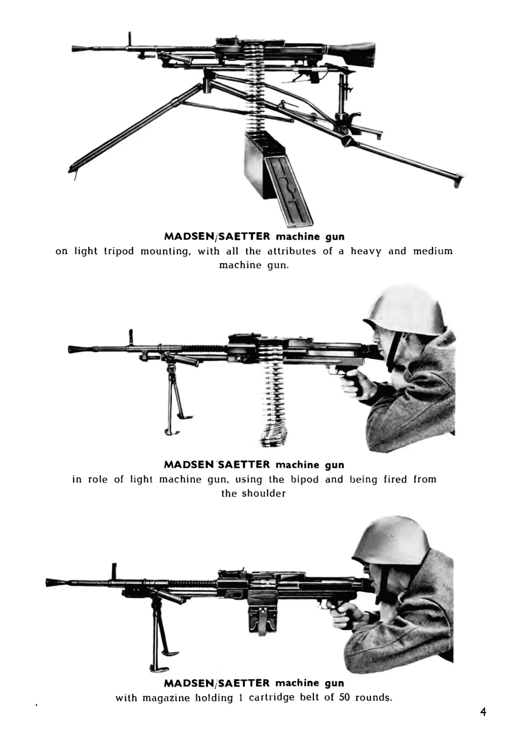
MADSEN/SAETTER machine gun
on light tripod mounting, with all the attributes of a heavy and medium
machine gun.
MADSEN SAETTER machine gun
in role of light machine gun, using the bipod and being fired from
the shoulder
MADSEN/SAETTER machine gun
with magazine holding 1 cartridge belt of 50 rounds.
4
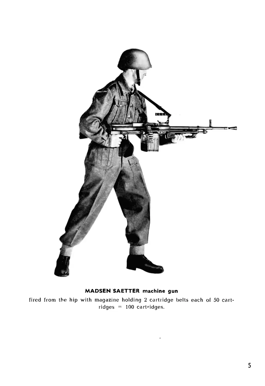
MADSEN SAETTER machine gun
fired from the hip with magazine holding 2 cartridge belts each of 50 cart-
ridges = 100 cartridges.
5
II. DATA
MADSEN/SAETTER MACHINE GUN
RIFLE CALIBRE
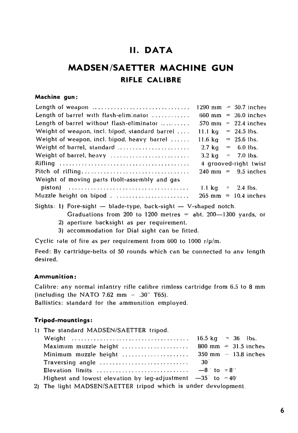
Machine gun:
Length of weapon ....................................
Length of barrel with flash-eliminatoi ..............
Length of barrel without flash-eliminator............
Weight of weapon, incl. bipod, standard barrel . .. .
Weight of weapon, incl. bipod, heavy barrel .........
Weight of barrel, standard ..........................
Weight of barrel, heavy .............................
Rifling .............................................
Pitch of rifling.....................................
Weight of moving parts (bolt-assembly and gas
piston) ..........................................
Muzzle height on bipod ..............................
1290 mm - 50.7 inches
660 mm = 26.0 inches
570 mm = 22.4 inches
11.1 kg = 24.5 lbs.
11.6 kg = 25.6 lbs.
2.7 kg = 6.0 lbs.
3.2 kg - 7.0 lbs.
4 grooved-right twist
240 mm = 9.5 inches
1.1 kg = 2.4 lbs.
265 mm = 10.4 inches
Sights: I) Fore-sight — blade-type, back-sight — V-shaped notch.
Graduations from 200 to 1200 metres = abt. 200—1300 yards, or
2) aperture backsight as per requirement.
3) accommodation for Dial sight can be fitted.
Cyclic rate of fire as per requirement from 600 to 1000 r/p/m.
Feed: By cartridge-belts of 50 rounds which can be connected to anv length
desired.
Ammunition:
Calibre: any normal infantry rifle calibre rimless cartridge from 6.5 to 8 mm
(including the NATO 7.62 mm - .30" T65).
Ballistics: standard for the ammunition employed.
Tripod-mountings:
1) The standard MADSEN/SAETTER tripod.
Weight ...................................
Maximum muzzle height .................
Minimum muzzle height .................
Traversing angle ......................
Elevation limits ......................
16.5 kg - 36 lbs.
800 mm = 31.5 inches
350 mm - 13.8 inches
30
—8 to r8"
Highest and lowest elevation by leg-adjustment —35 to -40
2) The light MADSEN/SAETTER tripod which is under development.
6
II. Data, continued.
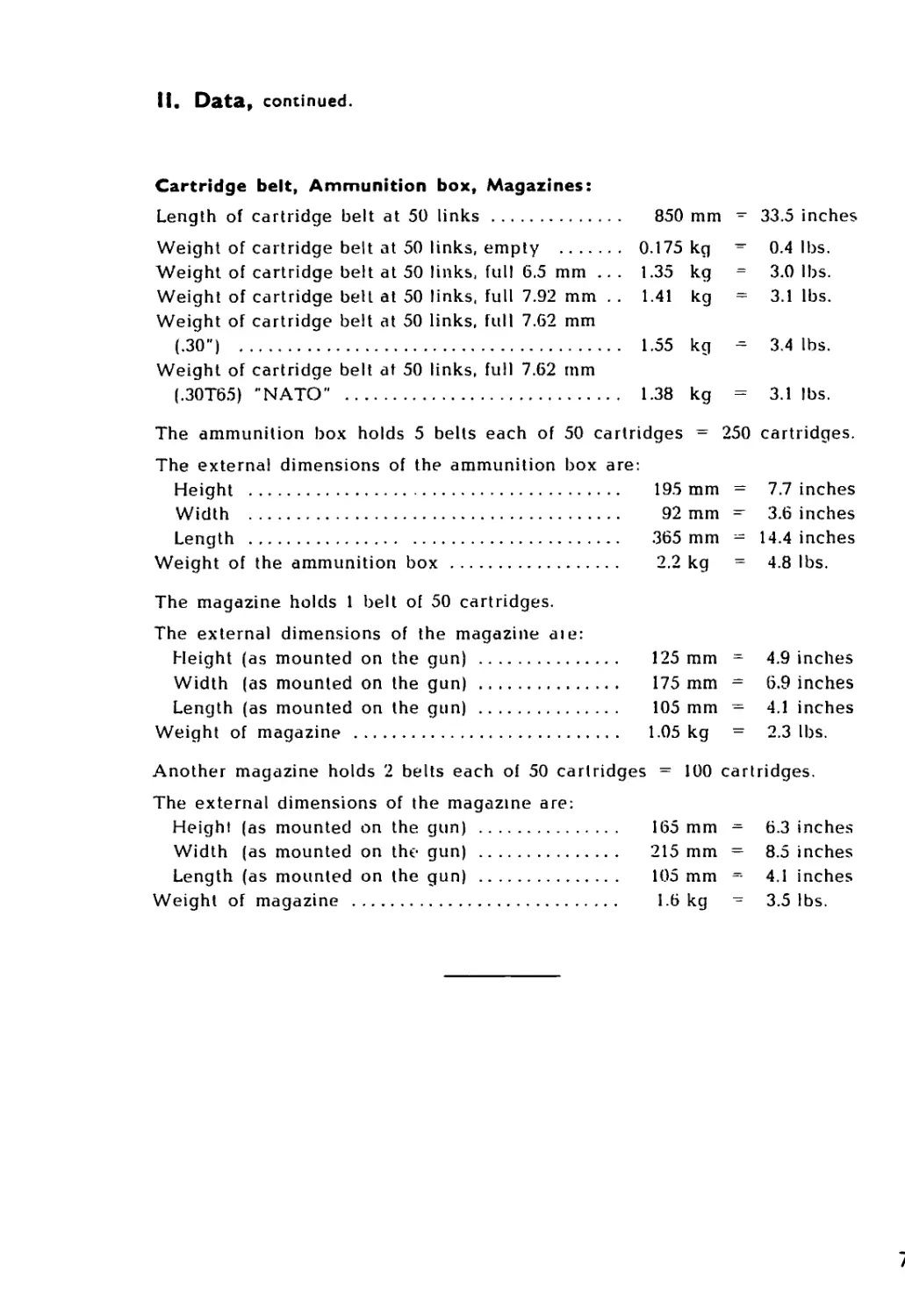
Cartridge belt, Ammunition box, Magazines:
Length of cartridge belt at 50 links .......... 850 mm = 33.5 inches
Weight of cartridge belt at 50 links, empty .......... 0.175 kg 0.4 lbs.
Weight of cartridge belt at 50 links, full 6.5 mm ... 1.35 kg = 3.0 lbs.
Weight of cartridge belt at 50 links, full 7.92 mm . . 1.41 kg = 3.1 lbs.
Weight of cartridge belt at 50 links, full 7.62 mm
(.30") ............................................. 1.55 kg - 3.4 lbs.
Weight of cartridge belt at 50 links, full 7.62 mm
(.30T65) "NATO" ...................................... 1.38 kg = 3.1 lbs.
The ammunition box holds 5 belts each of 50 cartridges = 250 cartridges.
The external dimensions of the ammunition box are:
Height .....................................
Width ......................................
Length .....................................
Weight of the ammunition box .................
195 mm = 7.7 inches
92 mm - 3.6 inches
365 mm - 14.4 inches
2.2 kg = 4.8 lbs.
The magazine holds 1 belt of 50 cartridges.
The external dimensions of the magazine aie:
Height (as mounted on the gun) ............. 125 mm
Width (as mounted on the gun) ............. 175 mm
Length (as mounted on the gun) ............. 105 mm
Weight of magazine ......................... 1.05 kg
4.9 inches
6.9 inches
4.1 inches
2.3 lbs.
Another magazine holds 2 belts each of 50 cartridges = 100 cartridges.
The external dimensions of the magazine are:
Height (as mounted on the gun) ..............
Width (as mounted on the gun) .............
Length (as mounted on the gun) ............
Weight of magazine ..........................
165 mm
215 mm
105 mm
1.6 kg
6.3 inches
8.5 inches
4.1 inches
3.5 lbs.
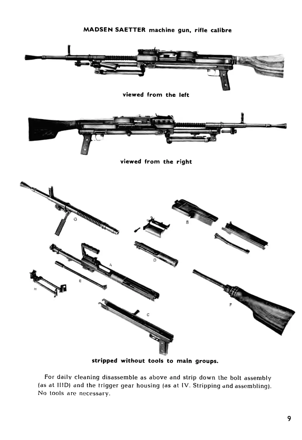
III. PRINCIPAL ASSEMBLIES
The MADSEN/SAETTER machine gun, Rifle calibre consists of the follow-
ing main groups, or assemblies:
A. Receiver (or Bodyj-assembly incl. back-sight-group.
B. Feed-mechanism.
C. Trigger-gear-assembly.
D. Bolt-assembly.
E. Gas-piston.
F. Butt-stock-assembly with return- and buffer-mechanism.
G. Barrel.
H. Bipod.
I. Cartridge-belts, ammunition box, magazines
K. Accessories.
L. Mounting.
8
MADSEN SAETTER machine gun, rifle calibre
viewed from the left
stripped without tools to main groups.
For daily cleaning disassemble as above and strip down the bolt assembly
(as at HID) and the trigger gear housing (as at IV. Stripping and assembling).
No tools are necessary.
9
A.
RECEIVER (or BODY)-ASSEMBLY
incl. BACK-SIGHT-GROUP
10
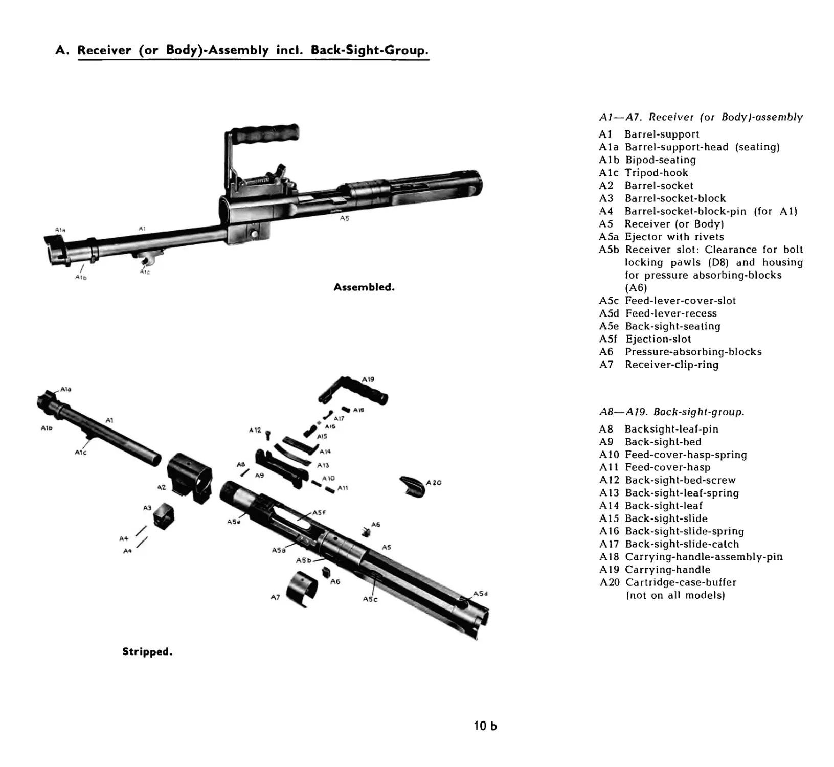
A. Receiver (or Body)-Assembly incl. Back-Sight-Group.
The principal part of the gun is the receiver (A5), on the forward end of
which is screwed the barrel-socket (A2). The latter forms a housing for the
barrel-socket-block (A3), into which is inserted the barrel-support (Al), and
has two trunnions providing a forward seating for the trigger-gear-housing
(at Cid). A3 is secured by the two pins A4. in the receiver is rivetted the
ejector (A5a). To take the initial shock of discharge pressure-absorbing-
blocks (A6) are positioned in slots in the receiver walls (A5b) and are pro-
tected by the receiver-clip-ring (A7). In the rear part of the receiver is the
feed-lever-recess (A5d) for the feed-lever (B15),
On the top of the forward end of the receiver is the back-sight-seating
(A5e) on which is the back-sight-bed (A9) the latter being secured by a
screw (A12). The front part of the back-sight-bed (A9) forms the seating for
the carrying-handle (A19) held by the carrying-handle-assembly-pin (A18),
and also accomodates the back-sight-leaf (A14) hinged on the back-sight-
Jeaf-pin (A8), and actuated by the back-sight-leaf-spring (A13) underneath.
The back-sight-slide (A15) fits round the leaf to which it is securely held
at the various ranges from 200 to 1200 metres by the spring loaded back-
sight-slide-catch (A17). At the rear of the back-sight-bed is fitted the feed-
cover-hasp (All) with its spring (A10) to keep the feed-cover (Bl) in posi-
tion when it is open. Two holes are drilled transversally in the rear of the
back-sight-bed (A9) for the feed-cover-hinge-pin (B13).
The front of the receiver provides the housing for the barrel (G) which
also seats on the barrel-support-head (Ala), on the left side of which is a
groove into which a flange on the foot of the barrel-handle (G3) engages
and locks the barrel (G) on assembly.
In rear of the barrel-support-head (Ala) is the bipod-seating (Alb) and
on the underside of the barrel-support (Al) is the tripod-hook (Ale) by
which the fore end of the gun is secured to the tripod (at LlOa).
The cartridge-case-buffer (A20) is an extra attachment, which is delivered
on request. It is desirable for certain types of ammunilion to protect the
cartridge cases. It is fitted into the Ejection-slot (A5f). See also General
Assembly drawing.
10 a
A. Receiver (or Body)-Assembly incl. Back-Sight-Group.
Assembled.
Stripped.
Al—A7. Receiver (or Body)-assembly
Al Barrel-support
Ala Barrel-support-head (seating)
Alb Bipod-seating
Ale Tripod-hook
A2 Barrel-socket
A3 Barrel-socket-block
A4 Barrel-socket-block-pin (for Al)
A5 Receiver (or Body)
A5a Ejector with rivets
A5b Receiver slot: Clearance for bolt
locking pawls (D8) and housing
for pressure absorbing-blocks
(A6)
A5c Feed-lever-cover-slot
A5d Feed-lever-recess
A5e Back-sight-seating
A5f Ejection-slot
A6 Pressure-absorbing-blocks
A7 Receiver-clip-ring
A8—A19. Back-sight-group.
A8 Backsight-leaf-pin
A9 Back-sight-bed
A10 Feed-cover-hasp-spring
All Feed-cover-hasp
A12 Back-sight-bed-screw
A13 Back-sight-leaf-spring
A14 Back-sight-leaf
A15 Back-sight-slide
Alb Back-sight-slide-spring
A17 Back-sight-slide-catch
A18 Carrying-handle-assembly-pin
A19 Carrying-handle
A20 Cartridge-case-buffer
(not on all models)
10 b
в.
FEED-MECHANISM
11
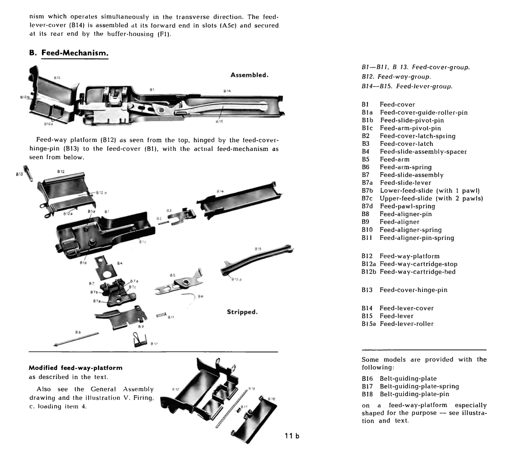
В. Feed-Mechanism.
The main parts of the feed-mechanism are the feed-cover (Bl) and the feed-
way-platform (B12), which actuate on a hinge-pin (B13), and the feed-levei
(B15) with its cover (B14). The forward end of the feed-lever-cover forms a
seating for the feed-cover, to which it is locked by a spring loaded latch (B3).
Advancing the belt through the feed-way proceeds in two stages by the
aid of the pawls in the feed-slide-assembly (B7), — which consists of the
feed-slide-lever (B7a), a two armed lever turning on the feed-slide-pivot-pin
(Bib) in the feed-cover engaging the feed-arm (B5) with the free end, and
two feed-slides carrying spring actuated pawls.
The upper feed-slide (B7c) carries two spring actuated pawls which func-
tion on both sides of the double pawl on the lower feed-slide (B7b).
The feed-slides move on the inserted feed-slide-assembly-spacer (B4),
which minimizes friction between feed-cover and feed-slides, and are guided
by two guide-rollers on the feed-cover-guide-roller-pin (Bia).
The feed-arm (B5) turning on its pin (Bic) in the cover transmits the
movement of the feed-lever (B15) to the feed-slide-lever (B7a) by engage-
ment with the roller (B15a). The purpose of the feed-arm-spring (B6) is to
position the feed-mechanism when the feed-cover is open to ensure that, on
closing the feed-cover, the rearward part of the feed-arm can move down
round the feed-lever-roller (B15a) when the latter is as far to the right as it
will go; the moving parts having been brought to the rearmost position.
The feed-aligner (B9) is located in the right side of the feed-cover and
pivots on the feed-aligner-pin (B8). Its purpose is to hold the cartridge in
place on the feed-way-platform and assist in guiding it into the chamber,
and it is held in position by the feed-aligner-pin-spring (Bl 1) whilst the
two arms on the feed-aligner-spring (BIO) press it down against the cart-
ridge-stop (B12a). At the same time, the loop on the aligner-spring (BIO)
keeps the feed-slide-lever (B7a) in place in the feed-cover (Bl).
The feed-way platform (B12) is curved outwards on its left side to facilit-
ate easy passage of the loaded cartridge-belt into the feed-way. A channel
(B12b) forms the cartridge bed from which the live round is fed into the
chamber by the bolt face (D3); the cartridge-stop (B12a) preventing the
round from moving further to the right and keeping the belt in position
as the round is pushed forward (see illustrations at para V).
Some models have an extra attachment: A spring-actuated plate (B16),
hinged by a pin (B18) onto a special feed-way-platform, is pushed to a hori-
zontal position by the belt which is thereby kept away from the receiver in
order to prevent the cases of certain cartridge types from hitting the belt
during ejection.
The feed-lever (B15), a slightly curved onearmed lever, links the feed-
mechanism to the bolt-assembly (D) and moves in the recess (A5d) with its
free end operating the feed-arm (B5). The action-head-roller (D14) travelling
in the curved track in the underside of the feed-lever (B15) as the bolt-
assembly moves in operation, transfers this movement to the feed-mecha-
11 a
nisni which operates simultaneously in the transverse direction. The feed-
lever-cover (B14) is assembled at its forward end in slots (A5c) and secured
at its rear end by the buffer-housing (Fl).
B. Feed-Mechanism.
Feed-way platform (B12) as seen from the top, hinged by the feed-cover-
hinge-pin (B13) to the feed-cover (Bl), with the actual feed-mechanism as
seen from below.
Bl — Bl I, В 13. Feed-cover-group.
B12. Feed-way-group.
B14—B15. Feed-lever-group.
Bl Feed-cover
Bia Feed-cover-guide-roller-pin
Bib Feed-slide-pivot-pin
Bic Feed-arm-pivot-pin
B2 Feed-cover-latch-spring
B3 Feed-cover-latch
B4 Feed-slide-assembly-spacer
B5 Feed-arm
B6 Feed-arm-spring
B7 Feed-slide-assembly
B7a Feed-slide-lever
B7b Lower-feed-slide (with 1 pawl)
B7c Upper-feed-slide (with 2 pawls)
B7d Feed-pawl-spring
B8 Feed-aligner-pin
B9 Feed-aligner
BIO Feed-aligner-spring
Bll Feed-aligner-pin-spring
B12 Feed-way-platform
B12a Feed-way-cartridge-stop
B12b Feed-way-cartridge-bed
B13 Feed-cover-hinge-pin
B14 Feed-lever-cover
B15 Feed-lever
В15a Feed-lever-roller
Modified feed-way-platform
as described in the text.
Also see the General Assembly
drawing and the illustration V. Firing,
c. loading item 4.
Some models are provided with the
following:
B16 Belt-guiding-plate
B17 Belt-guiding-plate-spring
B18 Belt-guiding-plate-pin
on a feed-way-platform especially
shaped for the purpose — see illustra-
tion and text.
11 b
с.
TRIGGER-GEAR-ASSEMBLY
12
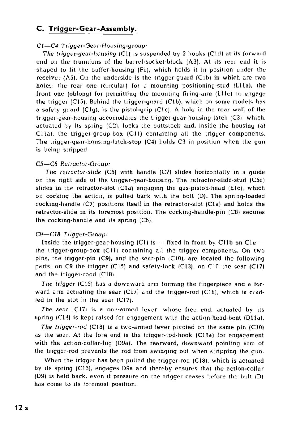
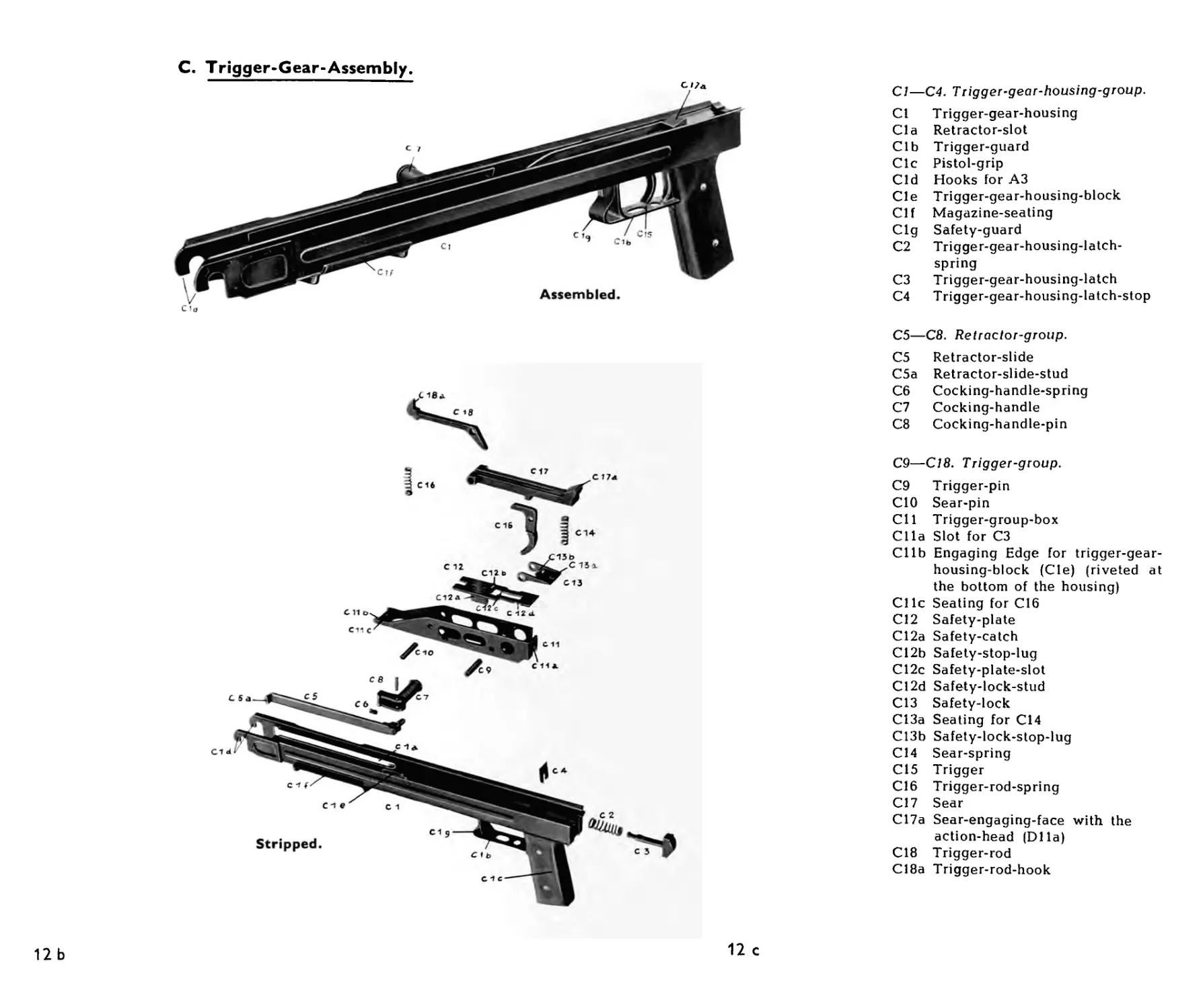
C. Trigger-Gear-Assembly.
Cl—C4 Trigger-Gear-Housing-group:
The trigger-gear-housing (Cl) is suspended by 2 hooks (Cid) at its forward
end on the trunnions of the barrel-socket-block (A3). At its rear end it is
shaped to fit the buffer-housing (Fl), which holds it in position under the
receiver (A5). On the underside is the trigger-guard (Clb) in which are two
holes: the rear one (circular) for a mounting positioning-stud (Lila), the
front one (oblong) for permitting the mounting firing-arm (Lt 1c) to engage
the trigger (C15). Behind the trigger-guard (Clb), which on some models has
a safety guard (Cig), is the pistol-grip (Clc), A hole in the rear wall of the
trigger-gear-housing accomodates the trigger-gear-housing-latch (C3), which,
actuated by its spring (C2), locks the buttstock and, inside the housing (at
Cl la), the trigger-group-box (Cll) containing all the trigger components.
The trigger-gear-housing-latch-stop (C4) holds C3 in position when the gun
is being stripped.
C5—C8 Relractor-Group:
The retractor-slide (C5) with handle (C7) slides horizontally in a guide
on the right side of the trigger-gear-housing. The retractor-slide-stud (C5a)
slides in the retractor-slot (Cla) engaging the gas-piston-head (Elc), which
on cocking the action, is pulled back with the bolt (D). The spring-loaded
cocking-handle (C7) positions itself in the retractor-slot (Cla) and holds the
retractor-slide in its foremost position. The cocking-handle-pin (C8) secures
the cocking-handle and its spring (C6).
C9—C/8 Trigger-Group:
Inside the trigger-gear-housing (Cl) is — fixed in front by Cllb on Cle —
the trigger-group-box (Cll) containing all the trigger components. On two
pins, the trigger-pin (C9), and the sear-pin (CIO), are located the following
parts: on C9 the trigger (C15) and safety-lock (C13), on CIO the sear (C17)
and the trigger-rood (C18).
The trigger (C15) has a downward arm forming the fingerpiece and a for-
ward arm actuating the sear (C17) and the trigger-rod (C18). which is crad-
led in the slot in the sear (C17).
The sear (C17) is a one-armed lever, whose fiee end, actuated by its
spring (C14) is kept raised for engagement with the action-head-bent (DI la).
The trigger-rod (C18) is a two-armed lever pivoted on the same pin (CIO)
as the sear. At the fore end is the trigger-rod-hook (C18a) for engagement
with the action-collar-lug (D9a). The rearward, downward pointing arm ol
the trigger-rod prevents the rod from swinging out when stripping the gun.
When the trigger has been pulled the trigger-rod (08), which is actuated
by its spring (CIG), engages D9a and thereby ensures that the action-collar
(D9) is held back, even if pressure on the trigger ceases before the bolt (D)
has come to its foremost position.
12 a
The safety-plate (C12), by means of a downward square flange (C12a) can
be moved forward to "Fire" and rearwards to "Safe" and is held in either
position by the safety-lock (C13) actuated by the sear spring (C14). In the
forward position the safety-stop-lug (C12b) is free of the sear (C17), which
can move freely. In the rear position the safety-stop-lug moves under the
stud on the underside of the sear and prevents the weapon from being fired
The safety-lock (C13) prevents the safety from moving off the position
"Fire" rearwards to "Safe" during automatic firing. The upward lug C13b
is approached during firing by the sear (C17) without being touched. There-
by the safety-lock (C13) cannot get out of its position, and it will prevent
the safety-lock-stud (C12d) from moving backwards.
12 b
C. Trigger-Gear-Assembly.
12 b
12 с
Cl—C4. Trigger-gear-housing-group.
Cl Trigger-gear-housing
Cl a Retractor-slot
Clb Trigger-guard
Clc Pistol-grip
Cid Hooks for A3
Cle Trigger-gear-housing-block
Clf Magazine-seating
Cig Safety-guard
C2 Trigger-gear-housing-latch-
spring
C3 Trigger-gear-housing-latch
C4 Trigger-gear-housing-latch-stop
C5—C8. Retractor-group.
C5 Retractor-slide
C5a Retractor-slide-stud
C6 Cocking-handle-spring
C7 Cocking-handle
C8 Cocking-handle-pin
C9—C18. Trigger-group.
C9 Trigger-pin
CIO Sear-pin
CH Trigger-group-box
Clla Slot for C3
Cllb Engaging Edge for trigger-gear-
housing-block (Cle) (riveted at
the bottom of the housing)
Cllc Seating for C16
C12 Safety-plate
C12a Safety-catch
C12b Safety-stop-lug
C12c Safety-plate-slot
C12d Safety-lock-stud
C13 Safety-lock
C13a Seating for C14
C13b Safety-lock-stop-lug
C14 Sear-spring
C15 Trigger
C16 Trigger-rod-spring
C17 Sear
C17a Sear-engaging-face with the
action-head (DIla)
C18 Trigger-rod
C18a Trigger-rod-hook
D.
BOLT-ASSEMBLY
E.
GAS-PISTON
13
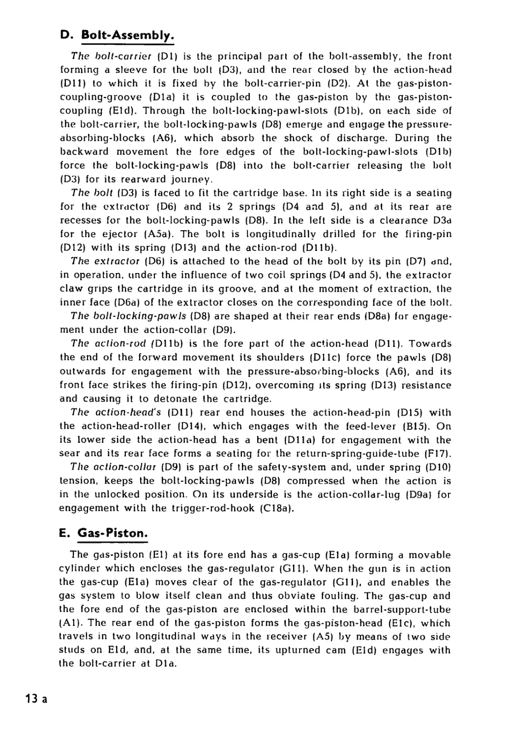
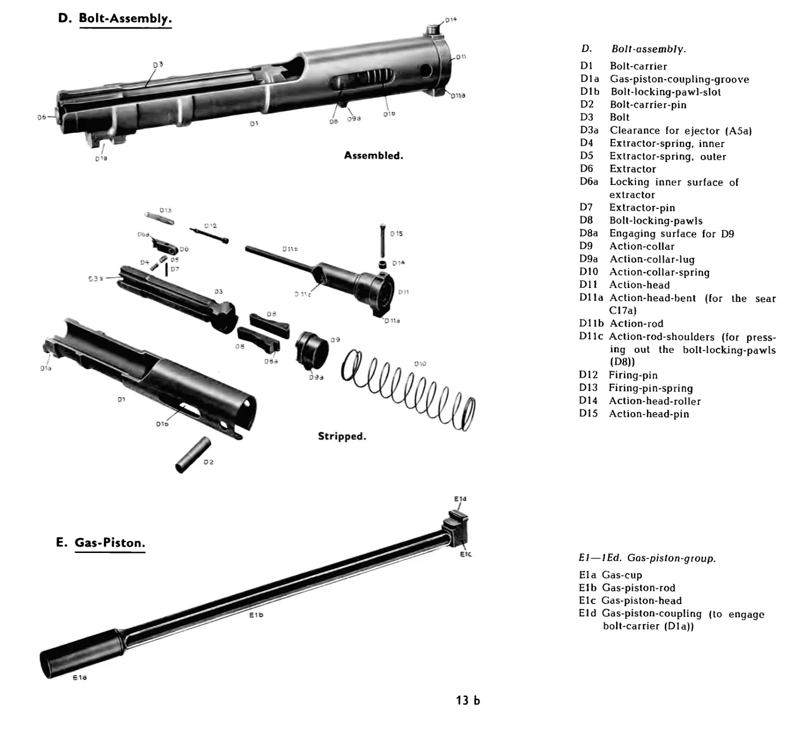
D. Bolt-Assembly.
The bolt-carrier (DI) is the principal part of the bolt-assembly, the front
forming a sleeve for the bolt (D3), and the rear closed by the action-head
(Dll) to which it is fixed by the bolt-carrier-pin (D2). At the gas-piston-
coupling-groove (Dla) it is coupled to the gas-piston by the gas-piston-
coupling (Eld). Through the bolt-locking-pawl-slots (Dlb), on each side of
the bolt-carrier, the bolt-locking-pawls (D8) emerge and engage the pressure-
absorbing-blocks (A6), which absorb the shock of discharge. During the
backward movement the fore edges of the bolt-locking-pawl-slots (Dlb)
force the bolt-locking-pawls (D8) into the bolt-carrier releasing the bolt
(D3) for its rearward journey.
The bolt (D3) is faced to fit the cartridge base. In its right side is a seating
for the extractor (D6) and its 2 springs (D4 and 5), and at its rear are
recesses for the bolt-locking-pawls (D8). In the left side is a clearance D3a
for the ejector (A5a). The bolt is longitudinally drilled for the firing-pin
(D12) with its spring (D13) and the action-rod (DI lb).
The extractor (D6) is attached to the head of the bolt by its pin (D7) and,
in operation, under the influence of two coil springs (D4 and 5), the extractor
claw grips the cartridge in its groove, and at the moment of extraction, the
inner face (D6a) of the extractor closes on the corresponding face of the bolt.
The bolt-locking-pawls (D8) are shaped at their rear ends (D8a) for engage-
ment under the action-collar (D9).
The action-rod (DI lb) is the fore part of the action-head (Dll). Towards
the end of the forward movement its shoulders (DI 1c) force the pawls (D8)
outwards for engagement with the pressure-absorbing-blocks (A6), and its
front face strikes the firing-pin (D12), overcoming its spring (D13) resistance
and causing it to detonate the cartridge.
The action-head's (Dll) rear end houses the action-head-pin (D15) with
the action-head-roller (D14), which engages with the feed-lever (B15). On
its lower side the action-head has a bent (DIla) for engagement with the
sear and its rear face forms a seating for the return-spring-guide-tube (F17).
The action-collar (D9) is part of the safety-system and, under spring (DIO)
tension, keeps the bolt-locking-pawls (D8) compressed when the action is
in the unlocked position. On its underside is the action-collar-lug (D9a) for
engagement with the trigger-rod-hook (C18a).
E. Gas-Piston.
The gas-piston (El) at its fore end has a gas-cup (Ela) forming a movable
cylinder which encloses the gas-regulator (Gil). When the gun is in action
the gas-cup (Ela) moves clear of the gas-regulator (Gil), and enables the
gas system to blow itself clean and thus obviate fouling. The gas-cup and
the fore end of the gas-piston are enclosed within the barrel-support-tube
(Al). The rear end of the gas-piston forms the gas-piston-head (Elc), which
travels in two longitudinal ways in the receiver (A5) by means of two side
studs on Eld, and, at the same time, its upturned cam (Eld) engages with
the bolt-carrier at Dla.
13 a
D. Bolt-Assembly
E. Gas-Piston.
9W
D. Bolt-assembly.
DI Bolt-carrier
Dla Gas-piston-coupling-groove
Dlb Bolt-locking-pawl-slot
D2 Bolt-carrier-pin
D3 Bolt
D3a Clearance for ejector (A5a)
D4 Extractor-spring, inner
D5 Extractor-spring, outer
D6 Extractor
D6a Locking inner surface of
extractor
D7 Extractor-pin
D8 Bolt-locking-pawls
D8a Engaging surface for D9
D9 Action-collar
D9a Action-collar-lug
DIO Action-collar-spring
Dll Action-head
Dlla Action-head-bent (for the sear
C17a)
Dllb Action-rod
Dllc Action-rod-shoulders (for press-
ing out the bolt-locking-pawls
(D8))
D12 Firing-pin
D13 Firing-pin-spring
D14 Action-head-roller
D15 Action-head-pin
Е14
I
El — lEd. Gas-pislon-gtoup.
Ela Gas-cup
Elb Gas-piston-rod
Elc Gas-piston-head
Eld Gas-piston-coupling (to engage
bolt-carrier (Dla))
13 b
F.
BUTT-STOCK-ASSEMBLY
14
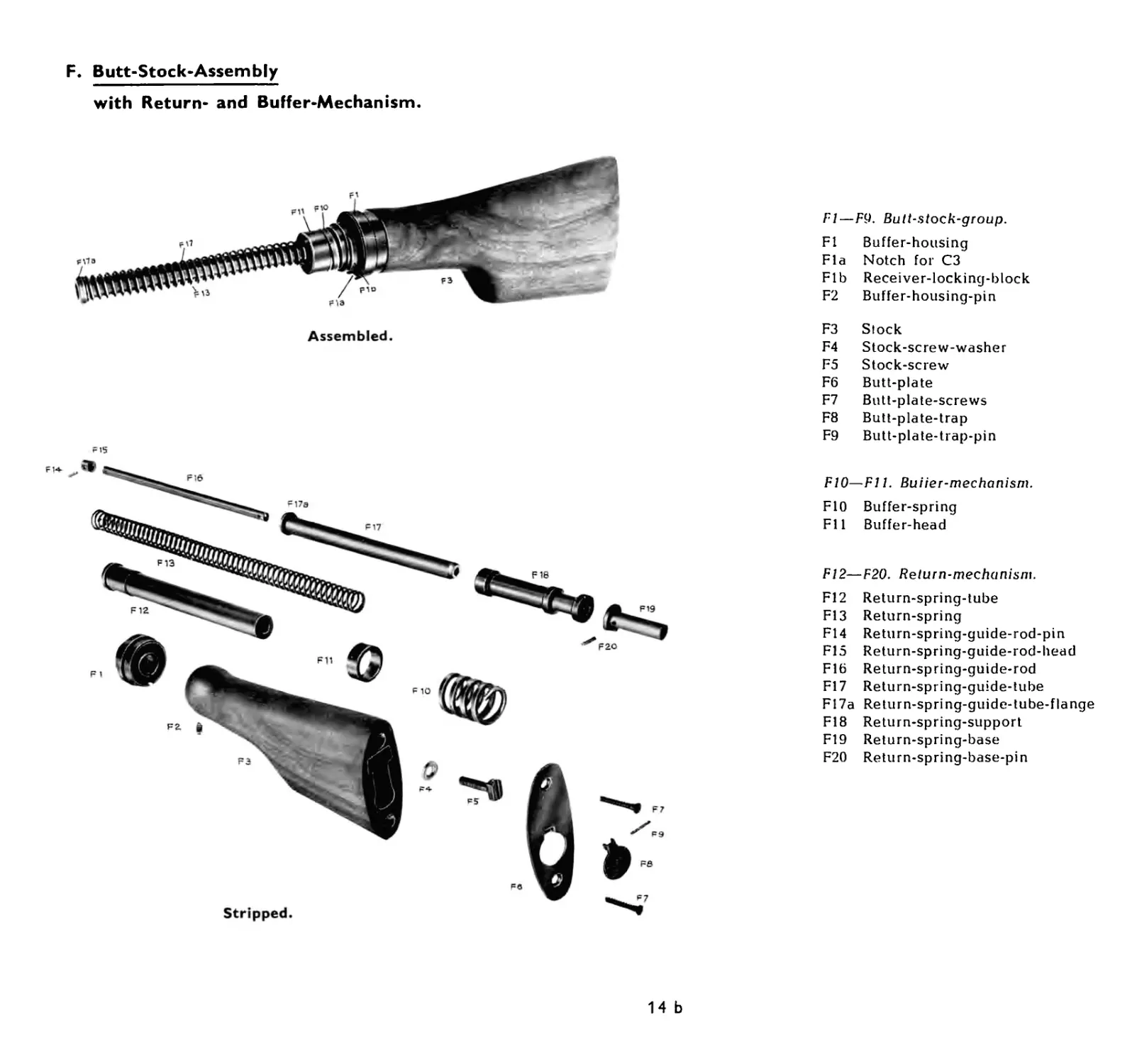
F. Butt-Stock-Assembly
with Return- and Buffer-Mechanism.
The wooden stock (F3) is drilled longitudinally io accomodate the return-
and buffer-mechanism. In the cavity is inserted the return-spring-tube (F12),
the fore, end of which protrudes through the buffer-housing (Fl) and is fixed
by the buffer-housing-pin (F2) to the fore end of the stock. At the rear the
stock is protected by the butt-plate (F6) secured by the butt-plate-screws
(F7). In the butt-plate is the butt-plate-trap (F8) with its pin (F9) covering a
housing for certain spare parts for the gun.
The return-mechanism is telescopic and includes the return-spring-guide-
tube (F17), which slides on the return-spring-guide-rod (F16), and around
which the return-spring (F13) operates, compressed between the return-spring-
guide-tube-flange (F17a) and the return-spring-support (F18), in rear of
which is the return-spring-base (F19). The return-spring-guide-rod-head (F15)
is fixed at the fore end of the return-spring-guide-rod (F16) by the pin (F14)
and limits the forward movement of the return-spring-guide-tube (F17). The
return-spring-base (F19) is secured to the rear end of the return-spring-
guide-rod (F16) by the pin (F20), and to the rear of the return-spring-tube
(F12) and the stock (F3) by the stock-screw (F5) with its washer (F4).
The buffer-housing (Fl) is provided with 2 lugs (Fib) which, by engagement
with 2 corresponding lugs in the receiver (A5), holds the stock. In the buf-
fer-housing is the buffer-spring (F10) which is located around the fore end
of the return-spring-tube (Fl2) and operates between the buffer-head (Fill
and the rear face of the buffer-housing, the buffer-head being able to move
freely longitudinally around the return-spring-tube (F12).
14a
F. Butt-Stock-Assembly
with Return- and Buffer-Mechanism.
Stripped.
Fl — F9. Butl-stock-group.
Fl Buffer-housing
Fla Notch for C3
Fib Receiver-locking-block
F2 Buffer-housing-pin
F3 F4 F5 F6 F7 F8 F9 Stock Stock-screw-washer Stock-screw Butt-plate Butt-plate-screws Butt-plate-trap Butt-plate-trap-pin
F10—F11. Buiier-mechanism.
F10 FU Buffer-spring Buffer-head
F12—F20. Return-mechanism.
F2O
F12
F13
F14
F15
Fib
F17
F17a
F18
F19
F20
Return-spring-tube
Return-spring
Return-spring-guide-rod-pin
Return-spring-guide-rod-head
Return-spring-guide-rod
Return-spring-guide-tube
Re turn-spring-guide-tube-flange
Return-spring-support
Return-spring-base
Return-spring-base-pin
14 b
G.
BARREL
15
G. Barrel.
The barrel is provided with a Hash-eliminator (G2) at the muzzle. Midway
along the barrel arc the foresight-base sleeve (GI4), the gas-regulator-socket
(GIO), and the bariel-handle-sleeve (G8), all of which are secured by the
barrel-nut (G15).
The ioresight-base-sleeve (G14) carries the foresight-base (G19) which
turns on the foresight-base-pin (G18) actuated by the spring (G17). The
spring rests on the ball (G16) at the bottom and presses against the top of
the foresight-base-spring-pin (G20) inside the hollow foresight-base.
The foresight (G22) is inseited in the foresight-base (G19), which also has
foresight-guards (G23) secured by the foresight-guard-screw (G21).
The gas-regulator-socket (GIO) encloses the gas-regulator (Gil), which is
secured by the gas-regulator-nut (G12) and is guided into position in the
gas-regulator-socket (GIO) by means of three facets on its outer side. The
gas-regulator is bored longitudinally, and in its base are three holes of
differing sizes, each of which, when brought into alignment with the gas-
port in the barrel, allows a corresponding flow of gas to impinge on the
gas-piston as required to actuate the mechanism; variation in ammunition
velocities can thus be accommodated. Most models are provided with a gas-
regulator-cover (G9) for protection of the gas-regulator.
The foresight-alignment-key (G13) fits into the alignment-keyway and
secures the gas-regulator-socket (GIO) and the foresight-base-sleeve (G14)
from turning on the barrel.
The barrel-handle-sleeve (G8) carries the barrel-handle (G3) and is
secured from turning by the tongue (G8a) in the groove (Glc). The barrel-
handle (G3) can be turned on its pin (G4) into two positions a) at right
angles to the barrel and b) folded towards the barrel with which it forms
an angle of about 15 . It is held in either position by the spring (G5) loaded
barrel-handle-locking-plunger (G6) and pellet (G7), and in the folded posi-
tion the longer flange on its base engages in a groove on the left side of the
barrel-support-head (Ala) and locks the barrel in position. In this locked
position the four barrel-locking-lugs (Gib) are in engagement with four
corresponding lugs in the receiver (A5) and, when the barrel-handle is at
right angles to the barrel, the lugs are completely free from engagement. Gia
is a clearance for the extractor (D6), so that the bolt (D3) can move fully
forward and the round be fired, when the barrel is in locked position.
15 a
G. Barrel.
6t9
unfolded ready for barrel-
change. The upper barrel is
shown with and the lower
without gas-regulator-cover
(G9).
G1—G2. Barrel-group.
G1 Barrel
Gia Extractor-clearance
Gib Barrel-locking-lugs
Glc Groove for G8a
Gid Foresight-alignment-keyway
G2 Flash-eleminator
G3—G8. Barrel-handle-group.
G3 Barrel-handle
G4 Barrel-handle-pin
G5 Barrel-handle-locking-spring
G6 Barrel-handle-locking-plunger
G7 Barrel-handle-locking-pellet
G8 Barrel-handle-sleeve
G8a Tongue for Glc
G9—G13. Gas-regulator-group.
G9 Gas-regulator-cover
GIO Gas-regulator-socket
Gil Gas-regulator
G12 Gas-regulator-nut
G13 Foresight-alignment-key
G14—G23. Foresight-group.
G14 Foresight-base-sleeve
G15 Barrel-nut
G16 Foresight-base-pellet
G17 Foresight-base-spring
G18 Foresight-base-pin
G19 Foresight-base
G20 Foresight-base-spring-pin
G21 Foresight-guard-screw
G22 Foresight
G23 Foresight-guards
15 b
н.
BIPOD
16
H. Bipod.
The weapon is provided with a detachable bipod (H). The two legs (Hl)
and (H2) turn on the bipod-pivot-screw (H3). When extended, the legs are
kept apart by the bipod-spring (H5) and locked by the bipod-leg-locking-
pawl (H4). The bipod-pivot-screw (H3) fits in the bipod-pivot-head (H6)
which is a joint permitting the legs a limited movement in relation to the
bipod-mounting (НИ), to which it (H6) is connected by the bipod-assembl-
ing-screw (H12) secured by its nut (H9). The bipod-mounting (Hl 1) can be
fixed to the barrel-seating, by the bipod-locking-plunger (H7) with the bipod-
locking-spring (H8), both limited in their movement by the bipod-locking-pin
(H10). The legs can be turned forward or backward to horizontal positions.
In the latter position they are held up under the barrel-support-tube (Al), by
the longitudinal flanges on the barrel-socket (A2).
16 a
HI—HI2. Bipod-group.
Hl Bipod-leg, left
112 Bipod-leg, right
H3 Bipod-pivot-screw
H4 Bipod-leg-locking-pawl
H5 Bipod-spring
H6 Bipod-pivot-head
H7 Bipod-locking-plunger
H8 Bipod-locking-spring
H9 Bipod-assembling-nut
H10 Bipod-locking-pin
Hll Bipod-mounting
H12 Bipod-assembling-screw
16 b
I.
CARTRIDGE-BELTS, AMMUNITION BOX,
MAGAZINES
17
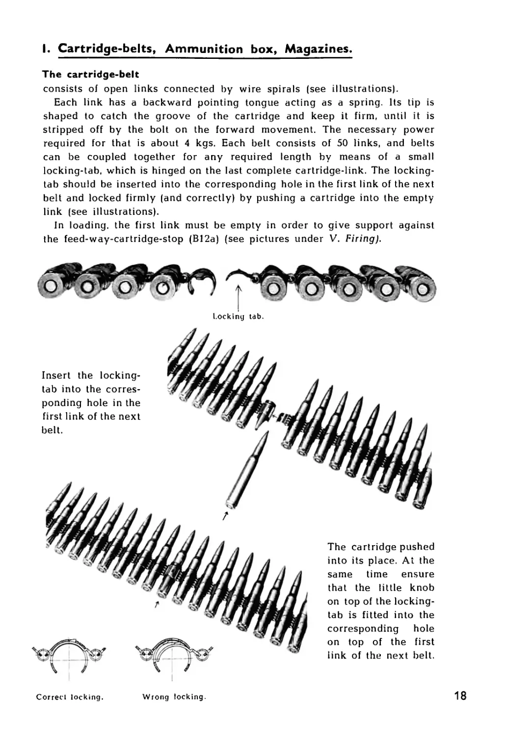
I. Cartridge-belts, Ammunition box, Magazines.
The cartridge-belt
consists of open links connected by wire spirals (see illustrations).
Each link has a backward pointing tongue acting as a spring. Its tip is
shaped to catch the groove of the cartridge and keep it firm, until it is
stripped off by the bolt on the forward movement. The necessary power
required for that is about 4 kgs. Each belt consists of 50 links, and belts
can be coupled together for any required length by means of a small
locking-tab, which is hinged on the last complete cartridge-link. The locking-
tab should be inserted into the corresponding hole in the first link of the next
belt and locked firmly (and correctly) by pushing a cartridge into the empty
link (see illustrations).
In loading, the first link must be empty in order to give support against
the feed-way-cartridge-stop (B12a) (see pictures under V. Firing).
Insert the locking-
tab into the corres-
ponding hole in the
first link of the next
belt.
Locking tab.
Correcl locking.
Wrong locking.
The cartridge pushed
into its place. At the
same time ensure
that the little knob
on top of the locking-
tab is fitted into the
corresponding hole
on top of the first
link of the next belt.
18
I. Cartridge-belts, Ammunition box, Magazines.
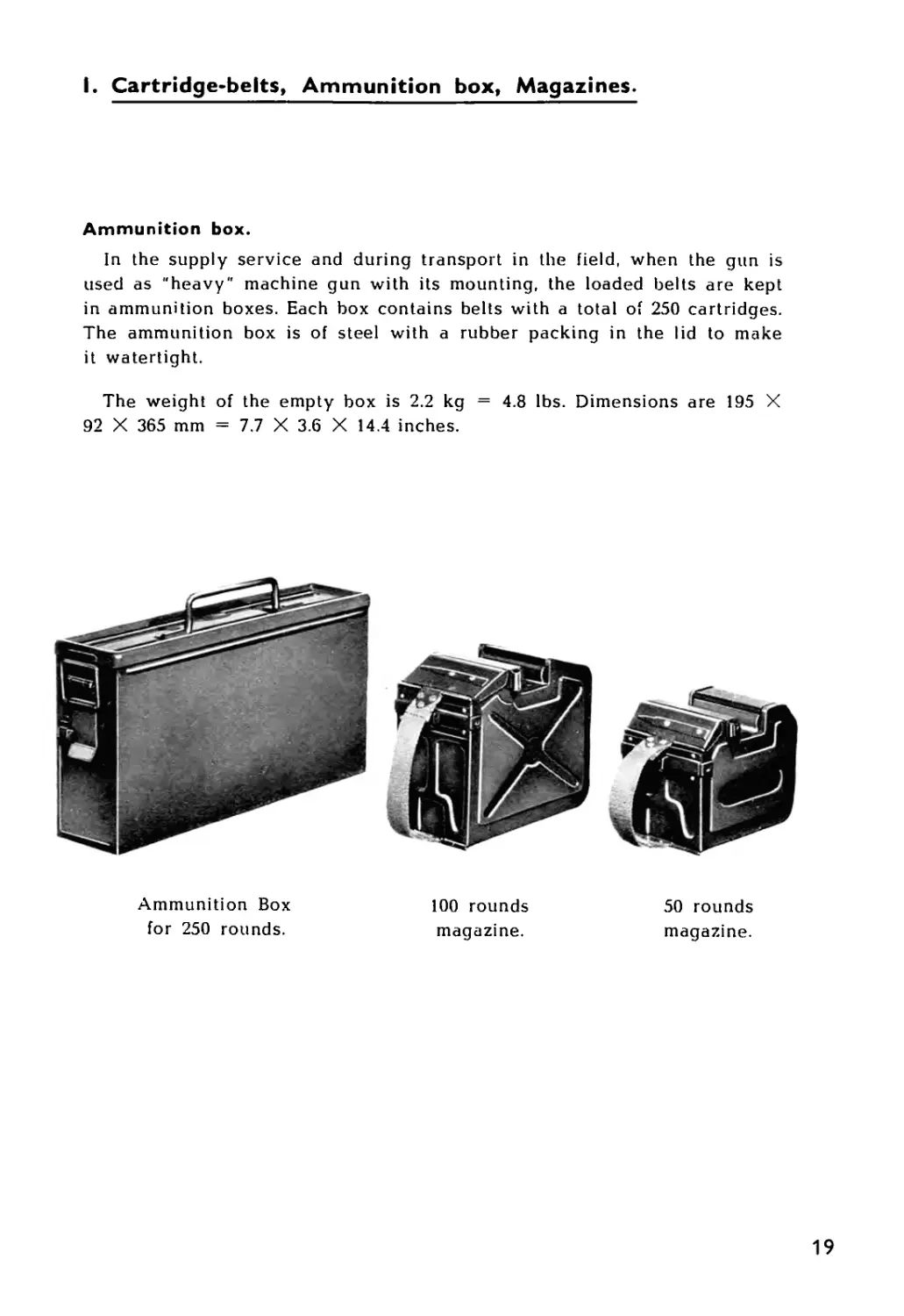
Ammunition box.
in the supply service and during transport in the field, when the gun is
used as "heavy" machine gun with its mounting, the loaded belts are kept
in ammunition boxes. Each box contains belts with a total of 250 cartridges.
The ammunition box is of steel with a rubber packing in the lid to make
it watertight.
The weight of the empty box is 2.2 kg = 4.8 lbs. Dimensions are 195 X
92 X 365 mm = 7.7 X 3.6 X 14.4 inches.
Ammunition Box
for 250 rounds.
100 rounds
50 rounds
magazine.
magazine.
19
I. Cartridge-belts, Ammunition box, Magazines.
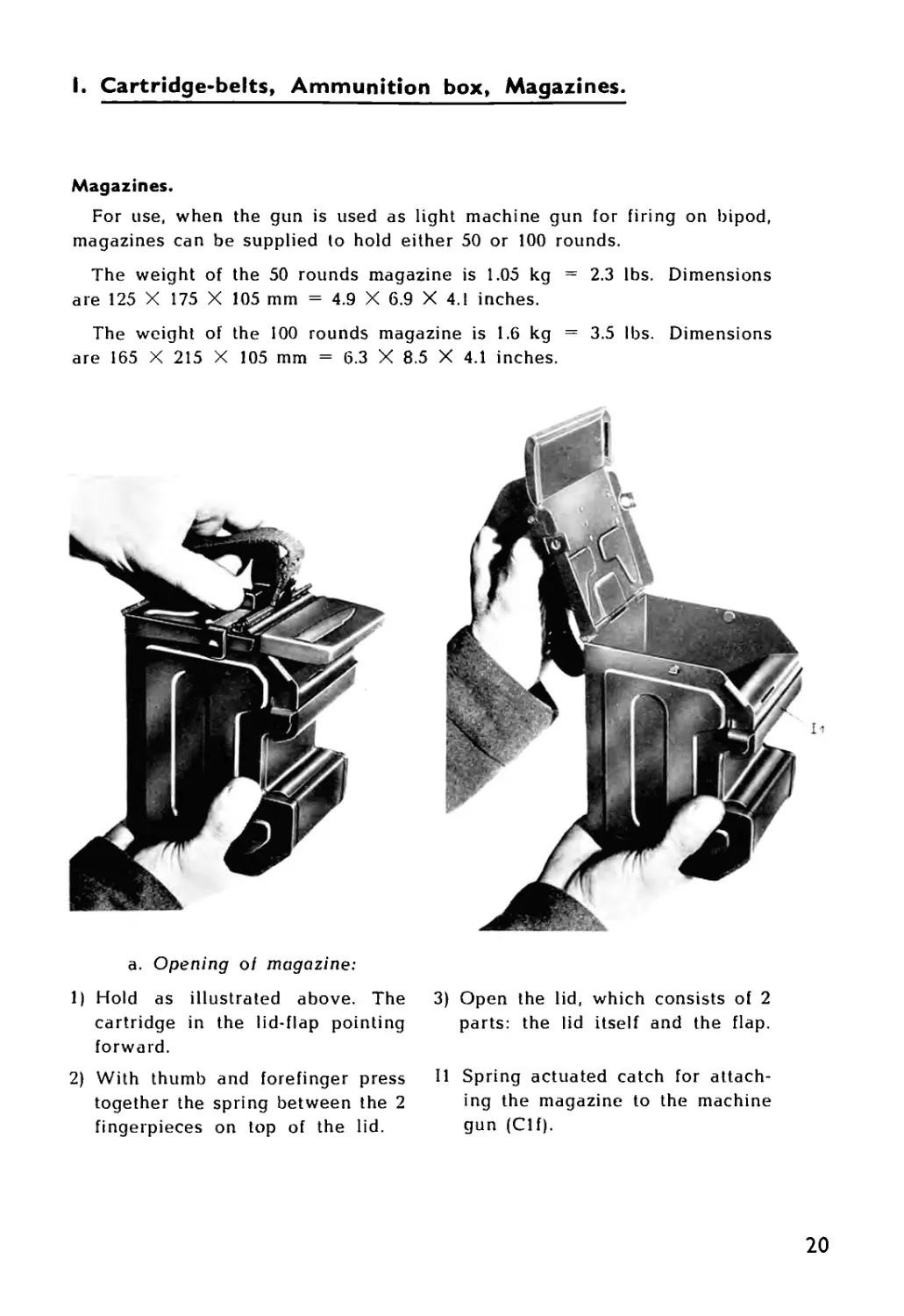
Magazines.
For use, when the gun is used as light machine gun for firing on bipod,
magazines can be supplied to hold either 50 or 100 rounds.
The weight of the 50 rounds magazine is 1.05 kg = 2.3 lbs. Dimensions
are 125 X 175 X 105 mm = 4.9 X 6.9 X 4.1 inches.
The weight of the 100 rounds magazine is 1.6 kg = 3.5 lbs. Dimensions
are 165 X 215 X 105 mm = 6.3 X 8.5 X 4.1 inches.
a. Opening oi magazine:
1) Hold as illustrated above. The
cartridge in the lid-flap pointing
forward.
2) With thumb and forefinger press
together the spring between the 2
fingerpieces on top of the lid.
3) Open the lid, which consists of 2
parts: the lid itself and the flap.
11 Spring actuated catch for attach-
ing the magazine to the machine
gun (Clf).
20
I. Cartridge-belts, Ammunition box, Magazines.
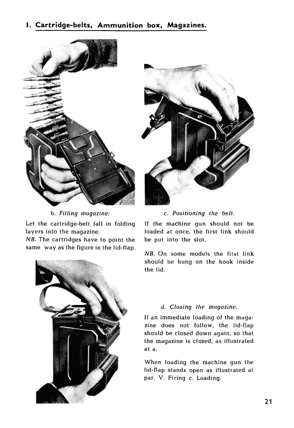
b. Filling magazine:
Let the cartridge-belt fall in folding
layers into the magazine.
NB. The cartridges have to point the
same way as the figure in the lid-flap.
c. Positioning the belt.
If the machine gun should not be
loaded at once, the first link should
be put into the slot.
NB. On some models the first link
should be hung on the hook inside
the lid.
d. Closing the magazine.
If an immediate loading of the maga-
zine does not follow, the lid-flap
should be closed down again, so that
the magazine is closed, as illustrated
at a.
When loading the machine gun the
lid-flap stands open as illustrated at
par. V. Firing c. Loading.
к.
ACCESSORIES
22
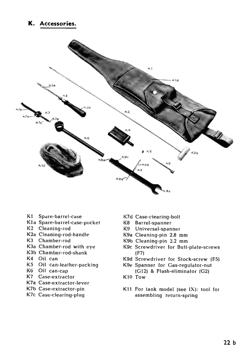
К. Accessories.
Supplied with the gun is a webbing spare-barrel-case (KI) which contains
the accessories as illustrated. The cleaning-rod (K2) fits in a channel inside
the rear wall of the case, and the other accessories are in a pocket (Kia)
on the front of the case.
The cleaning-rod (K2) is of steel with a rotating aluminium handle (K2a).
The chamber-rad (КЗ) is a jointed brass tool. On one end is an eye for
cleaning material (K3a), and the othei end has a wood handle (K3b).
The oil-can (K4), a flat container with a nozzle, is made of copper-nickel-
plated sheet iron. Built into the oil-can-cap (K6) is a brass lubricating rod.
Inside the cap is a leather washer (K5).
The case-extractor (K7) comprises the case-extractor-lever (K7a) and the
case-clearing-plug (K7c) coupled together by means of the pin (K7b).
The free end of the case-extractor-lever (K7a) is shaped to fit into lhe
groove of the cartridge, it can therefore be used for removing cases or
cartridges jammed in the chamber. It can also be used as an accessory tool
when spent cases or whole rounds have to be removed from the gun.
The case-clearing-plug (K7c) is used for removing a torn case from the
chamber when the case-clearing-bolt (K7d) is drawn out to its extreme po-
sition. The case-clearing-plug (K7c) is then pressed right into the chamber
and by means of a few light blows, the case-clearing-bolt (K7d) is driven
into the case-clearing-plug which expands in front of the neck of the case.
The torn case can now be eased out of the chambei by pressure on the
case-extractor-lever (K7a) coupled to the case-clearing-plug. The case can
be removed from the case-clearing-plug when the case-clearing-bolt (K7d)
is withdrawn to its extreme position.
The barrel-key-spanner (K8) is used in the field for changing the flash-
eliminator (G2) and grips the barrel-locking-lugs (Gib). The flash-eliminator
can then be loosened by means of the open ended spanner (K9e). The
barrel-key-spanner (K8) should also be used, when the gas-regulator-nut
(G12) has to be loosened and fixed in the field.
The universal-spanner (K9) consists of an open-ended spanner with two
cleaning-pins (K9a: 2.8 mm, and K9b: 2.2 mm) riveted loosely to its sides.
This tool is for use when the barrel is to be cleaned, the spanner being used
for unscrewing the flash-eliminator (G2) and the foresight-alignment-key
(G13), whereby the gas-regulator can be taken out and its holes cleaned by
means of the two cleaning pins (K9a and K9b). The other end of the spanner
is shaped into two screwdrivers placed at right angles (K9c and K9d), fitting
the butt-plate-screws (F7) and the stock-screw (F5) respectively.
22 a
К. Accessories.
Kt Spure-barrel-case
Kia Spare-barrel-case-pocket
K2 Cleaning-rod
K2a Cleaning-rod-handle
КЗ Chamber-rod
K3a Chamber-rod with eye
K3b Chamber-rod-shank
K4 Oil can
K5 Oil can-leather-packing
K6 Oil can-cap
K7 Case-extractor
K7a Case-extractor-lever
K7b Case-extractor-pin
K7c Case-clearing-plng
K7d Case-clearing-bolt
K8 Barrel-spanner
K9 Universal-spanner
K9a Cleaning-pin 2.8 mm
K9b Cleaning-pin 2.2 mm
K9c Screwdriver for Butt-plate-screws
(F7)
K9d Screwdriver for Stock-screw (F5)
K9e Spanner for Gas-regulator-nut
(G12) & Flash-eliminator (G2)
K10 Tow
Kll For tank model (see IX): tool for
assembling return-spring
22 b
L.
MOUNTING
23
L. Mounting.
a. The fixed parts:
The chassis (LI) consists ot the chassis-bar (Lie), which, in front cariies
the chassis-head (Lib), and at the rear 2 diagonal-stays (Lid) which,
together with the traversing-arc (Llg), form a rigid triangle.
Fixed to the chassis-head (Lib), which forms a seating for the pivot-
pin (L8), is the fore-leg-axle (Lla), on which the double fore-leg (L2)
hinges.
At the ends of the traversing-aic (Llg) are serrated discs, traversing-
arc-flanges (Lie) which act together with similar seriated discs, reai-leg-
flanges (L.3a), on the rear-legs (L3), whereby the rear-legs can be clamped
in various positions easily distinguished by marks on the traversing-arc-
flange (Lie). Clamping is effected by means of the clamping-handles (L4).
The fore.-leg is secured in its various positions by the adjustable stay-
bar (L5), one end of which hinges on the lore-leg and the other end is
coupled to the bifurcated head of the stay-bar-spring-guide (L5b). The
stay-bar-spring-guide travels inside the chassis-bar (Lie) and can be fixed
by means of the stay-bar-braking-handle (L5a), whereby the tripod fore-
leg is fixed simultaneously. When the stay-bar-braking-handle is re-
leased, the fore-leg is prevented from sliding out by a powerful com-
pression spring, the stay-bar-spring (L5c), built into the stay-bar-spring-
guide.
b. The movable parts:
The cross-slide (LG) moves in a curve on the traversing-arc (Llg) with
the pivot-pin (L8) as its centre, connected through the cross-slide-rod
(L6b). The cross-slide can be fixed ligidly by the traversing-clamping-
handle (L6a) or restricted in its lateral movements by the lateral-stop-
rings (Llf) on the traversing-arc.
The cradle-support (L7) can turn on a bolt on the cross-slide (L6) and
forms a seating for the elevating-spindle (L7a) which carries the rear-end
of the cradle. The elevating-spindle is moved by the elevating-handle
(L7c). The elevating-spindle-stops (L7b) can limit these movements.
The cradle (L9) consists of two parallel cradle-tubes (L9b) which, at
the fore end. are connected by the cradle-bridge (L9a) and, at the rear,
by the cradle-bolt (L9c) and cradle-bolt-sleeve (L9d). At the fore end
the cradle turns on the pivot-pin (L8), so that its rear end, which turns
on the elevating-spindle (L7a), can move both laterally and vertically.
Moving on the cradle are the gliders: front-glider (LIO) and reai-
glider (L11). The iront-glider carries the rear end of the gun-seating-
spindle (LlOc), which simultaneously runs through a hole in the cradle-
bridge (L9a|, and, on its fore end, has the gun-seating (LlOa). Compressed
on the gun-seating-spindle (LlOc) are two springs, the glider-springs,
(LlOb) which absorb the recoil of the gun in action and lessen the subse-
quent return movement.
23 a
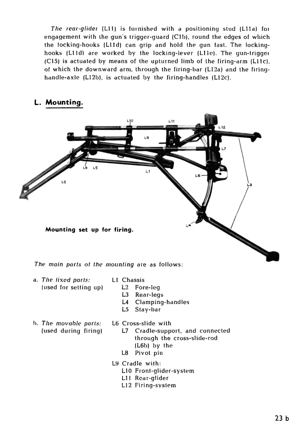
The rear-glider (Lil) is lurnished with a positioning stud (Lila) foi
engagement with the gun s trigger-guard (Clb), round the edges of which
the locking-hooks (LIId) can grip and hold the gun fast. The locking-
hooks (LI Id) are worked by the locking-lever (Llle). The gun-triggei
(C15) is actuated by means of the upturned limb of the firing-arm (Lllc),
of which the downward arm, through the firing-bar (L12a) and the firing-
handle-axle (L12b), is actuated by the firing-handles (L12c).
L. Mounting.
a. The fixed parts:
(used for setting up)
LI Chassis
L2 Fore-leg
L3 Rear-legs
L4 Clamping-handles
L5 Stay-bar
b. The movable parts:
(used during firing)
L6 Cross-slide with
L7 Cradle-support, and connected
through the cross-slide-rod
(L6b) by the
L8 Pivot pin
L9 Cradle with:
LIO Front-glider-system
LI I Rear-glider
L12 Firing-system
23 b
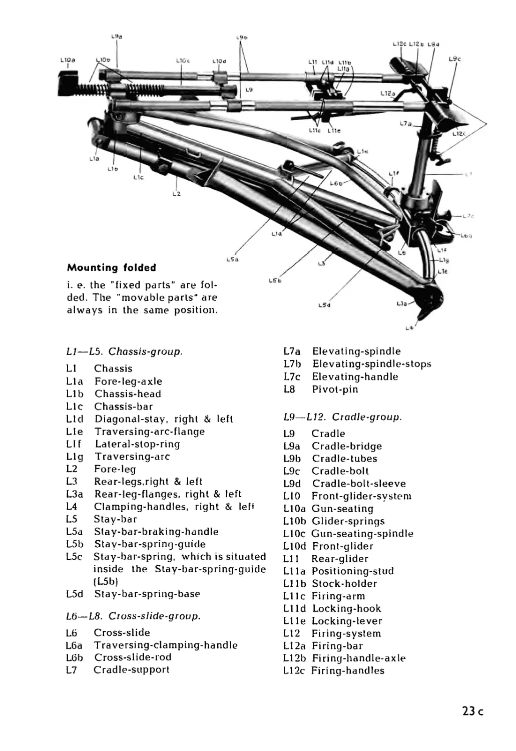
Mounting folded
i. e. the "fixed parts" are fol-
ded. The "movable parts" are
always in the same position.
LI—L5. Chassis-group.
LI Chassis
Lla Fore-leg-axle
Lib Chassis-head
Lie Chassis-bar
Lid Diagonal-stay, right & left
Lie Traversing-arc-flange
LI f Lateral-stop-ring
Llg Traversing-arc
L2 Fore-leg
L3 Rear-legs,right & left
L3a Rear-leg-flanges, right & left
L4 Clamping-handles, right & left
L5 Stay-bar
L5a Stay-bar-braking-handle
L5b Stay-bar-spring-guide
L5c Stay-bar-spring, which is situated
inside the Stay-bar-spring-guide
(L5b)
L5d Stay-bar-spring-base
L(i—L8. Cross-slide-group.
L6 Cross-slide
L6a Traversing-clamping-handle
L6b Cross-slide-rod
L7 Cradle-support
L7a Elevating-spindle
L7b Elevating-spindle-stops
L7c Elevating-handle
L8 Pivot-pin
L9—L12. Cradle-group.
L9 Cradle
L9a Cradle-bridge
L9b Cradle-tubes
L9c Cradle-bolt
L9d Cradle-bolt-sleeve
LIO Front-glider-system
LlOa Gun-seating
LlOb Glider-springs
LlOc Gun-seating-spindle
LlOd Front-glider
LI 1 Rear-glider
Lila Positioning-stud
LI lb Stock-holder
Lllc Firing-arm
LI Id Locking-hook
Llle Locking-lever
L12 Firing-system
L12a Firing-bar
L12b Firing-handle-axle
L12c Firing-handles
23 c
L. Mounting.
Tripod features:
The design of the MADSEN/SAETTER tripod mounting enables it to fulfil
any requirement in the mounting of a heavy machine gun.
The tripod, which weighs 16.5 kgs = 36 lbs., can be folded quite flat,
making it easy to carry on the back.
By means of its adjustable legs the tripod can be set up however undulat-
ing the ground, and the muzzle height can be varied from 350 mm to 800 mm,
= 13.8 inch, to 31.5 inch., enabling the gun to be operated in the prone,
kneeling or sitting position.
In case of a rapid change of position the tripod, with the gun mounted,
can be carried by one man, gripping the tripod fore-leg in the left hand and
the right half of the traversing arc with the right, and holding the gun close
to the body. In changing position over a somewhat longer distance, the
tripod and mounted gun should be carried by two men, one lifting the
tripod foreleg and the other gripping the two rear legs, one in each hand;
with this form of transport movement can be made over long distances, the
tripod and gun together weighing no more than 27.6 kgs = 60.7 lbs.
A factor contributing to the particularly good accuracy attainable with
the MADSEN/SAETTER gun on the MADSEN/SAETTER tripod is that the
gun rests on gliders, both of which move in the same plane, parallel with,
and at a short distance from, the axis of the gun; another factor is that the
gun trigger is so manipulated that vibrations of the gun are not disturbed
in its longitudinal movement of the cradle. During firing the gun itself
is entirely un-touched by the gunner's hand.
In order to make the tripod suitable for both indirect firing and firing
over, or through gaps or openings in own troops, it is provided with gradu-
ated scales and movement stops for both traversing and elevating.
The traversing scale is situated on the traversing arc, and is of such order
that a traversing slide movement of one big mark (10 mils) corresponds to
10 metres movement in the point of impact at a range of 1000 metres.
Between successive big marks is a smaller five mils mark. For each 50
mils a number is engraved.
The graduated scale for elevation is placed on the elevating spindle and
is of the same order as the direction scale on the liaversing arc, i. e. one
big mark on the spindle corresponds to 10 metres' vertical movement of the
point of impact at 1000 metres; but as one big mark corresponds to 2hs turns
of the elevating handle, it is possible to move the point of impact by 1
metre at 1000 metres (1 mil) by giving the elevating handle a quarter turn.
If more effective sighting possibilities are desired than those obtainable
by using the guns own sights, the tripod can be furnished with optical
sights, which can be mounted on a bracket on the cradle.
24
IV. STRIPPING AND ASSEMBLING
THE MACHINE GUN
a. Stripping.
1. Ensure that the chamber is empty by opening the feed-cover (press
the feed-cover-latch (B3) and pull back the cocking-handle (C7).
2. Remove the butt-stock: Seize the pistol-grip (Clc) with one hand,
with the thumb press the trigger-gear-housing-latch (C3). The butt-
stock (F3), now released, should be turned 90r with the other hand
and pulled straight back out of the receiver (A5).
3. Remove the trigger-gear-housing (Cl): The cocking-handle (C7)
should be pulled fully back and then pushed forward again. This
brings the bolt-carriei (DI) to its rearmost position. The trigger-gear-
housing can now be turned downwards and taken out of engagement
with the two trunnions on the barrel-socket-block (A3).
4. The trigger-group-box (CH), containing the trigger-mechanism, is
taken out by maintaining thumb pressure on the trigger-gear-housing-
latch (C3), turning the pistol-grip (Clc) up, and letting the trigger-
group-box fall out into the other hand and at the same time pulling
it free of the trigger-gear-housing-block (Cle) in the bottom of Cl,
in which it is secured at Cl lb. Take out the stop (C4). The trigger-
gear-housing-latch (C3) and spring (C2) are now free and are taken
out.
5. Remove the gas-piston (E): When the bolt-assembly (D) is in its
rearmost position, the gas-piston-head (Elc) is just outside a clear-
ance at the end of its tracks in the bottom of the receiver (A5), and
can be withdrawn — at the same time freeing it from its coupling
groove (Dla) —. It can then be withdrawn rearwards from the barrel-
support-tube (Al).
6. The bolt-assembly (D) is taken out by letting it slide rearwards out
of the receiver (A5).
7. The feed-cover (Bl) and the feed-way (B12) are turned upwards to a
vertical position, the feed-cover-hinge-pin (B13) is withdrawn to the
left, freeing the feed-mechanism.
8. The feed-lever-cover (B14) is lifted up and the feed-lever (B15) re-
moved.
9. To remove the barrel (G), turn the barrel-handle (G3) forward and
to the right vertically, push the barrel forward and it is free.
10. To remove the bipod (H), press the bipod-locking-plunger (H7) and
turn the bipod-mounting round until it is free of its track in the
bipod-seating (Alb).
11. The receiver-clip-ring (A7) can be removed by opening it slightly
and moving it rearwards.
25
IV. Stripping and Assembling the Machine Gun, continued.
12. To strip the bolt-assembly (D), press out the bolt-carrier-pin (D2),
pull back the action-head (Dll), and remove components. Press the
extractor (D6), take out the extractor-pin (D7), and remove the
extractor and its 2 springs (D4 and D5).
b. Assembling.
Reverse the above order. It should be noted that:
1. On assembling the bolt-assembly, the firing-pin-spring (D13) is put
on the firing pin (D12), which then is inserted, into the bolt (D3).
The action-rod (DIlb) is then pushed through the action-spring (DIO)
and collar (D9) into the bolt (D3). The assembled bolt is replaced in
the bolt-carrier (DI) and locked with the bolt-carrier-pin (D2). Finally
the bolt-locking-pawls (D8) are inserted.
2. The feed-cover (Bl) should not be closed, unless the moving parts
are in the rear position, i. e. first perform a cocking motion, then
close the feed-cover, and finally let the mechanism go forward, if
no shooting is to take place.
3. The weapon should be at “Safe" as any other weapon when not
in use.
26
V. FIRING
a. The machine gun mounted (see the following illustrations).
1. Hold the gun butt upwards at an angle of abt. 45 .
2. Insert the tripod-hook (Ale) into the foremost gun-seating (LlOa).
3. Place the pistol-grip (Clc) in the stock-holder (LI lb), the rear-glider
(Lil) being slid to the right position so that the positioning stud (Lila)
can be pushed upwards into the rearmost hole of the trigger-guard.
4. Close the locking-hook (LIId) round the trigger-guard by means of
the locking-lever (Llle), which is pressed upwards, and ensure that
the firing-arm (LI 1c) is placed in front of the trigger of the gun (C15).
If mounting is not used, the bipod legs are unfolded, unless the wea-
pon is to be fired in some other way.
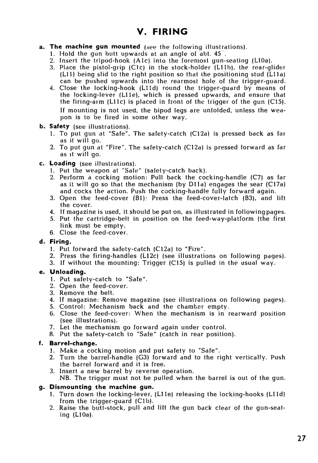
b. Safety (see illustrations).
1. To put gun at "Safe", The safety-catch (C12a) is pressed back as far
as it will go.
2. To put gun at "Fire", The safety-catch (C12a) is pressed forward as far
as it will go.
c. Loading (see illustrations).
1. Put the weapon at "Safe" (safety-catch back).
2. Perform a cocking motion: Pull back the cocking-handle (C7) as far
as it will go so that the mechanism (by DI la) engages the sear (C17a)
and cocks the action. Push the cocking-handle fully forward again.
3. Open the feed-cover (Bl): Press the feed-cover-latch (B3), and lift
the cover.
4. If magazine is used, it should be put on, as illustrated in following pages.
5. Put the cartridge-belt in position on the feed-way-platform (the first
link must be empty.
6. Close the feed-cover.
d. Firing.
1. Put forward the safety-catch (C12a) to "Fire".
2. Press the firing-handles (L12c) (see illustrations on following pages).
3. If without the mounting: Trigger (C15) is pulled in the usual way.
e. Unloading.
1. Put safety-catch to "Safe".
2. Open the feed-cover.
3. Remove the belt.
4. If magazine: Remove magazine (see illustrations on following pages).
5. Control: Mechanism back and the chamber empty.
6. Close the feed-cover: When the mechanism is in rearward position
(see illustrations).
7. Let the mechanism go forward again under control.
8. Put the safety-catch to "Safe" (catch in rear position).
f. Barrel-change.
1. Make a cocking motion and put safety to "Safe".
2. Turn the barrel-handle (G3) forward and to the right vertically. Push
the barrel forward and it is free.
3. Insert a new barrel by reverse operation.
NB. The trigger must not be pulled when the barrel is out of the gun.
g. Dismounting the machine gun.
1. Turn down the locking-lever, (Llle) releasing the locking-hooks (LI Id)
from the trigger-guard (Clb).
2. Raise the butt-stock, pull and lift the gun back clear of the gun-seat-
ing (LlOa).
27
1. Hold the gun butt upwards at an angle of abt. 45°.
2. Insert the tripod-hook (Ale) into the foremost gun-seating (LlOa).
3. Place the pistol-grip (Cle) in the stock-holder (LIlb), the rear-glider
(LU) being slid to the right position so that the positioning stud (Lila)
can be pushed upwards into the rearmost hole of the trigger-guard (Clb).
4. Close the locking-hook (LI Id) round the trigger-guard by means of the
locking-lever (Llle), which is pressed upwards to ensure that the firing-
arm (LI 1c) is placed in front of the trigger of the gun (C15).
28
V. Firing, continued.
re b: Safety.
Saie: The safely-catch
is pulled buck.
Fire: The safety-catch
is pushed forward.
re c: Loading, item 4.
Cocking motion:
1. Pull back the cocking-handle (07) as far as it will go, so that the aclion-
head-bent (DIla) engages the sear (C17a) and cocks the action.
2. Push the cocking-handle fully forward.
29
V. Firing, continued.
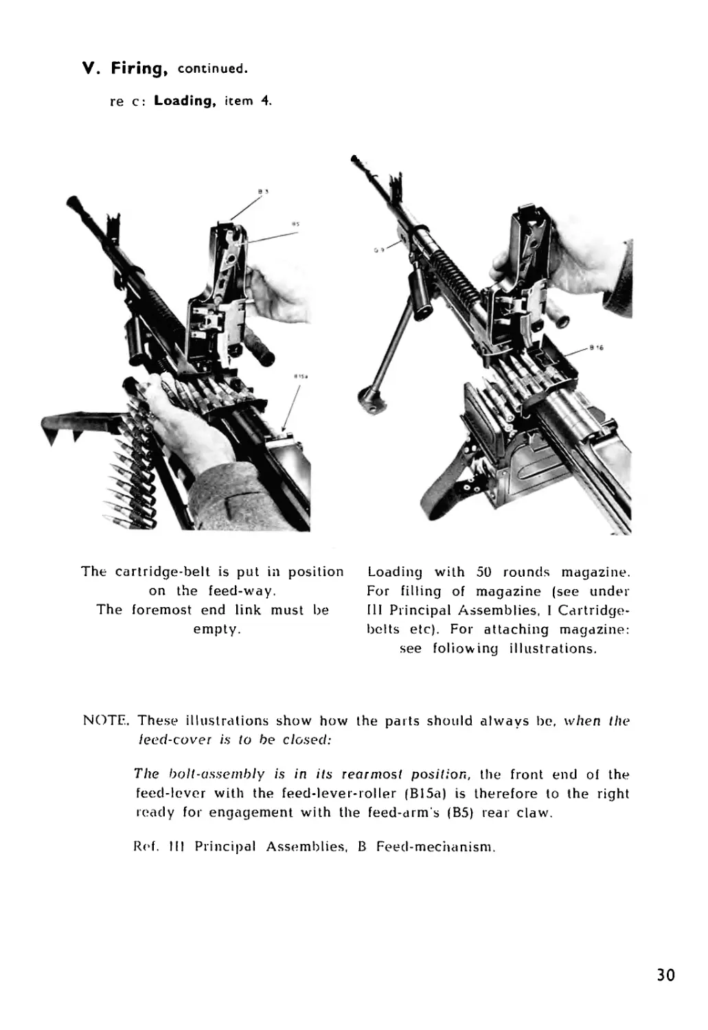
re c: Loading, item 4.
The cartridge-belt is put in position
on the feed-way.
The foremost end link must be
empty.
Loading with 50 rounds magazine.
For filling of magazine (see under
III Principal Assemblies, I Cartridge-
belts etc). For attaching magazine:
see foliowing illustrations.
NOTE. These illustrations show how
leed-cover is to be closed:
the parts should always be, when the
The bolt-assembly is in its rearmost position, the front end of the
feed-lever with the feed-lever-roller (B15a) is therefore to the right
ready for engagement with the feed-arm’s (B5) rear claw.
Ref. Ill Principal Assemblies, В Feed-mechanism.
30
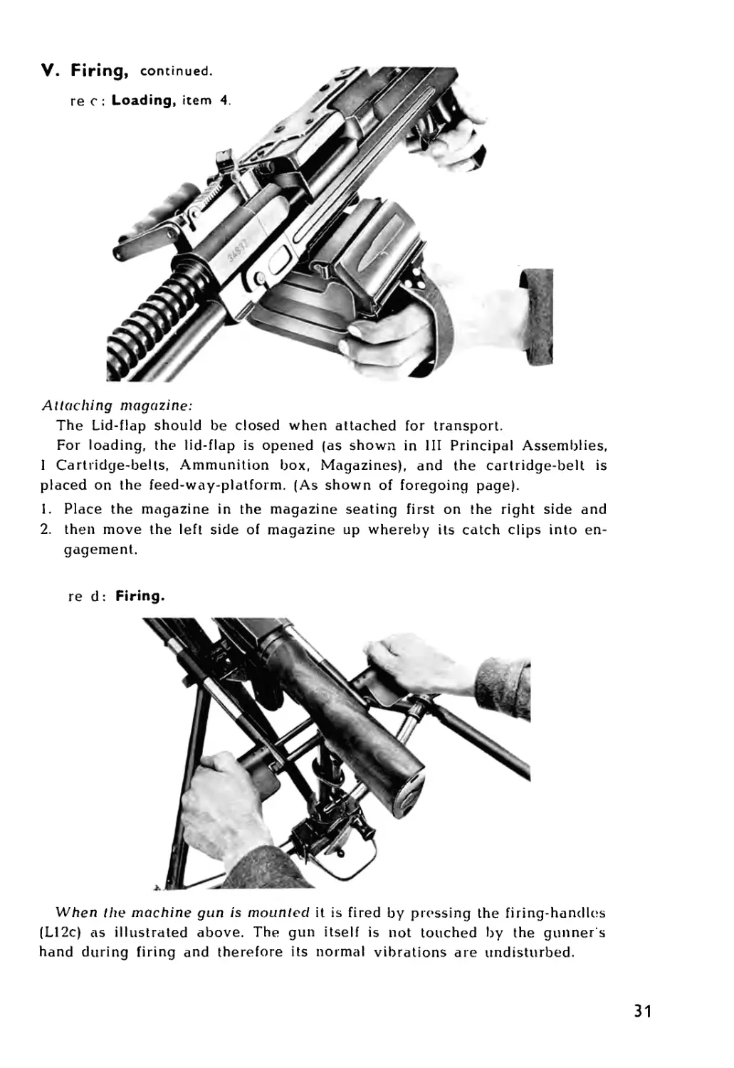
Attaching magazine:
The Lid-flap should be closed when attached for transport.
For loading, the lid-flap is opened (as shown in III Principal Assemblies,
I Cartridge-belts, Ammunition box, Magazines), and the cartridge-belt is
placed on the feed-way-platform. (As shown of foregoing page).
1. Place the magazine in the magazine seating first on the right side and
2. then move the left side of magazine up whereby its catch clips into en-
gagement.
re d: Firing.
When the machine gun is mounted it is fired by pressing the firing-handles
(L12c) as illustrated above. The gun itself is not touched by the gunner s
hand during firing and therefore its normal vibrations are undisturbed.
31
V. Firing, continued.
re e:
Unloadin
item 4.
To remove I he magazine:
Press in the magazine catch (II) with two fingers and the magazine will
be free.
re f: Change of barrel.
1. Perforin a cocking motion, and put safety to "Safe".
2. Turn the barrel-handle (G'3) forward and to the right vertically. Push the
barrel forward and it is free.
3. Insert a new barrel by reverse operation
NB. The trigger must not be pulled when the barrel is out of the weapon.
32
VI. FUNCTIONING
The weapon is loaded and ready lor firing. The bolt-assembly is in its
rearward position with the action-head-bent (DI la) engaging the sear (07).
The bolt-locking-pawls (D8) are compressed at D8a by the action-collar
(D9). The firing-pin (D12) is held back by the firing-pin-spring (D13). The
first cartridge is in position in the feed-way (B12b) between the cartridge-
stop (B12a) and the lower feed-slide-pawl (B7b).
On firing, the following takes place: — The trigger (C15) is actuated and
presses downwards the sear (C17| which is disengaged from the Action-
head-bent (DI la). The hook (C18a) of the spring actuated trigger-rod is
raised ready for engagement with the action-collar-lug (D9a).
The bolt-assembly (D) is now free and is pressed by the return-spring
(F13) towards its foremost position. During this movement, the bolt (D3)
pushes the cartridge in front of it out of the belt towards the chamber. The
upper-feed-slide (B7c) with its two pawls, blings the next round a half link
space to the right, while the lower-feed-slide (B7b), with one pawl, moves a
half link space to the left and grips the round, ready to move it on to its
place on the feed-way (B12b).
Towards the end of the foiward movement of the bolt-assembly (D) the
trigger-rod-hook (C18a) engages the action-collar (D9), thereby freeing the
bolt-locking-pawls (D8). The bolt (D3) pushes the caitridge home into the
chamber, and stops, whereas the bolt-carrier (DI) with the action-head
(Dll), action-rod (DI lb) and firing-pin (D12) continues. The action-head-
shoulders (DI 1c) press out the bolt-locking-pawls (D8) into their clearances
in bolt-carrier (Dlb) and receiver (A5b) to engage with the pressure-absorb-
ing-blocks (A6), positively locking the bolt.
The forward movement stops, the firing-pin (D12) igniting the cartridge.
The gas-cup (Ela) on the gas-piston has simultaneously moved right forward
and enclosed the gas-regulator (Gil).
The bullet on its way through the barrel (Gl) passes the gas-port, through
which part of the gasses following the bullet escapes through the gas-regula-
tor (Gil) and forces the gas-piston (El) rearwards together with the bolt-
assembly. The return-spring (F13) is thereby compressed.
During the rearward movement the sequence of events is as follows: The
bolt carrier (DI) with the action-head (Dll), action-rod (DI lb) and the firing-
pin (D12) under pressure of its spring (D13), begins to move, the bolt (D3)
meanwhile remaining motionless. The front edges of the slots (Dlb) of the
bolt-carrier act upon the bolt-locking-pawls (D8) and force them out of
engagement with the pressure-absorbing-blocks (A6), thus releasing the
bolt, which then moves back with the bolt-carricr.
The empty case will be pulled out of the chamber by the extractor (D6)
and carried back in the cartridge-seating on the bolt face. The action-collar
(D9) is now pressed forward by its spring (DIO), thereby locking the bolt-
locking-pawls (D8) in their withdrawn position.
During the further rearward movement, the base of the empty cartridge
case hits the ejector (A5a), and the case is forced to the right and ejected
through the opening (A5f) in the right side of the receiver.
By this time the lower-feed-slide (B7b) with its pawl has pushed the next
round to the right into position on the feed-way-platform (B12b), while the
2 pawls of the upper-feed-slide (B7c) have moved to the left and are now
behind the next round, ready to move the belt on, when the mechanism
moves forward again. The bolt assembly (D) completes the rearward move-
ment, rebounds against the buffer-mechanism (F10--11), and will continue
operating until brought to a stop.
34
VII. MAINTENANCE
1. Inspection:
a. Before shooting ensure:
1. that the barrel has been cleaned,
2. that the correct gas-hole is used,
3. that the ammunition is correctly fixed in the bells.
b. During shooting ensure:
1. that the cartridges are protected from dirt,
2. that the barrel is changed for each 200 rounds in case of sustained
firing.
c. After shooting ensure:
1. that the machine gun is unloaded,
2. that the barrel is oiled,
3. that cleaning is performed as soon as possible,
4. that possible faults are corrected and necessary changes made
35
VII. Maintenance, continued.
2. Possible replacements.
(For stripping and assembling see IV).
a. Barrel (G) changed (see picture under V Firing).
1. Make a cocking motion and put safety to "Safe".
2. Turn the barrel-handle (G3) forward and to the right vertically.
Push the barrel forward and it is free.
3. Insert a new barrel by reverse operation.
NB: The trigger must not be pulled when the barrel is out of the
weapon.
b. Firing-pin (D12) and firing-pin-spring (D13).
I. Stripping: press out the bolt-carrier-pin (D2), pull back the action-
head (Dll), and the remaining parts are easily removed. Remove
firing-pin and spiing from the bolt.
2. Change components, if considered necessary.
3. Assemble in the reverse order.
N.B. Remember to first insert the spring followed by the firing-pin.
c. Extractor (D6) and extractor-springs (D4 & D5).
1. Stripping: press in the extractor (D6) against the bolt (D3), remove
the extractor-pin (D7). Extractor and the 2 extractor-springs can
then be taken out.
2. Change components, if considered necessary.
3. Assemble in the reverse order.
d. Feed-mechanism-springs.
1. Fold back feed-cover (Bl) and feed-way (B12) and pull out to the
left feed-cover-hinge-pin (B13). Place the feed-cover in left hand
with the thumb on the feed-aligner (B9) pressing it down and, at
the same time, backwards, take out the feed-aligner-pin (B8). free-
ing the components and springs (BIO and Bl 1).
2. Change components, if considered necessary.
3. Assemble in the ieverse order.
36
VII. Maintenance, continued.
2. Possible replacements, continued.
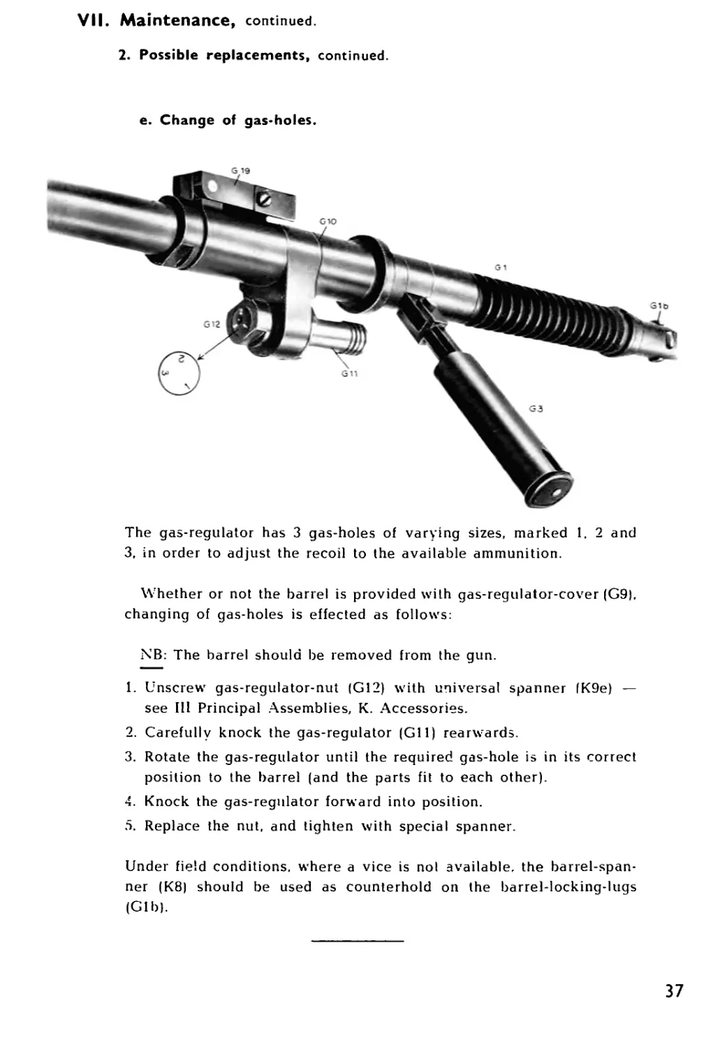
e. Change of gas*holes.
The gas-regulator has 3 gas-holes of varying sizes, marked 1. 2 and
3, in order to adjust the recoil to the available ammunition.
Whether or not the barrel is provided with gas-regulator-cover (G9),
changing of gas-holes is effected as follows:
NB: The barrel should be removed from the gun.
1. Unscrew gas-regulator-nut (G12) with universal spanner (K9e) —
see Ill Principal Assemblies, K. Accessories.
2. Carefully knock the gas-regulator (Gil) rearwards.
3. Rotate the gas-regulator until the required gas-hole is in its correct
position to the barrel (and the parts fit to each other).
4. Knock the gas-regulator forward into position.
5. Replace the nut, and tighten with special spanner.
Under field conditions, where a vice is nol available, the barrel-span-
ner (K8) should be used as counterhold on the barrel-locking-lugs
(Gib).
37
VIII. STOPPAGES AND REMEDIES
Should the gun stop while firing, the gunner must always
1. Move the safety-catch back to ’Safe”.
2. Perform a cocking motion.
3. Look through the ejection slot to see if there is a round or an empty
case in front of the bolt or in the chamber.
The gunner will then be able to ascertain one of the following stoppages,
which should be remedied in the manner described:
1. A whole round was ejected by the cocking motion.
The cocking motion required normal exertion.
Cause: Missfire.
The missfire may be due to a defective charge in the percus-
sion cap or defective fire-holes in the cartridge.
Remedy: The fault has been remedied by the cocking motion already
performed.
Note: If the fault is repeated: examine the ejected round. If there is no
mark from the firing-pin, the latter may be broken. Examine
the firing-pin and replace it if necessary. (See under VII
Maintenance, 2. Possible Replacements).
2. A whole round was ejected by the cocking motion.
The cocking motion required more than usual exertion.
Cause: Foreign body in the chamber.
The cartridge must have been jammed inside a torn case or
other foreign body in the chamber.
Remedy: Remove the barrel. Examine the chamber. If the half of a torn
case has remained in the chamber, remove it with the aid of
the case-extractor (K7) (refer K. Accessories). Replace the bar-
rel. Unload the gun. Raise the feed-way and see if the base of
the case is lying inside the gun, in which case it must be
removed. Close the feed-way and reload the gun.
If there is any foreign body such as powder grains or the like
in the chamber, clean the chamber with the chambei-rod (K3|.
Also see if there are any foreign bodies as above lying inside
the gun; if so, the gun must be stripped and cleaned before
firing is continued.
38
VIII. Stoppages and Remedies, continued.
3. An empty case was ejected by the cocking motion.
Cause: a) Bullet lodged in barrel,
b) loose bullet, or
c) short recoil.
In all three cases the ammunition is at fault.
a. In the first case the propellant charge was too weak, or
entirely missing, in which case the bullet would probably
have stopped somewhere in the barrel.
b. In the second case the bullet was loose in the case and fell
out during loading.
c. Short recoil, due to a low charge, causing the case to be
half extracted and then pushed back into the chamber.
Remedy: Remove the barrel and examine both chamber and bore. If
there is a bullet in the bore, use the cleaning-rod (K2) to push
it back and out of the chamber. Replace the barrel and con-
tinue firing. If there are powder grains in the chamber, remove
them with the chamber-rod (K3|. Replace the barrel, unload
the gun, and raise the feed-way and see if there are any
powder grains inside the gun. If so, strip the gun and clean it
before continuing firing.
In the following it is assumed that nothing was ejected when the cocking
motion was performed.
4. No cartridge or empty case in front of the bolt or in
the chamber.
Cause: Faulty feed.
Faulty feeding may have been caused by the failure of the
driving mechanism, or the bolt not having been behind the
round in the feed-way.
In both cases the cause may have been short recoil owing to
faulty ammunition.
Remedy: The fault has been remedied by the cocking motion already
performed.
Note: И the stoppage is repeated:
The cause may be that the gas holes in the gas-regulator |GII)
are choked owing to an excessively fouling ammunition. In
that case, remove the gas-regulator from the barrel (see in-
structions under VII Maintenance, 2. Possible Replacements)
and clean the gas holes with the cleaning-pins on the univer-
sal-spanner (K9) designed for the purpose.
39
VIII. Stoppages and Remedies, continued.
5. A whole cartridge in front of the bolt.
Cause: Faulty insertion.
On its way the nose of the bullet has struck the back end of
the barrel and has thus been prevented from moving on.
Remedy: Open the cover. Remove the cartridge-belt. Open the feed-
way. Remove the round by means of the case-extractor (K7).
Close the feed-way and reload.
6. An empty case in front of the bolt.
Cause: Faulty ejection or loose bullet.
Remedy: Unload the gun. Open the feed-way and remove the case by
means of the case-extractor (K7). See if there are powder
grains inside the gun; if so. strip the gun and clean it before
continuing firing. Otherwise, close the feed-way and reload.
7. An empty case in the chamber.
Cause: Faulty extraction.
This may be due to a torn flange, the flange having been too
weak, or the case is heat-jammed in the chamber.
Remedy: Remove the barrel and eject the case either by means of the
case-extractor (K7) or the cleaning-rod (K2).
Examine the flange of the case; if it is intact the faulty extrac-
tion may have been due to the extractor being damaged or
broken. If so, it must be replaced. Return the barrel, and if
necessary strip the gun and change the extractor (see instruc-
tions VII Maintenance, 2. Possible Replacements).
40
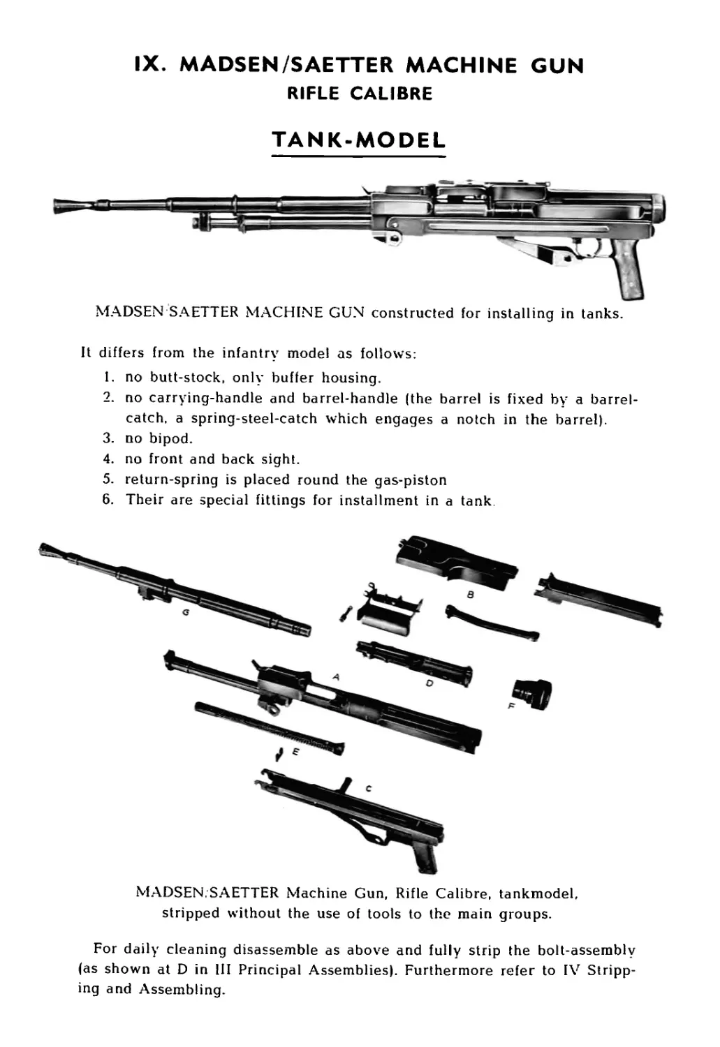
IX. MADSEN/SAETTER MACHINE GUN
RIFLE CALIBRE
TANK-MODEL
MADSEN SA ETTER MACHINE GUN constructed for installing in tanks.
It differs from the infantry model as follows:
1. no butt-stock, only buffer housing.
2. no carrying-handle and barrel-handle (the barrel is fixed by a barrel-
catch, a spring-steel-catch which engages a notch in the barrel).
3. no bipod.
4. no front and back sight.
5. return-spring is placed round the gas-piston
6. Their are special fittings for installment in a tank
MADSEN,SAETTER Machine Gun, Rifle Calibre, tankmodel,
stripped without the use of tools to the main groups.
For daily cleaning disassemble as above and fully strip the bolt-assembly
(as shown at D in HI Principal Assemblies). Furthermore refer to IV Stripp-
ing and Assembling.
IX. MADSEN SAETTER Machine Gun, Tank-model, continued.
MADSEN SAETTER Machine Gun, Tank-model firing on “special lightweight"
tripod outside the tank
“Special lightweight” Tank-tripod
unfolded.
“Special lightweight’ Tank-tripod
folded for transport in the tank.
42
IX. MADSEN SAETTER Machine Gun, Tank-model , continued.
Parts different from MADSEN/SAETTER Machine gun, infantry-model
Compare with III Principal Assemblies.
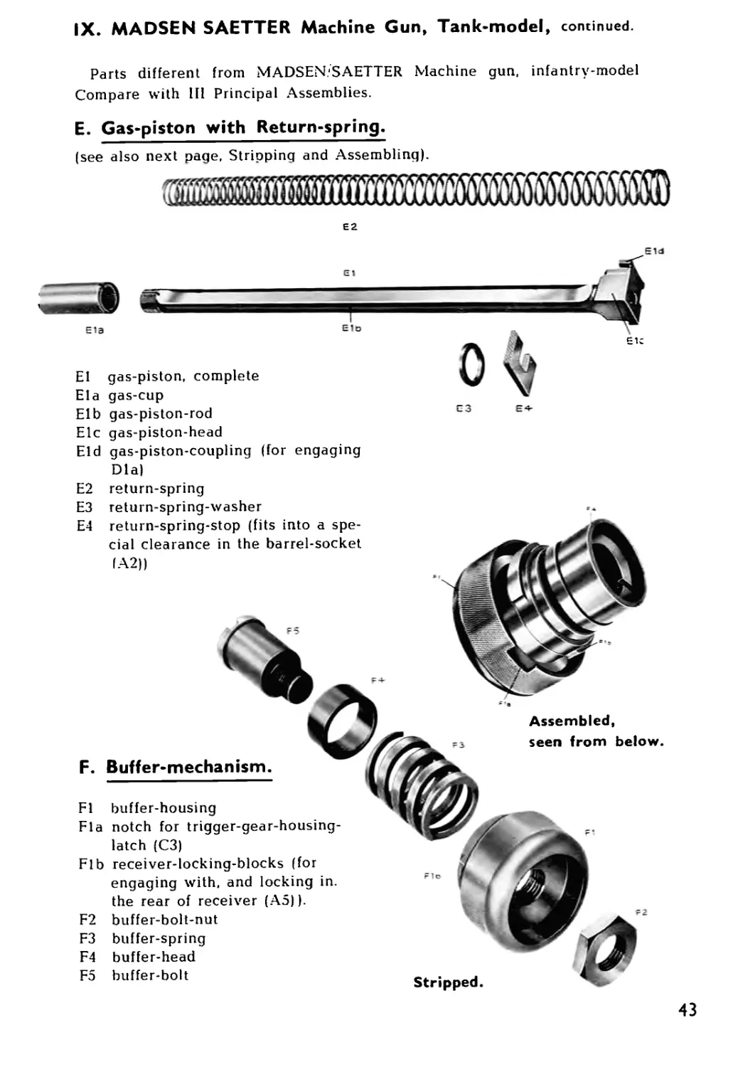
E. Gas-piston with Return-spring.
(see also next page, Stripping and Assembling).
я®ш
E2
Elb gas-piston-rod
Elc gas-piston-head
Eld gas-piston-coupling (for engaging
Dla)
eia
E2 return-spring
E3 return-spring-washer
Stripped
Assembled,
seen from below.
E4 return-spring-stop (fits into a spe-
cial clearance in the barrel-socket
IA2))
F. Buffer-mechanism.
Fl buffer-housing
Fla notch for trigger-gear-housing-
latch (C3)
Fib receiver-locking-blocks (for
engaging with, and locking in.
the rear of receiver (A5)).
F2 buffer-bolt-nut
F3 buffer-spring
F4 buffer-head
F5 buffer-bolt
43
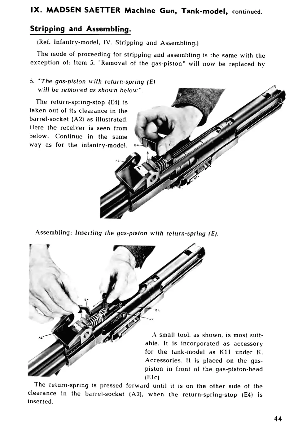
IX. MADSEN SAETTER Machine Gun, Tank-model , continued.
Stripping and Assembling.
(Ref. Infantry-model, IV. Stripping and Assembling.)
The mode of proceeding for stripping and assembling is the same with the
exception of: Item 5. "Removal of the gas-piston“ will now be replaced by
5. 'The gas-pislon with return-spring (El
will be removed as shown below".
The return-spring-stop (E4) is
taken out of its clearance in the
barrel-socket (A2) as illustrated.
Here the receiver is seen from
below. Continue in the same
way as for the infantry-model.
Assembling: Inserting the gas-piston with return-spring (E).
A small tool, as shown, is most suit-
able. It is incorporated as accessory
for the tank-model as Kll under K.
Accessories. It is placed on the gas-
piston in front of the gas-piston-head
(Elc).
The return-spring is pressed forward until it is on the other side of the
clearance in the barrel-socket (A2), when the return-spring-stop (E4) is
inserted.
44