/


Текст
The European Space Agency was formed out of, and took over the rights
and obligations of, the two earlier European Space Organisations: the""
European Space Research Organisation (ESRO) and the European
Organisation for the Development and Construction of Space Vehicle
Launchers (ELDO). The Member States are Belgium, Denmark, France,
Germany, Italy, Netherlands, Spain, Sweden, Switzerland and the
United Kingdom. Ireland has signed the ESA Convention and will
become a Member State upon its ratification. Austria, Canada and
Norway have been granted Observer status.
In the words of the Convention: The purpose of the Agency shall be to
provide for and to promote, for exclusively peaceful purposes, co¬
operation among European States in space research and technology and
their space applications, with a view to their being used for scientific
purposes and for operational space applications systems,
(a) by elaborating and implementing a long-term European space
policy, by recommending space objectives to the Member States,
and by concerting the policies of the Member States with respect to
other national and international organisations and institutions;
(b) by elaborating and implementing activities and programmes in the
space field;
(c) by co-ordinating the European space programme and national
programmes, and by integrating the latter progressively and as
completely as possible into the European space programme, in
particular as regards the development of applications satellites;
(d) by elaborating and implementing the industrial policy appropriate
to its programme and by recommending a coherent industrial
policy to the Member States.
The Agency is directed by a Council composed of representatives of
Member States. The Director General is the chief executive of the
Agency and its legal representative.
The Directorate of the Agency consists of the Director General; the ’
Director of Planning and Future Programmes; the Director of
Administration; the Director of Scientific and Meteorological Satellite
Programmes; the Director of Communication Satellite Programmes; the
Director of the Spacelab Programme; the Technical Inspector; the
Director of ESTEC and the Director of ESOC.
The ESA HEADQUARTERS are in Paris.
The major establishments of ESA are:
THF см — —
LOGY CENTRE
3), Darmstadt,
ascati, Italy.
L'Agence Spatiale Europeenne est issue des deux Organisations
spatiaies europeennes qui font precedee - /'Organisation europeenne
de recherches spatiaies (CERS) et /'Organisation europeenne pour /a
mise au point et la construction de /anceurs d'engins spatiaux (CEO LES)
- dont e/le a repris les droits et obligations. Les Etats membres en sont:
I'Allemagne, la Belgique, le Danemark, I'Espagne, la France,!'ItaHe, les
Pays-Bas, le Royaume-Uni, la Suede et la Suisse. L'lrlande a signe la
Convention de I'ESA et deviendra Etat membre de ГАдепсе lorsque la
Convention aura ete ratifiee. L'Autriche, le Canada et la Norvege
beneficient d'un statut d'observateur.
Seton les termes de la Convention: L'Agence a pour mission d'assurer et
de developper, a des fins exdusivement pacifiques, la cooperation entre
Etats europeens dans les domaines de la recherche et de la technologie
spatiaies et de leurs applications spatiaies, en vue de leur utilisation a des
fins scientifiques et pour des systemes spatiaux operationnels
d'applications:
(a) en elaborant et en mettant en oeuvre une politique spatiale
europeenne a long terme, en recommandant aux Etats membres des
objectifs en matiere spatiale et en concertant les politiques des
Etats membres a I'egard d'autres organisations et institutions
nationales et internationales;
(b) en ё/aborant et en mettant en oeuvre des activites et des
programmes dans le domaine spatial;
(c) en coordonnant le programme spatial europeen et les programmes
nationaux, et en integrant ces derniers progressivement et aussi
completement que possible dans le programme spatial europeen,
notamment en ce qui concerne le developpement de satellites
d'applications;
(d) en elaborant et en mettant en oeuvre la politique industrielle
appropriee a son programme et en recommandant aux Etats
membres une politique industrielle coherente.
L'Agence est dirigee par un Conseil, compose de representants des Etats
membres. Le Directeur genera! est le fonctionnaire executif superieur de
/'Agence et la represente dans tous ses actes.
Le Directoire de I'Agence est compose du Directeur general, du
Directeur des Programmes futurs et des Plans, du Directeur de
/'Administration, du Directeur des Programmes de satellites scientifiques
et meteorologique, du Directeur des Programmes de satellites de
communications, du Directeur du Programme Spacelab, de I'Inspecteur
technique, du Directeur de /'ESTEC et du Directeur de /'ESOC.
Le SIEGE de Г ESA est a Paris.
Les principaux Etab/issements de /'ESA sont:
LE CENTRE EURO PEEN DE RECHERCHE ET DE TECHNOLOGIE
SPAT!ALES (ESTEC), Noordwijk, Pays-Bas.
LE CENTRE EUROPEEN D'OPERATIONS SPAT!ALES (ESOC),
Darmstadt, AHemagne.
LE SERVICE DE DOCUMENTATION SPATIALE (ESRIN), Frascati,
Italie.
President du Conseil: Dr. W. Finke (AHemagne).
Directeur general: M. R. Gibson.
Volume 2 Number 2
Cover
Artist's impression of the trajectories of
the two deep-space Out-of-Ecliptic scien¬
tific probes (one spacecraft provided by
ESA and one by NASA) to be launched in
1983. Reference to the 00E mission can
be found in the articles on pages 93 and
131.
Editorial Office
ESA Scientific & Technical Putfircations
Branch, ESTEC, Noordwijk, The
Netherlands
Publication Manager
B. Battrick
Editors
B. Battrick
T.D. Guyenne
Assistant Editor
S. Vermeer
Printer
ESTEC Reproduction Services
781350
Copyright © 1978 by European Space Agency
Printed in The Netherlands
8-10 rue Mario Nikis
75738 Paris 15 France
H. Curien
93
Uranie et Cassandre:
La cooperation
europeenne dans l’Espace
Urania and Cassandra:
European Co-operation in
Space
G. Seibert
99
Material Sciences in Space
2. Future interest and
expectations
H.A. Pfeffer
C. Bartoli
& H. von Rohden
111
ESA’s Field-Emission
Electric Propulsion
Programme
J.P. Guignard
125
The European Synthetic-
Aperture-Radar (SAR)
Processor for Seasat-A
J.W. Cornelisse
131
Trajectory Analysis for
Interplanetary Missions
H.T. Huynh
145
Etude parametrique d’un
amortisseur d’extremite
contenant deux liauides
non miscibles faiblement
visqueux
Parametric Study of a Tip
Damper containing Two
ЪНдМЧу Viscous Immiscible
Liquids
F.M. Gardner
159
Clock Recovery from a
Nonlinear Channel
165
ESA Sponsored Conferences
& Symposia
169
ESA Publications and
Publications by ESA Staff in
the External Literature
1 * ' M--
■ ■;*> a
... v- W.
H. Curien
President du Centre National d'Etudes Spatiales, Paris
Uranie et Cassandre:
La cooperation europeenne dans l’Espace
Les activites spatiales ne manquent ni d’avocats ni de juges. Comme toutes les
nouveautes, elles provoquent d’amples fluctuations d’opinions entre deux limites
extremes egalement aberrantes: le scepticisme attarde et l’adhesion exclusive. Mon
propos n’est pas d’analyser ces fluctuations dont l’usure du temps se chargera
d’ailleurs d’attenuer 1’amplitude, ni de stigmatiser les elans excessifs des avocats de
l’un ou l’autre bord. Il me paraft plus utile de tenter de degager quelques elements de
jugement. a usages interne et externe, fondes sur une pratique a la fois quotidienne et
trop recente pour etre routiniere (encore que la routine n’attende pas toujours le
nombre des annees).
L’Agence Spatiale Europeenne a ete fondee par les nations d’Europe pour
parvenir au seuil critique dans la realisation de grands projets spatiaux et acceder
ensemble a l’independance dans ce domaine. Peut-on penser que nous soyons en
passe d’atteindre les objectifs fixes?
La reponse me paraft sans conteste positive en ce qui concerne la capacite de
lancement. Le developpement d’Ariane se deroule sans accroc. Nous serons done en
mesure tres bientot de placer en orbite tous nos satellites d’application, et nous
pouvons deja faire des offres de service. Du cote des satellites. OTS-2. dont les
premiers essais paraissent satisfaisants, marque une etape tres significative dans
notre activi europeenne. Il constitue, en matiere de telecommunications, l’element
de demonstration qui nous etait indispensable. La situation est moins claire pour le
satellite lourd H-Sat. A travers ses avatars, ses changements de noms de bapteme et
de parrains, on per^oit un manque d’unanimite politique a faire de son
dёveloppement l’un des grands programmes de l’Agence. Si chacun reconnaft que
l’avenir industriel et commercial d’un tel systeme n’est pas douteux. tous ne le
con^oivent pas de la meme maniere. Et ceci me paraft revelateur d’un fait dont la
Le Prqfesseur Hubert Curien est de puis-1976 President du Centre National (Г Etudes
Spatiales (CNES) et President du Comite du Programme Scientijique de ГАдепсе
spatiale europeenne. apres avoir ete Directeur scientijique puis Directeur general du
Centre National de la Recherche Scientijique (CNRS. 1966-69) et Delegue general d la
Delegation Generale d la Recherche Scientijique et Technique (DGRST. 1973). Ses
trauaux scientijiques ont porte en particulier sur la cristallographie et la mineralogic et
les effets de {'irradiation sur les cristaux. Son experience dans I'enseignement, la
recherche et I'administration de la science lui ont valu par ailleurs d'etre memhre et
president de nomhreuses societes sat antes Jran^aises et europeennes de renom.
Professor Hubert Curien has been President of CNES. and also Chairman of ESA’s
Science Programme Committee, since 1976. He has previously been Scientific
Director and then Director General of CNRS (1966-69) and Delegue general at
DGRST (1973). During his scientific career, he has been concerned particularly
with crystallography and mineralogy, and the effects of radiation on crystals. His
academic background and wide experience in scientific research and management
have led to his being both a member and chairman of numerous French and
European learned societies of high repute.
ESA Journal 1978. Vol. 2
93
Translation from original French:
Space activities lack neither advocates nor judges. Like everything that is new they
provoke wide fluctuations of opinion that range between two equally aberrant
extremes, those of outdated scepticism and unconditional attachment. It is not my
intention to analyse these fluctuations — the amplitude of which will in any case be
attenuated by the passage of time — nor to stigmatise the excessive enthusiasms of the
advocates of either party. It seems to me more useful to try to pick out some judgement
criteria, for internal and external use, based on a practical experience which although
of an everyday kind is nonetheless too recent to be routine (not that a number of years
necessarily has to elapse before something becomes routine!).
The European Space Agency was founded by the nations of Europe in order to get to
the critical threshold in the realisation of large space projects and in order to achieve,
together, independence in this field. Have we reason to think that we are in the process
oj attaining the objectives set?
To me, the reply seems unquestionably positive as far as launch capability is
concerned. The development of Ariane is proceeding without hitch. We shall very soon
have the ability to place all our applications satellites in orbit, and we are already in a
position to offer our services to others. In the satellite field OTS-2, the first tests of
which appear satisfactory, marks a very significant step in our European activity. It
constitutes, in the telecommunications field, the demonstrative element of which we
had an essential need. The situation is less clear in the case of the heavy satellite.
H-Sat. In all the ups and downs of this project, its changes of baptismal name and of
godparents, one discerns a lack of political unanimity when it comes to making its
development one of the Agency's major programmes. Whereas everyone agrees that
there is no question about the industrial and commercial future of such a system, not all
conceive of that future in the same manner. And this seems to me to bring out
something that will manifest itself with growing frequency in the future, namely that a
body like ESA, which was designed to carry out programmes devoted to scientific
research and technical development, does not have the optimum structure to produce
and to sell. This is a basic issue that cannot be evaded, but also one that it will not be
easy to resolve.
The ESA Council's rejection of the SPOT programme leads me to pose some
questions of a different nature. Far be it from me to start a controversy, either here or
elsewhere, about an incident that is over and done with. Nor is it my intention to query
the sincerity, or dispute the soundness, of the arguments that led to this particular
project not being Europeanised. But if someone were to ask me whether it would be
altogether ridiculous or unseemly to see in this incident a certain manifestation of what
in America is familiarly known as the NIH (‘not invented here') syndrome, it would be
difficult for me to reply ‘no' with great firmness and total conviction. Generally
speaking, and disregarding individual and always debatable cases, the executive
organs of an international agency should seek to be more attentive to the aspirations of
its members than to the trends induced by its own internal machinery. This is not
always easy to achieve, but since that which is easy is also self-evident, one must face
the need to speak about that which is difficult.
The scient ific programmes of ESA (as legatee of ESRO) have had, and are having,
some brilliant successes. TD-1, Europe's first three-axis-stabilised satellite, which was
developed by ESRO and launched in 1972, enabled us to discover and measure more
than a thousand stars that are bright in the ultraviolet, with the result that our
knowledge of the chromosphere of the hot stars has taken a great stride forward.
Cos-B. launched in August 1975, has conferred on Europe a dominant position in
94
ESA Journal 1978. Vol. 2
manifestation sera dans l’avenir de plus en plus frequente. C’est qu’un organisme tel
que l’ESA, qui a ete con^u pour mener des programmes de recherche scientifique ou
de developpement technique, n’a pas la structure optimale pour produire et pour
vendre. Il у a la une question posee, de caractere fondamental, qui ne doit pas etre
eludee et qui sera malaisee a resoudre.
La reaction de rejet du Conseil de l’Agence vis-a-vis du programme SPOT me
conduit a des reflexions interrogatives d’une autre nature. Loin de moi l’idee
d’introduire une polemique, ici ou ailleurs, autour d’un incident passe et classe. Mon
propos n’est pas davantage de mettre en doute la sincerite ni de discuter du bien-
fonde des arguments qui ont conduit a la non-europeanisation du projet. Mais a
quelqu’un qui me demanderait s’il serait tout a fait ridicule ou malseant de voir la
une certaine manifestation de 1’effet bien connu sous son sigle americain 'NIH’ (not
invented here), il me serait difficile de repondre non avec beaucoup de fermete et une
entiere conviction. D’une maniere generale, et en dehors de toute reference a des
exemples particuliers toujours contestables, les organes d’execution d’une agence
internationale devraient s’attacher a etre plus attentifs aux aspirations des membres
qu’aux tendances induites par la machinerie interne de l’organisation. Ce n’est pas
toujours chose aisee, mais puisque ce qui est facile va sans dire, il faut bien se
resoudre a parler de ce qui ne Test pas.
Les programmes scientifiques de l’ESA, heritiere du CERS, ont connu et
connaissent quelques brillants succes. TD-1, premier satellite scientifique europeen
stabilise trois axes, developpe par le CERS et lance en 1972, nous a permis de
decouvrir et de mesurer plus de mille etoiles brillantes en ultraviolet, faisant ainsi
progresser d’un grand pas les connaissances sur la chromosphere des etoiles
chaudes. Cos-B, lance en aout 1975, confere a 1’Europe une position dominante en
astronomie 7. Exosat, qui doit etre place en orbite par Ariane en 1981, mettra en
oeuvre la technique originale de localisation et d’identification precise des sources
par occultation lunaire. Il doit nous apporter une importante moisson de donnees
nouvelles dans la bande d’energie comprise entre 0,1 et 50 keV. Ces trois exemples de
realisations europeennes illustrent bien le chemin parcouru, d’un TD-1 a failure
encore un peu rustique a un Exosat raffine et a juste titre ambitieux.
Ces succes, ces espoirs justifies sont les resultats gratifiants d’une cooperation
europeenne active. Bien d’autres exemples pourraient etre evoques, qui impliquent
notamment des actions communes avec la NASA. Deux grands programmes, le
'Telescope spatial’, la 'Mission hors-ecliptique’ illustrent cette collaboration, qui
nous permet d’acceder, avec un poids relatif important, a des desseins de tres grande
envergure. Le risque de surdependance vis-a-vis des Etats-Unis ne doit cependant
pas etre ignore, et il convient de faire en sorte que la part de notre activite scientifique
qui depend de dёcisions americaines. prises a partir de considerations qui ne sont
pas necessairement les notres. ne devienne pas preponderate. Une decision
negative des autorites americaines (assez peu probable d’ailleurs. semble-t-il) sur le
projet Hors-ecliptique nous mettrait dans un embarras serieux. Dependance.
Independance. Interdependance et Surdependance. voila un beau sujet de
dissertation, et pas seulement dans l’espace.
Avec les quelque 70 MUC annuels du programme scientifique obligatoire.
l’Agence Spatiale Еигорёеппе a largement franchi le seuil critique d’une activitё
spatiale significative. Cependant. un des grands projets tels que ceux que nous
venons d^voquer repi^sente a lui seul le volume d’une ou deux аппёез budgёtaires.
Ne serait-il pas possible de susciter d’autres programmes, scientifiquement aussi
attrayants. mais dont la conception conduise a un coQt unitaire plus modeste? La
^utilisation de 5у51ёте5 ou de 5ои5-5у51ёте5 deja dёveloppёs. ou construits en vue
de missions гёрё1ёе8 ou de mission multidisciplinaire. est l’une des solutions qui
vient imir^diatement a l’esprit. Spacelab est le fruit de cette doctrine: puisse-t-il aussi
en etre un ё1ётет de dёmonstration convaincant! C’est maintenant un lieu
commun d’exprimer ses craintes a propos du coQt des experiences ргёрагёез pour
Spacelab. resultant en particulier des contraintes tres sёvёres qui leur sont 1тро5ёе5.
Spacelab reste cependant 1’espoir de tres nombreux scientifiques. vieux routiers ou
nouveaux venus dans l’utilisation des moyens spatiaux. Il faut faire en sorte que ces
espoirs ne soient pas dё(;us.
ESA Journal 1978. Vol. 2
95
gamma-ray astronomy. Exosat. which is due to be placed in orbit by Ariane in 1981,
will use the novel technique of precisely locating and identifying sources by lunar
occultation. It should bring us a major harvest of new data in the energy range 0.1 to
50 keV. These three examples of European achievements provide a good illustration of
the road travelled from a still somewhat rustic-style TD-1 to a refined and justifiably
ambitious Exosat.
These successes, these well-founded hopes, are the gratifying outcome of active
European co-operation. Many other examples could be quoted, involving, inter alia,
joint action with NASA. Two major programmes, the Space Telescope and the Out-of¬
Ecliptic project, are illustrations of this form of collaboration, which enables us to have
access, with a relatively substantial "voice", to projects of very wide scope. However,
the risk of overdependence on the United States must not be ignored and we must make
sure that that part of our scientific activity that depends on American decisions —
which may be taken on the basis of considerations that are not necessarily the same as
ours — does not become predominant. A negative decision by the American authorities
with respect to the Out-of-Ecliptic project (an albeit unlikely event, it appears) would
cause us serious embarrassment. Dependence, independence, interdependence and
overdependence — what a splendid subject for a dissertation, and one that need not be
confined to space!
With the annual 70 MA U or so of its mandatory scientific programme, the
European Space Agency has got well beyond the critical threshold of a significant
space activity. However, a single large project of the kind of which we have just been
speaking represents a volume of financing equivalent to the whole budget for one or two
years. Might it not be possible to think up other programmes, just as attractive from
the scientific point of view but of a concept resulting in a lower unit cost? Re-use of
systems and subsystems — both those already developed and those specifically
constructed with a view to repeated or multidisciplinary missions — is one solution that
immediately springs to mind. Spacelab is the fruit of such a doctrine', let us hope that it
also turns out to be a convincing demonstration of its soundness. It is now common
practice to express fears about the cost of the experiments prepared for Spacelab, a
cost that results, in particular, from the severe constraints that are imposed upon them.
Spacelab nonetheless remains the centre of hope for many scientists, both those who
are old hands and those who are newcomers to the use of space facilities. We must
ensure that their hopes are not disappointed.
Use of the same platform for a number of different missions is, of course, nothing
new. The Nimbus and Landsat satellites, for example, have demonstrated the
effectiveness of the practice. With OTS, ECS and Marots, the Europeans are setting
out on the same economical road. French technicians are also defining the SPOT
platform with the same consideration in mind. Naturally, defining a multipurpose
platform is all the more attractive if there are existing uses for it, and in this respect an
agency such as NASA, which launches dozens of satellites every year, is better placed
than a community that only produces a few units. But this is definitely one of the paths
of the future and although it may be difficult or even rash to imagine a very large
number of uses being found in Europe for a single platform, one can at least try to
standardise certain subsystems as much as possible. In this latter connection, the
stabilisation devices would seem to provide a good example.
There is no lack of imagination among European scientists. Their imagination must
be encouraged, and not disappointed. One itz/r of encouraging it is to issue frequent
calls for ideas, the subject f ramework of each call being defined on an open, "broad
trend". basis only. If however, only a tiny proportion of the ideas thus gathered can be
implemented, a wave of disappointment will follow, crushing the enthusiasm and, as
likely as not, blunting the imagination. I know of no good solution to this very general
problem, which dates from the time when research became too important an activity
not to be organised. However, meetings, seminars, colloquia and workshops that bring
scientists together do result — provided they are sufficiently informal — in any
brilliant new ideas spreading outwards and impregnating the milieu, with the result
that they assume a collective form in which everyone has the satisfaction of recognising
a little of himself. Certain meetings organised by ESA have had this beneficial effect.
The choice of new experiments is not the only delicate issue that confronts the
96
ESA Journal 1978. Vol. 2
L’utilisation, pour des missions variees, d’une meme plate-forme n’est pas non
plus une nouveaute. Les satellites Nimbus et Landsat, par exemple, en demontrent
l’efficacite. Avec OTS, ECS et Marots, les Europeens s’engagent dans la meme voie
economique. Les techniciens fran^ais definissent egalement la plate-forme de SPOT
dans le meme esprit. Bien sur. le concept de plate-forme a usages multiples est
d’autant plus interessant que les usages existent, et. a cet egard, la situation d’un pays
ou d’une agence comme la NASA qui lance chaque annee des dizaines de satellites
est plus confortable que celle d’une communaute qui n’en produit que quelques
unites. C’est la cependant une voie d’avenir. et s’il est difficile ou aventureux
d’imaginer en Europe de tres nombreux usages pour une meme plate-forme, du
moins peut-on s’attacher a normaliser dans toute la mesure du possible certains
sous-systemes. dont les dispositifs de stabilisation semblent donner un bon exemple.
L’imagination ne manque pas chez les scientifiques europeens. Il convient a la fois
de l’encourager et de ne pas la decevoir. Une maniere d’encouragement consiste a
recourir a de frequents appels d’idees, sous une forme ouverte, cadree seulement par
des indications de tendance. Si cependant les idees ainsi recueillies en grand nombre
ne peuvent que dans une proportion infime conduire a une realisation, une vague de
deception vient balayer 1’enthousiasme et risque d’affadir l’imagination. Je ne
connais pas de bonne solution a ce probleme tres general, qui date du temps ou la
recherche est devenue une activite trop importante pour qu’on ne l’organise pas.
Cependant. les rencontres, seminaires. colloques ou "ateliers’ entre scientifiques, s’ils
sont assez informels, font que les idees nouvelles. lorsqu’elles sont brillantes, se
diffusent et impregnent le milieu, prenant ainsi une forme collective dans laquelle
chacun trouve plaisir a se reconnaftre un peu. Quelques reunions organisees par
l’ESA ont eu cet effet benefique.
Le choix des experiences nouvelles n’est pas la seule question delicate a laquelle
sont confrontes les responsables. L’arret d’un programme a la date originellement
prevue est souvent aussi difficile, surtout lorsqu’il s’est avere productif. Doit-on
prolonger l’exploitation de Cos-B? Devait-on decider le lancement du deuxieme
modele de vol de Geos? Une reponse positive a ete donnee a ces deux questions par
le Comite des Programmes Scientifiques de l’Agence, apres тйге reflexion. Ce
faisant. le Comite etait conscient de se placer a la limite de ses possibilites financieres
globales.
La ran^on du succes d’une experience en orbite est le devoir d’en exploiter les
donnees. or l’indispensable equilibre entre les moyens consacres a l’observation et a
l’exploitation est parfois acrobatique. On dit des enfants qui souffrent d’indigestion
les soirs de fete qu’ils ont eu la bouche plus grande que le ventre. Surveillons notre
bouche ou adaptons notre ventre. L’exploitation rapide et complete des donnees
constitue d’ailleurs un devoir d’autant plus pressant que l’interet de ces donnees peut
etre caduc. Мёгёо5а1 est un bon sujet de reflexion, qui peut nous conduire aussi, dans
le meme ordre d’idee. a une discussion sur les relations de fournisseur a client de
services spatiaux. Nos programmes d’applications, aussi bien en telecommunication
qu’en meteorologie. sont d’abord con<;us en fonction des besoins exprimes ou
latents. La question la plus delicate est de definir un besoin latent: est-ce un besoin
qui ne se manifeste pas encore mais qui existe cependant deja. comme l’image sur la
pellicule photographique impressionnee et non developpee? Ou est-ce le besoin qui
ne manquera pas de naftre lorsque l’outil sera la. qui lui permettra de se realiser?
C’est a nous, qui avons pour charge de developper des systemes utiles, de prendre a
ce propos des risques controles. A nous aussi de faire la preuve de l’originalite des
services que nous apportons et de leur competitivite. a court ou long terme. avec les
systemes plus classiques.
Les quelques ^flexions rassemblees ici. en vrac. sont pour la plupart banales. Elies
forment la trame de nos preoccupations quotidiennes. Peut-etre regretterez-vous
que la composition de ces quelques lignes comporte plus de points d’interrogation
que de points d’exclamation. J’aurais pu. bien sQr. exprimer aussi 1’enthousiasme
que nous mettons dans nos projets, les Joies que nous eprouvons au succes de nos
entreprises et la foi que nous avons en l’avenir. La frequentation d’Uranie nous
procure bien des plaisirs. Elie est toute pleine de promesses. Elie ne peut cependant
nous faire oublier tout a fait Cassandre. □
ESA Journal 1978. Vol. 2
decision-makers. The stopping of a programme on the date originally foreseen is often
just as difficult an issue, particularly when the programme has proved productive.
Should one prolong the exploitation of Cos-B? Should one decide to launch the second
flight model of Geos? The Agency's Science Programme Committee, after careful
reflection, responded positively to these two questions. In doing so, the Committee was
aware that it was going to the limit of its overall financial means.
The \penalty to be paidfor the success of an experiment in orbit is the duty to exploit
the data produced, but it is sometimes a matter of acrobatic juggling to achieve the
essential balance between the resources devoted to observation and those devoted to
exploitation. One says of children who suffer from postprandial indigestion on festive
occasions that their eyes have proved bigger than their stomachs. So must we keep a
watch on our appetite, or we must adjust the size of our stomach. It is all the more
important that data be quickly and fully exploited inasmuch as they soon become
obsolete. Meteosat provides a good subject for reflection in this respect, and in the
same general context it can also take us on to a discussion of supplier/customer
relationships in the realm of space services. Our applications programmes, both those
devoted to telecommunications and those devoted to meteorology, are conceived in the
jirst instance on the basis of expressed or latent requirements. Defining a latent
requirement is the most tricky of tasks', is it a requirement that already exists although
it is not yet manifest — like the undeveloped image on an exposed photographic film —
or is it a requirement that will inevitably appear once the tool to satisfy it is available? It
is up to those of us who are responsible for developing useful systems to take controlled
risks in this domain. We must also provide proof of the originality of the services that
we are furnishing, and of their competitiveness, in the short or long term, with the more
conventional systems.
The few thoughts that have been lumped together here are for the most part
commonplace. They form the continuous thread of our daily preoccupations. Perhaps
you will be sorry to find that there are more question marks in these few lines than there
are exclamation marks. I could, of course, also have voiced the enthusiasm devoted to
our projects, the joys we experience when our undertakings are successful, and our
faith in the future. Sharing the company of Urania can provide us with many pleasures.
It is something full of promise. It cannot, however, make us altogether forget
Cassandra. □
ESA Journal 1978. Vol. 2
G. Seibert
Directorate of Planning and Future Programmes, European Space Agency, Paris
Material Sciences in Space
2. Future interest and expectations*
Abstract
The benefits of performing material-science experiments under near- weightlessness
in space can be applied to numerous materials of high technological importance,
ranging from crystals for electronic components, glasses, metals and alloys, to
biological specimens. Scientists and engineers alike have suggested a wide variety of
applications for which there is reasonable technical justification in the sense that
novel or improved products should be produced through the medium of space flight.
This article (Part 2) is an attempt to foresee what the Spacelab era, including the
material-sciences experiments to be flown as part of the First Spacelab Payload
(FSLP) in late 1980/early 1981, may bring in terms of such new and improved
materials and products.
Resume
Les methodes mises au point pour les experiences de science des materiaux en quasi-
apesanteur peuvent etre appliquees a de nombreux та!ёпаих d’un grand intetet
technologique, allant depuis les composants electroniques aux specimens biologi-
ques. en passant par les cristaux et verres et les metaux et alliages. Les chercheurs et
ingenieurs ont deja propose une grande variete d’applications qui sont assez bien
fondees sur le plan technique, en insistant sur le fait que les materiaux inedits ou
ameliores devraient etre produits en milieu spatial. Dans cet article (dont la lere
partie a deja paru dans l’ESA Journal 1,78). on tente de prevoir la contribution du
Spacelab - ainsi que des ехрёпепсе5 de science des та1ёпаих comprises dans la
premiere charge utile Spacelab (FSLP) dont le vol est prevu pour fin 1980.^but
1981 - sur le plan des materiaux et produits perfection!^.
* Part 1 of this article, subtitled‘Review of space experiments to date'was published in ESA Journal 78 1.
ESA Journal 1978. Vol. 2
99
Introduction
Electrophoresis
The novel characteristics of the space environment are the absence of both gravity
and a gaseous atmosphere, but the dominant criterion for the selection of processes
and manufacturing techniques suitable for application in orbit will be the absence of
gravity. Vacuum can be simulated on Earth, but it is limited by pumping capacity
and may contain residual reactive constituents with which certain materials may
combine.
In addition to voluminous, and heavy, instrumentation, space processing requires
the provision of high powers and large energies and, of course, it calls for
recoverability. Since conventional satellites do not fulfil these prerequisites, space¬
processing experiments have only been possible since the Skylab programme,
following some very preliminary experiments conducted during the Apollo flights. It
is in the areas of recoverability and short lead time that the main advantages of
Spacelab, the European element of the Space-Shuttle Programme, lie. With its large
payload capacity, it will also allow more conventional and less complex equipment
to be used.
A number of surveys and studies designed to identify and evaluate the research
and development possibilities of material sciences/space processing have been
performed in the United States and in Europe. From these activities it can be
concluded that the first phase of utilisation of the near-zero-gravity environment
should be devoted to applied research. The results and conclusions of this first phase
should then serve to stimulate industry’s interest in more elaborate experiments,
before moving on in a subsequent phase to exploitation proper.
In what follows we will concern ourselves particularly with the interest of and
expectations for electrophoretic separation, metallurgy, crystal growth and fluid
physics/fluid dynamics in space.
In biochemistry, the isolation of a molecular class with specific qualities opens the
way to the understanding of biological mechanisms at the molecular level.
Separation techniques applying sophisticated methods based on tenuous differences
in the biophysical and biochemical parameters of individual molecules are therefore
considered an essential tool of progress. Zero gravity could have a genuine
significance for those separation techniques in which gravity acts as a hinderance, as
in most electrophoretic separation methods which rely on the movement of charged
particles, macro-molecules or ions in a fluid medium under the influence of an
applied electrical field. On Earth, the separation and isolation of biological and
chemical materials by electrophoresis is limited by gravity sedimentation of the
components or thermal-convection stirring in the fluid phase.
During previous space experiments (ASTP), two methods of electrophoretic
separation have already been tried:
Tree-flow electrophoresis’, a dynamic and mainly preparative method
‘static-zone electrophoresis’, a mainly analytical method.
The first can separate charged particles in a streaming liquid curtain by application
of an electric field perpendicular to the curtain flow. A thin sample stream is injected
through the one wall into the liquid curtain. Depending on the surface charge of
particles in the sample, the sample stream splits as a result of the electric field
applied, and beyond the curtain a number of particle streams or bands are
observable.
On Earth, the application of free-flow electrophoresis to the preparative
separation of fractions from a mixture of proteins or particles such as living cells, has
not been particularly successful. The scaling-up of equipment to accommodate
industrial capacities has produced a series of problems associated with natural
convection due to heat dissipation, forced convection due to density differences,
diffusion effects and particle interactions. Terrestrial electrophoresis has been
hampered particularly by the effect of Joule heating on the liquid medium and by
electrical streaming effects, termed electro-osmosis, with the result that a wide
variety of systems have been developed to meet particular separatory needs.
Static-zone electrophoresis methods have a number variants such as phoresis.
100
ESA Journal 1978. Vol. 2
focussing and isotachophoresis (used in ASTP), most of which show high resolution
but low yields. Zone electrophoresis on Earth is subject to two major difficulties that
make it unsuitable for the separation of biological cells or larger particles, namely (a)
cell or particle sedimentation, and (b) convecti'on arising from Joule heating during
electrophoresis. Although various techniques have been developed to overcome
these problems, their elimination can be accomplished best in the near-zero-gravity
environment of space. Zone electrophoresis is a potentially powerful separation
technique for charged materials. Under terrestrial conditions, the method has been
applied successfully to the separation of macromolecules and small particles, but its
use for biological cells or larger particles is limited by gravity-driven processes such
as sedimentation and convection.
In summary, electrophoresis can be carried out on Earth with high resolution, but
processing capacity is limited. Gravity effects such as heat convection and
sedimentation limit its efficiency, and the cross-sectional dimensions of the
electrophoresis chambers must be kept small. Under zero-gravity conditions,
however, there should be no limits in these respects, although some other limiting
factors do emerge, such as heat transfer from the liquid medium in the chamber. A
rough calculation shows that effectiveness can be increased by a factor of ten with
equal or better resolution than in similar ground equipment.
Space electrophoresis may be of help in studying such phenomena as growth,
metabolism, genetics and immunity response, which function differently under low-
gravity conditions.
On Earth, the problem of convection during electrophoresis has been overcome,
or rather kept within limits, by using paper or gels on unidimensional strips of paper
or a buffer stream with adequate cooling in two-dimensional curtains. In space,
provided there are no acceleration gradients in the spacecraft during the experiment,
the weightlessness avoids the possibility of heat- and concentration-induced
convection currents.
Is this absence of convection solely advantageous? When the convection currents
that favour heat exchange towards the cell wall disappear, all heat transfer must be
achieved through conduction, and clearly this mechanism has its limitations. On the
other hand, the absence of convection opens the way to higher electrical fields and to
a thicker cell with higher throughput. Lower flow rates could also be applied to
increase dwell time between the electrodes, and this would improve separation or
resolution.
.Weightlessness, together with the vacuum available in space, offers great
opportunities for various types of metallurgical applied research and manufacturing
processes. This is particularly true for the purification of metals or alloys and the
processing of levitated materials. Other areas of potential benefit are the possibilities
of controlling the nucleation in molten metals and the forming of liquid metals
without moulds or crucibles.
The absence of buoyancy and convection results in stability of liquid-solid, liquid¬
liquid and liquid-gas mixtures, so that the production of metal matrix composites,
dispersion-strengthened alloys, metal foams and new alloys from immiscible liquids
becomes possible. Complex ordered structures such as directionally solidified
eutectics or composites can be made if fluid flow in the melt is reduced.
Investigations of the microstructure of eutectics obtained by various solidification
techniques have revealed that many defects are induced by variable solidification
rates, so that increased control over the solidification process is necessary before the
advantages of space processing can be clearly demonstrated. However, once we
attain this knowledge, in the order of thousands of eutectic materials, comprising
metals, ceramics, intermetallics and organics, become candidates for space
processing.
Processing in an extreme vacuum (around 10~ 14 torr) by using a ‘wake shield’
associated with the Space Shuttle may lead to materials with impurity contents
orders of magnitude lower than the best now obtainable. Since the history of
materials development contains frequent references to the sensitivity of physical
Metallurgy
ESA Journal 1978. Vol. 2
101
properties to the nature and quantity of impurities, theoretical property values may
be approached with the assistance of space processing.
The reduced-gravity conditions of the space environment allow:
Preparation of gravity-segregation-free alloys in the absence of buoyancy:
• composite materials by composite casting (no sedimentation of the
reinforcing material)
• alloys with superfine and homogeneous distribution of a second phase
precipitated in a liquid state, i.e. from melts with miscibility gaps
• foamed metals, by incorporating gas bubbles in melts.
Preparation of alloys in the absence of convection currents (no effect from
density differences):
• growth of defect-free single crystals
• preparation of improved aligned eutectics
Figure 1. Comparison of the distributions of
short reinforcing fibres in melts processed under
earth and space conditions.
Levitation melting of metals and alloys in the absence of induction fields:
• preparation of ultrapure metals and alloys by crucible-free melting
• improvement of floating-zone refining by removing the constraints due to
the weight of the liquid
• homogeneous solidification of metallic materials resulting in finer grained
structures.
Study of material and heat-transport phenomena, such as diffusion processes in
liquid and gaseous materials, normally concealed by gravity effects.
The possibility to prepare alloys without gravity segregation, with the attendant
stabilisation of the mixtures in the liquid state, e.g. of molten metals and alloys,
should lead ultimately to the manufacture of two- or multi-phase alloys as yet
unknown on Earth.
Composite materials
Space conditions allow one to prepare isotropic composite materials with
homogeneous dispersions of short fibres and particles in a molten metal matrix (see
example in Figure 1, which shows the difference in fibre distribution for space and
terrestrial processing). In addition to near-zero-gravity conditions, uniform fibre
dispersion and good fibre/matrix bonding requires both good wetting between
fibres and matrix, and outgassing of the molten metal matrix.
In space it will be possible to produce composite materials by composite casting,
the simplest method for shaping such materials. This would be a great step forward
because at present it is only possible to produce composites with continuous fibres,
short fibres or particles incorporated in a melt segregating under gravity. Property
anisotropies and joining difficulties - they cannot be welded without damage - are
the most serious drawbacks of Earth-produced composites containing short fibres
and particles. Such composites are nevertheless of great technical interest because of
their random distribution of reinforcing materials, which avoids anisotropy and
provides an improvement in strength, especially warm strength.
The influence of gravity on the sedimentation rates of the possible reinforcing
components has been thoroughly studied in the simulation experiments of Steuer &
Kay1, who estimate that for certain common density differences between fibre and
matrix (e.g. for carbon, A12O3 or SiC fibres in aluminium), the sedimentation rate
may be as high as a few centimetres per second. This category of composites includes
the most promising systems, possessing the best combinations of fibres and matrices,
e.g. the very high modulus, high-strength carbon, boron A12O3, SiC fibres or
whiskers with metal matrices. All of these high-strength fibres are very light
compared with the heavy metal matrices in which they must be embedded, and
hence the weightlessness of space is still more significant for their manufacture.
Immiscible alloys
Another opportunity offered by space processing is the production of two-phase
102
ESA Journal 1978, Vol. 2
alloys by solidification with a miscibility gap in the liquid state. If such an alloy is
heated above the critical point, it will be homogeneous. By passing through the
miscibility gap during cooling, separation into two different liquids occurs, resulting
in the precipitation of droplets of the second phase, which are considered to have a
fine and homogeneous distribution. It is possible that the processing of immiscible
materials consisting of phases of different specific densities in a microgravity
environment can be used to make products with unusual structures and properties.
The advantage of space processing would be that segregation effects as a result of
density differences could be avoided, or at least reduced to very low levels (Fig. 2).
There are approximately 500 binary metallic alloy systems which show miscibility
gaps, and very many systems based on glasses. Among the metallic systems are such
alloys as Al-Pb, Cu-Pb, Ga-Bi, Pb-Zn and Al-In.
As an added complication, on Earth convection currents can occur in single¬
phase fluids and in multiphase (liquid-liquid and liquid-solid) systems because of
density variations in the liquid phase produced by either temperature or
compositional gradients in the liquid phase. The overall compositional hetero¬
geneity induced by these effects leads to unsatisfactory properties, which are well
known to metallurgists.
There is another feature of these gravity-driven convection processes which leads
to coarse microstructures, namely the occurrence of various agglomeration
processes2. Coalescence can be produced by: direct particle-particle contact as a
result of growth in particle size; random collisions of the Brownian type; collisions
produced by Stokes’ flow, which is controlled by particle size; particle contact
produced by velocity gradients within the matrix fluid; contact brought about by
variations in interfacial energy as a result of temperature gradients (termed the
Marangoni effect); and particle growth as a result of an overall reduction in
interfacial energy (known also as Ostwald ripening3). Assuming that embryos lead
to stable nuclei with radii greater than a minimum critical value, then growth will
continue to occur as the overall free energy of the system decreases.
The coalescence processes outlined above are brought about by a reduction in
total interfacial energy, and the interest of the microgravity environment lies in
establishing which of these processes is rate-controlling if gravitational forces are
substantially reduced.
There are thus two features of immiscible-alloy systems which merit attention -
segregation and particle-size distribution. In a microgravitational environment,
segregation will be significantly reduced and particle sizes will be controlled by
diffusional growth rather than by convection-driven collisions. Given that these two
features can be realised in practice, the question of the potential advantages of
materials with homogeneous composition and uniform distributions of fine stable
particles then arises. Immiscible-alloy systems can produce such structures and
present understanding suggests that they can result in such desirable properties as
high strength, toughness, wear resistance, superconductivity, superplasticity and
good bearing characteristics. Potential applications for such microstructures
prepared from immiscible alloys have already been identified4, and though the list is
short it includes applications as diverse as catalysts and nuclear control systems.
The first results of the Skylab experiments were somewhat inconsistent and the
mixtures sometimes showed instability, probably because of coarsening of the
droplets. New space experiments are urgently needed to answer such questions as:
Does the absence of gravity associated with space processing enable alloy
systems containing an immiscible liquid region to solidify from the single-liquid
state with structures different from those obtained on Earth?
In particular, does the absence of gravity enable such alloys to be produced with
fine stable dispersions of one phase in a solid matrix, and do such materials
possess special or unusual properties in such systems?
Can values for parameters such as diffusion coefficient and interfacial energy be
determined?
Are current theories of particle-size stability valid for immiscible liquid-liquid
systems?
MELT A
MELT В
On Earth: Decomposition by gravity segregation.
In space: Fine dispersion of melt В is stable,
e.g. Al-Pb as bearing alloy, Al-In as solder.
Figure 2. Illustration of the effects of gravity on
the decomposition of immiscible alloys.
ESA Journal 1978. Vol. 2
103
Foamed metals
Foamed metals can be produced in space by incorporating gas bubbles in a melt.
Such metals, which can already be produced on Earth but by another very
complicated process, have special properties that offer advantages for particular
applications, including controlled thermal conductivity, improved shock resistance,
etc.
On the ground, dominant collision effects lead to unsatisfactory dispersion of the
particles or bubbles through aggregation. In space diffusion effects should be
dominant instead, while the effects of convection due to surface tension can be
avoided by employing the oxide films on the metal containers.
Bubbles can be formed by boiling the liquid, by ebullition of dissolved gases, or
they may be introduced artificially into the melt.
Defect-free crystals and aligned eutectics
Besides absence of segregation, the second major advantage of the space
environment for the preparation of alloys is the absence of the convection currents
induced in a molten metal by the density differences resulting from temperature
differences. Their absence will probably allow the production of single crystals with
a greater degree of perfection and an improvement in the quality of unidirectionally
solidified eutectics.
Levitation melting will be feasible in space without the need for any 'support’; it
will also serve as a very effective purification process in that the nucleation process
should only be homogeneous during solidification. It may be assumed, therefore,
that a very high degree of supercooling will be observed and that during
solidification a single crystal will be formed, especially if solidification is induced just
by contact with the solid material. Because of the surface cleanliness of the melt, a
seed crystal touching the supercooled liquid will transmit its orientation through the
molten material, and it should be possible to prepare defect-free single crystals.
Eutectic solidification is the mechanism leading from a single liquid phase to two
distinct solid phases of different composition during cooling. The product is thus a
natural composite and, in contrast to artificial composites, is called an 'in-situ
composite’. These eutectic materials, for which there are already numerous
projected applications (magnetics, optics, mechanics, electronics etc.) exhibit
differences in morphological aspect.
The Skylab and ASTP results5"7 were encouraging for fibrous morphologies like
alkali halides, and were relatively disappointing for lamellar metallic eutectics. It is
necessary here to bear in mind the complexity of the oriented eutectic growth
process which, in space as on the ground, involves numerous mechanisms:
homogeneous and heterogeneous germination, heat and mass transport (chemical
and thermal diffusion), coupled growth of the phases, the influence of boundaries or
external surfaces, equilibria of surface tensions, liquid decantation phenomena,
relationship between phase spacing and growth rate, agitation of the bath, and the
consequent mechanical or solute redistribution effects.
The co-participation of these various mechanisms leads to oriented structures
which usually contain many defects. Some of the mechanisms will be modified to
various degrees by the space environment, but not necessarily the ones that will
improve morphology. Consequently, though convection was originally considered
to be the main reason for structural defects, it is no longer possible to assign it sole
responsibility: we now know the influence of the growth parameters (thermal
gradient and speed) on interphase crystallographic orientation relationships. In
some systems, one of the phases can develop in the liquid ahead of the principal
interface and under these conditions hydrodynamic forces created by convection
currents can vary from one system to another. Their effects will be greater for small
eutectic fibres than for more voluminous lamellae, or for more fragile alkali halide
fibres than for metallic fibres. In fact, in order to study the influence of the lack of
convection (due to weightlessness), it will be more useful to study the modifications
occurring for the same system, obtained with fibres or lamellae of sufficiently
different dimensions by modifying the solidification conditions.
A large number of space experiments will be necessary in these areas, but the
104
ESA Journal 1978. Vol. 2
results achieved will depend critically on the quality of experiment preparation.
These experiments give scientists the opportunity to achieve improvements in
microstructure which might have enormous economic impact, the provision of
super alloys for turbine blades being but one example.
Levitation melting
The most efficient means of purifying metals on Earth is the zone-melting method
devised by Pfann. Under space conditions, the diameters of zone-refined ingots will
be limited only by the capabilities of Spacelab, because gravity-imposed constraints
on floating molten zones will be removed. Moreover, the absence of convection in
the melt will probably improve the refining process. Additional advantages also
seem possible from refinements in heat- and mass-transport control during melting.
In space, levitation melting can be applied to both conducting and nonconducting
materials, whereas on Earth it is restricted to small quantities of conducting
materials.
A further advantage of the space environment is the possibility of forming molten
metals into particular shapes and sizes, by applying magnetic and electric fields,
ultrasonics, surface-tension pulling, adhesion casting, or blow casting.
In conclusion, it is perhaps worth pointing out that most of the advantages of the
purification and levitation melting processes outlined above are not limited to
metals and alloys, but can also be used in the preparation of electronic and ceramic
materials.
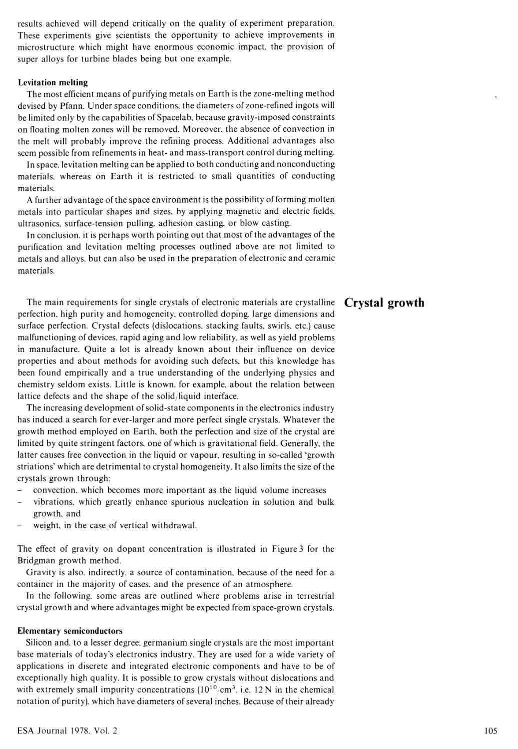
The main requirements for single crystals of electronic materials are crystalline Crystal growth
perfection, high purity and homogeneity, controlled doping, large dimensions and
surface perfection. Crystal defects (dislocations, stacking faults, swirls, etc.) cause
malfunctioning of devices, rapid aging and low reliability, as well as yield problems
in manufacture. Quite a lot is already known about their influence on device
properties and about methods for avoiding such defects, but this knowledge has
been found empirically and a true understanding of the underlying physics and
chemistry seldom exists. Little is known, for example, about the relation between
lattice defects and the shape of the solid/liquid interface.
The increasing development of solid-state components in the electronics industry
has induced a search for ever-larger and more perfect single crystals. Whatever the
growth method employed on Earth, both the perfection and size of the crystal are
limited by quite stringent factors, one of which is gravitational field. Generally, the
latter causes free convection in the liquid or vapour, resulting in so-called ‘growth
striations’ which are detrimental to crystal homogeneity. It also limits the size of the
crystals grown through:
convection, which becomes more important as the liquid volume increases
vibrations, which greatly enhance spurious nucleation in solution and bulk
growth, and
weight, in the case of vertical withdrawal.
The effect of gravity on dopant concentration is illustrated in Figure 3 for the
Bridgman growth method.
Gravity is also, indirectly, a source of contamination, because of the need for a
container in the majority of cases, and the presence of an atmosphere.
In the following, some areas are outlined where problems arise in terrestrial
crystal growth and where advantages might be expected from space-grown crystals.
Elementary semiconductors
Silicon and, to a lesser degree, germanium single crystals are the most important
base materials of today’s electronics industry. They are used for a wide variety of
applications in discrete and integrated electronic components and have to be of
exceptionally high quality. It is possible to grow crystals without dislocations and
with extremely small impurity concentrations (1010 cm3, i.e. 12 N in the chemical
notation of purity), which have diameters of several inches. Because of their already
ESA Journal 1978. Vol. 2
105
Figure 3. Example of the effects of gravity on
dopant concentration - in this case for the
Bridgman growth technique.
DOPANT
A CONCENTRATION
SPACE
GROUND
x/vWl
OISTANCE
high quality, silicon and germanium crystals would be particularly suitable for
studying the effects of zero gravity on crystal quality and pinpointing differences and
improvements. Growth of silicon crystals with diameters larger than 10 cm for
thyristor applications or as an extremely homogeneous base material for highly
integrated electronic components, such as charge-coupled imaging or data-storage
devices, are two cases in which space conditions are expected to provide significant
advantages.
Another elementary semiconductor for which an improvement in crystal
properties is expected is tellurium, the crystals of which currently have high
dislocation densities, probably because of their high atomic weight and the low
energy required for dislocation formation (these dislocations give rise to infrared
absorption and limit the lifetime of photoelectrically generated charge carriers).
Tellurium is of particular physical and technological interest because of its
exceptionally high nonlinear optical coefficient, and its use as base material for
electronic components operating in the infrared.
Compound semiconductors
High-quality single crystals are needed for:
opto-electronics and optical communications
computer memories
microwave engineering
piezo-electric and ultrasonic components, and
surface-wave engineering.
III-V semiconductors (in particular GaAs) are suitable for some of these
applications but industrial production of high-quality single crystals with large
diameters (several inches) still causes some problems. These difficulties could be
overcome with space-grown crystals, which would find application as substrates for
light-emitting diodes, for lasers, for high-frequency components such as Gunn
diodes, and also for piezo-electric and surface-wave components.
Light-emitting diodes are made today primarily of Ga(As,P) for red emission and
GaP for green and yellow emissions. Ga(As,P) can as yet be prepared only in the
form of thin epitaxial layers deposited on GaAs or GaP substrates; bulk crystals are
not sufficiently homogeneous and have too many non-radiating centres which
106
ESA Journal 1978, Vol. 2
substantially reduce the light yield. Space-grown Ga(As.P) crystals will bring
advantages if they have adequate luminescence quality and no additional epitaxy is
necessary for the fabrication of light-emitting diodes. Large homogeneous Ga(As,P)
crystals of luminescence quality could be grown, for instance, by the travelling¬
solvent technique.
Improvements in crystal quality may also be expected for high-melting
compounds and for compounds with melts that tend to attack the container walls.
Skylab experiments have shown that the contact between container and melt is
reduced in the space environment. Improved crystal growth of such materials as BN,
A1P, BP and SiC could provide new information on the implementation of high-
efficiency blue-luminescence diodes, high-temperature devices, and cold cathodes.
Oxide single crystals
The new oxidic materials such as mixed niobates and tantalates are the basic
constituents for advanced electro-optic and electronic components. Their use,
however, is limited in most cases by their low degree of structural perfection. Skylab
experiments have shown that under micro-gravity conditions, crystals of higher
structural perfection and with more uniform doping can be grown. Such crystals
have a high value per unit weight and for some applications, e.g. volume¬
holographic memories, relatively large quantities are required.
The space-processing facilities of Spacelab should be used to deepen our
knowledge of fundamental crystal-growth processes, to improve the performance of
existing devices and, possibly, to manufacture new crystals with unique properties
not attainable on Earth.
The near-zero-gravity environment of Spacelab offers wide-ranging possibilities Fluid physics/fluid dynamics
for performing basic studies of the physical and physico-chemical phenomena in
fluids, which are often fairly complicated and masked on Earth by gravity effects,
and for developing materials processes both on Earth and in space.
The most sophisticated potential source of process control based on weightless¬
ness stems from the possibility of maintaining relatively large fluid masses in an
almost quiescent state. In space, heat and mass transport in liquids and gases should
be governed solely by the well-known partial differential equations that describe
diffusion, heat conduction and radiation. These equations have unique solutions
determined by initial and boundary conditions, which can be controlled by
appropriate apparatus design. It seems possible that any physical or chemical
process that is controlled by heat and mass transport can be made to follow a
predetermined course in a properly designed space experiment, even for
heterogeneous material systems that include liquid and vapour phases. This type of
process control has potential applications in practically every type of solidification
and crystal-growth technique.
Since weightless fluids can be kept quiescent in the presence of intense
temperature and compositional gradients, it should be possible, for example, to
predict and control the effects of constitutional supercooling in most solidification
processes, or to grow highly perfect crystals on unsupported seeds by diffusion-
controlled transport in solutions. Similarly, weightlessness is expected to make way
for a wide range of idealised transport and temperature conditions for crystal
growth from the vapour.
The study of floating zones must also be considered a fundamental element of
materials purification and crystal-growth experiments, and six experiments are in
fact to be carried in the First Spacelab Payload (FSLP) for this purpose. The Fluid-
Physics Module that will be used for these experiments is illustrated in Figure 4. The
linear stability of a rotating liquid rod and Marangoni convection, as well as the
influence of viscosity on the dimensions of the fluid zone, are to be studied.
Theoretical models for near-zero-gravity zones8 have already been devised and
useful simulative experiments on Earth using Plateau techniques9 (e.g. Carruthers &
Grasso10 and more recently aboard Skylab11) have been performed.
Fluid convection under reduced-gravity conditions should be of particular
ESA Journal 1978. Vol. 2
107
VIEWING PORT
RESERVOIR
VIBRATING
LEVEL
SLIP RING
(thermistors high voltage)
SLIP RING
(heaters - thermistors)
VIBRATING DISC
(rotation .vibration- lateral displacement)
FEEDING DISC
[(rotation - tra n s I a t i о n)
TRANSLATION SCREW
FLUID ZONE
PARTS VIBRATING
SEALS
PARTS
NOT MOVING
Ш PARTS ROTATING AND VIBRATING
ExJ BALLBEARINGS
PARTS
TRANSLATING
[X<1 PARTS IN LATERAL DISPLACEMENT
XI VALVES
PARTS
ROTATING
LATERAL DISPLACEMENT
SHAFT
PORT FOR PRESSURE TRANSDUCER
OR OPTIC FIBER
Figure 4. The Fluid-Physics Module, which
forms part of the First Spacelab Payload
(FSLP).
■
L_
VIBRATION
. MOTOR
ROTATION
MOTOR M
ROTATION
MOTOR
TRANS
-LATION -
MOTOR
interest for studying the performance of phase-change materials employed for
spacecraft thermal control. Under heating conditions these materials melt and then
freeze when the temperature falls again. The convection provides the high heat
transfer rates that are desirable in most cases, known phase-change materials being
fairly poor heat conductors.
Gravity may have important effects in chemical reactions. Although it is fairly well
established that chemical reactions in a homogeneous reactor are independent of
gravity, because of the small mass of the molecules and atoms involved, in most cases
the rate and effectiveness of the chemical reactions are influenced by the availability
of the reactants. As the reaction advances, reactants are depleted and must be
replenished by some diffusion process. When the species react rapidly once they are
mixed, their arrival at the reaction zone is the controlling mechanism. If the diffusion
process is induced by buoyancy, as in the ordinary candle, the net attainable speed of
the reaction depends on gravity.
Surface tension and interfacial tension (Marangoni convection) occur in liquid-gas
or miscible liquid-liquid interfaces. The surface tension varies with temperature,
generally decreasing when the temperature increases. Surface-tension gradients
induce surface tractions. This mechanism is dominant under normal gravity
conditions only if the fluid-layer thickness is small enough. In space, it is nearly
always dominant if an interface exists.
Surface tension is extremely sensitive to small gradients in the chemical
composition of a fluid. Once the surface-tension gradient exceeds a certain threshold
(to be studied), a convection process starts.
Non-gravity driving forces which are usually suppressed by gravity and which
may cause natural convection in the space environment12 also include:
surface or interfacial tensions
thermal volume expansions
g-jitter (which could be produced by spacecraft manoeuvres)
magnetic and electrical forces.
The onset of unstable motion is highly dependent on the boundary conditions13 and
hence on:
108
ESA Journal 1978. Vol. 2
the magnitude and direction of residual accelerations
geometric configuration
material properties.
As far as convection due to magnetic and electric fields is concerned, it should be noted
that both induce body forces (like gravity) and so can generate convections and
phase separations similar to those in a gravitational field. Whereas in a gravitational
field convection is generated by density differences, in an electrical field the flow is
generated by differences in electrical conductivity and in a magnetic field by
differences in susceptibility. Both electrical conductivity and magnetic susceptibility
are temperature-dependent, so that temperature differences are usually required to
obtain flows. Conventional and unstable types of convection are possible with such
fields, and these phenomena are yet to be fully explored or exploited in space.
Theoretical studies of static capillary stability and of the dynamic stability of fluid
interfaces have, because of their intrinsic scientific interest, a long history in the
development of classical physics. Their relevance to space-processing activities has
generated renewed interest and the opportunity to conduct experiments in a genuine
micro-gravity environment seems likely to lead to fresh advances. Theoretical
studies of certain problems are already well developed, especially the static stability
of axisymmetric surfaces subject to various end-constraints, the dynamic behaviour
of axisymmetric surfaces in steady rotation about the axis of symmetry, and the
static stability of thin liquid films on solid surfaces. The last topic offers a possible
route to the accurate measurement of long-range intermolecular forces.
Further use of the Plateau technique seems likely to be beneficial, both as a simple
simulation tool in studying the practical feasibility of proposed space experiments
and, in cases where side-effects due to the viscosities and other properties of the two
fluids are unimportant, as a direct route to intrinsically useful results.
1. Steuer W H & Kay, S 1973, Preparation of composite materials in space,
Convair Aerospace Division of General Dynamics Report GDCA-DGB 73-
0014, January 1973.
2. Markworth A J et al. 1974, Immiscible materials and alloys. Proc. Third Space
Processing Symposium. Vol II, 1003-1029.
3. Ostwald W 1901. Z Phys Chem 37, 785.
4. Reger J L 1973, Study on processing immiscible materials at zero gravity, NASA
Contract NA 58-2867.
5. Skylab results. Proc Third Space Processing Symposium, Vols I and II,
Marshall Space Flight Center, Huntsville, Alabama 30.4 to 1.5. 1975.
6. Apollo-Soyuz Test Project. NASA Preliminary Science Report No. TM-X-
58175, February 1976.
7. ESA SP-114 Sept 1976. Material Sciences in Space. Proc Second European
Symposium on Material Sciences in Space. Frascati Italy 6-8 April 1976.
8. Fowle A A. Haggerty J J & Strong P F 1974. NASA CR 143876, October 1974.
9. Plateau J A F 1863, Smithsonian Inst. Ann. Rept., p. 250.
10. Carruthers J R & Grasso M 1972. J Appl Phys 43, 2, 436-445.
11. Carruthers J R, NASA Report M 74.5, V2. 837-856.
12. Grodzka P G 1973. Types of natural convection in space processes: Summary
and report. Lockheed Missiles and Space Co.. Inc.. Huntsville Research &
Engineering Center. HREC-5577-4. CMSC-HREC TR D30650. January 1973.
13. Ostrach S 1972. Natural convection in enclosures, in Advances in Heat
Transfer. Vol 8. Chapter 3. Academic Press.
References
Revised manuscript received 22 February 1978.
ESA Journal 1978. Vol. 2
109
H.A. Pfeffer, С. Bartoli & Н. von Rohden
Attitude and Orbit Control Division, ESTEC, Noordwijk, The Netherlands
ESA’s Field-Emission Electric Propulsion Programme*
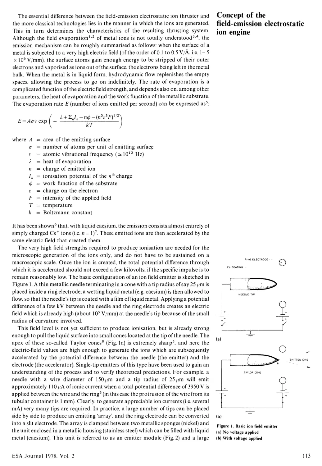
Abstract While the German radio-frequency ion thruster (RIT) system is being developed for
flight on board ESA’s heavy communications satellite, the Agency is also pursuing
its investigation of future ion-propulsion technologies. The principle adopted for
study is that of ion generation by electric fields (Field-Emission Electric Propulsion
or FEEP), which promises high electrical and mass-utilisation efficiency, great
mechanical and electrical simplicity, low hardware costs and straightforward
applicability to attitude control, auxiliary and primary propulsion through simple
clustering of thrust modules. The paper presents the history of the ESA programme,
and the results achieved to date using caesium as propellant (Isp >8000 s, mass
efficiency >0.75, thrust density ~ 1 mN/cm). The application of FEEP to North-
South Station-Keeping is discussed and a future plan of action outlined.
Resume Tout en continuant la mise au point du propulseur ionique radiofrequence (RIT)
allemand destine a son satellite lourd de telecommunications, l’ESA poursuit ses
etudes sur les technologies de pointe dans le domaine de la propulsion ionique. Le
principe conducteur de ces etudes est celui de la generation ionique par les champs
electriques (appele FEEP, ou ‘propulsion electrique par emission de champ’), qui
promet les avantages suivants: rendement eleve de la puissance electrique et
utilisation efficiente de la masse, grande simplicite mecanique et electrique, faible
coGt du materiel et possibilite d’application directe aux organes de commande
d’attitude, de propulsion principale et secondaire par simple assemblage de
modules. Cet article expose l’historique du programme ESA en la matiere et les
resultats obtenus a ce jour dans l’utilisation du cesium comme combustible
(impulsion specifique >8000 s, efficacite massique >0,75, densite de poussee
~ 1 mN, cm). L’application du principe FEEP au maintien a poste Nord-Sud est
examinee, et en conclusion un plan d’action est presente.
* Presented at AIAA DGLR 13th International Electric Propulsion Conference. San Diego. California.
April 1978.
ESA Journal 1978. Vol. 2
111
The context of space
propulsion
Any space activity involves one or more of the following types of propulsion:
launch propulsion, for placing payloads into orbit
primary (or large-impulse) space propulsion, to manoeuvre vehicles into
significantly different Earth orbits (e.g. orbit-injection stages, the Space Tug) or
to place them on interplanetary trajectories (e.g. comet rendezvous),
auxiliary (or medium-impulse) propulsion, to compensate for launcher
dispersions or to maintain critical orbits accurately (e.g. station-keeping,
modest orbit manoeuvring),
attitude-control (small-impulse) propulsion.
One of the European Space Agency’s tasks is to ensure that the technologies needed
to meet the demands of present and future European space activities be studied and
developed in Europe. This is achieved through a Technological Research and
Development Programme defined and undertaken jointly by the Agency and the
representatives of the Agency’s Member States.
In the field of propulsion, and setting aside the launching requirement which is to
be covered by the development of the Ariane launch vehicle, the Agency’s projects
have to date required attitude-control, orbit-control and orbit-injection propulsion
only. These are mainly small- and medium-impulse applications and they are based
on an already well-established European technological capability, namely cold gas
jets, low-thrust mono- and bipropellant systems, and apogee boost motors using
both liquid and solid propellants.
European missions requiring a high-impulse space-propulsion capability are yet
to be defined, but they will certainly materialise sooner or later. For such missions,
the highest propulsive performance (in terms of highest jet exhaust velocity and
lowest system mass) is clearly an essential requirement and prospective research and
development work must be conducted as early as possible.
The activities conducted by several nations on high-performance space
propulsion have singled out the electrostatic-ion-engine concept as one of the more
successful ones, because it allows good propulsive performance to be combined with
a wide range of applicability, cf. the work on mercury ion engines conducted, for
example, in the USA and Japan.
In Europe, the initially wide-ranging development work has progressively been
narrowed with a view to achieving the first realistic application to North-South
Station-Keeping (NSSK) and of the four technological approaches subsequently
brought to an advanced state of development [caesium contact and bombardment
in France, mercury bombardment in the UK and mercury radio-frequency
ionisation (RIT) in Germany], only the German programme is now being pursued
intensively to qualify for an early test flight on the heavy communications satellite
envisaged in the Agency’s programme.
It cannot be denied that today’s classical EP systems are complex, quite costly,
and that their application on any specific mission needs careful study and
optimisation. This is illustrated by the surprisingly long time scales that have
characterised EP system development and its reluctant acceptance for practical
space systems. In the Agency’s opinion, only a drastic reduction in EP system
complexity, and thus cost, compared with the first generation of technologies will
foster its more widespread use. The aims of a longer-term EP development
programme could therefore be summarised as follows:
to reduce the mechanical and electrical complexity of ion-engine systems
to maximise the fraction of electrical power usefully converted into beam power
to seek a modular thrust system, with which requisite thrust levels can be
provided by clustering modules of known and proven performance, or by simple
scaling, and
to achieve a straightforward and reliable mode of space operation.
The Agency’s programme of FEEP research is motivated by the above aims, and
results to date confirm that they can indeed be met.
112
ESA Journal 1978. Vol. 2
The essential difference between the field-emission electrostatic ion thruster and
the more classical technologies lies in the manner in which the ions are generated.
This in turn determines the characteristics of the resulting thrusting system.
Although the field evaporation12 of metal ions is not totally understood3 4, the
emission mechanism can be roughly summarised as follows: when the surface of a
metal is subjected to a very high electric field (of the order of 0.1 to 0.5 V/A, i.e. 1- 5
x 106 V/mm), the surface atoms gain enough energy to be stripped of their outer
electrons and vaporised as ions out of the surface, the electrons being left in the metal
bulk. When the metal is in liquid form, hydrodynamic flow replenishes the empty
spaces, allowing the process to go on indefinitely. The rate of evaporation is a
complicated function of the electric field strength, and depends also on, among other
parameters, the heat of evaporation and the work function of the metallic substrate.
The evaporation rate E (number of ions emitted per second) can be expressed as5:
Concept of the
field-emission electrostatic
ion engine
л + \1п-пф-(п3^У/2
kT
where A = area of the emitting surface
g = number of atoms per unit of emitting surface
г = atomic vibrational frequency (^1013 Hz)
л = heat of evaporation
n = charge of emitted ion
In = ionisation potential of the n{h charge
ф = work function of the substrate
i- = charge on the electron
F = intensity of the applied field
T = temperature
к = Boltzmann constant
It has been shown6 that, with liquid caesium, the emission consists almost entirely of
simply charged Cs+ ions (i.e. n= l)7. These emitted ions are then accelerated by the
same electric field that created them.
The very high field strengths required to produce ionisation are needed for the
microscopic generation of the ions only, and do not have to be sustained on a
macroscopic scale. Once the ion is created, the total potential difference through
which it is accelerated should not exceed a few kilovolts, if the specific impulse is to
remain reasonably low. The basic configuration of an ion field emitter is sketched in
Figure 1. A thin metallic needle terminating in a cone with a tip radius of say 25 ;zm is
placed inside a ring electrode; a wetting liquid metal (e.g. caesium) is then allowed to
flow, so that the needle’s tip is coated with a film of liquid metal. Applying a potential
difference of a few kV between the needle and the ring electrode creates an electric
field which is already high (about 105 V/mm) at the needle’s tip because of the small
radius of curvature involved.
This field level is not yet sufficient to produce ionisation, but is already strong
enough to pull the liquid surface into small cones located at the tip of the needle. The
apex of these so-called Taylor cones8 (Fig. la) is extremely sharp5, and here the
electric-field values are high enough to generate the ions which are subsequently
accelerated by the potential difference between the needle (the emitter) and the
electrode (the accelerator). Single-tip emitters of this type have been used to gain an
understanding of the process and to verify theoretical predictions. For example, a
needle with a wire diameter of 150/zm and a tip radius of 25/zm will emit
approximately 110 /zA of ionic current when a total potential difference of 3950 V is
applied between the wire and the ring5 (in this case the protrusion of the wire from its
tubular container is 1 mm). Clearly, to generate appreciable ion currents (i.e. several
mA) very many tips are required. In practice, a large number of tips can be placed
side by side to produce an emitting ‘array’, and the ring electrode can be converted
into a slit electrode. The array is clamped between two metallic sponges (nickel) and
the unit enclosed in a metallic housing (stainless steel) which can be filled with liquid
metal (caesium). This unit is referred to as an emitter module (Fig. 2) and a large
e
RING ELECTRODE - -
Cs COATING -
(b)
Figure 1. Basic ion field emitter
(a) No voltage applied
(b) With voltage applied
ESA Journal 1978. Vol. 2
113
Filling Funnel
Figure 2. Elementary emitter module
(a) Exploded and assembled views
(b) Close-up, with the array tips just visible»
amount of work to date has been concentrated on determining its characteristics as a
function of design and operating parameters.
It is the great mechanical simplicity of such an emitter, in combination with the
straightforward method of ion generation, that constitutes the primary attraction of
the FEEP principle. The ions are created with the theoretically lowest possible
expenditure of power, directly from the liquid phase of the propellant, and each ion
is ejected as soon as produced. Consequently, almost all of the electrical power
supplied can be used for true acceleration of the ions, in contrast to other ionisation
systems in which a much larger fraction of the power input is consumed for ion
generation.
The ion-generation process depends only on the geometry of the emitter and on
the applied voltage and does not require any special control loop. This greatly
simplifies the propellant feed device and the control electronics, allowing mass and
cost economies and aiding inherent reliability. The remaining regulation
requirements are limited to maintaining adequate thermal control of the thruster
unit itself. In particular, when the metallic propellant is permanently maintained in a
liquid state (this is realistic because of the low vapour pressures of liquid metals, e.g.
caesium: 1.5 x 10“ 6 torr at 28.5°C, and because of the small exposed area), the FE
engine allows instantaneous thrust switch-on and switch-off and thrust modulation,
because the ions are extracted directly from the liquid on demand. This makes FEEP
eminently suitable for very accurate attitude or thrust vector control, either as a side
benefit of its use for propulsion, or as a dedicated high-accuracy attitude-control
actuator on larger spacecraft.
In principle any liquid conductor can be sprayed by field emission9 -1 \ either in
droplet form (the well-known colloid thruster) or in ion form. To emit ions, the
propellant must be a metal, or a mixture of metals which are liquid at the
temperature of operation. Even if one restricts oneself to moderate melting
temperatures (say below 300°C), to obviate the need for excessive power for metal
melting, there is still a choice of several propellants (caesium, gallium, indium,
potassium, lithium, rubidium1012), thereby illustrating the flexibility of FEEP in
terms of propellant requirements. Of the metals that can be chosen, caesium is the
almost ideal propellant and it has been used in the majority of the FEEP work
conducted to date, because
as it melts at about 30°C, the whole emission process can take place at close to
satellite ambient temperature, so that there are no heat losses associated with
metal melting
it has favourable wetting characteristics on many materials
114
ESA Journal 1978, Vol. 2
it has been used extensively in other EP work (caesium contact and
bombardment, developed in France) and many components realised for these
systems can be directly reused or adapted for the FEEP system (tankage, valves,
neutralisers, isolators, etc.).
When the Agency began its own EP development programme in 1968, several
national European programmes were already well advanced. The Agency chose to
explore the colloid thruster because it appeared better suited to low power
satellites because its specific impulse was lower than that of the ion engines. The
colloid thruster was also being developed in the USA for similar reasons, but the
distinction of the ESA approach lay in the geometry selected for the emission edge.
While capillary tubes with individual ring electrodes were mainly used in the USA,
linear and annular sharp edges with fine slits were being tested in Europe. Good
colloid emission was obtained13 and the idea of using linear geometries to achieve
pure ion emission was advanced. This idea was also based on experiments at Electro
Optical Systems10 in which the emission of Cs ions from capillary tubes was
successfully tried out. The linear geometries used by ESA appeared suited to
obtaining high levels of ion emission, and the first feasibility study was awarded to
Culham Laboratory (UK) late in 197114.
Historical review of ESA’s
work on EP and the
evolution to FEEP
0.1 mm
0.02 mm
120gA emission
Figure 3. Scanning electron micrograph of apex
region of a tip covered with liquid caesium
(Taylor cone). Note jet at apex.
ESA Journal 1978. Vol. 2
115
5?
Figure 4. Nickel array (a) with 150 wires/cm,
and examples of different tip radii: 9 /.im (b),
1.5/zm (c) and 0.4/zm (d).
s
(a)
0.5 mm
(b)
(c)
(d)
sh
л
I
Figure 5. Tungsten array (a) with 200 wires/cm
and examples of different tip radii: 6 /zm (b) and
4 /zm (c).
I
r I
71
rl
W|
III
71
/I
71
f|
Il
0.5 mm
J
I
(a)
(b)
(c)
0.01 mm
116
ESA Journal 1978. Vol. 2
Very interesting results were rapidly obtained12, and by the end of 1973 the ESA
work on colloids was shelved (because of evolving mission planning where the
colloid was at a disadvantage) and activities were concentrated solely on the FE
principle. In the initial study performed by Culham Laboratory, irregular emission
was found with the razor blades used for colloid emission and the use of grooved
edges to create preferential emission sites was recommended. Further work then
revealed15 that the major keys to successful emission would be an adequate
understanding of the basic FE process, the accurate manufacture of emission arrays,
and the provision of a homogeneous film of liquid on the array. In the subsequent
contract5 a deeper theoretical understanding of the FE process was obtained,
resulting in a large increase in the ion current that could be emitted per single tip. In
particular, it was found that extreme tip sharpness was unnecessary and even
undesirable because intense ion emission is only possible when the electric field can
create a liquid cusp (microscopic Taylor cone) in the liquid metal covering the tip
(Fig. 3); when tips are too sharp (as had been the case in the previous attempts), they
do not allow the formation and support of such a cusp.
Specifications could then be laid down for the geometry of the emitting arrays and
their fabrication was studied at Fulmer Research Institute (UK). Arrays can now be
made reproducibly in nickel or tungsten, in a range of sizes from about 10 wires/cm
to some 300 wires/cm, with tip radii ranging from a few microns to some 10 microns,
and in strip lengths of about 5 cm16. The manufacturing process starts from
commercially available nickel meshes or from conventional tungsten wire (Figs. 4
and 5).
The various arrays made by Fulmer were evaluated as emitters at ONERA
(France) where the first measurements of neutral propellant emission were made17.
The conditions for achieving adequate wetting of the array by the caesium were
studied at Fulmer, where, based on the fact that very narrow flow passages create
correspondingly high capillary feed forces, the concept of packed arrays was
introduced1819 and shown to provide extremely consistent performance (Table 1).
In a packed-array configuration, the caesium is made to flow between two adjacent
arrays instead of over a single array exposed to vacuum.
The packed arrays led, in turn, to reconsideration of the straight linear slits used
initially for colloid testing and then abandoned because of irregular emission. With
Figure 6. Emitter module with linear slit as
emitter. The slit is just visible in (a), (b) shows the
edge profile, (c) shows part of the emission edge
with the nominal 15//m slit.
0.05 mm
ESA Journal 1978. Vol. 2
117
Table 1. Typical test results obtained with various emitter configurations. Only emission levels that could be sustained indefinitely (no emitter temperature rise) are
tabulated. Last line indicates maximum values sustained for a shorter period only.
DATE OF TESTS
December 1976
March 1977
October 1977
EMITTER MODULE CONFIGURATION
Single array
Ni 150 wires cm
Slit = 90 pm
Accel. gap= 4.0 mm
Edge holes ф = 6 mm
Double array
2 x Ni 150 wires cm
Slit = 90 pm
Accel. gap= 4.4 mm
Edge holes ф = 6 mm
Solid emitter
No array
Slit = 15 pm
Accel, gap = 4.0 mm
Edge holes ф= 10 mm
Emitter voltage kV
+ 7.2 +8.2 +9.4
+ 8.08 +8.71 +9.28
+ 11.5 +12.0 +12.4
Accel, voltage Vu, kV
-2.0 -2.0 -2.0
-2.0 -2.0 -2.0
-2.0 -2.0 -2.0
Emitter current /(>. mA
4.0 6.0 8.0
6.0 8.0 10.0
5.0 6.0 7.0
Accelerator current (drain) /H. //A
35 60 110
30 50 75
30 35 40
Transmission through accel. electrode
t = h L + C (°o)
99.1 99.0 98.6
99.5 99.4 99.3
99.4 99.4 99.4
Thrust measured by the balance Fh, mN
0.53 0.80 1.30
0.87 1.20 1.56
1.00 1.26 1.52
Mass flow measured by balance mb. kg s x 10“9
14 15 15
17 30 29
25 24 26
Theoretical mass flow rate
m = 1.39 x 10“6 /t„ kg sx 10“9
5.56 8.34 11.1
8.34 11.1 13.9
6.95 8.34 9.73
Mass efficiency //,„ = m mh. (%)
39.7 55.6 74.0
49.0 37.0 47.9
27.8 34.7 37.4
Specific impulse /sp= Fh (mh g). s
3859 5436 8834
5217 4077 5483
4077 5243 6052
Total power input W, = F, /(, + Vu Itl. W
28.9 49.3 75.4
48.5 69.8 92.9
57.6 72.1 86.9
Thrust density. mN cm
0.177 0.267 0.433
0.29 0.40 0.52
0.33 0.42 0.51
Max. obtained thrust. mN
Max. emitted current. mA
2.3
16
2.0
12.5
2.6
12.0
Single array
Slit
1/
Edge holes Accel, gap
Accel, electrode
the understanding achieved and advances made since 1971, the linear slit is now also
emitting at a very satisfactory level (Fig. 6 and Table 1).
Because the ions originate from point-like sources, which has both advantages
and disadvantages, ion-optics calculations were undertaken early (1974) in the
programme with the Culham Laboratory. One advantage lies in the well-defined
optical conditions, a disadvantage in the difficulty of calculating the ion optics with
point-like singularities19. Also, the point-like source leads by its very nature to
formation of a highly divergent beam. Control of the divergence requires several kV
118
ESA Journal 1978, Vol. 2
Figure 7. Example of computer plots of ion
trajectories and equipotentials at an emitter body
voltage of 2 kV and an accel. electrode voltage of
-8kV, assuming a hemispherical distribution of
ion trajectories at the source (emission tip).
of potential difference, making the FE device a higher specific impulse thruster20.
Figure 7 shows a calculated ion trajectory profile, assuming a hemispherical ion
distribution at the source.
FE modules are presently being tested at Fulmer18 and at the EP test facility at
ESTEC21. Typical characteristics like
emission threshold
emitter current as a function of emitter voltage
drain current (the current to the accelerating electrode)
temperature evolution due to drain currents
- thrust
mass flow rate
are measured as functions of such parameters as:
emitter-array tip density (from 10 to 300 tips per cm). The majority of the work is
done with nickel arrays with 150 tips per cm
emitter-array material (nickel, tungsten)
array protrusion from the emitter body
slit size in the emitter body through which the caesium flows to the tips of the
array
relative position of the acceleration electrode and its electrical bias
pre-treatment of the module (chemical cleaning and heating to 500°C by
electron bombardment, argon-ion bombardment) to achieve surface conditions
permitting easy wetting by caesium.
The ESTEC test facility22 is characterised by the use of a dual beam balance
allowing thrust and propellant consumption rate to be measured simultaneously. A
typical recording is shown in Figure 8, which also demonstrates the instantaneous
switch on/off capability of the FE thrust module. The emitted ion current for a given
Results of tests on FE
emitter modules
ESA Journal 1978. Vol. 2
119
Figure 8. Typical recording of thrust and mass
flow on dual beam balance.
"F
Figure 9. Typical example of a V-I
characteristic. The accel. electrode voltage is kept
constant.
F = 1.3mN
m =1.5x10® kg/s
Isp = 8834
VGm = 9.4 kV
vacc
= -2kV
I em
= 8 m A
I acc
= 110 |1A
150
I acc , |i A
100
50
0 I—г—I 1 1 1 1 1 . 1 1 > ►
123456789 Ю
I em >m A
Figure 10. Evolution of the drain current between
emitter body and accel. electrode for the run of
Figure 9.
I
- MASS FLOW
' I ' r ■
-- THRUST
J
-
TIME
60 S
emitter module, specified in Table 1 (column 3), is plotted as a function of emitter
voltage in Figure 9. Figure 10 shows the behaviour of drain current versus emitted
current for the same run. It can be seen (Table 1) that, for Ie = 8.0 mA, Iacc is still only
of the order of 100 ;zA, giving a transmission of the order of 99% at a thrust of
1.3 mN. The minimisation of the drain current is an essential requirement for the
long-term operation of the FE module, as drain leads to localised heating of the
emitting edge because of electron back-bombardment. This in turn leads to
propellant vaporisation, with the consequences of neutral losses, charge-exchange
processes, isolator contamination, etc.
In fact, due to the coarseness of the ion optics used, the still imperfect electrostatic
screening of the emitter module21, and the relatively small vacuum chambers used
for the tests17-18-22, areas of the emitter covered by liquid caesium are bombarded by
electrons originating from ion impingement on the accelerator electrode, the
chamber side walls, and the collector. This is the most probable reason for the
discrepancy between the theoretical values of mass flow corresponding to the
emitted current and the mass flow measured via the microbalance in the vacuum
chamber (Table 1): neutral propellant is simply lost due to evaporation resulting
from excessive electron back-bombardment. Steps are being taken to circumvent
these undesirable features by refining the ion optics, reducing the exposed areas of
emitter covered with liquid metal, and improving electrostatic screening of the
emitter itself and of the chamber’s walls and collector. However, it is clear that with
ground tests involving chamber walls and collectors, electron back-bombardment
will never be completely eliminated and the measured values of specific impulse will
always be conservative compared with the values to be expected in space.
The overall beam profile has been recorded using a wire probe arrangement in the
ESTEC test facility21 (Fig. 11). Figure 12 shows the ion current determined by a wire
probe travelling in a circular arc around the emitting edge, the wire being parallel to
the emitting edge. The emission is regular, but the beam is quite divergent. Figure 13
shows the distribution of the ion current measured by the probe 4 cm from the
120
ESA Journal 1978. Vol. 2
emitting edge (wire normal to the emission plane). The emission is regular and
symmetric once a sufficiently high voltage is applied. Beam divergence in the plane of
the emitter is much less pronounced than in the previous plot, showing that
impingement problems can be controlled by correct orientation of the emitters on a
spacecraft.
Thrust losses through beam divergence are at present estimated to be
approximately 5-10% and depend on the intensity of the emitted current. The
reduction of beam divergence is one of the aims of a more refined study of the ion
optics of the emitter module.
Table 2 compares the application of existing radio-frequency ionisation
technology and FEEP technology to the North-South Station-Keeping of a heavy
European communications satellite.
Assuming that the RIT and FEEP technologies must produce the same thrust
level, the RIT power requirement is significantly lower because of the lower specific
impulse chosen. The advantage of FEEP in terms of lower hardware mass stems
partly from the compactness of the thrust unit and simpler electronics, and partly
from the fact that although four 10 mN thrusters are used, only two beam power
supplies are required, permanently connected to a pair of thrusters. The thruster that
is not required to operate is kept 'frozen’ so that there is no ion emission in spite of
the high voltage applied.
A system study23 conducted by Societe Europeene de Propulsion (France) has led
to the conclusion that there are no basic feasibility problems remaining which could
prevent FEEP from becoming a practical system, for example, for NSSK. Future
work has been directed with this first application in mind, and the main emphasis is
laid on producing an elementary emitting module delivering about 2 mN of thrust,
fully optimised and characterised in terms of performance parameters, operating
Figure 12. Angular ion-beam profile.
Figure 13. Transverse ion-beam profile.
The application of FEEP to
an NSSK mission
ESA Journal 1978. Vol. 2
121
Table 2. Application of first-generation EP (RIT 10) and FEEP to North-South Station-Keeping of an
850 kg (beginning of life) geostationary satellite with a 7-year lifetime.
RIT 10 S
FEEP
Masses (kg)
Thrusters (number)
4.8 (4)
0.8 (4)
Tanks (number)
2.04 (2)
4 (4)
Total propellant
13.63
7.55
Central PCU
-
3
Thruster PCU (number)
24 (4)
6 (2)
Neutraliser (number)
Included
2 (4)
Cabling
2
1.5
Mounting & interface structure
6
2
Thrust vector control capability
2.4
Included
Total mass
54.87 kg
26.85 kg
Thruster specific impulse
3180 s
10 000 s
Total power input to drive 2 thrusters
640 W
1430 W
Daily on-time (one pair, each eclipse-free
2.615h
day)
Total on-time (whole mission with one
pair)
5144h
Energy for start-up
24 Wh
0 Wh
shut-down
12 Wh
0 Wh
Total energy per day of thrusting
1709 Wh
3740 Wh
Total volume
70 1
22 1
Mass gain with respect to
Hydrazine (146.3 kg)
91.43 kg
119.45 kg
Bipropellant (120 kg)
65.13 kg
93.15 kg
PAEHT (112.8 kg)
57.93 kg
85.95 kg
requirements, handling and long-term behaviour. In parallel, work is being done to
verify that clustering is indeed feasible, and to ensure that auxiliary systems are
defined and realised to the extent needed to verify that no feasibility problems will
arise in the event that it is decided to develop a functional thrust system.
As far as the application of FEEP to primary propulsion is concerned, one might
foresee the development of a system relying on further simple clustering of sufficient
emitter modules to produce the required thrust level. Although no studies have yet
been conducted with such applications in mind, it is not inconceivable that, for
missions where the specific impulse of the FE principle is adequate, the remarkable
simplicity of the FE engine and power-supply concept might well provide the key to
low-cost, high-performance space transportation.
References 1
2.
3.
4.
5.
Muller E W 1956. Phys Rev 102, 618.
Barofsky D F & Muller E W 1968. Surface Sei 10, 177.
Vesely, M & Erlich G 1973, Surface Sci 34, 547.
Farles R 1974, Surface Sci 46, 577.
Aitken К L, Jefferies D К & Clampitt R 1975, Culham Laboratory Final
Report CLM RR/E1/21, July 1975.
6.
Clampitt R & Jefferies D К 1973, Proc Workshop on Electric Propulsion.
Toulouse. June 1973.
7.
Aitken К L 1977. Mechanisms of ion emission from liquid caesium. Proc
ESTEC Field-Emission Day. ESASP-119. 23-39.
8.
9.
Taylor G 1964, Proc Roy Soc A 280, 383.
Swatick D S 1969, University of Illinois Rep. No. CPRL-3-69.
122
ESA Journal 1978. Vol. 2
10. Mahoney J F et al 1969, J Appl Phys 40, 5101.
11. Bailey A G 1977, Field emission studies, Proc ESTEC Field-Emission Day,
ESA SP-119, 87-99.
12. Clampitt R & Jefferies D К 1972, Culham Laboratory Final Report
CLM/RR/E14. August 1972.
13. Harrison MFA, Hotston E S & Montague R G 1974, Culham Laboratory
Final Report CLM/RR/E1/19, August 1974.
14. Bartoli C 1977, A review of past and present research studies on ion field
emission, Proc ESTEC Field-Emission Day, ESA SP-119, 1-10.
15. Aitken К L et al 1973, Culham Laboratory Final Report CLM/RR/E1/16,
October 1973.
16. Stewart D & Parkes R 1977, Manufacturing of field emitters, Proc ESTEC
Field-Emission Day, ESA SP-119, 101-114.
17. Le Grives E & Labbe J 1977, Experiments with field-emission ion sources,
Proc ESTEC Field-Emission Day, ESA SP-119, 41-52.
18. Stewart D, Wilson P & Austey N 1977, FRI Second Interim Report R 664/2,
August 1977.
19. Thomas C LI 1977, A computer code for thruster ion optics, Proc ESTEC
Field-Emission Day, ESA SP-119, 53-66.
20. Little P F 1977, Computed ion trajectories in thrustor beams, Proc ESTEC
Field-Emission Day, ESA SP-119, 67-74.
21. Bartoli C & Herhudt von Rohden H J 1977, Recent results of experimental
caesium field emitters with the ESTEC electric propulsion test facility, Proc
ESTEC Field-Emission Day, ESA SP-119, 115-141.
22. Herhudt von Rohden H J 1977, The ESTEC electric propulsion test facility,
Proc ESTEC Field-Emission Day, ESA SP-119, 11-22.
23. Moravie M, Robert M & Valentian D 1977, SEP Final Report
TS/L/DV/30.330/77, September 1977.
Manuscript received 16 February 1978
ESA Journal 1978, Vol. 2
123
J.P. Guignard
Data Handling Division, ESTEC, Noordwijk, The Netherlands
The European Synthetic-Aperture-Radar (SAR) Processor
for Seasat-A
Abstract The European Space Agency is in the process of procuring equipment to process
the synthetic-aperture-radar data from the US Seasat-A spacecraft. This SAR
processor is to be sited at Oakhanger in England and will be operated within the
framework of ESA’s Earthnet Programme. This paper presents a review of activities
involved in acquiring this advanced equipment.
L’Agence spatiale europeenne est en train de pn^der a l’achat d’un equipement
destine a traiter les donnees de radar a ouverture synthetique fournies par le satellite
americain Seasat-A. Ce processeur sera installe a Oakhanger (Royaume-Uni) et
fonctionnera dans le cadre du programme Earthnet de VESA. Le present article
passe en revue les activites de definition et de mise au point de cet equipement de
pointe.
ESA Journal 1978. Vol. 2
125
The Seasat-A Programme
The Seasat-A Programme has the following main objectives12:
to measure global ocean dynamics and physical characteristics
- to determine key features for an operational system
to improve the body of scientific ocean data/knowledge
- to demonstrate the utility of data to the user community.
The spacecraft itself (Fig. 1), to be launched in May 1978 into an 800 km orbit
(inclination 108°), carries five sensors in its payload:
- a scanning multifrequency microwave radiometer
a radar scatterometer
- a radar altimeter
- a visual infrared radiometer
a synthetic-aperture radar.
Figure 1. The Seasat-A spacecraft.
In addition to these earth-viewing sensors, tracking aids will assist the ground
system in determining the satellite’s exact position and the co-ordinates of the
sensors’ scanning so that data can be referenced accurately to a ground location.
The Seasat radar altimeter serves two functions. It monitors average wave height
to within 0.5-1 m. It also measures, to a precision of tens of centimetres, changes in
the ocean geoid and topography due to gravity variations and ocean tides, surges
and currents.
As surface winds increase, so does fine-scale surface roughness. The radar
scatterometer measures this function, which can be converted directly into wind
speed and direction. It will register wind speeds of 3-25 m/s with 2 m/s accuracy, and
direction, within 20° over two 500 km swaths on either side of the spacecraft ground
track.
The five-frequency microwave radiometer serves four functions:
126
ESA Journal 1978. Vol. 2
it measures surface temperature with a precision of ГС
it measures foam brightness, which can in turn be converted into a measurement
of high wind speed (up to 50 m/s)
- it maps ice coverage
it provides atmospheric correction data to the active radar by measuring liquid
and gaseous water content in the upper atmosphere. The surface swath of the
microwave radiometer is 600 km.
The visible and infrared radiometer will provide clear-weather surface temperature
data, cloud-coverage patterns, and corroborative images of ocean and coastal
features with a resolution of 5 km over a swath of 1500 km.
These first four sensors, known as the global sensors, will monitor the oceans and
adjacent coastal waters globally. Their data will be recorded on magnetic tape on
board Seasat and played back while the satellite is over one of the supporting
ground stations.
The fifth sensor, the synthetic aperture radar, will provide all-weather imagery of
ocean waves, ice fields, icebergs, ice leads, and coastal conditions and dynamic
processes to a resolution of 25 m over a 100 km swath. Because of the very high data
bandwidth of the radar imagery (110 Mbit/s), this sensor and its own separate data
system will be operated only in real time while within line of sight of specific tracking
stations equipped to receive and record its data.
Although the Earthnet station at Oakhanger is equipped to receive data from all
Seasat-A sensors, we will concern ourselves here only with the SAR data link and
processing.
The L-band (1275 MHz) radar signal is transmitted to the ground for digitisation,
storage and subsequent processing. A linear S-band modulator/transmitter receiver
demodulator combination is used. This equipment is completed by an SAR-unique
subsystem consisting of a data formatter (SDF), a high-density digital recorder
(HDDR) and an SAR simulator (SIM). The SDF accepts and digitises the analogue
offset video signal furnished by the demodulator. Digitisation occurs only during the
period when the SAR video return is expected. The resulting 13680 samples,
generated at a rate of up to 227 Mbit/s, are stored temporarily within the SDF.
The video samples, status information and GMT time are formatted and sent to
the HDDR at a rate of about 117.5 Mbit/s and this high-rate stream is recorded on
one-inch-wide magnetic tape (42 tracks).
The SAR simulator generates an SAR return signal including chirp, pilot, PRN
and return noise components at various frequencies to test the above hardware
before a satellite pass.
The role of the processor is to convert the radar video signal into images. For the
sake of simplicity, the two-dimensional radar information is processed in two
orthogonal directions: the along-track direction (azimuth) and the across-track
direction (range).
Across track, range resolution is achieved by establishing the relationship
between ground location and time delay of the return echo. Between two iso-delay
lines (range bin), the azimuth resolution is achieved by measuring the Doppler shift
in the transmitted frequency. Therefore, in range the SAR works like a classical
radar; in azimuth, the Doppler shift created by the relative movement of the
spacecraft with respect to the target is used (synthetic antenna techniques).
To achieve a suitable resolution in range, a classical pulse-compression technique
is used to limit the peak power. In the case of Seasat-A, the transmitted signal is
linearly modulated in frequency. On the other hand, it can be shown that to a first
approximation the Doppler effect in azimuth is also equivalent to a linear FM. The
processor is therefore intended to carry out two deconvolution processes, one in
range (Tange compression’) and one in azimuth (‘azimuth compression’).
Unfortunately, the following facts complicate the situation:
The SAR link
The SAR processing
problem
ESA Journal 1978. Vol. 2
Figure 2. Functional concept of the Seasat-A
SAR processor.
- the azimuth deconvolution (synthetic antenna) implies the storage of a large
number of samples (e.g. 4096 for a synthetic length of 20 km)
the parameters of the matched filter used for azimuth deconvolution are range¬
bin dependent and therefore the number of filters is equal to the number of range
bins (e.g. 6000)
during a radar measurement, the Earth is rotating and the returns have to be
compensated for (‘range migration correction’)
the attitude and orbit variations have to be taken into account to ensure
significance of the measurements.
The main tasks to be performed are therefore (Fig. 2):
- range compression (deconvolution)
range migration correction
azimuth compression (deconvolution)
the available inputs being:
the SAR data recorded on the HDDR
a tape of auxiliary data containing information on orbit, attitude and other SAR
engineering data (e.g. pulse repetition frequency, GMT, etc.).
The maximum playback ratio of 1/16 gives an HDDR serial output stream of
117/16 ~ 7 Mbit/s. This figure is not directly compatible with a computer-system
interface.
Candidate technologies
Previous ESTEC studies have shown that there are no existing devices suitable for
processing SAR data from Seasat-A. With a view to developing a European
processor, a feasibility study was placed with Marconi Research Laboratories in
early 1977 to assess the relative merits of three types of possible technologies:
general-purpose computers (plus array processor)
special-purpose hardware
optical processing.
Marconi was responsible for this study, in co-operation with Imperial College
London for the optical approach, and ICL for the array-processor approach.
A priori, optical means appear particularly attractive for achieving a two-
dimensional deconvolution process and various techniques have been proposed and
implemented3 4. Optical processing for SAR is a two-stage process; in the first the
return radar signal is written on film via a high-definition flying-spot cathode-ray
tube. After photographic development, the film is moved through an expanded
parallel laser beam and the transmitted light is collected by the optical processor
128
ESA Journal 1978. Vol. 2
system. In the second stage, range and azimuth compression are performed
simultaneously.
The azimuth compression requires coherent summation of light from the whole
length of a synthetic aperture; this is achieved by bringing it to a focus at the output
slit. The range lines are imaged onto the output slit with a slight defocussing to
provide the range dechirping. A second film moved in synchronism with the signal
film records the decoded image of the scene below the satellite5.
Preliminary specifications for all subunits have, however, shown that the
difficulties involved in developing the film-writing system and in designing and
manufacturing the lenses are such that the overall cost and time scale are identical to
those under consideration for the development of an electronic processor. On this
basis, the electronic processor has been thought more promising in terms of image
quality and flexibility.
The general computer-array processor approach has been assessed by ICL6, by
considering the capabilities offered by the following European devices:
APS supplied by Periphere Computer Systems (Germany)
CR80 supplied by Christian Rovsing (Denmark)
DAP supplied by International Computers Ltd. (England)
Propal II supplied by CIMSA (СП, France).
Both special hardware and array processor approaches lead to the same processor
architecture5, such a processor consisting basically of:
a special interface to the HDDR (e.g. format synchroniser plus minicomputer)
a number of minicomputers to achieve an optimum data flow between the
various processing units running in parallel
a number of disks (e.g. 300 Mbyte disks) as input and working store
one or two deconvolution processors, e.g. special hardware or array processor
for achieving 2048 or 4096 point Fast Fourier Transforms (FFTs)
one minicomputer to control the overall system and update processing
parameters (e.g. versus orbit and attitude variations).
At the end of the preliminary feasibility study, no major preference was given to
either approach, the main outcome of the study being the issue of a complete
specification for a suitable Seasat-A SAR processor.
On the basis of the feasibility study, it has been decided to procure the SAR
processor in two phas.es:
the first is a competitive phase resulting in a detailed proposal from each
contractor for the supply of the processor
the second will cover the development and implementation of the successful
proposal made as a result of that first contract.
As a result of a tender action in September 1977, the two contractors have already
been selected, namely Marconi Research Laboratories and Thomson-CSF (in
collaboration with CIMSA-CII), and the first, competitive phase is nearing-
completion. These studies are based on specifications aimed at emphasising image
quality, and in particular the performances noted in the following table are expected:
The processor specification
Spatial resolution
Number of independent looks
Swath width
Radiometric accuracy
Radiometric resolution
Image quantisation
Range scale
Azimuth scale
Quick look
: 25 m
: 4
: 100 km
: 1 dB
: 1 dB
: 8 bit
: linear
: linear
: lOx 10 km2 (fully processed)
ESA Journal 1978. Vol. 2
129
Conclusion
References
The processing of data from Seasat-A will provide ESA with a unique opportunity
of acquiring the expertise necessary for future missions, such as an eventual
European remote-sensing programme and the microwave experiments on Spacelab.
In addition, the European user community will have access for the first time to data
from a spaceborne SAR. In this context, the SAR processor outlined here will
constitute a major contribution to the operational use of remote sensing at
microwave frequencies.
1. Jordan R L & Rodgers D H 1976, A Seasat-A synthetic aperture imaging radar
system, Jet Propulsion Laboratory Report No. 76-966, October 1976.
2. Cuttering E. et al 1977, Mission design for Seasat-A, an oceanographic satellite,
AIAA 77-31, January 1977.
3. Cutrona L, Leith E N, Porcello J L J & Vivian W E 1966, On the application of
coherent optical processing techniques to SAR, Proc IEEE 54, 1026-1032.
4. Kozma A, Leith E N & Massey N G 1972, Tilted plane optical processor,
Applied Optics 11, 8.
5. Final report on the study of the definition of a ground SAR processor for Seasat-
A, June 1977, Marconi Research Laboratories, under ESA Contract
3154/77/NL/HP/SC.
6. Parkinson D 1977, European array processor for Seasat, ICL Dataskil Ltd.,
October 1977.
Manuscript received 7 April 1978.
130
ESA Journal 1978. Vol. 2
J.W. Cornelisse
Mathematical Analysis Division, ESTEC, Noordwijk, The Netherlands
Trajectory Analysis for Interplanetary Missions
Abstract
A brief outline of various methods for the computation of interplanetary trajectories
is presented. One of these, the patched-conic method, used in the ESTEC
Interplanetary Trajectory Program, is discussed in more detail and the various
trajectory problems that arise during mission analysis are outlined and possible
solutions given. The capabilities of the ESTEC program are also outlined and, by
way of an example of its application, a trajectory study for a possible back-up Out-
of-Ecliptic mission relying on an Ariane launch is briefly described.
Resume
On presente un bref aper^u de differentes methodes de calcul des trajectoires
interplanetaires. Mettant I’accent sur la methode des ‘spheres d’influence’ utilisee a
1’ESTEC, on decrit les differents problemes orbitaux qui se posent au cours de la
definition d’une mission interplanetaire ainsi que les solutions possibles. Les
possibilites du programme de calcul en usage a 1’ESTEC sont brievement exposees
et en conclusion, on resume, a titre d’exemple, une etude de trajectoire pour une
mission hors-ecliptique de reserve utilisant le lanceur Ariane.
ESA Journal 1978. Vol. 2
131
Introduction
In principle, two types of interplanetary trajectory may be distinguished: ballistic
trajectories and continuous low-thrust trajectories. A ballistic trajectory consists of a
series of coasting arcs during which the spacecraft is influenced only by the
gravitational attractions of the various celestial bodies and by small perturbation
forces such as solar-radiation pressure. These coast periods are only interrupted by
short-duration high-thrust phases (launch, capture manoeuvres, etc.) and by short
periods of thrusting for mid-course velocity corrections and retargeting.
On the other hand, a spacecraft on a low-thrust trajectory is propelled more or
less continuously by a low thrust, generated either by electric thrusters or by a solar
sail. Up to now only ballistic trajectories have been used for interplanetary missions,
and only their characteristics will be discussed here.
For an interplanetary mission, a spacecraft is launched from Earth and
accelerated to a velocity greater than the local escape velocity. It then recedes from
Earth along an approximately hyperbolic trajectory. As distance from Earth
increases, solar attraction gradually becomes more important, until finally the
spacecraft enters a heliocentric trajectory. The spacecraft flies along this trajectory
to reach the neighbourhood of the target planet, where the latter’s gravitational
attraction gradually ‘overtakes’ the solar gravitation.
The spacecraft then enters an approximately hyperbolic trajectory about the
target planet. If no orbital manoeuvres are executed during this phase, the spacecraft
will pass the target planet and recede again from it along the outgoing leg of the
hyperbola: this constitutes a flyby or swingby mission. For an orbiter mission, the
spacecraft is decelerated to enter a closed orbit about the target planet; for a lander
mission the spacecraft’s velocity with respect to the surface of the planet must be
reduced almost to zero.
It will be clear that for the detailed computation of an interplanetary trajectory
the motion of the spacecraft must be considered as a many-body problem. Apart
from the gravitational attractions of Earth, Sun and target planet, the attractions of
the Moon and other planets have also to be taken into account. Even if only the
major gravitational effects, i.e. those from Earth, Sun and target planet, are
accounted for, the analysis of interplanetary trajectories is still quite complex, due
mainly to the fact that computation of the trajectory constitutes a highly nonlinear,
two-point boundary-value problem. Moreover, the trajectory must satisfy
numerous constraints arising from both the scientific aims of the mission and the
technical and operational characteristics of satellite, launcher and ground segment.
In general, these constraints will not uniquely determine the trajectory, and in some
instances they may be contradictory. Consequently, optimisation and trade-off
studies are required, which implies the calculation and examination of a large
number of trajectories, and the availability of a quick and efficient trajectory
computation method and associated software is therefore indispensable. Although
approximative by nature, the computation method must yield results that have the
accuracy needed for the trajectory selection procedure.
This paper presents an outline of such a trajectory computation method and the
corresponding computer program that has been developed at ESTEC. In addition,
some typical results obtained with the program in connection with the Ariane
AVEGA Phase-А study for the Agency’s Out-of-Ecliptic (Solar-Polar) spacecraft
are presented.
Trajectory computation
methods
The most accurate method for computing an interplanetary trajectory is a
numerical integration of the /V-body trajectory equations. However, to start this
integration a complete set of initial values must be available. In general, this is not
the case, but boundary conditions are specified instead at both end points of the
integration interval. Hence, before this method can be applied, an approximation of
the trajectory, yielding first estimates of the missing initial values, must be obtained
by some other method. Moreover, as already mentioned, numerical trajectory
computation is not suited to mission-analysis purposes, as in general a large number
of trajectories must be computed. This would require enormous amounts of
computer time and yield results with a far greater accuracy than required for the
32
ESA Journal 1978. Vol. 2
mission analysis.
Some other methods, mostly analytical, suited both for mission-analysis purposes
and for obtaining a reference trajectory as a starting point for the numerical
integration, will be outlined below.
Circular со-planar planet orbits
The simplest method of computing an interplanetary trajectory is to assume that
the planets move in circular со-planar orbits, and that the planetary gravitational
attractions can be neglected. The trajectory then consists of a series of heliocentric
Keplerian orbits joined at the massless planet points. These heliocentric arcs must be
restricted so that their velocities of arrival and departure relative to the moving
planet point are equal in magnitude and differ in direction by an amount compatible
with the total deflection along a planet-centred hyperbola.
This very simple two-dimensional analysis yields results, however, which are not
accurate enough for mission-analysis purposes. It turns out that the eccentricities
and inclinations of the planetary orbits, although small, can influence the results
considerably. The method may be used, however, to obtain a rough estimate of such
important parameters as launch energy, arrival velocity, time of flight, etc. In
particular, estimates of these parameters may be obtained quickly for an optimal
(minimum launch energy) trajectory.
The optimal transfer between two circular со-planar orbits is a Hohmann transfer.
i.e. an elliptical arc from one apsis to the other. Considering a transfer from the Earth
to an arbitrary planet in an orbit with semi-major axis a. the hyperbolic excess
velocities for such a Hohmann transfer are
For Earth departure
For planet arrival
where EMOS is the ‘Earth Mean Orbital Speed’, i.e. 29.78 km,s, while the flight time
is
years.
A more extensive discussion of this method, as well as some general results, can be
found in Reference 1.
Patched-conic method
In this method too it is assumed that the planets are massless, yielding a
heliocentric transfer trajectory, from planet centre to planet centre, which is a pure
Keplerian arc. However, this method does take into account the real planetary
positions and velocities and therefore yields far better results than the previous
method. The results are accurate enough for trajectory selection and mission
planning and have found widespread application as such. It is a direct analytical
method involving no iterative procedures and is therefore very efficient. As this is the
method used in the ESTEC interplanetary trajectory computation program, a more
detailed discussion is included later in the paper.
Linked-conic method
This method uses a more accurate conic model, in that the trajectory is divided
into a series of alternating heliocentric and planetocentric Keplerian arcs by
assuming that within the planet’s sphere of influence (SOI) the trajectory is a
planetocentric hyperbola, while outside any planetary SOI it is a heliocentric conic.
Heliocentric and planetocentric conic arcs must match in position, velocity and
time at the exit and entry points of an SOI. The method, although analytical, is
indirect as iterative procedures are required to find the position and time of exit or
ESA Journal 1978, Vol. 2
133
The patched-conic model
entry of an SOI such that heliocentric and planetocentric velocities match. Starting
with an initial guess, based on the patched-conic model, of the positions and times of
exit or entry of the SOIs involved, the heliocentric conics and planetocentric conics
can be determined by solving Lambert’s problem. Although heliocentric and
planetocentric conics are then matched in position and time at the boundaries of the
SOI, velocity discontinuities are likely to exist there. Thus co-ordinates and time of
exit or entry of the SOIs must be changed in such a way as to drive all velocity
discontinuities to zero. The necessary changes can be found by using linear
techniques, such as gradient or Newton-Raphson methods.
Although more accurate than the patched-conic method, the linked-conic
approach is far less efficient because of the iterations needed to converge to
negligibly small velocity discontinuities.
Perturbed-conic method
In this method the perturbing effects of the Sun on the planetocentric legs, and of
the planets on the heliocentric legs, are accounted for. To start the computation, an
approximate reference trajectory is required. This may be obtained from the linked-
conic method. The disturbing accelerations due to third bodies are then evaluated
along the reference trajectory. Starting at the mid-point of each trajectory leg, the
position and velocity deviations at the end points due to third-body perturbations
may be calculated by solving simple quadratures.
It is then possible to determine the requisite mid-point position and velocity
offsets analytically such that the position offsets at both end points are zero. The
same situation then arises as in the linked-conic method, i.e. heliocentric and
planetocentric legs are matched in position and time, but not in velocity and again
some iterative method must be employed to change the co-ordinates of the matching
points such that the velocity discontinuities are driven to zero. A more detailed
discussion of this method is given by Bayliss2.
Although other methods are available for interplanetary trajectory computation
(e.g. matched asymptotic expansions3,4 or series approximations5), those above
have been chosen and outlined briefly because they form a sequence, each method
starting as a first approximation with the trajectory calculated with the preceding
one, thereby increasing the accuracy by accounting for more physical effects. The
trajectory calculated finally with the perturbed-conic model may serve as a first
reference for initiating numerical integration of the N-body equations of motion.
With this model one or more heliocentric conic arcs are generated which, in the
case of a ballistic (unpowered) swingby, are matched at the centre of the planet such
that the hyperbolic excess velocities on both arcs are equal. The complete
trajectory therefore consists of a series of conics with discontinuities in heliocentric
velocity at planetary encounters. The influence of the planets on the heliocentric
trajectory can then be expressed simply as a heliocentric AV imparted to the vehicle.
As will be shown later, this AV can be chosen more or less arbitrarily from a space
of possible AV’s. Once a AV is chosen, the planetary encounter is fixed and the
planetocentric hyperbola may be calculated.
The heliocentric phase
Consider the trajectory of a spacecraft launched from Earth at time to arrive at
the target planet at time t2. The positions and orbital velocities of the Earth and
target planet at the epochs and t2, respectively, can be determined from the
ephemerides of the planets. For patched-conic analysis, use of mean (time-varying)
planetary orbital elements yields the state vector with sufficient accuracy. Let Rj and
R2 be the heliocentric position vectors of Earth and target planet at epochs tx and f2,
respectively. As the orbital plane of the transfer trajectory must contain the Earth at
launch and the target planet at arrival, it is completely determined by Rj and R2,
except when both vectors lie along the same line, in which case the transfer trajectory
plane may be taken to coincide with the ecliptic. Once the out-of-plane parameters
such as inclination and longitude of the ascending node have been determined, the
134
ESA Journal 1978. Vol. 2
in-plane orbital elements can be determined by the use of Lambert's theorem. This
theorem states that the time to traverse a Keplerian arc depends only upon the semi¬
major axis, the sum of the distances from the initial and final point of the arc to the
attraction centre, and the length of the chord joining initial and final point. Thus
TF= TF (| Rj | + | R2 | , | Rj — R21 , a)
As Tf, Rj and R2 are known, this equation can be solved for the semi-major axis a of
the transfer conic. Since, in general, an explicit solution cannot be obtained, an
iterative procedure (e.g. Newton-Raphson) must be used to determine a. A very
practical, unified form of Lambert’s equations, valid for elliptic, hyperbolic and
parabolic orbits is presented by Lancaster & Blanchard6. Once the semi-major axis
is determined, semi-latus rectum, eccentricity, departure and arrival true anomaly,
etc., can be calculated from the geometrical relations for conic sections. The mean
anomalies at launch and target-planet arrival follow from Kepler’s equation while,
finally, the heliocentric velocities Vj and V2 at departure and arrival can be
determined from the well-known relations for conic trajectories. Of much more
importance than these heliocentric velocities are the velocities with respect to Earth
and target planet: the so-called "hyperbolic excess velocities'. These follow from
and VAj=V2- V„2
where V and Vp are the orbital velocities of Earth and target planet, respectively,
which can be calculated from the mean planetary orbital elements.
Of prime importance for mission-analysis purposes are the magnitudes of the
hyperbolic excess velocities. is a measure for the energy that must be supplied by
the launch vehicle, and for a swingby mission Ц, determines the possibile post¬
swingby trajectories; for an orbiter or lander mission the magnitude of the requisite
AT manoeuvre at the target planet is mainly influenced by T/b.
In general, the injection parameter C3 = is used instead of . As will be shown
later, the angle between the vector Vh and the Earth’s equator, known as the
declination of the launch asymptote (DLA), is an important parameter too, especially
for direct-ascent launches.
If the procedure outlined above is executed for a number of launch dates and
arrival dates, it is possible to generate in a launch-datez arrival-date diagram
contours of constant C3, L/b, DLA and possibly other parameters of importance. An
example of such a diagram is shown in Figure 1 for an Earth-Mars transfer during
1983/1984. As in all diagrams of this kind, two sets of contours can be distinguished.
These sets are separated by an almost straight line, the 180° transfer line,
corresponding to a total heliocentric transfer angle of about 180°. To be more
specific, it represents those transfers for which departure point (Earth at launch) and
arrival point (target planet at arrival) are in superior conjunction. As the target
planet will generally be out of the ecliptic at arrival time due to the inclination of its
orbit these 180° transfers will require a 90° out-of-ecliptic trajectory, resulting in
excessively high values of C3 and Ц,. The curves below the 180° transfer line
represent heliocentric transfer angles of less than 180° and are called type-\ transfers.
while the curves above the 180° line are for transfer angles greater than 180° (type-2
transfers). For both type-1 and type-2 transfers, C3 and Ц, have minima which
usually do not coincide. The farther launch and arrival dates lie from these optimal
dates, the greater the value of C3 (and Vh). Practically, this means that launch is
possible only during a particular period. A launch outside this period would require
C3 values beyond the capabilities of the launch vehicle.
As the relative positions of Earth and target pianet are repeated approximately
every synodic period, there is a launch opportunity during every such period. Owing
to eccentricity and inclination, the relative positions are not repeated exactly, which
can lead to considerable variations in the parameters that characterise a launch
opportunity (C3 , F/( and DLA).
LAUNCH DATE (1983/84)
Figure 1. Design chart for 1983 84 Mars
opportunity.
ESA Journal 1978. Vol. 2
135
Figure 2. Trajectory-plane launch geometry.
Figure 3. In-plane launch geometry.
The launch phase
Having determined the heliocentric arc between Earth and target planet, the near¬
Earth or ascent portion of the trajectory can be investigated. This ascent trajectory
consists of a rocket-powered flight such that at final cut-off the vehicle is injected
into the correct Earth-escape hyperbola, i.e. the vehicle must have the required
energy, characterised by C3, and the direction of the outgoing asymptote of the
launch hyperbola must be the same as that of Vh. This direction is known as the
outward radial direction and can be represented by a unit vector S at the centre of the
Earth.
In principle, two types of ascent trajectory can be distinguished: direct ascent and
parking-orbit ascent. For a direct ascent, the launcher’s stages are burned
successively and continuously with only short intermediate coasts for separation.
For a parking-orbit ascent, the vehicle is first injected into a parking orbit in which it
coasts for some time before a final burn phase injects it into the hyperbolic conic.
The influence of C3 on the launch phase is simple: it determines the total mass that
can be injected into heliocentric orbit since for a given vehicle the payload that can
be launched is almost entirely dependent on C3 (at least if a parking orbit ascent can
be employed). For a direct ascent, the situation is more complicated. For optimal
injection, the payload mass is completely determined by C3, but in many cases
optimal injection will not be possible and (large) payload losses may occur.
The constraint that the outward radial direction imposes on the launch phase is
more complex. Firstly, the final trajectory plane, i.e. after last-stage cut-off, must
contain the outward radial S. Considering only planar launches, i.e. no plane-change
(dog-leg) manoeuvres are executed, the trajectory plane must also contain the
launch site at the time of launch. By specifying launch time, the position of the
launch site is fixed in inertial space. As the outward radial S is also fixed, this means
that the trajectory plane is fixed in inertial space, which in turn implies a fixed launch
azimuth (Fig. 2).
Consequently, launch azimuth is a (single-valued) function of launch time. On the
other hand, if the launch azimuth is specified, the trajectory plane is fixed with
respect to the Earth and thus rotates in inertial space. Launch is then possible at the
instant when the trajectory plane contains S. This will occur twice a day if the
absolute value of the declination of S is less than the inclination of the trajectory
plane. Thus if S satisfies this condition, launch is possible twice a day with a specified
launch azimuth, and launch time is a double-valued function of launch azimuth.
If, however, the absolute value of the declination of S is greater than the
inclination of the orbital plane, this plane will never contain S and launch is not
possible with the specified launch azimuth. The launch azimuth must then be
changed so as to increase the inclination, usually by launching further away from
due east. As a due-east launch yields an inclination equal to the absolute latitude of
the launch site, there is a range of launch azimuths (symmetrical about due east) at
which it is not possible to launch if the outward radial declination is greater than the
launch-site latitude.
So far, only the matching of launch-trajectory plane and outward radial has been
considered. Another important parameter of the launch-geometry problem is the in¬
plane launch site, outward radial angle фь. This is the total angle that the vehicle
must sweep out from launch until it is far from the Earth. In Figure 3 it is the angle
between RLand S. Apart from declination of launch site and outward radial, which
may be considered fixed, ф[ is dependent on the difference in right ascension betweer
launch site and outward radial. As this right-ascension difference is dependent onb
on launch time, which is a function of launch azimuth, 0, is also a function of launcl
azimuth. According to Figure 3, the injection true anomaly is given by
°i~ ()s+ Фь~ Фе
(1
where фь is the total angle from launch to injection in the hyperbola, and ()s is the tri
anomaly of the asymptote, given by
136
ESA Journal 1978. Vol
cos () =
Ll + C3rP
Here // is the gravitational parameter of the Earth and rp the radius of the perigee of
the hyperbola. As the heliocentric arc is considered to be fixed, 0s is only a function of
rp. For performance reasons, r will be taken as small as possible, and consequently
0s is practically fixed. Concerning фь. a distinction must be made between direct and
parking-orbit ascent.
For a direct ascent, фь usually lies in the range 15-45°, depending on vehicle and
injection energy. Given these two, large variations in фь are no longer possible. It
now follows from Equation (1) that the injection true anomaly is almost entirely a
function of launch azimuth. For maximum performance, it is necessary that 0, as
large values of ()i require steep and inefficient ascent trajectories. Changing the
launch azimuth may lead to a more favourable value of but changing it away from
due east will also result in payload losses, thereby reducing the width of the daily
launch window and increasing launch azimuth variations within the window. In
general, it may be concluded that direct-ascent launches are only feasible for a
certain range of declinations of the outward radial. For a launch from Kourou, for
instance, direct-ascent trajectories require an outward radial declination between
about 0° and - 10°.
For a parking-orbit ascent, these problems do not occur. In that case, фь can be
written as
Фь= Ф1 + Ф.+ Ф1
where фх is the burn arc from launch to parking-orbit injection, фс is the coast arc in
the parking orbit, and ф2 is the powered-flight arc from parking orbit to final
injection. The introduction of фс thus removes the relative invariance of and фс
can always be chosen to optimise the final injection
In conclusion, therefore, parking-orbit ascent offers much greater flexibility in
launch azimuth, leading to wider daily windows and less launch-azimuth variation
during the window. In addition, relatively flat powered trajectories can be employed,
which are efficient in terms of payload. However, this type of ascent can only be
employed if the last-stage engine has a restart capability.
The target-planet phase
As for the launch phase, the patched-conic model assumes that the trajectory
about the target planet is a hyperbola, for which the hyperbolic excess velocity
(magnitude and direction) follows from the heliocentric-arc calculation. This
hyperbolic excess velocity, however, does not uniquely specify the hyperbola.
Another vector quantity is therefore introduced, the impact parameter B. This is a
vector from the centre of the planet to the incoming asymptote, normal to this
asymptote. The vectors V/t and В completely specify the planetocentric hyperbola.
B, which still has two degrees of freedom once the heliocentric leg is determined, has
to be chosen such that the planetocentric trajectory, and for a flyby the subsequent
heliocentric trajectory also, satisfies the numerous mission constraints. In order to
specify the impact parameters easily, a nonrotating planetocentric reference frame,
the RST frame, is used. The S-axis of this frame is parallel to the incoming asymptote
of the approach hyperbola and positive in the direction of Vh. The T-axis is parallel
to the ecliptic plane and normal to the S-axis, while the Л-axis completes the right-
handed orthogonal reference frame.
As the impact parameter is normal to V/r it lies in the R-T plane and the tip of the
vector В specifies the point where the incoming asymptote meets the R-T plane. For
obvious reasons, this point is called the aiming point, while the R-T plane is called the
targeting plane or impact parameter plane. The aiming point may now be specified by
the R- and T-components of B, or the magnitude of В and its angle with the T-axis.
For the discussion of trajectories about the target planet, two types of mission will
be distinguished:
ESA Journal 1978. Vol. 2
137
1. the orbiter mission in which the spacecraft is decelerated to enter a closed orbit
about the target planet
2. the flyby or swingby mission in which the gravitational field of the planet is used
to change the spacecraft’s heliocentric energy and impulse moment.
Orbiter missions
To enter a closed orbit about the target planet, a AV manoeuvre has to be applied
such that the velocity of the spacecraft is reduced below the local escape velocity.
The most efficient technique is to apply a planar A V at the periapsis of the hyperbola
opposite to the periapsis velocity. Then, for a sufficiently large A К the spacecraft will
enter an elliptical orbit about the target planet, with one of the apses coinciding with
the original hyperbolic periapsis. The magnitude of А И required is a function of
hyperbolic periapsis radius rp, semi-major axis a (or period, eccentricity, etc.) of the
new orbit, and hyperbolic excess velocity:
а
HYPERBOLIC EXCESS
CONE : rp < rmjn
Figure 4. Geometry of planetary flyby (velocity
space).
It can be seen from this equation that an orbiter mission will require a small Vh so as
to keep A К and thus propellant mass, small. AV decreases with increasing semi¬
major axis (or period), while for fixed semi-major axis it decreases with decreasing
periapsis radius. In general, however, periapsis radius and semi-major axis, which
are important parameters for the scientific mission, will largely be chosen on the
basis of scientific objectives. The latter may also impose constraints on other orbit
parameters, such as inclination with respect to planet equator, planetocentric
latitude of periapsis, etc. For the planar periapsis manoeuvre mentioned, these
parameters are interrelated and cannot be chosen freely to satisfy mission
constraints. The plane of the hyperbola, and thus that of the final orbit, contains the
fixed S-axis, which implies a relation between the planetocentric longitude of the
ascending node and the inclination with respect to the planet’s equator, while
restricting the inclination to values larger than the planetocentric equatorial
declination of the S-axis. In addition, it yields a dependence of the argument of
pericentre on inclination. If the required inclination, argument of pericentre, etc., lie
outside the range attainable with the planar periapsis manoeuvre, a numerical
optimisation has to be carried out to find the optimal hyperbolic approach
trajectory and transfer point, such that with minimum AV an orbit is obtained that
satisfies the mission constraints.
Flyby mission
For a flyby mission, the gravitational field of the planet is used to change the
heliocentric velocity of the spacecraft. As an illustration of this, Figure 4 presents a
velocity space in which heliocentric velocities are measured from the tail of the
vector V , representing the planet’s heliocentric orbital velocity, and planetocentric
velocities from the head of this vector. If Vf is the heliocentric velocity of the
spacecraft at planet arrival and Vh the corresponding hyperbolic excess velocity,
then
V„+ V
/1
while after swingby
V<> = Vp+ VA..
where V() is the post-encounter heliocentric velocity and Vh the hyperbolic
departure velocity with respect to the planet. The heliocentric Earth-planet leg
uniquely determines V/(. The hyperbolic departure velocity, however, can be chosen
more or less freely since for a ballistic flyby the only requirements are | V/( | = | Vh |
= Vh and angle (V/f, Vh )< %mux. This last constraint follows from the fact that the
138
ESA Journal 1978. Vol. 2
deflection angle a (i.e. the angle between V/( and VJ is dependent on pericentre
distance, according to
• a
This deflection angle increases as rp decreases, from a = 0 for rp^> oc to a = 180° for
rp = 0. The pericentre distance, however, cannot become arbitrarily small as the
pericentre has to lie above the surface of the planet, outside any appreciable
atmosphere or strong radiation belts, etc.
Thus r will have a minimum allowable value which determines the maximum
p
possible deflection angle aWflX. The locus of possible hyperbolic departure velocities
and heliocentric post-encounter velocities is therefore a sphere, centred at the tip of
Vp with radius ил, except for that part of the spherical surface lying inside a cone with
-V/r as axis and half angle n-aniax. Now any vector V/, and thus Vo
corresponding to a point on that sphere corresponds to one impact parameter B,
which in turn specifies a point in the impact parameter plane. Because the
planetocentric orbital plane is determined by the vectors Vh and V/i; and the vector
В also lies in this plane, В must lie along the intersection of the plane through V /( and
VA and the R-T plane. The magnitude of В follows from the deflection angle
according to
Vh2 tan «/2
It can be proved7 that, apart from a constant factor, the vector В is the stereographic
projection of the V/? vector on the R-T plane from the pole defined by the tip of the
V/r vector. By considering post-encounter trajectories of a certain class, e.g. with
equal semi-major axes or equal inclination, the post-encounter heliocentric velocity
Vo is constrained. For example, post-encounter trajectories having the same semi¬
major axes will all have the same magnitude of post-swingby heliocentric velocity. In
that case therefore, the locus of the tip of Vo is a sphere centred on the origin of
heliocentric velocity space. This sphere intersects the hyperbolic excess-velocity
sphere on a circle, which in velocity space represents the locus of post-swingby
trajectories with equal semi-major axes. By stereographic projection of this circle in
velocity space onto the R-T plane, the locus of aiming points can be obtained. In this
way the R-T plane can be inscribed with loci for, for example, constant semi-major
axes, constant inclination, constant perihelion distance, etc. A so-called "targeting
diagram' is then obtained, which is very useful for analysing different post-swingby
trajectories.
The flyby technique is usually used to redirect spacecraft to targets in space which
cannot be reached directly, or else require high launch energies andzor long flight
times. Specific examples are the Mariner Venus, Mercury missions, or the Voyager
missions, which after flyby of Jupiter will set course to Saturn and possibly
subsequently to Uranus.
The calculation of such multiple planet trajectories requires the ‘reverse solution’
of Lambert’s problem, since if launch and arrival time for the first heliocentric leg are
specified, the hyperbolic excess velocity at the first target planet is fixed. The second
heliocentric leg must then start with the same (in magnitude) hyperbolic excess
velocity. This problem therefore reduces to the determination of the transfer time
between two planets for a specified departure date and given value of departure
hyperbolic excess speed. It may have up to eight solutions and the feasibility of each
must be investigated. It may also be that no solutions exist, in which case a ballistic
flyby will not yield a multi-planet trajectory. A powered flyby may then be used,
executing a AU manoeuvre during flyby to obtain the correct post-flyby conditions
for encounter with the next planet. This manoeuvre must of course be optimised
with respect to the magnitude of AU
Finally, one very interesting application of the flyby technique should be
mentioned here. Although only planetary flybys have been mentioned in the
ESA Journal 1978. Vol. 2
139
The ESTEC interplanetary
trajectory program
foregoing, the method can equally well be applied to change a planetocentric orbit
by flyby of a moon of that planet. This is planned for the 1982 Jupiter-orbiter
mission, where the Galilean moons can be used to reduce the AF required for orbit
insertion as well as for orbit control once in a closed orbit around Jupiter. Repeated
swingbys of the same moon (resonance hopping) make it possible to gradually
change inclination (orbit cranking) or semi-major axis (orbit pumping). A detailed
discussion of these techniques in relation to the Jupiter-orbiter mission is presented
by Uphoff et als.
This program, written in Fortran and using the patched-conic model, was
developed specifically for fast trajectory analysis at the mission-design stage. As a
complete description is beyond the scope of this paper, only an outline of the
program’s capabilities will be given. Some results of a particular trajectory analysis
are also presented by way of an example of its application.
Capabilities
The program can generate trajectories between any two planets in the solar
system. In addition, by using the appropriate orbital elements, trajectories to and
from comets or other bodies whose motion is known may be calculated. The
program has the ability to generate various combinations of these trajectories:
multiple-leg trajectories connecting more than two bodies in the solar system. Apart
from the calculation of specific (hyperbolic) departure and arrival conditions
necessary for the important launch-opportunity diagrams, the program can
calculate the orbital elements for a specific trajectory as well as the time histories of
important parameters (distances, angles, rates).
For the planetocentric phase of an interplanetary mission, the program can
calculate launch parameters (azimuth, launch time, injection latitude and longitude,
etc.) for either a direct or parking-orbit-type ascent.
The optimal orbit insertion procedure - coplanar or non-coplanar - for a given
target planet can be calculated and a variety of associated parameters, such as final
in-orbit mass. Sun and Earth occultation parameters, etc., can be determined. For a
flyby mission, a ballistic flyby trajectory can be generated such that after swingby the
spacecraft sets course for another preselected target or region in the solar system.
For these swingby missions also, the necessary data for the targeting diagrams can
be calculated. In the case that a ballistic flyby does not lead to the requisite post¬
encounter heliocentric trajectory, an optimal (minimum AT) powered flyby
trajectory can be calculated.
Apart from generating single trajectories for specified launch and arrival dates,
search and optimisation techniques can be executed automatically to either
maximise or minimise particular parameters or to satisfy selected constraints;
parametric studies may be made of particular variables; minimum-launch-energy or
minimum-hyperbolic-arrival-velocity trajectories between any two planets can be
generated.
As the program has been used extensively for trajectory studies for baseline Out-
of-Ecliptic, solar-probe and Ariane AVEGA Out-of-Ecliptic missions, it contains a
number of subroutines specifically developed for these missions, in addition to the
general-purpose subroutines.
Ariane AVEGA Jupiter-swingby Out-of-Ecliptic mission
As an example, finally, a brief outline will be given of a back-up Out-of-Ecliptic
mission launched by Ariane for which the trajectory studies have been made with the
ESTEC Interplanetary Trajectory Program (the Phase-А study for this mission was
conducted by ВАС and is documented in Reference 9).
If a Jupiter swingby is used to obtain the high-inclination heliocentric trajectory
needed for the Out-of-Ecliptic mission, a high hyperbolic arrival velocity at Jupiter
is necessary. For a direct flight to Jupiter, this implies a high launch energy (C3
HOkm^s2). Even when equipped with a fourth stage, the payload capability of
Ariane is too small at these high values of C3 (Mtot < 200 kg), but a considerably
140
ESA Journal 1978. Vol. 2
larger mass can be injected into an Earth-Jupiter transfer trajectory by using a so-
called AVEGA trajectory (AV-Earth Gravity Assist). A AVEGA trajectory, first
proposed by Hollenbeck10 and later systematically studied by a.o. Stancati et al11, is
obtained by injecting the spacecraft into a nearly ecliptic, heliocentric ellipse with a
perihelion of about 1 AU and a period of approximately two years. Near aphelion of
this heliocentric ellipse, a retro impulse is applied to lower the perihelion below
1 AU. The resulting orbit then crosses the Earth’s orbit at two points (Fig. 5). By
adjusting initial aphelion distance and impulse, an Earth encounter can be forced at
either of these crossing points. At Earth encounter, which takes place slightly less (2 "
trajectory) or a little more (2+ trajectory) a than two years after launch, the swingby
technique is used to target the spacecraft for a Jupiter encounter.
For the high arrival velocities required at Jupiter, a AFmanoeuvre during Earth¬
swingby is necessary. As only the Earth is involved in the first part of the trajectory,
launches or Earth returns are possible on any desired date, and AVEGA
opportunities to Jupiter occur with the same regularity as for direct launches (once
every 13 months), except that both 2“ and 2+ trajectories can be used, yielding two
launch opportunities in a single synodic period. Although AVEGA trajectories have
some disadvantages (total flight time extension of about two years, greater
spacecraft and operations complexity due to the two AF manoeuvres), they provide
the possibility of high-energy interplanetary missions with useful spacecraft masses
unattainable on direct flights.
The aim of the study in question was to calculate the maximum mass in the post¬
Jupiter out-of-ecliptic orbit as a function of the inclination of this orbit with respect
to the solar equator, and associated trajectories and launch windows. The study was
done for the 1983 and 1984 launch opportunities, with either a P07 or MAGE-3
motor as a fourth stage for ESA’s Ariane launcher. Two alternatives were considered
as a source of propulsion for the two main AF manoeuvres:
(i) an MBB 400 N thrust liquid motor
(ii) two STAR 26 Thiokol solid motors.
The combination of a 1983 launch with MAGE-3 as fourth stage and the MBB
liquid engine as an auxiliary propulsion system gave the best performance, and what
follows relates to this combination.
In contrast to a direct transfer, where the heliocentric leg is only dependent on
launch and arrival dates, AVEGA trajectories have many more degrees of freedom
and the following parameters can be chosen more or less freely:
- launch date r0
- declination <5S. and right ascension as. of the launch asymptote
- injection energy C3
- time of first impulse
- time of Earth swingby t2
perigee radii of incoming and outgoing Earth swingby hyperbola, rp and rp
- Jupiter arrival date f3
- aiming point at Jupiter (Br, B().
Figure 5. The AVEGA trajectory.
These parameters uniquely determine the complete spacecraft trajectory and the
magnitudes of the AF manoeuvres.
Preliminary investigations showed that a launch asymptote in approximately the
same direction as the Earth’s orbital velocity was the optimal launch direction. For
the launch period considered, this would imply a launch-asymptote declination of
between—10° and —15°. However, Ariane flies a direct-ascent trajectory and its
payload capability is influenced greatly by (for a launch from Kourou, it is
maximal for = — 5.2° and degrades rapidly for differing declinations). As no exact
data on Ariane’s payload capability for different declinations were available, an
exact optimisation of ds. was not possible, but as a variation in its value only slightly
influenced the total AF required, it was concluded that .= —5.2° would be near-
optimal and all subsequent calculations were made with this value.
The right ascension of the launch asymptote was taken equal to the right
ascension of the Earth's orbital velocity. The total mass, Ml(tr injected by the Ariane
C3 ( KM2/S2)
Figure 6. Total mass injected into heliocentric
orbit by Ariane + MAGE3 as a function of
launch energy (CNES).
ESA Journal 1978. Vol. 2
141
400
LAUNCH DATE (1983)
Figure 7. Useful spacecraft mass in post-Jupiter
out-of-ecliptic orbit.
+ MAGE-3 combination into heliocentric orbit is then only a function of C3.
Figure6 shows the MtoJ-C3 relationship produced by CNES. The useful satellite
mass, i.e. the spacecraft mass after Jupiter swingby less the dry mass of the MBB
liquid engine, is
M = M - M - M - M
1V1 sat lvltot Ih P2 m
where M and M are the propellant masses required for the AF manoeuvres and
Mm is the inert motor mass which, although slightly variable due to the dependence
of tank dimensions on total propellant mass, was assumed fixed (Mm = 52kg).
According to Tsiolkowsky’s equation, the useful satellite mass can be written as
дг, + ди2 + ди,,,;
м
т
where AF/os.5 represents gravitational losses due to a finite thrust during the AF
manoeuvres, which are assumed to be impulsive. For the first manoeuvre, this loss is
negligible, while according to the ВАС study9 losses during the second manoeuvre
(Earth swingby) can be limited to 5% in the majority of cases. It is therefore assumed
that AF/HSS.= 0.05 A F2.
In general.
M„T Msal Uo’ fl' (2’ f3- C3. rj
Using a conjugate-gradient method, the program then optimises the parameters t{,
12, C3, rp and rp such as to yield maximum satellite mass for every launch and arrival
date in the interval of interest. This maximum satellite mass is shown in Figure 7,
while Figure 8 shows the optimal value of C3 and the corresponding value of the
total A К
Concerning the Earth-swingby trajectory, it was found that the AF manoeuvre
had to take place after passage of perigee on the incoming hyperbola, and that the
perigee radius of this hyperbola was equal to the minimum allowed value, i.e.
6571 km, corresponding to a perigee of 200 km. The optimum Earth swingby date
was found to lie between 665 and 685 days after launch.
The post-Jupiter heliocentric trajectory was required to have a perihelion at 1 AU
and an aphelion at Jupiter. The last requirement implies that the heliocentric
velocity vector after Jupiter swingby has to lie in a plane normal to the Sun-Jupiter
vector. This plane intersects the locus of all possible post-Jupiter heliocentric-
velocity vectors (the aforementioned hyperbolic excess velocity sphere) on a circle.
In general, only two points on this circle will yield a post-Jupiter heliocentric
Figure 8. Launch energy and total AV for 1983
AVEGA Jupiter swingby out-of-ecliptic mission.
JUPITER SWINGBY DATE (1986)
Figure 9. Maximum heliographic latitude after
Jupiter swingby.
Figure 10. Useful spacecraft mass in out-of-
ecliptic orbit as a function of maximum ►
heliographic latitude.
142
ESA Journal 1978, Vol. 2
Figure 11. Overall mission profile.
velocity corresponding to a perihelion of 1 AU. One therefore finds two possible
post-Jupiter heliocentric velocity vectors, one corresponding to a north-going
trajectory, the other to a south-going. Both trajectories have the same inclination
with respect to Jupiter’s orbital plane. As, however, the solar equator is inclined
about 6° with respect to Jupiter’s orbital plane, north- and south-going trajectories
will generally have different solar equatorial inclinations, the difference being a
maximum of about 12° if the spacecraft arrives at Jupiter when it is at one of the
nodes of the solar equator, and being zero when Jupiter is at the anti-nodes. This is
the case for a 1986 Jupiter arrival, corresponding to a 1983 launch. The maximum
heliographic latitude will therefore be approximately the same for the north- and
south-going trajectories.
In Figure 9 this heliographic latitude is shown as a function of Jupiter arrival date.
The combination of Figures 7 and 9 yields the useful spacecraft mass after Jupiter
swingby as a function of maximum heliographic latitude, as shown in Figure 10.
Figure 11 showsan overall mission profilefor a launch on 15 May 1983 and a Jupiter
swingby on 4 August 1986. Maximum heliographic latitude, being about 68°, will be
reached 5.55 years after launch, and for a second time (southern hemisphere) 6.02
years after launch. More information on this nominal trajectory (time histories of
various parameters, etc.) is to be found in the ВАС study report9.
It can be concluded that preliminary trajectory analysis for interplanetary
trajectories is most efficiently accomplished by the method of patched conics, as
applied in the ESTEC Interplanetary Trajectory Program. This program is deemed
to constitute a rapid analysis tool for a wide variety of ballistic interplanetary
missions, ranging from simple direct flights to an interplanetary target (planet,
comet or asteroid) for either flyby, orbiter, probe or lander missions, to the more
complicated multi-planet missions, one example of which has been presented here.
Conclusions
1. Cornelisse J W, Schoyer H F R & Wakker К F 1978, Rocket Propulsion and
Spaceflight Dynamics, Pitman Publ. Ltd., London.
2. Bayliss S 1971, Precision targeting for multiple swingby interplanetary
trajectories. J. Spacecraft 8 (9), 927-931.
3. Breakwell J V & Perko L M 1966. Matched asymptotic expansions, patched
conics and the computation of interplanetary trajectories in Al AA Progress in
Astronautics and Aeronautics: Methods in Astrodynamics and Celestial
Mechanics Vol. 17. Academic Press. New York. pp. 159-182.
References
ESA Journal 1978. Vol. 2
143
4. Lancaster J E & Allemann R A 1973, Numerical analysis of the asymptotic
two-point boundary value solution for N-body trajectories, Al A A J 11 (3),
259-260.
5. Nacozy PE & Feagin T 1972, Approximation of interplanetary trajectories by
Chebyshev series, AIAA J 10 (3), 243-244.
6. Lancaster E R & Blanchard R C 1969, A unified form of Lambert’s theorem,
NASA TN D-5368.
7. Dixon W J 1971, Post encounter mission options for Pioneer Jupiter flybys,
AAS Paper No. 71-136, AAS 17th Annual Meeting, Seattle.
8. Uphoff C, Roberts P H & Friedman L D 1976, Orbit design concepts for
Jupiter orbiter missions, J. Spacecraft 13 (6), 348-355.
9. Simpson J et al. 1977, OEE-on-Ariane, ВАС Study Report to ESA,
ESSZSS845.
10. Hollenbeck G R 1975, A new flight technique for outer planet missions, AAS
Paper No. 75-087, 1975 AAS AIAA Astrodynamics Conference, Nassau.
11. Stancati M L, Friedlander A L & Bender D F 1976, Launch opportunity
classification of VEGA and AV-EGA trajectories to the outer planets, AIAA
Paper No. 76-797, 1976 AASZAIAA Astrodynamics Conference, San Diego.
Manuscript received 28 March 1978.
144
ESA Journal 1978, Vol. 2
H.T. Huynh
ON ERA, Chatillon-sous-Bagneux, France
Etude parametrique d’un amortisseur d’extremite
contenant deux liquides non miscibles faiblement
visqueux*
Resume
Pour amortir les oscillations des antennes filaires d’un satellite en rotation, une
solution1 consiste a placer a leur extremite un petit reservoir contenant un ou
plusieurs liquides non miscibles: l’amortissement est alors obtenu par dissipation
d’cmergie des mouvements fluides a l’interieur du reservoir.
Cet article analyse la dissipation d’energie par les liquides dans un tel amortisseur
d’extremite, en examinant l’amortissement du mouvement de pendulation d’un
reservoir cylindrique contenant deux liquides non miscibles faiblement visqueux.
Les resultats obtenus, en ce qui concerne l’amortissement des antennes, sont d’ores
et deja prometteurs, en attendant une etude complementaire de faisabilite.
Abstract
One means of providing oscillation damping1 of wire antennas on a spinning
satellite is. to place a small tank containing one or more immiscible liquids at the
antenna tip. Damping is then achieved by energy dissipation via fluid movements
within the tank. This paper analyses the energy dissipation of liquids within such a
tip damper, with emphasis on the damping of the pendulum motion of a cylindrical
tank containing two slightly viscous immiscible liquids. The results obtained are
already promising, although a further feasibility study will be required.
* Cette ё1иёе a ete effectuee au titre d’un contrat de recherche appliquee (ESTEC no. 2514 75 AK) sous la
gestion technique de la Division Analyse Mathematiques de l'ESTEC.
ESA Journal 1978. Vol. 2
145
Introduction Pour amortir les oscillations d’une antenne filaire d’un satellite en rotation, une
solution1 consiste a placer un petit reservoir en bout d’antenne et a le remplir avec
un ou plusieurs liquides non miscibles. L’amortissement des oscillations de cette
antenne est alors obtenu par la dissipation d’energie des mouvements de liquides a
l’interieur du reservoir.
Les phenomenes physiques mis en jeu dans cette dissipation d’energie sont
notamment la viscosite des liquides et la tension superficielle au contact de la surface
libre, ou de l’interface de deux liquides non miscibles, avec la paroi du reservoir2.
En retenant seulement l’effet de la viscosite, on peut distinguer a priori deux types
de solutions pour le choix des liquides:
(i) Liquides faiblement visqueux: la dissipation d’energie provient essentiellement
de la couche limite au voisinage de la paroi. Bien que l’energie dissipee soit
localisee seulement dans cette partie du volume fluide, une valeur importante
peut etre obtenue par une excitation appropriee des mouvements des liquides.
Une etude preliminaire, faite a l’ESTEC3, propose l’emploi de deux liquides
non miscibles de densites voisines, permettant d’avoir une frequence propre du
ballottement de l’interface voisine de la frequence d’oscillation de l’antenne.
(ii) Liquides visqueux’. la dissipation d’energie provient de tout le volume occupe
par les liquides, et non plus uniquement de la couche limite.
Cet article analyse la dissipation d’energie dans le cas (i) ou l’amortisseur
d’extremite est un cylindre contenant deux liquides non miscibles. Cette analyse fait
Notations
dj = coefficient d’amortissement du ler mode de ballottement de
l’interface de deux liquides non miscibles
hb. h = hauteurs des liquides non miscibles
/d = moment d’inertie du reservoir (liquides figes par rapport au point
d’attache A)
I( = moment d’inertie du reservoir (liquides figes par rapport a 1’axe de
rotation du pendule)
J Д • ) = fonction de Bessel de lere espece
L= longueur du pendule
Lj = distance du point d'attache de la masse пц a l’axe du pendule (Fig. 5)
!<>' Iо — parametres du modele mecanique equivalent au ler mode de
ballottement (Fig. 3)
w?j./j. A-j = parametres du modele mecanique equivalent au ler mode de
ballottement (Fig. 3)
m, = masse totale des liquides
ш7 = masse totale du reservoir contenant les liquides
R = rayon du reservoir cylindrique
x'j = deplacement de la masse m, par rapport a sa position d'equilibre
X = - = rapport de la pulsation propre du mode de ballottement a la pulsation
0 propre du pendule
7 = angle du pendule avec la verticale (Fig. 2)
f) = angle de rotation du reservoir par rapport a son.point d’attache A
avec la verticale (Fig. 2)
J, = racine de rang 1 de 1’equation J\(c)= 0
v = viscosite des liquides
f)a f)h = masses volumiques des liquides
т = constante de temps d’amortissement du pendule
c9() = pulsation propre du pendule
= pulsation propre du ler mode de ballottement de l’interface de deux
liquides non miscibles.
146
ESA Journal 1978. Vol. 2
partie d’une etude plus complete qui envisage egalement la solution du reservoir
contenant un liquide visqueux4.
Pour simplifier l’etude, l’amortissement des antennes filaires en vol est remplace
par l’amortissement du mouvement de pendulation en pesanteur du reservoir, ce qui
permet egalement de comparer les resultats experimentaux de pendulation effectues
a l’ESTEC. On examinera particulierement l’amortissement obtenu au voisinage
d’un accord de frequence entre le mouvement de pendulation et celui de l’interface
des liquides.
Il convient de rappeler au prealable les principaux mouvements des antennes en
vol et d’indiquer la validite de cette approximation, ainsi que les hypotheses faites
dans 1’evaluation de l’energie dissipee par les liquides.
On considere le cas d’un satellite axisymetrique, tournant autour de son axe de
symetrie de revolution et equipe d’une paire d’antennes filaires identiques
diametralement opposees. A I’extremite de chacune de ces antennes, de masse
negligeable, est fixe un petit reservoir contenant des liquides dont la masse est
supposee ponctuelle.
Les petits mouvements d’un tel satellite au voisinage d’une rotation nominate
constante, peuvent etre decomposes en cinq modes fondamentaux suivants3,5,6,
(Fig. 1):
- nutation (N)
- meridien antisymetrique (MAS)
- meridien symetrique (MS)
- equatorial antisymetrique (EAS)
- equatorial symetrique (ES)
Certains de ces modes, notamment les modes symetriques, ne sont guere amortis
par un amortisseur de nutation. Par contre, un amortisseur d’extremite permet
d’amortir la plupart de ces modes, excepte le mode de nutation.
En s’interessant essentiellement a l’amortissement des modes symetriques apres
action de l’amortisseur de nutation, il a ete montre4 qu’un mouvement de
pendulation en pesanteur du reservoir permet de representer, en respectant des
conditions de similitude, les oscillations propres de ces antennes, moyennant les
hypotheses suivantes:
(i) la masse de l’amortisseur d’extremite est negligeable devant la masse du
satellite;
(ii) l’acceleration.de Coriolis est negligee dans le mouvement meridien (elle est
sans effet sur la dissipation des liquides dans le mouvement equatorial).
L’hypothese (i) n’est pas restrictive, car la masse de l’amortisseur peut etre prise en
compte sans difficulte dans d’analyse. En outre, 1’evaluation de la dissipation
d’energie par les liquides fait appel aux approximations supplementaires:
(iii) les mouvements des liquides sont infiniment petits et sont representes par le
ler mode de ballottement de l’interface;
(iv) la tension superficielle est negligee.
Le pendule est constitue d’un fil de longueur L, sans masse, au bout duquel est fixe
le reservoir cylindrique de section circulaire. L’axe de revolution du reservoir,
completement rempli de deux liquides non miscibles de densites voisines. pa et est
porte par le fil du pendule au repos.
Le pendule possede deux degres de liberte, caracterises par les parametres
angulaires a et (Fig. 2).
Probleme et hypotheses
Figure 1. Modes fondamentaux d un satellite
muni d’une paire d'antennes filaires (d’aprcs
Abramson2).
Equations du mouvement du
pendule couple avec le
premier mode de l’interface
Repere du mouvement
Dans cet article, les equations sont exprimees dans un repere lie au reservoir Axyz.
defini ainsi:
A = origine du repere, confondu avec le point d’attache du reservoir, les axes Ax et
ESA Journal 1978. Vol. 2
147
Figure 2. Parametres du pendule.
A у se trouvent dans le plan d’oscillation du pendule, Гахе Ay etant porte par
Гахе de revolution et dirige vers le haut.
Principe de la mise en equation
La position d’un point M du liquide est representee par la quantite suivante, dans
l’hypothese de la decomposition modale des petits mouvements de l’interface:
AM = AM°+ TJM) • q^t) (1)
avec
AM° = position non deformee du liquide
TJM) = vecteur deformation du mode de ballottement lateral de l’interface de
composantes X^M), Zr(M) dans le repere Axyz
q}(t) = coordonnee generalisee du mode de ballottement.
Les composantes de 4\(M) peuvent etre calculees a partir du potentiel de vitesse de
chacun des liquides en presence (voir plus loin).
Les equations du mouvement de pendulation du reservoir, couple avec le mode de
ballottement de l’interface, s’obtiennent par application des theoremes generaux de
la mecanique:
le mouvement de pendulation du reservoir, modifie par le ballottement des
liquides, est donne par le torseur des quantites d’acceleration au point d’attache
A du reservoir complet;
le mouvement des liquides, excites par les oscillations du reservoir, est donne
par le theoreme du travail virtuel.
Forme modale du ballottement (ТДМ))
Le potentiel de vitesse de chacun des deux liquides non miscibles a ete determine,
en fluide parfait, dans une etude preliminaire6.
Dans le cas d’un reservoir plein, et en se limitant au premier mode de ballottement
sous pesanteur, ce potentiel ФДЛО) s’ecrit, respectivement pour le liquide du bas
(indice a) et pour le liquide du haut (indice b) (voir Fig. 2):
ф1а(М,г)= sPlfl(M)e7wi'
Ф1Ь (M,t) = <Pib(M) e^if
(2)
avec
ou
A et B= coefficients constants
(r, ()' y)= coordonnees cylindriques d’un point M interieur au reservoir
ha et hb = hauteurs respectives des deux liquides
F(r,()) = Jj • cos 0 (Jp- fonction de Bessel de premiere espece)
Cj ~ 1,84= racine de rang 1 de l’equation J\ (c)= 0
(ol = pulsation du mode.
Il convient de noter que les constantes A et В sont liees entre elles par la relation
suivante, obtenue en ecrivant l’egalite des vitesses verticales a l’interface des deux
liquides:
148
ESA Journal 1978. Vol. 2
Ashc^= Bshc,-^
La pulsation ojj du mode de ballottement est donnee par l’expression:
(3)
wl= £1
£
R
Pa ~ Pb
Pa Pb
Thlc^R) Th^R)
(4)
ou pa et pb designent les masses volumiques des liquides en presence.
La forme modale definie par les composantes A\(M), У^М), ZX(M) du vecteur
УДМ) associees a chaque liquide s’obtient a partir du potentiel <PXa(M) (ou <£lb(M))
par les relations:
{VXa(M) = graci pour le liquide du bas (Fig. 2)
(5)
Т1Ь(Л/)= grad pour le liquide du haut
Equations du mouvement du pendule
Les equations du mouvement de l’ensemble pendule-liquides sont donnees par les
relations suivantes:
mTL'd+ ттд a+ тт л + qx qx = 0
IAft+ mTg /. mT L л a + ex qx+ ax g qx= 0
A + «I Qi)= ~La1 Д- g a, fi
(6)
avec les notations:
mT = masse totale du reservoir avec liquide fige
L= о A = longueur du pendule
z=| AG° | = distance du point d’attache A au centre de masse G° du reservoir
liquide fige;
I A = moment d’inertie du reservoir-liquide fige par rapport au point A
les ^grales au second membre etant etendues aux volumes Ya et Vb des deux
liquides en presence.
Definition du modele mecanique
Le mouvement relatif des deux liquides a l’interieur du reservoir peut etre
represents de faqon equivalente comme pour le cas d’un seul liquide avec surface
libre2, par un modele mecanique constitue d’une masse fixe m0, ayant une inertie
propre /0, et une masse mobile mx,, retenue par deux ressorts de meme raideur kx 2
(voir Fig. 3).
Parametres caracteristiques du modele
Les equations du mouvement du pendule, couple avec le mouvement des liquides,
represente par le modele mecanique equivalent ainsi defini (Fig. 3), sont donnees par
les relations suivantes:
Modele mecanique
equivalent
ESA Journal 1978, Vol. 2
149
Figure 3. Modele mecanique equivalent au
premier mode de ballottement de ('interface.
(a) a + Q^+ T'p+ 0
L mTL
(7)
02
1A
(c) Xj + — X! = — La — (lt + hb)fi—g[]
ou Xj est le deplacement de la masse mobile par rapport a la position d’equilibre.
Les parametres caracteristiques de la masse mobile mx sont obtenus en
identifiant les coefficients des equations (6) et (7):
Al
Liq
(x0^ - yLYj dm
+
Apres avoir effectue les integrates au second membre, en tenant compte des formes
modales donnees par les relations (2), (3) et (5), on obtient les valeurs des parametres
m{ et ddu modele mecanique:
■ 2 1 . (Pa ~ PbY
mi <;[<;? - i] , L + , L ()“ . p>>
faR fbR Th(ct ha/R) Th(ithb/R)
R
(8)
Pa - Pb
mP= nR2 (p„h„ + pbhb)
4
150
ESA Journal 1978. Vol. 2
Les parametres m0, /0 et Io relatifs a la masse fixe m0 du modele mecanique ne sont
pas donnes ici. Ils peuvent etre determines a partir de Ц et des parametres
caracterisant les liquides (masse totale mt et inertie propre /,).
Remarque
1. En annulant dans les relations (8) les termes en pb, relatifs au liquide du haut, on
retrouve bien les parametres du modele mecanique equivalent au premier mode
de surface libre en excitation laterale (cf. Ambramson2 p. 204 et 211).
2. La distance lx de la masse mobile par rapport a Linterface tend vers l’infini
quand la difference des densites Ap = pa — pb tend vers zero. En fait, on a les
valeurs limites suivantes:
= 0
lint
zlp-0
lint
zip-» 0
nij/j = 0
lint
zip—»0
ш,/2 =
mtR2 -8
1
Th(^ ha/R)
1
Th(c{ hb/R)
1
La valeur nulle de la masse equivalente indique que le liquide dans un reservoir
plein n’est pas excite dans un mouvement de translation. Par contre, une rotation du
reservoir est susceptible d’induire un mouvement relatif du liquide; cela correspond
a une limite non nulle pour le terme mJ2 et par suite a la valeur infinie pour /j
tendant vers zero quand Ap->0, on doit avoir /j -> x pour obtenir une valeur limite
finie pour le produit mJ2).
Prise en compte de la viscosite des liquides
Dans la suite, la dissipation d’energie due au ballottement des liquides relatifs au
premier mode de Linterface est supposee localisee dans la couche limite, comme dans
le cas d’un seul liquide avec surface libre1.
L’equation (7c) est par consequent remplacee par l’equation suivante:
Xj + 2 d{ Xj + a)2 Xj = -La- (lt + hb)fi — gfi (9)
ou le coefficient constant positif dx caracterise Lamortissement du a la viscosite des
liquides.
Il convient de noter que cette approche constitue une tres grossiere approxima¬
tion de la dissipation d’energie par les deux liquides non miscibles. Elie ne prend pas
en compte notamment Leffet, inconnu, des forces de tension superficielle a Linterface,
sur la dissipation d’energie. Cet effet pourrait etre important a cause de la tres faible
dimension du reservoir.
Cas particuiier envisage
Afin de comparer Lamortissement du pendule obtenu avec un reservoir contenant
un seul liquide, les valeurs numeriques choisies sont relatives au reservoir utilise
dans les essais de pendulation faits a l’ESTEC8.
Pour limiter le nombre de parametres a faire varier, on considere en outre les
simplifications suivantes:
(i) les deux liquides non miscibles sont de meme volume, leurs hauteurs sont done
egales (/i„ = /ib);
(ii) la masse totale mt des deux liquides est constante.
On peut noter que ces simplifications ne sont pas restrictives. En effet, les
caracteristiques du premier mode de ballottement de Linterface, donnees par les
relations (4) et (8), deviennent independantes des hauteurs ha et hb pour des reservoirs
suffisamment profonds: pour h(l/R >1 et hb/R >1, on a approximativement
Etude parametrique de
l’amortissement du pendule
ESA Journal 1978. Vol. 2
151
Thc^R) Thc^R) - Thc{(ha/2R) Thc{(hb/2R) 1 (^ = 1,84).
D’autre part, au voisinage d’un accord de frequence avec la frequence propre du
pendule, les densites des liquides sont tres voisines, ce qui justifie I’hypothese (ii).
Les valeurs numeriques relatives au reservoir et aux liquides envisages sont,
compte tenu des hypotheses precedentes:
R = 2,5 cm, h = ha= hb = 3 cm
mR = masse du reservoir seul = 74,8 g
mt= 117,8 g (ce qui correspond a (pa + pb)/2 ~ 1 g/cm3)
/Go = moment d’inertie du reservoir-liquides figes par rapport a son centre
de masse G° 1500g/cm2,
L = longueur du pendule = 78 cm.
Etude parametrique du systeme complet (pendule double)
Equation caracteristique
L’equation caracteristique des equations (7a-b) et (9) du mouvement de
pendulation du reservoir, est du sixieme ordre:
(s2 + (s2 + Q2) (s2 + 2 s+ 1 1 ——— (s2+ Qf)-
f A
,s4(s2 + Q2) . . . (10)
mT
. . (S2+ 2J1S+ w2)- W1(/| + hu}2 (s2+ Q2) (s2+ Qf)2= 0
A A
avec les notations
Q2 =
/71
Pulsations propres du pendule
En l’absence d’amortissement du mouvement des liquides (d{ =0 dans (10)), cette
equation admet trois paires de racines imaginaires pures conjuguees correspondant
aux pulsations propres du pendule et du mouvement des liquides. Les pulsations
propres du pendule ont pour valeurs respectivement:
ler mode: c’est le mode de pendulation proprement dit qui vaut approximative-
ment
(oQ /—-—r= 3,48 rd/s;
V L + z
2eme mode: il correspond aux oscillations du reservoir autour du point
d’attache A; sa pulsation est elevee et vaut:
+ e)= 20-7rd-s-
3eme mode: il correspond au mode de ballottement de l’interface, il est donne
approximativement par la pulsation propre (equation (4)).
Amortissement du pendule
L’amortissement du pendule est donne par les parties reelles des racines de
l’equation caracteristique (10).
La Figure 4 presente l’amortissement de chacun des deux modes du pendule,
obtenu par resolution numerique de l’equation (10), pour diverses valeurs du
coefficient d’amortissement d{ des liquides et du rapport X = a)l/(r)0 de la pulsation
propre du mode d’interface a la pulsation propre du pendule. On observe les
resultats suivants:
152
ESA Journal 1978, Vol. 2
Figure 4. Constante de temps т damortissement
du pendule a deux degres de liberte.
Figure 5. Parametres du pendule (un degre de
liberte).
- Famortissement du 2eme mode est pratiquement independant du rapport X
= co j/ co0 des pulsations (au moins pour des valeurs de X inferieures a 2); il est de
plus proportionnel au coefficient с/, d’amortissement des liquides;
- Famortissement du mode de pendulation (premier mode) est etroitement lie au
rapport X des pulsations propres. Pour un rapport X donne, voisin de 1, il existe
une valeur de Famortissement qui fournit un amortissement maximal pour le
pendule. L’amortissement du pendule est maximal lorsqu’un accord parfait des
frequences est realise entre la frequence propre du pendule et celle de Finterface
des liquides.
Avant d’analyser les resultats concernant Famortissement du mouvement de
pendulation proprement6 dit, il est interessant de comparer les valeurs obtenues
avec un pendule ayant un seul degre de liberte (pas de rotation autour du point
d’attache A).
Modele simplifie (pendule simple)
On neglige ici la rotation du reservoir autour de son point d’attache A.
Les equations du mouvement du pendule, couple avec le mode d’interface,
(represente par le modele mecanique equivalent indique sur la Figure 5) s’ecrivent
alors:
a + (»Q у.= —
/о
(И)
Xj + 2 c/j + wj Xj = -Lj
avec
ESA Journal 1978. Vol. 2
153
Lx — L+ /1 + /j
2 _ mTg (L + л) _ g
W° Ic A
A = longueur du pendule simple equivalent
Ic = moment d’inertie du reservoir-liquides figes par rapport au point C
(Fig. 5).
Equation caracteristique
L’equation caracteristique de ce systeme (11) est du quatrieme ordre:
(s2+ w2) (s2+ 2 5+ Wo)- ( s2 + у-) = 0 (12)
En l’absence d’amortissement (dA =0), elle admet deux paires de racines imaginaires
pures conjuguees relatives aux pulsations propres du pendule et du ballottement des
liquides.
La pulsation propre du pendule est donnee approximativement par la formule:
(L + z)
Ic
9
L + z
3,48 rd/s
L’amortissement du pendule est obtenu par resolution numerique des racines de
l’equation caracteristique (12). On constate que les resultats obtenus sont
pratiquement identiques aux resultats du precedent paragraphe ou la rotation du
reservoir autour de son point d’attache A est prise en compte. Ces resultats
permettent de deduire une solution analytique approchee de l’amortissement du
pendule.
Solution analytique de l’amortissement du pendule
En tenant compte de la valeur infiniment petite du coefficient de couplage
il est possible de resoudre approximativement les racines de l’equation (12).
On obtient l’expression suivante pour l’inverse de la constante de temps т
d’amortissement du pendule:
1
. ил? Л _ Д ?
w0 h \ ^1/
„ A V
Г . 2m.L2 /
2
4 — +
-
1 + ,
1 - —
\wo/
I c \
(13)
avec
X = — = rapport de la pulsation propre du premier mode de l’interface a la
0 pulsation propre du pendule
A = longueur du pendule simple equivalent definie par la relation
1 _ mT (L + z)
A“ Гс
La Figure 6 fournit 1’evolution comparee de l’amortissement du pendule calcule
par la relation approchee (13) avec l’amortissement obtenu par une resolution
numerique exacte des racines de l’equation (12). On constate que cette relation
fournit une bonne approximation de l’amortissement du pendule, excepte au
voisinage d’un accord strict des frequences (X = 1).
Plus precisement, la validite de cette solution analytique est donnee par la
condition suivante:
154
ESA Journal 1978. Vol. 2
\Х2- 1 | »
2mxL2
lc
(14)
En definitive, en dehors d’un accord strict des frequences, la constante de temps
d’amortissement du pendule est fournie par l’expression (15), deduite de (13) en
tenant compte de la condition de validite (14):
j _ Д у
1 0)0 C \ ^1 /
W°T + (X2 - l)2
pour | X2 — 1 | »
2m{L2
lc
Cette relation montre egalement qu’il existe, pour un rapport donne X des
pulsations propres, un coefficient d’amortissement df des liquides donnant un
amortissement maximal pour le pendule.
La valeur optimale d^ est donnee par:
V, Iх2-1' (16)
w0 2
et la constante de temps minimale du pendule vaut alors:
ЛА2
1 _ lc V M
4 | X2 - 1 |
(И)
avec | X2 — 1 | »
2тгЬ2
Comparaison avec un reservoir contenant un seul liquide
Les calculs effectues precedemment sont egalement valables pour un reservoir
contenant un seul liquide faiblement visqueux. Il suffit de modifier, pour cela, les
valeurs des parametres du modele mecanique equivalent, donnes par les relations (4)
et (8):
(i) reservoir plein: il s’obtient en faisant tendre la difference des densites Ap =
pa — pb vers zero, ce qui correspond au rapport X = 0 des pulsations propres;
(ii) reservoir partiellement rempli: en annulant les termes en ph relatifs au liquide du
haut, on obtient le cas du reservoir a moitie rempli, avec un rapport X des
pulsations propres valant:
L’amortissement du pendule, obtenu avec le reservoir contenant un seul liquide
dans ces deux cas, est egalement presente sur la Figure 6.
On note ainsi que:
- l’amortissement est plus grand pour un reservoir plein que pour un reservoir a
moitie rempli, ce resultat traduit le fait que la surface au contact avec la paroi (ou
se produit la dissipation d’energie) est plus grande dans le premier cas que dans
le second;
l’amortissement est plus faible que celui obtenu avec deux liquides non
miscibles, en realisant un accord de frequences, meme approche, entre le
mouvement de pendulation et le mode de ballottement de l’interface.
Applications numeriques
A l’accord parfait des frequences, la valeur calculee de la constante de temps
d’amortissement correspondant au pendule utilise dans les essais de l’ESTEC est
(Figs. 5 & 6):
ESA Journal 1978. Vol. 2
155
Figure 6. Constante de temps т d’amortissement
du pendule simple - Comparaison avec solution
anaiytique approchee.
T*= 57,5 s
co0 X (5 X 10 3)
Elie correspond a l’amortissement d^ des liquides valant:
Cette constante de temps est tres courte par rapport a la valeur minimale (1,40 h)
obtenue avec un reservoir contenant un seul liquide, meme visqueux3.
Lorsque l’accord des frequences n’est pas parfait, il en resulte une degradation de
l’amortissement du pendule. Ainsi, en conservant le meme coefficient d’amortisse¬
ment que precedemment (J*zoj0 = 0,01), une erreur de 5% dans l’accord des
frequences conduit a une constante de temps valant
1
(Do x (2 x IO-4)
24 mn
On peut noter que cette valeur est encore inferieure a la constante d’amortissement
obtenue avec un reservoir contenant un seul liquide visqueux de meme masse (la
formule (5.3) du chap. 5 de Ferrante &. Laine3 donne une constante de temps de 1,40
heure pour une sphere).
Viscosite des liquides
Afin d’avoir un ordre de grandeur de la viscosite des liquides necessaire pour
obtenir l’amortissement optimal du pendule, supposons que les deux liquides sont
de meme viscosite v et negligeons l’effet des forces de capillarite.
L’amortissement est lie a la viscosite par la relation suivante, en prenant le modele
donne par Abramson1 pour un cylindre:
156
ESA Journal 1978. Vol. 2
J = 1.^1= 0,793 v’'* 9~114 R~il4
(pour h >R)
(18)
En exprimant le second membre de cette relation en fonction de la pulsation propre
Wj = cd du liquide, compte tenu de la relation (4), on obtient:
(19)
On en deduit la relation reliant la viscosite optimale v* a la pulsation w0 pour le
reservoir utilise (R = 2,5cm)
— = 7,5 • 10"4 cm2 (pour — = 0.01)
D’ou la valeur de la viscosite optimale v* des liquides permettant d’obtenir un
amortissement maximal du pendule envisage, de pulsation foo = 3,48rdzs:
v*= 0.26 cS
Remarque sur Гamortissement des antennes
Etant donne la tres faible valeur du rapport r*zW0. il est difficile en pratique de
trouver des liquides de faible viscosite permettant de realiser un amortissement
optimal. Ainsi. pour amortir les oscillations dans un plan equatorial d’une antenne
ayant les caracteristiques suivantes. relatives au satellite ISEE-B1 2 *:
- rapport D L = 0.05
- Vitesse de rotation du satellite rs = 20 trzmn
et par consequent, une pulsation de 0,47 rdzs, la viscosite optimale v* des liquides
doit avoir la valeur suivante:
v*= 7.5 • 10"4 x 0,47 cm2zs = 0.035 cS
Cette viscosite optimale est tres faible et inferieure a celle du mercure (0,1 cS a 20°C).
Toutefois la constante de temps d’amortissement de l’antenne ne serait que de
7.1 mn seulement pour cette viscosite optimale et pourrait tolerer une importante
degradation.
L etude simplifiee. faite dans cet article en ce qui concerne la dissipation d’energie Conclusion
par les mouvements de deux liquides non miscibles, fournit des resultats
prometteurs, sous reserve de pouvoir trouver un couple de liquides adaptes: la
valeur obtenue pour la constante de temps d’amortissement, lorsque la frequence
propre du premier mode de l’interface est accordee a la frequence d’oscillation du
pendule. est beaucoup plus faible que celle fournie par les quelques essais de
pendulation faits a l’ESTEC4 8 sans realiser l’accord des frequences ni optimiser la
viscosite.
Les resultats de cette etude simplifiee sont evidemment a confirmer par une
analyse de faisabilite. et a confronter avec une experimentation appropriee.
1. Ferrante J G & Laine R A 1975. Brevet ESA PAT No. 43. References
2. Abramson H L 1966. The dynamic behaviour of liquids in moving containers.
NASA SP-106.
ESA Journal 1978. Vol. 2
157
3. Ferrante J G & Laine R A 1975, Proposal for a test program of a damper for
ISEE-B long wire antenna, Memo ESTEC/TMS/75-006/JGF/avs.
4. Huynh H T, Balanca J, Do Khac M & Ousset Y 1977, Dissipation d’energie
dans un amortisseur d’extremite a ballottement de liquides - Contrat ESA
No.2514/75 AK - Rapport technique ONERA no. 6/3282SY.
5. Ferrante J G 1974, IME-D Dynamic Stability, Memo ESTEC/TMS/74-
148/JGF/avs.
6. Janssens F 1976, Dynamics of spinning satellites modelled as a rigid central
body and spherical pendulums as appendages. Proc. ESA Symposium on
Dynamics and Control of Non-rigid Spacecraft, Frascati, May 1976.
ESA SP-117, pp. 39-49.
7. Balanca J, Huynh H T & Ricklin 1977, Mouvement de l’interface des liquides
dans un cylindre en excitation horizontale. Determination experimentale et
theorique des deux premiers modes de ballottement, Rapport technique
ONERA 5/3282 SY.
8. Vessaz J L 1977, Tip-damper measurements. Memo ESTEC/TTM/
77/2555/evdB.
Manuscript received 19 May 1978.
158
ESA Journal 1978. Vol. 2
F.M. Gardner
Gardner Research Company, Palo Alto, California
Clock Recovery from a Nonlinear Channel*
Abstract
Clock waveforms for retiming synchronous digital communications are frequently
regenerated by means of rectifiers operating on the baseband signals. Prefilters
placed in front of the rectifiers have been recommended1 as a means of suppressing
timing jitter caused by random data patterns. Simulations have shown that the
prefilter is relatively ineffective in a nonlinear channel, as is typical of satellite
transponders of the kind used in ESA’s Orbital Test Satellite (OTS) and European
Communications Satellite (ECS). Jitter is not reduced nearly so much as predicted
by linear analysis. The discrepancy is explained by random disturbances generated
by nonlinear distortion in the channel nonlinearity. Since the disturbances are
related to tails of overlapping signalling pulses, the term ‘intersymbol inter¬
modulation’ is proposed.
Resume
Les signaux d’horloge utilises pour la resynchronisation des liaisons numeriques
sont souvent regeneres a l’aide de redresseurs travaillant sur les signaux en bande de
base. On a preconise un prefiltrage en amont des redresseurs afin de supprimer les
instabilites dues au contenu du message. Des simulations ont montre que, dans un
canal non lineaire, comme c’est precisement le cas avec les repondeurs de satellite du
genre OTS et ECS, un tel prefiltrage etait loin d’etre aussi efficace que le laisse
prevoir l’analyse lineaire. La discordance s’explique par les perturbations aleatoires
dues a la distorsion non lineaire dans le canal. Ces perturbations etant liees au front
arriere des impulsions de signalisation qui se recouvrent, on propose d’adopter le
terme d’‘intermodulation entre les symboles’.
* This work was performed under Contract 2582 75MD to the European Space Agency.
ESA Journal 1978, Vol. 2
159
Introduction
Simple rectifiers are often used as nonlinear clock regenerators in narrowband,
synchronous digital communications links1 _ 5. The recovered clock wave contains
jitter caused by additive noise and by random data patterns. The latter may be
dubbed 'pattern jitter’ and is the dominant source of jitter in many applications.
Franks & Bubrouski1 have demonstrated that pattern jitter can be suppressed
completely by inserting a suitable prefilter in front of the rectifiers. Figure 1 is a block
diagram of a Quaternary Phase-Shift Keying (QPSK) receiver, featuring the
locations of prefilters and clock rectifiers.
The analysis in Reference 1 was restricted to linear transmission channels. A
typical satellite communications channel contains at least one nonlinear element in
the form of a saturated travelling-wave-tube amplifier in the transponder.
(Moreover, the earth-station transmitter may also be saturated, but that condition is
not considered explicitly here.)
We have performed simulations of clock recovery in the nonlinear link and have
found that the prefilter does not produce the same dramatic reduction in jitter as is
accomplished in the linear channel. This paper contains a summary of the
simulation results and explanations for the failure to suppress jitter. It will be shown
that the unsuppressed jitter arises from distortion of one pulse caused by the
overlapping tails of others; the term 'intersymbol intermodulation’ (ISIM) is
proposed.
Simulations
A block diagram of the computer simulation model is shown in Figure 2. A
description of the program may be found in Reference 6. The model is linear, except
for the transponder, which has a nonlinearity typical of Travelling-Wave-Tube
Amplifiers (TWTAs) currently available for satellite operations. Both amplitude
distortion and AM-PM conversion are included in the model.
The dominant data filtering produces 50% cosine-rolloff Nyquist pulses; the
pulse-shaping filtering is equally divided between transmitter and receiver. There
are also filters in the transponder (IMUX and OMUX). but these are broad relative
Figure 1. QAM receiver showing location of
Jock prefilters and rectifiers.
to the pulse-shaping filters. Individual pulses are spread over many symbol intervals.
Quadrature Amplitude Modulation (QAM) is used, with the in-phase and
160
ESA Journal 1978. Vol. 2
quadrature channels timed simultaneously (no staggering). Carrier recovery is
simulated as perfect, hardwired.
Simulation results are displayed in Figure 3 as plots of recovered clock jitter as a
function of signal-to-noise ratio. Four conditions of linear or nonlinear repeater and
with or without prefilter were simulated. The prefilter conforms exactly to the
recommendations of Reference 1. The same square-law rectifiers and the same,
single-tuned clock filter were used in each run.
The data and noise sequences were also the same in each run. Noise bandwidth of
the clock filter was fixed at 7°o of the symbol rate (rather too wide for this
application). Clock jitter is shown as a root-mean-square fraction of the symbol
interval T.
The independent variable is signal-to-noise ratio at the receiver, expressed as
Eh No. the ratio of energy per bit divided by noise spectral density. Because of the
nonlinear distortion, all bits do not have the same energy, so that Eh is really the
average energy per bit.
Curves C and D show the results with a simulated linear repeater; the extreme
reduction of jitter at large Eb: No due to insertion of a prefilter confirms the analysis
of Reference 1. (The 100 dB point on curve C should be off the bottom of the paper in
Figure 3 according to Reference 1. However, the simple, single-tuned clock filter
used in the simulation does not meet all of the conditions imposed upon clock filters
in Reference 1. The simulations show that practical filters are sufficient, though
imperfect, and that great pains need not be taken to approximate an ideal filter.)
Curves A and В show the comparable results when a nonlinear repeater is used.
Performance is very poor without a prefilter; cycle slipping was encountered at low
signal-to-noise ratio. Inserting a prefilter reduces the jitter, but by a comparatively
modest amount and uniformly over all values of signal-to-noise ratio. The extremely
large improvement, as shown by curve C compared to D, is absent when the link is
nonlinear.
The improvement shown between A and В can be explained as removal by the
prefilter of baseband spectral components - both additive noise and data
fluctuations - that would cause jitter, but do not contribute to generation of a clock
wave. Exact performance is dependent upon the rectifier type; if an absolute-value
Figure 2. Simulation model, overall block
diagram.
ESA Journal 1978. Vol. 2
161
Figure 3. Clock-jitter simulations.
0.05
0.02
0.01
a?
ш
0.005
и
о
—J
о
<л
X
ОС
0.002
SLIPS
RUN
NRS
PRE¬
FILTER
REPEATER
A
YES
NONLIN.
В
NO
NON LIN.
C
YES
LIN.
D
NO
LIN.
0.001
10dB
20 dB
100 d В
SIGNAL-T0-N0ISE RATIO, Eb/N0
rectifier is substituted for square law. insertion of a prefilter has almost no effect
upon jitter from the nonlinear channel.
Explanations
The analysis in Reference 1 assumed that the received signal consisted of a
sequence of identical signalling pulses, differing only in their complex amplitudes
(which are the data values). If the pulses overlap - as they must in a narrowband
system - they can be identical only if the channel is linear.
In a nonlinear channel, the shape of an individual received pulse depends not only
upon the transmitted pulse shape and the nonlinearity, but also upon the resultant
amplitude of the tails of all of the overlapping pulses as well. The nonlinearity causes
distortion of the pulses and the distortion is a function of the data sequence, which
may be considered random. Rather than delivering all pulses identical, as in
Reference 1. a nonlinear channel more nearly approaches a situation in which no
two pulses are the same, particularly if overlap extends over many pulses.
The prefilter of Reference 1 is selected such as to force evenly-spaced zeros on the
individual pulse output of the rectifier. But any particular prefilter design can force
the correct zeros on only one particular input pulse shape. If the actual input pulses
arc all different, the prefilter can. at best, effect a compromise; perfect shaping of all
pulses becomes impossible.
An equivalent explanation may be given by invoking the concept of ‘average
pulse’, as introduced by Eriksson & Fredricsson7. The received pulse train may be
162
ESA Journal 1978. Vol. 2
regarded as a sequence of identical average pulses (which can be calculated, by
computer, given the filtering and nonlinearity characteristics) plus an uncorrelated,
random component that is caused by the interpulse distortion.
The random component arises because the pulses overlap and because of the
nonlinearity; both conditions are necessary. By analogy to intersymbol interference
and to intermodulation distortion, we propose the term 'intersymbol inter¬
modulation’ (ISIM) for the disturbance so-generated. Some portion of clock jitter is
caused by ISIM. in addition to the previously-identified sources of additive noise
and pattern jitter.
The prefilter accomplishes little or nothing in suppressing ISIM. As a result, there
is still large clock jitter at high Eb.N0 in a nonlinear channel, despite the use of a
prefilter.
The prefilter for Figure 3 was optimised for a linear channel. One might argue that
it ought to be designed so as to suppress all of the pattern jitter associated with the
average pulse. Accordingly, a modified prefilter, based upon the calculated average
pulse, was modelled and simulations using it were performed. The results were
indistinguishable from those of curve A. Further simulations showed that a crude
approximation to the ideal prefilter would provide jitter results that approached
curve A very closely.
A prefilter is not nearly so effective in reducing clock jitter from a nonlinear Conclusions
channel as it is in a linear channel. It appears to have only marginal value in a
nonlinear link. Greater detail is given in Reference 8.
The simulations were programmed and run by Tom Axehult of L.M. Ericsson AB. Acknowledgement
Stockholm.
1. Franks L E & Bubrouski J P 1974. Statistical properties of timing jitter in a References
PAM timing recovery scheme. IEEE Trans CAS-21, 489-496.
2. Stiffler J J 1971. Theory of Synchronous Communications. Chapter 7. Prentice-
Hall. Englewood Cliffs. NJ.
3. Lyon D L 1975. Timing recovery using data-derived waveforms in QAM or
SQAM systems. Conf. Record ICC’75. Vol. II. pp. 20-32 to 20-36.
4. Takasaki. Y 1972. Timing extraction in baseband pulse transmission. IEEE
Trans COM-20; 877-884.
5. Gardner F M 1975. Clock recovery for QPSK-TDMA receivers. Conf. Record
ICC75. Vol. II. Paper 28C.
6. Hedderly D L & Lundquist L 1973. Computer simulation of a digital satellite
communication link. IEEE Trans COM-21, 321-325.
7. Eriksson L E & Fredricsson S A 1975. Analysis and optimisation of a QPSK
satellite transmission system with nonlinear TWT amplifiers. Final Report
ESRO ESTEC Contract No. 2148 74 MS. Royal Institute of Technology.
Stockholm. April 1975.
8. Gardner F M 1977. Clock and carrier synchronisation: Prefilter and
antihangup investigations. Final Report. ESTEC Contract 2582 MD. June
1977.
Manuscript received 25 January 1978.
ESA Journal 1978. Vol. 2
163
ESA Sponsored Conferences & Symposia
INTERNATIONAL SYMPOSIUM ON
SPACECRAFT ON-BOARD DATA MANAGEMENT
An international Symposium on 'Spacecraft on-board Data Management -
Standards, Economics, Technology, Checkout and Future Trends’ is being
organised jointly by the ESA Data Handling & Signal Processing Division (ESTEC)
and EUROSPACE. The objective of the Symposium - which is intended for
governmental and industrial designers, and makers and users of on-board data-
handling equipment and systems - is to review:
• the present status of spacecraft data-handling standards and methods in Europe
in the light of recent technology developments, and
• existing and future spacecraft data-handling equipment and techniques.
24-27 OCTOBER 1978
Nice, France
Invited papers from ESA, NASA and industrialists will cover the following five
topics:
1. Standards & Standardisation
2. On-Board Data-Handling Systems
3. Economics of On-Board Systems
4. Electrical Ground-Support Equipment (EGSE)
5. Payload Sensor Data Processing.
For further information, please contact:
S. Ciarrocca (THH)
Data Handling Division, ESTEC
Noordwijk, The Netherlands
Tel. 01719-82156 Telex 31698 NL
J.L. Blonstein
c o EUROSPACE
16 bis. Avenue Bosquet, 75007, Paris.
Tel. 555 8353 Telex 270716 F.
THIRD SYMPOSIUM ON MATERIALS SCIENCE
IN SPACE
Following the success of the two Materials Science symposia, held in Frascati in
1974 and 1976, a third European Materials Science Symposium is being planned in
Grenoble.
This Symposium will be co-sponsored by CNES, Centre d’Etudes Nucleates de
Grenoble (CENG) and ESA, and the topics to be covered include:
1. Status of experiment preparation for the Space Shuttle/Spacelab
2. New results from microgravity experiments
3. Recent scientific developments and advances in ground-based research
4. Future projects (missions, equipment, experiments)
5. Open forum: Long-term planning from a scientific viewpoint.
A Second Announcement and Call for Papers is to be issued in October 1978.
For further information please contact:
Mr. U. Huth, ESA, Paris (Tel. 5675578/Telex: ESA 202746)
Mr. C. Laverlochere, CNES, Toulouse (Tel. 61. 531112/Telex: 52862)
Dr. Y. Malmejac, CENG, Grenoble (Tel. 76. 974111/Telex: 320323 ENERGAT)
24-29 APRIL 1979
Grenoble, France
ESA Journal 1978. Vol. 2
165
ESRANGE SYMPOSIUM REPORT
EUROPEAN SOUNDING-ROCKET, BALLOON
AND RELATED RESEARCH, WITH EMPHASIS ON
EXPERIMENTS AT HIGH LATITUDES
The fourth of the Esrange Symposia, held within the framework of the Esrange
Special Project, and organised on this occasion by Centre National d’Etudes
Spatiales (CNES), took place in Ajaccio, Corsica from 24 to 29 April 1978.
Like the three previous meetings in the series, the Corsica Symposium was
arranged to act as a forum for the exchange of information, both new scientific data
and information on recent technical/technological developments and experiences,
between representatives from the many European countries still actively engaged in
national and co-operative sounding-rocket and balloon programmes.
Aside from, and as an extension to, the 86 formal papers presented in the course of
the five-day meeting, covering the domains of:
National programmes
Magnetospheric physics
Range facilities/programmes
Middle-atmosphere physics
Astrophysics
Material sciences
Subsatellites
Technology
a number of Working Groups were organised to discuss topics selected as being of
particular interest and relevance by a ‘poll’ of the participants.
One of the purposes of these Working Groups was to propose areas for further
study within the framework of the Esrange Programme Advisory Committee (РАС).
The proposals arrived at were as follows:
Proposal from the Working Group on "Co-ordination of Other Experiments with Eiscat'
To realise the great scientific potentialities of using Eiscat in conjunction with
sounding rockets, the Working Group recommends that:
the European space research community note that data on the capabilities and
performance of Eiscat are now becoming available at Eiscat HQ.
the problems of scheduling Eiscat operations during rocket countdowns need to
be studied.
Proposal from the Working Group on "Optical Experiments in Connection with Range
and Other Activities'
It was agreed by this group that there is a need for co-ordinated optical
measurements, to complement the rocket-range activities, Eiscat, Stare, and the
ionospheric-heating experiments. At present, quite a substantial part of upper¬
atmosphere research by optical methods within the European community is carried
out in isolation. Although a Committee for European Upper Atmosphere Studies by
Optical Methods was created at а РАС meeting in Spatind in 1974, and this
convenes once a year as an unofficial forum for space-oriented optical science in
Europe, this forum is not sufficient to provide the required level of mutual
interaction with other scientists sharing the same basic interest in upper-atmosphere
research, but using nonoptical methods.
With a view to co-ordinating various efforts using a variety of experimental
techniques for exchange of data andz or direct collaboration, it is recommended that:
1. Space-oriented optical campaigns, several of which are planned in the next year
or so at high latitudes, should be added to the list of rocket campaigns which the
ESA РАС circulates from time to time, and optical observers should be added to
the РАС mailing list.
166
ESA Journal 1978. Vol. 2
2. If ESA accepts recommendation 1, optical observers should provide ESA
periodically with up-to-date information on schedules, scientific objectives,
available instrumentation, sites to be used and dates of optical campaigns for
inclusion with the list of rocket campaigns.
Proposal from the Working Group on "Middle-Atmosphere Programme (MAP)
Experiments'
The Middle-Atmosphere Programme is a global co-operative effort to take place
during the early eighties, aimed at increasing our present understanding of the
chemical, physical and dynamical processes in the 20 to 120 km region. MAP is
planned to tie ground-based laboratory and theoretical studies with measurements
from aircraft, balloons, rockets and satellites.
European scientific groups have expressed an interest in investigating, in
particular, meridional transport in the lower thermosphere and mesosphere, to
study the coupling between the D-region chemistry and the distribution of minor
constituents, which may be linked to the progression of winter anomaly from higher
to lower latitudes.
Such a study would imply rocket launches from Esrange, Andpya, South Uist and
El Arenosillo, in conjunction with ground-based measurements such as meteor
radar, Eiscat, Na-Lidar, Al and A3 absorption, OH and H2O measurements.
The РАС should be encouraged to provide the necessary co-ordination between
interested scientific groups within Europe with a view to the measurements being
made in the early 1980s.
Proposal from the Working Group on "Subsatellites'
The participants of the meeting confirmed that there is a scientific need for field
and particle measurements from subsatellites released from the Space Shuttle. Of
special importance is the possibility of flying several such probes simultaneously for
space-time discrimination, active and passive wave measurements and many other
types of measurements. Although such Space Shuttle subsatellites cannot replace
ordinary rocket or satellite programmes, they form an important complement.
The recently subcontracted ESA studies have shown that subsatellites suitable for
many of these purposes can be produced at reasonable cost. The most important
question now is to find out the fees charged by NASA for launch and operation.
Present estimates and guesses about such .costs range from very low, to the order of
millions of accounting units. Before any serious project based on subsatellites can be
started, it is absolutely necessary to have reasonably fixed prices from NASA for all
kinds of services that can be of interest (probe spin-up, release, position
determination, telemetry operations, commands, etc.). It is recommended that ESA
contact NASA on these questions and try to negotiate agreements, sufficiently
favourable to make it possible for European scientists to utilise these unique
facilities.
On the last afternoon of the Symposium, the above Working Group proposals
were presented to the meeting at large, and a Round-Table Discussion was convened
during which personal appraisals were solicited from selected representatives from
each of the European countries represented, on the Esrange programme and its
associated activities, and on future sounding-rocket and balloon programmes in
general.
Seventy-five of the papers presented at this Corsica meeting, the full texts of the
Working Group reports, and a detailed report on the Round-Table Discussion can
be found in the Proceedings of the Symposium, available as ESA Special Publication
No. 135 (Price: 75 FF) [see table on page 176 for appropriate address].
Further information concerning either this particular Symposium or on the work
of the Esrange Special Project can be obtained from
Mr. T. Halvorsen Secretariat of the Esrange Programme Advisory Committee
European Space Agency. 8-10 rue Mario Nikis, 75738 PARIS 15. France.
167
REPORT ON THE CNES-ESA CONFERENCE ON
EARTH OBSERVATION FROM SPACE AND
MANAGEMENT OF PLANETARY RESOURCES,
TOULOUSE, 6-10 MARCH 1978
Some 400 participants from 30 countries and five international organisations
attended a Conference on ‘Earth Observation from Space and Management of
Planetary Resources’ organised by the French ‘Centre National d’Etudes Spatiales’
(CNES) and ESA, under the co-sponsorship of the Parliamentary Assembly of the
Council of Europe, the Commission of the European Communities and the
European Association of Remote Sensing Laboratories (EARSeL).
The objectives of the Conference were to survey the results obtained during the
first years of experimentation using spaceborne remote-sensing methods; to identify
potential applications and associated problem areas; and to present details on future
remote-sensing satellite programmes and plans. Results from research in the fields of
geology, hydrology, irrigation, cartography etc. were reviewed and discussed, and
the current and future European, American, Canadian and Soviet programmes were
presented, including the newly-approved French project (SPOT), and the US
preoperational LACIE (Large-Area Crop Inventory Experiment) programme,
which indicates that crop prediction is now possible with fairly high accuracy.
During the Conference, the participants were informed of the successful launch of
NASA’s Landsat-C (9 March), and were shown the first three-channel images taken
from ESA’s Meteosat spacecraft (launched 23 November 1977).
The specialised sessions highlighted the progress both in the understanding of the
physical processes occurring in remote sensing and in the field of algorithmic
research. With new computer programs specially designed for imagery processing,
one can expect to master fully automatic interpretation techniques, which are
proving to be an invaluable tool for operational exploitation.
Instrumentation and techniques (microwave, visible and infrared) were the main
topics discussed during the technical sessions, which demonstrated that high
resolution can now be achieved while maintaining synoptic coverage, thanks to the
quality of optics and to new types of detectors. Furthermore, advanced technology
now under development in the microwave field is expected to meet a variety of
mission requirements.
A session devoted to political and legal implications was followed by a round-
table discussion on the economic impact of remote sensing from space, which
concluded the Conference.
A Parliamentary Hearing session was held after the Conference by the Joint
European Scientific Co-operation Committee of the Council of Europe. This
Hearing - the first of its type in Europe - allowed Parliamentarians to question
technicians from national and European organisations on the implications of
exploitation of space remote sensing from the political, social, economic and
scientific points of view.
In conclusion, the Toulouse Conference was probably the largest and certainly
the most ambitious remote-sensing gathering ever organised in Europe. The intense
interest shown by the participants indicated the increasing importance that is being
attached to remote sensing as an information-gathering technique relevant to the
problems faced by the modern World. A great deal of work has already been and is
presently being carried out in Europe on evaluating and perfecting remote-sensing
techniques. This work will form an invaluable foundation for the European remote¬
sensing satellites that are expected to come into operation in the coming decade.
The Conference Proceedings (containing 38 papers in English and 37 papers in
French) were published in June 1978 under reference ESA SP-134 (662 pages,
150 FF) [see table on page 176 for availability].
168
ESA Journal 1978, Vol. 2
ESA Publications and Publications by ESA Staff in
the External Literature
The following publications have been recorded by ESA
Scientific and Technical Publications Branch since the last
issue of the Journal.
Entries are grouped according to Subject Categories: where a
publication could be listed under several categories, only the
principal category is used.
Where an entry relates to a publication by ESA, the ESA
reference of the document is given at item 3 and for those
ESA publications available on sale, item 4 shows either the
price code for a printed copy or ‘AVAIL MF’ if only
microfiche (or photocopy) versions have been made
available. Information on the procurement and costs of these
publications can be found inside the back cover. Only
complete ESA publications can be supplied (not reprints of
individual papers). External publications cannot be supplied
by ESA but in these cases item 3 gives sufficient information
for retrieval via libraries or bookshops.
The entries are archived for subsequent use in the ESA
Annual Report and, eventually, a catalogue of ESA
publications. If an author/editor considers that an entry
requires amendment, he should notify ESA Scientific and
Technical Publications Branch, quoting the accession
number of the entry, i.e. the first five digits in the heading of
the entry.
ASTRONAUTICS
Astronautics (General)
♦ 78GO34E t li Qv12 12
1 INTERNATIONAL CO-OPERATION IN MAJOR MANNED SPACE PROJECTS AFTER THE SHUTTLE
(FEN 78)
2 GIBSON, R.
3 ESA BULLETIN NO 12//PP 8-11
4 SEE ESA BULLETIN NO 12 (INDEXED UNDER 99)
5 -
Astrodynamics
* 78OO90E CRP 0996 13
1 THE OPTIMISATION OF SATELLITE TRAJECTORIES I VOL 1: STUDY REPORT / VOL 2:
THEORY / VOL 3: PROGRAMME DESCRIPTION AND USER'S GUIDE. (AUG 1977)
2 HSD, UK
3 ESA CR(P)-996//VOL 1: 91 PP/VOL 2: 48 PP/VOL 3: 144 PP.
4 AVAIL MF
5 THE APPLICABILITY OF OPTIMISATION TECHNIQUES TO THE PROBLEMS OF OPTIMALLY
MANOEUVRING SPACECRAFT IN ORBIT WAS INVESTIGATED. SEVEN SIMPLIFIED, BUT
REALISTIC, TEST MISSIONS WERE CONSIDERED, HAVING IN-TRAJECTORY AS WELL AS
END CONSTRAINTS. WHERE A PROBLEM COULD BE READILY SPECIFIED AS THE DETER¬
MINATION OF A COMPARATIVELY SMALL NUMBER OF VARIABLES, A DIRECT APPROACH
WAS ADOPTED, BUT WHERE SOME OF THE VARIABLES WERE ESSENTIALLY CONTINUOUSLY
VARIABLE, A HYBRID METHOD WAS USED WHICH COMBINED THE TECHNIQUES OF BOTH DI¬
RECT AND INDIRECT METHODS. THIS TECHNIQUE WAS SHOWN TO BE EFFECTIVE EVEN
WITH A SINGULAR ARC PROBLEM IN OPTIMAL CONTROL.
* 780104E X J 0201 13
1 DETERMINATION DES CONDITIONS DC LANCEHENT DE SPACELAB EN VUE DE SATISFAIRE
LES EXIGENCES D'UN PROJET D'EXPERIENCE PAR SPECTROMETRIE D'ABSORPTION (AVRIL
1978)
2 VERCHEVAL. J.
3 ESA JOURNAL VOLUME 2 N0. 1//PP 19-26
4 SEE ESA JOURNAL (INDEXED UNDER 99)
5 CETTE ETUDE A POUR OBJET DE PRECISER LES CONDITIONS 0'OBSERVAT IONS DE
L’HOMOSPHERE, ENTRE 20 ET 100 KM, PAR LA TECHNIQUE DE LA SPECTROMETRIE
D’ABSORPTION EXPLOITEE A PART1R DU SPACELAB. UTILISANT LES ELEMENTS DE
L'ORBITE NOMINALE PREVUE ET ADOPTANT L'EPOQUE DE L'ANNEE ET L'HEURE DE LANCE¬
MENT COMME PARAMETRES DU PROBLEME, ON ETABLIT LE FORMULAIRE PERMETTANT LE
CALCUL DES INTERVALLES DE TEMPS PROPICES AUX OBSERVATIONS, ELEMENTS UTILES
POUR LA DEFINITION D'UNE SEQUENCE DE VOL. ON RESOUT ENSUITE LE PROBLEME DU
CALCUL DES COORDONNEES GEOGRАРHI QUES DES POINTS DE TANGENCE DU RAYONNEMENT
SOLAIRE AVEC LES MVEAUX LIMITES; AINSI, IL EST MONTRE QUE LA COUVERTURE
EN LATITUDE DES OBSERVATIONS DEPEND TRES ETROITEMENT DES CONDITIONS DE LANCE¬
MENT. ENFIN, ON DONNE LES EXPRESSIONS DES ANGLES DE VISEE RAPPORTES A UN
TRIEDRE TERRESTRE INSTANTANE, ELEMENTS I NTERMED1 A IRES NtCESSAlRES POUR LA
FINAXTION DES ANGLES DE VISEE PROPREMENT DITS, C'EST-A-DIRE RAPPORTES A UN
TRIEDRE FIXE AU SPACELAB.
Spacecraft Design, Testing and
Performance
* 780042E E В 0012 18
1 ISEE-8 - A MINIMUM MODEL PROJECT (FEB 78)
2 EATON, D.
3 ESA BULLETIN NO 12//PP 19-23
4 SEE ESA BULLETIN NO 12 (INDEXED UNDER 99)
5 -
* 78C047E STH 0202 18
1 DEVELOPMENT AND IN-FLIGHT PERFORMANCE OF THE COS-B THERMAL-CONTROL SYSTEM.
(JAN 1978)
2 ALFERMANN, C.
3 ESA STM-202//76 PP.
4 ESA PRICE CODE C1
5 THIS PAPER DESCRIBES THE DEVELOPMENT AND IMPLEMENTATION OF THE COS-B
THERMAL-CONTROL SUBSYSTEM AND COMPARES THE IN-FLIGHT PERFORMANCES DURING
THE FIRST 17 MONTHS IN ORBIT WITH PRE-LAUNCH PREDICTIONS. THE MAIN STEPS
OF THE DEVELOPMENT SEQUENCE ARE PRESENTED, AND THE IMPORTANCE IS STRESSED
OF THE SOLAR SIMULATION TEST. A SOFTWARE SYSTEM IS DESCRIBED BY WHICH
ACTIVE IN-ORBIT TEMPERATURE CONTROL OF THE THERMALLY PASSIVE SATELLITE CAN
BE ACHIEVED VIA OPERATIONAL MODES AND ATTITUDE MANOEUVRES. IT IS SHOWN THAT
THF ACTUAL IN-FLIGHT TEMPERATURE LEVEL IS 4 TO 6 DEG C HIGHER THAN PRE¬
DICTED, BUT THAT EXCELLENT AGREEMENT WAS ACHIEVED WITH THE PREDICTED TEM¬
PERATURE DIFFERENCES. SENSITIVITIES AND VARIATIONS.
* 78U083E CRP 0961 18
1 MODIFICATION OF THE LUUVER ACTUATOR SYSTEM DEVELOPED UNDER ESTEC CONTRACT
NO. 1550/71 HP. (MAR 1977)
2 PETER REUSSER AG, SWITZERLAND
3 ESA CR(P)-961//127 PP.
4 AVAIL MF
5 TWO PROTOTYPES OF A THERMAL ACTUATOR FOR A LOUVER ARRAY WERE DEVELOPED AND
TESTED. THE ACTUATOR IS BASED ON A TA N К/В0URDON-TUВE SYSTEM WITH BECU
SPIRALS. PERFORMANCE TESTS OF THE FIRST DESIGN SHOWED THAT SPIRALS DEVELOPED
CRACKS, ATTRIBUTED TO THE FORMING TOOL. THE USE OF A NEW FORMING TOOL (SECOND
DESIGN), HOWEVER, INTRODUCED PROBLEMS RELATING TO A LONGER LINEAR PRESSURE
RANGE, ASSOCIATED WITH AN ОVERTEMPERATURE. AND NECESSITATED THE INTRODUCTION
OF AN OVERPRESSURE COMPENSATION EITHER BY BELLOWS OR BY OVERRIDE COUPLING.
BOTH TYPES OF ACTUATOR HAVE BEEN BUILT AND TESTED AND HAVE PERFORMED WELL.
Spacecraft Instrumentation
* 78U086E CRP 0968 19
1 RAPPORT D'ETUDE D'UN DEMODULATEUR POUR UN DECODEUR DE TELECOMMANDE EMBAR-
QUE. (JUIN 1977)
2 THOMSON-TSF, FRANCE
3 ESA CR(P )-968//316 PP.
4 AVAIL MF
5 LE PRESENT DOCUMENT RENDE COMPTE DES ETUDES REALISEES AU SUJET DES METHODES
ET DES PROBLEMES: (1) DE RECOUVREMENT DE SOUS-PORTEUSES ET D'HORLOGE DANS UNE
LIAISON DE TELECOMMANDE PCM; (2) DE RECOUVREMENT D'UNE INFORMATION DITE DE
SQUELCH QUI INTERROMPT LE FONCTIONNEMENT DU DECODEUR LORSQUE LE TAUX D'ERREUR
DE BIT (BER) DU SIGNAL DEHODULE EST SUPER1EUR A UNE VALEUR FIXEE; (3) DE
L'ASSEMBLAGE DES SOLUTIONS PARTIELLES PRECONISEES POUR FORMER UN DEMODULATEUR
COMPLET.
ESA Journal 1978, Vol. 2
169
Spacecraft Propulsion and Power
* 780092E CRP 0998 20
1 FIELD EMISSION ELECTRIC PROPULSION SYSTEM STUDY - FINAL REPORT VOLS 1 AND 2.
(SEP 1977)
2 SEP. FRANCE
3 ESA CR(P)-998//VOL 1: 159 PP/VOL 2: 118 PP.
4 AVAIL MF
5 A TECHNICAL STUDY AND A SYSTEMS STUDY ARE PRESENTED OF FIELD-EMISSION
ELECTRIC PROPULSION (FEEP) FOR A TELEVISION BROADCASTING SATELLITE. THE
TECHNICAL STUDY COVCRS THE DESIGN OF A LIGHTWEIGHT 1 MILLINEWTON LABORA¬
TORY THRUSTER. A LONG-LIFE 2- MILLINEWTON LABORATORY THRUSTER AND THE
FLIGHT MODEL WITH THRUSTER. TANK PROTECTION COVER AND POWER-CONDITIONING
UNIT. THE SYSTEM STUDY INCLUDES A TRADE-OFF BETWEEN SPECIFIC IMPULSE ANO
SYSTEM ELECTRIC POWER WITH A WEIGHT EVALUATION, A COMPATIBILITY STUDY OF
FEEP EFFLUX WITH THE SATELLITE. AND OF SATELLITE OUTGASSING WITH FEEP,
AND A RELIABILITY STUDY WITH THREE DIFFERENT SYSTEM CONFIGURATIONS (4 OR
8 THRUSTERS WITH DIFFERENT THRUST LEVELS).
Material Sciences (General)
* 78U103E E J 0201 21*
1 MATERIAL SCIENCES IN SPACE. 1. REVIEW OF SPACE EXPERIMENTS TO DATE
(APR 1978)
2 SEIBERT. G.
3 ESA JOURNAL VOLUME 2 NO. 1//PP 7-17
4 SEE ESA JOURNAL (INDEXED UNDER 99)
5 IN LESS THAN A DECADE. SPACE PROCESSING HAS DEVELOPED FROM AN IDEA, TO A
DISCIPLINE OF MATERIAL SCIENCE. THE RESULTS FROM SPACE EXPERIMENTS AND THE
SUPPORTING RESEARCH HAVE REPEATEDLY SHOWN THE ADVANTAGES OF WEIGHTLESS PROCES¬
SING FOR MANY DIFFERENT MATERIALS. THIS PAPER IS AN ATTEMPT TO PROVIDE A
CONCISE SURVEY OF MATER I AL-SС IEN СE/SPACE-PROСESSI NG EX PERI ME NTS CONDUCTED
SINCE THFIR INCEPTION IN THE LATE 1960'S (PART 1) AND, ON THE BASIS OF THIS
SURVEY, TO FORESEE THE ROLE OF AND EXPECTATIONS FOR MATERIALS PROCESSING IN
SPACE IN THE SHUTTLE-SPACELAB ERA OF THE 1980'S (PART 2).
ENGINEERING
Communications
♦ 780049E SP 0138 32
1 ADVANCED SATELLITE COMMUNICATIONS SYSTEMS USING THE 20-30 GHZ BANDS. (FEB
1978)
2 BERRETTA, G./BATTRICK, B./VERMEER. S. (EDS)
3 ESA SP-138//PP 2t>6
4 ESA PRICE CODE C2
5 THIS DOCUMENT CONTAINS 30 PAPERS. BY EUROPEAN, AMERICAN AND JAPANESE
AUTHORS, PRESENTED AT A SYMPOSIUM IN GENOA (ITALY), 14-16 DECEMBER 1977,
UNDER THE SPONSORSHIP OF CONSIGLIO NAZIONALE DELLE RICHERCHE AND THE EUROPEAN
SPACE AGENCY. THE PAPERS COVER BOTH THE SYSTEM AND TECHNOLOGY ASPECTS OF
USING THE 20/30 GHZ BANDS FOR SATELLITE COMMUNICATIONS. ECONOMIC VIABILITY
IS CONSIDERED AND THE APPLICATION OF SUCH NEW TECHNIQUES AS SATELLITE SWITCHED
TDIIA, ON-BOARD REGENERATION AND ADAPTIVE DOWNLINK POWER SHARING IS PROPOSED.
THE STATE-OF-THE-ART IN TERMS OF COMPONENTS, RADIO EQUIPMENT AND ANTENNAS IS
REPORTED AND THE EFFECT OF RAIN ON 20/30 GHZ LINKS CONSIDERED. IN ADDITION,
A REPORT ON THE ROUND-TABLE DISCUSSIONS THAT FOLLOWED THE SYMPOSIUM PRESEN¬
TATIONS IS INCLUDED. (29 PAPERS IN ENGLISH; 1 IN FRENCH).
♦ 78U050E X SP 0138 32
11978)LICATI0N °F THt 20"3° GHZ BANt> T° SATELLITE COMMUNICATION SYSTEMS. (JAN
2 CARASSA, F.
3 ESA SP-138//PP XI-XIII
4 SEE ESA SP-138 (INDEXED UNDER 32)
5 A LARGE INCREASE IN THE TRAFFIC TO BE ROUTED VIA SATELLITES IS EXPECTED IN
THE FUTURE NOT ONLY DUE TO INCREASES IN THE TRAFFIC ON INTERCONTINENTAL
ROUTES, BUT ALSO AS A CONSEQUENCE OF THE APPLICATION OF SATELLITES TO
REGIONAL AND DOMESTIC SYSTEMS. IN THE LATTER CASE TELEVISION DISTRIBUTION OR
BROADCASTING REPRESENT A FURTHER TRAFFIC COMPONENT TO BE TAKEN INTO ACCOUNT.
TO MEET THE EVER GROWING TRAFFIC REQUIREMENTS, THE FREQUENCIES ABOVE 10GHZ
MUST BE USED. AS IS WELL KNOWN, PROPAGATION AT THESE FREQUENCIES IS AFFECTED
BY PRECIPITATIONS, MAINLY RAIN, WHICH PRODUCE EFFECTS WHOSE IMPORTANCE INCREAS¬
ES WITH FREQUENCY, AT LEAST FOR THE FREQUENCIES OF GREATEST INTEREST.
♦ 780054E X SP 0138 32
1 ADAPTIVE CONTROL OF SATELLITE RESOURCES. (JAN 1978)
2 ARNBAK, J.
3 ESA SP-138//PP 43-49
4 SEE ESA SP-138 (INDEXED UNDER 32)
5 THE DEEP FADES IN A SATELLITE COMMUNICATIONS NETWORK EMPLOYING THE 20-30
GHZ BANDS MAY BE OVERCOME BY ADAPTING THE SATELLITE RESOURCES TO THE DYNAMIC
ENVIRONMENT. IN SUCH A CONCEPT. ALL LINKS CONTRIBUTE TO A MUTUAL INSURANCE
SCHEME BY SURRENDERING PART OF THEIR CLEAR-WEATHER LINK MARGINS WHEN NECESSARY
TO SUPPORT INDIVIDUAL LINKS THREATENED BY OUTAGE. THE MERITS OF EXERCISING
NETWORK RESOURCE CONTROL BY SATELLITE PROCESSING, RATHER THAN AT EACH ACCESS¬
ING EARTH TERMINAL, ARE EXPLORED. MULTIBEAM ANTENNAS AND MULTIMODE TRANS¬
PONDERS ARE CANDIDATE CONTROL ELEMENTS IN THE GENERIC APPROACHES DISCUSSED.
SIGNIFICANT ADVANTAGES OF SATELLITE-PROCESSED CONTROL CONCEPTS APPEAR TO BE
IMPROVED LINK AVAILABILITY WITHOUT SITE DIVERSITY ARRANGEMENTS, VIABILITY OF
STANDARDISED, LOW-COST TERMINALS. AND THE ACHIEVEMENT OF SMALL LOOP DELAYS IN
A CENTRAL CONTROL SCHEME.
♦ 78OO55E X SP 0138 32
1 ON-BOARD REGENERATION IN A SATELLITE COMMUNICATIONS SYSTEM OPERATING AT
30/20 GH7. (JAN 1978)
2 F10RICA, F./STENGEL. R.
3 ESA SP-138//PP 51-59
4 SEE ESA SP-138 (INDEXED UNDER 32)
5 USE OF SS-TDMA CAN SOLVE THE FUNDAMENTAL POWER LIMITATION PROBLEM AT 30/20
GHZ. THE HIGH TRAFFIC CAPACITY ACHIEVABLE IN THESE BANDS WILL BE THOROUGHLY
EXPLOITED, BY MEANS OF A LARGE NUMBER OF GROUND STATIONS, IF THE COST OF THE
INDIVIDUAL STATION CAN BE KEPT LOW. IT IS SHOWN HOW ON-BOARD REGENERATION
ACHIEVES SUCH A GOAL BY REDUCING POWER REQUIREMENTS AND THE COMPLEXITY OF THE
SS-TDMA TERMINAL, WHILE ALSO BRINGING ADVANTAGES IN SATELLITE HARDWARE. IN
ADDITION, A FEW POSSIBILITIES ARE OPEN, BY USE OF ON-BOARD REGENERATION,
WHICH ARE NOT CONCEIVABLE WITH CONVENTIONAL REPEATERS. IN THE CASE THAT ONE
SATELLITE REPEATER CAN BE DEDICATED TO EACH STATION, A MORE FAVOURABLE RE¬
ARRANGEMENT OF THE INFORMATION DATA IS POSSIBLE THAN IN SS-TDMA, WHICH LEADS
TO THE ELIMINATION OF BURST OPERATION IN BOTH THE DOWN AND UPLINKS, WHILE
RETAINING FULL INTERCONNEСT IV I TY . BOTH WITH SUCH A NEW TECHNIQUE AND WITH SS-
TDMA, REGNERATIVE OR NOT, SYSTEM RESOURCES CAN BE SPARED BY DEDICATING A FEW
SATELLITE REPEATERS TO FIXED LINKS BETWEEN THE MAIN TRAFFIC SOURCES.
♦ 78U056E E SP 0138 32
1 DESIGN CONSIDERATIONS FOR ANTENNAS FOR THE MILLIMETER WAVE BANDS. (JAN 1978)
2 AASTED, J.
3 ESA SP-138//PP 61-65
4 SEE ESA SP-138 (INDEXED UNDER 32)
5 THE USF OF THE 20/30 GHZ BAND FOR SATELLITE COMMUNICATION WILL ALLOW MUCH
MORE FREEDOM IN ANTENNA DESIGN THAN HAS BEEN POSSIBLE AT THE LOWER FREQUENCIES,
THEY CAN BE ELECTRICALLY LARGER EVEN IF THEY ARE MECHANICALLY IDENTICAL TO
LOWER FREQUENCY UNITS. THIS FREEDOM CAN BE USED TO PRODUCE ANTENNAS WITH
MULTIPLE BEAMS, WITH CONTOURED BEAMS, AND EVEN WITH MULTIPLE, CONTOURED AND
SWITCHABLE BEAMS, WITH ASSOCIATED ADDED FREEDOM IN SYSTEMS DESIGN. IT WILL
MAKE POSSIBLE SUCH CONCEPTS AS THE *SWITСHBOARD-IN-THE-SKY* AND ON-BOARD
REGENERATIVE SYSTEMS. UTILISATION OF THIS ADDED DEGREE OF FREFDOM WILL
REQUIRE THE DEVELOPMENT OF SEVERAL NEW TECHNOLOGIES.
♦ 78OO57E X SP 0138 32
1 STUDIES ON SATELLITE COMMUNICATION ANTENNAS AT UNIVERSITY OF NAPLES. (JAN
1978)
2 FRANCESCHETTI, G.
3 ESA SP-138//PP 07-74
4 SEE ESA SP-138 (INDEXED UNDER 32)
5 STUDIES IN THL FIELD OF SATELLITE COMMUNICATIONS ANTENNAS BUNG CARRIED OUT
IN THE DEPARTMENT OF ELECTRICAL ENGINEERING AT THE UNIVERSITY OF NAPLES UNDER
SEVERAL SPONSORSHIPS ARE SUMMARISED. THEY INCLUDE SUCH TOPICS AS THE DESIGN
OF MULTIBEAM REFLECTOR ANTENNAS. HIGH-PERFORMANCE ANTENNAS, FEED-RADIATION
PREDICTION AND NEAR-F1ELD/FAR-FIELD TECHNIQUES. IN PARTICULAR, A PRIMARY
FEED SYSTEM IS PRESENTED WHICH OPTIMISES THE RADIATION PATTERN OF THE
SECONDARY RADIATOR. THE EFFECT OF REFLECTOR RIM LOADING ON LOBE INTENSITY AND
POLARISATION PURITY IS STUDIED. AN ALTERNATIVE FORMULATION OF RADIATION FOR
PRIMARY FEEDS IS PRESENTED AND A NEW NEAR-F1ELD/FAR-FIELD EXPANSION TECHNIQUE
IS SUGGESTED, BASED ON A HYPERSPHER01DAL-FUNCTIONS REPRESENTATION.
♦ 780058E X SP 0138 32
1 NEW APPROACHES TO ANALYSIS AND SYNTHESIS OF REFLECTOR ANTENNAS. (JAN 1978)
2 GALINDO-ISRAEL, V./MITTRA, R.
3 ESA SP-138//PP 75-79
4 SEE ESA SP-138 (INDEXED UNDER 32)
5 THIS PAPER BRIEFLY REVIEWS SOME RECENTLY DEVLOPED TECHNIQUES FOR ANALYSING
AND SYNTHESISING SINGLE- AND DUAL-REFLECTOR ANTENNAS, FOR HIGH-EFFICIENCY AND
WIDE-ANGLE SCAN. THE PROBLEM OF CONTOUR BEAM SYNTHESIS USING SUPERPOSITION OF
PENCIL BEAMS IS ALSO DISCUSSED.
* 78U051E X SP 0138 32
1 EXPERIMENT PROGRAMME FOR THE JAPANESE COMMUNICATIONS SATELLITE. (JAN 1978)
2 HIRAI, M./UDA, H.
3 ESA SP-138//PP 1-15
4 SEE ESA SP-138 (INDEXED UNDER 32)
5 THE JAPANESE MEDIUM-CAPACITY COMMUNICATIONS SATELLITE FOR EXPERIMENTAL
PURPOSES (CS) HAS TWO C-BAND (6/4 GHZ), SIX K-BAND (30/20 GHZ) COMMUNICATION
TRANSPONDERS AND A HIGH-GAIN SHAPED-BEAM DESPUN ANTENNA. THE BANDWIDTH OF
EACH CHANNEL IS ABOUT 200 MHZ. THE CS SATELLITE WILL BE LAUNCHED BY A US
DELTA 2914 VEHICLE IN MIO DECEMBER 1977, AND LOCATED AT 135 E LONGITUDE IN A
GEOSTATIONARY ORBIT.
THE GROUND SYSTEM CONSISTS OF THREE FIXED AND SEVERAL TRANSPORTABLE STATIONS
AND ASSOCIATED FACILITIES. PARTICULAR ATTENTION IS PAID TO THE EXPERIMENTS
AND THE DEVELOPMENT OF QUAS I-MILLI METER WAVE COMMUNICATION SYSTEMS VIA THIS
SATELLITE FOR FUTURE NEEDS.
THIS PAPER DESCRIBES MISSION OBJECTIVES, PROGRESS IN THE PROGRAM, THE CHARAC¬
TERISTICS OF THE SPACECRAFT, THE LAUNCH SEQUENCE AND THE EARTH STATIONS, AND
PLANNED EXPERIMENTS AND SO FORTH.
* 78U052E X SP 0138 32
1 POINT-TO-POINT SATELLITE SYSTLMS AT 20/30 GHZ. (JAN 1978)
2 TIRRO, S.
3 ESA SP-138//PP 17-33
4 SEE ESA SP-138 (INDEXED UNDER 32)
5 THE USF OF THE 20/30 GHZ BAND IS VERY PROMISING FOR IMPLEMENTING POINT-TO-
POINT SATELLITE CIRCUITS TO COMPETE WITH EQUIVALENT TERRESTRIAL CIRCUITS.
NEW TECHNIQUES. SUCH AS USE OF MULTIBEAM SATELLITE ANTENNAS, SS-TDMA AND
SPACE DIVERSITY, NEED TO BE DEVELOPED.
AS TAR AS EUROPC IS CONCERNED, TRAFFIC REQUIREMENTS SUFFICIENT TO JUSTIFY THE
USE OF THE 20/30 GHZ BANDS WILL EXIST AT THE END OF THE 1980S, AND AN EXPERI¬
MENTAL PROGRAMME IN THE EARLY 1980S IS CONSIDERED NECESSARY.
* 780053E X SP 0138 32
1 UP-LINKS FOR BROADCASTING SATELLITES. (JAN 1978)
2 BROWN, A.
3 ESA SP-138//PP 35-42
4 SEE ESA SP-138 (INDEXED UNDER 32)
5 THE PAPER EXPLAINS THE EUROPEAN BROADCASTING UNION'S INTEREST IN USE OF THE
3U GHZ BAND FOR UPLINKS TO BROADCASTING SATELLITES. THE POSSIBILITY OF HAVING
VERY NARROW BEAM WIDTHS ON THE SATELLITE RECEIVING ANTENNAE MAY PERMIT THE
TOTAL BANDWIDTH NEEDED FOR THE UPLINKS TO BC LESS THAN 800 MHZ. THE EARTH¬
STATION TRANSMITTING ANTENNA COULD BE SMALL. AND THIS COULD HAVE OPERATIONAL
ADVANTAGES. A TENTATIVE LINK BUDGET IS PRESENTED.
* 780059E X SP 0138 32
1 At.TENNES A REFLECTEURS ET MU LT I SOUR С E S . (JAN 1978)
2 CURBELIE. B./BERNARD, J./SA I NT-ANDRE, V.
3 ESA SP-138//PP 81-89
4 SEE ESA SP-138 (INDEXED UNDER 32)
5 THE ADVANTAGES AND DRAWBACKS OF USING ARRAY-FED REFLECTOR ANTENNAS FOR
COMMUNICATIONS SATELLITES ARE RECALLED. COMPUTING PROGRAMS THAT PROVIDE FAST,
EFFICIENT MEANS FOR DESIGNING AND TESTING THIS CATEGORY OF REFLECTOR ANTENNA
ARE THEN PRESENTED. IN THE SECOND PART OF THE PAPER, THREE EXPERIMENTAL
STUDIES (IN L-BAND, C-BAND AND X-BAND) ARE PRESENTED AND FOR EACH WE GIVE
MAIN ELECTRICAL AND GEOMETRICAL CHARACTERISTICS, SIGNIFICANT RESULTS AND SOME
PREDICTIONS FROM THE ABOVE PROGRAMS.
* 780U60E X SP 0138 32
1 ANALYSIS OF FEED ELEMENTS FOR MULTIBEAM ANTENNAS USING THE METHOD OF
HOMLNTS AND SPHERICAL-WAVE TECHNIQUES. (JAN 1978)
2 BALLING. P.
3 ESA SP-138//PP 91-95
4 SLE ESA SP-138 (INDEXED UNDER 32)
5 TWO APPROACHES ARE PRESENTED FOR CALCULATING THE RADIATION FROM ROTATIONAL
SYMMETRIC FEED ELEMENTS PROTRUDING FROM AN INFINITE GROUND PLANE. IN ONE
METHOD A CALCULATION IS CARRIED OUT BY MEANS OF AN EXISTING, GENERAL-PURPOSE
ME ThOD-UF-MUMENTS PROGRAM FOR A FINITE CIRCULAR FLANGE AND THE FLANGE EFFECTS
ARE THEN REMOVED BY RAY-OPTICAL CONSIDERATIONS. IN THE OTHER METHOD, A SYSTEM
OF COUPLED INTEGRAL EQUATIONS ARE SET UP TO ALLOW ANALYSIS OF DIELECTRIC
LOADED FEED ELEMENTS TO BE CARRIED OUT.
MUTUAL IMPEDANCE CALCULATIONS ARE CARRIED OUT UTILISING THE CONCEPT OF
I1INIMUM-SCATTER ANTENNAS. SPHERICAL-MODE SPECTRA ARE UTILISED TO ALLOW THE
ACCURATE ASSESSMENT OF NFAR-FIELD EFFECTS ON THE COUPLING.
* 78U061E X SP 0138 32
1 PROBLEMS IN THE DESIGN OF MULTIBEAM ANTENNAS. (JAN 1978)
2 01 MASSA, G./P1ERRI, R./SOLLAZZO, F.
3 ESA SP-138//PP 97-103
4 SEE ESA SP-138 (INDEXED UNDER 32)
5 THE DESIGN OF A MULTIBEAM ANTENNA FOR A DOMESTIC SATELLITE POINT-TO-POINT
COMMUNICATION SYSTEM IS OUTLINED. AS AN EXAMPLE, THE CASE OF AN ITALIAN
SATELLITE IS CONSIDERED IN DETAIL. THE PROBLEM OF THE PHASE CENTRE IS ALSO
CONSIDERED AND A NEW MORE GENERAL DEFINITION SUGGESTED. FOR FEED APPLICATIONS
THIS DEFINITION IS LINKED WITH THE OPTIMISATION OF THE REFLECTOR RADIATION
DIAGRAM.
170
ESA Journal 1978. Vol. 2
* 780062Е X SP 0138 32
1 OFFSET-RtFLECTOR SPACECRAFT ANTENNAS: DESIGN AND EVALUATION AT 30 GHZ.
(JAN 1978)
2 RUDGE, A . U'./W I L L I AMS . N.
3 ESA SP-138//PP 105-114
4 SEE ESA SP-138 (INDEXED UNDER 32)
5 Al, INVESTIGATION OF THE PERFORMANCE AND LIMITATIONS OF MULTIPLE-ВEAM
ANTENNAS EMPLOYING OFFSLT PARABOLIC REFLECTORS AND MULTIPLE-ELEMENT PRIMARY
FEEDS IS PRESENTED. A DESIGN AND OPTIMISATION PROCEDURE IS DESCRIBED WHICH
INCLUDES COST EFFECTIVE COMPUTER-MODELLING TECHNIQUES TO PROVIDE ACCURATE
PREDICTIONS OF THE ANTENNA CO- AND CROSS-POLAR RADIATION CHARACTERISTICS.
THE PROCEDURE IS APPLIED TO GENERATE THE OPTIMISED DESIGN FOR A MULTIPLE-BEAM
ANTENNA SATISFYING A GIVEN ESA SPECIFICATION. VALIDATION OF THE THEORY IS
PROVIDED WITH THE CONSTRUCTION AND EVALUATION OF A PRECISION ELECTRICAL BREAD¬
BOARD MODEL OPERATING ABOUT A CENTRE FREQUENCY OF 30 GHZ.
* 78O069E X SP 0138 32
1 DESIGN CONSIDERATIONS, DESIGN LIMITS AND INTERFACE PROBLEMS FOR HIGH
FREQUENCY SATELLITE TWT’S. (JAN 1978)
2 DEML, D.
3 ESA SP-138//PP 167-173
4 SEE ESA SP-138 (INDEXED UNDER 32)
5 IN THE 4 AND 12 GHZ BAND, HELIX TWT’S ARE AVAILABLE WITH UP TO 30 W OUTPUT
POWER WITH EFFICIENCIES AS HIGH AS 46 AND 48% AT LOW NONLINEAR DISTORTIONS AS
3 DEGREE PER DB AM-PM CONVERSION. STARTING FROM "STATE OF THE ART" TUBE
DESIGN CRITERIA, LIMITS AND INTERFACES FOR HELIX TUBES IN THE 20, 30 AND 60
GHZ REGIONS ARE WORKED OUT AND PRESENTED. FURTHERMORE, AN APPRAISAL OF WHAT
CAN BE ACHIEVED WITH COUPLED CAVITY TUBES IS GIVEN. THE PARAMETERS OF
PARTICULAR INTERST ARE: - CATHODE LOADING AND BEAM AREA CONVERSION RATIO,
- MAGNETIC FIELD, - MINIMUM BEAM DIAMETER OR THERMAL AND MECHANICAL PROPERTIES
OF THE HELIX, - MAXIMUM OPERATING VOLTAGES.
♦ 780063E X SP 0138 32
1 SOME ASPECTS OF SATELLITE COMMUNICATIONS ANTENNAS FOR 20 AND 30 GHZ
FREQUENCY BANDS. (JAN 1978)
2 DE PADOVA, S./FERRAZZOLI. P . / PE L LE G R J N E S С H I , G.
3 ESA SP-138//PP 115-126
4 SEE ESA SP-138 (INDEXED UNDER 32)
5 THE INTRODUCTION OF NEW SATELLITE COMMUNICATION SYSTEMS OPERATING AT 20 AND
30 GHZ FREQUENCY BANDS WILL REQUIRE ADVANCES IN NEARLY EVERY SATELLITE SUB¬
SYSTEM OF SPACE AND GROUND SEGMENTS. THIS PAPER IS AN ATTEMPT TO SURVEY THE
MAIN FACTORS AFTECTING THE ELECTRI CAL PERFORMANCES OF DIFFERENT ANTENNA TYPES,
WITHOUT CLAIMING TO INDICATE OPTIMAL SOLUTIONS. IN PARTICULAR THE PAPER DEALS
WITH: - STRUCTURAL PROBLEMS» - MAIN EARTH ANTENNA RADIO-ELECTRIC ASPECTS»
-MULTIBEAM SATELLITE ANTENNAS.
* 780070E X SP 0138 32
1 LOW-NOISE TRANSPONDER FRONT ENPS: PROSPECTIVE SOLUTIONS. (JAN 1978)
2 D’AMBROSIO, A.
3 ESA SP-138//PP 175-180
4 SEE ESA SP-138 (INDEXED UNDER 32)
5 THIS CONTRIBUTION IS AIMED AT PROVIDING A PRELIMINARY COMPARISON OF THE
POSSIBLE WAYS OF ACHIEVING LOW-NOISE FRONT ENDS AT 30 GHZ, FOR THE FUTURE
MILLIMETER-WAVE, HIGH-CAPACITY COMMUNICATIONS SATELLITES. THE PAPER STARTS
FROM THE BASIS OF THE PRESENT STATE-OF-THE-ART, TRYING WHERE POSSIBLE TO
FORECAST THE LIKELY TECHNOLOGICAL PROGRESS WHEN THESE SATELLITES BECOME
OPERATIONAL. THE SURVEY INCLUDES RESISTIVE MIXERS, PARAMETERS AMPLIFIERS
(DEGENERATE OR NOT), FET AMPLIFIERS AND PARAMETRIC DOWN-CONVERTERS,
* 78U064E X SP 0138 32
1 TRANSPONDER AND ANTENNA-DESIGN PROBLEMS AT MILLIMETER WAVELENGTHS FOR 20-30
GHZ COMMUNICATIONS SATELLITES. (JAN 1978)
2 CUCCIA, C.L. ET AL.
3 ESA SP-138//PP 127-136
4 SEE ESA SP-138 (INDEXED UNDER 32)
5 THE JAPANESE MEDI UM-С APAС ITY COMMUNICATION SATELLITE (CS) INCLUDES TWO
C-BAND TRANSPONDER CHANNELS IN THE 4-6 GHZ RANGE, AND SIX K-BAND TRANSPONDER
CHANNELS IN THE 18-30 GHZ RANGE. EACH OF THESE CHANNELS IS 200 MHZ WIDE AND
THE DESIGN OF THESE CHANNELS WAS SPECIFICALLY DIRECTED TOWARD OPTIMAL TRANS¬
MISSION OF 100 MBPS BPSK DIGITAL CARRIERS. THIS SATELLITE IS A SPINNER SATEL¬
LITE USING A BUS DERIVED FROM THE NATO III SATELLITE AND HAS BEEN DESCRIBED
IN DETAIL IN TERMS OF ITS DESIGN AND FUNCTIONS BY T. ISHIDA, ET AL, IN А1АЛ
PAPER 76-225, APRIL 1976. THIS PAPER IS INTENDED TO EMPHASISE THE DIFFICUL¬
TIES ENCOUNTERED IN PROVIDING THE ACTUAL HARDWARE FOR THIS SATELLITE DUE TO
EXTREME PROBLEMS RELATED TO MECHANICAL ASSEMBLY AND TOLERANCE AND TO ANTENNA
PATTERN, CHANNEL BANDWIDTH, AND LOSS/POWER SENSITIVITY WHICH ARE NOT ENCOUN¬
TERED AT MUCH LOWER FREQUENCIES OF 4/6 GHZ AND 11/14 GHZ, BUT WHICH ARE
INDIGENOUS TO THE MILLIMETER WAVE FREQUENCIES OF 20 AND 30 GHZ. THE PAPER
INCLUDES A DISCUSSION OF THE PROBLEMS IN PACKAGING ANO INTEGRATION OF THE
20-30 GHZ PORTION OF THE TRANSPONDER AND THE 18-28 GHZ PORTION OF THE ANTENNA
FEED INVOLVING SHORTEST LENGTH AND THEREFORE LOWEST- LOSS CONNECTIONS IN
EXTREMELY CONFINED SPACES, WITHIN THE SATELLITE STRUCTURE.
* 780065E E SP 0138 32
1 THE MILLIMETER WAVE COMMUNICATIONS TRANSPONDER FOR THE H-SAT EXPERIMENT.
(JAN 1978)
2 LGPRIORE, M./PERROTTA, G.
3 ESA SP-138//PP 137-140
4 SEE ESA SP-138 (INDEXED UNDER 32)
5 THE EUROPEAN SPACE AGENCY HAS RECENTLY COMPLETED DEFINITION STUDIES OF THE
PAYLOADS CONSIDERED FOR THE HEAVY SATELLITE (H-SAT) PROGRAMME. THESE PAYLOADS
ARE: (A) A TELEVISION BROADCAST PAYLOAD OPERATING IN THE 11-14 GHZ BAND;
(B) A MILLIMETER WAVE PROPAGATION EXPERIMENT USING 20 AND 30 GHZ BEACONS»
(C) A MILLIMETER WAVE PAYLOAD FOR COMMUNICATIONS EXPERIMENTS.
THIS PAPER DESCRIBES THE PURPOSES OF THE MILLIMETER WAVE COMMUNICATION EXPERI¬
MENT (MWCE), THE SYSTEM CONCEPT FROM WHICH THE SELECTED CONFIGURATION HAS BEEN
DERIVED, AND THE KEY FEATURES OF THE TRANSPONDER CONSIDERED FOR FLIGHT ON
H-SAT.
* 780066E X SP 0138 32
1 THE PROSPECTIVE H-SAT MILLIMETRE WAVE CARRIER GENERATOR. (JAN 1978)
2 RONSISVALLE, M.
3 ESA SP-138//PP 147-154
4 SEE ESA SP-138 (INDEXED UNDER 32)
5 THE PROPOSED CARRIER GENERATOR CONFIGURATION IS DESCRIBED, THE OUTPUT
SIGNALS BEING OBTAINED BY MULTIPLYING FIVE S-BAND GENERATED FREQUENCIES. THE
LATTER ARE PROVIDED BY SOME PHASE-LOCKED SOURCES TO A CENTRALISED MASTER
OSCILLATOR. AFTER A PRELIMINARY COMPARISON WITH THE FUNDAMENTAL SYNTHESIS
APPROACH, THE BASIC ITEMS ARE DESCRIBED IN DETAIL AND THEIR LINK WITH THE OTS
AND ECS SPACE PROGRAMMES IS POINTED OUT.
THE EXPECTED CARRIER GENERATOR PERFORMANCES, BASED ON THE PRESENTLY AVAILABLE
PRELIMINARY RESULTS, ARE THEN REPORTED.
* 7B0067E X SP 0138 32
1 DESIGN GUIDELINES FOR A SATELLITE REGENERATIVE REPEATER. (JAN 1978)
2 CASTELLANI, V. ET AL.
3 ESA SP-138//PP 155-164
4 SEE ESA SP-138 (INDEXED UNDER 32)
5 A SATELLITE DIGITAL LINK WITH ON-BOARD REGENERATION IS CONSIDERED AND COM¬
PARED WITH CONVENTIONAL NO N R E G E Г, E R AT I V E DIGITAL LINKS. THE SYSTEM TRADEOFFS
ARE PRESENTED AND THE ADVANTAGES OF ON-BOARD REGENERATION ARE EMPHASISED. A
DIFFERENTIAL PHASE MODULATION IS PROPOSED FOR THE UPLINK AND A CONVENTIONAL
CPSK FOR THE DOWNLINK. THE PERFORMANCE OF ON-BOARD DEMODULATION IS STUDIED IN
DETAIL, BOTH FOR THE ACHIEVABLE ERROR RATES AND FOR THE BEHAVIOUR AND IMPAIR¬
MENT OF BIT TIMING RECOVERY CIRCUITS IN A DURST TRANSMISSION ENVIRONMENT.
EXTENSIVE NUMERICAL RESULTS ARE PRESENTED. THE HARDWARE IMPLEMENTATION
PROBLEMS ARE ALSO ANALYSED IN DETAIL, DESIGN GUIDELINES ARE DISCUSSED BOTH FOR
THE ON-bOARD RECEIVER AND TRANSMITTER.
* 780068E X SP O13F> 32
1 DESIGN LIMITATIONS OF AND EXPERIMENTAL RESULTS WITH 30-50 GhZ HIGH POWER CW
PPM-FOCUSSED TWT’S. (JAN 1978)
2 SEUNIK, H./GROSS, F ./WEINZIERL, F.
3 ESA SP-138//P 165
4 SEE ESA SP-138 (INDEXED UNDER 32)
5 FOR MOBILE MILLIMETER-WAVE SATELLITE COMMUNICATIONS TERMINALS, TWO TYPES OF
TWT HAVE BEEN DEVELOPED; A KA BAND TUBE WITH AN OUTPUT POWER EXCEEDING 1 KW
IN THE BAND 36.7 TO 38.2 GHZ (1) AND A Q BAND (40 TO 50 GHZ) TWT WITH AN OUT¬
PUT POWER OF MORE THAN 400 W (2). ADDITIONALLY A 30 GHZ 1 KW TWT IS PRESENTLY
BLING DEVELOPED UNDER CUNTRACT TO THE GERMAN SPACE ADMINISTRATION. THE BASIC
REQUIREMENTS WERE FOR A LIGHTWEIGHT AND RUGGED DESIGN FOR OPERATION UNDER
SEVERE ENVIRONMENTAL CONDITIONS. THEREFORE CONFIGURATIONS UTILISING PERIODIC
PERMANENT MAGNET FOCUSSING WERE SELECTED. HEAT-TRANSFER CONSIDERATIONS IN THE
SLOW WAVE STRUCTURE NECESSITATED LIQUID COOLING AND IN THE INTERESTS OF
OVERALL SYSTEM SIMPLICITY ALL THE TUBES ARE ENTIRELY LIQUID COOLED. THE
PRESENT DESIGN CONCEPT BASED ON POLE PIECES LOCATED OUTSIDE THE VACUUM ENVEL¬
OPE OFFERS THE DISTINCT ADVANTAGES OF A RELATIVELY LOW SLOW WAVE STRUCTURE
VOLTAGE OF ABOUT 25 KV AND EXCELLENT HEAT-TRANSFER CAPABILITY FOR HIGH CW
POWER OPFRATION. THE TUBES ARE DESIGNED WITH THREE-SEСTI ON COUPLED CAVITY
CIRCUITS WITH INSTANTANEOUS BANDWIDTHS BETWEEN 4 AND 8%.
* 780071E X SP 0138 32
1 CURRENT DEVELOPMENTS AT COMSAT LABORATORIES IN THE 20/30-GHZ COMMUNICATIONS
SATELLITE BANDS. (JAN 1978)
2 GETSINGER, W.J.
3 ESA SP-138//PP 181-186
4 SEE ESA SP-138 (INDEXED UNDER 32)
5 THIS PAPER DESCRIBES SOME OF THE MICROWAVE TECHNOLOGY RECENTLY DEVELOPED AT
COMSAT LABORATORIES IN THE 20- AND 30-GHZ SATELLITE COMMUNICATIONS BAND. THE
COMSTAR SATELLITE BEACONS AT 19.04 AND 28.56 GHZ, A 20-GHZ PARAMETRIC
AMPLIFIER, A SIMPLE 20/30-GHZ ANTENNA FEEO, A MULTIPLE BEAM REFLECTOR ANTENNA,
AND PROGRESS IN ACTIVE MULTIBEAM PROPAGATION IN THE 20-GHZ RANGE ARE PRESENTED
♦ 78U072E X SP 0138 32
1 LONG-TERM RAIN ATTENUATION OBSERVATIONS AT 13, 19 AND 28 GHZ. (JAN 1978)
2 MULLER, E.E.
3 ESA SP-138//PP 187-194
4 SEE ESA SP-138 (INDEXED UNDER 32)
5 A MEASUREMENT PROGRAMME TO GATHER DATA RELATING TO RAIN FADING AT 18 AND 30
GHZ COMMENCED SEVERAL YEARS AGO WITH IMPLEMENTATION OF A RADIOMETER EXPERI¬
MENT OPERATING AT FIVE SITES. THE RESULTS FROM THAT EXPERIMENT HAVE YIELDED
FADE DISTRIBUTION STATISTICS FOR SINGLE AND DIVERSITY SITE OPERATION. MOST
RECENTLY, WITH THE ADVENT OF COMSTAR, ADDITIONAL EQUIPMENT WAS INTRODUCED
WHICH ALLOWS US TO RECORD FADING WITH SIMULTANEOUS BEACON AND RADIOMETER
MEASUREMENTS. THIS PAPER BRIEFLY DESCRIBES THE LOCATIONS AND EQUIPMENT
INVOLVED IN THIS CURRENT SERIES OF MEASUREMENTS AND FOCUSES ON A COMPARISON
BETWEEN BEACON AND RADIOMETER RESULTS WITH A TIE-IN TO THE EARLIER RADIOMETER
MEASUREMENTS.
* 78U073E X SP 0138 32
1 PRESENT STATUS OF JAPANESE SATELLITE COMMUNICATIONS PROPAGATION STUDIES FOR
FRCQUCNCIES ABOVE 10 GHZ. (JAN 1978)
2 TAO, K.
3 ESA SP-138//PP 195-201
4 SEE ESA SP-138 (INDEXED UNDER 32)
5 THE MUST FUNDAMENTAL OBSTACLE ENCOUNTERED IN THE DESIGN OF SATELLITE COM¬
MUNICATION SYSTEMS FOR FREQUENCY BANDS ABOVE 10 GHZ IS ATTENUATION OF RADIO
WAVES BY PRECIPITATION, ESPECIALLY BY RAIN. THIS REVIEW DESCRIBES THE KNOW¬
LEDGE OBTAINED FROM A THEORETICAL STUDY MADE BY DR. OGUCHI ON DEPOLARISATION
DUE TO NONSPHERICITY OF FALLING RAINDROPS AND PROPAGATION EXPERIMENTS ON THE
EARTH-SPACE PATH. THREE COHERENT BEAM WAVES OF 1.7, 11.5 AND 34.5 GHZ,
EMITTED FROM THE ENGINEERING TEST SATELLITE TYPE II (ETS-1I), LAUNCHED IN
FEBRUARY 1977, HAVE BEEN USED TO MEASURE THE ATTENUATION DUE TO RAIN, TOGETHER
WITH THE C-BAND RAIN RADAR. A COMPREHENSIVE PROGRAMME OF PROPAGATION MEASURE¬
MENTS IS BEING MADE IN JAPAN IN CONNECTION WITH THE PLANNING OF EXPERIMENTAL
DOMESTIC SATELLITE SYSTEMS FOR OPERATION AT 14/12 GHZ AND 30/20 GHZ.
* 780074E X SP 0138 32
1 THE MEASUREMENT OF COHERENT AND INCOHERENT EM WAVES AT 20 AND 30 GHZ
DURING INTENSE PRECIPITATION. (JAN 1978)
2 CAPSONI, C./MAURI, M./PARABONI, A.
3 ESA SP-138//PP 203-208
4 SEE ESA SP-138 (INDEXED UNDER 32)
5 TOPICS RELATED TO THE COHERENT AND INCOHERENT PROPAGATION OF MILLIMETRE
WAVES IN THE PRESENCE OF INTENSE PRECIPITATIONS ARE DISCUSSED. FOR COHERENT
PROPAGATION, A COMPARISON OF THE PERFORMANCES OF SYSTEMS MEASURING DEPOLARIS¬
ATION IS MADE. CIRCULAR POLARISATION IS FOUND TO POSSESS BETTER CHARACTERIS¬
TICS FOR IDENTIFYING THE PHYSICAL PROPERTIES OF THE CHANNEL; 30 GHZ ALLOWS
BETTER ACCURACY THAN 20 GHZ AS FAR AS PROPAGATION IS CONCERNED. IT IS ALSO
FOUND THAT ACCURACY IN LINEAR POLARISATION DEPENDS STRONGLY ON THE SITE WHERE
MEASUREMENTS ARE MADE. FOR INCOHERENT PROPAGATION, IT IS SHOWN THAT HAIL CAN
PRODUCE A FAIRLY INTENSE DIFFUSE RADIATION. MULTIPLE SCATTERING IS SHOWN TO
CARRY MOST OF THE ENERGY INCIDENT ON THE ANTENNA. 20 AND 30 GHZ BEHAVE VERY
SIMILARLY. INCOHCRENT-TO-COHERENT RATIO DEPENDS STRONGLY ON ANTENNA GAIN.
* 78I/075E X SP 0138 32
1 CHOICE OF POLARISATION FOR AN EARTH-SPACE LINK AT 30 GHZ. (JAN 1978)
2 V1LAR, E.
3 ESA SP-138//PP 209-217
4 SEE ESA SP-138 (INDEXED UNDER 32)
5 THE PROBLEM OF ESTABLISHING A REASONABLY RELIABLE MODEL OF EXCESS ATTENUA¬
TION IN THE MILLIMETRE REGION IN THE ABSENCE OF IN-SITU RADIOMETER MEASURE¬
MENTS IS CONSIDERED. TWO MODELS FOR THE WEST-EUROPEAN REGION AT 30 AND 12
GHZ ARE THEN DERIVED AND THE 12 GHZ MODEL IS COMPARED WITH VARIOUS RADIOMETER
RESULTS AT 11.4 GHZ. BECAUSE OF THE HIGH ATTENUATIONS AT 30 GHZ, A CLOSER
LOOK IS TAKEN TO ASSESS THE DIFFERENCES IN RAIN ATTENUATION ACCORDING TO THE
POLARISATION CHOSEN. THE RESULTS ARE COMPARED WITH EXPERIMENTAL DATA AND THE
ADVANTAGE OR DISADVANTAGE OF USING VERTICAL OR HORIZONTAL RATHER THAN
CIRCULAR POLARISATION IS DISCUSSED. THE INCREASE IN AERIAL GAIN AS THE
DIAMETER INCREASES IS COMPARED WITH DIVERSITY GAIN.
* 73UO76E X SP U13G 32
1 DEPENDENCE OF SPECIFIC HAIN ATTENUATION AND PHASE SHIFT ON ELECTRICAL,
METEOROLOGICAL AND GEOMETRICAL PARAMETERS. (JAN 1978)
2 DAMUSSO, E.
3 ESA SP-138//PP 219-226
4 SEE ESA SP-138 (INDEXED UNDER 32)
5 THIS PAPER REPORTS A FIRST EFFORT TO UBTA1N SIMPLE RELATIONSHIPS BETWEEN
SPECIFIC ATTEI.UAT I ON/PH ASE SHIFT DUE TO RAIN AND FREQUENCY, IN THC RANGE 10 TO
3U GHZ, FOR FOUR DIFFERENT DROP-SIZE DISTRIBUTIONS AT A WATER TEMPERATURE OF
20 DEG C, AND FOR ELEVATION ANGLES FROM 0 TO 60 DEGREES. FOR EACH RELATION¬
SHIP, VALID FOR RAINFALL RATES FROM 5 TG 15G MM/H, THE REGRESSION PARAMETERS
AM) THE P-SQUARE COEFFICIENTS ARE GIVEN.
ESA Journal 1978. Vol. 2
171
* 7Я0077Е X SP 013d 32
1 I-EASUREHENT OF PROPAGATION PARAMETERS IN THE 20/30 GHZ BANDS. (JAN 1978)
2 ROBINS. W.P.
3 ESA SP-138//PP 227-236
4 SEE ESA SP-13S (INDEXED UNDER 32)
5 THE NEED FOR ACCURATE MEASUREMENTS OF SPECIFIC PROPAGATION CHARACTERISTICS
IN THE 2o AND 30 GHZ BANDS. PARTICULARLY THE VARIATION WITH ATMOSPHERIC
CONDITIONS OVER SLANT PATHS FROM A SATELLITE, IS OUTLINED TOGETHER WITH THE
DESIRABLE ACCURACY OF MEASUREMENT. PARAMETERS FOR GROUND STATIONS TYPICAL OF
THOSE LIKELY TO BE USED FOR THE MEASUREMENTS ARE TABULATED TOGETHER WITH THE
ACHIEVABLE MEASUREMENT ACCURACY AS LIMITED BY THERMAL NOISE. OTHER FACTORS
THAT LIMIT MEASUREMENT ACCURACY ARE ALSO DISCUSSED QUANTITATIVELY. SOME
CONSIDERATION IS GIVEN TO THE PROBLEMS OF MEASUREMENT OF ABSOLUTE PROPAGATION
LOSS. IN CASES WHERE THE SATELLITE INCORPORATES EXPERIMENTAL COMMUNICATIONS
REPEATERS IN THE SAME FREQUENCY BANDS, THERE ARE A NUMBER OF RESTRICTIONS ON
THE FREQUENCY PLANS THAT CAN BE CHOSEN. THESE RESTRICTIONS ARE DISCUSSED. A
SATELLITE BEACON THAT IS AT PRESENT OPERATIONAL IS BRIEFLY DESCRIBED.
* 78U078E X SP 0138 32
1 A RECEIVING SYSTEM FOR EXPERIMENTAL GEOSTATIONARY SATELLITES WITH VERY
ACCURATE PHASE DETECTION. (JAN 1978)
2 DIJK, J./OUDERLING, J.M.G.A.
3 ESA SP-138//PP 237-243
4 SEE ESA SP-138 (INDEXED UNDER 32)
5 A RECEIVING SYSTEM FOR THE MEASUREMENT OF CO- AND CROSS-POLARISATION LEVELS
AS WELL AS THE DIFFERENTIAL PHASE BETWEEN BOTH SIGNALS IS PRESENTED. THE
SYSTEM IS DESIGNED FOR THE OTS GEOSTATIONARY SATELLITE WHICH WILL TRANSMIT TWO
CARRIERS WITH FIXED POLARISATIONS, ONE LINEAR AND ONE CIRCULAR. CALCULATIONS
IN THIS PAPER HAVE BEEN CARRIED OUT FOR A BEACON WITH CIRCULAR POLARISATION,
ASSUMING A RECEIVER NOISE TEMPERATURE OF 3000 К AND 3 M CASSEGRAIN ANTENNA.
THESE CALCULATIONS SHOW THAT DEPOLARISATION LEVELS UP TO 50 DB BELOW THE CO-
POLAR LEVEL MAY BE MEASURED WITH GOOD ACCURACY, EVEN WHEN THE PHASE NOISE OF
THE BEACON GENERATOR DOES NOT ALLOW SMALL LOOP BANDWIDTHS.
* 780079E E SP 0138 32
1 A SUMMARY AND ASSESSMENT OF THE 20/30 GHZ ATS-6 PROPAGATION DATA COLLECTED
DURING THE EUROPEAN PHASE. (JAN 1978)
2 WATSON, P.A.
3 ESA SP-138//PP 245-249
4 SEE ESA SP-138 (INDEXED UNDER 32)
5 THE 20/30 GHZ PROPAGATION DATA COLLECTED DURING THE EUROPEAN PHASE OF THE
ATS-6 PROGRAMME IS ASSESSED FROM A SYSTEM STANDPOINT. FIRSTLY, ATTENUATION
STATISTICS FROM 9 SITES, REPRESENTING (FOR 30 GHZ) A TOTAL DATA BASE OF 3.3
YEARS. ARE COMPARED WITH THE ESA LONG-TERM 11 GHZ RADIOMETER DATA, USING
SUITABLE SCALING FACTORS. THE TWO SETS OF DATA ARE REMARKABLY CLOSE.
ATTENTION IS THEN DRAWN TO THE CROSS-POLARISATION RESULTS FROM ATS-6 AND IN
PARTICULAR TO ThE DISCOVERY OF SEVERE DEPOLARISATION ON TRANSMISSION THROUGH
ICE PARTICLES. CERTAIN FEATURES OF THIS TYPE OF CROSS-POLARISATION ARE
DESCRIBED, INCLUDING A LACK OF CORRELATION WITH ATTENUATION AND A WELL DEFINED,
NEAR QUADRATURE PHASE RELATIONSHIP TO THE COPOLAR CHANNEL. FINALLY THE ATS-6
SITE DIVERSITY MEASUREMENTS AND SCINTILLATION INVESTIGATIONS ARE DISCUSSED.
* 78U080X E 32
1 SIMPLIFICATION OF MEASUREMENT TECHNIQUES FOR THE EVALUATION OF
MULTICARRIER PERFORMANCES OF NON-LINEAR AMPLIFIERS. (1977)
2 BERRETTA.G./SMITH,K.
3 PROCEEDING UF THE INTERNATIONAL SYMPOSIUM ON MEASUREMENTS IN TELECOMMU¬
NICATIONS, LANNION, FRANCE 3-7 OCT 1977» CNET; FRANCE//PP 462-467
4 -
5 MANY SATELLITE COMMUNICATION SYSTEMS MAKE USE OF ON-BOARD AMPLIFIERS
CARRYING A MULTICARRIER SIGNAL. SUCH AMPLIFIERS ARE DESIGNED TO COMPROMISE
BETWEEN HIGH EFFICIENCY AND LOW INTERMODULATION. IN THE DEVELOPMENT PHASE
IT IS NECESSARY TO CARRY OUT CONTINOUSLY TESTS OF THE INTERMODULATION
PERFORMANCES OF THE AMPLIFIERS. WHEN THE NUMBER OF CARRIERS IS OF THE ORDER
OF TEN, MULTICARRIER TEST EQUIPMENT CAN BE EXPENSIVE AND BULKY. THIS PAPER
PRESENTS METHODS TO DERIVE THE MULTICARRIER INTERMODULATION PERFORMANCE
FROM UTHER CHARACTERISTICS OF THE AMPLIFIER, WHICH CAN BE EASILY MEASURED,
EVEN IN A LABORATORY WITH LIMITED TEST EQUIPMENT OR ON A TEST RANGE. THE
RELATIVE ADVANTAGES AND PRECISION OF DIFFERENT METHODS ARE EXAMINED. THE
THEORETICAL BASIS OF THE TECHNIQUES IS EXPLAINED AND COMPUTER PROGRAMMES
REQUIRED FOR PREDICTING MULTICARRIER PERFORMANCE FROM THE MEASUREMENTS ARE
DESCRIBED. THE VALIDITY OF THE PREDICTIONS IS ASSESSED BY C0MPAR1SI0N WITH •
FULL MULTICARRIER MEASUREMENTS.
* 78UU97E CRP 1007 32
1 REACTIVE DOWN CONVERTERS WITH CLOSE INPUT AND OUTPUT FREQUENCIES. (MAY 1977)
2 GTE ТЕLECOMMUNICAZ I ON I S.P.A., ITALY
3 ESA CR(P)-1007//78 PP.
4 AVAIL HF
5 REACTIVE SHF DOWN CONVERTERS ARE DISCUSSED FROM A THEORETICAL AND PRACTICAL
POINT OF VIEW FOR APPLICATION IN COMMUNICATION SATELLITE UPLI N К/DOWNLI N К
EQUIPMENT. THE FOLLOWING THEORETICAL ASPECTS ARE DEALT WITH: CURRENT THEORY,
STABILITY, GAIN AND BANDWIDTH AND NOISE. PERFORMANCES ARE COMPUTED FOR TWO
TYPES OF A 14.25 GIGAHERZ TO 11.2 GIGAHERZ CONVERTER, AND A 28.5 GIGAHERZ
TO 11.95 GIGAHERZ CONVERTER. THE EFFECTS OF THE RECTIFIED CURRENT IN AN
ACTUAL VARACTOR ON GAIN AND NOISE ARE DETERMINED, AS WELL AS THE SENSITIVITY
OF THL GAIN TO PUMP POWER VARIATIONS. THE EQUIVALENT CIRCUIT IN AN ACTUAL
CAVITY IS DERIVED. TEST RESULTS ON Л BREADBOARD MODEL OF A DOWN CONVERTER
BETWEEN THE FREQUENCIES 14 AND 11 GIGAHERZ ARE DESCRIBED.
* 780Ю6Е X J 0201 32
1 RELATIVE PERFORMANCES OF CONVENTIONAL QPSK AND STAGGERED QPSK MODULATIONS
IN A NONLINEAR CHANNEL (APR 1978)
2 CASTELLANO, E.
3 ESA JOURNAL VOLUME 2 НО. 1//PP 37-47
4 SEE ESA JOURNAL (INDEXED UNDER 99)
5 THE PERFORMANCES OF THREE MODULATION TECHNIQUES ARE COMPARED FOR A ONE-HOP
SYSTEM, INCLUDING A NONLINEAR ELEMENT BETWEEN IDEAL TRANSMIT AND RECEIVE
FILTERS, WITH THE HELP OF COMPUTER SIMULATION. FIRSTLY, THE POWER SPREADING
CAUSED BY Л TYPICAL SOURCE OF SYSTEM NONLINEARITY (TRAVELLING-WAVE-TUBE
AMPLIFIER) IS CONSIDERED. MINIMUM-SHIFT KEYING (MSK) IS SHOWN TO BE OF NO
INTEREST FOR THE SMALL CHANNEL SPACING USED IN COMMUNICATIONS SATELLITES,
MAINLY BECAUSE OF THE INTRINSICALLY WIDE SPECTRUM, WHILE OFFSET QUATERNARY
PHASE-SHIFT KEYING (O-QPSK) BEHAVES BETTER THAN CONVENTIONAL QPSK. THE IN-
BAND IMPAIRMENT CAUSED BY THE SATURATED TUBE IS THEN EVALUATED FOR DIFFERENT
ROLL-OFF RATES OF THE IDEAL COSINE FILTERS. FINALLY, AN ATTEMPT IS MADE TO
OPTIMISE THE ABOVE ONE-HOP SYSTEM ON THE BASIS OF A TRADE-OFF BETWEEN IN-BAND
DEGRADATION AI.D ADJACENT CHANNEL INTERFERENCE (ACI). FOR THE CASE CONSIDERED,
UHICH MAY BE SEEN AS REPRESENTATIVE OF A SATELLITE UPLINK, IT IS SHOWN THAT
OFFSET QPSK REQUIRES LESS TRANSMITTER POWER THAN QPSK. A PARAMETRIC ANALYSIS
OF THE EFFECTS OF ELEMENTARY LINEAR DISTORTION IS ALSO REPORTED.
* 7K0117X E 32
1 MULTIPACTOR CONTROL IN MICROWAVE SPACE SYSTEMS. (MAR 1978)
2 CLANCY, P.J.
3 MICROWAVE J. (USA)» MAR 1973//PP 77-83
4 “
5 ThE PHYSICAL CONDITIONS GIVING RISE TO THE MULTIPACTOR FAILURE MECHANISM
IN MICROWAVE SPACE SYSTEMS ARE DESCRIBED AND THE POWER LEVELS, FREQUENCY
RANGES AND GAP WIDTHS LIKELY TO CAUSE MULTIPACTOR ARE PRESENTED IN A FORM
SUITABLE FOR RAPID ENGINEERING EVALUATION. EXAMPLES OF TYPICAL RISK CAL¬
CULATIONS ON MICROWAVE FILTERS, ANTENNAS AND CONNECTORS ARE ALSO GIVEN.
Electronics and Electrical Engineering
* 78U084E CRX 0964 33
1 ETUDE D'AMELIORATION D'ALIMENTATION DU SOUS-SYSTEME ELECTRIQUE POUR LE
SECUND MODELE DE VOL DU SATELLITE "METEOSAT’: VOLS 1 AND 2. (JUIN 1977)
2 ETCA
3 ESA CR(X)-964//VOL 1: 98 РР/ VOL 2: 78 PP.
4 -
5 POSSIBLE WAYS OF IMPROVING THE PERFORMANCE OF THE METEOSAT ELECTRIC POWER
SUBSYSTEM, NOTABLY WITH RESPECT TO WEIGHT, TECHNOLOGY, DYNAMIC PERFORMANCES
AND EASE OF OPERATION, WERE STUDIED. THE FOLLOWING TOPICS ARE DISCUSSED:
MRU AUXILIARY ELECTRIC POWER» SUPPRESSION OF THE AOC CONVERTER» BATTERY
CHARGER AND CONFIGURATION» DISSIPATION RESISTANCE; THICK-LAYER TECHNOLOGY»
USE OF SOLID TANTALUM COMPOUNDS» CURRENT EQUALISATION OF THE BOOSTERS,
BATTERY DISCHARGER ANALYSIS. IT IS CONCLUDED THAT THE THICK-LAYER TECHNOLOGY
CAN BE APPLIED TO CERTAIN METEOSAT EQUIPMENT, BUT THAT THE PROBLEMS OF
AVAILABILITY OF THE COMPONENTS ON THE MARKET AND THE QUALIFICATION TARGET
DATE SET BY ESA (END 1977) MAKE THE APPLICATION OF THE NEW TECHNOLOGY IMPOS¬
SIBLE FOR THE SECOND FLIGHT MODEL.
Fluid Mechanics and Heat Transfer
* 78O091E CRP 0997 34
1 LIFE TESTS GF THE TELECOMMUNICATIONS SATELLITE HEAT PIPES. (JULY 1977)
2 IKE, U. STUTTGART, GERMANY
3 ESA CR(P)-997//64 PP.
4 AVAIL MF
5 RESULTS OBTAINED DURING HEAT-PIPE LIFE TESTS OVER A PERIOD OF THREE YEARS
ARE DESCRIBED, AS WELL AS THE INSTRUMENTATION AND THE TEST SFT-UP. BENDABLE
7 Mil OD ARTERY HEAT PIPES HAD PREVIOUSLY BEEN DEVELOPED FOR SATELLITE
APPLICATION. IN A STATIONARY LIFE TEST, 4 OF THESE HEAT PIPES WERE OPERATED
WITH A HFAT LOAD OF 15 w AT 60 DEG. C, WHILE ANOTHER, IN AN ACCELARATED
LIFE TEST, WAS OPERATED IN REFLUX BOILER MODE AT ABOUT 100 DEG. C. A SIXTH
PIPE UNDERWENT A THERMAL SHOCK TEST CONSISTING OF 3000 CYCLES BETWEEN 5 DEG.
AND 80 DEG. C. DURING THE LIFE TESTS, GAS GENERATION WITHIN ALL THE HEAT
PIPES WAS DETECTED, RESULTING IN A STEADILY INCREASING LENGTH OF BLOCKED
CONDENSER SECTION.
Instrumentation and Photography
♦ 78G089E CRX 0995 35
1 PRELIMINARY WORK TO MODIFY AN EMI 4-STAGE IMAGE INTENSIFIER TO BE SUITABLE
FOR SPACEBORNE ASTRONOMICAL INSTRUMENT ON L.S.T. (MAY 1977)
2 EMI ELECTRONICS LTD, UK
3 ESA CR(X )-995//72 PP
4 -
5 A STUDY IS REPORTED Oh THE FEASIBILTY OF MODIFYING THE EMI TYPE 9912
4-STAGE MAGNETICALLY FOCUSED CASCADE IMAGE INTENSIFIER TO PERMIT OPERATION
IN A SPACEBORNE ASTRONOMICAL INSTRUMENT. THE MODIFIED TUBE IS REQUIRED TO
WITHSTAND THE SPACECRAFT LAUNCH AND OPERATIONAL ENVIRONMENTS AND TO HAVE
A SPECTRAL RESPONSE EXTENDING INTO THE VACUUM ULTRAVIOLET REGION. PRELIMINARY
WORK ON SEMITRANSPARENT S20 PHOTOCATHODES MADE ON MAGNESI UM-FLUOR I DE WINDOWS
HAS BEEN CARRIED OUT IN A VARIETY OF TEST CELLS AND THE ABILITY OF A SUITABLY
MODIFIED TUBE TO WITHSTAND TYPICAL SPACECRAFT VIBRATION, ACOUSTIC AND PRESSURE
ENVIRONMENTS HAS BEEN DEMONSTRATED.
Mechanical Engineering
* 780088b CRX 0987 37
1 ACCELERATED LIFE TEST Oh A TELDIX DOUBLE-GI MBALLED MOMENTUM WHEEL. (DEC 1976)
2 ESTL/UKAEA, UK
3 ESA CR(X)-987//102 PP
4
5 A PROTOTYPE TELDIX DOUBLE-GI MBALLED MOMENTUM WHEEL (DGMW) HAS BEEN SUB¬
JECTED TO AN ACCELERATED LIFE TEST. THE TEST INCLUDED OPERATIONAL TESTS
ON THE WHEEL AND GIMBAL SYSTEMS, THE EMPHASIS BEING ON THE LONG-TERM
BEHAVIOUR OF THE EXPERIMENTAL LEAD-LUBRICATED BEARINGS, USED IN BOTH THE
ROLL AND YAW GIMBALS, DURING VARIOUS THERMAL TESTS UNDER VACUUM. IN
ADDITION, THE EARLY PART OF THE TEST INCLUDED OPERATION FOR SEVERAL
WEEKS UNDER ISOTHERMAL QUAL1FICAT I ON-LEVEL TEMPERATURES.
Quality Assurance and Reliability
* 780048E PSS 001902 38
1 QUALIFICATION OF MATERIALS AND MATERIALS LISTS APPLICABLE TO SPACE PRO¬
JECTS. (JAN 1978)
2 PRODUCT ASSURANCE DIVISION, ESTEC
3 ESA PSS-19(QRM-16)ISSUE 2// 19 PP
4 ESA PRICE CODE C1
5 THIS SPECIFICATION CONCERNS THE DOCUMENTATION SYSTEM THAT MUST BE APPLICD
TO MATERIALS DURING THE INITIAL PHASES OF ANY SPACE PROJECT. THE DOCU¬
MENTATION CONSIDERED HERE CONSISTS OF (A) PREFERRED MATERIALS LISTS AND
(B) DECLARED MATERIALS LISTS. ONLY THOSE MENTIONED UNDER (B) ARE A REQUIRE¬
MENT IMPOSED BY ESA Oh ITS CONTRACTORS. PREFERRED MATERIALS LISTS, WHICH
CONTRACTORS SHOULD ESTABLISH TO FACILITATE ADHERENCE TO THIS REQUIREMENT,
ARE ALSO DEALT WITH, HOWEVER. AN INTERPRETATION OF THE TERM 'QUALIFICATION'
IS GIVEN.
* 780081E PSS 004301 38
1 A SCREENING TEST METHOD EMPLOYING A THERMAL VACUUM FOR THE SELECTION OF
MATERIALS TO BE USED IN THE MANUFACTURE OF SPACECRAFT OPTICAL DEVICES. (JAN
1978)
2 PRODUCT ASSURANCE DIVISION, ESTEC
3 ESA PSS-43(QRM-31T) ISSUE 1.//12 PP
4 ESA PRICE CODE C1
5 THIS SPECIFICATION OUTLINES THE PROCEDURES ANO EQUIPMENT TO BE EMPLOYED
IN THE SCREENING OF MATERIALS INTENDED FOR USE IN THE MANUFACTURE OF
OPTICAL DEVICES FUR SPACECRAFT.
♦ 78O096E CRX 1006 38
1 ETUDE DE SYNTHESE DES ACTIONS DE PROPRETE ENGAGEES POUR LA REALISATION DU
RADIATEUR CRYOGENIQUE PASSIF DU RADIOMETRE DU SATELLITE METEOSAT. (AOUT 1977)
2 BERTH, ET CIE, FRANCE
3 ESA CR(X)-1006//116 PP
4 -
5 CETTE ETUDE FAIT LA SYNTHESE DES ACTIONS DE PROPRETE REALISEES PAR LA
SOCIETE BERTIN LORS DU DEVELOPPEME NT DU RADIATEUR DU RADIOMETRE METEOSAT.
NOUS AVONS RAPPELt LES OBJECTIFS DU PLAN DE PROPRETE, SON EVOLUTION ET
DETAILLE SON CONTENU FINAL. NOUS AVONS EN PARTICULAR MIS L'ACCENT SUR LE
FAIT QUE LA PROPRETE DEVAIT ETRE PRISE EN COMPTE DES LA CONCEPTION,
DETAILLE L'ORGAN I SAT ION ET LA DOCUMENTATION QUE NOUS AVONS MISES EN PLACE
POUR ASSURER LA GARANTIE DE L'OBJECTIF PROPRETE, AINSI QUE LES MOYENS
SPECIFIQUES UTILISES A CETTE OCCASION. L'ETUDE SE TERMINE PAR DES RECOM-
MANDATIONS PRATIQUES.
172
ESA Journal 1978. Vol. 2
* 73U098E CRP 1012 38
1 THERMAL CYCLING TESTS Oh SOLAR CELL PANEL SAMPLES UNDER VACUUM CONDITIONS.
(JAN 1977)
2 DFVLR, GERMANY
3 ESA CR(P)-1012//101 PP.
4 AVAIL MF
5 A TEST FACILITY WAS USED FOR COMPARATIVE DEEP THERMAL CYCLING TESTS UNDER
VACUUM OH EIGHT DIFFERENT SOLAR CELL PANEL SAMPLES SUPPLIED BY THREE EURO¬
PEAN MANUFACTURERS. FOUR RIGID AND FOUR FLEXIBLE SOLAR CELL PANELS WERE
TESTED SIMULTANEOUSLY FOR 2500 TEMPERATURE CYCLES (HOT-PHASE MAXIMUM TEM¬
PERATURE: 70 DEG. Cl COLD-PHASE MINIMUM TEMPERATURE: MINUS 180 DEG.C). AT
PREDETERMINED INTERVALS, SAMPLES WERE EXAMINED AT ROOM TEMPERATURE FOR
OPTICAL, ELECTRICAL AND MECHANICAL CHANGES. THE TEST FACILITY IS DESCRIBED
IN DETAIL AND THE RESULTS OBTAINED ARE DISCUSSED.
* 780114X E 46
1 CAMPO MAGNETICO I NTERPLANETAR10 Y ACTIVIDAD GEOMAG NET I CA. (MAY 1977)
2 DOMINGO,V.
3 It,GEN AERO ASTRU (SPAIN): NO 169//PP 11-19
4 -
5 CERCA DE DIEZ ANOS DE MEDIDAS DEL CAMPO MAGNETICO I НТERPLANETAR10 Y DE
LOS PARAMETROS QUE DEFINEN EL VIENTO SOLAR QUE LO TRANSPORTA, HAN SIDO
UT1L1ZAD0S PARA ESTUDIAR SU INTERACCION CON EL CAMPO MAGNETICO TERRESTRE
POR MEDIO DE CORRELACIONES CON LA ACTIVIDAD GEOMAGNETICA. LA CORRELACION
ENTRE EL ANGULO QUE FORMAN LA D1RECCI0N DEL CAMPO MAGNETICO INTERPLANE-
TARIO QUE LLEGA AL FRENTE DE LA MAGNETOSFERA CON EL DIPOLO MAGNETICO
TERRESTRE Y LA ACTIVIDAD GEOMAGNETICA, DEMUESTRA QUE LA CONEXION ENTRE
LOS CAMPOS MAGNETICOS TERRESTRES E I NTERPLANETAR I OS TIENE LUGAR PRINCI-
PALMENTE Eh LA PARTE DE LA MAGNETOSFERA SITUADA CERCA DE LA LINEA SOL
TIERRA, PERU QUE NO OCURRC SOLAMENTE ALL, SINO EN TODA LA MAGNETOPAUSA,
INCLUSO Eh LA DE LA COLA DE LA MAGNETOSFERA, EN SU PARTE DELANTERA 0
MAS CERCANA AL SOL.
GEOSCIENCES
Earth Resources
Meteorology and Climatology
* 78UO82X E 43
1 THE FUPOPEAN SPACE AGLNCY AND REMOTE SENSING BY SATELLITE. (1977)
2 GIBSON, R.
3 ITC JOURNAL, NO. 3, 1977//PP 467-481
4 -
5 SATELLITE REMOTE SENSING PROGRAMS UNDER DEVELOPMENT BY THE ESA ARE
REVIEWED, WITH ATTENTION GIVEN TO THE EARTH RESOURCES SATELLITE DATA
NETWORK (EARTHNET), SPACELAB PROJECTS, AND AUTOMATIC SATELLITE PROJECTS.
EARTHNET, CONSISTING OF THREE STATIONS PROVIDING COVERAGE OF THE WESTERN
EUROPEAN REGION (INCLUDING MOST OF GREENLAND AND THE CONTINENTAL SHELF),
WILL RECEIVE LANDSAT AND SEASAT DATA. SPACELAB, CAPABLE OF PROVIDING SYNOP¬
TIC COVERAGE AT INFREQUENT INTERVALS, MAY BE USED TO PROCURE CARTOGRAPHIC
MAPPING Ok SURVEYS OF SEMISTATIC FEATURES. AUTOMATIC SATELLITE PROGRAMS
EMPLOYING MULT I SPECTRAL SCANNERS FOR LAND SURFACE AND COASTAL ZONE APPLI¬
CATIONS, OR SYNTHETIC APERTURE RADAR FOR ALL-WEATHER SENSING, ARE ALSO
CONSIDERED.
Energy Production and Conversion
* 780040E E U 0012 44
1 IS EUROPE'S SPACE POWER TECHNOLOGY COMPETITIVE? (FEB 78)
2 CAPART, J.J.
3 ESA BULLETIN NO 12//PP 56-61
4 SEE ESA BULLETIN NO 12 (INDEXED UNDER 99)
5 -
♦ 780094E CRP 1003 47
1 ETUDE DE LA MESURE DU BILAN RADIATIF ATMOSPHERI QUE PAR L ’ I NTERMEDI AI RE DE
LA PRESSION DE RADIATION. (JUL 1977)
2 MET. NAT./ONERA/CERGA, FRANCE
3 ESA CR(P)-1003//179 PP
4 AVAIL MF
5 THE FEASIBILITY OF USING A MIN I ACCLLEROMETER AS A RADIATION-PRESSURE SENSOR
ON BOARD A SATELLITE, IN ORDER TO DETERMINE THE ATMOSPHERIC RADIATION BUDGET,
IS DISCUSSED. THE POTENTIAL INTEREST OF SUCH MEASUREMENTS TO CLIMATOLOGY IS
OUTLINED. THE FRENCH CACTUS EXPERIMENT FOR RADIATION-PRESSURE MEASUREMENT IS
DESCRIBED, AS WELL AS THE 0ATA-REDU СTI OU TECHNIQUES REQUIRED TO DISTINGUISH
AMONG SOLAR, INFRARED AND EARTH-REFLECTED RADIATION-PRESSURE COMPONENTS.
★ 780105E X J 0201 47
1 STUDY OF ATMOSPHERIC THERMAL BALANCE BY MEASUREMENT OF RADIATION PRESSURE
(APR 1978)
2 BARLIER, F. ET AL
3 ESA JOURNAL VOLUME 2 NO. 1//PP 27-36
4 SEE ESA JOURNAL (INDEXED UNDER 99)
5 THE USE OF A TRIAXIAL MICROACCELEROMETER ON-BOARD A SATELLITE TO MEASURE
RADIATION PRESSURE, I.E. DIRECT SOLAR RADIATION PRESSURE, REDIFFUSED SOLAR
RADIATION PRESSURE AND INFRARED TERRESTRIAL RADIATION PRESSURE IS DISCUSSED.
THE APPLICABILITY OF THE TECHNIQUE HAS BEEN SUITABLY DEMONSTRATED BY THE
CASTOR EXPERIMENT. IT ALLOWS A DIRECT MEASUREMENT OF THE EARTH'S RADIATION
BALANCE (NET FLUX) TO BE MADE UNDER PRESCRIBED ORBITAL CONDITIONS AND THE
INTEREST OF THIS AND OTHER POSSIBLE MEASUREMENTS FOR CLIMATOLOGY STUDIES IS
ALSO REVIEWED.
♦ 78UO85E CRX 0965 44
1 STUDY OF THE LIFETIME OF NICD CELLS FOR SPACE USE - FINAL REPORT. (JUN 1977)
2 KES. INST. OF NAT.DEFENCE, SWEDEN
3 ESA CR(X)-965//48 PP.
4 -
5 THE LIFETIME OF NICO CELLS WAS STUDIED UNDER FIXED OPERATING CONDITIONS
WITH A STEADILY INCREASING CHARGE FACTOR DURING GEOSTATIONARY-TYPE CYCLING.
CYCLING TESTS WERE CARRIED OUT AT THREE OPERATING TEMPERATURES: -100C, 100C
AND 300C. IF CELLS ARE OF UNIFORMLY HIGH QUALITY, OPERATING TEMPERATURE IS
LOW AND OVERCHARGE IS KEPT TO A MINIMUM, VERY LONG BATTERY LIFETIMES CAN
BE ACHIEVED.
* 780093E CRX 0999 44
1 PARALLEL DISCHARGE OF NICD BATTERIES - FINAL REPORT. (JUNE 1977)
2 FOA, STOCKHOLM, SWEDEN
3 ESA CR(X)-999//143 PP.
4 —
5 FULL-SCALE TESTS ARE REPORTED ON MULTIPLE NICD BATTERY SYSTEMS IN GEO¬
STATIONARY CYCLING CONDITIONS TO ASSESS THE EFFECT ON LIFETIME AND PERFORMANCE
OF THE FOLLOWING FOUR PARALLEL DISCHARGE METHODS: DISCHARGE WITH EQUAL
DISCHARGE VOLTAGE, DISCHARGE IN PARALLEL OF BATTERIES CONNECTED VIA DECOUPLING
DIODES, CURRENT-SHARING DISCHARGE AND SEQUENTIAL DISCHARGE AT DISCRETE TIME
INTERVALS. WITH RESPECT TO BATTERY DEGRADATION, LOSS IN STANDARD CAPACITY
AFTER ONE YEAR OF CYCLING, THE METHOD EMPLOYING CURRENT SHARING SEEMS TO
YIELD THE BEST RESULTS.
Geophysics
LIFE SCIENCES
Life Sciences (General)
* 73U046X E 51
1 SPACELAB AND ITS UTILIZATION FOR BIOMEDICAL EXPERIMENTS. (1976)
2 SEIBERT, G.
3 COSPAR LIFE SCIENCES AND SPACE RESEARCH XIV; А КADEM1E-VERLAG; BERLIN//PP
153-162
4 —
5 THE TYPES OF INVESTIGATIONS POSSIBLE IN THE ORBITAL LABORATORY SPACELAB
ARE CONSIDERED. A SUMMARY OF SERVICES AVAILABLE TO THE SPACELAB USER IS
GIVEN, IN WHICH THE LOAD CARRYING CAPACITY AND THE CHARACTERISTICS OF THE
ItAII. SUBSYSTEMS (E.G. THERMAL CONTROL. ENVIRONMENTAL CONTROL, ELECTRICAL
POWER AND ENERGY AS WELL AS DATA MANAGEMENT) ARE BRIEFLY DESCRIBED. LIFE
SCIENCE INVESTIGATIONS MAY BE UNDERTAKEN FOR TWO REASONS: FIRSTLY, TO
ENSURE SAFETY AND EFFICIENCY, AND, SECONDLY, FOR THEIR SCIENTIFIC INTEREST
RELATING TO EFFECTS OF WEIGHTLESSNESS OR COSMIC RADIATION. SAFETY OF THE
CREW AND THEIR GENETIC CELLS IN RELATION TO COSMIC RADIATION IS CONSIDERED
VITAL; ESSENTIAL KNOWLEDGE IS ALSO REQUIRED ABOUT THE PERFORMANCE OF THE
VESTIBULAR BALANCING MECHANISM AND THE RELATED PROBLEM OF 'STOMACH AWARE¬
NESS". THE EFFFCT OF ZERO-GRAVITY ON THE CARDIOVASCULAR SYSTEM IS STUOIED,
AND THE EFFECT OF CIRCULATORY CHANGES IN THE BRAIN, POSSIBLE PSYCHOLOGICAL
STRCSS AND EFFECTS ON EXERCISE TOLERANCE MEASURED. DUE TO THEIR RAPID
REPRODUCTION, IMPORTANT INFORMATION MAY BE GAINED FROM MICRO-ORGANISMS IN
RESPECT OF MUTATION RATES WHEN EXPOSED TO RADIATION. PLANTS DEPEND, TO SOME
EXTENT, ON GRAVITY IN GERMINATION AND GROWTH. OF INTEREST HERE IS THE
RELATIVE IMPORTANCE OF GRAVITATIONAL AND PHOTONIC INFLUENCES.
♦ 780035E E В 0012 46
1 THE INTERNATIONAL SUN-EARTH EXPLORER (ISEE) MISSION (FEB 78)
2 DURNEY. A.C.
3 ESA BULLETIN NO 12//PP 12-18
4 SEE ESA BULLETIN NO 12 (INDEXED UNDER 99)
5 -
♦ 780039E E В 0012 46
1 EARLY RESULTS FROM GEOS (FEB 78)
2 KNOTT, K.
3 ESA BULLETIN NO 12//PP 51-55
4 SEE ESA BULLETIN NO 12 (INDEXED UNDER 99)
5 -
* 780113X E 46
1 INFLUENCE OF THE MAGNETOSHEATH ON SOLAR PROTON PENETRATION INTO THE
MAGNETOSPHERE. (1977)
2 DOMINGO,V./WENZEL,K.-P.
3 PLANET SPACE SCI ; VOL 25//PP 1111 - 1117
4 -
5 THE OBSERVATION OF SOLAR PROTONS (1-9MEV) ABOARD HEOS-2 IN THE HIGH-
LATITUDE MAGNETOTAIL AND MAGNETOSHEATH ON 9 JUNE 1972, AND THEIR COMPA¬
RISON WITH SIMULTANEOUS MEASUREMENTS ON EXPLORERS 41 AND 43, BOTH IN
INTERPLANETARY SPACE, INDICATE THE EXISTENCE OF A DISTINCT REGION OF
THE INNER MAGNETOSHEATH (ABOUT 3 EARTH RADII THICK) NEAR THE HIGH-LATI¬
TUDE MAGNETOPAUSE IN WHICH THE SOLAR PARTICLE FLOW IS ALMOST REVERSED
WITH RESPECT TO THE FLOW OBSERVED IN INTERPLANETARY SPACE. THE REGION
CAN ALSO BE SEEN BY COMPARING MAGNETIC FIELD MEASUREMENTS ON THE THREE
SPACECRAFT. THE OBSERVATIONS IN THE OUTER LAYER OF THE MAGNETOTAIL SHOW
PROTONS PREDOMINANTLY ENTERING THE MAGNETOSPHERE SOMEWHERE NEAR THE EARTH,
PERHAPS THE CUSP REGION.
MATHEMATICAL AND COMPUTER
SCIENCES
Computer Operations and Hardware
* 73G099E CRP Ю13 60
1 ETUDE PR E L IIII N A I R E D'UN E I. R E G I S T R E U R DE DONNEES D'UNE MEMOIRE A BULLES
It Abt. E T I GUE S . (OCT 1977)
2 LETI - CENTRE D'ETUDES NUCLEATES DE GRENOBLE, FRANCE
3 ESA CR(P)-1 013//117 PP.
4 AVAIL I-"-F
5 L'ETUDE AVAIT PUUR OBJET DE DEMONTRER LA FAISABILITE D'UN MODULE DE BASE
D'UNE MEMOIRE A BULLES MAGNETIQUES POUR LES APPLICATIONS SPATIALES. LES
TRAVAUX ONT PORTE SUR TOUS LES ASPECTS DE LA TECHNOLOGIE, С'EST-A-DI RE:
(A) MISE AU POINT D'UN GRENAT PERMETTANT LE FONCTIONNEMENT DE LA MEMOIRE
ENTRE MOINS 25 DEG. С ET PLUS 60 DEG.C ET CAPABLE DE PORTER, AU CHOIX, DES
BULLES DE DIAMETRE DE 6 A 2,5 MICRONS. (8) REALISATION DE PUCES MEMOIRES DE
1 KBITS ET 4 KBITS. (C) DEMONSTRATION DE FON СTIONNEME NT DU MODULE A UNE
FREQUENCE DE CHAMP TOURf.ANT DE 100 KILOHERTZ; F ON С T I ON N EME N T EN ARRET-MARCHE
ET hOh-VOLATIL1 ТЕ DE L' I NFORMATI ON. (D) PROSPECTIVE; PROPOSITION D'UN NOUVEAU
PACKAGING UTILISANT UN BOITIER DE 4 PUCES. CE MODULE DE BASE AURAIT UNE
CAPACITE COMPRISE ENTRE 256 KBITS (4 PUCES DE 64 KBITS) ET 1 MBITS (4 PUCES
DE 256 KBITS).
ESA Journal 1978. Vol. 2
173
Computer Programming and Software
♦ 78C087E CRX 0982 61
1 STUDY OF SPAMAC/CAMAC INTERFACE FOR THE SPACELAB PROGRAM. (OCT 1976)
2 OCSTERRE1CH. STUDIENGES. F. ATOMENERGIE GMBH, AUSTRIA.
3 ESA CR(X)-982//197 PP.
4 —
5 THE CAMAC (COMPUTER-AIDED MEASUREMENT AND CONTROL) STANDARDS ALLOU VARIOUS
CONCEPTS FOR AN INTERFACE BETWEEN A CAMAC MODULE AND AN ON-BOARD COMPUTER.
A FEASIBILITY STUDY IS PRESENTED OF A HARDWARE AND SOFTWARE INTERFACING
CONCEPT ALLOWING EXTENSION OF THE CAPABILITIES OF THE SPACELAB COMMAND AND
DATA MANAGEMENT (COMS) ON BOARD AND DURING GROUND TEST PHASES. FOUR POSSIBLE
LAYS OF INTERCONNECTING CAMAC AND CDMS ARE PROPOSED AND DISCUSSED IN DETAIL.
THEY VARY IN EFFORT AND COST REQUIRED AS WELL AS FEATURES PROVIDED. NONE OF
THE PROPOSALS IS GIVEN A CLEAR PREFERENCE.
* 78U111X E 76
1 SURFACE RESONANCE PHENOMENA IN SECONDARY-ELEСTRON EMISSION FROM TUNGSTEN
CRYSTALS. (1977)
2 WILLIS,R.F./CHRISTENSEN,N.E.
3 PROC 7TH INTERN VAC CONGR & 3RD INTERN CONF SOLID SURFACES; EDITORIAL COMM
1VC-ICSS; VIENNA (PO BOX 30U)//PP 469-472
4 —
5 ANALYSIS OF ANGLE-RESOLVED SECONDARY ELECTRON EMISSION (SEE) FROM W(110),
W(111) CRYSTALS HAS REVEALED RESONANCE EFFECTS ASSOCIATED WITH THE QUANTUM
MECHANICAL NATURE OF THE EMITTED ELECTRON'S WAVEFUNCTION AT THE SURFACE.
FIRSTLY, WAVEMATCHING OCCURS BETWEEN THE VACUUM PLANE-WAVE STATES AND
"SURFACE” BLOCH STATES WHICH PROPAGATE IN DIRECTIONS DETERMINED BY THE
SURFACE LATTICE PERIODICITY. SECONDLY, WAVEMATCHING IN PHASE AS WELL AS
AMPLITUDE IS SHOWN TO BE IMPORTANT; PHASE EFFECTS GIVE RISE TO ENHANCED
EMISSION DUE TO RESONANCES IN THE TRANSMISSION PROBABILITY AMPLITUDES OF
THE "BULK" BLOCH WAVES AT THE SURFACE. "BAND-EDGE" TRANSMISSION RESONANCES
ARE IDENTIFIED AND DISCUSSED IN RELATION TO SIMILAR EFFECTS IN THE COMPLEX
ELASTIC REFLECTION AMPLITUDE COEFFICIENTS PREDICTED IN LEED BY MCRAE.
Statistics and Probability
* 780U95E CRP 1UO5 65
1 A SURVEY ON ROUNDING EFFECTS IN FLOATING-POINT ARITHMETIC. (MAY 1977)
2 ACM SCHAEMS AG, SWITZERLAND
3 ESA CR(P)-1UU5//73 PP.
4 AVAIL MF
5 A SELF-CONTAINED SURVEY OF THE CURRENT STATE OF THE ART IS GIVEN AS REGARDS
GENERATION AND PROPAGATION OF ROUNDING ERRORS ATTRIBUTABLE TO THE ARITHMETIC
CHARACTERISTICS OF CURRENTLY AVAILABLE COMPUTING MACHINES.. AFTFR A REVIEW AND
GEUEPAL DISCUSSION OF THE PRODLEMS, DETAILS ARE GIVEN OF THE ARITHMETIC SYS¬
TEMS IMPLEMENTED IN VARIOUS COMPUTERS, INCLUDING THE REPRESENTATIONS OF NUM¬
BERS. THE PROBABILISTIC BEHAVIOUR OF THE ROUNDING-ERROR EFFECTS OF THE BASIC
ARITHMETIC OPERATIONS IS OUTLINED.
SOCIAL SCIENCES
Administration and Management
* 780036E E В 0G12 81
1 QUELQUES ASPECTS DE LA POLITIQUE INDUSTRIELLE DE L'ESA (FEB 78)
2 PALACIOS, J.
3 ESA BULLETIN NO 12//PP 24-29
4 SEE ESA BULLETIN NO 12 (INDEXED UNDER 99)
5 -
Systems Analysis
* 78o107E E J O2U1 66
1 IHERMuCI NETI QUE DES TRANSFERTS COUPLES RADIAT1FS ET CONDUCTIFS. 1. ANALYSE
PAH S1NDA ET CSMP (AVRIL 1978)
2 SAULNIER. J . В ./FERRANTE, J.G./BOUCHEZ, J.P.
3 ESA JOURNAL VOLUME 2 NO. 1//PP 49-66
4 SEE ESA JOURNAL (INDEXED UNDER 99)
5 ON UTILISE DANS CETTE ETUDE DE THERMOС I NETI QUE DES MATERIAUX ABSORBANT
PARTIELLEMENT LE RAYONNEMENT THERMIQUE, UNE APPROCHE NON CONVENT I ON NELLE POUR
RESUUDRE LES EQUATIONS COUPLEES EN LUMINANCE OU TEMPERATURE, EN CE SENS QUE
L'uh Y DEVELOPPE UNE METHODE D’OPT IMI SAT I ON DE PARAMETRES INITIAUX. LE
THERM1C1LN Y DECOUVRIRA CSMP, LUGICIEL A LANGAGE EVOLUE, QUI NECESSITE UN
FICHIER D'ENTREE DE TAILLE MODESTE, COMPACT ET TRANSPARENT, DONT L'ECRITURE,
AU DEHEURANT AISEE, RESULTE QUASIMENT DE LA TRANSCRIPTION DIRECTE DES
EQUATIONS DYNAHIOUES DU PROBLEME. SEUL CE LOGIC1EL A ETE APPLIQUE A L'ETUDE
DES DEUX MODES DE TRANSFERT, RADIAT1F PUR ET RAD I AT IF-CONDUCTIF COUPLE. EN
PARALLELE, ON INDIQUE, POUR LA TRANSFERT RADIATIF PUR, LA SOLUTION DE
L'EQUATION DE FREDHOLM CORRESPONDANTE, AINSI QUE CELLE DE LA VERSION DUALE DU
PROBLEME TRANSPOSE DE DIFFUSION NON LINEAIRE TRAITE PAR SINDA, LOGICIEL
UTILISE A L'ESA POUR L'ETUDE CES ECHANGES THERM1QUES DANS LES MILIEUX NON
ABSORBANTS, ET QUI TROUVE ICI UNE EXTENSION DE SON DOMAINE D' APPLICAT I ON.
SEULE L'ANALYSE MATHEMATIQUE DIRECTE DU PROBLEME EST DECRITE DANS CETTE
PREMIERE PARTIE DE L'ETUDE. L'ASPECT IDENTIFICATION DU PROCESSUS TRANSFERT
RAD I AT I F-COllDUCT I F COUPLE PAR FILTRAGE DE KALMAN ET OPTIMISATION PARAMETRIQUE
FERA L'UBJET DE LA SECONDE PARTIE.
PHYSICS
Atomic and Molecular Physics
* 78O037E E В 0012 81
1 L'ELABORATION DE LA POLITIQUE TECHNOLOG I QUE DE L'AGENCE (FEB 78)
2 FRAYSSE, R.
3 ESA BULLETIN НО 12//PP 30-32 8 43-45
4 SEE ESA BULLETIN NO 12 (INDEXED UNDER 99)
5 -
* 780043E PSS 003901 81
1 PROJECT-CONTROL REQUIREMENTS AND PROCEDURES FOR SMALL CONTRACTS. (DEC 1977)
2 PROJECT-CONTROL DIVISION, ESA H.O.
3 ESA PSS-39 ISSUE 1// 39 PP
4 ESA PRICE CODE C1
5 THIS DOCUMENT STIPULATES THE PROJECT-CONTROL REQUIREMENTS AND PROCEDURES
FOR SMALL CONTRACTS. IT IS BASED ON DISCUSSIONS HELD AND AGREEMENTS REACHED
DURING A SERIES OF WORKING GROUP MEETINGS BETWEEN ESA AND EUROSPACE ON PRO¬
JECT CONTROL HELD DURING 1976 AND 1977. THESE REQUIREMENTS TAKE ACCOUNT OF
THE EXPERIENCE GAINED WITH THE PROJECT-CONTROL METHODS APPLIED TO PROCURE¬
MENT ACTIONS IN WHICH THE RATE OF EXPENDITURE RANGED FROM ABOUT 50 000 TO
250 000 AU PER YEAR.
Economics and Cost Analysis
* 780100E CRP 1014 83
1 EVALUATION DU MARCHE ACCESSIBLE A L'INDUSTRIE SPATIALE EUROPEENNE. (JUN 1977)
2 EUROSPACE, FRANCE
3 ESA CR(P)-1014//59 PP.
4 AVAIL MF
5 A SUMMARY OF LITERATURE INFORMATION CONCERNING THE POTENTIAL MARKET OPEN TO
SPACE INDUSTRY, ESPECIALLY EUROPEAN, UP TO 1985, IS PRESENTED. THE METHOD
USED FOR THE EVALUATION OF THE SPACE PRODUCT MARKET IS EXPLAINED. EXPECTED
TURNOVERS FOR THE VARIOUS SECTORS OF THE SPACE MARKET ARE TABULATED. THE
TURNOVERS ARE DISCUSSED FROM THE POINT OF VIEW OF EUROPEAN INDUSTRY. DETAILS
ARF GIVEN OF FIGURES CONCERNING THE GOVERNMENTAL AND THE COMMERCIAL MARKET.
* 73O119X E 72
1 CONTAM 1 NAT I UN-FREE SEPARATION OF STABLE NUCLIDES PRODUCED IN AN IRON
TARGET BY PROTUN BOMBARDMENT. (1977)
2 PERRON, C.
3 J. RADIOANAL. CNEM.; VOL 40(1977)//PP 85-91
4 -
5 Al. APPLICATION OF THE TEMPERATURE GRADIENT TUBE METHOD IS DESCRIBED, WHICH
HAS ALLCIilD TO CHEMICALLY SEPARATE THE ELEMENTS, BE, CA, SC, TI, V, CR, MN
PRODUCED IN AN IRON TARGET IRRADIATED BY HIGH ENERGY PROTONS, WITHOUT NOTI¬
CEABLE CONTAMINATION BY NATURAL IMPURITIES. IT IS SUGGESTED THAT THIS METHOD
COULD BE USEFUL 11. UTHER WORKS UN SMALL QUANTITIES OF STABLE ISOTOPES.
* 730122X E 72
1 COSMIC KAY SOUIJCE ABUNDANCE О Г CALCIUM.. (FEB 1978)
2 PERRON, C.
3 NATURE; VOL 271; NO 5644//PP425-426
4
5 ABSTRACT NOT SUPPLIED
Solid-State Physics
♦ 760 1 08л t 76
1 Pl.OTOt-MlSSIuN ANO THE ELECTRONIC PROPERTIES OF SURFACES. (1976)
2 FEUEPUACHER,d/FITTON, B./WILLIS, R.F. (EDS)
3 Juri.l WILEY c SU..S/ChICHESTErt//PP 57U
4 —
5 THE VULUUE CONSISTS OF THREE PARTS: THE FIRST, DEALING WITH THE THEORETICAL
QUANTUM MECHANICAL ASPECTS OF PriОТОEMISSI 0N THEORY AND THE INTERACTION OF
ELECTKOIAuNLTlC RADIATION WITH bUTII CLEAN SOLID SURFACES AND THOSE WITH
ADSORBATES PRESENT; Trit SECOND REVIEWING CRITICALLY CURRENT CONCEPTS AND
PRINCIPLES OF ELECTRONIC STATES INTRINSIC TO THE BARE SURFACE A,«D THE EFFECTS
INDUCED HY ADSORBED ATOMS AND 'lULECULtS; THE THIRD PART DESCRIBES THE EXPERI¬
MENTAL PHENOMENOLOGY OF. A WIDE VARIETY OF ELECTRONIC PROCESSES WHICH OCCUR
AT SURFACES AND, IN TUR.,, SERVE TO DETERMINE THE PHОТОEMISSI ON BEHAVIOUR
OF SOLIDS. THE TOPICS CHOSEN COVER A WIDE FIELD OF PHENOMENA IN SOLID STATE
PHYSICS; THE PHYSICS AND CHclUSTRY OF SURFACES, SEMICONDUCTORS AND METALLURGY.
* 78N110X E 76
1 DETECTION OF SURFACE COMPLEXES BY HIRELS. (1977)
2 ВЛСКХ.С./WILLIS, R.F-.
3 PROC 7TH INTERN VAC CONGR 8 3RD INTERN CONF SOLID SURFACES; EDITORIAL
COMM. I VC-ICSS; VIENNA (PO BGX 300) //PP 751-754
4 -
5 CHEMISORPTION OF C2H2 ON W (110) HAS BEEN STUDIED BY HIGH RESOLUTION
ELECTRON ENERGY LOSS SPECTROSCOPY. AT LOW COVERAGES (< OR = 1.L) THE
MOLCCULE DISSOCIATES AND VARIOUS SURFACE COMPLEXES ARE IDENTIFIED. FOR
HIGHER COVERAGES (> OR » 2L) THE SPECTRA CAN BE INTERPRETED IN TERMS OF
A STRONGLY REHYBRIDIZED SURFACE COMPLEX WITH A C-C BOND ORDER OF APPROX
0.25.
Law and Political Science
* 78UU44X E 84
1 DIRECT BROADCASTING BY SATELLITE, Al, OVERVIEW OF THE WORK OF THE UNITED
NATIONS. (1977)
2 KALTENECKER, H
3 EBU REVIEW ; VOL XXVII//PP 90-96
4 -
5 TECHNICAL, ECONOMIC AND LEGAL IMPLICATIONS OF THE USE OF SPACE TECHNOLOGY
FOR BROADCASTING PURPOSES, IN PARTICULAR FOR DIRECT BROADCASTING, ARE BEING
STUDIED SINCE 1967 BY THE UNITED NATIONS ORGANS. IN RECENT YEARS THE LEGAL
SUB-COMMITTEE OF THE COMMITTEE OH THE PEACEFUL USES OF OUTER SPACE HAS
EXAMINED DRAFT PRINCIPLES GOVERNING THE USE BY STATES OF ARTIFICIAL EARTH
SATELLITES FOR DIRECT TELEVISION BROADCASTING. THE TEXT OF NINE PRINCIPLES
WAS AGREED AND RATIFIED BY THE OUTER SPACE COMMITTEE. THESE ARE REFERRING TO:
THE APPLICABILITY OF THE PRINCIPLE OF FREE UTILISATION OF SPACE BY DIRECT
BROADCASTING; THE APPLICABILITY OF INTERNATIONAL LAW; THE RIGHTS AND BENEFITS
OF STATES; INTERNATIONAL COOPERATION; STATE RESPONSIBILITY; CONSULTATIONS;
PLACEFUL SETTLEMENT OF DISPUTES; COPYRIGHT AND PROTECTION OF TELEVISION
SIGNALS; NOTIFICATION OF ACTIVITIES TO THE UN. PRINCIPLES WHICH ARE STILL
UNDCR DISCUSSION COVER THE FOLLOWING ISSUES; PRIOR CONSENT AND PARTICIPATION;
SPILLOVER; PROGRAMME CONTENT; ILLEGALITY OF BROADCASTS. ALSO THE FINAL LEGAL
FRAMEWORK WITHIN WHICH THESE PRINCIPLES MIGHT BE EXPRESSED REMAIN TO BE
DEFINED (DECLARATION BY THE UN GENERAL ASSEMBLY, CONVENTION, INTERNATIONAL
MULTILATERAL AGREEMENTS). IT IS HOPED THAT A DEFINITIVE TEXT WILL MAKE IT
POSSIBLE TO APPLY THE NEW DIRECT BROADCASTING TECHNOLOGY WITHOUT ANY DIFFI¬
CULTY FUR THE BENEFIT OF ALL COUNTRIES.
* 78U045X E 84
1 THE NEW EUROPEAN SPACE AGENCY. (1977)
2 KALTENECKER, li.
3 J. SPACE LAI, ; VUL 5 ; SPRING 8 FALL 1977//PP 37-43
4
5 UN MAY 3u, 1975, REPRESENTATIVES OF ELEVEN EUROPEAN GOVERNMENTS SIGNED THE
NEW CONVENTION FOR THE lSTAВLISriMENT OF THE EUROPEAN SPACE AGENCY (ESA). THIS
WAS ACHIEVED AFTER A LONG PERIOD OF DELIBERATIONS TO REDEFINE EUROPE’S SPACE
POLICY ANO THE EUROPEAN SPACE PROGRAMMES IN THE SCIENCE, APPLICATIONS AND
LAUNCHER FIELDS. THE ELDO AND ESRO CONVENTIONS WILL TERMINATE ON THE DATE OF
ENTRY INTO FORCE OF THE ESA CONVENTION. THIS CONVENTION REFLECTS THE CLASSI¬
CAL STRUCTURE 0Г AU INTERGOVERNMENTAL ORGANISATION (COUNCIL, SUBORDINATE
BODIES, EXECUTIVE). NcW FEATURES uF TriE CONVENTION REFER TO MISSION AND PRO¬
GRAMME ASPtCTS: MANDATORY, OPTIONAL AND OPERATIONAL ACTIVITIES, AND PROVI¬
SION FOR I UTCRNATlONALISAT ION OF NATIONAL PROGRAMMES. FINANCIAL PLANNING
OF PROGRAMMES AND BUDGET STRUCTURE SHOW NEW ASPECTS COMPARED WITH FORMER
ELDO AND ESKO CONVENTIONS. SPECIAL REFERENCE IS MADE TO NEW RULES ON COOPE¬
RATION WITH IliTENATIONAL ORGANISATIONS AND GOVERNMENTS OF NON-MEMBER
STATES, AND TO THE SETTLEMENT OF CONFLICTS BETWEEN MEMBER STATES CONCERNING
THE APPLICATION OF THE CUNVENTION.
174
ESA Journal 1978, Vol. 2
SPACE SCIENCES
Space Sciences (General)
* 780Ю2Е X J 0201 88
1 THE ESA SCIENCE PROGRAMME: PLANS AND PROSPECTS (APR 1978)
2 REES, M . J .
3 ESA JOURNAL VOLUME 2 NO. 1//PP 1-5
4 SEE ESA JOURNAL (INDEXED UNDER 99)
5 ONLY A RATHER SMALL FRACTION OF ESA’S CURRENT BUDGET IS SPENT ON PURELY
SCIENTIFIC PROJECTS. THE SCIENCE PROGRAMME, FUNDED OUT OF THE MANDATORY
BUDGET AT A LEVEL ESTABLISHED IN THE ’PACKAGE DEAL' OF 1971, DOES HOWEVER
CONSTITUTE AN IMPORTANT AND RELATIVELY STABLE ELEMENT IN THE AGENCY'S ACTIVI¬
TIES. EUROPE’S RECORD IN SPACE SCIENCE HITHERTO, THOUGH SMALL IN SCOPE
COMPARED WITH NASA’S, CAN BE JUDGED A SUCCESS, AND THE PROJECTS NOW OPERATION¬
AL OR UNDER ACTIVE DEVELOPMENT SHOULD MAINTAIN THIS SITUATION FOR SEVERAL
FURTHER YEARS. PROSPECTS AND PREDICTIONS 8EC0ME MUCH MORE CONJECTURAL IF WE
VENTURE Tu LOOK TOWARDS THE MID 1980S OR BEYOND, DUT THIS ERA SHOULD NOW BE
ENTERING OUR PLANNING HORIZON. IT MAY, THEREFORE, BE WORTHWHILE (TENTATIVELY)
FOCUSSING OU SOME LIKELY TRENDS THAT MAY EVENTUALLY DETERMINE THE LONG-TERM
FUTURE OF EUROPEAN SPACE SCIENCE.
* 780121E SP Ю07 88
1 REPORT PRESENTED BY THE EUROPEAN SPACE AGENCY TO THE 21ST COSPAR MEETING
INNSBRUCK, AUSTRIA, JUNE 1978. (APR 1978)
2 WILLS, R.D. 8 BURKE, W.R. (EDS.)
3 ESA SP-1007//288 PP.
4 ESA PRICE CODE: E2
5 EACH YEAR, ESA PRESENTS A REPORT TO THE PLENARY MEETING OF THE COMMITTEE ON
SPACE RESEARCH (CUSPAR) OF THE INTERNATIONAL COUNCIL OF SCIENTIFIC UNIONS
(ICSU). THIS REPORT IS COMPILED BY THE VARIOUS ESA PROJECT SCIENTISTS FROM
MATERIAL PUT AT THEIR DISPOSAL BY THOSE WHO HAVE OBTAINED OR WORKED ON DATA
PROVIDED BY EXPERIMENTS CARRIED BY ESA/ESRO SPACECRAFT. THE REPORT IS DIVIDED
INTU CHAPTERS, LACH OF WHICH DEALS WITH THE RESULTS OBTAINED FROM A PARTICU¬
LAR SATELLITE AMD IS PREFACED BY A BRIEF DESCRIPTION OF THE SPACECRAFT AND
THE EXPERIMENTAL EQUIPMENT IT CARRIES. THERE ARE ALSO CHAPTERS ON PROJECTS IN
PREPARATION OR UNDER STUDY, AND THE REPORT ENDS WITH A CUMULATIVE BIBLIOGRAPHY
SUBDIVIDED INTO SECTIONS GROUPING REFERENCES TO A PARTICULAR SATELLITE.
* 78O116X E 90
1 GENERATION OF WHISTLER-IIODE RADIATION BY PARAMETRIC DECAY OF BERNSTEIN
WAVES. (AUG 1977).
2 BOSWELL,R.W./GILES,M.
3 PHYS REV LETTERS; VOL 39; NO 5//PP 277-280
4 -
5 IT IS SHOWN BOTH EXPERIMENTALLY AND THEORETICALLY THAT A BERNSTEIN WAVE
CAR DECAY PARAMETRICALLY INTO ANOTHER BERNSTEIN WAVE AND A WHISTLER-MCDE
WAVE. THE PROCESS ONLY OCCURS IN A HIGHLY COLLISIONLESS PLASMA AND IT IS
SUGGESTED THAT THIS IS THE DOMINANT MECHANISM FOR PRODUCING WHISTLER-MODE
NOISE IN THE AURORAL IONOSPHERE.
Space Radiation
* 780120X E 93
1 GALACTIC GAMMA-RAY SPECTRA, THE FLUX OF COSMIC RAY ELECTRONS AND COSMIC
RAY GRADIENTS. (1978)
2 STRONG, A.W./WOLFENDALE. A.W./BE NNETT, K./WILLS, R.D.
3 MON. NOT. R-ASTR. SOC. (1978); 182//PP 751-760
4 -
5 RECENT MEASUREMENTS OF COSMIC GAMMA RAYS ABOVE 35 MEV GIVE SPECTRAL
SHAPES WHICH INDICATE UNEXPECTEDLY HIGH FLUXES OF PRIMARY ELECTRONS IN
THE COSMIC RAY FLUX IN THE PRODUCING REGIONS. COUPLED WITH THE WELL KNOWN
DIFFICULTY IN EXPLAINING THE OBSERVED FLUX OF GALACTIC SYNCHROTRON
EMISSION It. TERMS OF THE LOCAL ELECTRON SPECTRUM AND LIKELY MAGNETIC
FIELDS IN THE GALAXY, THE GAMMA-RAY DATA INDICATE THAT THE ELECTRON/PROTON
RATIO IN COSMIC RAYS IN PROBABLY MUCH HIGHER ON AVERAGE IN THE GALAXY THAN
THE USUAL ESTIMATE FOR THE SOLAR VICINITY. CONSISTENCY WITH THE ABSOLUTE
GAMMA-RAY INTENSITIES REQUIRES A SIMULTANEOUS INCREASE IN ELECTRON FLUX
AND DECREASE IN PROTON FLUX RELATIVE TO SOLAR VALUES IN DIRECTIONS AWAY
FROM THE GALACTIC CENTRE, TOGETHER WITH SPATIAL VARIABILITY.
GENERAL
Astronomy
* 7.SOO38E E D 0U12 89
1 ULTRAVIOLET AND VISIBLE ASTRONOMY FROM SPACE (FEB 7i)
2 НЛССНЕТТО, F.
3 ESA BULLETIN НО 12//PP 46-50
<. SEE ESA BULLETIN NO 12 (INDEXED UNDER 99)
5 -
1
2
3
4
5
78UO41E В 0012
ESA BULLETIN (FEB 78)
BATTRICK, B./GUYENNE, T.D
ESA BULLETIN NO 12/PP 76
GRATIS
(EDS)
99
♦ 7Uu11?X E 89
1 CATALOGUE OF HE ASURLME MTS IN THE SIX-COLOUR PHOTOMETRIC SYSTCM (MAGNETIC
TAPE). (1978)
2 lil COLLIER, CL./HAUCK, B.
3 ASTRON ASTRGPHYS SUPPL: VOL 31//PP 437-438
4 -
5 DESCRIBES THE FORMAT ANO AVAILABILITY OF THIS CATALOGUE Oil MAGNETIC TAPE
WHICH CONTAINS ALL MEASUREMENTS MADE IN THE SIX-CULOUR SYSTEM OF STEBBINS
AI.D WhlTH/RD, BEli.G 1702 I IE A SU R lM t NT S FUR 1297 STARS
* 780101E J 0201 99
1 ESA JOURNAL. (APR 1978)
2 BATTRICK, B./GUYENNE, T.D. (EDS)
3 ESA JOURNAL VOLUME 2 NO. 1//PP 92
4 GRATIS
5 -
* 78O118E Z 99
1 FSA ANNUAL REPORT 1977. (HAY 1978)
2 GUYENNE,T.D./ASPINALL,K.J.(EDS)
3 NG ESA REFEREUCE//PP 220
4 NG CHARGE
5 REPORT TO THE COUNCIL OF THE EUROPEAN SPACE AGENCY BY ITS DIRECTOR
GENERAL ON THE ACTIVITIES OF THE AGENCY DURING 1977.
* 7bUl15X E 39
1 SEARCH FOR GAMMA-RAY EMISSION WITH A 4.8 H PERIODICITY FROM CYGNUS X-3
(1977)
2 BENNETT,К./3 I GNAI1I,G./HERUSEN,W./ИАYER-HASSELWANDER,H.A./PAUL,J.A./SCARSI,
L.
3 ASTRON ASTROPHYS; VOL 59//PP 273-274
4
5 THE ESA CUS-B SATELLITE HAS INVESTIGATED THE HIGH ENERGY GAMMA-RAY
EMISSION FROM THE CYGNUS REGION OF THE GALAXY DURING NOVEMBER TO DECEMBER
1975. FRUI1 THE COUNTS OBSERVED TO uRIGINATE WITHIN THE VICINITY OF CYGNUS
X-3 A HISTOGRAM IS DLRIVED USING THE APPROX 4.8 HOUR PERIOD OBSERVED AT
X-l'AY AND INFRA-RlD U A V E L E N GIIT S . THE PHASE ANALYSIS REVEALS NO EVIDENCE
FvR MODULATION OF THE GAMMA-RAY EMISSION AT THE TIME OF TiIE COS-B OB-
SLRVATluN.
* 7.-;.,123X E . o9
1 SPECTRAL characteristics’ of the galactic gamma radiation observed by COS-B.
(197';)
2 st'biFTT, К ./'..4 LLS , R . D. ET AL
3 ASTRO., ASTROPHYS.; 63//PP L31 - L33
4 -
5 TNT ESA SATELLITE COS-3 HAS MEASURED THE HIGH ENERGY GAMMA-RAY EMISSION
FRUM SEVERAL KFuIUUS OF THE GALACTIC DISC. TIIC ENERGY SPECTRA OF THIS
EMISSION HAVE BEEN MEASURED. TiIE ENERGY SPECTRA OF THE GAMMA RADIATION
IN T"L RANGE 50 MLV TO A FEW GEV DERIVED FROM SIX DIFFERENT LONGITUDE
INTERVALS HAVL ESSENTIALLY TIIE SAME SHAPE, WHICH RESEMBLES NEITHER A
PURE PI ZERO NOR A POWER LAW FORM. THESE RESULTS ARE DISCUSSED IN THE
LIGHT OF THE RECENT DISCOVERY BY COS-B OF SEVERAL POINT SOURCES ALONG
THE GALACTIC DISC.
Astrophysics
* 78G1U9X E 90
1 THE PHYSICS OF THE EARTH’S C0LLISI ONLLSS SHOCK WAVE. (DEC 1977)
2 FORHISANO.V
3 J. PHYS (FRANCE); VOL 38; NO 12 SUPPLEME NT//PP C6-65 - C6-87
4 -
5 A FAST MODE COLLISIONLESS BOW SHOCK IS A PERMANENT FEATURE OF THE SOLAR
WIND INTERACTION WITH THE EARTH. THE SHOCK IS APPROXIMATELY STATIONARY IN
earth coordinates, its structure, however, changes in space due to diffe¬
rent BN values, and in time, due to different solar wind CONDITIONS (MACH
NUMBER M AND BETA, TE/TI...). THE EARTH’S 30W SHOCK HAS REVEALED ITSELF
AS AN IMPRESSIVE TOOL FUR STUDYING COLLISIONLESS SHOCK WAVES. AFTER THE
LARGE THEORETICAL EFFORTS II. STUDYING Си L LI S I uh LE SS SnOCK WAVES, IN THE
PAST, IT IS POSSIBLE, TODAY, TO VERIFY EXPERIMENTALLY THAT DIFFERENT DISSI¬
PATION MECHANISMS ARE AT WORK IN DIFFERENT FLASMA PEGH’ES. THE EXTENSIVE
EXAMINATION OF BOW SHOCK MORPHOLOGY ALLOW US, TODAY, TO CORRELATE DIS¬
TINCTIONS IN BOW SHOCK STRUCTURE, REVEALED bY A VARIETY OF DIAGNOSTICS,
WITH II, BETA AND BN IN THE SOLAR WIND. FOR QUASI PARALLEL GEOMETRIES AND
APPARENTLY FOR ANY M AND BETA, THE SHOCK LAYER BROADENS AND BREAKS UP,
SHOWING LIMITED LEVEL OF PLASMA WAVE NOISE AND MARKED PRECURSOR EFFECTS.
FOR QUASI PERPENDICULAR SHOCK WAVES, ON THE CONTRARY, ELECTROMAGNETIC
TURBULENCE INCREASES WITH BETA, ALMOST INDEPENDENT OF M; WHILE ELECTRO¬
STATIC NOISE LEVEL INCREASE WITH M, ALMOST INDEPENDENT OF BETA, COMPARISON
WITH THE DIFFERENT THEORIES VALID IN THE DIFFERENT PLASMA REGIMES IS THE
PRESENT TASK.
ESA Journal 1978. Vol. 2
175
Availability of ESA & NASA Publications
PUBLICATION
Availability
Note
DISTRIBUTION
OFFICE
REPORTS
ESA Scientific Reports etc.
(ESA SR, SN, SM)
(D and (2)
ESA Technical Reports etc.
(ESA TR, TN, TM)
(D and (2)
ESA Scientific and Technical
Reports (ESA STR)
(1) and (2)
ESA Scientific and Technical
Memoranda (ESA STM)
(1) and (2)
ESA Special Publications (ESA SP)
(1) and (2)
ESA Contractor Reports (ESA CR)
(1) and (2)
Mme A. Luong
ESA Contractor Reports
ESA Space Do¬
(ESA CR(P))
(2)
cumentation Service
ESA Contractor Reports
Reproduct. Service
(ESA CR(P)* and CR(X))
(3)
8-10 rue Mario Nikis
ESA Technical Translations
75738 PARIS 15
(ESA TT)
(2)
France
ESA Electronic Component
(Telex ESA 202 746)
Databank Catalogues
(ESA ECDB)
(D
NASA Scientific & Technical
Publications
(2)
PROCEDURES, STANDARDS
& SPECIFICATIONS
ESA PSS
(1) and (2)
JOURNALS
ESA Bulletin (quarterly)
(4)
ESA Journal (quarterly)
(4)
PUBLIC RELATIONS
ESA Public Relations
MATERIAL
Service
General literature, brochures,
8-10 rue Mario Nikis
posters, photographs, films, etc.
-
75738 PARIS 15
France
I. CHARGES FOR ESA PUBLICATIONS (PRINTED
DOCUMENTS)
CATEGORY E
Number of
Pages
Code
Price
(French francs)
1-100
E1
25
101-200
E2
50
201-500
E3
100
Over 500
E4
150
CATEGORY C
Number of
Code
Price
pages
(French francs)
1-200
C1
25
201-500
C2
50
Over 500
C3
75
The above charges apply to Member States, Austria, Canada and
Norway. A 20% surcharge will be levied on orders from 'other States'.
II. CHARGES FOR ESA & NASA MICROFICHE AND
PHOTOCOPIES
Microfiche (up to 98 pages per fiche) FF 5.00
Photocopies (enlargement of one microfiche page) FF2.40/page
NOTE 1. Minimum orders of FF36.— per monthly invoice.
NOTE 2. Photocopies are supplied if original document out of print,
unless microfiche is specified (see Order Form).
(1) - Available in hard (printed) copy against a charge as long as
stocks last (see I).
(2) - Available in microfiche or photocopy against a charge (see II).
(3) - Restricted distribution only; further copies NOT available from
ESA.
(4) - Available without charge either as a regular issue or as back
numbers (as long as stocks last).
176
ESA Journal 1978. Vol. 2
NB. FOR HARD-COPY CHARGES, SEE FACING PAGE
ESA and NASA Scientific/Technical Publications
ORDER FORM
Before using this Order Form
read the important information on the reverse.
To: Mme A. Luong
ESA SPACE DOCUMENTATION SERVICE
8—10, Rue Mario Nikis
75738 Paris Cedex 15
France
From:
PLEASE SUP
XX/
ply:
Customer's Ref
/ Date Signature
No.
of co
pies
ESA or NASA
Reference
Title
For ESA use
1 cijppi Y
1 fc IF OUT OF PRINT IN MICROFICHE
DO NOT SUPPLY
MAILING LABEL (Print or type carefully)
ESA
r Order No.
Customer s Ref
To Name or Function
Organisation
Street Address
Town, Province, Postal Code
Country
ESA Journal 1978. Vol. 2.
177
ESA/NASA PUBLICATIONS ORDER FORM
INFORMATION
1. Use this form for your order.
2. (a) Except as mentioned below, publications are available in printed form (as long as stocks last), ir\ microfiche and as
photocopies.
(b) If a publication ordered in printed form is out of print, a microfiche copy will be supplied (unless NOTE 1 on the
form has been completed to indicate otherwise) and the Order Form will be amended accordingly.
(c) Publications in the following series are not available in printed form:
— the ESA CR(P) series;
— the ESA TT series;
— all NASA series.
(d) Publications in the ESA CR(P)* and CR(X) series are not available from ESA. (They are given a very restricted distribution
in printed form to the States participating in the relevant programme. The addressees in that distribution can be supplied on
request).
EXECUTION OF ORDER
3. After the handling of your order has been completed, the form will be returned to you, marked with the following symbols: —
A circle — the items encircled have been despatched
X — out of print or unavailable in printed form
Z — not available from ESA in any form
R — publication is restricted and cannot be supplied on this order
N — publication is in hand, stock not yet received.
C — unable to identify the publication from the information provided.
Y — publication requested from NASA, delay of at least 2 months expected.
4. In any subsequent correspondence, please QUOTE THE ESA ORDER NUMBER.
5. Printed copies are despatched from ESTEC, and microfiche and photocopies from ESA Head Office.
They will arrive in different packages at different times.
SUPPLIES OF THIS ORDER FORM ARE AVAILABLE FROM ESA SPACE DOCUMENTATION SERVICE AT THE
ADDRESS SHOWN OVERLEAF
178
ESA Journal 1978. Vol. 2
NOTES FOR CONTRIBUTORS
RECOMMANDATIONS AUX AUTEURS
Contributions, which should be original papers,
should be addressed to ESA Scientific and Technical
Publications Branch (attn. B. Battrick), c/o ESTEC,
Noordwijk, The Netherlands.
Manuscripts and Illustrations
The manuscript should be neatly typed on one side
of the paper only, with double spacing and an adequate
left-hand margin. Mathematics, where not typed,
should be very clearly written.
Diagrams and illustrations should be separate from
the typescript and of sufficient quality to permit
distinct reproduction. Line drawings should be clear,
with lettering large enough to be legible when reduced
for printing. Glossy photographs (approx. 18 x 24 cm)
permit the best quality of reproduction. A separate list
of captions and legends should be submitted, with a
clear indication of which illustration they must
accompany.
Abstract
This should be as brief as possible (normally not
more than 150 words) and should summarise the
conclusions of the paper. It should be self-explanatory
and not require reference to the paper itself. It should
be provided in both English and French where
possible.
References
Bibliographical references should be numbered and
listed at the end of the paper, and noted in the text with
Arabic indices.
For periodicals, the author’s name, year of publi¬
cation, title of the article, abbreviated name of the
periodical, volume number, issue number and page
numbers should be quoted. For books, the author’s or
editor’s name, year of publication, title of the book,
volume (where applicable), page numbers, name and
location of publisher should be given.
Le Journal publie des articles orginaux; ces derniers
doivent etre adresses a l’ESA. Service des Publications
scientifiques et techniques. ESTEC, Noordwijk, Pays-
Bas (a l’attention de B. Battrick).
Textes et illustrations
Les textes doivent etre correctement dactylogra¬
phies, au recto seulement, avec double interligne et une
marge suffisante a gauche. Les formules mathemati-
ques qui ne sont pas dactylographiees doivent etre
soigneusement ecntes a la main.
Les illustrations originales (dessins, photogra¬
phies ..), qui seront fournies sur des feuilles separees du
texte, doivent etre d’une qualite suffisante pour
permettre une reproduction claire. Les dessins doivent
etre assez nets et comporter des annotations assez
grandes pour rester lisibles apres reduction. Les
photographies sur papier glace (format 18 x 24 cm)
permettent les meilleures reproductions. Une liste des
legendes sera fournie sur une feuille separee, avec
indication precise de la figure que chacune d’elles
accompagne.
Resume
Chaque texte est accompagne d’un resume succinct
(pas plus de 150 mots) qui fait ressortir avec concision
les points saillants et les conclusions de l’etude. Ce
resume sera fourni, dans la mesure du possible, en
anglais et en fran^ais.
References
Les references bibliographiques doivent etre nume-
rotees et regroupees dans une liste a la fin du texte.
Pour les periodiques, on indiquera dans l’ordre:
nom(s) de(s) auteur(s), annee de publication, titre de
Particle, nom du periodique en abrege, numeros du
volume et du fascicule, nombre de pages. Pour les
livres, on indiquera: nom(s) de(s) auteur(s) ou
responsable(s) de la publication, annee de publication,
titre du livre, tome, pages concernees, editeur et lieu de
parution.
european space agency I agence spatiale europeenne
8-10 rue Mario Nikis
75738 Paris 15 France