/


Теги: weapons military affairs machine gun patent
Год: 1938
Текст
Nov. 5, 1940.
2,220,663
W. ROSSMANITH
MACHINE GUN
Filed Feb. 18, 1938
Patented Nov. 5, 1940
UNITED STATES PATENT OFFICE
2,220,663
MACHINE GUN
Wolfgang Rossmanith, Solothurn, Switzerland,
assignor to Rheinmetall-Borsig Aktiengesell-
schaft, Dusseldorf, Germany, a corporation of
Germany
Application February 18,1938, Serial No. 191,303
In Germany July 25,1935
8 Claims.
In order to improve the stability of machine
guns during firing especially light machine guns
which are adapted to be fired from the shoulder
as well as from a mounting, such guns have re-
5 cently been adapted to recoil on their mountings.
For this purpose the guns were provided with gun
supports which were connected with the mount-
ing by a parallel motion mechanism so as to be
able to swing to and fro.
1® The present invention combines with the above-
mentioned swinging mounting arrangement, a
novel trigger actuating device which renders it
possible to produce widely differing kinds of fir-
ing, that is single shots or continuous fire, and
15 also makes it possible to produce, as desired, dif-
ferent speeds of firing during the latter method
of firing.
In known arrangements in which repeater guns
were carried on, their mountings by rearwardly
20 swinging parallel moticns, a control lever actuated
during the backward and forward movement of
the gun was arranged to effect the opening and
closing movement of the breech, and a firing
finger controlled by the lever was arranged to in-
25 itiate the firing of a shot at the moment when
the breech became locked. In the arrangement
provided by the invention, in contrast with the
known constructions, the control member which
determines the action of a finger operating on
30 the trigger is a pivotally mounted link disposed
between the gun support and a fixed part of the
gun mounting and in order to enable different
kinds of firing to be produced (single shots, con-
tinuous fire with normal or retarded fire speed)
35 this pivotally mounted lever is arranged to be
adjustably movable with respect to the links of
the parallel motion. By making, adjustable the
position of the point, at which the control lever
is articulated to the fixed part of the mounting,
40 the firing finger, while the gun is still at rest, can
be caused to effect different movements of the
trigger for initiating firing or the movements of
the firing finger, in consequence of the swinging
of the gun during firing can be varied. The dif-
45 ferent modes of control of the firing finger, ob-
tainable by such adjustment determine the kind
of firing which will be effected. Thus the in-
vention also readers it possible, merely by dis-
placing a member on the gun mounting, to in-
50 itiate any desired type and speed of fire within
the range provided.
A typical embodiment of the invention is il-
lustrated in the accompanying drawing in which
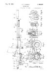
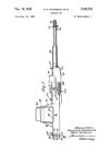
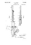
Fig. 1 shows diagrammatically in side eleva-
55 tion the swinging gun support of a machine gun
mounting together with the trigger control de-
vice, and
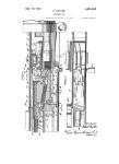
Fig. 2 shows on an enlarged scale an example
of construction of the adjusting handle on the
60 gun mounting.
(CI. 89—37)
The gun support I which carries the gun is
swingably articulated to the base 3 by means of
the parallel motion comprising the pivotally
mounted links 2 and its motion damped by one
or more sets of recoil braking and running out •
springs. The spring arrangement may be con-
structed as shown in Fig. 1‘where, approximately
diagonally disposed between the pivots 4 and 5
• of the parallel motion arms 2, there is connected
a spring assembly 6 having a recoil braking and
running-out spring 6' and an oppositely acting •
spring 6".
A bell-crank lever 8 is arranged to pivot about
a pin 7 fixed on the gun support i, one arm of the
bell crank lever being connected with the firing
finger 9 which operates bn the gun trigger. To
the other arm of the bell-crank lever 8 there is
pivoted a link 10 which in its turn is connected
with a pin f i the position of which may be ad-
justed on the fixed part of the base. This pin is ' '
adapted to be moved from a neutral position
denoted by “R” into different positions denoted
by “E” (corresponding to single-shot fire), “S”
(corresponding to rapid fire), “L” and “Li” (cor-
responding to retarded speed of fire). 25
The handle shown in Fig. 2 is in the form of a
spring press-button. When pressure is applied
to it the handle 12—11, a foot 15, thereon is dis-
engaged, against the action of the spring 13,
from notches 14 in the gun base and the handle 30
can then be moved in a slot in the base into the
position corresponding to the type of firing de-
sired in any particular case.
The link 10 is equal in length to that of the
pivotal arms 2 of the parallel motion and, in the 35
position R, E and S of the “pin,” lies parallel
with these arms 2. The notches 14 for these
three positions are for this purpose arranged on
an arc of a radius which is determined in der
pendence on the length of the arms of the bell- 40
crank lever 8. Then when the gun swings back-
ward and forward while firing, the position of
the firing finger 9 relative to the gun trigger
remains unchanged in the position dictated by
one of the setting points R. E and S, and the gun 45
trigger is not further influenced by the to-and-fro
movements of the gun.
The trigger device, for example, is adapted for
use with light machine guns in wh'ch the dif-
ferent kinds of fire are obtained in known man- 50
ner by drawing back the trigger by different
amounts. When the trigger is drawn back to a
certain extent, single shots are produced and
before each successive shot, the trigger must first
be returned to its initial position. If, however, 55
the trigger is drawn back beyond, the “single
shot” position, then the gun is adjusted for con-
tinuous fire. ,
The link 10 is normally in the position R. The
firing finger 9 then is drawn slightly forward 40
2
2,220,663
from the gun trigger. If single-shot fire is de-
sired, the link 10 is moved from the position R
into the position E. Thus by means of the bell-
crank lever 8, the firing finger 9 and therefore
5 also the gun trigger, are drawn back as far as
is necessary for single-shot fire. The shot is
fired, and in order that the process may be re-
peated, the link 10 must first be let back to R.
This is the normal operation in single-shot fire.
If the link is set at S the gun trigger is moved
back into the continuous-fire position. As this
position of the trigger is maintained without al-
teration on account of the backward and for-
ward movement of the gun, the gun now carries
1® out continuous fire with a certain normal speed
of fire.
When the link 10 has been adjusted into the
positions L and Li, the link is no longer parallel
with the pivotal arms 2 of the parallel motion
2® and when the gun recoils, the arms 2 carry out
different swinging movements from those of the
link 10. The result of this is that each time the
gun swings back after a shot is fired, the gun
__ trigger moves quickly backwards from the firing
M finger 9, then moves forward in the trigger-guard
of the gun into its normal position and interrupts
the firing of the gun. Only during the forward
swinging movement of the gun and its arrival in
an a certain forward position on the gun base, does
0 the finger 9 again press the gun trigger back and
the next shot is fired. Thus there is obtained a
continuous fire, the speed of which is considerably
less than the normal firing speed of the gun. It
is immaterial whether this continuous fire is
effected by means of a short movement of the
trigger such as is capable merely of producing
single-shot fire from the gun, or whether the pa.th
of movement of the trigger is greater and, apart
from the action of the control device, would pro-
dO duce continuous fire.
The rate of fire depends on the angular position
given to the link 10 in relation to the rocker levers
2. This angular position determines the forward
position of the gun in which the gun trigger,
<5 which is released from the finger 9 at each indi-
vidual shot, is again pressed back to the position
which permits the next shot to be fired. The
position Li is selected as the extreme position in
which the gun can be fired so that by delaying
®® the detonation, a second and each following shot
of a series is not fired until the gun moves back
by itself to its extreme front position. This pro-
duces the maximum recoil of the gun and conse-
quently a considerably reduced rate of fire as
®® compared with the setting L.
By the invention it is therefore possible to pro-
duce, as required, single-shots, rapid fire or con-
tinuous fire slowed down by different amounts.
The link f 0, may naturally also be provided with
®® an actuating device other than that shown in the
drawing: a rotatable handle would be suitable,
which, when turned, guides the pivotal point of
the link 10 on the base along the setting points
R, E, S and Li. For rapid fire, it is also sufficient
®® if the link 10 is approximately parallel to the
arms 2, provided that, when the gun moves back-
wards, the gun trigger is not released by the
finger 9, until the firing of the gun is to be inter-
rupted.
T® Having now particularly described and ascer-
tained the nature of my said invention and in
what manner the same is to be performed, I de-
clare that what I claim is:
1. A mounting for a machine gun which has a
variable rate of fire, comprising a base, a firing
finger, a gun support, a pair of parallel links piv-
otally connecting the support with the base, recoil
braking and running out means supporting the 5
parallel links and the gun support relative to the
base and connected to opposite ends of the links,
and means connected between the base and the
gun support for automatically actuating the firing
finger of the gun upon recoil of the support and 10
being adjustable to vary the automatic fire of the
gun.
2. A mounting for a machine gun which has a
variable rate of fire, comprising a base, a firing
finger, a gun support, a pair of parallel links piv-
otally connecting the support with the base, re-
coil braking and running out means supporting
the parallel links and the gun support relative to
the base and connected to opposite ends of the
links, and means connected between the base and
the gun support for automatically actuating the
firing finger of the gun upon recoil of the support,
said adjustable means comprising a linkage con-
nected between the base, the support and the fir-
ing finger and being adjustable on the base.
3. A device for adjusting the type and rate of
firing of a recoiling machine gun on a base, com-
prising a firing finger, a link mounted at one end
on the base, a bell crank lever connecting the
other end of the link with the gun and the firing
finger, and a pin at the first mentioned end of the
link for adjusting the link relative to the base
to vary the automatic fire of the gun.
4. A device according to claim 3, in which a
groove is provided in the base in which the link
is adjustable at certain points by means of the
pin corresponding to the various positions for the
various types and rates of firing.
5. A device for adjusting the type and rate of
firing of a recoiling machine gun on a base com-
prising a firing finger, a link mounted at one end
in the base, a bell crank lever rotatably mounted
on the gun at a point approximately intermediate
its ends and having the other end of the link piv-
otally mounted on one end of the lever and the
firing finger pivotally mounted on the other end
of the lever, and means in the base at the first
mentioned end of the link for adjusting the link
relative to the base to vary the automatic fire of
15
25
SO
35
the gun. I
6. A device for adjusting the type and rate of
firing of a recoiling machine gun on a base, com-
prising a firing finger, a link pivotally mounted
at one end on the base, means for connecting the
other end of the link with the gun and the firing 55
finger, and means on the link in cooperation with
a groove in the base for adjusting the position of
the link relative to the base to vary the type or
rate of fire of the gun.
7. A mounting according to claim 2, in which i
the said three links are of equal length.
8. A mounting for a machine gun which has a
variable rate of fire, comprising a base, a firing
finger, a pair of parallel links pivotally connect-
ing the gun with the base, recoil braking and ®*
running out means urging the gun to its forward
position relative to the base by means of the links
and connected to opposite ends of the link, and
means connected between the base and the gun
for automatically actuating the firing finger of *®
the gun upon recoil of the gun and being adjust-
able to vary the automatic fire of the gun.
WOLFGANG ROSSMANITH.