/


Теги: weapons military affairs machine gun patent
Год: 1948
Текст
Nov. 16, 1948,
G. A. CHADWICK ET AL
MACHINE GUN
2,453,830
Filed Dec. 21, 1932
15 Sheets-Sheet 1
Nov. 16, 1948.
2,453,830
G. A. CHADWICK ET AL
MACHINE GUN
Nov. 16, 1948.
G. A. CHADWICK ET AL
MACHINE GUN
2,453,830
Filed Dec. 21, 1932
15 Sheets-Sheet 3
J&aZ Ilk JB&crlc
Nov. 16, 1948. g. a. chadwick etal 2,453,830
MACHINE GUN
Filed Dec. 21, 1932 15 Sheets-Sheet 4
G. A. CHADWICK ET AL 2,453,830
MACHINE GUN
15 Sheets-Sheet 5
Not, 16, 1948.
Filed Dec. 21, 1932
Nov. 16, 1948.
2,453,830
G. A. CHADWICK ET AL
MACHINE GUN
Filed Deo. 21, 1932 15 Sheets-Sheet 6
Nov. 16, 1948.
G. A. CHADWICK ET AL
2,453,830
MACHINE GUN
/X
Nov. 16, 1948.
2,453,830
G. A. CHADWICK ST AL
MACHINE GUN
G. A. CHADWICK ET AL
MACHINE GUN
2,453,830
Nov. 16, 1948.
Filed Dec. 21, 1932
15 Sheets-Sheet 9
«txeayye Л. G&axSawcafc.
JBc&zzZ. 2ZZ JBzcv’jfc.
Nov. 16, 1948.
G. A. CHADWICK ET AL
2,453,830
Filed Dec. 21, 1932
MACHINE GUN
15 Sheets-Sheet 10
Nov. 16, 1948.
G. A. CHADWICK ET AL
2,453,830
MACHINE GUN
Filed Dec. 21, 1932
15 Sheets-Sheet 11
Nov. 16, 1948.
2,453,830
G. A. CHADWICK ET AL
MACHINE GUN
Filed Dec. 21, 1932
15 Sheets-Sheet 12
Nov. 16, 1948.
2,453,830
G. A. CHADWICK ET AL
MACHINE GUN
Nov. 16, 1948.
2,453,830
G, A. CHADWICK ET AL
MACHINE GUN
Filed Dec. 21, 1932
15 Sheets-Sheet 14
Nov» 16, 1948»
G. A. CHADWICK ET AL 2,453,830
MACHINE GUN
15 Sheets-Sheet 15
Filed Dec. 21, 1932
Patented Nov. 16, 1948
2,453,830
UNITED STATES PATENT OFFICE
2,453,830
MACHINE GUN
George A. Chadwick and Paul W. Burk,
Washington, D. C.
Application December 21,1932, Serial No. 648,296
22 Claims.
1
This invention relates to a machine gun and has
for its numerous objects the general improve-
ment of the effectiveness and safety of this type of
weapon. The several objects will more fully ap-
pear from the description of the construction and
operation of our invention.
In the drawings:
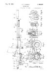
Fig. 1 is a side elevation of the assembled gun;
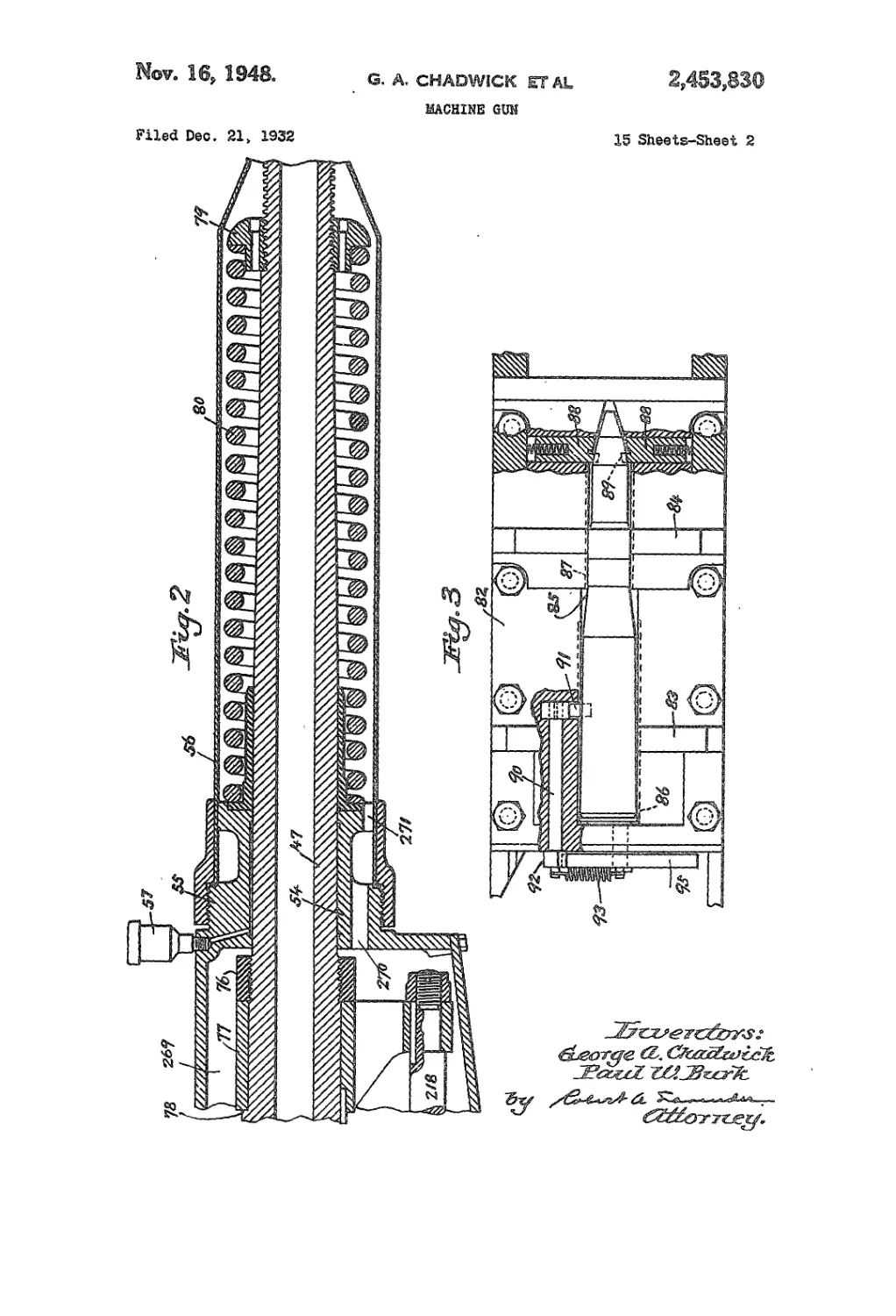
Fig. 2 is a partial longitudinal section showing
the water jacket and recoil spring;
Fig. 3 is a detail view showing a cartridge in the
feed plate ready to be forced into the chamber;
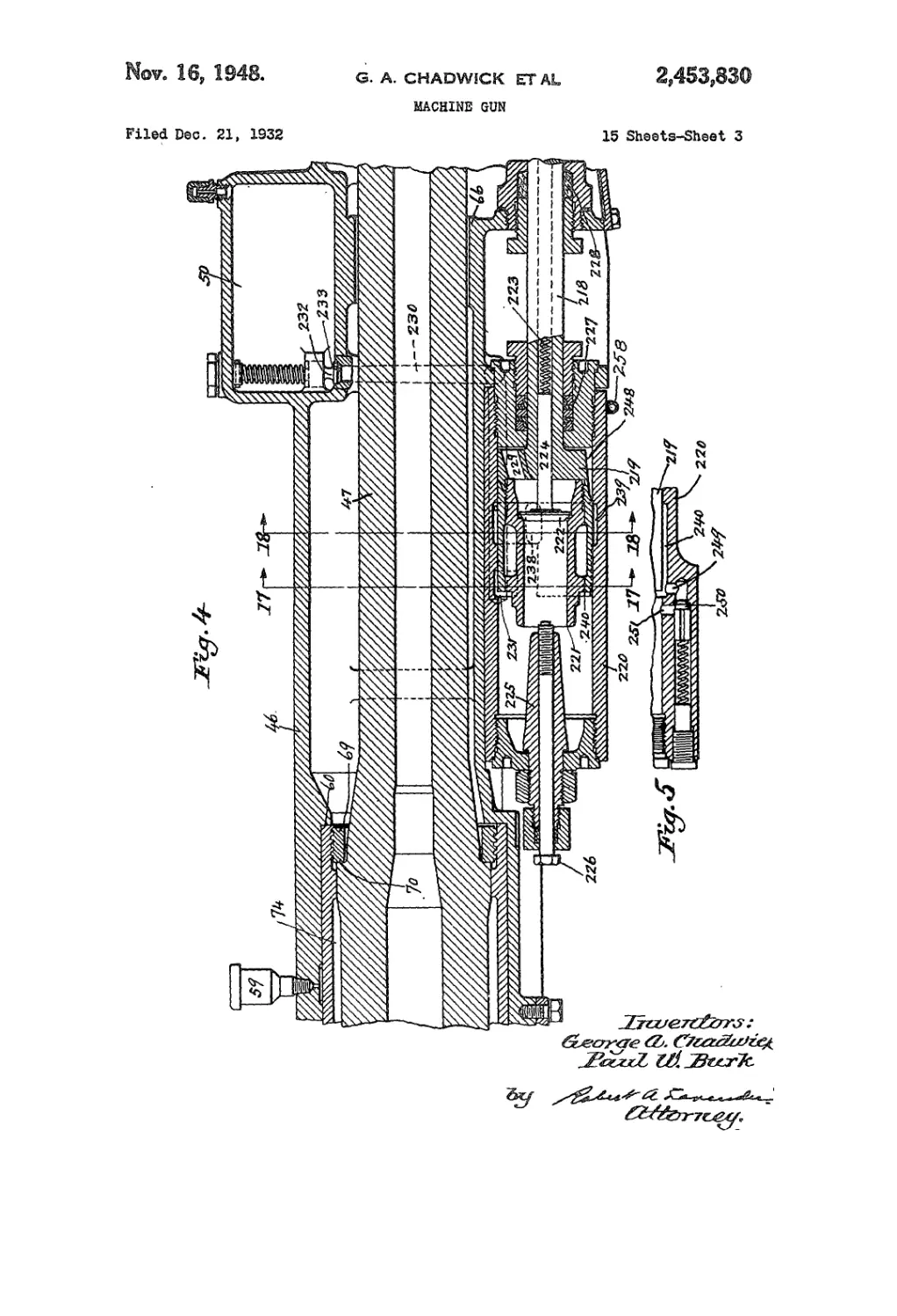
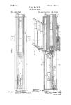
Fig. 4 is a partial longitudinal section showing
the recoil actuated breech operating mechanism;
Fig. 5 is a sectional detail of a relief valve in
the hydraulic breech operating mechanism;
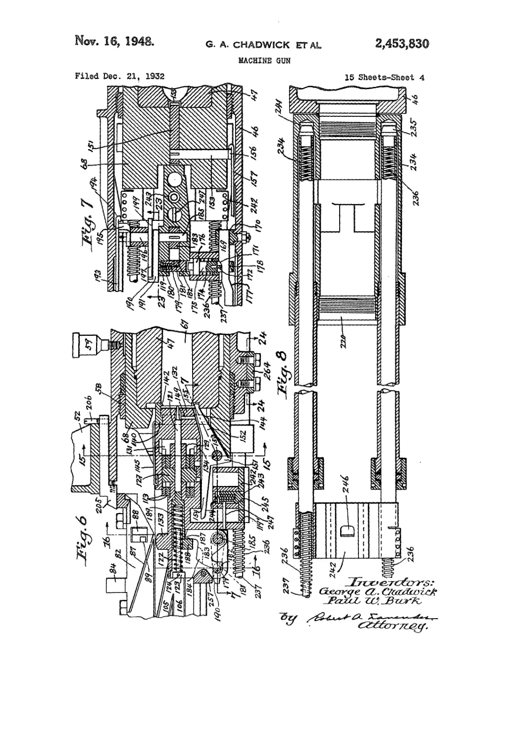
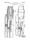
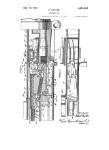
Fig. 6 is a partial longitudinal section through
the breech mechanism;
Fig..7 is a partial transverse section on line 7—7
of Fig. 6;
Fig. 8 is a sectional detail of the plunger mecha-
nism on line 8—8 of Fig. 18;
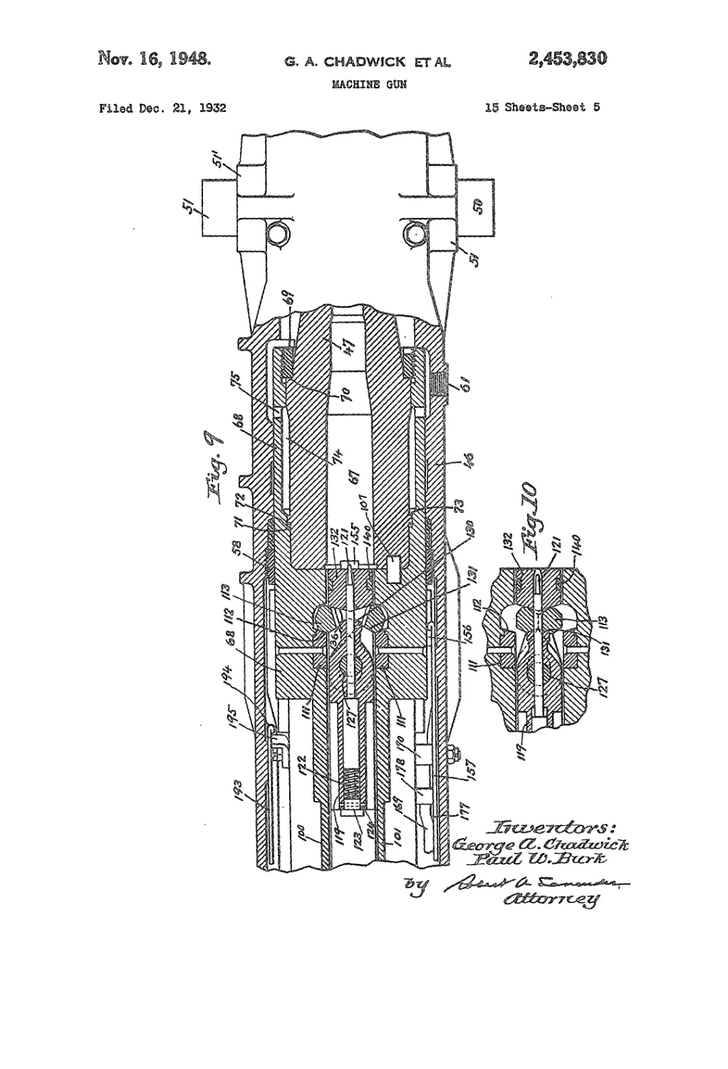
Fig. 9 is a transverse section showing the breech
block and breech locking mechanism in the closed
position;
Fig. 10 is a fragmentary view of the same parts
as shown in Fig. 9 with the breech block unlocked;
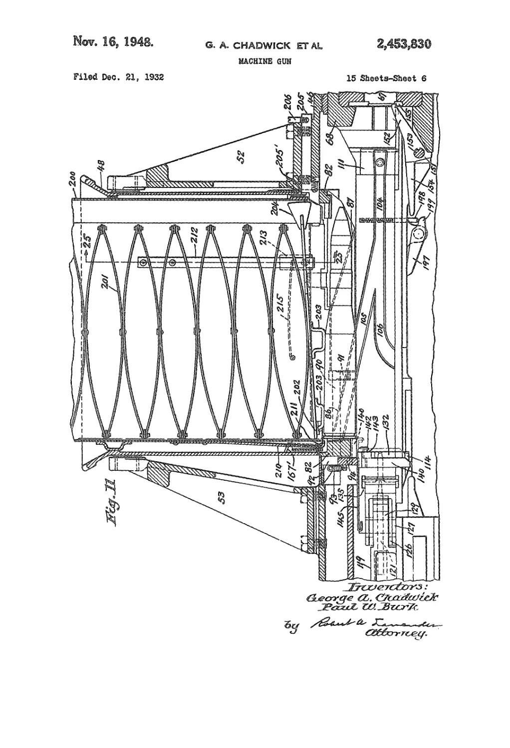
Fig. 11 is a partial longitudinal section through
an empty magazine in position above the loading
Plate taken on line 11—11 of Fig. 25;
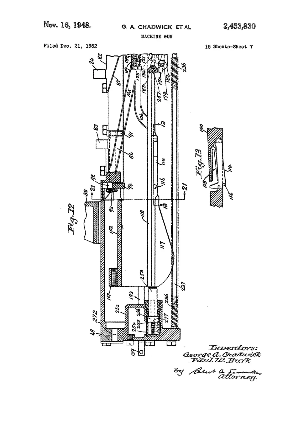
Fig. 12 is a longitudinal section of the rear por-
tion of the gun slide showing the buffer mecha-
nism for stopping the carrier;
Fig. 13 is a detail view of the extractor lifting
cams;
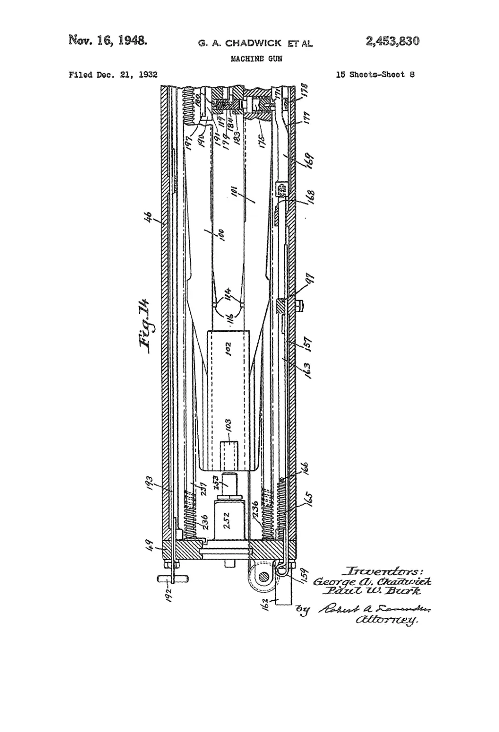
Fig. 14 is a transverse section of the rear end of
the slide showing the breech housing moved back;
Fig. 15 is a cross sectional view through the car-
rier and breech block on line 15—15 of Fig. 6;
Fig. 16 is a view similar to Fig. 15 but taken on
line 16—16 of Fig. 6;
Fig. 17 is a cross section through the barrel and
the hydraulic recoil mechanism on line 17—17 of
Fig. 4;
Fig. 18 is a view similar to Fig. 17 taken on line
18—18 of Fig. 4;
Fig. 19 is a face elevation of the breech end of
the gun;
Fig. 20 is a side elevation of the parts shown in
Fig. 19;
Fig. 21 is a cross section on line 21—21 of Fig.
12 showing the mechanism to prevent operation of
the gun in the event of failure to extract a spent
case from the chamber and to stop the operation
(Cl. 89—190)
2
of the gun in such a position that the breech is
open; ,
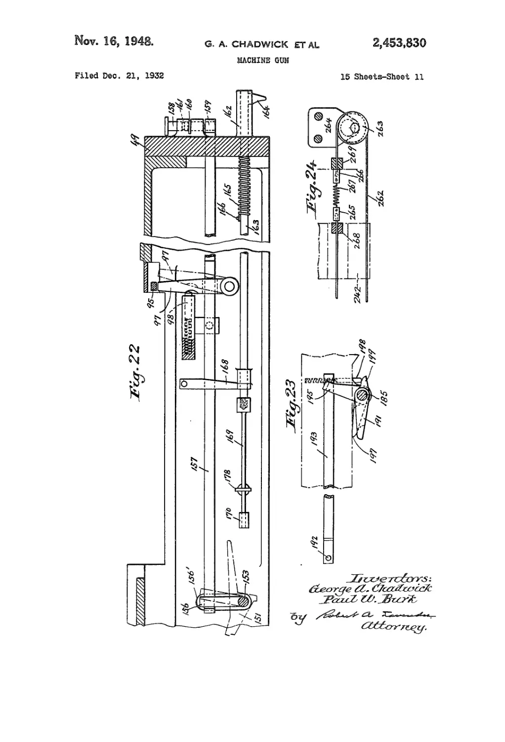
Fig. 22 is an elevational detail view of the carrier
locking mechanism and the trigger assembly;
5 Fig. 23 is a detail view of a part of the hand
cocking mechanism;
Fig. 24 is a detail view of a means for manually
moving the carrier rearwardly;
Fig. 25 is a cross section through an empty
10 magazine and a loaded magazine in position in the
cradle taken on line 25—25 of Fig. 11;
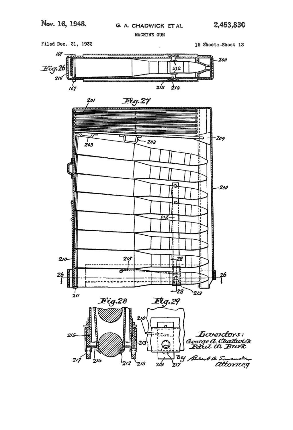
Fig. 26 shows a cartridge in the lower part of a
magazine in the position indicated by line 26—26
of Fig. 27;
15 Fig. 27 is a view of a loaded magazine with one
side thereof removed;
Figs. 28 and 29 show details of the means for
supporting the noses of the cartridges in the
magazine;
20 Figs. 30, 31 and 32 are respectively top plan view,
longitudinal section and rear end view of the
carrier;
Figs. 33, 34, 35 and 36 are details of the breech
locking wedges;
25 Figs. 37, 38 and 39 are respectively a longitu-
dinal section, a side elevation and a front eleva-
tion of the breech block;
Figs. 40 and 41 are respectively longitudinal
section and front end elevation of the extractor;
30 Fig. 42 is a top plan view of the breech housing
with parts in section;
Fig. 43 is a side elevation of the breech housing;
Fig. 44 is a cross section of the breech housing
on line 44—44 of Fig. 42;
35 Fig. 45 is a cross section on line 45—45 of Fig. 43.
This gun is composed of the following main
parts or assemblies: A slide 46, a gun barrel 47, a
magazine cradle assembly 48, a breech mechanism,
a feed plate, a recoil and breech operating system,
40 and a cooling system.
The slide 46 is preferably a bronze casting and
serves as a foundation upon which the rest of
the gun is built. Upon the rear end of the slide
is mounted the rear plate 49. Adjacent the for-
45 ward end is formed an expansion chamber 50 for
the oil used in the hydraulic recoil system.
Trunnions 51 serve to mount the gun pivotally in
any suitable supporting means adjacent which are
pads 51' for securing an elevating arc to the gun.
50 The forward bracket 52 and rear bracket 53 sup-
port the magazine cradle 48. The forward end
54 of the slide is contracted to serve as the for-
ward bearing in which the gun barrel slides and
is externally threaded at 55 to provide means for
55 securing the water jacket 56 thereto. An oil cup
2,463,830
3
67 supplies lubricant to the forward bearing.
Just forward of the bracket 52 the slide is thick-
ened to form the rear bearing and has a shoulder
60 formed thereon to act as the stop for the for-
ward movement of the barrel, lubricant for the
rear bearing being fed from cup 59. In the slide
there is provided a packing gland 58 to prevent
leakage of the cooling water which is introduced
through the hole б I and withdrawn through out-
let 62, it being the intention to circulate running
water to cool the gun. Recoil cylinder 220 is
secured to the lower side of the slide between the
rear bearing and expansion chamber 50, while the
forward end of the slide is extended downwardly
to form a pocket 64 for the recoil yoke, access
thereto being had by removing plate 65. On the
under side of the gun below the chamber 50 is a
shoulder 66 that is the stop for the rearward
movement of the barrel; it is engaged by the rear
side of the yoke if the brake mechanism does not
theretofore stop the recoil movement.
The gun barrel 47 is a single tube having a
chamber 67 at its rear end to receive the cartridge.
Breech housing 68 is secured to the barrel by an
internal nut 69 screwed into the forward end of
the breech housing and bearing against shoulder
70 on the barrel to draw shoulder 71 on the breech
housing against packing 72 that is disposed be-
tween shoulder 71 and rib 73 on the barrel to
prevent leakage of the cooling water which en-
ters through hole 61 and flows around the barrel
in space 74 from which it passes through opening
75. Forward of the breech housing, the barrel
47 is externally threaded to receive a nut 76 that
clamps the recoil yoke 77 against shoulder 78 on
the barrel. Some distance forward of the yoke
77, barrel 47 is externally threaded to receive a
nut 79 that confines recoil spring 80 under the
desired degree of compression against the front
end of the slide. The front end of water jacket
56 is closed against leakage by a gland 81 se-
cured in the end of jacket 56.
Cartridges are received from the magazine by
feed plate 82 that is fixed to the slide between
brackets 52 and 53. This plate is provided with
transverse ribs 83 and 84 against which the bot-
tom cartridge in a magazine will bear, the latter
rib being higher than the former to support the
smaller end of the cartridge. The upper faces
of these ribs are arcuate with their centers of
curvature on the opposite sides of a vertical axial
plane through the gun so that the pressure of
cartridges against the ribs will produce a com-
ponent tending to swing the magazine toward the
median longitudinal slot 85 through which the
cartridges pass to be rammed into the chamber.
Grooves 86 lead downwardly from the rear end
of slot 85 to guide the rim of the cartridge case
into alignment with the chamber; the slot 85 is
narrowed forwardly to form a downwardly slop-
ing cam surface 87 facing rearwardly and down-
wardly at each side of the slot 85 to engage the
sharply tapered portion of the cartridge to guide
the nose thereof to chamber 67. Spring pressed
plungers 88 support the nose of the cartridge in
the feed plate, these plungers having suitably
beveled faces to engage the sloping surface of the
bullet and a beveled projection 89 to extend par-
tially thereunder. The lower faces of the plung-
ers 88 contact sloping faces on the feed plate 82
to prevent their being moved away from the
cartridge by the weight thereof or by the pressure
of the magazine springs. A shaft 90 is rotatably
mounted in the rear end of feed plate 82 and has
secured to It a detent 91 that extends out into
6
10
15
20
25
30
35
40
45
50
55
60
65
70
75
4
slot 85 in position to be engaged by a cartridge
passing into the slot. At the rear face of feed
plate 82 a feed sear 92 is secured to shaft 90 and
is connected to spring 63 under tension that tends
always to move the detent 91 into slot 85. Rear
stop lever 94 has offset arms 95 and 96, the lat-
ter being disposed under the free end of feed sear
92 except when the detent 91 is moved out of
slot 05 by a cartridge.
Stop sear 97 is pivotally mounted on the slide
with its free end movable under the end of arm
95 of the rear stop lever, but normally held out
of that position by a spring pressed plunger 98
that acts upon carrier locking rod 157 connected
to the stop sear. Upon the rear stop lever is a
surface 99 against which the extractor contacts
and since the rear stop lever cannot be rotated
unless detent 91 is moved out of slot 85 by a car-
tridge, and also unless stop sear 97 is clear of
arm 95 of rear stop lever 94, the carrier will be
held and the operation of the gun will be stopped,
as will be hereinafter more fully explained.
The breech mechanism takes the cartridge
from feed plate 83, rams it into the gun chamber
67, closes the breech, fires the charge, opens the
breech, extracts and ejects the empty case. It
consists of the breech housing, carrier, breech
block, firing mechanism, rear stop lock, anti-
double loader, and carrier buffer.
The breach housing 68 is a steel forging con-
nected to the barrel as above set forth in con-
nection with the description of the barrel. The
forward end of the breech housing is bored out
to receive the chamber end of the barrel and has
formed in it the space 74 for the circulation of
cooling water. The outer surface of the forward
end of the breech housing slides in the rear bear-
ing and the front end thereof'contacts shoulder
60 to stop forward movement of the barrel. A
short distance from the back face of the barrel
the breech housing is divided into two side mem-
bers 100 and 101 that extend almost to rear plate
49 where they are connected together by a bridge
102 that carries an internally threaded lug 103
adapted to be .engaged by a threaded rod to pull
the breech housing backwardly for testing the
gun. In the inner face of members 100 and 101
are, formed grooves 104 to engage the rim of the
cartridge case and guide the case along the axis
of the gun into the chamber, these grooves being
connected to grooves 86 in the feed plate by an in-
clined portion 105. A curved groove 106 in each
of members 100 and 101 connects with grooves 104
in the same member, respectively, and guides the
spent case downwardly - and out of the gun. A
dowel pin 107 serves to position the barrel prop-
erly in the breech housing and a key 108 disposed
in groove 109 in the housing and groove 110 in
the slide prevents rotation of the housing and
barrel with respect to the slide, but permits rela-
tive longitudinal movement between these parts.
A short distance from the rear face of barrel 47
a block 111 is set in each side of the passage
through the breech housing; each of these blocks
has an outwardly sloping face 112 to coact with a
face on a locking wedge 113. A short distance
forward of the rear ends of members 100 and 101
there is disposed in each of these members an ex-
tractor-lifting cam 114, each cam being pivotally
mounted at one end and urged toward the space
between members 100 and 101 by a U-shaped
spring 115, as shown in Fig. 13. Each of these
cams has a rearwardly sloping face 116 to per-
mit the extractor to ride up over the cams when
the breech mechanism is being moved forwardly.
2,463,830
5
The member (01 carries at its rear end a down-
wardly extending cam 117 for automatically
cocking the firing mechanism.
Grooves (18 are formed in the inner faces of
members 101 in which grooves the carrier 119 is
slidably mounted. As shown in Figs. 30 to 32
inclusive, the carrier has in it a longitudinally ex-
tending bore 120 in which the firing pin 121 is
slidable, the rear portion of this bore being of
greater diameter to receive the enlarged rear por-
tion of the firing pin in which firing pin spring
122 is held in operative position by the spring
retainer 123 secured to the carrier by pin 124.
Locking wedges 113 have elongated holes 125 in
their limbs 126 to receive a pin 127 that is seated
in a hole 128 in the carrier, which pin is bored to
permit the firing pin to be passed therethrough,
the elongation of the hole permitting the locking
wedges to slide as well as pivot on pin 127, the
limbs of each locking wedge being placed astride
the portion 129 of the carrier. The front end of
portion 129 has on it oppositely sloping faces 130
that engage faces 131 on the locking wedges 113
to force the wedges apart and into engagement
with faces 112 of blocks 111 whereby the breech
block 132 is held firmly against the base of a
cartridge in chamber 67; portion 129 lies between
the locking wedges when in the breech locking
position to prevent casual movement of the
wedges from that position. On the upper surface
of carrier 119 is a lug 133 to support the nose of
a cartridge in case the spring pressed plungers 88
fail to function.
The locking wedges 113 (Figs. 33-36) each have
two limbs 126 adapted to embrace the portion 129
of carrier 119, the limbs of one of the wedges
being sufficiently spaced apart to lie outside the
limbs of the other wedge. Upon the upper and
lower surface of each wedge 113 at its forward
end is a lug 134 having a rounded rearward face,
which lugs are adapted to seat in grooves 135 in
the breech block, the grooves 135 being formed
to define a very obtuse angle opening forwardly,
the front edges of the grooves having somewhat
the same angular relation to each other as do
faces 136 on the breech block that are engaged
by the locking wedges when ramming a cartridge
into the chamber. Upon rearward movement of
the carrier after firing, pin 127 pulls back on the
wedges and lugs 134 engage the rear faces of slots'
135 and thereby draw the locking wedges back-
ward, the inward slope of the rearward faces of
the groove moving the locking wedges in so they
will clear the blocks 112 and permit the breech
block to be unseated. A beveled surface 137 on
the rear inner face of each locking wedge pro-
vides an appreciable contact area against which
portion (29 bears to lock the wedges positively
in the closed position. The inner face of each
wedge 113 has in it a groove (38, semi-circular in
cross section, to provide clearance for the firing
pin.
Adjacent the forward end of breech block 132
is a groove 139 that extends across and down
each side of the breech block to receive extractor
140. As shown in Figs. 40 and 41, the extractor
is a substantially horseshoe-shaped member hav-
ing legs to engage in the slot 139 on the sides of
the breech block and a forwardly projecting por-
tion 141 with a backwardly sloping beveled face
142 on its lower edge and a slot 143 back of that
edge, the beveled face 142 being adapted to engage
the rim of a cartridge case to cause the extractor
to ride up over the rim and thus set the rim in
slot 143 whereby backward movement of the
в
breech mechanism will withdraw the spent case
from the chamber, A backwardly sloping face
(44 is formed on the forward edge of each leg
of the extractor at the lower end thereof to cause
5 the extractor to slide over extractor cams 114
as the breech mechanism is being moved for-
wardly to ram a new cartridge. Two extractor
springs 145 have their rear ends bent over and
engaged in a slot 146 in the upper rear portion
10 of the breech block and extend forwardly to lie
upon the upper face 147 of the extractor to move
the extractor downwardly upon the breech block
and yet permit it to rise sufficiently to pass the
rim of a cartridge case. Breech block 132 has
•15 in it a passage 148 for the firing pin, and leading
downwardly from that passage a small opening
149 to permit the escape of gases that may enter
the passage 148 from a ruptured primer and also
to permit any particles of carbon that may be
20 carried by such gas into the passage 148 to drop
from the passage and so prevent interference
with the movements of the firing pin by such par-
ticles. In the lower portion of the forward end
of breech block 132 is a forwardly and upwardly
25 sloping slot 150 to accommodate one arm 152
of the anti-double loader lever 151, which arm
is adapted to be engaged by the rim of a cartridge
case in the chamber thereby rocking shaft 153
and actuating a carrier locking mechanism here-
30 inafter to be described to prevent a second car-
tridge being rammed while a case is still in the
chamber. The arm 154 of lever 151 will catch
the nose of a cartridge that may have dropped
down unduly while being loaded and guide the
35 same up into chamber 67. A slot 155 is formed
at the lower rear portion of chamber 67 to receive
arm 152 of lever 151 when a cartridge case is in
the chamber. The outer end of shaft 153 carries
a lever (56 that engages a hook on carrier lock-
40 mg rod (57 that is connected to stop sear 97
whereby, when arm 152 is held down by the rim
of a cartridge case in the chamber and lever 156
is thereby rocked forwardly, the stop sear 97 is
moved under arm 95 of rear stop lever 94 and
45 the rear stop lever cannot then rotate on its
pivot so that when the face 99 of rear stop lever
is contacted by extractor 140, the extractor is
prevented from riding up over extractor cams
114 and the mechanism is locked with the breech
open. The position of lever 156 may be ascer-
tained by looking through hole 156’ in the slide
and hence it can be determined whether failure
to fire is due to hangfire or misfire or failure to
g5 ram a charge. However, when the breech is open
and the case has been extracted, as in normal
operation, stop 97 is held back by plunger 98
and the rear stop lever can be rotated by the
extractor, thus permitting the extractor to move
00 over the extractor cams and allow the breech
mechanism to close. When it is desired to hold
the breech open, carrier locking rod 157 may be
held in the forward position, in which the stop
sear 97 is under arm 95 of the rear stop lever,
05 by moving plunger (58 downwardly through a
loop (59 formed on the rear end of the carrier
locking rod, or by pressing the thumb against
loop 159. A hairpin-shaped spring 160 is pro-
vided to engage grooves 161 in plunger 158 to re-
70 tain the plunger in either the locking or unlock-
ing position.
From rear plate 49 a sleeve 162 extends out-
wardly, this sleeve having in it a passage in
which a trigger rod 163 is slidable and having a
75 slot in the lower part of its wall to permit slid-
2,453,830
7
ing movement of trigger 164. Spring 165 is dis-
posed around trigger rod 163 and is held under
compression between a pin 166 fixed to rod 163
and the inner face of rear plate 49 to hold trigger
rod 163 normally forwardly and also under rota-
tional tension to exert a clockwise torque on
trigger rod 163. Opening into the right-hand
side of the passage in which trigger 164 slides is
a slot 164' having a forwardly extending portion.
7 he c.op 168 prevents movement of bar 169 con-
nected to rod 163 to the rear to the extent that
Ьлг 169 would be withdrawn from guide 170.
Stop 163 is resilient and can be moved aside to
permit the withdrawal of bar 169 from guide 170
s disassembling. A cam surface 171 on the
inner face of bar 169 is engageable with a mem-
ber 172 (Fig. 16) that bears against a collar 173
slidably mounted in the breech housing; a spring
174 is disposed around a plunger 175 between
collar 173 and a flange 176 on the plunger. A
cam face 177 on the outer edge of bar 169 is
adapted to contact a yoke 178 connected to the
plunger to move the plunger outwardly when
the breech is to be opened manually. To do
this, trigger 164 must be turned counter clock-
wise and moved forward in slot 164'. The delay
in opening the breech thus occasioned is an
added factor of safety in case of a hangfire. So
long as plunger 175 is held inwardly, the breech
cannot be opened. In automatic fire, as the
barrel and breech housing are moved back by
the recoil, the plunger 175 moves with them and
thus the yoke 178 is made to ride over cam face
177 on member 169, which is carried by the slide
and does not recoil, which withdraws the plunger
175 and permits the breech to be opened, as
will hereinafter be explained.
Slidably mounted in carrier 119, to be in align-
ment with plunger 175 when the breech is closed,
is a sear 179 that is urged toward the plunger
175 by a spring 180. Sear 179 has in its forward
side a slot 181 in which arm 182 of sear lever 183
is slidable, the sear lever having in one face a
cut-away portion to form a shoulder 184 with
which the sear will be moved into engagement
by spring 180 when the sear lever is rocked back-
wardly by pivot 185 that is mounted in opening
186 in the carrier. Arm 187 of sear lever 183
engages toe 188 of the firing pin 121 and thus
draws back the firing pin and compresses firing
pin spring 122 against spring retainer 123 when
the sear lever is rocked backward. When trigger
164 is moved backwardly to bring cam face 171
into the position with respect to plunger 175
shown in Fig. 7, spring 174 is free to move plunger
175 toward sear 179 and disengage the sear from
shoulder 184 on sear lever 183 which permits the
spring 122 to drive the firing pin forward and fire
the cartridge.
The gun is cocked, that is, sear lever 183 is ro-
tated to retract the firing pin and compress the
firing pin spring, by the portion 190 of cocking
lever 191 being formed downwardly by automatic
cocking cam 117 carried by member 100 of the
breech housing. Lever 191 is connected to pivot
185 upon which sear lever 183 is keyed and thus
the downward movement of this lever 191 ro-
tates sear lever 183 backwardly which effects the
cocking operation. Provision is made for recock-
ing the gun by hand by means of a bar 192
mounted in a rod 193 that is slidable through rear
plate 49 and has a hook 194 formed on its for-
ward end to engage a lever 195 carried by a shaft
185 to the other end of which is connected a lever
197 that may be brought into engagement with
5
10
15
20
25
30
35
40
45
50
55
60
65
70
75
8
portion 190 of lever 191 to rock lever 191 back-
wardly. A spring pressed plunger 198 bears
against a finger 199 extending oppositely to lever
197 and connected thereto to retain lever 197
in contact with hook 194 on rod 193.
Ammunition is fed into the gun from maga-
zines 200 mounted in cradle 48. The magazines
are enclosed on all sides except that which is
presented to the feed plate when mounted in the
cradle. A plurality of leaf springs 201 connected
together at their ends and substantially at their
mid points are placed under compression when
the magazine is loaded and force the cartridges
out when feeding into the gun. A push plate
202 connected to the lowermost leaf has members
203 attached thereto to contact the cartridge case
and a trip plate 204 at its forward end to release
the cradle latch when the magazine is empty. At
the lower edge of the forward end of each maga-
zine 200 is a slot 205' into which the cradle latch
205 may pass to lock the cradle in position to
align the cartridges in the magazine that is en-
gaged by the cradle latch with slot 85 in the
feed plate, the inner end of latch 205 extending
a short distance into the magazine in position
to be contacted by trip plate 204 when the maga-
zine is empty. A pin 206 is fixed in latch 205
to facilitate manual movement of the latch. Each
magazine is provided on each of its sides with a
block 207 that fits in a recess in the face of bar
208 that extends lengthwise of the cradle at its
upper side to support the magazine in the cradle,
the springs 209 secured to the sides of the cradle
serving to hold blocks 207 seated in the recess
in bar 208 but yielding readily to facilitate plac-
ing the magazine in the cradle.
The rim ends of the cartridges are retained in
the magazine by a spring clip 210 that has an
overturned portion 211 which extends beneath
the rim of the lowermost cartridge until the
magazine is placed in cradle 48 at which time tabs
167 carried by portion 211 ride over cam members
167' in cradle 48 and move the overturned portion
out of engagement with the cartridge rim to the
position shown in Fig. 11. The noses of the car-
tridges are supported by spring clips 21.2 inside
the magazine at the forward end thereof, each
of which has its lower end inturned toward the
cartridge. A plate 213 is slidably carried on the
outside of the magazine and normally covers the
aperture in the side of the magazine through
which pins 214 fixed to the clips 212 are adapted
to pass (Fig. 26), the plates 213 being held in
position to cover those apertures by springs 215
bearing thereon. However, when the magazine
is placed in the cradle, the lower edge of each
plate 213 contacts a shoulder 216 at the lower
edge of the cradle and the plate is moved up-
wardly to align an aperture 217 in the plate with
the corresponding pin 214 whereupon the action
of the pressure of springs 201 against the car-
tridges forces clips 212 laterally and the car-
tridge may then move out of the magazine. The
force exerted by the lowermost cartridge against
ribs 83 and 84 due to springs 201 has a compo-
nent directed toward the slot in said plate and
therefore, as soon as cradle latch 205 is released
by contact with the trip plate 204 in an empty
magazine, the loaded magazine is caused to move
into position above slot 85 in the feed plate where
it is locked by latch 205 until it in turn has been
emptied. This method of loading from the top
of the gun and the ejection of the spent cases
from the under side thereof permits placing sev-
eral guns in a single mount if desired, which is
2,463,830
9
not possible where the ammunition is fed through
the sides as is the usual practice. So long as the
empty magazines are replaced by loaded maga-
zines and the gun continues in action, the cradle
will be automatically swung back and forth to
position the loaded magazines over the slot in
the feed plate as soon as the previously used mag-
azine is emptied.
The gun mechanism is operated by the recoil
due to the discharge of the cartridge which moves
barrel 47 back in slide 46 and comprises recoil
spring 80, thus storing up energy to return the
gun to battery. Yoke 77 is connected to the
barrel and to piston rod 218 that carries piston
219 slidably mounted in recoil cylinder 220. In-
side piston 219 is mounted a throttling tube 221
having in it a seat for valve 222 that closes the
passage through the throttling tube at certain
times and is normally held against its seat by
spring 223 bearing against the valve stem 224
which is slidably mounted in piston rod 218.
Valve 222 has a somewhat close fit in the for-
ward portion of the throttling tube to restrict the
passage of the liquid, which increases the pres-
sure on the rearward face of piston 219 and re-
sults in a greater braking effect on the recoiling
parts of the gun. Throttling rod 225 is mounted
in the rear end of recoil cylinder 220 and has
threaded in it the valve stroke adjusting bolt
226 to hold valve 222 unseated for a predetermined
time. Suitable stuffing boxes 227 and 228 pre-
vent leakage of oil or water around piston rod
218. The space in cylinder 220 in front of pis-
ton 219 is in communication with the passage
through the throttling tube by a port 229. Ex-
pansion chamber 50 is connected to cylinder 220
through passages 230, of which there is one on
each side of the gun barrel, opening into the
cylinder through port 231. Each passage 230 is
normally closed at the bottom of the expansion
chamber by a spring loaded relief valve 232 hav-
ing a Small hole 233 therethrough to permit slow
leakage of oil from the chamber into the recoil
mechanism. If surges are set up in the oil in
recoil cylinder 220 by rearward movement of pis-
ton 219, some oil will be forced up through the
passages 230 whence it will pass into the expan-
sion chamber 50 after having unseated valves 232.
At each side of recoil cylinder 220 is a plunger
cylinder 234 in each of which is slidably mounted
a plunger 235 having within it a portton of the
long plunger spring 236 that extends to the rear
end of the gun and is prevented from buckling
outside the plunger by a guide rod 237 inside
the spring. The plunger cylinders are connected
to recoil cylinder 220 by ports 238 that are in
communication with the annular groove 239 in
cylinder 220, the cut-away portions 240 in the
inner face of cylinder 220 being continuous with
groove 239. In the forward end of each plunger
cylinder is a recess 241 that serves as a dash pot
to lessen the impact of the carrier against the
breech housing when the plungers are returned
by springs 236, the pressures in the two dash pots
being equalized by a pipe 258 that connects them
together. Yoke 242 is connected to both of the
plungers 235 at their outer ends and to carrier
219 by a spring pressed plunger 243 disposed in
recess 244 in the carrier, the plunger 243 having
a square face 245 to engage the wall of opening
246 in the plunger yoke and being held against
rotation in recess 244 by pin 247 that extends
into a longitudinal slot in plunger 243. carrier
119 is moved back by engagement of the rear edge
of yoke 242 against face 119' on the carrier.
5
10
15
20
gg
'so:
'u:
40
45
60
66
60
65
70
75
10
As barrel 47 is moved back by the recoil, pis*
ton 219 is also moved back, being connected to
the barrel through piston rod 218 and yoke 77.
Pressure is thus applied to the oil in cylinder
220 back of piston 219 which unseats valve 222
and allows the oil to flow through port 229 into
the space forward of the piston, the motion of
the piston moving throttling tube 221 over throt-
tling rod 225 and so decreasing the area of the
orifice through which the oil flows into the cylin-
der and checking the recoil. A portion of the
oil back of the cylinder may be forced through
port 231, passages 230 and valve 232 into the ex-
pansion chamber 50. The cross sectional area of
piston rod 218 is equal to the combined cross
sectional areas of the plunger cylinders. Thus a
quantity of oil sufficient to fill the space left by
the rearward movement of the plungers as the
plungers are moved through the recoil distance
due to their connection to the carrier through
the plunger yoke 242 is caused to pass into the
plunger cylinders through being displaced by the
piston rod. This prevents the sharp blow that
would result if the plunger cylinders remained
empty until oil is forced into them by forward
movement of the piston.
When recoil spring 80 returns the gun to bat-
tery, piston 219 is simultaneously moved forwardly
and the oil in cylinder 220 in front of the piston is
placed under pressure and valve 222 is seated
after the piston has traveled a sufficient distance
to clear the valve from bolt 226, thus preventing
movement of oil through the throttling tube to
the rear portion of the cylinder. Piston 219 has
on its lower forward portion a passage 248, which
decreases in cross section rearwardly, through
which the oil passes to annular groove 239 through
port 238 to the plunger cylinders, the volume of
the plunger cylinders being substantially the same
as that part of the volume of the forward por-
tion of cylinder 220 that is not occupied by pis-
ton rod 218, when the piston is in its recoil posi-
tion, and thus the return of piston 219 to its
forward position forces just enough oil into the
plunger cylinders to move the plungers the de-
sired distance. It is apparent that as piston 219
moves forward, the space in passage 248 through
which the oil may go into groove 239 diminishes
and hence there is effected a throttling action
that checks the movement of the barrel as it re-
turns to battery. The valve stroke adjusting bolt
226 may be set to hold valve 222 open for any
part of the return movement of the piston to en-
trap the correct quantity of oil in front of the
piston to supply the plunger cylinders. If the
pressure in front of the piston becomes exces-
sive after the piston has moved forwardly of
Port 251, some of the oil will pass from cut-away
portion 240, through port 249, unseat valve 258
and pass to the rear portion of the cylinder, back
of the piston, through port 251 (Fig. 5).
Forcing the oil from cylinder 220 into the
plunger cylinders drives back the plungers 235
with their connecting yoke 242 and since the
yoke is connected to carrier 219, the carrier is
also moved back which extracts the spent case
from chamber 67, ejects it from the gun and
operates the cocking mechanism. When piston
219 has reached the forward end of the cylin-
der, thus uncovering groove 240, the energy stored
up in plunger springs 236 drives the carrier for-
ward and rams a loaded cartridge into the cham-
ber, the oil from the plunger cylinders returning
to cylinder 220 through ports 238, annular groove
239 and the cut-away portion 240.
2,463,830
11
The recoil movement of carrier 219 is stopped
by the buffer mechanism, comprising a chamber
252 mounted in back plate 49 which has a ll-
shaped recess to receive the buffer mechanism.
A plunger 253 is slidable in a cylinder 254 that
has openings in its lower side through which oil
may pass from chamber 252 into cylinder 254
back of plunger 253, the inlet of oil being at
the bottom to insure the presence of oil in cyl-
inder 254 so long as any oil is contained in cham-
ber 252. A passage 255 is provided in the upper
forward portion of cylinder 254 to permit the es-
cape of any oil or air that may be trapped in
front of the piston 256 on the rear end of plunger
253. A striking plate 257 is mounted on carrier
219 to contact plunger 253, the plunger being
moved forwardly by spring 277. The buffer does
not function except in case the quantity of oil
forced into the plunger cylinders is in excess of
that required to move the carrier the proper dis-
tance.
It is sometimes desirable to retract the carrier
119 and the associated breech mechanism. For
this purpose we have provided a crank 259 con-
nected to a shaft 260 mounted on rear plate 49,
the shaft having a drum 261 at its lower end. A
wire 262 is wound a number of times around drum
261 and runs over a sheave 263 mounted on the
slide by means of a bracket 264. The ends of
the wire are secured to blocks 265 and 266 that
are connected together by a spring 267. The end
of the wire that is connected to block 265 passes
between the limbs of a bifurcated lug 268 on
plunger yoke 242 and the other end passes
through a guide 269. When crank 259 is ro-
tated in one direction, the engagement of block
265 with lug 268 draws back yoke 242 and slide
119 connected thereto; turning the crank in the
opposite direction leaves the carrier free to re-
turn to the breech closed position.
The barrel 47 is cooled by passing running wa-
ter in through the opening 61 where it circulates
through space 74 around the chamber, out
through aperture 75 to the space 269 around the
barrel in the forward end of the slide, thence
through passages 270 and 271 around the for-
ward bearing and into water jacket 56 and out
through the passage 62.
Operation
Two magazines 200 filled with cartridges are
placed in cradle 48, the cradle being swung to
position one of the magazines above the slot 85
in the feed plate 82. The placing of the maga-
zines in the cradle releases the retainers 210 and
212 that hold the cartridges in the magazine, as
above described. The carrier 119 and breech
block 132 associated therewith are moved back-
wardly either by means of crank 259 and wire
262 connected thereto or by a threaded rod in-
serted through aperture 272 in rear plate 49
and engaged with the threaded boss 103 on the
breech housing. As the breech housing is moved
back by the latter means, the recoil piston 219
is also moved back, oil is passed through throt-
tling tube 221 and port 229 to the forward end
of the recoil cylinder 220 whence it is forced into
plunger cylinder 234 upon release of the breech
housing to return forwardly, thereby driving
plungers 235 rearwardly which, through yoke
242 moves the carrier 119, breech block 132, etc.,
to the rear.
As the carrier assembly moves backwardly, the
limbs of extractor 140 spread cams 114 out-
wardly, the cams being moved in again by springs
io
15
20
25
30
35
40
45
50
55
60
65
70
75
12
I IS after passage of the extractor. Continued
rearward movement causes portion 190 of lever
191 to ride on the lower face of automatic cock-
ing cam 117 which rotates shaft 185 rearwardly
and with shaft 185 sear lever 183, moving the sear
lever so that sear 179 can engage shoulder 184
on the sear lever to lock the sear in the cocked
position; the arm 187 of lever 183 has simulta-
neously moved toe 188 of firing pin 121 back-
wardly and compressed the firing pin spring 122
where it is held under compression by the engage-
ment of sear 179 with the sear lever. The plung-
er springs 236 then move the carrier assembly
forwardly, the extractor 140 riding up the bev-
eled faces 116 of cams 114 and coming into con-
tact with the under face 99 of rear stop lever
94. If a cartridge has not been moved into the
slot in feed plate 82 into contact with detent 91,
the feed sear 92 will lie above arm 96 of lever
94 and prevent rotation thereof by the extractor
which will thus be prevented from riding up over
cams 114 and the carrier will be locked with the
breech open. However, if a cartridge has been
fed in the normal manner, feed sear 92 will be
swung out of the path of lever 94, the lever 94
will rotate to permit the extractor 140 to pass
over cams 114 and the carrier will continue to
move forwardly, bringing the extractor 190
against the rim of the cartridge as shown in dot-
ted lines in Fig. 11, the full lines showing the.
extractor prevented from passing over the cams
114 by rear stop lever 94. The pressure of the
extractor against the cartridge case produces a
force component between the case and cam sur-
faces 87 that retires the spring plungers 88 to
release the nose of the cartridge therefrom, which
permits the cartridge to move down under cam
surface 87, the rim following grooves 86 and
105, which aligns the cartridge with chamber 67
into which the cartridge is rammed by breech
block 132. The positioning of the cartridge in
chamber §7 stops the movement of the cartridge
and causes sloping face 142 of the extractor to
ride up over the rim of the cartridge after which
the extractor is moved into the groove adjacent
the cartridge rim by extractor springs 145 and
is then in position to withdraw the case when
spent.
When breech block 132 is stopped by striking
the breech face, carrier 119 continues to move
ahead, the faces 130 bearing against faces 131
of the locking wedges 113, forcing the wedges for-
wardly and. outwardly; the carrier moves up be-
tween the locking wedges and forces them
against faces 112 of blocks ill in the breech
housing which forces the forward faces of the
locking wedges firmly against faces 136 of the
breech block and thus provides a positive im-
movable lock to prevent displacement of the
breech block until the breech mechanism is
moved in its entirety. The cartridge moves down
arm 152 of lever 151 and rotates shaft 153 for-
wardly which moves lever 156 in the same sense;
the carrier locking rod 157 is engaged by lever
156 and moves forwardly therewith which draws
stop sear 97 into position under arm 95 of lever
94, preventing rotation of lever 94 so long as the
stop sear is in that position. The stop sear will
be held in locking position under rear stop lever
94 so long as arm 152 of lever 151 is kept de-
pressed by a cartridge in chamber 67 and thus,
in case of failure to extract a spent case, the
carrier is locked with the breech in the open
position until the case has been withdrawn from
the chamber. As before described, the carrier
9,403,830
13
can be locked with the breech in the open posi-
tion by moving plunger 158 into engagement
with loop 159 on the rear end of carrier locking
rod 157.
The cartridge is fired by pulling back on trig-
ger 164 which is connected to bar 169 by rod
163. The backward movement of bar 169 places
spring 174 under compression which urges the
plunger 175 outwardly. If the breech is com-
pletely closed, sear 179 will be aligned with
plunger 175 and will be disengaged from shoulder
184 of sear lever 183 which will release firing
pin spring 122 and allow it to drive firing pin
121 against the primer to fire the cartridge.
However, if the breech has not been completely
closed, the plunger 175 cannot disengage sear
179 from the sear lever and the cartridge will
not be fired.
The recoil moves barrel 47 and breech hous-
ing 68 back, which compresses recoil spring 80
and through yoke 77 and piston 218 forces piston
219 back in cylinder 220, the recoil being checked
by the pressure built up due to throttling tube
221 moving over throttling rod 225. Valve 222
is unseated by the pressure applied to the oil in
cylinder 220 back of piston 221 and oil is per-
mitted to flow into the forward portion of cyl-
inder 220 through port 229, valve 222 being held
open by the bolt 226 during a sufficient portion
of the return movement of piston 219 to permit
the return to the back portion of the cylinder
of all oil in excess of that required to move plung-
ers 235 the proper distance, after which valve
222 is seated and the oil remaining in the for-
ward portion of cylinder 220 is forced through
port 238 into plunger cylinders 234. The return
movement of piston 219 and the return of the
barrel to battery is effected by the energy stored
in recoil spring 80.
As plungers 235 are driven to the rear, springs
236 are compressed and plunger yoke 242 moves
carrier 119 to the rear. This movement of the
carrier brings pin 127 into contact with the rear
wall of openings 125 in the locking wedges which
draws the wedges rearwardly and inwardly to
the position shown in Fig. 10, thus unlocking the
breech block and permitting the extractor to
withdraw the spent case from the chamber. The
case is drawn back along grooves 104 in mem-
bers 100 and 101 until the rim is deflected down-
wardly by groove 106 which causes the case to
be ejected from the under side of the gun. The
carrier continues to move back until no more
liquid is being forced into the plunger cylinders
or it is stopped by striker plate 257 contacting
piston 253 in the buffer. The cocking action
occurs as before described by lever 191 being
moved downwardly by automatic cocking cam
117. Plunger spring 236 then moves the carrier
forwardly which rams another cartridge into
chamber 67 and if the trigger 164 is held back,
plunger 175 will be moved out by spring 174 to
disengage sear 179 from sear lever 183 as soon
as the breech is completely closed and the sear
is aligned with plunger 175, as is the case in au-
tomatic fire, the sloping lateral face of the car-
rier acting as a cam over which plunger 175
rides until it is aligned with the sear. If trigger
164 is released, spring 165 moves trigger rod 163
and bar 169 connected thereto forwardly, which
brings cam face 177 on bar 169 in contact with
yoke 178 and moves plunger 175 backward so it
cannot disengage sear 179 from sear lever .183
and thus prevents firing of the cartridge.
As soon as a magazine is emptied, the trip plate
5
10
15
20
25
30
35
40
45
50
55
60
65
70
75
14
204 moves cradle latch 205 out of engagement
with the cradle. The pressure on the lowermost
cartridge in the loaded magazine due to springs
201 applied to the inwardly sloping ribs 83 and
84 has a component directed toward the slot 05
in the feed plate which swings cradle 48 on its
trunnions and positions the loaded magazine
above the slot in the feed plate where it is locked
by cradle latch 205. Thus it is necessary only
to replace the empty magazines with loaded ones
and the cradle 48 will automatically swing into
position to feed the cartridge from a loaded mag-
azine in cradle 48 as soon as the other magazine
is emptied. If at any time it is necessary to re-
cock the gun while the breech is closed, bar 192
is pulled backwardly which draws the recocking
rod 193 back, brings hook 194 thereon into en-
gagement with lever 195, and by means of lever
197 moves the cocking lever 191 downwardly and
thus rotates sear lever 183 to retract the firing
pin and compress the firing pin spring.
Some of the numerous advantages inhering
in our gun and not found in others are:
An ammunition supply that permits continu-
ous fire without interruption for changing mag-
azines or feeding in new belts so disposed that,
in combination with the bottom ejection of the
spent cases, makes it feasible to operate several
guns side by side in the same mount.
A means of bringing the loaded cartridge into
line with the axis of the gun without employing
moving fingers or pawls.
Breech block locking wedges that have but
slight movement, and that in opposite direc-
tions, whereby their accelerating forces annul
each other and have no detrimental vibratory
effect on the operation of the gun.
Means to lock the breech mechanism open when
the ammunition supply is exhausted or if the
spent case is not extracted when the breech is
opened.
Means for stopping the gun with the breech
either open or closed and for resuming auto-
matic operation from either of these positions.
Means to delay the manual opening of the
breech in case of a hang-fire or a misfire.
Direct cooling of the chamber by circulating
water.
It will be understood that the above descrip-
tion and accompanying drawings comprehend
only the general and preferred embodiment of
our invention, and that various changes in con-
struction, proportion and arrangement of parts
may be made within the scope of the appended
claims without sacrificing any of the advantages
of this invention.
We claim:
1. In a machine gun, a barrel having in it a
cartridge chamber, a slide in which said barrel is
slidably mounted, a breech housing connected to
the rear end of said barrel and having spaced
apart portions extending rearwardly, a feed plate
secured to said slide having in it a slot disposed
above the space between said portions, upwardly
concave ribs on each side of said feed plate tilted
toward said slot to guide a cartridge toward said
slot, the forwardmost of said ribs on each side
of the slot being higher than the other, there be-
ing a groove in the inner face of each of said
portions to guide the rim of a cartridge toward
said chamber and a groove connected to each of
the aforesaid grooves to guide a spent case out
of the under side of the gun, a rib on each of said
portions to guide the nose of a cartridge toward
said chamber, a magazine cradle swingably
2,463,690
IS
mounted above said feed plate, two magazines
supported by said cradle, cartridges contained
within said magazines, means to lock said cradle
in position to feed the cartridges from one of
said magazines into said slot, the lowermost car-
tridge in the other magazine bearing on said ribs
adjacent thereto and means automatically to re-
lease said lock when the one magazine is empty
whereby the pressure of the cartridge in the other
magazine against said ribs can swing said other
magazine into feeding position over said slot.
2. In a machine gun, a barrel having in it a
cartridge chamber, a slide in which said barrel
is slidably mounted, a breech housing connected
to the rear end of said barrel and having spaced
apart portions extending rearwardly, a feed plate
' Secured to said slide having in it a slot disposed
above the space between said portions, upwardly
concave ribs on each side of said feed plate tilted
toward said slot to guide a cartridge toward said
slot, the forwardmost of said ribs on each side of
the slot being higher than the other, there being
a groove in the inner face of each of said portions
to guide the rim of a cartridge toward said cham-
ber and a groove connected to each of the afore-
said grooves to guide a spent case out of the
under side of the gun, and a rib on each of said
portions to guide the nose of a cartridge toward
said chamber.
3. In a machine gun, a barrel having in it a
cartridge chamber, breech mechanism operatively
related to said barrel, a longitudinally slotted
feed plate through which cartridges are passed to
be fed into said chamber, spring pressed plungers
disposed to support the nose of a cartridge when
in the slot in said feed plate, a swingably mounted
detent mounted in said plate to extend into said
slot when no cartridge is in said slot but movable
out of said slot by a cartridge therein and means
coacting with said detent to lock said breech
mechanism in the open position if opened when
no cartridge is in said slot.
4. In a machine gun, a barrel having in it a
cartridge chamber, a magazine cradle adapted to
contain two magazines swingably mounted above
said barrel adjacent the breench thereof, a cradle
latch to lock said cradle in position to feed car-
tridges from a magazine therein into said cham-
ber, a magazine in said cradle, resilient means in
said magazine to move cartridges out of the mag-
azine, a push plate carried by said resilient means
interposed between said means and the upper-
most cartridge therein, a plate carried by said
push plate to release said cradle latch when the
magazine is empty, means to retain cartridges in
the magazine when the magazine is not in the
cradle, means carried by said cradle to release
said cartridge retaining means when the maga-
zine is placed in the cradle, and means coacting
with the lowermost cartridge in a magazine not
in the feeding position whereby the pressure of
said resilient means on the cartridges in that
magazine will swing said magazine into the feed-
ing position when said cradle latch is released.
5. In a machine gun, a magazine comprising a
casing open at its lower end, a plurality of bowed
springs therein having their ends connected in
pairs and the mid-point of each spring connected
to the adjacent spring of the pair next thereto,
a push plate secured to the lowermost spring, a
plate on the forward end of said push plate, a
resilient member secured to the rear wall of said
casing having a portion adapted to engage the
rim of the lowermost cartridge in the casing, a
resilient member secured to each side wall adja-
5
io
15
20
25
30
35
40
4S
SO
65
00
05
70
75
16
cent the forward end of the casing and having an
overturned portion to underlie the nose of said
lowermost cartridge, a pin secured to each of
said last mentioned resilient members adapted to
pass through a hole in the casing wall, an aper-
tured plate slidably mounted against the exterior
face of each side wall movable to align the aper-
ture therein with the said hole in the casing wall
and means normally holding the aperture in said
plate out of alignment with the aperture in the
casing wall.
6. In a machine gun, a barrel, a breech block
movable toward and away from the breech thereof
having a hole therethrough to accommodate a
firing pin, adjacent its forward end a groove
across its upper face and down the sides thereof,
opposed obtusely V-shaped grooves in upper and
lower rearwardly extending portions and two faces
adjacent said V-shaped grooves intersecting at
substantially the angle of said V-shaped grooves;
locking blocks each having a face sloping in-
wardly and rearwardly mounted adjacent the
position of said faces on the breech block when
the block is in the closed position; a carrier slid-
ably mounted adjacent said breech block having
a forward portion with an obtusely V-shaped
end; locking wedges mounted on said carrier for
both pivotal and sliding movement, each of said
wedges having a portion extending into the
grooves in the upper and lower rearwardly ex-
tending portions of the breech block and faces
to coact with the said faces on the breech block,
the forward end of said carrier and the face on
a locking block whereby forward movement of
the carrier after the breech block has been
stopped will wedge the said wedges positively be-
tween said locking blocks and said breech block
with the said forward portion of the carrier be-
tween said locking wedges, a substantially horse-
shoe shaped extractor seated in the said groove
adjacent the forward end of the breech block,
resilient means normally to hold said extractor
down upon the breech block, means to move said
carrier and breech block toward and away from
the breech of said barrel and a firing pin mounted
in said carrier and said breech block.
7. In a machine gun, a barrel, a breech block
movable toward and away from the breech there-
of, locking wedges mounted for pivotal and longi-
tudinal movement to lock said breech block posi-
tively in the closed position, a slidable carrier
upon which said wedges are mounted adapted to
move said wedges into the locking position and to
lie between said wedges when locked, said wedges
forming an operative connection between the
carrier and the breech block, a firing pin mounted
in said carrier and passing through said breech
block, resilient means to urge said firing pin for-
wardly, means to move said firing pin rearwardly
to compress said resilient means, means to lock
said firing pin to hold said resilient means under
compression, means to release said locking means
and means to move said carrier and breech block
toward and away from said breech.
8. In a machine gun, a barrel, a breech block
movable toward and away from the breech there-
of, and means to lock said breech block in the
closed position comprising a locking block dis-
posed laterally and rearwardly of each side of
said breech block when in the closed position,
each of said locking blocks having an inwardly
and rearwardly sloping forward face, locking
wedges mounted for pivotal and longitudinal
movement having portions engaged with said
breech block and faces to coact with the said
2,453,830
17
faces on the locking blocks and faces on the
breech block and a carrier on which said wedges
are mounted adapted to move said wedges into
the locking position and to lie between parts of
said wedges when in that position.
9. In a machine gun, a barrel, a breech block
movable toward and away from said barrel, an
extractor carried by said breech block having legs
extending down the sides of the block and a por-
tion over the top of said block, there being a back-
wardly sloping face on the forward side of the
lower end of each of said legs, a cam in the path
of each of said extractor legs adapted to be moved
out of said path by said legs during backward
movement but not during forward movement of
said legs and having a rearwardly sloping face
over which said face on the extractor leg is
adapted to ride in normal operation, means to
position cartridges to be rammed into said barrel,
a detent disposed to be movable into the path
of a cartridge in said means and to be displaceable
therefrom by a cartridge in said means, a rotat-
ably mounted shaft upon which said dentent is
carried, a sear mounted on said shaft, a stop lever
pivotally mounted above said cams having an
arm disposed to be raised by said extractor as the
extractor rises over said cams in normal opera-
tion, said sear being movable to prevent rotation
of said arm of the stop lever when no cartridge
is in position to move said detent out of said path
whereby the extractor is prevented from rising
over said cams and the breech block is prevented
from moving into the closed position against said
barrel.
10. in a machine gun, a barrel, a breech block
movable toward and away from said barrel,
means to position a cartridge to be rammed into
said barrel, a cam disposed to extend toward each
side of the path of travel of said breech block
rearwardly of the closed position of said block,
a member engaged with said breech block to be
upwardly slidable thereon in normal operation to
to rise over said cams but to engage said cams
if prevented from rising thereover, a lever piv-
oted to be moved by said member when so rising
over the said cams and means to prevent such
movement of the lever when no cartridge is in
position to be rammed into said barrel whereby
the breech block is prevented from moving to the
closed position when no cartridge is so positioned.
11. In a machine gun, a barrel, a breech block
movable toward and away from said barrel, an
extractor carried by said breech block having legs
extending down the sides of the block and a por-
tion over the top of said block, there being a
backwardly sloping face on the forward side of
the lower end of each of said legs, a cam in the
path of each of said extractor legs adapted to be
moved out of said path by said legs during back-
ward movement but not during forward move-
ment of said legs and having a rearwardly slop-
ing face over which said face on the extractor
leg is adapted to ride in normal operation, a stop
lever pivotally mounted above said cams having
an arm disposed to be raised by said extractor
as the extractor rises over said cams in normal
operation, a stop sear mounted to be movable
to prevent raising of said arm by the extractor,
means normally holding said stop sear away from
said stc,. lever, an anti-double loading lever piv-
otally mounted with an arm disposed to be de-
pressed by a cartridge case in said barrel and
means connecting said anti-double loading lever
to draw said stop sear into position to prevent
movement of the stop lever when the said arm
10
15
20
25
30
35
40
45
50
55
00
65
70
75
18
is depressed whereby the return of the breech
block to the closed position is prevented when a
cartridge case is in the barrel while the breech
block is in the open position.
12. In a machine gun, a barrel, a breech block
movable toward and away from said barrel, means
to position a cartridge to be rammed into said
barrel, a cam disposed to extend toward each side
of the path of travel of said breech block rear-
wardly of the closed position of said block, a mem-
ber engaged with said breech' block to be up-
wardly slidable thereon in normal operation to
rise over said cams but to engage said cams if
prevented from rising thereover, a lever pivoted
to be moved by said member when so rising over
said cams and means to prevent such movement
of the lever when a cartridge case is in the bar-
rel while the breech block is in the open position.
13. In a machine gun, a barrel, a breech block
movable toward and away from said barrel, a cam
extending toward each side of the path of move-
ment of said breech block, a member engaged
with said breech block and movable with' respect
thereto to ride over said cams in normal opera-
tion but to engage said cams when prevented
from so moving, a stop lever pivotally mounted
above said cams having an arm disposed to be
moved by said member as it rides over said cams
but to prevent said member from riding over
said cams if not so moved, a stop sear movable to
prevent movement of said arm by said member,
means normally holding said sear away from said
stop lever and manually operable means to move
said stop sear into position to prevent movement
of said arm of the stop lever by said member
whereby said breech block may be held in the
open position.
14. In a machine gun, a barrel, a breech block
•and a carrier operatively connected together for
movement toward and away from said barrel, a
firing pin slidably mounted in said carrier and
breech block, a toe projecting from the rear end
of said firing pin, a spring mounted to be com-
pressed by backward movement of said firing pin
in said carrier, a sear lever pivotally mounted in,
said carrier having an arm disposed to bear
against said toe to move said firing pin back-
wardly when said lever is rotated on its pivot
and a second arm at an angle thereto with a por-
tion having an arcuate edge having a notch in it,
a spring pressed sear disposed to be moved into
said notch when the said lever is rotated on its
pivot to hold said firing pin in the cocked posi-
tion, a pivot upon which said lever is mounted, a
cocking lever on said pivot, a cam over which said
cocking lever rides to rotate said sear lever to
move said firing pin to the cocked position, means
manually operable from the exterior of the gun to
move said sear lever to the cocked position, a
spring pressed plunger mounted in a member
connected to said barrel to be aligned with said
sear when the breech is closed, a yoke connected
to said plunger to move said plunger outwardly
to an inoperative position or inwardly to release
said sear from said sear lever, a bar passing
through said yoke and slidably mounted on a fixed
member, said bar having on it a cam face slid-
able against said yoke to move said plunger into
the sear releasing position and a second cam face
on its opposite edge to move said plunger out-
wardly to the inoperative position to permit the
breech block to be moved away from said barrel,
and a trigger connected to said bar to move said
bar to move either of said cam faces against said
yoke.
2,463,830
19
15. In a machine gun, a slide, a reservoir for
liquid on said slide, a barrel slidably mounted in
said slide; a cylinder secured to said slide, the
inner face of said cylinder wall having in it an
annular groove, a rearwardly extending groove
at each side adjacent the lowermost portion of
said wall continuous with said annular groove, a
transversely extending groove in the uppermost
portion of said wall connected to said reservoir by
a plurality of passages and laterally disposed
ports opening through said wall from said annu-
lar groove; spring pressed valves in said reservoir
to control each passage from said transversely
extending groove to said reservoir, each of said
valves having a small passage therethrough; a
hollow piston in said cylinder having an open
rear end and a closed forward end and a hole
through said closed end, a piston rod connected
to said closed end, a yoke connected to said bar-
rel and said rod, a throttling tube fixed in said
piston, a valve disposed to seat in said throttling
tube and having a stem slidable in said piston
rod, a spring to urge said valve toward its seat, a
forwardly tapered throttling rod fixed to the rear
head of said cylinder over which said throttling
tube may be moved by recoil, a bolt adjustably
mounted in said throttling rod to hold said valve
unseated to a predetermined point in its travel,
a cylinder connected to each of said ports, a
plunger in each cylinder, a spring disposed to
bear against each plunger and against a member
at the rear end of the gun, a yoke connected to
both of said plungers, firing and breech closing
mechanism for said barrel, means connecting
said yoke to said mechanism and means connect-
ing the last mentioned cylinders to equalize pres-
sures therein.
16. In a machine gun, a slide, a barrel slidably
mounted therein, a reservoir for liquid on said
slide, a cylinder secured to said slide in com-
munication with said reservoir through a plu-
rality of passages, a spring pressed valve having
a small hole therethrough disposed to control
each of said passages, a piston in said cylinder
having a passage through its closed forward end,
a piston rod connected to said closed end, a yoke
connected to said piston rod and said barrel, a
throttling tube in sad cylinder, a valve disposed
to seat in said throttling tube adapted to be
unseated by pressure in said cylinder as said
piston is moved rearwardly and having a stem
slidable in said piston rod, a spring to urge said
valve toward its seat, said piston having in it
a rearwardly contracting throttling passage
through which liquid may pass from the front
end of said cylinder to a groove in said cylinder
whereby the movement of said barrel to battery
is checked, a pair of cylinders in communication
with said groove to receive liquid therefrom,
means to operate breech mechanism actuatable
by liquid in said pair of cylinders and means to
hold said valve unseated to meter the liquid
passed to said pair of cylinders to move said
breech mechanism through the proper distance.
17. In a machine gun, a barrel mounted to be
slidable for recoil, a cylinder fixedly mounted
with respect thereto having cut-away portions
in the inner face of the cylinder wall, a hollow
piston in said cylinder having in it a passage to
connect the forward portion of the cylinder with
said cut-away portions, means connecting said
piston to said barrel, means to control passage
of liquid through said piston from one end of
said cylinder to the other and a spring actuated
valve disposed to control by-passing of liquid
5
10
15
20
25
30
35
40
45
50
55
60
65
70
75
20
from said cut-away portions to he rear end of
said cylinder when the pressure in said portions
exceeds a predetermined value.
18. In a machine gun, a slidably mounted bar-
rel, firing and breech mechanism operatively re-
lated to said barrel, a hollow piston connected to
said barrel, said piston having a passage there-
though, means to control the flow of liquid there-
through and a throttling passage extending back-
wardly from the forward end thereof; a cylinder
in which said piston is slidable, said cylinder
having in its inner face an annular groove and
ports opening into said groove, said groove being
in communication with the throttling passage
in said piston except when the barrel is in bat-
tery, a plunger cylinder connected to each of said
ports, a plunger in each plunger cylinder adapted
to be moved backwardly by liquid forced into said
plunger cylinders through said ports, a spring
connected to each plunger to be compressed by
rearward movement of said plunger, and means
connecting said plungers to said breech mech-
anism whereby said mechanism is moved rear-
wardly by said plungers and forwardly by said
springs.
19. In a machine gun, a slidably mounted bar-
rel, firing and breech closing mechanism opera-
tively related thereto, a spring connected to said
barrel to be compressed by recoil of the barrel,
a cylinder fixedly mounted adjacent said barrel,
a hollow piston in said cylinder having a closed
end with an aperture therethrough, a piston rod
connected to said piston and said barrel, a valve
in said piston adapted to be unseated by liquid
pressure as said piston is moved rearwardly and
to be unseated on reverse movement of the piston,
a pair of plunger cylinders connected to the
aforesaid cylinder, a plunger in each of said
plunger cylinders, the combined cross sectional
area of said plunger cylinders being equal to
that of said piston rod whereby rearward move-
ment of sad piston will force into said plunger
cylinders sufficient liquid to move said plungers
the same distance as said piston moves, means
to hold said valve unseated to provide the proper
quantity of liquid ahead of said piston to move
said plungers rearwardly the proper distance to
operate said breech mechanism when said spring
returns the barrel to battery and means to store
energy during the rearward movement of said
plungers to return said breech mechanism
forwardly.
20. In a machine gun, a barrel, a slide in which
said barrel is mounted for longitudinal move-
ment relative thereto, a breech housing con-
nected to said barrel, firing and breech closing
mechanism slidably mounted in said housing,
said firing mechanism including a firing pin and
means to move said firing pin to the cocked posi-
tion, a sear to hold said firing pin in the cocked
position, a resiliently actuated plunger mounted
in- said housing to be aligned with said sear to
release said firing pin when the breech is closed,
said plunger being movable to an operative posi-
tion to release said sear and to lock said breech
mechanism against opening and also to an inop-
erative position, a yoke connected to said plunger
to move the plunger to either of said positions,
a bar carried by said slide and slidable through
said yoke having a cam face on its inner edge
adapted to contact said yoke to move said plunger
into said operative position and a second cam
face on its outer edge adapted to contact said
yoke to move said plunger into the said inopera-
tive position, the said yoke being moved over said
2,463,830
21
second cam by the recoil of the breech housing,
a trigger connected to said bar and a member in
which said trigger is slidable having an L-shaped
slot into which the trigger must be moved to
slide said bar forwardly, whereby said plunger
cannot be moved into the inoperative position
to open said breech manually until said trigger
has been rotated and slid into said slot.
21. In a machine gun, a barrel, firing and
breech closing mechanism mounted in operative
relation to said barrel, said firing mechanism
including a firing pin and means to move said
firing pin to the cocked position, means to retain
said firing pin in the cocked position, an element
movable to operative position to release said
retaining means and to lock the breech closing
mechanism against opening and also movable to
an inoperative position, a member connected to
said element, a bar slidable through said member
having a cam on one edge to contact said mem-
ber to move said element to the operative posi-
tion and a second cam on the opposite edge to
move said element to the inoperative position,
the said member being movable over said second
cam by the recoil of a member connected to said
barrel, a trigger connected to said bar and a
member in which said trigger is slidable, said
member having in it an L-shaped slot into which
said trigger must be moved to slide said bar for-
wardly, whereby said element cannot be moved
into the inoperative position for opening the
breech manually until said trigger has been
rotated and slid into said slot.
22. In a machine gun, a barrel, firing and
breech closing mechanism operatively related
thereto, means to release the firing mechanism
and to lock said breech closing mechanism
against manual opening, a trigger connected to
said means, and a member in which said trigger
is slidable, said member having in it an L-shaped
slot into which said trigger must be rotated and
slid to move said means to permit manual
opening of said breech.
GEORGS A. CHADWICK.
PAUL W. BURK.
REFERENCES CITED
The following references are of record in the
file of this patent:
UNITED STATES PATENTS
Number Name Date
35,877 Hursh_________________July 15, 1862
305,050 Cook_________________Sept. 16, 1884
439,248 Maxim_________________Oct. 28, 1890
10 522,508 Canet___________________July 3, 1894
579,401 Maxim_________________Mar. 23, 1897
642,018 Temstrom______________Jan. 23, 1900
710,094 Browning_____________Sept. 30, 1902
781,503 Driggs________________Jan. 31, 1905
15 802,033 Freeman_______________Oct. 17, 1905
802,279 Frommer_____________Oct. 17, 1905
804,986 Stamm_____;__________Nov. 21, 1905
870,719 Freeman_____________Nov. 12,1907
944,930 Whiting______________Dec. 28, 1909
20 1,096,679 Chronis_______________May 12, 1914
1,140,245 Bubar_______________May 18, 1915
1,343,444 Formby_______________June 15, 1920
1,346,012 Fairfax_______________July 6, 1920
1,396,949 Eickhoff____________Nov. 15, 1921
25 1,446,635 Berthier____________Feb. 27, 1923
1,453,439 Cedillo________________May 1, 1923
1,695,508 Skinner______________Dec. 18, 1928
1,709,162 Westervelt__________Apr. 16, 1929
1,709,399 Herlach_____________Apr. 16,1929
3<» 1,786,207 Hudson______________Dec. 23, 1930
1,805,383 Thiry_______________May 12,1931
2,026,528 Green____________Jan. 7,1936
2,112,660 Hudson_______________Mar. 29, 1938
зя FOREIGN PATENTS
Number Country Date
14,261 Great Britain___________________1891
56,872 Germany_______________May 30, 1891
275,149 Germany_________June 10,1914
4“ 291,387 Germany_________Apr. 15,1916
304,510 Great Britain________Jan. 24, 1929
582,097 Germany_____________Aug. 8, 1933
610,258 Germany_____________Mar. 6,1935
45