/


Теги: weapons military affairs machine gun patent
Год: 1921

Текст
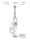
May 29, 1923.
1,456,625
A. T. DAWSON ET AL
YZZZZ.
MACHINE GUN
Filed Jan. 7. 1921 2 Sheets-Sheet 1
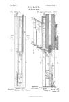
May 29, 1923.
1,456,625
A. T, DAWSON ET AL
MACHINE GUN
Filed Jan. 7. 1921
2 Sheets-Sheet 2
Patented May 29, 1923. 1,456,625
UNITED STATES PATENT OFFICE.
ARTHUR TREVOB DAWSON AND GEORGE THOMAS BUCKHAM, OF WESTMINSTER,
LONDON, ENGLAND, ASSIGNORS TO VICKERS LIMITED, OF WESTMINSTER,
LONDON, ENGLAND.
MACHINE GUN.
Application filed January 7, 1921. Serial No. 435,651.
(GRANTED UNDER THE PROVISIONS OF THE ACT OF MARCH 3, 1921, 41 STAT. L., 1313.)
To all whom it may concern:
Be it known that we, Arthur Trevor Daw-
son and George Thomas Buckham, both sub-
jects of the King of Great Britain, residing
6 at Vickers House, Broadway, Westminster,
in the county of London, England, have in-
vented certain new and useful Improve-
ments in or Relating to Machine Guns (for
which they have made application in Great
10 Britain September 4,1919, Pat. No. 165,859),
of which the following is a specification.
This invention relates to machine guns,
particularly those of the Vickers automatic
18 ty?he present invention consists of a ma-
chine gun in which there are combined and
nsed together the various devices and mech-
anism set forth in the specifications of our
three British Patents Nos. 165,857, 165,858
20 and 141,605, the essential features compris-
ing the device for retaining the firing spring
and the side lever axis pin of the lock in
their assembled position as described in the
first of our said specifications, the stop-piece
25 for the crank and the resilient bush between
the crank-handle roller and the spindle or
spigot of this roller as described in the sec-
ond of our said specifications, and the sear
and tumbler arrangement described in the
30 third of our said specifications.
In order that the said invention may be
clearly understood and readily carried into
effect the same will be described more fully
with reference to the accompanying draw-'
35 ings in which:—
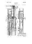
Figure 1 is a vertical longitudinal section
through the mechanism casing of a Vickers
automatic gun provided with the combina-
tion of features in accordance with this in-
40 vention,
Figure 2 is a local side elevation showing
the aforesaid crank-handle roller,
Figure 3 is a plan of Figure 1 with the
mechanism casing cover removed, Figures
45 4 and 5 are, respectively, a sectional side ele-
vation and a rear elevation showing on a
larger scale the lock and the parts carried
thereby.
A is the mechanism casing, A* is the
50 crank, A' is the connecting rod pivoted at
its rear end to the crank and at its forward
end to the socket A0 of the side levers which
are pivoted to the lock (the crank, the con-
necting rod and the side levers forming tog-
gle levers as is well understood), A2 is the 55
crank shaft, A3 is the crank handle, and A4
is the roller with which the tail A3x of this
crank handle co-operates. В is the lock cas-
ing, B' is the firing pin, B2 is the firing
spring and B3 is the side lever axis pin. C 60
is the tumbler for cocking the firing pin, C'
is the sear and C2 is the actuating arm for
the sear.
The aforesaid device for retaining the fir-
ing spring B2 and the side lever axis pin B3 65
in their assembled position comprises a re-
silient member having forwardly extending
arms D, D which are situated a suitable dis-
tance apart so as to fit tightly, by reason of
their resiliency, against the sides of the 70
lock casing. The lower forward parts of
said arms have curved recesses d which fit
in circumferential grooves cut in the axis
pin B3. D* is a bridge-piece connecting the
said arms together at the rear and D' is an 75
actuating member which is riveted or other-
wise connected to the bridge-piece D* in
front thereof and has two limbs one verti-
cal and depending and the other more or
less horizontal and projecting forwards. 80
The latter limb has lateral extensions D2, D2 •
(Figure 5) at its forward end adapted to
engage in recesses in front of projections
Ъ, b on the lock casing. The rear end of the
firing spring bears against the aforesaid ver- 85
tical limb and by the co-operation of the
lateral extensions D2, D2 with the said pro-
jections holds the arms D, D in engagement
with the circumferential grooves in the axis
pin B3. The lower part of the said vertical 90
limb has a dovetail D3 fitted into a corre-
spondingly shaped recess in the lower part
of the lock casing so as to prevent the de-
vice from moving out of position by a bodily
vertical movement during the working of 95
the gun.
To enable the axis B3 and the firing spring
B2 to be removed, the member D' is rocked
against the opposition of the firing spring
to disengage the arms D, D from the circum- 109
ferential grooves in the axis pin and is then
after the withdrawal of the axis pin rocked
by the spring B2 in the reverse direction to
disengage the dovetail D3 from its recess;
the member D' can then be lifted slightly to 105
disengage the lateral extensions D2, D2 from
1,46S,03B
the projections 6, Ъ and the device, is then
moved rearwards thus leaving the firing
spring free to be removed in a rearward di-
rection. To facilitate the manipulation of
5 the member D' the lower part of its verti-
cal limb is knurled and occupies a readily
accessible position at the lower part of the
mechanism casing of the gun; this limb is
also formed with a hole dr, through which
10 projects the tail of the safety sear F. The
construction and arrangement of these parts
is set forth fully in the specification of our
aforesaid British Patent Ko. 165,857.
E is the aforesaid stop-piece and E' is a
15 part on the crank for coming against the
said stop-piece at the end of the movement
of the crank during recoil of the barrel, the
said stop-piece E and the part E' being dis-
posed equally on each side of a vertical plane
20 containing the axis of the barrel. E2 is a
barrel returning spring which is em-
ployed in addition to the usual fusee
spring. The roller A4, with which the
tail A3* of the crank handle A3 co-
^25 operates at the commencement of the
recoil movement of the barrel as is well
understood, has between it and its spindle
or spigot A4x a bush a of fibre or other ma-
terial suitable for absorbing part of the
30 shock. This arrangement of the parts E, E',
and a is set forth fully in the specification
of our aforesaid British Patent No. 165858.
The tumbler C is adapted to co-operate
with a projection B'x on the firing pin B'
35 for cocking the latter and to be moved out
of the path of this projection (when the
cocking operation has been completed) by
a spring Bx which also operates upon the
aforesaid actuating arm C2 of_the sear C'
40 so as to urge the latter into engagement with
its bent on the firing pin. This arrangement
is substantially the same as that described in
the specification of our aforesaid British
Patent No. 141605.
45 What we claim and desire to secure by
Letters Patent of the United States is:—
1. In a machine gun of the barrel recoiling
type, the combination with a part recoiling
with the barrel, a crank pivoted on said
50 part, the lock, and a connecting rod connect-
ing said crank to said lock of a centrally ar-
ranged and rigid stop-piece which said crank
strikes at the end of its movement during
recoil of the barrel, and a device common to
55 the side lever axis pin and the firing spring
for retaining these two parts in their as-
sembled position.
2. In a machine gun of the barrel recoil-
ing type, the combination with a part re-
60 coiling with the barrel, a crank pivoted on
said part, the lock, and a connecting rod
connecting said crank to said lock of a cen-
trally arranged and rigid stop-piece, a mass
of metal on said crank, which mass strikes
65 the stop-piece at the end of the movement
of said crank during recoil of the barrel, and
a device operated upon by said spring to re-
tain said axis pin in its assembled position.
3. In a machine gun of the barrel recoiling
type, the combination with a part recoiling 70
with the barrel, a crank pivoted on said part,
the lock, and a connecting rod connecting
said crank to said lock of a centrally ar-
ranged and rigid stop-piece which said crank
strikes at the end of its movement during '
recoil of the barrel, a device common to the
side lever axis pin and the firing spring for
retaining these two parts in their assembled
position, a cocking tumbler bearing loosely
against part of the firing pin for cocking, a ai;'
spring for moving the tumbler out of the
path of said part after cocking and a seat-
engaging with said firing pin.
4. In a machine gun of the barrel recoil-
ing type, the combination with a part re- 85
coiling with the barrel, a crank pivoted on
said part, the lock, and a connecting rod con-
necting said crank to said lock of a centrally
arranged and rigid stop-piece, a mass of
metal on said crank, which mass strikes the 60
stop-piece at the end of the movement of
said crank during recoil of the barrel, a
device operated upon by said spring to re-
tain said axis pin in its assembled position, a
cocking tumbler bearing loosely against part 95
of the firing pin for cocking, a spring for
moving the tumbler out of the path of said
part after cocking and a sear engaging with
said firing pin, said spring also serving nor-
mally to hold the sear in engagement with 100
said firing pin.
5. In a machine gun of the barrel recoiling;
type, the combination with a part recoiling
with the barrel, a crank pivoted on said part,
the lock, and a connecting rod connecting J
said crank to said lock, a handle connected
to said crank, a roller with which a tail on
said handle co-operates at the commence-
ment of the recoil movement of the barrel, a
spindle on which said roller is mounted, a 1
bush of resilient material interposed between
said roller and said spindle, a centrally ar-
ranged and rigid stop-piece, a mass of metal
on said crank, which mass strikes the stop-
piece at the end of the movement of said
crank during recoil of the barrel, a device
operated upon by said spring to retain said
axis pin in its assembled position, a cocking
tumbler bearing loosely against part of the
firing pin for cocking, a spring for. moving 12
the tumbler out of the path of said part after
cocking and a sear engaging with said firing
pin, said spring also serving normally to
hold the sear in engagement with said firing
pin. 125
In testimony whereof we affix our signa-
tures.
ARTHUR TREVOR DAWSON.
GEORGE THOMAS BUCKHAM.