/


Автор: Irvine K.R.
Теги: information technology coding assembly programming language windows operating system
ISBN: 978-0-13-538165-6
Год: 2020
Похожие



Текст
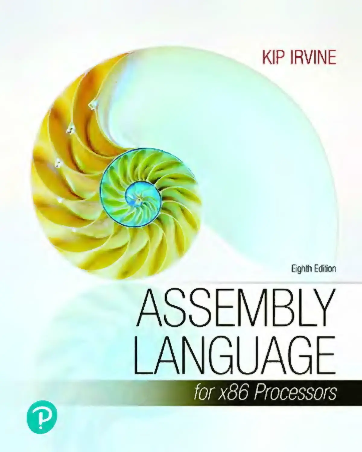
Assembly Language for x86
Processors
Eighth Edition
Kip R. Irvine
Florida International University
School of Computing and Information Sciences
Senior Vice President Courseware Portfolio Management: Marcia J.
Horton
Vice President, Portfolio Management: Engineering, Computer Science &
Global Editions: Julian Partridge
Executive Portfolio Manager: Tracy Johnson
Portfolio Management Assistant: Meghan Jacoby
Product Marketing Manager: Yvonne Vannatta
Field Marketing Manager: Demetrius Hall
Marketing Assistant: Jon Bryant
Managing Content Producer: Scott Disanno
Content Producer: Amanda Brands
Manufacturing Buyer, Higher Ed, Lake Side Communications, Inc. (LSC):
Maura Zaldivar-Garcia
Inventory Manager: Bruce Boundy
Rights and Permissions Manager: Ben Ferrini
Full-Service Project Management: Vanitha Puela, SPi Global
Cover Image: Tetra Images/Alamy Stock Photo
Printer/Binder: LSC Communications, Inc.
IA-32, Pentium, i486, Intel64, Celeron, and Intel 386 are trademarks of
Intel Corporation. Athlon, Phenom, and Opteron are trademarks of
Advanced Micro Devices. TASM and Turbo Debugger are trademarks of
Borland International. Microsoft Assembler (MASM), Windows Vista,
Windows 7, Windows NT, Windows Me, Windows 95, Windows 98,
Windows 2000, Windows XP, MS-Windows, PowerPoint, Win32,
DEBUG, WinDbg, MS-DOS, Visual Studio, Visual C++, and CodeView are
registered trademarks of Microsoft Corporation. Autocad is a trademark
of Autodesk. Java is a trademark of Sun Microsystems. PartitionMagic is a
trademark of Symantec. All other trademarks or product names are the
property of their respective owners.
Copyright © 2020, 2015, 2011, 2007, 2003 by Pearson Inc. 221 River
Street, Hoboken, NJ 07030. All rights reserved. Manufactured in the
United States of America. This publication is protected by Copyright and
permissions should be obtained from the publisher prior to any
prohibited reproduction, storage in a retrieval system, or transmission in
any form or by any means, electronic, mechanical, photocopying,
recording, or likewise. To obtain permission(s) to use materials from this
work, please visit http://www.pearsoned.com/permissions/.
Previously published as Assembly Language for Intel-Based Computers.
The author and publisher of this book have used their best efforts in
preparing this book. These efforts include the development, research, and
testing of the theories and programs to determine their effectiveness. The
author and publisher make no warranty of any kind, expressed or
implied, with regard to these programs or the documentation contained
in this book. The author and publisher shall not be liable in any event for
incidental or consequential damages in connection with, or arising out of,
the furnishing, performance, or use of these programs.
Microsoft and/or its respective suppliers make no representations about
the suitability of the information contained in the documents and related
graphics published as part of the services for any purpose. All such
documents and related graphics are provided “as is” without warranty of
any kind. Microsoft and/or its respective suppliers hereby disclaim all
warranties and conditions with regard to this information, including all
warranties and conditions of merchantability, whether express, implied or
statutory, fitness for a particular purpose, title and non-infringement. In
no event shall microsoft and/or its respective suppliers be liable for any
special, indirect or consequential damages or any damages whatsoever
resulting from loss of use, data or profits, whether in an action of
contract, negligence or other tortious action, arising out of or in
connection with the use or performance of information available from the
services. The documents and related graphics contained herein could
include technical inaccuracies or typographical errors. changes are
periodically added to the information herein. Microsoft and/or its
respective suppliers may make improvements and/or changes in the
product(s) and/or the program(s) described herein at any time. Partial
screen shots may be viewed in full within the software version specified.
Microsoft® and Windows® are registered trademarks of the microsoft
corporation in the usa and other countries. screen shots and icons
reprinted with permission from the microsoft corporation. This book is
not sponsored or endorsed by or affiliated with the microsoft corporation.
1 19
ISBN-13: 978-0-13-538165-6
ISBN-10:
0-13-538165-7
Preface
Assembly Language for x86 Processors, Eighth Edition, teaches assembly
language programming and architecture for x86 and Intel64 processors. It
is an appropriate text for the following types of college courses:
Assembly Language Programming
Fundamentals of Computer Systems
Fundamentals of Computer Architecture
Students use Intel or AMD processors and program with Microsoft
Macro Assembler (MASM), running on recent versions of Microsoft
Windows. Although this book was originally designed as a programming
textbook for college students, it serves as an effective supplement to
computer architecture courses. As a testament to its popularity, previous
editions have been translated into numerous languages.
Emphasis of Topics
This edition includes topics that lead naturally into subsequent courses in
computer architecture, operating systems, and compiler writing:
Virtual machine concept
Instruction set architecture
Elementary Boolean operations
Instruction execution cycle
Memory access and handshaking
Interrupts and polling
Hardware-based I/O
Floating-point binary representation
Other topics relate specially to x86 and Intel64 architecture:
Protected memory and paging
Memory segmentation in real-address mode
16-Bit interrupt handling
MS-DOS and BIOS system calls (interrupts)
Floating-point unit architecture and programming
Instruction encoding
Certain examples presented in the book lend themselves to courses that
occur later in a computer science curriculum:
Searching and sorting algorithms
High-level language structures
Finite-state machines
Code optimization examples
What’s New in the Eighth Edition
This edition represents this book’s transition into the world of interactive
electronic textbooks. We’re very excited about this innovative concept,
because for the first time readers will be able to experiment and interact
with review questions, code animations, tutorial videos, and multipleinput exercises.
All section reviews in the chapters have been rewritten as interactive
questions, giving the reader immediate feedback on their answers.
New questions were added, others removed, and many revised.
Code animations allow the reader to step through program code and
view both variable values and comments about the code. Readers no
longer have to visually jump back and forth between program code
and text explanations on the next page.
Links to timely tutorial videos have been inserted in the text, so
readers can receive tutoring on topics as they encounter them in the
text. Previously, readers would need to purchase a separate
subscription to gain access to the entire set of videos, presented as a
list. In this edition, videos are free.
Multiple-input exercises allow readers to browse a program listing
and insert variable values into boxes next to the code. They receive
immediate colorized feedback, giving them the opportunity to
experiment until all input values are correct.
Hypertexted definitions of key terms are placed throughout the text,
connected to an online glossary.
In short, we have taken the successful content of this book (refined
through many editions) and brought it into the interactive electronic
textbook world.
This book is still focused on its primary goal, to teach students how to
write and debug programs at the machine level. It will never replace a
complete book on computer architecture, but it does give students the
first-hand experience of writing software in an environment that teaches
them how a computer works. Our premise is that students retain
knowledge better when theory is combined with experience. In an
engineering course, students construct prototypes; in a computer
architecture course, students should write machine-level programs. In
both cases, they have a memorable experience that gives them confidence
to work in any OS/machine-oriented environment.
Protected mode programming is entirely the focus of chapters 1 through
13 . As such, students can create 32-bit and 64-bit programs that run
under the most recent versions of Microsoft Windows. The remaining
three legacy chapters cover 16-bit programming. These chapters cover
BIOS programming, MS-DOS services, keyboard and mouse input, dist
storage fundamentals, video programming, and graphics.
Subroutine Libraries
We supply three versions of the subroutine library that students use for
basic input/output, simulations, timing, and other useful tasks. The
Irvine32 and Irvine64 libraries run in protected mode. The 16-bit version
(Irvine16.lib) runs in real-address mode and is used only by Chapter 14
through Chapter 16 . Full source code for the libraries is supplied on the
companion website. The link libraries are available only for convenience,
not to prevent students from learning how to program input–output
themselves. Students are encouraged to create their own libraries.
Included Software and Examples
All the example programs were tested with Microsoft Macro Assembler,
running in a recent version of Microsoft Visual Studio. In addition, batch
files are supplied that permit students to assemble and run applications
from the Windows command prompt. Information Updates and
corrections to this book may be found at the Companion website,
including additional programming projects for instructors to assign at the
ends of chapters.
Overall Goals
The following goals of this book are designed to broaden the student’s
interest and knowledge in topics related to assembly language:
Intel and AMD processor architecture and programming
Real-address mode and protected mode programming
Assembly language directives, macros, operators, and program
structure
Programming methodology, showing how to use assembly language
to create system-level software tools and application programs
Computer hardware manipulation
Interaction between assembly language programs, the operating
system, and other application programs
One of our goals is to help students approach programming problems
with a machine-level mind set. It is important to think of the CPU as an
interactive tool, and to learn to monitor its operation as directly as
possible. A debugger is a programmer’s best friend, not only for catching
errors, but as an educational tool that teaches about the CPU and
operating system. We encourage students to look beneath the surface of
high-level languages and to realize that most programming languages are
designed to be portable and, therefore, independent of their host
machines. In addition to the short examples, this book contains hundreds
of ready-to-run programs that demonstrate instructions or ideas as they
are presented in the text. Reference materials, such as guides to MS-DOS
interrupts and instruction mnemonics, are available at the end of the
book.
Required Background
The reader should already be able to program confidently in at least one
high-level programming language such as Python, Java, C, or C++. One
chapter covers C++ interfacing, so it is very helpful to have a compiler on
hand. I have used this book in the classroom with majors in both
computer science and management information systems, and it has been
used elsewhere in engineering courses.
Features
Complete Program Listings
The author’s website contains supplemental learning materials, study
guides, and all the source code from the book’s examples. Two link
libraries (32-bit and 64-bit) are supplied with the book, containing more
than 40 procedures that simplify user input–output, numeric processing,
disk and file handling, and string handling. In the beginning stages of the
course, students can use this library to enhance their programs. Later,
they can create their own procedures and add them to the library.
Programming Logic
Two chapters emphasize Boolean logic and bit-level manipulation. A
conscious attempt is made to relate high-level programming logic to the
low-level details of the machine. This approach helps students to create
more efficient implementations and to better understand how compilers
generate object code.
Hardware and Operating System Concepts
The first two chapters introduce basic hardware and data representation
concepts, including binary numbers, CPU architecture, status flags, and
memory mapping. A survey of the computer’s hardware and a historical
perspective of the Intel processor family helps students to better
understand their target computer system.
Structured Programming Approach
Beginning with Chapter 5 , procedures and functional decomposition are
emphasized. Students are given more complex programming exercises,
requiring them to focus on design before starting to write code.
Java Bytecodes and the Java Virtual
Machine
In Chapters 8 and 9 , the author explains the basic operation of Java
bytecodes with short illustrative examples. Numerous short examples are
shown in disassembled bytecode format, followed by detailed step-bystep explanations.
Creating Link Libraries
Students are free to add their own procedures to the book’s link library
and create new libraries. They learn to use a toolbox approach to
programming and to write code that is useful in more than one program.
Macros and Structures
A chapter is devoted to creating structures, unions, and macros, which
are essential in assembly language and systems programming.
Conditional macros with advanced operators serve to make the macros
more professional.
Interfacing to High-Level Languages
A chapter is devoted to interfacing assembly language to C and C++. This
is an important job skill for students who are likely to find jobs
programming in high-level languages. They can learn to optimize their
code and see examples of how C++ compilers optimize code.
Instructional Aids
All the program listings are available on the Web. Instructors are
provided a test bank, answers to review questions, solutions to
programming exercises, and a Microsoft PowerPoint slide presentation
for each chapter. More details can be found on Page xxvi .
VideoNotes
VideoNotes are Pearson’s visual tool designed to teach students key
programming concepts and techniques. These short step-by-step videos
demonstrate basic assembly language concepts. VideoNotes allow for
self-paced instruction with easy navigation including the ability to select,
play, rewind, fast-forward, and stop within each VideoNote exercise.
Details below.
Chapter Descriptions
Chapters 1 to 8 contain core concepts of assembly language and
should be covered in sequence. After that, you have a fair amount of
freedom. The following chapter dependency graph shows how later
chapters depend on knowledge gained from other chapters.
1. Basic Concepts: Applications of assembly language, basic
concepts, machine language, and data representation.
2. x86 Processor Architecture: Basic microcomputer design,
instruction execution cycle, x86 processor architecture, Intel64
architecture, x86 memory management, components of a
microcomputer, and the input–output system.
3. Assembly Language Fundamentals: Introduction to assembly
language, linking and debugging, and defining constants and
variables.
4. Data Transfers, Addressing, and Arithmetic: Simple data
transfer and arithmetic instructions, assemble-link-execute cycle,
operators, directives, expressions, JMP and LOOP instructions,
and indirect addressing.
5. Procedures: Linking to an external library, description of the
book’s link library, stack operations, defining and using
procedures, flowcharts, and top-down structured design.
6. Conditional Processing: Boolean and comparison instructions,
conditional jumps and loops, high-level logic structures, and
finite-state machines.
7. Integer Arithmetic: Shift and rotate instructions with useful
applications, multiplication and division, extended addition and
subtraction, and ASCII and packed decimal arithmetic.
8. Advanced Procedures: Stack parameters, local variables,
advanced PROC and INVOKE directives, and recursion.
9. Strings and Arrays: String primitives, manipulating arrays of
characters and integers, two-dimensional arrays, sorting, and
searching.
10. Structures and Macros: Structures, macros, conditional assembly
directives, and defining repeat blocks.
11. MS-Windows Programming: Protected mode memory
management concepts, using the Microsoft-Windows API to
display text and colors, and dynamic memory allocation.
12. Floating-Point Processing and Instruction Encoding: Floatingpoint binary representation and floating-point arithmetic.
Learning to program the 32-bit floating-point unit. Understanding
the encoding of 32-bit machine instructions.
13. High-Level Language Interface: Parameter passing conventions,
inline assembly code, and linking assembly language modules to
C and C++ programs.
14. 16-Bit MS-DOS Programming: Memory organization, interrupts,
function calls, and standard MS-DOS file I/O services.
15. Disk Fundamentals: Disk storage systems, sectors, clusters,
directories, file allocation tables, handling MS-DOS error codes,
and drive and directory manipulation.
16. BIOS-Level Programming: Keyboard input, video text, graphics,
and mouse programming.
Appendix A: MASM Reference
Appendix B: The x86 Instruction Set
Appendix C: BIOS and MS-DOS Interrupts
Appendix D: Answers to Review Questions (Chapters 14 –
16 )
Instructor and Student Resources
Instructor Resource Materials
The following protected instructor material is available on pearson.com
For username and password information, please contact your Pearson
Representative.
Lecture PowerPoint Slides
Instructor Solutions Manual
Student Resource Materials
The following useful materials are located at www.asmirvine.com:
Getting Started, a comprehensive step-by-step tutorial that helps
students customize Visual Studio for assembly language
programming.
Corrections to errors found in the book.
Supplementary articles on assembly language programming topics.
Required support files for assembling and linking your programs,
complete source code for all example programs in the book, and
complete source code for the author’s supplementary library.
Assembly Language Workbook, an interactive workbook covering
number conversions, addressing modes, register usage, debug
programming, and floating-point binary numbers.
Debugging Tools: Tutorials on using the Microsoft Visual Studio
debugger.
Acknowledgments
Many thanks are due to Tracy Johnson, Portfolio Manager for Computer
Science at Pearson Education, who has provided friendly, helpful
guidance for many years. Vanitha Puela of SPi Global did an excellent job
on the book production, along with Amanda Brands as the Content
Producer at Pearson.
Previous Editions
I offer my special thanks to the following individuals who were most
helpful during the development of earlier editions of this book:
William Barrett, San Jose State University
Scott Blackledge
James Brink, Pacific Lutheran University
Gerald Cahill, Antelope Valley College
John Taylor
About the Author
Kip Irvine has written five computer programming textbooks, for Intel
Assembly Language, C++. Visual Basic (beginning and advanced), and
COBOL. His book Assembly Language for Intel-Based Computers has been
translated into six languages. His first college degrees (B.M., M.M., and
doctorate) were in Music Composition, at University of Hawaii and
University of Miami. He began programming computers for music
synthesis around 1982 and taught programming at Miami-Dade
Community College for 17 years. He earned an M.S. degree in Computer
Science from the University of Miami, and taught computer programming
in the School of Computing and Information Sciences at Florida
International University for 18 years.
Contents
Preface
1 Basic Concepts
1.1.1 Questions You Might Ask
1.1 Welcome to Assembly Language
1.1.2 Assembly Language Applications
1.1.3 Section Review
1.2 Virtual Machine Concept
1.2.1 Section Review
1.3.1 Binary Integers
1.3 Data Representation
1.3.2 Binary Addition
1.3.3 Integer Storage Sizes
1.3.4 Hexadecimal Integers
1.3.5 Hexadecimal Addition
1.3.6 Signed Binary Integers
1.3.7 Binary Subtraction
1.3.8 Character Storage
1.3.9 Binary-Coded Decimal (BCD) Numbers
1.3.10 Section Review
1.4 Boolean Expressions
1.4.1 Truth Tables for Boolean Functions
1.4.2 Section Review
1.5 Chapter Summary
1.6 Key Terms
1.7 Review Questions and Exercises
1.7.1 Short Answer
1.7.2 Algorithm Workbench
2 x86 Processor Architecture
2.1 General Concepts
2.1.1 Basic Microcomputer Design
2.1.2 Instruction Execution Cycle
2.1.3 Reading from Memory
2.1.4 Loading and Executing a Program
2.1.5 Section Review
2.2 32-Bit x86 Processors
2.2.1 Modes of Operation
2.2.2 Basic Execution Environment
2.2.3 x86 Memory Management
2.2.4 Section Review
2.3 64-Bit x86-64 Processors
2.3.1 64-Bit Operation Modes
2.3.2 Basic 64-Bit Execution Environment
2.3.3 Section Review
2.4 Components of a Typical x86 Computer
2.4.1 Motherboard
2.4.2 Memory
2.4.3 Section Review
2.5 Input-Output System
2.5.1 Levels of I/O Access
2.5.2 Section Review
2.6 Chapter Summary
2.7 Key Terms
2.8 Review Questions
3 Assembly Language Fundamentals
3.1 Basic Language Elements
3.1.1 First Assembly Language Program
3.1.2 Integer Literals
3.1.3 Constant Integer Expressions
3.1.4 Real Number Literals
3.1.5 Character Literals
3.1.6 String Literals
3.1.7 Reserved Words
3.1.8 Identifiers
3.1.9 Directives
3.1.10 Instructions
3.1.11 Section Review
3.2 Example: Adding and Subtracting Integers
3.2.1 The AddTwo Program
3.2.2 Running and Debugging the AddTwo Program
3.2.3 Program Template
3.2.4 Section Review
3.3 Assembling, Linking, and Running Programs
3.3.1 The Assemble-Link-Execute Cycle
3.3.2 Listing File
3.3.3 Section Review
3.4 Defining Data
3.4.1 Intrinsic Data Types
3.4.2 Data Definition Statement
3.4.3 Adding a Variable to the AddTwo Program
3.4.4 Defining BYTE and SBYTE Data
3.4.5 Defining WORD and SWORD Data
3.4.6 Defining DWORD and SDWORD Data
3.4.7 Defining QWORD Data
3.4.8 Defining Packed BCD (TBYTE) Data
3.4.9 Defining Floating-Point Types
3.4.10 A Program That Adds Variables
3.4.11 Little-Endian Order
3.4.12 Declaring Uninitialized Data
3.4.13 Section Review
3.5 Symbolic Constants
3.5.1 Equal-Sign Directive
3.5.2 Calculating the Sizes of Arrays and Strings
3.5.3 EQU Directive
3.5.4 TEXTEQU Directive
3.5.5 Section Review
3.6 Introducing 64-Bit Programming
3.7 Chapter Summary
3.8.1 Terms
3.8 Key Terms
3.8.2 Instructions, Operators, and Directives
3.9 Review Questions and Exercises
3.9.1 Short Answer
3.9.2 Algorithm Workbench
3.10 Programming Exercises
4 Data Transfers, Addressing, and Arithmetic
4.1 Data Transfer Instructions
4.1.1 Introduction
4.1.2 Operand Types
4.1.3 Direct Memory Operands
4.1.4 MOV Instruction
4.1.5 Zero/Sign Extension of Integers
4.1.6 LAHF and SAHF Instructions
4.1.7 XCHG Instruction
4.1.8 Direct-Offset Operands
4.1.9 Examples of Moving Data
4.1.10 Section Review
4.2 Addition and Subtraction
4.2.1 INC and DEC Instructions
4.2.2 ADD Instruction
4.2.3 SUB Instruction
4.2.4 NEG Instruction
4.2.5 Implementing Arithmetic Expressions
4.2.6 Flags Affected by Addition and Subtraction
4.2.7 Example Program (AddSubTest)
4.2.8 Section Review
4.3 Data-Related Operators and Directives
4.3.1 OFFSET Operator
4.3.2 ALIGN Directive
4.3.3 PTR Operator
4.3.4 TYPE Operator
4.3.5 LENGTHOF Operator
4.3.6 SIZEOF Operator
4.3.7 LABEL Directive
4.3.8 Section Review
4.4 Indirect Addressing
4.4.1 Indirect Operands
4.4.2 Arrays
4.4.3 Indexed Operands
4.4.4 Pointers
4.4.5 Section Review
4.5 JMP and LOOP Instructions
4.5.1 JMP Instruction
4.5.2 LOOP Instruction
4.5.3 Displaying an Array in the Visual Studio Debugger
4.5.4 Summing an Integer Array
4.5.5 Copying a String
4.5.6 Section Review
4.6 64-Bit Programming
4.6.1 MOV Instruction
4.6.2 64-Bit Version of SumArray
4.6.3 Addition and Subtraction
4.6.4 Section Review
4.7 Chapter Summary
4.8.1 Terms
4.8 Key Terms
4.8.2 Instructions, Operators, and Directives
4.9 Review Questions and Exercises
4.9.1 Short Answer
4.9.2 Algorithm Workbench
4.10 Programming Exercises
5 Procedures
5.1 Stack Operations
5.1.1 Runtime Stack (32-Bit Mode)
5.1.2 PUSH and POP Instructions
5.1.3 Section Review
5.2 Defining and Using Procedures
5.2.1 PROC Directive
5.2.2 CALL and RET Instructions
5.2.3 Nested Procedure Calls
5.2.4 Passing Register Arguments to Procedures
5.2.5 Example: Summing an Integer Array
5.2.6 Saving and Restoring Registers
5.2.7 Section Review
5.3.1 Background Information
5.3 Linking to an External Library
5.3.2 Section Review
5.4 The Irvine32 Library
5.4.1 Motivation for Creating the Library
5.4.2 The Win32 Console Window
5.4.3 Individual Procedure Descriptions
5.4.4 Library Test Programs
5.4.5 Section Review
5.5 64-Bit Assembly Programming
5.5.1 The Irvine64 Library
5.5.2 Calling 64-Bit Subroutines
5.5.3 The x64 Calling Convention
5.5.4 Sample Program that Calls a Procedure
5.5.5 Section Review
5.6 Chapter Summary
5.7.1 Terms
5.7 Key Terms
5.7.2 Instructions, Operators, and Directives
5.8 Review Questions and Exercises
5.8.1 Short Answer
5.8.2 Algorithm Workbench
5.9 Programming Exercises
6 Conditional Processing
6.1 Boolean and Comparison Instructions
6.1.1 The CPU Status Flags
6.1.2 AND Instruction
6.1.3 OR Instruction
6.1.4 Bit-Mapped Sets
6.1.5 XOR Instruction
6.1.6 NOT Instruction
6.1.7 TEST Instruction
6.1.8 CMP Instruction
6.1.9 Setting and Clearing Individual CPU Flags
6.1.10 Boolean Instructions in 64-Bit Mode
6.1.11 Section Review
6.2 Conditional Jumps
6.2.1 Conditional Structures
6.2.2 Jcond Instruction
6.2.3 Types of Conditional Jump Instructions
6.2.4 Conditional Jump Applications
6.2.5 Section Review
6.3 Conditional Loop Instructions
6.3.1 LOOPZ and LOOPE Instructions
6.3.2 LOOPNZ and LOOPNE Instructions
6.3.3 Section Review
6.4 Conditional Structures
6.4.1 Block-Structured IF Statements
6.4.2 Compound Expressions
6.4.3 WHILE Loops
6.4.4 Table-Driven Selection
6.4.5 Section Review
6.5 Application: Finite-State Machines
6.5.1 Validating an Input String
6.5.2 Validating a Signed Integer
6.5.3 Section Review
6.6 Conditional Control Flow Directives (Optional topic)
6.6.1 Creating IF Statements
6.6.2 Signed and Unsigned Comparisons
6.6.3 Compound Expressions
6.6.4 Creating Loops with .REPEAT and .WHILE
6.7 Chapter Summary
6.8.1 Terms
6.8 Key Terms
6.8.2 Instructions, Operators, and Directives
6.9 Review Questions and Exercises
6.9.1 Short Answer
6.9.2 Algorithm Workbench
6.10 Programming Exercises
6.10.1 Suggestions for Testing Your Code
6.10.2 Exercise Descriptions
7 Integer Arithmetic
7.1 Shift and Rotate Instructions
7.1.1 Logical Shifts and Arithmetic Shifts
7.1.2 SHL Instruction
7.1.3 SHR Instruction
7.1.4 SAL and SAR Instructions
7.1.5 ROL Instruction
7.1.6 ROR Instruction
7.1.7 RCL and RCR Instructions
7.1.8 Signed Overflow
7.1.9 SHLD/SHRD Instructions
7.1.10 Section Review
7.2 Shift and Rotate Applications
7.2.1 Shifting Multiple Doublewords
7.2.2 Multiplication by Shifting Bits
7.2.3 Displaying Binary Bits
7.2.4 Extracting File Date Fields
7.2.5 Section Review
7.3 Multiplication and Division Instructions
7.3.1 Unsigned Integer Multiplication (MUL)
7.3.2 Signed Integer Multiplication (IMUL)
7.3.3 Measuring Program Execution Times
7.3.4 Unsigned Integer Division (DIV)
7.3.5 Signed Integer Division (IDIV)
7.3.6 Implementing Arithmetic Expressions
7.3.7 Section Review
7.4 Extended Addition and Subtraction
7.4.1 ADC Instruction
7.4.2 Extended Addition Example
7.4.3 SBB Instruction
7.4.4 Section Review
7.5 ASCII and Unpacked Decimal Arithmetic
7.5.1 AAA Instruction
7.5.2 AAS Instruction
7.5.3 AAM Instruction
7.5.4 AAD Instruction
7.5.5 Section Review
7.6 Packed Decimal Arithmetic
7.6.1 DAA Instruction
7.6.2 DAS Instruction
7.6.3 Section Review
7.7 Chapter Summary
7.8.1 Terms
7.8 Key Terms
7.8.2 Instructions, Operators, and Directives
7.9 Review Questions and Exercises
7.9.1 Short Answer
7.9.2 Algorithm Workbench
7.10 Programming Exercises
8 Advanced Procedures
8.1 Introduction
8.2 Stack Frames
8.2.1 Stack Parameters
8.2.2 Disadvantages of Register Parameters
8.2.3 Accessing Stack Parameters
8.2.4 32-Bit Calling Conventions
8.2.5 Local Variables
8.2.6 Reference Parameters
8.2.7 LEA Instruction
8.2.8 ENTER and LEAVE Instructions
8.2.9 LOCAL Directive
8.2.10 The Microsoft x64 Calling Convention
8.2.11 Section Review
8.3 Recursion
8.3.1 Recursively Calculating a Sum
8.3.2 Calculating a Factorial
8.3.3 Section Review
8.4 INVOKE, ADDR, PROC, and PROTO
8.4.1 INVOKE Directive
8.4.2 ADDR Operator
8.4.3 PROC Directive
8.4.4 PROTO Directive
8.4.5 Parameter Classifications
8.4.6 Example: Exchanging Two Integers
8.4.7 Debugging Tips
8.4.8 WriteStackFrame Procedure
8.4.9 Section Review
8.5 Creating Multimodule Programs
8.5.1 Hiding and Exporting Procedure Names
8.5.2 Calling External Procedures
8.5.3 Using Variables and Symbols across Module
Boundaries
8.5.4 Example: ArraySum Program
8.5.5 Creating the Modules Using Extern
8.5.6 Creating the Modules Using INVOKE and PROTO
8.5.7 Section Review
8.6 Advanced Use of Parameters (Optional Topic)
8.6.1 Stack Affected by the USES Operator
8.6.2 Passing 8-Bit and 16-Bit Arguments on the Stack
8.6.3 Passing 64-Bit Arguments
8.6.4 Non-Doubleword Local Variables
8.7 Java Bytecodes (Optional Topic)
8.7.1 Java Virtual Machine
8.7.2 Instruction Set
8.7.3 Java Disassembly Examples
8.7.4 Example: Conditional Branch
8.8 Chapter Summary
8.9.1 Terms
8.9 Key Terms
8.9.2 Instructions, Operators, and Directives
8.10 Review Questions and Exercises
8.10.1 Short Answer
8.10.2 Algorithm Workbench
8.11 Programming Exercises
9.1 Introduction
9 Strings and Arrays
9.2 String Primitive Instructions
9.2.1 MOVSB, MOVSW, and MOVSD
9.2.2 CMPSB, CMPSW, and CMPSD
9.2.3 SCASB, SCASW, and SCASD
9.2.4 STOSB, STOSW, and STOSD
9.2.5 LODSB, LODSW, and LODSD
9.2.6 Section Review
9.3 Selected String Procedures
9.3.1 Str_compare Procedure
9.3.2 Str_length Procedure
9.3.3 Str_copy Procedure
9.3.4 Str_trim Procedure
9.3.5 Str_ucase Procedure
9.3.6 String Library Demo Program
9.3.7 String Procedures in the Irvine64 Library
9.3.8 Section Review
9.4 Two-Dimensional Arrays
9.4.1 Ordering of Rows and Columns
9.4.2 Base-Index Operands
9.4.3 Base-Index-Displacement Operands
9.4.4 Base-Index Operands in 64-Bit Mode
9.4.5 Section Review
9.5 Searching and Sorting Integer Arrays
9.5.1 Bubble Sort
9.5.2 Binary Search
9.5.3 Section Review
9.6 Java Bytecodes: String Processing (Optional Topic)
9.7 Chapter Summary
9.8 Key Terms and Instructions
9.9 Review Questions and Exercises
9.9.1 Short Answer
9.9.2 Algorithm Workbench
9.10 Programming Exercises
10 Structures and Macros
10.1 Structures
10.1.1 Defining Structures
10.1.2 Declaring Structure Objects
10.1.3 Referencing Structure Objects
10.1.4 Example: Displaying the System Time
10.1.5 Structures Containing Structures
10.1.6 Example: Drunkard’s Walk
10.2 Macros
10.1.7 Declaring and Using Unions
10.1.8 Section Review
10.2.1 Overview
10.2.2 Defining Macros
10.2.3 Invoking Macros
10.2.4 Additional Macro Features
10.2.5 Using Our Macro Library (32-Bit Mode Only)
10.2.6 Example Program: Wrappers
10.2.7 Section Review
10.3 Conditional-Assembly Directives
10.3.1 Checking for Missing Arguments
10.3.2 Default Argument Initializers
10.3.3 Boolean Expressions
10.3.4 IF, ELSE, and ENDIF Directives
10.3.5 The IFIDN and IFIDNI Directives
10.3.6 Example: Summing a Matrix Row
10.3.7 Special Operators
10.3.8 Macro Functions
10.3.9 Section Review
10.4.1 WHILE Directive
10.4 Defining Repeat Blocks
10.4.2 REPEAT Directive
10.4.3 FOR Directive
10.4.4 FORC Directive
10.4.5 Example: Linked List
10.4.6 Section Review
10.5 Chapter Summary
10.6.1 Terms
10.6 Key Terms
10.6.2 Operators and Directives
10.7 Review Questions and Exercises
10.7.1 Short Answer
10.7.2 Algorithm Workbench
10.8 Programming Exercises
11 MS-Windows Programming
11.1.1 Background Information
11.1 Win32 Console Programming
11.1.2 Win32 Console Functions
11.1.3 Displaying a Message Box
11.1.4 Console Input
11.1.5 Console Output
11.1.6 Reading and Writing Files
11.1.7 File I/O in the Irvine32 Library
11.1.8 Testing the File I/O Procedures
11.1.9 Console Window Manipulation
11.1.10 Controlling the Cursor
11.1.11 Controlling the Text Color
11.1.12 Time and Date Functions
11.1.13 Using the 64-Bit Windows API
11.1.14 Section Review
11.2 Writing a Graphical Windows Application
11.2.1 Necessary Structures
11.2.2 The MessageBox Function
11.2.3 The WinMain Procedure
11.2.4 The WinProc Procedure
11.2.5 The ErrorHandler Procedure
11.2.6 Program Listing
11.2.7 Section Review
11.3 Dynamic Memory Allocation
11.3.1 HeapTest Programs
11.3.2 Section Review
11.4 32-Bit x86 Memory Management
11.4.1 Linear Addresses
11.4.2 Page Translation
11.4.3 Section Review
11.5 Chapter Summary
11.6 Key Terms
11.7 Review Questions and Exercises
11.7.1 Short Answer
11.7.2 Algorithm Workbench
11.8 Programming Exercises
12 Floating-Point Processing and Instruction Encoding
12.1 Floating-Point Binary Representation
12.1.1 IEEE Binary Floating-Point Representation
12.1.2 The Exponent
12.1.3 Normalized Binary Floating-Point Numbers
12.1.4 Creating the IEEE Representation
12.1.5 Converting Decimal Fractions to Binary Reals
12.1.6 Section Review
12.2 Floating-Point Unit
12.2.1 FPU Register Stack
12.2.2 Rounding
12.2.3 Floating-Point Exceptions
12.2.4 Floating-Point Instruction Set
12.2.5 Arithmetic Instructions
12.2.6 Comparing Floating-Point Values
12.2.7 Reading and Writing Floating-Point Values
12.2.8 Exception Synchronization
12.2.9 Code Examples
12.2.10 Mixed-Mode Arithmetic
12.2.11 Masking and Unmasking Exceptions
12.2.12 Section Review
12.3.1 Instruction Format
12.3 x86 Instruction Encoding
12.3.2 Single-Byte Instructions
12.3.3 Move Immediate to Register
12.3.4 Register-Mode Instructions
12.3.5 Processor Operand-Size Prefix
12.3.6 Memory-Mode Instructions
12.3.7 Section Review
12.4 Chapter Summary
12.5 Key Terms
12.6 Review Questions and Exercises
12.6.1 Short Answer
12.6.2 Algorithm Workbench
12.7 Programming Exercises
13 High-Level Language Interface
13.1 Introduction
13.1.1 General Conventions
13.1.2 .MODEL Directive
13.1.3 Examining Compiler-Generated Code
13.1.4 Section Review
13.2 Inline Assembly Code
13.2.1 __asm Directive in Visual C++
13.2.2 File Encryption Example
13.2.3 Section Review
13.3 Linking 32-Bit Assembly Language Code to C/C++
13.3.1 IndexOf Example
13.3.2 Calling C and C++ Functions
13.3.3 Multiplication Table Example
13.3.4 Section Review
13.4 Chapter Summary
13.5 Key Terms
13.6 Review Questions
13.7 Programming Exercises
14 16-Bit MS-DOS Programming 622
14.1 MS-DOS and the IBM-PC
14.1.1 Memory Organization
14.1.2 Redirecting Input-Output
14.1.3 Software Interrupts
14.1.4 INT Instruction
14.1.5 Coding for 16-Bit Programs
14.1.6 Section Review
14.2 MS-DOS Function Calls (INT 21h)
14.2.1 Selected Output Functions
14.2.2 Hello World Program Example
14.2.3 Selected Input Functions
14.2.4 Date/Time Functions
14.2.5 Section Review
14.3.1 Create or Open File (716Ch)
14.3 Standard MS-DOS File I/O Services
14.3.2 Close File Handle (3Eh)
14.3.3 Move File Pointer (42h)
14.3.4 Get File Creation Date and Time
14.3.5 Selected Library Procedures
14.3.6 Example: Read and Copy a Text File
14.3.7 Reading the MS-DOS Command Tail
14.3.8 Example: Creating a Binary File
14.3.9 Section Review
14.4 Chapter Summary
14.5 Programming Exercises
15 Disk Fundamentals
15.1 Disk Storage Systems
15.1.1 Tracks, Cylinders, and Sectors
15.1.2 Disk Partitions (Volumes)
15.1.3 Section Review
15.2.1 FAT12
15.2 File Systems
15.2.2 FAT16
15.2.3 FAT32
15.2.4 NTFS
15.2.5 Primary Disk Areas
15.2.6 Section Review
15.3 Disk Directory
15.3.1 MS-DOS Directory Structure
15.3.2 Long Filenames in MS-Windows
15.3.3 File Allocation Table (FAT)
15.3.4 Section Review
15.4 Reading and Writing Disk Sectors
15.4.1 Sector Display Program
15.4.2 Section Review
15.5 System-Level File Functions
15.5.1 Get Disk Free Space (7303h)
15.5.2 Create Subdirectory (39h)
15.5.3 Remove Subdirectory (3Ah)
15.5.4 Set Current Directory (3Bh)
15.5.5 Get Current Directory (47h)
15.5.6 Get and Set File Attributes (7143h)
15.5.7 Section Review
15.6 Chapter Summary
15.7 Programming Exercises
15.8 Key Terms
16 BIOS-Level Programming
16.1 Introduction
16.1.1 BIOS Data Area
16.2 Keyboard Input with INT 16h
16.2.1 How the Keyboard Works
16.2.2 INT 16h Functions
16.2.3 Section Review
16.3 Video Programming with INT 10h
16.3.1 Basic Background
16.3.2 Controlling the Color
16.3.3 INT 10h Video Functions
16.3.4 Library Procedure Examples
16.3.5 Section Review
16.4 Drawing Graphics Using INT 10h
16.4.1 INT 10h Pixel-Related Functions
16.4.2 DrawLine Program
16.4.3 Cartesian Coordinates Program
16.4.4 Converting Cartesian Coordinates to Screen
Coordinates
16.4.5 Section Review
16.5 Memory-Mapped Graphics
16.5.1 Mode 13h: 320 * 200, 256 Colors
16.5.2 Memory-Mapped Graphics Program
16.5.3 Section Review
16.6 Mouse Programming
16.6.1 Mouse INT 33h Functions
16.6.2 Mouse Tracking Program
16.6.3 Section Review
16.7 Chapter Summary
16.8 Programming Exercises
A MASM Reference
B The x86 Instruction Set
C BIOS and MS-DOS Interrupts
D Answers to Review Questions (Chapters 14–16)
Glossary
ASCII Character Reference Charts
Supplemental Materials
Chapter 1
Basic Concepts
Chapter Outline
1.1
1.2
Welcome to Assembly Language
1.1.1
Questions You Might Ask
1.1.2
Assembly Language Applications
1.1.3
Section Review
Virtual Machine Concept
1.2.1
1.3
Section Review
Data Representation
1.3.1
Binary Integers
1.3.2
Binary Addition
1.3.3
Integer Storage Sizes
1.3.4
Hexadecimal Integers
1.3.5
Hexadecimal Addition
1.3.6
Signed Binary Integers
1.3.7
Binary Subtraction
1.3.8
Character Storage
1.3.9
Binary-Coded Decimal (BCD) Numbers
1.3.10 Section Review
1.4
Boolean Expressions
1.4.1
Truth Tables for Boolean Functions
1.4.2
Section Review
1.5
Chapter Summary
1.6
Key Terms
1.7
Review Questions and Exercises
1.7.1
Short Answer
1.7.2
Algorithm Workbench
This chapter establishes some core concepts relating to assembly
language programming. For example, it shows how assembly language
fits into the wide spectrum of languages and applications. We introduce
the virtual machine concept, which is so important in understanding the
relationship between software and hardware layers. A large part of the
chapter is devoted to the binary and hexadecimal numbering systems,
showing how to perform conversions and do basic arithmetic. Finally, this
chapter introduces fundamental Boolean operations (AND, OR, NOT,
XOR), which will prove to be essential in later chapters.
1.1 Welcome to Assembly Language
Assembly Language for x86 Processors focuses on programming
microprocessors compatible with Intel and AMD processors running
under current versions of Microsoft Windows.
The latest version of Microsoft Macro Assembler (known as MASM)
should be used with this book. MASM is included with Microsoft Visual
Studio . Please check our website (www.asmirvine.com) for the latest
details about using MASM in Visual Studio.
Assembly language is the oldest programming language, and of all
languages, bears the closest resemblance to native machine language. It
provides direct access to computer hardware, requiring you to understand
much about your computer’s architecture and operating system.
Educational Value
Why read this book? Perhaps you’re taking a college course whose title is
similar to one of the following courses that often use our book:
Microcomputer Assembly Language
Assembly Language Programming
Introduction to Computer Architecture
Fundamentals of Computer Systems
Embedded Systems Programming
This book will help you learn basic principles about computer
architecture, machine language, and low-level programming. You will
learn enough assembly language to test your knowledge on today’s most
widely used microprocessor family. You won’t be learning to program a
“toy” computer using a simulated assembler; MASM is an industrialstrength assembler, used by practicing professionals. You will learn the
architecture of the Intel processor family from a programmer’s point of
view.
If you are planning to be a C or C++ developer, you need to develop an
understanding of how memory, address, and instructions work at a low
level. A lot of programming errors are not easily recognized at the highlevel language level. You will often find it necessary to “drill down” into
your program’s internals to find out why it isn’t working.
If you doubt the value of low-level programming and studying details of
computer software and hardware, take note of the following quote from a
leading computer scientist, Donald Knuth, in discussing his famous book
series, The Art of Computer Programming:
Some people [say] that having machine language, at all, was the great mistake that I made. I
really don’t think you can write a book for serious computer programmers unless you are able
to discuss low-level detail.1
Visit this book’s website to get lots of supplemental information, tutorials,
and exercises at www.asmirvine.com.
1.1.1 Questions You Might Ask
What Background Should I Have?
Before reading this book, you should have programmed in at least one
structured high-level language, such as Java, C, Python, or C++. You
should know how to use IF statements, arrays, and functions to solve
programming problems.
What Are Assemblers and Linkers?
An assembler is a utility program that converts source code programs
from assembly language into machine language. A linker is a utility
program that combines individual files created by an assembler into a
single executable program. A related utility, called a debugger, lets you to
step through a program while it’s running and examine registers and
memory.
What Hardware and Software Do I Need?
You need a computer that runs a 32-bit or 64-bit version of Microsoft
Windows, along with one of the recent versions of Microsoft Visual
Studio.
What Types of Programs Can Be Created Using
MASM?
32-Bit Protected Mode: 32-bit protected mode programs run under all
32-bit and 64-bit versions of Microsoft Windows. They are usually
easier to write and understand than real-mode programs. From now
on, we will simply call this 32-bit mode.
64-Bit Mode: 64-bit programs run under all 64-bit versions of
Microsoft Windows.
What Supplements Are Supplied with This Book?
The book’s website (www.asmirvine.com) has the following:
Assembly Language Workbook, a collection of tutorials
Irvine32 and Irvine64 subroutine libraries for 32-bit and 64-bit
programming, with complete source code
Example programs with all source code from the book
Corrections to the book
Getting Started, a detailed tutorial designed to help you set up Visual
Studio to use the Microsoft assembler
Articles on advanced topics not included in the printed book for lack
of space
What Will I Learn?
This book should make you better informed about data representation,
debugging, programming, and hardware manipulation. Here’s what you
will learn:
Basic principles of computer architecture as applied to x86 processors
Basic Boolean logic and how it applies to programming and computer
hardware
How x86 processors manage memory, using protected mode and
virtual mode
How high-level language compilers (such as C++) translate
statements from their language into assembly language and native
machine code
How high-level languages implement arithmetic expressions, loops,
and logical structures at the machine level
Data representation, including signed and unsigned integers, real
numbers, and character data
How to debug programs at the machine level. The need for this skill
is vital when you work in languages such as C and C++, which
generate native machine code
How application programs communicate with the computer’s
operating system via interrupt handlers and system calls
How to interface assembly language code to C++ programs
How to create assembly language application programs
How Does Assembly Language Relate to Machine
Language?
Machine language is a numeric language specifically understood by a
computer’s processor (the CPU). All x86 processors understand a
common machine language. Assembly language consists of statements
written with short mnemonics such as ADD, MOV, SUB, and CALL.
Assembly language has a one-to-one relationship with machine language:
Each assembly language instruction corresponds to a single machinelanguage instruction.
How Do C++ and Java Relate to Assembly
Language?
High-level languages such as Python, C++, and Java have a one-to-many
relationship with assembly language and machine language. This
relationship implies that a single statement in C++, for example, expands
into multiple assembly language or machine instructions. Most people
cannot read raw machine code, so in this book, we examine its closest
relative, assembly language. For example, the following C++ code carries
out two arithmetic operations and assigns the result to a variable. Assume
X and Y are integers:
int
int
Y;
X = (Y + 4) * 3;
Following is the equivalent translation to assembly language. The
translation requires multiple statements because each assembly language
statement corresponds to a single machine instruction:
mov
eax,Y
register
; move Y to the EAX
add
eax,4
register
mov
ebx,3
register
imul ebx
mov
X,eax
; add 4 to the EAX
; move 3 to the EBX
; multiply EAX by EBX
; move EAX to X
(Registers are named storage locations in the CPU that hold
intermediate results of operations.) The point of this example is not to
claim that C++ is superior to assembly language or vice versa, but to show
their relationship.
Is Assembly Language Portable?
A language whose source programs can be compiled and run on a wide
variety of computer systems is said to be portable. A C++ program, for
example, will compile and run on just about any computer, unless it
makes specific references to library functions that exist under a single
operating system. A major feature of the Java language is that compiled
programs run on nearly any computer system.
Assembly language is not portable, because it is designed for a specific
processor family. There are a number of different assembly languages
widely used today, each based on a processor family. Some well-known
processor families are Motorola 68x00, x86, SUN Sparc, Vax, and IBM370. The instructions in assembly language may directly match the
computer’s architecture or they may be translated during execution by a
program inside the processor known as a microcode interpreter .
Why Learn Assembly Language?
If you’re still not convinced that you should learn assembly language,
consider the following points:
If you study computer engineering, you may likely be asked to write
embedded programs, which are short programs stored in a small
amount of memory in single-purpose devices such as telephones,
automobile fuel and ignition systems, air-conditioning control
systems, security systems, data acquisition instruments, video cards,
sound cards, hard drives, modems, and printers. Assembly language
is an ideal tool for writing embedded programs because of its
economical use of memory.
Real-time applications dealing with simulation and hardware
monitoring require precise timing and responses. High-level
languages do not give programmers exact control over machine code
generated by compilers. Assembly language permits you to precisely
specify a program’s executable code.
Computer game consoles require their software to be highly
optimized for small code size and fast execution. Game programmers
are experts at writing code that takes full advantage of hardware
features in a target system. They often use assembly language as their
tool of choice because it permits direct access to computer hardware,
and code can be hand optimized for speed.
Assembly language helps you to gain an overall understanding of the
interaction between computer hardware, operating systems, and
application programs. Using assembly language, you can apply and
test theoretical information you are given in computer architecture
and operating systems courses.
Some high-level languages abstract their data representation to the
point that it becomes awkward to perform low-level tasks such as bit
manipulation. In such an environment, programmers will often call
subroutines written in assembly language to accomplish their goal.
Hardware manufacturers create device drivers for the equipment they
sell. Device drivers are programs that translate general operating
system commands into specific references to hardware details. Printer
manufacturers, for example, create a different MS-Windows device
driver for each model they sell. Often these device drivers contain
significant amounts of assembly language code.
Are There Rules in Assembly Language?
Most rules in assembly language are based on physical limitations of the
target processor and its machine language. The CPU, for example,
requires two instruction operands to be the same size. Assembly
language has fewer rules than C++ or Java because the latter use syntax
rules to reduce unintended logic errors at the expense of low-level data
access. Assembly language programmers can easily bypass restrictions
characteristic of high-level languages. Java, for example, does not permit
access to specific memory addresses. One can work around the restriction
by calling a C function using JNI (Java Native Interface) classes, but the
resulting program can be awkward to maintain. Assembly language, on
the other hand, can access any memory address. The price for such
freedom is high: Assembly language programmers spend a lot of time
debugging!
1.1.2 Assembly Language Applications
In the early days of programming, most applications were written
partially or entirely in assembly language. They had to fit in a small area
of memory and run as efficiently as possible on slow processors. As
memory became more plentiful and processors dramatically increased in
speed, programs became more complex. Programmers switched to highlevel languages such as C, FORTRAN, and COBOL that contained a
certain amount of structuring capability. More recently, object-oriented
languages such as Python, C++, C#, and Java have made it possible to
write complex programs containing millions of lines of code.
It is rare to see large application programs coded completely in assembly
language because they would take too much time to write and maintain.
Instead, assembly language is used to optimize certain sections of
application programs for speed and to access computer hardware. Table
1-1 compares the adaptability of assembly language to high-level
languages in relation to various types of applications.
Table 1-1 Comparison of Assembly Language to High-Level
Languages.
Type of
High-Level
Application
Languages
Assembly Language
Commercial or
Formal structures
Minimal formal
scientific
make it easy to
structure, so one
application,
organize and
must be imposed by
written for single
maintain large
programmers who
platform, medium
sections of code.
have varying levels of
to large size.
experience. This
leads to difficulties
maintaining existing
code.
Type of
High-Level
Application
Languages
Assembly Language
Hardware device
The language may
Hardware access is
driver.
not provide for direct
straightforward and
hardware access.
simple. Easy to
Even if it does,
maintain when
awkward coding
programs are short
techniques may be
and well
required, resulting in
documented.
maintenance
difficulties.
Commercial or
The source code can
Must be rewritten
scientific
be recompiled on
separately for each
application
each target
platform, using an
written for
operating system
assembler with a
multiple
with minimal
different syntax.
platforms
changes. The
Difficult to maintain.
(different
concept
operating
demonstrated here is
systems).
known as
portability.
Type of
High-Level
Application
Languages
Assembly Language
Embedded
May produce large
Ideal, because the
systems and
executable files that
executable code is
high-performance
exceed the memory
small and runs
computer
capacity of the
quickly.
graphics.
device.
The C and C++ languages have the unique quality of offering a
compromise between high-level structure and low-level details. Direct
hardware access is possible but completely nonportable. Most C and C++
compilers allow you to embed assembly language statements in their
code, providing access to hardware details.
Interactive
1.1.3 Section Review
Section Review 1.1.3
5 questions
1. 1.
What is meant by a one-to-many relationship when comparing a high-level
language to machine language?
Each machine language statement matches multiple high-level language
statements.
Press enter after select an option to check the answer
Each high-level language statement matches multiple machine language
statements.
Press enter after select an option to check the answer
Next
1.2 Virtual Machine Concept
An effective way to explain how a computer’s hardware and software are
related is called the virtual machine concept . A well-known explanation
of this model can be found in Andrew Tanenbaum’s book, Structured
Computer Organization. To explain this concept, let us begin with the most
basic function of a computer, executing programs.
A computer can usually execute programs written in its native machine
language. Each instruction in this language is simple enough to be
executed using a relatively small number of electronic circuits. For
simplicity, we will call this language L0.
Programmers would have a difficult time writing programs in L0 because
it is enormously detailed and consists purely of numbers. If a new
language, L1, could be constructed that was easier to use, programs could
be written in L1. There are two ways to achieve this:
Interpretation: As the L1 program is running, each of its instructions
could be decoded and executed by a program written in language L0.
The L1 program begins running immediately, but each instruction has
to be decoded before it can execute, often causing a small time delay.
Translation: The entire L1 program could be converted into an L0
program by an L0 program specifically designed for this purpose.
Then the resulting L0 program could be executed directly on the
computer hardware.
Virtual Machines
Rather than using only languages, it is easier to think in terms of a
hypothetical computer, or virtual machine, at each level. Informally, we
can define a virtual machine (VM) as a software program that emulates
the functions of some other physical or virtual computer. The virtual
machine VM1, as we will call it, can execute commands written in
language L1. The virtual machine VM0 can execute commands written in
language L0:
Each virtual machine can be constructed of either hardware or software.
People can write programs for virtual machine VM1, and if it is practical
to implement VM1 as an actual computer, programs can be executed
directly on the hardware. Or programs written in VM1 can be
interpreted/translated and executed on machine VM0.
Machine VM1 cannot be radically different from VM0 because the
translation or interpretation would be too time-consuming. What if the
language VM1 supports is still not programmer-friendly enough to be
used for useful applications? Then another virtual machine, VM2, can be
designed that is more easily understood. This process can be repeated
until a virtual machine VMn can be designed to support a powerful, easyto-use language.
The Java programming language is based on the virtual machine concept.
A program written in the Java language is translated by a Java compiler
into Java byte code. The latter is a low-level language quickly executed at
runtime by a program known as a Java virtual machine (JVM). The JVM
has been implemented on many different computer systems, making Java
programs relatively system independent.
Specific Machines
Let us relate this to actual computers and languages, using names such as
Level 2 for VM2 and Level 1 for VM1, shown in Figure 1-1 . A
computer’s digital logic hardware represents machine Level 1. Above this
is Level 2, called the instruction set Architecture (ISA) . This is the first
level at which users can typically write programs, although the programs
consist of binary values called machine language .
Figure 1–1 Virtual machine levels.
Instruction Set Architecture (Level 2)
Computer chip manufacturers design into the processor an instruction set
to carry out basic operations, such as move, add, or multiply. This set of
instructions is also referred to as machine language. Each machinelanguage instruction is executed either directly by the computer’s
hardware or by a program embedded in the microprocessor chip called a
microprogram . A discussion of microprograms is beyond the scope of
this book, but you can refer to Tanenbaum for more details.
Assembly Language (Level 3)
Above the ISA level, programming languages provide translation layers to
make large-scale software development practical. Assembly language,
which appears at Level 3, uses short mnemonics such as ADD, SUB, and
MOV, which are easily translated to the ISA level. Assembly language
programs are translated (assembled) in their entirety into machine
language before they begin to execute.
High-Level Languages (Level 4)
At Level 4 are high-level programming languages such as C, C++, and
Java. Programs in these languages contain powerful statements that
translate into multiple assembly language instructions. You can see such
a translation, for example, by examining the listing file output created by
a C++ compiler. The assembly language code is automatically assembled
by the compiler into machine language.
Interactive
1.2.1 Section Review
Section Review 1.2.1
5 questions
1. 1.
Why do translated programs usually execute more quickly than interpreted
ones?
An interpreted program must pause before each statement executes to wait
for it to be translated to machine code.
Press enter after select an option to check the answer
A translated program must pause before each statement executes to wait for
it to be translated to machine code.
Press enter after select an option to check the answer
An interpreted program usually contains more statements, making it larger
and slower to read in memory.
Press enter after select an option to check the answer
Next
A translated program contains statements that directly access hardware
locations.
Press enter after select an option to check the answer
1.3 Data Representation
Assembly language programmers deal with data at the physical level, so
they must be adept at examining memory and registers. Often, binary
numbers are used to describe the contents of computer memory; at other
times, decimal and hexadecimal numbers are used. You must develop a
certain fluency with number formats, so you can quickly translate
numbers from one format to another.
Each numbering format, or system, has a base, or maximum number of
symbols that can be assigned to a single digit. Table 1-2 shows the
possible digits for the numbering systems used most commonly in
hardware and software manuals. In the last row of the table, hexadecimal
numbers use the digits 0 through 9 and continue with the letters A
through F to represent decimal values 10 through 15. It is quite common
to use hexadecimal numbers when showing the contents of computer
memory and machine-level instructions.
Table 1-2 Binary, Octal, Decimal, and Hexadecimal Digits.
System
Base
Possible Digits
Binary
2
01
Octal
8
01234567
System
Base
Possible Digits
Decimal
10
0123456789
Hexadecimal
16
0123456789ABCDEF
1.3.1 Binary Integers
A computer stores instructions and data in memory as collections of
electronic charges. Representing these entities with numbers requires a
system geared to the concepts of on and off or true and false. Binary
numbers are base 2 numbers in which each binary digit (called a bit) is
either 0 or 1. Bits are numbered sequentially starting at zero on the
right side and increasing toward the left. The bit on the left is called the
most significant bit (MSB) , and the bit on the right is the least
significant bit (LSB) . The MSB and LSB bit numbers of a 16-bit binary
number are shown in the following figure:
Binary integers can be signed or unsigned. A signed integer is positive or
negative. An unsigned integer is by default positive. Zero is considered
positive. When writing down large binary numbers, many people like to
insert a dot every 4 bits or 8 bits to make the numbers easier to read.
Examples are 1101.1110.0011.1000.0000 and 11001010.10101100.
Unsigned Binary Integers
Starting with the LSB, each bit in an unsigned binary integer represents
an increasing power of 2. The following figure contains an 8-bit binary
number, showing how powers of two increase from right to left:
Table 1-3 lists the decimal values of 20 through 215.
Table 1-3 Binary Bit Position Values.
n
Decimal Value
2
0
1
2
1
2
2
2
4
2
3
8
2
4
16
2
2
2
2
2
2
2
n
Decimal Value
8
256
9
512
10
1024
11
2048
12
4096
n
Decimal Value
2
5
32
2
6
64
2
7
128
2
2
2
2
2
n
Decimal Value
13
8192
14
16384
15
32768
Translating Unsigned Binary Integers to
Decimal
Watch Converting Between Unsigned Binary and Decimal
Weighted positional notation represents a convenient way to calculate the
decimal value of an unsigned binary integer having n digits:
n−1
dec = (Dn−1 × 2
n−2
) + (Dn−2 × 2
1
0
) + … + (D1 × 2 ) + (D0 × 2 )
D indicates a binary digit. For example, binary 00001001 is equal to 9. We
calculate this value by leaving out terms equal to zero:
3
0
(1 × 2 ) + (1 × 2 ) = 9
The same calculation is shown by the following figure:
Translating Unsigned Decimal Integers to
Binary
To translate an unsigned decimal integer into binary, repeatedly divide
the integer by 2, saving each remainder as a binary digit. The following
table shows the steps required to translate decimal 37 to binary. The
remainder digits, starting from the top row, are the binary digits D0, D1,
, D3, D4, and D5:
D2
Division
Quotient
Remainder
37 / 2
18
1
18 / 2
9
0
Division
Quotient
Remainder
9/2
4
1
4/2
2
0
2/2
1
0
1/2
0
1
We can concatenate the binary bits from the remainder column of the
table in reverse order (D5, D4 , ...) to produce binary 100101. Because
computer storage always consists of binary numbers whose lengths are
multiples of 8, we fill the remaining two digit positions on the left with
zeros, producing 00100101.
Tip
How many bits? There’s a simple formula to find b, the
number of binary bits you need to represent the unsigned
decimal value n. It is b
example, log2 17 + 1
= f loor(log2 n + 1).
= 5.087463,
If n
= 17
, for
which when lowered to the
nearest integer, equals 5. Most calculators don’t have a log
base 2 operation, but you can find web pages that will
calculate it for you.
1.3.2 Binary Addition
When adding two binary integers, proceed bit by bit, starting with the
low-order pair of bits (on the right) and add each subsequent pair of bits.
There are four ways to add two binary digits, as shown here:
0 + 0 = 0
0 + 1 = 1
1 + 0 = 1
1 + 1 = 10
When adding 1 to 1, the result is 10 binary (think of it as the decimal
value 2). The extra digit generates a carry to the next-highest bit position.
In the following figure, we add binary 00000100 to 00000111:
Beginning with the lowest bit in each number (bit position 0), we add
0 + 1,
producing a 1 in the bottom row. The same happens in the next
highest bit (position 1). In bit position 2, we add 1 + 1, generating a sum
of zero and a carry of 1. In bit position 3, we add the carry bit to 0 + 0,
producing 1. The rest of the bits are zeros. You can verify the addition by
adding the decimal equivalents shown on the right side of the figure
(4 + 7 = 11)
.
Sometimes a carry is generated out of the highest bit position. When that
happens, the size of the storage area set aside becomes important. If we
add 11111111 to 00000001, for example, a 1 carries out of the highest bit
position, and the lowest 8 bits of the sum equal all zeros. If the storage
location for the sum is at least 9 bits long, we can represent the sum as
100000000. But if the sum can only store 8 bits, it will equal to 00000000,
the lowest 8 bits of the calculated value.
1.3.3 Integer Storage Sizes
The basic storage unit for all data in an x86 computer is a byte ,
containing 8 bits. Other storage sizes are word (2 bytes), doubleword
(4 bytes), and quadword (8 bytes). In the following figure, the number
of bits is shown for each size:
Table 1-4 shows the range of possible values for each type of unsigned
integer.
Table 1-4 Ranges and Sizes of Unsigned Integer Types.
Type
Range
Storage Size in Bits
Unsigned byte
0 to 28 − 1
8
Unsigned word
0 to 216 − 1
16
Unsigned doubleword
0 to 232 − 1
32
Unsigned quadword
0 to 264 − 1
64
Unsigned double quadword
0 to 2128 − 1
128
Large Measurements
A number of large measurements are used when referring to both
memory and disk space:
One kilobyte is equal to 210, or 1024 bytes.
One megabyte (1 MByte) is equal to 220, or 1,048,576 bytes.
One gigabyte (1 GByte) is equal to 230, or 10243, or 1,073,741,824
bytes.
One terabyte (1 TByte) is equal to 240, or 10244, or 1,099,511,627,776
bytes.
One petabyte is equal to 250, or 1,125,899,906,842,624 bytes.
One exabyte is equal to 260, or 1,152,921,504,606,846,976 bytes.
One zettabyte is equal to 270 bytes.
One yottabyte is equal to 280 bytes.
1.3.4 Hexadecimal Integers
Large binary numbers are cumbersome to read, so hexadecimal digits
offer a convenient way to represent binary data. Each digit in a
hexadecimal integer represents four binary bits, and two hexadecimal
digits together represent a byte. A single hexadecimal digit represents
decimal 0 to 15, so letters A to F represent decimal values in the range 10
through 15. Table 1-5 shows how each sequence of four binary bits
translates into a decimal or hexadecimal value.
Table 1-5 Binary, Decimal, and Hexadecimal Equivalents.
Binary
Decimal
Hexadecimal
Binary
Decimal
Hexadecimal
0000
0
0
1000
8
8
0001
1
1
1001
9
9
Binary
Decimal
Hexadecimal
Binary
Decimal
Hexadecimal
0010
2
2
1010
10
A
0011
3
3
1011
11
B
0100
4
4
1100
12
C
0101
5
5
1101
13
D
0110
6
6
1110
14
E
0111
7
7
1111
15
F
The following example shows how binary 0001 0110 1010 0111 1001 0100
is equivalent to hexadecimal 16A794:
1
6
A
7
9
4
0001
0110
1010
0111
1001
0100
Converting Unsigned Hexadecimal to
Decimal
Watch Converting Between Unsigned Hexadecimal and Decimal
In hexadecimal , each digit position represents a power of 16. This is
helpful when calculating the decimal value of a hexadecimal integer.
Suppose we number the digits in a four-digit hexadecimal integer with
subscripts as D3D2D1D0. The following formula calculates the integer’s
decimal value:
3
2
1
0
dec = (D3 × 16 ) + (D2 × 16 ) + (D1 × 16 ) + (D0 × 16 )
The formula can be generalized for any n-digit hexadecimal integer:
n−1
dec = (Dn−1 × 16
n−2
) + (Dn−2 × 16
1
0
) + ... + (D1 × 16 ) + (D0 × 16 )
In general, you can convert an n-digit integer in any base B to
decimal using the following formula:
n−1
dec = (Dn−1 × B
n−2
) + (Dn−2 × B
1
0
) + ... + (D1 × B ) + (D0 × B ).
For example, hexadecimal 1234 is equal to
3
2
1
0
(1 × 16 ) + (2 × 16 ) + (3 × 16 ) + (4 × 16 ),
or decimal 4660. Similarly,
hexadecimal 3BA4 is equal to
3
2
1
0
(3 × 16 ) + (11 × 16 ) + (10 × 16 ) + (4 × 16 ),
or decimal 15,268. The
following figure shows this last calculation:
Table 1-6 lists the powers of 16 from 160 to 167.
Table 1-6 Powers of 16 in Decimal.
16n
Decimal Value
16n
0
1
16
1
16
16
2
256
16
16
16
16
Decimal Value
4
65,536
5
1,048,576
6
16,777,216
16n
Decimal Value
16n
4096
3
16
7
16
Decimal Value
268,435,456
Converting Unsigned Decimal to
Hexadecimal
To convert an unsigned decimal integer to hexadecimal, repeatedly divide
the decimal value by 16 and retain each remainder as a hexadecimal digit.
For example, the following table lists the steps when converting decimal
422 to hexadecimal:
Division
Quotient
Remainder
422 / 16
26
6
26 / 16
1
A
1 / 16
0
1
The resulting hexadecimal number is assembled from the digits in the
remainder column, starting from the last row and working upward to the
top row. In this example, the hexadecimal representation is 1A6. The
same algorithm was used for binary integers in Section 1.3.1 . To
convert from decimal into some other number base other than
hexadecimal, replace the divisor (16) in each calculation with the desired
number base.
1.3.5 Hexadecimal Addition
Debugging utility programs (known as debuggers ) usually display
memory addresses in hexadecimal. It is often necessary to add two
addresses in order to locate a new address. Fortunately, hexadecimal
addition works the same way as decimal addition, if you just change the
number base.
Suppose we want to add two numbers X and Y, using numbering base b.
We will number their digits from the lowest position (x0) to the highest. If
we add digits xi and yi in X and Y, we produce the value si. If si
recalculate si
= (si modulus b)
≥ b,
we
and generate a carry value of 1. When we
move to the next pair of digits xi+1 and yi+1, we add the carry value to
their sum.
For example, let’s add the hexadecimal values 6A2 and 49A. In the lowest
digit position, 2 + A
= decimal 12,
so there is no carry and we use C to
indicate the hexadecimal sum digit. In the next position,
A + 9 = decimal 19,
so there is a carry because 19
We calculate 19 modulus 16
= 3,
≥ 16,
the number base.
and carry a 1 into the third digit
position. Finally, we add 1 + 6 + 4
= decimal 11,
which is shown as the
letter B in the third position of the sum. The hexadecimal sum is B3C.
Carry
1
X
6
A
2
Y
4
9
A
S
B
3
C
1.3.6 Signed Binary Integers
Signed binary integers are positive or negative. For x86 processors, the
MSB indicates the sign: 0 is positive and 1 is negative. The following
figure shows examples of 8-bit negative and positive integers:
Two’s-Complement Representation
Negative integers use two’s-complement representation , using the
mathematical principle that the two’s complement of an integer is its
additive inverse. (If you add a number to its additive inverse, the sum is
zero.)
Two’s-complement representation is useful to processor designers
because it removes the need for separate digital circuits to handle both
addition and subtraction. For example, if presented with the expression
A − B,
the processor can simply convert it to an addition expression:
A + (−B).
The two’s complement of a binary integer is formed by inverting
(complementing) its bits and adding 1. Using the 8-bit binary value
00000001, for example, its two’s complement turns out to be 11111111, as
can be seen as follows:
Starting value
00000001
Step 1: Reverse the bits
11111110
Step 2: Add 1 to the value from Step 1
11111110
+00000001
Sum: Two’s-complement representation
11111111
11111111 is the two’s-complement representation of −1. The two’scomplement operation is reversible, so the two’s complement of
11111111 is 00000001.
Hexadecimal Two’s Complement
To create the two’s complement of a hexadecimal integer, reverse all bits
and add 1. An easy way to reverse the bits of a hexadecimal digit is to
subtract the digit from 15. Here are examples of hexadecimal integers
converted to their two’s complements:
6A3D --> 95C2 + 1 --> 95C3
95C3 --> 6A3C + 1 --> 6A3D
Converting Signed Binary to Decimal
Use the following algorithm to calculate the decimal equivalent of a
signed binary integer:
If the highest bit is a 1, the number is stored in two’s-complement
notation. Create its two’s complement a second time to get its
positive equivalent. Then convert this new number to decimal as if it
were an unsigned binary integer.
If the highest bit is a 0, you can convert it to decimal as if it were an
unsigned binary integer.
For example, signed binary 11110000 has a 1 in the highest bit, indicating
that it is a negative integer. First we create its two’s complement, and
then convert the result to decimal. Here are the steps in the process:
Starting value
11110000
Step 1: Reverse the bits
00001111
00001111
Step 2: Add 1 to the value from Step 1
+
Step 3: Create the two’s complement
1
00010000
Step 4: Convert to decimal
16
Because the original integer (11110000) was negative, we know that its
decimal value is −16.
Converting Signed Decimal to Binary
To create the binary representation of a signed decimal integer, do the
following:
1. Convert the absolute value of the decimal integer to binary.
2. If the original decimal integer was negative, create the two’s
complement of the binary number from the previous step.
For example, −43 decimal is translated to binary as follows:
1. The binary representation of unsigned 43 is 00101011.
2. Because the original value was negative, we create the two’s
complement of 00101011, which is 11010101. This is the
representation of −43 decimal.
Converting Signed Decimal to Hexadecimal
To convert a signed decimal integer to hexadecimal, do the following:
1. Convert the absolute value of the decimal integer to hexadecimal.
2. If the decimal integer was negative, create the two’s complement
of the hexadecimal number from the previous step.
Converting Signed Hexadecimal to Decimal
To convert a signed hexadecimal integer to decimal, do the following:
1. If the hexadecimal integer is negative, create its two’s
complement; otherwise, retain the integer as is.
2. Using the integer from the previous step, convert it to decimal. If
the original value was negative, attach a minus sign to the
beginning of the decimal integer.
You can tell whether a signed hexadecimal integer is positive
or negative by inspecting its most significant (highest) digit. If
the digit is ≥
8,
the number is negative; if the digit is ≤
7,
the
number is positive. For example, hexadecimal 8A20 is negative
and 7FD9 is positive.
Maximum and Minimum Values
A signed integer of n bits uses only n − 1 bits to represent the number’s
magnitude. Table 1-7 shows the minimum and maximum values for
signed bytes, words, doublewords, and quadwords.
Table 1-7 Ranges and Sizes of Signed Integer Types.
Type
Range
Storage Size in
Bits
Signed byte
to +27 − 1
8
15
to +215 − 1
16
31
to +231 − 1
32
63
to +263 − 1
64
to
128
7
−2
Signed word
−2
Signed doubleword
−2
Signed quadword
−2
Signed double
quadword
127
−2
127
+2
− 1
1.3.7 Binary Subtraction
Subtracting a smaller unsigned binary number from a large one is easy if
you go about it in the same way you handle decimal subtraction. Here’s
an example:
0 1 1 0 1
(decimal 13)
- 0 0 1 1 1
-----------
(decimal 7)
Subtracting the bits in position 0 is straightforward:
0 1 1 0 1
- 0 0 1 1 1
----------0
In the next position (0 − 1), we are forced to borrow a 1 from the next
position to the left. Here’s the result of subtracting 1 from 2:
0 1 0 0 1
- 0 0 1 1 1
----------1 0
In the next bit position, we again have to borrow a bit from the column
just to the left and subtract 1 from 2:
0 0 0 1 1
- 0 0 1 1 1
----------1 1 0
Finally, the two high-order bits are zero minus zero:
0 0 0 1 1
- 0 0 1 1 1
----------0 0 1 1 0
(decimal 6)
A simpler way to approach binary subtraction is to reverse the sign of the
value being subtracted, and then add the two values. This method
requires you to have an extra empty bit to hold the number’s sign. Let’s
try it with the same problem we just calculated: (01101 minus 00111).
First, we negate 00111 by inverting its bits (11000) and adding 1,
producing 11001. Next, we add the binary values and ignore the carry out
of the highest bit:
0 1 1 0 1
1 1 0 0 1
--------0 0 1 1 0
(+13)
(-7)
(+6)
The result, +6, is exactly what we expected.
1.3.8 Character Storage
If computers only store binary data, how do they represent characters?
They use a character set , which is a one-to-one mapping of characters to
integers. In earlier times, character sets used only 8 bits. Even now, when
running in character mode (such as MS-DOS), IBM-compatible
microcomputers use the ASCII (pronounced “askey”) character set.
ASCII is an acronym for American Standard Code for Information
Interchange. In ASCII, a unique 7-bit integer is assigned to each character.
Because ASCII codes use only the lower 7 bits of every byte, the extra bit
is used on various computers to create a proprietary character set. On
IBM-compatible microcomputers, for example, values 128 through 255
represent graphic symbols and Greek characters.
ANSI Character Set
The American National Standards Institute (ANSI) defines an 8-bit
character set that represents up to 256 characters. The first 128 characters
correspond to the letters and symbols on a standard U.S. keyboard. The
second 128 characters represent special characters such as letters in
international alphabets, accents, currency symbols, and fractions. Early
version of Microsoft Windows used the ANSI character set.
Unicode Standard
Today, computers must be able to represent a wide variety of
international languages in computer software. As a result, the Unicode
standard was created as a universal way of defining characters and
symbols. It defines numeric codes (called code points ) for characters,
symbols, and punctuation used in all major languages, as well as
European alphabetic scripts, Middle Eastern right-to-left scripts, and
many scripts of Asia. Three transformation formats are used to transform
code points into displayable characters called Unicode Transformation
Format (UTF) :
UTF-8 is used in HTML, and has the same byte values as ASCII.
UTF-16 is used in environments that balance efficient access to
characters with economical use of storage. Recent versions of
Microsoft Windows, for example, use UTF-16 encoding. Each
character is encoded in 16 bits.
UTF-32 is used in environments where space is no concern and
fixed-width characters are required. Each character is encoded in 32
bits.
ASCII Strings
A sequence of one or more characters is called a string. More specifically,
an ASCII string is stored in memory as a succession of bytes containing
ASCII codes. For example, the numeric codes for the string “ABC123” are
41h, 42h, 43h, 31h, 32h, and 33h. A null-terminated string is a string of
characters followed by a single byte containing zero. The C and C++
languages use null-terminated strings, and many Windows operating
system functions require strings to be in this format.
Using the ASCII Table
A table on the inside back cover of this book lists ASCII codes used when
running in Windows Console mode. To find the hexadecimal ASCII code
of a character, look along the top row of the table and find the column
containing the character you want to translate. The most significant digit
of the hexadecimal value is in the second row at the top of the table; the
least significant digit is in the second column from the left. For example,
to find the ASCII code of the letter a, find the column containing the a
and look in the second row: The first hexadecimal digit is 6. Next, look to
the left along the row containing a and note that the second column
contains the digit 1. Therefore, the ASCII code of a is 61 hexadecimal.
This is shown as follows in simplified form:
ASCII Control Characters
Character codes in the range 0 through 31 are called ASCII control
characters . If a program writes these codes to standard output (as in
C++), the control characters will carry out predefined actions. Table 1-8
lists the most commonly used characters in this range, and a complete list
may be found in the inside front cover of this book.
Table 1-8 ASCII Control Characters.
ASCII Code
Description
(Decimal)
8
Backspace (moves one column to the left)
9
Horizontal tab (skips forward n columns)
10
Line feed (moves to next output line)
12
Form feed (moves to next printer page)
ASCII Code
Description
(Decimal)
13
Carriage return (moves to leftmost output
column)
27
Escape character
Terminology for Numeric Data Representation
It is important to use precise terminology when describing the way
numbers and characters are represented in memory and on the display
screen. Decimal 65, for example, is stored in memory as a single binary
byte as 01000001. A debugging program would probably display the byte
as “41,” which is the number’s hexadecimal representation. If the byte
were copied to video memory, the letter "A" would appear on the screen
because 01000001 is the ASCII code for the letter A. Because a number’s
interpretation can depend on the context in which it appears, we assign a
specific name to each type of data representation to clarify future
discussions:
A binary integer is an integer stored in memory in its raw format,
ready to be used in a calculation. Binary integers are stored in
multiples of 8 bits (such as 8, 16, 32, or 64).
An ASCII digit string is a string of ASCII characters, such as “123” or
“65.” This is simply a representation of the number and can be in any
of the formats shown for the decimal number 65 in Table 1-9 :
Table 1-9 Types of Digit Strings.
Format
Binary digit string
Value
“01000001”
Decimal digit string
“65”
Hexadecimal digit string
“41”
Octal digit string
“101”
1.3.9 Binary-Coded Decimal (BCD)
Numbers
Decimal values can be stored in two general representations, commonly
known as packed BCD and unpacked BCD , where BCD indicates
binary-coded decimal . These representations rely on the fact that a
decimal digit can be represented by a maximum of 4 binary bits, from
0000 to 1001.
Unpacked BCD
In unpacked BCD, one decimal digit is encoded in each binary byte. For
example, the value 1,234,567 can be stored as an array of bytes: 01, 02,
03, 04, 05, 06, 07, shown here in hexadecimal format. If the high-order
digit occurs first in the sequence, we call that big-endian order.
Conversely, the opposite order is called little-endian order. Numbers in
unpacked BCD format can be of any arbitrary length and can be easily
translated into displayable ASCII characters (by adding 30h) to each byte.
For example, if you add 30h to the unpacked BCD value 07, the result
(37h) is the ASCII encoding of the displayable character “7.”
Packed BCD
In packed BCD format, two decimal digits are encoded in each binary
byte. For example, the value 1, 234, 567 can be stored as the array of
bytes (shown here in hexadecimal) as 01, 23, 45, 67. Because there are an
odd number of digits, the upper 4 bits of the first byte can be all zeros, or
they can be used to represent the number’s sign. (There are standard 4bit patterns to indicate whether a number is positive or negative, but we
won’t go into that here.)
Binary-coded decimal numbers are used often when representing
numbers that required precise accuracy. In languages such as Java or C++,
floating point values have certain rounding characteristics that make it
difficult to compare them for equality. Small rounding errors tend to be
magnified when calculations are repeated. However, BCD values have
almost unlimited precision and magnitude. A good example is the
BigInteger class in the Java class library.
Interactive
1.3.10 Section Review
Section Review 1.3.10
5 questions
1. 1.
Which of the following is the decimal representation of the unsigned binary
integer 11111000?
248
Press enter after select an option to check the answer
238
Press enter after select an option to check the answer
None of the other answers are correct
Press enter after select an option to check the answer
Next
278
Press enter after select an option to check the answer
1.4 Boolean Expressions
Boolean algebra defines a set of operations on the values true and false.
It was invented by George Boole, a mid-nineteenth-century
mathematician. When early digital computers were invented, it was found
that Boole’s algebra could be used to describe the design of digital
circuits. At the same time, Boolean expressions are used in computer
programs to express logical operations.
A Boolean expression involves a Boolean operator and one or more
operands. Each Boolean expression implies a value of true or false. The
set of operators includes the following:
NOT: notated as ¬ or ~ or ’
AND: notated as ∧ or •
OR: notated as ∨ or +
The NOT operator is unary, and the other operators are binary. The
operands of a Boolean expression can also be Boolean expressions. The
following are examples:
Expression
Description
¬X
NOT X
X∧Y
X AND Y
Expression
Description
X∨Y
X OR Y
¬X ∨ Y
(NOT X) OR Y
¬(X ∧ Y)
NOT (X AND Y)
X ∧ ¬Y
X AND (NOT Y)
NOT
The NOT operation reverses a Boolean value. It can be written in
mathematical notation as ¬X, where X is a variable (or expression)
holding a value of true (T) or false (F). The following truth table shows all
the possible outcomes of NOT using a variable X. Inputs are on the left
side and outputs (shaded) are on the right side:
X
¬X
F
T
X
¬X
T
F
A truth table can use 0 for false and 1 for true.
AND
The Boolean AND operation requires two operands, and can be
expressed using the notation X ∧ Y. The following truth table shows all
the possible outcomes (shaded) for the values of X and Y:
X
Y
X∧Y
F
F
F
F
T
F
T
F
F
T
T
T
The output is true only when both inputs are true. This corresponds to
the logical AND used in compound Boolean expressions in C++ and Java.
The AND operation is often carried out at the bit level in assembly
language. In the following example, each bit in X is ANDed with its
corresponding bit in Y:
X:
11111111
Y:
00011100
X ⋀ Y: 00011100
As Figure 1-2 shows, each bit of the resulting value, 00011100,
represents the result of ANDing the corresponding bits in X and Y.
Figure 1–2 ANDing the bits of two binary integers.
OR
The Boolean OR operation requires two operands, and is often expressed
using the notation X ∨ Y. The following truth table shows all the possible
outcomes (shaded) for the values of X and Y:
X
Y
X∨Y
F
F
F
F
T
T
T
F
T
T
T
T
The output is false only when both inputs are false. This truth table
corresponds to the logical OR used in compound Boolean expressions in
C++ and Java.
The OR operation is often carried out at the bit level. In the following
example, each bit in X is ORed with its corresponding bit in Y, producing
11111100:
X:
11101100
Y:
00011100
X ⋁ Y: 11111100
As shown in Figure 1-3 , the bits are ORed individually, producing a
corresponding bit in the result.
Figure 1–3 ORing the bits in two binary integers.
Operator Precedence
Operator precedence rules are used to indicate which operators execute
first in expressions involving multiple operators. In a Boolean expression
involving more than one operator, precedence is important. As shown in
the following table, the NOT operator has the highest precedence,
followed by AND and OR. You can use parentheses to force the initial
evaluation of an expression:
Expression
X
Order of Operations
¬X
∨
Y
NOT, then OR
¬(X
∨
Y)
OR, then NOT
∨
(Y
∧
AND, then OR
Z)
1.4.1 Truth Tables for Boolean
Functions
A Boolean function receives Boolean inputs and produces a Boolean
output. A truth table can be constructed for any Boolean function,
showing all possible inputs and outputs. The following are truth tables
representing Boolean functions having two inputs named X and Y. The
shaded column on the right is the function’s output:
Example 1: ¬X
X
F
¬
T
X
∨
Y
Y
F
¬X
∨
T
Y
X
¬
Y
X
¬X
∨
F
T
T
T
T
F
F
F
T
F
T
T
Example 2: X
∧
Y
¬Y
X
Y
¬Y
F
F
T
F
F
T
F
F
T
F
T
T
T
T
F
F
X
∧
¬Y
Example 3: (Y ⋀ S) ⋁ (X ⋀ ¬S)
X
Y
S
F
F
F
F
T
F
F
F
T
F
F
T
F
F
T
F
F
F
T
T
T
T
T
F
F
T
T
T
F
F
T
F
F
F
F
F
T
T
T
F
F
T
T
F
T
F
F
F
F
T
T
T
T
F
F
T
Y
∧
S
¬S
X
∧
¬S
(Y
∧
S)
∨
(X
∧
¬S)
The Boolean function in Example 3 describes a multiplexer , a
digital component that uses a selector bit (S) to select from a set of
inputs (in this case, X or Y). If S
same as X. If S
=
true,
=
f alse,
the function output (Z) is the
the function output is the same as Y. Here is a
block diagram of a multiplexer:
Interactive
1.4.2 Section Review
Section Review 1.4.2
5 questions
1. 1.
What is the value of the boolean expression (T ∧ F) ∨ T ?
true
Press enter after select an option to check the answer
false
Press enter after select an option to check the answer
Next
1.5 Chapter Summary
This book focuses on programming x86 processors, using the MSWindows platform. We cover basic principles about computer
architecture, machine language, and low-level programming. You will
learn enough assembly language to test your knowledge on today’s most
widely used microprocessor family.
Before reading this book, you should have completed a single college
course or equivalent in computer programming.
An assembler is a program that converts source-code programs from
assembly language into machine language. A companion program, called
a linker combines individual files created by an assembler into a single
executable program. A third program, called a debugger, provides a way
for a programmer to trace the execution of a program and examine the
contents of memory.
You will learn the following concepts from this book: basic computer
architecture applied to 32- and 64-bit Intel processors; elementary
Boolean logic; how x86 processors manage memory; how high-level
language compilers translate statements from their language into
assembly language and native machine code; how high-level languages
implement arithmetic expressions, loops, and logical structures at the
machine level; and the data representation of signed and unsigned
integers, real numbers, and character data.
Assembly language has a one-to-one relationship with machine language,
in which a single assembly language instruction corresponds to one
machine language instruction. Assembly language is not portable because
it is tied to a specific processor family.
Programming languages are tools that you can use to create individual
applications or parts of applications. Some applications, such as device
drivers and hardware interface routines, are more suited to assembly
language. Other applications, such as multiplatform commercial and
scientific applications, are more easily written in high-level languages.
The virtual machine (VM) concept is an effective way of showing how
each layer in a computer architecture represents an abstraction of a
machine. Layers can be constructed of hardware or software, and
programs written at any layer can be translated or interpreted by the
next-lowest layer. The virtual machine concept can be related to realworld computer layers, including digital logic, instruction set architecture,
assembly language, and high-level languages.
Binary and hexadecimal numbers are essential notational tools for
programmers working at the machine level. For this reason, you must
understand how to manipulate and translate between number systems
and how character representations are created by computers.
The following Boolean operators were presented in this chapter: NOT,
AND, and OR. A Boolean expression combines a Boolean operator with
one or more operands. A truth table is an effective way to show all
possible inputs and outputs of a Boolean function.
1.6 Key Terms
ASCII
ASCII control characters
ASCII digit string
assembler
assembly language
binary-coded decimal (BCD)
binary digit string
binary integer
bit
Boolean algebra
Boolean expression
Boolean function
character set
code point (Unicode)
debugger
device driver
exabyte
gigabyte
hexadecimal integer
high-level language
instruction set architecture (ISA)
Java Native Interface (JNI)
kilobyte
least significant bit (LSB)
machine language
megabyte
microcode interpreter
microprogram
Microsoft Macro Assembler (MASM)
most significant bit (MSB)
multiplexer
null-terminated string
one-to-many relationship
operator precedence
packed BCD
petabyte
registers
signed binary integer
terabyte
Unicode
Unicode Transformation Format (UTF)
unpacked BCD
unsigned binary integer
UTF-8
UTF-16
UTF-32
virtual machine (VM)
virtual machine concept
Visual Studio
yottabyte
zettabyte
1.7 Review Questions and Exercises
1.7.1 Short Answer
1. In an 8-bit binary number, which is the most significant bit
(MSB)?
2. What is the decimal representation of each of the following
unsigned binary integers?
a. 00110101
b. 10010110
c. 11001100
3. What is the sum of each pair of binary integers?
a. 10101111 + 11011011
b. 10010111 + 11111111
c. 01110101 + 10101100
4. Calculate binary 00001101 minus 00000111.
5. How many bits are used by each of the following data types?
a. word
b. doubleword
c. quadword
d. double quadword
6. What is the minimum number of binary bits needed to represent
each of the following unsigned decimal integers?
a. 4095
b. 65534
c. 42319
7. What is the hexadecimal representation of each of the following
binary numbers?
a. 0011 0101 1101 1010
b. 1100 1110 1010 0011
c. 1111 1110 1101 1011
8. What is the binary representation of the following hexadecimal
numbers?
a. 0126F9D4
b. 6ACDFA95
c. F69BDC2A
9. What is the unsigned decimal representation of each of the
following hexadecimal integers?
a. 3A
b. 1BF
c. 1001
10. What is the unsigned decimal representation of each of the
following hexadecimal integers?
a. 62
b. 4B3
c. 29F
11. What is the 16-bit hexadecimal representation of each of the
following signed decimal integers?
a.
−24
b.
−331
12. What is the 16-bit hexadecimal representation of each of the
following signed decimal integers?
a.
−21
b.
−45
13. The following 16-bit hexadecimal numbers represent signed
integers. Convert each to decimal.
a. 6BF9
b. C123
14. The following 16-bit hexadecimal numbers represent signed
integers. Convert each to decimal.
a. 4CD2
b. 8230
15. What is the decimal representation of each of the following
signed binary numbers?
a. 10110101
b. 00101010
c. 11110000
16. What is the decimal representation of each of the following
signed binary numbers?
a. 10000000
b. 11001100
c. 10110111
17. What is the 8-bit binary (two’s-complement) representation of
each of the following signed decimal integers?
a.
−5
b.
−42
c.
−16
18. What is the 8-bit binary (two’s-complement) representation of
each of the following signed decimal integers?
a.
−72
b.
−98
c.
−26
19. What is the sum of each pair of hexadecimal integers?
a.
6B4 + 3FE
b.
A49 + 6BD
20. What is the sum of each pair of hexadecimal integers?
a.
7C4 + 3BE
b.
B69 + 7AD
21. What are the hexadecimal and decimal representations of the
ASCII character capital B?
22. What are the hexadecimal and decimal representations of the
ASCII character capital G?
23. Challenge: What is the largest decimal value you can represent,
using a 129-bit unsigned integer?
24. Challenge: What is the largest decimal value you can represent,
using a 86-bit signed integer?
25. Create a truth table to show all possible inputs and outputs for
the Boolean function described by ¬(A
∨
B).
26. Create a truth table to show all possible inputs and outputs for
the Boolean function described by ¬A
∧
¬B.
How would you
describe the rightmost column of this table in relation to the table
from question number 25? Have you heard of De Morgan’s
Theorem?
27. If a Boolean function has four inputs, how many rows are
required for its truth table?
28. How many selector bits are required for a four-input multiplexer?
1.7.2 Algorithm Workbench
Use any high-level programming language you wish for the following
programming exercises. Do not call built-in library functions that
accomplish these tasks automatically. (Examples are sprintf and sscanf
from the Standard C library.)
1. Write a function that receives a string containing a 16-bit binary
integer. The function must return the string’s integer value.
2. Write a function that receives a string containing a 32-bit
hexadecimal integer. The function must return the string’s integer
value.
3. Write a function that receives an integer. The function must
return a string containing the binary representation of the integer.
4. Write a function that receives an integer. The function must
return a string containing the hexadecimal representation of the
integer.
5. Write a function that adds two digit strings in base b, where
2 ≤ b ≤ 10.
Each string may contain as many as 1,000 digits.
Return the sum in a string that uses the same number base.
6. Write a function that adds two hexadecimal strings, each as long
as 1,000 digits. Return a hexadecimal string that represents the
sum of the inputs.
7. Write a function that multiplies a single hexadecimal digit by a
hexadecimal digit string as long as 1,000 digits. Return a
hexadecimal string that represents the product.
8. Write a Java program that contains the calculation shown below.
Then, use the javap −c command to disassemble your code. Add
comments to each line that provide your best guess as to its
purpose.
int Y;
int X = (Y + 4) * 3;
9. Devise a way of subtracting unsigned binary integers. Test your
technique by subtracting binary 00000101 from binary 10001000,
producing 10000011. Test your technique with at least two other
sets of integers, in which a smaller value is always subtracted
from a larger one.
Chapter End Note
1.
Donald Knuth, MMIX, A RISC Computer for the New Millennium, Transcript of a lecture given
at the Massachusetts Institute of Technology, December 30, 1999.
Chapter 2
x86 Processor Architecture
Chapter Outline
2.1
2.2
2.3
2.4
2.5
General Concepts
2.1.1
Basic Microcomputer Design
2.1.2
Instruction Execution Cycle
2.1.3
Reading from Memory
2.1.4
Loading and Executing a Program
2.1.5
Section Review
32-Bit x86 Processors
2.2.1
Modes of Operation
2.2.2
Basic Execution Environment
2.2.3
x86 Memory Management
2.2.4
Section Review
64-Bit x86-64 Processors
2.3.1
64-Bit Operation Modes
2.3.2
Basic 64-Bit Execution Environment
2.3.3
Section Review
Components of a Typical x86 Computer
2.4.1
Motherboard
2.4.2
Memory
2.4.3
Section Review
Input-Output System
2.5.1
Levels of I/O Access
2.5.2
Section Review
2.6
Chapter Summary
2.7
Key Terms
2.8
Review Questions
This chapter focuses on the underlying hardware associated with x86
assembly language. It may be said that assembly language is the ideal
software tool for communicating directly with a machine. If that is true,
then assembly programmers must be intimately familiar with the
processor’s internal architecture and capabilities. We will discuss some of
the basic operations that take place inside the processor when
instructions are executed. We will talk about how programs are loaded
and executed by the operating system. A sample motherboard layout will
give some insight into the hardware environment of x86 systems, and the
chapter ends with a discussion of how layered input/output works
between application programs and operating systems. All of the topics in
this chapter provide the hardware foundation for you to begin writing
assembly language programs.
2.1 General Concepts
This chapter describes the architecture of the x86 processor family and its
host computer system from a programmer’s point of view. Included in
this group are all Intel IA-32 and Intel 64 processors, such as the Intel
Pentium and Core-Duo, as well as the Advanced Micro Devices (AMD)
processors, such as Athlon, Phenom, Opteron, and AMD64. Assembly
language is a great tool for learning how a computer works, and it
requires you to have a working knowledge of computer hardware. To that
end, the concepts and details in this chapter will help you to understand
the assembly language code you write.
We strike a balance between concepts applying to all microcomputer
systems and specifics about x86 processors. You may work on various
processors in the future, so we expose you to broad concepts. To avoid
giving you a superficial understanding of machine architecture, we focus
on specifics of the x86, which will give you a solid grounding when
programming in assembly language.
If you want to learn more about the Intel IA-32 architecture,
read the Intel 64 and IA-32 Architectures Software Developer’s
Manual, Volume 1: Basic Architecture. It’s a free download from
the Intel website (www.intel.com).
2.1.1 Basic Microcomputer Design
Figure 2-1 shows the basic design of a hypothetical microcomputer. The
central processor unit (CPU) , where calculations and logical operations
take place, contains a limited number of storage locations named
registers , a high-frequency clock, a control unit, and an arithmetic logic
unit.
Figure 2–1 Block diagram of a microcomputer.
The clock synchronizes the internal operations of the CPU with
other system components.
The control unit (CU) coordinates the sequencing of steps involved
in executing machine instructions.
The arithmetic logic unit (ALU) performs arithmetic operations such
as addition and subtraction and logical operations such as AND, OR,
and NOT.
The CPU is attached to the rest of the computer via pins attached to the
CPU socket in the computer’s motherboard. Most pins connect to the
data bus, the control bus, and the address bus. The memory storage unit
is where instructions and data are held while a computer program is
running. The storage unit receives requests for data from the CPU,
transfers data from random access memory (RAM) to the CPU, and
transfers data from the CPU into memory. All processing of data takes
place within the CPU, so programs residing in memory must be copied
into the CPU before they can execute. Individual program instructions
can be copied into the CPU one at a time, or groups of instructions can be
copied together.
A bus is a parallel transfer path that moves data from one part of a
computer to another. A computer system usually contains four bus types:
data, input/output (I/O), control, and address. The data bus transfers
instructions and data between the CPU and memory. The I/O bus
transfers data between the CPU and the system I/O devices. The control
bus uses binary signals to synchronize actions of all devices attached to
the system bus. The address bus holds the addresses of instructions and
data when the currently executing instruction transfers data between the
CPU and memory.
Clock
Each operation involving the CPU and the system bus is synchronized by
an internal clock pulsing at a constant rate. The basic unit of time for
machine instructions is a machine cycle (or clock cycle ). The length of
a clock cycle is the time required for one complete clock pulse. In the
following figure, a clock cycle is depicted as the time between one falling
edge and the next:
The duration of a clock cycle is calculated as the reciprocal of the clock’s
speed, which in turn is measured in oscillations per second. A clock that
oscillates 1 billion times per second (1 GHz), for example, produces a
clock cycle with a duration of one billionth of a second (1 nanosecond).
A machine instruction requires at least one clock cycle to execute, and a
few require in excess of 50 clocks. Instructions requiring memory access
often have empty clock cycles called wait states because of the
differences in the speeds of the CPU, the system bus, and memory
circuits.
2.1.2 Instruction Execution Cycle
A single machine instruction does not just magically execute all at once.
The CPU has to go through a predefined sequence of steps to execute a
machine instruction, called the instruction execution cycle . Let’s assume
that the instruction pointer register holds the address of the instruction
we want to execute. Here are the steps to execute it:
1. First, the CPU has to fetch the instruction from an area of
memory called the instruction queue . Right after doing this, it
increments the instruction pointer.
2. Next, the CPU decodes the instruction by looking at its binary bit
pattern. This bit pattern might reveal that the instruction has
operands (input values).
3. If operands are involved, the CPU fetches the operands from
registers and memory. Sometimes, this involves address
calculations.
4. Next, the CPU executes the instruction, using any operand values
it fetched during the earlier step. It also updates a few status flags,
such as Zero, Carry, and Overflow.
5. Finally, if an output operand was part of the instruction, the CPU
stores the result of its execution in the operand.
We usually simplify this complicated-sounding process to three basic
steps: Fetch, Decode, and Execute. An operand is a value that is either
an input or an output to an operation. For example, the expression
Z = X + Y
has two input operands (X and Y) and a single output operand
(Z).
A block diagram showing data flow within a typical CPU is shown in
Figure 2-2 . The diagram helps to show relationships between
components that interact during the instruction execution cycle. In order
to read program instructions from memory, an address is placed on the
address bus. Next, the memory controller places the requested code on
the data bus, making the code available inside the code cache . The
instruction pointer’s value determines which instruction will be executed
next. The instruction is analyzed by the instruction decoder , causing the
appropriate digital signals to be sent to the control unit, which
coordinates the ALU and floating-point unit. Although the control bus is
not shown in this figure, it carries signals that use the system clock to
coordinate the transfer of data between the different CPU components.
Figure 2–2 Simplified CPU block diagram.
2.1.3 Reading from Memory
As a rule, computers read memory much more slowly than they access
internal registers. This is because reading a single value from memory
involves four separate steps:
1. Place the address of the value you want to read on the address
bus.
2. Assert (change the value of) the processor’s RD (read) pin.
3. Wait one clock cycle for the memory chips to respond.
4. Copy the data from the data bus into the destination operand.
Each of these steps generally requires a single clock cycle , a
measurement of time based on a clock that ticks inside the processor at a
regular rate. Computer CPUs are often described in terms of their clock
speeds. A speed of 1.2 GHz, for example, means the clock ticks, or
oscillates, 1.2 billion times per second. So, 4 clock cycles go by fairly fast,
considering each one lasts for only 1/1,200,000,000th of a second. Still,
that’s much slower than the CPU registers, which are usually accessed in
only one clock cycle.
Fortunately, CPU designers figured out a long time ago that computer
memory creates a speed bottleneck because most programs have to
access variables. They came up with a clever way to reduce the amount of
time spent reading and writing memory—they store the most recently
used instructions and data in high-speed memory called cache . The idea
is that a program is more likely to want to access the same memory and
instructions repeatedly, so cache keeps these values where they can be
accessed quickly. Also, when the CPU begins to execute a program, it can
look ahead and load the next thousand instructions (for example) into
cache, on the assumption that these instructions will be needed fairly
soon. If there happens to be a loop in that block of code, the same
instructions will be in cache. When the processor is able to find its data in
cache memory, we call that a cache hit. On the other hand, if the CPU tries
to find something in cache and it’s not there, we call that a cache miss.
Cache memory for the x86 family comes in two types. Level-1 cache (or
primary cache) is stored right on the CPU. Level-2 cache (or secondary
cache) is a little bit slower, and attached to the CPU by a high-speed data
bus. The two types of cache work together in an optimal way.
There’s a reason why cache memory is faster than conventional RAM—it’s
because cache memory is constructed from a special type of memory chip
called static RAM . It’s expensive, but it does not have to be constantly
refreshed in order to keep its contents. On the other hand, conventional
memory, known as dynamic RAM , must be refreshed constantly. It’s
much slower, but cheaper.
2.1.4 Loading and Executing a Program
Before a program can run, it must be loaded into memory by a utility
known as a program loader . After loading, the operating system must
point the CPU to the program’s entry point , which is the address at
which the program is to begin execution. The following steps break this
process down in more detail:
The operating system (OS) searches for the program’s filename in
the current disk directory. If it cannot find the name there, it searches
a predetermined list of directories (called paths) for the filename. If
the OS fails to find the program filename, it issues an error message.
If the program file is found, the OS retrieves basic information about
the program’s file from the disk directory, including the file size and
its physical location on the disk drive.
The OS determines the next available location in memory and loads
the program file into memory. It allocates a block of memory to the
program and enters information about the program’s size and
location into a table (sometimes called a descriptor table).
Additionally, the OS may adjust the values of pointers within the
program so they contain addresses of program data.
The OS begins execution of the program’s first machine instruction
(its entry point). As soon as the program begins running, it is called a
process . The OS assigns the process an identification number
(process ID ), which is used to keep track of it while running.
The process runs by itself. It is the OS’s job to track the execution of
the process and to respond to requests for system resources.
Examples of resources are memory, disk files, and I/O devices.
When the process ends, it is removed from memory.
Tip
If you’re using any version of Microsoft Windows, press CtrlAlt-Delete and select the Task Manager item. The Task
Manager window lets you view lists of Applications and
Processes. Applications are the names of complete programs
currently running, such as Windows Explorer or Microsoft
Visual C++. When you click on the Processes tab, you see a
long list of process names. Each of those processes is a small
program running independently of all the others. You can
continuously track the amount of CPU time and memory used
by each process. In some cases, you can shut down a process
by selecting its name and pressing the Delete key.
Interactive
2.1.5 Section Review
Section Review 2.1.5
6 questions
1. 1.
The central processor unit (CPU) contains registers and what other basic
elements?
Control Unit, Arithmetic Logic Unit, and the instruction bus
Press enter after select an option to check the answer
Control Unit, Arithmetic Logic Unit, and the clock.
Press enter after select an option to check the answer
Instruction pointer, Arithmetic Logic Unit, and the clock
Press enter after select an option to check the answer
Data bus, Control bus, and Instruction bus
Press enter after select an option to check the answer
Next
2.2 32-Bit x86 Processors
In this section, we focus on the basic architectural features of all x86
processors. This includes members of the Intel IA-32 family as well as all
32-bit AMD processors.
2.2.1 Modes of Operation
x86 processors have three primary modes of operation: protected mode,
real-address mode, and system management mode. A sub-mode, named
virtual-8086 , is a special case of protected mode. Here are short
descriptions of each:
Protected Mode
Protected mode is the native state of the processor, in which all
instructions and features are available. Programs are given separate
memory areas named segments, and the processor prevents programs
from referencing memory outside their assigned segments.
Virtual-8086 Mode
While in protected mode, the processor can safely execute real-address
mode software such as MS-DOS programs in a sandbox-like environment
named virtual-8086 mode . In other words, if a program crashes or
attempts to write data into the system memory area, it will not affect
other programs running at the same time. A modern operating system
can execute multiple separate virtual-8086 sessions at the same time.
Real-Address Mode
Real-address mode implements the programming environment of an
early Intel processor with a few extra features, such as the ability to
switch into other modes. This mode is useful if a program requires direct
access to system memory and hardware devices. Current versions of the
Windows operating system do not support Real-Address mode.
System Management Mode
System management mode (SMM) provides its host operating system
with a mechanism for implementing functions such as power
management and system security. These functions are usually
implemented by computer manufacturers who customize the processor
for a particular system setup.
2.2.2 Basic Execution Environment
Address Space
In a 32-bit processor running in protected mode, a task or program can
address a linear address space of up to 4 GBytes. Beginning with the P6
processor, a technique called extended physical addressing allows a total
of 64 GBytes of physical memory to be addressed. Real-address mode
programs, on the other hand, can only address a range of 1 MByte. If the
processor is in protected mode and running multiple programs in virtual8086 mode, each program has its own 1-MByte memory area.
Basic Program Execution Registers
A register is a are high-speed storage location directly inside the CPU,
designed to be accessed at much higher speed than conventional
memory. When a processing loop is optimized for speed, for example,
loop counters are held in registers rather than variables. Figure 2-3
shows the basic program execution registers . There are eight general-
purpose registers, six segment registers, a processor status flags register
(EFLAGS), and an instruction pointer (EIP).
Figure 2–3 Basic program execution registers.
General-Purpose Registers
The general-purpose registers are primarily used for arithmetic and data
movement. As shown in Figure 2-4 , the lower 16 bits of the EAX
register can be referenced by the name AX.
Figure 2–4 General-purpose registers.
Portions of some registers can be addressed as 8-bit values. For example,
the AX register has an 8-bit upper half named AH and an 8-bit lower half
named AL. The same overlapping relationship exists for the EAX, EBX,
ECX, and EDX registers:
32-Bit
16-Bit
8-Bit (High)
8-Bit (Low)
EAX
AX
AH
AL
EBX
BX
BH
BL
ECX
CX
CH
CL
EDX
DX
DH
DL
The remaining general-purpose registers can only be accessed using 32bit or 16-bit names, as shown in the following table:
32-Bit
16-Bit
ESI
SI
EDI
DI
EBP
BP
ESP
SP
Specialized Uses
Some general-purpose registers have specialized uses:
EAX is automatically used by multiplication and division instructions.
It is often called the extended accumulator register.
The CPU automatically uses ECX as a loop counter.
ESP addresses data on the stack (a system memory structure). It is
rarely used for ordinary arithmetic or data transfer. It is often called
the extended stack pointer register.
ESI and EDI are used by high-speed memory transfer instructions.
They are sometimes called the extended source index and extended
destination index registers.
EBP is used by high-level languages to reference function parameters
and local variables on the stack. It should not be used for ordinary
arithmetic or data transfer except at an advanced level of
programming. It is often called the extended frame pointer register.
Segment Registers
In x86 protected mode, segment registers hold pointers to segment
descriptor tables. Some segments hold program instructions (code),
others hold variables (data), and another segment named the stack
segment holds local function variables and function parameters.
Instruction Pointer
The EIP, or instruction pointer , register contains the address of the next
instruction to be executed. Certain machine instructions manipulate EIP,
causing the program to branch to a new location.
EFLAGS Register
The EFLAGS (or just Flags ) register consists of individual binary bits
that control the operation of the CPU or reflect the outcome of some CPU
operation. Some instructions test and manipulate individual processor
flags.
A flag is set when it equals 1; it is clear (or reset) when it
equals 0.
Control Flags
Control flags control the CPU’s operation. For example, they can cause
the CPU to break after every instruction executes, interrupt when
arithmetic overflow is detected, enter virtual-8086 mode, and enter
protected mode.
Programs can set individual bits in the EFLAGS register to control the
CPU’s operation. Examples are the Direction and Interrupt flags.
Status Flags
The status flags reflect the outcomes of arithmetic and logical
operations performed by the CPU. They are the Overflow, Sign, Zero,
Auxiliary Carry, Parity, and Carry flags. Their abbreviations are shown
immediately after their names:
The Carry flag (CF) is set when the result of an unsigned arithmetic
operation is too large to fit into the destination.
The Overflow flag (OF) is set when the result of a signed arithmetic
operation is too large or too small to fit into the destination.
The Sign flag (SF) is set when an arithmetic or logical operation
generates a negative result.
The Zero flag (ZF) is set when an arithmetic or logical operation
generates a result of zero.
The Auxiliary Carry flag (AC) is set when an arithmetic operation
causes a carry from bit 3 to bit 4 in an 8-bit operand.
The Parity flag (PF) is set if the least-significant byte in the result
contains an even number of 1 bits. Otherwise, PF is clear. In general,
it is used for error checking when there is a possibility that data might
be altered or corrupted.
MMX Registers
MMX technology improves the performance of Intel processors when
implementing advanced multimedia and communications applications.
The eight 64-bit MMX registers support special instructions called SIMD
(Single-Instruction, Multiple-Data ). As the name implies, MMX
instructions operate in parallel on the data values contained in MMX
registers. Although they appear to be separate registers, the MMX register
names are in fact aliases to the same registers used by the floating-point
unit.
XMM Registers
The x86 architecture also contains eight 128-bit registers called XMM
registers . They are used by streaming SIMD extensions to the
instruction set.
Floating-Point Unit
The floating-point unit (FPU) performs high-speed floating-point
arithmetic. At one time a separate coprocessor chip was required for this.
From the Intel486 onward, the FPU has been integrated into the main
processor chip. There are eight floating-point data registers in the FPU,
named ST(0), ST(1), ST(2), ST(3), ST(4), ST(5), ST(6), and ST(7). The
remaining control and pointer registers are shown in Figure 2-5 .
Figure 2–5 Floating-point unit registers.
2.2.3 x86 Memory Management
x86 processors manage memory according to the basic modes of
operation discussed in Section 2.2.1 . Protected mode is the most robust
and powerful, but it does restrict application programs from directly
accessing system hardware.
In real-address mode, only 1 MByte of memory can be addressed, from
hexadecimal 00000 to FFFFF. The processor can run only one program at
a time, but it can momentarily interrupt that program to process requests
(called interrupts) from peripherals. Application programs are permitted
to access any memory location, including addresses that are linked
directly to system hardware. The MS-DOS operating system runs in realaddress mode, and Windows 95 and 98 can be booted into this mode.
In protected mode , the processor can run multiple programs at the same
time. It assigns each process (running program) a total of 4 GByte of
memory. Each program can be assigned its own reserved memory area,
and programs are prevented from accidentally accessing each other’s
code and data. MS-Windows and Linux run in protected mode.
In virtual-8086 mode, the computer runs in protected mode and creates
a virtual-8086 machine with its own 1-MByte address space that simulates
an 80x86 computer running in real-address mode. Windows NT and
2000, for example, create a virtual-8086 machine when you open a
Command window. You can run many such windows at the same time,
and each is protected from the actions of the others. Some MS-DOS
programs that make direct references to computer hardware will not run
in this mode under most versions of the Windows OS.
Chapter 11 explains many more details of both real-address mode and
protected mode.
Interactive
2.2.4 Section Review
Section Review 2.2.4
5 questions
1. 1.
What are the x86 processor’s three basic modes of operation?
Real-address mode, Protected mode, and Extended Mode
Press enter after select an option to check the answer
Real-address mode, Protected mode, and Virtual-8086 mode
Press enter after select an option to check the answer
System Management mode, Real-address mode, and Protected mode
Press enter after select an option to check the answer
Next
2.3 64-Bit x86-64 Processors
In this section, we focus on the basic architectural details of all 64-bit
processors that use the x86-64 instruction set. This group the Intel 64 and
AMD64 processor families. The instruction set is a 64-bit extension of the
x86 instruction set we’ve already looked at. Here are some of the essential
features:
1. It is backward-compatible with the x86 instruction set.
2. Addresses are 64 bits long, allowing for a virtual address space of
size 264 bytes. In current chip implementations, only the lowest 48
bits are used.
3. It can use 64-bit general-purpose registers, allowing instructions
to have 64-bit integer operands.
4. It uses eight more general-purpose registers than the x86.
5. It uses a 48-bit physical address space, which supports up to 256
terabytes of RAM.
On the other hand, when running in native 64-bit mode, these processors
do not support 16-bit real mode or virtual-8086 mode. (There is a legacy
mode that still supports 16-bit programming, but it is not available in 64bit versions of Microsoft Windows.)
Note
Although x86-64 refers to an instruction set, we will from this
point on treat it as a processor type. For the purpose of
learning assembly language, it is not necessary to consider
hardware implementation differences between processors that
support x86-64.
The first Intel processor to use x86-64 was the Xeon, followed by a host of
other processors, including Core i5 and Core i7 processors. Examples of
AMD’s processors that use x86-64 are Opteron and Athlon 64. You might
also have heard of another 64-bit architecture from Intel known as IA-64,
later renamed to Itanium. The IA-64 instruction set is completely different
from x86 and x86-64. Itanium processors are often used for highperformance database and network servers.
2.3.1 64-Bit Operation Modes
The Intel 64 architecture introduces a new mode named IA-32e.
Technically it contains two submodes, named compatibility mode and 64bit mode . But it’s easier to refer to these as modes rather than
submodes, so we will do that from now on.
Compatibility Mode
When running in compatibility mode (also known as 32-bit mode ),
existing 16-bit and 32-bit applications can usually run without being
recompiled. However, 16-bit Windows (Win16) and DOS applications
will not run in 64-bit Microsoft Windows. Unlike earlier versions of
Windows, 64-bit Windows does not have a virtual DOS machine
subsystem to take advantage of the processor’s ability to switch into
virtual-8086 mode.
64-Bit Mode
In 64-bit mode , the processor runs applications that use the 64-bit linear
address space. This is the native mode for 64-bit Microsoft Windows. This
mode enables 64-bit instruction operands.
2.3.2 Basic 64-Bit Execution
Environment
In 64-bit mode, addresses can theoretically be as large as 64-bits,
although processors currently only support 48 bits for addresses. In terms
of registers, the following are the most important differences from 32-bit
processors:
Sixteen 64-bit general purpose registers (in 32-bit mode, you have
only eight general-purpose registers)
Eight 80-bit floating-point registers
A 64-bit status flags register named RFLAGS (only the lower 32 bits
are used)
A 64-bit instruction pointer named RIP
As you may recall, the 32-bit flags and instruction pointers are named
EFLAGS and EIP. In addition, there are some specialized registers for
multimedia processing we mentioned when talking about the x86
processor:
Eight 64-bit MMX registers
Sixteen 128-bit XMM registers (in 32-bit mode, you have only 8 of
these)
General-Purpose Registers
The general-purpose registers, introduced when we described 32-bit
processors, are the basic operands for instructions that do arithmetic,
move data, and loop through data. The general-purpose registers can
access 8-bit, 16-bit, 32-bit, or 64-bit operands (with a special prefix).
In 64-bit mode, the default operand size is 32 bits and there are eight
general-purpose registers. By adding the REX (register extension) prefix
to each instruction, however, the operands can be 64 bits long and a total
of 16 general-purpose registers become available. You have all the same
registers as in 32-bit mode, plus eight numbered registers, R8 through
R15. Table 2-1 shows which registers are available when the REX prefix
is enabled.
Table 2-1 Operand Sizes in 64-Bit Mode When REX Is Enabled.
Operand
Available Registers
Size
8 bits
AL, BL, CL, DL, DIL, SIL, BPL, SPL, R8L, R9L, R10L, R11L,
R12L, R13L, R14L, R15L
16 bits
AX, BX, CX, DX, DI, SI, BP, SP, R8W, R9W, R10W, R11W,
R12W, R13W, R14W, R15W
32 bits
EAX, EBX, ECX, EDX, EDI, ESI, EBP, ESP, R8D, R9D, R10D,
R11D, R12D, R13D, R14D, R15D
Operand
Available Registers
Size
64 bits
RAX, RBX, RCX, RDX, RDI, RSI, RBP, RSP, R8, R9, R10,
R11, R12, R13, R14, R15
Here are a few more details to remember:
In 64-bit mode, a single instruction cannot access both a high-byte
register, such as AH, BH, CH, and DH, and at the same time, the low
byte of one of the new byte registers (such as DIL).
The 32-bit EFLAGS register is replaced by a 64-bit RFLAGS register in
64-bit mode. The two registers share the same lower 32 bits, and the
upper 32 bits of RFLAGS are not used.
The status flags are the same in 32-bit mode and 64-bit mode.
Interactive
2.3.3 Section Review
Section Review 2.3.3
6 questions
1. 1.
Current implementations of x86-64 processors use a 48-bit physical address
space, which supports up to 256 terabytes of RAM.
true
Press enter after select an option to check the answer
Next
false
Press enter after select an option to check the answer
2.4 Components of a Typical x86
Computer
Let us look at how the x86 integrates with other components by
examining a legacy motherboard configuration and the set of chips that
surround the CPU. Then we will discuss memory, I/O ports, and common
device interfaces. Finally, we will show how assembly language programs
can perform I/O at different levels of access by tapping into system
hardware, firmware, and by calling functions in the operating system.
Motherboard and chipset packages change all the time, so we will not
pretend to be up to date with the latest hardware. Instead, we will discuss
a sample system configuration that has existed for some time.
2.4.1 Motherboard
The heart of a microcomputer is its motherboard , a flat circuit board
onto which are placed the computer’s CPU, supporting processors
(chipset), main memory, I/O connectors, power supply connectors, and
expansion slots. The various components are connected to each other by
a bus , a set of wires etched directly on the motherboard. Dozens of
motherboards are available on the PC market, varying in expansion
capabilities, integrated components, and speed. The following
components have traditionally been found on PC motherboards:
A CPU socket—sockets are of different shapes and sizes, depending
on the type of processor they support
Memory slots (SIMM or DIMM), holding small plug-in memory
boards
BIOS (basic input–output system) computer chips, holding system
software
CMOS RAM, with a small circular battery to keep it powered
Connectors for mass-storage devices such as hard drives and CDROMs
USB connectors for external devices
Keyboard and mouse ports
PCI bus connectors for sound cards, graphics cards, data acquisition
boards, and other I/O devices
The following components are optional:
Integrated sound processor
Parallel and serial device connectors
Integrated network adapter
AGP bus connector for a high-speed video card
Following are some important support processors in a typical legacy
system:
The Floating-Point Unit (FPU) handles floating-point and extended
integer calculations.
The 8284/82C284 Clock Generator, known simply as the clock ,
oscillates at a constant speed. The clock generator synchronizes the
CPU and the rest of the computer.
The 8259A Programmable Interrupt Controller (PIC) interface
handles external interrupts from hardware devices, such as the
keyboard, system clock, and disk drives. These devices interrupt the
CPU and make it process their requests immediately.
The 8253 Programmable Interval Timer/Counter interrupts the
system 18.2 times per second, updates the system date and clock, and
controls the speaker. It is also responsible for constantly refreshing
memory because RAM memory chips can remember their data for
only a few milliseconds.
The Universal Serial Bus (USB) controller transfers data to and from
devices connected to USB ports.
PCI and PCI Express Bus Architectures
Historically, the PCI (Peripheral Component Interconnect ) bus provided
a connecting bridge between the CPU and other system devices such as
hard drives, memory, video controllers, sound cards, and network
controllers. The PCI Express bus provides two-way serial connections
between devices, memory, and the processor. It carries data in packets,
similar to networks, in separate “lanes.” It has been widely supported by
graphics controllers, and has been used for many years to transfer data at
high speed.
Motherboard Chipset
A motherboard chipset is a collection of processor chips designed to
work together on a specific type of motherboard. Various chipsets have
implemented features that increase processing power, multimedia
capabilities, or reduce power consumption. The Intel P965 Express Chipset
can be used as an example. It has been used in desktop PCs for many
years, with Intel Core 2 Duo and Pentium D processors. Here are some of
its features:
Intel Fast Memory Access uses an updated Memory Controller Hub
(MCH). It can access dual-channel DDR2 memory, at an 800-MHz
clock speed.
An I/O Controller Hub (Intel ICH8/R/DH) uses Intel Matrix Storage
Technology (MST) to support multiple Serial ATA devices (disk
drives).
Support for multiple USB ports, multiple PCI express slots,
networking, and Intel Quiet System technology.
A high definition audio chip provides digital sound capabilities.
A diagram may be seen in Figure 2-6 . Motherboard manufacturers will
build products around specific chipsets. For example, the P5B-E P965
motherboard by Asus Corporation uses the P965 chipset.
Figure 2–6 Intel 965 express chipset block diagram.
2.4.2 Memory
Several basic types of memory have been used in Intel-based systems for
many years: read-only memory (ROM) , erasable programmable readonly memory (EPROM), dynamic random-access memory (DRAM), static
RAM (SRAM), video RAM (VRAM), and complementary metal oxide
semiconductor (CMOS) RAM:
ROM is permanently burned into a chip and cannot be erased.
EPROM can be erased slowly with ultraviolet light and
reprogrammed.
DRAM, commonly known as main memory, is where programs and
data are kept when a program is running. It is inexpensive, but must
be refreshed every millisecond to avoid losing its contents. Some
systems use ECC (error checking and correcting) memory.
SRAM is used primarily for expensive, high-speed cache memory. It
does not have to be refreshed. CPU cache memory uses SRAM.
VRAM holds video data. It is dual ported, allowing one port to
continuously refresh the display while another port writes data to the
display.
CMOS RAM on the system motherboard stores system setup
information. It is refreshed by a battery, so its contents are retained
when the computer’s power is off.
Interactive
2.4.3 Section Review
Section Review 2.4.3
7 questions
1. 1.
SRAM is used for CPU cache memory because it is fast and does not need to be
refreshed constantly.
true
Press enter after select an option to check the answer
false
Press enter after select an option to check the answer
Next
2.5 Input–Output System
Tip
Because computer games are so memory and I/O intensive,
they push computer performance to the max. Programmers
who excel at game programming often know a lot about video
and sound hardware, and optimize their code for hardware
features.
2.5.1 Levels of I/O Access
Application programs routinely read input from keyboard and disk files
and write output to the screen and to files. I/O need not be accomplished
by directly accessing hardware—instead, you can call functions provided
by the operating system. I/O is available at different access levels, similar
to the virtual machine concept shown in Chapter 1 . There are three
primary levels:
High-level language functions: A high-level programming language
such as C++ or Java contains functions to perform I/O. These
functions are portable because they work on a variety of different
computer systems and are not dependent on any one operating
system.
Operating system : Programmers can call operating system functions
from a library known as the operating system API (application
programming interface ). The operating system provides high-level
operations such as writing strings to files, reading strings from the
keyboard, and allocating blocks of memory.
BIOS: The basic input–output system is a collection of low-level
subroutines that communicate directly with hardware devices. The
BIOS is installed by the computer’s manufacturer and is tailored to fit
the computer’s hardware. Operating systems typically communicate
with the BIOS.
Device Drivers
Device drivers are programs that permit the operating system to
communicate directly with hardware devices and the system BIOS. For
example, a device driver might receive a request from the OS to read
some data; the device driver satisfies the request by executing code in the
device firmware that reads data in a way that is unique to the device.
Device drivers are usually installed in one of two ways: (1) before a
specific hardware device is attached to a computer, or (2) after a device
has been attached and identified. In the latter case, the OS recognizes the
device name and signature; it then locates and installs the device driver
software onto the computer.
We can put the I/O hierarchy into perspective by showing what happens
when an application program displays a string of characters on the screen
(Figure 2-7 ). The following steps are involved:
1. A statement in the application program calls an HLL library
function that writes the string to standard output.
2. The library function (Level 3) calls an operating system function,
passing a string pointer.
3. The operating system function (Level 2) uses a loop to call a BIOS
subroutine, passing it the ASCII code and color of each character.
The operating system calls another BIOS subroutine to advance
the cursor to the next position on the screen.
4. The BIOS subroutine (Level 1) receives a character, maps it to a
particular system font, and sends the character to a hardware port
attached to the video controller card.
5. The video controller card (Level 0) generates timed hardware
signals to the video display that control the raster scanning and
displaying of pixels.
Figure 2–7 Access levels for input–output operations.
Programming at Multiple Levels
Assembly language programs have power and flexibility in the area of
input-output programming. They can choose from the following access
levels (Figure 2-8 ):
Level 3: Call library functions to perform generic text I/O and filebased I/O. We supply such a library with this book, for instance.
Level 2: Call operating system functions to perform generic text I/O
and file-based I/O. If the OS uses a graphical user interface, it has
functions to display graphics in a device-independent way.
Level 1: Call BIOS functions to control device-specific features such
as color, graphics, sound, keyboard input, and low-level disk I/O.
Level 0: Send and receive data from hardware ports, having absolute
control over specific devices. This approach cannot be used with a
wide variety of hardware devices, so we say that it is not portable.
Different devices often use different hardware ports, so the program
code must be customized for each specific type of device.
What are the tradeoffs? Control versus portability is the primary one.
Level 2 (OS) works on any computer running the same operating system.
If an I/O device lacks certain capabilities, the OS will do its best to
approximate the intended result. Level 2 is not particularly fast because
each I/O call must go through several layers before it executes.
Figure 2–8 Assembly language access levels.
Level 1 (BIOS) works on all systems having a standard BIOS, but will not
produce the same result on all systems. For example, two computers
might have video displays with different resolution capabilities. A
programmer at Level 1 would have to write code to detect the user’s
hardware setup and adjust the output format to match. Level 1 runs faster
than Level 2 because it is only one level above the hardware.
Level 0 (hardware) works with generic devices such as serial ports and
with specific I/O devices produced by known manufacturers. Programs
using this level must extend their coding logic to handle variations in I/O
devices. Real-mode game programs are prime examples because they
usually take control of the computer. Programs at this level execute as
quickly as the hardware will permit.
Suppose, for example, you wanted to play a WAV file using an audio
controller device. At the OS level, you would not have to know what type
of device was installed, and you would not be concerned with
nonstandard features the card might have. At the BIOS level, you would
query the sound card (using its installed device driver software) and find
out whether it belonged to a certain class of sound cards having known
features. At the hardware level, you would fine tune the program for
certain models of audio cards, taking advantage of each card’s special
features.
General-purpose operating systems rarely permit application programs to
directly access system hardware, because to do so would make it nearly
impossible for multiple programs to run simultaneously. Instead,
hardware is accessed only by device drivers, in a carefully controlled
manner. On the other hand, smaller operating systems for specialized
devices often connect directly to hardware. They do this in order to
reduce the amount of memory taken up by operating system code, and
they almost always run only one program at a time. The last Microsoft
operating system to allow programs to directly access hardware was MSDOS, and it was only able to run one program at a time.
Interactive
2.5.2 Section Review
Section Review 2.5.2
5 questions
1. 1.
Of the four levels of input/output in a computer system, which is the most
universal and portable?
BIOS function level
Press enter after select an option to check the answer
operating system function level
Press enter after select an option to check the answer
Next
application program level
Press enter after select an option to check the answer
hardware level
2.6 Chapter Summary
The central processor unit (CPU) is where calculations and logic
processing occur. It contains a limited number of storage locations called
registers , a high-frequency clock to synchronize its operations, a control
unit, and an arithmetic logic unit. The memory storage unit is where
instructions and data are held while a computer program is running. A
bus is a series of parallel wires that transmit data among various parts of
the computer.
The execution of a single machine instruction can be divided into a
sequence of individual operations called the instruction execution cycle .
The three primary operations are fetch, decode, and execute. Each step in
the instruction cycle takes at least one tick of the system clock, called a
clock cycle . The load and execute sequence describes how a program is
located by the operating system, loaded into memory, and executed by
the operating system.
x86 processors have three basic modes of operation: protected mode, realaddress mode, and system management mode. In addition, virtual-8086
mode is a special case of protected mode. Intel64 processors have two
basic modes of operation: compatibility mode and 64-bit mode . In
compatibility mode they can run 16-bit and 32-bit applications.
Registers are named locations within the CPU that can be accessed
much more quickly than conventional memory. Following are brief
descriptions of register types:
The general-purpose registers are primarily used for arithmetic, data
movement, and logical operations.
The segment registers are used as base locations for preassigned
memory areas called segments.
The instruction pointer register contains the address of the next
instruction to be executed.
The flags register consists of individual binary bits that control the
operation of the CPU and reflect the outcome of ALU operations.
The x86 has a FPU expressly used for the execution of high-speed
floating-point instructions.
The heart of any microcomputer is its motherboard, holding the
computer’s CPU, supporting processors, main memory, I/O connectors,
power supply connectors, and expansion slots. The PCI bus provides a
convenient upgrade path for Pentium processors. Most motherboards
contain an integrated set of several microprocessors and controllers,
called a chipset. The chipset largely determines the capabilities of the
computer.
Several basic types of memory are used in PCs: ROM, EPROM, Dynamic
RAM (DRAM), Static RAM (SRAM), Video RAM (VRAM), and CMOS
RAM.
I/O is accomplished via different access levels, similar to the virtual
machine concept. Library functions are at the highest level, and the
operating system is at the next level below. The BIOS is a collection of
functions that communicate directly with hardware devices. Programs can
also directly access I/O devices.
2.7 Key Terms
32-bit mode
64-bit mode
address bus
application programming interface (API)
arithmetic logic unit (ALU)
auxiliary carry flag
basic program execution registers
BIOS (basic input–output system)
bus
cache
carry flag
central processor unit (CPU)
clock
clock cycle
code cache
compatibility mode
control bus
control flags
control unit
data bus
data cache
device drivers
dynamic RAM
EFLAGS register
extended physical addressing
Flags register
floating-point unit
general-purpose registers
instruction decoder
instruction execution cycle
instruction queue
instruction pointer
interrupt flag
Level-1 cache
Level-2 cache
machine cycle
memory storage unit
MMX registers
motherboard
motherboard chipset
operating system (OS)
overflow flag
parity flag
PCI (peripheral component interconnect)
PCI express
process
process ID
program entry point
program loader
programmable interrupt controller (PIC)
programmable interval timer/counter
protected mode
random access memory (RAM)
read-only memory (ROM)
real-address mode
register
segment registers
sign flag
single-instruction, multiple-data (SIMD)
static RAM
status flags
system management mode (SMM)
Task Manager
Universal Serial Bus (USB) controller
virtual-8086 mode
wait states
XMM registers
zero flag
2.8 Review Questions
1. In 32-bit mode, aside from the stack pointer (ESP), what other
register points to variables on the stack?
2. Name at least four CPU status flags.
3. Which flag is set when the result of an unsigned arithmetic
operation is too large to fit into the destination?
4. Which flag is set when the result of a signed arithmetic operation
is either too large or too small to fit into the destination?
5. (True/False): When a register operand size is 32 bits and the REX
prefix is used, the R8D register is available for programs to use.
6. Which flag is set when an arithmetic or logical operation
generates a negative result?
7. Which part of the CPU performs floating-point arithmetic?
8. On a 32-bit processor, how many bits are contained in each
floating-point data register?
9. (True/False): The x86-64 instruction set is backward-compatible
with the x86 instruction set.
10. (True/False): In current 64-bit chip implementations, all 64 bits
are used for addressing.
11. (True/False): The Itanium instruction set is completely different
from the x86 instruction set.
12. (True/False): Static RAM is usually less expensive than dynamic
RAM.
13. (True/False): The 64-bit RDI register is available when the REX
prefix is used.
14. (True/False): In native 64-bit mode, you can use 16-bit real mode,
but not the virtual-8086 mode.
15. (True/False): The x86-64 processors have 4 more general-purpose
registers than the x86 processors.
16. (True/False): The 64-bit version of Microsoft Windows does not
support virtual-8086 mode.
17. (True/False): DRAM can only be erased using ultraviolet light.
18. (True/False): In 64-bit mode, you can use up to eight floatingpoint registers.
19. (True/False): A bus is a plastic cable that is attached to the
motherboard at both ends, but does not sit directly on the
motherboard.
20. (True/False): CMOS RAM is the same as static RAM, meaning
that it holds its value without any extra power or refresh cycles.
21. (True/False): PCI connectors are used for graphics cards and
sound cards.
22. (True/False): The 8259A is a controller interface that handles
external interrupts from hardware devices.
23. At which level(s) can an assembly language program manipulate
input/output?
24. Why do game programs often send their sound output directly to
the sound card’s hardware ports?
Chapter 3
Assembly Language Fundamentals
Chapter Outline
3.1
Basic Language Elements
3.1.1
First Assembly Language Program
3.1.2
Integer Literals
3.1.3
Constant Integer Expressions
3.1.4
Real Number Literals
3.1.5
Character Literals
3.1.6
String Literals
3.1.7
Reserved Words
3.1.8
Identifiers
3.1.9
Directives
3.1.10 Instructions
3.1.11 Section Review
3.2
3.3
Example: Adding and Subtracting Integers
3.2.1
The AddTwo Program
3.2.2
Running and Debugging the AddTwo Program
3.2.3
Program Template
3.2.4
Section Review
Assembling, Linking, and Running Programs
3.3.1
The Assemble-Link-Execute Cycle
3.3.2
Listing File
3.3.3
Section Review
3.4
Defining Data
3.4.1
Intrinsic Data Types
3.4.2
Data Definition Statement
3.4.3
Adding a Variable to the AddTwo Program
3.4.4
Defining BYTE and SBYTE Data
3.4.5
Defining WORD and SWORD Data
3.4.6
Defining DWORD and SDWORD Data
3.4.7
Defining QWORD Data
3.4.8
Defining Packed BCD (TBYTE) Data
3.4.9
Defining Floating-Point Types
3.4.10 A Program that Adds Variables
3.4.11 Little-Endian Order
3.4.12 Declaring Uninitialized Data
3.4.13 Section Review
3.5
3.6
Symbolic Constants
3.5.1
Equal-Sign Directive
3.5.2
Calculating the Sizes of Arrays and Strings
3.5.3
EQU Directive
3.5.4
TEXTEQU Directive
3.5.5
Section Review
Introducing 64-Bit Programming
3.7
Chapter Summary
3.8
Key Terms
3.9
3.10
3.8.1
Terms
3.8.2
Instructions, Operators, and Directives
Review Questions and Exercises
3.9.1
Short Answer
3.9.2
Algorithm Workbench
Programming Exercises
This chapter focuses on the basic building blocks of Microsoft assembly
language. You will see how constants and variables are defined, standard
formats for numeric and string literals, and how to assemble and run your
first programs. We particularly emphasize the Visual Studio debugger in
this chapter, as an excellent tool for understanding how programs work.
The important thing in this chapter is to move one step at a time,
mastering each detail before you move to the next step. You are building
a foundation that will greatly help you in upcoming chapters.
3.1 Basic Language Elements
3.1.1 First Assembly Language Program
Assembly language programming might have a reputation for being
obscure and tricky, but we like to think of it another way—it is a language
that gives you nearly total information. You get to see everything that is
going on, even in the CPU’s registers and flags! With this powerful ability,
however, you have the responsibility to manage data representation
details and instruction formats. You work at a very detailed level. To see
how this works, let’s look at a simple assembly language program that
adds two numbers and saves the result in a register. We will call it the
AddTwo program:
1: main PROC
2:
mov eax,5
register
3:
add eax,6
register
4:
5:
INVOKE ExitProcess,0
6: main ENDP
; move 5 to the eax
; add 6 to the eax
; end the program
Although line numbers have been inserted in the beginning of each line
to aid our discussion, you never actually type line numbers when you
create assembly programs. Also, don’t try to type in and run this program
just yet—it’s missing some important declarations that we will include
later on in this chapter.
Let’s go through the program one line at a time: Line 1 starts the main
procedure, the entry point for the program. Line 2 places the integer 5 in
the eax register. Line 3 adds 6 to the value in EAX, giving it a new value
of 11. Line 5 calls a Windows service (also known as a function) named
ExitProcess that halts the program and returns control to the operating
system. Line 6 is the ending marker of the main procedure.
The program also contains comments, which always begin with a
semicolon character. We’ve left out a few declarations at the top of the
program that we can show later, but essentially this is a working
program. It does not display anything on the screen, but we could run it
with a utility program called a debugger that would let us step through the
program one line at a time and look at the register values. Later in this
chapter, we will show how to do that.
Adding a Variable
Let’s make our program a little more interesting by saving the results of
our addition in a variable named sum. To do this, we will add a couple of
markers, or declarations, that identify the code and data areas of the
program:
1: .data
2: sum DWORD 0
sum
3:
4: .code
5: main PROC
6:
mov eax,5
register
7:
add eax,6
8:
mov sum,eax
9:
10:
INVOKE ExitProcess,0
11: main ENDP
; this is the data area
; create a variable named
; this is the code area
; move 5 to the eax
; add 6 to the eax register
; end the program
The sum variable is declared on Line 2, where we give it a size of 32 bits,
using the DWORD keyword. There are a number of these size keywords,
which work more or less like data types. But they are not as specific as
types you might be familiar with, such as int, double, float, and so on.
They only specify a size, but there’s no checking into what actually gets
put inside the variable. Remember, you are in total control.
By the way, those code and data areas we mentioned, which were marked
by the .code and .data directives, are called segments . A segment is a
designated storage area that holds either program code, program
variables (data), or the stack. So far, we have seen the code segment and
the data segment. Later on, we will see a third segment named stack.
Next, let’s dive deeper into some of the language details, showing how to
declare literals (also known as constants), identifiers, directives, and
instructions. You will probably have to read this chapter a couple of times
to retain it all, but it’s definitely worth the time. Throughout this chapter,
when we refer to syntax rules imposed by the assembler, we really mean
rules imposed by the Microsoft MASM assembler. Other assemblers are
out there with different syntax rules, but we will ignore them. We will
probably save at least one tree (somewhere in the world) by not
reprinting the word MASM every time we refer to the assembler.
3.1.2 Integer Literals
An integer literal (also known as an integer constant ) is made up of an
optional leading sign, one or more digits, and an optional radix character
that indicates the number’s base:
[{+ | − }] digits [ radix ]
We will use Microsoft syntax notation throughout the book.
Elements within square brackets [..] are optional and elements
within braces {..} require a choice of one of the enclosed
elements, separated by the | character. Elements in italics
identify items that have known definitions or descriptions.
So, for example, 26 is a valid integer literal. It doesn’t have a radix, so we
assume it’s in decimal format. If we wanted it to be 26 hexadecimal, we
would have to write it as 26h. Similarly, the number 1101 would be
considered a decimal value until we added a “b” at the end to make it
1101b (binary). Here are the possible radix values:
h
hexadecimal
r
encoded real
octal
t
decimal (alternate)
d
decimal
y
binary (alternate)
b
binary
q/o
And here are some integer literals declared with various radixes. Each
line contains a comment:
26
26d
11010011b
42q
42o
1Ah
0A3h
;
;
;
;
;
;
;
decimal
decimal
binary
octal
octal
hexadecimal
hexadecimal
A hexadecimal literal beginning with a letter must have a leading zero to
prevent the assembler from interpreting it as an identifier. Such is the
case with the hexadecimal value A3h in the foregoing list, which must be
written as 0A3h.
3.1.3 Constant Integer Expressions
A constant integer expression is a mathematical expression involving
integer literals and arithmetic operators. Each expression must evaluate
to an integer, which can be stored in 32 bits (0 through FFFFFFFFh). The
arithmetic operators are listed in Table 3-1 according to their operator
precedence order, from highest (1) to lowest (4). The important thing to
realize about constant integer expressions is that they can only be
evaluated at assembly time. From now on, we will just call them integer
expressions.
Table 3-1 Arithmetic Operators.
Operator
()
Name
Precedence Level
Parentheses
1
+, −
Unary plus, minus
2
*, /
Multiply, divide
3
Modulus
3
Add, subtract
4
MOD
+, −
Operator precedence refers to the implied order of operations when an
expression contains two or more operators. The order of operations is
shown for the following expressions:
4 + 5 * 2
12 −1 MOD 5
−5 + 2
(4 + 2) * 6
Multiply, add
Modulus, subtract
Unary minus, add
Add, multiply
The following are examples of valid expressions and their values:
Expression
Value
16 / 5
3
−(3 + 4) * (6 − 1)
− 35
−3 + 4 * 6 − 1
20
25 MOD 3
1
Suggestion: Use parentheses in expressions to clarify the order
of operations so you don’t have to remember precedence
rules.
3.1.4 Real Number Literals
Real number literals (also known as floating-point literals ) are
represented as either decimal reals or encoded (hexadecimal) reals. A
decimal real contains an optional sign followed by an integer, a decimal
point, an optional integer that expresses a fraction, and an optional
exponent:
[sign]integer.[integer][exponent]
These are the formats for the sign and exponent:
sign
exponent
{+, −}
E[{+, −}]integer
Following are examples of valid decimal reals:
2.
+3.0
−44.2E+05
26.E5
At least one digit and a decimal point are required.
An encoded real represents a real number in hexadecimal, using the
IEEE floating-point format for short reals (see Chapter 12 ). The binary
representation of decimal +1.0, for example, is
0011 1111 1000 0000 0000 0000 0000 0000
The same value would be encoded as a short real in assembly language as
3F800000r
We will not be using real-number constants for a while, because most of
the x86 instruction set is geared toward integer processing. However,
Chapter 12 will show how to do arithmetic with real numbers, also
known as floating-point numbers. It’s very interesting, and very technical.
3.1.5 Character Literals
A character literal is a single character enclosed in single or double
quotes. The assembler stores the value in memory as the character’s
binary ASCII code. Examples are
'A'
"d"
Recall that Chapter 1 showed that character literals are stored internally
as integers, using the ASCII encoding sequence. So, when you write the
character constant “A,” it is stored in memory as the number 65 (or 41
hex). We have a complete table of ASCII codes on the inside back cover
of this book, so be sure to look them over from time to time.
3.1.6 String Literals
A string literal is a sequence of characters (including spaces) enclosed
in single or double quotes:
'ABC'
'X'
"Good night, Gracie"
'4096'
Embedded quotes are permitted when used in the manner shown by the
following examples:
"This isn't a test"
'Say "Good night," Gracie'
Just as character constants are stored as integers, we can say that string
literals are stored in memory as sequences of integer byte values. So, for
example, the string literal “ABCD” contains the four bytes 41h, 42h, 43h,
and 44h.
3.1.7 Reserved Words
A reserved word is a word in a source code program that has a special
meaning determined by the assembly language’s syntax. It can only be
used in the correct context. Reserved words, by default, are not casesensitive. For example, MOV is the same as mov and Mov. There are
different types of reserved words:
Instruction mnemonics, such as MOV, ADD, and MUL
Register names, such as EAX and BX.
Directives, which tell the assembler how to assemble programs, such
as INVOKE or ENDP
Attributes, which provide size and usage information for variables
and operands. Examples are BYTE and WORD
Operators, used in constant expressions
Predefined symbols that return constant integer values at assembly
time
A common list of reserved words can be found in Appendix A .
3.1.8 Identifiers
An identifier is a programmer-chosen name. It might identify a variable,
a constant, a procedure, or a code label. There are a few rules on how
identifiers can be formed:
They may contain between 1 and 247 characters.
They are not case sensitive.
The first character must be a letter (A..Z, a..z), underscore (_), @ , ?,
or $. Subsequent characters may also be digits.
An identifier cannot be the same as an assembler reserved word.
Tip
You can make all keywords and identifiers case sensitive by
adding the −Cp command line switch when running the
assembler.
In general, it’s a good idea to use descriptive names for identifiers, as you
do in high-level programming language code. Although assembly
language instructions are short and cryptic, there’s no reason to make
your identifiers hard to understand. Here are some examples of wellformed names:
lineCount
myFile
firstValue
xCoord
index
main
line_count
x_Coord
The following names are legal, but not as desirable:
_lineCount
$first
@myFile
Generally, you should avoid the @ symbol and underscore as leading
characters, since they are used both by the assembler and by high-level
language compilers.
3.1.9 Directives
A directive is a command embedded in the source code that is
recognized and acted upon by the assembler. Directives do not execute at
runtime, but they let you define variables, macros, and procedures. They
can assign names to program segments and perform many other
housekeeping tasks related to the assembler. Directives are not, by
default, case sensitive. For example, .data, .DATA, and .Data are
equivalent.
The following example helps to show the difference between directives
and instructions. The DWORD directive tells the assembler to reserve
space in the program for a doubleword variable. The MOV instruction, on
the other hand, executes at runtime, copying the contents of myVar to the
EAX register:
myVar
mov
DWORD 26
eax,myVar
Although all assemblers for Intel processors share the same instruction
set, they usually have different sets of directives. The Microsoft
assembler’s REPT directive, for example, is not recognized by some other
assemblers.
Defining Program Segments
One important function of assembler directives is to define program
segments. For example, one segment can be used to define variables, and
is identified by the .data directive:
.data
The .code directive identifies the area of a program containing executable
instructions:
.code
The .stack directive identifies the area of a program holding the runtime
stack, setting its size:
.stack 100h
Appendix A contains a useful reference for directives and operators.
3.1.10 Instructions
An instruction is a statement that becomes executable when a program
is assembled. Instructions are translated by the assembler into machine
language bytes, which are loaded and executed by the CPU at runtime.
An instruction contains four basic parts:
Label (optional)
Instruction mnemonic (required)
Operand(s) (usually required)
Comment (optional)
This is how the different parts are arranged:
[label:] mnemonic [operands] [;comment]
Let’s explore each part separately, beginning with the label field.
Label
A label is an identifier that acts as a place marker for instructions and
data. A label placed just before an instruction implies the instruction’s
address. Similarly, a label placed just before a variable implies the
variable’s address. There are two types of labels: Data labels and Code
labels.
A data label identifies the location of a variable, providing a convenient
way to reference the variable in code. The following, for example, defines
a variable named count:
count DWORD 100
The assembler assigns a numeric address to each label. It is possible to
define multiple data items following a label. In the following example,
array defines the location of the first number (1024). The other numbers
following in memory immediately afterward:
array
DWORD 1024, 2048
DWORD 4096, 8192
Variables will be explained in Section 3.4.2 , and the MOV instruction
will be explained in Section 4.1.4.
A label in the code area of a program (where instructions are located)
must end with a colon (:) character. Code labels are used as targets of
jumping and looping instructions. For example, the following JMP (jump)
instruction transfers control to the location marked by the label named
target, creating a loop:
target:
mov
...
jmp
ax,bx
target
A code label can share the same line with an instruction, or it can be on a
line by itself:
L1: mov
L2:
ax,bx
Label names follow the same rules we described for identifiers in Section
3.1.8 . You can use the same code label more than once in a program as
long as each label is unique within its enclosing procedure. We will show
how to create procedures in Chapter 5 .
Instruction Mnemonic
An instruction mnemonic is a short word that identifies an instruction.
In English, a mnemonic is a device that assists memory. Similarly,
assembly language instruction mnemonics such as mov, add, and sub
provide hints about the type of operation they perform. Following are
examples of instruction mnemonics:
Mnemonic
Description
MOV
Move (assign) one value to another
ADD
Add two values
SUB
Subtract one value from another
MUL
Multiply two values
JMP
Jump to a new location
CALL
Call a procedure
Operands
An operand is a value that is used for input or output for an instruction.
Assembly language instructions can have between zero and three
operands, each of which can be a register, memory operand, integer
expression, or input–output port. We discussed register names in Chapter
2 , and we discussed integer expressions in Section 3.1.2 . A memory
operand is an instruction operand that implicitly references a memory
location, using either a register with brackets around it, or by using a
variable name. There are different ways to create memory operands—
using variable names, registers surrounded by brackets, for example. We
will go into more details about that later. A variable name implies the
address of the variable and instructs the computer to reference the
contents of memory at the given address. The following table contains
several sample operands:
Example
Operand Type
96
Integer literal
2 + 4
Integer expression
eax
Register
count
Memory
Let’s look at examples of assembly language instructions having varying
numbers of operands. The STC instruction, for example, has no operands:
stc
; set Carry flag
The INC instruction has one operand:
inc eax
; add 1 to EAX
The MOV instruction has two operands:
mov count,ebx
; move EBX to count
There is a natural ordering of operands. When instructions have multiple
operands, the first one is typically called the destination operand. The
second operand is usually called the source operand. In general, the
contents of the destination operand are modified by the instruction. In a
MOV instruction, for example, data is copied from the source to the
destination.
The IMUL instruction has three operands, in which the first operand is
the destination, and the following two operands are source operands,
which are multiplied together:
imul eax, ebx, 5
In this case, EBX is multiplied by 5, and the product is stored in the EAX
register.
Comments
Comments are an important way for the writer of a program to
communicate information about the program’s design to a person reading
the source code. The following information is typically included at the top
of a program listing:
Description of the program’s purpose
Names of persons who created and/or revised the program
Program creation and revision dates
Technical notes about the program’s implementation
Comments can be specified in two ways:
Single-line comments, beginning with a semicolon character (;). All
characters following the semicolon on the same line are ignored by
the assembler.
Block comments, beginning with the COMMENT directive and a
user-specified symbol. All subsequent lines of text are ignored by the
assembler until the same user-specified symbol appears. Here is an
example:
COMMENT !
This line is a comment.
This line is also a comment.
!
We can also use any other symbol, as long as it does not appear
within the comment lines:
COMMENT &
This line is a comment.
This line is also a comment.
&
Of course, you should provide comments throughout a program,
particularly where the intent of your code is not obvious.
The NOP (No Operation) Instruction
The safest (and the most useless) instruction is NOP (no operation). It
takes up 1 byte of program storage and doesn’t do any work. It is
sometimes used by compilers and assemblers to align code to efficient
address boundaries. In the following example, the first MOV instruction
generates three machine code bytes. The NOP instruction aligns the
address of the third instruction to a doubleword boundary (even multiple
of 4):
00000000 66 8B C3
00000003 90
instruction
00000004 8B D1
mov ax,bx
nop
; align next
mov edx,ecx
x86 processors are designed to load code and data more quickly from
even doubleword addresses.
Interactive
3.1.11 Section Review
Section Review 3.1.11
5 questions
1. 1.
Which of the following answer choices notates the decimal value –35 in
hexadecimal and binary formats consistent with MASM syntax?
DEh, 11011100b
Press enter after select an option to check the answer
DDh, 11011101b
Press enter after select an option to check the answer
Interactive
Next
CDh, 11001101b
Press enter after select an option to check the answer
Section Review 3.1.11
Reserved words can be instruction mnemonics, attributes, operators, predefined
symbols, and
.
×
Check Answers
Start Over
3.2 Example: Adding and
Subtracting Integers
3.2.1 The AddTwo Program
Let’s revisit the AddTwo program we showed at the beginning of this
chapter and add the necessary declarations to make it a fully operational
program. Remember, the line numbers appearing here are not part of the
program:
1:
2:
3:
4:
5:
6:
7:
8:
9:
10:
11:
12:
13:
14:
15:
16:
; AddTwo.asm - adds two 32-bit integers
; Chapter 3 example
.386
.model flat,stdcall
.stack 4096
ExitProcess PROTO, dwExitCode:DWORD
.code
main PROC
mov eax, 5
add eax, 6
; move 5 to the eax register
; add 6 to the eax register
INVOKE ExitProcess,0
main ENDP
END main
Line 4 contains the .386 directive, which identifies this as a 32-bit
program that can access 32-bit registers and addresses. Line 5 selects the
program’s memory model (flat), and identifies the calling convention
(named stdcall) for procedures. We use this because 32-bit Windows
services require the stdcall convention to be used. (Chapter 8 explains
how stdcall works.) Line 6 sets aside 4096 bytes of storage for the runtime
stack, which every program must have.
Line 7 declares a prototype for the ExitProcess function, which is a
standard Windows service. A function prototype consists of the function
name, the PROTO keyword, a comma, and a list of input parameters. The
input parameter for ExitProcess is named dwExitCode. You might think
of it as a return value passed back to the Window operating system. A
return value of zero usually means our program was successful. Any other
integer value generally indicates an error code number. So, you can think
of your assembly programs as subroutines, or processes, which are called
by the operating system. When your program is ready to finish, it calls
ExitProcess and returns an integer that tells the operating system that
your program worked just fine.
More Info: You might be wondering why the operating
system wants to know if your program completed successfully.
Here’s why: system administrators often create script files than
execute a number of programs in sequence. At each point in
the script, they need to know if the most recently executed
program has failed, so they can exit the script if necessary. It
often looks something like the script shown below, where
ErrorLevel 1 indicates that the process return code from the
previous step was greater than or equal to 1:
call program_1
if ErrorLevel 1 goto FailedLabel
call program_2
if ErrorLevel 1 goto FailedLabel
:SuccessLabel
Echo Great, everything worked!
Let’s return to our listing of the AddTwo program. Line 16 uses the end
directive to mark the last line to be assembled, and it identifies the
program entry point (main). A program’s entry point is the first
statement a program executes. The label main was declared on Line 10,
and it marks the address at which the program will begin to execute.
A Review of Assembler Directives
Let’s review some of the most important assembler directives we used in
the sample program. First, the .model directive tells the assembler which
memory model to use:
.model flat,stdcall
In 32-bit programs, we always use the flat memory model, which is
associated with the processor’s protected mode. Chapter 2 introduced
you to protected mode. The stdcall parameter tells the assembler how to
manage the runtime stack when procedures are called. That’s a
complicated subject that we will address in Chapter 8 . Next, the
.stack directive tells the assembler how many bytes of memory to
reserve for the program’s runtime stack:
.stack 4096
The value 4096 is probably more than we will ever use, but it happens to
correspond to the size of a memory page in the processor’s system for
managing memory. All modern programs use a stack when calling
subroutines—first, to hold passed parameters, and second, to hold the
address of the code that called the function. The CPU uses this address to
return when the function call finishes, back to the spot where the function
was called. In addition, the runtime stack can hold local variables, that is,
variables declared inside a function. The .model directive must appear
before both the .stack, .code, and .data directives.
The .code directive marks the beginning of the code area of a program,
the area that contains executable instructions. Usually the next line after
.code is the declaration of the program’s entry point, and by convention,
it is usually a procedure named main. The entry point of a program is the
location of the very first instruction the program will execute. We used
the following lines to convey this information:
.code
main PROC
The ENDP directive marks the end of a procedure. Our program had a
procedure named main, so the endp must use the same name:
main ENDP
Finally, the END directive marks the end of the program, and references
the program entry point:
END main
If you add any more lines to a program after the END directive, they will
be ignored by the assembler. You can put anything there—program
comments, copies of your code, etc.—it doesn’t matter.
3.2.2 Running and Debugging the
AddTwo Program
Watch Running and Debugging the AddTwo Program
You can easily use Visual Studio to edit, build, and run assembly
language programs. The book's example files directory has a folder
named Project32 that contains a Visual Studio Windows Console project
that has been configured for 32-bit assembly language programming.
(Another folder named Project64 is configured for 64-bit assembly.) The
following instructions, modeled after Visual Studio, tell you how to open
the sample project and create the AddTwo program:
1. Open the Project32 folder and double-click the file named
Project.sln. This should launch the latest version of Visual Studio
installed on your computer.
2. Open the Solution Explorer window inside Visual Studio. It
should already be visible, but you can always make it visible by
selecting Solution Explorer from the View menu.
3. Right-click the project name in Solution Explorer, select Add from
the context menu, and then select New Item from the popup
menu.
4. In the Add New File dialog window (see Figure 3-1 ), name the
file AddTwo.asm, and choose an appropriate disk folder for the file
by filling in the Location entry.
Figure 3–1 Adding a new source code file to a Visual Studio project.
5. Click the Add button to save the file.
6. Type in the program’s source code, shown here. The
capitalization of keywords shown here is not required:
; AddTwo.asm - adds two 32-bit integers.
.386
.model flat,stdcall
.stack 4096
ExitProcess PROTO, dwExitCode:DWORD
.code
main PROC
mov eax,5
add eax,6
INVOKE ExitProcess,0
main ENDP
END main
7. Select Build Project from the Project menu, and look for error
messages at the bottom of the Visual Studio workspace. It’s called
the Error List window. Figure 3-2 shows our sample program
after it has been opened and assembled. Notice that the status
line on the bottom of the window says Build succeeded when there
are no errors.
Figure 3–2 Building the Visual Studio project.
Debugging Demonstration
We will demonstrate a sample debugging session for the AddTwo
program. We have not shown you a way to display variable values
directly in the console window yet, so we will run the program in a
debugging session.
One way to run and debug a program is to, select Step Over from the
Debug menu. Depending on how Visual Studio was configured, either the
F10 function key or the Shift+F8 keys will execute the Step Over
command.
Another way to start a debugging session is to set a breakpoint on a
program statement by clicking the mouse in the vertical gray bar just to
the left of the code window. A large red dot will mark the breakpoint
location. Then you can run the program by selecting Start Debugging from
the Debug menu.
Tip
If you try to set a breakpoint on a non-executable line, Visual
Studio will just move the breakpoint forward to the next
executable line when you run the program.
Figure 3-3 shows the program at the start of a debugging session. A
breakpoint was set on Line 11, the first MOV instruction, and the debugger
has paused on that line. The line has not executed yet. When the
debugger is active, the bottom status line of the Visual Studio window
turns orange. When you stop the debugger and return to edit mode, the
status line turns blue. The visual cue is helpful because you cannot edit or
save a program while the debugger is running.
Figure 3–3 Debugger paused at a breakpoint.
Figure 3-4 shows the debugger after the user has stepped through lines
11 and 12, and is paused on line 14. By hovering the mouse over the EAX
register name, we can see its current contents (11). We can then finish the
program execution by clicking the Continue button on the toolbar, or by
clicking the red Stop Debugging button (on the right side of the toolbar).
Figure 3–4 After executing lines 11 and 12 in the debugger.
Customizing the Debugging Interface
You can customize the debugging interface while it is running. For
example, you might want to display the CPU registers; to do this, select
Windows from the Debug menu, and then select Registers. Figure 3-5
shows the same debugging session we used just now, with the Registers
window visible. We also closed some other nonessential windows. The
value shown in EAX, 0000000B, is the hexadecimal representation of 11
decimal. We’ve drawn an arrow in the figure, pointing to the value. In the
Registers window, the EFL register contains all the status flag settings
(Zero, Carry, Overflow, etc.). If you right-click the Registers window and
select Flags from the popup menu, the window will display the individual
flag values. Figure 3-6 shows an example, where the flag values from
left to right are: OV (overflow flag), UP (direction flag), EI (interrupt flag),
PL (sign flag), ZR (zero flag), AC (auxiliary carry), PE (parity flag), and
CY (carry flag). The precise meaning of these flags will be explained in
Chapter 4 .
Figure 3–5 Adding the Registers window to a debugging session.
Figure 3–6 Showing the CPU status flags in the Registers window.
One of the great things about the Registers window is that as you step
through a program, any register whose value is changed by the current
instruction will turn red.
Tip
The book’s website (asmirvine.com) has tutorials that show you
how to assemble and debug assembly language programs.
When you run an assembly language program inside Visual Studio, it
launches inside a console window. This is the same window you see
when you run the program named cmd.exe from the Windows Start menu.
Alternatively, you could open up a command prompt in the project’s
Debug\Bin folder and run the application directly from the command line.
If you did this, you would only see the program’s output, which consists
of text written to the console window. Look for an executable filename
having the same name as your Visual Studio project.
3.2.3 Program Template
Assembly language programs have a simple structure, with small
variations. When you begin a new program, it helps to start with an
empty shell program with all basic elements in place. You can avoid
redundant typing by filling in the missing parts and saving the file under a
new name. The following program (Template.asm) can easily be
customized. Note that comments have been inserted, marking the points
where your own code should be added. Capitalization of keywords is
optional:
; Program template (Template.asm)
.386
.model flat,stdcall
.stack 4096
ExitProcess PROTO, dwExitCode:DWORD
.data
; declare variables here
.code
main PROC
; write your code here
INVOKE ExitProcess,0
main ENDP
END main
Use Comments
It’s a very good idea to include a program description, the name of the
program’s author, creation date, and information about subsequent
modifications. Documentation of this kind is useful to anyone who reads
the program listing (including you, months or years from now). Many
programmers have discovered, years after writing a program, that they
must become reacquainted with their own code before they can modify it.
If you’re taking a programming course, your instructor may insist on
additional information.
Interactive
3.2.4 Section Review
Section Review 3.2.4
6 questions
1. 1.
In the AddTwo program, the the ENDP directive marks the last assembled line
in the program.
true
Press enter after select an option to check the answer
false
Press enter after select an option to check the answer
Interactive
Next
Section Review 3.2.4
In the AddTwo program, which register holds the sum?
×Check Answers
B
I
U
→
Start Over
←
•
1.
3.3 Assembling, Linking, and
Running Programs
A source program written in assembly language cannot be executed
directly on its target computer. It must be translated, or assembled into
executable code. In fact, an assembler is very similar to a compiler , the
type of program you would use to translate a C++ or Java program into
executable code.
The assembler produces a file containing machine language called an
object file . This file isn’t quite ready to execute. It must be passed to
another program called a linker , which in turn produces an executable
file . This file is ready to execute from the operating system’s command
prompt.
3.3.1 The Assemble-Link-Execute Cycle
The process of editing, assembling, linking, and executing assembly
language programs is summarized in Figure 3-7 . Here is a detailed
description of each step:
Step 1: A programmer uses a text editor to create an ASCII text file
named the source file .
Step 2: The assembler reads the source file and produces an object file,
a machine-language translation of the program. Optionally, it
produces a listing file . If any errors occur, the programmer must
return to Step 1 and fix the program.
Step 3: The linker reads the object file and checks to see if the program
contains any calls to procedures in a link library . The linker
copies any required procedures from the link library, combines
them with the object file, and produces the executable file .
Step 4: The operating system loader utility reads the executable file into
memory and branches the CPU to the program’s starting address,
and the program begins to execute.
See the topic “Getting Started” on the author’s website
(www.asmirvine.com) for detailed instructions on assembling, linking,
and running assembly language programs using Microsoft Visual Studio.
Figure 3–7 Assemble-Link-Execute cycle.
3.3.2 Listing File
A listing file contains a copy of the program’s source code, with line
numbers, the numeric address of each instruction, the machine code
bytes of each instruction (in hexadecimal), and a symbol table. The
symbol table contains the names of all program identifiers, segments, and
related information. Advanced programmers sometimes use the listing
file to get detailed information about the program. Figure 3-8 shows a
partial listing file for the AddTwo program. Let’s examine it in more detail.
Lines 1–7 contain no executable code, so they are copied directly from
the source file without changes. Line 9 shows that the beginning of the
code segment is located at address 00000000 (in a 32-bit program,
addresses display as 8 hexadecimal digits). This address is relative to the
beginning of the program’s memory footprint, but it will be converted
into an absolute memory address when the program is loaded into
memory. When that happens, the program might start at an address such
as 00040000h.
Figure 3–8 Excerpt from the AddTwo source listing file.
1:
; AddTwo.asm - adds two 32-bit integers.
2:
; Chapter3 example
3:
4:
.386
5:
.model flat,stdcall
6:
.stack 4096
7:
ExitProcess PROTO,dwExitCode:DWORD
8:
9:
00000000
.code
10:
00000000
main PROC
11:
00000000 B8 00000005
mov eax,5
12:
00000005 83 C0 06
add eax,6
13:
14:
invoke
ExitProcess,0
15:
00000008 6A 00
push
+000000000h
16:
0000000A E8 00000000 E
call
ExitProcess
17:
0000000F
main ENDP
18:
END main
Lines 10 and 11 also show the same starting address of 00000000,
because the first executable statement is the MOV instruction on line 11.
Notice on line 11 that several hexadecimal bytes appear between the
address and the source code. These bytes (B8 00000005) represent the
machine code instruction (B8), and the constant 32-bit value (00000005)
that is assigned to EAX by the instruction:
11:
00000000
B8
00000005
mov eax,5
The value B8 is also known as an operation code (or just opcode),
because it represents the specific machine instruction to move a 32-bit
integer into the eax register. In Chapter 12 , we explain the structure of
x86 machine instructions in great detail.
Line 12 also contains an executable instruction, starting at offset
00000005. That offset is a distance of 5 bytes from the beginning of the
program. Perhaps you can guess how that offset was calculated.
Line 14 contains the INVOKE directive. Notice how lines 15 and 16 seem
to have been inserted into our code. This is because the INVOKE
directive causes the assembler to generate the PUSH and CALL
statements shown on lines 15 and 16. In Chapter 5 , we will show how
to use PUSH and CALL.
The sample listing file in Figure 3-8 shows that the machine instructions
are loaded into memory as a sequence of integer values, expressed here
in hexadecimal: B8, 00000005, 83, C0, 06, 6A, 00, E8, 00000000. The
number of digits in each number indicates the number of bits: a 2-digit
number is 8 bits, a 4-digit number is 16 bits, an 8-digit number is 32 bits,
and so on. So our machine instructions are exactly 15 bytes long (two 4byte values and seven 1-byte values).
Whenever you want to make sure the assembler is generating the correct
machine code bytes based on your program, the listing file is your best
resource. It is also a great teaching tool if you’re just learning how
machine code instructions are generated.
Tip
To tell Visual Studio to generate a listing file, do the following
when a project is open: Select Properties from the Project
menu. Under Configuration Properties, select Microsoft Macro
Assembler. Then select Listing File. In the dialog window, set
Generate Preprocessed Source Listing to Yes, and set List All
Available Information to Yes. The dialog window is shown in
Figure 3-9 .
Figure 3–9 Configuring Visual Studio to generate a listing file.
The rest of the listing file contains a list of structures and unions, as well
as procedures, parameters, and local variables. We will not show those
elements here, but we will discuss them in later chapters.
Interactive
3.3.3 Section Review
Section Review 3.3.3
5 questions
1. 1.
Which of the following choices lists all types of files produced by the Microsoft
MASM assembler?
object file
Press enter after select an option to check the answer
object file and executable file
Press enter after select an option to check the answer
Next
object file and listing file
Press enter after select an option to check the answer
executable file
3.4 Defining Data
3.4.1 Intrinsic Data Types
The assembler recognizes a basic set of intrinsic data types , which
describe types in terms of their size (byte, word, doubleword, and so on),
whether they are signed, and whether they are integers or reals. There’s a
fair amount of overlap in these types—for example, the DWORD type (32bit, unsigned integer) is interchangeable with the SDWORD type (32-bit,
signed integer). You might say programmers use SDWORD to
communicate to readers that a value will contain a sign, but there is no
enforcement by the assembler. The assembler only evaluates the sizes of
operands. So, for example, you can only assign variables of type
DWORD, SDWORD, or REAL4 to a 32-bit integer. Table 3-2 contains a
list of all the intrinsic data types. The notation IEEE in some of the table
entries refers to standard real number formats published by the IEEE
Computer Society.
3.4.2 Data Definition Statement
A data definition statement sets aside storage in memory for a variable,
with an optional name. Data definition statements create variables based
on intrinsic data types (Table 3-2 ). A data definition has the following
syntax:
[name] directive initializer [,initializer] . . .
Table 3-2 Intrinsic Data Types.
Type
Usage
BYTE
8-bit unsigned integer. B stands for byte
SBYTE
8-bit signed integer. S stands for signed
WORD
16-bit unsigned integer
SWORD
16-bit signed integer
DWORD
32-bit unsigned integer. D stands for double
SDWORD
32-bit signed integer. SD stands for signed double
FWORD
48-bit integer (Far pointer in protected mode)
QWORD
64-bit integer. Q stands for quad
TBYTE
80-bit (10-byte) integer. T stands for Ten-byte
Type
Usage
REAL4
32-bit (4-byte) IEEE short real
REAL8
64-bit (8-byte) IEEE long real
REAL10
80-bit (10-byte) IEEE extended real
This is an example of a data definition statement:
count DWORD 12345
Name
The optional name assigned to a variable must conform to the rules for
identifiers (Section 3.1.8 ).
Directive
The directive in a data definition statement can be BYTE, WORD,
DWORD, SBYTE, SWORD, or any of the types listed in Table 3-2 . In
addition, it can be any of the legacy data definition directives shown in
Table 3-3 .
Table 3-3 Legacy Data Directives.
Directive
Usage
DB
8-bit integer
DW
16-bit integer
DD
32-bit integer or real
DQ
64-bit integer or real
DT
define 80-bit (10-byte) integer
Initializer
At least one initializer is required in a data definition, even if it is zero.
Its purpose is to assign a starting, or initial value to a variable. Additional
initializers, if any, are separated by commas. For integer data types,
initializer is an integer literal or integer expression matching the size of
the variable’s type, such as BYTE or WORD. If you prefer to leave the
variable uninitialized (assigned a random value), the ? symbol can be
used as the initializer. All initializers, regardless of their format, are
converted to binary data by the assembler. Initializers such as 00110010b,
32h, and 50d all have the same binary value.
3.4.3 Adding a Variable to the AddTwo
Program
Let’s create a new version of the AddTwo program we introduced at the
beginning of this chapter, which we will now call AddTwoSum. This
version introduces a variable named sum, which appears in the complete
program listing:
1: ; AddTwoSum.asm - Chapter 3 example
2:
3:
.386
4:
.model flat,stdcall
5:
.stack 4096
6:
ExitProcess PROTO, dwExitCode:DWORD
7:
8:
.data
9:
sum DWORD 0
10:
11:
.code
12:
main PROC
13:
mov eax,5
14:
add eax,6
15:
mov sum,eax
16:
17:
INVOKE ExitProcess,0
18:
main ENDP
19:
END main
You can run this program in the debugger by setting a breakpoint on line
13 and stepping through the program one line at a time. After executing
line 15, hover the mouse over the sum variable to see its value. Or, you
can open a Watch window. To do that, select Windows from the Debug
menu (during a debugging session), select Watch, and select one of the
four available choices (Watch1, Watch2, Watch3, or Watch4). Then,
highlight the sum variable with the mouse and drag it into the Watch
window. Figure 3-10 shows a sample, with a large arrow pointing at the
current value of sum after executing line 15.
Figure 3–10 Using a Watch window in a debugging session.
3.4.4 Defining BYTE and SBYTE Data
The BYTE (define byte) and SBYTE (define signed byte) directives
allocate storage for one or more unsigned or signed values. Each
initializer must fit into 8 bits of storage. For example,
value1
value2
value3
BYTE
BYTE
BYTE
'A'
0
255
; character literal
; smallest unsigned byte
; largest unsigned byte
value4
value5
SBYTE
SBYTE
−128
+127
; smallest signed byte
; largest signed byte
A question mark (?) initializer leaves the variable uninitialized, implying
that it will be assigned a value at runtime:
value6 BYTE ?
The optional name is a label marking the variable’s offset from the
beginning of its enclosing segment. For example, if value1 is located at
offset 0000 in the data segment and consumes one byte of storage, value2
is automatically located at offset 0001:
value1 BYTE 10h
value2 BYTE 20h
The DB directive can also define an 8-bit variable, signed or unsigned:
val1 DB 255
val2 DB −128
Multiple Initializers
; unsigned byte
; signed byte
If multiple initializers are used in the same data definition, its label refers
only to the offset of the first initializer. In the following example, assume
list is located at offset 0000. If so, the value 10 is at offset 0000, 20 is at
offset 0001, 30 is at offset 0002, and 40 is at offset 0003:
list BYTE 10,20,30,40
Figure 3-11 shows list as a sequence of bytes, each with its own offset.
Figure 3–11 Memory layout of a byte sequence.
Not all data definitions require labels. To continue the array of bytes
begun with list, for example, we can define additional bytes on the next
lines:
list
BYTE 10,20,30,40
BYTE 50,60,70,80
BYTE 81,82,83,84
Within a single data definition, its initializers can use different radixes.
Character and string literals can be freely mixed. In the following
example, list1 and list2 have the same contents:
list1
list2
BYTE 10, 32, 41h, 00100010b
BYTE 0Ah, 20h, 'A', 22h
Defining Strings
To define a string of characters, enclose them in single or double
quotation marks. The most common type of string ends with a null byte
(containing 0). Called a null-terminated string, strings of this type are used
in many programming languages:
greeting1
greeting2
BYTE "Good afternoon",0
BYTE 'Good night',0
Each character uses a byte of storage. Strings are an exception to the rule
that byte values must be separated by commas. Without that exception,
greeting1 would have to be defined as
greeting1 BYTE 'G','o','o','d' . . . .etc.
which would be exceedingly tedious. A string can be divided between
multiple lines without having to supply a label for each line:
greeting1 BYTE "Welcome to the Encryption Demo program "
BYTE "created by Kip Irvine.",0dh,0ah
BYTE "If you wish to modify this program, please "
BYTE "send me a copy.",0dh,0ah,0
The hexadecimal codes 0Dh and 0Ah are alternately called CR/LF
(carriage-return line-feed) or end-of-line characters . When written to
standard output, they move the cursor to the left column of the line
following the current line.
The line continuation character (\) concatenates two source code lines
into a single statement. It must be the last character on the line. The
following statements are equivalent:
greeting1 BYTE "Welcome to the Encryption Demo program
"
and
greeting1 \
BYTE "Welcome to the Encryption Demo program "
DUP Operator
The DUP operator allocates storage for multiple data items, using a integer
expression as a counter. It is particularly useful when allocating space for
a string or array, and can be used with initialized or uninitialized data:
BYTE 20 DUP(0)
zero
BYTE 20 DUP(?)
BYTE 4 DUP("STACK")
"STACKSTACKSTACKSTACK"
; 20 bytes, all equal to
; 20 bytes, uninitialized
; 20 bytes:
3.4.5 Defining WORD and SWORD
Data
The WORD (define word) and SWORD (define signed word) directives
create storage for one or more 16-bit integers:
word1
word2
word3
WORD
SWORD
WORD
65535
−32768
?
; largest unsigned value
; smallest signed value
; uninitialized, unsigned
The legacy DW directive can also be used:
val1
val2
DW
DW
65535
−32768
Array of 16-Bit Words
; unsigned
; signed
Create an array of words by listing the elements or using the DUP
operator. The following array contains a list of values:
myList
WORD 1,2,3,4,5
Figure 3-12 shows a diagram of the array in memory, assuming myList
starts at offset 0000. The addresses increment by 2 because each value
occupies 2 bytes.
Figure 3–12 Memory layout, 16-bit word array.
The DUP operator provides a convenient way to declare an array:
array WORD 5 DUP(?)
uninitialized
; 5 values,
3.4.6 Defining DWORD and SDWORD
Data
The DWORD directive (define doubleword) and SDWORD directive
(define signed doubleword) allocate storage for one or more 32-bit
integers:
val1 DWORD
val2 SDWORD
val3 DWORD
12345678h
−2147483648
20 DUP(?)
; unsigned
; signed
; unsigned array
The legacy DD directive can also be used to define doubleword data.
val1 DD
val2 DD
12345678h
−2147483648
; unsigned
; signed
The DWORD can be used to declare a variable that contains the 32-bit
offset of another variable. Below, pVal contains the offset of val3:
pVal DWORD val3
Array of 32-Bt Doublewords
Let’s create an array of doublewords by explicitly initializing each value:
myList DWORD 1,2,3,4,5
Figure 3-13 shows a diagram of this array in memory, assuming myList
starts at offset 0000. The offsets increment by 4.
Figure 3–13 Memory layout, 32-bit doubleword array.
3.4.7 Defining QWORD Data
The QWORD (define quadword) directive allocates storage for 64-bit (8byte) values:
quad1 QWORD 1234567812345678h
The legacy DQ directive can also be used to define quadword data:
quad1 DQ 1234567812345678h
3.4.8 Defining Packed BCD (TBYTE)
Data
Intel stores a packed binary coded decimal (BCD) integer in a 10-byte
package. Each byte (except the highest) contains two decimal digits. In
the lower 9 bytes, each half-byte holds a single decimal digit. In the
highest byte, the highest bit indicates the number’s sign. If the highest
byte equals 80h, the number is negative; if the highest byte equals 00h,
the number is positive. The integer range is −999,999,999,999,999,999 to
+999,999,999,999,999,999. Like all other data values, BCD are stored in
little-endian order (with the low-order byte at the variable's starting
offset).
Example
The hexadecimal storage bytes for positive and negative decimal 1234 are
shown in the following table, from the least significant byte to the most
significant byte:
Decimal Value
Storage Bytes
+1234
34 12 00 00 00 00 00 00 00 00
−1234
34 12 00 00 00 00 00 00 00 80
MASM uses the TBYTE directive to declare packed BCD variables.
Constant initializers must be in hexadecimal because the assembler does
not automatically translate decimal initializers to BCD. The following two
examples demonstrate both valid and invalid ways of representing
decimal −1234:
intVal
intVal
TBYTE
TBYTE
80000000000000001234h
−1234
; valid
; invalid
The reason the second example is invalid is that MASM encodes the
constant as a binary integer rather than a packed BCD integer.
If you want to encode a real number as packed BCD, you can first load it
onto the floating-point register stack with the FLD instruction and then
use the FBSTP instruction to convert it to packed BCD. This instruction
rounds the value to the nearest integer:
.data
posVal REAL8 1.5
bcdVal TBYTE ?
.code
fld posVal
fbstp bcdVal
; load onto floating-point stack
; rounds up to 2 as packed BCD
If posVal were equal to 1.5, the resulting BCD value would be 2. In
Chapter 7 , you will learn how to do arithmetic with packed BCD values.
3.4.9 Defining Floating-Point Types
REAL4 defines a 4-byte single-precision floating-point variable. REAL8
defines an 8-byte double-precision value, and REAL10 defines a 10-byte
extended-precision value. Each requires one or more real constant
initializers:
rVal1
rVal2
rVal3
ShortArray
REAL4 −1.2
REAL8
3.2E−260
REAL10 4.6E+4096
REAL4
20 DUP(0.0)
Table 3-4 describes each of the standard real types in terms of their
minimum number of significant digits and approximate range:
Table 3-4 Standard Real Number Types.
Data Type
Significant
Approximate Range
Digits
Short real
6
1.18 × 10
Long real
15
2.23 × 10
Extended-
19
3.37 × 10
precision real
−38
38
to 3.40 × 10
−308
308
to 1.79 × 10
−4932
4932
to 1.18 × 10
The DD, DQ, and DT directives can define also real numbers:
rVal1 DD −1.2
rVal2 DQ 3.2E-260
rVal3 DT 4.6E+4096
; short real
; long real
; extended-precision real
Clarification: The MASM assembler includes data types such
as REAL4 and REAL8, suggesting the values they represent
are real numbers. More correctly, the values are floating-point
numbers, which have a limited amount of precision and range.
Mathematically, a real number has unlimited precision and
size.
3.4.10 A Program That Adds Variables
The sample programs shown so far in this chapter added integers stored
in registers. Now that you have some understanding of how to declare
data, we will revise the same program by making it add the contents of
three integer variables and store the sum in a fourth variable.
1: ; AddVariables.asm - Chapter 3 example
2:
3:
.386
4:
.model flat,stdcall
5:
.stack 4096
6:
ExitProcess PROTO, dwExitCode:DWORD
7:
8:
9:
10:
11:
12:
13:
14:
15:
16:
17:
18:
19:
20:
21:
22:
23:
.data
firstval
secondval
thirdval
sum
DWORD
DWORD
DWORD
DWORD
20002000h
11111111h
22222222h
0
.code
main PROC
mov eax,firstval
add eax,secondval
add eax,thirdval
mov sum,eax
INVOKE ExitProcess,0
main ENDP
END main
Notice that we have initialized three variables with nonzero values (lines
9–11). Lines 16–18 add the variables. The x86 instruction set does not let
us add one variable directly to another, but it does allow a variable to be
added to a register. That is why lines 16–17 use EAX as an accumulator:
16:
17:
mov eax,firstval
add eax,secondval
After line 17, EAX contains the sum of firstval and secondval. Next, line
18 adds thirdval to the sum in EAX:
18:
add eax,thirdval
Finally, on line 19, the sum is copied into the variable named sum:
19:
mov sum,eax
As an exercise, we encourage you to run this program in a debugging
session and examine each of the registers after each instruction executes.
The final sum should be hexadecimal 53335333.
Tip
During a debugging session, if you want to display the variable
in hexadecimal, do the following: Hover the mouse over a
variable or register for a second until a gray rectangle appears
under the mouse. Right-click the rectangle and select
Hexadecimal Display from the popup menu.
3.4.11 Little-Endian Order
x86 processors store and retrieve data from memory using little-endian
order (low to high). The least significant byte is stored at the first
memory address allocated for the data. The remaining bytes are stored in
the next consecutive memory positions. Consider the doubleword
12345678h. If placed in memory at offset 0000, 78h would be stored in the
first byte, 56h would be stored in the second byte, and the remaining
bytes would be at offsets 0002 and 0003, as shown in Figure 3-14 .
Figure 3–14 Little-endian representation of 12345678h.
Some other computer systems use big-endian order (high to low).
Figure 3-15 shows an example of 12345678h stored in big-endian order
at offset 0:
Figure 3–15 Big-endian representation of 12345678h.
3.4.12 Declaring Uninitialized Data
The .data? directive declares uninitialized data. When defining a large
block of uninitialized data, the .data? directive reduces the size of a
compiled program. For example, the following code is declared
efficiently:
.data
smallArray DWORD 10 DUP(0)
.data?
; 40 bytes
bigArray DWORD 5000 DUP(?)
initialized
; 20,000 bytes, not
The following code, on the other hand, produces a compiled program
20,000 bytes larger:
.data
smallArray DWORD 10 DUP(0)
bigArray DWORD 5000 DUP(?)
; 40 bytes
; 20,000 bytes
Mixing Code and Data
The assembler lets you switch back and forth between code and data in
your programs. You might, for example, want to declare a variable used
only within a localized area of a program. The following example inserts
a variable named temp between two code statements:
.code
mov eax,ebx
.data
temp DWORD ?
.code
mov temp,eax
. . .
Although the declaration of temp appears to interrupt the flow of
executable instructions, MASM places temp in the data segment, separate
from the segment holding compiled code. At the same time, intermixing
.code and .data directives can cause a program to become hard to read.
Interactive
3.4.13 Section Review
Section Review 3.4.13
9 questions
1. 1.
Which of the following statements correctly declares an 16-bit unsigned integer
variable and assigns it a specific starting value?
first WORD ?
Press enter after select an option to check the answer
second SWORD 26
Press enter after select an option to check the answer
Next
third WORD 32
Press enter after select an option to check the answer
f
th BYTE 26
3.5 Symbolic Constants
A symbolic constant (or symbol definition) is created by associating an
identifier (a symbol) with an integer expression or some text. Symbols do
not reserve storage. They are used only by the assembler when scanning
a program, and they cannot change at runtime. The following table
summarizes their differences:
Symbol
Variable
Uses storage?
No
Yes
Value changes at runtime?
No
Yes
We will show how to use the equal-sign directive (=) to create symbols
representing integer expressions. We will use the EQU and TEXTEQU
directives to create symbols representing arbitrary text.
3.5.1 Equal-Sign Directive
The equal-sign directive associates a symbol name with an integer
expression (see Section 3.1.3 ). The syntax is
name = expression
Ordinarily, expression is a 32-bit integer value. When a program is
assembled, all occurrences of name are replaced by expression during the
assembler’s preprocessor step. Suppose the following statement occurs
near the beginning of a source code file:
COUNT = 500
Further, suppose the following statement should be found in the file 10
lines later:
mov eax, COUNT
When the file is assembled, MASM will scan the source file and produce
the corresponding code lines:
mov eax, 500
Why Use Symbols?
We might have skipped the COUNT symbol entirely and simply coded
the MOV instruction with the literal 500, but experience has shown that
programs are easier to read and maintain if symbols are used. Suppose
COUNT were used many times throughout a program. At a later time, we
could easily redefine its value:
COUNT = 600
Assuming that the source file was assembled again, all instances of
COUNT would be automatically replaced by the value 600.
Current Location Counter
One of the most important symbols of all, shown as $, is called the
current location counter . For example, the following declaration declares
a variable named selfPtr and initializes it with the variable’s offset value:
selfPtr DWORD $
Keyboard Definitions
Programs often define symbols that identify commonly used numeric
keyboard codes. For example, 27 is the ASCII code for the Esc key:
Esc_key = 27
Later in the same program, a statement is more self-describing if it uses
the symbol rather than an integer literal. Use
mov al,Esc_key
; good style
rather than
mov al,27
; poor style
Using the DUP Operator
Section 3.4.4 showed how to use the DUP operator to create storage for
arrays and strings. The counter used by DUP should be a symbolic
constant, to simplify program maintenance. In the next example, if
COUNT has been defined, it can be used in the following data definition:
array dword COUNT DUP(0)
Redefinitions
A symbol defined with = can be redefined within the same program. The
following example shows how the assembler evaluates COUNT as it
changes value:
COUNT = 5
mov al,COUNT
COUNT = 10
mov al,COUNT
COUNT = 100
mov al,COUNT
; AL = 5
; AL = 10
; AL = 100
The changing value of a symbol such as COUNT has nothing to do with
the runtime execution order of statements. Instead, the symbol changes
value according to the assembler’s sequential processing of the source
code during the assembler’s preprocessing stage.
3.5.2 Calculating the Sizes of Arrays and
Strings
When using an array, we usually like to know its size. The following
example uses a constant named ListSize to declare the size of list:
list BYTE 10,20,30,40
ListSize = 4
Explicitly stating an array’s size can lead to a programming error,
particularly if you should later insert or remove array elements. A better
way to declare an array size is to let the assembler calculate its value for
you. The $ operator (current location counter ) returns the offset
associated with the current program statement. In the following example,
ListSize is calculated by subtracting the offset of list from the current
location counter ($):
list
BYTE 10,20,30,40
ListSize = ($ − list)
ListSize must follow immediately after list. The following, for example,
produces too large a value (24) for ListSize because the storage used by
var2 affects the distance between the current location counter and the
offset of list:
list BYTE 10,20,30,40
var2 BYTE 20 DUP(?)
ListSize = ($ − list)
Rather than calculating the length of a string manually, let the assembler
do it:
myString BYTE "This is a long string, containing"
BYTE "any number of characters"
myString_len = ($ − myString)
Arrays of Words and DoubleWords
When calculating the number of elements in an array containing values
other than bytes, you should always divide the total array size (in bytes)
by the size of the individual array elements. The following code, for
example, divides the address range by 2 because each word in the array
occupies 2 bytes (16 bits):
list WORD 1000h,2000h,3000h,4000h
ListSize = ($ − list) / 2
Similarly, each element of an array of doublewords is 4 bytes long, so its
overall length must be divided by four to produce the number of array
elements:
list DWORD 10000000h, 20000000h, 30000000h, 40000000h
ListSize = ($ − list) / 4
3.5.3 EQU Directive
The EQU directive associates a symbolic name with an integer expression
or some arbitrary text. There are three formats:
name EQU expression
name EQU symbol
name EQU <text>
In the first format, expression must be a valid integer expression (see
Section 3.1.3 ). In the second format, symbol is an existing symbol name,
already defined with = or EQU. In the third format, any text may appear
within the brackets <…>. When the assembler encounters name later in
the program, it substitutes the integer value or text for the symbol.
EQU can be useful when defining a value that does not evaluate to an
integer. A real number constant, for example, can be defined using EQU:
PI EQU <3.1416>
Example
The following example associates a symbol with a character string. Then
a variable can be created using the symbol:
pressKey
EQU <"Press any key to continue . . . ",0>
.
.
.data
prompt BYTE
pressKey
Example
Suppose we would like to define a symbol that counts the number of cells
in a 10-by-10 integer matrix. We will define symbols two different ways,
first as an integer expression and second as a text expression. The two
symbols are then used in data definitions:
matrix1
matrix2
.data
M1 WORD
M2 WORD
EQU 10 * 10
EQU <10 * 10>
matrix1
matrix2
The assembler produces different data definitions for M1 and M2. The
integer expression in matrix1 is evaluated and assigned to M1. On the
other hand, the text in matrix2 is copied directly into the data definition
for M2:
M1 WORD 100
M2 WORD 10 * 10
No Redefinition
Unlike the = (equal-sign) directive, a symbol defined with EQU cannot be
redefined in the same source code file. This restriction prevents an
existing symbol from being inadvertently assigned a new value.
3.5.4 TEXTEQU Directive
The TEXTEQU directive, similar to EQU, creates what is known as a text
macro . There are three different formats: the first assigns text, the
second assigns the contents of an existing text macro, and the third
assigns a constant integer expression:
name TEXTEQU <text>
name TEXTEQU textmacro
name TEXTEQU %constExpr
For example, the prompt1 variable uses the continueMsg text macro:
continueMsg TEXTEQU <"Do you wish to continue (Y/N)?">
.data
prompt1 BYTE continueMsg
Text macros can build on each other. In the next example, count is set to
the value of an integer expression involving rowSize. Then the symbol
move is defined as mov. Finally, setupAL is built from move and count:
rowSize
count
move
setupAL
= 5
TEXTEQU %(rowSize * 2)
TEXTEQU <mov>
TEXTEQU <move al,count>
Therefore, the statement
setupAL
would be assembled as
mov al,10
A symbol defined by TEXTEQU can be redefined at any time.
Interactive
3.5.5 Section Review
Section Review 3.5.5
7 questions
1. 1.
The following statement correctly declares a symbolic constant using the equalsign directive that contains the ASCII code (08h) for the Backspace key:
BACKSPACE = 08h
true
Press enter after select an option to check the answer
false
Press enter after select an option to check the answer
Next
3.6 Introducing 64-Bit Programming
In this book, we focus on 32-bit programming because it covers all the
skills typically needed for machine-level programming. At the same time,
we live in a 64-bit world, with applications that take advantage of the
greater processing power of 64-bit instructions. MASM supports 64-bit
code, and the 64-bit version of the assembler is installed with all full
versions of Visual Studio. In each chapter, beginning with this one, we
will include 64-bit versions of some of our sample programs, and discuss
the Irvine64 subroutine library.
Let’s return to the AddTwoSum program shown earlier in this chapter and
modify it for 64-bit programming:
1:
2:
3:
4:
5:
6:
7:
8:
9:
10:
11:
12:
13:
14:
15:
16:
17:
; AddTwoSum_64.asm - Chapter 3 example.
ExitProcess PROTO
.data
sum DWORD 0
.code
main PROC
mov eax,5
add eax,6
mov sum,eax
mov ecx,0
call ExitProcess
main ENDP
END
Here’s how this program differs from the 32-bit version we showed
earlier in the chapter:
The following three lines, which were in the 32-bit version of the
AddTwoSum program are not used in the 64-bit version:
.386
.model flat,stdcall
.stack 4096
Statements using the PROTO keyword do not have parameters in 64bit programs. This is our new Line 3:
ExitProcess PROTO
This was the earlier 32-bit version:
ExitProcess PROTO,dwExitCode:DWORD
Lines 14–15 in our new program use two instructions to end the
program (mov and call). The 32-bit version used an INVOKE
statement to do the same thing. The 64-bit version of MASM does not
support the INVOKE directive.
In line 17 of the 64-bit program, the END directive does not specify a
program entry point. The 32-bit version of the program did.
Using 64-Bit Registers
If you need to perform arithmetic with integers larger than 32 bits, you
can use 64-bit registers and variables. For example, this is how we could
make our sample program use 64-bit values:
In line 6, we would change DWORD to QWORD when declaring the
sum variable.
In lines 10–12, we would change the EAX register to its 64-bit
version, named RAX.
This is how lines 6–12 would appear after the changes:
6: sum QWORD 0
7:
8: .code
9: main PROC
10:
mov rax,5
11:
add rax,6
12:
mov sum,rax
Whether you write 32-bit or 64-bit assembly programs is largely a matter
of preference. Here’s something to remember: You must be running the
64-bit version of Windows in order to run 64-bit programs.
Instructions are available at the author’s website (asmirvine.com) to help
you configure Visual Studio for 64-bit programming.
3.7 Chapter Summary
A constant integer expression is a mathematical expression involving
integer literals, symbolic constants, and arithmetic operators. Operator
precedence refers to the implied order of operations when an expression
contains two or more operators.
A character literal is a single character enclosed in quotes. The
assembler converts a character to a byte containing the character’s binary
ASCII code. A string literal is a sequence of characters enclosed in
quotes, optionally ending with a null byte.
Assembly language has a set of reserved words with special meanings
that may only be used in the correct context. An identifier is a
programmer-chosen name identifying a variable, a symbolic constant, a
procedure, or a code label. Identifiers cannot be reserved words.
A directive is a command embedded in the source code and interpreted
by the assembler. An instruction is a source code statement that is
executed by the processor at runtime. An instruction mnemonic is a
short keyword that identifies the operation carried out by an instruction.
A label is an identifier that acts as a place marker for instructions or
data.
Operands are values passed to instructions. An assembly language
instruction can have between zero and three operands, each of which can
be a register, memory operand , integer expression, or input-output port
number.
Programs contain program segments named code, data, and stack. The
code segment contains executable instructions. The stack segment
holds procedure parameters, local variables, and return addresses. The
data segment holds variables.
A source file contains assembly language statements. A listing file
contains a copy of the program’s source code, suitable for printing, with
line numbers, offset addresses, translated machine code, and a symbol
table. A source file is created with a text editor. An assembler is a
program that reads the source file, producing both object and listing files.
The linker is a program that reads one or more object files and produces
an executable file. The latter is executed by the operating system loader.
MASM recognizes intrinsic data types, each of which describes a set of
values that can be assigned to variables and expressions of the given
type:
BYTE and SBYTE define 8-bit variables.
WORD and SWORD define 16-bit variables.
DWORD and SDWORD define 32-bit variables.
QWORD and TBYTE define 8-byte and 10-byte variables,
respectively.
REAL4, REAL8, and REAL10 define 4-byte, 8-byte, and 10-byte real
number variables, respectively.
A data definition statement sets aside storage in memory for a variable,
and may optionally assign it a name. If multiple initializers are used in the
same data definition, its label refers only to the offset of the first
initializer. To create a string data definition, enclose a sequence of
characters in quotes. The DUP operator generates a repeated storage
allocation, using a constant expression as a counter. The current location
counter operator ($) is used in address-calculation expressions.
x86 processors store and retrieve data from memory using little-endian
order : The least significant byte of a variable is stored at its starting
(lowest) address value.
A symbolic constant (or symbol definition) associates an identifier with
an integer or text expression. Three directives create symbolic constants:
The equal-sign directive (=) associates a symbol name with a
constant integer expression.
The EQU and TEXTEQU directives associate a symbolic name with a
constant integer expression or some arbitrary text.
3.8 Key Terms
3.8.1 Terms
assembler
big-endian order
character literal
code label
code segment
compiler
constant integer expression
current location counter
data definition statement
data label
data segment
decimal real
directive
encoded real
equal-sign directive
end-of-line characters
executable file
flat memory model
floating-point literal
function prototype
identifier
initializer
instruction
instruction mnemonic
integer constant
integer literal
intrinsic data type
label
linker
link library
listing file
little-endian order
memory operand
object file
operand
operation code
operator precedence
packed binary coded decimal (BCD)
program entry point
program segment
real number literal
reserved word
source file
stack segment
string literal
symbolic constant
text macro
3.8.2 Instructions, Operators, and
Directives
+
(add, unary plus)
=
(assign, compare for equality)
/
(divide)
*
(multiply)
()
(parentheses)
−
(subtract, unary minus)
ADD
BYTE
CALL
.code
COMMENT
.data
DWORD
END
ENDP
DUP
EQU
MOD
MOV
NOP
PROC
SBYTE
SDWORD
.stack
TEXTEQU
3.9 Review Questions and Exercises
3.9.1 Short Answer
1. Provide examples of three different instruction mnemonics.
2. What is a calling convention, and how is it used in assembly
language declarations?
3. How do you reserve space for the stack in a program?
4. Explain why the term assembler language is not quite correct.
5. Explain the difference between big endian and little endian. Also,
look up the origins of this term on the Web.
6. Why might you use a symbolic constant rather than an integer
literal in your code?
7. How is a source file different from a listing file?
8. How are data labels and code labels different?
9. (True/False): An identifier cannot begin with a numeric digit.
10. (True/False): A hexadecimal literal may be written as 0x3A.
11. (True/False): Assembly language directives execute at runtime.
12. (True/False): Assembly language directives can be written in any
combination of uppercase and lowercase letters.
13. Name the four basic parts of an assembly language instruction.
14. (True/False): MOV is an example of an instruction mnemonic.
15. (True/False): A code label is followed by a colon (:), but a data
label does not end with a colon.
16. Show an example of a block comment.
17. Why is it not a good idea to use numeric addresses when writing
instructions that access variables?
18. What type of argument must be passed to the ExitProcess
procedure?
19. Which directive ends a procedure?
20. In 32-bit mode, what is the purpose of the identifier in the END
directive?
21. What is the purpose of the PROTO directive?
22. (True/False): An Object file is produced by the Linker.
23. (True/False): A Listing file is produced by the Assembler.
24. (True/False): A link library is added to a program just before
producing an Executable file.
25. Which data directive creates a 32-bit signed integer variable?
26. Which data directive creates a 16-bit signed integer variable?
27. Which data directive creates a 64-bit unsigned integer variable?
28. Which data directive creates an 8-bit signed integer variable?
29. Which data directive creates a 10-byte packed BCD variable?
3.9.2 Algorithm Workbench
1. Define four symbolic constants that represent integer 25 in
decimal, binary, octal, and hexadecimal formats.
2. Find out, by trial and error, if a program can have multiple code
and data segments.
3. Create a data definition for a doubleword that stored it in
memory in big endian format.
4. Find out if you can declare a variable of type DWORD and assign
it a negative value. What does this tell you about the assembler’s
type checking?
5. Write a program that contains two instructions: (1) add the
number 5 to the EAX register, and (2) add 5 to the EDX register.
Generate a listing file and examine the machine code generated
by the assembler. What differences, if any, did you find between
the two instructions?
6. Given the number 456789ABh, list out its byte values in littleendian order.
7. Declare an array of 120 uninitialized unsigned doubleword
values.
8. Declare an array of byte and initialize it to the first 5 letters of the
alphabet.
9. Declare a 32-bit signed integer variable and initialize it with the
smallest possible negative decimal value. (Hint: Refer to integer
ranges in Chapter 1 .)
10. Declare an unsigned 16-bit integer variable named wArray that
uses three initializers.
11. Declare a string variable containing the name of your favorite
color. Initialize it as a nullterminated string.
12. Declare an uninitialized array of 50 signed doublewords named
dArray.
13. Declare a string variable containing the word “TEST” repeated
500 times.
14. Declare an array of 20 unsigned bytes named bArray and
initialize all elements to zero.
15. Show the order of individual bytes in memory (lowest to highest)
for the following double-word variable:
val1 DWORD 87654321h
3.10 Programming Exercises
★ 1.
Integer Expression Calculation
Using the AddTwo program from Section 3.2 as a reference,
write a program that calculates the following expression, using
registers: A = (A + B) − (C + D). Assign integer values to the
EAX, EBX, ECX, and EDX registers.
★ 2.
Symbolic Integer Constants
Write a program that defines symbolic constants for all seven
days of the week. Create an array variable that uses the
symbols as initializers.
★ ★ Data
3.
Definitions
Write a program that contains a definition of each data type
listed in Table 3-2 in Section 3.4 . Initialize each variable to a
value that is consistent with its data type.
★ 4.
Symbolic Text Constants
Write a program that defines symbolic names for several string
literals (characters between quotes). Use each symbolic name
in a variable definition.
★ ★ ★ ★ 5.
Listing File for AddTwoSum
Generate a listing file for the AddTwoSum program and write a
description of the machine code bytes generated for each
instruction. You might have to guess at some of the meanings
of the byte values.
★ ★ ★ ★ 6.
AddVariables Program
Modify the AddVariables program so it uses 64-bit variables.
Describe the syntax errors generated by the assembler and
what steps you took to resolve the errors.
Chapter 4
Data Transfers, Addressing, and
Arithmetic
Chapter Outline
4.1
Data Transfer Instructions
4.1.1
Introduction
4.1.2
Operand Types
4.1.3
Direct Memory Operands
4.1.4
MOV Instruction
4.1.5
Zero/Sign Extension of Integers
4.1.6
LAHF and SAHF Instructions
4.1.7
XCHG Instruction
4.1.8
Direct-Offset Operands
4.1.9
Examples of Moving Data
4.1.10 Section Review
4.2
Addition and Subtraction
4.2.1
INC and DEC Instructions
4.2.2
ADD Instruction
4.2.3
SUB Instruction
4.2.4
NEG Instruction
4.2.5
Implementing Arithmetic Expressions
4.2.6
Flags Affected by Addition and Subtraction
4.2.7
Example Program (AddSubTest)
4.2.8
Section Review
4.3
4.4
4.5
Data-Related Operators and Directives
4.3.1
OFFSET Operator
4.3.2
ALIGN Directive
4.3.3
PTR Operator
4.3.4
TYPE Operator
4.3.5
LENGTHOF Operator
4.3.6
SIZEOF Operator
4.3.7
LABEL Directive
4.3.8
Section Review
Indirect Addressing
4.4.1
Indirect Operands
4.4.2
Arrays
4.4.3
Indexed Operands
4.4.4
Pointers
4.4.5
Section Review
JMP and LOOP Instructions
4.5.1
JMP Instruction
4.5.2
LOOP Instruction
4.5.3
Displaying an Array in the Visual Studio
Debugger
4.5.4
Summing an Integer Array
4.5.5
Copying a String
4.5.6
4.6
Section Review
64-Bit Programming
4.6.1
MOV Instruction
4.6.2
64-Bit Version of SumArray
4.6.3
Addition and Subtraction
4.6.4
Section Review
4.7
Chapter Summary
4.8
Key Terms
4.9
4.10
4.8.1
Terms
4.8.2
Instructions, Operators, and Directives
Review Questions and Exercises
4.9.1
Short Answer
4.9.2
Algorithm Workbench
Programming Exercises
This chapter introduces some essential instructions for transferring data
and performing arithmetic. A large part of this chapter is devoted to the
basic addressing modes, such as direct, immediate, and indirect, which
make it possible to process arrays. Along with that, we show how to
create loops, and use some of the basic operators, such as OFFSET, PTR,
and LENGTHOF. After reading this chapter, you should have a basic
working knowledge of assembly language, with the exception of
conditional statements.
4.1 Data Transfer Instructions
4.1.1 Introduction
A data transfer instruction copies data from a source operand to a
destination operand. When programming in languages like Java or C++,
it’s easy for beginners to be annoyed when the compilers generate lots of
syntax error messages. Compilers perform strict type checking in order to
help you avoid possible errors such as mismatching variables and data.
Assemblers, on the other hand, let you do just about anything you want,
as long as the processor’s instruction set can do what you ask. In other
words, assembly language forces you to pay attention to data storage and
machine-specific details. You must understand the processor’s limitations
when you write assembly language code. As it happens, x86 processors
have what is commonly known as a complex instruction set, so they offer a
lot of ways of doing things.
If you take the time to thoroughly learn the material presented in this
chapter, the rest of this book will read a lot more smoothly. As the
example programs become more complicated, you will rely on mastery of
fundamental tools presented in this chapter.
4.1.2 Operand Types
Chapter 3 introduced x86 instruction formats:
[label:] mnemonic [operands][ ; comment ]
Instructions can have zero, one, two, or three operands. Here, we omit
the label and comment fields for clarity:
mnemonic
mnemonic [destination]
mnemonic [destination],[source]
mnemonic [destination],[source-1],[source-2]
There are three basic types of operands:
Immediate operand—uses a numeric or character literal expression
Register operand—uses a named CPU register
Memory operand—references a memory location
Table 4-1 describes the standard operand types. It uses a simple
notation for operands (in 32-bit mode) freely adapted from the Intel
manuals. We will use it from this point on to describe the syntax of
individual instructions.
Table 4-1 Instruction Operand Notation, 32-Bit Mode.
Operand
reg8
Description
8-bit general-purpose register: AH, AL, BH, BL, CH, CL,
DH, DL
Operand
reg16
Description
16-bit general-purpose register: AX, BX, CX, DX, SI, DI,
SP, BP
reg32
32-bit general-purpose register: EAX, EBX, ECX, EDX,
ESI, EDI, ESP, EBP
reg
Any general-purpose register
sreg
16-bit segment register: CS, DS, SS, ES, FS, GS
imm
8-, 16-, or 32-bit immediate value
imm8
8-bit immediate byte value
imm16
16-bit immediate word value
imm32
32-bit immediate doubleword value
Operand
reg/mem8
Description
8-bit operand, which can be an 8-bit general register
or memory byte
reg/mem16
16-bit operand, which can be a 16-bit general register
or memory word
reg/mem32
32-bit operand, which can be a 32-bit general register
or memory doubleword
mem
An 8-, 16-, or 32-bit memory operand
4.1.3 Direct Memory Operands
A direct memory operand is an operand identifier that refers to a specific
offset within the data segment. For example, the following declaration for
a variable named var1 says that its size attribute is byte and it contains
the value 10 hexadecimal:
.data
var1 BYTE 10h
We can write instructions that dereference (look up) memory operands
using their addresses. Suppose var1 is located at offset 10400h. The
following instruction copies its value into the AL register:
mov al var1
It is assembled into the following machine instruction:
A0 00010400
The first byte in the machine instruction is the operation code (known as
the opcode). The remaining part is the 32-bit hexadecimal address of var1.
Although it might be possible to write programs using only numeric
addresses, symbolic names such as var1 make it easier to reference
memory.
Alternative Notation. Some programmers prefer to use the
following notation with direct operands because the brackets
imply a dereference operation:
mov
al,[var1]
MASM permits this notation, so you can use it in your own
programs if you want. Because so many programs (including
those from Microsoft) are printed without the brackets, we will
only use them in this book when an arithmetic expression is
involved:
mov
al,[var1 + 5]
(This is called a direct-offset operand, a subject discussed at
length in Section 4.1.8 .)
4.1.4 MOV Instruction
The MOV instruction copies data from a source operand to a destination
operand. Known as a data transfer instruction , it is used in virtually
every program. Its basic format shows that the first operand is the
destination and the second operand is the source:
MOV destination,source
The destination operand’s contents change, but the source operand is
unchanged. The right to left movement of data is similar to the
assignment statement in C++ or Java:
dest = source;
In nearly all assembly language instructions, the left-hand operand is the
destination and the right-hand operand is the source. MOV is very
flexible in its use of operands, as long as the following rules are observed:
Both operands must be the same size.
Both operands cannot be memory operands.
The instruction pointer register (IP, EIP, or RIP) cannot be a
destination operand.
Here is a list of the standard MOV instruction formats:
MOV
MOV
MOV
MOV
MOV
reg,reg
mem,reg
reg,mem
mem,imm
reg,imm
Memory to Memory
A single MOV instruction cannot be used to move data directly from one
memory location to another. Instead, you must move the source
operand’s value to a register before assigning its value to a memory
operand:
.data
var1 WORD ?
var2 WORD ?
.code
mov ax,var1
mov var2,ax
You must consider the minimum number of bytes required by an integer
constant when copying it to a variable or register. For unsigned integer
constant sizes, refer to Table 1-4 in Chapter 1 . For signed integer
constants, refer to Table 1-7 .
Overlapping Values
The following code example shows how the same 32-bit register can be
modified using differently sized data. When oneWord is moved to AX, it
overwrites the existing value of AL. When oneDword is moved to EAX, it
overwrites AX. Finally, when 0 is moved to AX, it overwrites the lower
half of EAX.
.data
oneByte BYTE 78h
oneWord WORD 1234h
oneDword DWORD 12345678h
.code
mov eax,0
;
mov al,oneByte
;
mov ax,oneWord
;
mov eax,oneDword
;
mov ax,0
;
EAX
EAX
EAX
EAX
EAX
=
=
=
=
=
00000000h
00000078h
00001234h
12345678h
12340000h
4.1.5 Zero/Sign Extension of Integers
Watch Zero and Sign Extension of Integers
Copying Smaller Values to Larger Ones
Although MOV cannot directly copy data from a smaller operand to a
larger one, programmers can create workarounds. Suppose count
(unsigned, 16 bits) must be moved to ECX (32 bits). We can set ECX to
zero and move count to CX:
.data
count WORD 1
.code
mov ecx,0
mov cx,count
What happens if we try the same approach with a signed integer equal to
?
−16
.data
signedVal SWORD -16
.code
mov ecx,0
mov cx,signedVal
; FFF0h (-16)
; ECX = 0000FFF0h (+65,520)
The value in ECX (+65,520) is completely different from −16. On the
other hand, if we had filled ECX first with FFFFFFFFh and then copied
signedVal to CX, the final value would have been correct:
mov ecx,0FFFFFFFFh
mov cx,signedVal
; ECX = FFFFFFF0h (-16)
The effective result of this example was to use the highest bit of the
source operand (1) to fill the upper 16 bits of the destination operand,
ECX. This technique is called sign extension . Of course, we cannot
always assume that the highest bit of the source is a 1. Fortunately, the
engineers at Intel anticipated this problem when designing the instruction
set and introduced the MOVZX and MOVSX instructions to deal with
both unsigned and signed integers.
MOVZX Instruction
The MOVZX instruction (move with zero-extend) copies the contents of a
source operand into a destination operand and zero-extends the value to
16 or 32 bits. This instruction is only used with unsigned integers. There
are three variants:
MOVZX
MOVZX
MOVZX
reg32,reg/mem8
reg32,reg/mem16
reg16,reg/mem8
(Operand notation was explained in Table 4-1 .) In each of the three
variants, the first operand (a register) is the destination and the second is
the source. Notice that the source operand cannot be a constant. The
following example zero-extends binary 10001111 into AX:
.data
byteVal BYTE 10001111b
.code
movzx ax,byteVal
; AX = 0000000010001111b
Figure 4-1 shows how the source operand is zero-extended into the 16bit destination.
Figure 4–1 Using MOVZX to copy a byte into a 16-bit destination.
The following examples use registers for all operands, showing all the
size variations:
mov
movzx
movzx
movzx
bx,0A69Bh
eax,bx
edx,bl
cx,bl
; EAX = 0000A69Bh
; EDX = 0000009Bh
; CX = 009Bh
The following examples use memory operands for the source and
produce the same results:
.data
byte1
word1
.code
movzx
movzx
movzx
BYTE 9Bh
WORD 0A69Bh
eax,word1
edx,byte1
cx,byte1
; EAX = 0000A69Bh
; EDX = 0000009Bh
; CX = 009Bh
MOVSX Instruction
The MOVSX instruction (move with sign-extend) copies the contents of a
source operand into a destination operand and sign-extends the value to
16 or 32 bits. This instruction is only used with signed integers. There are
three variants:
MOVSX
MOVSX
MOVSX
reg32,reg/mem8
reg32,reg/mem16
reg16,reg/mem8
An operand is sign-extended by taking the smaller operand’s highest bit
and repeating (replicating) the bit throughout the extended bits in the
destination operand. The following example sign-extends binary
10001111b into AX:
.data
byteVal BYTE 10001111b
.code
movsx
ax,byteVal
; AX = 1111111110001111b
The lowest 8 bits are copied as in Figure 4-2 . The highest bit of the
source is copied into each of the upper 8 bit positions of the destination.
Figure 4–2 Using MOVSX to copy a byte into a 16-bit destination.
A hexadecimal constant has its highest bit set if its most significant
hexadecimal digit is greater than 7. In the following example, the
hexadecimal value moved to BX is A69B, so the leading “A” digit tells us
that the highest bit is set. (The leading zero appearing before A69B is just
a notational convenience so the assembler does not mistake the constant
for the name of an identifier.)
mov
movsx
movsx
movsx
bx,0A69Bh
eax,bx
edx,bl
cx,bl
; EAX = FFFFA69Bh
; EDX = FFFFFF9Bh
; CX = FF9Bh
4.1.6 LAHF and SAHF Instructions
The LAHF (load status flags into AH) instruction copies the low byte of
the EFLAGS register into AH. The following flags are copied: Sign, Zero,
Auxiliary Carry, Parity, and Carry. Using this instruction, you can easily
save a copy of the flags in a variable for safekeeping:
.data
saveflags BYTE ?
.code
lahf
mov saveflags,ah
variable
; load flags into AH
; save them in a
The SAHF (store AH into status flags) instruction copies AH into the low
byte of the EFLAGS (or RFLAGS) register. For example, you can retrieve
the values of flags saved earlier in a variable:
mov ah,saveflags
AH
sahf
register
; load saved flags into
; copy into Flags
4.1.7 XCHG Instruction
The XCHG (exchange data) instruction exchanges the contents of two
operands. There are three variants:
XCHG
XCHG
XCHG
reg,reg
reg,mem
mem,reg
The rules for operands in the XCHG instruction are the same as those for
the MOV instruction (Section 4.1.4 ), except that XCHG does not accept
immediate operands . In array sorting applications, XCHG provides a
simple way to exchange two array elements. Here are a few examples
using XCHG:
xchg ax,bx
xchg ah,al
xchg var1,bx
with BX
xchg eax,ebx
; exchange 16-bit regs
; exchange 8-bit regs
; exchange 16-bit mem op
; exchange 32-bit regs
To exchange two memory operands, use a register as a temporary
container and combine MOV with XCHG:
mov
xchg
mov
ax,val1
ax,val2
val1,ax
4.1.8 Direct-Offset Operands
You can add a displacement to the name of a variable, creating a directoffset operand . This lets you access memory locations that may not have
explicit labels. Let’s begin with an array of bytes named arrayB:
arrayB
BYTE 10h,20h,30h,40h,50h
If we use MOV with arrayB as the source operand, we automatically
move the first byte in the array:
mov
al,arrayB
; AL = 10h
We can access the second byte in the array by adding 1 to the offset of
arrayB:
mov
al,[arrayB+1]
; AL = 20h
The third byte is accessed by adding 2:
mov
al,[arrayB+2]
; AL = 30h
An expression such as arrayB + 1 produces what is called an effective
address by adding an integer constant to the name of a data label.
Surrounding an effective address with brackets makes it clear that the
expression is dereferenced to obtain the contents of memory at the
address. The assembler does not require you to surround address
expressions with brackets, but we highly recommend their use for clarity.
MASM has no built-in range checking for effective addresses. In the
following example, assuming arrayB holds five bytes, the instruction
retrieves a byte of memory outside the array. The result is a sneaky logic
bug, so be extra careful when checking array references:
mov
al,[arrayB+20]
; AL = ??
Word and Doubleword Arrays
In an array of 16-bit words, the offset of each array element is 2 bytes
beyond the previous one. That is why we add 2 to ArrayW in the next
example to reach the second element, shown in this code:
.data
arrayW WORD 100h,200h,300h
.code
mov ax,arrayW
mov ax,[arrayW+2]
; AX = 100h
; AX = 200h
Similarly, the second element in a doubleword array is 4 bytes beyond
the first one shown in the following code:
.data
arrayD DWORD 10000h,20000h
.code
mov eax,arrayD
mov eax,[arrayD+4]
; EAX = 10000h
; EAX = 20000h
4.1.9 Examples of Moving Data
Let’s combine all the instructions we’ve covered so far in this chapter,
including MOV, XCHG, MOVSX, and MOVZX, to show how bytes,
words, and doublewords are affected. We will also include some directoffset operands in each of the following examples.
Copying an array of 16-bit values:
Interactive
Animation 4-1
Demonstration of Direct-Offset addressing:
Interactive
Animation 4-2
Demonstration of the MOVZX instruction:
Interactive
Animation 4-3
Demonstration of the MOVSX instruction:
Interactive
Animation 4-4
Demonstration of memory-to-memory exchange:
Interactive
Animation 4-5
Demonstration of direct-offset addressing (byte array):
Interactive
Animation 4-6
Demonstration of direct-offset addressing (word array):
Interactive
Animation 4-7
Demonstration of direct-offset addressing (doubleword array):
Interactive
Animation 4-8
Displaying CPU Flags in the Visual Studio
Debugger
To display the CPU status flags during a debugging session, select
Windows from the Debug menu, then select Registers from the Windows
menu. Inside the Registers window, right-click and select Flags from the
dropdown list. You must be currently debugging a program in order to
see these menu options. The following table identifies the flag symbols
used inside the Registers window:
Flag
Name
Overflow
Direction
Interrupt
Sign
Zero
Aux
Carry
Flag
Overflow
Direction
Interrupt
Sign
Zero
Name
Symbol
Aux
Carry
OV
UP
EI
PL
ZR
Each flag is assigned a value of 0 (clear) or 1 (set). Here’s an example:
As you step through your code during a debugging session, each flag
displays in red when an instruction modifies the flag’s value. You can
learn how instructions affect the flags by stepping through instructions
and keeping an eye on the changing values of the flags.
AC
Interactive
4.1.10 Section Review
Section Review 4.1.10
8 questions
1. 1.
Which of the following lists the three basic types of operands?
register, immediate, memory
Press enter after select an option to check the answer
indexed, register, immediate
Press enter after select an option to check the answer
memory, immediate, indirect
Press enter after select an option to check the answer
Next
indirect, register, memory direct
Press enter after select an option to check the answer
4.2 Addition and Subtraction
Arithmetic is a surprisingly big topic in assembly language! This chapter
will focus on addition and subtraction. Then we will talk about
multiplication and division later in Chapter 7 . Then we’ll switch over to
floating point arithmetic in Chapter 12 .
Let’s start with the easiest and most efficient instructions of them all: INC
(increment) and DEC (decrement), which add 1 and subtract 1. Then we
will move on to the ADD, SUB, and NEG (negate) instructions, which
offer more possibilities. Last of all, we will get into a discussion about
how the CPU status flags (Carry, Sign, Zero, etc.) are affected by
arithmetic instructions. Remember, assembly language is all about the
details.
4.2.1 INC and DEC Instructions
The INC (increment) and DEC (decrement) instructions, respectively, add
1 and subtract 1 from a register or memory operand. The syntax is
INC reg/mem
DEC reg/mem
Following are some examples:
.data
myWord WORD 1000h
.code
inc myWord
mov bx,myWord
dec bx
; myWord = 1001h
; BX = 1000h
The Overflow, Sign, Zero, Auxiliary Carry, and Parity flags are changed
according to the value of the destination operand. The INC and DEC
instructions do not affect the Carry flag (which is something of a
surprise).
4.2.2 ADD Instruction
The ADD instruction adds a source operand to a destination operand.
The syntax is
ADD dest,source
The source operand’s value is unchanged by the operation, and the sum
is stored in the destination operand. The operand types are the same for
ADD as for MOV, following these rules:
Both operands must be the same size.
Both operands cannot be memory operands.
The instruction pointer register (IP, EIP, or RIP) cannot be a
destination operand.
The following operand types are permitted for the ADD instruction:
ADD
ADD
ADD
ADD
ADD
reg,reg
mem,reg
reg,mem
mem,imm
reg,imm
Here is a short code example that adds two 32-bit integers:
.data
var1 DWORD 10000h
var2 DWORD 20000h
.code
mov eax,var1
add eax,var2
; EAX = 10000h
; EAX = 30000h
The Carry, Zero, Sign, Overflow, Auxiliary Carry, and Parity flags are
changed according to the value that is placed in the destination operand.
We will explain how the flags work in Section 4.2.6 .
4.2.3 SUB Instruction
The SUB instruction subtracts a source operand from a destination
operand. The set of possible operands is the same as for the ADD
instruction. The syntax is
SUB dest,source
Here is a short code example that subtracts two 32-bit integers:
.data
var1 DWORD 30000h
var2 DWORD 10000h
.code
mov eax,var1
sub eax,var2
; EAX = 30000h
; EAX = 20000h
The Carry, Zero, Sign, Overflow, Auxiliary Carry, and Parity flags are
changed according to the value that is placed in the destination operand.
4.2.4 NEG Instruction
The NEG (negate) instruction reverses the sign of a number by converting
the number to its two’s complement. The following operands are
permitted:
NEG reg
NEG mem
(Recall that the two’s complement of a number can be found by reversing
all the bits in the destination operand and adding 1.)
The Carry, Zero, Sign, Overflow, Auxiliary Carry, and Parity flags are
changed according to the value that is placed in the destination operand.
4.2.5 Implementing Arithmetic
Expressions
Watch Evaluating an Arithmetic Expression
Armed with the ADD, SUB, and NEG instructions, you have the means to
implement arithmetic expressions involving addition, subtraction, and
negation in assembly language. In other words, you can simulate what a
C++ compiler might do when a statement such as this:
Rval = -Xval + (Yval - Zval);
Let’s see how this statement would be implemented in assembly
language. The following signed 32-bit variables will be used:
Rval SDWORD ?
Xval SDWORD 26
Yval SDWORD 30
Zval SDWORD 40
When translating an expression, evaluate each term separately and
combine the terms at the end. First, we negate a copy of Xval and store it
in a register:
; first term: -Xval
mov eax,Xval
neg eax
; EAX = -26
Then Yval is copied to a register and Zval is subtracted:
; second term: (Yval - Zval)
mov ebx,Yval
sub ebx,Zval
; EBX = -10
Finally, the two terms (in EAX and EBX) are added:
; add the terms and store:
add eax,ebx
mov Rval,eax
; -36
4.2.6 Flags Affected by Addition and
Subtraction
When executing arithmetic instructions, we often want to know
something about the result. Is it negative, positive, or zero? Is it too large
or too small to fit into the destination operand? Answers to such
questions can help us detect calculation errors that might otherwise cause
erratic program behavior. We use the values of CPU status flags to check
the outcome of arithmetic operations. We also use status flag values to
activate conditional branching instructions, the basic tools of program
logic. Here’s a quick overview of the status flags we introduced in
Chapter 2 .
The Carry flag indicates unsigned integer overflow. For example, if an
instruction has an 8-bit destination operand but the instruction
generates a result larger than 11111111 binary, the Carry flag is set.
The Overflow flag indicates signed integer overflow. For example, if
an instruction has a 16-bit destination operand but it generates a
negative result smaller than −32, 768 decimal, the Overflow flag is set.
The Zero flag indicates that an operation produced zero. For
example, if an operand is subtracted from another of equal value, the
Zero flag is set.
The Sign flag indicates that an operation produced a negative result.
If the most significant bit (MSB) of the destination operand is set, the
Sign flag is set.
The Parity flag indicates whether or not an even number of 1 bits
occurs in the least significant byte of the destination operand,
immediately after an arithmetic or boolean instruction has executed.
The Auxiliary Carry flag is set when a 1 bit carries out of position 3 in
the least significant byte of the destination operand.
To display CPU status flag values when debugging, open the
Registers window, right-click in the window, and select Flags.
Unsigned Operations: Zero, Carry, and
Auxiliary Carry
The Zero flag is set when the result of an arithmetic operation equals
zero. The following examples show the state of the destination register
and Zero flag after executing the SUB, INC, and DEC instructions:
mov
sub
mov
inc
inc
dec
ecx,1
ecx,1
eax,0FFFFFFFFh
eax
eax
eax
; ECX = 0, ZF = 1
; EAX = 0, ZF = 1
; EAX = 1, ZF = 0
; EAX = 0, ZF = 1
Addition and the Carry Flag
The Carry flag’s operation is easiest to explain if we consider addition and
subtraction separately. When adding two unsigned integers, the Carry
flag is a copy of the carry out of the most significant bit of the destination
operand. Intuitively, we can say CF
= 1
when the sum exceeds the
storage size of its destination operand. In the next example, ADD sets the
Carry flag because the sum (100h) is too large for AL:
mov
add
al,0FFh
al,1
; AL = 00, CF = 1
Figure 4-3 shows what happens at the bit level when 1 is added to 0FFh.
The carry out of the highest bit position of AL is copied into the Carry
flag.
Figure 4–3 Adding 1 to 0FFh sets the Carry flag.
On the other hand, if 1 is added to 00FFh in AX, the sum easily fits into 16
bits and the Carry flag is clear:
mov
add
ax,00FFh
ax,1
; AX = 0100h, CF = 0
But adding 1 to FFFFh in the AX register generates a Carry out of the high
bit position of AX:
mov
add
ax,0FFFFh
ax,1
; AX = 0000, CF = 1
Subtraction and the Carry Flag
A subtract operation sets the Carry flag when a larger unsigned integer is
subtracted from a smaller one. Figure 4-4 shows what happens when
we subtract 2 from 1, using 8-bit operands. Here is the corresponding
assembly code:
mov
sub
al,1
al,2
; AL = FFh, CF = 1
Figure 4–4 Subtracting 2 from 1 sets the Carry flag.
Tip
The INC and DEC instructions do not affect the Carry flag.
Applying the NEG instruction to a nonzero operand always
sets the Carry flag.
Auxiliary Carry
The Auxiliary Carry (AC) flag indicates a carry or borrow out of bit 3 in
the destination operand. It is primarily used in binary coded decimal
(BCD) arithmetic, but can be used in other contexts. Suppose we add 1 to
0Fh. The sum (10h) contains a 1 in bit position 4 that was carried out of
bit position 3:
mov
add
al,0Fh
al,1
; AC = 1
Here is the arithmetic:
0 0 0 0 1 1 1 1
+ 0 0 0 0 0 0 0 1
-----------------0 0 0 1 0 0 0 0
Parity
The Parity flag (PF) is set when the least significant byte of the
destination has an even number of 1 bits. The following ADD and SUB
instructions alter the parity of AL:
mov
add
sub
al,10001100b
al,00000010b
al,10000000b
; AL = 10001110, PF = 1
; AL = 00001110, PF = 0
After the ADD instruction executes, AL contains binary 10001110 (four 0
bits and four 1 bits), and PF
= 1
. After the SUB instruction executes, AL
contains an odd number of 1 bits, so the Parity flag equals 0.
Signed Operations: Sign and Overflow Flags
Sign Flag
The Sign flag is set when the result of a signed arithmetic operation is
negative. The next example subtracts a larger integer (5) from a smaller
one (4):
mov
sub
eax,4
eax,5
; EAX = -1, SF = 1
From a mechanical point of view, the Sign flag is a copy of the destination
operand’s high bit. The next example shows the hexadecimal values of BL
when a negative result is generated:
mov
sub
bl,1
bl,2
; BL = 01h
; BL = FFh (-1), SF = 1
Overflow Flag
The Overflow flag is set when the result of a signed arithmetic operation
overflows or underflows the destination operand. For example, from
Chapter 1 , we know that the largest possible integer signed byte value
is +127; adding 1 to it causes the value to become negative.
mov
add
al,+127
al,1
; OF = 1
Similarly, the smallest possible negative integer byte value is −128.
Subtracting 1 from it causes underflow. The destination operand value
does not hold a valid arithmetic result, and the Overflow flag is set:
mov
sub
al,-128
al,1
; OF = 1
The Addition Test
There is a very easy way to tell whether signed overflow has occurred
when adding two operands. Overflow occurs when:
Adding two positive operands generates a negative sum
Adding two negative operands generates a positive sum
Overflow never occurs when the signs of two addition operands are
different.
How the Hardware Detects Overflow
The CPU uses an interesting mechanism to determine the state of the
Overflow flag after an addition or subtraction operation. The value that
carries out of the highest bit position is exclusive ORed with the carry
into the high bit of the result. The resulting value is placed in the
Overflow flag. In Figure 4-5 , we show that adding the 8-bit binary
integers 10000000 and 11111110 produces CF = 1, with
carryIn(bit7) = 0
. In other words, 1 XOR 0 produces OF = 1.
Figure 4–5 Demonstration of how the Overflow flag is set.
NEG Instruction
The NEG instruction produces an invalid result if the destination operand
cannot be stored correctly. For example, if we move −128 to AL and try to
negate it, the correct value (+128) will not fit into AL. The Overflow flag
is set, indicating that AL contains an invalid value:
mov al,-128
neg al
; AL = 10000000b
; AL = 10000000b, OF = 1
On the other hand, if +127 is negated, the result is valid and the Overflow
flag is clear:
mov al,+127
neg al
; AL = 01111111b
; AL = 10000001b, OF = 0
How does the CPU know whether an arithmetic operation is
signed or unsigned? We can only give what seems a dumb
answer: It doesn’t! The CPU sets all status flags after an
arithmetic operation using a set of boolean rules, regardless of
which flags are relevant. You (the programmer) decide which
flags to interpret and which to ignore, based on your
knowledge of the type of operation performed.
4.2.7 Example Program (AddSubTest)
The AddSubTest program shown below implements various arithmetic
expressions using the ADD, SUB, INC, DEC, and NEG instructions, and
shows how certain status flags are affected:
; Addition and Subtraction
(AddSubTest.asm)
.386
.model flat,stdcall
.stack 4096
ExitProcess proto,dwExitCode:dword
.data
Rval SDWORD ?
Xval SDWORD 26
Yval SDWORD 30
Zval SDWORD 40
.code
main PROC
; INC and DEC
mov ax,1000h
inc ax
dec ax
; 1001h
; 1000h
; Expression: Rval = -Xval + (Yval - Zval)
mov eax,Xval
neg
mov
sub
add
mov
eax
ebx,Yval
ebx,Zval
eax,ebx
Rval,eax
; -26
; -10
; -36
; Zero flag example:
mov cx,1
sub cx,1
mov ax,0FFFFh
inc ax
; ZF = 1
; Sign flag example:
mov cx,0
sub cx,1
mov ax,7FFFh
add ax,2
; SF = 1
; Carry flag example:
mov al,0FFh
add al,1
; Overflow flag example:
mov al,+127
add al,1
mov al,-128
sub al,1
INVOKE ExitProcess,0
main ENDP
END main
; ZF = 1
; SF = 1
; CF = 1, AL = 00
; OF = 1
; OF = 1
Interactive
4.2.8 Section Review
Section Review 4.2.8
10 questions
1. 1.
Which of the following statements increments the integer inside val2?
.data
val1 BYTE 10h
val2 WORD 8000h
val3 DWORD 0FFFFh
val4 WORD 7FFFh
add val2, 2
Press enter after select an option to check the answer
add 2, val2
Press enter after select an option to check the answer
Next
add [val2], 2
4.3 Data-Related Operators and
Directives
Operators and directives are not executable instructions; instead, they are
interpreted by the assembler. You can use a number of assembly
language directives to get information about the addresses and size
characteristics of data:
The OFFSET operator returns the distance of a variable from the
beginning of its enclosing -segment.
The PTR operator lets you override an operand’s default size.
The TYPE operator returns the size (in bytes) of an operand or of
each element in an array.
The LENGTHOF operator returns the number of elements in an array.
The SIZEOF operator returns the number of bytes used by an array
initializer.
In addition, the LABEL directive provides a way to redefine the same
variable with different size attributes. The operators and directives in this
chapter represent only a small subset of the operators supported by
MASM. You may want to view the complete list in Appendix D .
4.3.1 OFFSET Operator
The OFFSET operator returns the offset of a data label. The offset
represents the distance, in bytes, of the label from the beginning of the
data segment. To illustrate, Figure 4-6 shows a variable named myByte
inside the data segment.
Figure 4–6 A variable named myByte.
OFFSET Examples
In the next example, we declare three different types of variables:
.data
bVal
wVal
dVal
dVal2
BYTE
WORD
DWORD
DWORD
?
?
?
?
If bVal were located at offset 00404000 (hexadecimal), the OFFSET
operator would return the following values:
mov
mov
mov
mov
esi,OFFSET
esi,OFFSET
esi,OFFSET
esi,OFFSET
bVal
wVal
dVal
dVal2
;
;
;
;
ESI
ESI
ESI
ESI
=
=
=
=
00404000h
00404001h
00404003h
00404007h
OFFSET can also be applied to a direct-offset operand. Suppose myArray
contains five 16-bit words. The following MOV instruction obtains the
offset of myArray, adds 4, and moves the resulting address to ESI. We can
say that ESI points to the third integer in the array:
.data
myArray WORD 1,2,3,4,5
.code
mov esi,OFFSET myArray + 4
You can initialize a doubleword variable with the offset of another
variable, effectively creating a pointer. In the following example, pArray
points to the beginning of bigArray:
.data
bigArray DWORD 500 DUP(?)
pArray DWORD bigArray
The following statement loads the pointer’s value into ESI, so the register
can point to the beginning of the array:
mov esi,pArray
4.3.2 ALIGN Directive
The ALIGN directive aligns a variable on a byte, word, doubleword, or
paragraph boundary. The syntax is
ALIGN bound
Bound can be 1, 2, 4, 8, or 16. A value of 1 aligns the next variable on a 1byte boundary (the default). If bound is 2, the next variable is aligned on
an even-numbered address. If bound is 4, the next address is a multiple of
4. If bound is 16, the next address is a multiple of 16, a paragraph
boundary. The assembler can insert one or more empty bytes before the
variable to fix the alignment. Why bother aligning data? Because the CPU
can process data stored at even-numbered addresses more quickly than
those at odd-numbered addresses.
In the following example, bVal is arbitrarily located at offset 00404000.
Inserting the ALIGN 2 directive before wVal causes it to be assigned an
even-numbered offset:
bVal
ALIGN
wVal
bVal2
ALIGN
dVal
dVal2
BYTE
2
WORD
BYTE
4
DWORD
DWORD
?
; 00404000h
?
?
; 00404002h
; 00404004h
?
?
; 00404008h
; 0040400Ch
Note that dVal would have been at offset 00404005, but the ALIGN 4
directive bumped it up to offset 00404008.
4.3.3 PTR Operator
You can use the PTR operator to override the declared size of an operand.
This is only necessary when you’re trying to access the operand using a
size attribute that is different from the one assumed by the assembler.
Suppose, for example, you would like to move the lower 16 bits of a
doubleword variable named myDouble into AX. The assembler will not
permit the following move because the operand sizes do not match:
.data
myDouble DWORD 12345678h
.code
mov ax,myDouble
; error
However, the WORD PTR operator makes it possible to move the loworder word (5678h) to AX:
mov
ax,WORD PTR myDouble
Why wasn’t 1234h moved into AX? x86 processors use the little endian
storage format (Section 3.4.9 ), in which the low-order byte is stored at
the variable’s starting address. In Figure 4-7 , the memory layout of
myDouble is shown three ways: first as a doubleword, then as two words
(5678h, 1234h), and finally as four bytes (78h, 56h, 34h, 12h).
Figure 4–7 Memory layout of myDouble.
We can access memory in any of these three ways, independent of the
way a variable was defined. For example, if myDouble begins at offset
0000, the 16-bit value stored at that address is 5678h. We could also
retrieve 1234h, the word at location myDouble + 2, using the following
statement:
mov ax,WORD PTR [myDouble+2]
; 1234h
Similarly, we could use the BYTE PTR operator to move a single byte
from myDouble to BL:
mov bl,BYTE PTR myDouble
; 78h
Note that PTR must be used in combination with one of the standard
assembler data types, BYTE, SBYTE, WORD, SWORD, DWORD,
SDWORD, FWORD, QWORD, or TBYTE.
Moving Smaller Values into Larger
Destinations
We might want to move two smaller values from memory to a larger
destination operand. In the next example, the first word is copied to the
lower half of EAX and the second word is copied to the upper half. The
DWORD PTR operator makes this possible:
.data
wordList WORD 5678h,1234h
.code
mov eax,DWORD PTR wordList
12345678h
; EAX =
4.3.4 TYPE Operator
The TYPE operator returns the size, in bytes, of a single element of a
variable. For example, the TYPE of a byte equals 1, the TYPE of a word
equals 2, the TYPE of a doubleword is 4, and the TYPE of a quadword is
8. Here are examples of each:
.data
var1 BYTE
var2 WORD
var3 DWORD
var4 QWORD
?
?
?
?
The following table shows the value of each TYPE expression.
Expression
Value
Expression
Value
TYPE var1
1
TYPE var2
2
TYPE var3
4
TYPE var4
8
4.3.5 LENGTHOF Operator
The LENGTHOF operator counts the number of elements in an array,
defined by the values appearing on the same line as its label. We will use
the following data as an example:
.data
byte1
array1
array2
array3
digitStr
BYTE
WORD
WORD
DWORD
BYTE
10,20,30
30 DUP(?),0,0
5 DUP(3 DUP(?))
1,2,3,4
"12345678",0
When nested DUP operators are used in an array definition, LENGTHOF
returns the product of the two counters. The following table lists the
values returned by each LENGTHOF expression:
Expression
Value
LENGTHOF byte1
3
LENGTHOF array1
30 + 2
LENGTHOF array2
5*3
LENGTHOF array3
4
LENGTHOF digitStr
9
If you declare an array that spans multiple program lines, LENGTHOF
only regards the data from the first line as part of the array. Given the
following data, LENGTHOF myArray would return the value 5:
myArray BYTE 10,20,30,40,50
BYTE 60,70,80,90,100
Alternatively, you can end the first line with a comma and continue the
list of initializers onto the next line. Given the following data,
LENGTHOF myArray would return the value 10:
myArray BYTE 10,20,30,40,50,
60,70,80,90,100
4.3.6 SIZEOF Operator
The SIZEOF operator returns a value that is equivalent to multiplying
LENGTHOF by TYPE. In the following example, intArray has TYPE =
and LENGTHOF =
32
2
. Therefore, SIZEOF intArray equals 64:
.data
intArray WORD 32 DUP(0)
.code
mov eax,SIZEOF intArray
; EAX = 64
4.3.7 LABEL Directive
The LABEL directive lets you insert a label and give it a size attribute
without allocating any storage. All standard size attributes can be used
with LABEL, such as BYTE, WORD, DWORD, QWORD or TBYTE. A
common use of LABEL is to provide an alternative name and size
attribute for the variable declared next in the data segment. In the
following example, we declare a label just before val32 named val16 and
give it a WORD attribute:
.data
val16 LABEL WORD
val32 DWORD 12345678h
.code
mov ax,val16
mov dx,[val16+2]
; AX = 5678h
; DX = 1234h
val16 is an alias for the same storage location as val32. The LABEL
directive itself allocates no storage.
Sometimes we need to construct a larger integer from two smaller
integers. In the next example, a 32-bit value is loaded into EAX from two
16-bit variables:
.data
LongValue LABEL DWORD
val1 WORD 5678h
val2 WORD 1234h
.code
mov eax,LongValue
; EAX = 12345678h
Interactive
4.3.8 Section Review
Section Review 4.3.8
5 questions
1. 1.
The OFFSET operator always returns a 16-bit value.
true
Press enter after select an option to check the answer
false
Press enter after select an option to check the answer
Next
4.4 Indirect Addressing
Direct addressing is rarely used for array processing because it is
impractical to use constant offsets to address more than a few array
elements. Instead, we use a register as a pointer (called indirect
addressing) and manipulate the register’s value. When an operand uses
indirect addressing, it is called an indirect operand .
4.4.1 Indirect Operands
Protected Mode
An indirect operand can be any 32-bit general-purpose register (EAX,
EBX, ECX, EDX, ESI, EDI, EBP, and ESP) surrounded by brackets. The
register is assumed to contain the address of some data. In the next
example, ESI contains the offset of byteVal. The MOV instruction uses
the indirect operand as the source, the offset in ESI is dereferenced, and a
byte is moved to AL:
.data
byteVal BYTE 10h
.code
mov esi,OFFSET byteVal
mov al,[esi]
; AL = 10h
If the destination operand uses indirect addressing, a new value is placed
in memory at the location pointed to by the register. In the following
example, the contents of the BL register are copied to the memory
location addressed by ESI.
mov [esi],bl
Using PTR with Indirect Operands
The size of an operand may not be evident from the context of an
instruction. The following instruction causes the assembler to generate an
“operand must have size” error message:
inc [esi]
must have size
; error: operand
The assembler does not know whether ESI points to a byte, word,
doubleword, or some other size. The PTR operator confirms the operand
size, as the example here shows:
inc BYTE PTR [esi]
4.4.2 Arrays
Indirect operands are ideal tools for stepping through arrays. In the
following code example, arrayB contains 3 bytes. As ESI is incremented,
it points to each byte, in order:
.data
arrayB BYTE 10h,20h,30h
.code
mov esi,OFFSET arrayB
mov al,[esi]
inc esi
mov al,[esi]
inc esi
mov al,[esi]
; AL = 10h
; AL = 20h
; AL = 30h
If we use an array of 16-bit integers, we add 2 to ESI to address each
subsequent array element:
.data
arrayW WORD 1000h,2000h,3000h
.code
mov esi,OFFSET arrayW
mov ax,[esi]
add esi,2
mov ax,[esi]
add esi,2
mov ax,[esi]
; AX = 1000h
; AX = 2000h
; AX = 3000h
It can be helpful to see actual addresses, as if we were using a debugger.
Suppose arrayW is located at offset 10200h. The following illustration
shows the initial value of ESI in relation to the array data:
Example: Adding 32-Bit Integers
The following code example adds three doublewords. A displacement of
4 must be added to ESI as it points to each subsequent array value
because doublewords are 4 bytes long:
Suppose arrayD is located at offset 10200h. Then the following
illustration shows the initial value of ESI in relation to the array data:
Demonstration: Accessing an array of doublewords
Interactive
Animation 4-9
4.4.3 Indexed Operands
An indexed operand adds a constant to a register to generate an effective
address. Any of the 32-bit general-purpose registers may be used as index
registers. Two basic formats are permitted by MASM (the brackets are
part of the notation):
constant[reg]
[constant + reg]
Indexed operands can appear in one of two different formats, as either a
variable name combined with a register, or as a constant integer
combined with a register. In the first format, the variable name is
translated by the assembler into a constant that represents the variable’s
offset. Here are examples that show both notational forms:
arrayB[esi]
[arrayB + esi]
arrayD[ebx]
[arrayD + ebx]
Indexed operands are ideally suited to array processing. The index
register should be initialized to zero before accessing the first array
element:
.data
arrayB BYTE 10h,20h,30h
.code
mov esi,0
mov al,arrayB[esi]
; AL = 10h
The second mov instruction in this example adds ESI to the offset of
arrayB. The address generated by the expression arrayB[esi] is
dereferenced and the byte in memory is copied to AL.
Adding Displacements
Earlier, we said there are two basic formats for indexed addressing, and
the first one we showed was a variable name combined with a register.
Let’s now look at the second format, which combines a register with a
constant offset, in either order. The index register holds the base address
of an array or structure, and the constant identifies offsets of various array
elements. The following code example shows how to do this with an
array of 16-bit integers
.data
arrayW WORD 1000h,2000h,3000h
.code
mov esi,OFFSET arrayW
mov ax,[esi]
mov ax,[esi+2]
mov ax,[esi+4]
mov ax,[4+esi]
;
;
;
;
AX
AX
AX
AX
=
=
=
=
1000h
2000h
3000h
3000h
Using 16-Bit Registers
In real-address mode programs we can only use a limited set of 16-bit
registers (namely SI, DI, BX, and BP) in indexed operands. Here are some
examples:
mov
mov
mov
al,arrayB[si]
ax,arrayW[di]
eax,arrayD[bx]
As is the case with indirect operands, avoid using BP except when
addressing data on the stack.
Scale Factors in Indexed Operands
Indexed operands must take into account the size of each array element
when calculating offsets. Using an array of doublewords, as in the
following example, we multiply the subscript (3) by 4 (the size of a
doubleword) to generate the offset of the array element containing 400h:
.data
arrayD DWORD 100h, 200h, 300h, 400h
.code
mov esi,3 * TYPE arrayD
; offset of arrayD[3]
mov eax,arrayD[esi]
; EAX = 400h
The x86 instruction set provides a way for offsets to be calculated, using a
scale factor . The scale factor is the size of the array component
(Word = 2, doubleword = 4,
or quadword = 8). Let’s revise our previous
example by setting ESI to the array subscript (3) and multiplying ESI by
the scale factor (4) for doublewords:
.data
arrayD DWORD 1,2,3,4
.code
mov esi,3
mov eax,arrayD[esi*4]
; subscript
; EAX = 4
The TYPE operator can make the indexing more flexible should arrayD
be redefined as another type in the future:
mov esi,3
mov eax,arrayD[esi*TYPE arrayD]
; subscript
; EAX = 4
4.4.4 Pointers
A variable containing the address of another variable is called a pointer .
Pointers are great tools for manipulating arrays and data structures
because the addresses they hold can be modified at runtime. We could
use a system call to allocate (reserve) a block of memory, for example,
and save the address of that block in a variable. A pointer’s size is affected
by the processor’s current mode (32-bit or 64-bit). In the following 32-bit
code example, ptrB contains the offset of arrayB:
.data
arrayB byte 10h,20h,30h,40h
ptrB dword arrayB
We could also declare ptrB with the OFFSET operator to make the
relationship more explicit:
ptrB dword OFFSET arrayB
The 32-bit programs in this book use 32-bit pointers, so they are stored in
doubleword variables. Here are two examples: ptrB contains the offset of
arrayB, and ptrW contains the offset of arrayW:
arrayB
arrayW
ptrB
ptrW
BYTE
WORD
DWORD
DWORD
10h,20h,30h,40h
1000h,2000h,3000h
arrayB
arrayW
High-level languages purposely hide physical details about
pointers because their implementations vary among different
machine architectures. In assembly language, because we deal
with a single implementation, we find it easier to examine and
use pointers at the physical level.
TYPEDEF Operator
The TYPEDEF operator lets you create a user-defined type that appears in
the same context as built-in types when defining variables. TYPEDEF is
ideal for creating pointer variables. For example, the following
declaration creates a new data type PBYTE that is a pointer to 8-bit data:
PBYTE TYPEDEF PTR BYTE
Such a declaration would usually be placed near the beginning of a
program, before the data segment, allowing variables to be defined using
PBYTE:
.data
arrayB BYTE 10h,20h,30h,40h
ptr1
PBYTE ?
ptr2
PBYTE arrayB
array
; uninitialized
; points to an
Example Program: Pointers
The following program (pointers.asm) uses TYPDEF to create three
pointer types (PBYTE, PWORD, PDWORD). It declares several pointers,
assigns several array offsets, and dereferences the pointers:
TITLE Pointers
.386
.model flat,stdcall
.stack 4096
ExitProcess proto,dwExitCode:dword
; Create user-defined types.
PBYTE TYPEDEF PTR BYTE
bytes
PWORD TYPEDEF PTR WORD
words
PDWORD TYPEDEF PTR DWORD
doublewords
.data
arrayB BYTE 10h,20h,30h
arrayW WORD 1,2,3
arrayD DWORD 4,5,6
; Create some pointer variables.
ptr1 PBYTE arrayB
ptr2 PWORD arrayW
ptr3 PDWORD arrayD
.code
main PROC
(Pointers.asm)
; pointer to
; pointer to
; pointer to
; Use the pointers to access data.
mov esi,ptr1
mov al,[esi]
mov esi,ptr2
mov ax,[esi]
mov esi,ptr3
mov eax,[esi]
invoke
ExitProcess,0
main ENDP
END main
; 10h
; 1
; 4
Interactive
4.4.5 Section Review
Section Review 4.4.5
6 questions
1. 1.
Any 32-bit general-purpose register can be used as an indirect operand.
true
Press enter after select an option to check the answer
false
Press enter after select an option to check the answer
Interactive
Next
Section Review 4.4.5
In the following code listing, fill in the requested destination register values on the
right side of the following instruction sequence:
Interactive
.data
myBytes BYTE 10h,20h,30h,40h
myWords WORD 8Ah,3Bh,72h,44h,66h
myDoubles DWORD 1,2,3,4,5
myPointer DWORD myDoubles
.code
mov esi,OFFSET myBytes
mov al,[esi]
; AL =
×
mov
al,[esi+3]
; AL =
×
mov
mov
esi,OFFSET myWords + 2
ax,[esi]
; AX =
Section Review 4.4.5
In the following code listing, fill in the requested destination register values on the
right side of the following instruction sequence:
.data
myBytes BYTE 10h,20h,30h,40h
myWords WORD 8Ah,3Bh,72h,44h,66h
myDoubles DWORD 1,2,3,4,5
myPointer DWORD myDoubles
.code
mov esi,OFFSET myBytes
mov al,[esi]
; AL =
×
mov
al,[esi+3]
; AL =
×
mov
mov
esi,OFFSET myWords + 2
ax,[esi]
; AX =
4.5 JMP and LOOP Instructions
By default, the CPU loads and executes programs sequentially. But the
current instruction might be conditional, meaning that it transfers control
to a new location in the program based on the values of CPU status flags
(Zero, Sign, Carry, etc.). Assembly language programs use conditional
instructions to implement high-level statements such as IF statements and
loops. Each of the conditional statements involves a possible transfer of
control (jump) to a different memory address. A transfer of control, or
branch, is a way of altering the order in which statements are executed.
There are two basic types of transfers:
Unconditional Transfer : Control is transferred to a new location in
all cases; a new address is loaded into the instruction pointer, causing
execution to continue at the new address. The JMP instruction does
this.
Conditional Transfer : The program branches if a certain condition is
true. A wide variety of conditional transfer instructions can be
combined to create conditional logic structures. The CPU interprets
true/false conditions based on the contents of the ECX and Flags
registers.
4.5.1 JMP Instruction
The JMP instruction causes an unconditional transfer to a destination,
identified by a code label that is translated by the assembler into an
offset. The syntax is
JMP destination
When the CPU executes an unconditional transfer, the offset of
destination is moved into the instruction pointer, causing execution to
continue at the new location.
Creating a Loop
The JMP instruction provides an easy way to create a loop by jumping to
a label at the top of the loop:
top:
.
.
jmp top
; repeat the endless loop
JMP is unconditional, so a loop like this will continue endlessly unless
another way is found to exit the loop.
4.5.2 LOOP Instruction
The LOOP instruction, formally known as Loop According to ECX Counter,
repeats a block of statements a specific number of times. ECX is
automatically used as a counter and is decremented each time the loop
repeats. Its syntax is
LOOP destination
The loop destination must be within −128 to +127 bytes of the current
location counter. The execution of the LOOP instruction involves two
steps: First, it subtracts 1 from ECX. Next, it compares ECX to zero. If ECX
is not equal to zero, a jump is taken to the label identified by destination.
Otherwise, if ECX equals zero, no jump takes place, and control passes to
the instruction following the loop.
In the following example, we add 1 to AX each time the loop repeats.
When the loop ends, AX = 5 and ECX = 0:
mov
ax,0
mov ecx,5
L1:
inc ax
loop L1
A common programming error is to inadvertently initialize ECX to zero
before beginning a loop. If this happens, the LOOP instruction
decrements ECX to FFFFFFFFh, and the loop repeats 4,294,967,296 times!
If CX is the loop counter (in real-address mode), it repeats 65,536 times.
Occasionally, you might create a loop that is large enough to exceed the
allowed relative jump range of the LOOP instruction. Following is an
example of an error message generated by MASM because the target
label of a LOOP instruction was too far away:
error A2075: jump destination too far : by 14 byte(s)
Rarely should you explicitly modify ECX inside a loop. If you do, the
LOOP instruction may not work as expected. In the following example,
ECX is incremented within the loop. It never reaches zero, so the loop
never stops:
top:
.
.
inc ecx
loop top
If you need to modify ECX inside a loop, you can save it in a variable at
the beginning of the loop and restore it just before the LOOP instruction:
.data
count DWORD ?
.code
mov
ecx,100
top:
mov
count,ecx
.
mov
ecx,20
.
mov
ecx,count
loop top
; set loop count
; save the count
; modify ECX
; restore loop count
Nested Loops
When creating a loop inside another loop, special consideration must be
given to the outer loop counter in ECX. You can save it in a variable:
.data
count DWORD ?
.code
mov
ecx,100
L1:
mov
count,ecx
mov
ecx,20
L2:
.
.
loop L2
mov
ecx,count
loop L1
; set outer loop count
; save outer loop count
; set inner loop count
; repeat the inner loop
; restore outer loop count
; repeat the outer loop
As a general rule, nested loops more than two levels deep are difficult to
write. If the algorithm you’re using requires deep loop nesting, move
some of the inner loops into subroutines.
4.5.3 Displaying an Array in the Visual
Studio Debugger
In a debugging session, if you want to display the contents of an array,
here’s how to do it: From the Debug menu, select Windows, select
Memory, then select Memory 1. A memory window will appear, and you
can use the mouse to drag and dock it to any side of the Visual Studio
workspace. You can also right-click the window’s title bar and indicate
that you want the window to float above the editor window. In the
Address field at the top of the memory window, type the & (ampersand)
character, followed by the name of the array, and press Enter. For
example, &myArray would be a valid address expression. The memory
window will display a block of memory starting at the array’s address.
Figure 4-8 shows an example.
Figure 4–8 Using the debugger’s memory window to display an
array.
If your array values are doublewords, you can right-click inside the
memory window and select 4-byte integer from the popup menu. You can
also select from different formats, including Hexadecimal Display, signed
decimal integer (called Signed Display), or unsigned decimal integer
(called Unsigned Display) formats. The full set of choices is shown in
Figure 4-9 .
Figure 4–9 Popup menu for the debugger’s memory window.
4.5.4 Summing an Integer Array
There’s hardly any task more common in beginning programming than
calculating the sum of the elements in an array. In assembly language,
you would follow these steps:
1. Assign the array’s address to a register that will serve as an
indexed operand.
2. Initialize the loop counter to the length of the array.
3. Assign zero to the register that accumulates the sum.
4. Create a label to mark the beginning of the loop.
5. In the loop body, add a single array element to the sum.
6. Point to the next array element.
7. Use a LOOP instruction to repeat the loop.
Steps 1 through 3 may be performed in any order. Here’s a short program
that sums an array of 32-bit integers. The steps are numbered in the
individual comment lines.
; Summing an Array
(SumArray.asm)
.386
.model flat,stdcall
.stack 4096
ExitProcess proto,dwExitCode:dword
.data
intarray DWORD 10000h,20000h,30000h,40000h
.code
main PROC
mov edi,OFFSET intarray
of intarray
mov ecx,LENGTHOF intarray
loop counter
mov eax,0
L1:
beginning of loop
add eax,[edi]
integer
add edi,TYPE intarray
element
loop L1
ECX = 0
; 1: EDI = address
; 2: initialize
; 3: sum = 0
; 4: mark
; 5: add an
; 6: point to next
; 7: repeat until
invoke ExitProcess,0
main ENDP
END main
4.5.5 Copying a String
Programs often copy large blocks of data from one location to another.
The data may be arrays or strings, but they can contain any type of
objects. Let’s see how this can be done in assembly language, using a
loop that copies a string, represented as an array of bytes with a null
terminator value. Indexed addressing works well for this type of
operation because the same index register references both strings. The
target string must have enough available space to receive the copied
characters, including the null byte at the end:
; Copying a String
.386
.model flat,stdcall
.stack 4096
ExitProcess proto,dwExitCode:dword
.data
source BYTE "This is the source string",0
target BYTE SIZEOF source DUP(0)
.code
main PROC
mov esi,0
mov ecx,SIZEOF source
L1:
mov al,source[esi]
from source
mov target[esi],al
target
inc esi
character
loop L1
entire string
invoke
main ENDP
END main
(CopyStr.asm)
; index register
; loop counter
; get a character
; store it in the
; move to next
; repeat for
ExitProcess,0
The MOV instruction cannot have two memory operands, so each
character is moved from the source string to AL, then from AL to the
target string.
Interactive
4.5.6 Section Review
Section Review 4.5.6
7 questions
1. 1.
JMP is a coditional transfer instruction.
false
Press enter after select an option to check the answer
true
Press enter after select an option to check the answer
Interactive
Next
Section Review 4.5.6
In real-address mode, which register is used as the counter by the LOOP instruction?
×
Interactive
Check Answers
Start Over
Section Review 4.5.6
In real-address mode, which register is used as the counter by the LOOPD
instruction?
×Check Answers
Start Over
4.6 64-Bit Programming
4.6.1 MOV Instruction
The MOV instruction in 64-bit mode has a great deal in common with 32bit mode. There are just a few differences, which we will discuss here.
Immediate operands (constants) may be 8, 16, 32, or 64 bits. Here’s a 64bit example:
mov
rax,0ABCDEF0AFFFFFFFFh
operand
; 64-bit immediate
When you move a 32-bit constant to a 64-bit register, the upper 32 bits
(bits 32–63) of the destination are cleared (equal to zero):
mov
rax,0FFFFFFFFh
00000000FFFFFFFF
; rax =
When you move a 16-bit constant or an 8-bit constant into a 64-bit
register, the upper bits are also cleared:
mov
mov
rax,06666h
rax,055h
; clears bits 16-63
; clears bits 8-63
When you move memory operands into 64-bit registers, however, the
results are mixed. For example, moving a 32-bit memory operand into
EAX (the lower half of RAX) causes the upper 32 bits in RAX to be
cleared:
.data
myDword DWORD 80000000h
.code
mov
rax,0FFFFFFFFFFFFFFFFh
mov
eax,myDword
0000000080000000
; RAX =
But when you move an 8-bit or a 16-bit memory operand into the lower
bits of RAX, the highest bits in the destination register are not affected:
.data
myByte BYTE 55h
myWord WORD 6666h
.code
mov
ax,myWord
not affected
mov
al,myByte
not affected
; bits 16-63 are
; bits 8-63 are
The MOVSXD instruction (move with sign-extension) permits the source
operand to be a 32-bit register or memory operand. The following
instructions cause RAX to equal FFFFFFFFFFFFFFFFh:
mov
ebx,0FFFFFFFFh
movsxd
rax,ebx
The OFFSET operator generates a 64-bit address, which must be held by a
64-bit register or variable. In the following example, we use the RSI
register:
.data
myArray WORD 10,20,30,40
.code
mov rsi,OFFSET myArray
The LOOP instruction in 64-bit mode uses the RCX register as the loop
counter.
With these basic concepts, you can write quite a few programs in 64-bit
mode. Most of the time, programming is easier if you consistently use 64bit integer variables and 64-bit registers. ASCII strings are a special case
because they always contain bytes. Usually, you use indirect or indexed
addressing when processing them.
4.6.2 64-Bit Version of SumArray
Let’s recreate the SumArray program in 64-bit mode. It calculates the
sum of an array of 64-bit integers. First, we use the QWORD directive to
create an array of quadwords. Then, we change all 32-bit register names
to 64-bit names. This is the complete program listing:
; Summing an Array
(SumArray_64.asm)
ExitProcess PROTO
.data
intarray
QWORD 1000000000000h,2000000000000h,
QWORD 3000000000000h,4000000000000h
.code
main PROC
mov rdi,OFFSET intarray
; RDI = address
of intarray
mov rcx,LENGTHOF intarray
; initialize loop
counter
mov rax,0
; sum = 0
L1:
; mark beginning
of loop
add rax,[rdi]
; add an integer
add rdi,TYPE intarray
; point to next
element
loop L1
; repeat until
RCX = 0
mov ecx,0
; ExitProcess
return value
call ExitProcess
main ENDP
END
4.6.3 Addition and Subtraction
The ADD, SUB, INC, and DEC instructions affect the CPU status flags in
the same way in 64-bit mode as in 32-bit mode. In the following example,
we add 1 to a 32-bit number in RAX. Each bit carries to the left, causing a
1 to be inserted in bit 32:
mov rax,0FFFFFFFFh
add rax,1
; fill the lower 32 bits
; RAX = 100000000h
It always pays to know the sizes of your operands. When you use a partial
register operand, the remainder of the register is not modified. In the next
example, the 16-bit sum in AX rolls over to zero without affecting the
upper bits in RAX. This happens because the operation uses 16-bit
registers (AX and BX):
mov rax,0FFFFh
mov bx,1
add ax,bx
; RAX = 000000000000FFFF
; RAX = 0000000000000000
Similarly, in the following example, the sum in AL does not carry into any
other bits within RAX. After the ADD, RAX equals zero:
mov rax,0FFh
mov bl,1
add al,bl
; RAX = 00000000000000FF
; RAX = 0000000000000000
The same principle applies to subtraction. In the following code excerpt,
subtracting 1 from zero in EAX causes the lower 32 bits of RAX to
become equal to −1 (FFFFFFFFh). Similarly, subtracting 1 from zero in AX
causes the lower 16 bits of RAX to become equal to −1 (FFFFh).
mov
mov
sub
mov
mov
sub
rax,0
ebx,1
eax,ebx
rax,0
bx,1
ax,bx
; RAX = 0000000000000000
; RAX = 00000000FFFFFFFF
; RAX = 0000000000000000
; RAX = 000000000000FFFF
A 64-bit general-purpose register must be used when an instruction
contains an indirect operand. Remember that you must use the PTR
operator to clarify the target operand’s size. Here are examples, including
one with a 64-bit target:
dec BYTE PTR [rdi]
inc WORD PTR [rbx]
inc QWORD PTR [rsi]
; 8-bit target
; 16-bit target
; 64-bit target
In 64-bit mode, you can use scale factors in indexed operands, just as you
do in 32-bit mode. If you’re working with an array of 64-bit integers, use a
scale factor of 8. Here’s an example
.data
array QWORD 1,2,3,4
.code
mov esi,3
mov rax,array[rsi*8]
; subscript
; RAX = 4
In 64-bit mode, a pointer variable holds a 64-bit offset. In the following
example, the ptrB variable holds the offset of arrayB:
.data
arrayB BYTE 10h,20h,30h,40h
ptrB QWORD arrayB
Optionally, you can declare ptrB with the OFFSET operator to make the
relationship clearer:
ptrB QWORD OFFSET arrayB
Interactive
4.6.4 Section Review
Section Review 4.6.4
2 questions
1. 1.
Moving a constant value of 0FFh to the RAX register clears bits 8 through 63.
true
Press enter after select an option to check the answer
false
Press enter after select an option to check the answer
Interactive
Next
Section Review 4.6.4
What value will RCX contain after executing the following instructions? Give your
answer in hexadecimal, using only digits and capital letters:
×
mov rcx,1234567800000000h
sub ecx,1
Interactive
Check Answers
Start Over
Section Review 4.6.4
What value will RCX contain after executing the following instructions? Give your
answer in hexadecimal, using only digits and capital letters:
×
mov rcx,1234567800000000h
add rcx,0ABABABABh
Interactive
Check Answers
Start Over
Section Review 4.6.4
What value will the AL register contain after executing the following instructions?
Give your answer in hexadecimal, using only digits and capital letters:
×
Interactive
.data
bArray BYTE 10h,20h,30h,40h,50h
.code
mov rdi,OFFSET bArray
dec BYTE PTR [rdi+1]
inc rdi
mov al,[rdi]
Section Review 4.6.4
What value will the low 16 bits of RCX contain after executing the following
instructions? Give your answer in hexadecimal, using only digits and capital letters:
×
mov rcx,0DFFFhmov
bx,3add
cx,bx
Check Answers
Start Over
4.7 Chapter Summary
MOV, a data transfer instruction, copies a source operand to a destination
operand. The MOVZX instruction zero-extends a smaller operand into a
larger one. The MOVSX instruction sign-extends a smaller operand into a
larger one. The XCHG instruction exchanges the contents of two
operands. At least one operand must be a register.
Operand Types
The following types of operands are presented in this chapter:
A direct operand is the name of a variable, and represents the
variable’s address.
A direct-offset operand adds a displacement to the name of a variable,
generating a new offset. This new offset can be used to access data in
memory.
An indirect operand is a register containing the address of data. By
surrounding the register with brackets (as in [esi]), a program
dereferences the address and retrieves the memory data.
An indexed operand combines a constant with an indirect operand.
The constant and register value are added, and the resulting offset is
dereferenced. For example, [array+esi] and array[esi] are indexed
operands.
The following arithmetic instructions are important:
The INC instruction adds 1 to an operand.
The DEC instruction subtracts 1 from an operand.
The ADD instruction adds a source operand to a destination operand.
The SUB instruction subtracts a source operand from a destination
operand.
The NEG instruction reverses the sign of an operand.
When converting simple arithmetic expressions to assembly language,
use standard operator precedence rules to select which expressions to
evaluate first.
Status Flags
The following CPU status flags are affected by arithmetic operations:
The Sign flag is set when the outcome of an arithmetic operation is
negative.
The Carry flag is set when the result of an unsigned arithmetic
operation is too large for the destination operand.
The Parity flag indicates whether or not an even number of 1 bits
occurs in the least significant byte of the destination operand
immediately after an arithmetic or boolean instruction has executed.
The Auxiliary Carry flag is set when a carry or borrow occurs in bit
position 3 of the destination operand.
The Zero flag is set when the outcome of an arithmetic operation is
zero.
The Overflow flag is set when the result of an signed arithmetic
operation is out of range for the destination operand.
Operators
The following operators are common in assembly language:
The OFFSET operator returns the distance (in bytes) of a variable
from the beginning of its enclosing segment.
The PTR operator overrides a variable’s declared size.
The TYPE operator returns the size (in bytes) of a single variable or of
a single element in an array.
The LENGTHOF operator returns the number of elements in an array.
The SIZEOF operator returns the number bytes used by an array
initializer.
The TYPEDEF operator creates a user-defined type.
Loops
The JMP (Jump) instruction unconditionally branches to another location.
The LOOP (Loop According to ECX Counter) instruction is used in
counting-type loops. In 32-bit mode, LOOP uses ECX as the counter; in
64-bit mode, RCX is the counter.
The MOV instruction works almost the same in 64-bit mode as in 32-bit
mode. However, the rules for moving constants and memory operands to
64-bit registers are a bit tricky. Whenever possible, try to use 64-bit
operands in 64-bit mode. Indirect and indexed operands always use 64bit registers.
4.8 Key Terms
4.8.1 Terms
conditional transfer
data transfer instruction
direct memory operand
direct-offset operand
effective address
immediate operand
indexed operand
indirect operand
memory operand
pointer
scale factor
sign extension
unconditional transfer
4.8.2 Instructions, Operators, and
Directives
ADD
ALIGN
DEC
INC
JMP
LABEL
LAHF
LENGTHOF
LOOP
MOV
MOVSX
MOVZX
NEG
OFFSET
PTR
SAHF
SIZEOF
SUB
TYPE
TYPEDEF
XCHG
4.9 Review Questions and Exercises
4.9.1 Short Answer
1. What will be the value in EDX after each of the lines marked (a)
and (b) execute?
.data
one WORD 8002h
two WORD 4321h
.code
mov
edx,21348041h
movsx edx,one
movsx edx,two
; (a)
; (b)
2. What will be the value in EAX after the following lines execute?
mov eax,1002FFFFh
inc ax
3. What will be the value in EAX after the following lines execute?
mov eax,30020000h
dec ax
4. What will be the value in EAX after the following lines execute?
mov eax,1002FFFFh
neg ax
5. What will be the value of the Parity flag after the following lines
execute?
mov al,1
add al,3
6. What will be the value of EAX and the Sign flag after the
following lines execute?
mov eax,5
sub eax,6
7. In the following code, the value in AL is intended to be a signed
byte. Explain how the Overflow flag helps, or does not help you,
to determine whether the final value in AL falls within a valid
signed range.
mov al,-1
add al,130
8. What value will RAX contain after the following instruction
executes?
mov rax,44445555h
9. What value will RAX contain after the following instructions
execute?
.data
dwordVal DWORD 84326732h
.code
mov rax,0FFFFFFFF00000000h
mov eax,dwordVal
10. What value will EAX contain after the following instructions
execute?
.data
dVal DWORD 12345678h
.code
mov ax,3
mov WORD PTR dVal+2,ax
mov eax,dVal
11. What will EAX contain after the following instructions execute?
.data
dVal DWORD ?
.code
mov dVal,12345678h
mov ax,WORD PTR dVal+2
add ax,3
mov WORD PTR dVal,ax
mov eax,dVal
12. (Yes/No): Is it possible to set the Overflow flag if you add a
positive integer to a negative integer?
13. (Yes/No): Will the Overflow flag be set if you add a negative
integer to a negative integer and produce a positive result?
14. (Yes/No): Is it possible for the NEG instruction to set the
Overflow flag?
15. (Yes/No): Is it possible for both the Sign and Zero flags to be set
at the same time?
Use the following variable definitions for Questions 16–19:
.data
var1 SBYTE -4,-2,3,1
var2 WORD 1000h,2000h,3000h,4000h
var3 SWORD -16,-42
var4 DWORD 1,2,3,4,5
16. For each of the following statements, state whether or not the
instruction is valid:
a. mov ax,var1
b. mov ax,var2
c. mov eax,var3
d. mov var2,var3
e. movzx ax,var2
f. movzx var2,al
g. mov ds,ax
h. mov ds,1000h
17. What will be the hexadecimal value of the destination operand
after each of the following instructions execute in sequence?
mov al,var1
mov ah,[var1+3]
; a.
; b.
18. What will be the value of the destination operand after each of
the following instructions execute in sequence?
mov
mov
mov
mov
ax,var2
ax,[var2+4]
ax,var3
ax,[var3-2]
;
;
;
;
a.
b.
c.
d.
19. What will be the value of the destination operand after each of
the following instructions execute in sequence?
mov
edx,var4
movzx edx,var2
; a.
; b.
mov
edx,[var4+4]
movsx edx,var1
; c.
; d.
4.9.2 Algorithm Workbench
1. Write a sequence of MOV instructions that will exchange the
upper and lower words in a doubleword variable named three.
2. Using the XCHG instruction no more than three times, reorder
the values in four 8-bit registers from the order A,B,C,D to
B,C,D,A.
3. Transmitted messages often include a parity bit whose value is
combined with a data byte to produce an even number of 1 bits.
Suppose a message byte in the AL register contains 01110101.
Show how you could use the Parity flag combined with an
arithmetic instruction to determine if this message byte has even
or odd parity.
4. Write code using byte operands that adds two negative integers
and causes the Overflow flag to be set.
5. Write a sequence of two instructions that use addition to set the
Zero and Carry flags at the same time.
6. Write a sequence of two instructions that set the Carry flag using
subtraction.
7. Implement the following arithmetic expression in assembly
language: EAX =
− val2 + 7 − val3 + vall.
Assume that val1, val2,
and val3 are 32-bit integer variables.
8. Write a loop that iterates through a doubleword array and
calculates the sum of its elements using a scale factor with
indexed addressing.
9. Implement the following expression in assembly language:
AX = (val2 + BX) − val4
integer variables.
. Assume that val2 and val4 are 16-bit
10. Write a sequence of two instructions that set both the Carry and
Overflow flags at the same time.
11. Write a sequence of instructions showing how the Zero flag could
be used to indicate unsigned overflow after executing INC and
DEC instructions.
Use the following data definitions for Questions 12–18:
.data
myBytes BYTE
myWords WORD
myString BYTE
10h,20h,30h,40h
3 DUP(?),2000h
"ABCDE"
12. Insert a directive in the given data that aligns myBytes to an
even-numbered address.
13. What will be the value of EAX after each of the following
instructions execute?
mov
mov
mov
mov
mov
mov
mov
eax,TYPE myBytes
eax,LENGTHOF myBytes
eax,SIZEOF myBytes
eax,TYPE myWords
eax,LENGTHOF myWords
eax,SIZEOF myWords
eax,SIZEOF myString
;
;
;
;
;
;
;
a.
b.
c.
d.
e.
f.
g.
14. Write a single instruction that moves the first two bytes in
myBytes to the DX register. The resulting value will be 2010h.
15. Write an instruction that moves the second byte in myWords to
the AL register.
16. Write an instruction that moves all four bytes in myBytes to the
EAX register.
17. Insert a LABEL directive in the given data that permits myWords
to be moved directly to a 32-bit register.
18. Insert a LABEL directive in the given data that permits myBytes
to be moved directly to a 16-bit register.
4.10 Programming Exercises
The following exercises may be completed in either 32-bit mode or 64-bit
mode.
★ 1.
Converting from Big Endian to Little Endian
Write a program that uses the variables below and MOV
instructions to copy the value from bigEndian to littleEndian,
reversing the order of the bytes. The number’s 32-bit value is
understood to be 12345678 hexadecimal.
.data
bigEndian BYTE 12h,34h,56h,78h
littleEndian DWORD?
★★ 2.
Exchanging Pairs of Array Values
Write a program with a loop and indexed addressing that
exchanges every pair of values in an array with an even number
of elements. Therefore, item i will exchange with item i + 1,
and item i + 2 will exchange with item i + 3, and so on.
★★ 3.
Summing the Gaps between Array Values
Write a program with a loop and indexed addressing that
calculates the sum of all the gaps between successive array
elements. The array elements are doublewords, sequenced in
nondecreasing order. So, for example, the array {0, 2, 5, 9, 10}
has gaps of 2, 3, 4, and 1, whose sum equals 10.
★★ 4.
Copying a Word Array to a DoubleWord array
Write a program that uses a loop to copy all the elements from
an unsigned Word (16-bit) array into an unsigned doubleword
(32-bit) array.
★★ 5.
Fibonacci Numbers
Write a program that uses a loop to calculate the first seven
values of the Fibonacci number sequence, described by the
following formula: Fib(1)
= 1, Fib(2) = 1,
Fib(n) = Fib(n − 1) + Fib(n − 2)
.
★★★ 6.
Reverse an Array
Watch Reverse an Array
Use a loop with indirect or indexed addressing to reverse the
elements of an integer array in place. Do not copy the elements
to any other array. Use the SIZEOF, TYPE, and LENGTHOF
operators to make the program as flexible as possible if the
array size and type should be changed in the future.
★★★ 7.
Copy a String in Reverse Order
Write a program with a loop and indirect addressing that copies
a string from source to target, reversing the character order in
the process. Use the following variables:
source BYTE "This is the source string",0
target BYTE SIZEOF source DUP('#')
★★★ 8.
Shifting the Elements in an Array
Using a loop and indexed addressing, write code that rotates
the members of a 32-bit integer array forward one position. The
value at the end of the array must wrap around to the first
position. For example, the array [10,20,30,40] would be
transformed into [40,10,20,30].
Chapter 5
Procedures
Chapter Outline
5.1
5.2
5.3
5.4
Stack Operations
5.1.1
Runtime Stack (32-Bit Mode)
5.1.2
PUSH and POP Instructions
5.1.3
Section Review
Defining and Using Procedures
5.2.1
PROC Directive
5.2.2
CALL and RET Instructions
5.2.3
Nested Procedure Calls
5.2.4
Passing Register Arguments to Procedures
5.2.5
Example: Summing an Integer Array
5.2.6
Saving and Restoring Registers
5.2.7
Section Review
Linking to an External Library
5.3.1
Background Information
5.3.2
Section Review
The Irvine32 Library
5.4.1
Motivation for Creating the Library
5.4.2
The Win32 Console Window
5.4.3
Individual Procedure Descriptions
5.4.4
Library Test Programs
5.4.5
Section Review
5.5
64-Bit Assembly Programming
5.5.1
The Irvine64 Library
5.5.2
Calling 64-Bit Subroutines
5.5.3
The x64 Calling Convention
5.5.4
Sample Program that Calls a Procedure
5.5.5
Section Review
5.6
Chapter Summary
5.7
Key Terms
5.8
5.9
5.7.1
Terms
5.7.2
Instructions, Operators, and Directives
Review Questions and Exercises
5.8.1
Short Answer
5.8.2
Algorithm Workbench
Programming Exercises
This chapter introduces you to procedures, also known subroutines and
functions. A procedure is a block of code with a clearly marked
beginning and end, that when called from some other place in a program,
returns to its calling point when completed. Any program of reasonable
size needs to be divided into parts, and certain parts need to be used
more than once. You will see that parameters (input values to
procedures) can be passed in registers, and you will learn about the
runtime stack that the CPU uses to track the calling location of
procedures. Finally, we will introduce you to two code libraries supplied
with this book, named Irvine32 and Irvine64, containing useful utilities
that simplify input–output. For the first time, you will be able to print
information to the console window, the same text window that opens
when you use the MS-Windows command-line interface.
5.1 Stack Operations
If we were to place ten dinner plates on each other as in the following
diagram, the result could be called a stack. While it might be possible to
remove a plate from the middle of the stack, it would be much easier to
remove from the top. New plates could be added to the top of the stack,
but never to the bottom or middle without considerable effort (Figure 51 ):
Figure 5–1 Stack of plates.
A stack data structure follows the same principle as a stack of plates:
New data values are added to the top of the stack, and existing values are
removed from the top. Stacks in general are useful structures for a variety
of programming applications, and they can easily be implemented using
object-oriented programming methods. A stack is often called a LIFO
structure (Last-In, First-Out) because the last value put into the stack is
always the first value taken out.
In this chapter, we concentrate specifically on the runtime stack. It is
supported directly by hardware in the CPU, and it is an essential part of
the mechanism for calling and returning from procedures. Most of the
time, we just call it the stack.
5.1.1 Runtime Stack (32-Bit Mode)
The runtime stack is a memory array managed directly by the CPU,
used to keep track of subroutine return addresses, procedure parameters,
local variables, and other subroutine-related data. In 32-bit mode, the
ESP register (known as the stack pointer) holds a 32-bit offset into some
location on the stack. We rarely manipulate ESP directly; instead, it is
indirectly modified by instructions such as CALL, RET, PUSH, and POP.
ESP always points to the last value to be added to, or pushed on, the top
of stack. To demonstrate, let’s begin with a stack containing one value. In
Figure 5-2 , the ESP contains hexadecimal 00001000, the offset of the
most recently pushed value (00000006). In our diagrams, the top of the
stack moves downward when the stack pointer decreases in value:
Figure 5–2 A stack containing a single value.
Each stack location in this figure contains 32 bits, which is the case when
a program is running in 32-bit mode.
The runtime stack discussed here is not the same as the stack
abstract data type (ADT) discussed in data structures courses.
The runtime stack works at the system level to handle
subroutine calls. The stack ADT is a programming construct
typically written in a high-level programming language such as
C++ or Java. It is used when implementing algorithms that
depend on last-in, first-out operations.
Push Operation
A push operation decrements the stack pointer by the appropriate
amount according to the instruction operand’s size and copies a value
into the location in the stack referenced by the stack pointer. If the
operand size is 32 bits, for example, the stack pointer is decremented by a
value of 4. Figure 5-3 shows the effect of pushing 000000A5 on a stack
that already contains one value (00000006). Notice that the ESP register
always points to the last item pushed on the stack. The figure shows the
stack ordering opposite to that of the stack of plates we saw earlier,
because the runtime stack grows downward in memory, from higher
addresses to lower addresses. Before the push, EPS
the push, EPS
= 00000FFCh.
= 00001000h;
after
Figure 5-4 shows the same stack after
pushing a total of four integers.
Figure 5–3 Pushing integers on the stack.
Figure 5–4 Stack, after pushing 00000001 and 00000002.
Pop Operation
A pop operation returns a copy of the value in the stack referenced by
the stack pointer and increments the stack pointer by the appropriate
amount according to the size of the instruction operand. For a 32-bit
operand, for example, the stack pointer is incremented by a value of 4.
After the value is popped from the stack, the stack pointer is incremented
(by the stack element size) to point to the next-highest location in the
stack. Figure 5-5 shows the stack before and after the value 00000002 is
popped.
Figure 5–5 Popping a value from the runtime stack.
The area of the stack below ESP (at lower addresses) is logically empty,
and will be overwritten the next time the current program executes any
instruction that pushes a value on the stack.
Stack Applications
There are several important uses of runtime stacks in programs:
A stack makes a convenient temporary save area for registers when
they are used for more than one purpose. After they are modified,
they can be restored to their original values.
When the CALL instruction executes, the CPU saves the current
subroutine’s return address on the stack.
When calling a subroutine, you pass input values called arguments
by pushing them on the stack.
The stack provides temporary storage for local variables inside
subroutines.
5.1.2 PUSH and POP Instructions
Watch Using PUSH and POP Instructions to Reverse a String
We will, for the moment, reference only 32-bit x86 instructions when
talking about PUSH and POP. At a later time, we will show examples of
64-bit PUSH and POP instructions.
PUSH Instruction
The PUSH instruction first decrements ESP and then copies a source
operand into the stack. A 16-bit operand causes ESP to be decremented
by 2. A 32-bit operand causes ESP to be decremented by 4. There are
three instruction formats:
PUSH reg/mem16
PUSH reg/mem32
PUSH imm32
Here are some examples of statements using valid PUSH instructions:
.data
my16Val WORD 1234h
my32Val DWORD 12345678h
.code
push bx
push my16Val
push eax
push my32Val
push 3423424h
POP Instruction
The POP instruction first copies the contents of the stack element pointed
to by ESP into a 16- or 32-bit destination operand, and then increments
ESP. If the operand is 16 bits, ESP is incremented by 2; if the operand is
32 bits, ESP is incremented by 4:
POP reg/mem16
POP reg/mem32
Here are some examples of statements using valid POP instructions:
.data
my16Val WORD ?
my32Val DWORD ?
.code
pop bx
pop my16Val
pop eax
pop my32Val
PUSHFD and POPFD Instructions
The PUSHFD instruction pushes the 32-bit EFLAGS register on the stack,
and POPFD pops the stack into EFLAGS:
pushfd
popfd
The MOV instruction cannot be used to copy the flags to a variable, so
PUSHFD may be the best way to save the flags. There are times when it is
useful to make a backup copy of the flags so you can restore them to their
former values later. Often, we enclose a block of code within PUSHFD
and POPFD:
pushfd
; save the flags
;
; any sequence of statements here...
;
popfd
; restore the flags
When using pushes and pops of this type, be sure the program’s
execution path does not skip over the POPFD instruction. When a
program is modified over time, it can be tricky to remember where all the
pushes and pops are located.
A less error-prone way to save and restore the flags is to push them on
the stack and immediately pop them into a variable:
.data
saveFlags DWORD ?
.code
pushfd
pop saveFlags
; push flags on stack
; copy into a variable
The following statements restore the flags from the same variable:
push saveFlags
values
popfd
; push saved flag
; copy into the flags
PUSHAD, PUSHA, POPAD, and POPA
The PUSHAD instruction pushes all of the 32-bit general-purpose
registers on the stack in the following order: EAX, ECX, EDX, EBX, ESP
(value before executing PUSHAD), EBP, ESI, and EDI. The POPAD
instruction pops the same registers off the stack in reverse order.
Similarly, the PUSHA instruction, pushes the 16-bit general-purpose
registers (AX, CX, DX, BX, SP, BP, SI, DI) on the stack in the order listed.
The POPA instruction pops the same registers in reverse. You should
only use PUSHA and POPA when programming in 16-bit mode. (We
cover 16-bit programming in Chapters 14 –16 .)
If you write a procedure that modifies a number of 32-bit registers, use
PUSHAD at the beginning of the procedure and POPAD at the end to
save and restore the registers. The following code fragment demonstrates
a common pattern:
MySub PROC
pushad
registers
.
.
mov eax,...
mov edx,...
mov ecx,...
.
.
popad
purpose registers
ret
MySub ENDP
; save general-purpose
; restore general-
An important exception to the foregoing example must be pointed out;
procedures returning results in one or more registers should not use
PUSHA and PUSHAD. Suppose the following ReadValue procedure
returns an integer in EAX; the call to POPAD overwrites the return value
from EAX:
ReadValue PROC
pushad
registers
.
.
mov eax,return_value
.
.
popad
EAX!
ret
ReadValue ENDP
; save general-purpose
; error: overwrites
Example: Reversing a String
Let’s look at a program that loops through a string and pushes each
character on the stack. It then pops the letters from the stack (in reverse
order) and stores them back into the same string variable. Because the
stack is a LIFO (last-in, first-out) structure, the letters in the string are
reversed:
; Reversing a String
(RevStr.asm)
.386
.model flat,stdcall
.stack 4096
ExitProcess PROTO,dwExitCode:DWORD
.data
aName BYTE "Abraham Lincoln",0
nameSize = ($ - aName) - 1
.code
main PROC
; Push the name on the stack.
mov
ecx,nameSize
mov
esi,0
L1: movzx
push
inc
loop
eax,aName[esi]
eax
esi
L1
; get character
; push on stack
; Pop the name from the stack, in reverse,
; and store in the aName array.
mov
ecx,nameSize
mov
esi,0
L2: pop
mov
inc
loop
eax
aName[esi],al
esi
L2
INVOKE ExitProcess,0
; get character
; store in string
main ENDP
END main
Interactive
5.1.3 Section Review
Section Review 5.1.3
6 questions
1. 1.
In 32-bit mode, which register points to the most recent value pushed onto the
stack?
EBP
Press enter after select an option to check the answer
ESP
Press enter after select an option to check the answer
Next
SP
Press enter after select an option to check the answer
BP
5.2 Defining and Using Procedures
If you’ve already studied a high-level programming language, you know
how useful it can be to divide programs into subroutines. A complicated
problem is usually divided into separate tasks before it can be
understood, implemented, and tested effectively. In assembly language,
we typically use the term procedure to mean the assembly language
implementation of a subroutine subroutine. In other languages,
subroutines are often called methods or functions.
In terms of object-oriented programming, the functions or methods in a
single class are roughly equivalent to the collection of procedures and
data encapsulated in an assembly language module. Assembly language
was created long before object-oriented programming, so it doesn’t have
the formal structure found in object-oriented languages. Assembly
programmers must impose their own formal structure on programs.
5.2.1 PROC Directive
Defining a Procedure
Informally, we define a procedure as a named block of statements that
ends in a return statement. A procedure is declared using the PROC and
ENDP directives. It must be assigned a name (a valid identifier). Each
program we’ve written so far contains a procedure named main, for
example,
main PROC
.
.
main ENDP
When you create a procedure other than your program’s startup
procedure, end it with a RET instruction. RET forces the CPU to return to
the location from where the procedure was called:
sample PROC
.
.
ret
sample ENDP
Labels in Procedures
By default, code labels are visible only within the procedure in which they
are declared. This rule often affects jump and loop instructions. In the
following example, the label named Destination must be located in the
same procedure as the JMP instruction:
jmp Destination
It is possible to work around this limitation by declaring a global label ,
identified by a double colon (::) after its name:
Destination::
In terms of program design, it’s not a good idea to jump or loop outside of
the current procedure. Procedures have an automated way of returning
and adjusting the runtime stack. If you directly transfer out of a
procedure, the runtime stack can easily become corrupted. For more
information about the runtime stack, see Section 8.2 .
Example: SumOf Three Integers
Let’s create a procedure named SumOf that calculates the sum of three
32-bit integers. We will assume that relevant integers are assigned to
EAX, EBX, and ECX before the procedure is called. The procedure returns
the sum in EAX:
SumOf PROC
add eax,ebx
add eax,ecx
ret
SumOf ENDP
Documenting Procedures
A good habit to cultivate is one of adding clear and readable
documentation to your programs. The following are a few suggestions for
information you can put at the beginning of each procedure:
A description of all tasks accomplished by the procedure.
A list of input parameters and their usage, labeled by a word such as
Receives. If any input parameters have specific requirements for their
input values, list them here.
A description of any values returned by the procedure, labeled by a
word such as Returns.
A list of any special requirements, called preconditions , that must be
satisfied before the procedure is called. These can be labeled by the
word Requires. For example, for a procedure that draws a graphics
line, a useful precondition would be that the video display adapter
must already be in graphics mode.
The descriptive labels we’ve chosen, such as Receives,
Returns, and Requires, are not absolutes; other useful names
are often used.
With these ideas in mind, let’s add appropriate documentation to the
SumOf procedure:
;-------------------------------------------------------; SumOf
;
; Calculates and returns the sum of three 32-bit
integers.
; Receives: EAX, EBX, ECX, the three integers. May be
;
signed or unsigned.
; Returns: EAX = sum
-------------------------------------------------------SumOf PROC
add
eax,ebx
add
eax,ecx
ret
SumOf ENDP
Functions written in high-level languages like C and C++ typically return
8-bit values in AL, 16-bit values in AX, and 32-bit values in EAX.
5.2.2 CALL and RET Instructions
The CALL instruction calls a procedure by directing the processor to
begin execution at a new memory location. The procedure uses a RET
(return from procedure) instruction to bring the processor back to the
point in the program where the procedure was called. Mechanically
speaking, the CALL instruction pushes its return address on the stack and
copies the called procedure’s address into the instruction pointer. When
the procedure is ready to return, its RET instruction pops the return
address from the stack into the instruction pointer. In 32-bit mode, the
CPU executes the instruction in memory pointed to by EIP (instruction
pointer register). In 16-bit mode, IP points to the instruction.
Call and Return Example
Suppose that in main, a CALL statement is located at offset 00000020.
Typically, this instruction requires 5 bytes of machine code, so the next
statement (a MOV in this case) is located at offset 00000025:
main PROC
00000020
00000025
call MySub
mov eax,ebx
Next, suppose that the first executable instruction in MySub is located at
offset 00000040:
MySub PROC
00000040
mov eax,edx
.
.
ret
MySub ENDP
When the CALL instruction executes (Figure 5-6 ), the address following
the call (00000025) is pushed on the stack and the address of MySub is
loaded into EIP. All instructions in MySub execute up to its RET
instruction. When the RET instruction executes, the value in the stack
pointed to by ESP is popped into EIP (step 1 in Figure 5-7 ). In step 2,
ESP is incremented so it points to the previous value on the stack (step 2).
Figure 5–6 Executing a CALL instruction.
Figure 5–7 Executing a RET instruction.
5.2.3 Nested Procedure Calls
A nested procedure call occurs when a called procedure calls another
procedure before the first procedure returns. Suppose the main
procedure calls a procedure named Sub1. While Sub1 is executing, it
calls the Sub2 procedure. While Sub2 is executing, it calls the Sub3
procedure. The process is shown in Figure 5-8 .
Figure 5–8 Nested procedure calls.
When the RET instruction at the end of Sub3 executes, it pops the value
at stack[ESP] into the instruction pointer. This causes execution to
resume at the instruction following the call Sub3 instruction. The
following diagram shows the stack just before the RET instruction in
Sub3 is executed:
After the return, ESP points to the next-highest stack entry. When the
RET instruction at the end of Sub2 is about to execute, the stack appears
as follows:
Finally, when Sub1 returns, stack[ESP] is popped into the instruction
pointer, and execution resumes in main:
From this discussion, we hope you can see that the stack is a useful device
for remembering information, including nested procedure calls. Stack
structures, in general, are used in situations where programs must retrace
their steps in a specific order.
5.2.4 Passing Register Arguments to
Procedures
If you write a procedure that performs some standard operation such as
calculating the sum of an integer array, it’s not a good idea to include
references to specific variable names inside the procedure. If you did, the
procedure could only be used with one array. A better approach is to pass
the offset of an array to the procedure and pass an integer specifying the
number of array elements. We have already defined these as arguments
(also known as input parameters ). In assembly language, it is common
to pass arguments inside general-purpose registers.
In the preceding section, we created a simple procedure named SumOf
that added the integers in the EAX, EBX, and ECX registers. In main,
before calling SumOf, we assign values to EAX, EBX, and ECX:
.data
theSum DWORD ?
.code
main PROC
mov
eax,10000h
mov
ebx,20000h
mov
ecx,30000h
call Sumof
EBX + ECX)
mov
theSum,eax
;
;
;
;
argument
argument
argument
EAX = (EAX +
; save the sum
After the CALL statement, we have the option of copying the sum in EAX
to a variable.
5.2.5 Example: Summing an Integer
Array
Watch Summing an Integer Array
A common type of loop you may have already coded in C++ or Java is one
that calculates the sum of an integer array. This is very easy to implement
in assembly language, and it can be coded in such a way that it will run as
fast as possible. For example, one can use registers rather than variables
inside a loop.
Let’s create a procedure named ArraySum that receives two parameters
from a calling program: a pointer to an array of 32-bit integers, and a
count of the number of array values. It calculates and returns the sum of
the array in EAX:
;----------------------------------------------------; ArraySum
;
; Calculates the sum of an array of 32-bit integers.
; Receives: ESI = the array offset
;
ECX = number of elements in the array
; Returns: EAX = sum of the array elements
;----------------------------------------------------ArraySum PROC
push esi
; save ESI, ECX
push ecx
mov
eax,0
; set the sum to zero
L1: add
sum
add
loop
pop
pop
eax,[esi]
; add each integer to
esi,TYPE DWORD
L1
; point to next integer
; repeat for array size
ecx
esi
; restore ECX, ESI
ret
ArraySum ENDP
; sum is in EAX
Nothing in this procedure is specific to a certain array name or array size.
It could be used in any program that needs to sum an array of 32-bit
integers. Whenever possible, you should create procedures that are
flexible and adaptable.
Testing the ArraySum Procedure
The following program tests the ArraySum procedure by calling it and
passing the offset and length of an array of 32-bit integers. After calling
ArraySum, the program saves the procedure’s return value in a variable
named theSum.
; Testing the ArraySum procedure (TestArraySum.asm)
.386
.model flat, stdcall
.stack 4096
ExitProcess PROTO, dwExitCode:DWORD
.data
array DWORD 10000h,20000h,30000h,40000h,50000h
theSum DWORD ?
.code
main PROC
mov
mov
call
mov
esi,OFFSET array
ecx,LENGTHOF array
ArraySum
theSum,eax
;
;
;
;
ESI points to array
ECX = array count
calculate the sum
returned in EAX
INVOKE ExitProcess,0
main ENDP
;----------------------------------------------------; ArraySum
; Calculates the sum of an array of 32-bit integers.
; Receives: ESI = the array offset
; ECX = number of elements in the array
; Returns: EAX = sum of the array elements
;----------------------------------------------------ArraySum PROC
push
esi
push
ecx
mov
eax,0
; save ESI, ECX
; set the sum to zero
L1:
add
eax,[esi]
; add each integer to
add
loop
pop
pop
ret
esi,TYPE DWORD
L1
ecx
esi
; point to next integer
; repeat for array size
; restore ECX, ESI
sum
; sum is in EAX
ArraySum ENDP
END main
5.2.6 Saving and Restoring Registers
In the ArraySum example, ECX and ESI were pushed on the stack at the
beginning of the procedure and popped at the end. This action is typical
of most procedures that modify registers. When possible, we save and
restore registers modified by a procedure so the calling program can be
sure that none of its own register values will be overwritten. The
exception to this rule pertains to registers used as return values, usually
EAX. Do not push and pop them.
USES Operator
The USES operator, coupled with the PROC directive, conveniently lets
you list the names of all registers you want to save and restore within a
procedure. USES tells the assembler to do two things: First, generate
PUSH instructions that save the registers on the stack at the beginning of
the procedure. Second, generate POP instructions that restore the register
values at the end of the procedure. The USES operator immediately
follows PROC, and is itself followed by a list of registers on the same line
separated by spaces or tabs (not commas).
The ArraySum procedure from Section 5.2.5 used PUSH and POP
instructions to save and restore ESI and ECX. The USES operator can
more easily do the same:
ArraySum
mov
L1:
add
sum
add
loop
PROC USES esi ecx
eax,0
; set the sum to zero
eax,[esi]
; add each integer to
esi,TYPE DWORD
L1
; point to next integer
; repeat for array size
ret
ArraySum ENDP
; sum is in EAX
The corresponding code generated by the assembler shows the effect of
USES:
ArraySum PROC
push esi
push ecx
mov
eax,0
L1:
add
sum
add
; set the sum to zero
eax,[esi]
; add each integer to
esi,TYPE DWORD
; point to next integer
,
loop
L1
; p
g
; repeat for array size
pop
ecx
pop
esi
ret
ArraySum ENDP
Debugging Tip
When using the Microsoft Visual Studio debugger, you can
view the hidden machine instructions generated by MASM’s
advanced operators and directives. Right-click in the
Debugging window and select Go to Disassembly. This window
displays your program’s source code along with hidden
machine instructions generated by the assembler.
Exception
There is an important exception to our standing rule about saving
registers that applies when a procedure returns a value in a register
(usually EAX). In this case, the return register should not be pushed and
popped. For example, in the SumOf procedure in the following example,
it pushes and pops EAX, causing the procedure’s return value to be lost:
SumOf PROC
push eax
add
eax,ebx
add
eax,ecx
pop
eax
;
;
;
;
;
sum of three integers
save EAX
calculate the sum
of EAX, EBX, ECX
lost the sum!
ret
SumOf ENDP
Interactive
5.2.7 Section Review
Section Review 5.2.7
5 questions
1. 1.
The PROC directive begins a procedure and the END directive ends a
procedure.
true
Press enter after select an option to check the answer
false
Press enter after select an option to check the answer
Next
5.3 Linking to an External Library
If you spend the time, you can write detailed code for input–output in
assembly language. It’s a lot like building your own automobile from
scratch so you can drive somewhere. The work can be both interesting
and time consuming! In Chapter 11 , you will get a chance to see how
input–output is handled in MS-Windows protected mode. It is great fun,
and a new world opens up when you see the available tools. For now,
however, input–output should be easy while you are learning assembly
language basics. Section 5.3 shows how to call procedures from
the book’s link libraries, named Irvine32.lib and Irvine64.obj. The
complete library source code is available at the author’s website
(asmirvine.com). It should be installed on your computer in the
Examples\Lib32 subfolder of the book’s installed folder (usually named
C:\Irvine).
The Irvine32 library can only be used by programs running in 32-bit
mode. It contains procedures that link to the MS-Windows API when they
generate input–output. The Irvine64 library is a more limited library for
64-bit applications that is limited to essential display and string
operations.
5.3.1 Background Information
A link library is a file containing procedures that have been assembled
into machine code. A link library begins as one or more source code files,
which are assembled into object files. The object files are inserted into a
link library file. Suppose a program displays a string in the console
window by calling a procedure named WriteString. The program source
must contain a PROTO directive identifying the WriteString procedure:
WriteString proto
Next, a CALL instruction executes WriteString:
call WriteString
When the program is assembled, the assembler leaves the target address
of the CALL instruction blank, knowing that it will be filled in by the
linker. The linker looks for WriteString in the link library and copies the
appropriate machine instructions from the library into the program’s
executable file. In addition, it inserts WriteString’s address into the CALL
instruction. If a procedure you’re calling is not in the link library, the
linker issues an error message and does not generate an executable file.
Linker Command Options
The linker utility combines a program’s object file with one or more
object files and link libraries. The following command, for example, links
hello.obj to the irvine32.lib and kernel32.lib library files:
link hello.obj irvine32.lib kernel32.lib
Linking 32-Bit Programs
The kernel32.lib file, part of the Microsoft Windows Platform Software
Development Kit, contains linking information for system functions located
in a file named kernel32.dll. The latter is a fundamental part of MSWindows, and is called a dynamic link library. It contains executable
functions that perform character-based input–output. Figure 5-9 shows
how kernel32.lib is a bridge to kernel32.dll.
Figure 5–9 Linking 32-bit programs.
In Chapters 1 through 10 , our programs link either Irvine32.lib or
Irvine64.obj. Chapter 11 shows how to link programs directly to
kernel32.lib.
Interactive
5.3.2 Section Review
Section Review 5.3.2
4 questions
1. 1.
A link library consists of assembly language source code.
true
Press enter after select an option to check the answer
false
Press enter after select an option to check the answer
Next
5.4 The Irvine32 Library
5.4.1 Motivation for Creating the
Library
There is no Microsoft-sanctioned standard library for assembly language
programming. When programmers first started writing assembly
language for x86 processors in the early 1980s, MS-DOS was the
commonly used operating system. These 16-bit programs were able to
call MS-DOS functions to do simple input/output. Even at that time, if
you wanted to display an integer on the console, you had to write a fairly
complicated procedure that converted from the internal binary
representation of integers to a sequence of ASCII characters. Here is a
common algorithm, expressed in pseudocode: into pseudocode:
Initialization:
let n equal the binary value
let buffer be an array of char[size]
Steps:
i = size -1
buffer
repeat
r = n mod 10
; last position of
; remainder
n = n / 10
digit = r OR 30h
digit
buffer[i--] = digit
until n = 0
if n is negative
buffer[i] = "-"
sign
; integer division
; convert r to ASCII
; store in buffer
; insert a negative
while i > 0
print buffer[i]
i++
The digits are generated in reverse order and inserted into a buffer,
moving from the back to the front. The digits are then written to the
console in forward order. While this code is easy enough to implement in
C/C++, it requires some advanced skills in assembly language.
Professional programmers often prefer to build their own libraries, and
doing so is an excellent educational experience. In 32-bit mode running
under Windows, an input–output library written in assembly language
makes calls directly to the operating system. The learning curve is rather
steep, and it presents some challenges for beginning programmers.
Therefore, the Irvine32 library is designed to provide a simple interface
for input–output for beginners. As you continue through the chapters in
this book, you will acquire the knowledge and skills to create your own
library. You are free to modify and reuse the library, as long as you give
credit to its original author. Table 5-1 contains a complete list of
procedures in the Irvine32 library.
Table 5-1 Procedures in the Irvine32 Library.
Procedure
Description
Procedure
CloseFile
Description
Closes a disk file that was previously
opened.
Clrscr
Clears the console window and locates
the cursor at the upper left corner.
CreateOutputFile
Creates a new disk file for writing in
output mode.
Crlf
Writes an end-of-line sequence to the
console window.
Delay
Pauses the program execution for a
specified n-millisecond interval.
DumpMem
Writes a block of memory to the console
window in hexadecimal.
Procedure
DumpRegs
Description
Displays the EAX, EBX, ECX, EDX, ESI, EDI,
EBP, ESP, EFLAGS, and EIP registers in
hexadecimal. Also displays the most
common CPU status flags.
GetCommandTail
Copies the program’s command-line
arguments (called the command tail) into
an array of bytes.
GetDateTime
Gets the current date and time from the
system.
GetMaxXY
Gets the number of columns and rows in
the console window’s buffer.
GetMseconds
Gets the number of milliseconds elapsed
since midnight.
GetTextColor
Gets the active foreground and
background text colors in the console
window.
Procedure
GotoXY
Description
Locates the cursor at a specific row and
column in the console window.
IsDigit
Sets the Zero flag if the AL register
contains the ASCII code for a decimal digit
(0–9).
MsgBox
Displays a popup message box.
MsgBoxAsk
Displays a yes/no question in a popup
message box.
OpenInputFile
Opens an existing disk file for input.
ParseDecimal32
Converts an unsigned decimal integer
string to 32-bit binary.
ParseInteger32
Converts a signed decimal integer string
to 32-bit binary.
Procedure
Random32
Description
Generates a 32-bit pseudorandom integer
in the range 0 to FFFFFFFFh.
Randomize
Seeds the random number generator with
a unique value.
RandomRange
Generates a pseudorandom integer within
a specified range.
ReadChar
Waits for a single character to be typed at
the keyboard and returns the character.
ReadDec
Reads an unsigned 32-bit decimal integer
from the keyboard, terminated by the
Enter key.
ReadFromFile
Reads an input disk file into a buffer.
ReadHex
Reads a 32-bit hexadecimal integer from
the keyboard, terminated by the Enter key.
Procedure
ReadInt
Description
Reads a 32-bit signed decimal integer
from the keyboard, terminated by the
Enter key.
ReadKey
Reads a character from the keyboard’s
input buffer without waiting for input.
ReadString
Reads a string from the keyboard,
terminated by the Enter key.
SetTextColor
Sets the foreground and background
colors of all subsequent text output to the
console.
Str_compare
Compares two strings.
Str_copy
Copies a source string to a destination
string.
Str_length
Returns the length of a string in EAX.
Procedure
Str_trim
Description
Removes unwanted characters from a
string.
Str_ucase
Converts a string to uppercase letters.
WaitMsg
Displays a message and waits for a key to
be pressed.
WriteBin
Writes an unsigned 32-bit integer to the
console window in ASCII binary format.
WriteBinB
Writes a binary integer to the console
window in byte, word, or doubleword
format.
WriteChar
Writes a single character to the console
window.
WriteDec
Writes an unsigned 32-bit integer to the
console window in decimal format.
Procedure
WriteHex
Description
Writes a 32-bit integer to the console
window in hexadecimal format.
WriteHexB
Writes a byte, word, or doubleword
integer to the console window in
hexadecimal format.
WriteInt
Writes a signed 32-bit integer to the
console window in decimal format.
WriteStackFrame
Writes the current procedure’s stack
frame to the console.
WriteStackFrameName
Writes the current procedure’s name and
stack frame to the console.
WriteString
Writes a null-terminated string to the
console window.
WriteToFile
Writes a buffer to an output file.
Procedure
WriteWindowsMsg
Description
Displays a string containing the most
recent error generated by MS-Windows.
5.4.2 The Win32 Console Window
The Win32 console window (or command window) is a text-only window
created by MS-Windows when a command prompt is displayed. To
manually display a console window in Microsoft Windows, click the Start
button on the desktop, type cmd into the Start Search field, and press
Enter. Once a console window is open, you can resize the console
window buffer by right-clicking on the system menu in the window’s
upper-left corner, selecting Properties from the popup menu, and then
modifying the values, as shown in Figure 5-10 .
Figure 5–10 Modifying the console window properties.
You can also select various font sizes and colors. The console window
defaults to 25 rows by 80 columns. You can use the mode command to
change the number of columns and lines. The following, typed at the
command prompt, sets the console window to 40 columns by 30 lines:
mode con cols=40 lines=30
A file handle is a 32-bit integer used by the Windows operating system
to identify a file that is currently open. When your program calls a
Windows service to open or create a file, the operating system creates a
new file handle and makes it available to your program. Each time you
call an OS service method to read from or write to the file, you must pass
the same file handle as a parameter to the service method.
Note: If your program calls procedures in the Irvine32 library, you must
always push 32-bit values onto the runtime stack; if you do not, the
Win32 Console functions called by the library will not work correctly.
5.4.3 Individual Procedure Descriptions
In this section, we describe how each of the procedures in the Irvine32
library is used. We will omit a few of the more advanced procedures,
which will be explained in later chapters.
CloseFile
The CloseFile procedure closes a file that was previously created or
opened (see CreateOutputFile and OpenInputFile ). The file is
identified by a 32-bit integer handle, which is passed in EAX. If the file is
closed successfully, the value returned in EAX will be nonzero. The
following lines demonstrate a sample call to the procedure:
mov
call
eax,fileHandle
CloseFile
Clrscr
The Clrscr procedure clears the console window. This procedure is
typically called at the beginning and end of a program. If you call it at
other times, you may need to pause the program by first calling WaitMsg.
Doing this allows the user to view information already on the screen
before it is erased. Sample call:
call WaitMsg
key..."
call Clrscr
; "Press any
CreateOutputFile
The CreateOutputFile procedure creates a new disk file and opens it for
writing. When you call the procedure, place the offset of a filename in
EDX. When the procedure returns, EAX will contain a valid file handle
(32-bit integer) if the file was created successfully. Otherwise, EAX equals
INVALID_HANDLE_VALUE (a predefined constant). Sample call:
.data
filename BYTE "newfile.txt",0
.code
mov edx,OFFSET filename
call CreateOutputFile
The following pseudocode describes the possible outcomes after calling
CreateOutputFile:
if EAX = INVALID_HANDLE_VALUE
the file was not created successfully
else
EAX = handle for the open file
endif
Crlf
The Crlf procedure advances the cursor to the beginning of the next line
in the console window. It writes a string containing the ASCII character
codes 0Dh and 0Ah. Sample call:
call
Crlf
Delay
The Delay procedure pauses the program for a specified number of
milliseconds. Before calling Delay, set EAX to the desired interval. Sample
call:
mov
call
eax,1000
Delay
; 1 second
DumpMem
The DumpMem procedure writes a range of memory to the console
window in hexadecimal. Pass it the starting address in ESI, the number of
units in ECX, and the unit size in EBX (1 = byte, 2 = word,
4 = doubleword).
The following sample call displays an array of 11
doublewords in hexadecimal:
.data
array DWORD 1,2,3,4,5,6,7,8,9,0Ah,0Bh
.code
main PROC
mov
mov
mov
format
call
esi,OFFSET array
ecx,LENGTHOF array
ebx,TYPE array
; starting OFFSET
; number of units
; doubleword
DumpMem
The following output is produced:
00000001
00000006
00000007
00000002
00000003
00000004
00000005
00000008
00000009
0000000A
0000000B
DumpRegs
The DumpRegs procedure displays the EAX, EBX, ECX, EDX, ESI, EDI,
EBP, ESP, EIP, and EFL (EFLAGS) registers in hexadecimal. It also
displays the values of the Carry, Sign, Zero, Overflow, Auxiliary Carry,
and Parity flags. Sample call:
call DumpRegs
Sample output:
EAX=00000613
ESI=00000000
EIP=00401026
PF=1
EBX=00000000
EDI=00000100
EFL=00000286
ECX=000000FF EDX=00000000
EBP=0000091E ESP=000000F6
CF=0 SF=1 ZF=0 OF=0 AF=0
The displayed value of EIP is the offset of the instruction following the
call to DumpRegs. DumpRegs can be useful when debugging programs
because it displays a snapshot of the CPU. It has no input parameters and
no return value.
GetCommandTail
The GetCommandTail procedure copies the program’s command line into
a null-terminated string. If the command line was found to be empty, the
Carry flag is set; otherwise, the Carry flag is cleared. This procedure is
useful because it permits the user of a program to pass parameters on the
command line. Suppose a program named Encrypt.exe reads an input file
named file1.txt and produces an output file named file2.txt. The user can
pass both filenames on the command line when running the program:
Encrypt file1.txt file2.txt
When it starts up, the Encrypt program can call GetCommandTail and
retrieve the two file-names. When calling GetCommandTail, EDX must
contain the offset of an array of at least 129 bytes. Sample call:
.data
cmdTail BYTE 129 DUP(0)
.code
mov
edx,OFFSET cmdTail
call GetCommandTail
; empty buffer
; fills the buffer
There is a way to pass command-line arguments when running an
application in Visual Studio. From the Project menu, select <projectname>
Properties. In the Property Pages window, expand the entry under
Configuration Properties, and select Debugging. Then enter your command
arguments into the edit line on the right panel named Command
Arguments.
GetMaxXY
The GetMaxXY procedure gets the size of the console window’s buffer. If
the console window buffer is larger than the visible window size, scroll
bars appear automatically. GetMaxXY has no input parameters. When it
returns, the DX register contains the number of buffer columns and AX
contains the number of buffer rows. The possible range of each value can
be no greater than 255, which may be smaller than the actual window
buffer size. Sample call:
.data
rows
cols
.code
call
mov
mov
BYTE ?
BYTE ?
GetMaxXY
rows,al
cols,dl
GetMseconds
The GetMseconds procedure gets the number of milliseconds elapsed
since midnight on the host computer, and returns the value in the EAX
register. The procedure is a great tool for measuring the time between
events. No input parameters are required. The following example calls
GetMseconds, storing its return value. After the loop executes, the code
call GetMseconds a second time and subtract the two time values. The
difference is the approximate execution time of the loop:
.data
startTime DWORD ?
.code
call GetMseconds
mov startTime,eax
L1:
; (loop body)
loop L1
call GetMseconds
sub eax,startTime
milliseconds
; EAX = loop time, in
GetTextColor
The GetTextColor procedure gets the current foreground and background
colors of the console window. It has no input parameters. It returns the
background color in the upper four bits of AL and the foreground color in
the lower four bits. Sample call:
.data
color byte ?
.code
call GetTextColor
mov
color,AL
GotoXY
The GotoXY procedure locates the cursor at a given row and column in
the console window. When you call this procedure, pass the Y-coordinate
(row) in DH and the X-coordinate (column) in DL. Sample call:
mov
mov
call
dh,10
dl,20
GotoXY
; row 10
; column 20
; locate cursor
The user may have resized the console window, so you can call
GetMaxXY to find out the current number of rows and columns.
IsDigit
The IsDigit procedure determines whether the value in AL is the ASCII
code for a valid decimal digit. When calling it, pass an ASCII character
code in AL. The procedure sets the Zero flag if AL contains a valid
decimal digit; otherwise, it clears the Zero flag. Sample call:
mov
call
AL,somechar
IsDigit
MsgBox
The MsgBox procedure displays a graphical popup message box with an
optional caption. (This works when the program is running in a console
window.) Pass it the offset of a string in EDX, which will appear inside
the box. Optionally, pass the offset of a string for the box’s title in EBX.
To leave the title blank, set EBX to zero. Sample call:
.data
caption BYTE "Dialog Title", 0
HelloMsg BYTE "This is a pop-up message box.", 0dh,0ah
BYTE "Click OK to continue...", 0
.code
mov
ebx,OFFSET caption
mov
edx,OFFSET HelloMsg
call MsgBox
Sample output:
MsgBoxAsk
The MsgBoxAsk procedure displays a graphical popup message box with
Yes and No buttons. (This works when the program is running in a
console window.) Pass it the offset of a question string in EDX, which will
appear inside the box. Optionally, pass the offset of a string for the box’s
title in EBX. To leave the title blank, set EBX to zero. MsgBoxAsk returns
an integer in EAX that tells you which button was selected by the user.
The value will be one of two predefined Windows constants: IDYES
(equal to 6) or IDNO (equal to 7). Sample call:
.data
caption BYTE "Survey Completed",0
question BYTE "Thank you for completing the survey."
BYTE 0dh,0ah
BYTE "Would you like to receive the results?",0
.code
mov
ebx,OFFSET caption
mov
edx,OFFSET question
call MsgBoxAsk
;(check return value in EAX)
Sample output:
OpenInputFile
The OpenInputFile procedure opens an existing file for input. Pass it the
offset of a filename in EDX. When it returns, if the file was opened
successfully, EAX will contain a valid file handle. Otherwise, EAX will
equal INVALID_HANDLE_VALUE (a predefined constant).
Sample call:
.data
filename BYTE "myfile.txt",0
.code
mov edx,OFFSET filename
call OpenInputFile
The following pseudocode describes the possible outcomes after calling
OpenInputFile:
if EAX = INVALID_HANDLE_VALUE
the file was not opened successfully
else
EAX = handle for the open file
endif
ParseDecimal32
The ParseDecimal32 procedure converts an unsigned decimal integer
string to 32-bit binary. All valid digits occurring before a nonnumeric
character are converted. Leading spaces are ignored. Pass it the offset of a
string in EDX and the string’s length in ECX. The binary value is returned
in EAX. Sample call:
.data
buffer BYTE "8193"
bufSize = ($ - buffer)
.code
mov
edx,OFFSET buffer
mov
ecx,bufSize
call ParseDecimal32
; returns EAX
If the integer is blank, EAX = 0 and CF = 1
If the integer contains only spaces, EAX = 0 and CF = 1
If the integer is larger than 232 − 1,
EAX = 0
and CF = 1
Otherwise, EAX contains the converted integer and CF = 0
See the description of the ReadDec procedure for details about how the
Carry flag is affected.
ParseInteger32
The ParseInteger32 procedure converts a signed decimal integer string to
32-bit binary. All valid digits from the beginning of the string to the first
nonnumeric character are converted. Leading spaces are ignored. Pass it
the offset of a string in EDX and the string’s length in ECX. The binary
value is returned in EAX. Sample call:
.data
buffer BYTE "-8193"
bufSize = ($ - buffer)
.code
mov
edx,OFFSET buffer
mov
ecx,bufSize
call ParseInteger32
; returns EAX
The string may contain an optional leading plus or minus sign, followed
only by decimal digits. The Overflow flag is set and an error message is
displayed on the console if the value cannot be represented as a 32-bit
signed integer (range: −2, 147, 483, 648 to +2, 147, 483, 647).
Random32
The Random32 procedure generates and returns a 32-bit pseudo-random
integer in EAX. When called repeatedly, Random32 generates a simulated
random sequence. The numbers are created using a simple function
having an input called a seed. The function uses the seed in a formula that
generates the first random value. Subsequent random values are
generated using each previously generated random value as their seeds.
The following code snippet shows a sample call to Random32:
.data
randVal DWORD ?
.code
call Random32
mov
randVal,eax
Randomize
The Randomize procedure initializes the starting seed value of the
Random32 and RandomRange procedures. The seed equals the time of
day, accurate to 1/100 of a second. Each time you run a program that calls
Random32 and RandomRange, the generated sequence of random
numbers will be unique. You need only to call Randomize once at the
beginning of a program. The following example produces 10 random
integers:
call Randomize
mov
ecx,10
L1: call Random32
; use or display random value in EAX here...
loop
L1
RandomRange
The RandomRange procedure produces a random integer within the
range of 0 to n − 1, where n is an input parameter passed in the EAX
register. The random integer is returned in EAX. The following example
generates a single random integer between 0 and 4999 and places it in a
variable named randVal.
.data
randVal DWORD ?
.code
mov eax,5000
call RandomRange
mov randVal,eax
ReadChar
The ReadChar procedure reads a single character from the keyboard and
returns the character in the AL register. The character is not echoed in the
console window. Sample call:
.data
char BYTE ?
.code
call ReadChar
mov char,al
If the user presses an extended key such as a function key, arrow key, Ins,
or Del, the procedure sets AL to zero, and AH contains a keyboard scan
code. A list of scan codes is shown on the page facing the book’s inside
front cover. The upper half of EAX is not preserved. The following
pseudocode describes the possible outcomes after calling ReadChar:
if an extended key was pressed
AL = 0
AH = keyboard scan code
else
AL = ASCII key value
endif
ReadDec
The ReadDec procedure reads a 32-bit unsigned decimal integer from the
keyboard and returns the value in EAX. Leading spaces are ignored. The
return value is calculated from all valid digits found until a nondigit
character is encountered. For example, if the user enters 123ABC, the
value returned in EAX is 123. Following is a sample call:
.data
intVal DWORD ?
.code
call ReadDec
mov intVal,eax
ReadDec affects the Carry flag in the following ways:
If the integer is blank, EAX = 0 and CF = 1
If the integer is larger than 232 − 1,
EAX = 0
and CF = 1
Otherwise, EAX holds the converted integer and CF = 0
ReadFromFile
The ReadFromFile procedure reads an input disk file into a memory
buffer. When you call ReadFromFile, pass it an open file handle in EAX,
the offset of a buffer in EDX, and the maximum number of bytes to read
in ECX. When ReadFromFile returns, check the value of the Carry flag: If
CF is clear, EAX contains a count of the number of bytes read from the
file. But if CF is set, EAX contains a numeric system error code. You can
call the WriteWindowsMsg procedure to get a text representation of the
error. In the following example, as many as 5000 bytes are copied from
the file into the buffer variable. We assume that a file is already open, and
EAX contains its file handle:
.data
BUFFER_SIZE = 5000
buffer BYTE BUFFER_SIZE DUP(?)
bytesRead DWORD ?
.code
mov
edx,OFFSET buffer
mov
ecx,BUFFER_SIZE
call ReadFromFile
; points to buffer
; max bytes to read
; read the file
If the Carry flag were clear at this point, you could execute the following
instruction:
mov bytesRead,eax
actually read
; count of bytes
But if the Carry flag were set, you would call WriteWindowsMsg
procedure, which displays a string that contains the error code and
description of the most recent error generated by the application:
call
WriteWindowsMsg
ReadHex
The ReadHex procedure reads a 32-bit hexadecimal integer from the
keyboard and returns the corresponding binary value in EAX. No error
checking is performed for invalid characters. You can use both uppercase
and lowercase letters for the digits A through F. A maximum of eight
digits may be entered (additional characters are ignored). Leading spaces
are ignored. Sample call:
.data
hexVal DWORD ?
.code
call ReadHex
mov hexVal,eax
ReadInt
The ReadInt procedure reads a 32-bit signed integer from the keyboard
and returns the value in EAX. The user can type an optional leading plus
or minus sign, and the rest of the number may only consist of digits.
ReadInt sets the Overflow flag and display an error message if the value
entered cannot be represented as a 32-bit signed integer (range:
−2, 147, 483, 648
to +2, 147, 483, 647). The return value is calculated from
all valid digits found until a nondigit character is encountered. For
example, if the user enters +123ABC, the value returned is +123. Sample
call:
.data
intVal SDWORD ?
.code
call ReadInt
mov
intVal,eax
ReadKey
The ReadKey procedure performs a no-wait keyboard check. In other
words, it inspects the keyboard input buffer to see if a key has been
pressed by the user. If no keyboard data is found, the Zero flag is set. If a
keypress is found by ReadKey, the Zero flag is cleared and AL is assigned
either zero or an ASCII code. If AL contains zero, the user may have
pressed a special key (function key, arrow key, etc.) The AH register
contains a virtual scan code, DX contains a virtual key code, and EBX
contains the keyboard flag bits. The following pseudocode describes the
various outcomes when calling ReadKey:
if no_keyboard_data then
ZF = 1
else
ZF = 0
if AL = 0 then
extended key was pressed, and AH = scan code, DX =
virtual
key code, and EBX = keyboard flag bits
else
AL = the key's ASCII code
endif
endif
The upper halves of EAX and EDX are overwritten when ReadKey is
called.
ReadString
The ReadString procedure reads a string from the keyboard, stopping
when the user presses the Enter key. Pass the offset of a buffer in EDX
and set ECX to the maximum number of characters the user can enter,
plus 1 (to save space for the terminating null byte). The procedure returns
the count of the number of characters typed by the user in EAX. Sample
call:
.data
buffer BYTE 21 DUP(0)
byteCount DWORD ?
.code
mov
edx,OFFSET buffer
mov
ecx,SIZEOF buffer
call ReadString
mov
byteCount,eax
; input buffer
; holds counter
;
;
;
;
point to the buffer
specify max characters
input the string
number of characters
ReadString automatically inserts a null terminator in memory at the end
of the string. The following is a hexadecimal and ASCII dump of the first
8 bytes of buffer after the user has entered the string “ABCDEFG”:
41 42 43 44 45 46 47 00
ABCDEFG
After the user enters this string, we assume the variable byteCount
equals 7.
SetTextColor
The SetTextColor procedure (Irvine32 library only) sets the foreground
and background colors for text output. When calling SetTextColor, assign
a color attribute to EAX. The following predefined color constants can be
used for both foreground and background:
black = 0
red = 4
gray = 8
lightRed = 12
blue = 1
magenta = 5
lightBlue = 9
lightMagenta = 13
green = 2
brown = 6
lightGreen = 10
yellow = 14
cyan = 3
lightGray = 7
lightCyan = 11
white = 15
Color constants are defined in the Irvine32.inc file. To get a complete
color byte value, multiply the background color by 16 and add it to the
foreground color. The following constant, for example, indicates yellow
characters on a blue background:
yellow + (blue * 16)
The following statements set the color to white on a blue background:
mov
call
eax,white + (blue * 16)
SetTextColor
An alternative way to express color constants is to use the SHL operator.
You shift the background color leftward by 4 bits before adding it to the
foreground color.
yellow + (blue SHL 4)
The bit shifting is performed at assembly time, so SHL can only have
constant operands. In Chapter 7 , you will learn how to shift integers at
runtime. You can find a detailed explanation of video attributes in Section
16.3.2 of Chapter 16 .
Str_length
The Str_length procedure returns the length of a null-terminated string.
Pass the string’s offset in EDX. The procedure returns the string’s length
in EAX. Sample call:
.data
buffer BYTE "abcde",0
bufLength DWORD ?
.code
mov
edx,OFFSET buffer
call Str_length
mov
bufLength,eax
; point to string
; EAX = 5
; save length
WaitMsg
The WaitMsg procedure displays the message “Press any key to continue.
. .” and waits for the user to press a key. This procedure is useful when
you want to pause the screen display before data scrolls off and
disappears. It has no input parameters. Sample call:
call WaitMsg
WriteBin
The WriteBin procedure writes an integer to the console window in ASCII
binary format. Pass the integer in EAX. The binary bits are displayed in
groups of four for easy reading. Sample call:
mov eax,12346AF9h
call WriteBin
The following output would be displayed by our sample code:
0001 0010 0011 0100 0110 1010 1111 1001
WriteBinB
The WriteBinB procedure writes a 32-bit integer to the console window in
ASCII binary format. Pass the value in the EAX register and let EBX
indicate the display size in bytes (1, 2, or 4). The bits are displayed in
groups of four for easy reading. Sample call:
mov
eax,00001234h
mov
ebx,TYPE WORD
call WriteBinB
0011 0100
; 2 bytes
; displays 0001 0010
WriteChar
The WriteChar procedure writes a single character to the console
window. Pass the character (or its ASCII code) in AL. Sample call:
mov
call
al,'A'
WriteChar
; displays: "A"
WriteDec
The WriteDec procedure writes a 32-bit unsigned integer to the console
window in decimal format with no leading zeros. Pass the integer in EAX.
Sample call:
mov
call
eax,295
WriteDec
WriteHex
; displays: "295"
The WriteHex procedure writes a 32-bit unsigned integer to the console
window in 8-digit hexadecimal format. Leading zeros are inserted if
necessary. Pass the integer in EAX. Sample call:
mov
call
eax,7FFFh
WriteHex
; displays: "00007FFF"
WriteHexB
The WriteHexB procedure writes a 32-bit unsigned integer to the console
window in hexadecimal format. Leading zeros are inserted if necessary.
Pass the integer in EAX and let EBX indicate the display format in bytes
(1, 2, or 4). Sample call:
mov
mov
call
eax,7FFFh
ebx,TYPE WORD
WriteHexB
; 2 bytes
; displays: "7FFF"
WriteInt
The WriteInt procedure writes a 32-bit signed integer to the console
window in decimal format with a leading sign and no leading zeros. Pass
the integer in EAX. Sample call:
mov
call
eax,216543
WriteInt
; displays: "+216543"
WriteString
The WriteString procedure writes a null-terminated string to the console
window. Pass the string’s offset in EDX. Sample call:
.data
prompt BYTE "Enter your name: ",0
.code
mov
edx,OFFSET prompt
call WriteString
WriteToFile
The WriteToFile procedure writes the contents of a buffer to an output
file. Pass it a valid open file handle in EAX, the offset of the buffer in EDX,
and the number of bytes to write in ECX. When the procedure returns, if
EAX is greater than zero, it contains a count of the number of bytes
written; otherwise, an error occurred. The following code calls
WriteToFile:
BUFFER_SIZE = 5000
.data
fileHandle
DWORD ?
buffer
BYTE BUFFER_SIZE DUP(?)
.code
mov
eax,fileHandle
mov
edx,OFFSET buffer
mov
ecx,BUFFER_SIZE
call WriteToFile
The following pseudocode describes how to handle the value returned in
EAX after calling WriteToFile:
if EAX = 0 then
error occurred when writing to file
call WriteWindowsMessage to see the error
else
EAX = number of bytes written to the file
endif
WriteWindowsMsg
The WriteWindowsMsg procedure writes a string containing the most
recent error generated by your application to the Console window when
executing a call to a system function. Sample call:
call WriteWindowsMsg
The following is an example of a message string:
Error 2: The system cannot find the file specified.
5.4.4 Library Test Programs
Tutorial: Library Test #1
In this hands-on tutorial, you will write a program that demonstrates
integer input–output with screen colors.
Step 1: Begin the program with a standard heading:
; Library Test #1: Integer I/O (InputLoop.asm)
; Tests the Clrscr, Crlf, DumpMem, ReadInt,
SetTextColor,
; WaitMsg, WriteBin, WriteHex, and WriteString
procedures.
INCLUDE Irvine32.inc
Step 2: Declare a COUNT constant that determines the number of times
the program’s loop repeats later on. Then two constants,
BlueTextOnGray and DefaultColor, are defined here so they can
be used later on when we change the console window colors. The
color byte stores the background color in the upper 4 bits, and the
foreground (text) color in the lower 4 bits. We have not yet
discussed bit shifting instructions, but you can multiply the
background color by 16 to shift it into the high 4 bits of the color
attribute byte:
.data
COUNT = 4
BlueTextOnGray = blue + (lightGray * 16)
DefaultColor = lightGray + (black * 16)
Step 3: Declare an array of signed doubleword integers, using
hexadecimal constants. Also, add a string that will be used as
prompt when the program asks the user to input an integer:
arrayD SDWORD 12345678h,1A4B2000h,3434h,7AB9h
prompt BYTE "Enter a 32-bit signed integer: ",0
Step 4: In the code area, declare the main procedure and write code that
initializes EAX to blue text on a light gray background. The
SetTextColor method changes the foreground and background
color attributes of all text written to the window from this point
onward in the program’s execution:
.code
main PROC
mov
eax,BlueTextOnGray
call SetTextColor
In order to set the background of the console window to the new color,
you must use the Clrscr procedure to clear the screen:
call
Clrscr
; clear the screen
Next, the program will display a range of doubleword values
in memory, identified by the variable named arrayD. The
DumpMem procedure requires parameters to be passed in the
ESI, EBX, and ECX registers.
Step 5: Assign to ESI the offset of arrayD, which marks the beginning of
the range we wish to display:
mov
esi,OFFSET arrayD
Step 6: EBX is assigned an integer value that specifies the size of each
array element. Since we are displaying an array of doublewords,
EBX equals 4. This is the value returned by the expression TYPE
arrayD:
mov
ebx,TYPE arrayD
; doubleword = 4 bytes
Step 7: ECX must be set to the number of units that will be displayed,
using the LENGTHOF operator. Then, when DumpMem is called,
it has all the information it needs:
mov ecx,LENGTHOF arrayD
call DumpMem
; number of units in arrayD
; display memory
The following figure shows the type of output that would be generated by
DumpMem:
Dump of offset 00405000
---------------------------12345678
1A4B2000
00003434
00007AB9
Next, the user will be asked to input a sequence of four signed
integers. After each integer is entered, it is redisplayed in
signed decimal, hexadecimal, and binary.
Step 8: Output a blank line by calling the Crlf procedure. Then, initialize
ECX to the constant value COUNT so ECX can be the counter for
the loop that follows:
call
mov
Crlf
ecx,COUNT
Step 9: We need to display a string that asks the user to enter an integer.
Assign the offset of the string to EDX, and call the WriteString
procedure. Then, call the ReadInt procedure to receive input from
the user. The value the user enters will be automatically stored in
EAX:
L1: mov
call
call
into EAX
call
edx,OFFSET prompt
WriteString
ReadInt
; input integer
Crlf
; display a newline
Step 10: Display the integer stored in EAX in signed decimal format by
calling the WriteInt procedure. Then call Crlf to move the cursor
to the next output line:
call WriteInt
decimal
call Crlf
; display in signed
Step 11: Display the same integer (still in EAX) in hexadecimal and
binary formats, by calling the WriteHex and WriteBin procedures:
call WriteHex
hexadecimal
call Crlf
call WriteBin
call Crlf
call Crlf
; display in
; display in binary
Step 12: You will insert a Loop instruction that allows the loop to repeat
at Label L1. This instruction first decrements ECX, and then
jumps to label L1 only if ECX is not equal to zero:
Loop
L1
; repeat the loop
Step 13: After the loop ends, we want to display a “Press any
key. . . ”message and then pause the output and wait for a key to
be pressed by the user. To do this, we call the WaitMsg
procedure:
call
WaitMsg
; "Press any key..."
Step 14: Just before the program ends, the console window attributes
are returned to the default colors (light gray characters on a black
background).
mov
call
call
eax, DefaultColor
SetTextColor
Clrscr
Here are the closing lines of the program In this program and beyond, we
will be using a simplified command named exit, which substitutes for the
INVOKE ExitProcess statement you’ve seen in previous chapters. The exit
statement is defined inside the Irvine32.inc file.:
exit
main ENDP
END main
The remainder of the program’s output is shown in the following figure,
using four sample integers entered by the user:
Enter
a
32-bit
signed
integer: -42
-42
FFFFFFD6
1111 1111 1111 1111 1111 1111 1101 0110
Enter a 32-bit signed integer: 36
+36
00000024
0000 0000 0000 0000 0000 0000 0010 0100
Enter a 32-bit signed integer: 244324
+244324
0003BA64
0000 0000 0000 0011 1011 1010 0110 0100
Enter a 32-bit signed integer: -7979779
-7979779
FF863CFD
1111 1111 1000 0110 0011 1100 1111 1101
A complete listing of the program appears below, with a few added
comment lines:
; Library Test #1: Integer I/O
(InputLoop.asm)
; Tests the Clrscr, Crlf, DumpMem, ReadInt,
SetTextColor,
; WaitMsg, WriteBin, WriteHex, and WriteString
procedures.
INCLUDE Irvine32.inc
.data
COUNT = 4
BlueTextOnGray = blue + (lightGray * 16)
DefaultColor = lightGray + (black * 16)
arrayD SDWORD 12345678h,1A4B2000h,3434h,7AB9h
prompt BYTE "Enter a 32-bit signed integer: ",0
.code
main PROC
; Select blue text on a light gray background
mov
call
call
eax,BlueTextOnGray
SetTextColor
Clrscr
; clear the screen
; Display an array using DumpMem.
mov
mov
bytes
mov
in arrayD
call
esi,OFFSET arrayD
ebx,TYPE arrayD
; starting OFFSET
; doubleword = 4
ecx,LENGTHOF arrayD
; number of units
DumpMem
; display memory
; Ask the user to input a sequence of signed
integers
call Crlf
; new line
mov
ecx,COUNT
L1: mov
call
call
into EAX
call
edx,OFFSET prompt
WriteString
ReadInt
; input integer
Crlf
; new line
; Display the integer in decimal, hexadecimal, and
binary
call WriteInt
signed decimal
; display in
call Crlf
call WriteHex
hexadecimal
call Crlf
call WriteBin
binary
call Crlf
call Crlf
Loop L1
; display in
; display in
; repeat the loop
; Return the console window to default colors
call
key..."
mov
call
call
WaitMsg
; "Press any
eax,DefaultColor
SetTextColor
Clrscr
exit
main ENDP
END main
Library Test #2: Random Integers
Let’s look at a second library test program that demonstrates randomnumber-generation capabilities of the link library, and introduces the
CALL instruction (to be covered fully in Section 5.5 ). First, it randomly
generates 10 unsigned integers in the range 0 to 4,294,967,294. Next, it
generates 10 signed integers in the range −50 to +49
:
; Link Library Test #2 (TestLib2.asm)
; Testing the Irvine32 Library procedures.
INCLUDE Irvine32.inc
TAB = 9
.code
; ASCII code for Tab
main PROC
call Randomize
call Rand1
call Rand2
exit
main ENDP
; init random generator
Rand1 PROC
; Generate ten pseudo-random integers.
mov ecx,10
; loop 10 times
L1:
call
call
decimal
mov
call
loop
Random32
WriteDec
; generate random int
; write in unsigned
al,TAB
WriteChar
L1
; horizontal tab
; write the tab
call Crlf
ret
Rand1 ENDP
Rand2 PROC
; Generate ten pseudo-random integers from -50 to +49
mov ecx,10
; loop 10 times
L1:
mov
call
sub
call
mov
call
loop
eax,100
RandomRange
eax,50
WriteInt
al,TAB
WriteChar
L1
call Crlf
ret
Rand2 ENDP
END main
Here is sample output from the program:
;
;
;
;
;
;
values 0-99
generate random int
values -50 to +49
write signed decimal
horizontal tab
write the tab
3221236194
2227888607
2210931702
974700167
367494257
926772240
736071794
506254858
1769123448
2288603673
-34
-43
+38
+27
-34
+31
-13
-29
+44
-48
Library Test #3: Performance Timing
Assembly language is often used to optimize sections of code seen as
critical to a program’s performance. The GetMseconds procedure from
the book’s library returns the number of milliseconds elapsed since
midnight. In our third library test program, we call GetMseconds, execute
a nested loop, and call GetMSeconds a second time. The difference
between the two values returned by these procedure calls gives us the
elapsed time of the nested loop:
; Link Library Test #3
(TestLib3.asm)
; Calculate the elapsed execution time of a nested loop
INCLUDE Irvine32.inc
.data
OUTER_LOOP_COUNT = 3
startTime DWORD ?
msg1 byte "Please wait...",0dh,0ah,0
msg2 byte "Elapsed milliseconds: ",0
.code
main PROC
mov edx,OFFSET msg1
call WriteString
; "Please wait..."
; Save the starting time
call GetMSeconds
mov startTime,eax
; Start the outer loop
mov
ecx,OUTER_LOOP_COUNT
L1: call innerLoop
loop L1
; Calculate the elapsed time
call GetMSeconds
sub eax,startTime
; Display the elapsed time
mov
edx,OFFSET msg2
; "Elapsed milliseconds:
"
call WriteString
call WriteDec
call Crlf
; write the milliseconds
exit
main ENDP
innerLoop PROC
push ecx
value
L1:
mov
mul
mul
mul
loop
ecx,0FFFFFFFh
eax
eax
eax
L1
pop ecx
value
ret
innerLoop ENDP
END main
; save current ECX
; set the loop counter
; use up some cycles
; repeat the inner loop
; restore ECX's saved
Here is sample output from the program running on an Intel Core Duo
processor:
Please wait....
Elapsed milliseconds: 4974
Detailed Analysis of the Program
Let us study Library Test #3 in greater detail. The main procedure
displays the string “Please wait. . .” in the console window:
main PROC
mov
edx,OFFSET msg1
call WriteString
; "Please wait..."
When GetMSeconds is called, it returns the number of milliseconds that
have elapsed since midnight into the EAX register. This value is saved in
a variable for later use:
call
mov
GetMSeconds
startTime,eax
Next, we create a loop that executes based on the value of the
OUTER_LOOP_COUNT constant. That value is moved to ECX for use
later in the LOOP instruction:
mov
ecx,OUTER_LOOP_COUNT
The loop begins with label L1, where the innerLoop procedure is called.
This CALL instruction repeats until ECX is decremented down to zero:
L1:
call
loop
innerLoop
L1
The innerLoop procedure uses an instruction named PUSH to save ECX
on the stack before setting it to a new value. (We will discuss PUSH and
POP in the upcoming Section 5.4. ) Then, the loop itself has a few
instructions designed to use up clock cycles:
innerLoop PROC
push ecx
L1:
mov
mul
mul
mul
loop
ecx,0FFFFFFFh
eax
eax
eax
L1
; save current ECX value
; set the loop counter
; use up some cycles
; repeat the inner loop
The LOOP instruction will have decremented ECX down to zero at this
point, so we pop the saved value of ECX off the stack. It will now have
the same value on leaving this procedure that it had when entering. The
PUSH and POP sequence is necessary because the main procedure was
using ECX as a loop counter when it called the innerLoop procedure. Here
are the last few lines of innerLoop:
pop
ecx
ret
innerLoop ENDP
; restore ECX's saved value
Back in the main procedure, after the loop finishes, we call GetMSeconds,
which returns its result in EAX. All we have to do is subtract the starting
time from this value to get the number of milliseconds that elapsed
between the two calls to GetMSeconds:
call GetMSeconds
sub eax,startTime
The program displays a new string message, and then displays the integer
in EAX that represents the number of elapsed milliseconds:
mov
edx,OFFSET msg2
call WriteString
call WriteDec
EAX
call
exit
main ENDP
Crlf
; "Elapsed milliseconds: "
; display the value in
Interactive
5.4.5 Section Review
Section Review 5.4.5
Which procedure in the link library displays "Press [Enter] to continue...and waits for
the user to press the Enter key?
×
Interactive
Check Answers
Start Over
Section Review 5.4.5
Which procedure in the link library generates a random integer within a selected
range?
Interactive
×Check Answers
Start Over
Section Review 5.4.5
Which procedure from the link library writes an unsigned integer to the console
window in decimal format?
×
Interactive
Check Answers
Start Over
Section Review 5.4.5
Which procedure from the link library places the cursor at a specific console window
location?
Interactive
×Check Answers
Start Over
Section Review 5.4.5
Write the INCLUDE directive that is required when using the Irvine32 library.
×
Interactive
Check Answers
Start Over
Section Review 5.4.5
6 questions
1. 1.
What types of statements are inside the Irvine32.inc file?
compiled object code in a library format
Press enter after select an option to check the answer
assembly language instructions, such as MOV and ADD
Press enter after select an option to check the answer
PROTO statements (procedure prototypes) and constant definitions
Press enter after select an option to check the answer
Next
5.5 64-Bit Assembly Programming
5.5.1 The Irvine64 Library
Our book provides a minimal library to assist you with 64-bit
programming, containing the following procedures:
Crlf: Writes an end-of-line sequence to the console.
Random64: Generates a 64-bit pseudorandom integer in the range 0
to 264 − 1. The random value is returned in the RAX register.
Randomize: Seeds the random number generator with a unique
value.
ReadInt64: Reads a 64-bit signed integer from the keyboard,
terminated by the Enter key. It returns the integer value in the RAX
register.
ReadString: Reads a string from the keyboard, terminated by the
Enter key. Pass it the offset of the input buffer in RDX, and set RCX to
the maximum number of characters the user can enter, plus 1 (for the
null terminator byte). It returns a count (in RAX) of the number of
characters typed by the user.
Str_compare: Compares two strings. Pass it a pointer to the source
string in RSI, and a pointer to the target string in RDI. Sets the Zero
and Carry flags in the same way as the CMP (Compare) instruction.
Str_copy: Copies a source string to the location indicated by a target
pointer. Pass the source offset in RSI, and the target offset in RDI.
Str_length: Returns the length of a null-terminated string in the RAX
register. Pass it the string’s offset in RCX.
WriteInt64: Displays the contents of the RAX register as a 64-bit
signed decimal integer, with a leading plus or minus sign. It has no
return value.
WriteHex64: Displays the contents of the RAX register as a 64-bit
hexadecimal integer. It has no return value.
WriteHexB: Displays the contents of the RAX register as a
hexadecimal integer in either a 1-byte, 2-byte, 4-byte, or 8-byte
format. Pass it the display size (1, 2, 4, or 8) in the RBX register. It has
no return value.
WriteString: Displays a null-terminated ASCII string. Pass it the
string’s 64-bit offset in RDX. It has no return value.
Although this library is much smaller than our 32-bit library, it contains
many of the essential tools you need for making programs more
interactive. You are also encouraged to expand this library with your own
code as you progress through the book. The Irvine64 library preserves the
values of the RBX, RBP, RDI, RSI, R12, R14, R14, and R15 registers. On
the other hand, the RAX, RCX, RDX, R8, R9, R10, and R11 register values
are usually not preserved.
5.5.2 Calling 64-Bit Subroutines
If you want to call a subroutine you have created, or a subroutine in the
Irvine64 library, all you have to do is place input parameters in registers
and execute the CALL instruction. For example:
mov
call
rax,12345678h
WriteHex64
There’s one other small thing you have to do, which is to use the PROTO
directive at the top of your program to identify each procedure you plan
to call that’s outside your own program:
ExitProcess
API
WriteHex64
library
PROTO
; located in the Windows
PROTO
; located in the Irvine64
5.5.3 The x64 Calling Convention
Microsoft follows a consistent scheme for passing parameters and calling
procedures in 64-bit programs known as the Microsoft x64 Calling
Convention. This convention is used by C/C++ compilers, as well as by
the Windows Application Programming Interface (API). The only times
you need to use this calling convention is when you either call a function
in the Windows API, or you call a function written in C or C++. Here are
some of the basic characteristics of this calling convention:
1. The CALL instruction subtracts 8 from the RSP (stack pointer)
register, since addresses are 64-bits long.
2. The first four parameters passed to a procedure are placed in the
RCX, RDX, R8, and R9, registers, in that order. If only one
parameter is passed, it will be placed in RCX. If there is a second
parameter, it will be placed in RDX, and so on. Additional
parameters are pushed on the stack, in left-to-right order.
3. It is the caller’s responsibility to allocate at least 32 bytes of
shadow space on the runtime stack, so the called procedures can
optionally save the register parameters in this area.
4. When calling a subroutine, the stack pointer (RSP) must be
aligned on a 16-byte boundary (a multiple of 16). The CALL
instruction pushes an 8-byte return address on the stack, so the
calling program must subtract 8 from the stack pointer, in
addition to the 32 it already subtracts for the shadow space. We
will soon show how this is done in a sample program.
The remaining details about the x64 calling convention will be introduced
in Chapter 8 , when we discuss the runtime stack in greater detail.
Here’s the good news: you do not have to use the Microsoft x64 calling
convention when calling subroutines in the Irvine64 library. You only
need to use it when calling Windows API functions.
5.5.4 Sample Program that Calls a
Procedure
Let’s create a short program that uses the Microsoft x64 calling
convention to call a subroutine named AddFour. This subroutine adds
the values in the four parameter registers (RCX, RDX, R8, and R9) and
saves the sum in RAX. Because procedures normally return integer values
in RAX, the calling program expects that value to be in this register when
the subroutine returns. In this way, we can say that the subroutine is a
function, because it receives four inputs and (deterministically) produces
a single output.
1: ; Calling a subroutine in 64-bit mode
(CallProc_64.asm)
2: ; Chapter 5 example
3:
4: ExitProcess PROTO
5: WriteInt64 PROTO
; Irvine64 library
6: Crlf PROTO
; Irvine64 library
7:
8: .code
9: main PROC
10:
sub rsp,8
; align the stack pointer
11:
sub rsp,20h
shadow params
12:
13:
mov rcx,1
order
14:
mov rdx,2
15:
mov r8,3
16:
mov r9,4
17:
call AddFour
RAX
18:
call WriteInt64
19:
call Crlf
20:
21:
mov ecx,0
22:
call ExitProcess
23: main ENDP
24:
25: AddFour PROC
26:
mov rax,rcx
27:
add rax,rdx
28:
add rax,r8
29:
add rax,r9
30:
ret
31: AddFour ENDP
32:
33: END
; reserve 32 bytes for
; pass four parameters, in
; look for return value in
; display the number
; output a CR/LF
; sum is in RAX
Let’s examine a few other details in the example: Line 10 aligns the stack
pointer to an even 16-byte boundary. Why does this work? Before the OS
called main, we assume the stack pointer was aligned on a 16-byte
boundary. Then, when the operating system started our program by
calling the main procedure, the CALL instruction pushed an 8-byte return
address on stack. Subtracting another 8 from the stack pointer drops it
down to a multiple of 16.
You can run this program in the Visual Studio debugger and watch the
RSP register (stack pointer) change values. When we did this, we saw the
hexadecimal values shown graphically in Figure 5-11 . The figure shows
only the lower 32 bits of each address, since the upper 32 bits contained
all zeros:
1. Before line 10 executed, RSP
=
01AFE48.
This tells us that RSP
was equal to 01AFE50 before the OS called our program. (The
CALL instruction subtracts 8 from the stack pointer.)
2. After line 10 executed, RSP
=
01AFE40,
showing that the stack
was properly aligned on a 16-byte boundary.
3. After line 11 executed, RSP
=
01AFE20,
showing that 32 bytes
of shadow space were reserved at addresses 01AFE20 through
01AFE3F.
4. Inside the AddFour procedure, RSP
=
01AFE18,
showing that
the caller’s return address had been pushed on the stack.
5. After AddFour returned, RSP again was equal to 01AFE20, the
same value it had before calling AddFour.
Figure 5–11 Runtime stack for the CallProc_64 program.
Rather than calling ExitProcess to end the program, we might have
chosen to execute a RET instruction, which would return to the process
that launched our program. It would require, however, that we restore
the stack pointer to the way it was when the main procedure began to
execute. The following lines would be the replacement for lines 21–22 of
the CallProc_64 program:
21:
add rsp,28h
pointer
22:
mov ecx,0
23:
ret
; restore the stack
; process return code
; return to the OS
Tip
When using the Irvine64 library, add the file named
Irvine64.obj to your Visual Studio project. To do this in Visual
Studio, right-click the project name in the Solution Explorer
window, select Add, select Existing Item, and select the
Irvine64.obj filename.
Interactive
5.5.5 Section Review
Section Review 5.5.5
5 questions
1. 1.
A PROTO directive must appear at the top of your programs for each 64-bit
procedure you plan to call from the Irvine64 library.
true
Press enter after select an option to check the answer
false
Press enter after select an option to check the answer
Next
5.6 Chapter Summary
This chapter introduces the book’s link library to make it easier for you to
process input–output in assembly language applications.
Table 5-1 lists most of the procedures from the Irvine32 link library. The
most up-to-date listing of all procedures is available on the book’s
website (www.asmirvine.com).
The library test program in Section 5.4.4 demonstrates a number of
input–output functions from the Irvine32 library. It generates and
displays a list of random numbers, a register dump, and a memory dump.
It displays integers in various formats and demonstrates string input–
output.
The runtime stack is a special array that is used as a temporary holding
area for addresses and data. The ESP register holds a 32-bit OFFSET into
some location on the stack. The stack is called a LIFO structure (last-in,
first-out) because the last value placed in the stack is the first value
taken out. A push operation copies a value into the stack. A pop
operation removes a value from the stack and copies it to a register or
variable. Stacks often hold procedure return addresses, procedure
parameters, local variables, and registers used internally by procedures.
The PUSH instruction first decrements the stack pointer and then copies a
source operand into the stack. The POP instruction first copies the
contents of the stack pointed to by ESP into a destination operand and
then increments ESP.
The PUSHAD instruction pushes the 32-bit general-purpose registers on
the stack, and the PUSHA instruction does the same for the 16-bit
general-purpose registers. The POPAD instruction pops the stack into the
32-bit general-purpose registers, and the POPA instruction does the same
for the 16-bit general-purpose registers. PUSHA and POPA should only
be used for 16-bit programming.
The PUSHFD instruction pushes the 32-bit EFLAGS register on the stack,
and POPFD pops the stack into EFLAGS. PUSHF and POPF do the same
for the 16-bit FLAGS register.
The RevStr program (Section 5.1.2 ) uses the stack to reverse a string of
characters.
A procedure is a named block of code declared using the PROC and
ENDP directives. A procedure’s execution ends with the RET instruction.
The SumOf procedure, shown in Section 5.2.1 , calculates the sum of
three integers. The CALL instruction executes a procedure by inserting
the procedure’s address into the instruction pointer register. When the
procedure finishes, the RET (return from procedure) instruction brings
the processor back to the point in the program from where the procedure
was called. A nested procedure call occurs when a called procedure calls
another procedure before it returns.
A code label followed by a single colon is only visible within its enclosing
procedure. A code label followed by :: is a global label, making it
accessible from any statement in the same source code file.
The ArraySum procedure, shown in Section 5.2.5 , calculates and returns
the sum of the elements in an array.
The USES operator, coupled with the PROC directive, lets you list all
registers modified by a procedure. The assembler generates code that
pushes the registers at the beginning of the procedure and pops the
registers before returning.
5.7 Key Terms
5.7.1 Terms
arguments
console window
file handle
global label
input parameter
last-in, first-out (LIFO)
link library
nested procedure call
precondition
pop operation
procedure
push operation
runtime stack
stack pointer register
5.7.2 Instructions, Operators, and
Directives
ENDP
PUSH
POP
PUSHA
POPA
PUSHAD
POPAD
PUSHFD
POPFD
RET
PROC
USES
5.8 Review Questions and Exercises
5.8.1 Short Answer
1. Which instruction pushes all of the 32-bit general-purpose
registers on the stack?
2. Which instruction pushes the 32-bit EFLAGS register on the
stack?
3. Which instruction pops the stack into the EFLAGS register?
4. Challenge: Another assembler (named NASM) permits the PUSH
instruction to list multiple specific registers. Why might this
approach be better than the PUSHAD instruction in MASM? Here
is a NASM example:
PUSH EAX EBX ECX
5. Challenge: Suppose MASM contained no PUSH instruction. Write
a sequence of two other instructions that would accomplish the
same as push eax.
6. (True/False): The RET instruction pops the top of the stack into
the instruction pointer.
7. (True/False): Nested procedure calls are not permitted by the
Microsoft assembler unless the NESTED operator is used in the
procedure definition.
8. (True/False): In protected mode, each procedure call uses a
minimum of 4 bytes of stack space.
9. (True/False): The ESI and EDI registers cannot be used when
passing 32-bit parameters to procedures.
10. (True/False): The ArraySum procedure (Section 5.2.5 ) receives a
pointer to any array of doublewords.
11. (True/False): The USES operator lets you name all registers that
are modified within a procedure.
12. (True/False): The USES operator only generates PUSH
instructions, so you must code POP instructions yourself.
13. (True/False): The register list in the USES operator must use
commas to separate the register names.
14. Which statement(s) in the ArraySum procedure (Section 5.2.5 )
would have to be modified so it could accumulate an array of 16bit words? Create such a version of ArraySum and test it.
15. What will be the final value in EAX after these instructions
execute?
push
push
pop
pop
5
6
eax
eax
16. Which statement is true about what will happen when the
example code runs?
1:
2:
3:
4:
5:
6:
7:
8:
9:
10:
11:
12:
main PROC
push 10
push 20
call Ex2Sub
pop eax
INVOKE ExitProcess,0
main ENDP
Ex2Sub PROC
pop eax
ret
Ex2Sub ENDP
a. EAX will equal 10 on line 6
b. The program will halt with a runtime error on Line 10
c. EAX will equal 20 on line 6
d. The program will halt with a runtime error on Line 11
17. Which statement is true about what will happen when the
example code runs?
1:
2:
3:
4:
5:
6:
7:
8:
9:
10:
11:
12:
13:
14:
main PROC
mov eax,30
push eax
push 40
call Ex3Sub
INVOKE ExitProcess,0
main ENDP
Ex3Sub PROC
pusha
mov eax,80
popa
ret
Ex3Sub ENDP
a. EAX will equal 40 on line 6
b. The program will halt with a runtime error on Line 6
c. EAX will equal 30 on line 6
d. The program will halt with a runtime error on Line 13
18. Which statement is true about what will happen when the
example code runs?
1: main PROC
2:
mov eax,40
3:
push offset Here
4:
jmp Ex4Sub
5:
Here:
6:
mov eax,30
7:
INVOKE ExitProcess,0
8: main ENDP
9:
10: Ex4Sub PROC
11:
ret
12: Ex4Sub ENDP
a. EAX will equal 30 on line 7
b. The program will halt with a runtime error on Line 4
c. EAX will equal 30 on line 6
d. The program will halt with a runtime error on Line 11
19. Which statement is true about what will happen when the
example code runs?
1:
2:
3:
4:
5:
6:
7:
8:
9:
10:
11:
12:
13:
14:
main PROC
mov edx,0
mov eax,40
push eax
call Ex5Sub
INVOKE ExitProcess,0
main ENDP
Ex5Sub PROC
pop eax
pop edx
push eax
ret
Ex5Sub ENDP
a. EDX will equal 40 on line 6
b. The program will halt with a runtime error on Line 13
c. EDX will equal 0 on line 6
d. The program will halt with a runtime error on Line 11
20. What values will be written to the array when the following code
executes?
.data
array DWORD 4 DUP(0)
.code
main PROC
mov eax,10
mov esi,0
call proc_1
add esi,4
add eax,10
mov array[esi],eax
INVOKE ExitProcess,0
main ENDP
proc_1 PROC
call proc_2
add esi,4
add eax,10
mov array[esi],eax
ret
proc_1 ENDP
proc_2 PROC
call proc_3
add esi,4
add eax,10
mov array[esi],eax
ret
proc_2 ENDP
proc_3 PROC
mov array[esi],eax
ret
proc_3 ENDP
5.8.2 Algorithm Workbench
The following exercises can be solved using either 32-bit or 64-bit code.
1. Write a sequence of statements that use only PUSH and POP
instructions to exchange the values in the EAX and EBX registers
(or RAX and RBX in 64-bit mode).
2. Suppose you wanted a subroutine to return to an address that
was 3 bytes higher in memory than the return address currently
on the stack. Write a sequence of instructions that would be
inserted just before the subroutine’s RET instruction that
accomplish this task.
3. Functions in high-level languages often declare local variables
just below the return address on the stack. Write an instruction
that you could put at the beginning of an assembly language
subroutine that would reserve space for two integer doubleword
variables. Then, assign the values 1000h and 2000h to the two
local variables.
4. Write a sequence of statements using indexed addressing that
copies an element in a doubleword array to the previous position
in the same array.
5. Write a sequence of statements that display a subroutine’s return
address. Be sure that whatever modifications you make to the
stack do not prevent the subroutine from returning to its caller.
5.9 Programming Exercises
When you write programs to solve the programming exercises, use
multiple procedures when possible. Follow the style and naming
conventions used in this book, unless instructed otherwise by your
instructor. Use explanatory comments in your programs at the beginning
of each procedure and next to nontrivial statements.
★ 1.
Draw Text Colors
Write a program that displays the same string in four different
colors, using a loop. Call the SetTextColor procedure from
the book’s link library. Any colors may be chosen, but you may
find it easiest to change the foreground color.
★★ 2.
Linking Array Items
Suppose you are given three data items that indicate a starting
index in a list, an array of characters, and an array of link index.
You are to write a program that traverses the links and locates
the characters in their correct sequence. For each character you
locate, copy it to a new array. Suppose you used the following
sample data, and assumed the arrays use zero-based indexes:
start = 1
chars:
H
links:
0
A
4
C
5
E
6
B
2
D
3
F
7
G
0
Then the values copied (in order) to the output array would be
A,B,C,D,E,F,G,H. Declare the character array as type BYTE, and
to make the problem more interesting, declare the links array
type DWORD.
★ 3.
Simple Addition (1)
Write a program that clears the screen, locates the cursor near
the middle of the screen, prompts the user for two integers,
adds the integers, and displays their sum.
★★ 4.
Simple Addition (2)
Use the solution program from the preceding exercise as a
starting point. Let this new program repeat the same steps three
times, using a loop. Clear the screen after each loop iteration.
★ 5.
BetterRandomRange Procedure
The RandomRange procedure from the Irvine32 library
generates a pseudorandom integer between 0 and N
− 1.
Your
task is to create an improved version that generates an integer
between M and N
− 1.
Let the caller pass M in EBX and N in
EAX. If we call the procedure BetterRandomRange, the following
code is a sample test:
mov ebx,-300
mov eax,100
call BetterRandomRange
; lower bound
; upper bound
Write a short test program that calls BetterRandomRange from
a loop that repeats 50 times. Display each randomly generated
value.
★★ 6.
Random Strings
Create a procedure that generates a random string of length L,
containing all capital letters. When calling the procedure, pass
the value of L in EAX, and pass a pointer to an array of byte that
will hold the random string. Write a test program that calls your
procedure 20 times and displays the strings in the console
window.
★ 7.
Random Screen Locations
Write a program that displays a single character at 100 random
screen locations, using a timing delay of 100 milliseconds. Hint:
Use the GetMaxXY procedure to determine the current size of
the console window.
★★ 8.
Color Matrix
Write a program that displays a single character in all possible
combinations of foreground and background colors
(16 × 16
=
256).
The colors are numbered from 0 to 15, so you
can use a nested loop to generate all possible combinations.
★★★ 9.Recursive Procedure
Direct recursion is the term we use when a procedure calls itself.
Of course, you never want to let a procedure keep calling itself
forever, because the runtime stack would fill up. Instead, you
must limit the recursion in some way. Write a program that
calls a recursive procedure. Inside this procedure, add 1 to a
counter so you can verify the number of times it executes. Run
your program with a debugger, and at the end of the program,
check the counter’s value. Put a number in ECX that specifies
the number of times you want to allow the recursion to
continue. Using only the LOOP instruction (and no other
conditional statements from later chapters), find a way for the
recursive procedure to call itself a fixed number of times.
★★★ 10.
Fibonacci Generator
Write a procedure that produces N values in the Fibonacci
number series and stores them in an array of doubleword. Input
parameters should be a pointer to an array of doubleword, a
counter of the number of values to generate. Write a test
program that calls your procedure, passing N
=
47.
The first
value in the array will be 1, and the last value will be
2,971,215,073. Use the Visual Studio debugger to open and
inspect the array contents.
★★★ 11.
Finding Multiples of K
In a byte array of size N, write a procedure that finds all
multiples of K that are less than N. Initialize the array to all
zeros at the beginning of the program, and then whenever a
multiple is found, set the corresponding array element to 1.
Your procedure must save and restore any registers it modifies.
Call your procedure twice, with K
=
2.
and again with K
=
3.
Let N equal to 50. Run your program in the debugger and verify
that the array values were set correctly. Note: This procedure can
be a useful tool when finding prime integers. An efficient algorithm
for finding prime numbers is known as the Sieve of Eratosthenes.
You will be able to implement this algorithm when conditional
statements are covered in Chapter 6 .
Chapter 6
Conditional Processing
Chapter Outline
6.1
Boolean and Comparison Instructions
6.1.1
The CPU Status Flags
6.1.2
AND Instruction
6.1.3
OR Instruction
6.1.4
Bit-Mapped Sets
6.1.5
XOR Instruction
6.1.6
NOT Instruction
6.1.7
TEST Instruction
6.1.8
CMP Instruction
6.1.9
Setting and Clearing Individual CPU Flags
6.1.10 Boolean Instructions in 64-Bit Mode
6.1.11 Section Review
6.2
6.3
Conditional Jumps
6.2.1
Conditional Structures
6.2.2
Jcond Instruction
6.2.3
Types of Conditional Jump Instructions
6.2.4
Conditional Jump Applications
6.2.5
Section Review
Conditional Loop Instructions
6.3.1
LOOPZ and LOOPE Instructions
6.3.2
LOOPNZ and LOOPNE Instructions
6.3.3
6.4
6.5
6.6
Section Review
Conditional Structures
6.4.1
Block-Structured IF Statements
6.4.2
Compound Expressions
6.4.3
WHILE Loops
6.4.4
Table-Driven Selection
6.4.5
Section Review
Application: Finite-State Machines
6.5.1
Validating an Input String
6.5.2
Validating a Signed Integer
6.5.3
Section Review
Conditional Control Flow Directives (Optional topic)
6.6.1
Creating IF Statements
6.6.2
Signed and Unsigned Comparisons
6.6.3
Compound Expressions
6.6.4
Creating Loops with .REPEAT and .WHILE
6.7
Chapter Summary
6.8
Key Terms
6.9
6.8.1
Terms
6.8.2
Instructions, Operators, and Directives
Review Questions and Exercises
6.10
6.9.1
Short Answer
6.9.2
Algorithm Workbench
Programming Exercises
6.10.1 Suggestions for Testing Your Code
6.10.2 Exercise Descriptions
This chapter introduces a major item to your assembly language
toolchest, giving your programs the ability to make decisions. Nearly
every program needs this capability. First, we start by introducing you to
the Boolean operations that are the core of all decision statements
because they affect the CPU status flags. Then we show how to use
conditional jump and loop instructions that interpret CPU status flags.
Next, we show how to use the tools from this chapter to implement one
of the most fundamental structures in theoretical computer science: the
Finite-State Machine. We finish the chapter by demonstrating MASM’s
built-in logic structures for 32-bit programming.
A programming language that permits decision making lets you alter the
flow of control, using a technique known as conditional branching .
Every IF statement, switch statement, or conditional loop found in highlevel languages has built-in branching logic. Assembly language, as
primitive as it is, provides all the tools you need for decision-making
logic. In this chapter, we will see how the translation works, from highlevel conditional statements to low-level implementation code.
Programs that deal with hardware devices must be able to manipulate
individual bits in numbers. Individual bits must be tested, cleared, and
set. Data encryption and compression also rely on bit manipulation. We
will show how to perform these operations in assembly language.
6.1 Boolean and Comparison
Instructions
In Chapter 1 , we introduced the four basic operations of Boolean
algebra: AND, OR, XOR, and NOT. These operations can be carried out
at the binary bit level, using assembly language instructions. These
operations are also important at the boolean expression level, in IF
statements, for example. First, we will look at the bitwise instructions.
The techniques used here could be used to manipulate control bits for
hardware devices, implement communication protocols, or encrypt data,
just to name a few applications. The Intel instruction set contains the
AND, OR, XOR, and NOT instructions, which directly implement boolean
operations on binary bits, shown in Table 6-1 . In addition, the TEST
instruction is a nondestructive Boolean AND operation.
Table 6-1 Selected Boolean Instructions.
Instruction
AND
Description
Boolean AND operation between a source operand
and a destination operand.
OR
Boolean OR operation between a source operand and
a destination operand.
Instruction
XOR
Description
Boolean exclusive-OR operation between a source
operand and a destination operand.
NOT
Boolean NOT operation on a destination operand.
TEST
Implied Boolean AND operation between a source
and destination operand, setting the CPU flags
appropriately.
6.1.1 The CPU Status Flags
Boolean instructions affect the Zero, Carry, Sign, Overflow, and Parity
flags. Here’s a quick review of their meanings:
The Zero flag is set when the result of an operation equals zero.
The Carry flag is set when an operation generates a carry out of the
highest bit of the destination operand.
The Sign flag is a copy of the high bit of the destination operand,
indicating that it is negative if set and positive if clear. (Zero is
assumed to be positive.)
The Overflow flag is set when an instruction generates a result that is
outside the signed range of the destination operand.
The Parity flag is set when an instruction generates an even number
of 1 bits in the low byte of the destination operand.
6.1.2 AND Instruction
Watch AND, OR, NOT, and TEST Instructions
The AND instruction performs a boolean (bitwise) Boolean AND
operation between each pair of matching bits in two operands and places
the result in the destination operand:
AND destination,source
The following operand combinations are permitted, although immediate
operands can be no larger than 32 bits:
AND reg,reg
AND reg,mem
AND reg,imm
AND mem,reg
AND mem,imm
The operands can be 8, 16, 32, or 64 bits, and they must be the same size.
For each matching bit in the two operands, the following rule applies: If
both bits equal 1, the result bit is 1; otherwise, it is 0. The following truth
table from Chapter 1 labels the input bits x and y. The third column
shows the value of the expression X ∧ Y
:
x
y
x ∧ y
0
0
0
0
1
0
1
0
0
1
1
1
The AND instruction lets you clear 1 or more bits in an operand without
affecting other bits. The technique is called bit masking, much as you
might use masking tape when painting a house to cover areas (such as
windows) that should not be painted. Suppose, for example, that a
control byte is about to be copied from the AL register to a hardware
device. Further, we will assume that the device resets itself when bits 0
and 3 are cleared in the control byte. Assuming that we want to reset the
device without modifying any other bits in AL, we can write the
following:
and AL,11110110b
unchanged
; clear bits 0 and 3, leave others
For example, suppose AL is initially set to 10101110 binary. After ANDing
it with 11110110, AL equals 10100110:
mov al,10101110b
and al,11110110b
; result in AL = 10100110
Flags
The AND instruction always clears the Overflow and Carry flags. It
modifies the Sign, Zero, and Parity flags in a way that is consistent with
the value assigned to the destination operand. For example, suppose the
following instruction results in a value of Zero in the EAX register. In that
case, the Zero flag will be set:
and eax,1Fh
Converting Characters to Upper case
The AND instruction provides an easy way to translate a letter from
lowercase to uppercase. If we compare the ASCII codes of capital A and
lowercase a, it becomes clear that only bit 5 is different:
0 1 1 0 0 0 0 1 = 61h ('a')
0 1 0 0 0 0 0 1 = 41h ('A')
The rest of the alphabetic characters have the same relationship. If we
AND any character with 11011111 binary, all bits are unchanged except
for bit 5, which is cleared. In the following example, all characters in an
array are converted to uppercase:
.data
array BYTE 50 DUP(?)
.code
mov ecx,LENGTHOF array
mov esi,OFFSET array
L1: and BYTE PTR [esi],11011111b
inc esi
loop L1
; clear bit 5
6.1.3 OR Instruction
The OR instruction performs a Boolean OR operation between each pair
of matching bits in two operands and places the result in the destination
operand:
OR
destination,source
The OR instruction uses the same operand combinations as the AND
instruction:
OR
OR
OR
OR
OR
reg,reg
reg,mem
reg,imm
mem,reg
mem,imm
The operands can be 8, 16, 32, or 64 bits, and they must be the same size.
For each matching bit in the two operands, the output bit is 1 when at
least one of the input bits is 1. The following truth table (from Chapter
1 ) describes the Boolean expression x ∨ y
:
x
y
x ∨ y
0
0
0
0
1
1
1
0
1
x
y
x ∨ y
1
1
1
The OR instruction is particularly useful when you need to set 1 or more
bits in an operand without affecting any other bits. Suppose, for example,
that your computer is attached to a servo motor, which is activated by
setting bit 2 in its control byte. Assuming that the AL register contains a
control byte in which each bit contains some important information, the
following code only sets the bit in position 2:
or AL,00000100b
others unchanged
; set bit 2, leave
For example, if AL is initially equal to 11100011 binary and then we OR it
with 00000100, the result equals 11100111:
mov al,11100011b
or al,00000100b
11100111
Flags
; result in AL =
The OR instruction always clears the Carry and Overflow flags. It
modifies the Sign, Zero, and Parity flags in a way that is consistent with
the value assigned to the destination operand. For example, you can OR a
number with itself (or zero) to obtain certain information about its value:
or
al,al
The values of the Zero and Sign flags indicate the following about the
contents of AL:
Zero Flag
Sign Flag
Value in AL Is . . .
Clear
Clear
Greater than zero
Set
Clear
Equal to zero
Clear
Set
Less than zero
6.1.4 Bit-Mapped Sets
Some applications manipulate sets of items selected from a limited-sized
universal set. Examples might be employees within a company, or
environmental readings from a weather monitoring station. In such cases,
binary bits can indicate set membership. A bit-mapped set implements a
one-to-one correspondence between a sequence of binary bits and set
membership. Rather than holding pointers or references to objects in a
container such as a Java HashSet, an application can use a bit vector
(ordered sequence of bits) to map the bits in a binary number to an array
of objects.
For example, the following binary number uses bit positions numbered
from 0 on the right to 31 on the left to indicate that array elements 0, 1, 2,
and 31 are members of the set named SetX:
SetX = 10000000 00000000 00000000 00000111
(The bytes have been separated to improve readability.) We can easily
check for set membership by ANDing a particular member’s bit position
with a 1:
mov eax,SetX
and eax,10000b
SetX?
; is element[4] a member of
If the AND instruction in this example clears the Zero flag, we know
element [4] is a member of SetX.
Set Complement
The complement of a set can be generated using the NOT instruction,
which reverses all bits. Therefore, the complement of the SetX we
introduced is generated in EAX using the following instructions:
mov eax,SetX
not eax
; complement of SetX
Set Intersection
The AND instruction produces a bit vector that represents the
intersection of two sets. The following code generates and stores the
intersection of SetX and SetY in EAX:
mov eax,SetX
and eax,SetY
This is how the intersection of SetX and SetY is produced:
1000000000000000000000000000111
(SetX)
AND
1000001010100000000011101100011
(SetY)
-------------------------------------------------------1000000000000000000000000000011
(intersection)
It is hard to imagine any faster way to generate a set intersection. A larger
domain would require more bits than could be held in a single register,
making it necessary to use a loop to AND all of the bits together.
Set Union
The OR instruction produces a bit map that represents the union of two
sets. The following code generates the union of SetX and SetY in EAX:
mov eax,SetX
or eax,SetY
This is how the union of SetX and SetY is generated by the OR
instruction:
1000000000000000000000000000111
(SetX)
OR
1000001010100000000011101100011
(SetY)
-----------------------------------------------1000001010100000000011101100111
(union)
6.1.5 XOR Instruction
The XOR instruction performs a Boolean exclusive-OR operation
between each pair of matching bits in two operands and stores the result
in the destination operand:
XOR
destination,source
The XOR instruction uses the same operand combinations and sizes as
the AND and OR instructions. For each matching bit in the two operands,
the following applies: If both bits are the same (both 0 or both 1), the
result is 0; otherwise, the result is 1. The following truth table describes
the Boolean expression x ⊕ y:
x
y
x⊕y
0
0
0
0
1
1
1
0
1
1
1
0
A bit exclusive-ORed with 0 retains its value, and a bit exclusive-ORed
with 1 is toggled (complemented). XOR reverses itself when applied twice
to the same operand. The following truth table shows that when bit x is
exclusive-ORed with bit y twice, it reverts to its original value:
x
y
x⊕y
(x ⊕ y) ⊕ y
0
0
0
0
x
y
x⊕y
(x ⊕ y) ⊕ y
0
1
1
0
1
0
1
1
1
1
0
1
As you will find out in Section 6.2.4 , this “reversible” property of XOR
makes it an ideal tool for a simple form of encryption (encoding of data to
make it secret).
Flags
The XOR instruction always clears the Overflow and Carry flags. XOR
modifies the Sign, Zero, and Parity flags in a way that is consistent with
the value assigned to the destination operand.
Checking the Parity Flag
Parity checking is a function performed on a binary number that counts
the number of 1 bits contained in the number; if the resulting count is
even, we say that the data has even parity; if the count is odd, the data
has odd parity. In x86 processors, the Parity flag is set when the lowest
byte of the destination operand of a bitwise or arithmetic operation has
even parity. Conversely, when the operand has odd parity, the flag is
cleared. An effective way to check the parity of a number without
changing its value is to exclusive-OR the number with zero:
mov al,10110101b
xor al,0
(odd)
mov al,11001100b
xor al,0
(even)
Visual Studio uses PE
= 1
; 5 bits = odd parity
; Parity flag clear
; 4 bits = even parity
; Parity flag set
to indicate even parity, and PE
= 0
to indicate
odd parity.
16-Bit Parity
You can check the parity of a 16-bit integer by performing an exclusiveOR between the upper and lower bytes:
mov ax,64C1h
xor ah,al
(even)
; 0110 0100 1100 0001
; Parity flag set
Imagine the set bits (bits equal to 1) in each register as being members of
an 8-bit set. The XOR instruction zeroes all bits belonging to the
intersection of the sets. XOR also forms the union between the remaining
bits. The parity of this union will be the same as the parity of the entire
16-bit integer.
What about 32-bit values? If we number the bytes from B0 through B3, we
can calculate the parity as B0 XOR B1 XOR B2 XOR B3
6.1.6 NOT Instruction
The NOT instruction toggles (inverts) all bits in an operand. The result is
called the one’s complement. The following operand types are permitted:
NOT reg
NOT mem
For example, the one’s complement of F0h is 0Fh:
mov al,11110000b
not al
; AL = 00001111b
Flags
No flags are affected by the NOT instruction.
6.1.7 TEST Instruction
The TEST instruction performs an implied AND operation between each
pair of matching bits in two operands and sets the Sign, Zero, and Parity
flags based on the value assigned to the destination operand. The only
difference between TEST and AND is that TEST does not modify the
destination operand. The TEST instruction permits the same operand
combinations as the AND instruction. TEST is particularly valuable for
finding out whether individual bits in an operand are set.
Example: Testing Multiple Bits
The TEST instruction can check several bits at once. Suppose we want to
know whether bit 0 or bit 3 is set in the AL register. We can use the
following instruction to find this out:
test al,00001001b;
test bits 0 and 3
(The value 00001001 in this example is called a bit mask , which can be
thought of as a pattern of 1s and 0s that hide certain bits and expose
others in some bit-mapped field.) From the following example data sets,
we can infer that the Zero flag is set only when all tested bits are clear:
0
0
0
0
0
0
0
0
0
0
0
0
1
0
0
1
0
0
0
0
0
0
0
0
0
1
0
0
1
0
1
0
0
1
0
0
0
0
0
0
0
0
1
1
1
0
1
0
<<<<<<-
input value
test value
result: ZF = 0
input value
test value
result: ZF = 1
Flags
The TEST instruction always clears the Overflow and Carry flags. It
modifies the Sign, Zero, and Parity flags in the same way as the AND
instruction.
6.1.8 CMP Instruction
Having examined all of the bitwise instructions, let’s now turn to
instructions used in logical (Boolean) expressions. The most common
boolean expressions involve some type of comparison. The following
pseudocode snippets support this idea:
if A > B ...
while X > 0 and X < 200 ...
if check_for_error( N ) = true
In x86 assembly language, we use the CMP instruction to compare
integers. Character codes are also integers, so they work with CMP as
well. Floating-point values require specialized comparison instructions,
which we cover in Chapter 12 .
The CMP (compare) instruction performs an implied subtraction of a
source operand from a destination operand. Neither operand is modified:
CMP destination,source
CMP uses the same operand combinations as the AND instruction.
Flags
The CMP instruction changes the Overflow, Sign, Zero, Carry, Auxiliary
Carry, and Parity flags according to the value the destination operand
would have had if actual subtraction had taken place. When two unsigned
operands are compared, the Zero and Carry flags indicate the following
relations between operands:
CMP Results
ZF
CF
Destination < source
0
1
Destination > source
0
0
Destination = source
1
0
When two signed operands are compared, the Sign, Zero, and Overflow
flags indicate the following relations between operands:
CMP Results
Flags
Destination < source
SF ≠ OF
Destination > source
SF = OF
CMP Results
Flags
Destination = source
ZF = 1
CMP is a valuable tool for creating conditional logic structures. When you
follow CMP with a conditional jump instruction, the result is the
assembly language equivalent of an IF statement.
Examples
Let’s look at three code fragments showing how flags are affected by the
CMP instruction. When AX equals 5 and is compared to 10, the Carry flag
is set because subtracting 10 from 5 requires a borrow:
mov ax,5
cmp ax,10
; ZF = 0 and CF = 1
Comparing 1000 to 1000 sets the Zero flag because subtracting the source
from the destination produces zero:
mov ax,1000
mov cx,1000
cmp cx,ax
; ZF = 1 and CF = 0
Comparing 105 to 0 clears both the Zero and Carry flags because
subtracting 0 from 105 generates a positive, nonzero value.
mov si,105
cmp si,0
; ZF = 0 and CF = 0
6.1.9 Setting and Clearing Individual
CPU Flags
How can you easily set or clear the Zero, Sign, Carry, and Overflow flags?
There are several ways, some of which require modifying the destination
operand. To set the Zero flag, TEST or AND an operand with Zero; to
clear the Zero flag, OR an operand with 1:
test al,0
and al,0
or
al,1
; set Zero flag
; set Zero flag
; clear Zero flag
TEST does not modify the operand, whereas AND does. To set the Sign
flag, OR the highest bit of an operand with 1. To clear the Sign flag, AND
the highest bit with 0:
or al,80h
and al,7Fh
; set Sign flag
; clear Sign flag
To set the Carry flag, use the STC instruction; to clear the Carry flag, use
CLC:
stc
clc
; set Carry flag
; clear Carry flag
To set the Overflow flag, add two positive values that produce a negative
sum. To clear the Overflow flag, OR an operand with 0:
mov al,7Fh
inc al
or eax,0
; AL = +127
; AL = 80h (-128), OF=1
; clear Overflow flag
6.1.10 Boolean Instructions in 64-Bit
Mode
For the most part, 64-bit instructions work exactly the same in 64-Bit
mode as they do in 32-bit mode. For example, if the source operand is a
constant whose size is less than 32 bits and the destination is a 64-bit
register or memory operand, all bits in the destination operand are
affected:
.data
allones QWORD 0FFFFFFFFFFFFFFFFh
.code
mov rax,allones
; RAX =
FFFFFFFFFFFFFFFF
and rax,80h
0000000000000080
mov rax,allones
FFFFFFFFFFFFFFFF
and rax,8080h
0000000000008080
mov rax,allones
FFFFFFFFFFFFFFFF
and rax,808080h
0000000000808080
; RAX =
; RAX =
; RAX =
; RAX =
; RAX =
But when the source operand is a 32-bit constant or register, only the
lower 32 bits of the destination operand are affected. In the following
example, only the lower 32 bits of RAX are modified:
mov rax,allones
FFFFFFFFFFFFFFFF
and rax,80808080h
FFFFFFFF80808080
; RAX =
; RAX =
The same results are true when the destination operand is a memory
operand. Clearly, 32-bit operands are a special case that you must
consider separately from other operand sizes.
Interactive
6.1.11 Section Review
Section Review 6.1.11
6 questions
1. 1.
The following instruction clears the high 8 bits of AX and does not change the
low 8 bits.
and ax,00FFh
true
Press enter after select an option to check the answer
false
Press enter after select an option to check the answer
Next
6.2 Conditional Jumps
6.2.1 Conditional Structures
There are no block-oriented conditional instructions such as IF, ELSE, and
ENDIF in the ×86 instruction set, but you can implement useful
conditional structures, as we will call them, using a combination of
comparisons and jumps. Two steps are involved in executing a
conditional structure: First, an instruction such as CMP, AND, or SUB
modifies the CPU status flags. Second, a conditional jump instruction
tests the flags and causes a branch to a new address. Let’s look at a couple
of examples.
Example 1
The CMP instruction in the following example compares EAX to Zero.
The JZ (Jump if zero) instruction jumps to label L1 if the Zero flag was set
by the CMP instruction:
cmp
eax,0
jz
L1
.
.
; jump if ZF = 1
L1:
Example 2
The AND instruction in the following example performs a bitwise AND
on the DL register, affecting the Zero flag. The JNZ (jump if not Zero)
instruction jumps if the Zero flag is clear:
and
dl,10110000b
jnz L2
.
.
; jump if ZF = 0
L2:
6.2.2 Jcond Instruction
A conditional jump instruction branches to a destination label when a
status flag condition is true. Otherwise, if the flag condition is false, the
instruction immediately following the conditional jump is executed. The
syntax is as follows:
Jcond destination
cond refers to a flag condition identifying the state of one or more flags.
The following examples are based on the Carry and Zero flags:
JC
Jump if carry (Carry flag set)
JNC
Jump if not carry (Carry flag clear)
JZ
Jump if zero (Zero flag set)
JNZ
Jump if not zero (Zero flag clear)
CPU status flags are most commonly set by arithmetic, comparison, and
boolean instructions. Conditional jump instructions evaluate the flag
states, using them to determine whether or not jumps should be taken.
Using the CMP Instruction
Suppose you want to jump to label L1 when EAX equals 5. In the next
example, if EAX equals 5, the CMP instruction sets the Zero flag; then,
the JE instruction jumps to L1 because the Zero flag is set:
cmp eax,5
je L1
; jump if equal
(The JE instruction always jumps based on the value of the Zero flag.) If
EAX were not equal to 5, CMP would clear the Zero flag, and the JE
instruction would not jump.
In the following example, the JL instruction jumps to label L1 because AX
is less than 6:
mov ax,5
cmp ax,6
jl L1
; jump if less
In the following example, the jump is taken because AX is greater than 4:
mov ax,5
cmp ax,4
jg L1
; jump if greater
6.2.3 Types of Conditional Jump
Instructions
The x86 instruction set has a large number of conditional jump
instructions. They are able to compare signed and unsigned integers and
perform actions based on the values of individual CPU flags. The
conditional jump instructions can be divided into four groups:
Jumps based on specific flag values
Jumps based on equality between operands or the value of RCX, ECX,
or CX
Jumps based on comparisons of unsigned operands
Jumps based on comparisons of signed operands
Table 6-2 shows a list of jumps based on the Zero, Carry, Overflow,
Parity, and Sign flags.
Table 6-2 Jumps Based on Specific Flag Values.
Mnemonic
Description
Flags / Registers
Mnemonic
JZ
Description
Flags / Registers
Jump if zero
ZF = 1
Jump if not zero
ZF = 0
Jump if carry
CF = 1
JNC
Jump if not carry
CF = 0
JO
Jump if overflow
OF = 1
Jump if not overflow
OF = 0
Jump if signed
SF = 1
Jump if not signed
SF = 0
Jump if parity (even)
PF = 1
JNZ
JC
JNO
JS
JNS
JP
Mnemonic
JNP
Description
Flags / Registers
Jump if not parity (odd)
PF = 0
Equality Comparisons
Table 6-3 lists jump instructions based on evaluating equality. In some
cases, two operands are compared; in other cases, a jump is taken based
on the value of CX, ECX, or RCX. In the table, the notations leftOp and
rightOp refer to the left (destination) and right (source) operands in a
CMP instruction:
CMP leftOp,rightOp
The operand names reflect the ordering of operands for relational
operators in algebra. For example, in the expression X
<
leftOp and Y is called rightOp.
Table 6-3 Jumps Based on Equality.
Instruction
JE
Description
Jump if equal (lef top
= rightop
)
Y,
X
is called
Instruction
Description
JNE
Jump if not equal (lef top
JCXZ
Jump if CX
≠ rightop
)
= 0
JECXZ
Jump if ECX
= 0
JRCXZ
Jump if RCX
= 0 (64 − bit mode)
Although the JE instruction is equivalent to JZ (jump if Zero) and JNE is
equivalent to JNZ (jump if not Zero), it’s best to select the mnemonic (JE
or JZ) that best indicates your intention to either compare two operands
or examine a specific status flag.
Following are code examples that use the JE, JNE, JCXZ, and JECXZ
instructions. Examine the comments carefully to be sure that you
understand why the conditional jumps were (or were not) taken.
Example 1:
mov edx,0A523h
cmp edx,0A523h
jne L5
je L1
; jump not taken
; jump is taken
Example 2:
mov
sub
jne
je
bx,1234h
bx,1234h
L5
L1
; jump not taken
; jump is taken
Example 3:
mov
inc
jcxz
cx,0FFFFh
cx
L2
; jump is taken
ecx,ecx
L2
; jump is taken
Example 4:
xor
jecxz
Unsigned Comparisons
Jumps based on comparisons of unsigned numbers are shown in Table 64 . The operand names reflect the order of operands, as in the
expression (lef tOp
< rightOp)
The jumps in Table 6-4 are only
meaningful when comparing unsigned values. Signed operands use a
different set of jumps.
Table 6-4 Jumps Based on Unsigned Comparisons.
Instruction
JA
JNBE
Description
Jump if above (if lef tOp
> rightOp
Jump if not below or equal (same as JA)
JAE
Jump if above or equal (if
JNB
Jump if not below (same as JAE)
JB
JNAE
JBE
)
Jump if below (if lef tOp
lef tOp ≥ rightOp)
< rightOp
)
Jump if not above or equal (same as JB)
Jump if below or equal (if
lef tOp ≤ rightOp)
Instruction
JNA
Description
Jump if not above (same as JBE)
Signed Comparisons
Table 6-5 displays a list of jumps based on signed comparisons. The
following instruction sequence demonstrates the comparison of two
signed values:
mov al,+127
cmp al,-128
ja
IsAbove
7Fh < 80h
jg
IsGreater
> -128
; hexadecimal value is 7Fh
; hexadecimal value is 80h
; jump not taken, because
; jump taken, because +127
The JA instruction, which is designed for unsigned comparisons, does not
jump because unsigned 7Fh is smaller than unsigned 80h. The JG
instruction, on the other hand, is designed for signed comparisons—it
jumps because +127 is greater than −128
Table 6-5 Jumps Based on Signed Comparisons.
Instruction
Description
Instruction
JG
Description
Jump if greater (if lef tOp
> rightOp
)
JNLE
Jump if not less than or equal (same as JG)
JGE
Jump if greater than or equal (if lef tOp
JNL
Jump if not less (same as JGE)
JL
JNGE
Jump if less (if lef tOp
< rightOp
≥ rightOp
)
)
Jump if not greater than or equal (same as JL)
JLE
Jump if less than or equal (if lef tOp
JNG
Jump if not greater (same as JLE)
≤ rightOp
)
In the following code examples, examine the comments to be sure you
understand why the jumps were (or were not) taken:
Example 1
mov edx,-1
cmp edx,0
jnl L5
is false)
jnle L5
false)
jl
L1
true)
; jump not taken (-1 >= 0
; jump not taken (-1 > 0 is
; jump is taken (-1 < 0 is
Example 2
mov bx,+32
cmp bx,-35
jng L5
-35 is false)
jnge L5
is false)
jge L1
is true)
; jump not taken (+32 <=
; jump not taken (+32 < -35
; jump is taken (+32 >= -35
Example 3
mov ecx,0
cmp ecx,0
jg
L5
is false)
jnl L1
is true)
; jump not taken (0 > 0
; jump is taken (0 >= 0
Example 4
mov ecx,0
cmp ecx,0
jl
L5
is false)
jng L1
is true)
; jump not taken (0 < 0
; jump is taken (0 <= 0
6.2.4 Conditional Jump Applications
Testing Status Bits
One of the things assembly language does best is bit testing. Often, we do
not want to change the values of the bits we’re testing, but we do want to
modify the values of CPU status flags. Conditional jump instructions
often use these status flags to determine whether or not to transfer
control to code labels. Suppose, for example, that an 8-bit memory
operand named status contains status information about an external
device attached to the computer. The following instructions jump to a
label if bit 5 is set, indicating that the device is offline:
mov al,status
test al,00100000b
jnz DeviceOffline
; test bit 5
The following statements jump to a label if any of the bits 0, 1, or 4 are
set:
mov al,status
test al,00010011b
jnz InputDataByte
; test bits 0,1,4
Jumping to a label if bits 2, 3, and 7 are all set requires both the AND and
CMP instructions:
mov
and
cmp
je
al,status
al,10001100b
al,10001100b
ResetMachine
; mask bits 2,3,7
; all bits set?
; yes: jump to label
Larger of Two Integers
The following code compares the unsigned integers in EAX and EBX and
moves the larger of the two to EDX:
mov edx,eax
cmp eax,ebx
jae L1
mov edx,ebx
L1:
larger integer
; assume EAX is larger
; if EAX is >= EBX
;
jump to L1
; else move EBX to EDX
; EDX contains the
Smallest of Three Integers
The following instructions compare the unsigned 16-bit values in the
variables V1, V2, and V3 and move the smallest of the three to AX:
.data
V1 WORD
V2 WORD
V3 WORD
.code
mov
cmp
jbe
mov
L1: cmp
jbe
mov
L2:
?
?
?
ax,V1
ax,V2
L1
ax,V2
ax,V3
L2
ax,V3
;
;
;
;
;
;
;
assume V1 is smallest
if AX <= V2
jump to L1
else move V2 to AX
if AX <= V3
jump to L2
else move V3 to AX
Loop until Key Pressed
In the following 32-bit code, a loop runs continuously until the user
presses a standard alphanumeric key. The ReadKey method from the
Irvine32 library sets the Zero flag if no key is present in the input buffer:
.data
char BYTE
.code
L1: mov
call
call
jz
mov
?
eax,10
Delay
ReadKey
L1
char,AL
; create 10 ms delay
; check for key
; repeat if no key
; save the character
The foregoing code inserts a 10-millisecond delay in the loop to give MSWindows time to process event messages. If you omit the delay,
keystrokes may be ignored.
Application: Sequential Search of an Array
A common programming task is to search for values in an array that meet
some criteria. For example, the following program looks for the first
nonzero value in an array of 16-bit integers. If it finds one, it displays the
value; otherwise, it displays a message stating that a nonzero value was
not found:
; Scanning an Array
(ArrayScan.asm)
; Scan an array for the first nonzero value.
INCLUDE Irvine32.inc
.data
intArray
;intArray
data
;intArray
data
;intArray
data
noneMsg
SWORD 0,0,0,0,1,20,35,-12,66,4,0
SWORD 1,0,0,0
; alternate test
SWORD 0,0,0,0
; alternate test
SWORD 0,0,0,1
; alternate test
BYTE "A non-zero value was not found",0
This program contains alternate test data that are currently
commented out. Uncomment each of these lines to test the
program with different data configurations.
.code
main PROC
mov
ebx,OFFSET intArray
; point to the
array
mov
L1: cmp
zero
jnz
add
loop
loop
jmp
ecx,LENGTHOF intArray
; loop counter
WORD PTR [ebx],0
; compare value to
found
ebx,2
L1
; found a value
; point to next
; continue the
notFound
; none found
found:
value
movsx eax,WORD PTR[ebx]
EAX
call WriteInt
jmp
quit
; display the
; sign-extend into
notFound:
found" message
mov
edx,OFFSET noneMsg
call WriteString
; display "not
quit:
call Crlf
exit
main ENDP
END main
Application: Simple String Encryption
The XOR instruction has an interesting property. If an integer X is XORed
with Y and the resulting value is XORed with Y again, the value produced
is X:
((X
×
Y )
×
Y) = X
This reversible property of XOR provides an easy way to perform a simple
form of data encryption: A plain text message is transformed into an
encrypted string called cipher text by exclusive-ORing each of its
characters with a character from a third string called a key. The intended
viewer can use the key to decrypt the cipher text and produce the original
plain text.
Example Program
We will demonstrate a simple program that uses symmetric encryption ,
a process by which the same key is used for both encryption and
decryption. The following steps occur in order at runtime:
1. The user enters the plain text.
2. The program uses a single-character key to encrypt the plain text,
producing the cipher text, which is displayed on the screen.
3. The program decrypts the cipher text, producing and displaying
the original plain text.
Here is sample output from the program:
Program Listing
Here is a complete program listing:
; Encryption Program
INCLUDE Irvine32.inc
KEY = 239
BUFMAX = 128
.data
(Encrypt.asm)
; any value between 1-255
; maximum buffer size
sPrompt
sEncrypt
sDecrypt
buffer
bufSize
BYTE "Enter the plain text:",0
BYTE "Cipher text:
",0
BYTE "Decrypted:
",0
BYTE BUFMAX+1 DUP(0)
DWORD ?
.code
main PROC
call InputTheString
call TranslateBuffer
mov edx,OFFSET sEncrypt
message
call DisplayMessage
call TranslateBuffer
mov edx,OFFSET sDecrypt
message
call DisplayMessage
exit
main ENDP
; input the plain text
; encrypt the buffer
; display encrypted
; decrypt the buffer
; display decrypted
;----------------------------------------------------InputTheString PROC
;
; Prompts user for a plaintext string. Saves the string
; and its length.
; Receives: nothing
; Returns: nothing
;----------------------------------------------------pushad
; save 32-bit registers
mov
edx,OFFSET sPrompt
; display a prompt
call WriteString
mov
ecx,BUFMAX
; maximum character count
mov
edx,OFFSET buffer
; point to the buffer
call ReadString
; input the string
mov
bufSize,eax
; save the length
call Crlf
popad
ret
InputTheString ENDP
;----------------------------------------------------DisplayMessage PROC
;
; Displays the encrypted or decrypted message.
; Receives: EDX points to the message
; Returns: nothing
;----------------------------------------------------pushad
call WriteString
mov
edx,OFFSET buffer
call WriteString
call Crlf
call Crlf
popad
ret
DisplayMessage ENDP
; display the buffer
;----------------------------------------------------TranslateBuffer PROC
;
; Translates the string by exclusive-ORing each
; byte with the encryption key byte.
; Receives: nothing
; Returns: nothing
;----------------------------------------------------pushad
mov ecx,bufSize
; loop counter
mov esi,0
; index 0 in buffer
L1:
xor buffer[esi],KEY
; translate a byte
inc esi
; point to next byte
loop L1
popad
ret
TranslateBuffer ENDP
END main
You should never encrypt important data with a single-character
encryption key, because it can be too easily decoded. Instead, the chapter
exercises suggest that you use an encryption key containing multiple
characters to encrypt and decrypt the plain text.
Interactive
6.2.5 Section Review
Section Review 6.2.5
Which unsigned conditional jump instruction is equivalent to JNAE?
×Check Answers
Interactive
ml>
Start Over
Section Review 6.2.5
Which unsigned conditional jump instruction is equivalent to the JNA instruction?
×
Interactive
Check Answers
Start Over
Section Review 6.2.5
Which signed conditional jump instruction is equivalent to the JNGE instruction?
Interactive
×Check Answers
Start Over
Section Review 6.2.5
4 questions
1. 1.
Which list contains jumps instructions that only apply to signed integer
comparisons?
JA, JB, JAE, JBE
Press enter after select an option to check the answer
none of the other answers are correct
Press enter after select an option to check the answer
Next
JG, JL, JLE, JGE
Press enter after select an option to check the answer
6.3 Conditional Loop Instructions
6.3.1 LOOPZ and LOOPE Instructions
The LOOPZ (loop if zero) instruction works just like the LOOP
instruction except that it has one additional condition: the Zero flag must
be set in order for control to transfer to the destination label. The syntax
is
LOOPZ destination
The LOOPE (loop if equal) instruction is equivalent to LOOPZ, and they
share the same opcode. They perform the following tasks:
ECX = ECX - 1
if ECX > 0 and ZF = 1, jump to destination
Otherwise, no jump occurs, and control passes to the next instruction.
LOOPZ and LOOPE do not affect any of the status flags. In 32-bit mode,
ECX is the loop counter register, and in 64-bit mode, RCX is the counter.
6.3.2 LOOPNZ and LOOPNE
Instructions
The LOOPNZ (loop if not zero) instruction is the counterpart of LOOPZ.
The loop continues while the unsigned value of ECX is greater than zero
(after being decremented) and the Zero flag is clear. The syntax is
LOOPNZ destination
The LOOPNE (loop if not equal) instruction is equivalent to LOOPNZ,
and they share the same opcode. They perform the following tasks:
ECX = ECX - 1
if ECX > 0 and ZF = 0, jump to destination
Otherwise, nothing happens, and control passes to the next instruction.
Example
The following code excerpt (from the Loopnz.asm example program)
scans each number in an array until a nonnegative number is found
(when the sign bit is clear). Notice that we push the flags on the stack
before the ADD instruction because ADD will modify the flags. Then the
flags are restored by POPFD just before the LOOPNZ instruction
executes:
.data
array SWORD -3,-6,-1,-10,10,30,40,4
sentinel SWORD 0
.code
mov
esi,OFFSET array
mov
L1: test
pushfd
stack
add
position
popfd
stack
loopnz
jnz
sub
value
quit:
ecx,LENGTHOF array
WORD PTR [esi],8000h
; test sign bit
; push flags on
esi,TYPE array
; move to next
; pop flags from
L1
quit
esi,TYPE array
; continue loop
; none found
; ESI points to
If a nonnegative value is found, ESI is left pointing at it. If the loop fails to
find a positive number, it stops when ECX equals zero. In that case, the
JNZ instruction jumps to label quit, and ESI points to the sentinel value
(0), located in memory immediately following the array.
Interactive
6.3.3 Section Review
Section Review 6.3.3
6 questions
1. 1.
The LOOPE instruction jumps to a label only when the Zero flag is clear.
true
Press enter after select an option to check the answer
false
Press enter after select an option to check the answer
Next
6.4 Conditional Structures
We define a conditional structure to be one or more conditional
expressions that trigger a choice between different logical branches. Each
branch causes a different sequence of instructions to execute. No doubt
you have already used conditional structures in a high-level programming
language. But you may not know how language compilers translate
conditional structures into low-level machine code. Let’s find out how
that is done.
6.4.1 Block-Structured IF Statements
Watch Block-Structured IF Statements
An IF structure contains a Boolean expression followed by two lists of
statements; one performed when the expression is true, and another
performed when the expression is false:
if( boolean-expression )
statement-list-1
else
statement-list-2
The else portion of the statement is optional. In assembly language, we
code this structure in steps. First, we evaluate the boolean expression in
such a way that one of the CPU status flags is affected. Second, we
construct a series of jumps that transfer control to the two lists of
statements, based on the value of the relevant CPU status flag.
Example 1
In the following C++ code, two assignment statements are executed if op1
is equal to op2:
if( op1 == op2 )
{
X = 1;
Y = 2;
}
We translate this IF statement into assembly language with a CMP
instruction followed by conditional jumps. Because op1 and op2 are
memory operands (variables), one of them must be moved to a register
before executing CMP. The following code implements the IF statement
as efficiently as possible by allowing the code to “fall through” to the two
MOV instructions that we want to execute when the boolean condition is
true:
mov eax,op1
cmp eax,op2
jne L1
mov X,1
mov Y,2
L1:
; op1 == op2?
; no: skip next
; yes: assign X and Y
If we implemented the == operator using JE, the resulting code would be
slightly less compact (six instructions rather than five):
mov
eax,op1
cmp eax,op2
je
L1
jmp L2
L1: mov X,1
mov Y,2
L2:
;
;
;
;
op1 == op2?
yes: jump to L1
no: skip assignments
assign X and Y
As you see from the foregoing example, the same conditional
structure can be translated into assembly language in multiple
ways. When examples of compiled code are shown in this
chapter, they represent only what a hypothetical compiler
might produce.
Example 2
In the NTFS file storage system, the size of a disk cluster depends on the
disk volume’s overall capacity. In the following pseudocode, we set the
cluster size to 4,096 if the volume size (in the variable named terrabytes)
is less than 16 TBytes. Otherwise, we set the cluster size to 8,192:
clusterSize = 8192;
if terrabytes < 16
clusterSize = 4096;
Here’s a way to implement the pseudocode in assembly language:
mov
clusterSize,8192
cmp terrabytes, 16
jae next
mov clusterSize,4096
cluster
next:
; assume larger cluster
; smaller than 16 TB?
; switch to smaller
Example 3
The following pseudocode statement has two branches:
if op1 > op2
call Routine1
else
call Routine2
end if
In the following assembly language translation of the pseudocode, we
assume that op1 and op2 are signed doubleword variables. When
comparing variables, one must be moved to a register:
mov
eax,op1
cmp eax,op2
jg
A1
call Routine2
jmp A2
statement
A1: call Routine1
A2:
; move op1 to a register
; op1 > op2?
; yes: call Routine1
; no: call Routine2
; exit the IF
White Box Testing
Complex conditional statements may have multiple execution paths,
making them hard to debug by inspection (looking at the code).
Programmers often implement a technique known as white box testing ,
which verifies a subroutine’s inputs and corresponding outputs. White
box testing requires you to have a copy of the source code. You assign a
variety of values to the input variables. For each combination of inputs,
you manually trace through the source code and verify the execution path
and outputs produced by the subroutine. Let’s see how this is done in
assembly language by implementing the following nested-IF statement:
if op1 == op2
if X > Y
call Routine1
else
call Routine2
end if
else
call Routine3
end if
Following is a possible translation to assembly language, with line
numbers added for reference. It reverses the initial condition
(op1 =
= op2)
and immediately jumps to the ELSE portion. All that is left
to translate is the inner IF-ELSE statement:
1:
2:
3:
mov
cmp
jne
eax,op1
eax,op2
L2
; op1 == op2?
; no: call Routine3
; process the inner IF-ELSE statement.
4:
mov eax,X
5:
cmp eax,Y ; X > Y?
; X > Y?
6:
jg
L1
; yes: call Routine1
7:
call Routine2
; no: call Routine2
8:
jmp L3
; and exit
9: L1: call Routine1
; call Routine1
10:
jmp L3
; and exit
11: L2: call Routine3
12: L3:
In the following code examples, we will demonstrate this assembly code
using three different combinations of values for op1, op2, X, and Y.
First demonstration: (op1
Interactive
Animation 6-1
≠ op2) and X < Y:
Interactive
Animation 6-2
Interactive
Animation 6-3
Table 6-6 shows the results of white box testing of the sample code. In
the first four columns, test values have been assigned to op1, op2, X, and
Y. The resulting execution paths are verified in columns 5 and 6.
Table 6-6 Testing the Nested IF Statement.
op1
op2
X
Y
Line Execution Sequence
Calls
10
20
30
40
1, 2, 3, 11, 12
Routine3
10
20
40
30
1, 2, 3, 11, 12
Routine3
op1
op2
X
Y
Line Execution Sequence
Calls
10
10
30
40
1, 2, 3, 4, 5, 6, 7, 8, 12
Routine2
10
10
40
30
1, 2, 3, 4, 5, 6, 9, 10, 12
Routine1
6.4.2 Compound Expressions
Logical AND Operator
A compound expression is one that involves two or more subexpressions.
In the current context, we limit the subexpressions to boolean ones, and
we join them together using AND, OR, and NOT. Assembly language
easily implements compound expressions containing AND operators.
Consider the following pseudocode, in which the values being compared
are assumed to be unsigned integers:
if (al > bl) AND (bl > cl)
X = 1
end if
Short-Circuit Evaluation
The following is a straightforward implementation using short-circuit
evaluation (AND) , in which the second expression is not evaluated if
the first expression is false. This is the norm for high-level languages:
cmp al,bl
ja L1
jmp next
L1: cmp bl,cl
ja L2
jmp next
L2: mov X,1
next:
; first expression ...
; second expression ...
; both true: set X to 1
We can reduce the code to five instructions by changing the initial JA
instruction to JBE:
cmp al,bl
jbe next
cmp bl,cl
jbe next
mov X,1
next:
; first expression ...
; quit if false
; second expression
; quit if false
; both are true
The 29% reduction in code size (seven instructions down to five) results
from letting the CPU fall through to the second CMP instruction if the
first JBE is not taken.
Logical OR Operator
When a compound expression contains subexpressions joined by the
Boolean OR operator, the overall expression is true if any of the
subexpressions is true. Let’s use the following pseudocode as an example:
if (al > bl) OR (bl > cl)
X = 1
In the following implementation, the code branches to L1 if the first
expression is true; otherwise, it falls through to the second CMP
instruction. The second expression reverses the > operator and uses JBE
instead:
cmp al,bl
ja L1
expression
cmp bl,cl
jbe next
statement
L1: mov X,1
next:
; 1: compare AL to BL
; if true, skip second
; 2: compare BL to CL
; false: skip next
; true: set X = 1
For a given compound expression, there are multiple ways the expression
can be implemented in assembly language. For example, you can
experiment with implementing short-circuit evaluation (OR) : If the first
Boolean expression evaluates to True, the second part of a compound
expression is skipped.
6.4.3 WHILE Loops
A WHILE loop tests a condition first before performing a block of
statements. As long as the loop condition remains true, the statements
are repeated. The following loop is written in C++:
while( val1 < val2 )
{
val1++;
val2--;
}
When implementing this structure in assembly language, it is convenient
to reverse the loop condition and jump to endwhile if a condition
becomes true. Assuming that val1 and val2 are variables, we must copy
one of them to a register at the beginning and restore the variable’s value
at the end:
mov eax,val1
beginwhile:
cmp eax,val2
jnl endwhile
inc eax
dec val2
jmp beginwhile
endwhile:
mov val1,eax
; copy variable to EAX
;
;
;
;
;
if not (val1 < val2)
exit the loop
val1++;
val2--;
repeat the loop
; save new value for val1
EAX is a substitute for val1 inside the loop. References to val1 must be
through EAX. JNL is used, implying that val1 and val2 are signed
integers.
Example: IF statement Nested in a Loop
High-level languages are particularly good at representing nested control
structures. In the following C++ code, an IF statement is nested inside a
WHILE loop. It calculates the sum of all array elements greater than the
value in sample:
int array[] = {10,60,20,33,72,89,45,65,72,18};
int sample = 50;
int ArraySize = sizeof array / sizeof sample;
int index = 0;
int sum = 0;
while( index < ArraySize )
{
if( array[index] > sample )
{
sum += array[index];
}
index++;
}
Before coding this loop in assembly language, let’s use the flowchart in
Figure 6-1 to describe the logic. To simplify the translation and speed
up execution by reducing the number of memory accesses, registers have
been substituted for variables. EDX
= sample, EAX = sum, ESI = index,
and ECX = Arraysize (a constant). Label names have been added to the
shapes.
Figure 6–1 Loop containing IF statement.
Assembly Code
The easiest way to generate assembly code from a flowchart is to
implement separate code for each flowchart shape. Note the direct
correlation between the flowchart labels and labels used in the following
source code (see the sample program named Flowchart.asm):
.data
sum DWORD 0
sample DWORD 50
array DWORD 10,60,20,33,72,89,45,65,72,18
ArraySize = ($ - Array) / TYPE array
.code
main PROC
mov eax,0
; sum
mov edx,sample
mov esi,0
; index
mov ecx,ArraySize
L1: cmp esi,ecx
; if esi < ecx
jl
L2
jmp L5
L2: cmp array[esi*4], edx
; if array[esi] > edx
jg
L3
jmp L4
L3: add eax,array[esi*4]
L4: inc esi
jmp L1
L5: mov sum,eax
A review question at the end of Section 6.4 will give you a chance to
improve this code.
6.4.4 Table-Driven Selection
Table-driven selection is a way of using a table lookup to replace a
multiway selection structure. To use it, you must create a table containing
lookup values and the offsets of labels or procedures, and then you must
use a loop to search the table. This works best when a large number of
comparisons are made.
For example, the following is part of a table containing single-character
lookup values and addresses of procedures:
.data
CaseTable BYTE
'A'
DWORD Process_A
BYTE 'B'
DWORD Process_B
(etc.)
; lookup value
; address of procedure
Let’s assume Process_A, Process_B, Process_C, and Process_D are located
at addresses 120h, 130h, 140h, and 150h, respectively. The table would be
arranged in memory as shown in Figure 6-2 .
Figure 6–2 Table of procedure offsets.
Example Program
In the following example program (ProcTable.asm), the user inputs a
character from the keyboard. Using a loop, the character is compared to
each entry in a lookup table. The first match found in the table causes a
call to the procedure offset stored immediately after the lookup value.
Each procedure loads EDX with the offset of a different string, which is
displayed during the loop:
; Table of Procedure Offsets
(ProcTable.asm)
; This program contains a table with offsets of
procedures.
; It uses the table to execute indirect procedure calls.
INCLUDE Irvine32.inc
.data
CaseTable BYTE 'A'
; lookup value
DWORD Process_A
; address of procedure
EntrySize = ($ - CaseTable)
BYTE 'B'
DWORD Process_B
BYTE 'C'
DWORD Process_C
BYTE 'D'
DWORD Process_D
NumberOfEntries = ($ - CaseTable) / EntrySize
prompt BYTE "Press capital A,B,C,or D: ",0
Define a separate message string for each procedure:
msgA
BYTE "Process_A",0
msgB BYTE "Process_B",0
msgC BYTE "Process_C",0
msgD BYTE "Process_D",0
.code
main PROC
mov edx,OFFSET prompt
call WriteString
call ReadChar
AL
mov ebx,OFFSET CaseTable
table
mov ecx,NumberOfEntries
L1:
cmp al,[ebx]
; ask user for input
; read character into
; point EBX to the
; loop counter
; match found?
jne L2
call NEAR PTR [ebx + 1]
procedure
; no: continue
; yes: call the
This CALL instruction calls the procedure whose address is
stored in the memory location referenced by EBX + 1. An
indirect call such as this requires the NEAR PTR operator.
call WriteString
call Crlf
jmp L3
L2:
add ebx,EntrySize
entry
loop L1
L3:
exit
main ENDP
; display message
; exit the search
; point to the next
; repeat until ECX = 0
Each of the following procedures moves a different string
offset to EDX:
Process_A PROC
mov edx,OFFSET msgA
ret
Process_A ENDP
Process_B
mov
ret
Process_B
Process_C
mov
ret
Process_C
Process_D
mov
ret
Process_D
END main
PROC
edx,OFFSET msgB
ENDP
PROC
edx,OFFSET msgC
ENDP
PROC
edx,OFFSET msgD
ENDP
The table-driven selection method involves some initial overhead, but it
can reduce the amount of code you write. A table can handle a large
number of comparisons, and it can be more easily modified than a long
series of compare, jump, and CALL instructions. A table can even be
reconfigured at runtime.
Interactive
6.4.5 Section Review
Section Review 6.4.5
3 questions
1. 1.
Which of the code sequences correctly implements the following pseudocode in
assembly language, assuming the values in the registers are unsigned?
(val1 and X are 32-bit variables.)
if ebx > ecx
X=1
Sequence:
cmp
ebx,ecx
jae
next
mov
X,1
next:
Press enter after select an option to check the answer
Sequence:
cmp
ebx,ecx
ja
next
mov
X,1
next:
Press enter after select an option to check the answer
Next
Sequence:
cmp
ebx,ecx
6.5 Application: Finite-State
Machines
A finite-state machine (FSM) is a graph in which each vertex (node)
represents the state of a hypothetical machine. Machine or program that
changes state based on some input. It is fairly simple to use a graph to
represent an FSM, which contains squares (or circles) called nodes and
lines with arrows between the circles called edges (or arcs).
A simple example is shown in Figure 6-3 . Each node represents a
program state, and each edge represents a transition from one state to
another. One node is designated as the initial state, shown in our diagram
with an incoming arrow. The remaining states can be labeled with
numbers or letters. One or more states are designated as terminal states,
shown by a thick border around the square. A terminal state represents
a state in which the program might stop without producing an error. A
finite-state machine is a specific instance of a more general type of
structure called a directed graph . The latter is a set of nodes connected
by edges having specific directions.
Figure 6–3 Simple finite-state machine.
6.5.1 Validating an Input String
Programs that read input streams often must validate their input by
performing a certain amount of error checking. A programming language
compiler, for instance, can use a finite-state machine to scan source
programs and convert words and symbols into tokens, which are usually
keywords, arithmetic operators, and identifiers.
When using a finite-state machine to check the validity of an input string,
you usually read the input character by character. Each character is
represented by an edge (transition) in the diagram. A finite-state machine
detects illegal input sequences in one of two ways:
The next input character does not correspond to any transitions from
the current state.
The end of input is reached and the current state is a nonterminal
state.
Character String Example
Let’s check the validity of an input string according to the following two
rules:
The string must begin with the letter "x" and end with the letter "z."
Between the first and last characters, there can be zero or more letters
within the range {'a'...'y'}.
The finite-state machine diagram in Figure 6-4 describes this syntax.
Each transition is identified with a particular type of input. For example,
the transition from state A to state B can only be accomplished if the
letter x is read from the input stream. A transition from state B to itself is
accomplished by the input of any letter of the alphabet except z. A
transition from state B to state C occurs only when the letter z is read
from the input stream.
Figure 6–4 Finite-state machine for string.
If the end of the input stream is reached while the program is in state A or
B, an error condition results because only state C is marked as a terminal
state. The following input strings would be recognized by this finite-state
machine.
xaabcdefgz
xz
xyyqqrrstuvz
6.5.2 Validating a Signed Integer
A finite-state machine for parsing a signed integer is shown in Figure 65 . Input consists of an optional leading sign followed by a sequence of
digits. There is no maximum number of digits implied by the diagram.
Figure 6–5 Signed decimal integer finite-state machine.
Finite-state machines are easily translated into assembly language code.
Each state in the diagram (A, B, C, . . . ) is represented in the program by
a label. The following actions are performed at each label:
1. A call to an input procedure reads the next character from input.
2. If the state is a terminal state, check to see whether the user has
pressed the Enter key to end the input.
3. One or more compare instructions check for each possible
transition leading away from the state. Each comparison is
followed by a conditional jump instruction.
For example, at state A, the following code reads the next input character
and checks for a possible transition to state B:
StateA:
call
AL
cmp
je
cmp
je
call
a digit
jz
call
jmp
Getnext
; read next char into
al,'+'
StateB
al,'-'
StateB
IsDigit
;
;
;
;
;
StateC
DisplayErrorMsg
Quit
; go to State C
; invalid input found
leading + sign?
go to State B
leading − sign?
go to State B
ZF = 1 if AL contains
Let’s examine this code in more detail. First, it calls Getnext to read the
next character from the console input into the AL register. The code will
check for a leading + or − sign. It begins by comparing the value in AL to
a "+" character. If the character matches, a jump is taken to the label
named StateB:
StateA:
call Getnext
AL
cmp al,'+'
je
StateB
; read next char into
; leading + sign?
; go to State B
At this point, we should look again at Figure 6-5 , and see that the
transition from state A to state B can only be made if a + or − character is
read from input. Therefore, the code must also check for the minus sign:
cmp al,'-'
je
StateB
; leading − sign?
; go to State B
If a transition to state B is not possible, we can check the AL register for a
digit, which would cause a transition to state C. The call to the IsDigit
procedure (from the book’s link library) sets the Zero flag if AL contains a
digit:
call IsDigit
; ZF = 1 if AL contains a
digit
jz
StateC
; go to State C
Finally, there are no other possible transitions away from state A. If the
character in AL has not been found to be a leading sign or digit, the
program calls DisplayErrorMsg (which displays an error message on the
console) and then jumps to the label named Quit:
call DisplayErrorMsg
jmp Quit
; invalid input found
The label Quit marks the exit point of the program, at the end of the main
procedure:
Quit:
call Crlf
exit
main ENDP
Complete Finite-State Machine Program
The following program implements the signed integer FSM from Figure 65 :
; Finite State Machine
INCLUDE Irvine32.inc
ENTER_KEY = 13
(Finite.asm)
.data
InvalidInputMsg BYTE "Invalid input",13,10,0
.code
main PROC
call Clrscr
StateA:
call
into AL
cmp
je
cmp
je
call
contains
jz
call
found
jmp
StateB:
call
into AL
call
contains
jz
call
found
jmp
StateC:
call
into AL
call
contains
jz
cmp
pressed?
je
call
found
jmp
Getnext
; read next char
al,'+'
StateB
al,'-'
StateB
IsDigit
a digit
StateC
DisplayErrorMsg
;
;
;
;
;
leading + sign?
go to State B
leading − sign?
go to State B
ZF = 1 if AL
; go to State C
; invalid input
Quit
Getnext
; read next char
IsDigit
a digit
StateC
DisplayErrorMsg
; ZF = 1 if AL
; invalid input
Quit
Getnext
; read next char
IsDigit
a digit
StateC
al,ENTER_KEY
; ZF = 1 if AL
Quit
DisplayErrorMsg
; yes: quit
; no: invalid input
; Enter key
Quit
Quit:
call Crlf
exit
main ENDP
;-----------------------------------------------
Getnext PROC
;
; Reads a character from standard input.
; Receives: nothing
; Returns: AL contains the character
;----------------------------------------------call ReadChar
; input from keyboard
call WriteChar
; echo on screen
ret
Getnext ENDP
;----------------------------------------------DisplayErrorMsg PROC
;
; Displays an error message indicating that
; the input stream contains illegal input.
; Receives: nothing.
; Returns: nothing
;----------------------------------------------push edx
mov edx,OFFSET InvalidInputMsg
call WriteString
pop edx
ret
DisplayErrorMsg ENDP
END main
IsDigit Procedure
The Finite-State Machine sample program calls the IsDigit procedure,
which belongs to the book’s link library. Let’s look at the source code for
IsDigit. It receives the AL register as input, and the value it returns is the
setting of the Zero flag:
;--------------------------------------------------------------IsDigit PROC
;
; Determines whether the character in AL is a valid
decimal digit.
; Receives: AL = character
; Returns: ZF = 1 if AL contains a valid decimal digit;
otherwise,
ZF = 0.
;--------------------------------------------------------------cmp al,'0'
jb
ID1
; ZF = 0 when jump taken
cmp al,'9'
ja
ID1
; ZF = 0 when jump taken
test ax,0
; set ZF = 1
ID1: ret
IsDigit ENDP
Before examining the code in IsDigit, we can review the set of
hexadecimal ASCII codes for decimal digits, shown in the following table.
Because the values are contiguous, we need only to check for the starting
and ending range values:
Character
'0'
'1'
'2'
'3'
'4'
'5'
'6'
'7'
'8'
'9'
ASCII
30
31
32
33
34
35
36
37
38
39
code
(hex)
In the IsDigit procedure, the first two instructions compare the character
in the AL register to the ASCII code for the digit 0. If the numeric ASCII
code of the character is less than the ASCII code for 0, the program jumps
to the label ID1:
cmp al,'0'
jb ID1
taken
; ZF = 0 when jump
However, one may ask, if JB transfers control to the label named ID1,
how do we know the state of the Zero flag? The answer lies in the way
CMP works—it carries out an implied subtraction of the ASCII code for
Zero (30h) from the character in the AL register. If the value in AL is
smaller, the Carry flag is set, and the Zero flag is clear. (You may want to
step through this code with a debugger to verify this fact.) The JB
instruction is designed to transfer control to a label when CF = 1 and ZF =
0.
Next, the code in the IsDigit procedure compares AL to the ASCII code
for the digit 9. If the value is greater, the code jumps to the same label:
cmp al,'9'
ja ID1
taken
; ZF = 0 when jump
If the ASCII code for the character in AL is larger than the ASCII code of
the digit 9 (39h), the Carry flag and Zero flag are cleared. That is exactly
the flag combination that causes the JA instruction to transfer control to
its target label.
If neither jump is taken (JA or JB), we assume that the character in AL is
indeed a digit. Therefore, we insert an instruction that is guaranteed to
set the Zero flag. To test any value with zero means to perform an
implied AND with all zero bits. The result must be zero:
test ax,0
; set ZF = 1
The JB and JA instructions we looked at earlier in IsDigit jumped to a
label that was just beyond the TEST instruction. So if those jumps are
taken, the Zero flag will be clear. Here is the complete procedure one
more time:
Isdigit PROC
cmp al,'0'
jb
ID1
taken
cmp al,'9'
ja
ID1
taken
test ax,0
ID1: ret
Isdigit ENDP
; ZF = 0 when jump
; ZF = 0 when jump
; set ZF = 1
In real-time or high-performance applications, programmers often take
advantage of hardware characteristics to fully optimize their code. The
IsDigit procedure is an example of this approach because it uses the flag
settings of JB, JA, and TEST to return what is essentially a Boolean result.
Interactive
6.5.3 Section Review
Section Review 6.5.3
6 questions
1. 1.
A finite-state machine is a specific application of a tree data structure.
true
Press enter after select an option to check the answer
false
Press enter after select an option to check the answer
Next
6.6 Conditional Control Flow
Directives (Optional topic)
In 32-bit mode, MASM includes a number of high-level conditional
control flow directives that help to simplify the coding of conditional
statements. Unfortunately, they cannot be used in 64-bit mode. Before
assembling your code, the assembler performs a preprocessing step. In
this step, it recognizes directives such as .CODE, .DATA, as well as
directives that can be used for conditional control flow. Table 6-7 lists
the directives.
Table 6-7 Conditional Control Flow Directives.
Directive
.BREAK
Description
Generates code to terminate a .WHILE or .REPEAT
block
.CONTINUE
Generates code to jump to the top of a .WHILE or
.REPEAT block
.ELSE
Begins block of statements to execute when the .IF
condition is false
Directive
Description
.ELSEIF
Generates code that tests condition and executes
condition
statements that follow, until an .ENDIF directive or
another .ELSEIF directive is found
.ENDIF
Terminates a block of statements following an .IF,
.ELSE, or .ELSEIF directive
.ENDW
Terminates a block of statements following a .WHILE
directive
.IF
Generates code that executes the block of
condition
statements if condition is true.
.REPEAT
Generates code that repeats execution of the block of
statements until condition becomes true
.UNTIL
Generates code that repeats the block of statements
condition
between .REPEAT and .UNTIL until condition becomes
true
Directive
.UNTILCXZ
Description
Generates code that repeats the block of statements
between .REPEAT and .UNTILCXZ until CX equals zero
.WHILE
Generates code that executes the block of
condition
statements between .WHILE and .ENDW as long as
condition is true
6.6.1 Creating IF Statements
The .IF, .ELSE, .ELSEIF, and .ENDIF directives make it easy for you to
code multiway branching logic. They cause the assembler to generate
CMP and conditional jump instructions in the background, which appear
in the output listing file (progname.lst). This is the syntax:
.IF condition1
statements
[.ELSEIF condition2
statements ]
[.ELSE
statements ]
.ENDIF
The square brackets show that .ELSEIF and .ELSE are optional, whereas
.IF and .ENDIF are required. A condition is a boolean expression involving
the same operators used in C++ and Java (such as <, >, ==, and ! =). The
expression is evaluated at runtime. The following are examples of valid
conditions, using 32-bit registers and variables:
eax > 10000h
val1 <= 100
val2 == eax
val3 != ebx
The following are examples of compound conditions:
(eax > 0) && (eax > 10000h)
(val1 <= 100) || (val2 <= 100)
(val2 != ebx) && !CARRY?
A complete list of relational and logical operators is shown in Table 6-8 .
Table 6-8 Runtime Relational and Logical Operators.
Operator
expr1 = =
expr2
Description
Returns true when expr1 is equal to expr2.
Operator
expr1 ! =
Description
Returns true when expr1 is not equal to expr2.
expr2
expr1 >
Returns true when expr1 is greater than expr2.
expr2
expr1 ≥
Returns true when expr1 is greater than or equal to
expr2
expr2.
expr1 <
Returns true when expr1 is less than expr2.
expr2
expr1 ≤
Returns true when expr1 is less than or equal to
expr2
expr2.
! expr
Returns true when expr is false.
expr1 &&
Performs logical AND between expr1 and expr2.
expr2
Operator
Description
expr1 ∥ expr2
Performs logical OR between expr1 and expr2.
expr1 &
Performs bitwise AND between expr1 and expr2.
expr2
CARRY?
Returns true if the Carry flag is set.
OVERFLOW?
Returns true if the Overflow flag is set.
PARITY?
Returns true if the Parity flag is set.
SIGN?
Returns true if the Sign flag is set.
ZERO?
Returns true if the Zero flag is set.
Before using MASM conditional directives, be sure you
thoroughly understand how to implement conditional
branching instructions in pure assembly language. In addition,
when a program containing decision directives is assembled,
inspect the listing file to make sure the code generated by
MASM is what you intended.
Generating ASM Code
When you use high-level directives such as .IF and .ELSE, the assembler
writes code for you. For example, let’s write an .IF directive that compares
EAX to the variable val1:
mov eax,6
.IF eax > val1
mov result,1
.ENDIF
val1 and result are assumed to be 32-bit unsigned integers. When the
assembler reads the foregoing lines, it expands them into the following
assembly language instructions, which you can view if you run the
program in the Visual Studio debugger, right-click, and select Go to
Disassembly.
mov eax,6
cmp eax,val1
jbe @C0001
comparison
mov result,1
@C0001:
; jump on unsigned
The label name @C0001 was created by the assembler. This is done in a
way that guarantees that all labels within same procedure are unique.
To control whether or not MASM-generated code appears in
the source listing file, you can configure the Project properties
in Visual Studio. Here’s how: from the Project menu, select
Project Properties, select Microsoft Macro Assembler, select Listing
File, and set Enable Assembly Generated Code Listing to Yes.
6.6.2 Signed and Unsigned
Comparisons
When you use the .IF directive to compare values, you must be aware of
how MASM generates conditional jumps. If the comparison involves an
unsigned variable, an unsigned conditional jump instruction is inserted in
the generated code. This is a repeat of a previous example that compares
EAX to val1, an unsigned doubleword:
.data
val1 DWORD
5
result DWORD ?
.code
mov eax,6
.IF eax > val1
mov result,1
.ENDIF
The assembler expands this using the JBE (unsigned jump) instruction:
mov eax,6
cmp eax,val1
jbe @C0001
comparison
mov result,1
@C0001:
; jump on unsigned
Comparing a Signed Integer
If an .IF directive compares a signed variable, however, a signed
conditional jump instruction is inserted into the generated code. For
example, val2, is a signed doubleword:
.data
val2 SDWORD -1
result DWORD ?
.code
mov eax,6
.IF eax > val2
mov result,1
.ENDIF
Consequently, the assembler generates code using the JLE instruction, a
jump based on signed comparisons:
mov eax,6
cmp eax,val2
jle @C0001
comparison
mov result,1
@C0001:
; jump on signed
Comparing Registers
The question we might then ask is, what happens if two registers are
compared? Clearly, the assembler cannot determine whether the values
are signed or unsigned:
mov eax,6
mov ebx,val2
.IF eax > ebx
mov result,1
.ENDIF
The following code is generated, showing that the assembler defaults to
an unsigned comparison (note the use of the JBE instruction):
mov eax,6
mov ebx,val2
cmp eax, ebx
jbe @C0001
mov result,1
@C0001:
6.6.3 Compound Expressions
Many compound boolean expressions use the logical OR and AND
operators. When using the .IF directive, the ∥ symbol is the logical OR
operator :
.IF expression1 || expression2
statements
.ENDIF
Similarly, the && symbol is the logical AND operator :
.IF expression1 && expression2
statements
.ENDIF
The logical OR operator will be used in the next program example.
SetCursorPosition Example
The SetCursorPosition procedure, shown in the next example, performs
range checking on its two input parameters, DH and DL (see SetCur.asm).
The Y-coordinate (DH) must be between 0 and 24. The X-coordinate
(DL) must be between 0 and 79. If either is found to be out of range, an
error message is displayed:
SetCursorPosition PROC
; Sets the cursor position.
; Receives: DL = X-coordinate, DH = Y-coordinate.
; Checks the ranges of DL and DH.
; Returns: nothing
;-----------------------------------------------.data
BadXCoordMsg BYTE "X-Coordinate out of range!",0Dh,0Ah,0
BadYCoordMsg BYTE "Y-Coordinate out of range!",0Dh,0Ah,0
.code
.IF (dl < 0) || (dl > 79)
mov edx,OFFSET BadXCoordMsg
call WriteString
jmp quit
.ENDIF
.IF (dh < 0) || (dh > 24)
mov edx,OFFSET BadYCoordMsg
call WriteString
jmp quit
.ENDIF
call Gotoxy
quit:
ret
SetCursorPosition ENDP
The following code is generated by MASM when it preprocesses
SetCursorPosition:
.code
; .IF (dl < 0) || (dl > 79)
cmp dl, 000h
jb
@C0002
cmp dl, 04Fh
jbe @C0001
@C0002:
mov
call
jmp
; .ENDIF
edx,OFFSET BadXCoordMsg
WriteString
quit
@C0001:
; .IF (dh < 0) || (dh > 24)
cmp
jb
cmp
jbe
@C0005:
mov
call
jmp
; .ENDIF
@C0004:
call
quit:
ret
dh, 000h
@C0005
dh, 018h
@C0004
edx,OFFSET BadYCoordMsg
WriteString
quit
Gotoxy
College Registration Example
Suppose a college student wants to register for courses. We will use two
criteria to determine whether or not the student can register: The first is
the person’s grade average, based on a 0 to 400 scale, where 400 is the
highest possible grade. The second is the number of credits the person
wants to take. A multiway branch structure can be used, involving .IF,
.ELSEIF, and .ENDIF. The following shows an example (see the same
program named Regist.asm):
.data
TRUE = 1
FALSE = 0
gradeAverage WORD 275
; test value
credits
WORD 12
; test value
OkToRegister BYTE ?
.code
mov OkToRegister,FALSE
.IF gradeAverage > 350
mov OkToRegister,TRUE
.ELSEIF (gradeAverage > 250) && (credits <= 16)
mov OkToRegister,TRUE
.ELSEIF (credits <= 12)
mov OkToRegister,TRUE
.ENDIF
Table 6-9 lists the corresponding code generated by the assembler,
which you can view by looking at the Dissassembly window of the
Microsoft Visual Studio debugger. (It has been cleaned up here a bit to
make it easier to read.) MASM-generated code will appear in the source
listing file if you use the /Sg command-line option when assembling
programs. The size of a defined constants (such as TRUE or FALSE in the
current code example) is 32-bits. Therefore, when a constant is moved to
a BYTE address, MASM inserts the BYTE PTR operator.
Table 6-9 Registration Example, MASM-Generated Code.
mov byte
cmp
jbe
mov
jmp
@C0006:
cmp
jbe
cmp
ja
mov
jmp
@C0009:
cmp
ja
mov
@C0008:
ptr OkToRegister,FALSE
word ptr gradeAverage,350
@C0006
byte ptr OkToRegister,TRUE
@C0008
word ptr gradeAverage,250
@C0009
word ptr credits,16
@C0009
byte ptr OkToRegister,TRUE
@C0008
word ptr credits,12
@C0008
byte ptr OkToRegister,TRUE
6.6.4 Creating Loops with .REPEAT and
.WHILE
The .REPEAT and .WHILE directives offer alternatives to writing your
own loops with CMP and conditional jump instructions. They permit the
conditional expressions listed earlier in Table 6-8 . The .REPEAT
directive executes the loop body before testing the runtime condition
following the .UNTIL directive:
.REPEAT
statements
.UNTIL condition
The .WHILE directive tests the condition before executing the loop:
.WHILE condition
statements
.ENDW
Examples: The following statements display the values 1 through 10 using
the .WHILE directive. The counter register (EAX) is initialized to zero
before the loop. Then, in the first statement inside the loop, EAX is
incremented. The .WHILE directive branches out of the loop when EAX
equals 10.
mov eax,0
.WHILE eax < 10
inc eax
call WriteDec
call Crlf
.ENDW
The following statements display the values 1 through 10 using the
.REPEAT directive:
mov eax,0
.REPEAT
inc eax
call WriteDec
call Crlf
.UNTIL eax == 10
Example: Loop Containing an IF Statement
Earlier in this chapter, in Section 6.4.3 , we showed how to write
assembly language code for an IF statement nested inside a WHILE loop.
Here is the pseudocode:
while( op1 < op2 )
{
op1++;
if( op1 == op3 )
X = 2;
else
X = 3;
}
The following is an implementation of the pseudocode using the .WHILE
and .IF directives. Because op1, op2, and op3 are variables, they are
moved to registers to avoid having two memory operands in any one
instruction:
.data
X
DWORD 0
op1 DWORD 2
op2 DWORD 4
op3 DWORD 5
.code
mov eax,op1
mov ebx,op2
mov ecx,op3
.WHILE eax < ebx
inc eax
.IF eax == ecx
mov X,2
.ELSE
mov X,3
.ENDIF
.ENDW
; test data
; test data
; test data
6.7 Chapter Summary
The AND, OR, XOR, NOT, and TEST instructions are called bitwise
instructions because they work at the bit level. Each bit in a source
operand is matched to a bit in the same position of the destination
operand:
The AND instruction produces 1 when both input bits are 1.
The OR instruction produces 1 when at least one of the input bits is 1.
The XOR instruction produces 1 only when the input bits are
different.
The TEST instruction performs an implied AND operation on the
destination operand, setting the flags appropriately. The destination
operand is not changed.
The NOT instruction reverses all bits in a destination operand.
The CMP instruction compares a destination operand to a source
operand. It performs an implied subtraction of the source from the
destination and modifies the CPU status flags accordingly. CMP is usually
followed by a conditional jump instruction that transfers control to a code
label.
Four types of conditional jump instructions are shown in this chapter:
Table 6-2 contains examples of jumps based on specific flag values,
such as JC ( jump carry), JZ ( jump zero), and JO ( jump overflow).
Table 6-3 contains examples of jumps based on equality, such as JE
( jump equal), JNE ( jump not equal), and JECXZ ( jump if ECX = 0),
and JRCXZ ( jump if RCX = 0).
Table 6-4 contains examples of conditional jumps based on
comparisons of unsigned integers, such as JA ( jump if above), JB (
jump if below), and JAE ( jump if above or equal).
Table 6-5 contains examples of jumps based on signed
comparisons, such as JL ( jump if less) and JG ( jump if greater).
In 32-bit mode, the LOOPZ (LOOPE) instruction repeats when the Zero
flag is set and ECX is greater than Zero. The LOOPNZ (LOOPNE)
instruction repeats when the Zero flag is clear and ECX is greater than
zero. In 64-bit mode, the RCX register is used by the LOOPZ and
LOOPNZ instructions.
Encryption is a process that encodes data, and decryption is a process
that decodes data. The XOR instruction can be used to perform simple
encryption and decryption.
Flowcharts are an effective tool for visually representing program logic.
You can easily write assembly language code, using a flowchart as a
model. It is helpful to attach a label to each flowchart symbol and use the
same label in your assembly source code.
A finite-state machine (FSM) is an effective tool for validating strings
containing recognizable characters such as signed integers. It is relatively
easy to implement an FSM in assembly language if each state is
represented by a label.
The .IF, .ELSE, .ELSEIF, and .ENDIF directives evaluate runtime
expressions and greatly simplify assembly language coding. They are
particularly useful when coding complex compound boolean expressions.
You can also create conditional loops, using the .WHILE and .REPEAT
directives.
6.8 Key Terms
6.8.1 Terms
bit-mapped set
bit mask
bit vector
boolean expression
compound expression
conditional branching
conditional control flow directives
conditional structure
decryption
directed graph
encryption
finite-state machine (FSM)
logical AND operator
logical OR operator
short-circuit evaluation (AND)
short-circuit evaluation (OR)
symmetric encryption
terminal state
table-driven selection
white box testing
6.8.2 Instructions, Operators, and
Directives
AND
JRCXZ
JNL
.BREAK
JG
JNP
CMP
JGE
JNS
.CONTINUE
JL
JNZ
.ELSE
JLE
LOOPE
.ELSEIF
JP
LOOPNE
.ENDIF
JS
LOOPZ
.ENDW
JZ
LOOPNZ
.IF
JNA
NOT
JA
JNAE
OR
JAE
JNB
.REPEAT
JB
JNBE
TEST
JBE
JNC
.UNTIL
JC
JNE
.UNTILCXZ
JE
JNG
.WHILE
JECXZ
JNGE
XOR
6.9 Review Questions and Exercises
6.9.1 Short Answer
1. What will be the value of BX after the following instructions
execute?
mov bx,0FFFFh
and bx,6Bh
2. What will be the value of BX after the following instructions
execute?
mov bx,91BAh
and bx,92h
3. What will be the value of BX after the following instructions
execute?
mov bx,0649Bh
or bx,3Ah
4. What will be the value of BX after the following instructions
execute?
mov bx,029D6h
xor bx,8181h
5. What will be the value of EBX after the following instructions
execute?
mov ebx,0AFAF649Bh
or ebx,3A219604h
6. What will be the value of RBX after the following instructions
execute?
mov rbx,0AFAF649Bh
xor rbx,0FFFFFFFFh
7. In the following instruction sequence, show the resulting value of
AL where indicated, in binary:
mov al,01101111b
and al,00101101b
; a.
mov
and
mov
or
mov
xor
al,6Dh
al,4Ah
al,00001111b
al,61h
al,94h
al,37h
; b.
; c.
; d.
8. In the following instruction sequence, show the resulting value of
AL where indicated, in hexadecimal:
mov
not
mov
and
mov
or
mov
xor
al,7Ah
al
al,3Dh
al,74h
al,9Bh
al,35h
al,72h
al,0DCh
; a.
; b.
; c.
; d.
9. In the following instruction sequence, show the values of the
Carry, Zero, and Sign flags where indicated:
mov
test
mov
cmp
mov
cmp
al,00001111b
al,00000010b
al,00000110b
al,00000101b
al,00000101b
al,00000111b
; a. CF=
ZF=
SF=
; b. CF=
ZF=
SF=
; c. CF=
ZF=
SF=
10. Which conditional jump instruction executes a branch based on
the contents of ECX?
11. How are JA and JNBE affected by the Zero and Carry flags?
12. What will be the final value in EDX after this code executes?
mov
mov
cmp
jl
mov
L1:
edx,1
eax,7FFFh
eax,8000h
L1
edx,0
13. What will be the final value in EDX after this code executes?
mov
mov
cmp
jb
mov
L1:
edx,1
eax,7FFFh
eax,8000h
L1
edx,0
14. What will be the final value in EDX after this code executes?
mov edx,1
mov eax,7FFFh
cmp eax,0FFFF8000h
jl L2
mov edx,0
L2:
15. (True/False): The following code will jump to the label named
Target.
mov eax,-30
cmp eax,-50
jg Target
16. (True/False): The following code will jump to the label named
Target.
mov eax,-42
cmp eax,26
ja Target
17. What will be the value of RBX after the following instructions
execute?
mov rbx,0FFFFFFFFFFFFFFFFh
and rbx,80h
18. What will be the value of RBX after the following instructions
execute?
mov rbx,0FFFFFFFFFFFFFFFFh
and rbx,808080h
19. What will be the value of RBX after the following instructions
execute?
mov rbx,0FFFFFFFFFFFFFFFFh
and rbx,80808080h
6.9.2 Algorithm Workbench
1. Write a single instruction that converts an ASCII digit in AL to its
corresponding binary value. If AL already contains a binary value
(00h to 09h), leave it unchanged.
2. Write instructions that calculate the parity of a 32-bit memory
operand. Hint: Use the formula presented earlier in this section:
B0 XOR B1 XOR B2 XOR B3.
3. Given two bit-mapped sets named SetX and SetY, write a
sequence of instructions that generate a bit string in EAX that
represents members in SetX that are not members of SetY.
4. Write instructions that jump to label L1 when the unsigned
integer in DX is less than or equal to the integer in CX.
5. Write instructions that jump to label L2 when the signed integer
in AX is greater than the integer in CX.
6. Write instructions that first clear bits 0 and 1 in AL. Then, if the
destination operand is equal to zero, the code should jump to
label L3. Otherwise, it should jump to label L4.
7. Implement the following pseudocode in assembly language. Use
short-circuit evaluation and assume that val1 and X are 32-bit
variables.
if( val1 > ecx ) AND ( ecx > edx )
X = 1
else
X = 2;
8. Implement the following pseudocode in assembly language. Use
short-circuit evaluation and assume that X is a 32-bit variable.
if( ebx > ecx ) OR ( ebx > val1 )
X = 1
else
X = 2
9. Implement the following pseudocode in assembly language. Use
short-circuit evaluation and assume that X is a 32-bit variable.
if( ebx > ecx AND ebx > edx) OR ( edx > eax )
X = 1
else
X = 2
10. Implement the following pseudocode in assembly language. Use
short-circuit evaluation and assume that A, B, and N are 32-bit
signed integers.
while N > 0
if N != 3 AND (N < A OR N > B)
N = N − 2
else
N = N − 1
end while
6.10 Programming Exercises
6.10.1 Suggestions for Testing Your Code
We have a few suggestions on how you can test the code you write for
the programming exercises in this chapter, and in future chapters.
Always step through your program with a debugger the first time you
test it. It’s so easy to forget a small detail, and the debugger let’s you
see exactly what’s going on.
If the specifications call for a signed array, be sure to include some
negative values.
When a range of input values is specified, include test data that falls
before, on, and after these boundaries.
Create multiple test cases, using arrays of different lengths.
When you’re writing a program that writes to an array, the Visual
Studio debugger is the best tool for evaluating your program’s
correctness. Use the debugger’s Memory window to display the array,
choosing either hexadecimal or decimal representation.
Immediately after calling the procedure you’re testing, call it a second
time to verify that the procedure has preserved all registers. Here’s an
example:
mov esi,OFFSET array
mov ecx,count
call CalcSum ; returns sum in EAX
call CalcSum ; call second time to see if registers are
preserved
Usually there is a single return value in EAX, which of course, cannot be
preserved. For that reason, you usually should not use EAX as an input
parameter.
If you’re planning to pass more than one array to a procedure, make
sure you do not refer to the array by name inside the procedure.
Instead, set ESI or EDI to the array’s offset before calling your
procedure. That means you will be using indirect addressing (such as
[esi] or [edi]) inside the procedure.
If you need to create a variable for use only inside the procedure, you
can use the .data directive before the variable, and then follow it with
the .code directive. Here’s an example:
MyCoolProcedure PROC
.data
sum SDWORD ?
.code
mov sum,0
(etc.)
The variable will still be publicly visible, unlike local variables in
languages like C++ or Java. But when you declare it inside a procedure,
you’re making it obvious that you do not plan to use it anywhere else. Of
course, you must use a runtime instruction to initialize variables used
inside a procedure, because you will call this procedure more than once.
You don’t want it to have any leftover value the second time the
procedure is called.
6.10.2 Exercise Descriptions
★ 1.
Filling an Array
Create a procedure that fills an array of doublewords with N
random integers, making sure the values fall within the range
j...k, inclusive. When calling the procedure, pass a pointer to
the array that will hold the data, pass N, and pass the values of j
and k. Preserve all register values between calls to the
procedure. Write a test program that calls the procedure twice,
using different values for j and k. Verify your results using a
debugger.
★★ 2.
Summing Array Elements in a Range
Create a procedure that returns the sum of all array elements
falling within the range j...k (inclusive). Write a test program
that calls the procedure twice, passing a pointer to a signed
doubleword array, the size of the array, and the values of j and
k. Return the sum in the EAX register, and preserve all other
register values between calls to the procedure.
★★ 3.
Test Score Evaluation
Create a procedure named CalcGrade that receives an integer
value between 0 and 100, and returns a single capital letter in
the AL register. Preserve all other register values between calls
to the procedure. The letter returned by the procedure should
be according to the following ranges:
Score Range
Letter Grade
90 to 100
A
80 to 89
B
70 to 79
C
60 to 69
D
Score Range
Letter Grade
0 to 59
F
Write a test program that generates 10 random integers
between 50 and 100, inclusive. Each time an integer is
generated, pass it to the CalcGrade procedure. You can test your
program using a debugger, or if you prefer to use the book’s
library, you can display each integer and its corresponding
letter grade. (The Irvine32 library is required for this solution
program because it uses the RandomRange procedure.)
★★ 4.
College Registration
Using the College Registration example from Section 6.6.3 as a
starting point, do the following:
Recode the logic using CMP and conditional jump
instructions (instead of the .IF and .ELSEIF directives).
Perform range checking on the credits value; it cannot be
less than 1 or greater than 30. If an invalid entry is
discovered, display an appropriate error message.
Prompt the user for the grade average and credits values.
Display a message that shows the outcome of the
evaluation, such as “The student can register” or “The
student cannot register.”
(The Irvine32 library is required for this solution program.)
★★★ 5.
Boolean Calculator (1)
Create a program that functions as a simple boolean calculator
for 32-bit integers. It should display a menu that asks the user
to make a selection from the following list:
1. x AND y
2. x OR y
3. NOT x
4. x XOR y
5. Exit program
When the user makes a choice, call a procedure that displays
the name of the operation about to be performed. You must
implement this procedure using the Table-Driven Selection
technique, shown in Section 6.4.4 . (You will implement the
operations in Exercise 6 .) (The Irvine32 library is required for
this solution program.)
★★★ 6.
Boolean Calculator (2)
Continue the solution program from Exercise 5 by
implementing the following procedures:
AND_op: Prompt the user for two hexadecimal integers.
AND them together and display the result in hexadecimal.
OR_op: Prompt the user for two hexadecimal integers. OR
them together and display the result in hexadecimal.
NOT_op: Prompt the user for a hexadecimal integer. NOT
the integer and display the result in hexadecimal.
XOR_op: Prompt the user for two hexadecimal integers.
Exclusive-OR them together and display the result in
hexadecimal.
(The Irvine32 library is required for this solution program.)
★★ 7.
Probabilities and Colors
Write a program that randomly chooses among three different
colors for displaying text on the screen. Use a loop to display 20
lines of text, each with a randomly chosen color. The
probabilities for each color are to be as follows: White = 30%,
blue = 10%
, green = 60%. Suggestion: Generate a random integer
between 0 and 9. If the resulting integer falls in the range 0 to 2
(inclusive), choose white. If the integer equals 3, choose blue. If
the integer falls in the range 4 to 9 (inclusive), choose green.
Test your program by running it ten times, each time observing
whether the distribution of line colors appears to match the
required probabilities. (The Irvine32 library is required for this
solution program.)
★★★ 8.
Message Encryption
Revise the encryption program in Section 6.2.4 in the
following manner: Create an encryption key consisting of
multiple characters. Use this key to encrypt and decrypt the
plaintext by XORing each character of the key against a
corresponding byte in the message. Repeat the key as many
times as necessary until all plain text bytes are translated.
Suppose, for example, the key were equal to “ABXmv#7.” This
is how the key would align with the plain text bytes:
★★ 9.
Validating a PIN
Banks use a Personal Identification Number (PIN) to uniquely
identify each customer. Let us assume that our bank has a
specified range of acceptable values for each digit in its
customers’ 5-digit PINs. The table shown below contains the
acceptable ranges, where digits are numbered from left to right
in the PIN. Then we can see that the PIN 52413 is valid. But the
PIN 43534 is invalid because the first digit is out of range.
Similarly, 64535 is invalid because of its last digit.
Digit Number
Range
1
5 to 9
2
2 to 5
Digit Number
Range
3
4 to 8
4
1 to 4
5
3 to 6
Your task is to create a procedure named Validate_PIN that
receives a pointer to an array of byte containing a 5-digit PIN.
Declare two arrays to hold the minimum and maximum range
values, and use these arrays to validate each digit of the PIN
that was passed to the procedure. If any digit is found to be
outside its valid range, immediately return the digit’s position
(between 1 and 5) in the EAX register. If the entire PIN is valid,
return 0 in EAX. Preserve all other register values between calls
to the procedure. Write a test program that calls Validate_PIN at
least four times, using both valid and invalid byte arrays. By
running the program in a debugger, verify that the return value
in EAX after each procedure call is valid. Or, if you prefer to use
the book’s library, you can display “Valid” or “Invalid” on the
console after each procedure call.
★★★★ 10.Parity Checking
Data transmission systems and file subsystems often use a form
of error detection that relies on calculating the parity (even or
odd) of blocks of data. Your task is to create a procedure that
returns True in the EAX register if the bytes in an array contain
even parity, or False if the parity is odd. In other words, if you
count all the bits in the entire array, their count will be even or
odd. Preserve all other register values between calls to the
procedure. Write a test program that calls your procedure twice,
each time passing it a pointer to an array and the length of the
array. The procedure’s return value in EAX should be 1 (True)
or 0 (False). For test data, create two arrays containing at least
10 bytes, one having even parity, and another having odd
parity.
Tip
Earlier in this chapter, we showed how you can repeatedly
apply the XOR instruction to a sequence of byte values to
determine their parity. So, this suggests the use of a loop. But
be careful, since some machine instructions affect the Parity
flag, and others do not. You can find this out by looking at the
individual instructions in Appendix B . The code in your loop
that checks the parity will have to carefully save and restore
the state of the Parity flag to avoid having it unintentionally
modified by your code.
Chapter 7
Integer Arithmetic
Chapter Outline
7.1
Shift and Rotate Instructions
7.1.1
Logical Shifts and Arithmetic Shifts
7.1.2
SHL Instruction
7.1.3
SHR Instruction
7.1.4
SAL and SAR Instructions
7.1.5
ROL Instruction
7.1.6
ROR Instruction
7.1.7
RCL and RCR Instructions
7.1.8
Signed Overflow
7.1.9
SHLD/SHRD Instructions
7.1.10 Section Review
7.2
7.3
Shift and Rotate Applications
7.2.1
Shifting Multiple Doublewords
7.2.2
Multiplication by Shifting Bits
7.2.3
Displaying Binary Bits
7.2.4
Extracting File Date Fields
7.2.5
Section Review
Multiplication and Division Instructions
7.3.1
Unsigned Integer Multiplication (MUL)
7.3.2
Signed Integer Multiplication (IMUL)
7.3.3
Measuring Program Execution Times
7.4
7.5
7.6
7.3.4
Unsigned Integer Division (DIV)
7.3.5
Signed Integer Division (IDIV)
7.3.6
Implementing Arithmetic Expressions
7.3.7
Section Review
Extended Addition and Subtraction
7.4.1
ADC Instruction
7.4.2
Extended Addition Example
7.4.3
SBB Instruction
7.4.4
Section Review
ASCII and Unpacked Decimal Arithmetic
7.5.1
AAA Instruction
7.5.2
AAS Instruction
7.5.3
AAM Instruction
7.5.4
AAD Instruction
7.5.5
Section Review
Packed Decimal Arithmetic
7.6.1
DAA Instruction
7.6.2
DAS Instruction
7.6.3
Section Review
7.7
Chapter Summary
7.8
Key Terms
7.9
7.10
7.8.1
Terms
7.8.2
Instructions, Operators, and Directives
Review Questions and Exercises
7.9.1
Short Answer
7.9.2
Algorithm Workbench
Programming Exercises
This chapter introduces the x86 binary shift and rotation instructions,
playing to one of the great strengths of assembly language. In fact, bit
manipulation is an intrinsic part of computer graphics, data encryption,
and hardware manipulation. Instructions that do this are powerful tools,
and are only partially implemented by high-level languages, and
somewhat obscured by their need to be platform-independent. We show
quite a few ways you can apply bit shifting, including optimized integer
multiplication and division. Throughout this chapter, when discussing
arithmetic operations such as multiplication and division, we assume the
operands and outputs are integers. Operations with floating-point
numbers will be presented in Chapter 12 .
Arithmetic with arbitrary-length integers is not supported by all highlevel languages. But x86 assembly language instructions make it possible
to add and subtract integers of virtually any size. You will also be exposed
to specialized instructions that perform arithmetic on binary-coded
decimal integers and integer strings.
7.1 Shift and Rotate Instructions
Along with bitwise instructions introduced in Chapter 6 , shift
instructions are among the most characteristic of assembly language. Bit
shifting means to move bits right and left inside an operand. x86
processors provide a particularly rich set of instructions in this area
(Table 7-1 ), all affecting the Overflow and Carry flags.
Table 7-1 Shift and Rotate Instructions.
SHL
Shift left
SHR
Shift right
SAL
Shift arithmetic left
SAR
Shift arithmetic right
ROL
Rotate left
ROR
Rotate right
RCL
Rotate carry left
RCR
Rotate carry right
SHLD
Double-precision shift left
SHRD
Double-precision shift right
7.1.1 Logical Shifts and Arithmetic
Shifts
There are two ways to shift an operand’s bits. The first, logical shift , fills
each newly created bit position with zero. In the following illustration, a
byte is logically shifted one position to the right by moving each bit to the
next lowest bit position. Note that bit 7, the high-order bit, is assigned 0,
and bit 0 is copied into the Carry flag:
The following illustration shows a single logical right shift on the binary
value 11001111, producing 01100111:
Another type of shift is called an arithmetic shift . The newly created bit
position is filled with a copy of the original number’s sign bit:
Binary 11001111, for example, has a 1 in the sign bit. When shifted
arithmetically 1 bit to the right, it becomes 11100111:
7.1.2 SHL Instruction
Watch Binary Shifting Instructions
The SHL (shift left) instruction performs a logical left shift on the
destination operand, filling the lowest bit with 0. The highest bit is moved
to the Carry flag, and the bit that was in the Carry flag is discarded:
If you shift binary 11001111 left by 1 bit, it becomes 10011110:
The first operand in SHL is the destination and the second is the shift
count:
SHL
destination,count
The following lists the types of operands permitted by this instruction:
SHL
SHL
SHL
SHL
reg,imm8
mem,imm8
reg,CL
mem,CL
x86 processors permit imm8 to be any integer between 0 and 255.
Alternatively, the CL register can contain a shift count. Formats shown
here also apply to the SHR, SAL, SAR, ROR, ROL, RCR, and RCL
instructions.
Example
In the following instructions, BL is shifted once to the left. The highest bit
is copied into the Carry flag and the lowest bit position is assigned zero:
mov
shl
bl,8Fh
bl,1
; BL = 10001111b
; CF = 1, BL = 00011110b
When a value is shifted leftward multiple times, the Carry flag contains
the last bit to be shifted out of the most significant bit (MSB). In the
following example, bit 7 does not end up in the Carry flag because it is
replaced by bit 6 (a zero):
mov
shl
al,10000000b
al,2
; CF = 0, AL = 00000000b
Similarly, when a value is shifted rightward multiple times, the Carry flag
contains the last bit to be shifted out of the least significant bit (LSB).
Bitwise Multiplication
Bitwise multiplication is performed when you shift a number’s bits in a
leftward direction (toward the MSB). For example, SHL can perform
multiplication by powers of 2. Shifting any operand left by n bits
multiplies the operand by 2n. For example, shifting the integer 5 left by 1
bit yields the product of 5 × 21
mov
dl,5
= 10 :
shl
dl,1
If binary 00001010 (decimal 10) is shifted left by two bits, the result is the
same as multiplying 10 by 22
mov
shl
:
dl,10
dl,2
; before:
; after:
00001010
00101000
7.1.3 SHR Instruction
The SHR (shift right) instruction performs a logical right shift on the
destination operand, replacing the highest bit with a 0. The lowest bit is
copied into the Carry flag, and the bit that was previously in the Carry
flag is lost:
SHR uses the same instruction formats as SHL. In the following example,
the 0 from the lowest bit in AL is copied into the Carry flag, and the
highest bit in AL is filled with a zero:
mov
al,0D0h
; AL = 11010000b
shr
al,1
; AL = 01101000b, CF = 0
In a multiple shift operation, the last bit to be shifted out of position 0
(the LSB) ends up in the Carry flag:
mov
shr
al,00000010b
al,2
; AL = 00000000b, CF = 1
Bitwise Division
Bitwise division is accomplished when you shift a number’s bits in a
rightward direction (toward the LSB). Shifting an unsigned integer right
by n bits divides the operand by 2n. In the following statements, we
divide 32 by 21, producing 16:
In the following example, 64 is divided by 23:
mov al,01000000b
shr al,3
00001000b
; AL = 64
; divide by 8, AL =
Division of signed numbers by shifting is accomplished using the SAR
instruction because it preserves the number’s sign bit.
7.1.4 SAL and SAR Instructions
The SAL (shift arithmetic left) instruction works the same as the SHL
instruction. For each shift count, SAL shifts each bit in the destination
operand to the next highest bit position. The lowest bit is assigned 0. The
highest bit is moved to the Carry flag, and the bit that was in the Carry
flag is discarded:
If you shift binary 11001111 to the left by one bit, it becomes 10011110:
The SAR (shift arithmetic right) instruction performs a right arithmetic
shift on its destination operand:
The operands for SAL and SAR are identical to those for SHL and SHR.
The shift may be repeated, based on the counter in the second operand:
SAR
destination,count
The following example shows how SAR duplicates the sign bit. AL is
negative before and after it is shifted to the right:
mov
sar
= 0
al,0F0h
al,1
; AL = 11110000b (−16)
; AL = 11111000b (−8), CF
Signed Division
You can divide a signed operand by a power of 2, using the SAR
instruction. In the following example, −128 is divided by 23. The quotient
is −16:
mov
sar
dl,−128
dl,3
; DL = 10000000b
; DL = 11110000b
Sign-Extend AX into EAX
Suppose AX contains a signed integer and you want to extend its sign
into EAX. First shift EAX 16 bits to the left, then shift it arithmetically 16
bits to the right:
mov
shl
sar
ax,−128
eax,16
eax,16
; EAX = ????FF80h
; EAX = FF800000h
; EAX = FFFFFF80h
7.1.5 ROL Instruction
Watch Binary Rotation Instructions
Bitwise rotation occurs when you move the bits in a circular fashion. In
some versions, the bit leaving one end of the number is immediately
copied into the other end. Another type of rotation uses the Carry flag as
an intermediate point for shifted bits.
The ROL (rotate left) instruction shifts each bit to the left. The highest bit
is copied into the Carry flag and the lowest bit position. The instruction
format is the same as for SHL:
Bitwise rotation does not discard any bits. A bit rotated off one end of a
number appears again at the other end. Note in the following example
how the high bit is copied into both the Carry flag and bit position 0:
mov
rol
rol
rol
al,40h
al,1
al,1
al,1
;
;
;
;
AL
AL
AL
AL
=
=
=
=
01000000b
10000000b, CF = 0
00000001b, CF = 1
00000010b, CF = 0
Multiple Rotations
When using a rotation count greater than 1, the Carry flag contains the
last bit rotated out of the MSB position:
mov
rol
al,00100000b
al,3
; CF = 1, AL = 00000001b
Exchanging Groups of Bits
You can use ROL to exchange the upper (bits 4–7) and lower (bits 0–3)
halves of a byte. For example, 26h rotated four bits in either direction
becomes 62h:
mov
rol
al,26h
al,4
; AL = 62h
When rotating a multibyte integer by four bits, the effect is to rotate each
hexadecimal digit one position to the right or left. Here, for example, we
repeatedly rotate 6A4Bh left four bits, eventually ending up with the
original value:
mov
rol
rol
rol
rol
ax,6A4Bh
ax,4
ax,4
ax,4
ax,4
;
;
;
;
AX
AX
AX
AX
=
=
=
=
A4B6h
4B6Ah
B6A4h
6A4Bh
7.1.6 ROR Instruction
The ROR (rotate right) instruction shifts each bit to the right and copies
the lowest bit into the Carry flag and the highest bit position. The
instruction format is the same as for SHL:
In the following examples, note how the lowest bit is copied into both the
Carry flag and the highest bit position of the result:
mov
ror
ror
al,01h
al,1
al,1
; AL = 00000001b
; AL = 10000000b, CF = 1
; AL = 01000000b, CF = 0
Multiple Rotations
When using a rotation count greater than 1, the Carry flag contains the
last bit rotated out of the LSB position:
mov
ror
al,00000100b
al,3
; AL = 10000000b, CF = 1
7.1.7 RCL and RCR Instructions
The RCL (rotate carry left) instruction shifts each bit to the left, copies the
Carry flag to the LSB, and copies the MSB into the Carry flag:
If we imagine the Carry flag as an extra bit added to the high end of the
operand, RCL looks like a rotate left operation. In the following example,
the CLC instruction clears the Carry flag. The first RCL instruction moves
the high bit of BL into the Carry flag and shifts the other bits left. The
second RCL instruction moves the Carry flag into the lowest bit position
and shifts the other bits left:
clc
mov
rcl
rcl
bl,88h
bl,1
bl,1
;
;
;
;
CF = 0
CF,BL = 0 10001000b
CF,BL = 1 00010000b
CF,BL = 0 00100001b
Recover a Bit from the Carry Flag
RCL can recover a bit that was previously shifted into the Carry flag. The
following example checks the lowest bit of testval by shifting its lowest
bit into the Carry flag. If the lowest bit of testval is 1, a jump is taken; if
the lowest bit is 0, RCL restores the number to its original value:
.data
testval BYTE 01101010b
.code
shr testval,1
Carry flag
jc
exit
set
rcl testval,1
number
; shift LSB into
; exit if Carry flag
; else restore the
RCR Instruction
The RCR (rotate carry right) instruction shifts each bit to the right, copies
the Carry flag into the MSB, and copies the LSB into the Carry flag:
As in the case of RCL, it helps to visualize the integer in this figure as a 9bit value, with the Carry flag to the right of the LSB.
The following code example uses STC to set the Carry flag; then, it
performs a rotate carry right operation on the AH register:
stc
mov
rcr
ah,10h
ah,1
; CF = 1
; AH, CF = 00010000 1
; AH, CF = 10001000 0
7.1.8 Signed Overflow
Signed overflow occurs, when the result of a signed operation generates
a result that exceeds the capacity of the destination operand. Overflow
flag is set if the act of shifting or rotating a signed integer by one bit
position generates a value outside the signed integer range of the
destination operand. To put it another way, the number’s sign is reversed.
In the following example, a positive integer (+127) stored in an 8-bit
register becomes negative (−2) when rotated left:
mov al,+127
rol al,1
11111110b
; AL = 01111111b
; OF = 1, AL =
Similarly, when −128 is shifted one position to the right, the Overflow
flag is set. The result in AL (+64) has the opposite sign:
mov al,−128
shr al,1
01000000b
; AL = 10000000b
; OF = 1, AL =
The value of the Overflow flag is undefined when the shift or rotation
count is greater than 1.
7.1.9 SHLD/SHRD Instructions
The SHLD (shift left double) instruction shifts a destination operand a
given number of bits to the left. The bit positions opened up by the shift
are filled by the most significant bits of the source operand. The source
operand is not affected, but the Sign, Zero, Auxiliary, Parity, and Carry
flags are affected:
SHLD
dest, source, count
The following illustration shows the execution of SHLD with a shift count
of 1. The highest bit of the source operand is copied into the lowest bit of
the destination operand. All the destination operand bits are shifted left:
The SHRD (shift right double) instruction shifts a destination operand a
given number of bits to the right. The bit positions opened up by the shift
are filled by the least significant bits of the source operand:
SHRD
dest, source, count
The following illustration shows the execution of SHRD with a shift count
of 1:
The following instruction formats apply to both SHLD and SHRD. The
destination operand can be a register or memory operand, and the source
operand must be a register. The count operand can be the CL register or
an 8-bit immediate operand:
SHLD
SHLD
SHLD
SHLD
reg16,reg16,CL/imm8
mem16,reg16,CL/imm8
reg32,reg32,CL/imm8
mem32,reg32,CL/imm8
Example 1
The following statements shift wval to the left 4 bits and insert the high 4
bits of AX into the low 4 bit positions of wval:
.data
wval WORD 9BA6h
.code
mov
shld
ax,0AC36h
wval,ax,4
; wval = BA6Ah
The data movement is shown in the following figure:
Example 2
In the following example, AX is shifted to the right 4 bits, and the low 4
bits of DX are shifted into the high 4 positions of AX:
SHLD and SHRD can be used to manipulate bit-mapped images, when
groups of bits must be shifted left and right to reposition images on the
screen. Another potential application is data encryption, in which the
encryption algorithm involves the shifting of bits. Finally, the two
instructions can be used when performing fast multiplication and division
with very long integers.
The following code example demonstrates SHRD by shifting an array of
doublewords to the right by 4 bits:
.data
array DWORD
648B2165h,8C943A29h,6DFA4B86h,91F76C04h,8BAF9857h
.code
mov bl,4
; shift count
mov esi,OFFSET array
; offset of the array
mov ecx,(LENGTHOF array) − 1 ; number of array
elements
L1: push ecx
mov eax,[esi + TYPE DWORD]
mov cl,bl
shrd [esi],eax,cl
high bits of
add esi,TYPE DWORD
doubleword pair
pop ecx
loop L1
shr DWORD PTR [esi],4
doubleword
Interactive
7.1.10 Section Review
; save loop counter
; shift count
; shift EAX into
[ESI]
; point to next
; restore loop counter
; shift the last
Section Review 7.1.10
7 questions
1. 1.
Which of the following statements shifts each bit in EBX one position to the
left, and copies the highest bit into both the Carry flag and the lowest bit
position?
SHL
Press enter after select an option to check the answer
RCL
Press enter after select an option to check the answer
ROL
Press enter after select an option to check the answer
Next
RCR
7.2 Shift and Rotate Applications
When a program needs to move bits from one part of an integer to
another, assembly language is a great tool for the job. Sometimes, we
move a subset of a number’s bits to position 0 to make it easier to isolate
the value of the bits. In this section, we show a few common bit shift and
rotate applications that are easy to implement. More applications will be
found in the chapter exercises.
7.2.1 Shifting Multiple Doublewords
You can shift an extended-precision integer that has been divided into an
array of bytes, words, or doublewords. Before doing this, you must know
how the array elements are stored. A common way to store the integer is
called little-endian order (array) . It works like this: Place the low-order
byte at the array’s starting address. Then, working your way up from that
byte to the high-order byte, store each in the next sequential memory
location. Instead of storing the array as a series of bytes, you could store it
as a series of words or doublewords. If you did so, the individual bytes
would still be in little-endian order, because x86 machines store words
and doublewords in little-endian order.
The following steps show how to shift an array of bytes 1 bit to the right:
Step 1: Shift the highest byte at [ESI + 2] to the right, automatically
copying its lowest bit into the Carry flag.
Step 2: Rotate the value at [ESI + 1] to the right, filling the highest bit
with the value of the Carry flag, and shifting the lowest bit into
the Carry flag:
Step 3: Rotate the value at [ESI] to the right, filling the highest bit with
the value of the Carry flag, and shifting the lowest bit into the
Carry flag:
After Step 3 is complete, all bits have been shifted 1 position to the right:
The following code excerpt from the Multishift.asm program implements
the steps we just outlined:
.data
ArraySize = 3
array BYTE ArraySize DUP(99h)
nybble
.code
main PROC
mov esi,0
shr array[esi+2],1
rcr array[esi+1],1
Carry flag
rcr array[esi],1
Carry flag
; 1001 pattern in each
; high byte
; middle byte, include
; low byte, include
Although our current example only shifts 3 bytes, the example could
easily be modified to shift an array of words or doublewords. Using a
loop, you could shift an array of arbitrary size.
7.2.2 Multiplication by Shifting Bits
Sometimes programmers squeeze every performance advantage they can
into integer multiplication by using bit shifting rather than the MUL
instruction. The SHL instruction performs unsigned multiplication when
the multiplier is a power of 2. Here, we define unsigned multiplication
as the multiplying together of two unsigned numbers. Shifting an
unsigned integer n bits to the left multiplies it by 2n . Any other multiplier
can be expressed as the sum of powers of 2. For example, to multiply
unsigned EAX by 36, we can write 36 as 25
2
+ 2
and use the distributive
property of multiplication:
(
)
EAX * 36
5
2
=
EAX * (2
+ 2 )
=
EAX * (32 + 4)
=
(EAX * 32) + (EAX * 4)
The following figure shows the multiplication 123 × 36, producing 4428,
the product:
×
01111011
123
00100100
36
¯
01111011
123 SHL 2
+
01111011
123 SHL 5
¯
0001000101001100
4428
It is interesting to note that bits 2 and 5 are set in the multiplier (36), and
the integers 2 and 5 are also the required shift counters. Using this
information, the following code snippet multiplies 123 by 36, using SHL
and ADD instructions:
mov
mov
shl
shl
add
eax,123
ebx,eax
eax,5
ebx,2
eax,ebx
; multiply by 25
; multiply by 22
; add the products
As a chapter programming exercise, you will be asked to generalize this
example and create a procedure that multiplies any two 32-bit unsigned
integers using shifting and addition.
7.2.3 Displaying Binary Bits
A common programming task is converting a binary integer to an ASCII
binary string, allowing the latter to be displayed. The SHL instruction is
useful in this regard because it copies the highest bit of an operand into
the Carry flag each time the operand is shifted left. The following
BinToAsc procedure is a simple implementation:
;-------------------------------------------------------BinToAsc PROC
;
; Converts 32-bit binary integer to ASCII binary.
; Receives: EAX = binary integer, ESI points to buffer
; Returns: buffer filled with ASCII binary digits
;------------------------------------------------------push ecx
push esi
mov
ecx,32
; number of bits in EAX
L1: shl
eax,1
Carry flag
mov
BYTE PTR [esi],'0'
digit
jnc
L2
mov
BYTE PTR [esi],'1'
L2: inc
esi
loop L1
left
pop
esi
pop
ecx
ret
BinToAsc ENDP
; shift high bit into
; choose 0 as default
; if no Carry, jump to L2
; else move 1 to buffer
; next buffer position
; shift another bit to
7.2.4 Extracting File Date Fields
When storage space is at a premium, system-level software often packs
multiple data fields into a single integer. To uncover this data,
applications often need to extract sequences of bits called bit strings .
For example, in real-address mode, MS-DOS function 57h returns the
date stamp of a file in DX. (The date stamp shows the date on which the
file was last modified.) Bits 0 through 4 represent a day number between
1 and 31, bits 5 through 8 are the month number, and bits 9 through 15
hold the year number. If a file was last modified on March 10, 1999, the
file’s date stamp would appear as follows in the DX register (the year
number is relative to 1980):
To extract a single bit string, shift its bits into the lowest part of a register
and clear the irrelevant bit positions. The following code example extracts
the day number field of a date stamp integer by making a copy of DL and
masking off bits not belonging to the field:
mov
and
mov
al,dl
al,00011111b
day,al
; make a copy of DL
; clear bits 5-7
; save in day
To extract the month number field, we shift bits 5 through 8 into the low
part of AL before masking off all other bits. AL is then copied into a
variable:
mov
ax,dx
; make a copy of DX
shr
and
mov
ax,5
al,00001111b
month,al
; shift right 5 bits
; clear bits 4-7
; save in month
The year number (bits 9 through 15) field is completely within the DH
register. We copy it to AL and shift right by 1 bit:
mov
shr
mov
add
mov
al,dh
al,1
ah,0
ax,1980
year,ax
;
;
;
;
;
make a copy of DH
shift right one position
clear AH to zeros
year is relative to 1980
save in year
Interactive
7.2.5 Section Review
Section Review 7.2.5
4 questions
1. 1.
Suppose you wish to write assembly language instructions that multiply EAX
by 24 using binary multiplication. Which of the following code sequences
would accomplish this task?
mov
shl
shl
add
ebx,eax
eax,5
ebx,2
eax,ebx
Press enter after select an option to check the answer
mov
shr
shr
add
ebx,eax
eax,4
ebx,3
eax,ebx
Press enter after select an option to check the answer
mov
shl
shl
add
ebx,eax
eax,4
ebx,3
eax,ebx
Press enter after select an option to check the answer
mov
shl
shl
add
ebx,eax
eax,4
ebx,1
eax,ebx
Press enter after select an option to check the answer
Next
7.3 Multiplication and Division
Instructions
In 32-bit mode, integer multiplication can be performed as a 32-bit, 16bit, or 8-bit operation. In 64-bit mode, you can also use 64-bit operands.
The MUL and IMUL instructions perform unsigned and signed integer
multiplication, respectively. The DIV instruction performs unsigned
integer division, and IDIV performs signed integer division.
7.3.1 Unsigned Integer Multiplication
(MUL)
In 32-bit mode, the MUL (unsigned multiply) instruction comes in three
versions: The first version multiplies an 8-bit operand by the AL register.
The second version multiplies a 16-bit operand by the AX register, and
the third version multiplies a 32-bit operand by the EAX register. The
multiplier and multiplicand must always be the same size, and the
product is twice their size. The three formats accept register and memory
operands, but not immediate operands:
MUL
MUL
MUL
reg/mem8
reg/mem16
reg/mem32
The single operand in the MUL instruction is the multiplier. Table 7-2
shows the default multiplicand and product, depending on the size of the
multiplier. Because the destination operand is twice the size of the
multiplicand and multiplier, overflow cannot occur. MUL sets the Carry
and Overflow flags if the upper half of the product is not equal to zero.
The Carry flag is ordinarily used for unsigned arithmetic, so we’ll focus on
it here. When AX is multiplied by a 16-bit operand, for example, the
product is stored in the combined DX and AX registers. That is, the high
16 bits of the product are stored in DX, and the low 16 bits are stored in
AX. The Carry flag is set if DX is not equal to zero, which lets us know
that the product will not fit into the lower half of the implied destination
operand.
Table 7-2 MUL Operands.
Multiplicand
Multiplier
Product
AL
reg/mem8
AX
AX
reg/mem16
DX:AX
EAX
reg/mem32
EDX:EAX
A good reason for checking the Carry flag after executing MUL
is to know whether the upper half of the product can safely be
ignored.
MUL Examples
The following statements multiply AL by BL, storing the product in AX.
The Carry flag is clear (CF
= 0)
because AH (the upper half of the
product) equals zero:
mov
mov
mul
al,5h
bl,10h
bl
; AX = 0050h, CF = 0
The following diagram illustrates the movement between registers:
The following statements multiply the 16-bit value 2000h by 0100h. The
Carry flag is set because the upper part of the product (located in DX) is
not equal to zero:
.data
val1 WORD 2000h
val2 WORD 0100h
.code
mov ax,val1
mul val2
; AX = 2000h
; DX:AX = 00200000h, CF = 1
The following statements multiply 12345h by 1000h, producing a 64-bit
product in the combined EDX and EAX registers. The Carry flag is clear
because the upper half of the product in EDX equals zero:
mov
mov
mul
CF =
eax,12345h
ebx,1000h
ebx
0
; EDX:EAX = 0000000012345000h,
The following diagram illustrates the movement between registers:
Using MUL in 64-Bit Mode
In 64-bit mode, you can use 64-bit operands with the MUL instruction. A
64-bit register or memory operand is multiplied against RAX, producing a
128-bit product in RDX:RAX. In the following example, each bit in RAX is
shifted one position to the left when RAX is multiplied by 2. The highest
bit of RAX spills over into the RDX register, which equals
0000000000000001 hexadecimal:
mov rax,0FFFF0000FFFF0000h
mov rbx,2
mul rbx
; RDX:RAX =
0000000000000001FFFE0001FFFE0000
In the next example, we multiply RAX by a 64-bit memory operand. The
value is being multiplied by 16, so each hexadecimal digit is shifted one
position to the left (a 4-bit shift is the same as multiplying by 16).
.data
multiplier QWORD 10h
.code
mov rax,0AABBBBCCCCDDDDh
mul multiplier
; RDX:RAX =
00000000000000000AABBBBCCCCDDDD0h
7.3.2 Signed Integer Multiplication
(IMUL)
The IMUL (signed multiply) instruction performs signed integer
multiplication. We will define signed multiplication here as the
multiplying together of two signed numbers. Unlike the MUL instruction,
IMUL preserves the sign of the product. It does this by sign extending the
highest bit of the lower half of the product into the upper bits of the
product. The x86 instruction set supports three formats for the IMUL
instruction: one operand, two operands, and three operands. In the oneoperand format, the multiplier and multiplicand are the same size and the
product is twice their size.
Single-Operand Formats
The one-operand formats store the product in AX, DX:AX, or EDX:EAX:
IMUL
reg/mem8
; AX = AL * reg/mem8
IMUL
IMUL
reg/mem16
reg/mem32
; DX:AX = AX * reg/mem16
; EDX:EAX = EAX * reg/mem32
As in the case of MUL, the storage size of the product makes overflow
impossible. Also, the Carry and Overflow flags are set if the upper half of
the product is not a sign extension of the lower half. (As explained in
Chapter 4 , sign extension is the term used for copying the highest bit of a
number into all of the upper bits of its enclosing variable or register.) You
can use this information to decide whether to ignore the upper half of the
product.
Two-Operand Formats (32-Bit Mode)
The two-operand version of the IMUL instruction in 32-bit mode stores
the product in the first operand, which must be a register. The second
operand (the multiplier) can be a register, a memory operand, or an
immediate value. Following are the 16-bit formats:
IMUL
IMUL
IMUL
reg16,reg/mem16
reg16,imm8
reg16,imm16
Following are the 32-bit operand types showing that the multiplier can be
a 32-bit register, a 32-bit memory operand, or an immediate value (8 or
32 bits):
IMUL
IMUL
IMUL
reg32,reg/mem32
reg32,imm8
reg32,imm32
The two-operand formats truncate the product to the length of the
destination. If significant digits are lost, the Overflow and Carry flags are
set. Be sure to check one of these flags after performing an IMUL
operation with two operands.
Three-Operand Formats
The three-operand formats in 32-bit mode store the product in the first
operand. The second operand can be a 16-bit register or memory
operand, which is multiplied by the third operand, an 8- or 16-bit
immediate value:
IMUL
IMUL
reg16,reg/mem16,imm8
reg16,reg/mem16,imm16
A 32-bit register or memory operand can be multiplied by an 8- or 32-bit
immediate value:
IMUL
IMUL
reg32,reg/mem32,imm8
reg32,reg/mem32,imm32
If significant digits are lost when IMUL executes, the Overflow and Carry
flags are set. Be sure to check one of these flags after performing an IMUL
operation with three operands.
Using IMUL in 64-Bit Mode
In 64-bit mode, you can use 64-bit operands with the IMUL instruction. In
the single-operand format, a 64-bit register or memory operand is
multiplied against RAX, producing a 128-bit sign-extended product in
RDX:RAX. In the next example, RBX is multiplied by RAX, producing a
128-bit product of −16.
mov rax,−4
mov rbx,4
imul rbx
RAX = −16
; RDX = 0FFFFFFFFFFFFFFFFh,
In other words, decimal −16 is represented as FFFFFFFFFFF0 hexadecimal
in RAX, and RDX just contains an extension of RAX’s high-order bit, also
known as its sign bit.
The three-operand format is also available in 64-bit mode. In the next
example, we multiply the multiplicand (−16) by 4, producing −64 in the
RAX register:
.data
multiplicand QWORD −16
.code
imul rax, multiplicand, 4
FFFFFFFFFFFFFFC0 (−64)
Unsigned Multiplication
; RAX =
The two-operand and three-operand IMUL formats may also be used for
unsigned multiplication because the lower half of the product is the same
for signed and unsigned numbers. There is a small disadvantage to doing
so: The Carry and Overflow flags will not indicate whether the upper half
of the product equals zero.
IMUL Examples
The following instructions multiply 48 by 4, producing +192 in AX.
Although the product is correct, AH is not a sign extension of AL, so the
Overflow flag is set:
mov
mov
imul
al,48
bl,4
bl
; AX = 00C0h, OF = 1
The following instructions multiply −4 by 4, producing −16 in AX. AH is
a sign extension of AL, so the Overflow flag is clear:
mov
mov
imul
al,−4
bl,4
bl
; AX = FFF0h, OF = 0
The following instructions multiply 48 by 4, producing +192 in DX:AX.
DX is a sign extension of AX, so the Overflow flag is clear:
mov
ax,48
mov
bx,4
imul bx
OF = 0
; DX:AX = 000000C0h,
The following instructions perform 32-bit signed multiplication
*
(4, 823, 424
− 423)
, producing −2, 040, 308, 352 in EDX:EAX. The
Overflow flag is clear because EDX is a sign extension of EAX:
mov
eax,+4823424
mov
ebx,−423
imul ebx
FFFFFFFF86635D80h, OF = 0
; EDX:EAX =
The following instructions demonstrate two-operand formats:
.data
word1
SWORD 4
dword1 SDWORD 4
.code
mov
ax,−16
mov
bx,2
imul bx,ax
imul bx,2
imul bx,word1
mov
eax,−16
mov
ebx,2
imul ebx,eax
imul ebx,2
imul ebx,dword1
;
;
;
;
;
;
;
;
;
;
AX = −16
BX = 2
BX = −32
BX = −64
BX = −256
EAX = −16
EBX = 2
EBX = −32
EBX = −64
EBX = −256
The two-operand and three-operand IMUL instructions use a destination
operand that is the same size as the multiplier. Therefore, it is possible for
signed overflow to occur. Always check the Overflow flag after executing
these types of IMUL instructions. The following two-operand instructions
demonstrate signed overflow because −64, 000 cannot fit within the 16bit destination operand:
mov
imul
ax,−32000
ax,2
; OF = 1
The following instructions demonstrate three-operand formats, including
an example of signed overflow:
.data
word1
SWORD 4
dword1 SDWORD 4
.code
imul bx,word1,−16
imul ebx,dword1,−16
imul ebx,dword1,−2000000000
; BX = word1 * −16
; EBX = dword1 * −16
; signed overflow!
7.3.3 Measuring Program Execution
Times
Programmers often find it useful to compare the performance of one code
implementation to another by measuring their performance times. The
Microsoft Windows API provides the necessary tools to do this, which we
have made even more accessible with the GetMseconds procedure in the
Irvine32 library. The procedure gets the number of system milliseconds
that have elapsed since midnight. In the following code example,
GetMseconds is called first, so we can record the system starting time.
Then we call the procedure whose execution time we wish to measure
(FirstProcedureToTest). Finally, GetMseconds is called a second time, and
the difference between the current milliseconds value and the starting
time is calculated:
.data
startTime DWORD ?
procTime1 DWORD ?
procTime2 DWORD ?
.code
call GetMseconds
mov startTime,eax
.
call FirstProcedureToTest
.
call GetMseconds
sub eax,startTime
time
mov procTime1,eax
; get start time
; get stop time
; calculate the elapsed
; save the elapsed time
There is, of course, a small amount of execution time used up by calling
GetMseconds twice. However, this overhead is insignificant when we
measure the ratio of performance times between one code
implementation and another. Here, we call the other procedure we wish
to test, and save its execution time (procTime2):
call GetMseconds
mov startTime,eax
.
call SecondProcedureToTest
; get start time
.
call GetMseconds
sub eax,startTime
time
mov procTime2,eax
; get stop time
; calculate the elapsed
; save the elapsed time
Now, the ratio of procTime1 to procTime2 indicates the relative
performance of the two procedures.
Comparing MUL and IMUL to Bit Shifting
In older x86 processors, there was a significant difference in performance
between multiplication by bit shifting versus multiplication using the
MUL and IMUL instructions. We can use the GetMseconds procedure to
compare the execution time of the two types of multiplication. The
following two procedures perform multiplication repeatedly using a
LOOP_COUNT constant to determine the amount of repetition:
mult_by_shifting PROC
;
; Multiplies EAX by 36 using SHL, LOOP_COUNT times.
;
mov ecx,LOOP_COUNT
L1: push eax
; save original EAX
mov ebx,eax
shl eax,5
shl ebx,2
add eax,ebx
pop eax
; restore EAX
loop L1
ret
mult_by_shifting ENDP
mult_by_MUL PROC
;
; Multiplies EAX by 36 using MUL, LOOP_COUNT times.
;
mov ecx,LOOP_COUNT
L1:
push eax
mov ebx,36
mul ebx
pop eax
loop L1
ret
mult_by_MUL ENDP
; save original EAX
; restore EAX
The following code calls mult_by_shifting and displays the timing results.
See the CompareMult.asm program from the book’s Chapter 7 examples
for the complete implementation:
.data
LOOP_COUNT = 0FFFFFFFFh
.data
intval DWORD 5
startTime DWORD ?
.code
call GetMseconds
mov
startTime,eax
mov
eax,intval
call mult_by_shifting
call GetMseconds
sub
eax,startTime
call WriteDec
; get start time
; multiply now
; get stop time
; display elapsed time
After calling mult_by_MUL in the same manner, the resulting timings on a
legacy 4-GHz Pentium 4 showed that the SHL approach executed in 6.078
seconds and the MUL approach executed in 20.718 seconds. In other
words, using MUL instruction was 241 percent slower. However, when
running the same program on a more recent processor, the timings of
both function calls were exactly the same. This example shows that Intel
has managed to greatly optimize the MUL and IMUL instructions in
recent processors.
7.3.4 Unsigned Integer Division (DIV)
In 32-bit mode, the DIV (unsigned divide) instruction performs 8-bit, 16bit, and 32-bit unsigned integer division. We define unsigned division as
the division of one unsigned number by another. The single register or
memory operand is the divisor. The formats are
DIV
DIV
DIV
reg/mem8
reg/mem16
reg/mem32
The following table shows the relationship between the dividend, divisor,
quotient, and remainder:
Dividend
Divisor
Quotient
Remainder
reg/mem8
AL
AH
DX:AX
reg/mem16
AX
DX
EDX:EAX
reg/mem32
EAX
EDX
AX
In 64-bit mode, the DIV instruction uses RDX:RAX as the dividend, and it
permits the divisor to be a 64-bit register or memory operand. The
quotient is stored in RAX, and the remainder in RDX.
DIV Examples
The following instructions perform 8-bit unsigned division (83h/2),
producing a quotient of 41h and a remainder of 1:
mov
mov
div
ax,0083h
bl,2
bl
; dividend
; divisor
; AL = 41h, AH = 01h
The following diagram illustrates the movement between registers:
The following instructions perform 16-bit unsigned division (8003h /
100h), producing a quotient of 80h and a remainder of 3. DX contains the
high part of the dividend, so it must be cleared before the DIV instruction
executes:
Interactive
Animation 7-1
The following diagram illustrates the movement between registers:
The following code example performs 32-bit unsigned division using a
memory operand as the divisor:
Interactive
Animation 7-2
The following diagram illustrates the movement between registers:
The following 64-bit division code example produces the quotient
(0108000000003330h) in RAX and the remainder (0000000000000020h)
in RDX:
Interactive
Animation 7-3
Notice how each hexadecimal digit in the dividend was shifted 4
positions to the right, because it was divided by 64K. (Division by 16
would have moved each digit only one position to the right.)
7.3.5 Signed Integer Division (IDIV)
Signed division is the division of a signed number by another signed
number. Signed integer division is nearly identical to unsigned division,
with one important difference: The dividend must be sign-extended
before the division takes place. To show why this is necessary, let’s try
leaving it out. The following code uses MOV to assign −101 to AX, which
is the lower half of DX:AX:
.data
wordVal SWORD −101
; FF9Bh
.code
mov
dx,0
mov
ax,wordVal
mov
bx,2
idiv bx
operation)
; DX:AX = 0000FF9Bh
; BX is the divisor
; divide DX:AX by BX (signed
However, the 32-bit dividend DX:AX equals +65, 435 rather than the
expected −101, and clearly the quotient produced by the IDIV instruction
will be incorrect. Therefore, we must use the CWD (convert word to
doubleword) instruction to sign-extend AX into DX:AX before
performing the division. This is the corrected code:
.data
wordVal SWORD −101
.code
mov
dx,0
mov
ax,wordVal
cwd
mov
bx,2
idiv bx
; FF9Bh
; DX:AX = 0000FF9Bh
; DX:AX = FFFFFF9Bh (−101)
; AX = FFCEh (-50)
Let’s examine the set of x86 sign extension instructions before applying
them to signed integer division examples.
Sign Extension Instructions (CBW, CWD,
CDQ)
Intel provides three sign extension instructions: CBW, CWD, and CDQ.
The CBW instruction (convert byte to word) extends the sign bit of AL
into AH, preserving the number’s sign. In the next example, 9Bh (in AL)
and FF9Bh (in AX) both equal −101 decimal:
.data
byteVal SBYTE −101
.code
mov
al,byteVal
cbw
; 9Bh
; AL = 9Bh
; AX = FF9Bh
The CWD (convert word to doubleword) instruction extends the sign bit
of AX into DX:
.data
wordVal SWORD −101
.code
mov ax,wordVal
cwd
; FF9Bh
; AX = FF9Bh
; DX:AX = FFFFFF9Bh
The CDQ (convert doubleword to quadword) instruction extends the sign
bit of EAX into EDX:
.data
dwordVal SDWORD −101
.code
mov eax,dwordVal
cdq
FFFFFFFFFFFFFF9Bh
The IDIV Instruction
; FFFFFF9Bh
; EDX:EAX =
The IDIV (signed divide) instruction performs signed integer division,
using the same operands as DIV. Before executing 8-bit division, the
dividend (AX) must be completely sign-extended. The remainder always
has the same sign as the dividend.
Example 1
The following instructions divide −48 by 5. After IDIV executes, the
quotient in AL is −9 and the remainder in AH is −3:
Interactive
Animation 7-4
The following illustration shows how AL is sign-extended into AX by the
CBW instruction:
To understand why sign extension of the dividend is necessary, let’s
repeat the previous example without using sign extension. The following
code initializes AH to zero so it has a known value, and then divides
without using CBW to prepare the dividend. Before the division,
AX = 00D0h
(208 decimal). IDIV divides this by 5, producing a quotient
of 41 decimal, and a remainder of 3. That is certainly not the correct
answer.
Sample code:
Interactive
Animation 7-5
Example 2
16-Bit division requires AX to be sign-extended into DX. The next
example divides −5000 by 256:
Interactive
Animation 7-6
Example 3
32-Bit division requires EAX to be sign-extended into EDX. The next
example divides 50,000 by −256:
Interactive
Animation 7-7
All arithmetic status flag values are undefined after executing
DIV and IDIV.
Divide Overflow
If a division operand produces a quotient that will not fit into the
destination operand, a divide overflow condition results. This causes a
processor exception and halts the current program. The following
instructions, for example, generate a divide overflow because the quotient
(100h) is too large for the 8-bit AL destination register:
mov
ax,1000h
mov
div
bl,10h
bl
; AL cannot hold 100h
When this code executes, Figure 7-1 shows the resulting error dialog
produced by Visual Studio. A similar dialog window appears when you
execute code that attempts to divide by zero.
Figure 7–1 Divide overflow error example.
Here’s a suggestion: use a 32-bit divisor and 64-bit dividend to reduce the
probability of a divide overflow condition. In the following code, the
divisor is EBX, and the dividend is placed in the 64-bit combined EDX
and EAX registers:
mov
cdq
mov
div
eax,1000h
ebx,10h
ebx
; EAX = 00000100h
To prevent division by zero, test the divisor before dividing, as
demonstrated by the following code:
mov ax,dividend
mov bl,divisor
cmp bl,0
je
NoDivideZero
div bl
.
.
NoDivideZero:
zero")
; check the divisor
; zero? display error
; not zero: continue
;(display "Attempt to divide by
7.3.6 Implementing Arithmetic
Expressions
Chapter 4 showed how to implement arithmetic expressions using
addition and subtraction. We can now include multiplication and
division. Implementing arithmetic expressions at first seems to be an
activity best left for compiler writers, but there is much to be gained by
hands-on study. For example, you can learn how compilers optimize
code. Also, you can implement better error checking than a typical
compiler by checking the size of the product following multiplication
operations. Most high-level language compilers ignore the upper 32 bits
of the product when multiplying two 32-bit operands. In assembly
language, however, you can use the Carry and Overflow flags to tell you
if the product does not fit into 32 bits. The use of these flags are explained
in Sections 7.4.1 and 7.4.2 .
Tip
There are two easy ways to view assembly code generated by a
C++ compiler: While debugging in Visual Studio, right-click in
the debug window and select Go to Disassembly. Alternatively,
to generate a listing file, select Properties from the Project
menu. Under Configuration Properties, select Microsoft Macro
Assembler. Then select Listing File. In the dialog window, set
Generate Preprocessed Source Listing to Yes, and set List All
Available Information to Yes.
Example 1
Let us implement the following C++ statement in assembly language,
using unsigned 32-bit integers:
var4 = (var1 + var2) * var3;
This is a straightforward problem because we can work from left to right
(addition, then multiplication). After the second instruction, EAX contains
the sum of var1 and var2. In the third instruction, EAX is multiplied by
var3 and the product is stored in EAX:
Interactive
Animation 7-8
If the MUL instruction generates a product larger than 32 bits, the JC
instruction jumps to a label that handles the error.
Example 2
Let us implement the following C++ statement, using unsigned 32-bit
integers:
var4 = (var1 * 5) / (var2 − 3);
In this example, there are two subexpressions within parentheses. The
left side can be assigned to EDX:EAX, so it is not necessary to check for
overflow. The right side is assigned to EBX, and the final division
completes the expression:
Interactive
Animation 7-9
Example 3
Let us implement the following C++ statement, using signed 32-bit
integers:
var4 = (var1 * −5) / (−var2 % var3);
This example is a little trickier than the previous ones. We will begin with
the subexpression on the right side and store its value in EBX, which will
be the divisor of the subexpression on the left side. Because the operands
are signed, it is important to sign-extend the dividend into EDX and use
the IDIV instruction:
Animation 7-10
Interactive
Interactive
7.3.7 Section Review
Section Review 7.3.7
7 questions
1. 1.
Overflow can occur when the MUL and one-operand IMUL instructions
execute.
true
Press enter after select an option to check the answer
false
Press enter after select an option to check the answer
Next
7.4 Extended Addition and
Subtraction
Extended precision addition and subtraction is the technique of adding and
subtracting numbers having an almost unlimited size. In C++, for
example, no standard operator permits you to add two 1024-bit integers.
But in assembly language, the ADC (add with carry) and SBB (subtract
with borrow) instructions are well suited to this type of operation.
7.4.1 ADC Instruction
The ADC (add with carry) instruction adds both a source operand and the
contents of the Carry flag to a destination operand. The instruction
formats are the same as for the ADD instruction, and the operands must
be the same size:
ADC
ADC
ADC
ADC
ADC
reg,reg
mem,reg
reg,mem
mem,imm
reg,imm
For example, the following instructions add two 8-bit integers
(FFh + FFh)
mov
mov
, producing a 16-bit sum in DL:AL, which is 01FEh:
dl,0
al,0FFh
add
adc
al,0FFh
dl,0
; AL = FEh
; DL/AL = 01FEh
The following illustration shows the movement of data during the two
addition steps. First, FFh is added to AL, producing FEh in the AL register
and setting the Carry flag. Next, both 0 and the contents of the Carry flag
are added to the DL register:
Similarly, the following instructions add two 32-bit integers
(FFFFFFFFh + FFFFFFFFh)
, producing a 64-bit sum in EDX:EAX:
00000001FFFFFFFEh:
mov
mov
add
adc
edx,0
eax,0FFFFFFFFh
eax,0FFFFFFFFh
edx,0
7.4.2 Extended Addition Example
Next, we would like to demonstrate a procedure named Extended_Add
that adds two extended integers of the same size. Using a loop, it works
its way through the two extended integers as if they were parallel arrays.
As it adds each matching pair of values in the arrays, it includes the value
of the carry from the addition that was performed during the previous
iteration of the loop. Our implementation assumes that the integers are
stored as arrays of bytes, but the example could easily be modified to add
arrays of doublewords.
The procedure receives two pointers in ESI and EDI that point to the
integers to be added. The EBX register points to a buffer in which the
bytes of the sum will be stored, with the precondition that this buffer
must be one byte longer than the two integers. Also, the procedure
receives the length of the longest integer in ECX. The numbers must be
stored in little-endian order, with the lowest order byte at each array’s
starting offset. Here’s the code, with line numbers added so we can
discuss it in detail:
1:
;------------------------------------------------------2:
Extended_Add PROC
3:
;
4:
; Calculates the sum of two extended integers
stored
5:
; as arrays of bytes.
6:
; Receives: ESI and EDI point to the two integers,
7:
;
EBX points to a variable that will hold the
sum,
8:
;
and ECX indicates the number of bytes to be
added.
9:
; Storage for the sum must be one byte longer than
the
10:
;
input operands.
11:
; Returns: nothing
12:
;------------------------------------------------------13:
pushad
14:
clc
; clear the Carry
flag
15:
16:
L1: mov
al,[esi]
; get the first
integer
17:
adc
al,[edi]
integer
18:
pushfd
flag
19:
mov
[ebx],al
20:
add
esi,1
pointers
21:
add
edi,1
22:
add
ebx,1
23:
popfd
flag
24:
loop L1
25:
26:
mov
byte ptr [ebx],0
of sum
27:
adc
byte ptr [ebx],0
carry
28:
popad
29:
ret
30:
Extended_Add ENDP
; add the second
; save the Carry
; store partial sum
; advance all three
; restore the Carry
; repeat the loop
; clear high byte
; add any leftover
When lines 16 and 17 add the first two low-order bytes, the addition
might set the Carry flag. Therefore, it’s important to save the Carry flag by
pushing it on the stack on line 18, because we will need it when the loop
repeats. Line 19 saves the first byte of the sum, and lines 20–22 advance
all three pointers (for the two operands and the sum array). Line 23
restores the Carry flag, and line 24 continues the loop back to line 16.
(The LOOP instruction never modifies the CPU status flags.) As the loop
repeats, line 17 adds the next pair of bytes, and includes the value of the
Carry flag. So if a Carry had been generated during the first pass through
the loop, that Carry would be included during the second pass through
the loop. The loop continues this way until all bytes have been added.
Then, finally lines 26 and 27 look for any Carry that was generated when
the two highest bytes of the operand were added, and adds this Carry to
the extra byte in the sum operand.
The following sample code calls Extended_Add, passing it two 8-byte
integers. We are careful to allocate an extra byte for the sum:
.data
op1 BYTE 34h,12h,98h,74h,06h,0A4h,0B2h,0A2h
op2 BYTE 02h,45h,23h,00h,00h,87h,10h,80h
sum BYTE 9 DUP(0)
.code
main PROC
mov
mov
mov
mov
call
esi,OFFSET op1
edi,OFFSET op2
ebx,OFFSET sum
ecx,LENGTHOF op1
Extended_Add
;
;
;
;
first operand
second operand
sum operand
number of bytes
; Display the sum.
mov
mov
call
call
esi,OFFSET sum
ecx,LENGTHOF sum
Display_Sum
Crlf
The following output is produced by the program. The addition produces
a carry:
0122C32B0674BB5736
The Display_Sum procedure (from the same program) displays the sum
in its proper order, starting with the high-order byte, and working its way
down to the low-order byte:
Display_Sum PROC
pushad
; point to the last array element
add esi,ecx
sub esi,TYPE BYTE
mov ebx,TYPE BYTE
L1: mov al,[esi]
; get an array byte
call WriteHexB
; display it
sub esi,TYPE BYTE
; point to previous byte
loop L1
popad
ret
Display_Sum ENDP
7.4.3 SBB Instruction
The SBB (subtract with borrow) instruction subtracts both a source
operand and the value of the Carry flag from a destination operand. The
possible operands are the same as for the ADC instruction. The following
example code carries out 64-bit subtraction with 32-bit operands. It sets
EDX:EAX to 0000000700000001h and subtracts 2 from this value. The
lower 32 bits are subtracted first, setting the Carry flag. Then the upper 32
bits are subtracted, including the Carry flag:
mov
mov
sub
sbb
edx,7
eax,1
eax,2
edx,0
;
;
;
;
upper half
lower half
subtract 2
subtract upper half
Figure 7-2 demonstrates the movement of data during the two
subtraction steps. First, the value 2 is subtracted from EAX, producing
FFFFFFFFh in EAX. The Carry flag is set because a borrow is required
when subtracting a larger number from a smaller one. Next the SBB
instruction subtracts both 0 and the contents of the Carry flag from EDX.
Figure 7–2 Subtracting from a 64-bit integer using SBB .
Interactive
7.4.4 Section Review
Section Review 7.4.4
5 questions
1. 1.
The ADC instruction adds both a source operand and the Carry flag to a
destination operand.
true
Press enter after select an option to check the answer
false
Press enter after select an option to check the answer
Next
7.5 ASCII and Unpacked Decimal
Arithmetic
(The instructions discussed here apply only to programming in 32-bit
mode.) The integer arithmetic shown so far in this book has dealt only
with binary values. The CPU calculates in binary, but is also able to
perform arithmetic on ASCII decimal strings. The latter can be
conveniently entered by the user and displayed in the console window,
without requiring them to be converted to binary. Suppose a program is
to input two numbers from the user and add them together. The
following is a sample of the output, in which the user has entered 3402
and 1256:
Enter first number:
Enter second number:
The sum is:
3402
1256
4658
We have two options when calculating and displaying the sum:
1. Convert both operands to binary, add the binary values, and
convert the sum from binary to ASCII digit strings.
2. Add the digit strings directly by successively adding each pair of
ASCII digits (2 + 6, 0 + 5, 4 + 2, and
3+1)
. The sum is an ASCII
digit string, so it can be directly displayed on the screen.
The second option requires the use of specialized instructions that adjust
the sum after adding each pair of ASCII digits. Four instructions that deal
with ASCII addition, subtraction, multiplication, and division are as
follows:
AAA
(ASCII adjust after addition)
AAS
(ASCII adjust after subtraction)
AAM
(ASCII adjust after multiplication)
AAD
(ASCII adjust before division)
ASCII Decimal and Unpacked Decimal
The high 4 bits of an unpacked decimal integer are always zeros, whereas
the same bits in an ASCII decimal number are equal to 0011b. In any
case, both types of integers store one digit per byte. The following
example shows how 3402 would be stored in both formats:
Although ASCII arithmetic executes more slowly than binary arithmetic,
it has two distinct advantages:
Conversion from string format before performing arithmetic is not
necessary.
Using an assumed decimal point permits operations on real numbers
without danger of the roundoff errors that occur with floating-point
numbers.
ASCII addition and subtraction permit operands to be in ASCII format or
unpacked decimal format. Only unpacked decimal numbers can be used
for multiplication and division.
7.5.1 AAA Instruction
In 32-bit Mode, the AAA (ASCII adjust after addition) instruction adjusts
the binary result of an ADD or ADC instruction. Assuming that AL
contains a binary value produced by adding two ASCII digits, AAA
converts AL to two unpacked decimal digits and stores them in AH and
AL. Once in unpacked format, AH and AL can easily be converted to
ASCII by ORing them with 30h.
The following example shows how to add the ASCII digits 8 and 2
correctly, using the AAA instruction. You must clear AH to zero before
performing the addition or it will influence the result returned by AAA.
The last instruction converts AH and AL to ASCII digits:
mov ah,0
mov al,'8'
add al,'2'
aaa
result)
or
ax,3030h
ASCII)
; AX = 0038h
; AX = 006Ah
; AX = 0100h (ASCII adjust
; AX = 3130h = '10' (convert to
Multibyte Addition Using AAA
Let’s look at a procedure that adds ASCII decimal values with implied
decimal points. The implementation is a bit more complex than one
would imagine because the carry from each digit addition must be
propagated to the next highest position. In the following pseudocode, the
name acc refers to an 8-bit accumulator register:
esi (index) = length of first_number − 1
edi (index) = length of first_number
ecx = length of first_number
set carry value to 0
Loop
acc = first_number[esi]
add previous carry to acc
save carry in carry1
acc += second_number[esi]
OR the carry with carry1
sum[edi] = acc
dec edi
Until ecx == 0
Store last carry digit in sum
The carry digit must always be converted to ASCII. When you add the
carry digit to the first operand, you must adjust the result with AAA. Here
is the listing:
; ASCII Addition
(ASCII_add.asm)
; Perform ASCII arithmetic on strings having
; an implied fixed decimal point.
INCLUDE Irvine32.inc
DECIMAL_OFFSET = 5
; offset from right
of string
.data
decimal_one BYTE "100123456789765"
; 1001234567.89765
decimal_two BYTE "900402076502015"
; 9004020765.02015
sum BYTE (SIZEOF decimal_one + 1) DUP(0),0
.code
main PROC
; Start at the last digit position.
mov
esi,SIZEOF decimal_one − 1
mov
edi,SIZEOF decimal_one
mov
ecx,SIZEOF decimal_one
mov
bh,0
to zero
L1: mov
ah,0
addition
mov
al,decimal_one[esi]
digit
add
al,bh
carry
aaa
(AH = carry)
mov
bh,ah
carry1
or
bh,30h
ASCII
add
al,decimal_two[esi]
digit
aaa
(AH = carry)
or
bh,ah
carry1
or
bh,30h
ASCII
or
al,30h
to ASCII
mov
sum[edi],al
sum
dec
esi
dec
edi
loop L1
mov
sum[edi],bh
digit
; Display
mov
call
call
exit
the sum as a string.
edx,OFFSET sum
WriteString
Crlf
; set carry value
; clear AH before
; get the first
; add the previous
; adjust the sum
; save the carry in
; convert it to
; add the second
; adjust the sum
; OR the carry with
; convert it to
; convert AL back
; save it in the
; back up one digit
; save last carry
main ENDP
END main
Here is the program’s output, showing the sum without a decimal point:
1000525533291780
7.5.2 AAS Instruction
In 32-bit Mode, the AAS (ASCII adjust after subtraction) instruction
follows a SUB or SBB instruction that has subtracted one unpacked
decimal value from another and stored the result in AL. It makes the
result in AL consistent with ASCII digit representation. Adjustment is
necessary only when the subtraction generates a negative result. For
example, the following statements subtract ASCII 9 from 8:
.data
val1 BYTE '8'
val2 BYTE '9'
.code
mov ah,0
mov al,val1
sub al,val2
aas
pushf
or
al,30h
popf
;
;
;
;
;
;
AX = 0038h
AX = 00FFh
AX = FF09h
save the Carry flag
AX = FF39h
restore the Carry flag
After the SUB instruction, AX equals 00FFh. The AAS instruction converts
AL to 09h and subtracts 1 from AH, setting it to FFh and setting the Carry
flag.
7.5.3 AAM Instruction
In 32-bit Mode, the AAM (ASCII adjust after multiplication) instruction
converts the binary product produced by MUL to unpacked decimal. The
multiplication can only use unpacked decimals. In the following example,
we multiply 5 by 6 and adjust the result in AX. After adjustment,
AX = 0300h,
the unpacked decimal representation of 30:
.data
ascVal BYTE 05h,06h
.code
mov bl,ascVal
mov al,[ascVal+1]
mul bl
aam
;
;
;
;
first operand
second operand
AX = 001Eh
AX = 0300h
7.5.4 AAD Instruction
In 32-Bit Mode, the AAD (ASCII adjust before division) instruction
converts an unpacked decimal dividend in AX to binary in preparation for
executing the DIV instruction. The following example converts unpacked
0307h to binary, then divides it by 5. DIV produces a quotient of 07h in
AL and a remainder of 02h in AH:
.data
quotient BYTE ?
remainder BYTE ?
.code
mov ax,0307h
aad
mov bl,5
div bl
mov quotient,al
mov remainder,ah
;
;
;
;
dividend
AX = 0025h
divisor
AX = 0207h
Interactive
7.5.5 Section Review
Section Review 7.5.5
4 questions
1. 1.
Which of the following instructions converts a two-digit unpacked decimal
integer in AX to ASCII decimal?
or
ax,3000h
Press enter after select an option to check the answer
and
ax,0F0Fh
Press enter after select an option to check the answer
or
ax,0F0F0h
Press enter after select an option to check the answer
or
ax,3030h
Press enter after select an option to check the answer
Next
7.6 Packed Decimal Arithmetic
(The instructions discussed here apply only to programming in 32-bit
mode.) Packed binary-coded decimal integers, also known as packed
BCD integers, store two decimal digits per byte. You may recall that
binary-coded decimal integers were introduced in Chapter 1 . In order to
simplify the coding, we will use only unsigned BCD numbers. We will
store the numbers in little-endian order, with the low-order decimal digit
at the lowest address. Each digit is represented by 4 bits. If there is an odd
number of digits, the highest nybble is filled with a zero. Storage sizes
may vary:
bcd1 QWORD 2345673928737285h
decimal
bcd2 DWORD 12345678h
bcd3 DWORD 08723654h
bcd4 WORD 9345h
bcd5 WORD 0237h
bcd6 BYTE 34h
; 2,345,673,928,737,285
;
;
;
;
;
12,345,678 decimal
8,723,654 decimal
9,345 decimal
237 decimal
34 decimal
Packed decimal storage has at least two strengths:
The numbers can have almost any number of significant digits. This
makes it possible to perform calculations with a great deal of
accuracy.
Conversion of packed decimal numbers to ASCII (and vice versa) is
relatively simple.
Two instructions, DAA (decimal adjust after addition) and DAS (decimal
adjust after subtraction), adjust the result of an addition or subtraction
operation on packed decimals. Unfortunately, no such instructions exist
for multiplication and division. In those cases, the number must be
unpacked, multiplied or divided, and repacked.
7.6.1 DAA Instruction
In 32-bit Mode, the DAA (decimal adjust after addition) instruction
converts a binary sum produced by ADD or ADC in AL to packed decimal
format. For example, the following instructions add packed decimals 35
and 48. The binary sum (7Dh) is adjusted to 83h, the packed decimal sum
of 35 and 48.
mov
add
daa
al,35h
al,48h
; AL = 7Dh
; AL = 83h (adjusted result)
The internal logic of DAA is documented in the Intel Instruction Set
Reference Manual.
Example
The following program adds two 16-bit packed decimal integers and
stores the sum in a packed doubleword. Addition requires the sum
variable to contain space for one more digit than the operands:
; Packed Decimal Example
(AddPacked.asm)
; Demonstrate packed decimal addition.
INCLUDE Irvine32.inc
.data
packed_1 WORD 4536h
packed_2 WORD 7207h
sum DWORD ?
.code
main PROC
; Initialize sum and index.
mov
sum,0
mov
esi,0
; Add low bytes.
mov
al,BYTE PTR packed_1[esi]
add
al,BYTE PTR packed_2[esi]
daa
mov
BYTE PTR sum[esi],al
; Add high bytes, include carry.
inc
esi
mov
al,BYTE PTR packed_1[esi]
adc
al,BYTE PTR packed_2[esi]
daa
mov
BYTE PTR sum[esi],al
; Add final carry, if any.
inc
esi
mov
al,0
adc
al,0
mov
BYTE PTR sum[esi],al
; Display the sum in hexadecimal.
mov
eax,sum
call WriteHex
call Crlf
exit
main ENDP
END main
Needless to say, the program contains repetitive code that suggests using
a loop. One of the chapter exercises will ask you to create a procedure
that adds packed decimal integers of any size.
7.6.2 DAS Instruction
In 32-bit Mode, the DAS (decimal adjust after subtraction) instruction
converts the binary result of a SUB or SBB instruction in AL to packed
decimal format. For example, the following statements subtract packed
decimal 48 from 85 and adjust the result:
mov
mov
sub
das
bl,48h
al,85h
al,bl
; AL = 3Dh
; AL = 37h
(adjusted result)
The internal logic of DAS is documented in the Intel Instruction Set
Reference Manual.
Interactive
7.6.3 Section Review
Section Review 7.6.3
5 questions
1. 1.
The DAA instruction sets the Carry flag when the sum of a packed decimal
addition is greater than 99.
true
Press enter after select an option to check the answer
false
Press enter after select an option to check the answer
Next
7.7 Chapter Summary
Along with the bitwise instructions from the preceding chapter, shift
instructions are among the most characteristic of assembly language. To
shift a number means to move its bits right or left.
The SHL (shift left) instruction shifts each bit in a destination operand to
the left, filling the lowest bit with 0. One of the best uses of SHL is for
performing high-speed multiplication by powers of 2. Shifting any
operand left by n bits multiplies the operand by 2n . The SHR (shift right)
instruction shifts each bit to the right, replacing the highest bit with a 0.
Shifting any operand right by n bits divides the operand by 2n .
SAL (shift arithmetic left) and SAR (shift arithmetic right) are shift
instructions specifically designed for shifting signed numbers.
The ROL (rotate left) instruction shifts each bit to the left and copies the
highest bit to both the Carry flag and the lowest bit position. The ROR
(rotate right) instruction shifts each bit to the right and copies the lowest
bit to both the Carry flag and the highest bit position.
The RCL (rotate carry left) instruction shifts each bit to the left and copies
the highest bit into the Carry flag, which is first copied into the lowest bit
of the result. The RCR (rotate carry right) instruction shifts each bit to the
right and copies the lowest bit into the Carry flag. The Carry flag is copied
into the highest bit of the result.
The SHLD (shift left double) and SHRD (shift right double) instructions,
available on x86 processors, are particularly effective for shifting bits in
large integers.
In 32-bit mode, the MUL instruction multiplies an 8-, 16-, or 32-bit
operand by AL, AX, or EAX. In 64-bit mode, a value can also be
multiplied by the RAX register. The IMUL instruction performs signed
integer multiplication. It has three formats: single operand, double
operand, and three operand.
In 32-bit mode, the DIV instruction performs 8-bit, 16-bit, and 32-bit
division on unsigned integers. In 64-bit mode, you can also perform 64bit division. The IDIV instruction performs signed integer division, using
the same operands as the DIV instruction.
The CBW (convert byte to word) instruction extends the sign bit of AL
into the AH register. The CDQ (convert doubleword to quadword)
instruction extends the sign bit of EAX into the EDX register. The CWD
(convert word to doubleword) instruction extends the sign bit of AX into
the DX register.
Extended addition and subtraction refers to adding and subtracting integers
of arbitrary size. The ADC and SBB instructions can be used to implement
such addition and subtraction. The ADC (add with carry) instruction adds
both a source operand and the contents of the Carry flag to a destination
operand. The SBB (subtract with borrow) instruction subtracts both a
source operand and the value of the Carry flag from a destination
operand.
ASCII decimal integers store one digit per byte, encoded as an ASCII digit.
The AAA (ASCII adjust after addition) instruction converts the binary
result of an ADD or ADC instruction to ASCII decimal. The AAS (ASCII
adjust after subtraction) instruction converts the binary result of a SUB or
SBB instruction to ASCII decimal. All of these instructions are available
only in 32-bit mode.
Unpacked decimal integers store one decimal digit per byte, as a binary
value. The AAM (ASCII adjust after multiplication) instruction converts
the binary product of a MUL instruction to unpacked decimal. The AAD
(ASCII adjust before division) instruction converts an unpacked decimal
dividend to binary in preparation for the DIV instruction. All of these
instructions are available only in 32-bit mode.
Packed decimal integers store two decimal digits per byte. The DAA
(decimal adjust after addition) instruction converts the binary result of an
ADD or ADC instruction to packed decimal. The DAS (decimal adjust
after subtraction) instruction converts the binary result of a SUB or SBB
instruction to packed decimal. All of these instructions are available only
in 32-bit mode.
7.8 Key Terms
7.8.1 Terms
arithmetic shift
bit shifting
bit strings
bitwise division
bitwise multiplication
bitwise rotation
divide overflow
little-endian order (array)
logical shift
signed division
signed multiplication
signed overflow
unsigned division
unsigned multiplication
7.8.2 Instructions, Operators, and
Directives
AAA
DAS
SAL
AAD
DIV
SAR
AAM
IDIV
SBB
AAS
IMUL
SHL
ADC
MUL
SHLD
CBW
RCL
SHR
CDQ
RCR
SHRD
CWD
ROL
DAA
ROR
7.9 Review Questions and Exercises
7.9.1 Short Answer
1. In the following code sequence, show the value of AL after each
shift or rotate instruction has executed:
mov
shr
mov
sar
mov
sar
mov
rol
al,0D4h
al,1
al,0D4h
al,1
al,0D4h
al,4
al,0D4h
al,1
; a.
; b.
; c.
; d.
2. In the following code sequence, show the value of AL after each
shift or rotate instruction has executed:
mov
ror
mov
rol
stc
mov
rcl
stc
mov
rcr
al,0D4h
al,3
al,0D4h
al,7
; a.
; b.
al,0D4h
al,1
; c.
al,0D4h
al,3
; d.
3. What will be the contents of AX and DX after the following
operation?
mov
mov
mov
mul
dx,0
ax,222h
cx,100h
cx
4. What will be the contents of AX after the following operation?
mov ax,63h
mov bl,10h
div bl
5. What will be the contents of EAX and EDX after the following
operation?
mov
mov
mov
div
eax,123400h
edx,0
ebx,10h
ebx
6. What will be the contents of AX and DX after the following
operation?
mov
mov
mov
div
ax,4000h
dx,500h
bx,10h
bx
7. What will be the contents of BX after the following instructions
execute?
mov bx,5
stc
mov ax,60h
adc bx,ax
8. Describe the output when the following code executes in 64-bit
mode:
.data
dividend_hi QWORD 00000108h
dividend_lo QWORD 33300020h
divisor
QWORD 00000100h
.code
mov rdx,dividend_hi
mov rax,dividend_lo
div divisor
9. The following program is supposed to subtract val2 from val1.
Find and correct all logic errors (CLC clears the Carry flag):
.data
val1
QWORD 20403004362047A1h
val2
QWORD 055210304A2630B2h
result QWORD 0
.code
mov cx,8
;
mov esi,val1
;
mov edi,val2
clc
;
top:
mov al,BYTE PTR[esi]
;
sbb al,BYTE PTR[edi]
;
mov BYTE PTR[esi],al
;
dec esi
dec edi
loop top
loop counter
set index to start
clear Carry flag
get first number
subtract second
store the result
10. What will be the hexadecimal contents of RAX after the following
instructions execute in 64-bit mode?
.data
multiplicand QWORD 0001020304050000h
.code
imul rax,multiplicand, 4
7.9.2 Algorithm Workbench
1. Write a sequence of shift instructions that cause AX to be signextended into EAX. In other words, the sign bit of AX is copied
into the upper 16 bits of EAX. Do not use the CWD instruction.
2. Suppose the instruction set contained no rotate instructions.
Show how you would use SHR and a conditional jump instruction
to rotate the contents of the AL register 1 bit to the right.
3. Write a logical shift instruction that multiplies the contents of
EAX by 16.
4. Write a logical shift instruction that divides EBX by 4.
5. Write a single rotate instruction that exchanges the high and low
halves of the DL register.
6. Write a single SHLD instruction that shifts the highest bit of the
AX register into the lowest bit position of DX and shifts DX one
bit to the left.
7. Write a sequence of instructions that shift three memory bytes to
the right by 1 bit position. Use the following test data:
byteArray BYTE 81h,20h,33h
8. Write a sequence of instructions that shift three memory words to
the left by 1 bit position. Use the following test data:
wordArray WORD 810Dh, 0C064h,93ABh
9. Write instructions that multiply −5 by 3 and store the result in a
16-bit variable val1.
10. Write instructions that divide −276 by 10 and store the result in a
16-bit variable val1.
11. Implement the following C++ expression in assembly language,
using 32-bit unsigned operands:
val1 = (val2 * val3) / (val4 − 3)
12. Implement the following C++ expression in assembly language,
using 32-bit signed operands:
val1 = (val2 / val3) * (val1 + val2)
13. Write a procedure that displays an unsigned 8-bit binary value in
decimal format. Pass the binary value in AL. The input range is
limited to 0 to 99, decimal. The only procedure you can call from
the book’s link library is WriteChar. The procedure should
contain approximately eight instructions. Here is a sample call:
mov al,65
call showDecimal8
; range limit: 0 to 99
14. Challenge: Suppose AX contains 0072h and the Auxiliary Carry
flag is set as a result of adding two unknown ASCII decimal digits.
Use the Intel 64 and IA-32 Instruction Set Reference to determine
what output the AAA instruction would produce. Explain your
answer.
15. Challenge: Using only SUB, MOV, and AND instructions, show
how to calculate x = n mod y, assuming that you are given the
values of n and y. You can assume that n is any 32-bit unsigned
integer, and y is a power of 2.
16. Challenge: Using only SAR, ADD, and XOR instructions (but no
conditional jumps), write code that calculates the absolute value
of the signed integer in the EAX register. Hints: A number can be
negated by adding −1 to it and then forming its one’s
complement. Also, if you XOR an integer with all 1s, its 1s are
reversed. On the other hand, if you XOR an integer with all zeros,
the integer is unchanged.
17. Write a sequence of two instructions that shift the lowest bit of
AX into the highest bit of BX without using the SHRD instruction.
Next, perform the same operation using SHRD.
18. Challenge: Write a procedure named CountBits that counts the
number of 1 bits in the contents of the EBX register, and stores
this count in the EAX register.
19. Challenge: One way to calculate the parity of a 32-bit number in
EAX is to use a loop that shifts each bit into the Carry flag and
accumulates a count of the number of times the Carry flag was
set. Write a code that does this, and set the Parity flag
accordingly.
7.10 Programming Exercises
★ 1.
Display ASCII Decimal
Write a procedure named WriteScaled that outputs a decimal
ASCII number with an implied decimal point. Suppose the
following number were defined as follows, where
DECIMAL_OFFSET indicates that the decimal point must be
inserted five positions from the right side of the number:
DECIMAL_OFFSET = 5
.data
decimal_one BYTE "100123456789765"
WriteScaled would display the number like this:
1001234567.89765
When calling WriteScaled, pass the number’s offset in EDX,
the number length in ECX, and the decimal offset in EBX.
Write a test program that passes three numbers of different
sizes to the WriteScaled procedure.
★ 2.
Extended Subtraction Procedure
Create a procedure named Extended_Sub that subtracts two
binary integers of arbitrary size. The storage size of the two
integers must be the same, and their size must be a multiple of
32 bits. Write a test program that passes several pairs of
integers, each at least 10 bytes long.
★★ 3.
Packed Decimal Conversion
Write a procedure named PackedToAsc that converts a 4-byte
packed decimal integer to a string of ASCII decimal digits. Pass
the packed integer and the address of a buffer holding the
ASCII digits to the procedure. Write a short test program that
passes at least 5 packed decimal integers to your procedure.
★★ 4.
Encryption Using Rotate Operations
Write a procedure that performs simple encryption by rotating
each plaintext byte a varying number of positions in different
directions. For example, in the following array that represents
the encryption key, a negative value indicates a rotation to the
left and a positive value indicates a rotation to the right. The
integer in each position indicates the magnitude of the rotation:
key BYTE −2, 4, 1, 0, −3, 5, 2, −4, −4, 6
Your procedure should loop through a plaintext message
and align the key to the first 10 bytes of the message. Rotate
each plaintext byte by the amount indicated by its matching
key array value. Then, align the key to the next 10 bytes of
the message and repeat the process. Write a program that
tests your encryption procedure by calling it twice, with
different data sets.
★★★ 5.
Prime Numbers
Write a program that generates all prime numbers between 2
and 1000, using the Sieve of Eratosthenes method. You can find
many articles that describe the method for finding primes in
this manner on the Internet. Display all the prime values.
★★★ 6.
Greatest Common Divisor (GCD)
The greatest common divisor (GCD) of two integers is the
largest integer that will evenly divide both integers. The GCD
algorithm involves integer division in a loop, described by the
following pseudocode:
int GCD(int x, int y)
{
x = abs(x)
y = abs(y)
do {
int n = x % y
x = y
y = n
} while (y > 0)
return x
}
// absolute value
Implement this function in assembly language and write a
test program that calls the function several times, passing it
different values. Display all results on the screen.
★★★ 7.
Bitwise Multiplication
Write a procedure named BitwiseMultiply that multiplies any
unsigned 32-bit integer by EAX, using only shifting and
addition. Pass the integer to the procedure in the EBX register,
and return the product in the EAX register. Write a short test
program that calls the procedure and displays the product. (We
will assume that the product is never larger than 32 bits.) This
is a fairly challenging program to write. One possible approach
is to use a loop to shift the multiplier to the right, keeping track
of the number of shifts that occur before the Carry flag is set.
The resulting shift count can then be applied to the SHL
instruction, using the multiplicand as the destination operand.
Then, the same process must be repeated until you find the last
1 bit in the multiplier.
★★★ 8.
Add Packed Integers
Extend the AddPacked procedure from Section 7.6.1 so that it
adds two packed decimal integers of arbitrary size (both lengths
must be the same). Write a test program that passes AddPacked
several pairs of integers: 4-byte, 8-byte, and 16-byte. We
suggest that you use the following registers to pass information
to the procedure:
ESI
EDI
EDX
ECX
-
pointer to the first number
pointer to the second number
pointer to the sum
number of bytes to add
Chapter 8
Advanced Procedures
Chapter Outline
8.1
Introduction
8.2
Stack Frames
8.2.1
Stack Parameters
8.2.2
Disadvantages of Register Parameters
8.2.3
Accessing Stack Parameters
8.2.4
32-Bit Calling Conventions
8.2.5
Local Variables
8.2.6
Reference Parameters
8.2.7
LEA Instruction
8.2.8
ENTER and LEAVE Instructions
8.2.9
LOCAL Directive
8.2.10 The Microsoft x64 Calling Convention
8.2.11 Section Review
8.3
8.4
Recursion
8.3.1
Recursively Calculating a Sum
8.3.2
Calculating a Factorial
8.3.3
Section Review
INVOKE, ADDR, PROC, and PROTO
8.4.1
INVOKE Directive
8.4.2
ADDR Operator
8.4.3
PROC Directive
8.5
8.4.4
PROTO Directive
8.4.5
Parameter Classifications
8.4.6
Example: Exchanging Two Integers
8.4.7
Debugging Tips
8.4.8
WriteStackFrame Procedure
8.4.9
Section Review
Creating Multimodule Programs
8.5.1
Hiding and Exporting Procedure Names
8.5.2
Calling External Procedures
8.5.3
Using Variables and Symbols across Module
Boundaries
8.5.4
Example: ArraySum Program
8.5.5
Creating the Modules Using Extern
8.5.6
Creating the Modules Using INVOKE and
PROTO
8.5.7
8.6
Section Review
Advanced Use of Parameters (Optional Topic)
8.6.1
Stack Affected by the USES Operator
8.6.2
Passing 8-Bit and 16-Bit Arguments on the
Stack
8.6.3
Passing 64-Bit Arguments
8.6.4
Non-Doubleword Local Variables
8.7
Java Bytecodes (Optional Topic)
8.7.1
Java Virtual Machine
8.7.2
Instruction Set
8.7.3
Java Disassembly Examples
8.7.4
Example: Conditional Branch
8.8
Chapter Summary
8.9
Key Terms
8.10
8.9.1
Terms
8.9.2
Instructions, Operators, and Directives
Review Questions and Exercises
8.10.1 Short Answer
8.10.2 Algorithm Workbench
8.11
Programming Exercises
8.1 Introduction
This chapter introduces the underlying structure of subroutine calls,
focusing on the runtime stack. In Chapter 5 , we described the runtime
stack (which we will simply call the stack from now on) as a memory
array managed directly by the CPU, to keep track of subroutine return
addresses, procedure parameters, local variables, and other subroutinerelated data. The information in this chapter is valuable to C and C++
programmers, who frequently must inspect the contents of the stack
when debugging low-level routines that function at the operating system
or device driver level.
Most modern languages push subroutine arguments (parameters) on the
stack before calling subroutines. The subroutines, in turn, usually store
their local variables on the stack. The details you learn in this chapter are
relevant to your studies of languages like C++ and Java. We will show
how arguments are passed by value and by reference, how local variables
are created and destroyed, and how recursion is implemented. At the end
of the chapter, we will explain the different memory models and language
specifiers used by Microsoft’s assembly language documentation
(MASM). Parameters can be passed both in registers and on the stack.
This is the case in 64-bit mode, where Microsoft established the Microsoft
x64 calling convention .
Programming languages use different terms to refer to subroutines. In C
and C++, for example, subroutines are called functions. In Java,
subroutines are called methods. In MASM, subroutines are called
procedures. At the beginning of this chapter, when referring to general
principles, we use the general term subroutine . When referring to
specific assembly language code examples, we may also use the term
procedure when referring to a subroutine. Later in this chapter, we will
show low-level implementations of typical subroutine calls as they might
appear in C and C++.
Values passed to a subroutine by a calling program are called arguments.
When the values are received by the called subroutine, they are called
parameters.
8.2 Stack Frames
8.2.1 Stack Parameters
Watch Stack Parameters and Local Variables
In earlier chapters, our subroutines received register parameters. This is
true in the Irvine32 library, for example. In this chapter, we will show
how subroutines can receive parameters on the stack. In 32-bit mode,
stack parameters are always used by Windows API functions. In 64-bit
mode, however, Windows functions receive a combination of register
parameters and stack parameters.
A stack frame (or activation record ) is the area of the stack set aside
for passed arguments, subroutine return address, local variables, and
saved registers. The stack frame is created by the following sequential
steps:
1. Passed arguments, if any, are pushed on the stack.
2. The subroutine is called, causing the subroutine return address to
be pushed on the stack.
3. As the subroutine begins to execute, EBP is pushed on the stack.
4. EBP is set equal to ESP. From this point on, EBP acts as a base
reference for all of the subroutine parameters.
5. If there are local variables, ESP is decremented to reserve space
for the variables on the stack.
6. If any registers need to be saved, they are pushed on the stack.
The structure of a stack frame is directly affected by a program’s memory
model and its choice of argument passing convention.
There’s a good reason to learn about passing arguments on the stack;
nearly all high-level languages use them. If you want to call functions in
the 32-bit Windows Application Programmer Interface (API), for
example, you must pass arguments on the stack. On the other hand, 64bit programs use a different parameter passing convention, which we will
discuss in Chapter 11 .
8.2.2 Disadvantages of Register
Parameters
For a number of years, Microsoft has included a parameter passing
convention in 32-bit programs named fastcall. As the name implies, there
is some runtime efficiency to be had by simply placing parameters in
registers before calling a subroutine. The alternative, which involves
pushing parameters on the stack, executes more slowly. The registers
used for parameters typically include EAX, EBX, ECX, and EDX, and less
commonly, EDI and ESI. Unfortunately, these same registers are used to
hold data values such as loop counters and operands in calculations.
Therefore, any registers used as parameters must first be pushed on the
stack before procedure calls, assigned the values of procedure arguments,
and later restored to their original values after the procedure returns. For
example, this is the case when calling DumpMem from the Irvine32
library:
push ebx
values
push ecx
push esi
mov
esi,OFFSET array
mov
ecx,LENGTHOF array
mov
ebx,TYPE array
call DumpMem
pop
esi
values
pop
ecx
pop
ebx
; save register
;
;
;
;
;
starting OFFSET
size, in units
doubleword format
display memory
restore register
Not only do all the extra pushes and pops create code clutter, they tend to
eliminate the very performance advantage we hoped to gain by using
register parameters! Also, programmers have to be very careful that each
register’s PUSH is matched by its appropriate POP, even when there exist
multiple execution pathways through the code. In the following code, for
example, if EAX equals 1 on line 8, the procedure will not return to its
caller on line 17 because three register values were left on the stack.
1: push
values
2: push
3: push
4: mov
5: mov
6: mov
ebx
; save register
ecx
esi
esi,OFFSET array
ecx,LENGTHOF array
ebx,TYPE array
; starting OFFSET
; size, in units
; doubleword format
7: call DumpMem
8: cmp
eax,1
9: je
error_exit
10:
11: pop
esi
values
12: pop
ecx
13: pop
ebx
14: ret
15: error_exit:
16: mov
edx,offset error_msg
17: ret
; display memory
; error flag set?
; exit with flag set
; restore register
You may agree that a bug such as this is not easy to spot unless you
spend a considerable amount of time staring at the code.
Stack parameters offer a flexible approach that does not require register
parameters. Just before a subroutine call, the arguments are pushed on
the stack. For example, if DumpMem used stack parameters, we would
call it using the following code:
push
push
push
call
TYPE array
LENGTHOF array
OFFSET array
DumpMem
Two general types of arguments are pushed on the stack during
subroutine calls:
Value arguments (values of variables and constants)
Reference arguments (addresses of variables)
Passing by Value
When an argument is passed by value, a copy of the value is pushed on
the stack. Suppose we call a subroutine named AddTwo, passing it two
32-bit integers:
.data
val1
val2
.code
push
push
call
DWORD 5
DWORD 6
val2
val1
AddTwo
Following is a picture of the stack just prior to the CALL instruction:
An equivalent function call written in C++ would be
int sum = AddTwo( val1, val2 );
Observe that the arguments are pushed on the stack in reverse order,
which is the norm for the C and C++ languages.
Passing by Reference
An argument passed by reference consists of the address (offset) of an
object. The following statements call Swap, passing the two arguments by
reference:
push
push
call
OFFSET val2
OFFSET val1
Swap
Following is a picture of the stack just prior to the call to Swap:
The equivalent function call in C/C++ would pass the addresses of the
val1 and val2 arguments:
Swap( &val1, &val2 );
Watch Reference Parameters
Passing Arrays
High-level languages always pass arrays to subroutines by reference. That
is, they push the address of an array on the stack. The subroutine can
then get the address from the stack and use it to access the array. It’s easy
to see why one would not want to pass an array by value, because doing
so would require each array element to be pushed on the stack
separately. Such an operation would be very slow, and it would use up
precious stack space. The following statements do it the right way by
passing the offset of array to a subroutine named ArrayFill:
.data
array
.code
push
call
DWORD 50 DUP(?)
OFFSET array
ArrayFill
8.2.3 Accessing Stack Parameters
High-level languages have various ways of initializing and accessing
parameters during function calls. We will use the C and C++ languages as
an example. They begin with a prologue consisting of statements that
save the EBP register and point EBP to the top of the stack. Optionally,
they may push certain registers on the stack whose values will be restored
when the function returns. The end of the function consists of an
epilogue in which the EBP register is restored and the RET instruction
returns to the caller.
AddTwo Example
The following AddTwo function, written in C, receives two integers
passed by value and returns their sum:
int AddTwo( int x, int y )
{
return x + y;
}
Let’s create an equivalent implementation in assembly language. In its
prologue, AddTwo pushes EBP on the stack to preserve its existing value:
AddTwo PROC
push ebp
Next, EBP is set to the same value as ESP, so EBP can be the base pointer
for AddTwo’s stack frame:
AddTwo PROC
push ebp
mov
ebp,esp
After the two instructions execute, the following figure shows the
contents of the stack frame. A function call such as AddTwo(5, 6) would
cause the second parameter to be pushed on the stack, followed by the
first parameter:
AddTwo could push additional registers on the stack without altering the
offsets of the stack parameters from EBP. ESP would change value, but
EBP would not.
Base-Offset Addressing
We will use base-offset addressing to access stack parameters. EBP is the
base register and the offset is a constant. 32-bit values are usually
returned in EAX. The following implementation of AddTwo adds the
parameters and returns their sum in EAX:
AddTwo PROC
push ebp
mov
ebp,esp
mov
eax,[ebp + 12]
add
eax,[ebp + 8]
pop
ebp
ret
AddTwo ENDP
; base of stack frame
; second parameter
; first parameter
Explicit Stack Parameters
When stack parameters are referenced with expressions such as [ebp + 8],
we call them explicit stack parameters . The reason for this term is that
the assembly code explicitly states the offset of the parameter as a
constant value. Some programmers define symbolic constants to
represent the explicit stack parameters, to make their code easier to read:
y_param EQU [ebp + 12]
x_param EQU [ebp + 8]
AddTwo PROC
push ebp
mov
ebp,esp
mov
eax,y_param
add
eax,x_param
pop
ebp
ret
AddTwo ENDP
Cleaning Up the Stack
There must be a way for parameters to be removed from the stack when a
subroutine returns. Otherwise, a memory leak would result, and the stack
would become corrupted. For example, suppose the following statements
in main call AddTwo:
push
push
call
6
5
AddTwo
Assuming that AddTwo leaves the two parameters on the stack, the
following illustration shows the stack after returning from the call:
Inside main, we might try to ignore the problem and hope that the
program terminates normally. But if we were to call AddTwo from a loop,
the stack could overflow. Each call uses 12 bytes of stack space—4 bytes
for each parameter, plus 4 bytes for the CALL instruction’s return
address. A more serious problem could result if we called Example1 from
main, which in turn calls AddTwo:
main PROC
call
exit
main ENDP
Example1
Example1 PROC
push 6
push 5
call AddTwo
ret
Example1 ENDP
; stack is corrupted!
When the RET instruction in Example1 is about to execute, ESP points to
the integer 5 rather than the return address that would take it back to
main:
The RET instruction loads the value 5 into the instruction pointer and
attempts to transfer control to memory address 5. Assuming this address
is outside the program’s code boundary, the processor issues a runtime
exception, which tells the OS to terminate the program.
8.2.4 32-Bit Calling Conventions
In this section, we present the two most commonly used calling
conventions for 32-bit programming in a Windows environment. Think of
a calling convention as a standardized order for passing arguments and
clearing the stack when calling and returning from subroutines. First, the
C calling convention was established by the C programming language,
the language used to create both Unix and Windows. The STDCALL
calling convention describes the protocol for calling Windows API
functions. Both are important, since you may find yourself calling
assembly functions from C and C++ programs, and your assembly
language programs will also likely call numerous Windows API functions.
The C Calling Convention
The C calling convention is used by the C and C++ programming
languages. Subroutine parameters are pushed on the stack in reverse
order, so a C program making a function call such as this will first push B
on the stack, and then push A:
AddTwo( A, B )
The C calling convention solves the problem of cleaning up the stack in a
simple way: When a program calls a subroutine, it follows the CALL
instruction with a statement that adds a value to the stack pointer (ESP)
equal to the combined sizes of the subroutine parameters. Here is an
example in which two arguments (5 and 6) are pushed on the stack
before executing a CALL instruction:
Example1 PROC
push 6
push 5
call AddTwo
add
esp,8
the stack
ret
Example1 ENDP
; remove arguments from
Therefore, programs written in C/C++ always remove arguments from
the stack in the calling program after a subroutine has returned.
STDCALL Calling Convention
Another common way to remove parameters from the stack is to use a
convention named STDCALL. In the following AddTwo procedure, we
supply an integer parameter to the RET instruction, which in turn adds 8
to ESP after returning to the calling procedure. The integer must equal
the number of bytes of stack space consumed by the procedure’s
parameters:
AddTwo PROC
push ebp
mov
ebp,esp
mov
eax,[ebp + 12]
add
eax,[ebp + 8]
pop
ebp
ret
8
AddTwo ENDP
; base of stack frame
; second parameter
; first parameter
; clean up the stack
It should be pointed out that STDCALL, like C, pushes arguments onto
the stack in reverse order. By having a parameter in the RET instruction,
STDCALL reduces the amount of code generated for subroutine calls (by
one instruction) and ensures that calling programs will never forget to
clean up the stack. The C calling convention, on the other hand, permits
subroutines to declare a variable number of parameters. The caller can
decide how many arguments it will pass. An example is the printf
function from the C programming language, whose number of arguments
depends on the number of format specifiers in the initial string argument:
int x = 5;
float y = 3.2;
char z = 'Z';
printf("Printing values: %d, %f, %c", x, y, z);
A C compiler pushes arguments on the stack in reverse order. The called
function is responsible for determining the actual number of arguments
passed, and for accessing those arguments one by one. The function
implementation has no convenient way of encoding a constant in the RET
instruction to clean up the stack, so the responsibility is left to the caller.
The Irvine32 library uses the STDCALL calling convention when calling
32-bit Windows API functions. The Irvine64 library uses the x64 calling
convention.
From this point forward, we assume STDCALL is used in all
procedure examples, unless explicitly stated otherwise.
Saving and Restoring Registers
Subroutines often save the current contents of registers on the stack
before modifying them. This is a good practice, because the original
values can be restored just before the subroutine returns. Ideally, the
registers in question should be pushed on the stack just after setting EBP
to ESP, and just after reserving space for local variables. This helps us to
avoid changing offsets of existing stack parameters. For example, assume
that the following MySub procedure has one stack parameter. It pushes
ECX and EDX after setting EBP to the base of the stack frame and loads
the stack parameter into EAX:
MySub PROC
push ebp
mov
ebp,esp
push ecx
push edx
mov
eax,[ebp+8]
parameter
.
.
pop
edx
registers
pop
ecx
pop
ebp
ret
MySub ENDP
; save base pointer
; base of stack frame
; save EDX
; get the stack
; restore saved
; restore base pointer
; clean up the stack
After it is initialized, EBP’s contents remain fixed throughout the
procedure. Pushing ECX and EDX does not affect the displacement from
EBP of parameters already on the stack because the stack grows below
EBP (see Figure 8-1 ).
Figure 8–1 Stack frame for the MySub procedure.
8.2.5 Local Variables
In high-level languages, variables created, used, and destroyed within a
single subroutine are called local variables . Local variables are created
on the stack, usually below the base pointer (EBP). Although they cannot
be assigned default values at assembly time, they can be initialized at run
time. We can create local variables in assembly language by using the
same techniques as C and C++.
Example
The following C++ function declares local variables X and Y:
void MySub()
{
int X = 10;
int Y = 20;
}
If this code were compiled into machine language, we would see how
local variables are allocated. Each stack entry defaults to 32 bits, so each
variable’s storage size is rounded upward to a multiple of 4. A total of 8
bytes is reserved for the two local variables:
Variable
Bytes
Stack Offset
X
4
EBP − 4
Y
4
EBP − 8
The following disassembly (shown by a debugger) of the MySub function
shows how a C++ program creates local variables, assigns values, and
removes the variables from the stack. It uses the C calling convention:
MySub PROC
push ebp
mov
ebp,esp
sub
esp,8
mov
DWORD PTR [ebp−4],10
mov
DWORD PTR [ebp−8],20
mov
esp,ebp
stack
;
;
;
;
create locals
X
Y
remove locals from
pop
ebp
ret
MySub ENDP
Figure 8-2 shows the function’s stack frame after the local variables are
initialized.
Figure 8–2 Stack frame after creating local variables.
Before finishing, the function resets the stack pointer by assigning it the
value of EBP. The effect is to release the local variables from the stack:
mov
stack
esp,ebp
; remove locals from
If this step is omitted, the POP EBP instruction would set EBP to 20 and
the RET instruction would branch to memory location 10, causing the
program to halt with a processor exception. Such is the case in the
following version of MySub:
MySub PROC
push ebp
mov
ebp,esp
sub
esp,8
mov
DWORD PTR [ebp−4],10
mov
DWORD PTR [ebp−8],20
pop
ebp
ret
address!
MySub ENDP
; create locals
; X
; Y
; return to invalid
Local Variable Symbols
In the interest of making programs easier to read, you can define a
symbol for each local variable’s offset and use the symbol in your code:
X_local EQU DWORD PTR [ebp−4]
Y_local EQU DWORD PTR [ebp−8]
MySub PROC
push ebp
mov
ebp,esp
sub
esp,8
locals
mov
X_local,10
mov
Y_local,20
mov
esp,ebp
stack
pop
ebp
ret
MySub ENDP
; reserve space for
; X
; Y
; remove locals from
8.2.6 Reference Parameters
Reference parameters are usually accessed by procedures using baseoffset addressing (from EBP). Because each reference parameter is a
pointer, it is usually loaded into a register for use as an indirect operand.
Suppose, for example, that a pointer to an array is located at stack address
[ebp + 12]
. The following statement copies the pointer into ESI:
mov esi,[ebp+12]
; points to the array
ArrayFill Example
The ArrayFill procedure, which we are about to show, fills an array with
a pseudorandom sequence of 16-bit integers. It receives two arguments: a
pointer to the array and the array length. The first is passed by reference
and the second is passed by value. Here is a sample call:
.data
count
array
.code
push
push
call
= 100
WORD count DUP(?)
OFFSET array
count
ArrayFill
Inside ArrayFill, the following prologue code initializes the stack frame
pointer (EBP):
ArrayFill PROC
push ebp
mov ebp,esp
Now the stack frame contains the array offset, count, return address, and
saved EBP:
ArrayFill saves the general-purpose registers, retrieves the parameters,
and fills the array:
ArrayFill PROC
push ebp
mov
ebp,esp
pushad
mov
esi,[ebp+12]
mov
ecx,[ebp+8]
cmp
ecx,0
je
L2
L1:
mov
eax,10000h
call RandomRange
mov
[esi],ax
add
esi,TYPE WORD
loop L1
L2: popad
pop
ebp
ret
8
ArrayFill ENDP
8.2.7 LEA Instruction
;
;
;
;
;
save registers
offset of array
array length
ECX == 0?
yes: skip over loop
;
;
;
;
get random 0 − FFFFh
from the link library
insert value in array
move to next element
; restore registers
; clean up the stack
The LEA instruction returns the address of an indirect operand. Because
indirect operands contain one or more registers, their offsets are
calculated at run time. To show how LEA can be used, let’s look at the
following C++ program, which declares a local array of char and
references myString when assigning values:
void makeArray( )
{
char myString[30];
for( int i = 0; i < 30; i++ )
myString[i] = '*';
}
The equivalent code in assembly language allocates space for myString on
the stack and assigns the address to ESI, an indirect operand. Although
the array is only 30 bytes, ESP is decremented by 32 to keep it aligned on
a doubleword boundary. Note how LEA is used to assign the array’s
address to ESI:
makeArray PROC
push ebp
mov
ebp,esp
sub
esp,32
EBP−30
lea
esi,[ebp–30]
myString
mov
ecx,30
L1: mov
BYTE PTR [esi],'*'
inc
esi
loop L1
0
add
esp,32
(restore ESP)
pop
ebp
; myString is at
; load address of
;
;
;
;
loop counter
fill one position
move to next
continue until ECX =
; remove the array
ret
makeArray ENDP
It is not possible to use OFFSET to get the address of a stack parameter
because OFFSET only works with addresses known at compile time. The
following statement would not assemble:
mov
esi,OFFSET [ebp-30]
; error
8.2.8 ENTER and LEAVE Instructions
The ENTER instruction automatically creates a stack frame for a called
procedure. It reserves stack space for local variables and saves EBP on the
stack. Specifically, it performs three actions:
Pushes EBP on the stack (push ebp)
Sets EBP to the base of the stack frame (mov ebp, esp)
Reserves space for local variables (sub esp,numbytes)
ENTER has two operands: The first is a constant specifying the number of
bytes of stack space to reserve for local variables and the second specifies
the lexical nesting level of the procedure.
ENTER numbytes, nestinglevel
Both operands are immediate values. Numbytes is always rounded up to a
multiple of 4 to keep ESP on a doubleword boundary. Nestinglevel
determines the number of stack frame pointers copied into the current
stack frame from the stack frame of the calling procedure. In our
programs, nestinglevel is always zero. The Intel manuals explain how the
ENTER instruction supports nesting levels in block-structured languages.
Example 1
The following example declares a procedure with no local variables:
MySub PROC
enter 0,0
It is equivalent to the following instructions:
MySub PROC
push ebp
mov
ebp,esp
Example 2
The ENTER instruction reserves 8 bytes of stack space for local variables:
MySub PROC
enter 8,0
It is equivalent to the following instructions:
MySub PROC
push ebp
mov
ebp,esp
sub
esp,8
Figure 8-3 shows the stack before and after ENTER has executed.
Figure 8–3 Stack frame before and after ENTER has executed.
If you use the ENTER instruction, it is strongly advised that
you also use the LEAVE instruction at the end of the same
procedure. Otherwise, the stack space you create for local
variables might not be released. This would cause the RET
instruction to pop the wrong return address off the stack.
LEAVE Instruction
The LEAVE instruction terminates the stack frame for a procedure. It
reverses the action of a previous ENTER instruction by restoring ESP and
EBP to the values they were assigned when the procedure was called.
Using the MySub procedure example again, we can write the following:
MySub PROC
enter 8,0
.
.
leave
ret
MySub ENDP
The following equivalent set of instructions reserves and discards 8 bytes
of space for local variables:
MySub PROC
push ebp
mov
ebp,esp
sub
esp,8
.
.
mov
esp,ebp
pop
ebp
ret
MySub ENDP
8.2.9 LOCAL Directive
We can guess that Microsoft created the LOCAL directive as a high-level
substitute for the ENTER instruction. LOCAL declares one or more local
variables by name, assigning them size attributes. (ENTER, on the other
hand, only reserves a single unnamed block of stack space for local
variables.) If used, LOCAL must appear on the line immediately following
the PROC directive. Its syntax is
LOCAL varlist
varlist is a list of variable definitions, separated by commas, optionally
spanning multiple lines. Each variable definition takes the following form:
label:type
The label may be any valid identifier, and type can either be a standard
type (WORD, DWORD, etc.) or a user-defined type. (Structures and other
user-defined types are described in Chapter 10 .)
Examples
The MySub procedure contains a local variable named var1 of type
BYTE:
MySub PROC
LOCAL var1:BYTE
The BubbleSort procedure contains a doubleword local variable named
temp and a variable named SwapFlag of type BYTE:
BubbleSort PROC
LOCAL temp:DWORD, SwapFlag:BYTE
The Merge procedure contains a PTR WORD local variable named
pArray, which is a pointer to a 16-bit integer:
Merge PROC
LOCAL pArray:PTR WORD
The local variable TempArray is an array of 10 doublewords. Note the
use of brackets to show the array size:
LOCAL TempArray[10]:DWORD
MASM Code Generation
It’s a good idea to look at the code generated by MASM when the LOCAL
directive is used. The following Example1 procedure has a single
doubleword local variable:
Example1 PROC
LOCAL temp:DWORD
mov
eax,temp
ret
Example1 ENDP
MASM generates the following code for Example1, showing how ESP is
decremented by 4 to leave space for the doubleword variable:
push
mov
add
mov
leave
ret
ebp
ebp,esp
esp,0FFFFFFFCh
eax,[ebp−4]
; add −4 to ESP
Here is a diagram of Example1’s stack frame:
8.2.10 The Microsoft x64 Calling
Convention
Microsoft follows a consistent scheme for passing parameters and calling
subroutines in 64-bit programs, known as the Microsoft x64 calling
convention . This convention is used by C and C++ compilers, as well as
by the Windows API library. The only time you need to use this calling
convention is when you either call a Windows function, or you call a
function written in C or C++. Here are the characteristics and
requirements of this calling convention:
1. The CALL instruction subtracts 8 from the RSP (stack pointer)
register, since addresses are 64 bits long.
2. The first four parameters passed to a subroutine are placed in the
RCX, RDX, R8, and R9, registers, in that order. So if only one
parameter is passed, it will be placed in RCX. If there is a second
parameter, it will be placed in RDX, and so on. Additional
parameters are pushed on the stack, in left-to-right order.
3. Parameters less than 64 bits long are not zero extended, so the
upper bits have indeterminate values.
4. If the return value is an integer whose size is less than or equal to
64 bits, it must be returned in the RAX register.
5. It is the caller’s responsibility to allocate at least 32 bytes of
shadow space on the stack, so called subroutines can optionally
save the register parameters in this area.
6. When calling a subroutine, the stack pointer (RSP) must be
aligned on a 16-byte boundary. The CALL instruction pushes an
8-byte return address on the stack, so the calling program must
subtract 8 from the stack pointer, in addition to the 32 it subtracts
for the register parameters.
7. It is the calling program’s responsibility to remove all parameters
and shadow space from the stack after the called subroutine has
finished.
8. A return value larger than 64 bits is placed on the stack, and RCX
points to its location.
9. The RAX, RCX, RDX, R8, R9, R10, and R11 registers are often
altered by subroutines, so if the calling program wants them
preserved, it will push them on the stack before the subroutine
call, and pop them off the stack afterward.
10. The values of the RBX, RBP, RDI, RSI, R12, R13, R14, and R15
registers must be preserved by subroutines.
Interactive
Section Review 8.2.11
7 questions
1. 1.
A subroutine’s stack frame always contains the caller’s return address and the
subroutine’s local variables.
true
Press enter after select an option to check the answer
false
Press enter after select an option to check the answer
Interactive
Next
Section Review 8.2.11
Consider a C language function named MySub:
void MySub( int a, int b ) { ... }
Suppose you were to implement the equivalent procedure in assembly language,
beginning with these lines:
MySub PROC
push ebp
mov ebp,esp
How many 32-bit doublewords would be stored on the runtime stack after the MOV
instruction?
×
8.3 Recursion
A recursive subroutine is one that calls itself, either directly or indirectly.
Recursion , the practice of calling recursive subroutines, can be a
powerful tool when working with data structures that have repeating
patterns. Examples are linked lists and various types of connected graphs
where a program must retrace its path.
Endless Recursion
The most obvious type of recursion occurs when a subroutine calls itself.
The following program, for example, has a procedure named Endless that
calls itself repeatedly without ever stopping:
; Endless Recursion
(Endless.asm)
INCLUDE Irvine32.inc
.data
endlessStr BYTE "This recursion never stops",0
.code
main PROC
call
Endless
exit
main ENDP
Endless PROC
mov
edx,OFFSET endlessStr
call
WriteString
call
Endless
ret
; never executes
Endless ENDP
END main
Of course, this example doesn’t have any practical value. Each time the
procedure calls itself, it uses up 4 bytes of stack space when the CALL
instruction pushes the return address. The RET instruction is never
executed, and the program halts when the stack overflows.
8.3.1 Recursively Calculating a Sum
Useful recursive subroutines always contain a terminating condition.
When the terminating condition becomes true, the stack unwinds when
the program executes all pending RET instructions. To illustrate, let’s
consider the recursive procedure named CalcSum, which sums the
integers 1 to n, where n is an input parameter passed in ECX. CalcSum
returns the sum in EAX:
; Sum of Integers
INCLUDE Irvine32.inc
.code
main PROC
mov
ecx,5
mov
eax,0
call CalcSum
L1: call WriteDec
call Crlf
exit
main ENDP
(RecursiveSum.asm)
;
;
;
;
;
count = 5
holds the sum
calculate sum
display EAX
new line
;---------------------------------------------------CalcSum PROC
; Calculates the sum of a list of integers
; Receives: ECX = count
; Returns: EAX = sum
;---------------------------------------------------cmp
ecx,0
; check counter value
jz
L2
; quit if zero
add
eax,ecx
; otherwise, add to sum
dec
ecx
; decrement counter
call CalcSum
; recursive call
L2: ret
CalcSum ENDP
end Main
The first two lines of CalcSum check the counter and exit the procedure
when ECX
= 0
. The code bypasses further recursive calls. When the RET
instruction is reached for the first time, it returns to the previous call to
CalcSum, which returns to its previous call, and so on. Table 8-1 shows
the return addresses (as labels) pushed on the stack by the CALL
instruction, along with the concurrent values of ECX (counter) and EAX
(sum).
Table 8-1 Stack Frame and Registers (CalcSum).
Pushed on Stack
Value in ECX
Value in EAX
L1
5
0
L2
4
5
L2
3
9
L2
2
12
L2
1
14
L2
0
15
Even a simple recursive procedure makes ample use of the stack. At the
very minimum, four bytes of stack space are used up each time a
procedure call takes place because the return address must be saved on
the stack.
8.3.2 Calculating a Factorial
Recursive subroutines often store temporary data in stack parameters.
When the recursive calls unwind, the data saved on the stack can be
useful. The next example we will look at calculates the factorial of an
integer n. The factorial algorithm calculates n!, where n is an unsigned
integer. The first time the factorial function is called, the parameter n is
the starting number, shown here programmed in C/C++/Java syntax:
int function factorial(int n)
{
if(n == 0)
return 1;
else
return n * factorial(n−1);
}
Given any number n, we assume we can calculate the factorial of n − 1 If
so, we can continue to reduce n until it equals zero. By definition, 0!
equals 1. In the process of backing up to the original expression n!, we
accumulate the product of each multiplication. For example, to calculate
5!, the recursive algorithm descends along the left column of Figure 8-4
and backs up along the right column.
Figure 8–4 Recursive calls to the factorial function.
Example Program
The following assembly language program contains a procedure named
Factorial that uses recursion to calculate a factorial. We pass n (an
unsigned integer between 0 and 12) on the stack to the Factorial
procedure, and a value is returned in EAX. Because EAX is a 32-bit
register, the largest factorial it can hold is 12! (479,001,600).
; Calculating a Factorial (Fact.asm)
INCLUDE Irvine32.inc
.code
main PROC
push 5
; calc 5!
call Factorial
; calculate factorial
(EAX)
call WriteDec
; display it
call Crlf
exit
main ENDP
;----------------------------------------------------
Factorial PROC
; Calculates a factorial.
; Receives: [ebp+8] = n, the number to calculate
; Returns: eax = the factorial of n
;---------------------------------------------------push ebp
mov
ebp,esp
mov
eax,[ebp+8]
; get n
cmp
eax,0
; n > 0?
ja
L1
; yes: continue
mov
eax,1
; no: return 1 as the
value of 0!
jmp
L2
; and return to the
caller
L1: dec
eax
push eax
; Factorial(n−1)
call Factorial
; Instructions from this point on execute when each
; recursive call returns.
ReturnFact:
mov
ebx,[ebp+8]
mul
ebx
L2: pop
ebp
ret
4
Factorial ENDP
END main
;
;
;
;
get n
EDX:EAX = EAX * EBX
return EAX
clean up stack
Let’s examine the Factorial procedure more closely by tracking a call to it
with an initial value of N
= 3
. As documented in its specifications,
Factorial assigns its return value to the EAX register:
push 3
call Factorial
; EAX = 3!
The Factorial procedure receives one stack parameter, N, which is the
starting value that determines which factorial to calculate. The calling
program’s return address is automatically pushed on the stack by the
CALL instruction. The first thing Factorial does is push EBP on the stack,
to save the base pointer to the calling program’s stack:
Factorial PROC
push ebp
Next, it must set EBP to the beginning of the current stack frame:
mov
ebp,esp
Now that EBP and ESP both point to the top of the stack, the stack
contains the following stack frame. It contains the parameter N, the
caller’s return address, and the saved value of EBP:
The same diagram shows that in order to retrieve the value of N from the
stack and load it into EAX, the code must add 8 to the value of EBP, using
base-offset addressing:
mov
eax,[ebp+8]
; get n
Next, the code checks the base case, the condition that stops the recursion.
If N (currently in EAX) equals zero, the function returns 1, defined as 0!
cmp
ja
mov
of 0!
jmp
eax,0
L1
eax,1
; is n > 0?
; yes: continue
; no: return 1 as the value
L2
; and return to the caller
(We will examine the code at label L2 later.) Since the value in EAX is
currently equal to 3, Factorial will call itself recursively. First, it subtracts 1
from N and pushes the new value on the stack. This value is the
parameter that is passed with the new call to Factorial:
L1: dec
push
call
eax
eax
Factorial
; Factorial(n − 1)
Execution now transfers to the first line of Factorial, with a new value of
N:
Factorial PROC
push ebp
mov
ebp,esp
The stack now holds a second stack frame, with N equal to 2:
The value of N, which is now 2, is loaded into EAX and compared to zero.
mov
cmp
ja
zero
mov
jmp
eax,[ebp+8]
eax,0
L1
; N = 2 at this point
; compare N to zero
; still greater than
eax,1
L2
; not executed
; not executed
It is greater than zero, so execution continues at label L1.
Tip
You may have observed that the previous value of EAX,
assigned during the first call to Factorial, was just overwritten
by a new value. This illustrates an important point: when
making recursive calls to a procedure, you should take careful
note of which registers are modified. If you need to save any of
these register values, push them on the stack before making
the recursive call, and then pop them back off the stack after
returning from the call. Fortunately, in the Factorial procedure
it is not necessary to save the contents of EAX across recursive
procedure calls.
At L1, we are about to use a recursive procedure call to get the factorial of
N − 1
. The code subtracts 1 from EAX, pushes it on the stack, and calls
Factorial:
L1:
dec
push
call
eax
eax
Factorial
; N = 1
; Factorial(1)
Now, entering Factorial a third time, three stack frames are active:
The Factorial procedure compares N to 0, and on finding that N is greater
than zero, calls Factorial one more time with N
= 0
The stack now
contains its fourth stack frame as it enters the Factorial procedure for the
last time:
When Factorial is called with N
= 0
things get interesting. The following
statements cause a branch to label L2. The value 1 is assigned to EAX
because 0!
= 1,
and EAX must be assigned Factorial’s return value:
mov eax,[ebp+8]
cmp eax,0
ja
L1
mov eax,1
value of 0!
jmp L2
caller
;
;
;
;
EAX = 0
is n > 0?
yes: continue
no: return 1 as the
; and return to the
The following statements at label L2 cause Factorial to return to where it
was last called:
L2:
pop
ret
ebp
4
; return EAX
; clean up stack
At this point, the following figure shows that the most recent frame is no
longer in the stack, and EAX contains 1 (the factorial of Zero):
The following lines are the return point from the call to Factorial. They
take the current value of N (stored on the stack at EBP + 8), multiply it
against EAX (the value returned by the call to Factorial). The product in
EAX is now the return value of this iteration of Factorial:
ReturnFact:
mov
ebx,[ebp+8]
mul
ebx
L2: pop
ebp
ret
4
Factorial ENDP
;
;
;
;
get n
EAX = EAX * EBX
return EAX
clean up stack
(The upper half of the product in EDX is all zeros, and is ignored.)
Therefore, the first time the foregoing lines are reached, EAX is assigned
the product of the expression 1 × 1. As the RET statement executes,
another frame is removed from the stack:
Again, the statements following the CALL instruction execute,
multiplying N (which now equals 2) by the value in EAX (equal to 1):
ReturnFact:
mov ebx,[ebp+8]
mul ebx
L2: pop ebp
; get n
; EDX:EAX = EAX * EBX
; return EAX
ret 4
Factorial ENDP
; clean up stack
With EAX now equal to 2, the RET statement removes another frame
from the stack:
Finally, the statements following the CALL instruction execute one last
time, multiplying N (equal to 3) by the value in EAX (equal to 2):
ReturnFact:
mov ebx,[ebp+8]
mul ebx
L2: pop ebp
ret 4
Factorial ENDP
;
;
;
;
get n
EDX:EAX = EAX * EBX
return EAX
clean up stack
The return value in EAX, 6, is the computed value of 3 factorial. This was
the calculation we sought when first calling Factorial. The last stack frame
disappears when the RET statement executes.
Interactive
8.3.3 Section Review
Section Review 8.3.3
5 questions
1. 1.
Given the same task to accomplish, a recursive subroutine usually uses less
memory than an equivalent nonrecursive one.
true
Press enter after select an option to check the answer
false
Press enter after select an option to check the answer
Next
8.4 INVOKE, ADDR, PROC, and
PROTO
In 32-bit mode, the INVOKE, PROC, and PROTO directives provide
powerful tools for defining and calling procedures. Along with these
directives, the ADDR operator is an essential tool for defining procedure
parameters. In many ways, these directives approach the convenience
offered by high-level programming languages. From a pedagogical point
of view, their use is controversial because they mask the underlying
structure of the stack. Before using them, you would be wise to develop a
detailed understanding of the low-level mechanics involved in subroutine
calls.
There is a situation in which using advanced procedure directives leads to
better programming—when your program executes procedure calls across
module boundaries. In such cases, the PROTO directive helps the
assembler to validate procedure calls by checking argument lists against
procedure declarations. This feature encourages advanced assembly
language programmers to take advantage of the convenience offered by
advanced MASM directives.
8.4.1 INVOKE Directive
The INVOKE directive, only available in 32-bit mode, pushes arguments
on the stack (in the order specified by the MODEL directive’s language
specifier) and calls a procedure. INVOKE is a convenient replacement for
the CALL instruction because it lets you pass multiple arguments using a
single line of code. Here is the general syntax:
INVOKE procedureName [, argumentList]
ArgumentList is an optional comma-delimited list of arguments passed to
the procedure. Using the CALL instruction, for example, we could call a
procedure named DumpArray after executing several PUSH instructions:
push
push
push
call
TYPE array
LENGTHOF array
OFFSET array
DumpArray
The equivalent statement using INVOKE is reduced to a single line in
which the arguments are listed in reverse order (assuming STDCALL is in
effect):
INVOKE DumpArray, OFFSET array, LENGTHOF array, TYPE
array
INVOKE permits almost any number of arguments, and individual
arguments can appear on separate source code lines. The following
INVOKE statement includes helpful comments:
INVOKE DumpArray,
OFFSET array,
; displays an array
; points to the array
LENGTHOF array,
TYPE array
; the array length
; array component size
Argument types are listed in Table 8-2 .
Table 8-2 Argument types used with INVOKE .
Type
Examples
Immediate value
10, 3000h, OFFSET mylist, TYPE array
Integer expression
(10 * 20), COUNT
Variable
myList, array, myWord, myDword
Address expression
[myList + 2], [ebx + esi]
Register
eax, bl, edi
ADDR name
ADDR myList
OFFSET name
OFFSET myList
EAX, EDX Overwritten
If you pass arguments smaller than 32 bits to a procedure, INVOKE
frequently causes the assembler to overwrite EAX and EDX when it
widens the arguments before pushing them on the stack. You can avoid
this behavior by always passing 32-bit arguments to INVOKE, or you can
save and restore EAX and EDX before and after the procedure call.
8.4.2 ADDR Operator
The ADDR operator, also available in 32-bit mode, can be used to pass a
pointer argument when calling a procedure using INVOKE. The following
INVOKE statement, for example, passes the address of myArray to the
FillArray procedure:
INVOKE FillArray, ADDR myArray
The argument passed to ADDR must be an assembly time constant. The
following is an error:
INVOKE mySub, ADDR [ebp+12]
; error
The ADDR operator can only be used in conjunction with INVOKE. The
following is an error:
mov
esi, ADDR myArray
; error
Example
The following INVOKE directive calls Swap, passing it the addresses of
the first two elements in an array of doublewords:
.data
Array DWORD 20 DUP(?)
.code
...
INVOKE Swap,
ADDR Array,
ADDR [Array+4]
Here is the corresponding code generated by the assembler, assuming
STDCALL is in effect:
push
push
call
OFFSET Array+4
OFFSET Array
Swap
8.4.3 PROC Directive
Syntax of the PROC Directive
In 32-bit mode, the PROC directive has the following basic syntax:
label PROC [attributes] [USES reglist], parameter_list
Label is a user-defined label following the rules for identifiers explained in
Chapter 3 . Attributes refers to any of the following:
[distance] [langtype] [visibility] [prologuearg]
Table 8-3 describes each of the attributes.
Table 8-3 Attributes field in the PROC directive.
Attribute
distance
Description
NEAR or FAR. Indicates the type of RET instruction
(RET or RETF) generated by the assembler.
langtype
Specifies the calling convention (parameter passing
convention) such as C, PASCAL, or STDCALL.
Overrides the language specified in the .MODEL
directive.
visibility
Indicates the procedure’s visibility to other modules.
Choices are PRIVATE, PUBLIC (default), and EXPORT.
If the visibility is EXPORT, the linker places the
procedure’s name in the export table for segmented
executables. EXPORT also enables PUBLIC visibility.
Attribute
prologuearg
Description
Specifies arguments affecting generation of
prologue and epilogue code.
Parameter Lists
The PROC directive permits you to declare a procedure with a commaseparated list of named parameters. Your implementation code can refer
to the parameters by name rather than by calculated stack offsets such as
[ebp + 8] :
label PROC [attributes] [USES reglist],
parameter_1,
parameter_2,
.
.
parameter_n
The comma following PROC can be omitted if the parameter list appears
on the same line:
label PROC [attributes], parameter_1,
parameter_2, . . . , parameter_n
A single parameter has the following syntax:
paramName:type
ParamName is an arbitrary name you assign to the parameter. Its scope is
limited to the current procedure (called local scope). The same parameter
name can be used in more than one procedure, but it cannot be the name
of a global variable or code label. Type can be one of the following: BYTE,
SBYTE, WORD, SWORD, DWORD, SDWORD, FWORD, QWORD, or
TBYTE. It can also be a qualified type, which may be a pointer to an
existing type. Following are examples of qualified types:
PTR BYTE
PTR SBYTE
PTR WORD
PTR SWORD
PTR DWORD
PTR SDWORD
PTR QWORD
PTR TBYTE
Although it is possible to add NEAR and FAR attributes to these
expressions, they are relevant only in more specialized applications.
Qualified types can also be created using the TYPEDEF and STRUCT
directives, which we explain in Chapter 10 .
Example 1
The AddTwo procedure receives two doubleword values and returns
their sum in EAX:
AddTwo PROC,
val1:DWORD,
val2:DWORD
mov
eax,val1
add
eax,val2
ret
AddTwo ENDP
The assembly language generated by MASM when assembling AddTwo
shows how the parameter names are translated into offsets from EBP. A
constant operand is appended to the RET instruction because STDCALL
is in effect:
AddTwo PROC
push ebp
mov
ebp, esp
mov
eax,dword ptr [ebp+8]
add
eax,dword ptr [ebp+0Ch]
leave
ret
8
AddTwo ENDP
Note: It would be just as correct to substitute the ENTER 0,0 instruction in
place of the following statements in the AddTwo procedure:
push
mov
ebp
ebp,esp
Tip
To view details of MASM-generated procedure code, open
your program with a debugger and view the Disassembly
window.
Example 2
The FillArray procedure receives a pointer to an array of bytes:
FillArray PROC,
pArray:PTR BYTE
. . .
FillArray ENDP
Example 3
The Swap procedure receives two pointers to doublewords:
Swap PROC,
pValX:PTR DWORD,
pValY:PTR DWORD
. . .
Swap ENDP
Example 4
The Read_File procedure receives a byte pointer named pBuffer. It has a
local doubleword variable named fileHandle, and it saves two registers
on the stack (EAX and EBX):
Read_File PROC USES eax ebx,
pBuffer:PTR BYTE
LOCAL fileHandle:DWORD
mov
esi,pBuffer
mov
fileHandle,eax
.
.
ret
Read_File ENDP
The MASM-generated code for Read_File shows how space is reserved on
the stack for the local variable (fileHandle) before pushing EAX and EBX
(specified in the USES clause):
Read_File PROC
push ebp
mov
ebp,esp
add
esp,0FFFFFFFCh
push eax
push ebx
mov
esi,dword ptr [ebp+8]
mov
dword ptr [ebp−4],eax
pop
ebx
;
;
;
;
;
create fileHandle
save EAX
save EBX
pBuffer
fileHandle
pop
eax
leave
ret
4
Read_File ENDP
Note: Although Microsoft chose not to do so, another way to begin the
generated code for Read_File would have been this:
Read_File PROC
enter 4,0
push
eax
(etc.)
The ENTER instruction saves EBP, sets it to the value of the stack pointer,
and reserves space for the local variable.
RET Instruction Modified by PROC
When PROC is used with one or more parameters and STDCALL is the
default protocol, MASM generates the following entry and exit code,
assuming PROC has n parameters:
push ebp
mov
ebp,esp
.
.
leave
ret (n*4)
The constant appearing in the RET instruction is the number of
parameters multiplied by 4 (because each parameter is a doubleword).
The STDCALL convention is the default when you include Irvine32.inc,
and it is the calling convention used for all Windows API function calls.
Specifying the Parameter Passing Protocol
A program might call Irvine32 library procedures and in turn contain
procedures that can be called from C++ programs. To provide this
flexibility, the attributes field of the PROC directive lets you specify the
language convention for passing parameters. It overrides the default
language convention specified in the .MODEL directive. The following
example declares a procedure with the C calling convention:
Example1 PROC C,
parm1:DWORD, parm2:DWORD
If we execute Example1 using INVOKE, the assembler generates code
consistent with the C calling convention. Similarly, if we declare
Example1 using STDCALL, INVOKE generates consistent with that
language convention:
Example1 PROC STDCALL,
parm1:DWORD, parm2:DWORD
8.4.4 PROTO Directive
In 64-bit mode, we use the PROTO directive to identify a procedure that
is external to the program, as in the following example:
ExitProcess PROTO
.code
mov
ecx,0
call ExitProcess
In 32-bit mode, however, PROTO is a good deal more powerful because it
can include a list of procedure parameters. We say that the PROTO
directive creates a procedure prototype for an existing procedure. A
procedure prototype declares a procedure’s name and parameter list. It
allows you to call a procedure before defining it and to verify that the
number and types of arguments match the procedure definition.
MASM requires a prototype for each procedure called by INVOKE.
PROTO must appear first before INVOKE. In other words, the standard
ordering of these directives is
MySub PROTO
prototype
.
INVOKE MySub
.
MySub PROC
implementation
.
.
MySub ENDP
; procedure
; procedure call
; procedure
An alternative scenario is possible: The procedure implementation can
appear in the program prior to the location of the INVOKE statement for
that procedure. In that case, PROC acts as its own prototype:
MySub PROC
definition
.
.
MySub ENDP
.
INVOKE MySub
; procedure
; procedure call
Assuming you have already written a particular procedure, you can easily
create its prototype by copying the PROC statement and making the
following changes:
Change the word PROC to PROTO.
Remove the USES operator if any, along with its register list.
For example, suppose we have already created the ArraySum procedure:
ArraySum PROC USES esi ecx,
ptrArray:PTR DWORD,
array
szArray:DWORD
; (remaining lines omitted...)
ArraySum ENDP
This is a matching PROTO declaration:
; points to the
; array size
ArraySum PROTO,
ptrArray:PTR DWORD,
array
szArray:DWORD
; points to the
; array size
The PROTO directive lets you override the default parameter passing
protocol in the .MODEL directive. It must be consistent with the
procedure’s PROC declaration:
Example1 PROTO C,
parm1:DWORD, parm2:DWORD
Assembly Time Argument Checking
The PROTO directive helps the assembler compare a list of arguments in
a procedure call to the procedure’s definition. The error checking is not as
precise as you would find in languages like C and C++. Instead, MASM
checks for the correct number of parameters, and to a limited extent,
matches argument types to parameter types. Suppose, for example, the
prototype for Sub1 is declared thus:
Sub1 PROTO, p1:BYTE, p2:WORD, p3:PTR BYTE
We will define the following variables:
.data
byte_1
word_1
word_2
dword_1
BYTE
WORD
WORD
DWORD
10h
2000h
3000h
12345678h
The following is a valid call to Sub1:
INVOKE Sub1, byte_1, word_1, ADDR byte_1
The code generated by MASM for this INVOKE shows arguments pushed
on the stack in reverse order:
push
sub
bytes
push
mov
push
call
404000h
esp,2
; ptr to byte_1
; pad stack with 2
word ptr ds:[00404001h]
al,byte ptr ds:[00404000h]
eax
00401071
; value of word_1
; value of byte_1
EAX is overwritten, and the sub esp,2 instruction pads the subsequent
stack entry to 32 bits.
Errors Detected by MASM
If an argument exceeds the size of a declared parameter, MASM
generates an error:
INVOKE Sub1, word_1, word_2, ADDR byte_1
error
; arg 1
MASM generates errors if we invoke Sub1 using too few or too many
arguments:
INVOKE
Sub1, byte_1, word_2
arguments
INVOKE Sub1, byte_1,
arguments
word_2, ADDR byte_1, word_2
; error: too few
; error: too many
Errors Not Detected by MASM
If an argument’s type is smaller than a declared parameter, MASM does
not detect an error:
INVOKE Sub1, byte_1, byte_1, ADDR byte_1
Instead, MASM expands the smaller argument to the size of the declared
parameter. In the following code generated by our INVOKE example, the
second argument (byte_1) is expanded into EAX before pushing it on the
stack:
push
404000h
byte_1
; addr of
mov
byte_1
movzx
EAX
push
stack
mov
byte_1
push
stack
call
al,byte ptr ds:[00404000h]
; value of
eax,al
; expand into
eax
; push on
al,byte ptr ds:[00404000h]
; value of
eax
; push on
00401071
; call Sub1
If a doubleword is passed when a pointer was expected, no error is
detected. This type of error usually leads to a runtime error when the
subroutine tries to use the stack parameter as a pointer:
INVOKE Sub1, byte_1, word_2, dword_1
detected
; no error
ArraySum Example
Let’s revisit the ArraySum procedure from Chapter 5 , which calculates
the sum of an array of doublewords. Originally, we passed arguments in
registers; now we can use the PROC directive to declare stack
parameters:
ArraySum PROC USES esi ecx,
ptrArray:PTR DWORD,
szArray:DWORD
mov esi,ptrArray
mov ecx,szArray
mov eax,0
cmp ecx,0
;
;
;
;
;
;
points to the array
array size
address of the array
size of the array
set the sum to zero
length = zero?
L1:
sum
je
add
L2
eax,[esi]
add esi,4
loop L1
L2: ret
ArraySum ENDP
; yes: quit
; add each integer to
; point to next integer
; repeat for array size
; sum is in EAX
The INVOKE statement calls ArraySum, passing the address of an array
and the number of elements in the array:
.data
array DWORD 10000h,20000h,30000h,40000h,50000h
theSum DWORD ?
.code
main PROC
INVOKE ArraySum,
ADDR array,
; address of the array
LENGTHOF array
; number of elements
mov theSum,eax
; store the sum
8.4.5 Parameter Classifications
Procedure parameters are usually classified according to the direction of
data transfer between the calling program and the called procedure:
Input: An input parameter is data passed by a calling program to a
procedure. The called procedure is not expected to modify the
corresponding parameter variable, and even if it does, the
modification is confined to the procedure itself.
Output: An output parameter is created when a calling program
passes the address of a variable to a procedure. The procedure uses
the address to locate and assign data to the variable. The Win32
Console Library, for example, has a function named ReadConsole
that reads a string of characters from the keyboard. The calling
program passes a pointer to a string buffer, into which ReadConsole
stores text typed by the user:
.data
buffer BYTE 80 DUP(?)
inputHandle DWORD ?
.code
INVOKE ReadConsole, inputHandle, ADDR buffer,
(etc.)
Input–Output: An input–output parameter is identical to an output
parameter, with one exception: The called procedure expects the
variable referenced by the parameter to contain some data. The
procedure is also expected to modify the variable via the pointer.
8.4.6 Example: Exchanging Two
Integers
The following program exchanges the contents of two 32-bit integers.
The Swap procedure has two input–output parameters named pValX and
pValY, which contain the addresses of data to be exchanged:
; Swap Procedure Example
(Swap.asm)
INCLUDE Irvine32.inc
Swap PROTO, pValX:PTR DWORD, pValY:PTR DWORD
.data
Array DWORD 10000h,20000h
.code
main PROC
; Display the array before the exchange:
mov
esi,OFFSET Array
mov
ecx,2
; count = 2
mov
ebx,TYPE Array
call DumpMem
; dump the array values
INVOKE Swap, ADDR Array, ADDR [Array+4]
; Display the array after the exchange:
call DumpMem
exit
main ENDP
;------------------------------------------------------Swap PROC USES eax esi edi,
pValX:PTR DWORD,
; pointer to first
integer
pValY:PTR DWORD
; pointer to second
integer
;
; Exchange the values of two 32-bit integers
; Returns: nothing
;------------------------------------------------------mov
esi,pValX
; get pointers
mov
edi,pValY
mov
eax,[esi]
; get first integer
xchg eax,[edi]
; exchange with second
mov
[esi],eax
; replace first integer
ret
; PROC generates RET 8
here
Swap ENDP
END main
The two parameters in the Swap procedure, pValX and pValY, are input–
output parameters. Their existing values are input to the procedure, and
their new values are also output from the procedure. Because we’re using
PROC with parameters, the assembler changes the RET instruction at the
end of Swap to RET 8 (assuming STDCALL is the calling convention).
8.4.7 Debugging Tips
In this section, we call attention to a few common errors encountered
when passing arguments to procedures in assembly language. We hope
you never make these mistakes.
Argument Size Mismatch
Array addresses are based on the sizes of their elements. To address the
second element of a doubleword array, for example, one adds 4 to the
array’s starting address. Suppose we call Swap from Section 8.4.6 ,
passing pointers to the first two elements of DoubleArray. If we
incorrectly calculate the address of the second element as DoubleArray +
1, the resulting hexadecimal values in DoubleArray after calling Swap
are incorrect:
.data
DoubleArray DWORD 10000h,20000h
.code
INVOKE Swap, ADDR [DoubleArray + 0], ADDR [DoubleArray +
1]
Passing the Wrong Type of Pointer
When using INVOKE, remember that the assembler does not validate the
type of pointer you pass to a procedure. For example, the Swap
procedure from Section 8.4.6 expects to receive two doubleword
pointers. Suppose we inadvertently pass it pointers to bytes:
.data
ByteArray BYTE 10h,20h,30h,40h,50h,60h,70h,80h
.code
INVOKE Swap, ADDR [ByteArray + 0], ADDR [ByteArray + 1]
The program will assemble and run, but when ESI and EDI are
dereferenced, 32-bit values are exchanged.
Passing Immediate Values
If a procedure has a reference parameter, do not pass it an immediate
argument. Consider the following procedure, which has a single reference
parameter:
Sub2 PROC, dataPtr:PTR WORD
mov
esi,dataPtr
mov
WORD PTR [esi],0
zero
ret
Sub2 ENDP
; get the address
; dereference, assign
The following INVOKE statement assembles but causes a runtime error.
The Sub2 procedure receives 1000h as a pointer value and dereferences
memory location 1000h:
INVOKE Sub2, 1000h
The example is likely to cause a general protection fault, because memory
location 1000h is not likely to be within the program’s data segment.
8.4.8 WriteStackFrame Procedure
The Irvine32 library contains a useful procedure named WriteStackFrame
that displays the contents of the current procedure’s stack frame. It shows
the procedure’s stack parameters, return address, local variables, and
saved registers. It was generously provided by Professor James Brink of
Pacific Lutheran University. Here is the prototype:
WriteStackFrame PROTO,
numParam:DWORD,
parameters
numLocalVal: DWORD,
DWordLocal variables
numSavedReg: DWORD
registers
; number of passed
; number of
; number of saved
Here’s an excerpt from a program that demonstrates WriteStackFrame:
main PROC
mov eax, 0EAEAEAEAh
mov ebx, 0EBEBEBEBh
INVOKE myProc, 1111h, 2222h
; pass two integer
arguments
exit
main ENDP
myProc PROC USES eax ebx,
x: DWORD, y: DWORD
LOCAL a:DWORD, b:DWORD
PARAMS = 2
LOCALS = 2
SAVED_REGS = 2
mov a,0AAAAh
mov b,0BBBBh
INVOKE WriteStackFrame, PARAMS, LOCALS, SAVED_REGS
The following sample output was produced by the call:
Stack Frame
00002222
00001111
00401083
0012FFF0
0000AAAA
0000BBBB
EAEAEAEA
EBEBEBEB
ebp+12 (parameter)
ebp+8 (parameter)
ebp+4 (return address)
ebp+0 (saved ebp) <--- ebp
ebp−4 (local variable)
ebp−8 (local variable)
ebp−12 (saved register)
ebp−16 (saved register) <--- esp
A second procedure, named WriteStackFrameName, has an additional
parameter that holds the name of the procedure owning the stack frame:
WriteStackFrameName PROTO,
numParam:DWORD,
parameters
numLocalVal:DWORD,
variables
numSavedReg:DWORD,
procName:PTR BYTE
; number of passed
; number of DWORD local
; number of saved registers
; null-terminated string
You can find the source code for the Irvine32 library in the
\Examples\Lib32 directory of our book’s install directory (usually
C:\Irvine). Look for the file named Irvine32.asm.
Interactive
8.4.9 Section Review
Section Review 8.4.9
4 questions
1. 1.
The CALL instruction cannot include procedure arguments.
true
Press enter after select an option to check the answer
false
Press enter after select an option to check the answer
Next
8.5 Creating Multimodule Programs
Large source files are hard to manage and slow to assemble. You could
break a single file into multiple include files, but a modification to any
source file would still require a complete assembly of all the files. A better
approach is to divide up a program into modules (assembled units). Each
module is assembled independently, so a change to one module’s source
code only requires reassembling the single module. The linker combines
all assembled modules (OBJ files) into a single executable file rather
quickly. Linking large numbers of object modules requires far less time
than assembling the same number of source code files.
There are two general approches to creating multimodule programs: The
first is the traditional one, using the EXTERN directive, which is more or
less portable across different x86 assemblers. The second approach is to
use Microsoft’s advanced INVOKE and PROTO directives, which simplify
procedure calls and hide some low-level details. We will demonstrate
both approaches and let you decide which you want to use.
8.5.1 Hiding and Exporting Procedure
Names
By default, MASM makes all procedures public, permitting them to be
called from any other module in the same program. You can override this
behavior using the PRIVATE qualifier:
mySub PROC PRIVATE
By making procedures private, you use the principle of encapsulation to
hide procedures inside modules and avoid potential name clashes when
procedures in different modules have the same names.
OPTION PROC:PRIVATE Directive
Another way to hide procedures inside a source module is to place the
OPTION PROC:PRIVATE directive at the top of the file. All procedures
become private by default. Then, you use the PUBLIC directive to identify
any procedures you want to export:
OPTION PROC:PRIVATE
PUBLIC mySub
The PUBLIC directive takes a comma-delimited list of names:
PUBLIC sub1, sub2, sub3
Alternatively, you can designate individual procedures as public:
mySub PROC PUBLIC
.
mySub ENDP
If you use OPTION PROC:PRIVATE in your program’s startup module, be
sure to designate your startup procedure (usually main) as PUBLIC, or the
operating system’s loader will not be able to find it. For example,
main PROC PUBLIC
8.5.2 Calling External Procedures
The EXTERN directive, used when calling a procedure outside the current
module, identifies the procedure’s name and stack frame size. The
following program example calls sub1, located in an external module:
INCLUDE Irvine32.inc
EXTERN sub1@0:PROC
.code
main PROC
call
sub1@0
exit
main ENDP
END main
When the assembler discovers a missing procedure in a source file
(identified by a CALL instruction), its default behavior is to issue an error
message. Instead, EXTERN tells the assembler to create a blank address
for the procedure. The linker resolves the missing address when it creates
the program’s executable file.
The @n suffix at the end of a procedure name identifies the total stack
space used by declared parameters (see the extended PROC directive in
Section 8.4 ). If you’re using the basic PROC directive with no declared
parameters, the suffix on each procedure name in EXTERN will be @0. If
you declare a procedure using the extended PROC directive, add 4 bytes
for every parameter. Suppose we declare AddTwo with two doubleword
parameters:
AddTwo PROC,
val1:DWORD,
val2:DWORD
. . .
AddTwo ENDP
The corresponding EXTERN directive is EXTERN AddTwo@8:PROC.
Alternatively, you can use the PROTO directive in place of EXTERN:
AddTwo PROTO,
val1:DWORD,
val2:DWORD
8.5.3 Using Variables and Symbols
across Module Boundaries
Exporting Variables and Symbols
Variables and symbols are, by default, private to their enclosing modules.
You can use the PUBLIC directive to export specific names, as in the
following example:
PUBLIC count, SYM1
SYM1 = 10
.data
count DWORD 0
Accessing External Variables and Symbols
You can use the EXTERN directive to access variables and symbols
defined in external modules:
EXTERN name : type
For symbols (defined with EQU and =), type should be ABS. For
variables, type can be a data-definition attribute such as BYTE, WORD,
DWORD, and SDWORD, including PTR. Here are examples:
EXTERN one:WORD, two:SDWORD, three:PTR BYTE, four:ABS
Using an INCLUDE File with EXTERNDEF
MASM has a useful directive named EXTERNDEF that takes the place of
both PUBLIC and EXTERN. It can be placed in a text file and copied into
each program module using the INCLUDE directive. For example, let’s
define a file named vars.inc containing the following declaration:
; vars.inc
EXTERNDEF count:DWORD, SYM1:ABS
Next, we create a source file named sub1.asm containing count and
SYM1, an INCLUDE statement that copies vars.inc into the compile
stream.
; sub1.asm
.386
.model flat,STDCALL
INCLUDE vars.inc
SYM1 = 10
.data
count DWORD 0
END
Because this is not the program startup module, we omit a program entry
point label in the END directive, and we do not need to allocate storage
space for a stack.
Next, we create a startup module named main.asm that includes vars.inc
and makes references to count and SYM1:
; main.asm
.386
.model flat,stdcall
.stack 4096
ExitProcess proto, dwExitCode:dword
INCLUDE vars.inc
.code
main PROC
mov
count,2000h
mov
eax,SYM1
INVOKE ExitProcess,0
main ENDP
END main
8.5.4 Example: ArraySum Program
The ArraySum program, first presented in Chapter 5 , is an easy program
to separate into modules. For a quick review of the program’s design, let’s
review the structure chart (Figure 8-5 ). Shaded rectangles refer to
procedures in the book’s link library. The main procedure calls
PromptForIntegers, which in turn calls WriteString and ReadInt. It’s
usually easiest to keep track of the various files in a multimodule program
by creating a separate disk directory for the files. That’s what we did for
the ArraySum program, to be shown in the next section.
Figure 8–5 Structure chart, ArraySum program.
8.5.5 Creating the Modules Using
Extern
We will show two versions of the multimodule ArraySum program. This
section will use the traditional EXTERN directive to reference functions in
separate modules. Later, in Section 8.5.6 , we will implement the same
program using the advanced capabilities of INVOKE, PROTO, and PROC.
PromptForIntegers
_ prompt.asm contains the source code file for the PromptForIntegers
procedure. It displays prompts asking the user to enter three integers,
inputs the values by calling ReadInt, and inserts them in an array:
; Prompt For Integers
(_prompt.asm)
INCLUDE Irvine32.inc
.code
;---------------------------------------------------PromptForIntegers PROC
; Prompts the user for an array of integers and fills
; the array with the user's input.
; Receives:
;
ptrPrompt:PTR BYTE
; prompt string
;
ptrArray:PTR DWORD
; pointer to array
;
arraySize:DWORD
; size of the
array
; Returns: nothing
;----------------------------------------------------arraySize EQU [ebp+16]
ptrArray
EQU [ebp+12]
ptrPrompt EQU [ebp+8]
enter 0,0
pushad
registers
mov
cmp
ecx,arraySize
ecx,0
; save all
; array size <= 0?
jle
mov
prompt
mov
L2
edx,ptrPrompt
; yes: quit
; address of the
esi,ptrArray
L1: call WriteString
call ReadInt
into EAX
call Crlf
output line
mov
[esi],eax
add
esi,4
loop L1
; display string
; read integer
L2: popad
registers
leave
ret
12
stack
PromptForIntegers ENDP
END
; restore all
; go to next
; store in array
; next integer
; restore the
ArraySum
The _arraysum.asm module contains the ArraySum procedure, which
calculates the sum of the array elements and returns a result in EAX:
; ArraySum Procedure
(_arrysum.asm)
INCLUDE Irvine32.inc
.code
;----------------------------------------------------ArraySum PROC
;
; Calculates the sum of an array of 32-bit integers.
; Receives:
;
ptrArray
; pointer to array
;
arraySize
; size of array (DWORD)
; Returns: EAX = sum
;----------------------------------------------------ptrArray EQU [ebp+8]
arraySize EQU [ebp+12]
enter 0,0
push ecx
push esi
mov
mov
mov
cmp
jle
L1: add
sum
add
loop
; don't push EAX
eax,0
esi,ptrArray
ecx,arraySize
ecx,0
L2
; set the sum to zero
eax,[esi]
; add each integer to
esi,4
L1
; point to next integer
; repeat for array size
L2: pop
esi
pop
ecx
leave
ret
8
ArraySum ENDP
END
; array size <= 0?
; yes: quit
; return sum in EAX
; restore the stack
DisplaySum
The _display.asm module contains the DisplaySum procedure, which
displays a label, followed by the array sum:
; DisplaySum Procedure
(_display.asm)
INCLUDE Irvine32.inc
.code
;----------------------------------------------------DisplaySum PROC
; Displays the sum on the console.
; Receives:
;
ptrPrompt
; offset of prompt
string
;
theSum
; the array sum (DWORD)
; Returns: nothing
;----------------------------------------------------theSum
EQU [ebp+12]
ptrPrompt EQU [ebp+8]
enter 0,0
push eax
push edx
mov
call
mov
call
call
edx,ptrPrompt
WriteString
eax,theSum
WriteInt
Crlf
pop
edx
pop
eax
leave
ret
8
DisplaySum ENDP
END
; pointer to prompt
; display EAX
; restore the stack
Startup Module
The Sum_main.asm module contains the startup procedure (main). It
contains EXTERN directives for the three external procedures. To make
the source code more user-friendly, the EQU directive redefines the
procedure names:
ArraySum
PromptForIntegers
DisplaySum
EQU ArraySum@0
EQU PromptForIntegers@0
EQU DisplaySum@0
Just before each procedure call, a comment describes the parameter
order. This program uses the STDCALL parameter passing convention:
; Integer Summation Program
(Sum_main.asm)
;
;
;
;
Multimodule example:
This program inputs multiple integers from the user,
stores them in an array, calculates the sum of the
array, and displays the sum.
INCLUDE Irvine32.inc
EXTERN PromptForIntegers@0:PROC
EXTERN ArraySum@0:PROC, DisplaySum@0:PROC
; Redefine external symbols for convenience
ArraySum
EQU ArraySum@0
PromptForIntegers EQU PromptForIntegers@0
DisplaySum
EQU DisplaySum@0
; modify Count to change the size of the array:
Count = 3
.data
prompt1
prompt2
array
sum
BYTE "Enter a signed integer: ",0
BYTE "The sum of the integers is: ",0
DWORD Count DUP(?)
DWORD ?
.code
main PROC
call
Clrscr
; PromptForIntegers( addr prompt1, addr array, Count )
push Count
push OFFSET array
push OFFSET prompt1
call PromptForIntegers
; sum = ArraySum( addr array, Count )
push Count
push OFFSET array
call ArraySum
mov
sum,eax
; DisplaySum( addr prompt2, sum )
push sum
push OFFSET prompt2
call DisplaySum
call Crlf
exit
main ENDP
END main
The source files for this program are stored in the example programs
directory in a folder named ch08\ModSum32_traditional. Next, we will see
how this program would change if it were built using Microsoft’s INVOKE
and PROTO directives.
8.5.6 Creating the Modules Using
INVOKE and PROTO
In 32-bit mode, multimodule programs may be created using Microsoft’s
advanced INVOKE, PROTO, and extended PROC directives (Section
8.4 ). Their primary advantage over the more traditional use of CALL
and EXTERN is their ability to match up argument lists passed by
INVOKE to corresponding parameter lists declared by PROC.
Let’s rewrite the ArraySum program, using the INVOKE, PROTO, and
advanced PROC directives. A good first step is to create an include file
containing a PROTO directive for each external procedure. Each module
will include this file (using the INCLUDE directive) without incurring any
code size or runtime overhead. If a module does not call a particular
procedure, the corresponding PROTO directive is ignored by the
assembler. The source code for this program is located in the
\ch08\ModSum32_advanced folder.
The sum.inc Include File
Here is the sum.inc include file for our program:
; (sum.inc)
INCLUDE Irvine32.inc
PromptForIntegers PROTO,
ptrPrompt:PTR BYTE,
ptrArray:PTR DWORD,
arraySize:DWORD
; prompt string
; points to the array
; size of the array
ArraySum PROTO,
ptrArray:PTR DWORD,
arraySize:DWORD
; points to the array
; size of the array
DisplaySum PROTO,
ptrPrompt:PTR BYTE,
theSum:DWORD
; prompt string
; sum of the array
The _prompt Module
The _ prompt.asm file uses the PROC directive to declare parameters for
the PromptForIntegers procedure. It uses an INCLUDE to copy sum.inc
into this file:
; Prompt For Integers
(_prompt.asm)
INCLUDE sum.inc
; get procedure prototypes
.code
;----------------------------------------------------PromptForIntegers PROC,
ptrPrompt:PTR BYTE,
; prompt string
ptrArray:PTR DWORD,
; pointer to array
arraySize:DWORD
; size of the array
;
; Prompts the user for an array of integers and fills
; the array with the user's input.
; Returns: nothing
;----------------------------------------------------pushad
; save all registers
mov
cmp
jle
ecx,arraySize
ecx,0
L2
; array size <= 0?
; yes: quit
mov
mov
L1: call
call
call
mov
add
loop
edx,ptrPrompt
esi,ptrArray
; address of the prompt
WriteString
ReadInt
Crlf
[esi],eax
esi,4
L1
;
;
;
;
;
L2: popad
ret
PromptForIntegers ENDP
END
display string
read integer into EAX
go to next output line
store in array
next integer
; restore all registers
Compared to the previous version of PromptForIntegers, the statements
enter 0, 0 and leave are now missing because they will be generated by
MASM when it encounters the PROC directive with declared parameters.
Also, the RET instruction needs no constant parameter (PROC takes care
of that).
The _arraysum Module
Next, the _arrysum.asm file contains the ArraySum procedure:
; ArraySum Procedure
(_arrysum.asm)
INCLUDE sum.inc
.code
;----------------------------------------------------ArraySum PROC,
ptrArray:PTR DWORD,
; pointer to array
arraySize:DWORD
; size of array
;
; Calculates the sum of an array of 32-bit integers.
; Returns: EAX = sum
;-----------------------------------------------------
push ecx
push esi
; don't push EAX
mov
mov
mov
cmp
jle
; set the sum to zero
eax,0
esi,ptrArray
ecx,arraySize
ecx,0
L2
L1: add eax,[esi]
sum
add esi,4
loop L1
L2: pop esi
pop ecx
ret
ArraySum ENDP
END
; array size <= 0?
; yes: quit
; add each integer to
; point to next integer
; repeat for array size
; return sum in EAX
The _display Module
The _display.asm file contains the DisplaySum procedure:
; DisplaySum Procedure
(_display.asm)
INCLUDE Sum.inc
.code
;----------------------------------------------------DisplaySum PROC,
ptrPrompt:PTR BYTE,
; prompt string
theSum:DWORD
; the array sum
;
; Displays the sum on the console.
; Returns: nothing
;----------------------------------------------------push eax
push edx
mov
call
edx,ptrPrompt
WriteString
; pointer to prompt
mov
call
call
eax,theSum
WriteInt
Crlf
; display EAX
pop
edx
pop
eax
ret
DisplaySum ENDP
END
The Sum_main Module
The Sum_main.asm (startup module) contains main and calls each of the
other procedures. It uses INCLUDE to copy in the procedure prototypes
from sum.inc:
; Integer Summation Program
INCLUDE
Count =
.data
prompt1
prompt2
array
sum
(Sum_main.asm)
sum.inc
3
BYTE "Enter a signed integer: ",0
BYTE "The sum of the integers is: ",0
DWORD Count DUP(?)
DWORD ?
.code
main PROC
call Clrscr
INVOKE PromptForIntegers, ADDR prompt1, ADDR array,
Count
INVOKE ArraySum, ADDR array, Count
mov
sum,eax
INVOKE DisplaySum, ADDR prompt2, sum
call Crlf
exit
main ENDP
END main
Summary
We have shown two ways of creating multimodule programs—first, using
the more conventional EXTERN directive, and second, using the
advanced capabilities of INVOKE, PROTO, and PROC, in 32-bit mode.
The latter directives simplify many details and are optimized for calling
Windows API functions. They also hide a number of details, so you may
prefer to use explicit stack parameters along with CALL and EXTERN.
Interactive
8.5.7 Section Review
Section Review 8.5.7
5 questions
1. 1.
Linking OBJ modules is much faster than assembling ASM source files.
true
Press enter after select an option to check the answer
false
Press enter after select an option to check the answer
Next
8.6 Advanced Use of Parameters
(Optional Topic)
In this section, we explore some of the less commonly encountered
situations when passing parameters on the stack, in 32-bit mode. If you
were to examine code created by C and C++ compilers, for example, you
would see examples of techniques shown here.
8.6.1 Stack Affected by the USES
Operator
The USES operator, introduced in Chapter 5 , lists the names of registers
to save at the beginning of a procedure and restore at the procedure’s
end. The assembler automatically generates appropriate PUSH and POP
instructions for each named register. But there’s something you have to
know: The USES operator should not be used when declaring procedures
that access their stack parameters using constant offsets such as [ebp + 8].
Let’s look at an example that shows why. The following MySub1
procedure employs the USES operator to save and restore ECX and EDX:
MySub1 PROC USES ecx edx
ret
MySub1 ENDP
The following code is generated by MASM when it assembles MySub1:
push
push
pop
pop
ret
ecx
edx
edx
ecx
Suppose we combine USES with a stack parameter, as does the following
MySub2 procedure. Its parameter is expected to be located on the stack
at EBP + 8:
MySub2 PROC USES ecx edx
push ebp
mov ebp,esp
mov eax,[ebp+8]
pop ebp
ret 4
MySub2 ENDP
;
;
;
;
;
save base pointer
base of stack frame
get the stack parameter
restore base pointer
clean up the stack
Here is the corresponding code generated by MASM for MySub2:
push ecx
push edx
push ebp
mov ebp,esp
mov eax,dword ptr [ebp+8]
pop ebp
pop edx
pop ecx
ret 4
; wrong location!
An error results because the assembler inserted the PUSH instructions for
ECX and EDX at the beginning of the procedure, altering the offset of the
stack parameter. Figure 8-6 shows how the stack parameter must now
be referenced as [EBP + 16]. USES modifies the stack before saving EBP,
which corrupts the standard prologue code commonly used for
subroutines.
Tip
Earlier in this chapter, we saw that the PROC directive has a
high-level syntax for declaring stack parameters. In that
context, the USES operator causes no problems.
Figure 8–6 Stack frame of the MySub2 procedure.
8.6.2 Passing 8-Bit and 16-Bit
Arguments on the Stack
When passing stack arguments to procedures in 32-bit mode, it’s best to
push 32-bit operands. Although you can push 16-bit operands on the
stack, doing so prevents ESP from being aligned on a doubleword
boundary. A page fault may occur and runtime performance may be
degraded. You should expand them to 32 bits before pushing them on the
stack. The following Uppercase procedure receives a character argument
and returns its uppercase equivalent in AL:
Uppercase PROC
push ebp
mov ebp,esp
mov al,[esp+8]
cmp al,'a'
jb
L1
cmp al,'z'
ja
L1
sub al,32
L1:
pop ebp
ret 4
Uppercase ENDP
;
;
;
;
;
;
AL = character
less than 'a'?
yes: do nothing
greater than 'z'?
yes: do nothing
no: convert it
; clean up the stack
If we pass a character literal to Uppercase, the PUSH instruction
automatically expands the character to 32 bits:
push 'x'
call Uppercase
Passing a character variable requires more care because the PUSH
instruction does not permit 8-bit operands:
.data
charVal BYTE 'x'
.code
push charVal
call Uppercase
; syntax error!
Instead, we use MOVZX to expand the character into EAX:
movzx eax,charVal
push eax
call Uppercase
; move with extension
16-Bit Argument Example
Suppose we want to pass two 16-bit integers to the AddTwo procedure
shown earlier. The procedure expects 32-bit values, so the following call
would cause an error:
.data
word1 WORD 1234h
word2 WORD 4111h
.code
push word1
push word2
call AddTwo
; error!
Instead, we can zero-extend each argument before pushing it on the
stack. The following code correctly calls AddTwo:
movzx
push
movzx
push
call
eax,word1
eax
eax,word2
eax
AddTwo
; sum is in EAX
The caller of a procedure must ensure the arguments it passes
are consistent with the parameters expected by the procedure.
In the case of stack parameters, the order and size of the
parameters are important!
8.6.3 Passing 64-Bit Arguments
In 32-bit mode, when passing 64-bit integer arguments to subroutines on
the stack, push the high-order doubleword of the argument first, followed
by the low-order doubleword. Doing so places the integer into the stack
in little-endian order (low-order byte at the lowest address). The
subroutine can easily retrieve these values, as is done in the following
WriteHex64 procedure, which displays a 64-bit integer in hexadecimal:
WriteHex64 PROC
push ebp
mov
ebp,esp
mov
eax,[ebp+12]
call WriteHex
mov
eax,[ebp+8]
call WriteHex
pop
ebp
; high doubleword
; low doubleword
ret
8
WriteHex64 ENDP
The following sample call to WriteHex64 pushes the upper half of
longVal, followed by the lower half:
.data
longVal QWORD 1234567800ABCDEFh
.code
push DWORD PTR longVal + 4
; high doubleword
push DWORD PTR longVal
; low doubleword
call WriteHex64
Figure 8-7 shows a picture of the stack frame inside WriteHex64 just
after EBP was pushed on the stack and ESP was copied to EBP.
Figure 8–7 Stack frame after pushing EBP.
8.6.4 Non-Doubleword Local Variables
The LOCAL directive has interesting behavior when you declare local
variables of differing sizes. Each is allocated space according to its size:
An 8-bit variable is assigned to the next available byte, a 16-bit variable is
assigned to the next even address (word-aligned), and a 32-bit variable is
allocated the next doubleword aligned boundary. Let’s look at a few
examples. First, the Example1 procedure contains a local variable named
var1 of type BYTE:
Example1 PROC
LOCAL var1:byte
mov al,var1
ret
Example1 ENDP
; [EBP − 1]
Because stack offsets default to 32 bits in 32-bit mode, one might expect
var1 to be located at EBP − 4. Instead, as shown in Figure 8-8 , MASM
decrements ESP by 4 and places var1 at EBP − 1, leaving the three bytes
below it unused (marked by the letters nu, which indicate not used). In the
figure, each block represents a single byte.
Figure 8–8 Creating space for local variables (Example1 Procedure).
The Example2 procedure contains a doubleword followed by a byte:
Example2 PROC
local temp:dword, SwapFlag:BYTE
.
.
ret
Example2 ENDP
The following code is generated by the assembler for Example2. The
ADD instruction adds 8 to ESP, creating an opening in the stack between
ESP and EBP for the two local variables:
push ebp
mov ebp,esp
add esp,0FFFFFFF8h
mov eax,[ebp-4]
mov bl,[ebp-5]
leave
ret
; add −8 to ESP
; temp
; SwapFlag
Although SwapFlag is only a byte variable, ESP is rounded downward to
the next doubleword stack location. A detailed view of the stack, shown
as individual bytes in Figure 8-9 , shows the exact location of SwapFlag
and the unused space below it (labeled nu). In the figure, each block
equals a single byte.
Figure 8–9 Creating space in Example 2 for local variables.
If you plan to create arrays larger than a few hundred bytes as local
variables, be sure to reserve adequate space for the stack, using the
STACK directive. In the Irvine32 library, for example, we reserve 4096
bytes of stack space:
.stack 4096
If procedure calls are nested, the stack must be large enough to hold the
sum of all local variables active at any point in the program’s execution.
In the following code, for example, Sub1 calls Sub2, and Sub2 calls
Sub3. Each has a local array variable:
Sub1 PROC
local array1[50]:dword
callSub2
.
.
ret
Sub1 ENDP
Sub2 PROC
local array2[80]:word
callSub3
.
.
ret
Sub2 ENDP
Sub3 PROC
local array3[300]:dword
.
.
ret
Sub3 ENDP
; 200 bytes
; 160 bytes
; 1200 bytes
When the program enters Sub3, the stack holds local variables from
Sub1, Sub2, and Sub3. The stack will require 1,560 bytes to hold the
local variables, plus the two procedure return addresses (8 bytes), plus
any registers that might have been pushed on the stack within the
procedures. If a procedure is called recursively, the stack space it uses will
be approximately the size of its local variables and parameters multiplied
by the estimated depth of the recursion.
8.7 Java Bytecodes (Optional Topic)
8.7.1 Java Virtual Machine
The Java Virtual Machine (JVM) is system software that executes
compiled Java bytecodes. It is an important part of the Java Platform,
which encompasses programs, specifications, libraries, and data
structures working together. Java bytecodes is the name given to the
machine language inside compiled Java programs.
While this book teaches native assembly language on x86 processors, it is
also instructive to learn how other machine architectures work. The JVM
is the foremost example of a stack-based machine. Rather than using
registers to hold operands (as the x86 does), the JVM uses a stack for data
movement, arithmetic, comparison, and branching operations.
The compiled programs executed by a JVM contain Java bytecodes. Every
Java source program must be compiled into Java bytecodes (in the form of
a .class file) before it can execute. The same program containing Java
bytecodes will execute on any computer system that has Java runtime
software installed.
A Java source file named Account.java, for example, is compiled into a file
named Account.class. Inside this class file is a stream of bytecodes for each
method in the class. The JVM might optionally use a technique called
just-in-time compilation to compile the class bytecodes into the
computer’s native machine language.
An executing Java method has its own stack frame containing local
variables, the operand stack, input parameters, a return address, and a
return value. The operand area of the stack is actually at the top of the
stack, so values pushed there are available as arithmetic and logical
operands, as well as arguments passed to class methods.
Before local variables can be used in instructions that involve arithmetic
or comparison, they must be pushed onto the operand area of the stack
frame. From this point forward, we will refer to this area as the operand
stack .
In Java bytecodes, each instruction contains a 1-byte opcode, followed by
zero or more operands. When displayed by a Java disassembler utility,
the opcodes have names, such as iload, istore, imul, and goto. Each stack
entry is 4 bytes (32 bits).
Viewing Disassembled Bytecodes
The Java Development Kit (JDK) contains a utility named javap.exe that
displays the byte codes in a java .class file. We call this a disassembly of
the file. The command-line syntax is:
javap −c classname
For example, if your class file were named Account.class, the appropriate
javap command line would be
javap −c Account
You can find the javap.exe utility in the \bin folder of your installed Java
Development Kit.
8.7.2 Instruction Set
Primitive Data Types
There are seven primitive data types recognized by the JVM, shown in
Table 8-4 . All signed integers are in two’s complement format, just like
x86 integers. But they are stored in big-endian order, with the high-order
byte at the starting address of each integer (x86 integers are stored in
little-endian order). The IEEE real formats are described in Chapter 12 .
Table 8-4 Java Primitive Data Types.
Data Type
Bytes
Format
char
2
Unicode character
byte
1
signed integer
short
2
signed integer
int
4
signed integer
Data Type
Bytes
Format
long
8
signed integer
float
4
IEEE single-precision real
double
8
IEEE double-precision real
Comparison Instructions
Comparison instructions pop two operands off the top of the operand
stack, compare them, and push the result of the comparison back on the
stack. Let’s assume the operands are pushed in the following order:
The following table shows the value pushed on the stack after comparing
op1 and op2:
Results of Comparing op1 and
Value Pushed on the Operand
op2
Stack
Results of Comparing op1 and
Value Pushed on the Operand
op2
Stack
op1 > op2
1
op1 = op2
0
op1 < op2
−1
The dcmp instruction compares doubles, and fcmp compares float values.
Branching Instructions
Branching instructions can be categorized as either conditional branches
or unconditional branches. Examples of unconditional branches in Java
bytecode are goto and jsr.
The goto instruction unconditionally branches to a label:
goto label
The jsr instruction calls a subroutine identified by a label. Its syntax is:
jsr label
A conditional branch instruction usually inspects the value that it pops
from the top of the operand stack. Then, based on the value, the
instruction decides whether or not to branch to a given label. For
example, the ifle instruction branches to a label if the popped value is less
than or equal to zero. Its syntax is:
ifle label
Similarly, the ifgt instruction branches to a label if the popped value is
greater than zero. Its syntax is:
ifgt label
8.7.3 Java Disassembly Examples
In order to help you understand how Java bytecodes work, we will
present a series of short code examples written in Java. In the examples
that follow, please be aware that details in the bytecode listings may vary
slightly between different releases of Java.
Example: Adding Two Integers
The following Java source code lines add two integers and place their sum
in a third variable:
int
int
int
sum
A =
B =
sum
= A
3;
2;
= 0;
+ B;
Following is a disassembly of the Java code:
0:
1:
2:
3:
4:
5:
6:
7:
8:
9:
iconst_3
istore_0
iconst_2
istore_1
iconst_0
istore_2
iload_0
iload_1
iadd
istore_2
Each numbered line represents the byte offset of a Java bytecode
instruction. In the current example, we can tell that each instruction is
only one byte long because the instruction offsets are numbered
consecutively.
Although bytecode disassemblies usually do not contain comments, we
will add our own. Local variables have their own reserved area on the
stack. There is another stack called the operand stack that is used by
instructions when performing arithmetic and moving of data. To avoid
confusion between these two stacks, we will refer to variable locations
with index values 0, 1, 2, and so on.
Now we will analyze the bytecodes in detail. The first two instructions
push a constant value onto the operand stack and pop the same value
into the local variable at location 0:
0:
iconst_3
operand stack
1:
istore_0
// push constant (3) onto
// pop into local variable 0
The next four lines push two more constants on the operand stack and
pop them into local variables at locations 1 and 2:
2:
3:
4:
5:
iconst_2
istore_1
iconst_0
istore_2
//
//
//
//
push constant (2) onto stack
pop into local variable 1
push constant (0) onto stack
pop into local variable 2
Having seen the Java source code from which this bytecode was
generated, it is now clear that the following table shows the location
indexes of the three variables:
Location Index
Variable Name
0
A
1
B
Location Index
Variable Name
2
sum
Next, in order to perform addition, the two operands must be pushed on
the operand stack. The iload_0 instruction pushes the variable A onto the
stack. The iload_1 instruction does the same for the variable B:
6:
7:
iload_0
iload_1
// push A onto the stack
// push B onto the stack
The operand stack now contains two values:
We are not concerned with actual machine representation in these
examples, so the stack is shown as growing in the upward direction. The
uppermost value in each stack diagram is the top of stack.
The iadd instruction adds the two values at the top of the stack and
pushes the sum back on the stack:
8:
iadd
The operand stack contains the sum of A and B:
The istore_2 instruction pops the stack into location 2, which is the
variable named sum:
9:
istore_2
The operand stack is now empty.
Example: Adding Two Doubles
The following Java snippet adds two variables of type double and saves
them in a sum. It performs the same operations as our Adding Two Integers
example, so we will focus on the differences between processing integers
and doubles:
double A = 3.1;
double B = 2;
double sum = A + B;
Following are the disassembled bytecodes for our example. The
comments shown at the right were inserted by the javap utility program:
0:
ldc2_w
#20;
// double 3.1d
3:
4:
7:
8:
9:
10:
11:
dstore_0
ldc2_w
#22;
dstore_2
dload_0
dload_2
dadd
dstore_4
// double 2.0d
We will discuss this code in steps. The ldc2_w instruction at offset 0
pushes a floating-point constant (3.1) from the constant pool onto the
operand stack. The ldc2 instruction always includes a 2-byte index into
the constant pool area:
0:
ldc2_w
#20;
// double 3.1d
The dstore instruction at offset 3 pops a double from the operand stack
into the local variable at location 0. The instruction’s starting offset (3)
reflects the number of bytes used by the first instruction (opcode, plus 2byte index):
3:
dstore_0
// save in A
The next two instructions at offsets 4 and 7 follow suit, initializing the
variable B:
4:
7:
ldc2_w
#22;
dstore_2
// double 2.0d
// save in B
The dload_0 and dload_2 instructions push the local variables onto the
stack. The indexes refer to 64-bit locations (two variable stack entries)
because the doubleword values are 8 bytes long:
8:
9:
dload_0
dload_2
The next instruction (dadd) adds the two double values at the top of the
stack and pushes their sum back onto the stack:
10:
dadd
The final dstore_4 instruction pops the stack into the local variable at
location 4:
11:
dstore_4
8.7.4 Example: Conditional Branch
An important part of understanding Java bytecodes relates to how the
JVM handles conditional branching. Comparison operations always pop
the top two items off the stack, compare them, and push an integer result
value back onto the stack. Conditional branching instructions, which
often follow comparison operations, use the integer value at the top of
the stack to decide whether or not to branch to a target label. For
example, the following Java code contains a simple IF statement that
assigns one of two values to a boolean variable:
double A = 3.0;
boolean result = false;
if( A > 2.0 )
result = false;
else
result = true;
Following is the corresponding disassembly of the Java code:
0:
3:
4:
5:
6:
7:
10:
11:
14:
15:
16:
19:
20:
ldc2_w
#26;
dstore_0
iconst_0
istore_2
dload_0
ldc2_w #22;
dcmpl
ifle
19
iconst_0
istore_2
goto
21
iconst_1
istore_2
//
//
//
//
double 3.0d
pop into A
false = 0
store in result
// double 2.0d
//
//
//
//
//
//
if A <= 2.0, goto 19
false
result = false
skip next two statements
true
result = true
The first two instructions copy 3.0 from the constant pool onto the stack,
and then pop it from the stack into the variable A:
0:
3:
ldc2_w
#26;
dstore_0
// double 3.0d
// pop into A
The next two instructions copy the boolean value false (equal to 0) from
the constant area onto the stack, and then pop it into the variable named
result:
4:
5:
iconst_0
istore_2
// false = 0
// store in result
The value of A (location 0) is pushed onto the operand stack, followed by
the value 2.0:
6:
7:
dload_0
ldc2_w #22;
// push A onto the stack
// double 2.0d
The operand stack now contains two values:
The dcmpl instruction pops two doubles from the stack and compares
them. Since the value at the top of the stack (2.0) is less than the value
just below it (3.0), the integer 1 is pushed on the stack.
10:
dcmpl
The ifle instruction branches to a given offset if the value it pops from the
stack is less than or equal to zero:
11:
ifle
19
// if stack.pop() <= 0 goto 19
Here, we should recall that our starting Java source code example
assigned a value of false if A > 2.0 :
if( A > 2.0 )
result = false;
else
result = true;
The Java bytecode turns this IF statement around by jumping to offset 19
if A
≤
2.0.
At offset 19, result is assigned the value true. Meanwhile, if the
branch to offset 19 is not taken, result is assigned the value false by the
next few instructions:
14:
15:
16:
iconst_0
istore_2
goto
21
// false
// result = false
// skip next two statements
The goto instruction at offset 16 skips over the next two lines, which are
responsible for assigning true to result:
19:
20:
iconst_1
istore_2
// true
// result = true
Conclusion
The Java Virtual Machine has a markedly different instruction set than
that of the x86 processor family. Its stack-oriented approach to
calculations, comparisons, and branching contrasts sharply to the
constant use of registers and memory operands in x86 instructions. While
the symbolic disassembly of bytecodes is not as easy to read as x86
assembly language, bytecodes are fairly easy for the compiler to generate.
Each operation is atomic, meaning that it performs just one operation. In
cases where a just-in-time compiler is used by a JVM, the Java bytecodes
are translated into native machine language just before execution. In this
respect, Java bytecodes have a great deal in common with machine
languages based on the Reduced Instruction Set (RISC) model.
8.8 Chapter Summary
There are two basic types of procedure parameters: register parameters
and stack parameters. The Irvine32 and Irvine64 libraries use register
parameters, which are optimized for program execution speed. Register
parameters tend to create code clutter in calling programs. Stack
parameters are the alternative. The procedure arguments must be pushed
on the stack by a calling program.
A stack frame (or activation record) is the area of the stack set aside for a
procedure’s return address, passed parameters, local variables, and saved
registers. The stack frame is created when the running program begins to
execute a procedure.
When a copy of a procedure argument is pushed on the stack, it is passed
by value. When an argument’s address is pushed on the stack, it is passed
by reference; the procedure can modify the variable via its address.
Arrays should be passed by reference, to avoid having to push all array
elements on the stack.
Procedure parameters can be accessed using indirect addressing with the
EBP register. Expressions such as [ebp+8] give you a high level of control
over stack parameter addressing. The LEA instruction returns the offset of
any type of indirect operand. LEA is ideally suited for use with stack
parameters.
The ENTER instruction completes the stack frame by saving EBP on the
stack and reserving space for local variables. The LEAVE instruction
terminates the stack frame for a procedure by reversing the action of a
preceding ENTER instruction.
A recursive subroutine is one that calls itself, either directly or indirectly.
Recursion, the practice of calling recursive subroutines, can be a powerful
tool when working with data structures that have repeating patterns.
The LOCAL directive declares one or more local variables inside a
procedure. It must be placed on the line immediately following a PROC
directive. Local variables have distinct advantages over global variables:
Access to the name and contents of a local variable can be restricted
to its containing procedure. Local variables help when debugging
programs because only a limited number of program statements are
capable of modifying the local variables.
A local variable’s lifetime is limited to the execution scope of its
enclosing procedure. Local variables make efficient use of memory
because the same storage space can be used for other variables.
The same variable name may be used in more than one procedure
without causing a naming clash.
Local variables can be used in recursive procedures to store values on
the stack. If global variables were used instead, their values would be
overwritten each time the procedure called itself.
The INVOKE directive (32-bit mode only) is a more powerful replacement
for the CALL instruction that lets you pass multiple arguments. The
ADDR operator can be used to pass a pointer when calling a procedure
with the INVOKE directive.
The PROC directive declares a procedure name with a list of named
parameters. The PROTO directive creates a prototype for an existing
procedure. A prototype declares a procedure’s name and parameter list.
An application program of any size is difficult to manage when all of its
source code is in the same file. It is more convenient to break the
program up into multiple source code files (called modules), making each
file easy to view and edit.
Java Bytecodes
Java bytecodes is the name given to the machine language inside
compiled Java programs. The Java Virtual Machine (JVM) is the software
that executes compiled Java bytecodes. In Java bytecodes, each
instruction contains a 1-byte opcode, followed by zero or more operands.
The JVM uses a stack-oriented model for performing arithmetic, data
movement, comparison, and branching. The Java Development Kit (JDK)
contains a utility named javap.exe that displays a disassembly of the byte
codes in a java .class file.
8.9 Key Terms
8.9.1 Terms
activation record
C calling convention
calling convention
epilogue
explicit stack parameter
Java bytecodes
Java Development Kit (JDK)
Java Virtual Machine (JVM)
just-in-time compilation
local variables
Microsoft x64 calling convention
operand stack
passing by reference
passing by value
prologue
recursion
recursive subroutine
stack frame
STDCALL calling convention
reference parameter
stack parameter
subroutine
8.9.2 Instructions, Operators, and
Directives
ADDR
LOCAL
ENTER
PROC
INVOKE
PROTO
LEA
RET
LEAVE
USES
8.10 Review Questions and Exercises
8.10.1 Short Answer
1. Which statements belong in a procedure’s epilogue when the
procedure has stack parameters and local variables?
2. When a C function returns a 32-bit integer, where is the return
value stored?
3. How does a program using the STDCALL calling convention
clean up the stack after a procedure call?
4. How is the LEA instruction more powerful than the OFFSET
operator?
5. In the C++ example shown in Section 8.2.3 , how much stack
space is used by a variable of type int?
6. What advantages might the C calling convention have over the
STDCALL calling convention?
7. (True/False): When using the PROC directive, all parameters must
be listed on the same line.
8. (True/False): If you pass a variable containing the offset of an
array of bytes to a procedure that expects a pointer to an array of
words, the assembler will flag this as an error.
9. (True/False): If you pass an immediate value to a procedure that
expects a reference parameter, you can generate a generalprotection fault.
8.10.2 Algorithm Workbench
1. Here is a calling sequence for a procedure named AddThree that
adds three doublewords (assume that the STDCALL calling
convention is used):
push
push
push
call
10h
20h
30h
AddThree
Draw a picture of the procedure’s stack frame immediately after EBP has
been pushed on the stack.
2. Create a procedure named AddThree that receives three integer
parameters and calculates and returns their sum in the EAX
register.
3. Declare a local variable named pArray that is a pointer to an
array of doublewords.
4. Declare a local variable named buffer that is an array of 20 bytes.
5. Declare a local variable named pwArray that points to a 16-bit
unsigned integer.
6. Declare a local variable named myByte that holds an 8-bit signed
integer.
7. Declare a local variable named myArray that is an array of 20
doublewords.
8. Create a procedure named SetColor that receives two stack
parameters: forecolor and backcolor, and calls the SetTextColor
procedure from the Irvine32 library.
9. Create a procedure named WriteColorChar that receives three
stack parameters: char, forecolor, and backcolor. It displays a
single character, using the color attributes specified in forecolor
and backcolor.
10. Write a procedure named DumpMemory that encapsulates the
DumpMem procedure in the Irvine32 library. Use declared
parameters and the USES directive. The following is an example
of how it should be called: INVOKE DumpMemory, OFFSET
array, LENGTHOF array, TYPE array.
11. Declare a procedure named MultArray that receives two pointers
to arrays of doublewords, and a third parameter indicating the
number of array elements. Also, create a PROTO declaration for
this procedure.
8.11 Programming Exercises
★ 1.
FindLargest Procedure
Create a procedure named FindLargest that receives two
parameters: a pointer to a signed doubleword array, and a
count of the array’s length. The procedure must return the
value of the largest array member in EAX. Use the PROC
directive with a parameter list when declaring the procedure.
Preserve all registers (except EAX) that are modified by the
procedure. Write a test program that calls FindLargest and
passes three different arrays of different lengths. Be sure to
include negative values in your arrays. Create a PROTO
declaration for FindLargest.
★ 2.
Chess Board
Write a program that draws an 8 × 8 chess board, with
alternating gray and white squares. You can use the
SetTextColor and Gotoxy procedures from the Irvine32 library.
Avoid the use of global variables, and use declared parameters
in all procedures. Use short procedures that are focused on a
single task.
★★★ 3.
Chess Board with Alternating Colors
This exercise extends Exercise 2. Every 500 milliseconds,
change the color of the colored squares and redisplay the
board. Continue until you have shown the board 16 times,
using all possible 4-bit background colors. (The white squares
remain white throughout.)
★★ 4.
FindThrees Procedure
Create a procedure named FindThrees that returns 1 if an array
has three consecutive values of 3 somewhere in the array.
Otherwise, return 0. The procedure’s input parameter list
contains a pointer to the array and the array’s size. Use the
PROC directive with a parameter list when declaring the
procedure. Preserve all registers (except EAX) that are modified
by the procedure. Write a test program that calls FindThrees
several times with different arrays.
★★ 5.
DifferentInputs Procedure
Write a procedure named DifferentInputs that returns EAX = 1
if the values of its three input parameters are all different;
otherwise, return with EAX = 0. Use the PROC directive with a
parameter list when declaring the procedure. Create a PROTO
declaration for your procedure, and call it five times from a test
program that passes different inputs.
★★ 6.
Exchanging Integers
Create an array of randomly ordered integers. Using the Swap
procedure from Section 8.4.6 as a tool, write a loop that
exchanges each consecutive pair of integers in the array.
★★ 7.
Greatest Common Divisor
Write a recursive implementation of Euclid’s algorithm for
finding the greatest common divisor (GCD) of two integers.
Descriptions of this algorithm are available in algebra books
and on the Web. Write a test program that calls your GCD
procedure five times, using the following pairs of integers:
(5,20), (24,18), (11,7), (432,226), (26,13). After each procedure
call, display the GCD.
★★ 8.
Counting Matching Elements
Write a procedure named CountMatches that receives points to
two arrays of signed doublewords, and a third parameter that
indicates the length of the two arrays. For each element x i in
the first array, if the corresponding yi in the second array is
equal, increment a count. At the end, return a count of the
number of matching array elements in EAX. Write a test
program that calls your procedure and passes pointers to two
different pairs of arrays. Use the INVOKE statement to call your
procedure and pass stack parameters. Create a PROTO
declaration for CountMatches. Save and restore any registers
(other than EAX) changed by your procedure.
★★★ 9.
Counting Nearly Matching Elements
Write a procedure named CountNearMatches that receives
pointers to two arrays of signed doublewords, a parameter that
indicates the length of the two arrays, and a parameter that
indicates the maximum allowed difference (called diff) between
any two matching elements. For each element x i in the first
array, if the difference between it and the corresponding yi in
the second array is less than or equal to diff, increment a count.
At the end, return a count of the number of nearly matching
array elements in EAX. Write a test program that calls
CountNearMatches and passes pointers to two different pairs of
arrays. Use the INVOKE statement to call your procedure and
pass stack parameters. Create a PROTO declaration for
CountMatches. Save and restore any registers (other than EAX)
changed by your procedure.
★★★★ 10.Show Procedure Parameters
Write a procedure named ShowParams that displays the
address and hexadecimal value of the 32-bit parameters on the
stack of the procedure that called it. The parameters are to be
displayed in order from the lowest address to the highest. Input
to the procedure will be a single integer that indicates the
number of parameters to display. For example, suppose the
following statement in main calls MySample, passing three
arguments:
INVOKE MySample, 1234h, 5000h, 6543h
Next, inside MySample, you should be able to call ShowParams, passing
the number of parameters you want to display:
MySample PROC first:DWORD, second:DWORD, third:DWORD
paramCount = 3
call ShowParams, paramCount
ShowParams should display output in the following format:
Stack parameters:
--------------------------Address 0012FF80 = 00001234
Address 0012FF84 = 00005000
Address 0012FF88 = 00006543
Chapter 9
Strings and Arrays
Chapter Outline
9.1
Introduction
9.2
String Primitive Instructions
9.3
9.4
9.2.1
MOVSB, MOVSW, and MOVSD
9.2.2
CMPSB, CMPSW, and CMPSD
9.2.3
SCASB, SCASW, and SCASD
9.2.4
STOSB, STOSW, and STOSD
9.2.5
LODSB, LODSW, and LODSD
9.2.6
Section Review
Selected String Procedures
9.3.1
Str_compare Procedure
9.3.2
Str_length Procedure
9.3.3
Str_copy Procedure
9.3.4
Str_trim Procedure
9.3.5
Str_ucase Procedure
9.3.6
String Library Demo Program
9.3.7
String Procedures in the Irvine64 Library
9.3.8
Section Review
Two-Dimensional Arrays
9.4.1
Ordering of Rows and Columns
9.4.2
Base-Index Operands
9.4.3
Base-Index-Displacement Operands
9.5
9.4.4
Base-Index Operands in 64-Bit Mode
9.4.5
Section Review
Searching and Sorting Integer Arrays
9.5.1
Bubble Sort
9.5.2
Binary Search
9.5.3
Section Review
9.6
Java Bytecodes: String Processing (Optional Topic)
9.7
Chapter Summary
9.8
Key Terms and Instructions
9.9
Review Questions and Exercises
9.10
9.9.1
Short Answer
9.9.2
Algorithm Workbench
Programming Exercises
9.1 Introduction
If you learn to efficiently process strings and arrays, you can master the
most common area of code optimization. Studies have shown that most
programs spend 90% of their running time executing 10% of their code.
No doubt the 10% occurs frequently in loops, and loops are required
when processing strings and arrays. In this chapter, we will show
techniques for string and array processing, with the goal of writing
efficient code.
We will begin with the optimized string primitive instructions designed
for moving, comparing, loading, and storing blocks of data. Next, we will
introduce several string-handling procedures in the Irvine32 and Irvine64
libraries. Their implementations are fairly similar to the code you might
see in an implementation of the standard C string library. The third part
of the chapter shows how to manipulate two-dimensional arrays, using
advanced indirect addressing modes: base-index and base-indexdisplacement. Simple indirect addressing was introduced in Section 4.4 .
Section 9.5 , Searching and Sorting Integer Arrays, is the most interesting.
You will see how easy it is to implement two common elementary array
processing algorithms in computer science: bubble sort and binary
search. It’s a great idea to study these algorithms in Java or C++, as well
as assembly language.
9.2 String Primitive Instructions
The x86 instruction set has five groups of instructions for processing
arrays of bytes, words, and doublewords. Although they are called string
primitives , they are not limited to character arrays. In 32-bit mode, each
instruction in Table 9-1 implicitly uses ESI, EDI, or both registers to
address memory. References to the accumulator imply the use of AL, AX,
or EAX, depending on the instruction data size. String primitives execute
efficiently because they automatically repeat and modify array indexes.
Before we talk about this automatic behavior, we must discuss the
Direction flag. It is a control flag in the CPU Flags register that
determines whether automatically repeated instructions will increment or
decrement their target addresses.
Table 9-1 String Primitive Instructions.
Instruction
Description
MOVSB, MOVSW,
Move string data: Copy data from memory
MOVSD
addressed by ESI to memory addressed by EDI.
CMPSB, CMPSW,
Compare strings: Compare the contents of two
CMPSD
memory locations addressed by ESI and EDI.
Instruction
Description
SCASB, SCASW,
Scan string: Compare the accumulator (AL, AX,
SCASD
or EAX) to the contents of memory addressed
by EDI.
STOSB, STOSW,
Store string data: Store the accumulator
STOSD
contents into memory addressed by EDI.
LODSB, LODSW,
Load accumulator from string: Load memory
LODSD
addressed by ESI into the accumulator.
Using a Repeat Prefix
By itself, a string primitive instruction processes only a single memory
value or pair of values. However, if you include a repeat prefix , the
instruction repeats, using ECX as a counter. The repeat prefix permits you
to process an entire array using a single instruction. Any one of the
following repeat prefixes can be used:
REP
Repeat while ECX
REPZ, REPE
Repeat while the Zero flag is set and ECX
> 0
> 0
REPNZ, REPNE
Repeat while the Zero flag is clear and ECX
> 0
Example: Copy a String
In the following example, MOVSB moves 10 bytes from string1 to
string2. The repeat prefix first tests ECX
MOVSB instruction. If ECX
= 0
> 0
before executing the
, the instruction is ignored and control
passes to the next line in the program. If ECX
> 0
, ECX is decremented
and the instruction repeats:
cld
mov
mov
mov
rep
esi,OFFSET string1
edi,OFFSET string2
ecx,10
movsb
;
;
;
;
;
clear direction flag
ESI points to source
EDI points to target
set counter to 10
move 10 bytes
In this example, because the Direction flag is first cleared by the CLD
instruction, ESI and EDI are automatically incremented when MOVSB
repeats. This behavior is controlled by the CPU’s Direction flag.
Direction Flag
String primitive instructions increment or decrement ESI and EDI based
on the state of the Direction flag (see Table 9-2 ). The Direction flag can
be explicitly modified using the CLD and STD instructions:
CLD
STD
; clear Direction flag (forward direction)
; set Direction flag (reverse direction)
Forgetting to explicitly assign a value to the Direction flag before a string
primitive instruction can cause your program to behave in an
unanticipated way, since the ESI and EDI registers may not increment or
decrement as intended.
Table 9-2 Direction Flag Usage in String Primitive Instructions.
Value of the Direction
Effect on ESI and
Address
Flag
EDI
Sequence
Clear
Incremented
Low-high
Set
Decremented
High-low
9.2.1 MOVSB, MOVSW, and MOVSD
The MOVSB, MOVSW, and MOVSD instructions copy data from the
memory location pointed to by ESI to the memory location pointed to by
EDI. The two registers are either incremented or decremented
automatically (based on the value of the Direction flag):
MOVSB
Move (copy) bytes
MOVSW
Move (copy) words
MOVSD
Move (copy) doublewords
You can use a repeat prefix with MOVSB, MOVSW, and MOVSD. The
Direction flag determines whether ESI and EDI will be incremented or
decremented. The size of the increment/decrement is shown in the
following table:
Instruction
Value Added or Subtracted from ESI and EDI
MOVSB
1
MOVSW
2
MOVSD
4
Example: Copy Doubleword Array
Suppose we want to copy 20 doubleword integers from source to target.
After the array is copied, ESI and EDI point one position (4 bytes) beyond
the end of each array:
.data
source DWORD 20 DUP(0FFFFFFFFh)
target DWORD 20 DUP(?)
.code
cld
;
mov ecx,LENGTHOF source
;
mov esi,OFFSET source
;
mov edi,OFFSET target
;
rep movsd
;
direction = forward
set REP counter
ESI points to source
EDI points to target
copy doublewords
9.2.2 CMPSB, CMPSW, and CMPSD
The CMPSB, CMPSW, and CMPSD instructions each compare a memory
operand pointed to by ESI to a memory operand pointed to by EDI:
CMPSB
Compare bytes
CMPSW
Compare words
CMPSD
Compare doublewords
You can use a repeat prefix with CMPSB, CMPSW, and CMPSD. The
Direction flag determines the incrementing or decrementing of ESI and
EDI.
Example: Comparing Doublewords
Suppose you want to compare a pair of doublewords using CMPSD. In
the following example, source has a smaller value than target, so the JA
instruction will not jump to label L1.
.data
source DWORD 1234h
target DWORD 5678h
.code
mov
esi,OFFSET source
mov
edi,OFFSET target
cmpsd
ja
L1
; compare doublewords
; jump if source > target
To compare multiple doublewords, clear the Direction flag (forward
direction), initialize ECX as a counter, and use a repeat prefix with
CMPSD:
mov
mov
cld
mov
repe
esi,OFFSET source
edi,OFFSET target
ecx,LENGTHOF source
cmpsd
; direction = forward
; repetition counter
; repeat while equal
The REPE prefix repeats the comparison, incrementing ESI and EDI
automatically until ECX equals zero or a pair of doublewords is found to
be different.
9.2.3 SCASB, SCASW, and SCASD
The SCASB, SCASW, and SCASD instructions compare a value in
AL/AX/EAX to a byte, word, or doubleword, respectively, addressed by
EDI. The instructions are useful when looking for a single value in a
string or array. Combined with the REPE (or REPZ) prefix, the string or
array is scanned while ECX
> 0
and the value in AL/AX/EAX matches
each subsequent value in memory. The REPNE prefix scans until either
AL/AX/EAX matches a value in memory or ECX
= 0
.
Scan for a Matching Character
In the following example we search the string alpha, looking for the letter
F. If the letter is found, EDI points one position beyond the matching
character. If the letter is not found, JNZ exits:
.data
alpha BYTE "ABCDEFGH",0
.code
mov
edi,OFFSET alpha
string
mov
al,'F'
mov
ecx,LENGTHOF alpha
cld
repne scasb
jnz
quit
found
dec
edi
; EDI points to the
;
;
;
;
;
search for the letter F
set the search count
direction = forward
repeat while not equal
quit if letter not
; found: back up EDI
JNZ was added after the loop to test for the possibility that the loop
stopped because ECX
= 0
and the character in AL was not found.
9.2.4 STOSB, STOSW, and STOSD
The STOSB, STOSW, and STOSD instructions store the contents of
AL/AX/EAX, respectively, in memory at the offset pointed to by EDI. EDI
is incremented or decremented based on the state of the Direction flag.
When used with the REP prefix, these instructions are useful for filling all
elements of a string or array with a single value. For example, the
following code initializes each byte in string1 to 0FFh:
.data
Count = 100
string1 BYTE Count DUP(?)
.code
mov al,0FFh
mov edi,OFFSET string1
mov ecx,Count
cld
rep stosb
AL
;
;
;
;
;
value to be stored
EDI points to target
character count
direction = forward
fill with contents of
9.2.5 LODSB, LODSW, and LODSD
The LODSB, LODSW, and LODSD instructions load a byte or word from
memory at ESI into AL/AX/EAX, respectively. ESI is incremented or
decremented based on the state of the Direction flag. The REP prefix is
rarely used with LODS because each new value loaded into the
accumulator overwrites its previous contents. Instead, LODS is used to
load a single value. In the next example, LODSB substitutes for the
following two instructions (assuming the Direction flag is clear):
mov
inc
al,[esi]
esi
; move byte into AL
; point to next byte
Array Multiplication Example
The following program multiplies each element of a doubleword array by
a constant value. LODSD and STOSD work together:
; Multiply an Array
(Mult.asm)
; This program multiplies each element of an array
; of 32-bit integers by a constant value.
INCLUDE Irvine32.inc
.data
array DWORD 1,2,3,4,5,6,7,8,9,10
multiplier DWORD 10
.code
main PROC
cld
forward
mov
esi,OFFSET array
mov
edi,esi
mov
ecx,LENGTHOF array
L1: lodsd
EAX
mul
multiplier
value
stosd
[EDI]
loop L1
exit
main ENDP
END main
; test data
; test data
; direction =
; source index
; destination index
; loop counter
; load [ESI] into
; multiply by a
; store EAX into
Interactive
9.2.6 Section Review
Section Review 9.2.6
7 questions
1. 1.
In reference to string primitives, which 32-bit register is known as the
accumulator?
AL
Press enter after select an option to check the answer
AX
Press enter after select an option to check the answer
EDX
Press enter after select an option to check the answer
Next
EAX
Press enter after select an option to check the answer
9.3 Selected String Procedures
In this section, we will demonstrate several procedures from the Irvine32
library that manipulate null-terminated strings. The procedures are
clearly similar to functions in the standard C library:
; Copy a source string to a target string.
Str_copy PROTO,
source:PTR BYTE,
target:PTR BYTE
; Return the length of a string (excluding the null
byte) in EAX.
Str_length PROTO,
pString:PTR BYTE
; Compare string1 to string2. Set the Zero and
; Carry flags in the same way as the CMP instruction.
Str_compare PROTO,
string1:PTR BYTE,
string2:PTR BYTE
; Trim a given trailing character from a string.
; The second argument is the character to trim.
Str_trim PROTO,
pString:PTR BYTE,
char:BYTE
; Convert a string to upper case.
Str_ucase PROTO,
pString:PTR BYTE
9.3.1 Str_compare Procedure
The Str_compare procedure compares two strings. The calling format is
INVOKE Str_compare, ADDR string1, ADDR string2
It compares the strings in forward order, starting at the first byte. The
comparison is case sensitive because ASCII codes are different for
uppercase and lowercase letters. The procedure does not return a value,
but the Carry and Zero flags can be interpreted as shown in Table 9-3 ,
using the string1 and string2 arguments.
Table 9-3 Flags Affected by the Str_compare Procedure.
Relation
Carry Flag
Zero Flag
Branch If True
string1 < string2
1
0
JB
string1 = string2
0
1
JE
string1 > string2
0
0
JA
See Section 6.1.8 for an explanation of how CMP sets the Carry and
Zero flags. The following is a listing of the Str_compare procedure. See
the Compare.asm program for a demonstration:
;-------------------------------------------------------
---Str_compare PROC USES eax edx esi edi,
string1:PTR BYTE,
string2:PTR BYTE
;
; Compares two strings.
; Returns nothing, but the Zero and Carry flags are
affected
; exactly as they would be by the CMP instruction.
;---------------------------------------------------------mov esi,string1
mov edi,string2
L1: mov
mov
cmp
jne
cmp
jne
jmp
al,[esi]
dl,[edi]
al,0
L2
dl,0
L2
L3
L2: inc
inc
cmp
je
esi
edi
al,dl
L1
;
;
;
;
;
end of string1?
no
yes: end of string2?
no
yes, exit with ZF = 1
; point to next
; characters equal?
; yes: continue loop
; no: exit with flags set
L3: ret
Str_compare ENDP
We could use the CMPSB instruction when implementing Str_compare,
but it would require knowing the length of the longer string. Two calls to
the Str_length procedure would be required. In this particular case, it is
easier to check for the null terminators in both strings within the same
loop. CMPSB is most effective when dealing with large strings or arrays of
known length.
9.3.2 Str_length Procedure
The Str_length procedure returns the length of a string in the EAX
register. When you call it, pass the string’s offset. For example:
INVOKE Str_length, ADDR myString
Here is the procedure implementation:
Str_length PROC USES edi,
pString:PTR BYTE
mov edi,pString
mov eax,0
L1: cmp
je
inc
inc
jmp
BYTE PTR[edi],0
L2
edi
eax
L1
; pointer to string
; character count
;
;
;
;
end of string?
yes: quit
no: point to next
add 1 to count
L2: ret
Str_length ENDP
See the Length.asm program for a demonstration of this procedure.
9.3.3 Str_copy Procedure
The Str_copy procedure copies a null-terminated string from a source
location to a target location. Before calling this procedure, you must make
sure the target operand is large enough to hold the copied string. The
syntax for calling Str_copy is
INVOKE Str_copy, ADDR source, ADDR target
No values are returned by the procedure. Here is the implementation:
;------------------------------------------------------Str_copy PROC USES eax ecx esi edi,
source:PTR BYTE,
; source string
target:PTR BYTE
; target string
;
; Copies a string from source to target.
; Requires: the target string must contain enough
;
space to hold a copy of the source string.
;------------------------------------------------------INVOKE Str_length,source
; EAX = length source
mov
ecx,eax
; REP count
inc
ecx
; add 1 for null byte
mov
esi,source
mov
edi,target
cld
; direction = forward
rep
movsb
; copy the string
ret
Str_copy ENDP
See the CopyStr.asm program for a demonstration of this procedure.
9.3.4 Str_trim Procedure
Watch Trimming Trailing Characters From a String
The Str_trim procedure removes all occurrences of a selected trailing
character from a null-terminated string. The syntax for calling it is
INVOKE Str_trim, ADDR string, char_to_trim
The logic for this procedure is interesting because you have to check a
number of possible cases (shown here with # as the trailing character):
1. The string is empty.
2. The string contains other characters followed by one or more
trailing characters, as in “Hello##”.
3. The string contains only one character, the trailing character, as
in “#”.
4. The string contains no trailing character, as in “Hello” or “H”.
5. The string contains one or more trailing characters followed by
one or more nontrailing characters, as in “#H” or “###Hello”.
You can use Str_trim to remove all spaces (or any other repeated
character) from the end of a string. The easiest way to truncate characters
from a string is to insert a null byte just after the characters you want to
retain. Any characters after the null byte become insignificant.
Table 9-4 lists some useful test cases. For each case, assuming that the #
character is to be trimmed from the string, the expected output is shown.
Table 9-4 Testing the Str_trim Procedure with a # Delimiter
Character.
Input String
Expected Modified String
"Hello##"
"Hello"
"#"
"" (empty string)
"Hello"
"Hello"
"H"
"H"
"#H"
"#H"
Let’s look at some code that tests the Str_trim procedure. The INVOKE
statement passes the address of a string to Str_trim:
.data
string_1 BYTE "Hello##",0
.code
INVOKE Str_trim,ADDR string_1,'#'
INVOKE ShowString,ADDR string_1
The ShowString procedure, not shown here, displays the trimmed string
with brackets on either side. Here’s an example of its output:
[Hello]
For more examples, see Trim.asm in the Chapter 9 examples. The
implementation of Str_trim, shown below, inserts a null byte just after the
last character we want to keep in the string. Any characters following the
null byte are universally ignored by string processing functions.
;----------------------------------------------------------; Str_trim
; Remove all occurrences of a given delimiter
; character from the end of a string.
; Returns: nothing
;----------------------------------------------------------Str_trim PROC USES eax ecx edi,
pString:PTR BYTE,
; points to string
char: BYTE
; character to remove
mov edi,pString
; prepare to call
Str_length
INVOKE Str_length,edi
; returns the length in
EAX
cmp eax,0
; is the length equal to
zero?
je
L3
; yes: exit now
mov ecx,eax
; no: ECX = string length
dec eax
add edi,eax
; point to last character
L1: mov
cmp
jne
dec
loop
al,[edi]
al,char
L2
edi
L1
L2: mov BYTE PTR [edi+1],0
L3: ret
Stmr_trim ENDP
;
;
;
;
;
get a character
is it the delimiter?
no: insert null byte
yes: keep backing up
until beginning reached
; insert a null byte
Detailed Description
Let us carefully examine Str_trim. The algorithm starts at the end of the
string and scans backward, looking for the first nondelimiter character.
When it finds one, a null byte is inserted into the string just after the
character position:
ecx = length(str)
if length(str) > 0 then
edi = length − 1
do while ecx > 0
if str[edi] ≠ delimiter then
str[edi+1] = null
break
else
edi = edi − 1
end if
ecx = ecx − 1
end do
Next, let’s look at the code implementation, line by line. First, pString
contains the address of the string to be trimmed. We need to know the
length of the string, and the Str_length procedure receives its input in the
EDI register:
mov edi,pString
Str_length
INVOKE Str_length,edi
EAX
; prepare to call
; returns the length in
The Str_length procedure returns the length of the string in the EAX
register, so the following lines compare it to zero and skip the rest of the
code if the string is empty:
cmp
zero?
je
eax,0
; is the length equal to
L3
; yes: exit now
From this point forward, we assume that the string is not empty. ECX will
be the loop counter, so it is assigned a copy of the string length. Then,
since we want EDI to point to the last character in the string, EAX
(containing the string length) is decreased by 1 and added to EDI:
mov
dec
add
ecx,eax
eax
edi,eax
; no: ECX = string length
; point to last character
With EDI now pointing at the last character in the string, we copy the
character into the AL register and compare it to the delimiter character:
L1:
mov
cmp
al,[edi]
al,char
; get a character
; is it the delimiter?
If the character is not the delimiter, we exit the loop, knowing that a null
byte will be inserted at label L2:
jne
L2
; no: insert null byte
Otherwise, if the delimiter character is found, the loop continues to
search backward through the string. This is done by moving EDI
backward one position, and repeating the loop:
dec edi
loop L1
; yes: keep backing up
; until beginning reached
If the entire string is filled with only delimiter characters, the loop will
count down to zero and execution will continue on the next line after the
loop. This is, of course, the code at label L2, which inserts a null byte in
the string:
L2: mov
BYTE PTR [edi+1],0
; insert a null byte
If control arrives at this point because the loop counted down to zero, EDI
points one position prior to the beginning of the string. That is why the
expression [edi+1] points to the first string position.
Execution reaches label L2 in two different ways: either by finding a
nontrim character in the string, or by running the loop down to zero.
Label L2 is followed by a RET instruction at label L3 that ends the
procedure:
L3: ret
Str_trim ENDP
9.3.5 Str_ucase Procedure
The Str_ucase procedure converts a string to all uppercase characters. It
returns no value. When you call it, pass the offset of a string:
INVOKE Str_ucase, ADDR myString
Here is the procedure implementation:
;------------------------------------------------------; Str_ucase
; Converts a null-terminated string to uppercase.
; Returns: nothing
;------------------------------------------------------Str_ucase PROC USES eax esi,
pString:PTR BYTE
mov
esi,pString
L1:
mov
cmp
je
cmp
jb
cmp
ja
and
L2: inc
jmp
al,[esi]
al,0
L3
al,'a'
L2
al,'z'
L2
BYTE PTR [esi],11011111b
;
;
;
;
get char
end of string?
yes: quit
below "a"?
esi
L1
; next char
; above "z"?
; convert the char
L3: ret
Str_ucase ENDP
(See the Ucase.asm program for a demonstration of this procedure.)
9.3.6 String Library Demo Program
The following 32-bit program (StringDemo.asm) shows examples of
calling the Str_trim, Str_ucase, Str_compare, and Str_length procedures
from the Irvine32 library:
; String Library Demo
(StringDemo.asm)
; This program demonstrates the string-handling
procedures in
; the book's link library.
INCLUDE Irvine32.inc
.data
string_1 BYTE "abcde////",0
string_2 BYTE "ABCDE",0
msg0
msg1
msg2
msg3
msg4
msg5
BYTE
BYTE
BYTE
BYTE
BYTE
BYTE
"string_1 in upper case: ",0
"string_1 and string_2 are equal",0
"string_1 is less than string_2",0
"string_2 is less than string_1",0
"Length of string_2 is ",0
"string_1 after trimming: ",0
.code
main PROC
call
call
call
call
trim_string
upper_case
compare_strings
print_length
exit
main ENDP
trim_string PROC
; Remove trailing characters from string_1.
INVOKE Str_trim, ADDR string_1, '/'
mov
edx,OFFSET msg5
call WriteString
mov
edx,OFFSET string_1
call WriteString
call Crlf
ret
trim_string ENDP
upper_case PROC
; Convert string_1 to upper case.
mov
edx,OFFSET msg0
call WriteString
INVOKE Str_ucase, ADDR string_1
mov
edx,OFFSET string_1
call WriteString
call Crlf
ret
upper_case ENDP
compare_strings PROC
; Compare string_1 to string_2.
INVOKE Str_compare, ADDR string_1, ADDR string_2
.IF ZERO?
mov
edx,OFFSET msg1
.ELSEIF CARRY?
mov
edx,OFFSET msg2
than...
.ELSE
mov
edx,OFFSET msg3
than...
.ENDIF
call WriteString
call Crlf
ret
compare_strings ENDP
; string 1 is less
; string 2 is less
print_length PROC
; Display the length of string_2.
mov
edx,OFFSET msg4
call WriteString
INVOKE Str_length, ADDR string_2
call WriteDec
call Crlf
ret
print_length ENDP
END main
Trailing characters are removed from string_1 by the call to Str_trim. The
string is converted to upper case by calling the Str_ucase procedure. Here
is the String Library Demo program’s output:
string_1 after trimming: abcde
string_1 in upper case: ABCDE
string1 and string2 are equal
Length of string_2 is 5
9.3.7 String Procedures in the Irvine64
Library
In this section, we will show how to convert a few of the more important
string-handling procedures from the Irvine32 library to 64-bit mode. The
changes are very simple—stack parameters are eliminated, and all 32-bit
registers are replaced by 64-bit registers. Table 9-5 lists the string
procedures, with descriptions of their inputs and outputs.
Table 9-5 String Procedures in the Irvine64 Library.
Str_compare
Compares two strings
Input parameters: RSI points to the source string,
RDI points to the target string
Return values: Carry f lag = 1 if source < target, Zero
f lag = 1
if source = target, and Carry f lag = 0 and
Zero f lag = 0 if source > target.
Str_copy
Copies a source string to a location indicated by a
target pointer.
Input parameters: RSI points to the source string,
RDI points to the location where the copied string
will be stored.
Str_length
Returns the length of a null-terminated string
Input parameter: RCX points to the string
Return value: RAX contains the string’s length
In the Str_compare procedure, RSI and RDI are the logical choices for
input parameters, since they are used by the string comparison loop.
Using these register parameters lets us avoid copying input parameters
into these registers at the beginning of the procedure:
; ------------------------------------------------; Str_compare
; Compares two strings
; Receives: RSI points to the source string
;
RDI points to the target string
; Returns:
Sets ZF if the strings are equal
;
Sets CF if source < target
; ------------------------------------------------Str_compare PROC USES rax rdx rsi rdi
L1: mov
mov
cmp
jne
cmp
jne
jmp
L2: inc
inc
cmp
je
al,[rsi]
dl,[rdi]
al,0
L2
dl,0
L2
L3
rsi
rdi
al,dl
L1
;
;
;
;
;
;
end of string1?
no
yes: end of string2?
no
yes, exit with ZF = 1
point to next
; chars equal?
; yes: continue loop
; no: exit with flags set
L3: ret
Str_compare ENDP
Notice that the PROC directive includes the USES keyword to list all
registers that must be pushed on the stack at the beginning of the
procedure, and popped off the stack just before the procedure returns.
The Str_copy procedure receives its string pointers in RSI and RDI:
;-----------------------------------------------------; Str_copy
; Copies a string
; Receives: RSI points to the source string
;
RDI points to the target string
; Returns:
nothing
;-----------------------------------------------------Str_copy PROC USES rax rcx rsi rdi
mov rcx,rsi
string
call Str_length
; get length of source
mov
inc
cld
rep
ret
Str_copy
;
;
;
;
rcx,rax
rcx
movsb
; returns length in RAX
loop counter
add 1 for null byte
direction = up
copy the string
ENDP
The Str_length procedure receives a string pointer in RCX and loops
through the string until a null byte is found. It returns the string length in
RAX:
;------------------------------------------------------; Str_length
; Gets the length of a string
; Receives: RCX points to the string
; Returns: length of string in RAX
;------------------------------------------------------Str_length PROC USES rdi
mov rdi,rcx
; get pointer
mov eax,0
; character count
L1:
cmp BYTE PTR [rdi],0
je
L2
inc rdi
next
inc rax
jmp L1
L2: ret
RAX
Str_length ENDP
; end of string?
; yes: quit
; no: point to
; add 1 to count
; return count in
A simple test program
The following test program calls the 64-bit Str_length, Str_copy, and
Str_compare procedures. Although we did not write statements to display
the strings, it is a good idea to run this program in the Visual Studio
debugger so you can examine the memory window, registers, and flags.
; Testing the Irvine64 string procedures
(StringLib64Test.asm)
Str_compare
Str_length
Str_copy
ExitProcess
proto
proto
proto
proto
.data
source BYTE "AABCDEFGAABCDFG",0
target BYTE 20 dup(0)
.code
main PROC
mov
rcx,offset source
call Str_length
in RAX
mov
rsi,offset source
mov
rdi,offset target
call str_copy
; size = 15
; returns length
; We just copied the string, so they should be equal.
call
str_compare
; ZF = 1, strings
are equal
; Change the first character of the target string, and
; compare them again.
mov
target,'B'
call str_compare
target
mov
ecx,0
call ExitProcess
main ENDP
; CF = 1, source <
Interactive
9.3.8 Section Review
Section Review 9.3.8
8 questions
1. 1.
In a base-index operand, ESI must always appear before EDI, and the registers
must be surrounded by square brackets.
false
Press enter after select an option to check the answer
true
Press enter after select an option to check the answer
Next
9.4 Two-Dimensional Arrays
9.4.1 Ordering of Rows and Columns
From an assembly language programmer’s perspective, a twodimensional array is a high-level abstraction of a one-dimensional array.
High-level languages select one of two methods of arranging the rows
and columns in memory: row-major order and column-major order , as
shown in Figure 9-1 . When row-major order (most common) is used,
the first row appears at the beginning of the memory block. The last
element in the first row is followed in memory by the first element of the
second row. When column-major order is used, the elements in the first
column appear at the beginning of the memory block. The last element in
the first column is followed in memory by the first element of the second
column.
Figure 9–1 Row-major and column-major ordering.
If you implement a two-dimensional array in assembly language, you can
choose either ordering method. In this chapter, we will use row-major
order. If you write assembly language subroutines for a high-level
language, you will follow the ordering specified in their documentation.
The x86 instruction set includes two operand types, base-index and baseindex-displacement, both suited to array applications. We will examine
both and show examples of how they can be used effectively.
9.4.2 Base-Index Operands
A base-index operand adds the values of two registers (called base and
index), producing an offset address:
[base + index]
The square brackets are required. In 32-bit mode, any 32-bit generalpurpose registers may be used as base and index registers. (Usually, we
avoid using EBP except when addressing the stack.) The following are
examples of various combinations of base and index operands in 32-bit
mode:
.data
array
.code
mov
mov
mov
WORD 1000h,2000h,3000h
ebx,OFFSET array
esi,2
ax,[ebx+esi]
; AX = 2000h
mov
mov
mov
edi,OFFSET array
ecx,4
ax,[edi+ecx]
; AX = 3000h
mov
mov
mov
ebp,OFFSET array
esi,0
ax,[ebp+esi]
; AX = 1000h
Two-Dimensional Array
When accessing a two-dimensional array in row-major order, the row
offset is held in the base register and the column offset is in the index
register. The following table, for example, has three rows and five
columns:
tableB BYTE
10h, 20h, 30h, 40h, 50h
Rowsize = ($ − tableB)
BYTE
60h, 70h, 80h, 90h, 0A0h
BYTE 0B0h, 0C0h, 0D0h, 0E0h, 0F0h
The table is in row-major order and the constant Rowsize is calculated by
the assembler as the number of bytes in each table row. Suppose we want
to locate a particular entry in the table using row and column coordinates.
Assuming that the coordinates are zero based, the entry at row 1, column
2 contains 80h. We set EBX to the table’s offset, add (Rowsize *
row_index) to calculate the row offset, and set ESI to the column index:
row_index = 1
column_index = 2
mov
ebx,OFFSET tableB
; table offset
add
mov
mov
ebx,RowSize * row_index
esi,column_index
al,[ebx + esi]
; row offset
; AL = 80h
Suppose the array were located at offset 0150h. Then the effective address
represented by EBX+ESI would be 0157h. Figure 9-2 shows how
adding EBX and ESI produces the offset of the byte at tableB [1, 2]. If the
effective address points outside the program’s data region, a runtime
error occurs.
Figure 9–2 Addressing an array with a base-index operand.
Calculating a Row Sum
Base index addressing simplifies many tasks associated with twodimensional arrays. We might, for example, want to sum the elements in
a row belonging to an integer matrix. The following 32-bit calc_row_sum
procedure (see RowSum.asm in the Chapter 9 examples) calculates the
sum of a selected row in a matrix of 8-bit integers:
;---------------------------------------------------------; calc_row_sum
; Calculates the sum of a row in a byte matrix.
; Receives: EBX = table offset, EAX = row index,
; ECX = row size, in bytes.
; Returns: EAX holds the sum.
;---------------------------------------------------------calc_row_sum PROC USES ebx ecx edx esi
mul
ecx
size
add
ebx,eax
mov
eax,0
mov
esi,0
L1: movzx edx,BYTE PTR[ebx + esi]
add
eax,edx
accumulator
inc
esi
loop L1
; row index * row
;
;
;
;
;
row offset
accumulator
column index
get a byte
add to
; next byte in row
ret
calc_row_sum ENDP
BYTE PTR was needed to clarify the operand size in the MOVZX
instruction.
Scale Factors
If you’re writing code for an array of WORD, multiply the index operand
by a scale factor of 2. The following example locates the value at row 1,
column 2:
tableW WORD
10h, 20h, 30h, 40h, 50h
RowsizeW = ($ − tableW)
WORD
60h, 70h, 80h, 90h, 0A0h
WORD 0B0h, 0C0h, 0D0h, 0E0h, 0F0h
.code
row_index = 1
column_index = 2
mov
ebx,OFFSET tableW
add
ebx,RowSizeW * row_index
mov
esi,column_index
mov
ax,[ebx + esi*TYPE tableW]
; table offset
; row offset
; AX = 0080h
The scale factor used in this example (TYPE tableW) was equal to 2.
Similarly, you must use a scale factor of 4 if the array contains
doublewords:
tableD DWORD 10h, 20h, ...etc.
.code
mov
eax,[ebx + esi*TYPE tableD]
9.4.3 Base-Index-Displacement
Operands
A base-index-displacement operand combines a displacement, a base
register, an index register, and an optional scale factor to produce an
effective address. Here are the formats:
[base + index + displacement]
displacement[base + index]
Displacement can be the name of a variable or a constant expression. In
32-bit mode, any general-purpose 32-bit registers may be used for the
base and index. Base-index-displacement operands are well suited to
processing two-dimensional arrays. The displacement can be an array
name, the base operand can hold the row offset, and the index operand
can hold the column offset.
Doubleword Array Example
The following two-dimensional array holds three rows of five
doublewords:
tableD DWORD
10h, 20h, 30h, 40h,
Rowsize = ($ − tableD)
DWORD
60h, 70h, 80h, 90h,
DWORD 0B0h, 0C0h, 0D0h, 0E0h,
50h
0A0h
0F0h
Rowsize is equal to 20 (14h). Assuming that the coordinates are zero
based, the entry at row 1, column 2 contains 80h. To access this entry, we
set EBX to the row index and ESI to the column index:
mov
mov
mov
ebx,Rowsize
; row index
esi,2
; column index
eax,tableD[ebx + esi*TYPE tableD]
Suppose tableD begins at offset 0150h. Figure 9-3 shows the positions
of EBX and ESI relative to the array. Offsets are in hexadecimal.
Figure 9–3 Base-index-displacement example.
9.4.4 Base-Index Operands in 64-Bit
Mode
In 64-bit mode, operands that use register indexes must use 64-bit
registers. You can use both base-index operands and base-indexdisplacement operands.
Following is a short program that uses a procedure named get_tableVal
to locate a value in a two-dimensional table of 64-bit integers. If you
compare it to the 32-bit code in the previous section, notice that ESI has
been changed to RSI, and EAX and EBX are now RAX and RBX.
; Two-dimensional arrays in 64-bit mode
(TwoDimArrays.asm)
Crlf
WriteInt64
ExitProcess
proto
proto
proto
.data
table QWORD 1,2,3,4,5
RowSize = ($ − table)
QWORD 6,7,8,9,10
QWORD 11,12,13,14,15
.code
main PROC
; base-index-displacement operands
mov
mov
based)
>call
RAX
call
call
mov
rax,1
rsi,4
get_tableVal
; row index (zero-based)
; column index (zero; returns the value in
WriteInt64
Crlf
; and display it
ecx,0
; end program
call ExitProcess
main ENDP
;--------------------------------------------------; get_tableVal
; Returns the array value at a given row and column
; in a two-dimensional array of quadwords.
; Receives: RAX = row number, RSI = column number
; Returns: value in RAX
;--------------------------------------------------get_tableVal PROC USES rbx
mov
rbx,RowSize
mul
rbx
; product(low) = RAX
mov
rax,table[rax + rsi*TYPE table]
ret
get_tableVal ENDP
end
Interactive
9.4.5 Section Review
Section Review 9.4.5
5 questions
1. 1.
In 32-bit mode, which registers can be used in a base-index operand?
All general-purpose 32-bit registers
Press enter after select an option to check the answer
ESI and EDI only
Press enter after select an option to check the answer
ESI, EDX, and EBX
Press enter after select an option to check the answer
Next
9.5 Searching and Sorting Integer
Arrays
A great deal of time and energy has been expended by computer
scientists in finding better ways to search and sort massive data sets. For
example, we know that choosing the best algorithm for a particular
application is far more useful than buying a faster computer. Most
students study searching and sorting using high-level languages such as
C++ and Java. Assembly language lends a different perspective to the
study of algorithms by letting you see low-level implementation details.
Searching and sorting gives you a chance to try out the addressing modes
introduced in this chapter. In particular, base-indexed addressing turns
out to be useful because you can point one register (such as EBX) to the
base of an array and use another register (such as ESI) to index into any
other array location. Our first example will be an assembly language
implementation of the famous Bubble sort algorithm. It is a tremendously
inefficient algorithm for sorting large arrays, but it makes a great
assembly language coding exercise.
9.5.1 Bubble Sort
A bubble sort compares pairs of array values, beginning in positions 0
and 1. If the compared values are in reverse order, they are exchanged.
Figure 9-4 shows the progress of one pass through an integer array.
After one pass, the array is still not sorted, but the largest value is now in
the highest index position. The outer loop starts another pass through the
array. After n − 1 passes, the array is guaranteed to be sorted.
Figure 9–4 First pass through an array (bubble sort).
Pseudocode
Let’s create a simplified version of the bubble sort, using pseudocode that
is similar to assembly language. We will use N to represent the size of the
array, cx1 to represent the outer loop counter, and cx2 to represent the
inner loop counter:
cx1 = N − 1
while( cx1 > 0 )
{
esi = addr(array)
cx2 = cx1
while( cx2 > 0 )
{
if( array[esi] > array[esi+4] )
exchange( array[esi], array[esi+4] )
add esi,4
dec cx2
}
dec cx1
}
Mechanical tasks such as saving and restoring the outer loop counter
have purposely been left out. Note that the inner loop count (cx2) is
based on the current value of the outer loop count (cx1), which in turn
decreases with each pass through the array.
Assembly Language
From pseudocode, we can easily generate a matching implementation in
assembly language, placing it in a procedure with parameters and local
variables:
;------------------------------------------------------; BubbleSort
; Sort an array of 32-bit signed integers in ascending
; order, using the bubble sort algorithm.
; Receives: pointer to array, array size
; Returns: nothing
;------------------------------------------------------BubbleSort PROC USES eax ecx esi,
pArray:PTR DWORD,
; pointer to array
Count:DWORD
; array size
mov
dec
ecx,Count
ecx
; decrement count by 1
L1: push
mov
ecx
esi,pArray
; save outer loop count
; point to first value
L2: mov
cmp
values
jg
exchange
xchg
mov
eax,[esi]
[esi+4],eax
; get array value
; compare a pair of
L3
; if [ESI] <= [ESI+4], no
eax,[esi+4]
[esi],eax
; exchange the pair
esi,4
; move both pointers
L2
ecx
; inner loop
; retrieve outer loop
L3: add
forward
loop
pop
count
loop
L1
; else repeat outer loop
L4: ret
BubbleSort ENDP
Let’s now move to the complete opposite end of the efficiency scale, and
see how easy it is to code one of the best algorithms ever invented–the
binary search.
9.5.2 Binary Search
Watch Binary Search Example
Array searches are some of the most common operations in everyday
programming. For a small array (1000 elements or less), it’s easy to do a
sequential search, where you start at the beginning of the array and
examine each element in sequence until a matching one is found. For any
array of n elements, a sequential search requires an average of n/2
comparisons. If a small array is searched, the execution time is minimal.
On the other hand, searching an array of 1 million elements can require a
more significant amount of processing time.
The binary search algorithm is particularly effective when searching for a
single item in a large array. It has one important precondition: The array
elements must be arranged in ascending or descending order. The
following algorithm assumes the elements are in ascending order:
Before beginning the search, ask the user to enter an integer, which we
will call searchVal.
1. The range of the array to be searched is indicated by the
subscripts named first and last. If f irst
> last,
exit the search,
indicating failure to find a match.
2. Calculate the midpoint of the array between array subscripts first
and last.
3. Compare searchVal to the integer at the midpoint of the array:
If the values are equal, return from the procedure with the
midpoint in EAX. This return value indicates that a match has
been found in the array.
On the other hand, if searchVal is larger than the number at
the midpoint, reset first to one position higher than the
midpoint.
Or, if searchVal is smaller than the number at the midpoint,
reset last to one position below the midpoint.
4. Return to Step 1.
The binary search algorithm is spectacularly efficient because it uses a
divide and conquer strategy. The range of values is divided in half with
each iteration of the loop. For example, if you wanted to search an array
of 4,200,000,000 values, you would only need a maximum of 32
comparisons!
Following is a fairly common C++ implementation of a binary search
function designed to work with an array of signed integers:
int BinSearch( int values[], const int searchVal, int
count )
{
int first = 0;
int last = count − 1;
while( first <= last )
{
int mid = (last + first) / 2;
if( values[mid] < searchVal )
first = mid + 1;
else if( values[mid] > searchVal )
last = mid − 1;
else
return mid;
// success
}
return −1;
// not found
}
The following listing shows an assembly language implementation of the
sample C++ code:
;------------------------------------------------------------; BinarySearch
; Searches an array of signed integers for a single
value.
; Receives: Pointer to array, array size, search value.
; Returns: If a match is found, EAX = the array position
of the
; matching element; otherwise, EAX = −1.
;------------------------------------------------------------BinarySearch PROC USES ebx edx esi edi,
pArray:PTR DWORD,
Count:DWORD,
searchVal:DWORD
LOCAL first:DWORD,
last:DWORD,
mid:DWORD
;
;
;
;
;
;
mov
mov
dec
mov
mov
mov
; first = 0
; last = (count − 1)
first,0
eax,Count
eax
last,eax
edi,searchVal
ebx,pArray
L1: ; while first <= last
mov
eax,first
cmp
eax,last
jg
L5
pointer to array
array size
search value
first position
last position
midpoint
; EDI = searchVal
; EBX points to the array
; exit search
; mid = (last + first) / 2
mov
eax,last
add
eax,first
shr
eax,1
mov
mid,eax
; EDX = values[mid]
mov
esi,mid
shl
esi,2
mov
edx,[ebx+esi]
; scale mid value by 4
; EDX = values[mid]
; if ( EDX < searchval(EDI) )
cmp
edx,edi
jge
L2
;
first
mov
inc
mov
jmp
= mid + 1
eax,mid
eax
first,eax
L4
; else if( EDX > searchVal(EDI) )
L2: cmp
edx,edi
; optional
jle
L3
; last = mid − 1
mov
eax,mid
dec
eax
mov
last,eax
jmp
L4
; else return mid
L3: mov
eax,mid
jmp
L9
L4: jmp
L1
L5: mov
eax,−1
L9: ret
BinarySearch ENDP
;
;
;
;
value found
return (mid)
continue the loop
search failed
Test Program
To demonstrate the bubble sort and binary search functions presented in
this chapter, let’s write a short test program that performs the following
steps, in sequence:
Fills an array with random integers
Displays the array
Sorts the array using a bubble sort
Redisplays the array
Asks the user to enter an integer
Performs a binary search for the user’s integer (in the array)
Displays the results of the binary search
The individual procedures have been placed in separate source files to
make it easier to locate and edit source code. Table 9-7 lists each
module and its contents. Most professionally written programs are also
divided into separate code modules.
Table 9-7 Modules in the Bubble Sort/Binary Search Program.
Module
Contents
Module
BinarySearchTest.asm
Contents
Main module: Contains the main,
ShowResults, and AskForSearchVal
procedures. Contains the program entry
point and manages the overall sequence
of tasks.
BubbleSort.asm
BubbleSort procedure: Performs a bubble
sort on a 32-bit signed integer array.
BinarySearch.asm
BinarySearch procedure: Performs a
binary search on a 32-bit signed integer
array.
FillArray.asm
FillArray procedure: Fills a 32-bit signed
integer array with a range of random
values.
PrintArray.asm
PrintArray procedure: Writes the contents
of a 32-bit signed integer array to standard
output.
The procedures in all modules except BinarySearchTest.asm are written in
such a way that it would be easy to use them in other programs without
making any modifications. This is desirable because we might save time
in the future by reusing existing code. The same approach is used in the
Irvine32 library. Following is an include file (BinarySearch.inc) containing
prototypes of the procedures called from the main module:
; BinarySearch.inc - prototypes for procedures used in
; the BubbleSort / BinarySearch program.
; Searches for an integer in an array of 32-bit signed
; integers.
BinarySearch PROTO,
pArray:PTR DWORD,
; pointer to array
Count:DWORD,
; array size
searchVal:DWORD
; search value
; Fills an array with 32-bit signed random integers
FillArray PROTO,
pArray:PTR DWORD,
; pointer to array
Count:DWORD,
; number of elements
LowerRange:SDWORD,
; lower limit of random
values
UpperRange:SDWORD
; upper limit of random
values
; Writes a 32-bit signed integer array to standard
output
PrintArray PROTO,
pArray:PTR DWORD,
Count:DWORD
; Sorts the array in ascending order
BubbleSort PROTO,
pArray:PTR DWORD,
Count:DWORD
Following is a listing of BinarySearchTest.asm, the main module:
; Bubble Sort and Binary Search
(BinarySearchTest.asm)
;
;
;
;
Bubble sort an array of signed integers, and perform
a binary search.
Main module, calls BinarySearch, BubbleSort, FillArray
and PrintArray
INCLUDE Irvine32.inc
INCLUDE BinarySearch.inc
; procedure prototypes
LOWVAL = −5000
HIGHVAL = +5000
ARRAY_SIZE = 50
; minimum value
; maximum value
; size of the array
.data
array DWORD ARRAY_SIZE DUP(?)
.code
main PROC
call Randomize
; Fill an array with random signed integers
INVOKE FillArray, ADDR array, ARRAY_SIZE, LOWVAL,
HIGHVAL
; Display the array
INVOKE PrintArray, ADDR array, ARRAY_SIZE
call WaitMsg
; Perform a bubble sort and redisplay the array
INVOKE BubbleSort, ADDR array, ARRAY_SIZE
INVOKE PrintArray, ADDR array, ARRAY_SIZE
; Demonstrate a binary search
call AskForSearchVal
; returned in EAX
INVOKE BinarySearch,
ADDR array, ARRAY_SIZE, eax
call ShowResults
exit
main ENDP
;------------------------------------------------------AskForSearchVal PROC
;
; Prompt the user for a signed integer.
; Receives: nothing
; Returns: EAX = value input by user
;------------------------------------------------------.data
prompt BYTE "Enter a signed decimal integer "
BYTE "in the range of −5000 to +5000 "
BYTE "to find in the array: ",0
.code
call
Crlf
mov
edx,OFFSET prompt
call
WriteString
call
ReadInt
ret
AskForSearchVal ENDP
;------------------------------------------------------ShowResults PROC
;
; Display the resulting value from the binary search.
; Receives: EAX = position number to be displayed
; Returns: nothing
;------------------------------------------------------.data
msg1 BYTE "The value was not found.",0
msg2 BYTE "The value was found at position ",0
.code
.IF eax == −1
mov
edx,OFFSET msg1
call WriteString
.ELSE
mov
edx,OFFSET msg2
call WriteString
call WriteDec
.ENDIF
call Crlf
call Crlf
ret
ShowResults ENDP
END main
PrintArray
Following is a listing of the module containing the PrintArray procedure:
; PrintArray Procedure
(PrintArray.asm)
INCLUDE Irvine32.inc
.code
;---------------------------------------------------------PrintArray PROC USES eax ecx edx esi,
pArray:PTR DWORD,
; pointer to array
Count:DWORD
; number of elements
;
; Writes an array of 32-bit signed decimal integers to
; standard output, separated by commas
; Receives: pointer to array, array size
; Returns: nothing
;---------------------------------------------------------.data
comma BYTE ", ",0
.code
mov
esi,pArray
mov
ecx,Count
cld
; direction = forward
L1: lodsd
call
mov
call
loop
call
ret
PrintArray
END
WriteInt
edx,OFFSET comma
Writestring
L1
Crlf
; load [ESI] into EAX
; send to output
; display comma
ENDP
FillArray
Following is a listing of the module containing the FillArray procedure:
; FillArray Procedure
(FillArray.asm)
INCLUDE Irvine32.inc
.code
;----------------------------------------------------------FillArray PROC USES eax edi ecx edx,
pArray:PTR DWORD,
; pointer to array
Count:DWORD,
; number of elements
LowerRange:SDWORD,
; lower range
UpperRange:SDWORD
; upper range
;
; Fills an array with a random sequence of 32-bit signed
; integers between LowerRange and (UpperRange - 1).
; Returns: nothing
;---------------------------------------------------------mov
edi,pArray
; EDI points to the array
mov
ecx,Count
; loop counter
mov
edx,UpperRange
sub
edx,LowerRange
; EDX = absolute range
(0..n)
cld
; clear direction flag
L1: mov
eax,edx
call RandomRange
add
eax,LowerRange
stosd
loop
L1
ret
FillArray ENDP
END
; get absolute range
; bias the result
; store EAX into [edi]
Interactive
9.5.3 Section Review
Section Review 9.5.3
4 questions
1. 1.
If an array were already in sequential order, how many times would the outer
loop of the BubbleSort procedure in Section 9.5.1 execute?
n + 1 times
Press enter after select an option to check the answer
1 time
Press enter after select an option to check the answer
Next
n times
Press enter after select an option to check the answer
1 ti
9.6 Java Bytecodes: String
Processing (Optional Topic)
In Chapter 8 , we introduced Java bytecodes and showed how you can
disassemble java .class files into a readable bytecode format. In this
section, we show how Java handles strings and methods that work on
strings.
Example: Finding a Substring
The following Java code defines a string variable containing an employee
ID and last name. Then, it calls the substring method to place the account
number in a second string variable:
String empInfo = "10034Smith";
String id = empInfo.substring(0,5);
The following bytecodes are displayed when this Java code is
disassembled:
0: ldc #32;
2: astore_0
3: aload_0
4: iconst_0
5: iconst_5
6: invokevirtual #34;
java/lang/String.substring
9: astore_1
// String 10034Smith
// Method
Now we will study the code in steps, adding our own comments. The ldc
instruction loads a reference to a string literal from the constant pool onto
the operand stack. Then, the astore_0 instruction pops the string reference
from the runtime stack and stores it in the local variable named empInfo,
at index 0 in the local variables area:
0: ldc #32;
string: 10034Smith
2: astore_0
(index 0)
// load literal
// store into empInfo
Next, the aload_0 instruction pushes a reference to empinfo onto the
operand stack:
3: aload_0
the stack
// load empinfo onto
Next, before calling the substring method, its two arguments (0 and 5)
must be pushed onto the operand stack. This is accomplished by the
iconst_0 and iconst_5 instructions:
4: iconst_0
5: iconst_5
The invokevirtual instruction invokes the substring method, which has a
reference ID number of 34:
6: invokevirtual #34;
java/lang/String.substring
// Method
The substring method pops the arguments off the stack, and creates a
new string and pushes the string’s reference on the operand stack. The
following astore_1 instruction stores this string into index position 1 in the
local variables area. This is where the variable named id is located:
9: astore_1
9.7 Chapter Summary
String primitive instructions are optimized for high-speed memory access.
They are
MOVS: Move string data
CMPS: Compare strings
SCAS: Scan string
STOS: Store string data
LODS: Load accumulator from string
Each string primitive instruction has a suffix of B, W, or D when
manipulating bytes, words, and doublewords, respectively.
The repeat prefix REP repeats a string primitive instruction with
automatic incrementing or decrementing of index registers. For example,
when REPNE is used with SCASB, it scans memory bytes until a value in
memory pointed to by EDI matches the contents of the AL register. The
Direction flag determines whether the index register is incremented or
decremented during each iteration of a string primitive instruction.
Strings and arrays are practically the same. In older programming
languages such as C and C++, a string consisted of an array of single-byte
ASCII values, but recent languages allow strings to contain 16-bit
Unicode characters. The only important difference between a string and
an array is that a string is usually terminated by a single null byte
(containing zero).
Array manipulation is computationally intensive because it usually
involves a looping algorithm. Most programs spend 80 to 90 percent of
their running time executing small fraction of their code. As a result, you
can speed up your software by reducing the number and complexity of
instructions inside loops. Assembly language is a great tool for code
optimization because you can control every detail. You might optimize a
block of code, for example, by substituting registers for memory variables.
Or you might use one of the string-processing instructions shown in this
chapter rather than MOV and CMP instructions.
Several useful string-processing procedures were introduced in this
chapter: The Str_copy procedure copies one string to another. Str_length
returns the length of a string. Str_compare compares two strings.
Str_trim removes a selected character from the end of a string. Str_ucase
converts a string to uppercase letters.
Base-index operands assist in manipulating two-dimensional arrays
(tables). You can set a base register to the address of a table row, and
point an index register to the offset of a column within the selected row.
In 32-bit mode, any general-purpose 32-bit registers can be used as base
and index registers. Base-index-displacement operands are similar to
base-index operands, except that they also include the name of the array:
[ebx + esi]
array[ebx + esi]
displacement
; base-index
; base-index-
We presented assembly language implementations of a bubble sort and a
binary search. A bubble sort orders the elements of an array in ascending
or descending order. It is effective for arrays having no more than a few
hundred elements, but inefficient for larger arrays. A binary search
permits rapid searching for a single value in an ordered array. It is easy to
implement in assembly language.
9.8 Key Terms and Instructions
base-index operands
base-index-displacement operands
CMPSB, CMPSW, CMPSD
column-major order
Direction flag
LODSB, LODSW, LODSD
MOVSB, MOVSD, MOVSW
REP, REPE, REPNE, REPNZ, REPZ
repeat prefix
row-major order
SCASB, SCASD, SCASW
STOSB, STOSW, STOSD
string primitives
9.9 Review Questions and Exercises
9.9.1 Short Answer
1. Which Direction flag setting causes index registers to move
backward through memory when executing string primitives?
2. When a repeat prefix is used with STOSW, what value is added to
or subtracted from the index register?
3. In what way is the CMPS instruction ambiguous?
4. When the Direction flag is clear and SCASB has found a matching
character, where does EDI point?
5. When scanning an array for the first occurrence of a particular
character, which repeat prefix would be best?
6. What Direction flag setting is used in the Str_trim procedure from
Section 9.3 ?
7. Why does the Str_trim procedure from Section 9.3 use the JNE
instruction?
8. What happens in the Str_ucase procedure from Section 9.3 if
the target string contains a digit?
9. If the Str_length procedure from Section 9.3 used SCASB, which
repeat prefix would be most appropriate?
10. If the Str_length procedure from Section 9.3 used SCASB, how
would it calculate and return the string length?
11. What is the maximum number of comparisons needed by the
binary search algorithm when an array contains 1,024 elements?
12. In the FillArray procedure from the Binary Search example in
Section 9.5 , why must the Direction flag be cleared by the CLD
instruction?
13. In the BinarySearch procedure from Section 9.5 , why could the
statement at label L2 be removed without affecting the outcome?
14. In the BinarySearch procedure from Section 9.5 , how might the
statement at label L4 be eliminated?
9.9.2 Algorithm Workbench
1. Show an example of a base-index operand in 32-bit mode.
2. Show an example of a base-index-displacement operand in 32-bit
mode.
3. Suppose a two-dimensional array of doublewords has three
logical rows and four logical columns. Write an expression using
ESI and EDI that addresses the third column in the second row.
(Numbering for rows and columns starts at zero.)
4. Write instructions using CMPSW that compare two arrays of 16bit values named sourcew and targetw.
5. Write instructions that use SCASW to scan for the 16-bit value
0100h in an array named wordArray, and copy the offset of the
matching member into the EAX register.
6. Write a sequence of instructions that use the Str_compare
procedure to determine the larger of two input strings and write it
to the console window.
7. Show how to call the Str_trim procedure and remove all trailing
"@" characters from a string.
8. Show how to modify the Str_ucase procedure from the Irvine32
library so it changes all characters to lower case.
9. Create a 64-bit version of the Str_trim procedure.
10. Show an example of a base-index operand in 64-bit mode.
11. Assuming that EBX contains a row index into a two-dimensional
array of 32-bit integers named myArray and EDI contains the
index of a column, write a single statement that moves the
content of the given array element into the EAX register.
12. Assuming that RBX contains a row index into a two-dimensional
array of 64-bit integers named myArray and RDI contains the
index of a column, write a single statement that moves the
content of the given array element into the RAX register.
9.10 Programming Exercises
The following exercises can be done in either 32-bit mode or 64-bit
mode. Each string-handling procedure assumes the use of nullterminated strings. Even when not explicitly requested, write a short
driver program for each exercise solution that tests your new procedure.
★ 1.
Improved Str_copy Procedure
The Str_copy procedure shown in this chapter does not limit
the number of characters to be copied. Create a new version
(named Str_copyN) that receives an additional input parameter
indicating the maximum number of characters to be copied.
★★ 2.
Str_concat Procedure
Write a procedure named Str_concat that concatenates a source
string to the end of a target string. Sufficient space must exist in
the target string to accommodate the new characters. Pass
pointers to the source and target strings. Here is a sample call:
.data
targetStr BYTE "ABCDE",10 DUP(0)
sourceStr BYTE "FGH",0
.code
INVOKE Str_concat, ADDR targetStr, ADDR sourceStr
★★ 3.
Str_remove Procedure
Write a procedure named Str_remove that removes n
characters from a string. Pass a pointer to the position in the
string where the characters are to be removed. Pass an integer
specifying the number of characters to remove. The following
code, for example, shows how to remove “xxxx” from target:
.data
target BYTE "abcxxxxdefghijklmop",0
.code
INVOKE Str_remove, ADDR [target+3], 4
★★★ 4.Str_find Procedure
Write a procedure named Str_find that searches for the first
matching occurrence of a source string inside a target string and
returns the matching position. The input parameters should be
a pointer to the source string and a pointer to the target string.
If a match is found, the procedure sets the Zero flag and EAX
points to the matching position in the target string. Otherwise,
the Zero flag is clear and EAX is undefined. The following code,
for example, searches for “ABC” and returns with EAX pointing
to the “A” in the target string:
.data
target BYTE "123ABC342432",0
source BYTE "ABC",0
pos
DWORD ?
.code
INVOKE Str_find, ADDR source, ADDR target
jnz
notFound
mov
pos,eax
; store the position
value
★★ 5.
Str_nextWord Procedure
Write a procedure called Str_nextWord that scans a string for
the first occurrence of a certain delimiter character and replaces
the delimiter with a null byte. There are two input parameters:
a pointer to the string and the delimiter character. After the call,
if the delimiter was found, the Zero flag is set and EAX contains
the offset of the next character beyond the delimiter.
Otherwise, the Zero flag is clear and EAX is undefined. The
following example code passes the address of target and a
comma as the delimiter:
.data
target BYTE "Johnson,Calvin",0
.code
INVOKE Str_nextWord, ADDR target, ','
jnz notFound
In Figure 9-5 , after calling Str_nextWord, EAX points to
the character following the position where the comma was
found (and replaced).
Figure 9–5 Str_nextWord example.
★★ 6.
Constructing a Frequency Table
Write a procedure named Get_frequencies that constructs a
character frequency table. Input to the procedure should be a
pointer to a string and a pointer to an array of 256 doublewords
initialized to all zeros. Each array position is indexed by its
corresponding ASCII code. When the procedure returns, each
entry in the array contains a count of how many times the
corresponding character occurred in the string. For example,
.data
target BYTE "AAEBDCFBBC",0
freqTable DWORD 256 DUP(0)
.code
INVOKE Get_frequencies, ADDR target, ADDR freqTable
Figure 9-6 shows a picture of the string and entries 41
(hexadecimal) through 4B in the frequency table. Position
41 contains the value 2 because the letter A (ASCII code
41h) occurred twice in the string. Similar counts are shown
for other characters. Frequency tables are useful in data
compression and other applications involving character
processing. The Huffman encoding algorithm, for example,
stores the most frequently occurring characters in fewer bits
than other characters that occur less often.
Figure 9–6 Sample character frequency table.
★★★ 7.Sieve of Eratosthenes
The Sieve of Eratosthenes, invented by the Greek mathematician
of the same name, provides a quick way to find all prime
numbers within a given range. The algorithm involves creating
an array of bytes in which positions are “marked” by inserting
1s in the following manner: Beginning with position 2 (which is
a prime number), insert a 1 in each array position that is a
multiple of 2. Then do the same thing for multiples of 3, the
next prime number. Find the next prime number after 3, which
is 5, and mark all positions that are multiples of 5. Proceed in
this manner until all multiples of primes have been found. The
remaining positions of the array that are unmarked indicate
which numbers are prime. For this program, create a 65,000element array and display all primes between 2 and 65,000.
Declare the array in an uninitialized data segment (see Section
3.4.11) and use STOSB to fill it with zeros.
★ 8.
Bubble Sort
Add a variable to the BubbleSort procedure in Section 9.5.1
that is set to 1 whenever a pair of values is exchanged within
the inner loop. Use this variable to exit the sort before its
normal completion if you discover that no exchanges took place
during a complete pass through the array. (This variable is
commonly known as an exchange flag.)
★★ 9.
Binary Search
Rewrite the binary search procedure shown in this chapter by
using registers for mid, first, and last. Add comments to clarify
the registers’ usage.
★★★ 10.
Letter Matrix
Create a procedure that generates a four-by-four matrix of
randomly chosen capital letters. When choosing the letters,
there must be a 50% probability that the chosen letter is a
vowel. Write a test program with a loop that calls your
procedure five times and displays each matrix in the console
window. Following is sample output for the first three matrices:
D
S
U
L
K
N
O
A
P
A
G
I
W
I
I
A
X
U
R
U
O
E
K
A
A
V
O
I
S
U
Q
U
A
A
A
G
L
W
L
I
V
O
O
T
Z
U
E
D
★★★★ 11.
Letter Matrix/Sets with Vowels
Use the letter matrix generated in the previous programming
exercise as a starting point for this program. Generate a single
random four-by-four letter matrix in which each letter has a
50% probability of being a vowel. Traverse each matrix row,
column, and diagonal, generating sets of letters. Display only
four-letter sets containing exactly two vowels. Suppose, for
example, the following matrix was generated:
P
A
G
I
O
E
K
A
A
A
A
G
Z
U
E
D
Then the four-letter sets displayed by the program would
be POAZ, GKAE, IAGD, PAGI, ZUED, PEAD, and ZAKI.
The order of letters within each set is unimportant.
★★★★ 12.
Calculating the Sum of an Array Row
Write a procedure named calc_row_sum that calculates the
sum of a single row in a two-dimensional array of bytes, words,
or doublewords. The procedure should have the following stack
parameters: array offset, row size, array type, row index. It must
return the sum in EAX. Use explicit stack parameters, not
INVOKE or extended PROC. Write a program that tests your
procedure with arrays of byte, word, and doubleword. Prompt
the user for the row index, and display the sum of the selected
row.
★★★ 13.
Trimming Leading Characters
Create a variant of the Str_trim procedure that lets the caller
remove all instances of a leading character from a string. For
example, if you were to call it with a pointer to the string
“###ABC” and pass it the # character, the resulting string would
be “ABC”.
★★★ 14.
Trimming a Set of Characters
Create a variant of the Str_trim procedure that lets the caller
remove all instances of a set of characters from the end of a
string. For example, if you were to call it with a pointer to the
string “ABC#$&” and pass it a pointer to an array of filter
characters containing “%#!;$&*”, the resulting string would be
“ABC”.
Chapter 10
Structures and Macros
Chapter Outline
10.1
Structures
10.1.1 Defining Structures
10.1.2 Declaring Structure Variables
10.1.3 Referencing Structure Variable
10.1.4 Example: Displaying the System Time
10.1.5 Structures Containing Structures
10.1.6 Example: Drunkard’s Walk
10.1.7 Declaring and Using Unions
10.1.8 Section Review
10.2
Macros
10.2.1 Overview
10.2.2 Defining Macros
10.2.3 Invoking Macros
10.2.4 Additional Macro Features
10.2.5 Using Our Macro Library (32-Bit Mode Only)
10.2.6 Example Program: Wrappers
10.2.7 Section Review
10.3
Conditional-Assembly Directives
10.3.1 Checking for Missing Arguments
10.3.2 Default Argument Initializers
10.3.3 Boolean Expressions
10.3.4 IF, ELSE, and ENDIF Directives
10.3.5 The IFIDN and IFIDNI Directives
10.3.6 Example: Summing a Matrix Row
10.3.7 Special Operators
10.3.8 Macro Functions
10.3.9 Section Review
10.4
Defining Repeat Blocks
10.4.1 WHILE Directive
10.4.2 REPEAT Directive
10.4.3 FOR Directive
10.4.4 FORC Directive
10.4.5 Example: Linked List
10.4.6 Section Review
10.5
Chapter Summary
10.6
Key Terms
10.6.1 Terms
10.6.2 Operators and Directives
10.7
Review Questions and Exercises
10.7.1 Short Answer
10.7.2 Algorithm Workbench
10.8
Programming Exercises
10.1 Structures
A structure is a template or pattern given to a logically related group of
variables. The variables in a structure are called fields . Program
statements can access the structure as a single entity, or they can access
individual fields. Structures often contain fields of different types. A union
also binds together multiple identifiers, but the identifiers overlap the
same area in memory. Unions will be covered in Section 10.1.7 .
Structures provide a convenient way to cluster data and pass it from one
procedure to another. Suppose, for example, input parameters for a
procedure consisted of 20 different units of data relating to a disk drive.
Calling such a procedure would be error-prone, since one might mix up
the order of arguments, or pass the incorrect number of arguments.
Instead, one could place the input parameters in a structure and pass the
address of the structure to the procedure. Minimal stack space would be
used (just one address), and the called procedure could modify the
contents of the structure.
Structures in assembly language are essentially the same as structures in
C and C++. With a small effort at translation, you can take any structure
from the MS-Windows API library and make it work in assembly
language. The Visual Studio debugger can display individual structure
fields.
COORD Structure
The COORD structure defined in the Windows API identifies X and Y
screen coordinates. The field X has an offset of zero relative to the
beginning of the structure, and the field Y’s offset is 2:
COORD STRUCT
X WORD ?
Y WORD ?
COORD ENDS
; offset 00
; offset 02
Using a structure involves three sequential steps:
1. Define the structure.
2. Declare one or more variables of the structure type, called
structure variables.
3. Write runtime instructions that access the structure fields.
10.1.1 Defining Structures
A structure is defined using the STRUCT and ENDS directives. Inside the
structure, fields are defined using the same syntax as for ordinary
variables. Structures can contain virtually any number of fields:
name STRUCT
field-declarations
name ENDS
Field Initializers
When structure fields have initializers, the values are assigned when
structure variables are created. You can use various types of field
initializers:
Undefined: The ? operator leaves the field contents undefined.
String literals: Character strings enclosed in quotation marks.
Integers: Integer constants and integer expressions.
Arrays: The DUP operator can initialize array elements.
The following Employee structure describes employee information, with
fields such as ID number, last name, years of service, and an array of
salary history values. The following definition must appear prior to the
declaration of Employee variables:
Employee STRUCT
IdNum
BYTE
LastName BYTE
Years
WORD
SalaryHistory
Employee ENDS
"000000000"
30 DUP(0)
0
DWORD 0,0,0,0
Here is a linear representation of the structure’s memory layout:
Aligning Structure Fields
For best memory I/O performance, structure members should be aligned
to addresses matching their data types. Otherwise, the CPU will require
more time to access the members. For example, a doubleword member
should be aligned on a doubleword boundary. Table 10-1 lists the
alignments used by the Microsoft C and C++ compilers and by Win32 API
functions. In assembly language, the ALIGN directive sets the address
alignment of the next field or variable:
Table 10-1 Alignment of Structure Members.
Member Type
Alignment
BYTE, SBYTE
Align on 8-bit (byte) boundary
WORD, SWORD
Align on 16-bit (word) boundary
DWORD, SDWORD
Align on 32-bit (doubleword) boundary
QWORD
Align on 64-bit (quadword) boundary
REAL4
Align on 32-bit (doubleword) boundary
REAL8
Align on 64-bit (quadword) boundary
structure
Largest alignment requirement of any member
union
Alignment requirement of the first member
ALIGN datatype
The following, for example, aligns myVar to a doubleword boundary:
.data
ALIGN DWORD
myVar DWORD ?
Let’s correctly define the Employee structure, using ALIGN to put Years
on a WORD boundary and SalaryHistory on a DWORD boundary. Field
sizes appear as comments.
Employee STRUCT
IdNum
BYTE "000000000"
LastName BYTE 30 DUP(0)
ALIGN
WORD
Years
WORD 0
ALIGN
DWORD
added
SalaryHistory DWORD 0,0,0,0
Employee ENDS
; 9
; 30
; 1 byte added
; 2
; 2 bytes
; 16
; 60 total
10.1.2 Declaring Structure Variables
Structure variables can be declared and optionally initialized with specific
values. This is the syntax, in which structureType has already been
defined using the STRUCT directive:
identifier structureType < initializer-list >
The identifier follows the same rules as other variable names in
MASM. The initializer-list is optional, but if used, is a comma-separated
list of assembly-time constants that match the data types of specific
structure fields:
initializer [, initializer] . . .
Empty angle brackets < > cause the structure to contain the default field
values from the structure definition. Alternatively, you can insert new
values in selected fields. The values are inserted into the structure fields
in order from left to right, matching the order of the fields in the structure
declaration. Examples of both approaches are shown here, using the
COORD and Employee structures:
.data
point1
point2
point3
worker
COORD <5,10>
COORD <20>
COORD <>
Employee <>
;
;
;
;
X = 5, Y = 10
X = 20, Y = ?
X = ?, Y = ?
(default initializers)
It is possible to override only selected field initializers. The following
declaration overrides only the IdNum field of the Employee structure,
assigning the remaining fields default values:
person1 Employee <"555223333">
An alternative notational form uses curly braces { . . . } rather than angle
brackets:
person2 Employee {"555223333"}
When the initializer for a string field is shorter than the field, the
remaining positions are padded with spaces. A null byte is not
automatically inserted at the end of a string field. You can skip over
structure fields by inserting commas as place markers. For example, the
following statement skips the IdNum field and initializes the LastName
field:
person3 Employee <,"dJones">
For an array field, use the DUP operator to initialize some or all of the
array elements. If the initializer is shorter than the field, the remaining
positions are filled with zeros. In the following, we initialize the first two
SalaryHistory values and set the rest to zero:
person4 Employee <,,,2 DUP(20000)>
Array of Structures
Use the DUP operator to create an array of structures. In the following,
the X and Y fields of each element in AllPoints are initialized to zeros:
NumPoints = 3
AllPoints COORD NumPoints DUP(<0,0>)
Aligning Structure Variables
For best processor performance, align structure variables on memory
boundaries equal to the largest structure member. The Employee
structure contains DWORD fields, so the following definition uses that
alignment:
.data
ALIGN DWORD
person Employee <>
10.1.3 Referencing Structure Variables
References to structure variables and structure names can be made using
the TYPE and SIZEOF operators. For example, let’s return to the
Employee structure we saw earlier:
Employee STRUCT
IdNum
BYTE "000000000"
LastName BYTE 30 DUP(0)
ALIGN
WORD
Years
WORD 0
ALIGN
DWORD
SalaryHistory DWORD 0,0,0,0
Employee ENDS
;
;
;
;
;
;
;
9
30
1 byte added
2
2 bytes added
16
60 total
Given the data definition
.data
worker Employee <>
each of the following expressions returns the same value:
TYPE Employee
SIZEOF Employee
SIZEOF worker
; 60
; 60
; 60
The TYPE operator (Section 4.4 ) returns the number of bytes
used by the identifier’s storage type (BYTE, WORD, DWORD,
etc.) The LENGTHOF operator returns a count of the number
of elements in an array. The SIZEOF operator multiplies
LENGTHOF by TYPE.
References to Members
References to named structure members require a structure variable as a
qualifier. The following constant expressions can be generated at
assembly time, using the Employee structure:
TYPE Employee.SalaryHistory
LENGTHOF Employee.SalaryHistory
SIZEOF Employee.SalaryHistory
TYPE Employee.Years
;
;
;
;
4
4
16
2
The following are runtime references to worker, an Employee:
.data
worker Employee <>
.code
mov dx,worker.Years
mov worker.SalaryHistory,20000
mov [worker.SalaryHistory+4],30000
; first salary
; second salary
Using the OFFSET Operator
You can use the OFFSET operator to obtain the address of a field within a
structure variable:
mov edx,OFFSET worker.LastName
Indirect and Indexed Operands
Indirect operands permit the use of a register (such as ESI) to address
structure members. Indirect addressing provides flexibility, particularly
when passing a structure address to a procedure or when using an array
of structures. The PTR operator is required when referencing indirect
operands:
mov esi,OFFSET worker
mov ax,(Employee PTR [esi]).Years
The following statement does not assemble because Years by itself does
not identify the structure it belongs to:
mov ax,[esi].Years
; invalid
Indexed Operands
We can use indexed operands to access arrays of structures. Suppose
department is an array of five Employee objects. The following
statements access the Years field of the employee in index position 1:
.data
department Employee 5 DUP(<>)
.code
mov esi,TYPE Employee
mov department[esi].Years, 4
; index = 1
Looping through an Array
A loop can be used with indirect or indexed addressing to manipulate an
array of structures. The following program (AllPoints.asm) assigns
coordinates to the AllPoints array:
; Loop Through Array
(AllPoints.asm)
INCLUDE Irvine32.inc
NumPoints = 3
.data
ALIGN WORD
AllPoints COORD NumPoints DUP(<0,0>)
.code
main PROC
mov
edi,0
; array index
mov
ecx,NumPoints
; loop counter
mov
ax,1
; starting X, Y
values
L1:
mov
mov
add
inc
loop
exit
main ENDP
END main
(COORD PTR AllPoints[edi]).X,ax
(COORD PTR AllPoints[edi]).Y,ax
edi,TYPE COORD
ax
L1
Performance of Aligned Structure Members
We have asserted that the processor can more efficiently access properly
aligned structure members. How much impact do misaligned fields have
on performance? Let’s perform a simple test, using the two versions of the
Employee structure presented in this chapter. We will rename the first
version so both structures may be used in the same program:
EmployeeBad STRUCT
IdNum
BYTE "000000000"
LastName BYTE 30 DUP(0)
Years
WORD 0
SalaryHistory DWORD 0,0,0,0
EmployeeBad ENDS
Employee STRUCT
IdNum
BYTE "000000000"
LastName BYTE 30 DUP(0)
ALIGN
WORD
Years
WORD 0
ALIGN
DWORD
SalaryHistory DWORD 0,0,0,0
Employee ENDS
The following code gets the system time, executes a loop that accesses
structure fields, and calculates the elapsed time. The variable emp can be
declared as an Employee or EmployeeBad object:
.data
ALIGN DWORD
startTime DWORD ?
emp Employee <>
<>
.code
call GetMSeconds
mov
startTime,eax
mov
L1: mov
mov
loop
call
sub
call
; align startTime
; or: emp EmployeeBad
; get starting time
ecx,0FFFFFFFFh
; loop counter
emp.Years,5
emp.SalaryHistory,35000
L1
GetMSeconds
; get starting time
eax,startTime
WriteDec
; display elapsed time
In our simple test program (Struct1.asm), the execution time using the
properly aligned Employee structure was 6141 milliseconds. The
execution time when using the EmployeeBad structure was 6203
milliseconds. The timing difference was small (62 milliseconds), perhaps
because the processor’s internal memory cache minimized the alignment
problems.
10.1.4 Example: Displaying the System
Time
MS-Windows provides console functions that set the screen cursor
position and get the system time. To use these functions, create instances
of two predefined structures—COORD and SYSTEMTIME:
COORD STRUCT
X WORD ?
Y WORD ?
COORD ENDS
SYSTEMTIME STRUCT
wYear WORD ?
wMonth WORD ?
wDayOfWeek WORD ?
wDay WORD ?
wHour WORD ?
wMinute WORD ?
wSecond WORD ?
wMilliseconds WORD ?
SYSTEMTIME ENDS
Both structures are defined in SmallWin.inc, a file located in the
assembler’s INCLUDE directory and referenced by Irvine32.inc. To get the
system time (adjusted for your local time zone), call the MS-Windows
GetLocalTime function and pass it the address of a SYSTEMTIME
structure:
.data
sysTime SYSTEMTIME <>
.code
INVOKE GetLocalTime, ADDR sysTime
Next, we retrieve the appropriate values from the SYSTEMTIME
structure:
movzx eax,sysTime.wYear
call WriteDec
The SmallWin.inc file, located in the book’s installed software
folder, contains structure definitions and function prototypes
adapted from the Microsoft Windows header files for C and
C++ programmers. It represents a small subset of the possible
functions that can be called by application programs.
When a Win32 program produces screen output, it calls the MS-Windows
GetStdHandle function to retrieve the standard console output handle
(an integer):
.data
consoleHandle DWORD ?
.code
INVOKE GetStdHandle, STD_OUTPUT_HANDLE
mov consoleHandle,eax
(The constant STD_OUTPUT_HANDLE is defined in SmallWin.inc.)
To set the cursor position, call the MS-Windows
SetConsoleCursorPosition function, passing it the console output handle
and a COORD structure variable containing X, Y character coordinates:
.data
XYPos COORD <10,5>
.code
INVOKE SetConsoleCursorPosition, consoleHandle, XYPos
Program Listing
The following program (ShowTime.asm) retrieves the system time and
displays it at a selected screen location. It runs only in protected mode:
; Structures
INCLUDE Irvine32.inc
.data
sysTime SYSTEMTIME <>
XYPos COORD <10,5>
consoleHandle DWORD ?
colonStr BYTE ":",0
.code
(ShowTime.ASM)
main PROC
; Get the standard output handle for the Win32 Console.
INVOKE GetStdHandle, STD_OUTPUT_HANDLE
mov consoleHandle,eax
; Set the cursor position and get the system time.
INVOKE SetConsoleCursorPosition, consoleHandle,
XYPos
INVOKE GetLocalTime, ADDR sysTime
; Display the system time (hh:mm:ss).
movzx eax,sysTime.wHour
; hours
call
WriteDec
mov
edx,OFFSET colonStr
; ":"
call
WriteString
movzx eax,sysTime.wMinute
; minutes
call
WriteDec
call
WriteString
movzx eax,sysTime.wSecond
; seconds
call
WriteDec
call
Crlf
call
WaitMsg
; "Press any key
..."
exit
main ENDP
END main
The following definitions were used by this program from SmallWin.inc
(automatically included by Irvine32.inc):
STD_OUTPUT_HANDLE EQU -11
SYSTEMTIME STRUCT ...
COORD STRUCT ...
GetStdHandle
PROTO,
nStdHandle:DWORD
GetLocalTime PROTO,
lpSystemTime:PTR SYSTEMTIME
SetConsoleCursorPosition PROTO,
nStdHandle:DWORD,
coords:COORD
Following is a sample program output, taken at 12:16 p.m.:
12:16:35
Press any key to continue...
10.1.5 Structures Containing Structures
Structures can contain instances of other structures. For example, a
Rectangle can be defined in terms of its upper-left and lower-right
corners, both COORD structures:
Rectangle STRUCT
UpperLeft COORD <>
LowerRight COORD <>
Rectangle ENDS
Rectangle variables can be declared without overrides or by overriding
individual COORD fields. Alternative notational forms are shown:
rect1
rect2
rect3
rect4
Rectangle
Rectangle
Rectangle
Rectangle
<
{
{
<
>
}
{10,10}, {50,20} }
<10,10>, <50,20> >
The following is a direct reference to a structure field:
mov rect1.UpperLeft.X, 10
You can access a structure field using an indirect operand. The following
example moves 10 to the Y coordinate of the upper-left corner of the
structure pointed to by ESI:
mov esi,OFFSET rect1
mov (Rectangle PTR [esi]).UpperLeft.Y, 10
The OFFSET operator can return pointers to individual structure fields,
including nested fields:
mov
mov
mov
mov
edi,OFFSET rect2.LowerRight
(COORD PTR [edi]).X, 50
edi,OFFSET rect2.LowerRight.X
WORD PTR [edi], 50
10.1.6 Example: Drunkard’s Walk
At this point, it might be helpful for you to see a short application that
uses a structure. We will create a version of the “Drunkard’s Walk”
exercise, in which the program simulates the path taken by a not-toosober professor on his or her way home from a Computer Science holiday
party. Using a random number generator, you can choose a direction for
each step the professor takes. Suppose the professor begins at the center
of an imaginary grid in which each square represents a step in a north,
south, east, or west direction. They follow a random path through the
grid (Figure 10-1 ).
Figure 10–1 Drunkard’s walk, example path.
Our program will use a COORD structure to keep track of each step along
the path taken by this person. The steps are stored in an array of COORD
objects:
WalkMax = 50
DrunkardWalk STRUCT
path COORD WalkMax DUP(<0,0>)
pathsUsed WORD 0
DrunkardWalk ENDS
Walkmax is a constant that determines the total number of steps taken by
the professor in the simulation. The pathsUsed field indicates, when the
program loop ends, how many steps were taken. As the professor takes
each step, his or her position is stored in a COORD object and inserted in
the next available position in the path array. The program displays the
coordinates on the screen. Here is the complete program listing, designed
to run in 32-bit mode:
; Drunkard's Walk
(Walk.asm)
; Drunkard's walk program. The professor starts at
; coordinates 25, 25 and wanders around the immediate
area.
INCLUDE Irvine32.inc
WalkMax = 50
StartX = 25
StartY = 25
DrunkardWalk STRUCT
path COORD WalkMax DUP(<0,0>)
pathsUsed WORD 0
DrunkardWalk ENDS
DisplayPosition PROTO currX:WORD, currY:WORD
.data
aWalk DrunkardWalk <>
.code
main PROC
mov esi,OFFSET aWalk
call TakeDrunkenWalk
exit
main ENDP
;------------------------------------------------------TakeDrunkenWalk PROC
LOCAL currX:WORD, currY:WORD
;
; Takes a walk in random directions (north, south, east,
; west).
; Receives: ESI points to a DrunkardWalk structure
; Returns: the structure is initialized with random
values
;------------------------------------------------------pushad
; Use the OFFSET operator to obtain the address of the
; path, the array of COORD objects, and copy it to EDI.
mov
edi,esi
add
edi,OFFSET DrunkardWalk.path
mov
ecx,WalkMax
; loop counter
mov
currX,StartX
; current X-location
mov
currY,StartY
; current Y-location
Again:
; Insert current location in array.
mov ax,currX
mov (COORD PTR [edi]).X,ax
mov ax,currY
mov (COORD PTR [edi]).Y,ax
INVOKE DisplayPosition, currX, currY
mov eax,4
; choose a direction (03)
call RandomRange
.IF eax == 0
; North
dec currY
.ELSEIF eax == 1
; South
inc currY
.ELSEIF eax == 2
; West
dec currX
.ELSE
; East (EAX = 3)
inc currX
.ENDIF
add edi,TYPE COORD
; point to next COORD
loop Again
Finish:
mov (DrunkardWalk PTR [esi]).pathsUsed, WalkMax
popad
ret
TakeDrunkenWalk ENDP
;------------------------------------------------------DisplayPosition PROC currX:WORD, currY:WORD
; Display the current X and Y positions.
;------------------------------------------------------.data
commaStr BYTE ",",0
.code
pushad
movzx eax,currX
; current X position
call WriteDec
mov
edx,OFFSET commaStr ; "," string
call WriteString
movzx eax,currY
; current Y position
call WriteDec
call Crlf
popad
ret
DisplayPosition ENDP
END main
TakeDrunkenWalk Procedure
Let’s take a closer look at the TakeDrunkenWalk procedure. It receives a
pointer (ESI) to a DrunkardWalk structure. Using the OFFSET operator, it
calculates the offset of the path array and copies it to EDI:
mov
add
edi,esi
edi,OFFSET DrunkardWalk.path
The initial X and Y positions (StartX and StartY) of the professor are set to
25, at the center of an imaginary 50-by-50 grid. The loop counter is
initialized:
mov
mov
mov
ecx, WalkMax
currX,StartX
currY,StartY
; loop counter
; current X-location
; current Y-location
At the beginning of the loop, the first entry in the path array is initialized:
Again:
; Insert current location in array.
mov ax,currX
mov (COORD PTR [edi]).X,ax
mov
mov
ax,currY
(COORD PTR [edi]).Y,ax
At the end of the walk, a counter is inserted into the pathsUsed field,
indicating how many steps were taken:
Finish:
mov (DrunkardWalk PTR [esi]).pathsUsed, WalkMax
In the current version of the program, pathsUsed is always equal to
WalkMax, but that could change if we checked for hazards such as lakes
and buildings. Then the loop would terminate before WalMax was
reached.
10.1.7 Declaring and Using Unions
Whereas each field in a structure has an offset relative to the first byte of
the structure, all the fields in a union start at the same offset. The
storage size of a union is equal to the length of its longest field. When not
part of a structure, a union is declared using the UNION and ENDS
directives:
unionname UNION
union-fields
unionname ENDS
If the union is nested inside a structure, the syntax is slightly different:
structname STRUCT
structure-fields
UNION unionname
union-fields
ENDS
structname ENDS
The field declarations in a union follow the same rules as for structures,
except that each field can have only a single initializer. For example, the
Integer union has three different size attributes for the same data and
initializes all fields to zero:
Integer UNION
D DWORD 0
W WORD 0
B BYTE 0
Integer ENDS
Be Consistent
Initializers, if used, should have identical values. Suppose Integer were
declared with different initializers:
Integer UNION
D DWORD 1
W WORD 5
B BYTE 8
Integer ENDS
Also, suppose we declared an Integer variable named myInt using default
initializers:
.data
myInt Integer <>
As a result, values of myInt.D, myInt.W, and myInt.B would all equal 1.
The declared initializers for fields W and B would be ignored by the
assembler.
Structure Containing a Union
You can nest a union inside a structure by using the union name in a
declaration, as we have done here for the FileID field inside the FileInfo
structure,
FileInfo STRUCT
FileID Integer <>
FileName BYTE 64 DUP(?)
FileInfo ENDS
or you can declare a union directly inside the structure, as we have done
here for the FileID field:
FileInfo STRUCT
UNION FileID
D DWORD ?
W WORD ?
B BYTE ?
ENDS
FileName BYTE 64 DUP(?)
FileInfo ENDS
Declaring and Using Union Variables
A union variable is declared and initialized in much the same way as a
structure variable, with one important difference: No more than one
initializer is permitted. The following are examples of Integer-type
variables:
val1 Integer <12345678h>
val2 Integer <100h>
val3 Integer <>
To use a union variable in an executable instruction, you must supply the
name of one of the variant fields. In the following example, we assign
register values to Integer union fields. Note the flexibility we have in
being able to use different operand sizes:
mov val3.B, al
mov val3.W, ax
mov val3.D, eax
Unions can also contain structures. The following INPUT_RECORD
structure is used by some MS-Windows console input functions. It
contains a union named Event, which selects among several predefined
structure types. The EventType field indicates which type of record
appears in the union. Each structure has a different layout and size, but
only one is used at a time:
INPUT_RECORD STRUCT
EventType WORD ?
ALIGN DWORD
UNION Event
KEY_EVENT_RECORD <>
MOUSE_EVENT_RECORD <>
WINDOW_BUFFER_SIZE_RECORD <>
MENU_EVENT_RECORD <>
FOCUS_EVENT_RECORD <>
ENDS
INPUT_RECORD ENDS
The Win32 API often includes the word RECORD when naming
structures. This is the definition of a KEY_EVENT_RECORD structure:
KEY_EVENT_RECORD STRUCT
bKeyDown
wRepeatCount
wVirtualKeyCode
wVirtualScanCode
UNION uChar
UnicodeChar
AsciiChar
ENDS
dwControlKeyState
KEY_EVENT_RECORD ENDS
DWORD
WORD
WORD
WORD
?
?
?
?
WORD
BYTE
?
?
DWORD ?
The remaining STRUCT definitions from INPUT_RECORD can be found
in the SmallWin.inc file.
10.1.8 Section Review
All questions in this section are based on the following STRUCT
definition:
Interactive
MyStruct
one
two
MyStruct
STRUCT
WORD 3000h
DWORD 20 DUP(0)
ENDS
Section Review 10.1.8
7 questions
1. 1.
Using the given structure definition, which one of the answer choices contains a
statement that correctly creates a MyStruc variable named temp containing
default field initializer values?
MyStruct
one
two
MyStruct
STRUCT
WORD 3000h
DWORD 20 DUP(0)
ENDS
temp MyStruct
Press enter after select an option to check the answer
temp MyStruct <>
Press enter after select an option to check the answer
temp MyStruct <10>
Press enter after select an option to check the answer
MyStruct temp [ ]
Press enter after select an option to check the answer
Next
10.2 Macros
10.2.1 Overview
A macro procedure is a named block of assembly language statements.
Once defined, it can be invoked (called) as many times in a program as
you wish. When you invoke a macro procedure, a copy of its code is
inserted directly into the program. This type of automatic code insertion
is also known as inline expansion. It is customary to refer to calling a
macro procedure, although technically there is no CALL instruction
involved.
Tip
The term macro procedure is used in the Microsoft MASM
manual to identify macros that do not return a value. There are
also macro functions that return a value. Among
programmers, the word macro is usually understood to mean
the same thing as macro procedure. From this point on, we will
use the shorter form.
Placement
Macro definitions usually appear at the beginning of a program’s source
code, or they are placed in a separate file and copied into a program by an
INCLUDE directive. Macros are expanded during the assembler’s
preprocessing step. The assembler’s preprocessing step is an initial scan
of a program’s source code, looking for any special directives that control
the expansion of removal of source code. The output from the
preprocessing step is passed to the assembler proper. In this step, the
preprocessor reads a macro definition and scans the remaining source
code in the program. At every point where the macro is invoked, the
assembler inserts a copy of the macro’s source code into the program. A
macro definition must be found by the assembler before it can assemble
any invocations of the macro. If a program defines a macro but never
invokes it, the macro code does not become part of the compiled
program.
In the following example, a macro named PrintX calls the WriteChar
procedure from the Irvine 32 library. This definition would normally be
placed just before the data segment:
PrintX MACRO
mov al,'X'
call WriteChar
ENDM
Next, in the code segment, we invoke the macro:
.code
PrintX
When the preprocessor scans this program and discovers the name
PrintX, it replaces the macro invocation with the following statements:
mov al,'X'
call WriteChar
Text substitution has taken place. Although the macro is somewhat
inflexible, we will soon show how to pass arguments to macros, making
them more useful.
10.2.2 Defining Macros
A macro is defined using the MACRO and ENDM directives. The syntax
is
macroname MACRO parameter-1, parameter-2. . .
statement-list
ENDM
There is no fixed rule regarding indentation, but we recommend you
indent statements between macroname and ENDM. You might also want
to prefix macro names with the letter m, creating recognizable names
such as mPutChar, mWriteString, and mGotoxy. Statements between
the MACRO and ENDM directives are not assembled until the macro is
invoked. There can be any number of parameters in the macro definition,
separated by commas.
Macro Parameters
Macro parameters are named placeholders for text arguments passed by
the caller. The arguments may in fact be integers, variable names, or
other values, but the preprocessor treats them as text. Parameters contain
no type information, so the assembler’s preprocessor does not check
argument types to see whether they are correct. If a type mismatch
occurs, it is caught by the assembler after the macro has been expanded.
mPutchar Example
The following mPutchar macro receives a single input parameter named
char and displays it on the console by calling WriteChar from the book’s
link library:
mPutchar MACRO char
push eax
mov
al,char
call WriteChar
pop
eax
ENDM
10.2.3 Invoking Macros
A macro is invoked by inserting its name in the program, possibly
followed by macro arguments. The syntax for invoking a macro is
macroname argument-1, argument-2, . . .
Macroname must be the name of a macro defined prior to this point in the
source code. Each argument is a text value that replaces a parameter in
the macro. The order of arguments must correspond to the order of
parameters, but the number of arguments does not have to match the
number of parameters. If too many arguments are passed, the assembler
issues a warning. If too few arguments are passed to a macro, the unfilled
parameters are left blank.
Invoking mPutchar
In the previous section, we defined the mPutChar macro. When invoking
mPutchar, we can pass any character or ASCII code. The following
statement invokes mPutchar and passes it the letter A:
mPutchar 'A'
The assembler’s preprocessor expands the statement into the following
code, shown in the listing file:
1
1
1
1
push
mov
call
pop
eax
al,'A'
WriteChar
eax
The 1 in the left column indicates the macro expansion level, which
increases when you call other macros from within a macro. The following
loop displays the first 20 letters of the alphabet:
mov
al,'A'
mov
ecx,20
L1:
mPutchar al
inc al
loop L1
; macro call
Our loop is expanded by the preprocessor into the following code (visible
in the source listing file). The macro invocation is shown just before its
expansion:
mov
al,'A'
mov ecx,20
L1:
1
1
1
1
mPutchar al
push eax
mov al,al
call WriteChar
pop eax
inc al
loop L1
; invoke the macro
Tip
In general, macros execute more quickly than procedures
because procedures have the extra overhead of CALL and RET
instructions. There is, however, one disadvantage to using
macros: repeated use of large macros tends to increase a
program’s size because each macro invocation inserts a new
copy of the macro’s code into the program.
Debugging Macros
Debugging a program that uses macros can be a special challenge. After
assembling a program, check its listing file (extension.LST) to make sure
each macro is expanded the way you intended. Next, start the program in
the Visual Studio debugger, right click the debugging window, and select
Go to Disassembly from the popup menu. Each macro call is followed by
the code generated by the macro. Here is an example:
mWriteAt 15,10,"Hi there"
push edx
mov
dh,0Ah
mov
dl,0Fh
call _Gotoxy@0 (401551h)
pop
edx
push edx
mov
edx,offset ??0000 (405004h)
call _WriteString@0 (401D64h)
pop
edx
The function names begin with underscore (_) because the Irvine32
library uses the STDCALL calling convention.
10.2.4 Additional Macro Features
Required Parameters
Using the REQ qualifier, you can specify that a macro parameter is
required. If the macro is invoked without an argument to match the
required parameter, the assembler displays an error message. If a macro
has multiple required parameters, each one must include the REQ
qualifier. In the following mPutchar macro, the char parameter is
required:
mPutchar
push
mov
call
pop
ENDM
MACRO char:REQ
eax
al,char
WriteChar
eax
Macro Comments
Ordinary comment lines appearing in a macro definition appear each
time the macro is expanded. If you want to omit comments from macro
expansions, preface them with a double semicolon (;;). Here is an
example:
mPutchar MACRO char:REQ
push eax
contain 8 bits
mov
al,char
call WriteChar
pop
eax
ENDM
;; reminder: char must
ECHO Directive
The ECHO directive writes a string to standard output as the program is
assembled. In the following version of mPutchar, the message
“Expanding the mPutchar macro” is displayed during assembly:
mPutchar MACRO char:REQ
ECHO Expanding the mPutchar macro
push eax
mov
al,char
call WriteChar
pop
eax
ENDM
Tip
Visual Studio console window does not capture output from
the ECHO directive unless you configure it to generate
verbose output when building your program. To do this, select
Options from the Tools menu, select Projects and Solutions,
select Build and Run, and select Detailed from the MSBuild
project build output verbosity dropdown list. Alternatively, you
can open a command prompt and assemble the program. First,
execute this command, adjusting the path for your current
version of Visual Studio:
"C:\Program Files (x86)\Microsoft Visual
Studio\2017\Community\VC\Auxiliary\Build\vcvars
32"
Next, enter this command, where filename.asm is your source
code filename:
ml.exe /c /I "c:\Irvine" filename.asm
LOCAL Directive
Macro definitions often contain labels and self-reference those labels in
their code. The following makeString macro, for example, declares a
variable named string and initializes it with a character array:
makeString MACRO text
.data
string BYTE text,0
ENDM
Suppose we invoke the macro twice:
makeString "Hello"
makeString "Goodbye"
An error results because the assembler does not allow two labels to have
the same name:
makeString "Hello"
1
1
1
1
.data
string BYTE "Hello",0
makeString "Goodbye"
.data
string BYTE "Goodbye",0
; error!
Using LOCAL
To avoid problems caused by label redefinitions, you can apply the
LOCAL directive to labels inside a macro definition. When a label is
marked LOCAL, the preprocessor converts the label’s name to a unique
identifier each time the macro is expanded. Here’s a new version of
makeString that uses LOCAL:
makeString MACRO text
LOCAL string
.data
string BYTE text,0
ENDM
If we invoke the macro twice as before, the code generated by the
preprocessor replaces each occurrence of string with a unique identifier:
makeString "Hello"
1
.data
1
??0000 BYTE "Hello",0
makeString "Goodbye"
1
.data
1
??0001 BYTE "Goodbye",0
The label names produced by the assembler take the form ??nnnn, where
nnnn is a unique integer. The LOCAL directive should also be used for
code labels in macros.
Macros Containing Code and Data
Macros often contain both code and data. The following mWrite macro,
for example, displays a literal string on the console:
mWrite MACRO text
LOCAL string
.data
string BYTE text,0
.code
push edx
mov edx,OFFSET string
call WriteString
pop edx
ENDM
;; local label
;; define the string
The following statements invoke the macro twice, passing it different
string literals:
mWrite "Please enter your first name"
mWrite "Please enter your last name"
The expansion of the two statements by the assembler shows that each
string is assigned a unique label, and the MOV instructions are adjusted
accordingly:
mWrite "Please enter your first name"
1
.data
1
??0000 BYTE "Please enter your first name",0
1
.code
1
push
edx
1
mov
edx,OFFSET ??0000
1
call
WriteString
1
pop
edx
mWrite "Please enter your last name"
1
.data
1
??0001 BYTE "Please enter your last name",0
1
.code
1
push
edx
1
mov
edx,OFFSET ??0001
1
call
WriteString
1
pop
edx
Nested Macros
A macro invoked from another macro is called a nested macro . When
the assembler’s preprocessor encounters a call to a nested macro, it
expands the macro in place. Parameters passed to an enclosing macro are
passed directly to its nested macros.
Tip
Use a modular approach when creating macros. Keep them
short and simple so they can be combined into more complex
macros. Doing this helps to reduce the amount of duplicate
code in your programs.
mWriteln Example
The following mWriteln macro writes a string literal to the console and
appends an end of line. It invokes the mWrite macro and calls the Crlf
procedure:
mWriteln MACRO text
mWrite text
call
Crlf
ENDM
The text parameter is passed directly to mWrite. Suppose the following
statement invokes mWriteln:
mWriteln "My Sample Macro Program"
In the resulting code expansion, the nesting level (2) next to the
statements indicates a nested macro has been invoked:
mWriteln "My Sample Macro Program"
2
.data
2
??0002 BYTE "My Sample Macro Program",0
2
.code
2
push edx
2
mov edx,OFFSET ??0002
2
call WriteString
2
pop edx
1
call Crlf
10.2.5 Using Our Macro Library (32-Bit
Mode Only)
The sample programs supplied with this book include a small but useful
32-bit library, which you can enable simply by adding the following line
to your programs just after the INCLUDE you already have:
INCLUDE Macros.inc
Some of the macros are wrappers around existing procedures in the
Irvine32 library, making it easier to pass parameters. Other macros
provide new functionality. Table 10-2 describes each macro in detail.
The example code can be found in MacroTest.asm.
Table 10-2 Macros in the Macros.inc Library.
Macro Name
mDump
mDumpMem
Parameters
Description
varName,
Displays a variable, using its
useLabel
name and default attributes.
address,
Displays a range of memory.
itemCount,
componentSize
Macro Name
mGotoxy
Parameters
X, Y
Description
Sets the cursor position in
the console window buffer.
mReadString
varName
Reads a string from the
keyboard.
mShow
itsName, format
Displays a variable or
register in various formats.
mShowRegister
regName,
Displays a 32-bit register’s
regValue
name and contents in
hexadecimal.
mWrite
text
Writes a string literal to the
console window.
mWriteSpace
count
Writes one or more spaces to
the console window.
Macro Name
mWriteString
Parameters
buffer
Description
Writes a string variable’s
contents to the console
window.
mDumpMem
The mDumpMem macro displays a block of memory in the console
window. Pass it a constant, register, or variable containing the offset of
the memory you want displayed. The second argument should be the
number of memory components to be displayed, and the third argument
is the size of each memory component. (The macro invokes the
DumpMem library procedure, assigning the three arguments to ESI, ECX,
and EBX, respectively.) Let’s assume the following data definition:
.data
array DWORD 1000h,2000h,3000h,4000h
The following statement displays the array using its default attributes:
mDumpMem OFFSET array, LENGTHOF array, TYPE array
Output:
Dump of offset 00405004
------------------------------00001000 00002000 00003000 00004000
The following displays the same array as a byte sequence:
mDumpMem OFFSET array, SIZEOF array, TYPE BYTE
Output:
Dump of offset 00405004
------------------------------00 10 00 00 00 20 00 00 00 30 00 00 00 40 00 00
The following code pushes three values on the stack, sets the values of
EBX, ECX, and ESI, and uses mDumpMem to display the stack:
mov
eax,0AAAAAAAAh
push eax
mov
eax,0BBBBBBBBh
push eax
mov
eax,0CCCCCCCCh
push eax
mov
ebx,1
mov
ecx,2
mov
esi,3
mDumpMem esp, 8, TYPE DWORD
The resulting stack dump shows the macro has pushed EBX, ECX, and ESI
on the stack. Following those values are the three integers we pushed on
the stack before invoking mDumpMem:
Dump of offset 0012FFAC
------------------------------00000003 00000002 00000001 CCCCCCCC
AAAAAAAA 7C816D4F 0000001A
BBBBBBBB
Implementation
Here is the macro’s code listing:
mDumpMem MACRO address:REQ, itemCount:REQ,
componentSize:REQ
;
; Displays a dump of memory, using the DumpMem
procedure.
; Receives: memory offset, count of the number of items
; to display, and the size of each memory component.
; Avoid passing EBX, ECX, and ESI as arguments.
;-----------------------------------------------------push ebx
push ecx
push esi
mov
esi,address
mov
ecx,itemCount
mov
ebx,componentSize
call DumpMem
pop
esi
pop
ecx
pop
ebx
ENDM
mDump
The mDump macro displays the address and contents of a variable in
hexadecimal. Pass it the name of a variable and (optionally) a character
indicating that a label should be displayed next to the variable. The
display format automatically matches the variable’s size attribute (BYTE,
WORD, or DWORD). The following example shows two calls to mDump:
.data
diskSize DWORD 12345h
.code
mDump diskSize
mDump diskSize,Y
; no label
; show label
The following output is produced when the code executes:
Dump of offset 00405000
------------------------------00012345
Variable name: diskSize
Dump of offset 00405000
------------------------------00012345
Implementation
Here is a listing of the mDump macro, which in turn calls mDumpMem. It
uses a new directive named IFNB (if not blank) to find out if the caller has
passed an argument into the second parameter (see Section 10.3 ):
;---------------------------------------------------mDump MACRO varName:REQ, useLabel
;
; Displays a variable, using its known attributes.
; Receives: varName, the name of a variable.
;
If useLabel is nonblank, the name of the
;
variable is displayed.
;---------------------------------------------------call Crlf
IFNB <useLabel>
mWrite "Variable name: &varName"
ENDIF
mDumpMem OFFSET varName, LENGTHOF varName, TYPE
varName
ENDM
The & in &varName is a substitution operator, which permits the
varName parameter’s value to be inserted into the string literal. See
Section 10.3.7 for more details.
mGotoxy
The mGotoxy macro locates the cursor at a specific column and row
location in the console window’s buffer. You can pass it 8-bit immediate
values, memory operands, and register values:
mGotoxy
mGotoxy
mGotoxy
10,20
row,col
ch,cl
Implementation
; immediate values
; memory operands
; register values
Here is a source listing of the macro:
;-----------------------------------------------------mGotoxy MACRO X:REQ, Y:REQ
;
; Sets the cursor position in the console window.
; Receives: X and Y coordinates (type BYTE). Avoid
;
passing DH and DL as arguments.
;-----------------------------------------------------push edx
mov
dh,Y
mov
dl,X
call Gotoxy
pop
edx
ENDM
Avoiding Register Conflicts
When macro arguments are registers, they can sometimes conflict with
registers used internally by macros. If we call mGotoxy using DH and DL,
for example, it does not generate correct code. To see why, let’s inspect
the expanded code after such parameters have been substituted:
1
2
3
4
5
push
mov
mov
call
pop
edx
dh,dl
dl,dh
Gotoxy
edx
;; row
;; column
Assuming that DL is passed as the Y value and DH is the X value, line 2
replaces DH before we have a chance to copy the column value to DL on
line 3.
Tip
Whenever possible, macro definitions should contain
comments that specify which registers cannot be used as
arguments.
mReadString
The mReadString macro inputs a string from the keyboard and stores the
string in a buffer. Internally, it encapsulates a call to the ReadString
library procedure. Pass it the name of the buffer:
.data
firstName BYTE 30 DUP(?)
.code
mReadString?firstName
Here is the macro’s source code:
;-----------------------------------------------------mReadString MACRO varName:REQ
;
; Reads from standard input into a buffer.
; Receives: the name of the buffer. Avoid passing
;
ECX and EDX as arguments.
;-----------------------------------------------------push ecx
push edx
mov
edx,OFFSET varName
mov
ecx,SIZEOF varName
call
pop
pop
ENDM
ReadString
edx
ecx
mShow
The mShow macro displays any register or variable’s name and contents
in a caller-selected format. Pass it the name of the register, followed by an
optional sequence of letters identifying the desired format. Use the
following codes: H = hexadecimal, D = unsigned decimal, I = signed
decimal, B = binary, and N = append a newline. Multiple output formats
can be combined, and multiple newlines can be specified. The default
format is “HIN.” mShow is a useful debugging aid, and is used extensively
by the DumpRegs library procedure. You can use mShow as a debugging
tool, to display the values of important registers or variables.
Example
The following statements display the AX register in hexadecimal, signed
decimal, unsigned decimal, and binary:
mov
ax,4096
mShow AX
mShow AX,DBN
newline
Here is the output:
; default options: HIN
; unsigned decimal, binary,
AX = 1000h +4096d
AX = 4096d 0001 0000 0000 0000b
Example
The following statements display AX, BX, CX, and DX in unsigned
decimal, on the same output line:
; Insert some test values and show four registers:
mov
ax,1
mov
bx,2
mov
cx,3
mov
dx,4
mShow AX,D
mShow BX,D
mShow CX,D
mShow DX,DN
Here is the corresponding output:
AX = 1d
BX = 2d
CX = 3d
DX = 4d
Example
The following call to mShow displays the contents of mydword in
unsigned decimal, followed by a newline:
.data
mydword DWORD ?
.code
mShow mydword,DN
Implementation
The implementation of mShow is too long to include here, but may be
found in the Macros.inc file from the book’s installation folder (C:\Irvine).
When writing mShow, we were careful to show the current register
values before they were modified by statements inside the macro itself.
mShowRegister
The mShowRegister macro displays the name and contents of a single 32bit register in -hexadecimal. Pass it the register’s name as you want it
displayed, followed by the register itself. The following macro invocation
specifies the displayed name as EBX:
mShowRegister EBX, ebx
The following output is produced:
EBX=7FFD9000
The following invocation uses angle brackets around the label because it
contains an embedded space:
mShowRegister <Stack Pointer>, esp
The following output is produced:
Stack Pointer=0012FFC0
Implementation
Here is the macro’s source code:
;--------------------------------------------------mShowRegister MACRO regName, regValue
LOCAL tempStr
;
; Displays a register's name and contents.
; Receives: the register name, the register value.
;--------------------------------------------------.data
tempStr BYTE " ®Name=",0
.code
push
eax
; Display
push
mov
call
pop
the register name
edx
edx,OFFSET tempStr
WriteString
edx
; Display
mov
call
pop
ENDM
the register contents
eax,regValue
WriteHex
eax
mWriteSpace
The mWriteSpace macro writes one or more spaces to the console
window. You can optionally pass it an integer parameter specifying the
number of spaces to write (the default is one). The following statement,
for example, writes five spaces:
mWriteSpace 5
Implementation
Here is the source code for mWriteSpace:
;-----------------------------------------------------mWriteSpace MACRO count:=<1>
;
; Writes one or more spaces to the console window.
; Receives: an integer specifying the number of spaces.
; Default value of count is 1.
;-----------------------------------------------------LOCAL spaces
.data
spaces BYTE count DUP(' '),0
.code
push edx
mov
edx,OFFSET spaces
call WriteString
pop
edx
ENDM
Section 10.3.2 explains how to use default initializers for macro
parameters.
mWriteString
The mWriteString macro writes the contents of a string variable to the
console window. Internally, it simplifies calls to WriteString by letting
you pass the name of a string variable on the same statement line. For
example:
.data
str1 BYTE "Please enter your name: ",0
.code
mWriteString str1
Implementation
The following mWriteString implementation saves EDX on the stack, fills
EDX with the string’s offset, and pops EDX from the stack after the
procedure call:
;-----------------------------------------------------mWriteString MACRO buffer:REQ
;
; Writes a string variable to standard output.
; Receives: string variable name.
;-----------------------------------------------------push edx
mov
edx,OFFSET buffer
call WriteString
pop
edx
ENDM
10.2.6 Example Program: Wrappers
Let’s create a short program named Wraps.asm that shows off the macros
we’ve already introduced as procedure wrappers. Because each macro
hides a lot of tedious parameter passing, the program is surprisingly
compact. We will assume that all of the macros shown so far are located
inside the Macros.inc file:
; Procedure Wrapper Macros
(Wraps.asm)
; This program demonstrates macros as wrappers
; for library procedures. Contents: mGotoxy, mWrite,
; mWriteString, mReadString, and mDumpMem.
INCLUDE Irvine32.inc
INCLUDE Macros.inc
; macro definitions
.data
array DWORD 1,2,3,4,5,6,7,8
firstName BYTE 31 DUP(?)
lastName BYTE 31 DUP(?)
.code
main PROC
mGotoxy 0,0
mWrite <"Sample Macro Program",0dh,0ah>
; Input the user's name.
mGotoxy 0,5
mWrite "Please enter your first name: "
mReadString firstName
call Crlf
mWrite "Please enter your last name: "
mReadString lastName
call Crlf
; Display the user's name.
mWrite "Your name is "
mWriteString firstName
mWriteSpace
mWriteString lastName
call
Crlf
; Display the array of integers.
mDumpMem OFFSET array, LENGTHOF array, TYPE array
exit
main ENDP
END main
Program Output
The following is a sample of the program’s output:
Sample Macro Program
Please enter your first name: Joe
Please enter your last name: Smith
Your name is Joe Smith
Dump of offset 00404000
------------------------------00000001 00000002 00000003 00000004
00000006 00000007 00000008
00000005
Interactive
10.2.7 Section Review
Section Review 10.2.7
6 questions
1. 1.
When a macro is invoked, the CALL and RET instructions are automatically
inserted into the assembled program.
true
Press enter after select an option to check the answer
false
Press enter after select an option to check the answer
Next
10.3 Conditional-Assembly
Directives
A number of different conditional-assembly directives can be used in
conjunction with macros to make them more flexible. You can think of a
conditional-assembly directive as one that causes a block of source code
statements to be either visible or invisible to the assembler. The general
syntax for conditional-assembly directives is
IF condition
statements
[ELSE
statements]
ENDIF
Tip
The constant directives shown in this chapter should not be
confused with runtime directives such as .IF and .ENDIF
introduced in Section 6.7 . The latter evaluated expressions
based on runtime values stored in registers and variables.
Table 10-3 lists the more common conditional-assembly directives.
When the descriptions say that a directive permits assembly, it means that
any subsequent statements are assembled up to the next ELSE or ENDIF
directive. It must be emphasized that the directives listed in the table are
evaluated at assembly time, not at runtime.
Table 10-3 Conditional-Assembly Directives.
Directive
IF expression
Description
Permits assembly if the value of expression is
true (nonzero). Possible relational operators
are LT, GT, EQ, NE, LE, and GE.
IFB <argument>
Permits assembly if argument is blank. The
argument name must be enclosed in angle
brackets (<>).
IFNB <argument>
Permits assembly if argument is not blank. The
argument name must be enclosed in angle
brackets (<>).
IFIDN <arg1>,
Permits assembly if the two arguments are
<arg2>
equal (identical). Uses a case-sensitive
comparison.
IFIDNI <arg1>,
Permits assembly if the two arguments are
<arg2>
equal. Uses a case-insensitive comparison.
Directive
Description
IFDIF <arg1>,
Permits assembly if the two arguments are
<arg2>
unequal. Uses a case-sensitive comparison.
IFDIFI <arg1>,
Permits assembly if the two arguments are
<arg2>
unequal. Uses a case-insensitive comparison.
IFDEF name
Permits assembly if name has been defined.
IFNDEF name
Permits assembly if name has not been
defined.
ENDIF
Ends a block that was begun using one of the
conditional-assembly directives.
ELSE
Terminates assembly of the previous
statements if the condition is true. If the
condition is false, ELSE assembles statements
up to the next ENDIF.
Directive
Description
ELSEIF
Assembles all statements up to ENDIF if the
expression
condition specified by a previous conditional
directive is false and the value of the current
expression is true.
EXITM
Exits a macro immediately, preventing any
following macro statements from being
expanded.
10.3.1 Checking for Missing Arguments
A macro can check to see whether any of its arguments are blank. Often,
if a blank argument is received by a macro, invalid instructions result
when the macro is expanded by the preprocessor. For example, if we
invoke the mWriteString macro without passing an argument, the macro
expands with an invalid instruction when moving the string offset to
EDX. The following are statements generated by the assembler, which
detects the missing operand and issues an error message:
mWriteString
1
push edx
1
mov edx,OFFSET
Macro2.asm(18) : error A2081: missing operand after
unary operator
1
1
call WriteString
pop edx
To prevent errors caused by missing operands, you can use the IFB (if
blank) directive, which returns true if a macro argument is blank. Or, you
can use the IFNB (if not blank) operator, which returns true if a macro
argument is not blank. Let’s create an alternate version of mWriteString
that displays an error message during assembly:
mWriteString MACRO string
IFB <string>
ECHO ------------------------------------------ECHO * Error: parameter missing in mWriteString
ECHO * (no code generated)
ECHO ------------------------------------------EXITM
ENDIF
push edx
mov
edx,OFFSET string
call WriteString
pop
edx
ENDM
(Recall from Section 10.2.2 that the ECHO directive writes a message to
the console while a program is being assembled.) The EXITM directive
tells the preprocessor to exit the macro and to not expand any more
statements from the macro. The following shows the screen output when
assembling a program with a missing parameter:
Assembling: Macro2.asm
-------------------------------------------
* Error: parameter missing in mWriteString
* (no code generated)
-------------------------------------------
10.3.2 Default Argument Initializers
Macros can have default argument initializers . If a macro argument is
missing when the macro is called, the default argument is used instead.
The syntax is
paramname := < argument >
(Spaces before and after the operators are optional.) For example, the
mWriteln macro can supply a string containing a single space as its
default argument. If it is called with no arguments, it still prints a space
followed by an end of line:
mWriteln MACRO text:=<" ">
mWrite text
call Crlf
ENDM
The assembler issues an error if a null string (" ") is used as the default
argument, so you have to insert at least one space between the quotes.
10.3.3 Boolean Expressions
The assembler permits the following relational operators to be used in
constant boolean expressions containing IF and other conditional
directives:
LT
Less than
GT
EQ
NE
LE
GE
Greater than
Equal to
Not equal to
Less than or equal to
Greater than or equal to
10.3.4 IF, ELSE, and ENDIF Directives
The IF directive must be followed by a constant boolean expression. The
expression can contain integer constants, symbolic constants, or constant
macro arguments, but it cannot contain register or variable names. One
syntax format uses just IF and ENDIF:
IF expression
statement-list
ENDIF
Another format uses IF, ELSE, and ENDIF:
IF expression
statement-list
ELSE
statement-list
ENDIF
Example: mGotoxyConst Macro
The mGotoxyConst macro uses the LT and GT operators to perform
range checking on the arguments passed to the macro. The arguments X
and Y must be constants. Another constant symbol named ERRS counts
the number of errors found. Depending on the value of X, we may set
ERRS to 1. Depending on the value of Y, we may add 1 to ERRS. Finally, if
ERRS is greater than zero, the EXITM directive exits the macro:
;----------------------------------------------------mGotoxyConst MACRO X:REQ, Y:REQ
;
; Sets the cursor position at column X, row Y.
; Requires X and Y coordinates to be constant
expressions
; in the ranges 0 <= X < 80 and 0 <= Y < 25.
;-----------------------------------------------------LOCAL ERRS
;; local constant
ERRS = 0
IF (X LT 0) OR (X GT 79)
ECHO Warning: First argument to mGotoxy (X) is
out of range.
ECHO
*******************************************************
ERRS = 1
ENDIF
IF (Y LT 0) OR (Y GT 24)
ECHO Warning: Second argument to mGotoxy (Y) is
out of range.
ECHO
********************************************************
ERRS = ERRS + 1
ENDIF
IF ERRS GT 0
;; if errors found,
EXITM
;; exit the macro
ENDIF
push
mov
mov
call
pop
edx
dh,Y
dl,X
Gotoxy
edx
ENDM
10.3.5 The IFIDN and IFIDNI Directives
The IFIDNI directive performs a case-insensitive match between two
symbols (including macro parameter names) and returns true if they are
equal. The IFIDN directive performs a case-sensitive match. The former is
useful when you want to make sure the caller of your macro has not used
a register argument that might conflict with register usage inside the
macro. The syntax for IFIDNI is
IFIDNI <symbol>, <symbol>
statements
ENDIF
The syntax for IFIDN is identical. In the following mReadBuf macro, for
example, the second argument cannot be EDX because it will be
overwritten when the offset of buffer is moved into EDX. The following
revised version of the macro displays a warning message if this
requirement is not met:
;-----------------------------------------------------mReadBuf MACRO bufferPtr, maxChars
;
; Reads from the keyboard into a buffer.
; Receives: offset of the buffer, count of the maximum
;
number of characters that can be entered. The
;
second argument cannot be edx or EDX.
;-----------------------------------------------------IFIDNI <maxChars>,<EDX>
ECHO Warning: Second argument to mReadBuf cannot
be EDX
ECHO
**************************************************
EXITM
ENDIF
push ecx
push edx
mov
edx,bufferPtr
mov
ecx,maxChars
call ReadString
pop
edx
pop
ecx
ENDM
The following statement causes the macro to generate a warning message
because EDX is the second argument:
mReadBuf OFFSET buffer,edx
10.3.6 Example: Summing a Matrix Row
Section 9.4.2 showed how to calculate the sum of a single row in a byte
matrix. A programming exercise in Chapter 9 asked you to generalize
the procedure for word and doubleword matrices. Although the solution
to that exercise is somewhat lengthy, let us see if we can use a macro to
simplify the task. First, here is the original calc_row_sum procedure
shown in Chapter 9 :
;----------------------------------------------------------calc_row_sum PROC USES ebx ecx esi
;
; Calculates the sum of a row in a byte matrix.
; Receives: EBX = table offset, EAX = row index,
;
ECX = row size, in bytes.
; Returns: EAX holds the sum.
;----------------------------------------------------------mul
ecx
; row index *
row size
add
ebx,eax
; row offset
mov
eax,0
; accumulator
mov
esi,0
; column index
L1: movzx edx, BYTE PTR[ebx + esi]
add
eax,edx
accumulator
inc
esi
row
loop L1
ret
calc_row_sum ENDP
; get a byte
; add to
; next byte in
We start by changing PROC to MACRO, remove the RET instruction, and
change ENDP to ENDM. There is no macro equivalent to the USES
directive, so we insert PUSH and POP instructions:
mCalc_row_sum MACRO
push ebx
regs
push ecx
push esi
mul
ecx
row size
add
ebx,eax
mov
eax,0
; save changed
; row index *
; row offset
; accumulator
mov
esi,0
L1: movzx edx,BYTE PTR[ebx + esi]
add
eax,edx
accumulator
inc
esi
row
loop L1
pop
esi
changed regs
pop
ecx
pop
ebx
ENDM
; column index
; get a byte
; add to
; next byte in
; restore
Next, we substitute macro parameters for register parameters and
initialize the registers inside the macro:
mCalc_row_sum MACRO index, arrayOffset, rowSize
push ebx
; save changed
regs
push ecx
push esi
; set up the required registers
mov
eax,index
mov
ebx,arrayOffset
mov
ecx,rowSize
mul
ecx
size
add
ebx,eax
mov
eax,0
mov
esi,0
L1: movzx edx,BYTE PTR[ebx + esi]
add
eax,edx
accumulator
inc
esi
loop L1
pop
esi
regs
pop
ecx
; row index * row
; row offset
; accumulator
; column index
; get a byte
; add to
; next byte in row
; restore changed
pop
ENDM
ebx
Next, we add a parameter named eltType that specifies the array type
(BYTE, WORD, or DWORD):
mCalc_row_sum MACRO index, arrayOffset, rowSize,
eltType
The rowSize parameter, copied into ECX, currently indicates the number
of bytes in each row. If we are to use it as a loop counter, it must contain
the number of elements in each row. Therefore, we divide ECX by 2 for
16-bit arrays and by 4 for doubleword arrays. A fast way to accomplish
this is to divide eltType by 2 and use it as a shift counter, shifting ECX to
the right:
shr ecx,(TYPE eltType / 2)
; byte=0, word=1, dword=2
TYPE eltType becomes the scale factor in the base-index operand of the
MOVZX instruction:
movzx edx,eltType PTR[ebx + esi*(TYPE eltType)]
MOVZX will not assemble if the right-hand operand is a doubleword, so
we must use the IFIDNI operator to create a separate MOV instruction
when eltType equals DWORD:
IFIDNI <eltType>,<DWORD>
mov edx,eltType PTR[ebx + esi*(TYPE eltType)]
ELSE
movzx edx,eltType PTR[ebx + esi*(TYPE eltType)]
ENDIF
At last, we have the finished macro, remembering to designate label L1 as
LOCAL:
;----------------------------------------------------------mCalc_row_sum MACRO index, arrayOffset, rowSize, eltType
; Calculates the sum of a row in a two-dimensional
array.
;
; Receives: row index, offset of the array, number of
bytes
; in each table row, and the array type (BYTE, WORD, or
DWORD).
; Returns: EAX = sum.
;-----------------------------------------------------------LOCAL L1
push ebx
; save changed regs
push ecx
push esi
; set up the required registers
mov
eax,index
mov
ebx,arrayOffset
mov
ecx,rowSize
; calculate the row offset.
mul
ecx
size
; row index * row
add
ebx,eax
; row offset
; prepare the loop counter.
shr
ecx,(TYPE eltType / 2)
dword=2
; byte=0, word=1,
; initialize the accumulator and column indexes
mov
eax,0
; accumulator
mov
esi,0
; column index
L1:
IFIDNI <eltType>, <DWORD>
mov edx,eltType PTR[ebx + esi*(TYPE eltType)]
ELSE
movzx edx,eltType PTR[ebx + esi*(TYPE eltType)]
ENDIF
add
eax,edx
; add to accumulator
inc
esi
loop L1
pop
regs
pop
pop
ENDM
esi
; restore changed
ecx
ebx
Following are sample calls to the macro, using arrays of byte, word, and
doubleword. See the rowsum.asm program:
.data
tableB
BYTE
RowSizeB = ($ BYTE
BYTE
tableW
WORD
RowSizeW = ($ WORD
WORD
tableD
DWORD
RowSizeD = ($ DWORD
10h,
20h,
tableB)
60h,
70h,
0B0h, 0C0h,
10h,
20h,
tableW)
60h,
70h,
0B0h, 0C0h,
10h,
20h,
tableD)
60h,
70h,
30h,
40h,
50h
80h,
0D0h,
30h,
90h,
0E0h,
40h,
0A0h
0F0h
50h
80h,
0D0h,
30h,
90h,
0E0h,
40h,
0A0h
0F0h
50h
80h,
90h,
0A0h
DWORD
0B0h,
0C0h,
0D0h,
0E0h,
0F0h
index DWORD ?
.code
mCalc_row_sum index, OFFSET tableB, RowSizeB, BYTE
mCalc_row_sum index, OFFSET tableW, RowSizeW, WORD
mCalc_row_sum index, OFFSET tableD, RowSizeD, DWORD
10.3.7 Special Operators
There are four assembler operators that make macros more flexible:
&
Substitution operator
<>
Literal-text operator
!
%
Literal-character operator
Expansion operator
Substitution Operator (&)
The substitution (&) operator
resolves ambiguous references to
parameter names within a macro. The mShowRegister macro (Section
10.2.5 ) displays the name and hexadecimal contents of a 32-bit register.
The following is a sample call:
.code
mShowRegister ECX
Following is a sample of the output generated by the call to
mShowRegister:
ECX=00000101
A string variable containing the register name could be defined inside the
macro:
mShowRegister MACRO regName
.data
tempStr BYTE " regName=",0
However, the preprocessor would assume regName was part of a string
literal and would not replace it with the argument value passed to the
macro. Instead, if we add the & operator, it forces the preprocessor to
insert the macro argument (such as ECX) into the string literal. The
following shows how to define tempStr:
mShowRegister MACRO regName
.data
tempStr BYTE " ®Name=",0
Expansion Operator (%)
The expansion operator (%) expands text macros or converts constant
expressions into their text representations. It does this in several different
ways. When used with TEXTEQU, the % operator evaluates a constant
expression and converts the result to an integer. In the following
example, the % operator evaluates the expression (5 + count) and returns
the integer 15 (as text):
count = 10
sumVal TEXTEQU %(5 + count)
; = "15"
If a macro requires a constant integer argument, the % operator gives you
the flexibility of passing an integer expression. The expression is
evaluated to its integer value, which is then passed to the macro. For
example, when invoking mGotoxyConst, the expressions here evaluate
to 50 and 7:
mGotoxyConst %(5 * 10), %(3 + 4)
The preprocessor produces the following statements:
1
1
1
1
1
push
mov
mov
call
pop
edx
dh,7
dl,50
Gotoxy
edx
% at Beginning of Line
When the expansion operator (%) is the first character on a source code
line, it instructs the preprocessor to expand all text macros and macro
functions found on the same line. Suppose, for example, we wanted to
display the size of an array on the screen during assembly. The following
attempts would not produce the intended result:
.data
array DWORD 1,2,3,4,5,6,7,8
.code
ECHO The array contains (SIZEOF array) bytes
ECHO The array contains %(SIZEOF array) bytes
The screen output would be useless:
The array contains (SIZEOF array) bytes
The array contains %(SIZEOF array) bytes
Instead, if we use TEXTEQU to create a text macro containing (SIZEOF
array), the macro can be expanded on the next line:
TempStr TEXTEQU %(SIZEOF array)
%
ECHO The array contains TempStr bytes
The following output is produced:
The array contains 32 bytes
Displaying the Line Number
The following Mul32 macro multiplies its first two arguments together
and returns the product in the third argument. Its parameters can be
registers, memory operands, and immediate operands (except for the
product):
Mul32 MACRO op1, op2, product
IFIDNI <op2>,<EAX>
LINENUM TEXTEQU %(@LINE)
ECHO ------------------------------------------------%
ECHO * Error on line LINENUM: EAX cannot be the
second
ECHO * argument when invoking the MUL32 macro.
ECHO ------------------------------------------------EXITM
ENDIF
push eax
mov
mul
mov
pop
ENDM
eax,op1
op2
product,eax
eax
Mul32 checks one important requirement: EAX cannot be the second
argument. What is interesting about the macro is that it displays the line
number from where the macro was called, to make it easier to track down
and fix the problem. The Text macro LINENUM is defined first. It
references @LINE, a predefined assembler operator that returns the
current source code line number:
LINENUM TEXTEQU %(@LINE)
Next, the expansion operator (%) in the first column of the line
containing the ECHO statement causes LINENUM to be expanded:
%
ECHO * Error on line LINENUM: EAX cannot be the
second
Suppose the following macro call occurs in a program on line 40:
MUL32 val1,eax,val3
Then the following message is displayed during assembly:
------------------------------------------------* Error on line 40: EAX cannot be the second
* argument when invoking the MUL32 macro.
-------------------------------------------------
You can view a test of the Mul32 macro in the program named
Macro3.asm.
Literal-Text Operator (< >)
The literal-text operator (< >) groups one or more characters and
symbols into a single text literal. It prevents the preprocessor from
interpreting members of the list as separate arguments. This operator is
particularly useful when a string contains special characters, such as
commas, percent signs (%), ampersands (&), and semicolons (;), that
would otherwise be interpreted as delimiters or other operators. For
example, the mWrite macro presented earlier in this chapter receives a
string literal as its only argument. If we were to pass it the following
string, the preprocessor would interpret it as three separate macro
arguments:
mWrite "Line three", 0dh, 0ah
Text after the first comma would be discarded because the macro expects
only one argument. On the other hand, if we surrounded the string with
the literal-text operator, the preprocessor considers all text between the
brackets to be a single macro argument:
mWrite <"Line three", 0dh, 0ah>
Literal-Character Operator (!)
The literal-character operator (!) was invented for much the same
purpose as the literal-text operator: It forces the preprocessor to treat a
predefined operator as an ordinary character. In the following TEXTEQU
definition, the ! operator prevents the > symbol from being a text
delimiter:
BadYValue TEXTEQU <Warning: Y-coordinate is !> 24>
Warning Message Example
The following example helps to show how the %, &, and ! operators work
together. Let’s assume we have defined the BadYValue symbol. We can
create a macro named ShowWarning that receives a text argument,
encloses it in quotes, and passes the literal to the mWrite macro. Note
the use of the substitution (&) operator:
ShowWarning MACRO message
mWrite "&message"
ENDM
Next, we invoke ShowWarning, passing it the expression %BadYValue.
The % operator evaluates (dereferences) BadYValue and produces its
equivalent string:
.code
ShowWarning %BadYValue
As you might expect, the program runs and displays the warning
message:
Warning: Y-coordinate is > 24
10.3.8 Macro Functions
A macro function is similar to a macro procedure in that it assigns a name
to a list of assembly language statements. It is different in that it always
returns a constant (integer or string) via the EXITM directive. In the
following example, the IsDefined macro returns true (−1) if a given
symbol has been defined; otherwise, it returns false (0):
IsDefined MACRO symbol
IFDEF symbol
EXITM <-1>
ELSE
EXITM <0>
;; True
;; False
ENDIF
ENDM
The EXITM (exit macro) directive halts all further expansion of the macro.
Invoking a Macro Function
When you invoke a macro function, its argument list must be enclosed in
parentheses. For example, we can call the IsDefined macro, passing it
RealMode, the name of a symbol which may or may not have been
defined:
IF IsDefined( RealMode )
mov ax,@data
mov ds,ax
ENDIF
If the assembler has already encountered a definition of RealMode before
this point in the assembly process, it assembles the two instructions:
mov ax,@data
mov ds,ax
The same IF directive can be placed inside a macro named Startup:
Startup MACRO
IF IsDefined( RealMode )
mov ax,@data
mov ds,ax
ENDIF
ENDM
A macro such as IsDefined can be useful when you design programs for
multiple memory models. For example, we can use it to determine which
include file to use:
IF IsDefined( RealMode )
INCLUDE Irvine16.inc
ELSE
INCLUDE Irvine32.inc
ENDIF
Defining the RealMode Symbol
All that remains is to find a way to define the RealMode symbol. One
way is to put the following line at the beginning of a program:
RealMode = 1
Alternatively, the assembler’s command line has an option for defining
symbols, using the
–D switch. The following ML command defines the RealMode symbol
and assigns it a value of 1:
ML -c -DRealMode=1 myProg.asm
The corresponding ML command for protected mode programs does not
define the RealMode symbol:
ML -c myProg.asm
HelloNew Program
The following program (HelloNew.asm) uses the macros we have just
described, displaying a message on the screen:
; Macro Functions
(HelloNew.asm)
INCLUDE Macros.inc
IF IsDefined( RealMode )
INCLUDE Irvine16.inc
ELSE
INCLUDE Irvine32.inc
ENDIF
.code
main PROC
Startup
mWrite <"This program can be assembled to run
",0dh,0ah>
mWrite <"in both Real mode and Protected
mode.",0dh,0ah>
exit
main ENDP
END main
Real-mode programming is covered in Chapters 14 16 . A 16-bit Real
Mode program runs in a simulated MS-DOS environment, and uses the
Irvine16.inc include file and the Irvine16 link library.
Interactive
10.3.9 Section Review
Section Review 10.3.9
6 questions
1. 1.
The IFB directive is used to check for blank macro parameters.
true
Press enter after select an option to check the answer
false
Press enter after select an option to check the answer
Next
10.4 Defining Repeat Blocks
MASM has a number of looping directives for generating repeated blocks
of statements: WHILE, REPEAT, FOR, and FORC. Unlike the LOOP
instruction, these directives work only at assembly time, using constant
values as loop conditions and counters:
The WHILE directive repeats a statement block based on a boolean
expression.
The REPEAT directive repeats a statement block based on the value
of a counter.
The FOR directive repeats a statement block by iterating over a list of
symbols.
The FORC directive repeats a statement block by iterating over a
string of characters.
Each is demonstrated in an example program named Repeat.asm.
10.4.1 WHILE Directive
The WHILE directive repeats a statement block as long as a particular
constant expression is true. The syntax is
WHILE constExpression
statements
ENDM
The following code shows how to generate Fibonacci numbers between 1
and F0000000h as a series of assembly-time constants:
.data
val1 = 1
val2 = 1
DWORD val1
DWORD val2
val3 = val1 + val2
WHILE val3 LT 0F0000000h
DWORD val3
val1 = val2
val2 = val3
val3 = val1 + val2
ENDM
; first two values
The values generated by this code can be viewed in a listing (.LST) file.
10.4.2 REPEAT Directive
The REPEAT directive repeats a statement block a fixed number of times
at assembly time. The syntax is
REPEAT constExpression
statements
ENDM
constExpression, an unsigned constant integer expression, determines the
number of repetitions.
REPEAT can be used in a similar way as DUP to create an array. In the
following example, the WeatherReadings struct contains a location string,
followed by an array of rainfall and humidity readings:
WEEKS_PER_YEAR = 52
WeatherReadings STRUCT
location BYTE 50 DUP(0)
REPEAT WEEKS_PER_YEAR
LOCAL rainfall, humidity
rainfall DWORD ?
humidity DWORD ?
ENDM
WeatherReadings ENDS
The LOCAL directive was used to avoid errors caused by redefining
rainfall and humidity when the loop was repeated at assembly time.
10.4.3 FOR Directive
The FOR directive repeats a statement block by iterating over a commadelimited list of symbols. Each symbol in the list causes one iteration of
the loop. The syntax is
FOR parameter,<arg1,arg2,arg3, . . . >
statements
ENDM
On the first loop iteration, parameter takes on the value of arg1; on the
second iteration, parameter takes on the value of arg2; and so on through
the last argument in the list.
Student Enrollment Example
Let’s create a student enrollment scenario in which we have a COURSE
structure containing a course number and number of credits. A
SEMESTER structure contains an array of six courses and a counter
named NumCourses:
COURSE STRUCT
Number BYTE 9 DUP(?)
Credits BYTE ?
COURSE ENDS
; A semester contains an array of courses.
SEMESTER STRUCT
Courses COURSE 6 DUP(<>)
NumCourses WORD ?
SEMESTER ENDS
We can use a FOR loop to define four SEMESTER objects, each having a
different name selected from the list of symbols between angle brackets:
.data
FOR semName,<Fall2013,Spring2014,Summer2014,Fall2014>
semName SEMESTER <>
ENDM
If we inspect the listing file, we find the following variables:
.data
Fall2013 SEMESTER <>
Spring2014 SEMESTER <>
Summer2014 SEMESTER <>
Fall2014 SEMESTER <>
10.4.4 FORC Directive
The FORC directive repeats a statement block by iterating over a string of
characters. Each character in the string causes one iteration of the loop.
The syntax is
FORC parameter, <string>
statements
ENDM
On the first loop iteration, parameter is equal to the first character in the
string; on the second iteration, parameter is equal to the second character
in the string; and so on, to the end of the string. The following example
creates a character lookup table consisting of several nonalphabetic
characters. Note that < and > must be preceded by the literal-character (!)
operator to prevent them from violating the syntax of the FORC directive:
Delimiters LABEL BYTE
FORC code,<@#$%^&*!<!>>
BYTE "&code"
ENDM
The following data table is generated, which you can view in the listing
file:
00000000
00000001
00000002
00000003
00000004
00000005
00000006
00000007
00000008
40
23
24
25
5E
26
2A
3C
3E
1
1
1
1
1
1
1
1
1
BYTE
BYTE
BYTE
BYTE
BYTE
BYTE
BYTE
BYTE
BYTE
"@"
"#"
"$"
"%"
"^"
"&"
"*"
"<"
">"
10.4.5 Example: Linked List
It is fairly simple to combine a structure declaration with the REPEAT
directive to instruct the assembler to create a linked list data structure.
Each node in a linked list contains a data area and a link area:
In the data area, one or more variables can hold data unique to each
node. In the link area, a pointer contains the address of the next node in
the list. The link part of the final node usually contains a null pointer.
Let’s create a program that creates and displays a simple linked list. First,
the program defines a list node having a single integer (data) and a
pointer to the next node:
ListNode STRUCT
NodeData DWORD ?
NextPtr DWORD ?
ListNode ENDS
; the node's data
; pointer to next node
Next, the REPEAT directive creates multiple instances of ListNode
objects. For testing purposes, the NodeData field contains an integer
constant ranging from 1 to 15. Inside the loop, we increment the counter
and insert values into the ListNode fields:
TotalNodeCount = 15
NULL = 0
Counter = 0
.data
LinkedList LABEL PTR ListNode
REPEAT TotalNodeCount
Counter = Counter + 1
ListNode <Counter, ($ + Counter * SIZEOF ListNode)>
ENDM
The expression ($ + Counter * SIZEOF ListNode) tells the assembler to
multiply the counter by the ListNode size and add their product to the
current location counter. The value is inserted into the NextPtr field in
the structure. [It’s interesting to note that the location counter’s value ($)
remains fixed at the first node of the list.] The list is given a tail node
marking its end, in which the NextPtr field contains null (0):
ListNode <0,0>
When the program traverses the list, it uses the following statements to
retrieve the NextPtr field and compare it to NULL so the end of the list
can be detected:
mov
cmp
eax,(ListNode PTR [esi]).NextPtr
eax,NULL
Program Listing
The following is a complete program listing. In main, a loop traverses the
list and displays all the node values. Rather than using a fixed counter for
the loop, the program checks for the null pointer in the tail node and
stops looping when it is found:
; Creating a Linked List
(List.asm)
INCLUDE Irvine32.inc
ListNode STRUCT
NodeData DWORD ?
NextPtr DWORD ?
ListNode ENDS
TotalNodeCount = 15
NULL = 0
Counter = 0
.data
LinkedList LABEL PTR ListNode
REPEAT TotalNodeCount
Counter = Counter + 1
ListNode <Counter, ($ + Counter * SIZEOF ListNode)>
ENDM
ListNode <0,0>
; tail node
.code
main PROC
mov esi,OFFSET LinkedList
; Display the integers in the NodeData fields.
NextNode:
; Check for the tail node.
mov eax,(ListNode PTR [esi]).NextPtr
cmp eax,NULL
je quit
; Display the node data.
mov eax,(ListNode PTR [esi]).NodeData
call WriteDec
call Crlf
; Get pointer to next node.
mov esi,(ListNode PTR [esi]).NextPtr
jmp NextNode
quit:
exit
main ENDP
END main
Interactive
10.4.6 Section Review
Section Review 10.4.6
Which looping directive would be the best tool to generate a character lookup table?
Interactive
×Check Answers
Start Over
Section Review 10.4.6
6 questions
1. 1.
The WHILE directive repeats a statement block based on a boolean expression.
false
Press enter after select an option to check the answer
true
Press enter after select an option to check the answer
Next
10.5 Chapter Summary
A structure is a template or pattern used when creating user-defined
types. Many structures are already defined in the Windows API library
and are used for the transfer of data between application programs and
the library. Structures can contain a diverse set of field types. Each field
declaration may use a field-initializer, which assigns a default value to the
field.
Structure themselves take up no memory, but structure variables do. The
SIZEOF operator returns the number of bytes used by the variable.
The dot operator (.) references a structure field by using either a structure
variable or an indirect operand such as [esi]. When an indirect operand
references a structure field, you must use the PTR operator to identify the
structure type, as in (COORD PTR [esi]).X.
Structures can contain fields that are also structures. An example was
shown in the Drunkard’s Walk program (Section 10.1.6 ), where the
DrunkardWalk structure contained an array of COORD structures.
Macros are usually defined at the beginning of a program, before the data
and code segments. Then, when a macro is called, the preprocessor
inserts a copy of the macro’s code into the program at the calling location.
Macros can be effectively used as wrappers around procedure calls to
simplify parameter passing and saving registers on the stack. Macros such
as mGotoxy, mDumpMem, and mWriteString are examples of wrappers
because they call procedures from the book’s link library.
A macro procedure (or macro) is a named block of assembly language
statements. A macro function is similar, except that it also returns a
constant value.
Conditional-assembly directives, such as IF, IFNB, and IFIDNI, can be
used to detect arguments that are out of range, missing, or of the wrong
type. The ECHO directive displays error messages during assembly,
making it possible to alert the programmer to errors in arguments passed
to macros.
The substitution operator (&) resolves ambiguous references to
parameter names. The expansion operator (%) expands text macros and
converts constant expressions to text. The literal-text operator (< >)
groups diverse characters and text into a single literal. The literalcharacter operator (!) forces the preprocessor to treat predefined
operators as ordinary characters.
Repeat block directives can reduce the amount of repetitive code in
programs. The directives are as follows:
WHILE repeats a statement block based on a boolean expression.
REPEAT repeats a statement block based on the value of a counter.
FOR repeats a statement block by iterating over a list of symbols.
FORC repeats a statement block by iterating over a string of
characters.
10.6 Key Terms
10.6.1 Terms
conditional-assembly directive
default argument initializer
expansion operator (%)
field
invoke (a macro)
literal-character operator (!)
literal-text operator (< >)
macro
macro function
macro parameter
macro procedure
nested macro
preprocessing step
structure
substitution operator (&)
union
10.6.2 Operators and Directives
ALIGN
ECHO
ELSE
ENDIF
ENDS
EXITM
FOR
FORC
IF
IFB
IFDEF
IFDIF
IFDIFI
IFIDN
IFIDNI
IFNB
IFNDEF
LENGTHOF
LOCAL
MACRO
OFFSET
REPEAT
REQ
SIZEOF
STRUCT
TYPE
UNION
WHILE
10.7 Review Questions and Exercises
10.7.1 Short Answer
1. What is the purpose of the STRUCT directive?
2. Assume that the following structure has been defined:
RentalInvoice STRUCT
invoiceNum BYTE 5 DUP(' ')
dailyPrice WORD ?
daysRented WORD ?
RentalInvoice ENDS
State whether or not each of the following declarations is valid:
a. rentals RentalInvoice <>
b. RentalInvoice rentals <>
c. march RentalInvoice <'12345',10,0>
d. RentalInvoice <,10,0>
e. current RentalInvoice <,15,0,0>
3. (True/False): A macro cannot contain data definitions.
4. What is the purpose of the LOCAL directive?
5. Which directive displays a message on the console during the
assembly step?
6. Which directive marks the end of a conditional block of
statements?
7. List all the relational operators that can be used in constant
boolean expressions.
8. What is the purpose of the & operator in a macro definition?
9. What is the purpose of the ! operator in a macro definition?
10. What is the purpose of the % operator in a macro definition?
10.7.2 Algorithm Workbench
1. Create a structure named SampleStruct containing two fields:
field1, a single 16-bit WORD, and field2, an array of 20 32-bit
DWORDs. The initial values of the fields may be left undefined.
2. Write a statement that retrieves the wHour field of a
SYSTEMTIME structure.
3. Using the following Triangle structure, declare a structure
variable and initialize its vertices to (0,0), (5, 0), and (7,6):
Triangle STRUCT
Vertex1 COORD <>
Vertex2 COORD <>
Vertex3 COORD <>
Triangle ENDS
4. Declare an array of Triangle structures. Write a loop that
initializes Vertex1 of each triangle to random coordinates in the
range (0 . . . 10, 0 . . . 10).
5. Write a macro named mPrintChar that displays a single character
on the screen. It should have two parameters: this first specifies
the character to be displayed and the second specifies how many
times the character should be repeated. Here is a sample call:
mPrintChar 'X',20
6. Write a macro named mGenRandom that generates a random
integer between 0 and n − 1. Let n be the only parameter.
7. Write a macro named mPromptInteger that displays a prompt
and inputs an integer from the user. Pass it a string literal and the
name of a doubleword variable. Sample call:
.data
minVal DWORD ?
.code
mPromptInteger "Enter the minimum value", minVal
8. Write a macro named mWriteAt that locates the cursor and
writes a string literal to the console window. Suggestion: Invoke
the mGotoxy and mWrite macros from the book’s macro library.
9. Show the expanded code produced by the following statement
that invokes the mWrite-String macro from Section 10.2.5 :
mWriteStr namePrompt
10. Show the expanded code produced by the following statement
that invokes the mRead-String macro from Section 10.2.5 :
mReadStr customerName
11. Write a macro named mDumpMemx that receives a single
parameter, the name of a variable. Your macro must call the
mDumpMem macro from the book’s library, passing it the
variable’s offset, number of units, and unit size. Demonstrate a
call to the mDumpMemx macro.
12. Show an example of a macro parameter having a default
argument initializer.
13. Write a short example that uses the IF, ELSE, and ENDIF
directives.
14. Write a statement using the IF directive that checks the value of
the constant macro parameter Z; if Z is less than zero, display a
message during assembly indicating that Z is invalid.
15. Write a short macro that demonstrates the use of the & operator
when the macro parameter is embedded in a literal string.
16. Assume the following mLocate macro definition:
mLocate MACRO xval,yval
IF xval LT 0
EXITM
ENDIF
IF yval LT 0
EXITM
ENDIF
mov bx,0
mov ah,2
mov dh,yval
mov dl,xval
int 10h
ENDM
;; xval < 0?
;; if so, exit
;; yval < 0?
;; if so, exit
;; video page 0
;; locate cursor
;; call the BIOS
Show the source code generated by the preprocessor when the macro is
expanded by each of the following statements:
.data
row BYTE 15
col BYTE 60
.code
mLocate -2,20
mLocate 10,20
mLocate col,row
10.8 Programming Exercises
★ 1.
mReadkey Macro
Create a macro that waits for a keystroke and returns the key
that was pressed. The macro should include parameters for the
ASCII code and keyboard scan code. Hint: Call ReadChar from
the book’s link library. Write a program that tests your macro.
For example, the following code waits for a key; when it
returns, the two arguments contain the ASCII code and scan
code:
.data
ascii BYTE ?
scan BYTE ?
.code
mReadkey ascii, scan
★ 2.
mWritestringAttr Macro
(Requires reading ahead to Section 11.1.11.) Create a macro
that writes a null-terminated string to the console with a given
text color. The macro parameters should include the string
name and the color. Hint: Call SetTextColor from the book’s
link library. Write a program that tests your macro with several
strings in different colors. Sample call:
.data
myString BYTE "Here is my string",0
.code
mWritestring myString, white
★ 3.
mMove32 Macro
Write a macro named mMove32 that receives two 32-bit
memory operands. The macro should move the source operand
to the destination operand. Write a program that tests your
macro.
★ 4.
mMult32 Macro
Create a macro named mMult32 that multiplies two 32-bit
memory operands and produces a 32-bit product. Write a
program that tests your macro.
★★ 5.
mReadInt Macro
Create a macro named mReadInt that reads a 16- or 32-bit
signed integer from standard input and returns the value in an
argument. Use conditional operators to allow the macro to
adapt to the size of the desired result. Write a program that
tests the macro, passing it operands of various sizes.
★★ 6.
mWriteInt Macro
Create a macro named mWriteInt that writes a signed integer
to standard output by calling the WriteInt library procedure.
The argument passed to the macro can be a byte, word, or
doubleword. Use conditional operators in the macro so it
adapts to the size of the argument. Write a program that tests
the macro, passing it arguments of different sizes.
★★★ 7.The Professsor’s Lost Phone
When the professor took the drunkard’s walk around campus in
Section 10.1.6 , we discovered that he lost his cell phone
somewhere along the path. When you simulate the drunken
walk, your program must drop the phone wherever the
professor is standing at some randomly selected time interval.
Each time you run the program, the cell phone will be lost at a
different time interval (and location). Implement your program
using at least one structure (STRUCT directive) and one or
more conditional assembly directives.
★★★ 8.Drunkard’s Walk with Probabilities
When testing the DrunkardWalk program, you may have
noticed that the professor doesn’t seem to wander very far from
the starting point. This is no doubt caused by an equal
probability of the professor moving in any direction. Modify the
program so there is a 50% probability the professor will
continue to walk in the same direction as he or she did when
taking the previous step. There should be a 10% probability
that he or she will reverse direction and a 20% probability that
he or she will turn either right or left. Assign a default starting
direction before the loop begins. Implement your program
using at least one structure (STRUCT directive) and one or
more conditional assembly directives.
Watch Drunkards Walk with Probabilities
★★★★ 9. Shifting Multiple Doublewords
Create a macro that shifts an array of 32-bit integers a variable
number of bits in either direction, using the SHRD and SHLD
instructions. Write a test program that tests your macro by
shifting the same array in both directions and displaying the
resulting values. You can assume that the array is in littleendian order. Here is a sample macro declaration:
mShiftDoublewords MACRO arrayName, direction,
numberOfBits
Parameters:
arrayName
direction
numberOfBits
Name of the array
Right (R) or Left (L)
Number of bit positions to shift
★★★ 10.
Three-Operand Instructions
Some computer instruction sets have arithmetic instructions
with three operands. In this programming exercise, you are
asked to create macros that simulate three-operand
instructions. In the following macros, assume EAX is reserved
for macro operations and is not preserved. Other registers
modified by the macro must be preserved. All parameters are
signed memory doublewords. Write macros that simulate the
following operations:
a. add3
b. sub3
source1
c. mul3
d. div3
source1
destination,
destination,
− source2)
destination,
destination,
/ source2)
source1, source2
source1, source2 (destination =
source1, source2
source1, source2 (destination =
For example, the following macro calls implement the
expression
x = (w + y) * z:
.data
temp DWORD ?
.code
add3 temp, w, y
mul3 x, temp, z
; temp = w + y
; x = temp * z
Write a program that tests your macros by implementing
four arithmetic expressions, each involving multiple
operations.
Chapter 11
MS-Windows Programming
Chapter Outline
11.1
Win32 Console Programming
11.1.1 Background Information
11.1.2 Win32 Console Functions
11.1.3 Displaying a Message Box
11.1.4 Console Input
11.1.5 Console Output
11.1.6 Reading and Writing Files
11.1.7 File I/O in the Irvine32 Library
11.1.8 Testing the File I/O Procedures
11.1.9 Console Window Manipulation
11.1.10 Controlling the Cursor
11.1.11 Controlling the Text Color
11.1.12 Time and Date Functions
11.1.13 Using the 64-Bit Windows API
11.1.14 Section Review
11.2
Writing a Graphical Windows Application
11.2.1 Necessary Structures
11.2.2 The MessageBox Function
11.2.3 The WinMain Procedure
11.2.4 The WinProc Procedure
11.2.5 The ErrorHandler Procedure
11.2.6 Program Listing
11.2.7 Section Review
11.3
Dynamic Memory Allocation
11.3.1 HeapTest Programs
11.3.2 Section Review
11.4
32-bit x86 Memory Management
11.4.1 Linear Addresses
11.4.2 Page Translation
11.4.3 Section Review
11.5
Chapter Summary
11.6
Key Terms
11.7
Review Questions and Exercises
11.7.1 Short Answer
11.7.2 Algorithm Workbench
11.8
Programming Exercises
11.1 Win32 Console Programming
In earlier chapters, you may have been curious as to how we
implemented the book’s link libraries (Irvine32 and Irvine64). While the
libraries are convenient, you may wish to become more independent so
you can either create your own library or improve ours. Therefore, this
chapter shows how to use the 32-bit Microsoft Windows API for console
window programming. The Microsoft Windows Application
Programming Interface (API) is a collection of types, constants, and
functions that provide a way to call operating system functions from your
own programs. You will learn how to call API functions for text I/O, color
selection, dates and times, data file I/O, and memory management. We
will also include a few examples of code written for the book’s 64-bit
library, named Irvine64.
You will also learn how to create a graphical windows application with an
event processing loop. We’re not suggesting you use assembly language
for extended graphical applications, but our examples should help to
unmask some of the abstractions that high level languages use to hide
internal details.
Finally, we discuss the memory management capabilities of x86
processors, including linear and logical addresses, as well as
segmentation and paging. Although college-level operating systems
courses cover these topics in a more universal context, this chapter can
help you see how x86 processors work in partnership with operating
systems.
To provide some interest to graphical programmers, Section 11.2
introduces 32-bit graphical programming in a generic sort of way. It’s
only a start, but you might be inspired to go further into the topic. A list
of recommended books for further study is given in the summary at the
end of this chapter.
Win32 Platform SDK Closely related to the Win32 API is the Microsoft
Platform SDK (Software Development Kit), a collection of tools, libraries,
sample code, and documentation for creating MS-Windows applications.
Complete documentation is available online at Microsoft’s website.
Search for “Platform SDK” at www.msdn.microsoft.com. The Platform
SDK is a free download.
Tip
The Irvine32 library is compatible with Win32 API functions,
so you can call both from the same program.
11.1.1 Background Information
When a Windows application starts, it creates either a console window or
a graphical window. We have been using the following option with the
LINK command in our project files. It tells the linker to create a consolebased application:
/SUBSYSTEM:CONSOLE
The console has a single input buffer and one or more screen buffers:
The input buffer contains a queue of input records, each containing
data about an input event. Examples of input events are keyboard
input, mouse clicks, and the user’s resizing of the console window.
A screen buffer is a two-dimensional array of character and color
data that affects the appearance of text in the console window.
Win32 API Reference Information
Functions
Throughout this section, we will introduce you to a subset of Win32 API
functions and provide a few simple examples. Many details cannot be
covered here because of space limitations. To find out more, visit the
Microsoft MSDN website (currently located at
www.msdn.microsoft.com). When searching for functions or identifiers,
set the Filtered by parameter to Platform SDK. Also, in the sample
programs supplied with this book, the kernel32.txt and user32.txt files
provide comprehensive lists of function names in the kernel32.lib and
user32.lib libraries.
Constants
Often when reading documentation for Win32 API functions, you will
come across constant names, such as TIME_ZONE_ID_UNKNOWN. In a
few cases, the constant will already be defined in SmallWin.inc. But if you
can’t find it there, look on our book’s website. A header file named
WinNT.h, for example, defines TIME_ZONE_ID_UNKNOWN along with
related constants:
#define TIME_ZONE_ID_UNKNOWN 0
#define TIME_ZONE_ID_STANDARD 1
#define TIME_ZONE_ID_DAYLIGHT 2
Using this information, you would add the following to SmallWin.h or
your own include file:
TIME_ZONE_ID_UNKNOWN = 0
TIME_ZONE_ID_STANDARD = 1
TIME_ZONE_ID_DAYLIGHT = 2
Character Sets and Windows API Functions
Two types of character sets are used when calling functions in the Win32
API: the 8-bit ASCII/ANSI character set and the 16-bit Unicode set
(available in all recent versions of Windows). Win32 functions dealing
with text are usually supplied in two versions, one ending in the letter A
(for 8-bit ANSI characters) and the other ending in W (for wide character
sets, including Unicode). One of these is WriteConsole:
WriteConsoleA
WriteConsoleW
In all recent versions of Windows, Unicode is the native character set. If
you call a function such as WriteConsoleA, for example, the operating
system converts the characters from ANSI to Unicode and calls
WriteConsoleW.
In the Microsoft MSDN Library documentation for functions such as
WriteConsole, the trailing A or W is omitted from the name. In the
include file for the programs in this book, we redefine function names
such as WriteConsoleA:
WriteConsole EQU <WriteConsoleA>
This definition makes it possible to call WriteConsole using its generic
name.
High-Level and Low-Level Access
There are two levels of access to the Windows console, permitting
tradeoffs between simplicity and complete control:
High-level console functions read a stream of characters from the
console’s input buffer. They write character data to the console’s
screen buffer. Both input and output can be redirected to read from or
write to text files.
Low-level console functions retrieve detailed information about
keyboard and mouse events and user interactions with the console
window (dragging, resizing, etc.). These functions also permit
detailed control of the window size and position, as well as text
colors.
Windows Data Types
Win32 functions are documented using function declarations for C/C++
programmers. In these declarations, the types of all function parameters
are based either on standard C types or on one of the MS-Windows
predefined types (a partial list is in Table 11-1 ). It is important to
distinguish data values from pointers to values. For example, a type name
that begins with the letters LP is a long pointer to some other object.
Table 11-1 Translating MS-Windows Types to MASM.
MS-
MASM
Windows
Type
Description
Type
BOOL,
DWORD
A boolean value (TRUE or FALSE)
BYTE
BYTE
An 8-bit unsigned integer
CHAR
BYTE
An 8-bit Windows ANSI character
COLORREF
DWORD
A 32-bit value used as a color value
DWORD
DWORD
A 32-bit unsigned integer
HANDLE
DWORD
Handle to an object
HFILE
DWORD
Handle to a file opened by OpenFile
INT
SDWORD
A 32-bit signed integer
BOOLEAN
MS-
MASM
Windows
Type
Description
Type
LONG
SDWORD
A 32-bit signed integer
LPARAM
DWORD
Message parameter, used by window
procedures and callback functions
LPCSTR
PTR BYTE
A 32-bit pointer to a constant nullterminated string of 8-bit Windows
(ANSI) characters
LPCVOID
DWORD
Pointer to a constant of any type
LPSTR
PTR BYTE
A 32-bit pointer to a null-terminated
string of 8-bit Windows (ANSI)
characters
LPCTSTR
PTR
A 32-bit pointer to a constant character
WORD
string that is portable for Unicode and
double-byte character sets
MS-
MASM
Windows
Type
Description
Type
LPTSTR
PTR
A 32-bit pointer to a character string
WORD
that is portable for Unicode and
double-byte character sets
LPVOID
DWORD
A 32-bit pointer to an unspecified type
LRESULT
DWORD
A 32-bit value returned from a window
procedure or callback function
SIZE_T
DWORD
The maximum number of bytes to
which a pointer can point
UINT
DWORD
A 32-bit unsigned integer
WNDPROC
DWORD
A 32-bit pointer to a window procedure
WORD
WORD
A 16-bit unsigned integer
MS-
MASM
Windows
Type
Description
Type
WPARAM
DWORD
A 32-bit value passed as a parameter to
a window procedure or callback
function
SmallWin.inc Include File
SmallWin.inc, created by the author, is an include file containing constant
definitions, text equates, and function prototypes for Win32 API
programming. It is automatically included in programs by Irvine32.inc,
which we have been using throughout the book. The file is located in the
\Examples\Lib32 folder where you installed the sample programs from
this book. Most of the constants can be found in Windows.h, a header file
used for programming in C and C++. Despite its name, SmallWin.inc is
rather large, so we’ll just show highlights:
DO_NOT_SHARE = 0
NULL = 0
TRUE = 1
FALSE = 0
; Win32 Console handles
STD_INPUT_HANDLE EQU -10
STD_OUTPUT_HANDLE EQU -11
STD_ERROR_HANDLE EQU -12
The HANDLE type, an alias for DWORD, helps our function prototypes to
be more consistent with the Microsoft Win32 documentation:
HANDLE TEXTEQU <DWORD>
SmallWin.inc also includes structure definitions used in Win32 calls. Two
are shown here:
COORD
X
Y
COORD
STRUCT
WORD ?
WORD ?
ENDS
SYSTEMTIME STRUCT
wYear WORD ?
wMonth WORD ?
wDayOfWeek WORD ?
wDay WORD ?
wHour WORD ?
wMinute WORD ?
wSecond WORD ?
wMilliseconds WORD ?
SYSTEMTIME ENDS
Finally, SmallWin.inc contains function prototypes for all Win32 functions
documented in this chapter.
Console Handles
Nearly all Win32 console functions require you to pass a handle as the
first argument. A console handle is a 32-bit unsigned integer that
uniquely identifies an object such as a bitmap, drawing pen, or any
input/output device:
STD_INPUT_HANDLE
STD_OUTPUT_HANDLE
STD_ERROR_HANDLE
standard input
standard output
standard error output
The latter two handles are used when writing to the console’s active
screen buffer.
The GetStdHandle function returns a handle to a console stream: input,
output, or error output. You need a handle in order to do any
input/output in a console-based program. Here is the function prototype:
GetStdHandle PROTO,
nStdHandle:HANDLE
;
handle type
nStdHandle can be STD_INPUT_HANDLE, STD_OUTPUT_HANDLE, or
STD_ERROR_ HANDLE. The function returns the handle in EAX, which
should be copied into a variable for safekeeping. Here is a sample call:
.data
inputHandle HANDLE ?
.code
INVOKE GetStdHandle, STD_INPUT_HANDLE
mov inputHandle,eax
11.1.2 Win32 Console Functions
Table 11-2 contains a quick reference to the complete set of Win32
console functions.1 You can find a complete description of each function
in the MSDN library at www.msdn.microsoft.com.
Table 11-2 Win32 Console Functions.
Function
AllocConsole
Description
Allocates a new console for
the calling process.
CreateConsoleScreenBuffer
Creates a console screen
buffer.
ExitProcess
Ends a process and all its
threads.
FillConsoleOutputAttribute
Sets the text and
background color attributes
for a specified number of
character cells.
Function
FillConsoleOutputCharacter
Description
Writes a character to the
screen buffer a specified
number of times.
FlushConsoleInputBuffer
Flushes the console input
buffer.
FreeConsole
Detaches the calling
process from its console.
GenerateConsoleCtrlEvent
Sends a specified signal to a
console process group that
shares the console
associated with the calling
process.
GetConsoleCP
Retrieves the input code
page used by the console
associated with the calling
process.
Function
GetConsoleCursorInfo
Description
Retrieves information about
the size and visibility of the
cursor for the specified
console screen buffer.
GetConsoleMode
Retrieves the current input
mode of a console input
buffer or the current -output
mode of a console screen
buffer.
GetConsoleOutputCP
Retrieves the output code
page used by the console
associated with the calling
process.
GetConsoleScreenBufferInfo
Retrieves information about
the specified console screen
buffer.
Function
GetConsoleTitle
Description
Retrieves the title bar string
for the current console
window.
GetConsoleWindow
Retrieves the window handle
used by the console
associated with the calling
process.
GetLargestConsoleWindowSize
Retrieves the size of the
largest possible console
window.
GetNumberOfConsoleInputEvents
Retrieves the number of
unread input records in the
console’s input buffer.
GetNumberOfConsoleMouseButtons
Retrieves the number of
buttons on the mouse used
by the current console.
Function
GetStdHandle
Description
Retrieves a handle for the
standard input, standard
output, or standard error
device.
HandlerRoutine
An application-defined
function used with the
SetConsoleCtrlHandler function.
PeekConsoleInput
Reads data from the
specified console input
buffer without removing it
from the buffer.
ReadConsole
Reads character input from
the console input buffer and
removes it from the buffer.
ReadConsoleInput
Reads data from a console
input buffer and removes it
from the buffer.
Function
ReadConsoleOutput
Description
Reads character and color
attribute data from a
rectangular block of
character cells in a console
screen buffer.
ReadConsoleOutputAttribute
Copies a specified number
of foreground and
background color attributes
from consecutive cells of a
console screen buffer.
ReadConsoleOutputCharacter
Copies a number of
characters from consecutive
cells of a console screen
buffer.
ScrollConsoleScreenBuffer
Moves a block of data in a
screen buffer.
Function
SetConsoleActiveScreenBuffer
Description
Sets the specified screen
buffer to be the currently
displayed console screen
buffer.
SetConsoleCP
Sets the input code page
used by the console
associated with the calling
process.
SetConsoleCtrlHandler
Adds or removes an
application-defined
HandlerRoutine from the list
of handler functions for the
calling process.
SetConsoleCursorInfo
Sets the size and visibility of
the cursor for the specified
console screen buffer.
Function
SetConsoleCursorPosition
Description
Sets the cursor position in
the specified console screen
buffer.
SetConsoleMode
Sets the input mode of a
console’s input buffer or the
output mode of a console
screen buffer.
SetConsoleOutputCP
Sets the output code page
used by the console
associated with the calling
process.
SetConsoleScreenBufferSize
Changes the size of the
specified console screen
buffer.
SetConsoleTextAttribute
Sets the foreground (text)
and background color
attributes of characters
written to the screen buffer.
Function
SetConsoleTitle
Description
Sets the title bar string for
the current console window.
SetConsoleWindowInfo
Sets the current size and
position of a console screen
buffer’s window.
SetStdHandle
Sets the handle for the
standard input, standard
output, or standard error
device.
WriteConsole
Writes a character string to
a console screen buffer
beginning at the current
cursor location.
WriteConsoleInput
Writes data directly to the
console input buffer.
Function
WriteConsoleOutput
Description
Writes character and color
attribute data to a specified
rectangular block of
character cells in a console
screen buffer.
WriteConsoleOutputAttribute
Copies a number of
foreground and background
color attributes to
consecutive cells of a
console screen buffer.
WriteConsoleOutputCharacter
Copies a number of
characters to consecutive
cells of a console screen
buffer.
Tip
Win32 API functions do not preserve EAX, EBX, ECX, and
EDX, so you should push and pop those registers yourself.
11.1.3 Displaying a Message Box
One of the easiest ways to generate output in a Win32 application is to
call the MessageBoxA function:
MessageBoxA PROTO,
hWnd:DWORD,
be null)
lpText:PTR BYTE,
lpCaption:PTR BYTE,
title
uType:DWORD
; handle to window (can
; string, inside of box
; string, dialog box
; contents and behavior
In console-based applications, you can set hWnd to NULL, indicating that
the message box is not associated with a containing or parent window.
The lpText parameter is a pointer to the null-terminated string that you
want to put in the message box. The lpCaption parameter points to a nullterminated string for the dialog box title. The uType parameter specifies
the dialog box contents and behavior.
Contents and Behavior
The uType parameter holds a bit-mapped integer combining three types
of options: buttons to display, icons, and default button choice. Several
button combinations are possible:
MB_OK
MB_OKCANCEL
MB_YESNO
MB_YESNOCANCEL
MB_RETRYCANCEL
MB_ABORTRETRYIGNORE
MB_CANCELTRYCONTINUE
Default Button
You can choose which button will be automatically selected if the user
presses the Enter key. The choices are MB_DEFBUTTON1 (the default),
MB_DEFBUTTON2, MB_ DEFBUTTON3, and MB_DEFBUTTON4.
Buttons are numbered from the left, starting with 1.
Icons
Four icon choices are available. Sometimes more than one constant
produces the same icon:
Stop-sign: MB_ICONSTOP, MB_ICONHAND, or MB_ICONERROR
Question mark (?): MB_ICONQUESTION
Information symbol (i): MB_ICONINFORMATION,
MB_ICONASTERISK
Exclamation point (!): MB_ICONEXCLAMATION,
MB_ICONWARNING
Return Value
If MessageBoxA fails, it returns zero. Otherwise, it returns an integer
specifying which button the user clicked when closing the box. The
choices are IDABORT, IDCANCEL, IDCONTINUE, IDIGNORE, IDNO,
IDOK, IDRETRY, IDTRYAGAIN, and IDYES. All are defined in
Smallwin.inc.
SmallWin.inc redefines MessageBoxA as MessageBox, which
seems a more user-friendly name.
If you want your message box window to float above all other windows
on your desktop, add the MB_SYSTEMMODAL option to the values you
pass to the last argument (the uType parameter).
Demonstration Program
We will demonstrate a short program that demonstrates some capabilities
of the MessageBoxA function. The first function call displays a warning
message:
The second function call displays a question icon and Yes/No buttons. If
the user selects the Yes button, the program could use the return value to
select a course of action:
The third function call displays an information icon with three buttons:
The fourth function call displays a stop icon with an OK button:
Program Listing
Following is a complete listing of a MessageBox demonstration program.
The function named MessageBox is an alias for the MessageBoxA
function, so we will use the simpler name:
; Demonstrate MessageBoxA
(MessageBox.asm)
INCLUDE Irvine32.inc
.data
captionW
BYTE "Warning",0
warningMsg
BYTE "The current operation may take years
"
BYTE "to complete.",0
captionQ
BYTE "Question",0
questionMsg
found."
BYTE "A matching user account was not
BYTE 0dh,0ah,"Do you wish to continue?",0
captionC
infoMsg
BYTE
BYTE
BYTE
BYTE
"Information",0
"Select Yes to save a backup file "
"before continuing,",0dh,0ah
"or click Cancel to stop the
operation",0
captionH
haltMsg
your "
BYTE "Cannot View User List",0
BYTE "This operation is not supported by
BYTE "user account.",0
.code
main PROC
; Display Exclamation icon with OK button
INVOKE MessageBox, NULL, ADDR warningMsg,
ADDR captionW,
MB_OK + MB_ICONEXCLAMATION
; Display Question icon with Yes/No buttons
INVOKE MessageBox, NULL, ADDR questionMsg,
ADDR captionQ, MB_YESNO + MB_ICONQUESTION
; interpret the button clicked by the user
cmp
eax,IDYES
; YES button clicked?
; Display Information icon with Yes/No/Cancel buttons
INVOKE MessageBox, NULL, ADDR infoMsg,
ADDR captionC, MB_YESNOCANCEL + MB_ICONINFORMATION
\
+ MB_DEFBUTTON2
; Display stop icon with OK button
INVOKE MessageBox, NULL, ADDR haltMsg,
ADDR captionH,
MB_OK + MB_ICONSTOP
exit
main ENDP
END main
11.1.4 Console Input
By now, you have used the ReadString and ReadChar procedures from
the book’s link library quite a few times. They were designed to be simple
and straightforward, so you could concentrate on other issues. Both
procedures are wrappers around ReadConsole, a Win32 function. (A
wrapper procedure hides some of the details of another procedure.)
Console Input Buffer
The Win32 console has an input buffer containing an array of input event
records named a console input buffer . Each input event, such as a
keystroke, mouse movement, or mouse button click, creates an input
record in the console’s input buffer. High-level input functions such as
ReadConsole filter and process the input data, returning only a stream of
characters.
ReadConsole Function
The ReadConsole function provides a convenient way to read text input
and put it in a buffer. Here is the prototype:
ReadConsole PROTO,
hConsoleInput:HANDLE,
lpBuffer:PTR BYTE,
nNumberOfCharsToRead:DWORD,
to read
lpNumberOfCharsRead:PTR DWORD,
read
lpReserved:DWORD
; input handle
; pointer to buffer
; number of chars
; ptr to num bytes
; (not used)
hConsoleInput is a valid console input handle returned by the
GetStdHandle function. The lpBuffer parameter is the offset of a character
array. nNumberOfCharsToRead is a 32-bit integer specifying the maximum
number of characters to read. lpNumberOfCharsRead is a pointer to a
doubleword that permits the function to fill in, when it returns, a count of
the number of characters placed in the buffer. The last parameter is not
used, so pass the value zero.
When calling ReadConsole, include two extra bytes in your input buffer
to hold the end-of-line characters. If you want the input buffer to contain
a null-terminated string, replace the byte containing 0Dh with a null byte.
This is exactly what is done by the ReadString procedure from
Irvine32.lib.
Note
Win32 API functions do not preserve the EAX, EBX, ECX, and
EDX registers.
Example Program
To read characters entered by the user, call GetStdHandle to get the
console’s standard input handle and call ReadConsole, using the same
input handle. The following ReadConsole program demonstrates the
technique. Notice that Win32 API calls are compatible with the Irvine32
library, so we are able to call DumpRegs at the same time we call Win32
functions:
; Read From the Console
(ReadConsole.asm)
INCLUDE Irvine32.inc
BufSize = 80
.data
buffer BYTE BufSize DUP(?),0,0
stdInHandle HANDLE ?
bytesRead
DWORD ?
.code
main PROC
; Get handle to standard input
INVOKE GetStdHandle, STD_INPUT_HANDLE
mov stdInHandle,eax
; Wait for user input
INVOKE ReadConsole, stdInHandle, ADDR buffer,
BufSize, ADDR bytesRead, 0
; Display the buffer
mov
esi,OFFSET buffer
mov
ecx,bytesRead
mov
ebx,TYPE buffer
call DumpMem
exit
main ENDP
END main
If the user enters “abcdefg”, the program generates the following output.
Nine bytes are inserted in the buffer: “abcdefg” plus 0Dh and 0Ah, the
end-of-line characters inserted when the user pressed the Enter key.
bytesRead equals 9:
Dump of offset 00404000
---------------------------------61 62 63 64 65 66 67 0D 0A
Checking for Errors
If a Windows API function returns an error value (such as NULL), you can
call the GetLastError API function to get more information about the
error. It returns a 32-bit integer error code in EAX:
.data
messageId DWORD ?
.code
call GetLastError
mov messageId,eax
MS-Windows has a large number of error codes, so you’ll probably want
to obtain a message string explaining the error. To do that, call the
FormatMessage function:
FormatMessage PROTO,
dwFlags:DWORD,
lpSource:DWORD,
dwMsgID:DWORD,
dwLanguageID:DWORD,
lpBuffer:PTR BYTE,
string
nSize:DWORD,
va_list:DWORD
arguments
;
;
;
;
;
;
format a message
formatting options
location of message def
message identifier
language identifier
ptr to buffer receiving
; buffer size
; pointer to list of
Its parameters are somewhat complicated, so you will have to read the
SDK documentation to get the full picture. Following is a brief listing of
the values we find most useful. All are input parameters except lpBuffer,
an output parameter:
dwFlags, a doubleword integer that holds formatting options,
including how to interpret the lpSource parameter. It specifies how to
handle line breaks, as well as the maximum width of a formatted
output line. The recommended values are
FORMAT_MESSAGE_ALLOCATE_BUFFER and
FORMAT_MESSAGE_FROM_SYSTEM
lpSource, a pointer to the location of the message definition. Given the
dwFlags setting we recommend, set lpSource to NULL (0).
dwMsgID, the integer doubleword returned by calling GetLastError.
dwLanguageID, a language identifier. If you set it to zero, the message
will be language neutral, or it will correspond to the user’s default
locale.
lpBuffer (output parameter), a pointer to a buffer that receives the nullterminated message string. Because we use the
FORMAT_MESSAGE_ALLOCATE_BUFFER option, the buffer is
allocated automatically.
nSize, which can be used to specify a buffer to hold the message
string. You can set this parameter to 0 if you use the options for
dwFlags suggested above.
va_list, a pointer to an array of values that can be inserted in a
formatted message. Because we are not formatting error messages,
this parameter can be NULL (0).
Following is a sample call to FormatMessage:
.data
messageId DWORD ?
pErrorMsg DWORD ?
; points to error message
.code
call GetLastError
mov messageId,eax
INVOKE FormatMessage, FORMAT_MESSAGE_ALLOCATE_BUFFER + \
FORMAT_MESSAGE_FROM_SYSTEM, NULL, messageID, 0,
ADDR pErrorMsg, 0, NULL
After calling FormatMessage, call LocalFree to release the storage
allocated by FormatMessage:
INVOKE LocalFree, pErrorMsg
WriteWindowsMsg
The Irvine32 library contains the following WriteWindowsMsg
procedure, which encapsulates the message-handling details:
;---------------------------------------------------WriteWindowsMsg PROC USES eax edx
;
; Displays a string containing the most recent error
; generated by MS-Windows.
; Receives: nothing
; Returns: nothing
;---------------------------------------------------.data
WriteWindowsMsg_1 BYTE "Error ",0
WriteWindowsMsg_2 BYTE ": ",0
pErrorMsg DWORD ?
; points to error message
messageId DWORD ?
.code
call GetLastError
mov
messageId,eax
; Display
mov
call
call
mov
the error number.
edx,OFFSET WriteWindowsMsg_1
WriteString
WriteDec
edx,OFFSET WriteWindowsMsg_2
call
WriteString
; Get the corresponding message string.
INVOKE FormatMessage, FORMAT_MESSAGE_ALLOCATE_BUFFER
+ \
FORMAT_MESSAGE_FROM_SYSTEM, NULL, messageID, NULL,
ADDR pErrorMsg, NULL, NULL
; Display the error message generated by MS-Windows.
mov
edx,pErrorMsg
call WriteString
; Free the error message string.
INVOKE LocalFree, pErrorMsg
ret
WriteWindowsMsg ENDP
Single-Character Input
Single-character input in console mode is a little tricky. MS-Windows
provides a device driver for the currently installed keyboard. When a key
is pressed, an 8-bit scan code is transmitted to the computer’s keyboard
port. When the key is released, a second scan code is transmitted. MSWindows uses a device driver program to translate the scan code into a
16-bit virtual-key code, a device-independent value defined by MSWindows that identifies the key’s purpose. A message is created by MSWindows containing the scan code, the virtual-key code, and other
related information. The message is placed in the MS-Windows message
queue, eventually finding its way to the currently executing program
thread (which we identify by the console input handle). If you would like
to learn more about the keyboard input process, read the About Keyboard
Input topic in the Platform SDK documentation. For a list of virtual key
constants, see the VirtualKeys.inc file in the book’s \Examples\ch11
directory.
Irvine32 Keyboard Procedures
The Irvine32 library has two related procedures:
ReadChar waits for an ASCII character to be typed at the keyboard
and returns the character in AL.
The ReadKey procedure performs a no-wait keyboard check. If no
key is waiting in the console input buffer, the Zero flag is set. If a key
is found, the Zero flag is clear and AL contains either zero or an
ASCII code. The upper halves of EAX and EDX are overwritten.
In ReadKey, if AL contains zero, the user may have pressed a special key
(function key, cursor arrow, etc.). The AH register contains the keyboard
scan code, which you can match to the list of keyboard keys on the facing
page inside the front cover of this book. DX contains the virtual-key code,
and EBX contains state information about the states of the keyboard
control keys. See Table 11-3 for a list of control key values. After calling
ReadKey, you can use the TEST instruction to check for various key
values. The implementation of ReadKey is somewhat long, so we will not
show it here. You can view it in the Irvine32.asm file in the book’s \
Examples\ Lib32 folder.
Table 11-3 Keyboard Control Key State Values.
Value
Meaning
CAPSLOCK_ON
The CAPS LOCK light is on.
ENHANCED_KEY
The key is enhanced.
Value
Meaning
LEFT_ALT_PRESSED
The left ALT key is pressed.
LEFT_CTRL_PRESSED
The left CTRL key is pressed.
NUMLOCK_ON
The NUM LOCK light is on.
RIGHT_ALT_PRESSED
The right ALT key is pressed.
RIGHT_CTRL_PRESSED
The right CTRL key is pressed.
SCROLLLOCK_ON
The SCROLL LOCK light is on.
SHIFT_PRESSED
The SHIFT key is pressed.
ReadKey Test Program
The following program tests ReadKey by waiting for a keypress and then
reporting whether or not the CapsLock key is down. As we mentioned in
Chapter 5 , you should include a delay factor when calling ReadKey to
allow time for MS-Windows to process its message loop:
; Testing ReadKey
(TestReadkey.asm)
INCLUDE Irvine32.inc
INCLUDE Macros.inc
.code
main PROC
L1: mov
call
call
jz
eax,10
Delay
ReadKey
L1
; delay for msg processing
; wait for a keypress
test ebx,CAPSLOCK_ON
jz
L2
mWrite <"CapsLock is ON",0dh,0ah>
jmp
L3
L2:
mWrite <"CapsLock is OFF",0dh,0ah>
L3: exit
main ENDP
END main
Getting the Keyboard State
You can test the state of individual keyboard keys to find out which are
currently pressed. Call the GetKeyState API function.
GetKeyState PROTO, nVirtKey:DWORD
Pass it a virtual key value, such as the ones identified by Table 11-4 .
Your program must test the value returned in EAX, as indicated by the
same table.
Table 11-4 Testing Keys with GetKeyState.
Key
Virtual Key Symbol
Bit to Test in EAX
NumLock
VK_NUMLOCK
0
Scroll Lock
VK_SCROLL
0
Left Shift
VK_LSHIFT
15
Right Shift
VK_RSHIFT
15
Left Ctrl
VK_LCONTROL
15
Right Ctrl
VK_RCONTROL
15
Left Menu
VK_LMENU
15
Right Menu
VK_RMENU
15
The following example program demonstrates GetKeyState by checking
the states of the NumLock and Left Shift keys:
; Keyboard Toggle Keys
(Keybd.asm)
INCLUDE Irvine32.inc
INCLUDE Macros.inc
;
;
;
;
GetKeyState sets bit 0 in EAX if a toggle key is
currently on (CapsLock, NumLock, ScrollLock).
It sets the high bit of EAX if the specified key is
currently down.
.code
main PROC
INVOKE GetKeyState, VK_NUMLOCK
test al,1
.IF !Zero?
mWrite <"The NumLock key is ON",0dh,0ah>
.ENDIF
INVOKE GetKeyState, VK_LSHIFT
test eax,80000000h
.IF !Zero?
mWrite <"The Left Shift key is currently
DOWN",0dh,0ah>
.ENDIF
exit
main ENDP
END main
11.1.5 Console Output
In earlier chapters, we tried to make console output as simple as possible.
As far back as Chapter 5 , the WriteString procedure in the Irvine32 link
library required only a single argument, the offset of a string in EDX. It
turns out that WriteString is actually a wrapper around a more detailed
call to a Win32 function named WriteConsole.
In this chapter, however, you learn how to make direct calls to Win32
functions such as WriteConsole and WriteConsoleOutputCharacter.
Direct calls require you to learn more details, but they also offer you more
flexibility than the Irvine32 library procedures.
Data Structures
Several of the Win32 console functions use predefined data structures,
including COORD and SMALL_RECT. The COORD structure holds the
coordinates of a character cell in the console screen buffer. The origin of
the coordinate system (0,0) is at the top left cell:
COORD
X
Y
COORD
STRUCT
WORD ?
WORD ?
ENDS
The SMALL_RECT structure holds the upper left and lower right corners
of a rectangle. It specifies screen buffer character cells in the console
window:
SMALL_RECT
Left
Top
Right
Bottom
SMALL_RECT
STRUCT
WORD ?
WORD ?
WORD ?
WORD ?
ENDS
WriteConsole Function
The WriteConsole function writes a string to the console window at the
current cursor position and leaves the cursor just past the last character
written. It acts upon standard ASCII control characters such as tab,
carriage return, and line feed. The string does not have to be nullterminated. Here is the function prototype:
WriteConsole PROTO,
hConsoleOutput:HANDLE,
lpBuffer:PTR BYTE,
nNumberOfCharsToWrite:DWORD,
lpNumberOfCharsWritten:PTR DWORD,
lpReserved:DWORD
hConsoleOutput is the console output stream handle; lpBuffer is a pointer
to the array of characters you want to write; nNumberOfCharsToWrite
holds the array length; lpNumberOfCharsWritten points to an integer
assigned the number of bytes actually written when the function returns.
The last parameter is not used, so set it to zero.
Example Program: Console1
The following program, Console1.asm, demonstrates the GetStdHandle,
ExitProcess, and WriteConsole functions by writing a string to the
console window:
; Win32 Console Example #1
(Console1.asm)
; This program calls the following Win32 Console
functions:
; GetStdHandle, ExitProcess, WriteConsole
INCLUDE Irvine32.inc
.data
endl EQU <0dh,0ah>
; end of line sequence
message LABEL BYTE
BYTE "This program is a simple demonstration of"
BYTE "console mode output, using the GetStdHandle"
BYTE "and WriteConsole functions.",endl
messageSize DWORD ($ - message)
consoleHandle HANDLE 0
output device
bytesWritten DWORD ?
; handle to standard
; number of bytes written
.code
main PROC
; Get the console output handle:
INVOKE GetStdHandle, STD_OUTPUT_HANDLE
mov consoleHandle,eax
; Write a string to the console:
INVOKE WriteConsole,
consoleHandle,
; console output handle
ADDR message,
; string pointer
messageSize,
; string length
ADDR bytesWritten,
; returns num bytes
written
0
; not used
INVOKE ExitProcess,0
main ENDP
END main
The program produces the following output:
This program is a simple demonstration of console mode
output, using the GetStdHandle and WriteConsole
functions.
WriteConsoleOutputCharacter Function
The WriteConsoleOutputCharacter function copies an array of
characters to consecutive cells of the console screen buffer, beginning at a
specified location. Here is the prototype:
WriteConsoleOutputCharacter PROTO,
hConsoleOutput:HANDLE,
handle
lpCharacter:PTR BYTE,
buffer
nLength:DWORD,
dwWriteCoord:COORD,
coordinates
lpNumberOfCharsWritten:PTR DWORD
; console output
; pointer to
; size of buffer
; first cell
; output count
If the text reaches the end of a line, it wraps around. The attribute values
in the screen buffer are not changed. If the function cannot write the
characters, it returns zero. ASCII control codes such as tab, carriage return,
and line feed are ignored.
11.1.6 Reading and Writing Files
CreateFile Function
The CreateFile function either creates a new file or opens an existing file.
If successful, it returns a handle to the open file; otherwise, it returns a
special constant named INVALID_HANDLE_VALUE. Here is the
prototype:
CreateFile PROTO,
lpFilename:PTR BYTE,
dwDesiredAccess:DWORD,
dwShareMode:DWORD,
lpSecurityAttributes:DWORD,
attrib
dwCreationDisposition:DWORD,
options
dwFlagsAndAttributes:DWORD,
hTemplateFile:DWORD
template file
;
;
;
;
;
create new file
ptr to filename
access mode
share mode
ptr security
; file creation
; file attributes
; handle to
The parameters are described in Table 11-5 . The return value is zero if
the function fails.
Table 11-5 CreateFile Parameters.
Parameter
lpFileName
Description
Points to a null-terminated string
containing either a partial or a fully
qualified filename (drive:\path\filename).
dwDesiredAccess
Specifies how the file will be accessed
(reading or writing).
dwShareMode
Controls the ability for multiple programs
to access the file while it is open.
Parameter
lpSecurityAttributes
Description
Points to a security structure controlling
security rights.
dwCreationDisposition
Specifies what action to take when a file
exists or does not exist.
dwFlagsAndAttributes
Holds bit flags specifying file attributes
such as archive, encrypted, hidden,
normal, system, and temporary.
hTemplateFile
Contains an optional handle to a template
file that supplies file attributes and
extended attributes for the file being
created; when not using this parameter,
set it to zero.
dwDesiredAccess
The dwDesiredAccess parameter lets you specify read access, write access,
read/write access, or device query access to the file. Choose from the
values listed in Table 11-6 or from a large set of specific flag values not
listed here. (Search for CreateFile in the Platform SDK documentation).
Table 11-6 dwDesiredAccess Parameter Options.
Value
0
Meaning
Specifies device query access to the object. An
application can query device attributes without
accessing the device, or it can check for the
existence of a file.
GENERIC_READ
Specifies read access to the object. Data can be
read from the file, and the file pointer can be
moved. Combine with GENERIC_WRITE for
read/write access.
GENERIC_WRITE
Specifies write access to the object. Data can be
written to the file, and the file pointer can be
moved. Combine with GENERIC_READ for
read/write access.
dwCreationDisposition
The dwCreationDisposition parameter specifies which action to take on
files that exist and which action to take when files do not exist. Select one
of the values in Table 11-7 .
Table 11-7 dwCreationDisposition Parameter Options.
Value
CREATE_NEW
Meaning
Creates a new file. Requires setting the
dwDesiredAccess parameter to
GENERIC_WRITE. The function fails if the file
already exists.
CREATE_ALWAYS
Creates a new file. If the file exists, the
function overwrites the file, clears the
existing attributes, and combines the file
attributes and flags specified by the
attributes parameter with the predefined
constant FILE_ATTRIBUTE_ARCHIVE.
Requires setting the dwDesiredAccess
parameter to GENERIC_WRITE.
OPEN_EXISTING
Opens the file. The function fails if the file
does not exist. May be used for reading from
and/or writing to the file.
OPEN_ALWAYS
Opens the file if it exists. If the file does not
exist, the function creates the file as if
CreationDisposition were CREATE_NEW.
Value
TRUNCATE_EXISTING
Meaning
Opens the file. Once opened, the file is
truncated to size zero. Requires setting the
dwDesired-Access parameter to
GENERIC_WRITE. This function fails if the file
does not exist.
Table 11-8 lists the more commonly used values permitted in the
dwFlagsAndAttributes parameter. (For a complete list, search for CreateFile
in the online Microsoft documentation.) Any combination of the
attributes is acceptable, except that all other file attributes override
FILE_ATTRIBUTE_NORMAL. The values map to powers of 2, so you can
use the assembly time OR operator or + operator to combine them into a
single argument:
FILE_ATTRIBUTE_HIDDEN OR FILE_ATTRIBUTE_READONLY
FILE_ATTRIBUTE_HIDDEN + FILE_ATTRIBUTE_READONLY
Table 11-8 Selected FlagsAndAttributes Values.
Attribute
Meaning
Attribute
FILE_ATTRIBUTE_ARCHIVE
Meaning
The file should be archived.
Applications use this attribute to
mark files for backup or removal.
FILE_ATTRIBUTE_HIDDEN
The file is hidden. It is not to be
included in an ordinary directory
listing.
FILE_ATTRIBUTE_NORMAL
The file has no other attributes set.
This attribute is valid only if used
alone.
FILE_ATTRIBUTE_READONLY
The file is read only. Applications
can read the file but cannot write to
it or delete it.
FILE_ATTRIBUTE_TEMPORARY
The file is being used for temporary
storage.
Examples
The following examples are for illustrative purposes only, to show how
you might create and open files. See the online Microsoft documentation
for CreateFile to learn about the many available options:
Open an existing file for reading (input):
INVOKE CreateFile,
ADDR filename,
GENERIC_READ,
DO_NOT_SHARE,
NULL,
attributes
OPEN_EXISTING,
file
FILE_ATTRIBUTE_NORMAL,
attribute
0
;
;
;
;
ptr to filename
read from the file
share mode
ptr to security
; open an existing
; normal file
; not used
Open an existing file for writing (output). Once the file is open, we
could write over existing data or append new data to the file by
moving the file pointer to the end (see SetFilePointer, Section
11.1.6 ):
INVOKE CreateFile,
ADDR filename,
GENERIC_WRITE,
DO_NOT_SHARE,
NULL,
OPEN_EXISTING,
FILE_ATTRIBUTE_NORMAL,
0
; write to the file
; file must exist
Create a new file with normal attributes, erasing any existing file by
the same name:
INVOKE CreateFile,
ADDR filename,
GENERIC_WRITE,
DO_NOT_SHARE,
NULL,
CREATE_ALWAYS,
file
FILE_ATTRIBUTE_NORMAL,
0
; write to the file
; overwrite existing
Create a new file if the file does not already exist; otherwise, open the
existing file for output:
INVOKE CreateFile,
ADDR filename,
GENERIC_WRITE,
DO_NOT_SHARE,
NULL,
CREATE_NEW,
existing file
FILE_ATTRIBUTE_NORMAL,
0
; write to the file
; don't erase
(The constants named DO_NOT_SHARE and NULL are defined in the
SmallWin.inc include file, which is automatically included by Irvine32.inc.)
CloseHandle Function
The CloseHandle function closes an open object handle. Its prototype is
CloseHandle PROTO,
hObject:HANDLE
object
; handle to
You can use CloseHandle to close a currently open file handle. The return
value is zero if the function fails.
ReadFile Function
The ReadFile function reads text from an input file. Here is the prototype:
ReadFile PROTO,
hFile:HANDLE,
lpBuffer:PTR BYTE,
nNumberOfBytesToRead:DWORD,
read
lpNumberOfBytesRead:PTR DWORD,
read
lpOverlapped:PTR DWORD
info
; input handle
; ptr to buffer
; num bytes to
; bytes actually
; ptr to asynch
The hFile parameter is an open file handle returned by CreateFile;
lpBuffer points to a buffer that receives data read from the file;
nNumberOfBytesToRead specifies the maximum number of bytes to read
from the file; lpNumberOfBytesRead points to an integer indicating the
number of bytes actually read when the function returns; lpOverlapped
should be set to NULL (0) for synchronous reading (which we use). The
return value is zero if the function fails.
If called more than once on the same open file handle, ReadFile
remembers where it last finished reading and reads from that point on. In
other words, it maintains an internal pointer to the current position in the
file. ReadFile can also run in asynchronous mode, meaning that the
calling program does not wait for the read operation to finish.
WriteFile Function
The WriteFile function writes data to a file, using an output handle. The
handle can be the screen buffer handle, or it can be the one assigned to a
text file. The function starts writing data to the file at the position
indicated by the file’s internal position pointer. After the write operation
has been completed, the file’s position pointer is adjusted by the number
of bytes actually written. Here is the function prototype:
WriteFile PROTO,
hFile:HANDLE,
lpBuffer:PTR BYTE,
buffer
nNumberOfBytesToWrite:DWORD,
lpNumberOfBytesWritten:PTR DWORD,
written
lpOverlapped:PTR DWORD
info
; output handle
; pointer to
; size of buffer
; num bytes
; ptr to asynch
hFile is a handle to a previously opened file; lpBuffer points to a buffer
holding the data written to the file; nNumberOfBytesToWrite specifies how
many bytes to write to the file; lpNumberOfBytesWritten points to an
integer that specifies the number of bytes actually written after the
function executes; and lpOverlapped should be set to NULL for
synchronous operation. The return value is zero if the function fails.
SetFilePointer Function
The SetFilePointer function moves the position pointer of an open file.
This function can be used to append data to a file or to perform random-
access record processing:
SetFilePointer PROTO,
hFile:HANDLE,
lDistanceToMove:SDWORD,
pointer
lpDistanceToMoveHigh:PTR SDWORD,
move, high
dwMoveMethod:DWORD
; file handle
; bytes to move
; ptr bytes to
; starting point
The return value is zero if the function fails. dwMoveMethod specifies the
starting point for moving the file pointer, which is selected from three
predefined symbols: FILE_BEGIN, FILE_CURRENT, and FILE_END. The
distance itself is a 64-bit signed integer value, divided into two parts:
lpDistanceToMove: the lower 32 bits
pDistanceToMoveHigh: a pointer to a variable containing the upper 32
bits
If lpDistanceToMoveHigh is null, only the value in lpDistanceToMove is
used to move the file pointer. For example, the following code prepares to
append to the end of a file:
INVOKE SetFilePointer,
fileHandle,
0,
0,
FILE_END
;
;
;
;
file handle
distance low
distance high
move method
See the AppendFile.asm program.
11.1.7 File I/O in the Irvine32 Library
The Irvine32 library contains a few simplified procedures for file
input/output, which we documented in Chapter 5 . The procedures are
wrappers around the Win32 API functions we have described in the
current chapter. The following source code lists CreateOutputFile,
OpenFile, WriteToFile, ReadFrom-File, and CloseFile:
;-----------------------------------------------------CreateOutputFile PROC
;
; Creates a new file and opens it in output mode.
; Receives: EDX points to the filename.
; Returns: If the file was created successfully, EAX
;
contains a valid file handle. Otherwise, EAX
;
equals INVALID_HANDLE_VALUE.
;-----------------------------------------------------INVOKE CreateFile,
edx, GENERIC_WRITE, DO_NOT_SHARE, NULL,
CREATE_ALWAYS, FILE_ATTRIBUTE_NORMAL, 0
ret
CreateOutputFile ENDP
;-----------------------------------------------------OpenFile PROC
;
; Opens a new text file and opens for input.
; Receives: EDX points to the filename.
; Returns: If the file was opened successfully, EAX
; contains a valid file handle. Otherwise, EAX equals
; INVALID_HANDLE_VALUE.
;-----------------------------------------------------INVOKE CreateFile,
edx, GENERIC_READ, DO_NOT_SHARE, NULL,
OPEN_EXISTING, FILE_ATTRIBUTE_NORMAL, 0
ret
OpenFile ENDP
;------------------------------------------------------WriteToFile PROC
;
; Writes a buffer to an output file.
; Receives: EAX = file handle, EDX = buffer offset,
;
ECX = number of bytes to write
; Returns: EAX = number of bytes written to the file.
; If the value returned in EAX is less than the
; argument passed in ECX, an error likely occurred.
;------------------------------------------------------.data
WriteToFile_1 DWORD ?
; number of bytes written
.code
INVOKE WriteFile,
; write buffer to file
eax,
; file handle
edx,
; buffer pointer
ecx,
; number of bytes to write
ADDR WriteToFile_1,
; number of bytes written
0
; overlapped execution
flag
mov eax,WriteToFile_1
; return value
ret
WriteToFile ENDP
;------------------------------------------------------ReadFromFile PROC
;
; Reads an input file into a buffer.
; Receives: EAX = file handle, EDX = buffer offset,
;
ECX = number of bytes to read
; Returns: If CF = 0, EAX = number of bytes read; if
;
CF = 1, EAX contains the system error code returned
;
by the GetLastError Win32 API function.
;------------------------------------------------------.data
ReadFromFile_1 DWORD ?
; number of bytes
read
.code
INVOKE ReadFile,
eax,
; file handle
edx,
; buffer pointer
ecx,
; max bytes to
read
ADDR ReadFromFile_1,
; number of bytes
read
0
execution flag
mov eax,ReadFromFile_1
ret
ReadFromFile ENDP
; overlapped
;------------------------------------------------------CloseFile PROC
;
; Closes a file using its handle as an identifier.
; Receives: EAX = file handle
; Returns: EAX = nonzero if the file is successfully
;
closed.
;------------------------------------------------------INVOKE CloseHandle, eax
ret
CloseFile ENDP
11.1.8 Testing the File I/O Procedures
CreateFile Program Example
The following program creates a file in output mode, asks the user to
enter some text, writes the text to the output file, reports the number of
bytes written, and closes the file. It checks for errors after attempting to
create the file:
; Creating a File
(CreateFile.asm)
INCLUDE Irvine32.inc
BUFFER_SIZE = 501
.data
buffer BYTE BUFFER_SIZE DUP(?)
filename
BYTE "output.txt",0
fileHandle
HANDLE ?
stringLength DWORD ?
bytesWritten DWORD ?
str1 BYTE "Cannot create file",0dh,0ah,0
str2 BYTE "Bytes written to file [output.txt]:",0
str3 BYTE "Enter up to 500 characters and press"
BYTE "[Enter]: ",0dh,0ah,0
.code
main PROC
; Create a new text file.
mov
edx,OFFSET filename
call CreateOutputFile
mov
fileHandle,eax
; Check for errors.
cmp
eax, INVALID_HANDLE_VALUE
found?
jne
file_ok
mov
edx,OFFSET str1
error
call WriteString
jmp
quit
file_ok:
; Ask the user to input a string.
mov
edx,OFFSET str3
to ...."
call WriteString
mov
ecx,BUFFER_SIZE
string
mov
edx,OFFSET buffer
call ReadString
mov
stringLength,eax
chars entered
; Write the buffer to the output file.
mov
eax,fileHandle
mov
edx,OFFSET buffer
mov
ecx,stringLength
call WriteToFile
mov
bytesWritten,eax
value
call CloseFile
; Display the return value.
mov
edx,OFFSET str2
; error
; no: skip
; display
; "Enter up
; Input a
; counts
; save return
; "Bytes
written"
call
mov
call
call
WriteString
eax,bytesWritten
WriteDec
Crlf
quit:
exit
main ENDP
END main
ReadFile Program Example
The following program opens a file for input, reads its contents into a
buffer, and displays the buffer. All procedures are called from the Irvine32
library:
; Reading a File
(ReadFile.asm)
; Opens, reads, and displays a text file using
; procedures from Irvine32.lib.
INCLUDE Irvine32.inc
INCLUDE macros.inc
BUFFER_SIZE = 5000
.data
buffer BYTE BUFFER_SIZE DUP(?)
filename
BYTE 80 DUP(0)
fileHandle HANDLE ?
.code
main PROC
; Let user input a filename.
mWrite "Enter an input filename: "
mov
edx,OFFSET filename
mov
ecx,SIZEOF filename
call ReadString
; Open the file for input.
mov
edx,OFFSET filename
call OpenInputFile
mov
fileHandle,eax
; Check for errors.
cmp
eax,INVALID_HANDLE_VALUE
; error opening
file?
jne
file_ok
; no: skip
mWrite <"Cannot open file",0dh,0ah>
jmp
quit
; and quit
file_ok:
; Read the file into a buffer.
mov
edx,OFFSET buffer
mov
ecx,BUFFER_SIZE
call ReadFromFile
jnc
check_buffer_size
mWrite "Error reading file. "
message
call WriteWindowsMsg
jmp
close_file
; error reading?
; yes: show error
check_buffer_size:
cmp
eax,BUFFER_SIZE
; buffer large
enough?
jb
buf_size_ok
; yes
mWrite <"Error: Buffer too small for the
file",0dh,0ah>
jmp
quit
; and quit
buf_size_ok:
mov
buffer[eax],0
terminator
mWrite "File size: "
call WriteDec
size
call Crlf
; insert null
; display file
; Display the buffer.
mWrite <"Buffer:",0dh,0ah,0dh,0ah>
mov
edx,OFFSET buffer
; display the
buffer
call WriteString
call Crlf
close_file:
mov
eax,fileHandle
call CloseFile
quit:
exit
main ENDP
END main
The program reports an error if the file cannot be opened:
Enter an input filename: crazy.txt
Cannot open file
It reports an error if it cannot read from the file. Suppose, for example, a
bug in the program used the wrong file handle when reading the file:
Enter an input filename: infile.txt
Error reading file. Error 6: The handle is invalid.
The buffer might be too small to hold the file:
Enter an input filename: infile.txt
Error: Buffer too small for the file
11.1.9 Console Window Manipulation
The Win32 API provides considerable control over the console window
and its buffer. Figure 11-1 shows that the screen buffer can be larger
than the number of lines currently displayed in the console window. The
console window acts as a “viewport,” showing part of the buffer.
Figure 11–1 Screen buffer and console window.
Several functions affect the console window and its position relative to
the screen buffer:
SetConsoleWindowInfo sets the size and position of the console
window relative to the screen buffer.
GetConsoleScreenBufferInfo returns (among other things) the
rectangle coordinates of the console window relative to the screen
buffer.
SetConsoleCursorPosition sets the cursor position to any location
within the screen buffer; if that area is not visible, the console
window is shifted to make the cursor visible.
ScrollConsoleScreenBuffer moves some or all of the text within the
screen buffer, which can affect the displayed text in the console
window.
SetConsoleTitle
The SetConsoleTitle function lets you change the console window’s title.
Here’s a sample:
.data
titleStr BYTE "Console title",0
.code
INVOKE SetConsoleTitle, ADDR titleStr
GetConsoleScreenBufferInfo
The GetConsoleScreenBufferInfo function returns information about the
current state of the console window. It has two parameters: a handle to
the console screen, and a pointer to a structure that is filled in by the
function:
GetConsoleScreenBufferInfo PROTO,
hConsoleOutput:HANDLE,
lpConsoleScreenBufferInfo:PTR
CONSOLE_SCREEN_BUFFER_INFO
This is the CONSOLE_SCREEN_BUFFER_INFO structure:
CONSOLE_SCREEN_BUFFER_INFO STRUCT
dwSize
COORD <>
dwCursorPosition
COORD <>
wAttributes
WORD ?
srWindow
SMALL_RECT <>
dwMaximumWindowSize
COORD <>
CONSOLE_SCREEN_BUFFER_INFO ENDS
dwSize returns the size of the screen buffer, in character columns and
rows. dwCursorPosition returns the location of the cursor. Both fields are
COORD structures. wAttributes returns the foreground and background
colors of characters written to the console by functions such as
WriteConsole and WriteFile. srWindow returns the coordinates of the
console window relative to the screen buffer. drMaximumWindowSize
returns the maximum size of the console window, based on the current
screen buffer size, font, and video display size. The following is a sample
call to the function:
.data
consoleInfo CONSOLE_SCREEN_BUFFER_INFO <>
outHandle HANDLE ?
.code
INVOKE GetConsoleScreenBufferInfo, outHandle,
ADDR consoleInfo
Figure 11-2 shows a sample of the structure data shown by the
Microsoft Visual Studio debugger.
SetConsoleWindowInfo Function
The SetConsoleWindowInfo function lets you set the size and position of
the console window relative to its screen buffer. Following is its function
prototype:
SetConsoleWindowInfo PROTO,
hConsoleOutput:HANDLE,
handle
bAbsolute:DWORD,
lpConsoleWindow:PTR SMALL_RECT
rectangle
; screen buffer
; coordinate type
; ptr to window
bAbsolute indicates how the coordinates in the structure pointed to by
lpConsoleWindow are to be used. If bAbsolute is true, the coordinates
specify the new upper left and lower right corners of the console window.
If bAbsolute is false, the coordinates will be added to the current window
coordinates.
Figure 11–2 CONSOLE_SCREEN_BUFFER_INFO structure.
The following Scroll.asm program writes 50 lines of text to the screen
buffer. It then resizes and repositions the console window, effectively
scrolling the text backward. It uses the SetConsoleWindowInfo function:
; Scrolling the Console Window
(Scroll.asm)
INCLUDE Irvine32.inc
.data
message BYTE ": This line of text was written "
BYTE "to the screen buffer",0dh,0ah
messageSize DWORD ($-message)
outHandle
HANDLE 0
handle
bytesWritten DWORD ?
written
lineNum
DWORD 0
windowRect
SMALL_RECT <0,0,60,11>
left,top,right,bottom
.code
main PROC
; standard output
; number of bytes
;
INVOKE GetStdHandle, STD_OUTPUT_HANDLE
mov outHandle,eax
.REPEAT
mov
eax,lineNum
call WriteDec
number
INVOKE WriteConsole,
outHandle,
ADDR message,
messageSize,
ADDR bytesWritten,
written
0
inc lineNum
.UNTIL lineNum > 50
; display each line
;
;
;
;
console output handle
string pointer
string length
returns num bytes
; not used
; next line number
; Resize and reposition the console window relative to
the
; screen buffer.
INVOKE SetConsoleWindowInfo,
outHandle,
TRUE,
ADDR windowRect
; window rectangle
call
call
call
Readchar
Clrscr
Readchar
; wait for a key
; clear the screen buffer
; wait for a second key
INVOKE ExitProcess,0
main ENDP
END main
It is best to run this program directly from a command prompt rather than
an integrated editor environment. Otherwise, the editor may affect the
behavior and appearance of the console window. You must press a key
twice at the end: once to clear the screen buffer and a second time to end
the program.
SetConsoleScreenBufferSize Function
The SetConsoleScreenBufferSize function lets you set the screen buffer
size to X columns by Y rows. Here is the prototype:
SetConsoleScreenBufferSize PROTO,
hConsoleOutput:HANDLE,
; handle to screen buffer
dwSize:COORD
; new screen buffer size
11.1.10 Controlling the Cursor
The Win32 API provides functions to set the cursor size, visibility, and
screen location. An important data structure related to these functions is
CONSOLE_CURSOR_INFO, which contains information about the
console’s cursor size and visibility:
CONSOLE_CURSOR_INFO STRUCT
dwSize
DWORD ?
bVisible DWORD ?
CONSOLE_CURSOR_INFO ENDS
dwSize is the percentage (1 to 100) of the character cell filled by the
cursor. bVisible equals TRUE (1) if the cursor is visible.
GetConsoleCursorInfo Function
The GetConsoleCursorInfo function returns the size and visibility of the
console cursor. Pass it a pointer to a CONSOLE_CURSOR_INFO
structure:
GetConsoleCursorInfo PROTO,
hConsoleOutput:HANDLE,
lpConsoleCursorInfo:PTR CONSOLE_CURSOR_INFO
By default, the cursor size is 25, indicating that the character cell is 25
percent filled by the cursor.
SetConsoleCursorInfo Function
The SetConsoleCursorInfo function sets the size and visibility of the
cursor. Pass it a pointer to a CONSOLE_CURSOR_INFO structure:
SetConsoleCursorInfo PROTO,
hConsoleOutput:HANDLE,
lpConsoleCursorInfo:PTR CONSOLE_CURSOR_INFO
SetConsoleCursorPosition
The SetConsoleCursorPostion function sets the X, Y position of the
cursor. Pass it a COORD structure and the console output handle:
SetConsoleCursorPosition PROTO,
hConsoleOutput:DWORD,
dwCursorPosition:COORD
coordinates
; input mode handle
; screen X,Y
11.1.11 Controlling the Text Color
There are two ways to control the color of text in a console window. You
can change the current text color by calling SetConsoleTextAttribute,
which affects all subsequent text output to the console. Alternatively, you
can set the attributes of specific cells by calling
WriteConsoleOutputAttribute. The GetConsoleScreenBufferInfo
function (Section 11.1.9 ) returns the current screen colors, along with
other console information.
SetConsoleTextAttribute Function
The SetConsoleTextAttribute function lets you set the foreground and
background colors for all subsequent text output to the console window.
Here is its prototype:
SetConsoleTextAttribute PROTO,
hConsoleOutput:HANDLE,
handle
wAttributes:WORD
; console output
; color attribute
The color value is stored in the low-order byte of the wAttributes
parameter.
WriteConsoleOutputAttribute Function
The WriteConsoleOutputAttribute function copies an array of attribute
values to consecutive cells of the console screen buffer, beginning at a
specified location. Here is the prototype:
WriteConsoleOutputAttribute PROTO,
hConsoleOutput:DWORD,
lpAttribute:PTR WORD,
nLength:DWORD,
dwWriteCoord:COORD,
coordinates
lpNumberOfAttrsWritten:PTR DWORD
;
;
;
;
output handle
write attributes
number of cells
first cell
; output count
lpAttribute points to an array of attributes in which the low-order byte of
each contains the color; nLength is the length of the array; dwWriteCoord
is the starting screen cell to receive the attributes; and
lpNumberOfAttrsWritten points to a variable that will hold the number of
cells written.
Example: Writing Text Colors
To demonstrate the use of colors and attributes, the WriteColors.asm
program creates an array of characters and an array of attributes, one for
each character. It calls WriteConsoleOutputAttribute to copy the
attributes to the screen buffer and WriteConsoleOutputCharacter to
copy the characters to the same screen buffer cells:
; Writing Text Colors
(WriteColors.asm)
INCLUDE Irvine32.inc
.data
outHandle
HANDLE ?
cellsWritten DWORD ?
xyPos COORD <10,2>
; Array of character codes:
buffer BYTE 1,2,3,4,5,6,7,8,9,10,11,12,13,14,15
BYTE 16,17,18,19,20
BufSize DWORD ($-buffer)
; Array of attributes:
attributes WORD 0Fh,0Eh,0Dh,0Ch,0Bh,0Ah,9,8,7,6
WORD 5,4,3,2,1,0F0h,0E0h,0D0h,0C0h,0B0h
.code
main PROC
; Get the Console standard output handle:
INVOKE GetStdHandle,STD_OUTPUT_HANDLE
mov outHandle,eax
; Set the colors of adjacent cells:
INVOKE WriteConsoleOutputAttribute,
outHandle, ADDR attributes,
BufSize, xyPos, ADDR cellsWritten
; Write character codes 1 through 20:
INVOKE WriteConsoleOutputCharacter,
outHandle, ADDR buffer, BufSize,
xyPos, ADDR cellsWritten
INVOKE ExitProcess,0
main ENDP
END main
; end program
Figure 11-3 shows a snapshot of the program’s output, in which
character codes 1 through 20 are displayed as graphic characters. Each
character is in a different color, although the printed page appears in
grayscale.
Figure 11–3 Output from the WriteColors program.
11.1.12 Time and Date Functions
The Win32 API provides a fairly large selection of time and date
functions. Most commonly, you may want to use them to get and set the
current date and time. We can only discuss a small subset of the functions
here, but you can look up the Platform SDK documentation for the Win32
functions listed in Table 11-9 .
Table 11-9 Win32 DateTime Functions.
Function
CompareFileTime
Description
Compares two 64-bit file
times.
DosDateTimeToFileTime
Converts MS-DOS date and
time values to a 64-bit file
time.
FileTimeToDosDateTime
Converts a 64-bit file time to
MS-DOS date and time values.
FileTimeToLocalFileTime
Converts a UTC (universal
coordinated time) file time to a
local file time.
Function
FileTimeToSystemTime
Description
Converts a 64-bit file time to
system time format.
GetFileTime
Retrieves the date and time
that a file was created, last
accessed, and last modified.
GetLocalTime
Retrieves the current local
date and time.
GetSystemTime
Retrieves the current system
date and time in UTC format.
GetSystemTimeAdjustment
Determines whether the
system is applying periodic
time adjustments to its timeof-day clock.
GetSystemTimeAsFileTime
Retrieves the current system
date and time in UTC format.
Function
GetTickCount
Description
Retrieves the number of
milliseconds that have
elapsed since the system was
started.
GetTimeZoneInformation
Retrieves the current timezone parameters.
LocalFileTimeToFileTime
Converts a local file time to a
file time based on UTC.
SetFileTime
Sets the date and time that a
file was created, last
accessed, or last modified.
SetLocalTime
Sets the current local time and
date.
SetSystemTime
Sets the current system time
and date.
Function
SetSystemTimeAdjustment
Description
Enables or disables periodic
time adjustments to the
system’s time-of-day clock.
SetTimeZoneInformation
Sets the current time-zone
parameters.
SystemTimeToFileTime
Converts a system time to a
file time.
SystemTimeToTzSpecificLocalTime
Converts a UTC time to a
specified time zone’s
corresponding local time.
SYSTEMTIME Structure
The SYSTEMTIME structure is used by date- and time-related Windows
API functions:
SYSTEMTIME STRUCT
wYear WORD ?
wMonth WORD ?
; year (4 digits)
; month (1-12)
wDayOfWeek WORD ?
wDay WORD ?
wHour WORD ?
wMinute WORD ?
wSecond WORD ?
wMilliseconds WORD ?
SYSTEMTIME ENDS
;
;
;
;
;
;
day of week (0-6)
day (1-31)
hours (0-23)
minutes (0-59)
seconds (0-59)
milliseconds (0-999)
The wDayOfWeek field value begins with Sunday = 0, Monday = 1, and so
on. The value in wMilliseconds is not exact because the system can
periodically refresh the time by synchronizing with a time source.
GetLocalTime and SetLocalTime
The GetLocalTime function returns the date and current time of day,
according to the system clock. The time is adjusted for the local time
zone. When calling it, pass a pointer to a SYSTEMTIME structure:
GetLocalTime PROTO,
lpSystemTime:PTR SYSTEMTIME
The following is a sample call to the GetLocalTime function:
.data
sysTime SYSTEMTIME <>
.code
INVOKE GetLocalTime, ADDR sysTime
The SetLocalTime function sets the system’s local date and time. When
calling it, pass a pointer to a SYSTEMTIME structure containing the
desired date and time:
SetLocalTime PROTO,
lpSystemTime:PTR SYSTEMTIME
If the function executes successfully, it returns a nonzero integer; if it
fails, it returns zero.
GetTickCount Function
The GetTickCount function returns the number of milliseconds that have
elapsed since the system was started:
GetTickCount PROTO
; return value in EAX
Because the returned value is a doubleword, the time will wrap around to
zero if the system is run continuously for 49.7 days. You can use this
function to monitor the elapsed time in a loop and break out of the loop
when a certain time limit has been reached.
The following Timer.asm program measures the elapsed time between
two calls to GetTickCount. It attempts to verify that the timer count has
not rolled over (beyond 49.7 days). Similar code could be used in a
variety of programs:
; Calculate Elapsed Time
(Timer.asm)
; Demonstrate a simple stopwatch timer, using
; the Win32 GetTickCount function.
INCLUDE Irvine32.inc
INCLUDE macros.inc
.data
startTime DWORD ?
.code
main PROC
INVOKE GetTickCount
mov
startTime,eax
; get starting tick count
; save it
; Create a useless calculation loop.
mov
ecx,10000100h
L1: imul
ebx
imul
ebx
imul
ebx
loop
L1
INVOKE GetTickCount
cmp
eax,startTime
one?
jb
error
; get new tick count
; lower than starting
; it wrapped around
sub
eax,startTime
; get elapsed
milliseconds
call
WriteDec
; display it
mWrite <" milliseconds have elapsed",0dh,0ah>
jmp
quit
error:
mWrite "Error: GetTickCount invalid--system has"
mWrite <"been active for more than 49.7
days",0dh,0ah>
quit:
exit
main ENDP
END main
Sleep Function
Programs sometimes need to pause or delay for short periods of time.
Although one could construct a calculation loop or busy loop that keeps
the processor busy, the loop’s execution time would vary from one
processor to the next. In addition, the busy loop would needlessly tie up
the processor, slowing down other programs executing at the same time.
The Win32 Sleep function suspends the currently executing thread for a
specified number of milliseconds:
Sleep PROTO,
dwMilliseconds:DWORD
(Because our assembly language programs are single-threaded, we will
assume a thread is the same as a program.) A thread uses no processor
time while it is sleeping.
GetDateTime Procedure
The GetDateTime procedure in the Irvine32 library returns the number
of 100-nanosecond time intervals that have elapsed since January 1, 1601.
This may seem a little odd, in that computers were unknown at the time.
In any event, Microsoft uses this value to keep track of file dates and
times. The following steps are recommended by the Win32 SDK when
you want to prepare a system date/time value for date arithmetic:
1. Call a function such as GetLocalTime that fills in a SYSTEMTIME
structure.
2. Convert the SYSTEMTIME structure to a FILETIME structure by
calling the SystemTimeToFileTime function.
3. Copy the resulting FILETIME structure to a 64-bit quadword.
A FILETIME structure divides a 64-bit quadword into two doublewords:
FILETIME STRUCT
loDateTime DWORD ?
hiDateTime DWORD ?
FILETIME ENDS
The following GetDateTime procedure receives a pointer to a 64-bit
quadword variable. It stores the current date and time in the variable, in
Win32 FILETIME format:
;-------------------------------------------------GetDateTime PROC,
pStartTime:PTR QWORD
LOCAL sysTime:SYSTEMTIME, flTime:FILETIME
;
; Gets and saves the current local date/time as a
; 64-bit integer (in the Win32 FILETIME format).
;-------------------------------------------------; Get the system local time
INVOKE GetLocalTime,
ADDR sysTime
; Convert the SYSTEMTIME to FILETIME
INVOKE SystemTimeToFileTime,
ADDR sysTime,
ADDR flTime
; Copy the FILETIME to a 64-bit integer
mov esi,pStartTime
mov eax,flTime.loDateTime
mov DWORD PTR [esi],eax
mov eax,flTime.hiDateTime
mov DWORD PTR [esi+4],eax
ret
GetDateTime ENDP
Because a FILETIME is a 64-bit integer, you can use the extended
precision arithmetic techniques shown in Section 7.4 to perform date
arithmetic.
11.1.13 Using the 64-Bit Windows API
You can rewrite any 32-bit calls to Windows API functions as calls to 64bit functions. There are just a few key points to remember:
1. Input and output handles are 64 bits long.
2. Before calling a system function, the calling program must reserve
at least 32 bytes of shadow space by subtracting 32 from the stack
pointer (RSP) register. This allows the system function use the
space to hold temporary copies of the RCX, RDX, R8, and R9
registers.
3. When calling a system function, RSP should be aligned on a 16byte address boundary (basically, that’s any hexadecimal address
that ends with a zero). Fortunately, the Win64 API does not seem
to enforce this rule, and it is often difficult to precisely control the
stack alignment in application programs.
4. After a system call returns, the caller must restore RSP to its
original value by adding the same value to it that was subtracted
before the function call. This point is critical when you call a
Win64 API function from a subroutine, because ESP must end up
pointing at your subroutine’s return address by the time you
execute the RET instruction.
5. Integer parameters are passed in 64-bit registers.
6. INVOKE is not permitted. Instead, the first four arguments should
be placed in the following registers, from left to right: RCX, RDX,
R8, and R9. Additional arguments should be pushed on the
runtime stack.
7. System functions return 64-bit integer values in RAX.
The following lines show how the 64-bit GetStdHandle function is called
from the Irvine64 library:
.data
STD_OUTPUT_HANDLE EQU -11
consoleOutHandle QWORD ?
.code
sub rsp,40
align RSP
mov
call
mov
add
; reserve shadow space &
rcx,STD_OUTPUT_HANDLE
GetStdHandle
consoleOutHandle,rax
rsp,40
Once the console output handle has been initialized, the next code
example shows how we call the 64-bit WriteConsoleA function. There are
five arguments: RCX (the console handle), RDX (pointer to the string), R8
(length of the string), and R9 (a pointer to the bytesWritten variable), and
a final dummy zero parameter, which is added to the fifth stack position
above RSP.
WriteString proc uses rcx rdx r8 r9
sub
rsp, (5 * 8)
; reserve space for 5
parameters
movr cx,rdx
call Str_length
; returns length of string
in EAX
mov
rcx,consoleOutHandle
mov
rdx,rdx
; string pointer
mov
r8, rax
; length of string
lea
r9,bytesWritten
mov
qword ptr [rsp + 4 * SIZEOF QWORD],0 ; (always
zero)
call WriteConsoleA
add
rsp,(5 * 8)
; restore RSP
ret
WriteString ENDP
Interactive
11.1.14 Section Review
Section Review 11.1.14
7 questions
1. 1.
The /SUBSYSTEM:CONSOLE linker command-line option specifies that the
target program is designed to run in a Win32 console window.
false
Press enter after select an option to check the answer
true
Press enter after select an option to check the answer
Next
11.2 Writing a Graphical Windows
Application
In this section, we will show how to write a simple graphical application
for 32-bit Microsoft Windows. The program creates and displays a main
window, displays message boxes, and responds to mouse events. The
information provided here is only a brief introduction; it would require at
least an entire chapter to describe the workings of even the simplest
Windows application. If you want more information, see the Platform
SDK documentation. Another great source is Charles Petzold’s book,
Programming Windows.
Table 11-10 lists the various libraries and includes files used when
building this program. Use the Visual Studio project file located in the
book’s Examples\Ch11\WinApp folder to build and run the program.
Table 11-10 Files Required When Building the WinApp Program.
Filename
Description
WinApp.asm
Program source code
GraphWin.inc
Include file containing structures, constants, and
function prototypes used by the program
Filename
kernel32.lib
Description
Same MS-Windows API library used earlier in this
chapter
user32.lib
Additional MS-Windows API functions
/SUBSYSTEM:WINDOWS replaces the /SUBSYSTEM:CONSOLE we used
in previous chapters. The program calls functions from two standard MSWindows libraries: kernel32.lib and user32.lib.
Main Window
The program displays a main window which fills the screen. It is reduced
in size here to make it fit on the printed page (Figure 11-4 ).
Figure 11–4 Main startup window, WinApp program.
11.2.1 Necessary Structures
The POINT structure specifies the X and Y coordinates of a point on the
screen, measured in pixels. It can be used, for example, to locate graphic
objects, windows, and mouse clicks:
POINT STRUCT
ptX DWORD ?
ptY DWORD ?
POINT ENDS
The RECT structure defines the boundaries of a rectangle. The left
member contains the X-coordinate of the left side of the rectangle. The
top member contains the Y-coordinate of the top of the rectangle. Similar
values are stored in the right and bottom members:
RECT STRUCT
left
top
right
bottom
RECT ENDS
DWORD
DWORD
DWORD
DWORD
?
?
?
?
The MSGStruct structure defines the data needed for an MS-Windows
message:
MSGStruct STRUCT
msgWnd
DWORD ?
msgMessage
msgWparam
msgLparam
msgTime
msgPt
MSGStruct ENDS
DWORD
DWORD
DWORD
DWORD
POINT
?
?
?
?
<>
The WNDCLASS structure defines a window class. Each window in a
program must belong to a class, and each program must define a window
class for its main window. This class is registered with the operating
system before the main window can be shown:
WNDCLASS STRUC
style
lpfnWndProc
function
cbClsExtra
cbWndExtra
hInstance
hIcon
hCursor
hbrBackground
brush
lpszMenuName
lpszClassName
WNDCLASS ENDS
DWORD ?
DWORD ?
; window style options
; pointer to WinProc
DWORD
DWORD
DWORD
DWORD
DWORD
DWORD
;
;
;
;
;
;
?
?
?
?
?
?
DWORD ?
DWORD ?
shared
number
handle
handle
handle
handle
memory
of extra bytes
to current program
to icon
to cursor
to background
; pointer to menu name
; pointer to WinClass name
Here’s a quick summary of the parameters:
style is a conglomerate of different style options, such as
WS_CAPTION and WS_BORDER, that control the window’s
appearance and behavior.
lpfnWndProc is a pointer to a function (in our program) that receives
and processes event messages triggered by the user.
cbClsExtra refers to shared memory used by all windows belonging to
the class. Can be null.
cbWndExtra specifies the number of extra bytes to allocate following
the window instance.
hInstance holds a handle to the current program instance.
hIcon and hCursor hold handles to icon and cursor resources for the
current program.
hbrBackground holds a handle to a background (color) brush.
lpszMenuName points to a menu name.
lpszClassName points to a null-terminated string containing the
window’s class name.
11.2.2 The MessageBox Function
The easiest way for a program to display text is to put it in a message box
that pops up and waits for the user to click on a button. The MessageBox
function from the Win32 API library displays a simple message box. Its
prototype is shown here:
MessageBox PROTO,
hWnd:DWORD,
lpText:PTR BYTE,
lpCaption:PTR BYTE,
uType:DWORD
hWnd is a handle to the current window. lpText points to a nullterminated string that will appear inside the box. lpCaption points to a
null-terminated string that will appear in the box’s caption bar. style is an
integer that describes both the dialog box’s icon (optional) and the
buttons (required). Buttons are identified by constants such as MB_OK
and MB_YESNO. Icons are also identified by constants such as
MB_ICONQUESTION. When a message box is displayed, you can add
together the constants for the icon and buttons:
INVOKE MessageBox, hWnd, ADDR QuestionText,
ADDR QuestionTitle, MB_OK + MB_ICONQUESTION
11.2.3 The WinMain Procedure
Every Windows application needs a startup procedure, usually named
WinMain, which is responsible for the following tasks:
Get a handle to the current program.
Load the program’s icon and mouse cursor.
Register the program’s main window class and identify the procedure
that will process event messages for the window.
Create the main window.
Show and update the main window.
Begin a loop that receives and dispatches messages. The loop
continues until the user closes the application window.
WinMain contains a message processing loop that calls GetMessage to
retrieve the next -available message from the program’s message queue.
If GetMessage retrieves a WM_QUIT message, it returns zero, telling
WinMain that it’s time to halt the program. For all other messages,
WinMain passes them to the DispatchMessage function, which forwards
them to the program’s WinProc procedure. To read more about messages,
search for Windows Messages in the Platform SDK documentation.
11.2.4 The WinProc Procedure
The WinProc procedure receives and processes all event messages
relating to a window. Most events are initiated by the user by clicking and
dragging the mouse, pressing keyboard keys, and so on. This procedure’s
job is to decode each message, and if the message is recognized, to carry
out application-oriented tasks relating to the message. Here is the
declaration:
WinProc PROC,
hWnd:DWORD,
localMsg:DWORD,
wParam:DWORD,
lParam:DWORD
;
;
;
;
handle to the window
message ID
parameter 1 (varies)
parameter 2 (varies)
The content of the third and fourth parameters will vary, depending on
the specific message ID. When the mouse is clicked, for example, lParam
contains the X- and Y-coordinates of the point clicked. In the upcoming
example program, the WinProc procedure handles three specific
messages:
WM_LBUTTONDOWN, generated when the user presses the left
mouse button
WM_CREATE, indicates that the main window was just created
WM_CLOSE, indicates that the application’s main window is about to
close
For example, the following lines (from the procedure) handle the
WM_LBUTTONDOWN message by calling MessageBox to display a
popup message to the user:
.IF eax == WM_LBUTTONDOWN
INVOKE MessageBox, hWnd, ADDR PopupText,
ADDR PopupTitle, MB_OK
jmp WinProcExit
The resulting message seen by the user is shown in Figure 11-5 . Any
other messages that we don’t wish to handle are passed on to
DefWindowProc, the default message handler for MS-Windows.
Figure 11–5 Popup window, WinApp program.
11.2.5 The ErrorHandler Procedure
The ErrorHandler procedure, which is optional, is called if the system
reports an error during the registration and creation of the program’s
main window. For example, the Register Class function returns a nonzero
value if the program’s main window was successfully registered. But if it
returns zero, we call ErrorHandler (to display a message) and quit the
program:
INVOKE RegisterClass, ADDR MainWin
.IF eax == 0
call ErrorHandler
jmp Exit_Program
.ENDIF
The ErrorHandler procedure has several important tasks to perform:
Call GetLastError to retrieve the system error number.
Call FormatMessage to retrieve the appropriate system-formatted
error message string.
Call MessageBox to display a popup message box containing the
error message string.
Call LocalFree to free the memory used by the error message string.
11.2.6 Program Listing
Don’t be distressed by the length of this program. Much of it is code that
would be identical in any MS-Windows application:
; Windows Application
(WinApp.asm)
; This program displays a resizable application window
and
; several popup message boxes. Special thanks to Tom
Joyce
; for the first version of this program.
.386
.model flat,STDCALL
INCLUDE GraphWin.inc
;==================== DATA =======================
.data
AppLoadMsgTitle BYTE "Application Loaded",0
AppLoadMsgText BYTE "This window displays when the
WM_CREATE "
BYTE "message is received",0
PopupTitle
PopupText
BYTE "Popup Window",0
BYTE "This window was activated by a "
BYTE "WM_LBUTTONDOWN message",0
GreetTitle
GreetText
"
BYTE "Main Window Active",0
BYTE "This window is shown immediately after
BYTE "CreateWindow and UpdateWindow are
called.",0
CloseMsg
BYTE "WM_CLOSE message received",0
ErrorTitle BYTE "Error",0
WindowName BYTE "ASM Windows App",0
className
BYTE "ASMWin",0
; Define the Application's Window class structure.
MainWin WNDCLASS <NULL,WinProc,NULL,NULL,NULL,NULL,NULL,
\
COLOR_WINDOW,NULL,className>
msg
winRect
hMainWnd
hInstance
MSGStruct <>
RECT <>
DWORD ?
DWORD ?
;=================== CODE =========================
.code
WinMain PROC
; Get a handle to the current process.
INVOKE GetModuleHandle, NULL
mov
hInstance, eax
mov
MainWin.hInstance, eax
; Load the
INVOKE
mov
INVOKE
mov
program's icon and cursor.
LoadIcon, NULL, IDI_APPLICATION
MainWin.hIcon, eax
LoadCursor, NULL, IDC_ARROW
MainWin.hCursor, eax
; Register the window class.
INVOKE RegisterClass, ADDR MainWin
.IF eax == 0
call ErrorHandler
jmp Exit_Program
.ENDIF
; Create the application's main window.
INVOKE CreateWindowEx, 0, ADDR className,
ADDR WindowName,MAIN_WINDOW_STYLE,
CW_USEDEFAULT,CW_USEDEFAULT,CW_USEDEFAULT,
CW_USEDEFAULT,NULL,NULL,hInstance,NULL
; If CreateWindowEx failed, display a message and exit.
.IF eax == 0
call ErrorHandler
jmp Exit_Program
.ENDIF
; Save the window handle, show and draw the window.
mov hMainWnd,eax
INVOKE ShowWindow, hMainWnd, SW_SHOW
INVOKE UpdateWindow, hMainWnd
; Display a greeting message.
INVOKE MessageBox, hMainWnd, ADDR GreetText,
ADDR GreetTitle, MB_OK
; Begin the program's continuous message-handling loop.
Message_Loop:
; Get next message from the queue.
INVOKE GetMessage, ADDR msg, NULL,NULL,NULL
; Quit if no more messages.
.IF eax == 0
jmp Exit_Program
.ENDIF
; Relay the message to the program's WinProc.
INVOKE DispatchMessage, ADDR msg
jmp Message_Loop
Exit_Program:
INVOKE ExitProcess,0
WinMain ENDP
In the previous loop, the msg structure is passed to the
GetMessage function. It fills in the structure, which is then
passed to the MS-Windows DispatchMessage function.
;----------------------------------------------------WinProc PROC,
hWnd:DWORD, localMsg:DWORD, wParam:DWORD,
lParam:DWORD
;
; The application's message handler, which handles
; application-specific messages. All other messages
; are forwarded to the default Windows message
; handler.
;----------------------------------------------------mov eax, localMsg
.IF eax == WM_LBUTTONDOWN
; mouse button?
INVOKE MessageBox, hWnd, ADDR PopupText,
ADDR PopupTitle, MB_OK
jmp WinProcExit
.ELSEIF eax == WM_CREATE
; create window?
INVOKE MessageBox, hWnd, ADDR AppLoadMsgText,
ADDR AppLoadMsgTitle, MB_OK
jmp WinProcExit
.ELSEIF eax == WM_CLOSE
; close window?
INVOKE MessageBox, hWnd, ADDR CloseMsg,
ADDR WindowName, MB_OK
INVOKE PostQuitMessage,0
jmp WinProcExit
.ELSE
; other message?
INVOKE DefWindowProc, hWnd, localMsg, wParam,
lParam
jmp WinProcExit
.ENDIF
WinProcExit:
ret
WinProc ENDP
;--------------------------------------------------ErrorHandler PROC
; Display the appropriate system error message.
;--------------------------------------------------.data
pErrorMsg DWORD ?
; ptr to error message
messageID DWORD ?
.code
INVOKE GetLastError
; Returns message ID in
EAX
mov
messageID,eax
; Get the corresponding message string.
INVOKE FormatMessage, FORMAT_MESSAGE_ALLOCATE_BUFFER
+ \
FORMAT_MESSAGE_FROM_SYSTEM,NULL,messageID,NULL,
ADDR pErrorMsg,NULL,NULL
; Display the error message.
INVOKE MessageBox,NULL, pErrorMsg, ADDR ErrorTitle,
MB_ICONERROR+MB_OK
; Free the error message string.
INVOKE LocalFree, pErrorMsg
ret
ErrorHandler ENDP
END WinMain
Running the Program
When the program first loads, the following message box displays:
When the user clicks on OK to close the Application Loaded message
box, another message box displays:
When the user closes the Main Window Active message box, the
program’s main window displays:
When the user clicks the mouse anywhere inside the main window, the
following message box displays:
When the user closes this message box and then clicks on the X in the
upper-right corner of the main window, the following message displays
just before the window closes:
When the user closes this message box, the program ends.
Interactive
11.2.7 Section Review
Section Review 11.2.7
7 questions
1. 1.
A POINT structure contains two fields, ptX and ptY, that describe the X- and
Y-coordinates (in pixels) of a point on the screen.
true
Press enter after select an option to check the answer
false
Press enter after select an option to check the answer
Next
11.3 Dynamic Memory Allocation
Dynamic memory allocation , also known as heap allocation , is a
technique programming languages use for reserving memory when
objects, arrays, and other structures are created. In Java, for example, a
statement such as the following causes memory to be reserved for a
String object:
String str = new String("abcde");
Similarly, in C++ you might want to allocate space for an array of
integers, using a size attribute from a variable:
int size;
cin >> size;
int array[] = new int[size];
// user inputs the size
C, C++, and Java have built-in runtime heap managers that handle
programmatic requests for storage allocation and deallocation. Heap
managers generally allocate a large block of memory from the operating
system when the program starts up. They create a free list of pointers to
storage blocks. When an allocation request is received, the heap manager
marks an appropriately sized block of memory as reserved and returns a
pointer to the block. Later, when a delete request for the same block is
received, the heap frees up the block, returning it to the free list. Each
time a new allocation request is received, the heap manager scans the
free list, looking for the first available block large enough to grant the
request.
Assembly language programs can perform dynamic allocation in a couple
of ways. First, they can make system calls to get blocks of memory from
the operating system. Second, they can implement their own heap
managers that serve requests for smaller objects. In this section, we show
how to implement the first method. The example program is a 32-bit
protected mode application.
You can request multiple blocks of memory of varying sizes from
Windows, using several Win32 API functions listed in Table 11-11 . All
of these functions overwrite the general-purpose registers, so you may
want to create wrapper procedures that push and pop important registers.
To learn more about memory management, search for Memory
Management Reference in the Microsoft online documentation.
Table 11-11 Heap-Related Functions.
Function
Description
GetProcessHeap
Returns a 32-bit integer handle to the program’s
existing heap area in EAX. If the function
succeeds, it returns a handle to the heap in EAX.
If it fails, the return value in EAX is NULL.
Function
HeapAlloc
Description
Allocates a block of memory from a heap. If it
succeeds, the return value in EAX contains the
address of the memory block. If it fails, the
returned value in EAX is NULL.
HeapCreate
Creates a new heap and makes it available to
the calling program. If the function succeeds, it
returns a handle to the newly created heap in
EAX. If it fails, the return value in EAX is NULL.
HeapDestroy
Destroys the specified heap object and
invalidates its handle. If the function succeeds,
the return value in EAX is nonzero.
HeapFree
Frees a block of memory previously allocated
from a heap, identified by its address and heap
handle. If the block is freed successfully, the
return value is nonzero.
Function
HeapReAlloc
Description
Reallocates and resizes a block of memory from
a heap. If the function succeeds, the return
value is a pointer to the reallocated memory
block. If the function fails and you have not
specified HEAP_GENERATE_EXCEPTIONS, the
return value is NULL.
HeapSize
Returns the size of a memory block previously
allocated by a call to HeapAlloc or HeapReAlloc.
If the function succeeds, EAX contains the size
of the allocated memory block, in bytes. If the
function fails, the return value is SIZE_T – 1.
(SIZE_T equals the maximum number of bytes to
which a pointer can point.)
GetProcessHeap
GetProcessHeap is sufficient if you’re content to use the default heap
owned by the current program. It has no parameters, and the return value
in EAX is the heap handle:
GetProcessHeap PROTO
Sample call:
.data
hHeap HANDLE ?
.code
INVOKE GetProcessHeap
.IF eax == NULL
jmp quit
.ELSE
mov
hHeap,eax
.ENDIF
; cannot get handle
; handle is OK
HeapCreate
HeapCreate lets you create a new private heap for the current program:
HeapCreate PROTO,
flOptions:DWORD,
options
dwInitialSize:DWORD,
bytes
dwMaximumSize:DWORD
bytes
; heap allocation
; initial heap size, in
; maximum heap size, in
Set flOptions to NULL. Set dwInitialSize to the initial heap size, in bytes.
The value is rounded up to the next page boundary. When calls to
HeapAlloc exceed the initial heap size, it will grow as large as the value
you specify in the dwMaximumSize parameter (rounded up to the next
page boundary). After calling it, a null return value in EAX indicates the
heap was not created. The following is a sample call to HeapCreate:
HEAP_START =
2000000
;
HEAP_MAX = 400000000
;
.data
hHeap HANDLE ?
.code
INVOKE HeapCreate, 0, HEAP_START,
.IF eax == NULL
call WriteWindowsMsg
jmp quit
.ELSE
mov
hHeap,eax
.ENDIF
2 MB
400 MB
; handle to heap
HEAP_MAX
; heap not created
; show error message
; handle is OK
HeapDestroy
HeapDestroy destroys an existing private heap (one created by
HeapCreate). Pass it a handle to the heap:
HeapDestroy PROTO,
hHeap:DWORD
; heap handle
If it fails to destroy the heap, EAX equals NULL. Following is a sample
call, using the WriteWindowsMsg procedure described in Section
11.1.4 :
.data
hHeap HANDLE ?
.code
INVOKE HeapDestroy, hHeap
.IF eax == NULL
; handle to heap
call WriteWindowsMsg
.ENDIF
; show error message
HeapAlloc
HeapAlloc allocates a memory block from an existing heap:
HeapAlloc PROTO,
hHeap:HANDLE,
heap block
dwFlags:DWORD,
control flags
dwBytes:DWORD
allocate
; handle to existing
; heap allocation
; number of bytes to
Pass the following arguments:
hHeap, a 32-bit handle to a heap that was initialized by
GetProcessHeap or HeapCreate.
dwFlags, a doubleword containing one or more flag values. You can
optionally set it to HEAP_ZERO_MEMORY, which sets the memory
block to all zeros.
dwBytes, a doubleword indicating the size of the heap allocation, in
bytes.
If HeapAlloc succeeds, EAX contains a pointer to the new storage; if it
fails, the value returned in EAX is NULL. The following code allocates a
1000-byte array from the heap identified by hHeap and initializes the
array to all zeros:
.data
hHeap HANDLE ?
; heap handle
pArray DWORD ?
; pointer to array
.code
INVOKE HeapAlloc, hHeap, HEAP_ZERO_MEMORY, 1000
.IF eax == NULL
mWrite "HeapAlloc failed"
jmp quit
.ELSE
mov pArray,eax
.ENDIF
HeapFree
The HeapFree function frees a block of memory previously allocated from
a heap, identified by its address and heap handle:
HeapFree PROTO,
hHeap:HANDLE,
dwFlags:DWORD,
lpMem:DWORD
The first argument is a handle to the heap containing the memory block.
The second argument is usually zero, and the third argument is a pointer
to the block of memory to be freed. If the block is freed successfully, the
return value is nonzero. If the block cannot be freed, the function returns
zero. Here is a sample call:
INVOKE HeapFree, hHeap, 0, pArray
Error Handling
If you encounter an error when calling HeapCreate, HeapDestroy, or
GetProcessHeap, you can get details by calling the GetLastError API
function. Or, you can call the WriteWindowsMsg function from the
Irvine32 library. Following is an example that calls HeapCreate:
INVOKE HeapCreate, 0,HEAP_START,
.IF eax == NULL
;
call WriteWindowsMsg
;
.ELSE
mov
hHeap,eax
;
.ENDIF
HEAP_MAX
failed?
show error message
success
The HeapAlloc function, on the other hand, does not set a system error
code when it fails, so you cannot call GetLastError or WriteWindowsMsg.
11.3.1 HeapTest Programs
The following example (Heaptest1.asm) uses dynamic memory allocation
to create and fill a 1000-byte array:
; Heap Test #1
(Heaptest1.asm)
INCLUDE Irvine32.inc
; This program uses dynamic memory allocation to
allocate and
; fill an array of bytes.
.data
ARRAY_SIZE = 1000
FILL_VAL EQU 0FFh
hHeap
HANDLE ?
; handle to the process
heap
pArray DWORD ?
memory
newHeap DWORD ?
str1 BYTE "Heap size is: ",0
.code
main PROC
INVOKE GetProcessHeap
.IF eax == NULL
message
call
WriteWindowsMsg
jmp
quit
.ELSE
mov
hHeap,eax
.ENDIF
call
jnc
call
call
jmp
arrayOk:
call
call
call
allocate_array
arrayOk
WriteWindowsMsg
Crlf
quit
; pointer to block of
; handle to new heap
; get handle prog's heap
; if failed, display
; success
; failed (CF = 1)?
; ok to fill the array
fill_array
display_array
Crlf
; free the array
INVOKE HeapFree, hHeap, 0, pArray
quit:
exit
main ENDP
Interactive
11.3.2 Section Review
Section Review 11.3.2
5 questions
1. 1.
Dynamic memory allocation is also known as heap allocation.
false
Press enter after select an option to check the answer
true
Press enter after select an option to check the answer
Next
11.4 32-bit x86 Memory
Management
In this section, we would like to give a brief overview of the memory
management capabilities of 32-bit x86 processors. We will focus on two
primary aspects of memory management:
Translating logical addresses into linear addresses
Translating linear addresses into physical addresses (paging)
Let’s begin with a few basic definitions of terms we will use in this
chapter:
Multitasking permits multiple tasks (parts of programs) to run
during overlapping time periods. This creates the effect that the tasks
appear to be running at the same time. The processor divides its time
among all tasks scheduled to run at the same time.
Segments are variable-sized areas of memory used by a program
containing either code or data.
Segmentation provides a way to isolate memory segments from
each other. This permits programs to multitask without interfering
with each other.
A segment descriptor is a 64-bit value that identifies and describes a
single memory segment: It contains information about the segment’s
base address (which you can think of as a lowest starting address),
access rights, size limit, type, and usage.
A segment selector is a 16-bit value stored in a segment register (CS,
DS, SS, ES, FS, or GS).
A logical address is a combination of a segment selector and a 32-bit
offset.
We have ignored segment registers so far because they are never
modified directly by user programs. We have only used 64-bit and 32-bit
data offsets. From a system programmer’s point of view, however,
segment registers are important because they contain indirect references
to memory segments.
11.4.1 Linear Addresses
A linear address is a 32-bit integer ranging between 0 and FFFFFFFFh,
which refers to a memory location. The linear address may also be the
physical address of the target data if a feature called paging is disabled.
Translating Logical Addresses to Linear
Addresses
A multitasking operating system allows several programs (tasks) to run in
memory at the same time. Each program has its own unique area for data.
Suppose, for example, three programs each had a variable at offset 200h;
how could the three variables be isolated from each other in memory?
The answer to this is that x86 processors use a one- or two-step process
to translate each variable’s offset into a unique memory location. Before
we look at the steps, let’s define what we mean by a physical address : it
is a memory address that refers to a location in the computer’s actual
random-access memory area.
The first address translation step combines a segment value with a
variable’s offset to create a linear address . This linear address might be
the variable’s physical address, but operating systems such as MSWindows and Linux employ a feature called paging to permit programs
to use more linear memory than is physically available in the computer.
They employ a second translation step called page translation to convert
a linear address to a physical address. We will explain page translation in
Section 11.4.2.
First, let’s look at the way the processor uses a segment and offset to
determine the linear address of a variable. Each segment selector points
to a different segment descriptor (in a descriptor table), which contains
the base address of a unique memory segment. The 32-bit offset from the
logical address is added to the segment’s base address, generating a 32bit linear address, as shown in Figure 11-6 .
Figure 11–6 Converting a logical address into a linear address.
Paging
Paging is an important feature of the x86 processor that makes it
possible for a computer to run a combination of programs that would not
otherwise fit into memory. The processor does this by initially loading
only part of a program in memory while keeping the remaining parts on
disk. The memory used by the program is divided into small units called
pages, typically 4 KByte each. As each program runs, the processor
selectively unloads inactive pages from memory and loads other pages
that are immediately required.
The operating system maintains a page directory and a set of page tables to
keep track of the pages used by all programs currently in memory. When
a program attempts to access an address somewhere in the linear address
space, the processor automatically converts the linear address into a
physical address. This conversion is called page translation. If the
requested page is not currently in memory, the processor interrupts the
program and issues a page fault. The operating system copies the required
page from disk into memory before the program can resume. From the
point of view of an application program, page faults and page translation
happen automatically.
You can activate a Microsoft Windows utility named Task Manager and
see the difference between physical memory and virtual memory. Figure
11-7 shows a computer with 16 GByte of physical memory. The total
amount of memory currently in use is labeled as Committed. (also
known as a commit charge frame)Although not explicitly shown, the
virtual memory limit is considerably larger than the computer’s physical
memory size.
Figure 11–7 Windows Task Manager example.
Descriptor Tables
Segment descriptors can be found in two types of tables: global descriptor
tables and local descriptor tables .
Global Descriptor Table (GDT) A single GDT is created when the
operating system switches the processor into protected mode during boot
up. Its base address is held in the GDTR (global descriptor table register).
The table contains entries (called segment descriptors ) that point to
segments. The operating system has the option of storing the segments
used by all programs in the GDT.
Local Descriptor Tables (LDT) In a multitasking operating system, each
task or program is usually assigned its own table of segment descriptors,
called an LDT. The LDTR register contains the address of the program’s
LDT. Each segment descriptor contains the base address of a segment
within the linear address space. This segment is usually distinct from all
other segments, as in Figure 11-8 . Three different logical addresses are
shown, each selecting a different entry in the LDT. In this figure, we
assume that paging is disabled, so the linear address space is also the
physical address space.
Figure 11–8 Indexing into a local descriptor table.
Segment Descriptor Details
In addition to the segment’s base address, the segment descriptor
contains bit-mapped fields specifying the segment limit and segment
type. An example of a read-only segment type is the code segment. If a
program tries to modify a read-only segment, a processor fault is
generated.
Segment descriptors can contain protection levels that protect operating
system data from access by application programs. The following are
descriptions of individual selector fields:
Base address: A 32-bit integer that defines the starting location of the
segment in the 4 GByte linear address space.
Privilege level : Each segment can be assigned a privilege level between
0 and 3, where 0 is the most privileged, usually for operating system
kernel code. If a program with a higher-numbered privilege level tries to
access a segment having a lower-numbered privilege level, a processor
fault is generated.
Segment type: Indicates the type of segment and specifies the type of
access that can be made to the segment and the direction the segment can
grow (up or down). Data (including Stack) segments can be read-only or
read/write and can grow either up or down. Code segments can be
execute-only or execute/read-only.
Segment present flag: This bit indicates whether the segment is currently
present in physical memory.
Granularity flag: Determines the interpretation of the Segment limit field.
If the bit is clear, the segment limit is interpreted in byte units. If the bit is
set, the segment limit is interpreted in 4096-byte units.
Segment limit: This 20-bit integer specifies the size of the segment. It is
interpreted in one of the following two ways, depending on the
Granularity flag:
The number of bytes in the segment, ranging from 1 to 1 MByte.
The number of 4096-byte units, permitting the segment size to range
from 4 KByte to 4 GByte.
11.4.2 Page Translation
When paging is enabled, the processor must translate a 32-bit linear
address into a 32-bit physical address.2 There are three structures used in
the process:
Page directory: An array of up to 1024 32-bit page-directory entries.
Page table: An array of up to 1024 32-bit page-table entries.
Page: A 4 KByte or 4 MByte address space.
To simplify the following discussion, we will assume that 4 KByte pages
are used:
A linear address is divided into three fields: a pointer to a page-directory
entry, a pointer to a page-table entry, and an offset into a page frame.
Control register (CR3) contains the starting address of the page directory.
The following steps are carried out by the processor when translating a
linear address to a physical address, as shown in Figure 11-9 :
1. The linear address references a location in the linear address
space.
2. The 10-bit directory field in the linear address is an index to a
page-directory entry. The page-directory entry contains the base
address of a page table.
3. The 10-bit table field in the linear address is an index into the
page table identified by the page-directory entry. The page-table
entry at that position contains the base location of a page in
physical memory.
4. The 12-bit offset field in the linear address is added to the base
address of the page, generating the exact physical address of the
operand.
Figure 11–9 Translating linear address to physical address.
The operating system has the option of using a single page directory for
all running programs and tasks, or one page directory per task, or a
combination of the two.
Windows Virtual Machine Manager
Now that we have a general idea of how the IA-32 manages memory, it
might be interesting to see how memory management is handled by
Windows. The following passage is paraphrased from the online
Microsoft documentation:
The Virtual Machine Manager (VMM) is the 32-bit protected
mode operating system at the core of Windows. It creates,
runs, monitors, and terminates virtual machines. It manages
memory, processes, interrupts, and exceptions. It works with
virtual devices, allowing them to intercept interrupts and faults
that control access to hardware and installed software. The
VMM and virtual devices run in a single 32-bit flat model
address space at privilege level 0. The system creates two
global descriptor table entries (segment descriptors), one for
code and the other for data. The segments are fixed at linear
address 0. The VMM provides multithreaded, preemptive
multitasking. It runs multiple applications simultaneously by
sharing CPU time between the virtual machines in which the
applications run.
In the foregoing passage, we can interpret the term virtual machine to be
what Intel calls a process or task. It consists of program code, supporting
software, memory, and registers. Each virtual machine is assigned its own
address space, I/O port space, interrupt vector table, and local descriptor
table. Applications running in virtual-8086 mode run at privilege level 3.
In Windows, protected-mode programs run at privilege levels 0 and 3.
11.4.3 Section Review
Interactive
Note: All questions in this section pertain to 32-bit x86 processors.
Section Review 11.4.3
8 questions
1. 1.
Multitasking does not necessarily enable programs to run at precisely the same
time, but it allows programs to run during overlapping time periods.
true
Press enter after select an option to check the answer
false
Press enter after select an option to check the answer
Next
11.5 Chapter Summary
This chapter introduced 32-bit Windows console programming to show
how to perform standard input/output programming without the aid of
the book’s built-in library. You learned to use the Microsoft Platform
Software Development Kit (SDK), which is a subset of the Microsoft
Windows API.
Two types of character sets are used in Windows API functions: the 8-bit
ASCII/ANSI character set and a 16-bit version of the Unicode character
set.
Standard MS-Windows data types used in the API functions must be
translated to MASM data types (see Table 11-1 ).
Console handles are 32-bit integers used for input/output in console
windows. The GetStdHandle function retrieves a console handle. For
high-level console input, call the ReadConsole function; for high-level
output, call WriteConsole. When creating or opening a file, call
CreateFile. When reading from a file, call ReadFile, and when writing,
call WriteFile. CloseHandle closes a file. To move a file pointer, call
SetFilePointer.
To manipulate the console screen buffer, call
SetConsoleScreenBufferSize. To change the text color, call
SetConsoleTextAttribute. The WriteColors program in this chapter
demonstrated the WriteConsoleOutputAttribute and
WriteConsoleOutputCharacter functions.
To get the system time, call GetLocalTime; to set the time, call
SetLocalTime. Both functions use the SYSTEMTIME structure. The
GetDateTime function example in this chapter returns the date and time
as a 64-bit integer, specifying the number of 100-nanosecond intervals
that have occurred since January 1, 1601. The TimerStart and TimerStop
functions can be used to create a simple stopwatch timer.
When creating a graphical MS-Windows application, fill in a WNDCLASS
structure with information about the program’s main window class.
Create a WinMain procedure that gets a handle to the current process,
loads the icon and mouse cursor, registers the program’s main window,
creates the main window, shows and updates the main windows, and
begins a message loop that receives and dispatches messages.
The WinProc procedure is responsible for handling incoming Windows
messages, often activated by user actions such as a mouse click or
keystroke. Our example program processes a WM_LBUTTONDOWN
message, a WM_CREATE message, and a WM_CLOSE message. It
displays popup messages when these events are detected.
Dynamic memory allocation, or heap allocation, is a tool you can use to
reserve memory and free memory for use by your program. Assembly
language programs can perform dynamic allocation in a couple of ways.
First, they can make system calls to get blocks of memory from the
operating system. Second, they can implement their own heap managers
that serve requests for smaller objects.
The 32-bit memory management discussions in this chapter focuses on
two main topics: translating logical addresses into linear addresses and
translating linear addresses into physical addresses.
The selector in a logical address points to an entry in a segment
descriptor table, which in turn points to a segment in linear memory. The
segment descriptor contains information about the segment, including its
size and type of access. There are two types of descriptor tables: a single
global descriptor table (GDT) and one or more local descriptor tables
(LDT).
Paging is an important feature of the IA-32 processor that makes it
possible for a computer to run a combination of programs that would not
otherwise fit into memory.
Reading
For further reading about Windows programming, the following books
may be helpful:
Mark Russinovich and David Solomon, Windows Internals, Parts 1 and
2., Microsoft Press, 2012.
Johnson M. Hart, Windows System Programming 4/e, AddisonWesley, 2015.
Charles Petzold, Programming Windows, 5th Ed., Microsoft Press, 1998.
11.6 Key Terms
Application Programming Interface (API)
base address
console handle
console input buffer
dynamic memory allocation
Global Descriptor Table (GDT)
heap allocation
linear address
Local Descriptor Table (LDT)
logical address
multitasking
paging
physical address
privilege level
screen buffer
segment
segmentation
segment descriptor
Task Manager
Win32 Platform SDK
11.7 Review Questions and Exercises
11.7.1 Short Answer
1. Name the MASM data type that matches each of the following
standard MS-Windows types:
a. BOOL
b. COLORREF
c. HANDLE
d. LPSTR
e. WPARAM
2. Which Win32 function returns a handle to standard input?
3. Which Win32 function reads a string of text from the keyboard
and places the string in a buffer?
4. Describe the COORD structure.
5. Which Win32 function moves the file pointer to a specified offset
relative to the beginning of a file?
6. Which Win32 function changes the title of the console window?
7. Which Win32 function lets you change the dimensions of the
screen buffer?
8. Which Win32 function lets you change the size of the cursor?
9. Which Win32 function lets you change the color of subsequent
text output?
10. Which Win32 function lets you copy an array of attribute values
to consecutive cells of the console screen buffer?
11. Which Win32 function lets you pause a program for a specified
number of milliseconds?
12. When CreateWindowEx is called, how is the window’s
appearance information transmitted to the function?
13. Name two button constants that can be used when calling the
MessageBox function.
14. Name two icon constants that can be used when calling the
MessageBox function.
15. Name at least three tasks performed by the WinMain (startup)
procedure.
16. Describe the role of the WinProc procedure in the example
program.
17. Which messages are processed by the WinProc procedure in the
example program?
18. Describe the role of the ErrorHandler procedure in the example
program.
19. Does the message box activated immediately after calling
CreateWindow appear before or after the application’s main
window?
20. Does the message box activated by WM_CLOSE appear before or
after the main window closes?
21. Describe a linear address.
22. How does paging relate to linear memory?
23. If paging is disabled, how does the processor translate a linear
address to a physical address?
24. What advantage does paging offer?
25. Which register contains the base location of a local descriptor
table?
26. Which register contains the base location of a global descriptor
table?
27. How many global descriptor tables can exist?
28. How many local descriptor tables can exist?
29. Name at least four fields in a segment descriptor.
30. Which structures are involved in the paging process?
31. Which structure contains the base address of a page table?
32. Which structure contains the base address of a page frame?
11.7.2 Algorithm Workbench
1. Show an example call to the ReadConsole function.
2. Show an example call to the WriteConsole function.
3. Show an example call to the CreateFile function that will open an
existing file for reading.
4. Show an example call to the CreateFile function that will create a
new file with normal attributes, erasing any existing file by the
same name.
5. Show an example call to the ReadFile function.
6. Show an example call to the WriteFile function.
7. Show an example of calling the MessageBox function.
11.8 Programming Exercises
★★ 1.
ReadString
Implement your own version of the ReadString procedure,
using stack parameters. Pass it a pointer to a string and an
integer, indicating the maximum number of characters to be
entered. Return a count (in EAX) of the number of characters
actually entered. The procedure must input a string from the
console and insert a null byte at the end of the string (in the
position occupied by 0Dh). See Section 11.1.4 for details on
the Win32 ReadConsole function. Write a short program that
tests your procedure.
★★★ 2.
String Input/Output
Write a program that inputs the following information from the
user, using the Win32 ReadConsole function: first name, last
name, age, phone number. Redisplay the same information
with labels and attractive formatting, using the Win32
WriteConsole function. Do not use any procedures from the
Irvine32 library.
★★ 3.
Clearing the Screen
Write your own version of the link library’s Clrscr procedure
that clears the screen.
★★ 4.
Random Screen Fill
Write a program that fills each screen cell with a random
character in a random color. Extra: Assign a 50 percent
probability that the color of any character will be red.
★★ 5.
DrawBox
Draw a box on the screen using line-drawing characters from
the character set listed on the inside back cover of the book.
Hint: Use the WriteConsoleOutputCharacter function.
★★★ 6.
Student Records
Write a program that creates a new text file. Prompt the user for
a student identification number, last name, first name, and date
of birth. Write this information to the file. Input several more
records in the same manner and close the file.
★★ 7.
Scrolling Text Window
Write a program that writes 50 lines of text to the console
screen buffer. Number each line. Move the console window to
the top of the buffer, and begin scrolling the text upward at a
steady rate (two lines per second). Stop scrolling when the
console window reaches the end of the buffer.
★★★ 8.
Block Animation
Watch Block Animation
Write a program that draws a small square on the screen using
several blocks (ASCII code DBh) in color. Move the square
around the screen in randomly generated directions. Use a
fixed delay value of 50 milliseconds. Extra: Use a randomly
generated delay value between 10 and 100 milliseconds.
★★ 9.
Last Access Date of a File
Write a procedure named LastAccessDate that fills a
SYSTEMTIME structure with the date and time stamp
information of a file. Pass the offset of a filename in EDX, and
pass the offset of a SYSTEMTIME structure in ESI. If the
function fails to find the file, set the Carry flag. When you
implement this function, you will need to open the file, get its
handle, pass the handle to GetFileTime, pass its output to
FileTimeToSystemTime, and close the file. Write a test
program that calls your procedure and prints out the date when
a particular file was last accessed. Sample:
ch11_09.asm was last accessed on: 6/16/2005
★★ 10.
Reading a Large File
Modify the ReadFile.asm program in Section 11.1.8 so that it
can read files larger than its input buffer. Reduce the buffer size
to 1024 bytes. Use a loop to continue reading and displaying
the file until it can read no more data. If you plan to display the
buffer with WriteString, remember to insert a null byte at the
end of the buffer data.
★★★ 11.
Linked List
Watch Linked List
Advanced: Implement a singly linked list, using the dynamic
memory allocation functions presented in this chapter. Each
link should be a structure named Node (see Chapter 10 )
containing an integer value and a pointer to the next link in the
list. Using a loop, prompt the user for as many integers as they
want to enter. As each integer is entered, allocate a Node
object, insert the integer in the Node, and append the Node to
the linked list. When a value of 0 is entered, stop the loop.
Finally, display the entire list from beginning to end. This project
should only be attempted if you have previously created linked lists in
a high-level language.
End Notes
1.
Source: Microsoft MSDN Documentation, at http://msdn.microsoft.com/en-us/library/
windows/desktop/ms682073(v=vs.85).aspx
2.
The Pentium Pro and later processors permit a 36-bit address option, but it will not be
covered here.
Chapter 12
Floating-Point Processing and
Instruction Encoding
Chapter Outline
12.1
Floating-Point Binary Representation
12.1.1 IEEE Binary Floating-Point Representation
12.1.2 The Exponent
12.1.3 Normalized Binary Floating-Point Numbers
12.1.4 Creating the IEEE Representation
12.1.5 Converting Decimal Fractions to Binary Reals
12.1.6 Section Review
12.2
Floating-Point Unit
12.2.1 FPU Register Stack
12.2.2 Rounding
12.2.3 Floating-Point Exceptions
12.2.4 Floating-Point Instruction Set
12.2.5 Arithmetic Instructions
12.2.6 Comparing Floating-Point Values
12.2.7 Reading and Writing Floating-Point Values
12.2.8 Exception Synchronization
12.2.9 Code Examples
12.2.10 Mixed-Mode Arithmetic
12.2.11 Masking and Unmasking Exceptions
12.2.12 Section Review
12.3
x86 Instruction Encoding
12.3.1 Instruction Format
12.3.2 Single-Byte Instructions
12.3.3 Move Immediate to Register
12.3.4 Register-Mode Instructions
12.3.5 Processor Operand-Size Prefix
12.3.6 Memory-Mode Instructions
12.3.7 Section Review
12.4
Chapter Summary
12.5
Key Terms
12.6
Review Questions and Exercises
12.6.1 Short Answer
12.6.2 Algorithm Workbench
12.7
Programming Exercises
12.1 Floating-Point Binary
Representation
A floating-point decimal number contains three components: a sign, a
significand, and an exponent. In the number −1.23154 × 10⁵, for example,
the sign is negative, the significand is 1.23154, and the exponent is 5.
(Although slightly less correct, the term mantissa is sometimes substituted
for significand .)
Finding the Intel x86 Documentation. To get the most out of
this chapter, get free electronic copies of the Intel 64 and IA-32
Architectures Software Developer’s Manual, Vols. 1 and 2. Point
your Web browser to www.intel.com, and search for IA-32
manuals.
12.1.1 IEEE Binary Floating-Point
Representation
x86 processors use three floating-point binary storage formats specified in
the Standard 754-1985 for Binary Floating-Point Arithmetic produced by the
IEEE organization. Table 12-1 describes their characteristics.1
Table 12-1 IEEE Floating-Point Binary Formats.
Single
32 bits: 1 bit for the sign, 8 bits for the
Precision
exponent, and 23 bits for the fractional part of
the significand. Approximate normalized range:
−126
2
to 2127. Also called a short real .
Double
64 bits: 1 bit for the sign, 11 bits for the
Precision
exponent, and 52 bits for the fractional part of
the significand. Approximate normalized range:
−1022
2
to 21023. Also called a long real .
Double Extended
80 bits: 1 bit for the sign, 15 bits for the
Precision
exponent, 1 bit for the integer portion of the
real number, and 63 bits for the fractional part
of the significand. Approximate normalized
range: 2−16382 to 216383. Also called an
extended real .
Because the three formats are so similar, we will focus on the singleprecision format (Figure 12-1 ). The 32 bits are arranged with the most
significant bit (MSB) on the left. The segment marked fraction indicates
the fractional part of the significand. As you might expect, the individual
bytes are stored in memory in little-endian order [least significant bit
(LSB) at the starting address].
Figure 12–1 Single-precision format.
The Sign
If the sign bit is 1, the number is negative; if the bit is 0, the number is
positive. Zero is considered positive.
The Significand
In the floating-point number represented by the expression m
e
* b
, m is
called the significand, or mantissa; b is the base; and e is the exponent .
The significand (or mantissa ) of a floating-point number consists of the
decimal digits to the left and right of the decimal point. In Chapter 1 , we
introduced the concept of weighted positional notation when explaining
the binary, decimal, and hexadecimal numbering systems. The same
concept can be extended to include the fractional part of a floating-point
number. For example, the decimal value 123.154 is represented by the
following sum:
2
1
0
−1
123.154 = (1 × 10 ) + (2 × 10 ) + (3 × 10 ) + (1 × 10
−2
) + (5 × 10
−3
) + (4 × 10
All digits to the left of the decimal point have positive exponents, and all
digits to the right side have negative exponents.
Binary floating-point numbers also use weighted positional notation. The
floating-point binary value 11.1011 is expressed as
1
0
−1
11.1011 = (1 × 2 ) + (1 × 2 ) + (1 × 2
−2
) + (0 × 2
−3
) + (1 × 2
−4
) + (1 × 2
Another way to express the values to the right of the binary point is to list
them as a sum of fractions whose denominators are powers of 2. In our
sample, the sum is 11/16 (or 0.6875):
.1011 = 1/2 + 0/4 + 1/8 + 1/16 = 11/16
)
)
Generating the decimal fraction is fairly intuitive. The decimal numerator
(11) represents the binary bit pattern 1011. If e is the number of
significant bits to the right of the binary point, the decimal denominator is
. In our example, e
e
2
= 4
, so 2e
= 16
. Table 12-2 shows additional
examples of translating binary floating-point notation to base-10
fractions. The last entry in the table contains the smallest fraction that can
be stored in a 23-bit normalized significand. For quick reference, Table
12-3 lists examples of binary floating-point numbers alongside their
equivalent decimal fractions and decimal values.
Table 12-2 Examples: Translating Binary Floating-Point to Fractions.
Binary Floating-Point
Base-10 Fraction
11.11
3 3/4
101.0011
5 3/16
1101.100101
13 37/64
0.00101
5/32
1.011
1 3/8
Binary Floating-Point
0.00000000000000000000001
Base-10 Fraction
1/8388608
Table 12-3 Binary and Decimal Fractions.
Binary
Decimal Fraction
Decimal Value
.1
1/2
.5
.01
1/4
.25
.001
1/8
.125
.0001
1/16
.0625
.00001
1/32
.03125
The Significand’s Precision
The entire continuum of real numbers cannot be represented in any
floating-point format having a finite number of bits. Suppose, for
example, a simplified floating-point format had 5-bit significands. There
would be no way to represent values falling between 1.1111 and 10.000
binary. The binary value 1.11111, for example, requires a more precise
significand. Extending this idea to the IEEE double-precision format, we
see that its 53-bit significand cannot represent a binary value requiring 54
or more bits.
12.1.2 The Exponent
Single precision exponents are stored as 8-bit unsigned integers with a
bias of 127. The number’s actual exponent must be added to 127.
Consider the binary value 1.101 × 25: After the actual exponent (5) is
added to 127, the biased exponent (132) is stored in the number’s
representation. Table 12-4 shows examples of exponents in signed
decimal, then biased decimal, and finally unsigned binary. The biased
exponent is always positive, between 1 and 254. The actual exponent
range is from −126
to + 127
.
Table 12-4 Sample Exponents Represented in Binary.
Exponent (E)
Biased (E + 127)
Binary
+5
132
10000100
0
127
01111111
Exponent (E)
Biased (E + 127)
Binary
−10
117
01110101
+127
254
11111110
−126
1
00000001
126
01111110
−1
12.1.3 Normalized Binary Floating-Point
Numbers
Most floating-point binary numbers are stored in normalized form so as
to maximize the precision of the significand. Given any floating-point
binary number, you can normalize it by shifting the binary point until a
single “1” appears to the left of the binary point. The exponent expresses
the number of positions the binary point is moved left (positive
exponent) or right (negative exponent). Here are examples:
Denormalized
Normalized
Denormalized
1110.1
.000101
1010001.
Normalized
3
1.1101 × 2
−4
1.01 × 2
6
1.010001 × 2
Denormalized Values
To reverse the normalizing operation is to denormalize (or
unnormalize) a binary floating-point number. Shift the binary point until
the exponent is zero. If the exponent is positive n, shift the binary point n
positions to the right; if the exponent is negative n, shift the binary point
n positions to the left, filling leading zeros if necessary.
12.1.4 Creating the IEEE Representation
Real Number Encodings
Once the sign bit, exponent, and significand fields are normalized and
encoded, it’s easy to generate a complete binary IEEE short real. Using
Figure 12-1 as a reference, we can place the sign bit first, the exponent
bits next, and the fractional part of the significand last. For example,
binary 1.101 × 20 is represented as follows:
Sign bit: 0
Exponent: 01111111
Fraction: 10100000000000000000000
The biased exponent (01111111) is the binary representation of decimal
127. All normalized significands have a 1 to the left of the binary point, so
there is no need to explicitly encode the bit. Additional examples are
shown in Table 12-5 .
Table 12-5 Examples of Single Precision Bit Encodings.
Binary Value
Biased
Sign, Exponent, Fraction
Exponent
−1.11
127
1 01111111
11000000000000000000000
+1101.101
130
0 10000010
10110100000000000000000
−.00101
124
1 01111100
01000000000000000000000
+100111.0
132
0 10000100
00111000000000000000000
Binary Value
Biased
Sign, Exponent, Fraction
Exponent
+.0000001101011
120
0 01111000
10101100000000000000000
The IEEE specification includes several real-number and non-number
encodings.
Positive and negative zero
Denormalized finite numbers
Normalized finite numbers
Positive and negative infinity
Non-numeric values (NaN, known as Not a Number)
Indefinite numbers
Indefinite numbers are used by the floating-point unit (FPU) as
responses to some invalid floating-point operations.
Normalized and Denormalized
Normalized finite numbers are all the nonzero finite values that can be
encoded in a normalized real number between zero and infinity.
Although it would seem that all finite nonzero floating-point numbers
should be normalized, it is not possible when their values are close to
zero. This happens when the FPU cannot shift the binary point to a
normalized position, given the limitation posed by the range of the
exponent. Suppose the FPU computes a result of 1.0101111 × 2−129, which
has an exponent that is too small to be stored in a single-precision
number. An underflow exception condition is generated, and the number
is gradually denormalized by shifting the binary point left 1 bit at a time
until the exponent reaches a valid range:
−129
1.01011110000000000001111 × 2
−128
0.10101111000000000000111 × 2
−127
0.01010111100000000000011 × 2
−126
0.00101011110000000000001 × 2
In this example, some loss of precision occurred in the significand as a
result of the shifting of the binary point.
Positive and Negative Infinity
Positive infinity (+∞) represents the maximum positive real number,
and negative infinity (−∞) represents the maximum negative real
number. You can compare infinities to other values: −∞ is less than +∞ ,
−∞
is less than any finite number, and +∞ is greater than any finite
number. Either infinity may represent a floating-point overflow condition.
The result of a computation cannot be normalized because its exponent
would be too large to be represented by the available number of
exponent bits.
NaNs
NaNs (Not a Number) are bit patterns that do not represent any valid
real number. The x86 includes two types of NaNs: A quiet NaN can
propagate through most arithmetic operations without causing an
exception. A signaling NaN can be used to generate a floating-point
invalid operation exception. A compiler might fill an uninitialized array
with signaling NaN values so that any attempt to perform calculations on
the array will generate an exception. A quiet NaN can be used to hold
diagnostic information created during debugging sessions. A program is
free to encode any information in a NaN it wishes. The FPU does not
attempt to perform operations on NaNs. The Intel manuals contain a set
of rules that determine instruction results when combinations of the two
types of NaNs are used as operands.2
Specific Encodings
There are several specific encodings for values often encountered in
floating-point operations, listed in Table 12-6 . Bit positions marked with
the letter x can be either 1 or 0. QNaN is a quiet NaN, and SNaN is a
signaling NaN.
Table 12-6 Specific Single-Precision Encodings.
Value
Sign, Exponent, Significand
Positive zero
0 00000000 00000000000000000000000
Negative zero
1 00000000 00000000000000000000000
Positive infinity
0 11111111 00000000000000000000000
Negative infinity
1 11111111 00000000000000000000000
a
Value
Sign, Exponent, Significand
QNaN
x 11111111 1xxxxxxxxxxxxxxxxxxxxxx
SNaN
x 11111111 0xxxxxxxxxxxxxxxxxxxxxxa
SNaN significand field begins with 0, but at least one of the remaining bits must be 1.
12.1.5 Converting Decimal Fractions to
Binary Reals
When a decimal fraction can be represented as a sum of fractions in the
form (1/2 + 1/4 + 1/8 + ...), it is fairly easy for you to discover the
corresponding binary real. In Table 12-7 , most of the fractions in the left
column are not in a form that translates easily to binary. They can,
however, be written as in the second column.
Table 12-7 Examples of Decimal Fractions and Binary Reals.
Decimal Fraction
Factored As…
Binary Real
1/2
1/2
.1
1/4
1/4
.01
Decimal Fraction
Factored As…
Binary Real
3/4
1/2 + 1/4
.11
1/8
1/8
.001
7/8
1/2 + 1/4 + 1/8
.111
3/8
1/4 + 1/8
.011
1/16
1/16
.0001
3/16
1/8 + 1/16
.0011
5/16
1/4 + 1/16
.0101
Many real numbers, such as 1/10 (0.1) or 1/100 (.01), cannot be
represented by a finite number of binary digits. Such a fraction can only
be approximated by a sum of fractions whose denominators are powers
of 2. Imagine how currency values such as $39.95 are affected!
Alternate Method, Using Binary Long Division
When small decimal values are involved, an easy way to convert decimal
fractions into binary is to first convert the numerator and denominator to
binary and then perform long division. For example, decimal 0.5 is
represented as the fraction 5/10. Decimal 5 is binary 0101, and decimal
10 is binary 1010. Performing the binary long division, we find that the
quotient is 0.1 binary:
When 1010 binary is subtracted from the dividend the remainder is zero,
and the division stops. Therefore, the decimal fraction 5/10 equals 0.1
binary. We will call this approach the binary long division method.3
Representing 0.2 in Binary
Let’s convert decimal 0.2 (2/10) to binary using the binary long division
method. First, we divide binary 10 by binary 1010 (decimal 10):
The first quotient large enough to use is 10000. After dividing 1010 into
10000, the remainder is 110. Appending another zero, the new dividend
is 1100. After dividing 1010 into 1100, the remainder is 10. After
appending three zeros, the new dividend is 10000. This is the same
dividend we started with. From this point on, the sequence of the bits in
the quotient repeats (0011 . . . ), so we know that an exact quotient will
not be found and 0.2 cannot be represented by a finite number of bits.
The normalized single-precision encoded significand would be 100 1100
1100 1100 1100.
Converting Single-Precision Values to
Decimal
The following are suggested steps when converting a IEEE singleprecision value to decimal:
1. If the MSB is 1, the number is negative; otherwise, it is positive.
2. The next 8 bits represent the exponent. Subtract binary 01111111
(decimal 127), producing the unbiased exponent. Convert the
unbiased exponent to decimal.
3. The next 23 bits represent the significand. Notate a “1,” followed
by the significand bits. Trailing zeros can be ignored. Create a
floating-point binary number, using the significand, the sign
determined in step 1, and the exponent calculated in step 2.
4. Denormalize the binary number produced in step 3. (Shift the
binary point the number of places equal to the value of the
exponent. Shift right if the exponent is positive, or left if the
exponent is negative.)
5. From left to right, use weighted positional notation to form the
decimal sum of the powers of 2 represented by the floating-point
binary number.
Example: Convert IEEE (0 10000010 01011000000000000000000) to
Decimal
1. The number is positive.
2. The unbiased exponent is binary 00000011, or decimal 3.
3. Combining the sign, exponent, and significand, the binary
number is +1.01011 × 23.
4. The denormalized binary number is +1010.11.
5. The decimal value is +10
, or +10.75
3/4
Interactive
12.1.6 Section Review
Section Review 12.1.6
5 questions
1. 1.
The maximum positive real number that can be stored in IEEE floating point
notation is called:
max_positive
Press enter after select an option to check the answer
float_max
Press enter after select an option to check the answer
maximum value
Press enter after select an option to check the answer
Interactive
Next
positive infinity
Press enter after select an option to check the answer
Section Review 12.1.6
In the IEEE double-precision format, how many bits are reserved for the fractional
part of the significand?
×
Interactive
Check Answers
Start Over
Section Review 12.1.6
In the IEEE single-precision format, how many bits are reserved for the exponent?
×Check Answers
Start Over
12.2 Floating-Point Unit
The Intel 8086 processor was designed to handle only integer arithmetic.
This turned out to be a problem for graphics and calculation-intensive
software using floating-point calculations. It was possible to emulate
floating-point arithmetic purely through software, but the performance
penalty was severe. Programs such as AutoCADTM (by Autodesk)
demanded a more powerful way to perform floating-point math. Intel
sold a separate floating-point coprocessor chip named the 8087, and
upgraded it along with each processor generation. With the advent of the
Intel486, floating-point hardware was integrated into the main CPU and
called the FPU.
12.2.1 FPU Register Stack
The FPU does not use the general-purpose registers (EAX, EBX, etc.).
Instead, it has its own set of registers called a register stack . It loads
values from memory into the register stack, performs calculations, and
stores stack values into memory. FPU instructions evaluate mathematical
expressions in postfix format, in much the same way as Hewlett-Packard
calculators. The following, for example, is an infix expression: (5 * 6) + 4.
The postfix equivalent is
5 6 * 4 +
The infix expression (A + B)* C. requires parentheses to override the
default precedence rules (multiplication before addition). The equivalent
postfix expression does not require parentheses:
A B + C *
Expression Stack
An expression stack holds intermediate values during the evaluation of
postfix expressions. Figure 12-2 shows the steps required to evaluate
the postfix expression 5
6 * 4−
The stack entries are labeled ST(0) and
ST(1), with ST(0) indicating where the stack pointer would normally
be pointing.
Figure 12–2 Evaluating the postfix expression 5
6 * 4−
.
Commonly used methods for translating infix expressions to postfix are
well documented in introductory computer science texts and on the
Internet, so we will skip them here. Table 12-8 contains a few examples
of equivalent expressions.
Table 12-8 Infix to Postfix Examples.
Infix
Postfix
A + B
A B +
(A − B) / D
A B − D /
(A + B) * (C + D)
A B + C D + *
((A + B) / C) * (E − F)
A B + C / E F − *
FPU Data Registers
The FPU has eight individually addressable 80-bit data registers named
R0 through R7 (see Figure 12-3 ). Together, they are called a register
stack . A three-bit field named TOP in the FPU status word identifies the
register number that is currently the top of the stack. In Figure 12-3 , for
example, TOP equals binary 011, identifying R3 as the top of the stack.
This stack location is also known as ST(0) (or simply ST) when writing
floating-point instructions. The last register is ST(7).
Figure 12–3 Floating-point data register stack.
As we might expect, a push operation (also called load ) decrements TOP
by 1 and copies an operand into the register identified as ST(0). If TOP
equals 0 before a push, TOP wraps around to register R7. A pop operation
(also called store) copies the data at ST(0) into an operand, then adds 1 to
TOP. If TOP equals 7 before the pop, it wraps around to register R0. If
loading a value into the stack would result in overwriting existing data in
the register stack, a floating-point exception is generated. Figure 12-4
shows the same stack after 1.0 and 2.0 have been pushed (loaded) on the
stack.
Figure 12–4 FPU stack after pushing 1.0 and 2.0.
Although it is interesting to understand how the FPU implements the
stack using a limited set of registers, we need only focus on the ST(n)
notation, where ST(0) is always the top of stack. From this point forward,
we refer to stack registers as ST(0), ST(1), and so on. Instruction operands
cannot refer directly to register numbers.
Floating-point values in registers use the IEEE 10-byte extended real format
(also known as temporary real ). When the FPU stores the result of an
arithmetic operation in memory, it translates the result into one of the
following formats: integer, long integer, single precision (short real),
double precision (long real), or packed binary-coded decimal (BCD).
Special-Purpose Registers
The FPU has six special-purpose registers (see Figure 12-5 ):
Opcode register: stores the opcode of the last noncontrol instruction
executed.
Control register : controls the precision and rounding method used
by the FPU when performing calculations. You can also use it to mask
out (hide) individual floating-point exceptions.
Status register: contains the top-of-stack pointer, condition codes,
and warnings about exceptions.
Tag register: identifies the type of content each register in the FPU
data-register stack. It uses two bits per register to indicate whether
the register contains a valid number, zero, or a special value (NaN,
infinity, denormal, or unsupported format) or is empty.
Last instruction pointer register: stores a pointer to the last
noncontrol instruction executed.
Last data (operand) pointer register: stores a pointer to a data
operand, if any, used by the last instruction executed.
Figure 12–5 FPU special-purpose registers.
The special-purpose registers are used by operating systems to preserve
state information when switching between tasks. We mentioned state
preservation in Chapter 2 when explaining how the CPU performs
multitasking.
12.2.2 Rounding
The FPU attempts to generate an infinitely accurate result from a floatingpoint calculation. In many cases this is impossible because the destination
operand may not be able to accurately represent the calculated result. For
example, suppose a certain storage format would only permit three
fractional bits. It would permit us to store values such as 1.011 or 1.101,
but not 1.0101. Suppose the precise result of a calculation produced
+1.0111
(decimal 1.4375). We could either round the number up to the
next higher value by adding .0001 or round it downward to by
subtracting .0001:
a. 1.0111 --> 1.100
b. 1.0111 --> 1.011
If the precise result were negative, adding −.0001 would move the
rounded result closer to −∞. Subtracting −.0001 would move the
rounded result closer to both zero and +∞:
a. −1.0111 --> −1.100
b. −1.0111 --> −1.011
The FPU lets you select one of four rounding methods:
Round to nearest even: The rounded result is the closest to the
infinitely precise result. If two values are equally close, the result is an
even value (LSB
= 0).
Round down toward −∞: The rounded result is less than or equal to
the infinitely precise result.
Round up toward +∞: The rounded result is greater than or equal to
the infinitely precise result.
Round toward zero: (also known as truncation): The absolute value of
the rounded result is less than or equal to the infinitely precise result.
FPU Control Word
The FPU control word contains two bits named the RC field that
specify which rounding method to use. The field values are as follows:
00 binary: Round to nearest even (default).
01 binary: Round down toward negative infinity.
10 binary: Round up toward positive infinity.
11 binary: Round toward zero (truncate).
Round to nearest even is the default, and is considered to be the most
accurate and appropriate for most application programs. Table 12-9
shows how the four rounding methods would be applied to binary
, Similarly, Table 12-10 shows the possible roundings of binary
+1.0111
.
−1.0111
Table 12-9 Example: Rounding +1.0111.
Method
Precise Result
Rounded
Round to nearest even
1.0111
1.100
Round down toward −∞
1.0111
1.011
Method
Precise Result
Rounded
Round toward +∞
1.0111
1.100
Round toward zero
1.0111
1.011
Table 12-10 Example: Rounding −1.0111.
Method
Precise Result
Rounded
Round to nearest (even)
−1.0111
−1.100
Round toward −∞
−1.0111
−1.100
Round toward +∞
−1.0111
−1.011
Round toward zero
−1.0111
−1.011
12.2.3 Floating-Point Exceptions
In every program, things can go wrong, and the FPU has to deal with the
results. Consequently, it recognizes and detects six types of exception
conditions: Invalid operation (#I), Divide by zero (#Z), Denormalized
operand (#D), Numeric overflow (#O), Numeric underflow (#U), and
Inexact precision (#P). The first three (#I, #Z, and #D) are detected before
any arithmetic operation occurs. The latter three (#O, #U, and #P) are
detected after an operation occurs.
Each exception type has a corresponding flag bit and mask bit. When a
floating-point exception is detected, the processor sets the matching flag
bit. For each exception flagged by the processor, there are two courses of
action:
If the corresponding mask bit is set, the processor handles the
exception automatically and lets the program continue.
If the corresponding mask bit is clear, the processor invokes a
software exception handler.
The processor’s masked (automatic) responses are generally acceptable
for most programs. Custom exception handlers can be used in cases
where specific responses are required by the application. A single
instruction can trigger multiple exceptions, so the processor keeps an
ongoing record of all exceptions occurring since the last time exceptions
were cleared. After a sequence of calculations completes, you can check
to see if any exceptions occurred.
12.2.4 Floating-Point Instruction Set
The FPU instruction set is somewhat complex, so we will attempt here to
give you an overview of its capabilities, along with specific examples that
demonstrate code typically generated by compilers. In addition, we will
see how you can exercise control over the FPU by changing its rounding
mode. The instruction set contains the following basic categories of
instructions:
Data transfer
Basic arithmetic
Comparison
Transcendental
Load constants (specialized predefined constants only)
x87 FPU control
x87 FPU and SIMD state management
Floating-point instruction names begin with the letter F to distinguish
them from CPU instructions. The second letter of the instruction
mnemonic (often B or I) indicates how a memory operand is to be
interpreted: B indicates a BCD operand, and I indicates a binary integer
operand. If neither is specified, the memory operand is assumed to be in
real-number format. For example, FBLD operates on BCD numbers, FILD
operates on integers, and FLD operates on real numbers.
Table B-3 in Appendix B contains a reference listing of x86
floating-point instructions.
Operands
A floating-point instruction can have zero operands, one operand, or two
operands. If there are two operands, one must be a floating-point register.
There are no immediate operands, but certain predefined constants (such
as 0.0, π and log210) can be loaded into the stack. General-purpose
registers such as EAX, EBX, ECX, and EDX cannot be operands. (The only
exception is FSTSW, which stores the FPU status word in AX.) Memoryto-memory operations are not permitted.
Integer operands must be loaded into the FPU from memory (never from
CPU registers); they are automatically converted to floating-point format.
Similarly, when storing floating-point values into integer memory
operands, the values are automatically truncated or rounded into
integers.
Initialization (FINIT)
The FINIT instruction initializes the FPU. It sets the FPU control word to
037Fh, which masks (hides) all floating-point exceptions, sets rounding to
nearest even, and sets the calculation precision to 64 bits. We recommend
calling FINIT at the beginning of your programs, so you know the starting
state of the processor.
Floating-Point Data Types
Let’s quickly review the floating-point data types supported by MASM
(QWORD, TBYTE, REAL4, REAL8, and REAL10), listed in Table 12-11 .
You will need to use these types when defining memory operands for
FPU instructions. For example, when loading a floating-point variable
into the FPU stack, the variable is defined as REAL4, REAL8, or REAL10:
.data
bigVal REAL10 1.212342342234234243E+864
.code
fld
bigVal
; load variable into stack
Table 12-11 Intrinsic Data Types.
Type
Usage
QWORD
64-bit integer
TBYTE
80-bit (10-byte) integer
REAL4
32-bit (4-byte) IEEE short real
REAL8
64-bit (8-byte) IEEE long real
REAL10
80-bit (10-byte) IEEE extended real
Load Floating-Point Value (FLD)
The FLD (load floating-point value) instruction copies a floating-point
operand to the top of the FPU stack [known as ST(0)]. The operand can
be a 32-bit, 64-bit, or 80-bit memory operand (REAL4, REAL8, REAL10)
or another FPU register:
FLD
FLD
FLD
FLD
m32fp
m64fp
m80fp
ST(i)
Memory Operand Types
FLD supports the same memory operand types as MOV. Here are
examples:
.data
array REAL8 10 DUP(?)
.code
fld
array
fld
[array+16]
fld
REAL8 PTR[esi]
fld
array[esi]
fld
array[esi*8]
fld
array[esi*TYPE array]
fld
REAL8 PTR[ebx+esi]
fld
array[ebx+esi]
displacement
fld
array[ebx+esi*TYPE array]
displacement, scaled
;
;
;
;
;
;
;
;
direct
direct-offset
indirect
indexed
indexed, scaled
indexed, scaled
base-index
base-index-
; base-index-
Example
The following example loads two direct operands on the FPU stack:
.data
dblOne
REAL8 234.56
dblTwo
REAL8 10.1
.code
fld
dblOne
fld
dblTwo
= dblOne
; ST(0) = dblOne
; ST(0) = dblTwo, ST(1)
The following figure shows the stack contents after executing each
instruction:
When the second FLD executes, TOP is decremented, causing the stack
element previously labeled ST(0) to become ST(1).
FILD
The FILD (load integer) instruction coverts a 16-, 32-, or 64-bit signed
integer source operand to double-precision floating point and loads it
into ST(0). The source operand’s sign is preserved. We will demonstrate
its use in Section 12.2.10 (Mixed-Mode Arithmetic). FILD supports the
same memory operand types as MOV (indirect, indexed, base-indexed,
etc.).
Loading Constants
The following instructions load specialized constants on the stack. They
have no operands:
The FLD1 instruction pushes 1.0 onto the register stack.
The FLDL2T instruction pushes log210 onto the register stack.
The FLDL2E instruction pushes log2e onto the register stack.
The FLDPI instruction pushes π onto the register stack.
The FLDLG2 instruction pushes log102 onto the register stack.
The FLDLN2 instruction pushes loge2 onto the register stack.
The FLDZ (load zero) instruction pushes 0.0 on the FPU stack.
Store Floating-Point Value (FST, FSTP)
The FST (store floating-point value) instruction copies a floating-point
operand from the top of the FPU stack into memory. FST supports the
same memory operand types as FLD. The operand can be a 32-bit, 64-bit,
or 80-bit memory operand (REAL4, REAL8, REAL10) or it can be another
FPU register:
FST
FST
m32fp
m64fp
FST
FST
m80fp
ST(i)
FST does not pop the stack. The following instructions store ST(0) into
memory. Let’s assume ST(0) equals 10.1 and ST(1) equals 234.56:
fst
fst
dblThree
dblFour
; 10.1
; 10.1
Intuitively, we might have expected dblFour to equal 234.56. But the first
FST instruction left 10.1 in ST(0). If our intention is to copy ST(1) into
dblFour, we must use the FSTP instruction.
FSTP
The FSTP (store floating-point value and pop) instruction copies the value
in ST(0) to memory and pops ST(0) off the stack. Let’s assume ST(0)
equals 10.1 and ST(1) equals 234.56 before executing the following
instructions:
fstp
fstp
dblThree
dblFour
; 10.1
; 234.56
After execution, the two values have been logically removed from the
stack. Physically, the TOP pointer is incremented each time FSTP
executes, changing the location of ST(0).
The FIST (store integer) instruction converts the value in ST(0) to signed
integer and stores the result in the destination operand. Values can be
stored as words or doublewords. We will demonstrate its use in Section
12.2.10 (Mixed-Mode Arithmetic). FIST supports the same memory
operand types as FST.
12.2.5 Arithmetic Instructions
The basic arithmetic operations are listed in Table 12-12 . Arithmetic
instructions all support the same memory operand types as FLD (load)
and FST (store), so operands can be indirect, indexed, base-index, and so
on.
Table 12-12 Basic Floating-Point Arithmetic Instructions.
FCHS
Change sign
FADD
Add source to destination
FSUB
Subtract source from destination
FSUBR
Subtract destination from source
FMUL
Multiply source by destination
FDIV
Divide destination by source
FDIVR
Divide source by destination
FCHS and FABS
The FCHS (change sign) instruction reverses the sign of the floating-point
value in ST(0). The FABS (absolute value) instruction clears the sign of
the number in ST(0) to create its absolute value. Neither instruction has
operands:
FCHS
FABS
FADD, FADDP, FIADD
The FADD (add) instruction has the following formats, where m32fp is a
REAL4 memory operand, m64fp is a REAL8 operand, and i is a register
number:
FADD4
FADD
FADD
FADD
FADD
m32fp
m64fp
ST(0), ST(i)
ST(i), ST(0)
No Operands
If no operands are used with FADD, ST(0) is added to ST(1). The result is
temporarily stored in ST(1). ST(0) is then popped from the stack, leaving
the result on the top of the stack. The following figure demonstrates
FADD, assuming that the stack already contains two values:
Register Operands
Starting with the same stack contents, the following illustration
demonstrates adding ST(0) to ST(1):
Memory Operand
When used with a memory operand, FADD adds the operand to ST(0).
Here are examples:
fadd
fadd
mySingle
REAL8 PTR[esi]
; ST(0) += mySingle
; ST(0) += [esi]
FADDP
The FADDP (add with pop) instruction pops ST(0) from the stack after
performing the addition operation. MASM supports the following format:
FADDP ST(i),ST(0)
The following figure shows how FADDP works:
FIADD
The FIADD (add integer) instruction converts the source operand to
double extended-precision floating-point format before adding the
operand to ST(0). It has the following syntax:
FIADD
FIADD
m16int
m32int
Example:
.data
myInteger DWORD 1
.code
fiadd myInteger
; ST(0) += myInteger
FSUB, FSUBP, FISUB
The FSUB instruction subtracts a source operand from a destination
operand, storing the difference in the destination operand. The
destination is always an FPU register, and the source can be either an FPU
register or memory. It accepts the same operands as FADD:
FSUB5
FSUB
FSUB
FSUB
FSUB
m32fp
m64fp
ST(0), ST(i)
ST(i), ST(0)
FSUB’s operation is similar to that of FADD, except that it subtracts rather
than adds. For example, the no-operand form of FSUB subtracts ST(0)
from ST(1). The result is temporarily stored in ST(1). ST(0) is then
popped from the stack, leaving the result on the top of the stack. FSUB
with a memory operand subtracts the memory operand from ST(0) and
does not pop the stack.
Examples:
fsub
fsub
mySingle
array[edi*8]
; ST(0) −= mySingle
; ST(0) −= array[edi*8]
FSUBP
The FSUBP (subtract with pop) instruction pops ST(0) from the stack after
performing the subtraction. MASM supports the following format:
FSUBP ST(i),ST(0)
FISUB
The FISUB (subtract integer) instruction converts the source operand to
double extended-precision floating-point format before subtracting the
operand from ST(0):
FISUB
FISUB
m16int
m32int
FMUL, FMULP, FIMUL
The FMUL instruction multiplies a source operand by a destination
operand, storing the product in the destination operand. The destination
is always an FPU register, and the source can be a register or memory
operand. It uses the same syntax as FADD and FSUB:
FMUL6
FMUL
FMUL
FMUL
FMUL
m32fp
m64fp
ST(0), ST(i)
ST(i), ST(0)
FMUL’s operation is similar to that of FADD, except it multiplies rather
than adds. For example, the no-operand form of FMUL multiplies ST(0)
by ST(1). The product is temporarily stored in ST(1). ST(0) is then
popped from the stack, leaving the product on the top of the stack.
Similarly, FMUL with a memory operand multiplies ST(0) by the memory
operand:
fmul
mySingle
mySingle
; ST(0) *=
FMULP
The FMULP (multiply with pop) instruction pops ST(0) from the stack
after performing the multiplication. MASM supports the following format:
FMULP ST(i),ST(0)
FIMUL is identical to FIADD, except that it multiplies rather than adds:
FIMUL
FIMUL
m16int
m32int
FDIV, FDIVP, FIDIV
The FDIV instruction divides a destination operand by a source operand,
storing the dividend in the destination operand. The destination is always
a register, and the source operand can be either a register or memory. It
has the same syntax as FADD and FSUB:
FDIV7
FDIV
FDIV
FDIV
FDIV
m32fp
m64fp
ST(0), ST(i)
ST(i), ST(0)
FDIV’s operation is similar to that of FADD, except that it divides rather
than adds. For example, the no-operand form of FDIV divides ST(1) by
ST(0). ST(0) is popped from the stack, leaving the dividend on the top of
the stack. FDIV with a memory operand divides ST(0) by the memory
operand. The following code divides dblOne by dblTwo and stores the
quotient in dblQuot:
.data
dblOne
REAL8
1234.56
dblTwo
REAL8
dblQuot REAL8
.code
fld
dblOne
fdiv dblTwo
fstp dblQuot
10.0
?
; load into ST(0)
; divide ST(0) by dblTwo
; store ST(0) to dblQuot
If the source operand is zero, a divide-by-zero exception is generated. A
number of special cases apply when operands equal to positive or
negative infinity, zero, and NaN are divided. For details, see the Intel
Instruction Set Reference manual.
FIDIV
The FIDIV instruction converts an integer source operand to double
extended-precision floating-point format before dividing it into ST(0).
Syntax:
FIDIV
FIDIV
m16int
m32int
12.2.6 Comparing Floating-Point Values
Floating-point values cannot be compared using the CMP instruction—the
latter uses integer subtraction to perform comparisons. Instead, the
FCOM instruction must be used. After executing FCOM, special steps
must be taken before using conditional jump instructions (JA, JB, JE, etc.)
in logical IF statements. Since all floating-point values are implicitly
signed, FCOM performs a signed comparison.
FCOM, FCOMP, FCOMPP
The FCOM (compare floating-point values) instruction compares ST(0) to
its source operand. The source can be a memory operand or FPU register.
Syntax:
Instruction
Description
FCOM
Compare ST(0) to ST(1)
FCOM m32fp
Compare ST(0) to m32fp
FCOM m64fp
Compare ST(0) to m64fp
FCOM ST(i)
Compare ST(0) to ST(i)
The FCOMP instruction carries out the same operations with the same
types of operands, and ends by popping ST(0) from the stack. The
FCOMPP instruction is the same as that of FCOMP, except it pops the
stack one more time.
Condition Codes
Three FPU condition code flags, C3, C2, and C0, indicate the results of
comparing floating-point values (Table 12-13 ). The column headings
show equivalent CPU status flags because C3, C2, and C0 are similar in
function to the Zero, Parity, and Carry flags, respectively.
Table 12-13 Condition Codes Set by FCOM , FCOMP , FCOMPP .
Condition
C3
C2
C0
Conditional
(Zero
(Parity
(Carry
Jump to Use
Flag)
Flag)
Flag)
ST(0) > SRC
0
0
0
JA, JNBE
ST(0) < SRC
0
0
1
JB, JNAE
ST(0) = SRC
1
0
0
JE, JZ
Unordereda
1
1
1
(None)
a
If an invalid arithmetic operand exception is raised (because of invalid operands) and the
exception is masked, C3, C2, and C0 are set according to the row marked Unordered.
The primary challenge after comparing two values and setting FPU
condition codes is to find a way to branch to a label based on the
conditions. Two steps are involved:
Use the FNSTSW instruction to move the FPU status word into AX.
Use the SAHF instruction to copy AH into the EFLAGS register.
Once the condition codes are in EFLAGS, you can use conditional jumps
based on the Zero, Parity, and Carry flags. Table 12-13 showed the
appropriate conditional jump for each combination of flags. We can infer
additional jumps: The JAE instruction causes a transfer of control if
CF = 0
if ZF
. JBE causes a transfer of control if CF
= 0
= 1
or ZF
= 1
. JNE transfers
.
Example
Start with the following C++ code:
double X = 1.2;
double Y = 3.0;
int N = 0;
if( X < Y )
N = 1;
The following assembly language code is equivalent:
.data
X REAL8 1.2
Y REAL8 3.0
N DWORD 0
.code
; if( X < Y )
; N = 1
fld
X
fcomp
Y
fnstsw ax
sahf
jnb
L1
mov
N,1
L1:
;
;
;
;
;
;
ST(0) = X
compare ST(0) to Y
move status word into AX
copy AH into EFLAGS
X not < Y? skip
N = 1
P6 Processor Improvements
One point to be made about the foregoing example is that floating-point
comparisons incur more runtime overhead than integer comparisons.
With this in mind, Intel’s P6 family introduced the FCOMI instruction. It
compares floating-point values and sets the Zero, Parity, and Carry flags
directly. (The P6 family started with the Pentium Pro and Pentium II
processors.) FCOMI has the following syntax:
FCOMI ST(0),ST(i)
Let’s rewrite our previous code example (comparing X and Y) using
FCOMI:
.code
; if( X < Y )
; N = 1
fld
Y
fld
X
fcomi ST(0),ST(1)
jnb
L1
mov
N,1
L1:
;
;
;
;
;
ST(0) = Y
ST(0) = X, ST(1) = Y
compare ST(0) to ST(1)
ST(0) not < ST(1)? skip
N = 1
The FCOMI instruction took the place of three instructions in the
previous version, but required one more FLD. The FCOMI instruction
does not accept memory operands.
Comparing for Equality
Almost every beginning programming textbook warns readers not to
compare floating-point values for equality because of rounding errors that
occur during calculations. We can demonstrate the problem by
calculating the following expression: (sqrt(2.0) * sqrt(2.0)) − 2.0.
Mathematically, it should equal zero, but the results are slighty different
(approximately 4.4408921E-016 ). We will use the following data, and
show the FPU stack after every step in Table 12-14 :
val1 REAL8 2.0
Table 12-14 Calculating (sqrt(2.0) * sqrt(2.0)) − 2.0.
Instruction
FPU Stack
fld val1
ST(0): +2.0000000E+000
fsqrt
ST(0): +1.4142135E+000
fmul ST(0),ST(0)
ST(0): +2.0000000E+000
fsub val1
ST(0): +4.4408921E−016
The proper way to compare floating-point values x and y is to calculate
the absolute value of their difference, |x − y|, and compare it to a small
user-defined value called epsilon. Here’s code in assembly language that
does it, using epsilon as the maximum difference they can have and still
be considered equal:
.data
epsilon REAL8 1.0E-12
val2 REAL8 0.0
; value to compare
val3 REAL8 1.001E-13
; considered equal to val2
.code
; if( val2 == val3 ), display "Values are equal".
fld
epsilon
fld
val2
fsub val3
fabs
fcomi ST(0),ST(1)
ja
skip
mWrite <"Values are equal",0dh,0ah>
skip:
Table 12-15 tracks the program’s progress, showing the stack after each
of the first four instructions execute.
Table 12-15 Calculating a Dot Product (6.0 * 2.0) + (4.5 * 3.2).
Instruction
FPU Stack
Instruction
fld
fld
fsub
epsilon
val2
val3
fabs
fcomi ST(0),ST(1)
FPU Stack
ST(0): +1.0000000E−012
ST(0): +0.0000000E+000
ST(1): +1.0000000E−012
ST(0): −1.0010000E−013
ST(1): +1.0000000E−012
ST(0): +1.0010000E−013
ST(1): +1.0000000E−012
ST(0) < ST(1), so CF=1,
ZF=0
If we redefined val3 as being larger than epsilon, it would not be equal to
val2:
val3 REAL8 1.001E-12
; not equal
12.2.7 Reading and Writing FloatingPoint Values
Included in the book’s link libraries are two procedures for floating-point
input–output, created by William Barrett of San Jose State University:
ReadFloat: Reads a floating-point value from the keyboard and
pushes it on the floating-point stack.
WriteFloat: Writes the floating-point value at ST(0) to the console
window in exponential format.
ReadFloat accepts a wide variety of floating-point formats. Here are
examples:
35
+35.
−3.5
.35
3.5E5
3.5E005
−3.5E+5
3.5E−4
+3.5E−4
ShowFPUStack
Another useful procedure, written by Professor James Brink of Pacific
Lutheran University, displays the FPU stack. Call it with no parameters:
call
ShowFPUStack
Example Program
The following example program pushes two floating-point values on the
FPU stack, displays it, inputs two values from the user, multiplies them,
and displays their product:
; 32-bit Floating-Point I/O Test (floatTest32.asm)
INCLUDE Irvine32.inc
INCLUDE macros.inc
.data
first REAL8 123.456
second REAL8 10.0
third REAL8 ?
.code
main PROC
finit
; initialize FPU
; Push two floats and display the FPU stack.
fld
first
fld
second
call
ShowFPUStack
; Input two floats and display their product.
mWrite "Please enter a real number: "
call
ReadFloat
mWrite "Please enter a real number: "
call
ReadFloat
fmul
ST(0),ST(1)
; multiply
mWrite "Their product is: "
call
WriteFloat
call
Crlf
exit
main ENDP
END main
Sample input/output (user input shown in bold type):
------ FPU Stack -----ST(0): +1.0000000E+001
ST(1): +1.2345600E+002
Please enter a real number: 3.5
Please enter a real number: 4.2
Their product is: +1.4700000E+001
12.2.8 Exception Synchronization
The integer (CPU) and FPU are separate units, so floating-point
instructions can execute at the same time as integer and system
instructions. This capability, named concurrency , can be a potential
problem when unmasked floating-point exceptions occur. Masked
exceptions , on the other hand, are not a problem because the FPU
always completes the current operation and stores the result.
When an unmasked exception occurs, the current floating-point
instruction is interrupted and the FPU signals the exception event. When
the next floating-point instruction or the FWAIT (WAIT) instruction is
about to execute, the FPU checks for pending exceptions. If any are
found, it invokes the floating-point exception hander (a subroutine).
What if the floating-point instruction causing the exception is followed by
an integer or system instruction? Unfortunately, such instructions do not
check for pending exceptions—they execute immediately. If the first
instruction is supposed to store its output in a memory operand and the
second instruction modifies the same memory operand, the exception
handler cannot execute properly. Here’s an example:
.data
intVal DWORD 25
.code
fild
intVal
inc
intVal
; load integer into ST(0)
; increment the integer
The WAIT and FWAIT instructions were created to force the processor to
check for pending, unmasked floating-point exceptions before proceeding
to the next instruction. Either one solves our potential synchronization
problem, preventing the INC instruction from executing until the
exception handler has a chance to finish:
fild
fwait
inc
intVal
; load integer into ST(0)
; wait for pending exceptions
; increment the integer
intVal
12.2.9 Code Examples
In this section, we look at a few short examples that demonstrate floatingpoint arithmetic instructions. An excellent way to learn is to code
expressions in C++, compile them, and inspect the code produced by the
compiler.
Expression
Let’s code the expression valD
= −valA + (valB * valC).
A possible step-
by-step solution is: Load valA on the stack and negate it. Load valB into
ST(0), moving valA down to ST(1). Multiply ST(0) by valC, leaving the
product in ST(0). Add ST(1) and ST(0) and store the sum in valD:
.data
valA REAL8
valB REAL8
valC REAL8
valD REAL8
.code
1.5
2.5
3.0
?
; +6.0
fld
fchs
fld
fmul
fadd
fstp
valA
valB
valC
valD
;
;
;
;
;
;
ST(0) = valA
change sign of ST(0)
load valB into ST(0)
ST(0) *= valC
ST(0) += ST(1)
store ST(0) to valD
Sum of an Array
The following code calculates and displays the sum of an array of doubleprecision reals:
ARRAY_SIZE = 20
.data
sngArray REAL8 ARRAY_SIZE DUP(?)
.code mov
esi,0
; array index
fldz
; push 0.0 on stack
mov
ecx,ARRAY_SIZE
L1: fld
sngArray[esi]
; load mem into ST(0)
fadd
; add ST(0), ST(1), pop
add
esi,TYPE REAL8
; move to next element
loop L1
call WriteFloat
; display the sum in ST(0)
Sum of Square Roots
The FSQRT instruction replaces the number in ST(0) with its square root.
The following code calculates the sum of two square roots:
.data
valA REAL8 25.0
valB REAL8 36.0
.code
fld
valA
; push valA
fsqrt
fld
valB
fsqrt
fadd
;
;
;
;
ST(0)= sqrt(valA)
push valB
ST(0) = sqrt(valB)
add ST(0), ST(1)
Array Dot Product
The following code calculates the expression (array[0] * array[1])|+|
(array[2] * array[3]). The calculation is sometimes referred to as a dot
product. Table 12-16 displays the FPU stack after each instruction
executes. Here is the input data:
.data
array REAL4 6.0, 2.0, 4.5, 3.2
Table 12-16 Calculating a Dot Product (6.0 * 2.0) + (4.5 * 3.2)
Instruction
fld
array
fmul [array+4]
fld [array+8]
fmul [array+12]
fadd
FPU Stack
ST(0):
ST(0):
ST(0):
ST(1):
ST(0):
ST(1):
ST(0):
+6.0000000E+000
+1.2000000E+001
+4.5000000E+000
+1.2000000E+001
+1.4400000E+001
+1.2000000E+001
+2.6400000E+001
12.2.10 Mixed-Mode Arithmetic
Up to this point, we have performed arithmetic operations involving only
reals. Applications often perform mixed-mode arithmetic, combining
integers and reals. Integer arithmetic instructions such as ADD and MUL
cannot handle reals, so our only choice is to use floating-point
instructions. The Intel instruction set provides instructions that promote
integers to reals and load the values onto the floating-point stack.
Example
The following C++ code adds an integer to a double and stores the sum in
a double. C++ automatically promotes the integer to a real before
performing the addition:
int N = 20;
double X = 3.5;
double Z = N + X;
Here is the equivalent assembly language:
.data
N SDWORD 20
X REAL8 3.5
Z REAL8 ?
.code
fild
N
ST(0)
fadd
X
fstp
Z
; load integer into
; add mem to ST(0)
; store ST(0) to mem
Example
The following C++ program promotes N to a double, evaluates a real
expression, and stores the result in an integer variable:
int N = 20;
double X = 3.5;
int Z = (int) (N + X);
The code generated by Visual C++ calls a conversion function (ftol)
before storing the truncated result in Z. If we code the expression in
assembly language using FIST, we can avoid the function call, but Z is (by
default) rounded upward to 24:
fild
ST(0)
fadd
fist
int
N
; load integer into
X
Z
; add mem to ST(0)
; store ST(0) to mem
Changing the Rounding Mode
The RC field of the FPU control word lets you specify the type of
rounding to be performed. We can use FSTCW to store the control word
in a variable, modify the RC field (bits 10 and 11), and use the FLDCW
instruction to load the variable back into the control word:
fstcw
ctrlWord
; store control word
or
fldcw
ctrlWord,110000000000b
ctrlWord
; set RC = truncate
; load control word
Then we perform calculations requiring truncation, producing Z=23:
fild
ST(0)
fadd
fist
int
N
; load integer into
X
Z
; add mem to ST(0)
; store ST(0) to mem
Optionally, we reset the rounding mode to its default (round to nearest
even):
fstcw
ctrlWord
and
ctrlWord,001111111111b
default
fldcw
ctrlWord
; store control word
; reset rounding to
; load control word
12.2.11 Masking and Unmasking
Exceptions
Exceptions are masked by default (Section 12.2.3 ), so when a floatingpoint exception is generated, the processor assigns a default value to the
result and continues quietly on its way. For example, dividing a floatingpoint number by zero produces infinity without halting the program:
.data
val1
DWORD 1
val2
REAL8 0.0
.code
fild
val1
ST(0)
fdiv
val2
infinity
; load integer into
; ST(0) = positive
If you unmask the exception in the FPU control word, the processor tries
to execute an appropriate exception handler. Unmasking is accomplished
by clearing the appropriate bit in the FPU control word (Table 12-17 ).
Suppose we want to unmask the divide by Zero exception. Here are the
required steps:
1. Store the FPU control word in a 16-bit variable.
2. Clear bit 2 (divide by zero flag).
3. Load the variable back into the control word.
Table 12-17 Fields in the FPU Control Word.
Bit(s)
Description
0
Invalid operation exception mask
1
Denormal operand exception mask
Bit(s)
Description
2
Divide by zero exception mask
3
Overflow exception mask
4
Underflow exception mask
5
Precision exception mask
8–9
Precision control
10–11
Rounding control
12
Infinity control
The following code unmasks floating-point exceptions:
.data
ctrlWord WORD ?
.code
fstcw
ctrlWord
word
and
ctrlWord,1111111111111011b
zero
fldcw
ctrlWord
FPU
; get the control
; unmask divide by
; load it back into
Now, if we execute code that divides by zero, an unmasked exception is
generated:
fild
fdiv
fst
val1
val2
val2
; divide by zero
As soon as the FST instruction begins to execute, MS-Windows displays
the following dialog:
Masking Exceptions
To mask an exception, set the appropriate bit in the FPU control word.
The following code masks divide by zero exceptions:
.data
ctrlWord WORD ?
.code
fstcw
word
or
fldcw
FPU
ctrlWord
; get the control
ctrlWord,100b
ctrlWord
; mask divide by zero
; load it back into
Interactive
12.2.12 Section Review
Section Review 12.2.12
7 questions
1. 1.
Which of the following instructions loads a duplicate of ST(0) onto the FPU
stack?
fld
st(0,1)
Press enter after select an option to check the answer
fst
st(0)
Press enter after select an option to check the answer
fld
st(0)
Press enter after select an option to check the answer
fdup
Next
st(0)
Press enter after select an option to check the answer
12.3 x86 Instruction Encoding
To fully understand assembly language operation codes and operands,
you need to spend some time looking at the way assembly instructions
are translated into machine language x86 instruction encoding is complex
because of the rich variety of instructions and addressing modes available
in the Intel instruction set. We will begin with the 8086/8088 processor as
an illustrative example, running in real-address mode. Later, we will
show some of the changes made when Intel introduced 32-bit processors.
The Intel 8086 processor was the first in a line of processors using a
complex instruction set. What began as a simple, straightforward design
gradually evolved into an increasingly complicated system. Early on,
many experts predicted that the x86 would be overtaken by simpler
reduced instruction set (RISC) processors, but that did not turn out to be
true. Intel has continued to optimize the x86 and expand its abilities to
process multiple instructions at the same time. The instruction set
includes a wide variety of memory-addressing, shifting, arithmetic, data
movement, and logical operations. To encode an instruction means to
convert an assembly language instruction and its operands into machine
code. To decode an instruction means to convert a machine code
instruction into assembly language. Hopefully, our walk-through of the
encoding and decoding of Intel instructions will help to give you an
appreciation for the hard work done by MASM’s authors.
12.3.1 Instruction Format
The general x86 machine instruction layout (Figure 12-6 ) contains an
instruction prefix byte, opcode, Mod R/M byte , scale index byte (SIB),
address displacement, and immediate data. The prefix byte is located at
the instruction’s starting address. Every instruction has an opcode, but the
remaining fields are optional. Few instructions contain all fields; on
average, most instructions are 2 or 3 bytes. Here is a quick summary of
the fields:
The instruction prefix overrides default operand sizes.
The opcode (operation code) identifies a specific variant of an
instruction. The ADD instruction, for example, has nine different
opcodes, depending on the parameter types used.
The Mod R/M field identifies the addressing mode and operands.
The notation “R/M” stands for register and mode. Table 12-18
describes the Mod field, and Table 12-19 describes the R/M field for
16-bit applications when Mod
= 10 binary.
The scale index byte (SIB) is used to calculate offsets of array
indexes.
The address displacement field holds an operand’s offset, or it can
be added to base and index registers in addressing modes such as
base-displacement or base-index-displacement.
The immediate data field holds constant operands.
Figure 12–6 x86 Instruction Layout.
Table 12-18 Mod Field Values.
Mod
00
Displacement
DISP = 0,
disp-low and disp-high are absent (unless
r/m = 110).
01
DISP = disp
-low sign-extended to 16 bits; disp-high is
absent.
10
DISP = disp
-high and disp-low are used.
11
R/M field contains a register number.
Table 12-19 16-Bit R/M Field Values (for Mod = 10).
R/M
Effective Address
a
000
[BX + SI] + D16
001
[BX + DI] + D16
a
R/M
Effective Address
010
[BP + SI] + D16
011
[BP + DI] + D16
100
[SI] + D16
101
[DI] + D16
110
[BP] + D16
111
[BX] + D16
D16 indicates a 16-bit displacement.
12.3.2 Single-Byte Instructions
The simplest type of instruction is one with either no operand or an
implied operand. Such instructions require only the opcode field, the
value of which is predetermined by the processor’s instruction set.
Table 12-20 lists a few common single-byte instructions. It might appear
that the INC DX instruction slipped into the table by mistake, but the
designers of the instruction set decided to supply unique opcodes for
certain commonly used instructions. As a consequence, register
increments are optimized for code size and execution speed.
Table 12-20 Single-Byte Instructions.
Instruction
Opcode
AAA
37
AAS
3F
CBW
98
LODSB
AC
XLAT
D7
INC DX
42
12.3.3 Move Immediate to Register
Immediate operands (constants) are appended to instructions in littleendian order (lowest byte first). We will focus first on instructions that
move immediate values to registers, avoiding the complications of
memory-addressing modes for the moment. The encoding format of a
MOV instruction that moves an immediate word into a register is
B8 + rw dw,
where the opcode byte value is B8 + rw, indicating that a
register number (0 through 7) is added to B8; dw is the immediate word
operand, low byte first. (Register numbers used in opcodes are listed in
Table 12-21 .) All numeric values in the following examples are
hexadecimal.
Table 12-21 Register Numbers (8/16 bit).
Register
Code
AX/AL
0
CX/CL
1
DX/DL
2
BX/BL
3
SP/AH
4
Register
Code
BP/CH
5
SI/DH
6
DI/BH
7
Example: PUSH CX
The machine instruction is 51. The encoding steps are as follows:
1. The opcode for PUSH with a 16-bit register operand is 50.
2. The register number for CX is 1, so add 1 to 50, producing opcode
51.
Example: MOV AX,1
The machine instruction is B8 01 00 (hexadecimal). Here’s how it is
encoded:
1. The opcode for moving an immediate value to a 16-bit register is
B8.
2. The register number for AX is 0, so 0 is added to B8 (refer to
Table 12-21 ).
3. The immediate operand (0001) is appended to the instruction in
little-endian order (01, 00).
Example: MOV BX, 1234h
The machine instruction is BB 34 12. The encoding steps are as follows:
1. The opcode for moving an immediate value to a 16-bit register is
B8.
2. The register number for BX is 3, so add 3 to B8, producing opcode
BB.
3. The immediate operand bytes are 34 12.
For practice, we suggest you hand-assemble a few MOV immediate
instructions to improve your skills, and then check your results by
inspecting the code generated by MASM in a source listing file.
12.3.4 Register-Mode Instructions
In instructions using register operands, the Mod R/M byte contains a 3bit identifier for each register operand. Table 12-22 lists the bit
encodings for registers. The choice of 8-bit or 16-bit register depends on
bit 0 of the opcode field: 1 indicates a 16-bit register, and 0 indicates an 8bit register.
Table 12-22 Identifying Registers in the Mod R/M Field.
R/M
Register
R/M
Register
000
AX or AL
100
SP or AH
001
CX or CL
101
BP or CH
R/M
Register
R/M
Register
010
DX or DL
110
SI or DH
011
BX or BL
111
DI or BH
For example, the machine language for MOV AX, BX is 89 D8. The Intel
encoding of a 16-bit MOV from a register to any other operand is 89/r,
where / r indicates that a Mod R/M byte follows the opcode. The Mod
R/M byte is made up of three fields (mod, reg, and r/m). A Mod R/M
value of D8, for example, contains the following fields:
mod
reg
r/m
11
011
000
Bits 6 to 7 are the mod field, which identifies the addressing mode.
The mod field is 11, indicating that the r/m field contains a register
number.
Bits 3 to 5 are the reg field, which identifies the source operand. In our
example, BX is register 011.
Bits 0 to 2 are the r/m field, which identifies the destination operand.
In our example, AX is register 000.
Table 12-23 lists a few more examples that use 8-bit and 16-bit register
operands.
Table 12-23 Sample MOV Instruction Encodings, Register
Operands.
Instruction
Opcode
mod
reg
r/m
mov ax,dx
8B
11
000
010
mov al,dl
8A
11
000
010
mov cx,dx
8B
11
001
010
mov cl,dl
8A
11
001
010
12.3.5 Processor Operand-Size Prefix
Let us now turn our attention to instruction encoding for 32-bit x86
processors (also known as IA-32). Some instructions begin with an
operand-size prefix (66h) that overrides the default segment attribute for
the instruction it modifies. The question is, why have an instruction
prefix? When the 8088/8086 instruction set was created, almost all 256
possible opcodes were required for instructions using 8- and 16-bit
operands. When Intel introduced 32-bit processors, they had to find a
way to invent new opcodes to handle 32-bit operands, yet retain
compatibility with older processors. For programs targeting 16-bit
processors, they added a prefix byte to any instruction that used 32-bit
operands. For programs targeting 32-bit processors, 32-bit operands were
the default, so a prefix byte was added to any instruction using 16-bit
operands. Eight-bit operands need no prefix.
Example: 16-Bit Operands
We can see how prefix bytes work in 16-bit mode by assembling the
MOV instructions listed earlier in Table 12-23 . The .286 directive
indicates the target processor for the compiled code, assuring (for one
thing) that no 32-bit registers are used. Alongside each MOV instruction,
we show its instruction encoding:
.model small
.286
.stack 100h
.code
main PROC
mov
ax,dx
mov
al,dl
; 8B C2
; 8A C2
Let’s assemble the same instructions for a 32-bit processor, using the .386
directive; the default operand size is 32 bits. We will include both 16-bit
and 32-bit operands. The first MOV instruction (EAX, EDX) needs no
prefix because it uses 32-bit operands. The second MOV (AX, DX)
requires an operand-size prefix (66) because it uses 16-bit operands:
.model small
.386
.stack 100h
.code
main PROC
mov
eax,edx
mov
ax,dx
mov
al,dl
; 8B C2
; 66 8B C2
; 8A C2
12.3.6 Memory-Mode Instructions
If the Mod R/M byte were only used for identifying register operands,
Intel instruction encoding would be relatively simple. In fact, Intel
assembly language has a wide variety of memory-addressing modes,
causing the encoding of the Mod R/M byte to be fairly complex.
Exactly 256 different combinations of operands can be specified by the
Mod R/M byte. Table 12-24 lists the Mod R/M bytes (in hexadecimal)
for Mod 00. (The complete table can be found in the Intel 64 and IA-32
Architectures Software Developer’s Manual, Vol. 2A.) Here’s how the
encoding of Mod R/M bytes works: The two bits in the Mod column
indicate groups of addressing modes. Mod 00, for example, has eight
possible R/M values (000 to 111 binary) that identify operand types listed
in the Effective Address column.
Table 12-24 Partial List of Mod R/M Bytes (16-Bit Segments).
Byte:
AL
CL
DL
BL
AH
CH
DH
BH
Word:
AX
CX
DX
BX
SP
BP
SI
DI
Register ID:
000
001
010
011
100
101
110
111
Mod
R/M
Mod R/M Value
00
000
00
08
10
18
20
28
30
38
001
01
09
11
19
21
29
31
39
010
02
0A
12
1A
22
2A
32
3A
011
03
0B
13
1B
23
2B
33
3B
100
04
0C
14
1C
24
2C
34
3C
101
05
0D
15
1D
25
2D
35
3D
110
06
0E
16
1E
26
2E
36
3E
111
07
0F
17
1F
27
2F
37
3F
Suppose we want to encode MOV AX, [SI]; the Mod bits are 00, and the
R/M bits are 100 binary. We know from Table 12-19 that AX is register
number 000 binary, so the complete Mod R/M byte is 00 000 100 binary
or 04 hexadecimal:
mod
reg
r/m
00
000
100
The hexadecimal byte 04 appears in the column marked AX, in row 5 of
Table 12-24 .
The Mod R/M byte for MOV [SI], AL is the same (04h) because register
AL is also register number 000. Let’s encode the instruction MOV [SI],
AL. The opcode for a move from an 8-bit register is 88. The Mod R/M
byte is 04h, and the machine instruction is 88 04.
MOV Instruction Examples
All the instruction formats and opcodes for 8-bit and 16-bit MOV
instructions are shown in Table 12-25 . Tables 12-26 and 12-27
provide supplemental information about abbreviations used in Table 1225 . Use these tables as references when hand-assembling MOV
instructions. (For more details, refer to the Intel manuals.)
Table 12-25 MOV Instruction Opcodes.
Opcode
Instruction
Description
88/r
MOV eb,rb
Move byte register into EA byte
89/r
MOV ew,rw
Move word register into EA word
8A /r
MOV rb,eb
Move EA byte into byte register
8B/r
MOV rw,ew
Move EA word into word register
8C/0
MOV ew,ES
Move ES into EA word
8C/1
MOV ew,CS
Move CS into EA word
8C/2
MOV ew,SS
Move SS into EA word
8C/3
MOV ew,DS
Move DS into EA word
8E/0
MOV
Move memory word into ES
ES,mw
Opcode
Instruction
Description
8E/0
MOV ES,rw
Move word register into ES
8E/2
MOV
Move memory word into SS
SS,mw
8E/2
MOV SS,rw
Move register word into SS
8E/3
MOV
Move memory word into DS
DS,mw
8E/3
MOV DS,rw
Move word register into DS
A0 dw
MOV AL,xb
Move byte variable (offset dw) into AL
A1 dw
MOV AX,xw
Move word variable (offset dw) into AX
A2 dw
MOV xb,AL
Move AL into byte variable (offset dw)
Opcode
Instruction
Description
A3 dw
MOV xw,AX
Move AX into word register (offset dw)
B0 +rb db
MOV rb,db
Move immediate byte into byte register
B8 +rw
MOV rw,dw
Move immediate word into word
dw
register
C6 /0 db
MOV eb,db
Move immediate byte into EA byte
C7 /0 dw
MOV
Move immediate word into EA word
ew,dw
Table 12-26 Key to Instruction Opcodes.
/n:
A Mod R/M byte follows the opcode, possibly followed by
immediate and displacement fields. The digit n (0–7) is the
value of the reg field of the Mod R/M byte.
/r:
A Mod R/M byte follows the opcode, possibly followed by
immediate and displacement fields.
db:
An immediate byte operand follows the opcode and Mod
R/M bytes.
dw:
An immediate word operand follows the opcode and Mod
R/M bytes.
+rb
A register code (0–7) for an 8-bit register, which is added to
the preceding hexadecimal byte to form an 8-bit opcode.
+rw
A register code (0–7) for a 16-bit register, which is added to
the preceding hexadecimal byte to form an 8-bit opcode.
Table 12-27 Key to Instruction Operands.
db
A signed value between −128 and +127. If combined with a
word operand, this value is sign-extended.
dw
An immediate word value that is an operand of the
instruction.
eb
A byte-sized operand, either register or memory.
ew
A word-sized operand, either register or memory.
rb
An 8-bit register identified by the value (0–7).
rw
A 16-bit register identified by the value (0–7).
xb
A simple byte memory variable without a base or index
register.
xw
A simple word memory variable without a base or index
register.
Table 12-28 contains a few additional examples of MOV instructions
that you can assemble by hand and compare to the machine code shown
in the table. We assume that myWord begins at offset 0102h.
Table 12-28 Sample MOV Instructions, with Machine Code.
Instruction
Machine
Addressing Mode
Code
mov ax,myWord
A1 02 01
direct (optimized for
AX)
Instruction
Machine
Addressing Mode
Code
mov myWord,bx
89 1E 02 01
direct
mov [di],bx
89 1D
indexed
mov [bx + 2],ax
89 47 02
base-disp
mov [bx + si],ax
89 00
base-indexed
mov word ptr [bx + di +2],
C7 41 02 34
base-indexed-disp
1234h
12
Interactive
12.3.7 Section Review
Section Review 12.3.7
Provide opcodes for each of the following MOV instructions:
.data
myByte BYTE ?
myWord WORD ?
.code
mov ax,bx
;
×
mov bl,al
Interactive
×
mov al,[si]
;
;
Section Review 12.3.7
Provide Mod R/M bytes for each of the following MOV instructions:
.data
array WORD 5 DUP(?)
.code
mov ds,ax
;
×
mov dl,bl
;
×
mov bl,[di]
;
×
12.4 Chapter Summary
A binary floating-point number contains three components: a sign, a
significand, and an exponent. Intel processors use three floating-point
binary storage formats specified in the Standard 754-1985 for Binary
Floating-Point Arithmetic produced by the IEEE organization:
A 32-bit single precision value uses 1 bit for the sign, 8 bits for the
exponent, and 23 bits for the fractional part of the significand.
A 64-bit double-precision value uses 1 bit for the sign, 11 bits for the
exponent, and 52 bits for the fractional part of the significand.
An 80-bit double extended-precision value uses 1 bit for the sign, 16
bits for the exponent, and 63 bits for the fractional part of the
significand.
If the sign bit equals 1, the number is negative; if the bit is 0, the number
is positive.
The significand of a floating-point number consists of the decimal digits
to the left and right of the decimal point.
Not all real numbers between 0 and 1 can be represented by floatingpoint numbers in a computer because there are only a finite number of
available bits.
Normalized finite numbers are all the nonzero finite values that can be
encoded in a normalized real number between zero and infinity. Positive
infinity (+∞) represents the maximum positive real number, and negative
infinity (−∞) represents the maximum negative real number. NaNs are
bit patterns that do not represent valid floating-point numbers.
The Intel 8086 processor was designed to handle only integer arithmetic,
so Intel produced a separate 8087 floating-point coprocessor chip that was
inserted on the computer’s motherboard along with the 8086. With the
advent of the Intel486, floating-point operations were integrated into the
main CPU and renamed the Floating-Point Unit (FPU).
The FPU has eight individually addressable 80-bit registers, named R0
through R7, arranged in the form of a register stack. Floating-point
operands are stored in the FPU stack in extended real format while being
used in calculations. Memory operands are also used in calculations.
When the FPU stores the result of an arithmetic operation in memory, it
translates the result into one of the following formats: integer, long
integer, single precision, double precision, or binary-coded decimal.
Intel floating-point instruction mnemonics begin with the letter F to
distinguish them from CPU instructions. The second letter of an
instruction (often B or I) indicates how a memory operand is to be
interpreted: B indicates a binary-coded decimal (BCD) operand, and I
indicates a binary integer operand. If neither is specified, the memory
operand is assumed to be in real-number format.
The Intel 8086 processor was the first in a line of processors using a
Complex Instruction Set Computer (CISC) design. The instruction set is
large, and includes a wide variety of memory-addressing, shifting,
arithmetic, data movement, and logical operations.
To encode an instruction means to convert an assembly language
instruction and its operands into machine code. To decode an instruction
means to convert a machine code instruction into an assembly language
instruction and its operands.
The x86 machine instruction format contains an optional prefix byte, an
opcode, a optional Mod R/M byte, optional immediate bytes, and
optional memory displacement bytes. Few instructions contain all of the
fields. The prefix byte overrides the default operand size for the target
processor. The opcode byte contains the instruction’s unique operation
code. The Mod R/M field identifies the addressing mode and operands.
In instructions using register operands, the Mod R/M byte contains a 3bit identifier for each register operand.
12.5 Key Terms
address displacement
control register
concurrency
decode an instruction
denormalize
double extended precision
double precision
encode an instruction
exponent
expression stack
extended real
floating-point exception
FPU control word
indefinite number
instruction prefix
last data pointer register
last instruction pointer register
long real
mantissa
masked exception
Mod R/M byte
NaN (Not a Number)
negative infinity
normalized finite number
normalized form
opcode register
positive infinity
prefix byte
quiet NaN
RC field
register stack
Scale Index Byte (SIB)
short real
signaling NaN
significand
single precision
status register
tag register
temporary real
unmasked exception
12.6 Review Questions and Exercises
12.6.1 Short Answer
1. Given the binary floating-point value 1101.01101, how can it be
expressed as a sum of decimal fractions?
2. Why cannot decimal 0.2 be represented exactly by a finite
number of bits?
3. Given the binary value 11011.01011, what is its normalized
value?
4. Given the binary value 0000100111101.1, what is its normalized
value?
5. What are the two types of NaNs?
6. What is the largest data type permitted by the FLD instruction,
and how many bits does it contain?
7. How is the FSTP instruction different from FST?
8. Which instruction changes the sign of a floating-point number?
9. What types of operands may be used with the FADD instruction?
10. How is the FISUB instruction different from FSUB?
11. In processors prior to the P6 family, which instruction compares
two floating-point values?
12. Which instruction loads an integer operand into ST(0)?
13. Which field in the FPU control word lets you change the
processor’s rounding mode?
12.6.2 Algorithm Workbench
1. Show the IEEE single-precision encoding of binary +1110.011.
2. Convert the fraction 5/8 to a binary real.
3. Convert the fraction 17/32 to a binary real.
4. Convert the decimal value +10.75 to IEEE single-precision real.
5. Convert the decimal value −76.0625 to IEEE single-precision real.
6. Write a two-instruction sequence that moves the FPU status flags
into the EFLAGS register.
7. Given a precise result of 1.010101101, round it to an 8-bit
significand using the FPU’s default rounding method.
8. Given a precise result of −1.010101101, round it to an 8-bit
significand using the FPU’s default rounding method.
9. Write instructions that implement the following C++ code:
double
double
double
double
B
M
N
P
=
=
=
=
7.8;
3.6;
7.1;
−M * (N + B);
10. Write instructions that implement the following C++ code:
int B = 7;
double N = 7.1;
double P = sqrt(N) + B;
11. Provide opcodes for the following MOV instructions:
.data
myByte BYTE ?
myWord WORD ?
.code
mov ax,@data
mov ds,ax
mov
mov
mov
mov
mov
mov
es,ax
dl,bl
bl,[di]
ax,[si+2]
al,myByte
dx,myWord
;
;
;
;
;
;
a.
b.
c.
d.
e.
f.
12. Provide Mod R/M bytes for the following MOV instructions:
.data
array WORD 5 DUP(?)
.code
mov ax,@data
mov ds,ax
mov BYTE PTR array,5
mov dx,[bp+5]
mov [di],bx
mov [di+2],dx
mov array[si+2],ax
mov array[bx+di],ax
;
;
;
;
;
;
a.
b.
c.
d.
e.
f.
13. Assemble the following instructions by hand and write the
hexadecimal machine language bytes for each labeled instruction.
Assume that val1 is located at offset 0. Where 16-bit values are
used, the bytes must appear in little endian order:
.data
val1 BYTE 5
val2 WORD 256
.code
mov ax,@data
mov ds,ax
mov al,val1
mov cx,val2
; a.
; b.
; c.
mov
mov
mov
dx,OFFSET val1
dl,2
bx,1000h
; d.
; e.
; f.
12.7 Programming Exercises
★ 1.
Floating-Point Comparison
Implement the following C++ code in assembly language.
Substitute calls to WriteString for the printf() function calls:
double X;
double Y;
if( X < Y )
printf("X is lower\n");
else
printf("X is not lower\n");
(Use Irvine32 library routines for console output, rather
than calling the Standard C library’s printf function.) Run
the program several times, assigning a range of values to X
and Y that test your program’s logic.
★★★ 2.
Display Floating-Point Binary
Watch Display Floating-Point Binary
Write a procedure that receives a single-precision floating-point
binary value and displays it in the following format: sign:
display + or −; significand: binary floating-point, prefixed by
“1.”; exponent: display in decimal, unbiased, preceded by the
letter E and the exponent’s sign. Sample:
.data
sample REAL4 −1.75
Displayed output:
−1.11000000000000000000000 E + 0
★★ 3.
Set Rounding Modes
(Requires knowledge of macros.) Write a macro that sets the FPU
rounding mode. The single input parameter is a two-letter
code:
RE: Round to nearest even
RD: Round down toward negative infinity
RU: Round up toward positive infinity
RZ: Round toward zero (truncate)
Sample macro calls (case should not matter):
mRound RE
mRound RD
mRound RU
mRound RZ
Write a short test program that uses the FIST (store integer)
instruction to test each of the possible rounding modes.
★★ 4.
Expression Evaluation
Write a program that evaluates the following arithmetic
expression:
((A
+
B)
/
C)
*
((D
−
A)
+
E)
Assign test values to the variables and display the resulting
value.
★ 5.
Area of a Circle
Write a program that prompts the user for the radius of a circle.
Calculate and display the circle’s area. Use the ReadFloat and
WriteFloat procedures from the book’s library. Use the FLDPI
instruction to load π onto the register stack.
★★★ 6.
Quadratic Formula
Watch Quadratic Formula
Prompt the user for coefficients a, b, and c of a polynomial in
the form ax2 + bx + c
= 0
Calculate and display the real roots of
the polynomial using the quadratic formula. If any root is
imaginary, display an appropriate message.
★★ 7.
Showing Register Status Values
The Tag register (Section 12.2.1 ) indicates the type of
contents in each FPU register, using 2 bits for each (Figure 127 ). You can load the Tag word by calling the FSTENV
instruction, which fills in the following protected-mode
structure (defined in Irvine32.inc):
FPU_ENVIRON STRUCT
controlWord
WORD ?
ALIGN DWORD
statusWord
WORD ?
ALIGN DWORD
tagWord
WORD ?
ALIGN DWORD
instrPointerOffset
instrPointerSelector
operandPointerOffset
operandPointerSelector
WORD ?
FPU_ENVIRON ENDS
Figure 12–7 Tag word values.
DWORD ?
DWORD ?
DWORD ?
WORD ?
; not used
Write a program that pushes two or more values on the
FPU stack, displays the stack by calling ShowFPUStack,
displays the Tag value of each FPU data register, and
displays the register number that corresponds to ST(0). (For
the latter, call the FSTSW instruction to save the status
word in a 16-bit integer variable, and extract the stack TOP
indicator from bits 11 through 13.) Use the following
sample output as a guide:
------ FPU Stack -----ST(0): +1.5000000E+000
ST(1): +2.0000000E+000
R0
is empty
R1
is empty
R2
is empty
R3
is empty
R4
is empty
R5
is empty
R6
is valid
R7
is valid
ST(0) = R6
From the sample output, we can see that ST(0) is R6, and
therefore ST(1) is R7. Both contain valid floating-point
numbers.
End Notes
1.
Intel 64 and IA-32 Architectures Software Developer’s Manual, Vol. 1, Chapter 4 .
2.
Intel 64 and IA-32 Architectures Software Developer’s Manual, Vol. 1, Chapter 4 .
3.
From Harvey Nice of DePaul University.
4.
MASM uses a no-parameter FADD to perform the same operation as Intel’s no-parameter
FADDP.
5.
MASM uses a no-parameter FSUB to perform the same operation as Intel’s no-parameter
FSUBP.
6.
MASM uses a no-parameter FMUL to perform the same operation as Intel’s no-parameter
FMULP.
7.
MASM uses a no-parameter FDIV to perform the same operation as Intel’s no-parameter
FDIVP.
Chapter 13
High-Level Language Interface
Chapter Outline
13.1
Introduction
13.1.1 General Conventions
13.1.2 MODEL Directive
13.1.3 Examining Compiler-Generated Code
13.1.4 Section Review
13.2
Inline Assembly Code
13.2.1
asm Directive in Visual C++
13.2.2 File Encryption Example
13.2.3 Section Review
13.3
Linking 32-Bit Assembly Language Code to C/C++
13.3.1 IndexOf Example
13.3.2 Calling C and C++ Functions
13.3.3 Multiplication Table Example
13.3.4 Section Review
13.4
Chapter Summary
13.5
Key Terms
13.6
Review Questions
13.7
Programming Exercises
13.1 Introduction
Most programmers do not write large-scale applications in assembly
language because doing so would require too much time. Instead, highlevel languages hide details that would otherwise slow down a project’s
development. Assembly language is still used widely, however, to
configure hardware devices and optimize both the speed and code size of
programs.
In this chapter, we focus on the interface, or connection, between
assembly language and high-level programming languages. In the first
section, we will show how to write inline assembly code in C++. In the
next section, we will link 32-bit assembly language modules to C++
programs. Finally, we will show how to call C library functions from
assembly language. All references to the stack in this chapter are assumed
to be to the runtime stack managed by the processor.
13.1.1 General Conventions
There are a number of general considerations that must be addressed
when calling assembly language procedures from high-level languages.
First, the naming convention used by a language refers to the rules or
characteristics regarding the naming of variables and procedures. For
example, we have to answer an important question: Does the assembler
or compiler alter the names of identifiers placed in object files, and if so,
how?
Second, segment names must be compatible with those used by the highlevel language.
Third, the memory model used by a program (tiny, small, compact,
medium, large, huge, or flat) determines the segment size (16 or 32 bits),
and whether calls and references will be near (within the same segment)
or far (between different segments).
Calling Convention
The calling convention refers to the low-level details about how
procedures are called. The following details must be considered:
Which registers must be preserved by called procedures
The method used to pass arguments: in registers, on the stack, in
shared memory, or by some other method
The order in which arguments are passed by calling programs to
procedures
Whether arguments are passed by value or by reference
How the stack pointer is restored after a procedure call
How functions return values to calling programs
Naming Conventions and External Identifiers
When calling an assembly language procedure from a program written in
another language, external identifiers must have compatible naming
conventions (naming rules). External identifiers are names that have
been placed in a module’s object file in such a way that the linker can
make the names available to other program modules. The linker resolves
references to external identifiers, but can only do so if the naming
conventions being used are consistent.
For example, suppose a C program named Main.c calls an external
procedure named ArraySum. As illustrated in the following diagram, the
C compiler automatically preserves case and appends a leading
underscore to the external name, changing it to _ArraySum:
The Array.asm module, written in assembly language, exports the
ArraySum procedure name as ARRAYSUM because the module uses the
Pascal language option in its .MODEL directive. The linker fails to
produce an executable program because the two exported names are
different.
Compilers for older programming languages such as COBOL and
PASCAL usually convert identifiers to all uppercase letters. More recent
languages such as C, C++, and Java preserve the case of identifiers. In
addition, languages that support function overloading (such as C++) use a
technique known as name decoration that adds additional characters to
function names. A function named MySub(int n, double b), for example,
might be exported as MySub#int#double.
In an assembly language module, you can control case sensitivity by
choosing one of the language specifiers in the .MODEL directive.
Segment Names
When linking an assembly language procedure to a program written in a
high-level language, segment names must be compatible. In this chapter,
we use the Microsoft simplified segment directives .CODE, .STACK, and
.DATA because they are compatible with segment names produced by
Microsoft C++ compilers.
Memory Models
A calling program and a called procedure must both use the same
memory model. In real-address mode, for example, you can choose from
the small, medium, compact, large, and huge models. In protected mode,
you must use the flat model. We show examples of both modes in this
chapter.
13.1.2 .MODEL Directive
In 16-bit and 32-bit modes, MASM uses the .MODEL directive to
determine several important characteristics of a program: its memory
model type, procedure naming scheme, and parameter passing
convention. The last two are particularly important when assembly
language is called by programs written in other programming languages.
The syntax of the .MODEL directive is
.MODEL memorymodel [,modeloptions]
MemoryModel
The memorymodel field can be one of the models described in Table 131 . All of the models, with the exception of flat, are used when
programming in 16-bit real-address mode.
Table 13-1 Memory Models.
Model
Tiny
Description
A single segment, containing both code and data. This
model is used by programs having a .com extension in
their filenames.
Model
Small
Description
One code segment and one data segment. All code and
data are near, by default.
Medium
Multiple code segments and a single data segment.
Compact
One code segment and multiple data segments.
Large
Multiple code and data segments.
Huge
Same as the large model, except that individual data
items may be larger than a single segment.
Flat
Protected mode. Uses 32-bit offsets for code and data.
All data and code (including system resources) are in a
single 32-bit segment.
32-bit programs use the flat memory model, in which offsets are 32 bits,
and the code and data can be as large as 4 GByte. The Irvine32.inc file, for
example, contains the following .MODEL directive:
.model flat,STDCALL
ModelOptions
The ModelOptions field in the .MODEL directive can contain both a
language specifier and a stack distance. The language specifier
determines calling and naming conventions for procedures and public
symbols. The stack distance can be NEARSTACK (the default) or
FARSTACK.
Language Specifiers
The .MODEL directive has a number of different possible language
specifiers, some of which are rarely used (such as BASIC, FORTRAN, and
PASCAL). On the other hand, C and STDCALL are very common. Each is
shown here, combined with the flat memory model:
.model flat, C
.model flat, STDCALL
STDCALL is the language specifier used when calling Windows system
functions. In this chapter we use the C language specifier when linking
assembly language code to C and C++ programs.
STDCALL
The STDCALL language specifier causes subroutine arguments to be
pushed on the runtime stack in reverse order (last to first). To illustrate,
let’s write the following function call in a high-level language:
AddTwo( 5, 6 );
The following assembly language code is equivalent when STDCALL is
the chosen language specifier:
push 6
push 5
call AddTwo
Another important consideration is how arguments are removed from the
stack after procedure calls. STDCALL requires a constant operand to be
supplied in the RET instruction. The constant indicates the value added to
ESP after the return address is popped from the stack by RET:
AddTwo PROC
push ebp
mov
ebp,esp
mov
eax,[ebp + 12]
add
eax,[ebp + 8]
pop
ebp
ret
8
AddTwo ENDPP
; second parameter
; first parameter
; clean up the stack
By adding 8 to the stack pointer, we reset it to the value it had before the
arguments were pushed on the stack by the calling program.
Finally, STDCALL modifies exported (public) procedure names by storing
them in the following format:
_name@nn
A leading underscore is added to the procedure name, and an integer
follows the @ sign indicating the number of bytes used by the procedure
parameters (rounded upward to a multiple of 4). For example, suppose
the procedure AddTwo has two doubleword parameters. The name
passed by the assembler to the linker is _AddTwo@8.
The Microsoft linker is case sensitive, so _MYSUB@8 is
different from _MySub@8. To view all procedure names inside
an OBJ file, use the DUMPBIN utility supplied in Visual Studio
with the /SYMBOLS option.
C Specifier
The C language specifier requires procedure arguments to be pushed on
the stack from last to first, like STDCALL. Regarding the removal of
arguments from the stack after a procedure call, the C language specifier
places responsibility on the caller. In the calling program, a constant is
added to ESP, resetting it to the value it had before the arguments were
pushed:
push
6
; second argument
push
call
add
5
AddTwo
esp,8
; first argument
; clean up the stack
The C language specifier appends a leading underscore character to
external procedure names. For example:
_AddTwo
13.1.3 Examining Compiler-Generated
Code
C and C++ compilers have been generating assembly language source
code for a long time, but programmers usually do not see it. That’s
because assembly language is an intermediate step in the process of
creating an executable file. Fortunately, you can ask most compilers to
generate an assembly language source code file. For example, Table 132 lists the Visual Studio command line options that control assembly
source code output.
Table 13-2 Visual C++ Command-Line Options for Assembly Code
Generation.
Command Line
/FA
Contents of Listing File
Assembly-only listing
Command Line
Contents of Listing File
/FAc
Assembly with machine code
/FAs
Assembly with source code
/FAcs
Assembly, machine code, and source
Examining a compiler-generated code file helps you to understand lowlevel details such as stack frame construction, coding of loops and logic,
and may be useful in looking for low-level programming errors. Another
benefit is that you can more easily detect differences between code
generated by one compiler versus another.
Let’s examine the ways in which a C++ compiler produces optimized
code. As an initial example, we can write a simple C method named
ArraySum and compile it in Visual Studio, using the following settings:
Optimization = Disabled
Favor Size Or Speed
Assembler Output
(required when using the debugger)
= F avor
fast code
= Assembly
With Source Code
This is the source for arraySum, written in ANSI C:
int arraySum( int array[], int count )
{
int i;
int sum = 0;
for(i = 0; i < count; i++)
sum += array[i];
return sum;
}
Let’s look at the assembly code generated by the compiler for arraySum,
shown in Figure 13-1 . Lines 1–4 define negative offsets for the two local
variables (sum and i), and positive offsets for the input parameters array
and count:
1:
2:
3:
4:
_sum$ = -8
_i$ = -4
_array$ = 8
_count$ = 12
;
;
;
;
size
size
size
size
=
=
=
=
4
4
4
4
Lines 9–10 set up EBP as the frame pointer:
9:
10:
push
mov
ebp
ebp,esp
Next, lines 11–14 set aside stack space for local variables by subtracting
72 from ESP and saving three registers that will be modified by the
function.
11:
12:
13:
14:
sub
push
push
push
esp,72
ebx
esi
edi
Line 19 locates the local variable named sum inside the stack frame and
initializes it to zero. Since the symbol _sum$ was defined with the value −
8, this location is 8 bytes below the current value of EBP:
19:
mov
DWORD PTR _sum$[ebp],0
Lines 24 and 25 initialize the variable i to zero, and jump to Line 30,
bypassing statements that will later increment the loop counter:
24:
25:
mov
jmp
DWORD PTR _i$[ebp], 0
SHORT $LN3@arraySum
Lines 26–29 mark the top of the loop and the place where the loop
counter is incremented. The C source code implies that this increment
operation (i++) is performed at the end of the loop, but the compiler has
moved that code to the top of the loop:
26: $LN2@arraySum:
27:
mov
eax, DWORD PTR _i$[ebp]
28:
29:
add
mov
eax, 1
DWORD PTR _i$[ebp], eax
Lines 30–33 compare the variable i to count, and jump just beyond the
end of the loop if i is greater than or equal to count:
30: $LN3@arraySum:
31:
mov eax, DWORD PTR _i$[ebp]
32:
cmp eax, DWORD PTR _count$[ebp]
33:
jge SHORT $LN1@arraySum
Lines 37–41 evaluate the expression sum + = array[i]. Array[i] is copied
into ECX, sum is copied into EDX, and after the addition, EDX is copied
back into sum:
37:
38:
39:
40:
41:
mov
mov
mov
add
mov
eax, DWORD PTR _i$[ebp]
ecx, DWORD PTR _array$[ebp]
edx, DWORD PTR _sum$[ebp]
edx, DWORD PTR [ecx+eax*4]
DWORD PTR _sum$[ebp], edx
Line 42 returns control to the top of the loop:
42:
jmp
SHORT $LN2@arraySum
; array[i]
; sum
Line 43 holds a label that is just beyond the loop. It is a convenient place
to jump to when the loop has finished:
43:
$LN1@arraySum:
Line 48 moves the sum variable into EAX in preparation for the return to
the calling program. Lines 52–56 restore the saved registers, including
ESP, which must point to the calling program’s return address on the
stack.
48:
mov eax, DWORD PTR _sum$[ebp]
49:
50: ; 12 : }
51:
52:
pop edi
53:
pop esi
54:
pop ebx
55:
mov esp, ebp
56:
pop ebp
57:
ret 0
58:
_arraySum ENDP
You may think you could write faster code than this, and you’re probably
right. This code was written for interactive debugging, so it compromises
speed for readability. If you compile the same program to a release target
and select full optimization, the resulting code will execute very fast, but
is almost impossible for human readers to understand.
Debugger Settings
To see assembly language source code while debugging your C and C++
programs in Visual Studio, select Options from the Tools menu to display
the dialog window shown in Figure 13-2 , and select the option
indicated by the arrow. Do this before starting the debugger. Then, after a
debugging session has begun, right-click the source code window and
select Go to Disassembly from the popup menu.
Our goal in this chapter is to become familiar with the most
straightforward and simple code generation examples produced by the C
and C++ compilers. At the same time, it is important to realize that
compilers have many ways of generating code. For example, they can
optimize code for the fewest possible machine code bytes. Or, they can
try to produce the fastest possible code, even if the output results in a
larger number of machine code bytes (it usually does). Finally, a compiler
can compromise by optimizing for both code size and speed. Code that is
optimized for speed may contain more instructions because loops may be
unrolled to produce faster execution. Machine code can also be split into
two parts to take advantage of dual-core processors and their ability to
execute two parallel lines of code at the same time.
Figure 13–1 ArraySum assembly code generated by Visual Studio.
1:
2:
3:
4:
5:
6:
7:
8:
9:
10:
11:
12:
13:
_sum$ = -8
_i$ = -4
_array$ = 8
_count$ = 12
_arraySum PROC
; 4
push
mov
sub
push
push
;
;
;
;
;
size =
size =
size =
size =
COMDAT
4
4
4
4
: {
ebp
ebp, esp
esp, 72
ebx
esi
; 00000048H
14:
15:
16:
17:
18:
19:
20:
21:
22:
23:
24:
25:
26:
27:
28:
29:
30:
31:
32:
33:
34:
35:
36:
37:
38:
39:
40:
41:
42:
43:
44:
45:
46:
47:
48:
49:
50:
51:
52:
53:
54:
55:
56:
57:
58:
push
; 5
; 6
edi
: int i;
: int sum = 0;
mov
; 7
; 8
DWORD PTR _sum$[ebp], 0
:
: for(i = 0; i < count; i++)
mov
DWORD PTR _i$[ebp], 0
jmp
SHORT $LN3@arraySum
$LN2@arraySum:
mov
eax, DWORD PTR _i$[ebp]
add
eax, 1
mov
DWORD PTR _i$[ebp], eax
$LN3@arraySum:
mov
eax, DWORD PTR _i$[ebp]
cmp
eax, DWORD PTR _count$[ebp]
jge
SHORT $LN1@arraySum
; 9
:
sum += array[i];
mov
eax, DWORD PTR _i$[ebp]
mov
ecx, DWORD PTR _array$[ebp]
mov
edx, DWORD PTR _sum$[ebp]
add
edx, DWORD PTR [ecx+eax*4]
mov
DWORD PTR _sum$[ebp], edx
jmp
SHORT $LN2@arraySum
$LN1@arraySum:
; 10
; 11
:
: return sum;
mov
; 12
eax, DWORD PTR _sum$[ebp]
: }
pop
pop
pop
mov
pop
ret
_arraySum
edi
esi
ebx
esp, ebp
ebp
0
ENDP
Figure 13–2 Enabling address-level debugging in Visual Studio.
Interactive
13.1.4 Section Review
Section Review 13.1.4
5 questions
1. 1.
If you want to know whether a programming language compiler alters the
names of identifiers placed in object files, you need to know about its...
Linking rules
Press enter after select an option to check the answer
Linking profile
Press enter after select an option to check the answer
Naming convention
Press enter after select an option to check the answer
Next
Calling convention
Press enter after select an option to check the answer
13.2 Inline Assembly Code
13.2.1 asm Directive in Visual C++
Inline assembly code is assembly language source code that is inserted
directly into high-level language programs. Most C and C++ compilers
support this feature.
In this section, we demonstrate how to write inline assembly code for
Microsoft Visual C++ running in 32-bit protected mode with the flat
memory model. Other high-level language compilers support inline
assembly code, but the exact syntax varies.
Inline assembly code is a straightforward alternative to writing assembly
code in external modules. The primary advantage to writing inline code is
simplicity because there are no external linking issues, naming problems,
and parameter passing protocols to worry about.
The primary disadvantage to using inline assembly code is its lack of
portability. This is an issue when a high-level language program must be
compiled for different target platforms. Inline assembly code that runs on
an Intel Pentium processor will not run on a RISC processor, for example.
To some extent, the problem can be solved by inserting conditional
definitions in the program’s source code to enable different versions of
functions for different target systems. It is easy to see, however, that
maintenance is still a problem. A link library of external assembly
language procedures, on the other hand, could easily be replaced by a
similar link library designed for a different target machine.
The asm Directive
In Visual C++, the asm directive can be placed at the beginning of a
single statement, or it can mark the beginning of a block of assembly
language statements (called an asm block). The syntax is
__asm statement
__asm {
statement-1
statement-2
...
statement-n
}
(There are two underline characters before “asm.”)
Comments
Comments can be placed after any statements in the asm block, using
either assembly language syntax or C/C++ syntax. The Visual C++
manual suggests that you avoid assembler-style comments because they
might interfere with C macros, which expand on a single logical line.
Here are examples of permissible comments:
mov
mov
mov
Features
esi,buf
esi,buf
esi,buf
; initialize index register
// initialize index register
/* initialize index register */
Here is what you can do when writing inline assembly code:
Use most instructions from the x86 instruction set.
Use register names as operands.
Reference function parameters by name.
Reference code labels and variables that were declared outside the
asm block. (This is important because local function variables must be
declared outside the asm block.)
Use numeric literals that incorporate either assembler-style or C-style
radix notation. For example, 0A26h and 0xA26 are equivalent and can
both be used.
Use the PTR operator in statements such as inc BYTE PTR [esi].
Use the EVEN and ALIGN directives.
Limitations
You cannot do the following when writing inline assembly code:
Use data definition directives such as DB (BYTE) and DW (WORD).
Use assembler operators (other than PTR).
Use STRUCT, RECORD, WIDTH, and MASK.
Use macro directives, including MACRO, REPT, IRC, IRP, and ENDM,
or macro operators (< >, !, &, %, and .TYPE).
Reference segments by name. (You can, however, use segment
register names as operands.)
Register Values
You cannot make any assumptions about register values at the beginning
of an asm block. The registers may have been modified by code that
executed just before the asm block. The fastcall keyword in Microsoft
Visual C++ causes the compiler to use registers to pass parameters. To
avoid register conflicts, do not use fastcall and asm together.
In general, you can modify EAX, EBX, ECX, and EDX in your inline code
because the compiler does not expect these values to be preserved
between statements. If you modify too many registers, however, you may
make it impossible for the compiler to fully optimize the C++ code in the
same procedure because optimization requires the use of registers.
Although you cannot use the OFFSET operator, you can retrieve the offset
of a variable using the LEA instruction. For example, the following
instruction moves the offset of buffer to ESI:
lea esi,buffer
Length, Type, and Size
You can use the LENGTH, SIZE, and TYPE operators with the inline
assembler. The LENGTH operator returns the number of elements in an
array. The TYPE operator returns one of the following, depending on its
target:
The number of bytes used by a C or C++ type or scalar variable
The number of bytes used by a structure
For an array, the size of a single array element
The SIZE operator returns LENGTH * TYPE. The following program
excerpt demonstrates the values returned by the inline assembler for
various C++ types.
Microsoft Visual C++ inline assembler does not support the
SIZEOF and LENGTHOF operators.
Using the LENGTH, TYPE, and SIZE
Operators
The following program contains inline assembly code that uses the
LENGTH, TYPE, and SIZE operators to evaluate C++ variables. The value
returned by each expression is shown as a comment on the same line:
struct Package {
long originZip;
// 4
long destinationZip;
// 4
float shippingPrice;
// 4
};
char myChar;
bool myBool;
short myShort;
int myInt;
long myLong;
float myFloat;
double myDouble;
Package myPackage;
long double myLongDouble;
long myLongArray[10];
__asm {
mov eax,myPackage.destinationZip;
mov eax,LENGTH myInt;
//
mov eax,LENGTH myLongArray;
//
mov eax,TYPE myChar;
//
mov eax,TYPE myBool;
//
mov eax,TYPE myShort;
//
mov eax,TYPE myInt;
//
mov eax,TYPE myLong;
//
mov eax,TYPE myFloat;
//
mov eax,TYPE myDouble;
//
mov eax,TYPE myPackage;
//
mov eax,TYPE myLongDouble;
//
mov eax,TYPE myLongArray;
//
mov eax,SIZE myLong;
//
mov eax,SIZE myPackage;
//
1
10
1
1
2
4
4
4
8
12
8
4
4
12
mov
eax,SIZE myLongArray;
// 40
}
13.2.2 File Encryption Example
We will look at a short program that reads a file, encrypts it, and writes
the output to another file. The TranslateBuffer function uses an asm
block to define statements that loop through a character array and XOR
each character with a predefined value. The inline statements can refer to
function parameters, local variables, and code labels. Because this
example was compiled under Microsoft Visual C++ as a Win32 Console
application, the unsigned integer data type is 32 bits:
void TranslateBuffer( char * buf,
unsigned count, unsigned char eChar )
{
__asm {
mov esi,buf
mov ecx,count
mov al,eChar
L1:
xor [esi],al
inc esi
loop L1
}
// asm
}
C++ Module
The C++ startup program reads the names of the input and output files
from the command line. It calls TranslateBuffer from a loop that reads
blocks of data from a file, encrypts it, and writes the translated buffer to a
new file:
// ENCODE.CPP - Copy and encrypt a file.
#include <iostream>
#include <fstream>
#include "translat.h"
using namespace std;
int main( int argcount, char * args[] )
{
// Read input and output files from the command
line.
if( argcount < 3 ) {
cout « "Usage: encode infile outfile" « endl;
return -1;
}
const int BUFSIZE = 2000;
char buffer[BUFSIZE];
unsigned int count;
// character count
unsigned char encryptCode;
cout « "Encryption code [0-255]? ";
cin « encryptCode;
ifstream infile( args[1], ios::binary );
ofstream outfile( args[2], ios::binary );
cout « "Reading" « args[1] « "and creating"
« args[2] « endl;
while (!infile.eof() )
{
infile.read(buffer, BUFSIZE);
count = infile.gcount();
TranslateBuffer(buffer, count, encryptCode);
outfile.write(buffer, count);
}
return 0;
}
It’s easiest to run this program from a command prompt, passing the
names of the input and output files. For example, the following command
line reads infile.txt and produces encoded.txt:
encode infile.txt encoded.txt
Header File
The translat.h header file contains a single function prototype for
TranslateBuffer:
void TranslateBuffer(char * buf, unsigned count,
unsigned char eChar);
You can view this program in the book’s
\Examples\ch13\VisualCPP\Encode folder.
Procedure Call Overhead
If you view the Disassembly window while debugging this program in a
debugger, it is interesting to see exactly how much overhead can be
involved in calling and returning from a procedure. The following
statements push three arguments on the stack and call TranslateBuffer.
In the Visual C++ Disassembly window, we activated the Show Source
Code and Show Symbol Names options:
; TranslateBuffer(buffer, count, encryptCode)
mov
push
mov
push
lea
push
call
add
al,byte ptr [encryptCode]
eax
ecx,dword ptr [count]
ecx
edx,[buffer]
edx
TranslateBuffer (4159BFh)
esp,0Ch
The following code is a disassembly of TranslateBuffer. A number of
statements were automatically inserted by the compiler to set up EBP and
save a standard set of registers that are always preserved whether or not
they are actually modified by the procedure:
push
mov
sub
push
push
push
ebp
ebp,esp
esp,40h
ebx
esi
edi
; Inline code begins here.
mov
esi,dword ptr [buf]
mov
ecx,dword ptr [count]
mov
al,byte ptr [eChar]
L1:
xor
byte ptr [esi],al
inc
esi
loop L1 (41D762h)
; End of inline code.
pop
pop
pop
mov
pop
ret
edi
esi
ebx
esp,ebp
ebp
If we turn off the Display Symbol Names option in the debugger’s
Disassembly window, the three statements that move parameters to
registers appear as:
mov
mov
mov
esi,dword ptr [ebp+8]
ecx,dword ptr [ebp+0Ch]
al,byte ptr [ebp+10h]
The compiler was instructed to generate a Debug target, which is
nonoptimized code suitable for interactive debugging. If we had selected
a Release target, the compiler would have generated more efficient (but
harder to read) code.
Omit the Procedure Call
The six inline instructions in the TranslateBuffer function shown at the
beginning of this section required a total of 18 instructions to execute. If
the function were called thousands of times, the required execution time
might be measurable. To avoid this overhead, let’s insert the inline code
into the loop that called TranslateBuffer, creating a more efficient
program:
while (!infile.eof() )
{
infile.read(buffer, BUFSIZE );
count = infile.gcount();
__asm {
lea esi,buffer
mov ecx,count
mov al,encryptCode
L1:
xor [esi],al
inc esi
Loop L1
} // asm
outfile.write(buffer, count);
}
You can view this program in the book’s
\Examples\ch13\VisualCPP\Encode_Inline folder.
Interactive
13.2.3 Section Review
Section Review 13.2.3
6 questions
1. 1.
The primary advantage to writing inline code is simplicity because there are no
external linking issues, naming problems, and parameter passing protocols to
worry about.
false
Press enter after select an option to check the answer
true
Press enter after select an option to check the answer
Next
13.3 Linking 32-Bit Assembly
Language Code to C/C++
Programmers who create device drivers and code for embedded systems
must often integrate C/C++ modules with specialized code written in
assembly language. Assembly language is particularly good at direct
hardware access, bit mapping, and low-level access to registers and CPU
status flags. It would be tedious to write an entire application in assembly
language, but it can be useful to write the main application in C/C++ and
use assembly language to write only the code that would otherwise be
awkward to write in C. Let’s discuss some of the standard requirements
for calling assembly language routines from 32-bit C/C++ programs.
Arguments are passed by a C/C++ program from right to left, as they
appear in the argument list. After a function returns, the calling program
is responsible for restoring the stack to its previous state. This can be
done by either adding a value to the stack pointer equal to the size of the
arguments or popping an adequate number of values from the stack.
In assembly language source code, you need to specify the C calling
convention in the .MODEL directive and create a prototype for each
procedure called from an external C/C++ program. Here is an example:
.586
.model flat,C
IndexOf PROTO,
srchVal:DWORD, arrayPtr:PTR DWORD, count:DWORD
Declaring the Function
In a C program, use the extern qualifier when declaring an external
assembly language procedure. For example, this is how to declare
IndexOf:
extern long IndexOf( long n, long array[], unsigned
count );
If the procedure will be called from a C++ program, add a “C” qualifier to
prevent C++ name decoration:
extern "C" long IndexOf( long n, long array[], unsigned
count );
Name decoration, which we mentioned earlier in this chapter, refers to
the way C++ compilers modify function names in a way that indicates
both the function names and parameter types. It is required in any
language that supports function overloading (multiple functions having
the same name, with different parameter lists). From the assembly
language programmer’s point of view, the problem with name decoration
is that the C++ compiler tells the linker to look for the decorated name
rather than the original one when producing the executable file.
13.3.1 IndexOf Example
Let’s create a simple assembly language function that performs a linear
search for the first matching instance of an integer in an array. If the
search is successful, the matching element’s index position is found;
otherwise, the function returns − 1. We will call it from a C++ program. In
C++, for example, we might write it like this:
long IndexOf( long searchVal, long array[], unsigned
count )
{
for(unsigned i = 0; i < count; i++) {
if( array[i] == searchVal )
return i;
}
return -1;
}
The parameters are the value we wish to find, a pointer to the array, and
the size of the array. It is certainly an easy program to write in assembly
language. We will put the assembly language code in its own source code
file named IndexOf.asm. This file will be compiled into an object code file
named IndexOf.obj. We will use Visual Studio to compile and link the
calling C++ program and the assembly language module. The C++ project
will use Win32 Console as its output type, although there is no reason it
could not be a graphical application. Figure 13-3 contains a listing of the
source code in the IndexOf module. First, notice in lines 25–28 of the
assembly language code that the testing loop is small and efficient. We try
to use as few instructions as possible inside a loop that will execute many
times:
25: L1: cmp
26:
je
27:
inc
28:
loop
[esi+edi*4],eax
found
edi
L1
If a matching value is found, the program jumps to line 34 and copies EDI
into EAX, the register holding the function return value. EDI contains the
current index position during the search.
34: found:
35:
mov
eax,edi
If a matching value is not found, we assign − 1 to EAX and return:
30: notFound:
31:
mov eax,NOT_FOUND
32:
jmp short exit
Figure 13-4 contains a listing of the calling C++ program. First, it
initializes the array with pseudorandom values:
12:
13:
14:
long array[ARRAY_SIZE];
for(unsigned i = 0; i < ARRAY_SIZE; i++)
array[i] = rand();
Lines 18-19 prompt the use for a value to find in the array:
18:
19:
cout « "Enter an integer value to find: ";
cin » searchVal;
Line 23 calls the time function from the C library (in time.h) and stores
the number of seconds since midnight of Jan 1, 1970 in the variable
named startTime:
23:
time( &startTime );
Lines 26 and 27 perform the same search over and over, based on the
value of LOOP_SIZE (100,000):
26:
27:
);
for( unsigned n = 0; n < LOOP_SIZE; n++)
count = IndexOf( searchVal, array, ARRAY_SIZE
Since the array size is also 100,000, the overall number of execution steps
could be as many as 100,000 × 100,000, or 10 billion. Lines 31–33 check
the time of day again, and display the number of seconds that have
elapsed while the loop was running:
31:
time( &endTime );
32:
cout « "Elapsed ASM time: " « long(endTime startTime)
33:
« " seconds. Found = " « boolstr[found] «
endl;
When tested on a fairly fast computer, the loop executed in 6 seconds.
That’s not bad for 10 billion iterations. That’s about 1.67 billion loop
iterations per second. It’s important to realize that the program repeated
the procedure call overhead (pushing parameters, executing CALL and
RET instructions) 100,000 times. Procedure calls cause quite a bit of extra
processing.
Figure 13–3 Listing of the IndexOf module.
1: ; IndexOf function
(IndexOf.asm)
2:
3: .586
4: .model flat,C
5: IndexOf PROTO,
6:
srchVal:DWORD, arrayPtr:PTR DWORD, count:DWORD
7:
8: .code
9: ;----------------------------------------------10: IndexOf PROC USES ecx esi edi,
11:
srchVal:DWORD, arrayPtr:PTR DWORD, count:DWORD
12: ;
13: ; Performs a linear search of a 32-bit integer
array,
14: ; looking for a specific value. If the value is
found,
15: ; the matching index position is returned in EAX;
16: ; otherwise, EAX equals -1.
17: ;----------------------------------------------18:
NOT_FOUND = -1
19:
20:
mov eax,srchVal
; search value
21:
mov ecx,count
; array size
22:
mov esi,arrayPtr
; pointer to array
23:
mov edi,0
; index
24:
25: L1:cmp [esi+edi*4],eax
26:
je
found
27:
inc edi
28:
loop L1
29:
30: notFound:
31:
32:
33:
34:
35:
36:
37:
38:
39:
40:
mov
jmp
found:
mov
eax,NOT_FOUND
short exit
eax,edi
exit:
ret
IndexOf ENDP
END
Figure 13–4 Listing of the C++ test program that calls IndexOf.
1:
2:
3:
4:
5:
6:
7:
8:
9:
10:
11:
12:
13:
14:
15:
16:
17:
18:
19:
20:
21:
22:
23:
24:
25:
26:
27:
);
28:
29:
#include <iostream>
#include <time.h>
#include "indexof.h"
using namespace std;
int main() {
// Fill an array with pseudorandom integers.
const unsigned ARRAY_SIZE = 100000;
const unsigned LOOP_SIZE = 100000;
char* boolstr[] = {"false","true"};
long array[ARRAY_SIZE];
for(unsigned i = 0; i < ARRAY_SIZE; i++)
array[i] = rand();
long searchVal;
time_t startTime, endTime;
cout « "Enter an integer value to find: ";
cin » searchVal;
cout « "Please wait...\n";
// Test the Assembly language function.
time( &startTime );
int count = 0;
for( unsigned n = 0; n < LOOP_SIZE; n++)
count = IndexOf( searchVal, array, ARRAY_SIZE
bool found = count != -1;
30:
31:
time( &endTime );
32:
cout « "Elapsed ASM time: " « long(endTime startTime)
33:
« " seconds. Found = " « boolstr[found] «
endl;
34:
35:
return 0;
36: }
Watch Calling IndexOf from a C++ Program
13.3.2 Calling C and C++ Functions
You can write assembly language programs that call C and C++ functions.
There are at least a couple of reasons for doing so:
Input–output is more flexible under C and C++, with their rich input–
output libraries. This is particularly useful when working with
floating-point numbers.
Both languages have extensive math libraries.
When calling functions from the standard C library (or C++ library), you
must start the program from a C or C++ main( ) procedure to allow
library initialization code to run.
Function Prototypes
C++ functions called from assembly language code must be defined with
the “C” and extern keywords. Here’s the basic syntax:
extern "C" returnType funcName( paramlist )
{ . . . }
Here’s an example:
extern "C" int askForInteger( )
{
cout « "Please enter an integer:";
//...
}
Rather than modifying every function definition, it’s easier to group
multiple function prototypes inside a block. Then you can omit extern
and “C” from the individual function implementations:
extern "C" {
int askForInteger();
int showInt( int value, unsigned outWidth );
//etc.
}
Assembly Language Module
If your assembly language module will be calling procedures from the
Irvine32 link library, be aware that it uses the following .MODEL
directive:
.model flat, STDCALL
Although STDCALL is compatible with the Win32 API, it does not match
the calling convention used by C programs. Therefore, you must add the
C qualifier to the PROTO directive when declaring external C or C++
functions to be called by the assembly module:
INCLUDE Irvine32.inc
askForInteger PROTO C
showInt PROTO C, value:SDWORD, outWidth:DWORD
The C qualifier is required because the linker must match up the function
names and parameter lists to functions exported by the C++ module. In
addition, the assembler must generate the right code to clean up the stack
after the function calls, using the C calling convention (see Section
8.2.4 ).
Assembly language procedures called by the C++ program must use also
the C qualifier so the assembler will use a naming convention the linker
can recognize. The following SetTextColor procedure, for example, has a
single doubleword parameter:
SetTextOutColor PROC C,
color:DWORD
.
.
SetTextOutColor ENDP
Finally, if your assembly code calls other assembly language procedures,
the C calling convention requires you to remove parameters from the
stack after each procedure call.
Using the .MODEL Directive
If your assembly language code does not call Irvine32 procedures, you
can tell the .MODEL directive to use the C calling convention:
; (do not INCLUDE Irvine32.inc)
.586
.model flat,C
Now you no longer have to add the C qualifier to the PROTO and PROC
directives:
askForInteger PROTO
showInt PROTO, value:SDWORD, outWidth:DWORD
SetTextOutColor PROC,
color:DWORD
.
.
SetTextOutColor ENDP
Function Return Values
The C++ language specification says nothing about code implementation
details, so there is no standardized way for C and C++ functions to return
values. When you write assembly language code that calls functions in
these languages, check your compiler’s documentation to find out how
their functions return values. The following list contains several, but by
no means all, possibilities:
Integers can be returned in a single register or combination of
registers.
Space for function return values can be reserved on the stack by the
calling program. The function can insert the return values into the
stack before returning.
Floating-point values are usually pushed on the processor’s floatingpoint stack before returning from the function.
The following list shows how Microsoft Visual C++ functions return
values:
bool and char values are returned in AL.
short int values are returned in AX.
int and long int values are returned in EAX.
Pointers are returned in EAX.
float, double, and long double values are pushed on the floatingpoint stack as 4-, 8-, and 10-byte values, respectively.
13.3.3 Multiplication Table Example
Let’s write a simple application that prompts the user for an integer,
multiplies it by ascending powers of 2 (from 21 to 210) using bit shifting,
and redisplays each product with leading padded spaces. We will use C++
for the input–output. The assembly language module will contain calls to
three functions written in C++. The program will be launched by a
module written in C++. (Look for the Multiplication Table folder in this
chapter’s examples folder.)
Assembly Language Module
The assembly language module contains one function, named
DisplayTable. It calls a C++ function named askForInteger that inputs an
integer from the user. It uses a loop to repeatedly shift an integer named
intVal to the left and display it by calling showInt.
; Multiplication Table program
(multiplication.asm)
INCLUDE Irvine32.inc
; External C++ functions:
askForInteger PROTO C
showInt PROTO C, value:SDWORD, outWidth:DWORD
OUT_WIDTH = 8
ENDING_POWER = 10
.data
intVal DWORD ?
.code
;--------------------------------------------SetTextOutColor PROC C,
color:DWORD
;
; Sets the text colors and clears the console
; window. Calls Irvine32 library functions.
;--------------------------------------------mov
eax,color
call SetTextColor
call Clrscr
ret
SetTextOutColor ENDP
;--------------------------------------------DisplayTable PROC C
;
; Inputs an integer n and displays a
; multiplication table ranging from n * 2^1
; to n * 2^10.
;---------------------------------------------INVOKE askForInteger
; call C++ function
mov
intVal,eax
; save the integer
mov
ecx,ENDING_POWER
; loop counter
L1: push
shl
INVOKE
call
pop
counter
loop
ecx
intVal,1
showInt,intVal,OUT_WIDTH
Crlf
ecx
; save loop counter
; multiply by 2
; output CR/LF
; restore loop
L1
ret
DisplayTable ENDP
END
In the DisplayTable procedure, ECX must be pushed and popped before
calling showInt and newLine because Visual C++ functions do not save
and restore general-purpose registers. The askForInteger function returns
its result in the EAX register.
DisplayTable is not required to use INVOKE when calling the C++
functions. The same result could be achieved using PUSH and CALL
instructions. This is how the call to showInt would look:
push
first
push
call
add
OUT_WIDTH
; push last argument
intVal
showInt
esp,8
; call the function
; clean up stack
You must follow the C language calling convention, in which arguments
are pushed on the stack in reverse order and the caller is responsible for
removing arguments from the stack after the call.
C++ Test Program
Let’s look at the C++ module that starts the program. Its entry point is
main( ), ensuring the execution of required C++ language initialization
code. It contains function prototypes for the external assembly language
procedure and the three exported functions:
// main.cpp
// Demonstrates function calls between a C++ program
// and an external assembly language module.
#include <iostream>
#include <iomanip>
using namespace std;
extern "C" {
// external ASM procedures:
void DisplayTable();
void SetTextOutColor(unsigned color);
// local C++ functions:
int askForInteger();
void showInt(int value, int width);
}
// program entry point
int main()
{
SetTextOutColor( 0x1E );
DisplayTable();
procedure
system("pause")
return 0;
}
// Prompt the user for an integer.
// yellow on blue
// call ASM
int askForInteger()
{
int n;
cout « "Enter an integer between 1 and 90,000:";
cin » n;
return n;
}
// Display a signed integer with a specified width.
void showInt( int value, int width )
{
cout « setw(width) « value;
}
Building the Project
Add both the C++ and assembly language modules to the Visual Studio
project, and select Build Solution from the Project menu.
Program Output
Here is the sample output generated by the Multiplication Table program
when the user enters 90,000:
Enter an integer between 1 and 90,000: 90000
180000
360000
720000
1440000
2880000
5760000
11520000
23040000
46080000
92160000
Visual Studio Project Properties
If you’re using Visual Studio to build programs that integrate C++ and
assembly language and make calls to the Irvine32 library, you need to
alter some project settings. We’ll use the Multiplication_Table program as
an example. Select Properties from the Project menu. Under Configuration
Properties entry on the the left side of the window, select Linker. In the
panel on the right side, enter c:\Irvine into the Additional Library
Directories entry. An example is shown in Figure 13-5 Click on OK to
close the Public Property Pages window. Now Visual Studio can find the
Irvine32 library.
The information here was tested in the version of Visual
Studio available at the time of this book’s publication. Please
see our website (www.asmirvine.com) for updates.
Figure 13–5 Specifying the location of Irvine32.lib.
Interactive
13.3.4 Section Review
Section Review 13.3.4
5 questions
1. 1.
Which two C++ keywords must be included in a function definition if the
function will be called from an assembly language module?
static and public
Press enter after select an option to check the answer
public and PROTO
Press enter after select an option to check the answer
Next
public and extern
Press enter after select an option to check the answer
t
d "C"
13.4 Chapter Summary
Assembly language is the perfect tool for optimizing selected parts of a
large application written in some high-level language. Assembly language
is also a good tool for customizing certain procedures for specific
hardware. These techniques require one of two approaches:
Write inline assembly code embedded within high-level language
code.
Link assembly language procedures to high-level language code.
Both approaches have their merits and their limitations. In this chapter,
we presented both approaches.
The naming convention used by a language refers to the way segments
and modules are named, as well as rules or characteristics regarding the
naming of variables and procedures. The memory model used by a
program determines whether calls and references will be near (within the
same segment) or far (between different segments).
When calling an assembly language procedure from a program written in
another language, any identifiers that are shared between the two
languages must be compatible. You must also use segment names in the
procedure that are compatible with the calling program. The writer of a
procedure uses the high-level language’s calling convention to determine
how to receive parameters. The calling convention affects whether the
stack pointer must be restored by the called procedure or by the calling
program.
In Visual C++, the __asm directive is used for writing inline assembly
code in a C++ source program. In this chapter, a File Encryption program
was used to demonstrate inline assembly language.
This chapter showed how to link assembly language procedures to
Microsoft Visual C++ programs running in 32-bit protected mode.
A procedure named IndexOf was written in assembly language and called
from a Visual C++ program. We also examined assembly language source
file generated by the Microsoft C++ compiler to gain a clearer idea of how
compilers optimize code.
13.5 Key Terms
calling convention
external identifier
inline assembly code
name decoration
naming convention
13.6 Review Questions
1. When a procedure written in assembly language is called by a
high-level language program, must the calling program and the
procedure use the same memory model?
2. Why is case sensitivity important when calling assembly language
procedures from C and C++ programs?
3. Does a language’s calling convention include the preserving of
certain registers by procedures?
4. (Yes/No): Can both the EVEN and ALIGN directives be used in
inline assembly code?
5. (Yes/No): Can the OFFSET operator be used in inline assembly
code?
6. (Yes/No): Can variables be defined with both the DW and the
DUP operator in inline assembly code?
7. When using the __fastcall calling convention, what might happen
if your inline assembly code modifies registers?
8. Rather than using the OFFSET operator, is there another way to
move a variable’s offset into an index register?
9. What value is returned by the LENGTH operator when applied to
an array of 32-bit integers?
10. What value is returned by the SIZE operator when applied to an
array of long integers?
11. What is a valid assembly language PROTO declaration for the
standard C printf( ) function?
12. When the following C language function is called, will the
argument x be pushed on the stack first or last?
void MySub( x, y, z );
13. What is the purpose of the “C” specifier in the extern declaration
in procedures called from C++?
14. Why is name decoration important when calling external
assembly language procedures from C++?
15. Using an Internet search, make a short list of optimization tricks
used by C/C++ compilers.
13.7 Programming Exercises
★★ 1.
Multiply an Array by an Integer
Write an assembly language subroutine that multiplies a
doubleword array by an integer. Write a test program in C/C++
that creates an array, passes it to the subroutine, and prints the
resulting array values.
★★★ Longest
2.
Increasing Sequence
Write an assembly language subroutine that receives two input
parameters: the offset of an array and the array’s size. It must
return a count of the longest increasing sequence of integer
values. For example, in the following array, the longest strictly
increasing sequence begins at index 3 and has a length of 4 {
14, 17, 26, 42 }:
[ -5, 10, 20, 14, 17, 26, 42, 22, 19, -5 ]
Call your subroutine from a C/C++ program that creates the
array, passes the arguments, and prints the value returned by
the subroutine.
★★ 3.
Summing Three Arrays
Write an assembly language subroutine that receives the offsets
of three arrays, all of equal size. It adds the second and third
arrays to the values in the first array. When it returns, the first
array has all new values. Write a test program in C/C++ that
creates an array, passes it to the subroutine, and prints the
contents of the first array.
★★★ Prime
4.
Number Program
Write an assembly language procedure that returns a value of 1
if the 32-bit integer passed in the EAX register is prime, and 0 if
EAX is nonprime. Call this procedure from a high-level
language program. Let the user input a sequence of integers,
and have your program display a message for each one
indicating whether or not it is prime. Suggestion: use the Sieve
of Eratosthenes algorithm to initialize a boolean array the first
time your procedure is called.
★★ 5.
LastIndexOf Procedure
Modify the IndexOf procedure from Section 13.3.1 . Name
your function LastIndexOf, and let it search backward from the
end of the array. Return the index of the first matching value, or
if no match is found, return −1.
Chapter 14
16-Bit MS-DOS Programming
Chapter Outline
14.1
MS-DOS and the IBM-PC
14.1.1 Memory Organization
14.1.2 Redirecting Input–Output
14.1.3 Software Interrupts
14.1.4 INT Instruction
14.1.5 Coding for 16-Bit Programs
14.1.6 Section Review
14.2
MS-DOS Function Calls (INT 21h)
14.2.1 Selected Output Functions
14.2.2 Hello World Program Example
14.2.3 Selected Input Functions
14.2.4 Date/Time Functions
14.2.5 Section Review
14.3
Standard MS-DOS File I/O Services
14.3.1 Create or Open File (716Ch)
14.3.2 Close File Handle (3Eh)
14.3.3 Move File Pointer (42h)
14.3.4 Get File Creation Date and Time
14.3.5 Selected Library Procedures
14.3.6 Example: Read and Copy a Text File
14.3.7 Reading the MS-DOS Command Tail
14.3.8 Example: Creating a Binary File
14.3.9 Section Review
14.4
Chapter Summary
14.5
Programming Exercises
We recommend that you install an early version of Windows
such as Windows 98 to insure full compatibility with the
programs in this chapter. You may want to use a software
utility to create a virtual machine on your computer, so you
can experiment with this software.
14.1 MS-DOS and the IBM-PC
IBM’s PC-DOS was the first operating system to implement real-address
mode on the IBM Personal Computer, using the Intel 8088 processor.
Later, it evolved into Microsoft MS-DOS. Because of this history, it makes
sense to use MS-DOS as the environment for explaining real-address
mode programming. Real-address mode is also called 16-bit mode because
addresses are constructed from 16-bit values.
In this chapter, you will learn the basic memory organization of MS-DOS,
how to activate MS-DOS function calls (called interrupts), and how to
perform basic input–output operations at the operating system level. All
of the programs in this chapter run in real-address mode because they use
the INT instruction. Interrupts were originally designed to run under MSDOS in real-address mode. It is possible to call interrupts in protected
mode, but the techniques for doing so are beyond the scope of this book.
Real-address mode programs have the following characteristics:
They can only address 1 megabyte of memory.
Only one program can run at once (single tasking) in a single session.
No memory boundary protection is possible, so any application
program can overwrite memory used by the operating system.
Offsets are 16 bits.
When it first appeared, the IBM-PC had a strong appeal because it was
affordable and it ran Lotus 1-2-3, the electronic spreadsheet program that
was instrumental in the PC’s adoption by businesses. Computer hobbyists
loved the PC because it was an ideal tool for learning how computers
work. It should be noted that Digital Research CP/M, the most popular 8-
bit operating system before PC-DOS, was only capable of addressing 64K
of RAM. From this point of view, PC-DOS’s 640K seemed like a gift from
heaven.
Because of the obvious memory and speed limitations of the early Intel
microprocessors, the IBM-PC was a single-user computer. There was no
built-in protection against memory corruption by application programs.
In contrast, the minicomputer systems available at the time could handle
multiple users and prevented application programs from overwriting each
other’s data. Over time, more-robust operating systems for the PC have
become available, making it a viable alternative to minicomputer systems,
particularly when PCs are networked together.
14.1.1 Memory Organization
In real-address mode, the lowest 640K of memory is used by both the
operating system and application programs. Following this is video
memory and reserved memory for hardware controllers. Finally, locations
F0000 to FFFFF are reserved for system ROM (read-only memory). Figure
14-1 shows a simple memory map. Within the operating system area of
memory, the lowest 1024 bytes of memory (addresses 00000 to 003FF)
contain a table of 32-bit addresses named the interrupt vector table .
These addresses, called interrupt vectors, are used by the CPU when
processing hardware and software interrupts.
Figure 14–1 MS-DOS Memory Map.
Just above the vector table is the BIOS and MS-DOS data area. Next is the
software BIOS , which includes procedures that manage most I/O
devices, including the keyboard, disk drive, video display, serial, and
printer ports. BIOS procedures are loaded from a hidden system file on an
MS-DOS system (boot) disk. The MS-DOS kernel is a collection of
procedures (called services) that are also loaded from a file on the system
disk.
Grouped with the MS-DOS kernel are the file buffers and installable
device drivers. Next highest in memory, the resident part of the command
processor is loaded from an executable file named command.com. The
command processor interprets commands typed at the MS-DOS prompt
and loads and executes programs stored on disk. A second part of the
command processor occupies high memory just below location A0000.
Application programs can load into memory at the first address above the
resident part of the command processor and can use memory all the way
up to address 9FFFF. If the currently running program overwrites the
transient command processor area, the latter is reloaded from the boot
disk when the program exits.
Video Memory
The video memory area (VRAM) on an IBM-PC begins at location A0000,
which is used when the video adapter is switched into graphics mode.
When the video is in color text mode, memory location B8000 holds all
text currently displayed on the screen. The screen is memory-mapped, so
that each row and column on the screen corresponds to a 16-bit word in
memory. When a character is copied into video memory, it immediately
appears on the screen.
ROM BIOS
The ROM BIOS, at memory locations F0000 to FFFFF, is an important part
of the computer’s operating system. It contains system diagnostic and
configuration software, as well as low-level input–output procedures used
by application programs. The BIOS is stored in a static memory chip on
the system board. Most systems follow a standardized BIOS specification
modeled after IBM’s original BIOS and use the BIOS data area from 00400
to 004FF.
14.1.2 Redirecting Input–Output
Throughout this chapter, references will be made to the standard input
device and the standard output device. Both are collectively called the
console, which involves the keyboard for input and the video display for
output.
When running programs from the command prompt, you can redirect
standard input so that it is read from a file or hardware port rather than
the keyboard. Standard output can be redirected to a file, printer, or other
I/O device. Without this capability, programs would have to be
substantially revised before their input–output could be changed. For
example, the operating system has a program named sort.exe that sorts an
input file. The following command sorts a file named myfile.txt and
displays the output:
sort < myfile.txt
The following command sorts myfile.txt and sends the output to outfile.txt:
sort < myfile.txt > outfile.txt
You can use the pipe (|) symbol to copy the output from the DIR
command to the input of the sort.exe program. The following command
sorts the current disk directory and displays the output on the screen:
dir | sort
The following command sends the output of the sort program to the
default (non-networked) printer (identified by PRN):
dir | sort > prn
The complete set of device names is shown in Table 14-1 .
Table 14-1 Standard MS-DOS Device Names.
Device Name
Description
CON
Console (video display or keyboard)
LPT1 or PRN
First parallel printer
LPT2, LPT3
Parallel ports 2 and 3
COM1, COM2
Serial ports 1 and 2
NUL
Nonexistent or dummy device
14.1.3 Software Interrupts
A software interrupt is a call to an operating system procedure. Most of
these procedures, called interrupt handlers , provide input–output
capability to application programs. They are used for such tasks as the
following:
Displaying characters and strings
Reading characters and strings from the keyboard
Displaying text in color
Opening and closing files
Reading data from files
Writing data to files
Setting and retrieving the system time and date
14.1.4 INT Instruction
The INT (call to interrupt procedure) instruction calls a system subroutine
also known as an interrupt handler . Before the INT instruction
executes, one or more parameters must be inserted in registers. At the
very least, a number identifying the particular procedure must be moved
to the AH register. Depending on the function, other values may have to
be passed to the interrupt in registers. The syntax is
INT number
where number is an integer in the range 0 to FF hexadecimal.
Interrupt Vectoring
The CPU processes the INT instruction using the interrupt vector table,
which, as we’ve mentioned, is a table of addresses in the lowest 1024
bytes of memory. Each entry in this table is a 32-bit segment-offset
address that points to an interrupt handler. The actual addresses in this
table vary from one machine to another. Figure 14-2 illustrates the steps
taken by the CPU when the INT instruction is invoked by a program:
• Step 1: The operand of the INT instruction is multiplied by 4 to locate
the matching interrupt vector table entry.
• Step 2: The CPU pushes the flags and a 32-bit segment/offset return
address on the stack, disables hardware interrupts, and executes a
far call to the address stored at location (10h * 4) in the interrupt
vector table (F000:F065).
• Step 3: The interrupt handler at F000:F065 executes until it reaches an
IRET (interrupt return) instruction.
• Step 4: The IRET instruction pops the flags and the return address off
the stack, causing the processor to resume execution immediately
following the INT 10h instruction in the calling program.
Figure 14–2 Interrupt Vectoring Process.
Common Interrupts
Software interrupts call interrupt service routines (ISRs) either in the
BIOS or in DOS. Some frequently used interrupts are the following:
INT 10h Video Services. Procedures that display routines that control
the cursor position, write text in color, scroll the screen, and display
video graphics.
INT 16h Keyboard Services. Procedures that read the keyboard and
check its status.
INT 17h Printer Services. Procedures that initialize, print, and return
the printer status.
INT 1Ah Time of Day. Procedure that gets the number of clock ticks
since the machine was turned on or sets the counter to a new value.
INT 1Ch User Timer Interrupt. An empty procedure that is executed
18.2 times per second.
INT 21h MS-DOS Services. Procedures that provide input–output, file
handling, and memory management. Also known as MS-DOS function
calls.
14.1.5 Coding for 16-Bit Programs
Programs designed for MS-DOS must be 16-bit applications running in
real-address mode. Real-address mode applications use 16-bit segments
and follow the segmented addressing scheme described in Section
2.3.1 . If you’re using a 32-bit processor, you can use the 32-bit generalpurpose registers for data, even in real-address mode. Here is a summary
of coding characteristics in 16-bit programs:
The .MODEL directive specifies which memory model your program
will use. We recommend the Small model, which keeps your code in
one segment and your stack plus data in another segment:
.MODEL small
The .STACK directive allocates a small amount of local stack space for
your program. Ordinarily, you rarely need more than 256 bytes of
stack space. The following is particularly generous, with 512 bytes:
.STACK 200h
Optionally, you may want to enable the use of 32-bit registers. This
can be done with the .386 directive:
.386
Two instructions are required at the beginning of main if your
program references variables. They initialize the DS register to the
starting location of the data segment, identified by the predefined
MASM constant @data:
mov
mov
ax,@data
ds,ax
Every program must include a statement that ends the program and
returns to the operating system. One way to do this is to use the
.EXIT directive:
.EXIT
Alternatively, you can call INT 21h, Function 4Ch:
mov ah,4ch
int
21h
; terminate process
; MS-DOS interrupt
You can assign values to segment registers using the MOV
instruction, but do so only when assigning the address of a program
segment.
When assembling 16-bit programs, use the make16.bat (batch) file
provided in the example programs folder for this book. It links to
Irvine16.lib and executes the older Microsoft 16-bit linker (version
5.6).
Real-address mode programs can only access hardware ports,
interrupt vectors, and system memory when running under MS-DOS,
Windows 95, 98, and Millenium. Beginning with Windows XP, this
type of access is not permitted.
When the Small memory model is used, offsets (addresses) of data
and code labels are 16 bits. The Irvine16 library uses the Small
memory model, in which all code fits in a 16-bit segment and the
program’s data and stack fit into a 16-bit segment.
In real-address mode, stack entries are 16 bits by default. You can still
place a 32-bit value on the stack (it uses two stack entries).
You can simplify coding of 16-bit programs by including the Irvine16.inc
file. It inserts the following statements into the assembly stream, which
define the memory mode and calling convention, allocate stack space,
enable 32-bit registers, and redefine the .EXIT directive as exit:
.MODEL small,stdcall
.STACK 200h
.386
exit EQU <.EXIT>
14.1.6 Section Review
1. What is the highest memory location into which you can load an
application program?
2. What occupies the lowest 1024 bytes of memory?
3. What is the starting location of the BIOS and MS-DOS data area?
4. What is the name of the memory area containing low-level
procedures used by the computer for input–output?
5. Show an example of redirecting a program’s output to the printer.
6. What is the MS-DOS device name for the first parallel printer?
7. What is an interrupt service routine?
8. When the INT instruction executes, what is the first task carried
out by the CPU?
9. What four steps are taken by the CPU when an INT instruction is
invoked by a program? Hint: See Figure 14-2 .
10. When an interrupt service routine finishes, how does an
application program resume execution?
11. Which interrupt number is used for video services?
12. Which interrupt number is used for the time of day?
13. What offset within the interrupt vector table contains the address
of the INT 21h interrupt handler?
14.2 MS-DOS Function Calls (INT
21h)
MS-DOS provides a lot of easy-to-use functions for displaying text on the
console. They are all part of a group typically called INT 21h MS-DOS
Function calls. There are about 200 different functions supported by this
interrupt, identified by a function number placed in the AH register. An
excellent, if somewhat outdated, source is Ray Duncan’s book, Advanced
MS-DOS Programming, 2nd Ed., Microsoft Press, 1988. A more
comprehensive and up-to-date list, named Ralf Brown’s Interrupt List, can
be found on the Web. See the current book’s website for details.
For each INT 21h function described in this chapter, we will list the
necessary input parameters and return values, give notes about its use,
and include a short code example that calls the function.
A number of functions require that the 32-bit address of an input
parameter be stored in the DS:DX registers. DS, the data segment
register, is usually set to your program’s data area. If for some reason this
is not the case, use the SEG operator to set DS to the segment containing
the data passed to INT 21h. The following statements do this:
.data
inBuffer BYTE 80 DUP(?)
.code
mov
ax,SEG inBuffer
mov
ds,ax
mov
dx,OFFSET inBuffer
INT 21h Function 4Ch: Terminate
Process
INT 21h Function 4Ch terminates the current program (called a process).
In the real-address mode programs presented in this book, we have relied
on a macro definition in the Irvine16 library named exit. It is defined as
exit TEXTEQU <.EXIT>
In other words, exit is an alias, or substitute for .EXIT (the MASM
directive that ends a program). The exit symbol was created so you could
use a single command to terminate 16-bit and 32-bit programs. In 16-bit
programs, the code generated by .EXIT is
mov ah,4Ch
int
21h
; terminate process
If you supply an optional return code argument to the .EXIT macro, the
assembler generates an additional instruction that moves the return code
to AL:
.EXIT 0
Generated code:
; macro call
mov
mov
int
ah,4Ch
al,0
21h
; terminate process
; return code
The value in AL, called the process return code , is received by the calling
process (including a batch file) to indicate the return status of your
program. By convention, a return code of zero is considered successful
completion. Other return codes between 1 and 255 can be used to
indicate additional outcomes that have specific meaning for your
program. For example, ML.EXE, the Microsoft Assembler, returns 0 if a
program assembles correctly and a nonzero value if it does not.
Appendix D contains a fairly extensive list of BIOS and MSDOS interrupts.
14.2.1 Selected Output Functions
In this section we present some of the most common INT 21h functions
for writing characters and text. None of these functions alters the default
current screen colors, so output will only be in color if you have
previously set the screen color by other means. (For example, you can call
video BIOS functions from Chapter 16 .)
Filtering Control Characters
All of the functions in this section filter or interpret ASCII control
characters. If you write a backspace character to standard output, for
example, the cursor moves one column to the left. Table 14-2 contains a
list of control characters that you are likely to encounter.
Table 14-2 ASCII Control Characters.
ASCII Code
Description
08h
Backspace (moves one column to the left)
09h
Horizontal tab (skips forward n columns)
0Ah
Line feed (moves to next output line)
0Ch
Form feed (moves to next printer page)
0Dh
Carriage return (moves to leftmost output column)
1Bh
Escape character
The next several tables describe the important features of INT 21h
Functions 2, 5, 6, 9, and 40h. INT 21h Function 2 writes a single character
to standard output. INT 21h Function 5 writes a single character to the
printer. INT 21h Function 6 writes a single unfiltered character to
standard output. INT 21h Function 9 writes a string (terminated by a $
character) to standard output. INT 21h Function 40h writes an array of
bytes to a file or device.
INT 21h Function 2
Description
Write a single character to standard output and
advance the cursor one column forward
Receives
AH = 2
DL = character value
Returns
Nothing
Sample call
mov
mov
int
INT 21h Function 5
ah,2
dl,'A'
21h
INT 21h Function 5
Description
Write a single character to the printer
Receives
AH = 5
DL = character value
Returns
Nothing
Sample call
mov ah,5
output
mov dl,"Z"
printed
int 21h
Notes
; select printer
; character to be
; call MS-DOS
MS-DOS waits until the printer is ready to accept the
character. You can terminate the wait by pressing
the Ctrl-Break keys. The default output is to the
printer port for LPT1.
INT 21h Function 6
Description
Write a character to standard output
Receives
AH = 6
DL = character value
Returns
If ZF
= 0
, AL contains the character’s ASCII code
Sample call
mov
mov
int
Notes
ah,6
dl,"A"
21h
Unlike other INT 21h functions, this one does not
filter (interpret) ASCII control characters.
INT 21h Function 9
INT 21h Function 9
Description
Write a $-terminated string to standard output
Receives
AH = 9
DS:DX = segment/of f set of the string
Returns
Nothing
Sample call
.data
string BYTE "This is a string$"
.code
mov ah,9
mov dx,OFFSET string
int 21h
Notes
The string must be terminated by a dollar-sign
character ($)
INT 21h Function 40h
Description
Write an array of bytes to a file or device
Receives
AH = 40h
BX = f ile or device handle (console = 1)
CX = number of bytes to write
DS:DX = address of array
Returns
AX = number of bytes written
Sample call
.data
message "Hello, world"
.code
mov ah,40h
mov bx,1
mov cx,LENGTHOF message
mov dx,OFFSET message
int 21h
14.2.2 Hello World Program Example
The following is a simple program that displays a string on the screen
using an MS-DOS function call:
; Hello World Program
(Hello.asm)
.MODEL small
.STACK 100h
.386
.data
message BYTE "Hello, world!",0dh,0ah
.code
main PROC
mov ax,@data
mov ds,ax
mov ah,40h
mov bx,1
mov cx,SIZEOF message
mov dx,OFFSET message
int 21h
.EXIT
main ENDP
END main
; initialize DS
;
;
;
;
write to file/device
output handle
number of bytes
addr of buffer
Alternate Version
Another way to write Hello.asm is to use the predefined .STARTUP
directive (which initializes the DS register). Doing so requires the
removal of the label next to the END directive:
; Hello World Program
(Hello2.asm)
.MODEL small
.STACK 100h
.386
.data
message BYTE "Hello, world!",0dh,0ah
.code
main PROC
.STARTUP
mov ah,40h
mov bx,1
mov cx,SIZEOF message
mov dx,OFFSET message
int 21h
.EXIT
main ENDP
END
;
;
;
;
write to file/device
output handle
number of bytes
addr of buffer
14.2.3 Selected Input Functions
In this section, we describe a few of the most commonly used MS-DOS
functions that read from standard input. For a more complete list, see
Appendix D . As shown in the following table, INT 21h Function 1 reads
a single character from standard input:
INT 21h Function 1
Description
Read a single character from standard input
Receives
AH = 1
INT 21h Function 1
Returns
AL = character (ASCII code)
Sample call
mov
int
mov
Notes
ah,1
21h
char,al
If no character is present in the input buffer, the
program waits. This function echoes the character to
standard output.
INT 21h Function 6 reads a character from standard input if the character
is waiting in the input buffer. If the buffer is empty, the function returns
with the Zero flag set and no other action is taken:
INT 21h Function 6
INT 21h Function 6
Description
Read a character from standard input without
waiting
Receives
AH = 6
DL = FFh
Returns
If ZF
= 0
, AL contains the character’s ASCII code.
Sample call
mov
ah,6
mov dl,0FFh
int 21h
jz
skip
mov char,AL
skip:
Notes
The interrupt only returns a character if one is
already waiting in the input buffer. Does not echo the
character to standard output and does not filter
control characters.
INT 21h Function 0Ah reads a buffered string from standard input,
terminated by the Enter key. When calling this function, pass a pointer to
an input structure having the following format (count can be between 0
and 128):
count = 80
KEYBOARD STRUCT
maxInput BYTE count
inputCount BYTE ?
buffer BYTE count DUP(?)
KEYBOARD ENDS
; max chars to input
; actual input count
; holds input chars
The maxInput field specifies the maximum number of characters the user
can input, including the Enter key. The backspace key can be used to
erase characters and back up the cursor. The user terminates the input
either by pressing the Enter key or by pressing Ctrl-Break. All non-ASCII
keys, such as PageUp and F1, are filtered out and are not stored in the
buffer. After the function returns, the inputCount field indicates how
many characters were input, not counting the Enter key. The following
table describes Function 0Ah:
INT 21h Function 0Ah
Description
Read an array of buffered characters from standard
input
INT 21h Function 0Ah
Receives
AH = 0Ah
DS:DX = address of keyboard input structure
Returns
The structure is initialized with the input characters
Sample call
.data
kybdData
.code
mov
mov
int
KEYBOARD <>
ah,0Ah
dx,OFFSET kybdData
21h
INT 21h Function 0Bh gets the status of the standard input buffer:
INT 21h Function 0Bh
Description
Get the status of the standard input buffer
Receives
AH = 0Bh
INT 21h Function 0Bh
Returns
If a character is waiting, AL
= 0FFh
; otherwise,
AL = 0
Sample
Call
mov
ah,0Bh
int 21h
cmp al,0
je
skip
; (input the character)
skip:
Notes
Does not remove the character
Example: String Encryption Program
INT 21h Function 6 has the unique ability to read characters from
standard input without pausing the program or filtering control
characters. This can be put to good use if we run a program from the
command prompt and redirect the input. That is, the input will come
from a text file rather than the keyboard.
The following program (Encrypt.asm) reads each character from standard
input, uses the XOR instruction to alter the character, and writes the
altered character to standard output:
; Encryption Program
(Encrypt.asm)
; This program uses MS-DOS function calls to
; read and encrypt a file. Run it from the
; command prompt, using redirection:
;
Encrypt < infile.txt > outfile.txt
; Function 6 is also used for output, to avoid
; filtering ASCII control characters.
INCLUDE Irvine16.inc
XORVAL = 239
; any value between 0-255
.code
main PROC
mov ax,@data
mov ds,ax
L1:
mov ah,6
; direct console input
mov dl,0FFh
; don't wait for character
int 21h
; AL = character
jz
L2
; quit if ZF = 1 (EOF)
xor al,XORVAL
mov ah,6
; write to output
mov dl,al
int 21h
jmp L1
; repeat the loop
L2: exit
main ENDP
END main
The choice of 239 as the encryption value is completely arbitrary. You can
use any value between 0 and 255 in this context, although using 0 will not
cause any encryption to occur. The encryption is weak, of course, but it
might be enough to discourage the average user from trying to defeat the
encryption. When you run the program at the command prompt, indicate
the name of the input file (and output file, if any). The following are two
examples:
encrypt < infile.txt
Input from file (infile.txt), output to
console
encrypt < infile.txt >
Input from file (infile.txt), output to
outfile.txt
file (outfile.txt)
Int 21h Function 3Fh
INT 21h Function 3Fh, as shown in the following table, reads an array of
bytes from a file or device. It can be used for keyboard input when the
device handle in BX is equal to zero:
INT 21h Function 3Fh
Description
Read an array of bytes from a file or device
Receives
AH = 3Fh
BX = f ile/device handle (0 = keyboard)
CX = mximum bytes to read
DS:DX = address of input buf f er
Returns
AX = number of bytes actually read
INT 21h Function 3Fh
Sample
Call
.data
inputBuffer BYTE 127 dup(0)
bytesRead WORD ?
.code
mov ah,3Fh
mov bx,0
mov cx,127
mov dx,OFFSET inputBuffer
int 21h
mov bytesRead,ax
Notes
If reading from the keyboard, input terminates when
the Enter key is pressed, and the 0Dh, 0Ah,
characters are appended to the input buffer
If the user enters more characters than were requested by the function
call, excess characters remain in the MS-DOS input buffer. If the function
is called anytime later in the program, execution may not pause and wait
for user input because the buffer already contains data (including the
0Dh, 0Ah, marking the end of the line). This can even occur between
separate instances of program execution. To be absolutely sure your
program works as intended, you need to flush the input buffer, one
character at a time, after calling Function 3Fh. The following code does
this (see the Keybd.asm program for a complete demonstration):
;-----------------------------------------FlushBuffer PROC
; Flush the standard input buffer.
; Receives: nothing. Returns: nothing
;----------------------------------------.data
oneByte BYTE ?
.code
pusha
L1:
mov
ah,3Fh
; read file/device
mov
bx,0
; keyboard handle
mov
cx,1
; one byte
mov
dx,OFFSET oneByte
; save it here
int
21h
; call MS-DOS
cmp
oneByte,0Ah
; end of line yet?
jne
L1
; no: read another
popa
ret
FlushBuffer ENDP
14.2.4 Date/Time Functions
Many popular software applications display the current date and time.
Others retrieve the date and time and use it in their internal logic. A
scheduling program, for example, can use the current date to verify that a
user is not accidentally scheduling an appointment in the past.
As shown in the next series of tables, INT 21h Function 2Ah gets the
system date, and INT 21h Function 2Bh sets the system date. INT 21h
Function 2Ch gets the system time, and INT 21h Function 2Dh sets the
system time.
INT 21h Function 2Ah
Description
Get the system date
Receives
AH = 2Ah
Returns
CX = year
DH,DL = month, day
,
AL = day of week (Sunday = 0 Monday = 1
Sample Call
mov
int
mov
mov
mov
mov
INT 21h Function 2Bh
ah,2Ah
21h
year,cx
month,dh
day,dl
dayOfWeek,al
, etc.)
INT 21h Function 2Bh
Description
Set the system date
Receives
AH = 2Bh
CX = year
DH = month
DL = day
Returns
If the change was successful, AL
AL = FFh
.
Sample
Call
mov
mov
mov
mov
int
cmp
jne
ah,2Bh
cx,year
dh,month
dl,day
21h
al,0
failed
= 0
; otherwise,
INT 21h Function 2Bh
Notes
Does not work if you are running Windows with a
restricted user profile.
INT 21h Function 2Ch
Description
Get the system time
Receives
AH = 2Ch
Returns
CH = hours
(0 – 23)
CL = minutes
(0 – 59)
DH = seconds
(0 – 59)
DL = hundredths
of seconds (usually not accurate)
INT 21h Function 2Ch
Sample Call
mov
int
mov
mov
mov
ah,2Ch
21h
hours,ch
minutes,cl
seconds,dh
INT 21h Function 2Dh
Description
Set the system time
Receives
AH = 2Dh
CH = hours
(0 – 23)
CL = minutes
(0 – 59)
DH = seconds
(0 – 59)
INT 21h Function 2Dh
Returns
If the change was successful, AL
AL = FFh
= 0
; otherwise,
.
Sample
Call
mov
mov
mov
mov
int
cmp
jne
Notes
ah,2Dh
ch,hours
cl,minutes
dh,seconds
21h
al,0
failed
Does not work if you are running Windows with a
restricted user profile.
Example: Displaying the Time and Date
The following program (DateTime.asm) displays the system date and time.
The code is a little longer than one would expect because the program
inserts leading zeros before the hours, minutes, and seconds:
; Display the Date and Time
Include Irvine16.inc
(DateTime.asm)
Write PROTO char:BYTE
.data
str1 BYTE "Date: ",0
str2 BYTE ", Time: ",0
.code
main PROC
mov ax,@data
mov ds,ax
; Display the date:
mov
dx,OFFSET str1
call
WriteString
mov
ah,2Ah
;
int
21h
movzx
eax,dh
;
call
WriteDec
INVOKE Write,'-'
movzx
eax,dl
;
call
WriteDec
INVOKE Write,'-'
movzx
eax,cx
;
call
WriteDec
; Display the time:
mov
dx,OFFSET str2
call
WriteString
mov
ah,2Ch
;
int
21h
movzx
eax,ch
;
call
WritePaddedDec
INVOKE Write,':'
movzx
eax,cl
;
call
WritePaddedDec
INVOKE Write,':'
movzx
eax,dh
;
call
WritePaddedDec
call
Crlf
get system date
month
day
year
get system time
hours
minutes
seconds
exit
main ENDP
;--------------------------------------------Write PROC char:BYTE
; Display a single character.
;--------------------------------------------push eax
push edx
mov
ah,2
; character output function
mov
dl,char
int
21h
pop
edx
pop
eax
ret
Write ENDP
;--------------------------------------------WritePaddedDec PROC
; Display unsigned integer in EAX, padding
; to two digit positions with a leading zero.
;--------------------------------------------.IF eax < 10
push eax
push edx
mov
ah,2
; display leading zero
mov
dl,'0'
int
21h
pop
edx
pop
eax
.ENDIF
call WriteDec
; write unsigned decimal
ret
; using value in EAX
WritePaddedDec ENDP
END main
Sample output:
Date: 12-8-2006, Time: 23:01:23
14.2.5 Section Review
1. Which register holds the function number when calling INT 21h?
2. Which INT 21h function terminates a program?
3. Which INT 21h function writes a single character to standard
output?
4. Which INT 21h function writes a string terminated by a $
character to standard output?
5. Which INT 21h function writes a block of data to a file or device?
6. Which INT 21h function reads a single character from standard
input?
7. Which INT 21h function reads a block of data from the standard
input device?
8. If you want to get the system date, display it, and then change it,
which INT 21h functions are required?
9. Which INT 21h functions shown in this chapter probably will not
work under Windows NT, 2000, or XP with a restricted user
profile?
10. Which INT 21h function would you use to check the standard
input buffer to see if a character is waiting to be processed?
14.3 Standard MS-DOS File I/O
Services
INT 21h provides more file and directory I/O services that we can
possibly show here. Table 14-3 shows a few of the functions you are
likely to use.
Table 14-3 File- and Directory-Related INT 21h Functions.
Function
Description
716Ch
Create or open a file
3Eh
Close file handle
42h
Move file pointer
5706h
Get file creation date and time
File/Device Handles
MS-DOS and MS-Windows use 16-bit integers called handles to identify
files and I/O devices. There are five predefined device handles. Each,
except handle 2 (error output), supports redirection at the command
prompt. The following handles are available all the time:
0 Keyboard (standard input)
1 Console (standard output)
2 Error output
3 Auxiliary device (asynchronous)
4 Printer
Each I/O function has a common characteristic: If it fails, the Carry flag is
set, and an error code is returned in AX. You can use this error code to
display an appropriate message. Table 14-4 contains a list of the error
codes and their descriptions.
Table 14-4 MS-DOS Extended Error Codes.
Error Code
Description
01
Invalid function number
02
File not found
Error Code
Description
03
Path not found
04
Too many open files (no handles left)
05
Access denied
06
Invalid handle
07
Memory control blocks destroyed
08
Insufficient memory
09
Invalid memory block address
0A
Invalid environment
0B
Invalid format
Error Code
Description
0C
Invalid access code
0D
Invalid data
0E
Reserved
0F
Invalid drive was specified
10
Attempt to remove the current directory
11
Not same device
12
No more files
13
Diskette write-protected
14
Unknown unit
Error Code
Description
15
Drive not ready
16
Unknown command
17
Data error (CRC)
18
Bad request structure length
19
Seek error
1A
Unknown media type
1B
Sector not found
1C
Printer out of paper
1D
Write fault
Error Code
Description
1E
Read fault
1F
General failure
Microsoft provides extensive documentation on MS-DOS
function calls. Search the Platform SDK documentation for
your version of Windows.
14.3.1 Create or Open File (716Ch)
INT 21h Function 716Ch can either create a new file or open an existing
file. It permits the use of extended filenames and file sharing. As shown in
the following table, the filename may optionally include a directory path.
INT 21h Function 716Ch
Description
Create new file or open existing file
INT 21h Function 716Ch
Receives
AX = 716Ch
(
,
BX = access mode 0 = read 1 = write
2 = read/wrtite
,
)
(
,
CX = attributes 0 = normal 1 = read only
,
,
2 = hidden 3 = system 8 = volume ID
20h = archive
,
,
,)
(
,
,
DX = action 1 = open 2 = truncate 10h = create
DS:SI = segments/of f set
of filename
DI = alias hint(optional)
Returns
If the create/open was successful, CF
AX = f ile handle
, and CX
create/open failed, CF
= 1
= 0
= action taken
.
,
. If
)
INT 21h Function 716Ch
Sample
Call
mov ax,716Ch
open/create
mov bx,0
mov cx,0
attribute
mov dx,1
existing file
mov si,OFFSET Filename
int 21h
jc
failed
mov handle,ax
mov actionTaken,cx
taken
Notes
; extended
; read-only
; normal
; open
; file handle
; action
The access mode in BX can optionally be combined
with one of the following sharing mode values:
OPEN_SHARE_COMPATIBLE, OPEN_SHARE_
DENYREADWRITE, OPEN_SHARE_DENYWRITE,
OPEN_SHARE_ DENYREAD, OPEN_SHARE_
DENYNONE. The action taken returned in CX can be
one of the following values: ACTION_OPENED,
ACTION_CREATED_OPENED, ACTION_REPLACED_
OPENED. All are defined in Irvine16.inc.
Additional Examples
The following code either creates a new file or truncates an existing file
having the same name:
mov
mov
mov
mov
truncate
mov
int
jc
mov
mov
file
ax,716Ch
bx,2
cx,0
dx,10h + 02h
si,OFFSET Filename
21h
failed
handle,ax
actionTaken,cx
;
;
;
;
extended open/create
read-write
normal attribute
action: create +
; file handle
; action taken to open
The following code attempts to create a new file. It fails (with the Carry
flag set) if the file already exists:
mov
mov
mov
mov
mov
int
jc
mov
mov
file
ax,716Ch
bx,2
cx,0
dx,10h
si,OFFSET Filename
21h
failed
handle,ax
actionTaken,cx
;
;
;
;
extended open/create
read-write
normal attribute
action: create
; file handle
; action taken to open
14.3.2 Close File Handle (3Eh)
INT 21h Function 3Eh closes a file handle. This function flushes the file’s
write buffer by copying any remaining data to disk, as shown in the
following table:
INT 21h Function 3Eh
Description
Close file handle
Receives
AH = 3Eh
BX = f ile handle
Returns
If the file was closed successfully, CF
otherwise, CF
= 1
.
Sample
Call
.data
filehandle WORD ?
.code
mov ah,3Eh
mov bx,filehandle
int 21h
jc
failed
= 0
;
INT 21h Function 3Eh
Notes
If the file has been modified, its time stamp and date
stamp are updated.
14.3.3 Move File Pointer (42h)
INT 21h Function 42h, as can be seen in the following table, moves the
position pointer of an open file to a new location. When calling this
function, the method code in AL identifies how the pointer will be set:
0 Offset from the beginning of the file
1 Offset from the current location
2 Offset from the end of the file
INT 21h Function 42h
Description
Move file pointer
INT 21h Function 42h
Receives
AH = 42h
AL = method code
BX = f ile handle
CX:DX = 32-bit
Returns
offset value
If the file pointer was moved successfully, CF
= 0
and DX:AX returns the new file pointer offset;
otherwise, CF
= 1
.
Sample
Call
mov ah,42h
mov al,0
beginning
mov bx,handle
mov cx,offsetHi
mov dx,offsetLo
int 21h
Notes
; method: offset from
The returned file pointer offset in DX:AX is always
relative to the beginning of the file.
14.3.4 Get File Creation Date and Time
INT 21h Function 5706h, shown in the following table, obtains the date
and time when a file was created. This is not necessarily the same date
and time when the file was last modified or even accessed. To learn about
MS-DOS packed date and time formats, see Section 15.3.7. To see an
example of extracting date/time fields, see Section 7.3.4 .
INT 21h Function 5706h
Description
Get file creation date and time
Receives
AX = 5706h
BX = f ile handle
Returns
If the function call was successful, CF
DX = date
and SI
= 0
,
(in MS-DOS packed format), CX
= milliseconds
= time
. If the function failed, CF
,
= 1
.
INT 21h Function 5706h
Sample
Call
Notes
mov ax,5706h
creation date/time
mov bx,handle
int 21h
jc
error
failed
mov date,dx
mov time,cx
mov milliseconds,si
; Get
; quit if
The file must already be open. The milliseconds value
indicates the number of 10-millisecond intervals to
add to the MS-DOS time. Range is 0 to 199,
indicating that the field can add as many as 2
seconds to the overall time.
14.3.5 Selected Library Procedures
Two procedures from the Irvine16 link library are shown here:
ReadString and WriteString. ReadString is the trickiest of the two, since
it must read one character at a time until it encounters the end of line
character (0Dh). It reads the character, but does not copy it to the buffer.
ReadString
The ReadString procedure reads a string from standard input and places
the characters in an input buffer as a null-terminated string. It terminates
when the user presses the Enter key.:
;------------------------------------------------------ReadString PROC
; Receives: DS:DX points to the input buffer,
;
CX = maximum input size
; Returns: AX = size of the input string
; Comments: Stops when the Enter key (0Dh) is pressed.
;------------------------------------------------------push cx
; save registers
push si
push cx
; save digit count again
mov
si,dx
; point to input buffer
L1:
mov
int
cmp
je
mov
inc
loop
ah,1
21h
al,0Dh
L2
[si],al
si
L1
;
;
;
;
;
;
;
function: keyboard input
returns character in AL
end of line?
yes: exit
no: store the character
increment buffer pointer
loop until CX=0
L2:
mov byte ptr [si],0 ; end with a null byte
pop ax
; original digit count
sub ax,cx
; AX = size of input string
pop si
; restore registers
pop cx
ret
ReadString ENDP
WriteString
The WriteString procedure writes a null-terminated string to standard
output. It calls a helper procedure named Str_length that returns the
number of bytes in a string:
;------------------------------------------------------WriteString PROC
; Writes a null-terminated string to standard output
; Receives: DS:DX = address of string
; Returns: nothing
;------------------------------------------------------pusha
push ds
; set ES to DS
pop
es
mov
di,dx
; ES:DI = string ptr
call Str_length
; AX = string length
mov
cx,ax
; CX = number of bytes
mov
ah,40h
; write to file or device
mov
bx,1
; standard output handle
int
21h
; call MS-DOS
popa
ret
WriteString ENDP
14.3.6 Example: Read and Copy a Text
File
We presented INT 21h Function 3Fh earlier in this chapter, in the context
of reading from standard input. This function can also be used to read a
file if the handle in BX identifies a file that has been opened for input.
When Function 3Fh returns, AX indicates the number of bytes actually
read from the file. When the end of the file is reached, the value returned
in AX is less than the number of bytes requested (in CX).
We also presented INT 21h Function 40h earlier in this chapter in the
context of writing to standard output (device handle 1). Instead, the
handle in BX can refer to an open file. The function automatically updates
the file’s position pointer, so the next call to Function 40h begins writing
where the previous call left off.
The Readfile.asm program we’re about to present demonstrates several
INT 21h functions presented in this section:
Function 716Ch: Create new file or open existing file
Function 3Fh: Read from file or device
Function 40h: Write to file or device
Function 3Eh: Close file handle
The following program opens a text file for input, reads no more than
5,000 bytes from the file, displays it on the console, creates a new file, and
copies the data to a new file:
; Read a text file
(Readfile.asm)
; Read, display, and copy a text file.
INCLUDE Irvine16.inc
.data
BufSize = 5000
infile
BYTE "my_text_file.txt",0
outfile
BYTE "my_output_file.txt",0
inHandle WORD ?
outHandle WORD ?
buffer
BYTE BufSize DUP(?)
bytesRead WORD ?
.code
main PROC
mov
mov
; Open the
mov
mov
mov
mov
mov
int
ax,@data
ds,ax
input file
ax,716Ch
bx,0
cx,0
dx,1
si,OFFSET infile
21h
;
;
;
;
extended create or open
mode = read-only
normal attribute
action: open
; call MS-DOS
jc
quit
mov
inHandle,ax
; Read the input file
mov
ah,3Fh
mov
bx,inHandle
mov
cx,BufSize
mov
dx,OFFSET buffer
int
21h
jc
quit
mov
bytesRead,ax
; Display the buffer
mov
ah,40h
mov
bx,1
mov
cx,bytesRead
mov
dx,OFFSET buffer
int
21h
jc
quit
; Close the file
mov
ah,3Eh
mov
bx,inHandle
int
21h
jc
quit
; Create the output file
mov
ax,716Ch
mov
bx,1
mov
cx,0
mov
dx,12h
mov
si,OFFSET outfile
int
21h
jc
quit
mov
outHandle,ax
; Write buffer to new file
mov
ah,40h
mov
bx,outHandle
mov
cx,bytesRead
mov
dx,OFFSET buffer
int
21h
jc
quit
; Close the file
mov
ah,3Eh
mov
bx,outHandle
int
21h
quit:
call
Crlf
exit
main ENDP
END main
; quit if error
;
;
;
;
read file or device
file handle
max bytes to read
buffer pointer
; quit if error
;
;
;
;
write file or device
console output handle
number of bytes
buffer pointer
; quit if error
;
;
;
;
function: close file
input file handle
call MS-DOS
quit if error
;
;
;
;
extended create or open
mode = write-only
normal attribute
action: create/truncate
; call MS-DOS
; quit if error
; save handle
;
;
;
;
write file or device
output file handle
number of bytes
buffer pointer
; quit if error
; function: close file
; output file handle
; call MS-DOS
14.3.7 Reading the MS-DOS Command
Tail
In the programs that follow, we will often pass information to programs
on the command line. Suppose we needed to pass the name file1.doc to a
program named attr.exe. The MS-DOS command line would be
attr file1.doc
When a program starts up, any additional text on its command line is
automatically stored in the 128-byte MS-DOS Command Tail located in
memory at offset 80h from the beginning of the segment address
specified by the ES register. The memory area is named the program
segment prefix (PSP).The program segment prefix is discussed in
Section 17.3.1. Also see Section 2.3.1 for a discussion of how segmented
addressing works in real-address mode.
The first byte contains the length of the command line. If its value is
greater than zero, the second byte contains a space character. The
remaining bytes contain the text typed on the command line. Using the
example command line for the attr.exe program, the hexadecimal contents
of the command tail would be the following:
There is one exception to the rule that MS-DOS stores all characters after
the command or program name: It doesn’t keep the file and device names
used when redirecting input–output. For example, MS-DOS does not
save any text in the command tail when the following command is typed
because both infile.txt and PRN are used for redirection:
prog1 < infile.txt > prn
GetCommandTail Procedure
The GetCommandTail procedure from the Irvine16 library returns a copy
of the running program’s command tail under MS-DOS. When calling this
procedure, set DX to the offset of the buffer where the command tail will
be copied. Real-address mode programs often deal directly with segment
registers so they can access data in different memory segments. For
example, GetCommandTail saves the current value of ES on the stack,
obtains the PSP segment using INT 21h Function 62h and copies it to ES:
push es
.
.
mov
ah,62h
int
21h
mov
es,bx
; get PSP segment address
; returned in BX
; copied to ES
Next, it locates a byte inside the PSP. Because ES does not point to the
program’s default data segment, we must use a segment override (es:) to
address data inside the program segment prefix:
mov cl,es:[di-1]
; get length byte
GetCommandTail skips over leading spaces with SCASB and sets the
Carry flag if the command tail is empty. This makes it easy for the calling
program to execute a JC (jump carry) instruction if nothing is typed on the
command line:
cld
mov al,20h
repz scasb
jz
L2
.
.
L2: stc
;
;
;
;
scan in forward direction
space character
scan for non space
all spaces found
; CF=1 means no command tail
SCASB automatically scans memory pointed to by the ES segment
registers, so we had no choice but to set ES to the PSP segment at the
beginning of GetCommandTail. Here’s a complete listing:
;-------------------------------------------------GetCommandTail PROC
;
; Gets a copy of the MS-DOS command tail at PSP:80h.
; Receives: DX contains the offset of the buffer
;
that receives a copy of the command tail.
; Returns: CF=1 if the buffer is empty; otherwise,
;
CF=0.
;-------------------------------------------------SPACE = 20h
push es
pusha
; save general registers
mov
int
mov
ah,62h
21h
es,bx
mov
mov
mov
mov
cmp
je
cld
mov
repz
jz
dec
inc
si,dx
di,81h
cx,0
cl,es:[di-1]
cx,0
L2
al,SPACE
scasb
L2
di
cx
; get PSP segment address
; returned in BX
; copied to ES
; point to buffer
; PSP offset of command tail
; byte count
; get length byte
; is the tail empty?
; yes: exit
; scan in forward direction
; space character
; scan for non space
; all spaces found
; non space found
By default, the assembler assumes that DI is an offset from the
segment address in DS. The segment override ( es:[di] ) tells
the CPU to use the segment address in ES instead.
L1: mov
mov
inc
inc
loop
clc
jmp
L2: stc
tail
L3: mov
popa
pop
al,es:[di]
[si],al
si
di
L1
; copy tail to buffer
; pointed to by DS:SI
; CF=0 means tail found
L3
; CF=1 means no command
byte ptr [si],0
es
; store null byte
; restore registers
ret
GetCommandTail ENDP
14.3.8 Example: Creating a Binary File
A binary file is given its name because the data stored in the file is simply
a binary image of program data. Suppose, for example, that your program
created and filled an array of doublewords:
myArray DWORD 50 DUP(?)
If you wanted to write this array to a text file, you would have to convert
each integer to a string and write it separately. A more efficient way to
store this data would be to just write a binary image of myArray to a file.
An array of 50 doublewords uses 200 bytes of memory, and that is exactly
the amount of disk space the file would use.
The following Binfile.asm program fills an array with random integers,
displays the integers on the screen, writes the integers to a binary file,
and closes the file. It reopens the file, reads the integers, and displays
them on the screen:
; Binary File Program
(Binfile.asm)
; This program creates a binary file containing
; an array of doublewords. It then reads the file
; back in and displays the values.
INCLUDE Irvine16.inc
.data
myArray DWORD 50 DUP(?)
fileName
BYTE "binary array file.bin",0
fileHandle WORD ?
commaStr
BYTE ", ",0
; Set CreateFile to zero if you just want to
; read and display the existing binary file.
CreateFile = 1
.code
main PROC
mov
mov
ax,@data
ds,ax
.IF CreateFile EQ 1
call
FillTheArray
call
DisplayTheArray
call
CreateTheFile
call
WaitMsg
call
Crlf
.ENDIF
call
ReadTheFile
call
DisplayTheArray
quit:
call
Crlf
exit
main ENDP
;-----------------------------------------------------ReadTheFile PROC
;
; Open and read the binary file.
; Receives: nothing.
; Returns: nothing
;-----------------------------------------------------mov
ax,716Ch
; extended file open
mov
bx,0
; mode: read-only
mov
cx,0
; attribute: normal
mov
dx,1
; open existing file
mov
si,OFFSET fileName
; filename
int
21h
; call MS-DOS
jc
quit
; quit if error
mov
fileHandle,ax
; save handle
; Read the input file, then close the file.
mov
ah,3Fh
; read file or device
mov
bx,fileHandle
; file handle
mov
mov
int
jc
mov
mov
int
cx,SIZEOF myArray
dx,OFFSET myArray
21h
quit
ah,3Eh
bx,fileHandle
21h
; max bytes to read
; buffer pointer
;
;
;
;
quit if error
function: close file
output file handle
call MS-DOS
quit:
ret
ReadTheFile ENDP
;-----------------------------------------------------DisplayTheArray PROC
;
; Display the doubleword array.
; Receives: nothing.
; Returns: nothing
;-----------------------------------------------------mov
CX,LENGTHOF myArray
mov
si,0
L1:
mov
eax,myArray[si]
; get a number
call
WriteHex
; display the number
mov
edx,OFFSET commaStr
; display a comma
call
WriteString
add
si,TYPE myArray
; next array position
loop
L1
ret
DisplayTheArray ENDP
;-----------------------------------------------------FillTheArray PROC
;
; Fill the array with random integers.
; Receives: nothing.
; Returns: nothing
;-----------------------------------------------------mov
CX,LENGTHOF myArray
mov
si,0
L1:
mov
eax,1000
; generate random integers
call
RandomRange
; between 0 - 999 in EAX
mov
myArray[si],eax
; store in the array
add
si,TYPE myArray
; next array position
loop
L1
ret
FillTheArray ENDP
;-----------------------------------------------------CreateTheFile PROC
;
; Create a file containing binary data.
; Receives: nothing.
; Returns: nothing
;-----------------------------------------------------mov
ax,716Ch
; create file
mov
bx,1
; mode: write only
mov
cx,0
; normal file
mov
dx,12h
; action:
create/truncate
mov
si,OFFSET fileName
; filename
int
21h
; call MS-DOS
jc
quit
; quit if error
mov
fileHandle,ax
; save handle
; Write the integer array to the file.
mov
ah,40h
; write file or device
mov
bx,fileHandle
; output file handle
mov
cx,SIZEOF myArray
; number of bytes
mov
dx,OFFSET myArray
; buffer pointer
int
21h
jc
quit
; quit if error
; Close the file.
mov
ah,3Eh
mov
bx,fileHandle
int
21h
quit:
ret
CreateTheFile ENDP
END main
; function: close file
; output file handle
; call MS-DOS
It is worth noting that writing the entire array is done with a single call to
INT 21h Function 40h. There is no need for a loop:
mov
mov
mov
ah,40h
bx,fileHandle
cx,SIZEOF myArray
; write file or device
; output file handle
; number of bytes
mov
int
dx,OFFSET myArray
21h
; buffer pointer
The same is true when reading the file back into the array. A single call to
INT 21h Function 3Fh does the job:
mov
mov
mov
mov
int
ah,3Fh
bx,fileHandle
cx,SIZEOF myArray
dx,OFFSET myArray
21h
;
;
;
;
read file or device
file handle
max bytes to read
buffer pointer
14.3.9 Section Review
1. Name the five standard MS-DOS device handles.
2. After calling an MS-DOS I/O function, which flag indicates that
an error has occurred?
3. When you call Function 716Ch to create a file, what arguments
are required?
4. Show an example of opening an existing file for input.
5. When you call Function 716Ch to read a binary array from a file
that is already open, what argument values are required?
6. How do you check for end of file when reading an input file using
INT 21h Function 3Fh?
7. When calling Function 3Fh, how is reading from a file different
from reading from the -keyboard?
8. If you wanted to read a random-access file, which INT 21h
function would permit you to jump directly to a particular record
in the middle of the file?
9. Write a short code segment that positions the file pointer 50 bytes
from the beginning of a file. Assume that the file is already open,
and BX contains the file handle.
14.4 Chapter Summary
In this chapter, you learned the basic memory organization of MS-DOS,
how to activate MS-DOS function calls, and how to perform basic input–
output operations at the operating system level.
The standard input device and the standard output device are collectively
called the console, which involves the keyboard for input and the video
display for output.
A software interrupt is a call to an operating system procedure. Most of
these procedures, called interrupt handlers , provide input–output
capability to application programs.
The INT (call to interrupt procedure) instruction pushes the CPU flags
and 32-bit return address (CS and IP) on the stack, disables other
interrupts, and calls an interrupt handler. The CPU processes the INT
instruction using the interrupt vector table , a table containing 32-bit
segment-offset addresses of interrupt handlers.
Programs designed for MS-DOS must be 16-bit applications running in
real-address mode. Real-address mode applications use 16-bit segments
and use segmented addressing.
The .MODEL directive specifies which memory model your program will
use. The .STACK directive allocates a small amount of local stack space
for your program. In real-address mode, stack entries are 16 bits by
default. Enable the use of 32-bit registers using the .386 directive.
A 16-bit application containing variables must set DS to the location of
the data segment before accessing the variables.
Every program must include a statement that ends the program and
returns to the operating system. One way to do this is by using the .EXIT
directive. Another way is by calling INT 21h Function 4Ch.
Any real-address mode program can access hardware ports, interrupt
vectors, and system memory when running under MS-DOS, and early
version of Windows. and early version of Windows. On the other hand,
this type of access is only granted to kernel mode and device driver
programs in more recent versions of Windows.
When a program runs, any additional text on its command line is
automatically stored in the 128-byte MS-DOS command tail area, at offset
80h in special memory segment named the program segment prefix
(PSP). The GetCommandTail procedure from the Irvine16 library returns
a copy of the command tail.
Some frequently used BIOS interrupts are listed here:
INT 10h Video Services: Procedures that display routines that control
the cursor position, write text in color, scroll the screen, and display
video graphics.
INT 16h Keyboard Services: Procedures that read the keyboard and
check its status.
INT 17h Printer Services: Procedures that initialize, print, and return
the printer status.
INT 1Ah Time of Day: A procedure that gets the number of clock ticks
since the machine was turned on or sets the counter to a new value.
INT 1Ch User Timer Interrupt: An empty procedure that is executed
18.2 times per second.
A number of important MS-DOS (INT 21h) functions are listed here:
INT 21h MS-DOS Services: Procedures that provide input–output, file
handling, and memory management. Also known as MS-DOS
function calls.
About 200 different functions are supported by INT 21h, identified by
a function number placed in the AH register.
INT 21h Function 4Ch terminates the current program (called a
process).
INT 21h Functions 2 and 6 write a single character to standard output.
INT 21h Function 5 writes a single character to the printer.
INT 21h Function 9 writes a string to standard output.
INT 21h Function 40h writes an array of bytes to a file or device.
INT 21h Function 1 reads a single character from standard input.
INT 21h Function 6 reads a character from standard input without
waiting.
INT 21h Function 0Ah reads a buffered string from standard input.
INT 21h Function 0Bh gets the status of the standard input buffer.
INT 21h Function 3Fh reads an array of bytes from a file or device.
INT 21h Function 2Ah gets the system date.
INT 21h Function 2Bh sets the system date.
INT 21h Function 2Ch gets the system time.
INT 21h Function 2Dh sets the system time.
INT 21h Function 716Ch either creates a file or opens an existing file.
INT 21h Function 3Eh closes a file handle.
INT 21h Function 42h moves a file’s position pointer.
INT 21h Function 5706h obtains a file’s creation date and time.
INT 21h Function 62h returns the segment portion of the program
segment prefix address.
The following sample programs showed how to apply MS-DOS functions:
The DateTime.asm program displays the system date and time.
The Readfile.asm program opens a text file for input, reads the file,
displays it on the console, creates a new file, and copies the data to a
new file.
The Binfile.asm program fills an array with random integers, displays
the integers on the screen, writes the integers to a binary file, and
closes the file. It reopens the file, reads the integers, and displays
them on the screen.
A binary file is given its name because the data stored in the file is a
binary image of program data.
14.5 Programming Exercises
The following exercises must be done in real-address mode. Do not use
any functions from the Irvine16 library. Use INT 21h function calls for all
input–output, unless an exercise specifically says to do otherwise.
★★ 1.
Read a Text File
Open a file for input, read the file, and display its contents on
the screen in hexadecimal. Make the input buffer small—about
256 bytes—so the program uses a loop to repeat the call to
Function 3Fh as many times as necessary until the entire file
has been processed.
★★ 2.
Copy a Text File
Modify the Readfile program in Section 14.3.6 so that it can
read a file of any size. Assuming that the buffer is smaller than
the input file, use a loop to read all data. Use a buffer size of
256 bytes. Display appropriate error messages if the Carry flag
is set after any INT 21h function calls.
★ 3.
Setting the Date
Write a program that displays the current date and prompts the
user for a new date. If a nonblank date is entered, use it to
update the system date.
★ 4.
Uppercase Conversion
Write a program that uses INT 21h to input lowercase letters
from the keyboard and convert them to uppercase. Display only
the uppercase letters.
★ 5.
File Creation Date
Write a procedure that displays the date when a file was
created, along with its filename. Pass a pointer to the filename
in the DX register. Write a test program that demonstrates the
procedure with several different filenames, including extended
filenames. If a file cannot be found, display an appropriate error
message.
★★★ Text
6.
Matching Program
Write a program that opens a text file containing up to 60K
bytes and performs a case-insensitive search for a string. The
string and the filename can be input by the user. Display each
line from the file on which the string appears and prefix each
line with a line number. Review the Str_find procedure from
the programming exercises in Section 9.7 . Your program must
run in real-address mode.
★★ 7.
File Encryption Using XOR
Enhance the file encryption program from Section 6.3.4 as
follows:
Prompt the user for the name of a plaintext file and a
ciphertext file.
Open the plaintext file for input, and open the cipher text
file for output.
Let the user enter a single integer encryption code (1 to
255).
Read the plaintext file into a buffer, and exclusive-OR each
byte with the encryption code.
Write the buffer to the ciphertext file.
The only procedure you may call from the book’s link library is
ReadInt. All other input/output must be performed using INT
21h. The same code you write could also be used to decrypt the
ciphertext file, producing the original plaintext file.
★★★ CountWords
8.
Procedure
Write a program that counts the words in a text file. Prompt the
user for a file name, and display the word count on the screen.
The only procedure you may call from the book’s link library is
WriteDec. All other input/output must be performed using INT
21h.
Chapter 15
Disk Fundamentals
Chapter Outline
15.1
Disk Storage Systems
15.1.1 Tracks, Cylinders, and Sectors
15.1.2 Disk Partitions (Volumes)
15.1.3 Section Review
15.2
File Systems
15.2.1 FAT12
15.2.2 FAT16
15.2.3 FAT32
15.2.4 NTFS
15.2.5 Primary Disk Areas
15.2.6 Section Review
15.3
Disk Directory
15.3.1 MS-DOS Directory Structure
15.3.2 Long Filenames in MS-Windows
15.3.3 File Allocation Table (FAT)
15.3.4 Section Review
15.4
Reading and Writing Disk Sectors
15.4.1 Sector Display Program
15.4.2 Section Review
15.5
System-Level File Functions
15.5.1 Get Disk Free Space (7303h)
15.5.2 Create Subdirectory (39h)
15.5.3 Remove Subdirectory (3Ah)
15.5.4 Set Current Directory (3Bh)
15.5.5 Get Current Directory (47h)
15.5.6 Get and Set File Attributes (7143h)
15.5.7 Section Review
15.6
Chapter Summary
15.7
Programming Exercises
We recommend that you install an early version of Windows
such as Windows 95 or Windows 98 to insure full
compatibility with the programs in this chapter. You may want
to use a software utility to create a virtual machine on your
computer, so you can experiment with this software.
15.1 Disk Storage Systems
In this chapter, we introduce the basics of disk storage systems. We also
show how disk storage relates to the BIOS-level disk storage in legacy
versions of Windows, and we show how MS-Windows interacts with
application programs to provide access to files and directories. The
system BIOS was first mentioned in Section 2.5 . The interaction
between a computer’s different layers of input–output access is readily
apparent when you consider disk storage (Figure 15-1 ):
At the lowest layer is the disk controller firmware , which uses
intelligent controller chips to map out the disk geometry (physical
locations) for specific disk drive brands and models.
At the next layer is the system BIOS, which provides a low-level
collection of functions that operating systems use to perform tasks
such as sector reads, sector writes, and track formatting.
At the next highest layer is the operating system API, which provides a
collection of API functions that provides services such as opening and
closing files, setting file properties, reading files, and writing files.
Figure 15–1 Virtual levels of disk access.
Disk storage systems all have certain common characteristics: They
handle physical partitioning of data and access to data at the file level,
and they map filenames to physical storage. At the hardware level, disk
storage is described in terms of platters, sides, tracks, cylinders, and
sectors. At the system BIOS level, disk storage is described in terms of
clusters and sectors. At the OS level, disk storage is described in terms of
directories and files.
Assembly Language Programs
User-level programs written in assembly language can directly access the
system BIOS under MS-DOS, Windows 95, 98, and Millenium. For
example, you might want to store and retrieve data stored in an
unconventional format, to recover lost data, or to perform diagnostics on
disk hardware. In this chapter, we show examples of system-BIOS file and
sector functions. As an illustration of typical OS-level access to data, a
number of MS-DOS functions for drive and directory manipulation are
listed at the end of the chapter.
If you’re using recent 32-bit versions of Windows, user-level
programs can only access the disk system using the Win32
API. That rule safeguards system security, and can only be
bypassed by device driver programs running at the highest
privilege level.
15.1.1 Tracks, Cylinders, and Sectors
A typical hard drive, shown in Figure 15-2 , is made up of multiple
platters attached to a spindle that rotates at constant speed. Above the
surface of each platter is a read/write head that records magnetic pulses.
The read/write heads move in toward the center and out toward the rim
as a group, in small steps.
Figure 15–2 Physical elements of a hard drive.
The surface of a disk is formatted into invisible concentric bands called
tracks on which data is stored magnetically. A typical 3.5-inch hard
drive may contain thousands of tracks. Moving the read/write heads from
one track to another is called seeking. The average seek time is one type
of disk speed measurement. Another measurement is RPM (revolutions
per minute), typically 7200. The outside track of a disk is track 0, and the
track numbers increase as you move toward the center.
A cylinder refers to all tracks accessible from a single position of the
read/write heads. A file is initially stored on a disk using adjacent
cylinders. This reduces the amount of movement by the read/write heads.
A sector is a 512-byte portion of a track, as shown in Figure 15-3 .
Physical sectors are magnetically (invisibly) marked on the disk by the
manufacturer, using what is called a low-level format. Sector sizes never
change, regardless of the installed operating system. A hard disk may
have 63 or more sectors per track
Figure 15–3 Disk tracks and sectors.
Physical disk geometry is a way of describing the disk’s structure to
make it readable by the system BIOS. It consists of the number of
cylinders per disk, the number of read/write heads per cylinder, and the
number of sectors per track. The following relationships exist:
The number of cylinders per disk equals the number of tracks per
surface.
The total number of tracks equals the number of cylinders times the
number of heads per cylinder.
Fragmentation
Over time, as files become more spread out around a disk, they become
fragmented. A fragmented file is one whose sectors are no longer located
in contiguous areas of the disk. When this happens, the read/write heads
have to skip across tracks when reading the file’s data. This slows down
the reading and writing of files.
Translation to Logical Sector Numbers
Hard disk controllers perform a process called translation, the conversion
of physical disk geometry to a logical structure that is understood by the
operating system. The controller is usually embedded in firmware, either
on the drive itself or on a separate controller card. After translation, the
operating system can work with what are called logical sector numbers.
Logical sector numbers are always numbered sequentially, starting at
zero.
15.1.2 Disk Partitions (Volumes)
Under MS-Windows, a single physical hard drive can be divided into one
or more logical units named partitions , or volumes. Each formatted
partition is represented by a separate drive letter such as C, D, or E, and it
can be formatted using one of several file systems. A drive may contain
two types of partitions: primary and extended.
A primary partition is usually bootable and holds an operating system. An
extended partition can be divided into an unlimited number of logical
partitions. Each logical partition is mapped to a drive letter (C, D, E, etc.).
Logical partitions cannot be bootable. It is possible to format each system
or logical partition with a different file system.
Suppose, for example, that a 20 GByte hard drive was assigned a primary
10 GByte partition (drive C), and we installed the operating system on it.
Its extended partition would be 10 GByte. Arbitrarily, we could divide the
latter into two logical partitions of 2 GByte and 8 GByte and format them
with various file systems such as FAT16, FAT32, or NTFS. (We will
discuss the details of these file systems in the next section of this chapter.)
Assuming that no other hard drives were already installed, the two logical
partitions would be assigned drive letters D and E.
Multi-boot Systems
It is quite common to create multiple primary partitions, each capable of
booting (loading) a different operating system. This makes it possible to
test software in different environments and to take advantage of security
features in the more advanced systems. Before virtualization software was
widely available, software developers could use a primary partition to
create a test environment for software under development. Then they
could retain another primary partition that holds production software that
has already been tested and is ready for use by customers.
Logical partitions, on the other hand, are primarily intended for data. It is
possible for different operating systems to share data stored in the same
logical partition. For example, all recent versions of MS-Windows and
Linux can read FAT32 disks. A computer can boot from any of these
operating systems and read the same data files in a shared logical
partition.
Tools: You can use the FDISK.EXE program under MS-DOS
and Windows 98 to create and remove partitions, but it does
not preserve data. Better yet, recent versions of Windows have
a Disk Manager utility that provides the ability to create,
delete, and resize partitions without destroying data.
Master Boot Record
The Master Boot Record (MBR), created when the first partition is created
on a hard disk, is located in the drive’s first logical sector. The MBR
contains the following:
The disk partition table , which describes the sizes and locations of
all partitions on the disk.
A small program that locates the partition’s boot sector and transfers
control to a program in the sector that loads the operating system.
15.1.3 Section Review
1. (True/False): A track is divided into multiple units called sectors .
2. (True/False): A sector consists of multiple tracks.
3. A
consists of all tracks accessible from a single position
of the read/write heads of a hard drive.
4. (True/False): Physical sectors are always 512 bytes because the
sectors are marked on the disk by the manufacturer.
5. Under FAT32, how many bytes are used by a logical sector?
6. Why are files initially stored in adjacent cylinders?
7. When a file’s storage becomes fragmented, what does this mean
in terms of cylinders and seek operations performed by the drive?
8. Another name for a drive partition is a drive
.
9. What does a drive’s average seek time measure?
10. What is a low-level format?
11. What is contained in the master boot record ?
12. How many primary partitions can be active at the same time?
13. When a primary partition is active, it is called the
partition.
15.2 File Systems
Every operating system has some type of disk management system. At the
lowest level, it manages partitions. At the next-highest level, it manages
files and directories. A file system must keep track of the location, sizes,
and attributes of each disk file. Let’s take a look at the FAT-type file
system originally created for the IBM-PC, and still available under
Windows. A FAT-type file system uses the following structure:
A mapping of logical sectors to clusters , the basic unit of storage for
all files and directories.
A mapping of file and directory names to sequences of clusters.
A cluster is the smallest unit of space used by a file; it consists of one or
more adjacent disk sectors. A file system stores each file as a linked
sequence of clusters. The size of a cluster depends on both the type of file
system in use and the size of its disk partition. Figure 15-4 shows a file
made up of two 2048-byte clusters, each containing four 512-byte sectors.
A chain of clusters is referenced by a file allocation table (FAT) that
keeps track of all clusters used by a file. A pointer to the first cluster entry
in the FAT is stored in each file’s directory entry. Section 15.3.2 explains
the FAT in greater detail.
Figure 15–4 Cluster chain example.
Wasted Space
Even a small file requires at least one cluster of disk storage, which can
result in wasted space. Figure 15-5 shows an 8200-byte file, which
completely fills two 4096-byte clusters and uses only 8 bytes of a third
cluster. This leaves 4088 bytes of wasted disk space in the third cluster. A
cluster size of 4096 (4 KByte) is considered an efficient way to store small
files. Imagine what would result if our 8200-byte file were stored on a
volume having 32 KByte clusters. In that case, 24568 bytes (32768 − 8200)
would be wasted. On volumes having a large number of small files, small
cluster sizes are best.
Figure 15–5 Cluster chain showing wasted space.
Windows 2000/XP Example
Standard cluster sizes and file system types for hard drives used under
Windows 2000 and Windows XP are shown in Table 15-1 . These values
change often with new operating system releases, so the information
shown here is for illustrative purposes only.
Table 15-1 Partition and Cluster Sizes (Over 1 GByte).
Volume Size
FAT32
NTFS
Cluster
Clustera
32 KByte
4 KByte
2 KByte
2 GByte–4 GByte
64 KByteb
4 KByte
4 KByte
4 GByte–8 GByte
ns (not
4 KByte
4 KByte
ns
8 KByte
4 KByte
ns
16 KByte
4 KByte
ns
nsc
4 KByte
1.25 GByte–2
FAT16 Cluster
GByte
supported)
8 GByte–16
GByte
16 GByte–32
GByte
32 GByte–2
TByte
Default sizes under NTFS. Can be changed when disk is formatted.
64 KByte clusters with FAT16 are only supported by Windows 2000 and XP.
A software patch is available that permits Windows 98 to format drives over 32 GByte.
a
b
c
15.2.1 FAT12
The FAT12 file system was first used on IBM-PC diskettes. It is still
supported by all versions of MS-Windows and Linux. The cluster size is
only 512 bytes, so it is ideal for storing small files. Each entry in its file
allocation table is 12 bits long. A FAT12 volume holds fewer than 4087
clusters.
15.2.2 FAT16
The FAT16 file system is the only available format for hard drives
formatted under MS-DOS. It is supported by all versions of MS-Windows
and Linux. There are some drawbacks to FAT16:
Storage is inefficient on volumes over 1 GByte because FAT16 uses
large cluster sizes.
Each entry in the file allocation table is 16 bits long, limiting the total
number of clusters.
The volume can hold between 4087 and 65,526 clusters.
The boot sector is not backed up, so a single sector read error can be
catastrophic.
There is no built-in file system security or individual user
permissions.
15.2.3 FAT32
The FAT32 file system was introduced with Windows 95, and was refined
under Windows 98. It has a number of improvements over FAT16:
A single file can be as large as 4 GBytes minus 2 bytes.
Each entry in the file allocation table is 32 bits long.
A volume can hold between 65,526 and 268,435,456 clusters.
The root folder can be located anywhere on the disk, and it can be
almost any size.
Volumes can hold up to 32 GBytes.
It uses a smaller cluster size than FAT16 on volumes holding 1 GByte
to 8 GByte, resulting in less wasted space.
The boot record includes a backup copy of critical data structures.
This means that FAT32 drives are less susceptible to a single point of
failure than FAT16 drives.
15.2.4 NTFS
The NTFS file system is supported by all recent versions of Windows. It
has significant improvements over FAT32:
NTFS handles large volumes, which can be either on a single hard
drive or spanned across multiple hard drives.
The default cluster size is 4 KBytes for disks over 2 GBytes.
Supports Unicode filenames (non-ANSI characters) up to 255
characters long.
Allows the setting of permissions on files and folders. Access can be
by individual users or groups of users. Different levels of access are
possible (read, write, modify, etc.)
Provides built-in data encryption and compression on files, folders,
and volumes.
Can track individual changes to files over time in a change journal.
Disk quotas can be set for individual users or groups of users.
Provides robust recovery from data errors. Automatically repairs
errors by keeping a transaction log.
Supports disk mirroring, in which the same data are simultaneously
written to multiple drives.
Table 15-2 lists each of the different file systems commonly used on
Intel-based computers, showing their support by various operating
systems.
Table 15-2 Operating System Support for File Systems.
File
MS-
System
DOS
FAT12
X
FAT16
X
FAT32
Linux
Win
Win
Win 2000
95/98
NT 4
Onward
X
X
X
X
X
X
X
X
X
X
NTFS
X
X
X
15.2.5 Primary Disk Areas
FAT12 and FAT16 volumes have specific locations reserved for the boot
record, file allocation table, and root directory. (The root directory on a
FAT32 drive is not stored in a fixed location.) The size of each area is
determined when the volume is formatted. For example, the mapping of
sectors on a 3.5-inch, 1.44 MByte diskette is show in Table 15-3.
Table 15-3 Sector Mapping of a 1.44 MByte Diskette.
Logical Sector
0
1–18
19–32
33–2,879
Contents
Boot record
File allocation table (FAT)
Root directory
Data area
Boot Record
The boot record contains a table holding volume information and a short
boot program that loads MS-DOS into memory. The boot program checks
for the existence of certain operating system files and loads them into
memory. Table 15-4 shows a representative list of fields in a typical MSDOS boot record. The exact arrangement of fields varies among different
versions of the operating system.
Table 15-4 MS-DOS Boot Record Layout.
Offset
Length
Description
Offset
Length
Description
00
3
Jump to boot code (JMP instruction)
03
8
Manufacturer name, version number
0B
2
Bytes per sector
0D
1
Sectors per cluster (power of 2)
0E
2
Number of reserved sectors (preceding FAT #1)
10
1
Number of copies of FAT
11
2
Maximum number of root directory entries
13
2
Number of disk sectors for drives under 32
MByte
15
1
Media descriptor byte
16
2
Size of FAT, in sectors
18
2
Sectors per track
1A
2
Number of drive heads
1C
4
Number of hidden sectors
20
4
24
Offset
1
Length
25
1
Description
Number of disk sectors for drives over 32
26
1
MByte
27
4
Drive number (modified by MS-DOS)
2B
11
36
8
Extended boot signature (always 29h)
3E
—
Volume ID number (binary)
Reserved
Volume label
File-system type (ASCII)
Start of boot program and data
File Allocation Table (FAT)
The file allocation table is fairly complex, so we will discuss it at more
length in Section 15.3.3 .
Root Directory
The root directory is a disk volume’s main directory. Directory entries
can be other directory names or references to files. A directory entry that
refers to a file contains the filename, size, attribute, and starting cluster
number used by the file.
Data Area
The data area of the disk is where files and subdirectories are stored.
15.2.6 Section Review
1. (True/False): A file system maps logical sectors to clusters.
2. (True/False): The starting cluster number of a file is stored in the
disk parameter table.
3. (True/False): All file systems except NTFS require the use of at
least one cluster to store a file.
4. (True/False): The FAT32 file system allows the setting of
individual user permissions for directories, but not files.
5. (True/False): Linux does not support the FAT32 file system.
6. Under Windows 98, what is the largest permitted FAT16 volume?
7. Suppose your disk volume’s boot record was corrupted. Which
file system(s) would provide support for a backup copy of the
boot record?
8. Which MS-Windows file system(s) support 16-bit Unicode
filenames?
9. Which MS-Windows file system(s) support disk mirroring, where
the same data is simultaneously written to multiple drives?
10. Suppose you need to keep a record of the last ten changes to a
file. Which file system(s) supports this feature?
11. If you have a 20 GByte disk volume and you wish to have a
cluster size ≤ 8 KByte (to avoid wasted space), which file
system(s) could you use?
12. What is the largest FAT32 disk volume that supports 4 KByte
clusters?
13. Describe the four areas (in order) of a 1.44 MByte diskette.
14. On a disk drive formatted by MS-DOS, how might you determine
the number of sectors used by each cluster?
15. Challenge: If a disk has a cluster size of 8 KByte, how many bytes
of wasted space will there be when storing an 8200-byte file?
16. Challenge: Explain how NTFS stores sparse files. (To answer this
question, you will have to visit the Microsoft MSDN website and
look for the information.)
15.3 Disk Directory
Every FAT-style and NTFS disk has a root directory containing the
primary list of files on the disk. The root directory may also contain the
names of other directories, called subdirectories. A subdirectory may be
thought of as a directory whose name appears in some other directory—
the latter is known as the parent directory. Each subdirectory can contain
filenames and additional directory names. The result is a treelike
structure with the root directory at the top, branching out to other
directories at lower levels (Figure 15-6 ).
Figure 15–6 Disk directory tree example.
Each directory name and each file within a directory is qualified by the
names of the directories above it, called the path. For example, the path
for the file PROG1.ASM in the SOURCE directory below ASM on drive C
is
C:\ASM\SOURCE\PROG1.ASM
Generally, the drive letter can be omitted from the path when an input–
output operation is carried out on the current disk drive. A complete list
of the directory names in our sample directory tree follows:
C:\
\ASM
\ASM\LIB
\ASM\SOURCE
\JAVA
\JAVA\CLASSES
\JAVA\SOURCE
\CPP
\CPP\RUN
\CPP\SOURCE
Thus, a file specification can take the form of an individual filename or a
directory path followed by a filename. It can also be preceded by a drive
specification.
15.3.1 MS-DOS Directory Structure
If we tried to explain all the various directory formats available today on
Intel-based computers, we would at least have to include Linux, MS-DOS,
and all the versions of MS-Windows. Instead, let’s use MS-DOS as a basic
example and examine its structure more closely. Then we will follow with
a description of the extended filename structure available in MSWindows.
Each MS-DOS directory entry is 32 bytes long and contains the fields
shown in Table 15-5 . The filename field holds the name of a file, a
subdirectory, or the disk volume label. The first byte may indicate the
file’s status, or it may be the first character of a filename. The possible
status values are shown in Table 15-6 . The 16-bit starting cluster number
field refers to the number of the first cluster allocated to the file, as well as
its starting entry in the file allocation table (FAT). The file size field is a 32bit number that indicates the file size, in bytes.
Table 15-5 MS-DOS Directory Entry.
Hexadecimal Offset
Field Name
Format
00-07
Filename
ASCII
08-0A
Extension
ASCII
0B
Attribute
8-bit binary
0C-15
Reserved by MS-DOS
16-17
Time stamp
16-bit binary
18-19
Date stamp
16-bit binary
1A-1B
Starting cluster number
16-bit binary
1C-1F
File size
32-bit binary
Table 15-6 Filename Status Byte.
Status
Description
Byte
00h
The entry has never been used.
01h
If the attribute byte =
0Fh
and the status byte =
01h,
this is the first long filename entry. (Holds the last part of
the name, “.”, and the filename extension.)
05h
The first character of the filename is actually the E5h
character (rare).
E5h
The entry contains a filename, but the file has been
erased.
2Eh
The entry (.) is for a directory name. If the second byte is
also 2Eh (..), the cluster field contains the cluster number
of this directory’s parent directory.
Status
Description
Byte
4nh
First long filename entry (holds the first part of the name):
If the attribute byte =
0FH
this marks the last of multiple
entries containing a single long filename. The digit n
indicates the number of entries used by the filename.
Attribute Field
The attribute field identifies the type of file. The field is bit-mapped and
usually contains a combination of one of the values shown in Figure 157 . The two reserved bits should always be 0. The archive bit is set when a
file is modified. The subdirectory bit is set if the entry contains the name of
a subdirectory. The volume label identifies the entry as the name of a disk
volume. The system file bit indicates that the file is part of the operating
system. The hidden file bit makes the file hidden; its name does not appear
in a display of the directory. The read-only bit prevents the file from being
deleted or modified in any way. Finally, an attribute value of 0Fh
indicates that the current directory entry is for an extended filename.
Figure 15–7 File attribute byte fields.
Date and Time
The date stamp field (Figure 15-8 ) indicates the date when the file was
created or last changed, expressed as a bit-mapped value. The year value
is between 0 and 119, and is automatically added to 1980 (the year the
IBM-PC was released). The month value is between 1 and 12, and the day
value is between 1 and 31.
Figure 15–8 File date stamp field.
The time stamp field (Figure 15-9 ) indicates the time when the file was
created or last changed, expressed as a bit-mapped value. The hours may
be 0 to 23, the minutes 0 to 59, and the seconds 0 to 59, stored as a count
of 2-second increments. For example, a value of 10100 binary equals 40
seconds. The time stamp in Figure 15-10 indicates a time of 14:02:40.
Figure 15–9 File time stamp field.
Figure 15–10 Time stamp example.
File Directory Entry Example
Let’s examine the entry for a file named MAIN.CPP (Figure 15-11 ). This
file has a normal attribute, and its archive bit (20h) has been set, showing
that the file was modified. Its starting cluster number is 0020h, its size is
000004EEh bytes, the Time field equals 4DBDh (9:45:58), and the Date
field equals 247Ah (March 26, 1998).
Figure 15–11 Sample file directory entry.
In this figure, the time, date, and starting cluster number are 16-bit
values, stored in little-endian order (low byte, followed by high byte).
The File size field is a doubleword, also stored in little-endian order.
15.3.2 Long Filenames in MS-Windows
In MS-Windows, a filename longer than 8
+ 3
characters or a filename
using a combination of uppercase and lowercase letters is assigned
multiple disk directory entries. If the attribute byte equals 0Fh, the system
looks at the byte at offset 0. If the upper digit equals 4, this entry begins a
series of long filename entries. The lower digit indicates the number of
directory entries to be used by the long filename. Subsequent entries
count downward from n−1 to 1, where n = the number of entries. For
example, if a filename requires three entries, the first status byte will be
43h. The subsequent entries will be status bytes equal to 02h and 01h, as
may be seen in the following table:
Status
Description
Byte
43
Indicates that three entries are used for the long filename,
total, and this entry holds the last part of the filename, “.”,
and a three-character extension.
02
Holds the second part of the filename.
Status
Description
Byte
01
Holds the first part of the filename.
Example
To illustrate, let’s use a file having the 26-character filename
ABCDEFGHIJKLMNOPQRSTUV.TXT and save it as a text file in the root
directory of drive A. Next, we run DEBUG.EXE from the command
prompt and load the directory sectors into memory at offset 100. This is
followed by the D (dump command)1:
L 100 0 13 5
D 100
(load sectors 13h - 17h)
(dump offset 100 on the screen)
Windows creates three directory entries for this file, as shown in Figure
15-12 .
Figure 15–12 Directory entry for a long filename.
Let’s start with the entry at 01C0h. The first byte, containing 01, marks
this entry as the last of a sequence of long filename entries. It is followed
by the first 13 characters of the filename “ABCDEF GHIJKLM.” Each
Unicode character is 16 bits, stored in little-endian order. Note that the
attribute byte at offset 0B equals 0F, indicating that this is an extended
filename entry (any filename having this attribute is automatically
ignored by MS-DOS).
The entry at 01A0h contains the final 13 characters of the long filename,
which are “NOPQRSTUV.TXT.”
At offset 01E0h, the autogenerated short filename is built from the first six
letters of the long filename, followed by ∼ 1, followed by the first three
characters after the last period in the original name. These characters are
1-byte ASCII codes. The short filename entry also contains the file
creation date and time, the last access date, the last modified date and
time, the starting cluster number, and the file size. Figure 15-13 shows
the information displayed by the Windows Explorer Properties dialog,
which matches the raw directory data.
Figure 15–13 File properties dialog.
15.3.3 File Allocation Table (FAT)
The FAT12, FAT16, and FAT32 file systems use a table called the file
allocation table (FAT) to keep track of each file’s location on the disk.
The FAT maps the disk clusters, showing their ownership by specific files.
Each entry corresponds to a cluster number, and each cluster contains
one or more sectors. In other words, the 10th FAT entry identifies the
10th cluster on the disk, the 11th entry identifies the 11th cluster, and so
on.
Each file is represented in the FAT as a linked list, called a cluster chain.
Each FAT entry contains an integer that identifies the next entry. Two
cluster chains are shown in Figure 15-14 , one for File1 and the other for
File2. File1 occupies clusters 1, 2, 3, 4, 8, 9, and 10. File2 occupies
clusters 5, 6, 7, 11, and 12. The eoc (end of chain) marker in the last FAT
entry for a file is a predefined integer value marking the final cluster in
the chain.
Figure 15–14 Example: Two cluster chains.
When a file is created, the operating system looks for the first available
cluster entry in the FAT. Gaps occur when not enough contiguous
clusters are available to hold the entire file. In the preceding diagram, this
happened to both File1 and File2. When a file is modified and saved back
to disk, its cluster chain often becomes increasingly fragmented. If many
files become fragmented, the disk’s performance begins to degrade
because the read/write heads must jump between different tracks to
locate all of a file’s clusters. Most operating systems supply a built-in disk
defragmentation utility.
15.3.4 Section Review
1. (True/False): A file specification includes both a file path and a
file name.
2. (True/False): The primary list of files on a disk is called the base
directory.
3. (True/False): A file’s directory entry contains the file’s starting
sector number.
4. (True/False): The MS-DOS date field in a directory entry must be
added to 1980.
5. How many bytes are used by an MS-DOS directory entry?
6. Name the seven basic fields of an MS-DOS directory entry (do
not include the reserved field).
7. In an MS-DOS filename entry, identify the six possible status byte
values.
8. Show the format of the time stamp field in an MS-DOS directory
entry.
9. When a long filename is stored in a volume directory (under MSWindows), how is the first long filename entry identified?
10. If a filename has 18 characters, how many long filename entries
are required?
11. MS-Windows added two new date fields to the original MS-DOS
file directory entry. What are their names?
12. Challenge: Illustrate the file allocation table links for a file that
uses clusters 2, 3, 7, 6, 4, and 8, in that order.
15.4 Reading and Writing Disk
Sectors
INT 21h Function 7305h (absolute disk read and write) lets you read and
write logical disk sectors. Like all INT instructions, it is designed to run
only in 16-bit real-address mode. We will not attempt to call INT 21h (or
any other interrupt) from protected mode because of the complexities
involved.
Function 7305h works on FAT12, FAT16, and FAT32 file systems under
Windows 95, 98, and Windows Me. It does not work under Windows NT,
2000, XP, or beyond because of their tighter security. Any program
permitted to read and write disk sectors could easily bypass file and
directory sharing permissions. When calling function 7305h, pass the
following arguments:
AX
DS:BX
7305h
Segment/offset of a DISKIO structure variable
CX
0FFFFh
DL
Drive number
(0
=
def ault ,
1
=
A ,
2
=
B ,
3
=
C ,
etc.)
SI
Read/write flag
A DISKIO structure contains the starting sector number, the number of
sectors to read or write, and the segment/offset address of the sector
buffer:
DISKIO STRUCT
startSector
sector number
numSectors
sectors
bufferOfs
offset
bufferSeg
segment
DISKIO ENDS
DWORD 0
; starting
WORD 1
; number of
WORD OFFSET buffer
; buffer
WORD SEG buffer
; buffer
Following are examples of an input buffer to hold the sector data, along
with a DISKIO structure variable:
.data
buffer BYTE 512 DUP(?)
diskStruct DISKIO <>
diskStruct2 DiskIO <10,5>
10,11,12,13,14
; sectors
When calling Function 7305h, the argument passed in SI determines
whether you want to read or write sectors. To read, clear bit 0; to write,
set bit 0. In addition, bits 13, 14, and 15 are configured when writing
sectors using the following scheme:
Bits 15–13
Type of Sector
000
Other/unknown
001
FAT data
010
Directory data
011
Normal file data
The remaining bits (1 through 12) must always be clear.
Example 1: The following statements read one or more sectors from drive
C:
mov
mov
mov
mov
mov
int
ax,7305h
cx,0FFFFh
dl,3
bx,OFFSET diskStruct
si,0
21h
;
;
;
;
;
absolute Read/Write
always this value
drive C
DISKIO structure
read sector
Example 2: The following statements write one or more sectors to drive
A:
mov
mov
mov
mov
mov
int
ax,7305h
cx,0FFFFh
dl,1
bx,OFFSET diskStruct
si,6001h
21h
;
;
;
;
;
absolute Read/Write
always this value
drive A
DISKIO structure
write normal sector(s)
15.4.1 Sector Display Program
Let’s put what we’ve learned about sectors to good use by writing a
program that reads and displays individual disk sectors in ASCII format.
The pseudocode is listed here:
Ask for starting sector number and drive number
do while (keystroke <> ESC)
Display heading
Read one sector
If MS-DOS error then exit
Display one sector
Wait for keystroke
Increment sector number
end do
Program Listing
Here is a complete listing of the 16-bit Sector.asm program. It runs in realaddress mode under Windows 95, 98, and Me, but not under Windows
NT, 2000, XP, and beyond because of their tighter security relating to disk
access:
; Sector Display Program
(Sector.asm)
; Demonstrates INT 21h function 7305h (ABSDiskReadWrite)
; This Real-mode program reads and displays disk
sectors.
; Works on FAT16 & FAT32 file systems running under
Windows
; 95, 98, and Millenium.
INCLUDE Irvine16.inc
Setcursor PROTO, row:BYTE, col:BYTE
EOLN EQU <0dh,0ah>
ESC_KEY = 1Bh
DATA_ROW = 5
DATA_COL = 0
SECTOR_SIZE = 512
READ_MODE = 0
7505h
DiskIO STRUCT
startSector
sector number
numSectors
sectors
bufferOfs
offset
bufferSeg
segment
DiskIO ENDS
; for Function
DWORD ?
; starting
WORD 1
; number of
WORD OFFSET buffer
; buffer
WORD @DATA
; buffer
.data
driveNumber BYTE ?
diskStruct DiskIO <>
buffer BYTE SECTOR_SIZE
DUP(0),0
; one sector
curr_row
BYTE ?
curr_col
BYTE ?
; String resources
strLine
BYTE EOLN,79 DUP(0C4h),EOLN,0
strHeading
BYTE "Sector Display Program (Sector.exe)"
BYTE EOLN,EOLN,0
strAskSector
strAskDrive
BYTE "Enter starting sector number: ",0
BYTE "Enter drive number (1=A, 2=B, "
BYTE "3=C, 4=D, 5=E, 6=F): ",0
strCannotRead BYTE EOLN,"*** Cannot read the sector. "
BYTE "Press any key . . . ", EOLN, 0
strReadingSector \
BYTE "Press Esc to quit, or any key to
continue . . . "
BYTE EOLN,EOLN,"Reading sector: ",0
.code
main PROC
mov
mov
call
mov
greeting
call
for . . .
call
L1:
call
call
sector
jc
error
call
call
cmp
je
inc
jmp
loop
L2: mov
message
call
call
L3: call
exit
main ENDP
ax,@data
ds,ax
Clrscr
dx,OFFSET strHeading
; display
Writestring
; ask user
AskForSectorNumber
Clrscr
ReadSector
; read a
L2
; quit if
DisplaySector
ReadChar
al,ESC_KEY
L3
diskStruct.startSector
L1
;
;
;
;
dx,OFFSET strCannotRead
; error
Esc pressed?
yes: quit
next sector
repeat the
Writestring
ReadChar
Clrscr
;----------------------------------------------------AskForSectorNumber PROC
;
; Prompts the user for the starting sector number
; and drive number. Initializes the startSector
; field of the DiskIO structure, as well as the
; driveNumber variable.
;----------------------------------------------------pusha
mov
dx,OFFSET strAskSector
call WriteString
call ReadInt
mov
diskStruct.startSector,eax
call Crlf
mov
dx,OFFSET strAskDrive
call WriteString
call ReadInt
mov
driveNumber,al
call Crlf
popa
ret
AskForSectorNumber ENDP
;----------------------------------------------------ReadSector PROC
;
; Reads a sector into the input buffer.
; Receives: DL = Drive number
; Requires: DiskIO structure must be initialized.
; Returns: If CF=0, the operation was successful;
;
otherwise, CF=1 and AX contains an
;
error code.
;----------------------------------------------------pusha
mov
ax,7305h
;
ABSDiskReadWrite
mov
cx,-1
; always -1
mov
bx,OFFSET diskStruct
; sector
number
mov
si,READ_MODE
; read mode
int
21h
; read disk
sector
popa
ret
ReadSector ENDP
;----------------------------------------------------DisplaySector PROC
;
; Display the sector data in <buffer>, using INT 10h
; BIOS function calls. This avoids filtering of ASCII
; control codes.
; Receives: nothing. Returns: nothing.
; Requires: buffer must contain sector data.
;----------------------------------------------------mov
dx,OFFSET strHeading
; display
heading
call WriteString
mov
eax,diskStruct.startSector
sector number
call WriteDec
mov
dx,OFFSET strLine
line
call Writestring
mov
si,OFFSET buffer
buffer
mov
curr_row,DATA_ROW
column
mov
curr_col,DATA_COL
INVOKE SetCursor,curr_row,curr_col
mov
cx,SECTOR_SIZE
mov
bh,0
L1: push cx
counter
mov
ah,0Ah
character
mov
al,[si]
from buffer
mov
cx,1
int
10h
call MoveCursor
inc
si
next byte
pop
cx
counter
loop L1
loop
ret
DisplaySector ENDP
; display
; horizontal
; point to
; set row,
; loop counter
; video page 0
; save loop
; display
; get byte
; display it
; point to
; restore loop
; repeat the
;----------------------------------------------MoveCursor PROC
;
; Advance the cursor to the next column,
; check for possible wraparound on screen.
;----------------------------------------------cmp
curr_col,79
; last column?
jae
L1
; yes: go to
next row
inc
curr_col
; no:
increment column
jmp
L2
L1: mov
curr_col,0
; next row
inc
curr_row
INVOKE Setcursor,curr_row,curr_col
ret
MoveCursor ENDP
L2:
;----------------------------------------------------Setcursor PROC USES dx,
row:BYTE, col:BYTE
;
; Set the screen cursor position
;----------------------------------------------------mov
dh, row
mov
dl, col
call Gotoxy
ret
Setcursor ENDP
END main
The core of the program is the ReadSector procedure, which reads each
sector from the disk using INT 21h Function 7305h. The sector data is
placed in a buffer, and the buffer is displayed by the DisplaySector
procedure.
Using INT 10h
Most sectors contain binary data, and if INT 21h were used to display
them, ASCII control characters would be filtered. Tab and Newline
characters, for example, would cause the display to become disjointed.
Instead, it’s better to use INT 10h Function 0Ah, which displays ASCII
codes 0 to 31 as graphics characters. INT 10h is described in Chapter 16 .
Because Function 0Ah does not advance the cursor, additional code must
be written to move the cursor one column to the right after displaying
each character. The SetCursor procedure simplifies the implementation
of the Gotoxy procedure in the Irvine16 library.
Variations
Interesting variations can be created on the Sector Display program. For
example, you can prompt the user for a range of sector numbers to be
displayed. Each sector can be displayed in hexadecimal. You can let the
user scroll forward and backward through the sectors using the PageUp
and PageDown keys. Some of these enhancements appear in the chapter
exercises.
15.4.2 Section Review
1. (True/False): You can read sectors from a hard drive using INT
21h Function 7305h under Windows Me, but not under Windows
XP.
2. (True/False): INT 21h Function 7305h reads one or more disk
sectors only in protected mode.
3. What input parameters are required by INT 21h Function 7305h?
4. In the Sector Display program (Section 15.4.1 ), why is Interrupt
10h used to display characters?
5. Challenge: In the Sector Display program (Section 15.4.1 ), what
would happen if the starting sector number was out of range?
15.5 System-Level File Functions
In real-address mode, INT 21h provides system services (Table 15-7 )
that create and change directories, change file attributes, find matching
files, and so forth. These services go beyond what is typically available in
high-level programing language libraries. When calling any of these
services, the function number is placed in AH or AX. Other registers may
contain input parameters. Let’s take a detailed look at a few commonly
used functions. A more detailed list of MS-DOS interrupts and their
descriptions can be found in Appendix D .
Table 15-7 Selected INT 21h Disk Services.
Function Number
Function Name
0Eh
Set default drive
19h
Get default drive
7303h
Get disk free space
39h
Create subdirectory
3Ah
Remove subdirectory
3Bh
Set current directory
41h
Delete file
Function Number
Function Name
43h
Get/set file attribute
47h
Get current directory path
4Eh
Find first matching file
4Fh
Find next matching file
56h
Rename file
57h
Get/set file date and time
59h
Get extended error information
Windows 95/98/Me supports all existing MS-DOS INT 21h functions and
provides extensions that permit MS-DOS-based applications to take
advantage of features such as long file-names and exclusive volume
locking. INT 21h Function 7303h (get disk free space) is an example of an
enhanced system function that recognizes disks larger than those
originally supported in MS-DOS.
15.5.1 Get Disk Free Space (7303h)
INT 21h Function 7303h can be used to find both the size of a disk
volume and how much free disk space is available on a FAT16 or FAT32
drive. The information is returned in a standard structure named ExtGetDskFreSpcStruc, as follows:
ExtGetDskFreSpcStruc STRUC
StructSize
Level
SectorsPerCluster
BytesPerSector
AvailableClusters
TotalClusters
AvailablePhysSectors
TotalPhysSectors
AvailableAllocationUnits
TotalAllocationUnits
Rsvd
ExtGetDskFreSpcStruc ENDS
WORD
WORD
DWORD
DWORD
DWORD
DWORD
DWORD
DWORD
DWORD
DWORD
DWORD
?
?
?
?
?
?
?
?
?
?
2 DUP (?)
(A copy of this structure is in the Irvine16.inc file.) The following list
contains a short description of each field:
StructSize: A return value that represents the size of the
ExtGetDskFreSpcStruc structure in bytes. When INT 21h Function
7303h (Get_ExtFreeSpace) executes, it places the structure size in this
member.
Level: An input and return level value. This field must be initialized
to zero.
SectorsPerCluster: The number of sectors inside each cluster.
BytesPerSector: The number of bytes in each sector.
AvailableClusters: The number of available clusters.
TotalClusters: The total number of clusters on the volume.
AvailablePhysSectors: The number of physical sectors available on
the volume, without adjustment for compression.
TotalPhysSectors: The total number of physical sectors on the
volume, without adjustment for compression.
AvailableAllocationUnits: The number of available allocation units
on the volume, without adjustment for compression.
TotalAllocationUnits: The total number of allocation units on the
volume, without adjustment for compression.
Rsvd: Reserved member.
Calling the Function
When calling INT 21h Function 7303h, the following input parameters are
required:
AX must equal 7303h.
ES:DI must point to a ExtGetDskFreSpcStruc variable.
CX must contain the size of the ExtGetDskFreSpcStruc variable.
DS:DX must point to a null-terminated string containing the drive
name. You can use the MS-DOS type of drive specification such as
(“C:\”), or you can use a universal naming convention volume
specification such as (“\Server\ Share”).
If the function executes successfully, it clears the Carry flag and fills in
the structure. Otherwise, it sets the Carry flag. After calling the
function, the following types of calculations might be useful:
To find out how large the volume is in kilobytes, use the formula
(TotalClusters * SectorsPerCluster * BytesPerSector) / 1024.
To find out how much free space exists in the volume, in kilobytes,
the formula is (AvailableClusters * SectorsPerCluster *
BytesPerSector) / 1024.
Disk Free Space Program
The following program uses INT 21h Function 7303h to get free space
information on a FAT-type drive volume. It displays both the volume size
and free space. It runs under Windows 95, 98, and Millenium, but not
under Windows NT, 2000, XP, and beyond:
; Disk Free Space
(DiskSpc.asm)
INCLUDE Irvine16.inc
.data
buffer ExtGetDskFreSpcStruc <>
driveName BYTE "C:\",0
str1 BYTE "Volume size (KB): ",0
str2 BYTE "Free space (KB): ",0
str3 BYTE "Function call failed.",0dh,0ah,0
.code
main PROC
mov
mov
mov
mov
mov
to buffer
mov
mov
name
mov
free space
int
jc
= 1
ax,@data
ds,ax
es,ax
buffer.Level,0
di,OFFSET buffer
; must be zero
; ES:DI points
cx,SIZEOF buffer
dx,OFFSET DriveName
; buffer size
; ptr to drive
ax,7303h
; get disk
21h
error
; failed if CF
mov
call
call
call
call
dx,OFFSET str1
WriteString
CalcVolumeSize
WriteDec
Crlf
; volume size
mov
call
call
call
call
dx,OFFSET str2
WriteString
CalcVolumeFree
WriteDec
Crlf
; free space
jmp
quit
error:
mov
dx,OFFSET str3
call WriteString
quit:
exit
main ENDP
;----------------------------------------------------------CalcVolumeSize PROC
;
; Calculate and return the disk volume size, in
kilobytes.
; Receives: buffer variable, a ExtGetDskFreSpcStruc
structure
; Returns: EAX = volume size
; Remarks: (SectorsPerCluster * 512 * TotalClusters) /
1024
;----------------------------------------------------------mov
eax,buffer.SectorsPerCluster
shl
eax,9
; mult by 512
mul
buffer.TotalClusters
mov
ebx,1024
div
ebx
; return
kilobytes
ret
CalcVolumeSize ENDP
;----------------------------------------------------------CalcVolumeFree PROC
;
; Calculate and return the number of available kilobytes
; on the given volume.
; Receives: buffer variable, a ExtGetDskFreSpcStruc
structure
; Returns: EAX = available space, in kilobytes
; Remarks: (SectorsPerCluster * 512 * AvailableClusters)
/ 1024
;-----------------------------------------------------------mov
eax,buffer.SectorsPerCluster
shl
eax,9
; mult by 512
mul
buffer.AvailableClusters
mov
ebx,1024
div
ebx
; return
kilobytes
ret
CalcVolumeFree ENDP
END main
15.5.2 Create Subdirectory (39h)
INT 21h Function 39h creates a new subdirectory. It receives a pointer in
DS:DX to a null-terminated string containing a path specification. The
following example shows how to create a new subdirectory called ASM
off the root directory of the default drive:
.data
pathname BYTE "\ASM",0
.code
mov
ah,39h
subdirectory
mov
dx,OFFSET pathname
int
21h
jc
display_error
; create
The Carry flag is set if the function fails. The possible error return codes
are 3 and 5. Error 3 (path not found) means that some part of the
pathname does not exist. Suppose we have asked the OS to create the
directory ASM\PROG\NEW, but the path ASM\PROG does not exist.
This would generate Error 3. Error 5 (access denied) indicates that the
proposed subdirectory already exists or the first directory in the path is
the root directory and it is already full.
15.5.3 Remove Subdirectory (3Ah)
INT 21h Function 3Ah removes a directory. It receives a pointer to the
desired drive and path in DS:DX. If the drive name is left out, the default
drive is assumed. The following code removes the \ASM directory from
drive C:
.data
pathname BYTE 'C:\ASM',0
.code
mov
ah,3Ah
subdirectory
mov
dx,OFFSET pathname
int
21h
jc
display_error
; remove
The Carry flag is set if the function fails. The possible error codes are 3
(path not found), 5 (access denied: the directory contains files), 6 (invalid
handle), and 16 (attempt to remove the current directory).
15.5.4 Set Current Directory (3Bh)
INT 21h Function 3Bh sets the current directory. It receives a pointer in
DS:DX to a null-terminated string containing the target drive and path.
For example, the following statements set the current directory to
C:\ASM\PROGS:
.data
pathname BYTE "C:\ASM\PROGS",0
.code
mov
ah,3Bh
directory
mov
dx,OFFSET pathname
; set current
int
jc
21h
display_error
15.5.5 Get Current Directory (47h)
INT 21h Function 47h returns a string containing the current directory. It
receives a drive number in DL (0
=
def ault ,
1
=
A ,
2
=
B ,
etc.)
and a
pointer in DS:SI to a 64-byte buffer. In this buffer, MS-DOS places a nullterminated string with the full pathname from the root directory to the
current directory (the drive letter and leading backslash are omitted). If
the Carry flag is set when the function returns, the only possible error
return code in AX is 0Fh (invalid drive specification).
In the following example, MS-DOS returns the current directory path on
the default drive. Assuming that the current directory is C:\ASM\PROGS,
the string returned by MS-DOS is “ASM\PROGS”:
.data
pathname BYTE 64 dup(0)
by MS-DOS
.code
mov
ah,47h
directory path
mov
dl,0
mov
si,OFFSET pathname
int
21h
jc
display_error
; path stored here
; get current
; on default drive
15.5.6 Get and Set File Attributes
(7143h)
INT 21h Function 7143h retrieves or sets file attributes, among other
tasks. (In Windows 9x, it replaces the older MS-DOS INT 21h Function
39.) Pass the offset of a filename in DX. To set the file attributes, assign 1
to BL and set CX to one or more attributes listed in Table 15-8 . The
_A_NORMAL attribute must be used alone, but the other attributes can
be combined using the + operator.
Table 15-8 File Attributes (Defined in Irvine16.inc).
Value
_A_NORMAL
(0000h)
_A_RDONLY
Meaning
The file can be read from or written to. This value is
valid only if used alone.
The file can be read from, but not written to.
(0001h)
_A_HIDDEN
(0002h)
_A_SYSTEM
(0004h)
_A_ARCH
(0020h)
The file is hidden and does not appear in an ordinary
directory listing.
The file is part of the operating system or is used
exclusively by it.
The file is an archive file. Applications use this value
to mark files for backup or removal.
The following code sets the attributes of a file to read-only and hidden:
mov
mov
mov
mov
int
ax,7143h
bl,1
cx,_A_HIDDEN + _A_RDONLY
dx,OFFSET filename
21h
To get the current attributes of a file, set BX to 0 and call the same
function. The attribute values are returned in CX as a combination of
powers of 2. Use the TEST instruction to evaluate individual attributes.
For example,
test
cx,_A_RDONLY
jnz
readOnlyFile
read-only
; file is
The _A_ARCH attribute can appear with any of the other attributes.
15.5.7 Section Review
1. Which INT 21h function would you use to get the cluster size of a
disk drive?
2. Which INT 21h function would you use to find out how many
clusters are free on drive C?
3. Which INT 21h functions would you call if you wanted to create a
directory named D:\apps and make it the current directory?
4. Which INT 21h function would you call if you wanted to make a
file read-only?
15.6 Chapter Summary
At the operating system level, it is not useful to know the exact disk
geometry (physical locations) or brand-specific disk information. The
BIOS, which in this case amounts to disk controller firmware, acts as a
broker between the disk hardware and the operating system.
The surface of a disk is formatted into concentric bands called tracks ,
on which data are stored magnetically. The average seek time measures
the average amount of time spent moving from one track to another. Disk
performance can be measured in RPM (revolutions per minute), as well
as the data transfer rate (amount of data transferred to/from the drive in 1
second).
A cylinder refers to all tracks accessible from a single position of the
read/write heads. Over time, as files become more spread out around a
disk, they become fragmented and are no longer stored on adjacent
cylinders.
A sector is a 512-byte portion of a track. Physical sectors are
magnetically (invisibly) marked on the disk by the manufacturer, using
what is called a low-level format.
Physical disk geometry describes a disk’s structure to make it readable
by the system BIOS. A single physical hard drive is divided into one or
more logical units named partitions, or volumes. A drive may have
multiple partitions. An extended partition can be subdivided into an
unlimited number of logical partitions. Each logical partition appears as a
separate drive letter and may have a different file system than other
partitions. The primary partitions can each hold a bootable operating
system.
The master boot record (MBR) , created when the first partition is created
on a hard disk, is located in the drive’s first logical sector. The MBR
contains the following:
The disk partition table that describes the sizes and locations of all
partitions on the disk.
A small program that locates the partition’s boot sector and transfers
control to a program in the boot sector, which in turn loads the
operating system.
A file system keeps track of the location, size, and attributes of each disk
file. It provides a mapping of logical sectors to clusters, the basic unit of
storage for all files and directories, and a mapping of file and directory
names to sequences of clusters.
A cluster is the smallest unit of space used by a file; it consists of one or
more adjacent disk sectors. A chain of clusters is referenced by a file
allocation table (FAT) that keeps track of all clusters used by a file.
The following file systems are used in IA-32 Systems:
The FAT12 file system was first used on IBM-PC diskettes.
The FAT16 file system is the only available format for hard drives
formatted under MS-DOS.
The FAT32 file system was introduced with Windows 95 and was
refined under Windows 98.
The NTFS file system is supported by Windows NT, 2000, XP, and
beyond.
Every disk in FAT-type and NTFS file systems has a root directory ,
which is the primary list of files on the disk. The root directory may also
contain the names of other directories, called subdirectories.
MS-DOS and Windows use a table called the file allocation table (FAT)
to keep track of each file’s location on the disk. The FAT maps specific
disk clusters to files. Each entry corresponds to a cluster number, and
each cluster is associated with one or more sectors.
In real-address mode, INT 21h provides functions (Table 15-7 ) that
create and change directories, change file attributes, find matching files,
and so forth. These functions tend to be less available in high-level
languages.
The Sector Display program reads and displays each sector from the
diskette in drive A.
The Disk Free Space program displays both the size of the selected disk
volume and the amount of free space.
15.7 Programming Exercises
The following exercises must be compiled and run in real-address mode.
Be sure to make a backup copy of any disk affected by these programs, or
create a temporary scratch disk to be used while testing them. Under no
circumstances should you run the programs on a fixed disk until you have
debugged them carefully!
1. Set Default Disk Drive
Write a procedure that prompts the user for a disk drive letter
(A, B, C, or D), and then sets the default drive to the user’s
choice.
2. Disk Space
Write a procedure named Get_DiskSize that returns the
amount of total data space on a selected disk drive. Input: AL =
drive number (0 = A, 1 = B, 2 = C, . . . ). Output: DX:AX = data
space, in bytes.
3. Disk Free Space
Write a procedure named Get_DiskFreespace that returns the
amount of free space on a selected disk drive. Input: DS:DX
points to a string containing the drive specifier. Output:
EDX : EAX
=
disk f ree space,
in bytes. Write a program that
tests the procedure and displays the 64-bit result in
hexadecimal.
4. Show File Attributes
Write a procedure named ShowFileAttributes that receives the
offset of a filename in DX and displays the file’s attributes in the
console window. Attributes to look for are normal, hidden,
read-only, and system. Hint: Use INT 21h Function 7143h.
Write a program that calls ShowFileAttributes, passing it the
name of a file. Before running your program, set the file
attributes from Windows Explorer by right-clicking on the
filename, selecting Properties, and checking the Hidden and
Read-Only options. Alternatively, you can run the Attrib
command from the Windows command prompt. Run your
program and verify that the attribute display is correct. Sample
output:
temp.txt attributes: Hidden Read-only
5. Disk Free Space, in Clusters
Modify the Disk Free Space program from Section 15.5.1 so
that it displays the following information:
Drive specification:
"C:\"
Bytes per sector:
Sectors per cluster:
Total Number of clusters:
Number of available clusters:
512
8
999999
99999
6. Displaying the Sector Number
Using the Sector Display program (Section 15.4.1 ) as a
starting point, display a string at the top of the screen that
indicates the drive specifier and current sector number (in
hexadecimal).
7. Hexadecimal Sector Display
Using the Sector Display program (Section 15.4.1 ) as a
starting point, add code that lets the user press F2 to display the
current sector in hexadecimal, with 24 bytes on each line. The
offset of the first byte in each line should be displayed at the
beginning of the line. The display will be 22 lines high with a
partial line at the end. The following is a sample of the first two
lines, to show the layout:
0000 17311625 25425B75 279A4909 200D0655 D7303825
4B6F9234
0018 273A4655 25324B55 273A4959 293D4655 A732298C
FF2323DB
(etc.)
15.8 Key Terms
average seek time
cluster
cylinder
disk controller firmware
disk partition table
file allocation table (FAT)
master boot record (MBR)
partitions
Physical disk geometry
root directory
sector
tracks
Chapter End Note
1.
See the DEBUG tutorial on the book’s website.
Chapter 16
BIOS-Level Programming
Chapter Outline
16.1
Introduction
16.1.1 BIOS Data Area
16.2
Keyboard Input with INT 16h
16.2.1 How the Keyboard Works
16.2.2 INT 16h Functions
16.2.3 Section Review
16.3
Video Programming with INT 10h
16.3.1 Basic Background
16.3.2 Controlling the Color
16.3.3 INT 10h Video Functions
16.3.4 Library Procedure Examples
16.3.5 Section Review
16.4
Drawing Graphics Using INT 10h
16.4.1 INT 10h Pixel-Related Functions
16.4.2 DrawLine Program
16.4.3 Cartesian Coordinates Program
16.4.4 Converting Cartesian Coordinates to Screen
Coordinates
16.4.5 Section Review
16.5
Memory-Mapped Graphics
16.5.1 Mode 13h: 320 × 200, 256 Colors
16.5.2 Memory-Mapped Graphics Program
16.5.3 Section Review
16.6
Mouse Programming
16.6.1 Mouse INT 33h Functions
16.6.2 Mouse Tracking Program
16.6.3 Section Review
16.7
Chapter Summary
16.8
Programming Exercises
We recommend that you install an early version of Windows
such as Windows 95 or Windows 98 to insure full
compatibility with the programs in this chapter. You may want
to use a software utility to create a virtual machine on your
computer, so you can experiment with this software.
16.1 Introduction
Reading this chapter is like taking a step back in history. When the first
IBM-PC appeared, droves of programmers (including myself) wanted to
know how to get inside the box and work directly with the computer
hardware. Peter Norton was quick to discover all sorts of useful and
secret information, leading to his landmark book entitled Inside the IBMPC. In a fit of generosity, IBM published all the assembly language source
code for the IBM PC/ XT BIOS (I still have a copy). Pioneering game
designers such as Michael Abrash (author of Quake and Doom) learned
how to optimize graphics and sound software, using their knowledge of
PC hardware.1 Now you can join this esteemed group and work behind
the scenes, below MS-DOS and Windows, at the BIOS (basic input–output
system) level. Is the information obsolete? Absolutely not, if you are
working on embedded systems applications or if you would like to learn
how a computer BIOS is designed.
All of the programs in this chapter are 16-bit, real-mode applications. You
can develop and run the programs shown here in any version of
Microsoft Windows up to Windows XP. You will learn such useful things
as:
What happens when a keyboard key is pressed, and where all the
characters end up.
How to check the keyboard buffer to see if characters are waiting, and
how to clear old keystrokes out of the buffer.
How to read non-ASCII keyboard keys such as function keys and
cursor arrows.
How to display color text, and why colors are based on the video
display’s RGB color mixing system.
How to divide up the screen into color panels and scroll each one
separately.
How to draw bit-mapped graphics in 256 colors.
How to detect mouse movements and mouse clicks.
16.1.1 BIOS Data Area
The BIOS data area, partially shown in Table 16-1 , contains system data
used by the ROM BIOS service routines. For example, the keyboard
typeahead buffer (at offset 001Eh) contains the ASCII codes and keyboard
scan codes of keys waiting to be processed by the BIOS.
Table 16-1 BIOS Data Area, at Segment 0040h.
Hex Offset
Description
0000–0007
Port addresses, COM1–COM4
0008–000F
Port addresses, LPT1–LPT4
0010–0011
Installed hardware list
0012
Initialization flag
0013–0014
Memory size, in kilobytes
Hex Offset
Description
0015–0016
Memory in I/O channel
0017–0018
Keyboard status flags
0019
Alternate key entry storage
001A–001B
Keyboard buffer pointer (head)
001C–001D
Keyboard buffer pointer (tail)
001E–003D
Keyboard typeahead buffer
003E–0048
Diskette data area
0049
Current video mode
004A–004B
Number of screen columns
Hex Offset
Description
004C–004D
Regen (video) buffer length, in bytes
004E–004F
Regen (video) buffer starting offset
0050–005F
Cursor positions, video pages 1–8
0060
Cursor end line
0061
Cursor start line
0062
Currently displayed video page number
0063–0064
Active display base address
0065
CRT mode register
0066
Register for color graphics adapter
Hex Offset
Description
0067–006B
Cassette data area
006C–0070
Timer data area
16.2 Keyboard Input with INT 16h
In Section 2.5 we differentiated the various levels of input–output
available to assembly language programs. In this chapter, you are given
the opportunity to work directly at the BIOS level by calling functions that
were (for the most part) installed by the computer manufacturer. At this
level, you are only one level above the hardware, so you have a lot of
flexibility and control.
The BIOS handles keyboard input using calls to Interrupt 16h. BIOS
routines do not permit redirection, but they make it easy to read extended
keyboard keys such as function keys, arrow keys, PgUp, and PgDn. Each
extended key generates an 8-bit scan code, shown on the inside cover of
this book. The scan codes are unique to IBM-compatible computers. All
keyboard keys generate scan codes, but we don’t usually pay attention to
scan codes for ASCII characters because ASCII codes are standardized on
nearly all computers. Under MS-Windows, when an extended key is
pressed, its ASCII code is either 00h or E0h, shown in the following table:
Keys
ASCII
Code
Ins, Del, PageUp, PageDown, Home, End, Up arrow, Down
E0h
arrow, Left arrow, Right arrow
Function keys (F1–F12)
00h
16.2.1 How the Keyboard Works
Keyboard input follows an event path beginning with the keyboard
controller chip and ending with characters being placed in an array called
the keyboard typeahead buffer (see Figure 16-1 ). Up to 15 keystrokes can
be held in the buffer because a keystroke generates 2 bytes
(ASCII
code
+ scan code)
. The following events occur when the user
presses a key:
The keyboard controller chip sends an 8-bit numeric scan code (sc) to
the PC’s keyboard input port.
The input port is designed so that it triggers an interrupt, a predefined
signal to the CPU that an input–output device needs attention. The
CPU responds by executing the INT 9h service routine.
The INT 9h service routine retrieves the keyboard scan code (sc) from
the input port and looks up the corresponding ASCII code (ac), if any.
It inserts both the scan code and the ASCII code into the keyboard
typeahead buffer. (If the scan code has no matching ASCII code, the
key’s ASCII code in the typeahead buffer equals zero or E0h.)
Figure 16–1 Keystroke Processing Sequence.
Once the scan code and ASCII code are safely in the typeahead buffer,
they stay there until the currently running program retrieves them. There
are two ways to do this in real-mode applications:
Call a BIOS-level function using INT 16h that retrieves both the scan
code and ASCII code from the keyboard typeahead buffer. This is
useful when processing extended keys such as function keys and
cursor arrows, which have no ASCII codes.
Call an MS-DOS-level function using INT 21h that retrieves the ASCII
code from the input buffer. If an extended key has been pressed, INT
21h must be called a second time to retrieve the scan code. INT 21h
keyboard input was explained in Section 14.2.3 .
16.2.2 INT 16h Functions
INT 16h has some clear advantages over INT 21h when it comes to
keyboard handling. First, INT 16h can retrieve both the scan code and
ASCII code in a single step. Second, INT 16h has additional operations
such as setting the typematic rate and retrieving the state of the keyboard
flags. The typematic rate is the rate at which a keyboard key repeats when
you hold it down. When you don’t know whether the user will press an
ordinary key or an extended key, INT 16h is usually the best function to
call.
Set Typematic Rate (03h)
INT 16h Function 03h lets you set the keyboard typematic repeat rate, as
illustrated in the following table. When you hold down a key, there is a
delay of 250 to 1000 milliseconds before the key starts to repeat. The
repeat rate can be between 1Fh (slowest) and 0 (fastest).
INT 16h Function 03h
Description
Set typematic repeat rate
Receives
AH = 3
AL = 5
BH = repeat delay (0 = 250 ms; 1 = 500 ms; 2 = 750
ms; 3 = 1000 ms)
BL = repeat rate: 0 = fastest (30/sec), 1Fh = slowest
(2/sec)
Returns
Nothing
Sample
Call
mov
mov
mov
int
ax,0305h
bh,1
bl,0Fh
16h
; 500 ms repeat delay
; repeat rate
Push Key into Keyboard Buffer (05h)
As shown in the next table, INT 16h Function 05h lets you push a key into
the keyboard typeahead buffer. A key consists of two 8-bit integers: the
ASCII code and the keyboard scan code.
INT 16h Function 05h
Description
Push key into keyboard buffer
Receives
AH = 5
CH =
scan code
CL = ASCII code
Returns
If typeahead buffer is full, CF
otherwise, CF
= 1
and AL
= 1;
= 0, AL = 0.
Sample
Call
mov
mov
key
mov
int
ah,5
ch,3Bh
cl,0
16h
; scan code for F1
; ASCII code
Wait for Key (10h)
INT 16h Function 10h removes the next available key from the keyboard
typeahead buffer. If none is waiting, the keyboard handler waits for the
user to press a key, as shown in the following table:
INT 16h Function 10h
Description
Wait for key and scan key from keyboard
Receives
AH = 10h
Returns
AH = keyborad scan code
AL = ASCII code
Sample
Call
mov
int
mov
mov
Notes
ah,10h
16h
scanCode,ah
ASCIICode,al
If no key is already in the buffer, the function waits
for a key. Replaces INT 16h Function 00h.
Sample Program
The following keyboard display program uses a loop with INT 16h to
input keystrokes and display both the ASCII code and scan code of each
key. It terminates when the Esc key is pressed:
TITLE Keyboard Display
(Keybd.asm)
; This program displays keyboard scan codes
; and ASCII codes, using INT 16h.
INCLUDE Irvine16.inc
.code
main PROC
mov
ax,@data
mov
ds,ax
call
ClrScr
; clear screen
L1: mov
ah,10h
; keyboard input
int
16h
; using BIOS
call
DumpRegs
; AH = scan, AL = ASCII
cmp
al,1Bh
; ESC key pressed?
jne
L1
; no: repeat the loop
call
ClrScr
; clear screen
exit
main ENDP
END main
The call to DumpRegs displays all the registers, but you need only look at
AH (scan code) and AL (ASCII code). When the user presses the F1
function key, for example, this is the resulting display (3B00h):
EAX=00003B00
ESI=00000000
EIP=0000000F
PF=0
EBX=00000000
EDI=00002000
EFL=00003202
ECX=000000FF EDX=000005D6
EBP=0000091E ESP=00002000
CF=0 SF=0 ZF=0 OF=0 AF=0
Check Keyboard Buffer (11h)
INT 16h Function 11h lets you peek into the keyboard typeahead buffer to
see if any keys are waiting. It returns the ASCII code and scan code of the
next available key, if any. You can use this function inside a loop that
carries out other program tasks. Note that the function does not remove
the key from the typeahead buffer. See the following table for details:
INT 16h Function 11h
Description
Check keyboard buffer
Receives
AH = 11h
Returns
If a key is waiting,
ZF = 0, AH = scan code, AL = ASCIIcode;
otherwise, ZF
= 1.
Sample
Call
mov ah,11h
int 16h
jz
NoKeyWaiting
buffer
mov scanCode,ah
mov ASCIICode,al
; no key in
INT 16h Function 11h
Notes
Does not remove the key (if any) from the buffer
Get Keyboard Flags
INT 16h Function 12h returns valuable information about the current
state of the keyboard flags. Perhaps, you have noticed that wordprocessing programs often display flags or notations at the bottom of the
screen when keys such as CapsLock, NumLock, and Insert are pressed.
They do this by continually examining the keyboard status flag, watching
for any changes.
INT 16h Function 12h
Description
Get keyboard flags
Receives
AH = 12h
Returns
AX = copy of the keyboard f lags
INT 16h Function 12h
Sample
Call
mov
int
mov
Notes
ah,12h
16h
keyFlags,ax
The keyboard flags are located at addresses
00417h–00418h in the BIOS data area
The keyboard flags are particularly interesting because they tell you a
great deal about what the user is doing with the keyboard. Is the user
holding down the left shift key or the right shift key? Is he or she also
holding down the Alt key? Questions of this type can be answered using
INT 16h. Each bit is a 1 when its matching key is either currently held
down or is toggled on (Caps lock, Scroll lock, Num lock, and Insert).
Under Windows 95 and 98, the keyboard flag bytes can also be obtained
by directly reading memory at segment 0040h, offsets 17h 18h.
Clearing the Keyboard Buffer
Programs often have a processing loop that can only be interrupted by
prearranged keys. DOS-based game programs, for example, often check
the keyboard buffer to see if arrow keys and other special keys have been
pressed while at the same time displaying graphic images. The user might
press any number of irrelevant keys that only fill up the keyboard
typeahead buffer, but when the right key is pressed, the program is
expected to immediately respond to the command.
Using the INT 16h functions, we know how to check the keyboard buffer
to see if keys are waiting (Function 11h), and we know how to remove a
key from the buffer (Function 10h). The following program demonstrates
a procedure named ClearKeyboard that uses a loop to clear the keyboard
buffer while checking for a particular keyboard scan code. For testing
purposes, the program checks for the ESC key, but the procedure can
check for any key:
TITLE Testing ClearKeyboard
;
;
;
;
;
(ClearKbd.asm)
This program shows how to clear the keyboard
buffer while waiting for a particular key.
To test it, rapidly press random keys to fill
up the buffer. When you press Esc, the program
ends immediately.
INCLUDE Irvine16.inc
ClearKeyboard PROTO, scanCode:BYTE
ESC_key = 1
; scan code
.code
main PROC
L1:
; Display a dot, to show program's
mov
ah,2
mov
dl,'.'
int
21h
mov
eax,300
;
call
Delay
INVOKE ClearKeyboard, ESC_key
;
jnz
L1
;
ZF=0
quit:
call
exit
Clrscr
progress
delay for 300 ms
check for Esc key
continue loop if
main ENDP
;--------------------------------------------------ClearKeyboard PROC,
scanCode:BYTE
;
; Clears the keyboard while checking for a
; particular scan code.
; Receives: keyboard scan code
; Returns: Zero flag set if the ASCII code is
; found; otherwise, Zero flag is clear.
;--------------------------------------------------push
ax
L1:
mov
ah,11h
; check keyboard
buffer
int
16h
; any key
pressed?
jz
noKey
; no: exit now
mov
ah,10h
; yes: remove
from buffer
int
16h
cmp
ah,scanCode
; was it the exit
key?
je
quit
; yes: exit now
(ZF=1)
jmp
L1
; no: check
buffer again
noKey:
; no key pressed
or
al,1
; clear zero flag
quit:
pop
ax
ret
ClearKeyboard ENDP
END main
The program displays a dot on the screen every 300 milliseconds. When
testing it, press any sequence of random keys, which are ignored and
removed from the typeahead buffer. The program stops as soon as ESC is
pressed.
16.2.3 Section Review
1. Which interrupt (16h or 21h) is best for reading user input that
includes function keys and other extended keys?
2. Where in memory are keyboard input characters kept while
waiting to be processed by application programs?
3. What operations are performed by the INT 9h service routine?
4. Which INT 16h function pushes keys into the keyboard buffer?
5. Which INT 16h function removes the next available key from the
keyboard buffer?
6. Which INT 16h function examines the keyboard buffer and
returns the scan code and ASCII code of the first available input?
7. Does INT 16h function 11h remove a character from the keyboard
buffer?
8. Which INT 16h function gives you the value of the keyboard flag
byte?
9. Which bit in the keyboard flag byte indicates that the ScrollLock
key has been pressed?
10. Write statements that input the keyboard flag byte and repeat a
loop until the Ctrl key is pressed.
11. Challenge: The ClearKeyboard procedure in Section 16.2.2
checks for only a single keyboard scan code. Suppose your
program had to check for multiple scan codes (the four cursor
arrows, for example). Show examples of code modifications you
could make to the procedure to make this possible.
16.3 Video Programming with INT
10h
16.3.1 Basic Background
Three Levels of Access
When an application program needs to write characters on the screen in
text mode, it can choose among three types of output:
MS-DOS-LEVEL ACCESS: Any computer running or emulating MSDOS can use INT 21h to write text to the video display. Input/output
can easily be redirected to other devices such as a printer or disk.
Output is quite slow, and you cannot control the text color.
BIOS-LEVEL ACCESS: Characters are output using INT 10h function,
known as BIOS services. They execute more quickly than INT 21h and
let you specify the text color. When filling large screen areas, a slight
delay can usually be detected. Output cannot be redirected.
DIRECT VIDEO MEMORY ACCESS: Characters are moved directly
to video RAM, so execution is instantaneous. Output cannot be
redirected. During the MS-DOS era, word processors and electronic
spreadsheet programs all used this method. (Use of this method is
restricted to full-screen mode under Windows NT, 2000, XP, and
beyond.)
Application programs vary in their choice of which level of access to use.
Those requiring the highest performance choose direct video access;
others choose BIOS-level access. MS-DOS–level access is used when the
output may have to be redirected or when the screen is shared with other
programs. It should be mentioned that MS-DOS interrupts use BIOS-level
routines to do their work, and BIOS routines use direct video access to
produce their output.
Running Programs in Full-Screen Mode
Programs that draw graphics using the Video BIOS should be executed in
one of the following environments:
Pure MS-DOS
A DOS emulator under Linux
Under MS-Windows in full-screen mode.
In MS-Windows, there are several ways to switch into full-screen mode:
In Windows XP, create a shortcut to the program’s EXE file. Then
open the Properties dialog for the shortcut, select Options, and select
Full-screen mode in the Display Options group. (Note: Windows Vista
does not run 16-bit EXE programs in full-screen mode.)
Open a Command window from the Start menu, and press Alt-Enter
to switch to full screen mode. Using the CD (change directory)
command, navigate to your EXE file’s directory, and run the program
by typing its name. Alt-Enter is a toggle, so if you press it again, it will
return the program to Window mode.
Understanding Video Text
There are two basic video modes on Intel-based systems, text mode and
graphics mode. A program can run in one mode or the other, but not
both at the same time:
In text mode, programs write ASCII characters to the screen. The builtin character generator in the BIOS generates a bit-mapped image for
each character. A program cannot draw arbitrary lines and shapes in
text mode.
In graphics mode, programs control the appearance of each screen
pixel. The operation is somewhat primitive because there are no
built-in functions for line and shape drawing. You can use built-in
functions to write text to the screen in graphics mode, and you can
substitute different fonts for the built-in fonts. MS-Windows provides
a collection of functions for drawing shapes and lines in graphics
mode.
When a computer is booted in MS-DOS, the video controller is set to
Video Mode 3 (color text, defaults to 80 columns by 25 rows). In text
mode, rows are numbered from the top of the screen, row 0. Each row is
the height of a character cell, using the currently active font. Columns are
numbered from the left side of the screen, column 0. Each column is the
width of a character cell.
Fonts
Characters are generated from a memory-resident table of character
fonts. The BIOS permits programs to rewrite the character tables at run
time, so custom fonts can be displayed.
Video Text Pages
Text mode video memory is divided into multiple separate video pages,
each able to hold a full screen of text. Programs can display one page
while writing text to other hidden pages, and they can rapidly flip back
and forth between pages. In the days of high-performance MS-DOS
applications, it was often necessary to keep several text screens in
memory at the same time. With the current popularity of graphical
interfaces, this text page feature is no longer important. (INT 10h
Function 05h sets the current video page, but we do not cover it in this
chapter.) The default video page is page 0.
Attributes
As illustrated in the following diagrams, each screen character is assigned
an attribute byte that controls both the color of the character (called the
foreground) and the screen color behind the character (called the
background).
Each position on the video display holds a single character, along with its
own attribute (color). The attribute is stored in a separate byte, following
the character in memory. In the following figure, three positions on the
screen contain the letters ABC:
Blinking
Characters on the video display can blink. The video controller does this
by reversing the foreground and background colors of a character at a
predetermined rate. By default, when a PC boots into MS-DOS mode,
blinking is enabled. It is possible to turn blinking off using a video BIOS
function. Also, blinking is off by default when you open up an MS-DOS
emulation window under MS-Windows.
16.3.2 Controlling the Color
Mixing Primary Colors
Each color pixel on a CRT video display is generated using three separate
electron beams: red, green, and blue. A fourth channel controls the
overall intensity, or brightness of the pixel. All available text colors can
therefore be represented by 4-bit binary values, in the following form
(I = int ensity, R = red, G = green, B = blue).
The following diagram
shows the composition of a white pixel:
By mixing three primary colors (Table 16-2 ), new colors can be
generated. Furthermore, by turning on the intensity bit, you can make the
mixed colors brighter.
Table 16-2 Color Mixing Example.
Mix These Primary Colors
To Get This
Set The Intensity
...
Color
Bit
red + green + blue
light gray
white
green + blue
cyan
light cyan
Mix These Primary Colors
To Get This
Set The Intensity
...
Color
Bit
red + blue
magenta
light magenta
red + green
brown
yellow
(no colors)
black
dark gray
The MS-DOS–style primary colors and mixed colors are compiled into a
list of all possible 4-bit colors as shown in Table 16-3 . Each color in the
right-hand column has its intensity bit set.
Table 16-3 Four-Bit Color Text Encoding.
IRGB
Color
IRGB
Color
0000
black
1000
gray
0001
blue
1001
light blue
IRGB
Color
IRGB
Color
0010
green
1010
light green
0011
cyan
1011
light cyan
0100
red
1100
light red
0101
magenta
1101
light magenta
0110
brown
1110
yellow
0111
light gray
1111
white
Attribute Byte
In color text mode, each character is assigned an attribute byte, which
consists of two 4-bit color codes: background and foreground:
Blinking
There is one complication to this simple color scheme. If the video
adapter currently has blinking enabled, the high bit of the background
color controls the character blinking. When this bit is set, the character
blinks:
When blinking is enabled, only the low-intensity colors in the left-hand
column of Table 16-3 are available as background colors (black, blue,
green, cyan, red, magenta, brown, and light gray). The default color when
MS-DOS boots is 00000111 binary (light gray on black background).
Constructing Attribute Bytes
To construct a video attribute byte from two colors (foreground and
background), use the assembler’s SHL operator to shift the background
color bits four positions to the left, and OR it with the foreground color.
For example, the following statements create an attribute of light gray text
on a blue background:
blue = 1
lightGray = 111b
mov bh,(blue SHL 4) OR lightGray
; 00010111
The following creates white characters on a red background:
white = 1111b
red = 100b
mov bh,(red SHL 4) OR white
; 01001111
The following lines produce blue letters on a brown background:
blue = 1
brown = 110b
mov bh,((brown SHL 4) OR blue)
; 01100001
Fonts and colors may appear slightly different when running
the same program under different operating systems. For
example, in Windows 2000, XP, and beyond, blinking is
disabled unless you switch to full-screen mode. The same is
true for displaying graphics with INT 10h.
16.3.3 INT 10h Video Functions
Table 16-4 lists the most frequently used INT 10h functions. Each will
be discussed separately, with its own short example. The discussion of
functions 0Ch and 0Dh will be deferred to the graphics section (Section
16.4 ).
Table 16-4 Selected INT 10h Functions.
Function
Description
Number
0
Set the video display to one of the text or graphics
modes.
1
Set cursor lines, controlling the cursor shape and size.
2
Position the cursor on the screen.
3
Get the cursor’s screen position and size.
6
Scroll a window on the current video page upward,
replacing scrolled lines with blanks.
7
Scroll a window on the current video page downward,
replacing scrolled lines with blanks.
8
Read the character and its attribute at the current
cursor position.
Function
Description
Number
9
Write a character and its attribute at the current cursor
position.
0Ah
Write a character at the current cursor position without
changing the color attribute.
0Ch
Write a graphics pixel on the screen in graphics mode
(see Appendix C ).
0Dh
Read the color of a single graphics pixel at a given
location (see Appendix C ).
0Fh
Get video mode information.
10h
Set blink/intensity modes.
13h
Write string in teletype mode.
Function
Description
Number
1Eh
Write a string to the screen in teletype mode (see
Appendix C ).
It’s a good idea to preserve the general-purpose registers
(using PUSH) before calling INT 10h because the different
BIOS versions are not consistent in which registers they
preserve.
Set Video Mode (00h)
INT 10h Function 0 lets you set the current video mode to one of the text
or graphics modes. Table 16-5 lists the text modes you are most likely to
use:
Table 16-5 Video Text Modes Recognized by INT 10h.
Mode
Resolution (columns X rows)
Number of Colors
0
40 × 25
16
Mode
Resolution (columns X rows)
Number of Colors
1
40 × 25
16
2
80 × 25
16
3
80 × 25
16
7a
80 × 25
2
14h
132 × 25
16
Monochrome monitor.
a
It’s a good idea to get the current video mode (INT 10h Function 0Fh) and
save it in a variable before setting it to a new value. Then you can restore
the original video mode when your program exits. The following table
shows how to set the video mode.
INT 10h Function 0
INT 10h Function 0
Description
Set the video mode
Receives
AH = 0
AL=video mode
Returns
Nothing
Sample
Call
mov ah,0
mov al,3
text)
int 10h
Notes
; video mode 3 (color
The screen is cleared automatically unless the high
bit in AL is set before calling this function.
Set Cursor Lines (01h)
INT 10h Function 01h, as shown in the next table, sets the text cursor
size. The text cursor is displayed using starting and ending scan lines,
which make it possible to control its size. Application programs can do
this to show the current status of an operation. For example, a text editor
might increase the cursor size when the NumLock key is toggled on;
when it is pressed again, the cursor returns to its original size.
INT 10h Function 01h
Description
Set cursor lines
Receives
AH=01h
CH=top line
CH=top line
Returns
Nothing
Sample
Call
mov ah,1
mov cx,0607h
cursor size
int 10h
; default color
INT 10h Function 01h
Notes
The color video display uses eight lines for its cursor.
The cursor is described as a sequence of horizontal lines, where line 0 is
at the top. The default color cursor starts at line 6 and ends at line 7, as
shown in the following figure:
Set Cursor Position (02h)
INT 10h Function 2 locates the cursor at a specific row and column on the
video page of your choice, as seen in the following table.
INT 10h Function 02h
INT 10h Function 02h
Description
Set cursor position
Receives
AH = 2
DH, DL = row, column values
BH = video page
Returns
Nothing
Sample
Call
mov
mov
mov
mov
int
Notes
ah,2
dh,10
dl,20
bh,0
10h
For 80 × 25 modes,
DL = 0 to 79
; row 10
; column 20
; video page 0
modes,
DH = 0 to 24,
Get Cursor Position and Size (03h)
INT 10h Function 3, shown in the next table, returns the row/column
position of the cursor as well as the starting and ending lines that
determine the cursor size. This function can be quite useful in programs
where the user is moving the cursor around a menu. Depending on
where the cursor is, you know which menu choice has been selected.
INT 10h Function 03h
Description
Get cursor position and size
Receives
AH = 3
BH = video page
Returns
CH, CL = starting, ending cursor scan lines
DH, DL = row, column of cursor’s location
INT 10h Function 03h
Sample Call
mov
mov
int
mov
mov
ah,3
bh,0
10h
cursor,CX
position,DX
; video page 0
Showing and Hiding the Cursor
It is useful to be able to temporarily hide the cursor when displaying
menus, writing continuously to the screen, or reading mouse input. To
hide the cursor, you can set its top line value to an illegal (large) value. To
redisplay the cursor, return the cursor lines to their defaults (lines 6 and
7):
HideCursor
PROC
mov
int
or
mov
int
ret
HideCursor
ah,3
10h
ch,30h
ah,1
10h
; get cursor size
; set upper row to illegal value
; set cursor size
ENDP
ShowCursor PROC
mov
ah,3
int
10h
; get cursor size
mov
mov
int
ret
ShowCursor
ah,1
cx,0607h
10h
; set cursor size
; default size
ENDP
We’re ignoring the possibility that the user might have set the cursor to a
different size before hiding the cursor. Here’s an alternate version of
ShowCursor that simply clears the high 4 bits of CH without touching the
lower 4 bits where the cursor lines are stored:
ShowCursor
mov
int
mov
and
int
ret
ShowCursor
PROC
ah,3
10h
ah,1
ch,0Fh
10h
; get cursor size
; set cursor size
; clear high 4 bits
ENDP
Unfortunately, this method of hiding the cursor does not always work. An
alternative method is to use INT 10h Function 02h to position the cursor
off the edge of the screen (row 25, for example).
Scroll Window Up (06h)
INT 10h Functions 6 scrolls all text within a rectangular area of the screen
(called a window) upward. A window is defined using row and column
coordinates for its upper left and lower right corners. The default MSDOS screen has rows numbered 0 to 24 from the top and columns
numbered 0 to 79 from the left. Therefore, a window covering the entire
screen would be from 0,0 to 24,79. In Figure 16-2 , the CH/CL registers
define the row and column of the upper left corner and DH/DL define the
row and column of the lower right corner. This function has no
predictable effect on the cursor position.
As a window is scrolled up, its bottom line is replaced by a blank line. If
all lines are scrolled, the window is cleared (made blank). Lines scrolled
off the screen cannot be recovered. The following table describes INT 10h
Function 6.
INT 10h Function 06h
Description
Scroll window up
Receives
AH = 6
AL = number of lines to scroll (0 = all)
BH = video attribute for blanked area
CH, CL = row, column of upper left windows corner
DH, DL = row column of lower right window corner
Returns
Nothing
INT 10h Function 06h
Sample
Call
mov
mov
mov
mov
mov
mov
mov
area
int
ah,6
al,0
ch,0
cl,0
dh,24
dl,79
bh,7
;
;
;
;
;
;
;
scroll window up
entire window
upper left row
upper left column
lower right row
lower right column
attribute for blanked
10h
; call BIOS
Figure 16–2 Defining a Window Using INT 10h.
Example: Writing Text to a Window
When INT 10h Function 6 (or 7) scrolls a window, it sets the attributes of
the scrolled lines inside the window. If you subsequently write text inside
the window using a DOS function call, the text will use the same
foreground and background colors. The following program (TextWin.asm)
demonstrates this technique:
TITLE Color Text Window
(TextWin.asm)
; Displays a color window and writes text inside.
INCLUDE Irvine16.inc
.data
message BYTE "Message in Window",0
.code
main PROC
mov
mov
; Scroll a
mov
mov
mov
corner
mov
corner
int
; Position
mov
position
mov
mov
int
ax,@data
ds,ax
window.
ax,0600h
bh,(blue SHL 4) OR yellow
cx,050Ah
; scroll window
; attribute
; upper-left
dx,0A30h
; lower-right
10h
the cursor inside the window.
ah,2
; set cursor
dx,0714h
bh,0
10h
; Write some text in the window.
mov
dx,OFFSET message
call WriteString
; Wait for a keypress.
mov
ah,10h
int
16h
exit
main ENDP
END main
; row 7, col 20
; video page 0
Scroll Window Down (07h)
The scroll window down function is identical to Function 06h, except that
the text inside the window moves downward. It uses the same input
parameters.
Read Character and Attribute (08h)
INT 10h Function 8 returns the character and its attribute at the current
cursor position. It can be used by programs to read text directly off the
screen (a technique known as screen scraping). Programs might convert
the text to speech for hearing-impaired users.
INT 10h Function 08h
Description
Read character and attribute at current cursor
position
Receives
Returns
AH
=
8
BH
=
video page
AL
=
ASCII code of the character
AH
=
attribute of the character
INT 10h Function 08h
Sample
Call
mov ah,8
mov bh,0
int 10h
mov char,al
character
mov attrib,ah
attribute
; video page 0
; save the
; save the
Write Character and Attribute (09h)
INT 10h Function 9 writes a character in color at the current cursor
position. As can be seen in the following table, this function can display
any ASCII character, including the special BIOS graphics characters
matching ASCII codes 1 to 31.
INT 10h Function 09h
Description
Write character and attribute
INT 10h Function 09h
Receives
Returns
AH
=
9
AL
=
ASCII code of character
BH
=
video page
BL
=
attribute
CX
=
repetition count
Nothing
Sample
Call
mov ah,9
mov al,'A'
mov bh,0
mov bl,71h
light gray)
mov cx,1
int 10h
Notes
; ASCII character
; video page 0
; attribute (blue on
; repetition count
Does not advance the cursor after writing the
character. Can be called in text and graphics modes.
The repetition count in CX specifies how many times the character is to be
repeated. (The character should not be repeated beyond the end of the
current screen line.) After a character is written, you must call INT 10h
Function 2 to advance the cursor if more characters will be written on the
same line.
Write Character (0Ah)
INT 10h Function 0Ah writes a character to the screen at the current
cursor position without changing the current screen attribute. As shown
in the next table, it is identical to Function 9, except that the attribute is
not specified.
INT 10h Function 0Ah
Description
Write character
Receives
AH
=
0Ah
AL
=
character
BH
=
video page
CX
=
repetition count
Returns
Nothing
INT 10h Function 0Ah
Sample Call
mov
mov
mov
mov
int
Notes
ah,0Ah
al,'A'
bh,0
cx,1
10h
; ASCII character
; video page 0
; repetition count
Does not advance the cursor.
Get Video Mode Information (0Fh)
INT 10h Function 0Fh returns information about the current video mode,
including the mode number, the number of display columns, and the
active video page number, as seen in the following table. This function is
useful at the beginning of a program, when you want to save the current
video mode and switch to a new mode. When the program ends, you can
reset the video mode (with INT 10h Function 0) to the saved value.
INT 10h Function 0Fh
Description
Get current video mode information
INT 10h Function 0Fh
Receives
AH
=
0Fh
Returns
AL
=
current display mode
AH
=
number of columns (characters or pixels)
BH
=
active video page
Sample
Call
mov ah,0Fh
int 10h
mov vmode,al
mov columns,ah
columns
mov page,bh
Notes
; save the mode
; save the
; save the page
Works in both text and graphics modes.
Set Blink/Intensity Mode (10h; 03h)
INT 10h Function 10h has a number of useful subfunctions, including
number 03h, which permits the highest bit of a color attribute to either
control the color intensity or blink the character. See the following table
for details:
INT 10h Function 10h, Subfunction 03h
Description
Set blink/intensity mode
Receives
AH
=
10h
AL
=
3
BL
=
blink mode (0 = enable intensity, 1
Returns
=
enable blinking)
Nothing
Sample
Call
mov
mov
mov
int
ah,10h
al,3
bl,1
10h
; enable blinking
INT 10h Function 10h, Subfunction 03h
Notes
Switches on-screen text between blinking mode and highintensity mode. Under MS-Windows, blinking can only occur
when running the application in full-screen mode.
Write String in Teletype Mode (13h)
INT 10h Function 13h, shown in the following table, writes a string to the
screen at a given row and column location. The string can optionally
contain both characters and attribute values. (See the Colorst2. asm
program in the book’s sample programs folder named ch16.) This
function can be used in text mode or graphics mode.
INT 10h Function 13h
Description
Write string in teletype mode
INT 10h Function 13h
Receives
AH
=
13h
AL
=
write mode (see notes)
BH
=
video page
BL
=
attribute
CX
=
string length
DH, DL
ES:BP
Returns
Nothing
=
=
(if AL
=
00h
or 01h)
(character count)
screen row,
column
segment: of f set of string
INT 10h Function 13h
Sample
Call
.data
colorString BYTE
'A',1Fh,'B',1Ch,'C',1Bh,'D',1Ch
row
BYTE 10
column BYTE 20
.code
mov ax,SEG colorString
ES segment
mov es,ax
mov ah,13h
write string
mov al,2
write mode
mov bh,0
video page
mov cx,(SIZEOF colorString) / 2
string length
mov dh,row
start row
mov dl,column
start column
mov bp,OFFSET colorString
string offset
int 10h
; set
;
;
;
;
;
;
;
INT 10h Function 13h
Notes
Can be called when the display adapter is in text
mode or graphics mode.
Write mode values:
00h = string contains only character codes;
cursor not updated after write, and attribute is in
BL.
01h = string contains only character codes;
cursor is updated after write, and attribute is in
BL.
02h = string contains alternating character
codes and attribute bytes; cursor position not
updated after write.
03h = string contains alternating character
codes and attribute bytes; cursor position is
updated after write.
Example: Displaying a Color String
The following program (ColorStr.asm) displays a string on the console,
using a different color for each character. It must be run in full-screen
mode if you want to see characters blink. By default, blinking is enabled,
but you can remove the call to EnableBlinking and see the same string
on a dark gray background:
TITLE Color String Example
INCLUDE Irvine16.inc
.data
ATTRIB_HI = 10000000b
string BYTE "ABCDEFGHIJKLMOP"
color BYTE (black SHL 4) OR blue
.code
main PROC
mov
mov
call
call
mov
mov
ax,@data
ds,ax
ClrScr
EnableBlinking
cx,SIZEOF string
si,OFFSET string
(ColorStr.asm)
; this is optional
L1: push
cx
; save loop counter
mov
ah,9
; write
character/attribute
mov
al,[si]
; character to display
mov
bh,0
; video page 0
mov
bl,color
; attribute
or
bl,ATTRIB_HI
; set blink/intensity
bit
mov
cx,1
; display it one time
int
10h
mov
cx,1
; advance cursor to
call
AdvanceCursor
; next screen column
inc
color
; next color
inc
si
; next character
pop
cx
; restore loop counter
loop
L1
call
Crlf
exit
main ENDP
;-------------------------------------------------EnableBlinking PROC
;
; Enable blinking (using the high bit of color
; attributes). In MS-Windows, this only works if
; the program is running in full screen mode.
; Receives: nothing. Returns: nothing
;-------------------------------------------------push
ax
push
bx
mov
ax,1003h
mov
bl,1
int
10h
pop
bx
pop
ax
ret
EnableBlinking ENDP
; set blink/intensity mode
; blinking is enabled
The AdvanceCursor procedure can be used in any program
that calls INT 10h text functions.
;-------------------------------------------------AdvanceCursor PROC
;
; Advances the cursor n columns to the right.
; (Cursor does not wrap around to the next line.)
; Receives: CX = number of columns
; Returns: nothing
;-------------------------------------------------pusha
L1: push
cx
mov
ah,3
mov
bh,0
int
10h
inc
dl
mov
ah,2
int
10h
pop
cx
loop
L1
popa
ret
AdvanceCursor ENDP
END main
;
;
;
;
;
;
save loop counter
get cursor position
into DH, DL
changes CX register!
increment column
set cursor position
; restore loop counter
; next column
16.3.4 Library Procedure Examples
Let’s take a look at two useful, but simple procedures from the Irvine16
link library, Gotoxy and Clrscr.
Gotoxy Procedure
The Gotoxy procedure sets the cursor position on video page 0:
;--------------------------------------------------Gotoxy PROC
;
; Sets the cursor position on video page 0.
; Receives: DH,DL = row, column
; Returns: nothing
;--------------------------------------------------pusha
mov
ah,2
; set cursor position
mov
bh,0
; video page 0
int
10h
popa
ret
Gotoxy ENDP
Clrscr Procedure
The Clrscr procedure clears the screen and locates the cursor at row 0,
column 0 on video page 0:
;-----------------------------------------------------Clrscr PROC
;
; Clears the screen (video page 0) and locates the
; cursor at row 0, column 0.
; Receives: nothing
; Returns: nothing
;------------------------------------------------------pusha
mov
ax,0600h
; scroll entire window up
mov
cx,0
; upper left corner (0,0)
mov
dx,184Fh
; lower right corner (24,79)
mov
bh,7
; normal attribute
int
10h
; call BIOS
mov
ah,2
; locate cursor at 0,0
mov
bh,0
; video page 0
mov
dx,0
; row 0, column 0
int
10h
popa
ret
Clrscr ENDP
16.3.5 Section Review
1. What are the three levels of access to the video display
mentioned in the beginning of this section?
2. Which level of access produces the fastest output?
3. How do you run a program in full-screen mode?
4. When a computer is booted in MS-DOS, what is the default video
mode?
5. Each position on the video display holds what information for a
single character?
6. Which electron beams are required to generate any color on a
video display?
7. Show the mapping of foreground and background colors in the
video attribute byte.
8. Which INT 10h function positions the cursor on the screen?
9. Which INT 10h function scrolls a rectangular window upward?
10. Which INT 10h function writes a character and attribute at the
current cursor position?
11. Which INT 10h function sets the cursor size?
12. Which INT 10h function gets the current video mode?
13. What parameters are required when setting the cursor position
with INT 10h?
14. How is it possible to hide the cursor?
15. Which parameters are required when scrolling a window
upward?
16. Which parameters are required when writing a character and
attribute at the current cursor position?
17. Which INT 10h function sets blink/intensity modes?
18. Which values should be moved to AH and AL when clearing the
screen using INT 10h function 6?
16.4 Drawing Graphics Using INT
10h
INT 10h Function 0Ch draws a single pixel in graphics mode. You could
use it to draw complex shapes and lines, but it’s unbearably slow. To
learn the basics, we will start with this function and later show how to
draw graphics by writing data directly to video RAM.
You can draw text on the screen using INT 10h Function 9h
when the video adapter is in graphics mode.
Before drawing pixels, you have to put the video adapter into one of the
standard graphics modes, shown in Table 16-6 . Each mode can be set
using INT 10h function 0 (set video mode).
Table 16-6 Video Graphics Modes Recognized by INT 10h.
Mode
Resolution (Columns X Rows, in
Number of
Pixels)
Colors
6
640 × 200
2
0Dh
320 × 200
16
Mode
Resolution (Columns X Rows, in
Number of
Pixels)
Colors
0Eh
640 × 200
16
0Fh
640 × 350
2
10h
640 × 350
16
11h
640 × 480
2
12h
640 × 480
16
13h
320 × 200
256
6Ah
800 × 600
16
Coordinates
For each video mode, the resolution is expressed as horizontal X vertical,
measured in pixels. The screen coordinates range from x = 0,
y = 0
in the
upper left corner of the screen, to x = XM ax − 1, y = Y M ax − 1 in the
lower right corner of the screen.
16.4.1 INT 10h Pixel-Related Functions
Write Graphics Pixel (0Ch)
INT 10h Function 0Ch, as shown in the next table, draws a pixel on the
screen when the video controller is in graphics mode. Function 0Ch
executes rather slowly, particularly when drawing a lot of pixels. Most
graphics applications write directly into video memory after calculating
the number of colors per pixel, the horizontal resolution, and so on.
INT 10h Function 0Ch
Description
Write graphics pixel
Receives
AH
=
0Ch
AL
=
pixel value
BH
=
video page
CX
=
x-coordinate
DX
=
y-coordinate
INT 10h Function 0Ch
Returns
Nothing
Sample
Call
mov
mov
mov
mov
mov
int
Notes
ah,0Ch
al,pixelValue
bh,videoPage
cx,x_coord
dx,y_coord
10h
The video display must be in graphics mode. The
range of pixel values and the coordinate ranges
depend on the current graphics mode. If bit 7 is set
in AL, the new pixel will be XORed with the current
contents of the pixel (allowing the pixel to be
erased).
Read Graphics Pixel (0Dh)
Function 0Dh, shown as follows, reads a graphics pixel from the screen at
a given row and column position and returns the pixel value in AL.
INT 10h Function 0Dh
Description
Read graphics pixel
Receives
AH
=
0Dh
BH
=
video page
CX
=
x-coordinate
DX
=
y-coordinate
AL
=
pixel value
Returns
Sample
Call
mov
mov
mov
mov
int
mov
ah,0Dh
bh,0
cx,x_coord
dx,y_coord
10h
pixelValue,al
; video page 0
INT 10h Function 0Dh
Notes
The video display must be in graphics mode. The
range of pixel values and the coordinate ranges
depend on the current graphics mode.
16.4.2 DrawLine Program
The DrawLine program switches into graphics mode using INT 10h,
writes the name of the program in text, and draws a straight horizontal
line. If you run it in MS-Windows, switch the console window to fullscreen mode by pressing Alt-Enter.2 Following is the complete program
listing:
TITLE DrawLine Program
(DrawLine.asm)
; This program draws text and a straight line in
graphics mode.
INCLUDE Irvine16.inc
;------------ Video Mode Constants ------------------Mode_06 = 6
; 640 X 200, 2
colors
Mode_0D = 0Dh
; 320 X 200, 16
colors
Mode_0E = 0Eh
; 640 X 200, 16
colors
Mode_0F = 0Fh
; 640 X 350, 2
colors
Mode_10 = 10h
; 640 X 350, 16
colors
Mode_11
colors
Mode_12
colors
Mode_13
colors
Mode_6A
colors
= 11h
; 640 X 480,
= 12h
; 640 X 480, 16
= 13h
; 320 X 200, 256
= 6Ah
; 800 X 600, 16
.data
saveMode BYTE ?
video mode
currentX WORD 100
coordinate)
currentY WORD 100
coordinate)
COLOR = 1001b
2
; save the current
; column number (X; row number (Y; line color (cyan)
progTitle BYTE "DrawLine.asm"
TITLE_ROW = 5
TITLE_COLUMN = 14
; When using a 2-color mode, set COLOR to 1 (white)
.code
main PROC
mov
mov
; Save the
mov
int
mov
ax,@data
ds,ax
current video mode.
ah,0Fh
10h
saveMode,al
; Switch to a graphics mode.
mov
ah,0
mov
al,Mode_6A
int
10h
; Write the program name, as text.
mov
ax,SEG progTitle
progTitle
mov
es,ax
mov
bp,OFFSET progTitle
mov
ah,13h
string
mov
al,0
character codes
; set video mode
; get segment of
; store in ES
; function: write
; mode: only
mov
bh,0
mov
bl,7
mov
cx, SIZEOF progTitle
mov
dh,TITLE_ROW
cells)
mov
dl,TITLE_COLUMN
character cells)
int
10h
;
;
;
;
video page 0
attribute = normal
string length
row (in character
; column (in
; Draw a straight line.
LineLength = 100
mov
mov
dx,currentY
cx,LineLength
; loop counter
L1:
push
cx
mov
ah,0Ch
mov
al,COLOR
mov
bh,0
mov
cx,currentX
int
10h
inc
currentX
;inc color
multi-color
; write pixel
; pixel color
; video page 0
; enable to see a
line
pop
Loop
cx
L1
; Wait for a keystroke.
mov
ah,0
int
16h
; Restore the starting video mode.
mov
ah,0
; set video mode
mov
al,saveMode
; saved video mode
int
10h
exit
main ENDP
END main
Changing the Video Mode
You can try out different graphics modes by modifying a single program
statement that currently selects video Mode 6Ah:
mov ah,0
mov al,Mode_6A
different modes
int 10h
; set video mode
; modify for
; call BIOS routine
16.4.3 Cartesian Coordinates Program
The Cartesian Coordinates program draws the X and Y axes of a Cartesian
coordinate system, with the intersection point at screen locations
X
=
400
and Y
=
300
There are two important procedures,
DrawHorizLine and DrawVerticalLine, which could easily be inserted in
other graphics programs. The program sets the video adapter to Mode
6Ah (800 × 600, 16 colors).
TITLE Cartesian Coordinates
(Pixel2.asm)
; This program switches into 800 X 600 graphics mode and
; draws the X and Y axes of a Cartesian coordinate
system.
; Switch to full-screen mode before running this
program.
; Color constants are defined in Irvine16.inc.
INCLUDE Irvine16.inc
Mode_6A =
X_axisY =
X_axisX =
X_axisLen
Y_axisX =
Y_axisY =
Y_axisLen
6Ah
300
50
= 700
400
30
= 540
.data
saveMode BYTE ?
; 800 X 600, 16 colors
.code
main PROC
mov
mov
ax,@data
ds,ax
; Save the
mov
int
mov
current video mode
ah,0Fh
10h
saveMode,al
; Switch to a graphics mode
mov
ah,0
mov
al,Mode_6A
int
10h
; Draw the X-axis
mov
cx,X_axisX
line
mov
dx,X_axisY
line
mov
ax,X_axisLen
mov
bl,white
IRVINE16.inc)
call
DrawHorizLine
; Draw the
mov
line
mov
line
mov
mov
call
; get video mode
; set video mode
; 800 X 600, 16 colors
; X-coord of start of
; Y-coord of start of
; length of line
; line color (see
; draw the line now
Y-axis
cx,Y_axisX
; X-coord of start of
dx,Y_axisY
; Y-coord of start of
ax,Y_axisLen
bl,white
DrawVerticalLine
; length of line
; line color
; draw the line now
; Wait for a keystroke
mov
ah,10h
int
16h
; wait for key
; Restore the starting video mode
mov
ah,0
; set video mode
mov
al,saveMode
; saved video mode
int
10h
exit
main endp
;------------------------------------------------------
DrawHorizLine PROC
;
; Draws a horizontal line starting at position X,Y with
; a given length and color.
; Receives: CX = X-coordinate, DX = Y-coordinate,
;
AX = length, and BL = color
; Returns: nothing
;-----------------------------------------------------.data
currX WORD ?
.code
pusha
mov
mov
currX,cx
cx,ax
; save X-coordinate
; loop counter
DHL1:
push
cx
; save loop counter
mov
al,bl
; color
mov
ah,0Ch
; draw pixel
mov
bh,0
; video page
mov
cx,currX
; retrieve X-coordinate
int
10h
inc
currX
; move 1 pixel to the
right
pop
cx
; restore loop counter
loop
DHL1
popa
ret
DrawHorizLine ENDP
;-----------------------------------------------------DrawVerticalLine PROC
;
; Draws a vertical line starting at position X,Y with
; a given length and color.
; Receives: CX = X-coordinate, DX = Y-coordinate,
;
AX = length, BL = color
; Returns: nothing
;-----------------------------------------------------.data
currY WORD ?
.code
pusha
mov
mov
mov
DVL1:
currY,dx
currX,cx
cx,ax
; save Y-coordinate
; save X-coordinate
; loop counter
push
mov
mov
mov
mov
mov
int
inc
pop
loop
cx
al,bl
ah,0Ch
bh,0
cx,currX
dx,currY
10h
currY
cx
DVL1
;
;
;
;
;
;
;
;
;
save loop counter
color
function: draw pixel
set video page
set X-coordinate
set Y-coordinate
draw the pixel
move down 1 pixel
restore loop counter
popa
ret
DrawVerticalLine ENDP
END main
16.4.4 Converting Cartesian
Coordinates to Screen Coordinates
Points on a Cartesian graph do not correspond to the absolute
coordinates used by the BIOS graphics system. In the preceding two
program examples, it was clear that screen coordinates begin at
sx = 0, sy = 0
in the upper left corner of the screen. sx values grow to the
right, and sy values grow toward the bottom of the screen. You can use
the following formulas to convert Cartesian X, Y to screen coordinates sx,
sy:
sx = (sOrigX + X)
sy = (sOrigY − Y)
where sOrigX and sOrigY are the screen coordinates of the origin of the
Cartesian coordinate system. In the Cartesian Coordinates Program
(Section 16.4.3 ), our lines intersected at sOrigX
= 400
and sOrigY
= 300
,
placing the origin in the middle of the screen. If we use the four points in
Figure 16-3 to test the given conversion formulas, Table 16-7 shows
the results of the calculations.
Figure 16–3 Test Coordinates for Conversion Formulas.
Table 16-7 Testing the Conversion Formulas.
Cartesian (X, Y)
(400 + X, 300 − Y)
Screen (sx, sy)
(0, 100)
(400 + 0, 300 − 100)
(400, 200)
(100, 0)
(400 + 100, 300 − 0)
(500, 300)
(0, −100)
(400 + 0, 300 − (−100))
(400, 400)
Cartesian (X, Y)
(400 + X, 300 − Y)
Screen (sx, sy)
(−100, 0)
(400 + (−100), 300 − 0)
(300, 300)
16.4.5 Section Review
1. Which INT 10h function draws a single pixel on the video
display?
2. When using INT 10h to draw a single pixel, what values must be
placed in the AL, BH, CX, and DX registers?
3. What is the main disadvantage to drawing pixels using INT 10h?
4. Write ASM statements that set the video adapter to Mode 11h.
5. Which video mode is 800 × 600 pixels, in 16 colors?
6. What is the formula to convert a Cartesian X-coordinate to screen
pixel coordinates? (Use the variable sx for the screen column, and
use sOrigX for the screen column where the Cartesian origin
point (0, 0) is located.)
7. If a Cartesian origin point is located at screen coordinates
sy = 250, sx = 350,
convert the following Cartesian points in the
form (X, Y) into screen coordinates (sx, sy):
a. (0, 100)
b. (25, 25)
c.
(−200, −150)
16.5 Memory-Mapped Graphics
We have seen how drawing pixels using INT 10h is unbearably slow
except for the most rudimentary graphics output. Quite a lot of code
executes each time the BIOS draws a pixel. Now we can show you a more
efficient way to draw graphics, as done by professional software. We will
write graphics data directly to video RAM (VRAM) via input–output
ports.
16.5.1 Mode 13h: 320 × 200, 256 Colors
Video Mode 13h is the easiest mode to use for memory-mapped graphics.
Screen pixels are mapped as a two-dimensional array of bytes, 1 byte per
pixel. The array begins with the pixel in the upper left corner of the
screen and continues across the top line for 320 bytes. The byte at offset
320 maps to the first pixel in the second screen line, which continues
sequentially across the screen. The remaining lines are mapped in a
similar fashion. The last byte in the array is mapped to the pixel in the
lower right corner of the screen. Why use a whole byte for each pixel?
Because the byte holds a reference to one of 256 different color values.
OUT Instruction
Pixel and color values are transmitted to the video adapter hardware
using the OUT (output to port) instruction. The 16-bit port address is
assigned to DX, and the value sent to the port is in AL, AX, or EAX. For
example, the video color palette is located at port address 3C8h. The
following instructions send the value 20h to the port:
mov
mov
out
dx,3c8h
al,20h
dx,al
; port address
; value to be output
; send value to port
Color Indexes
The interesting thing about colors in Mode 13h is that each color integer
does not directly indicate a color. Instead, it represents an index into a
table of colors called a palette (Figure 16-4 ). Each entry in the palette
consists of three integer values (0 to 63) known as RGB (red, green, blue).
Entry 0 in the color palette controls the screen’s background color.
Figure 16–4 Converting Pixel Color Indexes to Display Colors.
You can create 262,144 different colors (64
3
)
with this scheme. Only 256
different colors can be displayed at a given time, but your program can
modify the palette at run time to vary the display colors. Modern
operating systems such as Windows and Linux offer (at least) 24-bit color,
in which each RGB value has a range of 0 to 255. That scheme offers 256
3
(16.7 million) different colors.
RGB Colors
RGB colors are based on the additive mixing of light, as opposed to the
subtractive method one uses when mixing liquid paint. With additive
mixing, for example, you create the color black by keeping all color
intensity levels at zero. White, on the other hand, is created by setting all
color levels at 63 (the maximum). In fact, as the following table
demonstrates, when all three levels are equal, you get varying shades of
gray:
Red
Green
Blue
Color
0
0
0
black
20
20
20
dark gray
35
35
35
medium gray
50
50
50
light gray
63
63
63
white
Pure colors are created by setting all but one color level to zero. To get a
light color, increase the other two colors in equal amounts. Here are
variations on the color red:
Red
Green
Blue
Color
63
0
0
bright red
10
0
0
dark red
30
0
0
medium red
63
40
40
pink
Bright blue, dark blue, light blue, bright green, dark green, and light
green are created in a similar manner. Of course, you can mix pairs of
colors in other amounts to create colors such as magenta and lavender.
Following are examples:
Red
Green
Blue
Color
0
30
30
cyan
Red
Green
Blue
Color
30
30
0
yellow
30
0
30
magenta
40
0
63
lavender
16.5.2 Memory-Mapped Graphics
Program
The Memory-Mapped Graphics program introduced next draws a row of 10
pixels on the screen using direct memory mapping in Mode 13h. The
main procedure calls procedures that set the video mode to Mode 13h, set
the screen’s background color, draw some color pixels, and restore the
video adapter to its starting mode. Two output ports control the video
color palette. The value sent to port 3C8h indicates which video palette
entry you plan to change. Then the color values themselves are sent to
port 3C9h. Here is the program listing:
; Memory Mapped Graphics, Mode 13
INCLUDE Irvine16.inc
VIDEO_PALLETE_PORT = 3C8h
(Mode13.asm)
COLOR_SELECTION_PORT = 3C9h
COLOR_INDEX = 1
PALLETE_INDEX_BACKGROUND = 0
SET_VIDEO_MODE = 0
GET_VIDEO_MODE = 0Fh
VIDE0_SEGMENT = 0A000h
WAIT_FOR_KEYSTROKE = 10h
MODE_13 = 13h
.data
saveMode
mode
xVal
yVal
msg
BYTE ?
; saved video
WORD ?
WORD ?
BYTE "Welcome to Mode 13!",0
; x-coordinate
; y-coordinate
.code
main PROC
mov
ax,@data
mov
ds,ax
call
SetVideoMode
call
SetScreenBackground
; Display a greeting message.
mov
edx,OFFSET msg
call
WriteString
call
Draw_Some_Pixels
call
RestoreVideoMode
exit
main ENDP
;-----------------------------------------------SetScreenBackground PROC
;
; Sets the screen's background color. Video
; palette index 0 is the background color.
;-----------------------------------------------mov
dx,VIDEO_PALLETE_PORT
mov
al,PALLETE_INDEX_BACKGROUND
out
dx,al
; Set the screen background color to dark blue.
mov
dx,COLOR_SELECTION_PORT
mov
al,0
; red
out
dx,al
mov
al,0
; green
out
dx,al
mov
al,35
; blue
(intensity 35/63)
out
dx,al
ret
SetScreenBackground endp
;----------------------------------------------SetVideoMode PROC
;
; Saves the current video mode, switches to a
; new mode, and points ES to the video segment.
;----------------------------------------------mov
ah,GET_VIDEO_MODE
int
10h
mov
saveMode,al
; save it
mov
mov
int
ah,SET_VIDEO_MODE
al,MODE_13
10h
push
VIDE0_SEGMENT
address
pop
es
video segment
ret
SetVideoMode ENDP
; to mode 13h
; video segment
; ES points to
;--------------------------------------------RestoreVideoMode PROC
;
; Waits for a key to be pressed and restores
; the video mode to its original value.
;---------------------------------------------mov
ah,WAIT_FOR_KEYSTROKE
int
16h
mov
ah,SET_VIDEO_MODE
; reset video
mode
mov
al,saveMode
; to saved mode
int
10h
ret
RestoreVideoMode ENDP
;----------------------------------------------Draw_Some_Pixels PROC
;
; Sets individual palette colors and draws
; several pixels.
;-----------------------------------------------; Change the color at index 1 to white (63,63,63).
mov
dx,VIDEO_PALLETE_PORT
mov
index 1
out
mov
mov
out
mov
out
mov
out
al,1
dx,al
dx,COLOR_SELECTION_PORT
al,63
dx,al
al,63
dx,al
al,63
dx,al
; set palette
; red
; green
; blue
; Calculate the video buffer offset of the first pixel.
; Method is specific to mode 13h, which is 320 X 200.
mov
screen
mov
mov
mode 13h
mul
add
xVal,160
; middle of
yVal,100
ax,320
; 320 for video
yVal
ax,xVAl
; y-coordinate
; x-coordinate
; Place the color index into the video buffer.
mov
cx,10
; draw 10 pixels
mov
di,ax
; AX contains
buffer offset
; Draw the pixels now. By default, the assembler assumes
; DI is an offset from the segment address in DS. The
; segment override ES:[DI] tells the CPU to use the
segment
; address in ES instead. ES currently points to VRAM.
DP1:
mov BYTE PTR es:[di],COLOR_INDEX
add
di,5
; move 5 pixels to the right
loop
DP1
ret
Draw_Some_Pixels ENDP
END main
This program is fairly easy to implement because the pixels happen to be
on the same screen line. To draw a vertical line, on the other hand, you
could add 320 to each value of DI to move to the next row of pixels. Or, a
diagonal line with slope −1 could be drawn by adding 321 to DI. Drawing
arbitrary lines between any two points is best handled by Bresenham’s
Algorithm, which is well-explained on many websites.
16.5.3 Section Review
1. (True/False): Video mode 13h maps screen pixels as a twodimensional array of bytes, where each byte corresponds to two
pixels.
2. (True/False): In video mode 13h, each screen row uses 320 bytes
of storage.
3. In one sentence, explain how video mode 13h sets the colors of
pixels.
4. How is the color index used in video mode 13h?
5. In video mode 13h, what is contained in each element of the
color palette?
6. What are the three RGB values for dark gray?
7. What are the three RGB values for white?
8. What are the three RGB values for bright red?
9. Challenge: Show how to set the screen background color in video
mode 13h to green.
10. Challenge: Show how to set the screen background color in video
mode 13h to white.
16.6 Mouse Programming
The mouse is usually connected to the computer’s motherboard through a
PS-2 mouse port, RS-232 serial port, USB port, or wireless connection.
Before detecting the mouse, MS-DOS requires a device driver program to
be installed. MS-Windows also has built-in mouse drivers, but for now
we will concentrate on functions provided by MS-DOS.
Mouse movements are tracked in a unit of measure called mickeys (guess
how they came up with that name?). One mickey represents
approximately 1/200 inch of physical mouse travel. The mickeys-to-pixels
ratio can be set for the mouse, which defaults to 8 mickeys for each 8
horizontal pixels and 16 mickeys for each 8 vertical pixels.3 There is also
a double-speed threshold, which defaults to 64 mickeys per second.
16.6.1 Mouse INT 33h Functions
INT 33h provides information about the mouse, including its current
position, last button clicked, speed, and so on. You can also use it to
display or hide the mouse cursor. In this section, we cover a few of the
more essential mouse functions. INT 33h receives the function number in
the AX register rather than AH (which is the norm for BIOS interrupts).
Reset Mouse and Get Status
INT 33h Function 0 resets the mouse and confirms that it is available. The
mouse (if found) is centered on the screen, its display page is set to video
page 0, its pointer is hidden, and its mickeys-to-pixels ratios and speed
are set to default values. The mouse’s range of movement is set to the
entire screen area. Details are shown in the following table:
INT 33h Function 0
Description
Reset mouse and get status
Receives
AX
Returns
If mouse support is available AX
=
0
BX
=
number of mouse buttons;
AX
=
0
=
FFFFh
and
otherwise,
.
Sample
Call
mov
int
cmp
je
mov
Notes
ax,0
33h
ax,0
MouseNotAvailable
numberOfButtons,bx
If the mouse was visible before this call, it is hidden
by this function.
Showing and Hiding the Mouse Pointer
INT 33h Functions 1 and 2, shown in the next two tables, display and
hide the mouse pointer, respectively. The mouse driver keeps an internal
counter, which is incremented (if nonzero) by calls to Function 1 and
decremented by calls to Function 2. When the counter is non-negative,
the mouse pointer is displayed. Function 0 (reset mouse pointer) sets the
counter to −1
INT 33h Function 1
Description
Show mouse pointer
Receives
AX
Returns
Nothing
=
1
Sample
Call
mov
int
Notes
ax,1
33h
The mouse driver keeps a count of the number of
times this function is called. Adds 1 to its internal
show/hide counter.
INT 33h Function 2
Description
Hide mouse pointer
Receives
AX
Returns
Nothing
=
2
Sample
Call
mov
int
Notes
ax,2
33h
The mouse driver continues to track the mouse
position. Subtracts 1 from its internal show/hide
counter.
Get Mouse Position and Status
INT 33h Function 3 gets the mouse position and mouse status, shown in
the following table:
INT 33h Function 3
Description
Get mouse position and status
Receives
AX = 3
Returns
BX = mouse button status
CX = X-coordinate (in pixels)
DX = Y-coordinate (in pixels)
Sample
Call
mov
int
test
jne
test
jne
test
jne
mov
mov
ax,3
33h
bx,1
Left_Button_Down
bx,2
Right_Button_Down
bx,4
Center_Button_Down
Xcoord,cx
yCoord,dx
INT 33h Function 3
Notes
The mouse button status is returned in BX as
follows: If bit 0 is set, the left button is down; if bit 1
is set, the right button is down; if bit 2 is set, the
center button is down.
Converting Pixel to Character Coordinates
Standard text fonts in MS-DOS are 8 pixels wide and 16 pixels high, so
you can convert pixel coordinates to character coordinates by dividing the
former by the character size. Assuming that both pixels and characters
start numbering at zero, the following formula converts a pixel coordinate
P to a character coordinate C, using character dimension D:
C
=
int(P/D)
For example, let’s assume that characters are 8 pixels wide. If the Xcoordinate returned by INT 33 Function 3 was 100 (pixels), the coordinate
would fall within character position 12: C
=
int(100/8)
.
Set Mouse Position
INT 33h Function 4, shown in the following table, moves the mouse
position to specified X and Y pixel coordinates.
INT 33h Function 4
INT 33h Function 4
Description
Set mouse position
Receives
AX = 4
CX = X-coordinate (in pixels)
DX = Y-coordinate (in pixels)
Returns
Nothing
Sample
Call
mov
mov
mov
int
Notes
ax,4
cx,200
dx,100
33h
; X-position
; Y-position
If the position lies within an exclusion area, the
mouse is not displayed.
Converting Character to Pixel Coordinates
You can convert a screen character coordinate to a pixel coordinate using
the following formula, where C
P
=
pixel coordinate
, and D
=
=
P
character coordinate,
character dimension
=
:
C × D
In the horizontal direction, P will be the pixel coordinate of the left side of
the character cell. In the vertical direction, P will be the pixel coordinate
of the top of the character cell. If characters are 8 pixels wide, and you
want to put the mouse in character cell 12, for example, the X-coordinate
of the leftmost pixel of that cell is 96.
Get Button Presses and Releases
Function 5 returns the status of all mouse buttons, as well as the position
of the last button press. In an event-driven programming environment, a
drag event always begins with a button press. Once a call is made to this
function for a particular button, the button’s state is reset, and a second
call to the function returns nothing:
INT 33h Function 5
Description
Get button press information
Receives
AX
=
5
BX
=
button ID (0 = lef t, 1
=
right, 2
=
centre)
INT 33h Function 5
Returns
AX
=
button status
BX
=
button press counter
CX
=
X − coordinate of last button press
DX
=
Y − coordinate of last button press
Sample
Call
mov ax,5
mov bx,0
int 33h
test ax,1
down?
jz
skip
mov X_coord,cx
coordinates
mov Y_coord,dx
Notes
; button ID
; left button
; no - skip
; yes: save
The mouse button status is returned in AX as
follows: If bit 0 is set, the left button is down; if bit 1
is set, the right button is down; if bit 2 is set, the
center button is down.
Function 6 gets button release information from the mouse, as shown in
the following table. In event-driven programming, a mouse click event
occurs when a mouse button is released. Similarly, a drag event ends
when the mouse button is released.
INT 33h Function 6
Description
Get button release information
Receives
AX
=
6
BX
=
button ID (0 = lef t, 1 = right, 2 = centre)
AX
=
button status
BX
=
button release counter
CX
=
X-coordinate of last button release
DX
=
Y-coordinate of last button release
Returns
INT 33h Function 6
Sample
Call
mov ax,6
mov bx,0
int 33h
test ax,1
released?
jz
skip
mov X_coord,cx
coordinates
mov Y_coord,dx
Notes
; button ID
; left button
; no - skip
; yes: save
The mouse button status is returned in AX as
follows: If bit 0 is set, the left button was released; if
bit 1 is set, the right button was released; if bit 2 is
set, the center button was released.
Setting Horizontal and Vertical Limits
INT 33h Functions 7 and 8, as illustrated in the next two tables, let you set
limits on where the mouse pointer can go on the screen. You do this by
setting minimum and maximum coordinates for the mouse cursor. If
necessary, the mouse pointer is moved so it lies within the new limits.
INT 33h Function 7
INT 33h Function 7
Description
Set horizontal limits
Receives
AX
=
7
CX
=
minimum X-coordinate (in pixels)
DX
=
maximum X-coordinate (in pixels)
Returns
Nothing
Sample Call
mov
mov
mov
int
INT 33h Function 8
ax,7
cx,100
dx,700
33h
; set X-range to
; (100,700)
INT 33h Function 8
Description
Set vertical limits
Receives
AX
=
8
CX
=
minimum
DX
=
maximum
Returns
Y-coordinate (in pixels)
Y-coordinate (in pixels)
Nothing
Sample Call
mov
int
mov
mov
int
ax,8
33h
cx,100
dx,500
33h
; set Y-range to
; (100,500)
Miscellaneous Mouse Functions
A number of other INT 33h functions are useful for configuring the mouse
and controlling its behavior. We don’t have the space to elaborate on
these functions, but they are listed in Table 16-8 .
Table 16-8 Miscellaneous Mouse Functions.
Function
AX
=
0Fh
Description
Input/Output P
Sets the
Receives: CX
=
horizontal mickeys, DX
number of
CX
=
16
=
8, DX
=
v
mickeys per
8 pixels for
horizontal
and vertical
mouse
motion.
AX
=
10h
Set mouse
Receives: CX, DX
exclusion
of lower right corner
=
X, Y
coordinates of uppe
area
(prevents
mouse from
entering a
rectangle).
AX
=
13h
Set double
speed
threshold.
Receives: DX
=
threshold
speed in mickeys p
Function
AX
=
1Ah
Description
Input/Output P
Set mouse
Receives: BX
sensitivity
per second), DX
=
horizontal speed
=
double speed
(mickeys pe
threshold in
and
threshold.
AX
=
1Bh
Get mouse
Returns: BX
=
horizonal speed, CX
=
vertic
sensitivity
and
threshold.
AX
=
1Fh
Disable
Returns: If unsuccessful, AX
=
FFFFh
mouse
driver.
AX
=
20h
Enable
None
mouse
driver.
AX
=
24h
Get mouse
Returns FFFFh on error; otherwise, returns: BH
information.
minor version number,
CH =
mouse type (1 = bus, 2
(0 for PS/2 mouse)
=
serial, 3
=
InPort,
16.6.2 Mouse Tracking Program
We’ve written a simple mouse tracking program that tracks the movement
of the text mouse cursor. The X and Y coordinates are continually
updated in the lower-right corner of the screen, and when the user
presses the left button, the mouse’s position is displayed in the lower left
corner of the screen. Following is the source code:
TITLE Tracking the Mouse
(mouse.asm)
; Demonstrates basic mouse functions available via INT
33h.
; In Standard DOS mode, each character position in the
DOS
; window equals 8 mouse units.
INCLUDE Irvine16.inc
GET_MOUSE_STATUS = 0
SHOW_MOUSE_POINTER = 1
HIDE_MOUSE_POINTER = 2
GET_CURSOR_SIZE = 3
GET_BUTTON_PRESS_INFO = 5
GET_MOUSE_POSITION_AND_STATUS = 3
ESCkey = 1Bh
.data
greeting
statusLine
blanks
xCoord
yCoord
xPress
button
yPress
button
BYTE
BYTE
BYTE
BYTE
WORD 0
WORD 0
WORD 0
press
WORD 0
press
"[Mouse.exe] Press Esc to
"Left button: "
"Mouse position: ",0
"
",0
; current
; current
; X-coord
; Display coordinates.
statusRow
BYTE ?
quit",0
X-coordinate
Y-coordinate
of last
; Y-coord of last
statusCol
buttonPressCol
statusCol2
coordCol
BYTE
BYTE
BYTE
BYTE
15
20
60
65
.code
main PROC
mov
ax,@data
mov
ds,ax
call Clrscr
; Get the
call
columns
dec
value
mov
screen X/Y coordinates.
GetMaxXY
; DH = rows, DL =
dh
; calculate status row
statusRow,dh
; Hide the text cursor and display the mouse.
call HideCursor
mov
dx,OFFSET greeting
call WriteString
call ShowMousePointer
; Display
mov
mov
call
mov
call
status information on the bottom screen line.
dh,statusRow
dl,0
Gotoxy
dx,OFFSET statusLine
Writestring
; Loop: show mouse coordinates, check for left mouse
; button press or keypress (Esc key).
L1: call
call
press
mov
int
jz
mov
buffer
int
cmp
key?
je
L2: jmp
ShowMousePosition
LeftButtonPress
ah,11h
16h
L2
ah,10h
; check for button
; key pressed already?
; no, continue the loop
; remove key from
16h
al,ESCkey
; yes. Is it the ESC
quit
L1
; yes, quit the program
; no, continue the loop
; Hide the mouse, restore the text cursor, clear
; the screen, and wait for a key press.
quit:
call HideMousePointer
call ShowCursor
call Clrscr
call WaitMsg
exit
main ENDP
;-------------------------------------------------------GetMousePosition PROC USES ax
;
; Gets the current mouse position and button status.
; Receives: nothing
; Returns: BX = button status (0 = left button down,
;
(1 = right button down, 2 = center button
down)
;
CX = X-coordinate
;
DX = Y-coordinate
;-------------------------------------------------------mov
ax,GET_MOUSE_POSITION_AND_STATUS
int
33h
ret
GetMousePosition ENDP
;-------------------------------------------------------HideCursor PROC USES ax cx
;
; Hide the text cursor by setting its top line
; value to an illegal value.
; Receives: nothing. Returns: nothing
;-------------------------------------------------------mov
ah,GET_CURSOR_SIZE
int
10h
or
ch,30h
; set upper row to
illegal value
mov
ah,1
; set cursor size
int
10h
ret
HideCursor ENDP
;--------------------------------------------------------
ShowCursor PROC USES ax cx
;
; Show the text cursor by setting size to default.
; Receives: nothing. Returns: nothing
;-------------------------------------------------------mov
ah,GET_CURSOR_SIZE
int
10h
mov
ah,1
; set cursor size
mov
cx,0607h
; default size
int
10h
ret
ShowCursor ENDP
;-------------------------------------------------------HideMousePointer PROC USES ax
;
; Hides the mouse pointer.
; Receives: nothing. Returns: nothing
;-------------------------------------------------------mov
ax,HIDE_MOUSE_POINTER
int
33h
ret
HideMousePointer ENDP
;-------------------------------------------------------ShowMousePointer PROC USES ax
;
; Makes the mouse pointer visible.
; Receives: nothing. Returns: nothing
;-------------------------------------------------------mov
ax,SHOW_MOUSE_POINTER ; make mouse cursor
visible
int
33h
ret
ShowMousePointer ENDP
;-------------------------------------------------------LeftButtonPress PROC
;
; Checks for the most recent left mouse button press
; and displays the mouse location.
; Receives: nothing. Returns: nothing
;-------------------------------------------------------pusha
mov
ax,GET_BUTTON_PRESS_INFO
mov
bx,0
; specify the left
button
int
33h
; Exit proc if the coordinates have not changed.
cmp
cx,xPress
; same X coordinate?
jne
L1
; no: continue
cmp
dx,yPress
; same Y coordinate?
je
L2
; yes: exit
; Coordinates have changed, so save them.
L1: mov
xPress,cx
mov
yPress,dx
; Position the cursor, clear the old numbers.
mov
dh,statusRow
; screen row
mov
dl,statusCol
; screen column
call
Gotoxy
push
dx
mov
dx,OFFSET blanks
call
WriteString
pop
dx
; Show coordinates where mouse button was pressed.
call
Gotoxy
mov
ax,xCoord
call
WriteDec
mov
dl,buttonPressCol
call
Gotoxy
mov
ax,yCoord
call
WriteDec
L2: popa
ret
LeftButtonPress ENDP
;-------------------------------------------------------SetMousePosition PROC
;
; Set the mouse's position on the screen.
; Receives: CX = X-coordinate
;
DX = Y-coordinate
; Returns: nothing
;-------------------------------------------------------mov
ax,4
int
33h
ret
SetMousePosition ENDP
;-------------------------------------------------------ShowMousePosition PROC
;
; Get and show the mouse coordinates at the
; bottom of the screen.
; Receives: nothing
; Returns: nothing
;-------------------------------------------------------pusha
call
GetMousePosition
; Exit proc if the coordinates have not changed.
cmp
cx,xCoord
; same X coordinate?
jne
L1
; no: continue
cmp
dx,yCoord
; same Y coordinate?
je
L2
; yes: exit
; Save the new X and Y coordinates.
L1: mov
xCoord,cx
mov
yCoord,dx
; Position
mov
mov
call
push
mov
call
pop
the cursor, clear the old numbers.
dh,statusRow
; screen row
dl,statusCol2
; screen column
Gotoxy
dx
dx,OFFSET blanks
WriteString
dx
; Show the
call
mov
call
mov
call
mov
call
mouse coordinates.
Gotoxy
ax,xCoord
WriteDec
dl,coordCol
Gotoxy
ax,yCoord
WriteDec
; screen column
L2: popa
ret
ShowMousePosition ENDP
END main
Varying Behaviors
The program’s behavior changes a bit depending on two factors: (1)
which version of MS-Windows you’re running and (2) whether you run it
in a console window or full-screen mode. In Windows XP and beyond, for
example, the console window defaults to 50 vertical text lines. When you
run in full-screen mode, the mouse cursor is a solid block; its coordinates
appear to change one pixel at a time, whereas the mouse cursor jumps
from one character to the next only when you have moved horizontally
by 8 pixels or vertically by 16 pixels. In console window mode, the mouse
cursor is a pointer; its coordinates change 8 pixels at a time horizontally
and 16 pixels at a time vertically.
16.6.3 Section Review
1. Which INT 33h function resets the mouse and gets the mouse
status?
2. Write ASM statements that reset the mouse and get the mouse
status.
3. Which INT 33h function shows and hides the mouse pointer?
4. Write ASM statements that hide the mouse pointer.
5. Which INT 33h function gets the mouse position and status?
6. Write ASM statements that get the mouse position and store it in
the variables mouseX and mouseY.
7. Which INT 33h function sets the mouse position?
8. Write ASM statements that set the mouse pointer to X
and Y
=
100
=
100
.
9. Which INT 33h function gets mouse button press information?
10. Write ASM statements that jump to label Button1 when the left
mouse button has been pressed.
11. Which INT 33h function gets mouse button release information?
12. Write ASM statements that get the mouse position at the point
when the right button was released, and store the position in the
variables mouseX and mouseY.
13. Write ASM statements that set the vertical limits of the mouse to
200 and 400.
14. Write ASM statements that set the horizontal limits of the mouse
to 300 and 600.
15. Challenge: Suppose you want the mouse pointer to point to the
upper left corner of the character cell located at row 10, column
20 in text mode. What X and Y values will you have to pass to
INT 33h Function 4, assuming 8 horizontal pixels per character
and 16 vertical pixels per character?
16. Challenge: Suppose you want the mouse pointer to point to the
middle of the character cell located at row 15, column 22 in text
mode. What X and Y values will you have to pass to INT 33h
Function 4, assuming 8 horizontal pixels per character and 16
vertical pixels per character?
17. Challenge: Who invented the computer mouse, in what year, and
at what location?
16.7 Chapter Summary
Working at the BIOS level gives you more control over the computer’s
input–output devices than you would have at the MS-DOS level. This
chapter shows how to program the keyboard using INT 16h, the video
display using INT 10h, and the mouse, using INT 33h.
INT 16h is particularly useful for reading extended keyboard keys such as
function keys and cursor arrow keys.
Keyboard hardware works with the INT 9h, INT 16h, and INT 21h
handlers to make keyboard input available to programs. The chapter
contains a program that polls the keyboard and breaks out of a loop when
the Esc key is pressed.
Colors are produced on the video display using additive synthesis of
primary colors. The color bits are mapped to the video attribute byte.
A wide range of useful INT 10h functions can control the video display at
the BIOS level. The chapter contains an example program that scrolls a
color window and writes text in the middle of it.
You can draw color graphics using INT 10h. The chapter contains two
example programs that show how to do this. A simple formula can be
used to convert Cartesian coordinates to screen coordinates (pixel
locations).
An example program with documentation shows how to draw high-speed
color graphics by writing directly to video memory.
Numerous INT 33h functions manipulate and read the mouse. An
example program tracks both mouse movements and mouse button
clicks.
For More Information
Digging up information on BIOS functions is not easy because many of
the good reference books have gone out of print. Here are my favorites:
Ralf, Brown, and Jim Kyle, PC Interrupts. A Programmer’s Reference to
BIOS, DOS, and Third-Party Calls, Addison-Wesley, 1991.
Ray, Duncan. IBM ROM BIOS, Microsoft Press, 1998.
Ray, Duncan. Advanced MS-DOS Programming, 2nd ed., Microsoft
Press, 1988.
Frank van, Gilluwe. The Undocumented PC: A Programmer’s Guide to
I/O, CPUs, and Fixed Memory Areas, Addison-Wesley, 1996.
Thom, Hogan. Programmer’s PC Sourcebook: Reference Tables for IBM
PCs and Compatibles, Ps/2 Systems, Eisa-Based Systems, Ms-DOS
Operating System Through Version, Microsoft Press, 1991.
Jim, Kyle. DOS 6 Developer’s Guide, SAMS, 1993.
Muhammad Ali, Mazidi, and Janice Gillispie Mazidi, The 80x86 IBM
PC & Compatible Computers, 4th Ed.,Volumes. I and II, Prentice-Hall,
2002.
This book’s website (www.asmirvine.com) has links to many additional
sources of information, including Ralf Brown’s list of MS-DOS and BIOS
interrupts.
16.8 Programming Exercises
The following exercises must be done in real-address mode:
★★ 1.
ASCII Table
Using INT 10h, display all 256 characters from the IBM
Extended ASCII character set (inside back cover of the book).
Display 32 columns per line, with a space following each
character.
★★★ Scrolling
2.
Text Window
Define a text window that is approximately three fourths of the
size of the video display. Let the program carry out the
following actions, in sequence:
Draw a string of random characters on the top line of the
window. (You can call Random_range from the Irvine16
library.)
Scroll the window down one line.
Pause the program for approximately 200 milliseconds.
(You can call the Delay function from the Irvine16 library.)
Draw another line of random text.
Continue scrolling and drawing until 50 lines have been
displayed.
This program and its various enhancements were given a
nickname by my assembly language students based on a
popular movie in which characters interact in a virtual world.
(I can’t mention the name of the movie here, but you will
probably figure it out by the time you complete the program.)
★★★ Scrolling
3.
Color Columns
Using the Scrolling Text Window exercise as a starting point,
make the following changes:
The random string should only have characters in columns
0, 3, 6, 9, . . . , 78. The other columns should be blank. This
will create the effect of columns as it scrolls downward.
Each column should be in a different color.
★★★★ Scrolling
4.
Columns in Different Directions
Using the Scrolling Text Window exercise as a starting point,
make the following change: Before the loop starts, randomly
choose each column to scroll either up or down. It should
continue in the same direction for the duration of the program.
Hint: Define each column as a separately scrolling window.
★ 5.
Drawing a Rectangle Using INT 10h
Using the pixel-drawing capabilities of INT 10h, create a
procedure named DrawRectangle that takes input parameters
specifying the location of the upper left corner and the lower
right corner, and the color. Write a short test program that
draws several rectangles of different sizes and colors.
★★★ Plotting
6.
a Function Using INT 10h
Using the pixel-drawing capabilities of INT 10h, plot the line
determined by the equation Y
=
2
2(X
).
★★★ Mode
7.
13 Line
Modify the Memory-Mapped Graphics program in Section
16.5.2 so that it draws a single vertical line.
★★★ Mode
8.
13, Multiple Lines
Modify the Memory-Mapped Graphics program in Section
16.5.2 so that it draws a series of 10 vertical lines, each in a
different color.
★★★ Box-Drawing
9.
Program
MS-DOS applications in the 1980s and early 1990s usually
displayed boxes and frames using line-drawing characters in
text mode. This programming exercise will reproduce those
techniques. Write a procedure that draws a single-line frame
anywhere on the screen. Use the following extended ASCII
codes from the table on the inside back cover of this book: C0h,
BFh, B3h, C4h, D9h, and DAh. The procedure’s only input
parameter should be a pointer to a FRAME structure:
FRAME STRUCT
Left BYTE ?
Top BYTE ?
Right BYTE ?
Bottom BYTE ?
FrameColor BYTE ?
FRAME ENDS
;
;
;
;
;
left side
top line
right side
bottom line
box color
Write a program that tests your procedure, passing it
pointers to various FRAME objects.
End Notes
1.
A prime example is Michael Abrash, The Zen of Code Optimization, Coriolis Group Books,
1994.
2.
You may have trouble running Pixel1.asm and Pixel2.asm under MS-Windows on computers
having a relatively low amount of video RAM. If this is a problem, switch to another mode or boot
into pure MS-DOS mode.
Appendix A: MASM Reference
A.1 Introduction
A.2 MASM Reserved Words
A.3 Register Names
A.4 Microsoft Assembler (ML)
A.5 Microsoft Assembler Directives
A.6 Symbols
A.7 Operators
A.8 Runtime Operators
A.1 Introduction
The Microsoft MASM 6.11 manuals were last printed in 1992, and
consisted of three volumes:
Programmers Guide
Reference
Environment and Tools
Unfortunately, the printed manuals have not been available for many
years, but Microsoft supplies electronic copies of the manuals (MS-Word
files) in its Platform SDK package. The printed manuals are definitely
collectors’ items.
The information in this chapter was excerpted from Chapters 1 to 3 of
the Reference manual, with updates from the MASM 6.14 readme.txt file.
The Microsoft license agreement supplied with this book entitles the
reader to a single copy of the software and accompanying documentation,
which we have, in part, printed here.
Syntax Notation
Throughout this appendix, a consistent syntax notation is used. Words in
all capital letters indicate a MASM reserved word that may appear in your
program in either uppercase or lowercase letters. In the following
example, DATA is a reserved word:
.DATA
Words in italics indicate a defined term or category. In the following
example, number refers to an integer constant:
ALIGN [[number]]
When double brackets [[ .. ]] surround an item, the item is optional. In
the following example, text is optional:
[[text]]
When a vertical separator | appears between items in a list of two or
more items, you must select one of the items. The following example
indicates a choice between NEAR and FAR:
NEAR | FAR:
An ellipsis ( . . . ) indicates repetition of the last item in a list. In the next
example, the comma followed by an initializer may repeat multiple times:
[[name]] BYTE initializer [[, initializer]] . . .
A.2 MASM Reserved Words
$
PARITY?
?
PASCAL
@B
QWORD
@F
REAL4
ADDR
REAL8
BASIC
REAL10
BYTE
SBYTE
C
SDWORD
CARRY?
SIGN?
DWORD
STDCALL
FAR
SWORD
FAR16
SYSCALL
FORTRAN
TBYTE
FWORD
VARARG
NEAR
WORD
NEAR16
ZERO?
OVERFLOW?
A.3 Register Names
AH
CR0
DR1
EBX
SI
AL
CR2
DR2
ECX
SP
AX
CR3
DR3
EDI
SS
BH
CS
DR6
EDX
ST
BL
CX
DR7
ES
TR3
BP
DH
DS
ESI
TR4
BX
DI
DX
ESP
TR5
CH
DL
EAX
FS
TR6
CL
DR0
EBP
GS
TR7
A.4 Microsoft Assembler (ML)
The ML program (ML.EXE) assembles and links one or more assembly
language source files. The syntax is
ML [[options]] filename [[[[options]] filename]] . . . [[/link linkoptions]]
The only required parameter is at least one filename, the name of a source
file written in assembly language. The following command, for example,
assembles the source file AddSub.asm and produces the object file
AddSub.obj:
ML -c AddSub.asm
The options parameter consists of zero or more command-line options,
each starting with a slash (/) or dash (–). Multiple options must be
separated by at least one space. Table A-1 lists the most common
command-line options. The command-line options are case sensitive.
Table A-1 ML Command-Line Options.
Option
Action
Option
/AT
Action
Enables tiny-memory-model support. Enables
error messages for code constructs that
violate the requirements for .COM format files.
Note that this is not equivalent to the .MODEL
TINY directive.
/Blfilename
Selects an alternate linker.
/c
Assembles only. Does not link.
/coff
Generates an object file in Microsoft Common
Object File Format. Usually required for 32-bit
assembly language, but not supported by the
64-bit assembler.
/Cp
Preserves case of all user identifiers.
/Cu
Maps all identifiers to uppercase. Not
supported by the 64-bit assembler.
Option
/Cx
Action
Preserves case in public and external symbols
(default).
/Dsymbol
Defines a text macro with the given name. If
[[=value]]
value is missing, it is blank. Multiple tokens
separated by spaces must be enclosed in
quotation marks.
/EP
Generates a preprocessed source listing (sent
to STDOUT). See /Sf.
/ERRORREPORT
If the assembler fails at runtime, send
[NONE | PROMPT|
diagnostic information to Microsoft.
QUEUE | SEND]
/Fhexnum
Sets stack size to hexnum bytes (this is the
same as /link /STACK:number). The value must
be expressed in hexadecimal notation. There
must be a space between /F and hexnum.
/Fefilename
Names the executable file.
Option
Action
/Fl[[ filename]]
Generates an assembled code listing. See /Sf.
/Fm[[filename]]
Creates a linker .MAP file.
/Fofilename
Names an object file.
/FPi
Generates emulator fixups for floating-point
arithmetic (mixed-language only). Not
supported by the 64-bit assembler.
/Fr[[filename]]
Generates a Source Browser .SBR file.
/FR[[filename]]
Generates an extended form of a Source
Browser .SBR file.
/Gc
Specifies use of FORTRAN- or Pascal-style
function calling and naming conventions. Not
supported by the 64-bit assembler.
Option
/Gd
Action
Specifies use of C-style function calling and
naming conventions. Not supported by the 64bit assembler.
/Gz
Use STDCALL calling connections. Not
supported by the 64-bit assembler.
/H number
Restricts external names to number significant
characters. The default is 31 characters. Not
supported by the 64-bit assembler.
/help
Calls QuickHelp for help on ML.
/I pathname
Sets path for include file. A maximum of 10 /I
options is allowed.
/link
Linker options and libraries.
/nologo
Suppresses messages for successful
assembly.
Option
/omf
Action
Generate an OMF (Microsoft Object Module
Format) file. This format is required by the
older 16-bit Microsoft Linker (LINK16.EXE). Not
supported by the 64-bit assembler.
/Sa
Turns on listing of all available information.
/safeseh
Marks the object as either containing no
exception handlers or containing exception
handlers that are all declared with .SAFESEH.
(In 32-bit assembly language, set this to :NO.)
Not available in ml64.exe.
/Sf
Adds first-pass listing to listing file.
/Sl width
Sets the line width of source listing in
characters per line. Range is 60 to 255 or 0.
Default is 0. Same as PAGE width.
/Sn
Turns off symbol table when producing a
listing.
Option
/Sp length
Action
Sets the page length of source listing in lines
per page. Range is 10 to 255 or 0. Default is 0.
Same as PAGE length.
/Ss text
Specifies text for source listing. Same as
SUBTITLE text.
/St text
Specifies title for source listing. Same as TITLE
text.
/Sx
Turns on false conditionals in listing.
/Ta filename
Assembles source file whose name does not
end with the .ASM extension.
/w
Same as /W0.
/Wlevel
Sets the warning level, where level
or 3.
= 0,
1, 2,
Option
/WX
Action
Returns an error code if warnings are
generated.
/X
Ignore INCLUDE Environment path.
/Zd
Generates line-number information in object
file.
/Zf
Makes all symbols public.
/Zi
Generates CodeView information in object file.
(For 16-bit programming only.)
/Zm
Enables M510 option for maximum
compatibility with MASM 5.1.
/Zp[[alignment]]
Packs structures on the specified byte
boundary. The alignment may be 1, 2, or 4.
Option
Action
/Zs
Performs a syntax check only.
/?
Displays a summary of ML command-line
syntax.
A.5 Microsoft Assembler Directives
NAME = EXPRESSION
Assigns the numeric value of expression to name. The symbol may be
redefined later.
.386
Enables assembly of nonprivileged instructions for the 80386
processor; disables assembly of instructions introduced with later
processors. Also enables 80387 instructions.
.386P
Enables assembly of all instructions (including privileged) for the
80386 processor; disables assembly of instructions introduced with later
processors. Also enables 80387 instructions.
.387
Enables assembly of instructions for the 80387 coprocessor.
.486
Enables assembly of nonprivileged instructions for the 80486
processor.
.486P
Enables assembly of all instructions (including privileged) for the
80486 processor.
.586
Enables assembly of nonprivileged instructions for the Pentium
processor.
.586P
Enables assembly of all instructions (including privileged) for the
Pentium processor.
.686
Enables assembly of nonprivileged instructions for the Pentium Pro
processor.
.686P
Enables assembly of all instructions (including privileged) for the
Pentium Pro processor.
.8086
Enables assembly of 8086 instructions (and the identical 8088
instructions); disables assembly of instructions introduced with later
processors. Also enables 8087 instructions. This is the default mode for
processors.
.8087
Enables assembly of 8087 instructions; disables assembly of
instructions introduced with later coprocessors. This is the default mode
for coprocessors.
ALIAS <alias> =
<actual-name>
Maps an old function name to a new name. Alias is the alternate or
alias name, and actual-name is the actual name of the function or
procedure. The angle brackets are required. The ALIAS directive can be
used for creating libraries that allow the linker (LINK) to map an old
function to a new function.
ALIGN [[number]]
Aligns the next variable or instruction on a byte that is a multiple of
number.
.ALPHA
Orders segments alphabetically.
ASSUME segregister:name [[, segregister:name]] . . .
ASSUME dataregister:type [[, dataregister:type]] . . .
ASSUME register:ERROR [[, register:ERROR]] . . .
ASSUME [[register:]] NOTHING [[, register:NOTHING]] . . .
Enables error-checking for register values. After an ASSUME is put
into effect, the assembler watches for changes to the values of the
given registers. ERROR generates an error if the register is used.
NOTHING removes register error-checking. You can combine
different kinds of assumptions in one statement.
.BREAK [[.IF condition]]
Generates code to terminate a .WHILE or .REPEAT block if condition
is true.
[[name]] BYTE initializer [[, initializer]] . . .
Allocates and optionally initializes a byte of storage for each
initializer. Can also be used as a type specifier anywhere a type is legal.
name CATSTR [[textitem1 [[, textitem2]] . . .]]
Concatenates text items. Each text item can be a literal string, a
constant preceded by a %, or the string returned by a macro function.
.CODE[[name]]
When used with .MODEL, indicates the start of a code segment
called name (the default segment name is _TEXT for tiny, small, compact,
and flat models, or module_TEXT for other models).
COMM definition [[, definition]] . . .
Creates a communal variable with the attributes specified in
definition. Each definition has the following form:
[[langtype]] [[NEAR | FAR]] label:type[[:count]]
The label is the name of the variable. The type can be any type
specifier (BYTE, WORD, and so on) or an integer specifying the number
of bytes. The count specifies the number of data objects (one is the
default).
COMMENT delimiter [[text]]
[[text]]
[[text]] delimiter [[text]]
Treats all text between or on the same line as the delimiters as a
comment.
.CONST
When used with .MODEL, starts a constant data segment (with
segment name CONST). This segment has the read-only attribute.
.CONTINUE [[.IF condition]]
Generates code to jump to the top of a .WHILE or .REPEAT block if
condition is true.
.CREF
Enables listing of symbols in the symbol portion of the symbol table
and browser file.
.DATA
When used with .MODEL, starts a near data segment for initialized
data (segment name _DATA).
.DATA?
When used with .MODEL, starts a near data segment for uninitialized
data (segment name _BSS).
.DOSSEG
Orders the segments according to the MS-DOS segment convention:
CODE first, then segments not in DGROUP, and then segments in
DGROUP. The segments in DGROUP follow this order: segments not in
BSS or STACK, then BSS segments, and finally STACK segments.
Primarily used for ensuring CodeView support in MASM stand-alone
programs. Same as DOSSEG.
DOSSEG
Identical to .DOSSEG, which is the preferred form.
DB
Can be used to define data like BYTE.
DD
Can be used to define data like DWORD.
DF
Can be used to define data like FWORD.
DQ
Can be used to define data like QWORD.
DT
Can be used to define data like TBYTE.
DW
Can be used to define data like WORD.
[[name]] DWORD initializer [[, initializer]] . . .
Allocates and optionally initializes a doubleword (4 bytes) of storage
for each initializer. Can also be used as a type specifier anywhere a type is
legal.
ECHO message
Displays message to the standard output device (by default, the
screen). Same as %OUT.
.ELSE
See .IF.
ELSE
Marks the beginning of an alternate block within a conditional block.
See IF.
ELSEIF
Combines ELSE and IF into one statement. See IF.
ELSEIF2 ELSEIF
block evaluated on every assembly pass if OPTION:SETIF2 is TRUE.
END[[address]]
Marks the end of a module and, optionally, sets the program entry
point to address.
.ENDIF
See .IF.
ENDIF
See IF.
ENDM
Terminates a macro or repeat block. See MACRO, FOR, FORC,
REPEAT, or WHILE.
name ENDP
Marks the end of procedure name previously begun with PROC. See
PROC.
name ENDS
Marks the end of segment, structure, or union previously begun with
SEGMENT, STRUCT, UNION, or a simplified segment directive.
.ENDW
See .WHILE.
name EQU expression
Assigns numeric value of expression to name. The name cannot be
redefined later.
name EQU <text>
Assigns specified text to name. The name can be assigned a different
text later. See TEXTEQU.
.ERR [[message]]
Generates an error.
.ERR2 [[message]]
.ERR block evaluated on every assembly pass if OPTION:SETIF2 is
TRUE.
.ERRB <textitem> [[, message]]
Generates an error if textitem is blank.
.ERRDEF name [[, message]]
Generates an error if name is a previously defined label, variable, or
symbol.
.ERRDIF [[I]] <textitem1>, <textitem2> [[, message]]
Generates an error if the text items are different. If I is given, the
comparison is case insensitive.
.ERRE expression [[, message]]
Generates an error if expression is false (0).
.ERRIDN [[I]] <textitem1>, <textitem2> [[, message]]
Generates an error if the text items are identical. If I is given, the
comparison is case insensitive.
.ERRNB <textitem> [[, message]]
Generates an error if textitem is not blank.
.ERRNDEF name [[, message]]
Generates an error if name has not been defined.
.ERRNZ expression [[, message]]
Generates an error if expression is true (nonzero).
EVEN
Aligns the next variable or instruction on an even byte.
.EXIT [[expression]]
Generates termination code. Returns optional expression to shell.
EXITM [[textitem]]
Terminates expansion of the current repeat or macro block and
begins assembly of the next statement outside the block. In a macro
function, textitem is the value returned.
EXTERN [[langtype]] name [[(altid)]] :type [[, [[langtype]] name
[[(altid)]] :type]] . . .
Defines one or more external variables, labels, or symbols called
name whose type is type. The type can be ABS, which imports name as a
constant. Same as EXTRN.
EXTERNDEF [[langtype]] name:type [[, [[langtype]] name:type]] . . .
Defines one or more external variables, labels, or symbols called
name whose type is type. If name is defined in the module, it is treated as
PUBLIC. If name is referenced in the module, it is treated as EXTERN. If
name is not referenced, it is ignored. The type can be ABS, which imports
name as a constant. Normally used in include files.
EXTRN
See EXTERN.
.FARDATA [[name]]
When used with .MODEL, starts a far data segment for initialized
data (segment name FAR_DATA or name).
.FARDATA? [[name]]
When used with .MODEL, starts a far data segment for uninitialized
data (segment name FAR_BSS or name).
FOR parameter [[:REQ | : =def ault]],]] , <argument [[, argument]] . . . >
statements
ENDM
Marks a block that will be repeated once for each argument, with
the current argument replacing parameter on each repetition.
Same as IRP.
FORC
parameter, <string> statements
ENDM
Marks a block that will be repeated once for each character in
string, with the current character replacing parameter on each
repetition. Same as IRPC.
[[name]] FWORD initializer [[, initializer]] . . .
Allocates and optionally initializes 6 bytes of storage for each
initializer. Also can be used as a type specifier anywhere a type is legal.
GOTO macrolabel
Transfers assembly to the line marked :macrolabel. GOTO is
permitted only inside MACRO, FOR, FORC, REPEAT, and WHILE
blocks. The label must be the only directive on the line and must be
preceded by a leading colon.
name GROUP segment [[, segment]] . . .
Add the specified segments to the group called name. This directive
has no effect when used in 32-bit flat-model programming and will result
in error when used with the /coff command-line option.
.IF condition1statements
[[.ELSEIF condition2
statements]]
[[.ELSE
statements]]
.ENDIF
Generates code that tests condition1 (for example, AX
> 7
) and
executes the statements if that condition is true. If an .ELSE
follows, its statements are executed if the original condition was
false. Note that the conditions are evaluated at runtime.
IF EXPRESSION1
ifstatements
[[ELSEIF expression2
elseifstatements]]
[[ELSE
elsestatements ]]
ENDIF
Grants assembly of ifstatements if expression1 is true (nonzero) or
elseifstatements if expression1 is false (0) and expression2 is true.
The following directives may be substituted for ELSEIF: ELSEIFB,
ELSEIFDEF, ELSEIFDIF, ELSEIFDIFI, ELSEIFE, ELSEIFIDN,
ELSEIFIDNI, ELSEIFNB, and ELSEIFNDEF. Optionally,
assembles elsestatements if the previous expression is false. Note
that the expressions are evaluated at assembly time.
IF2 expression
IF block is evaluated on every assembly pass if OPTION:SETIF2 is
TRUE. See IF for complete syntax.
IFB textitem
Grants assembly if textitem is blank. See IF for complete syntax.
IFDEF name
Grants assembly if name is a previously defined label, variable, or
symbol. See IF for complete syntax.
IFDIF [[I]] textitem1, textitem2
Grants assembly if the text items are different. If I is given, the
comparison is case insensitive. See IF for complete syntax.
IFE expression
Grants assembly if expression is false (0). See IF for complete syntax.
IFIDN [[I]] textitem1, textitem2
Grants assembly if the text items are identical. If I is given, the
comparison is case insensitive. See IF for complete syntax.
IFNB textitem
Grants assembly if textitem is not blank. See IF for complete syntax.
IFNDEF name
Grants assembly if name has not been defined. See IF for complete
syntax.
INCLUDE filename
Inserts source code from the source file given by filename into the
current source file during assembly. The filename must be enclosed in
angle brackets if it includes a backslash, semicolon, greater-than symbol,
less-than symbol, single quotation mark, or double quotation mark.
INCLUDELIB libraryname
Informs the linker that the current module should be linked with
libraryname. The libraryname must be enclosed in angle brackets if it
includes a backslash, semicolon, greater-than symbol, less-than symbol,
single quotation mark, or double quotation mark.
name INSTR [[position,]] texitem1, textitem2
Finds the first occurrence of textitem2 in textitem1. The starting
position is optional. Each text item can be a literal string, a constant
preceded by a %, or the string returned by a macro function.
INVOKE Eexpression [[,arguments]]
Calls the procedure at the address given by expression, passing the
arguments on the stack or in registers according to the standard calling
conventions of the language type. Each argument passed to the procedure
may be an expression, a register pair, or an address expression (an
expression preceded by ADDR).
IRP
See FOR.
IRPC
See FORC.
name LABEL type
Creates a new label by assigning the current location-counter value
and the given type to name.
name LABEL [[NEAR | FAR | PROC]] PTR [[type]]
Creates a new label by assigning the current location-counter value
and the given type to name.
.K3D
Enables assembly of K3D instructions.
.LALL
See .LISTMACROALL.
.LFCOND
See .LISTIF.
.LIST
Starts listing of statements. This is the default.
.LISTALL
Starts listing of all statements. Equivalent to the combination of
.LIST, .LISTIF, and .LISTMACROALL.
.LISTIF
Starts listing of statements in false conditional blocks. Same as
.LFCOND.
.LISTMACRO
Starts listing of macro expansion statements that generate code or
data. This is the default. Same as .XALL.
.LISTMACROALL
Starts listing of all statements in macros. Same as .LALL.
LOCAL localname [[, localname]] . . .
Within a macro, LOCAL defines labels that are unique to each
instance of the macro.
LOCAL label [[[count ]]] [[:type]] [[, label [[[count]]] [[type]]]] . . .
Within a procedure definition (PROC), LOCAL creates stack-based
variables that exist for the duration of the procedure. The label may be a
simple variable or an array containing count elements.
name MACRO [[parameter [[:REQ | :
=
default | :VARARG]]]] . . .
statements
ENDM [[value]]
Marks a macro block called name and establishes parameter
placeholders for arguments passed when the macro is called. A
macro function returns value to the calling statement.
.MMX
Enables assembly of MMX instructions.
.MODEL memorymodel [[, langtype]] [[, stackoption]]
Initializes the program memory model. The memorymodel can be
TINY, SMALL, COMPACT, MEDIUM, LARGE, HUGE, or FLAT. The
langtype can be C, BASIC, FORTRAN, PASCAL, SYSCALL, or
STDCALL. The stackoption can be NEARSTACK or FARSTACK.
NAME modulename
Ignored.
.NO87
Disallows assembly of all floating-point instructions.
.NOCREF [[name[[, name]] . . .]]
Suppresses listing of symbols in the symbol table and browser file. If
names are specified, only the given names are suppressed. Same as
.XCREF.
.NOLIST
Suppresses program listing. Same as .XLIST.
.NOLISTIF
Suppresses listing of conditional blocks whose condition evaluates to
false (0). This is the default. Same as .SFCOND.
.NOLISTMACRO
Suppresses listing of macro expansions. Same as .SALL.
OPTION optionlist
Enables and disables features of the assembler. Available options
include CASEMAP, DOTNAME, NODOTNAME, EMULATOR,
NOEMULATOR, EPILOGUE, EXPR16, EXPR32, LANGUAGE, LJMP,
NOLJMP, M510, NOM510, NOKEYWORD, NOSIGNEXTEND,
OFFSET, OLDMACROS, NOOLDMACROS, OLDSTRUCTS,
NOOLDSTRUCTS, PROC, PROLOGUE, READONLY, NOREADONLY,
SCOPED, NOSCOPED, SEGMENT, and SETIF2.
ORG expression
Sets the location counter to expression.
%OUT
See ECHO.
[[name]] OWORD initializer [[, initializer]] . . .
Allocates and optionally initializes an octalword (16 bytes) of storage
for each initializer. Can also be used as a type specifier anywhere a type is
legal. This data type is used primarily by Streaming SIMD instructions; it
holds an array of four 4-byte reals.
PAGE [[[[length]], width]]
Sets line length and character width of the program listing. If no
arguments are given, generates a page break.
PAGE+
Increments the section number and resets the page number to 1.
POPCONTEXT context
Restores part or all of the current context (saved by the
PUSHCONTEXT directive). The context can be ASSUMES, RADIX,
LISTING, CPU, or ALL.
label PROC [[distance]] [[langtype]] [[visibility]] [[<prologuearg>]]
[[USES reglist]] [[, parameter [[:tag]]]] . . . statements
label ENDP
Marks start and end of a procedure block called label. The
statements in the block can be called with the CALL instruction
or INVOKE directive.
label PROTO [[distance]] [[langtype]] [[, [[parameter]]:tag]] . . .
Prototypes a function.
PUBLIC [[langtype]] name [[, [[langtype]] name]] . . .
Makes each variable, label, or absolute symbol specified as name
available to all other modules in the program.
PURGE macroname [[, macroname]] . . .
Deletes the specified macros from memory.
PUSHCONTEXT context
Saves part or all of the current context: segment register assumes,
radix value, listing and cref flags, or processor/coprocessor values. The
context can be ASSUMES, RADIX, LISTING, CPU, or ALL.
[[name]] QWORD initializer [[, initializer]] . . .
Allocates and optionally initializes 8 bytes of storage for each
initializer. Can also be used as a type specifier anywhere a type is legal.
.RADIX expression
Sets the default radix, in the range 2 to 16, to the value of expression.
name REAL4 initializer [[, initializer]] . . .
Allocates and optionally initializes a single-precision (4-byte)
floating-point number for each initializer.
name REAL8 initializer [[, initializer]] . . .
Allocates and optionally initializes a double-precision (8-byte)
floating-point number for each initializer.
name REAL10 initializer [[, initializer]] . . .
Allocates and optionally initializes a 10-byte floating-point number
for each initializer.
recordname RECORD fieldname:width [[
[[, fieldname:width [[
= exp ression
= exp ression
]]
]]]] . . .
Declares a record type consisting of the specified fields. The fieldname
names the field, width specifies the number of bits, and expression
gives its initial value.
.REPEAT statements
.UNTIL condition
Generates code that repeats execution of the block of statements
until condition becomes true. .UNTILCXZ, which becomes true
when CX is zero, may be substituted for .UNTIL. The condition is
optional with .UNTILCXZ.
REPEAT expression statements
ENDM
Marks a block that is to be repeated expression times. Same as
REPT.
REPT
See REPEAT.
.SALL
See .NOLISTMACRO.
name SBYTE initializer [[, initializer]] . . .
Allocates and optionally initializes a signed byte of storage for each
initializer. Can also be used as a type specifier anywhere a type is legal.
name SDWORD initializer [[, initializer]] . . .
Allocates and optionally initializes a signed doubleword (4 bytes) of
storage for each initializer. Can also be used as a type specifier anywhere
a type is legal.
name SEGMENT [[READONLY]] [[align]] [[combine]] [[use]] [['class’]]
statements
name ENDS
Defines a program segment called name having segment
attributes align (BYTE, WORD, DWORD, PARA, PAGE), combine
(PUBLIC, STACK, COMMON, MEMORY, AT address,
PRIVATE), use (USE16, USE32, FLAT), and class.
.SEQ
Orders segments sequentially (the default order).
.SFCOND
See .NOLISTIF.
name SIZESTR textitem
Finds the size of a text item.
.STACK [[SIZE]]
When used with .MODEL, defines a stack segment (with segment
name STACK). The optional size specifies the number of bytes for the
stack (default 1024). The .STACK directive automatically closes the stack
statement.
.STARTUP
Generates program startup code.
STRUC
See STRUCT.
name STRUCT [[alignment]] [[, NONUNIQUE]]
fielddeclarations
name ENDS
Declares a structure type having the specified fielddeclarations.
Each field must be a valid data definition. Same as STRUC.
name SUBSTR textitem, position [[, length]]
Returns a substring of textitem, starting at position. The textitem can be
a literal string, a constant preceded by a %, or the string returned by a
macro function.
SUBTITLE text
Defines the listing subtitle. Same as SUBTTL.
SUBTTL
See SUBTITLE.
name SWORD initializer [[, initializer]] . . .
Allocates and optionally initializes a signed word (2 bytes) of storage
for each initializer. Can also be used as a type specifier anywhere a type is
legal.
[[name]] TBYTE initializer [[, initializer]] . . .
Allocates and optionally initializes 10 bytes of storage for each
initializer. Can also be used as a type specifier anywhere a type is legal.
name TEXTEQU [[textitem]]
Assigns textitem to name. The textitem can be a literal string, a
constant preceded by a %, or the string returned by a macro function.
.TFCOND
Toggles listing of false conditional blocks.
TITLE text
Defines the program listing title.
name TYPEDEF type
Defines a new type called name, which is equivalent to type.
name UNION [[alignment]] [[, NONUNIQUE]]
fielddeclarations
[[name]] ENDS
Declares a union of one or more data types. The fielddeclarations must
be valid data definitions. Omit the ENDS name label on nested UNION
definitions.
.UNTIL
See .REPEAT.
.UNTILCXZ
See .REPEAT.
.WHILE condition statements
.ENDW
Generates code that executes the block of statements while
condition remains true.
WHILE expressionstatements
ENDM
Repeats assembly of block statements as long as expression
remains true.
[[name]] WORD initializer [[, initializer]] . . .
Allocates and optionally initializes a word (2 bytes) of storage for
each initializer. Can also be used as a type specifier anywhere a type is
legal.
.XALL
See .LISTMACRO.
.XCREF
See .NOCREF.
.XLIST
See .NOLIST.
.XMM
Enables assembly of Internet Streaming SIMD Extension instructions.
A.6 Symbols
$
The current value of the location counter.
?
In data declarations, a value that the assembler allocates but does not
initialize.
@@:
Defines a code label recognizable only between label1 and label2,
where label1 is either start of code or the previous @@: label, and label2
is either end of code or the next @@: label. See @B and @F.
@B
The location of the previous @@: label.
@CatStr (string1 [[,string2...]])
Macro function that concatenates one or more strings. Returns a
string.
@code
The name of the code segment (text macro).
@CodeSize
0 for TINY, SMALL, COMPACT, and FLAT models, and 1 for
MEDIUM, LARGE, and HUGE models (numeric equate).
@Cpu
A bit mask specifying the processor mode (numeric equate).
@CurSeg
The name of the current segment (text macro).
@data
The name of the default data group. Evaluates to DGROUP for all
models except FLAT. Evaluates to FLAT under the FLAT memory model
(text macro).
@DataSize
0 for TINY, SMALL, MEDIUM, and FLAT models, 1 for COMPACT
and LARGE models, and 2 for HUGE model (numeric equate).
@Date
The system date in the format mm/dd/yy (text macro).
@Environ (envvar)
Value of environment variable envvar (macro function).
@F
The location of the next @@: label.
@fardata
The name of the segment defined by the .FARDATA directive (text
macro).
@fardata?
The name of the segment defined by the .FARDATA? directive (text
macro).
@FileCur
The name of the current file (text macro).
@FileName
The base name of the main file being assembled (text macro).
@InStr([[position]], string1, string2)
Macro function that finds the first occurrence of string2 in string1,
beginning at position within string1. If position does not appear, search
begins at start of string1. Returns a position integer or 0 if string2 is not
found.
@Interface
Information about the language parameters (numeric equate).
@Line
The source line number in the current file (numeric equate).
@Model
1 for TINY model, 2 for SMALL model, 3 for COMPACT model, 4 for
MEDIUM model, 5 for LARGE model, 6 for HUGE model, and 7 for
FLAT model (numeric equate).
@SizeStr (string)
Macro function that returns the length of the given string. Returns an
integer.
@stack
DGROUP for near stacks or STACK for far stacks (text macro).
@SubStr(string, position [[,length]])
Macro function that returns a substring starting at position.
@Time
The system time in 24-hour hh:mm:ss format (text macro).
@Version
610 in MASM 6.1 (text macro).
@WordSize
Two for a 16-bit segment or 4 for a 32-bit segment (numeric equate).
A.7 Operators
expressional1 + expression 2
Returns expression1 plus expression2.
expressional1 - expression 2
Returns expression1 minus expression2.
expression1 * expression 2
Returns expression1 times expression2.
expression1 / expression 2
Returns expression1 divided by expression2.
- expression
Reverses the sign of expression.
expression1 [expression 2]
Returns expression1 plus [expression2].
segment: expression
Overrides the default segment of expression with segment. The
segment can be a segment register, group name, segment name, or
segment expression. The expression must be a constant.
expression. field [[.field]]...
Returns expression plus the offset of field within its structure or union.
[register]. field [[.field]]...
Returns value at the location pointed to by register plus the offset of
field within its structure or union.
<text>
Treats textas a single literal element.
"text"
Treats “text” as a string.
'text'
Treats ‘text’ as a string.
!character
Treats character as a literal character rather than as an operator or
symbol.
;text
Treats text as a comment.
;;text
Treats text as a comment in a macro that appears only in the macro
definition. The listing does not show text where the macro is expanded.
%expression
Treats the value of expression in a macro argument as text.
¶meter&
Replaces parameter with its corresponding argument value.
ABS
See the EXTERNDEF directive.
ADDR
See the INVOKE directive.
expression1 AND expression2
Returns the result of a bitwise AND operation for expression1 and
expression2.
count DUP (initialvalue [[ , initialvalue ]] . . . )
Specifies count number of declarations of initialvalue.
expression1 EQ expression2
Returns true (−1) if expression1 equals expression2 and returns false (0)
if it does not.
expression1 GE expression2
Returns true (−1) if expression1 is greater than or equal to expression2
and returns false (0) if it is not.
expression1 GT expression2
Returns true [(−1)] if expression1 is greater than expression2 and
returns false (0) if it is not.
HIGH expression
Returns the high byte of expression.
HIGHWORD expression
Returns the high word of expression.
expression1 LE expression2
Returns true (−1) if expression1 is less than or equal to expression2 and
returns false (0) if it is not.
LENGTH variable
Returns the number of data items in variable created by the first
initializer.
LENGTHOF variable
Returns the number of data objects in variable.
LOW expression
Returns the low byte of expression.
LOWWORD expression
Returns the low word of expression.
LROFFSET expression
Returns the offset of expression. Same as OFFSET, but it generates a
loader resolved offset, which allows Windows to relocate code segments.
expression1 LT expression2
Returns true (−1) if expression1 is less than expression2 and returns
false (0) if it is not.
MASK {recordfilename | record}
Returns a bit mask in which the bits in recordfieldname or record are
set and all other bits are cleared.
expression1 MOD expression2
Returns the integer value of the remainder (modulo) when dividing
expression1 by expression2.
expression1 NE expression2
Returns true (−1) if expression1 does not equal expression2 and returns
false (0) if it does.
NOT expression
Returns expression with all bits reversed.
OFFSET expression Returns the offset of expression.
OPATTR expression
Returns a word defining the mode and scope of expression. The low
byte is identical to the byte returned by .TYPE. The high byte contains
additional information.
expression1 OR expression2
Returns the result of a bitwise OR operation for expression1 and
expression2.
type PTR expression
Forces the expression to be treated as having the specified type.
[[ distance ]] PTR type
Specifies a pointer to type.
SEG expression
Returns the segment of expression.
expression SHL count
Returns the result of shifting the bits of expression left count number of
bits.
SHORT label
Sets the type of label to short. All jumps to label must be short
(within the range
− 128
to +127 bytes from the jump instruction to label).
expression SHR count
Returns the result of shifting the bits of expression right count number
of bits.
SIZE variable
Returns the number of bytes in variable allocated by the first
initializer.
SIZEOF {variable | type]
Returns the number of bytes in variable or type.
THIS type
Returns an operand of specified type whose offset and segment values
are equal to the current location-counter value.
.TYPE expression
See OPATTR.
TYPE expression
Returns the type of expression.
WIDTH {recordfiledname | record}
Returns the width in bits of the current recordfieldname or record.
expression1 XOR expression2
Returns the result of a bitwise XOR operation for expression1 and
expression2.
A.8 Runtime Operators
The following operators are used only within .IF, .WHILE, or .REPEAT
blocks and are evaluated at runtime, not at assembly time:
expression1 == expression2
Is equal to.
expression1 != expression2
Is not equal to.
expression1 > expression2
Is greater than.
expression1 >= expression2
Is greater than or equal to.
expression1 < expression2
Is less than.
expression1 <= expression2
Is less than or equal to.
expression1 || expression2
Logical OR.
expression1 && expression2
Logical AND.
expression1 & expression2
Bitwise AND.
!expression
Logical negation.
CARRY?
Status of Carry flag.
OVERFLOW?
Status of Overflow flag.
PARITY?
Status of Parity flag.
SIGN?
Status of Sign flag.
ZERO?
Status of Zero flag.
Appendix B: The x86 Instruction Set
B.1 Introduction
B.1.1 Flags
B.1.2 Instruction Descriptions and Formats
B.2 Instruction Set Details (Non Floating-Point)
B.3 Floating-Point Instructions
B.1 Introduction
This appendix is a quick guide to the most commonly used 32-bit x86
instructions. It does not cover system-mode instructions or instructions
typically used only in operating system kernel code or protected-mode
device drivers.
B.1.1 Flags (EFlags)
Each instruction description contains a series of boxes that describe how
the instruction will affect the CPU status flags. Each flag is identified by a
single letter:
O Overflow
S Sign
P Parity
D Direction
Z Zero
C Carry
I
A Auxiliary Carry
Interrupt
Inside the boxes, the following notation shows how each instruction will
affect the flags:
1
Sets the flag.
0
Clears the flag.
?
May change the flag to an undetermined
value.
(blank)
The flag is not changed.
*
Changes the flag according to specific
rules associated with the flag.
For example, the following diagram of the CPU flags is taken from one of
the instruction descriptions:
From the diagram, we see that the Overflow, Sign, Zero, and Parity flags
will be changed to unknown values. The Auxiliary Carry and Carry flags
will be modified according to rules associated with the flags. The
Direction and Interrupt flags will not be changed.
B.1.2 Instruction Descriptions and
Formats
When a reference to source and destination operands is made, we use the
natural order of operands in all x86 instructions, in which the first
operand is the destination and the second is the source. In the MOV
instruction, for example, the destination will be assigned a copy of the
data in the source operand:
MOV destination, source
There may be several formats available for a single instruction. Table B1 contains a list of symbols used in instruction formats. In the
descriptions of individual instructions, we use the notation “x86” to
indicate that an instruction or one of its variants is only available on
processors in the 32-bit x86 family (Intel386 onward). Similarly, the
notation “(80286)” indicates that at least an Intel 80286 processor must be
used.
Table B-1 Symbols Used in Instruction Formats.
Symbol
reg
Description
An 8-, 16-, or 32-bit general register from the
following list: AH, AL, BH, BL, CH, CL, DH, DL,
AX, BX, CX, DX, SI, DI, BP, SP, EAX, EBX, ECX,
EDX, ESI, EDI, EBP, and ESP.
reg8, reg16,
A general register, identified by its number of
reg32
bits.
segreg
A 16-bit segment register (CS, DS, ES, SS, FS,
GS).
accum
AL, AX, or EAX.
Symbol
mem
Description
A memory operand, using any of the standard
memory-addressing modes.
mem8, mem16,
A memory operand, identified by its number of
mem32
bits.
shortlabel
A location in the code segment within −128 to
+127
nearlabel
bytes of the current location.
A location in the current code segment,
identified by a label.
farlabel
A location in an external code segment,
identified by a label.
imm
An immediate operand.
imm8, imm16,
An immediate operand, identified by its
imm32
number of bits.
Symbol
instruction
Description
An 80x86 assembly language instruction.
Register notations such as (E)CX, (E)SI, (E)DI, (E)SP, (E)BP, and (E)IP
differentiate between x86 processors that use the 32-bit registers and all
earlier processors that used 16-bit registers.
B.2 Instruction Set Details (Non
Floating-Point)
AAA
ASCII Adjust After Addition
Adjusts the result in AL after two ASCII digits have
been added together. If AL
> 9
, the high digit of the
result is placed in AH, and the Carry and Auxiliary
Carry flags are set.
Instruction format:
AAA
AAD
ASCII Adjust Before Division
Converts unpacked BCD digits in AH and AL to a
single binary value in preparation for the DIV
instruction.
Instruction format:
AAD
AAM
ASCII Adjust After Multiply
Adjusts the result in AX after two unpacked BCD digits
have been multiplied together.
Instruction format:
AAM
AAS
ASCII Adjust After Subtraction
Adjusts the result in AX after a subtraction operation.
If AL
> 9
AAS decrements AH and sets the Carry and
Auxiliary Carry flags.
Instruction format:
AAS
ADC
Add Carry
Adds both the source operand and the Carry flag to
the destination operand. Operands must be the same
size.
Instruction formats:
ADC reg,reg
reg,imm
ADC mem,reg
mem,imm
ADC reg,mem
accum,imm
ADD
Add
ADC
ADC
ADC
A source operand is added to a destination operand,
and the sum is stored in the destination. Operands
must be the same size.
Instruction formats:
ADD reg,reg
reg,imm
ADD mem,reg
mem,imm
ADD reg,mem
accum,imm
AND
ADD
ADD
ADD
Logical AND
Each bit in the destination operand is ANDed with the
corresponding bit in the source operand.
Instruction formats:
AND reg,reg
reg,imm
AND
AND mem,reg
mem,imm
AND reg,mem
accum,imm
BOUND
AND
AND
Check Array Bounds (80286)
Verifies that a signed index value is within the bounds
of an array. On the 80286 processor, the destination
operand can be any 16-bit register containing the
index to be checked. The source operand must be a
32-bit memory operand in which the high and low
words contain the upper and lower bounds of the
index value. On the x86 processor, the destination can
be a 32-bit register and the source can be a 64-bit
memory operand.
Instruction formats:
BOUND reg16,mem32
BOUND r32,mem64
BSF, BSR
Bit Scan (x86)
Scans an operand to find the first set bit. If the bit is
found, the Zero flag is cleared, and the destination
operand is assigned the bit number (index) of the first
set bit encountered. If no set bit is found, ZF
= 1
. BSF
scans from bit 0 to the highest bit, and BSR starts at
the highest bit and scans toward bit 0.
Instruction formats (apply to both BSF and BSR):
BSF reg16,r/m16
reg32,r/m32
BSWAP
Byte Swap (x86)
Reverses the byte order of a 32-bit destination
register.
Instruction format:
BSWAP reg32
BSF
BT, BTC,
Bit Tests (x86)
BTR, BTS
Copies a specified bit (n) into the Carry flag. The
destination operand contains the value in which the
bit is located, and the source operand indicates the
bit’s position within the destination. BT copies bit n to
the Carry flag. BTC copies bit n to the Carry flag and
complements bit n in the destination operand. BTR
copies bit n to the Carry flag and clears bit n in the
destination. BTS copies bit n to the Carry flag and sets
bit n in the destination.
Instruction formats:
BT r/m16,imm8
r/m16,r16
BT r/m32,imm8
r/m32,r32
CALL
Call a Procedure
BT
BT
Pushes the location of the next instruction on the
stack and transfers to the destination location. If the
procedure is near (in the same segment), only the
offset of the next instruction is pushed; otherwise,
both the segment and the offset are pushed.
Instruction formats:
CALL nearlabel
mem16
CALL farlabel
mem32
CALL reg
CBW
CALL
CALL
Convert Byte to Word
Extends the sign bit in AL throughout the AH register.
Instruction format:
CBW
CDQ
Convert Doubleword to Quadword (x86)
Extends the sign bit in EAX throughout the EDX
register.
Instruction format:
CDQ
CLC
Clear Carry Flag
Clears the Carry flag to zero.
Instruction format:
CLC
CLD
Clear Direction Flag
Clears the Direction flag to zero. String primitive
instructions will automatically increment (E)SI and
(E)DI.
Instruction format:
CLD
CLI
Clear Interrupt Flag
Clears the Interrupt flag to zero. This disables
maskable hardware interrupts until an STI instruction
is executed.
Instruction format:
CLI
CMC
Complement Carry Flag
Toggles the current value of the Carry flag.
Instruction format:
CMC
CMP
Compare
Compares the destination to the source by performing
an implied subtraction of the source from the
destination.
Instruction formats:
CMP reg,reg
reg,imm
CMP mem,reg
mem,imm
CMP
CMP
CMP reg,mem
accum,imm
CMPS,
CMP
Compare Strings
CMPSB,
CMPSW,
CMPSD
Compares strings in memory addressed by DS:(E)SI
and ES:(E)DI. Carries out an implied subtraction of the
destination from the source. CMPSB compares bytes,
CMPSW compares words, and CMPSD compares
doublewords (on x86 processors). (E)SI and (E)DI are
increased or decreased according to the operand size
and the status of the Direction flag. If the Direction
flag is set, (E)SI and (E)DI are decreased; otherwise
(E)SI and (E)DI are increased.
Instruction formats (formats using explicit operands
have intentionally been omitted):
CMPSB
CMPSD
CMPXCHG
Compare and Exchange
CMPSW
Compares the destination to the accumulator (AL, AX,
or EAX). If they are equal, the source is copied to the
destination. Otherwise, the destination is copied to
the accumulator.
Instruction formats:
CMPXCHG reg,reg
CMPXCHG mem,reg
CWD
Convert Word to Doubleword
Extends the sign bit in AX into the DX register.
Instruction format:
CWD
DAA
Decimal Adjust After Addition
Adjusts the binary sum in AL after two packed BCD
values have been added. Converts the sum to two
BCD digits in AL.
Instruction format:
DAA
DAS
Decimal Adjust After Subtraction
Converts the binary result of a subtraction operation
to two packed BCD digits in AL.
Instruction format:
DAS
DEC
Decrement
Subtracts 1 from an operand. Does not affect the
Carry flag.
Instruction formats:
DEC
DIV
reg
DEC
mem
Unsigned Integer Divide
Performs either 8-, 16-, or 32-bit unsigned integer
division. If the divisor is 8 bits, the dividend is AX, the
quotient is AL, and the remainder is AH. If the divisor
is 16 bits, the dividend is DX:AX, the quotient is AX,
and the remainder is DX. If the divisor is 32 bits, the
dividend is EDX:EAX, the quotient is EAX, and the
remainder is EDX.
Instruction formats:
DIV
ENTER
reg
DIV
mem
Make Stack Frame (80286)
Creates a stack frame for a procedure that receives
stack parameters and uses local stack variables. The
first operand indicates the number of bytes to reserve
for local stack variables. The second operand
indicates the procedure nesting level (must be set to 0
for C, Basic, and FORTRAN).
Instruction format:
ENTER imm16,imm8
HLT
Halt
Stops the CPU until a hardware interrupt occurs.
(Note: The Interrupt flag must be set with the STI
instruction before hardware interrupts can occur.)
Instruction format:
HLT
IDIV
Signed Integer Divide
Performs a signed integer division operation on
EDX:EAX, DX:AX, or AX. If the divisor is 8 bits, the
dividend is AX, the quotient is AL, and the remainder is
AH. If the divisor is 16 bits, the dividend is DX:AX, the
quotient is AX, and the remainder is DX. If the divisor is
32 bits, the dividend is EDX:EAX, the quotient is EAX,
and the remainder is EDX. Usually the IDIV operation is
prefaced by either CBW or CWD to sign-extend the
dividend.
Instruction formats:
IDIV
reg
IDIV
mem
IMUL
Signed Integer Multiply
Performs a signed integer multiplication on AL, AX, or
EAX. If the multiplier is 8 bits, the multiplicand is AL
and the product is AX. If the multiplier is 16 bits, the
multiplicand is AX and the product is DX:AX. If the
multiplier is 32 bits, the multiplicand is EAX and the
product is EDX:EAX. The Carry and Overflow flags are
set if a 16-bit product extends into AH, or a 32-bit
product extends into DX, or a 64-bit product extends
into EDX.
Instruction formats:
Single operand:
IMUL r/m8
r/m16
IMUL r/m32
IMUL
Two operands:
IMUL r16,r/m16
r16,imm8
IMUL
IMUL r32,r/m32
r32,imm8
IMUL r16,imm16
r32,imm32
IMUL
IMUL
Three operands:
IMUL r16,r/m16,imm8
r16,r/m16,imm16
IMUL r32,r/m32,imm8
r32,r/m32,imm32
IN
IMUL
IMUL
Input From Port
Inputs a byte or word from a port into AL or AX. The
source operand is a port address, expressed as either
an 8-bit constant or a 16-bit address in DX. On x86
processors, a doubleword can be input from a port
into EAX.
Instruction formats:
IN accum,imm
accum,DX
IN
INC
Increment
Adds 1 to a register or memory operand.
Instruction formats:
INC
INS, INSB,
reg
INC
mem
Input from Port to String (80286)
INSW,
INSD
Inputs a string pointed to by ES:(E)DI from a port. The
port number is specified in DX. For each value
received, (E)DI is adjusted in the same way as LODSB
and similar string primitive instructions. The REP
prefix may be used with this instruction.
Instruction formats:
INS dest,DX
INSB dest,DX
REP INSW dest,DX
INSD dest,DX
INT
REP
REP
Interrupt
Generates a software interrupt, which in turn calls an
operating system subroutine. Clears the Interrupt flag
and pushes the flags, CS, and IP on the stack before
branching to the interrupt routine.
Instruction formats:
INT
INTO
imm
Interrupt on Overflow
INT
3
Generates internal CPU Interrupt 4 if the Overflow flag
is set. No action is taken by MS-DOS if INT 4 is called,
but a user-written routine may be substituted instead.
Instruction format:
INTO
IRET
Interrupt Return
Returns from an interrupt handling routine. Pops the
stack into (E)IP, CS, and the flags.
Instruction format:
IRET
Jcondition
Conditional Jump
Jumps to a label if a specified flag condition is true.
When using a processor earlier than the x86, the label
must be in the range of −128 to +127 bytes from the
current location. On x86 processors, the label’s offset
can be a positive or negative 32-bit value. See Table B2 for a list of mnemonics.
Instruction format:
Jcondition
label
Table B-2 Conditional Jump Mnemonics.
Mnemonic
Comment
Mnemonic
Comment
JA
Jump if above
JE
Jump if equal
JNA
Jump if not above
JNE
Jump if not
equal
JAE
Jump if above or
equal
JZ
Jump if zero
Mnemonic
Comment
Mnemonic
Comment
JNAE
Jump if not above
JNZ
Jump if not zero
or equal
JB
Jump if below
JS
Jump if sign
JNB
Jump if not below
JNS
Jump if not sign
JBE
Jump if below or
JC
Jump if carry
JNC
Jump if no carry
JO
Jump if
equal
JNBE
Jump if not below
or equal
JG
Jump if greater
overflow
JNG
Jump if not
greater
JNO
Jump if no
overflow
Mnemonic
Comment
Mnemonic
Comment
JGE
Jump if greater or
JP
Jump if parity
JPE
Jump if parity
equal
JNGE
Jump if not
greater or equal
JL
Jump if less
equal
JNP
Jump if no
parity
JNL
Jump if not less
JPO
Jump if parity
odd
JLE
Jump if less or
equal
JCXZ,
JECXZ
Jump If CX Is Zero
JNLE
Jump if not less
than or equal
Jump to a short label if the CX register is equal to
zero. The short label must be in the range −128 to
+127
bytes from the next instruction. On x86
processors, JECXZ jumps if ECX equals zero.
Instruction formats:
JCXZ shortlabel
shortlabel
JMP
JECXZ
Jump Unconditionally to Label
Jump to a code label. A short jump is within −128 to
+127
bytes from the current location. A near jump is
within the same code segment, and a far jump is
outside the current segment.
Instruction formats:
JMP shortlabel
reg16
JMP nearlabel
mem16
JMP farlabel
mem32
JMP
JMP
JMP
LAHF
Load AH from Flags
The following flags are copied to AH: Sign, Zero,
Auxiliary Carry, Parity, and Carry.
Instruction format:
LAHF
LDS, LES,
Load Far Pointer
LFS, LGS,
LSS
Loads the contents of a doubleword memory operand
into a segment register and the specified destination
register. When using processors prior to the x86, LDS
loads into DS, LES loads into ES. On the x86, LFS loads
into FS, LGS loads into GS, and LSS loads into SS.
Instruction format (same for LDS, LES, LFS, LGS, LSS):
LDS
LEA
reg,mem
Load Effective Address
Calculates and loads the 16-bit or 32-bit effective
address of a memory operand. Similar to MOV,
OFFSET, except that only LEA can obtain an address
that is calculated at runtime.
Instruction format:
LEA
LEAVE
reg,mem
High-Level Procedure Exit
Terminates the stack frame of a procedure. This
reverses the action of the ENTER instruction at the
beginning of a procedure by restoring (E)SP and (E)BP
to their original values.
Instruction format:
LEAVE
LOCK
Lock the System Bus
Prevents other processors from executing during the
next instruction. This instruction is used when another
processor might modify a memory operand that is
currently being accessed by the CPU.
Instruction format:
LOCK instruction
LODS,
LODSB,
LODSW,
LODSD
Load Accumulator from String
Loads a memory byte or word addressed by DS:(E)SI
into the accumulator (AL, AX, or EAX). If LODS is used,
the memory operand must be specified. LODSB loads
a byte into AL, LODSW loads a word into AX, and
LODSD on the x86 loads a doubleword into EAX. (E)SI
is increased or decreased according to the operand
size and the status of the direction flag. If the
Direction flag (DF)
(DF) = 0
= 1
, (E)SI is decreased; if
, (E)SI is increased.
Instruction formats:
LODS
LODS
LODS
LOOP
mem
segreg:mem
LODSB
LODSW
Loop
Decrements ECX and jumps to a short label if ECX is
not equal to zero. The destination must be within the
range of −128 to +127 bytes from the current
location.
Instruction formats:
LOOP shortlabel
shortlabel
LOOPE,
LOOPW
Loop If Equal (Zero)
LOOPZ
Decrements (E)CX and jumps to a short label if (E)CX >
0 and the Zero flag is set.
Instruction formats:
LOOPE shortlabel
LOOPZ shortlabel
LOOPNE,
Loop If Not Equal (Zero)
LOOPNZ
Decrements (E)CX and jumps to a short label if
(E)CX > 0
and the Zero flag is clear.
Instruction formats:
LOOPNE shortlabel
LOOPNZ shortlabel
MOV
Move
Copies a byte or word from a source operand to a
destination operand.
Instruction formats:
MOV reg,reg
reg,imm
MOV mem,reg
mem,imm
MOV reg,mem
mem16,segreg
MOV reg16,segreg
segreg,mem16
MOV segreg,reg16
MOVS,
MOVSB,
MOVSW,
MOVSD
Move String
MOV
MOV
MOV
MOV
Copies a byte or word from memory addressed by DS:
(E)SI to memory addressed by ES:(E)DI. MOVS requires
both operands to be specified. MOVSB copies a byte,
MOVSW copies a word, and on the x86, MOVSD copies
a doubleword. (E)SI and (E)DI are increased or
decreased according to the operand size and the
status of the direction flag. If the Direction flag
(DF) = 1
, (E)SI and (E)DI are decreased; if DF
= 0
,
(E)SI and (E)DI are increased.
Instruction formats:
MOVSB
MOVSW
MOVSD
MOVS dest, source
MOVS ES:dest, segreg:source
MOVSX
Move with Sign-Extend
Copies a byte or word from a source operand to a
destination register and sign-extends into the upper
bits of the destination. This instruction is used to copy
an 8-bit or 16-bit operand into a larger destination.
Instruction formats:
MOVSX
reg16,reg8
MOVSX reg32,reg8
reg32,mem16
MOVSX reg32,reg16
reg16,m8
MOVZX
MOVSX
MOVSX
Move with Zero-Extend
Copies a byte or word from a source operand to a
destination register and zero-extends into the upper
bits of the destination. This instruction is used to copy
an 8-bit or 16-bit operand into a larger destination.
Instruction formats:
MOVSX
reg16,reg8
MOVZX reg32,reg8
reg32,mem16
MOVSX reg32,reg16
reg16,m8
MOVSX
MOVSX
MUL
Unsigned Integer Multiply
Multiplies AL, AX, or EAX by a source operand. If the
source is 8 bits, it is multiplied by AL and the product
is stored in AX. If the source is 16 bits, it is multiplied
by AX and the product is stored in DX:AX. If the source
is 32 bits, it is multiplied by EAX and the product is
stored in EDX:EAX.
Instruction formats:
MUL reg
NEG
MUL mem
Negate
Calculates the twos complement of the destination
operand and stores the result in the destination.
Instruction formats:
NEG reg
NOP
NEG mem
No Operation
This instruction does nothing, but it may be used
inside a timing loop or to align a subsequent
instruction on a word boundary.
Instruction format:
NOP
NOT
NOT
Performs a logical NOT operation on an operand by
reversing each of its bits.
Instruction formats:
NOT
OR
reg
NOT
mem
Inclusive OR
Performs a boolean (bitwise) OR operation between
each matching bit in the destination operand and
each bit in the source operand.
Instruction formats:
OR reg,reg
reg,imm
OR mem,reg
mem,imm
OR reg,mem
accum,imm
OUT
Output to Port
OR
OR
OR
When using processors prior to the x86, this
instruction outputs a byte or word from the
accumulator to a port. The port address may be a
constant if in the range 0–FFh, or DX may contain a
port address between 0 and FFFFh. On an x86
processor, a doubleword can be output to a port.
Instruction formats:
OUT imm8,accum
DX,accum
OUTS,
OUT
Output String to Port (80286)
OUTSB,
OUTSW,
OUTSD
Outputs a string pointed to by ES:(E)DI to a port. The
port number is specified in DX. For each value output,
(E)DI is adjusted in the same way as LODSB and similar
string primitive instructions. The REP prefix may be
used with this instruction.
Instruction formats:
OUTS dest,DX
OUTSB dest,DX
REP
REP OUTSW dest,DX
OUTSD dest,DX
POP
REP
Pop from Stack
Copies a word or doubleword at the current stack
pointer location into the destination operand and
adds 2 (or 4) to (E)SP.
Instruction formats:
POP reg16/r32
segreg
POP mem16/mem32
POPA,
POP
Pop All
POPAD
Pops 16 bytes from the top of the stack into the eight
general-purpose registers, in the following order: DI,
SI, BP, SP, BX, DX, CX, AX. The value for SP is
discarded, so SP is not reassigned. POPA pops into
16-bit registers, and POPAD on an x86 pops into 32-bit
registers.
Instruction formats:
POPA
POPF,
POPAD
Pop Flags from Stack
POPFD
POPF pops the top of the stack into the 16-bit FLAGS
register. POPFD on an x86 pops the top of the stack
into the 32-bit EFLAGS register.
Instruction formats:
POPF
PUSH
Push on Stack
POPFD
If a 16-bit operand is pushed, 2 is subtracted from
ESP. If a 32-bit operand is pushed, 4 is subtracted
from ESP. Next, the operand is copied into the stack at
the location pointed to by ESP.
Instruction formats:
PUSH reg16/reg32
segreg
PUSH mem16/mem32
imm16/imm32
PUSHA,
PUSH
PUSH
Push All (80286)
PUSHAD
Pushes the following 16-bit registers on the stack, in
order: AX, CX, DX, BX, SP, BP, SI, and DI. The PUSHAD
instruction for the x86 processor pushes EAX, ECX,
EDX, EBX, ESP, EBP, ESI, and EDI.
Instruction formats:
PUSHA
PUSHF,
PUSHAD
Push Flags
PUSHFD
PUSHF pushes the 16-bit FLAGS register onto the
stack. PUSHFD pushes the 32-bit EFLAGS onto the
stack (x86).
Instruction formats:
PUSHF
PUSHW,
PUSHFD
Push on Stack
PUSHD
PUSHW pushes a 16-bit word on the stack, and on the
x86, PUSHD pushes a 32-bit doubleword on the stack.
Instruction formats:
PUSH reg16/reg32
segreg
PUSH mem16/mem32
imm16/imm32
RCL
PUSH
PUSH
Rotate Carry Left
Rotates the destination operand left, using the source
operand to determine the number of rotations. The
Carry flag is copied into the lowest bit, and the
highest bit is copied into the Carry flag. The imm8
operand must be a 1 when using the 8086/8088
processor.
Instruction formats:
RCL reg,imm8
mem,imm8
RCL reg,CL
mem,CL
RCR
Rotate Carry Right
RCL
RCL
Rotates the destination operand right, using the
source operand to determine the number of rotations.
The Carry flag is copied into the highest bit, and the
lowest bit is copied into the Carry flag. The imm8
operand must be a 1 when using the 8086/8088
processor.
Instruction formats:
RCR reg,imm8
mem,imm8
RCR reg,CL
mem,CL
REP
RCR
RCR
Repeat String
Repeats a string primitive instruction, using (E)CX as a
counter. (E)CX is decremented each time the
instruction is repeated, until (E)CX
Format (shown with MOVS):
= 0
.
REP MOVS dest,source
REPcondition
Repeat String Conditionally
Repeats a string primitive instruction until
(E)CX = 0
and while a flag condition is true. REPZ
(REPE) repeats while the Zero flag is set, and REPNZ
(REPNE) repeats while the Zero flag is clear. Only
SCAS and CMPS should be used with REP
condition, because they are the only string
primitives that modify the Zero flag.
Formats used with SCAS:
REPZ
SCAS
REPZ
SCASB
REPE
SCASW
SCAS dest
dest
SCASB
REPNE
SCASW
REPNZ
REPNE
RET,
Return from Procedure
RETN,
RETF
Pops a return address from the stack. RETN (return
near) pops only the top of the stack into (E)IP. In realaddress mode, RETF (return far) pops the stack first
into (E)IP and then into CS. RET may be either near or
far, depending on the attribute specified or implied by
the PROC directive. An optional 8-bit immediate
operand tells the CPU to add a value to (E)SP after
popping the return address.
Instruction formats:
RET
RETN
RETF
ROL
RET
RETN
RETF
imm8
imm8
imm8
Rotate Left
Rotates the destination operand left, using the source
operand to determine the number of rotations. The
highest bit is copied into the Carry flag and moved
into the lowest bit position. The imm8 operand must
be a 1 when using the 8086/8088 processor.
Instruction formats:
ROL reg,imm8
mem,imm8
ROL reg,CL
mem,CL
ROR
ROL
ROL
Rotate Right
Rotates the destination operand right, using the
source operand to determine the number of rotations.
The lowest bit is copied into both the Carry flag and
the highest bit position. The imm8 operand must be a
1 when using the 8086/8088 processor.
Instruction formats:
ROR reg,imm8
mem,imm8
ROR reg,CL
mem,CL
ROR
ROR
SAHF
Store AH into Flags
Copies AH into bits 0 through 7 of the Flags register.
Instruction format:
SAHF
SAL
Shift Arithmetic Left
Shifts each bit in the destination operand to the left,
using the source operand to determine the number of
shifts. The highest bit is copied into the Carry flag,
and the lowest bit is filled with a zero. The imm8
operand must be a 1 when using the 8086/8088
processor.
Instruction formats:
SAL reg,imm8
mem,imm8
SAL reg,CL
mem,CL
SAR
SAL
SAL
Shift Arithmetic Right
Shifts each bit in the destination operand to the right,
using the source operand to determine the number of
shifts. The lowest bit is copied into the Carry flag, and
the highest bit retains its previous value. This shift is
often used with signed operands because it preserves
the number’s sign. The imm8 operand must be a 1
when using the 8086/8088 processor.
Instruction formats:
SAR reg,imm8
mem,imm8
SAR reg,CL
mem,CL
SAR
SAR
SBB
Subtract with Borrow
Subtracts the source operand from the destination
operand and then subtracts the Carry flag from the
destination.
Instruction formats:
SBB reg,reg
reg,imm
SBB mem,reg
mem,imm
SBB reg,mem
SCAS,
SBB
SBB
Scan String
SCASB,
SCASW,
SCASD
Scans a string in memory pointed to by ES:(E)DI for a
value that matches the accumulator. SCAS requires
the operands to be specified. SCASB scans for an 8bit value matching AL, SCASW scans for a 16-bit value
matching AX, and SCASD scans for a 32-bit value
matching EAX. (E)DI is increased or decreased
according to the operand size and the status of the
direction flag. If DF
= 1
, (E)DI is decreased; if DF
= 0
,
(E)DI is increased.
Instruction formats:
SCASB
SCASD
SCAS dest
SCAS ES:dest
SETcondition
SCASW
Set Conditionally
If the given flag condition is true, the byte specified
by the destination operand is assigned the value 1.
If the flag condition is false, the destination is
assigned a value of 0. The possible values for
condition were listed in Table B-2 .
Instruction formats:
SETcond reg8
SETcond mem8
SHL
Shift Left
Shifts each bit in the destination operand to the left,
using the source operand to determine the number of
shifts. The highest bit is copied into the Carry flag,
and the lowest bit is filled with a zero (identical to
SAL). The imm8 operand must be a 1 when using the
8086/8088 processor.
Instruction formats:
SHL reg,imm8
mem,imm8
SHL reg,CL
mem,CL
SHLD
SHL
SHL
Double-Precision Shift Left (x86)
Shifts the bits of the second operand into the first
operand. The third operand indicates the number of
bits to be shifted. The positions opened by the shift
are filled by the most significant bits of the second
operand. The second operand must always be a
register, and the third operand may be either an
immediate value or the CL register.
Instruction formats:
SHLD reg16,reg16,imm8
mem16,reg16,imm8
SHLD reg32,reg32,imm8
mem32,reg32,imm8
SHLD reg16,reg16,CL
mem16,reg16,CL
SHLD reg32,reg32,CL
mem32,reg32,CL
SHR
SHLD
SHLD
SHLD
SHLD
Shift Right
Shifts each bit in the destination operand to the right,
using the source operand to determine the number of
shifts. The highest bit is filled with a zero, and the
lowest bit is copied into the Carry flag. The imm8
operand must be a 1 when using the 8086/8088
processor.
Instruction formats:
SHR reg,imm8
mem,imm8
SHR reg,CL
mem,CL
SHRD
SHR
SHR
Double-Precision Shift Right (x86)
Shifts the bits of the second operand into the first
operand. The third operand indicates the number of
bits to be shifted. The positions opened by the shift
are filled by the least significant bits of the second
operand. The second operand must always be a
register, and the third operand may be either an
immediate value or the CL register.
Instruction formats:
SHRD reg16,reg16,imm8
mem16,reg16,imm8
SHRD reg32,reg32,imm8
mem32,reg32,imm8
SHRD reg16,reg16,CL
mem16,reg16,CL
SHRD
SHRD
SHRD
SHRD reg32,reg32,CL
mem32,reg32,CL
STC
SHRD
Set Carry Flag
Sets the Carry flag.
Instruction format:
STC
STD
Set Direction Flag
Sets the Direction flag, causing (E)SI and/or (E)DI to be
decremented by string primitive instructions. Thus,
string processing will be from high addresses to low
addresses.
Instruction format:
STD
STI
Set Interrupt Flag
Sets the Interrupt flag, which enables maskable
interrupts. Interrupts are automatically disabled when
an interrupt occurs, so an interrupt handler procedure
immediately reenables them, using STI.
Instruction format:
STI
STOS,
Store String Data
STOSB,
STOSW,
STOSD
Stores the accumulator in the memory location
addressed by ES:(E)DI. If STOS is used, a destination
operand must be specified. STOSB copies AL to
memory, STOSW copies AX to memory, and STOSD for
the x86 processor copies EAX to memory. (E)DI is
increased or decreased according to the operand size
and the status of the direction flag. If DF
decreased; if DF
= 0
= 1
, (E)DI is
, (E)DI is increased.
Instruction formats:
STOSB
STOSD
STOS mem
STOS ES:mem
SUB
STOSW
Subtract
Subtracts the source operand from the destination
operand.
Instruction formats:
SUB reg,reg
reg,imm
SUB mem,reg
mem,imm
SUB reg,mem
accum,imm
SUB
SUB
SUB
TEST
Test
Tests individual bits in the destination operand against
those in the source operand. Performs a logical AND
operation that affects the flags but not the destination
operand.
Instruction formats:
TEST reg,reg
reg,imm
TEST mem,reg
mem,imm
TEST reg,mem
accum,imm
WAIT
Wait for Coprocessor
TEST
TEST
TEST
Suspends CPU execution until the coprocessor
finishes the current instruction.
Instruction format:
WAIT
XADD
Exchange and Add (Intel486)
Adds the source operand to the destination operand.
At the same time, the original destination value is
moved to the source operand.
Instruction formats:
XADD reg,reg
mem,reg
XCHG
Exchange
XADD
Exchanges the contents of the source and destination
operands.
Instruction formats:
XCHG reg,reg
mem,reg
XCHG reg,mem
XLAT,
XCHG
Translate Byte
XLATB
Uses the value in AL to index into a table pointed to by
DS:BX. The byte pointed to by the index is moved to
AL. An operand may be specified in order to provide a
segment override. XLATB may be substituted for XLAT.
Instruction formats:
XLAT
segreg:mem
XLAT mem
XLAT
XLATB
XOR
Exclusive OR
Each bit in the source operand is exclusive ORed with
its corresponding bit in the destination. The
destination bit is a 1 only when the original source and
destination bits are different.
Instruction formats:
XOR reg,reg
reg,imm
XOR mem,reg
mem,imm
XOR reg,mem
accum,imm
XOR
XOR
XOR
B.3 Floating-Point Instructions
Table B-3 contains a list of all x86 floating-point instructions, with brief
descriptions and operand formats. Instructions are usually grouped by
function rather than strict alphabetical order. For example, the FIADD
instruction immediately follows FADD and FADDP because it performs
the same operation with integer conversion.
Table B-3 Floating-Point Instructions.
Instruction
Description
F2XM1
Compute 2x − 1. No operands.
FABS
Absolute value. Clears sign bit of ST(0). No operands.
Instruction
FADD
Description
Add floating-point. Adds destination and source
operands, stores sum in destination operand.
Formats:
FADD
and pop stack
FADD m32fp
FADD m64fp
FADD ST(0),ST(i)
FADD ST(i),ST(0)
FADDP
Add ST(0) to ST(1),
Add
Add
Add
Add
m32fp
m64fp
ST(i)
ST(0)
to
to
to
to
ST(0)
ST(0)
ST(0)
ST(i)
Add floating-point and pop. Performs the same
operation as FADD, then pops the stack. Format:
FADDP ST(i),ST(0)
ST(i)
Add ST(0) to
Instruction
FIADD
Description
Convert integer to floating-point and add. Adds
destination and source operands, stores sum in
destination operand. Formats:
FIADD m32int
ST(0)
FIADD m16int
ST(0)
FBLD
Add m32int to
Add m16int to
Load binary-coded decimal. Converts BCD source
operand into double extended-precision floatingpoint format and pushes it on the stack. Format:
FBLD m80bcd
register stack
Push m80bcd onto
Instruction
FBSTP
Description
Store BCD integer and pop. Converts the value in the
ST(0) register to an 18-digit packed BCD integer,
stores the result in the destination operand, and
pops the register stack. Format:
FBSTP m80bcd
and pop stack
FCHS
Store ST(0) into m80bcd,
Change sign. Complements the sign of ST(0). No
operands.
FCLEX
Clear exceptions. Clears the floating-point exception
flags (PE, UE, OE, ZE, DE, and IE), the exception
summary status flag (ES), the stack fault flag (SF), and
the busy flag (B) in the FPU status word. No
operands. FNCLEX performs the same operation
without checking for pending unmasked floatingpoint exceptions.
Instruction
FCMOVcc
Description
Floating-point conditional move. Tests status flags
in EFLAGS, moves source operand (second operand)
to the destination operand (first operand) if the given
test condition is true. Formats:
FCMOVB ST(0),ST(i)
FCMOVE ST(0),ST(i)
FCMOVBE ST(0),ST(i)
equal
FCMOVU ST(0),ST(i)
FCMOVNB ST(0),ST(i)
FCMOVNE ST(0),ST(i)
FCMOVNBE ST(0),ST(i)
or equal
FCMOVNU ST(0),ST(i)
unordered
Move if below
Move if equal
Move if below or
Move
Move
Move
Move
if
if
if
if
unordered
not below
not equal
not below
Move if not
Instruction
FCOM
Description
Compare floating-point values. Compares ST(0) to
the source operand and sets condition code flags C0,
C2, and C3 in the FPU status word according to the
results. Formats:
FCOM m32fp
to m32fp
FCOM m64fp
to m64fp
FCOM ST(i)
to ST(i)
FCOM
to ST(1)
Compare ST(0)
Compare ST(0)
Compare ST(0)
Compare ST(0)
FCOMP performs the same operation as FCOM and
then pops the stack. FCOMPP does the same task as
FCOM and then pops the stack twice. FUCOM,
FUCOMP, and FUCOMPP are the same as FCOM,
FCOMP, and FCOMPP, respectively, except that they
check for unordered values.
Instruction
FCOMI
Description
Compare floating-point values and set EFLAGS.
Performs an unordered comparison of registers ST(0)
and ST(i) and sets the status flags (ZF, PF, CF) in the
EFLAGS register according to the results. Format:
FCOMI ST(0),ST(i)
to ST(i)
Compare ST(0)
FCOMIP does the same task as FCOMI and then pops
the stack. FUCOMI and FUCOMIP check for unordered
values.
FCOS
Cosine. Computes the cosine of ST(0) and stores the
result in ST(0). Input must be in radians. No operands.
FDECSTP
Decrement stack-top pointer. Subtracts 1 from the
TOP field of the FPU status word, effectively rotating
the stack. No operands.
Instruction
FDIV
Description
Divide floating-point and pop. Divides the
destination operand by the source operand and
stores the result in the destination location. Formats:
FDIV
and pop stack
FDIV m32fp
FDIV m64fp
FDIV ST(0),ST(i)
FDIV ST(i),ST(0)
FDIVP
ST(1) = ST(1) / T(0),
ST(0)
ST(0)
ST(0)
ST(i)
=
=
=
=
ST(0)
ST(0)
ST(0)
ST(i)
/
/
/
/
m32fp
m64fp
ST(i)
ST(0)
Divide floating-point and pop. Same as FDIV, then
pops from the stack. Format:
FDIVP ST(i),ST(0) ST(i) = ST(i) / ST(0),
and pop stack
Instruction
FIDIV
Description
Convert integer to floating-point and divide. After
converting, performs the same operation as FDIV.
Formats:
FIDIV m32int
/ m32int
FIDIV m16int
/ m16int
FDIVR
ST(0) = ST(0)
ST(0) = ST(0)
Reverse divide. Divides the source operand by the
destination operand and stores the result in the
destination location. Formats:
FDIVR
and pop stack
FDIVR m32fp
FDIVR m64fp
FDIVR ST(0),ST(i)
FDIVR ST(i),ST(0)
ST(0) = ST(0) / ST(1),
ST(0)
ST(0)
ST(0)
ST(i)
=
=
=
=
m32fp
m64fp
ST(i)
ST(0)
/
/
/
/
ST(0)
ST(0)
ST(0)
ST(i)
Instruction
FDIVRP
Description
Reverse divide and pop. Performs the same
operation as FDIVR, then pops from the stack.
Format:
FDIVRP ST(i),ST(0) ST(i) = ST(0) /
ST(i), and pop stack
FIDIVR
Convert integer to float and perform reverse divide.
After converting, performs the same operation as
FDIVR. Formats:
FIDIVR m32int
/ ST(0)
FIDIVR m16int
/ ST(0)
FFREE
ST(0) = m32int
ST(0) = m16int
Free floating-point register. Sets the register to
empty, using Tag word. Format:
FFREE
empty
ST(i) ST(i) =
Instruction
FICOM
Description
Compare integer. Compares the value in ST(0) with
an integer source operand and sets the condition
code flags C0, C2, and C3 according to the results.
The integer source operand is converted to floatingpoint before the comparison. Formats:
FICOM m32int
to m32int
FICOM m16int
to m16int
Compare ST(0)
Compare ST(0)
FICOMP performs the same operation as FICOM, then
pops from the stack.
FILD
Convert integer to float and load onto register
stack. Formats:
FILD m16int
register stack
FILD m32int
register stack
FILD m64int
register stack
Push m16int onto
Push m32int onto
Push m64int onto
Instruction
FINCSTP
Description
Increment stack-top pointer. Adds 1 to the TOP field
of the FPU status word. No operands.
FINIT
Initialize floating-point unit. Sets the control, status,
tag, instruction pointer, and data pointer registers to
their default states. The control word is set to 037FH
(round to nearest, all exceptions masked, 64-bit
precision). The status word is cleared (no exception
flags set, TOP
= 0
). The data registers in the register
stack are unchanged, but they are tagged as empty.
No operands. FNINIT performs the same operation
without checking for pending unmasked floatingpoint exceptions.
Instruction
FIST
Description
Store integer in memory operand. Stores ST(0) in a
signed integer memory operand, rounding according
to the RC field in the FPU control word. Formats:
FIST m16int
m16int
FIST m32int
m32int
Store ST(0) in
Store ST(0) in
FISTP performs the same operation as FIST, then
pops the register stack. It has one additional format:
FISTP m64int
and pop stack
Store ST(0) in m64int,
Instruction
FISTTP
Description
Store integer with truncation. Performs same
operation as FIST, but automatically truncates the
integer and pops the stack. Formats:
FISTTP m16int
and pop stack
FISTTP m32int
and pop stack
FISTTP m64int
and pop stack
FLD
Store ST(0) in m16int,
Store ST(0) in m32int,
Store ST(0) in m64int,
Load floating-point value onto register stack.
Formats:
FLD m32fp
register stack
FLD m64fp
register stack
FLD m80fp
register stack
FLD ST(i)
register stack
FLD1
Push m32fp onto
Push m64fp onto
Push m80fp onto
Push ST(i) onto
Load + 1.0 onto register stack. No operands.
Instruction
Description
FLDL2T
Load log210 onto register stack. No operands.
FLDL2E
Load log2 e onto register stack. No operands.
FLDPI
Load pi onto register stack. No operands.
FLDLG2
Load log10 2 onto register stack. No operands.
FLDLN2
Load loge 2 onto register stack. No operands.
FLDZ
Load +0.0 onto register stack. No operands.
FLDCW
Load FPU control word from 16-bit memory value.
Format:
FLDCW m2byte
from m2byte
Load FPU control word
Instruction
FLDENV
Description
Load FPU environment from memory into the FPU.
Format:
FLDENV m14/28byte
Load FPU
environment from memory
FMUL
Multiply floating-point. Multiplies the destination
and source operands and stores the product in the
destination location. Formats:
FMUL ST(1) = ST(1) * ST(0), and pop
stack
FMUL m32fp
ST(0) = ST(0) *
m32fp
FMUL m64fp
ST(0) = ST(0) *
m64fp
FMUL ST(0),ST(i)
ST(0) = ST(0) *
ST(i)
FMUL ST(i),ST(0)
ST(i) = ST(i) *
ST(0)
Instruction
FMULP
Description
Multiply floating-point and pop. Performs the same
operation as FMUL, then pops the stack. Format:
FMULP ST(i),ST(0) ST(i) = ST(i) * ST(0),
and pop stack
FIMUL
Convert integer and multiply. Converts the source
operand to floating-point, multiplies it by ST(0), and
stores the product in ST(0). Formats:
FIMUL m16int
FIMUL m32int
FNOP
No operation. No operands.
FPATAN
Partial arctangent. Replaces ST(1) with
arctan(ST(1)/ST(0)) and pops the register stack. No
operands.
Instruction
FPREM
Description
Partial remainder. Replaces ST(0) with the remainder
obtained from dividing ST(0) by ST(1). No operands.
FPREM1 is similar, replacing ST(0) with the IEEE
remainder obtained from dividing ST(0) by ST(1).
FPTAN
Partial tangent. Replaces ST(0) with its tangent and
pushes 1.0 onto the FPU stack. Input must be in
radians. No operands.
FRNDINT
Round to integer. Rounds ST(0) to the nearest integer
value. No operands.
FRSTOR
Restore x87 FPU State. Loads the FPU state
(operating environment and register stack) from the
memory area specified by the source operand.
Format:
FRSTOR m94/108byte
Instruction
FSAVE
Description
Store x87 FPU State. Stores the current FPU state
(operating environment and register stack) in memory
specified by the destination operand and then
reinitializes the FPU. Format:
FSAVE m94/108byte
FNSAVE performs the same operation without
checking for pending unmasked floating-point
exceptions.
FSCALE
Scale. Truncates the value in ST(1) to an integral value
and adds that value to the exponent of the
destination operand ST(0). No operands.
FSIN
Sine. Replaces ST(0) with its sine. Input must be in
radians. No operands.
Instruction
FSINCOS
Description
Sine and cosine. Computes the sine and cosine of
ST(0). Input must be in radians. Replaces ST(0) with
the sine and pushes the cosine on the register stack.
No operands.
FSQRT
Square root. Replaces ST(0) with its square root. No
operands.
FST
Store floating-point value. Formats:
FST m32fp
m32fp
FST m64fp
m64fp
FST ST(i)
ST(i)
Copy ST(0) to
Copy ST(0) to
Copy ST(0) to
FSTP performs the same operation as FST, then pops
the stack. It has one additional format:
FSTP m80fp
and pop stack
Copy ST(0) to m80fp,
Instruction
FSTCW
Description
Store FPU control word. Format:
FLDCW m2byte
word to m2byte
Store FPU control
FNSTCW performs the same operation without
checking for pending unmasked floating-point
exceptions.
FSTENV
Store FPU environment. Stores the FPU environment
in a m14byte or m28byte structure, depending on
whether the processor is in real mode or protected
mode. Format:
FSTENV memop
environment to memop
Store FPU
FNSTENV performs the same operation without
checking for pending unmasked floating-point
exceptions.
Instruction
FSTSW
Description
Store FPU status word. Formats:
FSTSW m2byte
to m2byte
FSTSW AX
to AX register
Store FPU status word
Store FPU status word
FNSTSW performs the same operation without
checking for pending unmasked floating-point
exceptions.
FSUB
Subtract floating-point. Subtracts the source
operand from the destination operand and stores the
difference in the destination location. Formats:
FSUB
and pop stack
FSUB m32fp
FSUB m64fp
FSUB ST(0),ST(i)
FSUB ST(i),ST(0)
ST(0) = ST(1) − ST(0),
ST(0)
ST(0)
ST(0)
ST(i)
=
=
=
=
ST(0)
ST(0)
ST(0)
ST(i)
−
−
−
−
m32fp
m64fp
ST(i)
ST(0)
Instruction
FSUBP
Description
Subtract floating-point and pop. The FSUBP
instruction performs the same operation as FSUB,
then pops the stack. Format:
FSUBP ST(i),ST(0) ST(i) − ST(i) − ST(0),
and pop stack
FISUB
Convert integer to floating-point and subtract.
Converts source operand to floating-point, subtracts
it from ST(0), and stores the result in ST(0). Formats:
FISUB m16int
m16int
FISUB m32int
m32int
ST(0) = ST(0) −
ST(0) = ST(0) −
Instruction
FSUBR
Description
Reverse subtract floating-point. Subtracts the
destination operand from the source operand and
stores the difference in the destination location.
Formats:
FSUBR
and pop stack
FSUBR m32fp
FSUBR m64fp
FSUBR ST(0),ST(i)
FSUBR ST(i),ST(0)
FSUBRP
ST(0) = ST(0) − ST(1),
ST(0)
ST(0)
ST(0)
ST(i)
=
=
=
=
m32fp
m64fp
ST(i)
ST(0)
−
−
−
−
ST(0)
ST(0)
ST(0)
ST(i)
Reverse subtract floating-point and pop. The
FSUBRP instruction performs the same operation as
FSUB, then pops the stack. Format:
FSUBRP ST(i),ST(0) ST(i) = ST(0) –
ST(i), and pop stack
Instruction
FISUBR
Description
Convert integer and reverse subtract floatingpoint. After converting to floating-point, performs the
same operation as FSUBR. Formats:
FISUBR m16int
FISUBR m32int
FTST
Test. Compares ST(0) to 0.0 and sets condition code
flags in the FPU status word. No operands.
FWAIT
Wait. Waits for all pending floating-point exception
handlers to complete. No operands.
FXAM
Examine. Examines ST(0) and sets condition code
flags in the FPU status word. No operands.
Instruction
FXCH
Description
Exchange register contents. Formats:
FXCH ST(i)
ST(i)
FXCH
ST(1)
FXRSTOR
Exchange ST(0) and
Exchange ST(0) and
Restore x87 FPU, MMX Technology, SSE, and SSE2
State. Reloads the FPU, MMX technology, XMM, and
MXCSR registers from the memory image specified in
the source operand. Format:
FXRSTOR m512byte
Instruction
FXSAVE
Description
Save x87 FPU, MMX Technology, SSE, and SSE2
State. Saves the current state of the FPU, MMX
technology, XMM, and MXCSR registers to the
memory image specified in the destination operand.
Format:
FXSAVE m512byte
FXTRACT
Extract exponent and significand. Separates the
source in ST(0) into its exponent and significand,
stores the exponent in ST(0), and pushes the
significand on the register stack. No operands.
FYL2X
Compute y * log2x. Register ST(1) holds the value of
y, and ST(0) holds the value of x. Stack is popped, so
the result is left in ST(0). No operands.
FYL2XP1
Compute y * log2(x + 1). Register ST(1) holds the
value of y, and ST(0) holds the value of x. Stack is
popped, so the result is left in ST(0). No operands.
For complete information about floating-point instructions, consult the
Intel Architecture Manuals. The word stack in this table refers to the FPU
register stack. (Table B-1 lists many of the symbols used when
describing the formats and operands of floating-point instructions.)
C BIOS and MS-DOS Interrupts
C.1 Introduction
C.2 PC Interrupts
C.3 Interrupt 21H Functions (MS-DOS Services)
C.4 Interrupt 10H Functions (Video BIOS)
C.5 Keyboard BIOS INT 16h Functions
C.6 Mouse Functions (INT 33h)
C.1 Introduction
This appendix lists some of the more commonly used interrupt numbers,
in groups:
General list of PC interrupts, which correspond to the Interrupt vector
table stored in the first 1024 bytes of memory.
INT 21h MS-DOS functions
INT 10h Video BIOS functions
INT 16h Keyboard BIOS functions
INT 33h Mouse functions
Documenting PC interrupts is a huge task, due to the many different
versions of MS-DOS, as well as various DOS extenders and PC hardware
controllers. The definitive source for interrupts is Ralf Brown’s Interrupt
List, available in various forms on the web. My personal favorite is the
HTML version, of which one version is currently available at http://
www.ctyme.com/rbrown.htm. Web URLs change often, so check our
book’s website for up-to-date links to the Ralf Brown Interrupt List and
other assembly language websites. Please refer to Table C-1 for a
general list of PC interrupt numbers.
C.2 PC Interrupts
Table C-1 General List of PC Interrupt Numbers.a
Number
0
Description
Divide Error. CPU-generated: activated when
attempting to divide by zero.
1
Single Step. CPU-generated: active when the CPU Trap
flag is set.
2
Nonmaskable Interrupt. External hardware: activated
when a memory error occurs.
3
Breakpoint. CPU-generated: activated when the 0CCh
(INT 3) instruction is executed.
4
INTO Detected Overflow. CPU-generated: Activated
when the INTO instruction is executed and the
Overflow flag is set.
Number
5
Description
Print Screen. Activated either by the INT 5 instruction
or pressing the Shift-PrtSc keys.
6
Invalid OpCode (80286+)
7
Processor Extension Not Available (80286+)
8
IRQ0: System Timer Interrupt. Updates the BIOS clock
18.2 times per second. For your own programming,
see INT 1Ch.
9
IRQ1: Keyboard Hardware Interrupt. Activated when a
key is pressed. Reads the key from the keyboard port
and stores it in the keyboard typeahead buffer.
0A
IRQ2: Programmable Interrupt Controller
0B
IRQ3: Serial Communications (COM2)
Number
Description
0C
IRQ4: Serial Communications (COM1)
0D
IRQ5: Fixed Disk
0E
IRQ6: Diskette Interrupt. Activated when a disk seek is
in progress.
0F
IRQ7: Parallel Printer
10
Video Services. Routines for manipulating the video
display (see the complete list in Table C-3 ).
11
Equipment Check. Return a word showing all the
peripherals attached to the system.
12
Memory Size. Return the amount of memory (in 1024byte blocks) in AX.
Number
Description
13
Floppy Disk Services. Reset the disk controller, get the
status of the most recent disk access, read and write
physical sectors, and format a disk.
14
Asynchronous (Serial) Port Services. Initialize and read
or write the asynchronous communications port, and
return the port’s status.
15
Cassette Controller.
16
Keyboard Services. Read and inspect keyboard input
(see the complete list in Table C-4 ).
17
Printer Services. Initialize, print, and return the status
of the printer.
18
ROM BASIC. Execute cassette BASIC in ROM.
19
Bootstrap Loader. Reboot MS-DOS.
Number
1A
Description
Time of Day. Get the number of timer ticks since the
machine was turned on, or set the counter to a new
value. Ticks occur 18.2 times per second.
1B
Keyboard Break. This interrupt handler is executed by
INT 9h when CTRL-BREAK is pressed.
1C
User Timer Interrupt. Empty routine, executed 18.2
times per second. May be used by your own program.
1D
Video Parameters. Point to a table containing
initialization and information for the video controller
chip.
1E
Diskette Parameters. Point to a table containing
initialization information for the diskette controller.
1F
Graphics Table. 8 × 8 Graphics font. Table kept in
memory of all extended graphics characters with
ASCII codes higher than 127.
Number
20
Description
Terminate Program. Terminate a COM program (INT
21h Function 4Ch should be used instead).
21
MS-DOS Services (see the complete list in Table C-2 ).
22
MS-DOS Terminate Address. Point to the address of
the parent program or process. When the current
program ends, this will be the return address.
23
MS-DOS Break Address. MS-DOS jumps here when
CTRL-BREAK is pressed.
24
MS-DOS Critical Error Address. DOS jumps to this
address when there is a critical error in the current
program, such as a disk media error.
25
Absolute Disk Read (obsolete).
26
Absolute Disk Write (obsolete).
Number
27
28–FF
33
Description
Terminate and Stay Resident (obsolete).
(Reserved)
Microsoft Mouse. Functions that track and control the
mouse.
34–3E
3F
Floating-Point Emulation.
Overlay manager.
40–41
Fixed Disk Services. Fixed disk controller.
42–5F
Reserved: specialized uses
60–6B
Available for application programs to use.
6C–7F
Reserved: specialized uses
Number
Description
80–F0
Reserved: used by ROM BASIC.
F1–FF
Available for application programs.
Sources: Ray Duncan, Advanced MS-DOS, 2nd ed., Microsoft Press, 1998; Ralf Brown’s Interrupt
a
List, available on the web.
C.3 Interrupt 21H Functions (MSDOS Services)
There are so many MS-DOS services available through INT 21h that we
could not possibly document them all here. Instead, Table C-2 is simply
a brief overview of commonly used functions.
Table C-2 Interrupt 21h Functions (MS-DOS Services).
Function
Description
1
Read character from standard input. If no character is
ready, wait for input. Returns: AL = character.
2
Write character to standard output. Receives: DL =
character.
3
Read character from standard auxiliary input (serial
port).
4
Write character to standard auxiliary output (serial
port).
Function
Description
5
Write character to printer. Receives: DL = character.
6
Direct console input/output. If DL = FFh, read a waiting
character from standard input. If DL is any other value,
write the character in DL to standard output.
7
Direct character input without echo. Wait for a
character from standard input. Returns: AL =
character.
8
Character input without echo. Wait for a character
from the standard input device. Returns: AL =
character. Character not echoed. May be terminated
by Ctrl-Break.
9
Write string to standard output. Receives: DS:DX =
address of string.
0A
Buffered keyboard input. Read a string of characters
from the standard input device. Receives: DS:DX
points to a predefined keyboard structure.
Function
0B
Description
Check standard input status. Check to see if an input
character is waiting. Returns: AL = 0FFh if the
character is ready; otherwise, AL = 0.
0C
Clear keyboard buffer and invoke input function. Clear
the console input buffer, and then execute an input
function. Receives: AL = desired function (1, 6, 7, 8, or
0Ah).
0E
Select default drive. Receives: DL = drive number (0 =
A, 1 = B, etc.).
0F–18
19
FCB file functions (obsolete).
Get current default drive. Returns: AL = drive number
(0 = A, 1 = B, etc.)
1A
Set disk transfer address. Receives: DS:DX contains
address of disk transfer area.
Function
25
Description
Set interrupt vector. Set an entry in the Interrupt
Vector Table to a new address. Receives: DS:DX points
to the interrupt-handling routine that is inserted in the
table; AL = the interrupt number.
26
Create new program segment prefix. Receives: DX =
segment address for new PSP.
27–29
2A
FCB file functions (obsolete).
Get system date. Returns: AL = Day of the week (0–6,
where Sunday = 0), CX = year, DH = month, and DL =
day.
2B
Set system date. Receives: CX = year, DH = month, and
DL = day. Returns: AL = 0 if the date is valid.
2C
Get system time. Returns: CH = hour, CL = minutes, DH
= seconds, and DL = hundredths of seconds.
Function
2D
Description
Set system time. Receives: CH = hour, CL = minutes,
DH = seconds, and DL = hundredths of seconds.
Returns: AL = 0 if the time is valid.
2E
Set Verify flag. Receives: AL = new state of MS-DOS
Verify flag (0 = off, 1 = on), and DL = 00h.
2F
Get disk transfer address (DTA). Returns: ES:BX =
address.
30
Get MS-DOS version number. Returns: AL = major
version number, AH = minor version number, BH = OEM
serial number, and BL:CX = 24-bit user serial number.
31
Terminate and stay resident. Terminate the current
program or process, leaving part of itself in memory.
Receives: AL = return code, and DX = requested
number of paragraphs.
Function
32
Description
Get MS-DOS drive parameter block. Receives: DL =
drive number. Returns: AL = status; DS:BX points to
drive parameter block.
33
Extended break checking. Indicates whether or not
MS-DOS is checking for Ctrl-Break.
34
Get address of INDOS flag. (Undocumented)
35
Get interrupt vector. Receives: AL = interrupt number.
Returns: ES:BX = segment/offset of the interrupt
handler.
36
Get disk free space. (FAT16 only) Receives: DL = drive
number (0 = default, 1 = A, etc.). Returns: AX = sectors
per cluster, or FFFFh if the drive number is invalid; BX =
number of available clusters, CX = bytes per sector,
and DX = clusters per drive.
37
Get switch character. (Undocumented)
Function
Description
38
Get or set country information.a
39
Create subdirectory. Receives: DS:DX points to an
ASCIIZ string with the path and directory name.
Returns: AX = error code if the Carry flag is set.
3A
Remove subdirectory. Receives: DS:DX points to an
ASCIIZ string with the path and directory name.
Returns: AX = error code if the Carry flag is set.
3B
Change current directory. Receives: DS:DX points to
an ASCIIZ string with the new directory path. Returns:
AX = error code if the Carry flag is set.
3C
Create or truncate file. Create a new file or truncate an
old file to zero bytes. Open the file for output.
Receives: DS:DX points to an ASCIIZ string with the file
name, and CX = file attribute. Returns: AX = error code
if the Carry flag is set; otherwise AX = the new file
handle.
Function
3D
Description
Open existing file. Open a file for input, output, or
input–output. Receives: DS:DX points to an ASCIIZ
string with the filename, and AL = the access code (0 =
read, 1 = write, 2 = read/write). Returns: AX = error
code if the Carry flag is set, otherwise AX = the new
file handle.
3E
Close file handle. Close the file or device specified by
a file handle. Receives: BX = file handle from previous
open or create. Returns: If the Carry Flag is set, and AX
= error code.
3F
Read from file or device. Read a specified number of
bytes from a file or device. Receives: BX = file handle,
DS:DX points to an input buffer, and CX = number of
bytes to read. Returns: If the Carry flag is set, AX =
error code; otherwise, AX = number of bytes read.
40
Write to file or device. Write a specified number of
bytes to a file or device. Receives: BX = file handle,
DS:DX points to an output buffer, and CX = the number
of bytes to write. Returns: If the Carry flag is set, AX =
error code; otherwise, AX = number of bytes written.
Function
41
Description
Delete file. Remove a file from a specified directory.
Receives: DS:DX points to an ASCIIZ string with the
filename. Returns: AX = error code if the Carry flag is
set.
42
Move file pointer. Move the file read/write pointer
according to a specified method. Receives: CX:DX =
distance (bytes) to move the file pointer, AL = method
code, and BX = file handle. The method codes are as
follows: 0 = move from beginning of file, 1 = move to
the current location plus an offset, and 2 = move to
the end of file plus an offset. Returns: AX = error code
if the Carry flag is set.
43
Get/Set file attribute. Get or set the attribute of a file.
Receives: DS:DX = pointer to an ASCIIZ path and
filename, CX = attribute, and AL = function code (1 =
set attribute, 0 = get attribute). Returns: AX = error
code if the Carry flag is set.
Function
44
Description
I/O control for devices. Get or set device information
associated with an open device handle, or send a
control string to the device handle, or receive a
control string from the device handle.
45
Duplicate file handle. Return a new file handle for a file
that is currently open. Receives: BX = file handle.
Returns: AX = error code if the Carry flag is set.
46
Force duplicate file handle. Force the handle in CX to
refer to the same file at the same position as the
handle in BX. Receives: BX = existing file handle and
CX = second file handle. Returns: AX = error code if the
Carry flag is set.
47
Get current directory. Get the full path name of the
current directory. Receives: DS:SI points to a 64-byte
area to hold the directory path, and DL = drive
number. Returns: A buffer at DS:SI is filled with the
path, and AX = error code if the Carry flag is set.
Function
48
Description
Allocate memory. Allocate a requested number of
paragraphs of memory, measured in 16-byte blocks.
Receives: BX = number of paragraphs requested.
Returns: AX = segment of the allocated block and BX =
size of the largest block available (in paragraphs), and
AX = error code if the Carry flag is set.
49
Free allocated memory. Free memory that was
previously allocated by Function 48h. Receives: ES =
segment of the block to be freed. Returns: AX = error
code if the Carry flag is set.
4A
Modify memory blocks. Modify allocated memory
blocks to contain a new block size. The block will
shrink or grow. Receives: ES = segment of the block
and BX = requested number of paragraphs. Returns:
AX = error code if the Carry flag is set and BX =
maximum number of available blocks.
Function
4B
Description
Load or execute program. Create a program segment
prefix for another program, load it into memory, and
execute it. Receives: DS:DX points to an ASCIIZ string
with the drive, path, and filename of the program;
ES:BX points to a parameter block and AL = function
value. Function values in AL:0 = load and execute the
program; 3 = load but do not execute (overlay
program). Returns: AX = error code if the Carry flag is
set.
4C
Terminate process. Usual way to terminate a program
and return to either MS-DOS or a calling program.
Receives: AL = 8-bit return code, which can be queried
by DOS function 4Dh or by the ERRORLEVEL command
in a batch file.
4D
Get return code of process. Get the return code of a
process or program, generated by either function call
31h or function call 4Ch. Returns: AL = 8-bit code
returned by the program, AH = type of exit generated:
0 = normal termination, 1 = terminated by CTRLBREAK,
2 = terminated by a critical device error, and 3 =
terminated by a call to function call 31h.
Function
4E
Description
Find first matching file. Find the first filename that
matches a given file specification. Receives: DS:DX
points to an ASCIIZ drive, path, and file specification;
CX = file attribute to be used when searching. Returns:
AX = error code if the Carry flag is set; otherwise, the
current DTA is filled with the filename, attribute, time,
date, and size. DOS function call 1Ah (set DTA) is
usually called before this function.
4F
Find next matching file. Find the next filename that
matches a given file specification. This is always
called after DOS function 4Eh. Returns: AX = error
code if the Carry flag is set; otherwise, the current DTA
is filled with the file’s information.
54
Get Verify flag. Returns: AH = Verify flag for disk I/O (0
= off; 1 = on).
56
Rename/move file. Rename a file or move it to another
directory. Receives: DS:DX points to an ASCIIZ string
that specifies the current drive, path, and filename;
ES:DI points to the new path and filename. Returns: AX
= error code if the Carry flag is set.
Function
57
Description
Get/Set file date/time. Get or set the date and time
stamp for a file. Receives: AL = 0 to get the date/time
or AL = 1 to set the date/time; BX = file handle, CX =
new file time, and DX = new file date. Returns: AX =
error code if the Carry flag is set; otherwise, CX =
current file time and DX = current file date.
58
Get or set memory allocation strategy.a
59
Get extended error information. Return additional
information about an MS-DOS error, including the
error class, locus, and recommended action.
Receives: BX = MS-DOS version number (zero for
version 3.xx). Returns: AX = extended error code, BH =
error class, BL = suggested action, and CH = locus.
5A
Create temporary file. Generate a unique filename in a
specified directory. Receives: DS:DX points to an
ASCIIZ pathname, ending with a backslash (\); CX =
desired file attribute. Returns: AX = error code if the
Carry flag is set; otherwise, DS:DX points to the path
with the new filename appended.
Function
5B
Description
Create new file. Try to create a new file, but fail if the
filename already exists. This prevents you from
overwriting an existing file. Receives: DS:DX points to
an ASCIIZ string with the path and filename. Returns:
AX = error code if the Carry flag is set.
5C–61
62
Omitted.
Get program segment prefix (PSP) address. Returns:
BX = the segment value of the current program’s PSP.
7303h
Get disk free space. Fills a structure containing
detailed disk space information. Receives: AX = 1
7303h, ES:DI points to a ExtGetDskFreSpcStruc
structure, CX = size of the ExtGetDskFreSpcStruc
structure, and DS:DX points to a null-terminated string
containing the drive name. Returns: The
ExtGetDskFreSpcStruc is filled in with disk
information. See Section 15.5.1 for details.
Function
7305h
Description
Absolute disk read and write. Reads individual disk
sectors or groups of sectors. Does not work under
Windows NT, 2000, and XP. Receives: AX = 7305h,
DS:BX = segment/offset of a DISKIO structure variable,
CX = 0FFFFh, DL = drive number (0 = default, 1 = A, 2 =
B, 3 = C, etc.), and SI = Read/write flag. See Section
15.4 for details.
For details see Ray Duncan, Advanced MS-DOS, 2nd ed., Microsoft Press, 1998; Ralf Brown’s
a
Interrupt List, available on the web.
C.4 Interrupt 10H Functions (Video
BIOS)
Table C-4 lists the video BIOS INT 10h functions, Table C-5 lists the
keyboard BIOS INT 16h functions, and Table C-6 lists the mouse BIOS
functions.
Table C-3 Interrupt 10h Functions (Video BIOS).
Function
Description
0
Set video mode. Set the video display to monochrome,
text, graphics, or color mode. Receives: AL = display
mode.
1
Set cursor lines. Identify the starting and ending scan
lines for the cursor. Receives: CH = cursor starting
line, and CL = cursor ending line.
2
Set cursor position. Position the cursor on the screen.
Receives: BH = video page, DH = row, and DL =
column.
Function
3
Description
Get cursor position. Get the cursor’s screen position
and its size. Receives: BH = video page. Returns: CH =
cursor starting line, CL = cursor ending line, DH =
cursor row, and DL = cursor column.
4
Read light pen. Read the position and status of the
light pen. Returns: CH = pixel row, BX = pixel column,
DH = character row, and DL = character column.
5
Set display page. Select the video page to be
displayed. Receives: AL = desired page number.
6
Scroll window up. Scroll a window on the current video
page upward, replacing scrolled lines with blanks.
Receives: AL = number of lines to scroll, BH = attribute
for scrolled lines, CX = upper left corner row and
column, and DX = lower right row and column.
Function
7
Description
Scroll window down. Scroll a window on the current
video page downward, replacing scrolled lines with
blanks. Receives: AL = number of lines to scroll, BH =
attribute for scrolled lines, CX = upper left corner row
and column, and DX = lower right row and column.
8
Read character and attribute. Read the character and
its attribute at the current cursor position. Receives:
BH = display page. Returns: AH = attribute byte and AL
= ASCII character code.
9
Write character and attribute. Write a character and its
attribute at the current cursor position. Receives: AL =
ASCII character, BH = video page, and CX = repetition
factor.
0A
Write character. Write a character only (no attribute) at
the current cursor position. Receives: AL = ASCII
character, BH = video page, BL = attribute, and CX =
replication factor.
Function
Description
0B
Set color palette. Select a group of available colors for
the color or EGA adapter. Receives: AL = display mode
and BH = active display page.
0C
Write graphics pixel. Write a graphics pixel when in
color graphics mode. Receives: Al = pixel value, CX =
X-coordinate, and DX = Y-coordinate.
0D
Read graphics pixel. Read the color of a single
graphics pixel at a given location. Receives: CX = Xcoordinate, and DX = Y-coordinate.
0E
Write character. Write a character to the screen and
advance the cursor. Receives: AL = ASCII character
code, BH = video page, BL = attribute or color.
0F
Get current video mode. Get the current video mode.
Returns: AL = video mode and BH = active video page.
Function
10
Description
Set video palette. (EGA only) Set the video palette
register, border color, or blink/intensity bit. Receives:
AL = function code (00 = set palette register, 01 = set
border color, 02 = set palette and border color, 03 =
set/reset blink/intensity bit), BH = color, and BL =
palette register to set. If AL = 2, ES:DX points to a color
list.
11
Character generator. Select the character size for the
EGA display. For example, an 8 by 8 font is used for
the 43-line display, and an 8 by 14 font is used for the
25-line display.
12
Alternate select function. Return technical information
about the EGA display.
13
Write string. (PC/AT only) Write a string of text to the
video display. Receives: AL = mode, BH = page, BL =
attribute, CX = length of string, DH = row, DL = column,
and ES:BP points to the string (will not work on the
IBM-PC or PC/XT).
C.5 Keyboard BIOS INT 16h
Functions
Table C-4 Keyboard BIOS Interrupt 16h Functions.
Function
03h
Description
Set typematic repeat rate. Receives: AH = 03h, AL = 5,
BH = repeat delay, and BL = repeat rate. The delay
values in BH are 0 = 250 ms; 1 = 500 ms; 2 = 750 ms;
and 3 = 1000 ms. The repeat rate in BL varies from 0
(fastest) to 1Fh (slowest). Returns: nothing.
05h
Push key into buffer. Pushes a keyboard character and
corresponding scan code into the keyboard
typeahead buffer. Receives: AH = 05h, CH = scan code,
and CL = character code. If the typeahead buffer is
already full, the Carry flag will be set, and AL = 1.
Returns: nothing
10
Wait for key. Wait for an input character and keyboard
scan code. Receives: AH = 10h. Returns: AH = scan
code, and AL = ASCII character. (Function 00h
duplicates this function, using an older type of
keyboard.)
Function
11
Description
Check keyboard buffer. Find out if a character is
waiting in the keyboard typeahead buffer. Receives:
AH = 01h. Returns: If a key is waiting, its scan code is
returned in AH and its ASCII code is returned in AL,
and the Zero flag is cleared (the character will remain
in the input buffer). If no key is waiting, the Zero flag is
set. (Function 01h duplicates this function, using an
older type of keyboard.)
12
Get keyboard flags. Return the Keyboard Flag byte
stored in low RAM. Receives: AH = 12h. Returns:
Keyboard flags in AX. (Function 02h duplicates this
function, using an older type of keyboard.)
C.6 Mouse Functions (INT 33h)
INT 33h mouse BIOS functions receive their function number in the AX
register. For more information about these functions, see Section 16.6 .
For additional mouse functions, see Table 16-9.
Table C-5 INT 33h Mouse Functions.
Function
0000h
Description
Reset mouse and get status. Receives: AX = 0000h.
Resets the mouse and confirms that it is available.
The mouse (if found) is centered on the screen, its
display page is set to video page 0, its pointer is
hidden, and its mickeys-to-pixels ratios and speed are
set to default values. The mouse’s range of movement
is set to the entire screen area.
0001h
Show mouse pointer. Receives: AX = 0001h. Returns:
nothing. The mouse driver keeps a count of the
number of times this function is called.
0002h
Hide mouse pointer. Receives: AX = 0002h. Returns:
nothing. The mouse position is still tracked when it is
invisible.
Function
0003h
Description
Get mouse position and status. Receives: AX = 0003h.
Returns: BX = mouse button status, CX = X-coordinate
(in pixels), and DX = Y-coordinate (in pixels).
0004h
Set mouse position. Receives: AX = 0004h, CX = Xcoordinate (in pixels), and DX = Y-coordinate (in pixels).
Returns: nothing.
0005h
Get button press information. Receives: AX = 0005h,
and BX = button ID (0 = left, 1 = right, 2 = center).
Returns: AX = button status, BX = button press
counter, CX = X-coordinate of last button press, and
DX = Y-coordinate of last button press.
0006h
Get button release information. Receives: AX = 0006h,
and BX = button ID (0 = left, 1 = right, 2 = center).
Returns: AX = button status, BX = button release
counter, CX = X-coordinate of last button release, and
DX = Y-coordinate of last button release.
Function
0007h
Description
Set horizontal limits. Receives: AX = 0007h, CX =
minimum X-coordinate (in pixels), and DX = maximum
X-coordinate (in pixels). Returns: nothing.
0008h
Set vertical limits. Receives: AX = 0008h, CX =
minimum Y-coordinate (in pixels), and DX = maximum
Y-coordinate (in pixels). Returns: nothing.
Appendix D: Answers to Review
Questions (Chapters 14–16)
14 16-Bit MS-DOS Programming
14.1 MS-DOS and the IBM-PC
1. 9FFFFh.
2. Interrupt vector table.
3. 00400h.
4. The BIOS.
5. Suppose a program was named myProg.exe. The following
would redirect its output to the default printer:
myProg > prn
6. LPT1.
7. An interrupt service routine (also called an interrupt
handler) is an operating system procedure that (1) provides
basic services to application programs, and (2) handles
hardware events.
8. Push the flags on the stack.
9. See the four steps in Section 14.1.4 .
10. The interrupt handler executes an IRET instruction.
11. 10h.
12. 1Ah.
13. 21h * 4 = 0084h.
14.2 MS-DOS Function Calls (INT 21h)
1. AH.
2. Function 4Ch.
3. Functions 2 and 6 both write a single character.
4. Function 9.
5. Function 40h.
6. Functions 1 and 6.
7. Function 3Fh.
8. Functions 2Ah and 2Bh. To display the time, you would call
the WriteDec procedure from the book’s library. That
procedure uses Function 2 to output digits to the console. (Look
in the Irvine16.asm file for details, located in the
\Examples\Lib16 directory.)
9. Functions 2Bh (set system date) and 2Dh (set system time).
10. Function 6.
14.3 Standard MS-DOS File I/O
Services
1. Device handles: 0 = Keyboard (standard input), 1 =
Console (standard output), 2 = Error output, 3 =
Auxiliary device (asynchronous), and 4 = Printer.
2. Carry flag.
3. Parameters for function 716Ch:
AX = 716Ch
BX = access mode (0 = read, 1 = write, 2 = read/write)
CX = attributes (0 = normal, 1 = read only, 2 = hidden,
3 = system, 8 = volume ID, 20h = archive)
DX = action (1 = open, 2 = truncate, 10h = create)
DS:SI = segment/offset of filename
DI = alias hint (optional)
4. Opening an existing file for input:
.data
infile
BYTE "myfile.txt",0
inHandle WORD ?
.code
mov ax,716Ch
mov bx,0
mov cx,0
mov dx,1
mov si, OFFSET infile
int 21h
jc quit
mov inHandle,ax
;
;
;
;
extended create or open
mode = read-only
normal attribute
action: open
; call MS-DOS
; quit if error
5. Reading a binary array from a file is best done with INT
21h Function 3Fh. The following parameters are required:
AH = 3Fh
BX = open file handle
CX = maximum bytes to read
DS:DX = address of input buffer
6. After calling INT 21h, compare the return value in AX to
the value that was placed in CX before the function call. If AX is
smaller, the end of the file must have been reached.
7. The only difference is the value in BX. When reading from
the keyboard, BX is set to the keyboard handle (0). When
reading from a file, BX is set to the handle of the open file.
8. Function 42h.
9. Code example (BX already contains the file handle):
mov
mov
mov
mov
int
ah,42h
al,0
cx,0
dx,50
21h
;
;
;
;
move file pointer
method: offset from beginning
offset Hi
offset Lo
15 Disk Fundamentals
15.1 Disk Storage Systems
1. True.
2. False.
3. Cylinder.
4. True.
5. 512.
6. For faster access because the closer are the cylinders, the
smaller is the distance that the read/write heads must travel.
7. The read/write heads must jump over other cylinders,
wasting time and increasing the probabilility that errors will
occur.
8. Volume.
9. The average amount of time required to move the
read/write heads between tracks.
10. The marking of physical sectors on the disk surfaces.
11. The master boot record contains the disk partition table
and a program that locates a single partition’s boot sector and
runs another program that loads the operating system.
12. One partition.
13. System.
15.2 File Systems
1. True.
2. No. It is in the disk directory.
3. False (all systems, including NTFS, require at least one
cluster to store a file).
4. False.
5. False.
6. 4 GByte (shown in Table 15-1 ).
7. FAT32 and NTFS.
8. NTFS.
9. NTFS.
10. NTFS.
11. NTFS.
12. 8 GByte.
13. Boot record, file allocation table, root directory, and the
data area.
14. This information is at offset 0Dh in the boot record.
15. Two 8 KByte clusters would be required, for a total of
16,384 bytes. The number of wasted bytes would be (16,384 8,200), or 8,184 bytes.
16. (This one is up to you!)
15.3 Disk Directory
1. True.
2. False (it is called the root directory).
3. False (it contains the starting cluster number).
4. True.
5. 32 bytes.
6. Filename, extension, attribute, time stamp, date stamp,
starting cluster number, and file size.
7. The status bytes and their descriptions are listed in Table
15-5 .
8. Bits 0 to 4 = second; bits 5 to 10 = minutes; and bits 11 to
15 = hours.
9. The first byte of the entry is 4xh, where x indicates the
number of long filename entries to be used for the file.
10. Two filename entries.
11. There are three new fields: last access date, create date,
and create time.
12. File allocation table links:
15.4 Reading and Writing Disk Sectors
1. True.
2. False (the function runs in real-address mode).
3. Parameters:
AX: 7305h
DS:BX: Segment/offset of a DISKIO structure variable
CX: 0FFFFh
DL: Drive number (0 = default, 1 = A, 2 = B, 3 = C,
etc.)
SI: Read/write flag
4. INT 10h displays special ASCII graphics characters without
trying to interpret them as control codes (such as Tab and
Carriage return).
5. The Carry flag is set if function 7305h cannot read the
requested sector, and the program displays an error message.
(Remember that you cannot test this program under Windows
NT, 2000, XP, and beyond.)
15.5 System-Level File Functions
1. Function 7303h.
2. Function 7303h.
3. Function 39h (create subdirectory) and Function 3Bh (set
current directory).
4. Function 7143h (get and set file attributes).
16 BIOS-Level Programming
16.1 Introduction
No review questions.
16.2 Keyboard Input with INT 16h
1. INT 16h is best.
2. In the keyboard typeahead buffer, at location 0040:001E.
3. INT 9h reads the keyboard input port, retrieves the
keyboard scan code, and produces the corresponding ASCII
code. It inserts both in the keyboard typeahead buffer.
4. Function 05h.
5. Function 10h.
6. Function 11h examines the buffer and lets you know which
key, if any, is waiting.
7. No.
8. Function 12h.
9. Bit 4.
10. Code example:
L1: mov ah,12h
int 16h
test al,100h
jz
L1
; At this point, the Ctrl key
; get keyboard flags
; Ctrl key down?
; no: repeat the loop
has been pressed
11. To check for other keyboard keys, add more CMP and JE
instructions after the existing ones currently in the loop.
Suppose we wanted to check for the ESC, F1, and Home keys:
L1: .
.
cmp
je
cmp
je
cmp
ah,1
quit
ah,3Bh
quit
ah,47h
;
;
;
;
;
ESC key's scan code?
yes: quit
F1 function key?
yes: quit
Home key?
je quit
jmp L1
; yes: quit
; no: check buffer again
16.3 Video Programming with INT 10h
1. MS-DOS level, BIOS level, and Direct video level.
2. Direct video.
3. In MS-Windows, there are two ways to switch into fullscreen mode:
Create a shortcut to the program’s EXE file. Then open the
Properties dialog for the shortcut, select the Screen
properties, and select Full-screen mode.
Open a Command window from the Start menu, then press
Alt-Enter to switch to full-screen mode. Using the CD
(change directory) command, navigate to your EXE file’s
directory, and run the program by typing its name. AltEnter is a toggle, so if you press it again, it will return the
program to Window mode.
4. Mode 3 (color, 80 × 25).
5. ASCII code and attribute (2 bytes).
6. Red, green, blue, and intensity.
7. Background: bits 4 to 7. Foreground: bits 0 to 3.
8. Function 02h.
9. Function 06h.
10. Function 09h.
11. Function 01h.
12. Function 00h.
13. AH = 2, DH = row, DL = column, and BH = video page.
14. There are two ways: (1) use INT 10h Function 01h to set
the cursor’s top line to an illegal value, or (2) use INT 10h
Function 02h to position the cursor outside the displayable
range of rows and columns.
15. AH = 6, AL = number of lines to scroll, BH = attribute of
scrolled lines, CH & CL = upper left window corner, and DH &
DL = lower right window corner.
16. AH = 9, AL = ASCII code of character, BH = video page,
BL = attribute, and CX = repetition count.
17. Function 10h, Subfunction 03h (set AH to 10h and AL to
03h).
18. AH = 06h, and AL = 0.
16.4 Drawing Graphics Using INT 10h
1. Function 0Ch.
2. AH = 0Ch, AL = pixel value, BH = video page, CX =
X−coordinate and DX = Y−coordinate.
3. It’s very slow.
4. Code example:
mov ah,0
mov al,11h
int 10h
; set video mode
; to mode 11h
; call the BIOS
5. Mode 6Ah.
6. Formula: SX = (sOrignX + X)
7.
a. (350,150)
b. (375,225)
c. (150,400).
16.5 Memory-Mapped Graphics
1. False (each byte corresponds to 1 pixel).
2. True.
3. Mode 13h maps each pixel’s integer value into a table of
colors called a palette.
4. The color index of a pixel identifies which color in the
palette is to be used when drawing the pixel on the screen.
5. Each entry in the palette consists of three separate integer
values (0 to 63) known as RGB (red, green, blue). Entry 0 in the
color palette controls the screen’s background color.
6. (20,20,20).
7. (63,63,63).
8. (63,0,0).
9. Code example:
; Set screen background color to bright green.
mov dx,3c8h
; video paletter port
mov al,0
; index 0 (background
color)
out dx,al
mov dx,3c9h
; colors go to port 3C9h
mov al,0
; red
out dx,al
mov al,63
; green (intensity = 63)
out dx,al
mov al,0
; blue
out dx,al
10. Code example:
; Set screen background color to white
mov dx,3c8h
; video paletter port
mov al,0
; index 0 (background
color)
out dx,al
mov dx,3c9h
; colors go to port 3C9h
mov al,63
; red = 63
out dx,al
mov al,63
; green = 63
out dx,al
mov al,63
; blue = 63
out dx,al
(The last two MOV statements can be eliminated if you want to reduce
the amount of code in this example.)
16.6 Mouse Programming
1. Function 0.
2. Code example:
mov
int
cmp
je
ax,0
33h
ax,0
MouseNotAvailable
3. Functions 1 and 2.
4. Code example:
;
;
;
;
reset mouse
call the BIOS
mouse not available?
yes: show error message
mov
int
ax,2
33h
; hide mouse pointer
5. Function 3.
6. Code example:
mov
ax,3
status
int
33h
mov
mouseX,cx
mov
mouseY,dx
; get mouse position and
7. Function 4.
8. Code example:
mov
mov
mov
int
ax,4
cx,100
dx,400
33h
; set mouse position
; X-value
; Y-value
9. Function 5.
10. Code example:
mov
ax,5
information
; get button press
mov
int
test
down?
jne
bx,0
33h
ax,1
; button ID for left button
Button1
; yes: jump to label
; left button currently
Implementation note: This function will tell you if a certain button is
currently being pressed. But if you just want the coordinates of the last
button press, there is no need for the TEST instruction used in our
example.
11. Function 6.
12. Code example:
mov
ax,6
information
mov
bx,1
int
33h
test ax,2
released?
jz
skip
mov
mouseX,cx
mov
mouseY,dx
skip:
; get button release
; button ID
; right button
; no - skip
; yes: save coordinates
13. Code example:
mov
mov
mov
int
ax,8
cx,200
dx,400
33h
; set vertical limits
; lower limit
; upper limit
14. Code example:
mov
mov
mov
int
ax,7
cx,300
dx,600
33h
; set horizontal limits
; lower limit
; upper limit
15. Assuming that character cells are 8 pixels by 8 pixels, the
X, Y-coordinates values would be (8 * 20), (8 * 10). The cell
will be at position 160, 80.
16. The upper left corner of the cell will be at (8 * 22), (8 *
15). If we add 4 to each of these values to bring the mouse to
the center of the cell, the answer is 180, 124.
17. The mouse was invented by Douglas Engelbart in 1963 at
the Stanford Research Institute. (Source: http://
en.wikipedia.org/wiki/Computer_mouse).
Glossary
32-bit mode
Processor mode in which operands in the CPU are 32 bits long
64-bit mode
Processor mode in which operands in the CPU are 64 bits long
ASCII
A character encoding system widely used in older computer languages
that maps 7-bit integers to characters
activation record
(Also known as stack frame): Area of the runtime stack set aside for
passed arguments, subroutine return address, local variables, and saved
registers
address bus
Component in CPU onto which memory addresses are placed
address displacement
An operand’s offset, or it can be added to base and index registers in
addressing modes such as base-displacement or base-indexdisplacement.
Application Programming Interface (API)
Set of types, constants, and functions that allow application programs to
call operating system functions
arguments
Input values (also known as parameters) passed from a calling program
into a subroutine on the runtime stack
arithmetic logic unit (ALU)
Component in the CPU that performs arithmetic and data movement
arithmetic shift
A bit shifting operation that fills the newly vacated high-order bit position
with a copy of the number’s sign bit in the case of a right shift
ASCII control characters
Special character codes that control positioning within a page, such as
line feed, tab, and form feed
ASCII digit string
A string of digits represented as ASCII characters
ASCII string
A succession of bytes containing ASCII codes
assembler
A utility program that converts assembly language source code into
machine language
assembly language
A programming language with a one-to-one correspondence to machine
instructions
auxiliary carry flag
Status flag that is set when an arithmetic operation causes a carry from bit
3 to bit 4 in an 8-bit operand
average seek time
Average amount of time required by a drive read/write head to locate a
track
base address
Lowest starting address
base-index operand
An operand that represents the sum of two register values (called base
and index), producing an effective address
base-index-displacement operand
An operand that represents the sum of two register values (called base
and index) plus a constant, producing an effective address
basic program execution registers
Eight general-purpose registers, six segment registers, a processor status
flags register (EFLAGS), and an instruction pointer (EIP)
big-endian order
Ordering of binary bits with high-order bit at the end
binary digit string
A string of binary digits represented as ASCII characters
binary integer
An integer stored in memory in its raw format, ready to be used in a
calculation
binary-coded decimal (BCD)
A number format that encodes one or two decimal digits in each binary
byte
binary-coded decimal (BCD)
An array of bytes containing two decimal digits in each byte
BIOS (basic input–output system)
A collection of low-level subroutines that communicate directly with
hardware devices
bit
A single digit in a binary number
bit mask
A pattern of 1s and 0s that hide certain bits and expose others in a bitmapped field
bit shifting
Moving all bits in an number to the left or right
bit strings
Sequences of bits within integers
bit vector
Ordered sequence of bits
bit-mapped set
Implements a one-to-one correspondence between a sequence of binary
bits and set membership
bitwise division
The process of shifting an integer’s bits in a rightward direction toward
the least significant bit, resulting in division by powers of 2
bitwise multiplication
The process of shifting an integer’s bits in a leftward direction toward the
most significant bit, resulting in multiplication by powers of 2
bitwise rotation
Moving bits in a number to the left or right in a circular way so no bits are
lost
Boolean algebra
Algebra invented by the mathematician George Boole to manipulate
logical (true/false) expressions
Boolean expression
Expression containing a Boolean operator and one or more operands
Boolean expression
An expression that evaluates to either True or False
Boolean function
A function that receives Boolean inputs and produces a Boolean output
bus
Parallel transfer path that moves data from one part of a computer to
another
byte
A single unit of storage, consisting of eight binary bits
C calling convention
A way of passing arguments and clearing the stack in code generated by
C language compilers
cache
Memory inside the CPU that can hold recently used copies of instructions
and data
calling convention
Standardized order for passing arguments and clearing the stack when
calling and returning from subroutines
carry flag
Status flag that is set when the result of an unsigned arithmetic operation
is too large to fit into the current destination operand
central processor unit (CPU)
The core component of a computer that executes machine instructions
character literal
A sequence of characters enclosed in quotes
character set
A one-to-one mapping of characters to integers
clock
CPU component that synchronizes operations involving the CPU and
motherboard components
clock cycle
One tick of the clock inside the CPU
cluster
A basic unit of storage for files
code cache
High-speed cache memory that holds program instructions
code label
Identifier that is a target of jumping and looping instructions
code point (Unicode)
A unique Unicode integer value that can be translated into a character
code segment
Program area where assembly instructions are located
column-major order
An arrangement of a two-dimensional array in memory so that the first
column appears before the second column, and so on, until the end of the
array is reached
command processor
Part of the MS-DOS and MS-Windows operating systems, the command
processor interprets commands typed at the DOS prompt and loads and
executes programs stored on disk
commit charge frame
In Task Manager, this value indicates total amount of virtual memory
currently in use by the system
compatibility mode
A processor execution mode in which a 64-bit x86 processor has the
ability to run 16-bit and 32-bit programs
compiler
Utility program that converts a source program to machine language
compound expression
An expression involving two or more subexpressions, usually boolean
ones, joined together using AND, OR, and NOT
concurrency
The ability of the x86 CPU and the Floating-point unit to operate on
instructions simultaneously.
conditional branching
An instruction that directs the computer to another part of the program,
such as IF statements, switch statements, or conditional loops.
conditional control flow directives
Conditional assembler directives that enable or disable blocks of code
during an assembly preprocessing step
conditional structure
A combination of assembly language statements that uses a Boolean
condition to determine whether a certain block of statements will execute
conditional transfer
Causes a program to transfer control to a destination location if a certain
status condition is true
conditional-assembly directive
A type of directive that causes a block of source code statements to be
either visible or invisible to the assembler
console handle
Integer identifier assigned by the operating system to an input/output
device
console input buffer
An input buffer containing an array of input event records for the system
console window
console window
Standard output for assembly language programs, and the same text
window that opens when you use the MS-Windows command-line
interface
constant integer expression
A mathematical expression involving integer literals and arithmetic
operators
control bus
A bus that synchronizes actions of all devices on the system bus
control flags
Status bits that control the CPU’s behavior
control register
controls the precision and rounding method used by the floating-point
unit when performing calculations
control unit
Coordinates the sequencing of steps involved in executing machine
instructions inside the CPU
current location counter
The $ symbol, used to denote the offset associated with the current
program statement
cylinder
All tracks accessible from a single position of the read/write heads
data bus
A bus that transfers instructions and data between the CPU and memory
data cache
Cache memory for data (operands)
data definition statement
An assembly statement that sets aside storage in memory for a variable,
with an optional name
data label
Identifies the location of a variable, providing a convenient way to
reference the variable in code
data segment
The area of a program that holds variables
data transfer instruction
Instruction that copies data from a source operand to a destination
operand
debugger
A utility program that allows you to execute a program one statement at a
time and examine the contents of memory
decimal real
A constant declaration that contains an optional sign followed by an
integer, a decimal point, an optional integer that expresses a fraction, and
an optional exponent.
decode an instruction
To examine a machine instruction and identify each of its parts
decryption
Converting encrypted data into unencrypted data
default argument initializer
If a macro argument is missing when the macro is called, the default
argument is used instead
denormalize
Operation on a floating point number to shift the binary point until the
exponent is zero
descriptor table
A table maintained by the operating system that contains active segment
descriptors
device driver
Programs that translate general operating system commands into specific
references to hardware details
device drivers
Single-purpose programs that all hardware devices to function
direct memory operand
An operand identifier that refers to a specific offset within the data
segment
directed graph
A graph containing nodes and edges in which the edges have specific
directions
direction flag
A control flag in the CPU Flags register that determines whether
automatically repeated instructions will increment or decrement their
target addresses
directive
A command embedded in the source code that is recognized and acted
upon by the assembler
direct-offset operand
An operand that adds a displacement to the name of a variable, allowing
a program to reference a memory location without the use of an explicit
label
disk controller firmware
Software embedded in intelligent controller chips that map out the disk
geometry (physical locations) for specific disk drive brands and models
disk partition table
A table that describes the layout of disk partitions
divide overflow
Happens when a division operand produces a quotient that will not fit
into the destination operand
doubleword
A grouping of 4 bytes, or 32 bits
double extended precision
IEEE floating point format containing 80 bits
double precision
IEEE floating point format containing 64 bits
dynamic memory allocation
A technique programming languages use for reserving memory when
objects, arrays, and other structures are created
dynamic RAM
Memory that must be constantly refreshed
effective address
An address created by adding an integer offset to the name of a data label
EFLAGS register
Extended Flags register
encode an instruction
To convert an assembly language instruction into a machine instruction
encoded real
A real number appearing in hexadecimal that is based on the IEEE
floating-point format for short reals
encryption
Converting a block of unencrypted data into encrypted data
end-of-line characters
In Microsoft Windows, a sequence of two bytes (0Dh, 0Ah) that occurs at
the end of a line of text in the Console window
epilogue
The closing lines of a subroutine in which the EBP register is restored and
the RET instruction returns to the calling program
equal-sign directive
Associates a symbol name with an integer expression
exabyte
Approximately 2^60 bytes
executable file
The executable binary program produced a linker utility program
expansion operator (%)
An operator that expands text macros or converts constant expressions
into their text representations
explicit stack parameter
Refers to assembly code that expresses a stack parameter’s offset as a
constant value
exponent
One field within a floating-point number
expression stack
A stack in the floating-point unit that holds intermediate values during
the evaluation of postfix expressions
extended physical addressing
A memory addressing technique that allows a total of 64 GBytes of
physical memory to be addressed
extended real
Another name for double extended precision (80 bit) floating point
format
external identifier
A name placed in a module’s object file in such a way that the linker can
make it visible to other program modules
field
A variable declared inside a structure
file allocation table (FAT)
A table that maps file clusters to disk sectors
file handle
A 32-bit integer used by the Windows operating system to identify a
currently opened file
finite-state machine (FSM)
Graph in which each vertex (node) represents the state of a hypothetical
machine.
flags register
Register containing the CPU status and control flags
flat memory model
Instructs the assembler to produce a program that is compatible with x86
protected mode
floating-point exception
Error condition resulting from the execution of a floating-point
instruction
floating-point literal
Also known as a real-number literal, it contains an optional sign, digits,
an optional decimal point, followed by additional digits
floating-point unit
Special part of the CPU for moving and performing arithmetic on floatingpoint (real) numbers
FPU control word
Binary value stored in the FPU’s control register that configures the FPU’s
behavior
function prototype
In MASM, it is a description that includes the function name, PROTO
keyword, comma, and a list of input parameters
general-purpose registers
Registers for manipulating integer and string data
gigabyte
Approximately 1 billion (1024^3) bytes
Global Descriptor Table (GDT)
A table maintained by the operating system that contains entries (called
segment descriptors) that point to memory segments
global label
A code label that can be referenced by any instruction within a source
code file, regardless of its location
heap allocation
Reserving memory for arrays, objects, and other types of structured data
hexadecimal integer
A base-16 integer
high-level language
A programming language in which a single statement translates into
many machine instructions
identifier
A programmer chosen name that identifies a variable, constant,
procedure, or code label
immediate operand
An operand consisting of an integer or character constant
indefinite number
Special binary value generated by the floating-point unit as a response to
an invalid floating point operations
indexed operand
An operand that adds a constant to a register to generate an effective
address
indirect operand
An operand consisting of a reference to a memory location using a
register to hold the address
initializer
A starting value assigned to a variable when the program is loaded
inline assembly code
Assembly language source code that is inserted directly into high-level
language programs
input parameter
Also known as an argument, an input parameter is a value passed from a
calling program into a subroutine on the runtime stack
instruction
A statement that becomes executable when a program is assembled
instruction decoder
Unit in the CPU that interprets machine instructions
instruction execution cycle
Detailed steps required for the CPU to execute an instruction
instruction mnemonic
A short word that identifies an instruction, predefined by the assembly
language
instruction pointer
Register that holds the address of the next instruction to be executed
instruction prefix
In the x86 instruction format, the instruction prefix field overrides default
operand sizes
instruction queue
Holding area for instructions that are about to execute
instruction set architecture (ISA)
The design of a computer’s central processing unit (CPU)
integer constant
(Also known as an integer literal.) An optional sign, followed by numeric
digits, followed by an optional radix identifier (such as b or h)
integer literal
(Also known as an integer constant) An optional sign, followed by
numeric digits, followed by an optional radix identifier (such as b or h)
interrupt handler
An operating system subroutine activated by executing a software
interrupt
interrupt service routine
MS-DOS subroutines designed to handle basic video output, keyboard
input, printing, and other basic services
interrupt vector table
The lowest 1024 bytes of memory (addresses 00000 to 003FF), containing
a table of 32-bit addresses used by the CPU when processing MS-DOS
interrupts
intrinsic data type
Predefined data types, described in terms of their size (byte, word,
doubleword, and so on), whether they are signed, and whether they are
integers or reals
invoke (a macro)
A copy of a macro’s code is inserted directly into the program at the
location where the macro’s name appears. This type of automatic code
insertion is also known as inline expansion.
Java bytecodes
Symbolic compiled language produced by the Java compiler, ready to be
executed by the Java Virtual Machine
Java Development Kit (JDK)
a utility named javap.exe that displays the byte codes in a java .class file.
Java Native Interface (JNI)
A library that permits Java programs to execute native machine code
Java Virtual Machine (JVM)
System software that executes compiled Java bytecodes
just-in-time compilation
Conversion of Java byte codes into the host computer’s native machine
language
kilobyte
1,024 bytes
label
Identifier used to identify the location of variables and code statements
last data pointer register
FPU register that stores a pointer to a data operand, if any, used by the
last FPU instruction executed
last instruction pointer register
FPU register that stores a pointer to the last noncontrol instruction
executed
last-in, first-out (LIFO)
Commonly used in reference to a stack structure, LIFO asserts the last
value put into the stack is always the first value taken out
least significant bit (LSB)
The bit in a binary number having the lowest positional value
Level-1 cache
Primary cache memory, stored right on the CPU
Level-2 cache
Secondary cache memory, connected to the CPU by a high-speed bus
linear address
A 32-bit integer ranging between 0 and FFFFFFFFh, which refers to a
memory location. The linear address may also be the physical address of
the target data if a feature called paging is disabled.
link library
Collection of compiled subroutines that can be called from an assembly
program
linker
A utility program that combines individual files created by an assembler
into a single executable program
listing file
A file produced by the assembler that contains a copy of the program’s
source code, with line numbers, the numeric address of each instruction,
the machine code bytes of each instruction (in hexadecimal), and a
symbol table
literal-character operator (!)
An operator that forces the assembler’s preprocessor to treat a predefined
operator as an ordinary character
literal-text operator (<>)
An operator that groups one or more characters and symbols into a single
text literal. It prevents the preprocessor from interpreting members of the
list as separate arguments.
little-endian order
Ordering of binary bits with the low-order bit at the end
little-endian order (array)
In an array, the low-order byte is stored at the array’s starting address,
followed by the next highest byte at the next address, and so on, up to the
high order byte at the last array address
Local Descriptor Table (LDT)
A table of segment descriptors usually assigned by the operating system
to each task or program
local variable
A variable that is visible only inside a single subroutine
logical address
The combined values of a segment selector and a 32-bit offset
logical AND operator
Returns True if and only if its two operands equal True
logical OR operator
Returns True if either (or both) of its two operands equal True
logical shift
A bit shifting operation that fills the high order bit with 0 in the case of a
right shift, and it fills the low-order bit with 0 in the case of a left shift
long real
Another name for the IEEE extended precision (64 bit) number format
machine cycle
The basic unit of time when executing machine instructions
machine language
The native execution language of a computer processor
macro
Also known as a macro procedure, a macro is a named block of assembly
language statements
macro function
A macro procedure that returns a value
macro parameter
A named placeholder for a text argument passed by the caller
macro procedure
Also known as a macro, it is a named block of assembly language
statements
mantissa
One field within a floating-point number
masked exception
An exception type that does not prevent the FPU from completing the
current operation
master boot record
The first partition on a bootable disk, containing the disk partition table
and OS launcher
megabyte
1,048,576 bytes
memory operand
A memory operand is an instruction operand that implicitly references a
memory location, using either a register with brackets around it, or by
using a variable name.
memory storage unit
CPU component in which instructions and data are held while a
computer program is running
microcode interpreter
A small program running inside a CPU that translates machine
instructions into smaller steps
microprogram
A program consisting of statements on a more detailed level than
conventional machine language
Microsoft Macro Assembler (MASM)
The Microsoft utility program that translates entire assembly language
source programs into machine language
Microsoft x64 calling convention
A scheme used by Microsoft for passing parameters and calling
subroutines in 64-bit programs
MMX registers
Registers used by Single-Instruction Multiple-Data (SIMD) instructions
Mod R/M byte
In the x86 instruction format, the Mod R/M byte identifies the addressing
mode and operands
most significant bit (MSB)
The bit in a binary number having the highest positional value
motherboard
A flat circuit board onto which are placed the computer’s CPU,
supporting processors (chipset), main memory, input-output connectors,
power supply connectors, and expansion slots
motherboard chipset
A collection of processor chips designed to work together on a specific
type of motherboard
multiplexer
A digital component that outputs a copy of one of its multiple inputs
multitasking
Simulation of the simultaneous execution of multiple programs by a
single processor
name decoration
Languages that support function name overloading use this technique to
add extra unseen characters to a function name to make it unique in the
view of the linker
naming convention
Refers to the rules or characteristics regarding the naming of variables
and procedures
NaN (Not a Number)
Bit patterns that do not represent valid floating-point numbers
negative infinity
Represents the minimum possible negative number the processor can
generate
nested macro
A macro defined inside the scope of some existing macro
nested procedure call
This occurs when a called procedure calls a second procedure before the
first procedure returns
normalized finite number
A nonzero finite value that can be encoded in a normalized real number
between zero and infinity
normalized form
A floating-point binary number that has been shifted until a single “1”
appears to the left of the binary point
null-terminated string
A string terminated by a null byte (binary 0)
object file
Binary output file produced by the assembler
one-to-many relationship
In programming terms, this relationship applies when a single statement
translates into multiple statements
opcode register
Stores the opcode of the last noncontrol instruction executed
operand
Input or output value used in an assembly language instruction
operand stack
A special stack used by Java bytecodes to store operands used by
currently executing instructions
operating system (OS)
Software that interprets system commands, schedules programs for
execution, and manages memory
operation code
Also known as an op code, this is a hexadecimal number that identifies a
specific machine instruction
operator precedence
Rules indicating which operators execute first in arithmetic expressions
operator precedence
The implied order of operations when an expression contains two or
more operators
overflow flag
A status flag that is set when the result of a signed arithmetic operation is
too large or too small to fit into a destination operand
packed BCD
Binary-coded decimal format with two digits per byte
packed binary coded decimal
Arrangement of integers in a 10-byte package so that each byte (except
the highest) contains two decimal digits
page translation
The process of converting a linear address to a physical address
paging
The process of moving parts of program to and from external storage, in
order to maximize the number of programs that can run at the same time
parity flag
Status flag that is set if the least-significant byte in the result contains an
even number of 1 bits
partition
Also known as a volume, a partition is a logical unit inside a physical hard
drive
passing by reference
Passing the address of a variable to a subroutine
passing by value
Passing a copy of the value of a variable to a subroutine
PCI (peripheral component interconnect)
A bus that provides a connecting bridge between the CPU and other
system devices such as hard drives, memory, video controllers, sound
cards, and network controllers
PCI express
A bus that provides two-way serial connections between devices,
memory, and the processor
petabyte
Approximately 2^50 bytes
physical address
Memory address that refers to a location in the computer’s random-access
memory area
physical disk geometry
A way of describing the way a disk structures its cylinders, tracks, and
sectors
pointer
An operand that holds the address of a variable
pop operation
Returns a copy of the value in the stack referenced by the stack pointer
and increments the stack pointer by the appropriate amount according to
the size of the instruction operand. For a 32-bit operand, for example, the
stack pointer is incremented by a value of 4.
positive infinity
Represents the largest possible positive number the processor can
generate
precondition
Requirements that must be satisfied before the code in a subroutine can
be reliably executed
prefix byte
Leading byte at the beginning of an x86 instruction
preprocessing step
An initial scan of a program’s source code, looking for any directives that
control the expansion of removal of source code
privilege level
Segments are assigned integer privilege level values in order to control
which programs may access their data
procedure
A named block of statements that ends in a return statement
process
A program that has begun to execute, while managed by the operating
system
process ID
A unique identifier assigned to a running process
process return code
An integer status value returned by a called process to the process that
called it
program entry point
The address at which a program is to begin execution
program entry point
The first statement (and machine language address) executed by a
program.
program loader
Utility program that loads other programs into memory before they are
executed
program segment
Designated storage area for either program code, program variables
(data), or the stack.
program segment prefix
An area set aside for command-line parameters when a process is
executed by the MS-DOS operating system
programmable interrupt controller (PIC)
A part of the chipset that processes external interrupts from hardware
devices, such as the keyboard, system clock, and disk drives
programmable interval timer/counter
A part of the chipset that interrupts the system 18.2 times per second,
updates the system date and clock, and refreshes memory
prologue
Statements at the beginning of a subroutine that save the EBP register
and point EBP to the top of the stack
protected mode
The native state of an x86 processor, in which all instructions and features
are available
push operation
Decrements the stack pointer by the appropriate amount according to the
instruction operand’s size and copies a value into the location in the stack
referenced by the stack pointer. If the operand size is 32 bits, for example,
the stack pointer is decremented by a value of 4.
quadword
A grouping of 8 bytes, or 64 bits
quiet NaN
A bit pattern that is not a floating- point number, and will not generate a
floating-point invalid operation exception
random access memory (RAM)
Memory that can be accessed in any order, using individual addresses
RC field
Two-bit field in the FPU control word that determines which rounding
method to use
read-only memory (ROM)
Memory that can be written to only once
real number literal
Also known as a floating-number literal, it is a constant containing an
optional sign, digits, an optional decimal point, followed by additional
digits
real-address mode
Real-address mode implements the programming environment of an
early Intel processor with a few extra features, such as the ability to
switch into other modes
recursion
The practice of calling recursive subroutines
recursive subroutine
A subroutine that calls itself, either directly or indirectly
reference parameter
A subroutine parameter than contains a pointer to data
register
A 32-bit or 64-bit high-speed storage area inside the CPU, used for basic
logic and arithmetic operations
register operand
An operand consisting of the name of a CPU register
register stack
Floating-point unit registers, organized in a stack-like structure
registers
Small storage areas within a CPU that permit rapid manipulation of data
repeat prefix
A short mnemonic appearing before repeatable instructions such as
MOVSD that allow the instruction to be repeated automatically
reserved word
A word in a source code program that has a special meaning determined
by the assembly language’s syntax. It can only be used in the correct
context.
root directory
A directory containing the primary list of files and directories on disk
row-major order
An arrangement of a two-dimensional array in memory so that the first
row appears before the second row, and so on, until the end of the array
is reached
runtime stack
A memory array managed directly by the CPU, to keep track of
subroutine return addresses, procedure parameters, local variables, and
other subroutine-related data
scale factor
In indexed operands, the scale factor allows offsets to be calculated taking
into account the array component size
Scale Index Byte (SIB)
In the x86 instruction format, the SIB calculates offsets of array indexes
screen buffer
Memory area that holds data to be written to the physical screen
sector
A segment of a track, usually 512 bytes long
segment
Variable-sized area of memory used by a program containing either code
or data
segment descriptor
A 64-bit value that identifies and describes a single memory segment,
including the segment base address, access rights, size limit, type, and
usage
segment registers
In x86 protected mode, segment registers hold pointers to segment
descriptor tables
segmentation
The practice of separating running programs into distinct memory areas
(segments), to prevent them from interfering with each other
short real
Another name for the IEEE single-precision (32 bit) number format
short-circuit evaluation (AND)
Evaluation of the compound AND operator in which the right-hand
expression is not evaluated if the left-hand expression is false
short-circuit evaluation (OR)
Evaluation of the compound OR operator in which the right-hand
expression is not evaluated if the left-hand expression is true
sign extension
Using the highest bit of a source operand to fill the upper half of a
destination operand
sign flag
Status flag that is set when the result of an arithmetic or logical operation
generates a negative result
signaling NaN
A bit pattern that is not a floating-point number, and which can be used
to generate a floating-point invalid operation exception
signed binary integer
A binary integer in which a single bit (usually the high-order bit)
indicates the number’s positive or negative sign
signed division
Division of one signed number by another
signed multiplication
The multiplying together of two signed numbers
signed overflow
Occurs when the result of a signed operation generates a result that
exceeds the capacity of the destination operand
significand
One field within a floating-point number
single precision
IEEE short real floating point format containing 32 bits
single-instruction, multiple-data (SIMD)
Instructions that operate in parallel on the data values contained in MMX
registers
software BIOS
Procedures that manage most I/O devices, including the keyboard, disk
drive, video display, serial, and printer ports
software interrupt
A software tool for calling MS-DOS operating system procedures
source file
A text file containing assembly language source code
stack data structure
New data values are added to the top of the stack, and existing values are
removed from the top.
stack frame
(Also known as activation record): Area of the runtime stack set aside for a
single subroutine call, including passed arguments, the subroutine return
address, local variables, and saved registers
stack parameter
A subroutine parameter that has been passed on the stack
stack pointer register
A register that contains the address of the current stack location
stack segment
Area of a program reserved for the runtime stack, which holds subroutine
parameters, local variables, and subroutine return addresses
Standard C Library
Collection of standardized utility functions supplied with C compilers
static RAM
High-speed memory chips that do not have to be refreshed to hold their
data
status flags
Flags that reflect the outcomes of arithmetic and logical operations
performed by the CPU
status register
FPU register containing status information generated by the last
instruction executed
STDCALL calling convention
Describes the protocol for calling Windows API functions
string literal
A sequence of characters (including spaces) enclosed in single or double
quotes
string primitives
Specialized instructions for processing arrays of bytes, words, and
doublewords that have the capability to repeat automatically
structure
A template or pattern given to a logically related group of variables
subroutine
A general term used for both procedures and functions
substitution operator (&)
An operator that permits a macro parameter to be inserted directly into a
string literal
symbolic constant
An identifier associated with an integer expression or text that does not
reserve storage
symmetric encryption
A process by which the same key is used for both encryption and
decryption
system management mode (SMM)
An x86 processor mode that provides its host operating system with a
mechanism for implementing functions such as power management and
system security
table-driven selection
Using a table lookup to replace a multiway selection structure. A table
contains lookup values and the offsets of labels or procedures
tag register
Identifies the type of content in each of the FPU registers
Task Manager
A Windows utility that lets you view and control currently running
applications and processes
Task Manager
A MS-Windows utility that lets you view all running processes
temporary real
Another name for extended real format
terabyte
Approximately one trillion (2^40) bytes
terminal state
A state in which the program might stop without producing an error.
text macro
A statement that generates data statements, using three different formats:
the first assigns text, the second assigns the contents of an existing text
macro, and the third assigns a constant integer expression
track
Invisible concentric band on a storage disk, which stores magnetic data
two’s complement representation
The negative equivalent of a positive binary value can be obtained by
reversing its bits and adding the value 1
unconditional transfer
Causes a program to transfer control to a destination location
Unicode
A character encoding system that defines numeric codes (called code
points) for characters, symbols, and punctuation used in all major written
languages
Unicode Transformation Format (UTF)
A mapping of Unicode code points (integers) to specific characters
union
A directive that binds together multiple identifiers that overlap the same
area in memory
Universal Serial Bus (USB) controller
Processor that transfers data to and from I/O devices connected to USB
ports
unmasked exception
An exception type that prevents the FPU from completing the current
operation
unpacked BCD
Binary-coded decimal format with one digit per byte
unsigned binary integer
A binary integer that can only have a positive (including zero) value
unsigned division
Division of one unsigned number by another
unsigned multiplication
The multiplying together of two unsigned numbers
UTF-16
Unicode Translation Format for 16-bit values known as code points
UTF-32
Unicode Translation Format for 32-bit values known as code points
UTF-8
Unicode Translation Format for 8-bit values known as code points
virtual machine (VM)
A software program that emulates the functions of some other physical or
virtual computer
virtual machine concept
An effective way of showing how each layer in a computer architecture
represents an abstraction of a machine
virtual-8086 mode
While in protected mode, this sub-mode allows the CPU to safely execute
real-address mode software
Visual Studio
Integrated Development Environment software by Microsoft used for the
creating and running of programs
wait states
Empty clock cycles, caused by a processor waiting on other components
white box testing
Testing technique that uses knowledge of a program’s source code to
create tests that compare inputs to outputs
Win32 Platform SDK
A set of structures and functions that let applications produce
input/output, manage memory, and perform other essential tasks
word
Two bytes, or 16 bits of storage (this size is often relative to a particular
processor or computer system)
XMM registers
Eight 128-bit registers used by streaming SIMD extensions to the
instruction set
yottabyte
Approximately 2^80 bytes
zero extension
Filling the upper half of a destination operand with zero bits
zero flag
Status flag that is set when an arithmetic or logical operation generates a
result of zero
zettabyte
Approximately 2^70 bytes
ASCII Character Reference Charts
Supplemental Materials
The student resources that accompany this text are available online at
www.pearson.com/irvine.