/


Теги: military affairs engineering design handbook
Год: 1968
Похожие


Текст
AMC PAMPHLET
АМСР 706-251
Rep?°Uabte C°pV
ENGINEERING DESIGN
HANDBOOK
GUNS SERIES мдай
fs0,3 «J
MUZZLE DEVICES
STATEMENT #2 UNCLASSIFIED
This document is subject to special export
controls and each transmittal to foreign
governments or foreign nationals may be made
only with prior approval of: Army Materiel
Command, Attn: AMCRD-TV, Washington, D.C.
20315
HEADQUARTERS, U.S. ARMY MATERIEL COMMAND
MAY 1968
HEADQUARTERS
UNITED STATES ARMY MATERIEL COMMAND
WASHINGTON, D.C. 20315
AMC PAMPHLET
No. 706-251
17 May 1968
ENGINEERING DESIGN HANDBOOK
GUNS SERIES
MUZZLE DEVICES
This pamphlet is published for the information and guidance of all
concerned.
(AMCRD-R)
FOR THE COMMANDER:
OFFICIAL:
Chief, Administrative Office
CLARENCE J. LANG
Major General, USA
Chief of Staff
DISTRIBUTION
Special
АМСР 704-251
PIEFACE
The Engineering Design Handbook Series of the Army Materiel
Command is a coordinated series of handbooks containing basic in-
formation and fundamental data useful in the design and develop-
ment of Army materiel and systems. The handbooks are authorita-
tive referenci) books of practical Information and quantitative facts
helpful In the design and development of Army materiel so that It
will meet the tactical and the technical needs of the Armed Forces.
This handbook Is one of a series on Guns and presents Informa-
tion on the fundamental operating principles and design of muzzle
devices. Because of higher priorities assigned In the past to other
activities, progress in the design of bore evacuators, noise suppres-
sors, and smoke suppressors was not shared with that of muzzle
brakes, blast deflectors, and flash suppressors. Therefore, less design
guidance is presented for the first group of three than for the second
group. However, effort to improve all muzzle devices continues, and
this effort is being augmented by studies on human behavior when
exposed to the phenomena created at the gun muzzle. v ,_
This handbook was prepared by the Franklin Institute, Philadel-
phia, Pennsylvania, for the Engineering Handbook Office of Duke
University, prime contractor to the U. S. Army Research Office—
Durham. The handbook was prepared under the technical guidance
and coordination of a special committee with representation from the
U. S. Army Human Engineering Laboratory, U. S. Army Tank-
Automotive Command, Rock Island Arsenal, U. S. Army Weapons
Command, and Watervliet Arsenal.
Comments and suggestions on this handbook are welcome and
should be addressed to U. S. Army Research Office—Durham, Box
CM, Duke Station, Durham, North Carolina 27706.
АМСР 706 251
TABLE OF CONTENTS
Paragraph Page
PREFACE....................................... 1
LIST OF ILLUSTRATIONS......................... v
LIST OF TABLES.............................. vii
LIST OF SYMBOLS............................ viii
CHAPTER 1. INTRODUCTION
1—1 Purpose.................................... 1 — 1
1—2 Scope....................................... 1—1
1—3 General Description of Gun Muzzle Devices.. 1—1
1—3.1 Muzzle Brakes............................... 1—1
1—3.1.1 History..................................... 1—1
1—3.1.2 Purpose..................................... 1—2
1—3.1.3 Description................................. 1—2
1—3.1.4 Theory of Operation......................... 1—2
1—3.1.5 Advantages.................................. 1—3
1—3.1.6 Disadvantages............................... 1—3
1—3.1.7 Current State of the Art.................. 1—3
1—3.1.8 Types....................................... 1^1
1—3.2 Blast Deflectors............................ 1—4
1—3.2.1 History..................................... 1-4
1—3.2.2 Purpose..................................... 1—5
1—3.2.3 Description................................. 1—5
1—3.2.4 Theory of Operation......................... 1—5
1—3.2.5 Advantages.................................. 1—5
1—3.2.6 Disadvantages............................... 1—5
1—3.2.7 Current State of the Art................... 1—6
1—3.2.8 Types....................................... 1-6
1—3.3 Flash Suppressors........................... 1—6
1—3.3.1 History..................................... 1—6
1—3.3.2 Purpose and Description of Types............ 1—7
1—3.3.3 Theory of Operation......................... 1—7
1—3.3.4 Advantages and Disadvantages................ 1—9
-1—3.4 Smoke Suppressors.......................... 1—10
1—3.4.1 History.................................... 1—10
1—3.4.2 Purpose, Description, and Operation........ 1—10
1—3.4.3 Advantages and Disadvantages .............. 1—11
1—3.4.4 Typss...................................... 1—11
1—3.5 Noise Suppressors.......................... 1—11
1—3.6 Bore Evacuators............................ 1—12
CHAPTER 2. MUZZLE GAS FLOW
2—1 Muzzle Gas Phenomena........................ 2—1
2—2 Raising of Dust by a Gun Blast.............. 2—3
2—3 Mechanics of Muzzle Gas Row................. 2—4
2—4 Muzzle Gas Momentum......................... 2—7
ii
АМС? 706-251
TABLE OF CONTENTS (CONT.)
Paragraph
Page
CHAPTER 3. MUZZLE BRAKES
3—1 Theory of Gun Gas Deflection................... 3—1
3—1.1 Nozzle How....................................... 3—1
3—1.2 Thrust Calculations............................ 3—2
3—1.2.1 Discussion....................................... 3—2
3—1.2.2 Example Problem.................................. 3—6
3—2 Performance Calculations....................... 3—7
3—2.1 Impulse.......................................... 3—7
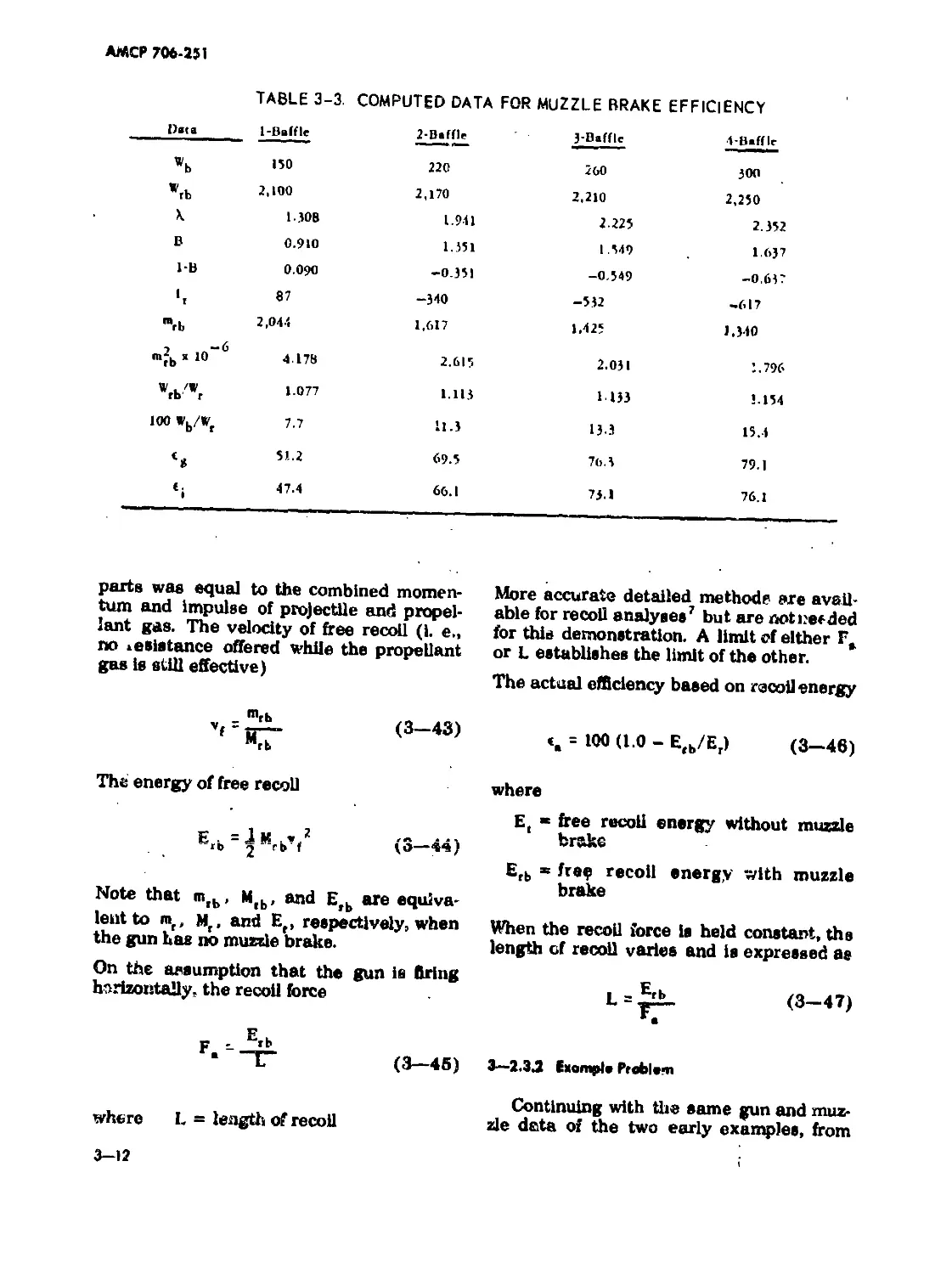
3—2.2 Efficiency of a Muzzle Brake................... 3—9
3—2.2.1 Discussion....................................... 3—9
3—2.2.2 Example Problem................................ 3—10
3—2.3 Effects on Recoil............................... 3—11
3—2.3.1 Discussion..................................... 3—11
3—2.3.2 Example Problem................................ 3—12
3—3 Analysis of Specific Types..................... 3—13
3—3.1 Closed Muzzle Brake................................ 3—13
3—3.1.1 Discussion..................................... 3—13
3—3.1.2 Example Problem ............................... 3—15
3—3.2 Open Muzzle Brake.............................. 3—16
3—3.2.1 Discussion ...............,.................... 3—16
3—3.2.2 Example Problem................................ 3—19
3—3.3 Free Periphery Muzzle Brake.................... 3—21
3—3.3.1 Discussion..................................... 3—21
3—3.3.2 Example Problem................................. 3—22
CHAPTER 4. BLAST DEFLECTORS
4—1 Design Procedure........................... 4—1
4—2 Overpressure Analysis of the Blast Field... 4—1
4—2.1 Discussion of Procedure.................... 4—1
4—2.1.1 Definition г nd Dimensions of Symbols...... 4—2
4—2.1.2 Equations of the Analysis.................. 4—4
4—2.2 Digital Computer Routine for Overpressure
Analysis................................. 4—6
CHAPTER 5. FLASH SUPPRESSORS
5—1 Performance Requirements..................... 5—1
5—1.1 Computed Temperatures of Muzzle Gas-Air
Mixtures................................... 5—2
5—1.2 Digital Computer Routines for Muzzle Gas
Temperature................................... 5—5
5—1.3 Length of Bar-type.............................. 5—5
5—2 Cone-type Suppressor......................... 5—12
5—3 Digital Computer Routines for Flash
Suppressor Configuration.................... 5—13
CHAPTER 6. SMOKE SUPPRESSORS OR ELIMINATORS
6—1 Suppressor Components........................ 6—1
6-1.1 Diverter Design Procedure........................ 6—1
AMCF 706-251
TABLE OF CONTENTS (CONT.)
Paragraph
Page
6—1.1.1 Example Problem .......................... 6—3
6—1.1.2 Diverter With Uniformly Distributed
Port Area................................. 6—4
6—1.2 Casing Design................................ 6—6
6—1.3 Filter Packing Materia].................... 6—6
CHAPTER 7. BORE EVACUATORS
7—1 General Design Parameters.. 7—1
7—2 Fixed Nozzle Design Parameters............... 7—2
7—3 Check Valve Design Parameters................ 7—4
7—4 Sample Problems.............................. 7—7
7—4.1 Fixed Nozzle................................... 7—7
7-4.2 Check Valve.................................... 7—8
CHAPTER 8. NOISE SUPPRESSORS
8—1 General Requirements..... 8—1
8—2 Sound Suppressor Experiments................... 8—1
CHAPTERS. HUMAN FACTORS
9—1 Introduction....................................... 9—1
9—2 Effects of Blast and Overpressure............... 9—1
9—2.1 Physiological Effects, ............................ 9—3
9—2.2 Tolerance Limits................................ 9—5
APPENDIXES
A—1 Isobar Source Program Listing............. A—1
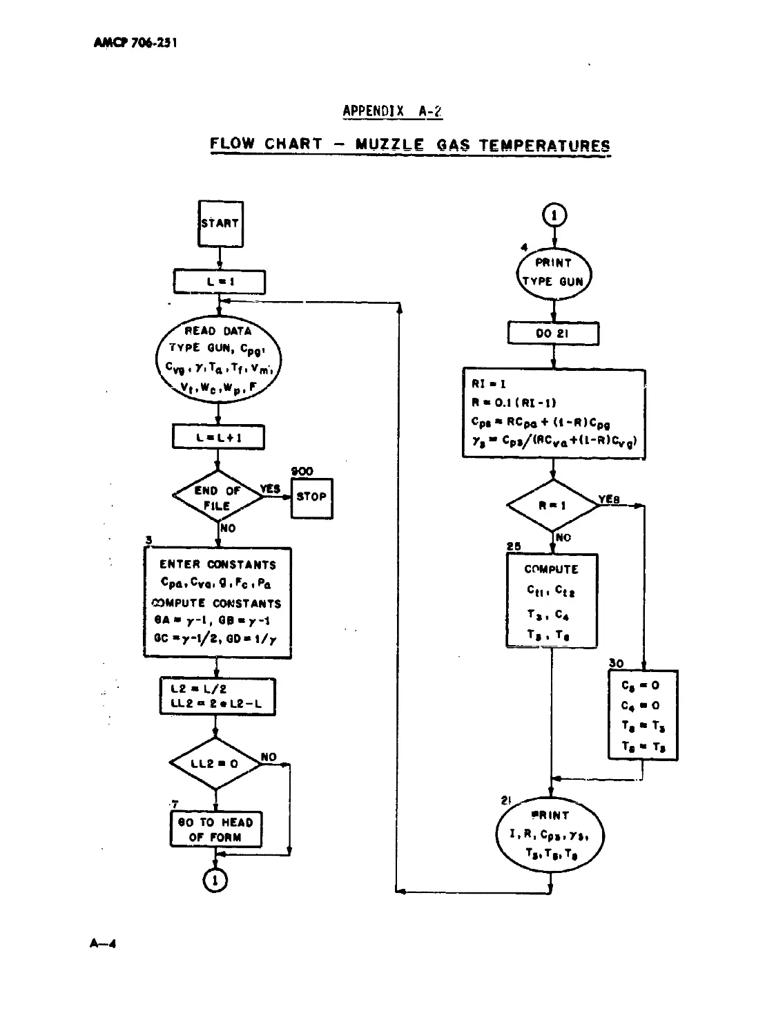
A—2 Flow Chart — Muzzle Gas Temperatures...... A—4
A—3 Muzzle Temperature Source Program Listing. A—5
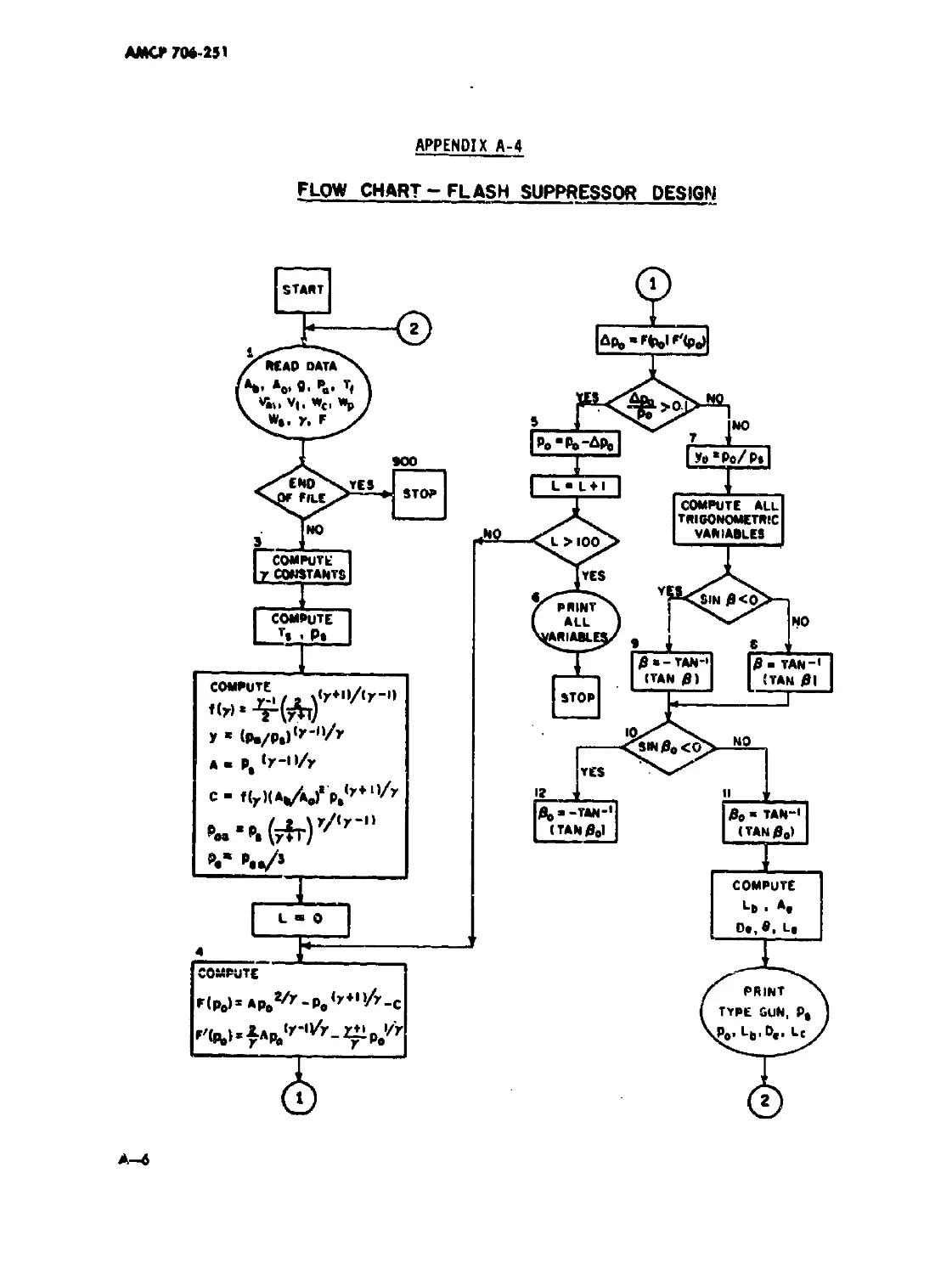
A—4 Flow Chart — Flash Suppressor Design...... A—6
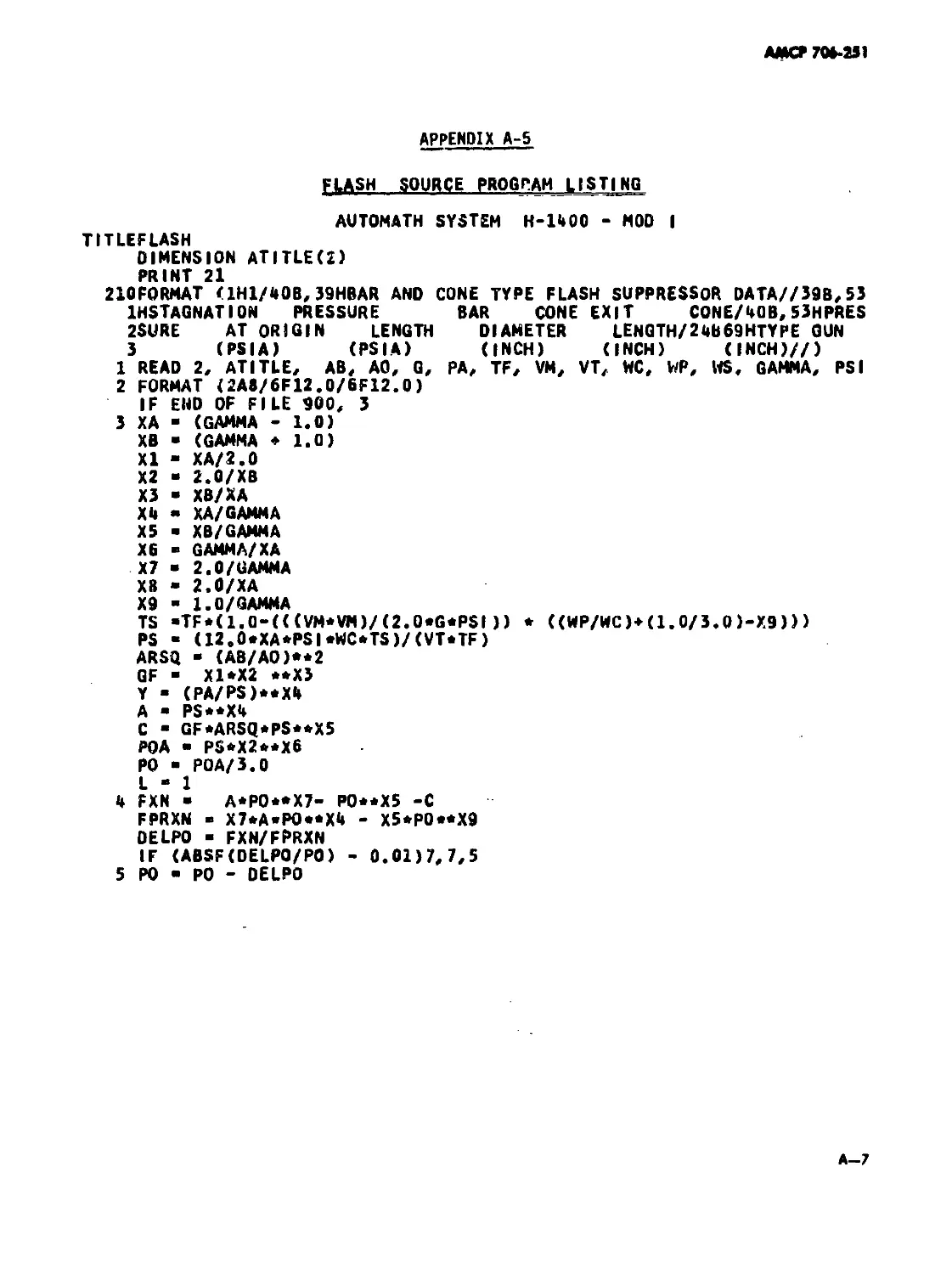
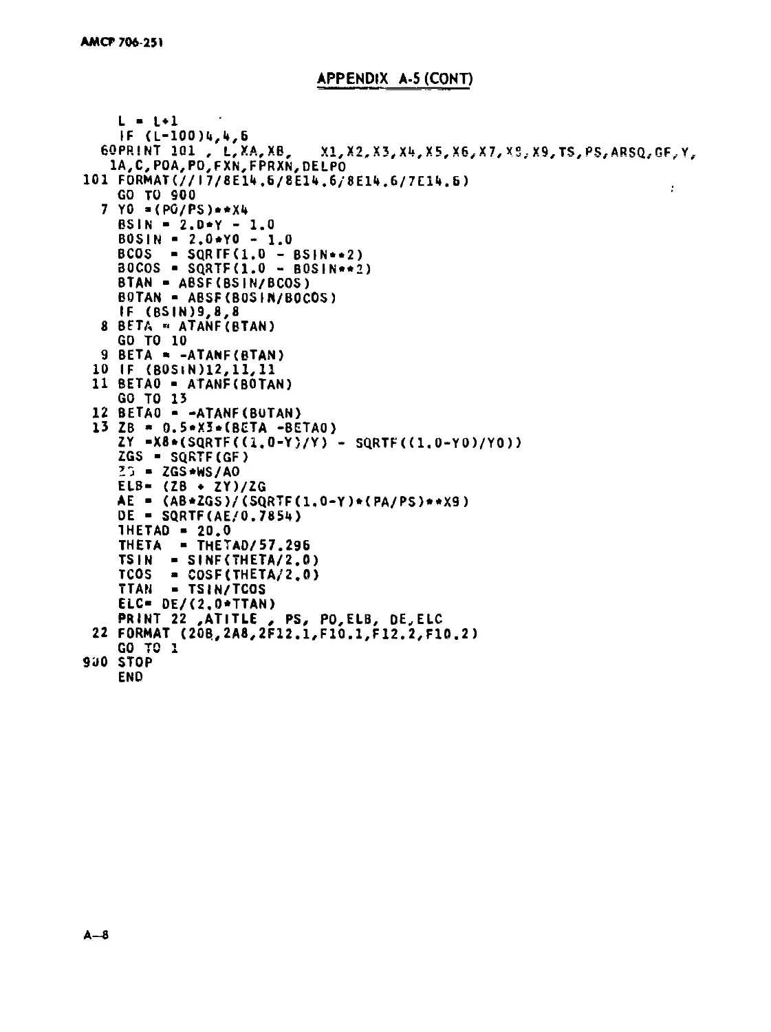
A—5 Flash Source Program Listing.............. A—7
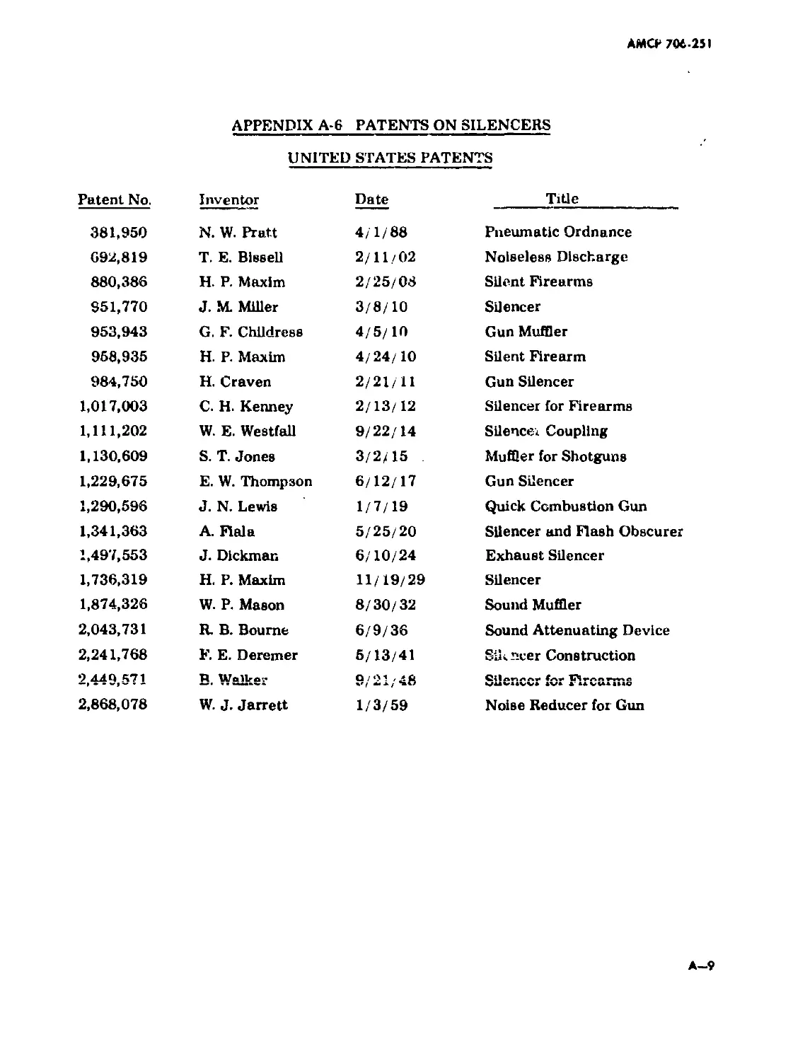
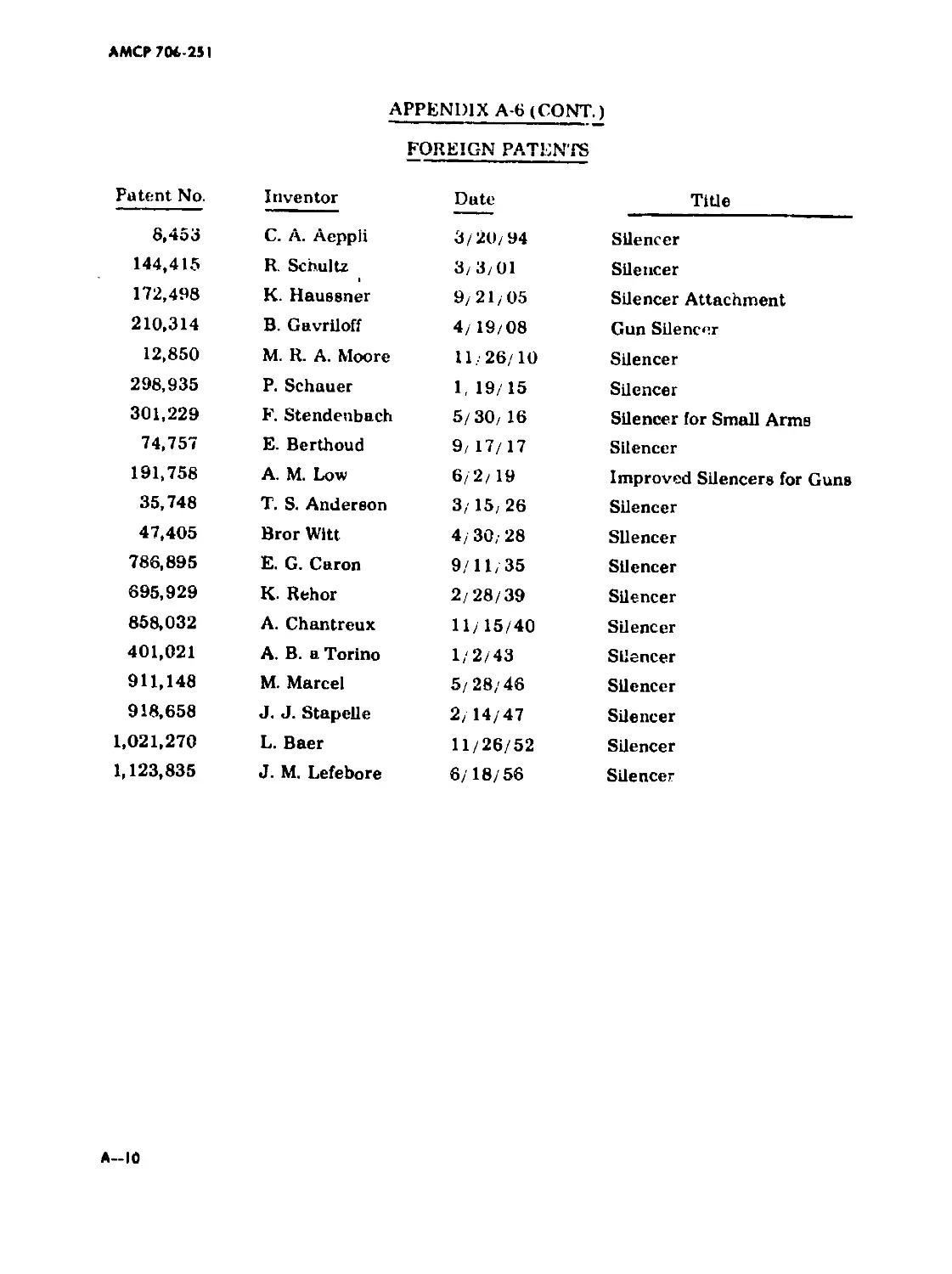
A—6 Patents on Silencers...................... A—9
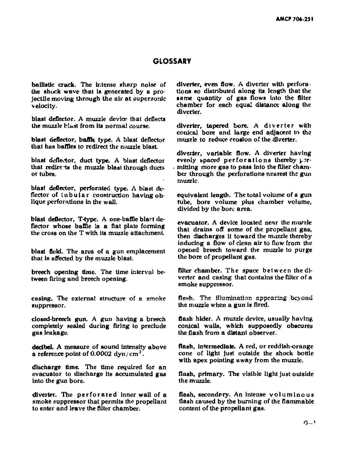
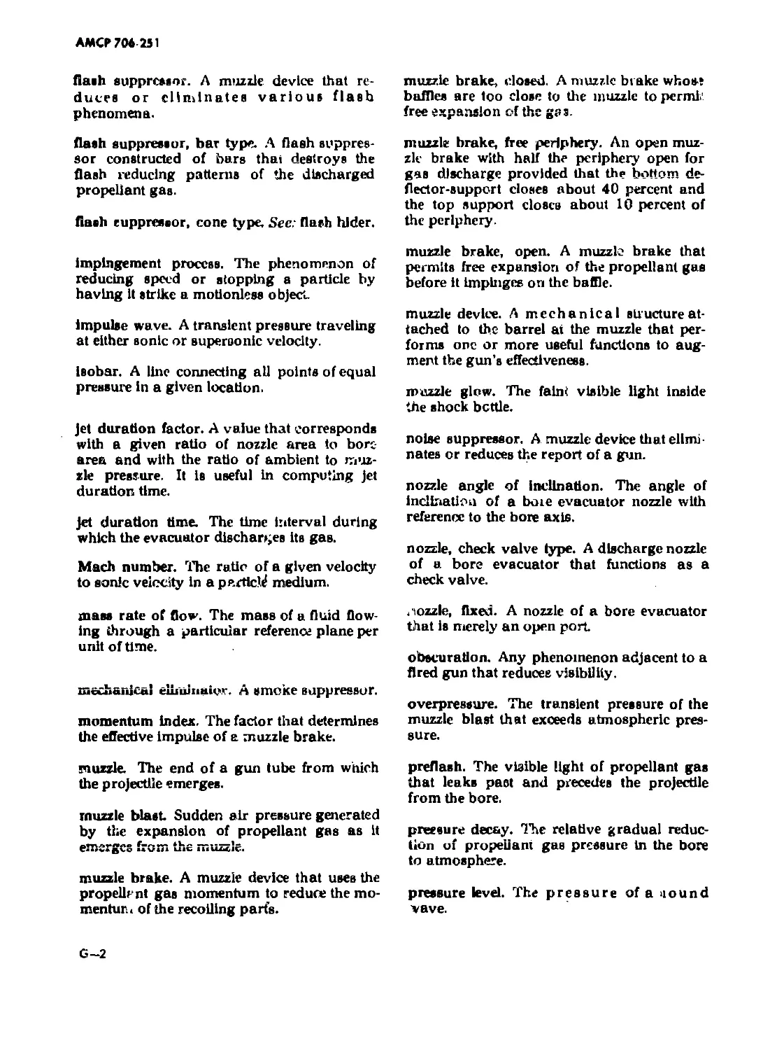
GLOSSARY.................................. G—1
REFERENCES.......................... R—1/R—2
BIBLIOGRAPHY............................ B-l
INDEX................................... 1-1
iv
АМСР7М 231
LIST OF ILLUSTRATIONS
Fig. No. Title Page
1-1 Schematic of Closed Muzzle Brake .... 1 •1 ''4
1-2 Schematic of Open Muzzle Brake .... 1—4
1—3 Cone Flash Hider .... 1-7
1—4 Bar Flash Suppressor .... 1—8
1-5 Unsuppressed Flash .... 1-9
1—6 Effects of Flash Suppressor .... 1-9
1-7 Example of Flash Suppression .... 1—9
1-8 Flash Prediction Temperature Curves .... 1--10
2-1 Maximum Volume Stage of Shock Bottle .... 2-2
2-2 Primary and Intermediate Flash .... 2—3
2—3 Three Types of Flash 2—4
2—4 Development of Muzzle Glow 2—4
2—5 Steady-state Shape of Shock Bottle .... 2—5
3-1 Muzzle Brake Gas Flow Diagram 3—]
3-2 Speed-up Factor vs Divergence .... 3-3
3-3 Schematic of Muzzle Brake Gas Flow .... 3—4
3—4 Effectiveness of Multiple Baffles .... 3-5
3-5 Thrust Comparison .... 3-6
3-6 Predicted Approximate Efficiency .... 3-11
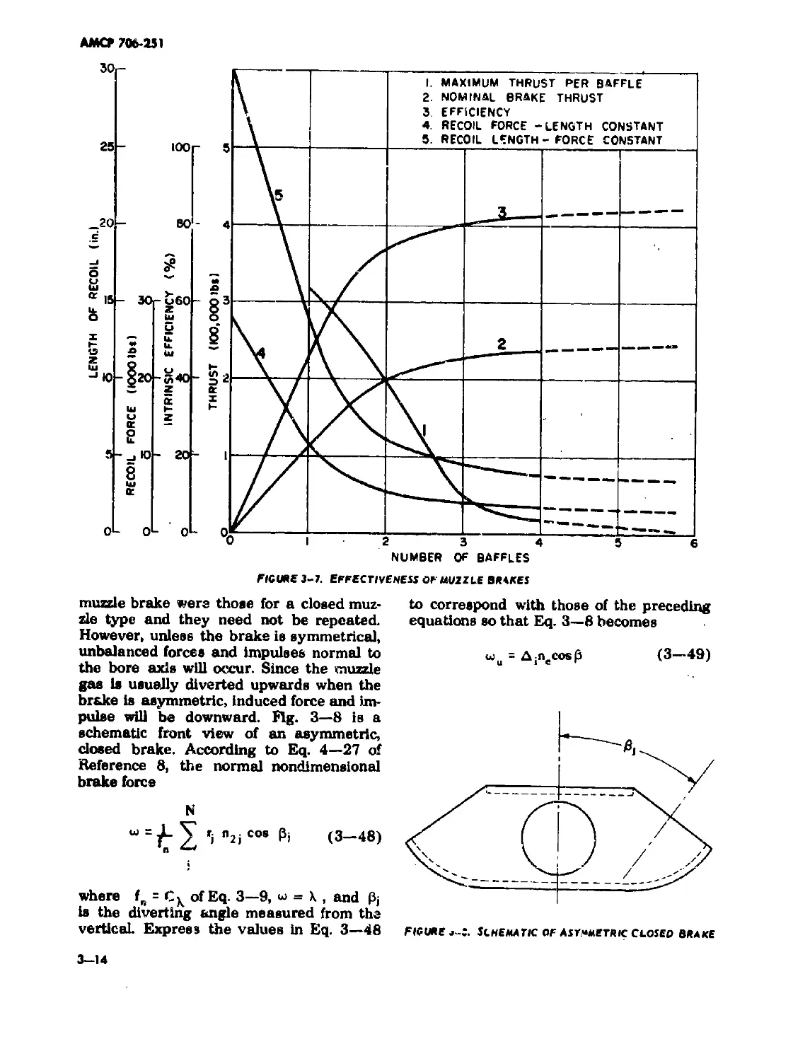
3—7 Effectiveness of Muzzle Brakes .... 3-14
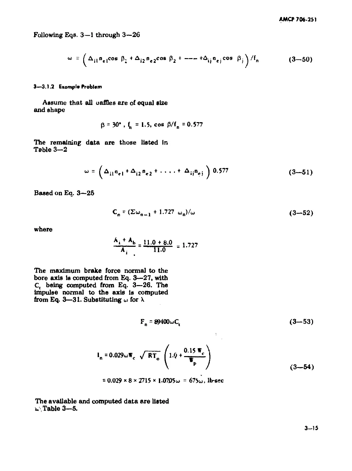
3—8 Schematic of Asymmetric Closed Brake .... 3—14
3—9 Schematic of Open Brake .... 3-17
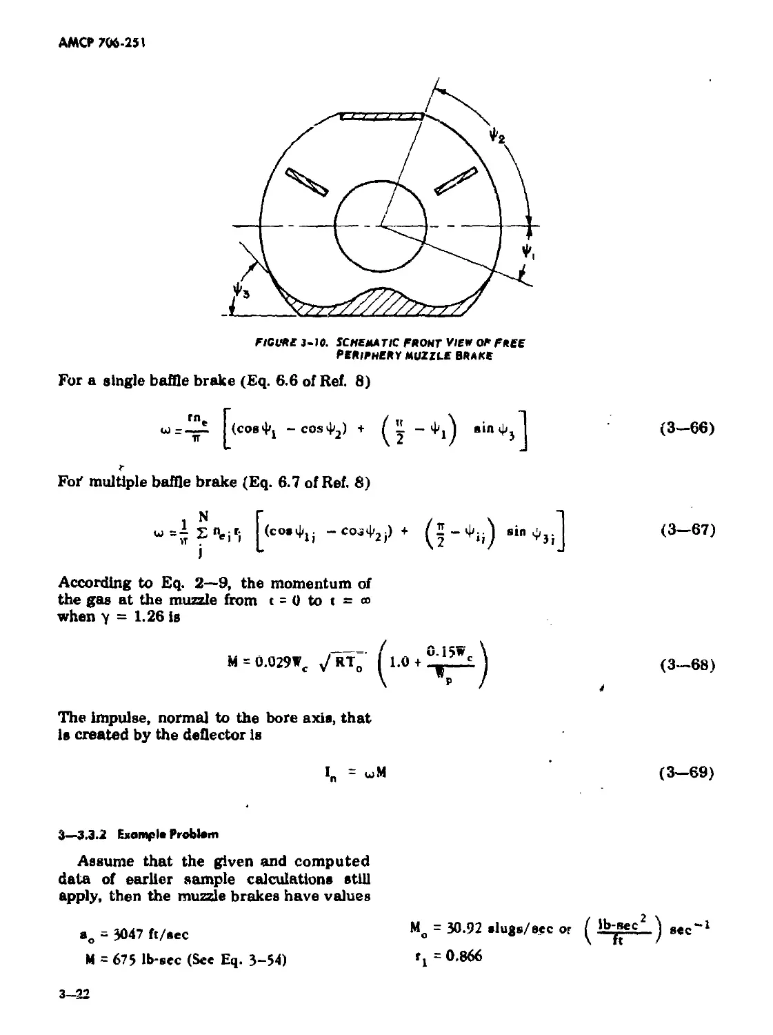
3—10 Schematic Front View of Free Periphery
Muzzle Brake 3—22
4—1 Geometry of Blast Area Positions 4—3
4—2 Overpressure Isobars 4- -11/4—12
3—1 Flow Pattern at a Gun Muzzle 5-1
3— x Gas State-ignition Curves 5-2
5—3 Ignition Boundaries of Various Propellants 5—3
5—4 Schematic of Bar Suppressor
5-5 Bar Contour for Theoretical Gas Discharge... 5-12
6-1 Smoke Suppressor Showing Major
Components 6-1
6-2 Area Function of Even Flow Diverter for a
Cal. .30 Gun 6-3
7—1 Bore Evacuators Showing Nozzles 7-3
7-2 Jet Duration Factors 7-5
7-3 Gas Cell Minimum Surface 7-10
8-1 Sound Suppressors (Schematics) 8—2
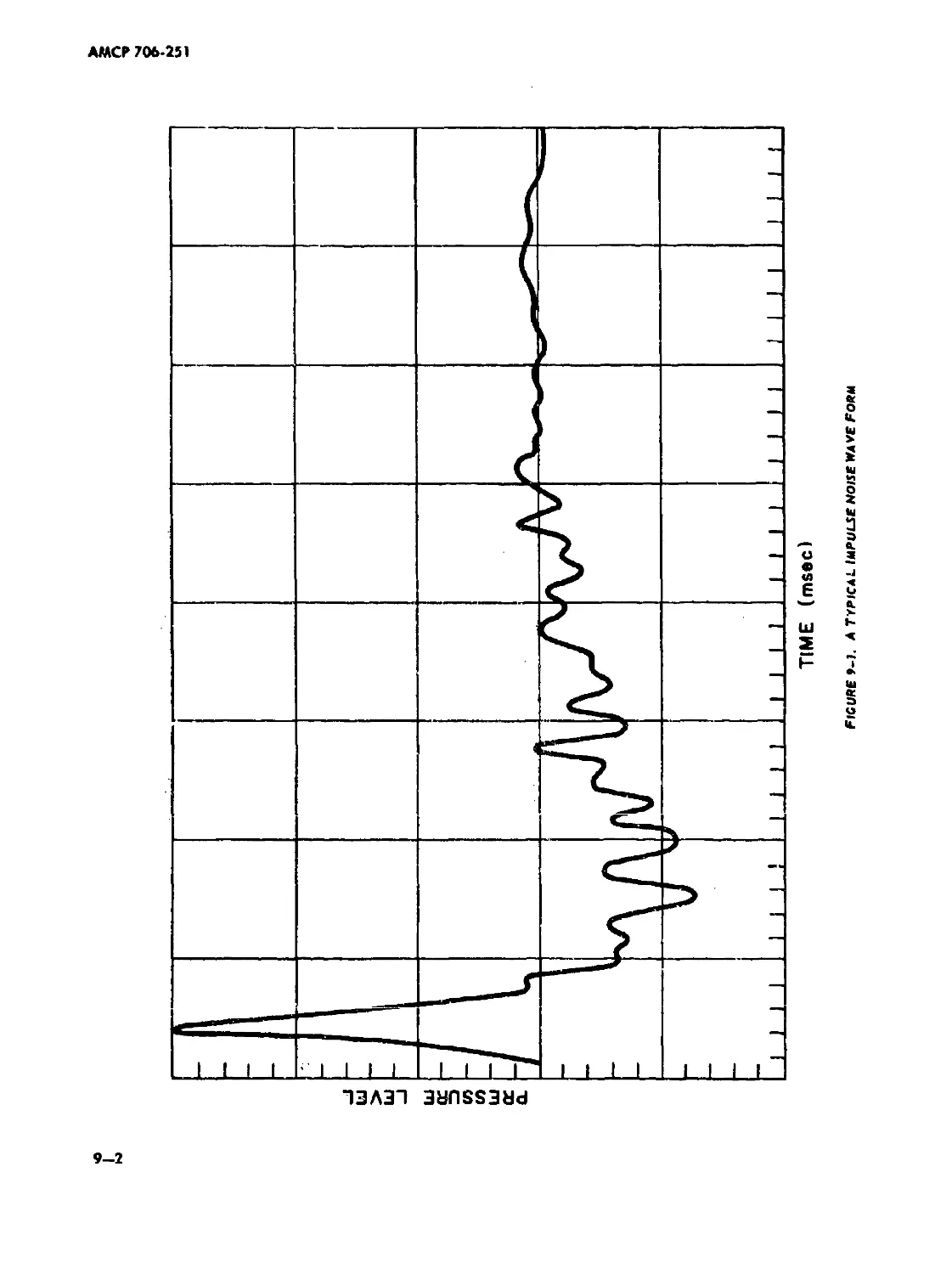
9-1 A Typical Impulse Noise Wave Form 9-2
АМСР 706-251
LIST OF ILLUSTRATIONS (CONT.)
Fig. No. Title Page
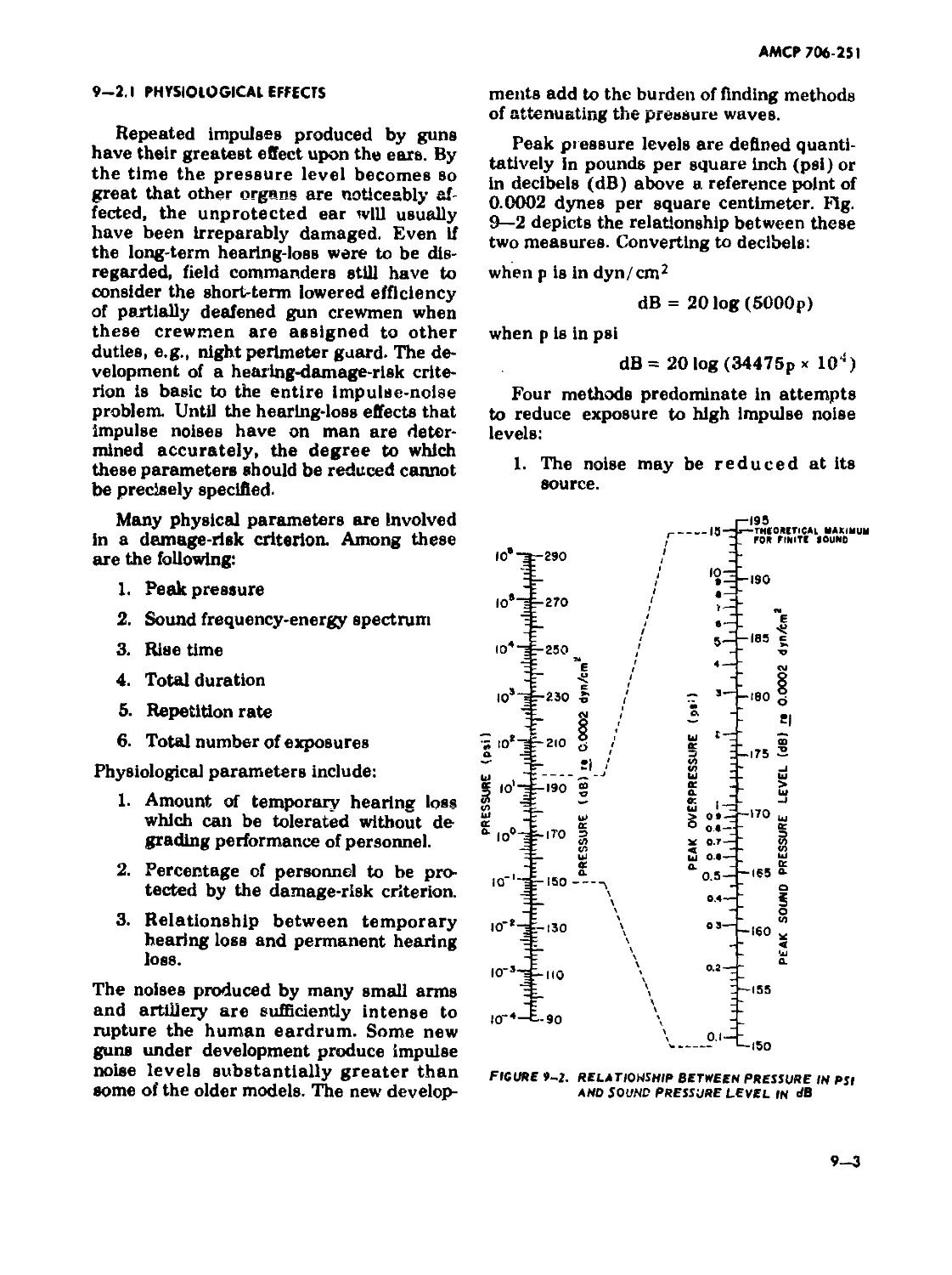
« 9-2 Relationship Between Pressure in psi and Sound-pressure Level in dB 9—3
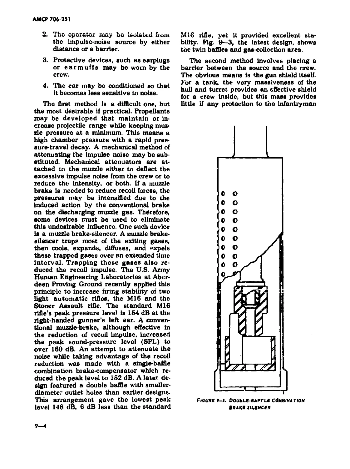
9 Д Double-baffle Combination Brake-silencer 9—4
9--4 Overpressure Contours ... 9-6
9 Characteristics of Ear Protective Devices ... 9-7
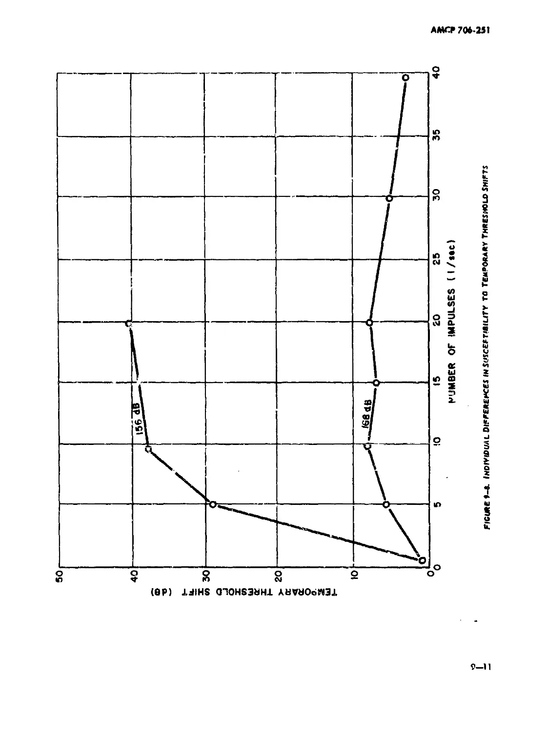
9-6 9—7 9-8 9-9 Diagram of the Ear . Temporary Threshold Shift vs Peak Pressure Level Individual Differences in Susceptibility to Temporary Threshold Shifts Mean Temporary Threshold Shifts (TTS) vs Peak Level .... 9—9 .... 9-10 .... 9-11 .... 9—12
Vi
АМСР 706-251
LIST OF TABLES
Table No. 2-1 Ti(le Page RT of Service Propellants 2—G X Correction Factors 3—3
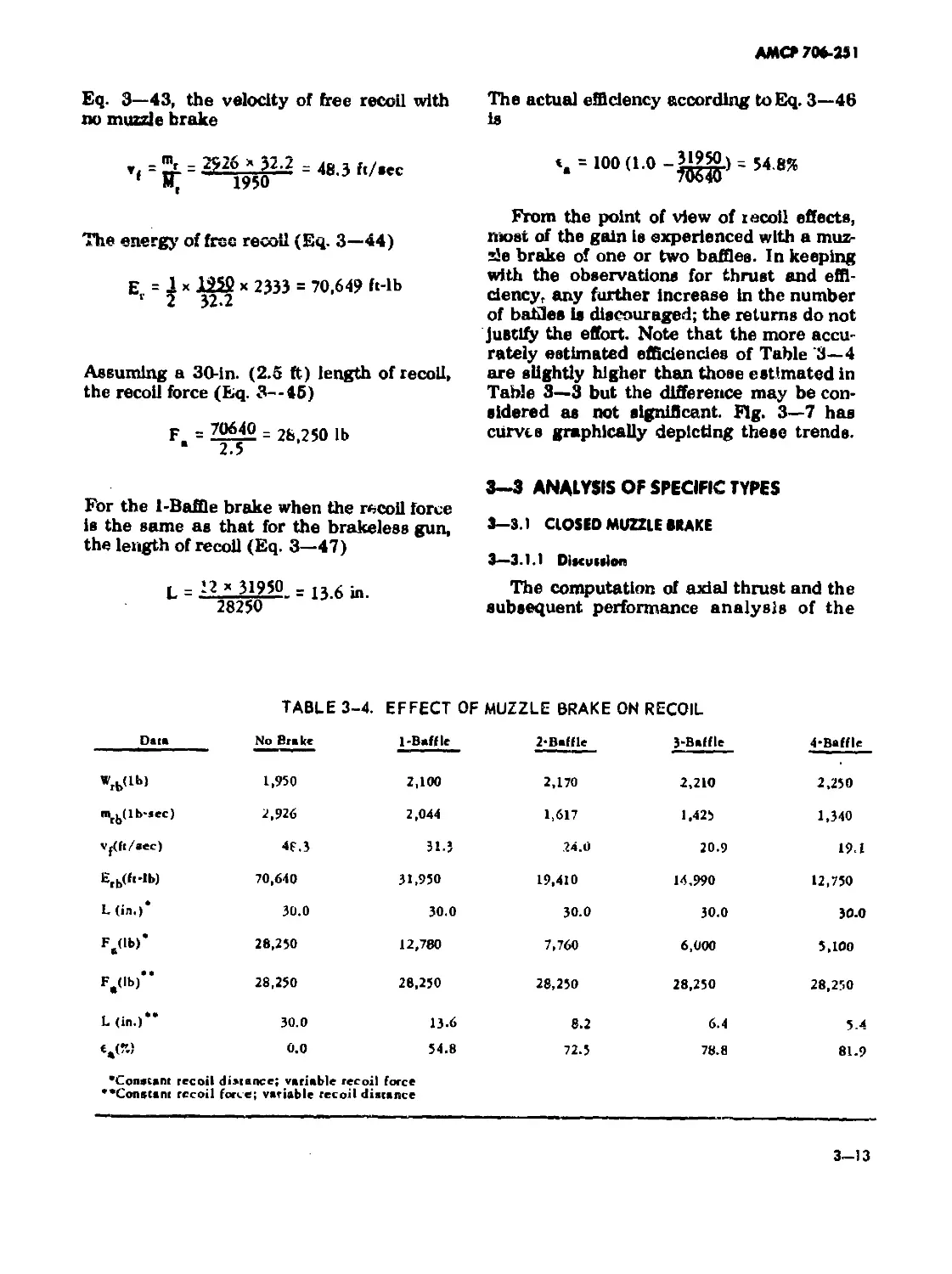
3—2 3-3 Computed Data for Muzzle Brake Thrust 3—7 Computed Data for Muzzle Brake Efficiency 3—12 Effect of Muzzle Brake on Recoil 3—13
3-5 Force and Impulse Normal to Bore Axis of Closed Muzzle Brake 3—16
3—6 Normal Forces and Impulses of Free Periphery — Closed Muzzle Brake 3—23/3—24 Symbol-code Correlation for I sober Program 4—7
4—2 Sample Input 4—8 Sample Output 4—8
5— 1 Symbol-code Correlation for Temperature Program 5—5
5-2 5-3 Input Data for Temperature Calculations 5—6 Output Data for Temperature Calculations 5—7 Symbol-code Correlation for Flash Suppressor Computations 5—14
5-5 Input Data for Flash Suppressor 5—15/5—16 Bar and Cone Type Flash Suppressor Data 5—15/5—16 Computed Port Area at Regular Intervals 6—5
6—2 Diverted Gas Ratios for Uniformly Distributed Port Area 6—6
6—3 Filter Packing Data 6—7/6—8
ЛМСР 706-251
LIST OF SYMBOLS*
A = bore area
Ab = area of projectile passage In muz-
zle device
Ae = exit area of flow passage
Ah = area of perforation In smoke sup-
pressor
Aj = Inner area of baffle passage
An = total nozzle area
Ao = area of flash suppressor at origin
of slots
Ap = port area
Apd = Initial port area
Api = total port area
A( - total open area
•o = velocity of sound in muzzle gas
В = momentum index
Be « effective momentum index
Вт = impulse on gun at any given time
Cf & conversion factor to compute gas
muzzle temperatures
C = thrust correction factor for projec-
tile passageway closure
Cpt = specific heat of air at constantpres-
sure
C = specific heat of muzzle gas at con-
* stant pressure
С n = specific heat at constant pressure
₽n of muzzle gas mixture, where n in-
dicates a particular region
C„ = specific heat of air at constant vol-
ume
Cv 6 specific heat of muzzle gas at con-
stant volume
= correction factor for thrust because
of friction and turbulence
D = bore diameter of gun tube
Db = diverter diameter of smoke suppres-
sor
De = exit diameter 1
D, = distance from muzzle to field posi-
tion
Dh - diameter of perforation of smoke
suppressor
Do = diameter of projectile passageway
in muzzle device
dB = decibel
F = energy
Ef = frictional and engraving losses
Eg = kinetic energy of gas
Eh - heat loss to gun tube
Em = muzzle energy
Ep = kinetic energy of projectile
Er - energy of free recoil without muz-
zle brake
Erb = energy of free recoil with muzzle
brake
Ere = thermal energy of gas at projectile
ejection
F = propellant potential
F( ) = function of ( )
F'( ) = first derivative of F( )
F. - recoil force
Fb = muzzle brake force; thrust
fbs = muzzle brake force, я identifies the
baffle number
Fc = 1400 ft-lb/BTU/*K (conversion
factor)
Fct = fraction of maximum overpressure
from opposite shock center
•A consistent set of dimension* must be employed in the
applicable formulae.
vill
АМСР 706-251
LIST OF SYMBOLS (CONT.)
Fm = maximum instantaneous force on L
Individual baffle
Fr = force on muzzle brake norma! to
gun axis M
fb = the thrust on a specific baffle dur- •
ing a specific time M
*„ = correction factor for computing «
muzde brake thrust M
fj = correction factor of 1.33 used as M
an approximation
M
8 = acceleration of gravity
H = heat of combustion
"lb
lg = impulse induced on gun during the
muzzle gas period
m
1, = impulse on muzzle brake at any *
given time
m
lmb = total impulse on muzzle brake
ln = impulse on muzzle brake normal to m
gun axis tb
I = resultant impulse on recoiling parts n
r m
i = number of groups of perforations to
position being investigated
i( = total number of groups of perfora- Nn
tions
j = subscript identifying a given posi- N
tion in a sequence
K. = symbol representing a value of
many terms in computing muzzle n
brake force, x identifies the baffle
number
•K = degrees Kelvin ne
к = (\-l)/\ where у is ratio of specific nej
heats n.
L = length of recoil; length of gas cell
Lb = length of flash suppressor bar p
Lc = length of cone pe
Ld = length of diverter pb
Le = equivalent length pd
= distance from muzzle to trunnions
— distance to muzzle of evacuator noz-
zle
- momentum of muzzle gas
= rate of change of momentum
= mass of propellant gas
effective mass
= mass r ate of flow at muzzle
= mass of projectile
--- mass of recoiling parts
= mass of recoiling parts including
muzzle brake
= mass of gas leaving muzzle per
second
-- total momentum of recoiling parts
without muzzle brake
= total momentum of recoiling parts
with muzzle brake
= maximum number of perforations
of periphery at each increment
of smoke suppressor
= actual number of perforations at
increment i of smoke suppressor
= total number of perforations of
smoke suppressor up to and includ-
ing increment i
= number of baffles; speed-up factor;
number of nozzles; molar gas vol-
ume
= exit speed-up factor
= exit speed-up factor at baffle No. j
= inner speed-up factor
= modified speed-up factor
= pressure, general term
= atmospheric pressure
= breech pressure
= design pressure
AM СР 706-251
LIST OF SYMBOLS (CONT.)
Ры = breech pressure at ehot ejection
PR - gage pressure; gas pressure
Po = pressure at muzzle; pressure at ori-
gin of Slots in flash suppressor; muz-
zle pressure at shot ejection
Po* - limit of pressure at origin of flash
suppressor slots
Pr - maximum theoretical operating
pressure in bore evacuator
p, - stagnation pressure
Q = rate of flow
QE = angle of elevation of a gun
R = gas constant
•R = degrees Rankine
R; = inside radius
Ro = outside radius
Rp = ratio of ambient to muzzle pressure
at shot ejection
t = mass ratio of air to total air-gas
mixture; radius of gun bore
гь = outside radius of baffle
te s radius of shock envelope at baffle
ri - ratio of baffle inlet area to total
area available for flow
tp = radiud of projectile passage
t, - fractional amount of deflected gas
SPL = sound pressure level
T = temperature of propellant gas hav-
ing done no external work; isochoric
flame temperature
Ta = absolute temperature of ambient
air
Tb = time between shot ejection and
breech opening
T, n flame temperature
Tj = jet duration time
Tjc »jet duration time of check valve
nozzle
T = computed temperature of muzzle
n gas of region indicated by digit n
To = average temperature of gas at shot
ejection
T, = stagnation temperature
TTS = temporary threshold shift
T - ignition temperatures of propellant
* indicated by any letter subscript
t = time, general term
V - chamber volume
c
Vp - volume of projectile and charge
Vr = reservoir volume of bore evacuator
Vt = total volume of gun tube
vf = velocity of free recoil
vo = muzzle velocity
- velocity of recoiling parts
vw = wind velocity
Vb ~ weight of gas flowing through pro-
jectile passage; weight of muzzle
brake
Vc = weight of propellant
V; = weight of gas diverted through
baffle
Wig = weight of igniter
Wp = weight of projectile
wt = weight of recoiling parts
Wrb = weight of recoiling parts with muz-
zle brake
= ratio of dynamic pressure to static
pressure
= total peripheral width of slots
» = distance from breech
% = distance traveled by gases from
muzzle to side port exit
xe «= lateral distance from tube axis to
side port exit
у * ratio of ambient pressure to stag-
nation pressure
X
АМСР 706-251
LIST OF SYMBOLS (CONT.)
y0 = ratio of muzzle pressure to stagna- zo = axial distance from muzzle to cen-
’ tion pressure ter of side port exit
GREEK LEPERS
° = baffle deflection angle
Pj = upward diverting angle of muzzle
brake
V - ratio of specific heats
A = expansion ratio
Ab = ratio of projectile passage area to
total available area
Aen = divergence of gas at the baffle exit
at baffle n
A; = ratio of baffle inlet area to total
available area
A. = ratio A j at any baffle j
An = divergence of gas from muzzle at
flow passage n
At = jet duration factor
6 = heat loss to gun tube as function
of shot energy; density of air
«a = actual muzzle brake efficiency
«e = efficiency of back traveling shock
wave
«g = gross efficiency of muzzle brake
- intrinsic efficiency of muzzle brake
t] = covolume
6 = a simplified term for a time expres-
sion in the gas flow equation; time
of muzzle pressure drop; angular
distance from muzzle to field posi-
tion
6m =- niinirnutii breech opening time
X = composite speed-up factor; ratio of
bore to reservoir volumes
Xd - ratio of bore to reservoir volumes
used in design
Xn = speed-up factor for baffle n
Xu = uncorrected speed-up factor
p = ratio of port area to open area of
smoke suppressor
Pa = actual value of p; mass density of
air
= theoretical deslgne value of p
Pg = ratio of gas entering filter of smoke
suppressor
S = summation
Ф = semi-angle of nozzle; inclination of
bore evacuator nozzle to bore axis
X = heat transfer factor
Ф = angular divergence of brake flow
passage
4'1 = angular distance from horizontal to
bottom plate of free periphery
brake
+2 = angular distance from horizontal to
top plate of free periphery brake
= deflection angle of bottom plate of
free periphery brake
w = speed-up factor for force normal to
bore axis; ratio of nozzle area to
bore area of a bore evacuator
wc = ratio of charging nozzle area to
bore area
ud = design value of w in a bore evacua-
tor
wde = ratio of discharging nozzle area to
bore area
= speed-up factor for normal thrust
at baffle n
= uncorrected speed-up factor for
force normal to bore axis
AMCF 706-251
CHAPTER 1
INTRODUCTION
1-1 PURPOSE
This design handbook provides a con-
venient and ready reference of: (1) funda-
mental and practical design information,
and (2) procedures for use by engineers to
select or adapt existing designs or to
evolve modified or new designs for achiev-
ing the intended performance characteris-
tics of various gun muzzle devices. *
1-2 SCOPE
Present warfare tactics require a high
degree of weapon mobility as well as means
by which the personnel and equipment may
achieve added protection e’ her from their
own weapon or from the enemy. Muzzle
devices that will reduce the forces acting
on a carrier will effectively reduce the mas-
siveness of its supporting structure, there-
by increasing its mobility. Those devices
that eliminate or reduce detectable phe-
nomena emanating from a gun will improve
weapon concealment. A device that reduces
disturbing effects on personnel will increase
efficiency and morale. All these features
are available to some degree in the field of
muzzle devices. Each distinct type has its
own characteristics, some of which may
overlap those of another device. Unfor-
tunately, all desirable performance charac-
teristics of any two, let alone all devices,
cannot be incorporated into one assembly.
For instance, a muzzle brake may also re-
duce flash; it cannot suppress noise. Al-
though dual purposes may be managed,
no confusion should arise as to the identity
or specific purpose of any given muzzle
device.
This handbook presents basic and ap-
plied information on the general character-
istics of guns with particular attention to
'Prepared by Martin Regina, Franklin Institute Research
Laboratories, Philadelphia, Pa.
the behavior of gases when in tne bore and
when discharged from the muzzle. It dis-
cusses both harmful and helpful aspects of
those gases, and describes those devices
that have been developed to minimize the
harmful and utilize the helpful aspects. It
explains convenient and generally reliable
design methods and procedures from early
concept to experimental verification, in-
cluding comments on reliability of scaling
size and performance. It contains material,
manufacturing, and maintenance phases
that contribute to successful designs. It
also has the more sophisticated design pro-
cedures programmed for a digital compu-
ter. A comprehensive bibliography, glos-
sary, and list of contributors completes the
contents and may assist the engineer in
this technological field when a problem is
not readily amenable to solution by proce-
dures or with data in this handbook.
1—3 GENERAL DESCRIPTION OF GUN
MUZZLE DEVICES
1—3.1 MUZZLE BRAKES
1—3.1.1 Hi»*ory
Despite the lack of a strong incentive
for its invention before 1888 (the advent of
the recoil mechanism), the first muzzle
brake appeared in 1842 in France built by
Colonel de Beaulieu. A crude affair, it con-
sisted of a series of holes in the muzzle
region of the barrel. The holes were sloped
rearward to divert the expanding gases in
that direction. Twenty-one years later, the
French military conducted tests with a 106
mm gun with 36 holes of 60 mm diameter
inclined rearward at 45 s. Data published
by de Beaulieu disclosed the great success
of doubling the accuracy and having the
recoil distance reduced to 25 percent of its
normal distance with only a 6 percent loss
in muzzle velocity. Reservations should be
1-1
АМСР 706-251
made with respect to the reliability and
accuracy of these claims unless all data are
available. However, this first official at-
tempt did establish the muzzle brake as a
practical and useful component of a gun.
The first attempt was followed by inven-
tions of Ha* ley (1871), de Place (1885),
Maxim (1890), Simpson (1902), and Smith
(1903). During the latter years, several
agencies began to devote efforts toward
muzzle brake development, thus lending
encouragement to the individuals inter-
ested in this field. This activity was not
monopolized by one country. The United
States, England, France, and Germany, all
were keenly aware of its potential and did
much to advance the technique in design
procedure through the years before and
during World War 1. Muzzle brakes of
assorted descriptions and sizes appeared
during this period with enough claims of
fantastic proportions to excite continued
interest in building and testing new hard-
ware. But, not until after the war, when
Rateau developed his theory, was i >y con-
certed effort made to apply scientific prin-
ciples to existing mechanical techniques in
order to rationalize muzzle brake design
concepts. Rateau's theory, still useful, be-
came the basis of our present theoretical
and practical design procedures.
>1—3.1.2 Purpot»
When a gun is fired, the burning propel-
lant and the subsequent gas activity are
the sole influences on gun structure and
projectile. While in the bore, the projectile
offers the inertial and frictional resistance
commensurate with the thermodynamics
of the propellant. After it leaves the muz-
zle, the projectile loses further influence.
On the other hand, the gas exerts pressure
on the gun tube while the projectile is being
propelled and after, until this pressure be-
comes ambient. The pressure forces on the
bore surface are balanced and have no ex-
ternal influence. Although of short dura-
tion, the pressure force on the breech
creates an impulse on the gun tube that is
equivalent and opposite to that on the pro-
jectile. This rearward impulse is responsi-
ble for recoil, an undesirable but controlla-
ble phenomenon of all closed-breech guns.
There are any number of ways of achieving
this control. If the gun is rigidly fixed to its
structure and foundation, everything re-
mains motionless and all resultant forces
are transmitted directly to the foundation.
If the gun is free to move, the impulse will
induce e rearward velocity to the movable
parts which eventually must be stopped.
The magnitude of the resistance determines
the recoil distance. Most guns provide this
resistance by some type of recoil mech-
anism, from the application of a person’s
body when firing shoulder or hand guns to
the elaborate recoil mechanisms of artil-
lery. A recoil mechanism moderates the
recoil force by diluting the propellant gas
impulse with a reaction extended over a
comparatively long period of time. The re-
coil force may be reduced further by reduc-
ing the recoiling mass momentum with a
muzzle brake.
1—3.1.3 Deicription
A muzzle brake is a device that is
attached to, or is integral with, the muzzle
of a gun. Usually the brake has a series of
baffles either perpendicular or nearly per-
pendicular to the gun tube axis. The brake
is generally closed on the bottom to pre-
vent escaping gases from endangering or
annoying the gun crew. To maintain sym-
metrical peripheral loading and therefore
balance, the top also is closed, leaving the
sides open for the gases to escape after
impinging on the baffles. Some standard
configurations, adhering to either theoreti-
cal or empirical practice, have evolved
through years of application.
1—3.1.4 Theory of Operation
Immediately as the projectile clears the
muzzle, the propellant gases follow, no
longer restrained by tube wall or projectile,
but still having an appreciable pressure
and a velocity equal to or slightly exceed-
ing that of the projectile. If left alone, the
gases expand into air and reduce to atmos-
pheric pressure. However, if the gun has a
muzzle brake, a different sequence of
1-2
AMCf* 706-251
events ensues. The projectile while passing
through the brake continues to restrain, to
some extent, gas flow in the axial direction.
But the side ports in the brake offer little
resistance to the expanding gas which can
now flow between the baffles. The general
direction of flow is therefore changed. The
resultant direction of this gas flow is no
longer diagonally forward, but is radial or
actually rearward. By diverting the flow in
these directions, the gas must impinge on
the baffles and induce a forward thrust.
This thrust generates an impulse which is
opposite in direction to the recoil momen-
tum, thereby reducing that momentum by
the amount of the muzzle brake impulse.
Unfortunately, the muzzle brake does not
perform while the projectile is still in the
bore. The recoiling parts almost reach their
full momentum during this time, thus con-
signing the function of the brake to the
analogous role of a corrective rather than
a preventive performer.
i— 3.1.5 Advontog«(
The principal advantage of a muzzle
brake is its ability to decrease the momen-
tum of the recoiling parts of a gun. How
this advantage is exploited depends on the
weapon assignment. If low weight is the
dominating criterion and knowing that re-
coil force is inversely proportional to length
of recoil, a conventional length of recoil
can be retained with subsequent low recoil
forces that lead toward lighter supporting
structures. In tanks, where space is at a
premium, short recoil lengths only are pos-
sible but recoil forces remain correspond-
ingly high thus offering little opportunity
to reduce structural weight. Some second-
ary advantages of a muzzle brake include
the ability to suppress flash to some ex-
tent, and help gun stability during recoil
partly by the effect of the additional mass
and partly by the thrust generated by the
muzzle gases. A few tests indicated an
accuracy increase but conclusive data are
lacking.
1—3.1.6 Ditodvontogti
Perhaps the principal disadvantage of a
muzzle brake is the deleterious effect that
the muzzle blast has on the crew, particu-
larly excessive overpressure. Air disturb-
ances or propellant gas moving at high
velocity, loud noise, and heat can be dis-
concerting if not outright injurious. The
resulting obscuration is a primary objec-
tion. Damage to camouflage and the danger
of flying debris are two undesirable pro-
ducts of the blast. Noise is always increased
although at least one model had the ability
to muffle sounds which seems contrary to
the inherent characteristics of a muzzle
brake but, until more substantiating data
are available, increased noise will continue
to be listed as a disadvantage. A minor
disadvantage is the added weight at the
muzzle. This weight increases muzzle pre-
ponderance and further burdens the elevat-
ing mechanism, particularly in older guns
that were not initially designed for a muz-
zle brake. Newly designed guns eliminate
this problem with a suitable equilibrator.
1—3.1.7 Current Stole of the Art
The present consensus among users has
the advantages of muzzle brakes out-
weighed by the disadvantages. As yet, its
objectionable muzzle blast has not been
eliminated from artillery but noted success
has been achieved with small arms. A high
degree of effectiveness is usually accom-
panied by strong muzzle blasts which al-
ways suggests a compromise in design.
Although improvements are continuing, the
designer is handicapped by the unwanted
blast. If the gun crew is shielded, as in a
tank, muzzle blast has little effect. How-
ever, artillery crews must be shielded or
some means developed to divert the blast
away from the crew. Even so, shielding
does little to protect support personnel in
the general weapon area. Some effort has
been directed toward this development, but
no real improvement has been achieved.
Much progress remains to be made in the
muzzle brake field but, aside from struc-
tural requirements, secondary effects cause
the greatest concern. Muzzle brake effi-
ciency and effectiveness have reached
highly acceptable levels. Empirical and
theoretical design procedures are available
beginning with somewhat elementary but
1-3
АМСР 706-251
effective Initial design approaches and end-
ing with the more sophisticated electronic
computer routines programmed for highly
theoretical approaches.
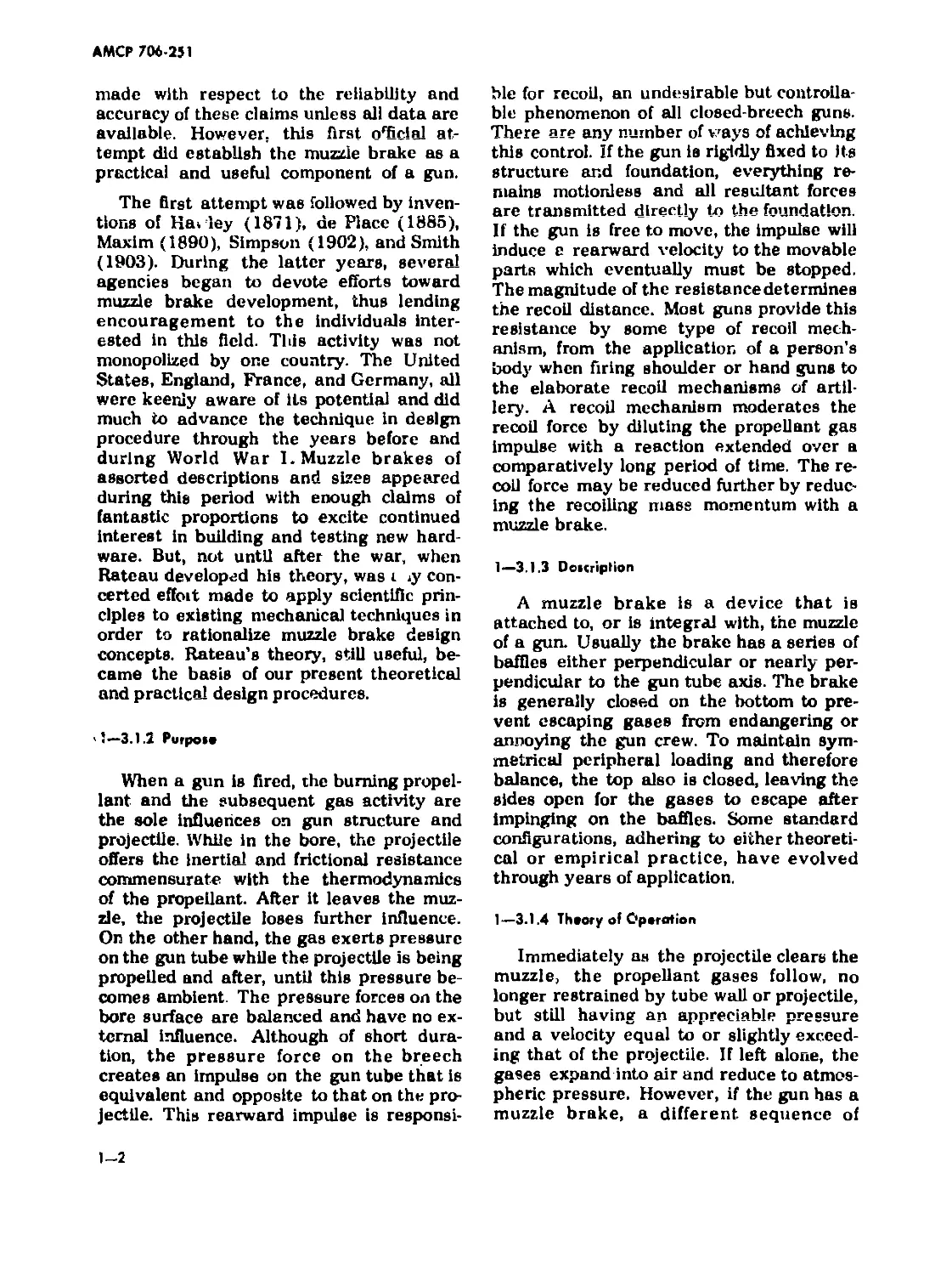
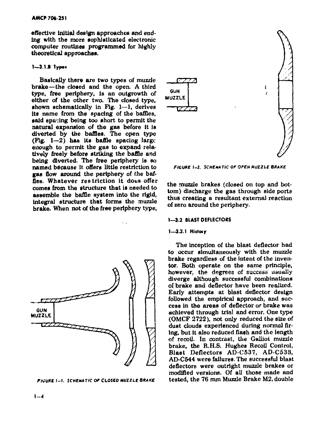
1—Э.1.В Туран
Basically there are two types of muzzle
brake—the closed and the open. A third
type, free periphery, is an outgrowth of
either of the other two. The closed type,
shown schematically in Fig. 1—1, derives
Its name from the spacing of the baffles,
said spacing being too short to permit the
natural expansion of the gas before it is
diverted by the baffles. The open type
(Fig. 1—2) has its baffle spacing large
enough to permit the gas to expand rela-
tively freely before striking the baffle and
being diverted. The free periphery is so
named because it offers little restriction to
gas flow around the periphery of the baf-
fles. Whatever res triction it does offer
comes from the structure that is needed to
assemble the baffle system into the rigid,
integral structure that forms the muzzle
brake. When not of the free periphery type,
...Fzza
GUN
MUZZLE
EZZ3
FfCURf 1-2. SCHEMA TIC OF OPEN MUZZLE BRAKE
the muzzle brakes (closed on top and bot-
tom) discharge the gas through side ports
thus creating a resultant external reaction
of zero around the periphery.
1—Э.2 BLAST DEFLECTORS
1—3.2.1 Hiitoiy
FlUURE 1-1. SCHEMATIC OF CLOSED MUZZLE BRAKE
l—и
The Inception of the blast deflector had
to occur simultaneously with the muzzle
brake regardless of the intent of the inven-
tor. Both operate on the same principle,
however, the degrees of success usually
diverge although successful combinations
of brake and deflector have been realized.
Early attempts at blast deflector design
followed the empirical approach, and suc-
cess in the areas of deflector or brake was
achieved through trial and error. One type
(OMCF 2722), not only reduced the size of
dust clouds experienced during normal fir-
ing, but It also reduced flash arid the length
of recoil. In contrast, the Galliot muzzle
brake, the R.H.S. Hughes Recoil Control,
Blast Deflectors AD-C537, AD-C538,
AD-C544 were failures. The successful blast
deflectors were outright muzzle brakes or
modified versions. Of all those made and
tested, the 76 mm Muzzle Brake М2, double
АМСР 706-251
baffle type, shewed the most promise with
respect to operational requirement and
acceptable size. The most successful, from
the operational point of view alone, con-
sisted of a muzzle assembly that had twin
ducts, one on each side and parallel to the
gun tube, or a single duct above the tube.
These ducts carried the propellant gases
rearward and discharged them at the trun-
nions- A 90* bend upward in each duct
directed the discharge away from both gun
and crew. This type also performed well as
a muzzle brake.
1—3.2.2 Purpoic
A blast deflector has a twin function—
to minimize obscuration and to lessen the
effect of muzzle blast on the crew if the gun
has a muzzle brake. Both these functions
need not apply simultaneously to all
weapon installations. The tank crew is
shielded from muzzle blast but the dust
cloud raised by the blast can hide the tar-
get, thus interfering with precise sighting.
On the other hand, the muzzle blast on
long range guns may be extremely discon-
certing or physically harmful to the gun
crew but obscuration presents no sighting
problem inasmuch as the target is usually
beyond visual range. For short-range weap-
ons, where targets are visible, the blast
deflector must exercise its dual function,
but only if the gun has a muzzle brake.
1—3.2.3 Deicription
The blast deflector is similar to the muz-
zle brake. In fact, either may also function
as the other. It is attached to the muzzle
and is so constructed that propellant gas
will be diverted away from the ground and
gun crew. The deflector has ports through
which the propellant gas flows. The ports
may be an arrangement of simple baffles
or may be more complex with channels of
circular, elliptical, or other cross-sections,
leading outward, usually perpendicular to
the bore, or canted slightly rearward. If
antiobscuration is the primary function, the
surface facing the ground should be closed.
If balance of forces is needed, the top also
should be closed.
1—3.2.4 Thoory of Oporotion
The blast deflector operates similarly to
the muzzle brake by controlling the flow
direction of the expanding propellant gas
as it leaves the muzzle. Бу changing the
direction of the resultant of the gas momen-
tum, the deflector must develop a com-
ponent of the resultant in the axial direc-
tion opposite to that of the recoil momen-
tum, thereby inducing a muzzle brake
effect. If used for antlobscuration purposes
only, the deflector diverts the gas upward
and outward but not toward the ground. In
so doing, thrust is generated in the direc-
tion opposite to the diverted gas flow. This
thrust can be balanced by providing equal
and opposite gas flow, readily achieved
with side ports for lateral stability. Vertical
stability can be achieved not only by clos-
ing the top of the deflector at the muzzle
region but by ducting the gas rearward and
discharging it upward at the trunnions. If
the blast deflector is an adjunct of the
muzzle brake, it must direct the rearward
flow of propellant gas at an angle that
reduces the impact on the crew to a limit
that can be tolerated.
1—3.2.5 Advantage»
A blast deflector reduces obscuration
which in turn increases the effectiveness of
the gun by keeping the target visible. It
reduces the muzzle blast effects to Emits
t-hfit гни hf> toler&ted by the gun crew.
Both foregoing advantages are morale
boosters. From one point of view, a target
obscured by one’s own gun fire is a source
of frustration. From another, the effect that
obscures the target may reveal the gun’s
position and, in a sense, create overex-
posure to enemy fire. An unabated muzzle
blast is analogous to inflicting self-injury, a
factor that does not promote either con-
fidence or efficiency.
1—3.2.6 Oitodvonlogat
The disadvantages are usually related
to the adverse effects produced on other
1-5
АМСР 706 251
equipment. Blast deflectors generally re-
duce the efficiency of muzzle brakes and
may overload the elevating mechanism.
Some models have a tendency to increase
fjash.
1—3.2.7 Current Slot* of the Art
The development of the blast deflector
Is almost congruous with that of the muz-
zle brake. Although its primary purpose is
to dilute the effect of the muzzle blast
created by the muzzle brake, one of the
more acceptable deflectors is a muzzle
brake. Many types of blast deflectors have
been proposed, built, and tested. Most have
been found wanting; some because of struc-
tural weakness, some because of massive-
ness or awkwardness in construction, and
some because of poor performance. The
successful deflectors were those that re-
directed the gas flow away from the crew
area but these invariably caused a de-
crease in brake efficiency. Those that were
made for antiobscuration only and were
considered successful have not been recom-
mended for general usage. However, the
degree of success of either blast deflector
or muzzle brake has always been relative,
comparing the performance of the new with
its predecessors. Muzzle brakes of rela-
tively high efficiency are available, but the
shock overpressures on gun crews are ob-
jectionable. Reducing the shock is the main
challenge to the blast deflector designer.
Some attempts have been made to attenu-
ate the shock induced by artillery fire but
were not totally successful. Development in
this direction is continuing.
1—3.2.0 Types
There are several types of blast deflec-
tor, some are actually muzzle brakes;
others were designed for their own parti-
cular function.
1. Baffle-type. This type is a natural
outgrowth of the baffle-type brake.
The muzzle brake has good anti-
obscuration characteristics provided
that the gas flow is diverted from the
ground. This type is one of the most
successful.
2. Perforated-type. Originally designed
as a muzzle brake (Swiss Solothurn)
this type proved unsuccessful on
artillery. Its structure was tubular,
circular, elliptical, rectangular, cross-
section, or an. other configuration
that appealed о the designer. Hori-
zontal holes, usually five, traversed
the device. Propellant gases, escap-
ing through the ten exits, were to
reduce obscuration. One model per-
formed well, the others proved to
have little or no significant effect.
3. T-type. This blast deflector is merely
a one-baffle muzzle brake. Its baffle
is a flat plate with a circular hole in
the center to permit projectile pas-
sage. The baffle plate is held, top
and bottom, by two other plates that
are fixed to a housing that attaches
to the muzzle. This type performs
well as an obscuration deterrent.
4. Duct-type. A rather massive affair,
this type, attached to the muzzle,
diverts the gas rearward through one
or two ducts and discharges into the
air above the trunnions. The dis-
charge direction is upward, perpen-
dicular to the bore, to that the in-
duced reaction passes through the
trunnions and thus scares the elevat-
ing gear an additional burden. Ideal
as an obscuration deterrent and hold-
inf promise as a muzzle brake, this
type has still to be accepted because
of its massiveness and, when applied
to artillery weapons, the gas dis-
charge is in close proximity to the
crew; therefore, during high Q. E.
firing, gas discharge is directed to-
ward the crew area.
1—3.3 FkASH SUPPRESSORS
I—3.3.1 History
Military authorities were cognizant of
the problem presented by muzzle flash be-
fore 1900 but did not attach material sig-
nificance to it until World War I. Betrayal
of gun position soon became evident to
both sides and was exploited accordingly.
АМСР 706-251
The вен reh for a flash eliminator or sup
pressor during this war became almost as
intense as the search for a higher perform-
ing grin; however, flash research always
lagged research on other gun phenonema.
For one reason, stimulants, such as the two
World Wars which revealed the dire need
for a flash suppressant, ceased before an
effective suppressor could be found or in-
vented. Perhaps a better explanation of
this lag was that flash behavior was never
fully understood. The pressure of other war
needs and the lack of adequate instruments
gave the technical investigators little more
than empirical procedures. (For a discus-
sion of the spectral characteristics of muz-
zle flash see Ref. 21.)
Earliest attempts at flash suppression
involved additives to the propellant. These
additives varied from email amounts of
black powder to inorganic salts oranyother
compound that struck the fancy of the ex-
perimenter. During World War I, the French
used a propellant for machine gun am-
munition consisting of nine parts smokeless
powder and one part black powder. For the
same reason, the German loaded cotton or
silk bags with potassium chloride and at-
tached these to the base of the projectile.
Both were effective in suppressing second-
ary flash but, as happened with many simi-
lar suppressants, smoke increased while
the ballistic properties of the propellant
suffered.
Research in flash suppression continued
in the interim between the two World Wars
but little progress was achieved. Beside
the additives as suppressants, muzzle
brakes and blast deflectors appeared to
have some effect on flash. This observation
led to organized attempts to learn the
mechanics of the muzzle blast and flash.
Since World War II, considerable data have
been accumulated, and mechanical flash
hiders and flash suppressors have been
developed with various degrees of success.
However, a great deal of progress is still
needed to achieve an efficient, practical
flash suppressor either mechanical or chem-
ical.
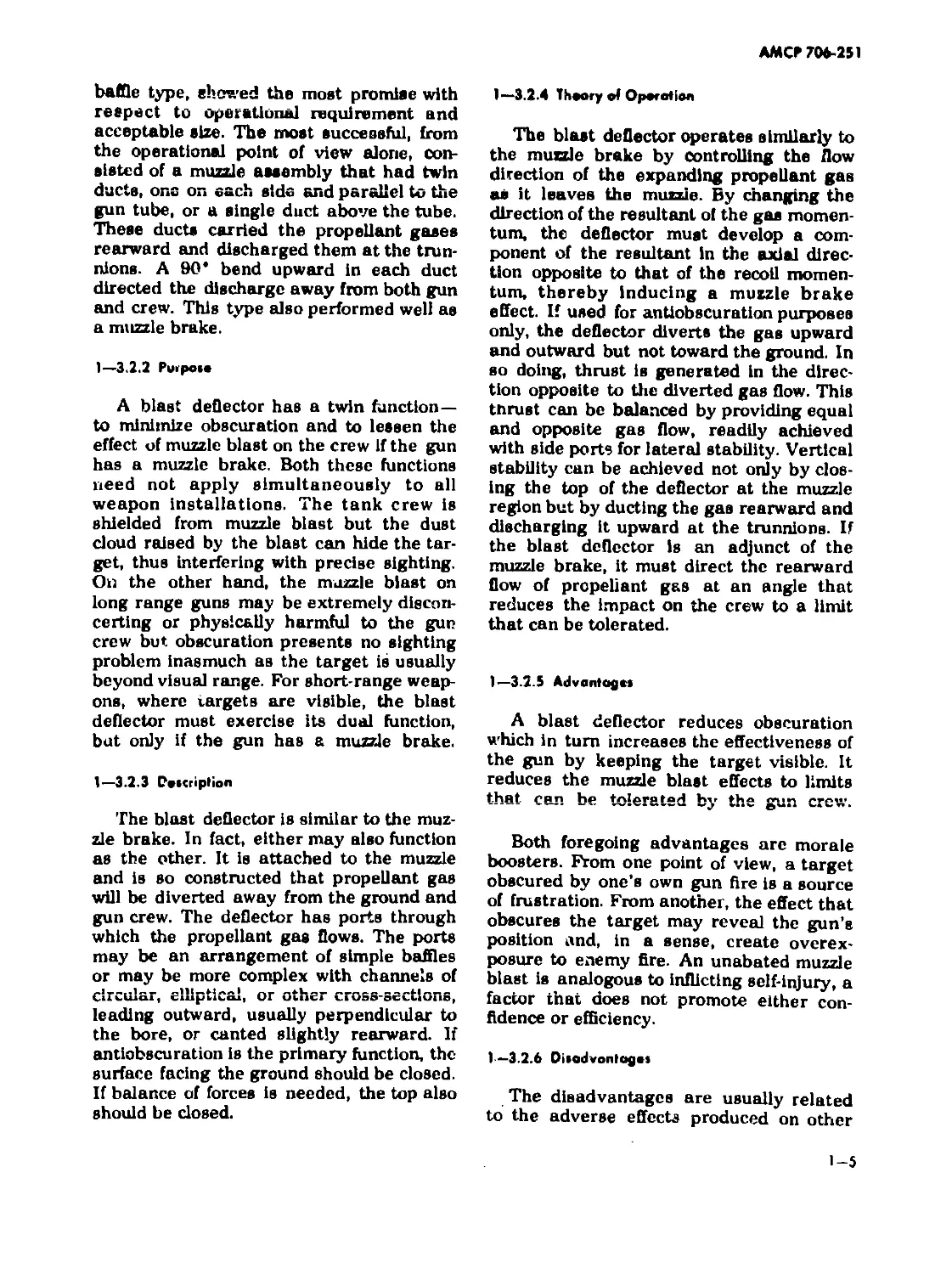
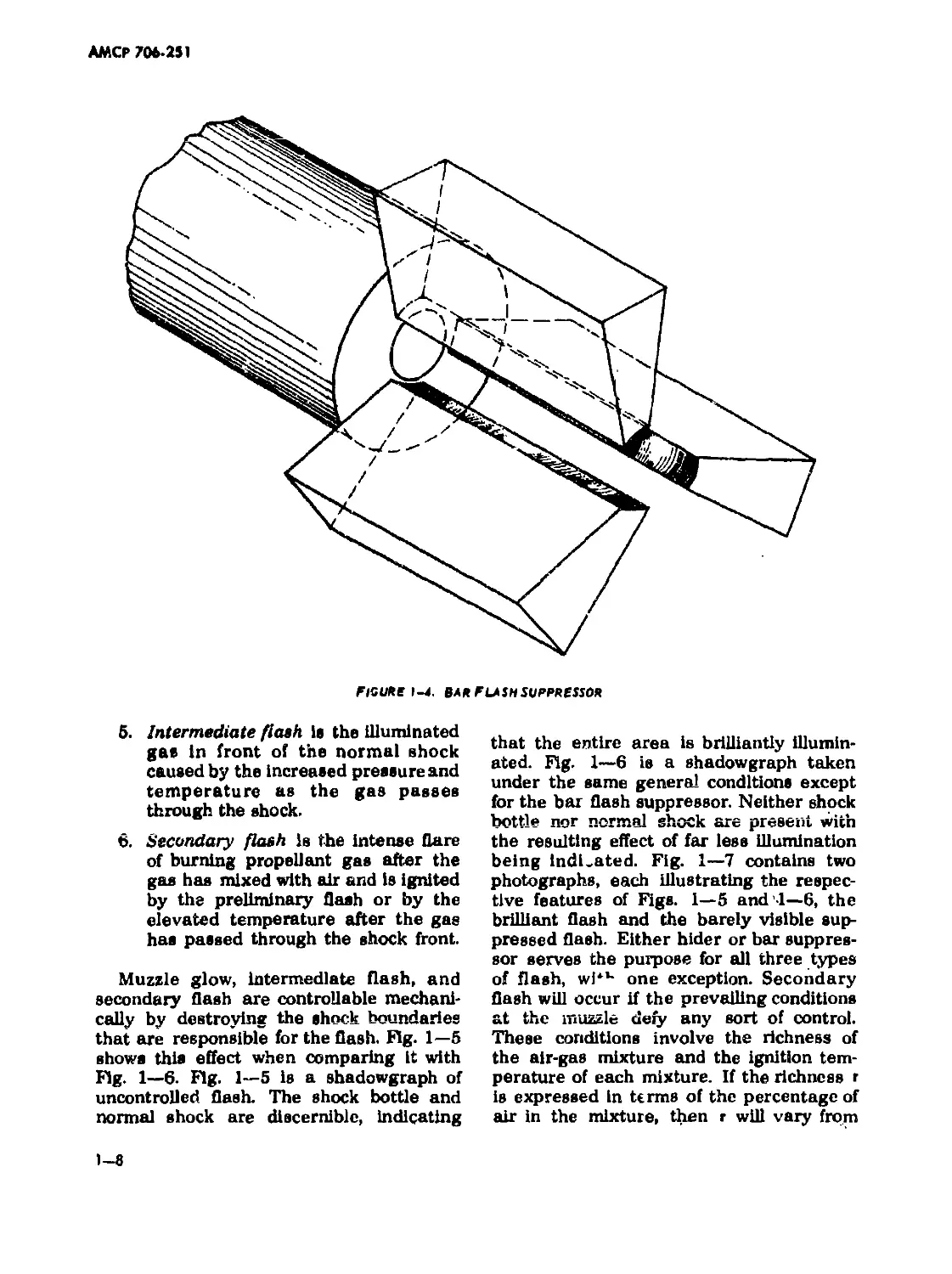
1—3.3.2 Purpose ond Daxripfion of Typo»
A flash hider or suppressor reduces muz-
zle flash to the extent that the illumination
does not reveal a gun position to the
enemy. The muzzle device may be a cone-
type (Fig. 1—3) or a bar-type (Fig. 1—4).
The former is sometimes called a flash
hider but irrespective of their labels, both
function according to the same physical
principles. Each is a simple device.
1—3.3.3 Thoory of Operation
In Chapter 2, five types of flash are de-
fined—preflash, primary, muzzle glow, in-
termediate, and secondary. To summarize:
1. Muzzle flash is a sequence of events
created by the propellant gas as it
issues from the muzzle.
2. Preflash is the burning of the gas
that leaks past the projectile before
the rifling fully engraves the rotating
'band or jacket and therefore before
obturation Is complete, or in worn
guns where obturation is never com-
plete.
3. Primary flash is the flame of con-
tinued burning of the propellant or
the incandescent gas at the muzzle.
Neither preflash nor primary flash
can be influenced by mechanical
means except by obscuration meth-
ods.
4. Muzzle glow is the illuminated gas
inside the shock bottie.
figure i-з. cone flash hider
1-7
АМСР 706-251
FlGUSB 1-4. вля flash supppssso*
5. Intermediate flash is the Illuminated
gas in front of the normal shock
caused by the increased pressure and
temperature as the gas passes
through the shock.
6. Secondary flash is the intense flare
of burning propellant gas after the
gas has mixed with air and is ignited
by the preliminary flash or by the
elevated temperature after the gas
has passed through the shock front.
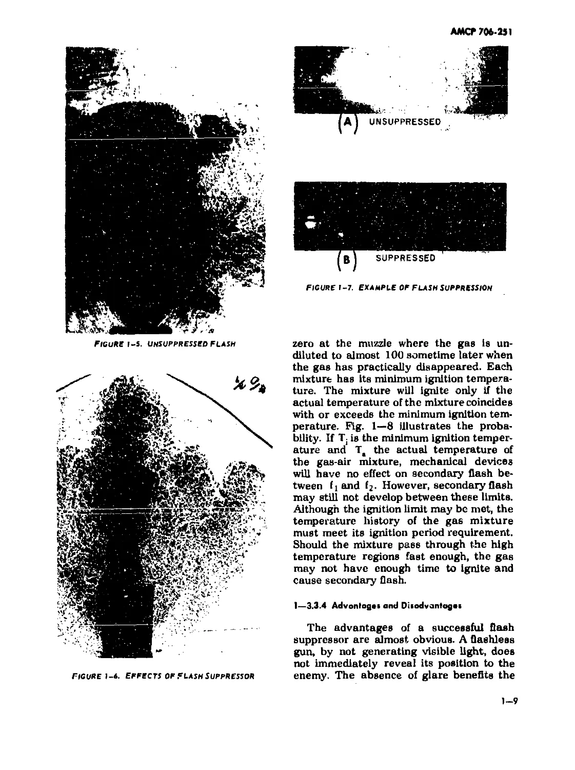
Muzzle glow, intermediate flash, and
secondary flash are controllable mechani-
cally by destroying the shock boundaries
that are responsible for the flash. Fig. 1—5
shows this effect when comparing it with
Fig. 1—6. Fig. 1—5 is a shadowgraph of
uncontrolled flash. The shock bottle and
normal shock are discernible, indicating
1-8
that the entire area is brilliantly illumin-
ated. Fig. 1—6 is a shadowgraph taken
under the same general conditions except
for the bar flash suppressor. Neither shock
bottle nor normal shock are present with
the resulting effect of far less illumination
being Indicated. Fig. 1—7 contains two
photographs, each illustrating the respec-
tive features of Figs. 1—5 and -1—6, the
brilliant flash and the barely visible sup-
pressed flash. Either hider or bar suppres-
sor serves the purpose for all three types
of flash, wi*K one exception. Secondary
flash will occur if the prevailing conditions
at the muzzle defy any sort of control.
These conditions involve the richness of
the air-gas mixture and the ignition tem-
perature of each mixture. If the richness r
is expressed in terms of the percentage of
air in the mixture, then r will vary from
АМСР 706-231
FIGURE 1-5. UNSUPPRESSED FLASH
FIGURE 1-7. EXAMPLE OF FLASH SUPPRESSION
FIGURE 1-*. EFFECTS OF FLASH SUPPRESSOR
zero at the muzzle where the gas is un-
diluted to almost 100 sometime later when
the gas has practically disappeared. Each
mixture has its minimum ignition tempera-
ture. The mixture will ignite only if the
actual temperature of the mixture coincides
with or exceeds the minimum ignition tem-
perature. Fig. 1—8 illustrates the proba-
bility. If Tj is the minimum ignition temper-
ature and Ta the actual temperature of
the gas-air mixture, mechanical devices
will have no effect on secondary flash be-
tween fj and fj. However, secondary flash
may still not develop between these limits.
Although the ignition limit may be met, the
temperature history of the gas mixture
must meet its ignition period requirement.
Should the mixture pass through the high
temperature regions fast enough, the gas
may not have enough time to ignite and
cause secondary flash.
I—3.3.4 Advontogai and Diiodvantagai
The advantages of a successful flash
suppressor are almost obvious. A flashless
gun, by not generating visible light, does
not immediately reveal its position to the
enemy. The absence of glare beneflts the
1-9
АМСР 706 251
figure i-в. Flash prediction Temperature Curves
crew by not hampering visibility. The sup-
pressor's primary disadvantage is its ten-
dency to generate more smoke than other-
wise would be emitted. Other disadvan-
tages, secondary in nature, are added
weight, added costs, and susceptibility to
damage during handling.
1-3.4 SMOKE SUPPRESSORS
I—3.4.1 History
Gunpowder ceased to be a powder about
1860 when General T. J. Rodman discov-
ered the principle of progressive combus-
tion. Propellants thereafter came in gi ains
the sizes of which were compatible with the
size of the gun. Although ballistics im-
proved after this change, black powder was
still unsatisfactory because, among other
undesirable effects, it produced large
amounts of smoke. The smoke problem
was reduced considerably in 1886 when
nitrocellulose was introduced as a smoke-
less propellant, however, enough smoke
was generated by other ammunition com-
ponents to perpetuate the search for a
smoke suppressant. The emphasis on flash
suppression by propellant additives did not
help because these additives usually gen
erated more smoke. Unfortunately, addi-
tives that reduce smoke generally contri-
bute to more intensive flash, thus directing
the search toward a mechanical smoke
suppressor.
Gun smoke is formed by the presence of
email particles suspended in muzzle gases.
These particles may condense from a gas
to a solid or liquid state, or may be minute
particles of metal or metallic oxides, de-
rived from cartridge case, projectile, and
barrel. Water vapor and carbon particles
are also present in the propellant gas.
When exposed to the atmosphere, the water
vapor may condense and increase the den-
sity of the smoke. Air temperature and
relative humidity will influence the forma-
tion and longevity of this contribution to
the density. Gun smoke can be suppressed
by removing some or all of these particles
from the gas. Before 1947, little research
effort was made for this purpose. An exten-
sive literature survey at this time on Dash
and smoke found over 900 references, of
which only four dealt with gun smoke’*.
From the survey, the conclusion was
reached that gun smoke was derived pri-
marily from the projectile, primer, and flash
suppressant and contained both water-
soluble and insoluble particles. Copper,
lead, zinc, antimony, and iron are the prin-
cipal elements of the insoluble particles,
whereas compounds of potassium, copper,
chlorine, sulfur, and sodium predominate in
the soluble particles. Collecting the smoke
for the analysis was difficult. Mechanical
filters were unsuitable but attempts at col-
lecting smoke particles proved veiy effi-
cient with electrostatic precipitators. After
the literature survey, a research program
was organized to ascertain the sources, and
the qualitative and quantitative nature of
the smoke particles to form a firm basis
for the development of efficient smoke sup-
pressors.
1—3.4.2 Purpoie, Description, ond Operation
Smoke suppressors should be capable of
removing the visible particles from the pro-
pellant gases without inducing or contribut-
ing to other deleterious effects such as
flash. The particles are removed by filtra-
tion. In the laboratory, successful filtering
•Superecrtpt numbers refer to References at the end of thie
handbook.
1-10
АМСР 706-251
has been achieved electrostatically. This
technique is not readily applicable for field
use. Generally, the smoke suppressor is a
long annular chamber the inside diameter
of which is larger than the gun tube bore
so as not to impede the radial expansion
of the propellant gas as it leaves the muz-
zle. The inner wall is perforated for the gas
to pass through it and enter the chamber
which is packed with a porous medium.
Since the size of a smoke particle is 0.5
micron or less, a filter which would screen
out this size material would be impractical,
sufficient time not being available for the
filter to accept the total flow. In addition,
the filter passages would soon be clogged
and useless. To avoid these deficiencies,
the filter is made much more porous to
permit a more generous flow of gas. How-
ever, no straight channele exist; hence the
smoke particles must continuouslylmpinge,
or bounce, from one solid filter element to
another, eventually losing ail momentum
and stopping. The gas continues to flow
into the chamber until the muzzle gas pres-
sure falls below the suppressor chamber
pressure, then flow reverses and exits from
the inner cylinder. The mechanics of opera-
tion are related more to the function of a
settling tank rather than to a filter.
1—3.4.3 Advantage» and Disadvantage»
An efficient smoke suppressor is advan-
tageous if it fulfills its purpose and may be
of further use by suppressing flash. One
disadvantage stems from the ability, at
times, of inducing flash. Other disadvan-
tages are the usual—added weight, added
cost, and probably frequent maintenance,
particularly the cleaning or replacing of
filter elements.
1—3.4.4 Type»
Two general types of smoke suppres-
sors have been used successfully, the elec-
trostatic type which thus far Is confined to
the laboratory, and the filter or impinge-
ment type. The latter may be subdivided
into three categories. The first makes no
attempt to control the flow, for the perfora-
tions are spaced evenly around and along
the inner wall. The second may have per-
forations of one size evenly spaced around
the periphery but becoming more dense in
the axial direction of flow, or may be the
same in number but increasing in size in
this same direction. In tills way, accessi-
bility to the chamber increases as pressure
drops along the axis thus making an
attempt to equalize the flow into the cham-
ber at all points. The third category is the
tapered bore suppressor. Experience shows
that the perforations nearest the gun muz-
zle frequently become clogged with copper
and other smoke particles. To relieve this
tendency, the inner diameter of the sup-
pressor is made larger than would other-
wise be necessary while the exit diameter
would be of conventional size, thereby pro-
viding a conical inner surface. In theory,
this construction distributes the impinging
properties of the perforations evenly along
the length of the suppressor or at least
delays the clogging of those nearest the
muzzle.
1—3.5 NOISE SUPPRESSORS
The report or noise of a firing gun is
numbered among the various objectionable
phenomena that develop at the muzzle.
Noise is closely associated with flash and
muzzle blast inasmuch as attempts to
attenuate any of the three will unquestion-
ably have some influence on the other two.
On th< other hand, if no controlling mea-
sures are taken, secondary flash may pro-
long the duration of report and muzzle
blast but not necessarily increase their in-
tensity. And, since muzzle gas pressures
are related to ail three, noise and blast
intensity may be assumed to influence
flash.
Noise produced by weapon firing can be
hazardous to hearing, cause communication
interference, and aid the enemy in detec-
tion. A blast deflector offers relief to the
crew by diverting the harmful pressure
waves away from the crew area but with-
out reducing the intensity to the extent
where it becomes undetectable. A flash
suppressor, however, can incorporate fea-
tures that reduce the intensity of the noise.
1-11
АМСР 706-251
If this type muzzle device can be developed
to the point where both flash and noise
can be reduced to acceptable limits, two
knotty problems become solved simultane-
ously. A large amount of effort has been
expended on flash suppressors; consider-
ably less on noise inhibitors. A measure
of success has been achieved in the sup-
pression of noise through experimentation-
No general design procedures, either the-
oretical or empirical, have been developed
for a noise suppressor, primarily because
no appreciable effort was ever assigned to
develop this type of muzzle device. A mea-
sure of success has been achieved in the
suppression of noise but usually as a by-
product of the development of another type
of muzzle device, such as a flash suppres-
sor.
1—3.6 SORE EVACUATORS
Rapid fire tank or dosed-cab mounted
guns have a tendency to discharge propel-
lant gases into the cab when the breech is
opened to receive the next round. This re-
verse flow not only is disconcerting to the
crew but also reduces its effectiveness by
impairing sight and breathing. Farther
damage is sustained on the occasions when
flashback occurs. To dispel the accumula-
tion of breech gas flow, large Installations
such ac naval gun turrets resort to rapid
ventilation methods. However, this method
of removing the objectionable gas requires
bulky equipment, not readily adaptable to
the already overcrowded tank compart-
ments.
Preventive measures, usually more
attractive than corrective ones, are avail-
able in the bore evacuator. The evacuator
is simply a gas reservoir that is attached
to the gun tube. Gas flow between reser-
voir and bore is achieved through one or
more nozzles that connect the two cliam-
bers. From the time the projectile passes
the nozzles until it leaves the muzzle, pro-
pellant gas flows into the evacuator. When
the pressure in the bore drops below that
in the evacuator, the stored gas reverses
its earlier flow and, by being directed by
the nozzles toward the muzzle, exits there
at an appreciable velocity. The flow of gas
from evacuator toward muzzle creates a
partial vacuum in this region which induces
clean air to enter the breech. This air,
under the influence of the differential pres-
sure, continues to flow toward the muzzle
to flush the bore of residual gas, thereby
precluding reverse propellant gas flow into
the gun compartment.
1-12
АМСР 706-25)
CHAPTER 2
MUZZLE GAS FLOW
2—1 MUZZLE GAS PHENOMENA
As it leaves the muzzle, the projectile is
followed by what appears to be a violent
eruption of propellant gases. This eruption
is called muzzle blast- Actually, the blast is
gas activity that adheres to a definite se-
quence of events. It is a jet of short dura-
tion formed by hot, high pressure gases
that follows a well-defined series of stages
as it grows and decays. Descriptively, muz-
zle blast is a system of normal and oblique
shock waves that form the boundaries of
the region in which the principal expanding
and cooling of gases occur. Surrounding
the shock boundary is a turbulent shell and
outside this shell is a turbulent "smoke
ring" that moves radially and advances
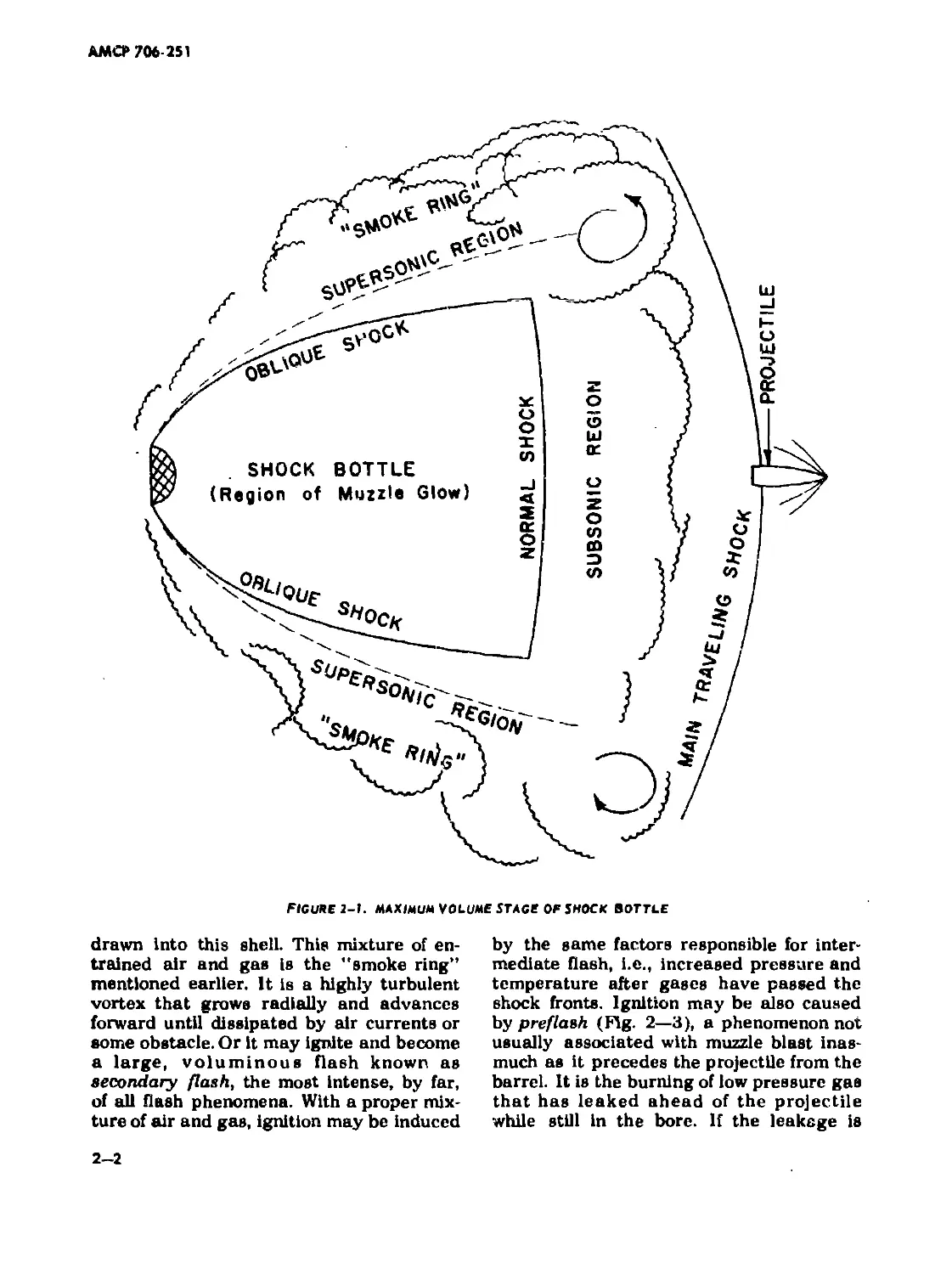
forward. Fig. 2—1 is a sketch of the muzzle
blast after 25 calibers of bullet travel from
the muzzle. It shows all the phenomena of
the blast in their relative positions except
for the weak shock caused by the air
pushed ahead of the bullet. Fig. 1—5 is a
shadowgraph of a muzzle blast. The normal
shock, barely visible, is in the center of the
blast area.
The main traveling shock is formed in
the air by the released propellant gases
when they flow past the projectile and in-
duce a succession of weak shocks in the
relatively still air behind the first, but
weaker projectile-induced shock. This suc-
cession soon merges into a strong shock
ahead of the projectile. In the meantime,
the projectile, by interfering with the direct
gas flow, causes a strong shock to form be-
hind it. This shock eventually becomes the
quasi-stationary normal shock and with the
oblique shock, forms the central super-
sonic region, dubbed shock bottle, of the
jet. The flow into the bottle starts at the
muzzle where the gas is luminous. This
visible light, extending only a short dis-
tance, is called primary flash and'may be
white light, indicative of actual burning, or
it may be the red glow of luminous solids
in the gas. It is the white dot in Figs. 2—2
and 2—3.
The principal expansion of the jet is con-
fined to the shock bottle where the flow,
starting at the muzzle with a Mach number
close to one, is practically adiabatic. As the
gas continues to move until checked by the
shock boundaries, both Mach number and
absolute velocity increase rapidly with a
corresponding decrease in pressure density
and temperature; the temperature being
low enough most of the time so that the
gas ceases to radiate visible light. When
the light is visible, the illumination fills the
shock bottle but does not extend outside it.
This light, muzzle glow (Fig. 2—4), is very
weak and rarely observed. Flow stream
lines are straight and diverge from the
muzzle as in point source flow, but density
and pressure at any plane normal to the
bore axis drop uniformly from the axis
outward. In the region just outside the ob-
lique shocks, the gas that has crossed
these shocks still has supersonic velocities
and temperatures that have dropped below
the luminous range. On the other hand, the
gas moving ahead through the normal
shock decelerates to subsonic velocity,
compresses, and consequently has its tem-
perature elevated to approximate that at
the muzzle. This temperature is high
enough to cause intermediate flash, a red
or reddish-orange cone of light (Figs. 2—2
and 2—3). The base of the cone is on the
normal shock; the apex pointe away from
the muzzle. Not nearly as intense as sec-
ondary flash, intermediate flash casts
enough light to reveal position during night
firing.
Surrounding the layer of supersonic
gases is a turbulent shell in which propel-
lant gas containing large amounts of hydro-
gen and carbon monoxide mix with air
2-1
AMO* 706-251
FIGURE 2-1. MAXIMUM VOLUME STAGS OF SHOCK BOTTLE
drawn into this shell. This mixture of en-
trained air and gas is the "smoke ring"
mentioned earlier. It is a highly turbulent
vortex that grows radially and advances
forward until dissipated by air currents or
some obstacle. Or it may ignite and become
a large, voluminous flash known as
secondary flash, the most intense, by far,
of all flash phenomena. With a proper mix-
ture of air and gas, ignition may be induced
by the same factors responsible for inter-
mediate flash, i.e., increased pressure and
temperature after gases have passed the
shock fronts. Ignition may be also caused
by preflash (Fig. 2—3), a phenomenon not
usually associated with muzzle blast inas-
much as it precedes the projectile from the
barrel. It is the burning of low pressure gas
that has leaked ahead of the projectile
while still in the bore. If the leakage is
2-2
AMCF 706-251
figure 2-2. primary ano intermediate flash
copious and the burning duration long, the
air-gas mixture can overtake it and thus
become ignited. Gas leakage of this nature
usually happens only in worn guns and is
not considc ed a major problem.
Flash is a by-product of muzzle blast
and, regardless of its appearance or In-
tensity, does not greatly influence the
evolution of the jet which is divided into
two periods — the growth and decay of the
shock bottle. Although gas discharge from
the gun decays steadily, the activity of the
bottle offers a convenient vehicle for a
qualitative analysis of the sequential
events. The growth, already discussed, is
complete when the bottle attains its maxi-
mum volume (Fig. 2—1). Hereafter, the
bottle goes through two well-defined pe-
riods of evolution. During the first, the nor-
mal shock remains stationary about 15
calibers from the muzzle, but the projected
area diminishes until the bottle reaches
steady-state proportions, having a shape
similar to the outline sketched in Fig. 2—5.
The last evolutionary period begins after
the steady-state condition. It involves the
steady shrinking of the bottle without ap-
parent change in shape.
Another phenomenon associated with
the decay of the jet has considerable
influence on obscuration activity. This is a
rarefaction wave that starts at the time of
shot ejection and travels from muzzle to
breech, reflected toward the muzzle to
emerge eventually in the jet. While this is
going on, the normed shock moves toward
the muzzle. Shock and rarefaction front will
meet somewhere ahead of the muzzle. The
events that happen afterward simulate the
rupture of a membrane restraining com-
pressed gas in a tube. The shock pressure
drops and the bottle collapses to complete
the final phase of the blast phenomenon.
2—2 RAISING OF DUST BY A GUN BLAST
The raising of a dust cicud when a gun
is fired too close to dry ground involves
lifting the dust off the ground and its subse-
quent diffusion. Two forces are responsible,
the pressure gradient surrounding the dust
2-3
АМСР 706-251
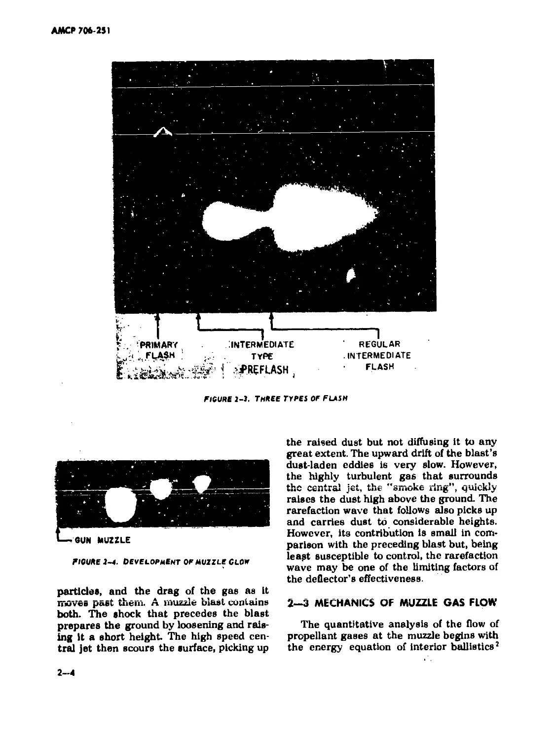
FIGURE г-3. THREE TYPES OF FLASH
FIGURE 2-4. Development of muzzle Clof
particles, and the drag of the gas as it
moves past them. A muzzle blast contains
both. The shock that precedes the blast
prepares the ground by loosening and rais-
ing it a short height The high speed cen-
tral jet then scours the surface, picking up
the raised dust but not diffusing it to any
great extent. The upward drift of the blast’s
dust-laden eddies is very slow. However,
the highly turbulent gas that surrounds
the central jet, the smoke ring”, quickly
raises the dust high above the ground. The
rarefaction wave that follows also picks up
and carries dust to considerable heights.
However, its contribution is small in com-
parison with the preceding blast but, being
leapt susceptible to control, the rarefaction
wave may be one of the limiting factors of
the deflector’s effectiveness.
2—3 MECHANICS OF MUZZLE GAS FLOW
The quantitative analysis of the flow of
propellant gases at the muzzle begins with
the energy equation of interior ballistics2
2-4
АМСР 706-251
(RT - RT ) = 1 W v2 (1 + 6) +1 1' v2
Y- 1 ° 2 p ° 6 c °
(2-1)
where
R = gas constant, ft-lb/lb/*R
T = temperature of propellant gas hav-
ing done no external work, ° R
To = average temperature of gas at shot
ejection, °R
»o = muzzle velocity, ft/sec
Wc = weight of propellant, lb
Wp = weight of projectile, lb
Y = ratio of specific heats
6 = fractional heat loss to gun tube as
function of shot energy
Weight W is a force, a defined term, and is
expressed in pounds (lb). Mass is a com-
puted term M = W/g, lb-sec2/ft (slugs)
where g is the acceleration of gravity.
Other dimensions may be used provided
that proper conversion of factors are used.
Eq. 2—1 is the application of Reaal’s equa-
tion at the instant of shot ejection provided
that all the propellant has burned. A simi-
lar equation exists that includes the pro-
pellant gas energy3. Either may be used,
the choice involves only the value of 6. In
Eq. 2—1, by substituting у for 6 and 1.26
for Y (a good approximation), and solving,
the equation becomes 4
RT0 = RT - 0.26 (1/6 + 4Vp/7Wc v2 (2—2)
Appropriate values of RT, a characteristic
of tbe propellant, are available In thermo-
chemical tables. In some ballistic opera-
tions, RT is called specific impetus the
dimensions of which are ft-lb/lb; and
RT/(Y -1), of the same dimensions, is the
potential of the propellant. Numerically,
RT/(Y - l)is about 1.5 x 106 ft-lb/lb. How-
ever, to be dimensionally compatible, RT
in Eqs. 2—1 and 2—2, contains the acceler-
ation of gravity, so that RT In these and
subsequent equations has the dimensions
of ft2/sec2. Values of RT for some service
propellants are listed in Table 2—1.
2-5
AMO* 706-251
TABLE 2-1. RT OF SERVICE PROPELLANTS
Propellant Ml М2 M6 M8 M9
RT, (ft2'.ec2) IO 6 9.83 11.60 10.13 12.31 12.30
Propellant MIO Ml 5 M17 T28 IMR
2 2 w6 RT. (h 'tec ) 10 10.90 10.82 11.22 1118 11.18
After computing RTo, the pressure at
any position in the bore at the Instant of
shot ejection 5
12RTO
Р = -7у—ч
8 F"4
. psi (2—3)
where
A = bore area, in.2
V, = total volume of bore and chamber,
in.’
x = distance from breech, in.
g = acceleration of gravity, ft/sec2
4 = covolume, usually dimensioned
in.’/lb
RTO x ft2/sec2
At the breech where x = 0,
(2-4)
at the muzzle where Ax = V(,
(2-5)
A МСР 706-251
2—4 MUZZLE GAS MOMENTUM
Hugoniot's gas flow theory, although ac-
curate within a few percent, has been modi-
fied to calculate the flow and momentum
of the propellant gases after shot ejection.
The rate of flow, by neglecting the second
and higher powers of Wc/W which is com-
patible with the general accuracy of all the
equations, is
where
(2-7)
(2-8)
where g = acceleration of gravity, ft/sec2.
If the variables in Eqs. 2—6, 2—7, and
2—8 are assigned the dimensions of
Eq. 2-3
Q = lb/sec
6 = sec
M = Ib-sec/sec
2-7
AM СР 706-251
The momentum equation of the gas at the
muzzle is the integral of Eq. 2—8 at any
given time t > provided that the second and
higher powers of Wc/Wp are neglected.
Retaining the above dimensions,
M
6
i.O +
(y+ i) Wc \
i2yWp )
, Ib-sec
(2-9)
2-S
АМСР 706-291
CHAPTER 3
MUZZLE BRAKES
3-1 THEORY OF GUN GAS DEFLECTION
3-1.1 NOZZLE FLOW
The passages in a muzzle brake are
treated by the one-dimensional theory of
nozzles, without allowance for friction at
the walls. Furthermore, the gas is assumed
to fill the nozzle completely; true only if
the nozzle is so designed that there is no
break away from the walls. To prevent
this, the semi-angle of a conical nozzle
should never exceed 30 *, a rather large
angle. Smaller angles result in larger noz-
zles, thereby increasing muzzle brake
weight. If more weight can be tolerated, a
smaller semi-angle of about 20° is pre-
ferred. Semi-angles below 15° offer no ap-
preciable advantage over their immediate
larger counterparts.
Fig. 3—1 is a schematic of a one-baffle
brake but is adequate for defining the geo-
metry and the flow.
A = bore area
Ab = area of projectile passage
Ae = exit area of baffle passage
Aj = inner area of baffle passage
ne = exit speed-up factor
iij = inner speed-up factor
% = muzzle velocity
a = baffle deflecting angle
Ф — semi-angle of nozzle
Because of the projectile passage, not all
of the gas will go through the baffle pas-
sage, a portion will continue straightahead,
the amount depending on the ratio of exit
areas. The weight of the quantity of gas
diverted through the baffles is expressed as
FIGURE 3-1. MUZZLE BRAKE GAS FLOW DIAGRAM
(3-1)
where Wc = weight of the propellant
л - , , ratio of baf-
Aj + Ab
flc inlet area to toted available area.
The weight of gas flowing through the pro-
jectile passage
<3-2>
where Д. = b ,
b A- + A.
4 D
the ratio of projectile
passage area to total available area.
The area of the baffle passage should di-
verge smoothly from inside to exit follow-
ing a straight line function or a smooth
3-1
АМСР 706-251
curve. The divergence of gas from muzzle
to the first flow passages
A + A.
A, = (3-3)
The divergence of the gas at the baffle exit
Л.Г £ <3-4>
The velocity reaches its maximum value
when the nozzle area diverges to about 25
times the throat area, in this application,
the bore area. In practice, both nozzle and
baffles normally would be too large to
achieve the optimum condition. Fig. 3—2
shows the relation between speed-up factor
n and divergence A. The speed-up factor is
the ratio of exit to the entrance velocity of
a flow passage. Examination of the curve
shows that the gain in efficiency is small
while the increase in size and weight of the
muzzle brake IS large for a divergence
larger than 5.
The change in momentum, or thrust, of
the muzzle gas is computed in Eq. 2—8.
However, only a portion of the total gas
impinges on the baffle. According to Eq.
3—1, if m* is the mass of gas issuing from
the muzzle per second, the mass flow per
second impinging on the baffle
V.
A-m = —2m. (3—5)
The thrust on that baffle during that second
fb =AimJ.(vi - ve cos a) (3—6)
but Vj = п;уо and ve = nevo , therefore
*'b =Aim/nivo " nevo = 4V<> (3-7)
where Xu is the uncorrected speed-up factor
Xu = Ai(««i-ne «ко) (3—8)
3—1.2 THRUST CALCULATIONS
3—1.2.1 Diicu nian
When computing the value of X, a cor-
rection is needed to compensate for pre-
viously neglected friction and turbulence.
Experiments show that the computed Xuis
too large and ehould be reduced by a cor-
rection factor C^so that
K'-\Ax
(3-9)
Examples of determined from firing
tests are listed in Table 3—1.
Unfortunately, Table 3—1 offers little but
qualitative values because test models arc
few and parameters are lacking. A value
of = 1.5 should be adequate for initial
design concepts.
The maximum thrust on a muzzle brake
occurs at t = 0, thus providing a conven-
ient means for computing X . By substitut-
ing t = 0, Y = 1.26, g = 32.2, ft/sec2 in
Eq. 2- the thrust in pounds becomes
F - ГкС 12xl 26AWcRTo
b |_ * 32.2 V,
1.0 +
(3-10)
where C{ — thiust correction factor
w / w \
Fb = 0.26C, ART„ (1.0 + ^k, lb (3-11)
The dimensions of A and Vt are expressed
in inches. The value of X may be readily
computed from Eq. 3—11 for either single
or multiple baffle brakes.
By assuming that all needed parameters
are given or estimated, the computation
for X follows the procedure outlined below
for a 3-baffle brake such as shown in
Fig. 3—3.
3-2
AMCP706-2S1
TABLE 3-J. ^CORRECTION FACTORS
Type of ЗЬ,Ф=ЗО* ЗС,ф = 15* German German
Brake 2 or 4 Baffle. 2 or 4 Baffle» Single Baffle Double Baffle
1.45 1.25 1.60 1.60
SPEED-UP FACTOR
DIVERGENCE, Д
figure 1—2. Speed-up Factor vs Divergence
АМСР 706-251
Given or estimated data
Gun: Wc. fp, Vt, vo A, RT
Muzzle Brake: Ab, Ac> А;, а, Ф
(Subscripts 1, 2, 3, indicate the
respective baffles)
After solving for RTo in Eq. 2—2, the
thrust on any baffle becomes (Eq. 3—11)
For the first baffle:
Solvefor Aitand Ablof Eqs. 3—1 and 3—2
Solve for Ад and Aelof Eqs. 3—3 and 3—4
From Fig. 3—2, read п;. and nel corres-
ponding to and Ael.Now Insert the
known values into Eqs. 3—8 and 3—9
. Ai = A;i (пи _ nei cos °i )/C\ (3—13)
For the second baffle:
д>2 = ды A ti2A - (3-14)
Ai3 Ab?
дьа=дыт—— (3—16)
Ai2 + Ab2
A;t + A. ,
Д> = A> - Abt (3-16)
де2 = д2 £1 (3-17)
Find the values of ni2 and that corres-
pond with Д2 and Де1 from Fig. 3—2 and
insert the appropriate values in Eq. 3—8
X2 =Ai2 (ni2 - ne2 cos (3—18)
FICUKB 3-3. 5СНВЦАГЮ OF MUZZLE BRAKE CAS FLOW
АМСР 706-231
For the third baffle:
A Ai3
дв =дЬ2 i (3-19)
лв Аьз
A..
ДЬЗ^Ь2Т-=ПГ- (3-20)
A13 АЬЗ
А,-+ Ah,
дз -Л, 2L- LL. (3-21)
ЛЬ2
де3=д3^2 (3-22)
Ai3
Find the values of nj3 and ne) that corres-
pond with and Де} in Fig. 3—2 and In-
sert the appropriate values in Eqs. 3—8
and 3—9
Xj =Д13(п.} -ne3 cos Oj)/C\
The value of X for the muzzle brake
X = Xj + x2 -» x3 (3—23)
If more baffles are used, the above proce-
dure merely, continues the sequential pat-
tern so that
X=X1+X2+-------+ xn4 +Xn (3-24)
The practice of adding many baffles is dis-
couraged by the fact that the increase of
baffles follows the law of diminishing re-
turns. The two charts in Fig. 3—4 illustrate
this principle. Here, the thrust on both in-
dividual and series of baffles is measured
in proportion to the maximum thrust had
100 percent cf the gases been utilized and
then plotted for the percentage of gas
tapped from zero to 100%. Through the
lower range (0 — 36%) of the amount of
gas tapped, multiple baffles are needed for
an effective muzzle brake indicating poor
design and inefficiency. In the upper range
(above 35%), only two will be almost as
effective as any number of baffles exceed-
ing two.
The modified Hugoniot theory embodies
inaccuracies in thrust computation during
the decay period of the muzzle gas; too low
at the beginning and too high at the end.
To correct for the thrust at the beginning
when the thrust is highest and therefore
loads are critical, the thrust is increased
by 70 percent. Fig. 3—5 shows the com-
parison between the computed and actual
thrust. The 70 percent increase is included
for strength considerations. However, for
the total momentum during the entire
period, the inaccuracies in the modified
theory are compensating and are reason-
ably accurate without additional correc-
tions. Another correction for the thrvst in-
volves the effect of closing the proj ctile
FIGURE 3-4. EFFECTIVENESS OF MULTIPLE BAFFLES
3-5
AM СР 706 251
TM#UST
FIGURE J-J. THKUST COMPARISON
passage as the projectile passes through
it. This correction for any given baffle is
Ф = 30°, semi-angle of nozzle
n = 4, number of baffles, all baffles and
passages are identical
From Eq. 2—2,
/ 1 ,4 17 \ 2
RTo=RT-0.26[ 6+7T /’•
10.6 - 2.34 ) 106 = 7.37 x Ю6 ft2/sec2
21/
The total thrust in terms of XC, (Eq. 3—11)
Cn = +
(3-25)
W / W
F. = 0.26 XC. --ART ( LO + -£.
b vt \
The thrust correction factor now becomes
C, = i.70Cn (3-26)
= 0.26 7.34 x 7.37 x 106 / 1.0 + -|L 'j XC,
3—1.2.2 Exampls Problem
Gun data:
A = 7.34 in.2, bore area
RT = 10.6 x 106 ft2/sec2, type N. H.
propellant
j =. 3fMU*b ft / vglrvitv
О mvw • w«.wj ... и т i— - •*’*'"
V, = 1357 in. \ bore volume
Wc = 8 lb, propellant weight
Wp = 17 lb, projectile weight
Muzzle Brake data:
Ab = 8.0 in.2, area of projectile passage
A = 14.25 In.2, exit area of flow passage
= 11.0 in.2, inlet area of Dow pas-
sage
C x = 1.5 speed-up factor correction
о = 135°, angle of gas deflection
cos a - -0.70711
= 89400 XCt, lb
(3-27)
From Eq. 3—3
Д1 = ^=1|28 = 2.5888
To save space and avoid repetitious alge-
bra, the values for the various computed
data from Eqs. 3—1 to 3—26 are listed in
Table 3—2. The maximum Instantaneous
load on the muzzle brake occurs when the
projectile has cleared the first baffle and
is passing through the second. On the
assumption that the brake force is distri-
buted in direct proportion to Xn/X, the
maximuni instantaneous force on the in-
dividual baffles as the projectile is passing
through that baffle is
VFb7 (3-28)
АМСР 706-251
TABLE 3-2. COMPUTED DATA FOR MUZZLE BRAKE THRUST
Dan l»i Baffle 2nd Baffle 3rd Baffle 4th Baffle
ль a.o 8,0 8.0 8.0
A e 11.25 14.25 14,25 14.25
A i 1I.0 11.0 11.0 11.0
Ai /<A! tAb> 0.579 0.579 0.579 0.579
V<VAb> 0.421 0.421 0.421 0.421
(Ai+Ab)/Ab-1 2.588 2375 2375 2.375
VAi 1.295 1.295 1-295 1.295
Д, 0.579 0.244 0.102 0.043
0.421 0.177 0.075 0.032
2 59 6.15 14.61 34.70
3.35 7.96 18.92 44.93
ni 1.94 2.25 2.43 2.57
% 2.05 232 2.47 2.60
n cos O' -1.45 -1.6-1 -1.75 -1.9Л
Kn 1308 0.633 0.84 0.12
X. 1308 1.941 2.225 2.352
Хп(Л1+ль)/А. 2.258 1.093 0.490 0.219
Cn 1.727 1.237 1.093 1.038
C| 2-936 2.103 1.858 1.765
Fb 343,000 365,000 369,000 371,000
343,000 119,000 47,000 20,000
The large loads appearing on the first and
second baffles are clear evidence why muz-
zle brakes must be ragged structures.
3—2 PERFORMANCE CALCULATIONS
3-2.1 IMPULSE
Although only the maximum force is
needed to establish the size of the struc-
tural components, the decreasing brake
force throughout the decay period of the
muzzle gas activity performs the essential
function of a muzzle brake, producing the
impulse that reduces the momentum of the
recoiling parts. The momentum of the muz-
zle gas at any time i (Eq 2—9), when
multiplied by the speed-up factor X , gives
the impulse of the brake during that time
3-7
АМСР 706-251
Except for detailed recoil analysis, these
incremental impulses are not needed. How-
ever, the sum of these increments is needed
for the total effect on recoil for preliminary
design and may be found by substituting
the limits of t = 0 to t = ® thereby reduc-
ing the expression
1.0 -
to 0.0 and 1.0. The total impulse induced
on the muzzle brake
’mb
YRT,
Wp
(3—30)
Substituting 1.26 for у and 32.2 ft/sec2
for g
________ / 0 15 W \
I.b s ° KWc У RTo I 10 * —y 1 - lb_eec
\ Wp /
(3-31)
The impulse induced on the gun during
this same period
I =11
8 <
RT
2k
0.15 W,
Wp
1 -
k—2 "
t_\ к
ib-sec
(3—32)
Bated on Eqa 6.312 and 6.4Q4 of Reference 5.
ЛМСГ 706-251
The resultant impulse on the recoiling parts
(3-33)
where
- X ГжьА)! 1/k
(1—k) [ 2—к
V
Xy/_2.V-1 = 0.696 X
V+l/
(3-35)
к = (y-D/y
y- 1.26
Operating within the limits of t = 0 to t = «о
It = 0.0417 (i—B) Wc
, ib-sec
(3-36)
Except for the parenthetical expression
(1—B), Eq. 3—34 is Identical to Eq. 3—32,
therefore by observation
lr =(1-01,
(3-37)
3—2.2 EFFICIENCY OF A MUZZLE BRAKE
3—2.2.1 Diicuuion
There are generally three types of effi-
ciency designations of a muzzle brake. The
first measure of efficiency is the momentum
index В that is zero if the gun has no muz-
zle brake. According to Eq. 3—36, as В in-
creases. the residual impulse on the recoil-
ing parts decreases aftei the projectile
leaves the muzzle. The intrinsic efficiency
and the gross efficiency are the other two
types. The gross efficiency is the percent-
age reduction of recoil energy caused by
the brake.
3-9
АМСР 706-251
The total momentum яг of the recoiling
parte is equal to the momentum of the pro-
jectile and gae just as the projectile emer-
ges from the muzzle, plus the impulse of
the gas afterwards
mr = M,.vf = Mpvo +1 Mcvo + i*
(3-38)
mf = Mevo + 1ж
where
Mc = mass of propellant gas
M^Mp + LM,. effective mass
Mp = mass of projectile
Mr = mass of recoiling parts
v( = velocity of recoil
With a muzzle brake, the total momentum
of the recoiling parts
«rb = 4’rb = V° + J Me% + ’r
(3-39)
mrb = M.’o + ‘r
Converting momentum to velocity of recoil-
ing parts
, =SQJ2L
r 4 (3-40)
where
W. - weight of muzzle brake
D
Wf = weight of recoiling parts
* =• weight of recoiling parts with muz-
r zle brake [
Fig. 3—6 is a curve indicating the intrinsic
efficiency for various values of the momen-
tum index.
3—2.2.2 Exonipls Problem
The computed effectiveness of a muzzle
brake here illustrated is for the same gun
and brake that were used to compute the
thrust. The given and computed data in
Table 3—2 are also used. Before the per-
formance can be computed, characteristic
weights must be estimated for the recoiling
parts and the muzzle brake. The muzzle
energy
E =-M„v?=4x—”9* W6 = 2,376,OOOft-ib
“ 2 p ° I 32.2
The recoiling weight6
Wr = 8.2 x 10"4 Em = 1950 ib
Muzzle 1-baffle, 150 ib; 2-baffie, 220 lb,
brake
weight: 3-baffle, 260 ib; 4-baffle, 3G0 lb
Since energy E = у Mv2 and since the gross
efficiency is based on the reduced recoil
energy, the gross efficiency
(_ 2 -2 \
I-Ту™. 1 100 (3—41)
mr /
The intrinsic efficiency is the gross effi-
ciency corrected by the weight of the muz-
zle brake
(3—42)
From Eq. 3—36
(015V
1.0+
»b
= 0.0417 > 8 x 2715 [ 1.0 + \
\ 17 /
= 905.7 x 1.07 = 969 ib-eec
From Eq. 3—37,
I, = 969U-B)
3-10
АМСР 706-251
(This relationship is only approximately correct
for normal guns and for the order of velocity
used to determine this relationship.)
FIGURE J-*. PREDICTED APPROXIMATE EFFICIENCY
From Eq. 3—38
3-2.3 EFFECTS ON RECOIL
/ 17 -i- 8/2
32.2
3000 = 1957 ib-sec
m, = MevQ + 1я = 2926 ib-sec
2 « .. -~6 1.2 „2
mr -o.5oi « iu io - sec
As indicated earlier from the thrust in
Table 3—2 the efficiencies of Table 3—3
show that little is to be gained by using the
third and fourth baffles.
3—2.3.1 Di»cu»»ion
A muzzle brake may affect either recoil
force, recoil length, or both. There are in-
finite variations but only two limits are
demonstrated. After acceptable values for
the two parameters are established for a
gun without a muzzle brake, variations in
recoil force are computed lor a constant
length of recoil. Then, holding the force
constant, variations in length of recoil are
computed. Earlier, Eqs. 3—38 and 3—39
showed that the momentum of the recoiling
3-11
АМСР 706-291
TABLE 3-3. COMPUTED DATA FOR MUZZLE BRAKE EFFICIENCY
Data 1-Baffle 2-Baffle 3‘Baffle 4-Baffle
Wb 150 220 260 300
*rb 2,100 2,170 2,210 2,250
X. 1-50B 1.941 2.225 2.352
в 0.910 1.351 1.549 1.637
1-B 0.090 -0.351 -0.549 -0.63?
87 -340 -532 -617
mrb 2,044 1,617 1,425 1,340
m?b s 10 4.178 2.615 2.031 1.796
W . /w rb r 1.077 1.113 1133 !.154
100 wb/vr 7.7 11.3 133 15.4
s 51.2 69.5 76.3 79.1
€. 47.4 66.1 73.1 76.1
parts was equal to the combined momen- tum and impulse of projectile and propel- lant gas. The velocity of free recoil (i. e., no resistance offered while the propellant gas is still effective) vf = (3-43) "rb The energy of free recoil E • “ «1 rb 2 f иГ1“я/ Note that mfb, M(b, and EJb are equiva- lent to mt, Mr. and Er, respectively, when the gun has no muzzle brake. On the assumption that the gun is firing horizontally, the recoil force F p - »b * T" (3—45) where L = length of recoil 3—12 More accurate detailed methode are avail- able for recoil analyses7 but are not needed for this demonstration. A limit of either F* or L establishes the limit of the other. The actual efficiency based on recoil energy <. = 100 (1.0 - E,b/Er) (3-46) where Et x free recoil energy without muzzle brake Erb = fra? recoil energy with muzzle brake When the recoil force is held constant, ths length of recoil varies and is expressed as L = (3-47) *• 3—2.33 Exempt* Problem Continuing with the same gun and muz- zle data of tiie two early examples, from
АМСЯ 706-251
Eq. 3—43, the velocity of free recoil with
no muzzle brake
9< = £ = ЗЦДШ=48.М«/.ес
The energy of free recoil (Eq. 3—44)
E = 1 x 1252 * 2333 = 70,64? ft-lb
r 2 32.2
Aeeumlng a 30-in. (2.5 ft) length of recoil,
the recoil force (Eq. 3—45)
F = = 2b,250 lb
* 2.5
For the 1-Baffle brake when the recoil force
is the same as that for the brakeless gun,
the length of recoil (Eq. 3—47)
L = * 31950 s 13.6
28250
The actual efficiency according to Eq. 3—46
is
<. = 100 (1.0 = 54.8%
From the point of view of recoil effects,
most of the gain is experienced with a muz-
zle brake of one or two baffles. In keeping
with the observations for thrust and effi-
ciency, any further increase in the number
of baffles is discouraged; the relume do not
justify the effort. Note that the more accu-
rately estimated efficiencies of Table 3—4
are slightly higher than those estimated in
Table 3—3 but the difference may be con-
sidered as not significant. Fig. 3—7 has
curves graphically depicting these trends.
3-3 ANALYSIS OF SPECIFIC TYPES
3—3.1 CLOSED MUZZLE MAKE
3—3.1.1 Difcuwion
The computation of axial thrust and the
subsequent performance analysis of the
TABLE 3-4. EFFECT OF MUZZLE BRAKE ON RECOIL
Data No Brake 1-Baffle 2-Baffle 3-Baffle 4-Baffle
Wrb(lb) 1,950 2,100 2,170 2,210 2,250
m^Qb-aec) 2,926 2,044 1,617 1,425 1,340
Vf((t/aec) 4f,3 31.3 24.i) 20.9 19.1
E,b(fr-lb) 70,640 31,950 19,410 14,990 12,750
L (in.)* 30.0 30.0 30.0 30.0 30.0
FJlb)’ 28,250 12,780 7,760 6,000 5,100
Fe(lb)*’ 28,250 28,250 28,250 28,250 28,250
L (in.)** 30.0 13.6 8.2 6.4 5-4
%(%) 0.0 54.8 72.5 78.8 81.9
"Constant recoil distance; variable recoil force
••Constant recoil force; variable recoil distance
3-13
AMCF 706-251
30
25
100
muzzle brake were those for a closed muz-
zle type and they need not be repeated.
However, unless the brake is symmetrical,
unbalanced forces and impulses normal to
the bore axle will occur. Since the muzzle
gas is usually diverted upwards when the
brake is asymmetric, induced force and im-
pulse will be downward. Fig. 3—8 is a
schematic front view of an asymmetric,
closed brake. According to Eq. 4—27 of
Reference 8, the normal nondimensional
brake force
N
w = j- »j n2j cos p, (3—48)
i
where fr = of Eq. 3—9, w = X , and p,
is the diverting angle measured from the
vertical. Express the values in Eq. 3—48
to correspond with those of the preceding
equations so that Eq. 3—8 becomes
wu = Ajnecosp (3—49)
figure.,-;. Schematic of asthmetric closed brake
3-14
АМСР 706-251
Following Eqs. 3—1 through 3—26
W =(AilnelC0S 0;+Д12Пе2СОв ₽2 +----+AijneiCOS рЛДп
(3-50)
3—3.1.2 Exempt* Problem
Assume that all waffles are of equal size
and shape
p= 30* , (, = 1.5, cos p/fn =0.577
The remaining data are those listed in
Table 3—2
w = ^Ai|nr| + Ai2ne2 + Д;|Пеj 0.577
Based on Eq. 3—25
+ 1.727 Wn)/W
where
Ai + Ab _ 11.0 + 6.0 j 727
Aj " 11.0
The maximum brake force normal to the
bore axis is computed from Eq. 3—27, with
C, being computed from Eq. 3—26. The
impulse normal to the axis Is computed
from Eq. 3—31. Substituting w for X
(3-51)
(3—52)
Fn = 8?400(*>C,
(3—53)
.----- / 0.15 W
ln=0.029uWc fW* (l.Q+_X
(3-54)
= 0.029 * 8 x 2715 * l.O7D5w = 67>w, Ib-sec
The available and computed data are listed
u Table 3—5.
3-15
АМСР706 251
TABLE 3-5. FORCE AND IMPULSE NORMAL TO BORE AXIS OF CLOSED MUZZLE BRAKE
Data lat Baffle 2nd Baffle 3rd Baffle 4th Baffle
Д, 0.579 0.244 0.102 0.041
n e 2.05 232 2.47 2.60
0.685 0327 0.145 0.065
w 0.685 1.012 1.157 1.222
1.727W(, 1.182 0.564 0.250 0.112
<:n 1.727 1.2.12 1.09.1 1.05’
<’•1 2-9.16 2.095 1.858 1.762
»„ 180,000 190.000 192,000 191,000
In 461 684 7 HO «25
3—3.2 OPEN MUZZLE MAKE
3—3-2.) Diicuaiion
Open muzzle brakes depend on the free
expansion of gas before impinging on, and
being deflected by the baffle®. The rigid
connection between baffle and muzzle con-
fines the flow to some extent but even with-
out special physical means, confinement of
flow Is assumed to be achieved by the
shock envelope. Fig. 3—9 is a schematic of
the muzzle, baffle, and outline of the shock
envelope with pertinent dimensions. If the
radius of the shock envelope does not ex-
ceed the radius of the baffle when the gas
contacts the baffle, the fraction of gas de-
flected is
r, -- j :(»<. £'b) (3-55)
\ " /
where
tb = outer radius of baffle
rr = radius of shock envelope at baffle
rp = radius of projectile passage
If the shock envelope is larger than the baf-
fle, the fraction of deflected gas
ri = I0-W + (srb”rJ)/,e (3—56)
where Ф = angular divergence of brake
flow passage. According to Eq. 5—10 of Ref-
erence 8, the muzzle brake force
Fb = M^iy, (1.0 - cos o)/f, (3—57)
where
so = velocity of sound in muzzle gas
fl = 1.33 (approximately) correction
factor
M_ — тчвя rate of flow at muzzle
П| - modified speed-up factor
о = baffle deflection angle
ao t /yRT .
(3-58)
3 16
AMCF 706-251
FRONT VIEW
figure 3-9. Schema tic of open brake
3-17
АМСР 706-251
From Eq. 2—6
M =fi
8
From Eqs. 5.8b and 5.8c of Reference 8,
the expansion ratio
(3-59)
A 1 +
(3-60)
n is found from the expression
(V-0
у-I
(3-61)
The impulses Induced on the gun at any
time according to Eq. 3.40 of Reference 8,
BT = If we substitute known
values for the variables, the impulses on
the gun are
Y-l /
ТГДТФ f^RT
(3—62)
where
A = bore area
Pbi - breech pressure at shot ejection
Vc = total weight of propellant
From t = 0 to t =«o, the expression for the
impulse becomes
<3-63)
Eq. 3—62 is practically ^identical to Eq.
3—32, thus demonstrating the close cor-
respondence between two sources of infor-
mation. The resulting impulse on the recoil-
ing parts from the influence of the muzzle
brake
•Thle equation wm determined from Eq. 3.71 of Refer-
ence 8 by lubelltutloa
3—IB
АМСР 706-251
lr = 1Ж(1 - Ве) (3—64)
where Ве is the effective momentum index.
В is not readily computable but based on
an existing brake performance Be - .97
(approximate).
3—3.2.2 Example Problem
The sample calculation for an open muz-
zle brake is based on the same gun data
that were used earlier for the multiple-
baffle closed brake.
Gun Data
r = 1.528 in., bore radius
RT = 10.6 x 106 ft2/sec2, type AH pro-
pellant
RT = 7.37 x 106 ft2/sec‘, at muzzle (Eq.
° 2-2)
Wc = 8 lb, total weight of propellant
Muzzle Brake Data «
rb = 6.0 in., radius of baffle
re = 4.584 in., radius of envelope-baffle
contact
rp = 1.68 in., radius of projectile pas-
sage
a = 135°, baffle deflecting angle
Ф = 1 rr, divergence angle
From Eq. 2—6, the rate of flow of gas when
t=0
= 12x8x7.34 /! + 8
1357 \ 6* 1.26х 17
l.26x7.37xio6
\ / -2-26
1 + 0-26x8 \ / 2 V-26
6x1.26.17 J
= 0.551 x 3072 x 0.588 = 995.5 Ib/sec
3-19
AM СР 706-251
The mass rate of flow (Eq. 3—59)
«о
вес-1 or slugs/sec
The expansion ratio (Eq. 3—60)
= 1 +
1 /4.584V
The speed-up factor of n, = 2.2 is read
from Fig. 3—2 for A = 5.5.
The fraction of gas deflected (Eq. 3—55)
= 1.0 -
168 V = 0.866
4.584/
The maximum muzzle brake force (Eq.
3-57)
Fb =мо Айто “|Г((1Л - cos 155*)/f3
= 30.92 x 3047 x 2.2 x 0.866 x 1.707/1.33 = 230,000 lb
The additional impulse induced by the pro-
pellant gas acting on the breech (Eq. 3—62)
I =I£\/rI fX+lV'7"1* =. 8 * Ao^xlO6
в g V Y \ 2/ 32.2 V 1-26
1.74
= 0.248 x 2900 x 1.505 = 1080 Ib-sec
The resultant impulse because of muzzle
brake (Eq. 3—64)
Ir = ^(1-Be) = 1080 x 0.03 = 32 ib-sec
The total momentum of the recoiling parts
(Eq. 3—39)
mrb = Me’o + ; = 1957 + 32 = 1989 Ib-sec
3-20
AMC?’C$351
If we assume that the muzzle brake weighs
200 lb, the total weight of the recoiling part
is
Wrb=195° + 200 = 215° lb
The velocity of free recoil (Eq. 3—43)
v( = g£L^.^y.2 = 29.8 ft/sec
The energy of free recoil
E . = 1 — v? = x 888 = 29,650 ft-ib
rb 2 g ‘ 64.4
With a 30-in. (2.5 ft) length of recoil, the
recoil force
F = = 29650 = 11,860 ib
* L 2~5
By maintaining a recoil force of 2g,250 lb
for no brake, the length of recoil
L =
Er
F"c
X 12 = 12.6 in
28250
The brake efficiency (Eq. 3—46)
/ E.k \
ta = 100 I 1.00 - Д =100
100-tS) = 580%
where Erb = 70640 ft-lb (eee Table 3—4)
Comparison of these results with those in
Table 3—3 shows that the open muzzle
brake is about as effective as the one-
baffie closed muzzle brake.
3-3.3 FREE PERIPHERY MUZZLE BRAKE
3—3.3.1 Dtscuwien
About half the periphery of a free peri-
phery muzzle brake is open for gas dis-
charge-provided that the bottom deflector-
support is of conventional size, closing
about 40 percent of the periphery, with the
top support closing about 10 percent. Other
supports are radial and do not interfere
materially with the flow. Fig. 3—10 shows
a schematic front view of this type brake.
Because of the difference in area*between
top support and bottom area, the gas flow
produces a downward thrust normal to the
bore axis. This thrust, according to Eqs.
4.4a and 6.5b of Ref. 8
Fn " Moaow (3—65)
3—21
АМСР 706-251
FfGURf 3-10. SCHEMATIC FRONT VIE* OF FREE
periphery huzzle brake
For a single baffle brake (Eq. 6.6 of Ref. 8)
(3-66)
r
Fof multiple baffle brake (Eq. 6.7 of Ref. 8)
1N
(coe^ij. -со»ф2р +
ein^3i
(3—67)
According to Eq. 2—9, the momentum of
the gas at the muzzle from t = 0 to c = <»
when у = 1.26 is
_____ / о 15w
M = 0.029W J RT 1.0 + - c
C V О I -W
The impulse, normal to the bore axis, that
is created by the deflector is
In = WM
(3—68)
(3—69)
3—3.3.2 Example Problem
Assume that the given and computed
data of earlier sample calculations still
apply, then the muzzle brakes have values
ao - 3047 ft/aec
M = 675 Ib-sec (See Eq. 3-54)
Mo - 30.92 slugs/sec or ib-вес sec"1
fj = 0,866
3—22
An'.Cr 706-25 i
The free periphery angles: ф = 20’, Ф, = 70°, ф, = 40е,ф = Л = 90*
1 2 з 2
According to Eq. 3—60, the expansion ratio
A=l+* /11Y = 1 + 1^854? = 5.5
n \r / 2ИЛ28J
In Fig. 3—2, the speed-up factor corres-
ponding to A = 5.5 is nc = 2.2. From Eq.
3-66
w = (cos 20° - cos ^0’) + ( E — n sin 40°
n \ 2 180 /
= 0.6C6 (0.940 - 0.342 + 1.222 x 0.643) = 0.840
The normal force (Eq. 3—65)
Fn = Moaou> = 30.92 x 9Q47 x 0.84 = 79,100 lb
The normal impulse (Eq. 3—69)
In = wM = 0.84 x 675 = 567 Ib-sec
For the four-baffle brake, assume all baf-
fles of the same size and shape wit' the
same periphery angles as above. Then,
according to Eq. 3—67,
4
w = 0.441 ne j rj
i=i
where tj corresponds with A; of Table 3—2
and ne• is obtained from Fig. 3—2. The
given and computed data of a free peri-
phery closed muzzle brake are listed in
Table 3-6.
TABLE 3-6. NORMAL FORCES AND IMPULSES OF FREE PERIPHERY - CLOSED MUZZLE BRAKE
Data 1м Baffle 2nd Baffle 3rd Baffle 4th Baffle
4 0.579 0.244 0.102 0.043
... Ae 3.55 7.96 18.92 44.93
n e 2.05 2.32 2.47 2.60
ПеГ| 1.19 0.57 0.25 0.11
1.19 1.76 2.01 2.12
w 0.525 0.776 0.886 0.935
Fn 49.500 73,100 83,500 68,000
335 524 598 632
3—23/3—24
АМСР 706 251
CHAPTER 4
BLAST DEFLECTORS
4—1 DESIGN PROCEDURE
Blast deflectors are designed according
to the same general procedures as muzzle
brakes. Although a blast deflector has in-
herent muzzle brake characteristics, the
converse is not always true. By directing
the muzzle blast away from the gun crew
arsa, the deflector does not alter the basic
behavior of gas flow within the structure.
The equations of Chapters 2 and 3 that
describe this flow apply also to blast de-
flectors; the braking properties are merely
a welcome by-product. Studies have been
made and methods have been developed to
analyze the pressures of the blast field in
an effort to establish guidance during the
early stages of the design.
4—2 OVERPRESSURE ANALYSIS OF THE
BLAST FIELD
4—2.1 DISCUSSION OF PROCEDURE
A method for assessing muzzle blast of
artillery during the development of a de-
sign concept is a decided asset in mini-
mizing time, effort, and cost. At this stage,
the designer can investigate the effect of
any proposed design detail on the static
overpressure in the crew area. The details
include tube length, propellant charge, and
muzzle brake characteristics. Such investi-
gations permit the designer to use a brake
of maximal efficiency consistent with toler-
able overpressure limits. These pressure
limits are presented in Chapter 9. Further-
more, parts of costly test programs for
overpressure measurements can be
avoided. An energy allocation based upon
the heat of the burning propellant deter-
mine s the available thermal energy re-
maining in the gases at projectile ejection.
This is the overwhelmingly large portion of
the energy available for shock formation.
A large portion of the propellant gas
ejects through the side ports of the muzzle
brake. In the mathematical model, two
centers of spherical shock are assumed to
form on each side of the muzzle brake. The
positions of the two point sources of shock
are located by applying the law of con-
servation of momentum and by finding the
center of gravity of the gases expelled
when the shock is fully developed9. Allo-
cating a portion of half of the total avail-
able thermal energy to each of the two
point sources permits calculating the scale
of the shock decay which depends only on
energy released and static ambient pres-
sure of 14.7 psia.
A relation for pressure decay from each
of the effective point sources was obtained
by fitting the experimental shock data for
a TNT explosion in air10. The fit is ade-
quate over the range 1—15 psi overpres-
sure. To evaluate the overpressure for a
point in the crew area, the distances to the
effective centers of shock must first be com-
puted, i.e., N the distance to the near shock
sphere, and О the distance to its counter-
part on the other side of the gun. The
static pressure contributed by each shock
center at the field point is computed from
the shock decay relationship. Shock waves
reflected or refracted from hard surfaces or
obstructions are not considered. Thus, the
theoretical model is not valid for distant
shock fields*1. The two pressure compo-
nents combine according to Ec. 36 of Ref.
11 which accounts for phase, i.e., time ar-
rival, differences in the two components.
Isobars oner a clear way of dlsplaving
overpressure calculations. However, to
compute the pressure explicitly for a given
field position is a more convenient arrange-
ment than to compute its converse (field
position for a given pressure). Therefore,
4-1
АМСР 706-251
since the value of each is known by selec-
tion, the procedure for computing the posi-
tion of any given pressure becomes itera-
tive. A digital computer program written in
FORTRAN has been prepared to locate the
static overpressure isobars in the blast
field.
The program uses integer ballistic, gun,
and muzzle brake data of the 105 mm
XM103 Howitzer for the example. Com-
puter isobars compare favorably with ex-
perimental values under a variety of condi
tions. Any realistic set of values for the
isobars may be chosen. A suggested set
is 7, 6, 5, 4, 3, 2.5, 2, 1.5, 1 psi.
Experimental peak overpressures are
usually located in a polar coordinate sys-
tem whose origin coincides with the center
of the muzzle when the gun tube is at
QE - 0’ angle of elevation. This point re-
mains the pole under all conditions.
To facilitate comparison with experi-
mental data, the same coordinate system
is used as that in the theoretical analysis
coordinate system. The plane of the com-
puted isobars is parallel to and at a speci-
fied height h above the horizontal plane
that passes through the gun trunnion axis.
Locations in the crew area of the blast
field are also identified by f the horizontal
distance behind the trunnion axis. Thus,
the coordinate solution includes the height
h, the angle relative to the gun axis 0, and
the polar distance Df of Fig. 4—1.
4—2.1.1 Definition and Dimoniiont of Symboli
A - bore area, in.2
В = momentum index
Df = distance from muzzle to field posi-
tion at 0° elevation, ft
Ef = frictional and engraving losses,
BTU
Eg = kinetic energy of gas, BTU
Eh = heat loss to gun tube, BTU
Ep = kinetic energy of projectile, BTU
E - kinetic energy of recoiling parts,
BTU
E = thermal energy in gas at projectile
ejection, BTU
F = propellant potential, ft.-lb/lb
F = fraction of maximum overpressure
contributed by opposite shock cen-
ter
H = heat of combustion, BTU/lb
Lg = distance of muzzle from trunnions,
in.
n = moles of gas
pg = average gas pressure at projectile
ejection, psi
QE = angle of elevation, degrees
R = gas constant, ft-lb/lb, ° К
T = isochoric flame temperature, ° К
Vc = chamber volume, in. '
V = volume of projectile and charge,
in.’
V = total internal volume of tube, in. ’
vo = muzzle velocity, ft sec
W = weight of charge, ib
Wjg = weight of igniter, lb
W = weight of projectile, lb
W = weight of recoiling parts, lb
xt, — effec!ivd,маисе traveled by
gases from muzzle to side port exit,
in.
xo = lateral distance from axis of gun
tube to side port exit, in.
z„ = axial distance from muzzle to
center of side port exit, in.
у = ratio of specific beats
fc = efficiency of energy conversion to
the back traveling shock wave
6 = angle between tube axis and line
from muzzle to field position, deg
4-2
АМСР 706-251
4-3
АМСР 706-251
4—2,1,2 Equotioni of )h« Analyii»
The equation» below arc those used to di-
rect the digital computer program:
W . - W 4 « r < ,e (4-1)
a - U % . < 1 (4-2)
R, - 1545i>,’ (4-3)
v /»;, (B/2 4 »r) '(Wj/2 * 15J (4 — 13)
Kv = (1/3) (14 V /v(>)? - Vt/\, (4—)4)
P =»1 'X (4-15)
g 50030
U V2 E _ —L—2. (v Л, Г ' 50030 (4-16)
E, . 0.05 Ep (4-17)
T, (°R) 1.8 T, (”K) (4—1)
Hy (BTU/ib ) = i.g нж (cal/gm) (4-5)
F, = Rx Tx (4-6)
o F (l-o) F V = !_ 4- !i_ V.,-1 (4-7)
R - aRci (l-o)Rjg (4-8)
4^1+ R/[oRc/(Vf-l) + (]-o)Rig/(Yij(-l)]
(4-9)
T = (Y-1)S'R (4-10)
HT=HcBc + Hie tie (4-11)
Ep = [wp *i-10 5 (vt"VJ vo/*X,30
(2gJ = 50030) (4-12)
•|n this and subsequenl equations. subscript x refers in
turn !o subscript c for charge and to subscript ig for
igniter.
0.597 (A'tt)1’ 75(V./A)(T - 530)
E| - L.
777.5 ) 1 4 [г.7096(А/тт)1"н''1]'В.| «.8575 |
(4—18)
Er<- =HT-Ep-E„ -Et-Ef-Eh (4-19)
=0.145(1 + В + B2) (4-20)
os = (0.18 £c • Elc)’ } (4-21)
d. = - x. 1 30 A b (4-22)
z, = dj(l-b) (4-23)
Xj - (d । - zp1 2 (4-24)
X = X(> 4 Xj (4-25)
АМСГ 706 251
z = *o + Z| (4-26)
Df - (Le + 0/cus 0 <4__27)
COM z [ (Lx + z) sin (QE) - hj2 + [(L* + z) cos (QE) + fj 2 (4 -28)
n = [(Df sin g - x)2 + comJ 1 * (4—29)
<ь = [(Df sin o + x)2 + comJ 1 2 <4—30)
FC. = e*p [ 2(N-4>)/N] (4—31)
Aj - in(N/o) (4-32)
A2 = (4-33)
x p = (0.66920384 -0.20572855 А,)"1 (4—34)
<Ь1 , = exp (-0.77394019 - 1.8989116 A( 2 + 0.30859282 A2 2) (4—35)
P3 = 14.7(ф/р + Ft| Ф/г)1/,г (4-36)
In iterating through Eqs. 4—27 to 4—36.
choose an initial estimate for f for a pres-
sure isobar p5 = 7. Call this initial esti-
mate f7. Then,
f7 = cos (QE) [a cosO -(L^ + z)] . (4—37)
4-5
АМСР 706 251
The recursive procedure is defined by
U luting the (i + l).if iterate for f to the >tr..
1) _ j(i. t (2/j) cosOff*’' * (L* * z) co;(QE)J
(PjO) - p, )/p, .for
f(’> + (L + z)cos(QE) > 0.1 a
Iteration continues until
|p, -р/’’l - .005 p.
(4—38)
If f(’1 + ( L# + z)cos(QE) > O.lo, the
value of p, cannot be found for the current
value of h. If this happens, the program
will direct the computer to print "no isobar
in this plane" and step to the next lower
value of p,.
4-2.2 DIGITAL COMPUTER ROUTINE FOR
OVERPRESSURE ANALYSIS
The computer program is written speci-
fically for the IBM-1620, but may be used
on other systems by merely changing the
control cards to be recognized by the parti-
cular equipment. The program permits
three parameters to be varied: the height
above the trunnion h; the elevation of the
tube QE: and the muzzle brake data indi-
cated by b, xo, zo, and *b. Table 4—1 lists
the symbols in the general text and the
corresponding FORTRAN code. They are
shown in order of appearance from Eqs.
4—1 to 4—38. Samples input and output
data are shown in T >i< 4—2 and 4—3
respectively, while Fig. >—2 illustrates the
Isobars of one set of conditions "’he pro-
gram listing is found in Appenr' . A— 1-
АИСТ 706 251
WLl-Ы
Symbol SYMBOL-CODE CORRELATION FOR ISOBAR PROGRAM
Code Symbol Code
Wt tn 1 WP EMP
Wc EMC vt VT
’g EMIG VP VP
a ALPHA vo VO
% RC vr/vo VRVO
*ig RIG 4 CONST
1VC Eg EKEG
Tig TVIG Er EKER
nc GMC Wr EMR
nig GMIG Ef KE В
Kc EC Eh EKEH
Hig EIG A AREA
% FC Ere EGAS
Fig FIG L G
g
I SIGMA ee EFC
*c GAMMAC В DFLAT
vig GAMIG % ALSTR •
R R dl DONE
Y GAMMA 21 ZONE
T TV X1 XONE
HT HTOT V Л
Ep EKE? z 2
X 0 XO N EN
20 20 Ф 0
Df DSTAR Fct FACT
f F A1 Al
0 THETA AZ A2
COM COM xp XP
L g QE G QE *1 PHI] PHIS
Xb Zeta ps PS
4—7
АМСР 706 as 1
TABLE 4-2 SAMPLE INPUT
ДМ103 CANNUN W/13b CHARGE ZONE 8 TEST RUN FOR PHASE STUDY JUNE 1^65
1.2385 1.2385 3040. 3040 . .04308 .0'130 8 974 . 974.
13.71 1710. 414. 4.35 .04 28.5 1430. 2200
2 2 3 128.
30. 42. 2. 45.
1.35 5. 3. 11.
.95 5. 3. 11.
0. 0. 0. 0.
TABLE Ц - 3 SAMPLE OUTPUT
ISOBAR IV G.SCHLENKER-S.OLSON .AWC-OR JUNE 1965
XM103 CANNON W/T56 CHARGE ZONE 8 TEST RUN FOR PHASE STUDY JUNE 1965
GAMMA C GAMMA IG TV C , DEG К TV IG, DEG К NC, CM MOL
1.2385 1.2385 3040.0 3040.0 .0' 308(
NIG, GM MOL EC, CAL/GM EIG, CAL/GM AREA, SQ IN
.043080 974.0 974.0 13.71
VT, CU IN VP, CU IN MC, LBM MIG, LBM MP, LBM
1710.0 414.0 4.350 .0 40 28.500
MR, LBM VO, FT/SEC
1430.0 2200.
ENERGIE S в T U
TOTAL 7696.55
PROJECTILE 2760.91
QAS kiMFTir 1 to Cn A -* V • * t v
RECOILING MASS 63.55
ENGRAVING 138.05
HEAT LOSS TO GUN 291.83
GAS, THERMAL 4303.62
B-FLAT G, IN XO, IN ZO, IN
1.35 128.00 5.00C 3.000
QE, DEG H, IN PS, PSI ZETA, IN
2.0 30.0 7.000 11.000
THETA STAR,DEG D STAR, FT F, FT
.00 9.314 -1.352
10 .00 9.151 -1.655
20.00 9.513 -1.727
30.00 10.111 -1.910
40.00 10.738 -2.441
50.00 11.329 -3.385
АМСР 704 251
TABLE 4 - 5 CONTINUED
B-FLAT G, IN XO, IN 20, IN
1.55 128.00 5.000 3.000
QE, DEG H, IN PS, PSI ZETA, IN
2.0 30.0 6.000 11.000
THETA STAR,DEG 0 STAR, FT F, FT
.00 10.254 -.453
10.00 10.068 -.751
20.00 10.555 -.956
50.00 10.884 -1.241
40.00 11.529 -1.855
50,00 12.019 -2.941
B-FLAT G, IN XO, IN ZO, IN
1.55 128.00 5.000 3.000
QE, DEG H, IN PS, PSI ZETA, IN
2.0 50.0 5.000 11.000
THETA STAR,DEG D STAR, FT F, FT
.00 11.462 . 795
10.00 11.245 .407
20.00 11.478 .119
50.00 11.957 -.529
40.00 12.529 -1.069
50.00 12.986 -2.513
B-FLAT G, IN XO, IN ZO, IN
1.55 128.00 5.000 3.000
QE, DEG H, IN PS, PSI ZETA, IN
2.0 50.0 4.000 11.000
THETA STAR,DEG 0 STAR, FT F, FT
.00 15.161 2.495
10.00 12.919 2.056
20.00 15.055 1.599
50.00 15.455 .966
40.00 15.948 .018
50.00 14.594 -1.414
8-FLAT G, IN XD, IN ZO, IN
1.55 128.00 5.000 5.000
QE, DEG H, IN PS, PSI ZETA, IN
2.0 50.0 3.000 11.000
THETA STAR,DEG D STAR, FT F, FT
.00 15.692 5.025
10.00 15.485 4.583
20.00 15.516 3.913
50.00 15.797 3.014
40.00 16.155 1.708
50.00 16.564 -.020
4-9
АМСР 706-251
B-FLAT 1.35 QE, DEG 2.0 TABLE 4-3 CONTINUED
G, IN 128.00 H, IN 30.0 XO, IN 5.000 PS, PSI 2.500 ZO, IN 3.000 ZETA, IN 11.000
THETA STAR,DEG D STAR, FT F, FT
.00 17.617 6.950
10.00 17.33*» 6.404
20.00 17. *»07 5.690
30.00 17.625 4.597
iiO.OO 17.939 3.075
50.00 18.2 44 1.060
B-FLAT G, IN XO, IN ZO, IN
1.35 128.00 5.000 3.000
QE, DEG H, IN PS, PSI ZETA, IN
2.0 30.0 2.000 11.000
THETA STAR,DEG D STAR, FT F, FT
.00 20.457 9.790
10,00 20.18*1 9.211
20,00 20.154 8.272
30.00 20,324 6.935
Ц0.00 20.553 5.078
50.00 20.800 2.703
B-FLAT G, IN XO, IN ZO, IN
1.35 128.00 5.000 3.000
QE, DEG H, IN PS, PSI ZETA, IN
2.0 30.0 1.500 11.000
THETA STAR,DEG D STAR, FT F, FT
.00 25.057 14.391
10.00 2*1.769 13.726
20.00 24.678 12.523
30.00 24.748 10.766
UO.OO 2*1.905 8.412
50,00 25.073 5.4 50
B-FLAT G, IN XO, IN ZO, IN
1.35 128.00 5.000 3.000
QE, DEG H, IN PS, PSI ZETA, IN
2.0 30.0 1.000 11.000
THETA STAR,DEG D STAR, FT F, FT
.00 34.618 23.952
10.00 34.331 23.1*13
20.00 34.170 21.442
30.00 34.117 18.880
UO.OO 34.134 15.481
50.00 3*1.170 11.297
4-10
AMCP 706-251
FEET BEHIND TRUNNION
4-11/4-12
АМСР 706-251
CHAPTER 5
FLASH SUPPRESSORS
5-1 PERFORMANCE REQUIREMENTS
Flash, the radiation of vlulb.'.e light from
propellant gases as they emerge from the
muzzle of the gun, is both physical and
chemical in nature; physical in the sense
that the gases are hot enough to become
luminous, and chemical through the pro-
cess of combustion. Suppression of flash
therefore may be achieved by removing or
deterring the influence of these phe-
nomena. Low muzzle gas temperatures re-
duce flash tendencies and may be achieved
by increasing the efficiency of the gun ”.
Two methode are immediately available for
increasing the efficiency although their
practical application may be questioned.
Each involves inducing optimum burning
rates and affiliated pressure development
rates by controlling the propellant grain
size or shape. One involves a higher muz-
zle velocity with the same charge; the
other, the same muzzle velocity at reduced
charge. In either case, a larger portion of
the available energy is transmitted to the
projectile rather than retained as heat in
the gas and the gun becomes ballistically
more efficient with a subsequent reduction
in critical temperatures that may be below
UIC UUBJJ'lllUUlllIg lCUi£V>
The flow pattern of uninhibited gases as
they issue from the muzzle is shown in Fig.
5—1. The pattern is divided into eight re-
gions designated by the corresponding nu-
meral. Each region has unique character-
istics.
Enumerating
Region
1 = surrounding air at atmospheric
pressure, p = pa
2 = all muzzle gas at p = pa
3 = 1 + 2, mixture at p = pa
4 = 3, after passing through shock
wave, p > p,
5 = 4, after reducing to atmospheric
pressure, p = pa
6=2, after passing through shock
wave, p > pa
7 = 6, after reducing to atmospheric
pressure, p = p,
8=7+ 1, mixture at p = pB
Preflash and primary flash originate at
the muzzle. No attachment has been de-
vised to prevent their occurrence but some
type of shielding can obscure them from all
observers except those directly in front of
the' gun. Muzzle glow occupies Region 2
while intermediate flash occurs in Regions
4 and 7. Any mechanical device that pre-
cludes the formation of the shock bottle
will destroy the formation of both phenom-
ena. Secondary flash occurs in Regions 3,
5, and 8, provided that ignition tempera-
tures and sufficient time prevail for any
given air-to-muzzle gas ratio. Secondary
figure s-i. Flow pattern at a cun muzzle
5-1
АМСР 706-251
flash will be eliminated when the tempera-
ture of the gas-air mixture Is lower than
the ignition temperature of that particular
mixture. Fig. 5—2 illustrates the suscepti-
bility of various muzzle gas-air mixtures at
atmospheric pressure to secondary flash.
Curves Te, Tfc, and Tc are Ignition tem-
perature curves of three hypothetical pro-
pellants. Tv T,, and T8 are the computed
temperatures of the muzzle gas in Regions
3, 5, and 8, respectively, of Fig. 6—1. If the
Ignition temperature curve intersects the
actual temperature curve in any region,
secondary flash will occur. Thus, the muz-
zle gas of the Ta curve will not ignite, that
of the Tb curve will ignite for any mixture
from r = 0.15 to r = 0.55 in Region 5,
whereas all three regions are susceptible
for the propellant represented by the Tc
curve.
The ideal suppressor contains the muz-
zle gases until pressures reduce to atmos-
pheric levels. Once released, no further
control can be exercised. The temperature
of the gas-air mixture throughout the rich-
ness range and the corresponding ignition
temperature become the criteria for deter-
mining the feasibility of installing a me-
chanical flash suppressor. The ignition tem-
peratures for any given propellant are
found experimentally for the range of muz-
zle gas-air mixtures. Some of these are
plotted in Fig. 5—3. Equal or overlapping
of the two temperatures renders as useless
any further attempt to control secondary
flash mechanically. Unfortunately, if the
ideal suppressor is feasible theoretically,
its geometric proportions may not be rea-
sonable and only trials of modified versions
can determine its practical application.
5—1.1 COMPUTED TEMPERATURES OF MUZZLE
GAS-AIR MIXTURES
Equations are available for computing
the temperatures of muzzle gas-air mix-
tures for any degree of richness and for
any propellant having known param-
eters 13. These temperatures are for the
mixtures at atmospheric pressure, l.e., for
an ideal flash suppressor. The specific heat
at constant pressure of the mixture in Re-
gion 3
ЯЮМЕ J-2 GAS STA TH-IGNITION CWVCS
5—2
AMCF 704-251
FIGURE S-3. IGNITION BOUNDARIES Of VARIOUS PROPELLANTS
CpJ = S. + Or)Cpg
where
Cpa - specific heat of air at constant
pressure
C g = specific heat of muzzle gas at
constant pressure
r - ratio of air to total air-gas nur-
ture
The ratio of specific heats of mixture In Re-
gion 3 is
Yj ' C„ + (l-r)Cy,
(5-2)
where CTB and Cv| are the specific heats
at constant volume of air and muzzle gas,
respectively. The absolute temperature of
the mixture In Region 3 Is
c
^2
T
3- F C
rc S3
(5—3)
where
АМСР 706-251
= Fr€ Т +г(1-г)уГг-2А('1е. + 1-1)1
с р* L 28 \\ з vj
(5-4)
S — (1—г)2уГ F—V,n /^Р + 1 \1 1
2 ( ’ Y[_ F-^- [(V=nrJ
(5-5)
С = specific heat at constant pressure
of air, BTU/lb/’R
F =RT/(y — 1), propellant potential
(usually ft-lb/lb)
Fc я 1400 ft-lb/BTU/° К • (Conversion
factor to make dimensions consis-
tent)
8 ~ acceleration of gravity, ft/sec2
Pa = atmospheric pressure, psi
T. = absolute temperature of ambient
air, ° К
V( = total volume of gun tube, in.5
»o = muzzle velocity, ft/ sec
Wc = weight of propellant charge, Ib
Wp = weight of projectile, lb
Y = ratio of specific heats of propellant
gas
Caution should be exercised to maintain
dimensional homogeneity.
The conversion factor to compute the tem-
perature of other mixture regions is
4Y1 ( г V2 /W J
[1 - j -{)] j - «,->1
(5-6)
where Cp|t is the specific heat at constant
pressure of muzzle gas and Tf is flame tem-
perature of the propellant
АМСР 706-251
The temperature in Region 5 is
t5=c
I
Vj
t
(\}-l)Cf +(V}< 1) T
(Yj + i)Cf + (Y,-1) j 3
(5-7)
Eqs. 5—1 to 5—5. This program may be
used in any system. provided that the con-
trol cards are revised to be recognized by
the particular system.
The temperature in Region 8
The constants that appear in the calcula-
tions are
t vr(Y"1)Cf+(Y+1) 1
S| l^l^HY-b J (5-8)
5—1.2 DIGITAL COMPUTER ROUTINES FOR
MUZZLE GAS TEMPERATURE
A digital computer routine has been
programmed for computing the three tem-
peratures T}, T5, and T„, of the air-pro-
pellant gas mixtures. Table 5—1 lists the
symbols in the general text and the corre-
sponding FORTRAN code*. They are
shown in order of appearence from
Cpa = 0.24 BTU/lb/’R,
в = 32.2 ft/sec2
Cva = 0.171 BTU/lb/°R
Fc = 1400 ft-lb/BTU/°K
Temperatures are computed for 8 guns
having the input data listed in Table 5—2.
5—1.3 LENGTH OF BAR-TYPE
The length of the ideal bar flash sup-
pressor is based on the physical propor-
tions of the gun and the muzzle gas proper-
ties. Fig. 5—4 is a schematic of a bar sup-
pressor attached to a gun muzzle. Since the
transition of bore area to the circumscribed
bar area should not be abrupt, an internal
TABLE 5-1. SYMBOL-CODE CORRELATION FOR TEMPERATURE PROGRAM
Symbol Code Symbol Code
Cpa CP} Y GAMMA
r R F PSI
C p« CPA vo VM
CP. CPG Я G
Yj GAMMA} w p WP
Cv. CVA W «('
Cv. CVG p « PA
T3 T} v. VT
cu CTI ct Cl
Ct2 CT2 Tt TF
FC Ts T5
T. TA T. ТВ
*Appendlx A—2 li the flow chart and Appendix A—3 U
the aource program lilting.
5—5
АМСР 706-251
TABLE 5-2. INPUT DATA FOR TEMPERATURE CALCULATIONS
Gun nn Propc Hunt BTU/jt/’R cv BTL/lb/»R V T В •к T,
1.57 I MR 0.426 0.346 1.231 295 З.Ю5
37 T28 0.429 0.347 1.238 295 3,080
75 M6 0.434 0.346 1.254 295 2,574
90 M17 0.446 0.360 1.239 295 3,017
105 M17 0.446 0.360 1.239 295 3,017
120 M|7 0.446 0.360 1.239 295 3,017
155 M6 0.434 0.346 1.254 295 2,574
175 M6 0.434 0.346 1.254 295 2,574
Gun mm vo ft/eec V, in? «с lb WP lb F ft-Ib/lb
1.5? 3,250 9.5 0.0322 • 0.0932 1,504,000
37 3,000 183.5 0.50 1.61 1,496,000
75 2,800 1,219.8 3.385 12.21 1,249.000
90 3,000 1,854 8.24 24.1 1,523,000
105 3,950 2,900 11.74 21.6 1,523,000
120 3.500 5,374 29.43 50.85 1,523,000
155 2,800 6,566 30.86 95.0 1,249,000
175 3,000 16,030 55.1 147.0 1,249,000
FLASH
SECTION A-A
FIGURE 5-4. SCHEMTIC OF BAR SUPPRESSOR
5-6
AM СР 706-251
TABLE 5-3
OUTPUT DATA FOR TEMPERATURE CALCULATIONS
MUZZLE GAS TEMPERATURES
FOR VARIOUS MIXTURE RATIOS OF 1.57MM GUN
I R
СРЭ GAMMA3 T3CDEG KJ T5(DEG K)
T8(DEG KJ
1 0.0 0.426 1.231 601. 1997. 1996
2 0.1 0.407 1.240 742, 1901. 1530
3 0.2 0.389 1.250 859, 1780. 1301
4 0.3 0.370 1.261 949. 1641, 1107
5 0.4 0.352 1.274 1008. 1490. 1126
6 0.5 0.333 1.288 1030, 1329. 1081
7 0.6 0.314 1.305 1009. 1161. 1027
8 0.7 0.296 1.323 937. 987. 941
9 0.8 0.277 1.346 804. 806. 804
10 0.9 0.259 1.372 995. 571. 595
11 1.0 0.240 1.404 295. 295. 295
MUZZLE GAS TEMPERATURES
FOR VARIOUS MIXTURE RATIOS OF 37-MM GUN
I R
CP3 GAMMA3 T3I0EG K) T5(DEG K)
T8(DEG K>
1 0.0 0.429 1.236 617. 1986. 1988
2 0.1 0.410 1.245 756. 1892. 1536
3 0.2 0.391 1.255 872. 1774. 1312
4 0.3 0.372 1.265 960. 1638. 1198
5 0.4 0.353 1.27g 101®. И89.
6 0.5 0.335 1.292 1039, 1331. 1090
7 0.6 0.316 1.307 1017. 1164. 1034
8 0.7 0.297 1.326 944. 991. 947
9 0,8 0,278 1.347 809. 811. 809
10 0.9 0.259 1.373 598. 570. 598
11 1.0 0.240 1.404 295. 295. 295
5-7
АМСР 706-251
TABLE 5-3 (CONT.)
MUZZLE GAS TEMPERATURES
FOR VARIOUS MIXTURE RATIOS OF 75-MM GUN
I R
CP3 GAMMAJ T3(DEG K) T5(PEG K)
Te(DEG K)
1 0.0 0,434 1.254 462. 1496. 1496
2 0.1 0.415 1.262 577. 1441. 1160
3 0.2 0.395 1.271 675, 1364, 1001
4 0.3 0,376 1.280 752, 1271. 927
5 0.4 0,356 1.291 805, 1166. 892
6 0,5 0.337 1.304 830, 1052. 867
7 0.6 0.318 1.318 821. 932. 834
8 0.7 0.298 1.334 773, 807. 776
9 0.8 0,279 1.353 677. 679. 677
10 0.9 0.259 1.376 523, 480. 522
11 1.0 0.240 1.404 295. 295. 295
MUZZLE GAS TEMPERATURES
FOR VARIOUS MIXTURE RATIOS OF 90-MM GUN
I R СРВ GAMMA3 T3IDEG К) T5(0CG K> T8(DEG K)
1 0.0 0.446 1.239 567, 2000. 2000.
2 0.1 0,425 1.247 719. 1921. 1518.
3 0.2 0.405 1.256 848. 1811. 1294.
4 0.3 0,384 1.267 949. 1679. 1189.
5 0.4 0.364 1.278 1018, 1531. 1138.
6 0.5 0.343 1.292 1049. 1371. 1102.
7 0.6 0,322 1.307 1035, 1201. Ю53,
8 0.7 0.302 1.325 967. 1022. 970.
9 0.8 0.281 1.347 832. 836. 832*
10 0.9 0.261 1.372 615, 594. 615.
11 1.0 0,240 1.404 295. 295. 295.
5—8
АМСР 706 251
TABLE 5-3 (CONT.)
MUZZLE GAS TEMPERATURES
FOR VARIOUS MIXTURE RATIOS OF 105-MM GUN
I R
CP3 GAMMA3 T5(DEG K) T5(DEG K)
TB(DEG K)
1 0.0 0.446 1.239 546. 2010. 2010
2 0.1 0.425 1.247 704. 1935. 1510
3 0.2 0.405 1.256 837. 1826. 1284
4 0.3 0.384 1.267 943. 1694. 1183
5 0.4 0.364 1.278 1015. 1545. 1135
6 0.5 0.343 1.292 1050. 1383. 1102
7 0.6 0.322 1.307 1038* 1211. 1056
8 0.7 0.302 1.325 971. Ю30. 975
9 0.8 0.281 1.347 836. 841. 836
10 0.9 0.261 1.372 618. 599. 618
11 1.0 0.240 1.404 295. 295. 295
MUZZLE GAS TEMPERATURES
FOR VARIOUS MIXTURE RATIOS OF 120-MM GUN
I R CP3 GANMA3 T3(0EG K) T5(DEG K) T8I0EG K)
1 0.0 0.446 1.239 571. 2159. 2159.
2 o.i 0.425 1.247 742. 2081. 1610.
3 0.2 0.405 1.256 887. 1964. 1367.
4 0.3 0.384 1.267 1001. 1821. 1259.
5 0.4 0.364 1*276 1080, 1659. 1209.
6 0.5 0.343 1.292 1117. 1483. 1174.
7 0.6 0.322 1.307 1104. 1295. 1124.
8 0.7 0*302 1-325 1031. 1098* 1035.
9 0.8 0,281 Ь347 884. 890. 885.
10 0.9 0.261 1.372 647 . 631. 647.
11 1.0 0.240 1.404 295, 295. 295*
5-9
AM СР 706 251
TABLE 5-3 (CONI.)
MUZZLE GAS TEMPERATURES
FOR VARIOUS MIXTURE RATIOS OF 155-MM GUN
I R CP3 GAMMA3 T3(0EG K) T5CDEG Kl T8IDEG K)
1 0.0 0.434 1.254 467, 1597. 1597,
2 0.1 0,415 1.262 994, 1542. 1223.
3 0.2 0.395 1.271 702. 1461, 1052.
4 0.Э 0.376 1.280 787, I960. 974,
5 0,^ 0.356 1.291 846. 1247. 939.
6 0.5 0.337 1 о 304 874, 1123. 914,
7 0.6 0.318 1.318 866 . 992. 880.
8 0,7 0.298 1.334 815. 855. 817.
9 0.8 0.279 1.393 711. 713. 711,
10 0.9 0,259 1.376 543. 909. 942,
11 1.0 0.240 1.404 299. 295. 295.
MUZZLE GA5 TEMPERATURES
FOR VARIOUS MIXTURE RATIOS OF 175-MM GUN
1 R CP3 GAMMA3 T3IDEG Ki T9(DEG K) T8(0EG K)
1 0.0 0.434 1.254 470. 1614. 1614.
2 0.1 0.415 1.262 599, 1559. 1234,
3 0.2 0.395 1.271 707. 1476. 1061.
4 0,3 0.376 1.280 794. 1375. 983.
5 0.4 0.356 1.291 853. 1260* 947.
6 0.5 0.337 1.304 882. 1134. 923.
7 0.6 0.318 1.318 873. 1001. 887,
« 0.7 O.Z98 1.334 821, 862. 824.
9 0.8 0.279 1.353 716, 718. 716,
10 0.9 0.259 1.376 946, 514, 546.
11 1.0 0.240 1.404 295. 295. 295,
5-10
МЛСГ 706-251
conical surface joins the bore to the inner
surface of the bar. The axial length of the
conical surface is somewhat arbitrary and
the optimum distance can best be obtained
empirically. A series of equations have
been developed to compute the various
parameters that affect the Ideal bar length.
The stagnation temperature from Eq. 18 of
Reference 13 is
t. = Г i -/Jb-+1 - 2) 1
• ' L 2gF \ W. 3 Y/ J
where T( is the given flame temperature.
From Eq. 16 of Reference 13, the stagna-
tion pressure
(5-9)
(Y-l)FW. T,
P = t ’
Vt Tf
(5-10)
The pressure at the origin of the slots be-
tween the bars of the suppressor is com-
puted from the expression13
2 / 2 \(Y+1)/(Y-1)
/М = Zy-i\ \y+I/________________________
\A7 \ 2Лр\2ЛГ о <Y-n/Y'‘
'P,7 L \P./ J
(5-И)
where
A = area of gun bore
Ao = area of flash suppressor at origin
of slots
Po = pressure at origin of slots
All other values being given or assumed,
po can be obtained through iterative com-
putation. The length of the bars of an ideal
flash suppressor according to Eq. 2 of
Reference 15 is
,4 ->]
*. /у 1/ 2 \<Y+‘)/(Y-d
V тЫ
(5-12)
5—11
АМСР 706-251
where у = p,/ps
Уо= Ро/Р.
ws = total width of slots around
p riphery
The length of the gun tube, therefore total
gun volume, for any given propellant
charge and projectile has a decided effect
on this length of the flash suppressor bar.
For instance, large bore guns, the total
volume-to-propellant charge ratio of which
is much smaller than that for small bore
guns, will need relatively much longer bars,
in fact, far out of proportion to the length
of gun tubes. Sample calculations will dem-
onstrate this peculiarity. One fortunate dis-
covery during experimentation with sup-
pressors of theoretical proportions was
their retention of effectiveness after the
bars were shortened.
Another favorable aspect of the bar
flash suppressor is its ability to function
satisfactorily without resorting to theoreti-
cal variations of discharge area along its
«length. After computing the total length
YLJ, of Eq. 5—12), the theoretical discharge
area at any intermediate distance would
have to be evaluated for a short incre-
mental distance of discharge. Fig. 5—5
gives a qualitative description of this ac-
tivity. Assume that the various gas pres-
sures are known at a distance Lbl from
the slot origin and over an axial distance
AL. In Eq. 5—11, let A « wtAL,po = pa,
and Ao = Ae. The exit area Ae can now be
computed, from which the column length or
actual bar thickness can be found from
geometric proportions. This theory has not
been tested experimentally but, as men-
tioned above, verification may not be nec-
essary.
5-2 CONE-TYPE SUPPRESSOR
The design of cone-type suppressor con-
figuration follows approximately the same
procedure as that of the bar-type. Where
slot width and number of bars are selected
somewhat arbitrarily and the length com-
puted to conform to these selections, the
exit area of the cone is computed and a
reasonable length selected to conform with
the conventional practice of having the in-
cluded angle of about 20° to 25* . After
stagnation temperature and pressure (Eqs.
5—9 and 5—10) are computed, the exit
area of the cone is found according to
Eq. 5-11
VIEW A-A
FIGURE 5-5. BAR CONTOUR FOR THEORETICAL CAS DISCHARGE
5-12
AM С? 706-251
A = Av'KvT /Р \ '/1 p? ИТ (5-13)
, v 1 (y+D/(y-D
where ((vu«
/ pa\(y-D/y
The exit diameter
О, =У 4Ae/ir (5-14)
The length of the cone
4=5 De/tan 0 (5-15)
where 0 = the included angle of the cone.
5—3 DIGITAL COMPUTER ROUTINES FOR
FLASH SUPPRESSOR CONFIGURATION
For convenience, particularly for the
iterative solution of po, Eq. 5—11 may be
written
^(Y-i)/ypj/y _ро‘У«>/У_Чу)р^+О/у/ 4V= 0 ° ° \ Ao / (5-16)
The solution of po is available by applying
the Newton-Raphson method of approxima-
tions where
F'(%-1) and where F* is the first derivative of Eq. 5—16. (5-17)
(5-18)
5—13
АМСР 706-251
Letting F*(p0) = 0 and po = Poe. solve
Eq. 5—18
„ /2 \Y/(V-D
Po. = P. ууТТ,) (5—19)
This value is the limit of Po for, when sub-
stituted in the denominator of Eq. 5—17,
xn becomes infinite and therefore meaning-
less. For a rational beginning of the itera-
tive computation to solve for the correct
value of po, choose its initial value to be
Poi = £ (S-20)
Table 5—4 lists the symbols used in the
text with their FORTRAN coded counter-
parts in the computer program*. They are
arranged, in order from Eqs. 5—9 to 5—20.
Some of the input data are natural con-
stants such as atmospheric pressure p, -
14.7 psi and gravitational acceleration g =
32.2 ft/вес2. The Inside diameter of the
bar suppressor at the origin of the slot
equals the O.D. of the tube at the muzzle,
and the total slot width equals half the
inner circumference of the suppressor.
These choices are arbitrary and may be
varied to suit the required performance.
Three guns are included in the sample cal-
culations: one 90 mm and 2 cal. .50, one
with a 20-inch and the other with a 41-inch
barrel. For the 90 mm gun (with outer di-
ameter of 5.6 in.)
Ao=j Dj =J(5.6)2 =24.63 in.2
W*=I °о = 2(5.6)=8.8т.
TABLE 5-4. SYMBOL-CODE CORRELATION FOR FLASH SUPPRESSOR COMPUTATIONS
Symbol Code Symbol Code
T. TS Lb LB
Tr TF У Y
V о VM *o YO
S G p. PA
F PSI w V ws
c w'C A e AE
W P WP f(y> GF
Y GAMMA D • DE
P, PS L c LC
v, VT 0 THETA
Ao AO F<‘n-t> FXN
Ab AB f'On.,) FPRXN
₽o Po Po. POA
’Appendix A—i 1. the flow chart and Appendix A—5 la
the lource program lilting.
5-14
АМСР 706-251
For the cal. .50 guns (with outer diameter
of 0.875 in.)
IT 2 1T 2 , 2
Ao=i Do = з °-875 = °-601 in-
it IT
w, = jDo = J0.875 - 1.37 in.
i q
The remaining input data are listed in
Table 5—-5.
TABLE 5-5. INPUT DATA FOR FLASH SUPPRESSOR
Gun 90 mm Cal. .50, 20-in. barrel Cal. .50» 41-in. barrel
2 Afa, in. 9 8425 0.1964 0.1964
Tf, "K 3,017 3,105 3,105
v . h/лес 3,000 2,600 3.252
V,. ia.3 1,842 5.184 9.5
* , lb 8.24 0.0322 0.0322
V >b 241 0.0932 0.0932
Y 1.24 1.23 1.23
F> ft-lb/lb 1,517.000 1,510,000 1,510,000
TABLE 5-6. BAR AND CONE TYPE FLASH SUPPRESSOR DATA
TYPE GUN STAGNATION PRESSURE (PSIA) PRESSURE AT ORIGIN (PSIA) BAR LENGTH (IN.) CONE EXIT DIAMETER (IN.) CONE LENGTH (IN.)
Q0MM GUN 15,130.0 13,348.2 61.8 28.28 80.20
CAL.50 20-IN BBL 21,541.3 19,240.5 10.7 4.66 13.22
CAL 50 41-IN BBL 10,416.4 9,2291 8.7 3.52 9.47
5-15/5-16
AMfP 706 2JI
CHAPTER 6
SMOKE SUPPRESSORS OR ELIMINATORS
6-1 SUPPRESSOR COMPONENTS
A mechanical eliminator or smoke sup-
pressor has been developed to filter muz-
zle gases by the impingement process 17
The operational characteristics of this pro-
cess are discussed in par. 1—3.4. The sup-
pressor has three major components: the
diverter, the filter chamber, and the filter
medium. Fig. 6—1 is a cross-sectional view
of the devk л The diverter is a cylindrical
structure with perforated walls that at-
taches to and extends beyond the gun
muzzle. The perforations permit the radially
expanding propellant gas to pass into the
filter chamber and later to return to the
projectile passageway. A larger cylindrical
structure attached to both ends of the di-
verter forms the filter chamber. Neither
outer wall nor end attachments are per-
forated. A porous medium fills the chamber
to absorb the smoke. Present practice
strives to eliminate smoke from 80 percent
of the muzzle gas.
6—1.1 DIVERTER DESIGN PROCEDURE
Definite design parameters or data have
not been established for smoke sup-
pressors, either for the complete assembly
or for any of the individual components.
Whatever information is available is em-
pirical and still somewhat nebulous. Design
data of two types of diverter are included,
the even flow type and the evenly spaced
port type. Both follow similar design pro-
cedures. Dimensions are usually based on
those of predecessors. The diverter of an
experimental suppressor for a 40 mm gun
has perforations extending over a 12-inch
length, or approximately 7.5 times the bore
diameter. On the other hand, a cal. .30
suppressor is 5.0 inches long, or almost 17
times the bore diameter. The required
length-bore ratio appears to be somewhat
arbitrary and at this stage may be as-
sumed to be a length that is most appro-
priate to provide the required port area
from both functional and structural view-
figure «-i. Smoke suppressor showing major components
6-1
АМСР 706-251
points. The inside diameter of the projec-
tile passageway (diverter bore diameter)
is about 10",. larger than the gun bore di-
ameter. After computing this value, the
dimension is rounded to the nearest con-
venient fraction- For example, the diverter
bore diameter
Db » 1.1D (6—1)
where D = gun bore diamete.r
An experimental suppressor for a cal.
.30 gun
D. = 1.1 x 0.30 = 0.33 in.
D
This dimension was rounded to Db = 0.375
in.
For the 40 mm diverter
Db= 1.1 x 1.575 = 1.733 in.
The actual diameter D. = 1.75 in.
D
The wall thickness of the diverter was
based on a design pressure of 7000. psi but
strain gage measurements indicated
stresses that were not always compatible
with the computed stresses. Discrepancies
varied widely enough to indicate that not
only were design pressures questionable
but that pressures seemed to vary con-
siderably along the axis. However, the
amount of test data was limited. Also too
few areas were investigated to determine
where and how theory was found wanting,
and what were the actual quantitative pro-
perties of the gas.
The designer is on firmer ground when
he determines the distribution of the port
area in the diverter wall. An even flow di-
verter has the port area so arranged along
its length that the same quantity of gas
flows into the filter chamber for each equal
distance along the diverter. The desired
port area, increased from the muzzle, at
any distance along the diverter is com-
puted as
A = ₽Аь (6-2)
p yip
where Ab - area of projectile passageway.
ль+ Ap
where Ab + Ap = open area
The ratio p is read from the curve in
Fig. 6—2 17 This curve is based on firing
test data from a cal .30 gun and shows the
relation between the quantity of gas di-
verted and the port area. By selecting any
position along the diverter in terms of the
percentage of total diverter length (ordi-
nate), the open area may be found on the
abscissa in terms of a fractional part of the
open area. Although Fig. 6—2 indicates
that 100 percent of the propellant gas can
pass through this smoke suppressor, Eq.
6—2 proves this condition attainable only
for an infinite port area. Hence, some ratio
less than 1.0 becomes a practical limit.
Present practice has this limit at 0.80.
The total port area can be determined
from Fig. 6—2 and Eq. 6—2. For 80 percent
of propellant gas received by the smoke
suppressor the required open area corre-
sponds to 0.9 of the total open area. Sub-
stituting this value of p in Eq. 6—2, the
total port area is
A₽. = *Ab (6-4)
The port area is distributed along the di-
verter by small holes spaced axially at
equal increments. The length of the incre-
ments is generally about twice the hole di-
ameter. Based on the 40 mm experimental
suppressor 17, the cylindrical surface of the
diverter is approximately 3 times the total
port area. With A (cyl) «3 Ap( “ 27 Ab,
the substitution of J Db for Ab and rr DbLd
for A(cyl) puts the first approximation of
the diverter length at
L. - 6.750. (6—5)
a b
Later this length may change in order to
compensate for the limit imposed by the
available peripheral area, i.e., the com-
puted port area may be larger than that
6-2
АМСР 706-251
FIGURE i-2. AREA FUNCTION Or EVEN FLOW DIVERTER FOR A CAL. .10 GUN
available for a particular segment of the
diverter. Thus, the structure itself imposes
geometric limits on the port area distribu-
tion.
6—1.1.1 Example Problem
Determine the size of a smoke suppres-
sor diverter for a 20 mm gun.
According to Eq. 6—1, the inside diame-
ter of the diverter is
Db = 1.10 - 1.1 x 0.787 = 0.866,
say 7 / 8 in.
A = n/4 D? = 0.601 in?
o D
From Eq. 6—5, the length of the diverter
Ld « 6.75Db = 6.75 x 0.875 =5.9, say 6 in.
The total port area for 80 percent gas in-
take is, from Eq. 6—4,
Ap = 9Ab = 5.409 ui?
On the assumption that l;8-in. holes are
drilled in the diverter walls, the maximum
number of holes around the periphery at
each increment of diverter length
Nm= = n(7/8)/(i/8) = 22 holes
Dh '
where Db = diameter of each hole or per-
foration. Because these holes would over-
lap slightly on the inner periphery, the
number is reduced to Nm - 20.. The re-
quired number of peripheral groups of holes
i = Ap - 5 =,. 22
N A ~ 20 x 0.01227
m n
where Ab = 0.01227 in?, the area of a 1/8
diameter hole.
6 -3
АМСР 706 251
By spacing the peripheral groups at 1/4-
Inch increments, the length of 6 inches pro-
vides space for 24 groups (j = 24) which
should be adequate. Table 6—1 lists the
given and computed data of the required
port area at each increment which repre-
sents 0.80/24 of propellant gas intake.
To Illustrate the computed results listed
in Table 6—1, the seventh increment (i = 7)
is selected for the purpose. The percentage
of propellant gas entering the filter cham-
ber is equivalent to the ratio of the perfora-
tion position to ttie diverter length which
can be expressed in terms of the increment
of travel. Since the effects are cumulative
the desired ratio of propellant gas entering
the chamoer at increment i = 7 to the 80
percent that eventually enters the chamber
is
Pd « (0.80) = 0.233 or 23.3?;
This ratio may be considered to be the
theoretical design ratio.
The corresponding initial port area ratio
from tho chart in Fig. 6—2, p = 0.348.
Insert this value tn Eq. 6—2 and solve for
the initial port area.
A d ° 0-601 s 0.3208 in?
₽d 1 - 0.348
The total number of perforations including
those at 7 is
The number at 7, N7 = EN7 - = 26 - 21 = 5
The actual port area at 7
Ap= EN7Ah *= 26 * 0.01227 = 0.3190 in?
The total open area
A, = Ap + Ab= 0.3190 + 0.6010 - 0.920 in?
The actual ratio of port area to open area
is
P . Ar = 0319 =
0.347
and the corresponding percent of gas enter-
ing the filter in the first 1.75 in. of diverter
length is read from Fig. 6—2.
P = 23 5 (reed on Pd axis)
Note that p( equals or nearly equals Pd .
The difference is caused by the fixed di-
ameter of the perforations which cannot be
converted into a whole number and still
furnish the p/ecise port area. Generally, Pf
shows the amount of gas escaping the di-
verter is evenly distributed through incre-
ment 18 (4 | inches). After this, only 20
holes can be drilled around the periphery,
and since more are needed for even flow,
the actual flow begins to decrease over this
last part of the diverter. If the original
length of 6 inches is maintained, only 72.2%
of the propellant gas will enter the filter
chamber. If 80% is still desired, a 2-inch
length must be added to the diverter to
provide the 441 holes needed to reach the
80% capacity.
The last portion of the diverter length
represents a rapid rate of diminishing re-
turns. Whether the additional unfiltered
smoke can be tolerated is a matter of trial
and observation, in terms of total propel-
lant gas, the increase amounts to only 8%
which seems low enough. But in terms of
the 20% unfiltered smoke, the increase be-
comes 40%, which is considerably more
significant. More holes at the beginning
would absorb the 8% although the in-
creased flow at this location may prove un-
desirable. Any of these approaches, or any
others that seem feasible, may be used.
However, only experiments will determine
the logical choice.
6—1.1.2 Divertor With Uniformly Ditlribuled Port
Aroo
Except for the distribution of the holes
in the diverter walls, the design procedures
АМСР 706-251
TABLE 6-1. . COMPUTED PORT AREA AT REGULAR INTERVALS
i p APd Xn Л P A, P, P.
1 0.033 0.050 0.0321 3 0.0368 0.6378 0.058 0.038
2 C.0u7 0.100 0 0644 6 0.0736 0.6746 0.096 0.06'
3 0.100 0.155 О.Ю35 9 0.1104 0 7Ц4 0.155 0.100
4 0.133 0.205 0.1550 13 0.1595 0.7605 0 210 0.138
5 0.167 0.252 0.2025 17 0 2086 0.8096 0.258 0.170
6 0.200 0.300 0.2576 21 0.2577 0.8587 0.300 0.200
7 0.233 0.348 0 3208 26 0.3190 0.9200 0.347 0.235
8 OJO1 0 390 0.3842 32 0.3926 0.0936 0.395 0.270
9 0.300 0.435 0.4627 38 0.4663 1.0673 0.437 0.300
10 0.333 <1.4'5 0.54 38 44 0.5399 1.1409 0.473 0.333
11 0.367 0.515 0.6382 52 0.6380 1.2390 0.515 0 367
12 0.400 0.450 O.734<> 60 0.7362 1.33'2 0.551 0.400
13 0.433 0.585 0.8472 69 0.8466 1 .4476 0.583 0.433
14 0.46’ 0.622 0.9889 81 0.9939 1.5949 0.623 0.467
15 0.500 0.655 1.1410 93 1.1411 1.7421 0.655 0.500
16 0.533 0.690 133’7 109 I 3374 1.9384 0.690 0 533
17 0.56' 0.720 1.5454 126 1.5460 2.1470 0.720 0.567
18 0.600 0'50 1.8030 147 1.8037 2.4017 0.750 0.600
19 0.633 0.780 2.1 ’08 169 2.0736 2 6746 0.775 0.630
20 0.667 0.805 2.4„I0 191 2 3436 2.9446 0.796 0.652
21 0.700 0.833 2.9978 213 26135 3 2 145 0.813 0.673
22 0.733 0.860 3.6918 235 2.8835 3.4845 0.828 0.690
23 0.767 0.880 4.40'3 257 3.1534 3 7544 0.840 0.706
24 0.800 0.900 5.4090 2'9 3.4233 4.0243 0.851 0.722
for the evenly distributed perforation type
are the same as for those of the even flow
type. The evenly distributed perforation
type permits more gases to enter the filter
chamber near the muzzle than at positions
farther away. Computations based on the
same general data as those for the even
flow diverter will demonstrate the differ-
ence in performance for the two types.
Thus,
Ab = 0.601 in.2 area of projectile pas-
sageway
Ah 0.01227 in2 area of each perfora-
tion
Db = 7/8 in., diameter of projectile pas-
sageway
Dh = 1/8 in., diameter of each perfora-
tion
i( = 24, total number of peripheral
groups of perforations
Ld ~ 6 in., length of diverter
Nm - 20. number of perforations on pe-
riphery at each increment
Ap = * Nin Ah =; 20 x 0.01227 i = 0.2454 i, in.2,
cumulated port area at any given
Increment.
The solutions for p from Eq. 6—3 gives
the ratio of the quantity of gas diverted to
the total quantity of gas.
p=-A_
A. + A
ь p
6-5
АМСР 706-251
TABLE 6-2. DIVERTED GAS RATIOS FOR UNIFORMLY DISTRIBUTED PORT AREA
i Л P A. » A b p P ' A p A , A b p P
1 .2454 .8464 .290 13 31902 3-7912 .842
2 .4908 1.0918 .450 14 3-4356 4.0366 -851
3 .7362 1-3372 .551 15 3 6810 4-2820 .860
4 .9816 1.582b .620 16 3-9264 4.5274 .867
5 1.2270 1.8280 .671 17 4.1718 4.7728 .874
6 1.4724 2.0734 .710 18 4.4172 5-0182 -880
7 1.7178 2.3188 .741 19 4.6626 5.2636 .886
8 19632 2-5642 .766 20 4.9080 5-5090 891
9 2.2086 2.8096 .787 21 5-1534 5.7544 .896
10 2.4540 3-0550 .803 22 5.3988 5.9998 -900
11 2.6994 3 3004 .818 23 5 6442 6.2452 904
12 2.9448 3.5458 .830 24 5-8896 6.4906 .907
6-1.2 CASINO DESIGN
The casing is the outer cover of the
smoke suppressor. Its length is determined
by the length of the diverter whereas its
inside diameter is determined by the size
of the filter packing. Pressures are gener-
ally low, subsequently, the casing wall will
be relatively thin. Unless the radius-towall-
thickness ratio is less than 10, the method
for computing hoop stresses In a thin-
walled cylinder will apply. If less than 10,
Lame’s Equation for hoop stress will be
adequate. For the experimental models,
this stress was computed for a pressure of
1,500 psi although the actual pressure for
the 40 mm Automatic Gun Ml used in the
test was not measured. Strain gage data
showed stresses well below the critical.
6-1.3 FILTER PACKING MATERIAL
The optimum form of filter media has
not been found because of the need for
further investigation but the assumption
persists that the efficiency of particle re-
moval is a function of surface area and
asymmetry of the matrix. There must be
sufficient surface area to remove all of the
smoke that enters- the chamber. The ma-
terial that provides the area must also re-
sist the erosion of the high velocity hot
propellant gas. Tests have shown that some
stainless steels and other high-temperature
alloys show promise. Three types of filter
packing were tested in a 40 mm model.
Table 6—3 lists the data.
A total of 38 rounds was fired for the
steel shavings filter. The No. 6 shavings
are equivalent to the coarsest commercial
steel wool available. This filter material
maintained its shape but some erosion oc-
curred in'the first few inches in the rear.
Some erosion also occurred at the perfora-
tions near the rear. Although structurally
acceptable, the steel shavings are inferior
material with respect, to erosion.
A total of 34 rounds was fired for the
1.75-in. thick stainless steel mesh and 27
rounds were fired for the thinner variety
that had a 1-inch gap between it and the
casing. Both showed good filtration pro-
perties and survived the erosion test. The
thick-walled filter was compressed forward
to almost half its length. The thin-walled
filter maintained its outside diameter de-
spite the lack of radial support and de-
creased in length by only one inch. From
the point of view of erosion and filtering
ability, the stainless steel wire mesh shows
much promise as a filtering material. Fur-
ther investigation is needed to improve on
structural strength, and to determine the
optimum size and structure of theTnesh.
6-6
АМСР 706-251
TABLE 6-3. FILTER PACKING DATA
Radial Wright, Density. Spec if ic Total
Material Thic knees. Surface, Surface.
in. lb Ib/ft 3 ft 2/lb r. 3
Steel Shavtnos No. й
Mild Carbon 1.75 10.0 71.5 7.5 750
Wire Mesh 304 Stainless 1.75 6.0 40.0 21.0 126.0
Wire Mesh 304 Stainless 0.75 2.5 40.0 21.0 52.5
6—7/6—8
АМСР 706-251
CHAPTER 7
BORE EVACUATORS
7-1 GENERAL DESIGN PARAMETERS
A design procedure is available to com-
pute various parameters of a bore evacua-
tor from available data11. However, these
parameters, although basically correct,
must be considered as preliminary inas-
much as several other factors may later
exert their influence on the design. Some
of these factors are newly acquired per-
formance data, limiting geometric propor-
tions, and available material. Meanwhile
the theoretical approach establishes the
general concept of the designs by following
a well-defined format.
Given V( the total gun volume which is
bore volume plus chamber volume, po the
muzzle pressure at shot ejection, A the
bore area, and Wr the weight of the propel-
lant charge; the time can be computed for
the pressure to drop to 0.06% or 6х 10'4 Po
on the assumption that all gases are im-
mediately discharged from the muzzle into
a vacuum. This time Interval is
<7_”
where g = acceleration of gravity
к=^(т7г) (’-2)
Y = ratio of specific heats
Breech opening normally should be delayed
until the bore pressure has subsided to at-
mospheric levels in order to preclude
copious gai? discharge rearward. The mini-
mum breech opening time is the time of
this delay.
Г (*?)]
0=0 Ro -1
n IP
(7-3)
p
where R ss , the ratio of ambient to
₽ Po
muzzle pressure at shot ejection.
Another parameter needed for computing
design data is the equivalent length
V
L--f
All the above computed values are inde-
pendent of reservoir location and geometry
but are needed to compute some of the
actual design details. Other design para-
meters are dependent on data, empirical in
nature, that are based on the performance
of earlier designs. Nozzle location, angle of
inclination, and the velocity of head wind
are so designated. The nozzles should be
far enough to the rear of the muzzle to in-
sure that both the charging and discharg-
ing functions of the evacuator perform ef-
ficiently, i.e., allow sufficient time for the
reservoir to be filled to capacity and then
for jet action to purge the tube of propel-
lant gases. Mechanical limitations may dis-
turb the ideal location, however, a strong
attempt should be made to limit the nozzle
location distance L to the muzzle to
n
0.1Ц < Ln 5 0.2L (7—5)
The best results are achieved with those
nozzles that are inclined at very small
angles with respect to the bore axis. But,
nozzles inclined less than 30* offer fabrica-
tion difficulites, thus a nozzle angle of Ф =
30° is recommended and becomes the
lower limit.
The presence of headwinds at the muz-
zle is deleterious to the performance of an
evacuator. Some compensatory measures
must be taken to neutralize the strongest
anticipated wind. A wind velocity of vw =
75 ft/sec is generally accepted as prac-
tical, A ratio of dynamic pressure to static
pressure may be expressed as
7-1
АМСР 706 251
р v 2
»w = 4-=-
2о
(7-6)
where
p.
= —, the mass density of air
6 = density of air
7—2 FIXED NOZZLE DESIGN PARAMETERS
Since fixed nozzles have the same flow
area in either direction, no distinction need
be made between charge and discharge
parameters. The ratio of nozzle area to
bore area may be expressed in terms of
Ww ,y, and 6 such that
Ww
w (Y+l) cos ф (7—7)
The required total nozzle area
Af-uA (7—8)
The value of 1c solely dependent on the
assigned head wind velocity which varies
to fit prevailing climatic conditions.
The computed value of w is necessary
for computing the reservoir volume. The
ratio of reservoir volume to gun volume is
identified as
. _ vr (7-9)
V.
where Vr is the reservoir volume.
Nozzle area is associated with reservoir
area through the ratio w/\. For the evacu-
ator to operate over a period of time that is
a theoretical maximum
2.5 R„
“л - тпг <7-10»
A.
where X is the heat transfer factor. To in-
troduce a measure of assurance to the com-
puted design data, the ratio of Eq. 7—10 is
arbitrarily doubled so that the ratio used
for design purposes
(w/Y)d=2(w/Y)=—;Л-------- (7-11)
yi.46
Later wd and Ad are introduced as the
practical design equivalents of the theoreti-
cal ratios of nozzle area tv bore area and
reservoir volume to bore volume, respec-
tively.
Present practice has X = 0.5, therefore
7 с p
-6'87R.' (7-,2)
Nozzles may be fixed or check valve
types. The fixed type, Fig. 7—1(A), has no
moving parts and usually is merely a hole
drilled through the tube wall. The check
valve type, Fig. 7—1(B), has a moving part
that regulates the flow; a relatively large
opening while the evacuator is being
charged, a smaller opening during dis-
charge. Valves that close completely after
charging are also used. This type relies on
other nozzles that remain partially or to-
tally open for discharging purposes. Re-
quired jet duration time usually dictates
the type nozzle. If charging and discharging
activities are compatible for the same noz-
zle area, then a fixed nozzle becomes the
logical choice. It is simple, has no moving
parts and is therefore more reliable, and
costs less. If charging and discharging are
not compatible for the same nozzle area,
then check valves or a combination of
check valves and fixed nozzles are in-
dicated.
The maximum theoretical operating
pressure in the reservoir is based on a 50%
heat loss, l.e., X = 0.5, and is computed
from the equation
Pr= Po X(w/Y)d « 1 po (wA)d (7-13)
The operating pressure should always be
at least 80 psi. This pressure is reasonable
when compared to firing test results with
the XP-3 Evacuator. In these tests, a p of
70 psi for Zone 5 resulted in marginal evac-
uation.
7-2
АМСР 706-251
(A) Fixed Nozzle Type
(В) Check Valve Type
Figure 7-1. bore evacuators showinc nozzles
Test data on the XP-3 ball-type experi-
mental bore evacuator agree dosely with
the theoretical pressure pt, i.e.:
Zone Computed pr, psi
~5~ SB
7_____________________294__________
On the other hand, test pressure on the
M126E1 Evacuator did not compare as
favorably with the computed pressures,i.e.:
Actual p , psi
7(5
293
No. of Tests
18
Zone
Computed pr, psi
552
560
A possible explanation of this discrep-
ancy may be that Ф = 30°, the inclination
of the charging nozzles toward the muzzle.
Actual P', psi Modified pt, psi
200 176 ’
________300___________________280_________
If the computed pressure were modified
by multiplying the expression for pressure
in Eq. 7—13 by *in ф, the new value would
АМСР 706 251
approach th' Actual value more closely. A
word of caution should be interjected here
to emphasize that practice does not always
precisely f< >w theory. According to the
data below, the actual pressures obtained
in the firing tests were for evacuators that
differed to some extent from computed de-
sign parameters.
Evacuator M126 El XP-3
Parameter Computed Actual Computed Actual
Nozzle Location, in. 14-19 22 24-48 53
Nozzle area, in.2 0.0468 0.188 0.0468 0.0689
Evac. Volume In.3 845 1,100 760 1,980
The XP-3 Evacuator is still in the ex-
perimental stage but the M126E1 Evacua-
tor is standard equipment for its assigned
weapon. The discharge area of the latter is
4 times larger and its volume 23 percent
larger than their theoretical counterparts.
Since the standard evacuator performs
adequately, indications are that the theo-
retical design approach should be modified
to conform more closely to the practical
approach and that more development work
is needed to modify the theory. Until this
criterion is realized, the designer can use
the present theory as a guide and rely on
experience and experiments to design an
acceptable bore evacuator. The wall of the
reservoir must be strong enough to sustain
the pressure if gases were accumulated
with no heat loss, thus, X = 1.0 and the de-
sign pressure becomes
I’d = 2pr (7-14)
One of the most critical parameters in-
volving the design of bore evacuators is
that of Jet duration time T. which is the
time required to discharge the gas from
the reservoir. The discharge time must ex-
ceed the breech opening time by a margin
great enough to give the induced air flow
adequate time to purge the tube effec-
tively. As a precautionary measure, the jet
duration time is increaseu 25 percent
above the breech opening time. Intricate
and tedious computations are avoided by
obtaining the Jet duration factor А т that
corresponds with (w/X)/Rp on the appro-
priate curve of Fig. 7—2 if (w/k)/Rp is as-
signed the readily computable value of
(w/X d/Rp • The Jet duration time can now
be computed after 0 is found from Eq. 7—1.
T - Атв
RP
(7-15)
If a departure from the theoretical mini-
mum nozzle size appears advisable, new
values of the various parameters must be
computed. The ratio of nozzle area to bore
area becomes
(7-16)
where Dn = nozzle diameter
n = number of nozzles
X Wd
d = (37fi7
(7-17)
The reservoir volume is
vr=xdvt (7—18)
Reservoir volumes should be kept reason-
ably small; therefore, nozzles should be
kept reasonably small since reservoir vol-
ume varies directly with nozzle area.
7-3 CHECK VALVE DESIGN PARAMETERS
If conditions are such that the breech
opening time exceeds the initial fixed noz-
zle jet duration time, a check valve type
nozzle must be used. A longer discharge
time can be had by using a smaller dis-
charge nozzle or by retaining the discharge
nozzle and using a larger charging nozzle
7-4
АМСР 706-251
FIGURE 1-1. JET DURATION FACTORS
which leads to a larger reservoir. Since
smaller discharge nozzles cannot compen-
sate for anticipated strong headwinds, the
logical choice is the larger charging nozzle
with correspondingly larger reservoir. This
approach is aided by the expression
(7-19)
where T. = jet duration time of a fixed noz-
1 zle
T-c = jet duration time of a check
valve nozzle
= ratio of charging nozzle area to
bore area
wdc = ratio of discharging nozzle area
to bore area
7-5
АМСР 706 2S1
The minimum values of wdr and %/K are
equated to their counterparts in fixed noz-
zle design
Wdc
(7—20)
(7-21)
If the breech opens Tb seconds after shot
ejection, the jet duration time is set at
Tjc = ‘-25Tb
(7-22)
The ratio of the charging nozzle area to
bore area becomes
(7-23)
and the ratio of reservoir volume to tube
volume
(7-24)
The total charging nozzle area and the res-
ervoir volume are computed according to
Eqs. 7—8 and 7—18.
The final step of the general design pro-
cedure is the efficient distribution of the
reservoir volume in order to minimize heat
losses. Two variables are known, the vol-
ume Vr and the inside radius R( of the gas
celt This radius is usually that of the outer
gun tube surface. By computing the ratio
V,/R; , and obtaining the corresponding
ratio of Ro/Rj from Fig. 7—3, both the
outer radius of the gas cell Ro and its
length L may be computed.
Ro =- R/RyRj) (7—25)
Vr
L------L— (7-26)
n(R0-R‘)
Normally these computed dimensions will
yield a bulky structure- However, tl e pro-
vision of a relatively long duration time
will compensate for the additional heat
losses and accompanying pressure drop
that occur when the gas is exposed to the
larger cooling surfaces of the slimmer res-
ervoir.
АМСР 706-231
7—4 SAMPLE PROBLEMS
7—4.1 FIXED NOZZLE
Determine the size of reservoir and
three fixed nozzles for a gun having the
following characteristics:
A = 13.4.2 in.2, bore area
Po - 12,000 psi, muzzle pressure
V' = 3858 in.3, total gun volume
vo = 3500 ft/sec, muzzle velocity
Wc = 17.3 lb, weight of propellant charge
V = 1.23 ratio of specific heats of pro-
pellant gas
! 1 7 \(У+1)/2Су-1) r——/ 7 \2.23/0.46
k-'Mnr) =O'65
From Eq. 7—1
2 /’Л _ 2 Г17.3 * 3858
e“A(v-l> V gpo“ " 13.42x0.65*0.23 \/ 386.4x12000
= 0.1183 sec
From Eq. 7—3, the minimum breech open-
ing time
/ I*
6,= e(Rp2Y-l
0.0935
-1
= 0.1183 x 0.878 = 0.104 sec
= e
where
R=£i=^B_ = 0.001225
₽ po П6ЯГ
The equivalent length of the gun tube (Eq.
7~4)
L, =L= 3858. = 287 in.
e A 13.42
7-7
АМСР 706-251
According to Eq 7—6, the ratio of aynamic
pressure to static pressure
« , r<> _0 00.236x(75)2._nff?jt?
* 2pa 2» 14.7*144
where vw = 75 ft, sec, velocity of head wind
p = L = 0 076 =q.oo?36 !k_ . ,
“ 8 32.2 (fj IT
mass density of air
The ratio of nozzle area to bore area (Eq.
7-7)
w =____-11____= 0.00312 _ 0 0CH61
(у + 1) cosф 2.23 хО.НЙА
where Ф - 30°, the inclination angle be-
tween nozzle and bore. The total nozzle
area required (Eq. 7—8)
An = = 0.00161 * 13.42 = 0.02165 in?
The diameter of each of 3 nozzdes
From Fig. 7—2, the jet duration factor
Д1 = 0.0157
Eq. 7—15 provides the fixed nozzle Jet dura-
tion time
t _ Дт(? 0.0157x0.1183
' Rp ” 0.001225
= 152 scc
This time is adequate provided that the
breech opening time is somewhat less,
say = 1.2 sec.
For manufacturing convenience, increase
the nozzle diameter to 1/8 in. The total
nozzle area
An = 3 * 0.1252 = 0.0368 in?
W . = = 0.00274 (Eq. 7—16)
d A 13.42
<E4-7-l7>
The required reservoir volume (Eq. 7—18)
/ 4A ,_____________
I) = \ / —2 =- Jfr009193 = 0.0959 in.
V 3 TT
Vf = XdVt = 0.1621 x 3858 = 629 in?
7—4.2 CHECKVALVE
From Eqs. 7—12 and 7—11
wA = 6.87 Rp = 6.87 x 0.001225 = 0.0084
Should the fixed nozzle Jet duration time
of T = 1.52 sec be too short because
circumstances dictate that the breech
opens at Tb = 2.5 sec after shot ejection,
a check vaive type charging nozzle is
needed. The jet duration time
The operating and design reservoir pres-
sures are obtained from Eqs. 7—13 and
7-14
Pr = I Po (\)d = I X 12000 x 0 0168 = 100 Psl
Prd = 2pr = 200 psl
\ /p ___ 0.0168
X'd r " 0.001225
= 13.7
Tjc= 1.25 Tb=1.25 * 2.5 =3.i25 sec (Eq. 7—22)
According to Eqs. 7—20, 7—21, and 7—22,
= 0.00161, W A. = 0.0168, and
de c
W = 0.00161 0.00331
c dc Tj 1.52
From Eq. 7—24
X=_212L_____0.197
(w A) 0.0168
c
7—8
АМСР 706 251
The three nozzles would have a total area
of
An « w a = 0.00331 x 13.42 = 0.0445 in?
t
which is equivalent of a nozzle diameter
of dc = 0.137 in.
The reservoir volume (Eq. 7—18)
vr = KV< = °-l?7 * З8» = 7^° in’
The nozzles would be located, according to
Eq. 7~5, between 28.7 and 56.4 inches
bom the muzzle. Assume a gun tube O-D.
of 7 in., then Ri = 3.5 in. and
From Fig. 7-3, = 2.15, and Ro = 2.15
Rj = 7.525, say 7,5. The length of the gas
cell (Eq. 7-26)
, _ 4_____________760 _ 760 •
г (R2 - R2) ~ (56.25-12.25)n " 138-23
= 5.5 in.
This shape is somewhat of a monstrosity.
A cell having a gap of one inch and a cor-
responding length of 30 inches would be
more palatable. However, design layouts
ere needed to conduct a more thorough
study before an acceptable compromise de-
sign is realized.
7-9
АМСР 706-251
Ro/Ri, GAS CELL RADIUS RATIO
Vr/R|S, VOLUME-RADIUS RATIO
FIGURE 7-3. GAS CELL MINIMUM SURFACE
7-10
АМСР 706-251
CHAPTER 8
NOISE SUPPRESSORS
8-1 GENERAL REQUIREMENTS
Noise is an inherent characteristic of a
gun and is usually associated with three
main producers: the projectile, the muzzle,
and the gun components other than the
muzzle. The noises produced by the gun
components are mostly mechanical such as
the sounds of moving parts, impact, and
vibration. The projectile noises are mainly
those caused by air turbulence following
the projectile and the supersonic shock
wave or ballistic crack generated by the
projectile nose. Muzzle noises are produced
by the air pressure build-up in the tube
ahead of the projectile and by the propel-
lant gases issuing from the muzzle after the
projectile passage.
The most intense noise of a firing gun is
caused by the rapidly decaying shock wave
that continues to travel at sonic velocity as
an impulse wave or sound wave. A crude
but effective experiment was conducted by
firing a 7.62 mm rifle through a metal con-
tainer 10 inches long by 8 inches dia-
meter'9. One end was attached to, and
supported by, the muzzle. The other end
had a bullet exit hole of 7/ 16-inch diameter
in its center. When the gun was fired, the
sound level of the report was drastically re-
duced. 'This sound level was not measured
but seemed equivalent to that of a cal. .22
rimfire cartridge. The sound reduction may
be rationalized by computing the gas pres-
sure in the can. Based on Corner’s theory
for space mean pressure and the character-
istics of NATO 7.62 mm round, adiabatic
expansion will yield a computed gas pres-
sure of 31.5 psia for one round. The result-
ing critical gas pressure ratio of 0.47 indi-
cates the gas exit velocity to be subsonic;
therefore, the sound heard is that of the
projectile.
Four operations determine the effective-
ness of a noise suppressor:
1. It should cool the muzzle gases to the
temperature that would quench the
burning gases and later prevent re-
ignitlon.
2. It should mix muzzle gases with air
gradually to prevent atmospheric
oxygen from supporting combustion.
3. It should decelerate the muzzle gases
to prevent shock-front formation.
4. It should retain the gases until they
become relatively cool through ex-
pansion thus preventing shock-front
temperature increases.
Operations 1, 2, and 4 prevent secondary
flash and thus the noise associated with it.
Operation 3 has inherent noise producing
capabilities. To be successful, any one or a
combination of the four operations must be
incorporated in a suppressor. Cooling will
occur if the gas flow is checked long enough
at a heat sink for heat to transfer by con-
vection and conduction, or by adiabatic ex-
pansion in a changing area flow passage.
Gradual mixing can be arranged by pro-
gressive venting downstream. Deceleration
and retention are to be had by changing
the cross-sectional area of the directed flow
passage.
8-2 SOUND SUPPRESSOR EXPERIMENTS
No specific procedures or data now exist
for designing a sound suppressor for any
given gun but work is currently being done
in this area. However, experiments have
been made to determine the feasibility of
such muzzle devices. One type was based
on the practice of bleeding off the gases be-
fore normal acceleration of the projectile is
complete. This method was effective to a
large degree, but at the expense of a
greatly reduced muzzle velocity that gener-
ally cannot be tolerated. Other tests were
8—1
ЫАСР 706-251
performed with two conventional silencer
types and two divergent-convergent flow
passage types. These four are shown sche-
matically in Fig. 8—1. Type (A) is the con-
ventional baffle type. Type (B) has vents
that permit access to a chamber filled with
absorbent material, such as glass wool or
metal screening. Type (C) has two diverg-
ing passageways connected by a converg-
ing one, whereas Type (D) adds another
converging-diverging section. Types (C)
and (D) are effective flash suppressors.
These models were tested by firing cal. .45
M1911 ammunition. The sound was mea-
sured at 10 meters to the right of the muz-
zle. The measured intensities are shown be-
low to be compared with the 141 decibels
having no suppressor attached.
Suppressor (А) (В) (C) (D)
Decibels 124 119 136 132
The above data indicate that the divergent-
convergent passage does suppress sound
but still not as effectively as the baffle or
absorbent material type silencers. How-
ever, when based on energy levels, Type
(D), in attenuating the sound from 141 dB
to 132 dB, reduces the energy level by 87
percent. Although there is a paucity of
technical information with respect to
designing sound suppressors, the known
characteristics indicate that this muzzle de-
vice is feasible. Many attempts throughout
the years have been made to prove this
feasibility particularly for hand guns al-
though considerable effort has been de-
voted to the larger small arms guns. Many
(A) Conventional Silencer
(B) Absorbent Material
(C) Two Stage Divergent
(0) Three Stage Divergent
figure e-i. sound suppressors (Schematics)
patents, both foreign and domestic, attest
to this activity. Appendix A-6 is a partial
list of these patents.
fl—2
АМСР 706-251
CHAPTER 9
HUMAN FACTORS*
9—1 INTRODUCTION
The two-fold purpose of the muzzle de-
vice is to give added protection to gun and
crew from the effects of the muzzle gases
and to hinder the enemy in locating the gun
emplacement. Muzzle brakes and blast de-
flectors aid the gun by reducing recoil
forces. Flash, noise, and smoke suppressors
reduce the probability of being detected by
the enemy. These muzzle devices plus the
bore evacuator also affect personnel in the
immediate vicinity of the gun. The effec-
tiveness of the muzzle devices with respect
to physical characteristics can be mea-
sured almost precisely but the limits of per-
sonnel tolerance to light, dust, and noise -
at and near the muzzle - cover a large
range. The effects of these muzzle pheno-
mena on personnel are being studied, the
emphasis being put on noise since it ap-
pears to be the most damaging.
9-2 EFFECTS OF BLAST AND OVER-
PRESSURE
Recent trends in weapon-system de-
velopment have mads these weapons psy-
chologically unpleasant and physiologically
dangerous to our own forces. Three major
changes are responsible. First, weapons
must be as light as possible for air mo-
bility. To decrease weight, tubes are short-
ened, thereby placing the origin of the im-
pluse noise closer to the gun crew. Corre-
sponding decreases in weight of other com-
ponents, particularly of the recoiling parts,
tend to increase recoil energy and there-
fore recoil forces unless these increases are
compensated for by muzzle brakes. But a
muzzle brake deflects the impulse noise
back toward the crew. Second, nuclear and
other sophisticated ammunition require
•Mint of Chapter 9 Is bawd on the contents of Ref. 20.
greater ranges than conventional projec-
tiles. The larger propellant charges needed
to reach the increased distances develop
higher pressures and cause an increase in
noise level. Third, increased firepower in-
creases the number of impulse noise insults
to the operator’s ears. Thus, increased fire-
power, increased pressures, and shorter
tubes, collectively expose the gun crew to
dangerous impulses.
When weapons - such as rifles, mortars,
or cannons - are fired, the spherical shock
wave, developed by the propellant gases
just beyond the muzzle, continues to move
outward, producing an abrupt increase in
pressure called a shock wave. As the shock
wave continues outward, it begins to lose
energy and several changes occur:
1. Velocity decreases
2. Peak pressure decreases
3. "Impulse” decreases
4. Duration increases
When it slows to sonic velocity, the shock
wave becomes simply an impulse sound
wave. Both are transient in nature and
may be damaging to personnel. Amplitude
and rate of pressure increase and decay
distinguish shock waves from impulse
sound waves for physical measurement
purposes. The shock wave has greater
peak-to-rms ratio than an impulse sound
wave, and requires a shorter time interval
to reach its maximum pressure and then to
decay. Because personnel are generally lo-
cated in areas where pressure waves are of
lower intensity and of longer duration than
in the proximity of the muzzle - and may
include both shock waves and impulse
sound waves - all transient, pressure waves
will be referred to as impulse noises. Also,
the maximum pressure reached will be re-
ferred to as the peak pressure level.
Fig. 9—1 represents a typical impulse noise
created by small arms.
9-1
PRESSURE LEVEL
АМСР 706-251
figure »-i. A typical impulse noise wave роям
АМСР 706 251
9-2.1 PHYSIOLOGICAL EFFECTS
Repeated impulses produced by guns
have their greatest effect upon the ears. By
the time the pressure level becomes so
great that other organs are noticeably af-
fected, the unprotected ear will usually
have been irreparably damaged. Even if
the long-term hearing-loss were to be dis-
regarded, field commanders still have to
consider the short-term lowered efficiency
of partially deafened gun crewmen when
these crewmen are assigned to other
duties, e.g., night perimeter guard. The de-
velopment of a hearing-damage-risk crite-
rion is basic to the entire impulse-noise
problem. Until the hearing-loss effects that
impulse noises have on man are deter-
mined accurately, the degree to which
these parameters should be reduced cannot
be precisely specified.
Many physical parameters are Involved
in a damage-risk criterion. Among these
are the following:
1. Peak pressure
2. Sound frequency-energy spectrum
3. Rise time
4. Total duration
5. Repetition rate
6. Total number of exposures
Physiological parameters include-.
1. Amount of temporary hearing loss
which can be tolerated without de
grading performance of personnel.
2. Percentage of personnel to be pro-
tected by the damage-risk criterion.
3. Relationship between temporary
hearing loss and permanent hearing
loss.
The noises produced by many small arms
and artillery are sufficiently intense to
rupture the human eardrum. Some new
guns under development produce impulse
noise levels substantially greater than
some of the older models. The new develop-
ments add to the burden of finding methods
of attenuating the pressure waves.
Peak pressure levels are defined quanti-
tatively in pounds per square Inch (psi) or
in decibels (dB) above a reference point of
0.0002 dynes per square centimeter. Fig.
9—2 depicts the relationship between these
two measures. Converting to decibels:
when p is in dyn/cm2
dB = 20 log (5000p)
when p is in psi
dB = 20 log (34475p x 10^)
Four methods predominate in attempts
to reduce exposure to high impulse noise
levels:
1. The noise may be reduced at its
source.
FIGURE 9-2. RELATIONSHIP BETWEEN PRESSURE IN PSI
AND SOUND PRESSURE LEVEL IN dB
9-3
АМСР 704-251
О — «мг»«» I* л I л 1«. 4- =_J
м« amv u|^vinkvi aaaeQr ии iDuiavvu UVHl
the impulse-noise source by either
distance or a barrier.
3. Protective devices, such as earplugs
or earmuffs may be worn by the
crew.
4. The ear may be conditioned so that
it becomes less sensitive to noise.
The first method is a difficult one, but
the most desirable if practical. Propellants
may be developed that maintain or in-
crease projectile range while keeping muz-
zle pressure at a minimum. This means a
high chamber pressure with a rapid pres-
sure-travel decay. A mechanical method of
attenuating the impulse noise may be sub-
stituted. Mechanical attenuators are at-
tached to the muzzle either to deflect the
excessive impulse noise from the crew or to
reduce the intensity, or both. If a muzzle
brake is needed to reduce recoil forces, the
pressures may be intensified due to the
induced action by the conventional brake
on the discharging muzzle gas. Therefore,
some devices must be used to eliminate
this undesirable Influence. One such device
is a muzzle brake-silencer. A muzzle brake-
silencer traps most of the exiting gases,
then cools, expands, diffuses, and expels
these trapped gases over an extended time
interval. Trapping these gases also re-
duced the recoil impulse. The U.S. Army
Human Engineering Laboratories at Aber-
deen Proving Ground recently applied this
principle to increase firing stability of two
light automatic rifles, the M16 and the
Stoner Assault rifle. The standard M16
rifle’s peak pressure level is 154 dB at the
right-handed gunner’s left ear. A conven-
tional muzzle-brake, although effective in
the reduction of recoil impulse, increased
the peak sound-pressure level (SPL) to
over 180 dB. An attempt to attenuate the
noise while taking advantage of the recoil
reduction was made with a single-baffle
combination brake-compensator which re-
duced the peak level to 152 dB. A later de-
sign featured a double baffle with smaller-
dlamete.- outlet holes than earlier designs.
This arrangement gave the lowest peak
level 148 dB, 6 dB less than the standard
Тш6| убь it provided excellent Stu*
blllty. Fig. 9—3, the latest design, shows
tire twin baffles and gas-collection area.
The second method Involves placing a
barrier between the source and the crew.
The obvious means is the gun shield itself.
For a tank, the very massiveness of the
hull and turret provides an effective shield
for a crew Inside, but this mass provides
little If any protection to the infantryman
О О
О о
Figure »-з. double-raffle ciSwination
BRAKE-SILENCER
9-4
АМСР 706 251
walking alongside, or to the tank com-
mander whose head may be outside the
cupola, at the time of firing. Shields on
artillery have very minimal blast-deflecting
properties. Firing test results of the M102,
105 mm Howitzer support this contention.
When fired with and without a shield, with-
out or with one of three different muzzle
brakes, at elevations of 0*, 45е, and 68е,
and with charges of 85 percent and 100
percent, the shield did not significantly re-
duce the peak pressure level in the crew
area. Fig. 9—4 shows a few representative
equal-pressure contour lines measured in
three of the many tests. The firings de-
picted were with a 100 percent charge at
45* angle of elevation. Placing the crew
farther from the impulse noise source would
Increase operating time and therefore re-
duce the weapon’s effectiveness. Resorting
to remote controls and automatic ammuni-
tion handling systems seems too costly and
not conclusively superior to a relatively
simple structure as a sound attenuator.
The third method involves using protec-
tive devices applied directly to the ear.
There are two possibilities: (1) placing a
device in the ear; (2) placing a device over
the ear. There is no highly accurate In-
formation about the impufse-nolse-at-
tenuating characteristics of the various
types of ear protectors. (Most evaluations
of ear protectors have been done with
steady noises or tones.) Personnel can
wear several types of pressure-attenuating
devices. The most common and practical
are: (a) the earplug, an extremely effective
but often uncomfortable device, (b) the ear-
muff, several types are available, and (c)
the helmet which is used in tanks and self-
propelled howitzers but provides very little
attenuation. Typical ear-protective devices
provide good attenuation of steady-state
sound at high frequencies (above 1000
cycles per second), but relatively poor pro-
tection at lower frequencies. Fig. 9—5
shows attenuation of steady-state sound as
a function of frequency for an average ear-
muff, for the standard Army-issue V-51R
earplug, for the CVC helmet, and for the
combination of earplugs and earmuffs. Note
that a combination of earmuff and earplug
was not as effective as the earmuff alone
for frequencies around 1200-2400 cps.
Existing standard earplugs have a num-
ber of major deficiencies. Three follow:
1. They must be selected to fit the in-
dividual and inserted properly to
achieve the desired attenuation.
2. Although properly inserted origi-
nally, they may work loose because
of movement of facial muscles.
3. Faint sounds cannot penetrate.
Voices must be raised to be heard.
This is especially objectionable since,
in many combat situations, the per-
ception of faint auditory cues is
vitally important: therefore, loud talk
cannot be tolerated.
Certain experimental types have elimi-
nated the first and third deficiencies.
The fourth method Involves conditioning
the ear so that it becomes less sensitive to
noise. One method of conditioning the ear
appears to have promise, it has proved
effective in some instances and may afford
almost as much protection as an earplug.
This method complements a natural
physiological protective mechanism of the
ear by eliciting, before firing, the contrac-
tion of certain middle-ear muscles, thereby
blocking to a certain extent the transmis-
sion channel of impulse noise. The muscle
stimulant is introduced over an intercom-
munication system and consists of sharp
pulses of sound during a 0.1-second inter-
val prior to firing the weapon. This device
would be of greatest value to tank and self-
propelled artillery crews. Infantrymen
firing their individual weapons would be
more difficult to protect with this condition-
ing method.
9-2.2 TOLERANCE LIMITS
The Atomic Energy Commision has de-
termined the effects that high-intensity
shock waves, from actual and simulated
nuclear explosions, have on animals and on
men. Its research has established tentative
lethality limits and thresholds of injury for
9-5
АМСР 706 251
(А)
No Blast Shield, WTV-F824I Brake
f
(8) With Blast Shield, WTV-F824I Brake
(C) No Blast Shield, No Brake
NOTE
Position* I, 2,and G ar* normally occupied by personnel during tiring
Figure e-е. oveRPReisuite contours
9-6
45
ATTENUATION (dB)
CVC
°O 75-150 150-300 300-600 600-1200 1200-2400 2400-4800 4000-9600
OCTAVE BAND LIMITS (ср»)
Figure »-s. characteristics of Ear Protective Devices
AMCP 706- 251
АМСР 706-251
various bodily organs. But man's hearing
mechanism can be temporarily or perma-
nently damaged by exposure to shock
waves or impulse-noise conditions that are
far below the threshold for damage to the
Gmgs or other organs. Thus the noise and
shock-wave phenomena that prevail in
muzzle blast may cause temporary or per-
manent damage to hearing, or decrements
Inhuman performance, or lesser physiologi-
cal harm to other organs of the body, but
which are not sufficiently intense to
threaten death. The sites of hearing dam-
age are identified in Fig. 9—6 which shows
a cross-section of the human hearing mech-
anism, including the external, middle, and
inner ear. Impulse-noise of high intensity
(above 180 dB) may rupture the eardrum
or damage the chain of three tiny bones or
ossicles of the middle ear. But most tem-
porary and permanent changes in hearing
are believed to be due to damage inside
the inner ear, or cochlea, and usually occur
at levels below 180 dB. Airborne acoustic
energy is transmitted to the eardrum,
through the middle ear, and through the
fluid Inside thj inner ear. Histological
studies of animals exposed to high level
noises have shown that damage to the hair
cells inside the cochlea is characteristic,
and this damage is at least partly respon-
sible for permanent hearing loss. The
underlying bases of temporary hearing
losses are not yet well understood.
Our knowledge about the effects of im-
pulse sound-pressure levels on hearing is
at best sketchy. The first systematic
studies had Australian enlisted men ex-
posed to a variety of small arms and artil-
lery noises. Fig. 9—7 shows some of the
results. Note that ten-round exposures at
a peak pressure level of about 188 dB,
comparable to noise in the crew area of a
105 mm Howitzer, produced temporary
hearing losses of 85 dB.
Many researchers have found the use of
firearms as noise sources impractical and,
therefore, have had to use other sources to
generate impulses. A number of impulse-
noise generators have been constructed,
but all have the same limitation: the
acoustic pulses are so unlike those pro-
9-0
duced by Army weapons that doubt exists
on the usefulness of their quantitative
value. However, the qualitative results of
various exposures are probably valid.
Several conclusions may be reached
based on the assumption that the qualita-
tive relationships are valid. There are very
large individual differences in susceptibility
to impulse-noise effects, both in Army and
in civilian populations. Fig. 9—8 illustrates
this wide variation. The subject repre-
sented by the upper curve sustained a tem-
porary hearing change, i.e., temporary
threshold shift (TTS) of 41 dB from ex-
posure to 20 impulses at a peak level of
156 dB, while another subject, represented
by the lower curve, sustained a TTS of only
about 2 dB after exposure to 40 impulses
(twice as many) with a peak level of 168
dB. The impulses in this study were gen-
erated by an impulse-noise source other
than a gun, but similar variation in sus-
ceptibility has been reported for an M14
rifle as a noise source. Other conditions
being equal, the higher the peak pressure
level, the greater the resulting TTS. This
relationship has already been illustrated
with data in Fig. 9—8. However, the lowest
peak level which will cause a measurable
TTS in the average person, remains an un-
known quantity. Recent research by the
British Royal Navy has shown that to de-
scribe an impulse noise solely in terms of
peak pressure level is no longer defensible.
The time during which potentially haz-
ardous energy is present must also be con-
sidered. Impulse durations vary from 100
microseconds for some small arms to
several milliseconds for artillery. Fig. 9—9
shows a measurable TTS by exposure to 75
impulses with a oeak pressure level of only
132 dB, 12 dB of TTS at 141 dB, and 24
dB of TTS at 144 dB. These data were
gathered from a sound source other than a
gun. On the other hand, experiments at the
Human Engineering Laboratories, Aber-
deen Proving Ground, have shown negli-
gible TTS after exposure to 100 gunfire
impulses with a controlled peak level of
140 dB. Thus, while it is logical to assume
some relationship between peak level and
amount of TTS produced, existing data are
АМСР 706-25
FlCURE 9-1. ГЕ. ;PORARV THRESHOLD SHIFT VS PEAK PRESSURE LEVEL
AMCP 706-251
50
FIGURE »-«. INDIVIDUAL DIFFEIlEfKES IH SiKCEfTMUTY TO TEMPORARY THRESHOLD SHIFTS
AMCP 706-251
Zl—6
FIGURE f-f. МЫН ТЫРОЯМТ THRESHOLD SHIFTS (TTS) W РЫК LSVEL
ISC-90Z OWV
АМСР 706-251
neither sufficient nor adequate to establish
the critical peak pressure level or duration
where hearing damage is imminent
The rate of exposure is an important
variable. When the rate of exposure falls
between one Impulse per second and on<
Impulse eash nine seconds, there is no
significant difference in the amount of ITS
produced. However, when the rate de-
creases to one impulse each 30 seconds,
the TTS is considerably less, indicating
that some recovery occurs in the 30 sec-
onds between successive impulses. A num-
ber of studies by the Army Medical Re-
search Laboratory, Ft. Knox, have shown
that, as the rate increases to more than
one impulse per second, the TTS decreases.
This and other evidence indicate that
acoustical disturbances excite reflex action
of the middle ear muscles to provide a cer-
tain amount of protection and maintain
this protection for subsequent Impulse
noises.
Other evidence indicates that the more
impulses a person is subjected to, for a
given peak level and rate of exposure, the
larger the TTS will be, but this relation-
ship has not been fully substantiated.
The available information on tolerance
limits may be summarized as follows:
1. There are large Individual differ-
ences in susceptibility to impulse-
noise effects.
2. Higher peak pressure levels mean
more hazard to hearing.
3. Rate of fire has an appreciable effect.
4. Number of impulses has an appreci-
able effect.
There are few data to indicate how these
variables influence each other, whether the
effects of impulse-noise parameters are
augmentative or compensatory. Also, there
is little Information about the effects of rise
time or duration ol Individual impulses be-
cause no means has been developed to
generate the type of acoustic impulses
needed without firing guns. Existing instru-
mentation confines research to (1) sound
generators which while giving some control
over rise time, duration, peak level, and
repetition rate, generate impulses which
are unlike gunfire, or (2) small arms and
artillery whose impulse sound-pressure
characteristics are, in general, Invariant
and can be modified only by placing the
subject at various distances from the muz-
zle. In the former case only qualitative data
can be obtained, in the latter only hazards
associated with specific weapons can be
established. Interpolation of data to inter-
mediate noise conditions is difficult, and
similarly difficult is obtaining data on the
relative value of rise time and duration.
Duration, incidentally, was a very signifi-
cant variable in the hlgh-intensity, shock-
wave studies carried out by the Atomic
Energy Commission. Research by the
British Royal Navy confirms this signifi-
cance.
Until considerably more research has
been completed, the nearest approach to a
damage-risk criterion is that recommended
by the National Research Council’s Com-
mittee on Hearing, Bio-Acoustics and Bio-
Mechanics (CH AB A). This committee
recommended that the unprotected ear
should not be subjected to peak sound-
pressure levels above 140 dB (.03 psl).
Every standard weapon that the Army
uses, including small arms, exceeds this
level. Therefore, the armed services are
faced with the problem of determining how
hazardous to the user are the various
weapons, how much must the pressure
level of these weapons be reduced, and how
can this reduction be accomplished.
9-13/9-14
AMCP7M-2S1
APPENDIX Д-1
ISOBAR SOURCE PROGRAM LISTING 18M-162 0
C ISOBAR IV G.SCHLENKER,S.OLSON AWC-OR JUKE 1955
DIMENSION BFLAT(6),XO(6),ZO(6), ZETA(6),QE(16),H(16),PS(9),
1 T|TLE(16),F7(6)
₽S(l)-7.
PS(2)-6.
PS(3)-5,
PS(4)-4.
PS(5)-3.
PS(b)-2.5
PS(7)-2.
PS(8)-1.5
PS(9)«1.
49 READ 1,TITLE,GAMAC,GAMiG,TVC,TV)G,GMC,GM)C, EC,EIG,AREA,VT,
I VP,EMC,EMIG,EMP,EMR,VO,NH,NQE,NMZB,G,H,QE, (BFLAT(I),XO(I),
2 ZO<I),ZETA(I),I-1,NMZB)
1 FORMAT (16A5,2(/8F10.0)/3l2,F14.0,2(/16F5.O>/(4F10.0))
IF (SENSE SWITCH 2)70,71
70 PAUSE 1111
71 CONTINUE
IF (SENSE SWITCH 1)5,4
4 PRINT 2,TITLE
PR I NT 3,GAMAC,GAM|G,TVC,TV IG,GMC,GM IG,EC,EIG,AREA,VT,VP,EMC,
1 EMIG,EMP,EMR,VO
GO TO 6
5 PUNCH 2,TITLE
PUNCH 3,GAMAC,GAMIG,TVC,TV IG,GMC,GM IG,EC,EIG,AREA,VT,VP,EMC,
1 EMIG,EMP,EMR,VO
2 FORMAT (48H ISOBAR IV G^SCHLENKER-S.OLSON AWC-OR JUNE 1965 //
1 16A5 //8X 7HGAMMA С 7X 8HGAMMA IG 4X 11HTV C, DEG К 3X
2 12HTV IG, DEG К 5X 10HNC, GM MOL )
3 FORMAT (2F15.4,2F15.1,F15.6// 4X 11HNIG, GM MOL 5X 10HEC, CAL/GM
1 4X 11HEIG, CAL/GM 19X 11HAREA, SQ IN /F15.S,
2 2F15.1, F30.2//6X 9HVT, CU IN 6X 9HVP, CU IN 8X 7HMC, LBM 7X
3 8HMIG, LBM 8X 7HMP, LBM /2F15.1,3F1S.3//8X 7HMR, LBM 5X
4 10HV0, FT/SEC / F15.1.F15.0 / )
6 tMT - EMC*EMIG
EC>1.8*EC
EIG>1.8*EIG
HTOT-EIG*EMIG+EC*EMC
ALPHA-EMC/EMT
RC-1545.*GMC
RIG«1545.*GMIG
TVC-1.8*TVC
TVIG-l,3*TVIG
FC-RC«TVC
FIG-RIG»TVIG
A—1
AMCP 706.251
APPENDIX A-1 (CONT)
SIGMA-ALPHA-FC/(GAMAC-1.)♦(1.-ALPHA )*FIG/(GAMIG-1.)
R-ALPHA*RC+ (1.-ALPHA) *RIG
GAMMA-1.♦ ₽/(ALPHA*RC/(GAMAC-1.)♦(1.-ALPHA)*RIG/(GAMIG-l. ))
TV-SIGMA*(GAMMA-1.)/R j
EKEP-V0*V0*( EMP+3. E-5*( VT-VP))/501)30.
VRV0-EMT/2.
VRVO-(VRVO+EMP)/(VRVO+EMR)
CONST-1,+VRVO
CONST-CONST*CONST/3.-VRVO
EKEG-EMT*VU*VO*CONST/50030.
EKER-EMR*VO*VO*VRVO*VRVO/50030.
EKEB-EKEP*.O5
CALIB-AREA/3.1415926
EKEH-.597*CALIB**.75*VT/AREA*(TV-530.)/
1 (777.5*(1.* .7096*CALIB**l.0875/EMT**.8375))
EGAS-HTOT-EKEB-EKEG-EKEH-EKEP-EKER
GF-G/12.
IF (SENSE SWITCH 1)7,8
8 PRINT 68,HTOT,EKEP,EKEG,EKER,EKEB,EKEH,EGAS
GO TO 9
7 PUNCH 68,HTOT,EKEP,EKEG,EKER,EKEB,EKEH,EGAS
68 F0RMAT(/16H E N E R G I E S 15X 5HB T U / 6H TOTAL 15X F15.2 /
1 11H PROJECTILE 10X F15.2 / 13H GAS, KINETIC 8X F15.2 I
215H RECOILING MASS 6X F15.2 / 10H ENGRAVING 11X F15.2 I
3 17H HEAT LOSS TO GUN 4X F15.2 I 13H GAS, THERMAL 8X F15.2 /)
9 DO 10 IBFLT-1) ZB
EFC (1.*BFLAT(|BFLT)*(1.+BFLAT(IBFLT)))*.145
ALSTR-(EFC*.18*EGAS)**.33333333
TEST-ALSTR*,!
D0)"> GANNA *V.T/AREA/30 e-Z ETA ( IBFLT)/12.
ZONE-DON E*(1.-BF LAKIBFLT))
XONE-SQRTF(DONE«DONE-ZONE*ZONE)
X-XONE+XO(IBFLT)/12.
Z-ZONE>ZO(I8FLT)/12.
GPZ-GF*Z
DO 10 IQE-1,NQE
COSQE-QE(IQE>/57.29578
£INQE-GPZ*SI NF(COSQE)
COSQE-GPZ*C0SF(COSQE)
DO 10 IH-l,Nri
COMA-(SINQE-H(|H)/12.)**2
ISW-1
DO 10 I PS-1,9
jps>*.пл;
IF (SENSE SWITCH 1)12,11
11 PRINT 13, BFLAT(IBFLT),G ,X0(IBFLT),Z0(IBFLT),ZETA(IBFLT),
1 QE(IQE),H(IH),PS(IPS)
GO TO 14
12 PUNCH 13, BFLAT(IBFLT),G ,X0(IBFLT),Z0(IBFLT),ZETA(IBFLT),
1 QE(IQE),H(IH),PS(IPS)
АМСР 706-251
APPENDIX A.] (CONT)
13 FORMAT C/9X 6HB-FLAT 10X 5HG, IN 9X 6HX0, IN 9X 6HZ0, |N 7X
1 8HZETA, IN / 2F15.2,3F15.3/ «X 7HQE, DEG 10X 5HH, IN 8X
2 7HPS, PSI / 2F15.1, F15.3/15H THETA STAR,DEG 5X 10HD STAR, FT
3 10X 5HF, FT )
1U ТНЕТД-О,
DO 15 ITHTA-1,8
COSTH-THETA/57.29578
SI NTH-SI NF(COSTH)
COSTH-COSF(COSTH)
GO TO (26,27),ISW
26 F-COSQE*(ALSTR*COSTH/GPZ-1.)
GO TO 28
27 F-F7(ITHTA)
28 DO 17 ITER-1,20
DSTAR-(GF*F)/COSTH
COM-COMA*(COSQE *F)* * 2
O-DSTAR«SI NTH
EN-SQRTF((0-X)**2*C0M)
O-SQRTF((0*X)**2*COM)
Al-LOGF(EN/ALSTR)
A2-L0GFC0/ALSTR)
PH 11-EXPF(-. 7739U019-1.8989116-Al*.30859282*A1*A1)
PHI2-EXPF(-.7739U019-1.8989116*A2*.30859282*A2*A2)
FACT-EX?F(2.*(EN-0)/EN)
65 XP-1./(.6O92O38U-.2O572855*A1)
6U PS3-1U.7*(PHI1**XP*PH12**XP*FACT)**(l./XP)
IF (ABSF(PS3-PS(|PS))-ERROR )18,18,19
19 FPC-F+COSQE
IF(FPC-TEST)16,16,17
16 CONTINUE
IF (SENSE SWITCH 1)52,20
20 PRINT U7,THETA
GO TO 53
52 PUNCH U7,THETA
U7 FORMAT( F15.1,5X 23HNO ISOBAR IN THIS PLANE )
53 F-COSQE*(ALSTR*COSTH/GPZ“1.)
GO TO U6
17 F-F + 2.*FPC*(PS3-PS(I PS))/PS(I PS)/3.*COSTH
GO TO 16
18 CONTINUE
IF (SENSE SWITCH 1)21,23
23 PRINT 22, THETA,DSTAR,F
GO TO U6
21 PUNCH 22, THETA,DSTAR,F
16 F7(ITHTA)-F
22 F0RMAT(F15.2,2F15.3)
15 THETA-THETA+10.
।
10 CONTINUE
CALL DUMP
END
A—3
АМСР 706-231
APPENDIX А-2
FLOW CHART - MUZZLE GAS TEMPERATURES
AJACP 704-251
APPENDIX A-3
MUZZLE TEMPERATURE SOURCE PROGRAM LISTING
AUTOMATH SYSTEM H-1400 - MOD I
TITLEMUZTMP 2
L - 1 2A
1 READ 2,AT|TLE, CPG, CVG, GAMMA, TA, TF, VM, VT, WC, WP, PSI A
L • L*1 4A
2 FORMAT ( AS/ 5F12.0 / 5F12.0 ) 5
IF END OF FILS 900, 3 6
3 CPA - 0.24 7
CVA - 0.171 I
PA - 14.7 SA
G - 32.2 9
FC 1400.U 10
GA - GAMMA ~1.0 11
GB - GAMMA ♦ 1.0 12
GC - GA/GAMMA 13
GD 1.0/GAMMA 14
L2 - L/2 ISA
LL2 2«L2 - L ISO
IF(LL2)4,7,4 ISC
7 PRINT 5 150
4 PRINT S,AT|TLE ISE
DO 21 I - 1,11 16
Rl " I 17
R ’ 0.1*(RI -1.0) 18
CPS - R«CPA * (1.0 - R)*CPG 19
GAMMAS - CP3/(R*CVA * (1.0-R)*CVG) 20
CMS c. GAMMAS 21
GMA GM3-1.0 22
GMB GM3*1.0 23
CMC 1.0/GM3 24
VMSQ ’ VM•• 2/(2.0*G) 25
FVM1 •VMSQ*((WP/WC) + (1.0/3.0)-GD) 29
FVM2 - VMSQ*((WP/WC)*(1.0/S.0>) 27
RCT - R«CPA*TA 28
CT1 - FC»RCT ♦R*(1.0-R)*GAMMA*(PSI-FVM1) 29
CT2 - (1.0-R>»2*GAMMA«( PS I-FVM2 )**GD»(PA*VT/(12.0 *GA»WC )) »«GC 30
T3 - (CT1 ♦ CT2)/(FC*CP3) 31
17<R-1.0 )25,30,25 31A
30 C5-0.0 31B
C4-0.0 SIC
T5-T5 31D
T8"T5 31E
GO TO 21 31F
25 C5 - (1.0“R)*CPG*TF«(1.0 - FVM1/PSI) 32
C4 { 4.0*GM3• ( RCT'C5 )/ ( CPS»T3) - GMB««2)/GMA 33
T5 • C4**GMC*((GMA*C4 ♦ GMB)/(GMB»C4 * GMA))*T3 34
T8 - (CT1 ♦ CT2*C4**GD*((GA*C4 ♦ GB)/(GB*C4 ♦ GA)))/(FC*CP3) 35
21 PRINT 66, I,R,CPS,GM3,T3,T5,T8 41
5 FORMAT (1H1) 42
60FORMAT (///47B,23HMUZZLE GAS TEMPERATURES/38B,29HFOR VARIOUS MIXTU 43
IRE RATIOS OF,1A8,4H GUN//290,59HI R CP3 GAMMAS T3(DEG К 44
2) T5CDEG X) T8(DEG K)//) 45
66 FORMAT(25BZI 5,F6.1,F7.3,F9,3,F10.G,2F12.0 ) 4SA
GD TO 1 46
900 STOP 47
END 48
A—5
АМСГ70*-2»1
APPENDIX А-4
FLOW CHART - FLASH SUPPRESSOR DESIGN
АМСР 708*291
APPENDIX A-5
FLASH SOURCE PROGRAM LISTING
AUTOMATH SYSTEM H-1U00 - MOD I
TITLEFLASH
DIMENSION ATITLE(Z)
PRINT 21
210FORMAT (1H1/UOB,39HBAR AND CONE TYPE FLASH SUPPRESSOR DATA//39B,53
1HSTAGNATI0N PRESSURE BAR CONE EXIT CONE/UOB,53HPRES
2SURE AT ORIGIN LENGTH DIAMETER LENGTH/2UB69HTYPE GUN
3 (PSIA) (PSIA) (INCH) (INCH) (INCH)//)
1 READ 2, ATI TLE, AB, AO, G, PA, TF, VH, VT, WC, HP, WS, GAMMA, PSI
2 FORMAT (2A8/6F12.0/6F12.0)
IF END OF FILE 900, 3
3 XA - (GAMMA - 1.0)
XB - (GAMMA * 1.0)
XI • XA/2.0
X2 - 2.0/XB
X3 • XB/XA
XU - XA/GAMMA
X5 XB/GAMMA
X6 - GAMMA/XA
X7 - 2.0/GAMMA
X8 • 2.0/XA
X9 “ 1.0/GAMMA
TS "TF*(1.0-(<(VM*VM)/(2.0«G*PSI)) * ((WP/WC)♦(1.0/3.0)-X9)))
PS • (12.0*XA*PSI*WC*TS)/(VT*TF)
ARSQ - (AB/A0)**2
GF - X1*X2 **X3
Y (PA/PS)**XU
A - PS**XU
C GF*ARSQ*PS**X5
POA PS*X2**X6
PO POA/3.0
L - 1
U FXN - A*PO**X7- PO**X5 -C
FPRXN - X7*A«P0«*XU - X5*P0**X9
DELPO - FXN/FPRXN
IF (ABSF(DELPO/PO) - 0.01)7,7,5
5 PO PO - DELPO
A-7
АМСР 706 251
APPENDIX А-5 (CONT)
L - LU
IF (L-100 )4,4,&
60PRINT 101 , L,XA,XB, XI, X2, X3, X4, X 5, X6, X 7, X5, X9, TS, PS, ARSQ, GF, Y
1A,C,POA,PO,FXN,FPRXN,DELPO
101 FORMAT(//I7/8E14.6/8E14,6/8E14.6/7E14.6)
GO TO 900
7 YO >(PG/PS)«*X4
BSIN - 2.D-Y - 1.0
BOSIN " 2.0*Y0 - 1.0
BCOS - SQRTFd.O - BSIN**2)
BOCOS - SQRTFd.O - B0SIN«*2)
BTAN - ABSF(BSIN/BCOS )
BOTAN - ABSF(BOSIN/BOCOS)
IF (BS|N)9,8,8
8 BFTA - ATANF(BTAN)
GO TO 10
9 BETA -ATANF(BTAN)
10 IF (BOS IN)12,11,11
11 BETAO - ATANF(BOTAN)
GO TO 15
12 BETAO - -ATANF(BOTAN)
13 ZB - 0.5»X3*(BETA -BETAO)
ZY -X8»(SQRTF((1.0-Y)/Y) - SQRTF((1.0-Y0)/YO))
ZGS " SQRTF(GF)
Z3 - ZGS*WS/AO
ELB- (ZB ♦ ZY)/ZG
AE - (AB*ZGS)/(SQRTF(1.0-Y)*(РА/PS)**X9)
OE - SQRTF(AE/O.7854)
1HETAD - 20.0
THETA - THETAD/57.296
TS I N - SI NF(THETA/2.0)
TCOS - COSF(THETA/2.0)
TTAN - TSIN/TCOS
ELC- DE/(2.0*TTAN)
PRINT 22 ,ATlTLE , PS, PO,ELB, DE,ELC
22 FORMAT (20В,2A8,2F12.1,F10.1,F12.2,F10.2)
GO TO 1
900 STOP
END
A-8
АМСР 706-251
APPENDIX A-6 PATENTS ON SILENCERS
UNITED STATES PATENTS
Patent No. Inventor Date Title
381,950 N. W. Pratt 4/1/88 Pneumatic Ordnance
092,819 T. E. Bissell 2/11/02 Noiseless Discharge
880,386 H. P. Maxim 2/25/08 Silent Firearms
951,770 J. M. MUler 3/8/10 Silencer
953,943 G. F. Childress 4/5/10 Gun Muffler
958,935 H. P. Maxim 4/24/10 Silent Firearm
984,750 H. Craven 2/21/11 Gun Silencer
1,017,003 С. H. Kenney 2/13/12 Silencer for Firearms
1,111,202 W. E. Westfall 9/22/14 Silencek Coupling
1,130,609 S. T, Jones 3/2/15 Muffler for Shotguns
1,229,675 E. W. Thompson 6/12/17 Gun Silencer
1,290,596 J. N. Lewis 1/7/19 Quick Combustion Gun
1,341,363 A. Flala 5/25/20 Silencer and Flash Obscurer
1,497,553 J. Dickman 6/10/24 Exhaust Silencer
1,736,319 H. P. Maxim 11/19/29 Silencer
1,874,326 W. P. Mason 8/30/32 Sound Muffler
2,043,731 R. B. Bourne 6/9/36 Sound Attenuating Device
2,241,768 F. E. Deremer 5/13/41 Slk ncer Construction
9 AAQ «71 » V f • * B. Walker 8/21/4S СПпплл»* (л*
2,868,078 W. J. Jarrett 1/3/59 Noise Reducer for Gun
A—9
AMCP 704 251
APPENDIX A-6(CONT.)
FOREIGN PATENTS
Patent No. Inventor Date Title
8,453 C. A. Aeppli 3/20/94 Silencer
144,415 R. Schultz 3/ 3/01 Silencer
172,498 K- Haussner 9/21/05 Silencer Attachment
210,314 B. Gavriloff 4/19/08 Gun Silencer
12,850 M. R. A. Moore 11,.26/10 Silencer
298,935 P. Schauer 1, 19/15 Silencer
301,229 F, Stendenbach 5/30/16 Silencer for Small Arms
74,757 E. Berthoud 9/17/17 Silencer
191,758 A. M. Low 6/2/19 Improved Silencers for Guns
35,748 T. S. Anderson 3/15/26 Silencer
47,405 Bror Witt 4/30, 28 Silencer
786,895 E. G. Caron 9/11, 35 Silencer
695,929 K. Rehor 2/28/39 Silencer
858,032 A. Chantreux 11/ 15/40 Silencer
401,021 A. B. a Torino 1/2/43 Silencer
911,148 M. Marcel 5/28/46 Silencer
918,658 J. J. Stapelle 2/14/47 Silencer
1,021,270 L. Baer 11/26/52 Silencer
1,123,835 J. M. Lefebore 6/18/56 Silencer
A—10
АМСР 706-251
GLOSSARY
ballistic crack. The intense sharp noise of
the shock wave that is generated by a pro-
jectile moving through the air at supersonic
velocity.
blast deflector. A muzzle device that deflects
the muzzle blast from its normal course.
blast deflector, baffle type. A blast deflector
that has baffles to redirect the muzzle blast
blast deflector, duct type. A blast deflector
that redirects the muzzle blast through ducts
or tubes.
blast deflector, perforated type. A blast de-
flector of tubular construction having ob-
lique perforations in the wall.
blast deflector, T-type. A one-baffle blart de-
flector whose baffle is a flat plate forming
the cross on the T with its muzzle attachment
blast field. The area of a gun emplacement
that is affected by the muzzle blast.
breech opening time. The time interval be-
tween firing and breech opening.
casing. The external structure of a smoke
suppressor.
closed-breech gun. A gun having a breech
completely sealed during flring to preclude
gas leakage.
dedbeL A measure of sound Intensity above
a reference point of 0.0002 dyn/cm2.
discharge time. The time required for an
evacuator to discharge its accumulated gas
into the gun bore.
diverter. The perforated inner wall of a
smoke suppressor that permits the propellant
to enter and leave the filter chamber.
diverter, even flow. A diverter with perfora-
tions so distributed along its length that the
same quantity of gas flows into the filter
chamber for each equal distance along the
diverter.
diverter, tapered bore. A diverter with
conical bore and large end adjacent to the
muzzle to reduce erosion of the diverter.
diverfer, variable flow. A diverter having
evenly spaced perforations thereby per-
mitting more gas to pass into the filter cham-
ber through the perforations nearest the gun
muzzle.
equivalent length. The total volume of a gun
tube, bore volume plus chamber volume,
divided by the bore area.
evacuator. A device located near the muzzle
that drains off some of the propellant gas,
then discharges it toward the muzzle thereby
inducing a flow of dean air to flow from the
opened breech toward the muzzle to purge
the bore of propellant gas.
filter chamber. The space between the di-
verter and casing that contains the filter of a
smoke suppressor.
flash. The illumination appearing beyond
the muzzle when a gun is fired.
flash hider. A muzzle device, usually having
conical walls, which supposedly obscures
the flash from a distant observer.
flash, intermediate. A red, or reddish-orange
cone of light just outside the shock bottle
with apex pointing away from the muzzle.
flash, primary. The visible light just outside
the muzzle.
flash, secondary. An intense voluminous
flash caused by the burning of the flammable
content of the propellant gas.
АМСР 706 251
flash suppressor. A muzzle device that re-
duces or eliminates various flash
phenomena.
flash suppressor, bar type. A flash suppres-
sor constructed of bars that destroys the
flash reducing patterns of the discharged
propellant gas.
flash euppressor, cone type. See: flash hlder.
impingement process. The phenomenon of
reducing speed or stopping a particle by
having it strike a motionless object
impulse wave. A transient pressure traveling
at either sonic or supersonic velocity.
isobar. A line connecting all pointe of equal
pressure in a given location.
jet duration factor. A value that corresponds
with a given ratio of nozzle area to bort-
area and with the ratio of ambient to muz-
zle pressure. It is useful In computing jet
duration time.
jet duration time. The time interval during
which the evacuator discharges Its gas.
Mach number. The ratio of a given velocity
to sonic velocity in a pp.rticW medium.
mass rate of flow. The mass of a fluid flow-
ing through a particular reference plane per
unit of time.
mechanical eluwnaior. A smoke suppressor.
momentum index. The factor that determines
the effective Impulse of a muzzle brake.
muzzle. The end of a gun tube from which
the projectlie emerges.
muzzle blast Sudden air pressure generated
by the expansion of propellant gas as it
emerges from the muzzle.
muzzle brake. A muzzle device that uses the
propellent gas momentum to reduce the mo-
menhir., of the recoiling part's.
muzzle brake, closed. A muzzle brake who»!
baffles are too dose to the muzzle to perm!'
free expansion of the gas.
muzzle brake, free periphery. An open muz-
zle brake with half the periphery open for
gas discharge provided that the bottom de-
flector-support closes about 40 percent and
the top support closes about 10 percent of
the periphery.
muzzle brake, open. A muzzle brake that
permits free expansion of the propellant gas
before it impinges on the baffle.
muzzle device. A mechanical structure at-
tached to the barrel at the muzzle that per-
forms one or more useful functions to aug-
ment the gun’s effectiveness.
muzzle glow. The faint visible light Inside
the shock bottle.
noise euppressor. A muzzle device that elimi
nates or reduces the report of a gun.
nozzle angle of inclination. The angle of
inclination of a boie evacuator nozzle with
reference to the bore axis.
nozzle, check valve type. A discharge nozzle
of a bore evacuator that functions as a
check valve.
nozzle, fixed. A nozzle of a bore evacuator
that is merely an open port.
obscuration. Any phenomenon adjacent to a
fired gun that reduces visibility.
overpressure. The transient pressure of the
muzzle blast that exceeds atmospheric pres-
sure.
preflash. The visible light of propellant gas
that leaks past and precedes the projectile
from the bore.
pressure decay. The relative gradual reduc-
tion of propellant gas pressure in the bore
to atmosphere.
pressure level. The pressure of a >iound
vave.
G—2
AMCP 706 251
pressure level, peak. The maximum pressure
level.
propellant gas. The gas generated by the
burning propellant.
propellant potential. The specific potential
energy of a propellant gas usually written
ft-lb/lb and includes the Influence of ratio of
specific heats.
recoil distance. The distance that a gun or
the recoiling parts of a gun move in recoil.
recoil force. The force that resists recoil.
recoil mechanism. The component of a gun
that provides recoil resistance.
silencer. See: noise suppressor.
shock. See. shock wave.
shock bottle. The central supersonic region
of a muzzle blast bounded by the normal
and oblique shocks.
shock, normal. The strong shock wave that
forms perpendicular to the path of the pro-
jectile.
shock, oblique. The shock wave that forms
oblique to the path of the projectile.
shock envelope. I'hc boundary of the shock
bottle.
shock wave. An area, not necessarily plane,
of moving compressed gas
smoke ring. The shell of turbulent gases that
surrounds the shock bottle.
smoke suppressor. Л muzzle device that
traps, filters out the smoke, and then re-
leases a considerable portion of the propel-
lant gas as it emerges front the muzzle.
specific impetus. Л specific energy potential
of a propellant usually written ft-lb/lb. It
does not include the influence of the ratio of
specific heats.
speed-up factor. The ratio of exit velocity
to the entrance velocity of the flow passage
in a muzzle brake.
temporary threshold shift A temporary
hearing change measured in decibels after
exposure to intense noises.
thrust correction factor. Л factor dial com-
pensates for inaccuracies in the theory for
computing muzzle brake thrust during the
first and final intervals of tire pressure de-
cay period.
G— 3/G— 4
АМСР 706 251
REFERENCES
1. H.H. Young, Smoke and Flash in Small
Arms Ammunition, Midwest Research
Institute, Contract No. DA-23-072-
ORD 769, 1954.
2. E.W. Hammer, Anti-Obscuration De-
vices and Muzzle Brakes, The Franklin
Institute Research Laboratories, June
1947, p. 51.
3. J. Comer, Theory of Interior Ballistics
of Guns, John Wiley and Sons, Inc.,
New York, 1950, p. 175
4. Op. cit., Reference 2, p. 121.
5. E.W. Hammer, Muzzle Brake Theory,
Vol II, The Franklin Institute Research
Laboratories, June, 1949, p. 320.
6. AMCP 706-340, Engineering Design
Handbook, Carriages and Mounts —
General.
7. AMCP 706-342, Engineering Design
Handbook, Recoil Systems.
8. George Schlenker, Contribution to the
Analysis of Muzzle Brake Design, Rock
Island Arsenal Rejx' 62 "794, May
1962.
9. George Schlenker, Theoretical Study of
the Blast Field of Artillery with Muzzle
IfcWA АО1Ш1и ГМОСПШ
No. 62-4257, Dec. 1962, Appendix II.
10. Harold L. Erode, Point Source Explo-
sions in Air, RM- 1824-AEC, AD 133030,
Rand Corp., Santa Monica, Cal., Dec.
1956.
11. George Schlenker and Stuart Olsen,
A Revised Method of Computing the
Overpressure Isobars in the Blast
Field of Artillery, Rock Island Arsenal
Technical Note 65-2, July 1965.
12. S.P. Carfagno and G.P, Wachtel], Re-
search and Development on Ignition of
pellants and Muzzle Gases, The
b .iklin Institute Research Laborato-
ries Report F-A1828, June 1958, p. 27.
13. S. P. Carfagno, Handbook on Gun
Fiash, The Franklin Institute Research
Laboratories, November 1961, Table
1, p. 16.
14. H.W. Lupman and A.E. Puichett, Intro-
duction to Aerodynamics of a Com-
pressible Fluid, John Wiley and Sons,
Inc., NY., 1947, p. 34.
15. Op. cit., Reference 13, Equation 2.
16. R. Landenburg, Studies of Muzzle
Flash and its Suppression, Ballistic Re-
search Laboratories, February 10,
1947.
17. S.F. Mathews, Feasibility Study of a
Mechanical Eliminator for Use on
40mm Artillery Weapons, Midwest Re-
search Institute Final Report 2199-C,
March 1959.
18. J.J. Pascale, Design Criteria for Bore
Evacuators, Watervliet Arsenal, File
Misc. 141, June 1957.
19. W.H. Watllng, Invejfigation of Flash
Suppressor for M73, 7.62mm Machine
Gun, Springfield Armory Report SA-
TR3-1911.
20. R.F. Challlet. et al, High-Intensity Im-
pulse Noise: A Major Problem, Tech-
nical Note 4-64, U.S. Army Human
Engineering Laboratory, Aberdeen
Proving Ground, Md., Aug., 1964.
21. AMCP 706-255, Engineering Design
Handbook, Spectral Characteristics of
Muzzle Flash.
R-l/R-2
АМСР 706 251
BIBLIOGRAPHY
1. J.T. Agnew, Basic and Technical Work
on Military Propellants, Final Report
No. F-2092 15, The Franklin Institute
Research and Development Laborato-
ries, Philadelphia, Pa., Dec. 1949.
2. J. Berry, Development of UBU Muzzle
Brake as Applied to the 105mm Howit-
zer, XM102, Final Report, Rock Island
Arsenal, August 1964.
3. J. M. Berry, P. Norausky and L. L.
JYauen, Development of UBU Muz-
zle Brake, The 1(-5mm Howitzer,
XM102. Supplement to Final Report,
Technical Report 61-2560, Rock Island
Arsenal, August 1965.
4. H.L. Brode, Space Plots of Pressure,
Density, and Particle Velocity for the
Blast Wave from a Point Source in Air,
RM-1913-AEC, Rand Corp., Santa
Monica, Calif., June 1957.
5. J. L. Brown, The Use of Colored
Filtered Goggles for Protection against
Flashblindness. Aviation Medical Ac-
celeration Laboratory, U. S. Naval Air
Development Center, Johnsville, Pa.,
NADC-MA-5917, October 1959.
6. S.P. Carfagno, Relationship Between
Propellant Composition and Flash and
Smoke Produced by Combustion Pro-
ducts (U), Report No. I-A2132-1, The
Franklin Institute Research Laborato-
ries, Philadelphia, Pa., July 1958.
(Confidential).
7. R. F. Chaillet and G. R. Garinther,
Maximum Noise Level for Army Ma-
teriel Command Equipment, HEL
Standard S-1-63B, U.S. Army Human
Engineering Laboratory, Aberdeen
Proving Ground, June 1964.
8. R. F. Chaillet, G. R. Garinther, D. C.
Hodge, F.N. Newcomb, High Intensity
Impulse Noise: A Major Problem,
Technical Note 4-64, U.S. Army Engi-
neering Laboratory, Aberdeen Proving
Ground, August 1964.
9. Gloria Chlsum and J.H. Hill, Flash-
b’indness Recovery Times following
exposure to High-Intensity Short-
Duration Flashes, Aviation Medical
Acceleration Laboratory, U.S. Naval
Air Development Center, Johnsville,
Pa., NADC-MA-6142, November 1961.
10. Development and Proof Service, Evacu-
ator Pressures and Operation 90mm
Gun, M3E4, Second Report, Project
TR3 3000, Aberdeen Proving Ground,
July 1949.
11. Development and Proof Service, Proof
and Recoil Energy Absorbtion Tests of
Blast Deflectors for Gun, 76mm,
T91E3, and for Gun, 76mm, T124, Sec-
ond Report, Project TR3-3037, Aber-
deen Proving Ground, September 1952.
12. Development and Proof Service, Sec-
ond Report on the Development Tests
of the Prong Type Flash Suppressor
for the 75mm (AA) Gun, T83, Project
TR3-3000 B/5th, Aberdeen Proving
Ground, Nov. 1953.
13. D.W. Eldredge, The Effects of Blast
Phenomena on Man: A Critical Review,
CH ABA Report No. 3, Armed Forces—
National Research Council, St. Louis,
June 1955.
14. Walter Fagan, Bore Scavenging Study
for Case-Loaded Cannon Mounted In
Closed-Cab Vehicles, AMF Project
MR1014, Mechanics Research Depart-
ment, American Machine and Foundry
Company, 20 September 1954.
15. Walter Fagan, Bore Scavaging Study
for Case-Loaded Cannon Mounted In
Closed-Cab Vehicles, AMF Project
B-l
AMCP 706 251
MR 1030, Mechanics Rebcarch Depart-
ment, American Machine and Foundry
Company, 15 June 1955.
1G. G.A- Fry and Norma Miller, Visual Re
covery from Brief Exposure to Very
High Luminance Ia'ucIs, USAF School
of Aerospace Medicine, Brooks Air
Force Base, Texas, SAM TDR 64-36,
August 1964.
17. G. R. Guilnther and J. B. Moreland,
Transducer Techniques for Measuring
the Effects of Small Arms Noise on
Hearing. Tech. Memo. 11-65, U. S.
Army Human Engineering Laboratory,
Aberdeen Proving Ground, July 1965.
18. H.C. Graves, Muzzle Blast Data from
Firing of Howitzer 105mm, XM102,
Report No. DPS-670, Aberdeen Proving
Ground, June 1962.
19. E.W. Hammer, Jr., Muzzle Brakes, Vol
ume I, History end Design, The Frank-
lin institute Research Laboratories,
Philadelphia, Pa., June 1949.
20. D.C. Hodge, R. B. McCommons and R.F.
Blackmer, Reliability of Temporary
Threshold Shifts Caused by Repeated
Impulse-Noise Exposures, Technical
Memorandum 3-65, U.S. Army Human
Engineering Laboratory, Aberdeen
Proving Ground, Md., February 1965.
21. I). C. Hodge and R. B. McCommons,
Farther Studies of the Reliability of
Temporary Threshold Shift from
Impulse-Noise Exposure, Tech. Memo.
3-66, U.S. Anny Human Engineering
Laboratory, Aberdeen i’roving Ground,
Md., December 1964.
22. Hugoniot, Comptes Rendus, Acad. Sci.
Paris, Vol. 103, 1886.
23. G.F. Kinney, Explosive Shocks in Air,
Macmillan, New York, 1962.
24. C.B. Millikan, E.E. Sechlef and R.D.
Buhler, A Study of Blast Deflectors,
NDRC Report No. Л-351, October
1945.
25. H.G. Noble, Jr., Muzzle Brake Blast
Attenuator (105mm Howitzer, XM102),
Rock island Arsenal, June 1963.
26. Pittaway, Young and Mathews, Reduc-
tion of Smoke and Flash ii: Small Arms
Ammunition — Historical and Techni-
cal Summary Report, (U), Progress
Report No. 12, Contract No. DA-23-
072-ORD-769, Midwest Research Insti-
tute, Kansas City, Missouri, 31 Octo-
ber* 1954.
27. A. Rateau, Theorie des Freins de
Boucke, Memorial de Г ArtUlerie Fran-
calse, Vol. XI, 1932.
28. R. Raymond and M. Salsbury, A Dis-
cussion of the Use of the Atlantic Re-
search Pencil Blast Gauge, Rock Island
Arsenal, August 1964.
29. R. Raymond and M. Salsbury, Calcu-
lating the Blast Field from A'tillery
Weapons, Rock Island Arsenal, June
1964.
30. R.L. Robinson, Reduction of Smoke and
Blast Obscuration Effect, NDRC Re-
port A-325, April 1945.
31. M.J. Salsbury, Experimental Test of
Reservoir-Type Muzzle Brake, Tech/
Report 65-1517, Rock Island Arsenal,
June 1965.
32. A.H. Shapiro, The Dynamics and Ther
modynamics of Compressible Fluid
Flow, Vols. I and 11, New York, The
Ronald Press Co., 1953.
33. J.J. Slade, Jr., Muzzle Blast: Its Char-
acteristics, Effects, and Control, NDRC
Report No. A-391 (OSRD No. 6462),
National Defense Research Commit-
tee, March 1946.
34. R.J. Sneed, G.G. Knight and E. Har-
touni, Flash Protection Device, Final
Report DA-19-129-QM-I965, General
Dynamics, Pomona, Calif., U.S. Army
Natick Labs, Natick, Mass., USA
NLABS64-1, 1963.
0-2
AMCf 706 251
35. P.E. Townsend, Development of a Gas
Gan to Investigate Obscuration Effects,
Tech. Report 66-3281, Rock Island Ar-
senal, November 1966.
36. J.W, Wise, Further Investigation Into
the Propagation of High Pressure
H'aoes in an Air Column, Ordnance-
Dept., U.S. Army, June 1950.
37. R. R. A. Coles, G. R. Garinthcr. D. C.
Hodge, C. G. Rice, "Hazardous Ex-
posure to Impulse Noise", Journal of
the Acoustical Society of America.
December 1967.
В- 3/B-4
АМСР 7D6-25I
INDEX
А
additives........................... 1—7
air-gas mixture..................... 1—8
angle
baffle deflecting ...............3—1, 3—16
elevation, of.................... 4—2
gas deflection................... 3—6
inclination, of.................. 7—1
included, of cone................ 5—13
nozzle........................... .'3—1
semi-angle................... 3—1, 3—6
antiobscuration.................... 1—6
area
bore.......................... 3— 1
discharge..................... 5—12
open.......................... 6—2
port.......................... 6—2
throat........................ 3—2
total available............... 3— 1
brake
efficiency...................... 1—6, 3—9
force.......................3—7, 3—14
normal....................... 3—15
muzzle.......................... 1—1
thrust calculations............... 3—2
camouflage......................
chamber, filter ................
closed muzzle brake.............
cone type flash suppressor....... 1—7
conversion factor.................
Corner’s theory................... 8—1
correction factor................... 3—2
covolume....................... 2—6
D
axis, gun tube............................. 1—2
decay period
В
decibel............................8—2, 9—3
baffle................................. 1—2
multiple...................3—2, 3—4
passage....................... 3—1
inner area..................
ratio of, area................. 3— 1
barrel............................ 1—10
bar-type flash suppressor........ 1—7
Beaulieu, Colonel de........... 1—1
direction of flow.................... 1—3
divergence, angular................. 3—16
diverter............................ 6—1
Inntrfh ____2
type
even flow.......................6—1, 6—2
evenly spaced port........... 6—1
uniformly distributed area... 6—4
dust cloud..................... 1—4, 2—3
blackpowder.............. 1—17, 1—10
E
blast
deflector... 1-4, 1—5, 1—6, 1—11, 4—1
types.......................... 1—6
effect of........................... St— 1
field............................... 4—1
distant..................... 4—1
intensity....................... 1—11
muzzle.......................... 4— 1
overpressure.................... 4—1
ear protective device...............
ear conditioning...................
efficiency
muzzle brake..................3—5, 3—9
types of................... 3—9
gross..............3—9, 3—10
intrinsic..........3—9, 3—10
momentum index......... 3—9
bore evacuator
1—12, 7—1
electrostatic precipitator.............. 1—10
l-l
AMO* 706-251
INDEX (CONT.)
elevating mechanism................. 1—3
energy
free recoil..................... 3—12
muzzle.......................... 3—10
propellant gas................ 2—5
recoil........................ 3—12
equilibrator......................... 1—3
expansion ratio................... 3—18
longterm...................... 9—3
heat transfer factor............ 7—2
Human Engineering Laboratories,
U. S. Army........................ 9—4
human factors..................... 9—1
Hughes, R.H.S....................... 1—4
Hugoniot.........................2—7, 3—5
F
........... 9—1
.......... 3—16
........... 1—10
factor
conversion..........
human............
modified speed-up
filter, mechanical..
flash.................... 1—4, 1—6, 1—7
hider...................... 1—7, 1—9
inducing range................ 5—1
suppressor........... 1—7, 1—11, 5—1
bar type.................... 5—5
cone type................. 5—12
flashback.......................... 1—12
flow rate............................ 2—7
free periphery muzzle brake......
ignition period................... 1—9
ignition temperature........... 1—9, 5—1
impulse.................... 1—2, 1—3, 3—7
level........................... 9—3
noise........................... 9— 1
noise insults................... 9—1
normal....................3—14, 3—15
recoiling parts, on........3—9, 3—18
residual....................... 3—9
soundwave...................... 9—1
total............................ 3—8
inorganic salts...................... 1—7
interior ballistics................ 2—4
energy equation of............... 2—4
intermediate flash............. 1—8, 2—1
G
isobar............................. 4—1
Galliot...............................
gas
activity.......................... i—2
constant....................... 2—5
divergence..................... 3—2
flow........................... 1—4
richness range................. 5—2
gunpowder........................... 1—10
gun stability........................ 1—3
length
equivalent......................... 7—1
evacuator, of................... 7—6
gun tube, of.................... 5—12
recoil, of................... 1—3, 1—4
Hawley........................... 1—2
head wind...................... 7—1
hearing loss..................... 9—3
damage-risk criterion......... 9—3
long-range weapon................ 1—5
luminous range................... 2—1
M
Mach number.................
2—1
1-2
AMCP 706-231
INDEX (CONT.)
mass
definition of..................... 2—6
mans flow...................... 3—2
rate of flow................... 3—16
Maxim...................... 1—2
fixed type..................... 7—2
location......................... 7—1
one-dimensional theory of...... 3—1
О
momentum........................... 1—3
change in..................... 3—2
correction...................... 3—5
index......................3—9, 3—10
muzzle gas, of.................. 3—2
rate of change of............ 2—7
recoiling parts, of.......... 3—7
total........................ 3—5
obscuration............... 1—3, 1—5, 9—1
obscuration activity............. 2—3
obturation methods.................. 1—7
open muzzle brake...............
overpressure....................1—3, 9—1
peak....................... 4—2
muzzle blast..............1—3, 1—5, 2—1
muzzle brakes.................. 1—1, 3—1
asymmetric..................... 3—14
efficiency of.................. 3—9
force on baffle................ 3—6
instantaneous load............. 3—6
types of....................... 1—4
brake-silencer............. 9—4
closed...................... 3—13
free periphery............. 3—21
open...................3—16, 3—19
muzzle gas momentum.......
muzzle preponderance.............. 1—3
muzzle region..................... 1—1
muzzle velocity...............1—1, 2—5
N
P
Place, de............................ 1—2
porous medium...................... 1—11
prefiash
1—7, 2—2, 5-1
pressure
breech.......................... 3—18
duration.......................... 9—1
evacuator operating............... 7—2
gradient....................... 2—3
level, peak...................9—1, 9—3
muzzle........................... 7—1
repetition rate................... 9—3
rise time......................... 9—3
stagnation...................... 5—12
wave, transient................... 9—1
noise.............................. 1—3
attenuators.................... 9—3
mechanical.................... 9—4
intensity....................... 1—11
level............................ 9—1
physiological effects of....... 9—3
shield........................... 9—5
suppressor................ 1—10, 8—1
tolerance limits............... 9—5
primary flash.................... 2—1
projectile.................... 1—2
passage......................3—1, 3—2
area.....................3—1, 3—6
propellant.................. 1—2, 1—7
additives..................... I—10
gas................... 1—2, 1—3, 1—12
potential..............2—5, 4—2, 5—4
weight.......................... 3—18
normal shock..................... 1—8
nozzle.............................. 1—12
area.............................. 7—2
check valve type............7—2, 7—4
conical........................... 3—1
R
rarefaction wave............... 2—3, 2—4
Rateau.............................. 1—2
1-3
АМСР 706-251
INDEX (CONT.)
recoil
distance......
effects on....
force.........
length........
mechanism....
momentum ....
weight........
recoiling parts..
impulse on....
momentum of.
....... 1-1, 1-2
....... 3—11
....... 1—2, 1—3
1-3, 3—11, 3—12
....... 1—1, 1—2
....... 1—2, 1—3
....... 3—10
............. 1-3
...л. 3—9
............. 3-7
suppressor.................1—10, 6—1
casing....................... 6—6
electrostatic............... 1—11
even area................... 1—11
even flow.................. 1—Ц
filter material............ 6—6
impingement................. 1—11
tapered bore................ 1—11
sound pressure level (SPL)......
SPL.............................
Resal............................ 2—5
reverse propellant gas flow....... 1—12
richness of mixture............... 1—8
Rodman, Gen. T. J................. 1—10
rotating band..................... 1—7
S
secondary flash
semi-angle.....
shadowgraph....
shielding......
1—8, 1—9, 2—2, 5-1
1-8
shock..................... 1—6, 1—7, 9—1
bottle...................... 1—7, 2—1
sound suppressor................... 8—1
types.......................... 8—2
absorbent................... 8—2
baffle...................... 6—2
converging-diverging........ 8—2
specific heat...................... 5—3
ratio of....................... 2—5
specific impetus................... 2—5
speed-up factor.................3—1, 3—2
correction..................... 3—6
exit........................... 3—1
inner.......................... 3—1
uncorrected.................... 3—2
subsonic........................... 2—1
supersonic......................... 2— 1
collapse.................... 2—3
evolution................... 2—3
steady state.................. 2—3
boundaries....................... 1—8
envelope....................... 3—16
decay.......................... 4—1
distant field of............... 4— 1
front....................... 1—o, 2—2
point source of...............
wave
normal.................... 2—1
oblique................... 2—1
short range weapon................ 1—5
side port........................... 1—3
silencer............................ 8—2
Simpson....................... 1—2
Smith........................... 1—2
T
T-type blast deflector........... 1—6
tank, settling................... 1—11
temperature
absolute........................ 5—3
flame......................... 5—11
history-....................... 1—9
temporary threshold shift (TTS).. 9—8
TTS.....................9—8, 9—13/9-14
thrust ................ 1—3, 3—2,
maximum......................
total........................
time
breech opening...................
evacuator discharge .........
jet duration.................
smoke
problem.......................... 1—10
ring...................2—1, 2—5, 2—9
tolerance limit...................9—1, 9—5
trunnions.......................... 1—5
twin-duct blast deflector........... 1—6
1—4
AMCP 706-251
INDEX (CONT.)
V
velocity
free recoil, of... ............. 3—12
head wind...................... 7—1
recoiling parts, of............ 3—10
volume, total...................... 2—6
W
warfare tactics.................. 1—1
weapon concealment............... 1—1
weapon mobility.................. 1—1
U S. GOVKtNMCNT PRINTING OPFICl ’MG O-JlQ-lli
I—5/1—6
ENGINEERING DESIGN HANDBOOK
f
Listed below are the Handbooks which have been published or are currently being printed. Handbooks with publication dates prior to 1 August 1962 were published as 20-series Ordnance Corps pamphlets. AMC Circular 310-36, 19. July 1963. redesignated those publications as 706-series AMC pamphlets (i.e., ORDP 20-138 was redesignated AMCP 706-138). All new, reprinted, or revised Handbooks are being published as 706-series AMC pamphlets.
No. Title No. Title
100 212(5) Fuzes, Proximity, Electrical, Part Two (U)
102 213(S) Fuzes, Proximity, Electrical, Part Three (U)
104 214(5) Fuzes, Proximity, Electrical, Part Four (U) Fuzes, Proximity, Electrical, Part Five (U)
106 Elements of Armament Engineering, Part One, 215(C)
Sources of Energy 235
107 Elements of Armament Engineering, Part Two, 238
Ballistics 239
108 Elements of Armament Engineering, Part Three, 240(C) Grenades (U)
Weapon Systems and Components 241
110 Experimental Statistics, Section 1, Basic Con- 242 Design for Control of Projectile Flight
cepts and Analysis of Measurement Data Characteristics
111 Experimental Statistics, Section 2, Analysis of 244 Ammunition, Section 1, Artillery Airmunition-- Ueneral, with Table of Contents, Glossary
Enumerative and Classificatory Data
112 Experimental Statistics, Section 3, Planning and Analysis of Comparative Experiments 245(C) and Index for Series Ammunition, Section 2, Design for Terminal
113 Experimental Statistics, Section 4, Special Effects (U)
Topics 247 Ammunition, Section 4, Design for Projection
114 Experimental Statistics, Section 5, Tables 248 Ammunition, Section 5, Inspection Aspects of
115 Artillery Ammunition Design
121 Packaging and Pack Engineering 249 Ammunition, Section 6, Manufacture of Metallic
123 Components of Artillery Ammunition
125 250 Guns--General
127 251 Muzzle Devices
130 Design for Air Transport and Airdrop of 252 Gun Tubes
Materiel 255 Spectral Characteristics of Muzzle Flash
134 Maintainability Guide for Design (Revised) 260
135 Inventions, Patents, and Related Matters 270 Propellant Actuated Devices
1 (Revised) 280
136 Servomechanisms, Section 1, Theory 281(S-RD)Weapon System Effectiveness (U)
137 Servomechanisms, Section 2, Measurement and Signal Converters 282 Propulsion and Propellants
283 Aerodynamics
138 Servomechanisms, Section 3, Amplification 284(C) Trajectories(U)
139 Servomechanisms, Section 4, Power Elements 285
and System Design 286 Structures
140 Trajectories, Differential Effects, and Data for Projectiles 290(C) Warheads--General (U)
291 Surface-to-Air Missiles, Part One, System
145 Integration
150 Interior Ballistics of Guns 292 Surface-to-Air Missiles, Part Two, Weapon
160(S) Elements of Terminal Ballistics, Part One, Kill Control
Mechanisms and Vulnerability (U) 293 Surface-to-Air Missiles, Part Three, Computers
161(5) Elements of Terminal Ballistics, Part Two, Collection and Analysis of Data Concerning 294(S) Surface-to-Air Missiles, Part Four, Missile
Armament (U)
Targets (U) 295(S) Surface-to-Air Missiles, Part Five, Counter-
162(S-RD)E1ements of Terminal Ballistics, Part Three, measures (U)
Application to Missile and Space Targets (U) 296 Surface-to-Air Missiles, Part Six, Structures
165 and Power Sources
170(C) Armor and Its Application to Vehicles (U) 297(S) Surface-to-Air Missiles, Part Seven, Sample
175 Solid Propellants, Part One Problem (U)
176(C) Solid Propellants, Part Two (U) 327 Fire Control Systems--General
177 Properties of Explosives of Military Interest 329
179 Explosive Trains 331 Compensating Elements
180 335
185 Military Pyrotechnics, Part One, Theory and 340 Carriages and Mounts--General
Application 341 Cradles
186 Military Pyrotechnics, Part Two, Safety, Procedures and Glossary 342 Recoil Systems
343 Top Carriages
187 Military Pyrotechnics, Part Three, Properties 344 Bottom Carriages
of Materials Used in Pyrotechnic Compositions 345 Equilibrators
189 Military Pyrotechnics, Part Five, Bibliography 346 Elevating Mechanisms
190 347 Traversing Mechanisms
205 355 The Automotive Assembly (Revised)
210 Fuzes, General and Mechanical 356 Automotive Suspensions
211(C) F'izes, Proximity, Electrical, Part One (U) 357