/


Теги: military affairs engineering design handbook
Год: 1970
Похожие


Текст
AMC PAMPHLET
ANCP 706-260
ENGINEERING DESIGN
HANDBOOK
GUNS SERIES
AUTOMATIC WEAPONS
Reproduced by the
CLEARINGHOUSE
for Federal Scientific & Technical
Information Springfield Va. 22151
штамп #e Шкздмпгаа
IMS teamt to
IraMBiital t» tortUM gevamwnt ч or одЧомм-э адг »*
ш1у ritfc >rl*f ........—_____________________
HEADQUARTERS, U.S. *ТмУ MATERIEL COMMAND FEiRIIMT 1970
HEADQUARTERS
AMC PAMPHLET UNITED STATES ARMY MATERIEL COMMAND
No. 7C6-26O WASHINGTON, D. C. 20315 5 February 1970
ciiGInccRiriG DESIGN HANDBOOK
AUTOMATIC WEAPONS
Paragraph Pagt
LIST OF ILLUSTRATIONS ............................... vi
LIST OF TABLES .... viii
LIST OF SYMBOLS ...................................... x
PREFACE .......................................... xviii
CHAPTER I • INTRODUCTION
1-1 SCOPE AND PURPOSE................................... 1-1
1-2 GENERAL............................................. 1-1
1-3 DEFINITIONS ........................................ 1-1
1-4 DESIGN PRINCIPLES FOR AUTOMATIC WEAPONS .... 1-1
CHAPTER 2. BLOWBACK WEAPONS
2-1 GENERAL 2-1
2-2 SIMPLE BLOWBACK .................................... 2-3
2-2.1 SPECIFIC REQUIREMENTS............................... 2-3
2-2.2 TIME OF CYCLE....................................... 2-4
2-2.2.1 Recoil Time.......................................... 2-5
2--2.2.2 Counterrecoil Time ................................. 2-6
2-2.2.3 Total Cycle Time ................................... 2-7
2-2.3 EXAMPLE OF SIMPLE BLOWBACK GUN...................... 2-8
2-2.3.1 Specificatiotu...................................... 2-8
2-2.3.2 Computed Deaign Data................................ 2-8
2-2.3.3 Case Travel During Propellant Gas Period .......... 2-10
2-2.3.4 Sample Problem of Case Travel . ................... 2-10
2-2.3.5 Driving Spring Design ........................ . 2-11
2-3 ADVANCED PRIMER IGNITION BLOWBACK.................. 2-12
2-3.1 SPECIFIC REQUIREMENTS ............................. 2-12
2-3.2 SAMPLE CALCULATIONS OF ADVANCED
PRIMER IGNITION .................................. 2-13
2-3.2.1 Firing Rate......................................... 2-13
2-3.2.2 Driving Spring Design............................... 2-15
2-4 DELAYED BLOWBACK................................... 2-17
2-4.1 SPECIFIC REQUIREMENTS ............................. 2-17
2-4.2 DYNAMICS OF DELAYED BLOWBACK....................... 2-18
2-4.3 SAMPLE PROBLEM FOR DELAYED
BLOWBACK ACTION .................................. 2-24
2-4.3.1 Specifications..................................... 2-24
2-4.3.2 Design Data ....................................... 2-24
2-4.4 COMPUTER ROUTINE FOR COUNTERRECOILING
BARREL DYNAMICS .................................. 2-33
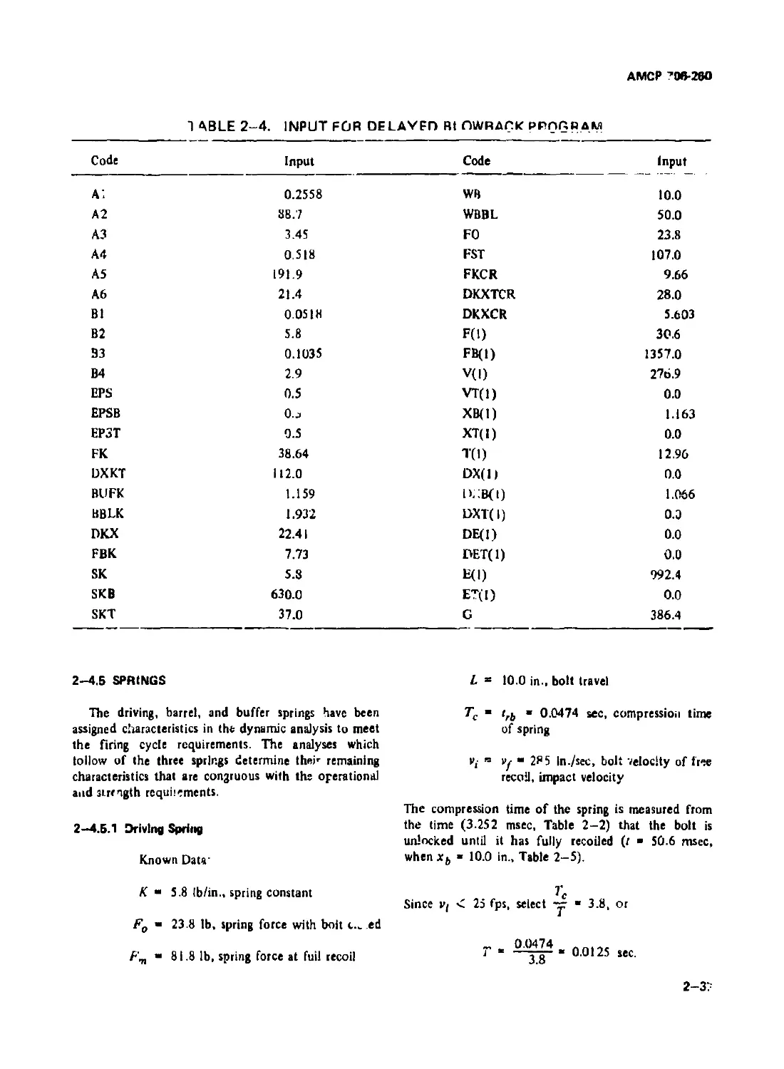
2-4.5 SPRINGS............................................ 2-37
2-4.5,1 Driving Spring .................................... 2-37
2-4.5.2 Barrel Spring...................................... 2-39
2-4.5.3 Buffer Spring...................................... 2-39
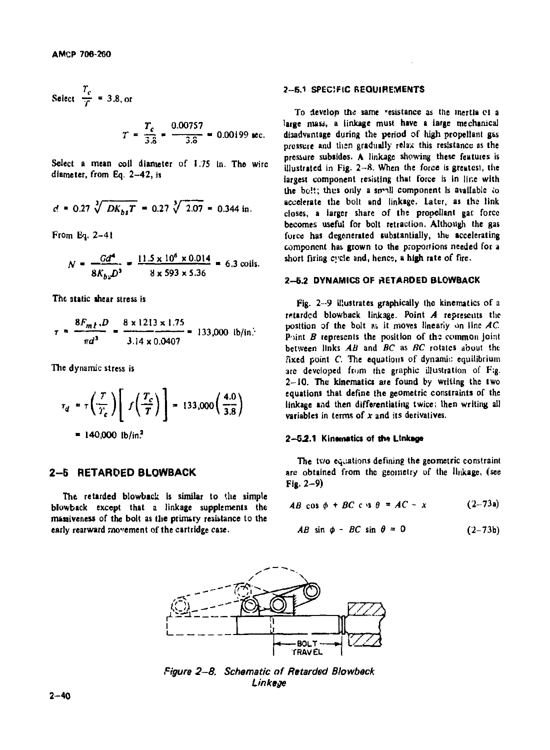
2-5 RETARDED BLOWBACK.................................. 2-40
2-5.1 SPECIFIC REQUIREMENTS ............................. 2-40
АМСР 706-260
TABLE OF CONTENTS (Con'».)
Pxsjnph Page
2—5.2 DYNAMICS OF RETARDED BLOWBACK....................... 2-40
2-5.2.1 Kinematics of the Linkage .......................... 2—40
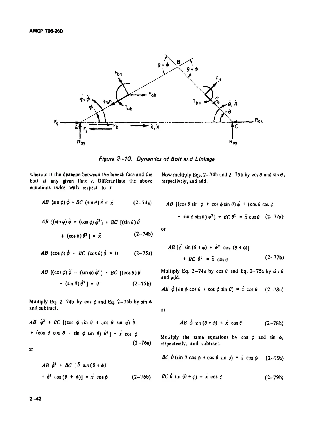
2-S.2.2 Equations ol Dynamic Equilibrium................ 2 13
2-5.2.3 Digital Computer Program for
the Dynamic Analysis......................................... 2-44
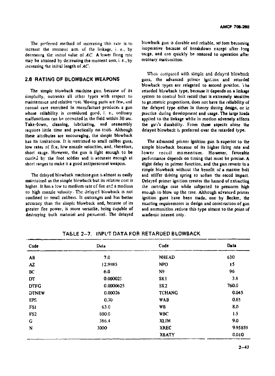
2-6 RATING OF BLOWBACK WEAPONS ......................... 2-47
CHAPTER 3. RECOIL-OPERATED WEAPONS
3-1 GENERAL 3-1
3-2 LONG RECOIL DYNAMICS......................... 3-1
3-3 SAMPLE PROBLEM - LONG RECOIL MACHINE GUN .. 3-1
3-3.1 SPECIFICATIONS ...................................... 3-1
3-3.2 DESIGN DATA.......................................... 3-1
3-4 SHORT RECOIL DYNAMICS ............................... 3-9
3-5 SAMPLE PROBLEM - SHORT RECOIL MACHINE GUN . . 3-9
3-5.1 SPECIFICATIONS ...................................... 3-9
3-5.2 DESIGN DATA ......................................... 3-9
3-6 ACCELERATORS .................................. 3 15
3-7 SAMPLE PROBLEM - ACCELERATOR................ 3-17
3-7.1 SPECIFICATIONS ..................................... 3-17
3-7.2 DESIGN DATA ........................................ 3-17
3-8 RAT'NG OF RECOIL-OPERATED GUNS...................... 3-21
CHAPTER 4. GAS-OPERATED WEAPONS
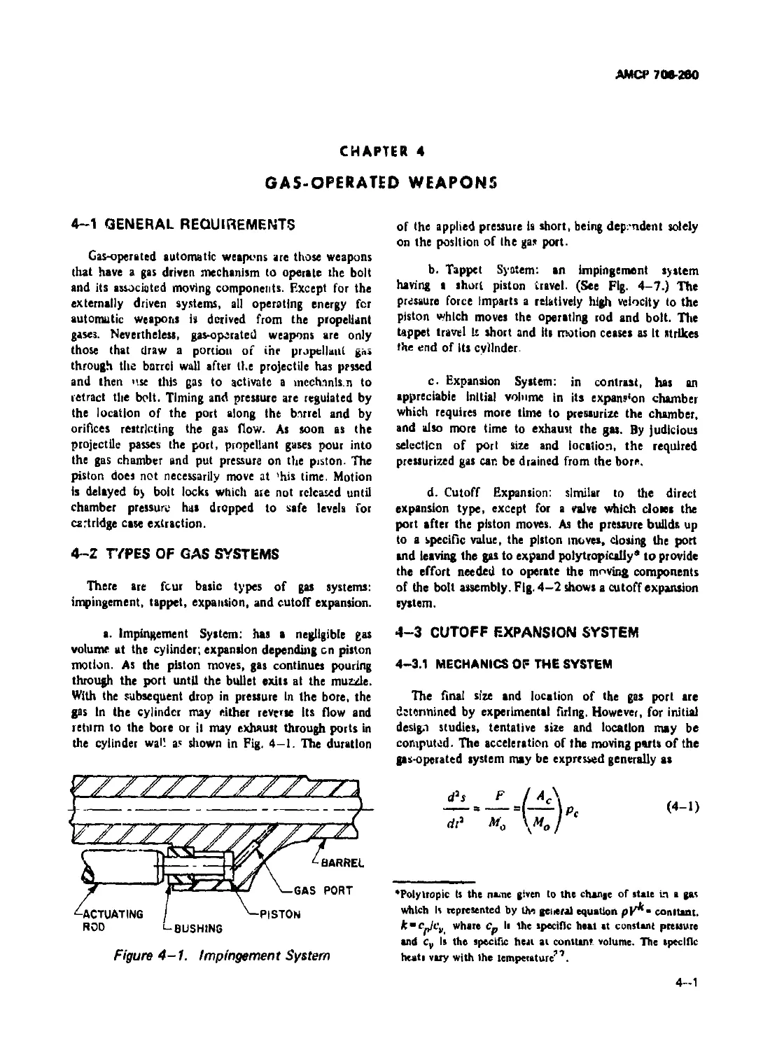
4-1 GENERAL REQUIREMENTS ........... 4-1
4-2 TYPES OF GAS SYSTEMS................................. 4-1
4-3 CUTOFF EXPANSION SYSTEM.............................. 4-1
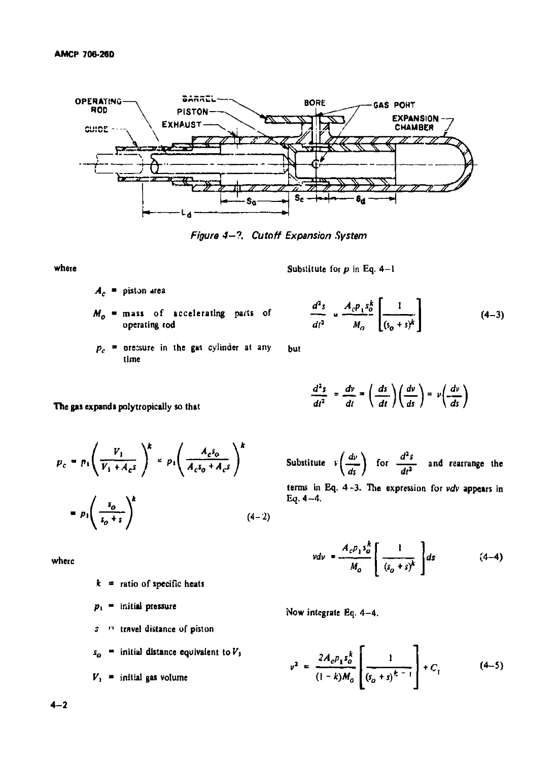
4-3.1 MECHANICS OF THE SYSTEM................................. 4-1
4-3.1.1 Gas Filling Period .................................. 4-6
4-?.1.2 Bolt Locking Cam..................................... 4-9
4-3.1.3 Cam Curve .......................................... 4-15
4-3.2 SAMPLE PROBLEM FOR CUTOFF EXPANSION
SYSTEM ..................................................... 4-17
4-3.2.1 Specifications...................................... 4-17
4-3.2.2 Design Data, Computed............................... 4-17
4-3.2.3 Countenecoil Computed Data.......................... 4-19
4-3.2.4 Counterrecoil Time ................................. 4-20
4-3.2.5 Recoil Time......................................... 4-23
4-3.2.5.1 Recoil Time, Decelerating........................ 4-23
4-3.2.5.2 Recoil Time, Accelerating. ...................... 4-24
4-3.3 DIGITAL COMPUTER ROUTINE FOR CUTOFF
EXPANSION................................................... 4-28
4-3.3.1 Gas Dynamics Before Cutoff.......................... 4-28
4-3.3.2 Gas Dynamics After Cutuff .......................... 4-29
4-3.3.2.I Bolt Unlocking During Helix Traverse............. 4-29
4-33.2.2 Bolt Unlocking During Parabola Traverse.......... 4-29
4—33.2.3 Bolt Unlocked, Bolt Traveling With
Operating Rod ............................................... 4-31
II
АМСР7М-Я0
TABLE OF CONTENTS (Con't.)
Paragraph Page
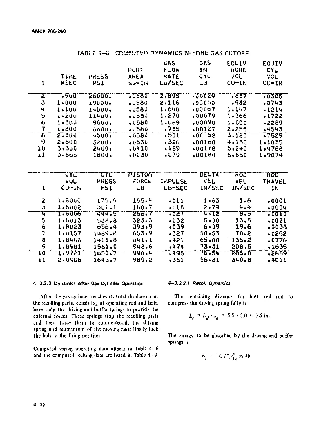
4-3.3.3 Dynamici After Gas Cylinder Operations .................... 4-32
4—3.3.3.1 Rcuuir Dyiiainiua....................................... 4—32
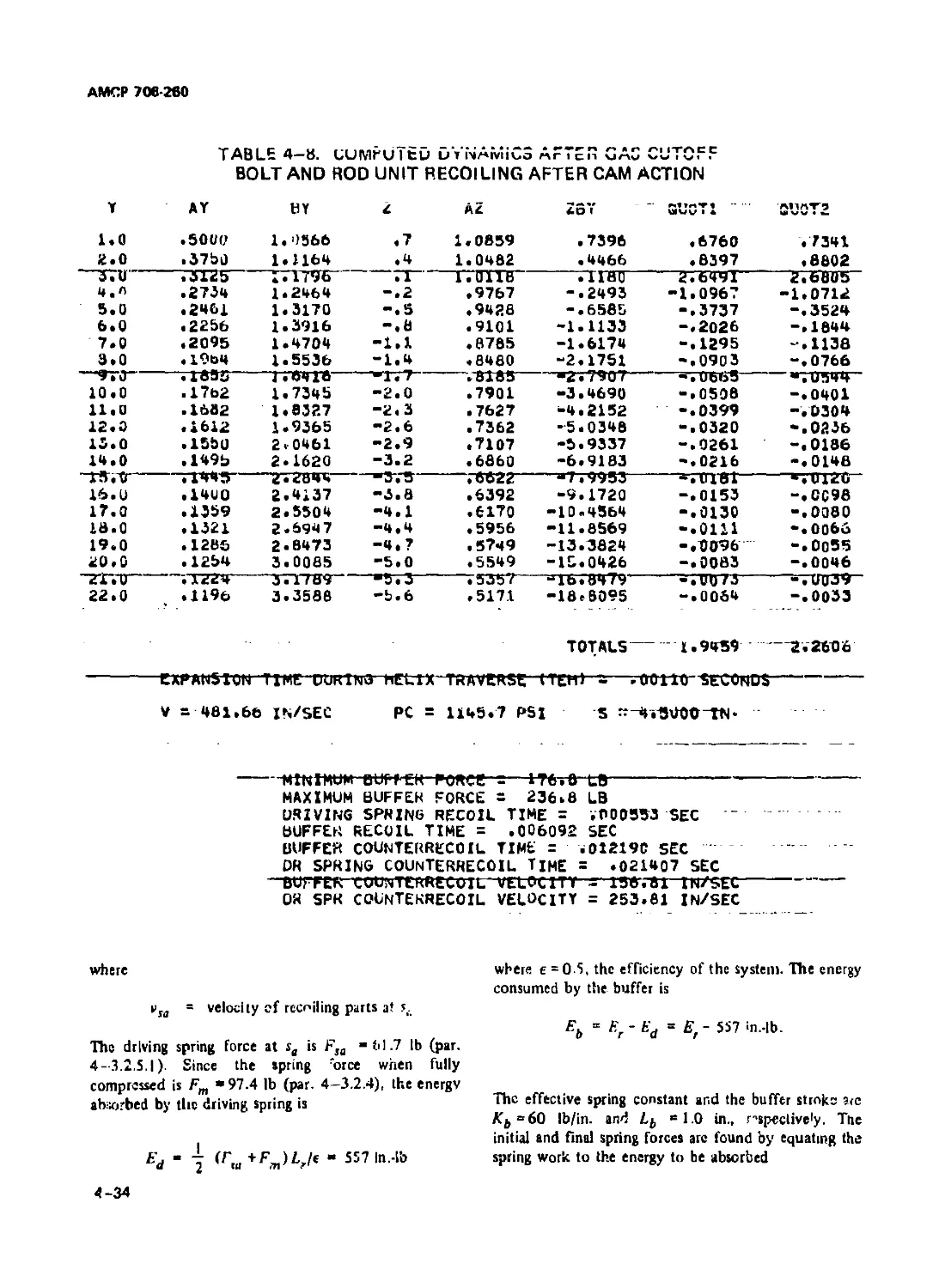
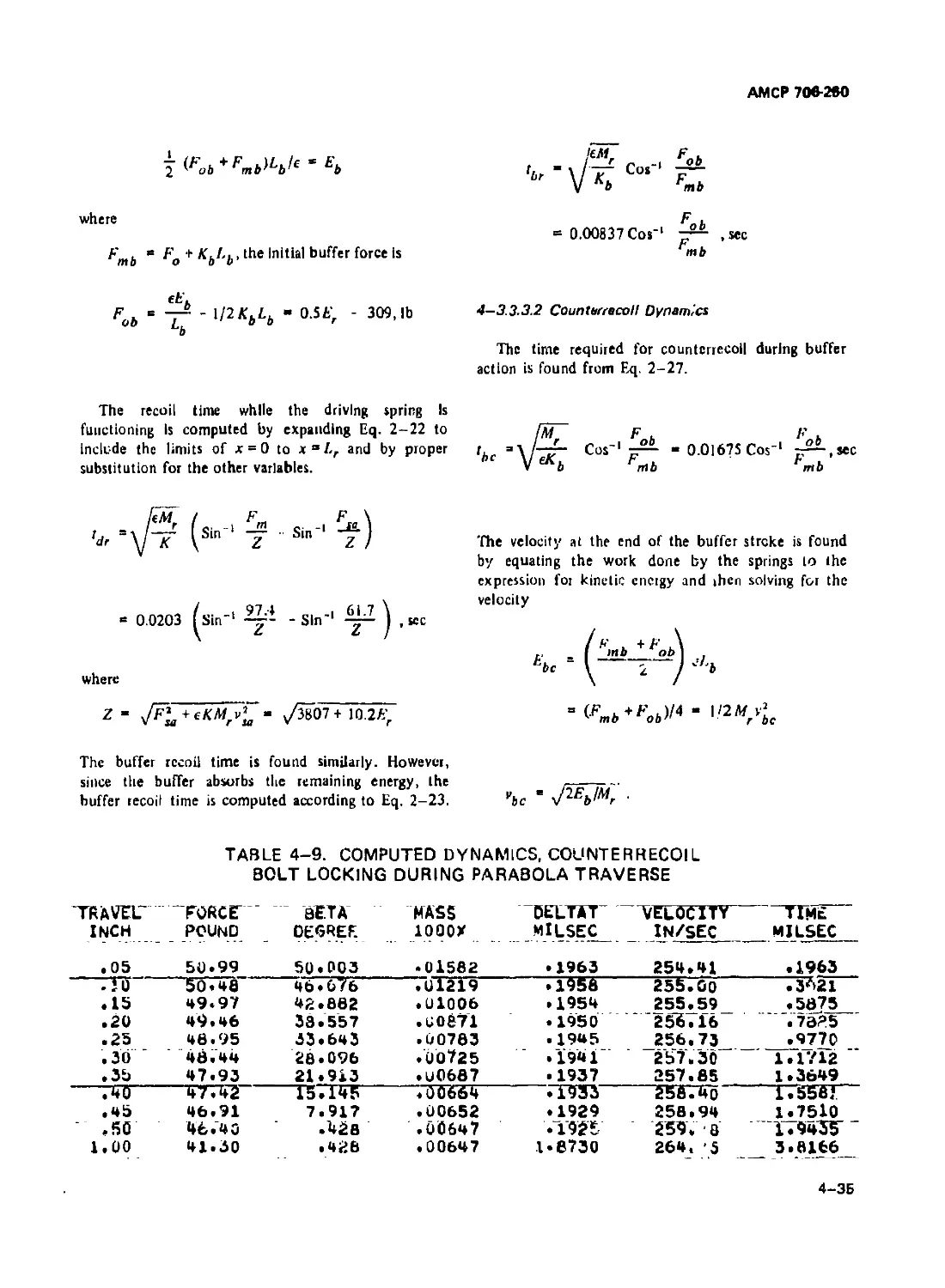
4-3.3.3.2 Counterrecoil Dynamic!.................................. 4-35
4-3.3.3.3 Bolt Locking Dynamic!................................... 4-36
4-З.З.зл hiring каге ............................................ 4-3/
4-3.4 SPRINGS................................................. 4-37
4-3.4.1 Driving Spring ......................................... 4-37
4-3.4,2 Buffer Spring........................................... 4-37
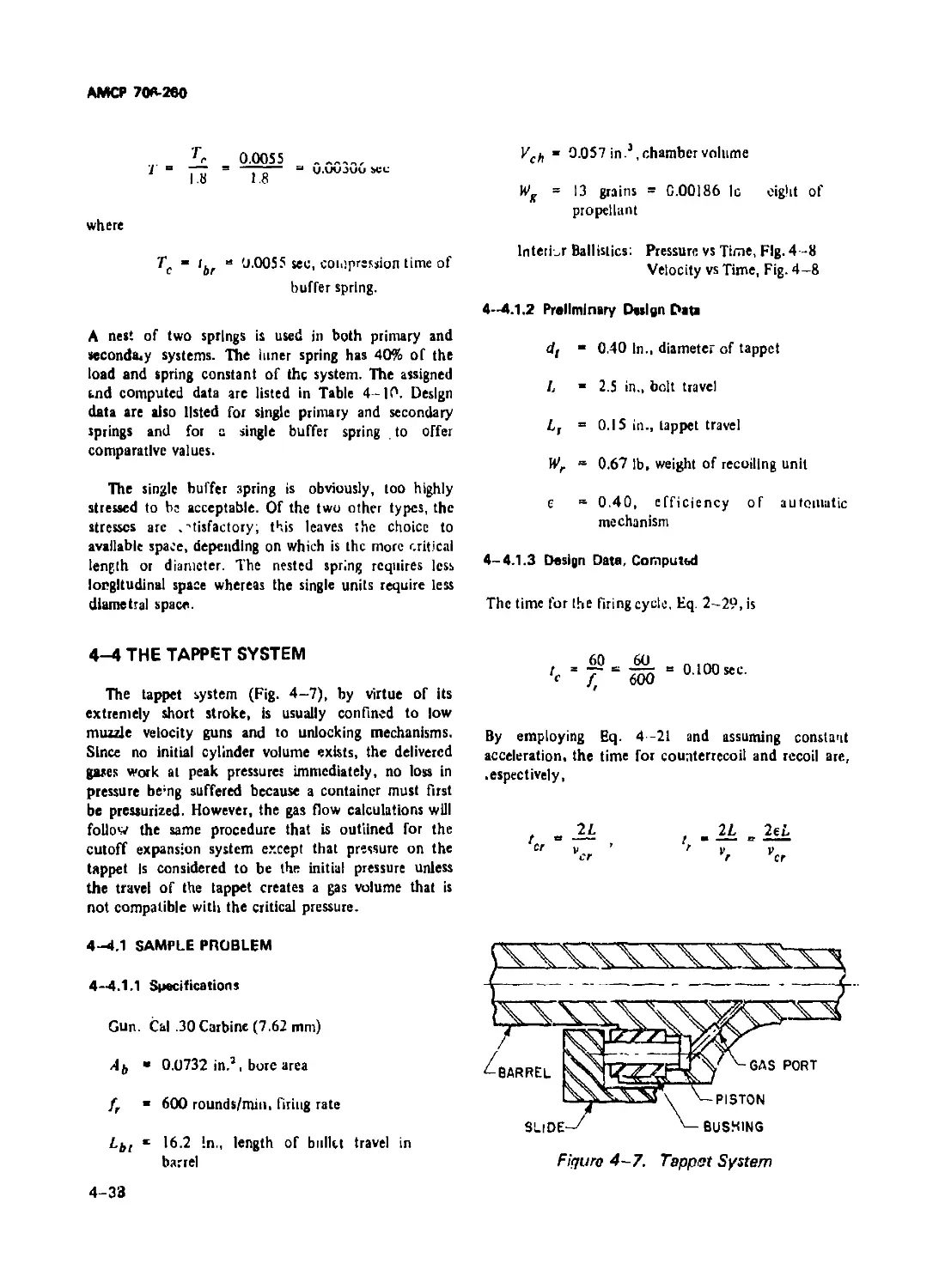
4-4 THE TAPPET SYSTEM.............................................. 4-38
4-4.1 SAMPLE PROBLEM ......................................... 4-38
4-4.1.1 Specifications.......................................... 4-38
4-4.1.2 Preliminary Design Data................................. 4-38
4-4.1.3 Design Data, Computed................................... 4-38
4-4.1.4 Spring Design Data ..................................... 4-45
CHAPTER 5. REVOLVER-TYPE MACHINE GUNS
5-1 SINGLE BARREL TYPE ............................................. 5-1
5- 1.1 PRELIMINARY DYNAMICS OF FIRING CYCLE ....................... 5-2
5-1 .l.t Sample Problem of Preliminary Firing Rate Estimate . . 5-7
5-1.1.2 Analysis of Cam Action................................... 5-8
5-1.1.2.1 Sample Calculation of Cam Action ...................... 5-14
5-1.1.2.2 Driving Spring.......................................... 5-18
5-1.2 FINAL ESTIMATE OF THE COMPLETE FIRING CYCLE 5-18
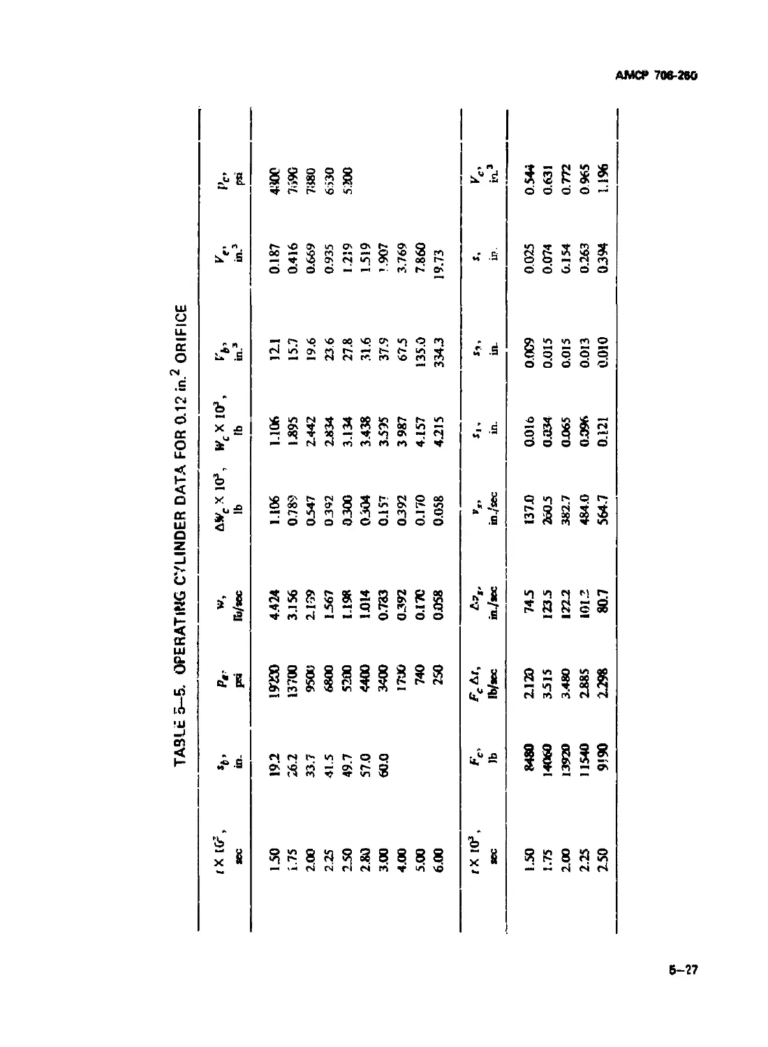
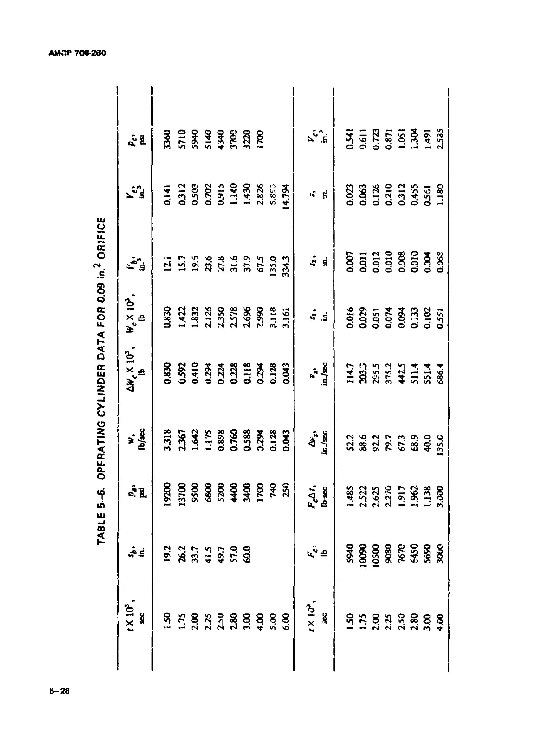
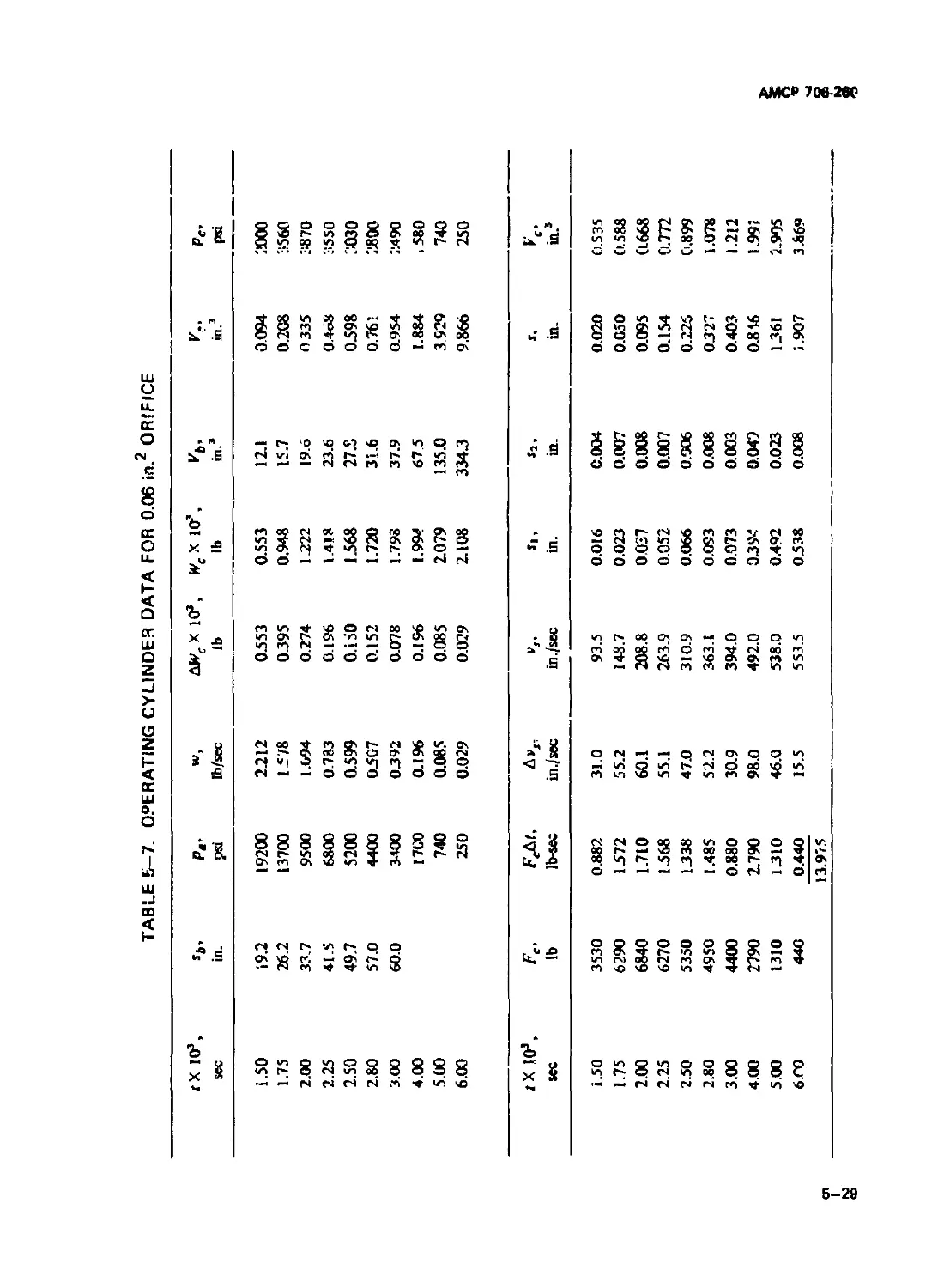
5-1.2.1 Control of Recoil Travel During Propellant Gas Period 5-20
5-1.2.2 Operating Cylinder Design .............................. 5-23
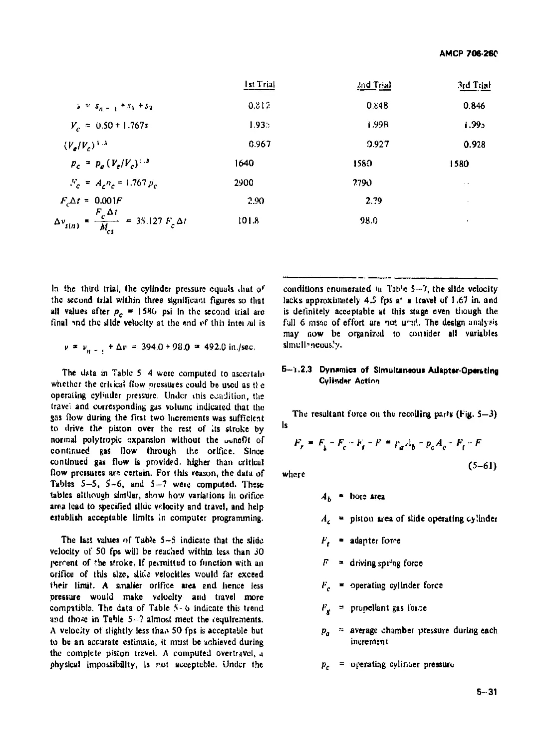
5-1.2.3 Dynamics of Simultaneous Adapteropcrating
Cylinder Action ................................................... 5-31
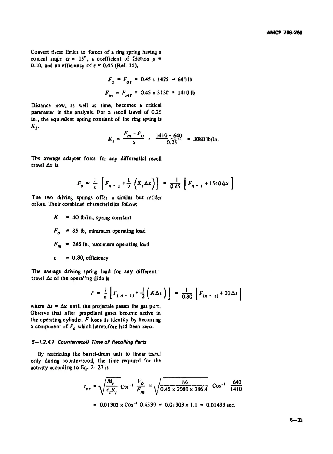
5-1.2.4 Sample Calculation for Complete Firing Cycle ......... 5-32
5-1.2.4.1 Counterrecoil Time of Recoiling Parts 5-33
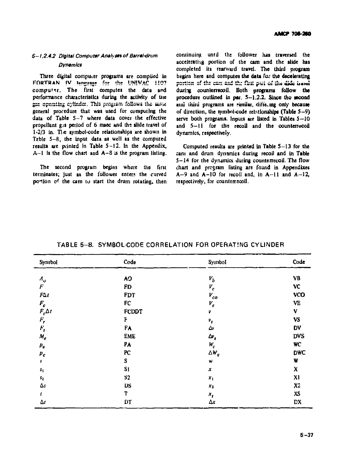
5-1.2.4.2 Digital Computer Analyses of Barrel-drum Dynamics . . . 5-37
5-1.2.4.3 Firing Rate Computation............................... 5-39
5-2 DOUBLE BARREL TYPE.................................... 5-46
5-2.1 FIRING CYCLE.......................................... 5-46
5-2.1.1 Cam Function ........................................... 5-46
5-2.1.2 Loading and Ejecting.................................... 5-48
5-2.1.3 Ammunition Feed System ................................. 5-48
5-2.2 DYNAMICS OF FIRING CYCLE................................ 5-49
5-2.2.1 Cam Analysis............................................ 5-50
5-2.2.2 Energy Concept ......................................... 5-52
5-2.2.3 Digital Computer Program for Firing Cycle .............. 5-52
CHAPTER 6. MULTIBARREL MACHINE GUN
6-1 GENERAL.................................................. 6-1
6-2 BOLT OPERATING CAM DEVELOPMENT........................... 6-1
6- 2.1 CAM ACTION.................................................. 6-1
6-2.1.1 Cam Kinematics .......................................... 6-3
6-2.1.2 Definition of Symbols.................................... 6-4
6-2.1.3 Cam Forces.............................................. 6-5
6-2.1.4 Locking Angle ........................................... 6-6
Ш
A*fCP7Qfr2W
TABLE OF CONTENTS (Con’t.)
P±—~-ph Pm
6-2.2 ROTOR KINEMATICS........................................... 6-7
6-23 ILLUSTRATIVE PROBLEM ...................................... 6-9
6-2.3.1 Cam Analysis During Peed, Kotor at Constant velocity . . 6-9
6-2,3.2 Cam Analysis During Ejection, Rotor at Constant
Velocity................................................. 6-11
6-2.3.3 Cam Analysis During Rotor Acceleration ................ 6-12
6-23.4 Digital Computer Program for Cun Operating Power .... 6-13
6-3 RATING GF GAS-OPERATED AND EXTERNALLY
POWERED GUNS ....................................... 6-14
CHAPTER 7. COMPONENT DESIGN
7-1 GENERAL.................. 7-1
7-2 FEED MECHANISM DESIGN .................................... 7-1
7-2.1 MAGAZINES ..................................................... 7-2
7-2.1.1 Box Magazines . . ........................................ '«-2
7-2.1.2 Box Feed System ........................................... 7-4
7-2.1.2.1 Flat Tape Spring ................................... 7-5
7-2.1.2.2 Rectangular Coil Spring.................................... 7-6
7-7.1.3 Example Problem»........................................... 7-6
7-2.13.1 Flat Tape Spring........................................... 7-7
7-2.1.3.2 Rectangular Coil Spring.................................... 7-8
7-22 BOLT-OPERATED FEED SYSTEM.......................... 7 •
7-2.3 ROTATING FEED MECHANISM .................................. 1-10
7-23.1 Recoil-operated Feed Mechaitiam ......................... 7-10
7-2.3.2 Electrically Driven Feed Mechaniam ....................... 7—12
7-2.4 UNKLESS FEED SYSTEM....................................... 7-14
7-2.4.1 Power Required ........................................... 7-19
7-2.42 Example Problem for Power Required ....................... 7-21
7-3 EXTRACTORS, EJECTORS, AND BOLT LOCKS ........................... 7-24
7-3.1 EXTRACTORS ............................................... 7-24
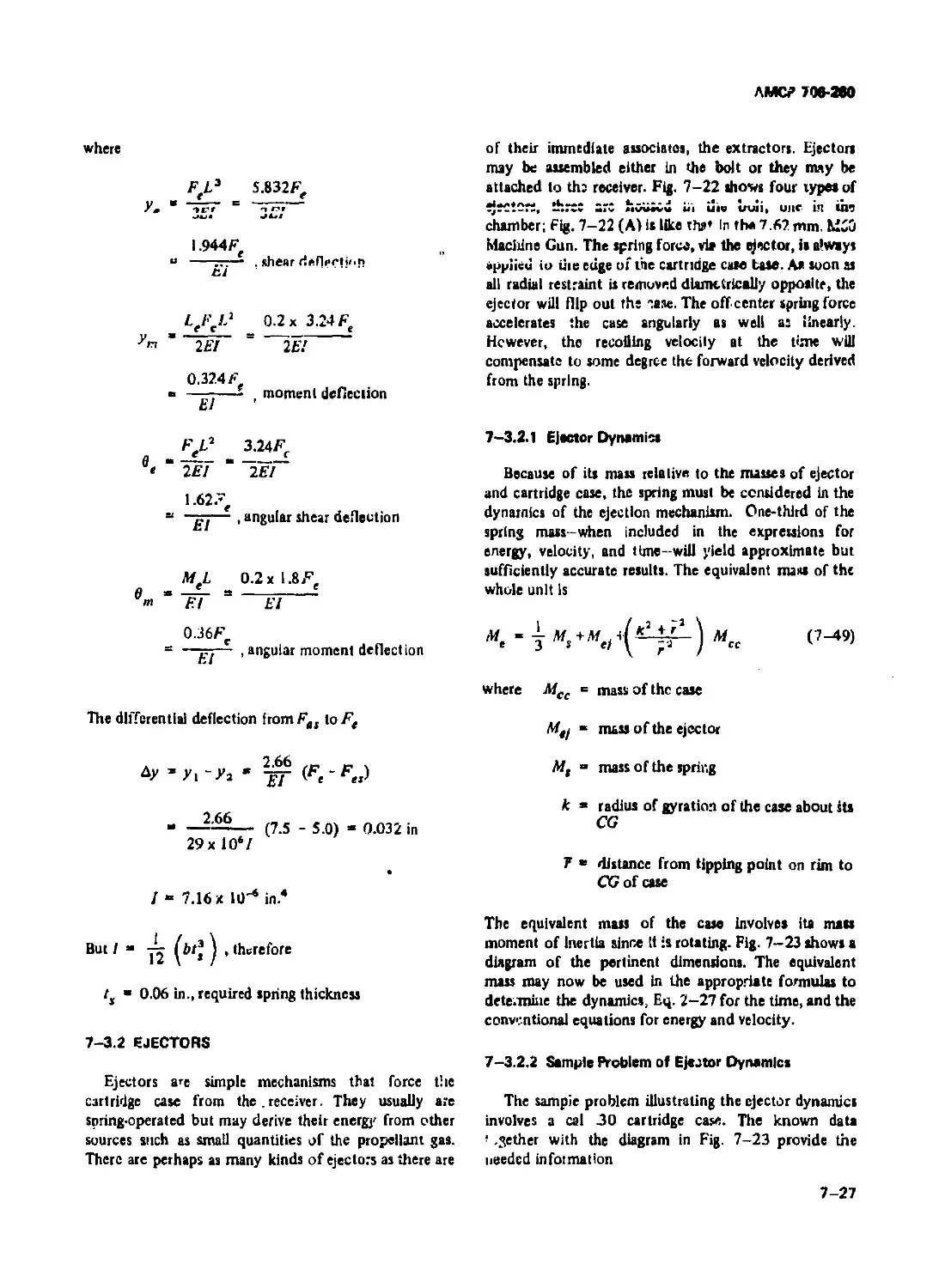
7-3.2 EJECTORS.................................................. 7-27
7-33.1 Ejector Dynamics ......................................... 7—27
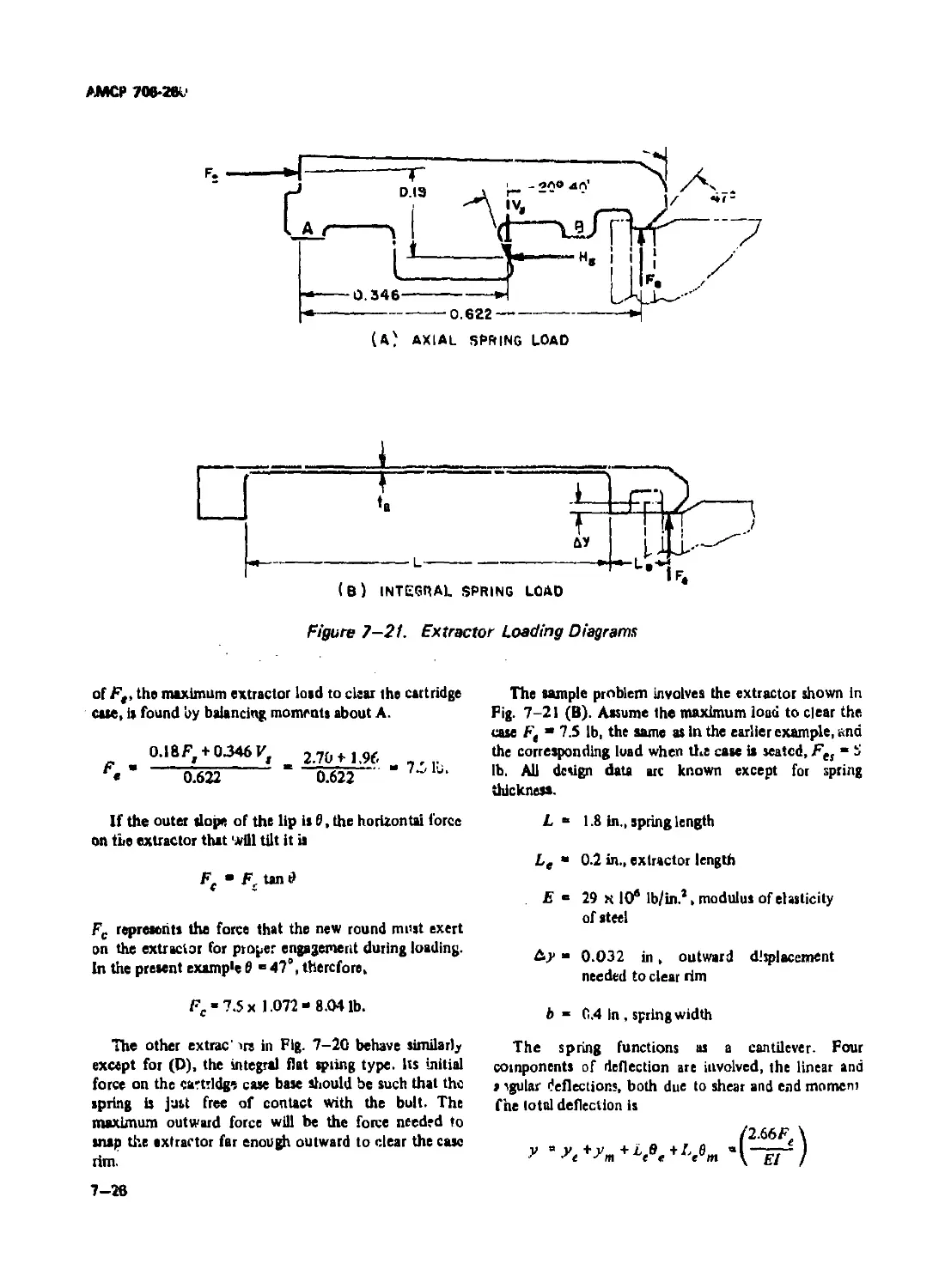
7-3.2.2 Sample Problem of Ejector Dynamics ....................... 7—27
7-3.3 BOLT LOCKS............... .................................... 7-30
7-4 FIRING MECHANISM.......................................... 7-32
7-4.1 COMPONENTS, TYPES, AND ACTION................................. 7-32
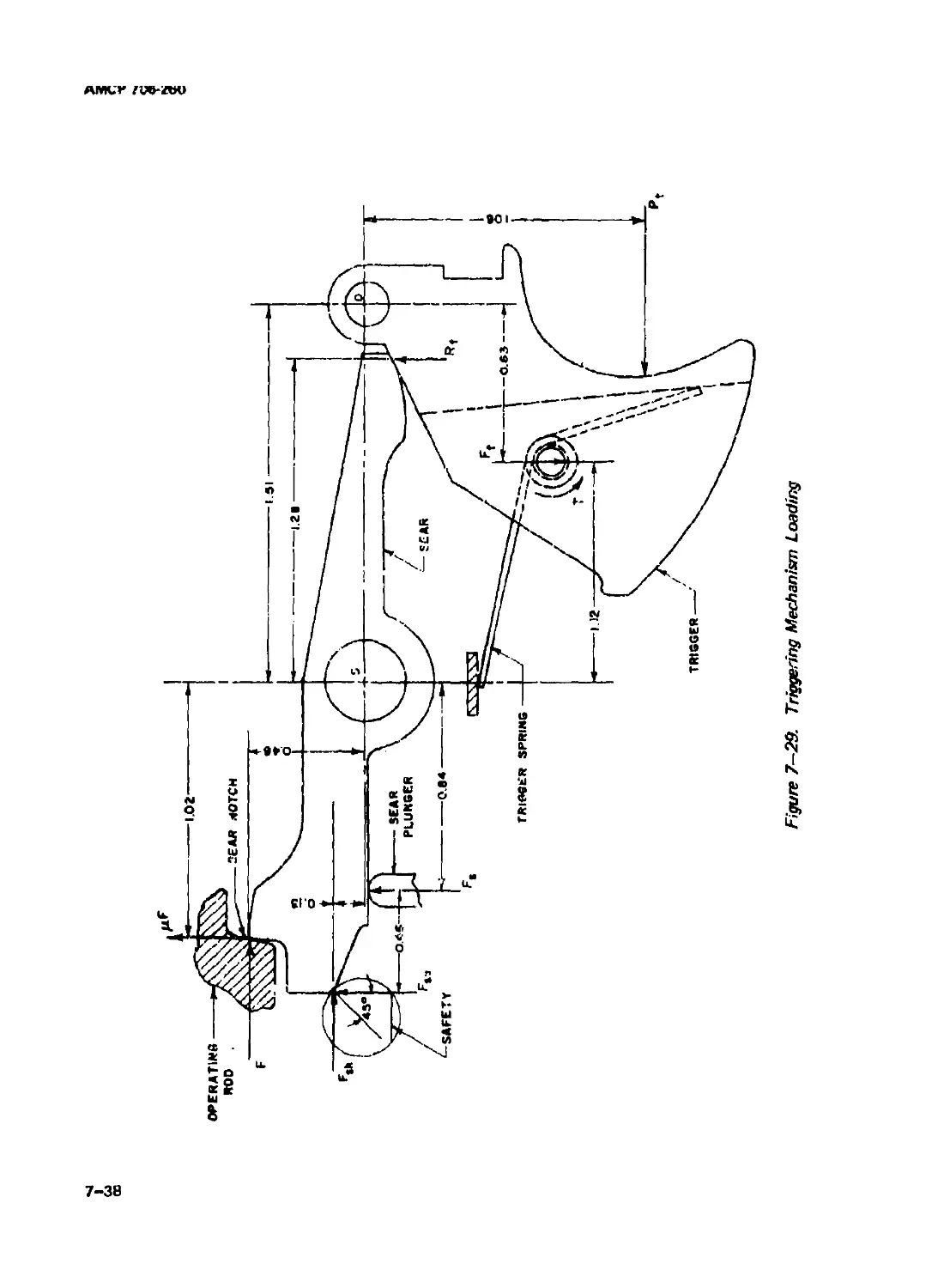
7-4.1.1 Trigger Pull.............................................. 7-37
7-41.2 Firing Pm Design.......................................... 7—39
7-5 LINKS .......................................................... 7-39
7-5.1 TYPES OF UNK ............................................. 7-40
7-52 DESIGN REQUIREMENTS....................................... 7-40
7-6 MOUNTS.................................................... 7-44
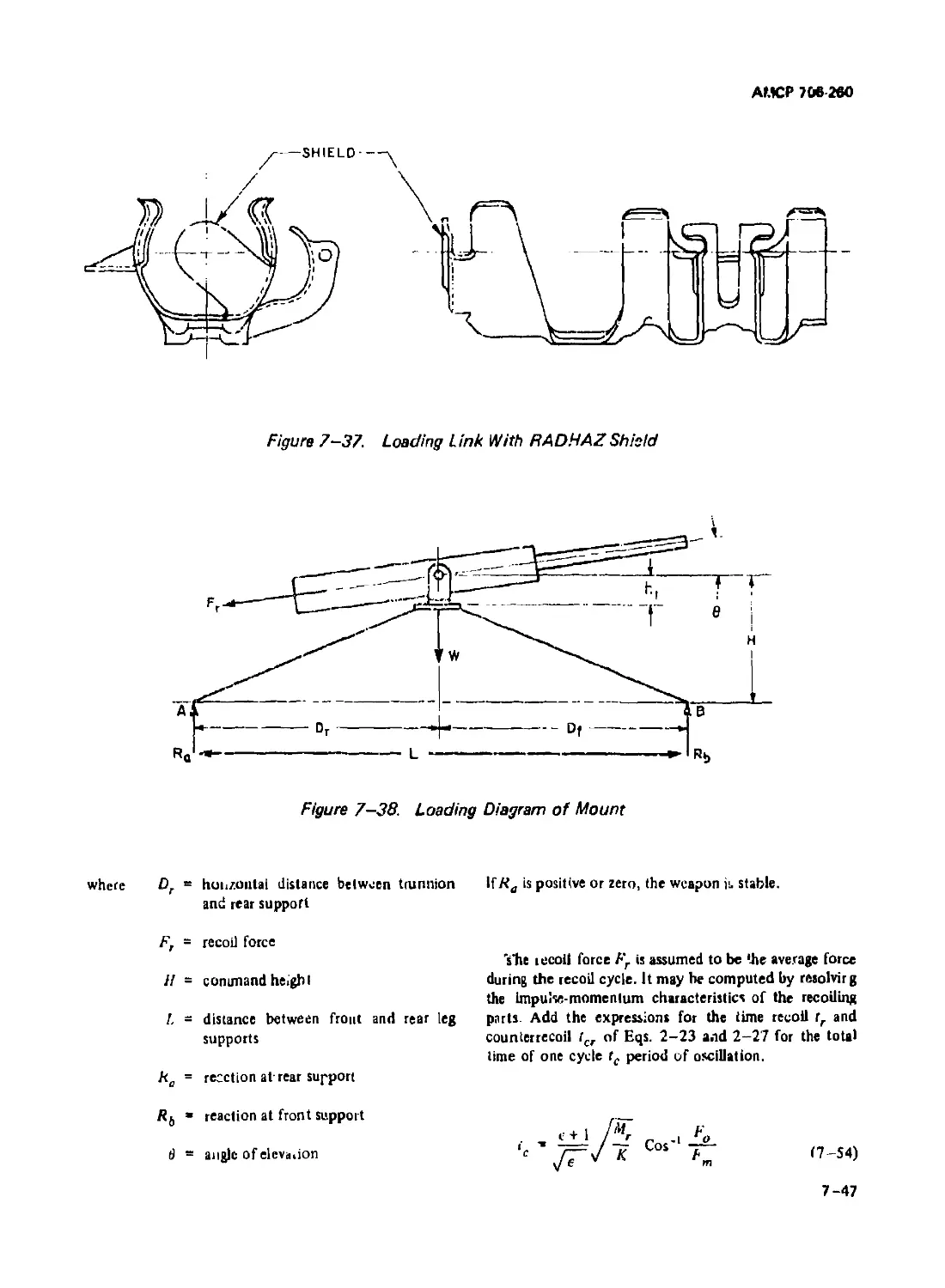
7-6.1 GEOMETRY AND RESOLUTION OF FORCES............. 7-44
7-6.2 SAMPLE PROBLEM ........................................... 7-48
CHAPTER 8. LUBRICATION OF MACHINE GUNS
8-1 GENERAL CONCEPT 8-1
8-2 EXAMPLES OF LUBRICANTS ....................... 8 -1
8-3 CASE LUBRICANT ............................................ 8-2
Iv
АМСР ЛМ-ЛО
TABLE OF CONTENT! (Can t.)
APPENDIXES
No. Title Psge
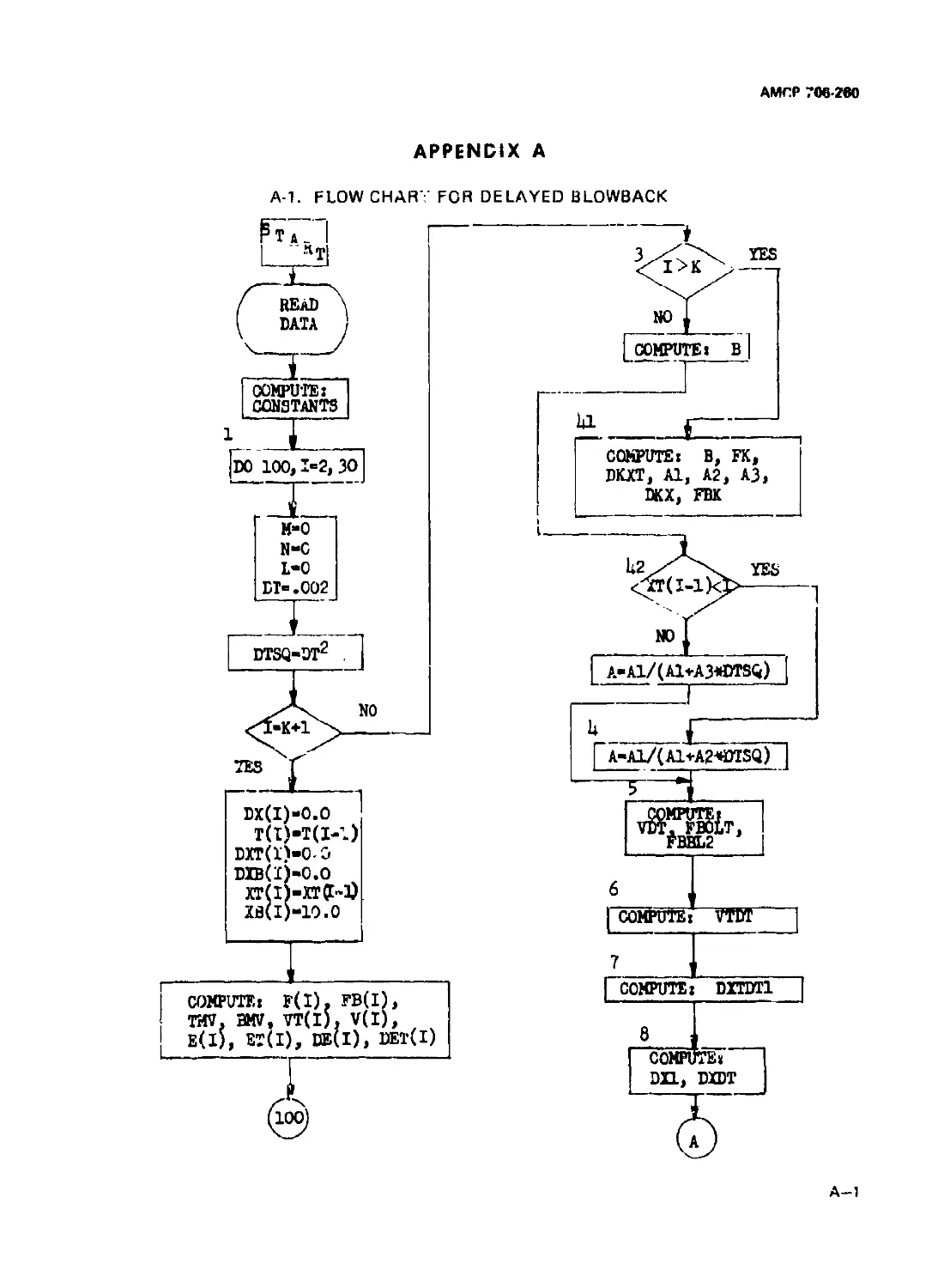
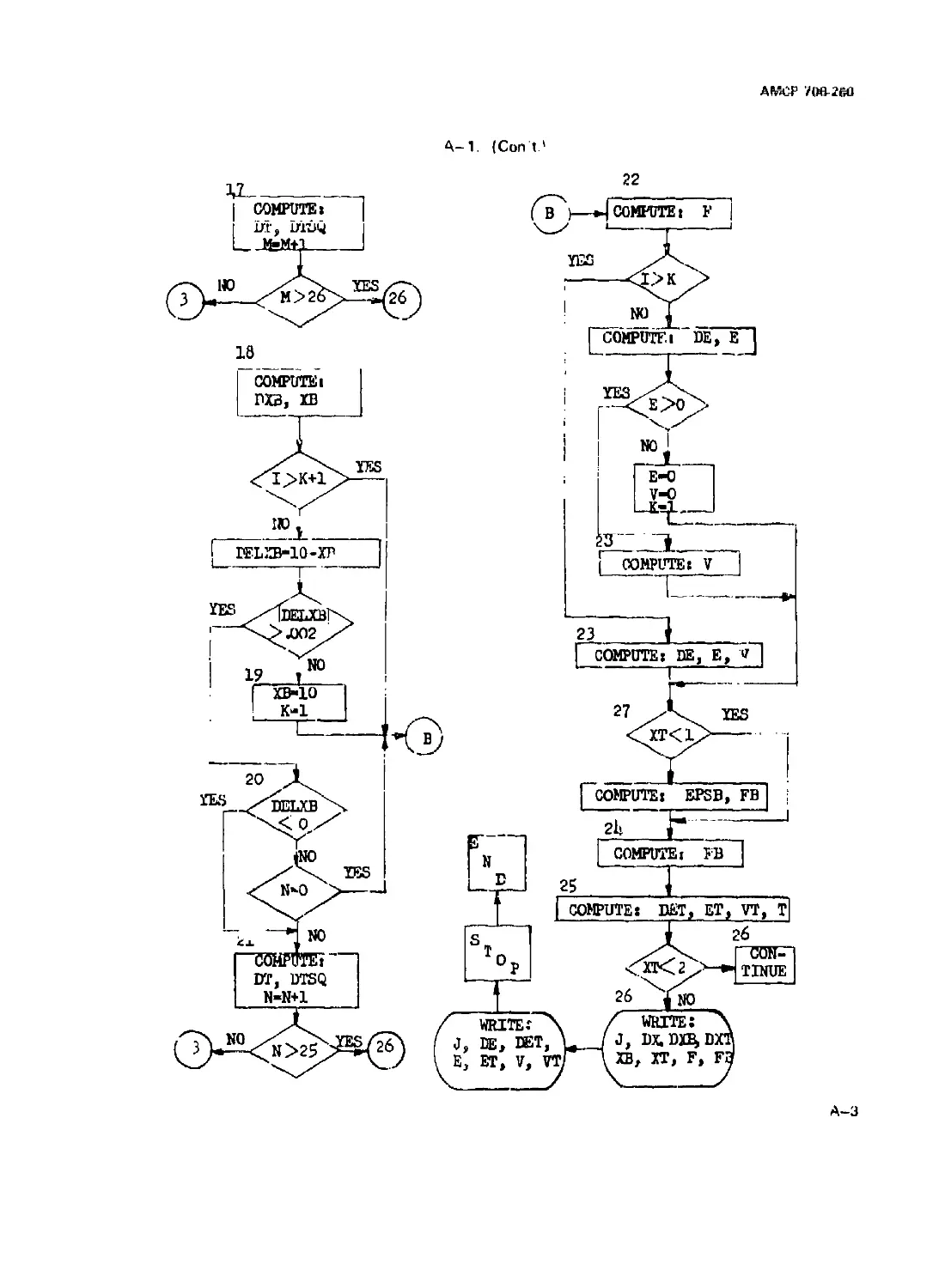
A-l Flow Chari for Delayed Blowback...................... A-1
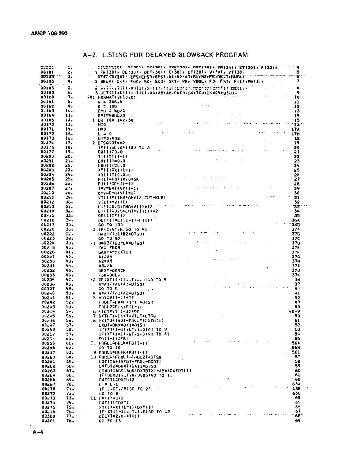
A-2 Utting for Delayed Blowback Program.......................... A-4
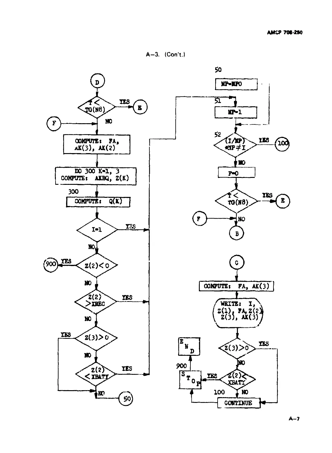
A-3 Flow Chart for Retarded Blowback ............................ A-6
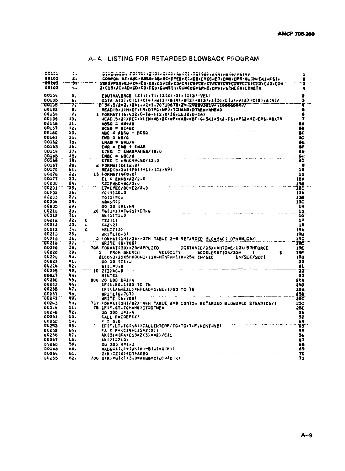
A—4 Utting for Retarded Blowback Program ........................ A-9
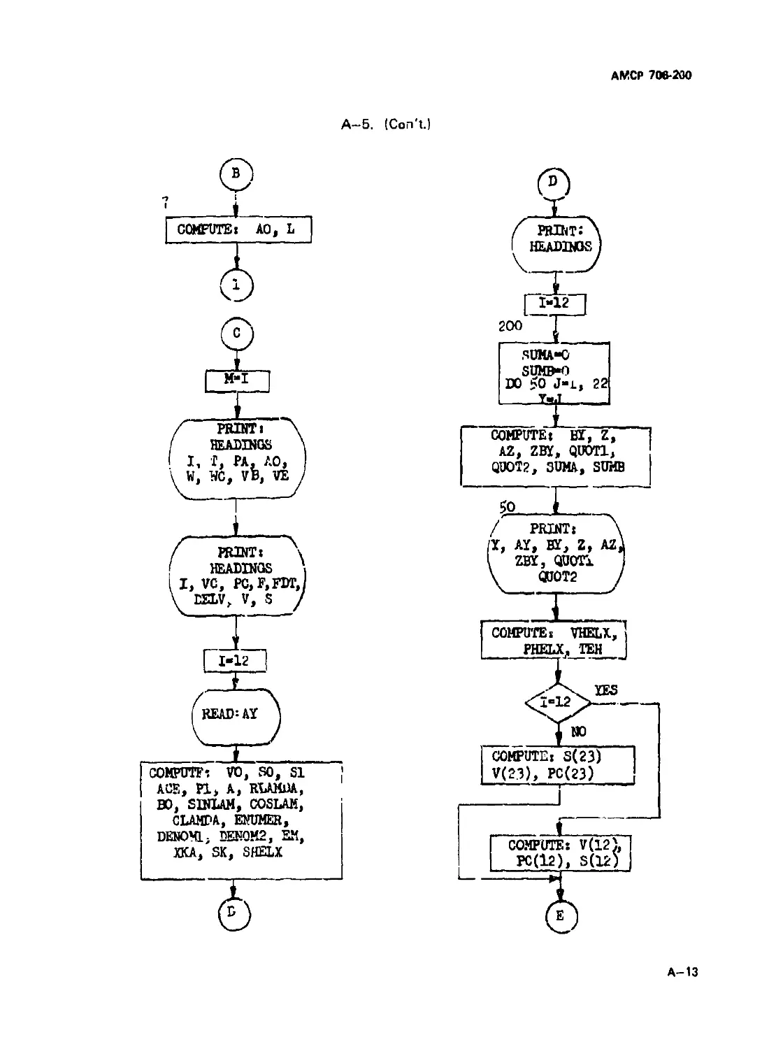
A - 5 Flow Chart for Cutoff Expantion ..................... A-l2
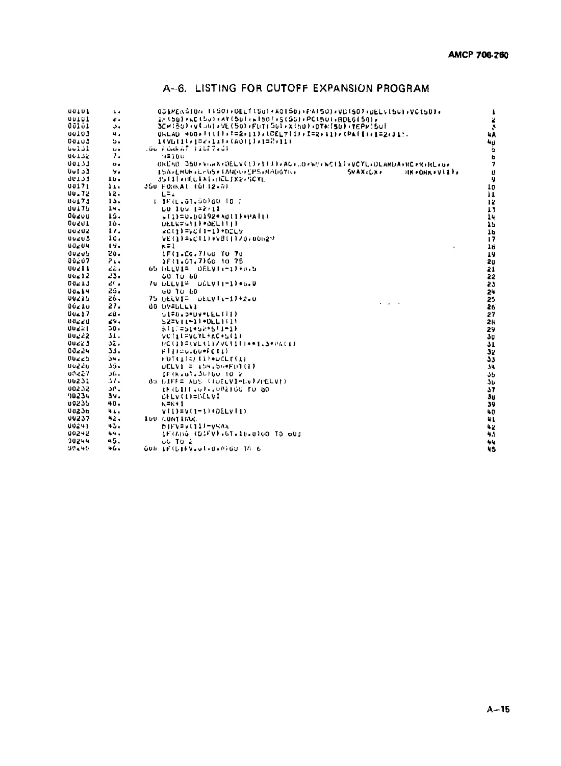
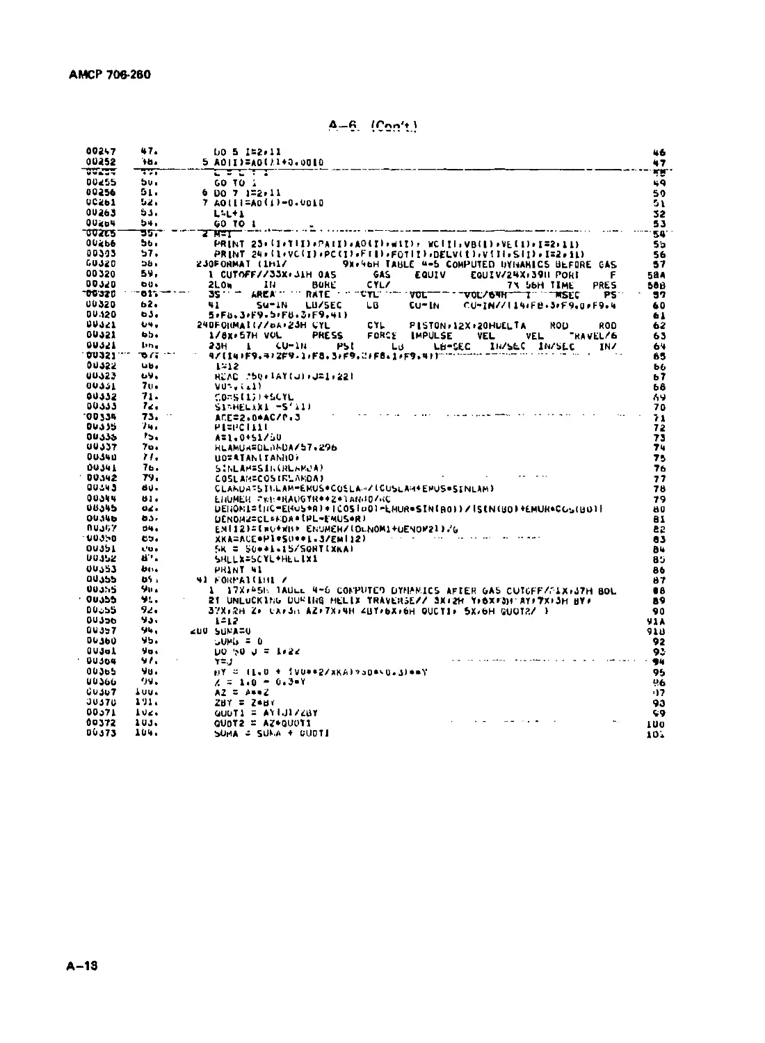
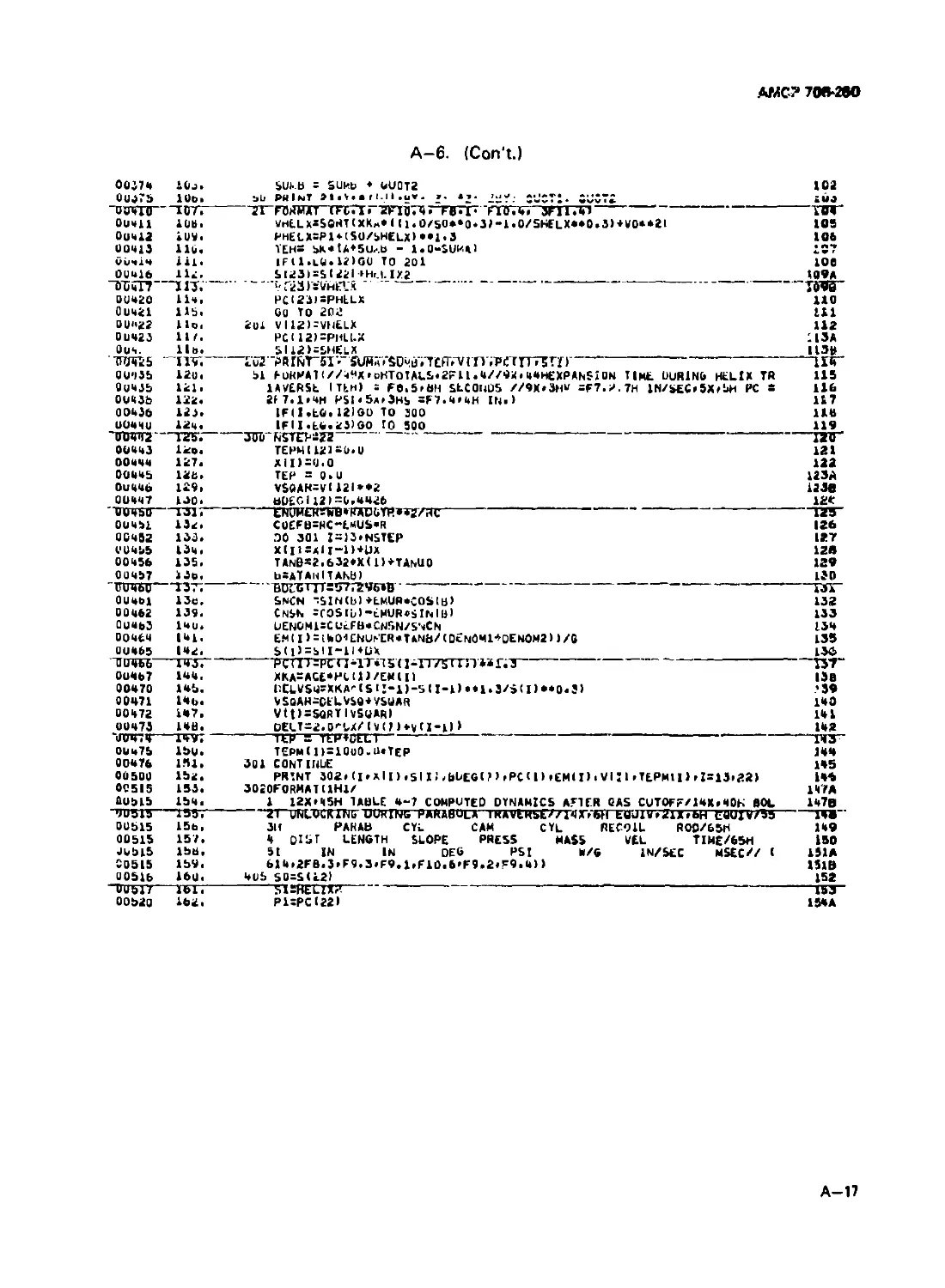
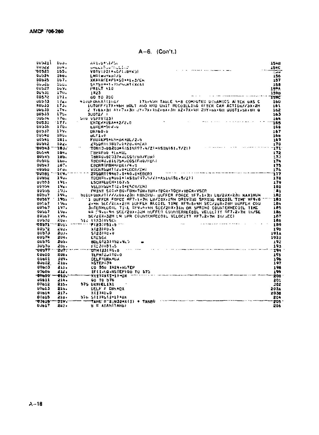
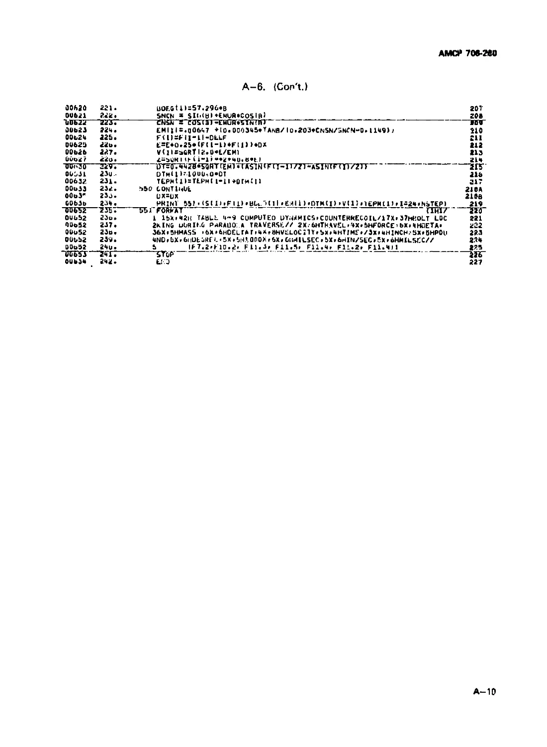
A-6 Lilting for Cutoff Expansion Program ................ A-15
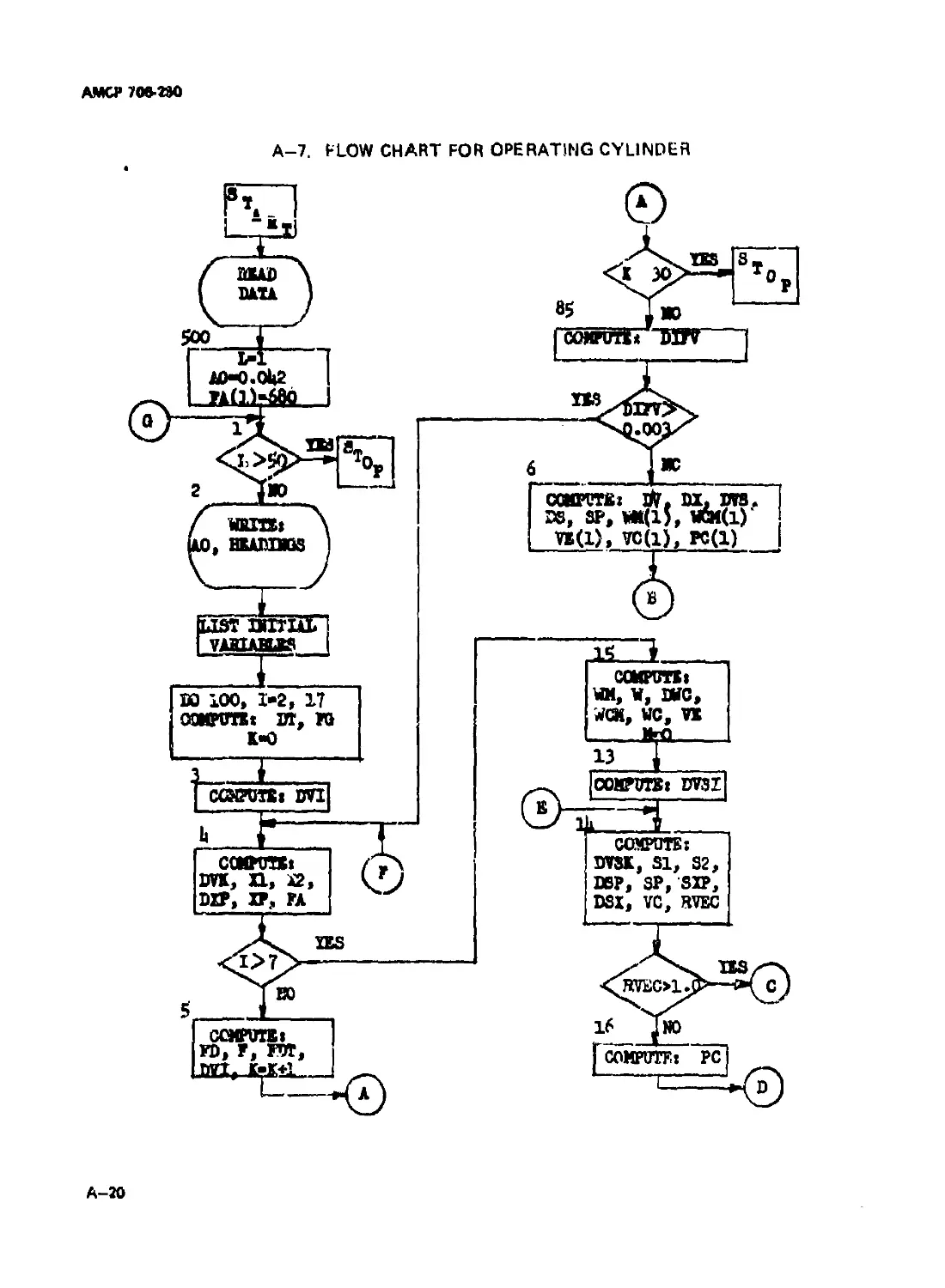
A-7 Flow Chart for Operating Cylinder ................... A-20
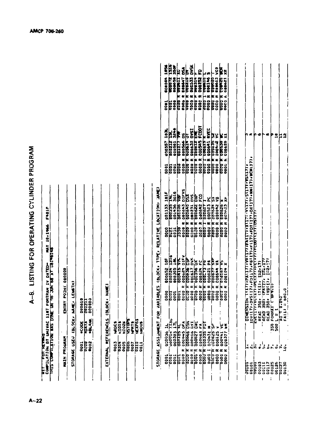
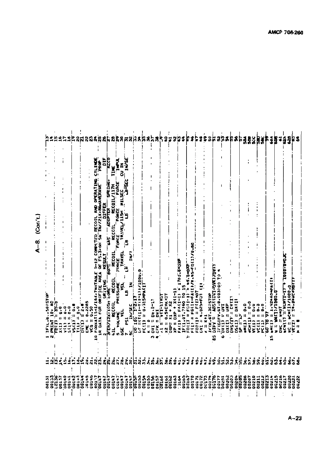
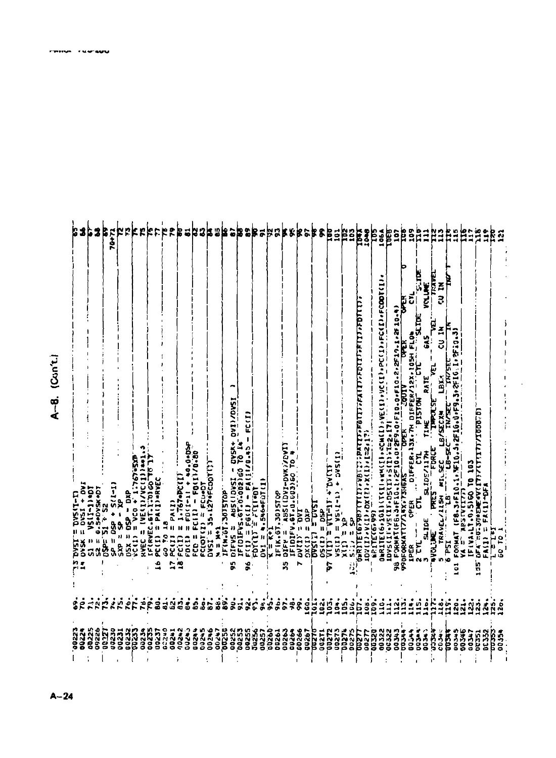
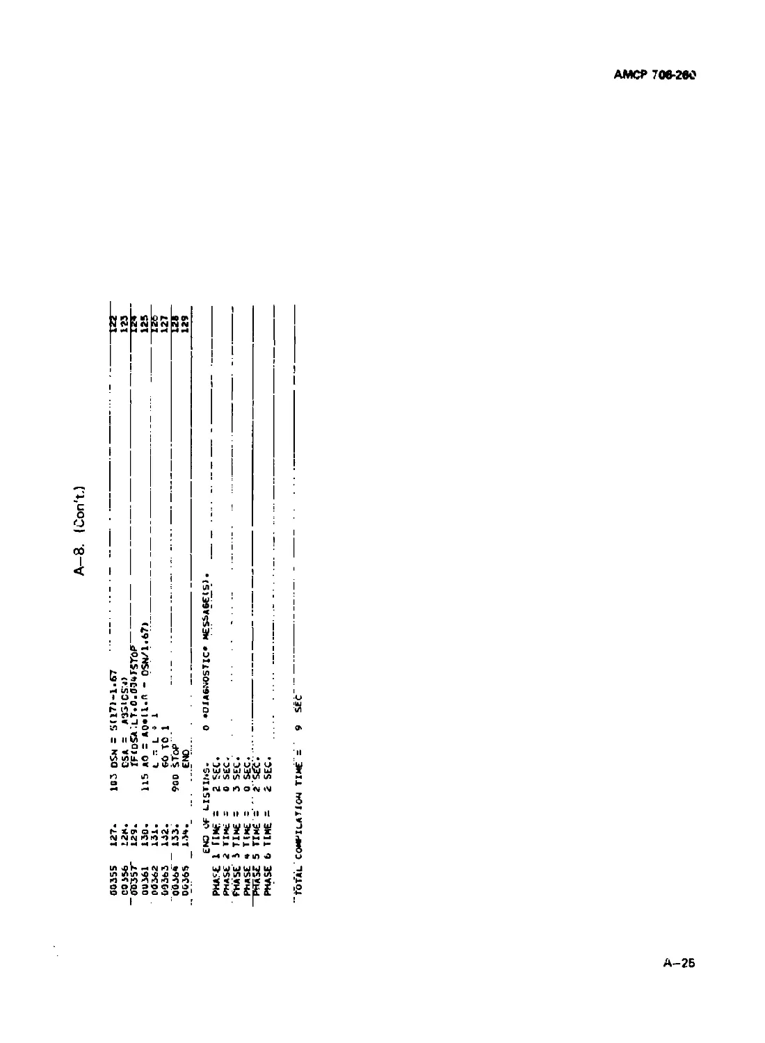
A-8 Utting for Operating Cylinder Program....................... A-22
A-9 Flow Cha-t for Cam and Drum Dynamics During Recoil . . A-26
A-10 Listing for Cam and Drum Dynamics During Recoil ............ A-3O
A-11 Flow Chart for Cam and Drum Dynamic! During
Counterrecoii............................................. A-35
A-12 Utting for Cam and Drum Dynamics During
Cotuiterrecoil............................................ A-38
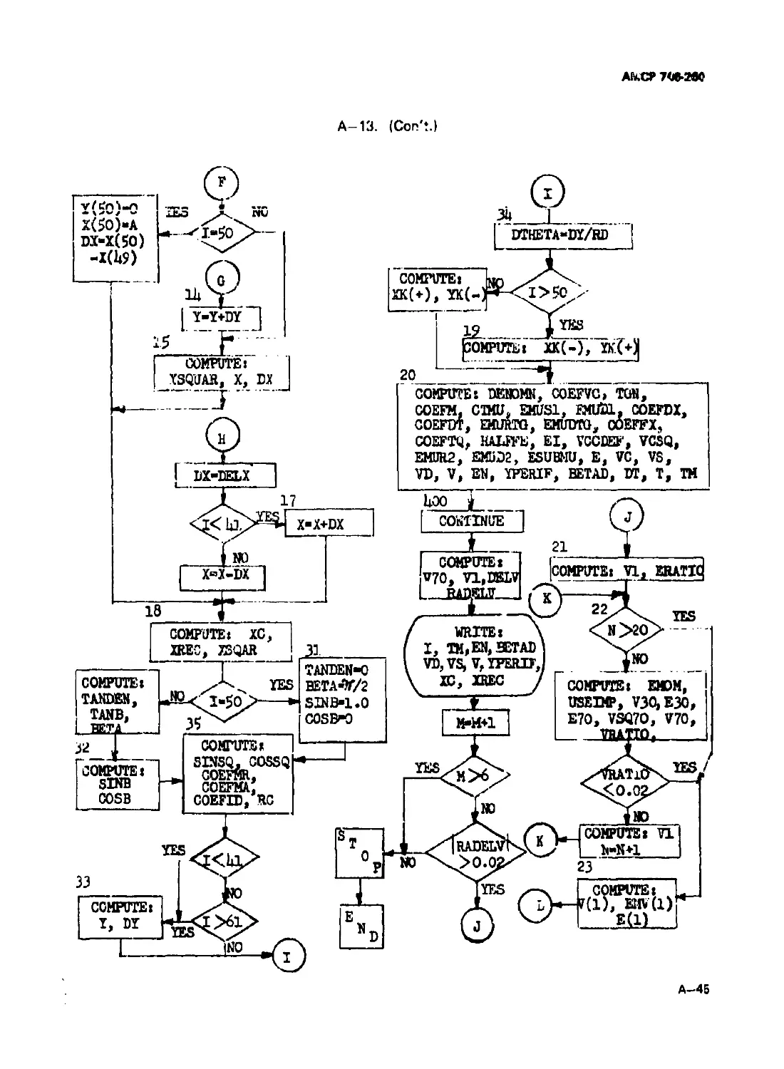
A-13 Flow Chut for Double Barrel Machine Gun ............. A-43
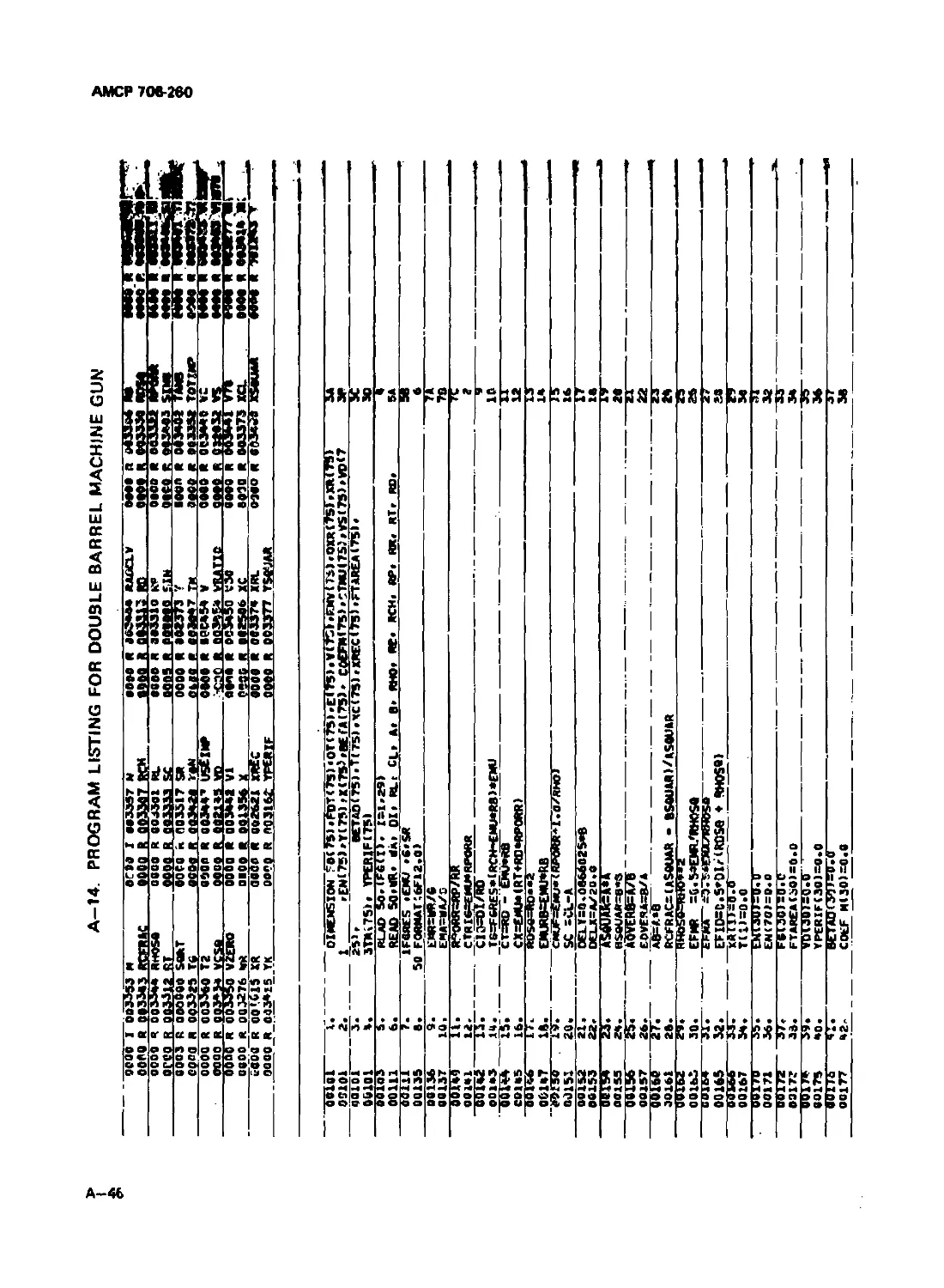
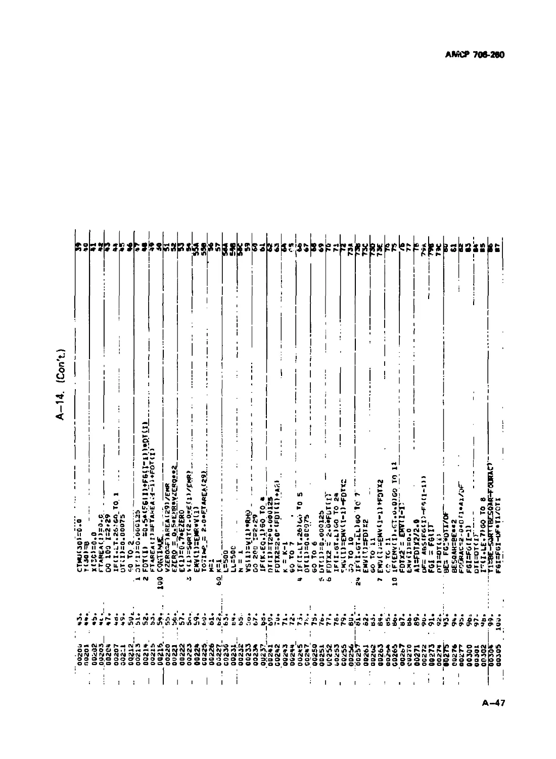
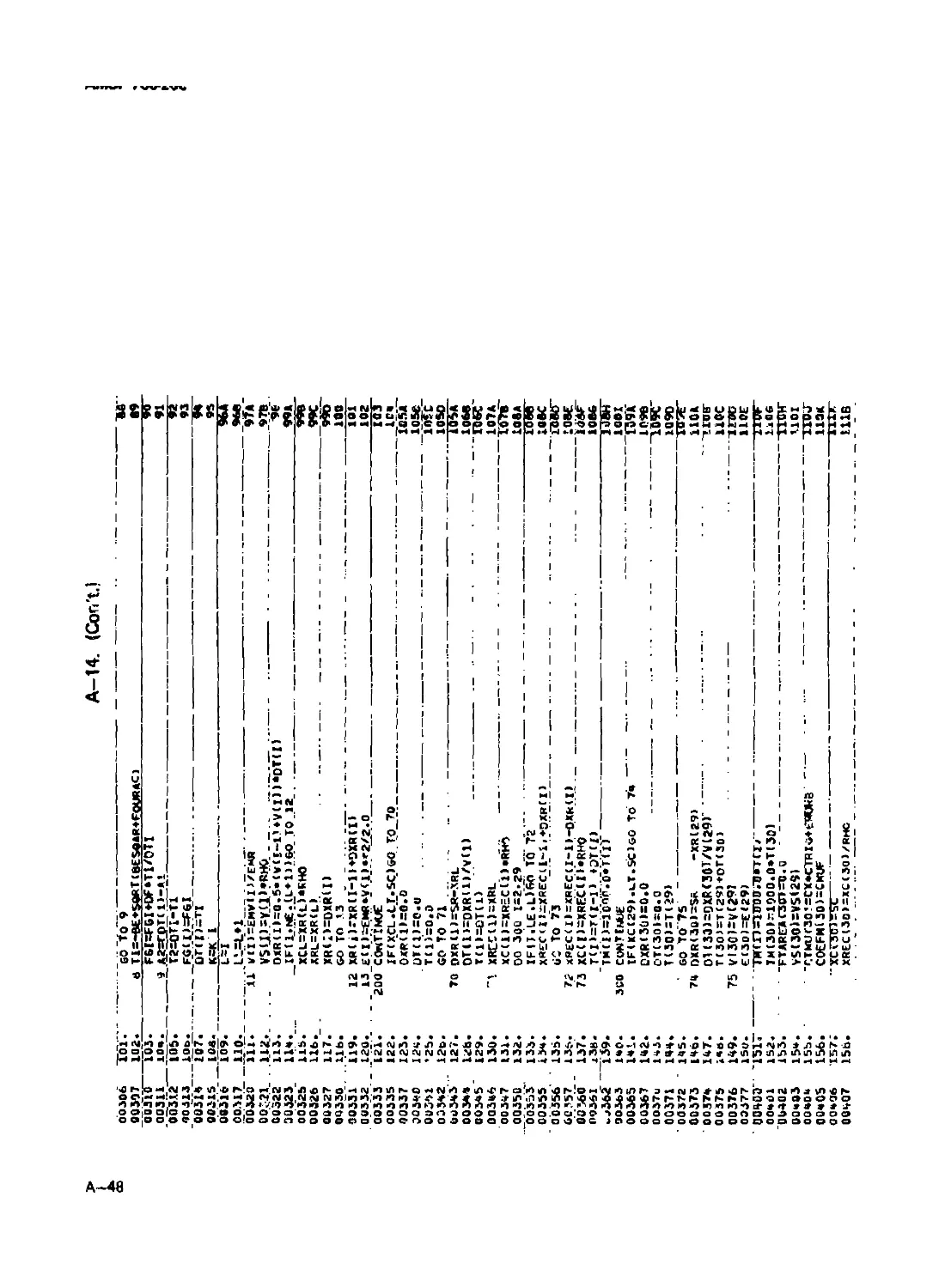
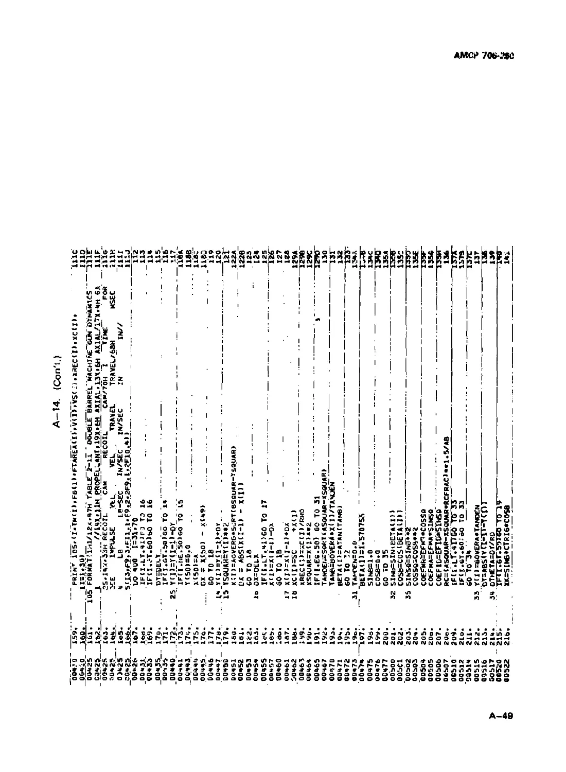
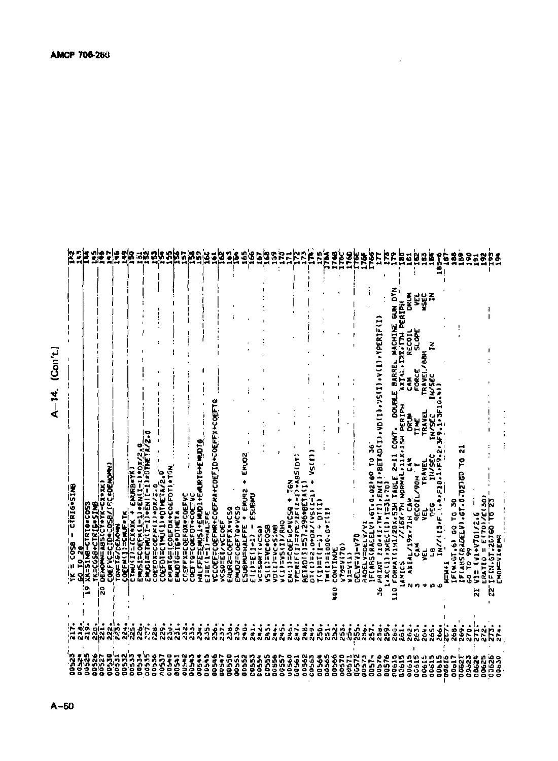
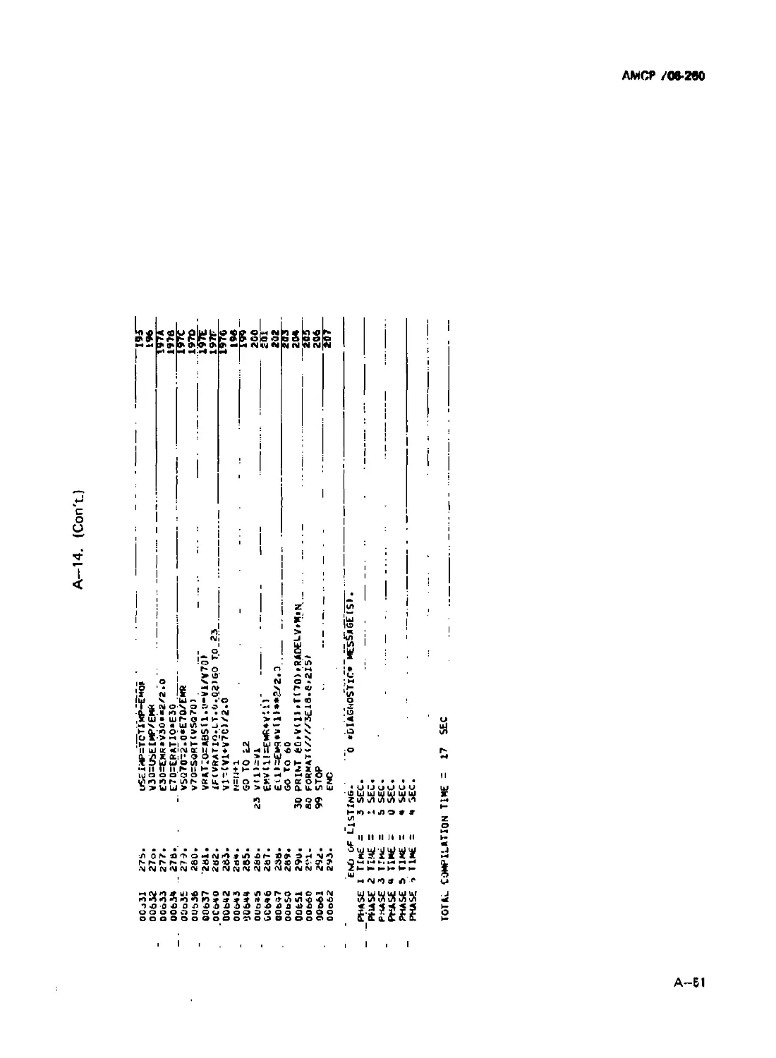
A-14 Program Listing for Double Barrel Machine Gun ....... A-46
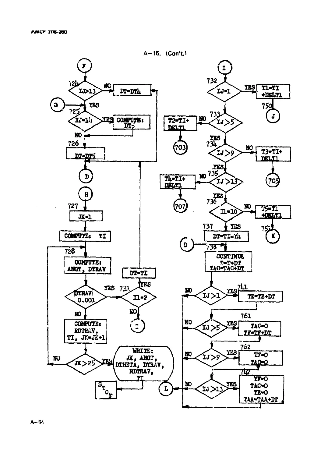
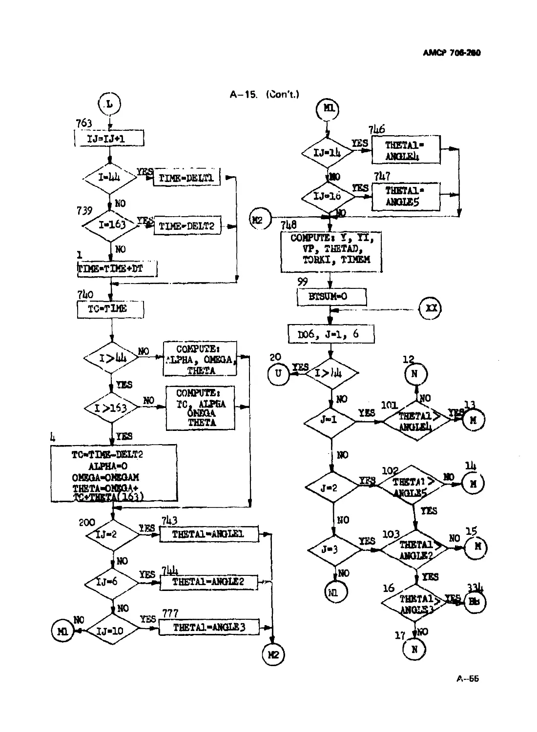
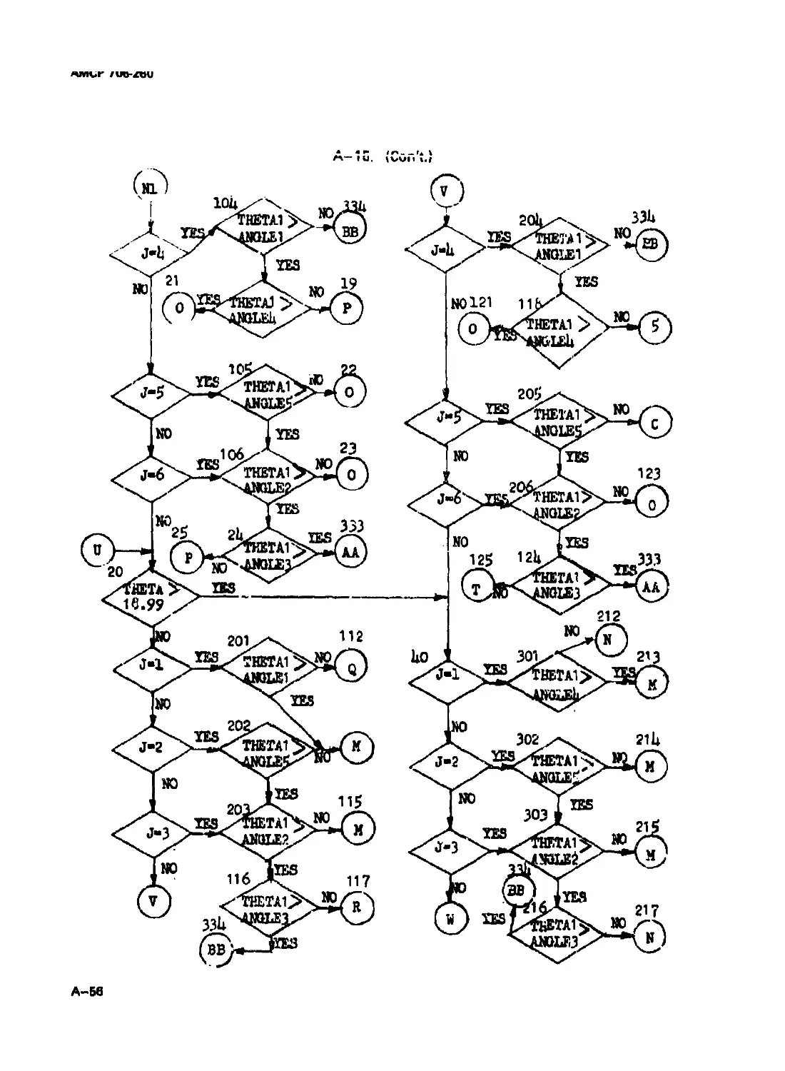
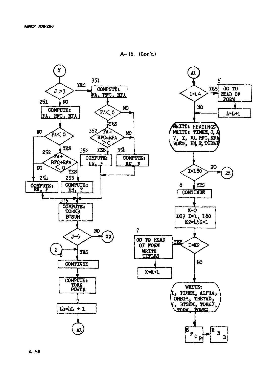
A-15 Flow Chart for Multibarrel Power............................ A-52
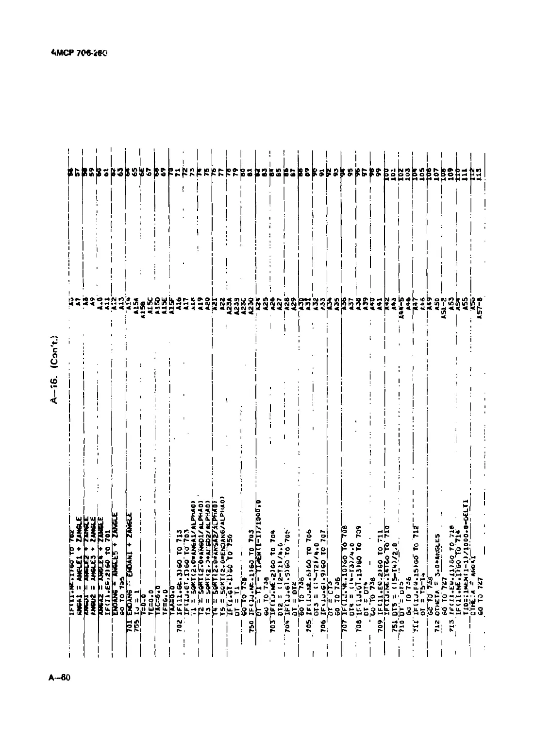
A-lЛ Program Listing for Multibarrel Power ...................... A-59
В Automatic Control of Rounds in a Burtt for
Weapon Effectiveness....................................... B-l
GLOSSARY.................................................... G-l
REFERENCES ................................................. R-l
v
АМСР 70в-2С0
LIST OF ILLUSTRATIONS
rig. bio.
Dm*
1
2-1 Typical Pressure-time Curve........................................ 2-1
2-2 Schematic of Simple Blowback Mechanism............................. 2-3
2 3 Allowable Caae Travel ............................................. 2-4
2-4 Pressure-time Curve of Cal .45(11.42 mm) Round............ 2-8
2-5 Schematic of Advanced Primer Ignition System...................... 2-13
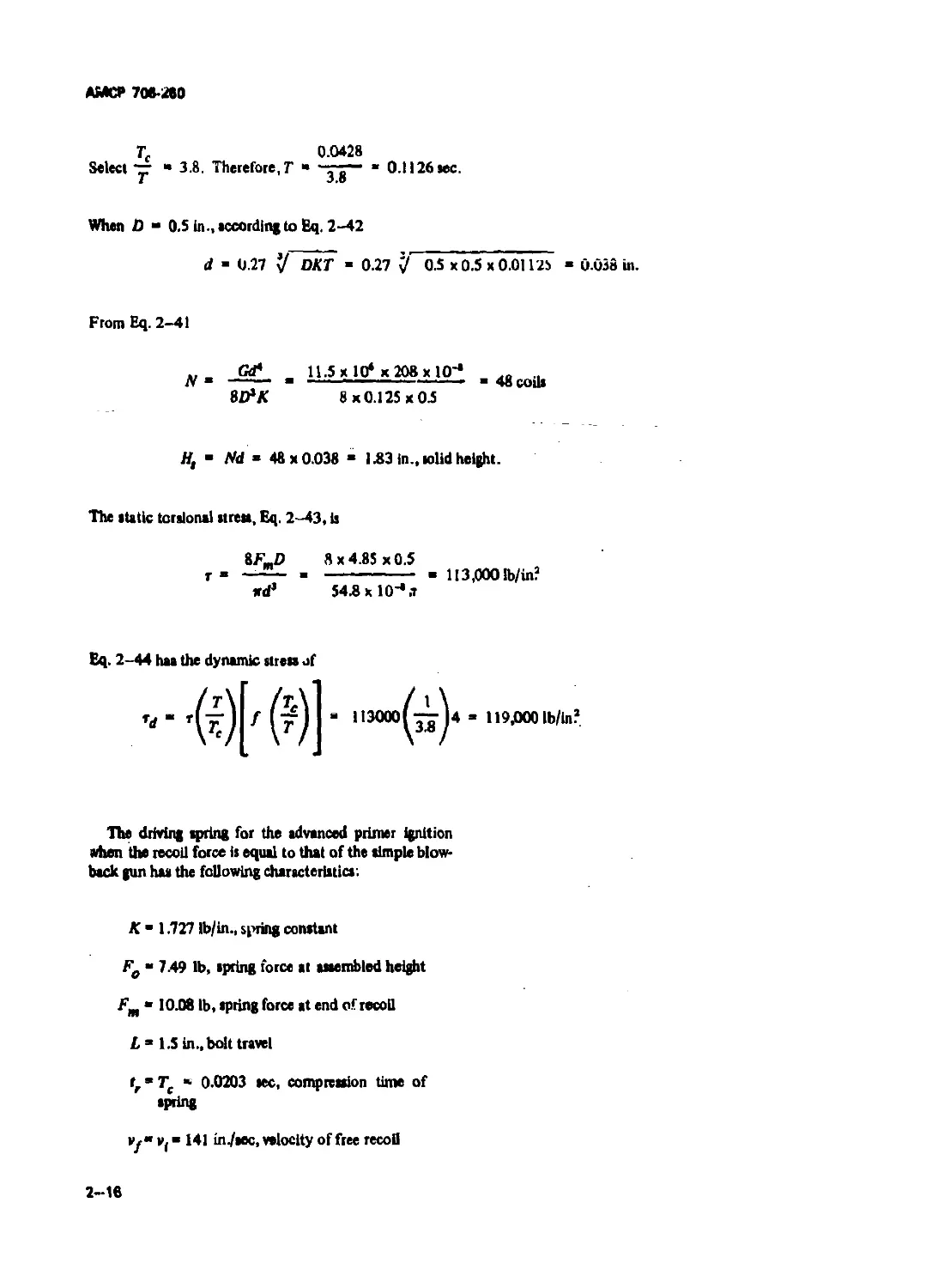
2-6 Locking System for Delayed Blowback .............................. 2-18
2-7 Pressure-time Curve of 20 mm Round................................ 2-25
2-8 Schematic of Retarded Blowback Linkage ......................... 2- 40
2-9 Kinematics of Retaided Blowback Linkage........................... 2-41
2-10 Dynamics of Bolt and Linkage ..................................... 2-42
3-1 Schematic of Long Recoil System ................................... 3-2
3-2 Schematic of Short Recoil System................................... 3-2
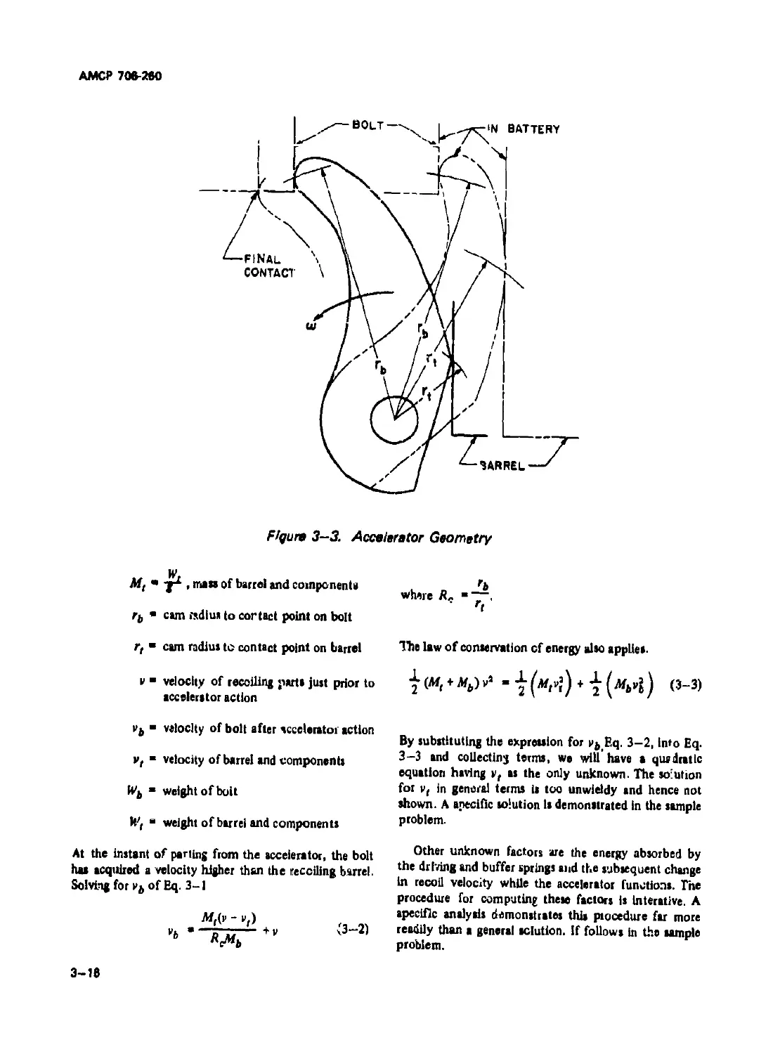
3 -3 Accelerator Geometry ............................................. 3-16
4-1 Impingement System........................................ 4-1
4-2 Cutoff Expansion System................................... 4-2
4-3 Rotating Bolt Lock and Activating Cam ............................ 4-11
4-4 Force System of Bolt Cam ......................................... 4—12
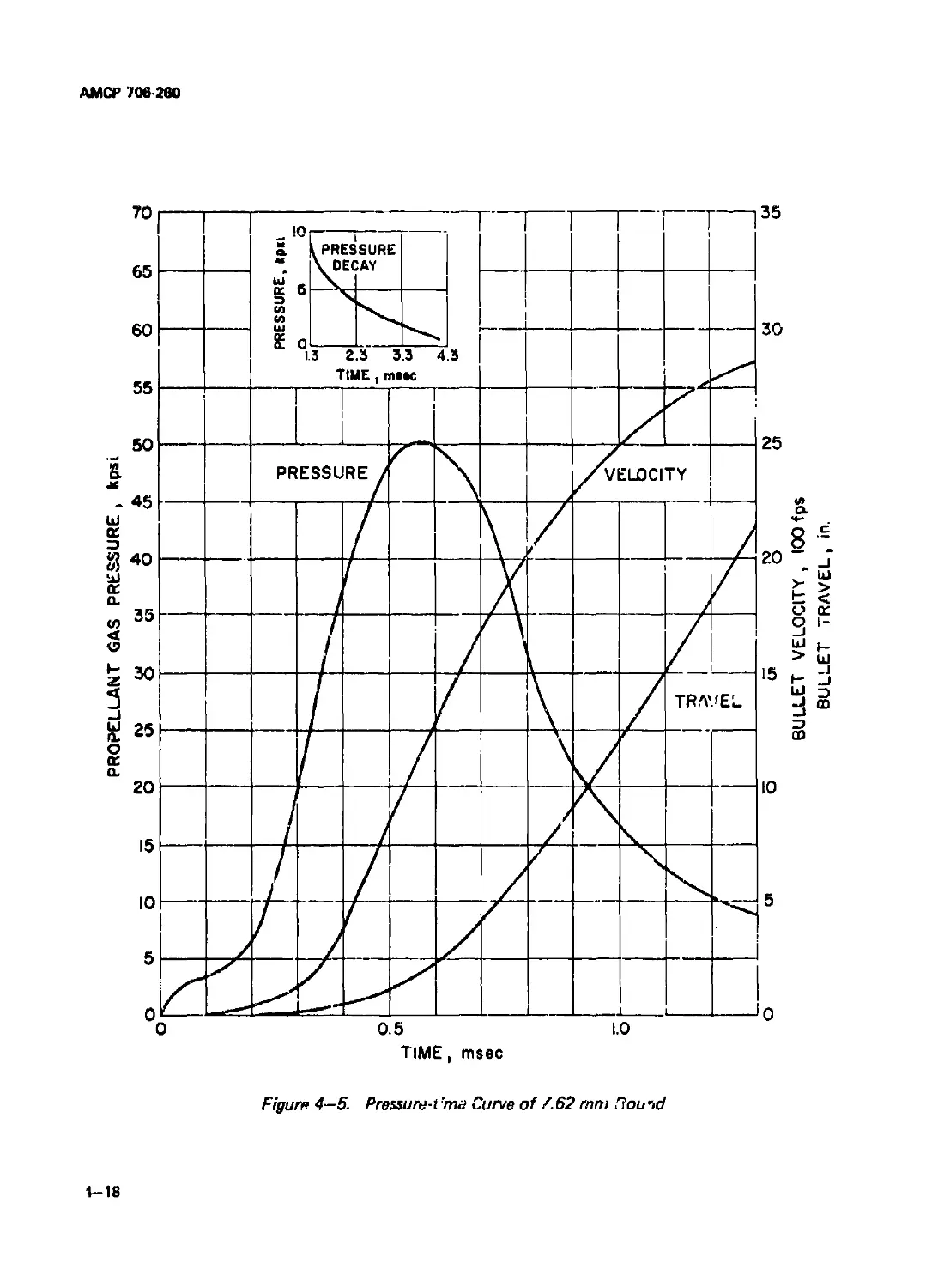
4-5 Pressure-time Curve of 7.62 mm Round.............................. 4—18
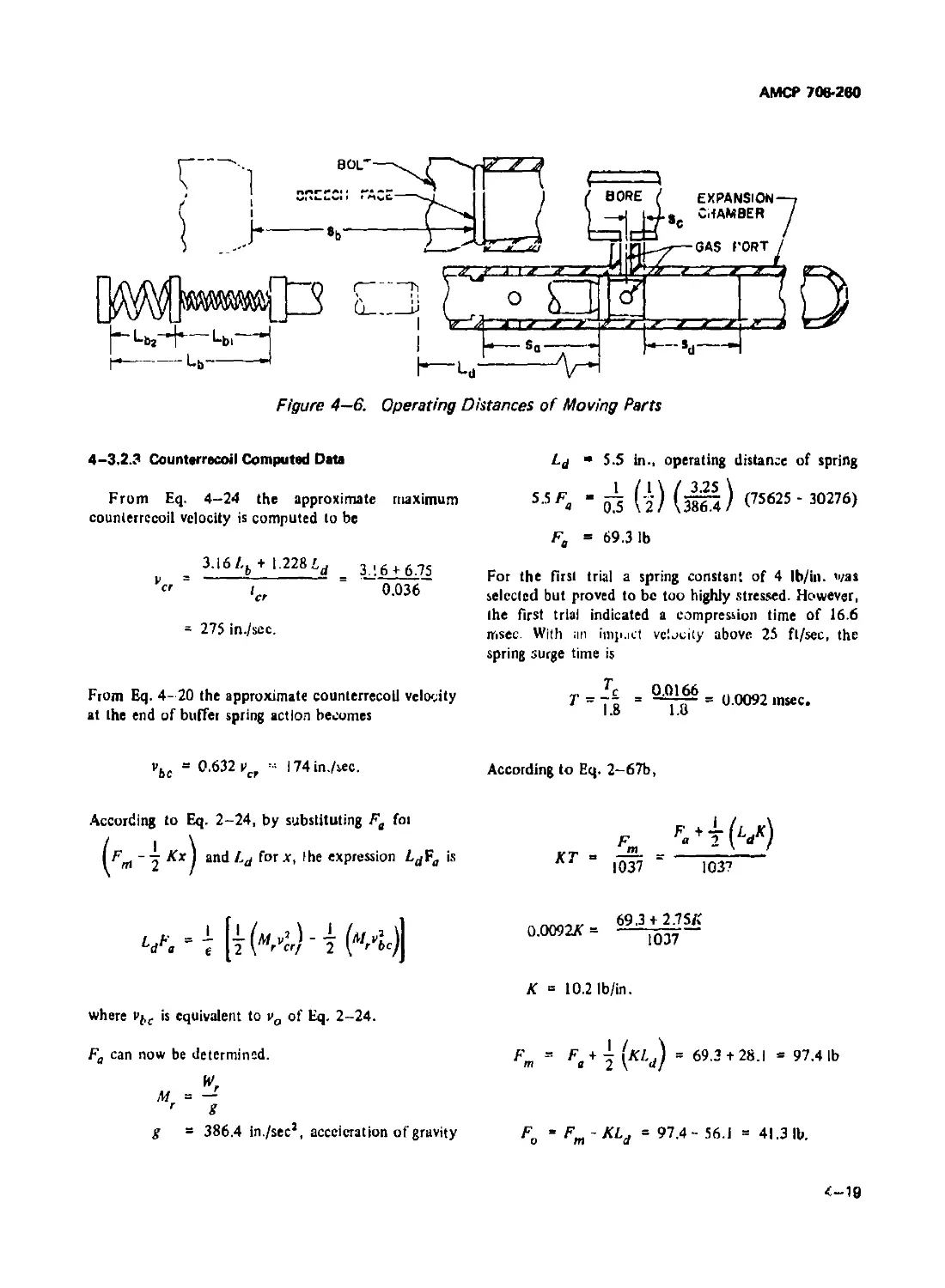
4-6 Operating Distances of Moving Parts............................... 4-19
4-7 Tappet System .................................................... 4-38
4-8 Pressure-time Curve of 7.62 mm Carbine Round...................... 4—40
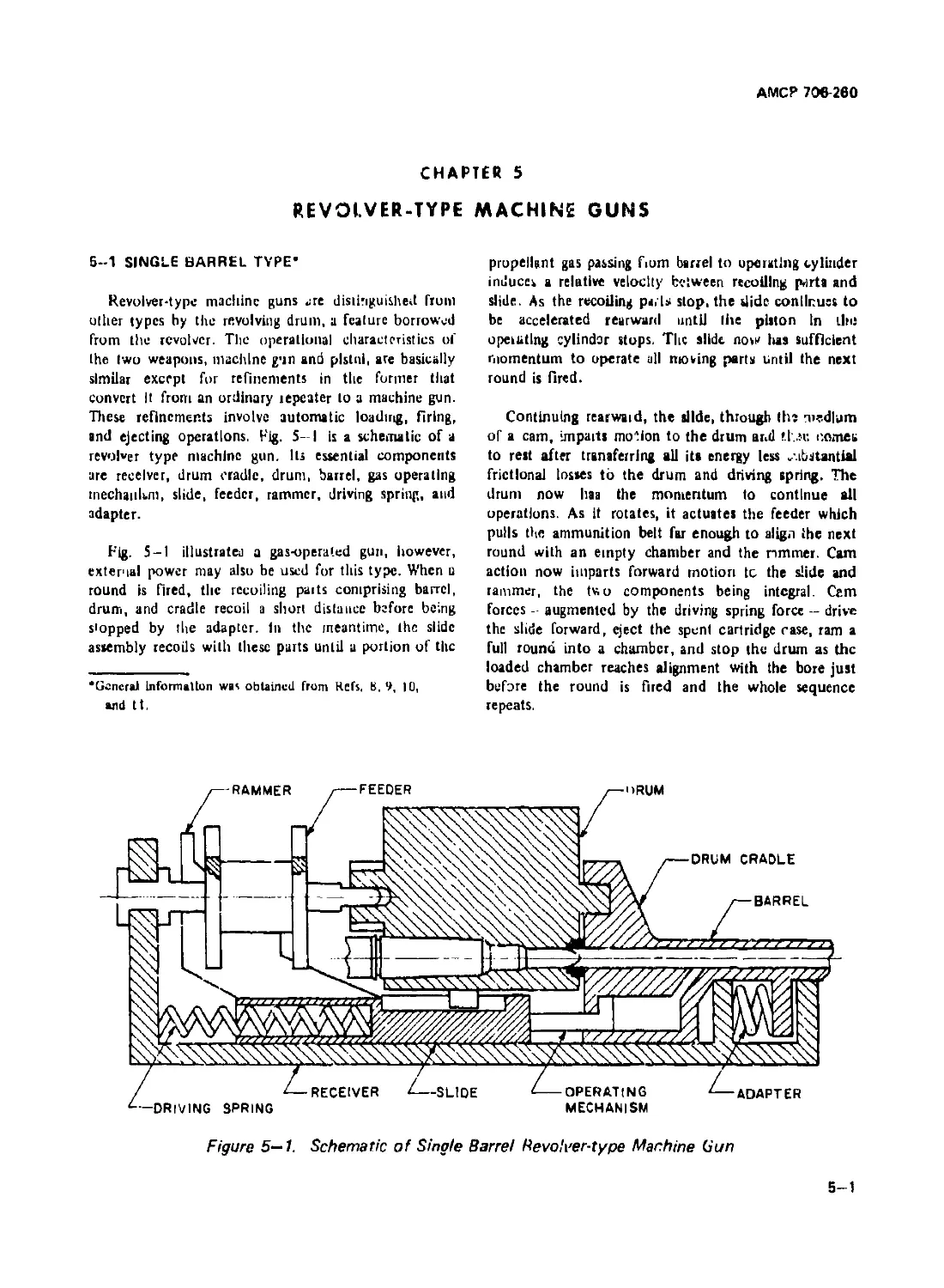
5-1 Schematic of Single Barrel Revolver-type Machine Gun .... 5-1
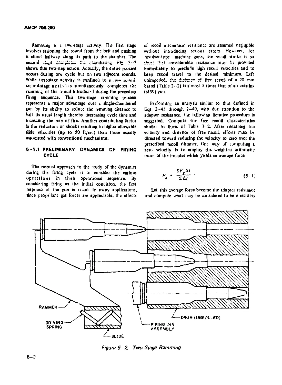
5-2 Two Stage Ramming.................................................. 5-2
5-3 Force Diagram of Recoiling Parts and Slide 5-3
5-4 Schematic of Cam Geometry.......................................... 5-5
5-5 Cam-slide Force Diagrams........................................... 5-9
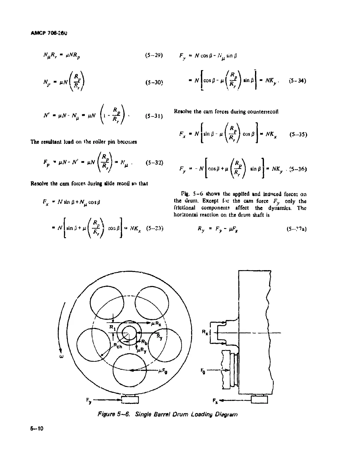
5-6 Single Barrel Drum Loading Diagram ............................... 5-10
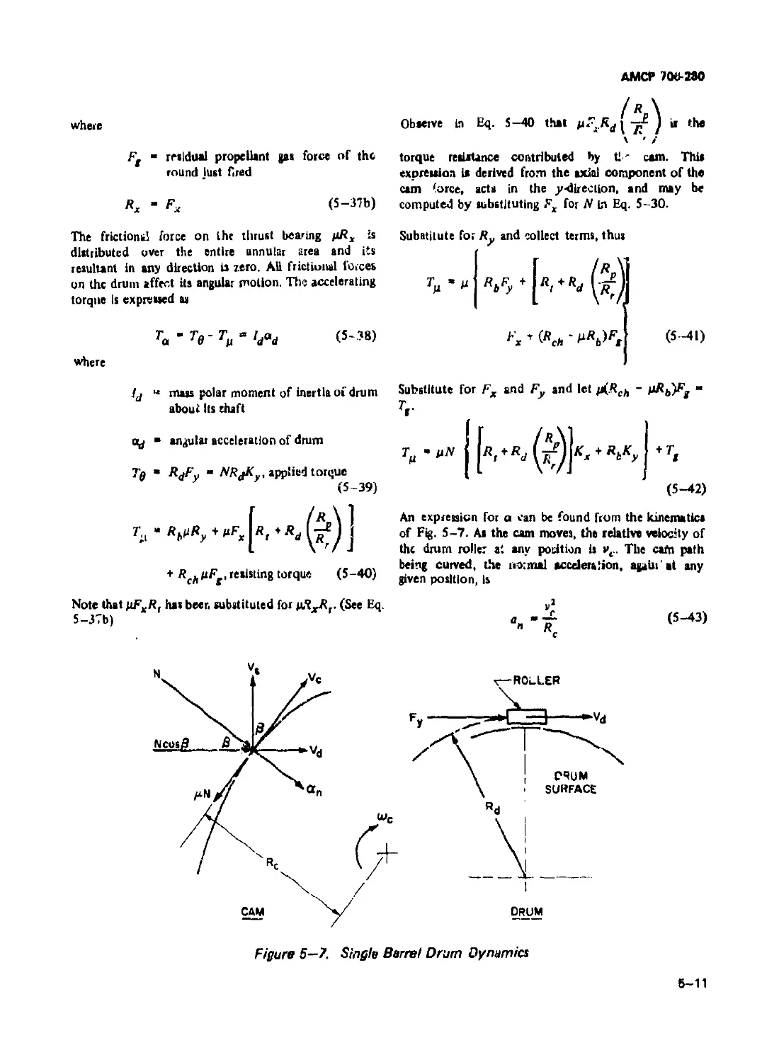
5-7 Single Barrel Drum Dynamics....................................... 5-11
5-8 Interior Ballistics of 20 mm Revolver-type Gun ................... 5-19
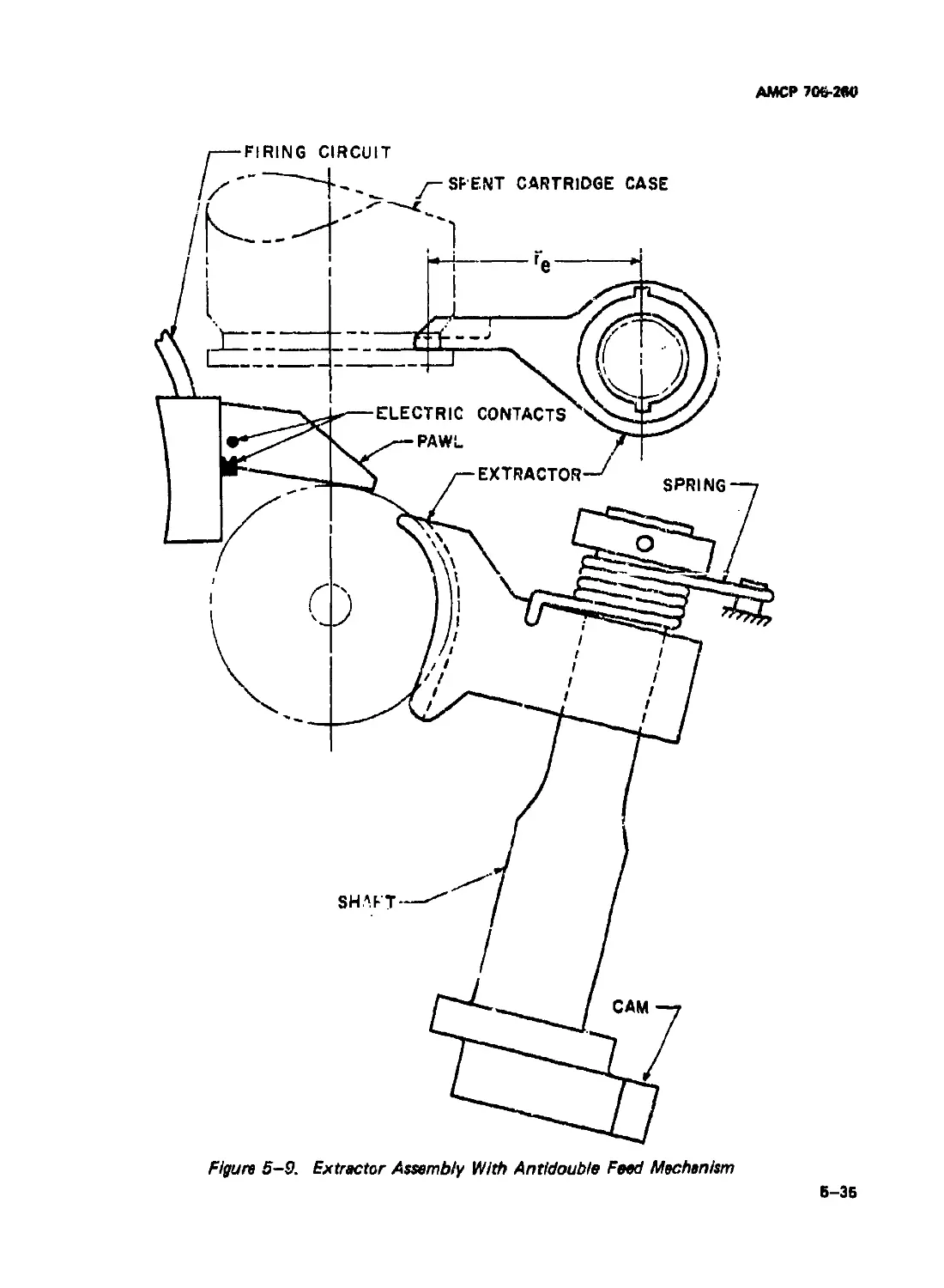
5-9 Extractor Assembly With Antidouble Feed Mechanism .... 5-35
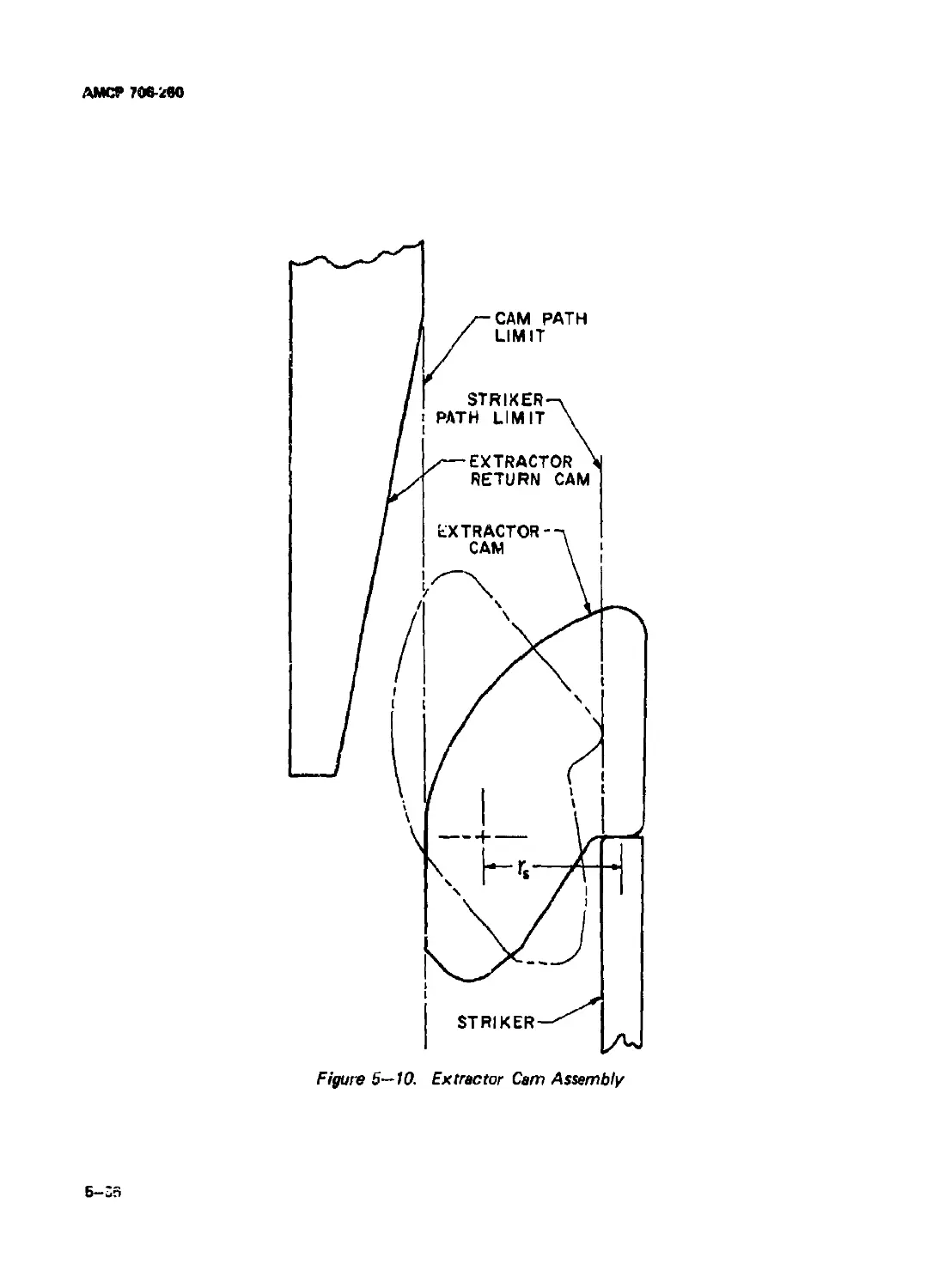
5-10 Extractor Cam Assembly ........................................... 5-36
5-11 Location of Basic Operations...................................... 5-47
5-12 Schematic of Double Barrel Drum-cam Arrangements.......... 5-47
5-13 Schematic of Ammunition Feed System .............................. 5-48
5-14 Schematic of Ammunition Magazine.................................. 5-49
5-15 Double Barrel Cam Force Diagrams ................................. 5-50
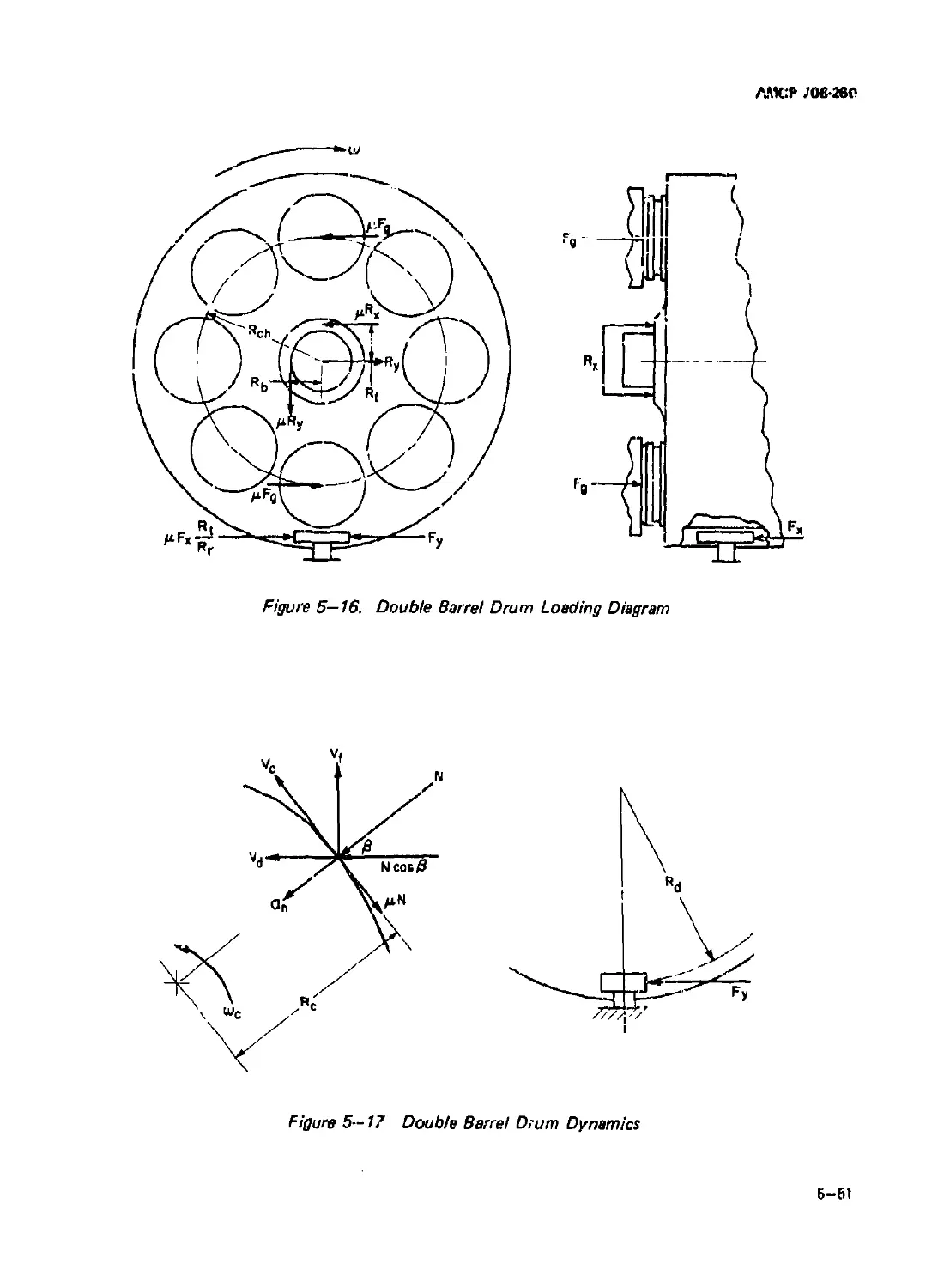
5-16 Double Barrel Drum Loading Diagram................................ 5-51
5-17 Double Barrel Drum Dynamics....................................... 5—51
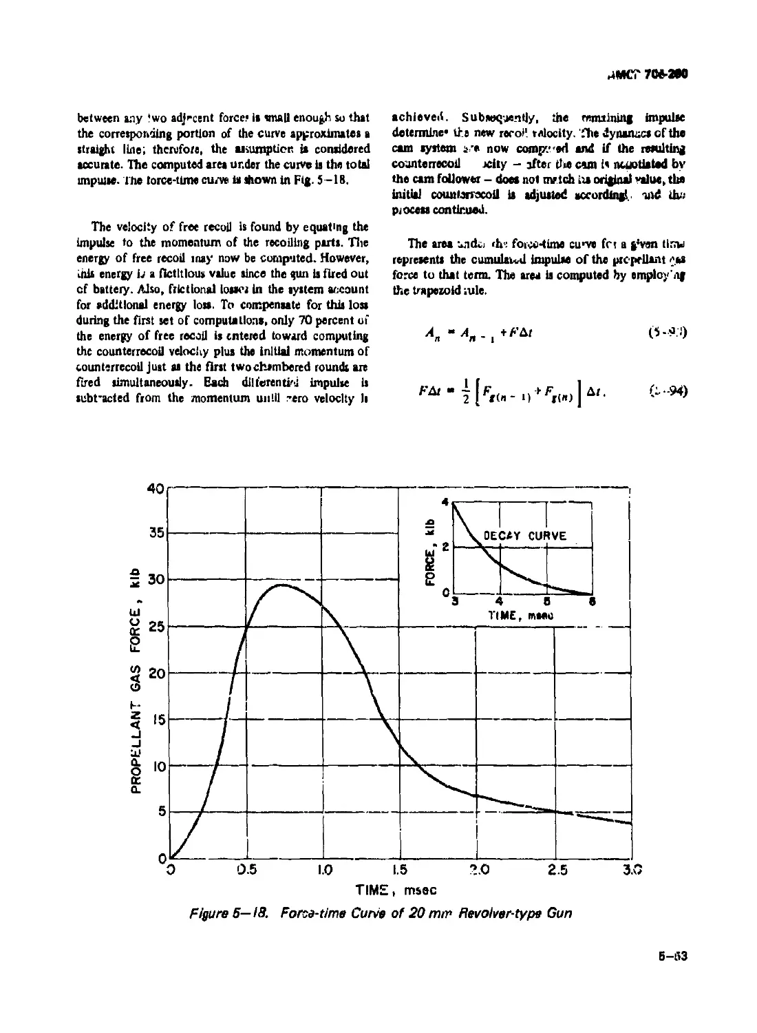
5-18 Force-time Curve of 20 mm Revolver-type Gun....................... 5-53
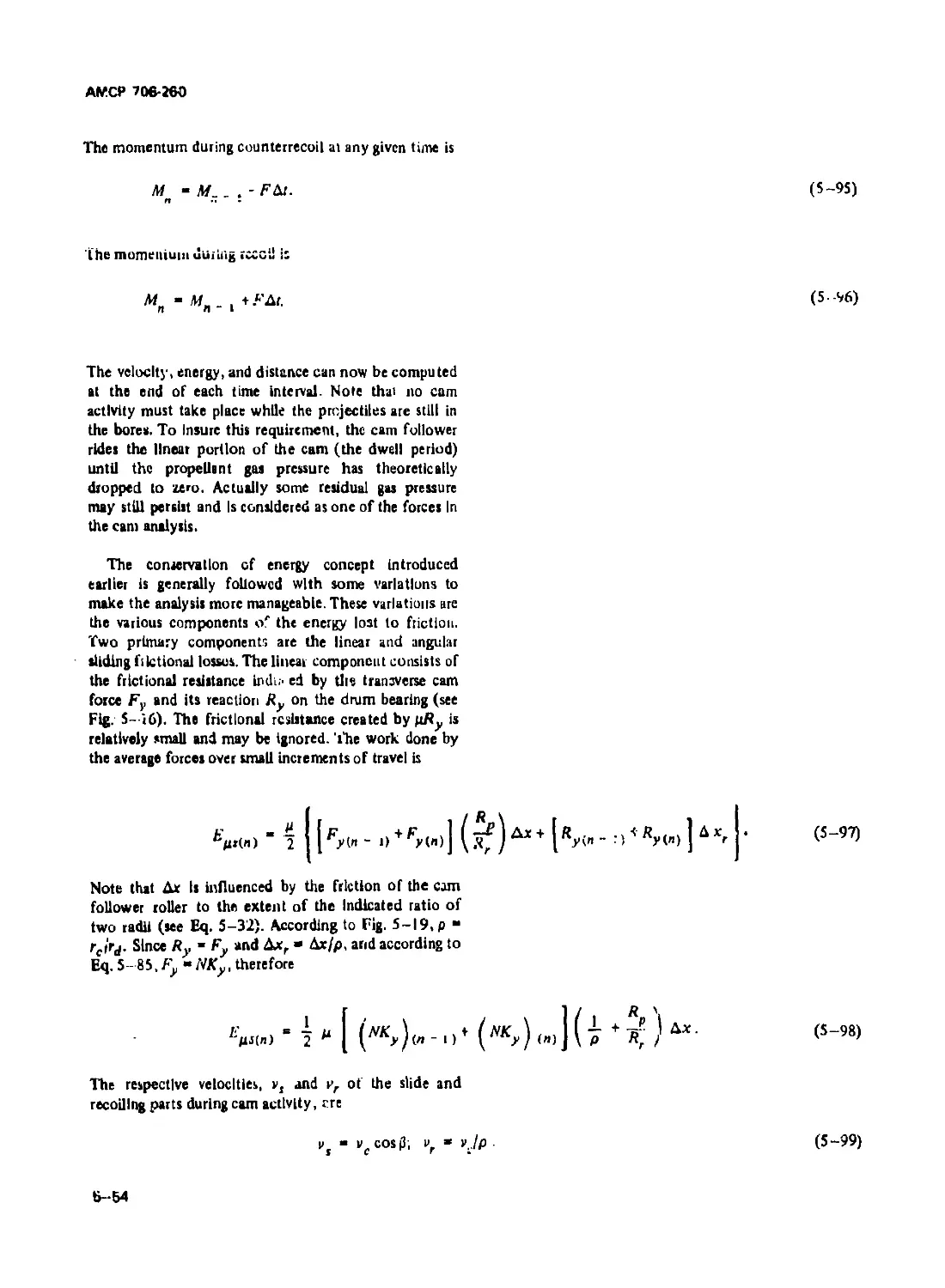
5-19 Geometry of Cam Actuating Lever........................... 5—55
6-1 Cam Contaur of Multibarrel Gun -................................... 6-2
6-2 Loading Diagram of Bolt and Cam During Acceleration . . . 6-2
6-3 Feed Portion of Cam................................................ 6-3
6-4 Loading Diagram of Bolt and Cam During Deceleration . . . 6-7
6-5 Bolt Position Diagram for Computer Analysis ...................... 6-13
vl
АМСР 706-280
LIST OF ILLUSTRATIONS (Con t.)
Fig. No. Title Page
7-1 Initial Contact of Bolt and Cartridge Css' B’S' ................
7-2 Chamber-projectile Contact ........................................ 7-2
7 -3 Box Magazine ...................................................... 7-2
7-4 Up Guides.......................................................... 7-3
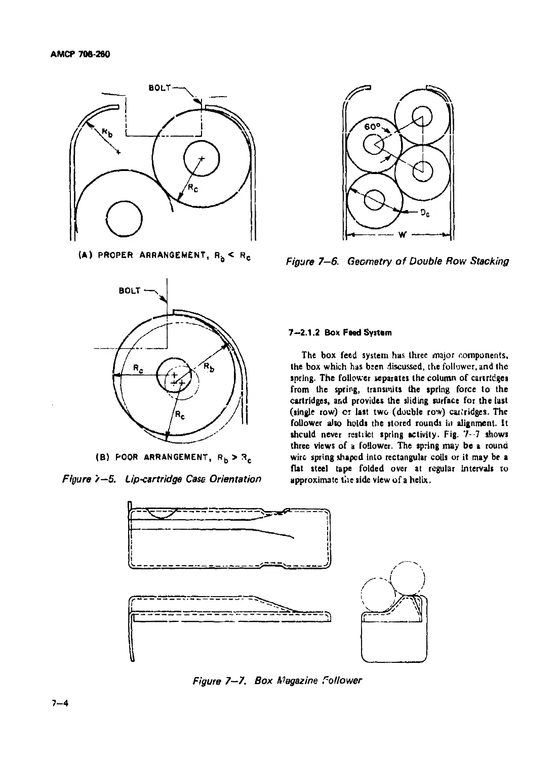
7-5 Lip-cartridge Case Orientation .................................... 7-4
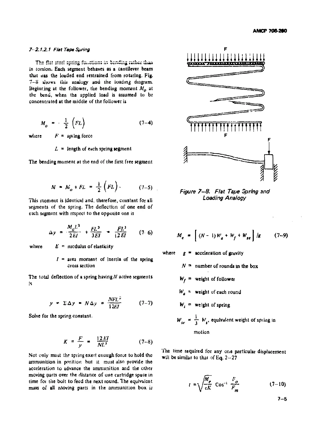
7-6 Geometry of Double Row Stacking ................................... 7-4
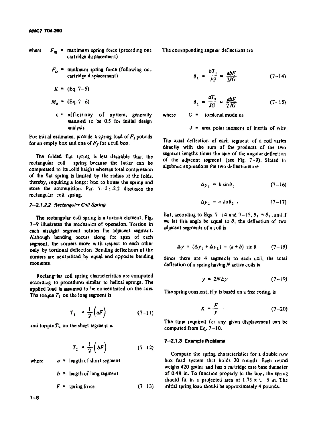
7-7 Box Magazine Follower ............................................. 7-4
7-8 Flat Tape Spring and Loading Analogy............................... 7-5
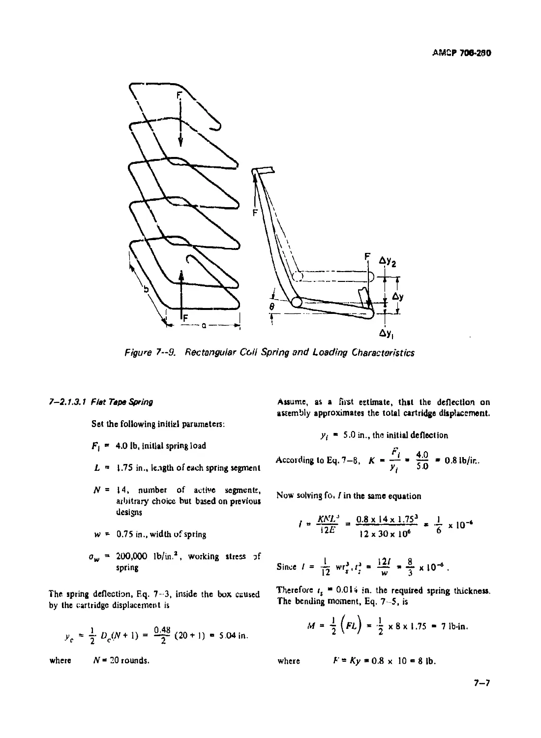
7-9 Rectangular Coil Spring and Loading Characteristics ............... 7-7
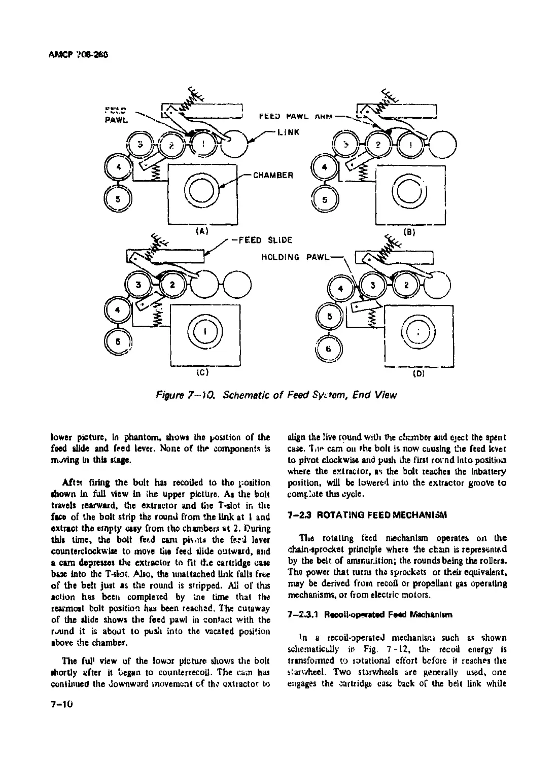
7-10 Schematic of Feed System, End View................................ 7-10
7-11 Feed System Illustrating Mechanics of Operation .................. 7-11
7-12 Recoil-operated Rotating Feed Mechanism .......................... 7-13
7-13 Feed Wheel and Operating Lever Units.............................. 7—14
7-14 Electrically Operated Rotating Feed Mechanism..................... 7—15
7-15 Outer Drum........................................................ 7-16
7-16 Inner Drum Helix................................................. 7-16
7-17 Conveyor Elements................................................. 7—17
7—18 Schematic of Unidess Feed System ................................. 7-18
7-19 Path of Rounds in Single End System............................... 7-19
7-20 Extractors ....................................................... 7—25
7-21 Extractor Loading Diagrams........................................ 7-26
7-22 Ejectors.......................................................... 7-28
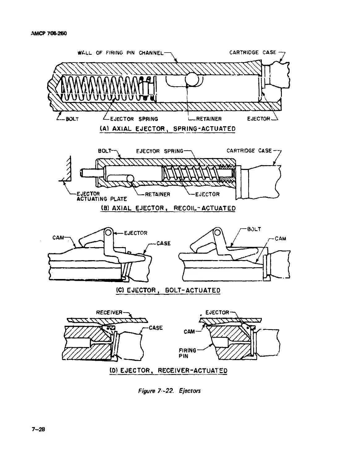
7-23 Ejector Loading Diagram .......................................... 7—29
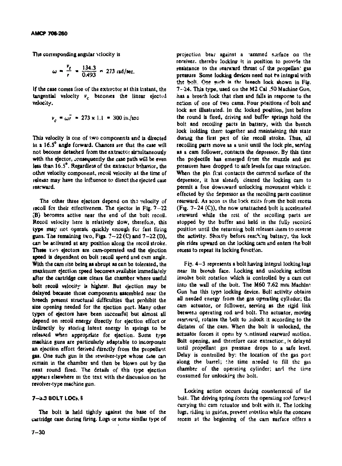
7-24 Sliding Breech Lock ...................................... 7—31
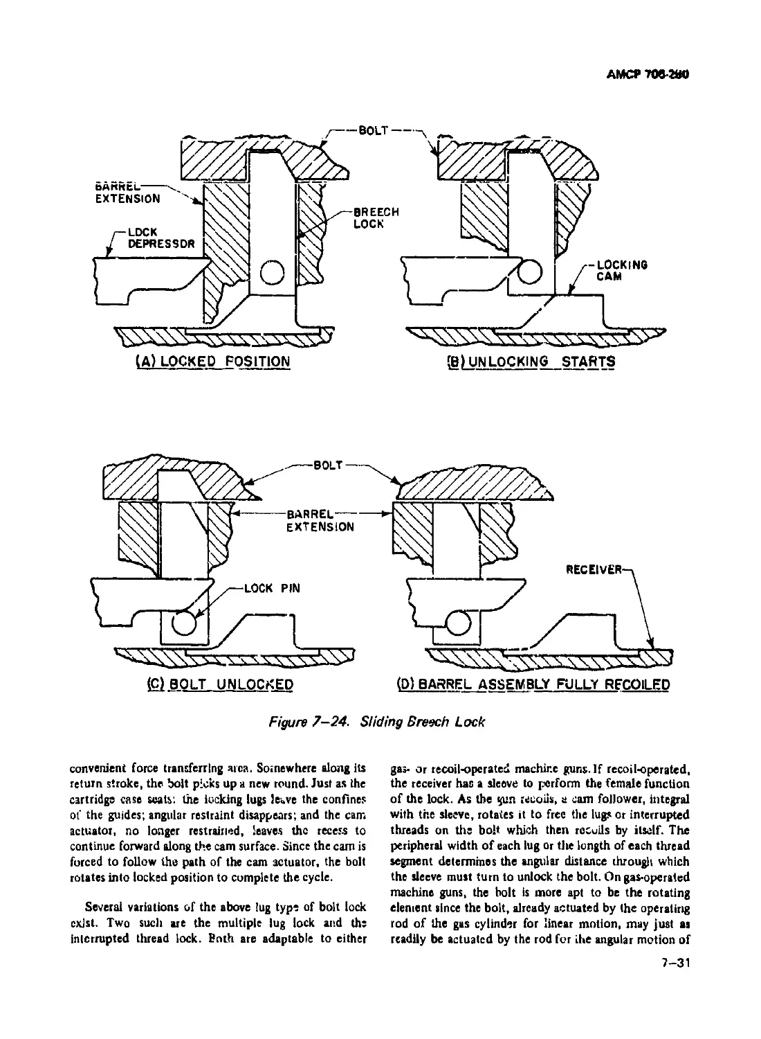
7-25 Tipping Bolt Lock ................................................ 7-32
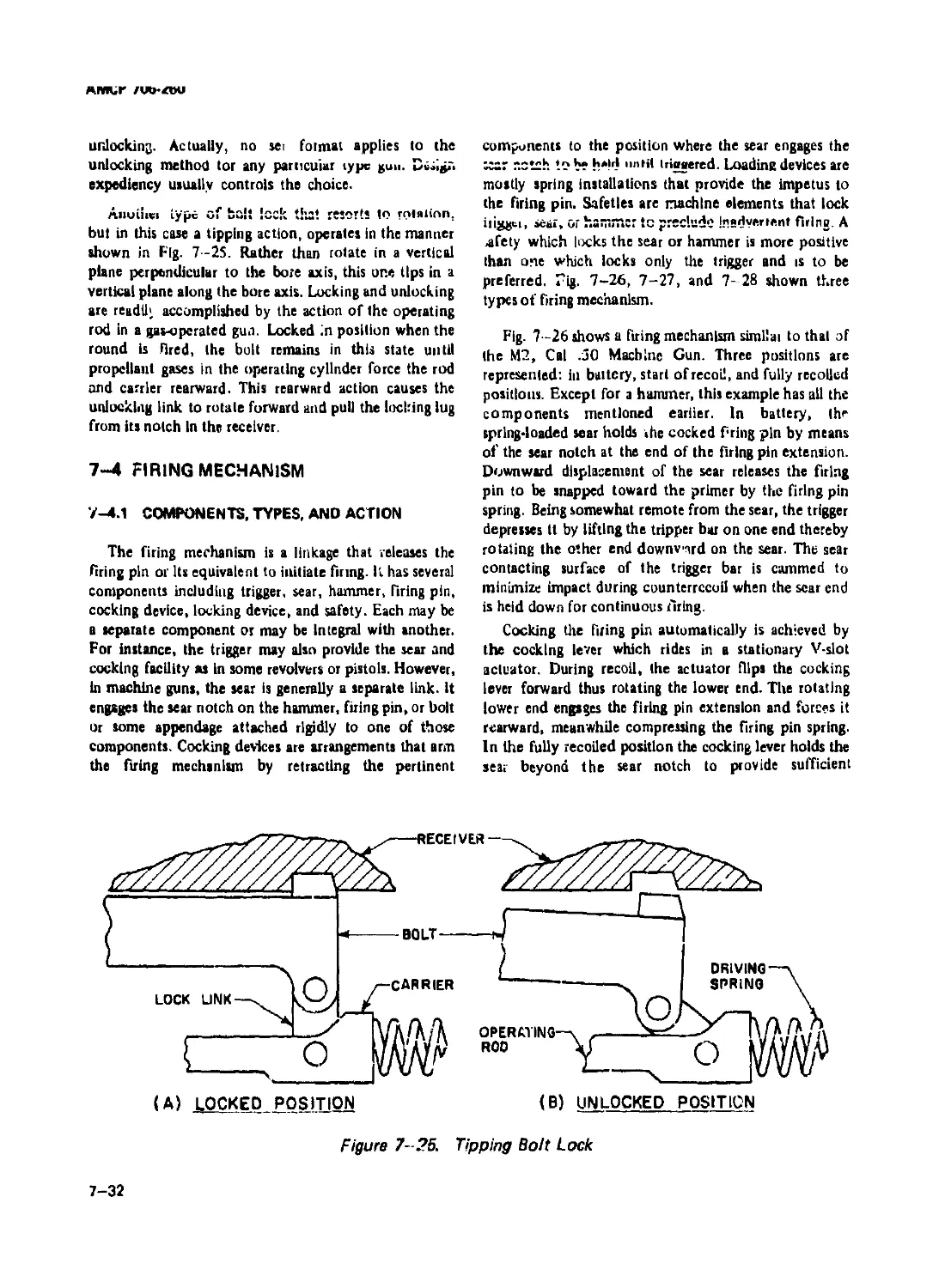
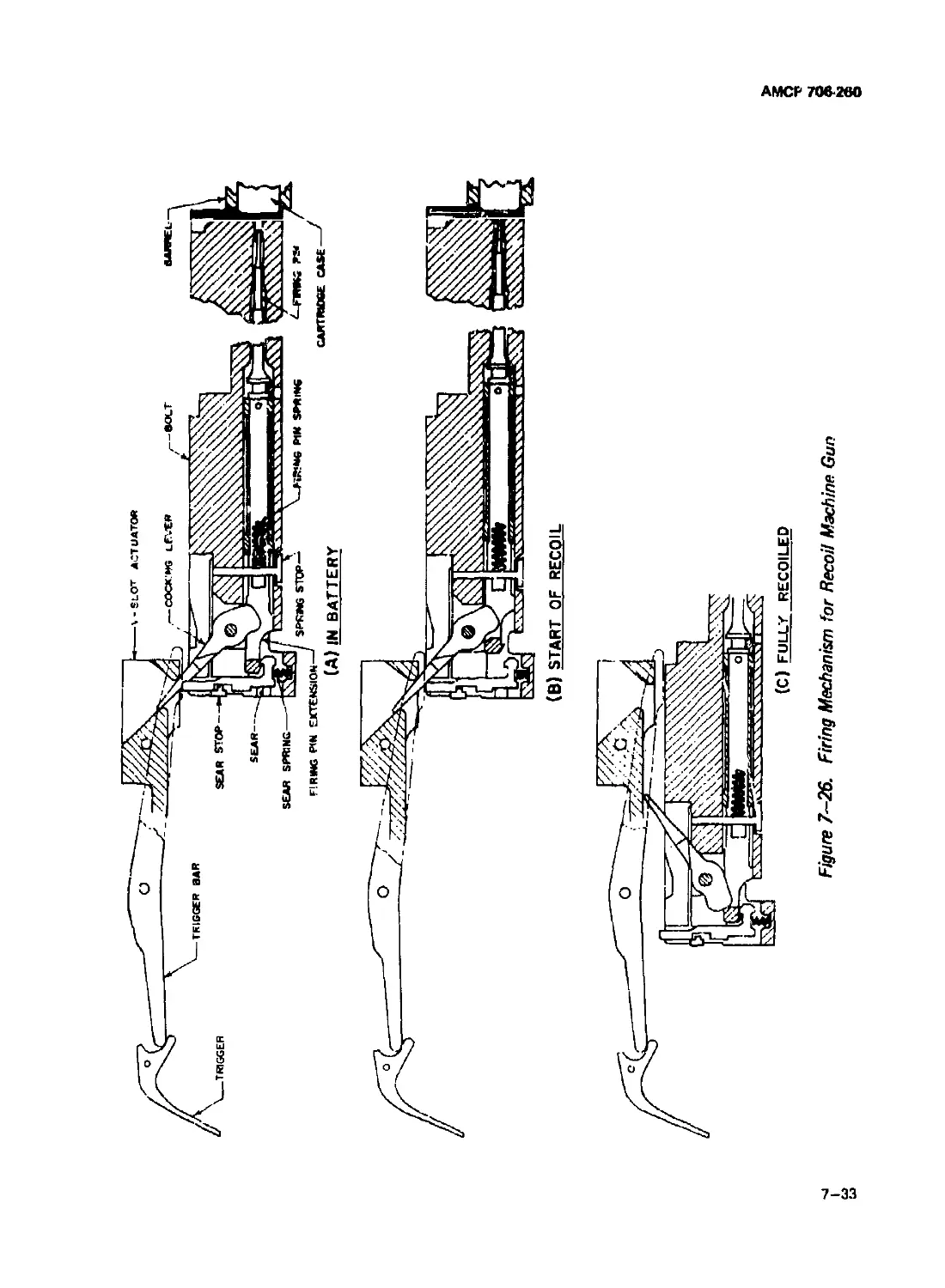
7-26 Firing Mechanism for Recoil Machine Gun........................... 7-33
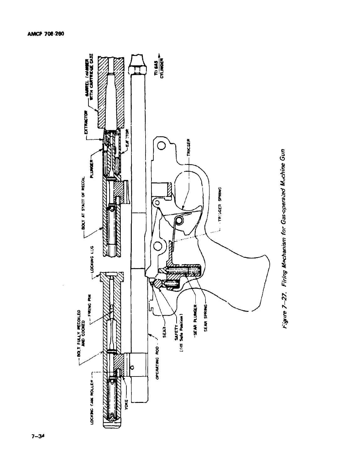
7-27 Firing Mechanism for Gas-operated Machine Gun..................... 7—34
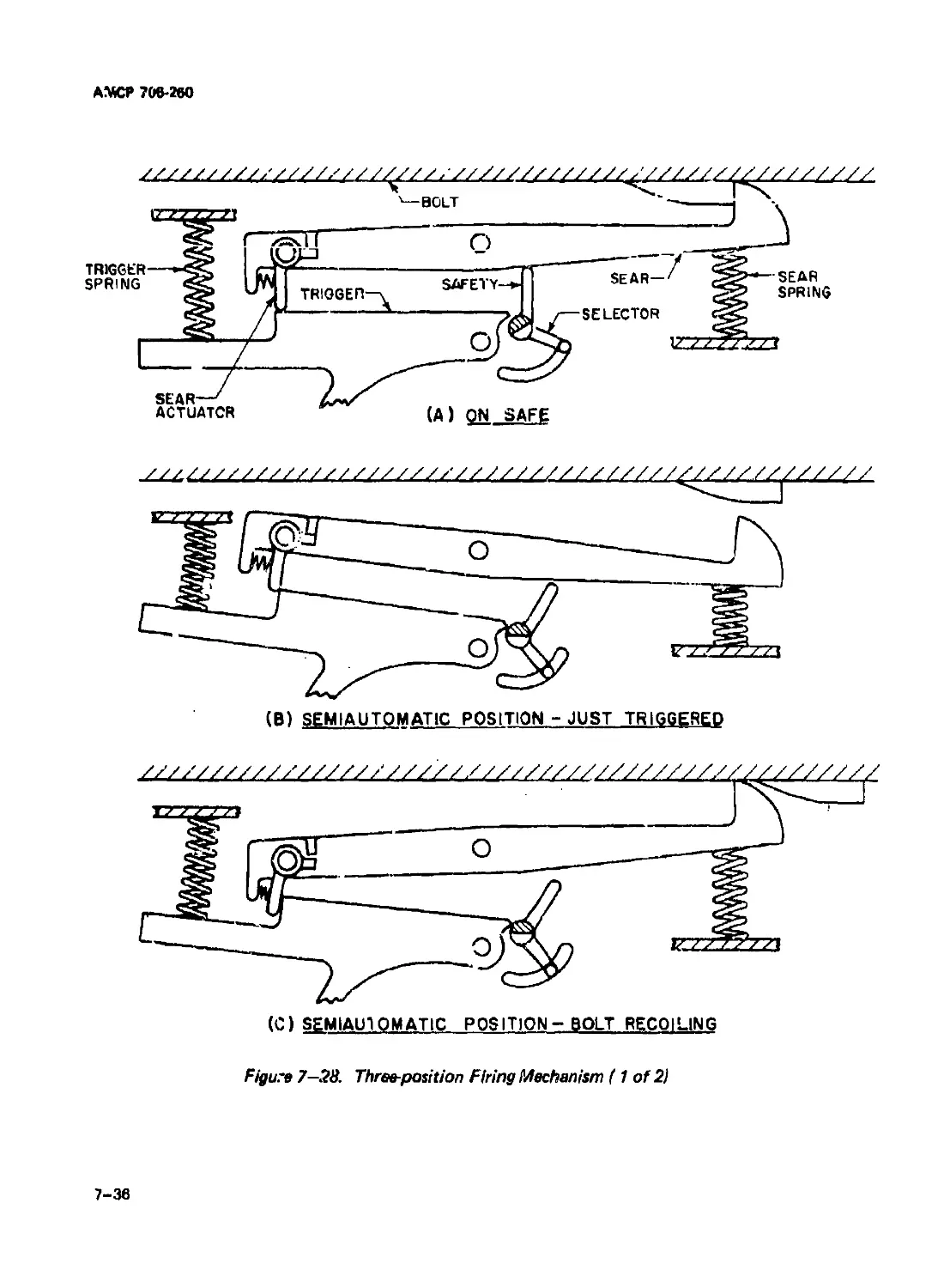
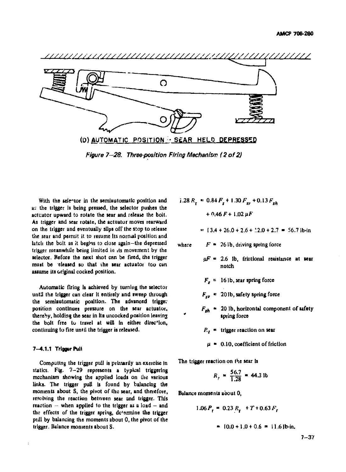
7-28 Three-position Filing Mechanism................................... 7-36
7-29 Triggering Mechanism Loading ..................................... 7-38
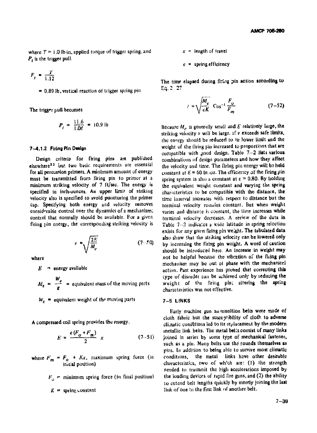
7-30 Ammunition link, Cal .50 Round.................................... 7—41
7-31 Nose Fanning Flexibility, 7.62 mm Link............................ 7-42
7-32 Base Fanning Flexibility, 7.62 mm Link ........................... 7-43
7-33 Geometry of Base Fanning ......................................... 7-44
7-34 Helical Flexibility, 7.62 mm Link ................................ 7-45
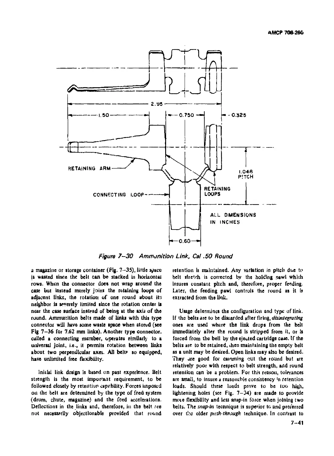
7-35 Total Folding 7.62 mm Ammunition Belt ............................ 7-46
7-36 Partial Folding 7.62 mm Ammunition Beit........................... 7-46
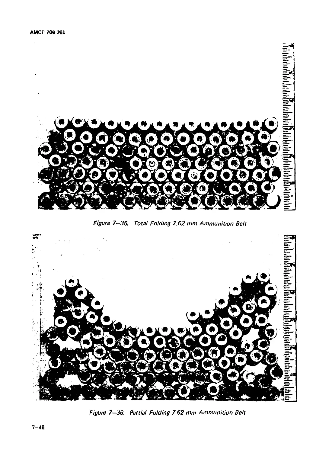
7-37 Loading Link With RADHAZ Shield................................... 7-47
7-38 Loading Diagram of Mount.......................................... 7-47
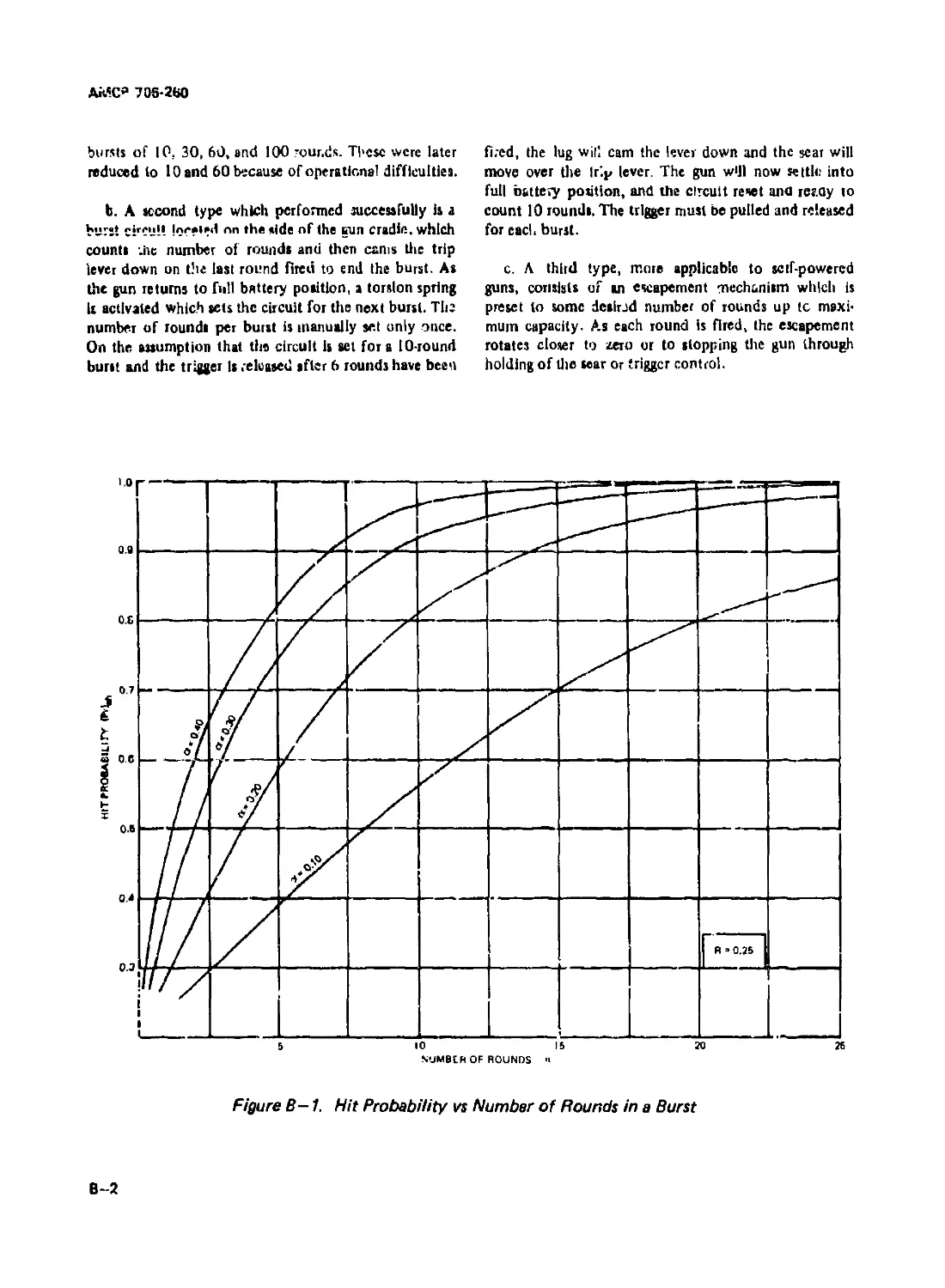
B-l Hit Probability vs Number of Rounds in a Burst ........... B—2
vil
АМСР 706-260
LIST OF TABLES
Tsbl* No. Title Раде
2-1 Саде Travel of Cal .45(11.42 mm) Gun............................ 2—11
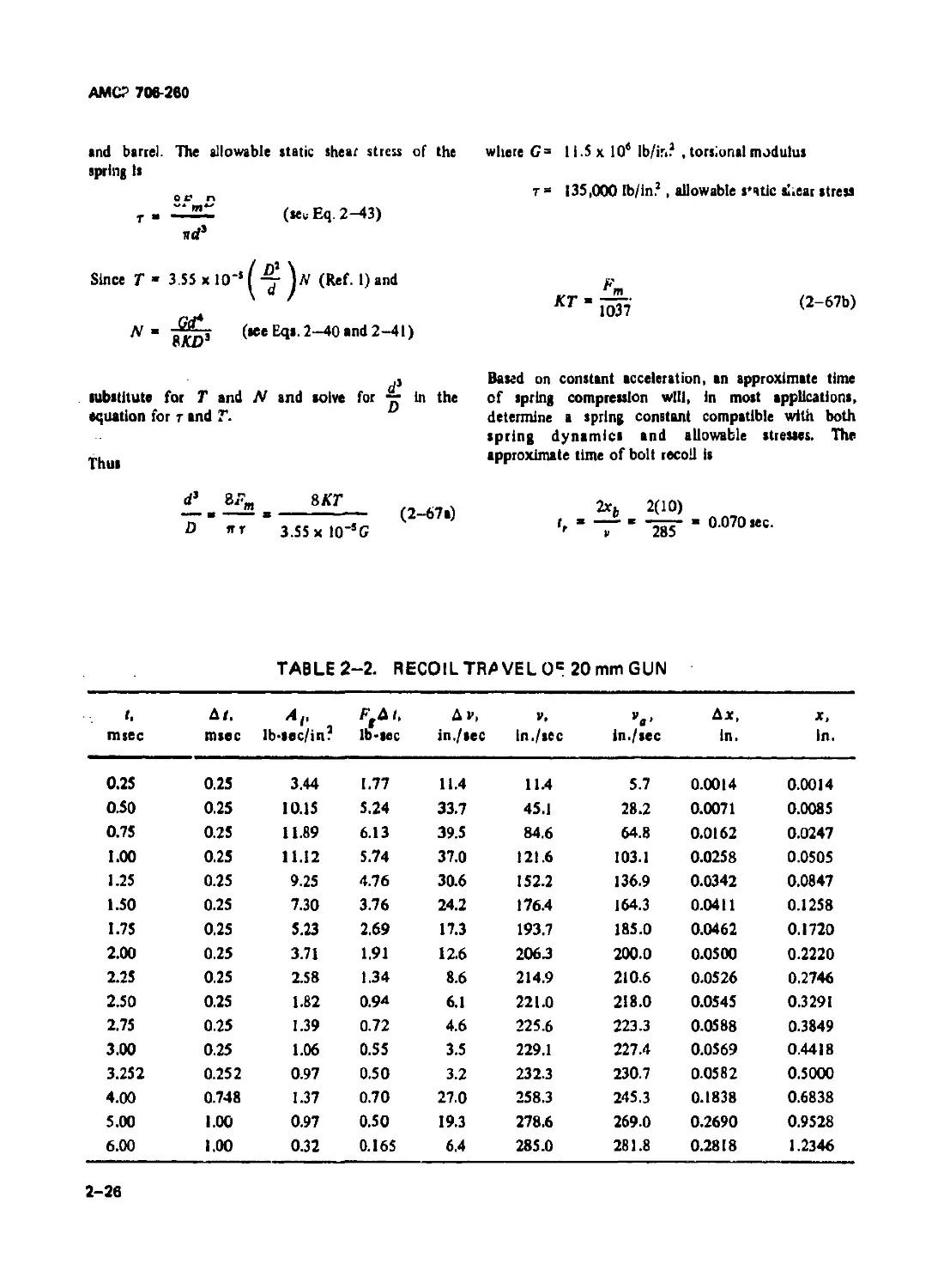
2-2 Recoil Travel of 20 mm Gun...................................... 2—26
2-3 Symbol-code Correlation for Delayed Blowback Program . . 2—36
2-4 Input for Delayed Blowback Program ............................. 2—37
2-5 Counterrecoil Dynamics of Delayed Blowback Gun........... 2—38
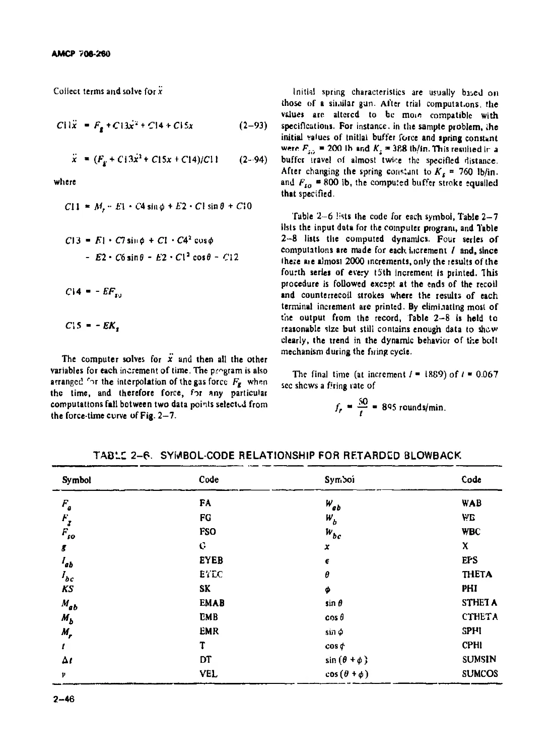
2-6 Symbol-code Correlation for Retarded Blowback .................. 2-46
2-7 Input Data for Retarded Blowback ............................... 2-47
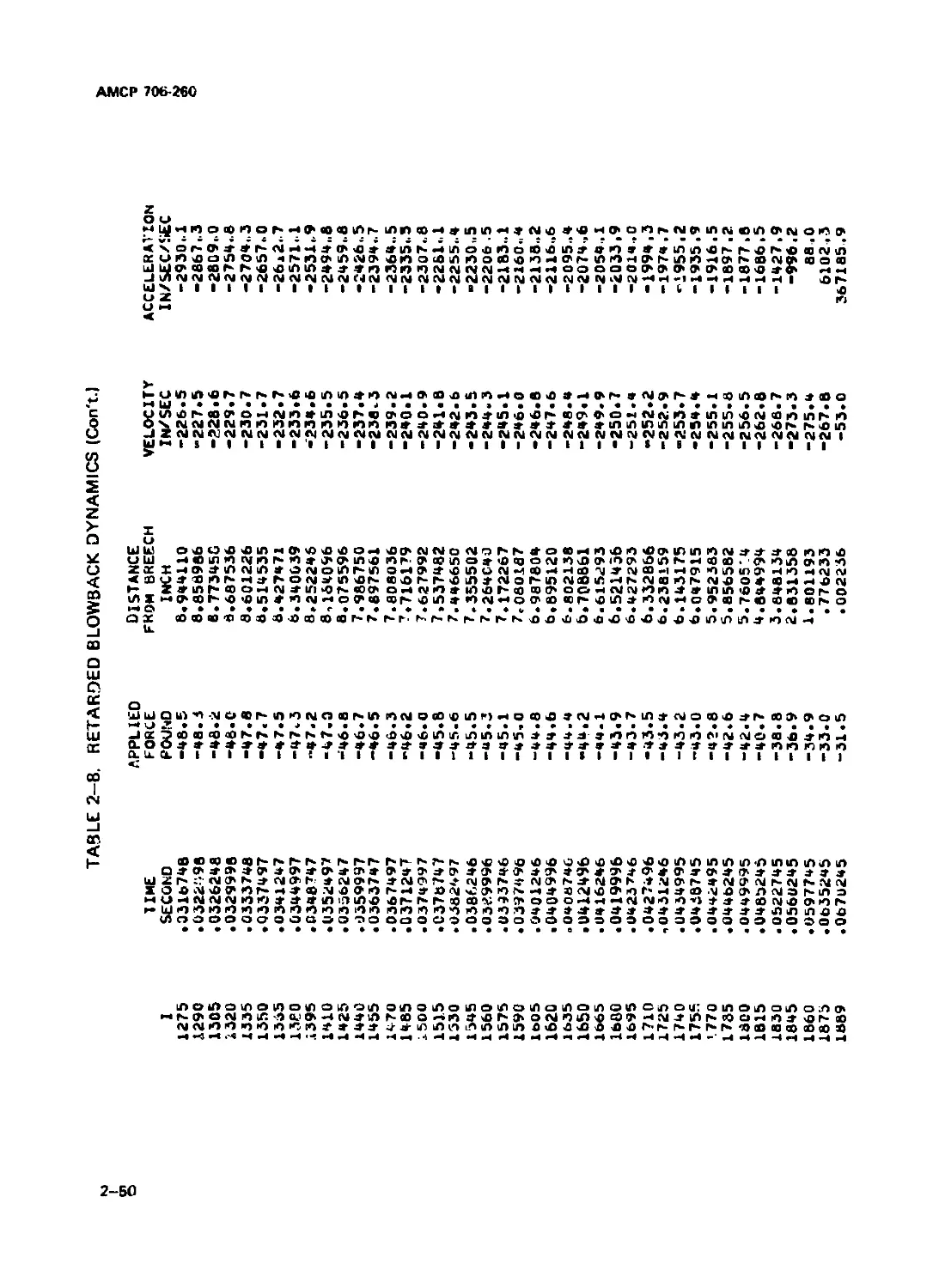
2-8 Retarded Blowback Dynamics ..................................... 2-48
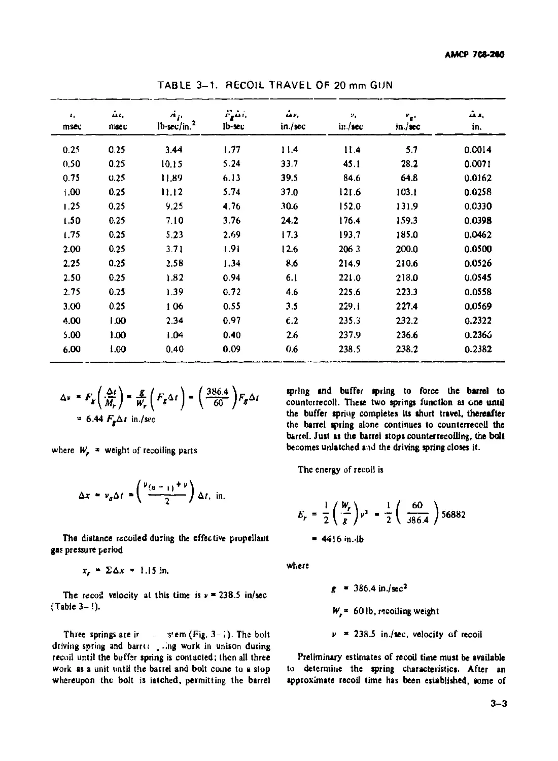
3-1 Recoil Travel of 20 mm Gun....................................... 3-3
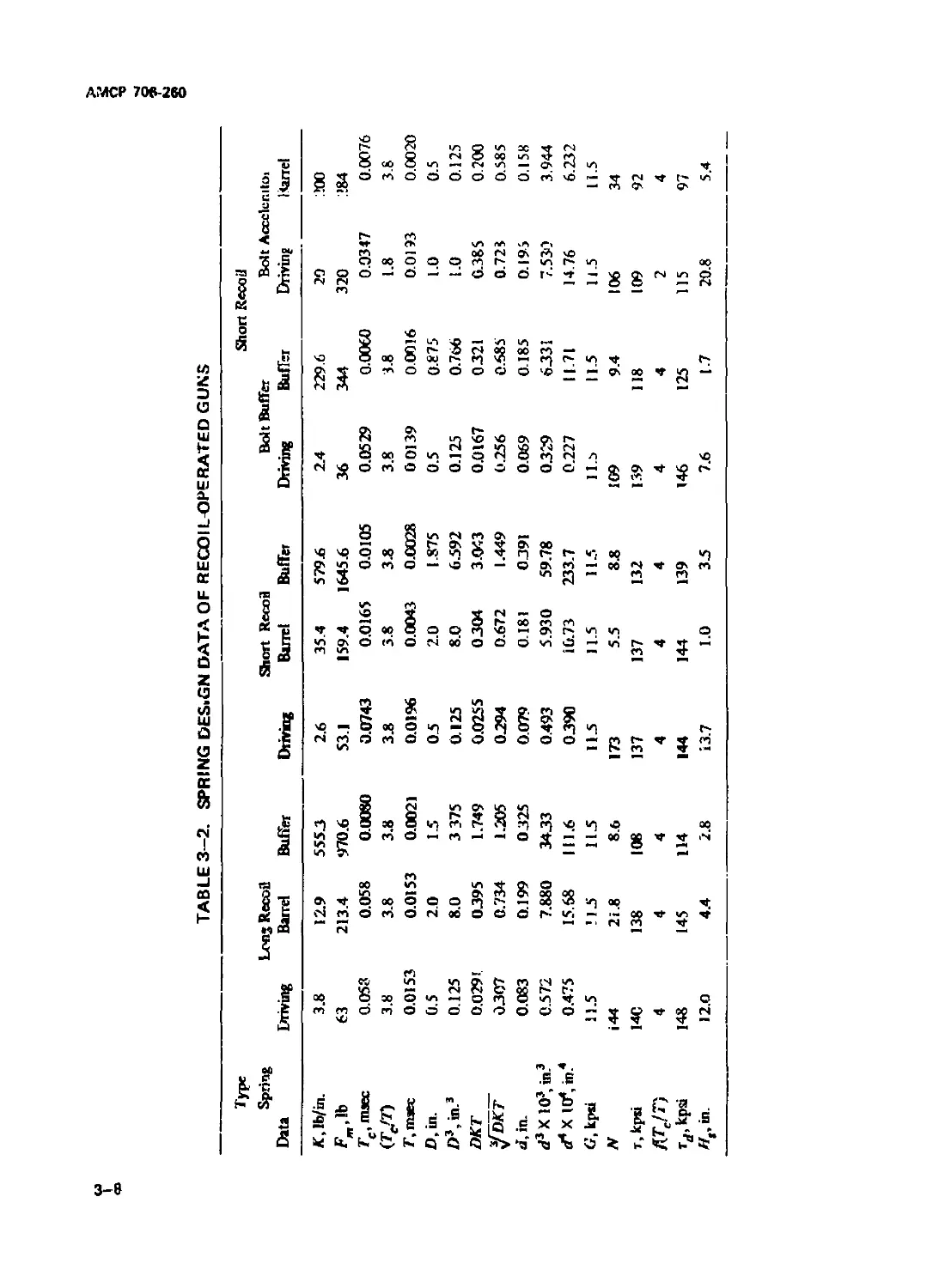
3-2 Spring Design Data of Recoil-operated Guns....................... 3-8
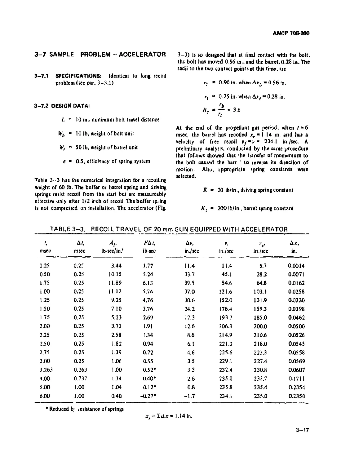
3-3 Recoil Travel of 20 mm Gun Equipped With Accelerator . . 3—17
4-1 Computed Dynamics of Gas Cutoff System ......................... 4-25
4-2 Gas Expansion Time Calculations ................................ 4—29
4-3 Symbol-code Correlation for Cutoff Expansion ............ 4-30
4-4 Input for Cutoff Expansion Program ............................. 4-31
4-5 Computed Dynamics Before Gas Cutoff............................. 4—32
4-6 Computed Dynamics After Gas Cutoff Bolt Unlocking
During Helix Traverse......................................... 4-33
4-7 Computed Dynamics After Gas Cutoff Bolt Unlocking
During Parabola Traverse................................................... 4-33
4-8 Computed Dynamics After Gas Cutoff Bolt
and Rod Unit Recoiling After Cam Action....................... 4-34
4-9 Computed Dynamics, Countenecoil Bolt Locking
During Parabola Traverse...................................... 4-35
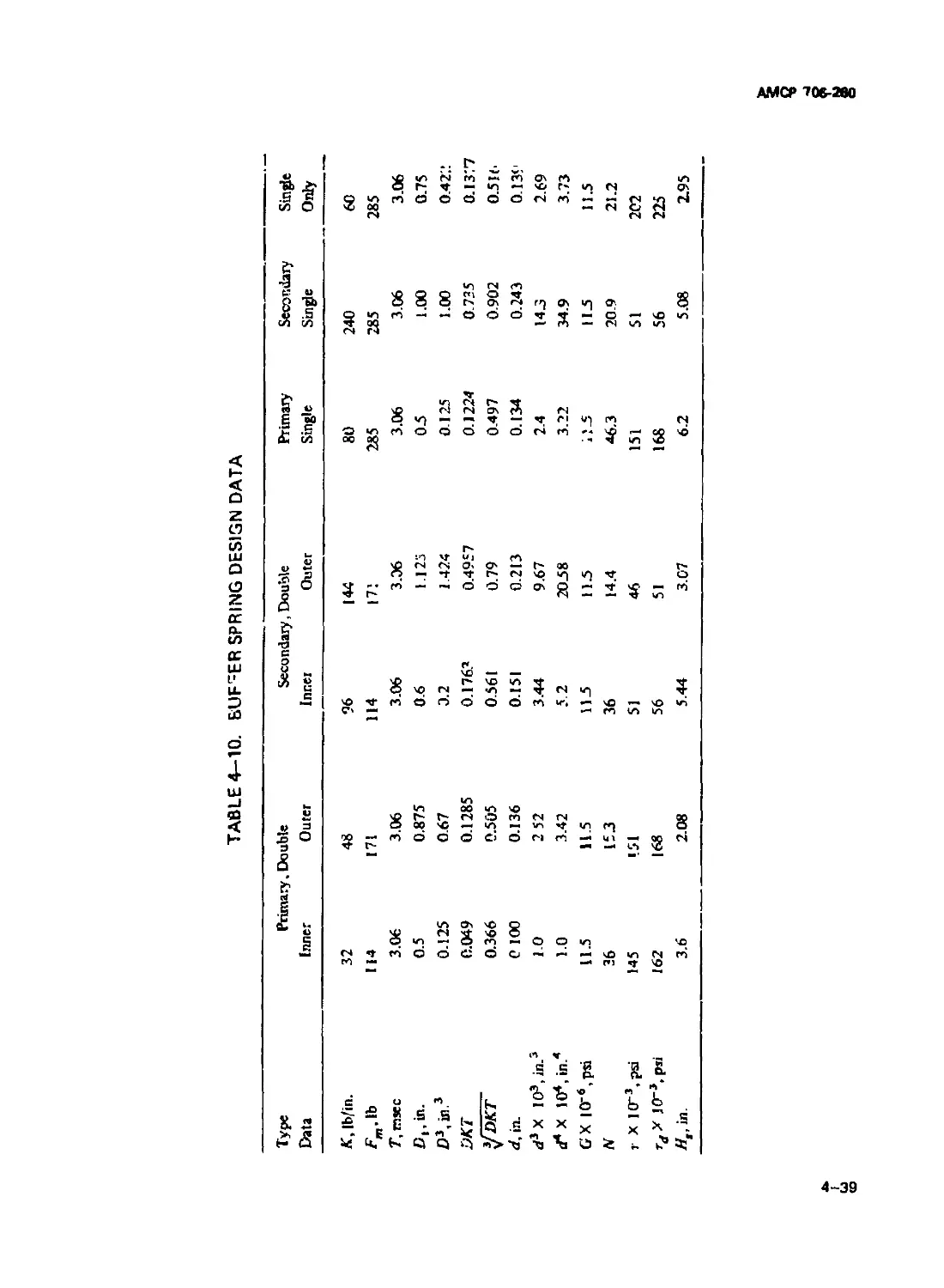
4-10 Buffer Spring Design Data....................................... 4—39
4-11 Dynamics of Tappet ............................................. 4-43
4-12 Critical Pressure Time Requirements............................. 4-46
5-1 Free Recoil Data of 20 mm Revolver-type Machine Gun . . . 5-21
5-2 Preliminary Recoil Adapter Data................................. 5-22
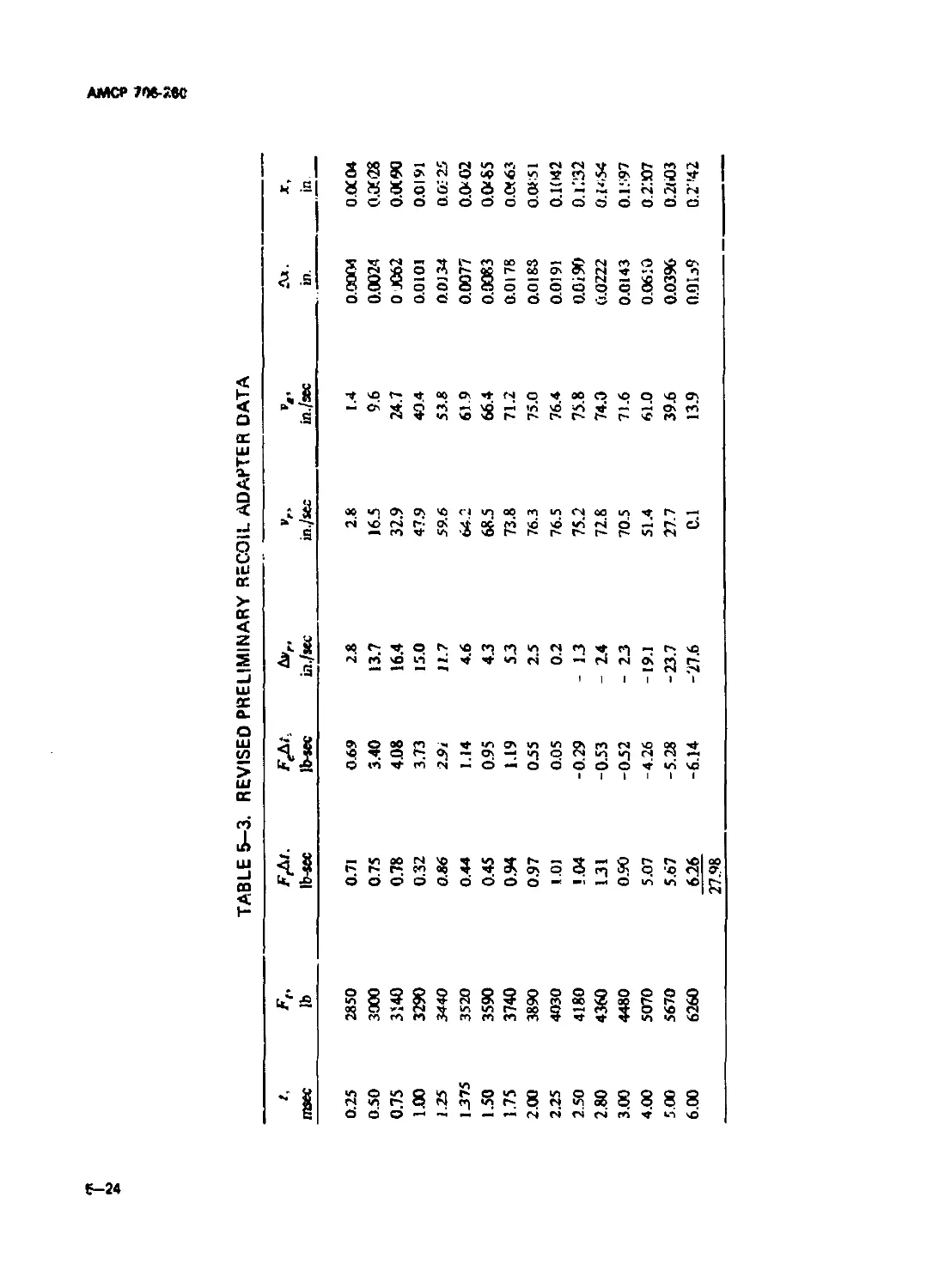
5-3 Revised Preliminary Recoil Adapter Data......................... 5-24
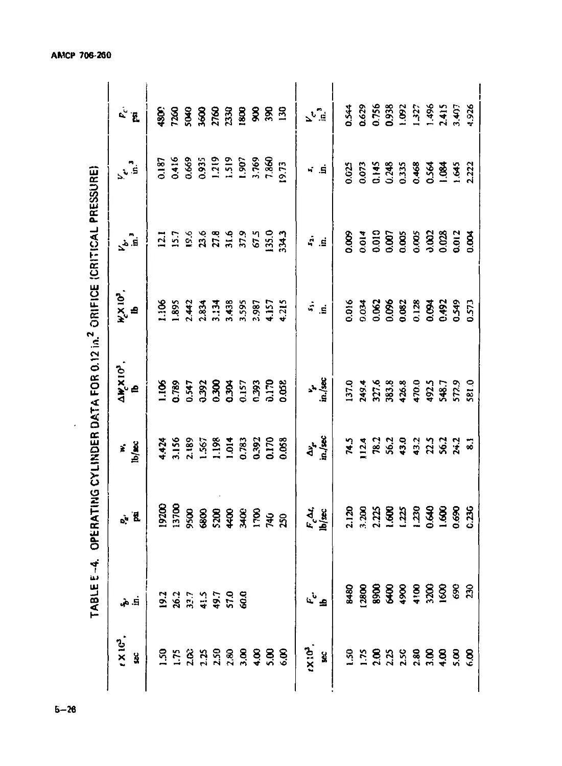
5—1 Operating Cylinder Data for 0.12 in?
Orifice (Critical Pressure)................................... 5-26
5-5 Operating Cylinder Data for 0.12 in? Orifice ................... 5-27
5-6 Operating Cylinder Data for 0.09 in? Orifice ................... 5-28
5-7 Operating Cylinder Data for 0.06 in? Orifice ................... 5-29
5-8 Symbol-code Correlation for Operating Cylinder.................. 5-37
5-9 Symbol-code Correlation for Cam Dynamics........................ 5-38
5-10 Input Data for Drum Dynamics During Recoil...................... 5-38
5-1! Input Data for Drum Dynamics During Counterrecoil .... 5-39
5-12 Computed Recoil and Operating Cylinder Data for
Orifice Area of 0.042 in? ............................. 5 -40
5-13 Cam and Drum Dynamics During Recoil ............................ 5-41
5-14 Cam and Drum Dynamics During Countenecoil....................... 5-42
5-15 Symbol-code Correlation for Double Barrel Machine Gun 5-56
5 -16 Input Data for Double Barrel Machine Gun ....................... 5-56
5-17 Double Barrel Machine Gun Dynamics ............................. 5-59
will
АМСР70»-2вО
LIST OF TABLES (Con h)
Tsble No. Ti»le Page
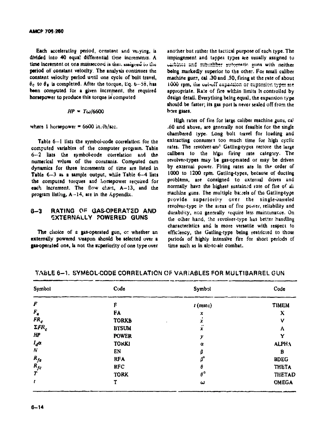
6-1 Symbol-code Correlation of Variables for
Multiband Gu.i .................................................... 6-14
6-2 Symbol-code Correlation and Input for Gun Operating
Power................................................... 6-IS
6-3 Cam Dynamics ............................................. 6-16
6-4 Gun Operating Power ...................................... 6-17
7-1 Power Required for Linkloss Be't Feed System.............. 7-24
7-2 Firing Pin Dynamics....................................... 7-40
lx
АМСР 706-200
LIST OF SYMBOLS
A coefficient in equation defining the tube recoil iravei В coefficient in equation defining recoil iravei; collective lenu in defining time during polytropic expansion of gas
At> “ bore area
b minor axis of an elliptical cam; length of
Л “ peripheral surface contact area between long segment of rectangular coil spring;
сазе and chamber; operating cylinder spring width
piaton area bcr minor axis of connterrecoil section of
A< differential area under pressure-time curve elliptical cam
Ao - orifice area br minor axis of recoil section of elliptical
cam
Apl “ area under pressure-time curve
r* c orifice coefficient
XpXj, ...Апш coefficients ofx in a series
cr end clearance of round
a general expression for linear acceleration;
major axis of elliptical cam; length of short segment of rectangular coll spring D - mean coil diameter
Db bore diameter
at “ average linear acceleration
horizontal distance between trunnion and
ac “ acceleration of chutes rear support
“c, " counterrecoil acceleration - diameter of cartridge case base
acrc mqor axis of cour.terrecoil portion of Dd - drum diameter
elliptical cam d wire diameter
ad " tangential acceleration of cam roller on
cam path dc gas cylinder diameter
at entrance unit acceleration; exit unit dp gas port diameter; piston diameter of
acceleration operating cylinder
°я " nori .il acceleration of cam roller on cam dt differentia! time
path dx differential distance
af •recoil acceleration; itainer acceleration
E modulus of elasticity; energy
arec " major axis of recoil portion of elliptical E, * energy of ammunition belt
cam; slide travel during slide deceleration Eb bolt energy; combined energy of buffer
a, " slide acceleration and driving springs
" acceleration of transfer unit Ebc • counterrecoil energy of buffer spring
X
AMCP 706-Mtl
LIST OF SYMBOLS (Con’t.)
£c - modulus ot elasticity ol сам; energy at Efo • barrel energy when bolt it unlocked
gas cutoff E, " energy loss attributed to spring system
£cr “ counterrecoil energy
E total energy loss caused by friction
Ec, = energy needed to bring slide up to speed Я
’ energy loss in drum
Ecrb " counterrecoil energy of barrel at end of pa
buffer action E M* » energy loss in slide
E"t countenecoil energy at beginning of incre- e base of natural logarithms
ment F ” general expression for force; driving spring
Ecn " maximum counterrecoil energy of barrel force; spring force at beginning of recoil
Ed " energy of rotating parts, drum energy F a = general expression for average force; aver-
age driving spring force; axial Inertial
Edcr " counterrecoil energy of drum force
EdS " energy of drum-slide system F.b " average force of spring-buffer system
E< " ejection energy of case F at " average force of spring system
El =• input energy of each increment; total energy at any given increment F b buffer spring force " operating cylinder force
F c
eq " energy of operating rod " average operating cylinder force
F ce
Eol " energy of operating rod at gas cutoff F CT " counterrecoil force
Er ” energy of recoiling parts; energy to be absorbed by mouni F e " general expression for effective force, exit
force, entrance force, maximum extractor
Erb ж recoil energy of bolt load to clear cartridge case
£s “ energy transferred from slide to driving spring; driving spring energy E'b " effective force on barrel ” load when cartridge is seated
F et
Etc " total work done by all springs until start •icsidual propellant gas force; propellant
of unlocking of bolt F g
gss force
Eicr “ slide counterrecoil energy = initial spring force
F i
Esr ж slide recoil energy el ” transverse force on locking lug; reaction
ESS " energy transferred from driving spring to on bolt
slide Fm " maximum spring force; spring force at end
E, " barrel energy of recoil
AMCC 706-260
LIST OF SYMBOLS (Con’t.)
Fmb “ maximum force of spring-buffer system t " acceleration due to gravity
* mt maximum force of barret and driving tb — vunuiifciiu livigtii
spring HP " horsepower
FMt » maximum force of barrel spring; of
adapter H. " solid height of spring
Fo "minimum spring force; minimum operat- h " depth of magazine storage space
ingload ht " distance between trunnion and pintle-leg
Fob " initial buffer spring system force Intersection
Fobs r initial buffer spring force / " area moment of inertia; general term for
mass moment of inertia
Fot " initial force of barrel spring; of adapter 'b " mass moment of Inertia of bolt
FP - cam roller pin load "mass moment of inertia of drum; mass
F, " average force during recoil moment of inertia of all rotating parts
F, " sear spring force; centrifugal force of " effective mass moment of inertia of drum
cartridge case or round J = area polar moment of inertia
F* horizontal component of safety spring
force К " spring constant, general; driving spring
constant
F„ " ufety spring force Ke coefficient in gas flow equation
Ft " force of barrel spring; of adapter; vertical
reaction of trigger spring pin Kb " combined spring constant during buffing
Ft " average adapter force for time interval dt Kb. " buffer spring constant
Ftb “ barrel spring force at end of propellant gas K. " combined constant of barrel and driving
period springs
Fx «resultant force of x-axis Kr " spring constant of barrel spring, of
adapter
Fy " resultant force of y-axis KW " coefficient in the rate of gas flow equa-
FIU " frictional force tion
Fdt, F&t " general expressions for differential im- > directional coefficient inFx equation
pulse «у > directional coefficient in Fv equation
f, " rate of fire
к " ratio of specific heats; radius of gyration;
ffTJT) “ function of the ratio of compression time bolt polar radius of gyration
to surge time L " general expression for lengths; length of
G " torsional modulus; shear modulus recoil; bolt travel; length of flat spring
xll
АМСР70&М0
LIST OF SYMBOLS (Co.i t.)
4 3 length of buffer spring travel M Q там of operating rod; bending moment at
first bend of flat tape spring
h>t " length of total bullet travel In barrel M n 3 mass of projectile
Lc 3 axial length of cam; length of slide travel; p
total peripheral length of cam M r 3 mass of recoiling part:
L<i * decelerating distance prior to buffer con- M ft « effective там of recoiling parts
tact; operating distance of operating rod spring; length of drum; driving spring mass of slide; mass of spring
travel 3 там of barrel
Lt extractor length
N 3 number of coila; normal reaction on cam
Lf 3 length of front pintle leg curve; normal force on roller; number cf
rounds; number of active segments in flat
L p 3 location of gas port along barrel spring
Lr 3 length of round; length of rear pintle leg ". axial component of normal force; number
of links of ammunition
3 tappet travel; barrel spring operating
deflection "c 3 number of chambers in drum
M 'man, general; mass of accelerating parts; bending moment Nr 3 number of retainer partitions
Ma 3 mass of round; mass of ammunition unit ", 3 transverse component of normal force
3 effective там of ammunition 3 cam tangential friction force
”b 3 mass of bolt P 3 general term for power
M cc там of cartridge case Pf 3 pourer required to drive feed system
Md 3 там of drum Л ” trigger pull
Md' 3 effective там of drum and ammunition p 3 pressure, general, pressure in reservoir;
belt; effective там of rotating drum general term for apace between rounds (pitch)
4 3 effective там, general; of extractor unit p. 3 average pressure; average bore pressure
3 effective там of extractor unit Pb 3 bore pressure
3 mass of ejector pc 3 average gas cylinder pressure
мг 3 там of propellant gas Per -critical pressure
Mn 3 momentum of recoiling or counterrecoil-
ing parts Pd 3 pitch of double helix drive
xlll
АМС? 706-200
C vun Al C t Г
i ier
to • W •
U t rvtw w •» * I w
Pl interface pressure s travel distance
Pm ’ propellant gas pressure a* bullet leaven s accelerating distance
muzzle 0
3h "bore travel; distance of bolt retraction
Pi: " component of presst'.re that dilate* 0 during recoil
cartridge caae s " cutoff distance
Pt initial pressure c
s "cam follower travel during counterrecoil
Pa final pre Bure Cr
" dwell distance
R " radius of bolt outer surface a
R„ ” reaction of rear support; radius to CG of *n " travel distance of operating unit at given
round time
Rb ’ reaction of front support »e " Initial distance
R “ cam radius soir "straight length of cam during counter-
c recoil
я 1. " radius of chamber centers of drum
ch so, straight length of cam during recoil; posi-
R„ “ distance from cam contact point to drum axis tion where slide contacts gas operating unit
Л. radius of locking lug pressure center »r cam follower travel during recoil; oper-
4- ating rod travel before bolt pickup
Rf roller radius; track reactions due to rota-
tional forces " travel component due to change in veloci-
ty
RT specific impetus Jr travel component due to velocity
R, ” track reactions due to tipping forces; trig-
ger reaction on rest T " surge time of spring; absolute tempera-
ture; torque about gun axis; spplied
" horizontal reaction on drum shaft torque of trigger spring
r " mean radius of case T' compression time of spring
r distance from tipping point on rim to CG ’ required drum torque
of сам Tl torque due to friction on drum bearing
rb ” cam radius to contact point on bolt and сам
r. " extractor radius h locking lug torque
r, " striker radius Tr required retainer torque
'r " cam radius to contact point on barrel applied torques
xiv
АМСЯ ТОЬ-280
LIST OF SYMBOLS (Con't.)
• accelerating torque Vb bore volume
" relisting torque к • kvs volume in operating cylinder
r9 " applied torque Kb chamber volume
t “ time Ko • operating cylinder displacement
t" " time to complete counterrecoil of slide К - equivalent gas volume
‘b ’ buffer time Ke • equivalent bore volume
‘be • buffer time during counterrecoil Kn - chamber volume plus total bore volume
•c " time of firing cycle К - initial volume of gas operating cylinder
Ke • counterrecoil time к - vertical component of spring load
Krb time of buffer counterrecoil к - Initial volume In gu equations
Krt • counterrecoil time of barrel after buffer
action к - final volume in gu equations
Kt " counterrecoil time of barrel V velocity, general
к • decelerating time of bolt before buffer is average velocity; axial velocity
contacted к • buffsr velocity during recoil
к " time of gas expansion Кс • bolt elocity during counterrecoil
•f • duration of propellant gas period
К • linear velocity of cam follower along cam;
•time interval of dwell between counter- velocity of chutes; linear elected velocity
recoil and recoil of cartridge case
к • recoil time of bolt Vcr • counterrecoil velocity
Kb • bolt decelerating time during recoil Vcrb • counterrtcoH velocity of buffer
Kt • counterrecoil time after buffer action vd - peripheral velocity of drum
'rr • recoil time of barrel during pressure decay vdm maximum peripheral velocity of drum
after bolt unlocking 4 • extractor velocity; maximum ejection
• thickness of spring velocity
Ker - counterrecoil time of slide Vf • velocity of free recoil
к • barrel spring compression time 4 • impact velocity
tr - accelerating time of rotor vm • muzzle velocity of projectile
XV
АМСР 706-260
LIST OF SYMBOLS (Cen t.)
*o ~ initial velocity, general term
vgl initial velocity of barret
v, “ recoil velocity
v( “ slide velocity
vM -velocity of recoiling parts at end of
accelerating travel
vtcf “ counterrecoil velocity of slide
v'tct “ slide velocity before impact
v._ ~ maximum slide velocity
f 7И
vt “ barrel velocity; tangential velocity of car-
tridge caae at ejection, velocity of transfer
unit
W general term for weight; wall ratio; work
We “ weight of round
Wb “ bolt weight
We “ wall ratio of case; weight of gas in cylin-
der; weight of propellant charge
Wcc weight of cartridge case; weight of empty
case
Wee » weight of gas at critical pressure
weight of drum
Wc equivalent weight of moving parts
Wg total weight of propellant or propellant
gas
WQ weight of moving operating cylinder com-
ponents
j - combined weight of components and slide
H'p - weight of projectile
И*, weight of recoiling parts
W, " work needed to compress spring; slide
weight; weight of spring
’ equivalent weight of spring in motion
**sr “ weight of slide with 2 rounds
№Irp “weight of slide, 2 rounds, and gas oper-
ating unit
“ barrel weight
w " rate of gas flow; width of magazine; width
of flat spring
w. " width of cam
c
x “ recoil travel, general; case travel; distance
In x-direction
x “ axial acceleration of bolt
xfc “ bolt travel
xio “ bolt travel at end of propellant gas period
xn “ axial length of parabola
xf " recoil distance during propellant gas
period; recoil travel of drum and barrel
assembly
xr/l “ recoil travel during impulse period
x " counterrecoiling travel during impulse
period
x( “slide travel; relative axial travel between
cam follower and drum
xrj “ travel of recoiling parts during cam dwell
period
xf - barrel travel with respect to gun frame
xrj * barrel travel during free recoil
xio x barrel travel during propellant gas period;
after buffer engagement; recoil travel dur-
ing cam dwell period
xvi
AMCP706-2W
LIST OF SYMBOLS (Con't.)
“ dlctincc u> y-uiicUiun, spring deflection yf shear deflection
y_ ” peripheral width of parabola: moment
- peripheral length ot constant «lope of cam deflection
GREEK LETTERS
a ’ angular acceleration, genual; angular acceleration of bolt; angular acceleration of rotor 9e «« ’ angular shear deflection * anguhr moment deflection
ad ” angular acceleration of drum X *> angle of bolt locking cam; slope of lug
helix
0 “ cam angle p = coefficient of friction
Pt. - cam locking angle pt index of friction
0o < slope of cam helix coefficient of rolling friction
У • correction factor coefficient of eliding friction
At time differential p, coefficient of friction of track
Av - velocity differential V Poisson’s ratio
Ax " distance differential P " ratio of spring energy to drum energy
фу - differential deflection; relative deflection
of one spring segment S *> summation
t " efficiency of spring system °i * tensile stress
(b " efficiency of buffer system °w " working stressof spring
er " efficiency of recoil adapter T " static stress of spring
rd " dynamic stress of spring
e « angular displacement, general; angular dis-
placement of rotor; angle of elevation; angular deflection in rectangular coll Ф “ angle of double helix drive
spring w “ angular velocity
= rotor travel for constant cam slope " angular velocity of drum
xvli
АМСР 706-260
PREFACE
This handbook, is one of a aeries on Guns. It is part of a group of handbooks covering
the engineering principles and fundamental data needed in the development of Army
materiel, which (as a group) constitutes the Engineering Design Handbook Series. This
handbook presents information on the fundamental operating principles and design of
automatic weapons and applies specifically to automatic weapons of all types such as
blowback, recoil-operated, gas-operated, and externally powered. These include single,
double, multibarrel, and revolver-type machine guns and range from the simple blowback
to the Intricate M61A1 Vulcan and Navy 20 mm Aircraft Gun Mark 11 Mod 5 Machine
Guns. Methods are advanced for preparing engineering design data on firing cycle, spring
design, gas dynamics, magazines, loaders, firing pins, etc. All components are considered
except tube design which appears in another handbook, AMCP 706-252, Gun Tubes.
This handbook was prepared by The Franklin Institute, Philadelphia, Pennsylvania, for
the Engineering Handbook Office of Duke University, prime contractor to the U.S. Army,
and was under the technical guidance and coordination of a special subcommittee with
representation from Watervliet Arsenal, Rock Island Arsenal, and Springfield Armory.
The Handbooks are readily available to all elements of AMC Including personnel and
contractors having a need and/or requirement. The Army Materiel Command policy is to
release these Engineering Design Handbooks to other DOD activities and their con-
tractors, and other Government agencies in accordance with cunent Army Regulation
70-31, dated 9 September 1966. Procedures for acquiring these Handbooks follow:
a. Activities within AMC and other DOD agencies should direct their request on an
official form to:
Commanding Officer
Letterkenny An”v Depot
ATTN: AMX \TD
Publications Distribution Branch
Chambersburg, Pennsylvania 17201
b. Contractors who have Department of Defense contracts should submit their
request, through their contracting officer with proper justification, to the address indi-
cated in par. a.
c. Government agencies other than DOD having need for the Handbooks may submit
their request directly to the Letterkenny Army Depot, as indicated in par. a above, or to:
Commanding General
U. S. Army Materiel Command
ATTN: AMCAD-PP
Washington, D.C. 20315
or
Director
Defense Documentation Center
ATTN: TCA
Cameron Station
Alexandria, Virginia 22314
xvlll
AMCP 706-260
PREFACE (Con't.)
d. Industries not having a Government contract (this includes I’r.lveisitiea) must for-
ward their request to;
Commanding General
U. S. Army Materiel Command
ATTN: AMCRD-T*/
Washington, D. C. 20315
e. All foreign requests must be submitted through the Washington, D. C. Embassy to.
Office of the Assistant Chief of Staff for Intelligence
ATTN: Foreign Liaison Office
Department of the Army
Washington, D. C. 20310
AU requests, other than those originating within the DOD, must be accompanied by a
Valid justification.
Comments and suggestions on this handbook are welcome and should be addressed to
Army Research Offlce-Durham, Box CM, Duke Station, Durham, N. C. 27706.
xix/xx
AMCF 706-200
V ПМГ СК 1
INTRODUCTION*
1-1 SCOPE AND PURPOSE
This handbook presents and discusses procedures
normally practiced for the design of automatic weapons,
and explores the problems stemming from the functions
of each weapon and its components. It is intended to
assist and guide the designer of automatic weapons of
the gun type, and to contain pertinent design informa-
tion and references. ' ,
1-2 GENERAL '
The purpose of the handbook is (1) to acquaint new
personnel with the many phases of automatic weapon
design, and (2) to serve as a useful reference for the
experienced engineer. It does not duplicate material
available in other handbooks of the weapon series. Those
topics which are presented in detail in other handbooks
are discussed here only in a general sense; consequently,
the reader must depend on the referenced handbook for
the details. Unless repetitive, the text - for cyclic
analyses, time-displacement (T-D) curves, chamber
design, strength requirements, springs, cams, and drive
systems - includes mathematical analyses embodying
sketches, curves, and Illustrative problems. Topics such
as ammunition characteristics, lubrication, handling and
operating features, and advantages and disadvantages are
generally described more qualitatively than quantita-
tively.
Appendix В is included to merely introduce the idea
of the automatic control of a burst of rounds for
weapon effectiveness in the point fire mode - a facet
which the gun designer may wish to consider.
1-3 DEFINITIONS
An automatic weapon is a self-firing gun. To be fully
automatic, the weapon must load, fire, extract, and eject
continuously after the first round is loaded and fired -
provided that the firing mechanism is held unlocked.
Furthermore, the automatic weapon derives all its oper-
ating energy from the propellant. Some weapons have
external power units attached and, although not auto-
matic in the strictest sense, are still classified as such.
'Prepared by Martin Regina, franklin Institute Research
Laboratories, Philadelphia, Pennsylvania.
There are three general classes of automatic weapons,
all defined according to their system of operation,
namely: blowback, gas-operated, and ,ecoii-
operated1**
a. Blowback is the system of operating the gun
mechanism that uses propellant gat pressure to force the
bolt to the roar; barrel and receiver remaining relatively
fixed. Hie pressure force is transmitted directly by the
cartridge case base to the bolt.
b. Gas-operated is the system that uses the propellant
gases that have been vented from the bore to drive a
piston linked to the bolt, The moving piston first
unlocks the bolt, then drives it rearward.
c. Recoil-operated is the system that uses the energy
of the recoiling parts to operate the gun.
Each system has variations that may borrow one or
more operational features from the others. These
variations, as well as the baalc systems, are discussed
thoroughly in later chapters.
1-4 DESIGN PRINCIPLES FOR AUTOMATIC
WEAPONS
The automatic weapon, in the process of firing a
round of ammunition, is essentially the same as any
other gun. Its basic difference is having the ability to
continue firing many rounds rapidly and automatically.
An outer stimulus is needed only to start or stop firing,
unless the latter occurs when ammunition supply is
exhausted. The automatic features require major effort
In design and development. The design philosophy has
been established, then the gun is to fire as fast as required
without stressing any component to the extent where
damage and therefore malfunction is imminent.
An extremely short firing cycle being basic, the
designer must exploit to the fullest the inherent proper-
ties of each type of automatic weapon. Generally, each
type must meet certain requirements In addition to
**Reforencoi an identified by a superscript number and an
tilted at the end of this handbook.
1-1
АМСР 706-260
being capable of operating automatically, these require-
ment! or design features are:
1. Use part of the available energy of the propellant
gases without materially affecting the ballistics.
2. Fin accurately at a sustained iate compatible with
the required tactics.
3. Use standard ammunition.
4. Be tight for easy handling.
5. Have a mechanism that is:
a. simple to operate
U. MIC
c. easy to maintain
d. economical with respect to manufacturing.
6. Have positive action for feeding, extracting, eject-
ing.
7. Insure effective breech closure until the propeUant
gas pressure hu- dropped to safe limits.
All successful automatic weapons meet these require-
ments but to a degree normally limited by type of
weapon. Conflicting requirements arc resolved by com-
promise.
1-2
AMCP 706-290
CHAPTER 2
BLOWBACK WEAPONS
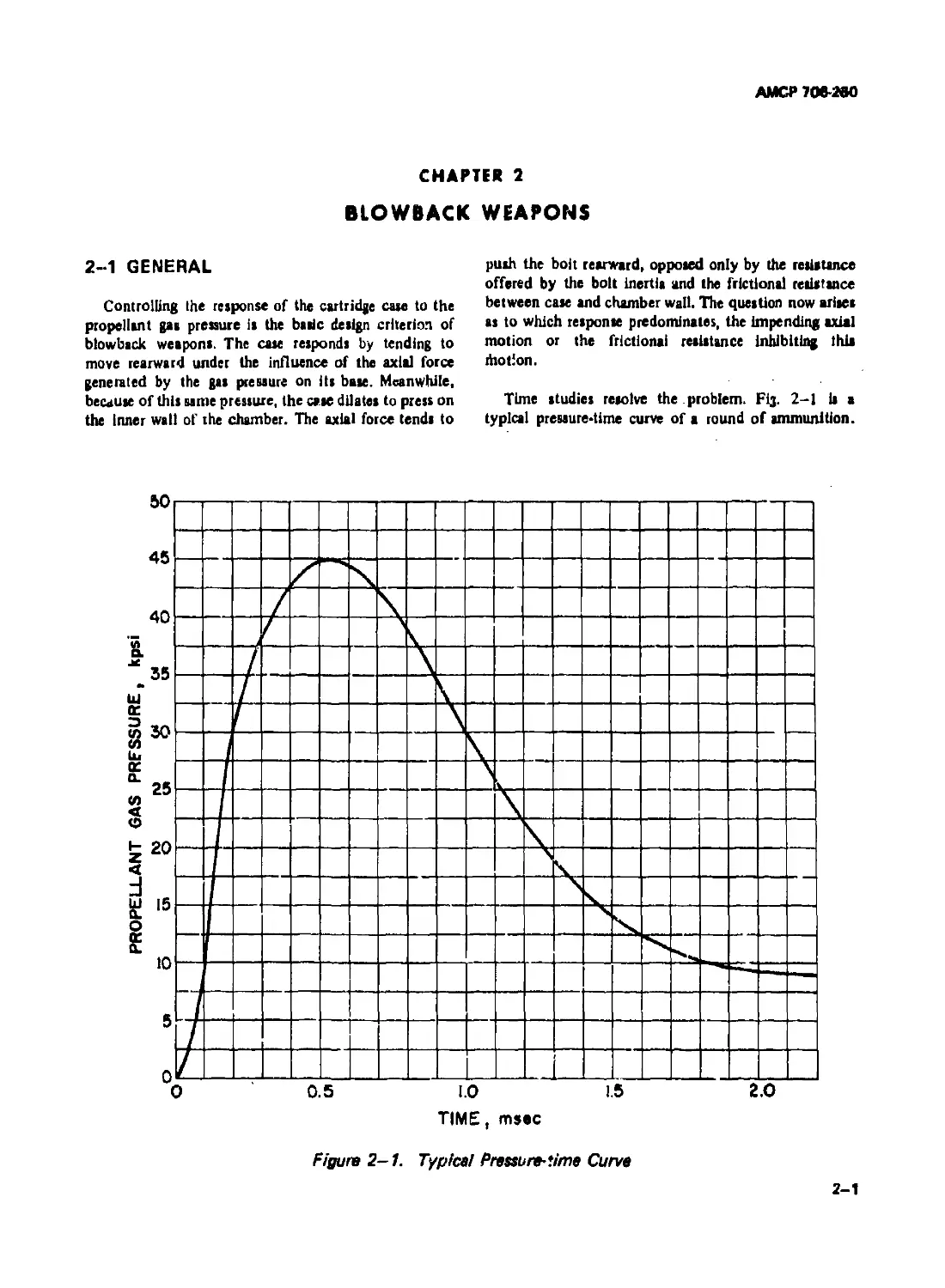
2-1 GENERAL
Controlling the response of the cartridge cue to the
propellant gas pressure is the basic design criterion of
blowback weapons. The case responds by tending to
move rearward under the influence of the axial force
generated by the gas pressure on its base. Meanwhile,
because of this nine pressure, the case dilates to press on
the inner wall of the chamber. The axial force tends to
push the bolt rearward, opposed only by the resistance
offered by the bolt inertia and the frictional resistance
between case and chamber wall. The question now arises
as to which response predominates, the impending axial
motion or the frictional resistance Inhibiting this
rhotion.
Time studies resolve the problem. Fij. 2-1 is a
typical preuure*time curve of a round of ammunition.
Figure 2-1. Typical Pressure-time Curve
2-1
AMCP 708-260
For sunpiicity, assume unity for bore area and bolt
wXafht. tO Fig. ?- 1, th* mevimiim rv««»nr*
of 45,000 psi develops in 0.0005 aec. Again for
simplicity, assume that the pressure varies linearly from
t • 0 io : — и.000j >cv. The pre»uiv p at any time
during the interval
₽"(®s) '"9х1°7' M"1
(2-1)
The corresponding force F driving the cartridge case and
bolt rearward is
F-Abp“9* 10’ IA lb (2-2)
where .4 д ” bore area in square inches
but, by assumption, Ab “ 1.0 in?, therefore
F»9x lO’r-AZ (2-3)
From mechanics
F-Mba
where a " bolt acceleration
Afj » mass of bolt.
According to an earlier assumption Mb
(2-4)
1.0
g
t
Solve fore in Eq. 2-4
a-f-Kgt (2-5)
At j,
but
(2-6)
Л2
Integration of Eq. 2-6 yields
v , . *.+ C’-Kgt1 + C, (2-7)
J Л1 dt 2
when r = 0, v « 0, therefore С( 0.
integration of Eq. 2-7 yields
s'!f'iKgt3 +C1 <2’8)
when t • 0,s • 0, therefore, Cj 0.
Assume that the limiting clearance between case aitd
chamber is equal to the case dilation as it reaches the
ultimate strength, and assume further that the cartridge
case has a nominal outside diameter of 1.5 in., a wall
thickness of 0.05 in., and an ultimate strength of 50,000
psi. Then, according to the thin-walled pressure vessel
formula, the pressure at which failure impends and
which presses the case ilrmly against the chamber wall is
о, t„ 50,000 x 0.05
pu~-P-~7-s---------------- 3440 Psi <2-9)
where
r 0.725 in., mean radius of case
" 0.05 in., w-11 thickness
o; 50,000 Ib/in.1, tensile stress
From Eq. 2-1, t is the time elapsed to reach this
pressure.
Pu
t ------------ 3.83 x IO’5 sec (2-10)
9x IO7
From Eq. 2-8, i is the distance that the case and bolt
travel during this time, i.e., when only the inertia of the
system is considered.
- | x 9 x 10’ x 386 x 56 x I0'1$ < 0.001 in.
О
This analysis indicates that when optimum conditions
prevail, the cartridge case scarcely moves before
frictional resistance begins to take effect. Motion will
continue until Eq. 2-11 is satisfied.
AbP “ ^cPl (2-11)
2-2
AMCP70S-MO
where
Ab = bore tree
= peripheral surface contact area between
cate and chamber
p « propellant aaa pressure
p( « interface pressure of caie and chamber
p • coefficient of friction
With no initial clearance between the сак and chamber,
an approximate interface pressure;^ may be determined
by equating the inside deflection of the chamber, due to
thia pressure, to the outside deflection of the cartridge
сак, due to both interface and propellant gas preslure,
when both сак and chamber are considered cylindrical.
Solve for the interface pressure.
where
Л' “ modulus of elasticity of chamber
Ec “ modulus of elasticity of сак
W ” wall ratio of chamber
W ’ wall ratio of сак
c
v ’ Poisson’s ratio (assumed to be equal for
both materials)
Spot checks indicate that thoK pressures which dilate
unsupported cartridge cases to the limit of their strength
are reasonably cIok to the difference in propellant gas
pressure and computed interface pressure. Thus
и., м n - n. ’J)
Ample clearance between сак and chamber is al.vays
provided but 1: never «О large thai uaiiei iecov«ry
exceeds case recovery after gu pressures subside;
otherwiK, Interference develops, i.e., damping the сак
to the chamber wall and rendering extraction difficult1.
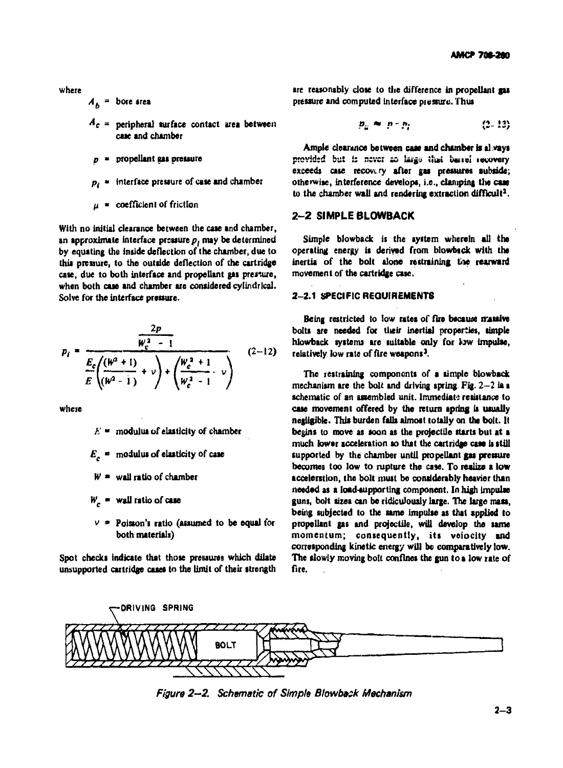
2-2 SIMPLE BLOWBACK
Simple blowback is the system wherein all the
operating energy is derived from blowback with the
inertia of the bolt alone restraining the rearward
movement of the cartridge сак.
2-2.1 SPECIFIC REQUIREMENTS
Being restricted to low rates of fire because massive
bolts are needed for tlteir inertial properties, simple
hlowback systems are suitable only for low impulK,
relatively low rate of fire weapons3.
The restraining components of a simple blowback
mechanism are the bolt and driving spring Fig. 2-2 ia a
schematic of an assembled unit. Immediate resistance to
сак movement offered by the return spring is usually
negligible. This burden falls almost totally on the bolt. It
begins to move as soon as the projectile starts but at a
much lower acceleration so that the cartridge сак is still
supported by the chamber until propellant gas pressure
becomes too low to rupture the сак. To realize a low
acceleration, the bolt must be considerably heavier than
needed as a load-supporting component. In high impuhe
guns, bolt sizes can be ridiculously large. The large так,
being subjected to the same impuhe as that applied to
propellant gas and projectile, will develop the same
momentum; consequently, its velocity and
conesponding kinetic energy will be comparatively low.
The slowly moving bolt confines the gun to a low rate of
fire.
Figure 2—2. Schematic of Simple Blowbask Mechanism
2-3
AMCt* /06-280
Figure 2-3. Allowable Case Travel
Although the boll mover, slowly, It still permits the
cue to move. The permissible travel while gas pressures
•re still high enough to rupture an unsupported case is
indicated by Fig. 2-3(A) for a standard cartridge case.
Fig. 2-3(B) Illustrates how a modified case can increase
the permissible travel. The geometry of chamber and
cartridge case are also involved. A slight taper or no
taper at all presents no problem but, for a large taper, an
axial displacement creates an appreciable gap between
case and chamber, thereby, exposing the case to
deflections verging on rupture. Therefore, for weapons
adaptable to simple blowback operation, cliainber and
case design takes on special significance if bolt travel is
reasonable while propellant gases are active. For
high-powered guns, exploiting this tame advantage gains
little. How little effect an increase in travel hu on
reducing bolts to acceptable sizes is demonstrated later.
The driving spring hat one basic function. It stores
some of the energy of the recoiling bolt, later using this
energy to dam the bolt back into firing position and in
the process, cocks the firing mechanism, reloads, and
trips the trigger io repeat the firing cycle. That the
driving spring stores only some of the eneigy of the
recoiling bolt when firing semiautomatic shotguns, rifles,
and pistols is indicated by the forward momentum not
being perceptible during reloading whereas the kick
during firing is pronounced.
2-2.2 TIME OF CYCLE
The time of the flring cycle is determined by the
impulse created by the propellant gases, and by the bolt
and driving spring characteristics. The impulse fFdt is
computed from the area beneath the force-time curve. It
is equated to the momentum of the bolt assembly, i.e„
2-4
£ FJt - Mbvf (2-14)
where
Ff “ propellant gas force
Mb - mass of bolt assembly
Vf • velocity of free recoil
dt time differential
The mass of the bolt assembly includes about one-third
the spring as the equivalent mass of the spring in motion.
However, the effect of the equivalent spring mass is
usually very small and, for all practical purposes, may be
neglected. After the energy of free recoil it known, the
recoil energy Et and the average driving spring force
become available
(2-15)
The average force Fa depends on the efficiency of the
mechanical system
e£
(2-16)
where L - length of recoil or bolt travel
e • efficiency of system
АМСР7М-МЮ
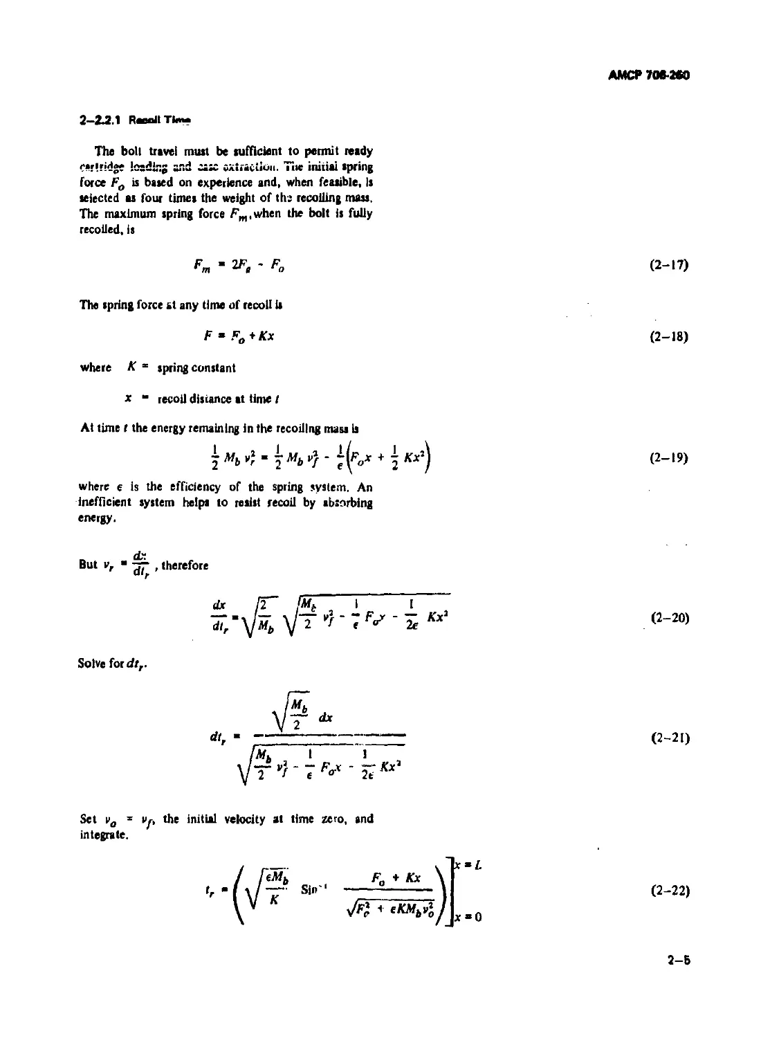
2-2J.1 RmUTIma
The boll travel must be sufficient to permit ready
''«ridge losdlr.j end ciX cxtraciiou. Tiie initial spring
force Fo is based on experience and, when feasible. Is
selected as four times the weight of th: recoiling mass.
The maximum spring force Fm,when the bolt is fully
recoiled, is
" 2F, - Fo (2-17)
The spring force at any time of recoil is
F ” Fo+Kx
where К = spring constant
x “ recoil distance at time t
At time t the energy remaining in the recoiling mass is
where e is the efficiency of the spring system. An
inefficient system helps to resist recoil by absorbing
energy.
(2-18)
(2-19)
dr.
But vr , therefore
dx /£”
л,"уЧ V 2
poy - Kx'
(2-20)
Solve ford/,.
(2-21)
Set v0 1 Vp the initial velocity at time zero, and
integrate.
(2-22)
2-6
AMCf* 706*260
TtU: cc~p2ted time Hn*« not include the time while
propellant gases are acting. The exclusion provides
a simple solution without serious error. Since
MvJ a ~ (Fm + Fo) and, by definition,
К - and ♦ eKAfv’ - Fm.
Therefore, the time elapsed during recoil tr from x « 0
tox“£ is
(2-23)
2—2.2.2 Countarracoil Time
The countenecoil time Is determined by the same
procedure as that for recoil, except that the low
efficiency of springs deter» rapid countenecoil. The
energy of the counterrecoiling inus of the bolt assembly
at any time tcr is
- 3 "6 + e( Fwx - 1 Kx*)
where vo initial velocity
vcr • countenecoil velocity at any time
&псе vcr " aT
Ulcr
(2-24)
(2-25)
Integrating
- Sin'1
(2-26)
When the initial velocity is aero, the time tcr to
countenecoil the total distance is
(2-27)
2-6
АМСР7ОВ-2ВО
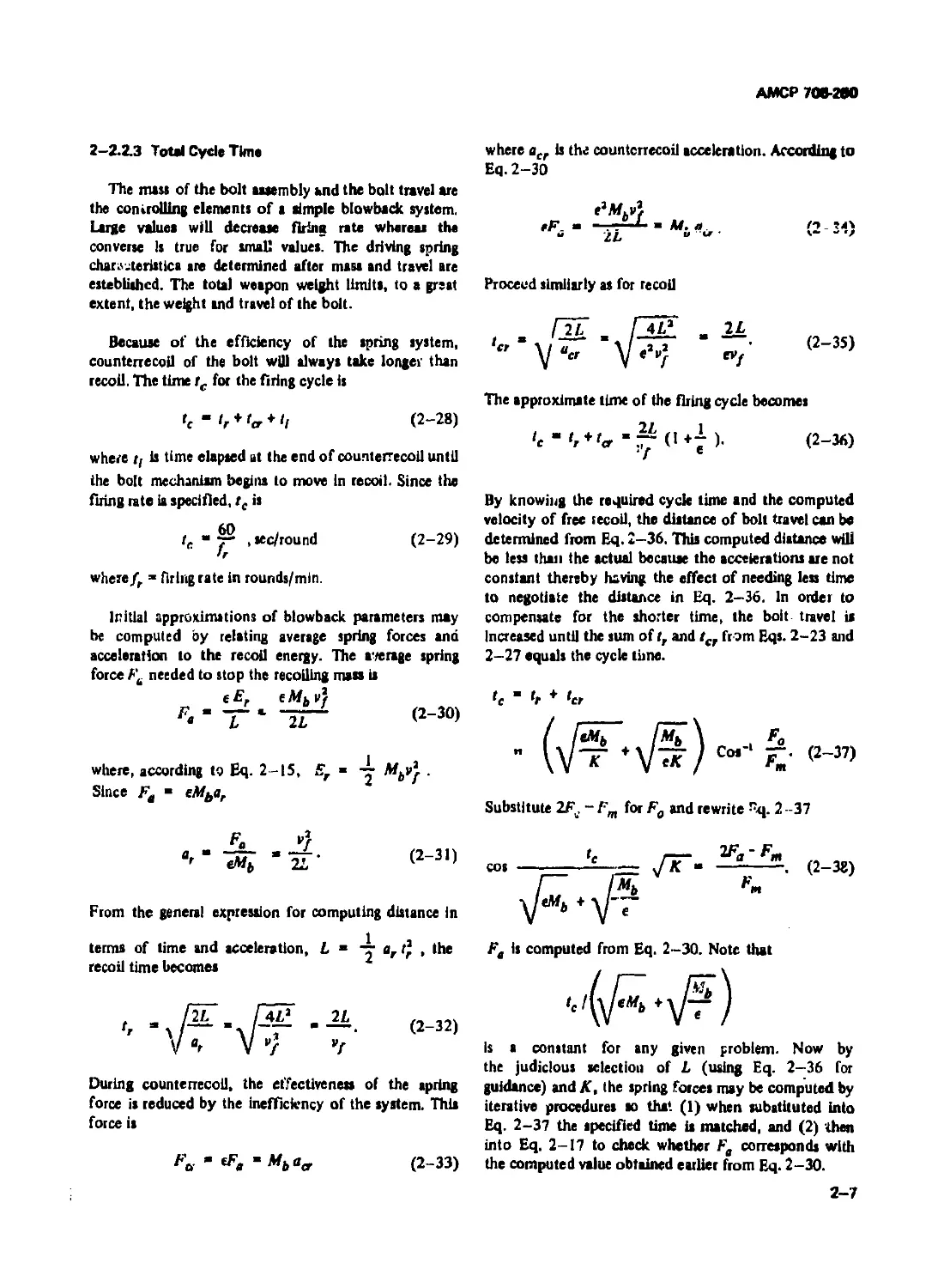
2-2.2.3 Total Cycle Time
The там of the bolt assembly and the bolt travel are
the controlling elements of I simple blowback system.
Large values will decrease firing rate whereas the
converse Is true for small values. The driving spring
characteristic» are determined after mass and travel are
established. The total weapon weight limits, to a great
extant, the weight and travel of the bolt.
Because of the efficiency of the spring system,
counterrecoil of the bolt will always take longer than
recoil. The time tc for the firing cycle is
Q “ <r * + ‘l (2-28)
where r, is time elapsed at the end of counterrecoil until
the bolt mechanism begins to move in recoil. Since the
firing rate ia specified, tc is
tc " у > *ec/round (2-29)
where fr =* firing rate in rounds/min.
Initial approximations of blowback parameters may
be computed by relating average spring forces and
acceleration to the recoil energy. The average spring
force Ft needed to stop the recoiling mass is
г . eMbVf
L 2L
(2-30)
where acr is the counterrecoil acceleration. According to
Eq. 2-30
Proceed similarly as for recoil
(2-35)
The approximate time of the firing cycle becomes
Il i
‘c “ ', + '<, (I+7 )• (2-36)
By knowing the required cycle time and the computed
velocity of free recoil, the distance of bolt travel can be
determined from Eq. 2-36. This computed distance will
be less than the actual because the accelerations are not
constant thereby having the effect of needing less time
to negotiate the distance in Eq. 2-36. In order to
compensate for the shorter time, the bolt travel is
Increased until the sum of tr and tcr from Eqs. 2-23 and
2-27 equals the cycle tune.
te " 'r ♦ ter
where, according to Eq. 2-15, Er » Mbvj .
Since Fa “ eMbar
Substitute 2Fu. - !'m for Fg and rewrite rq. 2-37
Fa
From the general expression for computing distance in
terms of time and acceleration, L ” 4- ar t* , the
recoil time becomes
(2-32)
During counterrecoil, the effectiveness of the spring
force is reduced by the inefficiency of the system. This
force is
Fa - tFe ~Mba„ (2-33)
Ft is computed from Eq. 2-30. Note that
Is a constant for any given problem. Now by
the judicious selection of L (using Eq. 2-36 for
guidance) and K, the spring forces may be computed by
iterative procedures so that (1) when substituted into
Eq. 2-37 the specified time is matched, and (2) then
into Eq. 2-17 to check whether Fe corresponds with
the computed value obtained earlier from Eq. 2-30.
2-7
АМСР 706-280
•n- firina nie ia determined from the final
computed cycle time.
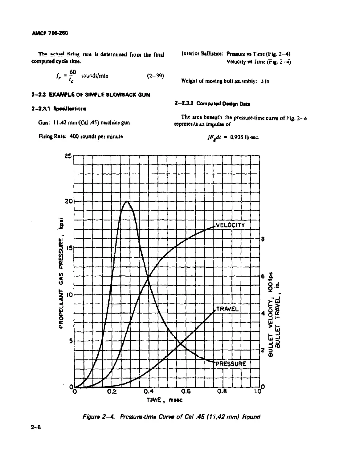
Interior Ballistica: Preuure v* Time (Fig. 2—4)
Velocity vs l une (Fig. 2-4)
Weight of moving bolt asiembiy: 3 ib
2-2.3 EXAMPLE OF SIMPLE BLOWBACK BUN
2-2.3.1 Speeillcationa
Gun: 11.42 mm (Cal .45) machine gun
Firing Rate: 400 roundi per minute
2-2.3.2 Computed Design Data
The area beneath the pressure-time curve of Fig. 2—4
represent a:t impulse of
JF^dr - 0.935 Ib-sec.
Figure 2-4. Pressure-time Curve of Cal .45 (1 i.42 mm) Hound
2-8
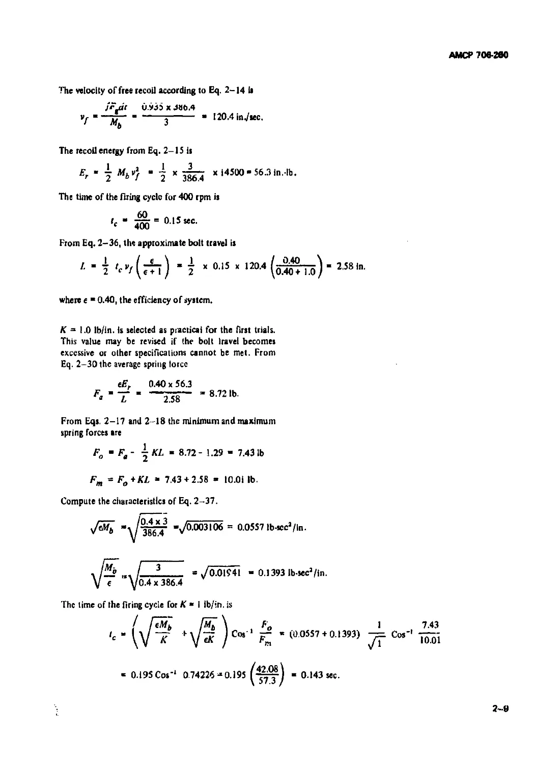
АМСР 706-200
The velocity of free recoil according to Eq. 2-14 ii
j'F^t v.935 x J«0.4
Vf " - -----j------ 120.4 in./sec.
The recoil energy from Eq. 2-15 is
Er • | Mbv} j x x 14500- 56.3 ln.4b.
The time of the firing cycle for 400 rpm is
“ 400 = 015mc-
From Eq. 2-36, the approximate bolt travel is
i '^(rh) - 7 x 015 x 1204 (оЖТо) 258
where e - 0.40, the efficiency of system.
К = 1.0 ib/in. is selected as practical for the first trials.
This value may be revised if the bolt Iravei becomes
excessive or other specifications cannot be met. From
Eq. 2-30 the average spring force
eEr 0.40 x 56.3
-Z58“ ’8721b-
From Eqs. 2-17 and 2-18 the minimum and maximum
spring forces are
Fo - Fa - | KL - 8.72- 1.29 - 7.43 lb
F„ - Fn+KL - 7.43 + 2.58 - 10.01 lb.
m О
Compute the characteristics of Eq. 2-37.
"t гУгТ -1/0.003106 = 0.0557 lb-sccJ/ln.
v u \/ JOO.4 *
, / 3 = У0.01941 - 0.1393 lb-sec3/ln.
V e yo.4x 386.4
The time of the firing cycle for К • I ib/in. is
+V?)cw'‘
Fo 1 7.43
— « (0 0557 + 0.1393) Cos'1 ~;
/1 IU.01
- 0.195 Cos'1 0.74226 *0.195 1—^1 - 0.143 sec.
2-9
АМСР 706-200
Thit cycle time gives a rate of fire of almost 420 rounds
per minute which is probably acceptable since firing Is
the final teat. However, attempts win be made to
approach the specified rate of 400 rounda/min more
closely. The spring constant of К « I appears acceptable;
F
therefore, to have rf 0.15 sec, Cos'* “ 0.76923
rad and cos 0.76923 rad = 0.7185 so that
Fo Fo
Fm " Fo + Kl.
- 0.7185.
Since К *1, -~7 - 0.7185 andR 2.552Z,.
Fo+ L 0
1 (Fo ♦ Fm)L
Also, since 7F/ - ------- — - E, - 56.3 in.-lb
'0+£ " 2Ft - ^P-40"56'3) « 45 04
Therefore
L1 7.379 in? L 2.72 in.
F 6.94 lb FM 9.62 lb
q m
The spring work IP, “ — (F„ + F_)L ” 22.52 in.-lb,
re j 2 * о m
which matches the input. The time tc of the firing cycle
for К - 1
6.94
» (0.557 + 0.1393) Cos'*
I 43.83
” 0.195 Cos'* 0.7214 ’ 0.195 I ~ГГГ
- 0.15 sec.
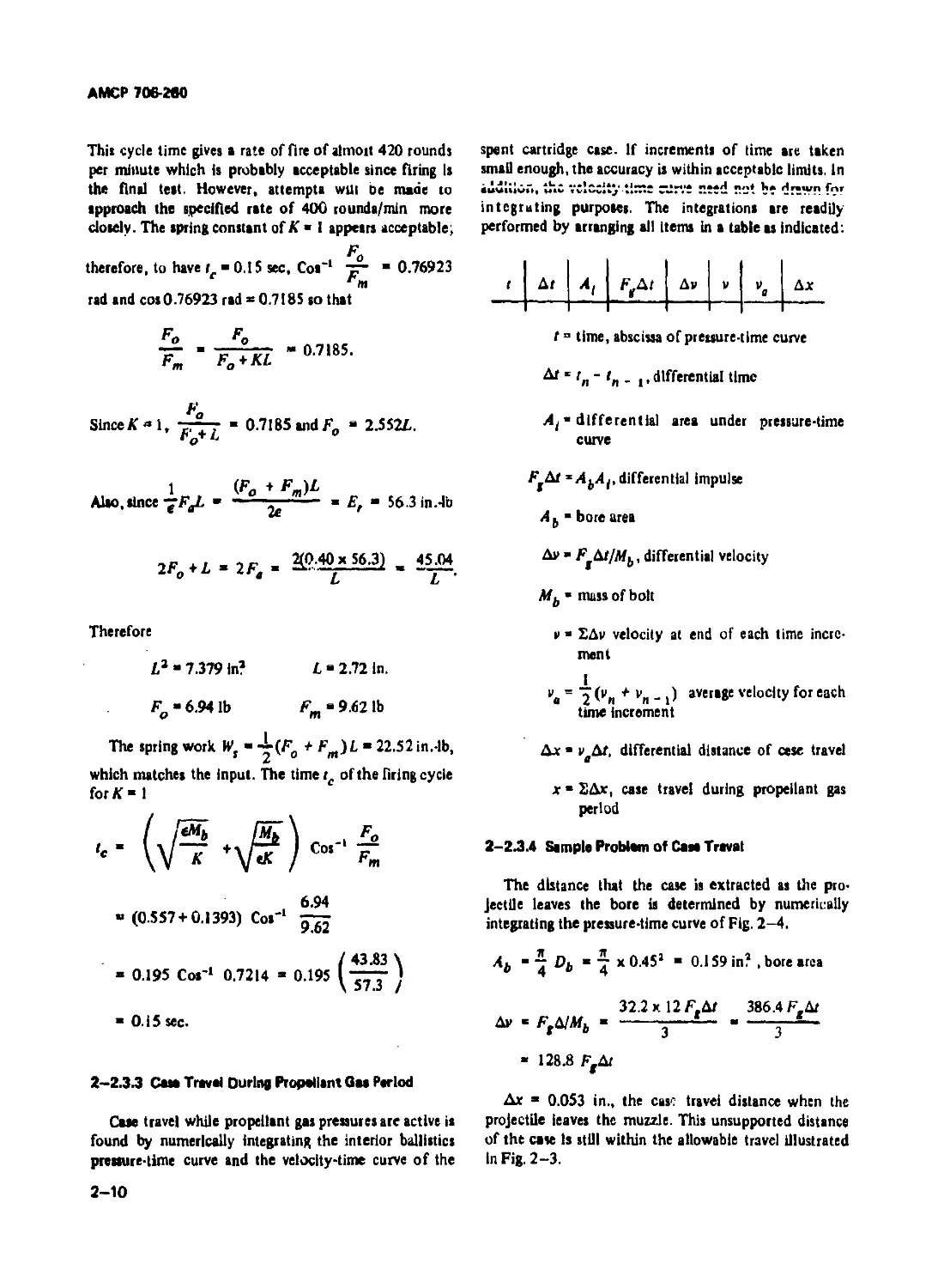
2-2.3.3 Сам Travel During Propellant Ом Period
Cate travel while propellant gas pressures are active is
found by numerically integrating the interior ballistics
pressure-time curve and the velocity-time curve of the
spent cartridge case, if increments of time are taken
small enough, the accuracy is within acceptable limits. In
euwidor,, the velocity time curve need not be drewn f'?r
integrating purposes. The integrations are readily
performed by arranging all items in a table as indicated:
Ax
t ° time, abscissa of pressure-time curve
Ar r„ - tn _ ,, differential time
At • differential area under pressure-time
curve
F*Ar *AbAj, differential impulse
A b bore area
Av " Ft^t/Mb, differential velocity
Mb • mass of bolt
v • EAv velocity at end of each time incre-
ment
v# = 'j (vh + vn _ () average velocity for each
time increment
Ax • v AT, differential distance of cese travel
a
x« EAx, case travel during propellant gas
period
2-2Л.4 Sample Problem of Сам Travat
The distance that the case is extracted as the pro-
jectile leaves the bore is determined by numerically
integrating the pressure-time curve of Fig. 2-4.
7 Di B 7 x 0.45a “ 0.159 in? , bore area
° 4 ° 4
32.2 x 12 F,AT 386.4 F.Ar
Av - Ff A/Af„-------------------------------
• 128.8 F,Ar
Ax ’ 0.053 in., the case travel distance when the
projectile leaves the muzzle. This unsupported distance
of the case is still within the allowable travel illustrated
in Fig. 2-3.
2-10
AMCP 706-260
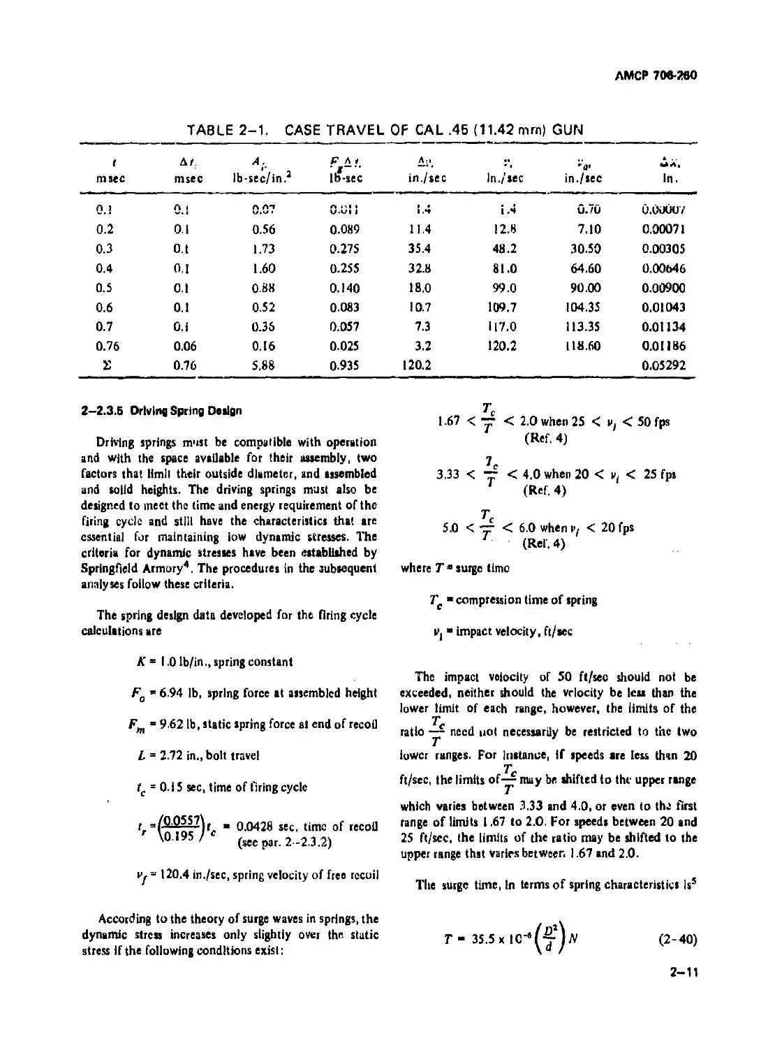
TABLE 2-1. CASE TRAVEL OF CAL .46 (11.42 mrn) GUN
t msec Af. msec a. lb-sec/in.3 F * f. Ilf-sec A? in./sec In./sec in./sec in.
nj 0.1 n A*» 0-vt 1 i .*♦ i .4 0.7u 0.00007
0.2 0.I 0.56 0.089 11.4 12.8 7.10 0.00071
0.3 o.t 1.73 0.275 35.4 48.2 30.50 0.00305
0.4 0.1 1.60 0.255 32.8 81.0 64.60 0.00646
0.5 0.1 0.88 0.140 18.0 99.0 90.00 0.00900
0.6 0.1 0.52 0.083 10.7 109.7 104.35 0.01043
0.7 0.1 0.35 0.057 7.3 117.0 113.35 0.01134
0.76 0.06 0.16 0.025 3.2 120.2 118.60 0.01186
2 0.76 5.88 0.935 120.2 0.05292
2-2.3.B Driving Spring Design
Driving springs must be compatible with operation
and with the space available for their assembly, two
factors that limll their outside diameter, and assembled
and solid heights. The driving springs must also be
designed to meet the time and energy requirement of the
firing cycle and still have the characteristics that are
essential for maintaining low dynamic stresses. The
criteria for dynamic stresses have been established by
Springfield Armory4. The procedures in the subsequent
analyses follow these criteria.
The spring design data developed for the firing cycle
calculations are
A' “ 1.0 Ib/in., spring constant
Fo = 6.94 lb, spring force at assembled height
Fm ‘ 9.62 lb, static spring force at end of recoil
L = 2.72 in., bolt travel
tc = 0. i 5 sec, time of firing cycle
rf “ 0.0428 sec, time of recoil
'° 195 ' (see par. 2-2.3.2)
iy - 120.4 in./sec, spring velocity of free recoil
According to the theory of surge waves in springs, the
dynamic stress increases only slightly over the static
stress if the following conditions exist:
1.67 < “ < 2.0 when 25 < < 50 fps
(Ref. 4)
3.33 < — < 4.0 when 20 < vt < 25 fps
(Ref. 4)
Tc
5.0 < ~ < 6.0 when V/ < 20 fps
(Ref. 4)
where T • surge time
Tc “ compression time of spring
Vj impact velocity, ft/sec
The impact velocity of 50 ft/sec should not be
exceeded, neither should the velocity be less than the
lower limit of each range, however, the limits of the
T
ratio — need not necessarily be restricted to the two
lower ranges. For Instance, if speeds are less than 20
T
ft/sec, the limits may be shifted to the upper range
which varies between 3.33 and 4.0, or even to the first
range of limits 1.67 to 2.0. For speeds between 20 and
25 ft/sec, the limits of the ratio may be shifted to the
upper range thst varies between 1.67 and 2.0.
Tlte surge time, In terms of spring characteristics lss
T - 35.5x IC-^—jfV
(2-40)
2-11
АМСР 706 260
where d ' wire diameter
D mean coil diameter
Л- number ofcoils
Tc “ tr ” 0.0428 sec, compression time of spring
re
Select— ж 3.8, or
T
Tc 0.0428
T ’ - г - “ 0.01125 sec
9.0 J .0
К .. or N - (Ref. 6) (2-41)
UfiN W3K
where G torsicnal modulus (11.5 x IO6 Ib/in? for
steel)
K‘ spring constant
Substitute the expression for N of Eq. 2-41 into Eq.
2-40, insert know ‘ vsiues, and solve for d
d - 0.27 у/ DKT
(2-42)
When О 0.5 in., and К “ 1.0 (from spring det.*.)
d 0.27 *J 0.5x1.0x0.01126 ” 0.048 in.
From Eq. 2-41
-
UfK
11.5 x 10s x 530 x 10"* ,. ..
...----------------- > Coils
8x0.125x1.0
И, ж ЛИ 61 x 0.048 « 2.93 in., solid height.
The static torsional stre: s r is6
8F_D 8 x 9.62 x 0.5
—— - --------------- ” 110,000 Ib/in?
ltd3 lllxlO^rr
(2-43)
According to Eq. 34 in Ref. 4, the dynamic torsional
stress Is
(2-44)
rd ” 110,000^^4= 116,000 Ib/in?
This stress is acceptable since the recommended maxi-
mum stress for music wire is 150,000 Ib/.’n? In Eq.
(T \
— ) Is the next largest even whole number
2" / j-
larger than the value of — if uiis ratio la not an even
whole number
2-3 ADVANCED PRIMER IGNITh>M BLOV-'-
BACK
Timing the ignition so that the new round is fired just
before the bolt scats gives the first part of the impulse
c-e^ted by the propellant gas force opportunity to act as
a buffer for the returning bolt. The rest of the impulse
provides the effort for recoiling the bolt. The system
that abacus a portion of the impulse in this manner is
called Advanced Primer Ignition Blowback. This system
has its artilbry counterpart in the out-of-battery firing
system, i.e., the firing of the artillery weapon being
initiated during counterrecoil but with the breechblock
closed.
2-3.1 SPECIFIC REQUIREMENTS
Ry virtue of its ability to dispose of the early
influence of propellant gas force on recoil, the advanced
primer ignition system is much more adaptable to high
rates of fire than the simple blowback system. Reducing
the effectiveness of the impulse by fifty percent alone
reduces the bolt weight by a factor of two with a sub-
stantial increase in firing rate.
The restraining components may be considered as real
and virtual; the real being the bolt and driving spring; the
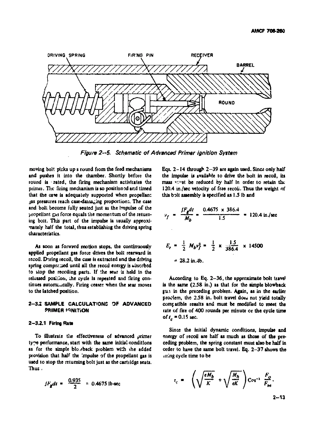
virtual, the momentum of the returning bolt. Fig. 2 -5 is
a schematic of tie advanced primer ignition system. The
firing cycie starts with the bolt latched open by a sear
and the driving spring compressed. Releasing the scar,
frees the bolt for the spring to drive it forward. The
2-12
AMCP 706-280
Figure 2-5. Schematic of Advanced Primer ignition Syttem
moving bolt picks up s round from the feed mechanisms
and pushes it into the chamber. Shortly before the
round is - sated, the firing mechanism activiiatea the
primer. Tire firing mechanism is so positioned and timed
that the case ia adequately supported when propellant
^as pressures reach case-daiiiablng proportion:. The case
and bolt become fully seated Just as the Impulse of the
propellant gas force equals the momentum of the return-
ing bolt. This part of the impulse ia usually approxi-
mately half the total, thus establishing the driving spring
characteristics.
As soon as forward motion stops, the continuously
applied propellant gas force drives the bolt rearward in
recoil. During recoil, the case is extracted and the driving
spring comprr^ed until all the reccd energy is absorbed
to stop the recoiling parts. If the sear is held in the
released position, he cycle Is repeated and Cuing con-
tinues automcucally. Firing cease* when the sear moves
to the latched position.
2-3.2 SAMPLE CALCULATIONS OF ADVANCED
PRIMER I^NtTiON
2-3.2.1 Firing Rate
To illustrate tire effectiveness of advanced primer
ty?e performance, start with the same initial conditions
as for the simple bio./back problem with the added
provision that half the impulse of the propellant gas is
used to stop the returning bolt just as the cartridge seats.
Thus .
= 0.4675 Ib-sec
Eqs. 2-14 through 2-39 are again used. Since only half
the impulse is available to drive the bolt in recoil, its
mass ’,:’,at be reduced by half in order to retain the
120.4 in./sec velocity of free recoil. Thus the weight of
this bolt assembly is specified as 1.5 lb and
JF-dt 0.4675 x 386.4
—ns— l20-4in/“c
b'r l | * 38^ X 14500
“ 28.2 in.-lb.
According to Eq. 2-36, the approximate bolt travel
is the same (2.58 in.) as that for the simple blowback
gui in the preceding problem. Again, as in the earlier
proclem, the 2.58 in. bolt travel does not yield totally
compatible results and mutt be modified to meet the
rate of fire of 400 rounds per minute or the cycle time
of te «0.15 sec.
Since the initial dynamic conditions, impulse and
energy of recoil are half as much as those of the pre-
ceding problem, the spring constant must also be half in
order to have the same bolt travel. Eq. 2-37 shows the
tiring cycle time to be
2—13
АМСР 706-260
Since К - 0.5 lb/in., е 0.40, At, ,
4 386.4 in. ’
! ж 0 ***•
А’ .Г Г / 0.15 \
7^ ’ Fo + 0.5Z. ” С0‘ ^O.I9s/573
- cos 44’04’ - 0.7185
= 0.4675 lb-sec
F_ “7.49 lb, minimum spring load, simple
blowback
F « 10.08 lb, maximum
m
F ~ F 2 59
K‘ " 7T I-727 lb/in.
Lj 1 .Э
Solve for Fg
e - 0.40, efficiency of spring system
Fo -1.2762L.
Also
2eE.
2F0 + KL-2F0 + O.5L-2F,- -7-
2 X 0.4 x 28.2
L
Substitute fur Fo and collect terms
£ 2.72 in.
Fo‘ 3.47 lb
F_ • 4.83 lb
In
The work Wa done to compress the springs is
W, - -|(FO + FW)L - 8.785x1.5 - 13.18 In.-Ib.
The velocity Vj of free recoil is
JF-dt flF-dt
f Mb wb •
The recoil energy Er — Mb vj
Substitute for
E' -
When the efficiency of the system is considered, the
spring work is
Recompute the time for the firing cycle
W, - 04£, or £,-2.5%,
Substitute for £, and solve for %. the weight of the
bolt
(347\
~ I “ 0.195 x 0.769 » 0.15 sec
4л 3 f
Another approach illustrates the advantage of
increasing the firing rate by incorporating the advanced
primer technique. The length of recoil in the preceding
problems was selected to balance the dynamics of the
problem and is not necessarily the ideal minimum dis-
tance. Suppose that the Ideal bolt travel la 1.5 in. and
that the recoil force of the simple blowback gun is
acceptable. The mass of the bolt is adjusted to suit the
requirements.
2.5% - -(/F^dt)2^
32.95 - ~ x 0.2185
4 \ Wb J
Wb ~ ^3W5 “ 1281 lb-
The velocity of free recoil becomes
386,4 x 0.4675 .
*7“ % 1.281 " 141 ln^wc
2-14
АМСР 706-260
The recoil energy Er = ~(ми2г) - -7 19880 32.95 in.-lb.
2 \ J / 2 \Joo.4/
The time of a firing cycle ii
= 0.0370x0.733 “ 0.071 sec
where
0.40 x 1.281
1.727 x 386.4
- У 0.000768 ” 0.0277
’.281
Mb < !------
eK " V 0.40 x 1.121 x 386.4 " 7 °-00*80 ж 00693
га I 1 1
Co»'1 ~ - Co»’1 —-1 » 42° • 0.733 rad
Гщ \lU.Uo/
The firing rate is
ft ~ " 845 rounda/min.
2-322 Driving Spring Design
The driving spring for the advanced primer ignition
blowback gun has been assigned the following character-
istics to comply with the requirements of the firing cycle
for the simple blowback gun:
К “ 0.5 Ib/in., spring constant
Fo = 3.48 lb, spring force at assembled height
Fm - 4.85 lb, spring force at end of recoil
L = 2.73 in., bolt travel
tr = Tc = 0.0428 tec, compression time of
spring
Vf~v, 120.4 in./scc, velocity of free recoil,
spring impact velocity
2-16
AMCP 706-ЛО
T. 0.0428
Select ~ “ 3.8. Therefore,? 1 . « 0.1126 sec.
Т З.о
When D “ 0.5 in., according to Eq. 2-42
d - (J.27 У DKT - 0.27 У 0.5x0.5x0.0112) ” 0.038 in.
From Eq. 2-41
_ Gf _ 11.5 x IO4 x 208x10-* „
Л ” -----— ” ------------------------- “ 48 coils
8D4 8x0.125x05
H, - Nd ” 48 x 0.038 ” 1.83 in., nlid height.
The atatic torsional stress, Eq. 2-43, is
8F_D 8x4.85x0.5
r ” —— - ------------------ - II 3,000 Ib/in?
xd’ 54Лх10-*.т
Eq. 2-44 haa the dynamic stress of
/ I \
1130001— 4 ’ 119,000 Ib/in?
\ ’J'® /
The driving spring for the advanced primer ignition
when the recoil force is equal to that of the simple blow*
back gun has the following characteristics:
К 1.727 Ib/in., spring constant
Fo 7.49 lb, spring force at assembled height
Fm “ 10.08 lb, spring force at end of recoil
L ’ 1.5 in., bolt travel
tr ’ Tc K 0.0203 sec, compression time of
spring
“ 141 in./eec, velocity of free recoil
2-16
АМО» 706-280
Тс 0.0203
Select — “ 3.8. Therefore, Т ’ " q а" “ 0.00535 гес.
When D “ 0.5, according to Eq. 2 -42
d =• 0.27 7~fiKT 0.21 У 0.5 x 1.727x0.00535 ” 0.045 in.
From Eq. 2-41
Gd* 11.5 x 10* x 41 x 10’’ ... ..
N “ ------- “ -------------------------- 27.3 coils
8D®К 8 x 0.125 x 1.727
H, -Nd - 27.3x0.045 » 1.23 in., solid height.
The static torsional stress, Eq. 2-43,4
8FmD 8x10.08x0.5
r - ---------- ----------------- 141,000 lb/In?
ita3 91.1 x 10'S
The dynamic stress, Eq. 2-44, is
/ 1 \
» 141,000 (“ 14 148,500Ib/in?
\ J.c /
2-4 DELAYED BLOWBACK
Delayed blowback is the syst’tn .'hat keeps the bolt
locked until the projectile leaves tie muult. At this
instant an unlocking mechanism, responding to some
influence such u recoil or propellant gas pressure,
releases the bolt thereby permitting blowback to take
effect.
2—4.1 SPECIFIC REQUIREMENTS
Slice the tremendoua Impulse developed by the
propellant gases while the projectile is in the bore is not
available for operating the bolt, the recoiling mast -
including driving, buffing, and barrel sprint - need not
be nearly so heavy as the two types of 'aowbsck dis-
cussed earlier.The smaller recoiling mass moves relatively
faster and the rate of fire increases correspondingly.
f
Delayed blowback guns may borrow operating principles
from other types of action, eg., the piston action of the
gas operating gun or the moving recoiling parts of the
recoil operating gun. In either case, only unlocking
activity is associated w>Jt these two types, the primary
activity involving bolt action still functions according to
the blowback principle. Fig. 2—6 shows a simple locking
•ystent
Like any other automatic gun, bolt action is con-
gruous with timing particularly with respect to unlock-
ing time. If recoil operated, distance also becomes an
important factor. For ,nis type gun, the band must
recoil a short distance before the moving parte force
open the bolt lock. Sufficient time should elapse to per-
mit the propellant gas pressure to drop to levels below
the bursting pressure of the cartridge case but retain
enough Intensity to blow back the bolt.
2-17
AMCF 706-260
Figure 2-6. Locking System for Delayed Blowback
The stiffness of the springs should not be so great as
to interfere unduly with early recoil. Therefore, a system
consisting of three springs is customarily used: (1) a
barrel spring having an initial load slightly larger than the
recoiling weight to insure almost free recoil and still have
the capacity to hold the barrel in battery, (2) a buffer
spring to stop the recoiling parts and return them, and
(3) a bolt driving spring to control bolt activity. Before
the bolt ia unlocked, all moving parts recoil as one mass
with only the banal spring resisting recoil but this spring
force is negligible compered to the propellant gas force
and may be neglected during recoil. After the bolt
becomes unlocked, the barrel spring combines with the
buffer spring to arrest the recoiling barrel unit.
The unlocked bolt continues to be accelerated to the
rear by the impetus of the decaying propellant gas pres-
sure whose only resistance now is the force of the driv-
ing spring, a negligible resistance until the propellant gas
pressure becomes almost zero. Thereafter, the spring
stops the bolt and later closes it. Normally the barrel
unit has completed counterrecoil long before the bolt
has fully recoiled to provide the time and relative dis-
tance needed for extracting, ejecting, and loading. After
the barrel unit 4 in battery, the bolt unit functions as a
single spring unit.
2-4Я DYNAMICS OF DELAYED BLOWBACK
While the complete unit is recoiling freely and later
while all springs are operating effectively, the dynamics
of the system are readily computed by an iterative
process. Given the pressure-time curve, by knowing the
2-ia
size of the masses in motion, the dynamics at any given
time are determined by the summations of computed
values for ail preceding increments of time. The impulse
during each increment is
(2-45)
where Ab " bore area
At ” area under Ar of preasure-tlme curve
Ar “ time increment
When the impulse is being determined during low pres-
sure periods due consideration should be given to the
resistance offered by the driving spring. Ffbt should be
adjusted after the driving spring and gas pressure forces
become relatively significant. Duringeach increment, the
differential velocity is
F,Ar
Ap - -t- (2 46)
where Mf » mass of the recoiling parts influenced by
FAt.
The velocity of recoil at the end of each increment
becomes
* “ »(a- D+ *v
(2-47)
where = velocity at the preceding increment
АМСР708-МО
The distance traveled by the bolt with respect to the gun
frame during tire increment is
Дг - veA/ - /и(л. ,,+y Av) At
(2-4«)
where = average velocity for the increment.
The total distance at the end of each increment is
2 Ax.
(2-49)
When the propellant gas pressures cease to be
effective, the behavior of the barrel and bolt units
depend entirely on springs. One such instance involving
the buffer spring occurs when the bolt is unlocked.
Although the gas pressure continues its effective action
on the bolt, it can no longer influence the barrel unit
except secondarily through the driving spring. Rewrite
Eq. 2—19 for the isolated barrel unit and include the
influence of the driving spring. Thus, the energy
remaining in the recoiling глава is
* 2 (^/] + (2~5O)
where F « drive spring force
Fob » initial huffer spring force
Kb ’ spring constant of combined buffer and
barrel springs
Af( u mass of barrel unit
vot“ velocity of barrel unit
v » final velocity of barrel unit
x, “ travel of barrel with respect to gun frame
t • efficiency of drive spring unit
“ efficiency of buffer spring unit which in-
cludes the barrel spring
The buffer spring performs in unison with the barrel
spring. During countenecoil, at the end of buffer spring
travel, the barrel spring continues to accelerate the barrel
unit in its return to battery. During recoil, the propellant
gas force is oo much larger than the barrel spring force as
to render the latter practically ineffective. Except for
the last millisecond or two, the bolt driving spring also
offers a negligible resistance to the propellent gat force.
However, it does contribute a small force opposing the
buffer spring and is represented in Eq. 2-50 by the
expression effective force of the driving
spring. lhe actual spring force F may be assumed
to be the driving spring force at the time when the
bolt it unlocked. Preliminary estimates should provide
reasonable approximations at thia stage of the design
study.
An equation can be derived for the recoil time of the
band unit by developing Eq. 2-50 by the same
procedure used for Eq. 2-19. The recoil time for the
barrel after bolt unlocking until pressure becomes uro is
2—18
AMCP 70*260
Fob ~ F
_sin-‘ 47 ...--Sin- —. — -7-^1
V s.j> | / / Jft \ a , ! I eb\ 1
’ \JF»b'\7)F * 'bKbMplt yJF°b~\7)F + Wtsw,»
(2-51)
where x(o barrel travel from lime of buffer engage-
ment to er>d of propellant gaa period
AU valuer are known except xl0. Since tr( ia the time
elapsed from bolt unlocking to pleasure effectiveness
reaching zero, thia distance may be computed from Eq.
2—SI. It represents the buffer spring deflection. The
total band travel with respect to the frame is
xt * xio ♦ x'f
(2-52)
where x tj “ barrel travel during free recoil.
The amount that the driving spring is compressed,
while the band traverses xt, is the relative travd
distance between barrel and bolt, thus
For the remainder of the buffer stroke and for the
time that the band unit is counterrecoiling, the
dynamics of the system may be computed by dividing
the time into convenient intervds, and by use of the
relationship existing between impulse and momentum,
computing the dynamicc for each corresponding
increment of travd. Both recoil and counterrecoil of
the barrel take place while the bolt is recoiling which
dianges the effective buffer spring forces for the two
directions. The expression of the driving spring
effective force does not change since '.he bolt travel
direction does not change. The ferce of the driving
spring at the end ol each increment of t.avel is
F " Fln-i) + Кйхь
(2-55)
xb x * xt
(2—53a)
where
In terms of dlfferentid values, the equation becomes
Axg ’ Ax - Axf
(2—53b)
On the assumption that the recoil velocity of the
bolt has been computed at the time correaponding to
xlo, the energy of the bolt can be computed and
converted to the potential energy of the driving spring
from which the spring forces may be determined. The
avenge driving spring force over the remaining
distance. Eq. 2-16, is
F<»~ i) "
driving spring force at beginning of
increment
К “ driving spring constant
Axb " incremental driving spring deflection
The buffer spring force at the end of ill increment of
travd is
Fb x Fb(n - i) + Fb^xl (2-56)
where
(2-54)
where Eb ia calculated according to Eq. 2-15 and
Lb- xb ia the spring deflection rerr lining at the end of
free recoil of the bolt.
У
* a
buffer spring force at beginning of
increment
Kb ” buffer spring constant which includes
the band spring
Ax, “ incremental buffer spring deflection
2-20
АМСР 700-200
The effective spring force on the bolt while it is
recoiling is
. F * Ft« - >
The effective spring force on the barrel while it is
recoiling is
According to the relationship of impulse and
momentum, Fdt Mv, th? general expression for
differential velocity is
Based on this expression, the bolt travel during each
increment is derived in a sequence of algebraic
expressions. Thus
1 / \ M'3
(2-60a)
2eMb (4eMb /ДЛ|1'
(2-60b)
But &xb “ Ax - Ax, (see Eq. 2-53b). Substituting
this expression and collecting terms, the incremental
travel of the bolt becomes
Ax »
4€Afb
4eMb + KA/3
F(-.()A/» /КД?\
А/ . ---------+ г ----- 1Дх,
2еМь \ЪМЬ
(2 -60с)
2-21
АМСР 706-2в0
The incremental travel for the barrel is a similar
expression
А*г ” pr(n - i) 2 ( A|,/ At ) “ *’t(n - l) At ’ 2Mt
(2-61 a)
Д/1
(и - 1) Kb&xt
4 + 4
/>-,) ХЛхь
e 2e
r 2-6 lb)
Again substituting Ax - bxt for &xb and collecting
terms, the incremental travel of the barrel in recoil is
4eebM,
Ax. . ---------------------------
dee^M, + eKbAt3 + efcKAt3
"rtn - i) A' -
Fb(n • i) At3 f(n - i> At3
2ebM, + 2eAfr
(2—61c)
While the barrel is counterrecolling, and the bolt
recoiling, the effective spring force on the barrel is
Ffb ” ebFb ’ Fe " fbFb(n - i) “ I 2 / ^Дхг
Ftn- i) *Axt
e 2e
(2-62)
The incremental travel of the barrel now becomes
• / \ ^jA'1
A*( я х/(и - i) At + у AfjAr ) - vl(„ - n At +
(2—63a)
^(a-t)A/a /еьКьЫ* \ /К*‘Л.
A*r *‘’Hn-i)A'+ 2Mt \ 4M, ' 2eM, ’ /Ax‘1
(2-63b)
Substitute Ax - Ax^ for Ax^, collect terms and solve
for Axr
4eM(
Ax, “ ------------------------
4eM, + ееьКьЛ1г - KSt2
еЬ^Ь(ц - I) At3 ^(и - I) At3 ^KAt3 »
‘,Г(л-1)А'+ -^4еД/, уДх .
(2-63c)
2-22
АМСР 706-260
While both bolt and barrel are counterrecoiiing, the
effective enrino fnrr»* nn th* hnlt к
Fe = e(F+ Fn _ ,) 12 - eFin . ,, - еКДхл/2. (2-64a)
Now, substitute for F, and expand Eq. 2-60a so that
Д* * '’(и - 1)Дг -
е^(м - 1) ( \
4Mj )ЛХЬ
2M6
Д/’.
(2-64Ь)
But, according to Eq. 2-53b, Axb “ Ax
therefore
Дх р(и- ОДГ -
t)
2A/6
Д/2
еК \ I еК \
~ггг IД/2 Ах - I -ггт- 1 Д/а Ах..
АМЬ / \ 4МЬ /
(2-64с)
Collect terms and solve for Ax
4Л/Ь
Ах ----------------
4МЬ - с /ГД/2
v{n- 1)д' -
/еКА''\
--------- ------- )Дх
АМЬ /
2Mb
(2-64d)
The effective force on the banel during this period ia
Feb " еЬЕЬ ' “ eb
КьДх,
?b(n - i) 2
F(n- i) ‘
КАх^
2
(2-65а)
- €
The incremental barrel travel is, according to Eq.
2-63a
W'1
Лх( “ +~Щ-‘
(2-65b)
Substitute the expression for of Eq. 2-65b,
Ax - Axt for Axb, and collect terms. The incremental
barrel travel now becomes
AM,
Ax. » --------------------—
AM, + (eK + cbKb) Д/’
•'/(и- 1)Д' +
ebFb(n - 1
) I
- дг1
2М,
eF(„-i)l eK
—ол7" 1д,а + д/
2Mt I 4Mt
(2-65с)
2-23
AMCP 7Ов-2вО
То avoid repetition, general expressions are used to
complete the analysis. The distinction between ’.
and bene! ccti'dtie: чу*!! be demcnetr!»**! !?»*r \ • •
sample problem. The spring force at the end cf each
increment is computed by Eqs. 2—55 and 2-55. The
ioiai energy ehioibou by • spring cystcr o.cr :
distancr Ax is
xl0 “ 0.5 in., recoil distance to unlock bolt
r **0.5. efficiency of driving spring unit
e4" 0.3, efficiency of combined buffer
3?!d bassrs^i «ем4по
hum ’Г****в “у
e( " 0.5, efficiency of barrel spring unit
F(« - r)
2e
(2-66a)
ДЕ "
The energy released by s spring system over a distance
Ax is
[ F0i - i)1 F I
ДЕ - el --------y----- Ax. (2-66t)
The total energy at the end of the increment is found
by adding the incremental energy to the total at the
end of the preceding increment when energy is
released, or subtracting when it is being absorbed.
£ “ E(„ - i) ± AF (2-66c)
Table 2-2 has the numerical integration for a recoiling
weight of 60 lb. In Table 2-2, the area At is measured
under the pressure-time curve, Fig. 2-7
F#At " AbAt 0.515 А/ Ib-sec
F Ar
" 6 44 FAf in./sec when r < 0.003252 sec
where
W, 60
Mr “ T ° "3864
у M (2-66d)
2-4.3 SAMPLE PROBLEM FOR DELAYED
BLOWBACK ACTION
2—4.3.1 Specifications
Gun: 20 mm machine gun
Firing rate: corresponding to minimum
bolt travel
Interior ballistics: Pressure vs Time, Fig.
2-7
Ab " 0.515 in? .borearea
2-4.32 Design Data
L 10 in., minimum bolt travel
Wb » 10 lb, weight of bolt unit
№r " 50 lb, weight of barrel unit
» 38.64 FjA/ in./sec when t >0.003252 sec
where
10
Mb ° g 386.4
л a - ‘>+*’ * •
Ax " veAr “ I------------ I Ar, in.
When the bolt is unlocked at Г 3.252 msec, the
velocity attained by the recoiling parts is 232.3 in./sec
(see Table 2-2).
The energy of the barrel unit at this velocity is
= ) = т(ж-)53960
- 3491 in.-lb.
2-24
АМСР 706-260
Figure 2-7. Pressure-time Curve of 20 mm Round
The velocity attained by the bolt at the end of the
pressure period, v • 285 in./sec (see Table 2-2). The
energy of the bolt is
- 1051 in .-lb.
On the assumption that the driving spring system
absorbs this energy over its total deflection of 10 in.,
the average force is
ebEb 0.5x1051
Fa - —д- - - - 52.6 lb.
Earlier, a spring constant of K"3 appeared practical,
but the resulting stress was too large. Also an earlier
attempt at having a buffer etroke of half an inch
proved impractical from the dynamic stress point of
view. Increasing the stroke to one inch and applying
recommended dynamic spring behavior, meanwhile
retaining an acceptable firing rate, led to a feasible
spring constant for all three springs - driving, buffer,
2-26
АМС? 706-260
and barrel. The allowable static shear stress of the
spring Is
т
or n
m*'
where G = I i.5 x IO6 Ib/ir.? , torsional modulus
т = 135,000 Ib/in.2, allowable static si.ear stress
nrf3
(see Eq. 2-43)
Since T • 3.55 x 10"’ ( ~ (Ref. 1) and
KT -
1037
(2-67b)
N -
(see Eqs. 2—40 and 2-41)
substitute for T and N and solve for —• in the
equation for т and T.
Thus
d’ &Fm 6 KT
О nr 3.55xlO"’G
(2-67a)
Based on constant acceleration, an approximate time
of spring compression will, in most applications,
determine a spring constant compatible with both
spring dynamics and allowable stresses. The
approximate time of bolt recoil is
2xt 2(10)
r, ” ------- “ 0.070 sec.
' и 285
TABLE 2-2. RECOIL TRAVEL Oc 20 mm GUN
t. msec Д/. msec Л/’ lb-sec/in. FfA/, lb-sec A in./sec in./sec in./sec Ax, in. X, in.
0.2$ 0.25 3.44 1.77 11.4 114 5.7 0.0014 0.0014
030 0.25 10.15 5.24 33.7 45.1 28.2 0.0071 0.0085
0.75 0.25 11.89 6.13 39.5 84.6 64.8 0.0162 0.0247
1.00 0.25 11.12 5.74 37.0 121.6 103.1 0.0258 0.0505
1.25 0.25 9.25 4.76 30.6 152.2 136.9 0.0342 0.0847
1.50 0.25 7.30 3.76 24.2 176.4 164.3 0.0411 0.1258
1.75 0.25 $.23 2.69 17.3 193.7 185.0 0.0462 0.1720
2.00 0.25 3.71 1.91 12.6 2063 200.0 0.0500 0.2220
2.25 0.25 2.58 1.34 8.6 214.9 210.6 0.0526 0.2746
2.50 0.25 1.82 0.94 6.1 221.0 218.0 0.0545 0.3291
2.75 0.25 1.39 0.72 4.6 225.6 223.3 0.0588 0.3849
3.00 0.25 1.06 0.55 3.5 229.1 227.4 0.0569 0.4418
3.252 0.252 0.97 0.50 3.2 232.3 230.7 0.0582 0.5000
4.00 0.748 1.37 0.70 27.0 258.3 245.3 0.1838 0.6838
5.00 1.00 0.97 0.50 19.3 278.6 269.0 0.2690 0.9528
6.00 1.00 0.32 0.165 6.4 285.0 281.8 0.2818 1.2346
2-26
AMCP 706-260
Since v < 25 ft/sec. (see par. 2-2.3.5), у « 3.8,
T. » < and Я m ₽ * — .Г» t /Сл. -> 1Т--Л
v г - - m ‘a 2 ' s—*v - ••««•**
2-18), Eq. 2-67b, after Гс/3.8 is substituted for T,
becomes
Fg + 0.5 KI
KTC “ 273
0.070A- S16±JK.
Solve f<v K, thus
Кя1Й7-3-721b/ln-
Fm “ Fe + "jt A£) " 526 + 5 * 3'72 " 71'2 1Ь
Fo “ Fm ' KL " 71 2 ' 37 2 " 34 01b.
Compute t from Eq. 2-23
I 0.5x10
у 3.72 x 386.4
(61.5 \
yyy I ” 0.063 sec.
2Lb 2x1.0
' V 231Г ’ 0 0086 “c
where Lb " buffer stroke
vb recoil velocity of band when buffer
is contacted
The average buffer force Fab is
Follow the same procedure for the buffer as for the
driving spring
лМс 273
273 x 0.0086^ - 1047 + 0.5 Kb .
Solve for Kb, thus
1047
Kb " 7-57 “ 566 Ib/in., buffer spring
° I »o3
constant
Fmb “1047 * 283 - 1330 lb, max buffer
force
Fob - 1047 - 283 “ 764 lb, min buffer
force
Recomputing by inserting the newly calculated time t
for Гс, the data converge to К “ 4.4 Ib/in. and t ”
0.062 sec.
The first set of detailed calculations (not shown)
yielded a bolt recoil time of t ” Tc 51.5 msec. For
this time, the computed spring constant of К 5.8
ib/in. becomes the final value for computing the
dynamics of Table 2-3.
The spring constant of the buffer system is found
by assuming that the energy £(O"3491 in.-Ib will be
absorbed over the 1-inch buffer stroke. Later,
adjustments will be made to compensate for the small
discrepancies involving the spring forces. The time /j
of buffer action during recoil is
Compute tb from Eq. 2-23
" 0.3x50 / 764 \
566 x 386.4 C°* * \ ВЗО / " 0 0079 ,ec‘
Recompute Kb by inserting the time 0.0079 sec for
Tc- The new value of the spring constant Kb Is 630
Ib/in., but the new time remains tb “ G.(H179 sec.
2-27
АМСР 706-26С
The spring constant for the barrel ipring is
computed similarly but in this instance the spring force
at the assembled height is set at Fo " 70 ib, a minimal
vuuc iiiai icwu uinlaiivi; aurj sue
appropriate for bolt action. The time of barrel spring
compression is the same as that for the buffer plus the
propellant gas period.
t, ” tb + t 0.0079 + 0.006 - 0.0! 39 sec
The barrel spring has an operating deflection of Lt «
2.0 in.
• Fot + KtLt “ 70 + 2Kf, max barrel spring force
T. 0.0139
With T - — - sec,
J.C J.о
Eq. 2 -67b may be written as
Substitute the new value of Tc ” t, and compute. The
time and spring constant coverge to tt “ 0 0143 sec
and Kt « 37 Ib/in., and Fm “ 144 Ib. The buffer spring
bGaioietis >•
" Kfc- Kt 630- 37 « 593 ib/in.
Now that the constants of all three springs are firmly
established, more exact values of the minimum and
maximum spring forces of the buffer spring system are
computed. Since the driving spring does deflect while
the propellant gas pressure is st1’1, effective, less than
the full spring deflection is available to absorb the bolt
rtergy. For this reason, increasing the initial load to
Fo ” 25 lb for early estimates seems advisable. This
spring force became effective and therefore is included
In Table 2-2 after the 4 msec interval. In the
meantime, the driving spring transfers some of the bolt
energy the moving oarrei. The average driving spring
force after bolt unlocking until, the barrel stops
recoiling is approximately 27 lb.
Thus
70+2A,
0.0139A', - 27’
Et = Eto + (‘7 )Lt
! 27 \
• 3491 + I — 11.5 3572 in.-lb
Kt “ r-T “ 39 lb/ln., bariel spring constant
1 >o
Fmf " 70 + 78 “ 148 lb, max barrel spring force
Before recomputing time ir, according to Eq. 2-23,
some allowance must be mede for the effective barrel
mass. Since both barrel and buffer spiuigs are active
over the buffer stroke, a logical distribution can be
arranged according to the average spring forces. The
effective nuus for the barrel spring is
И'г/ 'br+^.r
‘ " g \FOb*Fn,b
\ so
I ” g
5.2
g
where Z,' is the barrel travel after the bolt is
unlocked. From Table 2-2, when t “ 3.252, x 0.5,
then Z,1 “ Lt -x • 2.0 - 0.5 “ 1.5 in.
The energy absorbed by the barrel spring over the
half-inch travel before the buffer Is contacted is
1 [ (fr + 1 (88.5 + 107)0.5
AFr " 2 [ e, J " 2 x 0.5
- 98 in.-lb
where F/ and F" are the barrel spring forces at
half .nch and one-inch travel positions, isspectively.
The average force of the buffer spring system found
according to Eq. 2-30 is
eJE. - ЬЕ.) 0.3 x 3474
Fab " ” 10421b.
2-28
АМСР 708-280
’’'he in>’iai force of the buffer spring system is
Fob " F„b ' A ( KbLb )" 1042- 630 )1.0 - 727 lb
Fob, “ гь-(л'о1 + 1.0К,) = 6201b
where A;, “ 630 lb/in., the buffer spring system
constant.
The maximum buffer spring system force is
FMb ' Fob+KbLb " 727 + 630x 1.0 - 13571b
Fmbs ~ Fmb~ Fmt “ 12131b
The impact velocity of the barrel on the buffer spring
is
l2(Et - &Et) /2(3572 - 98) 386.4
----- ‘V 50 231.7 in./sec.
The bolt is unlocked at 3.252 msec and continues
to be accelerated until 6 msec. During most of the
remaining time of 2.748 msec the barrel spring is the
sole resistance to barrel recoil. After the barrel recoils
a half-inch farther, the barrel spring is joined by the
buffer spring. Based on Eq. 2-51, the time increment
for this half-inch travel is
Д/,( = 0.0418 (12.84- 9.91) /57.3 - 0.002137 sec
2-28
АМСР 706-260
where F - 25 lb, estimated driving spring force
during period
Fl - 88.5 lb. barrel spring force when bolt
is unlocked
Ff 107 lb, barrel spring force when
buffer la contacted
e “ 0.50, efficiency of driving spring
e( - 0.50, efficiency of barrel spring
F; - )f I - 63.51 - 40321b1
etKtMtv' 0.5 x 37 x 2F( - 132,164 lb1
The time still remaining during propellant gas activity
is
t„ - 0.006- 0.003252- 0.002137 - 0.000611 sec.
During, this time the barrel contacts the buffer and
continues rearward over a distance that is computed
according to Eq. 2-5).
Sin 1 —
/03 x 50 / 63Qr,. + 711
0.000611 ~\Ln Sin11 -------------------~r-------
\/630 x 386.4 \ 134ь
where
e-j - 0.3, efficiency of buffer spring system
/ \ / 0.3 \
• Fob - ( 7 )?. " 727 - )27 - 711 lb
Fm< /CjXro + Foe - 630 x(o + 711 |b
" 2*bKb(Et-ЬЕ') -03 x 630 x 6948-1313,172 ib 3
2-30
AMCP70e-2W
Z» JfI. »./T518.693 1348 ih
Cnntjfjitino
0.000611 = 0.00785
/ 630xfo + 71i
Sill1! -----~—
\ 1 j4o
0.0778 - Sin’’ (0.4674x(o + 0.5274)- Sin’1 0.5274
Sin'1 (0.4674x/o + 0.5274) « 31° 50' +4° 28' 36° 18'
0.4674x,o « O.5Q20 - 0.5274 - 0.06i6
x/0 • 0.138 in.
The barrel has 0.862 in. to go to complete its
buffer stroke. The time needed to tranverse this
distance it> obtained from Eqs. 2—60c and 2—61c.
Calculate the constants in Eq. 2-60c.
4eM. 4(o.5)=~7 = 0.0518 ib-sec3/in.
** \ /Joo ,4
Si;- 7757775-MM
*Mb 4x0.5x10 /se*'
Substitute these vsiiies into Eq. 2-60c.
A* " В | v(„ - ,> Д/ - 38.64 FlK . ,) At1
+ 112ДГ3Дх, | (2-68a)
1 386/t - 12.88 in./(lb-sec3)
Ы 2x0.3x50
1 386.4 - 7.73 in./(Ib-se?)
2eMt 2 x 0.5 x 50
К 4eMt ж 5 8 X 386 4 4 x 0.5 x .50 - 22.41/sec3
Substitute in Eq. 2-61c.
-4 " * [ vt(n - i>Д' " IW»(s - i) A/’
+ 7.73F(„_ 0Ata + 22.41 At3 Дх|
(2-68b>
where
ц . 0 05 i 8
0.0518 + 5.8 Д?
Calculate the constants in Eq. 2-61c.
0.0776 +316.7 Дг2
Solve for the various parameters and then for Ar.
Дх( - Дг - xin - 1.00 - 0.138 - 0.862 in.
*«ebMt
4 x 0.5 x 0.3 x 50 _
386.4
0.0776 lb-sec2/in.
eKb + tbK- 0.5x 630 + 0.3 x5.8 316.7 ib/in.
The driving spring force is estimated as the average
during this period
АМСР 706-260
FlH - i) “ 27 ib (assumed constant)
f*(n - i) " Fob + Kb*to " 727 + «0 x С.13Я - 814 lb
ДЛ' ’ 2«r[ F°b + Fbln ’ ° ]Х'° " 3S4in ‘lb
, ( - В, - ДЕ( - ДК(' 3572 - 98 - 354 - 3120 in.-IL
Дх - 1.928 (assumed and then verified below)
/2£’.(п_ и / 6240 x 386.4
"цп - ' > “ V----" V---------------50---- " 48223 ’ 219 6 in /MC
0862 " ( 0.0776°Л176.'7"Д7 ) (219'6 Д'" 10484 Д'’ + 209A'’ + 43Д,1)
0.862 + 3518Д/1 - 219.6ДГ- 10232Дга
Дг1 - 15.97 хЮ"’Дг +62.70x10-* -0
ДГ-6.96хЮ-’
Since Дг1 - 48.4 х 10’* .the fraction---------- - 0.9946
0.0518 + 5.8 Др
Дх - 0.9946 ^(п_ 0Дг- 38.64 F(„ _ 0Др + 112ДрДх,|
- 0.9946 ^285 х 6.96 х Ю"3 - (38.64 х 27 - 112 х 0.862) 48.4 х Ю"*
Дх - 0.9946(1.984- 0.046) - 1.928 in.
The absolute distance trawled by the barrel at this
time is 2Л in., and xfc the distance that the bolt
traveled with respect to the barrel is
xb - ЕДх-Г, + Дх « 1.235 - 2.0+ 1.928 - 1.163 in.
The total time of buffer spring action during recoil is
tbr - („ + ДГ - 0.00061+0.00696 - 0.00757 see.
2-32
АМСР 70S- 260
The prevailing conditions at the end of the
propellant gas плНлЯ •«> n;— computed. Tiie barrei
travel is
x, - Ых.+х.. - lO + nijn - 1.1281П.
where 1'Дх( “ 1.0 in., barrel travel when it contacts
buffer at 5.389 msec. The bolt travel or driving spring
deflection is
xbo - ЕДх-х, - 1.235- 1.138 - 0.097 in.
where £Дх “ 1.235 in., absolute bolt travel at end of
propellant gas period (Table 2-2). The average driving
spring force for the remaining deflection is
eEb 0.5 x 1051
“ L-xbo " 10.0-0.097 " 53,1 Ib'
For К " 5.8, the force at 0.10 in. deflection is
f"0 ” F„ - | JC(£ - xbo) - 53.1 - 28.7 - 24.4 lb.
The driving spring force when the bolt is fully
retracted is
Fm « F^K(L-xbo) • 24.4 + 57.4 - 81.8 ib.
The driving spring force at zero bolt travel Is
Fo - Fm - KL 81.8- 58 23.8 lb.
U HI
The belt travel from the time that the propellant gas
becomes ineffective until the barrel it fully recoiled is
Xj “xb-xbo “ 1.163 - 0.097 » 1.066 in.
The driving spring force F is
F F'o +K x'b - 24.4 + 5.8 x 1.066 - 30.61b.
The absorbed energy expressed as the differential
energy Д£ is
The energy remaining becomes
E - Eb - ДЕ - 1051 - 58.6 ” 992.4 in.4b.
Tne bo*t velocity at this time becomes
•" У"76693 ж 276.9 in./sec.
The time t at full recoil of the barrel or when barrel
begins to countenecoil is
I • r* + Дг 12.96 msec
where tf • 0.006 sec, duration of propellant gas
period
ДГ ” 0.00696 sec, time for barrel to
complete recoil after tg.
2-4.4 COMPUTER ROUTINE FOR COUNTER-
RECOILING BARREL DYNAMICS
A digital computer routine is programmed in
FORTRAN IV language for computing the dynamics of
the barrel during countorrecoil. Since time and distance
are the most pertinent parameters, the program is
generated about these data. During a given differential
time, Eqa. 2-60c and 2- 64d give the differential travel
'distance of the bolt while Eqs. 2-63c and 2-65c give
the differential travel distance of the barrel. Eq. 2-53a
provides the relative travel which is equivalent to the
driving spring compression. The differential relative
travel between barrel and bolt is computed from Eq.
2-53b.
After substituting the various known constants, Eqs.
2-60c and 2-64d are rewritten as Eqa. 2-68a and
2—70a to define the action of the boit during recoil
and countenecoil, respectively. The substitution of
constants into Eq. 2—63c yields equations for the
barrel travel while the bolt is recoiling; Eq. 2—69a
when the buffer is active; and Eq. 2-69b when tire
barrel spring acts alone. Eq. 2-65c, after the
substitution of numerical constants, becomes Eq.
2-70b which defines the differential barrel travel if
the buffer is still active. When the buffer ia inactive,
Eq. 2-70c defines the differential barrel travel.
2-33
АМСР 7M-2M
Since the equation for solving Дх includes an
expression that contains Ax(, and the equation for
solving Дх( includes an expression that contains Дх,
the computer program contains an initiative routine
that approximate! these two differential distances. The
approximations for Дх and Ax, eventually approach
the true values close enough to render any error
negligible.
Thu computed values of the constants in Eq. 2—63c
for the barrel counterrecoiling under the Influence of
the buffer while the bolt is still recoiling are
The constants In Eq. 2-63c now become
ееД, - A - 0.5 x 0.5 x 37 - 5.8 3.45 ib/in.
et _ 0.5 x 386.4
2Л/. " 2 x 50
Substitute the revised constants into Eq. 2—63c.
рг(и - i)A/ + p.932Fj(„ _
... 4 xO.S x 50 . ««„„ .. ..
4e3f( *- —3864— 0.2588 Ib-aec /in.
eebKb - К 0.5 x 0.3 x 630 5.8 • 88.7 Ib/in.
- 7.73F(n _ 1( | At3 - 22.41 Ar3 Ax
where
(2-69b)
tb 0.3 x 386.4
2Л<; "ТПоГ" »1591п./(1Ь-ис’)
Щ • ПКП® 773
к
5.8 х 386.4
4x0.5x50
22.41 / sec3
Substitute these constants in Eq. 2-63c
- 7.73F(n - ,Л Ar’ - 22.41 At’ Дх I (2-69a)
where
0.2558
0.2558 + 88.7 At3
At the end of buffer return, only barrel and driving
springs remain effective. These design data for the
barrel spring are
A _ 0.2558
0.2558 + 3.45ДГ3
The constants of Eq. 2-64d, when both bolt and
barre1 counterrecoil, are computed to be
4Afj 0.1035 ib-sec’/in.; tK ” 2.9 ib/in.
t/2Mb - 9.66 in./(lb-iec’); еКЦМь 28/sec3
B _ QI 035
О.Ю35 - 2.9ЛГ’ ’
Eq. 2-64d now becomes
A* " B | У(п - i)Ar - 9.66F(n _ , )A/’
- 28At’Axrj. (2-70a)
The constants of Eq. 2-65c also change.
4Mr ” 0.518 Ib-sec’/in. cK/4Mt - 5.6 /sec’
Kt - 37 Ib/ln., Fol - !07lb, e, - 0.5 el?Mt I.932 in./(lb-sec’)
2-34
АМСР 706-260
If the buffer is still active, the computed constants are
eA+ejKj «0.5x5.8+0.3x630“ I91.9ib/in.
<j/2M( = 1.159 in./(ib-sec3); A “ -
0.518 + i9i .9Д1 ’
After substituting these constants into Eq. 2-65c, the
differential barrel travel becomes
Дх, A
vt(n 1) Д,+ { 1159/Г4(п - I)
- 1.932f(„ _ ,) + 5.6Дх Дг1 . (2-70b)
With the buffer no longer active, the constants become
eK + erK( “ 0.5 x 5.8 + 0.5 x 37 = 21.4 ib/in.
eJ2M. - 1.932 in./(lb-sec3); A----------------------------
0.518 + 21.4 Д/3
After being assigned these constants, Eq. 2-65c
becomes
Дх, “ A
"Kn- i) Д' + [1-Э32£Ь(я- d
- 1.932^.,) + 5.6Дх Дг3
(2-70c)
When the barrel spring operates alone, this force is
Fb 'Fb(n-iS - 37Дх,. (2-710)
After the spring forces are computed, ths respective
energies and velocities of the holt and barrel are
computed from formulss based on Eqs. 2—66a, 2-66b,
and 2-66d.
For convenience, the computer program is divided
into four periods: (I) during buffer action, (2) during
bolt recoil, (3) after buffer action, and (4) during
bolt counterrecoil. Bolt action occurs simultaneously
with barrel action (buffer action being a part of barrel
action), but usually continues after the barrel is fully
counterrecoiled. When the bolt is fully recoiled at t
50.63 msec (Table 2-5), it immediately starts
counterrecoiling with the band and these two now
counterrecoil as one mass. The velocity at this instant
is computed from the law of the conservation of
momentum.
Mtvt = (M,+Mt) 1( (2-7Id)
Table 2-3 lists the variables and corresponding
FORTRAN code In alphabetical order. Table 2—4 lists
the input and Table 2-5 lists the output or results of
the computer. The program is found in Appendix A-l
and its flow chart In Appendix A—2.
After the barrel has fully counterrecoiled, all
remaining activity is confined to the bolt. It still has to
negotiate its complete counterrecoil stroke. The time
elasped for the bolt to complete the remaining
counterrecoil stroke is computed from Eq. 2-26.
Although functions of the spring forces appear In
the equations for computing the distance traveled by
bolt and band, the spring forces must be computed
for each increment of time since those values are
projected into the next increment. At the end of each
increment, the spring forces on bolt and barrel are
computed, respectively, from Eqs. 2-55 and 2-56.
The driving spring force is
^erb
(2-72)
F ‘ F(n- i, +5.8Дхд.
(2-7 la)
rcrb“ 0.0945[sin--(^)-Sin-‘(^
While the buffer is operating, the counterrecoil force
on the barrel becomes
Fb Fb(n - i) - бЗОДх,. (2—71b)
- 0.0945 [Sin'1 (-) 0.2693 - Sin'1 (-)O.9252j
- 0.0945 (344.37 - 292.3) /57.3 - 0.0859 sec
2-36
AMCP 706-260
TABLE 2—3. SYMBOL-CODE CORRELAT’D?*.1 FOR DELAYED В LOY/ВАС К PROGRAM
Symbol Code Symbol Code
E E n 1
At DE t T
ET Д/ DT
At; DET V V
F F vt VT
Fb FB wb WB
Fo FO wbbl WBBL
X C bx DX
К SK xb XB
Kb SK3 ^xb DXB
SKT xt XT
Mb EMB ^x, DXT
Mt EMT e EPS
MbY BMV eb EPSB
TMV <h EPST
where Mh - ,o. lb-sec’ /in., mass of bolt
" 386.4
К “ 5.8 Ib/in., driving spring rai-i
Fo ” 23.8 lb, spring force when bolt is
closed
F" 8i.77 lb, last driving spring foice in
Table 2-5
Af^v’ IE “ 97 in.-lb, (E is last value of
bolt energy in Table 2-5)
e “ 0.5, efficiency of driving spring
Time elapsed from the complete cycle of barrel
action including free recoil, buffing, and counterrecoil
is
ttc 54.73 msec, elapsed time of barrel cycle
(Table 2-5)
‘c = he + 'erb = 0.0547 + 00859 = 0.1406 sec.
The firing rate is
, 60 _ 60 , , .
fr ‘ ~ QJ406 = 426 rounds/mn-
The velocity of the bolt just as counterrecoil ia
completed is
^3745 +
0.5 x 105.57 x 386.4 x 9.995
10
155-3 in./sec.
2-36
AMCP ТОв-260
1 ABLE 2-4. INPUT FOR DELAYED Rt nWRAGK РРПГ.вдм
Code Input Code input
a; 0.2558 WB 10.0
A2 88.7 WBBL 50.0
A3 3.45 FO 23.8
A4 0.518 FST 107.0
A5 191.9 FKCR 9.66
A6 21.4 DKXTCR 28.0
Bl 0.0518 DKXCR 5.603
B2 5.8 F(l) 30.6
33 0.1035 FB(1) 1357.0
B4 2.9 V(l) 276.9
EPS 0.5 VT(1) 0.0
EPSB O.j XB(1) 1.163
EP3T 0.5 XT(I) 0.0
FK 38.64 T(l) 12.96
DXKT 112.0 DX(1) 0.0
BUFK 1.159 D.;B(t) 1.066
BBLK 1.932 DXT(I) 0.Э
DKX 22.41 DE(I) 0.0
FBK 7.73 DET(l) 0.0
SK 5.8 E(l) 992.4
SKB 630.0 ET(I) 0.0
SKT 37.0 G 386.4
2-4.5 SPRINGS
The driving, barrel, and buffer springs have been
assigned characteristics in the dynamic analysis to meet
the firing cycle requirements. The analyses which
follow of the three springs determine their remaining
characteristics that are congruous with the operational
and strength requirements.
2—4.5.1 Driving Spring
Known Data'
К 5.8 Ib/in., spring constant
Fg 23.8 lb, spring force with bolt t.. ed
Fm 81.8 lb, spring force at full recoil
L * 10.0 in., bolt travel
Tc » trb « 0.0474 sec, compression time
of spring
v, и vy 285 In./sec, bolt velocity of free
recoil, impact velocity
The compression time of the spring is measured from
the time (3.252 msec, Table 2-2) that the bolt is
unlocked until it has fully recoiled (r 50.6 msec,
when xb • 10.0 in., Table 2-5).
’c
Since < 25 fps, select у « 3.8, or
„ _ 0.0474 ____________
“ • —• 0.0125 sec.
5.o
2-3?
АМСР 706260
TABLE 2-5. COUNTERRECOIL DYNAMICS OF DELAYED BLOWBACK GUN
iljCHi- 1 l.clL-.i IVF Ol.LlA r\, .It 1 1 i<Cri i:GL T 1/ 0-1 .. L L T Й INCH TP । AL B'-LT rr> h'.ii'l !' CN to tai ПЛРРГ L T.. /.VI I Г'Сч nt;I Vino SPRIf'G RORfF POUND HAHifuL SHUf.G Fl Sri C’i- PGUNjj
1 • b i; 1) 1 • (ibo .01 0 1 • 16.3 . U'l l'l 3 Г. • t>6 ij'->7* и
г 554 .005 1-717 . nn5 33.76 1353.7
3 • bJU . !/:.ь .017 2-272 . n?2 36.ЧЯ 1343.2
4 • 'J ^7 .555 . 0?8 2-027 .050 4П.20 1325.2
b • МЧ . 55ч .0411 З.З.'Л .041 43.41 1299.9
6 • Й99 • 551 .052 3.932 • 142 46.61 1267.2
7 .M(..5 .5 At, .063 4.470 .206 43.77 1227.4
U • 4U6 .54 0 .074 5.01B • 2flO 52.91 1100.7
9 .447 <532 .01-5 5>550 .36b 55.99 1127.2
10 • U26 .521 .095 6-072 .460 59.02 1067,4
11 • U(i4 • b G 9 .105 fc.bflO .564 61.97 1001.5
12 .530 .116 7»074 .670 64.H3 929,9
13 . JbH .M7c, • 122 7.550 • НПО 67.59 853.0
14 . 326 • 45b .150 fl.005 .430 70.23 771.3
1 J • Ibb . c'E □ .070 fl.230 1 .noo 71.53 107.0
16 .416 .138 fl.646 1.13B 73.95 101.9
17 • гмм .36.3 • 1.3-/ 9.02'1 1.277 76.16 96, fl
16 • 2Jb 346 .140 9-375 1.417 7R.17 91.6
19 • lu3 .30 b . 142 9.6.00 1.559 79.94 86.3
20 .НЧ .257 . 143 9-937 1.702 01.43 01.0
21 .ul 7 • Of. 4 . 0» 7 10-000 1.749 01.80 79.3
22 • 000 .060 .000 in.000 1.749 01.80 79.3
23 -.12b — • и о з .122 9.9‘>7 1.671 01 .75 74.fl
24 li'5 -.002 .123 0,995 1.994 01 .77 70.2
2b .000 .006 9-995 2.COO 01.77 70.0
DELIA lIEI.TA
INCRL- □ OLf l'ARREL BOLT HARREL BOLT BARREL
J4LN1 TISE ENERGY ENERGY ENERGY ENERGY VELOCITY VELOCITY
1 kbtC ItJ-Lii IN-Lb TN-LB IN—LP IN/SEC IN/SEC
1 12.96 . 0 .0 992.4 .0 276.9 .0
2 14.96 3b. 1 2.2 956.7 2.2 271.9 5.8
3 16.96 39.3 6.8 917.5 6.9 266.3 11.7
4 18,96 42.8 11.4 fl /4.6 20.3 260.0 17.7
b 20.96 46.3 15.8 828.3 36.1 253.0 23.6
G 22.96 49.0 20.0 7/8.7 56. 1 245.3 29.4
7 24.96 52. г 23.6 726.1 79.7 236.9 35.1
(1 26.96 5b. 5 26. fl 6*0.6 106.5 227.7 40.6
9 28.96 57.9 29.4 612. 7 135.9 217.6 45.8
10 30.96 611.0 31.3 552.7 167.2 206.7 50.8
11 32.96 61.5 32.5 491.2 199.6 194.8 5b.5
12 34.96 62 • t> 32.9 42B.6 232.6 182.0 60.0
13 36.96 63.0 32.6 365.6 265.2 168. 1 64.0
14 38.96 62.6 31.6 302. fl 2Q6.8 153.0 67.7
15 39.99 31.9 15.7 2/1.0 312.5 144.7 69.5
16 41.99 00.5 7.2 210.5 319.7 127.5 70.3
17 43.99 57.4 6.9 153.0 326,6 108.8 71.1
18 45.99 53.4 6.6 99.6 333.2 07.7 7i.a
19 47.99 4(1.3 5.3 bi.4 339.6 63.0 72.4
20 49.99 41.4 6.0 9.° 345.5 27.7 73.1
21 50.63 10.4 1.9 .0 347.4 .0 73.3
22 30.63 48.3 106.2 48.3 241.3 -61.1 61.1
23 52.63 . 1 4.7 48.4 246.0 -61.1 61.7
24 54.63 . 1 4.5 48.5 250.4 -61.2 62.2
25 54.73 .0 .2 48.5 250.6 -61.2 62.2
2-3B
АМСР 706-260
Select a mean coil diameter of 1.0 in. Then according
to Eq. 2-42, the wire diameter is
d = 0.27 $ DXT - 0.27 У 0.0725 • O.t 13 in.
From Fq. 2- 41
„ G'd* 1 i .5 x 10* x 1.63 x t0“* ,n. „
/V = ---- a ---------------------- a 40.5 COlls.
8XD3 8x5.8x10
Select ~ = 3.8, or
T, 0.013
T - 77 -ГТ- - 0.0034 sec.
J.D 3.0
Select a mean coil diameter of 1.0 In. According to
Eq. 2-42, the wire diameter is
d » 0.27 tf~bxfT - 0.27 У"(Г1258 - 0.136 in.
Static shear stress is
From Eq. 2-41
8F_D 8 x 81.8 x i.Ox 10’
r . ; 44,500 Ib/in?
nd1 3.14 x 1.442
Gd* 11.5 x 10* x3.42x 10“* lq
------- — - - « 13 coils.
BKp* 8 x 37 x 1.0
Dynamic shear stress is
The static shear stress is
/ Г \ Г /Тс\1 , 0.0
- 152,100 Ib/in?
iFmtD 8 x 144 x 1.0
T nd3 3.14 x 2.52 x I0'3
145,500 Ib/in?
The dynamic shear stress is
2-4.5-2 Barral Spring
Known Data:
Kt " 37 Ib/in., spring constant
Fot " 70 ib. spring force with barrel in
battery
Fml • 144 lb, spring force with barrel fully
recoiled
Lt " 2.0 in., barrel travel
~c tr ’ 0.013 sec, compression time of
spring
vl ~ VJ “ 232.3 in./sec, barrel velocity of
tree ecoil, impact velocity
The compression time of die spring includes the time
of free recoil and that for the rest of the recoil
distance.
= 153,000 Ib/in?
\ 4.0
144,500)^
2—4.5.3 Buffer Spring
Known Data:
Fobs “ 620 lb, spring force when first
contacted
Fmbt ” 1213 Ib, spring force at end of buffer
stroke
Kbs 593 ib/in., spring constant
L “ 1.0 in., length of butfer stroke
Tc “ tbr 0.00757 sec, compression time
of spring (see p. 2-32)
V/ " 231.7 in./sec, impact velocity of
buffer (see p. 2-29)
2-39
AMCP 706-260
Select у = 3.8,or
T, 0.00757
T * — - TT- - 0.00199 sec.
Э.0 J. о
Select a mean coil diameter of 1.75 In. The wire
diameter, from Eq. 2-42, Is
Л • 0.27 V DKbsT - 0.27 У 2.07 ‘ 0.344 in.
From Eq. 2-41
Gd* 11.5 x 10е x 0.014 _ , „ „
V ------------- ---------------- “6.3 coils.
SKj.D’ 8 x 593 x5.36
The static shear stress is
8Fmb,D 8x1213x1.75
т = ------ ----------------- 133,000 ib/in?
nd3 3.14x0.0407
The dynamic stress is
- 140,000 ib/in?
133,000
2-5 RETARDED BLOWBACK
The. retarded blowback is similar to the simple
blowback except that a linkage supplements the
massiveness of the bolt as the primary resistance to the
early rearward movement of the cartridge case.
2—6.1 SPECIFIC REQUIREMENTS
To develop the same 'esistance as the inertia ct a
large mass, a linkage must have a large mechanical
disadvantage during the period of high propellant gas
pressure and then gradually relax this resistance as the
pressure subsides. A linkage showing these features is
illustrated in Fig. 2-8. When the force Is greatest, the
largest component resisting that force Is In line with
the bolt; thus only a str-dl component is available io
accelerate the bolt and linkage. Later, as the link
closes, a larger share of the propellant gat force
becomes useful for bolt retraction. Although the gas
force has degenerated substantially, the accelerating
component has grown to the proportions needed for a
short firing cycle and, hence, a high rate of fire.
2-6.2 DYNAMICS OF RETARDED BLOWBACK
Fig. 2-9 illustrates graphically the kinematics of a
retarded blowback linkage. Point A represents the
position of the bolt as it moves linearly on line AC.
Point В represents the position of the common joint
between links AB and BC as BC rotates about the
fixed point C. The equations of dynamic equilibrium
arc developed from the graphic illustration of F;g.
2-10. The kinematics are found by writing the two
equations that define the geometric constraints of the
linkage and then differentiating twice; lhen writing all
variables in terms of x and its derivatives.
2-6.2.1 Kinematics of the Linkage
The two equations defining the geometric constraint
are obtained from the geometry of the linkage, (see
Fig. 2-9)
AB cos Ф + ВС c ‘S 0 e AC ~ x (2—73a)
AB sin ф - BC sin 9 = 0 (2-73b)
Figure 2-8. Schematic of Retarded Blowbeck
Linkage
2-40
AMCP 706-260
BREECH FACE
POSITION OF BOLT
AT ANY TIME, t
Figure 2-9. Kinematics of Retarded Blowback Linkage
2-41
AMCP 706-280
Figure. 2-10. Dynamics of Bott ai d Linkage
where x is the distance between the breech face and the
bolt at any given time i. Differentiate the above
equations twice with respect to t.
AB (sin 0) ф + BC (sin 0) i = i (2- 74a)
AB [(sin ф) ф + (совф)0а] + BC [(sin в) Й'
+ (cos 0) Й2 ] « x (2-74b)
AB (cos ф')ф - BC (cos 0)9 = 0 (2-75a)
AB [(cos 0)0 - (sin 0)0*] - BC [(cos 0)0
- (slnO)d1] - 0 (2-75b)
Multiply Eq. 2-74b by cos ф and Eq. 2-75b by sin Л
and subtract.
AB Ф2 + BC ((cos 0 sin 0 + cos 8 sin ф) i)
+ (cos Ф cos 0 - sin ф Sin 0) 04] = x cos Ф
(2-76a)
or
AB фг + BC [ O' sin(0 +0)
+ Й2 cos(0 + 0)) « x cos 0 (2-76b)
Now multiply Eqs. 2-74b and 2-75b by cos 0 and sin 0,
respectively, and add.
AB [(cos Osin 0 + cos 0 sin 0) 0 + (cos 0 cos ф
- sin 0 sin 0) 0a ] т ВС &1 “ x cos 0 (2-77a)
or
AB [0 sin (0 t 0) + ф2 cos (0 + 0)]
+ BC 0J • x cos 0 (2—77b)
Multiply Eq. 2-74a by cos 0 and Eq. 2-75a by sin 0
and add.
AB 0 (sin 0 cos 0 + cos ф sin 0) = z cos 0 (2-78a)
or
AB ф sin (0+0) = x cos 6 (2-78b)
Multiply the same equations by cos 0 and sin 0,
respectively, and subtract.
BC 6 (sin 0 cos 0 + cos 0 sin 0) » x cos 0 (2-79a)
BC 6 sin (0 + 0) = x cos 0 (2-79b)
2-42
АМСР 706-280
Solve fo' 0 and О
; x cos О
Ф = ЛВ^п^М) (2-80)
л cos ф
ВС sin (0 + ф) ‘
(2-81)
Solve tqs. 2-76b .md 2 77b for 0 and ф, respectively
)j - * cos Ф Att & COS(fl+0) (j 82j
BC sin (в + ф) sin (0 + 0)
x cos в ВС О1 ф1 cos (0 + ф)
Ф АВ sin (в + ф) sin (0+0) ' (2-М)
2—5.2.2 Equations of Dynamic Equilibrium
Fig. 2 10 shows lhe applied and inertial forces of
the bolt and Ik.ige. The inertial forces ate functions
of lhe kinematic;, of Fig. 2-9.
Nomenclature of symbols in Figs- 2-9 and 2-10,
and in the dynamic analysis follow*'
aab « acceleration of A with respect to В
aa.i “ normal acceleration of 4 with respect to Я
b - acceleration of В
abn ~ normal acceleration of В with respect to A
abu ~ tangential acceleration of В with respect to A
»bc - tangential acceleration of В with respect to C
acn = normal acceleration of В with respect to C
AB - length of link AB
BC - length of link BC
‘Since these symbols are unique for this par-, they arc not
repeated In the general List of Symbols.
Fa applied force on recoiling parts
• 470 ‘ ’»»»*•**• iuvi'iiui iGi'wC VI tittU
Fb “ bolt inertial force
Fbn normal force of link AB
Fbl tangential inertial force of (Ink AB
Fcn normal force of link BC
Frt ” tangential inertial force of link BC
Fg * propellant gas force
Fs » driving spring force
Fsll « mitia1 spring force
lab mass moment of Inertia of link AB
fbc “ mass moment of inertia of link BC
A'j " spring constant
Mab “ massof link AB
Mb “ mass of bolt
Mr = massof recoiHng parts
Rey " vertical reaction at A
Rcr = horizontal reaction at C
RCy я vertical reaction at C
Tab “ inertial torque of link. AB
ГЬс =• inertial torque of link BC
vba “ vclociiy of В with respect to A
vbc • velocity of В with respect to C
x = velocity of boh al A
x ~ acceleration of holt at A
c - efficiency of the spring system
H ~ \te during recoil;№ e during counterrecoil
2-43
AMCP 708-280
fl = angle of SC with horizontal
A — .ияи!.. I... or* “з';*1--
д - r.ngular acceleration of BC, shown positive
ф = angle of AB with horiz ontal
ф ° angular velocity of AB, shown positive
ф =• angular acceleration of AS, shown positive
= | Tab - Tbc - F.fc(^)sin0 + (-<^ )Fb
i
- Fc„ AB sin (в + ф)
+ Fcl I AB cos (’ + </>) + -yj /AC (2-85)
Rcx, the horizontal reaction at C, is found by isolating
link BC and equating the applied пк ,,vllt to the inertlai
moment.
To achieve equilibrium in the dynamic system, the
applied forces and reactions of Fig. 2-10 are equated to
the inertial forces. The reactions of the linkage ABC are
computed by balancing the moments and forces of the
complete system or of any individual link. Tile Inertia
forces and moments of each c< 'ipouent are expressed in
terms of the respective accelerations.
RcxBC sin fl - RcyBC cos fl » Tbe - Fcl(~)
(2-86)
d = « c°8tf + . _fc£_
« c> sin fl flCsinfl 2sinfl
(2-87)
" МяЬх (2—84a)
Fb - Mbx (2 -84b)
Fbn Af„6(^)0i (2-84c)
F»r (2-84d)
-mJ,™)*1 (2-84e)
fer (2-84f)
hb ж (2-84g)
he - M (2-84h)
RCjl, the vertical reaction at C (Fig. 2-10) is found by
computing the moments about A and dividing by length
AC.
2-44
The general equation for determining the dynamics of
the system consists of the applied horizontal forces and
reactions, and the horizontal components of the inertial
forces. The Inertial moments and vertical foice
components arc not directly involved although they are
needed to establish the general equation.
Fg - EFS Rcx Mrx - Fb„ c >s ф - Fbl sin ф
+ Fen cos fl Fc„ sinfl (2-88)
where
F, T(F,O + ЛИ)
4 = маЬ + мь
Eq. 2-88 may be solved by numerical integration after
the variables ф, В,ф, Й' are written in terms of x
and x.
2-6.2.3 Digital Computer Program for the Dynamic
Analysis
A digital computer program is compiled in
FORTRAN IV language for the UN1VAC 1107
computer. The various parameters are solved for each
one of many small increments of time into which the
recoil and counterrecoil periods are divided. The
АМСР 706-280
solution follows the procedure of the R inge-Kutta-Gill
Method of numerical integration. The program listing is
in Appendix A-3, the corresponding Flow Chart in
Appendix A- 4.
Because Eq. 2—88 becomes extremely unwieidly
when the appropriate expressions are substituted for
0। simple Cvonieieiiis are introduced tn
sequence to represent the cumbersome expressions. The
continued substitution eventually leads to an equation
of simple terms. The list of coefficients that follow are
determined from Eqs. 2-80 to 2-83.
CI cos ф/ВС sin (fl + ф)
C2 • - AB/BC sin (0 + 0)
C3 - cos (fl + 0)/sin (0 + 0)
C4 cos 91 AB sin (0 + 0)
E3 - Qab + £1 • ABfflAC
£4 El sin i>IAC
E5 = E2 • AB sin (fl + Ф)!АС
E6 = {£2(^008(0 + 0) + ВСП] - ГЬс I/4C
Collect terms and as r?. new coefficients
Rcy - C8x t С9хг
where
(2-90b)
C8 » ES • C4 - £4 + £6 • Cl
C9 « £3 Cl - £5 • Cla + £6 • Ct>
C5 - - BCIAB -in (0 + 0)
Rewrite Eq. 2 -87
д . c8/^);:+C9(^)
CJt \ sin 0 / \ sin 6 /
+ £7(Clx+ v'6*a)/»in0 (2-91 a)
Rewrite Eqs. 2-80 to 2-83 by inserting coefficient. the proper Rcx ‘ C10x + CI2xa (2-91 b)
0 » C4x (2-89a)
(J « Clx 1.2-895) where 4c £2 1/1 " BC 2
0 = Clx + C6xa (2-89c)
ф = C4x + C7xa (2-89d) CIO - (C8 cos fl + £7 • Cl)/sin 0
Rewrite Eq. 2-85 C12 =• (C9 cos fl + £7 • C6)/sln в
Rcy = £3 (C4x + Clx1) - E4x Recall Eq. 2-83. solve for £ end inacit coefficients. appropriate
- ES • C)axa + £6(Cix + C6xa) (2 -90a)
where =• MTx - £I(C4x + C7xa)sin 0 - El C4axa cos0
£1 - Mab • AB/2 + £2(Clx+C6xa)sinfl +Е2-С1Л :a cos 0
E2 • Mbc • BC/2 + ClOx + C12xa - E(E0 K,x) (2-92)
2-46
АМСР 706-260
Collect terms and solve for x
Cilx - F|+<?llx1 + C14 + CISx (2-93)
x • (^ + Ci3?+C15x+ C14)/C11 (2-94)
where
Cll • A*,-’ ‘ C4 sin0 + E2 • Cl sin0 + CIO
C13 Ki • Cl sin ф + CI • C4J cos0
- E2 • C6sin0 - fc'2 • C1J cosfl - C12
CI4 - - EF„
Cl 5 - - EK,
The computer solves for x and then all the other
variables for each increment of time. The program is also
arranged ror the interpolation of the gas force Fg when
the time, and therefore force, for any particular
computations fall between two data points selected from
the force-time curve of Fig. 2-7.
Initial spring characteristics are usually based on
those of a similar gun. After trial computat.ons, the
values arc altered to be mom compatible with
specifications. For instance, in the sampte problem, the
initial values of Initial buffer force and spring constant
were F.. “ 200 lb and K. =• 388 tb/in. This resulted in a
buffer travel of almost twice the specified distance.
After changing the spring constant to K, = 760 Ib/in.
and F,g 800 ib, the computed buffer stroke equalled
that specified.
Table 2-6 lists the code for each symbol, Table 2-7
lists the input data for the computer program, and Table
2-8 lists the computed dynamics. Four series of
computations are made for each increment I and, since
there a>e almost 2000 increments, only the lesults of the
fourth series of every tSth Increment is printed. This
procedure is followed except at the ends of the recoil
and counterrecoil strokes where the results of each
terminal increment arc printed. By eliminating most of
the output from the record, Table 2-8 is held to
reasonable size but still contains enough data to show
clearly, the trend in the dynamic behavior of the bolt
mechanism during the firing cycle.
The final time (at increment / 1889) of I « 0.067
sec shews a firing rate of
SO
fr " j- 895 rounds/min.
TABLE 2-6. SYMBOL-CODE RELATIONSHIP FOR RETARDED BLOWBACK
Symbol Code Symbol Code
?a FA W.b WAB
FG Wb WE
F"> FSO *bc WBC
g G X X
EYEB € EPS
’be E'i&C e THETA
KS SK Ф PHI
M'b EMAB sin в STHETA
EMB COS fl CTHETA
M, EMR sin ф SPH1
t T cos ф CPH1
Ar DT sin (0 +ф ) SUMSIN
p VEL cos (0 + ф) SUMCOS
2-46
AMCP 7(Ю-260
The preferred method of increasing this rale is to
increase the moment arm of the linkage, i e., by
decreasing the initial value of AC. A lower firing rate
may be attained by decreasing the moment arm, i. e., by
increasing 'he initial length of AC.
2.6 RATING OF BLOWBACK WEAPONS
The simple blowback machine gun, because of ils
simplicity, outranks all other types with respect to
maintenance and relative '•cst. Moving parts arc few, and
normal care exercised In manufacture produces a gun
whose reliability is considered good, I. e., ordinary
malfunctions can bn corrected In the field within 30 sec.
Take-down, cleaning, lubricating, and reassembly
requires little time and practically no tools. Although
these attributes are encouraging, the simple blowback
has Its limitations. It is restricted to small caliber guns,
low rates oi' fl;e, low muzzle velocities, and, therefore,
short range. However, the gun is light enough to be
carried by the foot soldier and ia accurate enough at
short ranges to make it a good antipersonnel weapon.
The delayed blowback machinegun is almost as easily
maintained as the simple blowback but its relative cost is
higher, it has a low to medium rate of fire and a medium
to high muzzle velocity. The delayed blowback is not
confined to small calibers. It outranges and has better
accuracy than the simple blowback and, because of its
greater fire power, is more versatile, being capable of
destroying both materiel and personnel. The delayed
blowback gun is durable and reliable, set tom becoming
inoperative because of breakdown except after long
usege, and can quickly be restored to operation after
ordinary malfunction.
guns, the advanced prlnKr ignl.ion and retarded
blowback types are relegated to second position, 'i he
retarded blowback type, because It depends on a linkage
system to control bolt recoil that Is extremely sensitive
to geometric proportions, does not have the reliability of
the delayed type either In theory during design, or in
piacllce during development and usage. The large loads
applied to the linkage while In motion adversely affects
the gun’s durability. From these aspects alone the
delayed blowback is preferred over the retarded type.
The advanced primer ignition gun Is superior to the
simple blowback because of its higher firing rate and
lower recoil momentum. However, favorable
performance depends on timing that must be precise. A
slight delay in primer function, and the gun reverto tea
simple blowback without the benefit of a massive bolt
and stiffer driving spring to soften the recoil impact.
Delayed primer ignition creates the hazard of extracting
the cartridge case while subjected to pressures high
enough io blow up the case. Although advanced primer
ignition guns have been made, one by Becker, the
exacting requirements in design and construction of gun
and ammunition reduce this type almost to the point of
academic interest only.
TABLE 2-7. INPUT DATA FOR RETARDED BLOWBACK
Code Data Code Data
AB 7.0 NHEAD 630
AZ 12.9985 NPO IS
BC 6.0 N9 96
DT 0.000025 SKI 3.8
DTFG 0.0000625 SK2 760.0
DTNEW 0.00026 TCHANG 0.045
EPS 0.50 WAB 0.85
FS1 63.0 WB 8.0
FS2 800.0 WBC 1.5
G 386.4 XLIM 9.0
N 3000 XREC 9.95859
ХВАТУ 0.010
2-47
2-48
TABLE 2—8. RETARDED BLOWBACK DYNAMICS
TIME APPLIED FORCE distance FROM BREECH VELOCITY ACCELERATION
I SECONC POUND INCH IN/SEC 1N/SEC/SEC
1 .0000250 398.0 .000000 .0 180.5
15 .0003750 18774.0 .000165 1.6 10185.6
30 .0007530 23834.0 .001383 9.2 36242.9
45 «0011250 18663.9 .009210 34.6 109085.5
60 .0015000 12783.8 .032415 96.7 220112.1
75 .0016750 7733.4 .085583 190.0 260383.3
90 .0022500 4922.7 .174304 281.2 224086.7
105 .0026250 3801.8 .294690 358.9 187483.0
120 .0030000 2670.7 .441364 420.8 140860.9
135 .0033750 1794.4 .608063 46< 0 1002*6.5
150 .0037560 1103.0 .788991 497.0 66704.3
165 .0041250 651.6 .979433 517.3 43452. 7
ieo .0045000 425.1 1.176159 531.1 30563.6
195 .0048750 218.5 1.377183 540.3 19058 ..6
210 .0052500 107.0 1.580966 546.2 12324..6
225 .0056250 -9.6 1.786483 549.6 5869.6
240 .0060000 -141.1 1.992836 550.6 -900..6
255 .0063750 -142.7 2.199224 550.1 -1938 ,.7
270 .0067500 -144.3 2.405343 549.2 -2753.. 7
265 •0071250 -145.8 2.511077 548. U -3410.0
30C .0075000 -147.4 2.816333 546.6 -3950.3
315 .0073750 -149.0 3.021035 545.1 -4494.2
330 •0082500 -150.5 3.225119 543.3 -4792.3
345 .0086250 -’.52.1 3.428530 541.5 -5129.6
360 .0090000 -153.6 3.631220 539.5 -5427.2
375 .0093750 “155-1 3.833148 537.4 -5693.4
390 .0097500 -156.7 4.034276 535.2 -5934.5
405 .0101250 -158.2 4.234569 533.0 -6155.4
420 .0105000 -159.7 4.433997 530.6 -6360.1
435 .0108750 -161.2 4.632531 528.2 -6551.7
450 .0112500 -162.7 4.830144 525.7 -6732.7
465 .0116250 -164.2 5.026810 523.2 -6905.4
460 .0120000 -165.7 5.222506 520.5 -7071.6
495 .0123750 -167.2 5.417207 517.9 -7232.8
510 .0127500 -168.6 5.610891 515.1 -739C.5
525 .0131250 -170.1 5.803537 512.3 -7546.0
540 .0135000 -171.6 5.995121 509.5 -7700.6
555 .0138750 -173.0 6.185623 506.5 -785S.5
570 .0142500 -174.5 6.375019 503.6 -8012.0
565 .0146250 -175.9 6.56329C 500.5 -8171.3
600 .0150000 -177.3 6.7504Ц 497.4 -8334.9
615 .0153750 -178.7 6.936361 494.3 -6504.2
630 .0157500 -180.1 7.121114 491.1 -8681.2
TABLE 2—3. RETARDED BlOWBACK DYNAMICS (Con't.)
'—40
TIME APPLIED FORCE DISTANCE FROM BREECH VELOCITY ACCELERATION
I SECOND POUND INCH IN/SEC IN/SEC/SEC
645 .0161250 -181.5 7.304647 487.8 -8867.6
660 .0165000 -182.9 7.486933 484.4 -9066.d
675 .0168750 -184.3 7.667944 481.0 -9279.6
690 .0172499 “185.6 7.847650 477.4 -9509.9
705 .0176249 -187.0 8.026019 473.8 -9762.8
720 .0179999 -188.3 8.203013 470-1 -10042.6
735 .0163749 -189.7 8.378596 466.3 -10355.1
750 .0187499 -191.0 8.552722 462.3 -10708.1
765 .0191249 -192.3 8.725342 458.3 -lino.e
760 .0194999 -193.6 8.896399 454.0 -11575.0
795 .0196749 -1693.8 9.065089 439.4 -83221.1
810 .0202499 -2136.3 9.22380C 406.5 -92816.8
825 .0206249 -2358.8 9.369479 369.9 -101264.3
840 .0209999 -2559.6 9.500939 330.5 -108497.8
855 .0213749 -2737.2 9.617160 288.7 -114496.0
870 .0217499 -2890.1 9.717299 244.8 -119288.4
685 .0221249 -3017.5 9,e00679 199.4 -122954.1
9Q0 .0224999 -3118.5 9.856734 152.6 -125611.6
915 .0228749 -3192.5 9.915237 105.3 -127399.2
930 .0232499 -3239.2 9.945783 57.3 -128449.3
945 .0236249 -3258.3 9.958274 9.0 -128860.8
948 .0236999 -614.7 9.958599 -.2 -32217.9
960 .0239999 -614.1 9.957093 -9.9 “32205.7
975 .0243749 -611.8 9.951135 -22.0 -32157.0
990 .0247499 -807.8 9.940655 -34.0 -32069.7
1005 .0251249 -802.1 9.925667 -46.0 -31941.7
1020 •0254999 -794.7 9.906187 -58*0 “31769.7
1035 .0256749 -785.5 9.882240 -69.8 -31550.1
1050 .0262498 -774.7 9.853856 -81.6 -31278.5
1065 .0266248 -762.2 9.821074 -93.3 -30950.7
1080 .0269998 -748.0 9.783940 -104.8 -30562.1
1095 .0273748 -732.2 9.742508 -116.2 -30108.6
1110 .0277498 -714.7 9.696843 -127.4 -29586.5
1125 .0281248 -695.7 9.647018 -138.4 -28992.3
1140 .0284998 -675.1 9.593116 -149.1 -28323.7
1155 .0286748 -653.0 9.535232 -159.6 -27578.8
1170 .0292498 -629.4 9.473469 -169.8 -26756.7
1185 .0295248 -604.4 9.407945 -179.7 -25857.1
1200 .0299998 -578.0 9.338783 -189.2 -24880.7
1215 .0303748 -55C.2 9.266123 -198.3 -23828.9
1230 .0307496 -521.2 9.190113 -207.1 -22703.7
1245 .0311248 -491.0 9.110909 -215.3 -21507.6
1260 .0314996 -459.6 9.028681 -223.2 -20244.4
AMCP 706-260
TABLE 2-8. RETARDED BLOWBACK DYNAMICS (Con't.)
□9-г
1IME APPLIED FORCE DISTANCE FROM BREECH VELOCITY ACCELERATION n 4J
I SECOND POUND INCH IN/SEC IN/SEC/SEC
1275 .0316748 -48.5 8.944110 -226.5 -2930.1
1290 .0322' }98 -48.3 8.858986 -227.5 -2867.3 о
1305 .0326248 -48.2 8.77345G -228.6 -2809.0
1320 .0329998 -48.0 8.687536 -229.7 -2754.8
1335 .0333748 -47.8 8.601226 -230.7 -2704.,3
1350 .0337497 -47.7 8.514535 -231.7 -2657.0
13115 .0341247 -47.5 8.427471 -232.7 -26*2.7
13E0 .0344997 -47.3 8.340039 -233.6 -2571.1
.1395 .0348747 "47.2 8.252246 -234.6 -2531.9
1*10 .0352497 -47.Э 8,164096 -235.5 -2494.,8
1425 .0356247 -46.8 8.075596 -236.5 -2459.8
1440 .-J359997 -46.7 7.986750 -237.4 -2426.5
1455 .0363747 -46.5 7.897561 -238.3 -2394.7
1470 .0367497 -46.3 7.808036 -239.2 -2364..5
1465 .0371247 -46.2 7.716179 -240.1 -2335.3
1500 .0374997 -46.0 7.627992 -240.9 -2307.8
1515 .0378747 -45.8 7.537482 -241.8 -2261.1
1530 .0382497 -45.6 7.446650 -242.6 -2255.4
1545 .0386246 -45.5 7.355502 -243.5 -2230.5
1560 .0389996 -45.3 7.264C40 -244.3 -2206 .5
1575 •0393746 -45.1 7.172267 -245.1 -2183.1
1590 .0397496 -45.0 7.080187 -246.0 -2160.4
1805 .0401246 -44.8 6.987804 -246.8 -2138.2
1620 .0404996 -44.6 6.895120 -247.6 -2116.6
1635 •0408746 -44.4 6.802138 -248.4 -2095.4
1650 .1)412*96 -44.2 6.708861 -249.1 -2074.6
1665 .0416246 -44.1 6.615293 -249.9 —2054.1
1680 .0419996 -43.9 6.521436 -250.7 “2033>9
1695 .0423746 -43.7 6.427293 -251.4 -2014.0
1710 .0427496 -43.5 6.332866 -252.2 -1994,3
1725 .0431246 -43.4 6.238159 -252.9 -1974.7
1740 .0434995 -43.2 6.143175 -253.7 -1955.2
1755 .0458745 -43.0 6.047915 -254.4 -1935.9
’.770 .0442495 -42.8 5.952383 -255.1 -1916.5
1735 .0446245 -42.6 5.856582 -255.8 -1897.2
1600 .0449995 -42.4 5.7605'4 -256.5 -1877.8
1815 .0485245 -40.7 4.844994 -262.8 -1686.5
1630 .0522745 -38.8 3.848134 -268.7 -1427.9
1845 .0560245 -36.9 2.831358 -273.3 -996.2
1860 .0597745 -34.9 1.801193 -275.4 88,0
1875 .0635245 -33.0 .776233 -267.8 6102.3
1889 .0670245 -31.5 .002236 -53.0 367185.9
AMCP 700-280
CHAPTER 3
Ri’COIL-OPERATED WEAPONS
3-1 GENERAL
Recoil-operated weapon! ar: Ihoie weapon! that rely
on recoil activity to operate the bolt and related parts.
The bolt, locked to the barrel during firing, ii released
during recoil after the chamber pressure has become
safe. Action ii confined to two general types; long recoil
and short recoil.
Long recoil has the barrel and bolt recoiling as a unit
for the entire distance (Fig. 3-1). Thia recoil distance
must be greater than the length of the complete round
to provide apace for loading. At the end of the recoil
stroke, the bolt is held while the barrel counterrecoils
alone. '.Then sufficient space develops between bolt and
breech, the spent case is ejected. Later, as the barrel
reaches the in-battery position, the bolt is released to
reload the gun.
Short recoil has the barrel and bolt recoiling as a unit
for a distance shorter than tire length of the complete
round (Fig. 3-2). The bolt Is unlocked shortly before
the barrel negotiates its full stroke. As the barrel stops,
the momentum of the bolt carries it farther rearward
opening a space - between it and barrel — large enough
for extracting the spent case and «loading. The
returning bolt, while reloading, may push the barrel into
battery or the barrel may counterrecoil independently of
the bolt.
3-2 LONG RECOIL DYNAMICS
The dynamics of the long recoil-operated gun are
similar to those of the blowback types oxcept that the
barrel and bolt units recoil together. Time of recoil may
be decreased by delaying energy of recoil absorption
until near the end of the recoil stroke, which can be
done with a heavy buffer spring operating over a short
stroke. The barrel spring should be stiff enough to held
the recoiling parts in battery while the bolt is returning
whereas the bolt driving spring should be capable of
closing the brlt in minimal time. The stiffer the spring,
the less time needed for the return. However, since the
converse is not true, some compromise must be arranged
to achieve an acceptable firing rate. For initial estimates,
the driving spring should have properties that are
approximate to those needed to absorb the recoil energy
of the bolt. Later adjustments can be made in the
properties of all the springs in the system to achieve
appropriate time and velocity criteria.
The buffer characteristics should be so arranged that
its useful potential energy, when hilly compressed,
approximately equals that of the barrel spring, yet still is
compatible with other design requirements. Thia
arrangement gives the barrel sufficient momentum at tlie
beginning of the counterrecoil stroke for a quick return
without inducing excessive impact when stopping the
returning barrel.
3-3 SAMPLE PROBLEM - LONG RECOIL
MACHINE GUN
3-3.1 SPECIFICATIONS
Gun; 20 mm machine gun
Firing Rate: corresponding to minimum bolt travel
Interior ballistics: Pressure vs Time, Fig. 2-7
0.5 15 in? bore area
3—3.2 DESIGN DATA
L " i 0 in, recoil distance
^b "10 lb, weight of bolt unit
Wf = 501b, weight of barrel unit
e 0.5, efficiency of spring system
Table 3-1 has the numerical integration for a
recoiling weight of 60 lb. The column At represents the
area under the pressure-time curve, Fig. 3-1, for each
interval of time.
FgAr - 0.515 At, Ib-sec.
3-1
АМСР 706-260
COL'NTERRECOILtNG
FULLY RECOILED
Figure 3— 7. Schematic of Long Recoil System
CAM
Figure 3—2. Schematic of Short Recoil System
3-2
АМСР 7СЯ-2Ю
TABLE 3-1. RECOIL TRAVEL OF 20 mm GUN
1, msec Ul, msec A‘‘ i Ib-sec/in. I . lb* sec UK, in./sec y, in./sec ra’ Jn./iec Д Д, in.
0.25 0.25 3.44 1.77 11.4 11.4 5.7 0.C014
0.50 0.25 10.15 5.24 33.7 45.1 28.2 0.0071
0.75 0.25 11.89 6.13 39.5 84.6 64.8 0.0162
1.00 0.25 11.12 5.74 37.0 121.6 103.1 0.0258
1.25 0.25 9.25 4.76 30.6 152.0 131.9 0.0330
1.50 0.25 7.10 3.76 24.2 176.4 159.3 0.0398
1.75 0.25 5.23 2.69 17.3 193.7 185.0 0.0462
2.00 0.25 3.71 t .91 12.6 206 3 200.0 0.0500
2.25 0.25 2.58 1.34 8.6 214.9 210.6 0.0526
2.50 0.25 1.82 0.94 6.1 221.0 218.0 0.0545
2.75 0.25 1.39 0.72 4.6 225.6 223.3 0.0558
3.00 0.25 1 06 0.55 3.5 229.1 227.4 0.0569
4.00 1.00 2.34 0.97 t.2 235.3 232.2 0.2322
5.00 1.00 1.04 0.40 2.6 237.9 236.6 0.2366
6.00 1.00 0.40 0.09 0.6 238.5 238.2 0.2382
Л . Г / \ . 1 / Г Л J ( 386 4 \ г л <
4,1 \ 60 /,Л/
u 6.44 FjAf in./sec
where Wr * weight of recoiling parts
spring and buffer spring to force the barrel to
countcrrecoll. These two springs function as one until
the buffer spring completes Its short travel, thereafter
the barrel spring alone continues to countenecoil the
barrel. Just as the barrel stops counterrecoiling, the bolt
becomes unlatched and the driving spring closes it.
The energy of recoil is
/"(a - |) + Л
Дх • клДГ = у ----------J At, in.
The distance recoiled during the effective propellant
gas pressure period
xr “ 2Дх = 1.15 in.
The recoil velocity at this time is и “ 238.5 in/sec
(Table 3- 1).
Three springs are ir stem (Fig. 3- i). The bolt
driving spring and barrr: .-.ng work in unison during
recoil until the buffer spring is contacted; then all three
work as a unit until the barrel and bolt come to a stop
whereupon the bolt is latched, permitting the barrel
- 4416in.-ib
where
g » 386.4 in./sec1
IVr = 60 Ib, recoiling weight
v = 238.5 in./sec, velocity of recoil
Preliminary estimates of recoil time must be available
to determine the spring characteristics. After an
approximate recoil time has been established, some of
3-3
АМСР 706-260
the data used in early calculations may be altered Гог
greater accuracy. A reasonable approach L achieved by
abacrblng 75% ot the recou energy oeiore the buffer is
reached thereby reducing the recoil velocity by 50%
during the same period. Assigning more energy within
ILtilts to the buffer will Increase the firing rate and
conversely, less energy absorbed by the buffer will
decrease the firt'.g rate. The energy to be absorbed by
the buffer is
Eb 0.25 Er - 0.25 x 4416 = 1104 in.-lb
The recoil velocity as the buffer is contacted becomes
[2Eb /2208 x 386.4 ’ ._
vb-уч "v——/1422°
119.25 in./sec
The average force of the system which includes the
driving, banal, and buffer springs is
tEh 0.5x1104
“ 77 oT~
1104 1b
where l,b “ length of bufler stroke.
For constant acceleration, the buffing time and
therefore the compression time of the springs Is
2Lb 2 x 0.5
T< -00084 *c'
The corresponding surge time is computed to be
Tc 0.0084
T “ 18 * ~18~ “ °’0022 “С'
From Eq. 2-67
1037
Fmb = Fas^Q^^b = 1104+136 = 12401b
Fob = Fax - °-25 Kb = 1104 - 136 = 968 lb.
lhe new compression time of the springs, Eq. 2-23,
becomes
« 0.0080 sec.
By repeating the above process, Tc remains at 0.0080 sec
and Eb changes to 572 Ib/in.
Fmb =F^ 4(^'4’ 1104 + 143 ’ 1247 Ib
Fob -^4(^)= “°4' 143 *961lb
Assume constant deceleration, then the recoil time from
the end of tire accelerating period to buffer contact will
ke
2Ld 16.7
° v + vj ° 238.5 + 119.25 ' °'0467set
where Ld L - Lb - x “ 10.0 - 0.5 - 1.15 - 8.35 in.
v = 238.5 in./sec, recoil velocity at end of
acceleration
= 119.25 in./sec recoil velocity at start of buffing
The compression time of the springs includes the
accelerating lime and the buffing tii-ie.
Te “ r4 + Г, + Гь = 0.006 + 0.0467 + 0.008
0.0607 sec.
1037 x 0.0022 Kb •= i 104 + 0.25 Kb
The corresponding surge time is
1104
дзд • 543.6 Ib/in., combined spring constant
Tc 0.0607
Г=18 = ~3T = 00160 SeC'
AMCP 706-200
The average combined force of the driving and barrel
springs, based on 75% recoil energy absorption, becomes
0.75 x0.5x4416
Fa == = g-Jj = 198.3 lb.
According to Eq. 2-67b,
* г - 1 т
’ ' 1037 ’ 1037
1037x0.016 Ks = 198.3 + 4.175 Kf
1QQ О
= ihi? ° l6o|b/‘n-
Pa* 4 175K, = 198.3 + 66.8 » 265.1 lb
For= pa' 4.175 - t98.3- 66 8 - 131.5 1b
springs function as one spring. The combined minimum
and maximum forces are
pot t(, + xr)
* 198.3 - 16.7(4.175 + 1.15) - 198.3 - 88 °
= 109.41b
Fmt = Fol + ^ » 109.4 + 16.7 x 10 276.4 lb
The combined spring forces at end of acceleration period
and st the beginning of buffing are
po, ’Fai+Ktb ° 109.4 + 16.7x1.15 « 128.61b
pmi " pmt - = 276.4 - 16.7 x 0.5 « 268 lb
By setting the minimum driving spring force at
Fo » 25 lb, the minimum barrel spring force becomes
poi = pos' ro = '09.4 - 25.0 = 84.41b.
From Eq. 2-22 the time span between accelerating and
buffing is
Maintain the same ratio between spring constants as for
the initial forces. The driving and barrel spring constants
become, respectively,
0.0697 (Sin*1 0.8938-Sin1 0.4434)
= 00697x0.647 = 0.0451 sec
84.4
1094
where Z = J F°t + eK,Mrvo* = J87948 = 296.6. The corresponding maximum forces are, respectively,
The new compression time becomes
Fm = + KL =» 25 + 3.8 x 10 » 63 lb
Tc * '« + 'r + 'i = 0.006 + 0.0451 < 0.008 Fm, = For + K,L = 84.4+ 12.9 x 10 = 213.41b.
x 0.0591 sec.
Repeating the above series of calculations has the time
converging to tr - 0.044 sec, or Tc= 0.058 sec and
Ks = 16.7 ib/in. P-lbrs buffing, the driving and barrel
The spring constant of the buffer spring is
Kb, ’ Kb- Ks = 572- 16.7 = 555.3 ib/in.
3-5
АМСР 7М-20О
The buffer spring foice at initial contact with recoiling
parts is
Fob, ' Fob - F‘ms - 961 - 268 - 693 Ib.
Al ClIU of buiTlIlg, ihc luaxiinuiii ing Гипс ia
Fmb, -f-'mb- Fms " - 276.4 - 970.6 lb.
Table 3-2 lists design data and computed stresses for
these three springs as well as for the springs of the three
types of action employed in the short recoil gun. The
calculations are based on the following formulas.
d 0.27 y~DKT, (Based on Eq. 2-67a)
N “ ------ , number of coils
8K£>’
т
, static shear stress
, dynamic shear stress
Ht " dN, solid height
The available potential energy in the buffer spring
for counterrecoil is
Ebe " ^Fmb, +Fob,Hb ’ T (970.6 + 693)0.5
= 208 ln.4b.
The available potential energy in the barrel spring
for counterrecoil is
E, " “ (Eml*Eot)L ~ T (213-* + 84.4)10
- 744.5 in.-lb.
The potential energy of the barrel spring that augments
the buffer spring is
ДЕ, - f(Fmr+F;r)£d - ^(213.4 + 207)0.5
- 52.6 in.-lb.
where
FL. = F-.- it.Lb 2'>.4- 12.9x0.5 = 207 Ib.
The total energy of the counterrecoiling barrel at the
Cliu uf uuffCi* £С*аОГ| vCrOaaiCS
Fcrb “ Ebc + ^Er “ 260.6 in.-lb.
The corresponding velocity is
/ 2Ecrb /52 t'2x 386.4 _______
V"b ° у M, "]/ 50 — ‘
" 63.5 injsec.
The maximum energy of the counterrecoiling barrel is
Ecrt *’ Eb + Et 208 + 744.5 - 952.5 in.-lb.
The maximum velocity attained by the bolt In
counterrecoil is
/ 2Ecrl /7905 x 386.4 t_______________
” у "м/ ’ \l 50 " />4722
121.3 ln./sec.
The maximum energy of the counterrecolling bolt Is
Ecfd "f (Fm+Fp)L - Ц (63 + 25) 10
220 In.-lb.
The maximum velocity attained by the bolt in countcr-
recoil is
Г>Ecrd /440 x 386.4 _______
V" ” у ~л<7 ’ у 10 ' '/17002
" 130.4 in./sec
The time elapsed from the propellant gas period until
the buffer is reached, obtained from Eq. 2-51, will be
fa, / fL, f0. \
t, -\ \ Sin4 ’ Sin
у Aj \ Z z /
r.. ’ 0.0682(Sin4 0.3904- Sin'1 0.4280)
• 0.0682(63.10- 25.33)/57.3 - 0.045
3-6
AMCP 706-260
where
= I2S 6 lb ; FL. “ 2681b
f I 0.5 x 60
\ / T" ~\lTZi—= 0-C68 sec
у Л, у 16.7 x 386.4
Z - У^/ = /165387 73747
• 301 lb
K, = 16.7 Ib/in.
e • 0.5
Mr^0 = 2Er • 8832 in.-lb
The time elapsed during buffing. Eq. 2-23, becomes
- 0.1418|sin-' (- 0.3557)- Sin"' (- 0.8723)
- 0.1418 (339.17 - 299.27)/57.3 - 0.098" sec
where
0.5 x 12.9 x 386.4
50
- У 0.0’01 0.1418 sec
0.5 x60 961
Cos"1 * * *
572x 386.4------------1247
- У O.OOO1357 Cos"1 0.7706 - 0.0116
= 0.008 sec.
The time elapsed for counterrecoil at the end of buffer
activity is obtained from Eq. 2-27.
The time elapsed for countetrccoil of the bolt. Eq. 2-27,
10 , i 25
0.5 x 38 x 386.4 Cc” 63
- /6.01362 Cos ' 0.3968
/~ 4 , 7>t>r * F<nt
'c'bV e^.+Kr) C°S Fmb,^m,
’ 0.1167 (^y)* 0.1347 sec.
1 50 900
0.5 x 568.2 x 386.4 1184
= 0.0214 Cos'1 0.7601 « 0.0214 ( —y
= 0.0151 sec.
Compute the time elapsed for the barrel to negotiate
the remaining distance in counterrecoil according to
Eq. 2-26.
Time of cycle will be
tc “ + 0 + tb + tCrb + ^ert + ter
= 0 006 + 0.045 + 0.008 + 0.0151 r 0.0987 + 0.1347
= 0.3075 sec
The rate of fire becomes
60 60 . .. , . .
4 " Г " 03075 1 95 'uund^min-
3-7
в-Е
AMCP 706-260
TABLE 3—2. SPRING DES.GN DATA OF RECOIL OPERATED GUNS
Type Spring Long Recoil Barrel Buffer Driving Short Recoil Short Recoil
Bolt Buffer Bolt Acceknitoi
Data Driving Barrel Buffer Driving Buffer Driving llarrel
K, Ib/in. 3.8 12.9 5553 2.6 35.4 5796 2.4 229.6 29 200
Fm ,1b 63 213.4 970.6 53.1 159.4 1645.6 36 344 320 :184
Tc,nuec 0.058 0.058 0.0080 0.0743 0.0165 0.0105 0.0529 0.0060 0.0347 0.0076
(тут) 3.8 3.8 3.8 33 3.8 33 3.8 3.8 1.8 3.8
T, msec 0.0153 0.0153 0.0021 0.0196 0.0043 0.0028 0 0139 0.0016 0.0193 0.0020
D, in. 0.5 2.0 13 03 2.0 1.875 0.5 0.875 1.0 0.5
D3,in.3 0.125 8.0 3 375 0.125 8.0 6392 0.125 0.766 1.0 0.125
DKT 0.029! 0395 1.749 0.0255 0304 3.043 0.0167 0321 0.38S 0.200
^DKT 0307 0.734 1.205 0394 0.672 1.449 0.256 0.685 0.723 0385
J, in. 0.083 0.199 0325 0.079 0.181 0391 0.069 0185 0.195 0.158
d3X IO3, in.3 0.572 7.880 3433 0.493 5.930 59.78 0329 6331 7.530 3.944
<Г*Х l0*,m.4 0.475 15.68 111.6 0390 10.73 233.7 0.227 11.71 14.76 6.232
G, kpsi 11.5 !13 113 113 11.5 113 11.5 11.5 113 11.5
N i44 2i.8 8.6 173 53 8.8 109 9.4 106 34
t, kpsi 14C 138 108 137 137 132 139 118 109 92
лге/г) 4 4 4 4 4 4 4 4 2 4
Trf.kPSi 148 145 114 144 144 139 146 125 115 97
fff, й>- 12.0 4.4 2.8 13.7 1.0 33 7.6 17 20.8 5.4
АМСР 706-260
3-4 SHORT RECOIL DYNAMICS
The dynamics of the short recoil-operated gun
approach those of the retarded blowback types more
nesrly then the inn* recoil. To eliminate all blowback
tendencies, the bolt latch >s not released until the
propellant gas becomes ineffective. After unlatching,
bolt and barrel continue recoiling, but at separate
units. The barrel is arrested by the combined effort of
the barrel spring and buffer. Having the same velocity
of free recoil, but because It travels a much shorter
distance than the bolt, the barrel will slop recoiling
before the bolt. Both the bolt driving spring and buffer
spring characteristics are determined from the recoil
energy of the respective masses. The characteristics of
the barrel spring are selected more arbitrarily but still
must conform to the same Initial load requirement as
that for the long recoil barrel spring, l.e., sufficient to
hold the barrel in battery.
3-5 SAMPLE PROBLEM-SHORT RECOIL
MACHINE GUN
3-6.1 SPECIFICATIONS: Identical to long recoil
problem (aee par. 3-3.1)
3-6.2 DESIGN DATA
L - iO in., minimum bolt travel
distance
“ 10 ib, weight of bolt unit
Wt 50 lb, weight of barrel unit
e “ 0.5, efficiency of spring system
The numerical integration of Table 3-1 also applies to
this problem, therefore, the distance recoiled during the
effective pressure period of this propellant gas, xra 1.15
in. and the corresponding recoil velocity v » 238.5
in./sec. The recoil energy of the boit is
Erb - i (ж)56882 " 736 in-lb-
To be compatible with allowable ttresw- the spring
characteristics must conform to comput'd data obtained
from Eqs. 2-23 and 2-67b. When based on constant
deceleration, the time required to stop the bolt in recon
is
Ш -xr) 2 x 8.85
t - —-------------- 0.0743 sec.
Including the time of the effective gas period.
compression time of inc driving spring >s
Tc - t + ra - 0.U743 + 0.006 0.0803 sec.
The corresponding surge time will be
Apply Eq. 2-67b tc compute the spring constant K.
и Fe + %K(L-X,)
" 1037 “ 1037
21.881 К » 41,6 + 4.425 К
K “ Г7.456 " 2-41b/ln-
'л Г.+ЫМ 41,6+10.6 <• 52.21b
£ - Fa- 4A25K - 41.6- 10.6 - 31.0 Ib
The decelerating time, Eq. 2-23, is
УГх 10 31.0
2.4x386.4 Co’’ 512
- 0.0735 x 0.935 0.C687 sec.
The average force cf the driving spring becomes
eErb 0.5 x 736
' 10.0- 1Л5
41.61b.
The total compression time cf the spring ia
Tc “ t + ta 0.0687 + 0.006 - 0.0747 sec.
3-e
АМСР 706 260
Adjust the time and recompute Eqs. 2-67b ,...u 2-23,
the time and spring constant coverge to I “0.0*5 sec
. J V-Л Z Ik ll_
<liv Л — IVros-f iva^wruvr; .
Tlic 1И«ал1шиГ.> uilviug spiiFig fviCv iS
Fm +-i-K(L'Xr) » 41.6+11.5 = 53.1 lb.
The driving spring force at x “ 1.15 in. is
X’ * Fm - KU- - *r) " «.I - 23.0 » 30.1 Ib.
The initial driving spring force is
Fo = Fm-KL - 53.1 - 26.0 - 27.1 Ib.
According to Eq. 2-22 the time of bolt recoil is
0.5 v. 10 30.1
Cos*1_
2.6x386.4------------53.1
The time elapsed during bolt action may determine the
firing rate, provided that the barrel returns to battery
Kefnrn hnlt fnllv Th* rfecnil pn*rm< nf
barrel Is
£„“^(м^)=-Ь(^) 56882
= 3680 In.-lb.
The average buffing force. Io be approximately the
same as for the long recoil, should have a buffer travel of
Lb - 1.375 in.
According to Eq. 2-16 the average spring force during
buffing is
eEr, 0.5 x 3680
Fab ° ~L^ ° L375~ * 1338 lb‘
Assume constant deceleration so that the time ne*dcd
to stop the barrel during recoil becomes
1Lb 2.75
tf/ - —“ jjg-j- = 0.0115 sec.
/0ЮО4976 Cos*1 0.5669 • 0.0706 (
0 .0683 sec.
According to Eq. 2-27, the time of bolt counterrecoil is
' 10 27.1
0.5 x2.6x386,4 53.1
- /0ХН99 Cos"' 0.5104 = 0.1411( ~~
This time is also the compression time Tc for the
combined buffer and barrel springs. The surge tin.e is
Tc 0.0115
T » — - —77— « 0.00302 sec.
J.о J.o
Apply Eq. 2-67b to solve for the spring constant and
corresponding forces.
ль/ 1037 1037
3.132 Xj = 1338 +0.688 Xj
*6 = Sr - S471b'in-
Fmb - 1338 + 0.588 Kb = 1338 + 376 = 1714 1b
= 0.1459 sec.
Fob ‘ 1338- 0.688 Kb • 1338- 376 - 9621b
3-10
AMCP 706-260
The decelerating time, Eq. 2-23, will be
/^T. F°b
: = vus ^7
I 0.5x50 962
* * / —Cos"1 ""
У 547 x386.4 1714
- 0.0109x0.975 • 0.0106 sec.
By repeated computation, the time and spring constant
quickly converge.
tfl 0.0105 sec
Kb - 615 Ib/in.
Fob ' Fab' ^КЪ^У 1338 - 423 - 915 1b
Fmb ’ ^ob^b'-b ’ 915 + 846 - 1761 lb
To realize an acceptable tiring rate, the barrel spring
force at Tiring is set as Fol - 70 lb, the initial barrel
spring force.
The compression time includes the propellant gas period
and becomes
Tc " ‘rt *‘a = 0.0105 + 0 006 " 0 0165 мс-
т
The surge time T “ 0.00434 sec.
The appropriate spring constant is computed from
Eq. 2-67b.
1037 Kt T - Fm Fcr + K, Lt - 70 + 2.525 Kt
where Z.( - I.b +x,. - 1.375 + 1.15 « 2.525 in.
„ 7C 70 ,сл1и,.
K> ' 43^2525 L975 35Alb/in'
The barrel spring force al end of recoil ia
FJ1f - Fot + КrZ-, « 70 + 89.4 - 159.4 lb.
The buffer spring constant is
Kbs » Kb - K, - 615 - 35.4 - 579.61b/in.
The barrel spring force et the end of the propellant gas
period is
Ftb ' F0,^Ktxr 7O + 35.4X 1.15 110.71b.
The buffer spring force st the beginning of buffing is
Fob, ” Fob- Ftb - 915- 110.7 ‘ 804.31b.
The meximum buffer spring force is
Fmbs ’Fmb-Fm, 1761- 159.4 - 1601.61b.
The time of barrel recoil from Eq. 2-22 becomes
,F°i>
Kb Cos
i 03 x 50 915
= y 615 x 386.4 Co‘ 1761
= /0.000105 Cos ' 0.5196 = 0.0102s(~J
' 0.0105 sec.
The available energy released by the spring system ot the
end of buffer travel is
Fc,b ‘ f (Fmb ^Fob)Lb - (1761 +915) 1.375
920in.-ib.
3-11
АМСР 706-760
The c-.vunterrecoil velocity at ths end of buffer action
becomes
12ЕегЬ /Т840 x 386.4___________
V‘'b = “ у SO * /Т422С
1192 in./sec.
The time consumed for counterrecoii by buffer action,
Eq. 2-27, is
/2Е r -i Fot Г 50 r Jill
,Crb ' V eKb C°S ^mb " V 0.5 x615 x386.4 CoS 1761
(co 7 \
~j I = 0.0210 sec.
The time of counterrecoii foi the remaining barrel travel
ofx, " 1,15 in. via Eq. 2-26 Is
- 0.0855 [Sin’* (- 0.1854) - Sin'1 (- 0.2934)]
- 0.0855 (349.32 • 342.93)/57.3 • 0.0095 sec
where
’ /0.00731
- 0.0855 sec
110.7’ + ^f
1840
- 377.5 lb
The time elapsed for the complete barrel cycle is
rcj = ta +t„ + tcrb + tcrl
= 0.0060 + 0.0105 + 0.0210 + 0.0095
« 0.0470 sec.
The time of the barrel cycle is considerably less than the
recoil time of the bolt, tr 0.0683 sec, and therefore has
no influence on the Tiring cycle if its present operation
. emcins undisturbed. The cyle time of the bolt is
" le + fr + ?СГ
- 0.0060+ C.C683 + 0.1459 = 0.2202 sec.
The firing rate is
f' " 02202 ° 222 round>/min
This rate is faster than for long recoil (fr ». 195) but
slower than the recoil-operated delayed blowback gun
(ft" 420). The rate of the short recoil gun can be
improved by resorting to a softer driving spring and the
addition of a bolt buffer. The time of bolt travel will
then be less in both directions thereby increasing the
rate of fire. For example, to initiate the computations,
select a driving spring having these preliminary
characteristics:
Fo 12 Ib (2 lb greater than the 10 lb bolt
weight)
К “ 1.0 Ib/in., preliminary spring constant
Lb " 0.5 in., buffer travel
3-12
АМСР 708-260
Th: driving spring force when the buffer is reached
becomes
Fdb “ Fo ¥ K (I Lb) ’12+1 «9-5 = 21.51b.
The initial driving spring force at x 1.15 in. is
F = Fg i Kxr = 12 + 1.15 ’ 13.15 ib
The energy absorbed during this period will be
Fd = (F*FdbHd = 77^5 ( 34.65 ) 8.35
- 289 in.-lb
where
Ld - Л - Lb - xr • 10.0- 0.5 - 1.15 = 8.35 In.
The energy to be absorbed by the combined effort of
buffer and driving springs is
Eb ‘ Erb - Ed = 736 - 289 = 447 in.-ib
The velocity of the bolt as it contacts the buffer is also
the buffer velocity vb during recoil.
/ ! 894 x 386.4 ------
“ 185.9 in./sec
The time during this decelerating period, based on
constant deceleration, is
2Ld 2 x 8.35
“ 7+"^ ° 238.5 + 185.9 ’ 0 0393 SeC’
Buffing time, based on constant deceleration, is
2Lb 2x0.5
'»“"V’TeT? °ооя‘к
The total time of driving spring compiession will be
Tr = r„ + td + lb = 0.0507 sec.
Tc
Ths» «nrino '.нго* lim* 7 - = 0 0133 WiC.
-r- - u •• u й
The required spring constant that supersedes the
preliminaiy К » 1.0 is computed front Eq. 2 -67b.
Fm F + KLd I3.2 + 8.35K
XT = ‘ a “ a ~~ * “*
1037 10^7 1037
13 2
K ' Б5ГТГ " Z4|b/,n'
The spring forces at the limits of Ld are
Fd " Fo+Fxr ' 12.0+2.4x 1.15 14.81b
Fdb ‘ Fo*KU' - Lb> ’ 12 0+2.4x9.5 • 34.8 ib.
The time for this driving spring to compress from the
propellant gas period to the buffer is obtained from Eq.
2-22.
0.0735 ^Sin’1 0.7807- Sin4 0.3318^
« 0.0735 (51.18- 19.28)/ 57.3 « 0.0409 sec
where
0.5 x 10 ,_____
/O0539 - 0.0735.ec
Z - /f^ +eKMbv2
= /219 + 0.5^ 2.4 x 1472 = 44.6 Ib
Mbv3 - 2Erb - 1472 in.-lb.
3-13
AMCP 706-280
td is somewhat higher than the initial 0.0507 sec.
Repenting the computation otlebluht* va<:,*e To
continue the analysis of the spring system, compute the
energy to be absorbed by the buffer tys.enr.
/ Fd + Fdb \
Eg " E,b (------— Ld = 736 - 414 - 3221b
where
Ld “ 8.35 In.
e » 0.5
+ EastQ.25Kb
K‘b' " 71557 ' “ 7037 ' Ю37
1037 x 0.00158 Kb = 322 + 0.25 Kj
Kb - «° 2321^
Fob « 322- 0.25 Kj = 264ib
Fmb - 322 + 0.25 Kb • 3801b.
The average buffer spring system is
eEb 0.5 x 322
' 05 ” 322 lo'
According to Eq. 2-23, the buffing time will be
The velocity at buffer contact is
V2Eb / 644 x 386.4
~
0.5 x 10 264
Cn®"1 •
232x 386.4 380
- 157.7 inVsec.
- IO"5 У 55.78 Cos’1 0.6947 - 0.00747 x 0.803
For constant deceleration, th; time of buffer action in
recoil and also the compression time of Ле spring is
2Lb 2 x 0.5
Tc " tj * “ 157.7 “ 0-0063 **c-
- 0.0060 sec
which verifies that tb 0.0060 sec and fixes the spring
constant at Kb 232 Ib/in. The spring constant of the
buffer spring alone becomes
The surge time T *77 0.0016 sec.
J >o
Iterative computation has the spring characteristics
converging rapidly. The computed buffer time,
according to the procedure which follows, was 0.006
see. Thus Tc “ tb “ 0.006 sec and 71" 0.00158 sec.
Kbs - Kb- К = 232- 2.4 = 229.6 Ib/in.
Fob, “ F,S - 0-25^ - Fdb - 322- 58 - 34.8
= 229.21b
The spring constant is computed from Eq. 2-67b.
Fmbs = Fobt+Kb,Lb " 229.2+114.8 “ 3441b.
3-14
АМСР 706-260
The recoil time of the bolt and, therefore, the
compression time of the driving spring is
л . >ч ГЛ»А<*> . А AArn
lrb ~ * rd r rb ~ v.wvou » uaw? > v.ww
« 0.0529 sr.
Tire time of bolt return from buffing action, Eq. 2 27,
is
Time of the complete cycle is
'c = 's + 'd + 'b + ‘erb + 'er
• 0.0060 + 0.0409 + 0.006C + 0.0120 + 0.0916
- 0.1565 sec.
The rate of fire is
erb
/ Mh Pob
Cos’1 ’ 0.0149x0.803
<*b Fmb
f, -
60 60
— fft ' 1 •“ •
tc 0.1565
= 383 rounds/min.
= 0.012 sec.
The energy of the moving bolt at the end of buffer
return is
Ecrb = f ^ob + ?mb) ‘ b ‘ -T (38° + 2M) ° 5
= 80.5 in.-lb.
The time elapsed for completing the bolt return, Eq.
2-26, becomes
T -Sln 1
10
0.5 x 2.4 x 386.4 \Sin '
-12
44.54
= 0.1168 (344 37 - 3O8.62)/57.3 = 0.0916 sec
where
This rate is an increase of 28% over the rate of the gun
which does not have a buffer for the bolt.
3-6 ACCELERATORS
Recoil-operated machine guns are relatively slow
firing because of their slow response to the propellant
gas forces This slow response is due primarily to the
large inertial resistance that must be overcome while
accelerating the recoiling parts. The entire dynamics
structure depends or. the velocity of free recoil; the
higher the velocity, the higher the rate of fire, but the
velocity of free recoil can be influenceu only by the
mass of the recoiling parts which, for any given gun, ia
usually limited by structural requirements High speeds,
therefore, must be gained by other means. One of these,
as demonstrated in the preceding problem, involves the
arrangement of springs whereby somewhat faster action
develops by delaying large energy absorption until the
buffer is reached. This constitutes the extent of control
over firing rates of long recoil guns. However, for short
recoil guns, higher rates can be achieved by installing
accelerators.
An accelerator, Fig. 3-3, is merely a rotating cam
arranged to transfer, over a short distance, some
momentum from the rest of the recoiling parts to the
bolt, thus augmenting its velocity. At any given instant,
the cam and the two masses represent a rotating system.
From the law of conservation of angular momentum,
the total remains unchanged after an exchange of
momentums.
r^f,v (3-1)
1984 = 44.54 Ib.
where
Mvirb ’ 1Ecrb ’ 161 in'|b'
g “ acceleration of gravity
W
Mb= , mass of bolt
3-1Б
AMCP 706-260
Figure 3-3. Accelerator Geometry
w
M, * -j1-, ma» of barrel and component»
rt, " cam rxdiun to contact point on bolt
rt “ cam radius tc contact point on barrel
v “ velocity of recoiling parti just prior to
accelerator action
vb “ velocity of bolt after accelerator action
vt " velocity of barrel and components
iVj ” weight of bolt
Й'( weight of barrel and components
At the instant of parting from the accelerator, the bolt
has acquired a velocity higher than the recoiling barrel.
Solving for vj of Eq. 3-1
where Я,
rb
rt '
lhe law of conservation of energy also applies.
| (M, + MJ (Mrf) + | ) (3-3)
By substituting the expression for vj.Eq. 3-2, into Eq.
3-3 and collecting terms, we will have a quadratic
equation having vt as the only unknown. The solution
for v, in general terms is too unwieldy and hence not
shown. A specific solution is demonstrated in the sample
problem.
Other unknown factors are the energy absorbed by
the driving and buffer springs and the subsequent change
in recoil velocity while the accelerator functions. The
procedure for computing these factors is interative. A
specific analysis demonstrates this procedure far more
readily than a general solution. If follows in the sample
problem.
3—IB
АМСР 7(№М0
3-7 SAMPLE PROBLEM-ACCELERATOR
3-7.1 SPECIFICATIONS: Identical to long recoil
problem (see par. 3-3.1)
3-7.2 DESIGN DATA:
/, = 10 in., minimum bolt travel distance
1V6 " 10 Ib, weight of belt unit
" 50 Ib, weight of barrel unit
e 0.5, efficiency of spring system
Table 3-3 has the numerical integration for a recoiling
weight of 60 lb. The buffer or barrel spring and driving
springs resist recoil from the start but are measureabiy
effective only after l/2 inch of recoil. The buffer spring
is not compressed on installation. The accelerator (Fig.
3-3) is so designed that at final contact with the bolt,
the bolt has moved 0.56 in., and the barrel. 0.28 in. The
radii to the two contact points at this time, are
n x 0.90 In. when Ar, ОГЛи
. и - - •'
rt “ 0.25 in. when Ax, “ 0.28 in.
'b
Л = — » 3.6
c rt
At the end of the propellant gas period, when t*6
msec, the barrel has recoiled xr ” 1.14 in. and hni a
velocity of free recoil Vy«v“ 234.1 in./sec. A
preliminary analysis, conducted by the same procedure
that follows showed that the transfer of momentum to
the bolt caused the barr ’ to reverse its direction of
motion. Also, appropriate spring constants were
selected.
A ’ 20 ib/in., driving spring constant
Ar " 200 Ib/in., barrel spring constant
TABLE 3-3. RECOIL TRAVEL OF 20 mm GUN EQUIPPED WITH ACCELERATOR
t, msec Д/, msec rip lb-sec/in.a Л’Дг, lb-sec Av, in./sec V, in./sec •> in./sec in.
0.25 0.25 3.44 1.77 11.4 11.4 5.7 0.0014
0.50 0.25 10.15 5.24 33.7 45.1 28.2 0.0071
0.75 0.25 11.89 6.13 39.5 84.6 64.8 0.0162
1.00 0.25 11.12 5.74 37.0 121.6 103.1 0.0258
1.25 0.25 9.25 4.76 30.6 152.0 131.9 0.0330
1.50 0.25 7.10 3.76 24.2 176.4 159.3 0.0398
1.75 0.25 5.23 2.69 17.3 193.7 185.0 0.0462
2.00 0.25 3.71 1.91 12.6 206.3 200.0 0.0500
2.25 0.25 2.58 1.34 8.6 214.9 210.6 0.0526
2.50 0.25 1.82 0.94 6.1 221.0 218.0 0.0545
2.75 0.25 1.39 0.72 4.6 225.6 223.3 0.0558
3.00 0.25 1.06 0.55 3.5 229.1 227.4 0.0569
3.263 0.263 1.00 0.52* 3.3 232.4 230.8 0.0607
4.00 0.737 1.34 0.40* 2.6 235.0 233.7 0.1711
5.00 1.00 1.04 0.12* 0.8 235.8 235.4 0.2354
6.00 1.00 0.40 -0.27* -1.7 234.1 235.0 0.2350
* Reduced b' resistance of springs
xr = lAx • 1.14 in.
3-17
AMCP 706-260
The energy absorbed by the springs during the bolt
acceleration period reduced the recoil velocity to 225.4
in.Лес. Th'* velocity was obtained bv iterative
computation The energy absorbed by the barrel spring
is
At;
228 + 284
2x0.5~
e 143 tn.-lb
Ft “ " 200 x 1.14 " 228 lb, barrel spring force
at beginning of accelerator action
Fm,- K.(xr + Ax,) 200(1.14 + 0.28) ’ 284 lb barrel
spring force at end of barrel
iisvel
e 0.5, efficiency of spring system.
The two preceding sets of calculations had the energy
absorbed by the driving spring equalling 3948 and 392?
in.-lb, respectively. With the average E ” 3936 in.-lb, the
average driving spring force over the remaining tecoil
distance becomes
The driving spring force at assembly is
F„ ‘ Fm - KLd = 320 - 200 • I2O lb.
The energy absorbed by the driving spring force during
/ Fe + F \ / 154 + 143 \
)ax6= (-^3)0.56
= 166 in.-lb
where F » Fo + Kxt. ° 120 + 20 x 1.14 “ 143 ib.
The total recoil energy Is
1 ( W( + \ 60 x 54803
= T\ 386.4 )vf ° 772.8 " 42S5in -lb-
The energy remaining in the moving parts is
E - Er - Afc, - ДЕЬ = 4255 - 143- 166
- 3946 in.-lb.
The corresponding velocity becomes
05^936 . 237 ib
O.J
where
Ldr • Ld - xr - bxb • 10.0- 1 14- 0.56 = 8.3 in.
„ и ПИТ /7892 x 386.4 /V/zrr
V—55—
“ 225.4 in./sec
M/iv-v,) 50(225.4-a,)
'ь —+ 225 4
= 538,5 - 1.39 vt
The driving spring force at the end of acceleration is
Fe = F'~ “ 237’ 83 * 154 lb-
The driving spring force at the end of recoil is
Fm e + -f( KLdr ) = 237 + 83 = 320 lb.
v’ = 289982- 1497.0 n, + 1.932 vj
To solve for v, multiply all terms by g and equate 'he
equivalent energies
386.4 x 3946 » 25 vj + 5 (289982 - 1497 v,
i 1.932 vf)
3-1В
АМСР 706-260
v* - 215.95 v, - 2158.8 = О
v. = 9.57 in./sec.
The low negative velocity indicates a direction change
near the end of the accelerating process.
vb - 538.5 - 1.39», = 538.5 + 13.3 = 5S1.8 in /sec.
Compute the energy of bolt and barrel
Eb " 2‘(A/b‘’b)“(7^);,04i83 ' 3940 In.-lb
7718 “ 6inlb
E - Eb + Et - 3946 In.-lb
This energy compares favorably with the earlier
computed energy of 3946 in -lb thereby rendering the
last computed data substantially correct.
The time .if bolt acceleration period is
2Дл4 2x0.56 1.12
,ab "7+i^ ' 225.4 + 551.8 ‘ 777.2
“ 0.0014 sec.
The time of bolt decelerating period during recoil, Eq.
2-23, is
MV V
trb- \l K Cos
/ 0.5 x 10" t 154
\ 20 ГЗ86Д Cos ' *320“
= /0.000647 Cos"1 0.4812 • 0.0254
= 0.0271 sec.
The time elapsed during recoil, which >s the
compression time of the barrel spring, is
<br " l<ib + le " 0.0014+0.0060 • 0.0074 sec
where tg « 0.0060 sec, the propellant gas period.
The time elapsed during bolt recoil, which is the
compression time of the driving spring, is
tr " >br*‘rb ' 0.0074 + 0.0271 - 0.0345 sec.
The time for the bolt to return as far as the latched
barrel, Eq. 2-27, is
/ «Л F
‘"b "y tK C0S’' F„,
’ 10 148.4
1 1 —Cos'1 1
0.5 x 20 x386 t 32.0
- 7 0.002588 Cos"' 0.4638
- 0.0508 7777 - 0.0553 sec
\ 57.25/0 /
where F = Fo + ЛГ(ГДх + Дл:,) - 120 + 20 x 1.42
* 148.4 lb, the driving spring force as the barrel latch
is release*».
The energy of the bolt at this time is
Eb - e ( "j— ]\L - 21Дх - Дхг)
! 320+ 148.4 \
~ 0.5\----------------/8.58 = 1004.7 in.-lb.
3-19
АМСР 706-260
The bolt velocity at barrel pick-up is
l2Eb /2009.4 x 386.4 ______
vc'b “ \ГЙ7 ’ \/ Fo" ” /77643
« 278.6 in./sec.
The velocity of all counierrecoiling pans after ‘he
barrel is engaged by the bolt, according to th.
conservation <_f momentum, is
Kbvcrb
V" “ W,
/ 278.6 \
10\-бГ)в
464 l.t./sec.
With both springs acting us a unit, rhe combined spring
constant is
K, - ’ ‘>'1 + 200 220 ib/in.
Die spring force at the time of impact is
F, - F + Fmf - 148.4 + 284 ’ 432.4 Ib.
Ths spring for<e at the end of counterrecoil, since the
barrel spring fcce reduces to zero, is
Fo- 1201b.
According to Eq. 2—26, the time elapsed for
completing the recoiling parts return is
343.02- 311.55
57 3
0.0239 sec.
3-20
АМСР 706-2С')
where
- /334070 578 lb.
Type Rate of Fire,
rounds/min
Blowback 420
Lorn Recoil 195
Short Recoil 272
(without bolt buffer)
Short Recoil 383
(without bolt buffer)
Short Recoil $28
(with accelerator)
The time consumed f"t the firing cycle It
'c “ 'dr + 'crft + 'er
- 0.0345 + 0.0553 + 0.0239-0.1137 sec.
The rate of fir:
, 60 ,„o ...
/, • [37 5+8 rounds/mm.
Recapitulating, the firing rates of the various types of
recoil-operated guns are shown in tile table which
follows. All guns are identical except for the type of
automatic action.
3-9 RATING OH RECOIL-OPERATED
GUNS
The recoil-operated machine guns are Idealy suited
for Urge caliber weapons. Their Inherent low rate of
fire keeps them out of the small caliber field but, for
latge caliber, the firing rate is relatively high and
therefore acceptable. Of the two types involved, the
long recoil is superior to some extent although the
short iecoil has a higher firing rate. Both have the
same range but the long recoil is more accurate
because the high loading accelerations of the short
recoil gun disturb the sighting. Also the higher
accelerations require heavier feeders and
correspondingly heavier associated parts. The large
loads imposed to accelerate these components have a
tendency to cause them to wear out faster, thus
decreasing the reliability and durability of the weapon.
3-21/3-22
AMCP 706-260
CHAPTER 4
GAS-OPERATED WEAPONS
4-1 GENERAL REQUIREMENTS
Gas-operated automatic weapons are those weapons
that have a gas driven mechanism to operate the bolt
and its associated moving components. Except for the
externally driven systems, all operating energy for
automutic weapons is derived from the propellant
gases. Nevertheless, gas-operated weapons are only
those that draw a portion of ine propellant gas
through the barrel wall after the projectile has prssed
and then use this gas to activate a incchnnls.n to
retract the bolt. Timing and pressure are regulated by
the location of the port along the b-irrel and by
orifices restricting the gas flow. As soon as the
projectile passes the port, propellant gases pour into
the gas chamber and put pressure on the piston. The
piston does not necessarily move at ’his time. Motion
is delayed by bolt locks which are not released until
chamber pressure has dropped to safe levels for
cartridge case extraction.
4~Z TYPES OF GAS SYSTEMS
There are four basic types of gas systems:
impingement, tappet, expansion, and cutoff expansion.
a. Impingement System: has a negligible gas
volume at the cylinder; expansion depending on piston
motion. As the piston moves, gas continues pouring
through the port until the bullet exits at the muzzle.
With the subsequent drop in pressure in the bore, the
gas in the cylinder may either reverse its flow and
return to the bore or it may exhaust through ports in
the cylinder wall as shown in Fig. 4-1. The duration
of the applied pressure is short, being dependent solely
on the position of the gas port.
b. Tappet System: an impingement system
having s short piston travel. (See Fig. 4-7.) The
pressure force Imparts a relatively high velocity to the
piston which moves the operating rod and bolt. Tire
tappet travel Is short and its motion ceases as it strikes
the end of Its cylinder.
c. Expansion System: in contrast, has an
appreciable initial volume in its expans'on chamber
which requires more time to pressurize the chamber,
and also more time to exhaust the gas. By judicious
selection of port size and location, the required
pressurized gas can be drained from the bore.
d. Cutoff Expansion: similar to the direct
expansion type, except for a valve which closes the
port after the piston moves. As the pressure builds up
to a specific value, the piston moves, closing the port
and leaving the gas to expand polytropically* to provide
the effort needed to operate the moving components
of the bolt assembly. Fig. 4-2 shows a cutoff expansion
eystem.
4-3 CUTOFF EXPANSION SYSTEM
4-3.1 MECHANICS OF THE SYSTEM
The final size and location of the gas port are
determined by experimental firing. However, for initial
design studies, tentative size and location may be
computed. The acceleration of the moving parts of the
gas-operated system may be expressed generally as
'777'777Z77y
BARREL
GAS PORT
PISTON
Figure 4-1. Impingement System
d's ? /
----=-------=1------
dt1 \MO /
(4-1)
ROD
C— BUSHING
'Polytropic is the паше given to the change of stale in в gas
which Is represented by the geiieral equation constant.
k*Cplev where Cp Is the specific heal it constant pressure
and cv Is the specific heat at constant volume. The specific
heats very with lhe temperature71.
4-1
АМСР 706-26D
Figure 4-?. Cutoff Expansion System
where
Ac “ piston area
Mo “ mass of accelerating parts of
operating rod
pe ’ oressurc in the gas cylinder at any
time
The gas expands polytropically so that
Substitute for p In Eq. 4-1
/ И \ / \
₽e " + _4es у “ P,y^(.s0+^(.s у
(dv \ das
—— | for -------- and rearrange the
ds / dr1
terms in Eq. 4-3. The expression for vdv appears in
Eq. 4-4.
(4-2)
where
(4-4)
к = ratio of specific heats
Pi " initial pressure
J " travel distance of piston
so " initial distance equivalent to V>
Vt " initial gas volume
Now integrate Eq. 4-4.
2AcPlSg 1
(|-*)M0 (so+s)fc- '
(4-5)
4-2
АМСР 706-260
Solve for C|
, ^tPtso
г « +----------
• ° (к- 1)Л/О
(4-6)
When s • 0, i' - ua generally, although v0 « 0 before
the piston begins to move.
. _ / 2?>cP|
dr V (* - 1WO
(4-7)
where
(4-8)
2V,s*
V tX !—
‘ (* - 1)M„
Г_________~1 (.so+^''_________________
+S)l " ’ *] + "o’*' ' ‘
Let a = 1 + —
So
; ds - sQda
(4-9)
dt -
s(* + I 1/3 , I--Ja
0 V^-* e*-1
dt =
. (* + i )/i
Ъ
da
a'-k +pj '!Ke
(4 -10)
4-3
АМСР 7С6-26О
о
dt я
,(* * D/i
J2_________
В
i - A I ‘ 1/3
aj_2.1 I .
-y-) da
(4-11)
Expand according to the series (1 - x) 1
(1-лГ 1/3
1 13,135,
rx + 7' -x3 +- • -• —x3
2 2 4 2 4 6
1 3 . 5 7
2 4 6 8
(4-12)
where Л । ,A] ,A2, etc., arc coefficients of x of the expanded series.
Now let a1 "*
Лк + I)/»
dt = °
В
в1.^
Вг
fl3<‘ - *>
B3
B*
da
(4-13)
Now integrate
I
-a----- +Л,
Я(2-/с)
a3 2k
fl’(3- 2x)
д«~ 3*
fl’(4- 3fc)
a
fl*(5 - 4Jt)
(4-14)
when t ” 0, s 0 and a
я i.O, thus
Лк + 1 )/2
C, - - -2-==
-di
A
<4j
Aa
(2-k)B
(3 - 2ik)Sa (4 - 3fc)flJ
(5 - 4*)fl‘
(4-15)
4-4
AMCP 706-МО
Before continuing with the analysis of the
rtf tHe nne.nmrnteH < *e I ♦ 1*1
parameters must be established such as the
chsracterstics of driving springs and buffers, time of
tCCGaj aiiu СмиГпСп CCvii, uiiu port sizes dftu lOvaiioii.
Since springs or their equivalent store energy for
counterrecoil, they must be given the working capacity
foi reloading the gun and returning the recoiled parts
in the prescribed time. Since the efficiency of the
spring system involving recoil activity is relatively low
in automctic guns, counterrecoil must necessarily take
longer than recoil. Practice sets the preliminary
estimate of counterrecoil time as
r,, = 1.5tr = 0.60tc = jr sec (4-16)
where
4 “ firing rate, rounds/min
t “ time of firing cycle, sec
tr • time of recoil, sec
Driving and buffer springs, whether single springs or
nests of two or more, are generally installed in series.
The driving spring is the softer of the two and, during
recoil, seats before the buffer springs begin to move.
Its fully compressed load is less than the initial spring
load of the buffers. Deflections are consistent with
type, the driving spring has a large deflection whereas
the much stiffer buffer springs deflect approximately
15% of the total recoil travel. In counterrecoil, the
buffer springs complete their action first, then the
driving spring continues the accelerating effort the rest
of the way. Another proportion which must be
considered during the preliminary design characteristics
involves the ratio of counterrecoil energy contributed
by the buffer springs to the total counterrecoil energy.
A practical value is
Tht velocity at the end of counterrecoil is computed
clmllarlv
•/ -
Now
— « Уо?4 or vfcc “ 0.632vcr. (4-20)
vcr
Based on average velocities, the time required to
negotiate the buffer spring travel becomes
2Z. 3.16L.
D О
f Л - < —
de p. у
be er
(4-21)
where
Lb travel of buffer spring.
The time required for the remaining counterrecoil
travel is
2£d 1.225Ld
t a x
rj p. + V v
be cr vcr
(4-22)
where
Ld " driving spring travel
The total 'time of counterrecoil is approximately tcf.
~ = 0.40.
(4-17)
3.16 L. + 1.225 L.
'cr “ 'be + 'rr---------------JI-----------
(4-23)
The counterrecoil velocity at the end of buffer spring
action is computed from the kinetic energy equation.
Since tcr is know, Eq. 4-16, the approximate
maximum counterrecoil velocity is
/2 x 0.4£
(4 -18)
3.I6L. + 1.225 L,
»c,---------ь----------i. (4_24)
cr
4—6
АМСР 706-280
Sufficient data are now known so that, via Eq. 2-26,
practical values of characteristics for the various springs
can be estimated. Spring constant: may vary greatly
among those In the whole system but the loads should
be reesonebly nrornrrlnned. The minimum toad on the
driving spring sbou>d be 3 to 4 times the weight of the
recoiling parts. The minimum load of the buffer
springs In series should be equal and in turn should be
about twice the fully compressed load of the driving
spring.
4 3.1.1 Gaa Filling Period
The tlmt. muat also be computed during the period
while the initial volume of the operating cylinder is
being Tilled with propellant gas. The operating piston
and rod begin to move as soon as the gas force is
sufficient to overcome friction. According to the
equation of gas flow through an orifice, the nte w of
gas flow is1
w =
(4-25)
where
Ao * orifice area, in.1
C “ orifice coefficient
g 386.4 in./sec1, acceieiafon of gravity
к « ratio oi" specific heats
p * pi assure in reservoir, ib/in.1
RT " specific impetus, ft-lb/lb
Eq. 4-25 is valid as long as the discharge pressure does
not exceed the critical Row pressure. For gases, the
critical flow pressure prr is
pcr = 0.5 3p.
(4-26)
All the values of Eq. 4-2$ are usually known
except for orifice area and pressure so the equation
4-.J
may be simplified by substituting Kw for the product
of C times the term under the radical of Eq. 4-25, i.e.,
w = K...A0P. (4-27)
where the pressure now becomes pa, the average
pressure over a time Interval. The time intervals should
be short in duiation so that the spread of values is
small between average pressure and the tnax;mutn and
minimum values, thereby minimizing the ertors
introduced by pressure variations over lhe interval. The
weight ДИ'с of gas flowing lute the operating cylinders
during the time interval Дг is
Д Wc = wAr (4-28)
Pressures are read from the pressure-time curve, the
initial pressure being that corresponding to the position
of the orifice in the barrel. A tentative location of the
orifice may correspond approximately with bullet
location when approximately 50 to 70 percent of its
time in the barrel has elnpsed. Pressures in the
operating cylinder may be adjusted by increasing the
orifice area for higher pressures or decreasing it for
lower pressures. If higher pressures are needed but a
larger orifice is not deemed wise, these higher'pressures
are available by locating the orifice nearer to the
breech. Conversely, lower pressures are available by
shifting the orifice toward the muzzle. In both
alternatives, these latter effects follow the prescription
only if the orifice size remains unchanged.
There are so many variables in this exercise that
some values must be assigned arbitrarily in order to
approach a practical solution. An initial close
approximation of these assigned values saves
considerable time, which emphasizes the value of
experier.ee. By the time that the gas operating
mechanism is being considered, good estimates should
have be n made on the weights of the bolt and its
related moving parts and on the travel distance of
these components. With the help of these estimates
and with Eqs. 4-16 through 4-24, the early
characteristics of counterrecoii are determined to serve
as data for determining the recoil characteristics. As
the first step, let the accelerating distance of the gas
piston be indicated by sB.
sa ° °-3(Лг +ir>) (4-29)
АМСР 706-260
The velocity of recoil at the end of the gas piston
stroke is a function of the countenecoil velocity at the
•cmc holt pcs.ncn. Tiic two vclvK-iiies are related by
the efficiency of the spring system The counteirecoil
velocity at this position is determined from Eq. 2-24,
UIUS
\JV^ Mr
(4-30)
where
к ° ratio of specific heats
Pi " initial preicuie
Pi " final pressure
И " initial volume of gas cylinder
P? “ final volume of gas cylinder
Since
At any given position, the energy remaining to be
absorbed by the spring may be expressed generally as
e£f
Eq. 4-35 may be written as
eEf - | (мЛ’) = (—f"2) /- (4-3D
At the same position during counterrecoil, the energy
released by the spring is indicated by Eq. 4-32.
(4-36)
= f4-32>
By assigning a value to the ratio so that
Ei “ I “ I И , Eq. 1-36 may be written
Solve for ~Ш~~2 L In Eq. 4-32 and substitute the
appropriate terms in Eq. 4-31 to obtain Eqs. 4-33
and 4-34.
Р.У,
к- 1
(4-37)
j (*-/) s («,>;)
(4-33)
vc,
V s -------
r e
(4-34)
The work done during a polytropic expansion of a gas
is defined in Eq. 4—35.
Experience has indicated that к 1.3 and that the
ratio — „2 offers a practical beginning in the
design study. Substitute these values in Eq. 4-37 to
express the work done by the expanding gas so that
Pi H - Pi Ei
W-— “Г"
(4-35)
W = 0.473pi И .
(4-38)
4-7
АМСР 706-260
Tlds work Is equal l о the kinetic energy of the
reroiling mass By substitution, the expression for the
energy in Eq. 4-38 becomes
7 far) ' 0A13P'
PlV, = 1.06Иг>>’. (4-40)
Neither pt or P| are known but gas volume and
corresponding dimensions must he compatible with ths
dimensions of the gun. Tire initial pressure must be
low eno tgh to assure its at iainabllity and still perform
according to time limits. An initial pressure in tiie
neighborhood of 1000 to 1500 psi is appropriate.
On tiro assumption that the preliminary design is
completed to the extent that tentative sizes have been
established and the gas port in the barrel located, the
pressure in the operating cylinder becomes the primary
concern. Note that before the bullet passes tl i port,
the gas operating cylinder is empty. As soon as the
bullet passes the port, gases pour into the cylinder and,
when the pressure becomes high enough, the piston
begins to move. However, a finite time is required,
however small, for the gas to fill the cylinder. Also,
the pressure In the bore is rapidly diminishing. For this
reason, the pressure in the operating cylinder doea not
have sufficient time to reach bore pressure before cut
off when the port is closed. The gaa pressure in the
operating cylinder is found by establishing a
relationship between the gas weight in the cylinder and
the total propellant gas weight, and between the
cylinder volume and the effective volume of the bore.
Tne effective volume assumes the barrel to be
extended beyond the muzzle to correspond with
pressure decay. is the effective bore volume after
the bullet leaves the barrel.
(4-41)
where
bo “ rstio <?f specific heats of orooellant
gas in bore, usually considered to be
1.2 as compared to 1.3 in operating
cy'ui'.dcr since the two location? have
different temperatures, ^ee footnote,
par. 4-31.
pg ” average propellant gas pressure
pa • propellant gas pressure as bullet
leases muzzle
" chamber volume plus total bore
volume
The equivalent gas volume In the cylinder at pg is
shown as
/%\
r । 5 к
e W b
where
(4-42)
lfc = SA1VC , weight of gas in the cylinder
Wt total weight of propellant gas
The gas pressure in the cylinder becomes
(4-43)
к * ratio of specific heats in operating
cylinder
pa • average bore pressure over a time
increment
k'c “ cylinder volume
4-8
AMCP 706 260
The gas force applied to the pistc-n in the operating
cylinder
(4-44)
The coiresponding impulse FcAr is obtained by
multiplying the gas force by the differential time, tu.
Since momentum and impulse are the same
dimensionally, the change in velocity of the recoiling
unit during any given Increment becomes Av.
FAt
Av = <7- (4-45)
Af,
where
Mr = mass of the recoiling unit
The velocity v at the end of any given increment is the
summation of the Av
The initial orifice area is found by first solving for
the weight о I gas In the operating cylinder at cutoff
and then, on the bosi-> of average values, computing the
erea by Eq. 4-27. When the known or available values
are substituted for the ttnkown in Eqs. 4—4!, 4 42,
4-43, the solution for the weight of the gas becomes
- i/*>
ra
(4-49)
Select an Initial value of the cylinder pressure pc.
Assume that it Is the cdtical flow pressure, thereby
fixing the a.'erage bore pressuru pa(p in Eq. 4-26).
locate the pressure and the corresponding lime on the
pressure-time curve. Now measure the area under the
pressure-time curve between the limits of the above
time and when the bullet passes the gas port. The area
divided by pa gives the time needed to operate at the
average pressure.
v = XAv = vn _ ( + Av (4-46)
The distance s traveled by the operating unit at ar.y
given time of the st
s = si +sa H - ! = J (AvAO + - i & + s„ - ।
(4-47)
and the corresponding gas volume in the cylinder is
(4-48)
^₽r
,4-50)
where Ap/ » area under pressure-time curve.
The ra’c of flow Is now stated as
и. = -c (4-51)
The orifice aiea Ao may now be computed from Eq.
a-27,
The entire computing procedure to arrange the
dynamics of the recoiling system so that these data are
compatible with counterrecoiling data is iterative and
depends on the logical selection of initial values to
hold the quantity of exploration to a minimum.
Experience is the best guide in this respect but if
lacking, difinit- trends In earlier computations should
soon lead to the proper choice.
4-3.1.2 Bolt Locking Cam
The cum that controls the locking and unlocking of
the bolt is arranged for the oolt to be teleased
completely only after the propellant gas pressure ir. ihe
chamber is no longer dangerous and, conversely,
completely locks the bolt before the chambered round
4-9
АМСР 706-260
к fired. In a gnsoperated machine gun such as the
7.62 mm. M60. the operating rod moves a short
distance before bolt pickup. Ou'lng this traverse, about
half Its axial length, the cam has a shallow constant
slope to Insure • st»»!! »r.ciil»r holt travel and therebv
exposes only the high s.rength end of the case at its
rim. The cam then follows a parabolic cuive to
complete the unlocking process. A bolt having two
locking lugs generally turns about sixty degrees (Fig.
4-3).
To simplify the dynamics of cam operation, all
components are assumed to be ,’lgid so that transfer of
momentum or energy from translation to rotation is
made without considering the elasticity of the system.
Therefore, as soon as the cam follower mcvea under
the Influence of the operating rod, the bolt
immediately assumes the angular kinetics of the
moving system. Linear velocity converted to angular
velocity becomes
co
tan 0, rad/unlt time (4--S3)
where
“ cam radius
vo “ operating rod velocity immediately
preceding cam action
0 » cam rise angle
Apply the law of the conservation of momentum, thus
Afv At v + If,
о о о OR
c
(k2 \ i
-- j tan# I v (4-54)
R.f I
where
Ib " mass moment of inertia of bolt
к * bolt polar radius of gyration
Mb “ mass of bolt
At0 " mass of opera .ing rod assembly
v * axial linear velocity
F.g. 4-4 shows the accelerating force system
involved in the cam dynamics. .All forces and reactions
are derived from the cam nonnat lorce and irom the
geometry of the bolt components.
Fi c. transverse force on locking lug;
reaction on bolt
N ° cam normal force
Na " axial force on cam and locking lug
Nc “ tangential farce on cam; reaction on
bolt
N * reaction normal foice
R ° bolt radius
Rc “ cam radius
R: = radius of locking lug pressure center
л " locking lug helix angle
pr = coefficient of roiling friction of cam
roller
Ut “ coefficient of sliding friction
co * angula. /eioclty
From the geometry, the axial component of the
normal cam force ?.nd the cam friction is
Na “ + hfcos0) (4—55)
Since the lug cam is analogous to a screw, the other
forces and reactions are obtained by resolving the
static forces accordingly. Let N, be the reaction
normal to the helix of the lug and the frictional
resistance. The axial component of these two forces is
/Vj “ A^cosX + ptsL"f). (4-56)
The inertia force of the operating rod and the axial
cam force must balance the accelerating force, thus
Ff *= M0<i + A(sinj3 + p,w?tP) (4-57)
4—10
CAM OUTLINE ON BOLT PERIPHERAL SURFACE
LOCKING LUGS
Figure 4—3 Rotating Bolt Lock and Activating Cam
OK-ОД
АМСР 706-260
where a * linear acceleration of locking lug.
where
The applied torque NCRC of the transverse cam force
bslSHC? th1* in»*, ti* nf th* hnlt nlut th*
Indjced torque of the lug, plus 'lit two components of
frictional resistance of ‘he boh.
Vr = lba' *'l 'l + + Vi* (4-58>
1Ь • mass moment of inertia of bolt
Nc Mcos0 - цг sin0)
Г7, * A'jtsiiiA - MjCOiX)
!ba « Мькг (~\ tanfl
\ c /
a * angular acceleration of bolt
Figure 4—4. Force System of Bott Cam
After these expressions are substituted into Eq. 4-53
and the terms collected, Eq. 4-59 may be compiled.
tV(coa0 - ^slnfS) (Re ~ ж ~ c tan3 - N* (sin X - д4соаХ) (R^ - iisR)
(4-59)
Soive for N, in terms of iV via Eqs. 4-5$ and 4—56.
! sinfl + fl COS0
V » Л' I---------------—г
» ycoaX + jajinX
(4-60)
4-12
AMCP 705-260
Substitute for Ns in Eq. 4-59, collect terms and solve
for N.
к iaiip _________________
N = Mba fT~{(Rc - ntR) (cos₽ - pf sin/3) + (RL - р,Л) (sin/S+ prcos0)]
where
sinX - (1 cosX
й
X cosX-i-PjSlnX
Now substitute for /V in Eq. 4-57 so that
M M __________k1 Ung____
° Ь Г(Я -M,A’)(cos0-u sing)
4 ——+cx(^-^
(4-62)
For unlocking, F is the gas pressure force on the
operating rod. It is the driving spring force during
locking. The expression in the braces of Eq. 4-62 is
equivalent to an effective mass Me. Eq. 4-62 may now
be written as
Both pc and Fs may be found by assigning small
increments to the operating rod travel s.
s = s„ . , + As (4-65)
Fc “ Mra
(4-63)
The average acceleration over the increment is
“a =7<%-l +вп) t* 4"66)
(4-64)
The velocity at the end of each increment is obtained
by first computing the energy Eo of the operating rod
During the unlocking period, the operating rod
derives Its accelerating force from the propellant gases
which, after cutoff, expand polytropically. The
pressure in the operating cylinder at a given position of
the rod is computed according to Eq. 4-2 and the
force according to Eq. 4-44.
/ so \k
P' '₽1 (v?)
(from Eq. 4-2)
E = E , + AT, - E+ AT
О Ot О O(n I) 0
] Д1 <4 67>
where Eol * energy of operating rod at gas cutoff
Fc “ Acpc (from Eq. 4-44)
(4-68)
4-13
АМСР 7С6-260
The inci emental time may be computed from the
expressi< n
(4-60)
Solving for Az<( the incremental time of the gas
expansion stroke becomes
(4-70)
The time for the total gas expansion stroke is tt.
te - ХД-; (4-71)
During the locking period, the applied force Is
derived from the driving spring. The spring accelerating
forces at any position of the operating rod when
efficiency is considered is
F ° e(F( +Ks) = Fn . ! + еКД1 (4-72)
where
Ff » initial driving spring force as bolt
seats
Fn _ , " spring accelerating force of previous
increment
К " spring constant
s " operating rod travel after bolt seats
Дг * Incremental operating rod travel
e • efficiency of the spring system
The breech end of the locking lugs carries the axial
reaction cn the bolt, thereby relieving the helix end of
all loads during cam action. Therefore, in Eq. 4-62,
X • 0, and the effective mass becomes
Af « Af + Mh
t 3 o
Z? tang
[ (R - ilR) (<x»0 - u sin g) 1
Rc [ cosg ' j
(4-73)
АМСР 708-260
Note that if the cam roller is not installed for either
locking or unlocking, the coefficient of rolling friction
fir changes to p, the coefficient of sliding friction in
Eqs. 4-62 and 4 73.
4-3.1.3 Cam Curve
The cam curves on the breech end of tl.c bolt are
helices, usually having Identical slopes. The straight
slope merges smoothly with the parabolic curve which
may be expressed as
у = Ax1 + Bx +C.
(4-74)
Locate the coordinate c <es so that у " 0 when x ” 0,
thus C'O which reduces the equation to
у=Ахг+Вх (4-75)
The slope of the curve is defined as
- 2Ax + B - tang (4-76)
dx
dv
when x » 0; g,-£ tangQ,andfi » tanP6.
the slope of the helix and therefore the slope of the
parabola where it joins the helix. When x and у reach
their respective limits, dimensions that have been
assigned and then substituted In Eq. 4-75 will yield
the value of the coefficient A.
where
r. — aviiil length of the parabeia (tee Fig.
4-3)”"
ym * peripheral width of the parabola (see
fig. 4-3)
From Eq. 4-62, the equivalent mass for the unlocking
system Is a constant when the cam action involves the
helix. The values assigned to the parameters in the
equation are:
к " 0.275 in., radius of gyration
R " 0.39 In., bolt radius
Rc * 0.32 in., cam radius
я 0.034 coefficient of rolling friction
g, = 0.30 coefficient of sliding friction
tan go 0.00746$, slope of cam helix
RL " 0.5 in., radius of locking lug
Wb 0.75 lb, bolt weight
Wo " 2.5 lb, operating rod weight
cosg0 - 0.999972
sing0 - 0.0074648
X 3°, slope of lug helix
4-15
АМСР 706-260
М, -
к1 tan/3
Wo + Wh--------------—....... -°--------------------------
О 0 r
}(₽ - и • н sinfl Ъ 1
*' i ' ' * CX "Л)|
386.4
[_____________0.0756 x 0.0074(>5 1
2.5 + 0.75 |Q 32 (Q 2Q3 x 24 12 - 0.244 x 0.383)]
where
cosB - u slnfl 0.99997 - O.OOO25
---2--------Z _ ---------------- = 24 12
sin0o +m,cos0o 0.00746 + 0.0340
sink - p cosX 0.05234 - 0.29959
(\ a - w .. e - Q 244
x wsX + ^sinX 0.99863 +0.01570
2.5 +0.75 x 1.18 x10 * 2.50001 ......., ,,.
------------"386Л----------------38iZ = 0.00647 Ib-sec’/in.
The effective mass adds less than one percent to the
operating rod mass as the cam follower progresses
Jong the constant cam slope hence it need not be
considered in the calculations until the parabolic
curvature is reached. Because the entire bolt mass
without modification was entered in the analysis of the
period before gas cutoff, this analysis may be
considered conservative. The effective mass while the
cam follower negotiates the parabolic curvature of the
cam for the unlocking process becomes (Eqs. 4-63
and 4-62)
4.58 x 10'* tan0
M. » 6.47 x IO 3
0.203 ' 0 093
\ smp + 0.034 cosp /
The effective mass for the locking process is obtained
from Eq. 4-73.
Mf - 6.47 x 10'J
4.58 x IO~* tanjl
+ 0.203-0.1,5
\ sin/3 + 0.034 cos/J /
4-16
AMCP 708-260
The straight slope of the cam is half the axial cam
travel distance
Xc * у Sr - 0.5 in.
r,-sc “ 0.5 in., axial length of parabola
According to Eq. 4-76, В "tan 0O • 0.007465. The
bolt must turn through an angle of 60° to unlock. The
peripheral width of the parabola (see Fig 4—3) is
ym “ ~B/Rc “ 10397 * °-32 0.3327 in.
From Eq. 4-77, the constant A la
. Ут ~ Bxm 0.3327 - 0.007465 x 0.5
,s 0.25
m
- 1.316/in.
The slope of the curve, Eq. 4-76, is
tan0 - - 2-632* +0-°°7465-
4-3.2 SAMPLE PROBLEM FOR CUTOFF
EXPANSION SYSTEM
4-3.2.1 Specification»
Gun: 7.62 mm machine gun
Firing Rate: 1000 rounds/min
Interior BaJUstlca: Pressure vs Time, Fig.
4-5
Velocity vs Time, Fig.
4-5
4-3.2.2 Design Data, Computed
The time for the firing cycle, from Eq. 2-29, is
The counterrecoil time r , Eq. 4-16 , is
CP n ’
f 9 ПМ)/ О 016
cr c
The recoil time
t, " / - r, 0.060 - 0.036 = 0.024 sec.
r c cr
Fig. 4-6 shows a sketch of the various distances
involved in the operation of the moving mechanisms
during the firing cycle. These initial distances are based
on those of an earlier gun.
dc " 0.874 in., gas cylinder diameter
dp " 0.135 in., gas port diameter
Lb “ 1.00 in., buffer stroke
Lbi “ °-7^ 'n" operating distance of
primary buffer rpring
Lbl "0.25 In., operating distance of
secondary buffer spring
Ld " 5.5 in., operating distance of
operating rod spring
sa " 2.0 In., accelerating distance of gas
piston
sb " 4.5 in., distance of bolt retraction
during recoil.
sc " 0.20 in., cutoff distance
sd "1.8 in., dwell distance
sr * 1.00 In., operating rod travel before
bolt pickup
V " 1.8 in?, initial gas volume of
operating cylinder
Wb " 0.75 ib, weight of bolt
“ 2.5 lb, weight of moving operating
mechanism
Wr " Wb + И'о = 3.25 Ib, weight of recoiling
parts
e " 0.50, efficiency of spring system
4-17
r
Figure 4—5. Pressure-1 ’me Curve of S.62 mm Пои'id
AMCP 706-260
BULLET VELOCITY , 100 fps
BULLET TRAVEL, in.
АМСР 706*260
Figure 4—6. Operating Distances of Moving Parts
4-3.2.3 Counterrecoil Computed Data
From Eq. 4-24 the approximate maximum
counlerrccoil velocity is computed to be
3.16/.b + 1.228 7, d з I6 + 6.75
Vcr le, ’ 0.036
- 275 in./sec.
From Eq. 4-20 the approximate counterrecoil velocity
at the end of buffer spring action becomes
Ld 5.5 in., operating distance of spring
5 5 (IKS) P5625 - 30276)
Fe = 69.3 1b
For the first trial a spring constant of 4 Ib/in. was
selected but proved to be too highly stressed. However,
the first trial indicated a compression time of 16.6
msec. With an imp-ict velocity above 25 fl/sec, the
spring surge time is
T = " = = 0.0092 msec.
1.0 l.o
vbc “ 0'632 vcr - 174 in./sec.
According to Eq. 2-67b,
According to Eq. 2-24, by substituting Fa fot
F^ Kx \ and Ld for x, the expression Z,dF„ is
F
tri ’
1037 “ 103?
V. -7 [И"Л) 4 (*«<)]
where is equivalent to vo of Eq. 2-24.
Fa can now be determined.
Wr
M = —
r S
g = 386.4 in./sec2, acceleration of gravity
0.0092X =
69.3 + 2.7SK
1037
К = 10.2 Ib/in.
F = F + 4 (kLA = 69.3 + 28.1 = 97.4 1b
m e 2 \ “/
Fo - Fm - KLd = 97,4 - 56.1 = 41,3 Ib.
<-10
AMCP 706-260
For the buffer springs in series, the spring constant Kk
is
X. = 60 Ib/in.
0
b
- 1.0 in.
/ 2 x 3.25 [ -i / !.0x60- 285 \ Зл 1
‘be “ У386.4 x 60 [ Ь П \ 285 / " 2 ]
where v0 - 0, at the start of counterrecoil
In « 1
2 mb 2
^60j 1.0
- 0.01675 [Sin’1 (- 0.78947) - 4.7124]
= 0.01675 (5.3733- 4.7124) - 0.0111 sec.
From Eq. 2-24, the buffer counterrecoil velocity is
expressed In terms of spring energy.
Fmb " 2(<27-3+ 15) - 284.6 1b, say, 2851b
F„b ° F„TKbLb - 285 - 60 - 225 1b.
Fmb^b ~ 2 \ KbLb)
Vbc M
r
Since the buffer springs In series should have the
same terminal loads, spring constants will vary Inversely
as their deflections. Thus,
(285 x 1.0- 30 x 1.0)386.4
3.2J
! 255x386.4 . ,, a
'be ” ----325---- 40318 in.1/sec1
The spring constants of the primary and secondary
springs of the buffer are
F. - Fnh 60
Ki . ^_ob . _ . 801b/)n
Кг - 3X: ” 240 ib/in.
vbc « 174.1 in./sec, buffer counterrecoil velocity
which checks favorably with the first computed
velocity of 174 in./aec
4-3.2.4 Countarrocoil Time
The counterrecoil time is divided into two periods,
i.e., during buffer spring action and during driving
spring action. Both are computed according to Eq.
2-26. For the buffer springs, vo - 0 therefore
The time consumed for counterrecoil during driving
spring action also is divided into two periods, when the
total recoiling msss is considered, and after the bolt
stops when the moving mass consists only of the
moving parts of the operating rod unit. According to
Eq. 2-26, the first time component Is
4—20
АМСР 706-260
/ Ь -----------'-Sin1/ \|
\ ./XL + 2ХЛ/..1 J (. f 2 км ’
ч. ... • у v т f uv! -
/ 3.25_______, 10.2 x 4.5 - 97,4 - 97.4___
386.4 x 0.5 x 10.2 [ 1П у9487 + 5202” /9487 + 5202
= 0.04061 I Sin '1 (-0.4249)- Sin'1 (-0.8036)
= 0.040Ы (334.85- 306.52)/57.3 ‘ 0.C406I x 0.4944 ” 0.0201 sec
where
Fm = 97.4 lb
К = 10.2 Ib/ln.
м' г ш lb-sccl/in-
Sf. ” 4.5 in.
vbc • 30,318 in?/sec1
e - 0.50
According to f:'.q. 2 24, the expression for the
counterrecoii velocity is
wnu 97 4 K 4 5 ’ 10 2 * 2O-2S/2 1ЯЛ л
30318 +------------J25--------- 386.4
= 30318 + 39832 = 70150 in?/sec2
pcr = 2^-^ in./sec “ 22.08 ft/sec, maximum bolt velocity on nturn.
The terminal part of the counterrecoii stroke occurs
after lhe bolt is in battery and the operating rod
components are the remaining moving parts. From Eq.
2- 26, the second time component is
-Sin’1 m
4-21
АМСР 706-260
II f L I Q . _ | 1 i , J
“ /386.4x0.5 x 10.2 Pin .Am, + 9?sx
,/2652 + 9258
= 0.03562 |sin 1 (- 0.3784)- Sin- 1 ( 0.4719)1
« 0.035 62 (337.77 • 331.85)/57.3 = 0 0037 sec
where
Fn, “ 51.5 lb “ 38^4 lb-seci/il
- 4t.3 Ib 4 4.5 in.
К « 10.2 Ib/in. = 70147 in./sec1
I'd " 5.5 in. £ = 0.50
The total counterrecoil time is
'er “ ,bc*,c, + tc, = 0.0349 sec.
This computed time compares favorably with the
assigned time (0.036 sec) for counterrecoil thus
supporting the characteristics of the selected spring.
At the end of counterrecoil the velocity of the
operating rod moving parts, according to Eq. 2-24 is
v , = Ai + 2e k„ (Ld ' - 4 K(Ld ~ ’a)’ I Iм»
cr io l.Ti d o' j a 9 7 I ' о
= /70147 4(51.5 x 1.0- 10.2 x1.0/2)386.4/2.5
= V'773J8 = 278 in./sec = 23.08 ft/sec = 277 in./sec
which checks with the first computed velocity oi 275
in./sec.
4-22
AMCP 706-260
4-3.2.5 Recoil Time
The dynamics of the operating ,od and bolt while
propellant gases are active in the gas cylinder do not
include the resistance of the driving spring since the
spring forces are negligible as compared to gas forces.
With r'spcct to the dynamics, two periods are
involved, i. e., accelerating and decelerating. Initially,
the time of each is proportioned according to their
respective distance of operation. The decelerating time
is computed to be
= 0.0166 sec
5.5 + 1.0- 2.01
5.5+1.0 ,
0.024
Fsa " 41.3 + Ksa - 41.3 + 20.4 - 61.7 lb
К ”10.2 Ib/in., spring constant
M. = 3.25/g, Ib-cec'in.
se » 2.0 In.
v0 = 503.6 in./sec, initial velocity
e =0.5, efficiency of spring system
The working distance of the drive spring during the
decelerating period of recoil is Lt
L = . - s. - 5.5 - 2.0 - 3.5 In.
r a a
where rr = 0.024 sec (see par. 4-3.2.2) and
Expand Eq. 2 22 to include the limits of x “0 to
x = Lr, thus the time to compress the drive spring is
where sa = 2.0 in., the distance that the piston moves
while being accelerated by the propellant
gas.
The counterrecoil velocity at this position is
computed according to Eq. 2-24
vcr = A + K(-Ld ’P’l 'Mr
= УЗОШ + (97.4x 3.5 - 10.2 x 12.25/2)386.4/3.25
= 251.8 in./sec.
From Eq. 4-34, the velocity of recoil at this position
becomes
1 25i.8 ... . . ,
vr = 7 'cr ° “оУ ‘ 503-6'"•/“=•
/ёлГ / F + KL,
” / T ( Sin‘ ‘ ~
-Sin'1
/
(sin- -Sin- jfbZ)
= 0.0081 see.
The velocity of the recoiling parts as the buffer is
contacted is
(2F + /fZ, )£
4-3.2.5.1 Recuit Time, Decelerating “ po ' ------ё/Й------
As computed above, the recoil velocity at the end
cf the operating cylinder stioke is 503.6 in./sec which = 253613 -
becomes the initial velocity of the spring system as x
deceleration begins. At this time the driving spring has
been compressed to the extent of the two inches that
the operating gas piston has traveled. The design data _________________
include = y/253613- 132410 = J121203 = 348.1 in./sec.
4-23
АМСР 706-260
Since the buffer absorbs the remaining energy,
,/Х + eKhMj2h » F.,
v ob bro mo
therefore. Eq. 2-23 becomes the expression for
recoil time during buffing,
0.5 x 3.2S
60 x 386.4
„ 225
CoS 295
= 0.00837 Cos’1 0.78947 = 0.00837
’ 0.0055 sec.
The total recoil time during deceleration
t' ’ г., + r. " 0.0081 +0.0055 - 0.0136sec.
r ar b
4-3.2.H.2 Recoil Time, Accelerating
The time needed to accelerate the recoiling mass
consists of two parts, i. e., time before cutoff and time
after cutoff. First, the tentative size of the operating
cylinder must be determined. According to Eq. 4-40,
the work done by the expanding gas >s
Therefore, the average pressure in the barrel needed to
provide it is, according to Eq. 4—26,
Pc
Pa “ 633 " 23CJ lb/in
Other values are
к "1.3, ratio of specific heats in
operating cylinder
kb = 1.2, inlio of specific heats in hore
pm “ 9000 lb/in.a, muzzle pressure from
Fig. 4-5
Vco = Fi =1.8 in.3, initial volume of
□pealing cylinder
“ 1.74 in.3, chamber volume plus bore
volume
Wf = 0.00629 lb, weight of propellant
The weight of the gas in lhe operating cylinder a*, its
maximum pressure, according to Eq. 4 49, is
Pi И » I.ObAfv1 = 1.06 [ ) 253613
r r \ Job.4 /
\ ™
= 2261 in.-lb
= 0.00629 = 0.001321b.
\. .74/ \ 1970 /
Select pi B 1250 lb/in.1
И
a P|Z| _ 2261 r
pi ' 1250 *
1.8 in.1
VI 3
With the ratio — — the volume at the end cf the
5 1
gas expansion stroke is Kj.
Vi - И « (4) 1 8 “ 30 in ’
3 \ •>/
To insure total access, the diameter cf the orifice
should not exceed the cutoff distance; thus the two
orifices of 0.162 in. diameter.
The measured area under the pressure-time curve
between 0.0002 sec and 0.0032 sec is equivalent to
ApZ= 16.43 Ib-sec/ir..1 The firsi time (0.0002 sec)
represents approximately 70% of the bullet travel and
lhe second corresponds with the pressure, pa = 2360
psi. From Eq. 4-52, the first estimate of the orifice
area is
The selected cylinder pressure is pc“pi = 1250 psi.
Assume this pressure to be the critical flow pressure.
Wp,
0.00132
0.00192 x 16.43
= 0.042 in.1
4-24
АМСР 706-280
where, in Eq. 4-25, the expression for the term Kw is
/ X , ( 2 \ (* + ,)/l* ‘ °
"w “ RT
- 0.00192/sec
C “ 0.30, orifice coefficient
g " 32.2 ft/sec1
к - 1.3
RT 350,000 ft-lb/ib. specific impetus
With Ao » 0.042 in.1 detailed iterative computations
arc performed in Table 4-1. These calculations
indicate a cutoff at r * 0.20 In. of piston travel. Alio,
an orifice area ot 0.042 in.'seems sufficient. A piston
area of 0.60 in.1 is suitable. Note that in the listed
values of the cylinder pressure p, never exceeds the
critical flow pressure of pcr»0.53 pa except for the
last Increment. Here the computed pressure of 1134
psi via Eq. 4-43 is considered reasonable Inasmuch as
the pressure of polytropic expansion during the
interval drops only to 1105 psi and the continued flow
from the barrel should be enough so that the cylinder
pressure will approach the 1134 pai.
TABLE 4-1. COMPUTED DYNAMICS OF GAS CUTOFF SYSTEM
/ X 10*. Pa' Ao' W, ДИ^Х 10*, we X 10*, Vb' Va' VC
sec psi in.1 Ib/sec Ib lb in? In.3 In.3
9 26000 0.042 2.096 2.096 2.096 0.837 0.0278 1.8000
10 19009 0.042 1.531 1.531 3.627 0.942 0.0543 1.8002
11 14800 0.042 1.193 1.193 4.820 1.147 0.0879 1.8003
12 11400 0.042 0.919 0.919 5.739 1.366 0.1216 1.8006
13 9600 0.042 0.774 0.774 6.513 1.600 0.1657 1.8011
18 6600 0.042 0.532 2.660 9.173 2.255 0.329 1.8080
23 4500 0.042 0.363 1.815 10.988 . 3.120 0.545 1.8236
28 3200 0.037 0.227 1.135 12.123 4,130 0.796 1.850
33 2400 0.025 0.115 0.575 12.698 5.240 1.058 1.888
36.31 1800 0.007 0.024 0.088 12.786 6.650 1.350 1.920
tX 10*, Pc F,, Др, Jj X 10*, SjX 10*. sX 10*,
sec psi lb Ib-sec in./sec in./sec in. In. in.
9 114 69 0.0069 0.82 0.82 0 n 0
10 202 121 0.0121 1.44 2.26 1 1 2
11 294 176 0.0176 2.09 4.35 1 2 5
12 354 212 0.0212 2.52 6.87 1 4 10
13 425 255 0.0255 3.03 9.90 2 7 19
18 717 430 0.2150 25.56 35.46 64 50 133
23 934 560 0.280 33.29 68.75 83 177 393
28 1069 641 0.321 38.17 106.9 95 344 832
33 1128 677 0.339 40.31 147.2 101 535 1468
36.31 1134 680 0.225 26.75 174.0 44 487 1999
4-26
АМСР 706-260
At CJtoff. th? У*-*?4?!*'* 0^ ih* mnvina naris haft
reached 174 In./sec. This represents a kinetic energy of
b’r 4H 4(з1Й) 30276 - .27.3 m.-ib.
The work done by polytropic expansion. Eq. 4-35, Is
P‘ ~ ft V* 1134x 1,92- 635 x 3.0
к - I “ 1.3 - 1.0
« 907.6 in. lb
where
- 1134x0.56 - 635 Ib/in.
И « Исо + Acs = 1.? + 0.6 x 0.2 = 1.92 in.’
The total work done by the operating cylinder is
Er - Ec + W » 127.3 + 907.6 « 1034.9 in.-lb
The velocity of the system at the end of the
accelerating period becomes
Доб9.8х 386.4 4П,Л„, ,
v. - j— - /------------------------- 496.0. In./sec.
' yj Mr у 3.25
This velocity compares favorably with the required
velocity of 503.6 In./sec (par. 4-3.2.5) and represents
an error of only 1.5%. A slight increase in orifice area
or location will match the two velocities, but the small
error Involved does not warrant further computation.
Although the weight of recoiling parts does not
become 3.25 lb until tne bolt is picked up after ' inch
of travel, the bolt weight is included to compenstate
for whatever losses are experienced during the
accelerating stroke.
The analysis which follows for the time, r ° 2.8 x
I0-’ sec, illustrates the mechanics for computing die
results listed in Table 4-1. Tne increment of time
hi - 0.0005 sec and the corresponding average pressure
are read from the pressure decay-time curve (see
insert) of Fig. 4—5, pa = 3200 psi. Resorting to Eq.
4 57 to estimate the travel during the interval, observe
that hv is unknown. However, in the preceding
interval, the difference in hv
[Av for (r = 2.3 x 10"’)] - [Av for (r - 1.8 x 10"’)]
<8 in./sec. Add this increment to hv (t - 2.3 x IO’3).
Thus, Av = 33 + 7 = 40 in./sec.
The rate of flow by Eq. 4-27 is computed to be
w - KwAope - 0.00192 x 0.037 x 3200
“ 0.227 ib/sec.
The weight of the gas flowing through the oiifice
during the 0.0005 sec increment according to Eq.
4-28 Is
AH'. = wAr = 0.227 x 5 x 10“* - 1.135 x IO'4 Ib.
The total weight of the gas in the cylinder
wc -- saw; - ivc(n. „ +aivc
• (10.988+1.135)10“* = 0.0012123 lb.
By first trial, the distance traveled by the operating
unit (Eq. 4-47) is
s - 4- AvAf + v, , Ar + s_ _ ,
2 n i n i
« ~ (0.OOO5) + 68.75 x 0.0005 + 0.0393
= 0.0837 in.
From Eq. 4- 48, the cylinder volume
Ус " “ 1.8 + 0.6 x 0.0837 - 1.850 in.’
4-28
AMCP 706-260
According to Eq. 4-41,
to \ i /hi
• / 5000 \ 1/1
L74 \ 3200/
= 1.74x 2.37 = 4.13 in.3
1 « у (avAj + v„. ,A/ + a„ . i
» +68.75) 0.0005 + 0.0393
= 0.0095 + 0.0344 + 0.0393 = 0.0832 in.
From Eq. 4-42, 1'ie equivalent gas volume in the
operating cylinder at the average bore pressure pa
becomes
(0.0012123
0.00629
= 0.796 in?
From F.q. 4-43, the gas pressure in the operating
cylinder is
Pa
0,796
1.850
3200
- 0.334x3200 = 1069 Ib/in?
From Eq. 4-48, the chamber volurue Is
Fc = Ус0+Ас! = 1.8 +0.6x 0.0832 = 1.850 in?
This volume matches the earlier estimate thereby
completing this series of calculations. Had the volumes
not checked, a new change in volume would be
investigated and the series of calculations repeated.
The time elapsed between firing and complete
cutoff is the final figure (36.31) in the time column of
Table 4-1.
t " 0.0036 sec.
CO
The gas force applied to the operating rod, Eq. 4-44,
Is
Fc =•- Acpc - 0.6 x 1069 = 641 lb.
The impulse during the Interval Is
« 641 x 0.0005 - 0.321 Ib-sec.
The velocity at the end of the time interval. Eq. 4-46,
is
- 68.75. writafes
Af,
3.25
= 68.75 + 38.17 » 106.9 In./sec.
The time of the remaining accelerating period is
determined by Eqs. 4-14 and 4-15. The known data
follow:
Ac - 0.60 in?, area of operating piston
к * 1.3, ratio of specific heats
M. , mass of recoiling unit
r 386.4 in.
Pi 1134 Ib/in?, initial pressure
r =1.8 in., total travel of piston
so “ 3.2 in., equivalent travel distance at
Pi
vo » 174 in./sec, initial velocity
The distance traveled by the operating unit, Eq. 4-47,
is
Substitute the expression for Ct, Eq. 4-15, in Eq.
4-14, and rewrite, for convenience, the time for the
gas expansion st roke
4-27
АМСР 706-260
Tlie total recoil time is
t “ 4 L 4
r co e r
» 0.0036 + 0.0046 + 0.0136 = 0.0218 sec.
3.81
f м —
' 1563
(4.658 - 2.763) = 0.0046 sec
This Is only 2.2 msec less that the specified 24 msec
(pai. 4-3.2.1) and, therefore, is acceptable. The time
for the firing cycle is
where
lc “ fcr + tr r 0.0349 + 0.0218 = 0.0567 sec.
। 562
so ?'2
UcPiso 2 x 0.6 x 1134x 4.53 x 386,4
" = (1.3-1)3.25
» 2,443,000 in.’/sec’
The rate of fire is
fr = y- = 1058 rounds/rriii,.
This rate is only 5.8% over the specified rate of 1000
(par. 4-3.2.1) and is acceptable. Firing tests will
determine the accuracy of lhe theoretical rate and any
undesirable discrepancies are to be corrected in
compliance with the lest data.
” 1,563 In./sec
v‘
30276 x 1.418 _ . ...
*1443000 1 018
(* + i э/a = 3.2* 11 = 3.81
о
у - 1.2,3........
z ’ (у + I) - yk = 1.0- 0.3y
SA -2— = 3.0959 (summation of last column in
У гвУ Table 4-2)
лу
У. —— - 1.763 (summation of next to lasl column in
гВУ Table 4-2)
The detailed calculations are tabulated for convenience
in Table 4-2.
4-28
4-3.3 DIGITAL COMPUTER ROUTINE FOR
CUTOFF EXPANSION
This digital computer program is compiled in
FORTRAN IV language for the UNIV AC 1107
Computer. The program considers the dynamics of the
gas, the bolt operating cam, the bolt, and the operating
rod. The specified and computed data are the same as
those for the sample problem of par. 4-3.2. The
program also follows the same sequence of
computations except for the inclusions of the bolt
unlocking and locking processes. Each set of
computations is discussed in sequential order.
4-3.3.1 Gas Dynamics Before Cutoff
This analysis follows the same procedure as that for
the preceding example of Table 4—1 except that the
bolt is being ‘timed by the helix portion of the cam.
Bolt frictional and rotational inertia forces are
considered by substituting the effective mass of Fq.
4—62 for th-; actual mass of the operating rod. At gas
cutoff, the operating rod velocity is set for
approximately 350 in./sec and to reach this velocity,
the gas port is assigned an initial area of 0.40 in? If
the computed velocity at gas c.’.toff exceeds ±10
in./sec, the port area is adjusted accordingly and the
AMCP 706-260
TABLE 4—2. GAS EXPANSION TIME CALCULATIONS
У АУ V 2 uz гВУ А^/гВУ
1 0.5000 1.018 0.7 1.366 0.713 0.7013 0.9580
2 0.3750 1.036 0.4 1.195 0.414 0.9058 1.0824
3 0.3125 1.055 0.1 1.045 0.106 2.9481 3.0808
4 0.2734 1.074 -0.2 1/1 093 -0.215 -1.2716 -1.1634
5 0.2461 1.C93 -0.5 1/1.25 -0.547 -0.4490 -0.3599
6 0.2256 1.113 -0.8 1/1.428 -0.890 -0.253S -С. 1775
7 0.2095 1.134 -1.1 1/1.634 -1.247 -0.1680 -0.1028
8 0.1964 1.154 -1.4 1/1.868 -1.615 -0.12i6 -0.065!
9 0.1855 1.175 -i.7 1/2.14 -1.998 -0.0928 -0.0434
10 0.1762 1.196 -2.0 1/2.44 -2.392 -0.0736 -0.0302
11 0.1682 1 217 -2.3 1/2.79 -2.799 -0.0601 -0.0215
12 0.1612 1.238 -2.6 ’./3.19 -3.219 -0.0501 -0.0157
13 0.1550 1.261 -2.9 1/3.65 -3.657 -0.0424 -0.0116
14 0.1495 1.284 -3.2 1/4,17 -4.109 -0.0364 -0.0087
15 0.1445 1.307 -3.5 1/4.76 -4.574 -0.0316 -0.0066
16 0.1400 1.331 -3.8 1/5.45 -5.058 -0.0277 -0.0051
17 0.1359 1.355 -4.1 1/6.22 •5.556 -0.0245 -0.0039
18 0.1321 1.380 -4.4 1/7.11 -6.072 -0.0218 -0.0030
19 0.1286 1.40ч -4.7 1/8.12 -6 599 -0.0195 -0.0024
20 0.1254 1.429 -5.0 1/9.30 -7.145 -0.0176 -0.0019
21 0.1224 1.455 -5.3 1/10.65 -7.712 -0.0159 -0.0015
22 0.1196 1.481 -5.6 1/12.2 -8.294 -0.0144 -0.0011
2= 1.7631 2=3.0959
computation is repeated. Operating rod travel is also
computed and should not exceed the axial length of
the cam helix. Table 4-5 lists the computed data.
4-3.3.2 Gm Dynamics After Cutoff
f-3.3.2.1 Bolt Unlocking During Helix Traverse
If a portion of the helix remains to be traversed by
the cam follower, the time is computed according to
Eqs. 4-6 through 4-15. This procedur. was also used
to compule the values of Table 4- 2. The velocity at
the end of the helix is obtained from Eq. 4-7.
Although the bolt moves axially over the small
distance permitted by the locking Ing. the effects of
this distance anl corresponding velocity have a
negligible effect on the dynamics of the system and,
therefore, are not included in the analysis. Computed
dala are listed in Table 4-6.
4-3.3.2.2 Bolt Unlocking During Parabola Traverse
The major part of the unlocking process is done by
the parabolic portion of the cam (see Figs. 4-3 and
4—4). For the same reason as for the heli.c analysis,
only bolt rotational effects are considered. The axial
length of the parabola is divided into short equal
increments. Cam curve characteristics are then
determined and these are integrated with the rest of
the analysis. The equivalent mass of the system is
found from Eq. 4-73. The cam constants and variables
are determined elsev/here (see par. 4-3.1).
4-29
АМСР 706-260
TABLE 4-3. SYMBOL-CODE CORRELATION FCR CUTOFF EXPANSION
Symbol Code Symbol Code Symbol Code
Ao AO P. PA Vc VC
Ac AC Pc PC Vco VCYL
Ay AY Py Pl Ve VE
a A R R V V
AZ *c RC VBCR
ВУ BY *L RL VMAX
CLAM DA 5 S vo VO
dx DX sa SA v,c VSCR
Eb EB sc SCYL DELV
Ebc EBCR sm SMAX Wb WB
^cr E r ‘o SO Wc WC
Ef ER sr-xm HELIX 1 DELV.'
ESCR *(1) S(1) Wo WO
F F si IV W
Emb FBM s2 X X
Eob FBO i TEP A' HEL1X2
bF DELF ‘be TBRC У Y
g C *br TBR 2 Z
К DRK lcr TDCR fl В
“a SKA 'dr TOR € EPS
Kb BK •(1) T1 X DLAMDA
к RADGYR Ar DELT dr EMUR
Lb BL tan0o TANBO Д, EMUS
EM V VB
xm 0.5 in., axial length of parabola (Eq.
4-77)
ym “ 0.3327 in., peripheral width of
parabola (Eq. 4—77)
A - 1.3161 in. (Eq. 4-77)
В - 0.007455 in. (Eq. 4-77)
у ” Ax2 + Bx = 1.3IGx2 + '1.007465*
(Eq. 4-75)
- 24“ * В « 2 632л + 0.007465
dx
(Eq. 4-76)
tan (i - Q
dx
At any given position of x,
x = SAx » xn . [ + Ax
the corresponding length of the gas cylinder Is
s = s0 +x 3.5 +x , in.
The operating cylinder pressure, according to Eq. 4-2,
becomes
4-50
АМСР 706-260
According to Eq. 4-7, the velocity at the end of each
increment ol travel is
-5 22625) +,з
3.5+s0'3' °
in./sec.
The corresponding time interval and total time arc
., ax
at - — , sec; t = LAr.sec
"a
where
ve = average velocity over the increment.
Computed data are listed In Table 4-7.
4-.?.3.2.3 Bait Unlocked, Bolt Traveling With
Operating Rod
as mentioned In par. 4-3.3.2.1. Only linear motion
prevails since cam action is complete; therefore the
mass of lhe bolt is no longer influenced by rotational
effects. Now the bolt and nneratin® rod ere moving sr
a uni', at the same velocity; the bolt acquired its initial
velocity just as unlocking became complete. As all of
the momentum just prior to this event was
concentrated in the operating rod, some of it was
transferred to the bolt with a subsequent reduction in
velocity. Based on the law of conservation of
momentum, this velocity is the velocity of the
recoiling parts and has ‘.he value
Movo ,
M, " 3.25 'in'/set-
v.
where
Л70 ” Wo/g, mass of operating rud
At the time that the boli is completely unlocked,
bolt and operating rod begin to travel as a unit.
However, one inch of operating rod travel still remains
under the Influence of cylinder pressure. Except for
the initial conditions involving velocity, pressure,
distance, and mass; the analytic procedure is the same
Mr - Wtig, mass of recoiling parts
vo " velocity of operating rod at transition
Table 4-8 ha- the computed data.
TABLE 4-4. INPUT FOR CUTOFF EXPANSION PROGRAM
Code Data Code Data
AC 0.60 RL 0.5
BK 60.0 SA 2.0
DELV(I) 0.5 SCYL 3.0
Э LAM DA 3 SMAX 5.0
DRK 10.2 SO 3.5
DX 0.05 S(l) 0
EMUR 0.034 TANBO 0.007465
EMUS 0.3 T(l) 0.8
EPS 0.5 VCYL 1.8
C 386.4 VMAX 350
HELIX! 0.5 V(l) 0
HELIX? 0.5 we 0.75
R 0.39 WCl 0
RADGYR 0.275 wo 2.5
RC 0.32
4-31
AMCP 7%-2M
TABLE 4-0. COMPUTED nVNAMICS BEFORE GAS CUTOFF
I 11 HL MSEC PRESS PSI PORT AREA SU-IN OAS FLOh RATE Lu/SEC 6AS IN CYL LB EQU1V BORE v'OL CU-IN EQLUV CYL V01» CU-IN
2" 26006. “2.W5" . O<3029 ' -.837' ~o335~
3 1.000 19000. .0580 2.116 .00050 .932 .0743
4 1.100 14b00. .0580 1.648 .00067 1.147 .1214
u 1 .zuu 114uU. .0580 1.270 .00079 1.366 .1722
6 1.300 9600. .0580 1.069 .00090 1.60 0 .2289
7 1.800 6600 .0580 .735 .00127 2.255 .4543
S' 2.300 45U0. .0580 .ЬИГ • GT 5? 3.120 77529 ’
9 2.800 3200. .0530 .326 .00108 4.130 1.1035
10 3.300 2400. .0410 .189 .00178 5.240 1.4788
11 3'bob 1800. .0230 .079 .00180 6.650 1.9074
CYl ’ CYL- —FTST0R" DELTA- ROD ’ ROD ’
VUL PRESS FORCE IMPULSE vel VEL TRAVEL
I CU-IN PSI LB lB-SEC IN/SEC 1N/SEC IN
2 l.BuuO 175,6 105.4 .011 1.63 1.6 .0001
3 1.8U02 301.1 180.7 .018 2*79 4.4 .0004
4 1,b0o6 "444.5 266.7 .027 "V.-T2 "Ъ. 5 ;0010
5 1.8013 538.8 323.3 .032 5.00 13.5 .0021
6 1.8023 656.4 393.9 .039 6.09 19.6 .0038
7 1.8157 1089.8 653.9 .327 50.53 70.2 .0262
8 1.8466 1401.8 841.1 .421 65.00 135.2 .0776
9 1.8981 1581.0 948.6 .474 73.31 20815 .1635
10 1.9721 16507 "99O.4 ‘ >495 ?6.54 2’35,0 ". 26’69’
11 2.0406 1648.7 989.2 «361 55.81 340.8 .4011
4-3.3.3 Dynamics After Gas Cylinder Operation
After the gas cylinder reaches Its total displacement,
the recoiling parts, consisting of operating rod and bolt,
have only the driving and buffer springs to provide the
external forces. These springs stop the recoiling parts
und then force them to counterrecoil: the driving
spring and momentum of the moving mass finally lock
the boll in the firing position.
Computed spring operating data appear in Table 4 -6
and the computed locking data arc listed in Table 4 -9.
4-3.3.3.1 Recoil Dynamics
The remaining distance for bolt and rod to
compress the driving spring fully is
Lr = Lj~ sa = 5.5 - 2.0 = 3.5 in.
The energy to be absorbed by the driving and buffer
springs is
Er- 1/2 Л*rv]0 in.-lb
4-32
АМСР 706-280
TABLE 4-6. COMPUTED DYNAMICS AFTER GAS CUTOFF
BOLT UNLOCKING DURING HELIX TRAVERSE
T AT ВТ Z AZ ZBY QU0T1 0U0T2
1.0 .5000 1.0335 .7 1.0203 .7235 .6911 .7051
2.0 .3750 1.0661 .4 1.0115 .4273 .3777 .8878
' У.0" • JUS 1.1039 .1 I .0029 .1104" ' 278300“— atоjbv
4.0 .2734 1.1409 -.2 .9943 -.2282 -1.1982 -1.1913
5.0 .2461 1.1792 -.5 .9858 -.5896 -.4’74 -.4115
0.0 .2256 1.2187 -.8 .9773 -.9749 -.2314 -.2262
7.0 .2095 1.2595 -1.1 .9690 -1.3855 -.1512 -.1465
8.0 .1964 1.3017 -1.4 .9607 -1.8224 -.1078 -.1035
' 9T0 " . 1855 1«3*5.4 ’ '«9524“
10.0 .1762 1.3904 -2.0 .9443 -2.7808 -.0634 -.0598
11.0 .1682 1.4370 -2.3 .9362 -3.3051 -.0509 -.0476
12.0 .1612 K4651 -2.6 .9282 -3.8614 -.0417 -.0367
13.0 .1550 1.5349 -2.9 .9202 -4.4512 ”.0348 -.0320
14.0 .1495 1.5863 -3.2 .9123 -5.0763 -.0295 -.0269
16.9 .1445 1 a 3.5 .91145 -5.7383 ' _-‘.П025'2 0'228
16.0 .1400 1.6944 -3.6 .8966 -6.4389 -.0217 -.0195
17.0 .1359 1.7512 -4.1 .8891 -7.1800 -.0189 -.0168
18.0 .1321 1.8099 -4.4 .8815 -7.9636 -.0166 -.0146
19.0 .1286 1.8705 -4.7 .8739 -B.7916 -.0146 -.0’28
20.0 .1254 1.9332 -5.0 .8665 -9.6661 -.0130 -.0112
21*0 • 1224 1.9980 —5 • 3 .8590 “"10.5894 "•ullo '".0099
22.0 .1196 2.0650 -5.6 .8517 -11.5638 -.0103 -.0088
TOTALS 1.6603 --------1.9S40
-*-=-381.89 IN/SEC
PC =1588.4 PSI
S = 3.5000 114.
TABLE 4-7. COMPUTED DYNAMICS AFTER GAS CUTOFF
BOLT UNLOCKING DURING PARABOLA TRAVERSE
I PARAB DIST IN EOUIV CYL LENGTH IN CAM SLOPE DEG CYL PRESS PSI EOUIV RECOIL MASS W/G ROD VEL IN/SEC TIME MSEC
13 .050 3.550 7.917 1559.4 .006529 400.05 .1279
14 .100 3.600 15.145 1531.3 .006689 416.71 .2503
15 .150 3.650 21.913 1504.1 .006974 431.83 .3682
16 .200 3.700 28.096 1477.7 .007419 445.33 .4822
17 .250 3.750 33.643 1452.1 «008072 457.19 .5930
'IB .300 “ 3"."B00 “3'8.557 ‘ "1427.3 467.39 ' "77011
19 .350 3.850 42.882 1403.3 .010303 475.98 .8071
20 .400 3.900 46.676 1379.9 .012142 483.03 .9114
21 .450 3,950 50.003 1357.3 .014778 488,66 1.0143
22 .500 4.000 52.926 1335.3 .018676 492.99 1.1162
4-33
АМСР 708-260
TABLE 4—В. CUMruitu uYniAwliCS АгТсГ? GAS CUTOFF
BOLT AND ROD UNIT RECOILING AFTER CAM ACTION
Y AY BY z AZ Z6V WUV 1 1 QV0T2
1.0 .5000 1.0S66 .7 1.0859 .7396 .6760 . 7341
2.0 • 37b0 1.1164 .4 1.0482 .4466 .8397 .8802
' 5.0 • 312b 2.1796 .1 1.011B • ПВО ' 2.649T " 2.6805
4.0 .2734 1.2464 -.2 .9767 -.2493 -1.0967 -1.0712
5.0 .2461 1.3170 -.5 .9428 -.6585 -.3737 -.3524
6.0 .2256 1.3916 -.8 .9101 -1.1133 -.2026 -.1844
7.0 .2095 1.4704 -1,1 .8785 -1.6174 -.1295 -.1138
3.0 .1964 1.5536 -1.4 .8480 “2.1751 -.0903 -.0766
' '9'»0 • 1695 I .75'416 »6X63 2.790T uok>5 .854'4
10.0 .1762 1.7345 -2.0 .7901 -3.4690 -.0508 -.0401
11.0 .1682 1.8327 -2.3 .7627 =4.2152 -.0399 -.0304
12.0 .1612 1.9365 -2.6 .7362 -5.0348 -.0320 -.0256
13.0 . 15bU 2.0461 -2.9 .7107 -5.9337 -.0261 -.0186
14.0 .1495 2.1620 -3.2 .6860 -6.9183 -.0216 -.0148
15.0 .1445 —2.284'» -J3 • 5 "'.6622 ' “7.9953 "“.trier “*.8120
16. U .14UQ 2.4137 -3.8 .6392 -9.1720 -.0155 -.0098
17.0 .1359 2.5504 -4.1 .6170 -10.4564 -.0130 -.0080
18.0 .1321 2.6947 -4.4 .5956 -11.8569 -.0111 ••0066
19.0 .1285 2.8473 -4.7 .5749 -13.3824 -.0096 -.0055
20.0 .1254 3.0085 -5.0 .5549 -15.0426 -.0083 -.0046
21.U .1224 "371789 -5.3 .5357 -16."8479 -.01) 75 -.0039
22.0 .1196 3.3588 -b.6 .5171 -18.8095 -.0064 -.0033
TOTALS----X .9454.—2.2606
EXPANSION'TIME DURING HELIX TRAVERSE СТЕН» -—.00110 SECONDS
V =481,66 XN/SEC
PC = 1145.7 PSI
S ~ 4.3VOO TN-
-----MINIMUM BUFFER РОКСЕ'=—ГТбтв-ЦВ-------------
MAXIMUM BUFFER FORCE = 236.8 LB
□RIVING SPRING RECOIL TIME = .000353 SEC
BUFFER RECOIL TIME = .006092 SEC
BUFFER COUNTERRECOIL TIME = .012190 SEC
DR SPRING COUNTERRECOIL TIME = .021407 SEC
"BUFFER COUNTERRECOIL-VELOCITY ?' 156V81—IN/SEC
OR SPR COUNTEKRECOIL VELOCITY = 253.81 IN/SEC
where
v„ = velocity ef recoiling parts at s,.
The driving spring force at sa is FJ0 -Ы.7 lb (par.
4-3.2.5.1). Since the spring rorce when fully
compressed is Fm "97.4 lb (par. 4—3.2.4), the energy
absorbed by the driving spring is
i -557 in-lb
where e = 0 5, the efficiency of the system. The energy
consumed by the buffer is
Eb = Er ’ Ed = E,~ 557 in -lb-
The effective spring constant and the buffer stroke are
A't=60 Ib/in. and =1.0 in., r’'speclively. The
initial and final spring forces arc found by equating the
spring work to the energy to be absorbed
4-34
AMCP 706-260
2 (EUb+Emb'Lblc ” Eb
[eM
c“"
Emb
where
Emb в ^о +Kb/.b, the Initial buffer force is
p
= 0.00837Cos’1 ~ .sec
itl D
efc\
E0b " ~T - il2KbLb “ °4 - 3O9’lb
4—3.3.3.2 Countaiyacoll Dynamics
The time required for counterrecoil during buffer
action is found from Eq. 2-27.
The recoil time while the driving spring Is
functioning Is computed by expanding Eq. 2-22 to
include the limits of x = 0 to xaI.r and by proper
substitution for the other variables.
M. F<n, F „
‘be C05'1^ - 0.0167SCOS-1 /\sec
" b mb rmb
- 0.0203 (sin'1 2L- - Sin'1 —) .see
\ £* £/ ]
The velocity at the end of the buffer stroke is found
by equaling the work done by the springs to the
expression for kinetic energy and rhen solving for the
velocity
where
Z - + - /38ОТ+ 10.2A;
The buffer recoil time is found similarly. However,
since the buffer absorbs the remaining energy, the
buffer recoil time is computed according to Eq. 2-23.
l'2AVlc
TABLE 4-9. COMPUTED DYNAMICS, COUNTERRECOIL
BOLT LOCKING DURING PARABOLA TRAVERSE
'TRAVEL INCH FORCE - POUND BETA degree MASS 1000У DELTAT "VELOCITY TIME milsec
MILSEC IN/SEC
.05 .10 50.99 50.003 46.6>6 •01582 >1963 254.41 .1963
50.48 .01219 >1958 255.Co .3^21
• 15 49.97 42.862 .01006 .1954 255.59 .5875
.20 49.46 33.557 .00371 • 1950 25S.16 . 7825
.25 48.95 33.643 .00783 • 1945 256.73 .9770
.30 48.44 28.096 .00725 • 1941 257.30 1.1712 "
• 35 47.93 21.913 .00687 • 1937 257.85 1.3649
.40 47.42 15.145 .710664 258.40 ‘ ~ 1.S58J
.45 46.91 7.917 .00652 .1929 258.94 1.7510
.50 46.40 /428 .06647 • 192? 259 . 8 "179435" -
1.00 41.30 .428 .00647 1.8730 264, 5 3.8166
4-ЗБ
АМСР 706-260
The Нт» гд/шиол Гог /мм i n t аг грг/м i diirinn Hrivin/t HXihl klWlfl of ihC ПЯГаЬоЫ is divided 11110 COUal lOllUth
---------------------------------------------------------------- '-e - -
spring action and while bolt and operating rod are moving as a unit is computed from Eq. 2-26 (Sin“ "T Su'" ~г) = 0.04061 ^Sin"1 -y- - Sin"1 where = 97.4- 10.2 x 4.5 = 51.5 lb 1 = /’Z + KMr vbJe + /9487 + 40.8 h fc(. The toial work done by all springs until locking starts is *se =*6e + ( \ “) Efo + 167.5 , in.-lb. The velocity at this time is vt(. " , in./sec. 4- 2.3.3 3 Bolt Locking Dynamics When the bolt reaches the breech face, the operating rod continues on its linear path for the remaining one inch of travel. In the meantime, the cam follower on the operating tod locks the bolt, riding over the parabolic cam curve for a half inch of travel and over the helix for the other half inch. Meanwhile, the driving spring continues to force the moving parts into battery. The cam action during locking is the reverse of that during unlocking but follows a similar pattern. The increments. The spring force is determined at the end of each increment to comp ite the time and velocity fnr r*-u»h int'rom^ni Fn T s/inIHc lh«* HilTnrpnt i-rl time with being the effective mass obtained from Eq. 4 73. For countenecoil, the cam follower is a sliding surface, therefore. ,U. = 0.00647 +— 0.203 ( 0.114‘Й \ sni/3 + 0.3 cosfl / While the cam follower is traversing the helix during the last stage of locking the bolt, the operating rod continues toward its in-battery position. The differcnti.il time for any increment of travel is /Wt./ ! / X t v ~77 .Sin"1 ——- Sm"1 —I <' v ел \ Z Z / — / Z’rs < 1 \ = 0.4428 yw, ( Sin"1 Sin* —j where Fr) = spring force at beginning of increment FC1 “ Ec j KZSs. spring force at end of increment As = increment of countcrrccoil travel Z = хЛ*, + KMe vJ /с = J1 , + 40.8 A(.rj. Etrj - co-, nten cco'l energy at beginning of increment The energy at the end of each increment is E = E . + - (F + F )As cr "zi 2 ' 1 ctr - E„rl + 0.25 (Fc F ) As , in.-lb.
4-36
АМСР 70е ~Й0
The cui.nlcrrccoil velocity al lhe end of each
Incrcntcnl is
Since i>( > 25 ft/scc, select ~z: = 1.8; therefore
i’cr ~ yjU'crlM,, in./sec.
‘ 0.0163 nr4,irz
/ = — = —* » 0.0906 see, surge time
l.o 1.0
4—3.3.4 Firing Rate
The lime of cadi firing cycle is the total accumidalcd
hy all operutiinis.
where , lhe eompiession lime.
Set lhe coil diameter at D ° 0.375 in. According to F.q.
2 42, the wire diameter is
Time, sec Operation Table
0.003665 Before Gi*s CutolT 4 5
0.000220 Dolt Unlocking, Helix 4 6
0.001 i 16 Bolt Unlocking, I’aral’ ilu 4 7
0.001100 Gas Expansion After Cam Action 4 8
0.000553 Driving Spring Recoil 4 8
0.006 192 Buffer Recoil 4 8
0.012190 Buffer Counterrecoii 4 8
0.021407 Driving Spring Counterrecoii 4 8
0.003817 Boll Locking 4 9
0.0501 Ы1 Total Filing Cycle
Firing rate J'r = 05016 ’ 1 гои111^/тт.
4-3.4 SPRINGS
4-3.4.1 Driving Spring
The driving spring, in order to comply with the
dynamic requirements of the gun, is assigned the
following data
A = I0.2 lb/in., spring constant
f’ = 41.3 Ib, load at assembled height
Fln = 97.4 lb. load at fully compressed
height
/.j = 5.5 in., operating distance of spring
th “ 0.0055 sec (see par. 4 3.2.5 I)
tf ~ 0.02I8 see (see per. 4 3.2.5.2)
v(. = мг = 503.6 in./sec, impact velocity
(see par. 4 3.2.5)
0.087 in.
from Eq. 2-41 is
x tO6 x 57.3 x IO '6
d * 0.27 \JhKT * 0.27 '/‘о’о.ЗЗЗ
= 0.27 x 0.322
The number of coils
= Jn/L- LU________________________
KDaK " 8 x 0.0527 x 10.2
where G » shear modulus.
The static torsional stress, Eq. 2 43, is
8\I£) / 8 x 97.4 x O.375\
\ 3.14 x 0.659 )
= 141,000 lb/in?
The dynamic torsional stress, Eq. 2 -44, is
= 15 7,000 lb/in.2
Tire solid height is
ils - Nd - 152 x 0.087 = 13.22 in.
4-3.4.2 Buffer Spring
During recoil, the buffer springs arc contacted at an
impact velocity of vt = = 348.1 in/scc (sec par.
4-3.2.5.1). Since v, > 25 ft/sec, the surge time
4-37
AMCP 70A-260
Л 0.0055
“ п ’ ~ТГ “ UWJUU5eu
where
ИсЛ » 0.057 in.3, chamber volume
Wg - 13 grains = C.00186 Ic eight of
propellant
Тс “ lbf а 9.0055 sec, contpression time of
buffer spring.
A nest of two springs is used in both primary and
seconda.y systems. The inner spring has 40% of the
load and spring constant of the system. The assigned
end computed data are listed in Table 4-10. Design
data are also listed for single primary and secondary
springs and for c single buffer spring to offer
comparative values.
The single buffer spring is obviously, too highly
stressed to be acceptable. Of the two other types, the
stresses arc , ^tisfactory; this leaves the choice to
available space, depending on which is the more critical
length or diameter. The nested spring requires less
longitudinal space whereas the single units require less
diametral space.
Interior Ballistics: Pressure vs Time, Fig. 4 -8
Velocity vs Time, Fig. 4-8
4—4.1.2 Preliminary Design Data
clt “ 0.40 In., diameter of tappet
Л ж 2.5 in., bolt travel
Lt = 0.15 in., lappet travel
Wr = 0.67 Ib, weight of recoiling unit
c = 0.40, efficiency of automatic
mechanism
4-4.1.3 Design Data, Computed
The time for the firing cycle. Eq. 2-29, is
4-4 THE TAPPET SYSTEM
The tappet system (Fig. 4-7), by virtue of its
extremely short stroke, is usually confined to low
muzzle velocity guns and to unlocking mechanisms.
Since no initial cylinder volume exists, the delivered
gases work at peak pressures immediately, no loss in
pressure bemg suffered because a container must first
be pressurized. However, the gas flow calculations will
follow the same procedure that is outlined for the
cutoff expansion system except that pressure on the
tappet Is considered to be the initial pressure unless
the travel of the tappet creates a gas volume that is
not compatible with the critical pressure.
f - &
By employing Eq. 4-21 and assuming constant
acceleration, the time for counterrecoil and recoil are,
.espectively,
. _ 21 ,21 2eL
" V, ’ ' V v
сГ Г СГ
4-4.1 SAMPLE PROBLEM
4-4.1.1 Specifications
Gun. Cal .30 Carbine (7.62 mm)
4(, 0.0732 in.2, bore area
4 » 600 rounds/min, firing rate
Lbt * 16.2 In., length of bnlkt travel in
barrel
4-33
Figure 4~7. Tappet System
TABLE 4-10. BUFFER SPRING DESIGN DATA
Type Data Primary, Double Secondary, Double Primary Single Secondary Single Single Only
Inner Outer Inner Outer
K, Ib/in. 32 48 96 144 80 240 60
F.lb 114 171 114 17! 285 285 285
T, msec 3.06 3.06 3.06 3.36 3.06 3.06 3.06
Dj, in. 0.5 0.875 0.6 1.123 03 1.00 0.75
D3, in.3 0.125 0.67 3.2 1.424 0.125 1.00 0.42.!
DKT 0.049 0.1285 0.176? 0.4957 0.1224 0.735 0.13.7
f/DKT 0.366 0.505 0.561 0.79 0.497 0.902 0.516
d, in. 0 100 0.136 0.151 0.213 0.134 0.243 0.139
d3X IO3, in.3 1.0 2 52 3.44 9.67 2.4 143 2.69
cf’X 10*. in.4 1.0 3.42 5.2 2038 3.22 34.9 3.73
GX |0-6,psi 11.5 11.5 11-5 11.5 113 11.5
36 153 36 14.4 46.3 20.9 21.2
1 X ICF3,psi 145 1.51 51 46 151 51 202
rrfX 10~3, psi 162 168 56 51 168 56 225
//f, in. 3.6 2.08 5.44 3.07 6.2 5.08 2.95
4-39
AMCP 706-280
AMCP 706 260
PROPELLANT GAS PRESSURE, Кpsi
BULLET VELOCITY, IOG fps
EULLET TRAVEL , in.
4-40
AMCP 706-280
Solve both equation Гог vcr , equate and reduce to lhe simplest terms Tills i> the lime needed for lhe tappet to reach the velocity of 172 in./sec. The everage pressure in the tappet cylinder is
‘r " **СГ W*nU,CT p A, 0.1257 “ l360lb/in’
/ + t 1 4ПГ M Л IW-- r cr ’' "‘cr w• • w ** where
tc/. = 0.071 sec 4( = r/1 = 0.1257 in.1 , lappet area
lr ’ 0 .029 sec </( = 0.40 in., tappet diameter
The counterrecoil velocity ;s
"cr = t~ ° 0.071 = ™-4'"/sec. cr Assume that the pressure In the tappet cylinder is the critical pressure, then the corresponding pressure in the bore becomes, Eq. 4 26,
The recoil velocity is Pb ’ 553 “ 2556 lb/1"-’
21. 2x2.5 , ~ -1 W29 ‘ 172 l,’-/sc,:- The area of lhe pressure-lime coircsponding lo the mpiilsc of the lappet, Eq. 4 50, is
The energy of the recoiling part. Eq. 2- 15, is A ” f't/ = 2566 x 0.00175 = 4.5 Ib-scc/in.1
.. 1 / \ , I ( 0.67 \ '>= 2 I?) 2 Ж) 296W According to Eq. 4-49, when the bullet Is still in the barrel, pn.-pf, and f',,. * h’4, therefore, if kb=k = 13
= 25.65 in.-lb.
The average force on the tappet, Eq. 2-16, is / v\/ p\ 1/1,3 / Vr\ lVe ° \ V \~b) “ 0,614 /
- t:r 25.65 ln. .. F“ - T, TIT = 171 ,b- = 0.614 fo.OO186) ~~ = 1.728 x IO'J Ib \ / 1.245
The momentum of the recoiling parts Mvr is where
Mv, = 172 = 0.298 Ib-sec. r \ 386.4/ pc = 0.53p4, the pressure in the tappet cylinder, considered to be the critical pressure
Equate momentum and impulse, and solve for time /. = A,l.t = 0.0189 in.3 , volume of tappet displacement
Mv 0 2°8 r = ~ = ^2 ,b =.. o.OOl 75 sec F 171 - l':)l + А^.ы = 1.245 in.3, chamber plus bore volumes
4-41
АМСР 706-260
The estimated orifice area. Eq. 4-52 is
= ‘'wApt 1.92 x tO'2 x 4.5
where
= 0.00192/scc (see par. 4-3.2.5.2)
The orifice diameter da « 0.0505 in.
If we proceed with the above computed parameters
and with lhe assumed critical pressures, data similar к
those in Table 4-11 were computed for the period of
time starting at 0.53 msec and extending to the muzzle
at 1.15 msec. The aiea under the pressure-time curv;
within these time limits equals the 4.5 area computed
earlier. Although the required tappet velocity of 172
in./sec was obtained, the tappet travel of 0.072 In. was
far short of lhe required 0.15 in. The required travel
could be obtained by merely shifting the gas oort
toward the muzzle. However, the computed equivalent
volumes Vt, Eq. 4—42, were always larger than the
computed chamber volume Vf, Eq 4--48. This creuted
the Illusion that the tappet cylinder pressure pc. Eq.
4-43, was much higher that the available bore
pressure, a physical impossibility substantiated by the
rate of pleasure decline in the bore, so that pressure in
the cylinder cannot be maintained higher than that in
the bore.
Based on the first computed data, the gas Hort was
mot rd farther toward the muzzle. Minimum limits cn
size precluding the use o’.' a port small enough to
regutate the pressure to be compatible with velocity
and distance had the original port location been kept.
Tappet cylinder pressures were assumed to be bore
pressure. The assumption is virtually correct since a
much higher mass of gas can pass through the port
than volume created to accommodate it on the other
side by the accelerating tappet.
The pressure in the tappet cylinder now being the
same as the bore pressure, the area under the
pressure-time curve becomes
Apt “ Pc1 " 1360x0.00175 = 2.38 ib-sec/in.2
Now that the gas port has been moved closer to the
muzzle, some of the area of the pressure time curve
beyond the muzzle must be considered to compensate
fr.t the! lot! b*J the relocation z,f rbe nnrl The first sei
of calculations is a good guide for locating the new
port position. After the second set of calculations are
cuinpivieu, iite exact Vo,o"ity and tappet travel are
determined by manipulating the areas under the
pressure-time curve of the first and last increment.
That amount subtracted from one must be added to
the other to maintain the same area and hence
velocity. If the travel distance is too short, the
acceleration at the beginning is too high. Lowering the
acceleration al the beginning grants the addition»! time
needed at the end to cover the lota! inquired distance.
A reduction of the area of the pressure-time curve at
the stait of the activity and 1 tc equal added to the end
resolves this problem. If travel distance goes beyond
t'nat required, an increase in acceleration at the
beginning is needed so that the terminal teppet
velocity is realized at a shorter distance. A transfer ol
pressure-time areu from the end tc the beginning will
serve the purpose. When both lappet travel distance
and velocity comply with the required values, the gas
port becomes located along the length of the barrel
corresponding with the time when this activity started.
Tip data presented in Table 4- 11 arc the results of
a series of computations arriving at a terminal tappet
velocity of 172 in./sec on moving a distance of 0.15
in. the required value. The pressure is read from the
ptessure-time curve in Fig. 4-8 between the time
limits 0.867 msec to 2.13 msec, which extends into
the decay period after the bullet leaves the muzzle.
While the bullet is still in the barrel, she pressures are
read at the time interval and are assumed to be
constant over the Interval. To illustrate the procedure,
lhe sequence of calculations for t = 1.1 msec follows.
At г я 11. Ox 10"4,pe = 3100 lb/in.2 (Fig. 4-8)
(The average pressure for 1.65 and 2.13 msec is
obtained by dividing the differential area of the
pressure-time curve by the corresponding time
increment.)
The increment of time, Д/ = 0.00005 sec.
The impulse on the tappet is
FA/ “ Л^Дг 0.0195 IE-sec
where
4f » 0.1257 in.J, area of lappet
4-42
АМСР 706-280
TABLE 4-11. DYNAMICS OF TAPPET
t, msec Ar X 10s, sec psi in. FArX 10\ ID’SCC Дг, m/’sec p, in/sec ДлХ 10£, in.
0.876 ! 57QQ Q Л 111 6.4 6.4 5
0.90 5 4800 10.4 302 17.4 23.8 44
0.95 5 4300 11.5 270 15.6 39.4 39
1.00 5 3900 12.7 246 14.2 53.6 36
1.05 5 .1500 13.9 220 1 2.7 66.3 32
l.iO 5 3100 15.1 195 11.3 77.6 28
1.15 5 2800 16.2 176 10.1 87.7 25
1.65 50 1630 — 1022 56.9 t46.6 1472
2.13 48 730 — 440 25.4 172.0 610
I, Ajj X 10s, sX 10s, 7 X IO3, A1VX IO6, Wc X 10е, 7, X 103,
msec in. in. in.3 Ib in? lb in?
0.876 0 5 0.0063 0.340 0.759 0.34 0.139
0.90 32 81 0.102 0.924 0.819 1.264 0.556
0.95 119 239 0.300 0.826 0.899 2.09 1 910
1.00 197 472 0.590 0.750 0.987 2.8a 1.505
1.05 268 772 0.970 0.622 1.075 3.462 2.00
1.10 332 1132 1.42 0.595 1.165 4.06 2.54
1.15 388 1545 1.95 0.538 1.245 4.60 3.08
1.65 4385 7402 9.34 3.130 3.67 7.72 15.26
2.i3 7047 15059 18.9 1.344 6.24 9.07 30.4
The velocity at the end of the time interval. Eqs. 4-45 s “ — AvAr + i1 Az + .r
and 4-46, is 2 " ‘ 1 "" ।
- + 66.3/ 0.GOOO5 + 0.00772
. FAr „ , . 0.0195 x 386.4 ' 2 '
лГ “663+—оТб7-------------
r = 0.00028 + 0.00332 + 0.00772 0.01132 In.
= 66.3+ 113 * 77.6 in./sec.
The distance traveled by the tappet, Eq. 4-47,
becomes
The gas volume in the cylinder according to Eq. 4-48
is
vc r Vco*Ats “ 0.1257x0.01132 - 0.00142 tn.’
4-43
АМСР 70€-280
where the initial volume Vco = 0.
The rate of flow, liq. 4-27, is
w = KwAnpu « 0.00129 x 0.002 x 3100
- (!9!!9O!b,'jK.
The weight of the gas flowing through the port during
the interval, Lq. 4-28, is
A IF, « Aw - 0.00005 x 0.01190 = 5.95 x 10’’ lb.
The total weight of the gas In the tappet cylinder Is
WC ’ WCtn - I ) * ДИ'с “ (3-462 + 0.595) l°'6
» 4.057 x 1G-® Ib.
The equivalent volume of this gas at 3100 psi pressure,
according to Eq. 4-42 becomes
This pressure is absurd but it docs indicate that more
gas is capable of flowing through the port than the
cylinder, as the receiver, ear. admit; therefore, the
assumption tnat cylinder pressure is nearly cquai to
bore pressure is highly probable particularly since
V, >Vr throughout the operation- Further assurance is
available by computing the time needed during each
interval to bring the pressure in the cylinder to the
critical. In each increment, the gas (low is rapid
enough to reach the critical before the moving tappet
creates the corresponding volume This approach is
conservative since the differential pressures in the
computations were based solely on critical pressures as
limits although considerable time is available for
additional gas flow into the cylinder, thus tending to
approach the bore pressure. For example, continue
with the same sequence of calculations for ’’1.1
msec. The critical pressure Is
pc. = O.53pfl = 0.53 x 3100 - 1640 Ib/in?
I Wc\
V =1 —- f,
' \Wn
4.057 x IO'6
1.86 x l0 J
1.165
The pressure due to expansion of the gas in the
cylinder during the Interval provided that gas flow
ceases is pe.
0.00254 in?
where Kb is the gas volume of the barrel
= 1135 Ib/in?
Vb ” r0+4iJi “ 0057 + 0.0732x 15.1 = 1.165 in?
where
i'„ = 0.057 in?, initial volume (chamber)
Ab = 0.073'1 in?, bore area
sb - 15.1 ir,„ bullet travel at t - 1.1 msec
(Fig. 4-8)
According to Eq. 4-43
where
pcr. 1 = 1860 Ib/in?, the critical pressure of
the previous interval
И = 0.00142 in?, rhe gas volume in the
tappet cylinder
Ис_ , = 0.00097 in?, the gas volume of the
previous interval
- 2.13 x 3100 = 6600 ib/in?
The differential pressure between the expanded gas in
the cylinder and the critical pressure provided by gas
flow
Apc = pCi. - pe 1640- 1135 - 505 Ib/.a?
4-44
AMCP 706-280
The equivalent bore volume of the gas expanded to the
critical pressure is
E,
25.65 in.-lb
where
the weight of the gas at the critical pressure in the
tappet cylinder is
lh.~
386.4 tn.
, mass ot bolt unit
172 in./sec, recoil velocity
_ [ OOP । *2
I “ \ 1.90
0.00186
From Eq.
2- 67b
= 1.39 x IO‘ Ib.
The weight of the gas flowing into the cylinder Is that
needed to Inct’sse the pressure from pe to pcr.
KT •
Л-
1037'
2
1037
where
К =
4.36
0.0071x1037- 1.175 6.188
4.36
= 4.28 x IO'1 Ib.
0.70 lb, spring constant
The time needed for the flow is
T = 777 “ 0.0071 sec, surge time of spring
3.0
Ж 4.28 x IQ-1
” w * 0.0119
“ 3.60x IO'5 sec.
The time is about 70% that of the specified interval of
5 x 10"s sec. The results of the rest of the
calculations appear in Table 4-12. On further
examination of the tabulated results - since time is
available for gas flow beyond the critical - note that
the pressure due to expansion pv, would be greater
than shown, thereby reducing the time needed to icach
the critical pressure, and meanwhile, providing more
lime for lhe tappet cylinder pressure to reach the bore
pressure.
7'(, = r, - r = 0.029 - 0.0021 " 0.0269 sec, preliminary
estimate of compression time of spring
The average spring force, Eq. 2-30, is
E iEr 0.040 x 25.65
= t; ~^35— 436
4—4.1.4 Spring Design Data
Spring characteristics are determined more readily
during recoil since more data are immediately available.
Accoiding to Eq. 2-15, after fhe bolt has traveled its
full distance in recoil, the energy to be absorbed by
the spring is £, .
where
Ld « L - Lf = 2.35 in., spring
deflection after tappet stops.
4-45
AMCF 706-280
TABLE 4-12. CRITICAL PRESSURE TIME REQUIREMENTS
t, msec Per Р» w X 103, Jb/sec ve X 10s, in.3 ?e’ psi APC. PO Vee in. W.X IO6, lb ДИ1 X IO6, cc ib Д^Х 10s. sec
0.867 2760 20.00 0.0063 0 2760 1.24 0.001 0.001 0.05
0.90 2540 18.46 0.102 73 2467 134 0.142 0.133 0.77
0.95 2280 16.52 0300 625 1655 1.47 0380 0.276 1.67
1.00 1990 15.00 0390 $>45 1045 1.61 0.683 0.376 2.50
1.05 1860 12.44 0.970 1040 820 1.75 1.03 0.453 3.64
1.10 1640 11.90 1.42 1135 505 1.90 139 0.428 3.60
1.15 1480 10.76 1.95 1088 392 2.03 1.79 0.474 4.40
1.65 870 6.26 9.34 182 688 5.98 2.90 2.250 36 60
2.13 387 2.80 18.90 348 39 10.18 3.46 0348 12.40
АМСР 706-260
The driving spring force when the bolt is fully retracted
is
i / \ i / \
J ♦ 2 \KLd) ’ \2ii) 070
The elapsed time for the Tiring cycle becomes
tc - te + tf + tcf - 0.0021 + 0.0258 + 0.06459
= 0.0948 sec.
— t IO Ik The new tiring rate of
lhe driving spring force when tappet contacts bolt is 60 fr e -— B 633 rounds/min is acceptable since it is only
F = F KL. = 5.18 - 2.35 x 0.70 = 3.54 1b. o tn a 5.5% higher than the specified rate. The revised surge time of the spring becomes
The time for the bolt to recoil, excluding the time of the Initial 0.15 in. of tappet travel, ii computed via Eq. 2-23. Tc 'a ’l’f' 0 0021 + 0-0258 ' ’ 3.8 " 3.8 " ' ~3.8 - 0.00734sec.
Г 0.4 x 0.6? ~ ,3.54
0.70x 386.4 Los 5.18
= 0.0315 x 0 818 = 0.0258 sec
Having set the coil diameter at D “ 0.25 In., we
establish the spring constant at К " 0.70 Ib/in., thus
the wire diametci according to Eq. 2-42 becomes
d = 0.27 'jDKT » 0.27 Уо.001286
» 0.27 x 0.1088 “ 0.0294 in.
Spring data and countenecoil time are now computed for
The number of coils, Eq. 2—41, is N.
F„ - F - KI. = 5.18 0.70 x 2.5 = 3.43 lb
o tn
where
I, = 2.5 in., total length of bolt travel
including tappet travel.
The time of countenecoil, Eq. 2-27,
,V-
8D’A'
11.5 x IO6 x 74.7 x IQ~* ж
8x0.0156x0.66
104 coils
The static torsional shear stres. becomes
8FO 8x5.18x0.25
т ’ —— - ---------------------- - 130,000 lb/in.’
nd3 3.14 x 25.4 x 10 ‘
The dynamic stress is
/ 0.67 3.43
V 0.4 x 386.4x 0.70 0S 5.18
» 0.079 x 0.847 = 0.0669 sec.
= 137,000 lb/in?
The time needed to accelerate the bolt during recoil is
obtained from Table 4-11 where r0 - r = 0.0021 sec,
the last value (rounded to 4 places) in the time column.
lhe solid height is
Hs = Nd = 104 x 0.0294 = 3.06 in.
4-47/4-48
AMCP 706-260
CHAPTER 5
REVOLVER-TYPE MACHINE GUNS
6-1 SINGLE BARREL TYPE*
Revolver-type machine guns are distinguished from
other types by the revolving drum, a feature borrowed
from the revolver. The operational characteristics of
lhe two weapons, machine gun and plstnl, are basically
similar except for refinements in the former that
convert It from an ordinary repeater to a machine gun.
These refinements involve automatic loading, firing,
and ejecting operations, Fig. 5-1 is a schematic of a
revolver type machine gun. Its essential components
are receiver, drum cradle, drum, barrel, gas operating
rnechaulwn, slide, feeder, rammer, driving spring, and
adapter.
Fig. 5-1 illustrated a gas-operated gun, however,
external power may also be used for tins type. When a
round is fired, the recoiling paits comprising barrel,
drum, and cradle recoil a short distance before being
shopped by the adapter, tn the meantime, the slide
assembly recoils witli these parts until a portion of the
•General informalton was obtained from Refs. B. 9, 10,
and tt.
propellant gas passing fiom barrel to operating cylinder
induces a relative velocity between recoiling parts and
slide. As the recoiling pa.ls stop, the slide continues to
be accelerated rearward until the piston in tin:
operating cylinder stops. The slide now has sufficient
momentum to operate all moving parts until the next
round is fired.
Continuing rearwaid, the slide, through th? medium
of a cam, imparts moflon to the drum and tl .rv. comes
to rest after transferring all its energy less substantial
frictional losses to the drum and driving spring. The
drum now haa the momentum to continue all
operations. As it rotates, it actuates the feeder which
pulls the ammunition belt far enough to align the next
round with an empty chamber and the nmmer. Cam
action now imparts forward motion tc the slide and
rammer, the tv.о components being integral. Cem
forces - augmented by the driving spring force - drive
the slide forward, eject the spent cartridge case, ram a
full round into a chamber, and stop the drum as the
loaded chamber reaches alignment with the bore just
before the round is fired and the whole sequence
repeats.
Figure 5—1. Schematic of Single Barrel Revolver-type Machine (iun
5-1
АМСР 706-260
Ramming is a iwostage activity. The first stage
involves shipping the round from the beit and pushing
it about halfway along its path to the chamber. The
Kvunu complete» the cheer.ber.r.g. rig. 5 2
ahowa this two-step action. Actually, the entire process
occurs during one cycle but on two adjacent rounds.
While tint-stage activity is confined io a new tuiitiu,
second-stage a с l i v 11 у simultaneously completes the
ramming of the round introduc'd during the preceding
firing sequence. This two-stage ramming process
represents a major advantage over a single-chambered
gun by its ability to reduce the ramming distance to
half its usual length thereby decreasing cycle time and
Increasing the rate of fire. Another contributing factor
U the reduction of shocks resultbig In higher allowable
slide velocities (up to 50 ft/кс) than those usually
associated with conventional mechanisms.
6-1.1 PRELIMINARY DYNAMICS CP FIRING
CYCLE
The normal approach to the ’.tudy of the dynamics
during the firing cycle is to consider the various
operations in their operational sequence. By
considering firing as the ir llial condition, the first
response of the gun is recoil. In many applications,
since propellant gas forces are appreciable, the effects
of recoil mechanism resistance are assumed negligible
without intioducing serious errors. Howcwi, for
revolver-type machine guns, the recoil stroke is so
short *•??• considerable resistance must be provided
Immediately to preclude high recoil velocities and to
keep recoU travel to the desited minimum. Left
ий1гйрСмСи, the dister.ee of free recoil of « 20 mm
barrel (Table 2-2) Is almost 5 times that of an existing
(M39) gun.
Performing an analysis similar to that defined in
Eqs. 2-45 through 2-49, with due attention to the
adapter resistance, the following Iterative procedure la
suggested. Compute the free recoil characteristics
similar to thou of Table 3-2. After obtaining the
velocity and distance of free recoil, efforts must be
directed toward reducing the velocity to zero over the
prescribed recoil distance. One way of computing a
zero velocity Is to employ the weighted arithmetic
moan of the Impulse which yields an average force
SAr
(5-1)
Let this average force become the adapter resistance
and compute ./hat may be considered to be a resisting
ptgure 5—2. Two Stage Ramming
5-2
AMCP 70в-2в0
impulse for each inclement of time, which, when
subtracted from the original impulse, will yield an
effective tmpulse.
(Fbi)f - Ffbt-F'bt (5-2)
"fhe change in velocity during each time interval will
be
(^Ar),
Др - M-
Thls procedure will always have to = 0, thus mceth.g
one of the design criteria. The recoil distance ir
obtained front Eqs. 2 47, 2-48, and 2—49.
The data of Tabic 2-2 can illustrate lhe above
procedure
(Fbt)e “ (F^Z-F.AZ) = 0
it Др = L
« 0
adapter resit ar.ee increases as recoil progresses, the
error in assuming F( constant Is minimal since the
distance over which it functions is extremely short.
The recoiling parts continue to acceteraie until
(FAr)e becomes zero. When thia happens, the recoiling
parts begin to decelerate but the slide continues to
move under its own Inertia unless the projectile hrs
already passed the operating cylinder's pss port. In tide
event, a strong probability, the slide сопОпига to
accelerate tinder the influence cf the newly supplied
force source. Fig. 5-3 is a force diagram showing the
accumulated effect of the various applied and induced
forces
where
Fr » adepter force
Fc • operating cylinder force
Fg " propellant gas force
Mf " mass of slide
When slide and recoiling parts act as a unit
M = Mt + Mj (otherwise M - Me the mass of the
recoiling parts), the recoil acceleration becomes
x “ Sdx " 0.4313 in.
If x Is too large, Fa Is increased; if too small, it is
decrea»ed. Based on the 0.25 in. recoil distance of the
M39 Machine Gun, Fa mast be increased. Although the
+ wt
(5-t)
Figure 5—3. Force Diagram of Recoiling Parts and Slide
6-3
АМСР 706-280
The slide acceleration becomes
where
"r = «, + (5 5)
J
The dynamics of the gas operating cylinder follow a
procedure similar to that for the cutoff expansion
iyslem (see par. 4-3.1.1).
Befoie continuing with the ge« system analysis, the
required operating energy - jSt be estimated which
lends to the selection and analysis of the slide and
drum dynamics. Transfer of energy of slide to drum
and driving spring and then back to slide must be
achieved with operative efficiency and tolerable forces.
A system s»ch as this is notorious fo; Its high energy
losses and large forces. These two characteristics arc
kept within bounds by an elliptical cam, although
other cu.ves may be used if they display similar
properties with respect to cam action.
The physical dimensions of the drum are besi suited
to generate olhei design parameters. Drum length
dictated by round length. Its outer radius is based on
the number of chambers and the strength of the outer
wall. A minimum of 4 chambers is sufficient to meet
the basic operating requirements of present
revoiver-tyne machine gun concepts but may prove
awkward in actual practice because of large angular
displacement for each filing cycle, thus reducing the
Tiring rate and putting an added burden on the
designer to provide more power and acceptable
mechanisms such as rammers. A design study at
Springfield Armory Indicates an optimum number of 5
chambers when based on kinematics alone. When ether
factors were considered, 5 or 6 chambers showed little
difference with 5 having a slightly lower firing rate but
definitely lower forces and less weight, thus leaning
toward 5 as the recommended r umber. With the
number of chambers established, the linear dimensions
are now available from which the mass of the drum
can bo estimated.
Present practice has the weight of the slide
approximately 1/3 the weight of '.he drum. Another
established criterion that provides acceptable design
parameters of the cam is the relationship shown in Eq.
5-6a.
5
a ~ major axis of elliptical cam
h = minor axis of elliptical cam
Mj «= mass of drum
,W, = mass of slide
When = ЗЛ/„
a = 1.732 b. (5—6b)
Another design parameter, the index bf friction,
"t = ,r 4 <Rcf- l4>
(5-7a)
Substitute the value fora lu Eq. 5—6b into Eq. 5-7u
p, = rr( I 732 + 0.577) =• 7.23. (5-7a)
This index may vary if other ratios of c and b become
more attractive.
The slide travel relative to the receiver need be only
sligb Jy more than half the round length since ramming
takes place in two stages. The addition to the
hclf-lenglh depends on the desired clearances between
projectile nose and drum, and between rammer and
cartridge case base. Straight portions of the cam
provide a dwell period for the drum before and after
firing; one over the first part of slide travel during
recoil, the other over the last part of counterrecoil.
These straight portions may be of different lengths as
may be the width of the cam curves for recoil and
counterrecoil. Because cam forces arc inherently less
severe during counterre.cuil, a larger sweep of the curve
for recoil has the tendency to equalize the forces of
the two actions, thereby increasing the efficiency of
the system. A separate study of the individual cases is
recommended but the relative dimension of an existing
system serves as a guide. Fig. 5- 4 is a schematic of
such ar. arrangement.
£ = a + s (5 -8)
c rec or ' '
Le = acrc
5-4
АМСР 7Gb 260
^-0.6 (5-9) (5-Ю)
“rec h IT * °-75 or
—- = 0.5 (5-И)
n “ГСС 1.5 (5-12)
- | ly4- Cr , cam length (5-13)
/.j = l.r, diuin length
Dd 60^, drum diameter
where
l)h ~ bore diameter.
(5-1 5а»
(5- 15b)
The mass of the drum and rotating feeder
components may be estimated as the solid cylinder
having lhe above dimensions. For moving ammunition
by lhe feeder, an additional 10 percent Is added to the
effort. For ramming, lhe mass of two rounds is added
to 'hat of slide and rammer, whose mass Mx is
approximately equal to 1/3 of the drum components
thus
(5 16)
M, = 1/3 Mj.
where
l.r = length of round
Cr - total clearance of the round ut both
ends
flic cam wid.h is
2яЯ.
wc = Ьг*Ьег ~ (5 — 14)
where
Л'с = number of chambers in drum
= radius of chamber about drum axis
After the preliminary cam dimensions have been
estimated, attention is now directed toward the effort
needed to operate all moving parts at speeds
commons-..rate with the firing rate of the gun.
Operations that require energy include feeding,
lamming, and ejecting. Components Chat must be
activated are slide and rammer, drum, feeder, and
loaded ammunition belt. The size of lhe d'um, based
on present 20 mm data, has the length and
diameter Dj indicated in Eqs. 5- 1 Sa and 5 15b.
The spent cartridge -tse should be ejected at a
velocity of approximately 70 f'./sec. The velocity of
other moving parts depend on the rate of fire f
However, since the maximum velocity of lhe slide
'hould not exceed 50 ft/sec, this limit may be used as
the initial estimate of the maximum slide velocity. The
energy of the slide at this velocity represents the input
energy of the system.
Figure 6-4. Schematic of Cam Geometry
5-5
AMCP 706-260
By the time that all moving parts have returned to
the firing position, where all motion ceases,
considerable energy has been expended to friction,
loading, and cjCviiG*.. According to Ref. Id '.‘.'her * a
L, the loss of energy from slide to drum due to
f.iction Is
“ <10-e '""‘Vd (5-17)
where Ed Is the total energy transferred from slide to
drum if the system were frlctlonless and д is lhe
coefficient of friction. The energy of the drum alone
(belt energy Is of no help because it cannot push) just
as the slide starts to counterrecoil is computed from
Eq. 59, Ref. 9, and shown in Eq. 5 —18
Edcr “
- Д,Д V
bd
(5-18)
where
Md “ man of drum
M, “ effective mass of drum and
de ...
ammunition belt
According to Eq. 69, Ref. 9, when x.= 0, the frictional
energy loss in the slide when fully countenecoiled is
(5-19)
The loss attributed to the driving spring is
Et ж ' £1) (5-20)
where
E, •> energy transferred from slide to
driving spring
e = efficiency of spring system
The energy expended to eject the spent cartridge case
at velocity ve is
С5'2»
The total expenditure of energy of ‘.he drum and its
associated components during a firing cycle is
expressed in Eq. 5-22.
W£p.+V£e (5-72)
".lie energy of the slide derived from normal recoil and
the gas operating cylinder is
E » 1 i м v1 )
w 2 \ m4m)
(5-23)
where
v,n, S 50 ft/sec. maximum slide velocity
Mt mass of slide
A relatively stiff driving spring Is recommended to hold
the maximum velocity of drum and bell to a
minimum (Ref. 9). If p is the ratio of spring energy
Et to drum energy iid,
p “ TT (5-24)
r'd
Since the slide energy is converted to spring and drum
energy, Elr = Et + Ed, the total energy transferred to
the drum is shown to be
*d " M1 +рЛ
(5-25)
The preliminary firing rate Is estimated from the
times of recoil and counterrecoil when based on Lhe
relative velocity of the cam follower on the drum and
the cam in the slide. The recoil time (Eq. ?8, of Ref.
9) is
(5-26)
where
* cam length for recoil
where Mc mass of cartridge case
vdm " maximum peripheral velocity of drum
7 = correction factor
5-8
АМСР 706-260
The cour.tetr ecoil time will be
2 s.
t
(5-271
where
scr “ cam length for counterrecoii
vlcr « counterrecoii velocity of rlidc
Baaed on operating gum, the empirical у « 0.435 (Ref.
9).
6+6
br = | » 2.15 (from Eq. 5-10)
bcr - 3.77- 2.15 - 1.62 in.
sor " “ arec я 1
tocf “ Lc~ acrc «3.0 In.
„ ATT?
s, » so, + \ J ~- 1.67 + 4.40 - 6.07 in..
The firing rate la
cam follower travel during recoil
fr » —------- , rounds/min. (5-28)
r cr
6-1.1.1 Sample Problem of Preliminary Firing Ra»a
Eitimate
ff Kk + hcr
” JOcr + i “ 3 0 + 286 я 5’861"-
cam follower travel during counterrecoii
Given data Wd * 30 lb, weight of drum
IVx = 10 lb, weight of slide
% « 0.6 Ib, weight of round
Wcc B 0.2 lb, weight of case
« 3 in., radius of cam contact point to drum axis
= 840 In./sec, maximum recommended
ejection velocity of cartridge
lJttl = 600 in./sec, maximum allowable slide
velocity
I /,. i \ 10 x 360000
c — I M V2 1 ш -
»r 2 \тЧт/ 2x386.4
Lc =5 in., distance of slide travel (same
ns cam length)
Nc =5 chambers
L
arec » — “ 3.33 in. (from Eqs. 5-8
and 5—11)
acrc « 0.6 artc « 2.0 in. (from Eq. 5-9)
“ 4658.4 in.-lb, maximum slide energy of recoil
Select p ° 0.25
- _ 6sr и 4658.4
d “ 1+ p " 1.25
* 3726.7 in.-ib, energy to be transferred
to drum
br + bcr °
5
= 3.77 in., peripheral cam
E. = E„-Ed - 931.7 in.-lb,
travel
energy io be transferred to driving spring
АМСР 706-260
At the end of slide recoil, the energy in the drum, Eq.
5 - IB, becomes
/ ., \ /_________________________\
/ "'</ 1 - «/«,. BO / »«' 1
tdcr \Md</ E<l ° 33 \e° 723 /
» 11'-°' - 1644.1 in.-lb
68
where
“ l.lA/j = 33/g
Up 7.23x0.1 = 0.723
4 Mdvdm
whe.e lj = mass moment of inertia of drum
!: = radius of gyration
Wj = angular velocity of drum
= У84704 “ 291 in./sec, maximum
The energy expended for ejection, Eq. 5 21, is
I 0.2 x 705 600 „
t = - I M _v. J = ——-,o~7T'~ 182.6 m.-lb.
" \ ' f
The energy in the slide at end of countenecoil is
Escr ~ ^sd + 1"-е~ 121 1.8 m.-lb.
The velocity of the slide al end of counterrecoil when
it bears the additional weight of two rounds is
I 2h'acr _ /2 x 1211.8 x386,4
Pr<r “ у Aft + 2Affl " у 10 + 7 x 0.6
» ^83614 = 289 in./sec.
According to Eqs. 5-26 and 5-27, the firing cycle
time becomes
r„ - 2y (------i
\ vrm Vd:n '‘dm + l’r<v /
- . 87 ( t 186 \
87 \ 891 580 }
» 1.87 (0.0068 + 0.9101) = 0.0316 sec
where 7 ж 0.935.
The firing rate, Eq. S-28, is estimated to be
/' = — " = 1898 rounds/inin.
peripheral velocity of drum
The energy transferred from drum to slide, from Eq.
5—19, is
- > ”'4„ •
The energy transferred from driving spring to slide,
assuming 80% efficiency, Eq. 5 -20, is
Ess = егЕ5 0.64x931.7 = 596.3 in.-lb.
If the firing rate is too high, the initial velocity of the
slide may be reduced proportionately. If too low,
other avenues of design improvement must be explored
since the upper limit of slide velocity has been
incorporated. A stiffer driving spring, variations in
moving masses, and efficiency improved by lowering
frictional resistance represent three means of achieving
a h’glier firing rate. All involve refinements io design.
5-1.1.2 Analysis of Cam Action
The forces induced by cam action on the slide and
drum roller are shown diagrarrunatically in Fig. 5-5
5-8
AMCP 706260
fm both lhe recoiling and counterrecoiling slide.
Because the slide and drum are constrained in the
>' СПС A'-dircCuCno, icjpcuiivciy, cneir motions are
restricted to axial and peripheral travel, respectively.
Other forces are also present; on the slide, the driving
spring force and track reactions; on lhe drum, the
thrust and radial bearing reactions. The accelerating
forces on either slide or drum arc affected only to the
extent of the frictional resistances provided by these
reactions.
Before resolving the cam forces, the influence of the
drum roller must be considered. If the cam follower
were a sliding ratner than a rolling element, the
tangential frictional force on the cam would be merely
u/V. The roller reduces nN to a lesser value depending
on the ralio of pin radius to roller radius. In the drum
roller force diagram of Fig. 5-5, the friction resistance
is generated between the roller and the pin since no
sliding rakes place on the rolling surface. Equate the
moments about the pin center.
Figure 5—5. Cam-slide Force Diagrams
DRUM FORCES
RECOIL
DRUM FORCES
COUNTERRECOIL
5-9
АМСР 706*240
V' - M/V«p
(5-29) Fv = ЛГ cos 0 - Лд tin 0
I r\
N„ “ mn( б4’)
V'/
(5-30)
(5-34)
/ R \
N' - nN - " fiN \i --jf I - (5-31)
Resolve the cam forces during counterrecoii
The resultant load on the roller pin becomes
(5-35)
/ЯД
Fp ’ nN-N' -nN (1 “ Л'м . (5-32)
Fy “ -N
COS 0 + n
sin 0 j NKp
(5-36)
Resolve the cam forces during slide recoil so that
Fx * N sin 0 + cos0
/ «Д 1
“ N sin0 + M|-/-J cos0l“/VK (5-33)
\ A- / I x
Fig. 5-6 shows the applied and inauced force: on
the drum. Except f >r the cam force Fy only the
frictional components affect the dynamics. The
horizontal reaction on the drum shaft is
Ry ’ Fy- nFy
(5-?7a)
Figure 5—6. Single Barrel Drum Loading Diagram
5-10
AMCP >00-230
where
Ff " residual propellant gas force of the
round just fired
- Fx (5-37b)
The frictions! force on the thrust bearing nRx is
distributed over the entire annular area and its
resultant in any direction b zero. AU frictional forces
on the drum affect its angular motion. The accelerating
torque Is expressed as
/*,\
Observe in Eq. 5—40 that у ii the
torque resistance contributed by t!' cam. Thb
expression b derived from the axial component of the
cam force, acts in the ^-direction, and may be
computed by substituting Fx for N in Eq. 5-30.
Subatitute for Ry and collect terms, thus
Ta ' Тв~ Тц* ‘dad (5-’8)
(5-41)
where
'* mass polar moment of inertia of drum
about Its ehaft
aj angular acceleration of drum
Tg • RgFy - NRjKy, applied torque
(5-39)
[ /« \ ]
+ . resisting torque (5-40)
Substitute for Fx and Fy and let "
тг
• nN
т
и
(5-42)
An expression for a can be found from the kinematics
of Fig. 5-7. As the cam moves, the relative velocity of
the drum roller at any position Is vt. The cam path
being curved, the normal acceleration, again 'at any
given position, is
Note that nFxRt has been substituted for U.txR,- (See Eq.
(5-43)
Figure 5—7. Single Barrel Drum Dynamics
5-11
АМСР 706-260
However, the roller on the drum can physically travel
only in the direction indicated oy us tangential
velocity hence the tangential roller acceleration
becomes
ad = an uosii = я” CUS’J
With = v,. cos fl, the angular acceleration of the
diurn may be expressed In terms of the slide velocity.
(5-44)
“d
*d‘ Rd “ RcRd
Rewrite Eq. 5-38 with appropriate substitutions and
solve for Л'. Thus,
(5 45)
NRdKy -
Wy
( *'s
Г" = 'd \RcRd Cl,s^
(5 46)
ldvc со^ + ,r
ReRd '
(Rd - nRb)Ky - p
(5-47)
In the meantime, the slide is subjected to cam forces
as well as the driving spr'itg force F and also the
frictional resistance fiFy of the slide t tacks.
The earn >s the medium for transferring energy. The
equation of an elliptical cam is
(5-48)
or
у = ± Ja2 - x1
(5-49)
where
a = half of the ><iajor axis in x-direction
b = hp.if of the minor axis in y-direction
5-12
АМСР 709-260
The slope at any point is tan |3.
dv
b/ x \
Р-Э0)
dx2 (а2-хг)з/2
(5-51)
The radius of the curvature of the cam al any position
is Rc
(5-52)
The cam dynamics involve an Iterative integration
procedure for which the raw of conservation of energy
becomes a convenient basis for computing the vrlues
of each increment. For any increment
where
(5-53)
Ah' = differential driving spring energy
Ej = drum energy at end of increment
Ej 1 input energy of each increment
Esr = slide energy at end of increment
Ea = average driving spring force
Ar - incremental travel of slide
= frictional losses during increment
e “ spring efficiency.
Note that for the next increment,
Ej = preceding = E^
(5-54)
6-13
АМСР 706-260
The object now is to put into terms of vs so that
Eq. 5—53 may bt solved. The resultant frictional force
in the x-direction is composed of the frictional
g' aaidc trzcii* 2ltd t oi *hU ''Om
x-direction
»Fy
^y
(5-55)
Write F? in terms of N.
I Rn 1
-рЛкД|.0+^
(5-56)
» 25l 52.2’ " 0.4470 raa
sin (J, = 0.4364
cos0| * 0.8998
dly = ab * 3.33x2.15
dx2 = (a2 - x2?1' l8'88
» 0.379 (fiomEq. 5-51).
The energy lose in the dide is
According to Eq. 5—52
V1 <Fiu.+
(5-57)
where subscripts i and 2 indicate values for adjacent
increments.
The energy loss in the drum becomes
Г ,1 1 3/2
a2-- (?-5l)
> -I °2 J
• ab
r
I"09" 1L09 (>109-4-62)
° тТб
* гм>)Дв-
(5-58)
3.62 in.
The total frictional losses in drum and slide is the sum
of the two components
“ EHd + Ep, • <S“S9>
5-1.1.2 1 Semple Calculation of Cam Action
The sample problem is the continuation of the one
outlined in par. 5-1.1.1, at a time when the slide has
traveled 2.0 inches on the cam. Thus, x1 " 2.0. From
Eq. 5-49.
У1Г09—
” 0.6456 X 2.6627 - 1.719 in.
At this time the driving spring has been compressed by
tx - sof+x - 1.67 +2.0 - 3.67 in.
The energy absorbed by the spring at this position is
Е,-
Et « ~ 931.7 - 684 in.-lb
The energy confined to the drum-slide system is
Edi ’ Eir ’ E, “ 3974 4 in ‘lb-
tan ₽|
2.15
3.33
/ _2 0_\
\ 2.6627 /
“ 0.4850 (from Eq. 5-50)
After losses have been deleted, the eneigy remaining ir
the system is
x
, - р.п —
Ed, “ Ed,e “ <Ref-14> <• -*°)
6 14
AMCP
- 0.434 3974 4
E’ = 3974.4 e - * 2576 in,4b
as 1.543
where - -- * - 7.23 xO.l w 2 0/3 зз « - n 43л
и
, 2576x 386.4 1, 1
v, - T947To“ “ 1431425 /sec
v} * 378.7 in./sec
where
j Mde tan’ft 1.94/g
4 - 5.0/jf
The above given and computed values are assumed
to he the values of the parameters at x “ 2.0 in. To
illustrate the Integration process, assume an
incremental travel of Дх 0.05 in.
Xj = x( + Ax « 2.00 + 0.05 » 2.05 in.
y- • - ( y/a2 - x2) = — J|T.O9- 4.203
a \ / 3.33 v
- 0.6456x 2.6243 - i.694 In.
Ay “ y, - y2 • 0.025
A8 - 0.00833 rad
Additional given data arc now listed.
Fg 1000 lb, propellent gas force
(residual)
Rf, " 1.0 in., radius of radial bearing
Rch " 1.5 in-, clumber center to drum axis
Rp * 0.25 in., radius of roller pin
Rr • 0.5 in., roller radius
R j r- 1.25 in., thrust bearing pressure
radius
p 0.10, coefficient of friction
In Eq. 5-42,
Tt e ^Ch * 010(| S - 0 ,0!< I 0)100°
« 140 in.-lb
b/ x \ 2.15x2.05
tan?, ’ -( j== ] “ 3.^3 x 2.6243
\ya - x2 /
3ife (I)
4.4075
8.7389
= 0.5044
" 0.35 lb-in.-sec2, mass moment
of inertia of drum
0, - 26“ 4t.’ = 0.4672 rad
sin li3 = 0.4504
cos/ij - 0.8929
During slide recoil when the ammunition must also be
accelerated, the effective mass moment of inerth
clunges from Id to
/de “(1.1)/^ » 0.385 |b-in.-sec2.
6—15
АМСР 706-260
From Eq. 5-33
/₽ \
Arl = sin0t + leosu,
= 0.4364 + 0.10 x0.5 x 0.8998 = 0.4814
I cus/Jj “ 0.4505 + 0.10 x 0.5 x 0.8929 = 0.4950.
From Eq. 5- 34
К
= cos Д|
" cos [i.
Sin0! = 0.8998- 0.10x 0.5 x0.4364 =
sin = 0.8929 - 0.10x 0.5 x0.4504 =
0.8780
0.8704.
Since the slide is recoiling, substitute e,/ccs /> for i>f in
Eq. 5-47, thus
--+r
Rc,Vos0| *
N. a-----------------------
I/ K„ \1
+ \ ~R~ ) J Kx !
0.385 x 143425
3-62x 3.0x0.8998' ° _ 5651 + 140 _ 5791
(3.0- 0.10 x1.0)0.8780- 0.10(1.25 + 3.0x0.5)0.4814 ” 2.546 0.132 " 2.414
N2 =
Zde vst____
cos f5.
К
[/ R \
0.385 v]2
'3.55x3.0 x 0.8929 + 140
2.9x0.8704- 0.275 x 0.4950
0.0405 + 140
2.524 - 0.136
= 0.01696 vs\ + 59.
6-15
АМСР /06-240
The preliminary characteristics of the driving spring
are based on an assumed efficiency of 80% and f-.r Fm
* 2F„. The average spring force !•„ over the full recoil
distance is now computed.
Fu elii 0.8x931.7 ~ /.4 ' ~~5 149 Ib
F a Fo iF,n = F<, + iFo 2 2 = 149
Fo = ^«-99.з; = lnu.7 Ib.
The spring constant
F - F
К = —у—" = = 19.88 Ib/in.
Insert the appropriate values in Eqs. 5 -42 and 5-56
and compute the torsional and slide frictional
ГСШЬпгр
T = N. (0.275 A,, + 0.1X„.) + T„
' •• • j "
= 2399(0.1324 +0.0878) + 140 = 668.3 Ib-in.
r;j - ^(0.275 л; 3 + 0.1Ayl) + 7;
= (0.01696^ + 59) (0.1361 +0.0870)+ 140
- 0.0037’'vj 2 + 153.2 Ib-in.
F = O ° 0.15 x 0.8780x 2j99
= 315.91b
F = F +3.67 К = 99.3+73.0 = 192.31b
X I о
/’ 0 l5A'|iaVa “ 0.1 5 x 0.8704 (0.0|696i’' + 59)
Fxi Fo + 3'72K = 99.3 + 74.0 = 173.3 1b.
» O.OG221p'2 + 7.7 Ib
Isolate the components of Eq. 5 - 53 tn compute
the combined energy of drum and slide
E. = E\ = 2576 in.-lb
i as
According to Eqs. 5-57 and 5-58, lhe energy losses
arc
= |(3lS.9+7.7 + O.CO22l p’JO.05
1 / \ l0l,s\
°2о£Г 00,294
। / tur.’fij \
л — / I -----------• 1 p*
'd 1 'dc\ ! 'll
\ Kd /
= ( p = 0.00544 V-
\ 2x9 / 3 2 31
/1723 jJ732
\ 0?8 x 2
0.05
= 10.8 in.-lb.
= 8.1 + 5.525 x 10'V
Fpd = 2 (668-3t I+ 0.00378 p;2>0.00833
= 3.4 г 1.574 x I O’V2
Insert computed values in Eq. 5-53 and solve fot slide
velocity Vj and the energy
2576 = (1294 + 544+ 5.525 + 1.574)1-^ x 10"’
+ 10.8 + 8.1 + 3.4
5-17
АМСР 706-260
1845.1 х 10'5v’ = 2553.7
Compute the number of coils from Eq. 2-41.
vn - V'I38,4I2 - 372 in./sec Gd* 1 1 5 x i0‘ x 3.90 x IO"* _o , 8D’K 8 x 1.0 x 20
F - 11.5 + 7.099 x IO'1 v’j в 1 1.5 + 9.9 The spring solid height Is
21.4 in.-lb Hs B Nd = 28.1 x 0.1406 “ 4 in.
F, - , - ДЕ- Fg 2543.8 in.-lb F + F Since F - —°- -- and F “ F - Ka a 2 a tn r
S— 1.1.2.2 Driving Spring
The avenge force on each of two driving springs
over the decelerating period of the allde is computed
from the known slide energy.
F' B + Ч - 111.9 + 33.3 = 145.2 1b
m "2
The static torsional stress, Eq. 2-43, is
_ 8x 145.2 x 1.0
nd’ rx 2.78x10'’
- 133,200 lb/in?
where
artc " 333 ii<., elide travel during slide
deceleration
E, - 931.? in.-lb, tilde energy
e = 0.80, system efficiency (assumed)
Investigation shows that К 11 20 ib/in. is a practical
spring constant. The compression time of the spring
The dynamic torsional stress, Eq. 2-44, is
Td
- 133,200 (rV|2 " 148,000 lb/in J
\ l.o /
T - t - 1.87x0.0068 “ 0.0127 sec
c r
(see par. 5-1.1.1).
The surge time T * * 0.00706 sec (see par.
2-233). 18
Select a spring diameter of L> • 1.0 In., then compute
the wire diameter according to Eq. 2—42.
d « 0.27 ^DKT - 0.27 ^071412 - 0.1406 in.
6-1.2 FINAL ESTIMATE OF THE COMPLETE
FIRING CYCLE
This sample problem involves the procedures for
computing all the data Involved for making mi accurate
estimate of the firing rate for a drum-type machine
gun by analyzing the firing cycle in detail. The interior
ballistics of Fig. 5-8 are for a 20 mm gun firing а
2000-gram projectile with a 500-grain propellant
charge. The pressure has been modified so that the
impulse generated by the gas force is congruous with
the momentum of projectile and gas from the
expression obtained from Eq. z—14
Ffdt « + - Mf)di>
5-18
AMCP 7П6-2У0
BORE PRESSURE, kpsi
Г 70
[-«О
I
[—50
Figure 5—8. Interior Ballistics of 20 mm Revolver-type Gun
5-19
AMCP 703 260
Only half the mass of the propelint gas is assumed m
motion. This assumption is based on the theory khat
the velocity of the gas varies linearly as the distance
that inc prujcviuc uaa ueVclcd in the here It *.zr:—
from zero in the chamber to the projectile velocity.
Thus, If the projectile velocity is v, the momentum of
the propeUant gas at any time is м(ии, whicii
indicates that the equivalent mass moving at projecti'e
velocity ia 1/2 Mf
6-1.2.1 Control of Recoil Travel During Proponent
Gas Period
The given design data Include all the given and
computed data available from the preliminary tiring
rate and cam analyses. The additional design data
include
L, • 0.25 in., recoil distance of barrel
Lp " 16 in., location of gas port along
barrel
%. 96 lb, weight of recoiline p.,is
including 10-lb slide
Table 5-1 shows a free recoil distance of x B 0.572 in.
that exceeds the specified travel Lt a 0.25 in. To curb
free recoiling tendencies, the adapter resists the
propellant gas force at aU times. To realize a shorter
recoil stroke, the resistance of the adapter and the
influence of the gaa pressure force in the operating
cylinder must be used This effort is shown in Table
5-2. Since the gas activity in the slide operating
cylinder haa not been analyzed, its effect on the
recoiliiig parts at this stage is assumed to be included
in the adapter performance.
Before computing the data in Table 5-2, some of
the data in Table 5-1 are modified to fit more closely
the design requirements. The impulse of the propellant
gU force forms the basis for the modified values,
FfAr * 29.65 Ib-sec. If left uninhibited, a free recoil
velocity of 119.4 in./sec is induced, a condition that
should not prevail. Lower velocities are achieved by
establishing lower effective impulses. The total impulse
at t " 1.375 msec when the projectile reaches the gas
port (SF Д/)р ».20.31 lb-sec. At this time, the force
on the slide operating piston is arbitrarily assumed to
exceed the component of the propellant ga: force
(see Fig. 5-1).
Thus separating the slide from the recoiling paits and
reducing the latter's weight from 96 to 86 Ib lends to
increase .ecoil accelerations, provided that the puts are
subjected to the same impulses. The average impulsive
force corrected for the change of weight is
I! I
20.31 +8.37
0.006
» 47801b
(r « 0.006 sec from list entry In the first column
Table 5-2).
The impulse ^-f the propellant gas is present over the
entire recoil stroke, therefore, to have the recoil
velocity reach zero just at full recoil, a resisting
impulse equal io the applied impulse must be made
available. This impulse should be distributed so that
the full stroke and zero velocity are reached
simultaneously w.luch can be achieved by iterative
computation with time rather than distance
determining the distribution of forces. The initial and
final resisting forces are determined from the average
with the foimer low enough not to limit recoil travel
too severely, and the latter not to reach load*, that
cannot be tolerated with respect to handling and
structural sizes. During the firs'. 0.25 msec, the average
gas force is " 5600 lb. Since motion should not he
totally impeded, a resisting force of about half this
value, or Fot " 300G lb may serve as a fust trial. The
corresponding resistance offered by the adapter Is the
maximum adapter force.
" 9560 - 3000 - 65601b
mt a 01
The restating force at any time is based on the initial
force of Fot
F, " Fo, +
B 3000 + 593333Г
5-20
TABLE 5-1. FREE RECOIL DATA OF 20 mm REVOLVER-TYPE MACHINE GUN
л msec Az, msec A,; Ib-sec/in.2 Ff&t. !b-»ec *7 in./sec 7 in./sec P^ is ./sec Ar, in. A in.
0.25 0.25 2.72 2.40 5.6 5.6 2.8 0.0007 0.0007
0.50 0.23 8.06 4.15 16.7 223 14.0 0.0035 0.0042
0.75 0.25 9.44 4.86 19.6 41.9 3X1 0.0080 0.0122
1.00 0.25 8.84 455 183 60.2 5X0 0.0130 0.0252
1.25 0.25 732 3.77 15.2 75.4 67.8 0.0170 0.0422
1375 0.125 3.06 158 6.4 81.8 78.6 0.0098 0.0520
150 0.125 2.72 1.40 5.6 «7.4 84.6 0.01 Of > 0.0626
1.75 0.25 4.14 213 8.6 96.0 91.7 0.G22S' 0.0855
2.00 0.25 2.95 152 6.1 102.1 99.0 0.0248 3.1103
Z25 0.25 2.06 1.06 43 106.4 1042 0.026C ‘1.1363
2.50 0.25 1.46 0.75 3.0 109.4 1075 0.0270 0.1633
2.80 030 151 0.78 3.) 1125 111.0 0.0333 11.1966
3.00 0.20 0.73 038 15 114.0 113.2 0.0226 (13192
4.00 1.00 1.57 0.81 33 117.3 115.6 0.1156 03348
5.00 1.00 0.75 039 1.6 118.9 118.1 0.1181 (1.4529
6.00 1.00 0.24 0.12 05 119.4 119.2 0.1192 (‘5721
U-:
оог-зд
ANfCP 706-260
TABLE 5—2. PRELIMINARY RECOIL ADAPTER DATA
G msec Ib /ykr, Ib-sec Имес in./$fcC in./sec ir.Jsec Дх, in. ii.
0.25 3150 0.79 0.61 2.5 2.5 1.2 0.0003 О.СООЗ
0.50 3300 0.82 333 13.4 15.9 9.2 0.0023 0.0026
0.75 3440 0.86 4.00 16.1 32.0 24.0 0.0060 0.0086
1.00 3590 0.90 3.65 14.7 -*0.7 39.4 0.0098 0.1)184
1.25 3740 0.94 2.83 11.4 58.1 52.4 0.0131 0.0315
1375 3820 0.48 1.10 4.4 62.5 60.3 0.0075 0.0390
1.50 3890 0.49 0.91 4.1 66.6 64.6 0.0081 O.'347I
1.75 4040 1.01 1.12 5.0 71.6 6».l 0.0173 0.3544
2.00 4190 1.05 0.47 2.1 73.7 71.6 0.0132 0.9826
2.25 4330 1.08 -0.02 - 0.1 73.c 73.6 0.0184 0.1010
2.50 4480 1.12 -037 - 1.7 71.9 72.8 0.0182 0.1192
2.80 4660 1.40 -0.62 - 2.8 69.1 70.5 0.0225 0 1417
3.0) 4780 0.96 -0.58 - 2.6 66.5 67.8 0.0136 01553
4.00 5370 537 -4.56 -20.5 46.0 56.2 0.0562 0.2115
5.00 5970 5.97 -5.58 -25.1 20.9 33.4 0.0334 0.2449
5.74 6410 4.74 -4.65 -20.9 0 10.4 0.0077 0.2526
AMCF 7»l-2№
The resisting impulse al any increment of time is Fatit
and the effective impulse on the recoil ina parts is
FcAt " (Ft&t - Ftbt)
where FfM is recd from Table 5-1. The other data of
Table 5-2 are computed similarly to those of Table
5-1. When completed. Table 5-2 (for the first trial)
shows that the recoiling parts stop before the
propellant gas pressuie period ends but very close to
the 0 25 in. allotted recoil stroke. This close proximity
between computed and specified distance is attributed
to the choice of Fo ° 3000 lb, a shear coincidence. If
recoil action over the whole gas period is desired, the
adapter force Is reduced proportionately and the values
of Table 5 -2 recomputed.
The recoil data are revised by proportioning the
recoiling masses and lhe corresponding impulses
according to time Since the slide and recoiling parts
move as a unit for 1.37j msec and the slide Is a
separate mass afterwards, the effective mass for the
period is
«, . L™ (ip) «,
, 1 / 1-375 x 96 + 4,625 x 86 \ _ a29.75
6 \ 386Z / “ 2316.4
- 0.2285 Ib-sec’/in.
A negative velocity of 7.5 in./sec at the end of 6 msec
is eliminated by reducing the adapter force of Table
5-2 thereby permltllng a larger portion of the gas
Impulse to act on the recoiling parts. Compute the
momentum for the negative velocity and solve for the
force of the equivalent Impulse.
AC. ДГГ MeAvr a 0.2285 (- 7.5)
dF « —- - - “07036-------
slope of the adapter load while retaining the same area
Under th* force.time curve Ис*ш»м»г d—- -f
Tables 5-2 and 5-3 need not be more accurate for
preliminary estimates inasmuch as the adapter
retistance varies v.’lth distance rath:: than with time.
Later wUii the dynamics, of the slide operating
cylinder are developed, the recoil analysis will be more
precise since th'- effects of all variable:, such as time
and distance, will be Included.
5-1.2.2 Operating Cylinder D*»lyt
Aside fiont the requirements dictated by the slide,
the design data of the operating cylinder are based on
four parameters: orifice size, orifice location, cylinder
diameter, and stroke. If the cam dwell corresponds
with the powei stroke, only three parameters need to
be resolved. These tliree parameters may be resolved
by searching for compatible relationships among bore
pressure, cylinder pressure, and operating cylinder size.
An early estimate may be had by calculating the
average performance data. The known data ai this
stage are
xor • 1.67 in., length of power stroke
vt0 ж 62.5 in./sec, slide velocity t> at t »
1.375 msec (Table 5-2) ’ '
vtm 600 in./sec, maximum slide velocity
Wg 1.0 lb, weight of moving operating
cylinder components
Wal “ * h7, “ 1 i .0 lb, combined weight
of components and slide
Wt * 10 lb, weight of slide
The slide velocity of 62.5 in./sec will be computed
more accurately later but is sufficiently accurate for its
intended purpose now.
= - 286, say, - 3001b
The energy still needed to bring the slide to speed is
By adding -300 lb to each Ft in Table 5-2, a new set
of data is computed and arranged in Table 5-3. The
final results chow practically zero velocity in the
allotted time but a larger recoil stroke than the
prescribed, which may be corrected by changing the
г , Wos , a a , II x 356100
c« g s sm rso> 386.4
- 10,140 in.-lb.
5-23
AMCP 706-7.6C
TABLE 5-3. REVISED PRELIMINARY RECOIL ADAPTER DATA
z, msec Ft. lb FjA/. Ib-sec F^‘. Ib-sec in./sec in./sec in./sec Дм. in. X, in.
0.25 2850 0.71 0.69 2Я 2.8 1.4 0.0064 0.0(04
0.50 3000 0.75 3.40 13.7 163 9.6 0.0024 0.0028
0.75 3140 0.78 4J08 16.4 32.9 24.7 0 JC62 0.0(90
1.00 3290 0.32 3.73 15.0 47.9 40.4 0.0101 0.0191
1.25 3440 0.86 2.9, 11.7 59.6 53.8 0.0J34 O.O.- 25
1375 3520 0.44 1.14 4.6 64.2 61.9 0.0077 0.002
1.50 3590 0.45 0.95 4.3 68.5 66.4 0.0383 0.085
1.75 3740 0.94 1.19 53 73.8 71.2 0.0178 0.0(63
2.00 3890 0.97 035 2.5 76.3 75.0 0.0183 0.0851
2.25 4030 1.01 0.05 0.2 76.5 76.4 0.0191 0.1042
2.50 4180 '.04 -0.29 - 13 75.2 75.8 0.0190 0.1132
2.80 4360 131 -0.53 - 2.4 72.8 74.0 0.0222 0.1 <54
3.00 4480 0.90 -032 - 23 70.5 71.6 0.0143 0.1597
4.00 5070 5.07 -4.26 -19.1 51.4 61.0 0.0610 0.2:Ю7
5.00 5670 5.67 -5.28 -23.7 27.7 39.6 0.0396 0.21 ЮЗ
6.00 6260 6.26 -6.14 -27.6 0.1 13.9 0.0 0.2’42
27.98
АМСР 706-260
The average operating cylinder force is
’ tst =6O721b'
Assume that the gas pressure in the cylinder does not
drop below 1000 psi, therefore, flow from bore to
operating cylinder ceases at 3.85 msec. The area under
the pressure time curve from 1.375 to 3.85 msec Is
Ai - 17 lbsrc/in?
The average bore pressure for this Interval Is
e u_________________17 _ 1/
Po “ Дг 0.00385 0.001375 “ b.OOZd?!
- 6870 Ib/in.1
where
L “ 1 Э --sirs лГ км!с
Ут * 33.1 in.1, bore volume plus chamber
voiutne
Wf - 5CO gr " 0.0714 lb, propellant gas
weight
The rate of flow. Eq. 4-51, Is
Wc 0.0039
W “ St 0.002475 " l'58,WseC'
The first estimate of orifice area. Eq. 4-52, is
w 1.58
A° “ ° 0.00192 x 6870
-0.120 in.1
The orifice diameter “ 0.391 In.
Based on critical flow pressure, the average pressure in
the operating cylinder during the same interval is
pc - O.53pe - 3640 Ib/in?
The required piston aiea is
6072
3540
1.67 In.1
A * ~
" Pc
The corresponding piston diameter d? - 1.46 in. A
nominal diameter of 1.5 in., has an area of
Ac - 1.767 in.1
The operating cylinder displacement is
Vc0 ж “ 1-67 x 1.767 - 2.95 in?
The initial orifice area is estimated by finding the
quantity Wc of gas flowing into the operating dyinder.
Eq. 4—49 serves the purpose by substituting pa for pm
since the muzzle pressure does not apply, hence
/ Vc0 \ / ₽c \
“'с-М-Г V - 0.00391b
\ r m / \ •
Computed data of the operating cylinder are listed
in Tables 5-4 to 5—7. The analyses do not consider
the influence'of recoil adapter or driving spring since
they tre an attempt to learn how the gas behaves when
entering the operating cylinder. After the nature of gas
activity becomes known, all contributing factors to the
operating cylinder dynamics will be included in the
digital computer program where the effects of their
simultaneous activity can be computed in a reasonable
time.
Computations in the four tables follow essentially
the same procedure. Three values are read directly
from Fig 5-8: t, the thne;sft, the bore travel; and p4,
the avenge bore pressure selected as the pressure
falling half way between time intervals. The time of t
:: 101 - 4.00 in Table 5-7 illustrates the procedure.
From Eq. 4-27
w - KwAopa • 0.00192 x 0.06 x 1700 = 0.196 Ib/sec
where
Kw - 0.00192/sec (see par. 4-3.2.5.2)
The amount of gas capable of passing through the
orifice al 1700 psi during the interval of 0.001 sec is
AW. - wSt - 0.l96 x 0.001 - 1.96 x IO”1 lb.
Б-25
tn
I
£
2
О
TABLE E -4. OPERATING CYLINDER DATA FOR 0.12 in.2 ORIFICE {CRITICAL PRESSURE!
706 200
tX IC3, sec in. Р» w, Ib/sec AH'. XI O’, lb H'.XIO’, lb V ' inJ Pc.
1.50 19.2 19200 4.424 1.106 1.106 12.1 0.187 4800
1.75 26.2 13700 3.156 0.789 1.895 15.7 0.416 7260
2.GC 33.7 9500 2.189 0.547 2.442 19.6 0.669 5040
2.25 41.5 6800 1.567 0392 2.834 23.6 0.935 3600
2.50 49.7 5200 1.198 0300 3.134 27.8 1.219 2760
2.80 57.0 4400 1.014 0304 3.438 31.6 1519 2330
3.00 60.0 3400 0.783 0.157 3.595 37.9 1.907 1800
4.00 1700 0392 0393 3.987 675 3.769 900
5.00 740 0.170 0.170 4.157 135.0 7.860 390
6.00 250 0.058 0.058 4.215 3343 19.73 130
ixio3. Fc- F_Az. Дц, V J2, s, yc-
sec lb Ib/sec in./sec in./sec in. in. in. in.3
1.50 8480 2.120 745 137.0 0.016 0.009 0.G25 0.544
1.75 12800 3.200 112.4 249.4 9.034 0.014 0.073 0.629
2.00 8900 2.225 78.2 327.6 0.062 0.010 0.145 0.756
2.25 6400 1.600 56.2 383.8 0.096 0.007 0.248 0.938
2.5C 4900 1.225 43.0 426.8 0.082 0.005 0.335 1.092
2.80 4100 1-230 43.2 470.0 0.128 0.005 0.468 1327
3.00 3200 0.640 225 4925 0.094 0.002 0.564 1.496
4.00 1600 1.600 56.2 548.7 0.492 0.028 1.084 2.415
5.00 690 0.690 24.2 572.9 0549 0.012 1.645 3.407
6.00 230 C.23G 8.1 581.0 0.573 0.004 2.222 4.926
TA3LE о—Б. OPERATING CYLINDER DATA FOR 0.12 in.2 ORIFICE
tX [(r, sec 3e> in- £1 w, Ib/sec 103, lb h^X 103, Ib in.3 in.3 Pc> psi
150 19.2 19200 4.424 1.106 1.106 12.1 0.187 41100
i.75 26.2 13700 3.156 0.789 1-895 15.7 0.416 7590
2.00 33.7 9500 2.139 0547 2.442 19.6 0.669 7880
2.25 41.5 6800 1.567 0392 2.834 236 0.935 6:>30
250 49.7 5200 1.198 0300 3.134 27.8 1.219 5200
2.80 57.0 4400 1J014 0304 3.438 31.6 1519
3.00 60.0 3400 0.783 0.157 3595 37.9 ’.907
4.00 1700 0392 0392 3 987 675 3.769
5.00 740 0.170 0.170 4.157 135.0 7.860
6.00 250 0Л58 0.058 4.215 3343 19.73
fX IO3, FcAf, Хл»
sec lb Ib/sec injsec in ./sec in. in. ii?. in.3
1.50 8480 2.120 745 1370 0.016 0.009 0.025 0544
1.75 14060 3515 1235 2605 0.034 0.015 0.074 0.631
2.00 13920 3.480 1223 382.7 0-065 0.015 6.154 0.772
2.25 11540 2885 101.2 484.0 0.096 0.013 0.263 0.965
2.50 9'90 2398 80.7 564.7 0.121 0.010 0394 1.196
6-27
AMCP 708-260
I
8
AMCP 706-200
TABLE 5 -в. OPERATING CYLINDER DATA FOR 0.09 in.2 ORIFICE
rx io3, sec fb> in. Р1» psi w, Ib/sec AJVCX 103, Ib Wc* 103, lb in.’ in.3 РЯ
130 19.2 19200 3318 0.830 0.830 Hi 0.141 3360
1.75 26.2 13700 2367 0392 1.422 15.7 0312 5710
2.00 33.7 9500 1.642 0.410 1.832 19.5 0303 5940
2.25 41.5 6800 1.175 0.294 2.126 23.6 0.702 5140
2-50 49.7 5200 0.898 0-224 2350 27.8 0.915 4340
2.80 57.0 4400 0.769 0.228 2378 31.6 1.140 3700
3.00 60.0 3400 0388 0.118 2.696 37.9 1.430 3220
4.00 1700 3294 0294 2.990 673 2.826 1700
5.00 740 0.128 0.128 3.118 135.0 5.8S3
6.00 250 0.043 0.043 3.161 3343 14.794
rx IO3, 7^ V', Ff, Si, J,
sec Ib Ib-sec ir.Jssc iu/sec in. in. •JI. in.3
1.50 5940 1.485 52.2 114.7 0.016 0.007 0.023 0341
1.75 10090 2322 88.6 2035 0.029 0.011 0.063 0.611
2.00 10500 2.625 92.2 2955 0.051 0.012 0.126 0.723
2.25 9030 2.270 79.7 375.2 0.074 0.010 0.210 0.871
2.50 7670 1.917 673 4423 0.094 0.008 0312 1.051
2.80 £450 1.962 68.9 511.4 0.133 0.010 0.455 1304
3.00 5690 1.138 40.0 551.4 0.102 0.004 0361 1.491
4.00 3000 3.000 135.0 686.4 0351 0.06Й 1.180 2335
TABLE Ь-l. OPERATING CYLINDER DATA FOR 0.06 in.2 ORIFICE
rx IO3, sec in. Pv psi w, Ib/sec ДК..Х 103, lb ivex IO3, ib Kb. in.3 И., in.3 Pc- psi
1.50 19.2 19200 2.212 0.553 0.553 Ill 0.094 2000
1.75 26.2 13700 1578 0395 0.948 15.7 0.208 3560
2.00 33.7 9500 1.694 0.274 1.222 19.6 0 335 2S7O
2.25 41.5 6800 0.783 0.196 1.418 23.6 0.468 3550
2.50 49.7 5200 0.599 0.1 SO 1.568 27.8 0398 2030
2.80 57.0 4400 03G7 0.152 1.720 31.6 0.761 2800
3.00 60.0 3400 0392 0.078 1.798 37.9 0.954 2490
4.00 1700 0.196 0.196 1.994 675 1.884 । 580
5.00 740 0.085 0.085 2.079 135.0 3.929 740
6.00 250 0.029 0.029 1108 3343 9.866 250
I
fX IO3, sec ib Ib-sec in./sec in./sec *1» in. «2, in. J, in. in.3
1.50 3530 0.882 31.0 93.5 O.OI6 0.004 0.020 0.535
1.75 6290 1372 55.2 148.7 0.023 0.007 0.050 0388
2.00 6840 1.710 60.1 208.8 0,037 0.008 0.095 0.668
2.25 6270 1368 55.1 263.9 0.052 0.007 0.154 0.772
2.50 5350 1338 47.0 310.9 0.066 0.006 0.225 0.899
2.80 4950 1.485 52.2 363.1 0.093 0.008 0327 1.078
3.00 4400 0.880 30.9 394.0 0.073 0.003 0.403 1.212
4.00 2790 1790 98.0 492.0 0394 0.049 0.816 1.991
5.00 1310 1310 46.0 538.0 0.492 0.023 1361 1905
6.00 440 0.440 15.5 553.5 0338 0.008 i.907 3.869
13.975
AMCP 706-280
АМСР 706-260
The total weight of gas in the operating cylinder is
Ы л. Л lj> « / I TOU 4. л 104\ - in-3 м 1 00/1 « 10-1 Ik
"cm - i >' "c ' ...-• ‘ • " ........"
The equivalent volume of the hore, since the projectile
has left the muzzle, according to Eq. & -51 is
’ Vm ( — ) ‘ Ь = 67 5 in ’
b m\Pa
where
pm = 4000 Ib/in.2, niuzzle pressure
Vm • 33.1 In.1, bore volume plus chamber
volume
kb “ 1.2, ratio of specific heats of bore gas
The equivalent gas volume Ve I", the cylinder at pa «
1700 ptl is
l,994x IO'1
U.O7I4
67.5 = 1.884 in.1
Since the cylinder volume Vc * 0.50 + 1ci“ 0.5C t
1.767 s Is not known at this time, a trial and error
procedure is adopted. First anticipate a change in slide
velocity; that for the preceding interval is adequate.
Then calculate, in turn, the differential travel, the total
travel, the new cyl'nder qas volume, its pressure, piston
force, correspond'ng impulse and change in Jide
velocity, and continue until the values converge to
pr-.scribed limits. Convergence for these calculations is
rapid.
1st Trial 2nd Trial 3rd Trial
f -4X10’3sec fromТаЫе 5_7
ДГ = 0.001
л 1 2 3
Av, 3O-5 >01.8 98.0
S| - vn - ]A1 0.394 0.394 0.394
S1 = у (даАг) 0.015 0.05) 0.049
'Note that fsw the fust trial Av,^ .. j • 30.9
u obtained from Table 5-1 for f 0.003 sec.
6-30
AMCP 706-260
1st Trial 2nd Trial 3rd Trial
s S„ . ! +5, +J, 0.81 2 O.b48 0.846
Vc = 0.50 + 1,767s 1.93.: 1.998 i.99c
WeIVc)' 3 0.967 9.927 0.928
Pc = Pa^cY1 1640 1580 1580
.'•'c = Acnc = 1.767 pc 2900 2790
FAt = 0.00 IF 2.90 2.79
F At *%>= л/ = 35.127 А;дг cs 101.8 98.0
In the third trial, the cylinder pressure equals that or
the second trial within three slgnilicunt figures so that
all values after pc * 158b psi In the second trial arc
final ind the slide velocity at the end of this intei .;ul is
v ’ ,+ Ar = 394.0 + 98.0 “ 492.0 in./sec,
The data in Tabic 5 4 were computed io ascertain
whether the critical flow pressures could be used as tl c
operating cybnder pressure. Under itiis condition, the
travel and corresponding gas volume indicated that the
gas flow during the first two Increments was sufficient
to drive the piston over the rest of Its stroke by
normal polytropic expansion without the benefit of
continued gas Bow through the orifice. Since
continued gas flow is provided, higher than critical
flow pressures are certain. For this reason, the data of
Tables 5-5, 5-6, and 5—7 wete computed. These
tables although similar, show ho'.v variations In orifice
area lead to specified slide velocity and travel, and help
establish acceptable limits in computer programming.
The last values of Table 5-5 indicate that the slide
velocity of 50 fps will be reached within less than 30
percent of the stroke, If permitted to function with an
orifice of this size, slide velocities would far exceed
their limit. A smaller orifice area and hence less
pressure would make velocity and travel more
compatible. The data of Table 5- b indicate this- trend
and thrive in Table 5-7 almost meet the requirements.
A velocity of slightly less than 50 fps is acceptable but
to be an accurate estimate, it must be achieved during
the complete piston travel. A computed overtravcl, a
physical impossibility, Is not acceptable. Under the
conditions enumerated ui Tab'e 5—7, the slide velocity
lacks approximately 4.5 fps a' a travel of 1.67 in. and
is definitely acceptable at this stage even though the
full 6 ms&c of effort are not urid. The design analysis
may now be organized to consider all variables
slmull-neous.'y.
Б-1.2.3 Dynamics of Simultaneous Adapter-Operating
Cylinder Action
The resultant force on the recoiling parts (Fig. 5—3)
Is
(5-61)
where
“ bore area
At “ piston area of slide operating cylinder
Ft adapter force
F - driving sprng force
Fc ” operating cylinder force
Fg = propellant gas force
pa - average chamber pressure during each
increment
pc = operating cylinder pressure
Б-31
АМСР 708-260
During erch time increment Ar, the recoiling parts are
subjected to the impulse F.Ar that induces a theme in
velocity defined by Eq ' S5.
(5-62)
where M, represents the man of all the recoiling parts
until tlie projectile passes the gas port where it loses
the burden of the slide and moving operating cylinder
components but picks up the operating cylinder for».
During countenecoil It regains the mass of the
operating cylinder components. The velocity at the end
of each increment is
The absolute slide travel is
s - s,,. .+Atvn _ i + ЦлгДу) . (5-68)
The slide travel with respect to recoil travel is the
piston travel, thus
x, - s - x. (5 -69)
The corresponding gas volume in the operating cylinder
becomes
Ve - bo (5-70)
vr “ “ lr(n - и +л”г- (5-63)
The recoil travel is
6-1.2.4 Sample Calculation for Complete Firing Cycle
X " -n - ! +jC> +X1
- x„ _ , + ArAvr(„ .,) + {( At Av, ) . (5 64)
After the projectile passes the gas port and
propellant gases begin to act on the slide operating
mechanism, the kinematics of the recoiling parts are
superimposed on the slide. If the slide unit is isolated,
the dynamics of the system follow those expressed in
Eqs. 4-51 to 4-58 but modified to fit the prevailing
conditions. The resultant force on the piston of the
operating cylinder is
fc"^Pc-Fd (5—65)
The absolute differential velocity of the slide (absolute
refers to the nonrecolling parts as the fixed reference)
is
F Ar
Av Av + Av “ Av. + -r:— (5-661
' * Mc,
The absolute slide velocity and travel are the same as
for the recoiling parts until the nrojectile passes the gas
port. The absolute velocity is
The preliminary calculations summarized in Tables
5-3 and 5-7 provide the initial values for the
complete firing cycle analysis. The functioning times of
each are identical to the propellant gas perind and,
although the final results do pot conform exactly to
specifications they are close enough to be acceptable;
9 fall within design specification acceptance limiK To
('resent simultaneous activity, the effects of the
adapter and slide forces during the gas period must be
synchronized. In Table 5-3, £FfAr ” 27.9g Ib-sec; in
Table 5-7, EFcAr “ 13.98 Ib-sec. Based on time, the
average adapter force
t ~ 0.006
= 23301b
Maintain the proportions of Tabic 5-3 where Fe “
27.98/0.006 « 4660 lb, thus the minimum Fot and
maximum Fmt adapter forces are
F * I ) 2850 = И25 Ib
Ur \ 4660 /
where 2850 is first value in Ft cclumn of Table 5-3,
and
Fm. ’ ( I 6260 “ 3130 lb
mC \ 4660 /
v ° SAp « p„ , + Av .
n I
(5-67) where 6260 is the last value inFf column ofTrbre 5-3.
6-32
АМСР 70В-280
Convert these limits to forces of a ring spring having a
conical angle a 15°. a coefficient of friction я •
0.10, and an efficiency of e r 0.45 (Ref. 15),
“ Fo. • 045 ;; 1425 - 6401b
F_ = ’ 0.45 x3130 « 14101b
m mi
Distance now, as well as time, becomes a critical
parameter in the analysis. For a recoil tiavei of 0.25
in., the equivalent spring constant of the ring spring is
K,.
~ R 1410- 640 .. __________
Л, - --------- r. ---------- . 30801b/in.
The average adapter force fcr any differential recoil
travel Дх is
7 ря-. 4(м*)| “ oi h-i+ls<°4*]
Tne two driving springs offer a similar but redder
effort. Their combined characteristics follow:
К "40 lb/in., spring constant
Fo " 85 Ib, minimum operating load
Fm = 285 Ib, maximum operating load
e " 0.80, efficiency
The average driving spring load for any different?
travel As of the operating slide Is
f - »4(хд*)| 6Foh--'>+2o4
where Ar = Ax until the projectile passes the gas port.
Observe that after propellant gases become active in
the operating cylindei, F loses its identity by becoming
a component of Fc which heretofore had been zero.
6—/.2.4.1 Counterrecoii Time of Hecolllng Peru
By restricting the barrel-drum unit to linear travel
only during counterrecoii, the time required for the
activity according to Eq. 2- 27 is
/4 ! l‘o a / 86 640
'cr " Л/ед C°s у 0.45 x3080x 386.4 VOS 1410
- 0.01303 x Cos4 0.4539 - O.O13O3x 1.1 - 0.01433 sec.
8—33
«МСР 70tt-Xt>u
Earlier, the total time of reco;’ was estimated to be ir
- 0.0127 sec. Since 0.006 sec has been consumed for
the !.*? *n »w>tl. the remaining time of 0.0067 sec
indicates that the counterrecoil of barrel and slide will
overlap and a component of the adapter force will be
uaiismlttcd tc ths dldsrotstlng dr1.'!" combination.
Because of the simultaneous activity, the applied force
on the slide will be modified according to the involved
masses and the cam slope. The components of the
adapter force allotted to recoiling parts, drum, and
slide are found by a procedure based on the laws of
conservation of m> mentum and energy. Equate the
adapter impulse to the lineal momentum of recoiling
parts anu tilde so that
F/ft “ Mfvcr + ^,v, “ Mrvcr + Mtvc co,/} (5~7l)
whore F, is the average adapter fc.re for the time
interval dt and is the velocity of the cam follower
along the cam. This form of showing the slide velocity
is adopted to avoid the use of tan ft which eventually
become* infinite and cannot be used ir. the digital
computer. The energy of the adapter distributed io the
various movi./ eloment is
Ff Дх • | { (M/2 cca’ P )
+ | )
(5-72)
where
effective mass of the rotating drum.
The two simultaneous equation* may be solved by
obtaining the expression for vcr in Eq. 5—71 and
substituting it into Eq. 5-72. This process merely
involves algebraic gymnastics and, since the solution is
unwleldly, the expressions fo; the two velocities are
left in their present state. However, with the various
constants known, the solutions reduce to a simple
quadratic equation of the order
AvJ + Bvc - C - 0 (5-73)
•Par. 5-1.1.2.2
One great advantage inherent in the revolver-type
machine gun Is the independence of loading and
ejecting. Both occur simultaneously with neither
interfering with the other. Lam action is illustrated In
Figs. 5-9 and 5-10 which show the mechanics of
operation. The striker and extractor are fixed to and
move with the operating slide whereas the extractor
mechanism is fixed to the drum housing and moves
with it. As the drum completes its angidar travel, the
spent cartridge case has moved into contact with the
extractor and, in the meantime, lifting the antidouble
feed safety switch to break the electric firing circuit so
that inadvertent firing of the newly positioned round is
precluded. During counterrecoil, the return cam has
enough clearance to avoid contact with the extractor
cam but, at a proscribed position, the striker hits the
extractor cam with the impact needed to rotate the
extractor, thereby extracting and ejecting the empty
case. After the cam leaves, the antidoublc feed safety
switch drops into place to reclose the firing circuit.
Extraction failure maintains an open circuit until the
malfunction is corrected.
During alide tecoil, the extractor return cam forces
the extractor cam into its normal position. The torsion
spring does not activate the extractor, being used
primarily as a safety to hold the extractor firmly in
position. The cama transmit all effort from slide to
extractor. Relative dimensions must comply with
required ejection velocity. Once the counterrecoil
velocity of the slide is estimated, the ratio of extractor
radius to striker radius, rtlrt, can be arranged to fit the
ejection velocity requirement. The required ratio
2 -
r, v,cr (5-74)
where
. counterrecoil velocity of the slide
The ejection velocity is assumed immediately at
impact of the striker on the ejector cam, reaulting in a
change of momentum of all involved moving parts.
According to the conservation of momentum,
(5-75)
where
Mtt * effective mas* of extractor unit
v'K. " slide velocity before impact.
5-34
АМСР 706-200
Figure 5—10. Extractor Cam Assembly
AMCF 7M-M0
6-1.2.4.2 Digital Computer Analytm of Barrel-drum
Dvoamlci
Three digital computer programi are compiled in
FORTRAN IV l.mni.tt. tn, th» inuivar iinn
computer. The first computes the data and
performance characteristic! during the activity of tire
gas operating cylinder. This program follow» the ««Гчс
general procedure that was used for computing the
data of Table 5-7 where data cover the effective
propellant g.is period of 6 msec and the slide travel of
1-2/3 in. T1 ie symbol-code relationships are shown in
Table 5-8, the input data as well as the computed
results are printed In Table 5-12. In the Appendix,
A-l Is the flow chart and A-8 is the program listing.
The second program begins where the first
terminates; just as the follower enters the curved
po-tion e< the cam to start the drum rotating, then
continuing until the follower has traversed the
accelerating portion of the cam and the slide has
completed its rearward travel. The third program
begins here and computes the data for the decelerating
portion of the COOs «*гЛ ths fl*St vf u'«« «ui uavu
during counlerrecoil. Both programs follow the
procedure outlined in par. 5-1.2.2. Since the second
anti third programs are rimiiar, riifie. ing only because
of direction, the symbol-code rel.' tloruhips (Table 5-9)
serve both programs. Inputs are listed in Tables 5-10
and 5-11 for the recoil and the counterrecoil
dynamics, respectively.
Computed results are printed in Table 5-13 for the
cant and drum dynamics during recoil and in Table
5-14 for the dynamics during counterrecoil. The flow
chart and program listing are found in Appendixes
A-9 and A-10 for recoil and, in A—11 and A—12,
respectively, for counterrecoil.
TABLE 5-8. SYMBOL-CODE CORRELATION FOR OPERATING CYLINDER
Symbol Code Symbol Code
*0 AO VB
F FD Vc VC
Fbt FDT *со VCO
?c FC V' VE
FCM FCDDT V V
Fr F V! VS
*r FA Av DV
Me EME Av, DVS
₽□ PA "e WC
Pc PC ди/е DWC
s S w W
St SI X X
Ъ S2 Xi XI
As DS Xj X2
t T x: XS
nt DT Ax DX
Б-37
АМСР 708-289
TABLE 6-9. SYMBOLCODE CORRELATION FOR CAM DYNAMICS
Symbol Code Symbol Cods
CX Ed RD
Cy CY s S
F E Us DS1
£bbl EDBL SK SX
DEBBL &sx D5X
Ed ED h TG
E, El TMU
En EMU t TM
EMD kt DELT
EMS E'er DTCR
F FD V V
E, FA vc VC
Ex FX vd VD
Ey FY V! VS
Eus FUS X
Id DIE Дх DX1
Ky YK Дх0 DX10
Kx XK Дх, DXU
Afr EMR У Y
M EMSL 13 BETAD
N EN 0 THETA
Ec RC до DTHETA
TABLE 5-10. INPUT DATA FOR DRUM DYNAMICS DURING RECOIL
Symbol Dau Code Dita
CX 0.275 FA(17) 1278.72
CY 2.9 FD(17) 151.8
DF 0.15 S (17) 1.67
DIE 0.385 TM(17) 6.0
EMR 0.22 VC (17) 478.8
EMSL 0.02588 VS C.7) 478.8
RD 3.0 X(I6) 0.224
TG 140.0 X(I7) 0.224
&- 38
AMCP 706-260
TABLE 5-11. INPUT DATA FOR DRUM DYNAMICS DURING COUNTERRECOIL
ГпНл Data Code Data
CY 2.9 FX(2) 333.c
CX 0.275 FY(2) t <4
DF 0.I5 S (2) 5.0
D'u 0.35 SX (2) 0.0
EMR 0.22 TM (1) 18.6
E.MSLR 0.029 TM (2) 19.5968
RD 3.0 TMU (2) 50.014
TG 140.0 V(2) 0.0
BET AD (2) 90.0 VC (2) 199.1
E(2) 848.01 VD(2) 199.)
EN (2) 333.0 VS (2) 0.0
FA (2) 1256.0 X(l) 0.2112
FD(2) 285.0 X(2) 0.2113
FUS(2) 2.1 7(2) 0.0
B~ 1.2,4.3 Firing Rate Computation
Just as the cam comple’es its cycle, lhe drum
reaches its next firing position and rotation has ceased.
According to the print out of the values, neither
recoiling parts nor slide has completed its retuni. The
prevailing conditions are
te » 0.0329 sec,* elapsed time since Tiring
sor “ 1.67 in., position where slide contacts
gar. operating unit
Ft ж 1210 lb,* recoil adapter force
F = 204 lb* driving spring force
K, ” 1780 Ib/in., recoil adapter spring
constant
К >40 Ib/in., driving spring constant of 2
springs
vcr « 8.91 in./sec,* barrel counterrecoil
velocity
vscr ” 231.6 in./sec,* slide countenecoil
velocity
‘Obtained from Table 5-14.
s ” 2.974 in.,* remaining counterrecoil
travel of slide
x = 0.1854 in.,* remaining counlerrecoi!
travel of barrel
Wr " 85 Ib, weight of barrel and other
recoiling parts
>11.2 lb, weight of slide with 2 rounds
= 12.2 Ib, + weight of gas
operating unit
ef ” 0.45, efficiency of recoil adapter
e ~ 0.80, efficiency of driving spring
According tc Eq. 2-26, the time of counterrecoil
under spring action
lMr / Kx - F ’ F;
= V Sin"' №
where
Б-39
r
s
ТАЫ.Е 5—12. COMPUTED RECOIL AND OPERATING CYLINDER DATA FOR ORIFICE AREA OF 0.042 in.
AVERAGE PROP □GIVING RESULT DIFFER DIFFER
BURE BORE GAS ADAPTER RECOIL RECOIL RECOIL RECOIL recoxL kEUuIl
TIME VOLUME PRESSURE FORCE FORCE FORCE FORCE IMPULSE VEL VEL TRAVEL TRAVEL
JULSEC ' CO Ш ' PSI LB LB LB “LB LB-SEC TM/SEC IH/5EC —ПГ- TN
♦230 2.2 14B00. 5562." MO. 85. 3<99. " ♦ e J r.5- З.Ь ” • obo* .tiiJtW-
.500 3.0 3’200. 16563. M5. 85. 14510. 3.63 14.6 18.1 .0027 •0'131
• 700 4.3 "37700. 19*15. 89’. 85. 17315. 4.33 17.4 35.5 .0067 .0199
1.000 v.3 35300. 16179. 917. 86. 16035. 4.01 16.1 51.7 .0109 .0108
1.250 970 29300. 15069 942. 86. 12887. '•22 13.0 64.6 .0145" .0553
1.5’5 10.5 24500. 12617; 957. 87. 10382. 1.30 5.2 69.9 .0084 .0LJ7
1.500 12.1 21800. 11227- 973. 67. 7/45. • <>7 74.3 • 110^0 • J
1.750 15.7 16500. 8497, 1007. 88. 1725. .43 2.0 76.2 • C1M • 0715
2.000 19.6 11800. SO” 7r 1040. B9. -2650. -.66 -3.0 73.2 • QIS / • Ssoz
2.250 23.6 6200. 4223. 1072. 91. -4565. —1.14 -5.2 68.0 .0177 .1079
2.500 27.8 5600. 2987. 1181. 94. -49з9. -1.25 •5»7 62.4 •OieS .1242
2.600 33.1 4500. 2317. 1132. 97. -5093. -1.53 -6.9 55.4 .0177 .1418
3.0П0 37.9 3700. 1905. 1151. 100. -5042. -1.01 •••ft 50.8 • VlOb • 1623
4.000 67.5 1600. 824. 1224. 115. -4243. -4.24 •19.3 31.5 .0412 .1937
5.000 135.0 7fcC 9 391. 1263. 133. •5fob» -3.76 -17.1 14.4 .IJZOC .2167 ~
6.000 ЗЗч.о 230. 116. 1278. 152. -3129. -3.13 -14.2 • 2 .0073 .2240
GAS OPER EOUIV OFER OPER OPEF OPER GlfTtK DIFFER
FLOW CYL CYL CYL CYL PISTCN CYL SLIDE SLIDE SLIDE SLIDE
GAS VOLUME VOLUME PRES VEL VEL 1RAVEL T1AVLL
MILSEC LB/SECXK LBXM CU IN CU IN PSI LB LB-SEC II/SEC IN/SEC IN IN
.250 .0 .000 .000 .000 0. <b .000 3.5 3.5 .OOC .000
.500 0 .060 .000 • uoo 0. 0. • DOO 14.6 lft« 1 ".HOL •uv3
.750 .0 .000 .000 .000 0. (b .000 17.4 35.5 .007 .010
1.000 .0 .000 .000 • Loo 0. u. • ООО 16.1 51.7 • Oil. .021
1.250 .0 .000 .000 .000 0. 1). .000 13.0 64.6 ."IS .035
1.575 • u .000 000' .ooo 0. II. • QUO 5.2 69,9' .'00<> •cur
1.500 1763.0 .220 .037 .->01 746. 13111. .151 5.3 75.’ .009 .053
1.750 1334.4 " .554 .122 .510 2566. 4 5- 5. 1.106 35.9 114.0 • O2‘l • 077
2.000 954.3 .793 .217 .535 3631. 6415. 1.576 55.4 169,4 .os:; .112
2.2Ы1 663.2 .958 ' _ .’317 .593 3626. 64C6. 1.5/3 45.3 224.6 ЛГ4Ч .161
2.500 460.1 1.076 .419 .673 3130. 5530. 1.553 47.5 2/2.2 .06 1 .222
2.600— 363.9 " 1.185 • 549 .79/ 2770. 4894. 1.432 bo.3 322.5' • O&i •310
3.000 299.2 1.245 .660 .097 2485. 4390. .853 30.0 352.4 .067 .377
6.000 12?» A 1.374 1.298 1328. 2341. 2.203 7/*< *29.8 •M. •799
5.000 61.5 1.435 2.713 2.239 760. 1343. 1.177 41.3 471.1 .441» 1.201
5.000 Xceft Хб*Ь"» o.8u5 3.052 230. MUD* • 2X7 478.8 .464 t.868
AM CP 706-260
TA3LE 5-13. CAM AND DRUM DYNAMICS DURING RECOIL
RECOIL DRIVING NORMAL AXIAL PERIPH COUNTER COUNTER
ADAPTER SPRING CAM Саи CAM CAM RECOIL RECOIL slide liLIDE
TIME FORCE FORCE FORCE TRAVEL TRAVEL SLOPE VEL VEL POSITION VEL TIIAVEL
MIlSEC LB Lb LB In IN DESREE In/S£<. 1N/SEC In IN''SEC IN
b.16657 1279. 155 4 2010. .0900 .0009 1.0 8.3 .4308 •2240 476. 1.760
6.37Л62 1278. 159.0 1988. • 1800 • 0033 2.0 16.5 • 7931 • 2238 672.;» J. .850
5.57050 1278. 162.6 1967. .2700 .0072 3.0 24.6 1.1304 .2237 46/.<1 I..940
6.7©435 1278. 166.2 1967. .3600 • 0128 *•0 32.5 1*6627 •2234 463.3 ;?.03i
b.9b032 1277. 169.6 1928. .4500 .019? 5-.0 4Q.4 1.7303 .2231 “ 458,4 11.121
7*15858 1276* 173.5 1911. .5400 • 0286 6.1 *d«l 1.9927 •2227 453.;» P-211
7.35930 1276. 177.1 18?5. .6300 • 0390 7.1 55.7 2.2296 .2223 447. || <1*302
7.56266 1275. 180.7 1880. .7200 .0510 6.1 63*2 2.6605 .2218 442.0 P-392
7.7588b 1274. 184.3 1665. .8166 • 0647 9.2 7o.b 2.6252 • 2213 436. П <*.*600
7.97811 1273. 187.9 1852. .9000 • 0802 10.3 77.9 2.7826 .2208 429.6 • 1.573
8.19065 1272. 191.6 1B40. .9900 .0974 11*4 Ob*U 2*9121 .2202 423.U • 1.664
8*00671 1271. 195.2 1829. 1.0800 • 1164 12*5 92-1 3.0123 • 2195 416.ii P.754
8.62658 1270. 198.8 "619. 1.1700 .13/2 13*b 99.0 3.0823 .2189 408. 1 11.845
8.84718 1268. 202.4 x859. 1.2600 .1600 14.8 105.9 3.1123 • 2182 401.'. I:.934
9.0/55Г 1267. 206.0 1802. 1.3500 .1847 15.0 112.6 3.1089 .21/5 393.11 3.0Z5
9.30510 1266. 209.6 15*8. 1.4400 .2116 17.2 119.3 3.067J .2168 384.4 3.114
9.53976 1265. 213.1 1845. 1.5300 • 2405 ia.b 125.6 2.9/86 • 2161 376,1! Ik. 204
9.78003 1263. 216.7 3.842. 1.6200 .2717 19.S 132.0 2.8450 .2154 367.li 3.293
1Q*Q£6M> 1262. 220.3 1841. lef1UU 21-1 138.2 2.6625 .2147 35’.7 h*36^
10.28347 1261. 223.9 1777. 1.8000 .3413 22.5 144.3 2.4429 .2140 347.» 3.473
10.54794 1260. 227.5 1 f Zb* 1.0700 • 0800 ZU.o 150.2 2.1809 .2154 33?*b II.W
10.82061 1259. 231.2 1775. 1.9800 .4215 25.5 156.0 1.6591 .2129 326.7 3.654
11.10237 12afi. 234.8 1//5. 2.U700 .4060 27.1 101.0 1.4/11 .2124 Sl.S.'i 3.745
11.39427 1257. 238.4 1777. 2.1600 .5138 28.8 167*1 1.0082 .2120 3G3.7 3.835
11.69 Ob 1257. 242.0 1781. 2.2500 •5651 30.6 172.4 .4612 .2116 291.Л 3.925
11.93028 1257. 244.7 1785. 2.3166 *6057 32*0 176*2 .0000 • 2118 281.7 3.992
12.25745 1257. 248.3 1835. 2.4066 • 6641 34.0 181.0 • 0000 ' .211/ 2b6.<: ••002
12.60215 1257. 251.9 1900. 2.*966 .7274 36*2 185.6 • 0000 .2117 253.» «••172
12.96759 1257. 255.5 1910. 2*5866 . /960 *3.5 189.9 .0000 .2116 L38.'.| '.262
13.35799 1257* 259.1 I960* 2.6766 • 8710 41.1 193.9 .0000 .2116 222.3 « .352
13.77909 1257* 262.7 З.У6В. 2.‘ЬЬЬ • 9535 43.9 19/.5 .uuuu • 2110 20*. 4 • •442
14.23911 1256. 266.3 2005. 2.8566 1.0*52 47.1 200.6 .0000 .2115 186.1! « .532
14.75046 1255. 269.9 2056. 2.9466 1.1485 50.8 203.2 • 0000 .2115 io5. ,r 1 .622
15.33356 1256. 273.5 2133. 3.0366 1.2677 55.1 205.0 .0000 .2114 142. <1 • .712
16.02666 1256. 2’7.1 2268. 3.126b 1.4102 69** 205-fe • uouo .2114 116.7 '.BU2
16.92005 1256. 280.7 2605* 3.2166 1.5938 67.5 206*1 . ocoo .2114 84.7 < .892
14.59680 1256. 2B5.2 " -353. □.□зов 2.1500 90.0 199.1 • uouo .2113 ".II !>.UU5
6-41
AMCP 706-260
6-42
AMCP 706-260
TABLE 5—14. CAM AND DRUM DYNAMICS DURING COUNTERRECOIL
RECOIL DRIVING NORMAL AX1AL FERI PH COUNTER COUNTER
ADAPTER SPRING CAM Cam cam CAM DRUM RECOIl. RFCOIl. SLIDE SLIDE
TIRE force. FORCE FORCE TRAVEL TRAVEL SLO°£ VEL VEL POSITI OWN VEL TRAVEL
MILSEC LB LB LB In In DEGREE “1N/SEC 1N7SEC “IN UVSEC IN
аг.17219 1254. 281*0 1*05. • 100 .5058 67.9 193.3 • i)000 .2103 78.4 4.899
23.26010 1253. 2Н.Ф 1346. .200 .7061 59.1 17974 .0000 .2093 ig7.2 " А.7ЧЯ
24.11989 1251. 272.9 1238. .300 .8534 52.6 166.9 .oooo .2083 127.7 4.697
2*»8t>381 1249. 268.8 1167. .400 .9720 *1.2 155.1 .ooOo .2073 - 143TB-
25.53485 1247. 26**b 111*. .500 1.0715 *2.6 1**.* .0000 .2063 157.2 4.495
26.15502 1245. 260.3 1074. “Лоо 1.1565 38c 4 133.6 .0000 .2053 T68.5 "47394
26.73740 liM*. 256.7 16*1. . .700 1.2311 3*.7 123.5 .0000 .2043 178.3 4.293
27.28523 1244. 252.7 1029. ЛС0 1.2960 31.5 113.5 .0000 .«fU . □ 4.193
£7«til027 248*7 1U06. .900 1.3530 2S-1 103.7 .2408 .2042 194.3 4.093
28.31741 1243. 244.7 986. l.L‘00 17403ff “25.1 9379“ .6028“ ’ 7204'0 200.9
28.81013 1242. 2*0.7 970. 1.100 14**67 22.2 84.4 1.0728 .2036 206.7 3.892
29.29120 1241. 236.7 957. тгоо 1.4848 T975~“ 74.9 1.63/8 .2029 211.8 792
29.78285 1240. 232.6 9*5. 1.300 1.5175 16.8 65.* 2.2897 .2020 216.2 3.691
30.2269/ 1237. 228.6 ЧЯ. 1.400 1.5454 14.3 эд.и 3.0212 .20’78 220.U 3.5Ч1Г
30.68518 1235. 224.5 929. 1.500 1.5686 11-8 *6.7 3.8271 .1992 223.3 3.488
31,13390 1231. 220.4 924. 1.OQ0 1.5873 9Л’ " "57 Л 4./035 .1973 226.0 “ т.звв
31.58986 1227. 216.3 920. 1.700 1.6017 7.C 2E.0 5.6505 .1950 228.2 3.284
32.03313 1222. 212.2 913. l.ooc 1.6119 ‘ 4.7 18.7 6.6670 .1923“ • о T.T8T
32.48601 1217. 208*1 918. 1.900 J.6180 2.3 9.* 7.7509 .1891 231.0 3.078
J2.4J4JU 1210. “30U.D Ч1В. 2.UOO 1.6200 ' ' .0 •и 6.4U58 .1854 2.979
AMCP 706-260
For counterrecoil of the banel
/ОТ » у 1210’ + ~~ (o.22)8.91’
» 1238.2.
The time required to complete the counterrecoil of the
barrel
, М Г 0.22
0.45 x 1780
1780x0,1854 1210
1238.2
Sin"1
1210
1238.2
Sin "1
= 0.01657 [Sin"1 (- 0.71070)- Sin"1 (- 0.9772?.)]
г , nmr-57 ( 31471 ‘ 28225
'er , 0,01657 ^—Ж —
The energy of the moving unit at the end of
counterrecoil
'„ = J (MX) +er (Ft " I KIX)X
- 4 ( ) 8.91’ +0.45 [ 1210- ~ / 0.1854^ 1 0.1854
2 \ 386.4 / L 2 \ /J
“ 95.9 in.-lb.
The maximum counterrecoil velocity
Compute the counterrecoil time of the slide in three
steps, before the slide contacts the gas operating unit,
the effect of cartridge case ejection, and after the slide
picks up the operating unit. Tire distance traveled
before contact is
sc = r - sQr “ 2.974- 1.67 = 1.304 in.
The time to traverse this distance, Eq. 2- 26,
(Sin”
Ks„ - F _ p
C .1 - г
/от ’ /от
5-43
АМСР 706-260
where
\ ~ - /й-g- = \/0-000906 » 0.0301
у *?Л V 0.8 х 40 х 386.4 у
/(F) = . Гг1 + - М v‘ = /2042 + к 0.029 X 231.6’ = 345.5.
/ € *' '•cr \f U.0
Therefore
бег " 0 0101 (Sln'' ~р—- Sin'1 +|~ j 0.0301 ISin*' (- 0.43S46|- Sin'1 (- 0 59(5451 j
. 00301 (зях^зм j . 0005,„
The slide energy at this position
Fr - ЦМ,Лг )+((F~ i Kse)sc =(-?-) 231.6’ +0.8 [204-^(1.304) 1 1.304
- 963.4 in.-tb.
The corresponding velocity
vscr
'66441 = 257.8 in./sec.
Те. avoid duplication of the above exercise, assume
that cartridge case ejection and gas operating piston
pick-up occur at the seme time. When pick-up occurs,
the slide gains one pound. From the conservation of
momentum when the ejection velocity, ve = 840
in ./see.
2887 - 168 ,,, 0. , .
i> «-------x-z----* 222.9 in. sec
icr 12.2
E—44
АМСР 706-260
where
U/ 9 Uiainht лС ...UU -*•--J-
sr .-“Ip... Ml — .мм .-.И. л. SVWItW»
W„p “ weight of slide, 2 rounds, and gas
Mpcictiuig unii
The time to complete slide counterrecoii is
/Й~ / Ks-F . F \
“V-^ \ ‘n ’ ~KF)~ ' )
where
\ ~F “ Л в L2-<a-Z7 e Jo.00987 - 0.0314
V бл v 0.8 x 40 x 386.4 v
F = 204-Xs, « 204 - 52,16 = 151.841b.
/(F) =^Fa * 4 <,) -^ISi-841 + (о.031б) 222.9’ = 318.7.
Thus
r" = 0.0314 ( Sin’1 Ц?н~-715—- - Sin'1 “ 0.0314 [Sin"1 (- 0.26683)- Sin'1 (- 0.47643)]
*cr \ Jln.t j Io./ /
= 0.0314 ( 344 S^7~-3331--)= 0.0071 sec.
The total slide countereecoil time after cam action is
t. = C, + “ 0.0053 + 0.0071 = 0.0124 sec.
scr ЖСГ tCr
The slide energy and
velocity at the end of
counterrecoii are
- ) 222.9’ +0.8 [ 151.84- у (1.6?) ] 1.67 = 943.8 in.-lb.
“ /St ° = 244 4 in /ieC-
5-45
AMCP 706-230
The time of slide counterrecoil exceeds that for the
banel, therefore, the firing rate is based on the former.
Th? *«••• time io complete the flrine cvcle
ic tf + tKr • 0.0329 ♦ 0.0124 - 0.0453 sec.
Thr Че of fire
fr = ~ 1324 rounds/min.
lc
Originally, the maximum recoil velocity of the slide
was assumed to be 600 in./sec but, to satisfy some of
the other design crlterls, this velocity reduces to 478.8
in./sec. Rather than manipulate other variables to reach
the 600 in./sec velocity, 478.8 in./sec was accepted to
continue the analysis. When this reduced velocity was
introduced in the earlier time estimates of par.
5-1.1.1, a revised rate of fire of 1590 rounds/min was
computed. These two firing rates - one obtained by
means of a digital computer, the other by a short cut
estimate - are within 80% agreement of each other.
Б-2 DOUBLE BARREL TYPE
The Navy MK 11 Gun is an excellent example of a
double barrel revolver-type machine gun. This gun is
recoil-operated and fires 4000 rounds/min at a muzzle
velocity of 3300 ft/sec (Ref. 16). The high rate of fire
is attributed to (1) the simultaneous loading, firing,
and ejection of two belts of ammunition for each
operation, (2) the use of advance primer ignition
technique, and (3) the absence of conventional recoil
and counterrecoil shock absorbing elements.
6-2.1 FIRING CYCLE
The firing cycle involves three basic operations:
ramming, firing, and case ejection. All perform
simultaneously at six chambers of the eight-chambered
drum. Fig. 5-11 locates the relative positions of these
operations. One belt of ammunition enters the rear
drum area from each side of the gun and assumes the
respective positions. The rounds in the top and bottom
chambers, properly aligned with the barrels, are fired
simultaneously. Propellant gases, Ned from one barrel
only, actuate the rammers and eject the empty cases,
all other mechanical functions depend on recoil
activity. Since firing must precede ramming and
ejecting., an imperceptible lag occurs between firing and
tile two other functions.
At the start of each burst, only one shot is fired,
always from the same first-fire barrel. Thus, the
5-46
momentum of the recoiling parts is equivalent to the
impulse generated by the propellant of this single shot.
During the latter part of the recoil travel, the energy
of translation of the recoiling parts is converted to
rotational energy of the drum by cam action. The
drum now acts as a flywheel, delivering energy needed
to operate the feed system, meanwhile storing the
remainder that eventually would be reconverted, by
continued action, into the translational energy of
counterrecoil. Just before reaching the in-battery
position, both barrels arc fired. Part of the total
impulse of the two shots compensate for the
momentum of counterrecoil to stop the moving pails
in their forward motion. The remaining impulse
induces the recoil that follows. This action continues
until the end of the burst when i single shot is fired in
tire last fire barrel, as opposed to the first-fire barrel
that starts the burst. The impulse of this shot stops the
counterrecoiling parts. Any residual impulse is
absorbed by a buffer which also absorbs the full
counterrecoil shock in the event of a misfire.
6—2.1.1 Cam Function
The drum I.as eight elliptical cams cut into its outer
surface in lhe arrangement shown in Fig. 5-12-
Forward and rear cam followers, mounted on a
p’voting arm, engage alternately forward and rear cams
during successive rounds. Fig. S — 12(A) shows the gun
in battery with the forward cam follower engaged in a
forward cam. As the gun recoils, the follower moves
along the straight portion of the cam. The relative
motion between cam and follower is augmented by the
rocker arm which pivots about its fixed center. As its
lower end swings forward during recoil, it draws the
cam followers forward thus increasing the relative
motion between cam and follower. Fig. 5-12(B) shews
the positions at full recoil. By this time the follower
has traversed half the curved distance and rotated the
drum 22-1/2 deg. All energy is now rotational energy
with only the drum and associated parts in motion. As
the drum continues to turn, it actuates the follower
which induces counterrecoil thereby reversing all
translational motion that occurred during recoil. 1'ig.
5 -12(C) shows the positions of the various
components after all rotation has reverted to
translation. Fig. S—12(D) shows the respectiv’
positions after the return to battery. The fi .nt
follower has been lowered to disengage it from the
cant while the rear follower has been raised to engage
the next cam which reaches this position after the
drum has completed the 45 deg of travel during the
firing cycle.
АМСР 706-260
Top Barrel Ramming Station-^
Bottom Barral Ejection Station
Bottom Barrel Firing Station”
-Top Barrel Firing Station
/•“Top Barrel Ejection Station
'—Bottom Barrel Ramming Station
Figure 5—11. Location of Baer Operations
(A) (B)
(O (p)
Figure 5—12. Schematic of Double Barrel Drum-cam Arrangements
5-47
АМСР 706-260
Б-2.1.2 Loading ®'** Ejecting
Ammunition is convoyed to the gun in cylindrical
links which are connected to form s belt. Each ILJc
lias a pin and hook diametrically opposite io eacii
otlwr. The hook of one link engages tire pin of the
following link to form a joint of limited flexibility that
permits the belt to be twisted or folded. Two belts
feed the gun, one from each side. The intermittent
rotation of the feed sprocket, which is splined io tire
drum shaft, pulls th.*, ammunition belts into the loader.
Two gas-operated rammers, diametrically opposite with
reference to the drum, simultaneously strip a round
from a link of each belt and ram the ammunition at a
speed of SO ft/sec into the empty chambers adjacent
to the barrels. On the next cycle these two rounds are
fired. The following cycle, after the drum rotates 45
deg, finds the chambers containing the spent cases and
their corresponding links in line with the gas ejector
ports and ejection ducts. Propellant gases, tapped from
the fin t-fir г barrel, issue from the ports at high
velocity und blow the empty cases Into the empty
links. The case momentum is high enough to seat the
cases in the links, slip the belt attachment, and carry
the case-link, unit Into the mouth of the ejection ducts
at a velocity of 75 ft/sec which is enough to insure
emergence from the ducts at 50 ft/sec. During the next
vjrviVs mv viiaiiiuvti iviaaeiii viiip»y ats~iw
advance to the 3 and 9 o’clock positions, where the
two ammunition belts enter the loader (see Fig. 5--11).
By remaining empty, the two idle chambers provide
the space requirements for efficient operation.
5--2.1.3 Ammunition Feed System
The ammunition feed system consists of a
pneumatic motor, a drive system, and an ammunition
magazine. The system functions as a unit - the motor
provides the power, the drive transmits the power tc-
the ammunition belts and magazine, while the
magazine releases the ammunition and lotates to
maintain proper alignment between stored belt and
feed throat. Fig. 5 13 Is a schematic of the feed
system that Illustrates the functions in sequence.
Although the gun is self-feeding, the pneumatic power
boosters at the magazine Insure high rate of fire and
high functional link belt reliability. The power Is
transmitted by drive shafts and gear boxes to the
sprockets which (I) engage the ammunition belts, (2)
pull the belts from the magazine, and (3) drive the
ammunition toward the loader. Another power drive,
reduced to low apeeds, turns the magazine.
Figure 5-13. Schematic of Ammunition Feed System
5—4B
АМСР 706260
Figure 5—14. Schematic of Ammunition Magazine
The feed system is equipped with two manually
operated driving units that are turned by hand cranks.
When the magazine is being loaded, a jaw clutch is
disengaged, separating magazine drive from ammunition
drive so that magazine and feed sprockets can be rotated
independently. One unit turns the magazine worm drive
which rotates the magazine to the desired loading
position; the other manual drive turns the feed sprocket
to move the ammunition bolt into the magazine.
The magazine is a cylindrical drum that has an even
number of radial partitions. Each partition houses 60
rounds of ammunition. The two ammunition belts are
loaded symmetrically aboul the axis so that the belts can
be withdrawn simultaneously from two diametrically
opposite sectors. Fig. 5-14 shows the arrangement of
the stored ammunition and the method of withdrawal.
The end view shows the balanced nature of the stored
ammunition while the arrow indicates the direction of
rotation. The side view shows how a belt is folded in the
partitions. The belts leave the magazine through the feed
throat on the left. Ammunition in the sectors is so
arranged thar only a small segment of each belt is
accelerated at any time during a burst. As the
ammunition empties from one sector, the next loaded
sector - by virtue of the slowly rotating magazine -
comes into line with the feed throat. Alignment is
assured by synchronizing belt speed with the rotational
speed of the magazine.
6-2.2 DYNAMICS OF FIRING CYCLE
To introduce the dynamics of the firing cycle, .issurne
that the machine gun is operating normally, i. e., both
barrels are firing simultaneously. Since the gun fires out
of battery, the momentum of the counterrecoiling mass
must be dissipated before recoil can begin. This
momentum is counteracted by the initial impulse of the
propellant gas force. The remaining impulse Is converted
to linear momentum of the recoiling parts and later, by
cam action, the linear momentum is converted into
anguiar momentum of the drum and its associated
moving parts.
The cam arrangement is such that only linear motion
of the recoiling parts occurs shortly before, during, and
immediately following firing, lhe dynamics are readily
computed if the firing time is divided into mtall
increments of time. If the acceleration during this short
time interval is assumed to be constant, the various
parameters esn be computed for each time increment.
Thus, after the increment of time At, the momentum of
the counterrecoiling parts at increment n is
Mn ~ Mn _ , + FfAt (5-76)
where Ff = propellant gas force during Ai
Mn- ] = momentum just preceding At
During counterrecoii, momentum and velocity are
considered to be negative as opposed to positive during
recoil. Propellant gss force is always positive- Momentum
is defined as Mv, therefore the velocity after Ai is
Af„
v « тг (5-77)
where Mr - mass of recoiling parts.
The distance traveled during Ar is
Ax, » + ,)Ar/2. (5-78)
6-49
AMCP 706-260
Designate л. the distance that the recoiling parts are out
of battery.
S “ V»- >, + Д» <5 -™
During iccoi1, x, is the recoil travel distance of barrel
and drum assembly.
6-232.1 Cum A.nalysis
The forces Induced by cam action are shown
diagr&mmatically in Fig 5-15. Because the cam
follower is constrained in the j’-dlrecilon,motion In this
direction is restricted to the peripheral travel of the
drum. Because of tire linkage arrangement shown in Fig.
5-12. the cam-to-cam follower position is determined
by the rehtlve displacement of the cam during retail, or
ccunterrocoil, and lhe movement of the cam follower
that is determined by the link rotation.
The resolution of cam forces and the mutual
Influence of the various moving parts on one another are
illustrated in Figs. 5-15, 5—16, and 5-17; and are
defined, except for those referring to the springs and
slide, by the expressions of Eqs. 5—29 through 5 4/.
Because this cam analysis follows the same procedure as
that developed for tire slide-cam analysis, only the
pertinent equation' will be given, thus avoiding
repetition. According to Eqs. 5-33 through 5-36, the
directional coefficients during recoil are
[RB \
!C « sin/3 +J -£ I cosp
\ •'» /
/ Й \
Ky созр-pl IsinP
and during counterrecoil, they are
Kx sin0-Л \ cosp
(5-80)
(5-81)
(5-82)
(5-83)
Figure 5--15. Double Barrel Cam Force Diagrams
COUNTER -
RECOIL
(B) CAM FOLLOWER
Б-БО
ЛМС* <’0€-26С
Figure 5—16. Double Barre! Drum Loading Diagram
Figure 5—17 Double Barret Drum Dynamics
Б—61
АМСР 706-280
The axial and tangential cam forces are, respectively,
Fx - NKX (5-84)
Fy - NXy (5-85)
From Et], 5 -41, the resisting torque induced by the
residual propellant gas force is
Tg “ ^Rch'^F, (5-86)
The ctun normal force, Eq. 5—47, is
——— +T
Я/ijCosP *
/ «„ \1
(5-87)
where >>r is the axial relative ve'oclty between cam
follower and cam which is also the slide velocity. The
various parameters of the cam geometry are expressed ir.
Eqs. 5-48 through 5-52.
fi -2.2.4 Energy Concept
During the early part of the recoil stroke and the
latter part of the counterrecoil stroke, the cam follower
moves axially in rhe straight portion of the cam;
therefore, energy is exchanged between rotating and
translating parts. When the cam follower is riding in the
curved portion of ths cam. an exchange of energy takes
place. At any given time, by the law of conservation of
energy, the total energy remains unchanged. By dividing
the cam travel into short increments, the amount of
energy Et in each group of moving parts may be
expressed with negligible error in terms of total energy
and the changing geometry of cam.
(5-88)
where Ee energy of ammuntion belt
Ед " energy of rotating parts
Et - total energy at any given increment
Er = energy of recoiling parts
Ец energy leases due io friction
Note that for the next increment,
E. =£(.,- (5-89)
The individual energy terms are expressed in terms of
the linear velocity of the recoiling parts as shown In the
next three equations.
(5-90)
(5-91)
(5-92)
where Ig = mass moment of inertia of drum
Me * mass of one link of ammunition
Mr * mass of recoiling parts
Na a number of links of ammunition
affected
Rd - distance of cam to center of drum
rg “ effective ratio between vr and belt
velocity
vr “ velocity of recoiling parrs
6—2.2.3 Digital Computer Program for Firing Cycle
A digital computer program is arranged to compute
the aigniTutant data occurring during the firing cycle, it is
an iterative procedure that first computes the total
impulse. The force-time curve of the interior ballistics is
divided into small time Increments from which the
respective p/opellant gas force is read. The median force
is assumed to be the average. The differential time
5-62
ДМСГЛМ-МО
between any 'wo adjacent force? la small enough so that
the corresponding portion of the curve approximates a
straight line; therefore, the assumption is considered
accurate. The computed area under the curve is the total
impulse, lhe torce-time curve is shown in Fig. 5-18.
The velocity of free recoil is found by equating the
impulse to the momentum of the recoiling parts. The
energy of free recoil may now be computed. However,
Uris energy ij a fictitious value since the gun is fired out
cf battery. Also, frictional losses in the system account
for additional energy loss. To compensate for this loss
during the first set of computations, only 70 percent of
the energy of free recoil is entered toward computing
the counterrecoii velocity plus the initial momentum of
counterrecoii just as the first twochsmbered rounds are
fired simultaneously. Each dilferenti'ii impulse is
subtracted from the momentum until 'его velocity h
achieved. Subsequently, the rermining impulse
determine* the new roroi’. velocity. The dynamics of the
cam system ire now compt-ed and if the resulting
counterrecoii rcity - after die cam is negotiated by
the cam follower - does not nut ch its original value, the
initial counterrecoii is adjusted according! nnd th»
pi осей continued.
The area unde: <h: force-time cu*ve fcr a g‘ven time
represents the cuinulaud impulse of the propellant >'.ы
force to that term. The area is computed by smploy'ng
the trapezoid rule.
Л.-л.-,*™' I*-”-)
FAr 2 _ I( +FI(B) | Ar.
(1.-94)
Figure 5—13. Force-time Curve of 20 mm Revolver-type Gun
6-63
AMCP 706-260
Th« momentum during counterrecoil at any given tune is
M - M . . - FAr.
Л ...
the momentum duiiug rccci! i:
M “ M. . , + .'"’Ar.
И n i
(5-95)
(5 96)
The velocity, energy, and distance can now be computed
at the end of each time interval. Note that no cam
activity must take place while the projectiles are still in
the bores. To Insure this requirement, the cam follower
rides the linear portion of the cam (the dwell period)
until the propellant gas pressure has theoretically
dropped to zero. Actually some residual gas pressure
may still persist and Is considered as one of the forces In
the cam analysis.
The conservation cf energy concept introduced
earlier is generally followed with some variations to
make the analysis more manageable. These variations are
the various components o' the energy lost to friction.
Two primary components are the linear and angular
sliding frictional losses. The linear component consists of
the frictional resistance indi.- cd by the t ran averse cam
force Fy and its reaction Ry on the drum bearing (see
Fig. $-16). The frictional resistance created by pRy is
relatively small and may be ignored. The work done by
the average forces over small increments of travel is
“ d[Fytn- .) + Fy(")] (^)AX+[Ry<"-3</?J'(")]A’Cr
Note that Ax Is influenced by the friction of the cam
follower roller to the extent of the Indicated ratio of
two radii (see Eq. 5-32). According to Fig. 5-19, p "
rcird. Since Ry - Fy and Axr “ Ax/p, and according to
Eq. 5 85, Fy - NKy, therefore
(5-97)
[1 / R '
.)* (*S) (»)](? + RPr) Д*- <S-98)
The respective velocities, vt and vr of the slide and
recoiling parts during cam activity, ere
vs “ vf cos 0; vr * vjp
(5-99)
b-54
АМСР 706-260
Figure б—19. Geometry of Cam Actuating Lever
At the same time, the distances traveled are
computed from the position of cain follower and cam as
indicated in Eq. 5-49. Since the distance x on the curve
indicates the relative travel along thex-axls between cam
follower and ram, the total axial distance at any given
Interval>s
(5-100)
where sor is the straight length of the cam. The
corresponding travel xr ol the recoiling parts (drum and
barrel assemblies) is
xf “ xs/p. (5-101)
During the cam dwell period, the travel of the
recoiling parts is
X'd “ Xrd(n - I). + f ' •) + Vi-(n) ] Д/
(5-102)
where xrd is used Instead of xr to differentiate between
the dwell period and the active earn period. The Interval
Ar, spans the time when the follower enters the dwell
and until the propellant gas forces of the next round
become effective. Here, Ал is the first time interval of
the firing cycle.
Ar. “ I I s Jp I " x 1 /v
1 I \ or / W I ' cr
(5—103)
where vcr “ counterrecoii velocity
xru *= counterrecoii travel during impulse
period
The lime interval after the impulse period and until cam
action begins during recoil is
4 = |(V*) -5и|/^ <5 |М)
where vm " max reco,1 velocity
xrn = recoil travel during irnpuls*' period
5-56
АМСР 706-260
TABLE 6-15. SYMBOL-CODE CORRELATION FOR DOUBLE BARREL MACHINE GUN
OyillUWl C.nie
0 A Jo SC
FTAREA s0,/p SR
b В t T
cx CX Дг DT
cy CY 'm TM
E E Tt TG
FG V V
Ftr FGRES vc VC
FEt FDT vd VD
g G vg VS
‘d DI WA
Kx XK WR
Ky YK X X
L' CL Ex DX
Lr RL xr XC
‘»a EMA xrd XR
Mr EMR Ex, DXR
К EMV XREC
N EN V Y
RR DY
&ch RCH 3 BETA
Rd RD 9 THETA
Rp RP Д0 DTHETa
R, RR Д EMU
R, RT p RHO
TABLE Б-16. INPUT DATA FOR DOUBLE BARREL MACHINE GUN
Cods Value Codn Value
A 1.5 RD 3.25
В 1.276275 RHO 2.5
CL 3.17.5 RL 1.25
DI 0.81 RP 0.25
EMU 0.1 RR 0.5
FGRES* 200.0 RT 1.25
G 386.4 SR 0.65
RB 1.0 WA 12.256
RCH 2.25 WR 120.0
•The valuer of FG ire 1И1е4 in lh< output, Tible 2-11.
6-66
AMCP 706-260
Throughout the computer program, several combina-
tions of values are repeated. Also, similar terms
ann*arino in more than nn₽ *rniatinr> ar* lifted frnm
those equations and combined into another unique
expression. To avoid recomputation and for pro-
gKiiiisiuitg tuuvviiiviiw। uavii vuiiauhidiivii io uueiuu ал
a coefficient which Is identified by a new symbol.
These coefficients, when isolated, have little physical
significance, and therefore, can be defined best by
association throughout the development of the com-
puter program.
For any given increment n, both Nln _ and
А' (и - i) arc known so that
where
F. * C. v2
p-etn /Л V
(5- ItO)
The resolution of the angular component of sliding
r„1i„..........................-....J... TV.-
iiiviavu iviiunv м <*Ulsa*Ma w a vuv wwi v, luv tvwaaa
lost to friction In the rotating drum is
| -.) + ^(n) 1 “> (’-HD
where T„ is the frictional torque. The equation for the
frictional torque may be composed by referring to Fig.
5-16.
ЛДИ(Л - I) “ 2
= ^укь VMjf
+ 2^’Л
’ Cm(n- /(»- D^2 <5-1O5>
(5-112)
Note that in general, C
- CttlN+7t.
The other part involving NK^ lias unkown values anJ
these are expressed in terms of computable parameters.
Thus
£дг(п) “ 2 [ p + ] A*
(5-H3)
At the beginning of each increment, alt daU are known.
Tpin - i)"Ct|i(n - D^n - r) + 7r (S-H4)
* сИ(.4^2
(5-106)
By combinli.g the various expressions of Eq. 5-47 into
simple terms
(5-107)
Л, = с;л1+Гхл (5-108)
Now substitute for/V in Eq. 5-106
At the end of etch increment, N is not known but may
be expressed in terms of сотри tabu parameters
T^"C'nN+Tt (5-|!5)
The various terms for energy may now be expressed by
multiplying the frictional torques by ЛЙ/2 and
combining lhe terms when appropriate
Compute the energy of the/V(n _ , (term of Eq. 5-114.
A' « F + (' T
сЦ${п) ciltm fax‘gn
(5-‘°9) (S-47)
6-67
АМСР 706-260
Compute the energy of the vc term of Eq. 5 116
(5-118)
Compute th; energy of the terms of Eqs. 5-109
and 5-116
k'^lt “ [ Cdx + С1Ц (y )]rfn “ (Cdx + Cdt ) 7gn
(5-И9)
Compute the energy of the T. terms of Eqs. 5-114 end
5-116.
Vrx" -2-(Г« + Г«)“й6Г<- <5~12O)
The total readily computable energy loss is
&Ц1 * +Eyrtg + &!Jdtt+Epdi. (5 *21)
The effective masses of the recoiling parts (Afrr),
ammunition (Mae), and drum (/^е) with respect to the
cam velocity when energy Is involved are
(5-122)
The energy that remains in the system after the readily
computable energy loss is subtracted
= | Mr( sin1 о f (+ lde } cos1 0 + Сл + C/g | V1
(Cmr + Cmu+Gd + Cfx+Cr,H
(5-122)
where Ce is ’he coefficient of v*
vc “ АЛе (5-124)
E^E^Cfx + (Cfx^C,g)< (5 125)
f7 “ El - 1 ' ЕЦ
(5-126)
The computed results show the time for one cycle to
be 26.2 msec (see Table .5-17) which indicates a firing
rate of 4580 rounds/min since both barrels are firing
simultaneously.
6-58
АМСР 706-280
TABLE Б—17. DOUBLE BARREL MACHINE GUN DYNAMICS
1 1 1 1“ u f-'.bLv PUOPl.LLAflT ОЛЬ FOKCt Lb IM’ULSE LH-SLC RECOIL VEL IlJ/St'C Axial CAM VEL I ri/SEC RECOIL TRAVEL IM AXIAL CAM TRAVEL Ih
1 0.U71 . ') .00 97.6 243.9 .0577 . 1442
a 6.19o 2Ы19.0 .16 96.6 241,4 .0456 .1139
5 6.341 7000.и .75 92.7 231.0 .0337 . 0843
4 6.446 15200.0 2.14 63.0 209,5 .0227 .0567
Э 6. 571 23OUQ.0 4.5). 68.2 170.4 .0132 .0330
и Ь.и9ь 264 00.1) 7.1'1 47.2 118.1 .0060 .0150
7 6.621 29500.0 11.43 23.9 59.9 .0015 .0038
u Ь.9*Ь 26000.0 15.06 .6 1.4 .0000 .0000
9 0.901) 2b 573 • •’ 10.55 .0 .0 -.0000 -.0000
lu 7.190 24bU0.fl 21 .MU 42.4 107.1 .0053 .0132
11 7.321 22UU0.li 2*1.» 61.7 154.2 .0118 . 0295
1г 7.4чо 1U2C0.0 27.11 77.0 192.0 .0205 • 0Ы2
Id 7. Ь 71 12400.0 28.9u 88.6 221.4 .0308 • 0771
14 7.09b 10000c 0 30.30 97.6 243.9 .0425 .1062
lb 7.U11 0500.0 31.46 105.0 262.6 .0551 .1378
lu 7.94ь 7500.И 32.4b 111.5 278.7 .0687 .1717
17 Л. U 71 0600.0 33.3b 117.2 293.0 .0830 .2074
Id 8.196 O400.0 34.1 7 122.5 306.3 .0979 .2449
19 8.321 6000. (I 34.ri5 127.5 318.0 .1136 .2839
•lu 6.44b bbUO.O 55.67 132.1 330.4 .1298 .3245
21 a.b7i 5200.0 36.34 136.5 341.1 .1466 .3665
аг 8.6V6 4UU0.0 36.96 140.5 351.2 • 1639 .4097
гл 0.641 4500.0 37.54 144.2 360.6 .1817 .4542
гч 6.940 4200.0 30.1'9 147.7 369.3 .1999 .4998
гъ 9.071 39u0.U 38.59 151.0 377.5 .2186 .5465
20 9.021 1700.0 40.69 164.5 411.3 .3369 .8423
27 10. b 71 7UO.O 41.59 170.3 425.8 .4625 1.1562
2b 11.321 200.0 4 1.93 172.5 431.2 .5910 1.4775
29 12.071 . 0 42.01 173.0 432.4 • 7206 1.8014
Зи 12.U71 .0 .06 173.0 432.4 • 6500 1.6250
6-60
5-60
TABLE S—17. DOUBLE BARREL MACHINE GUN DYNAMICS (Con't.)
1 TIME -tbLC UOF<«AL Ca:< FOKCE Lb CAP. SLOPE GE 6 PER I PH DR4M VEL IN/SEC AXIAL CAP VEL IN/SEC RECOIL VEL IH/SEC PERIPH DRUM TRAVEL IN AXIAL CAM TRAVEL IN RECOIL TRAVEL IN
31 12.2452 8ч50.0 2.44 1P.3 430.b 172.3 .0016 1.7000 .6800
3г 12.4202 b416.9 4.69 36.5 426-6 170.7 .0064 1.7750 .7100
33 12.»976 8396.9 7-56 54.4 42).7 168.7 .0144 1.8500 .7400
3ч 12-7761 8390.0 9.85 72.2 415.9 166.4 .0258 1-9250 .7700
3i> 12.9579 659t.3 12.39 89.9 40°. 1 163.7 .0405 2.0000 .8000
3o IS.1429 8416.1 14.98 107.4 401.4 160.5 .0588 2.0750 .8300
,_>7 13.3319 8449.6 17.64 124.8 392.5 157.0 .0807 2.1500 .8600
oa 13.5264 8498.2 20.37 142.1 382.6 153.0 .1065 2.2250 .8900
3-i 15.7243 8562.2 23.21 159.2 371.4 148.6 .1365 2.3000 .9200
4u 15.9297 &O42.9 26.16 176-3 358.9 143.6 .1710 2.3750 .9500
41 14.'«o85 8937.7 34.37 2ie-9 320.1 128.0 .2815 2.5647 1.0259
42 14.9098 9274.3 41.53 250.Э 232.3 112.9 .3920 2.7067 1.081:7
43 15.jolb 9660.9 48. 14 273.6 245.1 98.0 .5026 2.8179 1.1272
44 15.7730 10132.3 54.44 291.2 208.2 ЯЗ.З • 6131 2.9066 1.1626
4b 18.1442 lu774.9 60 • 55 303.9 171.6 68.6 .7236 2.9771 1.19C8
4 о 16.5027 11019.7 66 • 54 312-1 135.4 54.2 .8342 3.0321 1.2128
47 10.8545 14079.2 72.45 315.5 99.8 39.9 .9447 3.0735 1.221*
48 17.2Cbb 23522.3 78.32 312.0 64.5 25.8 1.0552 3.1023 1J.2409
49 17.5625 17832.9 E4. 17 303.9 31.1 12.4 1.1657 3.1194 1.2477
b’J 17.9252 96.6 90.00 299.8 .0 .0 1.2/63 3.1250 1.2500
Ы 18.299ч 1u835.0 84.17 294.9 30.1 12.1 1.3868 3.1194 1.2477
Ьа* 18.0025 7595.4 78.32 2b4.5 58.8 23.5 1.4973 3.1023 1.2409
bi 19.0602 6012.2 72.45 272-6 86.2 34.5 1.6079 3.0735 1.2294
5ч 19.4975 5983.9 66.54 258.4 112.2 44.9 1.7184 3.0321 1.21H8
bb 19.9599 5470.2 60-55 241.9 136.6 54.6 1.8289 2.9771 1.19D8
bo 20.4164 5007.2 54.4 4 222.8 159.2 63.7 1.9394 2.9066 1.1626
57 20.9300 4572.5 4J. 14 201.1 180.1 72.1 2.0500 2.8179 1.1272
be 21.5256 4157.0 41.53 176.4 199.1 79.7 2.1605 2.7067 1.0827
59 28.8u93 5757.6 34.37 147.8 216.1 86.4 2.2710 2.5647 1.0259
bO 23.0589 3365.8 20.16 113.3 230.6 92.2 2.3816 2.3750 .9530
bl 23.5814 3245.0 23.21 100.b 234.5 93.8 2.4160 2.3000 .9200
O£. 25.0991 3134.4 20.37 88.2 237.6 95.1 2.4460 2.2250 • 8900
Ы 24.0131 3u38.2 17.64 76.3 240.0 96.0 2.4718 2.1500 • 8600
64 24.3245 2952.9 14.98 64.7 241.8 96.7 2-4938 2.0750 .8300
65 24.o339 2877.3 12.59 53.4 243.0 97.2 2.5120 2.0000 .8000
bo 24.9422 2610.4 9-85 42.3 243.6 97.4 2.5268 1.9250 .7700
67 25.8500 2751.3 7.36 31.5 243.7 97.5 2.5381 1.8500 -7400
ob 25.5580 2699.4 4-89 20-8 243-4 97.3 2.5462 1.7750 .7100
69 25*ooo7 2654.1 2.4 4 10.3 242.6 97.0 2.5510 1.7000 .6800
7b 2o.17o7 2814.9 • GO .0 241.3 96.5 2.5525 1.6250 .6500
AMCP 708-280
АМСР 7(4-260
CHAPTER 6
MULTIBARREL MACHINE GUN
6-1 GENERAL
The Gatling Gun type of machine gun provides very
high rates of fire by being capable of what may
essentially be called simultaneous loading, firing,
extracting, and ejecting and still not overexpose any one
barrel to the effects of rapid, continuous fire. Each of
the above four functions are performed in separate
barrels during the same interval thus fixing four as the
lower limit for the number of barrels, io the gun.
Physical size establishes the upper limit but five or sir. is
the usual number of barrels in each cluster with six being
preferred. Several of these six-barreled guns have proved
successful and are production items.
6—2 BOLT OPERATING CAM
DEVELOPMENT
Th- closing and opening of the bohs of a
multibarreled gun are regulated by a cam attached to
or cut into the inner housing wall. Each bolt has a cam
follower equlppe'' v.ith a roller that rides in the cam.
As the gun rotates, carrying the bolts with it, the cam
followers force these bolts into prescribed directions.
Fig. 6-1 shows a cam contour. It has two dwell
periods, the rear when the bolt is fully retracted and
the front when the bolt is closed. The rear dwell
provid's time to complete the cartridge case ejection
and to receive a new round. The front dwell provides
firing time ,md holds the bolt closed until propellant
gas pressures reduce to safe limits. The feeding and
ejection periods have three intervals: accelerating,
constant velocity, and decelerating. Because of the
differences in cam force during the two periods, the
accelerating distance is generally three times that of
the decelerating. The constant velocity period is not
absolutely essential but incorporating it has the
advantage of distributing power requirements.
6-2.1 CAM ACTION
Parabolic curves are selected for the accelerating and
decelerating portions of the earns because of the
constant acceleration characteristic. In the same sense,
straight lines form the constant velocity portions of the
cam. Fig. 6-2 shows the loading diagram on the bolt
and cam arrangements during acceleration. Fig. 6-3
isolates the feeding portion of the cm path shown in
Fig. 6-1. It consists of two parabolic curves tangent to a
straight line. The analysis for feeding or ejecting are
identical. Acceleration endsai/*i and deceleration starts
at Pi, the slope p being the same at these two points.
The expression for the accelerating curve is
/"Kx. (6-1)
The slope Is
dx _ 2y 2y lx
К (6-2)
The s*ope at P\ is
(6-3)
The expression for the decelerating curve Is
Oj - .V? “ A'(x, - x). (6-4)
Solve forx.
* = *2 у Oi У? (6-5)
Ty~^-y') (6-6)
dx
wheny = 0, x = 0, and 3— > 0, therefore К “ —~
dy x,
The slope at Pi, where у “ 0, is
(•b\ t (6-7)
У,
6-1
AMCP 706-260
Figure 6—1. Cam Contour of Multibarr-al Cun
Figure 6-2. Loading Diagram of doit and Cam During Acceleration
6-2
AMCP 706-260
Since the same straight line is tangent to the curves atp,
and P7, their sic; s are equal at these points.
Therefore
(6- 8)
(6-9)
The rotor, after its accelerating period turns at a
constant velocity and the lengths of v, and y7 arc
known, is chosen to comply with deshed design
conditions.
У, = Rcd, = R^t, (6-10)
where 0a = rotor travel for constant cam slope
The slope at Pi is the differential
. (6-14)
\ dy /, У a •’’a
Equate the sloprs of Eqs. 6-2 and 6-14, and solve for
X|.
в by,
1 “ 2ya +Ti Vi
(6-15)
6-2.1.1 Cam Kinematic*
After x, andxj are computed, the slope at P, and/)
and the value of the constant In Eq. 6-1 can be found.
Sufficient information is now available to determine the
mechanics of the system. Based on Eqs. 6-9, 6-1, and
6- 3, the mechanics during feed acceleration follow.
л F (я>1р) (6 '16)
The axial velocity of the bolt becomes
i = | (p’w’r). (6-17)
The corresponding acceleration is
i = (6-18)
У1 = Лсв, = Ясо>Г, (6 11)
where Rc ~ cam radius
co = angular velocity of the rotor
which is constant, conforming to the characteristics of
the parabola. For the straight lines connectmg the two
parabolas where 0 is constant
Lc = total peripheral length of the cam.
(6-12)
ya is the peripheral length of the constant slope of the
ca.n
У a ' <6”'3)
x = у tan 0 = Rcix>t tan fl (6—19)
x = Rcio tan 0 (constant) (6-20)
x = 0 (6-21)
Lc = 2пЛс
6-?
АМСР 706 260
The mechanics of ihe cam during feed deceleration are
H««arroinad hy developing Eq. 6-5. Substitute H^-wt for
У-
x ' 7 Й ’ ^V+*Jw’r’) (6-22)
л » «Jw’r) (6-23)
x » - y(/?’ca5). (6-24)
The ejection part of the cam behaves similarly but in the
opposite direction. The curve for ejection acceleration Is
The curve for the ejection deceleration is defined as
-(Га-у) “ " (6-34)
when у 0, x “ 0, x2 <0
* ” -Хз + у(у2 -2y,y+yj (6-35)
» ^(-2y?+2y) - 1 (y-y2) (6 36)
dx Уз
when у " 0, -г- < 0, therefore К > 0 and К —
' dy ' x2
-у1 - Kx
* - r(r")
when у “УрХ “ x3, and < 0,
Уз
therefore К > 0 and К « — ,
*3
Continue tlic mechanics and substitute Rmi for у
(6-25)
x » - x} + (y2 - 2y1«cwi‘ + AjuiV)
(6-25) <6-37>
x “ p (Я*о?Г -у2Л w) (6-38)
(6-27) K c c
(6-39)
6—2.1.2 Definition of Symbols
Continue with the mechanics and substitute
Ясо>Г for y.
- - - i M
; - - f(«;“’«)
(6-28)
(6-29)
(6-30)
While ejecting over the straight portion of the cam, the
mechanics are
x “ - ЛсшГ tan fl
ji - Rcu tan0
(6-31)
(6-32)
x » 0.
(6-33)
b = moment arm for tipping track reactions
c * moment arm for rotating track reactions
d distance, CG of bolt to center of cam roller surface
F driving force
Fe •= axial inertia] force of bolt and round
or of boh and case
Fb centrifugal force of bolt
Fba = tangential inertia force of bolt
Ft “ centrifugal force of round nr of case
Fsa “ tangential inertia force of round or of
case
Fa tangential inertia force of bolt and
round or of bolt and case
6-4
AMCP 708-280
/ь. = mass moment of inertia or al1 rotating
parts
L " iengui oi'inm navel
M = M(, + Mg “ mass of bolt unit
Mg = mass of round
M), и mass of bolt
Mcc ° mass of case
N » normal force on roller
Me " axial component of the normal force
of the roller
Nt ° transverse component of the normal
force of the roller
R " radius, gun axis to bolt
Rc cam radius
Rf,. » frictional resistance due to tangential
inertia forces
RfC * frictional resistance due to centrifugal
forces
Kj, <* frictional resistance due to track
reactions
R, " track reactions due to rotational forces
R( - track reactions due to tipping forces
T “ torque about gun axis
i = axial acceleration of bolt
O' - angular acceleration of rotor
0 = angle of cam path (slope)
6 “ angular displacement of rotor
p, = coefficient of rolling friction
= coefficient of friction of case
g( coefficient of friction of track
w “ angular velocity of rotor
6-2.1.3 Cam Forces
The axial inertia force of the boll and round Is
F -(M^M.tx. (6-40)
« и л
The centrifugal force of the bolt is
Fb = . (6-41)
The centrifugal force of the round is
Ff « Mfiu1 . (6-42)
The frictional resistance due to centrifugal force is
Rfc “ ± (Wb + • (6-43)
The tangential inertia force of bolt and round induced
by angular acceleration is
Fa " Fb' + Fu ’ MbRa + M.Ra • (6^4)
The frictional resistance due *o the tangential inertia
forces is
“ ± Wb< + WJ (‘-«J
The axial component of the normal force of the roller is
Na “ V cos (j - Ц, N sin 0 (6-46)
where u,N is the resistance induced by rolling friction.
The transverse component of the normal force is
N, “ Wsin 0 <• ii, N cos 0. (6—47)
The driving force of the cam is
F » V(sit- 0 >ii, cos 0/. (6-48)
6-6
АМСР 706-230
The track reaction» due to rotational forces are found by
bckmcing in th* p'*n* nomenriiciilar to the
bolt axis.
Fig. 6-4 showa the loading diagram on the bolt end
cam arrangement during deceleration. All the developing
equations are me: ante as for acceleration except
cRr “ d6
Л, "(7)/=’ (6—49)
The track reactions due to tipping forces are found
by balancing moments in the vertical plane parallel to
the bolt axis.
bR, - dNa
“ A cos fl + nrN sin 0 (6-53)
N sin fl - nrN cos fl (6-54)
F Nt A’(sin p - cos fl). (6-55)
Equate the sum of the forces along the x-axls to zero,
2Fx“0.
(6-50)
Fe + м(Л, + Rfc + + Rff + Rfa ‘ 0 (6-56)
The frictional resistance due to track reactions is
Rfr - ±2д,(Яг+Л,).
Лув ,Rjc »ndRfr have the same a’gebralc sign aix.
Substitute all values containing N for the terms in Eq.
6-56 and solve for/V.
N “ I (^ +Rfc + [(^A + 2 d urnt
- 2 7 Ц' - 1.0) cosfl - (jir + nt + 27 и,?'
+ 2 - ц ) sin fl I (6-57)
c • JI
Тле normal force on the cam roller Is found by
balancing the axial forces thus 2FX “ 0
The driving torque about the gun axis is
+ "Л + Rfc - N. + Rfr + Rfc - ° (6-5 D
T XFRC + ! -n
(6-58)
Substitute all values containing N for the terms in Eq.
6-51 and then solve for N. Note that N is always .
positive.
Р«+йа + м|(мг+дг+27'1.'
_ d . _ d
- 2 7 ) sinfl + Gr^gj + 2-
+ 27 nt - 1.0) cos fl] J (6-52)
Thia force system also applies to the constant velocity
portions cf the cam, Fa being zero but all other force
components acting in the same direction.
where SF is the total driving force on all bolts.
6—2.1 A Locking Angle
The cam becomes self-locking when the required
driving force becomes infinite. Substitution of the
expression for N of Eq. 6-52 into Eq. 6-48 Indicates
that F v ««when the denominator becomes zero. Equate
the denominator to zero; divide by cc: fl, and then solve
for , the locking angle, defined by Eq. 6-59.
»,»,(.< 2 -J)-2 L.
(6-59)
6-6
AMCP 708*260
Figure 6-4. Leading Diagram of Bolt and Cam During Deceleration
6-2.2 ROTOR KINEMATICS
The rotor is brought to speed under constant, varying,
or a combination of both types angular acceleration
during a prescribed period of time t. During the
acceleration of the rotor, the acceleration of the round
induced by the cam is modified by the components
derived from the ;mgular acceleration. If the acceleration
is constant at a, the angular velocity is
co “ or
(6-60)
and the angular travel becomes
e»^-(oi2)- (6-61)
Positive indicates feed; negative, ejection. The linear
velocity Is
x“ ± Rcar tan (3. (6-63)
The linear acceleration becomes
x ± R(a tan (3. (6-64)
When traversing the feed and ejection acceleration
portions of the cam, in this case a parabola, the axial
travel, Eq. 6-16, while the rotor has constant
acceleration is defined by
x - («J 92) - ~ (a1'4) (6-65)
While the rotor has constant acceleration when
traversing the constant slope of the cam, the axial travel
of the cam follower according to Eqs. 6-19 and 6-31 is
x “ ± (rcH j tan 0 » ± ~ (rc at1 } tan p. (6-62)
x » ± (or2r j (6-66)
(6-67)
6-7
АМСР 70В-260
»лл*1*»» Нгкл wtartas n>mtiv»
indicates ejection acceleration. During feed end ejection
deceleration. Eq. 6 22, white the rotor has constant
acceleration, i 6-61, the rr,vCu«i,aC« alternate
correspondingly.
* “ * *3 T | J's - Mfel’ + 7 ( л? ) |
(6-68)
While traversing the increasing slope ol the cam.
Eqs. 6 16 and 6-28, when x ± — , the
mechanics for feed and ejection appear, respectively,
Aj
К
x = ±
/*</',+ 3C, С,
----- )г«Ц---------------
x " * £ (ЛХ fl - 2У^са1)
(6-69)
+ tqc, + ф t1 + 2c,c,r t cj (6-7C)
i-7 *- - 2ytRca) (6-70)
Daring dwell periods at constant rotor acceleration; the
travel, velocity, and acceleration are all zero, i.e.,
x “0,* “0,i“0.
When the rotor has > variable acceleration, a constantly
decreasing one is generally preferred, thus
J Л (6-71)
““ ~ "Kal + C‘ (6-72)
w * T ’ 7’К'’) + C1' + C1
6 ‘ i (KX)+ 4 (c,fi)+c»'+ c» (6~74)
While traversing the constant slope of the cam for feed
and ejection, Eqs. 6-19 and 6—31, when* - ± Ac0, tan
0, the mechanics are alternately
* • ±Kc[i (v) +y (cif2)+ c’r + c’]lan(’
(6-75)
i • ±Яе[у (а'ог’) +C|f + Ci] tan,3 (6-76)
i = iRt(Kat r C,) tan/3. (6-77)
4КаС^ + 3C? \
—3----------) r’+ (A0C, + ЗС,С2)Г
+ 2(С,С3 tejK + 2C\C3
(6-79)
+ (4KaC2 + 3C?)P
+ 2(AaC3 + 3CjCj)r + 2(C,C, t ф j
(6-30)
If F (a^) represents the function in the brackets of
Eq. 6-78, then the last three equations reduce to
x=t^[F(Aar)| (6-81)
i = 1 A [FX/>]
* -4 T
(6-82)
(6-83)
амср томео
ГЪе mechanics for deceleration during feed, Eq. 6—22,
and ejection, Eq. 6-37, are alternately
(6-84)
X ” ±K
*<г)г1 + С|' + Сэ]
(6-85)
*“ 1 К
2y^c(Kat +C,)- Я’ |f"(V)]
(6-86)
6-2.3 ILLUSTRATIVE PROBLEM
Compute the cam accelerating forces, the torque
needed to develop these forces, and all associated data to
operate a 20 mm, 6-barreled gun. The assigned data
b • 3.0 in., moment arm of tipping track
reactions
г - 1.5 tn., moment arm of rotational
track reactions
d - 0.732 in., CG of bolt to center of cam
roller surface
fr “ 3000 rounds/min, firing rate
(equivalent to angular velocity of
52.36 rad/sec)
ij - 11.2 lb-ln.-seca, moment of inertia of
all rotating parts
L - 6.6 in., length of bolt travel
Л “ 2.643 in., radius, gun axis to bolt CG
Rc K 3.375 in., cam radius
1Л - 0.35 sac, accelerating time of rotor
Wf, = 1.15 Ib, bolt weight
Wa - 0.57 ib, weight of total round
Wcc - 0.25 lb, weight of empty case
am “ 200 rad/sec1, maximum acceleration
of rotor
p, 0.063, coefficient of rolling friction of
cam toller
p, - 0.22, coefficient of friction of case
pf • 0.125, coefficient of friction of track
Fig. 6-1 illustrates the developed cam. For an effective
firing cycle, the bolt travel in terms of peripheral travel
of the rotor
dr - 36°, dwell while bolt is fuiiy retracted
0a “ 42°, acceleration distance with total
round
9V “ 90°, distances at constant velocity in
each direction
- 12°, decelerating distance In each
direction
40°, dwell while firing
вс - 38°, acceleration distance with empty
case
The total peripheral length of the cam, Eq. 6-12
1. = 2tr« • 6.75tr - 21.2058 in.
c c
6-2.3.1 Cam Analysis During Feed, Rotor at Constant
Velocity
The peripheral travel of the bolt while carrying the
total round via Eq. 6—10
'i “«A ^.375 ^) - 2.4740in.
- 3.375 (lg) - 0.7069in.
8-9
дмсртм-ам)
The peripheral Iravei during constant velocity. Eq. 6- 13
Ув “ у Kc = s.jum in.
. _ Lyt 6.6 x 2.474 _ 1.1846 in.
4 ^ya+y,+y1 13.7837
From Eq. 6-9
X1 " (У?) * / 0 7069 \ 2.474 , 1 1.1846
’ 0.3385 in.
From Eq. 6-2
„ . 0.677
fl - Tan'1 Уз " Ta" 0.7069
- Tan'1 0.9577 » 43’46'
sin fl » 0.69172
cos fl “ 0.72216.
The inertia force of bolt an J round, Eq. t 40, ‘s
f a л - 1.72 л 31.27 - 53.» !h.
Тле centrifugal forces of bolt and round according to
Eqs. 6-41 and 6-42 are
~ j Rw1 » 1.15 x 18.8 - 21.61b
where
Rm1 . 2.643 x 2742 _ ,oc
g 386.4 B
Fs = - 0.57 x 18.8 » 10.7 lb.
The frictional resistance due to centtifugal force (Eq.
6-43,x > 0)
“ »,Fb + UA “ = 5 ib. 0.125 x 21.6* 0.22 x 10.7
“ 0 (since a ~ 0)
According to Eq. 6-2, for the accelerating curve
„ _ 2y> и 4,948 c ,,,, .
Un fl 0.9577 5 1665 “*•
For the decelerating curve, Kt Is round when.? 0 in
Eq. 6-6
„ 2У1 1.4138 , .
Un fl 0.9577 1-4762 in.
The firing rate of 3000 rounds/min is equivalent to 500
rpm since there are tlx barrels. The angular velocity is
_ 2 x 500* _ r„ ,, j,._.
w ~~2n------------- 52.36 rad/sec.
oU
The bolt acceleration with total round, Eq. 6- 18, is
a
22.78 x 2742
5.1665
= 12089 in./sec1 » 31.29 g.
If we substitute the numerical equivalents for the general
terms, Eq. 6-52 may be written
,, _ 58.8
0.9234 cos fl - 0.3062 sin fl "
The locking angle, Eq. 6—59, Is
fl, Tan'1 » Tan’1 3.0157 » 71°39'.
The bolt deceleration with total round, Eq. 6-24, is
/ 2 \ , - 22.78 x 2742
X ‘ (kJ R‘“ ‘ ------------------14762“
= - 42,313 in./sec1 = - 109.5g .
The inertia force of bolt and round, Eq. 6—40, is
Fa • йИь+М0)х •= 1.72 (-109.5) » - 188.3 1b.
6-10
AMCP 706-230
By proper substltuiion of numerical equivalents, Eq.
6-57 read» (x > 0)
лг »----------------.
1.0454 cos 0 + 0.3138 sin/3
While the bolt moves along the constant slope of the
cam, x = 0, and the normal force on the roller becomes
N“ 0.9234 cos 0 - 0.3062 sin p “ 0.6668- 0.2118 “ 11 lb'
6-2.3.2 Cam Analysis During Ejection, Rotor at
Constant Velocity
The peripheral travel of the bolt carrying the empty
cate during acceleration >s computed from Eq. 6 10
y, » Rc9c » 3.375 ( - 2.2384 in.
yi - 0.7069 in.,ye “ 5.3014 in., same as for total round.
From Eq. 6-15
2ya + ?’, + У1
6.6 x 2.2384
13.5481
1.0904 in.
From Eq. 6-9
*s = ( ~ 'I *r “ ( '-0904 " °-344'1
3 \ Ух I 1 \ 2.238ч /
From Eq. 6-2
p = Tan’1 — = Tan’1 ~~ » Tan’1 0.97426 « 44°15'
y, 2.2384
sin P • 0.69779 cos P = 0.71630.
For the accelerating curve, Eq. 6-2,
„ _ 2>'t 4.4768 _ .......
** t7n~p 03)743 4 5944 in‘
For the decelerating curve, /f7 is found when v » 0 in
Eq. 6-6
2>Ч г 4138
“ Tnp Ж ОТ ‘ ,-45°9i"'
6-11
f.MCV 708-260
The bolt acceleration with empty case, Eq. 6 30. is
; - -(£)
22.?® у Jtan
4.5944
- 13595 in./кс' - - 33.2 g.
The inertia force of holt and empty cs.ie, Eq. 6-40, is
Fa - (Mb +Mcc)ii - 1.40 (- 35..?; » -49.3 1b.
The forces during ejection have the same Identification
aa those during feed since the same dynamic equations
apply to both periods.
The centrifugal forceF, of the empty case, Eq. 6 -42, Is
F = M Ru1 » 0.25 x 18.8 4.7 lb.
r cc
The frictional resistance due to centrifugal force (Eq.
6-43, x < 0)
Rfc " - O'A +
- - (0425 x 21.6 + 0.22 x 4.7) • - 3.7 lb.
*fe"°
After numerical equivalents are substituted, Eq. 6-52
reads
N . _____________520.__________
0.9234 cos P - 0.3062 sin 0 '
The bolt deceleration with empty case, Eq. 6-39,
becomes
/ 2 \ D1 3 22.78 x 2742
X ж ( К J “ ------L4509”
= 43,051 in./sec1 “ 111A g.
From Eq. 6-40
Fe = (Mb + Mcc)'x • 1.40x111.4 = 156 1b.
The substitution of numerical equivalents makes Eq.
6—57 read (x < 0)
N „ --------------1S23------------
1.0454 cos0+0.3138 sin#
For the cunstanl slope portion of the cam while x • 0,
3.7
N “ 0.9234 cos (J - 0.3062 sin 0 0.4452 " °
A—2.3.3 Cam Analysis During Rotor Aocalerstlon
The rotor is brought Io speed under a constant
acceleration of 200 rad/sec2 for 0.1736 sec and then at a
constantly reducing acceleration that It defined in Eqs.
6-71 and 6-72. When t r 0 and a “ 200, In Eq. 6-72,
Ci = 200; when a «0, Kat = -200 Under constant
acceleration, the rotor has acldeved an angular velocity
of 34.72 rad/sec; therefore, for the initial conditions of
Eq. 6-73, when r = 0, w = 34.72 and C, - 34.72,
и » ~ = -| (xata) + 200 r + 34.72 (6-87)
substitute -200 for Fttt and 52.36 rad/sec for w (see
par. 6-2.3.1), the upper limit of the angular velocity
52.36 » - I00t + 200r + 34.72
Г “ °-!764 sec
’ - 0U764 ‘ - “33-79-
Rewrite Eqs. 6-72 and 6-73 and include the time
elapsed durl ig constant acceleration
#0
dt1
1133.79(r - 0.1736) + 200
(6-88)
w = - 566.895 (.< - 0.I736)2
+ 200 (r - 0.1736) + 34.72 (6-89)
Substitute the proper values inio Eq. 6-74 and Integrale
в » - 188.965 P + lOOP + 34.721 + C3 (6-90)
when t = 0, 0 =3.014, and Cj “ 3.014. Modify the time
by compensating for the constant acceleration period
в » - 188.965(Г - 0.1736)3 + 100(f- 0.I736)1
+ 34.72 (t - 0.1736) + 3.014 (6-91)
when r « 0.35 sec
8 - - 1.037 + 3.112+ 6.125 + 3.014 • 11.215 rad.
8-12
AMCP 706-200
During constant acceleration of a “ 2C0,
w “ в/ • 200r when r < 0.1736 (6-92)
в » -у for’ ) “ 100r3 when r < 0.1736
2 ' ' (6-93)
6-2.3.4 CMghal Computer Routine for Sun Operating
Power
A digital computer program has been compiled in
FORTRAN IV language for die JJNJVAC 1107
Computer. Thj program follows, In proper sequence, the
computing procedures discussed throughout Chapter 6
i.e., begin with constant acceleration; continue at a
reducing acceleration at a constant rate; and then
complete the computations while the rotor is turning at
constant velocity.
Fig. 6-5 is a visual concept of the analysis. The
drum and, therefore, the projected cam periphury rt
divided into six equal zones, each zone being occupied
by one cam roiiower and corresponding bolt wrucn are
numbered in sequence according to zone number.
Although ail bolts travel the full periphery during each
rotor revolution, we assume that each travels, from в0
to Oi six times in one zone. Thus, in Fig. 6-5, Bolt
No. 1 moves from 0° to 60°. On reaching 60° (fli ) it
becomes Bolt No. 2. In the meantime, Bolt No. 2
moves from 60° (do) to 120° (dt) where it becomes
Bolt No. 3. The sequence -ontlnues until Bolt No. 5
becomes Bolt No. 1 and then the cycle repeata. This
procedure is a convenient method for defining the
dynamics of all bolls ai any position on ihe cam. For
the analysis, all bolts are assumed to start from 0» and
in line, and (ravers' the distance to Fig. 6-1 shows
the relative positions on the cam.
BOLT
NO.
I
PERIPHERAL DRUM POSITION, degrees
2
3
6
60
120
10 20 30
I । I
— FEED ACCELERATION----------
50 60
FEED, ,
CONST VEL
70
80
90
FEED, CONSTANT
100
VELOCITY------
110
) I 130
. feed _L
CON
VEL
140
FEED1-
DECEL
•50
120
160
ISO
FD
240
I9C
200
210
220
170
---‘— FIRING DWELL
EJECT ACCELERATION -
230
EJECT
CONST VEL
250
|
260 270 280
I I I
----EJECT, CONSTANT VELOCITY -
290
240
300
30n 310
;ec r I
' ,i VEL
320
EJECT_
DECEL
330
340 350
LOADING DWELL -—
360
T« Te
TIME BOUNDARIES
Figure 6-5. Bolt Position Diagram for Computer Analysis
6-13
АМСР 709 «О
Each accelerating period, constant and varying, is
divided into 40 equal differential time increments. Л
time increment ot one muiuecond is then auigi ICU iw UI9
period of constant velocity. The analysis continues the
constant velocity period until one cycle of bolt travel,
6t. to 0( is completed. After the torque, Uq. t>~5s, has
been computed for a given increment, the required
honepower to produce this torque is computed
HP « Tgj/6600
where 1 horsepower ” 6600 in.-lb/scc.
Table 6-1 lists the symbol-code correlation for the
computed variables of the computer program. Table
6-2 lists the symbol-code correlation and the
numerical values of the constants. Computed cam
dynamics for three increments of time are listed In
Table 6-3 as a sample output, while Table 6-4 lists
the computed torques and horsepower required for
each Increment. The flow chart, A-13, and the
program listing, A -14, are In the Appendix.
8-3 RATING 0₽ GAS-OPERATED AND
EXTERNALLY POWERED GUNS
The choice of c gas-operated gun, or whether an
externally powered weapon should be selected over a
gas-operated one, la not the superiority of one type over
another but rather the tactical purpose of each type. The
impingement and tappet types are usually assigned to
»<-blr.c; and subediber »nns with neither
being markedly superior to the other. For small caliber
machine guns, cal -30 and .50, firing at the rate of about
iuuu rpm, iue cm-он expansion or expansion types ere
appropriate. Rate of fire within limits Is controlled by
design detail, Everything being equal, the expansion type
should be faster; its gas port Is never sealed off from the
bore gases.
High rates of fire for large caliber machine guns, ca'
.60 and above, are generally not feasible for lhe single
chambered lype. Long bolt travel for loading and
extracting consumes too much time for high cyclic
rates. The revolver-an<’ Gatllng-types restore the large
calibers to the htgn firing rate category. The
revolver-types may be gas-operated or may be driven
by external power. Firing rates are In the order of
I 000 to 1200 rpm. Gatllng-types, because of ducting
problems, are consigned to external drives and
normally have the highest sustained rate of fire of ali
machine guns. The multiple barrels of the Gatling-type
provide superiority over the single-barreled
revolver-type in the areas of fire power, reliability and
durability, яг.a generally require less maintenance. On
the other hand, the revolver-type has better handling
characteristics and Is more versatile with respect to
efficiency, the Gatling-type being restricted to those
periods of highly intensive fire for short periods of
time such as In air-to-air combat.
TABLE 6-1. SYMBOL-CODE CORRELATION OF VARIABLES FOR MULTIBARREL GUN
Symbol Code Symbol Code
F F t (msec) T1MEM
F' FA X X
FRC TORKB X V
2FRC BTSUM X A
HP POWER У Y
T0KK1 Ct ALPHA
N EN 0 В
RFA f BDEG
Rfc RFC 8 THETA
T TORK 8° THETAD
t T CO OMEGA
6-14
TABLE 6-2. SYMBOL-CODE CORRELATION AND INPUT FOR GUN OPERATING POWER
No. Symbol Code Data No. Symbol Code Dtta
1 AFK S.1774 24 “o ALPHAG 2C0
2 DFK 1.4762 25 ^max OMEGAM 5236
3 AEK 4.5944 26 vlf YIF 2.4740
4 Kdt DEK 1.4509 27 Уз( Y2F 0.7069
S ка AK -1133 79 28 x,f X1F 1J846
6 C, Cl 200.0 29 xlf X2F 03385
7 ^2 C2 34.72 30 tanpf TANBF 0.9577
8 G C3 3.014 31 TANBE 0.9743
9 в> ANGLE 1 0.0698 32 У,е YIE 2.2384
10 0! ANGLE? 0.2094 33 Уге Y2E 0.7069
11 ANGLE3 0.4189 34 xte XIE 1.0904
12 0« ANGLE4 0.7330 35 X2E 03444
13 0r ANGLES 1.0472 36 g G 3S6.4
14 Z EL 6.6 37 4 DELT1 0.00434
15 R R 2.643 38 DELT2 0.00441
16 Re RC 3.375 39 ^3 DELT3 0.001
17 WB LIS 40 EMUR 0.063
18 WST 0.57 41 * EMUS 022
19 *cc WSE 0.25 42 Vr EMUT 0.125
20 Kc. COEFCI 0.9234 43 ! EYE 11.2
21 Кез C0EFC2 1.0454 44 BF1 0.76387
22 *fl C0EFS1 03062 45 BE1 Q.7523C
23 COEFS2 03138
AMCP 706-260
AMCP 706-260
TABLE 6-3. CAM DYNAMICS
CAM DYNAMICS AT 116.59 MILLlSECOMJS
BOLT axial NORMAL AN6JLAR CAN CAM CAM HOLT
BOLT BOLI В01Л AXIAL INERIIA FRICTION INERTIA LUKVL NORMAL DRIVING DRIVING
NO ACCELERATION VELOCITY TRAVEL FORCE FORCE FORCE ANGLE FORCE FORCE TJR6UE
IN/SEC/SEC In/sEC ‘ INCH POUND POUND POUND ‘ DtSKt-L POUND POUbSl "СГ*П<
1 —yr. 5.91 .214 u. 1. 0. 22.143 1. 1. 2«
2 690. 75.37 3.209 3. 1. 0. 43.767 8. 6. 20.
J 5ДО* 38.40 Ь»Ы2 "Z» J • 0. " 26.012 5. " if. A.
4 -3*. -27.30 6.458 -0. 1. 0; 19.133 1. 0. 1.
5 -641. ’ =7Г. »2 з.ьзо 1» 0. 43. Ы 7 7. 5* ’ 17»
6 -622. -38.07 .888 -2. 1. 0. 25.817 4. 2. 7.
— .
СЛМ DYNAMICS AT 118 .8>> MILLISECONDS
BOLT axial NORMAL ANGULAR CA« CAM CAM JOLT
bolt BOLT В0П A 1 AY - INERTIA FRICTION INERTIA" CURVE NORMAL □RIVING DRIVING
NO ACCELERATION VELOCITY TRAVEL force FORCE FORCE ANGLE FORCE FORCE TORiXJE
In/ЕЕС/ЬЕС IN/Stf INCH POUND POUND POUND □ESHEL POUND POUND" X3"iH
1 /2. B.l’b .293 и» 1. 0. 25.449 2» !• 3»
2 64b. 7Y.S2 3.380 3. I. 0. 43.767 8. 6. 20.
3 48b. 19./5 6.578 2; 1. 0. 13*631 4> 1. ' 4.
4 - 5U. -33.90 6.389 -0. 1. 0. 22.911 1. 1. 2.
ъ "641. •76*lb 3.361 -2. 1. u. чЗ.Ы 1 T*_ 5. 17 •
6 -599. -’.9.58 .823 -2. 1, 0. 13.716 4. 1. 4»
CAM DYNAMICS AT 121 .08 MILLISECONDS
BOLT AXI*L NORMAL ANGULAR CAM CAM CAM BOLT
BOLT BOLI BOLl AXIAL INERTIA FRICTION INERTIA CURVE NORMAL DRIVING" DRIVING
NO ACCELERATION VELOCITY TRAVEL force FORCE FORCE ANGLE FORCE FORCE T0R6UE
IN7SEC/5LC IN/SLC INCH POUND POUND POUND _ U66KLL POUND POUND L8"IN
I 93. ИЛЛГ . 38t 0. 1« 0. 28.641 2. 1. 3»
2 646. 78.27 3.554 3. 1. 0. 43.767 8. 6. 20.
J 427. — .02 b»600 2. !• u« -.013 3* Об” 1 •
4 -69. -40.85 6.306 -U. 1. 0. 26.555 <_• 1. 3.
b -641. -77.Ы) -2. 1 6 u« 43.517 7 e 5. 17»
6 -567. .02 .801 -2. 1. 0. -.013 3. 0. 1.
TABLE 6-4. GUN OPERATING POWER
ROTOR ROTOR —1 ROTOR BOLT TOTAL
IN- AN6ULAR AN8ULAH TCHIWE^AL CAM ROTOR RE. eu IRE о
CRI” TIC ACCELERATION VELOCITY TRAVEL travel TO₽CUE TOROUE TOROUE HORSE”
СКГГ MIuSEC RACZSECZSEC KAOZbtC DtSRet. INCH LB-IN LB-IN LB-IN POKER
1 26.420 200.00 5.28 I/U .236 62. 2240. 2382. 1 • в
2 31.255 200.00 6.25 5.6 .330 63. 2240. 2303. 2.2
3 200.00 7.22 7.b .440 64* 2240. 2304. 2»5
4 40.925 200.00 8.19 9.6 .565 66. 2240. 2306. 2.9
5 45./60 208.00 9.15 12.0 • 707 2240. 2307. 3«2
6 50.501 200.00 10.10 14.6 .86'. 51. 2249. 2291. 3.5
1 S5.Z»4 zuo.uu 11.85 17.9 . 1*UOO 67» 2240. ' 22B7C 3«6
6 59.932 200.00 12.00 20.6 1.214 48, 2240. 2258. 4.2
9 6». /22 2U9.UU 12.94 24.0 1.414 Эи» 2240. 2293. 4*5
10 69.946 200.00 13.99 28.0 1.G51 60. 2240. 2300. 4.9
11 zuo.uo 15.03 52 o* 1.90/ 72* 2240. 2312. 5*3
12 60.392 200.00 16.08 37.0 2.181 87. 2240. 2327. 5.7
13 CMoOLO ZOO.00 17*12 42*0 t.lN 10 7* 2248. 2М7» o»l
14 93.974 200.00 18.79 50.6 2.981 69. 2240. 2309. 6.6
X 3 1U2*333 zdO.OV 60.0 3.534 71. 2240. 2311. 7.2
13 105.668 209.00 21.14 64.0 .236 7£. 2240. 2312. 7.4
17 10/.291 200.00 £!•«> 66.0 • 351 12. 2240. 2312. 7.5
IS 106.693 200.00 21.78 67.9 .468 73. 2240. 2313. 7.6
19 110.496 sOo.co 22.10 70.U .586 /4. 2240. itOZW* 7.7
20 112.098 200.00 22.42 72.0 .707 74. 2240. 2314. 7.9
21 ИфсО*!4* 200.00 22.8/ 74.9 .67* 05. 2240. 23o3. 8.0
22 116.590 200.00 23.32 77.9 1.053 55. 2240. 2295. 8.1
23 115.837 2UU.U0 £3* /1 80.9 1.232 <9. 2240. 2289. "8 .'2
24 121.083 200.00 24.22 84.0 1.414 44. 2240. 2284. 8.4
2b 124.168 200.00 24.50 98*3 1.669 4Ъ« 2240. ' 2285. 9«o
26 127.253 200rC0 25.45 92.8 1.931 50. 2240. 2290. 8.8
z9 13U.33V 2UU.UU 26*U f • 3 2.199 94* 2240. 22/4. 9.1
23 133.424 200.00 гь.ел 102.0 2.474 60. 2240. 2301.- 9.3
1 Tt /у 200.00 27.81 110.3 2.993 Г9. 2240. 2319. 9.8
33 144.720 200.00 28.94 120.0 3.534 81. 2240. 2321. 10.2
<31 147.112 200.UU 29.42 124.0 • 456 &£• 2240* 2322. 10*3
32 148.280 200.00 29.66 126.0 .352 82. 2240. 2322. 10.4
A*7I C** • ZU0VO0 £ 9 8 У 128.0 • *69 63. 2240. 2323. 10.3
34 150.615 200.00 30.12 130.0 .588 64. 2240. 2324. 10.6
3b 131*/М 200.00 30*36 132.0 • 7Ц7 6э« 2240. 2325. 10.7
36 153.471 200.00 30.69 135.C .881 73. 2240. 2313. 10.8
37 155.156 200.00 ЗХ*иэ 137»» 1*096 64* " 2240. 2304. 10«6
38 156.846 200.00 31.37 141.C 1.234 57. 2240. 2297. 10.9
158.334 200.00 31.71 1*414 91. 2240. 2291» 11*0
40 160.938 200.00 32.19 148.4 1.673 53. 2240. 2293. 11.2
4^ X 153.341 200.CO 32*6? 152«7 1*436 96* 2240. 2296. Ll«*
42 165.745 200.00 33.15 157.4 2.203 60. 2240. 2300. 11.6
*3 188.149 200.00 33*63 162*0 Z*474 69* 2240. Z9q5« 11*7
44 173.600 200.00 34.72 172.7 3.103 89. 2240. 2329. *2.3
A5 177.237 195.88 35**4 180.0 3 • ЬЗ* 94 * 2194. 2277 • 12.2
АМСР 706-260
6-13
TABLE 3-4. GUN OPERATING POWER (Co nr.)
ROTOR ROT JR ROTOR ЬССТ TOTAL
IS- CR8- TIME ANSULAR ACCELERATION ANBUUUt VELOCITY ANMJUAH TRAVEL PEKIWCMM. travel CAR TOROUE ЮТТЖ TOROUE TOROUE HORSE*
МЕЯ! MILSEC MEZ5EC/5EC RAO/SEC INCH LB—IN LB—IN LB-XK PU8ER'
*B 179.195 193.66 35'82 ‘ " 184.0 .236 112. 2169. ' ZZB1. 12.4
4T 100.159 A92.56 36.01 106.0 .352 132. 2157. 2289. 12.5
181.122 191.67 36.19 185.7 .876 147. 21**. 2291. 12,5
*9 102.006 190.30 36,30 190.0 .538 162. 2132. 2294. 12. C
50 163.5*9 109.29 38.58 192.0 .707 ' ITV.’ 2120. 22У7. 12. I
81 18*. *50 107.69 36.02 195.0 .Ml -*37. 2102. 1665. 9.3
52 1^5 • €6 Y 106.09 37109 197.9 1.B56 "2b6. 20*4- 1878. 10.6
83 107.276 106.49 3T.35 200.9 1.233 18. 2066. 2064. 11.8
58 100.685 102.90 37,61 204.V 1.414" ” 247. 2o*8. 22У5. 15.1
55 190.730 100.57 37.90 200.4 1.673 296. 2022. 2319. 13.3
56 193.791 ‘ “176.2* 38,35 212. У 1.938'' - 334. 1996. 2350. 13.7
57 19*.0*3 175.91 30.71 217.4 2.205 419. 1970. 2569. 14.0
55 196.8% 173.59 39.07 222«V 2.471'’ 492. 1W4. "2*37. ' '1414
59 200.052 169.10 39.75 230.9 3.0C0 93. 189*. 1987. 12.0
60 2oo.Mo 166.62 60.61 244.0 93. 16*4. 1*36.'' ‘‘11.9
61 206.531 162.66 *0.69 244.0 .236 120. 1822. 1942. 12.0
62 237.364 161.70 60.53 246,0" «Ззэ 147. 1811. ' 1952. 12*1
63 208.237 160.73 *0.97 246.0 .472 155. 1800. 1955. 12.1
209.091 189.76 *i;iu " 250.0 .590 17Q« 1789. ' 1959. 12«2
65 209.9** 150.79 81.2* 252.0 .707 196. 1778. 1*64. 12.3
M 211.1‘ . 157.37 оно*-' 288.0 •884 •^23» '.ТЫ* «
67 212.*51 150.95 41.63 256.0 1.060 -196. 1747. 1551. 9.8
M 213.708 158L53 ” 61.53 ' 251.0 l«ZJO 27« 1757. 11*1
69 214.957 1'3.11 42.02 264.0 1.414 250. 1715. 1965. 12.5
TO 216.601 151.02 62750 _ 268.5 XoO74 303. 1691. "T99I.
T1 210.6*5 1*0.93 «2.50 272.9 1.940 357. 1668. 2025. 13.1
It 220.869 ' 164.66 62.55 ' 277.4 2.206 1545. 2055. 13.4
73 222.332 1*4.75 43.12 282.0 2.474 493. 1621. 211*. 13.8
76 225.931 140.67 290,9 3.000 IPO. 1575. 1575. ' 11*1
75 229.530 136.59 **.13 300.0 3.534 100. 1530. 1630. 10.9
75 ill.107 134.00 66.35 ' 304.0" 230 l£Oo 1610. 1636. Il.U '
77 231.090 133.91 44.45 306.0 .352 147. 1500. 16*7. 11.1
76 232.673 133.02 44.56 308.0" •w 1Ы« 1490. Jl»l
79 233.456 132.16 44,63 310.0 .587 176. 1480. 1656. 11.2
00 234.238 “131.25 WW.7b 312.0 .707 ' ‘ 1921 1»?O. 1662.
01 235.400 129.93 44.91 315.0 .Ml —424. 1455. 1031. 7.0
17k. n? 65.06 ' 318.0 1.057 -194. ' 144Ц. "Т2Ч7.
03 237.722 127.30 •5.21 321.0 1.23* 29. 1*26. 1*55. xo«o
84 236.666 125.99 O« JO 324.0 1.41* 254. " 1411. ' 1655. XX**
OS 2*0.59? 124.66 45.57 328c* 1.675 303- A389. 1692. 11.7
66 262.311 122.14 45.79 ззг.у 1.939 359. 13677" " 1727. 12.0
0? 2*6.025 120.15 45.99 337.* 2.204 423. 13*6» 1768. 12.3
M 285.734 110.21 46.20' ' '341.9 2.474' __ 495. 1324. ” Г817. 12.7
69 2*9.122 114.37 40.59 350.9 3.001 106. 1281. 1387. 9.8
04 252.535 114.58 46.97 365.0 3.534 IOC. 1238. ‘’344.
AMCP 706-280
TABLE 6-4. GUN OPERATING POWER (Con tJ
ROTOR ROTOR ROTOR BOLT TOTAL
-I№--------------ANCCOCR-----ANGULAR--ANGULAR PERIPHERAL CAR PUTUR REQUIRED-------------REQUIRED-
CR®- TIME ACCELERATION VELOCITY TRAVEL TRAVEL TORQUE TORQUE TORQUE HOfSE-
NENT MILSEC-RAO/SEC/SEC RAD/SEC DEGREE INCH CB=IN CC=IN LB-IN F01IER---
fll-l
1UB.86 47.13 364.0 .236 132. 1219. —Г35П— та—
92 254.727 108.02 47.2J 366.0 .354 153. 1210. 1363. 9.7
2557465- ~ICT.IO 57.4*4 368.0 • 671 167. 1200. 1366* 9.8
9* 256.203 106.35 47.37 370.0 .589 182. 1191. 1373. ’>.9
то гзь.ущ 105.51 Ч77ЧГ5- " 372.0 • /07 196. 1182. 1360. ..... -
96 258.040 104.26 *7.57 375.0 .884 -416. 1168. 752. 5.4
97 259.139 103.02 * t .OB XaUBU 113*« 962 J •’♦U
98 260.237 101.77 47.79 381.0 1.237 35. 1140. 1176. th 5
£81 • 03b 1U0.53 47.90 384.0 1.414 255» 1126* 1582. Ttl.O
100 262.965 96,68 40.07 308.5 1.678 307. 1105. 1412. 1(1.3
TOT 264.594 96.83 48.22 393.0 1.943 363. Iu85: 1447. 10.6
102 266.222 94.99 *0.30 397.5 2.209 426. 1064. 1490. 10.9
1UJ 1О>.ЬЭ1 93.14 48.53 4O2.‘J 2.474 997. 1045. mo. 11.3
104 271.069 09.49 *6.53 *11.0 3.004 110. 1002. 1113т t'.Z
105 ' 274.28B - 85.84 49.11 420.0 3.53# 113. 961. 1071. tl.O
1C6 275.707 84.23 *9.23 *£*• 0 •236 136. 943. 1079. 11.1
Al] j* 83.4У 49.29 426.0 • 355 1э7. 93*6 1092. 11.2
108 277.122 02.63 *9.35 420.0 .472 172. 925- 1097. 8.2
109“ 'ill, 830 81.83 49.41 430. U • 590 XBf • 916. 1103. 11.5
no 270.537 01.02 *9.66 432.0 • 707 202. 907. 1110. tl.3
ПГ 279.592 79.83 49.55 435.0 • 835 -411. 699» *63» :i.6
112 250.640 78.63 49.63 433.0 1.061 -181. 881. 700. !..3
77.43 49.72 441.0 1.238 90« Bo/ • 907. t>«8
IIP 282.759 76.24 49.00 444.0 1.414 259. 354. 1112. 6.4
115 284.329 74.4b 49.92 448.5 1 »M0 309» 63*. XX*3«
116 205.099 72.68 50.03 453.0 1-9** 365. 014. 1179. 11.9
70.90 50.14 457.5 2.210 926» 794 • 1222. 9.3
lie 289.039 69.12 50.25 462.0 2. *7* 498. 774. 1273. 9.7
114 292.155 ’ 65.59 471.0 i.065 119. /35» 3*2. <»»3
120 295.266 62.06 50.66 480.0 3.534 113. 695. 808. <>.2
121 296. 6П.49 50.75 484.0 • 236 139« 676. ОЖ t • <>•□
122 297.330 59.72 50.79 586.0 .355 160. 669. 829. (>.4
• U 1 t эи.оо • 973 175» 660. 535« *
124 298.704 58.16 50.07 490.0 .591 190. 651. 841. <>.5
1£Э 6 У а Зв A .707 205. 693« B*3 • i»e5
126 300.417 58.22 50.97 495.0 .885 —407. 630. 1.7
147 3U1.445 55.05 51.02 498.0 1.062 •478. 617.
128 302.470 53.89 51.08 501.0 1.239 43. 604. 647. 5.5
129 303.497 52.72 51.1 5 504.0 lo*l* 266 • 5vl» B51. It. 6
130 305.028 50.99 51.21 503.5 1.680 311. 571. 882. ...5
131' 3U5.559 51.29 513.0 1 «0*5 367» 552» 91B«
132 308.090 47.52 51.36 517.5 2.211 430. 532. 962. i'»5
133 .309.622 66.75 51.5* 522.0 2«*7* 500. 513» 1012. 9
134 312.668 42.33 51.57 531.V 3.006 116. 474. 590» '.6
135 315./15 35.57 91.69 3*0*9 3.534 115« *36. 351 •
AMCf* 708-260
ог-а
TABLE 6-4. GUN OFER/.TING POWER (Con't) — REWJIAEIi HORSE-
ROTOR ROTOR ROTOR BOLT TOTAL
IN- CR» TIME ANGULAR ACCELERATION ANGULAR VELOCITY ANWUK TRAVEL RtKirwuL TRAVEL CAM TOROUE ROTOR TOROUE TKIIUII&C TOROUE
ЖНТ MILbEC MD/5EC/SEC RAO/btC ULSRLL INCH LB—IN lb-iN LN—IN RJBER-
136 317.064 37.54 51.75 54*. и .236 141. *18. 559. 4.4
137 317.738 36.58 51.77 546.0 .356 162. *10. 572. 4.5
130 316.417 35.81 51.79 543. U .473 177. 001* 578. <•5
139 319.956 35.05 51.82 550.0 .591 192. 393 > 59*. 4.6
TWO- 319.760 34.29 51.8* 552.0 .707 207. 384. 591. Фф 0
191 320.768 33.14 51.88 555.0 .886 -405. 371. -3*. -.3
142 321.777 32.00 51.91 558.0 1.062 “176. 358. IK. 1.4
1*3 322.786 30.85 51.9* 561.0 1.239 *5. 3*6. 390. 3.1
144 323.795 29.71 Ы.97 564.0 ' 1.41* 26Г. 333. 594. *•7
145 325.304 28.00 52.01 568.5 1.681 312. 31*. 625. 4.9
144 326.512 26.29 ьг.оь 573.0 i;9*6 ~ ЗЫ. zw» 8 5.2'
1*7 320.320 24.58 52.09 577.5 2.211 430. 275. 706. 5.6
1*6 329.629 22 Л7 52.15 582.0 ' 2.67* 16 0. 256. /90» 0.0
1*9 332.838 19.46 52U9 591.0 3.006 117. 210* 335. 2.6
150 335.646 16.65 52.25 600.0 3.53* 116. ISO. 2Y6. 2.0
151 337.183 14.53 52*27 604.0 .236 142. 163. 39*. 2.4
152 337.850 15.77 ' 52.28 606.0 • 355 103. 15*. 317. 2*0
153 338.518 13.02 52.29 608.0 .473 177. 146. 323. 2.6
IM 339.165 12^26 52.29 610.0 • 591 192. 137. Зои. 2»9
155 339.852 11.50 52.30 612.0 .707 208« 129. 336. 2.7
IM 3*0.653 10.37 615.0 • 903 -*ob. 140. •209* **Z«5
157 3*1.85* 9.2* 52.32 618.0 1.062 -176. 103. “73. -.6
IM 342.855 8.10 52.33 621.0 1.239 ' *<• 91. ХМ»
159 3*3.855 6.97 52.3* 62*.0 1.41* 261. 78. 339. 2.7
150 3*5.355 5.27 52.35 628.5 1.680 312. sv« 3/1. z.m
161 3*6.054 3.57 52.35 633.0 1.9*5 367. «0. 407. 3.2
162 3^8.354 1.67 52.36 631.5 2.210 430. 21. '*51- 5.5
163 350.000 — •00 52.36 6*2.5 2.*7* 500. -0. 500. *.0
164 353.000 .00 52.00 оЪа.ь 3.U31 M« 0« " о*. • 9
165 356.001 .00 52.36 060.5 3.53* 6*. 0. 6*. .5
100 <33 f *330 • 00 52.36 723Б 96 • и» 96*
167 358.000 • 00 52.36 666.5 .381 132. Do 132. 1.0
106 066*667 .00 52.5o 668.5 .498 192» 0« XS3« £
169 359.333 *00 52.36 670.5 .516 17*. 0. 17*. 1.*
17C 560.009 .00 92«3b 672.5 * 73 Г 191 • u« 1У1. ‘ 1«9
171 361.090 .00 52.36 675.5 • 911 -626. 0. -626. -5.0
172 362.001 .00 52.34 tra.s 1.08/ --206 • 0* ^соз» 2.2
173 363.001 .00 52.36 681.5 1.264 43. 0. *3. .3
174 364.401 .00 WM 1.414 314. D* 31<» 2*5
175 365.501 .00 52,36 689.0 1.705 38*. 0. 38*. 3.0
176 367.001 - .00 3«do3b 1.971 " №?• 0, 457. 5.6
177 368.500 .00 52.36 698.0 2.236 537, 0. 537. 4«3
1/2 3,0.uuu • 00 52.36 7112.S £•474 61b« 8« 0108 0*9
179 373.000 .00 52.36 711.5 3.031 64. 0. 6*. .5
ISC3767001 • co 52.30 /«£&< 5 3.534 0« Ь4. •9
AMO* 708-250
АМСР 706-260
! П М Г I СП Z
COMPONENT DESIGN
7-1 GENERAL
Automatic weapons are equipped with practically the
same components that other weapons need to insure
effective and safe (to the operator) performance.
Differences lie only in application since the components
in the automatic weapon must be geared to automatic
performance. These components include feed
mechanisms, breech locking systems, sears, firing
mechanisms, extractors, ejectors, and cocking
mechanisms. Characteristics of other components such
as muzzle devices which include silencers ate presented
in detail in other design handbooks 3S or published
reports 3‘. Each component generally has features
unique to automatic weapons.
7-2 FEED MECHANISM DESIGN
Automatic weapons are fed ammunition from
magazines, clips, and belts; the type and capacity
depending upon type of weapon. The bolt, moving in
counterrccoU, strips the round from the feed
mechanism and carries it into the chamber. The
withdrawn round is Instantly replaced by the next
round of the supply.
The first step in designing a feed mechanism is
defining the feed path. The feed path Is the course of the
round from meclianism to chamber. Two requisites take
precedence: (I) to have the Initial position of the
projectlie move as close to tho chamber as the system
permits, and (2) to have the base of the cartridge case as
close in line to the center line of the bore as possible at
the time of feed. The ideal would have the center lines
of round and bore collinear. The Ideal is not dways
possible; therefore, other arrangements must suffice but
care must be exercised to avoid impact between bolt
face and primer since bolt contacts cartridge during
counterrecoil. The primer is the restricting element. The
two views of Fig. 7-1 illustrate this characteristic.
Unless surface contact is assured at impact, the outer
edge of the bolt face must never extend into the primer
surface, otherwise the edge may strike the primer with
enough resulting penetration to set it off. To preclu'le
premature discharge, a minimum space of 0.010 in.
between the edges of the primer and bolt face is
necessary. Because of override, impact cannot be
eliminated; thereby, obviating this approach as a
solution for premature firing. Override is the clearance
between bolt face and cartridge case base needed to
position the round before the bolt moves forward.
Interference here cannot be tolerated, otherwise
malfunction is inevitable.
Figure 7—1. Initial Contact of 8olt and Cartridge Case Base
7-1
АМСР 706-260
Figure 7—2. Chamber-projectile Contact
The next design operation is to provide a path for the
round between the Immediate receptacle and chamber,
and guidance along this path. The receptaclo-whether
magazine, clip, or belt-provides the Initial guidance
which will be discussed later. The chamber provides the
terminal guidance. The entrance to the chamber and the
path of the round should be so arranged that any
contact between chamber and projectile will take place
on the ogive. Fjg. 7-2 shows this arrangement. The
chamber entrance may be enlarged by a ramp to
eliminate the probability of the nose, striking the
chamber walls first.
7-2.1 MAGAZINES
Magazines, box or drum, are of limited capacity. Box
magazines generally held from 7 to 20 rounds In single
or double rows; drums, up to ISO rounds.
7-2.1.1 Box Megulnaa
A box magazine may be attached to the receiver or it
may be an integral part of it. Both types have a spring to
keep forcing the rounds toward the bolt as firing
continues. The box not only stores the rounds but also
restrains their outward motion at the mouth and guides
each round as the bolt strips it from the box. The
restraining end guiding elements, called Ups, are integral
with the sides. Fig. 7-3 shows a box magazine with
several rounds of ammunition.
Correct lip length is vital to dependable loading.
Combined with the direction of the spring force, the lips
control the position of the round as it enters the
chamber. As indicated in Fig. 7-3, continuous control is
exercised by the lips while they restrain the round and
so long as the resultant spring force passes within their
confines. If the resultant spring force faUs forward of the
lips, the round will have a tendency to tip excessively
7-2
АМСР 706-200
and increase lhe probability of jamming. Fig. 7-4
demonstrates how a short lip may fail to guide a round
jG that it GiitviS tui. Ciiaiuvvi V.-,u*vui iiiicil«iriivc. a ig.
7-4 demonstrates how a longer lip will retain contact
with the round long enough for the ogive to hit the ramp
just prior io entering the chamber.
Tire shape of the lip has considerable influence en
feeding. The round to be loaded should be restrained у
lino contact between the cartridge case and lip. Fig. 7 - 5
shows how this effect can oe arranged by making the
inner redius of the lip less than the radius of the
cartiidge case. Absolute assurance of line contact is
assured by forming the dp by a right angle bend. The
spring lead holds the round firmly until the bolt
dislodges it. On the other hand, If the lip radius is larger
than the cartridge case radius, accurate positioning of
the rounds cannot bn achieved with any degree of
assurance. The cartridge case position, from round to
round, may virtuallv float; thereby, causing an
inconsistency in contact area between the bolt face and
the rounds. Fig. 7-5 shows how the posiiiors may vary
with respect to the fixed bolt position. The larger the
radius, the less assurance of sufficient contact area
between the bolt face and cartridge case base. In
extreme esses the bolt may hit the primer first and
initiate it.
The dimensions of the canridge and the intended
capacity determine tiie size of the magazine. For a single
ivw v' viuuiugn, uw vzidih equals the diameter Oi the
base plus 0.005 in.
w * Dc + 0.005 (7-1)
where Dc = diameter of cartridge case base
w » inside width of magazine
Double rows of cartridges are stacked so that the center*
form an equilateral triangle as shown in Fig. 7-6 where
the inside width of the magazine Is
w " 1.866 Dc + 0.005. (7-2)
The nominal depth of the magazine storage space with
double rows is
h = у 1) (7-3)
where h “ depth
W = number of rounds
7-3
AMCP 706-260
Figure 7—6. Geometry of Double Flow Stacking
Figure 7—5. Lip-cartridge Case Orientation
7—2.1.2 Box Feed System
The box feed system has three major components,
the box which has been discussed, the follower, and the
spring. The follower separates the column of cartridges
from the spring, transmits the spring force to the
cartridges, and provides the sliding surface for the last
(single row) cr last two (double row) cartridges. The
follower also holds the stored rounds in alignment. It
should never restrict spring activity. Fig. 7--7 shows
three views of a follower. The spring may be a round
wire spring shaped into rectangular colls or it may be a
flat steel tape folded over at regular Intervals to
approximate the side view of a helix.
7-4
АМСР 706-210
7-2.1.2.1 Flat Тара Spring
The flat ct-Cl spring functions ... »с.~.„1йд ,«ti>Ci uiaii
in torsion. Each segment behaves as a cantilever beam
that uas the loaded end restrained from rotating. Fig.
7-o shows this analogy and the ioadmg diagram.
Beginning at the follower, the bending moment Mo at
the bend, when the applied load is assumed to be
concentrated at the middle of the follower is
F
Af0 - - | (FA) (7-4)
where Л' = spring force
L - length of each spring segment
The bending moment at the end of the first free segment
llllillllllilllifllll
Figure 7-8. Flat Tape Spring and
Loading Analogy
M » Mo + Fl. • (7-5)
This moment is identical and. therefore, constant for all
segments of the spring. The deflection of one end of
each segment with respect to the opposite one is
where E - modulus of elasticity
7 = area moment of Inertia of the spring
cross section
The total deflection of a spring having?/ active segments
NFL*
у »• ХДу » N Ay = 7777- (7-7)
Solve for the spring constant.
K 7 “ /w? (7~8)
Not only must the spring exert enough force to hold the
ammunition in position hut it must also provide the
acceleration to advance the ammunition and the other
moving parts over the distance of cue cartridge space in
time foi the bolt to feed the next round. The equivalent
mass of all moving parts in the ammunition box u
4 • [ (^ - 1) K a + Wf + W„ ] <7~9)
where g = acceleration of gravity
N - number of rounds in the box
Wf = weight of follower
Wa - weight of each round
htj = weight of spring
“ у hy equivalent weight of spiing in
motion
The time required for any one particular displacement
will be similar to that of Eq. 2-27
(7-10)
7-6
AMCP 708-260
where Fm ’ maximum spring force (preceding one
cartridge displacement)
Fo minimum spring force (following on.
c«rtridM displacement)
К » (Eq. 7-5)
M, ’ (Eq. 7-6)
e “ efficiency of system, generally
assumed to be 0.5 for initial design
analysis
For Initial estimates, ptovide a spring load of F, pounds
for an empty box and one of Ff for a full box.
The folded flat spring Is less desirable titan the
rectangular coll spring because the latter can be
compressed to Its .olid height whereas total compression
of the flat spring Is limited by the radius of the folds,
thereby, requiring a longer box to house the spring and
store the ammunition. Par. 7-2.1.2.2 discusses the
rectangular coil spring.
7—2.1.2.2 ftetongul-r Coll Spring
The rectangular coil spring is a torsion element. Fig.
7-S illustrates the mechanics of operation. Torsion in
each straight segment rotates the adjacent segment.
Although bending occurs along the span of each
segment, the comers move with respect to ench other
only by torsional deflection. Bending deflections at the
comers are neutralized by equal and opposite bending
moments.
Rectang"lar coil spring characteristics are computed
according to procedures similar to helical springs. The
applied load is assumed to he concentrated on the axis.
Thio torque Г; on the long segment is
'G (7-H)
and torque on the short segment is
Г “ y(^) (7-12)
where a ’ length cf short segment
b = leiigth of long segment
F spring force (7-13)
The corresponding angular deflections are
0 > !Q yr. (7-14)
where 3 JG 2JG G « torsional modulus (7- IS)
J “ area polar moment of Inertia of wire
The axial deflection of each segment of a coil varies
directly with the sum of the products of the two
segment lengths times the sine of the angular deflection
of the adjacent segment (see Fig. 7 -9). Stated in
algebraic expressions the two deflections are
d/i t sind. (7-16)
Ьуг = a sind, . (7-17)
But, according to Eqs. 7-i4 and 7-15, 9| 9,, and if
we let this angle be equal to d, the deflection of two
adjacent segments of a coil is
by = (Ay, + A_y,) = (a * b) sind (7-18)
Since there are 4 segments to each coil, the total
deflection of a spring having N active coils is
у - 2Nby. (7-19)
The spring constant, ifj' is based on a free soring, is
К = у (7-20)
The time required for any given displacement can be
computed from Eq. 7-10.
7-2.13 Example Problems
Compute the spring characteristics for a double row
box feed system that holds 20 rounds. Each round
weighs 420 grains and has a cartridge case base diameter
of 0.48 in. To function properly In the box, the spring
should fit In a projected area of 1.75 x t, 5 in. The
Initial spring loau should be approximately 4 pounds.
7-6
АМСР 706-280
Flgwe 7—9. Rectangular Coil Spring and Loading Characteristics
7-2.1.3.1 Fiat Tape Spring
Set the following initial parameters:
F| “ 4.0 lb, initial spring load
L = 1.75 in., length of each spring segment
N = 14, number of active segments,
arbitrary choice but based on previous
designs
w = 0.75 in., width of spring
aw = 200,000 lb/in.1, working stress of
spring
The spring deflection. Eq. 7-3, inside the box caused
by the cartridge displacement is
yc = у Ocw+ 1) = (20+1) » 5.04 in.
where N - 20 rounds.
Assume, as a first estimate, that the deflection on
assembly approximates the total cartridge displacement.
У1 5.0 in., the initial deflection
F, 4 q
According to Eq. 7—8, К “ — • yjj * 0.8 lb/ir..
Now solving fo. / in the same equation
. 0.8xl4xl.753 1
i » “ -7 x 10 ’
l2L 12x30x10* 6
Since / = -pr wr’.t* » — » 4- x I O'* .
12 1 - w A
Therefore ts “ 0.014 in. the required spring thickness.
The bending moment. Eq. 7-5, is
M » у (fz.) = у x 8 x 1.75 - 7 Ib-in.
where F = Ky = 0.8 x 10 8 Ib.
7-7
АМСР >06-260
The bending stress is
о = — ' --x0-°9? . . 294,000lb/in.a
1 0.1667 x 10'*
where c —• in.
This stress Is too high. To lower it to acceptable levcE,
the initial and final loads were reduced to 1.0 and 2.0
pounds, respectively. Subsequent computation produced
the following data:
К » 0.2 Ib/ln.
r, » 0.00874 i:>.
M - 1.75 1b-in.
a - 183,000 Ib/ln.2
The bending stress is still uncomfortably high which
almost rules out tills type spring for the above
application. However, a time analysis will give additional
data. The time will be computed for spring action after
the first and next to the last round are removed. If the
spring weighs 0.063 lb and the follower 0.044 lb, the
equivalent moving mass for 19 rounds, according to Eq.
7-9, is
( 0 063 '
19 x 0.06 + 0.044 + —— j /386.4
= 0.003121b-sec2/in.
Substitute the appropriate values in Eq. 7-10 to
compute, the time for the’first round
, , n -I F /0Л0312 „ 1.952
' ”V^ Cos ЛгТоЗ Cos ~
“ 7*0.0312 Cos'1 0.976 0.1765 x0.22
0.039 sec
where e • 0.5, the efficiency of the system.
For the last round
Mt - ( 0.06 + 0.044 + ) /386.4
» 0.000323 lb-sec2 /in.
v 0.5x02 Fj v i.v-to
- nn57x 0.301 « 0.0172 sec
The slower of the two is equivalent Io 1500 rotinds/niin
which is more than adequate.
7—2.1.3.2 Roctangular Coll Spring
Set the following initial parameters:
a“ 0.75 in., length of short segment
1.75 In., length of long segment
Ft = 4.0 ib, initial spting load
N = 7, number of colls, arbitrary choice
hut based on previous designs
yc - 5.04 in., cartridge displacement (see
par. 7—2.1.3.1)
yf = 5.0 in., assembled deflection (see par.
7-2.1.3.1)
4 0
К - -i - = 0.8lb/hi.
У/ SO
The total deflection for a full box of cartridges is
у - yr з У] = 10.04 in.
The deflection for two adjacent segments ol a coil from
Eq. 7-19 is
Ду = ~ = " 0 717 ir.
7 2jV ]4 U./l/lt..
The angular displacement according to Eq. 7-18 is
Ду 0717
sin в = X = = 0.2868
а + b 2.5
0 = 16° 40' = 0.291 rad.
Solve for J in Eq. 7-15.
7-8
A.MCF 736-260
where Л »• Ку » 0.8 х 10.04 - 8.032 1Ь,
maximum spring load
G = 12 x 106 lb,'in.:, torsional modulus of
steel
Since J * (—) d< = 1.509 x IO"6
d* = 15.37 x IO 6
d = 0.0626 in., say,0.0625 in.
Th-n J = 1.5 x 10"‘ in.4 and the maximum spring
force is
„ 2/Gfl 36x0.29! an,.
m ub 1.3125
The maximum torque, Eq. 7-12. is
ri “ 4 “ T (L75) 8,0 “ 7olbin-
The torsionci shear stress is
Тгс 7.0x0.03125 ,
r ” T a TsTio^ “ 146'0001Ь/,п-
where c = -y 0.03125 in.
This stress is accep'able.
If the spring weighs 0.036 lb, and the follower 0.044
lb, the moving mass icr 20 rounds, according to Eq. 7—9
is
Me - (19 x 0.06 т 0.044 1- ) /386.4
- 0.0031 lbsec2/in.
For 19 cartridges,
yc = 4.8 in. andFo “(5.0 + 4.8) 0.8 » 7.84 ib.
The time to move this mass through lhe space left by the
departed projectile is computed by Eq. 7 10.
, /4 г -i - I 0-^31 r„ -i LSI
\/ eK tus ~ v0.5 x 0.8 C s 8.0
= 0.088x0.201 = 0.018 sec
where e ~ 0.5, the efficiency of the system.
The lime of 18 msec is far less than needed Io operate
under any existing conditions.
7-2.2 BOL T-OPERATED FEEP SYSTEM
The bolt-operated feed system illustrated in Figs.
7-10 and 7-11 lepiesentj one of many similar types.
The operating features are described by partially
Isolating each function and then later showing the
coordination that exists in the whole system. Fig. 7—10
shows the ammunition belt system including the
components directly associuted wltli it. Sketch (A)
shows the position of ah parts just as the chambered
round has been fired. Sketch (B) shows all parts in the
same position except that Round I and the empty case
are partially extracted, and the feed slide has moved io
the left with the feed pawl riding on Round 2. Note that
if Round 1 had not bien ax traded from the belt, the
pawl arm would ride over this round to lift tire feed pawl
above Round 2 io preclude engagement between pawl
end Round 2. This operation prevents double feeding or
jamming. With Round I extracted, the feed pawl carried
by pawl arm and slide, continues across Round 2 and
eventually engages it as shown in Sketch (C). In the
meantime the hcidi.ig pawl prevents the bell from
moving backward.
After the slide completes its travel to the I'.ft, the
extractor pushes Round 1 downward to align it with
the chamber and eject the empty ease. After this
cffcrl, the slide begins its return tu the right and since
the feed pa1.1.! has engaged Round 2, die slide forces
the belt to move alto. Two positions cf the return are
shown in Sketches (C) and (D). Round 3 forces the
holdbig pawl downward to permit boll travel. As soon
as Round 2 reaches the original position of Round 1
end all other rounds have simultaneously moved up
one position, all feed belt activity will stop with all
components taking the positions according to Sketch
(A).
The feed slide is activated by the feed lever whicn
in turn is activated by the bolt. The lever fulciam Is
fitted to the cover of the receiver, one end activates
the slide while the other end rides in a cam groove in
the bolt's top surface. Each end of the cam is straight
and parallel to the longitudinal axis of the bolt hi
order to permit a short dwell period for the slide at
the end of each half cycle. Shifting the emphasis
between the upper and lower iliuul rations of Fig. 7—11
provides the opportunity of outlining lhe whole
loading and firing c.clc. Assume lhat tiie bolt is in
battery and firing Is imminent. The upper picture
shows, in phantom, Round 1 of Fig. 7- 10 (A) ready
ro be stripped. The extractor iip is in the extractor
groove of the cartridge case. At this same tune, the
7-9
AMCP 7C6-268
Figure 7-tO. Schematic of Feed System, End View
lower picture, In phantom, shows the position of the
feed slide and feed lever. None of the components is
moving in this stage.
After Tiring the bolt has recoiled to the position
shown in full view in ihc Upper picture. As the bolt
travels rearward, the extractor and the T-siot in the
face of the bolt strip the round from the link at 1 and
extract the empty easy from tho chambers at 2. During
this time, the bolt feed cam pis .ria the feed lever
counterclockwise to move the feed slide outward, and
a cam depresses the extractor to fit the cartridge case
bue into the Т-slot. Also, the unattached link falls free
of the belt just as the round is stripped. All of this
action has been completed by tne time that the
rearmost bolt position has been reached. The cutaway
of the slide shows the feed pawl in contact with the
round it is about to push into the vacated position
above the chamber.
The ful* view of the lower picture shows the bolt
shortly after it began to counterrecoil. The cam has
continued the downward movement of the extractor to
7-10
align the live round with the chcmber and eject the spent
case. Тл>> cam on the bolt is now causing Lhe feed lever
to pivot clockwise and push the first rornd Into position
where the extractor, as the bolt reaches the Inbattery
position, will be lowered into the extractor groove to
come lute this cycle.
7-2.3 ROTATING FEED MECHANISM
The rotating feed mechanism operates on the
chain-sprocket principle where the chain is represented
by the belt of ammur.it ion; the rounds being the rollers.
The power that turns the sprockets or their equivalent,
may be derived from recoil or propellant gas operating
mechanisms, or from electric motors.
7-2.3.1 Recoil-operated Feed Mechanism
In a recoil-operated mechanism such as shown
schematically in Fig. 7-12, the recoil energy is
transformed to rotational effort before it reaches the
starv/heel. Two starwheels are generally used, one
engages the cartridge case back of the belt link while
II-.
Figure 7-11. Feed System lllusti?ting Mechanics of Operation
MZ-WZdSWV
AMCP 706-260
the other engages the projectile just ahead of the
rotating band. As the belt and ammunition move with
rh« «tarwhmh. «irinner cams wedae between the
cartridge case and the clamps of the belt links and pry
the links off the case. The freed single end of the link,
Wataa it? dOwba* Said *»*!! 3tt*Chvd tO ***♦ fCUH —
guided by the link deflector into the I1 .k chute.
Freeing the double end releases the link completely
from the belt. The detached link falls through the link
chute for retrieval or diacard. Meanwhile, lhe link-free
round, guided by outer cover and starwheels, continues
on its circular path. As it approaches the feed mouth,
the round begins to fall away from Its cradled position
In the atarwheals and into the lower contour of the
cartridge guides (Fig. 7-12 (B)). The guides complete
the path to the feed mouth entrance. Before reaching
the mouth, the round contacts the spring-loaded,
cartridge holding cams. Forced by the tag tooth of
each starwheel, the round pushes the holding cams
aside and entera the mouth. As the lag teeth ride over
the round, gaps between round and cam surfaces occur
to permit the cams to awing back to establish contact
between cam surface and round (Fig. 7-12 (Б)). The
spring loads on the cams force the round downward
and simultaneously prevent it from reversing its
direction.
The round continues downward until Ii alights on top
of the bolt which is locked in the firing position. It
remains in this position until the chambered round is
fired and the bolt recoils. The round now moves to the
bottom of the mouth where it la retained by a
constriction in the mouth. This constriction, or way, ia
sloped forward at an angle of about three degrees. The
round is held in thia position by the vertical component
of the starwheel force transmitted by the round
following. While counterrecoiling, the bolt contacta the
lower portion of the cartridge case base and drives the
round toward the chamber; the three-degree slope
prescribes the desired projectile feed path. As the round
clears the ways it is forced downward to become
correctly aligned with the bolt. Its former space is now
occupied with the next round.
Just prior to entering the feed mouth, the round
contacts the lower edge of the spring-loaucd cartridge
control pawl (Fig. 7-12 (C)). Continued round travel
raises the pawl which in turn lifts the holding dog.
This action removes the obstruction that the normal
position of the dog provides and gives free access at
the feed mouth entrance to the preceding round. This
process Is continuous for the entire length of the
ammunition belt except for the last round. Because no
round follows io lift the pawl, the dog remains
undisturbed and holds the last round at the mouth
entrance, but at a position low enough to clear the
starwheel. If the last round should be able to drop to
the top of the bolt as the next-to-last round Is fired,
al! po’ltjv* confrat over it Is lost, thereby increasing
the probability of jamming. But, since it is held, the
counterrecoiling bolt merely closes on an empty
chamber. Action resumes when the first round of a
new belt reaches the control pawl.
7-2.3.2 Electrically Driven Feed Mechanism
The round and link control of an electrically driven
feed mechanism consists of two operating units, the feed
wheel unit and the operating lever unit. The feed wheel
unit contains two feed wheels, two loading levers, and a
bank of three link strippers. The operating lever unit
contains two operating levers, two loading guides, and
one round retaining ,'mger. The related components
between these two units are shown schematically in Fig.
7-13 where the round Is used as a common reference.
Loading lever and retaining finger are spring loaded; the
spring force to the loading lever is transmitted by the
operating lever. The retaining finger has its own spring.
The electric motor turns the feed wheel ritaft through
a gear and clutch system. The two feed wheels draw the
belt of ammunition into the feeder at the stripper
location (Fig. 7-14 (A)), lhe link stripper rotates with
the feed wheel shaft and its three segments contact the
crimp between the leading double and lagging single end
of *he link. The prying action rf tile link stripper force
on the link crimp and the stripper cover reaction snaps
the double end or the link off the lead round (Fig. 7—14
(B)). But the single end of the link Is still attached to the
lag round. However, continued action of the stripper on
the crimp guides the link into the link chute while the
freed round continues on its circular path, guided by the
feed wheel and link chute support (Fig. 7-14 (C)). As
the ammunition belt continues to advance, the prying
action of the chute on the double end, combined with
the restriction imposed cn the lag round by feed wheel
and chute support, releases the single end from the
round, pennittlng the now freed link to fall through the
link chute.
The freed round continues along the curved chute
cipport until it reaches the entrance to the feed mouth
where it contacts the loading guides on the opposite side
of the mouth. These guides form the path for the round
as It moves into the mouth. Here the round contacts the
loading levers and retaining finger. As the feed wheel
7-12
АМСР 706-280
(A) Stripper Can Action
(В) Bolding Cam Action
(C) Holding Dog and Control Pawl Action
Figure 7— IS. Recoil-operated Rotating Feed Mechan/tm
7-13
АМСР 706-260
(A) ROUND ENTERING
FEED MOUTH____
(В) ROUND POSITIONED AT
BOTTOM OF FEED MOUTH
Figure 7-13. Feed Wheel and Operating Lever Units
continues to push the round downward, forcea
transmitted through the round rotate loading levers and
retaining finger outward until the round moves free of
the feed wheel. At this stage, being free of the influence
of the feed wheel, the loading levers ate ready to return
to their original position. meanwhile holding the round
against the top of «he bolt. As soon as the bolt recoils,
the loading levers snap the round downward to the ways
where it is held in proper alignment by the levers snd
retaining finger until pushed forward and chambered by
the bolt. (This series of events Is illustrated in parts (D),
(E), (F) °* Fig. 7-14.) Unlike the recoil-operated feed
mechanism, the last round in the belt may be fired
without fear of jamming because of the position control
on the round exercised by the loading levers and
regaining finger.
While each lound Is resting on top of the bolt waiting
for recoil, the loading mechanism stops. Although these
intervals are short, a friction clutch slips a short distance
during each interval to prevent the motor from
overloading.
7-2.4 LINK LESS FEED SYSTEM
The linkless feed system was developed in order to
provide a reliable high speed method of feeding
ammunition to a gun without inducing the
tremendously high inertia forces that are normally
experienced with the conventional Jink systems. Not
only are accelerating forces in the conveyor held to a
minimum, but the linkleu feed system also provides a
large, convenient storage capacity for the ammunition.
The major components are the fixed cuter drum that
stores the ammunition, the rotating inner drum that
advances the stored ammunition for loading and
feeding purposes, the exit unit tlrat transfers
ammunition from drum to conveyor belt, and the
conveyor system that carries the loaded ammunition to
the Qun and carries the spent cases to the entrance unit
where these cases are returned to the drum assembly.
Two transfet units, at the rear of Jte gun, transfer live
and spent ammunition from conveyor belt to gun and
later from gun to conveyor belt. There are two general
classes of linkless ammunition feed, the double and
7-14
AMCP7M-M0
Figure 7—14. Electrically Operated Rotating Feed Mechanism
7-15
АМСР 706-260
single end. The double end system hits all the Textures
defined above whereas the single end system has only
those components that operate with live ammunition;
all spent cases and unfired rounds that pass the
uMi nt tlw. a»" »re. dumped from the system
by the gun.
The oo*er drum is a stationary norage compartment
that may hold as many ar 1200 20 mm round'. It Is a
large cylinder that Is lined with Lshapcd double
partitions that extend along the entire drum length and
protrude radially toward the axis. Rounds of
ammunition occupy the parallel spaces between the
partitions. Near the- drum wall, a longitudinal rib on each
aide of tl;n [iartitlons engages the extractor groove to
hold the round in place with the nose pointed toward
the axis. The partitions also guide the rounds as they are
advanced along the drum. Fig. 7— !.' is a typical outer
drum showing lhe partition and ammunition
arrangement. Two adjacent spaces near the exit and
entrance units remain empty at all times to avoid
jamming operation.
'lhe inner drum is the rotating meir.ber of Ute two
drums, к is a tube with thin sheet metal forming a
double helix attached to the outer periphery (Fig.
7-16). The outer periphery of the helix is laige enough
to engage the ogive of each round. As the drum rotates,
the helix advances the ammunition longitudinally along
the outer drum. During each revolution, two radial
layers of ammunition are carried to the conveyor by
virtue of the double helix which assures continuous feed.
Each e.-'.tt and entrance of the double helix has a scoop
disc arrangement, which ic merely an extension of the
helix, to lemove or replace a component of ammunition
as the scoop passes the respective storage space on the
outer drum. A sprocket carries the round along the
scoop and deposits it Into a compartment in the retainer
partition assembly.
The retainer partition assembly is mounted on the
pnd cover of the outer drum and transfers the rounds
from scoop disc to exit unit. The retainer has two less
partitions (n - 2) than the number of spaces in the outer
.drum. The fewer partitions compensate for the two
'empty storage spaces in the outer drum and permit a
'continuous flow of ammunition to the gun. All gearing
!of the rotating components is timed to insure
^synchronization. The ammunition is removed from the
:retamer partition assembly by another scoop-spiockct
mechanism and loaded in the ammunition conveyor.
Figure 7—15. Outer Drum
Figure 7—16. Inner Drum Helix
7-1S
Амср 706-гел
The conveyor is an endless belt made of elemenis
similar to conventional ammunition links. The belt
travels in two chutes; the feed chute and the return
chute. The former supports and guides the loaded
ammunition b It from drum assembly to the gun while
the siinnnrts and guides the empty bell from gun
to drum. The enute consist of mtny links or frames that
arc hocked together to form a smooth, continuous track
which can twist and bend to assume the desired path
contours. The chute erd frames have snap fasteners for
ready attachment to other system components thus
providing a good maintenance characteristic.
Ecch conveyor element is made of two semicircular
loops of different size that are held together by a rivet.
The larger loop has lugs thit engage the extractor groove
of the cartridge case. When connected, the smaller loop
of one element rests under a tab in the forward part of
the larger loop of the adjacent clement. Fig. 7-17 shows
several elements Joined in this manner. One holds a
round of ammunition. On the left, a small loop is shown
free with its lai ger counterpart shown on the right. Thu
element docs not grip the case tightly and can fully
support the round only with aid af the chutes. Once
outside the chutes, the rounds or cases are easily lifted
from or placed into the elements by the sprockets of the
various transfer units. Once the element is relieved of the
case, the belt can be easily disconnected or folded over
itself. Since the belt Is oo folded as It passes through the
feeder, two elements could part if at least one of them
were empty while in the feed chute. Therefore, all
elements should be leaded while In the feed chute
Fig. 7-18 is a schematic of the operating features
of a double end linkleu feed system. Both conveyor
bell and ammunition loop are continuous circuits, The
stationary outer drum shows only one row of
ammunition. When the rotating elements turn (in the
direction indicated by the heavy airows) the helix on
the inner drum advances the ammunition to the right
where the scoop picks up the round as it leaves the
helix at Л. As the scoop continuer toward the next
stored row of ammunition, a sprocket in the scoop
disc assembly carries the round to the retainer
parlition assembly whe:e the transfer is nude at B. Tc
have an empty partition available for the next round,
U must travel faster than A. The round leaves the
retainer partitio" at C, the transfer point to the
ammunition exit unit. In the meantime, the retainer
partitio,. assembly continues to rotate, but the
partitions between C and D are empty and will not
receiver any rounds until В parses C. The scoop disc at
D, the end of the other helix, is diametrically opposite
A. It too is collecting a round from each row of stored
ammunition and depositing It into a retainer partition.
Since the retainer Is moving faster than the scoop, all
pirtllions between D and В will be filled by the scoop
at D, just as В passes C. However, because the exit
unit at C occupies somo space, the flow of ammunition
from A to В must be interrupted to avoid jamming the
rounds against the exit unit. For this reason, two rows
of storage space, accurately indexed ahead of C, will
interrupt the flow until the required clearance is
achieved. Until pick-up Is resumed, empty partitions
continue to accumulate beyond C. Proper
synchronization by gear trains insure continuous
ammunition supply to the conveyor.
If there are n storage rows in Ute uatui drum, then
there are n - 2 rows of stored ammunition. Since two
byers of rounds are removed for each revolution of
the inner drum, the total number reachea N 2 (n -
2). fo retrieve thia discharge, the retainer partltlcn
assembly must route at leut twice the speed of tlie
Figure 7-17. Cor,/eyor Elements
7-17
АМСР70в-2В0
Figure 7-IS. Schematic oi Linkless Feed System
inner drums. However, while the scoop pusses two
rows, four empty partitions pass by C. Therefore, for
proper indexing, the number of partitions in the
retainer * n - 4. Hut the retainer must pick up N
rounds, hence Its angu'ar velocity must be
d (7-21)
where is the angular velocity of the inner drum. If
n « 32 rows, .hen N • 60 rounds per revolution, and
Nr « 28 compart nents. Therefore co, ’ (15/7) i.e.,
the retainer partition assembly must rotate 2-1/7 tir.ies
faster than the drum.
After the ammunition leaves the retainer partition at
C, it passes through the exit unit where it is loaded into
the elements of the conveyor. The conveyor carries the
ammunition through the feed chute to the transfer unit
where it is loaded into the gun. After firing, the spent
case is returned to the transfer unit and reloaded in the
conveyor which now moves through the return chute
end back to the ammunition entrance unit. The entrance
unit removes the cases, and the empty conveyor
completes Its loop to the exit unit. The empty cases now
repeat .the samt functions ns the live rounds but In
reverse order, eventually to be stored again In the outer
drum.
The single end linkless feed system. operates
similarly to the double end system except that empty
cases and unfired rounds are not returned to the drum
but are ejected completely from the system. Therefore,
the various ammunition handling units are needed only
at the exit end of the drum. Fig. 7--19 shows the
operation schematically. Since empty cases and v.nfired
rounds no longer need to be reloaded into the
conveyor, the transfer unit is simplified Io the point
where it actually becomes little more titan a feeder.
The drum is loaded by disconnecting the system at the
exit unit and reversing the direction of moving units
and ammunition.
7—18
АМСР 706260
Figure 7—19. Path of Rounds in Single-end System
Ali llnkless teed systems, whet’re: single or doubh
ended, require continuous external power. Also the
feeder must be declutched or disengaged from the gun
to provide gun clearing after each burst or single shot
to prevent “cook-off’.
7-2.4.1 Power Required
Tire power required to operate a linkless feed system
includes the power to accelerate the ammunition and ali
moving components, and that needed to overcome the
frictional resistance Io all motion. Velocities and
accelerations vary from component to component of the
feed system; therefore, Io maintain a reasonable
perspective of the action in each component, the
velocity and acceleration of each component is given in
terms of its counterpart in lhe gun. The action
throughout the system may oc dernonstated more
clearly by realizing that each lime a new round is
accepted by the gun: fl) the rounds in each component
advance through the respective spaces between rounds,
and (2) that the acceleration and velocity for any given
component will vary as the linear distance between the
rounds. The achema'ic of Fig. 7-18 illustrates and
identifies the components.
The following symbols will be used in the equation
for computing the power required Io drive a linkleu feed
system:
a x genera) term for linear acceleration
F “ general term for force
/ “ genera! term for the mass moment uf
inertia
P “ general term for power
p ” general term for space between rounds
(pitch)
N = number of rounds or elements, loaded
or empty in each component
R <* general tenn for radius; gun axis tn
chamber center
7-19
AMCP 706 260
i tvijll for
v a general term for linear velocity
a = general l erm for angular acceleration
0 » double helix drive angle
co " general term for angular velocity
The following subscripts refer to the specific component
of the terms just defined:
c " chute; feed bipass, or return
d drum, Inner
e “ exit or entrance unit
r “ retainer partition
t “ transfer unit
The peripheral acceleration and velocity at the chamber
axis are
in thi> ammunition entrance and exit units
\ P I
(7 -28)
(7-29)
In the retainer partition assembly
ar * a.
(7-30)
(7-31)
If the storage drum has N storage spaces of which two
are empty, and the retainer has N- 4 partitions, the
ratio of the kinematics of retainer partition to inner
drum is
a-aR (7-22)
0 . .
pd jV-4
(7-32)
v - ыЯ. (7-23)
The corresponding accelerations and velocities of the
rounds in the other components of the feed system will
vary according to the ratio of the pitches. In the transfer
unit
provided that the inner drum has a double helix drive. If
ф is the angle of the double helix drive and pd is the
pitch, the slope of the helix is
tan0 pdl2itRd • (7-33)
(7-24)
(7-25)
To express the axial acceleration and velocity along the
outer drum spaces in terms of their retainer
counterparts, the ratio of the radii of Inner drum and
retainer must also be Included. The axial acceleration
and velocity of the stored rounds are
In any of the chutes
(7-26)
(7-34)
(7-35)
и
c
Eqs. 7-22 through 7—35 contain the information
(7-27) needed to compute the power required io overcome the
7-20
АМСР 70С 260
resistance of friction and inertia. The axial force on
the helix that will drive the rounds contained in ihc
outer drum is
where fvu = We < Wa or We + Wcc for exit and entrance
units, respectively.
Tc
(7-43)
In
+ ") (7 36)
where g acceleration of gravity
Nj “ total rounds in outer drum
Wa weight of each round
p “ coefficient of friction
The corresponding power required is
- Favc. (7-37)
The torque required to turn the inner drum end
overcome the sliding friction on the helix is
(^-38)
a0
where » -—— - . The expression for pt ver is
(7-44)
(7-45)
Obsc-ve that llc and fvc represent the number and
wc.ghl of round and conveyor element for the feed
chute, the number and weight of only the empty
cartridge case and conveyor dement for the return
chute, and the number and weight of the element above
for ihe bypass chute. In th? transfer unit
F, - Л7,
(7-46)
where Wf may be И<, or 1'2СС, depending on whether the
round is entering or the case emerging from the gum
P. “ TjCUj “ T. \ \ .
d d d d \ .q^iantf j
(7-39)
7 / “ Zr
The torque required to turn the retainer partition will
also include that necessary to turn the ammunition In
half the partitions since this number of rounds is never
exceeded.
(7-47)
(7-40)
where Rq “ radius to the CG of the round
“r ’ ar/Fr
T ne corresponding power is
Pr :t T,ut =
(7-41)
Similar equations arc used, where applicable, for the
other components. In the ammunition entrance and exit
units the force is
F
a
(7-42)
pt -Vr+rrf«;) (7-48)
7—2.4.2 Example Problem fnr Power Required
Compute the power required for a double end linkless
feed system having the following design data:
= 9.32 lb-in.-sec2
Ie - 0.032 lb-in.-sec1
I, - 2 54 lb-in.-sec2
It 0.095 lb-in.-sec2
N = 32 partitions
Nc ° 45 feed; 35 bypass;25 -.eturn
7-21
RMCP 7U6 ZB0
Л/ . a -> ! 9ПП rnundt
л; = 3 rounds; 3 casei
", « 2 rounds; 2 cases
p " 2.77 in.
Pc 1.62 In.
Pd ’ 2.54 In.
P' » 2.09 in.
Pc » 2.24 in.
p, = 2.09 in.
R = 2.643 In.
*e. i.Oln.
- 7.0 in.
*< “ 2.0 in.
Я. " 10.C in.
«Г 2.0 in.
» 0.57 lb, weight of round
" 0.25 lb, weight cf case
" 0J.2 Ib, weight of element
0.22, coefficient of friction
I 0.809a \ / 7 \
\ 2.143 / \ 10 / v '
“ 0.0153 a, in./sec*; v„ “ 0.0153 v, in./sec
(a \
— +Д
g /
1200 x 0.57 (0.0000396 a + 0.22)
- 150.40+ 0.027 a, lb
Pt “ fye ' (2-302 + 0.r0O41 a) v, in.-lb/sec
+ 0.22 (150.48 +0.027 а)7.0 = 0.3530a
+ 231.7 + 0.0416a » ?? 1.7 + 0.39-*6a, Ib-in.
Pd - Td“d и («1.7 + 0.3946a) (
“ (8.775 + 0.01494a)p, in.-lb/sec
AU data computed from Eqs. 7-22 through 7-48 are
put in terms of the gun kinematics.
! 2 09 \
at “ ^a- 0.755a v, - 0.755 a
ac " a - 0.585a vc » 0.585 v
“e " (я)'-0”5' "’c - 0.755 v
ar " ( 277) e 0*80^ V. = 0.809 v
2(32- 2) _ 60 32‘- 4 " Ц “ 2443
tan ф = = 0.05775 i4r
ГгШ2-54(1^г)+14(ё)(0-809а)6-0
’ (0.2055+ 0.!002)a = 0.3057a, Ib-in.
Nr » -j (/V - 4) » 14
Rr - 10.0 in.
^“7;(^)”(0-ЗС57<,)(^)
O.O2t73av, in.-ib/sec
7-22
АМСЛ* 7О*-2ВО
The combined data in the entrance and exit units
according to Eqs. 7 -42, 7—47, and 7—44 are
F - V ) a. » 0.755a " 0.00621 a, ib
where I Wu = (We + Ifj + + %) - (0.37 + 0.69).
(c \
~| = 2 x 0.032 x 0.755 a/2.0 » 0.024160 a, Ib-in.
P„ ’ F.v. + T. 0.00621 n x 0.755? 4 0.02416a x 0.755c/2.0 ’ 0.00469a?
4 e e ₽ у К J
+ 0.00912av 0.01381 av, in.-lb/sec.
The accumulated data in the chutes according to Eqs.
7 -45 and 7-46 are
Fc “ [ W + “'e' +JVPW‘ + + H'P] ("7 +P)
= (45 x 0.69 + 35 x 0.12 + 25 x 0.37) ( VoT,~ + 0-22 ]
\ joO.4 f
» 9.79 + 0.06737 a, lb
whe Vf*Nc-45^р»Лс = 35;Лг = ^'’25.
Pc " rcvc ' O.585?FC = (5.727 + 0.03941 a)?, in.-lb/sec
The accumulated data in the transfer: ait чге computed
according to Eqs. 7-44,7—45, an»1 7-46.
Ff “ ^(lVe + » 2(0.57+O.25)O.755fl/386.4 » O.OO32«,lb
/ \
T. » I. I - - ] • O.O95 xO.755a/2.O - 0.03586a, Ib-in.
\ Kt /
P, « « 0.0032a x0.755?+0.03586a (• 0.00242л>
+ 0.01 353av “ O.01595uv, in.-lb/sec.
The total power required to drive the ’ nkiess feed
system is
Pf "• Fa +Pd +Pr *Pe *PC+P' » (2.302 + 0.00041 а)? + (8~75 + 0.01494а)?
+ 0.02473d? + 0.01 ЗЯ la? + (5.727 + 0.03941a)? + O.O!595«v
“ 16.804?+ O.1093ev » Pv ^Pav, in.-lb/sec
7-23
АМСР 706-260
The power will be computed for several increments i
taken from the tabulated values of Tabic 6-4, the
Gun Operating Power comnutat.ons. From Eos. 7-22
arid 7-23, the linear acceleration and velocity are
a * 2.643a
v = 2.643ш
The computed data are listed in Table 7-1. The twe
components of the total power яге
Pr 16.804»
Pev -0.10S.4t»
7-3 EXTRACTORS, EJECTORS, AND BOLT
LCCka
7-3.1 EXTRACTORS
Extractors are machined components that pull the
cartridge case from the chamber as the bolt recoils.
Assembled near the breech face of the bolt, they are
generally spring loaded to tilt toward the longitudinal
axis of the bolt and thus direct a continuous clamping
effort on the certridge case. This clamping effort is
sometimes supplemented by the restruining wad ct the
receiver or by the induced moment of the axial forces
needed for extraction. The source of whatever effort is
applied is detemdned by the type extractor.
Four types of extractor are shown in Fig. 7-20. Of
these, (,A) snd (C) are similar insofar as spring
installation is concerned but differ with resoect to
method of transmitting the tipping action. (A) is the
extractor used in the 7.62 mm, M60 Machine Gun. The
helics! compression spring provides the clsmplng effort.
The plunger transmits the spring force to the outer
portion of the extractor while the bolt offers the
reaction on the inner portion. Contact between
extractor and bolt is effected by a boss on the extractor
which rests in a recess in the bolt. The front surface of
the boss is conical and is matched by its female
counter^ 't. Tipping action uses this location as the
fulcrum.
Springs must be reasonably stiff so that an
appreciable effort is demanded to release the case rim.
f'^r instance, the nominal spring load Is Fs = 15 lb on
the extractor. (M60 Machine Gun). The horizontal
reaction Hs (Fig. 7-21 (A)) has the same value but since
it is on u slope of 20° 40', it lias a vertical component.
Vt » HstonlD°40' = 15 x 0.377 = 5.65 1b
'file vertical reactions on the pads at A and В (Fig.
7-21 (A)) do not contribute to the solution of Fe for
the reaction at В gradually disappears as Fe increases to
the value that displaces the extractor outward. The value
TABLE 7-1. POWER REQUIRED FOR LINKLESS BELT FEED SYSTEM
i G, rad/seca w, rad/ice a, in./sec1 p, In./sec Л,, in.-lb/sec p in.-lb/sec in.-lb/sec HP
44 200.0 34.72 528.6 91.8 1543 5304 6847 1.04
$8 173.6 39.07 458.8 103.3 1737 5180 6917 1.05
60 164.6 40.41 435.0 IG6.8 1795 5078 6873 1.04
73 144.8 43.12 382.7 114.0 1916 4/68 6684 1.01
88 118.2 46.20 312.4 122.1 2052. 4169 6221 0.94
100 98.7 48.07 260.9 127.0 2134 3622 5756 0.87
120 62.1 50.66 164.1 133.9 2250 2402 4652 0.70
130 51.0 51.21 134.8 135.3 2274 1993 4267 0.65
140 34.3 51.84 90.6 137.0 2302 1357 3659 0.55
150 J6.1 52.25 42.6 138.1 2321 643 2964 0.45
162 1.9 52.36 5.0 138.4 2326 76 2402 0.36
Sl ice the maximum power required to operate the gun is 14.4 HP., at Increment i = 58 (see Table .6-4) the total
power for gun and feed system totals 15.45 HP.
7-24
АМСР 706-260
(A)EXTRACT0R WITH PLUNGER AND AXIAL SPRING
(B) EXTRACTOR WITH RADIAL SPRING
(C) EXTRACTOR WITH AXIAL SPRING
(D) EXTRACTOR WITH INTEGRAL FLAT SPRING
Figure 7-20. Extractors
7-26
АМСР 706-26.
Figure 7-2t. Extractor Loading Diagrams
of Ft, the maximum extractor load to clear the cartridge
cate, is found by balancing moments about A.
0.18Ff+ 0346Ff 2.701-1,96 _ .
*'• " 0.622 “ 0.622 " “ 7‘*'
If the outer slope of the lip is в, the horizontal force
on the extractor that 'will tilt it is
Ff F, tan t>
Fc represents the force that the new round must exert
on the extractor for proper engagemerit during loading.
In the present examp'e S - 47°, therefore,
Fc-7.5x 1.072 - 8.04 lb.
The other extrac' >rs in Fig. 7-20 behave similar)/
except for (D), the integral flat spring type. Its initial
force on the cartridge case base should be such that the
spring is just free of contact with the bolt. The
maximum outward force will be the force needed to
snap the extractor far enough outward to clear the case
rim.
The sample problem involves the extractor shown in
Fig. 7-21 (B). Assume the maximum load to clear the
case F( - 7.5 lb, the same as In the earlier example, <snd
the corresponding load when the сам is seated, Fts - 5
lb. AU design data arc known except for spring
thickness.
£- 1.8 in., spring length
Lt 0.2 in., extractor length
E - 29 x 10е lb/in?, modulus of elasticity
of steel
A? - 0.032 in, outward displacement
needed to clear rim
b “ 0.4 In , spring width
The spring functions as a cantilever. Four
components of deflection are involved, the linear and
> igular deflections, both due to shear and end momem
fhe total deflection is
/2.66F \
у « у + у +Z9+Z, 8 «I ——— )
- -'e "e ‘'etn \ Ei /
7-26
ЛМСР 706-200
where
FfL3 S.832F,
У. “ °
1.944Ff
« ... - . shear rffcfWtw.n
LtFcl.} 0.2 x 3.24 Ft
y” " ’ 2Е/ ° 2Ё!
0.32.4 F
= ———* , moment deflection
El
Fp 3.24F
fl‘ “ 2Ё7 “ ~2E~
1.62.V
“ —gj— , angular shear deflection
ML 0.2xl.8F,
A я ------ a — -----
« El El
0.36Fc
= —, angular moment deflection
The differential deflection from Fes to F(
Ду = y1 -y2 « (Fe-F„)
- -Ю.— (7.5 - s.o) « 0.032 in
29x 10‘/
I » 7.16 x 10'4 in.4
But I (btj } , therefore
r, • 0.06 in., required spring thickness
of their immediate associates, the extractors. Ejectors
may be assembled either in the bolt or they пну be
attached to th: receiver. Fig. 7-22 shows four type* of
ejectors, three are houccd tr, u«« buii, unc in in?
chamber; fig. 7-22 (A) is like rfw* In the 7.67. mm.
Macliine Gun. The spring force, vie the ejector, is always
applied io uie edge of the cartridge case base. Aa soon as
all radial restraint is removed diametrically opposite, the
ejector will flip out the ease. The off-center spring force
accelerates the case angularly as well as linearly.
However, the recoiling velocity at the rime will
compensate to some degree the forward velocity derived
from the spring.
7-3.2.1 Elector Dynamics
Because of its mass relative to the masses of ejector
and cartridge case, the spring must be considered in the
dynamics of the ejection mechanism. One-third of the
spring nuss-when included in the expressions for
energy, velocity, and time-will yield approximate but
sufficiently accurate results. The equivalent там of the
whole unit Is
'W . 1 Ms ) Mcc (7-49)
where Mcc = mass of the case
Mtj - mass of the ejector
Mt » mass of the spring
к = radius of gyration of the case about sts
CG
7 •= distance from tipping point on rim to
CG of case
The equivalent mass of the case involves ita mass
moment of Inertia since It is rotating. Fig. 7-23 shows a
diagram of the pertinent dimensions. The equivalent
mass may now be used in the appropriate formulas to
dete.mine the dynamics, Eq. 2-27 for the time, and the
conventional equations for energy and velocity.
7-3.2 EJECTORS
Ejectors are simple mechanisms that force the
cartridge case from the . receiver. They usually are
spring-operated but may derive their energy from other
sources such as small quantities of the propellant gas.
There are perhaps as many kinds of ejectors as there are
7-3.2.2 Sample Problem of Ejector Dynamics
The sample problem illustrating the ejector dynamics
involves a cal 30 cartridge case. The known data
.’ether with the diagram in Fig. 7-23 provide the
needed information
7-27
АМСР 708-260
WALL OF FIRING PIN CHANNEL
CARTRIDGE CASE
N
— BOLT
EJECTOR SPRING
i—RETAINER
EJECTOR
(A) AXIAL EJECTOR, SPRING-ACTUATED
BOLT-
EJECTOR SPRING
EJECTOR
ACTUATING PLATE
RETAINER
CARTRIDGE CASE—7
-EJECTOR
(B) AXIAL EJECTOR, RECOIL-ACTUATED
(D) EJECTOR, RECEIVER-ACTUATED
Figure 7-22. Ejectors
7-28
АМСР 70S 2S0
Figure 7-23. Ejector Loading Diagram
Fo « 14.5 lb, minimum spring force
Fm » 24.0, maximum spring force
к ~ 0.794 in, radius of gyration of case
about its CG
К = 68 Ib/in., spring constant
7 = 1.1 in., distance from tipping point on
rim tc CG of case
Vcc “ 0.0293 lb, weight of case
Wef 0.0492 lb, weight of ejector
= 0.0039 lb, weight of spring
Ay 0.14 in, spring deflection during
ejector operation
To find the time of c. se ejection, apply Eq. 2-27 and
then assume that ti.: spring is 90% effective
_ Fo /2.46 x 10-* ., 14.5
Cos 1 -=— e / n Cos -rr
V 0.9 x 68 24
m
= 2.005 x IO'3 Cos4 0.604 = 0.002005 ()
= 0.00184 sec.
The velocity of the ejector at this time is found from the
expressions for kinetic eneigy and the work dona by the
spring by resorting to the appropriate portions of Eq.
2-24 and solving for the velocity.
Af
0.9 x 38.5 xO.I4
‘ 2.46 x 10Ц
= 140 in./sec
From Eq. 7-49,
м . .1/1 w + w w )
i g\3 s 'i гг cci
= 0.0013 + 0.0492
Jo 0.4 I
“ 2.46 x 10”* lb-sec2/in.
During this time, with the extractor as tire center of
rotation, the case has traveled through the angle 6 (Fig.
7-23). The last point of contact between base of case
and ejector is shown at Л. The tangential velocity at tlus
point, since the case is still rotating, is the component of
ve that is perpendicular to the turning radius r.
vf = vecoi0 = 140 x0.959 = 134.3 in./sec
where в = Tar'1 = Tan4 0.296 » I6°3O'.
0.473
7—29
АМСР 706-280
Pie corresponding angular velocity is
*r 134.3 „ ..
w 7 ’ Ж 2/3 rad/*c-
If the case comes free of the extractor at this instant, the
tangential velocity vc becomes the linear ejected
velocity.
vc “ cor “ 273 x 1.1 300 in./sec
This velocity Is one of two components and is directed
in a 16.5° angle forward. Chances are that the case will
not become detached from the extractor simultaneously
with the ejector, consequently the case path will be even
less than 16.5°. Regardless of the extractor behavior, the
other velocity component, recoil velocity at the time of
release may have the Influence to direct the ejected case
rearward.
The other three ejectors depend on tho velocity of
recoil for their effectiveness. The ejector in Fig. 7-22
(B) becomes active near the end of the bolt recoil.
Recoil velocity here is relatively slow, therefore, this
type may not operate quickly enough for fast firing
guns. The remaining two, Figs. 7-22 (C) and 7-22 (D),
can be activated at any position along the recoil stroke.
These ejectors are cam-operated and the ejection
speed is dependent on boll recoil speed and cam angle.
With the cam rise being as abrupt as can be tolerated, the
maximum ejection speed becomes available immediately
after the cartridge case clears tire chamber where useful
bolt recoil velocity is highest. But ejection may be
delayed because those components assembled near the
breech present structural difficulties that prohibit the
size opening needed for the ejection port. Many other
types of ejectors have been successful but almost all
depend on recoil energy directly for ejection effort or
indirectly by storing latent energy In springs to be
released when appropriate for ejection. Some type
machine guns are particularly adaptable to incorporate
an ejection effort derived directly from the propellant
gas. One such gun is the revolver-type whose case can
remain in the chamber and then be blown out by the
next round fired. The details of this type ejection
appears elsewhere m the text with the discussion on he
revolver-type machine gun.
7-J.3 BOLT L OCK J
The bolt is held tightly against the base of the
cartridge case during firing. Lugs or some similar type of
7-30
projection bear against a rammed surface on the
receiver, thereby locking It in position to provide the
resistance to the rearward thrust cf the propellant gas
pressure Some locking devices need not t*e integral with
the bell. One «nnh t« thr breech lock shown in Fin.
7-24. This type, used on the М2 Cal .50 Machine Gun.
has a breech lock that rises and falls in response to the
action of one of two cams. Four positions of bolt and
lock are illustrated. In the locked position, just before
the round Is fired, driving and buffe- springs hold the
bolt and recoiling parts in battery, with the breech
lock holding them together and maintaining this state
during the first part of the recoil stroke. Thus, all
recoiling parts move as a unit until the lock pin, serving
as a cam follower, contacts the depressor. By this time
the projectile has emerged from the muzzle and gas
pressures have dropped to safe levels for case extraction.
When the pin first contacts the cammed surface of the
depressor, it has already cleared the locking cam to
permit a free downward unlocking movement which it
effected by the depressor as the recoiling parts continue
rearward. As soon гл the lock exits from the bolt recess
(Fig. 7-24 (C)), the now unattached bolt is accelerated
i earward while the rest of the recoiling parts are
stopped by the buffer and held in the fully recoiled
position until the returning bolt releases itiem to reverse
the activity. Shortly before reaching battery, the lock
pin rides upward on the locking cam and enters the bolt
recess to repeat its locking function.
Fig. 4-3 represents a bolt having integral locking lugs
near Its breech face, lacking and urdocking actions
involve bolt rotation wldch is controlled by a cam cut
into the wall of the bolt. The M60 7.62 mm Machine
Gun has this type locking device. Bolt activity obtains
all needed energy from the gns operating cylinder; the
cam actuator, or follower, serving as the rigid link
between operating rod and bolt. Ths actuator, moving
resrwd, rotates the bolt to snlock it according to the
dictates of the cam. When the bolt is unlocked, the
actuator forces it open by continued rearward motion.
Bolt opening, and therefore case extraction, is delayed
until propellant gas pressure drops to a safe level.
Delay is controlled by: the location of the gas port
along the barrel; the time nteded to fill the gas
chamber of the operating cylinder; and the time
consumed for unlocking the bolt.
Locking action occurs during counterrecoii of the
bolt. The driving spring forces the operating rod forward
carrying tiio cam rctuator and bolt with it. The locking
tugs, riding in guides, prevent rotation while the concave
recess at the beginning of the cam surface offers a
AMCP 708-ам)
Figure 7—24. Sliding Breech Lock
convenient force transferring area. Somewhere along its
return stroke, the bolt picks up a new round. Just as lhe
cartridge case scats: the locking lugs leave the confines
of the guides; angular restraint disappears; and the cam
actuator, no longer restrained, leaves the recess to
continue forward along the cam surface. Since the cam is
forced to follow the path of the cam actuator, the bolt
rotates into locked position to complete the cycle.
Several variations of the above lug type of bolt lock
exist. Two such are the multiple lug lock and th:
interrupted thread lock. Both are adaptable to either
gas- or recoil-operated machine guns. If recoil-operated,
the receiver has a sleeve to perform the female function
of the lock. As the 41m recoils, a cam follower, integral
with the sleeve, rotates it to free the lugs or interrupted
threads on the bolt which then recoils by itself. The
peripheral width of each lug or tlie length of each thread
segment determines the angular distance through which
the sleeve must turn to unlock the bolt. On gas-operated
machine guns, the bolt is more apt to be the rotating
element since the bolt, already actuated by lhe operating
rod of lhe gas cylinder for linear motion, may just as
readily be actuated by the rod for ihe angular motion of
7-31
А1УЛ.Г ПЛ-ZW
unlocking. Actually, no set format applies to the
unlocking method tor any particular type gun. Dv»lgn
expediency usually controls the choice.
Anuiiici type of bolt lock that resorts to rotation,
but in this case a tipping action, operates in the manner
shown in Fig. 7-25. Rather than rotate in a vertical
plane perpendicular to the bore axis, this one tips in a
vertical plane along the bore axis. Locking and unlocking
are readth accomplished by the action of the operating
rod in a gasoperated gun. Locked in position when the
round is fired, lhe bolt remains in this state until
propellant gases in the operating cylinder force the rod
and carrier rearward. This rearward action causes the
unlocking link to rotate forward and pull the locking lug
from its notch In the receiver.
7-4 FIRING MECHANISM
7-4.1 COMPONENTS. TYPES, AND ACTION
The firing mechanism is a linkage that releases the
firing pin or Its equivalent to initiate firing. It has several
components including trigger, sear, hammer, Tiring pin,
cocking device, locking device, and safety. Each may be
a separate component or may be Integral with another.
For instance, the trigger may also provide the sear and
cocking facility as in some revolvers or pistols. However,
In machine guns, the sear is generally a separate link. It
engages the sear notch on the hammer, firing pin, or bolt
or some appendage attached rigidly to one of those
components. Cocking devices are arrangements that arm
the firing mechanism by retracting the pertinent
components to the position where the sear engages the
tear r.atnh to be h*,rJ ""til irleaered. Loadine devices are
mostly spring installations that provide the impetus to
the firing pin. Safeties are machine elements that lock
iiiggci, sear, or hammer tc preclude Inadvertent firing. A
afety which locks the sear or hammer is more positive
than one which locks only the trigger and is to be
preferred, rig. 7-26, 7-27, and 7-28 shown three
types of firing mechanism.
Fig. 7-26 shows a firing mechanism simllai to that of
lhe М2, Cal JO Machine Gun. Three positions are
represented: in baitcry, start of recoil, and fully recoiled
positions. Except for a hammer, this example has all the
components mentioned earlier. In battery, the
spring-loaded soar holds <he cocked fring pin by means
of the sear notch at the end of the firing pin extension.
Downward displacement of the sear releases the firing
pin to be snapped toward the primer by the firing pin
spring. Being somewhat remote from the sear, the trigger
depresses tt by lifting the tripper bar on one end thereby
rotating the other end downv'ard on the sear. The sear
contacting surface of the trigger bar is cammed to
minimize impact during counterrecoil when the scar end
is held down for continuous firing.
Cocking the firing pin automatically is achieved by
the cocking lever which rides in a stationary V-slot
actuator. During recoil, lhe actuator flips the cocking
lever forward thus rotating the lower end. The rotating
lower end engages the firing pin extension and forces it
rearward, meanwhile compressing the Tiring pin spring.
In the fully recoiled position the cocking lever holds the
sear beyond the sear notch to provide sufficient
(A) LOCKED POSITION
(B) UNLOCKED POSITION
Figure 7-25. Tipping Bolt Lock
7-32
-33
Figure 7—26. Firing Mechanism for Recoil Machine Gun
AMCF- 706-260
Л"4
мм» 7оемо
Figure 7—27. Firing Mechanism for Gas-operaied Machine Gun
АМСР 706 280
clearance and time fur the war to engage the notch
properly thereby reducing the possibility of a
prematurely released firing pin. A spring forces the sear
-f.nui iniu ills iuiching position. AS tire bolt
countenecolls, the cocking lever continues to hold the
Г ring pin in Its most rearward position until the lever is
ro'ated by the actuator to free the firing pin and permit
it to slide forward a shcrt distance to engage the sear
notch. This action is completed when die recoiling parts
are almost in battery and Just short of the position
where the sear passes beneath the trigger.
This firing mechanism is essentially one for automatic
operation. Although adapiable to other types, this firing
mechanism was designed for a recoil-operated gun, a
type whose firing rate is largely detem’ined by the
Inertial properties of the recoiling parts. Another limit
on the firing rate Is imposed by the sear spring. Since the
spiing force must be compatible with trigger pull, the
spring may not have the capacity of lifting the sear Into
latching position before the cocking lever tends to
release the firing pin if the bolt is moving too fast. In
this event, the unrestrained firing pin will follow the
cocking lever and lose the effectiveness of its spring, thus
reducing the striking velocity on the primer. Should the
firing pin velocity be lowered too much, the primer may
not initiate, reducing the gun to inadvertent single shot
operation. Planned single shot operation depends on the
quick reflexes of the gunner to release the trigger before
the sear hits the trigger bar during second round activity.
However, positive single shot control is available by
installing a bolt latch unit to the receiver. This unit
latches to the recoiled bolt and retains II, thus
interrupting the firing wquence until released manually.
The interruption permits single shot firing.
Fig. 7-27 shows the type firing mechanism used in
the M60, 7.62 nun Machine Gun. Two views of the bolt
show the travel limits of it and the firing pin. Trigger and
sear are shown only In the cocked position but their
directions of motion and relative displacements when
actuated are readily visualized In the sketch. The war
functions through the notch in the cpeiating rod by
holding rod, bolt, and all associated moving parts in the
cocked position - the boil being fully retracted except
for the length of buffer travel. Here the sear engages the
sear notch to stop all further counterrecoil progress. The
sear pivots on a pin and is held in the cocked position by
the trigger on one end and by war plunger and safety on
the other. Ali three are spring loaded. Trigger travel is
limited on either end by a fixed limit stop. When the
trigger Is squeezed, it lifts its end of the sear and
depresws the other end against (1) the resistance of sear
and safety springs and (2) the fictional resistance
indtieed by the driving spring between sear and sear
notch. As the war clears the sear notch, the driving
spring forces the operating rod. bolt, and ГНп» »<>
forward; closing the bolt and firing the round.
A yoke connects the operating rod to the bolt and
firing pin. It is fastened rigldiy to ihe operating tod but
rides in a cammed slot In the wall of the bolt and cradles
the firing phi. Aa the rod moves, the yoke carries the
bolt in the same direction. This action is described in
detail In par. 4-3.1.2. Relative lineat motion between
the yoke snd bolt causes the firing pin to slide Inside
th' boll. Only linear travel of the firing pin is eswntial.
Any angular motion between It and its adjacent
components is Inconsequential, contributing nothing tc
firing efforts. The firing pin rests in the saddle of the
yoke, the two Integral collars wrving as force
transmitters, guides, and retainers. As retainers, they
prevent relative lineai motion between yoke and pin. Aa
a guide, the front collar helps center the firing pins. As
force transmitters, the front collar serves during firing
activity whereas the rear one serves during retraction as
well as the transmitter of the firing pin spring force. The
firing pin opening becomes uwful after the locking lug
engages the lock to provide the necessary external
reaction. This arrangement augments the driving spring
effort in maintaining a counterrecoil velocity and,
subwquently, a firing pin velocity conducive to rapid
bolt closing and piimer initiation. Designed for
automatic operation only, this mechanism continues to
fire as long as the trigger Is held depreswd. When
releawd, all elements return to the cocked position as
the sear catches the operating rod during the early part
of counterrecoll Io stop further firing activity.
Afterwards the firing mechanism may be put on safe by
rotating the safety until its plunger is seated to establish
a rigid link between sear and trigger housing. No matter
what position the trigger now assumes, the res! .if the
firing mechanism is firmly locked to eliminate accidental
firing.
Fig. 7-28 illustrates a method whereby firing control
is achieved by a three-position lever: the first for
automatic, the Intermediate for semiautomatic, and the
third for putting the gun on safety. T'.i safety is a
secondary lever integral with the selector lever. It bears
against the war, holding that component firmly in the
slot. When Ip this position, any pull on the trigger will
not disturb the bolt. In either firing position, the safety
swings free of the sear and offers no further interference.
7-36
AVCP 706-260
(В) SEMIAUTOMATIC POSITION - JUST TRIGGERED
Figure 7-28. Three-position Firing Mechanism (1 of 2)
7-36
АМСР 706-260
Figure 7-28. Three-position Firing Mechanism (2 of 2)
With the selector in the semiautomatic position and
as the trigger Is being pressed, the selector pushes the
actuator upward to rotate the sear and release the bolt.
As trigger and sear rotate, the actuator moves rearward
on the trigger and eventually slips oft the stop to release
the sear and permit it to resume Its normal position and
latch the belt as it begins to close agaln-the depressed
trigger meanwhile being limited in >ls movement by the
selector. Before the next shot can be fired, the trigger
must be eleased so that the sear actuator too can
assume its original cocked position.
Automatic firing Is achieved by turning the selector
until the trigger can clear It entirely and sweep through
the semiautomatic position. The advanced trigger
position continues pressure on the sear actuator,
thereby, holding the sear in Ita uncocked position leaving
the bolt free to travel at will In either dlrec'lon,
continuing to Tire until the trigger is released.
7-4.1.1 Trigger Pull
Computing the trigger pull is primarily an exercise In
statics. Fig. 7-29 represents a typical triggering
mechanism showing the applied loads on die various
links. The trigger pull is found by balancing the
moments about S, the pivot of the sear, and therefore,
resolving the reaction between sear and trigger. This
reaction - when applied to the trigger as a load - and
the effects of the trigger spring, de'ermine the trigger
prill by balancing the moments about 0, the pivot of the
trigger. Balance moments about S.
i.28F = 0.84 F+ I.30F +0.13F.
Г S IV in
1.02 pF
« 13.4 + 26.0 + 2.6 + .‘.2.0 + 2.7 - 56.7 Ib-in
where F“ 26 lb, driving spring force
iiF " 2.6 lb, frictional resistance at sear
notch
F, = 161b, sear spring force
FsV = 20 lb, safety spring force
“ 20 lb, horizontal component of safety
' spring force
P.t ° trigger reaction on sear
p “ 0.10, coefficient of friction
The trigger reaction on the sear Is
“ 44311
Balance moments about 0,
1.06Pr “ 0.23 Rf + T + 0.63F,
- 10.0 + 1.0 + 0.6 » 11.6 ib-in.
7-37
7-38
AAMIV
Figure 7—29. Triggering Mechanism Loading
AMCP 706-280
where Г = 1.0 Ib-in, applied torque of trigger spring, and
Pt is the trigger pull.
F = —L_
' 1.12
9 0.89 lb, vertical reaction of trigger spring pin
x = length of travel
e » spring efficiency
The time elapsed during firing pin action according to
Eq. 2
The trigger pull becomes
Г5? “ l0*9lb
7-4.1.2 Firing Pin Design
Design criteria for firing pins are published
elsewhere’1 but two basic requirements are essential
for all percussion primers. A minimum amount of energy
must be transmitted from firing pin to primor at a
minimum striking velocity of 7 ft/sec. The energy is
specified in inch-ounces. Au upper limit of striking
velocity also is specified to avoid puncturing the primer
cap. Specifying both energy and velocity removes
considerable control over the dynamics of a mechanism;
control that normally should be available. For a given
firing pin energy, the corresponding striking velocity is
where
E " energy available
Iti. “ —- = equivalent inass of the moving parts
g
Wc 9 equivalent weight of the moving parts
A compressed coil spring provides the energy.
where Fm '= Fo + Ex, maximum spring force (in
initial position)
Fo 9 minimum spring force (in final position)
К B spring constant
Because A/,. is generally small and E relatively large, the
striking velocity v will be large, if v exceeds safe limits,
the energy should be reduced to its lower limit and the
weight of the firing pin increased to proportions that are
compatible with good design. Table 7-2 lists various
combinations of design parameters and how they affect
the velocity and time. The firing pin energy will b:: held
constant at E = 60 Inez. The efficiency of the firing pin
spring system is also a constant at e = 0.80. By holding
the equivalent weight constant and varying the spring
characteristics to be compatible with the distance, the
time interval increases with respect to distance but the
terminal velocity remains constant. But when weight
varies and distance is constant, the time increases while
terminal velocity decreases. A review of the data in
Tabic 7 -2 indicates a v.ide latitude in spring selection
exists for nny giv.-n firing pin weight. The tabulated data
also show that the striking velocity can be lowered only
by increasing the firing pin weight. A word of caution
should be introduced heic. An increase in weight may
not be helpful because the vibration of the firing pin
mechanism may be out ol phase with the mechanicel
action. Past experience has proved that correcting this
type of disoider can be achieved only by reducing the
weight of the firing phi; altering the apring
characteristics was not effective.
7-5 LINKS
Early machine gun an-munltion belts were made of
cloth fabric but the susceptibility of cloth, to advene
climatic conditions led to Hr. replacement by tile modern
metallic link belts. The metal belts consist of many links
Joined In series by some type of mechanical fastener,
such as a pin. Many belts use the rounds themselves as
pins. In addition to being able to survive most climatic
conditions, the metal links have other desirable
characteristics, two of wh’ch are: (1) lhe strength
needed to transmit the high accelerations imposed by
the loading devices of rapid fire guns, and (2) the ability
to extend belt lengths quickly by merely joining the last
link of one to the first link of another belt.
7-39
АМСР 706 260
TABLE 7-2. FIRING PIN DYNAMICS
A, FL, t. У,
oz in. ib/'in. ib W SvC in./sec
0.5 0.50 13.5 6 GO 12.75 0.00296 304
1.0 0.50 13.5 6.00 12.75 0.00418 215
1.5 0.50 la.5 6.00 12.75 0.00513 175
2.0 0.50 13.5 6.00 12.75 0.00592 152
0.5 0.75 8.0 3.25 9.25 0.00445 304
1.0 0.75 8.0 3.25 9.25 0.00629 215
1.5 0.75 8.0 3.25 9.25 0.00771 175
2.0 0.75 8.0 3.25 9.25 0.00890 152
0.5 1.00 3.5 2S4 6.44 0.00590 304
10 1.00 3.5 2.94 6.44 0.00834 215
1.5 1.00 3.5 2.94 6.44 0.01022 175
2.0 1.00 3.5 2.94 6.44 0.01180 152
7-S.1 TYPES OF LINK
There are three general lypes of link: tlie old or
extracting type, and the new push through and side
stripping types. The extracting type has Ils round
gripped in the cannelure of the cartridge case base and
then pulled rearward from the link. When completely
withdrawn, the round Is lowered into the bolt path and
rammed, by the bolt, Into the chamber. The push
through type depends on a rammer or bolt to push the
round directly through the link toward the chamber.
Tire round in the side stripping type link is forced out by
applying a force, usually by cam action, perpendicular to
the axis of the round. After leaving the link, the round
continues Its aldewards path until in line with rammer or
bolt.
7-5.2 DESIGN REQUIREMENTS
Fig. 7-30 shows a link that may fit any of the above
three categories. It components consist of two retaining
loops, a connecting loop, and a retaining arm. The
retainer loops grip the cartridge case and hold it firmly
with respect to any lateral motion between round and
link. The retaining arm prevents longitudinal relative
motion between round and link. The connecting loop
fits loosely over the preceding round to preserve the
continuation of the bell. For this link configuration, the
rounds are analogous to pins in a chain. Clearances
between connecting loop and cartridge cuse determine
7-40
the amount of free llexibilily in an ammunition belt.
The attachment between the. connecting loop and the
retaining loops, И not rigid, also lend a degree of free
flexibility to the belt. Free flexibility is the flexing of
the bell so that It will assume a fan-like position c* form
a helix, made available by taking up the slack provided
by the accumulated clearances in all the ’inks. Its
counterpart, induced or forced flexibility, may be cither
he'ical ‘jt fanning but the deflection Is derived from the
elastic deflection within the Individual links. Allowable
Induced flexibility Is determined txpeiimoniaUy; helical
by measjrir.g the torque necessary to twist the belt
through a given angle, and fanning by fixing one end of
the bell in a guided circle and hanging a weight on lhe
other end. Either type of induced fler.ibillty must always
perform within the elastic range of lhe link, material.
The aitiinu nitior, belt may assume two positions for
fanning flexibility, the nose fanning of Fig. 7-31 where
touching Is not permissible, and the base fanning of Fig.
7 32 where touching Is permissible. Only ftee flexibility
is represented since the ends of the belts are not
constrained which Is necessary to induce elastic
deflection. Fig. 7-33 shows the geometry of two
adjacent rounds in a base fanned belt. Free helical
flexibility Is shown in Fig. 7-34. Another lype of belt
configuration involves the fold radius. When the
connector is a loop over the case (see Fig. 7-30), the
linked round can rotate through a complete circle except
for the interference of the adjacent round. Thus when a
belt of ammunition in 7.62 mm M13 Links Is housed in
АМСР 706-260
a magazine or storage container (Fig. 7-35), little apace
is wasted since the belt can be stacked in horizontal
rows. When the connector doea not wrap around the
case but instead merely joins the retaining loops of
adjacent links, the rotation of one round about it-J
neighbor is severely limited since the rotation center is
near the case surface instead of being at the axis of the
round. Ammunition belts made of links with this type
connector will have some waste space when stored (see
Fig 7-36 for 7.62 mm links). Another type connector,
called a connecting member, operates similarly to a
universal joint, i.e.t it permits rotation between links
about two perpendicular axes. All belts so equipped,
have unlimited free flexibility.
initial link design is based on past experience. Belt
strength is the most important requirement, to be
followed closely by retention capability. Forces imposed
on the bell are determined by the type of feed system
(drum, chute, magazine) and the feed accelerations.
Deflections in the links and, therefore, in the belt .'re
not necessarily objectionable provided that round
retention Is maintained. Any variation in pitch due to
belt stretch is corrected bv the holding pawl which
Insures constant pitch and, therefore, proper feeding,
loiter, the feeding pawl controls the round as it Is
extracted from the link.
Usage determines the configuration and type of link.
If the belts are to be discarded after tiring, disintegrating
ones are used where the link drops from the belt
Immediately after the round Is stripped from it, or is
forced from the bell by the ejected cartridge case. If the
belts are to be retained, then maintaining the empty belt
as a unit may be desired. Open links may also be desired.
They are good for camming cut the round but are
relatively poor with respect to belt strength, and round
retention can be a problem. For this reason, tolerances
are small, to insure a reasoneble consistency ‘n retention
loads. Should these loads prove to be too high,
lightening holes (see Fig. 7-34) are made to provide
moie flexibility and less snap-in force when joining two
belts. The snap-in teennique is superior to and preferred
over tl’.c older push-through technique. In contrast to
7-41
'—42
I
8
Figure 7—31. Nose Fanning Flexibility, 7.62 mm Link
Figure 7—32. Base Fanring Flexibility, 7.62 mm Link
АМСР 706-2M
AMCP 706-260
Figure 7—33. Geometry of Base Fanning
open links, closed loop links provide excellent belt
strength and retentivity. Extracting the round may be a
bit more troublesome than that experienced for the
open loop but If a removable cover Is used to complete
the loop, an effective open loop link can be had by first
stripping off the cover thus exposing-the round to the
extracting mechanism.
A unique means has been devised to protect electric
primers from being initiated inadvertently. This hazard Is
usually associated with aircraft since radiation eman? I Ing
from communication (radio), detection (radar), and fire
direction (usually on shipboard) facilities are generally
associated with air terminals. A compatible antenna,
such as a screwdriver, with a different potential in the
7-44
established radiation field, may Induce a spark at the
рмаТаСа tc Thi* •• prmi«ctiv а ffiound
handling one which is most prevalent during loading,
connecting, or breaking ammunition belts. Effective
protection is available tluough the use of с RAHHAZ
(radiation hazard) shown in Fig. 7-37. It is merely an
extension of the link bent over the primer to form a
cover. The primer Is thus shielded from any metal rod
that is brought near It.
After the initial design or subsequent modification,
pilot lots are made to determine acceptability. The links
arc stamped out In the annealed Ante, then heal treated.
Extreme care must be exercised to hoid the small
tolerances. The pilot lots are tested In accordance with
operating requirements. One of these Is the catenary test
to check retentim unde.* shock loads. If a free span of
belt exists in the installation, л similar length of belt is
lifted at mldspan to u prescribed height and released io
approximate belt whip. If the Itnk is found wanting from
this or any of the other tests, the design Is modified to
strengthen the weak ureas, and the manufacturing and
testing procedures repeated until an acceptaDle link
evolves. Because of its trial and error nature and
because of demanding manufacturing technique long
periods of time, in some cases more than a year, are
devoted to designing and producing a successful link.
7—8 MOUNTS
Machine gun mounts are either fixed to vehicles or
rest on the ground. Generally simple structures, mounts
are adapted to thu required limits of elevation mid
traverse and must be stable within these limits. Stability
Is readily achieved on Vehicles by merely fastening the
mount rigidly to the structure of the vehicle. But, If it
reals on the ground, a mount such as the tripod type
must depend on geometric proportions for stability. For
this type, stability Is a function of recoil force,
command height, total weight, and length of lhe legs. If
traverse is limited to the spiead of the rear legs, the
position of any given angle of elevation is that at zero
traverse.
7—6.1 GEOMETRY AND RESOLUTION ОГ FORCES
Fig. 7-3S shows the forces involved in 'he side view
projection. Take moments abou’ A and solve for the
reaction at В
Rb " I Dr + ,7r sin °) " HFr cos 01 lL (7-53)
-45
Figure 7—34. HeHcs! Flexibility 7.62 mm Linx
AMCP 706-260
АМСГ 706 260
Figure 7—35. Total Folding 7.62 mm Ammunition Belt
Figure 7-36. Partial Folding 7.62 mm Ammunition Belt
7-46
АМСР 706-260
Figure 7-37. Loading Link With RADHAZShield
Figure 7-38. Loading Diagram of Mount
where Dr - honzontai distance between trunnion
and rear support
Ft = recoil force
H = command height
I. = distance between front and rear leg
supports
= reaction at-rear support
Rb • reaction at front support
d = angle of eleva.ion
If Ra is positive or zero, the weapon is stable.
site recoil force Fr is assumed to be *he average force
during the recoil cycle. It may be computed by resolvirg
the Impulse-momentum characteristics of the recoiling
parts. Add the expressions for the time recoil tr and
counterrecoii tcr of Eqs. 2-23 and 2-27 for the total
lime of one cycle tc period of oscillation.
I7-S4)
7-47
АМСР7«-2вО
where Fm = spring force at end of recoil
F ° snrina force at beginning of recoil
n “ spring constant
Mr “ mass of recoiling parts
e “ efficiency of spring
The impulse on the recoiling parts induced by the
propellant charge may be obtained by measuring the
area under the propellant gas force-time curve or by
computing the velocity of free recoil and then the
momentum of the recoiling parts which is equal
numerically to the impulse. The momentum of recoil
/ W \
“ 17 / V " (WpVm + 4700 w*)lg (Ref'23)
(7-55)
where g = acceleration due to gravity
Vf = velocity of free recoil
vm muzzle velocity of projectile
И* = weight of propellant charge
Wp weight of projectile
Wr “ weight of recoiling parts
4700 > empirical value of the propellant gas
velocity in ft/sec, theiefore, the other
kinematic parameters must be dimen-
sioned in ft arid sec.
Since impulse is numerically equal to momentum, Eq.
2-14, the average recoil force Is
Fr * 7^ “ T2 (7-56)
The length of the rear iegs extending from the tpade
to the intersection or leg and pintle is computed by first
equating the weight and force moments about A at zero
elevation.
DrW*HFr (7-57)
The projected horizontal distance between spade and
trunnion is
Dr ~ (7-58)
The rear leg length becomes
Lr ‘ +(H- h,)1 /cos?. (7-59)
where h, = distance between trunrlon and pintle
leg intersection
Ф half of the angular s-'tead between the
rear legs.
Half of the average force durng the recoil cycle is
assumed to be the applied forward acting force just as
lhe cycle Is completed. The diitance needed to balance
this forward upsetting momen. with the weight moment
is
HFr
Df‘~2w‘ 2 Dr <7- 6°>
The length of the front leg is
Lf » У^МЯ-Й,)1 . (7-61)
The structural requi'ements of the legs, size, strength,
and rigidity are satisfied through the usual procedure for
computing stresses and deflections of an eccentrically
loaded column of uniform cross section34. If the leg
varies in cross section, the area moment of inertia of the
cross section Is a function of the distance, and the
bending moment it a function of the distance and of the
deflection. Unless some simplifying assumptions are
made, the alternative rigorous analysis is performed most
conveniently with a digital computer.
7-6.2 SAMPL'i PROBLEM
Compute the recoil spring characteristics and lengths
of the legs of a tripod mount for a gun having lhe
following da'a:
H 14 in., command height
h = 5 in., height of trunnion above pintie
X = 2000 lb/in., spring constant (ring
spring)
7-48
*Mtf Г0П2в<)
I. = 0.5 in . length of recoil
vm • 3000 ft/sec, muzzle velocity
W “ 225 Ib, estimated weight of weapon
IV. = 0.09 th. weigh! of ргоплПяп! гЬйг<м
Wp » 0.2 lb, weight of projectlie
Wr » 110 Ib, weight of rcc"iling parts
e = 0.50, elflclency of ring spring
0 = 0°, angle of elevation
2ф » 50°, spread of rear legs
From Eq. 7 -55, the velocity of free recoil is
0.2 x 3000 + 4700 x 0.09 „ . . .
7 ‘--------------По----------‘ 93
The energy to absorbed during recoil is
£„ = 4 (м Л ) • ( ттт ) 86.49 » 147.73 lt-!h.
r 2 \ r J / \ 64.4 /
The total average recoil force h>
Ft = у = —-у/-12 » 3546 lb.
Since the efficiency of the spring, e " 0.50, assists in
stopping the recoiling parts, the actual average spring
force is
£aJ = cF, - 1773 lb.
But
»F+1 KL
Го ° F<, ' | KL = 1773 -у (2OO0) 0.5
a 1071 Ik
F “г т KL • i 273 r iOOO * 22731b
m о
According to Eq. 7-54
0.707 /2ООО x 386.4 C°’ ' 0,56005
- 2.122x 0.0119x0.976 - 0.0246 sec.
The average impulsive force during the recoil cycle, Eq.
7-56, is
г . ^2 - 110x9,3 „ 1023 =
Fr tc 32.2 x 0.0246 0.792 2 ‘ b'
The projected horizontal distance of the rear leg, Eq.
7-58, is
The length of this rear leg, Eq. 7—59, is
£r » v^f+(W;\)3/co»« ” 89-3 in.
The length of the front leg, Eqs. 7-60 and 7-61, Is
Lf • + hf)1 - /1697 04 41.2 in.
7-40/7-50
АМСР 7W-2M
CHAPTER 8
LUBRiCATION OF MACHINE GUNS
Conventional, good lubrication design practice is
requited ir machine gun design. Excess, rather than
Insufficient, lubricant is to be avoided on most sibling
parts, if the coat of oil or grease is too thick, dust will
readily collect, cause excessive wear, and impede action
sometimes to the extent of malfunction. Maintenance
Instruction., stress this fact by emphasizing that all
excess lubricant be wiped off all surfaces. Not all self-
operating machine guns require reservoirs of lubilcatlon.
In some cases, trie recoil adapter spiing or the driving
spring may be lubricated with a graphite grease, tn
electric or hydraulic-driven machine guns, the driving
units are lubricated by applying grease or oil Io the mov-
ing parts which arc usually protected from exposure to
dirt by their housings.
A weli-designad machine gun b inherently a readily
lubricated one, particularly if only a thin coating ol
lubricant is needed on the sliding part. The lubricant Is
usually applied after cleaning, which procedure lollov's
after prolonged firing or during periodic inspection and
maintenance. Because of this practice, errphrsis is
generally placed on the lubricant rather than on specific
design practices that are controlled by lubrication
requirements.
8-1 GENERAL CONCEPT
The machine gun designer mu s' be cognizant of the
lubrication requirements for the. sliding surfaces of his
design. His primary objective is smooth surfaces coupled
with his acquaintance with available lubricants, and their
general properties and uses. If lubricant properties and
required lubricating properties are compatible, the
designer's problem is solved. If a proper lubricant is not
available, a search fo' one must be made or the weapon
relegated to limited specific conditions, which normally
ic undesirable. Another alternative involves auxiliaiy
equipment such as healers to keep the viscosity level of
the lubricant in an acceptable range.
The lubrication of machine guns is usually confined
to applying a thin film of oil, grease, or other material to
sliding surfaces with the expectation that it will last until
the next general cleaning tune. Military Specifications
define In detail the properties of available lubricants.
Substitutes are acceptable only after extensive tests
prove that the new product has ali the necessary proper-
ties. The Specifications enumerate all known datn from
preparation to delivery and storage. A general outline is
prepared for illustration.
1. SCOPE. Type of lubricant, general usage, and
operating temperature range.
2. APPLICABLE DOCUMENTS
2 .J A list of Federal and Military Specifications
supplementing the given specifications.
2 .2 Standards prepared by accepted private organ-
izations.
3. REQUIREMENTS
3.1 Qualification. The material must have passed
qualifying tests.
3.2 Material. The ingredients of the material must
confonn to specification.
3.3 Physical and chemical requirements. Some ot
these are listed as flash point, poui point,
viscosity at temperature limits, hydroelectric
liability, oxidation strbility, storage stability,
rust preventinn, gun perfonrance, workman-
ship (homogeneous, clear, sod with no visibly
suspended matter).
4. QUALITY ASSURANCE PROVISIONS
4,i Specified inspection procedure.
4.2 Specified tests.
8—2 EXAMPLES OF LUBRICANTS
Unless a smoother finish is required, an RMS (rough
machine surface) of 16 to 32 pin. will provide proper
sliding action when covered with a thin layer of lubri-
cant. However, under extremely adverse conditions, the
designer may be helpless to cope with the sliding surface
preparation. A number of activities associated with
machine gun fire at high altitudes demonstrates the diffi-
culties experienced in attempts to eliminate malfunc-
tions. These activities deal with lubricant rather than
design.
АМСР 70<I 26U
chjring World War II, highflying airplanes had gun
injunction at temperatures below -zu F. Tnis ied tu
gun heaters, but the added weight ana not complete
reliability led to attempts tu develop new lubricants that
would correct the inairunctloning components*'. lhe
Investigation yielded success in three operations. Low
temperature exposure at high altitude followed by con-
densation at warmer levels and again freezing after
reti -nlng to high altitudes caused the triggering solenoid
to become frozen In place. A free-moving solenoid was
assured by spraying the unit with sillcone oil Io prevent
the water condensate from collecting. The material is an
open chain methyl silicone having a viscosity of 20 cSt
at 77°F mid 300 cSt at -65°F, and a pour point of
~75°F. [lodecone phosphoric acid (0.1 percent by
weight) was added for lubrication. Tills material was
labeled NRL S-75-G interim, in the meantime, special
attention to ammunition feeders led to “trouble-free
lifetime lubrication" with the application of
MIL G-1 5793 (BuOrd) grease. Also, synthetic oil
MiL-L-17353 (BuOrd) with 2 percent by weight of
trccresyl phosphate for wear prevention was discovered
to perform adequately for other moving parts of the
gun.
In contrast, tests conducted with the Cal .50 М3
Machine Gun, to prove the reliability of removing gun
heaters, when lubricated with PD 500 oil gave totally
negative results*8. Remember that this oil made feasible
the removal of healeu ficin tile 20 mm M24A1 Gun
without the gun malfunctioning at low temperatures.
Apparently some Inherent feature in each type of gun
rendered acceptance and rejection in the particular
weapon. Unfortunately, the tests were not sufficiently
broad in scope to determine what, design features were
responsible.
A semi-fluid grease and an oil blend were developed
with satisfactory performance at extreme temperatures
for the M61 Multibarreled Gun19. Test results indicate
that either lubr’cant satisfied all requirements, but the
semi-fluid grease had longer life and was therefore
selected as the lubricant for the M6I Gun.
Dry lubricants are recommended for slowly moving
parts with relatively few cycles of operation. Tests of 18
resin systems pigmented with molybdenum disulfide
were tested3 °. A pigment-to-resin ratio of 9; I v/as found
most effective. Epoxy-phenolic and epoxy-polyamide
resin systems were best for both lubrication and storage
stability.
8-3 CASE LUBRICANT
Although the gun designer is not directly involved
with ammunition design, he is directly concerned with
handling, loading, and er.uacling during firing. smooth
chamber is essential for extraction and a properly lubri-
cated case is a decided asset. The lubricant should be a
dry lubricant and should be applied at the factory.
Considerable effort hat been made to find suitable lubri-
cants for this purpose. Some success has been achieved
but continued search Is still being advised, especially
since two Independent facilities arc nut in total agree-
ment.
The Naval Research Laboratories conducted tests of
brass and steel cartridge cases coated with films of
polytetrafluoroethylene (Teflon)311. Results were out-
rtandlng in meeting requited protection and lubrication
properties. Laboratory results, later confirmed by firing
tests, showed low friction and consequently less wear in
gun barrels. Other desirable features Include freedom
from cartridge malfunction, no chamber deposits,
decreased ice adhesion, and less chance of thermal
“cook-off*. Teflon can be applied to steel and brass
ammuriifon by mass proauction methods. Its piotectlve
ability permits prebelting and packaging of ammunition
since no further handling prior to use is necessary. Its
supply is abundant and its cost reasonable. Thus the use
of Teflon in this capacity seems ideal.
Aberdeen Proving Ground is more reserved in its
appraisal of Teflon coating11. Whether or not the
techniques of applying the coatings were similar, those
used at APG were not free of coating defects a high cull
rate existed. When tested with cartridges coated v/ith
microcrystalline wax, ceresin wax, and uncoated
ammunition; the Teflon-coated wax showed many
advantages but was also found wanting in some respects.
Teflon and micro-wax had better extraction properties
and Teflon left a much cleaner cnomber than the others;
micro-wax was second best. About 50 percent of the
Teflon-coated esses had slight bulges after extraction;
other types also were similarly damaged but with no
apparent significance attached to a definite choice. For
dusted ammunition, the Teflon and micro-wax were far
superior to the other Iwo types with Teflon having a
slight advantage, although when fired in a comparatively
rough chamber, Teflon was outperformed by all. Reiter-
ating, the gun designer, aside from providing smooth
sliding surfaces, is almost tot; Uy dependent on the
physical properties of the lubricant to make his gun per-
form satisfactorily under all assigned conditions.
8-2
АМСР 706 260
APPENDIX А
А-1. FLOW CHARY FOR DELAYED BLOWBACK
A—1
AMCP 706-26U
A—1. (Con't.)
J________
r.CMPITTR, I
ВХ(1)",0ХТ(1)
XT(I)
FB(I-1)»FST
FBBL1-BELK * FB(I-l)
________1
?_______—~~
|FBBL1"BUFK * FB(I-l) ]
10
COMPUTEI
FWFL
DDXDT
Drnm-DXTPT2
L-L-4
DELXT-2.0-XTtfY-' I
A-2
АМСР 7ОТ-2И
А-1. (Con i '
А—3
АМСР >06-260
А-2. LISTING FOR DELAYED BLOWBACK PROGRAM
M • тннчлн пгт»чп>» WtiSnM XTfSO)» /(321»“ 4
00101 2. 1 FHiJOl. CEI3U). OETtJOl. К (30) > CTI301. V(3U>> VTIJOl 5
0010У - 3. RE ADOS ПШ! tTC*EPSn»EPSt» А1гЖ2РД5»15Г*В2*ГХ»0КйПВиНи — —.
00103 4. 1 BULK) OKX> FOK> $K> SXB' SKT > WB> wBBLt FO. FST. F11)tFB11>I 7
UU1UO 5- R
OU103 6« 3 UET <11.L<ll»Lt(ll,A4»A5»A6iFKCR.OKXTCR»DKXCR*e3»B4 9
0Э160 7. 101 FORMAT 17F10.0> 10“
00161 Ь. 0 = 326.4 11
00167 9. К 5 100 12
0U16J 1U. EMU - 4Ц/6 13
00164 11. EMT=WnL/G 14
UDlbb 12. 1 00 10U 1=2.30 15
00170 13. M=o ' ‘ ' ’ ~ " • - is-
C0171 14. H=Q ПЛ
00172 15. U = 0 ПВ
U0173 16. UT=0.002 la
0U174 17. 2 0TSQ-0T**2 19
0U175 lib IF I I .I.L.K+1 IGO To 3 20
00177 19. OXtll’O.O ......... '21
UU20U 20. 111>=Ti1-11 22
00201 21. GXrlD = C.O 23
0U2O2 22. 1>MU( Il5b.ll 24
00203 23. XTI I15XTH-1I 25
00204 24. kill 1 1=10.QUO 26
00205 2b. F11>"FQ*10.O*SK 27
0020b 2u. FUtI’=FHtl-|> 26
00207 27. TMV=EMT*VTU-1) ‘ 29
J021D 20. B’IV=EHH»VH-1I 30
00211 29. VTI n = 1 TMV*RMV ) / 1 Е?'Т+ЕМП 1 31
00212 Ju. V(|l=eVTlt> 32
00213 31. F.HI-0.5»FM(r*VtIH*2 ' ’ ’ ’ -ЗУ
QU<14 3<. LI 111=0.5.LHT.VT <11»♦? 34
QU?ii 33. DE 111 =E < 1 > 35
•U216 r*» ПЕГ И15ЕГ11-11-ГТШ 36A
00217 35. GO TO 100 • 36B
00220 3b. 3 IFU.bT.KI60 ГО Ml 37A
00222 C7. n=O1/111! >B2»0T50) 378
00223 3d. GO TO 42 Э7С
00224 39. 41 nsB3/ID3-64*0rSQl " ’ " 370
002 5 4b. FKS FKCR 37E
00226 41. GKXTS-0KX1CR 37F
00227 42» AI=A4 37G
00230 43. A2=AS ’ “ 37H
00231 44, A3=A6 371
00232 45. DKX=-OKXCR 37J
00233 46. >aK=eULK 37K
0023м 47. 42 IFlxnt’ll.LT.l.lilGO TO 4 36
00236 4b. Л=А1/1ЛИАЗ»1Л50) 3°
C033? 49. GO TO 5 • • 4'1
U0240 50. ц A=A)/UMA2»UI5O) 41
00241 51. 5 VDTSVU-1MDT 42
('0242 52. FdOLTSF<l-lI»OrSQ 4 3
00243 53. FiWL2SFr.N*FU-ll 44
00244 54. b \TOT=VT ’l-lMOr 45-9
и 0243 55 • 7 Г|хт(»т1=окхт»угст»от«;а 50
UU246 bu. b |-X1=U* 1 VDI-FB4LT*bXГОГ 1 ) 51
00247 57. OXDT=DKX»OXl*dTSO 52
0U250 56. 1? ( XT( 1-11 . LI. 1.01 Г.1 TO V 53
0U2U 54. IFCXT<Л-11.GT.1.01GO TO 31 54
0025ч ub. RHHUFSI 55
00255 61. Г; FHAL12n&LK4FDtI-n 56A
00256 62. C-0 TO 10 568
00237 63. 9 FmiLlSVUFKtFDl!••!> • 56C
00260 b4. lu H!r,LSIFI’lRl-MBL2l>DT5a 57
00261 65. UXT !"!♦ IVTDT+FOriL-DXDT) 56
00262 66. l)X t DT2S0KX1 *DXT1 «0750 59
00263 67. OOXOTxAHSlЛВ51DX10TB)-ABS(OxTDTl11 60
00264 bb • 1F 1 00X01.1.T .(J * U005) GO TO 11 61
00266 69. DXTDTl=QXT0r2 ' 62
00267 7b. L = L>1 63м
00270 71. IF 1 L.GT.25!GO TO 26 • 63В
0U272 ?2. GO 10 В 63C
00273 73. 11 HX(i)=bXl 64
00274 74. OXT(11= DXT1 bh
00275 75. XTC1>-XT <I-&» *DXT((> 6S
002/6 7U. 1F(XT(1-11.LT.1.0160 TO 12 67
осзоо 77. • • uELXTsa.o-xTUJ — 6B’
QUJOl 7b. GO TO 13 69
A-4
AMCP 706-260
A2. (Con't.)
00302 79. 12 0ELXT=1.O-XTI11 .. . 7g . .
OuJuJ би > 13 If- (ЛВЫ1 £LXTI .07,0.002160 TO 16 71-2
п 1 IF « XT « i - * 1 • uT • к и » uu i v i □ 73
0U307 ()2. xTlll=2.u 74
00310 аз. go to ia • - — - ’ 73'’
UQ611 64. 15 П I' 1 = 1.0 76
00312 RS. ло тл ia — — ft
UUJ13 6b. 16 1FIN.nL.UIG0 Ю 10 ?a
00315 07. IFIDELXT.LT.0.01 GO TO 17 79
00317 I’d. IF IM.LG.O’ GO 10 10 60
D0321 av. 1 7 DTXADS 1 DT* 1 OX T ( Г1+DELXT)/ОХТ ( * ) 1 ' ~ - er-
00322 Vu. IlISGSUT**? B2
00323 01 . v.-.|.Hl .... - - — • 63
00324 92. IFIM.GI.2bfG0 TO 26 ВЧ
003?8 93. GO TO 3 * -- BS -
00327 9ч. io uxhu»=d«i i»+r• xr <; i B6
00330 95. x3(t>sxeii-n*oxou, ... ... ..— —• -ГГ "
00331 9b. ,F1 1.6T.IK* 11 I GO TO 11 ep
00333 97. |lELXfi= I 0 • O“Xd < I) “ ее
U033U 9'1. IF I AfaS (ULLXII1 . GT« 0. HQ2 160 TO 20 90
00336 99. 19 ЖП1 11 = 10.0 . - - - . - 91
00337 10u. K=i 02
003*40 - 101. GO TO 22 93*
00441 LU2. 20 IF(DLLXB.L1.0.0160 To 21 Г4
003*43 103. IFIII.EG.OJGO TO 22 95
0113*4 b 104. 21 UT=Aa5IOt» |ЭХ:э 1 1 > • JElKIl 1/DXB11 > I 96
00346 105. DT5Q2DT442 ' ’ ’ • " -97-
003*47 IUD. IPNU 98.
00350 >07. ' ’ 1FIU.GT.25IGO TO 26 ’ ' — ' ' • *>
U03b2 10b. GO TO 3 100
00353 J 09. 22 Fl 11=FO*SK*X0111 .... 101
OU 35*4 liu. IF II.GT.KJGO TO 23 102
00356 in. DE Г11=0X8U1•(F1 Г I*F(l“l1l/(2.0*EPSI 103
0U357 112. EJr)=t<i-ii-Dt:ni 104
~00360 113. ’ ‘ ‘ TFtEtir.GT.O.OIGO TO 28" ” ~ ЮТА—
OU362 114. E<11=0.0 1058
00363 45. VUISO.O • — ... - . .. ... 109C
0036*4 x:t>. к = I 1051
' 00365 117. GO TO 27 - .. - -tost
00366 lie. 26 VII»=5GRTt2.0*E1])/EM0) I05F
b ОЗб t ' 119. vo Tv /7 100*
0ПЭ70 12u. 23 C£l1l-ABJIOXBI11.(Fill«Fl I-11I.EPS/2.01 107
00371 121. EUI=LII-H ♦DE(H —1W
0U372 1^. Vl 1 )=-SGR1 !2.u*L( I) /£41) 109
00373 123. 27 lF(XTCr-n.LT.l.OIGO TO 24 — —rw~
00375 124. CPSU=EPST 111
00376 125. FRd;=FSl-SKT*(XTUI-1.0J ~ - nr
00377 12u. go то гъ 113
00*400 127. 24 FM1)SFHI1)«-$kD*XTID TJV
00*4 (JI 120. 25 DET I JISCXI HI* tFBd-n ♦F’X 111 *EPSR/?.O 113
00402 129. ET(l)SFTIl*l)*oeriО _ ns -
UU4(13 134. VT( 1)=50НП2.11*ЕТ (1 l/EMT> 11T
004Q4 131. Tin=TlI«U+1000,0*DT -in-
00.05 13v. IFIXTIII.LT,2.0100 ro 10U 119A
004Q7 133. GO TO 26 - . • - . 1198
00410 134. 1UU CONI ZNUE 120
00412 135. 26 wr;теi6» ic?) ТЭТ"’
004(4 13o. AH! Tr (6. 11)31 IJ.C'Xl JI lOXBl JI ,0X1 : JI ,ХП1 J> » XT t Jl > И I JI «FBI J> > 122
00414 137. 1 J S Mil - 123
□ 0431 13a. HR 1T£(6» 104 ) 124
00433 139. 104 FORMAT 11H1Z|2Xr57HTABLT 2-5 COUNTFRRECOtL DYNAMICS OF DELATED SLOW 125A
□ 0433 140. 1 BACK GUN// 12S8
00433 141. 2 1ЧХ.65l, RELATIVE DELTA DELTA ' ~ TOTAL TOTAL ' O' —1«- -
00433 142. 3IIIVIN6 LAHRLL/7TH INOUE- DELTA ROuT BARREL BOL 127
Оичзз 143. 4T DARREL SPRING 5PRtNG/6X»70H WENT ‘TRAVEL TRAVEL T 12B
UO4J1 144. 5RAWEL TRAVEL TRAVEL FORCE FORCE/BXt1Н1»7Х»60H INCH 1 129
00433 145. бпсн ;:i:ch inch nicii ' pound pound//) ~ 130
00434 14q. 1UJ FORFAT 11 *.’» F 12.3» 2F9.3»F 1 U. 3» F9.3» F9«2«F10 • 11 131
00435 147. 104 F0RMATlir.l/9X<624TAD.t 2“5 CONTO-CDUNTmRCOir’DTkWICS OF 'DECAYED " ТЗЭТ”
00435 14b. 1 BLOSUW GUN// L32B
00435 149, 2 25XH4H DELTA DELГЛ/6Х»6ШNCRE-» 1 3X»53H 80LT BARREL 133
00435 15U. 3 BOLT BAHREL BOLT BARREL/6X»7UH MLNT TIME ENE 13.
00435 151. URGY ENERGY ENERGY ENERGY VELOCITY VEX0ClTY7aX»lHb7Xi53H‘ — 1ЭТ
00435 152. 5 MStC 1N-LB 1N-LH 1N-LB IN-LB 1N/SEC INZSEC/ZI 136
00436 153. WniTEt6»105) IJ«T(J).DElJI»DETrjr»“E(JF»rT<J)»V(jr.VT(J)» ” 137
00436 154. 1 J = ПИ 13.
00453 155. 105 FORMAT 119rF12.2• 2Г9.1» >10.1» F9.I»gFl0,17 ' ’ ’ ' 139
00454 1S;U. 199 5ToP 1«3
00455 157. END 141
A-6
АМСР 706-260
А—3. FLOW CHART FOR RETARDED BLOWBACK
А—в
АМСР 7М-290
А-3. (СопЧ.)
COMPUTE I FA,
АК(3), М(2)
—zz±
DO 300 К-1, 3
COMPUTE: AKBQ, Z(K)
300
COMPUTE: FA, AK(3)
NO
WRITE: I,
FA,Z(2
, M(3)
100
~ C ONTINUE
A—7
АМСР 706-280
А—3. (Con't.)
Eh, Е5, Еб, Cl, С2, СЗ, Ch,
05, ChSQ, C1SQ, Сб, C7, C8,
С?, СЮ, C12, СП, C13, EPSIL
A-8
АМСР 706-260
А—4. LISTING FOR RETARDED BLOWBACK PROGRAM
00103 00103 к 4. COMMON AZ.A8C.ABS«.AB>K.EYE8.E:.Ea.CVEC.E7>EMR.EFSrXLlR>EMl>F51, ltK2l*«2>t3>K*>e5>E»>Cl.C2>C3lC*lcen;tlC7(C*rCYlCItncn>nZ>C13.CI«‘ 2.C15.ACMO.bO.CO.FSO,SUMS!t«IWMCOS»SFHl.CPHI.STHETAtCTKETR 1 6 - -3 4
00104 5. EQUIVALENCE. <ZU).n.(Zt2) >хГ, tZ(3> VELI 2
00105 6s DATA Atl>iClll.C(G),B(l>,Bl*),BI2)•8I3>.A(3>.C<3*,A(8> >012».»(»>/ 3
Trains 7 П T*. 5> i*a. > 8*1 ••8*1.70 Т10475.Г* ,1«893П1Г.“7Пй5«45вв77 4
00122 It READ 15 • 11N • 0T • H 9.0 TAG»NPO • TCHANO. DTNCM • МНЕ A0 S
001JU 9. 1 FORMAT 1 I6.E12.0. »>< 12.0U6.2E12.0*161 6
00134 10. «EADt5.2>XREC,XLIM>A8.aC>W₽.4AB<4BC>G,SKl.S4i.FSl.FS2,AE>£P$>XBaTY 7
00144 11. ABM = AB«AB BA
00157 12. bcso = ac«ac M
UD160 13. ABC = ABSO BCM BC
00161 14» EMB X MB/G 00
00162 15. EMA0 г WAB/Q BE
00163 16. EMR a EM8 ♦ EMAB OF
00164 17. EYEB S EMAS*ADSG/12.0 82
00165 10. EMBC S W8C/B &H
troiw 1». EYEC = £AjC»BCSG/18.0 ~ BI
00167 10. 2 F0RMAT(6fl2,DI 9
00170 21» REAOlb.lUllFGI1♦!>>1=4>N9) 10
00176 22. 15 formati we. 01 11
00177 23. El = EMR8»AB/2.0 12A
00200 24, Г.2=ЕИВС«ВС/2»и 118
‘00201' "25. ' E7=EYEC/BC-E2/2.0 — ‘ uc -
OUZOi 26. F€< 1)80.0 I3A
60203 27» TO(H=0« 13B
00204 2Н» NasN^l 13C
00205 29. DO 20 I81»h9 14
CC21Q 30. 20 TG(I+l)8Tt(1)*DTFG 15
тгаи? 31, AK'H=1.0 ’ ~ — • • - xar
06212 32. C T8ZI1) 17
00212 33. c X=Z<2> IB
00212 34, C V£L=ZI3) I9A
00215 35. WR1TEI6»3> 198
D'j2I3 36. 3 >ORMAT(1H1/2S*»Э7Н TABLE 2-6 RETARDED BLOWBAC ' QTNAMICS/I 19C
тгааг» 37. WRITE <4.7041 — ~VK -
00220 30. 708 FORMAT (30Х» 23г1 APPLIED DISTANCE/15X» 4HTIME, 12X157HFQRCE 19C
00220 39. 1 FROM BREECH VELOCITY ACCELERAT10N/2DH I 5 19F
00220 *0. ; 2EC0ND»11X5HPQUND»11X4HINCH»11Х125H IN/SEC 1N/SEC/SEC1 194
00221 41. 00 10 trl»y 20
00226 42» 6(1180.0 21
0U225 43. 10 2TI1SC.0 и
00227 44» M1NT82 83
09230 *5, 800 00 100 1=1»N 2U
00233 *6» IFd.EO.llGO 10 75 246
00235 47. IF((1/NHEAU1•NHEAO+l.NE•11 GO TO 75 25A
00237 46, WRlTE<5>707) 256
wr •49; WRITE <4.7081 ... - 25C
00243 SO. 707 FORMAT(1Н1/22ХЧ4Н TABLE 2-6 CONTQ. RETARDED BLOWBACK DYNAMICS/1 250
00244 51» 75 1F<T.GT.TCHaNG>DT=DTN£W 25E
DU246 52. Do 300 J=1.U 26
00251 53. Call FACOEFU) 58
002b£ 54, r s 0.0 64
00253 55. IFIT.LT.TG<N8I1CALLINTERP1TG.FG.T.F.MtNTlNSl " w
00259 56. FA = F*<ClG*C15.Zt2)1 55
00256 57. AK(318(FA«C13*2(3)4*2)/C11 54
00267 la. AK(2)SZ(3) 67
09260 59. Du 300 K=l»3 66
00245 60. AXBO=A(JI»(AK(K>-BIJ>«Q(K>1 69
00264 61, 2<K) =2 (K) ♦OPAKBQ ‘ ’ — TO
DU265 62, 300 O(K)^Q(K>«3.0»AKaO-C<J><*r,lK> 71
A-9
АМСР 706-260
А—4. iCon't.)
0Q270 03. IFI l.LO.l >.0 ТО 51 71X
ЛОЖ72 ©*. XriZ'.I) iLTrO-liteo 10 .00 72
иО27й 03. IF(Zli).0T.XREC100 ТО 51 73A
00273 00. IF<Zt3).UT.0.U)00 TO 00 7 SB
оздоо 67. IF t Z > 21 .LT • XBF.TT > 00 TO 51 73C
00202 66» 50 HPSHPO 730
00303 69. м to st 73€
00300 70. ы hp=i 74
00 30fl 71. Si IF< < IO»I •NP.nE. t >00 TO 100 75
00307 72. F a 0.0 71
00310 73. IF(T.LT.10<N»>'CALl.INTERP<T0.F..T.F.RtHT>Nel 71
00312 7ц. CALI FACOEFtZ) 72
00313 75. FA = M<C1‘>K1S'Z<2>> 73
0031* 70» AX < * 1--IF A< C1 j*Z (3) **2 >/С11 74
00313 77. WUlttt.Ml.Ulb* AiZiZ) <Zt3>< AK<3) 76
OU323 ?е. IF<Z<J).0T.0.*«C TO 100
00327 79. IF<Z(Z>.LT.ХВАТУ)STOP 77A
00331 60. 100 CONTINUE 77
00333 еь 6 FORMAT<I6>F15.7>F1S>1*F1T.6.FIS.1>FI7.1) 76
оизз* 02. ООО STOP 79
00335 03. ENO BO
А—10
AMCP 706-230
A-4. (Con't )
INPUT CARD CVMT
SUCROUHlJu 1НГСМР1Т1
IF |r,.CU. 1 Ibb 10
IF [ I .GE • T Г In I I Ci(j To 20
DO 1 i=r»N
IF И . Eb 1111-I))G0 TO i
IF I ILl•*Ti|I I GO TO 4
1 CUlillrilC
г *=i
Fs4b < К - I I
HEiurui
4 K = 1
I?JFI = Г1 lbl*T TP-1)
AX£(T-TI(K-iII/U1FF
A2=1 Г Г P. I-Г I/0 IFF
FSAKFFI^I »A2*FF (K-I )
HtriZtIJ
kO FSFFIN.'
HE’UHN
ENO
QU1Q1 1. SUBROUTINE FACOEFtZ) Si
0U1Q3 2. COMMON AZ»ABC» ABSG»Ab»BC• EYEB’£b E2»£YEC г C7»EMF,»EPS» XLIM* 5K1»FSb $2
0ULQ3 3. lSK2iFS2»t3»E4»E5»£SiCl»C/»C3»C4»C5»C6»C7»C*»C9pC1QiC11»C12»C13iC1U 3
0Q1Q3 4. 2.Clb«AC»AU»flD»CD»FSO»aUMSrN.S'JMCOS»SPHbCFI<r »STHETA»CTHETA 4
(JU104 5. DIMENSION ЛЛ 54
00105 6» AC-AZ-2<2? 27
00106 7» A0s(AuC*AC**2>/12•Ocac1 24
00107 e. BRACSABSQ-AD»»2 29A
oo;io 9. 40=0. 29B
00111 10. JF(BRAC.ttT.O.JbD=SQRT(RRAc>
00113 lb CD - AC-AU 30
00X14 12. sp;ji s 60/AR 31
00115 13. CPHI = АО/AB 32
00116 14. STHETA = BU/Bv 33
00117 15. CTHETA - CO/0C 34
0U120 Io. SUMStN = STHtTA»CPHI * ctheta*sphi 35
00121 17. SUHCOS = СГНЕ1АЧСРН1 - $ТНЕТЛПРНГ 36
00122 16. bCSrOM = BC.* SUNS IN 37
00123 19. ABbU;4 = AB*SUN$IN 36
00124 2U. ЕЭ = (EYEb ♦ £1«AB/2.Q)/AC 39A
00125 2b E4=tbSPHI/AC 39B
00126 22» £5=E2*ABSUM/AC 39C
00127 23» E6 = (E2«lAB»SUMCOS * BC/2.0) - CYECb'AC 390
00130 2U. Cl ~ CPHl/bCSUM 40
00131 25» C2 = -A0/DCSUM 41A
00132 26» C3 ~ -SUMCOS/SUMSIN 41B
00133 27. СЧ г CTHE1A/ABSUM 42
00134 26. CS - -BC/A&SUM 43
00135 29» C45O = C4**2 44
00136 3Ue CISC = Cl«»2 45A
00137 3b C6 = C2*C4SO*C3*C1S3 454
00140 32. C7 = C5*CISQ*C3»C4SQ 46
00141 33» CfisE3*CU*Eb»Cl-E4 47
00142 34. C9SE3»C7H*6«C6-E5«C1SQ 46
00ШЗ 35. C10=(Cd»CTHETA*E?»Cb/STHETA 49
00144 36. C12sU9ACTHET*+E?*C6>/5THETA 50
□ 0145 37. C11=EMR*£2*C1*STH£TA-E1*C4*$PH1*C1Q 51
00146 зе. C13=EI»C4SU*CPHX*fl*C7«SPHI-E2*CI5Q*CTHETA- E2*C6*STmETA-C12 5 k
00147 39. EPSIL = F.PS у 9
00150 40. IF C Z13 >.Gt.O.U)EPSXL=l.D/EPS 54
00152 41. IF ( 212 bGT. XL1MIGO TO 4 55
00154 42. SK = SKI 57
00155 4?» F$0 = FS1 50
00156 44. 60 To 5 u9
00157 45. 4 SK = SK1*SK2 60
00160 46» FSO = FS1+FS2-5K2*^11W 61
00161 47. 5 C15 s -SOEPS'L 62
00162 49. C14 x -FSO«EPSIL 63
00163 49. RETURN S<ft
00164 50. ENO S49
A—11
АМСР 7ОЬ-26О
А-5. FLOW CHART FOR CUTOFF EXPANSION
DO 100 1-2, 11
65
NO
COMPUTE! W,
DEDW, ЧС, VE
K-l
ZES
MO
ZES
TO
UKLVI«DELV(I-1)*6
I>7
1-7
ft- .....- —t________
ПЕЪУ1-РЕЬУ(1-) )+2
80 '
COMPUTE: DV, SI
32, S, tc, PC, F
FBI, DELVI.
A-12
АМСР 706-200
А~5. (Con't.)
COMPUTE: АО, L
г Z*
READDY
_____
COMPUTE i VO, SO, SI
ACE, Pl, A, RUMBA,
BO, S1NLAM, COSLAM,
CLAMPA, ENUMEH,
DENOML, DEN0M2, EM,
XKA, SK, SHELX
A-13
АМСР 706-260
А-5. (Con't.)
к
so-suz)
31-НЕЫХ2
PlvC(22)
COMPUTE: A, SHELX
VO, EM, XKA, 3K
1-23
NO
1-23
500
x-o
MSTEP-22
TEPMfl2)-C
X-O
TEP-0
COMPUTE: VSQAH, BDEG
ENUMER, COEFB,
DO 301 1-13, NSTEP
COMPUTE: X, TANB, В
BIEG, SNCN, CNSN,
DEN0M1, EM, S, PC,
XKA, DELVSQ, VSQAH,
V, DELT, ТЕР, ТЕРМ
301
CONTINUE
|~~ DO 55о 1-2Ц, ЗЬ
ASSDGN(l-l)
VALUES TO
V, F, X, S,E.
BDEG, DTM,
ТЕРМ, ULF
55o |
Г I
___Ш-Ш_____
VSA- V(23)
COMPUTE: ER, EB
BK-60, BL-1
COMPUTE: F0O, Z, TDR
F2M, TBR, TBCR, EBCR,
VBCR- Z, TDCR, E3CR,
vsc®
уяг-Я
575 |
COMPUTE:
DX, PELF, X
576 |
COMPUTE;
, TANB, В
DEG, SNCN,
NSN, EM, F
, V, Z, DT.
DTM, ТЕРМ
A-14
АМСР 700-790
А—6. LISTING FOR CUTOFF EXPANSION PROGRAM
uuiui x« Qi lP£i\£ I UN 1 150) .DtuT I’jU) • AO 1 bU) • f'A (5U). VU (50 > »uLL; 1 bC 1»VC {bO) ♦ 1
UU1U1 4, 1;-IbU)»uCItj)»At{bubнISO'»SI 061»PC<5U).BDIGt 50)» 2
Oulul 0 < ЗЕИСВиЬ V< Jb) •Vb(5o) »Fl=TI 5u) , X < hU > «DTK CftQ) .TEPm!$uI
001U3 4 « OhLAU мио» । 1 (1 1 И =2» 11 1 t (CELT l И » 1=2 » 111» (Pfc 1 1) И =2U 1 ‘. UA
OUxdd 5. KVbll b 1=2.111 • (AOI I 1 »l=p. 11 ) <*u
UU t и . uu r Gr.f» >. i i iin t • w . Э
UG1JL 7. MS 1UL b
UU1J3 O i (J HL AC 350» Vi.aXr CE.LV ( 1 ) 11 ( 1 ) t AL . „0 • Ы’ ♦ WC 11) . VC YL. DLAMUA »UC »K. RL»и» 7
(Juf IbA’LHlJh.Lrbb» IAN(.l) rLPS.il AUG Th. SvAXcLX» UK »OHK»V( 1 >» u
deib-J lu. 35111 »1 ILL 1 X I. HuL I X2 • SC Y|. 9
0U171 li. JbU FOjb.Al <61 12.И) 10
UU>72 12. L=i 11
Ubl73 13. I 1F(L.OT.Jb)GU Ю i 12
UU175 14 . LU lUu |=2r H 13
OQ^UU 1 *3 • « ( I ) = U.UU102* AU(1) M’A1 1 ) 14
0U2U1 16. ULLkSul|)*OLLI1|1 lb
(JUifU^ 1 r. лС(1>-бС1 l-lHDbL> lb
ии^иЗ 11). Vt (1 )=fcC 111 »VSl I 1 /0. UUo2'7 17
U0<:U4 19. K= 1 lb
(JU2Ub 20. lFU.EG.7luO TO 7u 19
00^07 Pl. 1F<1.GT.7)GO 10 75 2q
UU«f 1 1 fc* I 65 lilLVl= OF-LVU“lMi».b 21
00*12 23. CO To bU 22
OU.; 13 2' . 7u LLLV1- Ul.LV 1 |-D«b.U 23
UU*14 2u. ou To 10 24
UU2ib 26. 7b uLLVI= ut.LV 11-1 > +2.0 25
Ou^lu 27. CO UVSLLLVi 26
Uu*17 *o. □ 1=1). Э»и V *LLu 1 1 | ) 27
UU*2U 2S., 52=V 11-11 «DLL 1 HI 2H
UU2*| □ O. $.ii:=biMbi!*b‘ i-D 29
0u^22 31. VCHI=VLYL4AC»bll> 3Q
Ои^З 3& < PC Ц ) = (VL <1 )/ VLI 11 1**1,3*)'Л( 1 1 31
00^24 33. F 1 | )-u.6U*f CH) 32
Ob^^b 3м. HIT(1)=l (1l-uCLrCl) 33
Ub22o 35. uELV 1 = i Ьч , bo»Fi>l (1 > 34
002*7 JG. IF(K.uT.3l1bu 10 2 3b
00231 Л/. Oj LIFTS AUS <lutLVl-C.V » /I’LLvt ) 3 b
002 32 3f. IF (L 11 1 .и 1 . . UL’2 1 UU Ги 00 37
90234 3м. CELV( DsdLlvI 3b
UQ23b 40. K=K4 1 39
0023b 41. V ( H = V( 1-1) ♦DtLv 1 1) 40
UU237 42. luu (.UNTIUUL 41
00*41 4 и. П IFV = v (11 )-V'<AX 42
00242 44 , 1F (M>6 (DlFv) »ЬТ . lb.Uk-0 TO oUd 43
90244 *45. uL TO L 44
O'? <4 5 46. uUli IFtblFV.vl .U.C'iGU ТП 6 45
А—1Б
АМСР 706-260
A—A {Con'» 1
00247 47. ЬО 5 1=2'11 66
00252 ♦6. 5 AOiI)=А0(?1*0.0010 47
...
00255 5и 60 ТО 1 49
00256 51. 6 DO 7 1=2'11 50
0С2Ы 52. 7 AOI 1 1 =*0 < 1 I-O.V010 51
0U463 53. L-L+l 32
00264 54, GO TO 1 53
ноль 55. v Mil
002Ь6 56. PRINT 23•11•T111•ГA 11>.*0<11.11>, ИС 1 11 . VB<1>>Vt<1>1=2.Ill 5b
00503 57. PRINT 24» ( bVC( I) »PC(1 >'F [ |) .FOTI ! ) »DELV( t) »VUI »SI D • IS2» Ш 56
00520 ЭД* 25QF0RMAT (1Н1/ 9M'4bH TABLE u-5 COMPUTED DYNAMICS BEFORE CAS 57
00320 59. 1 CUTOFF//33X»31H 0A5 GAS EQUIV EQUIV/2UX»3911 PORI F sax
00520 ьи. 2L06 IN BORE CYL/ 7\ 66H TIME PRES 58B
-09’320 -or.—* 3$”- AREA ПАТЕ ' - "tTU TOE TOL/64H Г MSEC PS so
00320 62. 41 SU-1N LU/SEC LO CU-lN CU-IN//114'FB.3»F9.0'F9.4 60
0U .120 оЗ. 5'F0.3'F9.5'FU.3'F9.41) 61
64. JMOFOHMAl 1//OA>2JH CYL CYL PISTON . 12X .JOHLClTA HOD ROD 62
00521 65. 1/вХ>57Н VOL PRESS FORCE IMPULSE VEL VEL "HAVEL/b 63
0U521 bh. 23H 1 CU-lN PSt LU Lb-SEC Xh/StC 1N/SLC IN/ 64
ОО32Г’ *" "О Гf * 4/(U>F9.4>ZF9.1»F8.3»F9.L4Fe*l'F9.4l) - 65
00322 U6. 1-12 66
00523 ЬУ. RLAC .*50» IAY( JHJ=1»22I 67
0U341 7и. VO*-» i*l> 66
00432 71. r.0=S(i;i+5CYL 69
00553 72. S1--HEL1X1 -S' 111 70
00334 73. АГ.Е=2.0*АС/е.З >1
06355 7ч. P|=PCI111 72
00336 Ь. ASl.O+51/jU 73
U0537 7и. HLAMU4=QLnbDA/57.296 74
оизчо 7/. UOSATAM ГАМЮ» 75
00541 7ь. Slf.LAMsSli,(HLhMi?A> 76
00342 79. COSLAMSCOSIK'-AMOA) 77
00543 во. CLAbUA'HI'LAM-£MUS*COSLA-/lCU*>LA.'i*EMUS»51NLAM) 7B
00544 01. LHUMER .4-t!*HAUGYRO2HAN1»0/.iC 79
00545 U2. UEIjONl=tl<C-EHoS*R>» ICOSIuOl-LHUR»StN<RO> >/ IS tN <U01 ♦EMUK»CC-JlUOl I BO
OU54b в.). D£N0M^=CL»F0A‘tPL-l4US»RI Bl
0UJG7 64. E.M 1121 = ( nV* Wh * ENUMER/ (DuNOMl +UEN0M21) /6 62
OOJhO 05. XK*=ACE.Pl»S0«»1.3/EMl12) 63
oujbl Си. f.K = SO«*1.15/SOHTIXK*I BU
00352 в'*. SHLLXsSCYL^HLlIXI 85
0Uj53 во. PHInT 41 86
00355 0$ > 41 ЮКРАШН1 / 87
00355 9и. 1 17X><*5h lAUuc. 4-6 COFPUTCQ DYNAMICS XFtEH GAS CUTCFF/.'LX>J7H 80L 86
00355 9?.. 2T UNLOCK ING UU^IUQ HELIX TRAVERSE// 3X'2H Y»eX’JH AY’7X’3M BY» 89
DUubb 92. 3?X'2H 2» VA'3h A2'7Xi4H ZUY'bX»6H 0UCT1' 5X/6H QUQT?./ I 90
оизэъ 95. 1-12 VIA
00557 94. 200 Ы1МА=и 91B
00350 9Ь. ^UMb г 0 92
ООЗоХ Уа. DO >0 J = 1'22 93
OU304 9/. Y=J • - • • 94
00365 9и. t.iY ~ (l.U ♦ 1 V(J««2/XKAI->aO»'-O. JI»»V 95
00366 ОУ. /. s 1.0 - 0.3«Y 96
СиЗб7 1UU. AZ = 17
0U370 ГД. ZBY = Z*Bt 93
00з71 102. OUUTl i AV I.J1Z21JY 99
0О372 105. QU0T2 = AZ*QUUM 1U0
00J7J 104. ЪОМА - SUM * CU0T1 io;
А—13
AMC? 70П-260
A-6. (Con't.)
06J74 AOj. SUkb - SURb * UUQT2 102
10b. ьь PhIajT >i • v. • h.j i .uv. >• *2* 2‘JOTl. CUCT* >UJ
“05410 “107 *. ’ г! FORMAT <14.1» zFlij.G. FB.l» FLO.и» 3F11.A> ‘ЛГ
0U4U lUU, VHCLX=S4HT(XK„4i(1.OZSO»»0.3)-i.O/SHfLX««0.J>*V04*2l 109
0U412 109. PHELX=P1♦ISO/SHELX)**1•3 106
00413 lib. YEHS 6K«tA45u...b - 1.0-SUMAl • «•»
VV414 ill. IFU.lG.IZIGU TO 201 ioe
0UU16 112. S1231 =S < 221 »Hr.l. IX2 I09A
“OUST? “Ill. v:23)svh»:i.x iwir
DU420 114, PC 1231SPHtLX 110
0U441 115, 00 TO 202 111
01)422 Uo< 2UX VI12)-VHELX 112
00423 11/. PC (12) =PHl(.X :i3a
Ous. lib. SH2)=SHElX 113»
Wil 5 ' rar. Lui PRINT Ы- SUMrtiSUMd.TCH.Vili .₽((!) »3!i) 1РГ
QU‘135 12u. Ы FORMAT(ZZ4HX•oHTOTALS.Zr11.UZ/OX»V4HEXPANS1ON TIME DURING HELtX TR 115
0U4J5 121. 1A VERSE ITtHl = Fe.5»BH SECONDS ZZ,X»3HV =F7.Z.7H INZSEC.SXlSH PC > 116
оичзь 122. 217.1.ЧН PSl»5x»3HS =F7.Ч.ЧН IN. > 117
0046 123. IFIT.LG. 12I0U TO 300 114
U044U 12ц. IFII.EO.23)00 <0 SOO 119
~1Л)4И2 12b. JUL NSTEPRZ2 130'
0U443 12b. ТЕРМ(121=0.0 121
ооччч 127. XI I)=0.0 122
ООЧЧЬ 126. TEP = O.u 123A
0U446 129. VSQAR=V(121**2 1238
00*47 1^0. ttOECI12)=0.4426 12C
UUHbU IJh £NllMEHSWB»HAUG'fH**2/’H<.' "" 125
0U4bl 13г. COCFB=HC-EMUS*R 126
004S2 133. □0 301 I=)3.NSTEP 127
VU4U5 13ч. x([i=Air“l)*Ux 120
00456 135. TAnBS2.632»X< D+TAnUO 129
00457 13b. bSATANlTAKB) ISO
иичьо 157. Bucouis'j/.гчб.в .. .... .... .
Оичы 13c. 5NCN -SlN(b)*EMUR*COS(B> 132
00462 139. CNbh =COSIu)-lMUR*SIMB) 133
Оичьз 140* UENOMIZCL'EFB'CNSN/S'aCN 134
00464 1*1. EM 11 > = i bO« £NUr'ER*TANB/ (DcN041*DEN0M2)) /0 13S
0U465 14г. S(l)=bH“ll*DX 136
0U466 143.' “ PC<n-PCU-l>4<S<l-llZ5TIi>**1.3 T37~
0o4b7 144. XKA=AC£*PC(1)/EM(I) 13.
00470 145. t:CLVS4FXKA<(Si;-l)-S(I-l)4 41.3ZS<I)«40.J) .’3«
00471 1*6. VSQAH=OELVSQ*VSUAR 140
00472 147. Vtt)=SORTIVSOAR) 141
00473 14В. CELT—2.OrLXZ(V(7)<1-1)> 142
лиг» 4 m. I2.M м It^TLftL. 1 " ' 143
0U47& 15U. T£PM(l)=10u0.U«TEP 144
00476 1!U. 301 CONTINUE 1.5
00500 1Ьг. PRINT 302.(I.XlI>>slI)<ЬСЕО(>).PC<1><£MiI).VI:1.TLPM1I)»IslJ.aA) 1.5
00515 153. 3020FORMAT11H1/ 1I7A
<10015 154. 1 12Х.Ч5Н table m~7 computed dynamics after oas cutoffzux.mok sol 1Ч7В
UU515 *195» 2Г UNCOCK nib TJOHINB PARABOLA IRAVLHSE/ZW.bH EUJlV.ZlI.bH EUUIV7B5 140
00515 15b. 3U PAHAB CYL CAM CYL RECOIL R00Z65H 149
00515 157, A Disr LENGTH SLOPE PRESS MASS VEL TIME/65H 150
JUbl5 15b, St IN IN DEG PSI W/G 1N/SEC MSEC// ( 1S1A
00515 159. 61U»2FB.3»F9.3»F9.1,F10.6»F9.2»F9.U)) 151B
00516 16U. 4U5 5D=S(i2) 152
"DUblT Ibl. Sl=hELlXZ " - 153
0052Q 1ьг. P1:PC<22> 154 A
A—17
АМСР 706*260
А-6. (Con't.)
UC'jijl luo.
UUUZA 1UH t
“00523 165.
0ub24 Ibo.
00525 167.
UWJCU л MU »
Oub27 lu'*.
QUbJl 17u.
005^2 171.
UOb-13 1 /*.
II0UJ3 17J.
UUUJ3 17ч.
00633 17b.
JU634 17o.
0U53U 177.
UUbih 17b.
0U647 179.
0US4U 1HU.
иоьщ 181.
DU642 144.
"0US43 - 183.'
00644 164,
оиьчь 185.
0U64G Ibn.
00547 18?.
UOUbU It'd.
710631 ~ ТСЗЙ. -
QUU52 19u.
U'.‘563 m.
UQbb4 19<.
gu'jbb 1*J4.
Q0bu7 194.
80567 • 195;
0ML67 19b.
U06b7 197.
OU'JbV LUo.
0USb7 X99.
QU57Q 2Uua
803П - 'EVI'. '
DUS72 ZUz.
0Ub73 2uj«
0U574 204.
OU57S 2ua.
20576 20b.
-VtnjTT “2U?T "
CObQO 20b«
DUbOl 209.
00bQ2 21U.
ODbO3 211.
09bPb 212.
Oflolfr —
00611 214.
0(1612 21b.
U(lul3 21b.
DU614 217.
0Qol5 21u«
-VJfllG— Л W
OJbl? 220.
»\=l.0*'.l/Si
VO=V*L?2l*».G7lnO+Wjl
ЦМ5( hiil/G
XKASAC.E»P1*50»*1*5/£k
C.V sin*<H . I S/Si.mT i ХКД1
PRINT 410
1=23
1540
154C
156
157
158
1590
go то гос ......... —--------— .......—me
HlduFQKKAUliil/ 17X»4bH TAbl.E 4-B COMPUTED LKuAMlCG A? TCH GAS C 160
lUT0FF'l7X»4bH HOLT AhO ШЮ UNIT RCC0ILL1NG AFTER CAM ACYl0N//3X»2H 161
i Yt6X’3>i М»Тд»ЗН dY»7x» 1HZ»OA» 3li AZ«7X»4H ZUY»bX*6ll UU0Tl»bXi6l< Q 162
3U0T2/ I 163
bitu VS^ = V(23> 164
E-R=Erf*VSA**2/Z.O ....... ' '....155
LU=LH-5<-2.u |66
UK=60.0 167
UL-liO 166
F|IO=LPS*L'i“OK»UL/2.<l 169
Z=bQHI15UU7.0+2U.4»lK) 170
TORn3.00203^<ASlNl97.4/ZI-ASlNl61.7/Z) ) .......... ...... ' ~171'
riil'SFuU ♦IhOUL 172
76R=U.0C W*AtGStHHl/FUMl 17Л
T BCIISJ. О 1Ь75»лСС5 (FHU/FDr . I 174
E0CRS iFBM+r UG1 /4«*J 175
VUCRZbuRT (Z«U«L[)CR/!£Ml 176
Z2$QRTt9467'Q*t0«C«E0CR) .... ........*-----------------------------177
TDCR=U.u‘40bl«lASrh<47,4/ZHAblH(51.5/Z) ) 178
LSCH=UCKH67.5 179
VSL№buHT(2.0*ESCH/LM) 180
PRINT 5Ol»l-O0»FbM»TOH»TUH» fpCR» YOcR » VBCR»VSCP. ;81
bulUFQRMTI////.CiX»23H MIMMU-- BUFFER FORCE =F7*1»3H LB/2UX»23h MAXIMUM 182
I DUFFER A’OPCC =F7.1»3H LU/20Xi29H DRIVING SPRING RECOIL TIMF SF9.6-------183
2»<*H StC/2t-A»2JH b'JKFLR RECOIL TIME =F9.b»4H SEC/ZUXi 28H UUFFLR COM 1B4
3HTU<HtC01L TL-.L =F9.6i4H SEC/2HX»31h OR SPRING COUNTERRECOIL TIME 185
U- Г9.0.ЧП Sf.C/2UX»0^H BUFFE'l COUhTERRtCOlL VEUX? ГГ “F7.2.7H IN/SE 186
ЬС/2СХ»32Н LH bPR COUNTF.RHECOlL VELOCITY =F?.2»7H IH/jEC) 167
ьк viaaisvsch ifle
----f(23J?51.5 •
X(23)=Q.S
SI25)=U.U
L=E5C<(
ttOLGlia^bi!.^ j •
r’C3)=₽l.L
---“DIM(231=G.O .....-
TLPMl£jl=U.O
DELF=DRK*liX
NSTF,P^36
CO 55U 1326INSTEP
IFCI.hC.NSVEPIGO TO 573
-----m7=xti-xti)x .......—
GO TO Ь76
676 UXS1CLIX1
201
202
UELF : DRK*DX 203A
X(D=U.O 2038
Sib SI I)=bU-l)*0x 206
----ТАМГ =~21V32»X(D ♦ TANBO ------------------------------------------- ?05 *
В = ATANlYANB) 206
A-18
АМСР 70&.2Й0
А-6. (Con't.)
00620 221. UOF.Gtl>:57.296«B 20T
00621 222. SNCN » 51ЫВ> »£MUR»COSIB> zoo
UUb2^ 223 • cN5N-"cusia>-tuon»srNin> " IB.
00623 224. EMI11=.00647 *10.000J»S»T*Ne/10.203*CNSN/SNCN-0.114911 210
овьгк ZZ5. F(l)SFII-ll-0tLF £11
00620 226. E=E«O.25><F( I-1MFID »«DX 212
00626 ггл. V(llsseRTIZ.0*E/EMI 213
Uuotf ? 22а. 2=6WK 1 <b i 1-1» 214
OUI'36 329. ОТ=0.442в*4а1ГП£М1ТПГ51Я<П1-11’77Г-*5ГПГт/2Н ’ - " ’ 1ГГ
OUSJ1 23и- DTmU i' lOUU'iO^OT 216
00632 231. itpMti>=tlpm( i-ii*oги:ц 217
ООьЗЗ 232. 650 CONTlHUt 210A
OOuJ' 233. ux=ux 2100
0063b 234. PRINT 551 > ISC I) .Fill. HU.'>111 .E:Al 1 >>OTM<I> .VI11<ТЕРМ11>.1=24.NSTEPI 219
ииьъг 23Ь. bbl FORkAT (1И1/ 210
оиььг 23d. 1 15X.42H TABLE 4-4 COMPUTED DYU4MICS.COUNTERKECOU.Z17X> 37HP.OLT LOC 221
00ь52 237. 2KING DURING PRRAUO: A TRAVERSE// 2X.'6HTRAVELг4X.5HF0RCE > bX> AHOETAt 222
00652 23b. 36XI5HMASS • 6X • 6hOEL Г А Г»UX . bHVLLOC * 1Y»bX»UHT IMf •/3Xi4HINCH.'bX»6HP0U 223
ооььг 239. 4NDibX»6i [UtiRfL‘5X»bN»OOOXг6X.GHMILSEC»bX»6HIN/5EC»5X*6НЛ1к5ГС// 2.14
00ь52 гчи. 5 IF7.2’F)O.2' F11.3. F11.5. F11.4» F1L.2. F11.4I1 2Я5
иььвд 241. STuP —1!Г
00634 242. tr:j 227
А—10
AMCP 706-230
A—7. FLOW CHART FOR OPERATING CYLINDER
BO 100, 1-2, 17
ООМКПК' ЭТ, ГО
ICOPCTSi ЭТ1
A—20
АМСРТОв-МО
A-7. (Con't.l
97 „L_
COMPUTE,
FCt И), PCD,
FCDDT, DTSI
M-H+l
COMPUTEDIFVS
COMPUTE»
JLl та>_x
wo "T" "
A-21
А-22
А-8. LISTING FOR OPERATING CYLINDER PROGRAM
В1Г FC« HtVKO--------------------------------------------------
COMPILATION ВТ UNIVAC 111T FORTRAN IV DATED- MAY 10»1066 F*01(*
THIS CWlLAtiUN MAS OTNt UN ПЬ JU& Ы if blI*ST<B----------------
MAIN PROGRAM STORAGE U5EU ENTRY POINl OOOOOO
(BLOCK» NAME* LENGTH)
0001 •CODE 0*0610
viioo *U*I* 001211
*002 •BLANK ocoooo
AMCP 70в-2в0
EXTERNAL REFERENCES (BLOCK» NAME!
0003 NROCS
’“TOR kIOTV
0005 NI02S
-----ишь—W5T6W
0007 NPRTG
' “DITTO NEXP61
0011 NMDUS
STORAGE ASSIGNMENT FOR VARIABLES (BLOCK» ТТРЕ» RELATIVE LOCATION» ЛАХ)
0001 “(TO or 0001 030036 1L uOCHTIU Tliu 000303 17L 0000 «00652 10F oogo 001133 101F 0001 *00557 103L 00*1 •6*00* 1050
5 ЛЯ- ООО! 00662* 1216 000305 i*L 0101 С0Э1 тпягазг 000*36 1*L 3016 OflOI OOOl (№0212 000501 »L 32*0 0001 0000 QQUQГ2 13X6 *0065* 359F
UUJ1 fljnitjb UL ODOL 000*15 97L 3000 bdiooG w UUOO OOXOLf usoo H U20911 ди
oouo R 0000*5 QFA 0000 R 00062* OIFV ООО* R 0006*3 DIFVS ocoo R 000566 OS 0000 R *006*7 DSA
OJCO R 000646 D5n--------DC DO H ОООДО DSP----------0000 R OODMtf DSX--------0000 R 00061» 6T----------VW* R WWTTT—
□ООО R 000O16 DVI 0000 R QQC617 OV* COOP R 0*0231 QMS__ ROOP R 000633 QVSI ____ 30C0 R 0*8533 OVSK
00*00 R "0'00627 Cic* * ffJTOOTT"00C55B^)X" " Otco R 000622 DXP Dooo r oooei2 ЕЖ ®o«lo p □wOALW'F-
0000 R 000063 fa 0000 R 00052* FC OC05 R 0006*2 FCD 0000 R 0005*5 FCDDT 1000 R 000292 FO
-------ЛПЛГТ 000535 FDT---------0000 H 000173 FO-----------0000 I 000607 J-----------Ш0 1 600615 R----------J005 1 00*61U“C---
□ООО I 000631 M 0000 R 000021 PA 0000 R Q0D503 PC 0000 R 0006*1 RVEC 0000 R 0001*6 S
---—OOCTTR' CKC6&5~5fi---------ОДОО H 000637 5XH----------0009 R'MWSI---------------0000 R‘ ОООоЗЬ’ S2 0000 R 00*000“Г---
0000 R 000125 V 0000 R C006** VA 0000 R 0000*2 V8 *000 R QOOAiiZ VC 0060 R *0*613 VCO
— • —0000 R OOOVU1 VET.........0ЛТТ“Я“1Г«(И67 VS-----------0600 R“fl00Ь2Ъ" Ы---------0000 R QQ0S30 К OUUU H 000*20 0W“
0000 R 000377 *M 0000 R 00010* X 0000 Я ОСЗРЗЭ XP OOQC R 00*620 XI 0060 A G*O621 X2
—mur-------n--------dtmekston hi / >•paiin»vbtiл »fa< гтьхптr•viTrnsun • vm i л»----------r
00101 2. IDV(17J»DVS(17bFO(17b₽6U7)»Fll7bFDTli7bDX(17).*Mll7)»*CMlJ7)» *
--0U1U1 3~ ZVEl 1/I»VL (17) »PL(J. И »Ю ХЛ »FLUU II 111 cUSl I Л '-------------5
00103-------------------------------------------------------------------------------------*.--------------READ 350» <ТШ» 1Ь2» 17) 6
" 00I1I S.“ ' READ 35IF’ CFAW» T^2»T77 Г
00117 b. READ 350» IV8<I>« 1-2»171 В
"• 00125 7. 350 FOWCr ("BF9T0J------------------------------------------------------У
00126 6. 500 L = I 1*
--DOIZ7"“ ’ 9. АО -"ЦТ(П*«_ IT
00130 10. FAID = 660.0 12
A—8. (Con'tJ
" 00131 11. 1 IF<L.6..50J STOP- _ . . . 15'
00133 12. 2 PRINT 10» AC 14
— LC136" Г31 ” ТСмП = K5.-0 .. ... ..
00137 >»- XU> = 0'0 16
*00140 15. ¥<1) = 0.0 17
00141 16. S<1> = 0.0 16
□ui»2 1?.’ VSQ> = 0.0 Г9-
00143 13. TH> - 0.0 20
0414* IS. OV(1J = 2.0 д - -
wOlHS 20. EME - 0.2285 22
0014b 21. VCO = 0.50 23
001“7 22. 10 FORKATI lHlZlGX.7»HTAaLE b-12 C(W>fTED RECOIL AND OPERATING cylinde 24
«ЛТ 23. ’ 1R DATA FOR ORIFICE AREA OF F5.3.6H SO Гн//21А>8ЬНАУЕЙА«£~ PROP ’ ’ -25’
00147 24. 2 DRIVING RESULT DIFFER DIF 26
’ tf0147 2b. 3^EW7f7Xr£05M ’W № ’бЛГ ADAPTER SWIlWF 27
00147 26. LIL RECOIL RECOIL RECOIL RECOIL REC01LZ11TH TI№ 2B
0014/ 27. 5 VOLUME PRESSURE "ORCE FORCE FORCE FORCE" - IHHJL 29
00147 26. 6SE VEL VEL TRAVEL TRAVEL/115H HILSEC CU IN 30
00147 ‘ 29. 7 PSI LB - Lb ~LB LB LB-SEC - 1n/S£~ 31
00147 30. SC iH/SEC IN IH/> 32
0515П- 31. no IOC 1*2.17 ,5 2*
00153 32. GT =CT<I>-T4l-I)|/I00u.0 34
0015» 33. FCtll = 0.HMPAII1 "33“
0 0155 Aw- К = 0 36
00156 35. 3 OVI - DV.l-i! — . — 37-
00157 3o. 4 СИК = DVI 56
00160 ЗТ» Al - vn*-ll*GT ^9
00161 36. X2 = O.5«CV»UDT 40
(Г0Г62 39. DXP= XI ♦ XZ ..
00163 40. XP = DIP ♦ Xll-l) 42
3164 41. FA<I> = FAII-1J ♦ 17CO.O«OXP 43
00165 42. 1FC1.6T.?>6O TO 15 «4
00167 43. 5 FD(I) = FUIX-B) ♦ 40.040XP
00170 44. F<P = F6lXI-FA(I>/e.45-+;0{I?/Q.M 46
00171 45. FDT<I> =F(I>«OT" — ц 7 *
00172 46. LV1 = 4.Q2b»FUl (Ц 46
04173 47. M = K*1 ... ' 49'
00174 •6. jfck.6T.3c;stop 50
01/176 49. Ob DlFV - ABSUUVI-WnUzDVii 51
00177 50. :F<DIFV.61«O.C03)GO to 4 52
002Л1 51. 6 DV(I) s* OVI . . _ —ъз
00262 52. OX(I) = DIP 54
-00203 53. OVSCD' = DVCII .... - 55
00204 54. DS(I) = DXIJI 56
CV2G5 S5". SP = k? 5 *
00206 56. •M(l) = o.o 55A
00207 57. tfOCD = 0.0 ... - 500
00210 56. VE<1) = O.U 50C
~ ' 00211 59. VC(LI = □’□ ~ 58U
00212 6Q. PC 11) = 0.0 56€
SHZI3 61 • GO" TO vt ' 59
00214 62. 15 »MCI) = 1.42«AO*PA(II 604
00215 63. W - VHII>71000.0 we
0C216 64. DVC = »«QT 61
00217 65. iitmu — -* ivOg«v^O«JC ”5»
00220 66. wc = »CM(1>/1000.0 628
00221 67. VEID - Owl
00222 66. м = a 64
АМСР 708-260
A—8. (Con'tj
~~ 00223 69. 15*&У5Г= W<l-n •-
00224 70. 14 QVSK = OVSI + DV1 M
’ 00225 71. SI - VSU-1MDT - - . ЪУ
09226 72. 52 - 0.5*DV5K*DT 68
08227 73. DSP= 31 » S2 - — 1 AV
00230 74. $P - DSP ♦ SU-D 70*71
00231 7S. $XP = SP - xp — 12
00232 76. DSX = DSP - DXP 75
SD233’ 77.’ vC(t> = VCO ♦ r.767*W " T4
0023* 76. RVEC - (МЕЧ>/МС(Ш*41.3 75
" 00535 79. iFtRvte.6Ы.0160 to 17 76
00537 60. 16 PC(I) г PA<D«R¥EC
O0><«0 fll. 60 »O IB 71"
002*1 62. 17 PC(II = PAID 79
“ 002*2 63. iBFCtl) = I.767.PCW 09
0(JZ4j 64. FOCI) = FD<I-1I ♦ 40.0*D5₽ «1
0024* 65. FCD s FCII> - FO<n/0V60 82
002*5 8e. FCODTCX) = FCU»DT 63
00246 67. MSI = 5Ь.127«РС0бГ(П ' - ВД
00247 66. M 3 M41 B5
'йпззв 89.* IF(M.GT»3OJ5TGP ы>
00252 90. 95 DIFVS £ AtlSCIDVSI - CVS** OVIJ/DVS! > 87
00253 91. IF(OIFVS.GT.0.002)SO 70 14 " ' 4Ш
00255 92. 96 FCI) = F6<1) - FAIII/0.45 - FCCD 89
002'56 93. * Ft>T(l) = r I'll «ОТ _ ’ 98
00257 94. OWI = 4.546«FuT(ll 91
002'60* ’ 9$.— ’ * = K*1 92
00261 9b. XFIK.GT.30)STOP 93
00263 97. 35 OIFV = ASSl lOVI-OVK/ZCYlT "" 94
0026* 98. IFIDIFV.6T.0.003)60 TO 4 95
00266 99. 7 DV(I> ~ DVI ...... 96
00267 LOG. OXCI) s QXP 97
UU270 101. t>V£i il 5 UVSl ' W
0C2T1 102. OSU) = DSP 99
“00272 IOj, 47 V(I> - kll-ll ♦ Mill 100
00273 104. VS(D = ¥SQ-1) * DVS(I) 101
0027k 105. ХЦ1 = xp ' ‘ ' ' 1D2
00275 106. 1C2 s:i> - sp 103
0027 7 ”177.“ “ ~<5»Я1ТЕТ6Т9ВТ1ТГ1)ЛУЙ11 :.₽*<!» .Рви ).₽*!!> гХечг, >₽II)»F07<t>< 1B.A
00277 108. lDVlI)*V(I>'DxmrX(DHS2«l?> 1048
00320 1D9.* .RfTEWWJ - 105
00322 110. OkRITE<6>101KT<IbKM(IbCCM(I)>VE<l>>VC<I>>PC<I>>FC<t>>FCOOr<II« 106A
CC322 111. IDVStI» • VS(IT.DSXI* »S(D »Ts2. 17Г ЧОЕВ
00343 112. 98 FQRMAT(F6»3'Fk0.tr2F10.0’2F9.0»F10.0'F10.2'2F10.1'2F10.4) 107
QV344" 113.* 990FORMAT17/14X.73M6AS" * OPEN cOUTT UW< " "МЯ 0 1 " 1U5
0034* 114. 1PER CPER DIFFER.13X»7H DIFFER/12X.105H FLO* CYL 109
~ 003*4 115. ’ 2 TYL CYL • CYL ’ PISTON CYV' “ ' SLIDE —П O’
0034*4 lie. 3 SLIDE SLIDE/117H TIME RATE SAS VCUM- Ill
- —1177’- •VOLUME' PRES FORCE* TWRX'SE VEL ” ‘ VEL" TL’AOEL —m-
C034v 118. 5 TRAVEC./115H MI и SEC L8/SECXM ЬВХл CU IN CU IN 113
00344 11$. 6 PS1 Lb Lb«SEC IW/ЪЕС ГЯ/ЪЕС "IS 1КГ Г “ " n«
00345 120. 101 FORMAT (Fe.3.F10.1>V10.B>2FI0.a>F4.3*8FlC I>*Fi8.3l 115
00305 LZl. VA = APSCVVITD
00347 122. IFiYA.LT.O.SIGO TO 103
* 0V351 123. 135" OF A’ “IF. 30**EHEW Г7У71ТТТ7Т7ПГ37Г1Я —416
00332 12ч. FAID = FA(L)*DFA 119
* тгаззз’ 125." * * L i L4 ' * 120
00354 12©. 60 TO 1 121
i
A—8. (Con't,)
00355 127. 103 D$N = 5(171-1.67 —
CO 556 12H. CSA = A3SICS4)
0О35Г 129. IF t dSA LT• 0.00* FSTOF
0U361 130. 115 AO = AO*(i.n - DSN/1.67)
00362 131. L - L ♦ 1
09363 132. GO TO 1
003b* 133. 900 STOP’" '
00365 1.3*. ENO
£NO OF LISTING- 0 •DIAGNOSTIC* M£$bA6E(S).
PHASE l Г1МЕ = 2 SEC.
PHASE 2 TIME = 0 SEC-
ftMSE 1 TIME - 5 sec.
phase * T(M£ = 0 SEC.
—FflASE s time s' ' г s«. "
phase ь time - г sec.
TOTAL COMPILATION TIME = 9 SEC
>
I
СЛ
1ZF
123
тгг
125
TZC
127
тгг
129
дмср 706-гее
АМСР 706-200
А-9. FLOW CHART FOR CAM AND DRUM DYNAMICS DURING RECOIL
A-26
АМСР 708-260
J>75
COMPUTE»
mi
А--9. (Con't.)
KK-0
LL-0
vci-ycCMQ
573
1007 Г
COMPUTE»
FAX-601 ОХИ
FMVSQ, ENUMA
-------»H
522----J________
COMPUTE» ICIK.
MDC, TP, EN7C,
.ENI, И, FUSI,
IUS, DSIK
100?
“ COMPUTE»
FAJ£-j$>55.6 DUK
FMVSQ, EMJMA,
ЕМУ*. EFtu—
590______f___________
COMPUTE» тмит, TMU,
ЕМ5,'ПГНЕТЛ, EMD, EMU
FDI, И), ED, И, S,
DEN, VCI, VSI, TOI
5*01
COMPUTE» DTI, И2К,
PH, FX, m, FI, ENF
m, ENX, EFAB, ENXR
1C22
k»h
ПППЕГ
1.5706
FS IN-1.0
io3___________
COMPUTE»
fasq, dejbq
DENSO
NO
COMPUTE»
T
o.
s
361
NO
FSIN
1.0
U5
1200 flES
” сом?игаТ этлх
Lb-LL+l
A—27
AMCP 706-260
A-28
AMCP 786*260
A-23
А-30
А-10. LISTING FOR САМ AND DRUM DYNAMICS DURING RECOIL
WM 7' «.£531 FDi COLO rt 00234* Frt*SO 'odoO R“M2SS» FSXN
ик н «аг&ия fk oooc rt 002337 FXl b'OOO R 002070 FY
MW 1 M22U X 0000 1 мгзи ik 0000 1" 002254 KkLUC.
6066 К 062303 НС bGOO Л 0022*4 RO GOflO R 002372 Hvl
iodi A eMUi S1n ooau otilVo Se OOoJ Я 600000 S6KF
' 9990 Я 602275 SXI 0006 A 0C231T TF 11000 R 0022*5 16
бом Я CB237T /hi O0C0 ii dOizTb Ts*.- 0000 A 002324 IffUl
0600 R 60231* MCI uOUO H 032315 VC1K 0000 Я 001626 YD
0040 Я 000242 vs 0600 rt oozsfl vsi ' 0000 К 002370 ViAJ
0060 • 002375 XX ODBC rt C02305 XX 0000 < 0007*6 *
0000 Я 002Л0» IK
0600 9 001210 FVS 0000 R 002322 кия
0900 R 9023*0 FT1 6000 I 02255 1
0060 I 002313 LX oeoo r 002277 ЯКО
0000 R COOObb 5 0300 R 002376 st
000a R 000666 SX 6600 R □0227* 5ЛВЖТ
UUOQ R 001*52 Tb£TA OJOO R 00057? 1Я
JbOJ R COOISA V 6003 к 0Ji5*3 VC
ocou R 002335 *01 oooc H 002371 VI
Cuoo я JOOO^D X 0009 h 302262 J®iFF
0000 R 0023vl Yl 0000 R OQ730G •ax
AMCP 706-260
И101 X. dOJNEXSlOW Xlb4>»SlS<>rVCb<>rvSl5*)»FA(5b).FD<5ft)»£N<b4)r^M<>4)/
60101 2; 13^йР7тЧ54Г«Ь€ТА0Г5^)'гВЯнТ5<) 'FUS(5*> гТЭД*54) 'tLl54> гТНЕТд<5М •
•<101 3»_________24CC54l*VuC54)»BCOSCS4>'FM$4bFY<54bCBeL<54)
60103 0. REAt'Cbr3tV?l®*iur'i6«A*bTE’CT»CX«0F.EHSL«KC16)»x(i7)rS<i7)«VS(inr
00103 5._________1VCC17I*FAU7) *FD<17> *TnU7)
•6125oi 363fohkaT wfikut-
00126 7. V<17> = 0'0
•0127 К Ln<17/ = 0.0
C130 9. SX(17) = 0*0
00131 £<17) = Л5
00132 IX*________Ги(17> = 0*0_____________________
9О1ЗЗ bf. “ "FH17F"= <J*B 1 ‘ -.- ... . _ . . .
HIM 13» Ш7) = U.<J
-rass—ik------------Fveu/i a o;o---------------------------
00136 15» TMU<17> = re
W137------IK--------ЕВвк(1Л±0.~0------------------------------
•0140 17» KKLUE = 1
“Ш1------ГК---------DO 700“ 1 - 18730---------------------------- - -
061*4 19. Ir(X(I~D.6T.e.O>60 TO 5-2
W1U------ZK-----531 0X1 = 0.0------------------------------------ -------------- -
061*7 21. osx = USX8AT
"тая-----2Z7--------КЯЛЕ~=“-1------------------------------------
00151 23. M TO 511
~та53----ZC-----53Z DKI2 g V.OTCCK 1-2J-X 11-1*7------- - —
•0153 25» XDIFF-xa~l»~bXI2
ЮТ--------ZK--------IKX31FF.L7.U.~U>bO 10 b/0-------- -------------------------
*0156 27* 510 X^(I«6T»16>G0 TQ 792________________
061Ы 60 TC 993
~WA63----3JtH---99Zran^~rnrrr=rF=TWn=ZrnTWrra------------------
69163 31.________pXi?~_VtI*V*UeLT -
09166 33. IFlf>XIl.L7.0-0)60 TO 1001
00170-----зк--------w vo та---------------------------
06171 35. 1001 DKIO = 0.26-X(J-l>
•0172-----3K--------IF<I»5*Dm;6T.*BSXUAll>7<0~TCr 1C02
0017* 37. 1003 DXJ X DXIO
“WITS----3K---------WKTWJ--------------------- -
06176 39. 1002 0X1 = 0X11
"QO1/I---MH-----993FU3=D----------------------------- -
00200 01* DSX ~ 0*09
’Т’ТЗП "^ZT-------W 10 ................ ’
00202 *3* 570 &KLVE - 0
1
2
3
*
5
6
7
8
9
10
it
"1Z
13
14
15
' 16
17
16
19
-20-
21
22
23
' 24
25
26
27
28
29
33
31
32
33
• 34
35
3b
37
38
39
*0
*1B
*2
АМСР 706-260
он
ЛЬ-
«6
Lb
94
*6
Ч1ч0»«-0* + n-JMS - ГПЛ -ТОТ U?nn
________________________л:э. *..5М_=Л2_____________‘.”"1__31ZOS______
«1эн1Л*((1)лм1 * п*илии»яч = "V9___________________’па
_______ wziii-ih - ши = «хт.цт.... __________ •?&_____*1?1Л_____
«s^ttljsnd + tt-HW)*’» = Sb?__________'th___________CZ’<10
_________ _гна ={1>н>.| •«£ _?<2п0 ____
91 ♦__ar^io = " ’rnwi nee •<<’ й**о
_-isn _=. Ч15П •*€ IU7M____
isnj = UJSrtj T6 £.9*<!O
________ШГЭ«43 = _____*»6 9^*0
TV7 = (1W1 -Тб 5«7П0
_ __ 31 ♦ ?AM3 - I Hl _ ‘fife У»?пд
г^»*:?А»т? - *>ArJX 44W Co?lO
... .....____ <0/91 - 31 . . ._
ITO - Mtxo •;#
_ »JA = #гзч ьос . •«_ o°zn?
= тэч *Gfi z^ne
__________________________ ...... £. = n. _...._ .•#» . _ ____
* i w fzi *co ss*no
I
______ . ............ iwn. - *$1 IS! .SAS_____»Sy9Q_________
CIS 01 W|C*5i‘3DWj!________________________________*19 2S*#C
_____ _______________ уд*х*с. ♦ = io _____,**a_ i<rzoo
= 30_____________________________________________*M л<;?по
_______ (9э*Э*«0*и<1ЭДО9«ЗТ* - 10......... •®A_. _А*?ЛИ___
>S»XO - ^i*A0 = 90 'ZZ 9**00
_.msc^so.^ .♦.IXlllTS? = MW-____________________*Q£ s**»a
(T)41S<)*90*0 -Cljsoy s ТЛК_____________________>CZ ***00
______;wrpis<n =<T>soy>**z
(#.1ЭПГ»15 r (IMS'’ *tt Z*^rt6
S6ST4ZS*.btti.?i*a)xs»Kes_*c _= эм________*ZA T»?ao
¥13В*9бг*£б - (ПСМ1ЭО 9ЛС. **£.
_ . _ ЗСТО;Г)*$*?5!Г»'Ф9)НУ1* S’15 4*s_____^U_-A£Zftfl_
90S 01 09 *69 9CZ00
____________ ____________ ~ »1У Qfr<; ‘pa _ 9C*ftO
" 1<G 01 <Й<0*о*19*95НТ ’ "’’•7’9 ’’€??«•
.... . <iia*£9S9^1 г <п.*1ЭЛк________гегао_________
11 Z <T)l *99 TF*OO
_____________________XIA - sj:?_______________**9 Qf?oo_____
(IVMeoSfr?*^ =XI1 frff T9 zr*«w
._ . ttSLW^^rXiLT.ES . •79 SZZfift
УСС 01 09 9*700
0‘Л 1 *S •09 #?7no
wr=mxs •69 C77P0
_ (fSlXS^CfCsXSO •°S г**по
n-o = спгч *cs •zs T7700
. .___£££ 0^ 09(*5’ПД1МГ ZT7Q0
Z«*(I)XS - 6WTT = OS •eg 91700
IXS = (T)X< •*s ST7QQ
ISO 4 (T-T)XS = I xs trs TS #1700
ivexs/exso - tT-I>XS - 0-S) = 1X4XS0 •zc CTXOO
9V - ®**S = LV9XS •T9 21700
1 = ev •03 treat
ТГС1 ♦ TSO = xso •6« 01790
I10«TS> - IS9 •Jr*| ifl’no
(T-l)SA l: J^A •2» 90700
юю = tip •9* S0700
<T-T)A/ITO = МЗАП #0700
1T-I1Y = IXfl •M £0700
(Ъиоэ) Ql-V
Z£-'
A—10. (Con’t.)
0U3db lite. FOLD = Fbl 1 IW
AUj, £0 - ♦ FO<I)l«0*e<2S «uSXK 192
A.1*... ?|T------------’ГГТ.Т PTT. . _ FR----------- ----- - -------------- — - •• —-----------------r.a
Uub05 11ч. lUb. Li = t(l-i> - Ейи - ЕВ ecu = ei ХОД 19*
ObjU* 1UO. и£л = e.3»)£>sL»8ct5U).*a*PiE»ies!fi?’;zf<u>«»2> 105
OUJUb 10?, VCl = S*i <r7«n.'Ml»S 106
Уи^иб 16<>. <S1 £ VCl«bCUbU> 1B7
CU3U7 XUV. V»)] - VCMbSIMl) 108
OuolO -nv.-- " 'LF(KKLUC«E<4«0)60' TO'51'2 !«’
uudA2 111. 572 1ЯД = DS1K/C 4VSS ♦ YS<I~1>1*0.5> 110
П2. Ofifc - idCu.TT.oTl ЦГ
6и«>1ц 115, FXI = £Ki])*XA 112
tU015 114. Fill) = FXI 113 ’
0UJ16 lib. F>'1 = EN1II.TK 114
0«3i7 —lie “ FTCD s= FXI 1I5~
Ouiiu 117. ENF = 0.5*tFX<I-l>+Fi4;> 116
Ou oil li’o» £F4"= c.*SW<l=n ' - • LX f
00322 119. ENX - tfcF-EFA 110
Ouoiy i»iu» EF*R = »ri-n/(nW5 . - 119
0u324 A2A, ENXA = £»* - tFAN 120
12с» iFfl.tb.16)60 10 1007 121
Du 02 7 120. 1022 AF<Vtl-l> »»T.U.0>GO TO Юо7 122
uuyji 114. "гггт-1>'.1Л.1г.от«сг is“iou9 12У
DQO03 l^b. iu.jo ;f<hnz.6T.o.oJgo to ioio 124
UUJ13 lie lOuo bX16-u.<ldCC* 125“
□ОэЗо Ал>7. 60 TO 10U7 126
4JIUJJ ~X£O' 1отг(Гнх>г.«5т;т-йт«о тоютг -XZT-
0U341 129. It 11 LXIK = Озй 128
Ub342 uu. Id 1U07 " ‘ 129
&Ud'*3 131. 1UU VXlk=-0*UU004 139
DuiUU 132. IdUF B01.UWX1K .— - - T3I
DUo*5 133. FM/Sto t5U1.0*EMR*V(I~l)*«2 132
UUJllb 13h. ' EHJHIS 1*7 « LNX 133
0U.W7 1ОЭ. GO TO 1013 IM
OU.'bO Ado. 1ЬиУ Fl* : 3?bbTb*L'llK 135
OVJbl 137. FMWiG ” J9bS.b«V<I-l>*»2»£MR 136
VU352 ibo. LH14A =“FAX ♦INW A 37
CO353 13V. c);i - ENXR 138
UU3b4 “ТЧиТ- LFa - k>*W • — • • • — 13»
6U3bS 1*1. It 15 F4SG - t«<X»*2 14D
JU35b 142. 1 th v ’ 161
OVJJ>7 145. XF CL£»<59«и « о. 0> STOP 1*2
Uddol ♦ “ " AHLEl.SU.'oTflO.UJ&U TU' 344 " • ~ ’ ’ 1*3" ’
00363 14b. 901 ESI* -let 16*
' UUdbt ' 14b. fbAN =№ — ..._._ .
OuSob 147.. VC TO *4* . 166
иил<л 148. 344 L-cUUZ - S.)-rtDE).5J1 147
0иЗб7 149. ENUMo = eNX 168
UU3/U 15 J. LblN - AbSlbtaJMA/UENOB* 149
0v371 АЫ. ГЫк = АЬ5<£*«Жв/0Е«0И> ISO
1)01)2 152* 35м 1ИИЛИ.Ы .L.U1STCP" 191
OU J 74 ibo. *«s *ii&-£F: ЛЫЫГЫН» 152
“ ииугь А5Ч, bO 10 551 1W
09576 1ЬЭ. .«• AN6LLF = 1.Ь7ив 154
vu о 1 x53. Jbl IF kbSlFT.bT.l.DJbO TU 1200- 1596—
C04U1 157. 60 TO 3q2 1658
" U0UU2 15b. iauu бк.л ~ юлгл . иения» “ 156 •
004C3 159. Lt - Lt*l 157
ose-sotdawv
AMCP 706-260
ста tsa ох о*<в,а-1ттмэг»и:-’>'*яю)Л гогт •ITS лева
»т» 7» Ai m •эт? •TCftft
тта согт oi э»(г»т»чм)»1Л •«тг 9TS00
к 9^ Zfi^T OI М(0*0*19* Л-Т1А)XT BAtJT »»тг гтсвб
м» o’oscmeea •стг TTSOO
•аг 6*£sTA 6061 •>Т» втсов
хм 0001 01 OO(0V0*19*XMJT •?тг ЭОССО
MUf f fKA'Cfltft (MB* • TA •лтг CfiCCtf
«м ниэ/(Х)леоэ*оаг = e$A •во? *0Сй6
Wtf Toeia 4 (t-Dnao? - ni*ie83 *ВА9 *ЛСАЛ
ем <*ИПНЭ-,Ф(УХХ'!)$'ге = 19930 6TO •гог soseo
гм «яО1ЭГйСТ*ВЗТГ>Л •эог COCOD
хм t+rr=rr sis •*..г 11*П0
•*» AOC OI 09 •наг 9/*06
Ml ITO * TSO = tsc •сог <•1*90
•6Т * о*т>*мтжо = :xa /эс •го? W*06
«М1 гк oi oo •юг ClhfiD
V1AT хм oi 09iifl*o«io*<dicrw>sav>di лс •оог 11*06
МТ dia/uio) 3smv "061 01*00
ш не Cl 09 •вм Z99-50
•61 (ала/ию) = jstnv its "1ST <*<•00
гл STS 01 09 •95Т S9*90
W 1*5 01 09(0-OTV13TO).4l •96Т 799QI
ТЛ1 2tf 01 MfO*0*19*UI0>dI **6Т mw
мт кою - na = uia see •С6Т C9*00
_jfaKX — dC15fOOT'Q3*XX)dI "Z6T 95*00
••X T ♦ Ю s XM •ты 95*00
/•!_ мною - ина = ипэа •ост *5*30
9С1 ЮЮ*0*000Т г МНЛО 5 ТОТ "691 ?5*00
cat (оМ'Г’зтод* *«г/9*с<£с/ыи?1 imbsi =aoia этот •о«п гс*оо
мт S*OT 01 09 •1ЯТ 19*00
от гэмтд1здг *(го*то9/мЮ1 ixo^i = изю *тот •*591 05*00
г»т ЭТОТ oi 09(0*0*17* (Т-Т >АЭJX ЛОТ "591 9**00
тет «ТОТ 01 С9 •*9Х s**a»
m • полною оггт *сэ: ***00
АЛ ЛОГ 0» С9(0*0*1Т9МГ?>П31 •гвт г**оо
w Лот 01 09(0*0*19*9ИЛЭ£ВлХ •тэт 0**00
Jit ЗЗТвНТ - ЛП9ЧТ - 9NTT3T 9*9 •091 KMG
ш <NX93JNISVs33T9W W •611 97*00
<Ut. ТТ<*. 01 09 •ел 57*00
*4T а*?/ъэ10*л-ш= ххо •нт *7*00
С/Т 0*Z/(lSA*i7-DSA)»aJlQ=X5O £90т •ЭЛ 7€*n0
am оггт oi оэ •ел sr*so
VZ/T /ООТ О1 МГТ0’0*1*1*<ЫЭ1<иЧ>»31(КТ10»9ЯУ) >jy •*л 07**0
ПТ <9HV-I3o>sev *<<e*T08/»M3!lWS> =НЭ10 SBOT •ти гг*оо
ОЛ оггт oi оэ •гл 9?*00
MX ЭТОТ 01 09(0*0*lT9*i¥73C)dT •тл *г*оо
••• »90l 01 О9(0*0-19-9ЧПЭО>Л м/т гг*оо
in 0015 * Т-З3999*=9*тэп •6QT тг*ло
991 aois’i = 33T9HV ass •991 ог*по
«91 ЭОС 01 09<0666в6*0*1ТНТ53>Л П1Р •191 91*00
MT 99С 01 09<ОТЧТ9М>Л SOt •99Т »т»ст
C9l 609 01 09 •СОТ СТ*ПО
ггт 9-SS6C/X(dP - KIXO = тхо zost •*9Т гт*ло
w GOS 01 09 •С9Т 11*00
-fill 0-IQ9ZXWJ0 - Я1Х0 = rxo 90?T •29У 01*00
мт югт от 09«Р0’1т<т-т,мл тогт чч 9с*<ю
_М1________________________________________________<ю±9<опт-аз-Т11 л 1" 21 »П*П9.
»\ис»э| oi-V
•33S 9 s 3W11 Т 3SW4J
АМСР 706-260
ЭЫ!1СП *3 ПЫЧ
-вог— м оо 601S 006 *2/2 •T£2 ♦IWJ о?онп 62900
1С»ПТ4Т
592 •’VOU-9*0,UZ*T*01J*V04*9’OW2'0,,lT4*l-6d-0-64«S«OT4) AV«»04020£ •69? 4290 0
_^ЛЗ— (•OoT-TMlKf ITICA6IT4Y6 «ПЯТ •907 СП9ПП
£92 * < I ><м« sr > ах1Эв« (I )*• <i>xs« <: >мэ« < uoj« и >»з« и mi) <гл<9>эиа« •492 £0900
_>SZ— ТЛИ MS/Ш 11СЛ1Т -ГХ/Ht ЧЧМЧП 1 •0Q7 гоапо
192 NI NT 93 93 вЗ ЭЭВЗТИ М£ТТ«Х?9 •So? 20900
—ftSZ— /ЗЗХУМ» ЗЗА Ч0Т1ТСДЙ ЗЗА Т?А 34011 £ •992 гмпо
33AVH1 ЗЗА¥И1 33U04 33*04 33*04 >Ц Н»ТТ«Х29 •C92 20900
лзат^ 3CLL3S— з1пзам пгппзу JtQMO МЖЗ £ •797 2Л9ПП
1ST ЮЗ ЮЗ ЮЗ SNlteS UUdvOV Н50Т*ХП/«1НООЭ изг •T92 20*011
5« /гпогзи внтипо ssitmuo или onv иуэ ct-s этв»ит«хк/тнт)1»иж>1 отт •65? г Очоа
%g? ГПТТ*9131ТЫЯ. ТО/ «ЙСЕ
иг ЗПИИМЭ 001 •тчг 94600
91*9 тлл П1 м«ее»е»1А*/Тахчз-1Т «тс •9C7 «|?спл
тег IV4 = (1П4 •ssz ££500
—Лв2— 0iX*D“OQJT * A»fiM “ 184 СТС *VC7 2/САА
б«г 9Z6 О£ 09 •CC2 Т£500
9*7 ?Х g <1>Х •2C7 П/СПП
£92 0-0 U 1* •162 £9900
0*7 ТА = (ПА •fic? 99СГ.П
S92 0’0 л IA •6W2 69600
ьдя - • •ft - (П84 МС •Й92 99С0А
с«г Cts 01 OOCO’O’lOMT-DXtJ! *£•2 29630
7*у7 ПА g <T33A •9*7 Т9СОО
т«г I0A z (I)0A •£*2 09500
TCA - fficx
«сг IHI z (I)H1 •г*г 96600
ае? Yin*a«eOftT = TWL •Fte? 9ССП0
££? IS z (!!S •t#2 *6600
9£2 , MISO * fT-HS = 15 CTC •042 £6600
SC8 IX = <I)X 610 •6£Z «sn
9С2 CIS 01 09 •кг 16900
кг 0«6 = <I)A •££2 06500
_гс2_ CZ*0 s el)X *28 'Of? £9600
тег 629 01 MtWO'lTni41 •S£2 6*600
8£2 TM . IT-Ill £ IX J 28 •u« «гасло
622 I A- s C)A S29 ♦E£2 £9600
«22 £28 01 00 •292 г*соо
£22 1A s (I)A 929 •т»г Т9600
«2? £2« 01 DM0*a-134I}TM3)dI 220 •392 £€600
522 us oi oo «622 9С600
*** TXO ♦ isoo = xsc •»гг . SCS9C..
СП I10G»!T-I>SA = ISOO •аг *€566
272 ГиОД*<Т-1)А = XXO •922 с£600
пг ♦ ((1-1)Л>5в* >>/<(T-!)A>S8V 1 - 04)«ПО = 1100 TCT •егг 2С600
•» 928 01 06 • *4j22 тесла
*тг 0*0 - 1A T£9 •ггг ОГ500
ЯП in oi MiaviPiviAMTJi «гсво
£12 S9V/IA = IAS Г28 •тг§ £2600
W. _ za^ksa •ви аква
6Т2 £29 01 09(*«t>»19* (398Э5х(Т-Т)"ИвЭ))41 «6Т2 ггсоо
_ш ™ 01 0» •кг тгеоо
(1.uo0) (Ц-v
А-34
АМСР 706-260
А—11. FLOW CHART FOR CAM AND DRUM DYNAMICS DURING COUNTERRECOIL
KKLUE
II-O
______________
DO 700 1-3,22
5D3I&'
- tom|>
о
NO
IBS
993
DSXKJ.IO
711
706 , ...___I COMPUTE» SX|
DSX-7- L_ ----------j
732
-ПХ12>0
731 N0
йсг-сГ
DSX-LSXBAT
КИЛЕ—1
SX(21)
SX-2
1-1.62
j BETA-0
NO
К 22
770 | ND
COMPOTES ЮПЛЕ-G,
DXI, DTCR, DTI, VSI
DSI. DSX. AD-I,
£x2at, DSXBAT
zzzzr
70Ц____
Гс«»?1ЛТЕ1
I ESQ, I; BETA |
LroH........1
ГсОМРОТЕ» BS1N,
BOOS, THETA, RC,
XK, IK, CG, CI, CFj
CT
992 ______
ГббМРУТЕ:
jDELT, DXI1
>0
[ РХ1-0.00?.. I
NO
ЮС1 Удал
COMPUTE :DXI0 |
710
"T 775
^х^^коП
<T[KIiUE"0
709
773 re
XL“U
LL«O
DSI-
IX+DXIi
□
К
COMPUTES VG1K- DHK,
EN, PUS, Й61К, BiU, EKS
DTHETA, END, ECT FD,
ED, E, ВДВ, DENA, RATIO,
ПЕНЕ, DEN, TCI, ?SI, VDI
A—35
AMCh 7СК-2ЭД
Д-11 ICnn't )
NO
772
ESIN-1.0
FS IN-1,0
Ш*
NO
356
res
oomFiHjJ
ANQLEF
Й5ЛК1
AWT
«1.5708
ESIN>1
1007
NO
1009
NO
100
1011
om-o
1201
VCI-lKQ
TiH (80X
YES
101.?
ANQIEE
-1.5708
COMPUTE
UKLANG
COMPUTEt
PW>
ENUMA
COMPUTE* DTI,
DTDf, bTt, FT, ENF,
EFA, ENX, EFAR, ENXR
361*
NO
1200
YES
ES.IN<
.999
K<10
(1-1
NO
IBS
>0
EELANG-0
1087
0.01
so
SO
COMPUTE*
ИХ, PSI
1088$ NO
COMPUTE
COMPOTE*
ГАХ(3955<6
FMVSQ,
ENUMA
ENX. KFA
NO
36?.
ns
599
NO
YES
LL-100
12QZ
COMPUTE»
MI (39556)
1010
OS
1011
FD
1013
YES
FA3Q, DENSQ
31lU
COMPUTE*
A-36
АМСР 700-260
А—11. (Con't.)
386 V
nWOTET
ANCLES,
DELANG
1017
NO
OTCR(801)
1015
DTCR-DTI |
YES
1220
COMPUTE»
DTCRM
DELTM
KL-KL+1
KL>100
TOfiQ
YES
<-DEBHL
I V>C
I EBHL-0
Vd-lX^^
Ci-a)>
BBLCI
823
COMPUTE» EVI
821
1016 f
COMPUTE»
DTCR( 3955.67
VI-0
822
т
о
CONFUTE»
DDTC, ЛИ
DDSI, D6X
82b
J V-VI
S,
‘°P
585 ^NO
Г COMPUTE» DIFT
ALDIF-
DIFT/DTCR
-----!----
ALD
DUT/DTI
COMPOTE»
X-0.25
_y-o_
x-n
577
712
~йГ....*1
COMPUTE» SI, S,
TNI, TM, VS, TO, VC
I
YES
COMPUTE» FA
J-100
516
COMPUTE»
QEBBL, EBBL
V3Q, VSI
51b
FA-0
И
99^
587
YES
700
WRITE»
TH, FA, FD,
sx, x betad
TO, V, X, VS,
______S-------
M
NO
A-37
А-38
А—12. LISTING FOR САМ AND DRUM DYNAMICS DURING COUNTERRECOIL
Ш e низ* topia
Ш R WU4FRH-
еам i omtss
aaaa a ofiaoi avi
wa » япгг
ooao а oooas* »
GWH04«»WV
eaiai
voisr
win
—aaiiy
•was
~wijy
ox«x
—mw
»C<22i>VS'.22>>va(22>>FX(C2NFr(2»tEMk.(2Z>
~иё«и.з7|>>м>,тв.&й;в1едт.огяг. иидстдгапкапгп
lF4(2>>FD<2).E>,C2>.V(2),VCt2).VS<2>.PXI2>-FTta).FU5<2) ’M><2>.£<2>.
»№>ЛШ1»Л(М'6ЭТМ>12>ЛМ11>'Х1Г>--------------
i
T-
з
»
370 FOfUWT <0Fl2.0>
—ивпт-------
s
T
osi«3 o. xi = о a
ИП4--------ГГ-------W 7W I = 3>22----------------------------------------------------------14
01*7 11. 1F<X<I-1>.GT.0.0)60 TO 732 11
---.3X51----И7------73135УГ-^576------------------------------'——----------------------------12
00152 13.
"09IB3----IV
DSX = 05X847
4015* 15. 60 TO Til
15
eotle M161 1Ъ iol 73Z~0X!2 = 2;o*tX<t-2>-X<I-l>) IF<<X<I-l>-OXI2>.6T.0.4>«O T. Щ ТПГ«ЕйТ"й 0 ' ’ * 0Ж1 = xci-ij u 17 IB 19
ОДШ 00163 Й. 21. DICK s UX1/V4-1? 4 OTX = OTCR . , л id
0010* 22. VS! S VSll-ll -‘.a- и
00165 23. DSt = VSI40TK 23
00166 24. DS** = DSI • Dll ' ~ ~ 34
00167 25. Ав = I , 25
OoiTo 26. 5Х8ЛТ S 22.4 - M U
00171 27. DSXMT = <2.0 - sxtl-l) - PSKI/SxaAT 27
МОХум - 60 TO 71Г U
00173 20, 710 IF<V< 1~1>.ST.0.0)60 To 99? <9
44175 30. IFIVC1-1).LT.0.0)60 T6 902 3o
00177 31. 991 DXX = 1.001 31
93Z00 32. 60 TO 902' 31
•6201 33. 992 DELT = <THtI-l)-Tt:<!-2>>/1004.* 33
40232 34. Olli = VII-1>>OELT "34
00203 35. IF(DX11.0T.4bC)M TO 1002 35
60235“’ iFfOXIl.LT.O.olCO Td 1401 u
00207 37. «0 TO 991 37
40214 -“h. 'lOOl'Dlie--0.35-ХЧ-1) 31
•0211 39. KF<(1.5*dxlO-leStOXnD.6T.B.«)eO TO 10*2 39
0 0213 4Q. 1003 0X1 = DXIo 49
90214 41. 6C TO 993 •1
9<« 1002 0X1 = DXI1 42
00216 43. 993 *M=0 43
00217 44. оъх = u.id •Я
00220 *5. Til SX(I) = SX<I-1> * OSX 45
AMCP 70в-2СИ
i
I
I
i
i
I
<
I
I
i
I
i
I
i
i
I
I
A—39
AMGP /UfrZGU
a
СЧ
I
<
A—40
A-12.
---пита-----1527----ГЯИ O5X=DTCR*TVyrr^~TvV5IJ. ЯЛ-------------------
COM3 163. OX] sv ц-l> «OTCR/2.0
---ОТМ5Ж----IC<7--------СГ"Г 7-7П----------------------------------
ooms .*?* У
00*37 А>\ • XF(Oe:^G.6T.C.O)60 ТО 1017
—отрпп—гаг--------------‘1fideuwg.lt.и.o>w то in?--------------------
004*3 169. 1220 OTCR=OTX
---ОПТО-----ТИП---------60 ТО 1015-----------------------------------
0C44S 171. 1017 XFCVU-JD.LT.0.0)60 ТО 1016_____________ ____
---00447“’ 17Z7 roirinw - ISeETTEWTO^i»ЛТ* AB5CDELAN6) '
00*50 175. 6С ТО 1015
---00451 Т7Ч» 1016 ОТСЧ- CS«ftTrEHV39S5.fc7lT4~M5{D€LAH0) “
CU452 175. 11’15 07CRM = 1qOO«0*OTCR
---UL'UbJ---1757--------DEL TH S DT1M - UTCWH------------------------
0045* 177. KL = KL *1
---60*55’ "T7B".--------IFTKL.&r.lOOJSTOP----------------------------
00457 1*9. 58S DIF; ~ QT] - DTCR
---004'0----ПЯГ.--------IFIDIFT.LT.O.U1GO TO Ml--------------------
O0*c> 161. IFIDIFi .GT*O.U)60 TO 5*2
---ОТЛГ64---TBZ7--------60 TO /12------------------------------------
CO465 163. 541 ALDXF = (DlFT/DTCR)
---U046U----П-Й7--------60 10 577-----------------
OU *67 185. 5*2 ALCIF = <ClFT/DTl)
DHWTO PSo7 577 TF( AEMALUIF ).’Ы • S ,U1 IU 5*?'
00472 . F-7. 60 Г0 712
ТИЛЛУ----ГЖ------5FFDX1 S U*1K*ll«U ♦ ЗЦЛЬ/’^ТП---------------
C0474 189. DSI = ♦ OXI
LU475 T9 СП---------БСТ0 '709---------’ ------------------------
C0476 191. 712
UU47T' - T9Z7-------IFt\W:tOT)OOTSTOP----------------------------
00501 193. 819 DE06L s дВ5<ОХ1К>*(~ЕМЖА>
-CTSU2---Г7ЧГ7-------kHHLUJ 3 ЕВЖ.ГГ»!) t'OWL " "
ООЬьЗ 195. VSO = 2.G*EBBL(X)/EmR
“ --00504---flo~--------VlS5MrrASMVS4>)------------------------------
00505 197. XF(VI.6T.0.10)67 TO 1099
---00507----ПЯГ "TU«’i VISQ.U-------------------------------------
Ct'510 199. EB8L(I)-0.0
---mn ran IJ90 IF 19(1*1 J.b.Tfrn^W »U 1202
00513-----------------------------------------------201.-IFCV(I-1>.lT-0.0)00 TO 1203
---00515" ^02.----------GO TO 822------------------------------------
00516 203. 1202 XF(<EB8L(I-1>*0€B8L).uT.0.0)60 TO 823
—cnJ5zu—год;-.....—ьо io jzz---------------------------------------
00531 205o 1203 IFKEBSLd-l>*tiEB8L).GT.0.0>G0 TO 823
U05Z3 2OKJ toQ id 8ZZ
00524 207. 823 RVI = VI/ ABS(V<]-1>)
-1Ш525----2tTB. - - --rF(RVX.€T.0,10)60 TU 821---------------------
0052? 209, 60 CO 831
---00330----210i- 821 DCTT = OT1*(1.Q CA8S<VCT*D >/< C RBStVCX»!
00531------211. DXI = V(K«1)*CD?I
---№332------»2T--------OD5I - VSl!*l)060TI--------------------------
0U533 213. G5X = 0051 < D?X
---(TO53W----2ГС--------GO TO Til------------------------------
00535 215. 831 VI r 0.0
---O JSIC'—2X5".--------GO TO 82»------------------------------------
00537 217. 822 XFCEBBLtll.LT.0*0)66 TO 825
---00571----ZTBT----BZT’VTrr-S-VT------------------------------------
OOS42 219. GO TO 827
(Con't.}
таг
159
ТЫГ
161
1БЕ*
163
-rar
хм
rar
167
IM
169
1/0*
1706
171
1?2
11э
17»
ITS
166
i/z
176
17S 160
loi
122
xta
166
165
IM
12/ 188
189
190
19Z
193
196
1-H
19*
” 197
192
199 200
291
tit 2*3
m
ги
to*
to?
206
aoo’
no
“2ХГ
212
71У
AMCP 706-2M
1
A—12. (Con ".J
905W OOM* 2P0. 221. 825 vtl* = -vi 827 XS = X(I-l) - OXI 815 216
505*5 222. IFIXi.LT.o.25)63 TO 8W 21?
005*7 223. 828 XII) - 8.25 210
DQ55O V<I> - 0.0 219
AMCP 706-260
00551 225. CO TO 515 _ 220_
---00555 2KL------R9 X<t) ="H ------ . . . . -
00553 227.----515 Si = - OSIK 222
---BBSS!—5557 Ш1 i'5! Я3“
00555 229.-TMi = TX(I-1>. 100C.0*DTI 22«'
S05S5 2357 THU; = Th l *£S~
00557__231, _ vs<i> = vsl ______ 22t
8056C Г327.......VDCl' - vol" ~ ....... г27
00561 233. veti) = vcl £28
---UU5S5 23*:-------IF(X(I-1).6T.0.8)40 TO 513----------------------------------229“
005e>*---------------------------------------------------------------------------235. 51* Fill) = 0.0-230
00563“ "536. vti)“= o.o ...
00566 £37. Xtll = o.o _232_
00567 238:" "6ОТ7>“5Г6 " ....... 233“
00570 £39. 513 F*lI>=6eO.O * 1700.0<XtI> 23*
---00571 7*07 Ы6 ТНЯПЬбТ. 1749WT60 TO 711____________________________Z35~
00573 2*1.----700 CONTINUE ____ ____________________________________ _236
00577 '50577 ’ 00577 2«3 . 2«S. —Ш“ШТЕТ6717(П : 237“
170 FORMAL1H1/3*X»S3MTABLE 5-14 СДМ AND DRUN DYNAMICS CXJRIN6 COUKTERR ЮТГГ7713х785НнГС0Гк ТЗРШН5 НфКМГ ШИ. —РЕЯТРН - 2 COUNTER COUNTER/ 2M 240
0U577 206. 3 12Х.2Я5Ч ADAPHR SPHIUt CAM CaM CAM 241
00577 2“7. * CAM DRUM RECOIL RECOIL SLIDE SLIDE/ 242
TO 577 2VJT 53Г.ЮТ4 TIME force force ЛХСЕ ~TRaWEL TRAVEL ЭТЗ~
00577 249. 6 SLOPE VEL VEL POSITIONS VEL TRAVEL/ 2M
00577" ’ T50, ' 72XSTI3M miLSEC LB LB Lb' Ih In 245
00577 251. 8 DE6REE IH/SFC IH/CEC IN IN/SEC IN) 2*6
oueoo 252. VRlTE<6r7o2> I ILID.FAU) >FD4< «ЕМ1)'.5ТЧГ.Т< I) .BkTADlII.VDF!) • 24T
09000 253. lV<I).X(I).ysll)»S<I)>I-3»22) 2M
00&21 —255'. “ “ '742ТакмГГГР1-о.'5ТР5707Г9ГПТГ075ТР10.3.Г11.*.₽в.1»Р1С.1:Р10'Л»П071|". “1*9
00621 255. IF10.1.F10.3) 250
DUbi.2 T56; STOP “251
00623 257. END 252
_________ F.HO OF LIST THS. _ О -DIAGNOSTIC* XSSAOEtS).
PHASE' 1 TIKE = 3 SEC'.
PHASE 2 TINE = 0 SEC.
PhasI'3 TlH£ : * set: “ ...
PHASE * TIME - 1 SEC.
----PHASE 5 Tl« -----3"5EC.-------------------------------
phase 6 TIME = _3 SEC.
---ТОТАО^СоР^ЮАТкоТПХйЕ ““ITS-SEC--------
KMC? 706-2В0
А-13, FLOWCHART FOR DOUBLE BARREL MACHINE GUN
A
[ №0.00075
6
ccmpotsi mm
EMV, Al, иг, rai.
DTI, BE, BSQAR,
TOURAC, ГО1, DTI
DO 200 1-2, 29 I
K-l
K-K-l
_______
DT-TL ♦ 0.000125
j _ [pfr,----1 FDT£?-2(JDT * A2)
p-" 0.00012511________K"K~1_______
EDTX2-2FDT _______1__________
ras
2k
I>LL
>L
NO
EHV-KDTI2
EMV-EMV(l-l)
-FDTX2
7_________L_
EMV-EMV(I-l)
+FDTX2
V, VS, DIR
иге»
COMPUTE:
SOL,
XR.-DXR
NO
jaxbl
I»b*l
NO
8
n I
13 [
COMPUTE: X
I 230________
n L-»TcGIT2jraE
A-43
АМОР 703-260
А-13. (Con’t.)
А-44
АЙ.СР 7<в-2вО
A-13. (Con't.l
* 4 / w
x(5o)-a
DX-X(SO)
-1(1*9)
NG
и* у
I.1
2_____г.
COMPUTE*
YSQUAR, X, DX
Г DX-DELX
X«X-DX
18
X-X+DX
COMPUTE* XC
ZEE", XSQAR
COMPUTE:
XK{+), YK(
,3U____]_______
Г DTHETA-DY/HD
I>?0 >
1£._
[COMPUTE: XK(-), YhT+)|
20 _________________
’ COMPUTES DENOMN, COEFVC, TON,
COEFM, CTMU, EMUSI, EMUDl, COEFDX,
COEFDT, EMURTG, EMUDTO, OOEFFX,
COEFTQ, HALFFE, El, VCCDEF, VCSQ,
EMUR2, EMUD2, ESUBMU, E, VC, VS,
VD, V, EN, YFERIF, BETAD, DT, T, TH
UOO j______
CONTINUE ~[
COMPUTE:
v?0, Vl.DELV
__BADELff_
21
COMPUTE: VI, ERATIC
22
COMPUTE:
TANDEN,
TANB,
_BEIA____
jL2—1:___
COMPUTE:
SINE
COSB
YES
3$ ______
COMPUTE:
SINSQ, COSSQ
GOEFMR,
coefma;
COEFID, RO
21______
TANDEN-0
ВЕТА-У/2
SINB-1.0
COSB-O
NO
YES
N>20
33
COMPUTE:
Y, DY
XI
М-И+1
COMPUTE: EMDM,
USEIMP, V3Q.E30,
E7O, VSQ7O, V70,
YES
NO
ND
YES
COMPUTE: VI
N-N*l
23__________
COMPUTE*
(1), KW'(l)
....ELU-...
A—46
1 A—14. PROGRAM LISTING FOR DOUBLE BARREL MACHINE GUN oeoo i созззз и oc«« I must n mn R ооз*** rmclv oooo r <йзз«4 я» НН 6 ООРД я изз*з RCFRAC 0000 R 003307 йен ИМ К IffiUK 9RM. !LJE>33W-SH, 0000 R 0033»» RHOSO 0000 R 004301 RL 0000 R 003310 КО ОООО R 003331 ЯРОЯЯ МН 6 МНИЛИ: . ОГСО R 003312 RT QQ9Q R.MWM НС 0003 R PMM0 ЫИ нм R ад *ffg * **УМ{?Й6г 0003 R OOOCOO SORT 0000 к 003317 SR 0000 R 002373 7 loon R 003002 ТМВ 1ИЙ RTWWrfrlHBf ердр я оозз« те оооо к ооэого тон оои я ооэоот ти оооо я ооззм тотгм» оооо я яямИйО, оооо R ооззоо та оооо R оом*’ useimp оооо я оес*5* v оооо я оезмо «с НН R ШйтоПкВНГ оооо Я 003*Н 7CSO оооо я 002W и> Лге R MgtS* tBATie SOW R Щ>?? S. WOO я ООЗЯН WTO . oobc R COiMo VZERO 0000 К QQMM VI вбМ К 0СМ5О V36 0М9 R ДОЙ1 vft MR 0000 Я 00^276 w 0000 Ж 001354 X ОМС Я 06*56* ХС 6000 Ж G03373 XCL W Ж —Ж £000 R 00'015 XR 0000 Я 002621 XREC 0000 Я 00337* XRL ОООО Я 0М*£3 XS0U6* НМ * 7ПМЗГТ ОООО Я 003*15 ТК ОООО Я 003162 YFCRIF ОООО Я 003377 TSOMM ooiol 1. OIWMSION 5ОС751.FDT<75)»0Т<75>»Е'75>•V<7i>»EMV<73><0XR(T5>»XR<73> ЗА 0S101 2. 1 »ЕН175>»Т(75) »Х175>.ЯЕГА<75>. С0ЕЯМ»75>.1ТЖ1<73>.«(73>»ГО17 ЭР 40101 3. 25>, ВЕТА0<75>.Т175>.ЧСС75).ХЯЕС<75>»ГГЛЯ£А<75>. X 06101 1. 3TM.75I. TPERIFt73> X 00103 5. RLAD SO.'FOCII. 1Х1,г9> « 00111 6. READ 50»*Я» МА» 01 • RLt CL» А» B> ОНО. Re» KH> RP. RR. RT. RO. SA 00111 7. IFftOES «EMU 38 00135 8* 50 FOKMATZ6F12»0> ft 00136 9. EMR=M/0 7* 00137 10. ERA=MA/C 70 001*9 It. Rf*0RR5RP/RR to “ 001*1 12. CtRICSEMNRPORR 2 001*2 13. CI9=0I/RD « - ... 001*3 14. T6=F6RES*lRCH-»£MU*ft8>*EMU 10 001** 15. CT=RD - &U».®- П CO 1*5 16. CX=£MU*(RT*RD*RPORR> 12 o01«* 17. Rose=Ro«*a 13 “ 061*7 1». EmRB=€MU*RB 1* . №>130 . 1». CMUF=EMU*<RPORR-»1.OZRHO> >3 00151 20. SC -CL-A 16 00X52 21. 0ELY=0*08ftft025*8 17 00153 22e DEU(=A/2Q*0 10 WISE” ТЗ. АЗДШЗДМ - - w — 00155 Z*. eSOUAR=8«S 20 00156 25. A6VER6=A/B 21 ” —' 00157 26. EOVFRASB/A 22 00160 27. AB=1..6 ’ 23 30161 26. RCKRACXIASOUAR - 2S0UM1/AS0UAR 2* 00162“ 24. RH650=RH0**2 25 " - - — 00163 3o. efmr =c.s*em.'ie»se » . 0016* 31. EFHA ±ЗС5*ЕЯ1Л8»5. 27 “ 00165 32. EFID=C.5»0IziRDSe ♦ RH05«> M 06366 S3* хА(1>=0об Z9 00167 TCDSO.O 50 00170 35. EH130>=0.0 31 00171 36. EN<70>=0.0 32 00172 37. F0130IF0.C 33 03172 33. FTAREAt30l=0.0 3* 0017* 39. VD130>±0.0 1 35 ’ 00175 *0. VPERIF(30)=0.0 36 " 0ИТ6’ <1. BET AD <391=0.9 . - . . JT . .. —M 00177 *2. COEF M<30)=0.0 SB
AMCP 706-260
A—14. (Con't.
0020U nozoi *5. CTMUC3Q1=0.0 *(30)=B
00<02 *ь« Xt’C>=0.0
0Q3O3 *с • FTARgAt1)=0*C
0020* *7. 00 100 I=2»29
00207 *otl. IF(I.LT.2S-‘GO TO 1
«021.1 *9. UTU>=0.00075
00.212.. 90 to a
00213 51. 1 □T?I)=O.OC'&125
0021* S2. 2 FDT(I» =a.6»<FGII)*F6tI-in»pT(I(
0021b 53. FT AREA (IJ sFTAREA .4-1 1 *FOT C f )
0021b . 5*. . 100 CONTINUE.. ....
00220 5b. VZERO^Ti AREA129)/EHR
00221 56. EZ£R£ = O.S*EKR*V£E«g**a_
00222 57. Etl>-C'.7»E2ER0
00223 &r.. 3 V<l)=S9RT<2.0»E,(l)/fHR> _
0022» 59. EMV<l)=EMR«Vll>
CO 225. 6‘J. TO7IHP = 2.0*FTAREA(29) ,
00226 61. M=1
00227 ь2. 60 K = 1
C0230 63e L-500
00231 t*. LL=50C
0023Z 65. N = 1
00233 bo. VSI1>=V(1)«RHO
0023* 67. 00 200 1=2.29
0U25? 65 . 1F<K.EQ.1)SO TO «
002*1 69 « DTII>=T2*0.000125
G02*2 ?U. FDTX2=2.C* IFDT ( X) ♦*?.»
002*3 71. К = к-1
002** 72» 60 To 7
002*5 7j . * IF(ULT.26)Gv TQ 5
€02*7 7k. DT(D=0.0C075
00250 75. GO TO 6
00251 76. 5 DT'D^Q.000125
UC252 77. 6 FDTX2 = 2.0«FDTtn
00253 78. IFtX.GT.DGO TO 2*
C0Z55 79. II)=€MV(l-l)-FDTX2
00256 BU. 30 TO 10
оогЬТ 61. 2» IFII.GT.LL16O 1C 7
00261 62. EMV(TJ=FDTS2
00262 63. GO TO 11
00263 6*. 7 EMV(lJ-EMV(l-l)t-F9TX2
0026* 65. C? TG II
G0265 B6. 10 1FCEMVC X > .(TT.O.O)GO ТО П
оогь7 »7. FDTX2"= EFVTI-Г '
CU270 65. fl)=0.0
00271 89. *l=FDH2/2.»
00272 90. DF= ABSIFGlI)—F*(I—I))
00273 : 9i. FGI = FGlir
0027* 92. OTl=DTCi>
00275" 93.’ B£= FG>1)1X/Ob
00276 9*. BESOAH=8€*«2
OOZT* 95. FCJJRAC-2-0*n ri.AXZDF"
00300 96 i F6I=FGtl-l>
00501 97. DTt=OT<Jl
> 00502 9Ь. I'rCI.LE.7>W TO 8
1 0030* 99. •" TltBE-5<WT IBESOAR-FOURAC»
ь 00305 100. F6I=FGI-DFAT1/DTI
«о
*Г
*У
*5 96
»т
м
4Т м
41
52
S3
5*
55л
59а
56
57
ыл
мв
ме
59
м
61
U
63
- - м
CS
66
6?
69
75
71
72
73*
“тза
ПС
720
7 ЭЕ
75
75
/Ь
77
ТВ
— 7W-
79С
5U
£1
В2
вз
- - ”W
85
86
87
АМСР 706-260
B*~V
00306 10"i7
003Э7 102.
00310 103.
00311 104.
003X2 105»
00313 10b.
00314 107.
00315 104.
00310 109.
00Л17 ,110.
00320 111.
00,-21
00322 113.
30323 11«.
00325 115.
00326 116.
00327 117.
00330 lib.
00331 119.
00332 120.
00333 121.
00335 122.
00337 123.
00340 12*;.
0U341 ’25.
03342 12b.
00343 127.
00344 12b.
00345 129.
00346 130.
00347 131.
00350 132.
003эЗ“ 133.
00355 154.
0'0356 135.
60 557 136.
00360 137.
П0361 13й«
159.
90363 140.
00565 141.
00367 142.
D037u 143.
00371 144*
00372 145.
00473 146.
00374 147.
00375 140.
00376 149.
00377 15V.
oom" 151."
00401 152.
00402 155.
00403 15*.
00404 155.
00405 156.
00406 157;
00407 15b.
-66"fo"9
в TIs-BE+SCRTIBESRAR+FOURaC)
FSI=FGI*OMT1/OTI
___9. A2=T0T( D-Д 1_______________
Т2=0П-Т1
___fg<d=f6_x_____ _________
6np=Ti
K=Kl_______________ __________
L=I
L'-=L»1_ _ ____________
11 VtX)=£MVtI>/EMR
V5U)=Ya>*RHQ._________ ___________
DXR(I)=0.5*<V<I~l)*V(I))*DT(I)
_IFU_»Ne..(L*l>>&0 TO 12 _
XCL=XR(L)*RHO
XRL=XR<U> _
XRC;>=DXR(D
GO TO 13 _ ___
12 XR(i)“XR(1-1l*OXRClI
_ _______________________________
200 COffflNUE
IFCXCL.LT.SClGO T0_70 ____________
0XR(l>=0.0
DTCIIZO-O _ ______
T(l)=o.o
CO TO 71 ______
70 DXR(l)=SR-XRi_
0T(L>=DXR4>/Vtl) _____________
T(1>=DT(1>
Л XRCC(D=XRL __________
xcci)=xr=c(i)»rh6
DO 300 1=2»29 ______
IFIJ.LE.LMi0 f0 72
XR£C<X)-XREC_(1-1 »*DXR( I )_
60 TO 73
72 XR£C(I>=XREC(1-1>-OXR(I>
73 XC(D=XREC(I»*RHO
T(I»=T(I-I> *£>TU)
TMCIJeioW/oWlT
300 CONTINUE
IF( КС C29) «L.T .SC >GQ TO 7w
DXR<3O)SO»O
07(301=0.0
T(30>=T(29>___________________
' GO TO”75
74 DXR(30>=SF -XR(29>
OH30)sgXR(30T/V(29)'---------
r(30>=T(29>*or<30>
75 VI3O)=VC291 ’ ’
€(3O)=€<29)
ТЯСПгПЛШЛНТСТ/-----------------
TM(30>^1900.0*T(30)
“FTARE*r3Cn^0.0 ’--------------
VS(30)sVS<29)
CTMUr30?=CX*CTRIG*€4WB -----
COEFMl30>=CKUF
XC\3C5=5C---------------------
XRE.C (30 > =XC ( 30 ) ZRHC
A—14. (Con't.)
97B
9€
94*
94B
— — — 99C
100
101
102
143
105A
iolc
1050
Шд 1068
ПЯ"
10?*
. T57b“
108*
1008 100C
яве-
loot
— —— —- — -
1086
loan
1001
. — — • -
1098
— ... . - 1OTC-
1090
1<Г«
110*
1Г0ЕГ
HOC
— . — — —— into
HOE
HUF H06
~ - — •— ~ так
1101
. — •— — • — 1ЮУ
11ЭК
ntr
ШВ
AMCP 7Q6-XK
A—48
A—14. (Con't.)
A—60
00523 217. TK = C0$8 - CTRI6VSXNB W
00524 218. _ _ GO TO 20___________________________________________________________ 143
00525 219. 19 XK=5INB-CTRt«*C0S3 1*4
00526_ _220.________TK=CG5B*CTRIG*SI№______________________________________________________1*5.
00527 221. 20 OENOMN=ABS(CY*YK-CX«XK) 1*6
00Ъ30_ 222r
00531 2>3.
00532 22ч.
00533 ' 225.
00534 226.
00535" 2?7.
00536 226-
Л0537 229.
00540 230.
00541 231.
OU542 232.
00543 233.
0054* 234.
005*5 235»
00546 236.
005*7 237.
00550 235.
00551 259.
00552 2*0.
00553 2*1.
0055* 242.
00555 243.
00556 244.
00557 245.
U0560 246.
00561 2*7.
00562 246.
C05S3 249.
0056* 250.
O056S 251.
00566 252.
00570 253.
00573 25*.
___coefvc=ciD»cose/(rc*oenqmn)_______________
TGW=T&/C€M>WJ
COEF*<n~CMUF«TK _____________________________
CTHUCD-CCX4XK ♦ ЕЙЖВ*ГК>
EMUS ISQOEFM£1-1 > »EN (I -1 > «0Х/2 • O___
£«UO X=c TMU (I-1) *£N (I -1) • DTHFTA/2 . 0
CO£FOX=CO€FK(1>»DX/Z.O ______
COtFDTSCTHUa>*0TНЕТА/2.o
ЕмдеТ6= (COEFDX+CCEFDT) *T<5n ______
eMUDT6=fG«DTHETA
Cr,EFFX=COEFOX*COEFVC
coeFTa=c»EFOT»coervc ......... ’
HXLFTE^MUS1+£MUD1*E*URT&*E4IJDTG
tI=E(1—1)-HAL5FE
VC C0€F5C0€FMR+COEFMA *COEFID*COEFFX+COEFTG
VCSO=EI/VCCO€F
EMUR2=C0€FFX*VCSQ
£«UD2^CoeFT©*VCSO
CSU8HV=HALFFE ♦ ЕМЦЧ2 ♦ EMU02
EtX)=E<l*i> - E5UBMU
<C=SO«T(tfCSO)
VS(II=VC*COSB
VDCI)=VC*S'.N0
V СI>=VS<I)/RHO
EN'.1»=C0EFvC*VCSQ ♦ 7GN
YPERlF(I>=rPE.-*lF(l-l>*H0S(Dr:' ' ~ '
BET Л01Х)257.29ЫВЕТ AID
от С I)S2.O*DX/(VSC1-1> ♦ Vs(fl)
TCl)sni-D * 0Ш)
ГН(1> = 1000.0*ТЧ)
400 CONTINUE ______
V70=V(70>
V1=VU)
165
166"
167
Г6Г
159
170
171
"ПМ"
TT6A~
1768
IT6C~
1760
0G572 ‘ ~25Ь. OELV=V1-VTO Г76Е~
00573 25Ъ. RADELV=DELV/VL L76f
0057» 257. !F(A4SCRALELV>.6Т.0.02>60 ГО 36 ГТМ“
00576 25в. 36 PRINT nO*a«TM?TbEN(I>’BETW(IbVD(lb VS<I)'V<Ib iXPERIrlD in
00576 259. 1«ХСИ) »XrttCtI) »I=31»70) 17Г
00615 26G. 110 FORMAT С1М1/20Хг53Н TABLE 2-11 CONT. DOUBLE BARREu MACHINE GUN D*N 179
00615 261. LAKICS //16X*7H NORMaL.11X.15h PERIPH axTaL.I2X.T7W PERIPH ‘ 186“
00615 262. 2 AXIAL/19X.71H CAM CAM DRUM CAM RECOIL DRUM 161
0G61S " 263. 3 Cam RECOIL/90H I TIME FORCE SLOPE VEL -’ISZ"
00615 264. 4 VEL VEL TRAVEL TRAVEL TRAVEI./88H MSEC 153
006*15 265. 5 LB 0E6 IN/SEC IN/SEC IN/SEC IN IN 184’
00615 266. 6 IN//<I3»F.'.»»F10.1»F9.2»3F9.1»3F10.4H 165-6
Ш76Г6 / • M^M+l - • - ... 187-
00о17 265. IFIM.GT.6» 60 TO 30 188
*0062 Г 269. ’ IF(ABS(R4DELVb6T.0.75ZTGDTO 21 - — 1B9
00623 27Q. 60 TO 99 190
С0624 - 271Г - 21 Vl= (rfl*V70)/2.G “ ‘ 191
00625 272. ERATIO = E(70>/E(30> 192
*00626* Z73. ’ 22“1РСЫ.ЬТ.20Т60*'П5_2У * — — — -193-
ООъЗО 27*. £MOM=V1«ENR 194
АМСР 70А-Ж1
A—14. (Con't.)
0Cu3I
00632
00633
00634
00o35
0U636
00637
00640
00642
00643
00644
0Uo*5
GC646
00647
00&50
00651
00660
00661
00o62
27$.
27oi
277.
276.
279.
280.
281.
282.
283.
284.
255.
286.
287.
235.
289.
29U.
2V1.
292.
293.
USciMPsTCTlKP—EMOi
М30=<ЛЕ1НР/ЕИЙ _
E30=EMR*V30*«2/2.0 '
E70=ERATIO»E30 ____ _______
95070’2.0«Е70/ЁМЯ
V70=SQRTCVSQ70)
vR*T;o=Aesti.v-vi/v7b>
IF(VRATIO.LT.0.02)G0 TO 23
VJ“CVl*V7C)/2.6
H=U+1
60 TO 12
23 V<D-V1 __
EMV(ll=£MR»Vin
£il>=€*R»Vfl»4*2/2.3
GO TO 60
30 PRINT eO»mbT(70>'RAD€LV'M>N....
80 FORMATC////3E18.8»2I5>
99 STOP
END
ENO OF LISTING. 6 «DIAGNOSTIC* MESSAGE IS>.
PHASE X TIME = 3 SEC. _ _
PFIASE 2 TIME = 1 SEC.
PrtASE 3 TIME = 5 SEC. _
PHASE 4 TIME - 0 SEC.
PHASE 5 TIME - 4 SEC. _ __
PHASE •> TIME = 4 SEC.
TOTAL COMPILATION TIME = 17 SEC
196
Т97Г
1978
I57C
2Ш—
202
—газ--
204
газ
206
—~$гг~
АМСР /06-290
АМСР 706-2!«0
А—15. FLOW CHART FOR MULTIBARREL POWER
___i_
time-o
COMPUTE:
CONSTANTS
DO 8 I"l,16o
COMPUTE: П, П371
II, ZZ, ZANOU ।
7
NO
COMPOTE: ANQA1,
ANGD1, ANGD2, ANGA2
IKS
ENDANO" ANGLE< ZANGlX
701________□_______________
I ШПМУО-ЕМРЛЮ.*. ZANQLB ]
7gg p
[ЬЧ T-0
TE-0 TAC-0
’02
IJ >1
NO
I COMPUTE?’
|П, T2, T3
I TU, T5
J J—
7$0
NO
IJ-1
DT-T1
NO
COMPUTE, DT I
DT2-(T2-Tfl7h" |
IJ ". 2
NO
70U
NO
708
705
РТЗ-(ТЗ-Т2)Л
DT-DT3
IJ>9
^fe{DT-(T4-T3)/w
DT-DTU
738 1
i о
IJ "IO
Ijr-6
IKS
70
А-Б2
AMCP ТОв-ZW
A—16. (Con't.)
А-БЭ
AMV 709-260
Л-М
A—16. (Con't.1
AMCP 706-260
I-lih
763
I ЫДЫ*1
739
TIME-DELT2 I
NO
x NO
IME-riMS+lXr ” |
7hO
TC-TIME
COMPUTE!
* ALPHA, OMEGAi*
THETA J
YES
NO
COMPUTE:
TC, ALPHA
ONBQA
THETA
YES
TC-TMMJELT2
ALPHA-0
OMEGA-O NEG AM
THETA-0
J-2
7^3
YES-----
NO
200
J-c
NO
IJ-10
YESr^
A-15. (Con't.)
TIME-DELT1 *n
7h6
yesF^
iJ-lh
THEY Al
ANGLES
THEYA11
ANGLES
COMPUTE! Y, YI,
VP, TKETAL,
TOHKI, TIMEM
NO
7U7
YES
99
STSUM-0
THETA1-ANG1E1~
YES ---------------
THETA1-ANQU!2
D06, J-l, 6_]
101
0
NO
YES
TAI
J-l
THETA1-ANGLE3
NO
lit
M
J-2
YES
NO
J-3
ТНКТА1Ч
THETA1
ANGLE
THKTA1>
QL2
YES
15
A-66
Mivtvr / w-ли
А-Б6
АМСР 706-260
A—1b. (Con't.)
33h
30L
NO
18
THEY Al >
BB
THETA1
219
YES
M
223
30
ns
J-6
M
YES
22U
THETA1>
THETA1>'
2
ГНЕТAl>
YES
YES
COMPOTE» AJ
COMPOTE» Au
Ш XK ...
ССКГОТЕ» A J j,
AA
333
1-0
COMPUTE,
AJ, TANB
I COMPOTE: XX, TANB
COMPUTE: XK
COMPUTE» TANB |
COMPUTE» Aj Yj I, В
33U ♦
| X-6.6
ззГ
j~TPO"
I v-o
Soo 4
| ЮВ&*$7.29$
О
A-67
ямку me- ми
А-1Б. (Con't.)
251
NO
351
YES
J COMPUTE» |
FA, -RFC, BFAi
NO
FA<0
NO
COMPOTE»
FA, RFC, RFA
2$2
352
COMPUTE»
251»
RFC+RFA
NO
YES
AYES
352^Рл>х
COMPOTE»
t
YES
253
COMPUTEl
ЕЙ, F
YES
CONTINUE
COMPOTE»
ТОЯКВ
BTSUM
J “6
YES
CONTINUE
7
00 TO HEAD
OF FORM
WRITE
Ш1Д8
K-0
DO? 1-1, 180
K2-U5K+1
NO
K’K+1
COMPUTE»
TORE
POWER
/ WRITE»
fl. TIHEM, A
-----, ALPHA, \
OMEGA, THETAD, |
BTSUM, TORSI,/
Tn
Op
E N I
А-Б8
СЛ
A—15. PROGRAM LISTING FOR MULTIBARREL POWER
ea»jnr
DIMENSION TIMEMC 140b ALPHA HOL IOMEGA! 180> »THETA( ISO) »THETADC 160). 3 1
IBTSCSrtlStn.TCRKrciear.TGRKCilOl.xCbl. VC6).At6r»r:iBO>.BO€G<6>> A 2
2FAC&) »RK(6‘ »RFA<6) •fN(6) »FC6) »0C6) *T0RK5t6> »POWER(1«O) S 3
4KEKOrS<751*Fr,.orx. AEK. O£K« »K." Cl L2~СП-ЛКЙСЕГ.- 6 ч>
1 AN&LE2* ANGLO' ANGLE*)* -ANGLES EL» R» RC» «8» WST» 7 5
2ЬЬЕ» C&tFCl' CotFCi* C0EFSl»C0£FS2»aCPHaOFDME&AM»Y1F. Y2F. 8*9 ' 6
3 X1F» X2F. 7АН8Г» TanCE» TIE» Т2Е» Х1Е» Х2Е» 8» 10 7
A DLLT). 0EM2»ENUAN1» ЕРСЯ» EMUS» EMUT. EVE» BFb BE1 ‘ 11 ’
7b FORMAT 19F8.0) 12 9
Tint = J.o лЗ IB
L = 0 14 11
RCxt = koaMlei "ISA ;г
RCTF = KC»TAf®F 156 13
RCTE - KCATAnBE 15C 1»
RSG = RL»*2 150 15
' "VJF = 0ME9AM*P.CTF ’ - - - - - . _ _ . . 15F' к
VJE = -OMEGAM«RCTE L56 17
AJA-3 = Z.0*KC**’*0ME6AM*»2 “Т.5Й хе
Aw’AF = AJA3/AFK LSI 19
... Aj£jr s -AjA3/0pK ISO
AJAE = -AJAVAEK 15K 21
Ajoe = 15L 22
AJAP = KCTF*ALPHA0 15M 23
AJAi, - -*CtE*AL₽HA0 I5f< ” ’ 24
XK1F = HCTF*(ANGLE5*'AN6Lfc«»> 150 25
- — xkie - нстс»<angle5-an&lea> ..... 15P ........
XX2F s KCTF» (2.0*ANGLE5~Afc6LE9) 15a 27
TOQE = RCTE»i2.0»ANGLE5-ANGLE1») IbR ’ 23
XK.3F = *K2F * RCTF*ANGL£2 15S 29
XK3c = Xx2£ ♦ RCIE*<N6LL2 I5T М
YF2 S 2»C*Y2F«RC 154J 4»1
TE?‘= 2-0*T2E>RC 15V 32— • —
A1F2 - 1F2KALPHA0 ISV 33
— АГЕ2 =YE2OLPHA0 15X '
AJ3 = 3>-G»PC**2*ALPHA0**2 15Y 35
A<JOF ~ AJJAXFK 152 зь
AJi4. = AJ3/AEK 15АД 37
" W2F = AYF2/DFK 1588 м
DJ2E = AYrI2/0€K 15 AC 39
DJOF - AJJ/QFX 15ЛС- 40
DJ3L = AUixDLK 15AE 91
VJT4‘ = b>U»RbC*AK.*»2/6«U ‘ 15AF 42
AJT3 = 13.C*RSG«AK»C1/3.O 15AS 93
TiJTZ r. RSQ*«.0*AK*C2 ♦3.0»CI*»2) 15 AH дд
AJTl = X.O»NSG*t*K»CJ * 3.0»Cl«C2) 15A1 95
AJTO S'Z.0*RSd«CCl*C3' + C2*«2) - L5AJ
BX=C2/CA 15АЛ 4?
B5O=tfX»»2 15ДС- 9 Я
CX=2'O/C1 15ЛМ ♦?
8C DO 6 1=1.180 16
XI = CI-D/15 Al 51
115 - IS«II 52
IX = *1S> ♦ 1 A3 53
tL = U ’ 1A 54
2ANGLE “ ZZ*AN6LES A5 55
AMCP 706-260
А—16. (Con't
A—60
---------XFTrr;NE..XJW TtTTBZ------------------
AMGA1 = AMRXl ♦ ZANgX_________________
_________A*GU2 = W6t-£3 * ZAN6LE___
EFCU»EG*2)S0 TO 701
---------EMOARS ="««15 ♦ ZAM5LE
GO TO 755
701 ENDANG •• ENOAHI * WANGLE"
_____75Ь juo^QI____________________
TE=3.0
Тдс-0-0 -- -------
TFSG.O
---------ТЮЯЯГ70-------------------------------
702 XF(11.6t.3)GO TO 713
TFHJ.eT.DGO’ TO ’703
71 - 5O*TC2.O*AN6A1/AU>KAO>
---------T2 i“MRT(ZZ0»AN«H/ALPHA0J ’
T3 = SeKT<a.3*ArsD2/ALPHA0>
---------IV х’ЗоЯ’П й*Щ7Д£РК« J------------
T5 = 5G*T(2.0*ENOAN<5/ALPHA0>
----------rrn;-eT>1)G0 To- T50
DT = T1
------G0^r0"7TB"’ -----------------------
750 IF<U.Ht.l»60 TO 703
ft--" ti - тгнёи<i-u/roocrro
GO TO 738
703~IF<ij;NE.2)GO TO 70*
DT2 = It2-Tl»/*.D
’TO* LFCXJ.61.5>6OTO’705
□T = DT2
go" ТбТЗа ' " ’ " ’ - •
705IF(IJ.?X.6>GO TO 706
0T3 = c:-«-T2)/*.o
706 IFUJ*GU9)G0 TO 707 ____________
от = сТз’
_____ GO TO 736 ______
DT* = (t4-T3)/4.0
706 IF(1J«67«13)6O TO 709
DT = DT*
"‘GOTO 738
709 IF(I1»E0.2)GO TO 711
----------IF(Ij7nL.15T&o To 7Г0-
_ _751 DT5 = C(5-TU)/2>0_
710““O’T'-“0T5“
GO ГО 736
ffl XFflJ.FU.iSlGO TO ’712"
ОТ = T5-14
‘60 ГО 738
_ 712 OTHETA = 3-0*ANGLE5
” GO TO’ 7ii7
_7I3 rFCIl.fW.lDGO TO 718
IFUI.NE.VGOTO 71*
__________T10=71*UlU-l)/1000.0-G€LTl
ОТНЬТА - ANGA1
GO TO 7Z7
ОК-WL <ЮН>
------KW2-------------------------- ЮТ---
МЛ 101
— W-5----------------------- Г02
АЧ6 103
----М7---------------------------- ЮТ---
А«б 105
------Д<9----------------------------ЮТ---
Д50 107
*51-2--------— -------ЮТ----
*53 109
------AS4F— ----------------------- Ш---
*55 111
------ A5G----------------------- ГЕ2---
*57-6 ИЗ
A—16. (Con't.)
>
I
O>
" 71* IF<1J.H£.2)6O TO 715
DTHETA - ANG01
--- ' GO TO 727
715 5F(lJ.Lt.5)GO "0 736
IF(IJ>NE.6)GO TO 716
bTHt-TA = А.ЧЗО2
GO TO 727
716 IFCIJ-Lt.9) 60 TO 736
IF(I4.Nt.LO)SO TO 717
DTKilA - ANGA2
GO TO 727
717 IF(IU.Lt.L3)GC TQ 733
" " I7CII.LC.10IGO TO-725
IFUJ.Nt.l*>GO TO 7*5
OTHLTa-= XN0AN6" ........... ” “
GO TO 727
'7*5 GV <0 73*
719 IF(JJ.GLDW JO 719 __ _
ОТ = ANGLEl/iKGAb..............................
30 TO 75b
------7K IF(Xj.nE..3TG0"T0 72U" " "
D12 = (Ah:GLE2 - ANGLED/(A.O*OMEGAM>
--- 720 IFtIUi6T«5)60 TO 7gl
ОТ - ОТ/
- ---- GO TO 736
721 XF(IJ»№..6)60 TO 722
---------UT3~- (ANSLE3 - JWBCE’2>‘ZTT*1.'*0«GJrM7 -----
722 Z^(I4.GI.9>60 TO 723-
•— DT S DT3 • “
GO TO 73b
~ 723 IFUJ.Ht.lOJG© TO 72*’ .......... ~ —
DT* - (ANGLE* - ANGLt3)/»*^U*0KS6*N)
---7Z<*lFCTJ*6T*13>60* T0’72S”--------- --------- ‘
ОТ = DT*
...--w Tc 73e
725 IFCI4.NL. LOGO TO 726
“ DT5 = (A.9GLE5 - ANGLE*)/ <2.0*OME6AM) "
726 DT = 0T5
--------GU-TU- 7ЭД -------- — — — .... ....
727 JK = 1
TI3SGRT10£G*CX»CDT>CTA-G3>)-OJT
726 AN6T = AK*II**3/6.Q ♦ Cl*TI••2/2.0 ♦ C2«TI ♦ C3
---------DTHAV = dTTCTA - —
XFCAbS(UTRAV).LT,O.OGl>GO TO 731
---------RXnWrr^ DTRAV/(DT>ETA-C3T’ " — " ------
TI =TZ»<l-0 * RDTRAV) '
— -------JK = jrn
IFCJK.61.25)60 TO 729
--------- то. тгг-
729 W?1TE(6*73O)JK.ANGT»D7«TA»UTRAV,RCTRAV»TI
------730 FWWrniZr 5ЕГ5.6) ---------------
GO TO SJO
—73X IF(H.NL.2>G0 TO 732
DT = Tl - T5
- -------0T=TT’ ’ ' ‘ ’ "
GO TO 746
------732"XFnj'.l*..DW TO 733-------------- --------
Tl = T14CLT1
А59
AbO
АЫ
A62
A63
А6Я
А65
Д66
А67
— XIW •
115
---11b ’
117
----цв-
119
----170“
121
-----I22—
А 68
А69 "
А70
А71 ’ “
А72
’ А73------------
А7Ц
*75-8
А79
Ав О ‘
А81
АВ2-----
лез
А 84
135
136
А85 137
А 86 -- ----—
А87 139
А 88 " ----~ -------------- ТЛЛ ~
А89 141
А90 ’ Т42"
А91 143
’ А92-------------- - --- 1Ж<-
А93 145
----А 94--------------------------146““
А95 14?
А96’ та-
ло? 14*
А96 Г5С-
А99 151
---д100-----------------------—£32—
A10J. 153
А102 — — ’ 154—
А1СЗ
Д104*
АЮЬ
А106
А107
A1J8
А109
А110
А111
А11£
А113
Ail4
А1а5
A1XS
А116
А117
Al 18
155
156
157
159
160 -
161
162-"
1^3
164
165
166
167
168
169
170-
171
саг-вод <юиу
А»
м GO ТО ЭД
733 !FdJ.G‘.5)GO ТО 734
TZ - П*ЛЯЛХ' "
GO ТО 7«3
’ 734 lFCIj.feT.9lGO ТО 735
_ тз = Троап _
GO ТО 70ъ
735 ;F4J.G».1MG3 10 736
“ 74 — fl*£€LTi ’
__ _GO ТО 7U7 ______ _ ___
’ Тзб iFdY.ew.ioiGd’Td 737
_________Т5 - TI + J6LT1__________________ ______
60“Т0>5Г"
____737_ОТ - Т1“«4____________ _
COMiNUt -----____________________- — -
T=T*DT
ТДСХТАС*4)Т
IFdj.GC.HGO ТО 741
....60 ТО 743
____?*LTE=TE*D> __________ ____________
IFCij.G)'.5>6dT6 >61
GO ТО 7ЬЗ _
761 ТА0=0.О
__ _ TF=TF*D» __ ______________
“ЙНй‘-бГ.9)30 ТО 762
GO ТО 7t»3
—ГЯТР^ГЛ" ---------------------------------- “
ТАС=0.0
iFUJ.Gl .13160 ТО 742
GC ТО 7е>3
742 TF-J.0
ТАС=0.0
---------ТГ=С.Г .................
ТАА=ТАА*ОТ
763 TjSlJH
IFd.NE«44)G0 ТО 739
.... _tdc’=_l*_lti-------------- ------- —
_____GO (0 74Q _____
739 IF с 1 «РАЕТ» 1оЗ) &0 то 1
TIME = UELT2
60 ТО 74g
1 TIME = UKE/WT
-------------------------------------'740TC= TIME
------------------------------------- IFCJ.6T«44)GO lj 2
"ЛСРнКТГГ =_А£рй*О " ‘ ........................
______________ OMEGA CP = ALPMUI>*TC
“ cHETAdT = 0ME6A;i>*TC/2.C '
________GO Тл 2U0
‘ 2“IF(I.GT-163)60 TO ¥
7C- TIME. - DELT1
----------AuPhX(T)~=_ar*TC* Cl--------------- ----
0ME6A( pSAK4VC«*2/2.*Cl« i'C*C2
---- ” ТнеТАСГТ=*К«ТС**3/Ь.+С1*ТС*«2/2.*С24ТС*СЗ
GO TO 2l>0
4 TC= TIME - Ш.72
__________ALPHA(I» =_U.O__________________________
ОМЁбА'СГГ ~ ОМЕёАМ" ......
TiiEJACI» = p»CGA(n«TC+ Ti£TA(163>
A—16. (Con't.)
’ "Axl9“ A120 1Г2 173
A121 " 1W“
A122 175
A123 ‘ I FB
A12* *77
‘ - Л25 176 "
A126 179
л 127 IM
A128 iai
A129 ” 1ЖГ
A150 183
Al II A132 IBS
A133 " 1И
*13* 1B7
A135 xaa
A136A 189
Allfce 190
4136C 191
*137 192
Alba 193
A139 1W 1
AKO 195
AK1
Al 92 197
“ • - -- дх<3 198
AIM 199
Al*5 - “ -2OT—
AIM 201
17A . 2Д2—
1?B 203
AMCP 706-2ЯС
17D 205
17E'-------------------------29Г-
17F 20?
Г7^-------------------- “ W -
17H 209
------171---------------------------ZIO—
17J---------------------------------211
L7K - ------- - -------—
18 213
I9JT------------:— ’ --------2t9---
1% 215
•....zo-----------------------------zn—
21 21?
22 ----— — "ZIB----
23 219
2Ц-5 -------- - ” "Х2Г"‘
26 221
2? ------------------------222---
28 223
29 • - - - .....22Г '
30 225
31-2’
33
3*
35
(гиоэ) '9L-V
01 09( J3T9W3TtV13HUdI »0Т
.. OnS 01 00.. __
(Bffifl) HVlv = (Г)9
______d£MX*Jl X*U0/?M Ш-JZU -dZXz (D X
ЛЛ*РМ¥± = (Г)А
_______ . jua/iu*jzi)«o*z z »Л1
г>* 31жЗСГ0-32Г0=(Г>* XT
_____________ »Cg Г.1 O9(CT?W19*K13H1 НТ-91-----
Gns 01 09
.,_... _ ...... ..... T4q - .1CJ8
d9Wl*dM = (P)A
. .... ... _. .............._.rfw*w = teiw
ph ♦ dTx ♦ dgHVi»<iH - irn si
.......... 91 Д1 09(23394*,13> WlHTidl fCr___
065 01 09
____________________________ .__ TJfl Z..(DS____
dIXX + JTX ♦ 30N*1»<ZH = (Г)Х
______________ . dA»38N»t z £f)A . __
dvr* = cd* »t
СЛТ rt! Oa<CT194Y ‘lA'TUt^mT Z^T
OftS 01 09
__ ... . I3O.= _CT.LS_______
♦ dT* s"<Cf»X
____________ .... __ . . ..dAr^atYl =. (ГМ _. ..... .
d*i*Y Z (DY 21
__________________ . ..._______ Dns_ 01 09._____
(9NY1) HV1V = (D8
________________________»1L)J^= LCLX _
SNVl»»dA=(r)A
ML1H^2_=1W1 ..... ...
l»dc4*V=(DV ST
r*19fli «SOT «*0Т «СОТ «20Т «ТОТ! ci 09 от
—___D2_ QX_iz9/AitlljailJJl_______________________
9»T=n 9 00
........... . . o“o=i_ijwn5ia_£>6___
3WI1*D*COOT = (НИЗИН
____________________шзн<т*эхз. ^_1ШЖ1_____________
(I)V13Hi«9&?*XS s (TJ2V13H1
_____.(I.)*9Э*0»2Ъ_= -dA. _ ...
гЗТ94¥4Эа~(1)1 s 11
_________________________LU2HX®^_U)A_9U.________
S3T9HV - TV13HX L^L
_________________________________8Ы 01 09_______
4339NV s TV13H1 9HZ
...________ ___________________ЯлГ.С109_ _______
C339NV = TY13H1 U.L
______________..... . _________bw. _oi_oa_______
2339NV = П1ЭН1 <itjZ
_________________________________fiw-oxia_______
T339W = ТУ1Э<1 C*Z
___________ ________ _ ...9HZ_Q1..O9____________
34?WZ-iI)*13U. т TY13M1
.............. .....Z$Z_. 01_ 091Э11ВЗ.ТТ HI____
91»z 01 09(»ТвеЗТ1Н1
_______ _ ___ ZZJ 01 09(OT«R3*r*Hl_____________
1»*z 01 09(9 ’eSTDJI
______________ __£«!£ _ 0± PSLZ. Tftairildl MZ_
АМСР 706-260
А-84
А—16. (Cori't)
А-65
---------- M(j)=RCrF*UK4TK*CD .............
V(J) = VPwTANfjF
----------------------------------------------------TfQT-± jCjr * YTI>*TIn6F' * XK2F- -
B(J) = ©Fl
--------- ’60 TO 5VD............................ ' -
lib iF(TXTbl.GT.*N&LE3)9O «0 33*
------------------------------------------------------------117 OJF z YFZ*<AK«TF*C1' '
Aj = AJl4*fF«*U > AJT3»TF*t3 ♦ AjT2»TF*e2 * AJT1*TF ♦ AJTO
----- <OJF .-ди7/Прк - .... -
TAN© = Z.0*(Y2F-H>/CFK
= Vp*TANB
X* J>=X2»--< Y2F-YI)**2/DFk*XlF*XK3F
.....BCj) = atan ctanb>
GO ГО *»U0
-----т^тггтйетАг.^А^&хг^б^тц-ззч-”---------------— - - • •
lie IFITMETAI.GTtAN'.LE'OGO TO 121
~ " Aj z AJTuatt*3U <•' AJT3*T£a*J ♦ A jTz*T£MZ“ * "АЛ 1*T£ ♦ AJTO
AC J) = “AJ/AEr.
TAN» x <d.QMV.p~RCAl>7AEK
___VtJ) S “VP*TAN6_ _______ __ ______ _ _
" xRs(tTl>-R<A$>*«2zAEA
Xtji = LL-XK
' a(J) - AT AN CTANHl
GO TO 5VQ
-----12Г“АТ;Л=-АСТЕ*ГАГ>ТАД«<1.»
V(J) S-VP»rANti£
-----XK""i”xlE’♦“1Y( 1 I-’yIE-P’CIITaTAnBE--------------------
X'.J) =. tL-XX _
••— eu) - m - —
GO TO bU<J ___
205’lFtTHETAb6T.ANGL£5)GO‘TO 206” '
A(J)S-RCT£*(AK«T *СИ ___ ______________________
---------vrj?- --vp-.TANBE------ “ '
XK = Xlt * Y(*)«TAN&E ♦ XK1E
----------хщггги-Ж---------------------------------------------------------------- . . —
B(J) = BEl
----------------------------------------------GO TC" 530------------------------------------••
206 XFCTHETA1.GT«anGLE£>60 TO 124
----------------------------------------------Xrj)r-NL ILAlAKiiTACTTn ---
V(J) =-VP»VJ®E
— - XK 5 XIE*XK2E ♦CY(:>*TANflt >
XC41 г tL-XX ___
- -------Btjr S BE1
GO TO 5U0
-----12* TFC tHbT»l,GT.~ANG>,EyiGO TO 333 ’ “
AJ = aj4«TF*»4 ► AJT3aTF««J ♦ AJT2»TF«*2 ♦ AJT1*TF ♦ AJTO
-----123"OJ€ = Yt2*tAKATF *C1)
ACJ) s <uJC * AJ1/DEK
-----TANS’ OA'CTZE-TI >/DEK - •
VCJ)=-VH»TAN3
---------ffnjr=AT»QiFTANBT ----------------
XK=X IE гХк 3c<- a2E- < Y 2EZ-Y X»2/ DER
XCJ) = Lu-XK ......
60 TO 500
-----ЭД-GO TO С50Г.302*ЗВЗ*30*«ЗОГ*306Г,J
301 IF(TKtTAi.6T.ANGLEM60 TO 213
-----^12’ ACJr S AJAF ' ’ ...........
TANb = 2.0»Y(I>/AFK
133 134 345“ 347
135 348
136 349
1 л л 35U
138 351
"139
140 353
_ .
142 355
143 ’ 356
144 357
1<6 — ' — 3W
147 359
" 145 ’ ~35П
149 361
150 -—
151 363
152 ' “ .
.53 365
15U 366
155 367
156 - 366
157 369
"158 ' “ 5/0
159 371
Г60" 3/2
1и1А 3?3
161В • — • —379“
162 375
163 3 /ь
164 377
155 з/в
166 379
’ — 167 ’ - — - 35цг
166 361
169 ^02
170 363
1/1 364
172 305
173 зве>
174 367
х Гб зы
176 309
ITT 39U
178 391
179 __ .. 392-
180 393
181 394—
182 395
163 ~ • 396—
164 397
185 - 398 '
166 399
167 400 ‘
166 801
189 • - — ~ 4С2 “
190А 403
АМСР 706-230
s*z
----м*._________ _________________ мз
----гъ--------- --------------- . г*з
4£* T*Z
----«М_______ .. _ _ otz
fist_________ecz
де-------------------------- «г
£S* LC3
ZS* «г
ts* scz
A£ft______
6H
WCZ
«3
AM______________________________ZEZ
i** тег
AM____________________________ OEZ
«м ьгт
am___________________ . _. «гг
EM LZZ
AM_______9ZZ_
TM szz
am*гз _______
6F* EZZ
AU----------------------------... ZZZ .
LEW 173
at»zz___
rt* vozz
-----«£*. 6TZ____
rt* tn
----гс*_________________________ _ гтг.. .
rt*_____________________________*тг
<k£A 69* _ M* £12 *TZ ACT?
£?* METZ
02* _..ATZ
сг» TTZ
*2* OTZ
at, 603
zz* ₽ог
TZ* юг
flZfe 903
61» £03
flTfc *U3. -
LT* EOZ
«I* 303
ST* TOZ
*T* ooz
CT* 66T
ZU______________________________ttT_
TI* 16»
Al*_____________________________961
6M S6T
АМОР 706-МО
AM__________________- .MT
£6* C6T
Aft*___________________ . Z6T
SM T6I
AM__________________________ 9C6T
лэо/г** Гт i-’зг! >+згх-зс)1х-Э1*-йз= tc j х
________________________ QNXl«dAw> = _£Г)Л________
"" мэа/:ик-згм*о*7? = яки
__________________эог*. = _<г) у_зг?_
сс: 01 09(СП9ЮГ19*Тх13Н1)31
. . .. . м_ .. _ _0ой.о1 оэ ______
ТЗя = (Г)А
_________________________тзантичти+дмх+зтхт - .и.=_Ш1Х____________
ЗгЛ= (CJA
... ..... . . . п = (Г)<__с?г__
ь’гг 01 O9(?JT9N¥“19Mwl3U)dI сое
....................... ... O.OS 0L.P9________
ТЗЯ = (Г)Ь
. _______ _____________taixx * 3RNWi<tin ♦ ат*) - *п = <г>х_______
ЗгЛх 7Г)Л
____ п = .(гп_г?г______
9ПС 01 09(S3T9NW»i9*rvi3Hildr SOC
DOS 01 09. .... ._
11Я = (С)Я
.... ............ ^ЗЗЧГ1*/ТУр>*-?Т1-<1>А) +37X1-7?= (Г1Х__________
ЗГХ- <Г)Л
________________________________________________о-=_£Г)х тг?______
0ns 01 09
______... <8мп> **<* =<г>а ________
хзх/г*»(т*эа-(Ш)-1з sinx
... _____________________________________wn*a&z=i£}2____________
«Х/П¥3>1-<1 )Д)«0'7 = RNVl
____. . . . _ . . Э»Г< =(ГЛУ_Л1С...
"t?Z 01 09<*3n9N*e19’Tvl^l JJI 9TZ
_ WE 01 O9(m9NW3TTvl3MlJdI_W0E....
OnS 01 09
_______________________________i2tDLLLJiXXJt^_.CClfl_______
зеух*зiх*мja/г»•(iд-зглj-чгх=<rj x
______________________ _.©N*l*dA_=..(.C)A_____ ..
X^l/»U-d21W0*Z = «*<*1
........... ... 39CX_=_.(r>W_4X?_____
bff 01 09(E3T9NW19*Tt13H'9T?
_______________________________________________DQs__Ql. 09
Т1Я = (0 9
♦ 3TX ♦ 48Wl*aU = 1Г1Х___________
JTn z (ГМ
fl г (Г>у_ягг______
9тг 01 O9<Z3-»W19-Tvl3HlJdT СОЕ
____________________________________Ons ОI 09
fiq z 1C)9
___ _ _ dTX» ♦ 4TX ♦ 3HNX1*'T)1 g (Г)Х_________
jr*A = (CJA
____ _.— _ r_= ________________________________
- COE 01 O94S3T9N**194»13H1)JI ?0E
_ _. __ . _ _ . OfiS-Ot 09
14Я г (Г’Э
..................J6№«lUU*<I)A> * JlX-SJCiX...________
drЛ = (CJA
0 S.triv_£12____
OftS 01 09
1SNV11 W19 S IT) fl_______
XdV/2»«(in г (Г'.Х
0SVl*dA - (Г)Л . _
П.иоЭ) ’9i-v
A—16. (Con't.)
A—67
ETUT = *ТА>Г~П*нё1 “
60 TO 500
зззпгтиг"- и,a
ЭТБ---------------------------—
247 «63
ZWX--------------------------WW----
ea то з-*5 2*PS *65
334 XlUJ — 4*6 2<BC 4Ы
335 VU) = UrO 2^9 *6?
AlJJ £ U.O 25U
8CJ) = U.O 251 *e«
boe'BUEGlJt - 57.294»B<J> 252 <*v
IF(J.GT«3)60 TO 351 253 871
2^1 F-AIJ> ~ A(UJ«<«6*HST’/6 254 872 "
RFC(J) = RtOMEGACX;*«2*‘EMUT*WB*€MU5a«Sri/6 255 873
RFA < JT" гТ^ТШЗДГГП * (EHUT*1i®'«£MQ5'«E5TT75 256 4 /4
IFCFAC4».GE«0.)GO TO 254 257 475
252 IF <F1(J>TRFCTJi»RFAtJI>253»2b3<25« 253 J 6
253 ENC J) = (frA(J)*RFCt J)+RFA< J> )/<-C0€FC2»C<>S <B<J))-C0EF52«S[N 259 877
FTJ) =ElTTj>»TEHUR»tCE TBlJll-SIN IBljm ~ 260 878
GO TO 3*5 261 879
25* EnT Jftn-*TjTWFCQI»RF*<J> >7lCdEFCl*C6b <B< J: >-C0€F5I*5lN TECJJIT 262 «С"
FCjJ =EMJ)*CSIN (BCv>))*EMUR«C05 263 Ml
&0 TO 3*5 2 54
*51 FA(J) = A(J)«(KB * toSEMG 265 483
KrC'U» = R»0ME6A< 11 (£MUr»«e*EMUS»WS€T7e 2СМ» W
RFAtu) = R*ALPHAU»MEHUT*WH*EMUS*WSEb*G 267 485
IF(FA(JJ•GE^OVOTGO* TO 35* 26B 48b
352 IFIFA(J?-RFC(J)"RFAtJ))554>354»353 269 827
ЗЛЗ EN« J> S<F Д { JJ «RFC IU) "RFA < <J > > ** lCOt>C2eCOb ( ВI «jH ^tb£FS2*SI N <B<U)JJ 2/U 483
F(J.'sen<U>*<EMUR«COS 2?1A 489
60 TO 375 271B 4 W
35« £N<j)=CFa(J)-RFC(J)-RFAtJ))/(CO£FSl«SIN (8(4))-COEFCl«COS IBUIH 272 891
Fl JK’ENlJUlSIh (BtOI >'*EMUH«C05 TBIJHJ 213 4VZ
375 TORKBCJ» = r-lj:«RC 274 493
bisuhii* = eiJUMdHicRKm jt 275Д 898
6 COUTINUt 27SE 495
"TORKCir ГЕТаимт ♦ TORKim z/p 44^
POuERCD = TORKСI>*OH£GA(I>/6600•0 277 *97
L3 - u»3+l " Z/6
B03 IF(bttf>L3)G0 TO 56 279 »w
- 5 VKlIElB’bUl) 26U 908
L = L*1 221 Ml
' SOX fWKAT! 1HX/37X»*3HTABCE 6-2 OUTPUT aF’tACH"BOLT AT ’GIVEN TUtZZl 252 902
66 aRITE<6>601)TIHtR<I>><J*AtJ>-V«J>iXlj;>CAtJ>.RFC(J>.RFA<J>«B»:6<J) 263 5G3
‘ 1'ENtJ'>K Ji . TWARi jl 2-9* 504
601 F(kRMAT( /41Х*15НСАМ DYNAMICS AT F7.2»13H M1U.ISECGMOS//33X74MBOLT 285 505
a axIal nvhmau AnGuLak CaM «.am cam 236 506
2ВОСГ/Х06Н BOLT BOLT ВОСТ AXIAL INERTIA FRICTI - "30N INERTIA ' “CURTC ' NORHIX” DRIVING"" ClttVlNB/lOBH’ NO ACCE" 287 507
2M see
4LEHATI0* VELOCITY TRAVEL FORCE FORCE FORCE ANGL 289 509
5€ FORCE force toroue/tx. ioohih/sec/sec inzsec 29J 5LU
oINCH POUND POUND POUND DEGREE POUND POUND T •LBgTN//TTW7FX2«0>M2«2«F11T«y/FT~.0»2FTgT3»Fl.U.'3*'3FTCKtrH 291 511
ZV2 512
8 CONTINUE 293A 313
К = 0 ... 2936 914
DO 9 1 - li 130 29X 513
K2 = K**5*T" 293U 5x4
1F(UNE*D<5O TO 1051 29 X 517
ИН1IE(b*1052] 293F 51B
GO TO 1U5H 293G 919
AMCP 706-200
A—68
A-16. (Con't.)
"1052 FORMAT(1HI/33X.29HTABLE 6-3 "GUN OPERAT'.Ntf РОЙ&/Г....... 293H 520"
B02 F0RHATUH1/30X.3SHTABLE 6-3 CON TO GON OPERATING P06E9ZI 2931 S21
‘losiTFcr.ME-Kira»"гегчг - --------------- .. . - - - w sa-
7 .-’RlTE<fc»eO2> 295A 523
ID5¥'WRTrE<6> 10531 - . - Z9se .........."5Zr~
к - *♦! 296 525
‘ «RlIttO-aOD t. ТХмЕЙГтПАй’НдГиЛомЕбАТрТГнЕГАЬСП.ТТГПвТЯжП)’ ’ 297 -. . . 5zi
lrTORKI<l>.T0RKtI)>POkEK<I> 29E 527
IdS^FOReAT I ............... ~Trt.TSSWTW r'oTor ” 299" " 52B-
1 ROTOR _ BOLT _ T0TALZ5H IN-. 13X.7BHANGUL.VT ANGULAR AN 300 __________329
VgOlar peripheral' "cam ' rotor'""R'ESuiRto reouireo/osh cri- soi ~ 530
____3_TtME_ ACCELERATION VELQCliV TRAVEL TRAVEL TOROUE TORO 302 531_
•tUE' T'OHoilE. ' "h6r'SE-/9»H WENT MILSEC " ’ RlOZSECZSEC RA07SEC ’ "" 303 " '_532
50EGREE INCH L0-IN LB-IU LB-IN POWER/ 1 304 533
~"5вгт(ЖйАПк;р9;з7»1т.'г7Р1Т7'ппо;з;я«»лг/рпл7'_’ ------------------- зог sw-
900 STOP 306 535
eno • 307 — - ............” "536“
AMCP 706-260
AMC? 706-280
APPENDIX В
AUTOMATIC CONTROL OF ROUNDS IN A
BURST FO.'i WEAPON EFFECTIVENESS
Since it Is not generally possible to automatically vary
the number of rounds in a bunt from modern automatic
weapons, it is of interest to know whether or not advan-
tage could be taken of such a capability to increase the
cost effectiveness of such weapons.
In the most general case, hit probability (Pr)th is a
variational problem because hit probability ia repre-
sented at
2rroJ
(B-I)
Extensive studies to date with plotted curves for veri-
one values of n have shown that, in terms of . a
tight control of n should reduce an excess им of
ammunition. Since the value of n It generally under the
trigger control of the gunner who cannot concentrate on
or control discrete number of rounds in most circum-
stances, it appears logLal that consideration should be
given to the evaluation and design of a capability in the
trigger or sear area to easily preselect an automatic
number of rounds in a burst. Fig. B-l illustrates the
nature of (Л)гЛ in relation to the number of rounds л in
a burst. In interpreting this figure
a • — -—
2rrcj
where
(Pr)tll “ engagement hit probability
A area of target
a
“ variance of dispersion
‘.a
“ variance of bias
n • number of rounds in burst (each round
assumed independent)
* exp £r’/ 2aj ]
r radial distance from target center
The reference for Eq. B-l and its derivation is Eq.
4-413, AMCP 706-327, Fire Control Systems -
General.
Observe tliat (Л)еА Is a function of, among other
parameters, л. Thus, there is an optimum value of n for a
burst. To exceed this optimum value of л increases the
use and cost of rounds without appreciably Increasing
the hit probability. Use of an n smaller thar the opti-
mum value decreases hit prcbebility, thereby, decreasing
the effectiveness of the weapon.
For additional Information on effectivei.eas vs the
number of rounds in a burst for point fire refer tc
I. Summary of Test Data and Effectiveness Evalua-
tion for Special Purpose Individual Weapon, Ballis-
tic Research Laboratories Technical Note 1542,
Aberdeen Proving Ground, Md., August 1964.
2. Dispersions for Effective Automatic Small Arms
F're and a Comparison of the M14 Rifle With a
Weapon Yielding Effective Automatic Fire, Ballis-
tic Research Laboratories Techt 'cal Note 1372,
Aberdeen Proving Ground, Md., January I961.
The methods for automatically controlling the
number of rounds in a burst are limited only by the
ingenuity of the designer. Several methods that have
been successfully employed are described briefly:
a. l he M61A> Vulcan Machine Gun employs a bunt
length control device which is essentially an electrical
accessory that Is preset by the operator. The accessory
controls the length of time that power is supplied to the
gun drive and firing circuits. The oilginal design required
B-1
AnSC* 705-260
bursts of 10. 30, 60, and 100 rounds. These were later
reduced to 10 and 60 because of operational difficulties.
b. A second type which performed successfully is a
burst ei’eul! lortU’d лп rhe side of the кип cradle, which
counts '.he number of rounds anti then cams die trip
lever down on Lhe last round fired to end the burst. As
the gun returns to full battery position, a torsion spring
it activated which sets the circuit for the next burst. Tita
number of rounds per burst is manually set only once.
On the assumption that tits circuit is set for a 10-round
burst and the trigger is released after 6 rounds have been
fired, the lug will cam the lever down and the sear will
move over the Ir'.p lever. The gun wdl now settle into
full battery position, and the circuit reset ana ready to
count 10 rounds. The trigger must be pulled and released
for each burst.
c. A third type, more applicable to self-powered
guns, consists of an escapement mechanism which is
preset to some desired number of rounds up tc maxi-
mum capacity. As each round is fired, the escapement
rotates closer to zero or to stopping the gun through
holding of tlio sear or trigger control.
Figure B— 1. Hit Probability vs Number of Rounds in a Burst
B-2
АМСР 700-260
GLOSSARY
accelerator. A cam arrangement that converts barrel
momentum to bolt momentum lhereby increasing bolt
velocity and decreasing time.
automatic weapon. A rapid, self-firing weapon.
barrel spring. The driving spring equivalent for the
barrel.
belt, ammunition. Fabric ot metal band with loops for
carrying cartridges that ere fed from it to an aulomatic
weapon.
belt, disintegrating. An ammunition belt where empty
links are detached as the individual rounds are removed.
blowback. The class of automatic weapon that uses the
propellant gat pressure on the cartridge case base to
I'see the bolt open, barrel and receiver remaining rela-
tively fixed.
blowback, advanced primer ignition. A blowback gun
that frres before the round is fully chambered.
blov/b.:ck, delayed. A blowback gun that keeps the bell
locked until the projectile leaves the muzzle.
blowback, retarded. A blowback gun that has a linkage
to provide a large, early resistance to recoil.
blowback, simple. Л blowback gun that relics on bolt
inertia for early recoil resistance.
breech closure. Complete closing of the breech by bolt
or breechblock.
buffer spring. A spring that augments either driving ot
barrel spring during the last stages of either bolt or barrel
travel.
compression time. The time during which a spring
becomes compressed.
cutoff. The closing of the gas port between bore and
operating cylinder.
cutoff expansion system. An expansion system that has
a valve to dose the gas inlet port after the operating
piston moves a prescribed distance.
cnuntenecoU time. Time acquired for a counterrecoiling
part to relurn to battery.
critical pressure. The pressure on the discharge end of a
nozzle at which flow rate becomes Independent regard-
less of hew much the down stream pressure is reduced.
cycle, time of. The time required for a gun to negotiate
the firing cycle.
driving spring. The spring thet stores some of the bo’t
recoil energy, stops the recoiling bolt, then drives It into
the in-battery position.
ejector. A device in the breech mechanism which auto-
matically throws out an empty cartridge case or unfired
cartridge from the breech or receiver.
e.’ pension system. An operating cylinder of a machine
gun that has an initial expansion chamber at the gas inlet
port
external power unit. A unit that drives some or all oper-
ating components of an automatic weapon by deriving
its power from a source other than the propellant gases.
extractor. A device in the breech mechanism that pulls
an empty cartridge case or unfired cartridge from the
chamber.
firing cycle. The sequential activity that takes place
from the lime a round is fired until the next round is
about to be fired.
firing mechanism. The mechanism that actuates and
controls the firing of a gun.
firing pin. The component of a firing mechanism that
contacts die primer and relays the detonaung energy of
the firing mechanism to the primer.
flexibility. The flexing of an ammunition belt so that it
will assume a Ian-like attitude or form a helix.
flexibility, base fanning. The fan-like flexibility where
the caitridge case bases form the inner arc.
flexibility, free. The flexibility that becomes available
by taking up the slack provided by the accumulated
clearances of the links.
G-1
AMCP 706-260
flexibility, helical. Tnc fiexiuiiiiy Гс~; c helix.
flexibility, Induced ov forced. The flexibility that is
derived fioni the elastic deflection of iiie ijuivldual
links.
flexibility, nose fanning. The fan-lli;e flexibility where
the cartiidge noses form the Inner arc.
gas filling period. The time of gas activity in il'.e oper-
ating cylinder.
gas-operated. The mass of automatic weapon that uces
propellant gases vented through the barrel wali to oper-
ate nil moving components.
hammer. The striking component of a firing mechanism.
Impingement system. Л gas-operand gun that has no
initial expansion chamber at the gas Inlet port.
link. The unit of an ammunition belt that firmly holds
and carries one round.
rink, extracting typr. A link from which the round is
removed axially by pulling it rearward.
link, push through type. A link from which the round is
removed axially by pushing it forward by bolt or
rammer,
line, side stripping type. A link from which the round is
removed perpendicular to the axis.
locking cam, bolt. The cam that controls the locking
and unlocking of the bolt.
locking period. The time needed to lock the bolt in its
closed position.
machine gun. An automatic weapon that can sustain
relatively long bursts of firing.
magazine, box. A magazine, usually detachable, of
rectangular construction and of small capacity.
magazine, drum. A magazine of drum construction
whose capacity is larger than that of the box magazine.
operating cylinder. The gas pressure system that powers
a gas-operated machine gun
override. The clearance between bolt face and cartridge
case base when the bolt Is in its rearmost position.
prop?!!?.!’! »’ period. The time that propellant gas pres-
sures are effective.
rate of fire. The number of rounds fired per minute.
recoil, long. A recoil-operated gun that has the barrel
recoiling as far as the bolt, both recoiling as a unit but
countorrecoiling separately.
recoll-operated. The class of auromatic weapon that
uses the energy of all recoiling parts to operate the gun.
recoil, short. A recoil-operated gun that has the barrel
recoiling a short distance, with barrel and bolt moving as
a unit for part of that distance, whereupon the bolt Is
released to continue its rearward motion.
recoil time. The time required for a recoiling part to
negotiate its rearward travel.
recoil time, accelerating. The time required to accelerate
the recoiling parts.
recoil time, decelerating. The time required to stop the
recoiling parts.
sear. The component of a firing mechanism that releases
the hammer.
safety. A locking or cutoff device that prevents a
weapon from being fired accidentally.
semiautomatic. A gun that functions automatically
except that each round fired must be triggered manually.
specific impetus. The unit energy, ftlb/lb, of a propel-
lant.
surge time. The period of time required for a compres-
sion wave to traverse a spring.
tappet system. An impirigenr.nl system that has a very
short piston travel.
trigger. The component of a firing mechanism that
releases the sear to initiate all firing.
G-2
АМСР 7М-280
(rigger puli. I lie force lhai is required io auiuuic lire
trigger.
unlocking period. The time needed to release Hie bolt
from its closed position.
• •• - * 9- . . ~ a - II TL a -aaaa- laariaa A A<*r > • Л
TTlUVIiy Ul >..UAU„U11. -
recoiling part would attain If left unimpeded during
recoil.
wall ratio. The ratio of outer to Inner diameter of a
hollow cylinder.
G-3/G-4
AMCP 706 МО
REFERENCES
l. Thomas J. Heys, Elements of Ordnance, John Wiley
and Sons, Inc., N. Y., 1938, page 632.
2. AMCP 706-252, Engineering Design Handbook,
Guns Series,Gun Tubes, par. VIC-1.
3. George M. Chinn, The Machine Gun, Vol. IV, U. S,
Government Printing Office, Washington, D. C.,
1955, Chapter 1,
4. Driving Springs for Automatic Guns: Study of
Static and .Dynamic Loading, Springfield Armory
Memorandum Report SAMRI5-10C1, Springfield,
Мам., 26 July 1950.
5. Reference 4, Equation 19.
6. Handbook of Mechanicci Spring Design, Associated
Spring Corporation Bristol, Conii.
7. Marks Mechanical Engineers' Handbook, Fifth
Edition, McGraw-Hill Book Company, Inc.. N. Y.,
1951, page 334.
8. TM 9-2310, Caliber .60 Automatic Guns М38 and
TI30E3 and 20 mm Automatic Guns f ',30 and
T260E3.
9. Kinematic Analysis of the 20 mm Automatic Gun
of the T74 Type, Springfield Armory Technical
Report SA-TR7-1M3, Springfield, Mass., March
1950.
10. Precalculation of the Cyclic Function for Drum-
Type Guns, Cal .50, Cal .60, and 26 mm, Spring-
field Armory Technical Report SA-TR5-3OO3,
Springfield, Mass., Jan. 1950.
11. Holes on Development Type Material Pertaining to
Gun, Automatic, 20 tnr.i, T160 and Gun, Auto-
matic, Cal ,60, T130, Armour Research Foundation
(now !IT Research Institute), Chicago, III., April
.952.
12 Equation 16, .Reference 10.
13. Equation 29, Reference 10
14. Equation 55', Reference 9.
15. AMCP 706-342, Engineering Design Handbook, Car-
riages and Mounts Series, Recoil Systems, page 62,
Fig. 41.
16. OP-2719, Gun Pod MK 4 Mod 0. Description, Oper-
ation, and Maintenance, Bureau of Nd’.al Weapons,
Dept, of Navy.
i7. NRL Repoti 4175, All-Weather Lubrication of the
20 mm M-3 Aircraft Machine Gun and Accessories,
May 27, 1953.
18. AFAC-TN-57-8, January 1957.
19. Lubricants for Rapid Fire Automatic Weapons,
Frankford Aiscn^l Report A64-18,Philadelphia, Pa.,
June 1964.
2' . Rock Island Arsenal Report No. 59-1515,Investiga-
tion of Resin Systems or Bonding Agents for Dry
Lubricants, Rock Island, III.. 4 June 1959.
21. Test of Teflcn and Microcrystalline Wax, 41st
Report, Project No. TS1-47, Aberdeen Proving
Ground, M-L, 1 Dec. 1954.
22. AMCP 706-270, Engineering Design Handbook,
Propellant Actuated Devices.
23. AMCP 706-340, Engineering ?esign Handbook,
Carriages and Mounts Series, Caniages and Mounts
- General, Eq. Sa, page 16.
24. S. Timoshenko, Strength of Materials, Part II,
Second Ed., Chapter 1, D. Van Nusttand Company,
Inc., N.Y., 1948.
25. AMCP 706-251, Engineering Design Handbook,
Gu.,s Series, Muzzle Devices.
26. Silencers, Frankford Arsenal Report R-1896, Phila-
delphia, Pa., August 1968.
27. Reference 7, page 295.
28. NRL Report No. 4278, Dry Lubricants and Preser-
vative Coatings for Ammunition, November 1953.
R-1/R-2
hMCP 706-260
(AMCRD-TV)
FOR THE COMMANDER:
LEO B. JONES
Major General, USA
Chief of Staff
DISTRIBUTION:
Specie!
TCNOINEEHING DESIGN HANDBOOKS
Listed below ire tlie Handbooks which have been published or ere currently under preparation. Handbooks with publica-
tion date* er lor to 1 Auoust 1962 were published as 20-serles Ordnance Ccrps pamphlets. ЛИС Circular 310-38, 19 July
1963, redesignated those publications as 7C6«serles AMC pamphlets (eg , ORDP 20-I.ib was redesignated AMCP /Ub-ldij.
All new, reprinted, or revised Handbooks are being nubllshed as 7O6*serles AMC parrphlets.
ж Title
100 •Design Guidance frr Produclbi 1 lly
104 "Value Engineering
106 Elaments of Armament Engineering, Part One,
Sources of Cnerpy
107 Elements uf ".rmament Engineering, Part Two,
Balltitles
106 Elements of Armament Jnoerlng, Part Three,
Weapon Systems ano luariponents
tio Experimental Statistics, SrcVlon 1, Bailc Con-
Title
202 ‘Rotorcraft Engineering, Part Two, Beta-1
Des I gn
203 ‘Rotorcraft Engineering, Part Three, Qualifi-
cation Assurance
cepts and Analysis of Measurement Data
III Experimental Statistics, Section 2t Analysis of
Enumerative and Classiflcetory Data
112 Experimental Statistics, 5 tlnn 3, Planning
and Analysis of Comparative Experiments
11J Experimental Statistics. Section 4, Special
Topics
114 Experimental Statistics, Section 5, Tables
115 Basic Environmental Concepts
116 ‘Basic Environmental factors
I?U *Deblg,. Criteria for Environmental Control of
Mobile Systems
121 Packaging and Pack Engineering
123 ‘Hydreuiic Fluids
1?5 Electrical Wire and Cable
127 ‘infrared Military Systems, Part One
I28(S) ‘Infrared Military systems, Part Twu (U)
130 Design for Air Transport and Airdrop of
Materiel
244
134
135
136
137
138
1.19
140
Maintainability Guide for Design
Inventions, Patents, and Related Matters
Servomechanisms, Section 1, Theory
Servomechanisms, Section 2, Measurement and
Signal Converters
Servomechanisms, Section 3, Amplification
Servomechanisms, Section 4, Power Elements
and Sys ten Design
Trajectories, Differential Effects, and Data
for Project!les
•Dynamics of a Tracking Gimbal System
Interior Ballistics of Guns
161(5}
Elements of Terminal ballistics, Part One,
kill Mechanisms and vulnerability (U)
Elements of Terminal Ballistics, Pai t Two.
I62(S-RO)
165
170(C)
175
176(C)
177
178(C)
179
180
185
186
187
188
189
190
195
196
197
198
199
200
201
Collection and Analysis of Cota Concerning
Targets (J)
Elements of Terminal Ballistics, Part Three,
Application to Missile and Space Targets (!)
Liquid-Filled Projectile Der Ign
Armor and Its Application to Vehicles (П)
Solid Prop 'lints, Part One
Solid Propellants, Part Two (U)
Properties of Explosives of Military Interest
tPropertles of Explosives of Military Interest,
Section 2 (II)
Explosive Trains
•Principles of Explosive Behavior
Military Pyrotechnics. Part One. Theory end
Appllcat I он
Military Pyrotechnics, Part Two, Safety,
Procedures and Glossary
Military Pyrotechnics. Part Fhiee, Properties
uf Materials Used In Pyrotechnic Composition*.
•Military Pyrotechnics, Part Fnjr, Design of
Anrxjnitfon for Pyrotechnic effects
Military Pyrotechnics, Pirl Five, Bibliography
•Army Weapon System Analysis
•loevelopment Guide for Reliability, part One
•Develooment Guide for Reliability, Part Two
'Development Guide for Reliability, Prrt Three
•Development Guide for Reliability, Part Four
•Development Guide for Reliability, Part Five
•Oevel np.nent Guide for Reliability, Part Six
•Rotorcraft Engineering, Pari One, Prelimi-
nary DesIgn
245(C)
246
247
248
249
250
251
252
255
260
270
280
”31(S-RD)
292
283
284(C)
285
2115
290(C)
291
292
293
294(5)
295(S)
296
297(5)
327
329
331
335(S-R0)
340
341
342
343
344
345
346
347
350
355
3b6
357
‘Timing Systems and Components
Fuzes
Fuzes, Proxlmlty, Electrical. Part One (U)
Fuzes, Proximity, Electrical, Part fwo (U)
F'zis, Proximity. Electrical. Part Threa (U)
Fizes, Proximity, Electrical. Part Four (111
Fuzes, Proximity, Electrical, Part Flv. (U)
‘Hardening Weapon System Against RF Energy
‘Small /rms Amnunltion (U)
Grenides (U)
‘Land Mines (U)
Design for Control of Projectlie Flight
Characterise Icj
Armunition, Section I, Artillery Ammunition**
General, w'th Table of Contents, Glossary
and Index for Sarles
Алтай 111 on, Section 2, Design for Terminal
Effects (U'j
tAmnxjnl tlon , Suction 3,
Flight Charac ter Is I 11
Acrunitlon, Section 4,
♦Armuni tlon, Section 5,
Ar11 llery Inimunl tlon
Airman 111 on, Section 6,
DesIgn for Control of
:$
Design for Projection
Inspection Aspects of
Design
Manufacture of Metallic
Components of Artillery Ammunition
Guns--Generai
Muzzle Devices
Gun Tubes
Spectral Characteristics of Kizzle Flash
Automatic Weapons
Propellant Actuated Devices
Design of Aerodynamics Ily Stabilized Free
Rocke ts
Weapon System Effectiveness (U)
tPropulsion and Propellants
Aerodynamics
Tt jcctorles (U)
Elements uf Aircraft and Missile Propulsion
Structures
Warheads--Genera I (U)
Surface-to-Alr Missiles, Part One, System
Integration
Surfece-to-AIr Missiles, Part Two, Weapon
Control
Surface-lo-AIr Missiles, Part Three, Computers
Jurface-to-Air Missiles, Part Four, Missile
Armament \U)
Surface-to-Air Missiles, Part Five, Counter-
measures (U)
Surface-to-Alr Missiles, Part Six, Structures
and Power Sources
Surface-tc-Alr Missiles, Part Seven, Sample
Problem (U)
Fire Control System-General
•Fire Control Computing Systems
Conpensat 1r-g Elements
•Nuclear Effects on Weapon Systems tU)
Carriages and Mounts--Gener?|
Cradles
Recoil Systems
Top Carrlages
Bottom Carriages
EquItIbrators
Elevating Mechanisms
Traversing Mechanisms
•Wheeled Amphibians
The Automotive Assembly
Automotive Suspensions
•Automotive Bonies and Hulls
• UNDER PREPARATION—r.ot available
+ OBSOLETE—out of etook