/


Теги: military affairs engineering design handbook
Год: 1964
Похожие


Текст
AMC PAMPHLET
АМСР 706-252
RESEARCH AND DEVELOPMENT
OF MATERIEL
ENGINEERING DESIGN HANDBOOK
GUNS SERIES
GUN TUBES
STATEMENT 32 UNCLASSIFIED
This document is subject to special export
controls and each transmitta 1 to foreign
governments or foreign nationals may be made
only with prior approval of: Army Materiel
Command, Attn: AMCRD-TV, Washington, D.C.
20315
=>. ARMY MATERIEL COMMAND
FE8RUARY 1964
ENGINEERING DESIGN HANDBOOK SERIES
inc bnginecrinB 1- 1C гг- —- - *О“РН**,Л* л* Г***'«'‘?1 - fundamental data to
supplement experience Ln assisting engineer* in the evolution of new design* which will meet tactical and technical
need* while also embodying satisfactory produclbillty and maintainability.
Listed below are the Handbook* which have been published or submitted for publication. Handbooks with publica-
tion dates prior to 1 August 1962 were published ae 20-eerias Ordnance Corp* p*mphlete. AMG circular 310-38, 19
July 1963, redeeignated those publications as 706-eeriee AMC pamphlet* (L.e., ORDP 20-138 wa* redesignated AMCP
706-138). AH new. reprinted, or revised Handbooks ars being published ae 706-eeries AMC pamphlets*
General and Miscellaneous Subjects
Number Title
106 Elements of Armament Engineering. PartOne,
Sources of Energy
107 Elements of Armament Engineering, Part Two.
Ballistic*
108 Elements of Armament Engineering. Part Three,
Weapon System* and Components
110 Experimental Statistics. Section 1, Basic Con-
cepts and Analysis of Measurement Data
111 Experimental Statistics. Section 2, Analysis of
Enumerative and CUssiflcatory Data
112 Experimental Statistics, Section 3, Planning and
Analysis of Comparative Experiments
113 Experimental Statistics. Section 4, Special
Topics
114 Experimental Statistics, Sections, Tables
134 Maintenance Engineering Guide for Ordnance
Design
135 Invention*, Patents, and Related Matters
136 Servomechanism*. Section 1. Theory
137 Servomechanisms, Section 2- Measurement
and Signal Converters
138 Servomechanisms, Section 3. я ..iplification
139 Servomechanisms, Section 4, Power Element*
and System Design
170(C) Armor and Its Application to Vehicle* (U)
252 Gun Tubes (Guns Series)
270 Propellant Actuated Devices
290(C) Warheads--General (U)
331 Compensating Elements (Fir* Control Series)
355 The Automotive Assembly (Automotive Series)
Ammunition and Explosive* Serie*
175 Solid Prop.ll.nt.. Port On.
176(C) Solid Propellent*, Part Two (U)
177 Properties of Explosives of Military Interest, Section 1
178(C) Properties of Explosive* of Military Interest, Section 2 (U)
210 Fuc... G.n.r.l and M.chanlcU
21ЦС) Fuses, Pro>dmity, Electrical, Part One (U)
212(8) Fusee, Proximity, Electrical, Part Two (U)
213(3) Fuses, Proximity, Electrical, Part Three (U)
214(3) Fusee, Proximity, Electrical, Part Four (U)
215(C) Fuc, Proximity, Electrical. Port Fiva (U)
244 Section 1, Artillery Ammunition--General, with Tabla of Contents, Glossary and Index for Serie*
245(C) Section 2, Design for Terminal Effect* (U)
246 Section 3, Design for Control of Flight Char- acteristic*
247(C) Section 4, De.ign for Projection (U)
248 Section 5, Inspection Aspects of Artillery Ammunition Design
249(C) Section 6, Manufacture of Metallic Components of Artillery Ammunition (U)
Ballistic Missile Serie*
Number
2H1(S-RD)
282
284(C)
286
Title
Weapon System Effectiveness (U)
Propulsion and xropellants
Trajectories (U)
Structures
Ballistics Serie*
140 Trajectories. Differential Effects* and
Data for Projectiles
160(S) Elements of Terminal Ballistics, Part
Ons, Introduction, Kill Mechanisms,
and Vulnerability (U)
161(S) Elements of Terminal Ballistics, Part
Two, Collection and Analysis of Data
Concerning Targets (U)
L62(S-RD) Elements of Terminal Ballistics, Part
Three, Application to Miasile and
Space Target* (U)
Carriages and Mounts Series
340 Carriage* and Mounts--General
341 Cradles
342 Recoil System*
343 Top Carriages
344 Bottom Carriages
345 Equilibrators
346 Elevating Mechanisms
347 Traversing Mechanisms
Materials Handbooks
301 Aluminum and Aluminum Alloys
302 Copper and Copper Alloy*
303 Magnesium and Magnesium Alloys
305 Titanium and Titanium Alloy*
306 Adhesives
307 Gaeket Materials (Nonmetallic)
308 Glass
309 Plastic*
310 Rubber and Rubber-LLke Materials
311 Corrosion and Corrosion Protection of
Metals
Military Pyrotechnics Series
186 Part Two, Safety, Procedure* and
Glossary
187 P*rt Three, Properties of Materials Used
in Pyrotechnic Compositions
Surface-to-Air Missile Series
291 Part One, System Integration
292 Part Two, Weapon Control
293 Part Three, Computers
294(S) Fart Four, Ml sells Armament (U)
295(8) part Five, Counter measures (U)
296 Part Six, Structures and Power Sources
297(8) Part Seven. Sample Problem (U)
II
Ol’IBIj lON.'Wil.Uillil IVfitS
HEADQUARTERS
UNITED STATES ARMY MATERIEL COMMAND
WASHINGTON 25, D, C.
АШ1. aiid/ar SPLGLAL
28 February 1964
AMCP 706-252, Gun Tubes, forming part of the Guns Series
of the Army Materiel Command Engineering Design Handbook Series
is published for the information and guidance of all concerned.
(AMCRD)
FOR THE COMMANDER:
OFFICIAL:
SELWYN D. SMITH, JR
Major General, USA
Chief of Staff
R. O. DA VIDEO N ’
Colonel, GE I
Chief, Administrative Office
DISTRIBUTION: Special
PREFACE
This handbook is the first of a planned series on Guns. It is part of a group
of handbooks covering the engineering principles and fundamental data needed
in the development of Army materiel, which (as a group) constitutes the Engineer-
ing Design Handbook Series. This handbook presents information on the funda-
mental operating principles and design of gun tubes.
This handbook was prepared by The Franklin Institute, Philadelphia, Penn-
sylvania, for the Engineering Handbook Office of Duke University, prime con-
tractor to the Army Research Office—Durham. The Guns Scries is under the
technical guidance and coordination of a special committee with representation
from Frankford Arsenal of the Munitions Command; and Springfield Armory
and Watervliet Arsenal of the Weapons Command. Chairman of this committee
is Mr. Anthony Muzicka of Watervliet Arsenal.
Agencies of the Department of Defense, having need for Handbooks, may
submit requisitions or official requests directly to Equipment Manual Field Office
(7), Letterkenny Army Depot, Chambersburg, Pennsylvania. Contractors should
submit such requisitions or requests to their contracting officers.
Comments and suggestions on this handbook are welcome and should be
addressed to Army Research Office—Durham, Box CM, Duke Station, Durham,
North Carolina 27706.
TABLE OF CONTENTS
Page
PREFACE............................................... i
LIST OF ILLUSTRATIONS ................................ v
LIST OF TABLES...................................... vii
LIST OF SYMBOLS.................................... viii
Снарп® 1. INTRODUCTION.......................................... 1
A. Scope and Purpose............................. 1
B. Functions..................................... 1
C. Types of Guns................................. 1
Chaptbr 2. REGIONS OF THE GUN TUBE.............................. 2
A. Chamber....................................... 2
B. Breech Ring Attachment........................ 2
C. Bore.......................................... 3
D. Muzzle........................................ 3
Chapter 3. TYPES OF GUN TUBES................................... 5
A. Artillery Tubes............................... 6
1. Monobloo Tube............................... 5
2. Jacketed Tubes............................. 5
B. Small Arms Tubes.............................. 5
1. Quasi Two-Piece Tube........................ 5
2. Revolver Type Tube......................... 5
C. Recoilless Tube .............................. 7
D. Expendable Tubes.............................. 7
Chapter 4. FIRING PHENOMENA AFFECTING GUN TUBES ... 8
A. Mechanical Loading ............................ 8
1. Propellant Gas Pressure .................... 8
2. Projectile Effects
3. Recoil Forces
4. Vibration . . .
CO 3 Ф
II
TABLE OF CONTENTS—(continued)
Page
B. Heating............................................. 9
1. Thermal Stresses.................................. 9
2. Dimensional Changes............................. 11
3 Cook-Off......................................... 11
C. Erosion............................................ 12
1, Causes........................................... 12
2. Region Affected................................. 12
Chapter 5. WAYS OF MINIMIZING HARMFUL EFFECTS TO
GUN TUBES.............................................................. 13
A. Mechanical Design................................. 13
1. High Strength Materials........................ 13
2. Vibration Correction Measures ................. 13
3. Vibration Calculations......................... 13
B. Cooling Methods................................... 17
1. Large Tube Masses ............................. 17
2. Coolants........................................ 18
3. Boundary Layer Cooling.......................... 18
4. Low Heat Input................................. 19
C. Low Erosion Measures.............................. 19
1. Rotating Band Properties....................... 19
2. Rifling......................................... 19
3. Liners and Plating............................. 21
Chapter 6. GUN TUBE DESIGN ........................................... 22
A. Design Objectives.................................. 22
B. Interior Ballistics Curves......................... 22
C. Chamber Requirements............................... 22
1. Cartridge Case Fit.............................. 23
2. Chamber Slope................................... 24
3. Forcing Cone Slope ............................. 24
4. Chamber Geometry—Recoilless Guns ............... 24
D. Nozzle Design, Recoilless Guns.................... 28
1. Parameters...................................... 28
2. Nozzle Shape.................................... 27
3. Nozzle Pressure Distribution.................... 28
4. Recoil Balancing................................ 28
E. Bore............................................... 30
1. Bore Diameter .................................. 30
2. Bore Length .................................... 30
F. Temperature Distribution........................... 30
III
TABLE OF CONTENTS—(continued)
Page
G. RiHing............................................. 30
1. Profile......................................... 30
2. Rifling Twist................................... 31
3. Kitting Torque.................................. 33
H. Determination of Thickness of Tube Walls .......... 38
1. Design Pressures................................ 38
2. Strength Requirements........................... 39
3. Equivalent Stress............................... 40
4. Pressure Stresses............................... 40
5. Rifling Torque Stresses......................... 41
6. Shrinkage Stresses .•........................... 41
7. Thermal Stresses................................ 44
8. Inertia of Recoil Stresses...................... 45
9. Stress Concentration............................ 45
10. Special Applications for Tube Analyses.......... 45
11. Stress Compensating Measures.......... 00
12. Strain Compensation............................. 62
I. Liner Design........................................ 03
J. Quasi Two-Piece Tube................................ 03
K. Mechanical Features................................ 64
1. Threads ........................................ 64
2. Rifling Torque Transmitters..................... 00
3. Muzzle Attachments.............................. 66
L. Gun Tube Materials.................................. 60
1. Steel........................................... 66
2. Titanium Alloy.................................. 08
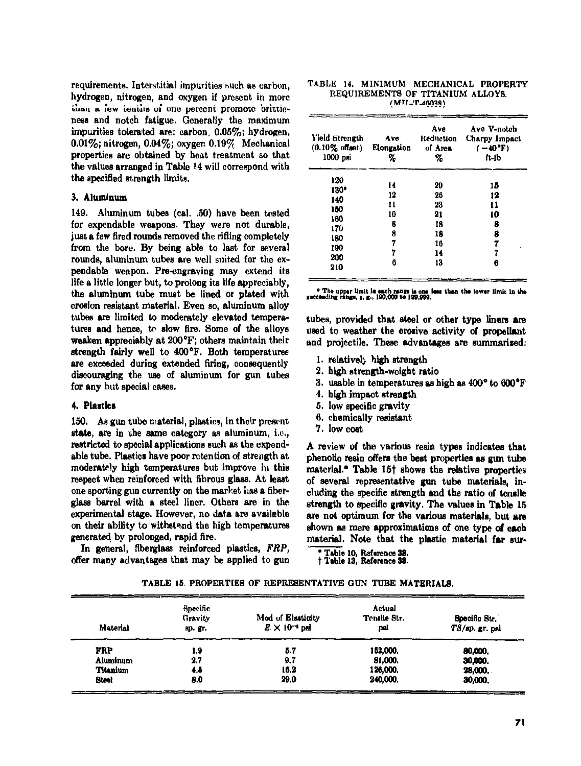
3. Aluminum ....................................... 71
4. Plastics........................................ 71
5. Stellite........................................ 72
6. Chromium ....................................... 72
M. Manufacturing Procedures.......................... 73
Chapter 7. MAINTENANCE .............................................. 74
A. Corrosion Inhibitors .............................. 74
B. Inspection......................................... 74
Chapter 8. SAMPLE PROBLEMS........................................ 75
A. Monobloc Tube, Artillery........................... 75
1. Regular Tube..................................... 75
2. Autofreitaged Tube............................... 76
B. Jacketed Tube, Artillery .......................... 76
1. Tube With Single Jacket......................... 76
2. Tube With Two Jackets........................... 78
iv
TABLE OF CONTENTS—(continued)
Page
(J. Small Arms Barrel With Shrink Fitted Liner and Cap . 81
1. Shrink Fit Pressure ............................ 81
2. Shrink Fit Stresses............................. 82
3. Pressure Stresses............................... 82
4. Combined Stresses............................... 83
D. Small Anns Barrel With Combined Pressure and
Thermal Stresses...................................... 83
1. Propellant Gas Pressure Stresses................ 83
2. Shrink Fit Pressure Stresses................... 83
3. Thermal Stresses............................... 84
E. Recoilless Gun.................................... 84
1. Gun Tube ...................................... 84
2. Chamber........................................ 87
3. Nozzle....................,r................... 91
GLOSSARY.................................................. 94
REFERENCES................................................ 99
LIST OF ILLUSTRATIONS
Fig. No. Page
1 Typical Gun Tube Showing Regions................................ 2
2 Chambers of Various Tube Types................................. 4
3 Jacketed Tube.................................................. 6
4 Quasi Two-Piece Tube........................................... 6
5 Revolver Type Tube Showing Separate Chamber With Round . . 6
6 Gatling Gun Tubes.............................................. 6
7 Recoilless Gun Tube............................................ 6
8 Temperature Distribution Across Tube Wall...................... 9
9 Temperature Along Outer Surface of Caliber .30 Tube........... 10
10 Thermal Cracks on Bore Surface ............................... 11
11 Dispersion-Frequency Ratio Curve .............................. 14
12 Gun Tube Showing Subdivisions ................................ 14
13 M/I Diagram of Gun Tube....................................... 15
14 Types of Rifling Contour...................................... 20
15 Progressive Engraving......................................... 20
16 Interior Ballistics of Caliber .30 Gun......................... 22
17 Case-Chamber Stress-Strain Curves.............................. 23
18 Chamber With Pertinent Dimensions.............................. 24
19 Forcing Cone Study............................................. 25
20 Schematic of Recoilless Gun .................................. 25
21 Nozzle Entrance Geometry...................................... 26
22 Pressure Ratio-Area Ratio Curve............................... 27
23 Lines of Constant Dimensionless Recoil ....................... 27
24 Nozzle Shapes—Schematic....................................... 27
25 Nozzle Pressure-Area Ratio Curve, M10 Propellant.............. 28
v
LIST OF ILLUSTRATIONS—(continued)
Fig. No.
Page
26
27
28
29
30
31
32
33
34
35
36
37
38
39
40
41
42
43
44
45
46
47
48
49
50
51
52
53
54
55
56
57
58
59
60
61
62
63
64
Groove-uorc iteiiiuons.......................................... 31
Standard Rifling Profiles....................................... 32
Rifling Force Diagram.................. . . . . ............... 33
Torque Curves for 37 mm Gun..................................... 34
Effects on Rifling Torque by Varying Exit Angle................. 35
Tipped Parabola 35
Rifling Torque Curves for Caliber .30 Barrel.................... 37
Wall Ratio-Pressure Factor Curves for Multilayer Tubes........ 43
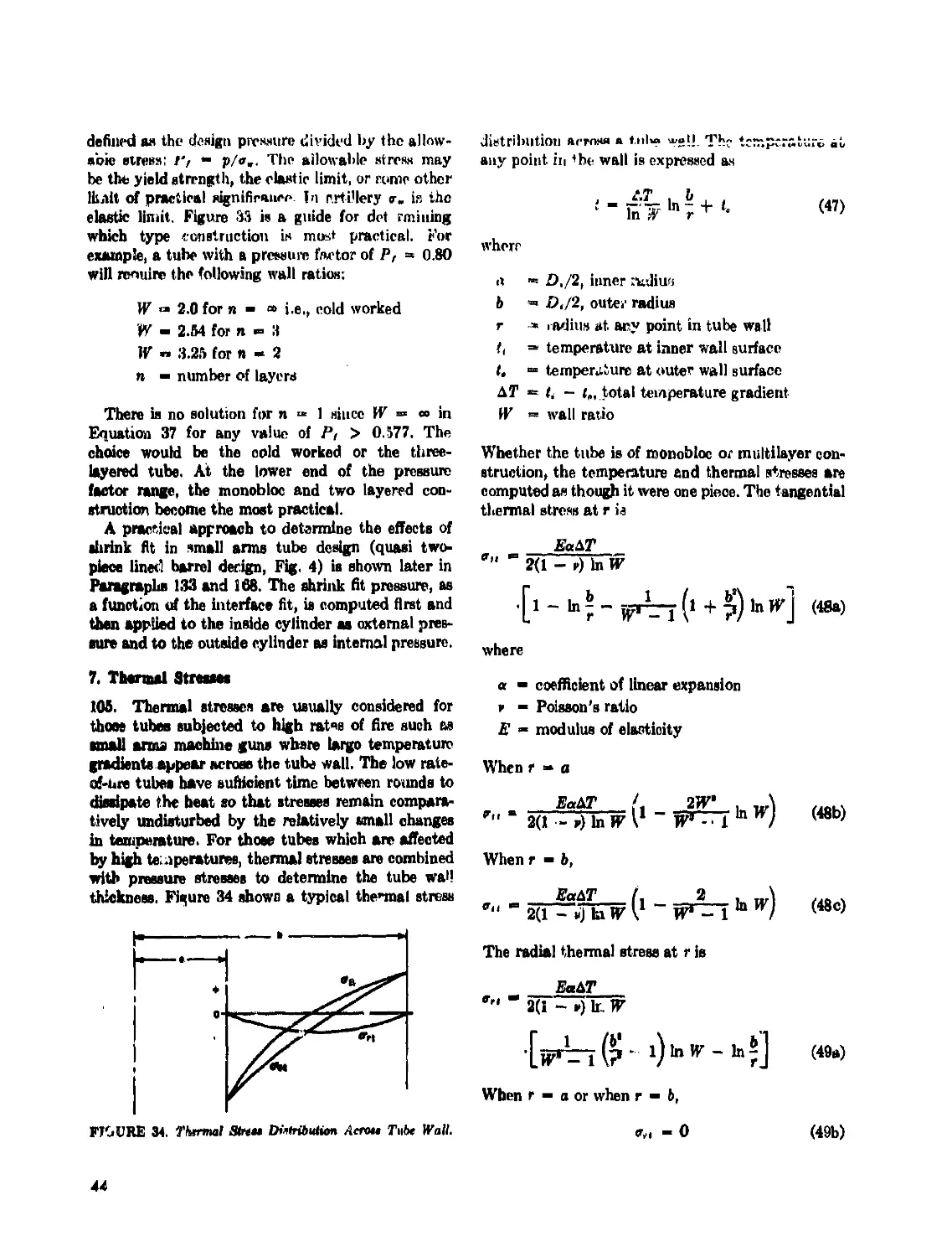
Thermal Stress Distribution Across Tube Wall.................... 44
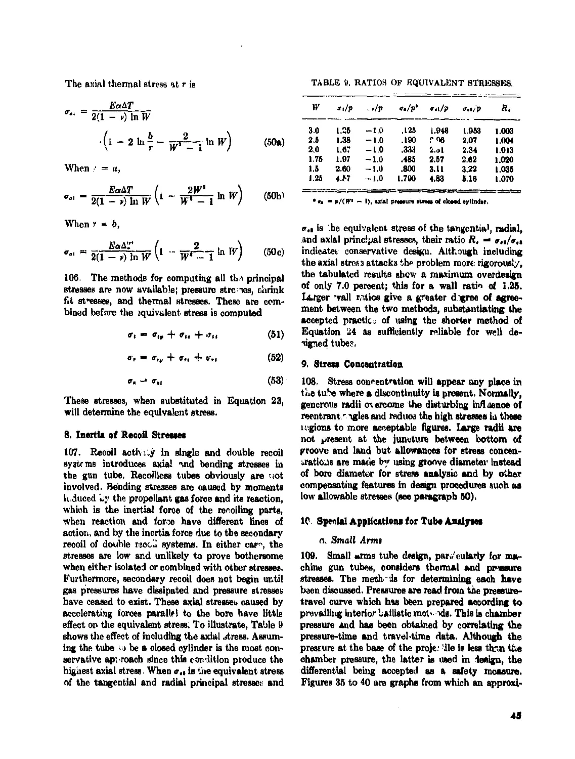
Equivalent Stress as a Function of Wall Ratio and Temperature
Distance for an Internal Pressure of 10,000 psi............... 46
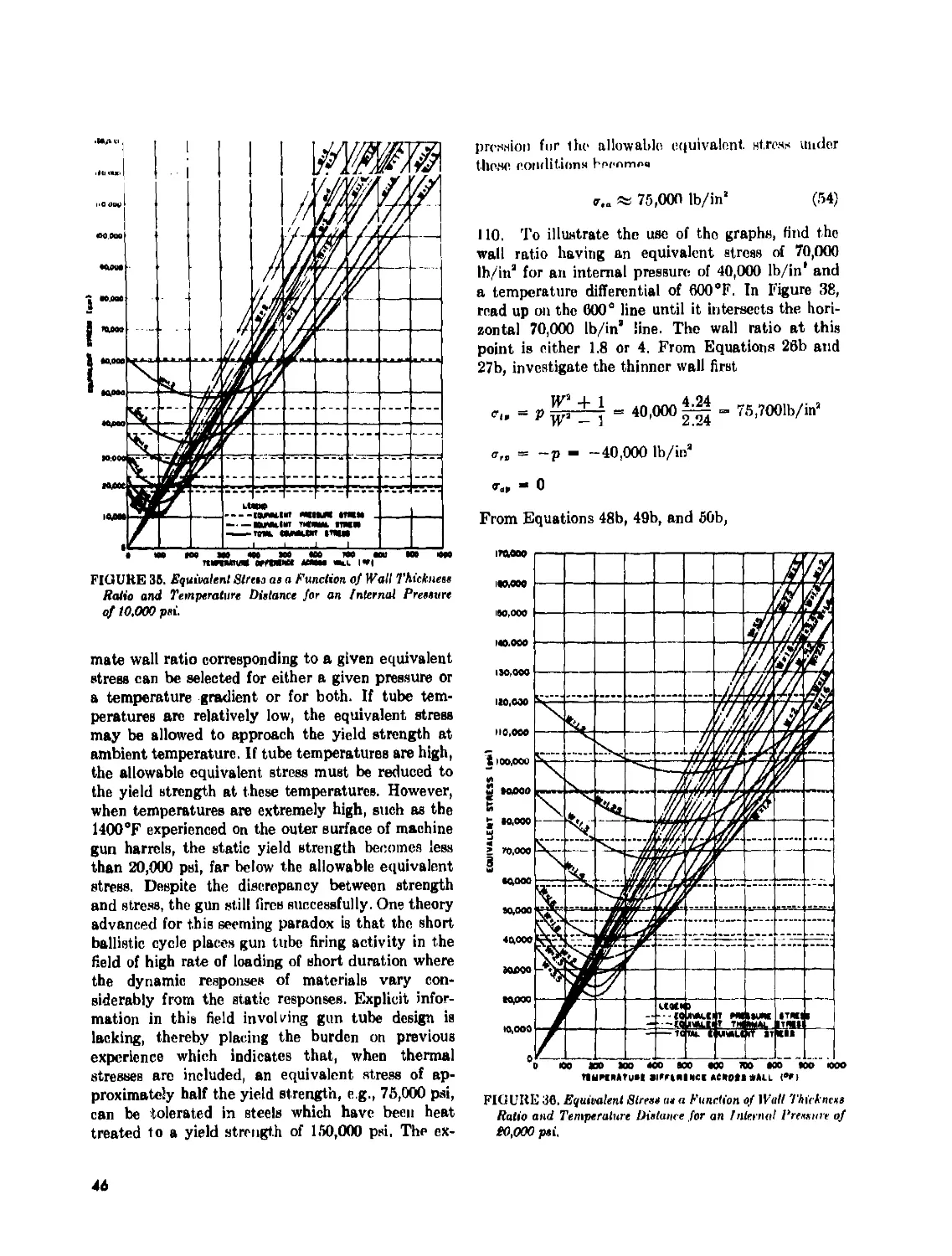
Equivalent Stress as a Function of Wall Ratio and Temperature
Distance for an Internal Pressure of 20,000 psi............... 46
Equivalent Stress as a Function of Wall Ratio and Temperature
Distance for an Internal Pressure of 30,000 psi............... 47
Equivalent Stress as a Function of Wall Ratio and Temperature
Distance for an Internal Pressure of 40,000 psi............... 47
Equivalent Stress as a Function of Wall Ratio and Temperature
Distance for an Internal Pressure of 50,000 psi............... 48
Equivalent Stress as a Function of Wall Ratio and Temperature
Distance for an Internal Pressure of 60,000 psi............... 48
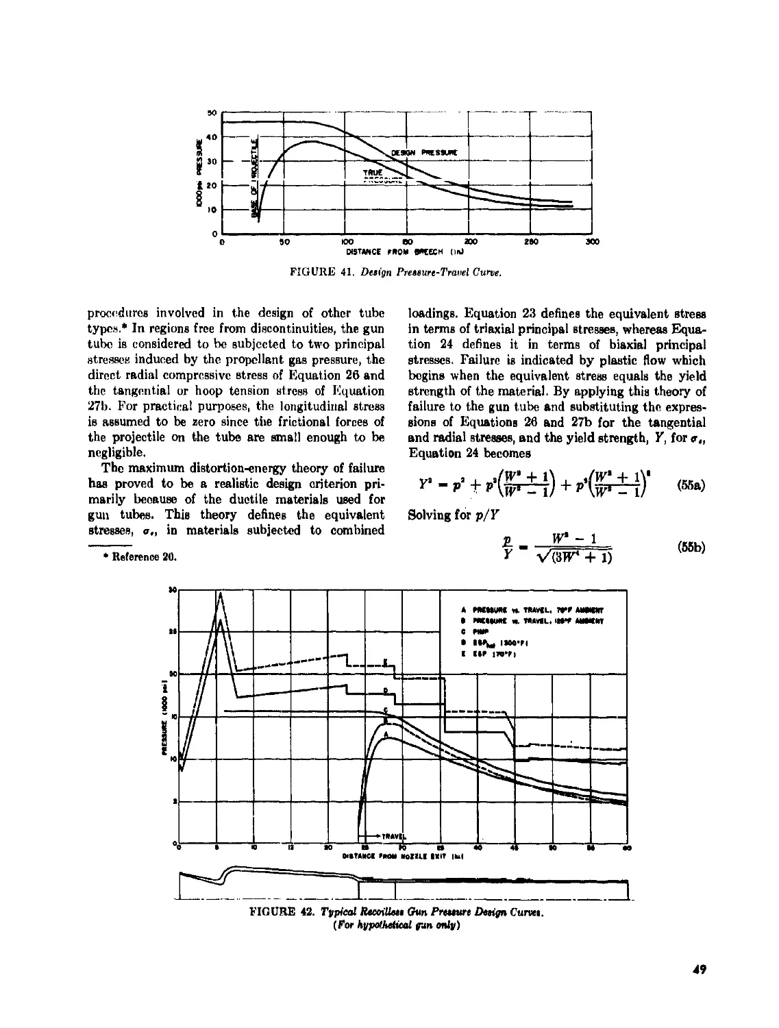
Design Pressure-Travel Curve................................ . 49
Typical Recoilless Gun Pressure Design Curves................... 49
Gimbal Ring Loading............................................. 53
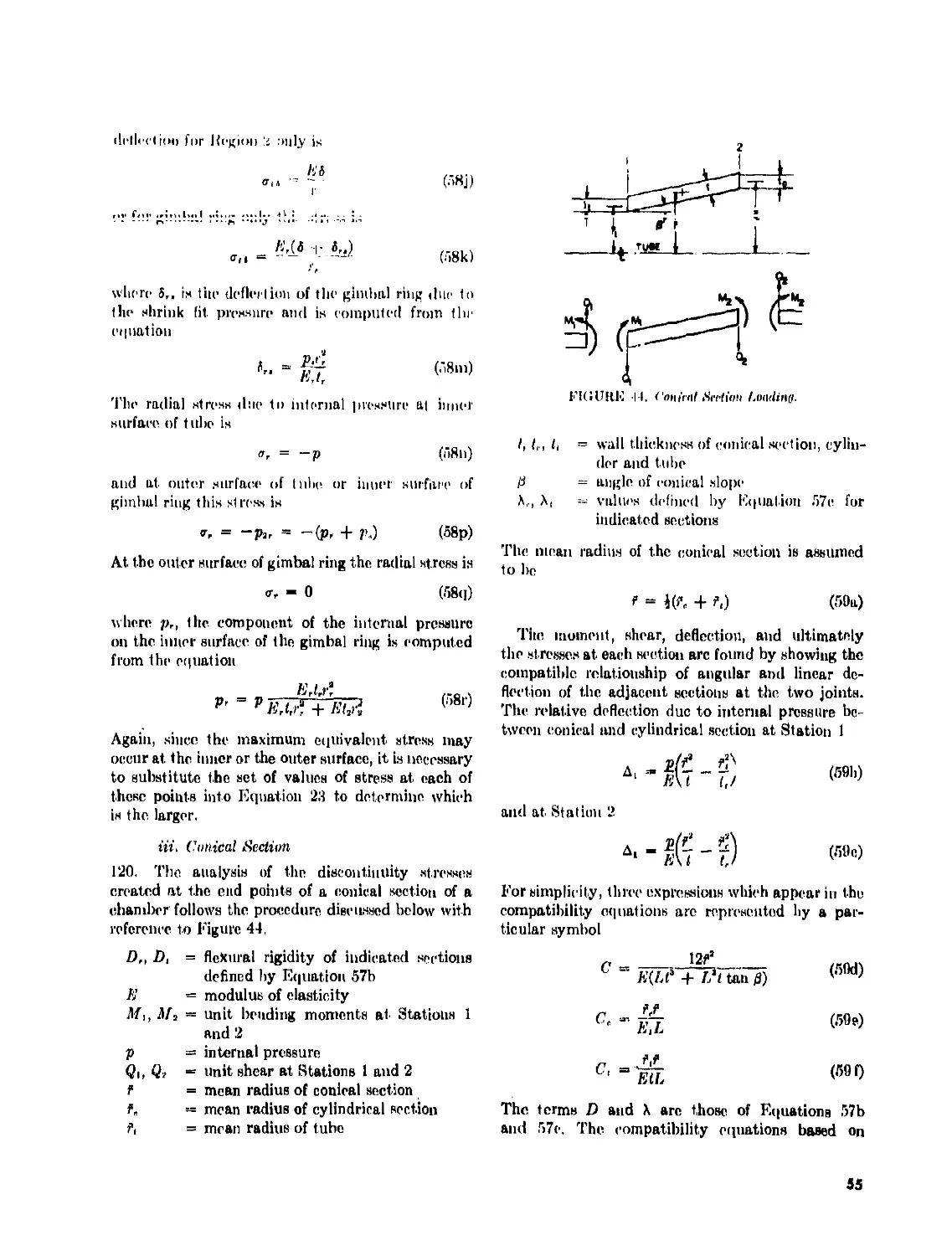
Conical Section Loading......................................... 55
Toroidal Section Loading........................................ 56
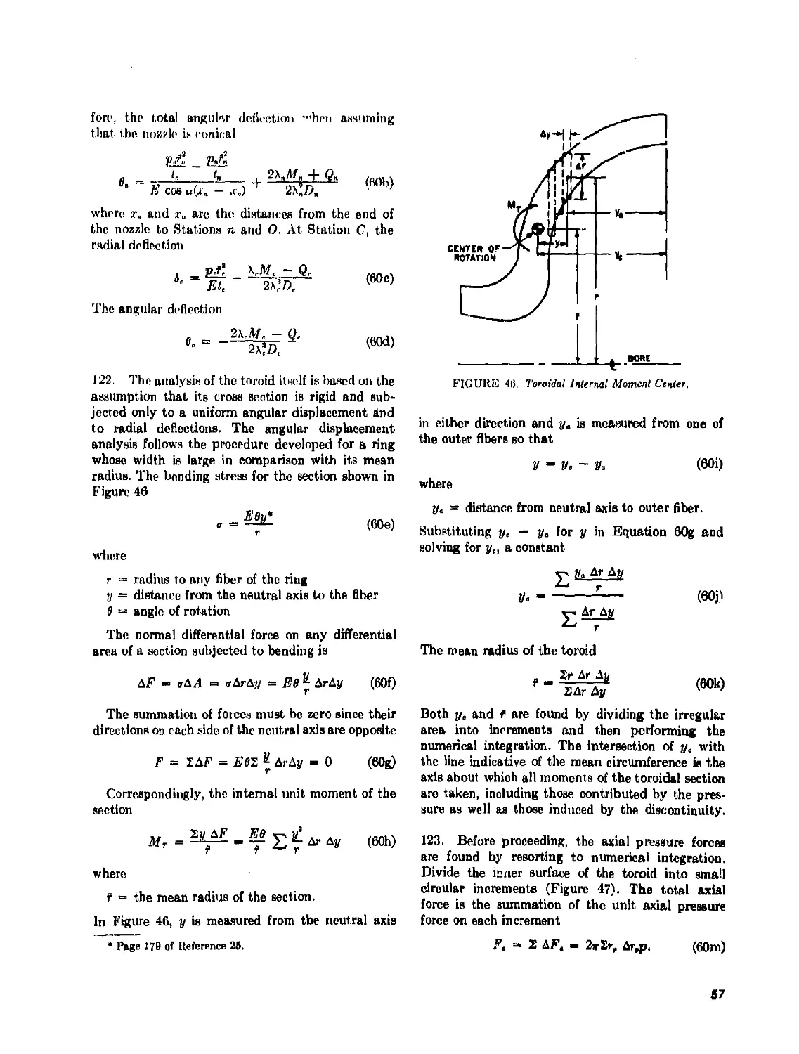
Toroidal Internal Moment Center................................. 57
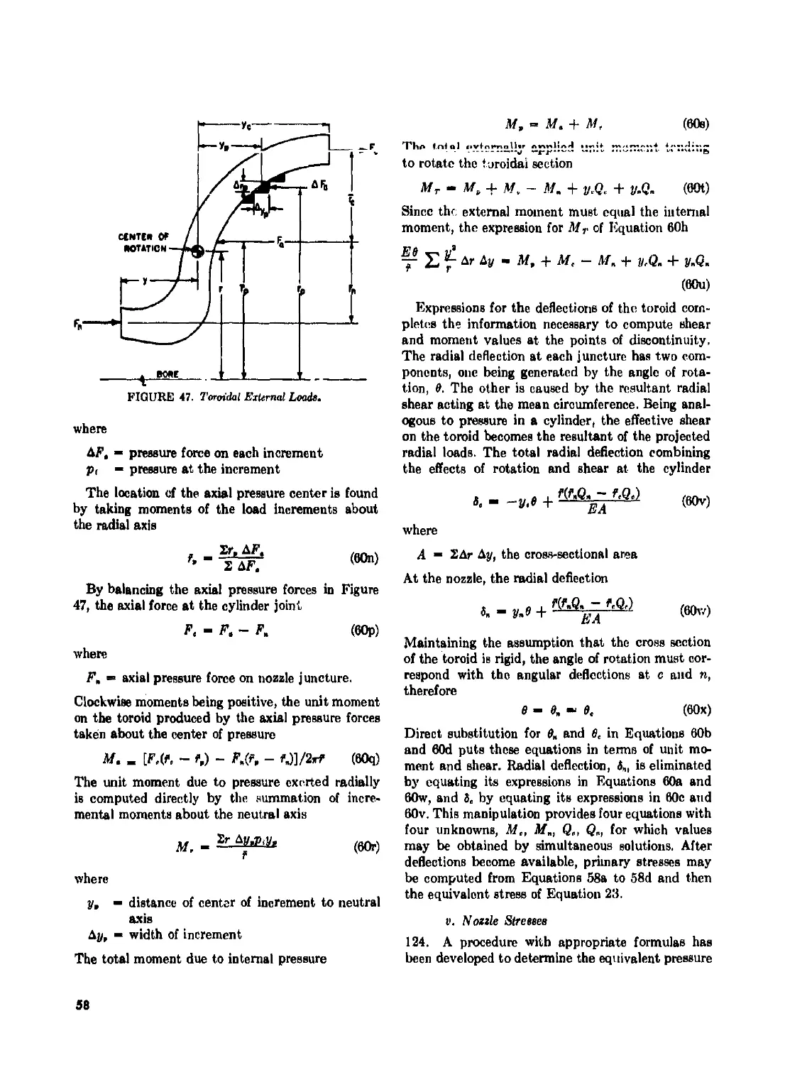
Toroidal External Loads......................................... 58
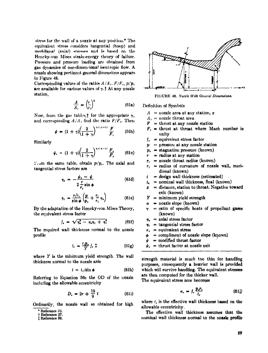
Nozzle With General Dimensions.................................. 59
Threaded Joint With Butted End.................................. 64
Thread Profile Types ........................................... 64
Interrupted Threads............................................. 65
Threaded Joint................................................. 65
Rifling Torque Reactions . 66
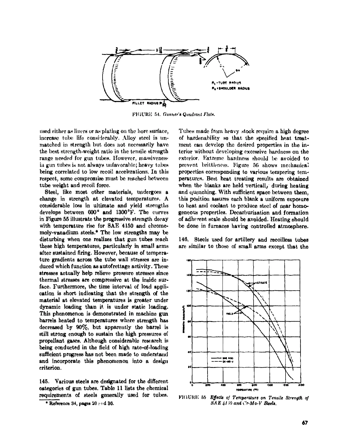
Gunner’s Quadrant Flats......................................... 67
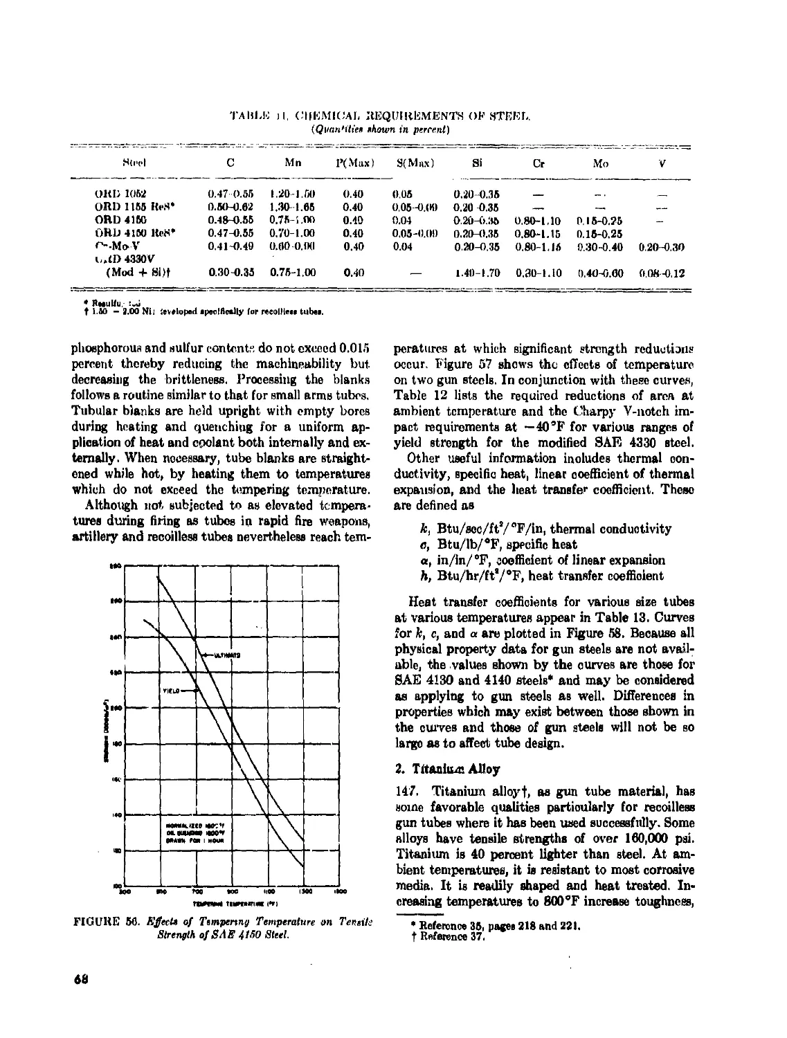
Effects of Temperature on Tensile Strength of SAE 4150 and Cr-Mo-V
Steels....................................................... 67
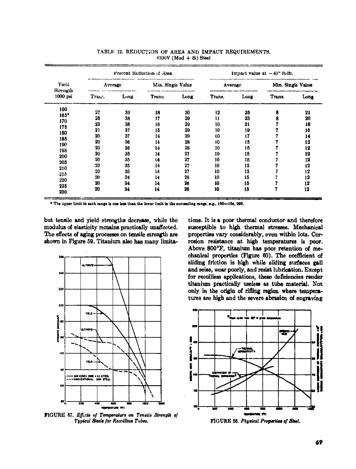
Effects of Tempering Temperature on Tensile Strength of SAE 4150
Steel........................................................... 68
Effects of Temperature on Tensile Strength of Typical Steels for
Recoilless Tubes................................................ 69
Physical Properties of Steel.................................... 69
Effects of Aging Processes on Tensile Strength of Titanium at Various
Temperatures.................................................. 70
Effects of Temperature on Tensile Strength of Titanium Alloy . . 70
Design Data, Monobloc Artillery Tube............................ 75
Design Data, Jacketed Artillery Tube............................ 77
Schematic of Tube With Liner.................................... 81
Tangential Stress of Shrink Fitted Tube.......................... 83
vi
LIST OF TABLES
Table No. Page
1 M/1 Calculations for Static Condition............................ 15
2 Area Moments for Static Condition................................ 10
3 Natural Frequency Parameters, Static Condition................... 16
4 M/1 Calculations for Dynamic Condition........................... 17
5 Area Moments for Dynamic Condition............................... 17
6 Natural Frequency Parameters, Dynamic Condition.................. 18
7 Forcing Cone Slopes.............................................. 24
8 Rifling Torque Calculations for Exponential Rifling.............. 38
9 Ratios of Equivalent Stresses 45
10 Wall Ratio-Pressure Ratio Chart for Monobloc Gun Tubes ... 50
11 Chemical Requirements of Steel.................................... 68
12 Reduction of Area and Impact Requirements ........................ 69
13 Heat Transfer Coefficients, h..................................... 70
14 Minimum Mechanical Property Requirements of Titanium Alloys 71
15 Properties of Representative Gun Tube Materials................... 71
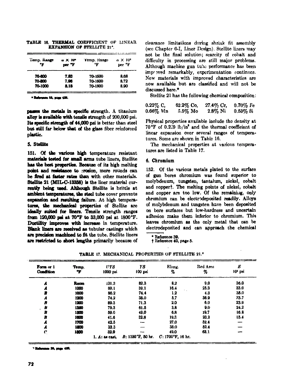
16 Thermal Coefficient of Linear Expansion of Stellite 21 ........... 72
17 Mechanical Properties of Stellite 21.............................. 72
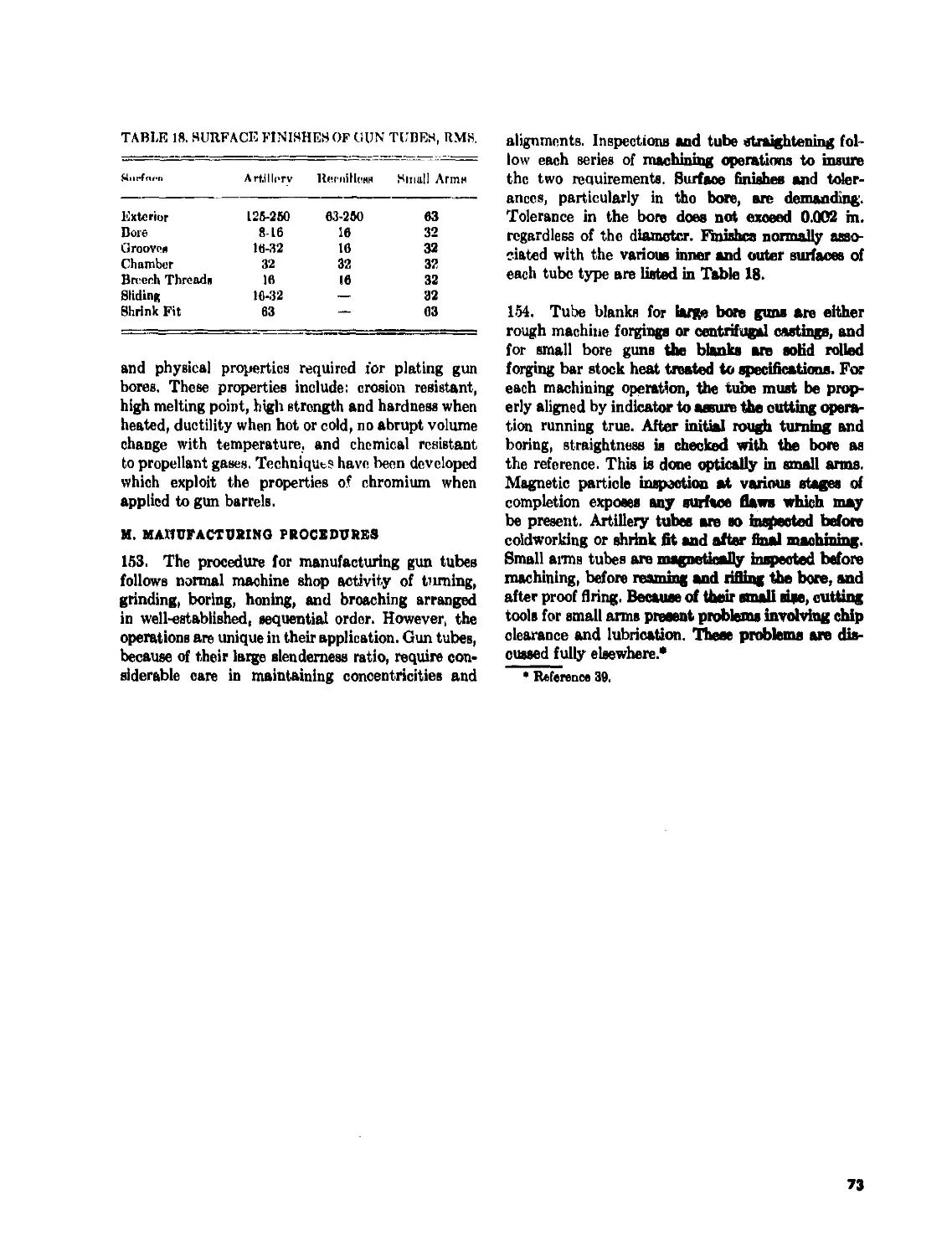
18 Surface Finishes of Gun Tubes, RMS................................ 73
19 Design Data of Theoretical Monobloc Tube.......................... 76
20 Design Data of Actual Monobloc Tube............................... 76
21 Design Data of Theoretical Autofrettaged Tube..................... 77
22 Design Data of Actual Autofrettaged Tube.......................... 77
23 ESP Calculations for Single Jacketed, 100 mm Tube................. 79
24 Combined Shrink Fit and Pressure Stresses (lb/ina)................ 83
25 Nozzle Stresses................................................... 92
vll
LIST OF SYMBOLS
a = distance from origin of coordinate axes
to origin of rifling curve: ' iner radius;
linear acceleration of projectile
= maximum projectile acceleration
A — area of section; general expression for
area
A, = nozzle approach area
A i = bore area
Ar = chamber area
A, = nozzle exit area
Л, = original nozzle throat area; projected
area of nozzle
A, = nozzle throat area
A, — nozzle area at distance x from the throat
ДЛ„ = change in nozzle throat area
b = twice distance from origin of rifling to
point of maximum pressure; outer radius
C — weight of propellant charge
CMP — computed maximum pressure
d, — depth of thread
D = diameter varying from D, to D,‘, mean
diameter; general expression for diam-
eter; general expression for flexural
rigidity
Dt = outside diameter of liner; inside diameter
of jacket
Db — bore diameter
Dt =-• inside diameter
D, = mean diameter; mandrel diameter
D„ - outside diameter
ДД, = nominal clearance between bore and
projectile
E = modulus of elasticity; propellant po-
tential
E, = equivalent modulus of elasticity
Er — modulus of elasticity of ring
ESP = elastic strength pressure
/, = equivalent stress factor
/„ = natural frequency
/, = firing rate
F = general expression for force; specific
impetus; nozzle thrust
F, = propellant gas force
F. == nozzle force
F'r = cradle key load induced by rifling torque
F, = thread load; thrust at nozzle throat at
Mach No. 1
Fy = unit load on breechblock thread
ДЕ = force increment
g = acceleration of gravity
G = number of rifling grooves; shear modulus
h = depth of rifling groove; depth of key way
I = area moment of inertia, general ex-
pression
J = area polar moment of inertia
к = radius of gyration of projectile
k, «• high temperature strength reduction
factor
К = kinetic energy
K, = constant in rifling torque equation for
constant twist
L = axial length of rifling curve; length of
engaged thread; length of key; length
of increment
Ly length of diverging cone
L, = load factor
L„ — length of nozzle cone
L„ = required maximum length of chamber
M = general expression for moment
M, = mass of projectile
M, = recoiling mass; momentum of recoiling
mass .
Mr. = specified momentum of recoiling mass
ДМ, = required change in momentum
n — exponent defining rifling curve
n. = twist of rifling stated in calibers per turn
N = induced force normal to rifling curve
p = constant in equation for increasing twist
rifling; general expression for design
pressure
рл = pressure at point A of equivalent bore
p, = chamber pressure; true computed pres-
sure
pt = autofrettage pressure
p, = propellant gas pressure
p,„ == maximum propellant gas pressure
Pt = internal pressure
p„ = computed design pressure, based on
PIMP
p. = external or outside pressure; reservoir
pressure
p, = pressure induced by shrink fit
Pt = design pressuic at nozzle throat; pitch
p» = allowable pressure
viii
LIST OF SYMBOLS—(continued)
V. = nozzle pressure at point x
P = recorded ninig piconuiv
PIMP = permissible individual maximum pressure
PMMP = permissible mean maximum pressure
r = radius at any point in tube wall; general
expression for radius
r. - radius of nozzle approach area
r, = radius of nozzle exit
r, = radius of nozzle throat
R = radius of pendulum; projectile radius;
bore radius
R. = ratio of effective stresses
R, = frequency ratio
RMP = rated maximum pressure
8 = constant in equation for increasing twist
rifling
s„ length of free run
8Л = distance from breech of equivalent cham-
ber to A
SB = distance from breech of equivalent cham-
ber to base of projectile
sf - factor of safety
t = time; thickness; temperature at any
point in wall
la = time of propellant gas period
t< = temperature at inner wall surface
la = temperature at outer wall surface
t. = required wall thickness
T = rifling torque; period of pendulum
t. = rifling torque component due to pressure
T. = rifling torque component due to velocity
&T = total temperature gradient
V = projectile velocity at any point in bore
v„ = muzzle velocity
Vr = recoil velocity
V, = propellant bag space
V. = nozzle entrance volume
vf = final gun volume
V. = chamber volume
w = weight; wall ratio; dynamic force of beam
increment
we = weight of propellant charge; corrected
wall ratio
w, = wall ratio of finished tube
w, = wall ratio of jacket
WL = wall ratio of liner
IF,, = weight of projectile
W, = weight of recoiling mass
w, = weight of tube
X = axial length of rifling curve; linear ampli-
tude of pendulum
it = axial length of rifling in bore
” — deflectine hmm irmrnmnnt.i nnrinhcral
distance of rifling around bore
У - yield strength
a — coefficient of linear expansion; angle of
twist of rifling; half angle of diverging
cone
aK ~ exit angle of rifling
3 slope of conical surface of chamber; X
equivalent of combined region
7 = ratio of specific heats
i = total deflection; total shrink interference;
general expression for deflection; density
of steel
6j = deflection on jacket
it = deflection on liner
= deflection of mandrel
S,, = deflection of ring due to shrink fit
4( = deflection of tube
A = loading density; general expression for
relative radial deflection
A( -- required interference between tube and
mandrel
Д„ = maximum bag density of propellant
«I = tangential unit strain
6 =• slope of wall; angular displacement of
projectile; general expression for angular
deflection
в„ = included angle of nozzle
i = angular velocity of projectile
9 = angular acceleration of projectile
X = nozzle divergence angle correction factor
= axial stress factor
fli = tangential stress factor
д = coefficient of friction
r = Poisson’s ratio
P « polar radius of gyration
<r„ = principal stress in axial direction
v0„ = axial stress caused by pressure
<».< = axial thermal stress
«ты = bearing stress
v. = equivalent stress
= allowable equivalent stress
= fillet bending stress
v, = principal stress in radial direction
ar„ = radial pressure stress
a,, = radial shrink fit stress
<rrl = radial thermal stress
= principal stress in tangential direction
<г(и = tangential stress produced by moment
<Г|Л = tangential pressure stress
lx
LIST OF SYMBOLS—(continued)
tangential shrink nt stress r tangential thermal stress r„ tangential stress produced by radial 4> deflection ф allowable tensile stress ы yield strength of material = torsional stress; direct shear stress = allowable shear stress = mass moment of inertia of projectile = thrust factor = critical speed; ratio, recoil momentum to projectile momentum
CHAPTER 1
INTRODUCTION
A. SCOPE AND PURPOSE
1. The term gun tube, or simply tube, is used
throughout this handbook to designate the prin-
cipal part of a gun; i.e., that part which dischargee
the projectile. It is used in its general application
without limitation as to caliber, and embraces the
terms gun barrel or barrel frequently employed,
especially in small arms terminology. The material
in this handbook discusses procedures for the design
of the various types of gun tubes. It is intended to
present various problems facing the tube designer
and in this light discusses the present approach in
tube design. This handbook should prove helpful
in familiarizing new personnel with the many phases
of tube design and also should be a useful reference
for the experienced.
B. FUNCTIONS
2. The tube is the primary component of a gun.
Basically it is a tubular pressure vessel, closed at
the breech and open at the muzzle; except in a
ermlless gun in which the breech also has controlled
openings. The tube determines the initial activities
of the projectile. Before firing, it provides space for
the complete round. During firing, it restrains the
propellant gas in all directions except that of pro-
jectile travel, thus directing the impetus of the gas
against the projectile. In recoilless guns part of the
gas impetus is directed rearward to counteract recoil.
The azimuth and elevation determine the direction
of flight. In rifled tubes the rifling imparts the neces-
sary rotation for projectile stability. In brief, the
mission of the tube is to direct the projectile toward
the target with a specified velocity.
C. TYPES OF GUNS
3. Generally, the tube bears the label of the
weapon. Tubes are placed in three general classes,
namely: artillery, small arms, and recoilless. Artillery
includes guns of over 30 mm in bore diameter, such
as guns, howitzers and rrrtars. Small arms include
automatic and semiautomatic, single fire, guns which
generally do not exceed 30 mm in caliber. A few
automatic weapons of caliber larger than 30 mm,
such as the 37 mm Vigilante and the 90 mm Sky-
sweeper, make specific classification difficult. Re-
coilless guns are those of any caliber whose recoil
forces are neutralized by the reaction of propellant
gas escaping rearward.
1
CHAPTER 2
REGIONS OF THE GUN TUBE
4, A gun tube may be divided into four regions;
the front portion or bore through which the pro-
jectile travels when the round is fired; the rear
portion or chamber which houses the round before
firing; the rear opening or breech through which the
ammunition is loaded; and the 'front opening or
muzzle from which the projectile emerges. In re-
coilless guns the rear opening or nozzle provides
for recoillessness. Exceptions do prevail with respect
to the functions of these regions particularly with
breech opening and loading technique. For example,
most mortars arc muzzle loaded and have per-
manently closed chambers. Figure 1 is a typical tube
showing the regions applicable to conventional gun
tubes.
A. CHAMBER
5. After loading but prior to firing, the part of
the projectile forward of the rotating band or its
equivalent is located in the bore, and in the case of
recoilless ammunition, the pre-engraved band also
rests in the bore. The remainder of the round rests
in the chamber, which, except for revolver type
guns, is integral with the bore and consists of the
chamber body, the first shoulder, the centering
cylinder for artillery or the neck for small arms,
the second shoulder, bullet seat, and the forcing
cone, (Fig. 2a). The forcing cone is a conical frustum
whose slope extends through the origin of rilling
and intersects the bore surface. Engraving of the
rotating band occurs here. The section immediately
to the rear of the bullet seat is called the centering
cylinder or neck. It is just large enough to receive
the rotating band or the neck of the cartridge case.
This feature is not always found in heavy artillery
tubes. The main and largest compartment, the
chamber hody, houses the propellant and igniter.
Parts b, c, d, and e, of Figure 2 show complete
rounds positioned in various tube chambers. Artillery
tubes using separate loading ammunition have the
inner chamber wall cylindrical or conical, the mini-
mum diameter of either contour being limited to
the maximum diameter of the forcing cone. If
conical, the inner surface may be the extension of
the forcing cone. On the other hand, for tubes firing
fixed and semifixed ammunition, the clearances be-
tween chamber and cartridge case and the slopes of
the chamber walls are critical, since the cartridge
case walls, by expanding, seal in the propellant
gases, but must recover sufficiently after firing to
assure easy case extraction. This is particularly
true in small arms where small clearances are de-
sired along the tapers including those in which a
definite longitudinal interference is desired at the
first shoulder. During loading, the force of the
breechblock may actually collapse the case slightly
in this region to obviate the likelihood of axial
failure of the case. This collapsing action is called
crush-up and contributes to easy case extraction.
B. BRUCH RING ATTACHMENT
6. The chamber is closed by a breechblock or
bolt or, as in recoilless weapons, by the nozzle unit.
A breech ring supports the breechblock. The breech
ring is threaded to the outside of the chamber wall.
Its counterpart in some small arms is the receiver
which houses the bolt. The nozzle unit of a recoilless
tube may be attached directly to the rear of the
chamber wall or to a modified breech ring. These
elements are attached to the tube so that the re-
F1GU11E 1. Typical Gun Tube Showing Region*.
2
sultant gas force applied to them may be transmitted
to the tube. Thus, tube and breech assembly act
as a unit in transmitting the resultant force to the
structure supporting the tube.
C. BORE
7. The bore is formed by the inner surface of a
circular cylinder. It is the accelerating tube for the
projectile. Early firearms were smooth bore and
inherently inaccurate. Eventually, either by accident
or design, it was discovered that spinning the pro-
jectile about the flight axis increased accuracy.
Several methods have been introduced to achieve
this rotation. One method utilizes the behavior of
air impinging on canted fins attached to projectiles
such as projectiles fired from smooth bore mortars.
Another method uses rifling to impart the rotation.
Rifling consists of splines which spiral along the
bore surface. The raised portions are called lands,
the spaces between them are called grooves. The
spiral may have a constant angle of twist, i.e., a
helix, or it may have a variable angle of twist con-
forming to some exponential expression. As the
projectile moves through the bore, it turns with the
rifling at an angular velocity proportional to the
linear velocity and to the tangent of the angle of
twist.
8. Contact with the rifling is assured by having
the diameter of the jacket of a bullet or the rotating
band of a larger projectile at least equal to the groove
diameter. Then, just as the projectile starts to move,
the band or jacket is forced into the rifling. This
process is called engraving and takes place at the
beginning, or origin, of rifling. For recoilless guns,
rotating bands are preengraved to eliminate the
large engraving forces which are undesirable in this
type weapon. Some mortar projectiles have a flaired
skirt, or sabot, at the base which is pressed into the
rifling by the propellant gas pressure. Rotating
bands arc bands of relatively soft material which
are welded, bonded, or mechanically attached to the
projectile. Jackets may be considered as bands
which cover the hiillo.ts completely. Either jacket,
rotating band, or sabot is necessary to transmit to
the projectile the angular accelerating force induced
by the rifling, and to serve as a seal to prevent pro-
pellant gases from escaping past the projectile.
9. Tapered bores (squeeze bores) have been used
in the past as a means to increase muzzle velocity.
An oversize bore at the chamber was gradually
tapcred to a much smaller diameter near the muzzle.
The larger bore diameter exposed a larger pressure
area to the propellant gases thereby increasing the
projectile acceleration. The projectile relied on two
rotating bands having oversized diameters to keep
it centered and in contact with the rifling. The
bands, spaced far enough apart to form an effective
wheelbase, were squeezed inward toward, the base
of the projectile as it traveled along the tapered
bore. This concept was proved impractical and now
has no more than historical significance. A more
logical use of the tapered bore is that practiced in
small arms. In order to decrease its diameter slightly
as the muzzle is approached, the bore is provided
with a shallow taper along its entire length. This
design concept, better known as choke bore, has
been adopted to compensate for the anticipated
erosion. In shotguns, choke bore is applied to a
short distance at the muzzle to control the area of
spread, or shot pattern.
D. MUZZLE
10. The muzzle end of the tube serves as the at-
tachment for front sights, blast deflectors, and
muzzle brakes. Blast deflectors do not apply severe
loads to the tube. However, muzzle brakes develop
large forces which usually are transmitted to the
tube by a threaded attachment near the muzzle.
3
ГУ у УУУУ # / // / / X^Z?,Z2
zzzzzzzzzzzzs
BODY
NECK
BORE
^ZZZ^ZZZXZZZjlzS^L^
(a) CHAMBER SHOWING COMPONENTS
U>) SMALL ARMS CHAMBER CONTAINING FIXED ROUND
(c) ARTILLERY CHAMBER CONTAINING FIXED ROUND
(4) ARTILLERY CHAMBER CONTAINING SEPARATELY LOADED ROUND
FIGURE 2. Chamber» of Various Tube Type».
4
CHAPTER 3
TYPES OF GUN TUBES
11. Gun tubes are generally classified according
to weapon, i.e., artillery tubes, small arms tubes,
and recoilless tubes. Each is subdivided according
to method of construction although a particular
construction need not be confined to any one weapon
type.
A. ARTILLERY TUBES
1. Monobloc Tube
12. Artillery tubes fall into two categories, mono-
bloc and jacketed. The true monobloc tube (Figure 1)
is made of one piece of material. A variant is the
lined tube which deviates only slightly in principle
from the true monobloc because the liner is usually
not a major contributor of strength to the tube wall.
Liners may be assembled by shrink fit or they may
be a loose fit. They may extend along the full length
of the bore or for only a short distance at and beyond
the origin of rifling where erosion-'ls most severe.
Liners may prolong tube life by being made of
material which is highly resistant to erosion. Loose
fitting liners prolong tube life by being replaceable
in the field. Most of the shrink fitted type serve
throughout the life of the tube. The length is de-
termined by the ability to maintain proper clearances
while the liner is being inserted into the tube.
Monobloc tubes are also used for mortars, an
adjunct of artillery. Mortars are usually emplaced
manually and are often transported manually, there-
fore low weight is essential. In this respect, mortar
tube requirements are similar to those of recoilless
tubes.
2. Jacketed Tubes
13. The jacketed, or built-up, type (Figure 3) is
constructed of two or more close fitting, concentric
tubes not of the same length. (It may, or may not,
have a replaceable liner.) The jackets do not extend
to the muzzle where pressures are low but are only
long enough to provide the built-up tube with wall
thicknesses required by the pressure along the bore.
Assembly is usually by shrink fit. Although the
jackets are not full-length, the inside tube, including
its unreinforced forward end, is still referred to as
the liner. Formerly, jacketed tubes included the
wire-wrapped type. The wire, square in ernes sec-
tion, was wrapped under tension on a central tube
thereby inducing an initial compressive stress in
the tube, the same effect realized from shrink fitting.
However, its tendency to droop and whip excessively,
improvement in manufacturing techniques, and ad-
vances in inspection methods, have all contributed
to the replacement of the wire-wrapped tube by the
present jacketed type.
B. SHALL ARMS TUBES
14. Small arms tubes may be monobioc or they
may be made of two or more components, as are the
quasi two-piece and the revolver type tubes.
1. Quasi Two-Piece Tube
The quasi two-piece tube (Fig. 4) is particularly
adapted to a machine gun. It consists of two units:
a lined tube and a cap. The cap contains the cham-
ber. The units are assembled permanently by a
combination of threads and shrink fits to become,
virtually, a one piece, lined tube.
2. Revolver Type Tube
Another small arms barrel is the revolver type
sketched in Figure 5. It has two primary components,
the barrel and the drum. The barrel contains the
forcing cone and bore and, in this respect, is similar
to other tubes. The drum is the chamber housing.
It is made of one piece so that the chambers which
may number four, five or six, are integral. Three
are equally spaced around the axis of the rotating
drum and are so indexed that each one, in sequence,
becomes aligned with the bore when the drum stops
for the round to be fired. A seal, carried by each
chamber, precludes the escape of propellant gases
between drum and tube.
In contrast, the several tubes of the Gatling type
gun (Fig. 6), although operating as a unit similar
to the revolver type, are complete conventional
tubes, each with its own chamber and bore. The
advantage of this type lies in its capability of a
high rate of fire while subjecting the individual tubes
5
OUTER JACKET
INNER JACKET
FIGURE 3. JarXflfd Tube.
FIGURE 4. Quant Two-Piece Tube.
ORUM
BARREL
RINO SEAL
JZZZzzZZZJZZZZ
zzzzzzzzzSZzzS^^SS
FIGURE &. Rceolcer Тире Tube Showing Separate Chamber IKi'IA Round.
FIGURE 7. Rceoittcee Gun Tube,
6
to a relatively low rate. The design criteria differs
only to the the extent that individual tubes derive
considerable rigidity from the assembly and there-
fore ean be made as light as induced stresses, ma-
chining operations, and handling abuse will permit.
The ring supporting the tubes; at the muzzles, one
of the parts furnishing this rigidity, has been omitted
from Figure Ci.
C. RECOILLESS TUBE
15. If practical, monobloc construction is preferred
for recoilless tubes. A one-piece tube (Fig. 7) is de-
sirable from the viewpoint of low weight and sim-
plicity. However, to minimize manufacturing com-
plexities, tubes with integral chambers are currently
employed with the nozzle being a separate com-
ponent fastened and scaled to the chamber, usually
by some type of threaded joint.
D, EXPENDABLE TUBES
16. Expendable tubes are not a type in the same
sense of the preceding ones but may be considered
a unique type in terms of application or service.
The chief argument for expendability is the saving
of weapon weight, resulting in greater mobility and
easier handling. A truly expendable weapon might
lx', considered as being one which would be fired
only once, and then discarded. This suggests that
the tube could be designed to, or very close to, the
point of failure. It is quickly realized, however,
that such a design criterion would not be practicable
because of the nature of mechanical properties of
materials, inconsistencies of material composition,
and variations in performance. This leads to con-
sideration of another possibility in the concept of
expendability, namely, a limited-life tube.
The real gains accruing to the weapon (reduction
in weight, volume, complexity, cost, etc.) are made
in ehanging from extended-life usage. There ap-
pears to be little or no gain in reducing the use of
the tube from spveral shots to only one shot, The
reasonableness of going from one to a few shots
in an expendable system was demonstrated by an
experiment involving caliber .50 aluminum tubes.
The experiment showed that several rounds could
lie fired from each ' ube before the rifling was stripped
to the point of not providing sufficient spin stability.
It should be recognized that even in these early
experiments, the use of a fln-stablized or possibly
a pre-engraved projectile would have resulted in
improved useful life. It may be concluded, therefore,
that a limited-life, light-weight tube capable of
firing several full caliber rounds can be developed.
7
CHAPTER 4
FIRING PHENOMENA AFFECTING GUN TUBES
17. To be effective, the gun tube must be accurate.
Accuracy is directly affected by any change or
irregularity in the angular or linear velocity of the
projectile as it loaves the muzzle of the gun. Useful
life of the tube depends on its ability to withstand
the rigors of firing and still maintain the desired
muzzle velocity. The ballistic cycle of a gun is
extremely short, a matter of milliseconds. During
this short period, the tube is subjected to extremely
high temperatures, rapidly applied pressures, and
inertia forces. Normally a small number of rounds
will cause little measurable deterioration. But, after
firing a large number of rounds, deterioration be-
comes evident. High rates of fire accelerate the
deterioration. Any phenomenon which reduces ac-
curacy or velocity life, by causing damage or wear
in the tube, must be considered deleterious. The
adverse effects of some are immediately apparent.
Others are less pronounced but are cumulative in
nature and eventually will prove harmful. Com-
pensating measures taken during the design stage
will minimize many of these ill effects.
A. MECHANICAL LOADING
18. With the exception of rotating band pressure,
the effects of mechanical loadings are more pre-
dictable than those of heat and erosion, therefore
compensating measures can be incorporated in de-
sign concepts with considerable confidence.
1. Propellant Gas Pressure
19. From the structural viewpoint, the propellant
gas pressure is the predominant influence in the
design of the gun tube. Standard procedures for
computing wall thicknesses and accompanying
stresses are available and are usually sufficient for
good trbe design. However, stress concentrations
due to rifling and stresses due to other phenomena
such as heat should not be treated lightly.
2. Projectile Effects
a. Rotating Band Pressure
20. Rotating bands or their equivalent perform
two functions when the round is fired. They transmit
the rifling torque to the projectile and seal or
obturate the propellant gases to minimize leakage
past the projectile. Both functions are performed
effectively after the bands are engraved into the
rifling. Since engraving is somewhat of a swaging
operation, appreciable resistance is offered by the
rifling to the rotating band. This resistance is in
the nature of a radial force around the periphery
and its frictional counterpart. The radial force when
distributed uniformly over the band surface be-
comes the rotating band pressure. The band pressure
is higher on the rifling lands than on the bottom
of the grooves simply because more material is
displaced by the lands.
21. Band pressures may reach considerable pro-
portions and can cause damage to the tube. Un-
fortunately their intensity can not be predicted
accurately. Maximum pressures appear at the origin
of rifling and grow smaller as the projectile moves
along the bore, mainly because the band is likely
to wear to reduce the interference and because the
tube walls become thinner farther on and offer less
resistance to dilation. Band pressures progress along
the tube with the projectile and although they may
be very large, the area of application is local and
smell, and the pressure is present for such a short
time that immediate damage is not always apparent.
However, repeated application of such band pres-
sures will ultimately damage the bore. Small, im-
perceptible cracks will develop first and then steadily
grow larger as firing continues. This progressive
stress damage finally results in tube rupture or in
the spalling of rifling lands. Spalling is the out-
growth of cracks starting in the fillets of the rifling
grooves and propagating beneath the land. When
two such cracks from opposite sides join, the land
becomes a floating spline and is then extremely
vulnerable to rotating band action. Little effort is
then needed to remove it completely from the bore.
Rotating band pressure has a tendency to flatten
rifling lands. This swaging effect will happen only
if the bearing strength of the bore material is ex-
ceeded. Although not as severe a consequence to
8
the tube life as spalling, the working depth of the
rifling is decreased accompanied by a proportionn: c
decrease in its effectiveness.
b. Rifling Torque
22. Rifling torque is another loading condition
closely associated with gas pressure. It varies di-
rectly as the gas pressure and as a function of the
rifling curve. Absolute values of this torque can be
large but ordinarily the gun tube is so rigid that the
induced torsional stress is inconsequential. However,
provision must be made in the mounts for absorbing
the torque.
3. Recoil Forces
23. Recoil forces as such are almost incidental to
tube design. In single ’ecoil systems, their effects
never exceed the axial stresses due to propellant
gas pressures. In double recoil systems, the inertia
forces created by secondary recoil accelerations bend
the tube, but secondary recoil occurs after the pio-
jectile leaves the tube thus its influence and that
of the propellant gas pressure cannot combine. Alone,
the stresses due to secondary recoil are not critical
but should be computed to complete the design
investigation.
4. Vibration
24. The rapidly applied and released loads to which
the tube is subjected are likely to excite vibrations
which may prove harmful either structurally by
causing failure or operationally by reducing ac-
curacy. There are several sources for these vibra-
tions. Propellant gas and rotating band pressures
induce dilative vibrations which produce ringing
sounds and may contribute to muzzle cracking. The
balloting of a projectile may be another source.
Tube whip is another. It is the term designating the
motion normal to the longitudinal axh which is
attributed to the moment developed by the col-
lateral but directly opposite the propellant gas force
and the induced inertial force of the recoiling mass.
Another contributor to tube whip, at least a theo-
retical one, is the tendency of the propellant gases
and projectile to straighten the tube of the curva-
ture brought about by bending under its own weight.
25. Generally, the effects on accuracy caused by
vibrations in the heavy tubes of slow-fire weapons
fall within acceptable limits. These vibrations, affect-
ing only the round being fired, damp out before
the next round is fired. Rapid-fire guns are more
seriously affected. The rate of fire is high enough
FIGURE 8. Temperature Distribution Across Tube Wall.
that the vibrations initiated in firing each round
are not damped out sufficiently between rounds,
thus each round may be a resonating influence.
Structurally, the tube and mounting should be so
designed that vibrations are damped out. This is
particularly true for tubes of the recoilless type
which must be light for mobility and handling ease.
Low weight requirements demand designs of opti-
mum structural efficiency thereby rendering the tube
more susceptible to some forces which would other-
wise be harmless. A rigorous approach is therefore
needed for optimum design;. This does not mean
that more liberties can be taken with heavy tubes.
They too must be designed (or maximum structural
efficiency. However, their bulk may be sufficient to
absorb the disturbances created by vibrations.
/
B, HEATING
1. Thermal Stresses
26. The burning propellant releases a tremendous
amount of heat in the bore. Much of it is absorbed
by the tube. The bore surface, being adjacent to
the source, receives the brunt of it. If the heat were
applied gradually and a reasonable temperature
gradient appears through the tube wall, the induced
thermal stresses, being compressive in the inner
portion, would he analogous to autofrettage and,
therefore, beneficial. This, in effect, is what happens
in the tube of a rapid Are gun. During prolonged
firing, the temperature at the bore surface may
reach 2000°F, whereas that at the other surface
will be only 1400”F. The temperature distribution
across the wall is logarithmic (see Fig. 8), lending
credence to the assumption that heat transfer
9
FIGURE fl. Temperature .4/cnf Clj.'-r Surface о/ Caliber ,30
Tube.
the wall is constant after reaching the steady state
condition, the basis for thermal stress calculations
of gun tubes. Thermal stresses may be considerable
but compensating pressure stresses arc available to
confine them to the noncritical range. Thermal
stresses still prevail after pressures cease but to a
lesser extent ’^cause bore temperatures drop as soon
as hot gases begin to disappear. Since temperatures
vary along the tube length (Fig. 9), the gradient
too will vary, not only according to the heat input
itself but also according to variations in wall thick-
ness. Although the heat input is less at the thin wall
regions, the ratio of heat input to wall mass is larger
than at the thicker wall regions, thereby increasing
the thin wall temperatures. The higher wall tem-
peratures do not necessarily mean higher thermal
stresses. The heat follows a shorter path in thin
walls, consequently the temperature distribution will
show less variation across the wall than for thick
walls.
Although thermal stresses are reduced by pressure
stresses in a hot gun tube since the thermal tangential
stress is compressive near the bore surface and tensile
near the outside surface, the converse of thermal
stresses reducing pressure stresses should not be-
come a design criterion. The helpful stress pattern
depends upon a large negative temperature gradient
from the bore surface outward which..will exist as
long as firing is continued. However, if Bring is
temporarily ceased, the temperature will rapidly
tend to equalize throughout the tube and the whole
tube may be at a high temperature level, thereby
reducing the yield strength of the metal. If firing
is now resumed, the tangential thermal stress will
be p ositive for a short time even near the bore
surface, and thus will not lower the pressure in-
duced stress, Therefore, thermal stresses should not
be depended upon to help compensate for a reduced
yield strength in the tube material when at elevated
temperatures.*
* Stated in Conclusions of Reference 1. References are
listed at the end of this handbook.
27. Rate of fires as well as total rounds fired play
an important role in the heat transfer across the
tube waii. A steady state condition exists for every
firing schedule. For instance, the maximum tem-
perature of 1400 °F on the outer surface, of я ся! .30
machine gun tube is reached after firing 7 bursts
of 125 rounds each in 14 seconds at a rate of one
burst per minute. Adhering to this schedule, con-
tinued firing will not increase the tube temperature.
Before the steady state condition is reached, rate
of fire has an appreciable effect on the temperature
gradient. According to Figure 8, the bc-e surface
temperature increases with the rate of Are, but
at some distance removed from the bore surface,
the temperature after 50 rounds is higher for the
slower firing rates. This illustrates that time of heat
application is an essential parameter in thermal
stress considerations.
28. Thermal activity is responsible for another type
stress, one confined to a thin layer of tube at the
bore surface. No accurate method is available for
computing this stress. Its effect is not immediately
apparent but cracks will eventually appear on the
surface and grow deeper as firing progresses. Figure
10 shows these thermal cracks. Two theories explain
this phenomena. The first is metallurgical in nature;
the second is mechanical. Both are based on metal
contracting after cooling.
29. When a gun is fired, propellant gases heat the
bore surface beyond temperatures of 1400° to
1500°F, the transition temperature range of austen-
ite. After the hot gases leave the bore, the relatively
cool metal adjacent to the surface and air in the tube
quickly cool the bore layer to transform it to marten-
site. Austenite and martensite have different crystal-
line structures and, therefore, have different volumes,
austenite having the larger. Upon cooling, the ac-
companying shrinking induces high stresses. If these
stresses exceed the tensile strength of the material,
cracks will appear.
30. From the mechanical point of view, if heat at
high temperatures is applied for only a short time,
a large temperature gradient develops through the
tube wall and creates a corresponding compressive
stress on the bore surface. When this stress exceeds
the yield strength it causes plastic flow. The material
at the bore surface having no other escape, moves
inward. Upon cooling, the compressive stresses are
relieved and the material attempts to return to its
original position. However, only tangential and axial
10
FIGURE 10. Thermal Crack» on Bare Surface.
stresses are available to pull the metal back. The
new radial growth is proportional to Poisson’s ratio,
a displacement considerably less than that of the
compressive activity which displaced it originally.
Effectively, there is not sufficient material to com-
pensate for the elongations created by the newly
induced tangential and axial tensile stresses. Hence,
when these stresses exceed the tensile strength, sur-
face cracks appear.
2. Dimensional Changes
31. Dimensional changes are also a source of con-
cern to the designer. Solar radiation can cause the
top of the tube to become hotter than the bottom.
The resulting longitudinal differential expansion will
bow the tube downward to be accompanied by a
slight reduction in angle of elevation and, therefore,
a shortening in range. Conversely, a coolant such
as rain will lower temperatures on top and cause the
hot tube to bend upward with an accompanying
reduction in accuracy. Dilation of the bore caused
by elevated temperatures may also reduce accuracy
simply by increasing the clearance between bore
surface and projectile to permit gas leakage and to
create a greater tendency toward balloting. A likely
cause of malfunction due to unequal dimensional
changes concerns cartridge cases. The clearance be-
tween unfired case and chamber is large enough to
permit easy loading. On firing, the propellant gas
pressure expands the case and presses it tightly
against the chamber wall. After the pressures ceases,
the case recovers from the distortion sufficiently to
provide ready extraction. The difference in thermal
coefficients of expansion of case and chamber wall
must be considered to avoid cancelation of the re-
covery tendencies of the case by this factor.
3. Cook-Off*
32. A phenomenon which plagues gunners during
prolonged firing is cook-off. Cook-off is the deflagra-
tion or detonation of ammunition caused by the
absorption of heat from its environment. Usually
it consists of the accidental and spontaneous dis-
charge of, or explosion in, a gun or firearm caused by
an overheated chamber or barrel igniting a fuze,
propellant charge, or bursting charge. Cook-off is
confined mostly to automatic guns and to mortars.
Muzzle-loaded mortars when hot have a tendency
to fire the propelling charge before the round reaches
the breech; sometimes even before it drops com-
pletely through the muzzle. The danger in auto-
matic weapons stems from the live round left in the
chamber to start the next burst.
33. When cook-off occurs, the consequences may
be disastrous. The propellant, its primer, or any of
* Reference 2.
the explosive components in a round inay ignite.
If it is the DroDellant within a round in battery the
projectile passes out of the barrel. In this instance,
primary danger is to personnel and equipment in
line of fire. However, if projectile cuuk-oiT occurs
in battery, i.e., with round in chamber and all
weapon components in their firing positions, or if
in the ram or loading position in a small arms
weapon, severe damage is almost certain. The gun
undoubtedly will be rendered inoperative. Further-
more, the explosion may damage the carrier or
injure the crew. In contrast, the danger in slow-fire
weapons should be negligible for these need not be
kept loaded for any appreciable time.
34. Although cook-off is a safety hazard of some
importance, no method has been devised for de-
signing a tube that is safe from this complex heat-
transfer problem. In acceptance, all high rate-of-fire
weapons must be tested to make certain that the
cook-off threshold of their ammunition is not ex-
ceeded, and attempts made to introduce corrective
measures if needed. For example, in the 20 mm
revolver gun, M39, cook-off was eliminated when
the chamber-to-barrel seal was redesigned to re-
move the heat sink (see Figure 5). The approach is
necessarily empirical, after the need for corrective
measures is determined.
C. EROSION
1. Causes
36. Erosion is literally the wearing away of the
bore surface and of all phenomena unfavorable to
long tube life, it is the worst offender. Erosion is
primarily a physical activity although chemical
action can increase its rate. The abrasive effects of
propellant gases and rotating bands are the most
damaging. The gases impinging at high velocities
on the bore surface sweep away some of the metal.
This phenomenon is called gas wash. The rotating
Kartrlu hovn turn ЗП CTOSsGi’iJ
the first is induced by gas wash, the second by ordi-
nary sliding friction. Intense heat also contributes
indirectly to erosion, by melting an extremely thin
layer of the bore surface, thus making it easier for
the gases and band to carry off the material. Also,
because of high heat, some constituents of the pro-
pellant gases may combine with the metal at the
bore surface. The newly formed compound, probably
a nitride and therefore brittle, may crack and peel
off under the action of rotating bands and propel-
lant gases.
2. Regions Affected
36. The region at the origin of rifling suffers most
from erosion. Here the factors conducive to high
erosion rates arc most destructive. Temperatures are
highest, engraving takes place here, and frictional
forces are highest. Teets have shown that engraving,
friction, and gas wash contribute approximately
one-third each to the total wear*. This proportion
occurs only when relatively cool-burning propellants
are used. When the charge consists of hot-burning
propellants, the erosion induced by the gases is so
great that wear due to other causes becomes rela-
tively insignificant. Although propellant gases move
faster farther along the tube and should be more
erosive than at the origin of rifling, the other con-
tributing causes diminish considerably, with a sub-
sequent lower rate of erosion. The rate increases
again at the muzzle but not nearly as much as at
the origin of rifling. The actual cause of the ac-
celerated muzzle erosion has never been determined.
However, it may be considered secondary, for the
damaging effects sustained by the projectile at the
origin can never be completely undone by corrective
measures.introduced at the muzzle.
* Reference 3, page 509,
12
CHAPTER 5
WAYS OF MINIMIZING HARMFUL EFFECTS TO GUN TUBES
There are a number of measures which may be
incorporated either in tube design or in the ammuni-
tion to eliminate completely or reduce the effective-
ness of those firing phenomena which shorten tube
life.
A. MECHANICAL DESIGN
1. High Strength Materials
37. A gun tube should havo all the physical prop-
erties required for efficiency and durability. Since
some of the ideal physical properties may not be
congruous, a compromise may have to be made,
reducing the resistance against one adverse phe-
nomenon in order to retain the effectiveness against
another. It is not good design practice to compromise
strength in a gun tube. A tube should always be
strong enough to support its loads including pressure
and inertia forces. Failure attributed to these forces
renders the tube beyond salvage regardless of its
resistance to heat and erosion. The attractive fea-
ture of high strength materials, particularly steel,
is the ability to withstand other destructive agents
to an acceptable degree. Even if these properties
are less than adequate, corrective measures dis-
cussed earlier in the chapter are available to over-
come the deficiency.
2. Vibration Correction Measures
38. Structural failures due to vibrations are in-
frequent and highly unpredictable. From the view-
point of economy, corrective measures are usually
adopted only after failure occurs. This is particularly
true for muzzle cracking due to dilative vibrations.
However, one must be aware that tubes are in-
herently weaker at the muzzle because of the open
end effects and failure here may be due to normally
applied pressures. An overall thicker wall or a
gradual thickenipg at the muszle to form a muzzle
bell will increase tube strength. The vibrations which
disturb accuracy are corrected by a change in tube
mass or shape. A heavier tube may also absorb the
adverse effects of balloting but activity of this nature
should be eliminated or moderated at the source,
namely, the projectile. Size or shape of tube wall
can contribute nothing toward this end thus, placing
the burden entirely on the projectile designer.
3. Vibration Calculations
39. Accuracy dispersions due to tube vibrations
have been measured and correlated with the natural
frequency of the tube and the firing rate of the
gun*. Figure 11 shows how dispersion varies with the
frequency ratio of the tube which is expressed as
Л/ - £ (la)
where
/. - natural frequency of the tube, cycles/seo
/, - firing rate, rounds/sec
To avoid large dispersions, the tube is designed
for a natural frequency so that R, > 3.5 or, if the
size of the tube, hence its stiffness, precludes a fre-
quency ratio of this magnitude, attempts should be
made to direct the frequency ratio toward a value
approaching one of the minima in the curve of
Figure 11.
40. Calculations for the natural frequency are based
on the Stodola Method of Calculating Critical Speeds
of Multimass Systemsf. Generally
(lb)
where
g — acceleration of gravity, 386.4 in/sec*
W = dynamic force of each beam increment, lb
у = deflection of beam increment, in.
ш = critical speed, rad/sec
The critical speed may be written in terms of
natural frequency,
/, - -r- cycles per sec (1c)
* Reference 4.
t Reference 6, page 1(6.
13
FIGURE 11. Diepereion-Freyuency Hatio Curve.
The tube is considered a cantilever beam loaded
dynamically by vibratory motion. For the first
approximation, w is usually selected as unity and
the deflection, y, is obtained for the beam bending
under its own weight. For the analysis, divide the
tube into a convenient number of sections, each
section representing a uniformly applied load. Then
determine the deflection curve. The example shown
below follows the area-moment method.
41. For the example, assume Figure 12 to represent
a gun tube, 36 in. long, consisting of three cylindrical
sections of equal length: А, В, C. Subdivide each
section into lengths of 4 inches and compute the
deflection at the center of each of the nine incre-
ments. The effect of the bore is assumed negligible,
thus the analysis is for a solid bar. Area moments of
inertia of the sections are
L “ ~ 249 in<
64 64
IB - - jqI.754 - .46 in4
04 04
= £7 2,°4 “ -785 in4
64 64
The tube being steel, the weight of each increment is
W„ - IF.» - Wv. - «| d\ L - 2.0 lb
IF., = = H’„ = ф; A » 2.72 lb
Wh - IF,» - Wkl « «| 4 b - 3.56 lb
where
L - 4 in., length of each increment
S = .283 lb/in*, density of steel
Calculations of M/I at each station on the beam
as indicated in Figure 13 are arranged in Table 1.
Now calculate the area moment of the M/1
curve. The moments of the area are found at the mid-
span of each increment as indicated numerically in
Figure 13. The M/1 curve represents a new loading
condition, the load on each increment being tra-
pezoidal. The calculations arc arranged in Table 2.
The moments of the simulated beam are taken from
loft to right.
Showing the calculations for Station 6,
+ dsi + An
- 2455 + 609 + 589 - 3653 lb/in’
FIGURE 12. Gun Tube Hhawiny Hulxlieinione.
14
Мл» ш 4" ♦'в-^лт + в«2л«
- 1.03 X 621 + 2.98 X 647 4- 4 X 3653
- 640 4- 1930 4- 14610 - 17180 lb/in
ЪМЛ» - 1Мл1 4- MA,
= 20100 4- 17180 - 37280 lb/in
The actual deflection at any station
ЯМл
(2)
where
E = 20 X 10* lb/in”, modulus of elasticity
S Мл - the summation of the area moments at
the station
Now compute the items necessary to find the
natural frequency and arrange them in Table 3.
21ИУ, - 49.26 X 10'’ lb-in,
IWy’, - 182.9 X 10"' lb-in’
From Equation lb, the first approximation for the
critical speed is
* - vw - - 323 rad/aeo
where
g = 380.4 in/нес’
Now repeat the calculations but this time with the
dynamic loading based on w*. Thus
)И| _ Wlh _ 270^.
Table 4 will 1ю similar to Table 1.
TABLE 1, M/l CALCULATIONS FOR STATIC CONDITION.
Stu Sect IF (lb) sir (lb) a (in i Ax (in) и IF (lb-in) (Ill-ill) M (lli-iil) • M/l (ib.ln>)
u on 2.0 0 2 0 4.00 0 4.00 10
b ul> 2.0 2.0 2 4 4.00 8.0 10.0 04
c be 2.0 4.0 2 4 4.00 10.0 30.0 144
<1 <<1 2.72 0.0 2 4 5.14 24.0 05.1 142
0 de 2.72 8.72 2 4 5.14 34.1) 105 228
f of 2.72 11.44 2 4 5.14 45.8 156 338
a fa 3.50 14.16 2. 4 7.10 56.0 220 -280
h ah 3.50 17.72 2 4 7.10 70.1) 208 378
i hl 3.50 21.28 2 4 7.10 85.1 31Ю 41)0
И’ = weight of each increment, assumed concentrated at center of section
21, “ the shear at the right end of section contributing to the moment at the
station Ix'ing considered
a = moment am of distributed weight for each section
Ax = moment arm of total shear at right end of section
M •* 2(alK 4- Ax Sir), total moment at station.
15
TABLE 2. AREA MOMENTS FOR STATIC CONDITION.
Statinn Al (Ib/in1) Ая (Ib/in1) 2л (ib/in*) 4 (in) (in) в (in)
9 933 818 0 1.02 0 0
8 707 809 933 1.02 3.02 4
7 889 847 2488 .98 3.02 4
в 821 811 3863 1.03 2.98 4
8 413 327 4921 1.04 3.04 4
4 288 287 8848 1.0 3.04 4
3 248 188 8467 1.06 3.0 4
2 104 88 8992 1.07 3.07 4
1 24 — 7264 1.11 3.14 4
?Al rA«_i »ZA Мл гМл
Station (Ib/in) (Ib/in) (Ib/in) (Ib/in) (Ib/in)
9 960 0 0 960 960
8 720 2460 3730 6910 7860
7 880 1840 9820 12240 20100
в 840 1980 14610 17180 37280
8 430 1680 19680 21660 68940
4 280 990 23380 24660 83690
3 200 860 26830 26960 110640
2 110 620 27970 28600 139140
1 30 180 29060 29270 168410
AL - area to the immediate left of the station
A* - area to the immediate right of the station
2л - represents the total simulated shear at the preceding station
qAl — moment of the area to the immediate left of tho station
rA*_i - moment of the area to the immediate right of the preceding station
«£л «= moment of the simulated total shear at the preceding station
MA » area moment
The calculations of the area moments of the M/I
curve in Figure 13 are listed in Table 5.
The deflection at each station due to the dynamic
loading is foi nd according to Equation 2. The de-
flection anu '.te natural frequency parameters are
listed in Table в.
TABLE 3. NATURAL FREQUENCY PARAMETERS,
STATIC CONDITION.
Station Vi (in) w (lb) Wy> X 10' (Ib-in) Ж»? X 10* (lii-in1)
1 .0068 2.0 11.60 67.3
2 .0048 2.0 9.60 46.1
3 .00382 2.0 7.64 29.2
4 .00288 2.72 7.84 22.6
6 .00203 2.72 6.62 11.21
0 .001287 2.72 3.60 4.60
7 .000694 3.66 2.47 1.716
8 .000273 3.66 .97 .266
9 .000033 3.66 .12 .004
SlFjh - 49.3 X 10” Ib-in;
ХИУ - 190.0 X 10” Ib-in’
From Equation lb, the second approximation of this
critical speed is
"* ” ” v/100’500 = 317 rad/»*50
This differs from ы, by less than 2% and is therefore
considered to be a sufficiently close figure for the
natural frequency. Expressed in terms of natural
frequency
— 50.6 cycles/second
For a gun flring 1200 rounds per minute
. 1200 .
I, — до •• ” 20 rounds/second
From Equation la, the frequency ratio is
16
TABLE 4. M/l CALCULATIONS FOR DYNAMIC CONDITION.
StJi Seri Hi (lb) Д1Г , (lb) a (in) Лг (in) aiv, (Ib-in) (Ib-in) M (Ib-in) M/I (lb/in’)
a oa 3.13 0 2 0 6.26 0 6.26 25
1) ah 2.60 3.13 2 4 5.18 12.5 23.9 96
(• be 2.06 6.72 2 4 4.12 22.8 50.9 204
d cd 2.11 7.78 2 4 4.22 31.9 86.2 187
e de 1.49 9.89 2 4 2.98 39.6 129 280
f of .94 11.38 2 4 1.88 45.5 176 382
g fg .67 12.32 2 4 1.34 49.3 227 290
h th .26 12.99 2 4 0.58 52.0 279 356
i hi .03 13.25 2 4 0.06 53.0 332 422
e' - A - ' 2'82
Checking this value on the curve (Figure 11) shows
that it falls on a minimum dispersion portion of the
curve and may be acceptable. However, frequency
ratio greater than 3.5 is preferred. This would re-
quire that the tube be made stiffer (and heavier) to
increase its natural frequency if the firing rate of
750 rounds per minute is to be retained. Firing tests
eventually determine whether the dispersion caused
by tube vibration is acceptable. If not, the tube is
modifled to change its stiffness and firing tests are
performed for each modification until a trend ie
established. With the aid of Figure 11, this trend
readily predicts the tube stiffness necessary for
minimum dispersion.
B. COOLING METHODS
1. Large Tube Mattes
42. Heat effects the tube adversely, and conversely,
cooling effects are beneficial. The tube can be kept
relatively cool by rapid heat dissipation or by insula-
tion of the bore surface. Most methods are ineffective
during prolonged firing although some do provide
TABLE 5. AREA MOMENTS FOR DYNAMIC CONDITION.
Station A4 (lb/in») A* (lb/in’) Sa (lb/in») ? (in) (in) 4 (in)
9 811 745 1.01 0 0
8 679 613 811 1.02 3.01 4
7 626 718 2235 .98 3.02 4
6 7t3 611 3474 1.02 2.98 4
5 513 420 4905 1.03 3.03 4
4 383 400 6029 .99 3.03 4
3 354 246 6832 1.05 2.99 4
2 156 85.5 7586 1.07 3.07 4
1 37.5 — 7988 1.11 3.14 4
rAa-i • Sa Ma ZMa
Station (lb/in) (lh/in) (lb/In) (lb/in) (lb/in)
9 819 0 0 819 819
8 693 2240 3240 6170 6990
7 613 1850 8940 11400 18400
6 728 2140 13900 16770 35200
5 528 1850 19000 21980 57100
4 379 2170 24100 25750 82900
3 372 1200 27330 28900 111800
2 167 756 30340 31260 143000
1 42 268 31980 32280 175300
TABLE 8. NATURAL FREQUENCY PARAMETERS,
DYNAMIC CONDITION.
Station v> (In) w (lb) Wyi x 10» (Ib-in) Wr? X 10» (Ib-in*)
1 .00806 2.0 2.10 73.20
2 .00403 2.0 9.86 48.60
3 .00388 2.0 7.72 29.76
4 .00288 2.72 7.78 22.26
6 .00107 2.72 6.36 10.58
6 .00121 2.72 3.29 3.98
7 .000836 3.66 2.26 1.41
8 .000241 3.66 .86 .21
0 .000028 3.66 .10 —
some compensating features. One of these involves
large tub*; masses acting as heat sinks. Heat is
conducted rapidly from the bore surface into the
tube mass. Transfer of the heat to the air surrounding
the tube is a slower process but, at any given firing
rate, the tube eventually reaches a steady state
condition. Heavy tubes or light tubes with cooling
fins will reach steady state later than plain light
tubes. If the yield strength at steady state tem-
perature approaches the firing stresses, continued
firing becomes dangerous. Gun steels begin to lose
strength above 600’F. A wall thicker than needed
for a tube in which thermal stresses are not present
will be stressed correspondingly lower, to a value
where a lower yield point can be tolerated. But,
regardless of tube wall strength, the bore surface
can not escape the deterioration attributed to other
sources. The solution here then is to select a material
not subject to damage by heat, as well as one of
required strength.
2. Coolants
43. The use of a coolant helps to increase the per-
missible duration of sustained firing but arrange-
ments for their application are too awkward to be
practical. One of these, the forced convection pro-
cess, has fluid flowing through a jacket or tank sur-
rounding the barrel. If nucleate boiling, i.e., active
boiling, can be maintained, the rate of heat transfer
is higher than for Him boiling with its insulated film
of vapor between the fluid and outer barrel Surface.
The forced convection equipment makes a good
laboratory apparatus but is hardly acceptable for
the field. Weight and bulk of a circulating system
built to sustain the inertia forces of recoil become
more burdensome than the advantage of cooling
warrants. However, a weapon still finding some favor
in the field is the early concept of a water cooled
18
machine gun. In this version, the tank forms a
cooling system with no provision for a continuous
incoming tlow of cool water. The tank is vented to
prevent high steam pressures. So long as water is
present, surface temperatures can be held to reason-
able limits.
44. Another application of coolant involves water
spray injected into the bore after each round or
short burst. However, the time lost durir g spraying
reduces the rate of fire, probably to tha. of normal
slow Are activity. That this method of cooling offers
any veritable advantage in prolonging tube life is
questionable. The same viewpoint can be applied
to a type of construction referred to as a jacketed
liner. This type of construction has thin steel liners
reinforced by thicker jackets of copper or aluminum.
The high thermal conductivity of the jacket is ex-
pected to keep the barrel cooler than if it were
made entirely of steel. However, neither copper nor
aluminum is acceptable structurally because of low
strength. Although considerably stronger, their
alloys do not have the heat conducting capacity of
the parent metal and actually approach that of
steel, thus forfeiting the only advantage that this
structure can offer.
3. Boundary Layer Cooling
45. Boundary layer cooling introduces the practice
of insulating the bore surface from the heat of the
propellant gases. Two techniques have been in-
vestigated; one involving ammunition, the other
involving tube design. The first or smear technique
provides a protective bore coating. The latest appli-
cation of this cooling concept has a small plastic
capsule of silicone oil located in a recess in the base
of the projectile. A plunger, eliding in the recess,
crushes the capsule when the round is fired and
squeezes the oil outward upon the bore surface.
This is a one-shot function, the oil deposit being
carried off by the next round. Tests show that 0.08
ec of 80,000 centistokes silicone oil reduces the heat
input into a 20 mm barrel by 60 percent*. Two
difficulties remain: one is to make a suitable capsule
that will neither leak nor affect the ballistics too
much; the other is the tremendous difficulty of
retrofit, i.e., adapting it to existing materiel, a task
which is not practical. However, the acitivity asso-
ciated with smears doss not constitute any part of
tube design but rather one associated with preven-
tive maintenance. On the other hand, transpiration
cooling does involve tube design. This process de-
* Reference 2, page 120.
pends on a porous tube liner of sintered metal to
"mid under pressure го г’пе bore surface where
it forms a protective coating. Two major disad-
vantages are an intricate injection system is re-
quired to maintain even flow on the bore surface
during the time that the highly transient gas pres-
sure is present and still not supply an overabundance
of fluid between rounds, and although the principle
of transpiration cooling has merit, the sintered liner
does not have the strength to survive the severe
punishment to which it is subjected during firing.
4. Low Heat Input
46, The best means for retaining relatively cool
equipment during firing is to hold the amount of
heat generated to a minimum. This can be done
within limits by employing cool burning rather than
hot burning propellants. A cool burning propellant
has a flame temperature of less than 2000 “K whereas
hot burning ones may reach as high as 3600 “K.
Although even 2000°K is higher than desirable,
it does offer an appreciable advantage over the
higher temperatures inasmuch as tube strength will
decrease at a slower rate than if it were subjected
to hot burning propellants during sustained firing.
The lower temperature also aids in reducing gas
wash and other types of erosion.
C. LOW EROSION MEASURES
47. Many attempts have been made to discover
techniques or material capable of resisting erosion.
One method involves the removal or restraint of
phenomena responsible for erosion. Heat being one
of these, any means of curbing its destructiveness
will help. Under this circumstance, the various cool-
ing methods above, if effective, will reduce erosion.
Methods other than cooling are available for moder-
rating erosion, but these involve projectiles and
propellants rather than gun tubes and further dis-
cussion on these items is not within the scope of
this handbook.
1. Rotating Band Properties
48. The erosion caused by rotating band action
can be checked to some extent by selectivity in de-
sign and materials. Materials should be easily en-
graved, have low abrasive and good bearing prop-
erties, and should have low coppering tendencies,
i.e., should leave little or no metallic deposit on the
bore surface. Soft materials including copper, gilding
metal (brass), pure iron, and many plastics fall into
this category. Some plastics have exhibited excellent
ability in retarding erosion. The metals above show
about equal tendencies toward erosion and tube
iiie. i he big problem is work hardening developed
during the assembly of band to projectile. Con-
ventionally. metal bands are swaged into peripheral
grooves called band seats. This operation work
hardens the metal, thereby increasing its engraving
resistance and erosion tendencies. Banding methods
are available which circumvent work hardening;
some by welding, others by mechanical means.
Plastics avoid most fabrication problems by being
molded directly into the band seat. However, some
problems still remain including the inability of most
plastics to meet rotating band requirements such as
retention during projectile flight, dimensional sta-
bility during temperature changes, and impervi-
ousness to aging characteristics during long periods
of storage.
49. Band contour and size directly affect engraving.
The optimum band diameter is just large enough for
adequate obturation but not so large that excessive
engraving effort is needed or high band pressures
develop. The use of preengraved bands in recoilless
weapons eliminates both engraving effort and band
pressure whereas, in other weapons, indexing diffi-
culties while loading, and the added cost cannot be
tolerated. Band width too is critical but band
diameter is somewhat more significant. In the de-
velopment of new weapon systems, the tube designer
should cooperate with the projectile designer to in-
corporate the most compatible design features in
rotating band and rifling.
2. Rifling
50, The bore erodes most severely at and near the
origin of rifling. Attempts have been made to al-
leviate this condition by varying the design of the
rifling itself, introducing some variations to ease the
engraving process and to redude band pressures, and
to reduce rifling torque. Depth of rifling and width
of groove are usually determined from the dynamics
of the projectile while in the bore, with little leeway
extended toward modification of these parameters.
However, there is considerable leeway in selecting
the cross-sectional contour of the rifling. For in-
stance, the lands and grooves may be sharply rec-
tangular in one extreme or the grooves may be cir-
cular segments in the other (Fig. 14). Experimental
firing data on rifling profiles are lacking but by
inspection it appears that engraving resistance and
band pressures would increase as the profile varies
from rectangular to circular grooves because band
material displaced during engraving increases, i.e.,
19
(LLimCAL
FIGURE 14. Турен of Rifting Contour.
interference between band and rifling increases. How-
ever, the susceptibility to large stress concentra-
tion suggests large fillets and a trend toward rounded
contours.
51. The slope of forcing cone and rifling at the
origin has a decided influence on engraving force.
The force diagram is equivalent to that of a wedge;
consequently, the gentlor the slope, the less re-
sistence offered to translation, hence engraving.
Since the total amount of band material displaced
is independent of slope, final band pressure too is
independent although its rate of increase will vary
with slope. A rapidly applied load creates higher
stresses than one applied more slowly, therefore,
the relatively slow rate of band pressure rise is
another favorable characteristic of a gentle forcing
cone slope.
52. Ease of engraving is not always au asset.
Engraving, generally requiring fairly high propellant
gas forces, delays travel in the bore to maintain the
design density of loading until burning rate and
gas pressure are optimum for maximum efficiency.
If engraving resistance is materially reduced, reach-
ing the desired burning rate may be delayed, and
peak pressure will appear farther along the bore
with the added possibility of not realizing maximum
values of pressure and velocity. This may not be
serious in highly charged rounds but when condi-
tions are marginal such as in low zone firing, muzzle
velocities may be too low. A larger propellant charge
will restore the velocity but at reduced efficiency.
Another means of compensating for delayed peak
pressures resulting from low engraving resistance is
the use of faster burning propellants, if feasible, as
in recoilless weapons.
53. Variation in the rifling curves are sometimes
used to lower erosion rates. Most are concerned with
reducing rifling torque at the origin. The mechanics
of rifling curves and rifling torque, are discussed
later in Chapter 0. Low torque itself will not inhibit
erosion but it docs dclav rotational activity until
the undamaged rifling farther along the bort; is
reached. A new gun with constant twist rifling pre-
sents no problem. Engraving is complete, with rifling
and rotating band mating perfectly to impart torque
to the projectile. On the other hand, a worn gun
or a revolver type weapon presents a difficult
problem. In these, the projectile begin to move
before the rifling is engaged, i.e., it has free run.
If the rifling twist is uniform, the theoretical instan-
taneously acquired angular velocity during engrav-
ing creates a torsional impact which may cause
rotating band failure. Furthermore when it first
reaches the rifling of a worn gun the band barely
touches the lands and the shallow contact is not
sufficient to.carry the load. The rifling here may act
as a cutting tool, machining off the top band sur-
face. Or, perhaps the contact is light enough and
the slope shallow enough that the rifling swages the
band rather than engraves it. The problem is to
find a rifling capable of minimizing the abuse.
54. To minimize the damage to rotating bands
caused by free run or wear, wear compensating
rifling is introduced. This type is so named because
it reduces the rifling torque near the origin of rifling
where erosion is most severe. The location of the
origin remains unchanged but the rifling is without
twist for a short distance, usually a length of about
one inch in small arms. Then, a length of increasing
twist leads to the final angle at a short distance from
the muzzle from which point the rifling assumes
uniform twist. In a variate application the rifling
curve starts at the origin also with a zero angle of
twist. Either method relieves the band of the rifling
torque at the origin where most of the damage takes
place and does no worse at the muzzle where constant
twist is retained. Currently, increasing twist rifling
is confined to small arms but the practice should
wsrasM twist мемлэко twist
млввшв
oortlM of bon4
FIGURE 15. Progreuive Engraving.
20
not be abandoned for larger gun tubs if favorable
characteristics can be used to advantage. Incrcnsinir
twist rifling has been used successfully in some large
guns such as the 14 in., M1920 MH and the 12 in.,
Ml900 guns.
55. Wear compensating rifling decreases the shock
after free run which is experienced in revolver type
guns and in worn guns of uniform twist. Loads on
rifling, rotating band, and fuze are thereby eased.
It permits the use of free run without rifling or with
rifling of zero height at the origin and continuing
in a very gradual slope until it reaches the normal
height of land at the bore. For the benefits gained,
the price is a higher torque farther along the tube
which, in itself, is not necessarily a serious disad-
vantage. A disadvantage which may prove serious
involves the rotating band whose width and there-
fore load carrying capacity is limited by the con-
tinuous engraving produced by the changing slope
of the rifling. Figure 15 shows the results of this pro-
gressive engraving. After being engraved, the ef-
fective band material remaining must bo capable
of transmitting the induced torque.
3. Liners and Plating
56, The most effective means of moderating erosion
entails the use of materials which resist wear. These
materials must be hard so as to resist abrasive
activity, have good thermal properties to resist
heat, and must be chemically inert, to retain the
original physical properties. Unfortunately, those
materials which are erosion resistant seldom have
sufficient strength. In this respect, high strength
strf’l w*rvns л. dim? nnmrwn *Thn «Irmurlh
an obvious need whereas the accompanying hardness
decreases the susceptibility to wear although this ad-
vantage; applies only to guns firing relatively slcwly.
For rapid firing guns, the increased life derived from
high strength steel is not enough to class it as a
low erosion material. However, steel tubes with
plated or lined surfaces have increased the dura-
bility to the extent where the special effort in manu-
facturing has become worthwhile.
57. Plating the bore surfaces with a hard, heat
resistant material such as chromium reduces erosion
and helps keep the tube clean but it still is not totally
satisfactory. It is not impervious to gas wash and
has a tendency to chip and spall, particularly near
the origin of rifling. Liners arc far more satisfactory
but assembly difficulties limit their length. Figure 4
shows a liner assembly. Being restricted to short
lengths is only a minor disadvantage because rifling
erodes fastest in the region adjacent to the origin.
Present practice exploits the advantages offered by
both plating and liner by applying each to different
sections of the bore. The liner, containing forcing
cone and a short length of rifling, comprises the
bore adjacent to the chamber. The remaining length
of bore, comprising the parent metal of the tube, is
plated. The thickness of the plating gradually in-
creases from the front end of the liner to the
muzzle to realize the shallow taper of the choke bore.
The gradual restriction thus compensates for erosion,
particularly at the muzzle where it can be severe.
21
CHAPTER б
GUN TUBE DESIGN
A. DESIGN OBJECTIVES
58. Establishment of the basic performance re-
quirements for a gun tube belongs to the ballistician
and the ammunition designer. They establish the
weight, size and shape of the projectile plus its
muzzle velocity and spin. The tube designer takes
over after all ammunition and interior ballistics
data become available. It is his task to design a
tube sufficiently strong and durable to meet the
ballistic requirements and to design adequate at-
tachments for sights, breech ring or receiver, a
recoil brake rod and cradle adapters, and where
required, muzzle brakes and flash hiders.
B. INTERIOR BALLI8TIC8 CURVES
59. The tube designer is primarily interested in
the pressure-travel and velocity-travel curves. The
interior ballistics information is ordinarily available
as pressure-time and pressure-travel curves from
which the velocity-time and velocity-travel curves
are easily derived. Typical examples of all four
curves are shown in Figure 16. However, the pressure
here is chamber pressure. If used as a design param-
eter, it yields conservative results since actual pres-
sures along the tube are lower. The conservative
approach is acceptable since its effect is to introduce
a small safety factor. If desired, the actual propellant
gas pressure along the tube can be calculated by
Equation 3.
(3)
where
p4 = pressure at point A of bore
pc =• chamber pressure
Sa = distance from breech of equivalent chamber
to point A
6'я - distance from breech of equivalent chamber
to base of projectile
Sb “ SA for maximum pressure at A
W, - weight of propellant charge
IF, =• weight of projectile
The equivalent chamber is a hypothetical chamber
of bore diameter having the actual chamber volume.
It is obtained by extending the actual bore rear-
ward which establishes a new breech location.
C. CHAMBER REQUIREMENTS
60. Chambers are designed to be compatible with
the ammunition and ballistic data. If the gun is to
fire existing ammunition, the chamber is designed
accordingly so that no difficulty should arise in
loading the round or extracting the case whether
FIGURE 16. Interior Balliriict of Caliber .SO Cun.
22
FIGURE 17. Cate-Chamber Street-Strain Curvet.
this activity is manual or mechanical; whether single
shot, semiautomatic, or automatic. If the ammuni-
tion is newly designed and not finalized, any early
difficulty in handling or firing should be resolved
by the ballistician, the ammunition designer, and
the tube designer to their mutual satisfaction. Not
only should the chamber be designed to control
density of loading, but also its interior should be
so shaped as to promote the most effective gas
flow from chamber to bore. Usually chamber geom-
etry is such that it is compatible with the remaining
tube structure, otherwise some measures must be
taken to compensate for discontinuities. This is
readily done in heavy tubes by arbitrarily extending
the large outside chamber diameter beyond the
origin of rifling region. In thin tubes where weight
is critical, rigorous analyses are necessary to provide
adequate strength without excess weight.
1. Cartridge Case Fit
61. The shape of the chamber for fixed and semi-
fixed ammunition is somewhat more critical than
that for the separately loaded type. Here both
processes of loading the round and of extracting the
cartridge case must be considered. Chamber slope
and clearance aid both activities. Clearance between
case and chamber should be sufficient for easy
loading but the space should not be so large as to
permit excessive plastic deformation or rupture.
When the round is fired, propellant gas pressure
expands the case to the chamber wall. As the case
itself is not strong enough to withstand the pressure
of the chamber must be designed to prevent excessive
dilation, as detailed below.
62. The mechanics of case recovery is demon-
strated by the stress-strain curves of Figure 17. It
must be assumed that the chamber recovers com-
nlptnlv frnm thn rlllflf lAn rlllo ПГСО
sures otherwise the chamber too would be stressed
beyond its yield strength and therefore improperly
designed. The yield strength of quarter hard 70-30
cartridge case brass is 40,000 lb/in’.* The case,
being too thin to contain the gas pressures, will ex-
pand beyond the initial clearance io the dilated
inner wall of the chamber. The total case expansion
is represented by the distance, ox, on the stress-
strain curves. The correspond'ng stress is Indicated
by y, Assume that the initial clearance equals the
strain, ox,, which is beyond the strain corresponding
to the yield strength of the case. As the gas pressure
falls to zero, the chamber will recover totally from
its expansion, x to ra. In the meantime, the case,
being stressed beyond its yield strength, will not
return to о but to x,, the elastic flow back, which is
found by drawing a line through у parallel to the
modulus oj/i . If ox, is less than the initial clearance,
ox, (Fig. 17a), a resultant clearance, x9xi, is available,
making the case free for extraction. If ox, is greater
than the initial clearance, an interference x^e,
(Fig. 17b) develops, claiming the case and rendering
the extraction difficult. Assuming the same case and
pressure for both curves, Figure 17b obviously is
based on a thinner chamber wall. By observation,
the logical way to prevent interference caused by
excessive dilation of the case is to increase the
chamber wall thickness or to reduos temperatures
in the chamber region thereby maintaining small
clearances between case and chamber. The ac-
companying lower stress and strain shifts xy toward
the ordinate so that x, will fall to the left of x,
thereby ensuring the clearance necessary for extrac-
tion. Small initial clearances are also helpful. How-
ever, for a small permanent set (ox,), case clastic
flowback fox) must be a minimum.
63. Longitudinal clearance is also involved in load-
ing procedures. If this clearance is too large, cases
may pull apart, delaying extraction in slow-fire
guns but jamming automatic weapons. Dimensional
relationships are established to provide automatic
small arms with longitudinal interference between
case and chamber and invite crush-up. Sufficient
residual energy must be available in the moving
breechblock or bolt to perform this function. The
amount of required energy is not predictable, hence,
tests must be made on a prototype to assure proper
action. If crush-up demands too much of the avail-
able energy, the chamber is deepened to relieve the
* Reference 6, Table 26.
23
FIQURK 18- Chunter ИШ Pertintnl Dinuntiom.
interference. In same deeigne, a nominal interference
is determined by allowing metal-to-metal contact
for а minimum case and a maximum chamber.
This provides crush-up for all conditions except the
one where the contacting surfaces just meet. Present
practice does not provide erush-up in artillery; a
nominal clearance of 0Л10 inch being currently
used. Figure 18 shows the details of a chamber in-
eluding the longitudinal dimensions to the bolt or
breech face where the base of the cartridge case
beam against it. All pertinent dimensions are shown,
most of which are dictated by the sire and shape of
the care. The radii at the first and second shoulders
are tangent to the straight lines but their locations
are determined from the points of intersection of
three fines. The ares conform to their counterparts
on the cartridge case but, according to existing
chambers, are not correlated with chamber size.
In addition, the second shoulder in the chamber of
many artillery tubes extends directly to the forcing
cone or is totally absent.
2. Chamber Slept
M. Chamber elope is an added precaution to en-
sure ready extraction. If, for some reason, the case
retains contact with the chamber after propellant
gases disappear, the slightest motion of the case will
break the contact, freeing the case for extraction
without further interference. Some leeway can be
exercised for chamber slope which is demonstrated
by 10 contemporary guns having diametral tapers
varying from 0.0064 to 0.035 in/in. A chamber slope
having any uf these tapers may be used ii both
case and chamber have the same nominal taper.
Diametral taper is also referred to as included taper
per inch (TPI).
3. Forcing Cone Slope
65. Great variety is found in the slopes of forcing
cone angles. These vary from 0.040 to 0.3350 in-
cluded TPI. Table 7 shows the included taper per
inch of the forcing cones of a number of small arms
and artillery guns.
A shallow taper permits a relatively long pro-
jectile travel before rotating band contacts forcing
cone which increases the length of free run to invite
a high impact velocity. A steep taper reduces this
travel thereby providing a short free run and hold-
ing the impact velocity to moderate speeds. Figures
19a and 19b illustrate the two types. A double taper
forcing cone (Fig. 19c) embodies the favorable as-
pects of both; the short distance Wore contact is
made and the gradual engraving by the rifling. The
interferences between band and forcing cone are
purposely exaggerated in order to demonstrate
clearly the dimensions which control the length
of free run.
4. Chamber Geometry-Ttecoilless Guns
60. Theoretical and experimental date have been
collected to study the behavior of different chamber
shapes but more work is needed before optimum
chamber shapes can be finalized for general require-
ments alone*. The present trend in design is toward
the conical shapef. It has the ability to meet the
gas flow requirement which stipulates that the
* Reference 1.
t Reference 8.
TABLE 7. FORCING CONE SLOPES.
Tube Included TPI in/in Tube Included TPI in/in
CaL Л0 Machine Gun 0.040 37 mm Gun M3A1 0.1514
CaL Л0 Rifle 0.200 70 mm Gun М3 0.1307
CaL JO Machine Gun 0.040 76 mm Gun M1A2 0.2000
CaL JO Rifle 0.082 00 mm Gun M1A1 0.2080
90 МмЫпв 0.2030 105 mm Gun M3T4 0.3350
30 BUD Wrecks rere Qqh 0.000 120 mm Gun Ml 0.1333
37 mm Machine Gun 0.100 155 mm Gun М2 0.1000
24
В • NOWTIND BAND
в *rUNO ONOOVt
Р PROJECTILE
Т TUBE
Ip- PRE* CONTACT. TRAVEL
FIGURE 19. Forcing Cone Study.
velocity of the gas approaching the nozzle throat
should be approximately zero, meaning, in effect,
an ideal reservoir of infinite volume. The finite
reservoir can closely approximate the ideal by having
the chamber approach area adjacent to the nozzle at
least four times the throat area or A, 5 4Л,. In
practice, conical chambers having a much lower
ratio, of the order of 1.7 to 2.0, can be tolerated
with acceptable results.
67. Figure 20 is a schematic of the interior of a
recoilless gun tube showing bore, chamber and
nozzle. The chamber has three sections consisting
of the nozzle entrance, the body, and the forward
end leading to the bore. The body is considerably
larger than the other two. Chamber volume is de-
termined from interior ballistic requirements. The
assigned design data are
2? = F/(y - l),ft-lb/lb (propellant potential)
F = specific impetus, ft-lb/lb
w = ratio, rifle recoil momentum to projectile
momentum
M„ = mass of projectile
t>„ - muzzle velocity
Wr — weight of projectile
A - loading density
Д» = maximum bag density of propellant (ap-
proximately 0.5 for existing chamlxrs)
ы — rn + ш r\f oWuiiAa tiaaia rvf амм«*мь11т«ъ+ влвлл
constant pressure to constant volume
The calculated design data for chamber volume in-
clude muzzle energy, weight of change, and volume
of charge. The kinetic energy of the projectile at
the muzzle, or muzzle energy
K = (4a)
2 p
The weight of propellant charge
The required chamber volume
I . > 7 > 27.7 v m’/lb (4c)
A A
The bag space, or the space occupied by the propel-
lant package of a round of ammunition
ft
V. - ~ (4d)
Assuming that the minimum croes-sectkmal area of
propellant charge is the same as the nosale throat
area, the required maximum chamber length
b. - J (4e)
When the chamber is a conical frustum whose minor
radius is the bore radius, the volume of the chamber
body becomes
V. -^(гЛ-гЛ + Я^ (40
where
r. - radius of nozzle approach area. A„ deter-
mined from Equation fib
R - bore radius
This volume is acceptable if В meets the require-
ments . * Equation 4c.
4 Reference 9.
25
FIGURE 21. Nante Entrance Geometry.
68. The nozzle entrance is part of the chamber. It
it extremely short, serving merely as a smooth
junction between chamber body and nozzle throat.
A generous radius of the order of one inch sweeps
through the throat and becomes tangent to the
noszle surface to establish a smooth flow path. The
volume of the noszle entrance is the solid of revolu-
tion generated by rotating about the x-axis an are
of the fourth quadrant of a circle whose center is
at у “ b (see Fig. 21). The arc begins at x 0
and extends to x - a with x r being the upper
limit. The volume of this solid of revolution is
V. - r(ab* 4- or1 - -
' Q
— ab Vr* — a* — br* sin'1 (4g)
The total chamber volume less noszle and bore
entrance volumes determines the chamber length.
D. NOZZLE DESION, RECOILLESS GUNS
69. The recoilless rifle is a gun which overcomes
recoil forees by utilising part of the propellant gases
to produce a force in the forward direction. The rear-
ward end of the chamber opens into a converging-
diverging noszle which allows the passage of a
fraction of the propellant gas and its associated
momentum to the rear. For a given nozzle geometry,
the orifice cross section is adjusted until the net
pressure forces are of the proper magnitude to
neutralize each other. Thus, the rearward momen-
tum of the gases which issue from the nozzle is
utilised to counteract the equivalent forces imparting
forward momentum to the projectile, and impulses
due to other factors, such as projectile friction, en-
graving resistance, or gas drag.
1. Parameters
7u. The design oi a recoilless rifle is based on four
interrelated parameters: (1) the ratio of rifle bore
area to nozzle throat area, (2) the ratio of nozzle
approach area to throat area, (3) the divergence
angle of the nozzle cone, and (4) expansion ratio
of nozzle cone, A,/At. The oriteria assigned to the
parameters are based on rocket theory, but final
nozzle dimensions are adjusted for a given weapon
design on the basis of empirical data obtained from
balancing experiments (see paragraph 78). These
empirical data are:
4* « 1.45
A/
(5a)
(5b)
if
the divergence angle is less than 15s (included
angle), and if At/A, № 2 where
A. - nozzle approach area
A> = bore area (known)
A, ~ nozzle exit area
A, - nozzle throat area
Since a significant portion of the balancing force
of a recoilless rifle is caused by the reaction of escap-
ing gases on the cone of the nozzle, the third param-
eter, the divergence angle of the cone, is significant.
The divergence angle influences the component of
balancing forces created by the velocity thrust of
the nozzle gases. This influence is represented by the
divergence angle correction factor
. 1 — cos 2a
4(1 — сова)
(5c)
where
a “ half angle of the diverging cone.
Equation 5a may now be corrected to
> 1.45 (5d)
ЛЛ ।
However, for values of a < 15*, A does not deviate
sufficiently from unity to warrant any analysis
beyond that provided by Equation 5a.
72. After a has been established, two remaining
dimensions of the nozzle are specified for a given
type of nozzle, namely, length and exit radius, one
being dependent on the other. Other parameters to
be considered are
26
Ito
FIGURE 22, Ртемиге Ratio-Area Ratio Curve.
p. - stagnation pressure (pressure at A. leading
to nozzle)
p, — chamber pressure
The approach area to throat area ratio, A./A,, is
determined from Equation 5b. This value, when
entered on the pressure ratio-area ratio curve of
Figure 22, indicates p./p,. Since A,/A, is known,
the ratio A.p,/A.p, is readily computed. Now refer
to Figure 23 and from the curve of the appropriate
momentum ratio, w, locate the corresponding
A./A,.* Then, the exit area
A.-(f>. (5.)
The radius of the exit area
* Reference 10.
у/аТ/чг
(5f)
The length of the nozzle cone
L -r--R
’ tana
2. Nozzle Shape
73. A central orifice nozsle (Fig. 24a) is of optimum
design in the sense that it is the simplest and lightest.
This is most important because low weight is usually
шамтма. osraa
FIGURE 23. Linet of Cantlant Dimenoionlut Recoil.
M SM MUCH
ui юмгГмако
FIGURE 24. Nook Stutpoo-SehemoHc.
27
FIGURE 24. Route Prtuurt-Arta Ratio Curve, M10
PropMtml.
a critical design criterion. However, a number of
problems are associated with thia type. It does not
permit torque compensation. Normally it loses more
unbumed propellant through the nozzle, therefore
yielding less uniform ballistic performance than is
obtained from guns having other type nozzles.
Furthermore, sane difficulty is presented in pro-
viding for ready access to the round for firing. This
accessibility can be achieved either by attaching a
firing line, commonly called a pig tail, or by housing
a centrally located firing device such as that found
in a bar breech type nozzle (Fig. 24h).
Um bar breech derives its name from the bar
which is centered across the nozzle exit and houses
the firing device. This arrangement is merely a
modified central orifice type noszle whose basic
throat and exit areas must be adjusted to com-
pensate for the bar interference.
74. Another type nozzle is kidney shaped (Fig. 24c).
It has the advantage of having a solid center for
housing the firing device. Another asset is its adapta-
bility to rifling torque compensation by canting the
nosale sections or channels. Symmetry is essential.
Its disadvantages are complexity and extra weight,
making it the most costly of all types to produce.
It also has the tendency to develop cracks in the
webs between the orifices. The number of kidney
shaped channels are determined by the available
space for the required throat area. To summarize,
noasle shape depends on required throat area, the
type firing mechanism, cartridge case geometry, and
whether weight and torque compensation are par-
ticularly critical.
75. Attachment of nozsle to chamber depends on
loading method. If the gun is a muzzle loading type,
the noasle and chamber can be integral. If it is a
breech loading type, the nozzle can be hinged, i.e.,
be a part of the breech door. A new concept uses a
segmented nozzle of 8 pieces held by a circum-
ferential spring. It dilates for the round to be loaded
by the radial displacement of the segments. This
type requires a pig tail firing line.
76. The nozzle is usually conical, diverging from
Ai to A,. Although the included angle of this cone
is theoretically satisfactory to 30“, smaller angles
are desirable to prevent detachment of flow. During
the development of the nozzle, an included angle of
14° provides a good starting point. However, a small
angle such as this means a long nozzle and more
weight. By readjusting the angle and length, an
acceptable compromise can be reached between
weight, included angle, and nozzle effectiveness.
3. Nozzle Pressure Distribution
77. The pressure in the nozzle is controlled by the
type propellant and the nozsle parameters. With the
aid of the curve in Figure 25 the pressure at any point
in the nozzle for MIO propellant may be obtained.
The curve is plotted for the solutions of Equation 5h
where у for MIO propellant is 1.24.
(ьГ.(ЯЫ£2Г w
\pj /7 _ j\/ 2 k 1
\ 2 Ду + 1/
where
A, - nozzle throat area
A, — nozsle area at x
p, - chamber pressure
p, °* pressure in nozsle at x
4. Recoil Balancing
78. In the recoilless weapon field, recoil is defined
as the momentum of the weapon which is derived
from the residual impulse between gun tube and
nozsle. An ideal nozzle would maintain the weapon
motionless during the firing cycle. However, perfec-
tion is not sought since variations in performance are
always present and slight variations from round to
round are unavoidable. In the long run, the pro-
gressive wear in the tube and nozsle will aggravate
these variations. Hence, a slight amount of recoil
is tolerated. In fact, some recoil is deliberately
planned since it is desirable, for maximum nozzle
life, to have the initial recoil at as high a level as
can be tolerated, in the rearward direction. As the
* Reference 11.
M
nozzle throat wears, rearward recoil diminishes to
zero and ultimately forward motion occurs.
The iTiterin fcr c=tab!:;±:r.g limits or, rwvil »ie
determined from the effects on the gunner or on the
mount. For shoulder fired weapons, the effect of
recoil on the gunner will be reflected in physio-
logical effects of excessive rearward recoil, effects on
his stability, and psychological effects of forward
recoil. The recoil should not be sc severe as to
injure him, or to destroy his aim by disturbing his
stability or cause him to flinch. Limited tests have
indicated that the impulse should not exceed 3.0
Ib-sec (rearward), the limit specified for the 90 mm
M67 rifle (Military Specification, MIL-R-45511),
Experience with conventional weapons leads him
to expect rearward recoil of reasonable intensity
and he will accept it, but forward recoil will be dis-
concerting. On a mount, the effects of recoil forces
involve stability and strength of structure including
attachments such as the mounting trunnions of the
gun. Usually, the stability of the system dictates the
rearward and forward limits of recoil, When these
limits have been established, the effects on struc-
tural strength can be absorbed by designing the
mount accordingly.
Recoil is usually specified as an impulse. Since
impulse and momentum have the same dimensions,
the equations associated with recoil may be stated
in terms of momentum. On this basis, action and
reaction being equal and opposite, the momentum
of the recoiling mass plus the impulse of that gene-
rated by the nozzle equals the projectile momentum.
Expressed as an equation
M, + /'* F, dt - Mf. (6a)
where
F, — nozzle force
M, — mass of projectile
M, - momentum of recoiling mass
tt — time of propellant gas period
dt — differential time of application of F„
= muzzle velocity (measured)
Firing tests performed with the recoilless rifle sus-
pended as a pendulum provide the data for com-
puting the projectile and recoil momentum of Equa-
tion 6a and hence, for. recoil balancing. The weapon
is freely suspended and fired. Muzsle velocity, ampli-
tude of pendulum swing and period are measured.
These measurements are used to determine pro-
jectile momentum and recoil momentum of the
suspended mass. Thus:
where
g = acceleration of gravity
T = period of pendulum
Wr *= weight of suspended mass after firing
x = linear amplitude of pendulum swing
Recoilless weapons with fixed vents can be ad-
justed to the desired recoil balance by increasing
the throat area to decrease rearward recoil or by
decreasing the nozzle length to increase rearward
recoil. The former method is simpler and is most
commonly used, although in some designs it is
necessary to exercise care in determining the loca-
tion of the throat (minimum cross section for gas
flow). Newly designed nozzles should have the
throat restricted more than necessary in the test
gun to assure a substantial rearward recoil. Subse-
quent developmental firing tests will indicate the
degree of enlargement to meet the specified recoil.
79. The procedure for computing the change in
throat area is based on the change in momentum
necessary to be compatible with the specified recoil
momentum.
ДЛЛ - Mr - M„ (6c)
where
Mt. =• specified momentum of recoiling mass
ДЛ/,, = required change in momentum
Small changes in recoil momentum are approxi-
mately directly proportional to nozzle throat area,
thereby forming the relationship:
(M)
where
— original nozzle throat area
ДА, » indicated change in throat area
Since this relationship is approximate, variables
such as propellant gas pressure and chamber-nozzle
configuration may yield even wider deviations.
Hence, Equation 6d should be used as a guide only.
A more precise relationship becomes available for
the individual gun after interpreting the experi-
mental data obtained for this gun during the balanc-
ing process.
It is important to note that when the required
amount of material is removed from the throat of
the nozzle, the remaining sharp corners or dknon-
tinuities should be carefully blended into the original
entrance radius and the divergent conical surface.
Failure to do so will seriously affect nozzle per-
formance. Adjustments that can be made in the
Held to compensate for changes in recoil due to
nozslc wear are desirable. An example is the 57 mm
recoilless rifle, a shoulder fired weapon, which pro-
vides for recoil balancing by use of replaceable
throat rings.
B. BOBB
1. Bore Diameter
80. The nominal bore diameter is determined by
the combined effort of ballistician and projectile
designer in meeting the terminal ballistic require-
ments of the projectile. Although the tube designer
specifies surface finishes and tolerances, practice
has set a plus tolerance of 0.002 inch on practically
all tubes of 20 mm or larger. Smaller tubes have
smaller tolerances, usually 0,0015 inch.
2. Bore Length
81. The length of the bore is determined with the
aid of interior ballistics. For a given projectile, a
propellant charge is designed which will impart the
required velocity within a distance, i.e., bore length,
compatible with the particular use of the weapon.
If the ballistics of an established round of ammuni-
tion meet the requirements of a proposed gun, then
the bore length is made to coincide with the travel
distance to the point corresponding to the desired
muzsle velocity on the velocity-travel curve. An
approximate length can be determined provided
severai data are known. This method is used in
recoilless rifle design. Assuming that the data arc
A b = bore area
a, - maximum projectile acceleration
К « kinetic energy of projectile (Equation 4a)
M, •= projectile mass
p u piezometric efficiency
The maximum propellant gas pressure
(7a)
(7b)
The bore length
_ K,
I» is determined from empirical data from test gun
firings. In the absence of such data ц — 0.0 is a
reasonable approximation for guns with expansion
ratios, V,/V„ « 2. Where V,/V, equals the ratio
of final gun volume to chamber volume. For hiahcr
ratios, ц will decrease.
F. TEMPERATURE DISTRIBUTION
82. The temperature distribution along the tube
and across the wall induces thermal stresses which
may become appreciable. Although temperatures on
the outer surface and through the tube can be
readily measured, instrumentation to measure the
temperature on the immediate bore surface has still
to be perfected. Consequently, temperatures here
can only be approximated. This approximation be-
comes more difficult and less reliable when tempera-
tures must be predicted for a new design since no
accurate method is available for computing them.
Temperature estimation therefore depends on good
judgement and experience. Thermal stress is not a
design criterion for tubes of slow-fire weapons, but
it is for machine gun type barrels. In a caliber .30
machine gun lined barrel, the maximum differential
between bore and outer surface is 600°F at the
point of maximum outer temperature. The corre-
sponding bore surface temperature is assumed to
be 2000 °F. Figure 9 shows the variation along the
outer surface. The temperature gradient across the
wall is assumed constant at 600°F along the tube
from the breech to the point of maximum tempera-
ture. From the point of maximum temperature to the
muzzle, it decreases as wall thickness decreases.
One method of estimating sets the temperature
gradient at fJOO°F for a wall ratio of 2.0 varying to
one of 450°F for a wall ratio of 1.5. The temperature
distribution curve shows a higher temperature be-
yond the liner. This demonstrates the insulating
effect of the liner-tube intersurface since the bore
temperatures of the liner are at least as high as
the bore temperatures beyond.
G. RIFLING
1. Profile
83. Rifling and rotating band are intimately asso-
ciated because of their respective functions-that of
imparting torque to the projectile and that of trans-
mitting this torque. The mating lands are the load
transmitting members and should be designed so
that both rifling and band can support the induced
tangential load after engraving. The rotating band,
being of softer material than the rifling, will require
wider lands. Consequently, the rifling grooves will
be wider than the lands. Although no method, either
theoretical or empirical, has been established for
30
determining the ratio of groove to laud width, a
ratio o' 3 i,u 2 in leuHunabie, and gencrasiy satis-
factory in practice.
84. The number of grooves in present guns varies
approximately as bore diameter but still no precise
method for determining the number can be based
on this information. Eight grooves per inch of bore
diameter seems to be an appropriate value for the
equivalent pitch.
G PW 8Д (8a)
where
G = number of grooves (to the nearest whole
number)
Di, = bore diameter, in.
If the 3 to 2 ratio and the pitch are maintained, the
groove width, b — 0.2356 in., and the land widthj
w - 0.1571 in., are constants. Since the product
8A will not always be a whole number, the values
of b and w will be modified accordingly.
The depth of groove is the third parameter in-
volving the physical aspects of rifling. Here again
present rifling offers only a guide, not an exact
procedure. Based on present dimensions, a nominal
groove depth of
A - .DID* (8b)
is in keeping with accepted practice. Generally the
smaller bores have groove depths exceeding this
dimension whereas for large bores the groove depths
are slightly less. Weapons having low propellant
gas pressure and low muzzle velocities, such аз
howitzers and recoilless guns, may need only half
this depth but hypervelocity weapons may need
considerably more. Rather than vary depth of rifling
to correspond to the particular type tube, it may be
more feasible to vary the band width to provide the
same compensation.
Some option may be exercised in determining the
rifling parameters of groove number and size since
present weapons have demonstrated that deviations
from any rifling pattern can be successfully applied.
Heretofore the number of grooves has been re-
stricted to multiples of 3 or 4 to assure proper land
or groove alignment for 3 or 4 tipped star gages.
Now that air gages are available, this practice is no
longer necessary. Figure 26 has the curves of groove
depth and number of grooves of present rifling
plotted with bore diameter as the abscissa. Many
points do not fall on these curves but the trend is
general. No such trend is available for either land
О IS
O.M
3 0.11
0.10
0.00
ooe
0 04
0 01
0
or groove width. For a ready reference, the various
parameters of standard rifling profiles are provided
in Figure 27. For a new tube, the practice is to select
the standard rifling profile for that caliber. The
standard profiles may not be optimum in strength,
durability, and efficiency, but they have been suc-
cessful in many guns and have become an excellent
initial design. For guns which depart drastically
from what is considered normal ballistic' conditions,
the standard rifling may not be adequate, thereby
calling for a modified profile. Even so, because of
their empirical status, standard forms should be
tried first, then, if found wanting, other profiles
must be tried. Since rilling and rotating bands work
as a unit, considerable attention should be directed
toward the band design before any rifling form в
finalized. Close collaboration with the projectile de-
signer should yield rifling and rotating band with
a high degree of compatibility.
2. Rifling Twist
85. The rotational velocity of the projectile, or
bullet spin, varies directly with the tangent of the
developed rifling curve. Since two primary require-
ments of exterior ballistics are the values at the
muzzle of velocity and spin rate, the tube designer
is given the required exit angle of the rifling or the
bullet spin. But the tube, designer is also concerned
with the rifling characteristics throughout the tube
and therefore is also given the interior ballistics
curves. The twist of rifling is usually expressed in
31
calibers per turn, i.e., the bore length measured in
terms ot calibers in which the rifling makes one
complete turn. There are two types of rifling twist,
uniform and increasing. In uniform twist, the rifling
haa a constant angle from origin to muzzle, whereas
in increasing twist, this angle varies in accordance
with an exponential curve. The general equation
for the rifling curve is
У = px" (9a)
V»h «Гб
n = exponent which defines the rifling curve
p — constant determined from the exit angle
TYPE В
BORE D> a 1), t) w r c
. —— —I
20MM 0.787 9 0.817 .004 .205 .205 .01 —
эоны 1.181 10 1.216 .004 .135 .098 .01 <r^
37MM 1.457 12 1.497 .004 .2314 .15 .01 —
«ММ 1.573 16 1.618 .004 .220 .089 .024 —
57MM 2,244 24 2.284 .004 .1730 .120 .02 —
75MM 2.950 28 3.010 .004 .I860 .1444 .015 —
MN 3.330 28 3.080 .004 .1860 .15 .015
СОММ» 3.543 32 3.555 .002 .1978 .15 .002 —
90MM 3.543 32 3.623 .004. .1978 .15 .015
IQBMMf 4.134 36 4.194 .004 .2108 .15 .015 —
105MM* 4.134 36 4.208 .004 .2108 .15 .015 —
105MM 4.134 36 4.224 .004 .2108 .15 .015 —
105ММ» 4.134 36 4.208 .004 .2108 .15 .015 —
4.5-IN 4.500 32 4.574 .006 .2945 .1473 .02 —
4.7-IN 4.700 42 4.790 .006 .2016 .15 .02 ——•
6-IN 6.000 48 6.100 .006 .2493 .1134 .02 .01
iUMM 6.100 48 6.200 .006 .2493 .16 .02 Oi
MN 8.000 64 8.140 .006 .2360 .1571 .02 .01
240MM 9.449 68 0.009 .008 .2619 .1740 .02 .015
10-IN 10.000 72 10.160 -008 .2019 .1744 .02 .015
13-IN 12.000 84 12.200 .008 .2693 .1795 .02 .015
14-IN 14.000 92 '4.240 .008 .2868 .1912 .02 .015
16-IN 16.0.0 96 16.280 .008 .3142 .2005 .030 .015
• НамАмв Eaehiaiwlir
FIGURE 27. Sudani If ift mg P'ojilti'.
32
,с = axial length of rifling curve
it = R8. pcrinheral distance of riflinw «round iv.m
(Equation II)
The constant, p. is found by differentiating Equa-
tion 9a.
= pnx"~' » tan « (9b)
where tan a is the slope of the developed rifling
curve. In other words, a is the angle formed by the
tangent to the rifling curve and the z-axis which is
parallel to the bore axis. For constant twist rifling,
n = 1 and p = tan a. At the end of increasing twist
rifling where a becomes the exit angle, Equation 9b
becomes
pnxt~ = tan aK
(9c)
FFG URE 23. Rifling Farce Oiagnua.
where
xK >= total axiai length of the portion of the rifling
curve which follows the assigned equation
at «= exit angle of the rifling
tan «к
nzi*‘
(9d)
Consequently, the general equation may be written
tana» ,
У " 77^ *
nxg
(9e)
and from the slope and change in slope of the rifling
curve. Figure 28 is a diagram of the dynamics
involved.
N •* induced force normal to rifling curve
liN = frictional force parallel to rifling curve
R - radius of projectile; bore radius
6 => angular displacement of projectile
a — angle of twist
м - coefficient of friction
g-tana-^-^z""' (Of)
ax Xjg
The torque on the projectile induced by the rifling is
d3y dianct (и — 1)tana* ..a
d? ” dx ” z* x
(10)
(9g)
where
P
T - *9
When the required twist of rifling at the muzzle is
expressed in calibers per turn, n„
. it
tan аа м —
(Oh)
Ф ™ polar mass moment of inertia of
projectile
6 « angular acceleration of projectile
p » polar radius of gyration of projectile
Л1, = mass of projectile
Equations 9f and 9g may be written
From Figure 28,
tana - ztz"-1 (9i)
d tan ct r(n —1) n-a
dx ” n.xi‘‘ X
3. Rifling Torque *
86. The rifling torque is derived from the propellant
gas pressure applied to the base of the projectile
* The materiel presented ou the mechanics of rifling is
based on data made available by Hpringficld Acmnry. Refer-
ence 12.
у - Ri (11)
- tan a «» ft « R - R6 £ (12)
ax Ox al ax в
where
v « linear velocity of projectile.
The angular velocity or spin rate from Equation 13
* - m
ЭЗ
The angular acceleration
/d®
« W 1 d(v tan a) 1 a\dt dx)
" dt ” R dt ~Я dt
l/tPx dy d® day d®\
“ R\d? dx + dtd? dt)
If . , 9 d tan a\ ....
- tan a + v’ (14)
where
a “ linear acceleration of the projectile.
Substituting the expression for 6 in Equation 14
into Equation 10, the rifling torque becomes
_ . । d tan a\ .. r .
T - tan a + w (15a)
By observation, in Figure 28, rifling torque may also
be expressed as
T - N(cob a - p sin a)R (15b)
Solved for the land force by equating the torques of
Equations 15a and 15b
. , a dtana
a tan a + v ——
cos a — g sin a .
(16а)
Linear acceleration is equal to the net forward force
divided by the mass or the difference between the
gas pressure force and two resisting force components
indicated in Figure 28.
a _ gx4 - JVsin_« - И.9<”* (i6b)
A = bore area
p, — propellant gas pressure
Rewrite Equation 15a by substituting the values for
N obtained from Equation 16a after the acceleration,
a, in that equation has been expressed in terms of the
values of Equation 16b. Thus
T - <> - ’
-j + tan a — д tan al —j — 11
(17)
87. It is possible to simplify considerably Equation
17 by evaluating, relatively, some of the expressions.
(1 — ц tan a) can be considered to be nearly equal to
unity, as both p and tan a are small quantities, and
their product would therefore be insignificant. In the
denominator, tan" a is also an insignificant quantity.
The expression д tan a(R’/p — 1) can be neglected,
because p tan a, as before, is a small quantity and
the value of (Я*/ра — 1) for a homogeneous cylinder
is equal to unity. Equation 17 therefore reduces to
its approximate equivalent
+ <18>
For uniform twist rifling, d tan a/dx is zero, and
Equation 18 reduces to
(Ma)
n
34
Since all quantities on the right hand side of the
equation, except p„ are constant for a given gun,
Equation 19a may be written
T - K,p, (19b)
where K, is a constant whose value is (p’A» tan a)/R.
88. The advantage of increasing twist rifling is
demonstrated in Figure 29. Here a series of curves
of computed rifling torques for a 37 mm gun show
the distribution along the barrel. They fulfill the
purpose of increasing twist rifling by reducing the
torque near the origin of rifling where it is most
damaging. The curves also demonstrate that just
any increasing twist rifling is not the sole answer
as higher than necessary torques, may still be in-
duced. The ideal is a curve approaching constant
torque such as that of у = px‘”°. Although the
remaining curves show less torque at one extremity,
the other end, either at origin of rifling or at the
muzzle, has unduly high torques to compensate for
these corresponding low values. The effects on rifling
torque by varying the exit angle for a constant and
an increasing twist rifling are illustrated in Figure 30.
As mentioned earlier-, some increasing twist rifling
with free run have, at least in theory, an inflnite
torque applied instantaneously at the origin. A
curve is available which eliminates the infinite
torque. It is the quadratic parabola whose axis of
symmetry is rotated from the perpendicular axis*.
This tipped parabola is so constructed that the
origin of the coordinate axes lies to the left of the
* Reference 13.
point of tangency on the abscissa, i.e., the origin
of the coordinate axes and the rifling do not coincide
(Fig. 31). Thus, the variable x will always have a
value greater than zero and an infinite torque is
avoided. The curve may be written as
exyt + p1/l - p (20a)
or
V - p* - 2psz,/’ + (20b)
The constants s and p are obtained by substituting
known values of the first derivative of Equation 20b.
These are
tana - 0 when x - a
and
tan a - - when x - a +
ft
where
a — arbitrary distance from origin of coordinate
axis to origin of rifling curve. Eight calibers
is a reasonable value for a.
xg •= axial length of rifling curve in bore.
FIGURE 31. Tipped Parabola.
35
TABLE 8. RIFLING TORQUE CALCULATIONS FOR EXPONENTIAL RIFLING.
(in) 4.» a ti tan « / 1 \ <£r Vn? X Jv - (pei) V- А Ш “ (ft’/flec1) (lb-in) 7'.- (lb-in) T (lb-in)
0 0 0 10.0 0 0 0 0
1 0.0169 001083 44.0 .59 3.9 3.4 7.3
3 они» 000814 47.5 1.37 6.4 6.1 12.5
3 00838 000600 45.9 2.10 8.0 8.1 16.1
4 (MMOO 000636 42.9 2.79 8.9 9.0 18.5
5 <MM6i 000577 38.4 3.42 9.2 10.8 20.0
6 00618 000539 33.4 4.04 8.9 11.9 20.8
7 00070 000500 29.2 4.54 8.7 12.7 21.4
8 00610 0.00482 26.0 4.97 8.4 13.2 21.0
8 (МИМ 0.00462 23.4 5.38 8.1 13.6 21.7
10 00711 000445 21.1 5.71 7.8 13.9 21.7
11 00766 0.00438 19.2 6.00 7.5 14.1 21.0
12 007(8 0.00415 17.5 6.25 7.2 14.2 21.4
13 00830 0.00402 16.2 6.50 7.0 14.3 21.3
14 00878 0.00392 15.0 6.7 L 6.8 14.4 21.2
18 00018 0.00382 13.9 6.89 6.6 14.4 21.0
16 00066 0.00372 12.9 7.02 6.4 14.3 20.7
17 00008 0.00863 12.0 7.16 6.2 14.3 20.5
IS 0.1028 000866 11.2 7.29 6.0 14.2 20.2
10 0.1063 000840 10.5 7.40 5.8 14.1 19.9
30 0.1006 0.00342 9.9 7.51 5.6 14.1 19.7
21 0.1130 0.00336 9.3 7.59 5.4 14.0 19.4
22 0.1163 0.00330 8.8 7.67 5.3 13.9 19.2
33 0.1108 000836 8.4 7.75 5.2 13.8 19.0
34 0.1280 000830 8.0 7.84 5.1 13.7 18.8
89. To supplement the information in Figures 29
nd 80 and to illustrate the method for computing
rifling torque, the torques are computed for several
rifling curves of a cal. JO barrel whose interior
baUistio curves appear in Figure 16. These rifling
curves are
a. uniform twist,
b. quadratic parabola with one inch free run
c. tipped parabola with one inch free run
d. exponential with no free run
e. exponential with one inch free run
All exit at an angle of 7 degrees. The torque is
computed for each rifling at one-inch increments of
travel. In addition to the ballistic curves and the
exit angle, other data are
L - 24 in*, distance of projectile travel in bore
R - 0.15 in, bore radius
W - 140 grains - 0Л2 lb, projectile weight
p - .1R, radius of gyration of projectile.
The design data are incorporated into Equations 18
* State L is oaly rfghtly карг than x* for the no-free-run
eooditioB, the two an аашамГequal in this dlicuwion with-
out involving емким enrar.
or 19 and the torquee computed for each rifling. The
detailed calculations are listed in Table 8 only for
the exponential curve with no free run. Rifling torque
curves appear in Figure 32 for all five types. To
simplify the tabulation procedure, the torque com-
puted from Equation 18 is divided into two com-
ponents, the pressure component
T, - fo1 * p, - 0.00519 tan a p, (21a)
Л
and the velocity component
T, - »’ ^2-2 - .000548?(21h)
л ax ax
The total torque now becomes
T = Г» + T, -(51.9 tan a p, + 5.48?
(22)
a: Uniform Twist Rifling, у = px
With no free run, xt =• L « 24 inf
From Equations 9b and 9c,
t See preceding footnote.
FIG UHE 32. Rifling Torque Curvee for Caliber .80 Barrel.
tan a = p - tan 7° - 0.123 and ш 0
ax
Therefore, from Equation 22,
Г - 51.9 X 10'* X .123p, - .00064p, Ib-in
b; Quadratic Parabola (1.0 in. Free Run), у - px“
With 1.0 m. free run,
x, = L - 1.0 = 24 - 1.0 - 23 in
From Equation 9b,
tan a - x - 0.00535л
From Equation 9c,
- 0.00535
ДО 40
Substituting these values into Equation 22
T - (27.8р,л + 2.93t»*)10'' Ib-in
c: Tipped Parabola (1.0 in. Free Run),
у « p“ — 2ptxl/* + Л;
xB = L - 1.0 - 24 - 1.0 - 23 in
a - 8 X 2Л - 2.4 in
tan a « Ф - "^7i + s’
.ax x
dtana _ d*u _ ps
dx di? 2x’z*
When x — a, tan a = 0, в = p/ \/a, and tan a —
-p'/V’ax + p*/a.
Whenx - a + x» — 25.4in.,tana - tana, » .123.
Substituting these values and solving for p
2 4 V2.4 X 25.4
p - 0.652; a - - 0.421
leDD
* 0374
tan a - 0.177 —-pr
SB
dtana 0.137
dx ” 3?*
Equation 22 now becomes
T - [(4.92 - 7.62x“izl)p, + 0.7ВЛ"*ТЮм Ib-in
d: Exponential (No Free Run), у — px'*“
with no free run, хя “ L - 24 in.
From Equation 9b,
tan a - »* *” - 0.016Mb*
From Equation 9c
dtanq 0.625 X 0.123 .01053
dx " 24* "V*" "V71"-
According to Equation 22
T - (85.3p^t* *“ + 5.78ЛГ* ’’W Ib-in
The increment at 16 inch travel is selected to show
the detailed calculation. Hen
p, °* 12,900 psi (From sum No. 1, Fig. 16)
37
v “ 2Ш5О ft/scc (From curve No. 2, Fig. 16)
x « 16 in
. UM
5.66 = u.uvoo
*0-"* = 2.83, -~a - ~~ - 0.00372
OX 2,9.4
According to Equation 22
T - (51.9 X 0.0955 X 12,900 + 5.48 X 7.02
X 10* X 0.00372)10'‘ - 6.4 + 14.3 - 20.7 Ib-in
e: Exponential (1.0 in. Free Run) у - px* M*
With 1.0 in. free run,
xB - L - 1.0 » 24 - 1.0 - 23 in.
From Equation 9b,
tana - - 0.0173X’•«’
From Equation 9c,
d tan a 0.625 X 0.123 nAifift/»1”’4
- - 23a.ny.m- - 0.0108/x
For this rifling curve, Equation 22 becomes
T - (89.8p,я0••,• + 5.92p,®“’’“’,)10_* Ib-in
90. The torque curves in Figure 32 indicate that
the exponential rifling, у " px' either with or
without free run are superior to the others inasmuch
as their torques are practically constant after reach-
ing a maximum. After free run, the exponential
curve (curve d) has an instantaneous inflnite torque
which is of little consequence since it reduces to
12 Ib-in. in less than 5 microseconds. It soon reaches
the torque exhibited by its counterpart; the ex-
ponential curve with no free run. The two torque
curves then continue along the remainder of the
bore travel within 3 percent of each other; so close
to each other that there would be some difficulty
in distinguishing them as being separate.
H. DETERMINATION OF THICKNESS OF TUBE
WALLS
I, Design Pressures
91. The fundamental data for the design of the
gun tube and its breech closure arc given by the
pressure-travel curve of the propellant gases. This
curve is the plotted results of interior ballistic
calculations, and its preparation is usually one of
the concluding steps in a feasibility study for the
weapon system. Methods followed by the interior
ballistician are available in other sources.*
The lower curve in Figure 41 is a typical pressure-
* References 14, 18, 10.
travel curve. The pressure during the first short
portion of projectile travel rises very sharply, re-
flect!!'.; extremely rapid buiuing ui the propeiiant
immediately after ignition. The engraving of the
rotating band and the inert ia of the projectile create
enough resistance to retard projectile travel thereby
maintaining the relatively small volume conducive
to rapid burning of the propelling charge which is
normally complete shortly after peak pressure is
attained. Once past the point of peak pressure, the
continued rapid increase in volume back of the
projectile as it travels in the bore causes a rapid
diminution of pressure.
92. In order that gun tubes be designed in ac-
cordance with the developed pressure-travel curve
and that a measure of uniformity be adopted,
agreement is necessary among all tube designers
on how the design data should be employed and on
the terms by which these data are identified. Many
of these data involve design pressures. The various
steps in arriving at the pressures employed for the
purpose of analyzing gun tubes of slow Are weapons
and the deflnitions of these pressures which appear
in the Gun Pressure Codef are:
Computed Maximum Pressure {CMP) is the
maximum pressure computed from interior ballistics
equations, developed in the gun to achieve rated
muzzle velocity during operation at 70°F.
Rated Maximum Pressure (RMP) is the maximum
pressure which should not be exceeded by the
average of maximum pressure achieved by firing a
group of the specified projectiles at the specified
muzzle velocity and at 70°F. RMP is obtained by
increasing the CMP by 2400 psi. It is used as one
of the criteria for acceptance of the propellant.
Permissible Mean Maximum Pressure (PMMP)
is the pressure which should not be exceeded by the
average of the maximum pressures developed in a
series of rounds fired under any service condition.
Permissible Individual Maximum Pressure
(PIMP) is the pressure which should not be ex-
ceeded by the maximum pressure of any individual
round under any service condition. PIMP is the
proof pressure for a weapon and is the basis for its
design. It is obtained by multiplying the RMP
by 1.15.
Information is now available to obtain the gun
tube pressure design curve. With the PIMP estab-
lished as the new maximum chamber pressure and
with the weight of propellant charge unchanged, the
portion of the curve beyond the previous point of
f Reference 17.
38
maximum pressure is recalculated. Note that the
PIMP IB the ftfffiet.iVA пгряяигг» frnm thn r»nint. nf
maximum pressure back to the breech. Artillery
tube designers currently computp the values for
PIMP curve directly without first resorting to the
computed pressure-travel curve.
93. Basically the design approach of recoilless
weapons is similar to that for artillery tubes, but
refinements based on statistical treatment of results
of actual firing data are then introduced. These re-
finements are necessary due to the demand .for
minimum weight while still retaining safety in firing.
Therefore, following the preliminary weapon design,
a test gun is produced, having the desired interior
contour, but with wall thicknesses substantially in-
creased over those calculated as being necessary.
With this gun a propelling charge is established to
give the desired muzzle velocity with gun and charge
at 70 °F. A sufficient number of rounds are fired
to give adequate statistical data for establishing the
Normal Operating Pressure (NOP) which is the
average of pressures measured in a test barrel firing
an established round to produce the rated muzzle
velocity with the temperature at 70°F. The NOP
then replaces the CMP for final prototype weapon
design and the gun tube pressure design curve is
revised accordingly.
Permissible Individual Maximum Pressure
(PIMP) is determined more exactly than for artil-
lery tubes. With the firing data from the test weapon,
and with the NOP established, a new design pres-
sure curve is plotted. The methode for computing
NOP and PIMP appear later with the detailed
discussion on design procedures for the respective
tubes.
94. For small arms tube design, pressures for com-
puting wall thickness are obtained from pressure-
travel curves already established by firing tests
or computed by interior ballisticians. As ” ith re-
coilless and artillery tubes, the maximum design
pressure extends back to the breech. Chamber pres-
sures corresponding to the position of the projectile
are used rather than the actual pressure at the base
of the projectile. The pressure at any point in the
bore by being somewhat lower than in the chamber
introduces a small factor of safety for stress com-
putation.
2. Strength Requirement»
95. Having determined the pressures which will
act along the various sections of the gun tube the
required wall thicknesses can now be determined
fn»* nn+iro ft'.lwx lartrvik ITri» tHie ninmnnn л» nllnwi
... ----------—-----------—----I------*-> •***
able stress is assigned, above which no part shall he
stressed. This figure must not be greater than the
elastic limit of the material at the temperature
existing in the material. An exception involving
small arms is discussed later (Section 10a). The wall
thickness so determined will be minimum and may
be increased for handling or machining reasons. The
allowable stress assigned to a particular tube de-
pends on the nature of its service. For relatively slow
fire artillery weapons it is the elastic limit at 70°F,
which is defined as being 10,000 psi less than the
yield point. For recoilless tubes, it is necessary to
consider the temperature attained in' the tube
material and design* the tube on the basis of the
yield point at that temperature. Figures 56 and 58
give properties of steels used in gun tubes at all
temperatures of interest. As discussed later in
Section 10a, small arms tubes have been assigned
an allowable stress of 75,000 psi for approved steels.
06. As a convenience in design, ths term Elastic
Strength Pressure (ESP) has been established. It
is defined as the pressure which produces an equiva-
lent stress in the section wall equal to the allowable
stress of the gun tube material at 70 *F. In a gun
tube of changing cross section there is an ESP
corresponding to each type of section. For recoilless
gun tube design an additional term is introduced,
called ESPiHh the elastic strength pressure of a
hot tube. Formerly its value of 0.80 ESP was used
to compensate for the degradation of material
strength at elevated temperatures. Now it is the
gas pressure at a point in the tube which produces
an equivalent stress at that point equal to the yield
point of the material at the permissible maximum
tube temperature.
With more experience and additional design data,
a more exact approach is available for the design
of prototype recoilless gun tubes. Two conditions
make this possible. The first is an ESPt„ computed
from the PIMP that is based on the anticipated
chamber pressure for firing at 125’F, the upper
limit of the ambient temperature range for recoilless
gun operation. The second is the known degraded
yield strength of the tube material at elevated tem-
perature, У». The allowable maximum tube tempera-
ture is usually made to correspond to a given rate
of fire or the allowable maximum temperature is
specified and the rate of fire adjusted to it. The tube
is designed in accordance with the reduced strength
of the material at these elevated temperatures.
39
Typical examples of the effect of temperature on
strength of recoilless tube material are shown in
Figures 57 and 58.
in inis procedure, asPi,,, tor design is determined
on the basis of the pressure generated by the bring
of a hot (+125 °F) round in a gun that is no hotter,
A better estimate may be made of the design through
the use of data (if available) relating to the effects
of inserting a hot round into a hotter gun whose
tube temperature is at or near the permissible maxi-
mum. The gun could then be designed for the con-
ditions of equilibrium temperature of gun and round.
These conditions are entirely system dependent and
generally in the past, tests have not been conducted
to obtain such diata.
97. For any given gun, the inside diameter is the
bore diameter and therefore is a constant except in
the chamber regions. For rifled tubes, the inside
diameter is the groove diameter, also a constant,
It is the bore diameter increased by double the
depth of groove. Since bore and inside diameter of
chamber are fixed, outside diameters and material
are the two general variables to be determined. The
outside diameter and therefore wall thickness are
based on the strength of the tube material. The
pressure factor which is the ratio of design pressure
to allowable stress has a practical upper limit for
single simple tube construction. Equation 55c fixes
this limit at 0.5, i.e., the maximum design pressure
must not be greater than half the allowable stress
of the tube material. When this limit is exceeded,
the tube designer must resort to one of two alter-
natives available. He may use multilayer con-
struction, i.e., having one or more jackets shrunk
over the tube, or he may use autofrettage, the pre-
stressing technique practiced in gun tube manu-
facture. These two design concepts, In addition to
the simple tube construction, are later discussed in
detail.
3. Equivalent Stress
98. Gun tubes are subjected to the three principal
stresses which are produced by applied pressure,
shrink fit, and a temperature gradient through the
tube wall. Depending on the design technique, pres-
sure stresses may be used alone or they may be
combined with either or both thermal and shrinkage
stresses. The three principal stresses are
a, - tangential stress
a, - radial stress
v. - axial stress
Them- stresses are then inserted in the von Mises-
Hencky equation following the “Strain Energy
Theory of Failure” to find the equivalent stress, <r..
2<rJ — (<r, - <7r)“ + (<7, — a,)’ 4- (a. - at)* (23)
The stressed material remains in the clastic range
so long as a. does not exceed the yield strength in
tension.
For an open end cylinder, a. becomes zero and
Equation 23 reduces to
v! ™ ff’ — И" <r* (24)
4. Pressure Stresses
99. The stresses induced by the propellant gas
pressures are considered for all types of guns but
application techniques differ for the different types.
The design pressures are adjusted to fit the indivi-
dual techniques although the stress calculations are
identical. According to Lamd, the tangential stress
at any diameter due to the design pressure, p, is
pD?(D: + D*)
<r‘> “ D“(O! - Dt) (25)
where
D{ - inside diameter
D, - outside diameter
D = diameter at any point (varying from Dt
to D.)
For stress computations, the rifling groove diameter
is generally considered to be the inside diameter.
The maximum tangential stress occurs at the inner
wall
’<• - P (26)
where
W - - the wall ratio
The general radial stress is
The maximum radial stress occurs on the inner wall
<r„ = -p (27b)
Since the tube is not a dosed cylinder, the only
axial stresses related to pressure are those intro-
duced by the recoil acceleration and the frictional
forces induced by the projectile. As later shown in
paragraph 107, the axial stress reduces the effective
stress, thereby introducing a measure of conserva-
40
tive design when this component of the stress is
omitted from the analysis.
5. Rifling Torque Stresses
100. Rifling torque induces torsional stresses in the
tube of
r - у (28)
where
c — distance from the center to the stress
location
J = polar moment of inertia of tube cross section
T = rifling torque
Torsional stresses of this nature are usually low and
seldom enter into the stress analysis of the tube.
6. Shrinkage Stresses
101. The jacketed or built-up tube is constructed
of two or more concentric cylinders assembled by
shrink lit. The shrink fit partly compensates for
the nonuniformity of the stresses later induced by
the propellant gases. This type construction permits
use of thinner walls than a nonprestresaed mono-
bloc. A routine procedure based on the maximum
shear theory of failure has been developed to deter-
mine the wall thickness of tubes with one liner and
one jacket provided that similar materials comprise
both. This procedure provides a close approximation
of the final wall ratio which eventually is determined
by Iterative calculations.
a. Tube With One Jacket
The known quantities are:
p - design pressure
Dt - ID of liner
<r„ » working stress, may be the elastic limit
The quantities to be determined are:
D, - OD of jacket
D, - OD of liner, ID of jacket
p, — pressure at D„ induced by shrink fit
3 - total shrink interference between liner and
jacket
The wall ratios of tube and liner are derived by
equating the stresses at each inner surface and
solving for the wall ratio of the built-up tube and
expressing this ratio in terms of allowable stress and
design pressure. Thus
W - * * (29a)
Hi ff. — P
* Band on the solution to Problem 202 found on page 328
ci Reference 18.
The liner wall ratio is
Ж‘ " t
(29b)
The jacket wall ratio is
WDj
VWD,
Vw
(29c)
W,
The shrink fit pressure equation is derived by re-
sorting to the Shear Theory of Failtire which states
that
r« — Jv» — a, — a, t (30a)
where
<zr - radial stress
<r, = tangential stress
e„ — allowable tensile stress
г» - allowable shear stress
According to Lamd,
<r, — —p (30c)
where
p — internal pressure
p, — shrink fit pressure
W « wall ratio of total wall
Wt — liner wall ratio (inside tube wall ratio)
Substitute the expressions for <r, and <r, in Equation
30a. Further, substitute y/W for WL (Equation 29b)
and for W in terms of «•, (Equation 29a), then solve
for p„
* “ 4^ <81>
102. The equations for stresses and deflections of
gun tube walls are based on Lamp’s equation for
thick walled pressure vessels which can be found in
most strength of materials texts. The total deflection
due to shrink fit is found by adding those of jacket
and liner. The diametral deflection of the liner
where к is Poisson’s ratio. The deflection of the
jacket
-ЖЧ »
t Baaed on Equations 414 and 418, page 328 of Reference
18.
t Baaed on Equation 362 and page 314 of Reference IS.
41
where rr\ — waii ratio of jacket. If liner and jacket ’лге of the same material, the total deflection becomes a * . . Р.Д. Wl 4- 1 , W} + 1\ . » - h + Ъ “ E t 1 wi _ J (32c) The tangential and radial stresses on the inner wall of the liner due to shrink fit are, respectively, OWe “ -p, (33a) a„ - 0 (33b) The corresponding stresses on the outer surface of the liner are (34a) IT It — 1 «„, • -p, (34b) The tangential and radial stresses on the inner surface of the jacket are - P< (35a) a,,, « —p, (35b) At the outer surface of the jacket, the stresses are 2 — p« j (36a) a, ., - 0 (36b) The stresses caused by the propellant gases are calculated as though the tube were monobloc. These stresses are then combined with those caused by shrink fit. If the resulting principal stresses remain undisturbed from other influences such as heat, the equivalent stress is computed from Equation 25. If the result deviates too far from a», the wall thickness is modified to bring v, more in line and the above analysis is repeated to check the modified version. b. Tube TVtlh Two Jackets 103. The known quantities are p, Dlf <r„, identical to those for the tube with one jacket. The quantities to be determined are: D, — OD of outer jacket Dt - ID of outer jacket, OD of inner jacket Dt - ID of inner jacket; OD of finer D, - ID of liner p,, = pressure at Dh induced by shrink fit i>„ — pivsBure at D,, induced by shrink tit The wall ratio of the composite tube is based on the working stress and the design pressure. 1 "/* ♦ v~ where n “ the number of layers, in this case n = 3. Various values of Equation 37 are plotted in Figure 33. The complete jacketed tube is so constructed that the individual layers have equal wall ratios. If a constant, C, is assigned to the squares of these equal wall ratios, then <»•> Then Д;. ХД|Х e (2sY _ C> „ (а8Ы D! X DJ X D? \Dj c w (38b) and C - W*n (38c) Therefore the individual wall ratios are: Wi, - D./D, - W',/1 (39a) W„ - Dt/D, - W*” (39b) Wh - Dt/Di - W,/l (39c) IV., - D./D, - W*'* (39d) W.t - D./Dt - W1'* (39e) The shrink fit pressure is found from Equation 31. Half of this pressure is developed at D, and half at Da so that p.i-p.i*,^ (40) Distributed thusly, the shrink fit pressures require approximately the same overlap at D, and D,. The tangential and radial stresses on the inner surface of the liner due to shrink fit are, respectively, - P.L P„ (41a) ar. - 0 (41b) The corresponding stresses on the outer surface of the liner are * Baaed on Equation 23 of Reference 19.
42
FIGURE 33. Waft Ratio-Fieiuure Factor Curvet for Multilayer "Vw.
~ -P.. - p.eWl, ]£№ <42»)
IT|( - Д tV H — 1
- -F.i - Р.Ж, (42b)
rrn 1
The two stresses on the inner surface of the inner
jacket
„ _ „ иг + 1 _ ЖЛ + 1 ,,Чйч
’>• p.i j|fS~ _ j Pi»” »» jjxir _ । (43a)
“ -P.i - Р.Ж, (43b)
The two stresses on the outer surface of the inner
jacket
2 иг + I ... .
"p" иг -1 p,‘ г (44a)
<rr, - -p.i (44b)
The tangential and radial stresses on the inner
surface of the outer jacket
W*t +1
- p.i (45a)
ъ» ш -р.» (45b)
Finally, the two stresses on the outer surface of
the tube are
2
(46a)
ff„ “ 0
(46b)
When the maximum equivalent stress of each tube
component is not equal to the allowable stress, wall
ratios and shrink flt pressures may be modified to
achieve this objective. Equivalent stresses slightly
less than the allowable are acceptable; those only
slightly larger are not.
104. Figure 33* shows variations between wall
ratios and pressure factors. The pressure factor is
* Computed from Equation 37.
4Э
defined ля the design pressure divided by the allow-
able sirens: /'/ “ p/а,. The allowable stress may
be the yield strength, the elastic limit, or runic other
liinit of practical significance In rrti’lery a. is the
elastic limit. Figure 33 is a guide for det mining
which type construction is most practical. For
example, a tube with a pressure factor of Pt = 0.80
will require the following wall ratios:
W « 2.0 for n - » i.e., cold worked
W - 2.54 for n = 3
IF ” 3.25 for n - 2
n - number of layers
There is no solution for n “ 1 since IF = ® in
Equation 37 for any value of Р/ > 0.577. The
choice would be the cold worked or the three-
layered tube. At the lower end of the pressure
factor range, the monobloc and two layered con-
struction become the most practical.
A practical approach to determine the effects of
shrink fit in small arms tube design (quasi two-
piece lined barrel decign, Fig. 4) is shown later in
Paragraphs 133 and 168. The shrink fit pressure, as
a function of the interface fit, is computed first and
then applied to the inside cylinder as external pres-
sure and to the outside cylinder as internal pressure.
7. Thermal Stresses
105. Thermal stresses are usually considered for
thorn tubes subjected to high rates of fire such as
small ama machine guns where largo temperature
gradients appear across the tube wall. The low rate-
of-hre tubes have sufticient time between rounds to
dissipate the heat so that stresses remain compara-
tively undisturbed by the relatively small changes
in temperature. For those tubes which are affected
by high temperatures, thermal stresses are combined
with pressure stresses to determine the tube wall
thickness. Figure 34 shown a typical thermal stress
distribution across » t.iil» we! 1. Th? temperature at
any point iii wall is expressed as
AT b
whore
<» = D./2, inner ivuliuM
b « D,/2, outer radius
r -» radius at any point in tube wall
t, = temperature at inner wall surface
t. = temperature at outer wall surface
Af = I, - /„. total temperature gradient
IF = wall ratio
Whether the tube is of monobloc or multilayer con-
struction, the temperature and thermal stresses are
computed as though it were one piece. The tangential
thermal stress at r is
EabT
“ 2(1 - f) In W
•[1 - In*- (1 +^)lnWr] (48a)
where
a - coefficient of linear expansion
r - Poisson's ratio
E - modulus of elasticity
When т » a
ЕаЕГ /. 2Ж* , ,.A
“ 2(1 - ») In W i1 “ F’ - 1 111 W) (48b)
When r - b,
__________EaET_____(. 2 . „Л .
ff" " 2(1 - nJ la IF V W* -1 h W) (48c)
FIGURE 34. Thtrmal Strut Distribution Aerott Tube IFal/.
The radial thermal stress at r is
Ea&T
*'* “ 2(1 - n) It. W
When r — a or when r — b,
- 0 (49b)
44
The axial thermal stress at r is
_ Ea&T
~ 2(1 - ►) In W
• (1 - 2 In | - ц,Л i ,n (5°a)
When = a,
EaAT (. 2№ra ,
“ 2(1 - r) In W V " И ’ - 1 to ¥/ (50b
When r = b,
Ea&T (. ___2 . ,.A .
~ 2(1 - f) in W V ” 1 111 W) (50c)
106. The methods for computing all th i principal
stresses are now available; pressure strc.ies, elirink
fit sfesses, and thermal stresses. These are com-
bined before the jquivulent stress is computed
<r< - ffi» + <n. + a,, (51)
ffr " + V" + ft'rl
(52)
(53)
These stresses, when substituted in Equation 23,
will determine the equivalent stress.
8. Inertia of Recoil Stresses
107. Recoil activity in single and double recoil
systems introduces axial and bending stresses in
the gun tube. Recoilless tubes obviously are 4Ot
involved. Bending stresses are caused by moments
kduced Ly the propellant gas force and its reaction,
which is the inertial force of the recoiling parts,
when reaction and force have different lines of
action, and by the inertia force due to the secondary
recoil of double reccli systems. In either car", the
stresses are low and unlikely to prove bothersome
when either isolated or combined with other stresses.
Furthermore, secondary recoil does not begin until
gas pressures have dissipated and pressure stresses
have ceased to exist. These axial stresses caused by
accelerating forces parallel to the bore have little
effect on the equivalent stress. To illustrate, Table 9
shows tire effect of includihg the axial stress. Assum-
ing the tube to be a closed cylinder is the most con-
servative approach since this condition produce the
highest axial stress When er,t is the equivalent stress
of the tangential and radial principal stresses and
TABLE 9. RATIOS OF EQUIVALENT STRESSES.
w tt/p >/p »./p’ <r.i/p R.
3.0 1.26 -1.0 .126 1.948 1.953 1.003
2.6 1.38 -1.0 .190 2.07 1.004
2.0 1.07 -1.0 .333 2.01 2.34 1.013
1.75 1.97 -1.0 .485 2.67 2.02 1.020
1.6 2.00 -1.0 .800 3.11 3.22 1.038
1.26 4.57 -1.0 1.790 4.83 8.16 1.070
• 9Я p/( 5F1 — 1), ixtai pnwaure itrwgg of eloMd cylinder.
ff.i is he equivalent stress of the tangential, radial,
and axial principal stresses, their ratio R, -
indicates conservative design. Although including
the axial stress attacks the problem more, rigorously,
the tabulated results show a maximum overdesign
of only 7.0 percent; this for a wall rath of 1.25.
Larger wall ratios give a greater d egree of agree-
ment between the two methods, substantiating the
accepted practice of using the shorter method of
Equation 24 as sufficiently reliable for well de-
signed tube?,
9. Stress Concentration
108, Stress concentration will appear any place in
the tube where a discontinuity is present. Normally,
generous radii overcome the disturbing influence of
reentrant,r ngles and reduce the high stresses in these
legions to more acceptable figures. Large radii are
not present at the juncture between bottom of
groove and land but allowances for stress concen-
trations are made by using groove diameter Instead
of bore diameter for stress analysis and by other
compensating features in design procedures such as
low allowable stresses (see paragraph 50),
10. Special Applications for Tube Analyses
n. Small Arms
109. Small arms tube design, pan/cularly for ma-
chine gun tubes, considers thermal and pressure
stresses. The meth-de for determining each have
been discussed. Pressures are read from the pressure-
travel curve which has been prepared according to
prevailing interior ballistic mot' ids. This is chamber
pressure and has been obtained by correlating the
pressure-time and travel-time data. Although the
pressure at the base of the proje; -lie is less th?n the
chamber pressure, the latter is used in design, the
differential being accepted as a safety measure.
Figures 35 to 40 are graphs from which an approxi-
45
FIGURE 36. Equivalent Stress as a Eunction of Wall Thickness
Ratio and Temperature Distance for an internal Pressure
of 10,000 psi.
mate wall ratio corresponding to a given equivalent
stress can be selected for either a given pressure or
a temperature gradient or for both. If tube tem-
peratures are relatively low, the equivalent stress
may be allowed to approach the yield strength at
ambient temperature. If tube temperatures are high,
the allowable equivalent stress must be reduced to
the yield strength at these temperatures. However,
when temperatures are extremely high, such as the
1400°F experienced on the outer surface of machine
gun harrels, the static yield strength becomes less
than 20,000 psi, far below the allowable equivalent
stress. Despite the discrepancy between strength
and stress, the gun still fires successfully. One theory
advanced for this seeming paradox is that the short
ballistic cycle places gun tube firing activity in the
field of high rate of loading of short duration where
the dynamic responses of materials vary con-
siderably from the static responses. Explicit infor-
mation in this field involving gun tube design is
lacking, thereby placing the burden on previous
experience which indicates that, when thermal
stresses are included, an equivalent stress of ap-
proximately half the yield strength, e.g., 75,000 psi,
can be tolerated in steels which have been heat
treated to a yield strength of 150,000 psi. The ex-
pression for the allowable equivalent stress under
these conditions beenmna
<r.. % 75,000 ib/in’
(54)
110. To illustrate the use of the graphs, find the
wall ratio having an equivalent stress of 70,000
lh/iti’ for an internal pressure of 40,000 Ib/in’ and
a temperature differential of 600°F. In Figure 38,
read up on the 600° line until it intersects the hori-
zontal 70,000 Ib/in’ line. The wall ratio at this
point is either 1.8 or 4. From Equations 26b and
27b, investigate the thinner wall first
= p ^44 “ 4o'oo° Hl= 75-7ooib/in’
a„ = -p - -40,000 Ib/in’
From Equations 48b, 49b, and 50b,
- 0
FIGURE 36. Equivalent Stress as a Function of Walt Thickness
Ratio and Temperature Distance for an internal Pressure of
£0,000 psi.
46
НаЬТ Л 2IF’ , „Л
<Т,, = ----—I 1 - VT73-------7 1П W )
*4 — Ч ш ГГ ч гг — 1 t
= 30 X Ю* X 6.5 X КГ* X 600
2 X 0.7 X 0.59
(1 - Ь|0.5»)
= -100,700 lb/in’
<7Г, = О
ЕаДГ (, 2W3 \ . w
ffal = 2(1 - ») In W V W3 - 1/ 1,1 W
- -100,700 lb/in2
From Equations .51, 52 and 53 and since there are
no shrinkage stresses
= alp + <r,। = —25,000 lb/in2
a, = ffrp + <r,i = —40,000 lb/in2
a« “ <r«p + a«i = —100,700 lb/in’
From Equation 23,
2<r! - (a, - a,)2 + (<7, — <7U)’ + (<r. - <7|)’
<r. = [|(2.25 + 36.85 + 57.3)10’)</’
= <48^2 X 10* - 69,500 lb/in’
F1GUHK 37. Equivalent Stress aa a Function of IV alt Thickness
Ratio amt Temperature Distance for <ih Internal Pressure of
30,000 psi.
FIGUHE 38. Equivalent Stress as a Function of Wall Thickness
Ratio and Temperature Distance for an Internal Pressure of
40,000 psi.
Therefore, the indicated wall ratio of 1.8 is satis-
factory.
111. When the given design data cannot be located
conveniently on the graphs, the unknown data must
be interpolated. For example, given:
p = 45,000 psi
ДТ - 450°F
a,„ = 65,000 psi
From Figure 39 (p = .50,000 psi), IF = 2.33
From Figure 38 (p = 40,000 psi), IF = 1.81
average IF — 2.07
The computed equivalent stress for IF — 2.07
<r. - 62,800 lb/in’
indicating that a wall ratio slightly smaller than
2.07 may be acceptable.
47
FIGURE 39. Equivalent Stress at a Function of Wall Thickness
Ratio and Temperature Distance for an Internal /‘nature of
SO,ООО pti.
b. Artillery
112. ArtilLiy tubes are designed on pressure
stresses alone. Thermal stresses not being con-
sidered, the equivalent stress is based on the yield
strength modified by a small factor of safety. The
wall thicknesses along the tube length are governed
by a computed design pressure-travel curve. The
maximum pressure determines the tube wall thick-
ness from the breech to the point of maximum
pressure on the pressure-travel curve. The wall
thicknesses of the remaining length of the tube are
determined from the maximum value of the com-
puted design pressures, p, corresponding to the
various positions. The design pressure-travel curve
is a composite of two pressure-travel curves of dif-
ferent shapes. It represents the values of either
curve, whichever is maximum at the particular
location. Any pressure on the curve is a true pres-
sure which does not incorporate a factor of safety.
The maximum pressure coincides with the PIMP
at the breech. Computation details of the curve are
not considered relevant here. At this stage, a ma-
terial advantage is achieved if the tube designer
knows interior ballistics so that he may compute
(he design pressures, iH’come familiar with the
complete problem, and thus lx- in a position to
direct logical revisions if necessary.
The strength of the tube is based on the clastic
limit nf thn Tnnfarinl iu dnfit»r»rl пы 1H ЛПП
ib/in’ less than the yield strength in tension. It is
impractical to machine a tube to conform accurately
to a given pressure distribution, hence, portions of it,
whether straight or tapeied, will be stronger than
necessary. The pressure necessary to stress any
longitudinal increment of the tube to the clastic
limit is called the elastic strength pressure. The ratio
of elastic strength pressure to actual design pressure
is the factor of safety for that increment. If p is
the design pressure and ESP is the elastic strength
pressure, then ESP must be greater than p at
every section. To ensure safe firing, the ratio of
ESP/p has been assigned a minimum value of 1.05.*
c. Recoilless Guns
i. Gun Tube
113. Recoilless gun tube dimensions are based on
static loading and determined by the same general
FIGURE 40. Equivalent Street as a Function of IVatt Thickness
Ratio and Temperature Distance for an Intimal Pressure of
00,000 psi.
* This practice has been eetabliohed by Watervliet Arsenal.
48
so
procedures involved in the design of other tube
types.* In regions free from discontinuities, the gun
tube is considered to be subjected to two principal
stresses induced by the propellant gas pressure, the
direct radial compressive stress of Equation 26 and
the tangential or hoop tension stress of Equation
27b. For practical purposes, the longitudinal stress
is assumed to be zero since the frictional forces of
the projectile on the tube are small enough to be
negligible.
The maximum distortion-energy theory of failure
has proved to be a realistic design criterion pri-
marily because of the ductile materials used for
gun tubes. This theory defines the equivalent
stresses, <z„ in materials subjected to combined
* Reference 20.
loadings. Equation 23 defines the equivalent stress
in terms of triaxial principal stresses, whereas Equa-
tion 24 defines it in terms of biaxial principal
stresses. Failure is indicated by plastic How which
begins when the equivalent stress equals the yield
strength of the material. By applying this theory of
failure to the gun tube and substituting the expres-
sions of Equations 26 and 27b for the tangential
and radial stresses, and the yield strength, Y, for <r„
Equation 24 becomes
* P \ P \lVe •— 1/ "T" — 1/ (55ft)
Solving for p/Y
Y ij (“b)
FIGURE 42. Typical Rccoillcu (Tun Preuure Detign Curvet.
(For hypothetical fan only)
49
TABLE 10. WALL RATIO-PRESSURE RATIO CHART FOR MONOBLOC GUN TUBES
Y W Y W P Y W p Y W
0.010 1.0101 0.070 1.0755 0.130 1.1513 0.190 1.2417
0.011 1.0111 0.071 1.0767 0.131 1.1527 0.191 1.2434
0.012 1.0122 0.072 1.0779 0.132 1.1541 0.192 1.2451
0.013 1.0132 0.073 1.0790 0.133 1.1555 0.193 1.2468
0.014 1.0142 0.074 1.0802 0.134 1.1569 0.194 1.2485
0.015 1.0153 0.075 1.0814 0.135 1.1583 0.195 1.2502
0.016 1.0163 0.076 1.0826 0.136 1.1596 0.196 1.2518
0.017 1.0173 0.077 1.0838 0.137 1.1610 0.197 1.2535
0.018 1.0183 0.078 1.0849 0.138 1.1624 0.198 1.2552
0.019 1.0194 0.079 1.0861 0.139 1.1638 0.199 1.2569
0.020 1.17204 0.080 1.0873 0.140 1.1652 0.200 1.2586
0.021 1.0215 0.081 1.0885 0.141 1.1666 0.210 1.2761
0.022 1.0225 0.082 1.0897 0.142 1.1680 0.220 1.2942
0.023 1.0236 0.083 1.0910 0.143 1.1695 0.230 1.3131
0.024 1 0246 0.084 1.0922 0.144 1.1710 0.240 1.3328
0.025 1.0257 0.085 1.0934 0.145 1.1724 0.250 1.3533
0.020 1.0267 0.086 1.0946 0.146 1.1738 0.260 1.3747
0.027 1.0278 0.087 1.0958 0.147 1.1753 0.270 1.3971
0.028 1.0288 0.088 1.0971 0.148 1.1767 0.280 1.4205
0.029 1.0299 0.089 1.0983 0.149 1.1782 0.290 1.4450
0.080 1.0300 0.090 1.0995 0.150 1.1796 0.300 1.4709
0.031 1.0320 0.091 1.1007 0.151 1.1811 0.310 1.4980
0.032 1.0331 0.092 1.1020 0.152 1.1825 0.320 1.5267
0.033 1.0342 0.093 1.1032 0.153 1.1840 0.330 1.5571
0.034 1.0352 0.094 1.1045 0.154 1.1855 0.340 1.5892
0.035 1.0363 0.095 1.1056 0.155 1.1870 0.350 1.6234
0.036 1.0374 0.096 1.1069 0.156 1.1884 0.360 1.6599
0.037 1.0385 0.097 1.1082 0.157 1.1899 0.370 1.6989
0.СЙ8 1.0395 0.098 1.1094 .0.158 1.1914 0.380 1.7408
0.039 1.0406 0.099 1.1107 0.159 1.1928 0.390 1.7859
0.040 1.0417 0.100 1.1119 0.160 1.1943 0.400 1.8347
0.041 1.0428 0.101 1.1132 0.161 1.1958 0.410 1.8878
0.042 1.0430 0.102 1.1145 0.162 1.1974 0.420 1.9457
0.043 1.0450 0.103 1.1157 0.163 1.1989 0.430 2.0094
0.044 1.0461 0.104 1.1170 0.164 1.2004 0.440 2.0800
№045 1.0472 0.105 1.1183 0.165 1.2020 0.450 2.1585
0.046 1.0482 0.106 1.1196 0.166 1.2035 0.460 2.2469
0.04? 1.0403 0.107 1.1209 0.167 1.2050 0.470 2.3472
0.048 1.0504 0.108 1.1221 0.168 1.2065 0.480 2.4628
0.049 1.0515 0.109 1.1234 0.169 1.2081 0.490 2.5976
0.050 1.0526 0.110 1.1247 0.170 1.2096 0.500 2.7578
0.051 1.0537 0. Ill 1.1260 0,171 1.2112 0.510 2.9524
0.052 1.0549 0.112 1.1273 0.172 1.2127 0.520 3.1960
0.053 1.0560 0.113 1.1286 0.17? 1.2143 О.Б30 3.5134
0.054 1.0571 0. Ill 1.1299 0.174 1.2159 0.540 3.9512
0,055 1.0583 0.115 1.1313 0.175 1.2174 0.550 4.6116
0.056 1.0594 0.116 1.1326 0.176 1.2190 0.560 5.7824
0.057 1.0605 0.117 1.1339 0,177 1,2206 0.570 8,8720
0.058 1.0616 0.118 1.1352 0.178 1.2222 0.580 00
0.059 1.0628 0.119 1.1365 0.179 1.2237
0.060 1.0639 0.120 1.1378 0.180 1.2253
0.061 1.0651 0.121 1.1392 0.181 1.2269
0.062 1.0662 0.122 1.1405 0.182 1.2286
0.063 1.0674 0.123 1.1419 0.183 1.2302
0.064 1.0685 0.124 1.1432 0.184 1.2319
0.065 1.0697 0.125 1.1446 0.185 1.2335
0.066 1.0709 0.126 1.1459 0.186 1.2351
0.067 1.0720 0.127 1.1473 0,187 1.2368
0.068 1.0732 0.128 1.1486 0.188 1.2384
0.069 1.0743 0.129 1.1500 0.189 1.2400
50
or, solving for II7
J1 _ -2fj?Y],za
_ _ Z > 1 \Г/ I
where
IF = wall ratio
p = internal design pressure, psi
Values of W for various ratios of p/Y are listed in
Table 10.
For a specified bore diameter or caliber, the wall
ratio determines the required outside diameter,
thereby establishing a minimum wall thickness. This
minimum thickness must be maintained despite
any variation that may result from manufacturing
tolerances and eccentricities. Thus, the wall thickness
obtained by subtracting the maximum inside radius
to the bottom of the rifling grooves from the mini-
mum outside radius must be further modified by
considering the permissible eccentricity between the
bore and outer tube surface. This eccentricity is
defined by the manufacturing requirement which
states that “The wall thickness at any point shall
not be less than 00 percent of the wall thickness at
a point diametrically opposite.” The wall ratio
obtained from Tabic 10 must be adjusted to an
apparent wall ratio
W„ - W - -Ar (53d)
or
W. » 1.05551У - 0.0555 (55e)
The minimum outside diameter is then calculated
from the apparent wall ratio.
114. CMP serves as the basis for preliminary de-
sign. Maximum pressures, after becoming available
from firing tests, establish the NOP. Unless, by
some coincidence, the two are equal, the more
realistic NOP supersedes the CMP to become the
criterion for final prototype tube design.
To calculate PIMP, determine the standard devi-
ation of NOP from the statistical relationship
1 (56a)
where
N = number of rounds
P - recorded pressure of each of N rounds
P = NOP
The value of establishes a D9.fi percent
confidence level for the pressure variation, but since
the upper level promotes greater safety in the de-
sign, only the. pins variation is used шш Che PIMP
becomes
PIMP - 1.05 NOP + (7\ - 70°) + 3^„P
(56b)
where
1.05 = factor allowing for .5 percent tolerance
on lot to lot propellant variations
Ьр/bT =• pressure change per unit of propellant
temperature change, psi/°F, deter-
mined from empirical data from test
gun firings. In the absence of such
data, 20 psi/°F is a recommended ap-
proximation.
= upper limit of atmospheric tempera-
ture for recoilless gun operation, “F
(usually 125°F).
For final tube design, by definition:
ESP^ = 8, X PIMP (56c)
where
Sf = factor of safety.
A factor of safety found to be satisfactory in re-
coilless gun design is 1.15. ,
115. To find the wall ratio, either from Table 10
or to compute it from Equation 56b, the degraded
yield strength is obtained from curves similar to
those in Figure 57 and the expression ESPt,i/Yk
is substituted for p/Y. The apparent wall ratio is
computed from Equation 55e. The minimum outside
diameter becomes
D. - D,W. (56d)
where
D, = inside diameter of tube (generally con-
sidered to be the rifling groove diameter
plus the tolerance).
W, = apparent wall ratio from Equation 56c.
If desired, the ESP of the gun (which is not used
in design), i.e., the elastic strength pressure when the
gun temperature is 70°F, may be obtained by de-
termining the wall ratio using the expression ESP/Y
in place of ESP^/Y,,. The ESP is generally higher
than ESPi,.,.
The wall thickness obtained in the above pro-
51
rcdtlir drx's not lliakr iilhiwiimc lor si геч.ч cowen-
tratioii at disrontinnities such им in the region where
barrel joins chainlxT, hence, it should be used only
in regions unaffected by stress raisers.
Additional relationships inehide:
RMP - J .05 NOP (56e)
PM MP = RMP + ^(Th- 70° F) (56f)
Before experimental data become available for
the final recoilless tube design, a preliminary design
of the tube is made, The dimensions are determined
by the same procedure as for the final design but
based on theoretically computed or estimated design
data rather than the more accurate, measured data
used in the final design. Theoretical design data in-
cludes the CMP which replaces the NOP in Equa-
tion 56. The procedure follows that lor final design,
and may lx1 outlined as follows:
1. Obtain CMP from ballistician.
2. Calculate PIMP from Equation 56b which
becomes
PIMP - 1.05 CMP + (Г* - 70°F) + 3<гРИГ
(66g)
The ratio bp/bT is the same as in Equation 56b
but at this early stage <rNOI> is not available from
test firings and must therefore be estimated and
assigned the value of <тСиг. Past experience indi-
cates that a a cue equal to 3 percent of CMP is
suitable for preliminary design.
3. Calculate ESP/,., using Equation 56c:
Я8Р*.! - 1.15 PIMP
4. Determine from temperature degradation data,
or estimate the degraded yield strength of the
material, Fk.
5. Compute E8Pk.,/Y„ « p/Y of Table 10.
6. Obtain W from Table 10 corresponding to
value from 5.
7. Convert to apparent wall ratio by Equa-
tion 55e.
8. Calculate minimum outside diameter from
Equation 56d.
116. The test weapon from which firing data are
established has a much thicker wall than either the
preliminary or the final tube in order to provide a
tube of unquestionable safety. The wall thickness
is derived by arbitrarily increasing the design pres-
sure, usually to P > 2 CMP. The resulting p/Y
Milne (!< I<-rn>int-x t|ie wall ml io fiinnil in Table 10
iihiI, subsequently, the outside diameter. X» nlluw-
anee is made for eccentricity as the overstrengt.il
of the wail more than compensates for manufactur-
ing m viii.iivii.ivH. I'uriiiennoi e, t ile omside snriaee
is usually made cylindrical, since optimum weight
is not a design criterion for test guns.
After sufficient, experimental data become avail-
able, the design of the final prototype tube can be
established following the same procedure as out-
lined for the preliminary tube. However, results
obtained from Equations 56a through 56d will be
more accurate since estimated design flat a will be
largely eliminated and actual values useti instead.
Matching the pressure-travel curve with a cor-
responding stress curve produces a tube whose pro-
file is also curved. A tube conforming precisely to
this curve represents optimum design. However, this
is impractical because of high machining costs and
because of the necessity for thicker sections in the
muzzle region to prevent mechanical damage. Pre-
sent practice approximates the ideal by joining, with
a straight taper, the required outer surface at the
point of maximum pressure to the minimum surface
at the muzzle. Propellant gas pressure at the muzzle
of recoilless guns generally varies from approxi-
mately J to J of maximum chamber pressure.
Therefore, for preliminary design, J CMP replaces
NOP in Equation 56b for determining the equivalent
PIMP and eventually the minimum outside diam-
eter at the muzzle. In some cases, simulated firings
of the theoretical gun are performed on an analog
computer to obtain a theoretical pressure-travel
curve for preliminary design. Computer information
so obtained has proved accurate to within 5 to 8
percent when compared with experimental data.
Wall thickness at the muzzle is calculated on the
basis of the pressure curve established by the NOP.
Although the waU is strong enough to contain the
pressure, it usually is not thick enough to provide
the rigidity needed during machining and handling.
Based on field handling experience, the wall thickness
is increased to 0.15 inch for a distance of about 1.5
inches from the muzzle. A straight taper is provided
from here to the location of the maximum wall
thickness at the chamber end.
The axial stress, a., in the chamber wall is ap-
preciable. An analysis of the chamber wall shows
that the wall can be made slightly thinner if the
three principal stresses rather than the radial and
tangential principal stresses arc considered.* This
• Reference 21.
52
argument in substantiated in paragraph 107. How-
ever, the gain is slight and the possibility of dis-
I'ontinuities introducing stress concentrations pre-
vails, and indicates that t.h^ slightly more conserva-
tive approach applied to the barrel wall also should
he. applied to the chamber wall.
117. Design data drawings are prepared for each
prototype recoilless gun designed, a typical example
of which is shown in Figure 42 for a hypothetical
gun. Three pressure-travel curves are shown, the
first for firing at 70°F air temperature, the second
for firing at 125°F air temperature, and the third
for the permissible individual maximum pressure
(PIMP'). Two capability curves are also shown.
One indicates the pressure which will produce equiv-
alent stresses of 170,000 psi at 70°F (ESP), and the
other indicates the pressure which will produce
equivalent stresses of 140,000 psi at300°F (ESP^).
These two curves illustrate the strength capabilities
of the tube at ambient and elevated temperatures.
ii. Gimbal Ring—Recoilless Tube
118. Recoilless tubes with shrunk on attachments
such as gimbal rings are subjected to discontinuity
stresses induced by the lamina. Figure 43 shows the
laminated structure and the diagram of induced
loads and deflections.
The analysis for the discontinuity stresses is based
on a procedure developed for recoilless tubes when
these tubes arc considered as having thin walls.*
The shrink fit pressure is one of the parameters
and is assumed to be uniform over the entire cylin-
drical contact surface between ring and tube. It is
determined by equating the radial interference to the
sum of the radial deflections of ring and tube pro-
duced by the shrink fit pressure and then solving
for that pressure, using the formula
p. = yr------pr (o7a)
El, + ЁЛ
Two other parameters include the general expressions
D = j2,i flexural rigidity (57b)
x “ (57o)
The laminated structure is influenced by the indivi-
dual properties of Region 2 and the ring. Their
respective moduli of elasticity are modified to be
* Reference 22.
FIGURE 43. Gimbal Hing Loading.
Definitions of Symbols
E, Er - moduli of elasticity of tube and ring
E. = equivalent modulus of elasticity of
combined section
ЛЛ, Мл = moment per unit circumference at
Stations 4, 5
p = internal pressure
p, = shrink fit pressure
Qu Q> = shear per unit circumference at Sta-
tions 4, 5
г,, гг, r3 = mean radii Region 1, 2, 3 of tube
r, = mean radius of ring
Дг = radial interference between rim and
Region 2
ti, fa, h = wall thickness of Region 1, 2, 3
t, wall thickness of ring and Region 2
of tube combined
t, = wall thickness of ring
5s = radial deflections at Stations 4, 5
04, 0t “ angular deflections at Stations 4, 5
y, vr = Poisson’s ratio for tube and ring
E - E/d - /) (57d)
Er = E,/(l - ?!) (57e)
Other properties are determined by treating the
two members as an equivalent one-piece structure.
Its mean radius
T1 4- r,
2
(57f)
and the product
Ett, “ Elt -f- E,tr
are approximate but the error is small enough to be
negligible. The flexural rigidity for the equivalent
region is
n E‘t: + EW 4 Ж(4&, + 4- 4
D'-------------i2(J?G + -------- (£>7h)
S3
The A equivalent of <!>*• combined region is denoted
by & and is defined by
«- (£)“ <s7i>
where
(Ri, 4- R t V - (../?», 4- .Ц)’
+ gJr) (^1)
Each region of the tube is isolated to determine the
angular and radial deflection at the discontinuities.
For Region 1 at Station 4
• РГ। . X|A/j Q,
6' = El? + (57k)
л 2Х,Л/, - Qt „„ .
9--------(”7m)
Note that the shrink fit pressure is not. applied to
this region. For the Equivalent Section e, i.e.,
Region 2 and the ring combined, at Station 4 the
shear and moment as represented in Figure 43 will
increase the inside radius of the laminated structure
but the shrink fit pressure will tend to decrease it
by compressing the inside tube.
. P>r* । + Q*
4 E.t, EG г 2?D.
, 23A/« •+ Q<
9* 2eaD,
(.17n)
(Л7р)
The two components of the equivalent section func-
tion as a unit under shear and bending particularly
since an initial interference exists between them.
At Station 6,
i £_£!> 4. + Q5
’ E.t. EG T 2(3’D
2$M a + Qe
9a 2fD.
For Region 3 at Station
- i XaA'fn — Qa
S' = Eg + ’ 2X3aD.
(57r)
(57 s)
(57t)
2XaA/a — Qt
119. The shear and moment values are obtained
by equating the two expressions for deflections at
each side of the discontinuity and solving for Q
and M from the two pairs of simultaneous equations.
Since general solution;; are awkward, the substitution
of numerical values will result in equations which
are much easier to handle. After the values for shear,
moment, and the two deflect ions are foiilid, the three
cumpouenls of stress may lx* computed. The first
is the uxial stress produced by the moment.
tilf
a„ = —a- (;>8а)
The second is the tangential stress which is made
up of two parts. One part is produced by the mo-
ment and is given by
<r(m - w., (58b)
and the other is produced by the radial deflection
and is given by
ES
ffll =-
The third is the radial stress due to internal pressure
at - -p
(58d)
The above stresses arc positive when tensile and
negative when compressive. Since the maximum
equivalent stress may occur at the inner or the
outer surface, it is necessary to substitute the set
of values of stress at each of these points into Equa-
tion 23 to determine which is critical.
Similar stresses on the gimbal ring and the portion
of the tube which it covers arc determined by first,
finding the following parameters:
(c - ef)EE,Gtr(G + G)
(Ef, +ЕЛ)'
11 =
1 № ~
2 \El, + £,</
(fi8f)
. 3(Ef? - - M,
" 12r(J?G + Rrir)
4(Et? 4- Wf< +
12r(EG + Ab)
(58g)
The three components of stress in Region 2 and
the gimbal ring may now be computed. The axial
stress produced by the moment is
<r„ « Д-[-А/(Я + At) + e(c + J +
(58h)
where At is the distance from the interface of the
ring and tube to the point in question and is assumed
positive when measured outward from the interface.
The tangential stress produced by the moment is
fflm " ха. (58i)
and the tangential stress produced by the radial
54
deflection fur Kegion .nil.y is
an - -
г
г,,.. ..... :
(58j)
(58k)
where 5„ is tile deficit ion of the gimbal ring due to
the shrink fit pressure and is computed from the
equation
f„ = (58m)
The radial stress due to internal pressure at inner
surface of tube is
a, = — p (58n)
and at. outer surface of tube or inner surfiire of
gimbal ring this stress is
<r, = -pa, = ~(p, + P.) (58p)
At the outer surface of gimbal ring the radial stress is
<r, — 0 (58q)
where pr, the component of the internal pressure
on the inner surface of the gimbal ring is computed
from the equation
= (,,8r)
Again, since the maximum equivalent stress may
occur at. the inner or the outer surface, it is necessary
to substitute the set of values of stress at each of
these points into Equation 23 to determine which
is the larger.
in. Conical Section
120. The analysis of the discontinuity stresses
created at the end points of a conical section of a
chamber follows the procedure discussed below with
reference to Figure 44.
D„ D, = flexural rigidity of indicated sections
defined by Equation 57b
H - modulus of elasticity
M,, — unit bending moments at Stations 1
and 2
p = internal pressure
Qi, Qi = unit shear at Stations 1 and 2
f = mean radius of conical section
fr — mean radius of cylindrical section
f, = mean radius of tube
2
I, t,., t, — wall thickness of conical section, cylin-
der and tube
p - angle of conical slope
Xr, X, -• values defined by Equation 57c for
indicated sections
The mean radius of the conical section is assumed
to be
f = № + Л)
(50a)
The moment, shear, deflection, and ultimately
the st resses at each section arc found by showing the
compatible relationship of angular and linear de-
flection of the adjacent sections at the two joints.
The relative deflection due to internal pressure be-
tween conical and cylindrical section at Station 1
A.
(5911)
and at Station 2
4- - $.7 - ?)
For simplicity, three expressions which appear in the
compatibility equations are represented liy a par-
ticular symbol
(50d)
(59e)
(59 f)
The terms D and X are those of Equations 57b
and 57c. The compatibility equations based on
55
FIGURE 48. Toroirlal Section /Mailing.
The compatibility equations based on radial de-
flection at Stations 2 and I, respectively, are
(' + v + I- (' - '?)«
- (т ~ 2й7л)л'' + ~ 4‘ (“')
(c. - + (c, + + ^)v.
By substituting the expressions available in Equa-
tions 59b and 50c for Д, and Д, and then inserting
the known values, Equations 59g to 59j may be
solved simultaneously for Mt. M,, Qi and which
complete the data needed for the radial deflections
at Stations I and 2. The deflections are found from
2^ 4. IL . .. Q.
Ett 1 2XJD, T 2$),
83
„ rd j_ ,Дг_. i. &_
Ete т 2Х?Д r 2x‘d;
(59k)
(59m)
Definition of Symbols
А» “ projected area of nozzle.
[)t, D* = flexural rigidity of sections indicated
defined by Equation 57b
E = modulus of elasticity
Mt, M„ “ unit moments at Stations c and n
P«t P« = design pressures at Stations с, n, о
p, == design pressure at nozzle throat
Qr, <?» ~ unit shear at. Station c and n
?« = mean radii at. Stations с, n, о
r, — radius of nozzle throat
tr, t„, f, = wall thickness at Stations с, n, о
a •= angle of nozzle slope
X,, X, defined by Equation 57c for indicated
sections
► - Poisson’s ratio
angular deflections at Sections 2 and I, respectively,
are
-- (с + + CM> = 0 <5°й
X ЛеХХс/
£ XX ХЛ< Ixf/
- CM, + (c + rrrWi = 0 (WIO
\ Ki Lft I
The computed data and the given pressure! arc
sufficient to determine the primary stress of Equa-
tions 58a to 58d and eventually the equivalent
stress of Equation 23.
w. Toroidal Section
121. The analysis at the toroidal section of the
chamber involves pressure st resses and discontinuity
stresses induced by shear and bending where cylinder
and nozzle join the toroid. Figure 45 shows dia-
gramatically the various components contributing
to the analysis which is based on procedures de-
veloped for recoilless rifles?
Shear and moment are determined by equating
the expressions for linear and angular deflections
at c and n, the points of discontinuity, Figure 45.
The deflections of nozzle and cylinder are found
similarly to those in the gimbal ring analysis (para-
graph 118). The radial deflection at n
S" = t,E cos а 2Хфп (00a)
The angular deflection has a pressure component
which is estimated by assuming a straight line varia-
tion of radial deflection over a short distance. There-
• Reference 23.
t Derived from Formula for «, of Case 3 on page 299 of
Reference 24.
t Combined from Cases 10 and 11 on page 271 of Refer-
ence 24.
56
fore, the total angular deflection '"hen assuming
that the. nozzle is conical
t tn , 2Л.К + Qn
E cos u(i„ — .<••,) 2a,D„
(Mb)
where r„ and rD are the distances from the end of
the nozzle to Stations n and O. At Station C, the
radial deflection
«e = (6OC)
jifre ZAr/Je
The angular deflection
e< = Q'~ (60d)
ЛЛр i'i
122. The analysis of the toroid itself is based on the
assumption that its cross section is rigid and sub-
jected only to a uniform angular displacement And
to radial deflections. The angular displacement
analysis follows the procedure developed for a ring
whose width is large in comparison with its mean
radius. The bonding stress for the section shown in
Figure 46
0- = (Me)
r
whore
r — radius to any fiber of the ring
у = distance from the neutral axis to the fiber
S =“ angle of rotation
The normal differential force on any differential
area of a section subjected to bending is
AF = а ДА = crArAy = Ев ДгДу (60f)
The summation of forces must be zero since their
directions on each side of the neutral axis are opposite
F = EAF = E6S % Arty - 0 (60g)
T
Correspondingly, the internal unit moment of the
section
Mr = (60h)
where
f = the mean radius of the section.
In Figure 46, у is measured from the neutral axis
* Page 179 of Reference 25.
FIGURE 415. Toroidal Internal Moment Center.
in either direction and y, is measured from one of
the outer fibers so that
У - V, ~ V.
where
(60i)
yt = distance from neutral axis to outer fiber.
Substituting ye — y„ for у in Equation 60g and
solving for yc, a constant
у У, Ar Ду
V.------------Г---- (60j^
Ar Ay
The mean radius of the toroid
Sr Ar Ay
2 Ar Ду
(60k)
Both y, and f are found by dividing the irregular
area into increments and then performing the
numerical integration. The intersection of yt with
the line indicative of the mean circumference is the
axis about which all moments of the toroidal section
are taken, including those contributed by the pres-
sure as well as those induced by the discontinuity.
123. Before proceeding, the axial pressure forces
are found by resorting to numerical integration.
Divide the inner surface of the toroid into small
circular increments (Figure 47). The total axial
force is the summation of the unit axial pressure
force on each increment
F. - 2 AF. - 2x2г, Ar,p, (60m)
57
where
AF, - pressure force on each increment
p( - pressure at the increment
The location of the axial pressure center is found
by taking moments of the load increments about
the radial axis
Sr, AF,
S AF
By balancing the axial pressure forces in Figure
47, the axial force at the cylinder joint
F, - F. - F. (60p)
where
F, = axial pressure force on nozzle juncture.
Clockwise moments being positive, the unit moment
on the toroid produced by the axial pressure forces
taken about the center of pressure
M. _ [F,(r. - f,) - F„(f, - (60q)
The unit moment due to pressure exerted radially
is computed directly by the summation of incre-
mental moments about the neutral axis
M. _ (60r)
f
where
y, — distance of center of increment to neutral
axis
Ay, — width of increment
The total moment due to internal pressure
Л/, = M. + M, (60s)
’T'hn f.ntni nvfnmniiy npp!iod гг.стмг»**
to rotate the toroidal section
MT - Mt 4- ЛЛ - м. + y.Q. + y.Q„ (flOt)
Since the external moment must equal the internal
moment, the expression for MT of Equation 60h
7^ 22 Ar Ay M, + M. - Mn + yrQ. + y.Q.
(60u)
Expressions for the deflections of the toroid com-
pletes the information necessary to compute shear
and moment values at the points of discontinuity,
The radial deflection at each juncture has two com-
ponents, one being generated by the angle of rota-
tion, 9. The other is caused by the resultant radial
shear acting at the mean circumference. Being anal-
ogous to pressure in a cylinder, the effective shear
on the toroid becomes the resultant of the projected
radial loads. The total radial deflection combining
the effects of rotation and shear at the cylinder
a. - -y.e + (60v)
where
A — SAr Ay, the cross-sectional area
At the nozzle, the radial deflection
«» - У.9 + (60w)
a A
Maintaining the assumption that the cross section
of the toroid is rigid, the angle of rotation must cor-
respond with the angular deflections at c and n,
therefore
9 - 9, » 9t (60x)
Direct substitution for and 6t in Equations 60b
and 60d puts these equations in terms of unit mo-
ment and shear. Radial deflection, &,, is eliminated
by equating its expressions in Equations 60a and
60w, and by equating its expressions in 60c and
60v. This manipulation provides four equations with
four unknowns, M„, Mn, Q,, Q„, for which values
may be obtained by simultaneous solutions. After
deflections become available, primary stresses may
be computed from Equations 58a to 58d and then
the equivalent stress of Equation 23.
v. Nozzle Stresses
124. A procedure with appropriate formulas has
been developed to determine the equivalent pressure
58
dress for the wall of a nozzle at any position.* The
equivalent stress considers tangential (hoop) and
meridional (axial) н^ннея and i« based on the
Hencky-von Mises strain-energy theory of failure.
Pressure and pressure loading arc obtained from
gas dynamics of one-dimenriona! isentropic flow. A
nozzle showing pertinent general dimensions appears
in Figure 48.
Corresponding values of the ratios AIA,. F/F„ p'p„
are available for various values of y.f At any nozzle
station,
FIGURE 48. Noate With General Dimeruion».
A
A,
(61a)
Now, from the gas tables,! for the appropriate y,
and corresponding A/A, find the ratio F/Ft. Then
(Cf \ 7/1 7- II Г1
rh) k (61b)
Similarly
(9 \7/(7-П и
Й (e,c)
I'.um the same table, obtain p/p„. The axial and
tangential stress factors are
T ,
2 — sin ф
By the adaptation of the Hencky-von Mises Theory,
the equivalent stress factor
/. “ Vni - Mi + 4» (61 f)
The required wall thickness normal to the nozzle
profile
(61g)
where F is the minimum yield strength. The wall
thickness normal to the nozzle axis
t = i,/sin<f> (61h)
Referring to Equation 56c the OD of the nozzle
including the allowable eccentricity
io
D. - 2r + у t (61i)
(7
Ordinarily, the nozzle wall so obtained for high
' Reference 26.
t Reference 27.
t Reference 26.
Definition of Symbols
A = nozzle area at. any station, x
At = nozzle throat area
F = thrust at any nozzle station
Ft = thrust at thrqat where Mach number is
unity
/, = equivalent stress factor
p — pressure at any nozzle station
p„ - stagnation pressure (known)
r radius at any station
r, °* nozzle throat radius (known)
r, = radius of curvature of nozzle wall, meri-
dional (known)
t - design wall thickness (estimated)
t, = nominal wall thickness, final (known)
x = distance, station to throat. Negative toward
exit (known)
Y = minimum yield strength
a — nozzle slope (known)
7 » ratio of specific heats of propellant gases
(known)
i), = axial stress factor
= tangential stress factor
<r. = equivalent stress
ф » compliment of nozzle slope (k^own)
ф = modified thrust factor
= thrust factor at nozzle exit
strength material is much too thin for handling
purposes, consequently a heavier wall is provided
which will survive handling. The equivalent stresses
are then computed for the thicker wall.
The equivalent stress now becotnes
(6ij)
where t. is the effective wall thickness based on the
allowable eccentricity.
The effective wall thickness assumes that the
nominal wall thickness normal to the nozzle profile
59
has incorporated the allowable eccentricity. The
apparent wall ratio
IF. = Li!" (61k)
Tlicii according та Kciercitcc 14, the actual wall ratio
IF - .047и; J- 0.053 (61m)
The stresses are based on the wall whose a lowable
eccentricity now shows a minimum effective wall
thickness of
t. = r(JF - 1) (Gin)
11. Stress Compensating Measures
a. Jacketed Construction
125. Gun tub's are high pressure vessels that must
be made of high strength material to hold wall
thicknesses within reasonable limits. Depending on
high tensile strength alone will not always satisfy
weight requirements so the designer must resort,
to other techniques to augment the inherent strength
of the tube. The techniques involve mechanical
procedures. One such is multilayer construction com-
prising two or three shrink fitted concentric cylin-
ders. The use of more than three is rare in the gun
tube field. Sometimes the nature of the tube struc-
ture dictates the method of construction. We find
this in the quasi two-piece tube (Figure 4) where
the cap is threaded to and shrunk over the tube to
serve in the multiple capacity of chamber, liner
retainer, and the tube jacket.
126, The methods for determining wall thickness
and shrinkage pressure are presented in Part H-3,
Shrinkage Stresses. The amount of interference be-
tween cylinders of a two layered tube is equal to
the total deflection of Equation 32c. The equations
for determining the interference between cylinders
of a three layered tube are derived below. The tan-
gential strain of a cylinder may be expressed as
e‘ “ i ~ (02a)
where v is Poisson’s ratio. The change in diameter is
4 =. _ Dtl (62b)
Substituting for e,
* “ («'i “ ",) (62 c)
From Lamp’s solution for thick walled cylinders,*
. * Reference 18, page 21)9.
the general expression for tangential und radial
stresses for internal and external pressures p, and p0,
respect ivcly, are
(62d)
(62e)
(62f)
where
D = any diameter, D, < D < Do
D, - innide diameter
D„ — outside diameter
pM - p,D* + (p, - p„)
Substituting for <r, and a, in Equation 62c,
D p,d\ - p„n: + (p, - P„)
p„tf -p.D’+ ^£(p,—p.)
+ p------------j—---------------_
where
Dt = ID of liner
Di •= OD of liner, ID of inner jacket
Da = OD of liner jacket, ID of outer jacket
D. = OD of outer jacket
The first operation is shrinking the inner jacket
over the liner, For the liner, p( = 0, p, = p,,,
D„ — The change in OD of the liner is
«». - -e^TdT)^^1 " <63*)
For the inner jacket, p( - p,„ p„ = 0, D, = Dh
D, = Da. The change in its ID
«о - [D?(1 “ v) + °’(1 + p)] (03b>
The second operation is shrinking the outer jacket
over the liner-inner jacket composite tube. For
the composite tube, p( = 0, p. = p,a, D„ = Da.
The change in inner jacket OD.
“ g(b;D-Da) [D’(1 "p) + D?(1 + *)] (63c)
For this outer jacket, p, - p,a, p. = 0, D, » Da.
The change in ID is
«'• ’ L^1 “
60
The required interferences between liner and inner
jacket, and between the inner and outer jackets arc,
H inner4 ivnlv
«i = - (63e)
ia = — i«i + i,i (63 f)
6. Autofrettage
127. Autofrettage or self-hooping is a method for
prestressing thick-walled cylinders which has Ixien
successfully applied to gun tuhes. It follows the
technique of stressing the inner portion of the wall
beyond the elastic region hut not exceeding the
yield on the outer surface. When the stress inducing
agent, either hydrostatic pressure or oversized
mandrel is removed, the outer surface will contract
in an effort to recover its original size. The contrac-
tion will compress the inner wall to induce sub-
stantial compressive stresses. Meanwhile, because
the recovery from the outer strain is not complete,
residual tensile stresses will remain in this region.
I’restressed in this manner, the tube will respond
elastically and will be safe for any pressure which
does not exceed the autofrettage pressure or its
equivalent. Tube wall thickness is determined from
the allowable stress and the strength of the material.
The autofrettage pressure
n *
Р/ - Y In g (64a)
where
D„ - outside diameter of tube
D, = inside diameter of tube
Y — yield strength of material
In terms of the elastic strength pressure (ESP), the
pressure that the tube can sustain, Watervliet
Arsenal has found experimentally that this pressure
in a finished tube is
ESP - 1.08 F In W, (64b)
where. IV, is the wall ratio of the finished tube.
Since the outer surface is stressed to the yield point
by the autofrettage pressure, the residual stress
here is
al = Y — <z[„ (65a)
where, according to Equation 25, the upper limit of
the hoop stress is due to the autofrettage pressure,
pt, thus, substituting for D, and pf for p,
ale “ Pf j|,s _ j
(65b)
* Reference 18, Equation 432.
Hereafter, the resultant stress on the outer surface
induced by the allowable pressure is
2
a, = a', + p,„ (65c)
By substituting the expressions for a', and then for
a'„, Equation 65c becomes
2
’< = Y - (pf - p„) (65d)
This shows that the tulie will be safe for all working
pressures which do not exceed p,.
128. When autofrettage is performed by applying
a constant hydrostatic pressure along the full length
of the bore, the outside of the tube must be pre-
vented from straining beyond the yield point. Even
the thickest part of the tube should be restrained
as a safety measure. The restraining cylinder is
called a container. Clearance between container and
and tube should be so arranged that the outer sur-
face of the tube is on the verge of yielding at auto-
frettage pressure. Since the container induces ex-
ternal pressure on the tube, both internal and ex-
ternal pressures must be included in the analysis.
Based on the Maximum-Shear-Stress Theory Y -
2т»,f where r. is the allowable stress of the material
in shear, and is equal to i(a, — a,). Substituting
for r,
a, - a, - Y (66a)
and
a, - Y In r + C t (66b)
where r is the general term for radius and C is a
constant of integration, whose value is determined
from the boundary conditions. When r = r„ the
outer radius, ar — — p„, the external pressure.
Therefore
C = —p„ — Y Inr. (66c)
and
a, — Y In ~ p, (66d)
or, in terms of diameters
a, = Y In - p„ (66e)
When D = D,, the internal diameter, a, = — pt.
Substituting in Equation 66e,
—Pt - Y In — p. (66f)
t Reference 28, page 39.
t Reference 18, Equation 427.
61
The tube wall thickness is determined from Kqna-
tion 64d. The effective autofrottftor«< niwunm
(p, - p.) - Y In (07)
Substituting for rr, from Equation 66a into Equa-
tion 66e, the tensile stress at any point in the tube
wall after autofrettage pressure is fully applied
a, - r(l + In £-) - p, (68a)
When D - D„,
04 " Y — p„ (68b)
and, from Equation 62c, the corresponding outer
diametral deflection of the tube is
- I1 [У - p.(l + s)J (69a)
Where Di - the nominal OD of the tube and ID
of the container. The inner diametral deflection of
the container, also from Equation 62c, is
+ (69b)
where We - wall ratio of the container which may
be any reasonable value provided that its stress re-
mains in the elastic range. The diametral clearance
between tube and container preceding autofrettage is
Д, - 6, - 3. (69c)
Therefore, the inside diameter of the container is
D„ - D, + Д. (70)
129. When autofrettage is performed with an over-
sized mandrel, the object is to induce stresses equiva-
lent to those developed by the hydrostatic pressure
method. Tube size is determined from Equation
64a and the equivalent autofrettage pressure also
from Equation 64a, by substituting the allowable
pressure, p. for ph and the allowable stress, a. for Y.
The deflection of the inside diameter of the tube
D’ °
3,------------ (71a)
4 ViGDi
where
G — shear modulus
D, — ID of tube and nominal diameter of mandrel
The deflection of the mandrel
3„-p,^(l-p) (71b)
* Reference 28, Equation 8.62.
The required interference between tube and mandrel
Д< - 3, + (71c)
Therefore, the mandrel diameter
D. - D, + Д. (71d)
12. Strain Compensation
130. Light weight being a major design criterion
for recoilless tubes, thin walls and high stresses with
corresponding large bore dilations become axio-
matic. Such large bore dilations must he compen-
sated for. This was demonstrated by one recoilless
gun whose inaccuracy was traced to the balloting
of the projectile as it traveled through the tube.f
Excessive clearance l>etween projectile and bore sur-
face was responsible. This clearance comprised the
nominal clearance, the tolerance, and the tube dila-
tion induced by the propellant gas pressure. Re-
ducing clearance and tolerance did not help materi-
ally. Accuracy was eventually improved to an
acceptable level by providing a small interference
between projectile and bore. This development led
to the introduction of strain compensating tubes
whose initial interferences compensate for the dila-
tion of the tube resulting from gas pressure.
131. Theoretically, the interference should equal
the diametral deflection induced by the propellant
gas less the desirable clearance. In practice a
nominal interference between front bourrelet and
bore of 0.002 inch was found satisfactory. At the
rear bourrelet the diametral interference necessary
to achieve normal projectile action in the bore is
computed to be
" дА (72)
where
D - mean diameter of tube
ДО, — desired clearance between bore and pro-
jectile during dilation
E = modulus of elasticity
p, = propellant gas pressure
t = wall thickness
The restricted bore is relieved for a short distance
at the start. Here rifling diameters are standard in
order to seat the projectile.
Generally only a very highly stressed tube with
corresponding large deflection requires strain com-
pensation. The technique of strain compensation as
applied to recoilless tubes is fairly new and until
t Reference 29.
«2
<!?.*?. hn/Kimo nvnilublr tn <>stH.I>lish firlll design
procedures, firing test using prototypes with con-
ventional clearances must lx> conducted to de-
termine whether or not. strain coinpeiiratiuu is
necessary.
I. LINER DESIGN
132. Whore liners are designed solely for the pur-
pose of prolonging tnlie life, strength is secondary.
However, these liners must be strong enough to
develop and transmit, the rifling torque and to with-
stand the collapsing pressure of shrink fit. Such
liners if made only as thick as required for machining
and handling are generally adequate to transmit
torque and, Ix’ing thin and therefore loss rigid, have
the inherent advantage of developing low shrink
fit pressures. For example, the liner for the 7.62 mm
machine gun has a wall thickness of approximately
i inch. However, when the liner of a multilayer tube
extends along the full length as shown in Figure 3,
it must be as one of the constituent members, subject
to the same design requirements as the other
members.
Liners should preferably extend through the total
length of the bore but if their lengths are restricted,
they should at least cover the regions of the forcing
cone and the first part of the rifled bore where erosion
is normally most severe. The practice of assembling
the liner by shrink fit limits its length if, as in small
bore tubes, the clearance between heated tube and
cool liner is also small. During assembly this clear-
ance may disappear as the liner is inserted. Available
insertion time and hence liner length depends on how
soon the heat from the tube expands the liner to a
diameter which prevents further travel. Liners in
small arms are limited to about в inches. On the
other hand artillery tubes have large diameters,
clearances due to heat expansion are correspondingly
large, consequently, more time is available for
assembly to permit the installation of long liners.
133. Practical shrink fit experience determines the
compatibility between interference limits and liner
length. For small arms, diametral interference limits
vary from 0.0002 to 0.0012 inch. Shrink fit pressures
and stresses are computed for the maximum'inter-
ference to insure against liner collapse. When three
tubes are shrunk together, the shrink fit pressure is
computed first for the interference between the
inside and middle layers. Later, this composite tube
is treated as one homogeneous tube to find the pres-
sure between middle and outer layers of tube.* If
* This procedure и practiced at. Springfield Armory.
the interference for shrink fit has l>ecn established
through practice, as for small arms, the shrink fit
pressure is readily computed. The pressure between
two tubes of like material is
M(b“ - Д')(с? - ba) t ,
where
a = inner radius of assembly
b = intermediate radius of assembly
c = outer radius of assembly
i = total radial deflection at interface,
If ’he mating tubes have different moduli! of
elas-ieity, the shrink fit pressure becomes
i
(73b)
where
Ej = modulus of elasticity of jacket
El " modulus of elasticity of liner
vj = Poisson's ratio of jacket
vt. “ Poisson's ratio of liner
Once the shrink fit pressures become known,
resultant stresses throughout the composite wall can
be computed by applying the appropriate method.
A sample calculation demonstrating the procedures
appears in Chapter 8, Part C.
J. QUASI TWO-PIECE TUBE
134. The quasi two-piece tube (Figure 4) repre-
sents a small arms lined tube which aptly illustrates
the advantages of the lined type. Not only does the
liner prolong tube life, but the shrink fitted members
increase the strength while the arrangement of the
structural components inhibits extreme tempera-
tures at the chamber. Referring to Figure 4, gaps
at A and D, the ends of the liner and cap, respec-
tively, are arranged so that a positive seal material-
izes at B, lietween liner and tube, and at C, be-
tween cap and liner. Further benefit is derived
from tbe gap at D. Since the hottest region of the
tube is near the forward end of the liner, heat flows
from here in either direction. As it reaches the gap,
D, the rearward flow to the cap is interrupted,
thereby inducing the temperature drop which may
be observed in Figure 9. The comparatively cool
chamber wall relieves two sources of trouble. One,
t Reference 26, 242.
«3
FIGURE 49. Threrjlrd Joint IV'iih Huttnl End.
its low temperature limits thermal expansion and
hence clearances Ix'tween chandler and cartridge
case are maintained to limits which preclude case
rupture. Two, the small heat flow to the chamber
deters cook-off tendencies. The gap may be small
since the two members affecting the gap D are of
the same material, therefore, changes in tempera-
ture will not disturb it. The difference in linear coeffi-
cients of expansion Iwtwcen steel and liner material
require that the gap at the end of the liner be wide
enough to compensate for the excess thermal ex-
pansion of the liner, since liner materials generally
have the larger coefficient. The gap at ambient
temper at ures should be
Д7, - (Oi - а,)Л ДТ (74)
where
L » liner length
ДТ = change in temperatures
ai, = coefficient of linear expansion of liner
a, =• coefficient of linear expansion of tube
Present practice has
ДТ ~ 1000°F
a,, — «, = 5 X 10"7 in/in/°F when liner is
stellite and tube is steel
К MECHANICAL FEATURES
135. The structural components which help to
moderate, support, and transmit, firing loads to the
mount or other supporting structure must have
some convenient, functional, and strong means of
attachment to the tube*. Established methods in-
clude threaded connections for axially loaded com-
ponents and keys for torsionally loaded ones. Screw
threads should conform to unified thread standards.*
Threads should never bp used to align and position
a component in an assembly. Wear due to continued
take-down and reassembly and local failure at the
entering end will advance the travel of the threaded
joint at each tightening. Continued alignment and
positioning arc assured by machining off the in-
complete thread so that the two mating pieces will
mutual!?' butt against finished surfaces, and by
providing1 sleeve contact, as shown in Figure 49.
• Reference 30.
1. Threads
13(1. Threads curry the”' load in shear. A eon-
MTvauvc meilioit for computing the shear stress
assumes the shear area to be formed at. the mean
diameter of the thread. Eliminating the space 1м:-
tweeii. the threads, only half the length of the en-
gaged threads can lie considered. The shear stress
becomes
F
T = РДЛ (75)
where
D„ = mean diameter of thread
F = force on thread, general expression
L = length of engaged threads
137. When quick detachable assemblies become
necessary, interrupted threads are used. These arc
usually acme, buttress, or square threads (Figure 50).
The latter two arc more often used in small arms.
Interrupted threads are made by removing half the
thread periphery alternately along a various num-
ber of segments on the two mating components
(Figure 51). After sliding the two pieces together,
only a fractional turn (the reciprocal of the number
of segments) is needed to realize total engagement.
In artillery design, all engaged threads are assumed
to be acting whereas in small arms design, a much
more conservative philosophy is adopted by assum-
ing that only one thread carries the full load. Shear
and bearing stresses determine the feasibility of the
design.
.138, In artillery, breech ring is attached to tube
by interrupted threads. The larger caliber weapons
in the small arms category are similarly attached
but complete screw threads (tW) are used for the
smaller calibers. The maximum load appearing on
these threads is based on the maximum propellant
gas pressure. and the rear chamber area for separate
la) fMC THM10
1Ы SOUmSE thmao
tel (UTTKESI THRtAD
FIGURE 50. Thread Profile Tapee,
64
loaded ammunition, or the internal area of the base
<if 1 hn лп r4 ri г1стп nuun fnr ommiinifinri
F, = p,. * в; (76)
where
D, = rear chamber diameter or equivalent
F, - thread load
p,m = maximum propellant gas pressure
139. Threaded joints in the chamber of recoilless
tubes are designed on the basis of a Watertown
Arsenal Laboratory method which assigns the maxi-
mum load on any one thread as one half the total
load.* Stress concentrations at the root of the threads
are emphasized. Four stresses are involved: the di-
rect shear, the direct bearing, the fillet bending,
and the net section tensile stress. The latter two
are influenced by concentrations factors which are
readily available.! Figure 52 shows the cross section
of a chamber joint with an enlarged view of the
thread showing dimensions and loads where
C = clearance
d, = depth of thread
D„ = mean diameter of thread
Pi — pitch of thread
r “ radius of fillet and rounded comer
t — wall thickness at joint
w - width of thread at root diameter
The total load on the threads is computed from
Equation 76. Since half the load is assumed to be
* Reference 31.
t References 32 and 33.
FIGURE 51. Interrupted Threads.
carried by one thread and concentrated on the mean
circumference, the unit load
"• - fa <И»
The direct shear stress at the mean diameter
The direct bearing stress
The net tensile stress through the wall
- fc. (77d)
(bl thrcao OCTAIL
FIGURE 52. Threaded Joint.
65
FIGURE S3. Rifting Torque Reactions.
where k, is the stress concentration factor. The
fillet bending stress is based on cantilever beam
analogy.
<z, - 3fc. (77e)
2. Rifling Torque Transmitters
140. To transmit rifling torque effectively from
tube to cradle and to prevent the tube from rotating,
cradle and tube are keyed together. The rifling
torque reacts on the key and bearing whose moment
arm extends from the key to the center of the
assumed triangular distributed load on the pro-
jected diameter. According to Figure 53, the key
load is
Fi-l (78)
where T is the maximum rifling torque obtained
from Equations 18 or 10. The shear stress on the
key and the bearing stress on the keyway are, re-
spectively,
(79a)
«Г»," & (79b)
nL
where
h «= depth of keyway
L « length of key
< — thickness of key
141. Recoilless tubes exert, little or no external
forces. Both recoil force and generally rifling torque
are balanced by the noszle discharge. Therefore,
supporting structures need only the rigidity and
strength necessary to support the weight and hold
the gun firmly in firing position. Light clamps or
rings around the tube or lugs integral with the
chamber provide attachments for the supports.
Ease of handling rather than strength becomes the
design philosophy of the attachments. Ono of these
provisions, as with other gun tubes, is the gunner’s
quadiaut liui.s shown in Figure trt. Each tube must
have flats on which to rest the gunner’s quadrant
during engineering tests. The flats are machined on
collars integral with the tube and are spaced be-
tween chamber and trunnions, but located as close
to the trunnions as convenient. The surface estab-
lished by the two flats must be parallel to the
trunnion axis laterally and to the bore axis longi-
tudinally.
3. Muzzle Attachments
142. Muzzle attachments comprise muzzle brakes,
flash suppressors or hiders, blast deflectors, and
sights. Sights at the muzzle are usually confined
to shoulder arms and machine guns a,nd fit into
dove-tailed slots or are clamped around the tube.
Muzzle brakes, flash suppressors and blast de-
flectors are threaded or clamped to the muzzle,
Threads, being the better arrangement, may be the
interrupted type. If necessary, the wall thickness
at the muzzle is increased to keep the root diameter
within the limits commensurate with pressure-
strength requirements. Axial loads predominate and
are induced by recoil acceleration and propellant
gas pressure.
L. GUN TUBE MATERIALS
143. Gun tube material must have diversified
properties. It must have high strength to withstand
the high propellant gas pressures. It must be ductile
to be able to respond favorably to the repeated
quickly applied and released loads. It must be re-
sistant to the erosive action of hot propellant gases
and1 the abrasive action of rotating bands. These
properties must be maintained throughout the
temperature range of —65 °F to approximately
2000°F. The latter temperature is estimated as
that of the bore surface after continuous firing of a
machine gun. No one material meets all these re-
quirements. If one material has the needed strength,
it may be susceptible to erosion; if erosion resistant,
it may be too brittle. Combinations in the form of
liners and plating overcome these deficiencies to an
appreciable extent.
1. Steel
144. Alloy steel is the nearest approach to an ideal
gun tube material. Although some materials excel
h in erosion resistance, it responds favorably to
erosion activity when subjected to other than su-
stained automatic firing. Erosion resistant materials
66
FIGURE 54. Gunner'» Quadrant Flat».
used either ан liners or ан plating on the bore surface,
increase tube life considerably. Alloy steel is un-
matched in strength but docs not necessarily have
the Ixist strength-weight ratio in the tensile strength
range needed for gun tubes. However, massiveness
in gun tuljcs is not always unfavorable; heavy tubes
being correlated to low recoil accelerations. In this
respect, some compromise must be reached between
tube weight and recoil force.
Steel, like most other materials, undergoes a
change in strength at elevated temperatures. A
considerable loss in ultimate and yield strengths
develops between 600° and 1300°F. The curves
in Figure 55 illustrate the progressive strength decay
with temperature rise for SAE 4150 and chromc-
moly-vanadium steels.* The low strengths may be
disturbing when one realizes that gun tubes reach
these high temperatures, particularly in small arms
after sustained firing, However, because of tempera-
ture gradients across the tube wall stresses are in-
duced which function as autofrettage activity. These
stresses actually help relieve pressure stresses since
thermal stresses are compressive at the inside sur-
face. Furthermore, the time interval of load appli-
cation is short indicating that the strength of the
material at elevated temperatures is greater under
dynamic loading than it is under static loading.
This phenomenon is demonstrated in machine gun
barrels heated to temperatures where strength has
decreased by 90%, but apparently the barrel is
still strong enough to sustain the high pressures of
propellant gases. Although considerable research is
being conducted in the field of high rate-of-loading
sufficient progress has not been made to understand
and incorporate this phenomenon into a design
criterion.
145. Various steels are designated for the different
categories of gun tubes. Table 11 lists the chemical
requirements of steels generally used for tubes.
* Reference 34, pages 20 г rd 36.
Tubes made from henvy stock require a high degree
of hardenability so that the specified heat treat-
ment can develop the desired properties in the in-
terior without developing excessive hardness on the
exterior. Extreme hardness should !>e avoided to
prevent brittleness. Figure 56 shows mechanical
properties corresponding to various tempering tem-
peratures. Best heat treating results are obtained
when the blanks are held vertically during heating
and quenching. With sufficient space between them,
this position assures each blank a uniform exposure
to heat and coolant to produce steel of near homo-
geneous properties. Decarburization and formation
of adherent scale should be avoided. Heating should
be done in furnaces having controlled atmosphere.
146. Steels used for artillery and recoilless tubes
are similar to those of small arms except that the
FIGURE 55 Effect» of Temperature on Tensile Strength of
SAE 41 >0 and Cr-Mo-V Steel».
67
TABLE j I, CHEMICAL REQUIREMENTS OF STEEL.
(Qvan'itiea ehown in percent)
Steel C Mn l’(Mux) S(Mnx) Si Cr Mo V
ORD 1062 0.47 0.56 1.20-1.50 0.40 0.05 0.20-0.36 — .
ORD 1165 ReS* 0.60-0.62 1.30-1.66 0.40 0,05-0.(K) 0.20 0.35 — — —
ORD 4160 0.48-0.66 0.75-1.00 0.40 0.04 0.20-0.35 0.80-1,10 0.16-0.25 —
ORD 4 IM) ReS* 0.47-0.55 0.70-1.00 0.40 0.05-0.00 0.20-0.36 0.80-1.15 0.15-0.25
G-.MoV 0.41-0.40 o.oo-o.fxi 0.40 0.04 0.20-0.35 0.80-1.15 0.30-0.40 0.20-0.30
l,.ID 4330V (Mod + Si)f 0.30-0.35 0.75-1.00 0.40 — 1.40-1.70 0.30-1.10 0.40-0.60 0,08-0.12
* RmuUu, !~J
f 1.Л0 - 2.00 №; developed ipecfflcdly for r«col)leu tube*.
phosphorous and sulfur content.", do not exceed 0.015
percent thereby reducing the machineability but
decreasing the brittleness. Processing the blanks
follows a routine similar to that for small arms tubes.
Tubular blanks are held upright with empty bores
during heating and quenching for a uniform ap-
plication of heat and coolant both internally and ex-
ternally. When necessary, tube blanks are straight-
ened while hot, by heating them to temperatures
which do not exceed the tempering temperature.
Although not subjected to as elevated tempera-
tures during Oring as tubes in rapid fire weapons,
artillery and recoilless tubes nevertheless reach tem-
FIGURE 50. Effect» of Tempering Temperature on Ter nil:
Strength of 8ЛЕ 4160 Steel.
peraturcs at which significant strength reductions
occur. Figure 57 shows the effects of temperature
on two gun steels. In conjunction with these curves,
Table 12 lists the required reductions of area at
ambient temperature and the ('harpy V-notch im-
pact requirements at — 40’F for various ranges of
yield strength for the modified SAE 4330 steel.
Other useful information inoludes thermal con-
ductivity, specific heat, linear coefficient of thermal
expansion, and the heat transfer coefficient. These
are defined as
k, Btu/sec/ft’/°F/in, thermal conductivity
c, Btu/lb/eF, specific heat
a, in/in/°F, coefficient of linear expansion
h, Btu/hr/ft’/’F, heat transfer coefficient
Heat transfer coefficients for various size tubes
at various temperatures appear in Table 13. Curves
for k, c, and a are plotted in Figure 58. Because all
physical property data for gun steels are not avail-
able, the values shown by the curves are those for
SAE 4130 and 4140 steels* and may be considered
as applying to gun steels as well. Differences in
properties which may exist between those shown in
the curves and those of gun steels will not be so
largo as to affect tube design.
2. Titanium Alloy
147. Titanium alloyf, as gun tube material, has
some favorable qualities particularly for recoilless
gun tubes where it has been used successfully. Some
alloys have tensile strengths of over 160,000 psi.
Titanium is 40 percent lighter than steel. At am-
bient temperatures, it is resistant to most corrosive
media. It is readily shaped and heat treated. In-
creasing temperatures to 800°F increase toughness,
* Reference 35, pages 218 and 221.
f Reference 37.
68
TABLE 12. REDUCTION OF AREA AND IMPACT REQUIREMENTS.
4330V (Mod + Si) Steel
Yield Strength 1000 psi Train Percent Reduction of Area Impact value at —40“ ft-lb.
Average Min. Single Value Average Mln. Single Value
i. Long Tranu. Long Trane. Long Trane. Long
160 165* 170 175 180 186 190 196 200 27 39 18 30 12 26 8 21
26 38 17 29 11 23 8 20
23 38 16 29 10 21 7 18
21 37 16 29 10 19 7 16
20 37 14 29 10 17 7 14
20 36 14 28 10 15 7 12
20 36 14 28 10 16 7 12
20 36 14 27 10 16 7 12
206 210 215 220 226 230 20 36 14 27 10 16 7 12
20 36 14 27 10 16 7 12
20 36 14 27 10 16 7 12
2(1 34 14 26 10 15 7 12
20 34 14 26 10 15 7 12
20 34 14 26 10 16 7 12
* The upper limit in uoh renge le one let* then the lower limit In the eueoeedlng range, e.g., 160—164, 9M,
but tensile and yield strengths decrease, while the
modulus of elasticity remains practically unaffected.
The effects of aging processes on tensile strength are
shown in Figure 59. Titanium also has many limita-
tions. It is a poor thermal conductor and therefore
susceptible to high thermal stresses. Mechanical
properties vary considerably, even within lots. Cor-
rosion resistance at high temperatures is poor.
Above 800°F, titanium has poor retention of me-
chanical properties (Figure 60). The coefficient of
sliding friction is high while sliding surfaces gall
and seise, wear poorly, and resist lubrication. Except
for recoilless applications, these deficiencies render
titanium practically useless as tube material. Not
only in the origin of rifling region where tempera-
tures are high and the severe abrasion of engraving
FIGURE 68. Phytical Propottie* of Steel.
69
FIGURE 59. Effect» of Aging Proceuei on Tentile Strength
of Titanium at Varioue Temperature».
takes place, but also in the rest of the bore the
eroeion rate is extremely high under normal firing
conditions. Unless given a protective coating of some
sort, titanium tubes are worthless. Since no satis-
factory method for applying adherent coatings has
been developed, any bore surface protection must
be provided with liners.
For recoilless application, the advantages of
titanium outweigh the disadvantages. Recoilless
tubes erode at a rate less than either artillery or
small arms tubes primarily because engraving action
to eliminated by pre-engraved rotating bands and
the propellant gases move at relatively low veloci-
ties. Low firing rates also keep temperatures at
levels where tensile strength and erosion resistance
are maintained. The adequate erosion and strength
properties can be maintained only in the chamber
Allay,
and bore. In nosslee where gas velocities are con-
siderably higher, titanium surfaces wear away
rapidly. However, the protection offered by thin
steel liners inhibits rapid erosion thereby converting
the otherwise vulnerable titanium nozzle to one as
effective as steel.
148. The chemical composition of titanium alloys
should be selected and specified to meet physical
TABLE 13. HEAT TRANSFER COEFFICIENTS, A*.
(For Horitonial taro titel tube in ahnotphere at SOfF)
Tube dl, *F., Temperature Difference from Tube Surface to Air
OD--------------------------------------------------------------------------------------------------
(In) 60 100 160 200 250 300 400 600 600 700 800 900 1000 1100 1200
.96 2.12 2.48 2.76 3.10 3.41 3.76 4.47 6.30 6.21 7.26 8.40 9.73 11.20 12.81 14.65
1.33 3.03 2.38 2.66 2.98 3.29 3.62 4.33 6.16 6.07 7.11 8.26 9.57 11.04 12.66 14.48
3.38 1.93 2.27 2.62 2.86 3.14 3.47 4.18 4.99 6.89 6.92 8.07 9.38 10.85 12.46 14.28
4.46 1.84 2.16 2.41 2.72 3.01 3.33 4.02 4.83 5.72 6.75 7.89 9.21 10.66 12.27 14.09
8.63 1.76 2.06 2.29 2.60 2.89 3.20 3.88 4.68 6.57 6.60 7.73 9.05 10.50 12.10 13.93
12.76 1.71 2.01 2.24 2.64 2.82 3.13 3.83 4.61 6.50 6.62 7.65 8.95 10.42 12.03 13.84
34.00 1.64 1.93 2.16 2.46 2.72 3.03 3.70 4.48 5.37 6.39 7.62 8.83 10.28 11.90 13.70
• Referee» M, poet ITS.
70
requirements. Interwtitial impurities t.uch as carbon,
hydrogen, nitrogen, and oxygen if present in more
tiiun u, iew ieniiiB of one percent promote brittic-
ness and notch fatigue. Generally the maximum
impurities tolerated are: carbon, 0.05%; hydrogen,
0.01%; nitrogen, 0.04%; oxygen 0.199? Mechanical
properties are obtained by heat treatment so that
the values arranged in Table 14 will correspond with
the specified strength limits.
3. Aluminum
149. Aluminum tubes (cal. .50) have been tested
for expendable weapons. They were not durable,
just a few fired rounds removed the rifling completely
from the bore. By being able to last for several
rounds, aluminum tubes are well suited for the ex-
pendable weapon. Pre-engraving may extend its
life a little longer but, to prolong its life appreciably,
the aluminum tube must be lined or plated with
erosion resistant material. Even so, aluminum alloy
tubes are limited to moderately elevated tempera-
tures and hence, to slow fire. Some of the alloys
weaken appreciably at 200°F; others maintain their
strength fairly well to 400°F. Both temperatures
are exceeded during extended firing, consequently
discouraging the use of aluminum for gun tubes
for any but special cases.
4. Plastics
150. As gun tube material, plastics, in their prese nt
state, are in the same category as aluminum, i.e.,
restricted to special applications such as the expend-
able tube. Plastics have poor retention of strength at
moderately high temperatures but improve in this
respect when reinforced with fibrous glass. At least
one sporting gun currently on the market has a fiber-
glass barrel with a steel liner. Others are in the
experimental stage. However, no data are available
on their ability to withstand the high temperatures
generated by prolonged, rapid fire.
In general, fiberglass reinforced plastics, FRP,
offer many advantages that may be applied to gun
table u. minimum mechanical property
REQUIREMENTS OF TITANIUM ALLOYS.
(МП_т_алл«)
Ave Ave V-notch
Yield Strength Ave Reduction Charpy Impact
(0.10% offset) Elongation of Area (—40’F)
1000 pei % % ft-lb
120 130* 140 14 12 29 28 15 12
ISO 11 23 11
160 10 21 10
170 8 18 8
180 8 18 8
190 200 7 7 16 14 7 7
210 6 13 6
* Th* upper limit la each ntnie b ом 1ам than the lower limit In (ho
iiucceodlng range, a,130,000 to 130,990.
tubes, provided that steel or other type liners are
used to weather the erosive activity of propellant
and projectile. These advantages are summarised:
1. relatively high strength
2. high strength-weight ratio
3. usable in temperatures as high as 400° to 600“F
4. high impact strength
5. low specific gravity
6. chemically resistant
7. low cost
A review of the various resin types indicates that
phenolio resin offers the best properties as gun tube
material.* Table 15f shows the relative properties
of several representative gun tube materials, in-
cluding the specific strength and the ratio of tensile
strength to specific gravity. The values in Table 15
are not optimum for the various materials, but are
shown as mere approximations of one type of each
material. Note that the plastic material far sur-
* Table 10, Reference 38.
t Table 13, Reference 38.
TABLE 16. PROPERTIES OF REPRESENTATIVE OUN TUBE MATERIALS.
Specific Actual
Gravity Material up. gr. Mod of Elasticity Tcnille Str. Specific Str.' E X IO-1 pal pal TiS/ap. gr. pai
FRP 1.9 Aluminum 2.7 Titanium 4.5 Steel 8.0 5.7 152,000. 80,000. 9.7 81,000. 30,000. 10.2 126,000. 28,000. 29.0 240,000. 30,000.
TABLE 1Й. THERMAL COEFFICIENT OF LINEAR
EXPANSION OF STELLITE 21*.
kemp. luuige •F a X IU* per *F Temp. Range ’F a X IU* per °F
70400 7 A3 70-1600 8.88
70-800 7.98 70-1800 8.72
70-1000 8.18 70-1800 8.90
Uraou, ш ue.
рмвея the metals in specific strength. A titanium
alloy is available with tensile strength of 200,000 psi.
Its specific strength of 44,000 psi is better than steel
but still far below that of the glass fiber reinforced
plastic.
5. Stellite
151. Of the various high temperature resistant
materials tested for small arms tube liners, Stellite
has the best properties. Because of its high melting
point and resistance to erosion, more rounds can
be fired at faster rates than with other materials.
Stellite 31 (MIL-C-13358) is the liner material cur-
rently being used. Although Stellite is brittle at
ambient temperatures, the steel tube cover prevents
expansion and resulting failure. At high tempera-
tures, the mechanical properties of Stellite are
ideally suited for liners. Tensile strength ranges
from 130,000 psi at 70°F to 33,000 psi at 1800°F.
Ductility improves with increase in temperature.
Blank liners are received as tubular castings which
are precision machined to fit the tube. Stellite liners
are restricted to short lengths primarily because of
clearance limitations during shrink fit assembly
(see Chapter 6-1, Liner Design). Stellite liners may
not be the final solution; scarcity of cobalt and
difficulty in processing are still major problems.
Although machine gun tu.\: performance has been
impnved remarkably, experimentation continues.
New materials with improved characteristics are
now available but are classified and will not be
discussed here.*
Stellite 21 has the following chemical composition:
0.22% C, 62.2% Co, 27.4% Or, 0.70% Fe
0.66% Mn 5.5% Mo 2.8% Ni 0.53% Si
Physical properties available include the density at
70°F of 0.220 Ib/in* and the thermal coefficient of
linear expansion over several ranges of tempera-
tures. Some are shown in Table 16.
The mechanical properties at various tempera-
tures are listed in Tabic 17.
6. Chromium
152, Of the various metals plated to the surface
of gun bores chromium was found superior to
molybdenum, tungsten, tantalum, nickel, cobalt
and copperf. The melting points of nickel, cobalt
and copper are too low. Of the remaining, only
chromium can be electrodeposited readily. Alloys
of molybdenum and tungsten have been deposited
on bore surfaces but low-hardness and uncertain
adhesion make them inferior to chromium. This
leaves chromium as the only metal that can be
electrodeposited and can approach the chemical
* Reference 39.
t Reference 40, page 5.
TABLE 17. MECHANICAL PROPERTIES OF STELLITE 21.’
Form or 1 Conditi on Тетр. •F UTS 1000 pel rs 100 pel Elnng. % Red Aren % Ё 10* pel
A Room 101.3 82.3 8.2 9.0 36.0
A 1000 69.1 39.1 18.4 28.3 33.0
В 1000 86.2 74.4 1.2 4.3 38.0
A 1200 74.2 38.0 8.7 36.9 33.7
В 1200 89.3 71.3 2.0 6.0 23.9
В 1300 79.3 61.8 3.8 9.0 24.2
В 1000 89.0 49.0 6.8 19.7 16.8
В 1800 41.6 32.8 19.3 23.2 18.4
А 1700 42.8 — 27.0 82.4 —-
А 1800 33.3 — 38.0 82.4 —
С 1800 32.9 49.0 63.1 —
1. Л: ы cait, Bt 138O"F, 80 hr. C: 1700’F, 16 hr.
займам is. *«e> *aa
72
TABLE 18. SURFACE FINISHES OF GUN TUBES, RMS.
Wurf nrn Artillery Sumi! Лгтн
Exterior 126-260 63-250 63
Dore 8-16 16 32
Grooves 16-32 16 32
Chamber 32 32 32
Breech Threads 16 16 32
Sliding 16-32 — 32
Shrink Fit 63 — 03
and physical properties required for plating gun
bores. These properties include: erosion resistant,
high melting point, high strength and hardness when
heated, ductility when hot or cold, no abrupt volume
change with temperature, and chemical resistant
to propellant gases. Technique? have been developed
which exploit the properties of chromium when
applied to gun barrels.
M. MANUFACTURING PROCEDURES
153. The procedure for manufacturing gun tubes
follows normal machine shop activity of turning,
grinding, boring, honing, and broaching arranged
in well-established, sequential order. However, the
operations are unique in their application. Gun tubes,
because of their large slenderness ratio, require con-
siderable care in maintaining concentricities and
alignments. Inspections and tube straightening fol-
low each series of machining operations to insure
the two requirements. Surface finishes and toler-
ances, particularly in tho bore, are demanding.
Tolerance in the bore does not exceed 0.002 m.
regardless of the diameter. Finishes normally asso-
ciated with the various inner and outer surfaces of
each tube type are listed in Table 18.
154. Tube blanks for large bore guns are either
rough machine forgings or centrifugal castings, and
for small bore guns the blanks are solid rolled
forging bar stock heat treated to specifications. For
each machining operation, the tube must be prop-
erly aligned by indicator to assure the cutting opera-
tion running true. After initial rough turning and
boring, straightness is checked with the bore as
the reference. This is done optically in small arms.
Magnetic particle inspection at various stages at
completion exposes any surface flaws which may
be present. Artillery tubes are so inspected before
coldworking or shrink fit and after final machining.
Small aims tubes are magnetically inspected before
machining, before reaming and rifling the bore, and
after proof firing. Because of their small rise, cutting
tools for small arms present problems involving chip
clearance and lubrication. There problems are dis-
cussed fully elsewhere.*
* Reference 39.
73
CHAPTER 7
MAINTENANCE
Maintenance of gun tubes is usually restricted to
the preventive processes inasmuch as the tube wall,
regardless of how slight its failure, cannot be re-
paired for further use. This limits corrective main-
tenance to the repair of the bore surface.
A. CORROSION INHIBITORS
155. Preventive maintenance begins at the com-
pletion 'k manufacture when corrosion inhibitors
are applied. The exposed outer surfaces of large
caliber tubes are painted. Those of small arms are
phosphatised, a process which provides protection
from normal exposure. Exposed sliding surfaces are
oiled. Bore surfaces may be protected by oil or
plating. These surfaces are oiled immediately after
manufacture and after each firing session. Plating
is used primarily as an erosion resistant measure,
although it does prevent corrosion until worn off
by propellant and projectile activity. Then the ex-
posed surface must receive the same care as the
unplated tube.
B. INSPECTION
156. Inspection is carried on throughout manu-
facturing to detect any flaws which may develop.
Rifling in one of the critical items on the schedule,
not only to insure good machining and correct size
but also to cheok the angle of twist. The angle can
be computed from Equations 9f or 9i for any position
in the bore. It may be measured with a rotating
cylinder equipped with radial pins which fit snugly
in the grooves and ride on the edges of the lands.
The cylinder is positioned in the bore by a rod
attached to it. The rod indicates the bore travel
and turns a dial which indicates the angular dis-
placement of the rifling which should correspond in
degrees with the computed angle. Increasing twist
rifling has such a small angular displacement ad-
jacent to the origin that starting measurements at
the muzzle becomes more practical from the view-
point of correlating rifling twist with travel.
157. Frequent, diligent inspection of the bore while
in service is essential from the viewpoint of safety
as well as that of effectiveness. Visual inspection,
aided or unaided by a borescope, followed by star
and plug gaging are methods of inspection. The hore
should be free of dirt, grit, rust and propellant
fouling. Mild coppering, like mild erosion, is not
detrimental. Only coppering severe enough to im-
pede firing is detrimental. A clean bore is not neces-
sarily shiny but may be a dull gray. A shiny, polished
surface may indicate the use of abrasive cleansers.
Scratches, nicks, pitting and scoring permit gas
leakage which aggravates erosion and reduces muzzle
velocity with a subsequent loss in range. These
defects must be smoothed even with the original
surface and all sharp edges rounded Advancement
of the forcing cone caused by erosion, and the
spalling and crushing of the rifling lands are other
damaging factors. The location, character, and ex-
tent of any damage determines whether the tube
is still serviceable. Plug gaging helps to determine
the extent of erosion at the origin of rifling and is
sometimes correlated with accuracy life. Otherwise,
no specific rules on serviceability exist for field
inspection. Experience, therefore, becomes the quali-
fying trait in those who evaluate the condition of
the tube. Where facilities are available, barrel life
is determined by proof firing and is based on velocity
drop and on loss of accuracy.
74
CHAPTER 8
SAMPLE PROBLEMS
A. MONOBLOC TUBE, ARTILLERY
1. Regular Tube*
158. A 100 mm gun tube is selected for the sample
design problem of artillery tubes. The 100 mm bore
avoids confusion with existing weapons. The problem
is to determine the wall thickness of a regular tube
at all points for the interior dimensions of chamber
and bore and for the pressures along the tube shown
in Figure 61. These pressures are the computed
design pressures discussed in paragraph 112. For
this analysis, the tube is assumed to be smooth bore
and made of SAE 4150 steel having a yield strength
of 160,000 lb/in‘. Artillery tube design procedures
do not include stress concentrations induced by the
rifling other than by adopting the compensating
measure of extending the inside diameter to the
grooves. This anslysiis, therefore, would also apply
to a rifled tube have a groove diameter of 100 mm.
The design pressure is the maximum pressure to
which any given tube section is subjected under any
expected service or test condition. To ensure safe
firing,- the tube is designed for 105 percent of this
pressure or 1.05p. No permanent bore enlargement
during firing being permitted, the equivalent Stress is
limited to the elastic limit, at., of the material which,
in this application, is 10,000 lb/in* less than the
yield strength, or oL - 150,000 lh/in9. Long'tudinal
stresses, being negligible, are omitted.
The required wall ratios and consequently the
outride diameters are found by modifying Equation
55b. Substitute a for Y and increase the pressure
to incorporate a factor of safety of 1.05, then solve
for a..
°. " ^K^1.05p. (80)
where
p„ = computed pressure, based on PIMP
p ~ 1.05 p. - design pressure
V « wall ratio.
If D- is the inside diameter, the outride diameter is
______ D, - WD, (81)
* Rubmitted by Watervliet Arsenal.
The equivalent stress in this problem must not
exceed the clastic limit, at, 150,000 lb/in*. The re-
quired wall ratio for any pressure along the bore
may now be computed by Equation 80 or obtained
from Table 10, where p/Y is equivalent to p/at,.
Table 19 lists the design data of the theoretical tube.
159. The tabulated dimensions for the outside
diameter establishes the contour of minimum wall
thicknesses. This theoretical contour and the actual
contour are shown in Figure 61. The walls of the
tube are generally made thicker than the minimi, n
requirements for practical reasons such as: provide
compatibility with dimensions of mating com-
ponents, provide the necessary rigidity to minimize
droop, provide ease of manufacture with cylindrical
or conical surfaces rather than curvatures along the
length. Actual wall thicknesses exceed the design
thickness everywhere except at the breech end where
one-half inch continuous buttress threads appear
over a length of five inches to provide for the attach-
*ment of the breech ring. This structure reinforces the
gun tube, providing ample overall strength. For
pressure stress calculations, the pitch diameter is
assumed to be the effective outside tube diameter.
The diameter of the chamber forward of the thread
exceeds the thread major diameter so that ample
clearance is provided when the tube slides through
the recoil mechanism during assembly. The elastic
strength pressure (ESP), the actual pressure that
7S
TABLE 19. DESIGN DATA OF THEOHETICAL
MONOBLOC TUBE.
Diet. From Breech (in.) P* (pei) P/'i. W IE (in.) (i«.)
0 72400 .483 2.503 0.00 15.02
14 72400 .483 2.603 4.80 12.01
16 72400 .483 2.603 4.20 10.61
20 72400 .483 2,603 3.94 9.86
32 72400 .483 2.603 3.94 9.80
40 64000 .431 2.010 3.94 7.94
60 60400 .336 1.576 3.94 6,20
60 39000 .266 1.388 3.94 5.47
70 32600 .217 1.288 3.94 5,07
80 26300 .175 1.217 3.94 4.79
90 22100 .147 1.176 3.94 4.03
100 18900 .126 1.146 3.94 4.51
120 14200 .096 1.106 3.94 4.35
140 10600 .070 1.075 3.94 4.24
100 8400 .060 1.068 3.04 4.17
170 7600 .061 1.063 3.94 4.15
* ЙМ T*bU 31 for value* «I computed doelgn preoeuru, p*.
the tube can sustain at any section, is computed
from Equation 56b, or interpolated from Table 10,
by substituting ESP for p, and <rh (150,000) for У
and leads to the factor of safety of the tube.
„ EiSP
Sf - (82)
This and other design data of the actual tube ap-
pear in Table 20.
2. Autofrettaged Tube*
160. Theoretical wall ratios are to be determined
for the 100 nun tube, prestressed by autofrettage
practices. A factor of safety of 1.2 applied to the
design pressures, Instead of the customary 1.05, is
prescribed by Watervliet Arsenal to allow for some
uncertainties in the design procedures which have
not been completely identified and rationalized. The
tube outlines with corresponding design pressure
data are similar to those of Figure 01. If p is substi-
tuted for ESP m Equation 64b, and the 1.2 factor
of safety is included, the expression for natural
logarithm of the wall ratio becomes
h W' " \MY “ 111 У
For 8AE 4150 steel, having a yield strength of
* Submitted by Watervliet Arsenal.
TABLE 20. DESIGN DATA OF ACTUAL
MONOBL<)C TUBE.
Diet. From Breed-. (in.) I), (in-) D. (in.) II' ESP (|>«i) P (psi)
0 6.00 15.0 2.60 .483 72400 72400 1.00
5 5.67 15.0 2.69 .490 74400 72400 1.03
5 5.67 15.4 2.76 .500 75000 72400 1.06
14 4.8 15.4 3.21 .520 78000 72400 1.08
16 4.2 15.4 3.67 .534 80100 72400 1.10
20 3.94 15.4 3.91 .539 80800 72400 1.11
60 3.94 15.4 3.91 .539 80800 72400 1.60
90 3.94 8.0 2.03 .433 64000 72400 2.93
170 3.94 6.6 1.06 .358 53700 72400 7.00
* Based on 1.05 computed «Icalgn pressure.
160,000 psi before cold working, the expression
becomes in Wf = p/144,000.
The values for pressure from the pressure-travel
curve are now substituted for p at suitable intervals
along the tube length and the values of in Wf de-
termined, as shown in Table 21. The values of Wt
are then obtained by reference to a table of natural
logarithms, and the required outside diameters cal-
culated by referring to Table 21.
161. Following the same practice as that for the
monobloc tube, preceding, the wall thicknesses are
increased for practical considerations. Since the wall
ratios are known, the ESP is readily computed from
Equation 64b. The factor of safety becomes that of
Equation 82. The factors of safety and other design
data of the actual autofrettaged tube appear in
Table 22.
B. JACKETED TUBE, ARTILLERY
1. Tube With Single Jacketf
102. A 100 mm single jacketed tube, i.e., liner with
one jacket, is selected as an example of a shrink fit
type tube construction. The shrink fi‘ is determined
first at the breech end where the wall ratio is critical.
The selection of wall ratio here involves trial a.id
error. Approximate values may be obtained by either
Equation 29a or 37. Equation 29a, by yielding wall
ratios larger than needed, is more conservative. Al-
though Equation 37 is based on stresses developed
in a closed cylinder, it yields wall ratios closer to the
required value and hence, is used in the sample prob-
lem. After the tube wall ratio is estimated, the wall
f Submitted by Watervliet Arsenal.
ratios of tube and jacket are determined, to be fol-
lowed by the calculations for the clastic strength
pressure (ESP) for each component. The tube shown
in Figure 62 is analyzed to learn whether it can
sustain the pressures at various locations along its
length measured from the breech.
The following are the design data at the breech:
Dj = 6.0 in, inside diameter
p„ = 69,000 psi, computed design pressure, based
on PIMP
8, = 1.05
p = 1.05 p„ = 72,400 psi
= 150,000 lb/in’, elastic limit
According to Equation 37,
W =
_____1____
i _ 1732г
* 2<r£
1.724
Therefore, D, = 1.724 D, => 10.344 in. To confine
the outer diameter to nominal dimensions, increase
D, to 10.5 in and W to 1.75. According to Equations
29b and 29c, the liner and jacket wall ratios are
WL - W, - VW - 1.323
and Di — 1.323 D, «= 7.94 in.
163. The next problem is that of finding the inter-
ference necessary for shrink fit and the subsequent
elastic strength pressure when this pressure will
TABLE 21. DESIGN DATA OF THEORETICAL
AUTOFRETTAGED TUBE.
Diet. From Breech (in.) P* (pel) In Wf w, D, (in.) D, (in.)
0 69000 .479 1.614 6.0 9.68
14 69000 .479 1.614 4.8 7.75
18 69000 .479 1-614 4.2 6.78
20 69000 .479 1.614 3.94 6.36
32 69000 .479 1.614 3.94 6.36
40 61500 .427 1.533 3.94 6.04
№ 48000 .333 1.395 3.94 5.50
60 38000 .264 1.302 3.94 5.13
70 31000 .215 1.240 3.94 4.89
80 25000 .174 1.190 3.94 4.69
80 21000 .146 1.157 3.94 4.57
100 18000 .125 1.133 3.94 4.46
120 13500 .094 1.099 3.04 4.33
140 10000 .1169 1.071 3.94 4.22
160 8000 .056 1.058 3.94 4.18
170 7200 .050 1.051 3.94 4.14
TABLE 22. DESIGN DATA OF ACTUAL
AUTOFRETTAGED TUBE.
Di,t. From Brecrh (in.) (in.) D. (in.) w, In W, К8Г <P-i) P- (pi) s,*
0 0.0 9.75 1.625 .485 83800 60000 1.21
5 5.57 9.75 L.750 .660 06800 60000 1.40
5 5.57 10.0 1.795 .585 101100 60000 1.46
14 4.8 10.0 2.083 .734 126800 60000 1.84
16 4.2 10.0 2.381 .868 150,000 60000 2.17
20 3.04 10.0 2.538 .931 160,900 60000 2.33
50 3.94 10.0 2.538 .931 160,900 48000 3.35
90 3.04 7.75 1.967 .676 116,800 21000 5.56
170 3.94 6.50 1.65 .501 86600 7200 12.0
* Bued on computed deaign ргемиге.
induce the maximum equivalent stress. By desig-
nating the elastic strength pressure as the applied
pressure (p - ESP), the tangential stress at the
inner surface of the liner according to Equation
30b becomes
V. - ESP Ъ. - i
The radial stress (Equation 30c) is
v, - -ESP
Substitute these expressions in Equation 24 and
replace at, on the assumption that the equivalent
stress will be equal to the elastic limit, and then
solve for ESP. Before proceeding, collect the com-
plex expressions and condense them into simple
terms so the final equations will bu less complicated.
The expressions and their numerical values for the
first trial calculation are
FIGURE 62. Dttign Data, Jaekthd MUtty Tub*.
77
Dt — 7.94 in., OD liner, ID jacket
и; - * i .323
n - 10.5 in., OD 17 - ^ = i.75O
A “ ~ 2 333 C " t J ~ 1334
В - - 1-970 F - ^r~ - 0.364
G -В* + В + 1 - 6.851
H - A + 2AB - 11.525
J - C* + CF + F‘ = 2.
The solution for the elastic strength pressure of the
liner is
ESP, - —~-ЗЛ8Р; (83)
The tangential stress at the inner surface of the
jacket induced by the elastic strength pressure and
the shrink fit pressure is, according to Equations
25 and 26,
a, ₽ ESP j + P.
The radial stress, combining the effects of Equations
27a and 27b, is
<r, - ESP jyTZ-f ~ P.
By substituting these expressions in Equation 24
and collecting terms, the solution for ESP of the
jacket becomes
- & (84)
The shrink fit pressure is obtained by solving for
p, in Equation 32c.
P. " (Wl - l)F6 (85)
164. Only the interference remains to be deter-
mined. It becomes available by stressing the jacket
to the limit as its most critical section, first by solv-
ing fc ' the shrink fit pressure and then for the shrink
fit interference. The total interference normally has
a spread of 0.003 inch. The maximum interference
is assigned to the analysis involving jacket whereas
the minimum interference is confined to the liner
analysis. Continuing with the numerical value estab-
lished earlier, and solving for p, from Equation 84
p. = - ESP,}
/1 кп ллл \
“ 0 364С1~54Г “ 72,450) " 8870 P®’1
Solving for Amal as A in Equation 85
t__________________
(ЙТ - 1)FE
2 X 8870 X 7.94____ _ _ .
" .75 X 0.364 X 29.6 X 101 “ 1 ,n
5«<. - «... - 0.003 - 0.014 in
For the liner, substitute for 6 in Equation 85
p. - (1П - 1)F«.(.
= 2o S 7~oT~ X 075 X 0.364 X 0.014 - 7120 psi
2 X / «У4
According to Equation 83
ESP - 8-207 + ~ -3 X Ю4 - 69,000 psi
Since this pressure stresses the liner to its limit, the
liner is unable to contain an ESP of 72,400 psi
without suffering permanent damage, therefore, a
larger wall ratio is indicated. For the second trial,
a 10.75 inch outside diameter is selected. The cal-
culations for this section and all succeeding sections
are arranged in sequence in Table 23.
2, Tube With Two Jackets
165. A tube for a heavy artillery gun is used to
demonstrate the technique for determining the wall
thickness and shrink fit conditions of a multilayered
construction. Computations at the chamber section
are given in this example. Calculations at other in-
crements along the tube, if needed, are made in the
same manner. The known design data are
Di - 10.0 in, inside diameter
n = 3, the number of layers
p„ » 69,000 psi, computed design pressure, based
on the PIMP
Sf «= 1.U5, factor of safety
p - Stpm - 72,400 psi
vl - 150,000 lb/in1, elastic limit
According to Equation 37, the wall ratio
W -
- 1.64
78
TABLE 23. ESP CALCULATIONS FOR SINGLE JACKETED, 100 MM TUBE.
I) iwt.n 11 <('-
From
Bri’pch 0 5 5 11 16 2D -30 3D DO DO /О Mil
1). 6.0 5.571 5.571 4.8 4.2 3.94 3.94 3.94 3.94 3.94 3.94
8.0 8.0 8.0 8.0 8.0 8.0 7.75 7.75 7.75 7.75 7.75
10.75 10.75 11.0 11.0 11.0 11.0 11.0 11.0 9.025 9.625 8.25
w 1.792 1.930 1.075 2.292 2.619 2.792 2.792 2.792 2.443 2.443 2.094
WL 1.333 1.436 1.430 1.667 1.905 2.030 1.967 1.967 1.967 1.967 1.967
Wj 1.3*1 1.344 1.375 1.375 1.375 1.375 1.419 1.419 1.242 1.242 1 005
Л 2.287 1.942 1.942 1.562 1.380 1.320 1.349 1.349 1.349 1.310 1.349
H 1.905 1.734 1.680 1.470 1.341 1.294 1.294 1.294 1.403 1.403 1.591
c 1.209 1.030 .997 .680 .493 .425 .444 ,444 .512 .512 .630
F .365 .296 .307 .210 .152 .131 .149 .149 .109 .100 040
ЗЛ’ 15.69 11.31 11.31 7.32 5.71 5.23 5.46 5.46 5 46 5.46 5.40
3.63 3.01 2.85 2.16 1.80 1.67 1.67 1.67 1.97 1.97 2.53
c* 1.61 1.06 .994 .462 .243 .181 .197 .197 .262 .262 .397
№ .133 .088 .094 .044 .023 .017 .022 .022 .012 .012 .002
ЛВ 4.36 3.37 3.28 2.30 1.85 1.71 1.75 1.75 1.89 1.89 2.15
(F .463 .305 .300 .143 .075 .0.56 .006 .066 .056 .056 .025
G 6.53 5.74 5.54 4.63 4.14 3.97 3.97 3.97 4.37 4.37 5.12
H 11.0 8.68 8.50 6.15 5.08 4.74 4.84 4.84 5.13 5.13 5.64
J 2.21 1.453 1.394 .649 .341 .254 .285 .285 .330 .330 .424
.017 .017 .017 .017 .017 .017 .007 .003 .003 .001 .001
.020 .020 .020 .020 .020 .020 .010 .006 .006 .004 .004
p»l 8900 9900 10200 11800 12600 12800 5700 2450 1800 600 200
ESPl 73400 77300 79200 85000 88800 90300 82300 78300 73800 72400 66500
ptj 10400 11600 12100 13800 14800 15100 8200 4900 3600 2400 900
ESP, 72400 85100 87700 120000 160000 183000 226000 248000 228000 239000 208000
Therefore, D„ = 1.64 X 10 - 16.40 in. Increasing
the OD to a nominal dimension, D, becomes 16.5 in.
and W becomes 1.65. According to Equations 39a
through 39e, the individual wall ratios of liner,
intermediate tube, and outer tube are
JFU - - IT,, - Win - 1.81
and of the inner and outer combinations of tubes are
W,< - IV., - W1'3 - 1.394
Thus Di - 10, - 11.81 in and D, - 10 Ж>( -
13.94 in. From Equation 31, the total shrinkage
pressure is
o’ 72,400’ ,, гпл .
P< = 4<r/- 2p “ 600 000 - 144,900 “ 11,520 P®'
According to Equation 40, the shrink fit pressure at
each interface is
p«, =₽•.“??“ 5,760 psi
&
166. The tangential and radial stresses due to
shrink fit pressure at the various surfaces of the
tube are computed by Equations 41a to 46b. From
these shrink fit pressures and those induced by the
design propellant gas pressure, the total effective
stress at the inner surface of the inner jacket exceeds
the yield strength. The effective stresses at other
regions are below the yield. To reduce the effective
stress at the inner surface of the jacket to an ac-
ceptable value and also to realize a more efficient
tube with respect to stress distribution, the shrink
fit pressures are increased and the wall thicknesses
of the three layers are modified according to the
dimensions below.
Dt - 10.0 in. Di = 11,67 in.
D, = 16.75 in. D, ** 13.75 in.
- 1.167 IV,, - 1.18
Wsi - 1.375 W,t - 1.438
W - 1.675 JF,t ~ 1.218
p,, - 3,300 pei p„ - 6,750 psi
According to Equations 41a and 41b. the liner
stresses at the inner surface are
... - -2 X 3300 X 1=1 -!xra!|
- -53,600 lh/in’
<7,, •• 0
79
Equations 42a and 42b yield the corresponding
stresses on the outer surface
....-3300g-втмх 1.3»
----46,500 Ib/in*
<r„ - -3300 - 6750 X 1.39 ~~-----7100 lb/in“
U.oH
The two stresses (Equations 43a and 43b) on the
inner surface of the inner ‘acket are
••-’«»S-e7s,)XL3’ol
- 20,200 - 24,800 - -4600 ib/in*
a,, = -7100 In/in* (same as outer surface of liner)
From Equations 44a and 44b, the two stresses on
the outer su.faoe of the inner jacket are
<r„ " 3300 ™ - 67501Ц - 16,900 - 21,900
- -УЧЮ lh/in*
o„ - • 6800 Ib/in*
According to Equations 46a and 45b, the tangential
and radial stresses at the inner surface of the outer
jacket are
О IB
<r„ - 6750 - 34,900 Ib/in
<rr, - -6800 Ib/in'
The stresses on the outer surface of the tube are
found from Equations 46a and 46b.
<r„ - 6750 — - 28,100 Ib/in*
•4o
o„ “ 0
According to Equation 25, in terms of the wall
ratios, the tangential pressure stress at any surface
x of the composite tube is
1 ** +
**’ " r w! W* - 1
From Equation 27a, in terms of the wall ratios, the
corresponding radial stress is
i if*- if;
о,.- P jjrj _ 1
W‘ - 2.80
At the inner surface of the liner, i.e., the bore sur-
face, W. - 1
<r„ - 72,400 - 153,000 ib/in*
1 *oU
a,, = —p ” —72,400 Ib/in3
At the interface between liner and inner jacket,
IF,’ • JFf, - 1.36
- 72,400 X — “ 123,000 Ib/in’
1 lOD 1 »oU
ar, - -72,400 7^ X ~ - -42,600 Ib/in’
MO l.OU
At interface between inner and outer jacket,
W’. = JF.? = 1.89
o„ - 72,400 “ X “ 100,000 Ib/in’
1 «ОУ 1 -OU
= -72,400 X = -19,400 Ib/in’
At the outer surface of the composite tube, IV, - W
o„ - 72,400 ~ - 80,500 Ib/in’
1 . W
<7r, - 0
Combine the shrink fit with the pressure stresses
at the various surfaces. Inner surface of liner
o, - o„ + <r„ - 153,000 - 53,600 - 99,400 Ib/in*
or - orp + o„ - -72,400 + 0 - -72,400 Ib/in*
Outer surface of liner
o, - o„ + <r„ - 123,000 - 46,500 - 76,500 Ib/in*
о, - o„ + <z„------42,600 - 7100
=• -49,700 Ib/in’
Inner surface of inner jacket
<r, - <r„ + <r,. - 123,000 - 4600 - 118,400 Ib/in*
<7, - o„ + or,-----42,600 - 7100
- -49,700 Ib/in*
Outer surface of inner jacket
о, = <7„ + <7„ - 100,000 - 5000 - 95,000 Ib/in’
<7. “ o„ + <7„ — —49,400 — 6800
- -26,200 Ib/in*
Inner surface of outer jacket
o, - + o„ - 100,000 + 34,900
- 134,900 Ib/in’
o, — or, + a„ — —19,400 — 6800
= -26,200 Ib/in*
M
Outer surface of tube
CAP
<r, - <r„ + <r„ - 80,500 + 28,100 - 108,600 lb/in'
O’, " <7„ + <7„ “ 0
The critical stresses occur at the inner surfaces
of all three tubes. According to Equation 24, the
total mean effective stress at each location is:
i--va httva a e а e ir w //л
FIGURE 63. Schematic of Tube With Liner,
Liner, <z. - 149,500 lb/in’
Middle Tube, <7. - 149,600 lb/in*
Outer Tube, v. =» 149,800 lb/in’
167. The required interference between liner and
inner jacket and between outer and inner jacket are
found by solving Equations 63a to 63d. Poisson’s
ratio for steel is 0.30, and E - 29 X 10* lb/in’.
From Equation 63a,
. 11.67 X 3300 _ rnftn n _
*•' " 29 X 1O’(136 - 100) [136(10 °'3>
+ 100(1.0 + 0.3)] - -0.0083 in.
From Equation 63b,
jt 11*67 X 3300 поди л_______________л
4<* " 29 X 10“(189 - 136) [136<10 °-8)
+ 189(1.0 + 0.3)] - 0.0086 in.
Since both outer diameter of liner and inner diame-
ter of the inner jacket decreased under the assigned
conditions and diametral interference needed be-
tween these two members is, according to Equa-
tion 63i
J, - 0.0083 + 0.0086 - .0169 in.
From Equation 63c,
" 29 xio‘(18^joo) - O'3)
+ 100(1.0 + 0.3)] - -0.0094 in.
From Equation 63d,
. 13.75 X 6750 поди 0 — 0 31
**• 29 X 10*(280 - 189) °13)
+ 280(1.0 + 0.3)] - 0.0173 in.
From Equation 63f, the diametral interference be-
tween the jackets is
j, - .0094 + -0173 - .0267 in
During assembly, when heated to 970°F, the in-
crease in diameter at each interface is
&D, - D,« AT - 11.67 X 7.5
X 10~* X 900 - .0786 in
AD, - Dnx AT - 13.75 X 7.5
X 10’’ X 900 - .0927 in
Where a is the mean linear coefficient of thermal
expansion for steel through the temperature range
of 32°-932°F*. The above diametral clearances are
ample for the shrink fit process.
C. SMALL ARMS BARREL WITH SHRINK FITTED
LINER AND CAPf
168. Shrink fit stresses are combined with pressure
stresses for a shrink fitted small arms tube with
stellite liner which is shown schematically in Figure
63. For brevity, stresses are computed in one location
only. The design data are listed below.
r, » .150 in, internal radius (caliber .30)
r, - .250 in, OR liner; IR tube
r, - .375 in, OR tube, IR cap
r. - .500 in, OR cap
Pe - 32,000 psi, design propellant gas pressure
Ej “ 30 X 10* psi, modulus for steel (jacket)
El - 35 X 10* psi, modulus for stellite (liner)
j, = .00025 in, interference between tube and
linert
a, - .00045 in, interference between tube and
capt
rj — 0.3, Poisson’s ratio of steel
vl = 0.3, Poisson’s ratio of stellite
1. Shrink Fit Pressure
Shrink fit pressure between tube and liner is
calculated from Equation 73b. Here the various
radii are
о - r, - .150 in
5 - r, - .250 in
c - r, - .375 in
* Reference 36, page 321.
t Submitted by Springfield Armoey.
I These Interferences nave been established by practice.
•1
р.< -
.00025 X 10*
Г 1 /.1406 + .0625
L?0 '..140S .0S25
+ ,з) + ± f-ggg5 + -0225 _ яЯ
/ 35 \.бб2о — .U225 /J
= 6720 pei
The shrink fit pressure between tube and cap is
determined by considering the liner-tube assembly
a homogeneous unit and solving for the shrink fit
pressure by Equation 73a. Here the various radii are
a — r, «= .150 in
b - rt - .375 in
c = r, - .500 in
30Х10'Х45Х10~а(.1406—.0225)(.250—.1406)
2 X .O527(.25O—.0225)
- 7270 psi
2. Shrink Fit Stresses
a. Inner Surface of Liner
From p,u based on first part of Equation 41a
2r*
“-6720^H125" -«.««Ь/Ь1
From p,„ baaed on second part of Equation 41a
Ы
" “*• rT-7
“ -727°Ж^25- -17.3°°lb/in’
b. Outer Surface of Liner
From p,„ based on first part of Equation 42a
r! + <;
- -6720 Mg - —14,300 lb/in*
»UuZ0 — ЛЮТО
From p,„ based on second part of Equation 42a
rj rS 4- r?
.1406 .0625 + .0225
” “7'47U .овгв Д406 - .0225
- —11,800 lb/in’
c. Inner Surface of Tube
From p„, based on first part of Equation 43a
„„„ .1406 + .0625 .. ,
" 6720 :йое - ,O6~25 и 17-500 lb/m
Note that this stress exists before the cap is assem-
bled. The stress from p„ is the same as for the outer
surface of the liner,
<z,..---11,800 lb/in’
d. Outer Surface of Tube
From p,„ based on first part of Equation 44a
2r!
- 6720 !«»- дав - ">'M0 W
From p,„ based on second part of Equation 44a
чпмл .1406 + .0225 .
~7270 .1406 - 0225 -10'0001b/in
e. Inner Surface of Cap
The cap is affected only by p,„ based on Equa-
tion 45a
“ 7270S^-2e’000lb/int
/. Outer Surface of Cap
Based on Equation 46a
T:' "5----1
' * ' fl - ’‘a
3. Pressure St tosses
The formulas for the pressure stresses are based
on Equation 26.
82
a. Inner Surface of Liner
। I
I 9 I f (
Д|р в pA Л 4
Г a *" T f
915П -U
- 32,000 - 38,300 ,b/“’
b. Interface Between Liner and Tube
r’ r? + rj
- 32,000 ^|| “ 15-800 Ib/in’
c, Interface Between Tube and Cap
FIGURE 64. Tangential Strut of Shrink Fitted Tube.
Pi 7a r* _
19 nnn ’11225 .250 + .1400 _ ___ .
32,000 Л406 .250 - .0225 8,800 lb/m
d. Outer Surface of Cap
2r!
*1» “ Pi T----nr
r, — r(
- 32,000 ,2^Ли5 - 6,300 1Ь/Ь1‘
4. Combined Stresses
The streeses are combined for each surface and
are listed in Table 24 and plotted in Figure 64. The
total stress
& " <7|«, 4" <Tll, + <?>,
D. SMALL ARMS BARREL WITH COMBINED
PRESSURE AND THERMAL STRESSES*
169, Stresses are computed to determine the total
effective stress at the inner surface of the outer tube
of a two-piece barrel subjected to propellant gaa
pressure, shrink 6t pressure, and a temperature
gradient through the wall. The design data are
TABLE 24. COMBINED SHRINK FIT AND PRESSURE
STRESSES (lb/ln-).
Part Surface tffp V
Liner Inner -21,000 -17,300 38,300 0
Outer -14,300 -11,800 13,800 -10,300
Tube Inner 17,300 -11,800 13,800 8,800 21,500
Outer 10,800 -10,000 9,800
Cap Inner 28,000 8,800 34,800
Outer 18,700 8,300 25,000
* Submitted by Springfield Armory.
rt - .250 in, internal radius (caliber .50)
r, - .375 in, radius at interface
r. - .500 in, outer radius
ДГ - 1400°F, temperature drop across total wall
pt - 35,000 psi, design propellant gas pressure
E - 30 X 10* Ib/in1, modulus of steel
a - 7 X 10* in/in/’F, coefficient of linear ex-
pansion of steel
» » .3, Poisson’s ratio for steel
S ” .00025 in., interference at the interface
According to Equation 73a, the shrink fit pressure is
30 ХЮ*Х25Х10~'(.1406—.0625)(.250—.1406)
P> ” 2X.0527(.250—.0625)
- 3,240 Ib/in'
1. Propellant Gas Pressure Stresses, from Equa-
tions 26 and 27a,
_ .«r!x £+11
“ 35,000 Д406 X ЛЙЙГ—T0625 32,400 lb/fa
Г? . . r! - r J
ллп «0625 .250 .1406
- 35,000 140e >< 250 - .0625 W00“>/®
2. Shrink Fit Pressure Stresses, from Equation 34a
(in terms of tube radii), and Equation 34b,
r! + r?
" 3240 2Ю+ "14М “ 11,600 lb/in‘
ff„ “ -p, - —3,240 Ib/in1
33
3. Thermal Stresses
The temperature variation across the wall in
assumed to be logarithmic although there 1н л rem.
pemture discontinuity at the interface. According
to Equation 48a, the tangential thermal stress
*" “ Т(Г-.З)^1 “ 288 " Ю + 1 -78)-693]
- 21,300 lb/in1
Fran Equation 40a, the radial thermal stress
- УЛз)7стЗ^*(1-78 " 1)ЛМ “ '288)]
- -32,700 lb/in*
Fran Equation 30a, the axial thermal stress
30 X 7 X 1400 . .
“ 2(1 -^3).693 (1 " 576 1 X 603)
- -11,500 lb/in’
According to Equations 51, 52 and 53,
a, - 32,400 + 11,600 + 21,200 - 65,200 lb/in*
<z, - -9100 - 3200 - 32,700 - -45,000 lb/in*
a. - — 11,500 lb/in'
In Equation 23,
a, - ar - 110,200 lb/in*
<r, - a, - 33,600 lb/in'
-76,700 lb/in*
2»! - 1.914 X 10,e(lh/in*)*
Therefore, the total equivalent stress
<r, - 97,600 lb/in*
Uris equivalent stress does not conform to the dis-
cussion of paragraph 109, indicating that some di-
mensional changes are necessary or a yield strength
of 195,000 lb/in* b required.
B. BBCOIIXBM GUM»
1. Goa Tube
170. A 120 nun tube b selected for the sample
design problem for recoilless tubes. Only the com-
puted pressure-travel curve and the CMP read
from it are available. 'Им computed wall thickness
will be that for а ргеНпйычу design (see para-
graph 114).
* Bernd on material subedited by Frankford Arsenal.
Given design data
CMP = 12,500 psi, nt 5 in. of projectile travel
Pmu, = -i/Ho psi, pressure at muzzle
Dt = 4.742 in., groove diameter plus tolerance
Y = 1.53,000 !b/in*. yield strength at am-
bient temperature (Fig. .57)
T„ = 125°F, atmospheric temperature
Г, — 600°F, elevated temperature of tube.
Material is conventional gun steel
Follow the outlined procedure of paragraph 115.
1. t'MP is listed in the design data
2. According to Equation 56g
PIMP » 1.0.5 CMP + (T. - 70°) + ЗДслге
= 1.05 X 12,500 + 20(125 - 70)
+ 3 X 0.03 X 12,500
- 13,125 + 1100 + 1125 - 15,350 psi
where
- 20psi/°F
&СЫР " 3% of CMP
3. Applying Equation 56c
ESP»,. - 1.15 PIMP - 17,650 psi
•I. From Figure 58, У, - 120,000 lb/in’ at 600'F
5. - 0.147
6. From Table 10, the corresponding value of
W for a p/ Y - 0.147 is 1.175.
7. According to Equation 55e
W. - 1.0555И7 - 0.0555
- 1.240 - 0.56 - 1.184 in.
8. From Equation 56d
D. - D,W. - 4.742 X 1.184 -= 5.615 in
The same procedure is followed to find the wall
thickness at the muzzle; for preliminary design
p„, - 3545 psi ESPi.,i/Yh - 0.0492
PIMPM, - 5140 psi W - 1.0515
ESP,., - 5910 psi W. - 1.055
Г» - 120,000 lb/in* D, - 5.00
84
For a test barrel, assume p = 2.5 CMP = 31,200 psi
m Ml 9ЛЛ
Y ~ 135,000 “ 0,204
From Table 10, by interpolation
W - 1.265
According to Equations 57d and 57e, respectively,
E e 1G.5> ;o* _ 18J}2 x 10. lb/jn<
ЛУ1
E, " “oiF5- “ 32 8 x 10‘ ®»/m*
D. - D,W - 4.742 X 1.265 - 6.00 in
From Equations 57f and 57g
As stated in paragraph 116 for economy the test
barrel is constructed with a uniform outside diam-
eter and no allowance is made for eccentricity.
After firing the test gun, sufficiently accurate infor-
mation becomes available to design a prototype tube
according to the method discussed in paragraph 115.
a. Gimbal Ring Analysis
171. A steel gimbal ring is shrunk on a titanium
tube of a recoilless gun. The problem requires the
stresses at the points of discontinuity, 4 and 5 of
Figure 43, in tube and ring. The known data deflned
in paragraph 118 are
E - 16.5 X 10“ lb/in* p - 7245 lb/in*
E, - 30 X 10* lb/in* t, - 0.1565 in
rt — 2.429 in f> “ 0.148 in
r, - 2.425 in i, - 0.178 in
r. — 2.440 m tf - 0.0G3 in
r, “ 2.530 in r - 0.33
Ar - 0.004 in »r - 0.29
The computed design data follow. The shrink fit pressure (Equation 57a)
Ar 0,004 X 10' 4000
₽• “ 7*;. - 5^-, gt 516 " 090 lb/in
Ett + E,tf 2.44 + 1.89
From Equation 57b,
n Et‘
D 12(1 - ?)
D, - 5.9 X 10' Ib-in D, - 8.7 X 10' Ib-in
Dt - 5.0 X 10“ Ib-in D, - .682 X 10“ Ib-in
From Equation 57c,
Xi » 2.08/in X, - 1.94/in
X, » 2.13/in X, - 3.22/in
E.t. - (16.5 X 0.148 + 30 X 0.063)10'
4.33 X 10* lb/in
The flexural rigidity equivalent (Equation 57h)
n 343 X 4.81 4- 1076 X .158
12(27.45 •> 20.65)
, 607(8.18 -f- 5.21 + 1.48)
+ 12(27.45 + 20.65)
- X 10* - 18.8 X 10* Ib-in
According to Equation 57j
C _ 2315 -(9.06 4-5.98)*
6.14 X 48.1 X ,<Г
" X 10* " 7 08 X
The X equivalent (Equation 57i)
Equating the expressions for St in Equations 57k
and 57n and substituting for the known values
7245 X 5.9 , 2.08JG - Q<
16.5’ X 104 X .1565 h 2 X 9.0 X 5.6 X itf
7245 X 6.14 _ 690X5.88
4.33 X 10* 16 5 X 10“ X .148
. ____1.75 - ЛОЛ WWW
+ 2 X 5.38 X 183 X 10* M* ~ " -7вв
Equating the expressions for 8« in Equations 57m
and 57o and substituting for ths known values
2 X 2.08ЛС - Q« 2 X 1.75 2M, 4-Q,
2 X 4 32 X 5.0 X 10“ "2 X 3.07 X 1MX №
M, -0.0080.
0. - 622 lb/in M. - 61.1 Ib-in/b 1. - .01192 b
85
Equating the expressions for Ла in Equations 57p
and 57r and substituting the known values
. 1.752M. т O.\ 1
* w -r 202.5 210*
7245 X 5.95 , 1.94Л/, - Qt
~ 16.5 X 10“ X .178 + 2 X 7.3 X 8.7 X 10*
- Mo + 1.942Q, - 922
Equating the expressions for et in Equations 57r
and 57t and substituting the known values
4.16M, + Q, _ 2 X 1.94M, - Q,
51.0 w “2 X 3.76 X 8.7 X 10’
M, - 0.0742Q,
Qt 519 lb/in Ма - 38.5 Ib-in/in 3C a ,01117 in
Before starting the actual stress computation, find
the factors of Equations 58e, 58f and 58g which
determine the distribution of loads and moments
in the gimbal ring region.
Similarly, at Station 4, tube Region 2, inner surface
ff- “ 1|1Мт7?Г~61 1(0 02Яв “ 0 ,48>
------ a-
+ 0.01192 (о.ЗЗ 18f A1- - 2350
_ 4020 X 0.148)J
- 986(7.294- 0.01192(2550 - 2320 - 298)]
- 6400 lb/in*
where Al - —0.148 in, measured inward from
interface
<r,« - w. “ 0.33 X 6400 - 2100 lb/in’
ЕЬа 16.5 X 10“ X 0.01192 1ЛЛ .... „
<r<i - — -----------------------w 81,100 lb/in
“ fi« + “ 83,200
в, - -p - -7245 lb/in*
a. - 84,400 lb/in*
„ (0.33 - 0.29)18.52 X 32.8 X 10* X 0.148 X 0.063(0.148 + 0.063) .nnn ,L „
B ---------------27478(18.52^0.148 + ЙГХОЛЙ)----------------------- “ 4020 ,b/in
и 1 A8 52 X 0.0219 - 32.8 X 0.00397\ _ n пма
U~2 \ 18.52 X 0.148 + 32.8 X 0.063 J m
1 3 X 0.276(0.134 - 0.0377) - 4(0.060 + 0.0082)(0.910 + 5.97) Ih
12 X 2.487 X 4.82 ”
Sufficient data are now available to compute the
stresses in the members according to Equations 58a
through 58p. Maximum stresses occur at the inner
surface and are tensile except for the radial stresses.
At Station 4, tube Region 1, from Equations 58a,
58b, 58c, 58d,
6Af« 6X 61.1
'• “ V " 04565*“ " 151000 lb/in
- w. - ОЛЗ X 1SO00 - 4,W0 lb/in*
. «& . iMxwffisia. мда)b/b.
v, “ »<• + <r,» ™ 86,000 lb/in*
- -p - —7245 lb/in*
By Equation 23
»! - iKffi - *r)‘ + (». - ffi)’ + (<r. — ffi)*]
- 71 X 10*
<r. * 84,300 lb/in*
Analysis of gimbal ring at Station 4, inner sur-
face, when At measured from the interface is sero.
From Equation 58h
’• - §лхк?[-ил x
+ 0.01192 (o.29 ^‘l^1— “ 232o)]
- 1745[—1.75 + 0.01192(2155 - 2320)]
- -6500 lb/in*
From Equation 58i
<r,. - г,». - 0.29(—6500) = -1900 Ib/m*
Since the derivation of deflections (paragraph 118)
did not consider the effects of shrink lit pressure on
the gimbal ring deflection, this deflection is deter-
mined separately. Thus, from Equations 58m and
58k
> .. P.r, 690 X 6.4 л ллойд in
E,tr 30 X 10* X 0.063 0 00284 ш
Er(6, + <,.) _ 30 X 10*(0.01192 + 0.00234)
- 169,000 Ib/in’.
a, ™ a,. + an 167,100 Ib/in*
brom Equation 58r,
P’ ~ 7246 1.89 X 6.4 + 2.44 X 5.9 “ 3310 lb/m‘
The total radial stress at the interface
<r, = -P., - -(pr + p.) - -(3310 + 690)
- -4000 Ib/in’
a. - 172,300
Analysis of gimbal ring at Station 4, outer surface,
when At measured from the interface is I,. From
Equation 58h
<7. " 183 X iffl “ei l(° 028e + 0 063)
+ 0.01192 (o.29 ^ om10* “ 2320
+ 4020 X 0.063) j
- 1745[—5.60 + 0.01192(2155 - 2320 + 127)]
- -10,600 Ib/in’
“ 0.29(—10,600) - -3100 Ib/in*
rlt = 169,000 Ib/in* (same as for inner surface)
a, “ + «'ll “ 165,900 Ib/in*
<r, — 0
<7. 7 171,500 Ib/iu*
The stresses at Station 5 are obtained similarly.
b. Thread»
172. Compute the four stresses involved in a
threaded joint according to the procedure discussed
in paragraph 139. The dimensions and other design
data of Figure 52 are
» 4260 Ib/in, unit load on one thread
C = 0.005 in, clearance
d, — 0.070 in, depth of thread
Pi — 0.0250 in, pitch
r - 0.016 in, fillet and comer radii
t - 0.153 in, wall thickness at root of thread
w - 0.143 in, width of thread at root diameter
The direct shear stress according to Equation 77b
2F, 2 X 4260 „„
T - T- “ "0-250- " ,j4’100 lb/m
The bearing stress (Equation 77c)
129,100 lb/to*
The net tensile stress through the wall according
to Equation 77d
2F„ 2 X 4260 , мл il ,:_i
<7. ~ —т - 2.1---rr:— “ 117,000 ib/in
t .loo
where
kt - 2.1*, the stress concentration factor.
From Equation 77e, the fillet bending stress
„ F.(d< + О о v „ 4260 X 0.075
°’ 3fc* 5? = 3 X 2.8 Q 02()4
= 131,500 Ib/in*
which is well within the yield strength of 153,000
Ib/in* where
k. — 2.8f, the stress concentration factor.
2. Chamber
a, Chamber Volume
173. The known data (paragraph 67) involving the
design of the chamber of a 120 mm recoilless rifle are
A, - 17.35 in*, bore area
E - F/(y - 1) - 1.46 X 10* ft-lb/lb
F = 365,000 ft-lb/lb, specific impetus
u - 0, ratio of momentums, rifle to projectile,
i.e., momentum of rifle is zero
v. - 650 ft/sec, muzzle velocity
W, - 50 lb, projectile weight
A - 0.5 gm/cc, loading density
A, - 1/30. Ib/in*, bag density of propellant
у — 1.25, ratio of specific heats.
From Equation 4a, the muzzle energy
К - | r- “ 6^4 «З.ООО - 328,000 ft-lb
According to Equation 4b (with w — 0), the pro-
pellant charge
cwy(n.a-^yg)
• Reference 32.
t Reference 38.
87
The required chamber volume (Equation 4c)
a 7 is
?. - it.7 7 - 27.7 -j-jr - 396 in*
Д 0.5
The propellant bag apace determined from Equa-
tion 4d is
V. - -Г - 30 X 7.15 - 214 in"
From Equation 4e, the required chamber length
v
L* “ A " 17,9 in
where
A, - - 11.96 in’
1 >40
Assuming the main portion of the chamber to be a
conical frustum and the length of the nossle entrance
to be 0.44 in, the length of the frustum .is
Ц - 17.9 - 0.44 * 17.46 in
The volume of the frustum according to Equation
4g is
Vi - Ф (r! + r.r> + r» - 26.0 - 475 in’
v О
where
r. - 3.5 in, large radius of frustum,
r> “ 2.35 hi, small radius of frustum, bore radius
Thus,
which meets the requirement of Equation 5b. The
volume of the nossle entrance (Equation 4g)
V, " + ar* — — abVr* - a* - br’sin'1
- r(2.54 + 0.85 - 0.028 - 0 - .73)
- 1.87r - 0 in’
Where the dimensions of Figure 21 are
a > 0.44 in
b » 2.40 in
r — .44 in
The nossle entrance volume increases the chamber
volume to
V. - Vi + V, - 475 + 6 - 481 in*
which meets the requirement of Equation 4c by
being greater than 396 in’.
b. Conical Section—Discontinuity Stresses (para-
graph 120)
174. The known data involving the chamber design
are
E “ 16.5 X 10’ lb/‘n’, modulus of elasticity of
titanium alloy
L - I f J in, length of conical section
p " 15,640 Ib/in*, internal design pressure
f " 2.835 in, mean radius of conical section
ft " 2.50 in, mean radius of tube
Fe - S .70 in, mean radius of chamber
t = 0.44 in, wall thickness of conical section
(, = 0.40 in, wall thickness of tube
t„ = 0.40 in, wall thickness of chamber
3 r> 21.2°, slope of conical surface of chamber
v - 0.33, Poisson's ratio for titanium
From Equations 59b and 50c
Ai -
15640 /8.04 6.25\
16.6 X 10* \0.44 ~ 0.40/
15640 /8.04 10.05\
" 16.5 X 10’ \0.44 ~ 0.40/
- 0.00252 in
- — б'.ООб in
From Equations 59d, 59e, 59f
c . , X
E(Lf + 1’1 tan 0)
___________12 X 8.04 7 n v in-’ ik
" 16.5 X 10*(0.136 + 0.700) 7 0 X 10 b
Л 2s£- 3.17 X 2.83
* “ EtL “ 16.5 X 10rX 0л4 X 1.6
- 0.774 X 10'* in’/lb
„ f,f _____________2Л X 2.83 _________
' “ EtL " 16.5 X 10~X 0.44 X 1.6
- 0.61 X 10"’ in’/lb
From Equations 57b and 57c
n Sl'
‘ ' 12(1 - /)
16.5 X 6.4 X 104 nn — ,L
- ~Fx 07891----------- 98’700 1Ь-Ш
88
D> " 12'(f^r) = 98,700 “>in
, 4 /3(1 - ?) 4 / 3(1 - 0.10ft) . .
X” “ У fJiF “ V 10.05 X 0.16 = 1 136 ln
X _ *O „ „ ! 278 in
X| У f,t, У 6.25 X 0.16 1,278
Substituting the known and computed values in
Equations 59g to 59j
1.675Q, - 5.6Qi - 15.92M, 4- 7.0ЛГ, » 0
5.6Q, - 2.50Q, - 7.0M, 4- 14.92ЛГ, - 0
8.7ОД, - 3.87Q1 - 1.67ЛЛ + 5.61И, = -6460
-3.37Q, 4- 7.51Q, + 5.61И, - 2.50ЛЛ ~ 2520
The solution of the four simultaneous equations
yields
Qi = —185 lb/in Mi = 4441b-in/in
Q, " -1080 lb/in Mt ” 145 Ib-in/in
The radial deflections are computed from Equa-
tions 59k and 59m
, 15640 X 6.25
1 " 16.5 X 10* X 0~40
_______444__________________182_______
+ 2 X 1.63 X 98700 2 X 2 08 X 98700
° .01482 + -00138 - .00044 » 0.01576 in
. 15640 X 10 05
’ " 16.5 X 10* X 0.40
145 1080
' 2 X 1.29 X 08700 2 X 1 47 X 98700
« .02380 + .00057 - .00373 - 0.02064 in
Stress computations are shown for the tube where
it joins the conical section. The axial bending stress
according to Equation 58a
6ЛЛ 6 X 444 .--------- „ .
v. = -jp-L “ q jg— " 16,600 Ib/m
The tangential bending stress according to Equa-
tion 58b
<r,m “ w. “ 0.33<r. ” 5,500 lb/in*
The tangential stress derived from the radial de-
flection from Equation 58c
16:S-X ,1|‘A-°--S— “ 104,000 lb/in’
“i
Total tangential stress
v, = <rt„ 4- v,i = 109,500 lb/in’
Th» rorliol o+moc /TTritio + ir\n
“ *— - — .---j —--— —-/
ar — — p = —15,600 lb/in*
According to Equation 23, the effective stress
<r. 112,000 lb/in’
c. Toroidal Section—Discontinuity Stresses (para-
graph 121)
175. The known data for the toroidal section shown
in Figure 45 are
E » 16.5 X 10* lb/in’, modulus of elasticity of
titanium alloy
p. = 15,640 lb/in’, design pressure at C
p„ = 4,860 lb/in’, design pressure at n
p, = 2,400 lb/in’, design pressure at О
p, - 8,680 lb/in*, design pressure at nozzle
throat
=* 4.124 in, mean radius at C
fn * 2,419 in, mean radius at n
f, * 2.612 in, mean radius at 0
r, - 1.935 in, radius of throat
t, •» 0.45 in, wall thickness at C
» 0.652 in, wall thickness at n
i, •« 0.492 in, wall thickness at 0
a “ 15°15', half angle of nozzle
v = 0.33, Poisson’s ratio for titanium
From Equations 57b and 57e
12(Г37)
„ 16.5 X 10* X 0.0913 . лпд v .. .
-----12(Г^0Д09)------- 1,406 X 10 lh-in
n .. Ei'
D,> 12(1 - s’)
и И.5 X 10* X -.277 _ « ,...
------12(1 - 0.109) 4.28X10 Ib-m
5 и Ipi -Lo-iw) _ 0939 h
N 17 X 0.203 111
5, _ ’ W1 - yl) ‘ /3d ~ ° 109) » 1 П1Я
У M " Л5.85 X 0.425 1 018
From Equation 60a,
— к
X. -
4860 X 5.85_________
0.352 X 16.5 X 10’ X 0.965
1.0185/, 4- Qn
~ 2 X 1055 X 4.28 X 10*
- 0.00274 - (1.13M. 4- I.IIQJIO"’
89
From Equation 60b,
/2400 X 6.82\ _ /4860 X 5.8\
\__0.492 / \ 0.652 )
’• " 16.5 X 10* X 0.965 X 1 0
, 2 X 1.018M. + Q.
+ 2 X 1.036 X 4.28 X 10'
where
x. — x, 1.0 in., distance between n and О
в. - (-650 + 2.3 M. 4- 1.13 QJIO-*
From Equation 60c,
. 15640 X 17 0.939M, - Q,
* “ 16.5 ХЮГ X 045 - 2 X 0.828 X 1.406 X 10*
- 0.0358 - (4.035/. - 4.28Q,)10"‘
From Equation 60d
a 2 X 0»W9Af, - Q,
‘ " 2 X 0.883 X 1400 X 16*
- —(7.585/, - 4.03Q,)10"‘
To obtain the design data of the toroidal section,
the area in. divided into narrow radial strips Ay wide.
The length of each strip, Ar, is measured from a
sketch drawn to scale (see Figure 46). Numerical
integration provides the location of neutral axis and
mean radius. The detailed computations are omitted.
From Equation 60j, the neutral axis location is
given by
у У» АУ
r 1.165 . a. .
v. - “ отГ “ re4 ь
2 Ar Ay
The distance from the neutral axis to Station n
V» “ 2.708 — y, - 1.068 in
The mean radius according to Equation 60k
- _ s_r Ar Ay 51.9 X 0.125 „ м .
f 1678376ЛЙ 3 09 m
Continuing with the numerical integration process,
the unit moment in terms of 9 is determined from
the stresses on the cross sectional area and according
to Equation 60h, is
и гЛ. л. 16.5 X 10’ X 0.326
Mr - T 2 7 --------309----------
- 1.71 X 10’61b-in/in
The effects of the pressure on the toroid are deter-
mined next. The pressures are obtained for a gas
constant of 1.226.* Detailed calculations are shown
for one increment, to be followed by the total effects.
The increment adjacent to the cylinder,
Ar, » 0.010 in
Ay, - 0.167 in
y„ » 1.553 in
i„ 3.895 in
p, — 15,335 Ib/m* (obtained from gas tables)
The incremental axial force, according to Equation
60m
AF, = 2rr, Ar,p, — 3750 lb
The loads on the remaining increments are computed
similarly. The total axial load
F. = 2 AF. - 516,000 lb
The total axial force on the nozzle, when the nozzle
is assumed to be conical
F. » A.p. - »(r*. - Op.
- 22.9 X 1200 - 27,500 lb
where
p. - 1200 lb/in*, average nozzle pressure (Ref-
erence 19)
r. » 3.42 in, exit radius
r., » 2.10 in, inner radius at Station n.
The total axial force at the cylinder, Equation 60p
F. - F. - F. - 488,500 lb
The distance of the center of pressure from the
axis, according to Equation 60n is
f, -
Sr, AF,
S AF.
1596000
516000
“ 3.093 in
That f, almost equals r is purely coincidental.
The unit moment at the mean radius produced by
the axial loads
и ш — f„)
“ 2rf
488500 X 1.031 - 27500 X 0.674
" 19.41"
- 25,100 Ib-in/in
(negative indicates counterclockwise direction)
The total moment on the toroid produced by radial
pressure forces are computed according to Equa-
* Reference 27.
90
tion 60r. For the same increment as that for the
axial direction
ДЛ/, = — 2irr A/zpij/» = —97,100 Ib-in
The Ri.immfttinn of the remaining increments
2 ЛМ, = -432000 Ib-in
The unit moment about the mean radius
m. = “ -22'300 lb-in/in
The resultant unit moment due to pressure forces
on the mean circumference
M, = M„ 4- Mr = 2,800 lb-in/in
Substituting valuer in Equation 60t
MT = 2800 + Me - M„ 4- 1.64Q, 4- 1.068Q.
Earlier Mr was found to equal 1.71 X 10*9, therefore
9 - 0.685 X 10“MT - (1640 4- 0.585M.
- 0.585М» 4- 0.96Q. 4- 0.6ОД)10*‘
The radial deflection at n from Equation 60w
« - 1 0689 4- «1192^-4424^}
+ 16.5 X 10* X 2.10
- (1752 4- 0.625M, - 0.625ЛГ.
4- 0.659Q, 4- 0.884Q.)10"'
Equating this deflection to that for the nossle and
collecting terms
1.994Q. 4- 0.669Q. 4- 0.508M. 4- 0.625ЛЛ - 988
The radial deflection at c from Equation 60v
i . 1 649 + 3.09(2.419<?П|-Л-1.219>)
b 16.5 X 10* X 2.10
- (-2690 - 0.96Af. 4- 0.963/.
- 1.943Q, - 0.809Q,)10"'
Equating this deflection to that for the cylinder and
collecting terms
-0.809Q. - 6.223Q. 4- .963/. + 3.073/. - 38490
According to Equation 60x, 9 - 9b - 9,. Two more
equations become available by substituting the
above expressions of 9 for 9» and 9, and collecting
terms.
O.5O5Q. - 0.96Q. 4- 2.8853/. - 0.5853f, - 2290
—0.625Q. 4- 3.07Q, 4- 0.5853/. - 8.1653f, - 1640
The solution to the four simultaneous equations has
Q„ = 6,580 Ib/in M, = -4,720 lb-in/in
Q, = -10,170 Ib/in Mr = -4,865 lb-in/in
fl = « fl. » —0.004 radian
5. = 0.00274 4- (1.13 X 4720 - 1.11 X 6580)10"'
- 0.00078 in
9, - 0.0358 4- (4.03 X 4865 - 4.28 X 10170)10"'
- 0.0119 in
All data are now available to compute the stresses
by means of Equations 58a through 58d and Equa-
tion 23, following the procedures illustrated in
paragraph 171.
3. Nozzle
a. Design
176. Two parameters for the nozzle design of the
120 mm recoilless rifle, namely the approach area
and the throat area, have been determined in the
earlier chamber analysis. Other known data are
ш » 0, ratio of momentums
p, “ 15,600 Ib/in*, stagnation pressure
r. w 3.5 in, radius of approach area
r, * 1.95 in, throat radius
7 - 1.25, ratio of specific heats
Ф - 90 — « « 75’29', complement of nossle
slope
The value of p„ for design purposes here includes
a 1.15 factor of safety, thus p. - 1.15 PIMP.
Since A»/At “ 1.45 and AJA,3.22, the ratio
p./р., according to Figure 22, is 1,02. Therefore,
the ratio
4^ - 1-45 X 1.02 - 1.48
Atp,
Locating this ratio on the co 0 curve of Figure 23
indicates the ratio AjA, “ 2.3. According to
Equation 5e
A. - - 2.3 X 11.96 - 26.3 in*,
theoretical nozzle exit area r. — 2.90 in., correspond-
ing exit radius
J ш f| — — Q AT ln
L* tsnT---------Л59 367
where
a — 14’31', nozzle slope
91
TABLE 26, NOZZLE STRESSES,
hltution r __ К R -:;.w — i .iii u .0(1
r 3.440 3.340 2.895 2.4-15 1.960 3.060
t/'tt 1.762 1.712 1.485 1.254 1.000 1.568
Г1 00 05 a> 00 .44 -1.11
Г|/г, c 0 0 0 4.43 -1.768
♦ 75’20' 75*211' 75°29' 75’29' 90’ 37°O5'
in e .968 .008 .008 .968 1.00 .603
F/F, 1.242 1.232 1.188 1.124 .80 2.04
1.551 1.541 1.484 1.405 1.00 2.548
P/P> .0570 .0628 .0973 .1704 .555 .962
0 .010 .067 .140 .551 -.997
4a 0 -.003 -.022 -.060 -.276 .528
4f .1050 .1112 .1402 .221 -.667 .083
Л .1050 .1128 .1612 .250 .581 .492
1. ,02i .023 .033 .052 .118 .100
t. .150 .165 .236 .300 .625 .375
И’. 1.043 1.050 1.082 1 123 1.320 1.122
IF 1.042 1.048 1.078 1.117 1.303 1.116
t. 0.144 0.100 0.226 0.286 0.591 0.355
»• 22,200 21,609 21,700 27,200 29,900 42,200
From past experience this length of nozzle appears
far too short. Increased to a length of 5.75 in., the
exit radius becomes
r. - r, + L. tan « - 1.95 + 5.75 X .259 - 3.44 in
b. Stresses
The nozzle contour is now complete and with a
computed wall thickness, the effective stress may
be computed at each station. Refer to Figure 48 for
illustration. For instance, at Station —1.91, r “
2.445. From Equation 61a,
£ . $ . 1.2M- - 1.572
f, - ‘
From Equation 61b
......f.
£a) 1124
- 1.25 X 1.124 - 1.405
At the exit,
- fe)’-‘”2‘-311
* Reference 37.
- 1.242f and
2- - 0.1704f
From Equation 61c,
- 1.25^ - 1.25 X 1.242 - 1.551
The axial stress factor (Equation 61d)
„ _ _ 1.551 - 1.405 _
о r ef„ л 2 X 1'2M X .968 0 060
Л — sin ф
"l
The tangential stress factor (Equation 61e),
* - .Vife + n ’) - Tg®-1™ + °> - »-ai
where
n/n - 1.95/® ” 0
According to Equation 6 If, the equivalent stress
factor
/. + ч.ч1 + ч?
- 0.014/36 + 133 + 488 - 0.256
To compute the wall thickness, the yield strength
at elevated temperature is assumed to be the same
as that for the tube.
Y - 150,000 lb/in’
t Reference 27.
92
I rom Equation 61g,
, r,p,, 1.95 X 15,600 , „ ,
t - -f /. “ -Teo^oo~ f’ ' 0,203“ 0,062 m
This wall is too thin for handling. Therefore, it is
increased to the dimensions shown in Tab!» 25.
Continuing tne calculations for Station —1.91, the
apparent wall ratio (Equation 01k) for a nominal
wall thickness of I. - 0.30 in. is
ш e L±Ja m 2.445 + 0.30 _
r 2.445 1,123
The actual wall ratio (ТПлпа+тц ?1гл)
W ~ .9471V. + 0 053 - 1.064 + 0.053 - 1.117
T he effective wall thickness (Equation 6 In)
t. - r(W - 1) - 2.445 X .117 - 0.280
The effective stress now becomes (Equation 6’5)
<r. - /, - .256 - 27,200 lb/in*
v* .4oO
Effective stresses at other stations are computed
similarly with all data hated in Table 25.
93
GLOSSARY
(In general, terms are defined with specific reference to their use in respect to guns.)
antotrettage. (‘'self-hooping") A method of tube
manufacture, using cold working, i.e., prestressing
by radial expansion which see.
ballistic cycle. Elapsed time from ignition of
propellant to time that action of propellant gases
on the projectile ceases.
barrel. Common terminology for gun tube of
small arms. See: tube, gun.
band, rotating. Soft metal band around projectile
near its base. The rotating band centers the
projectile and makes it fit tightly in the bore,
thus preventing the escape of gas, and by engaging
the rifling, gives projectile its spin.
band, rotating, preengraved. A rotating band
fitted to or integral with a projectile and contain-
ing grooves to fit the rifling of the weapon. The
grooves are formed during manufacture of the
projectile. This practice is followed in the manu-
facture of ammunition for recoilless weapons.
bolt, gun. As applied to small arms, that portion
of the gun which carries the firing pin, and which
doses the rear of the chamber during burning of
the propellant; bolt.
bon. The interior of a gun tube.
bon, smooth. Bore of a gun with smooth surface,
i.e., not rifled.
bon , taperod. Bore of a gun tube with a diameter
which decreases along all or part of the length of
bore.
bourrelet. The cylindrical surface of a projectile
on which the projectile bears while in the bore of
the weapon.
breech. The rear part of the bore of a gun, es-
pecially the opening that permits the projectile
to be inserted at the rear of the boro.
breechblock. A movable steel block in the mech-
anism of a breech-loading gun that seals the
breech opening of the tube during firing.
breech ring. Breechblock housing, screwed or
shrunk on the rear of a cannon, in which the
breechblock engages.
built-up gun. Gun (tube) assembled by shrinkage
method. Consists of two or more concentric
cylinders shrunk one on another.
bullet. The projectile fired, or intended to be
fired, from a small arm.
caliber. The diameter of the bore of a gun tube.
In a rifled bore it is measured on the surface of
the lands.
cannon. A complete assembly, consisting of a
tube and a breech mechanism, firing mechanism
or base cap, which is a component of a gun,
howitzer, or mortar. It may include muzzle
appendages. The term is generally limited to
calibers greater than 30 mm.
cap. The shrunk-on retainer of a small arms lined
tube. It contains the chamber.
centering cylinder. A cylindrical section in the
forward portion of the chamber, and of a reduced
diameter, which seats tho rotating band.
chamber. Region of a gun tube in which the charge
is placed.
choke bore. A tapered bore with diameter de-
creasing towards the muzzle.
cold-worked gun. Gun produced by cold working,
that is, by radial expansion, which see.
complete round. All of the ammunition components
necessary to fire a weapon once.
94
GLOSSARY—(continued)
соок-об. The deflagration or detonation or am-
munition caused by the absorption of heat from
its environment. Usually it consists of the ac-
cidental and spontaneous discharge of, or explosion
in, a gun or firearm, caused by an overheated
chamber or barrel igniting a fuze, propellant
charge, or bursting charge.
cooling, boundary layer. Cooling of gun tube by
insulating bore surface from heat of propellant
gases.
cooling, transpiration. Cooling of gun tube by
injecting a coolant through porous walls.
coppering. Metal fouling left in the bore of a
weapon by the rotating band or jacket of a
projectile.
cradle. The nonrecoiling structure of a weapon
that houses the recoiling parts and rotates about
the trunnions to elevate the gun,
crush-up. In small arms, longitudinal interference
between case and chamber, designed to prevent
cartridge cases from pulling apart during gun
firing.
drum. Rotatable cylinder containing a group of
chambers equally spaced radially about the
axis; a component of a revolver type weapon.
engraving. The process by which the rotating
bands of projectiles or jackets of bullets are
out by the rifling.
erosion. The enlargement or wearing away of the
bore of a weapon by the movement of high-
temperature gases and residues generated from
the burning of the propellant, by chemical action
and by friction between the projectile and the
bore.
extraction. Process by which the cartridge cases
are pulled from the chamber of a gun.
fixed ammunition. Ammunition with primer and
propellant contained in a cartridge case per-
manently crimped or attached to a projectile.
Loaded into the weapon м a unit. Usually
termed a cartridge.
forcing cone. Conical section which includes ta-
pertiu beginning of the lands at the origin of the
rifling of a gun tube. The forcing cone allows the
rotating band of the projectile to be gradually
engaged by the rifling thereby centering the
projectile in the bore.
free run. Travel of a projectile from its original
position in the gun chamber until it engages with
the rifling in the gun bore.
frequency ratio. In automatic weapons, ratio of
natural frequency of gun tube to firing rate.
gas wash. Erosion caused by propellant gas
activity.
groove. One of the helical grooves forming the
rifling.
gun. 1. General term for a piece of materiel,
consisting essentially of a tube or barrel, for
throwing projectiles by force, usually the force of
an explosive. The general term embraces sueh
weapons as are sometimes specifically designated
as gun, howitser, mortar, cannon, firearm, rifle,
shotgun, carbine, pistol, revolver. 9. Specific term
for a weapon with relatively long tube, usually
over 30 calibers, which fires a projectile with
relatively high initial velocity, and with a com-
paratively flat trajectory (fired at low angles of
elevation).
gun, Gatling type. A gun having several tubes
rigidly attached together which rotate about a
common axis and Are in rotation.
gun, revolver type. A gun having several chambers
rigidly attached together which rotate about a
common axis and fire in rotation through a
common tube.
howitser. Normally, cannon with a medium length
barrel between that of a mortar and a gun in
length, operating with a relatively high angle of
Are, and using a medium mussle velocity. '
interior ballistics. The science which deals with
the motion of the projectile and accompanying
phenomena in a gun tube.
jacket. One of the outer layers of a multilayer gun
• tube.
M
GLOSSARY—(continued)
Jacket, bullet. A metal shell surrounding a metal
core, the combination crnnnri»in» a b’ltet for
small arms.
land. One of the raised ridges in the bore of a
rifled gun tube.
Haar. 1. Inside layer of a multilayer gun tube,
f, An inside cylinder of a email arms tube designed
for withstanding erosion and heat damage to
prolong tube life.
loading. Process of placing the round in the
chamber.
mortar. Weapon which, in comparison to gun or1
howitser of the same caliber, has the shortest tube'
length. Usually designed to fire at very higlj
elevations and to obtain very short ranges by
combinations of reduced propelling charge and
very high elevations.
muzzle. The end of a gun tube from which the
projectile is discharged.
muzzle brake. Device attached to the muzzle
which utilizes escaping gases to reduce recoil
forces.
muzzle velocity. Velocity of the projectile as it
leaves the mussle. Also called "initial velocity."
nozzle. A convergent-divergent structure, forming
the rear portion of a recoilless weapon. Flow of
propellant gases through the nozzle produces the
counterrecoil force to prevent rearward movement
of the gun.
nozzle, bar breech. A nozsle with a bar zeroes its
opening to retain the round and to house the
firing mechanism.
nozzle, central orifice. A nozzle with passageway
centrally located.
nozzle, kidney-shaped. A nozsle with two or more
kidney-shaped passageways symetrically located.
nozsle index. The sum of the products of the
chord by width of all nozzle openings.
origin at rifling. The position in a rifled gun bore
at which the rifling begins. More specifically, the
p'.ir.c, peipvuu'wuiur to the axis oi tne gun bore,
in which the rifling starts.
pressure, rotating band. The pressure generated
between rotating band and gun tube.
pressure, computed maximum. (CMP) The maxi-
mum pressure computed from interior ballistics
equations, developed in the gun to achieve rated
muzzle velocity during operation at 70°F.
pressure, elastic strength. (ESP) The pressure that
will produce an equivalent stress (based on
distortion-energy criteria) at some point in the
tube that is equal to the minimum elastic limit of
the material at ambient temperature (+70°F).
pressure factor. The ratio of design pressure to
the allowable stress for the material.
pressure, permissible individual maximum. (PIMP)
Pressure which should not be exceeded by the
maximum pressure of any individual round under
any service condition.
pressure, propellant gas. Pressure in a gun tube
exerted by the propellant gas.
pressure, rated maximum. (RMP) Pressure which
should not be exceeded by the average of maxi-
mum pressures achievdd by firing a group of the
specified projectiles at the specified muzzle
velocity.
propellant. A low explosive substance which,
through burning, can be made to produce gases
at controlled rates and to provide the energy
necessary to propel a projectile.
radial expansion. A method of making gun tubes
by expanding steel cylinders under internal
pressure until the interior diameter has been
permanently enlarged. This method is also
known as cold-working and autofrettage. (The
latter is a French term meaning "self-hooping.")
receiver. The basic unit of a firearm, especially a
small arm, which contains the operating mech-
anism of the weapon and to which the barrel and
other components are attached.
GLOSSARY—(continued)
Tn uvrtoll orma tko roortirawl
motion of the gun or tube, due to firing. In
recoilless weapons, the residual impulse between
gun tube and nozzle which may move the gun
rearward or forward. If the impulses balance, no
motion occurs and the gun is truly recoilless.
recoil system, double. A recoil system composed
of two complete systems, a primary system and a
secondary system.
recoil system, primary. The system of the double
recoil type which permits recoil of the tube and
its components.
recoil system, secondary. The system of tho
double recoil type which permits the top carriage
to recoil.
recoil system, single. A recoil system that has
only the gun tube and its components м recoiling
parts.
recoilless. Of a gun: built so as to completely or
nearly eliminate recoil, by discharging part of
the propellant gases to the rear.
rifling. Spiral grooves in the bore of a weapon
designed to give a spin to the projectiles for
greater accuracy and carrying power. Rifling
includes both the grooves and the ridges between,
called lands.
rifling torque. Torque induced by the rifling acting
on the projectile.
rifling, wear compensating. Rifting designed to
compensate for wear. It has zero twist for a short
distance from the origin, followed by increasing
twist.
semifixed ammunitiwi. Ammunition in which the
cartridge case is not permanently fixed to the
projectile, so that the zone charge within the
cartridge case can be edjusted to obtain the
desired range; loaded into the weapon as a unit.
separated ammunition. Separated ammunition is
characterised by the arrangement of the propelling
charge and the projectile for loading into the gun.
The propelling charge, contained in a primed
cartridge case that is sealed with a closing plug,
nnj the nrninniiln ora the snir* in rtno
operation. Separated ammunition is used when the
ammunition is too large to handle м fixed am-
munition.
separate loading ammunition. Ammunition in
which the projectile, propellant charge (bag
loaded) and primer are handled and loaded
separately into the gun. No cartridge case is
utilized in this t'*pe of ammunition.
slope, chamber. The diametral taper of the
chamber.
slope, forcing cone. The diametral taper of the
forcing cone.
small arms. Guns which do not exceed a caliber of
30 mm.
strain compensation. The practice of providing an
interference between projectile and bore to
preclude excessive clearances when the tube
dilates because of propellant gas pressure.
stress, allowable working. The maximum stress to
which a structure is intended to be subjected
during normal performance.
stress concentration. The presence of localised
stresses in a structure, which are significantly
larger than the stresses existing in Immediate
neighboring areas The larger stresses are usually
due to discontinuities in the structure.
stress, axial. Principal stress in the longitudinal
direction.
stress, equivalent The resultant stress obtained
by combining the principal stresses according to
some theory of failure. The theory now employed
in gun tube design is that of Hencky-von Mises
for the strain energy concept.
stress, pressure. Stress induced in a gun tube by
the propellant gas.
stress, principal. One of three mutually perpen-
dicular stresses on an element which is oriented
such that no shear stress appears on the faces of
the element.
f7
GLOSSARY—(continued)
Princlps! «tress ш tu^ inuiai uirve-
tioc.
rim, shrink flt. Btrern induced by shrink fit.
кем, tangential. Principal stress in the tangential
direction.
stress, thermal. Stress Induced by a temperature
gradient across a wall.
travel, projectile. Distance traveled by the pro-
jectile'in the bore.
tube, gm». (Often shortened to tube.) Hollow
cylindrical structure in which the projectile
receives Ito motion and initial direction. Tubes
for small arms are commonly called barrels.
tube, Jacketed. See: tube, multilayered.
tube, monobloc. Tube made of one piece of
material.
tube, multilayered. A tube composed of two or
more concentric tubes assembled by shrink fit.
tube, quasi two-piece. Built-up small arms tube
comprising barrel, liner, and cap assembled by
threaded connection with shrink fit.
twist, ingle of. Angle formed by rifling and
longitudinal line on bore surface.
twist, increasing. Rifling in r?hich the degree of
twist increases from the origin of rifling to the
muscle; gain-twist, gaining twist.
twist, left hand. Rifling in which the twist is such
as to impart a left hand rotation to the projectile
when viewed from the origin.
twist, right hand. Rifling in which the twist is such
м to impart a right hand rotation to the projectile
when viewed from the origin.
twict (of rifling). Inclination of the spiral grooves
(rifling) to the axis of the bore of a weapon It is
expressed as the number of calibers of length in
which the rifling makes one complete turn.
twist, uniform. Rifling in which the degree of twist
is constant from the origin of rifling to the muscle,
the path of the groove being a uniform spiral;
constant twist.
whip. Motion of tube in plane normal to its
longitudinal axis during firing.
wira-wrapped. Term applied to guns manufactured
by wrapping wire under tension on a eentral tube.
references
1. M. J. Pascual, et al, Transient Thermal Stresses
in Gun Tubes, Part II, Watervliet Arsenal Tech-
nical Report WVT-RR-6208, May 1962.
2. Gunther Cohn, Cook-off in Aircraft Guns, The
Franklin Institute Report F-A2144-2, Contract
DA-36-034-504-ORD-1, April I960.
3. National DeLnse Research Committee, Hyper-
velocity Guns and the Control of Gun Erosion,
Washington, D. C., 1946.
4. D. E. Wente, et al, An Investigation of the Effects
of Natural Frequency of Vibration of the Barrel
upon the Dispersion of an Automatic Weapon,
Report No. 311, U. S. Army Ordance Experi-
mental Station, Purdue University, April 1,1965.
5. J. P. Den Hartog, Mechanical Vibrations, Fourth
Edition, McGraw-Hill Book Company, Inc.,
N. Y., 1956.
6. ORDP 20-302, Materials Handbook, Copper and
Copper Alloys.*
7. ORD-L784, TN2-8051, Study of Pressure Gradi-
ents in Recoilless Rifle Chamber, Aircraft Arma-
ments, Inc., for Frankford Arsenal, September
1959. (Confidential)
8. J. J. Donnelly and H. H. Kahn, Interior Bal-
listics Designs for FA-1 System for Davy Crockett,
Frankford Arsenal Report No. MR-678, June
1958. (Secret)
9. D. J. Katsanis, A New Concept of Ле Ballistic
Efficiency of Recoilless Rifles, Frankford Arsenal
Report R812, March 1956.
10. S. G. Hugos, Summary of Interior Ballistics
Theory for Conventional Recoilless Rifles, Frank-
ford Arsenal Report R-) 140, Project TS4-4014.
11. H. W. Leipman and A. Roshkoe, Elements of
Gas Dynamics, John Wiley and Sous, N. Y., 1957.
12. Alexander Hammer, Barrel Research and De-
velopment at Springfield Armory, 1955.
13. A Study of Past and Present Designs of Rotating
Band and Rifling, Part I, Franklin Institute
Laboratories Report No. 307, Contract W-36-
034-ORD-7380, June 1946.
14. ORDP 20-247 (C), Engineering Design Hand-
book, Artillery Ammunition Series, Section 4,
Design for Projection (U).*
* See inside back cover for additional information per-
taining to Engineering Deiign Handbooks.
15. ORDP 20-175, Engineering Design Handbook,
Explosives Series, Solid Propellants, Part One*
16. ORDP 20-106, Engineering Design Handbook,
Elements of Armament Engineering, Part 1,
Sources of Energy.*
17. OCM Item 29196, 27 September 1945.
18. Seeley and Smith, Advanced Mechanics of Ma-
terials, Second Edition, John Wiley and Sons,
N. Y., 1952.
19. R. A. Stnib, Distribution of Mechanical and
Thermal Stresses in Multilayer Cylinders, Trans-
actions ASME, January 1953.
20. С. M. King, The Design of Gun Tubes, Frank-
ford Arsenal Report MR-608, Project T84-4020,
July 1955.
21. A. M. Stott, Simplified Method of Utilising Dis-
tortion Energy Concept for Ле Design and Stress
Analysis of Tubes and Chambers, Frankford Ar-
senal Technical Note TN-1110, January 1961.
22. Stress Analysis for Recoilless Rifle XMM, Spotter
and Gimbal Brackets Calculations, Technik, Inc.,
Report 61-10 for Frankford Arsenal, April
1961.
23. Stress Analysis Nettle Section, XM-B4, Recoilless
Rifle, Ordance Engineering Associates, Project
No. 2041, Progress Report for Frankford Arsenal,
28 February 1961. (Conftdential)
24. R. J. Roark, Formulae for Street and Strain,
Third Edition, McGraw-Hill Book Company,
Inc., N. Y, 1954.
25. S. Timoshenko, Strengta of Materials, Part II,
Second Edition, D. Van Nostrand Company,
Inc., N. Y, 1945.
26. Minimum Weight Design of Noule for Isentropic
Flow, Technik, Inc., Report 61-3, Contract DA-
30-069-ORD-3081 for Frankford Arsenal, Janu-
ary 1961.
27. J. H. Keenan and J. Kaye, Gae Tablee, John
Wiley and Sons, N. Y., 1948.
28. Hoffman and Sachs, Introduction to Ле Theory of
Plasticity for Engineers, McGraw-Hill Book Com-
pany, Inc., N. Y., 1953.
29. C. W. Musser, et al, Strain Compensated Barrels,
Frankford Arsenal Report No. R-1008, May
1951.
30. Screw-Thread Standards for Federal Services, Na-
99
REFERENCES—(continued)
tional Bureau of Standards Handbook H28,
Part I.
31. Watertown Arsenal Laboratories, Quarterly Pro-
gress Report to Frankford Arsenal on XM-88 and
XM-99, 17 March 195».
32. R. E. Petersen, Stress Concentration Design Fac-
tors, John Wiley and Sons, N. Y., 1053.
33. T. J. Dolan and E. L. Broghamer, A Photo-
elastic Study of Stresses in Gear Tooth Fillets,
University of Illinois Experimental Station Bul-
letin 335, 1942.
34. Elevated-Temperature Properties of Wrought Me-
dium-Carbon Alloy Steels, A8TM Special Tech-
* Hee inutile buck rover for additional information per-
taining to Engineering Ueaign Handbooks,
nical Publication No. 199, Philadelphia, 1957.
35. АЯМЕ Handbook, Metals Properties, McGraw-
Hill Book Company, Inc., N. Y., 1954
36. W. H. McAdams, Heat Transmission, Third
Edition, McGraw-Hill Book Company, Inc.,
N. Y., 1954.
37. ORDP 20-305, Materials Handbook, Titanium
and Titanium Alloys.*
38. ORDP 20-309, Materials Handbook, Plastics.*
39. Gunther Cohn, Barrels for Automatic Weapons,
Franklin Institute Report FA-2461, May 1961.
(Confidential)
40. R. J. Girad and E. F. Koetsch, Production
Hard Chromium Plating of the M14 Rifle Barrel,
Springfield Armory.
100
* и. I. OOVnHMDrr MUNTnta OTHCt 1И4 О П1-И1 urn)