/


Теги: weapons military affairs patent
Год: 1938

Текст
March 8, 1938.
H. E. G. T. GERLICH
BULLET
Filed Oct. 29, 1935
2,110,264
4 Sheets-Sheet 1
' /1-ГТ/1Л,
March 8, 1938.
H. E. G. T. GERLICH
BULLET
2,110,264
Filed Oct. 29, 1935 4 Sheets-Sheet 2
HEfiMAN Е.а.Г. GE/ШСН
D Deceased
ЩЯМММ GE ALSEA Adm/MS/ra/rfr
ятго/шяу'
March 8, 1938.
2,110,264
H. E. G. T. GERL1CH
BULLET
Filed Oct. 29, 1935
4 Sheets-Sheet 3
ATTORNEY
March 8, 1938.
H. E, G. T. GERLICH
BULLET
Filed Oct. 29, 1935
2,110,264
4 Sheets-Sb et 4
Fig. 19.
Fig. 21.
ATTOPAIFV
Patented Mar. 8. 1938
2Д10Д64
UNITED STATES P'ATENT OFFICE
2,110,264
BUIXET
Hermann E. G. T. Gerlich, deceased, late of
Hstrupgaard, per Otterup, Fyn, Denmark, by
Franka Gerlicb, administratrix, 0strupfaard,
per Otterup, Fyn, Denmark
Application October 29, 1935, Serial No. 47,331
In Yugoslavia November 3, 1934
16 Claims.
This invention relates to projectiles to be fired
from projectile propelling apparatus generally,
particularly rifles, cannons, aircraft guns and
so forth, such as are used in military work. The
5 invention is also applicable to sporting arms.
The invention is especially applicable for use
with projectile propelling apparatus of the
known form in which the cross sectional area of
the barrel is greater adjacent the breech cham-
10 ber than it is at the muzzle of the barrel, and
in which the cross sectional area decreases to
the smaller area in a gradual taper or curve.
A barrel for projectile propelling apparatus
having these characteristics was described in
15 prior Patent No. 1,944,883 which also described
how the bore could be very considerably enlarged
at the breech chamber end in comparison with
the bore at the muzzle end of the barrel, and
enlargements of from say 20 to 200 percent or
20 more °of the cross sectional area were contem-
plated.
Prior Patent No. 1,944,883 also explained how
the enlarged breech chamber end of the barrel
might be maintained cylindrical or substantially
25 cylindrical throughout that length of the barrel
overlwhich the maximum gas pressures operate
and explained how afterwards the bore may de-
crease gradually to the muzzle calibre, and how
the bore might be cylindrical for a short section
30 before the muzzle.
Said prior patent also explained that the fea-
tures above named could be employed in a rifled
or partially rifled or a smooth bore barrel, and
explained that the lands bore in a rifled barrel
35 should, as well as the groove bore, be enlarged in
a direction towards the breech chamber end in
one or more tapers, and also explained that the
lands bore could have a cylindrically enlarged
section at the breech chamber end and a cy-
40 lindrical portion at the muzzle end if desired.
In a partially rifled barrel the rifling, which ex-
tended rearwardly from the muzzle, could ter-
minate at any suitable position in the barrel so
as to leave the enlarged cylindrical portion of the
45 bore in front of the breech chamber smooth.
1ц prior Patent No. 1,944,885 was described a
projectile suitable for use with the barrel de-
scribed in. Patent No. 1,944,883 and having two
or more spaced annular ductile depressible
50 flanges which stood out from the projectile body
at the commencement of the projectile’s motion,
but were gradually depressed into cannelures,
provided one behind each flange to receive the
latter when depressed, as the projectile passed
55 through the barrel. The projectile body was to
(Cl. 102—26)
be of substantially the same calibre as (or of
slightly less calibre than) the minimum muzzle
calibre of the barrel for which the projectile was
designed. The flanges were to take the gas
pressure and seal the bore in the enlarged parts 6
of and throughout the latter, and they were also
intended to take all the lateral strains set up
by the flanks of the lands which, when provided,
cut into the flanges to cause the projectile to
rotate but do not cut into the body of the pro-
jectile.
When a projectile of the kind last referred
to is propelled from a barrel enlarged in a di-
rection towards the breech chamber as previous-
ly described, and especially where the enlarge- 15
ment is rather great, say, for example,, in the
order of fifty to two hundred or more percent,
then, just at the commencement of the pro-
jectile’s movement in the barrel, as the flanges
of the projectile are not a very good flt in the 20
latter, some gases of explosion leak into the space
defined at the front and rear by the flanges of
the projectile and defined exteriorly by the walls
of the bore of the barrel and interiorly by the
body of the projectile. These gases join the air 25
already in said space. Almost immediately the
pressure behind the flanges causes these to seal
the barrel perfectly and so air and other gases
are trapped in the space between the flanges. As
the projectile moves through the tapered part of 30
the bore of the barrel the flanges are depressed
by the tapering walls of the barrel bore so that
the said space between the flanges gradually de-
creases until just prior to the projectile leaving
the barrel. This space is exceedingly small. 3g
Hence the pressure of the gases collected in the
space between the flanges of the projectile gets
ever higher and higher, and it has been found
in practice that when it is desired to obtain
projectile velocities over about 900 to 1000
metres/second these trapped gases have the ef-
fect of blowing off the front, and sometimes the
rear, flange of the projectile whilst the latter is
in the barrel or at the moment the projectile
leaves the barrel. Sometimes these trapped 45
gases merely blow the flanges up again either
partially or wholly just as the projectile leaves
the barrel. The trapped gases also otherwise
detrimentally affect the projectile and its per-
formance, and it is one of the objects of this in- M
Vention to eliminate this interference with the
projectile and with its performance.
Another object of the invention is generally
to improve bullets of the flanged kind, whilst a
further object of the invention is further to im-
2,110,264
б
10
15
20
25
30
35
40
45
50
.55
60
65
70
75
2
prove the highly successful results obtained with
barrels and projectiles according to prior Pat-
ents Nos. 1,944,883 and 1,944,885 respectively.
Thus with these objects in view this inven-
tion provides a projectile having axially spaced
peripheral flanges adapted to be depressed into
cannelures provided for their reception in the
body of the projectile, such projectile being char-
acterized by the provision of means, additional
to said cannelures, for the reduction of the pres-
sure of gases collecting in the space between the
flanges of the projectile and which space de-
creases during the passage of the projectile to the
muzzle of the barrel.
By the term “reduction of the pressure of gases
in the space between the flanges” it is not neces-
sarily meant that the gas pressure is reduced
below the initial pressure but that the ultimate
pressure of gases between the flanges late in the
progress of the projectile through the barrel will
when this invention is embodied in a projectile
be less than in the case where the present inven-
tion is not embodied in the projectile and when
all other conditions are the same in both cases.
This provision for the reduction of said gas
pressure may be effected by grooving or recess-
ing the outer surface of the body of the projectile
between the flanges and additional to said can-
nelures, or may be effected by the formation of
passages through the front flange of the projectile
or through the body of the latter so as to permit
of the escape of gases from said space between
the flanges, or any other suitable form of cavity-
ing or hollowing the projectile externally or in-
ternally can be employed. Moreover any suit-
able combination of the above named methods
of reducing the gas pressure may be employed.
It will be appreciated that by using a barrel
having an enlarged cross sectional area at the
breech chamber end a larger powder charge can
be employed and so greater energy can be given
to the projectile without materially affecting
the normal gas pressure height within the barrel
and whilst using a projectile which is Anally (as
it leaves the barrel) of more or less normal
calibre and of more or less normal sectional
density and whilst the barrel is of more or less
normal weight. Thus very much higher per-
formance efficiency can be obtained, such as for
example very much increased velocities, greater
accuracy and greater penetrating powers.
Alternatively ^normal velocities may be ob-
tained with sub-normal gas pressures and sub-
normal powder charges. ,
In order that the invention may be more fully
understood and readily carried into practice, I
append hereto four sheets of drawings illustrat-
ing the various features of my invention and cer-
tain practical embodiments thereof. It should
be understood that the drawings are given by
way of illustration only and not by way of limita-
tion.
Figures 1. 3 to 8, 10, 12, 13, 15 to 17 and 19 to
22 are part longitudinal cross sectional elevations
and part side elevations of various forms of pro-
jectile constructed in accordance with this inven-
tion. Figure 18 is a similar view to Figure 17
but shows the projectile of Figure 17 after firing.
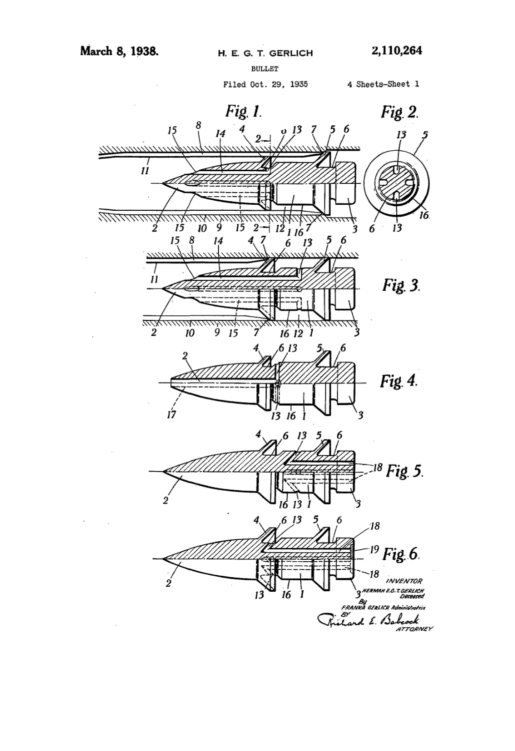
Figures 1 and 3 show the projectile diagram-
matically in a firearm barrel constructed in ac-
cordance with Patent No. 1,944,883 previously
referred to.
Figure 2 is a cross sectional elevation on line
2—2, Fig. 1, looking in the direction of the ar-
rows.
Figure 9 is a section on line 9—9, Fig. 8.
Figure 11 is an end elevation of the projectile
shown in Fig. 10, looking in the direction of the
arrow A.
Figure 14 is a cross section on line 14—14, Fig. 5
13, looking in the direction of the arrows.
The projectile shown in Figures 1 and 2 com-
prises a body I having a pointed nose 2 and a
cylindrical tail 3. The projectile is provided with
two axially spaced outwardly and backwardly ю
projecting annular flanges respectively marked
4 and 5 and behind each of these flanges is pro-
vided in the body of the projectile an annular
cannelure or groove 6, each serving just wholly
to receive the flange in front of it when the lat- 15
ter is depressed.
The projectile shown in Figure 1 is primarily
intended for firing from a barrel constructed
as described above and which is rifled and has at
the breech chamber end a portion of enlarged 20
diameter, both in regard to the groove bore and
the lands bore, such enlarged portion being
substantially cylindrical and extending along the
barrel over that part thereof in which the gas
pressures are at their highest values. 25
When the projectile is inserted in the barrel
in a position for firing the rear flange 5 abuts
the rear ends 1 of the rear ends of the lands 8
of the barrel 9 and the rear flange 5 is of such
a diameter that it is a slightly forcing fit in the 30
groove bore 10, whereas the front flange 4 is of
smaller diameter and is either exactly the same
diameter as the lands bore II or a very slight
forcing fit therein.
It will be seen that the space 12 between the 35
flanges 4 and 5 communicates, during the earlier
parts of the flight of the projectile with the
spaces in front of the projectile via the grooves
between the lands 8, into which the front flange
does not initially project. Hence, during the 40
earlier parts at least of the travel of the pro-
jectile, the gases which have collected in the
space' or chamber 12 can escape through the
spaces between the lands and over the edges of
the front flange 4. 45
- The gases collected in the chamber 12 at the
beginning of the projectile’s movement are air
which is initially present between the flanges of
the projectile and gases which leak past the rear
flange of the projectile at the very beginning of so
the firing phenomenon.
Further to facilitate the escape of gases from
the space 12 the projectile is, as shown in Figure
1, provided with a plurality of radial circum-
ferentially spaced passages 13 (in addition to 55
making the flange. 4 less in diameter than flange
5), each communicating with a forwardly extend-
ing passage 14 which opens at its front end 15 in
the nose 2, of the projectile. The passages 13
open into the cannelure 8, behind - the front эд
flange 4.
It will be seen that as the space or chamber
12 gradually decreases in volume and particu-
larly in radial width as the projectile moves down
the tapered part of the barrel 9 of the firearm 65
gases at first escape from the chamber 12 . both
by way of passages 13 and 14 and over the edge
of the front flange 4 and between the lands 8 of
the barrel. Subsequently when the flange 4 has
been cut into by the lands and the flange is bear- 70
ing on the base of the grooves of the bore the
escape of gas from chamber 12 takes place solely
through the passages 13 and 14.
By this means, such trapped gases as may be
left between Цш flanges 4 and 5 of the projectile 75
3,110,364
just prior to the latter leaving the barrel are
at such a pressure as’not to be dangerous or detri-
mental to the performance of the projectile.
Referring to Figure 3 of the drawings, it will
5 be seen that the projectile there illustrated is
in most respects similar to that shown in Figures
1 and 2 and for similar parts similar references
are employed. However, in this projectile the
forward flange 4 is of the same diameter as the
10 rear flange 5 and when the projectile is inserted
into the barrel it is the forward flange that ini-
tially bears against the end 1 of the lands 8.
Also in this projectile instead of the radial pas-
sages 13 opening into the front cannelures 6
15 they open into the space 12 between the flanges
4 and 6 in the part of the cylindrical interme-
diate body portion 16 of the projectile. Thus
the passages 13 are open to the very last and the
flow of gases to these passages is not in any
20 way restricted by the down-folding of the front
flange 4 of the projectile.
The projectile shown in Figure 4 differs from
the one shown in Fig. 1 mainly in that the pas-
sages 13 communicate with a common central
25 axial bore 21 with which the projectile is pro-
vided, and which is closed at its rear end and open
at the nose 2 of the projectile.
Also the passages 13 open at the front end of
the cylindrical portion 16 of the body instead
30 of in the cannelure 6.
In Figure 5 is shown a projectile which is a
modification of the projectile illustrated in Fig-
ure 3 and the projectile has a series of radial
passages 13 obliquely disposed with respect to the
35 axis of the projectile and each of which com-
municates at its inner end with a longitudinal
passage 18 extending from the passage 13 to the
rear of the projectile. The passages 13 open at
the cylindrical part 16 of the projectile as shown.
40 The flanges 4 and 5 of the projectile shown in
Figure 5 are of equal diameter.
Figure 6 shows a projectile very similar to that
shown in Fig. 5 but in this case the oblique pas-
sages 1'3 open into the front'cannelure 6 of the
45 projectile insead of in the cylindrical part 16
thereof. Moreover, the rear ends of the pas-
sages 18 are closed by a detachable valve plate
19 sunken into the tail 3 of the projectile and
which valve is adapted to be blown open when
50 the gas pressure between the flanges 4 and 5
exceeds the gas pressure behind the projectile.
Figure 7 shows a projectile somewhat similar
to that shown in Figure 4 but in which the bore
17 is replaced by a rearwardly extending bore 20
55 which opens at the rear of the projectile instead
of at the front. This figure also illustrates how
the passages 13 may be arranged in different
cross sections of the projectile.
In order that the pressure acting on the rear
GO end of the projectile in the moment of firing shall
not be reduced by escaping of the gases from the
space behind the projectile through the passages
28 and 13 and past the flange 4, (which is less in
diameter than the rear flange 5 and so does not
G5 fit initially closely to the bore of the barrel) to
the space in front of the projectile, the passage
26 is closed at the rear by means of a valve plate
19 (similar to that described with reference to
Figure 6) opening outwardly. This plate will re-
70 main in position as long as the propelling pres-
sure on the rear-end of the projectile is greater
than the pressure of the trapped gases. When,
on the other hand, the latter pressure -becomes
the greater, the valve plate is pressed off its seat,
76 and the space between the flanges thereafter
3
communicates directly with the space behind the
projectile.
Figures 8 and 9 show respectively how the pas-
sages 13 may be arranged obliquely to the axis
of the projectile and how a projectile having a _
rearwardly extending passage 20 need not nec-
essarily have a valve 19 if the front flange 4 is
not less in diameter than the rear flange because
in the latter the gases will not be able to escape
past the front flange to any appreciable extent 10
because after the first moment of firing the
front flange fits closely in the bore. Figure 9
also shows how the passages 13 may be more or
less tangential to the passage 20, and these pas-
sages 13 in suqh a case would be designed to dis-
charge the gases in the opposite rotational di-
rection to that in which the projectile turns when
fired.
Figures 10 and 11 show how, if desired, either
in a projectile having front and rear flanges of 20
equal diameters; means .may be provided In the
front flange for enabling gases collecting in the
space 12 to escape, such means comprising two
or more passages 21 formed in the front flange 4
so as to extend from the front face of the latter 25
to the cannelure 6 at the rear of the flange. In
addition, any of the other devices herein de-
scribed, for reducing the gas pressure between
the flanges for example the radial passages 13
and forwardly extending passages 14, may be 30
employed in this construction of projectile in
addition to the passages 21 in the front flange 4.
Figure 12 shows a modification of the projec-
tile Illustrated in Figures 10 and 11 in which, in
this case, the front flange 4 is of the same diam- 35
eter as the rear flange 5 instead of being of less
diameter than the latter as in the construction
illustrated in Figure 10 and the passages 13 and
22 are omitted.
Figures 13 and 14 show a modification of the 40
projectile shown in Figure 1, in which the pas-
sages 13 communicate with a peripheral groove
24 provided at the base of the cannelure 6 be-
hind the front flange. In this way, the pressure
in all of the passages 13 is equalized by reason 45
of these passages still being in communication
with one. another when the front flange 4 is de-
pressed into its cannelure.
. Figure 15 shows a projectile very similar to
that illustrated in Figures 13 and 14 but in this 50
case the annular groove 24 is provided in the
cylindrical body part 16 of the projectile instead
of at the base of the front cannelure 6.
With a projectile such as shown in Figure 15
the passages 13 are all in communication with 55
one another (and the pressures in all these pas-
sages are therefore equalized) even when the
flanges of the projectile have been depressed and
when the cylindrical part-16 of the projectile
lies in contact or substantially in contact with co
the bore of the barrel.
Another method of reducing or obviating the
detrimental effects created by obtaining high
gas pressure in the space between a pair of pro-
jectile flanges is shown in Figure 16 and com- 65
prises in providing a projectile (having the front
flange 4 less in diameter than the rear flange 5
as in the projectile shown in Figure 1) with an
annular cavity or 'recess 26 in the cylindrical
part 16 thereof, which recess forms an annular 70
enlargement of the space in which the trapped
gases, (1. e. those which do not escape over the
front flange and between the lands) are housed
and in which they are not very considerably com- .
pressed. To facilitate the passage of the trapped Ц
2,110,384
ferred but very good results can be obtained with
the other constructions illustrated in the draw-
ings and particularly those with either passages
in the front flange as shown for example in Fig-
ure 12 or rearwardly extending passages as shown 5
for example in Figure 7 or 8. Although projec-
tiles with passages extending forwardly through
the body also produce the desired result they are
not so desirable in practice as the other pro-
.. jectiles illustrated and referred to because of 10
eddy currents that the open passage ends in the
front of the projectile are liable to create.
It will be understood that where the forward
flange or flanges is or are of smaller diameter
than the rear flange or flanges, the forward 15
flange or flanges gradually cut into the lands in
a rifled barrel as the projectile moves forwardly
through the barrel. The rate at which the for-
ward flanges are cut into by the lands depends,
of course, on the conicity or rate of taper of the 20
barrel.
The rear flange of the projectile may in some
cases be made stronger than the forward flange
of the projectile, and this strengthening of the
rear flange may be employed whether the forward 25
flange is smaller than the rear flange or not.
in the cases of projectiles having one or more
passages therethrough the shapes of the openings
to the passages provided in the projectiles, espe-
cially the passages opening into the flank of the 30
point of the projectile or into any part of the
projectile in front of the foremost flange, may be
given any desired or suitable cross sectional shape
and may also be covered by graphite, wax, cere-
sine, etc., which will be driven out by the expelled 35
gases.
The cross sectional area of the respective pas-
sages and the number of these passages and/or
the volume or volumes of said annular or equiva-
lent recess or groove or recesses or grooves should 43
be regulated in relation to the volume and the
pressure of the gases to be disposed of, as well as
in accordance with the time-factor, i. e. the time
within which the expulsion of the gases has to
be effected, and also in accordance with the vary- 45
ing conditions, and the respective resistance
which is offered under the varying conditions to
this expulsion or blowing out of the gases. It
will be appreciated that the resistance offered is
different in the case of expulsion in a forward 50
direction, to the resistance in the case of ex-
pulsion to the rear of the projectile.
It will be appreciated that this invention by
providing for the escape of gases which otherwise
would be trapped or for reducing the pressure of 55
such gases, decreases the resistance of the pro-
jectile flanges to depression, eliminates or de-
creases the possibility of the flanges being par-
tially or wholly blown up on the projectile leav-
ing the firearm barrel, and generally materially 60
contributes to an improved performance on the
part of the projectiles.
What is claimed is:-—
1. A projectile for firearms comprising a body,
axially spaced depressible peripheral flanges on 65
said body and projecting outwardly and rear-
wardly therefrom, a cannelure behind each of
said flanges adapted to receive such parts of the
latter as are pressed thereinto as the projectile
p isses through the barrel of the firearm, and 70
means adapted to reduce the pressure of gases
collecting between the flanges of the projectile
during the period that the latter is In the barrel.
2. A projectile for firearms comprising a body,
axially spaced depressible peripheral flanges on 75
4
gases behind the foremost flange 4 to- the recess
26, the diameter of the projectile may, at 27, be
rather less than the nominal calibre of the cylin-
drical part 16. It will be appreciated that were
5 the groove or cavity 26 not provided and were
no other means provided for the escape of gas
from between the flanges, gases trapped between
the flanges would attain a very high and danger-
ous pressure as the projectile passes down the
10 barrel because the space in which they are housed
would become extremely small and at the most
would only be a radially very narrow annular
space. On the other hand, where the groove or
cavity 26 or its equivalent is provided these
15 trapped gases are housed in a greater space than
that just referred to even at the moment before
the bullet leaves the barrel and therefore the
trapped gases are at a considerably less pressure
than would be the. case if the groove or cavity
20 were not provided and if no other means of
escape were provided.
Figure 17 illustrates a projectile somewhat
similar to that shown in Figure 16, but in this
case the front and rear flanges 4 and 5 are of
2i> equal diameter and all the gases trapped between
these flanges are retained, during the movement
of the projectile through the barrel, between the
flanges but the pressure of these trapped gases is
kept sufficiently low as not to be harmful to
30 the performance of the projectile. This is at-
tained by providing the groove 28 circumferen-
tially around the body I of the projectile between
the front and rear flanges 4 and 5 and by mak-
ing this groove 28 of dimensions suitable for the
35 purpose above indicated for any given calibre.
The groove 28 is preferably made shallow and
wide and without comers, as shown in the draw-
ings, so as to interfere to the minimum degree
with the performance of the'projectile after it
40 leaves the barrel.
A projectile constructed in accordance with
Figures 16 or 17 is simple and relatively inex-
pensive to manufacture and is very efficient in
action.
45 Figure 18 shows the projectile illustrated in
Figure 17 after it has been fired and from this
figure it will be seen that the flanges 4, and 5
when folded down fill the cannelures 6, 6.
Figure 19 shows a projectile in all respects
50 like that shown in Figure 17 with the exception
that an annular groove 31 of shallow V-shaped
cross section replaces the groove 28 of curved
cross section shown in Figure 17.
Figure 20 shows how the grooves 28 and 31
55 of Figures 17 and 19 respectively can be re-
placed by a groove 32 of shallow rectangular
cross section.
Figure 21 shows how the simple annular cir-
cumferential grooves 28, 31 and 32 can be re-
CO placed by a helical groove 35.
Figure 22 illustrates how grooves 28, 31, 32
and 35 can be replaced by a plurality of smaller
spaced grooves 36. The grooves 36 shown in this
figure by way of example are of rectangular cross
C5 section.
Obviously many other shapes and forms of
groove or recess can be employed for effecting a
reduction of the pressure of the trapped gases
to the required extent. .
70 In practice it is found that a projectile con-
structed in accordance with Figure 16 or Figure
17 gives excellent results and attains the object
in view; The construction shown in Figure 19 at-
tains the same result to . almost the same degree
75 and these three constructions are the ones pre-
2,110,284
said body and projecting outwardly and rear-
wardly therefrom, a cannelure behind each of
said flanges adapted to receive such parts of the
latter as are pressed thereinto as the projectile
5 passes through the barrel of the firearm, and
said body being cavltied, additionally to said
cannelures, in order to effect a reduction of the
pressure of gases collected between the flanges of
the projectile during the period that the latter
10 is in the barrel.
3. A projectile for firearms comprising a body
axially spaced depresslble peripheral flanges on
said body and projecting outwardly and rear-
wardly therefrom, a cannelure behind each of
15 said flanges adapted to receive such parts of the
latter as are pressed thereinto as the projectile
passes through the barrel of the firearm, and the
said body being recessed, additionally to and in-
dependently of said cannelures, at its periphery
20 between the flanges.
4. A projectile for firearms comprising a body,
axially spaced depresslble peripheral flanges on
said body and projecting outwardly and rear-
wardly therefrom, a cannelure behind each of
25 said flanges adapted to receive such parts of the
latter as are pressed thereinto as the projectile
passes through the barrel of the firearm, and
said body also having in its surface, and between
successive flanges, a recess extending around the
30 body.
5. A projectile for firearms comprising a body,
axially spaced depresslble peripheral flanges on
said body and projecting outwardly and rear-
wardly therefrom, a cannelure behind each of
35 said flanges adapted to receive such parts of the
latter as are pressed'thereinto as the projectile
passes through the barrel of the firearm, and
said body also having in its outer surface, and be-
tween successive flanges, an annular groove ex-
40 tending completely around the body.
6. A projectile for firearms comprising a body,
a pair of axially spaced depresslble peripheral
flanges on said body, such flanges being of the
same diameter as one another and each project-
45 ing outwardly and rearwardly from the body, a
cannelure behind each of said flanges adapted to
receive such parts of the latter as are pressed
thereinto as the projectile passes through the bar-
rel of the firearm, and the said body being re-
50 cessed, independently of said cannelures, at its
periphery between said flanges.
7. A projectile for firearms comprising a body,
a pair of axially spaced depresslble peripheral
' flanges on said body, such flanges being of the
55 same diameter as one another and each pro-
jecting outwardly and rearwardly from the body,
a cannelure behind each of said flanges adapted
to receive such parts of the latter as are pressed
thereinto as the projectile passes through the
60 barrel of the firearm, and the body having be-
tween the flanges a groove extending around the
body.
8. A projectile fpr firearms comprising a body,
a pair of axially spaced depresslble peripheral
65 flanges on said body, such flanges being of the
same diameter as one another and each project-
ing outwardly and rearwardly from the body, a
cannelure behind each of said flanges adapted
to receive subh parts of the latter as are pressed
70 thereinto as the projectile passes through the
barrel of the flrparm, and the body having between
the flanges a continuous annular recess of. curved
cross section. ,
9. A projectile for firearms comprising a body,
75 a pair of axially spaced depresslble peripheral
5
flanges on said body, such flanges being of the
same diameter as one another and each pro-
jecting outwardly and rearwardly from the body,
a cannelure behind each of said flanges adapted
to receive such parts of the latter as are pressed 5
thereinto as the projectile passes through the
barrel of the firearm, the body having between
the flanges a continuous annular recess which is
wide in relation to its depth and is of curved cross
section. 10
10. A projectile for firearms comprising a body,
a pair of axially spaced peripheral outwardly and
rearwardly extending flanges on said body, a
cannelure behind each of said flanges adapted to
receive such flanges when pressed down as the 15
projectile passes through the barrel of the fire-
arm, the forward flange of the pair being of
smaller diameter than the other flange, and the
said body being recessed, independently of said
cannelures, at its periphery between said flanges. 20
11. A projectile for firearms comprising a body,
a pair of axially spaced peripheral outwardly and
rearwardly extending flanges on said body, the
forward flange of the pair being of smaller diam-
eter than the other flange, and the body hav- 25
ing between the flanges a groove extending around
the body.
12. A projectile for firearms comprising a body,
a pair of axially spaced peripheral outwardly and
rearwardly extending flanges on said body, the 30
forward flange of the pair being of smaller diam-
eter than the other flange, the body having be-
tween the flanges a continuous annular recess
of curved cross section.
13. A projectile for firearms comprising a body, 35
axially spaced depresslble peripheral flanges on
said body and projecting, outwardly and rear-
wardly therefrom, a cannelure behind each of
said flanges adapted to receive such parts of the
latter as are pressed thereinto as the projectile 40
passes through the barrel of the firearm, and said
body'having passage means therethrough, such
passage means communicating with the exterior
of the body at an end thereof and beyond said
flanges and also communicating with the space or 45
spaces between successive flanges.
14. A projectile for firearms comprising a body,
axially spaced depresslble peripheral flanges of
equal diameter on said body and projecting out-
wardly and rearwardly therefrom, a cannelure 50
behind each of said flanges adapted to receive
such parts of the latter as are pressed thereinto
as the projectile passes through the barrel of the
firearm, and said body having passage means
therethrough, such passage means communicat- 55
ing at one end with the exterior of the projectile
at the rear of the rear flange thereof and at the
other end communicating with the space or spaces
between successive flanges.
15. A projectile for firearms and comprising a 60
body having axially spaced circumferential
flanges adapted to be depressed around the said
body during its passage through the barrel of.
the firearm, said body also having behind each
of said flanges a cannelure to receive the flange, eg/
and in addition having inwardly extending pas-
sages transverse to the axis of the projectile and
communicating with the space between a pair of
successive flanges and also communicating with
longitudinal passage means provided in the said 70
body, and said longitudinal passage means being
adapted to discharge behind the rear flange of
the projectile, and an openable valve adapted to
close temporarily the rear end of said passage
means. .75
6
16. A projectile for firearms comprising a body,
axially spaced depressible peripheral flanges on
said body and projecting outwardly and back-
wardly therefrom, a cannelure behind each of said
flanges adapted to receive the adjacent flange as
it is pressed down as the projectile passes through
the barrel of the firearm, and the projectile hav-
ing passage means formed through a part there-
S, 110,864
of and such passage means communicating with
the space between a pair of said axially spaced
flanges and also communicating with the space
beyond these flanges.
FRANKA GERUCH, 6
Administratrix of the Estate of Hermann E. G. T.
Gerlich, Deceased.