/
Теги: weapons military affairs patent
Год: 1938
Текст
Dec. 12, 1939.
2,182,907
H. VOLLMER
AUTOMATIC FIREARM
Filed May 31, 1938
Inventor.
Heinrich Vollmer.
Patented Dec. 12, 1939
2,182,907
UNITED STATES PATENT OFFICE
2,182,907
AUTOMATIC FIBEABM
Heinrich Vollmer, Biberach-Biss, Germany, as-
signor to Gustav Genschow & Co. Aktlengesell-
schaft, Berlin, Germany, a company of Ger-
ТИЯ.'Пу
Application May 81, 1938, Serial No. 211,049
In Germany May 31,1937
2 Ciaims. (CL 42—3)
A known method of regulating the speed of
discharge of automatic firearms consists in
providing the weapon with a pneumatic brake
which can he put into operation so as to retard
5 the movement of some reciprocating part of
the firearm operative in connection with the dis-
charge, so that with the brake mechanism in
operation the rate of discharge is lower than
when that mechanism is put out of action.
1® According to my invention the brake mecha-
nism, which includes a plunger operating in a
pneumatic brake cylinder, is associated with a
pawl which is connected to the plunger and is
adapted, when free to act, to engage the re-
1S ciprocating part of the firearm mechanism so
that the plunger retards the movement preced-
ing the discharge of a shot, the pawl being,
however, automatically disengaged from the re-
ciprocating part when the required retardation
20 has been effected.
For rendering the brake mechanism inopera-
tive, so that the rate of discharge is normal,
the pawl may be put out of operation by means
of a manually controlled catch which prevents
25 it from engaging the reciprocating member re-
ferred to.
The brake mechanism may be a detachable
unit which can be fixed to the weapon by a sim-
ple Operation, with the pawl in position to en-
80 gage the reciprocating member.
An embodiment of the invention is shown by
way of example in the accompanying drawing, in
which—
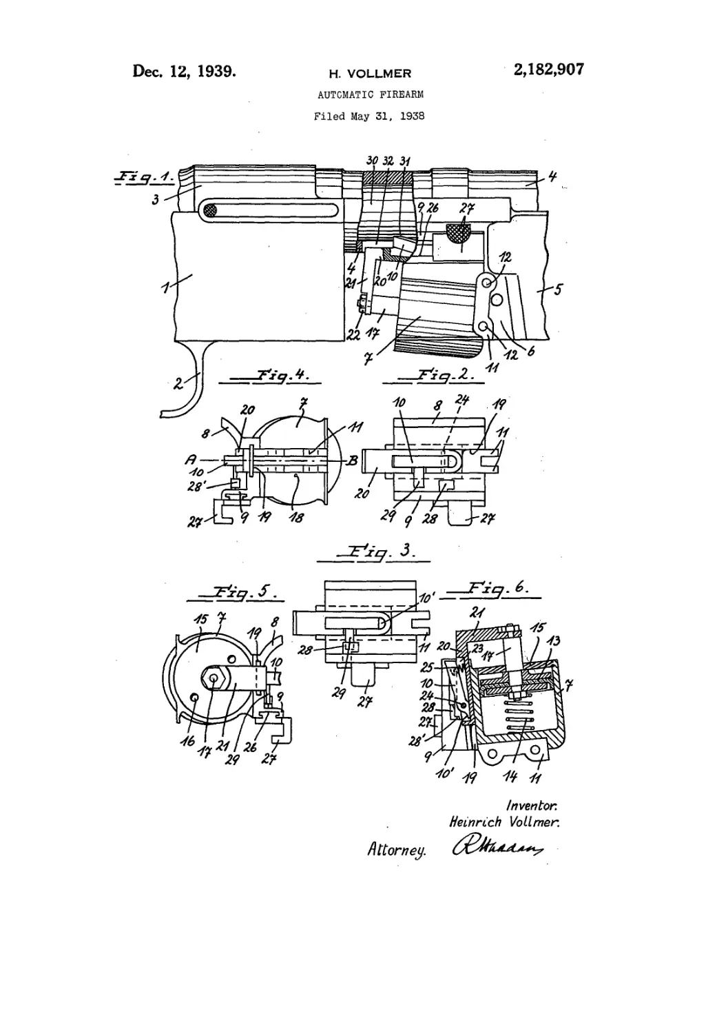
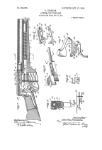
Fig. 1 is a side view, with a portion of the
85 stock removed.
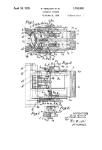
Fig. 2 being a plan view of the brake mecha-
nism, in the operative pPTltion, and
Fig. 3 a plan view of the same in the inoper-
ative position.
40 Mgs. 4 and 5 are end views of the mechanism,
and
Mg. 6 is a section on the line A—В of Fig. 4.
Fig. 1 shows part of the stock t and trigger
guard 2, and the clasp 3 holding the rear end
45 of the barrel tube 8 or chamber. The cartridge
feed casing 5 has at the rear a narrow lug 8.
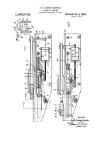
Between the stock I and the cartridge feed
casing 5 is a brake cylinder 7, which has two
Cheeks 8, 9 fitting against the under part of the
50 barrel tube 8. This part of the barrel has a
recess' 82 for entrance of one arm of a pawl
18 adapted to coact with a reciprocating, part of
the firearm. This may be the chamber 30, but
, where the barrel reciprocates it may be the bar-
65 r el or a tube fixed thereto. In the embodiment
illustrated the chamber 30 sliding in the tube <3
has at the bottom a recess or an abutment
for engagement with the pawl.
The cylinder 7 has at the rear two lugs И,
between which the lug 6 of the casing S engages, g
The lugs have holes enabling the cylinder to be
fixed to the firearm by means of bolts 12, no
other fastening being required.
The axis of the cylinder 1 is slightly inclined
to that of the tube fl, and the cylinder has there- 2®
in a plunger S3 urged rearwards by a coiled
spring I fl. The cylinder is closed at the rear by
a head S3, which is screwed into it and has vent
holes S@ and also a central hole for the plung-
er rod J 7. The cylinder head at the other end SB
has a small vent hole 08» the effective size of
which may be regulatable.
Between the cheeks 8 and 9 the wall of the
cylinder has an external guide channel 19 for
a slide 20, which has an arm 2i fixed by a nut gg
22 to the plunger rod. The slide has a recess
in which the pawl 10 is mounted on a pivot
28, and a spring 2S acts on the pawl so that the
tip of the pawl is urged out of the recess, and
the tail iO1 of the pawl is pressed against the
bottom of the recess (Mg. 6).
When recoil causes the chamber to slide to the
rear the pawl is first depressed and the recess or
abutment at the under part thereof then engages
the pawl, so that when the chamber moves for- 33
wards again the slide 20 and plunger 13 move
with it, the movement of the chamber being
braked by the plunger. Owing to the inclined
position of the cylinder the pawl recedes from
the chamber during this movement, and is 35
thereby at a certain point automatically disen-
gaged therefrom, allowing the chamber to con-
tinue its movement, without brake action, for
completing Its part of the action which pro-
duces discharge. 49
The cheek 9 has a slotted guideway for a slide
having a handle 27 on the outside of the cheek
and a nose 20 on the inside. The pawl i@ has a
pin 29 projecting laterally therefrom into the
path of the nose 28, so that when the handle 45
Is pulled to the rear, into the position shown in
Fig. 3 the nose engages over the pin and de-
presses the pawl, so that the pawl cannot en-
gage the chamber. A projection 281 on the nose
limits the extent to which the slide can be pulled 50
back. With the handle in the position shown in
Fig. 2 the pawl is thrust out of the recess 23
by the spring 25, as shown In Fig. в.
What I claim as my Invention and desire to
secure by Letters Patent of the United States is: 55
2,182,907
2
1. An automatic firearm having in combina-
tion'firing mechanism including a member mak-
ing a reciprocating movement operative for each
discharge, a pneumatic brake comprising a cyl-
5 inder and plunger therein, and a pawl connected
to. said plunger, adapted temporarily to engage
said reciprocating member during the movement
of said reciprocating member preceding each dis-
charge, so that brake action is applied to said
10 movement by said plunger, the axis of said
cylinder being inclined to the path of said re-
ciprocating member so that said pawl recedes
from said member while moving in engagement
therewith, and is thereby moved out of engage-
16 ment.
2. An automatic firearm having in combina-
tion firing mechanism Including a member mak-
ing a reciprocating movement operative for each
discharge, a pneumatic brake comprising a cyl-
inder and a plunger therein, said plunger having
a rod projecting from said cylinder, a slide slid- б
able on said cylinder, parallel with the axis
thereof, means connecting said slide to said
plunger rod, for reciprocating said slide, and a
pawl mounted on said slide, adapted temporarily
to engage said reciprocating member of said 10
firing mechanism during the movement of said
reciprocating member preceding each discharge,
so that brake action is applied to said move-
ment by said plunger.
16
HEREftlCH VOLLMER.