/


Автор: Kilgard M.J. Fernando R.
Теги: programming information technology computer graphics computer games
ISBN: 0-321-19496-9
Год: 2003


Текст
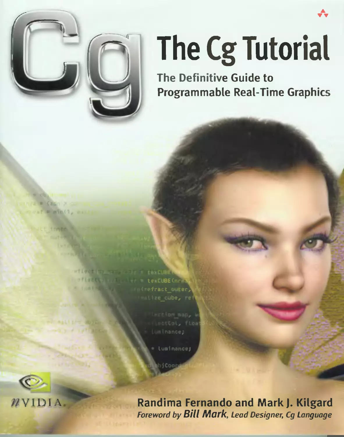
                    The Cg Tutorial
The Definitive Guide to
Programmable Real-Time Graphics
E
tt BE<nr
*fract_ t«r,
i, -
nance;
* lualnanct;
• jCoo
Randima Fernando and Mark J. Kilgard
Foreword by Bill Mark, Lead Designer, Cg Language

The Cg Tutorial
The Definitive Guide to
Programmable Real-Time
Graphics
Randima Fernando
Mark J. Kilgard
AAddison-Wesley
Boston • San Francisco • New York • Toronto • Montreal
London • Munich • Paris • Madrid
Capetown • Sydney • Tokyo • Singapore • Mexico City
I

Mail) of the designations used by manufacturers and sellers to distinguish their products are claimed as trademarks.
Where those designations appear in this book, and Addison-Wesley was aware of a trademark claim, the designations have
been printed with initial capital letters or in all capitals.
The authors and publisher have taken care in the preparation of this hook, but make no expressed or implied warranty of
any kind and assume no responsibility for errors or omissions. No liability is assumed for incidental or consequential
damages in connection with or arising out of the use of the information or programs contained herein.
The publisher offers discounts on this book when ordered in quantity tor bulk purchases and special sales, lor more
intormation, please contact:
U.S. Corporate and Covernment Sales
(800) 382-3419
corpsales^'pearson techgrotip.com
For sales outside of the U.S., please contact:
International Sales
(3H) S81-3T93
inicrnational(^pearsontechgroup.com
Visit Addison-Weslev on the Web: www.awprotessional.com
Library or Congress Control Number: 20021 \~^l)4
Copyright (0 2003 by NVIDIA Corporation
All rights reserved. No part of this publication mav he reproduced, stored in a retrieval system, or transmitted, in any
form, or b\ au\ means, electronic, mechanical, photocopying, recording, or oiherwise. without the prior consent of the
publisher, l'rinted in the United States or America. Published simultaneously in Canada.
For information on obtaining permission tor use of material from this work, please submit a written request to:
Pearson l.ducation. Inc.
Rights and (.ontracts Department
"S Arlington Street. Suite 300
Boston. MA 021 16
Fax: (6P) 848-~04_
1SBN 0-321-194%-')
Text printed on recycled paper
1 2 3 4 S 6 ~ 8 9 10—CRS—07()60'S0403
First printing, February 2003

For my parents and my sister
—P.R.I-
For Deirdre
—M.J.K.

Contents
Figures and Plates xix
Examples xxv
Tables xxvii
Equations xxix
Foreword xxxi
Preface xxxiii
Chapter 1
Introduction 1
1.1 What Is Cg? 1
1.1.1 A Language for Programming Graphics
Hardware 2
1.1.2 Cg's Data-Flow Model 2
1.1.3 GPU Specialization and CPU Generalization 3
1.1.4 The Performance Rationale for Cg 4
1.1.5 Coexistence with Conventional Languages 4
1.1.6 Other Aspects of Cg 5
1.1.7 The Limited Execution Environment of
Cg Programs 7
1.2 Vertices, Fragments, and the Graphics Pipeline 8
1.2.1 The Evolution of Computer Graphics
Hardware 8
1.2.2 Four Generations of Computer Graphics
Hardware 9
1.2.3 The Graphics Hardware Pipeline 13
1.2.4 The Programmable Graphics Pipeline 17
1.2.5 Cg Provides Vertex and Fragment
Programmability 21
~- »_»,-,-,-„..,., jx
Contents

1.3 Cg's Historical Development 21
1.3.1 Microsoft and NVIDIA's Collaboration to
Develop Cg and HLSL 22
1.3.2 Noninteractive Shading Languages 23
1.3.3 Programming Interfaces for 3D Graphics 26
1.4 The Cg Environment 26
1.4.1 Standard 3D Programming Interfaces: OpenGL
and Direct3D 26
1.4-2 The Cg Compiler and Runtime 28
I.4.3 The CgFX Toolkit and File Format 30
1.5 Exercises 34
1.6 Further Reading 34
Chapter 2
The Simplest Programs 37
2.1 A Simple Vertex Program 37
2.1.1 Output Structures 38
2.1.2 Identifiers 39
2.1.3 Structure Members 40
2.1.4 Vectors 40
2.1.5 Matrices 42
2.1.6 Semantics 42
2.1.7 Functions 43
2.1.8 Input and Output Semantics Are Different 44
2.1.9 The Function Body 45
2.2 Compiling Your Example 47
2.2.1 Vertex Program Profiles 47
2.2.2 Classes of Cg Compilation Errors 48
2.2.3 Profile-Dependent Errors 49
2.2.4 The Norm: Multiple Entry Functions 50
2.2.5 Downloading and Configuring Vertex and
Fragment Programs 51
2.3 A Simple Fragment Program 53
2.3.I Fragment Program Profiles 54
2.4 Rendering with Your Vertex and Fragment Program
Examples 56
2.4.1 Rendering a Triangle with OpenGL 57
Contents

2.4.2 Rendering a Triangle with Direct3D 57
2.4.3 Getting the Same Results 58
2.5 Exercises 60
2.6 Further Reading 60
Chapter 3
Parameters, Textures, and Expressions 61
3-1 Parameters 6l
3-1-1 Uniform Parameters 6l
3-1.2 The const Type Qualifier 64
3-1-3 Varying Parameters 65
3.2 Texture Samplers 67
3.2.1 Sampler Objects 67
3.2.2 Sampling Textures 69
3.2.3 Sending Texture Coordinates While Sampling
a Texture 69
3.3 Math Expressions 70
3.3.1 Operators JO
3.3.2 Profile-Dependent Numeric Data Types 73
3.3.3 Standard Library Built-in Functions 75
3.3.4 2D Twisting 79
3.3.5 Double Vision 83
3.4 Exercises 87
3.5 Further Reading 88
Chapter 4
Transformations 89
4-1 Coordinate Systems 89
4.1.1 Object Space 91
4.1.2 Homogeneous Coordinates 91
4.1.3 World Space 92
4.1.4 The Modeling Transform 92
4.1.5 Eye Space 93
4.1.6 The View Transform 93
4.1.7 Clip Space 95
4.1.8 The Projection Transform 95
- .~«- —^«—».— xi
Contents

4.1.9 Normalized Device Coordinates 96
4.1.10 Window Coordinates 97
4.2 Applying the Theory 97
4.3 Exercises 98
4.4 Further Reading 98
Chapters
Lighting 101
5.1 Lighting and Lighting Models 101
5.2 Implementing the Basic Per-Vertex Lighting
Model 103
5.2.1 The Basic Lighting Model 103
5.2.2 A Vertex Program for Basic Per-Vertex
Lighting 110
5.2.3 The Fragment Program for Per-Vertex
Lighting 120
5.2.4 Per-Vertex Lighting Results 120
5.3 Per-Fragment Lighting 121
5.3.1 Implementing Per-Fragment Lighting 123
5.3.2 The Vertex Program for Per-Fragment
Lighting 123
5.3.3 The Fragment Program for Per-Fragment
Lighting 124
5.4 Creating a Lighting Function 126
5.4.1 Declaring a Function 126
5.4.2 A Lighting Function 128
5.4.3 Structures 128
5.4.4 Arrays 129
5.4.5 Flow Control 130
5.4.6 Computing the Diffuse and Specular
Lighting 132
5.5 Extending the Basic Model 132
5.5.1 Distance Attenuation 133
5.5.2 Adding a Spotlight Effect 134
5.5.3 Directional Lights 138
5.6 Exercises 140
5.7 Further Reading 141
xii . ,,.~—«—.. 11 ,-—w^..,,,,,.-...-
Contents

Chapter 6
Animation 143
6.1 Movement in Time 143
6.2 A Pulsating Object 144
6.2.1 The Vertex Program 144
6.2.2 Displacement Calculation 146
6.3 Particle Systems 149
6.3.I Initial Conditions 150
6.3-2 Vectorized Computations 150
6.3.3 The Particle System Parameters 151
6.3.4 The Vertex Program 152
6.3.5 Dressing Up Your Particle System 154
6.4 Key-Frame Interpolation 155
6.4.1 Key-Framing Background 156
6.4.2 Interpolation Approaches 158
6.4.3 Basic Key-Frame Interpolation 159
6.4.4 Key-Frame Interpolation with Lighting 161
6.5 Vertex Skinning 162
6.5.1 The Theory of Vertex Skinning 163
6.5.2 Vertex Skinning in a Vertex Program 165
6.6 Exercises 167
6.7 Further Reading 167
Chapter 7
Environment MappingTechniques 169
7.1 Environment Mapping 169
7.1.1 Cube Map Textures 170
7.1.2 Generating Cube Maps 171
7.1.3 The Environment Mapping Concept 171
7.1.4 Computing Reflection Vectors 172
7.1.5 Assumptions for Environment Mapping 174
7.2 Reflective Environment Mapping 175
7.2.1 Application-Specified Parameters 176
7.2.2 The Vertex Program 176
7.2.3 The Fragment Program 180
7.2.4 Control Maps l8l
7.2.5 Vertex Program vs. Fragment Program 182
Contents

7-3 Refractive Environment Mapping 182
7.3.1 The Physics of Refraction 183
7.3.2 The Vertex Program 186
7.3.3 The Fragment Program 188
7.4 The Fresnel Effect and Chromatic Dispersion 188
7.4.1 The Fresnel Effect 189
7.4.2 Chromatic Dispersion 190
7.4.3 Application-Specified Parameters 191
7.4.4 The Vertex Program 192
7.4.5 The Fragment Program 194
7.5 Exercises 196
7.6 Further Reading 196
Chapter 8
Bump Mapping 199
8.1 Bump Mapping a Brick Wall 199
8.1.1 The Brick Wall Normal Map 200
8.1.2 Storing Bump Maps As Normal Map Textures. . . 201
8.1.3 Simple Bump Mapping for a Brick Wall 204
8.1.4 Specular Bump Mapping 208
8.1.5 Bump Mapping Other Geometry 211
8.2 Bump Mapping a Brick Floor 213
8.2.1 The Vertex Program for Rendering a Brick Floor . . 215
8.3 Bump Mapping a Torus 2l8
8.3.1 The Mathematics of the Torus 219
8.3.2 The Bump-Mapped Torus Vertex Program 222
8.4 Bump Mapping Textured Polygonal Meshes 224
8.4.1 Examining a Single Triangle 224
8.4.2 Caveats 227
8.4.3 Generalizing to a Polygonal Mesh 228
8.5 Combining Bump Mapping with Other Effects 229
8.5.1 Decal Maps 229
8.5.2 Gloss Maps 229
8.5.3 Geometric Self-Shadowing 230
8.6 Exercises 231
8.7 Further Reading 232
Xiv »- ■■ " ■"■"--
Contents

Chapter 9
Advanced Topics 233
9-1 Fog 233
9.1.1 Uniform Fog 234
9.1.2 The Attributes of Fog 235
9.1.3 The Mathematics of Fog 236
9.1.4 Intuiting the Equations 238
9.1.5 Creating Uniform Fog with Cg 239
9.2 Nonphotorealistic Rendering 241
9.2.I Toon Shading 242
9-2.2 Implementing Toon Shading 243
9.2.3 Putting It All Together 246
9.2.4 Problems with This Technique 246
9.3 Projective Texturing 248
9.3.I How Projective Texturing Works 249
9-3-2 Implementing Projective Texturing 251
9.3.3 The Code for Projective Texturing 253
9.4 Shadow Mapping 255
9.5 Compositing 258
9.5.I Mapping Input to Output Pixels 259
9-5-2 Basic Compositing Operations 259
9-6 Exercises 263
9.7 Further Reading 264
Chapter 10
Profiles and Performance 267
10.1 Profile Descriptions 267
10.1.1 The Vertex Shader Profile for DirectX 8 267
10.1.2 The Basic NVIDIA Vertex Program Profile for
OpenGL 268
10.1.3 The ARB Vertex Program Profile for
OpenGL 269
10.1.4 The Vertex Shader Profiles for DirectX 9 269
10.1.5 The Advanced NVIDIA Vertex Program
Profile for OpenGL 269
10.1.6 The Pixel Shader Profiles for DirectX 8 270
—— _——,,- . xv
Contents

10.1.7 The Basic NVIDIA Fragment Program Profile
for OpenGL 271
10.1.8 The DirectX 9 Pixel Shader Profiles 271
10.1.9 The ARB Fragment Program Profile for
OpenGL 272
10.1.10 The Advanced NVIDIA Fragment Program
Profile for OpenGL 272
10.2 Performance 273
10.2.1 Use the Cg Standard Library 273
10.2.2 Take Advantage of Uniform Parameters 274
10.2.3 Using Vertex Programs vs. Fragment
Programs 274
10.2.4 Data Types and Their Impact on
Performance 275
10.2.5 Take Advantage of Vectorization 275
10.2.6 Use Textures to Encode Functions 276
10.2.7 Use Swizzling and Negation Freely 277
10.2.8 Shade Only the Pixels That You Must 277
10.2.9 Shorter Assembly Is Not Necessarily Faster 278
10.3 Exercises 278
10.4 Further Reading 279
Appendix A
Getting Started with Cg 281
A.l Getting This Book's Accompanying Software 281
A.2 Getting the Cg Toolkit 281
Appendix B
The Cg Runtime 283
B.l What Is the Cg Runtime? 283
B.2 Why Use the Cg Runtime? 283
B.2.1 Future-Proofing 283
B.2.2 No Dependency Issues 284
B.2.3 Input Parameter Management 284
B.3 How Does the Cg Runtime Work? 284
B.3.1 Header Files 286
B.3.2 Creating a Context 286
xvi ~~- ■■
Contents

B.30 Compiling a Program 286
B.3.4 Loading a Program 287
B.3.5 Modifying the Program Parameters 288
B.3.6 Executing a Program 288
B.3.7 Releasing Resources 289
B.3.8 Handling Errors 290
B.4 More Details 290
Appendix C
The CgFX File Format 291
C.l What Is CgFX? 291
C.2 Format Overview 291
C.2.1 Techniques 292
C.2.2 Passes 293
C.2.3 Render States 293
C.2.4 Variables and Semantics 294
C.2.5 Annotations 295
C.2.6 A Sample CgFX File 295
C.3 Cg Plug-Ins Supporting the CgFX Format 297
C.4 Learning More About CgFX 298
Appendix D
Cg Keywords 299
D.l Cg Keyword List 299
Appendix E
Cg Standard Library Functions 301
E.l Mathematical Functions 302
E.2 Geometric Functions 3^6
E.3 Texture Map Functions 307
E.4 Derivative Functions 309
E.5 Debugging Function 310
Index 311
^_ »—,».,,>. xvi i
Contents

Figures and Plates
Figures
Figure 1-1. A Snippet of Assembly Language Code 6
Figure 1-2. Forces Driving Graphics Hardware Innovation 8
Figure 1-3. The Graphics Hardware Pipeline 13
Figure 1-4. Types of Geometric Primitives 14
Figure 1-5. Standard OpenGL and Direct3D Raster Operations ... 16
Figure 1-6. Visualizing the Graphics Pipeline YJ
Figure 1-7. The Programmable Graphics Pipeline YJ
Figure 1-8. Programmable Vertex Processor Flow Chart 18
Figure 1-9. Programmable Fragment Processor Flow Chart 20
Figure l-lO. Sources of Cg's Technology Heritage 21
Figure l-ll. Inspirations for Cg's Development 22
Figure 1-12. A Shade Tree Example, Based on Rob Cooks Original
SIGGRAPH Paper 24
Figure I-13. How Cg Fits into a Standard Cg Application 30
Figure 1-14. Digital Content Creation Applications That Use Cg
and CgFX 32
Figure 1-15. How CgFX Fits into a Standard Application 33
Figure 2-1. The Flow of Semantic Inputs and Outputs for
C2Elv_green 45
Figure 2-2. Compiling and Loading a Cg Program into
the GPU 52
Figure 2-3. Locating Error Lines in an Integrated Development
Environment 56
Figure 2-4. A 2D Triangle for Rendering 57
—~~ in ^^,- „ xix
Figures and Plates

Figure 2-5. Rendering a Triangle with C2Elv_green and
C2E2f_passthrough 58
Figure 2-6. A 2D View of Clip Space 59
Figure 2-7. Primitives Rendered with C2Elv_green and
C2E2£_passthrough Require 2D Clipping 59
Figure 3-1. Rendering a Gradiated 2D Triangle with
C3E2v varying and C2E2f _passthrough .... 66
Figure 3-2. Querying a Texture 68
Figure 3-3. Rendering a Textured 2D Triangle with
C3E2v_varying and C3E3f_texture 70
Figure 3-4. C3E4v_twist Results with Different twisting
Parameter Settings 80
Figure 3-5. Improving the Fidelity of C3E4v_twist by
Increasing Tessellation 82
Figure 3-6. Creating a Double-Vision Effect with
C3E5v_twoTextures andC3E6f_twoTextures. . 84
Figure 4-1. Coordinate Systems and Transforms for Vertex
Processing 9°
Figure 4-2. The Effect of Modeling Transformations 93
Figure 4-3. The Effect of the Viewing Transformation 94
Figure 4-4. The Effect of the Projection Matrix 96
Figure 4-5. Optimizations for Transforming to Clip Space 97
Figure 5-1. Different Lighting Models 102
Figure 5-2. The Emissive Term 104
Figure 5-3. Rendering the Emissive Term 104
Figure 5-4. The Ambient Term 105
Figure 5-5. Rendering the Ambient Term 105
Figure 5-6. Diffuse Light Scattering 106
Figure 5-7- The Diffuse Term 106
Figure 5-8. Rendering the Diffuse Term 106
Figure 5-9. Calculating Diffuse Lighting 107
Figure 5-10. The Specular Term 108
Figure 5-11. Rendering the Specular Term 108
XX -~ ' ' '""~~
Figures and Plates

rigure 5-12. Examples of Different Shininess Exponents 108
Figure 5-13. Calculating the Specular Term 109
Figure 5-14. Putting the Terms Together 110
Figure 5-15. Per-Vertex Lighting Results 120
Figure 5-16. The Effects of Tessellation on Lighting 121
Figure 5-17. Comparing Per-Vertex and Per-Fragment Lighting ... 122
Figure 5-18. Specifying a Spotlight Cut-Off Angle 135
Figure 5-19. Vectors for Calculating the Spotlight Effect 135
Figure 5-20. Specifying Inner and Outer Cones for a Spotlight .... 136
Figure 5-21. The Effect of Adding Inner and Outer Spotlight
Cones 137
Figure 5-22. A Graph of the smoothstep Function 138
Figure 6-1. Making an Object Bulge 144
Figure 6-2. A Pulsating Alien 145
Figure 6-3. A Particle System 149
Figure 6-4. A Point Size Function 154
Figure 6-5. Converting Points to Point Sprites 155
Figure 6-6. A Particle System with Point Sprites 155
Figure 6-7. Key Frames for an Alien 157
Figure 6-8. An Example of Key-Frame Blending 157
Figure 6-9. Various Interpolation Functions 160
Figure 7-1. Texture Images for a Cube Map 170
Figure 7-2. Environment Mapping 172
Figure 7-3. Calculating the Reflected Ray 173
Figure 7-4. Reflective Environment Mapping 175
Figure 7-5. Refractive Environment Mapping 183
Figure 7-6. Snell's Law 184
Figure 7-7. Refraction into an Environment Map 185
Figure 7-8. Multiple Refractions vs. One Refraction 185
Figure 7-9. Understanding Chromatic Dispersion 190
Figure 7-10. The Fresnel Effect and Chromatic Dispersion 191
-«——».-■- xxi
Figures and Plates

Figure 8-1. A Height Field Image for a Brick Bump Map 203
Figure 8-2. A Bump-Mapped Brick Wall with Different Light
Positions 204
Figure 8-3. Using Cube Maps to Normalize Vectors 207
Figure 8-4- Consistent Texture-Space Bump Mapping vs.
Inconsistent Object-Space Bump Mapping 217
Figure 8-5. Per-Vertex Texture Space Bases 2l8
Figure 8-6. A Tessellated Torus 219
Figure 8-7- Procedural Generation of a Torus from a 2D Grid. . . . 222
Figure 8-8. Two Bump-Mapped Brick Tori Rendered with
C8E6v_torus and C8E4f_specSurf 224
Figure 8-9. The Same Triangle Exists in Object Space and Texture
Space 225
Figure 9-1. Adding Uniform Fog to a Scene 234
Figure 9-2. Fog Particles May Affect Light Traveling from Point A
to Point B 235
Figure 9-3. Toon Shading 242
Figure 9-4. A Continuous Function vs. a Step Function 244
Figure 9-5. Encoding a Step Function in a ID Texture 245
Figure 9-6. Projective Texturing 249
Figure 9-7. Transformations for a Conventional Camera vs.
Those for a Projector 250
Figure 9-8. Using Shadow Mapping to Add Shadows to
a Scene 256
Figure 9-9. The Shadow Mapping Depth Comparison 257
Figure B-l. The Parts of the Cg Runtime API 285
Plates
The 31 plates listed here can be found in the color insert bound into
the center of the book.
Plate 1. Cg Shaders in Maya 4.5 Using the Maya Cg Plug-in
Plate 2. Bead Shapes Rendered with Maya and Cg on the NVIDIA
Quadro FX
Plate 3. Discreet 3ds max 5 and the 3ds max Cg Plug-in
xxii ,,„«— ^
Figures and Plates

Plate 4. The 3ds max Cg Plug-in and Connection Editor
Plate 5. Softimage|XSI v.3.0 Integrating Cg
Plate 6. Creating a Double Vision Effect
Plate 7. Combining the Ambient, Diffuse, and Specular Lighting
Terms
Plate 8. Six Texture Images Combined to Form a Cube Map
Plate 9. Reflective Environment Mapping
Plate 10. Refractive Environment Mapping
Plate 11. The Fresnel Effect and Chromatic Dispersion
Plate 12. A Grayscale Height Field Converted to a Range-Compressed
Normal Map
Plate 13. Bump Mapping a Textured Polygonal Mesh
Plate 14. Nonphotorealistic Rendering
Plate 15. The Dawn Character, Driven by Shaders for the Skin's
Surface, Skeletal Skinning, and Shape Blending
Plate 16. NVIDIA Time Machine Demo
Plate 17. NVIDIA Dancing Ogre Demo
Plate 18. Yeti's Gun Metal Game, Using Cg for Advanced Visual
Effects
Plate 19. Iritor Online, Using Cg Shaders
Plate 20. Procedural Wood Shader
Plate 21. Depth of Field
Plate 22. Dynamic Reaction Diffusion Textures
Plate 23. Relief Texture Mapping
Plate 24. Bump Reflection Mapping
Plate 25. Detail Normal Maps
Plate 26. Water Interaction
Plate 27. A Procedural Terrain Demo
Plate 28. Realistic Fresnel Reflection Effects
Plate 29. The NVIDIA Cg Browser Interface
Plate 30. A Mechanical Model with a Gooch Cg Shader Applied
Plate 31. Using CgFX to Apply Multiple Shaders to a Ray Gun Model
Figures and Plates

Examples
Example 2-1. The C2Elv_green Vertex Program 38
Example 2-2. The C2E2f_passthrough Fragment Program 53
Example 3-1. The C3Elv_anyColor Vertex Program 62
Example 3-2. The C3E2v_varying Vertex Program 65
Example 3-3. The C3E3f_texture Fragment Program 67
Example 3-4. The C3E4v_twist Vertex Program 79
Example 3-5. The C3E5v_twoTextures Vertex Program 83
Example 3-6. The C3E6f_twoTextures Fragment Program .... 85
Example 3-7. The C3E7f _twoTextures Fragment Program .... 86
Example 4-1. The C4Elv_transf orm Vertex Program 97
Example 5-1. The C5Elv_basicLight Vertex Program Ill
Example 5-2. The C5E2v_f ragmentLighting Vertex
Program 124
Example 5-3. The C5E3f_basicLight Fragment Program 125
Example 5-4. The C5E4v_twoLights Vertex Program 131
Example 5-5. TheC5E5_computeLighting Internal Function . . 132
Example 5-6. The C5E6_attenuation Internal Function 133
Example 5-7. The C5E7_attenuateLighting Internal
Function 135
Example 5-8. The C5E8__spotlight Internal Function 136
Example 5-9. The C5E9_dualConeSpotlight Internal
Function 139
Example 5-10. The C5E10_spotAttenLighting Internal
Function 139
Example 6-1. The C6Elv_bulge Vertex Program 145
Examples

Example 6-2. The C6E2v_particle Vertex Program 152
Example 6-3. The C6E3v_keyFrame Vertex Program 159
Example 6-4. The C6E4v_litKeyFrame Vertex Program 161
Example 6-5. The C6E5v_skin4m Vertex Program 166
Example 7-1. The C7Elv_ref lection Vertex Program 177
Example 7-2. The C7E2f_ref lection Fragment Program .... 180
Example 7-3. The C7E3v_ref raction Vertex Program 187
Example 7-4. The C7E4f _ref raction Fragment Program .... 188
Example 7-5. The C7E5v_dispersion Vertex Program 193
Example 7-6. The C7E6f_dispersion Fragment Program 195
Example 8-1. The C8Elv_bumpWall Vertex Program 205
Example 8-2. The C8E2f_bumpSurf Fragment Program 206
Example 8-3. The C8E3v_specWall Vertex Program 208
Example 8-4. The C8E4f_specSur£ Fragment Program 209
Example 8-5. The C8E5v_bumpAny Vertex Program 2l6
Example 8-6. The C8E6v_torus Vertex Program 223
Example 9-1. The C9Elf _f og Fragment Program 240
Example 9-2. The C9E2v_fog Vertex Program 240
Example 9-3. The C9E3v_toonShading Vertex Program 247
Example 9-4. The C9E4£_toonShading Fragment Program . . . 248
Example 9-5. The C9E5v_projTex Vertex Program 254
Example 9-6. The C9E6f_projTex Fragment Program 254
Example 9-7. The c9E7v_screenAlign Vertex Program 260
Example 9-8. The C9E8f _tint Fragment Program 260
Example 9-9. The C9E9f_a_over_b Fragment Program 261
Example 9-10. The C9E10f_a_in_b Fragment Program 262
Example 9-11. The C9Ellf_a_out_b Fragment Program 262
Example 9-12. The C9E12f_a_dissolve_b Fragment
Program 262
Example C-l. A Sample CgFX File 295
xxvi -~— -~~* -
Examples

Tables
Table 1-1. Features and Performance Evolution of Selected
NVIDIA GPUs, by Generation 12
Table 2-1. Cg Vertex Profiles 47
Table 2-2. Cg Fragment Profiles 55
Table 3-1. Cg Sampler Types 68
Table 3-2. Precedence, Associativity, and Usage of Operators 72
Table 3-3. Data Types for Various Profiles 75
Table 3-4. Selected Cg Standard Library Functions 76
Table 5-1. Application-Specified Data for the Graphics Pipeline . . 112
Table 6-1. Variables in the Particle Equation 151
Table 7-1. Application-Specified Parameters for Per-Vertex
Environment Mapping 176
Table 7-2. Indices of Refraction 184
Table 7-3. The C7E5v_dispersion Program Parameters 192
Table E-l. Mathematical Functions 302
Table E-2. Geometric Functions 307
Table E-3. Texture Map Functions 308
Table E-4. Derivative Functions 310
Table E-5. Debugging Function 310
Tables
XXVII

Equations
Equation 3-1. 2D Rotation 81
Equation l\-\. Converting Between Nonhomogeneous and
Homogeneous Positions 91
Equation 6-1. Particle Trajectory 150
Equation 6-2. Linear Interpolation 158
Equation 7-1. Vector Reflection 173
Equation 7-2. Snell's Law 184
Equation 7-3. An Approximation of the Fresnel Equation 189
Equation 8-1. A Rotation Matrix Formed by Tangent, Binormal,
and Normal Column Vectors 215
Equation 8-2. Cross-Product Relationships Between Tangent,
Binormal, and Normal Vectors 215
Equation 8-3. Parametric Equations for a Torus 219
Equation 8-4. Partial Derivatives of the Parametric Torus 220
Equation 8-5. The Normal of a Surface Expressed in Terms of Its
Parametric Inverse Gradients 221
Equation 8-6. The Tangent, Binormal, and Normal on
a Surface 221
Equation 8-7. Plane Equation Coefficients for (x, s, t) Plane for
a Single-Textured Triangle 225
Equation 8-8. Object-Space Partial Derivatives for a Texture-Space
Triangle in Terms of the Texture Coordinates. . . . 226
Equation 9-1. Uniform Fog 238
Equation 9-2. The Sequence ofTransformations for Projective
Texturing 252
~». . I. —»„■., xxix
Equations

Foreword
Real-time computer graphics hardware is undergoing a major transition, from
supporting a few fixed algorithms to being fully programmable. At the same time, the
performance of graphics processors (GPUs) is increasing at a rapid rate—even greater than
that of CPUs—because GPUs can effectively exploit the enormous parallelism
available in graphics computations. These improvements in GPU flexibility and
performance are likely to continue in the future, and will allow developers to write increasingly
sophisticated and diverse programs that execute on the GPU.
Until recently, most GPU programs were written in assembly language, but history has
shown that developers make the most creative and effective use of programmable
hardware when they have the opportunity to program in a high-level language. Our goal in
designing Cg was to provide developers with the same flexibility and performance
available in assembly language, but with the expressiveness and ease-of-use of a high-
level language. The C language has demonstrated enormous success in achieving these
goals on the CPU, and so we chose C's syntax and philosophy as the starting point for
defining Cg. In particular, this choice gave us confidence that the Cg language would
be able to implement any GPU program, rather than restricting developers to a
predefined framework designed specifically for shading computations.
Cg also builds on ideas and lessons learned from earlier work in computer graphics.
My personal interest in programmable graphics hardware was inspired by the
PixelFlow project at the University of North Carolina and, in particular, by the
shading language compiler that Marc Olano and others built for PixelFlow. In many
respects, the most direct predecessor to Cg was the real-time programmable shading
system that Kekoa Proudfoot, Pat Hanrahan, I, and others built at Stanford for single-
chip GPUs. The knowledge that we acquired from building the Stanford system was
crucial to the design of Cg. Offline movie rendering has relied on programmable
shading for much longer. The RenderMan language designed by Pat Hanrahan at Pixar
served as a major source of inspiration for Cg, particularly in the choice of Cg's built-
in functions.
—~ «~ xxxi
Foreword

The desire to create one GPU programming language that would be widely supportec
for both the OpenGL and Direct3D APIs led us to collaborate with Microsoft on the
design of Cg. Microsoft's implementation of the language is called HLSL, and it is
shipped as part of DirectX 9. At Microsoft, Craig Peeper and Loren McQuade were
particularly influential in the design of the language. The examples in this book work
equally well with HLSL and Cg.
Designing and implementing Cg in less than a year was possible only because we had
a large and highly talented team of people working together. Two individuals made
particularly unique contributions. Steve Glanville's extensive compiler and language
expertise was crucial to the Cg design effort, and he implemented most of the front
end of the first version of the Cg compiler. Kurt Akeley's experience as a system
designer was invaluable throughout the project.
In this book, Randy and Mark have assembled a series of Cg tutorials that introduce
Cg while simultaneously describing many of the real-time shading techniques
supported by modern GPUs. By integrating these two sets of concepts within one
collection of tutorials, this book enables you to experience the fun of writing and
experimenting with your own GPU programs. Enjoy the journey!
Bill Mark
Cg Language Lead Designer
Assistant Professor
The University of Texas at Austin
xxxn
Foreword

Preface
Once upon a time, real-time computer graphics was all about vertices, triangles, and
pixels. In fact, it still is. However, the level at which a programmer controls the
processing and appearance of these graphics primitives has advanced considerably. Until a
few years ago, programmers had to rely on the CPU to process all the transformation
and rasterization algorithms needed to produce computer-generated images. Over
time, hardware engineers executed these algorithms via specialized, high-performance
3D graphics hardware. Rather than implement the algorithms directly, programmers
learned to access the hardware-provided graphics functionality through standard 3D
programming interfaces, such as OpenGL (developed by Silicon Graphics [SGI]) and
Direct3D (developed by Microsoft). At first, such costly 3D graphics hardware
appeared only in high-priced UNIX workstations and flight simulators. Now, through
the miracle of Moore's Law, the benefits of graphics hardware acceleration have been
bestowed on low-cost PCs and game consoles.
Although the performance gained by employing dedicated graphics hardware to
execute the brute-force tasks of transforming vertices, rasterizing triangles, and updating
pixels far exceeded the performance possible just with CPU programming, real-time
3D programmers gave up a considerable measure of control in exchange for this speed.
Developers were limited to using a fixed-function palette of graphics operations that
the hardware could handle. Sometimes a skilled and dedicated programmer could coax
the graphics programming interface and hardware to accomplish something beyond
the ordinary, but this was usually hard, time-consuming work.
While graphics hardware engineers were advancing the real-time performance of their
specialized pixel-pushing hardware, off-line computer graphics software packages such
as Pixar's PhotoRealistic RenderMan were changing the look of movies and television
with amazing computer-generated special effects. The pre-recorded nature of movies
and most television content makes these media well suited for offline rendering.
Computer-generated images for film and video are not rendered in real time but
instead carefully constructed frame by frame in hours, days, or weeks using standard
Preface
XXXII

general-purpose CPUs. The advantage of using general-purpose CPUs is that rather
than settle for hard-wired hardware algorithms, programmers and artists can use the
CPU to create any effect they might imagine. What these so-called offline rendering
systems lack in relative speed, they make up in rendering quality and realism.
The flexibility and generality of offline rendering systems are the key features that
have been missing from preceding generations of 3D graphics hardware. In other
words, what was lost was programmability.
Realizing this limitation, computer graphics architects have designed a new generatio
of graphics hardware that permits an unprecedented degree of programmability. Now
many of the programmable shading techniques that are employed so successfully in
offline rendering can enter the realm of real-time graphics.
Developers of offline rendering systems created a type of specialized computer
language known as a shading language to express the graphics operations required to mal
surfaces look the way artists intend. A shading language for programmable graphics
hardware provides the same sort of functionality but in the context of real-time grapl
ics hardware. Graphics programmers and artists benefit from such a high-level
programming language in much the same way that conventional programmers do from
C++ or Java. Using a high-level language for graphics hardware automates the process
of translating the programmer's intent into a form that the graphics hardware can
execute.
This book is about Cg, the premier language for programmable graphics hardware.
NVIDIA developed Cg in close collaboration with Microsoft. Cg is the most portabl
and productive way for you to unleash the power within programmable graphics hare
ware. This book is a tutorial to teach you how to write Cg programs.
Our Intended Audience
We tried to write this book in a way that makes it valuable to both novices and
advanced readers. If you're new to the world of programmable graphics, this bookshoul
give you a firm foundation on which to build. If you encounter a word or concept
that is foreign to you and not sufficiently explained, consult the "Further Reading"
section at the end of each chapter.
The main audience for this book is 3D game and application programmers, manager!
of such projects, real-time 3D artists, and computer graphics students—or anyone els
interested in learning about the state of the art in real-time rendering. You do nothav
xxxiv - ■" — ~~-~
Preface

to be an experienced programmer to learn Cg from this book, though you should be
relatively familiar with programming language concepts. If you are familiar with C or
one of its derivatives, such as C++ or Java, Cg will be very approachable. Cg programs
are relatively short, often less than a page, so even an artist or novice programmer can
get the gist of Cg from this tutorial and learn to write interesting Cg programs.
Computer graphics programming involves math. Understanding basic algebra and
trigonometry will help you appreciate several sections. You should also be familiar
with the math behind basic computer graphics vertex transformation and lighting
models. You do not need to know OpenGL or Direct3D, but familiarity with either
programming interface is very helpful. All of the Cg examples described work with
either OpenGL or Direct3D unless otherwise noted. Some examples that require
advanced Cg functionality may not work on older graphics processors.
The Book's Structure
Chapter 1 introduces Cg. Each chapter that follows is a short tutorial that presents
specific Cg concepts and techniques. The tutorials build upon each other, so we
recommend reading the chapters in order.
• Chapter 1 lays out the foundations of Cg and real-time programmable graphics
hardware.
• Chapter 2 presents the simplest Cg programs.
• Chapter 3 explains parameters, textures, and expressions.
• Chapter 4 shows how to transform vertices.
• Chapter 5 covers the implementation of lighting models with Cg.
• Chapter 6 describes how to animate and morph models with Cg vertex programs.
• Chapter 7 explains environment mapping with Cg.
• Chapter 8 shows how to implement bump mapping.
• Chapter 9 discusses a number of advanced topics: fog, cartoon shading, projected
spotlights, shadow mapping, and compositing.
• Chapter 10 explains the set of currently available Cg vertex and fragment profiles,
and provides advice for improving the performance of Cg programs.
This book gets you started but does not contain everything you will eventually want
to know about Cg. This tutorial complements other documentation (such as the Cg
Toolkit User's Manual: A Developers Guide to Programmable Graphics) included with
Preface
xxxv

I' M»J
a
the Cg Toolkit. Please consult the user's manual and other Cg documentation for
further information.
Formatting Conventions
Various elements in this book are specially formatted for easier reading. Code samples
are written in the Courier font on a light reverse highlight. Variables and keywords are
in bold Courier in the text, and key concepts are italicized.
In addition, we use icons to identify special topics, as shown here.
Advanced Topic. Provides extra insight for advanced readers but can be safely glossed over
without loss of continuity.
Caution. Indicates a subtlety or concept to be wary of when writing Cg code, to avoid errors.
CineFX. Describes algorithms or features that are available only on the NVIDIA CineFX
architecture, or on architectures with similar advanced capabilities.
Coding Tip. Gives guidelines about good coding practices.
Performance Tip. Points out ways to use Cgto achieve optimal GPU performance.
Trying the Examples
We've designed the accompanying software framework so that you can get straight to
work, even if you don't know anything about OpenGL, Direct3D, C, or C++. Our
goal is to isolate the Cg language and allow you to experiment freely with it. Of
course, as you move toward starting a real-world application with Cg, your project
will probably require some combination of OpenGL, Direct3D, C, and C++.
The accompanying software framework allows you to try out the various Cg examples
in the book without worrying about graphics APIs, C, or C++ code. The latest
versions of the applications are free to download via the book's companion Web site. The
software on the accompanying CD works only on the Windows platform, but version
xxxvi
Preface

for Linux and Macintosh systems are available online. Appendix A explains how to
download the latest versions of Cg and the accompanying tutorial application.
The tutorial application makes it easy for you to tweak the book's examples, to see
how changing a particular Cg example can immediately affect the rendered 3D result.
If you can, have a computer that supports Cg nearby to try out the examples. With
our software, you just write Cg programs without worrying about the particulars, such
as loading 3D models and textures. When you want to know all the gory details,
examine the source code, all of which is freely available for download, so you can see
how Cg interfaces with C++ and OpenGL or Direct3D. The Cg Toolkit also comes
with several simple examples that you can learn from.
The end of each chapter includes suggested exercises that you can work on to explore
Cg further.
Acknowledgments
We would like to thank our many colleagues at NVIDIA who contributed to Cg and
helped us with this book. Bill Mark, Steve Glanville, Mark Kilgard, and Kurt Akeley
worked to define the original Cg language in 2001 and 2002. David Kirk, Jensen Huang,
Dwight Diercks, Matt Papakipos, and Nick Triantos recognized the need for a high-level
language for graphics processors and provided the resources necessary to make Cg a
priority and a reality in just over a year's time. Geoff Berry, Michael Bunnell, Chris Dodd, Cass
Everitt, Wes Hunt, Craig Kolb, Jayant Kolhe, Rev Lebaredian, Nathan Paymer, Matt
Pharr, Doug Rogers, and Chris Wynn developed the Cg compiler, Standard Library, and
runtime technology. Sim Dietrich, Ashu Rege, and Sebastien Domine worked on the
original CgFX technology. Chris Seitz gave us a great deal of support in all aspects of the
project, helping out in ways that are too numerous to list, but without which this book
would not exist. John Spitzer provided the clear foresight, as well as the essential
resources, for Cg's development, and gave us the backing from his team to make this
book possible. Sanford Russell's contagious motivation helped to get this book started.
Cyril Zeller created the handy tutorial framework that accompanies this book and
contributed the material for Appendix B. Sim Dietrich shared his knowledge of CgFX in
Appendix C. Kevin Bjorke lent his insight by writing the compositing section of the
advanced chapter. Teresa Saffaie, Catherine Kilkenny, and Debra Valentine reviewed our
writing in an effort to make it clear. Caroline Lie, Spender Yuen, Dana Chan, Huey
Nguyen, and Steve Burke lent their creativity and imagination to design and beautify the
book's cover, figures, and artwork. NVIDIA's demo team (Curtis Beeson, Dan Burke, Joe
Demers, Eugene d'Eon, Steve Giesler, Simon Green, Daniel Hornick, Gary King, Dean
Preface
XXXVII

Lupini, Hubert Nguyen, Bonnie O'Clair, Alexei Sakhartchouk, and Thant Tessman,
under the direction of Mark Daly) contributed several of the color plates.
We are also grateful to Jason Allen, Geoff Berry, Michael Bunnell, Sim Dietrich,
Chris Dodd, Gihani Fernando, Simon Green, Larry Gritz, Eric Haines, Wes Hunt,
Gary King, Craig Kolb, Jayant Kolhe, Eric Lengyel, Cameron Lewis, Gilliard Lopes,
Viet-Tam Luu, Kurt Miller, Tomas Akenine-Moller, Russell Pflughaupt, Matt Pharr,
John Spitzer, Nick Triantos, Eric Werness, Matthias Wloka, Cyril Zeller, and our
anonymous reviewers for their invaluable comments in the review process. Each set
of comments helped to make the book clearer and more accurate.
Microsoft and NVIDIA collaborated to agree on the syntax and semantics of a
standard hardware shading language. The DirectX 9 High-Level Shading Language and
Cg are the same language because of this effort. We particularly appreciate the work of
Craig Peeper, Loren McQuade, Dave Aronson, Anuj Gosalia, Chas Boyd, and Mike
Toelle.
We acknowledge the pioneering research on hardware shading languages conducted at
the University of North Carolina and Stanford University. Obviously, Pixar's Render-
Man Shading Language provided a great deal of inspiration for NVIDIA's efforts to
develop a real-time language for mass-market graphics hardware. Ken Perlin's work on
the Pixel Stream Editor, not to mention his early Cg compiler testing, deserves
recognition as well.
On the hardware front, we acknowledge the fundamental work of Erik Lindholm and]
Henry Moreton, who architected the user-programmable vertex processing engine
inside NVIDIA's GeForce3 GPU. OpenGL's and Direct3D's support for general
programmable vertex processing, and hence Cg's support for the same, are indebted to
this work.
The hard work and dedication of NVIDIA's architecture, hardware, and software
engineers to deliver ever faster and ever more programmable graphics processors was and still
is the overriding justification for Cg. We acknowledge the efforts of all the engineers at
NVIDIA who strive to make real-time programmable shading a reality for everyone.
We thank the Addison-Wesley production team for making this book a reality. We
particularly thank Chris Keane for manhandling our manuscript into shape.
Finally, we thank the thousands of Cg developers for their feedback, bug reports,
patience, and enthusiasm.
Preface

The Cg Tutorial
i

Chapter 1
Introduction
This chapter has the following four sections:
• "What Is Cg?" introduces the Cg programming language.
• "Vertices, Fragments, and the Graphics Pipeline" describes the data flow of
modern graphics hardware and explains how Cg fits into this data flow.
• "Cg's Historical Development" provides some background on how Cg was
developed.
• "The Cg Environment" explains how applications go about using Cg programs
through the Cg runtime and existing 3D application programming interfaces
(APIs).
What Is Cg?
This book teaches you how to use a programming language called Cg. The Cg
language makes it possible for you to control the shape, appearance, and motion of
objects drawn using programmable graphics hardware. It marries programmatic control
of these attributes with the incredible speed and capabilities of today's graphics
processors. Never before have computer graphics practitioners, whether artists or
programmers, had so much control over the real-time images they generate.
Cg provides developers with a complete programming platform that is easy to use and
enables the fast creation of special effects and real-time cinematic-quality experiences
on multiple platforms. By providing a new level of abstraction, Cg removes the need
for developers to program directly to the graphics hardware assembly language, and
1.1 What Is Cg?
1

thereby more easily target OpenGL, DirectX, Windows, Linux, Macintosh OS X, and
console platforms such as the Xbox. Cg was developed in close collaboration with
Microsoft Corporation and is compatible with both the OpenGL API and Microsoft's
High-Level Shading Language (HLSL) for DirectX 9.0.
Cg stands for "C for graphics." The C programming language is a popular, general-
purpose language invented in the 1970s. Because of its popularity and clean design, C
provided the basis for several subsequent programming languages. For example, C++
and Java base their syntax and structure largely on C. The Cg language bases itself on
C as well. If you are familiar with C or one of the many languages derived from C,
then Cg will be easy to learn.
On the other hand, if you are not familiar with C or even programming languages in
general but you enjoy computer graphics and want to learn something new, read on
anyway. Cg programs tend to be short and understandable.
Much of this chapter is background that provides valuable context for understanding
Cg and using it effectively. On the other hand, you may find Cg is easier to learn by
doing. Feel free to skip to Chapter 2 at any time if you feel more comfortable just
diving into the tutorial.
A Language for Programming Graphics Hardware
Cg is different from C, C+ + , and Java because it is very specialized. No one will ever
write a spreadsheet or word processor in Cg. Instead, Cg targets the ability to pro-
grammatically control the shape, appearance, and motion of objects rendered using
graphics hardware. Broadly, this type of language is called a. shading language.
However, Cg can do more than just shading. For example, Cg programs can perform
physical simulation, compositing, and other nonshading tasks.
Think of a Cg program as a detailed recipe for how to render an object by using
programmable graphics hardware. For example, you can write a Cg program to make a
surface appear bumpy or to animate a virtual character. Later, in Section 1.3, you will J
learn more about the history of shading languages and where Cg fits into this history.
Cg's Data-Flow Model
In addition to being specialized for graphics, Cg and other shading languages are
different from conventional programming languages because they are based on a data-
Chapter l: Introduction

flow computational model. In such a model, computation occurs in response to data
that flows through a sequence of processing steps.
Cg programs operate on vertices and fragments (think "pixels" for now if you do not
know what a fragment is) that are processed when rendering an image. Think of a Cg
program as a black box into which vertices or fragments flow on one side, are
somehow transformed, and then flow out on the other side. However, the box is not really
a black box because you get to determine, by means of the Cg programs you write,
exactly what happens inside.
Every time a vertex is processed or the rasterizer generates a fragment while rendering
a 3D scene, your corresponding vertex or fragment Cg program executes. Section 1.3
explains Cg's data-flow model further.
Most recent personal computers—and all recent game consoles—contain a graphics
processing unit (GPU) that is dedicated to graphics tasks such as transforming and
rasterizing 3D models. Your Cg programs actually execute within the GPU of your
computer.
1.1.3 GPU Specialization and CPU Generalization
Whether or not a personal computer or game console has a GPU, there must be a
CPU that runs the operating system and application programs. CPUs are, by design,
general purpose. CPUs execute applications (for example, word processors and
accounting packages) written in general-purpose languages, such as C++ or Java.
Because of the CPU's specialized design, it is much faster at graphics tasks, such as
rendering 3D scenes, than a general-purpose CPU would be. New CPUs process tens
of millions of vertices per second and rasterize hundreds of millions or even billions of
fragments per second. Future GPUs will be even speedier. This is overwhelmingly
faster than the rate at which a CPU could process a similar number of vertices and
fragments. However, the GPU cannot execute the same arbitrary, general-purpose
programs that a CPU can.
The specialized, high-performance nature of the GPU is why Cg exists. General-
purpose programming languages are too open-ended for the specialized task of
processing vertices and fragments. In contrast, the Cg language is fully dedicated to this
task. Cg also provides an abstract execution model that matches the CPU's execution
model. You will learn about the unique execution model of GPUs in Section 1.2.
1.1 What Is Cg?
3

The Performance Rationale for Cg
To sustain the illusion of interactivity, a 3D application needs to maintain an
animation rate of 15 or more images per second. Generally, we consider 60 or more frames
per second to be "real time," the rate at which interaction with applications appears to
occur instantaneously. The computer's display may have a million or more pixels that
require redrawing. For 3D scenes, the GPU typically processes every pixel on the
screen many times to account for how objects occlude each other, or to improve the
appearance of each pixel. This means that real-time 3D applications can require
hundreds of millions of pixel updates per second. Along with the required pixel
processing, 3D models are composed of vertices that must be transformed properly before
they are assembled into polygons, lines, and points that will be rasterized into pixels.
This can require transforming tens of millions of vertices per second.
Moreover, this graphical processing happens in addition to the considerable amount of
effort required of the CPU to update the animation for each new image. The reality is
that we need both the CPU and the GPU's specialized graphics-oriented capabilities.
Both are required to render scenes at the interactive rates and quality standards that
users of 3D applications and games demand. This means a developer can write a 3D
application or game in C++ and then use Cg to make the most of the GPU's
additional graphics horsepower.
Coexistence with Conventional Languages
In no way does Cg replace any existing general-purpose languages. Cg is an auxiliary
language, designed specifically for GPUs. Programs written for the CPU in
conventional languages such as C or C++ can use the Cg runtime (described in Section 1.4.2)
to load Cg programs for GPUs to execute. The Cg runtime is a standard set of subrou
tines used to load, compile, manipulate, and configure Cg programs for execution by
the GPU. Applications supply Cg programs to instruct GPUs on how to accomplish
the programmable rendering effects that would not otherwise be possible on a CPU a
the rendering rates a GPU is capable of achieving.
Cg enables a specialized style of parallel processing. While your CPU executes a
conventional application, that application also orchestrates the parallel processing of
vertices and fragments on the GPU, by programs written in Cg.
If a real-time shading language is such a good idea, why didn't someone invent Cg
sooner? The answer has to do with the evolution of computer graphics hardware. Pri
Chapter i: Introduction

to 2001, most computer graphics hardware—certainly the kind of inexpensive
graphics hardware in PCs and game consoles—was hard-wired to the specific tasks of vertex
and fragment processing. By "hard-wired," we mean that the algorithms were fixed
within the hardware, as opposed to being programmable in a way that is accessible to
graphics applications. Even though these hard-wired graphics algorithms could be
configured by graphics applications in a variety of ways, the applications could not
reprogram the hardware to do tasks unanticipated by the designers of the hardware.
Fortunately, this situation has changed.
Graphics hardware design has advanced, and vertex and fragment processing units in
recent GPUs are truly programmable. Before the advent of programmable graphics
hardware, there was no point in providing a programming language for it. Now that
such hardware is available, there is a clear need to make it easier to program this
hardware. Cg makes it much easier to program GPUs in the same manner that C made it
much easier to program CPUs.
Before Cg existed, addressing the programmable capabilities of the GPU was possible
only through low-level assembly language. The cryptic instruction syntax and manual
hardware register manipulation required by assembly languages—such as DirectX 8
vertex and pixel shaders and some OpenGL extensions—made it a painful task for
most developers. As GPU technology made longer and more complex assembly
language programs possible, the need for a high-level language became clear. The
extensive low-level programming that had been required to achieve optimal performance
could now be delegated to a compiler, which optimizes the code output and handles
tedious instruction scheduling. Figure 1-1 is a small portion of a complex assembly
language fragment program used to represent skin. Clearly, it is hard to comprehend,
particularly with the specific references to hardware registers.
In contrast, well-commented Cg code is more portable, more legible, easier to debug,
and easier to reuse. Cg gives you the advantages of a high-level language such as C
while delivering the performance of low-level assembly code.
Other Aspects of Cg
Cg is a language for programming "in the small." That makes it much simpler than a
modern general-purpose language such as C++. Because Cg specializes in transformin
vertices and fragments, it does not currently include many of the complex features
required for massive software engineering tasks. Unlike C++ and Java, Cg does not
support classes and other features used in object-oriented programming. Current Cg
i.i What Is Cg?

DEFINE LUMINANCE = {0.299, 0.587, 0.114,
O.O.TEX HO, f[TEX0], TEX4, 2D;
TEX HI, f[TEX2], TEX5, CUBE;
DP3X Hl.xyz, Hi, LUMINANCE;
MULX HO.W, HO.W, LUMINANCE.w;
MULX Hl.w, Hl.x, Hl.x;
MOVH H2, f[TEX3].wxyz;
MULX Hl.w, Hl.x, Hl.w;
DP3X HO.xyz, H2.xzyw, HO;
MULX HO.xyz, HO,
Hi.W.TEX Hi, f[TEX0], TEX1, 2D;
TEX H3, f[TEX0], TEX3, 2D;
MULX HO.xyz, HO, H3;
MADX Hl.w, Hl.w, 0.5, 0.5;
MULX Hl.xyz, Hi, {0.15, 0.15, 1.0, 0.0};
MOVX HO.W,
Hi.W.TEX HI, Hi, TEX7, CUBE;
TEX H3, f[TEX3], TEX2, ID;
MULX H3.w, HO.W, H2.W;
MULX H3.xyz, H3, H3.W;
Figure 1-1. A Snippet of Assembly Language Code
implementations do not provide pointers or even memory allocation (though future
implementations may, and keywords are appropriately reserved). Cg has absolutely no
support for file input/output operations. By and large, these restrictions are not
permanent limitations in the language, but rather are indicative of the capabilities of
today's highest performance GPUs. As technology advances to permit more general
programmability on the GPU, you can expect Cg to grow appropriately. Because Cg is
closely based on C, future updates to Cg are likely to adopt language features from C
and C++.
Cg provides arrays and structures. It has all the flow-control constructs of a modern
language: loops, conditionals, and function calls.
Cg natively supports vectors and matrices because these data types and related math
operations are fundamental to graphics and most graphics hardware directly supports
vector data types. Cg has a library of functions, called the Standard Library, that is
Chapter i: Introduction

well suited for the kind of operations required for graphics. For example, the Cg
Standard Library includes a reflect function for computing reflection vectors.
Cg programs execute in relative isolation. This means that the processing of a
particular vertex or fragment has no effect on other vertices or fragments processed at the
same time. There are no side effects to the execution of a Cg program. This lack of
interdependency among vertices and fragments makes Cg programs extremely well
suited for hardware execution by highly pipelined and parallel hardware.
1.1.7 The Limited Execution Environment of Cg Programs
When you write a program in a language designed for modern CPUs using a modern
operating system, you expect that a more-or-less arbitrary program, as long as it is
correct, will compile and execute properly. This is because CPUs, by design, execute
general-purpose programs for which the overall system has more than sufficient
resources.
However, GPUs are specialized rather than general-purpose, and the feature set of
GPUs is still evolving. Not everything you can write in Cg can be compiled to execute
on a given GPU. Cg includes the concept of hardware "profiles," one of which you
specify when you compile a Cg program. Each profile corresponds to a particular
combination of GPU architecture and graphics API. Your program not only must be
correct, but it also must limit itself to the restrictions imposed by the particular profile
used to compile your Cg program. For example, a given fragment profile may limit
you to no more than four texture accesses per fragment.
As GPUs evolve, additional profiles will be supported by Cg that correspond to more
capable GPU architectures. In the future, profiles will be less important as GPUs
become more full-featured. But for now Cg programmers will need to limit programs to
ensure that they can compile and execute on existing GPUs. In general, future profiles
will be supersets of current profiles, so that programs written for today's profiles will
compile without change using future profiles.
This situation may sound limiting, but in practice the Cg programs shown in this
book work on tens of millions of GPUs and produce compelling rendering effects.
Another reason for limiting program size and scope is that the smaller and more
efficient your Cg programs are, the faster they will run. Real-time graphics is often about
balancing increased scene complexity, animation rates, and improved shading. So it's
always good to maximize rendering efficiency through judicious Cg programming.
1.1 What Is Cg?
7

Keep in mind that the restrictions imposed by profiles are really limitations of current
GPUs, not Cg. The Cg language is powerful enough to express shading techniques
that are not yet possible with all GPUs. With time, GPU functionality will evolve far
enough that Cg profiles will be able to run amazingly complex Cg programs. Cg is a
language for both current and future GPUs.
Vertices, Fragments, and the Graphics Pipeline
To put Cg into its proper context, you need to understand how GPUs render images.
This section explains how graphics hardware is evolving and then explores the modern
graphics hardware-rendering pipeline.
The Evolution of Computer Graphics Hardware
Computer graphics hardware is advancing at incredible rates. Three forces are driving
this rapid pace of innovation, as shown in Figure 1-2. First, the semiconductor
industry has committed itself to doubling the number of transistors (the basic unit of
computer hardware) that fit on a microchip every 18 months. This constant redoubling of
Moore's Law:
continuing redoubling
of computer power
The embarrassing
parallelism of the
image generation
Human desire for
visual stimulation
and entertainment
Continually improving
graphics hardware
Figure 1-2. Forces Driving Graphics Hardware Innovation
Chapter 1: Introduction

computer power, historically known as Moore's Law, means cheaper and faster
computer hardware, and is the norm for our age.
The second force is the vast amount of computation required to simulate the world
around us. Our eyes consume and our brains comprehend images of our 3D world at
an astounding rate and with startling acuity. We are unlikely ever to reach a point
where computer graphics becomes a substitute for reality. Reality is just too real.
Undaunted, computer graphics practitioners continue to rise to the challenge.
Fortunately, generating images is an embarrassingly parallel problem. What we mean by
"embarrassingly parallel" is that graphics hardware designers can repeatedly split up
the problem of creating realistic images into more chunks of work that are smaller
and easier to tackle. Then hardware engineers can arrange, in parallel, the ever-greater
number of transistors available to execute all these various chunks of work.
Our third force is the sustained desire we all have to be stimulated and entertained
visually. This is the force that "connects" the source of our continued redoubling of
computer hardware resources to the task of approximating visual reality ever more
realistically than before.
As Figure 1-2 illustrates, these insights let us confidently predict that computer
graphics hardware is going to get much faster. These innovations whet our collective
appetite for more interactive and compelling 3D experiences. Satisfying this demand is
what motivated the development of the Cg language.
Four Generations of Computer Graphics Hardware
In the mid-1990s, the world's fastest graphics hardware consisted of multiple chips
that worked together to render images and display them to a screen. The most complex
computer graphics systems consisted of dozens of chips spread over several boards. As
time progressed and semiconductor technology improved, hardware engineers
incorporated the functionality of complicated multichip designs into a single graphics chip.
This development resulted in tremendous economies of integration and scale.
You may be surprised to learn that the GPU now exceeds the CPU in the number of
transistors present in each microchip. Transistor count is a rough measure of how
much computer hardware is devoted to a microchip. For example, Intel packed its 2.4
GHz Pentium 4 with 55 million transistors; NVIDIA used over 125 million
transistors in the original GeForce FX GPU.
1.2 Vertices, Fragments, and the Graphics Pipeline

NVIDIA introduced the term "GPU" in the late 1990s when the legacy term "VGA
controller" was no longer an accurate description of the graphics hardware in a PC.
IBM had introduced Video Graphics Array (VGA) hardware in 1987. At that time,
the VGA controller was what we now call a "dumb" frame buffer. This meant that the
CPU was responsible for updating all the pixels. Today the CPU rarely manipulates
pixels directly. Instead, graphics hardware designers build the "smarts" of pixel updates
into the GPU.
Industry observers have identified four generations of GPU evolution so far. Each
generation delivers better performance and evolving programmability of the GPU
feature set. Each generation also influences and incorporates the functionality of the
two major 3D programming interfaces, OpenGL and DirectX. OpenGL is an open
standard for 3D programming for Windows, Linux, UNIX, and Macintosh
computers. DirectX is an evolving set of Microsoft multimedia programming interfaces,
including Direct3D for 3D programming.
Pre-GPU Graphics Acceleration
Prior to the introduction of GPUs, companies such as Silicon Graphics (SGI) and
Evans & Sutherland designed specialized and expensive graphics hardware. The
graphics systems developed by these companies introduced many of the concepts, such as
vertex transformation and texture mapping, that we take for granted today. These
systems were very important to the historical development of computer graphics, but
because they were so expensive, they did not achieve the mass-market success of single-
chip GPUs designed for PCs and video game consoles. Today, GPUs are far more
powerful and much cheaper than any prior systems.
First-Generation GPUs
The first generation of GPUs (up to 1998) includes NVIDIAsTNT2, ATI's Rage, an
3dfx's Voodoo3. These GPUs are capable of rasterizing pre-transformed triangles and
applying one or two textures. They also implement the DirectX 6 feature set. When
running most 3D and 2D applications, these GPUs completely relieve the CPU from
updating individual pixels. However, GPUs in this generation suffer from two clear
limitations. First, they lack the ability to transform vertices of 3D objects; instead,
vertex transformations occur in the CPU. Second, they have a quite limited set of
math operations for combining textures to compute the color of rasterized pixels.
Chapter i: Introduction

Second-Generation GPUs
The second generation of GPUs (1999-2000) includes NVIDIA's GeForce 256 and
GeForce2, ATI's Radeon 7500, and S3's Savage3D. These GPUs offload 3D vertex
transformation and lighting (T&L) from the CPU. Fast vertex transformation was one
of the key capabilities that differentiated high-end workstations from PCs prior to this
generation. Both OpenGL and DirectX 7 support hardware vertex transformation.
Although the set of math operations for combining textures and coloring pixels
expanded in this generation to include cube map textures and signed math operations,
the possibilities are still limited. Put another way, this generation is more configurable,
but still not truly programmable.
Third-Generation GPUs
The third generation of GPUs (2001) includes NVIDIA's GeForce3 and GeForce4 Ti,
Microsoft's Xbox, and ATI's Radeon 8500. This generation provides vertex program-
mability rather than merely offering more configurability. Instead of supporting the
conventional transformation and lighting modes specified by OpenGL and DirectX 7,
these GPUs let the application specify a sequence of instructions for processing
vertices. Considerably more pixel-level configurability is available, but these modes are
not powerful enough to be considered truly programmable. Because these GPUs
support vertex programmability but lack true pixel programmability, this generation is
transitional. DirectX 8 and the multivendor ARB_vertex_program OpenGL
extension expose vertex-level programmability to applications. DirectX 8 pixel shaders and
various vendor-specific OpenGL extensions expose this generation's fragment-level
configurability.
Fourth-Generation GPUs
The fourth and current generation of GPUs (2002 and on) includes NVIDIA's
GeForce FX family with the CineFX architecture and ATI's Radeon 9700. These
GPUs provide both vertex-level and pixel-level programmability. This level of
programmability opens up the possibility of offloading complex vertex transformation
and pixel-shading operations from the CPU to the GPU. DirectX 9 and various
OpenGL extensions expose the vertex-level and pixel-level programmability of these
GPUs. This is the generation of GPUs where Cg gets really interesting. Table 1-1 lists
selected NVIDIA GPUs representing these various GPU generations.
1.2 Vertices, Fragments, and the Graphics Pipeline
li

Table 1-1. Features and Performance Evolution of Selected NVIDIA GPUs, by Generation
Generation Year
Antialiasing Polygon
Product Name Process Transistors Fill Rate Rate Note
First
First
Second
Second
Third
Third
Fourth
Late 1998
Early 1999
Late 1999
Early 2000
Early 2001
Early 2002
Early 2003
RIVA TNT
R1VA TNT2
GeForce 256
GeForce2
GeForce3
GeForce4 Ti
GeForce FX
0.25 n
0.22 |i
0.22 |i
0.18(1
0.15 m
0.15 M
0.13 M
7M
9M
23 M
25 M
57 M
63 M
125 M
50 M
75 M
120 M
200 M
800 M
1200M
2000 M
6M
9M
15M
25 M
30 M
60 M
200 M
1
2
3
4
5
6
7
Notes
1. Dual texture DirectX 6
2. AC,I'4x
3. Fixed-function vertex hardware, register combiners, cube maps, DirectX 7
4. Performance, double data-rate (DDR) memory
5. Vettex ptogtams, quad-texturing, textufe shadets, DirectX 8
6. t'erfotmance, antialiasing
7. Massive vertex and fragment programmability, floating-point pixels, DitectX 9, A(i? 8x
The table uses the following terms:
• Process—the minimum feature size in microns (|i, millionths of a meter) for the ,
semiconductor process used to fabricate each microchip
• Transistors—an approximate measure, in millions (M), of the chips' design and
manufacturing complexity
• Antialiasing fill rate—a GPU's ability to fill pixels, measured in millions (M) of 32-
bit RGBA pixels per second, assuming two-sample antialiasing; numbers in italics
indicate fill rates that are de-rated because the hardware lacks true antialiased
rendering
• Polygon rate—a GPU's ability to draw triangles, measured in millions (M) of trian
gles per second
The notes highlight the most significant improvements in each design. Performance
rates may not be comparable with designs from other hardware vendors.
Future GPUs will further generalize the programmable aspects of current GPUs, and
Cg will make this additional programmability easy to use.
Chapter i: Introduction

Vertex Connectivity
1
Colored
Fragments Fragments
*■♦ t y.erte1.:_J ■■► Assembly and! <■» Texturing and J 9+ _ Ras*f J K^
Transform^ ^ RasterizattaJ C°'°"^S^ Operation^ —'
Vertices Transformed a Pixel
Vertices J Updates
Pixel Positions
Figure 1-3. The Graphics Hardware Pipeline
The Graphics Hardware Pipeline
A pipeline is a sequence of stages operating in parallel and in a fixed order. Each stage
receives its input from the prior stage and sends its output to the subsequent stage.
Like an assembly line where dozens of automobiles are manufactured at the same
time, with each automobile at a different stage of the line, a conventional graphics
hardware pipeline processes a multitude of vertices, geometric primitives, and
fragments in a pipelined fashion.
Figure 1-3 shows the graphics hardware pipeline used by today's GPUs. The 3D
application sends the GPU a sequence of vertices batched into geometric primitives:
typically polygons, lines, and points. As shown in Figure 1-4, there are many ways to
specify geometric primitives.
Every vertex has a position but also usually has several other attributes such as a color,
a secondary (or specular) color, one or multiple texture coordinate sets, and a normal
vector. The normal vector indicates what direction the surface faces at the vertex, and
is typically used in lighting calculations.
Vertex Transformation
Vertex transformation is the first processing stage in the graphics hardware pipeline.
Vertex transformation performs a sequence of math operations on each vertex. These
operations include transforming the vertex position into a screen position for use by
the rasterizer, generating texture coordinates for texturing, and lighting the vertex to
determine its color. We will explain many of these tasks in subsequent chapters.

v •
• v.
Points
Independent Lines
Line Loop
Line Strip
■Ai
Independent Triangles
Triangle Strip
Triangle Fan
Independent Quads Quad Strip
Figure 1-4. Types of Geometric Primitives
Polygon
Primitive Assembly and Rasterization
The transformed vertices flow in sequence to the next stage, called primitive assembly
and rasterization. First, the primitive assembly step assembles vertices into geometric
primitives based on the geometric primitive batching information that accompanies
the sequence of vertices. This results in a sequence of triangles, lines, or points. The
primitives may require clipping to the view frustum (the view's visible region of 3D
space), as well as any enabled application-specified clip planes. The rasterizer may al.
discard polygons based on whether they face forward or backward. This process is
known as culling.
Polygons that survive these clipping and culling steps must be rasterized. Rasterizati
is the process of determining the set of pixels covered by a geometric primitive. Poly
gons, lines, and points are each rasterized according to the rules specified for each
14
Chapter 1: Introduction

of primitive. The results of rasterization are a set of pixel locations as well as a set of
fragments. There is no relationship between the number of vertices a primitive has and
the number of fragments that are generated when it is rasterized. For example, a
triangle made up of just three vertices could take up the entire screen, and therefore
generate millions of fragments!
Earlier, we told you to think of a fragment as a pixel if you did not know precisely
what a fragment was. At this point, however, the distinction between a fragment and a
pixel becomes important. The term pixel is short for "picture element." A pixel
represents the contents of the frame buffer at a specific location, such as the color, depth,
and any other values associated with that location. A. fragment is the state required
potentially to update a particular pixel.
The term "fragment" is used because rasterization breaks up each geometric primitive,
such as a triangle, into pixel-sized fragments for each pixel that the primitive covers. A
fragment has an associated pixel location, a depth value, and a set of interpolated
parameters such as a color, a secondary (specular) color, and one or more texture
coordinate sets. These various interpolated parameters are derived from the transformed
vertices that make up the particular geometric primitive used to generate the
fragments. You can think of a fragment as a "potential pixel." If a fragment passes the
various rasterization tests (in the raster operations stage, which is described shortly),
the fragment updates a pixel in the frame buffer.
Interpolation, Texturing, and Coloring
Once a primitive is rasterized into a collection of zero or more fragments, the
interpolation, texturing, and coloring stage, interpolates the fragment parameters as necessary,
performs a sequence of texturing and math operations, and determines a final color
for each fragment. In addition to determining the fragment's final color, this stage
may also determine a new depth or may even discard the fragment to avoid updating
the frame buffer's corresponding pixel. Allowing for the possibility that the stage may
discard a fragment, this stage emits one or zero colored fragments for every input
fragment it receives.
Raster Operations
The raster operations stage performs a final sequence of per-fragment operations
immediately before updating the frame buffer. These operations are a standard part of
OpenGL and Direct3D. During this stage, hidden surfaces are eliminated through a
1.2 Vertices, Fragments, and the Graphics Pipeline
15

Fragment &
Associated
Data
Figure 1-5. Standard OpenGL and Direct3D Raster Operations
process known as depth testing. Other effects, such as blending and stencil-based shad
owing, also occur during this stage.
The raster operations stage checks each fragment based on a number of tests,
including the scissor, alpha, stencil, and depth tests. These tests involve the fragment's final
color or depth, the pixel location, and per-pixel values such as the depth value and
stencil value of the pixel. If any test fails, this stage discards the fragment without u
dating the pixel's color value (though a stencil write operation may occur). Passing
depth test may replace the pixel's depth value with the fragment's depth. After the
tests, a blending operation combines the final color of the fragment with the
corresponding pixel's color value. Finally, a frame buffer write operation replaces the pix
color with the blended color. Figure 1-5 shows this sequence of operations.
Figure 1-5 shows that the raster operations stage is actually itself a series of pipeline
stages. In fact, all of the previously described stages can be broken down into subst
as well.
Visualizing the Graphics Pipeline
Figure 1 -6 depicts the stages of the graphics pipeline. In the figure, two triangles
rasterized. The process starts with the transformation and coloring of vertices. Nex
the primitive assembly step creates triangles from the vertices, as the dotted lines i

Colored Vertices After _ . .^. . ..
.,_.,. . ^. Primitive Assembly
Vertex Transformation
Figure 1-6. Visualizing the Graphics Pipeline
Rasterization
Interpolation, Texturing,
and Coloring
cate. After this, the rasterizer "fills in" the triangles with fragments. Finally, the register
values from the vertices are interpolated and used for texturing and coloring. Notice
that many fragments are generated from just a few vertices.
.4 The Programmable Graphics Pipeline
The dominant trend in graphics hardware design today is the effort to expose more
programmability within the GPU. Figure 1-7 shows the vertex processing and
fragment processing stages in the pipeline of a programmable GPU.
Figure 1-7 shows more detail than Figure 1-3, but more important, it shows the vertex
and fragment processing broken out into programmable units. The programmable
Pretransformed
Vertices
I I
%+\ ProgrammftbNlJ "
Vertex Procw«gjl
Transformed Rasterized
Vertices Pretransformed
Fragments
I (
^^ Programmable J J
■^ Fragment Ji
° raw
Transformed
Fragments
Figure 1-7. The Programmable Graphics Pipeline
1.2 Vertices, Fragments, and the Graphics Pipeline
V

vertex processor is the hardware unit that runs your Cg vertex programs, whereas the
programmable fragment processor is the unit that runs your Cg fragment programs.
As explained in Section 1.2.2, GPU designs have evolved, and the vertex and fragment
processors within the GPU have transitioned from being configurable to being
programmable. The descriptions in the next two sections present the critical functional
features of programmable vertex and fragment processors.
The Programmable Vertex Processor
Figure 1-8 shows a flow chart for a typical programmable vertex processor. The
dataflow model for vertex processing begins by loading each vertex's attributes (such as
Vertex
Program
Instruction
Loop
Perform Instruction!
Math/OpwattagB
Output
Registers
Figure 1-8. Programmable Vertex Processor Flow Chart
18
Chapter 1: Introduction

position, color, texture coordinates, and so on) into the vertex processor. The vertex
processor then repeatedly fetches the next instruction and executes it until the vertex
program terminates. Instructions access several distinct sets of registers banks that
contain vector values, such as position, normal, or color. The vertex attribute registers
are read-only and contain the application-specified set of attributes for the vertex. The
temporary registers can be read and written and are used for computing intermediate
results. The output result registers are write-only. The program is responsible for
writing its results to these registers. When the vertex program terminates, the output result
registers contain the newly transformed vertex. After triangle setup and rasterization,
the interpolated values for each register are passed to the fragment processor.
Most vertex processing uses a limited palette of operations. Vector math operations on
floating-point vectors of two, three, or four components are necessary. These
operations include add, multiply, multiply-add, dot product, minimum, and maximum.
Hardware support for vector negation and component-wise swizzling (the ability to
reorder vector components arbitrarily) generalizes these vector math instructions to
provide negation, subtraction, and cross products. Component-wise write masking
controls the output of all instructions. Combining reciprocal and reciprocal square
root operations with vector multiplication and dot products, respectively, enables
vector-by-scalar division and vector normalization. Exponential, logarithmic, and
trigonometric approximations facilitate lighting, fog, and geometric computations.
Specialized instructions can make lighting and attenuation functions easier to compute.
Further functionality, such as relative addressing of constants and flow-control support
for branching and looping, is also available in more recent programmable vertex
processors.
The Programmable Fragment Processor
Programmable fragment processors require many of the same math operations as
programmable vertex processors do, but they also support texturing operations. Texturing
operations enable the processor to access a texture image using a set of texture
coordinates and then to return a filtered sample of the texture image.
Newer GPUs offer full support for floating-point values; older GPUs have more
limited fixed-point data types. Even when floating-point operations are available,
fragment operations are often more efficient when using lower-precision data types. GPUs
must process so many fragments at once that arbitrary branching is not available in
current GPU generations, but this is likely to change over time as hardware evolves.
~" — 19
1.2 Vertices, Fragments, and the Graphics Pipeline

Figure 1-9. Programmable Fragment Processor Flow Chart
Cg still allows you to write fragment programs that branch and iterate by simulating
such constructs with conditional assignment operations or loop unrolling.
Figure 1-9 shows the flow chart for a current programmable fragment processor. As
with a programmable vertex processor, the data flow involves executing a sequence 0
instructions until the program terminates. Again, there is a set of input registers. H
ever, rather than vertex attributes, the fragment processor's read-only input registers
contain interpolated per-fragment parameters derived from die per-vertex parameters
of die fragment's primitive. Read/write temporary registers store intermediate values.
Write operations to write-only output registers become the color and optionally the
new depth of the fragment. Fragment program instructions include texture fetches. :

1.2.5 Cg Provides Vertex and Fragment Programmability
These two programmable processors in your GPU require you, the application
programmer, to supply a program for each processor to execute. What Cg provides is a
language and a compiler that can translate your shading algorithm into a form that
your GPU's hardware can execute. With Cg, rather than program at the level shown in
Figures 1-8 and 1-9, you can program in a high-level language very similar to C.
1.3 Cg's Historical Development
Cg's heritage comes from three sources, as shown in Figure 1-10. First, Cg bases its
syntax and semantics on the general-purpose C programming language. Second, Cg
incorporates many concepts from offline shading languages such as the RenderMan
Shading Language, as well as prior hardware shading languages developed by acade-
mia. Third, Cg bases its graphics functionality on the OpenGL and Direct3D
programming interfaces for real-time 3D.
General-Purpose
Programmin • i>.
Langua :;'
Non-Real-Time
Shading
Langua- '"
Specialized for
GPUs
Optimized for
Real-Time
Cg
High-Level
Language Support
Programmable
GPUs and
3D APIs
Figure 1-10. Sources of Cg's Technology Heritage
21
1.3 Cg's Historical Development

PixelFlow
Shading
Language
(UNC.1
Real-Time
Shading Langu
(Stanford. 2
Cg
(NVIDIA. 2002)
General-purpose Languages Graphics Application Programming. Interfaces
Shading Languages
Figure 1-11. Inspirations for Cg's Development
Figure 1-11 shows the general-purpose programming languages, 3D application
programming interfaces, and shading languages that inspired Cg's development.
Earlier, we mentioned how Cg leverages C's syntax and semantics. Over the course of
this book, you will find that Cg mostly does what C programmers expect. Cg differs
from C in situations where either Cg's specialization for GPUs or performance justifi
a change.
1.3.1 Microsoft and NVIDIA's Collaboration to Develop Cg and HLSL
NVIDIA and Microsoft collaborated to develop the Cg language. Microsoft calls its
implementation High-Level Shading Language, or HLSL for short. HLSL and Cg are
Chapter 1: Introduction

the same language but reflect the different names each company uses to identify the
language and its underlying technology. HLSL is a part of Microsoft's DirectX
Graphics, a component of the DirectX 9 multimedia framework. Direct3D is the 3D
component of Microsoft's DirectX Graphics. Cg is independent of the 3D programming
interface and fully integrates with either Direct3D or OpenGL. A properly written Cg
application can be written once and then work with either OpenGL or Direct3D.
This flexibility means that NVIDIA's Cg implementation provides a way to author
programs that work with both dominant 3D programming interfaces and whatever
operating system you choose. Cg works whether you choose Windows, Linux, Mac
OS X, a game console, or embedded 3D hardware as your 3D computing platform.
Cg programs work with hardware from multiple hardware vendors because Cg layers
cleanly upon either Direct3D or OpenGL. Cg programs work on programmable
GPUs from all the major graphics hardware vendors, such as 3Dlabs, ATI, Matrox,
and NVIDIA.
The multivendor, cross-API, and multiplatform nature of the Cg language makes it
the best choice when writing programs for programmable GPUs.
Noninteractive Shading Languages
The RenderMan Interface Standard describes the best-known shading language for
noninteractive shading. Pixar developed the language in the late 1980s to generate
high-quality computer animation with sophisticated shading for films and
commercials. Pixar has created a complete rendering system with its implementation of the
RenderMan Interface Standard, the offline renderer PRMan (PhotoRealistic Render-
Man). The RenderMan Shading Language is just one component of this system.
Shade Trees
The inspiration for the RenderMan Shading Language came from an earlier idea
called shade trees. Rob Cook, then at Lucasfilm Ltd., which later spun off Pixar,
published a SIGGRAPH paper about shade trees in 1984. A shade tree organizes various
shading operations as nodes within a tree structure. Figure 1-12 shows a shade tree for
rendering a copper surface. The leaf nodes are data inputs to the shade tree. The non-
leaf nodes represent simple shading operations. During the process of rendering, the
renderer evaluates the shade tree associated witfi a given surface to determine the color
of the surface in the rendered image. To evaluate a shade tree, a renderer performs the
1.3 Cg's Historical Development
23

Weight
Ambient
Componeii
Figure 1-12. A Shade Tree Example, Based on Rob Cook's Original SIGGRAPH Paper
shading operation associated with the topmost node in the shade tree. However, to
evaluate a given node, the Tenderer must first evaluate the node's child nodes. This
is applied recursively to evaluate the shade tree fully. The result of a shade tree eval
tion at a given point on a surface is the color of that point.
Shade trees grew out of the realization that a single predefined shading model woul
never be sufficient for all the objects and scenes one might want to render.
Shade tree diagrams are great for visualizing a data flow of shading operations. Ho
ever, if the shade trees are complex, their diagrams become unwieldy. Researchers
Pixar and elsewhere recognized that each shade tree is a limited kind of program,
realization provided the impetus for a new kind of programming language known
shading language.
The RenderMan Shading Language
The RenderMan Shading Language grew out of shade trees and the realization th
open-ended control of the appearance of rendered surfaces in the pursuit of photo
ism requires programmability.
Chapter 1: Introduction

Today most offline Tenderers used in actual production have some type of support for
a shading language. The RenderMan Shading Language is the most established and
best known for offline rendering, and it was significantly overhauled and extended in
the late 1990s.
Hardware-Amenable Shading Languages
A hardware implementation of an algorithm is most efficient when the task
decomposes into a long sequence of stages in which each stage's communication is limited to
its prior stage and its subsequent stage (that is, when it can be pipelined).
The vertex-based and fragment-based pipeline described in Section 1.2 is extremely
amenable to hardware implementation. However, the Reyes algorithm used by Photo-
Realistic RenderMan is not very suitable for efficient hardware implementation,
primarily due to its higher-level geometry handling. Contemporary GPUs rely
completely on a graphics pipeline based on vertices and fragments.
Researchers at the University of North Carolina (UNC) began investigating
programmable graphics hardware in the mid-1990s, when UNC was developing a new
programmable graphics hardware architecture called PixelFlow. This project fostered a
new line of computer graphics research into hardware-amenable shading languages by
Marc Olano and others at UNC. Unfortunately, PixelFlow was too expensive and
failed commercially.
Subsequently, researchers at Silicon Graphics worked on a system to translate shaders
into multiple passes of OpenGL rendering. Although the targeted OpenGL hardware
was not programmable in the way GPUs are today, the OpenGL Shader system
orchestrates numerous rendering passes to achieve a shaders intended effect.
Researchers at Stanford University, including Kekoa Proudfoot, Bill Mark, Svetoslav
Tzvetkov, and Pat Hanrahan, began building a shading language designed specifically
for second-generation and third-generation GPUs. This language, known as the
Stanford Real-Time Shading Language (RTSL), could compile shaders written in RTSL
into one or more OpenGL rendering passes.
The research at Stanford inspired NVIDIA's own effort to develop a commercial-
quality hardware-amenable shading language. Bill Mark joined NVIDIA in 2001 to
lead the effort to define and implement the shading language we now call Cg.
During this time, NVIDIA collaborated with Microsoft to agree on a common language
syntax and feature set.
—" 25
1.3 Cg's Historical Development

Programming Interfaces for 3D Graphics
The third influence on Cg was the pair of standard 3D programming interfaces,
OpenGL and Direct3D. The influence of these programming interfaces on Cg is
ongoing, as is explained in the next section.
The Cg Environment
Cg is just one component of the overall software and hardware infrastructure for
rendering complex 3D scenes with programmable GPUs at real-time rates. This section
explains how Cg interacts with actual 3D applications and games.
Standard 3D Programming Interfaces: OpenGL and Direct3D
In the old days of 3D graphics on a PC (before there were GPUs), the CPU handled
all the vertex transformation and pixel-pushing tasks required to render a 3D scene.
The graphics hardware provided only the buffer of pixels that the hardware displayed
to the screen. Programmers had to implement their own 3D graphics rendering
algorithms in software. In a sense, everything about vertex and fragment processing back
then was completely programmable. Unfortunately, the CPU was too slow to produ
compelling 3D effects.
These days, 3D applications no longer implement dieir own 3D rendering algorith
using the CPU; rather, they rely on either OpenGL or Direct3D, the two standard 3
programming interfaces, to communicate rendering commands to the GPU.
OpenGL
In the early 1990s, Silicon Graphics developed OpenGL in coordination with an
organization called the OpenGL Architecture Review Board (ARB), which comprised
the major computer graphics system vendors. Originally, OpenGL ran only on pow
ful UNIX graphics workstations. Microsoft, a founding member of the ARB, then
implemented OpenGL as a way to support 3D graphics for its Windows NT operat
ing system. Microsoft later added OpenGL support to Windows 95 and all of
Microsoft's desktop operating systems.
Chapter 1: Introduction

OpenGL is not limited to a single operating or windowing system. In addition to
supporting UNIX workstations and Windows PCs, OpenGL is supported by Apple
for its Macintosh personal computers. Linux users can use either the Mesa open-
source implementatioh of OpenGL or a hardware-accelerated implementation such as
NVIDIA's OpenGL driver for Linux. This flexibility makes OpenGL the industry's
best cross-platform programming interface for 3D graphics.
Over the last decade, OpenGL has evolved along with graphics hardware. OpenGL is
extensible, meaning that OpenGL implementers can add new functionality to
OpenGL in an incremental way. Today, scores of OpenGL extensions provide access
to all the latest GPU features. This includes ARB-standardized extensions for vertex
and fragment programmability. As extensions are established, they are often rolled into
the core OpenGL standard so tiiat the standard as a whole advances. At the time of
this writing, the current version of OpenGL is 1.4. Ongoing work to evolve OpenGL
is underway in various OpenGL ARB working groups. This work includes both
assembly-level and high-level programmable interfaces. Because Cg operates as a layer
above such interfaces, it will continue to function with future revisions of OpenGL in
a compatible manner.
Direct3D
Microsoft began developing the Direct3D programming interface about 1995 as part
of its DirectX multimedia initiative. Direct3D is one of the programming interfaces
that make up DirectX. Microsoft introduced DirectX and Direct3D to jump-start die
consumer market for 3D graphics, particularly gaming, on Windows PCs. Microsoft's
Xbox game console also supports Direct3D. Direct3D is the most popular graphics
API for games on Windows, due to its history of closely matching the capabilities of
available graphics hardware.
Every year or so, Microsoft has updated DirectX, including Direct3D, to keep up widi
the rapid pace of PC hardware innovation. The current version of DirectX at the time
of this writing is DirectX 9, which includes HLSL, Microsoft's implementation of the
same language syntax and constructs found in Cg.
3D Programming Interface Detente
A few years ago, OpenGL and Direct3D competed to see which programming
interface would dominate, particularly in the domain of Windows PCs. The competition
continues to be good for both programming interfaces, and each has improved in
1.4 The Cg Environment
27

performance, quality, and functionality. In the area of GPU programmability that Cg
addresses, both programming interfaces have comparable capabilities. This is because
both OpenGL and Direct3D run on the same GPU hardware and the graphics
hardware determines the available functionality and performance. OpenGL has a slight
advantage in functionality because hardware vendors are better able to expose their
entire feature set through OpenGL, though vendor-specific extensions do add some
complexity for developers.
Most software developers now choose a 3D programming interface based on progr
mer preference, history, and their target market and hardware platform, rather than
technical grounds.
Cg supports either programming interface. You can write Cg programs so that they
work with either the OpenGL or Direct3D programming interface. This is a huge
boon for 3D content developers. They can pair their 3D content with programs writ
ten in Cg and then render the content no matter what programming interface the
final application uses for 3D rendering.
1.4.2 The Cg Compiler and Runtime
No GPU can execute Cg programs directly from their textual form. A process know
as compilation must translate Cg programs into a form that the GPU can execute.
The Cg compiler first translates your Cg program into a form accepted by the appli
don's choice of 3D programming interface, either OpenGL or Direct3D. Then your
application transfers the OpenGL or Direct3D translation of your Cg program to th
GPU using the appropriate OpenGL or Direct3D commands. The OpenGL or
Direct3D driver performs the final translation into the hardware-executable form yo
GPU requires.
The details of this translation depend on the combined capabilities of the GPU and
3D programming interface. How a Cg program compiles its intermediate OpenGL
Direct3D form depends on the type and generation of GPU in your computer. It
be that your GPU is not capable of supporting a particular valid Cg program becau
of limitations of the GPU itself. For example, your Cg fragment program will not
compile if your program accesses more texture units than your target GPU supports.
Chapter 1: Introduction

Support for Dynamic Compilation
When you compile a program with a conventional programming language such as C or
C++, compilation is an offline process. Your compiler compiles the program into an
executable that runs directly on the CPU. Once compiled, your program does not need
to be recompiled, unless you change the program code. We call this static compilation.
Cg is different because it encourages dynamic compilation, although static compilation
is also supported. The Cg compiler is not a separate program but part of a library
known as the Cg runtime. 3D applications and games using Cg programs must link
with the Cg runtime. Applications using Cg then call Cg runtime routines, all
prefixed with the letters eg, to compile and manipulate Cg programs. Dynamic
compilation allows Cg programs to be optimized for the particular model of GPU installed in
the user's machine.
CgGL and CgD3D, the 3D-API-Specific Cg Libraries
In addition to the core Cg runtime, Cg provides two closely related libraries. If your
application uses OpenGL, you will use the CgGL library to invoke the appropriate
OpenGL routines to pass your translated Cg program to the OpenGL driver.
Likewise, if your application uses Direct3D, you will use the CgD3D library to invoke the
appropriate Direct3D routines to pass your translated Cg program to the Direct3D
driver. Normally, you would use either the CgGL or the CgD3D library, but not both,
because most applications use either OpenGL or Direct3D, not both.
Compared with the core Cg runtime library that contains the Cg compiler, the CgGL
and CgD3D libraries are relatively small. Their job is to make the appropriate
OpenGL or Direct3D calls for you to configure Cg programs for execution. These
calls transfer a translated Cg program to the appropriate driver that will further
translate the program into a form your GPU can execute. For the most part, the CgGL and
CgD3D libraries have similar routines. The routines in the CgGL library begin with
cgGL; the routines in the CgD3D library begin with cgD3D.
How the Cg Runtime Fits into Your Application
Figure 1-13 shows how a typical 3D application uses the Cg libraries. If you are a
programmer, you will want to learn more about the Cg runtime and the specific
library for the 3D API your application uses to render 3D graphics. Most of this book
focuses on the Cg language itself and on how to write Cg programs, but Appendix B
has more information about the Cg runtime library.
1.4 The Cg Environment

3D Application or Game
- . »».... n, ■ ,.M, ,
Direct3D OpenGL ;
Cg Compiler Cg Runtime Cg Runtime
Core Cg Runtime
3D API: OpenGL or Direct3D
Graphics Processing Unit (GPU)
Figure 1-13. How Cg Fits into a Standard Cg Application
The CgFX Toolkit and File Format
Cg programs need 3D models, textures, and other data to operate on. A Cg progr
without any associated data is useless. Cg programs and data also require the correct
3D programming interface configuration and state. It is often helpful to have a way
bundle all the information required to render a 3D model, including its associated
program.
What CgFX Provides
CgFX is a standardized file format for representing complete effects and appearanc
As they did with Cg, Microsoft and NVIDIA collaborated to develop the CgFX for
mat. CgFX files are text-based, with a syntax that is a superset of Cg's, and may coa
tain any number of Cg programs. The . f x suffix identifies CgFX files. A CgFX fil
describes the complete render state for a particular effect: multiple passes, texture
states, and any number of individual vertex and fragment programs may be defined
create a complete appearance or effect. An accompanying development toolkit is p
vided for using and parsing CgFX files. The toolkit exposes user-interface hooks to
host applications, so that CgFX-aware applications can automatically supply mean'
ful controls and semantics to users and developers alike.
Chapter 1: Introduction

Cg programs describe the vertex or fragment processing that takes place in a single
rendering pass, but some complex shading algorithms require multiple rendering
passes. CgFX offers a format to encode complex multipass effects, including
designating which Cg program is used for each rendering pass.
More specifically, CgFX supports three additional capabilities beyond what the core
Cg language supports:
1. CgFX provides a mechanism for specifying multiple rendering passes and optional
multiple implementations for a single effect.
2. CgFX allows you to specify nonprogrammable rendering states, such as alpha-test
modes and texture-filtering. The settings for these render states may take the form
of simple expressions, which are evaluated on the CPU when the effect is initialized.
3. CgFX allows annotations to be added to shaders and shader parameters. These
annotations provide additional information to applications, including content
creation applications. For example, an annotation can specify the allowed range of
values for a shader parameter.
Multiple Shader Instancing
The CgFX file format encapsulates multiple implementations of Cg programs for a
given shader. This means you can have one Cg shader program written for a third-
generation or fourth-generation GPU, while also including a simpler program that
supports a less capable, second-generation GPU. An application loading the CgFX file
can determine at runtime the most appropriate shader implementation to use based
on the computer's available GPU.
Multiple instancing of Cg programs with CgFX is one way to address the functional
variations in GPUs of different generations or different hardware vendors. Multiple
instancing also lets you develop a Cg program specialized for a particular 3D API—for
example, if OpenGL exposes extra functionality through an extension. Cg programs
specialized for Direct3D, standard OpenGL, or OpenGL with extensions can all be
contained in a single CgFX file.
CgFX and Digital Content Creation
The CgFX Toolkit consists of the CgFX compiler, which supports the full CgFX
syntax; the CgFX runtime API, for loading and manipulating CgFX files; and plug-
in modules for major digital content creation (DCC) applications such as
1.4 The Cg Environment
31

Alias]Wavefront's Maya and Discreet's 3ds max. Figure 1-14 shows these applications
making use of CgFX. Softimage|XSI 3.0 provides direct support for Cg compilation
in its Render Tree.
Prior to CgFX, there was no standard way for a DCC application to export 3D
content with all the associated shading knowledge necessary to render the content in real
time. Now the major DCC applications use CgFX in their content creation process
and support the CgFX file format. This means that CgFX can significantly improve
the artistic workflow from DCC applications to real-time games and other 3D
applications. Using CgFX, artists can view and tweak Cg shaders and associated 3D
content to see, from within the DCC tool of their choice, how their work will appear in i
3D game or application.
discreet' Softimage*
■ ■ I «» I 111*1*1^11 H MB
Figure 1-14. Digital Content Creation Applications That Use Cg and CgFX
Chapter 1: Introduction

How CgFX Fits into Your Application
Figure 1-15 shows how a CgFX file containing multiple instanced shaders is used by
an application in conjunction with the Cg runtime and your choice of rendering API.
Most of this book focuses on the Cg language itself and on how to write Cg programs,
rather than CgFX, but see Appendix C for more information about the CgFX file
format and its associated runtime API.
Onward to the Tutorial
Having finished this introduction to the Cg programming language, you are now
ready to take on the tutorial chapters, which will teach you how to write Cg programs.
:gFX File
GUI
Parameters
Annotations
Other...
PS2 Shader
Xbox Shader
DirectX 8 Shader •
Cg Shader
Application
Offline Compile
Parse I
Cg
Compiler
DirectX
Runtime I
Compile
OpenGL
Figure 1-15. How CgFX Fits into a Standard Application
1.4 The Cg Environment
33

Exercises
The exercises at the end of each chapter help you review your knowledge and develop
practical programming skills.
1. Answer this: Name two standard 3D programming interfaces for which you can
compile Cg programs. What operating systems does each programming interface
support?
2. Answer this: What are the major stages of the graphics pipeline? In what order are
the stages arranged?
3. Answer this: Where do vertex and fragment programs fit into the pipeline?
4. Answer this: What is a vertex? What is a fragment? Distinguish a fragment from a
pixel.
5. Try this yourself: We haven't begun writing Cg programs yet (we'll get there soon
enough in the next chapter), so take a break and watch a good feature-length com
puter graphics animation such as Monsters, Inc.
Further Reading
Cg builds on a host of concepts in computer language design, computer hardware
design, and computer graphics. Doing justice to all these contributions in the context
of this tutorial is not always practical. What we attempt in the "Further Reading"
section at the end of each chapter is to offer you pointers to learn more about the
contributions that underlie the topics in each chapter.
There are plenty of books on C. The C Programming Language, Third Edition
(Prentice Hall, 2000), by Brian Kernighan and Dennis Ritchie, is a classic; the authors
invented the C language. Cg includes concepts from both C and C++. There now m
actually be more books about C++ than about C. The classic C++ book is The C++
Programming Language, Third Edition (Addison-Wesley, 2000), by Bjarne Stroustrup,
who invented the language.
To learn more about the RenderMan Shading Language, read The RenderMan
Companion: A Programmers Guide to Realistic Computer Graphics (Addison-Wesley, 1989)
by Steve Upstill. Pat Hanrahan and Jim Lawson published a SIGGRAPH paper abo
Chapter i: Introduction

RenderMan called "A Language for Shading and Lighting Calculations" (ACM Press)
in 1990.
Robert Cook's 1984 SIGGRAPH paper titled "Shade Trees" (ACM Press) motivated
the development of RenderMan.
The development of programmable graphics hardware and its associated languages has
been an active and fruitful research area for almost a decade. Anselmo Lastra, Steven
Molnar, Marc Olano, and Yulan Wang at UNC published an early research paper in
1995 titled "Real-Time Programmable Shading" (ACM Press). Researchers at UNC
also published several papers about their programmable PixelFlow graphics
architecture. Marc Olano and Anselmo Lastra published a SIGGRAPH paper titled "A
Shading Language on Graphics Hardware: The PixelFlow Shading System" (ACM Press) in
1998.
Kekoa Proudfoot, Bill Mark, Svetoslav Tzvetkov, and Pat Hanrahan published a
SIGGRAPH paper in 2001 titled "A Real-Time Procedural Shading System for
Programmable Graphics Hardware" (ACM Press) that describes a GPU-oriented shading
language developed at Stanford.
Real-Time Rendering, Second Edition (A. K. Peters, 2002), written by Eric Haines and
Tomas Akenine-MoUer, is an excellent resource for further information about graphics
hardware and interactive techniques.
The OpenCL Graphics System: A Specification documents the OpenGL 3D
programming interface. The best tutorial for learning OpenGL programming is the OpenCL
Programming Guide: The Official Guide to Learning OpenGL, Third Edition (Addison-
Wesley, 1999), by Mason Woo, Jackie Neider, Tom Davis, and Dave Shreiner. The
www.opengl.org Web site serves up much more information about OpenGL.
Documentation for the Direct3D programming interface is available from Microsoft's
msdn.microsofit.com Web site.
NVIDIA provides further information about the Cg runtime, CgFX, and Cg itself on
its Developer Web site at deveIoper.nvidia.com/Cg.
1.6 Further Reading
35

Chapter 2
The Simplest Programs
This chapter introduces Cg programming through a series of simple vertex and
fragment programs. The chapter has the following four sections:
• "A Simple Vertex Program" presents a straightforward vertex program and explains
the basic elements and syntax of the Cg language.
• "Compiling Your Example" explains how to compile programs for different GPUs,
using the concept of profiles.
• "A Simple Fragment Program" defines a basic fragment program and introduces
fragment profiles.
• "Rendering with Your Vertex and Fragment Program Examples" shows how to
render simple geometry with OpenGL or Direct3D. This section also mentions the
concept of clipping.
2.1 A Simple Vertex Program
Green is the color associated with inexperience and growth, so a Cg program for
rendering a green 2D triangle is a fitting way to start learning Cg.
Example 2-1 shows the complete source code for your first vertex program in Cg.
Source code examples in this book use boldface to indicate Cg keywords, built-in
functions, and built-in data types. This notation will help you identify words in
programs that have special meaning to the Cg compiler. In addition, comments in code
samples are set in gray type, to distinguish them from the rest of the code. Comments
■1
2.1 A Simple Vertex Program
37

in Cg work just as in C++: you can use the /* and */ delimiters, or you can precede
comments with the // characters.
The Naming Convention for Examples
The vertex program in Example 2-1 is quite simple. The "C2Elv" prefix used in
various parts of the program stands for "Chapter 2, Example 1 vertex program." We use
this notation to make it easier to find examples across chapters and in the
accompanying software framework. This convention makes it easier to keep track of the various
examples in this book, but it is not a requirement of the Cg language itself and indee
is not a convention intended for your own programs.
struct C2Elv_Output {
float4 position : POSITION;
float4 color : COLOR;
};
C2Elv_Output C2Elv_green(float2 position : POSITION)
{
C2Elv_Output OUT;
OUT.position = float4(position, 0, 1);
OUT.color = float4(0, 1, 0, 1); // RGBA green
return OUT;
}
Example 2-1. The C2Elv__green Vertex Program
If you are familiar with C or C++, you can probably deduce what the program do
The program assigns the vertex's incoming 2D position to the vertex's output 2D
tion. In addition, it assigns the RGBA (red, green, blue, alpha) constant representi
green to the output color of the vertex.
Output Structures
The C2Elv__green program begins with this declaration:
Chapter 2: The Simplest Programs

struct C2Elv_0utput {
float4 position : POSITION;
float4 color : COLOR;
};
This declaration is for a special structure known as an output structure. This structure
contains the bundle of values that represent the output (or result) of a given Cg
program.
A program written in a general-purpose CPU language such as C can perform a wide
variety of tasks, such as reading and writing files, soliciting input from users, printing
text, displaying graphics, and communicating over a network. Cg programs, on the
other hand, are limited to outputting a bundle of values. A Cg program's output
structure encapsulates the potential range of output values for a given Cg program.
Cg declares structures with the same syntax used in C and C++. A structure
declaration begins with the struct keyword, followed by the name of the structure.
Enclosed in curly brackets, a structure definition contains a list of structure members,
each with a name and a type.
An output structure differs from a conventional C or C++ structure because it
includes semantics for each member. We will return to the concept of semantics soon
in Section 2.1.6.
2.1.2 Identifiers
When you declare a structure, you provide an identifier, or name, after the struct
keyword; you do this for each structure you declare. An identifier in Cg has the same
form as in C and C++. Identifiers consist of a sequence of one or more uppercase or
lowercase alphabetic characters, the digits 0 to 9, and the underscore character (_).
For example, Matrix_B and pi2 are valid identifiers. An identifier cannot begin
with a digit and cannot be a keyword.
Identifiers not only name structures, but also name type declarations, members of
structures, variables, functions, and semantics (you will learn more about each of these
shortly). Other identifiers in Example 2-1 are these:
• C2Elv_green—the entry function name
• position—a function parameter
• OUT—a local variable
2.1 A Simple Vertex Program
39

• f loat4—a vector data type that is part of Cg's Standard Library
• color and position—structure members
• POSITION and COLOR—semantics
Cg maintains different namespaces, based on the context of an identifier, in the same
manner as C and C++. For example, the identifier position identifies a function
parameter and a member of the C2Elv_Output structure.
Keywords in Cg
Many Cg keywords are also C and C++ keywords, but Cg uses additional keywords
not found in C or C++. Over the course of the book, we will explain most of these
keywords. Appendix D contains the complete list of Cg keywords. As in C and C++,
Cg's keywords are not available for use as identifiers.
.3 Structure Members
Within the curly brackets of a structure declaration, you will find one or more
structure members. Each member is a data type with an associated member name.
In the C2Elv_Output structure, there are two members: position and color.
Both members are four-component floating-point vectors, as indicated by their type,
float*.
.4 Vectors
The fundamental data types in C or C++ are scalar quantities, such as int or f loa
In C or C++, there is no native "vector" type, so vectors are typically just arrays of
scalar values. Because vectors are essential to vertex and fragment processing and
because GPUs have built-in support for vector data types, Cg has vector data types.
The members (position and color) are declared using the float 4 data type,
name is not a reserved word in Cg; it is a standard type definition in the Cg Stand
Library. Unlike in C and C++, there is no need to specify a preprocessor statement
(such as ttinclude) to include declarations for Cg's Standard Library. Instead, Cg
automatically includes the declarations needed by most Cg programs.
You should rely on the predefined vector data types provided by the Cg Standard Li
brary, such as f loat2, float 3, f loat4, and other such types to ensure that yo
Chapter 2: The Simplest Programs

programs make the most efficient use of the vector processing capabilities of your
programmable GPU.
Vector types in Cg, such as f loat3 and float*, are not 100 percent equivalent to arrays of
however many floats. For example, float x[4] is not the same declaration as float* x.
These vector types are, in fact, packed arrays. Packed arrays, often just called vectors, tell the
compiler to allocate the elements of packed arrays so that vector operations on these variables
are most efficient. If two input vectors are stored in packed form, programmable graphics
hardware typically performs three-component or four-component math operations—such as
multiplications, additions, and dot products—in a single instruction.
Packed arrays are not available in conventional programming languages like C and C++. Recent
CPU instruction sets-such as Intel's SSE2, SSE, and MMX; AMD's 3DN0W!; and Motorola's
AltiVec—have additional vector instructions, but packed arrays are not natively supported by
most general-purpose programming languages. Cg, however, provides specific support for
packed arrays because vector quantities are integral to vertex and fragment processing. Packed
arrays help the Cg compiler take advantage of the fast vector operations provided by
programmable GPUs.
As with many aspects of Cg, how you use packed arrays depends on the Cg profile you select. For
example, packed arrays are usually limited to four or fewer components. They are often
extremely efficient for vector operations such as assignment, negation, absolute value,
multiplication, addition, linear interpolation, maximum, and minimum. Dot-product and cross-product
operations with packed operands are also very efficient.
On the other hand, accessing packed arrays with a nonconstant array index is either inefficient
or unsupported, depending on the profile. For example:
float* data = { 0.5, -2, 3, 3.14159 }; // Initializer,
// as in C
int index = 3;
float scalar;
scalar = data[3]; // Efficient
scalar = data[index]; // Inefficient or unsupported
The rule of thumb is to declare all vectors that consist of two, three, or four components (such as
colors, positions, texture coordinate sets, and directions) as packed arrays by using Cg's built-in
vector types.
2.1 A Simple Vertex Program
41

Matrices
In addition to vector types, Cg natively supports matrix types. Here are some
examples of matrix declarations in Cg:
float4x4 matrixl; // Four-by-four matrix with 16 elements
half3x2 matrix2; // Three-by-two matrix with 6 elements
fixed2x4 matrix3; // Two-by-four matrix with 8 elements
You can declare and initialize a matrix with the same notation that would be used to
initialize an array in C or C++:
float2x3 matrix4 = { 1.0, 2.0,
3.0, 4.0,
5.0, 6.0 };
Like vectors, matrices are packed data types in Cg, so operations using standard matrix
types execute very efficiently on the GPU.
Semantics
A colon and a special word, known as a semantic, follow the position and color
members of the C2Elv_Output structure. Semantics are, in a sense, the glue that
binds a Cg program to the rest of the graphics pipeline. The semantics POSITION
and COLOR indicate the hardware resource that the respective member feeds when the
Cg program returns its output structure. They indicate how the variables preceding
them connect to the rest of the graphics pipeline.
The POSITION semantic (in this case, in an output structure used by a Cg vertex
program) is the clip-space position for the transformed vertex. Later graphics pipeline
stages will use the output vector associated with this semantic as the post-transform,
clip-space position of the vertex for primitive assembly, clipping, and rasterization.
You will be introduced to clip space later in this chapter, and more formally in
Chapter 4. For now, you can think of a 2D vertex's clip-space position simply as its positio
within a window.
The COLOR semantic in this context is what Direct3D calls the "diffuse vertex color"
and OpenGL calls the "primary vertex color." Color interpolation for a triangle or
other geometric primitive during rasterization depends on the primitive's per-vertex
colors.
Chapter 2: The Simplest Programs

Do not confuse a member name with its semantic. In Example 2-1, the position member is
associated with the position semantic. However, it is the use of the position semantic
after the member name—not the name of the member itself—that makes the rasterizer treat the
position member as a position. In the following output structure, the member names
density and position are poorly chosen, but Cg abides by the specified semantics despite
the misleading names:
struct misleadingButLegal {
float4 density : POSITION; // Works, but confusing
float* position : COLOR; // Also confusing
};
Subsequent examples will introduce other output semantic names. Not all semantics
are available in all profiles, but in our examples, we will use the semantics that are
broadly supported by existing profiles.
You can also create your own semantic names, but in this book, we limit our examples
to the standard set of semantics. For more information about using your own
semantic names, see the Cg Toolkit User's Manual: A Developers Guide to Programmable
Graphics.
2.1.7 Functions
Declaring functions in Cg works in much the same way as it does in C and C++. You
specify a return type for the function (or void if nothing is returned), its name, and a
comma-separated parameter list in parentheses. After the declaration, the body of the
function describes the computation performed by the function.
Functions can be either entry functions or internal functions.
Entry Functions
An entry function defines a vertex program or fragment program; it is analogous to the
main function in C or C++. A programs execution starts in its entry function. In
Example 2-1, the entry function called C2Elv_green is defined as follows:
C2Elv_Output C2Elv_green(float2 position : POSITION)
a
2.1 A Simple Vertex Program
43

This function returns the output structure C2Elv_Output described earlier. This
means that the function outputs both a position and a color. These outputs have
semantics defined by the structure.
The function also accepts an input parameter named position. This parameter has
the type float 2, so it is a floating-point vector with two components. When a colon
and semantic name follow an input parameter name, this indicates the semantic
associated with that input parameter. When POSITION is used as an input semantic, this
tells the vertex processor to initialize this parameter with the application-specified
position of every vertex processed by the function.
Internal Functions
Internal functions are helper functions called by entry functions or other internal
functions. You can use the internal functions provided by the Cg Standard Library, and
you can define your own internal functions as well.
Internal functions ignore any semantics applied to their input or output parameters o
return values; only entry functions use semantics.
2.1.8 Input and Output Semantics Are Different
Figure 2-1 shows the flow of input and output semantics for the C2Elv_green
vertex program.
Input and output semantics are not the same, even though some have the same nam
For example, for an input parameter to a vertex program, POSITION refers to the
application-specified position assigned by the application when it sends a vertex to
GPU. However, an output structure element with the POSITION semantic represe
the clip-space position that is fed to the hardware rasterizer.
Both semantics are named POSITION and, indeed, each is a position. However, ea
position semantic refers to a position at different points along the graphics pipeline.
Your Cg vertex program transforms the application-supplied vertex position into a
vertex suited for primitive assembly, clipping, and rasterization. In the C2Elv_gr
program, this transformation is trivial (the vertex position is passed along unchang
but later in this book, particularly in Chapters 4 and 5, you will learn more useful
interesting ways to transform vertices.
44
Chapter 2: The Simplest Programs

From application
POSITION Semantic
float4 position
♦
Vertex Program ;
j ' :
J C2Elv_green
1 OUT.position « posit
| OUT.color « float
♦
C2Blv_0utput
£loat4 position
£loat4 color
# %
POSITION Semantic COLOR Semantic
% #
To primitive assembly
and rasterization
Figure 2-1. The Flow of Semantic Inputs and Outputs for C2Elv_green
2.1.9 The Function Body
The substance of the C2Elv_green function is contained in its body:
{
C2Elv_Output OUT;
OUT.position = floats(position, 0, 1);
OUT.color = float*(0, 1, 0, 1); // RGBA green
return OUT;
}
Because the function's return type is C2Elv_Output, you must declare a variable of
this type to hold the value that the function returns. We often call a structure returned
by an entry function an output structure. The function body sets both elements of this
structure variable and returns the structure. (Note that the entry function's return type
2.1 A Simple Vertex Program
45

is not required to have the same prefix as the entry function, although we've chosen to
make them the same in our examples.)
The dot between OUT and position, as well as OUT and color, is the member
operator and gives access to a member within a structure. This is the same way that C and
C++ access structure members. Think of a structure as a container for multiple values
The member operator lets you retrieve the values contained in a structure:
OUT.position = float*(position, 0, 1);
OUT.color = float4(0, 1, 0, 1); // RGBA green
First, the program assigns the position input parameter to OUT.position.
However, the output structure member OUT.position is of type f loat4 (Chapter 4
explains why). The expression float 4 (position, 0, 1) converts a two-component
position vector to a four-component vector by setting the third and fourth components
to 0 and 1, respectively.
Second, the program assigns the RGBA color value for green to OUT. color. To
provide the numeric value for green, construct the appropriate four-component color
vector. The type of the color member is float 4 because the color is an RGBA
color. The "A" in RGBA stands for "alpha," which normally encodes a measure of ho
opaque or transparent a color value is. The value 1 for alpha means the color is fully
opaque.
When you use the float 4 or similar vector type name like a function (for example,
f loat4 (0, 1, 0, 1)), this is a called a constructor. This constructor creates a
value of the type specified out of the values listed in the parentheses. C++ has the con
cept of constructors, but C does not. Constructors in Cg are provided for vectors and
matrices.
The syntax f loat4 (0, 1, 0, 1) creates a vector (0, 1,0, 1) that is assigned to
the color member of type float 4 in OUT. The vector (0, 1,0, 1) is green because
the color components are in the red, green, blue, alpha (RGBA) order with a green
(and alpha) contribution specified, but no red or blue contribution.
return OUT;
Finally, the return statement returns the output structure you initialized. The coll
tion of values within OUT is passed along to the next stage of the graphics pipeline,
indicated by the semantics assigned to each member.
Chapter 2: The Simplest Programs

2.2 Com piling Your Example
You use the Cg runtime to load and compile Cg programs. When you compile a
program, you must specify two things in addition to the text of the program:
• The name of the entry function to compile
• The profile name for the entry function to compile
The name of the entry function in Example 2-1 is C2Elv_green.
C2Elv green is a vertex program, so you need to compile for a vertex profile. The
vertex profile you^choose depends on the programming interface your application uses
for 3D rendering (OpenGL or Direct3D), as well as the hardware capabilities of your
GPU.
2.2.1 Vertex Program Profiles
There are several appropriate vertex profiles for compiling our example, as listed in
Table 2-1. Future GPUs will no doubt support profiles that are more capable.
Your first example is very simple, so there is no problem compiling it with any of the
profiles in Table 2-1, or any future vertex profile for that matter. As you progress
through the book, you'll encounter some complex Cg programs that will require
advanced vertex or fragment profiles. When an advanced profile is required, we are careful
Table 2-1. Cg Vertex Profiles
Programming
Profile Name Interface Description
arbvpl
vs_l_l
vp20
vs_2_0
vs_2_x
OpenGL
DirectX 8
OpenGL
DirectX 9
Basic multivendor vertex programmability (corresponding to
ARB vertex program functionality)
Basic multivendor vertex programmability
Basic NVIDIA vertex programmability (corresponding to
NV vertex program functionality)
Advanced multivendor vertex programmability
vp30 OpenGL Advanced NVIDIA vertex programmability (corresponding to
NV vertex program2 functionality)
—■ 47
2.2 Compiling Your Example

to point that out. Most examples in this book are written to compile for a broad range
of Cg profiles.
Because you'll want your C2Elv_green example to compile on the broadest range of
GPUs, the best profiles for your example are arbvpl for OpenGL and vs_l_l for
DirectX 8. Is there any reason to choose another profile? Yes, if you want to use
advanced vertex programmability functionality, such as complex flow control or fast
hardware instructions, which are not available in the basic profiles. For example, if you
choose the vp30 profile, you can write a Cg vertex program that loops a varying (non-
constant) number of times.
If there is a basic profile that is sufficient for compiling your Cg example, use it to gain the
broadest hardware support. However, if you choose a more advanced profile, your Cg program may
execute more efficiently and you can program using more general programming practices.
So what is the disadvantage of a more advanced profile? It may limit your program to
newer GPUs. To get the best of both worlds—broad hardware support as well as the
latest available hardware—you might provide both a fallback Cg program for basic
profiles and a more advanced Cg program for more advanced profiles. The CgFX
format simplifies this approach by providing a unified way to encapsulate multiple C
implementations of a given rendering effect in a single source file. Appendix C
explains more about CgFX.
Refer to Appendix B to learn how an application can use the Cg runtime library to
load and compile Cg programs. In general, you call a set of Cg runtime routines that
require your program text, your entry function name, and your chosen profile. If the
are errors in your program, the compilation will fail. You can request a list of compil
errors to assist you in correcting your code. Once your program compiles successfully
other Cg runtime routines assist you in configuring your 3D programming interface
of choice (OpenGL or Direct3D) to render with your program.
Classes of Cg Compilation Errors
There are two classes of compilation errors for Cg programs: conventional and prof
dependent.
Conventional errors are caused either by incorrect syntax, usually due to typos, or by
incorrect semantics, such as calling a function with the wrong number of paramete
Chapter 2: The Simplest Programs

These types of errors are not fundamentally different from the everyday compile errors
that C and C++ programmers deal with.
Profile-dependent errors result from using Cg in a way that is syntactically and semanti-
cally correct but not supported by your specified profile. You may have written valid Cg
code, but it might not compile because of the profile you specified. General-purpose
programming languages do not have this type of error.
2.2.3 Profile-Dependent Errors
Profile-dependent errors are usually caused by limitations of the 3D programming
interface and the underlying GPU hardware for which you are attempting to compile
your program. There are three categories of profile-dependent errors: capability,
context, and capacity.
Capability
All current profiles for fragment programs permit texture accesses, but no current
vertex profiles do. The reason for this is simple. The programmable vertex processors
in most current GPUs do not support texture accesses. Future vertex profiles are likely
to permit texture accesses.
Cg does not allow you to compile a program that is impossible to execute, given the
specified profile for compilation. If a vertex profile does not support texture accesses, a
profile-dependent error of capability occurs. The hardware, or the 3D programming
interface, lacks the ability to do what Cg allows you to express.
Context
An error of profile-dependent context is more fundamental, though rare. For example,
it is an error to write a vertex program that does not return exactly one parameter that
is bound to the POSITION semantic. This is because the remainder of the graphics
pipeline assumes that all vertices have a position.
Likewise, a fragment profile cannot return a POSITION the way a vertex profile must.
Such errors are caused by using Cg in a manner inconsistent with the data flow of the
graphics pipeline.
2.2 Compiling Your Example
49

Capacity
Capacity errors stem from a limit on a GPU's capability. Some GPUs can perform
only four texture accesses in a single rendering pass. Other GPUs can perform any
number of texture accesses in a single rendering pass, restricted only by the number of
fragment program instructions the hardware supports. If you access more than four
textures in a profile that does not permit access to more than four textures, you receive
a capacity error.
Capacity errors are probably the most frustrating, because it may not be apparent
from looking at your program what the exceeded capacity is. For example, you may
have exceeded the maximum number of vertex program instructions allowed by the
GPU in a single program, but that fact may not be obvious.
Preventing Errors
There are two ways to avoid these frustrating errors. One is to use a more advanced
profile. The more advanced a profile is, the less chance you have of bumping into the
capability and capacity limits of the profile. As the functionality of programmable
graphics hardware improves, you will worry less and less about capability and capaci
limits.
Another solution is to educate yourself about the limitations of capability, context,
and capacity for the profiles you use in your 3D application. Consult the documen
tion that accompanies the Cg Toolkit to learn about these limits.
You can often get a good sense of the profile-dependent restrictions by knowing the
limitations of the raw 3D programming interface you are using. Consult your
OpenGL and Direct3D documentation; it will help you identify Cg constructs that
might be subject to profile-dependent limitations.
The Norm: Multiple Entry Functions
C and C++ programs begin executing when the operating system invokes a progr
instance and calls the program's main routine (or WinMain routine for Windows
programs). Example 2-1 is complete, but it has no routine named main. Why?
Because, instead, we named the entry function C2Elv green. In this book, we adh
to our naming convention to distinguish our examples from each other and to m
Chapter 2: The Simplest Programs

them easy to locate. In your own 3D application, however, you can name the entry
function whatever you choose, as long as the name is a valid identifier.
Your 3D application will typically use a collection of Cg programs, not just one. At a
minimum, you will probably have one vertex program and one fragment program,
though you can use the fixed-function pipeline for vertex processing, fragment
processing, or even both if you wish. A complex application may have hundreds of Cg
programs. Because Cg programs can be compiled at runtime, you can even generate
new Cg programs while your application is running, by formatting Cg program text
procedurally.
Of course, you can still use the name main, which is the default entry function name
for Cg programs if no explicit entry function name is specified when you compile Cg
source code.
(Tjni To avoid confusion, find descriptive names for your entry functions. If all your entry functions are
Usil named main, it will be difficult to have several entry functions in a single Cg source file—even if
that is the default entry function name assumed by the runtime.
2.5 Downloading and Configuring Vertex and Fragment Programs
In a general-purpose language, the operating system invokes the main (or WinMain)
routine and the program executes the code contained in that main routine. If the
main routine returns, the program terminates.
However, in Cg, you do not invoke a program that runs until it terminates, as you
would in C or C++. Instead, the Cg compiler translates your program into a form that
your 3D programming interface can download to hardware. It is up to your
application to call the necessary Cg runtime and 3D programming interface routines to
download and configure your program for use by the GPU.
Figure 2-2 shows how an application compiles a Cg program and converts it into a binary
microcode that the GPU's vertex processor directly executes when transforming vertices.
Once loaded with a vertex program, the programmable vertex processor in your GPU
runs that program every time the application feeds a vertex to the GPU. When it
renders a complex model with thousands of vertices, your current vertex program
processes every vertex in the model. The vertex program runs once for each vertex.
2.2 Compiling Your Example
51

Cg Program Text:
struct C2Elv_Output {
float4 position : FOSITXOM;
£lo«t4 color : COLOR:
}.-
C2Elv_Output
C2Elv_green(£lost2 position : POSXTXGR
(
C2Elv_Output OUT;
OUT.position - flost4(position,0,l)i
OUT.color - float4(0,1.0.1); // RSBA
irtum OUT;
}
Cg Profile: Cg Entry Function:
arbvpl C2Elv_green
Cg Runtime
API
Cg Compiler
ARB_vertex_program Text:
1
! ! ARBvpl.0
PARAM CO - (0,1,0,1);
ATTRIB vl6 * vertex.position;
HOV result.position.xy, vl6;
MOV result.color.front.prinary.xyz
END
CgGL Runtime
API
OpenGL Driver Support!
, ARB_vertex_progra
Vertex Program Hardware Microcode
010100001011010101010101'
10010010001010111000110
101110011010001010101'
1
GPU with Programma
Vertex Processor
Figure 2-2. Compiling and Loading a Cg Program into the GPU
A single current vertex program is loaded in the programmable vertex processor for
execution at any one time. However, your application may change the current verta
program, as needed.
This same concept of a single current program applies to the programmable fragme
processor in your GPU too. You compile your Cg fragment program and use the Cg
runtime, along with your 3D programming interface, to download your program an
bind it as the current fragment program for processing fragments generated by the
rasterizer. After your fragment program is bound, 3D primitives are rasterized into
fragments and your current fragment program processes each generated fragment,
fragment program runs once for each fragment.
52
Chapter 2: The Simplest Programs

Typically, 3D applications co-program the programmable vertex and fragment
processors in the GPU to achieve a particular rendering effect. This approach is very efficient
because of the parallel and highly pipelined nature of the programmable vertex and
fragment processors in GPUs.
2.3 A Simple Fragment Program
So far, our example involves only a vertex program, C2Elv_green. This section
presents a simple fragment program that you can use with our vertex program.
Example 2-2 shows the complete Cg source code for our first fragment program.
struct C2E2f_Output {
£loat4 color : COLOR;
};
C2E2f_Output C2E2f_passthrough(float4 color : COLOR)
{
C2E2f_Output OUT;
OUT.color = color;
return OUT;
}
Example 2-2. The C2E2f_passthrough Fragment Program
This program is even simpler than the example for the C2Elv_green vertex
program. In fact, it does almost nothing. The program outputs the unchanged
interpolated color assigned for every fragment generated by the rasterizer. The GPU's raster
operation hardware uses this color to update the frame buffer if the fragment survives
the various raster operations, such as scissoring and depth testing.
Here is the output structure returned by C2E2f_passthrough:
struct C2E2f_Output {
£loat4 color : COLOR;
};
Fragment programs have a simpler output structure than vertex programs. A vertex
program must output a position and may return one or more colors, texture coordinate
2.3 A Simple Fragment Program
53

sets, and other per-vertex outputs. A fragment program, however, must reduce
everything to a single color that will update the frame buffer. (In some advanced profiles,
fragment programs can write additional data such as a depth value as well.) The COLOR
semantic assigned to the color member in a fragment program indicates that the
member is the color to be used to update the frame buffer.
The entry function declaration for C2E2f_passthrough is this:
C2E2_Output C2E2f_passthrough(float4 color : COLOR)
The function returns the C2E2f _Output output structure with one color. The
function receives a single four-component vector, named "color," bound to the COLOR
input semantic. The COLOR input semantic for a fragment program is the color of the
fragment interpolated by the rasterizer, based on the primitive's assigned vertex colors.
The body of C2E2f _passthrough is this:
{
C2E2f_Output OUT;
OUT.color = color;
return OUT;
}
After declaring an OUT variable with the C2E2f _Output output structure type, the
program assigns the fragment's interpolated color (the single input parameter) to the
final fragment color in the output structure. Finally, the program returns the OUT
structure.
Fragment Program Profiles
Just as you needed a profile to compile the C2Elv green example, you also need
profile to compile the C2E2f _passthrough example. However, the profiles for
compiling the C2Elv_green example were for vertex programs. To compile
C2E2f _passthrough, you must choose an appropriate fragment profile.
Table 2-2 lists various profiles for compiling fragment programs.
Like the earlier vertex program example, this first fragment program example is so
simple that you can compile the C2E2f _passthrough example with any of the
profiles in Table 2-2.
Chapter 2: The Simplest Programs

Table 2-2. Cg Fragment Profiles
Profile Name
Programming
Interface
Description
PS_1_1
ps_l_2
ps_l_3
DirectX 8
Basic multivendor fragment programmability
£p20 OpenGL Basic NVIDIA fragment programmability (corresponding to
NV_texture_shader and NV_register_combiners
functionality)
arbf pi OpenGL Advanced multivendor fragment programmability (corresponding
to ARB fragmentj>rogram functionality)
ps_2_0
ps_2_x
DirectX 9
Advanced multivendor fragment programmability
fp30 OpenGL Advanced NVIDIA fragment programmability (corresponding to
NV fragment program functionality)
Cg has a command-line compiler known as cgc, which is short for "Cg compiler."
Dynamic compilation at runtime can be very powerful and is highly recommended.
However, when you are writing Cg programs, you often want to verify that they
compile correctly without having to run your 3D application. To detect Cg compiler
errors while writing programs, try running cgc. It will "test compile" the Cg program
files used by your application as part of your regular application build process. Using
cgc in an integrated development environment (IDE) such as Microsoft's Visual C++
can make it quick and easy to find compilation errors. A good IDE will even help you
quickly locate the appropriate line of code, based on line numbers in the error
message, just as you would with C or C++ programs. Figure 2-3 shows an example of
debugging compiler errors in Microsoft Visual Studio.
Cg developers often write a single Cg program that works for both OpenGL and Direct3D, even if
they predominantly use one programming interface or the other. However, profile-dependent
differences can exist between what is valid in the corresponding profiles for these 3D
programming interfaces. So make it your practice to compile your Cg programs twice with cgc: once for
the appropriate OpenGL profile, and again for the appropriate Direct3D profile.
2.3 A Simple Fragment Program
55

3 e* S*» ¥** l>w»t £rojo« &hH loolt ]£»dcw 14**
M:«uo *. feel
• iiB.pe;ii>|5r'
JBS
•HAig»ltfr.«
Q9 Woikipae* 'chapMi? 1 pmwab)
'_jj SoucsFbt
SchwtoZc
r*s*H*c
-Q He** Fax
^JRnoutcFln
^ VlCjjFtei
I8lC2E1v jBtncol
l*J LJEidanulDependanciM
'^Ow^'|^F»*%wJ"
_»J| « CM. !«..»,«*
C2El«_j P
fl*i»'
struct C*Elv_i»-itput {
float4 position PCj^iOt
float* color y-JLiM:
C2Ely_Ootput C;Elv_groemCfloats position
{
C2Elv_putput CUT.
0. 1).
X).
return OUT.
hi
I line*, i errois
oapile vitfa Microaoft ELS1 fox Direct 3D "»e_l_l' profile
C vFerfovc«\davr*lNCg_Boi^Ne>aaplesNcnapter2NC2Elv_.grMt> og(10) erre
compilation failed, do coda produced
Could Mot Find C NP*rforce\devrelNCgL.Book\ezaapleaNcnapter2NC2Elv_9r«
Tim eyatea cumot find the file opacified
L " " '" ' " rect3D *va Z 0' i jfila
Z3004 undeclared ldantifiai
•ttttpili
compilation failed, no code produced
Could Mot Find C ^Perforc«Ndevrel^CguBookvaB«aplea'>chapter2NC2El*_9ri
The ayatea cannot find the file epecifind
Error executing c ^*indow>a)r«tea32Ncad •*•
v_9raen *p — 8 erior(e). 0 varning(a)
IIEK ^./^X*** *".'.*-'X«"* "
l^mmuOi^tcimCv^et /
~J
Figure 2-3. Locating Error Lines in an Integrated Development Environment
2.4 Rendering with Your Vertex and Fragment Program
Examples
Now it's time to see your two simple Cg programs in action. Don't expect too much,
because these are both very simple programs. However, you can still learn a lot by
examining how the programs work together—and with the rest of the graphics
pipeline—to draw a green triangle.
Look at the 2D triangle in Figure 2-4. This is the geometry that your vertex and fr
ment program will operate on in this example.
56
Chapter 2: The Simplest Programs

(-0.8, 0.8)
(0.8, 0.8)
*■ x
(0.0, -0.8)
Figure 2-4. A 2D Triangle for Rendering
4.1 Rendering a Triangle with OpenGL
In OpenGL, you can render this 2D triangle with the following commands:
glBegin{GL_TRIANGLES);
glVertex2f(-0.8, 0.8);
glVertex2f(0.8, 0.8);
glVertex2f(0.0, -0.8);
glEnd();
4.2 Rendering a Triangle with Direct3D
In Direct3D, you can render the same triangle with the following code:
D3DXVECTOR4 vertices[3] =
{
P3DXVECTOR4(-0.8f, 0.8f, O.f, l.f),
D3PXVECTOR4( 0.8f, 0.8f, O.f, l.f),
D3DXVECTOR4( O.Of, -0.8f, O.f, l.f),
};
m_pD3DDevice->DrawPrimitiveUP(D3DPT_TRIANGLELIST, 1,
vertices, sizeof(D3DXVECTOR4));
2.4 Rendering with Your Vertex and Fragment Program Examples
57

There are other, more efficient ways to transfer vertices to the GPU in OpenGL or
Direct3D. When you use Cg programs to process vertices, it doesn't matter how the
application sends the vertices to the GPU.
Getting the Same Results
Figure 2-5 shows the result of rendering this triangle with the C2Elv_green vertex
program and C2E2f _passthrough fragment program configured. The result is the
same, whether rendered with OpenGL or Direct3D. Admittedly, it's not very exciting
but the triangle is solid green.
Figure 2-5. Rendering a Triangle with C2Elv_green and C2E2fj>assthrough
The vertex program passes the specified 2D position of each vertex to the rasterizer.
The rasterizer expects positions to be specified as coordinates in clip space. Clip spa
defines what is visible from the current viewpoint. If the vertex program supplies 2D
coordinates, as is the case in Figure 2-5, the portion of the primitive that is rasterize
is the portion of the primitive where x and y are between -1 and +1. The entire rrian
gle is within the clipping region, so the complete triangle is rasterized.
Figure 2-6 shows the region of rasterization for 2D clip space.
Primitives are rendered into the frame buffer if they fall within the gray region (the
region of clip space where x and y are between -1 and +1). You'll learn more about
space in Chapter 4.
Figure 2-7 shows what happens when you use the C2Elv_green vertex program
C2E2f _passthrough fragment program with 2D geometry that is not entirely
within the visible region of 2D clip space. When the stars include vertices that have
Chapter 2: The Simplest Programs

Y
-1
I I I I I I II 1 I
+1
-H-+-
+1
Mill" x
-- 1
Figure 2-6. A 2D View of Clip Space
or y coordinates outside the -1 to +1 region, the rasterizer clips some of the green stars
by the edge of the visible region. If no part of a primitive is within the viewable region
of clip space, the rasterizer eliminates the primitive.
The GPU then transforms clip space automatically (by a simple scale and bias) into
window space coordinates for the rasterizer. Effectively, the GPU stretches clip-space
coordinates as necessary, prior to rasterization, to fit the rendering viewport and
window position.
Figure 2-7- Primitives Rendered with C2Elv_green and C2E2£_passthrough Require 2D
Clipping
2.4 Rendering with Your Vertex and Fragment Program Examples
59

Chapter 4 generalizes this 2D notion of clip space to 3D, and includes perspective
views. But in this chapter and Chapter 3, the examples use 2D rendering to keep
things simple.
2.5 Exercises
1. Answer this: What GPU profiles does your Cg compiler support? Consult your
compiler's documentation or try running cgc -help at the command line.
Which profiles are vertex profiles and which are fragment profiles?
2. Try this yourself: Modify the C2Elv_green vertex program to color the vertices
red instead of green.
3. Try this yourself: Change the one triangle vertex position by extending the vertex
coordinates outside the [-1, +1] range. Run the example. Is the triangle clipped as
you would expect?
2.6 Further Reading
Check out the documentation, such as the Cg Toolkit User's Manual: A Developer's
Guide to Programmable Graphics, that accompanies the Cg Toolkit software
distribution.
Also, visit the Web site www.cgshaders.org for current Cg information. This site has;
articles, forums where you can ask questions, and freely available sample shader cod
Chapter 2: The Simplest Programs

Chapter 3
Parameters, Textures,
and Expressions
This chapter continues to present Cg concepts through a series of simple vertex and
fragment programs. The chapter has the following three sections:
• "Parameters" explains how Cg programs handle parameters.
• "Texture Samplers" explains how fragment programs access textures.
• "Math Expressions" shows how math expressions compute new vertex and
fragment values.
3.1 Parameters
The C2Elv_green and C2E2f_passthrough examples from Chapter 2 are very
basic. We will now broaden these examples to introduce additional parameters.
3.1.1 Uniform Parameters
C2Elv_green (see page 38 in Chapter 2) always assigns green for the vertex color. If
you rename the C2Elv_green program and change the line that assigns the value of
OUT. color, you can potentially make a different vertex program for any color you
like.
For example, changing the appropriate line results in a hot pink shader:
OUT.color = float4(l.0, 0.41, 0.70, 1.0); // RGBA hot pink
61
3.1 Parameters
■*

The world is a colorful place, so you wouldn't want to have to write a different Cg
program for every color under the sun. Instead, you can generalize the program by
passing it a parameter that indicates the currently requested color.
The C3Elv_anyColor vertex program in Example 3-1 provides a constantColor
parameter that your application can assign to any color, rather than just a particular
constant color.
struct C3Elv_0utput {
£loat4 position : POSITION;
£loat4 color : COLOR,-
};
C3Elv_Output C3Elv_anyColor(£loat2 position : POSITION,
uniform £loat4 constantColor)
{
C3Elv__Output OUT;
OUT.position = £loat4(position, 0, 1);
OUT.color = constantColor; // Some RGBA color
return OUT;
}
Example 3-1. The C3Elv_anyColor Vertex Program
The difference between C3Elv_anyColor and C2Elv_green is the function inter
face definition and what each program assigns to OUT. color.
The updated function definition is this:
C3Elv_Output C3Elv_anyColor(float2 position : POSITION,
uniform £loat4 constantColor)
In addition to the position parameter, the new function definition has a parameter
named constantColor that the program defines as type uniform f loat4. As
discussed earlier, the float 4 type is a vector of four floating-point values—in this
case, assumed to be an RGBA color. What we have not discussed is the uniform
qualifier.
Chapter 3: Parameters, Textures, and Expressions

The uniform Type Qualifier
The uniform qualifier indicates the source of a variable's initial value. When a Cg
program declares a variable as uniform, it conveys that the variable's initial value
comes from an environment that is external to the specified Cg program. This external
environment contains your 3D programming interface state and other name/value
pairs established through the Cg runtime.
In the case of the constantColor variable in the C3Elv_anyColor example, the
Cg compiler generates a vertex program that retrieves the variable's initial value from a
vertex processor constant register within the GPU.
Using the Cg runtime, your 3D application can query a parameter handle for a
uniform parameter name within a Cg program—in this case, constantColor—and
use the handle to load the proper value for the particular uniform variable into the
GPU. The details of how uniform parameter values are specified and loaded vary by
profile, but the Cg runtime makes this process easy. Appendix B explains how to do
this.
Our C3Elv_anyColor vertex program assigns the vertex output color to the value of
its constantColor uniform variable, as shown:
OUT.color = constantColor; // Some RGBA color
Whatever color the application specifies for the constantColor uniform variable
is the color that the Cg program assigns to the output vertex color when
C3Elv_anyColor transforms a vertex.
The addition of a uniform parameter lets us generalize our initial example to render
any color, when originally it could render only green.
When There Is No uniform Qualifier
When a Cg program does not include the uniform qualifier to specify a variable, you
can assign the initial value for the variable in one of the following ways:
• Using an explicit initial assignment:
float* green = float*(0, 1, 0, 1) ;
• Using a semantic:
float* position : POSITION;
3.1 Parameters
63

• Leaving it undefined or equal to zero, depending on the profile:
float whatever; // May be initially undefined or zero
What uniform Means in RenderMan vs. Cg
a The uniform reserved word will be familiar to programmers who have written shaders in Render
Man. However, the meaning of uniform in Cg is different from its meaning in RenderMan.
In RenderMan, the uniform storage modifier indicates variables whose values are
constant over a shaded surface, whereas varying variables are those whose values
vary over the surface.
Cg does not have this same distinction. In Cg, a uniform-qualified variable obtains
its initial value from an external environment and, except for this initialization
difference, is the same as any other variable. Cg permits all variables to vary, unless the v
able has the const type qualifier specified. Unlike RenderMan, Cg has no varyin
reserved word.
Despite the semantic difference between RenderMan's concept of uniform and Cgs
concept of it, variables declared uniform in RenderMan correspond to variables
declared uniform in Cg, and vice versa.
3.1.2 The const Type Qualifier
Cg also provides the const qualifier. The const qualifier affects variables the same
way that the const qualifier does in C and C++: it restricts how a variable in your
program may be used. You cannot assign a value to, or otherwise change, a variable
that is specified as constant. Use the const qualifier to indicate that a certain value
should never change. The Cg compiler will generate an error if it detects usage that
would modify a variable declared as const.
Here are some examples, of usage not allowed when a program qualifies a variable
const:
const float pi = 3.14159;
pi = 0.4; //An error because pi is specified const
float a = pi++; // Implicit modification is also an error
64 -—
Chapter 3: Parameters, Textures, and Expressions

The const and uniform type qualifiers are independent, so a variable can be
specified using const or uniform, both const and uniform, or neither.
Varying Parameters
You have already seen examples of a per-vertex varying parameter in both
C2Elv_green and C3Elv_anyColor. The POSITION input semantic that follows
the position parameter in C2Elv_green and C3Elv_anyColor indicates that
the GPU is to initialize each respective position parameter with the input position
of each vertex processed by each respective program.
Semantics provide a way to initialize Cg program parameters with values that vary
either from vertex to vertex (in vertex programs) or fragment to fragment (in fragment
programs).
A slight modification to C3Elv_anyColor, called C3E2v_varying, in Example 3-2,
lets the program output not merely a single constant color, but rather a color and
texture coordinate set (used for accessing textures) that can vary per vertex.
struct C3E2v_Output {
float4 position : POSITION;
£loat4 color : COLOR;
float2 texCoord : TEXCOORDO;
};
C3E2v_Output C3E2v_varying(float2 position : POSITION,
£loat4 color : COLOR,
float2 texCoord : TEXCOORDO)
{
C3E2v_Output OUT;
OUT.position = float4(position, 0, 1) ;
OUT.color = color;
OUT.texCoord = texCoord;
return OUT;
}
Example 3-2. The C3E2v_varying Vertex Program
3.1 Parameters

The C3E2v_varying example prototypes its vertex program as:
C3E2v_Output C3E2v_varying(float2 position : POSITION,
float4 color : COLOR,
£loat2 texCoord : TEXCOORDO)
The C3E2v_varying example replaces the constantColor parameter declared as a
uniform parameter in the C3Elv_anyColor example with two new nonuniform
parameters, color and texCoord. The program assigns the COLOR and TEXCOORDO
semantics, respectively, to the two parameters. These two semantics correspond to the
application-specified vertex color and texture coordinate set zero, respectively.
Instead of outputting the per-vertex position and a constant color, this new program
transforms each vertex by outputting each vertex's position, color, and a single texture
coordinate set witli the following code:
OUT.position = £loat4(position, 0, 1);
OUT.color = color;
OUT.texCoord = texCoord;
Figure 3-1 shows the result of rendering our original triangle using the C3E2v_varyi
vertex program and the C2E2£_passthrough fragment program. Here, we assume th
you have used OpenGL or Direct3D to assign the vertices of the triangle the per-vertex
colors bright blue for the top two vertices and off-blue for the bottom vertex. Color int
polation performed by the rasterization hardware smoothly shades the interior fragmen
of the triangle. Although per-vertex texture coordinates are input and output by the
C3E2v_varying vertex program, the subsequent C2E2f_passthrough fragment
program ignores the texture coordinates.
Figure 3-1. Rendering a Gradiated 2D Triangle with C3E2v_varying and
C2E2 £_passthrough
66
Chapter 3: Parameters, Textures, and Expressions

Texture Samplers
The C3E2v__varying example passed per-vertex texture coordinates through the
vertex program. Although the C2E2f_passthrough fragment program ignores
texture coordinates, this next fragment program, called C3E3f_texture and shown
in Example 3-3, uses the texture coordinates to sample a texture image.
struct C3E3f_Output {
£loat4 color : COLOR;
};
C3E3f_Output C3E3f_texture(float2 texCoord : TEXCOORDO,
uniform sampler2D decal)
{
C3E3f_Output OUT;
OUT.color = tex2D(decal, texCoord);
return OUT;
}
Example 3-3. The C3E3£_texture Fragment Program
The C3E3f_Output structure is essentially the same as the C2E2f_Output
structure used by C2E2f _passthrough, our prior fragment program example. What is
new about the C3E3f_texture example is in its declaration:
C3E3f_Output C3E3f_texture(float2 texCoord : TEXCOORDO,
uniform sampler2D decal)
The C3E3f _texture fragment program receives an interpolated texture coordinate
set but ignores the interpolated color. The program also receives a uniform parameter
called decal of type sampler 2D.
Sampler Objects
A sampler in Cg refers to an external object that Cg can sample, such as a texture. The
2D suffix for the sampler2D type indicates that the texture is a conventional two-
dimensional texture. Table 3-1 lists other sampler types supported by Cg that
correspond to different kinds of textures. You will encounter some of these in later
chapters.
3.2 Texture Samplers

Table 3-1- Cg Sampler Types
Sampler Type Texture Type Applications
saiqplerID One-dimensional texture 1D functions
sampler2D Two-dimensional texture Decals, normal maps, gloss maps, shadow maps,
and others
sampler3D Three-dimensional texture Volumetric data, 3D attenuation functions
sajqplerCUBE Cube map texture Environment maps, normalization cube maps
sajqplerRECT Non-power-of-two, Video images, photographs, temporary buffers
non-mipmapped 2D texture
Texture coordinates specify where to look when accessing a texture. Figure 3-2 shows
2D texture, along with a query based on the texture coordinates (0.6, 0.4). Typically,
texture coordinates range from 0 to 1, but you can also use values outside the range.
We will not go into detail about this here, because the resulting behavior depends on
how you set up your texture in OpenGL or Direct3D.
The semantic for the texture coordinate set named texCoord in Example 3-3 is
TEXCOORD0, corresponding to the texture coordinate set for texture unit 0. As the
name of the sampler parameter decal implies, the intent of this fragment program
to use the fragment's interpolated texture coordinate set to access a texture.
(0,1)
(0, 0.5)
(1,1)
Color of the Texel
at (0.6,0.4)
(0,0) (0.5,0) (1,0)
Figure 3-2. Querying a Texture
68
Chapter 3: Parameters, Textures, and Expressions

3-2.2 Sampling Textures
The next interesting line of C3E3f_texture accesses the decal texture with the
interpolated texture coordinates:
OUT.color = tex2D(decal, texCoord);
The routine tex2D belongs to the Cg Standard Library. It is a member of a family of
routines that access different types of samplers with a specified texture coordinate set
and then return a vector result. The result is the sampled data at the location indicated
by the texture coordinate set in the sampler object.
In practice, this amounts to a texture lookup. How the texture is sampled and filtered
depends on the texture type and texture parameters of the texture object associated
with the Cg sampler variable. You can determine the texture properties for a given
texture by using OpenGL or Direct3D texture specification commands, depending on
your choice of 3D programming interface. Your application is likely to establish this
association by using the Cg runtime.
The 2D suffix indicates that tex2D must sample a sampler object of type
sampler2D. Likewise, the texCUBE routine returns a vector, accepts a sampler of
type samplerCUBE for its first argument, and requires a three-component texture
coordinate set for its second argument.
Basic fragment profiles (such asps_l_l and fp20) limit texture-sampling routines,
such as tex2D and texCUBE, to the texture coordinate set that corresponds to the
sampler's texture unit. To be as simple as possible and support all fragment profiles,
the C3E3f_texture example follows this restriction. (See Section 2.3.1 for a brief
introduction to profiles.)
Advanced fragment profiles (such as ps_2_x, arbfpl, and fp30) allow a sampler to
be sampled using texture coordinate sets from other texture units, or even texture
coordinates computed in your Cg program.
3.2.3 Sending Texture Coordinates While Sampling a Texture
The C3E2v_varying vertex program passes a per-vertex position, color, and texture
coordinate set to the rasterizer. The C3E3£_texture fragment program ignores the
interpolated color, but samples a texture image with the interpolated texture
coordinate set. Figure 3-3 shows what happens when you first bind both Cg programs with a
3.2 Texture Samplers
69

1
Figure 3-3. Rendering a Textured 2D Triangle with C3E2v__varying and C3E3£_texture
texture that contains the image of a gruesome face, and then render our simple
triangle with additional per-vertex texture coordinates assigned.
Math Expressions
So far, all the Cg examples we've presented have done little more than pass along
parameters, or use a parameter to sample a texture. Conventional nonprogrammable 3
programming interfaces can accomplish just as much. The point of these examples
was to introduce you to Cg and show the structure of simple Cg programs.
More interesting Cg programs perform computations on input parameters by using
operators and built-in functions provided by the Cg Standard Library.
Operators
Cg supports the same arithmetic, relational, and other operators provided by C and
C++. This means that addition is expressed with a + sign, multiplication with a *
Chapter 3: Parameters, Textures, and Expressions

symbol, and greater-than-or-equal-to with the >= operator. You have already seen in
prior examples that assignment is accomplished with the = sign.
Here are some examples of Cg expressions:
float total = 0.333 * (red + green + blue);
total += 0.333 * alpha;
float smaller = (a < b) ? a : b;
float eitherOption = optionA || optionB;
float allTrue = v[0] && v[l] && v[2];
Cg is different from C and C++ because it provides built-in support for arithmetic
operations on vector quantities. You can accomplish this in C++ by writing your own
classes that use operator loading, but vector math operations are a standard part of the
language in Cg.
The following operators work on vectors in a component-wise fashion:
* Multiplication
/ Division
Negation
+ Addition
Subtraction
When a scalar and a vector are used as operands of one of these component-wise
operators, the scalar value is replicated (sometimes called "smeared") into a vector of the
matching size.
Here are some examples of vector Cg expressions:
float3 modulatedColor = color * float3(0.2, 0.4, 0.5);
modulatedColor *= 0.5;
float3 specular = float3(0.1, 0.0, 0.2);
modulatedColor += specular;
negatedColor = -modulatedColor;
float3 direction = positionA - positionB;
3.3 Math Expressions
71

Table 3-2. Precedence, Associativity, and Usage of Operators
Operators Associativity Usage
( ) [ ]
Left to right Function call, array reference, structure reference,
component selection
j J ++ _ + Right to left
- ■ ■ (type)
Unary operators: negation, increment, decrement,
positive, negative, indirection, address, cast
* / ■
Left to right Multiplication, division, remainder
+
<<=>>=
Left to right Addition, subtraction
Left to right Shift operators
Left to right Relational operators
Left to right Equality, inequality
■
&&
Left to right Bitwise AND
Left to right Bitwise exclusive OR
Left to right Bitwise OR
Left to right Logical AND
II
Left to right Logical OR
Right to left Conditional expression
h= -= *= /= Right to left
Assignment, assignment expressions
Left to right Comma operator
Notes
• Operators are listed top to bottom, from highest to lowest precedence.
• Operators in the same row have the same precedence.
• Operators marked with a reverse highlight are currently reserved for future use.
Chapter 3: Parameters, Textures, and Expressions

Table 3-2 presents the complete list of operators, along with their precedence,
associativity, and usage. Operators marked with a reverse highlight are currently reserved.
However, no existing Cg profiles support these reserved operators because current
graphics hardware does not support bitwise integer operations.
3.3.2 Profile-Dependent Numeric Data Types
When you program in C or C++ and declare variables, you pick from a few different-
sized integer data types (int, long, short, char) and a couple of different-sized
floating-point data types (float, double).
Your CPU provides the hardware support for all these basic data types. However,
GPUs do not generally support so many data types—though, as GPUs evolve, they
promise to provide more data types. For example, existing GPUs do not support
pointer types in vertex or fragment programs.
Representing Continuous Data Types
Cg provides the float, half, and double floating-point types. Cg's approach to
defining these types is similar to C's—the language does not mandate particular
precisions. It is understood that half has a range and precision less than or equal to the
range and precision of float, and float has a range and precision less than or equal
to the range and precision of double.
The half data type does not exist in C or C++. This new data type introduced by Cg
holds a half-precision floating-point value (typically 16-bit) that is more efficient in
storage and performance than standard-precision floating-point (typically 32-bit)
types.
The NVIDIA CineFX GPU architecture supports half-precision values for fragment programs. The
half data type is often appropriate for intermediate values in fragment programs, such as
colors and normalized vectors. By using half values when possible rather than float, you
speed up the performance of your fragment programs.
GPUs, by design, provide data types that represent continuous quantities, such as
colors and vectors. GPUs do not (currently) support data types that represent
inherently discrete quantities, such as alphanumeric characters and bit masks, because
GPUs do not typically operate on this kind of data.
CineFX
3.3 Math Expressions
73

Continuous quantities are not limited to integer values. When programming a CPU,
programmers typically use floating-point data types to represent continuous values
because floating-point types can represent fractional values. Continuous values
processed by GPUs, particularly at the fragment level, have been limited to narrow
ranges such as [0, 1] or [-1, +1], rather than supporting the expansive range provided
by floating-point. For example, colors are often limited to the [0, 1] range, and
normalized vectors are, by definition, confined to the [-1, +1] range. These range-limited
data types are known as "fixed-point," rather than floating-point.
Although fixed-point data types use limited precision, they can represent continuous
quantities. However, they lack the range of floating-point data types, whose encoding
is similar to scientific notation. A floating-point value encodes a variable exponent in
addition to a mantissa (similar to how numbers are written in scientific notation, such
as 2.99 X 10⁸), whereas a fixed-point value assumes a fixed exponent. For example, an
unnormalized vector or a sufficiently large texture coordinate may require
floatingpoint for the value to avoid overflowing a given fixed-point range.
Current GPUs handle floating-point equally well when executing vertex and fragment
programs. However, earlier programmable GPUs provide floating-point data types o
for vertex processing; they offer only fixed-point data types for fragment processing.
Cg must be able to manipulate fixed-point data types to support programmability f
GPUs that lack floating-point fragment programmability. This means that certain
fragment profiles use fixed-point values. Table 3-3 lists various Cg profiles and
describes how they represent various data types. The implication for Cg programmers'
that float may not actually mean floating-point in all profiles in all contexts.
The f p20 and ps_l_l profiles treat variables in fragment coloring as fixed-point values in t
range [-1, +i]. By fragment coloring, we mean math operations performed after the texture m
ping results. If you want true floating-point data types, use the arbfpl, fp30, or vp_2_0
profiles, but be aware these are advanced profiles not supported by older GPUs.
The CineFX architecture also supports a special high-performance continuous data type call
fixed for fragment programs. The fixed data type has a [-2, +2) range (meaning, ranging
negative 2 to not quite positive 2) for the fp30 profile. In other profiles, the fixed data ty
synonymous with the smallest continuous data type available. Although the Cg compiler (c
and runtime support the fixed data type (and vector versions such as f ixed3 and fixe
Microsoft's HLSL compiler (f xc) does not.
74 -—
Chapter 3: Parameters, Textures, and Expressions
(1
pneFX

Table 3-3. Data Types for Various Profiles
Profile Names Types Numerics
arbfE
arbvj
vs_l_
vs_2_
vp20
vp30
fp20
PS_1_
PS_1_
ps_l_
ps_2_
ps_2_
fp30
>1
)1
.1
_0
_1
_2
.3
_0
_x
float
double
half
fixed
int
float
double
half
int
fixed
float
double
half
int
fixed
float
double
int
half
fixed
float
double
int
half
fixed
Floating-point
Floating-point clamped to integers
Floating-point for texture mapping; fixed point with [-1, +1] range
for fragment coloring
Floating-point for texture mapping; fixed-point with
GPU-dependent range for fragment coloring; range depends on
underlying Direct3D capability
24-bit floating-point (minimum)
Floating-point clamped to integers
16-bit floating-point (minimum)
Depends on compiler settings
Floating-point
Floating-point clamped to integers
16-bit floating-point
Fixed-point with [-2, 2) range
Standard Library Built-in Functions
The Cg Standard Library contains many built-in funaions that simplify GPU
programming. In many cases, the functions map to a single native GPU instruaion, so
they can be very efficient.
3.3 Math Expressions

Table 3-4. Selected Cg Standard Library Functions
Function Prototype Profile Usage Description
abs (x) All Absolute value
cos (x) Vertex, advanced Cosine of angle in radians
fragment
cross(vl, v2) Vertex, advanced Cross product of two vectors
fragment
ddx(a)
ddy(a)
determinant(M)
dot(a, b)
Advanced fragment
Vertex, advanced
fragment
All, but restricted basic
fragment
Approximate partial derivatives of a with
respect to window-space xor y
coordinate, respectively
Determinant of a matrix
Dot product of two vectors
floor (x) Vertex, advanced Largest integer not greater than x
fragment
isnan (x) Advanced vertex and True if xis not a number (NaN)
fragment
lerp(a, b.
log2(x)
max(a, b)
mul(M, N)
mul (M, v)
mul (v, M)
pow(x, y)
radians(x)
reflect(v.
f)
n)
All
Vertex, advanced
fragment
All
Vertex, advanced
fragment
Vertex, advanced
fragment
Vertex, advanced
fragment
Vertex, advanced
fragment
Linear interpolation between a and b
based on f
Base 2 logarithm of x
Maximum of a and b
Matrix-by-matrix multiplication
Matrix-by-vector multiplication
Vector-by-matrix multiplication
Raise x to the power y
Degrees-to-radians conversion
Reflection vector of entering ray vand
normal vector n
76
Chapter 3: Parameters, Textures, and Expressions

Table 3-4 (continued). Selected Cg Standard Library Functions
Function Prototype Profile Usage Description
round(x)
rsqrt(x)
tex2D(sampler, x)
tex3Dproj(sampler.
texCUBE(sampler, x)
x)
Vertex, advanced
fragment
Vertex, advanced
fragment
Fragment, restricted for
basic
Fragment, restricted for
basic
Fragment, restricted for
basic
Round x to nearest integer
Reciprocal square root
2D texture lookup
Projective 3D texture lookup
Cube-map texture lookup
These built-in functions are similar to C s Standard Library functions. The Cg
Standard Library provides a practical set of trigonometric, exponential, veaor, matrix, and
texture functions. But there are no Cg Standard Library routines for input/output,
string manipulation, or memory allocation, because Cg does not support these
operations (though your C or C++ application certainly could).
We already used one Cg Standard Library function, tex2D, in Example 3-3. Refer to
Table 3-4 for a select list of other functions that the Cg Standard Library provides.
You can find a complete list of Cg Standard Library functions in Appendix E.
Function Overloading
The Cg Standard Library "overloads" most of its routines so that the same routine
works for multiple data types. As in C++, function overloading provides multiple
implementations for a routine by using a single name and differendy typed parameters.
Overloading is very convenient. It means you can use a function, for example abs,
with a scalar parameter, a two-component parameter, a three-component parameter,
or a four-component parameter. In each case, Cg "calls" the appropriate version of the
absolute value function:
float4 a4 = float4<0.4, -1.2, 0.3, 0.2);
float2 b2 = float2(-0.3, 0.9);
float4 a4abs = abs(a4);
float2 b2abs = abs(b2);
3.3 Math Expressions
77

The code fragment calls the abs routine twice. In the first instance, abs accepts a
four-component vector. In the second instance, abs accepts a two-component vector.
The compiler automatically calls the appropriate version of abs, based on the
parameters passed to the routine. The extensive use of function overloading in the Cg
Standard Library means you do not need to think about what routine to call for a
given-size vector or other parameter. Cg automatically picks the appropriate
implementation of the routine you name.
Function overloading is not limited to the Cg Standard Library. Additionally, you
write your own internal functions with function overloading.
Function overloading in Cg can even apply to different implementations of the same
routine name for different profiles. For example, an advanced vertex profile for a n
GPU may have special instructions to compute the trigonometric sine and cosine
functions. A basic vertex profile for older GPUs may lack that special instruction.
However, you may be able to approximate sine or cosine with a sequence of suppo
vertex instructions, although with less accuracy. You could write two functions and
specify that each require a particular profile.
Cg's support for profile-dependent overloading helps you isolate profile-dependent
limitations in your Cg programs to helper functions. The Cg Toolkit User's Manual:
Developers Guide to Programmable Graphics has more information about profile-
dependent overloading.
The Cg Standard Library's Efficiency and Precision
Whenever possible, use the Cg Standard Library to do math or other operations it
supports. The Cg Standard Library functions are as efficient and precise as—or mo
efficient and precise than—similar functions you might write yourself.
For example, the dot function computes the dot product of two vectors. You migh
write a dot product function yourself, such as this one:
float myDot(float3 a, float3 b)
{
return a[0]*b[0] + a[l]*b[l] + a[2]*b[2],-
}
This is the same math that the dot function implements. However, the dot functi
maps to a special GPU instruction, so the dot product provided by the Cg Standar
Library is very likely to be faster and more accurate than the myDot routine.
78
Chapter 3: Parameters, Textures, and Expressions

ran By using Cg Standard Library functions wherever possible, you guide the Cg compiler to gener-
1331 ate the most efficient and precise program for your particular GPU.
3.3.4 2D Twisting
In the next example you will put expressions, operators, and the Cg Standard Library
to work. This example demonstrates how to twist 2D geometry. The farther a vertex is
from the center of the window, the more the vertex program rotates the vertex around
the center of the window.
The C3E4v_twist program shown in Example 3-4 demonstrates scalar-by-vector
multiplication, scalar addition and multiplication, scalar negation, the length
Standard Library routine, and the sincos Standard Library routine.
struct C3E4_Output {
£loat4 position : POSITION;
float4 color : COLOR;
};
C3E4_Output C3E4v_twist(float2 position : POSITION,
float4 color : COLOR,
uniform float twisting)
{
C3E4_Output OUT;
float angle = twisting * length(position);
float cosLength, sinLength;
sincos(angle, sinLength, cosLength);
OUT.position[0] = cosLength * position[0] +
-sinLength * positionfl];
OUT.position[l] = sinLength * position[0] +
cosLength * position [1],-
OUT.position[2] = 0;
OUT.position[3] = 1;
OUT.color = color;
return OUT;
}
Example 3-4. The c3E4v_twist Vertex Program
3.3 Math Expressions
79

twisting = -0.65 twisting = 2.9
Figure 3-4. c3E4v_twist Results with Different twisting Parameter Settings
The C3E4v_twist program inputs the vertex position and color as varying
parameters and a uniform scalar twisting scale factor. Figure 3-4 shows the ex
with various amounts of twisting.
The length and sincos Standard Library Routines
The length routine has an overloaded prototype, where SCALAR is any scalar da
type and VECTOR is a vector of the same scalar data type as SCALAR with one, two
three, or four components:
SCALAR length(VECTOR X);
The Cg Standard Library routine length returns the scalar length of its single in
parameter:
float angle = twisting * length(position);
The program computes an angle in radians that is the twisting parameter times
length of the input position. Then the sincos Standard Library routine comput
the sine and cosine of this angle.
The sincos routine has the following overloaded prototype, where SCALAR is
scalar data type:
void sincos(SCALAR angle, out SCALAR s, out SCALAR c);
Chapter 3: Parameters, Textures, and Expressions

jftClvanced
When sincos returns, Cg updates the calling parameters s and c with the sine and
cosine, respectively, of the angle parameter (assumed to be in radians).
Call-by-Result Parameter Passing
An out qualifier indicates that when the routine returns, Cg must assign the final
value of a formal parameter qualified by out to its corresponding caller parameter.
Initially, the value of an out parameter is undefined. This convention is known as
call-by-result (or copy-out) parameter passing.
C has no similar parameter-passing convention. C++ allows a reference parameter to
function (indicated by & prefixed to formal parameters), but this is a call-by-reference
parameter-passing convention, not Cg's call-by-result convention.
Cg also provides the in and inout keywords. The in type qualifier indicates that Cg
passes the parameter by value, effectively call-by-value. The calling routine's parameter
value initializes the corresponding formal parameter of the routine called. When a
routine with in-qualified parameters returns, Cg discards the values of these
parameters unless the parameter is also out-qualified.
C uses the copy-by-value parameter-passing convention for all parameters. C++ uses
copy-by-value for all parameters, except those passed by reference.
The inout type qualifier (or the in and out type qualifiers that are specified for a
single parameter) combine call-by-value with call-by-result (otherwise known as call-
by-value-result or copy-in-copy-out).
The in qualifier is optional because if you do not specify an in, out, or inout
qualifier, the in qualifier is assumed.
You can use out and inout parameters and still return a conventional return value.
Rotating Vertices
Once the program has computed the sine and cosine of the angle of rotation for the
vertex, it applies a rotation transformation. Equation 3-1 expresses 2D rotation.
y
cosy
sin#
— sin 6
cos 6
Equation 3-1. 2D Rotation
81
3.3 Math Expressions

The following code fragment implements this equation. In Chapter 4, you will learn
how to express this type of matrix math more succinctly and efficiently, but for
we'll implement the math the straightforward way:
• now
OUT.position[0]
OUT.position[l]
cosLength * position[0] +
-sinLength * position[l];
sinLength * position[0] +
cosLength * position[l];
The Importance of Tessellation for Vertex Programs
The C3E4v_twist program works by rotating vertices around the center of die
image. As the magnitude of the twist rotation increases, an object may require more
vertices—thus higher tessellation—to reproduce the twisting effect reasonably.
Generally, when a vertex program involves nonlinear computations, such as the
trigonometric functions in this example, sufficient tessellation is required for
acceptable results. This is because the values of the vertices are interpolated linearly by the
rasterizer as it creates fragments. If there is insufficient tessellation, the vertex progr
may reveal die tessellated nature of die underlying geometry. Figure 3-5 shows how
increasing the amount of tessellation improves the twisted appearance of the
C3E4v_twist example.
twisting = 0
"is
>?
twisting =4.25
Figure 3-5. Improving the Fidelity of C3E4v twist by Increasing Tessellation
82
Chapter 3: Parameters, Textures, and Expressions

3-3-5 Double Vision
Now we demonstrate how to combine a vertex program and a fragment program to
achieve a textured "double vision" effect. The idea is to sample the same texture twice,
based on slightly shifted texture coordinates, and then blend the samples equally.
The C3E5v_twoTextures vertex program shown in Example 3-5 shifts a single
texture coordinate position twice, using two distinct offsets to generate two slightly
separated texture coordinate sets. The fragment program then accesses a texture image
at the two offset locations and equally blends the two texture results. Figure 3-6 shows
the rendering results and the required inputs.
void C3E5v_twoTextures(floats position : POSITION,
floats texCoord : TBXCOORDO,
out float* oPosition : POSITION,
out float2 leftTexCoord : TEXCOORDO,
out floats rightTexCoord : TEXCOORD1,
uniform floats leftSeparation,
uniform floats rightSeparation)
{
C3E5v_Output OUT;
oPosition = float* (position, 0, 1) ,-
leftTexCoord = texCoord + leftSeparation;
rightTexCoord = texCoord + rightSeparation;
return OUT;
}
Example 3-5. The C3E5v_twoTextures Vertex Program
The Double Vision Vertex Program
The C3E5v_twoTextures program in Example 3-5 passes through the vertex
position. The program outputs the single input texture coordinate twice, once shifted by the
leftSeparation uniform parameter and then shifted by the rightSeparation
uniform parameter.
oPosition = float*(position, 0, 1);
leftTexCoord = texCoord + leftSeparation;
rightTexCoord = texCoord + rightSeparation;
— 83
3.3 Math Expressions

Two Texture Samples lef tSeparation = (-0.5, 0) Triangle with a Single
for Each Fragment rightSeparation = ( + 0.5, 0) Texture Coordinate Set
C3E5v twoTextures & C3E6f twoTextures
L
I
Figure 3-6. Creating a Double Vision Effect with c3E5v twoTextures and
C3E6f twoTextures
Out Parameters vs. Output Structures
The C3E5v_twoTextures example also shows a different approach to outputtin
parameters. Rather than return an output structure, as all our previous examples h
done, the C3E5v_twoTextures example returns nothing; the function's return
is void. Instead, out parameters with associated semantics, which are part of the
entry function's prototype, indicate which parameters are output parameters. The
choice of using out parameters or an output return structure to output parameters
from an entry function is up to you. There is no functional difference between the
two approaches. You can even mix them.
The remainder of this book uses the out parameter approach, because it avoids h
ing to specify output structures. We add an "o" prefix for out parameters to disti
guish input and output parameters that would otherwise have the same name—fo
example, the position and oPosition parameters.
Chapter 3: Parameters, Textures, and Expressions

void C3E6f_twoTextures(float2 leftTexCoord : TEXCOORDO,
£loat2 rightTexCoord : TEXCOORD1,
out float4 color : COLOR,
uniform sampler2D decal)
{
float4 leftColor = tex2D(decal, leftTexCoord);
£loat4 rightColor = tex2D(decal, rightTexCoord);
color = lerp(leftColor, rightColor, 0.5);
}
Example 3-6. The c3E6f_twoTextures Fragment Program
In Example 3-5 and subsequent examples, we also line up and group the parameters to
the entry function as input, output, and uniform parameters. This style takes extra
work to format code, but we use it in this book to make the examples easier to read,
particularly when the examples have many parameters.
The Double Vision Fragment Program for Advanced Fragment
Profiles
The C3E6f _twoTextures fragment program in Example 3-6 takes the two shifted
and interpolated texture coordinate sets computed by C3E5v_twoTextures and
uses them to sample the same texture image twice, as shown in Figure 3-6.
£loat4 leftColor = tex2D(decal, leftTexCoord);
£loat4 rightColor = tex2D(decal, rightTexCoord);
Then the program computes the average of the two color samples:
color = lerp(leftColor, rightColor, 0.5);
The lerp routine computes a weighted linear interpolation of two same-sized vectors.
The mnemonic lerp stands for "linear interpolation." The routine has an overloaded
prototype in which VECTOR is a vector with one, two, three, or four components and
TYPE is a scalar or vector with the same number of components and element types as
VECTOR:
VECTOR lerp(VECTOR a, VECTOR b, TYPE weight);
3.3 Math Expressions
85

The lerp routine computes:
result — (1 — weight) x a + weight x b
A weight of 0.5 gives a uniform average. There is no requirement that the weight be
within the 0 to 1 range.
Unfortunately, the C3E6f _twoTextures fragment program will not compile with
basic fragment profiles such as fp20 and ps_l_l (you will learn why shortly). It
compiles fine, however, with advanced fragment profiles, such as £p30 and ps_2_0.
The Double Vision Fragment Program for Basic Fragment Profiles
The C3E6f twoTextures example uses two texture coordinate sets, 0 and 1, to
access texture unit 0. Because of this, the program does not compile with basic
fragment program profiles. Such profiles can use only a given texture coordinate set with
the set's corresponding texture unit due to limitations in third-generation and earlier
GPUs.
You can alter the C3E6£_twoTextures program slightly so that it works with basic
and advanced fragment profiles. The C3E7f_twoTextures version in Example 3-7
contains the necessary alterations.
void C3E7f_twoTextures(float2 leftTexCoord : TEXCOORD0,
floats rightTexCoord : TBXCOORD1,
out float4 color : COLOR;
uniform sampler2D decalO,
uniform sampler2D decall)
{
floats leftColor = tex2D(decalO, leftTexCoord);
float* rightColor = tex2D(decall, rightTexCoord);
color = lerp(leftColor, rightColor, 0.5);
}
Example 3-7. The C3E7f_twoTextures Fragment Program
The modified program requires two texture units:
uniform samplersD decalO,
uniform sampler2D decall
Chapter 3: Parameters, Textures, and Expressions

So that the two texture units sample the same texture image, the C3E7f_twoTextures
fragment program requires the application to bind the same texture for two separate
texture units. The original C3E6f_twoTextures program did not require the
application to bind the texture twice.
When the program samples the two textures, it samples each texture unit with its
corresponding texture coordinate set, as required by basic fragment program profiles:
float* leftColor = tex2D(decalO, leftTexCoord) ,-
float* rightColor = tex2D(decall, rightTexCoord);
The performance of these two approaches is comparable. This example demonstrates
that simpler Cg programs—those that are not too complicated—can often be written
with a little extra care to run on older GPUs, which support basic vertex and fragment
profiles, as well as on recent GPUs, which support advanced profiles.
3.4 Exercises
1. Answer this: Beyond mere convenience, why do you suppose the sincos
Standard Library routine returns both the sine and the cosine of an angle? Hint: Think
trigonometric identities.
2. Answer this: Explain in your own words why the increased tessellation shown in
Figure 3-5 is required for the twisted triangle to look good.
3. Try this yourself: Modify the C3E4v_twist example so that the twisting centers
on some arbitrary 2D point specified as a uniform £loat2 parameter, rather
than on the origin (0, 0).
4. Try this yourself: Modify the C3E5v_twoTextures and C3E7f_twoTextures
programs to provide "quadruple vision." Make sure your new program works on
both basic and advanced profiles. Assume that your GPU supports four texture
units.
5. Try this yourself: Modify the C3E5v_twoTextures example to return an output
structure rather than use out parameters. Also, modify an earlier example, such as
C3E4v_twist, to use out parameters rather than return an output structure.
Which approach do you prefer?
3.4 Exercises
87

3.5 Further Reading
You can learn more about 2x2 matrices, such as the rotation matrix in the twist
example, in The Geometry Toolbox for Graphics and Modeling (A. K. Peters, 1998), by
Gerald Farin and Dianne Hansford.
88
Chapter y. Parameters, Textures, and Expressions

Chapter 4
Transformations
When you write vertex or fragment programs, it is important to understand the
coordinate systems that you are working with. This chapter explains the transformations
that take place in the graphics pipeline, without going into detail about the underlying
mathematics. The chapter has the following two sections:
• "Coordinate Systems" explains the various coordinate systems used to represent
vertex positions as they are transformed prior to rasterization.
• "Applying the Theory" describes how to apply the theory of coordinate systems
and matrices in Cg.
4.1 Coordinate Systems
The purpose of the graphics pipeline is to create images and display them on your
screen. The graphics pipeline takes geometric data representing an object or scene
(typically in three dimensions) and creates a two-dimensional image from it. Your
application supplies the geometric data as a collection of vertices that form polygons, lines,
and points. The resulting image typically represents what an observer or camera would
see from a particular vantage point.
As the geometric data flows through the pipeline, the GPU's vertex processor
transforms the constituent vertices into one or more different coordinate systems, each of
which serves a particular purpose. Cg vertex programs provide a way for you to
program these transformations yourself.
,,. 89
4.1 Coordinate Systems

Vertex programs may perform other tasks, such as lighting (discussed in Chapter 5)
and animation (discussed in Chapter 6), but transforming vertex positions is a task
required by all vertex programs. You cannot write a vertex program that does not
output a transformed position, because the rasterizer needs transformed positions in order
to assemble primitives and generate fragments.
So far, the vertex program examples you've encountered limited their position
processing to simple 2D transformations. This chapter explains how to implement
conventional 3D transformations to render 3D objects.
Figure 4-1 illustrates the conventional arrangement of transforms used to process
vertex positions. The diagram annotates the transitions between each transform with the
coordinate space used for vertex positions as the positions pass from one transform to
the next.
The following sections describe each coordinate system and transform in this
sequence. We assume that you have some basic knowledge of matrices and transfer
tions, and so we explain each stage of the pipeline with a high-level overview.
Object
Space
,_^^ Modeling J
^^ TransforntJH
r
Projection
Transfc* = ~
r
Viewport and ^
Depth Ra
Transf
World
Space
Trai
View
Eye
Space
Clip
Space
. Perspective
* Divide
ive J
A
Normalized Device
Space
Window
Space
Figure 4-1. Coordinate Systems and Transforms for Vertex Processing
Chapter 4: Transformations

i Object Space
Applications specify vertex positions in a coordinate system known as object space (also
called model space). When an artist creates a 3D model of an object, the artist selects a
convenient orientation, scale, and position with which to place the model's
constituent vertices. The object space for one object may have no relationship to the
object space of another object. For example, a cylinder may have an object-space
coordinate system in which the origin lies at the center of the base and the z direction
points along the axis of symmetry.
You represent each vertex position, whether in object space or in one of the
subsequent spaces, as a vector. Typically, your application maintains each object-space 3D
vertex position as an (x, y, z) vector. Each vertex may also have an accompanying
object-space surface normal, also stored as an (x, y, z) vector.
2 Homogeneous Coordinates
More generally, we consider the (x, y, z) position vector to be merely a special case of
the four-component (x, y, z, w) form. This type of four-component position vector is
called a homogeneous position. When we express a vector position as an (x, y, z)
quantity, we assume that there is an implicit 1 for its w component.
Mathematically, the w value is the value by which you would divide the x, y, and z
components to obtain the conventional 3D (nonhomogeneous) position, as shown in
Equation 4-1.
(—,—,—, 1 ) = (x, y, z, w)
\w w w /
Equation 4-1. Converting Between Nonhomogeneous and Homogeneous Positions
Expressing positions in this homogeneous form has many advantages. For one,
multiple transformations, including projective transformations required for perspective 3D
views, can be combined efficiently into a single 4x4 matrix. This technique is
explained in Section 4.2. Also, using homogeneous positions makes it unnecessary to
perform expensive intermediate divisions and to create special cases involving
perspective views. Homogeneous positions are also handy for representing directions and
curved surfaces described by rational polynomials.
4.1 Coordinate Systems
91

We will return to the w component when discussing the projection transform.
World Space
Object space for a particular object gives it no spatial relationship with respect to
other objects. The purpose cfc world space is to provide some absolute reference for all
the objects in your scene. How a world-space coordinate system is established is
arbitrary. For example, you may decide that the origin of world space is the center of your
room. Objects in the room are then positioned relative to the center of the room and
some notion of scale (Is a unit of distance a foot or a meter?) and some notion of
orientation (Does the positive j>-axis point "up"? Is north in the direction of the positive
x-axis?).
The Modeling Transform
The way an object, specified in object space, is positioned within world space is by
means of a modeling transform. For example, you may need to rotate, translate, and
scale the 3D model of a chair so that the chair is placed properly within your room's
world-space coordinate system. Two chairs in the same room may use the same 3D
chair model but have different modeling transforms, so that each chair exists at a
distinct location in the room.
You can mathematically represent all the transforms in this chapter as a 4 x 4 matrix.
Using the properties of matrices, you can combine several translations, rotations,
scales, and projections into a single 4x4 matrix by multiplying them together. Whe
you concatenate matrices in this way, the combined matrix also represents the com
nation of the respective transforms. This turns out to be very powerful, as you will
If you multiply the 4x4 matrix representing the modeling transform by the object-
space position in homogeneous form (assuming a 1 for the w component if there is
explicit w component), the result is the same position transformed into world space
This same matrix math principle applies to all subsequent transforms discussed in
chapter.
Figure 4-2 illustrates the effect of several different modeling transformations. Thel
side of the figure shows a robot modeled in a basic pose with no modeling transfer
tions applied. The right side shows what happens to the robot after you apply a se
of modeling transformations to its various body parts. For example, you must rota
Chapter 4: Transformations

\
I
TV
Modeling
Transformations
Figure 4-2. The Effect of Modeling Transformations
and translate the right arm to position it as shown. Further transformations may be
required to translate and rotate the newly posed robot into the proper position and
orientation in world space.
4.1.5 Eye Space
Ultimately, you want to look at your scene from a particular viewpoint (the "eye"). In
the coordinate system known as eye space (or view space), the eye is located at the
origin of the coordinate system. Following the standard convention, you orient the scene
so the eye is looking down one direction of the z-axis. The "up" direction is typically
the positive y direction.
Eye space, which is particularly useful for lighting, will be discussed in Chapter 5.
4.1.6 The View Transform
The transform that converts world-space positions to eye-space positions is the view
transform. Once again, you express the view transform with a. Ay.A matrix.
The typical view transform combines a translation that moves the eye position in
world space to the origin of eye space and then rotates the eye appropriately. By doing
this, the view transform defines the position and orientation of the viewpoint.
4.1 Coordinate Systems
93

1
. * V
(0,0,-5)
(0,0,0)
— x
^
Viewing
Transformation
(0,0,5)
Figure 4-3. The Effect of the Viewing Transformation
Figure 4-3 illustrates the view transform. The left side of the figure shows the robot
from Figure 4-2 along with the eye, which is positioned at (0, 0, 5) in the world-spa
coordinate system. The right side shows them in eye space. Observe that eye space
positions the origin at the eye. In this example, the view transform translates the ro
in order to move it to the correct position in eye space. After the translation, the ro
ends up at (0, 0, -5) in eye space, while the eye is at the origin. In this example, eye
space and world space share the positive y-axis as their "up" direction and the transla*
tion is purely in the z direction. Otherwise, a rotation might be required as well as a
translation.
The Modelview Matrix
Most lighting and other shading computations involve quantities such as positions
and surface normals. In general, these computations tend to be more efficient when
performed in either eye space or object space. World space is useful in your
application for establishing the overall spatial relationships between objects in a scene, but
is not particularly efficient for lighting and other shading computations.
For this reason, we typically combine the two matrices that represent the modeling
and view transforms into a single matrix known as the modelview matrix. You can
combine the two matrices by simply multiplying the view matrix by the modeling
matrix.
Chapter 4: Transformations

4-1.7 Clip Space
Once positions are in eye space, the next step is to determine what positions are
actually viewable in the image you eventually intend to render. The coordinate system
subsequent to eye space is known as clip space, and coordinates in this space are called
clip coordinates.
The vertex position that a Cg vertex program outputs is in clip space. Every vertex
program optionally outputs parameters such as texture coordinates and colors, but a
vertex program always outputs a clip-space position. As you have seen in earlier
examples, the POSITION semantic is used to indicate that a particular vertex program
output is the clip-space position.
4.1.8 The Projection Transform
The transform that converts eye-space coordinates into clip-space coordinates is
known as the projection transform.
The projection transform defines a view frustum that represents the region of eye space
where objects are viewable. Only polygons, lines, and points that are within the view
frustum are potentially viewable when rasterized into an image. OpenGL and
Direct3D have slightly different rules for clip space. In OpenGL, everything that is
viewable must be within an axis-aligned cube such that the x, y, and z components of
its clip-space position are less than or equal to its corresponding w component. This
implies that — w < x < w, —w <y<w, and — w < z< w. Direct3D has the same
clipping requirement for x and y, but the z requirement is 0 < z < w. These clipping rules
assume that the clip-space position is in homogeneous form, because they rely on w.
The projection transform provides the mapping to this clip-space axis-aligned cube
containing the viewable region of clip space from the viewable region of eye space—
otherwise known as the view frustum. You can express this mapping as a 4 x 4 matrix.
The Projection Matrix
The 4x4 matrix that corresponds to the projection transform is known as the
projection matrix.
Figure 4-4 illustrates how the projection matrix transforms the robot in eye space from
Figure 4-3 into clip space. The entire robot fits into clip space, so the resulting image
should picture the robot without any portion of the robot being clipped.
4.1 Coordinate Systems
95

MC
Multiply by
Projection Matrix and
Perspective Divide
View Frustum
Figure 4-4. The Effect of the Projection Matrix
Clip Coordinates
The clip-space rules are different for OpenGL and Direct3D and are built into the
projection matrix for each respective API. As a result, if Cg programmers rely on the
appropriate projection matrix for their choice of 3D programming interface, the
distinction between the two clip-space definitions is not apparent. Typically, the
application is responsible for providing the appropriate projection matrix to Cg programs.
Normalized Device Coordinates
Clip coordinates are in the homogenous form of (x, y z, w), but we need to compute
a 2D position (an x andy pair) along with a depth value. (The depth value is for dep
buffering, a hardware-accelerated way to render visible surfaces.)
Perspective Division
Dividing x, y and z by w accomplishes this. The resulting coordinates are called no
ized device coordinates. Now all the visible geometric data lies in a cube with positions
between (-1, -1, -1) and (1, 1, 1) in OpenGL, and between (-1, -1, 0) and (l, 1,1) in
Direct3D.
The 2D vertex programs in Chapters 2 and 3 output what you now know as normal
ized device coordinates. The 2D output position in these examples assumed an
implicit z value of 0 and a w value of 1.
Chapter 4: Transformations

Object ^^ ! Modelview *# *^aaa»»»»»»»»»W Projection ;fr ^-^ Clip
Coordinates ^^ Matrix / Taaaaaaaaaaaaaw- Matrix ^^ Coordinates
Object ■ *^^M J ■ Clip
Coordinates **l^^^^^+ P^'"™»' «1^^^^^^ Coordinate.
Figure 4-5. Optimizations for Transforming to Clip Space
4.1.10 Window Coordinates
The final step is to take each vertex's normalized device coordinates and convert them
into a final coordinate system that is measured in pixels for x and y. This step, called
the viewport transform, feeds the GPUs rasterizer. The rasterizer then forms points,
lines, or polygons from the vertices, and generates fragments that determine the final
image. Another transform, called the depth range transform, scales the z value of the
vertices into the range of the depth buffer for use in depth buffering.
4.2 Applying the Theory
Despite all the discussion about coordinate spaces, the Cg code you need for
transforming vertices correctly is quite trivial. Normally, the vertex program receives vertex
positions in object space. The program then multiplies each vertex by the modelview
and projection matrices to get that vertex into clip space. In practice, you would
concatenate these two matrices so that just one multiplication is needed instead of two.
Figure 4-5 illustrates this principle by showing two ways to get from object
coordinates to clip coordinates.
Example 4-1 shows how a typical Cg program would efficiently handle 3D vertex
transformations from object space directly to clip space.
void C4Elv_transform(£loat4 position : POSITION,
out £loat4 oPosition : POSITION,
uniform £loat4x4 modelViewProj)
{
// Transform position from object space to clip space
oPosition = mul(modelViewProj, position);
}
Example 4-1. The c4Elv_transf orm Vertex Program
4.2 Applying the Theory
97

The program takes the object-space position (position) and concatenated mod-
elview and projection matrices (modelViewProj) as input parameters. Your
OpenGL or Direct3D application would be responsible for providing this data. There
are Cg runtime routines that help you load the appropriate matrix based on the
current OpenGL or Direct3D transformation state. The position parameter is then
transformed with a matrix multiplication, and the result is written out to
oPosition:
// Transform position from object space to clip space
oPosition = mul(modelViewProj, position);
In this book, we explicitly assign all output parameters, even if they are simply being
passed through. We use the "o" prefix to differentiate input and output parameters
that have the same names.
Exercises
1. Answer this: List the various coordinate spaces and the sequence of
transformations used to move from one to the next.
2. Answer this: If you are interested in the theory of transformations, list some situa
tions where you can use just a 3x3 matrix for the modelview and projection
matrices instead of a complete 4x4 matrix.
3. Try this yourself: Use cgc to output the vertex program assembly for the
C4Elv transform example. The DP4 instruction computes a four-component
dot product. How many such instructions are generated by the program's mul
routine?
Further Reading
Computer graphics textbooks explain vertex transformation and develop more of tl
matrix math underlying the topic than presented here. We recommend Edward
Angel's Interactive Computer Graphics: A Top-Down Approach with OpenGL, Third
Edition (Addison-Wesley, 2002).
Chapter 4: Transformations

If you want to develop your intuition for the projective transformations that underlie
vertex transformation and be entertained at the same time, read Jim Blinn's Corner: A
Trip Down the Graphics Pipeline (Morgan Kaufmann, 1996).
Graphics Gems (Academic Press, 1994), edited by Andrew Glassner, has many useful
short articles about modeling, transformation, and matrix techniques.
4.4 Further Reading
99

w
Chapter 5
Lighting
This chapter shows you how to illuminate the objects in your scenes with light sources.
We start by building a simplified version of a commonly used lighting model. Then,
we gradually add functionality to the basic model to make it more useful in common
situations. This chapter has the following five sections:
• "Lighting and Lighting Models" explains the importance of lighting and
introduces the concept of a lighting model.
• "Implementing the Basic Per-Vertex Lighting Model" presents a simplified version
of the lighting model used in OpenGL and Direct3D. This section also goes
through a step-by-step implementation of this lighting model in a vertex program.
• "Per-Fragment Lighting" describes the differences between per-vertex and per-
fragment lighting and shows you how to implement per-fragment lighting.
• "Creating a Lighting Function" explains how to create your own functions.
• "Extending the Basic Model" describes several improvements to the basic lighting
model, including texturing, attenuation, and spotlight effects. While explaining
these improvements, we introduce several key Cg concepts, such as creating
functions, arrays, and structures.
Lighting and Lighting Models
So far, all our examples have been straightforward, focusing on the fundamental
concepts that you need to start writing programs. The next few chapters will show you
how to add some more interesting effects. This chapter explains lighting.
________________^_____•_____. ,,, 101
5.1 Lighting and Lighting Models
r
5.1

Adding a light to a scene causes many variations in shading and creates more
interesting images. This is why movie directors pay such close attention to lighting: it plays a
big part in telling a compelling story. Dark areas of a scene can evoke a sense of
mystery and heightened tension. (Unfortunately, in computer graphics, shadows do not
come "for free" when you add lights to a scene. Chapter 9 visits the separate topic of
shadow generation.)
Together, lighting and an object's material properties determine its appearance. A
lighting model describes the way light interacts with an object, based on the light's
characteristics and the object material's characteristics. Over the years, numerous ligh
ing models have been developed and used, ranging from simple approximations to
extremely accurate simulations.
Figure 5-1 shows a set of objects that were rendered using various lighting models.
Notice how the different formulations resemble an assortment of real-world materi
\ V " ^
Phong Anisotropic Fresnel Blinn
Figure 5-1. Different Lighting Models
In the past, fixed-function graphics pipelines were limited to one lighting model,
which we call the fixed-Junction lighting model. The fixed-function model is based
what is known as the Phong lighting model, but with some tweaks and additions,
fixed-function lighting model has several advantages: it looks adequate, it's cheap t
compute, and it has a number of intuitive parameters that can be tweaked to con
appearance. The problem with it, however, is that it works well for only a limited
of materials. A plastic or rubbery appearance is the most common symptom of us'
the fixed-function lighting model, and this explains why many computer graphics
images do not look realistic.
To get around the limitations of the fixed-function lighting model, graphics pro
mers found innovative ways to use other features of the pipeline. For example, cl
102 —— -^——^— 1
Chapter 5: Lighting

programs used texture-based methods to mimic the surface characteristics of a wider
range of materials.
With the advent of Cg and programmable hardware, you can now express complicated
lighting models concisely using a high-level language. You no longer have to configure
a limited set of graphics pipeline states or program tedious assembly language routines.
And, you don't have to limit your lighting model to fit the fixed-function pipeline's
capabilities. Instead, you can express your own custom lighting model as a Cg program
that executes within your programmable GPU.
5.2 Implementing the Basic Per-Vertex Lighting Model
This section explains how to implement a simplified version of the fixed-function
lighting model using a vertex program. The familiarity and simplicity of this lighting
model make it an excellent starting point. First we give some background about the
fixed-function lighting model. If you are already familiar with this lighting model, feel
free to skip ahead to the implementation in Section 5.2.2.
5.2.1 The Basic Lighting Model
OpenGL and Direct3D provide almost identical fixed-function lighting models. In
our example, we will use a simplified version that we will refer to as the "Basic" model.
The Basic model, like the OpenGL and Direct3D models, modifies and extends the
classic Phong model. In the Basic model, an object's surface color is the sum of
emissive, ambient, diffuse, and specular lighting contributions. Each contribution depends
on the combination of the surface's material properties (such as shininess and material
color) and the light source's properties (such as light color and position). We represent
each contribution as a £loat3 vector that contains the red, green, and blue color
components.
This high-level equation describes the Basic model mathematically:
surfaceColor = emissive + ambient + diffuse + specular
The Emissive Term
The emissive term represents light emitted or given off by a surface. This contribution
is independent of all light sources. The emissive term is an RGB value that indicates
• ~-— - 103
5.2 Implementing the Basic Per-Vertex Lighting Model

Emissive
% t f
Object Surface
Figure 5-2. The Emissive Term Figure 5-3. Rendering the Emissive Term
the color of the emitted light. If you were to view an emissive material in a complete
dark room, it would appear to be this color. The emissive term can simulate glowing.
Figure 5-2 illustrates the emissive term conceptually, and Figure 5-3 shows a render'
of a purely emissive object. The rendering is understandably boring, because the em"
sive color is the same all over the object. Unlike in the real world, an object's emissiv
glow does not actually illuminate other nearby objects in the scene. An emissive obj
is not itself a light source—it does not illuminate other objects or cast shadows.
Another way to think of the emissive term is that it is a color added after computing all
the other lighting terms. More advanced global illumination models would simulate
how the emitted light affects the rest of the scene, but these models are beyond the
scope of this book.
Here is the mathematical formulation we use for the emissive term:
emissive = Ke
where:
• Ke is the material's emissive color.
The Ambient Term
The ambient term accounts for light that has bounced around so much in the scene
that it seems to come from everywhere. Ambient light does not appear to come fro
any particular direction; rather, it appears to come from all directions. Because of
the ambient lighting term does not depend on the light source position. Figure 5-4
illustrates this concept, and Figure 5-5 shows a rendering of an object that receives
only ambient light. The ambient term depends on a material's ambient reflectance,
Chapter 5: Lighting

Incoming Ambient Light
Reflected Ambient Light
Object Surface Object Surface
Figure 5-4. The Ambient Term
4
Figure 5-5. Rendering the Ambient Term
well as the color of the ambient light that is incident on the material. Like the emissive
term, the ambient term on its own is just a constant color. Unlike the emissive color,
however, the ambient term is affected by the global ambient lighting.
Here is the mathematical formulation we use for the ambient term:
ambient = Ka x globalAmbient
where:
• Ka is the material's ambient reflectance and
• globalAmbient is the color of the incoming ambient light.
The Diffuse Term
The difRise term accounts for directed light reflected off a surface equally in all
directions. In general, diffuse surfaces are rough on a microscopic scale, with small nooks
and crannies that reflect light in many directions. When incoming rays of light hit
these nooks and crannies, the light bounces off in all directions, as shown in Figure 5-6.
5.2 Implementing the Basic Per-Vertex Lighting Model
105

*
Diffuse Object (Magnified)
Figure 5-6. Diffuse Light Scattering
The amount of light reflected is proportional to the angle of incidence of the light
striking the surface. Surfaces with a dull finish, such as a dusty chalkboard, are said to
be diffuse. The diffuse contribution at any particular point on a surface is the same,
regardless of where the viewpoint is. Figure 5-7 illustrates the diffuse term, and Figure
5-8 shows a rendering of a diffuse object.
Incoming Light
/
t?
Object Surface
Figure 5-7. The Diffuse Term
Reflected Diffuse Light
"sM^x
Object Surface
*
Figure 5-8. Rendering the Diffuse Term
106
Chapter 5: Lighting

N
h »()a
P Light
Figure 5-9. Calculating Diffuse Lighting
Here is the mathematical formulation we use for the diffuse term (illustrated in Figure
5-9):
diffuse = Kd x lightColor x max(7V • L, 0)
where:
• Kd is the material's diffuse color,
• lightColor is the color of the incoming diffuse light,
• TV is the normalized surface normal,
• L is the normalized vector toward the light source, and
• P is the point being shaded.
The vector dot product (or inner product) of the normalized vectors ./Vand L is a
measure of the angle between the two vectors. The smaller the angle between the
vectors, the greater the dot-product value will be, and the more incident light the surface
will receive. Surfaces that face away from the light will produce negative dot-product
values, so the max{N • L, 0) in the equation ensures that these surfaces show no diffuse
lighting.
The Specular Term
The specular term represents light scattered from a surface predominantly around the
mirror direction. The specular term is most prominent on very smooth and shiny
surfaces, such as polished metals. Figure 5-10 illustrates the concept of specular
reflection, and Figure 5-11 shows a rendering of a completely specular object.
Unlike the emissive, ambient, and diffuse lighting terms, the specular contribution
depends on the location of the viewer. If the viewer is not at a location that receives
5.2 Implementing the Basic Per-Vertex Lighting Model
107

Incoming Light ^A Reflected Specular Light
108
tf
\
Object Surface Object Surface
Figure 5-10. The Specular Term
v -.-
Figure 5-11. Rendering the Specular Term
the reflected rays, the viewer will not see a specular highlight on the surface. The
specular term is affected not only by the specular color properties of the light source and
material, but also by how shiny the surface is. Shinier materials have smaller, tighter
highlights, whereas less shiny materials have highlights that are more spread out.
Figure 5-12 shows some examples of shininess, with the shininess exponent increasing
from left to right.
Shininess = 5 Shininess = 20 Shininess = 50 Shininess = 100
Figure 5-12. Examples of Different Shininess Exponents
Chapter 5: Lighting

Here is the mathematical formulation we use for the specular term (illustrated in
Figure 5-13):
specular = Ksx UghtColor x facing x (max(7V • H, 0))shininess
where:
• Ks is the material's specular color,
• UghtColor is the color of the incoming specular light,
• N is the normalized surface normal,
• V is the normalized vector toward the viewpoint,
• L is the normalized vector toward the light source,
• H is the normalized vector that is halfway between VznA L,
• P is the point being shaded, and
• facing is 1 if N- L is greater than 0, and 0 otherwise.
When the angle between the view vector Kand the half-angle vector H is small, the
specular appearance of the material becomes apparent. The exponentiation of the dot
product of N and //ensures that the specular appearance falls off quickly as //and V
move farther apart.
Additionally, the specular term is forced to zero if the diffuse term is zero because A^-
L (from diffuse lighting) is negative. This ensures that specular highlights do not
appear on geometry that faces away from the light.
Y:
N H
Eye \ H
x 1/
Light
Figure 5-13. Calculating the Specular Term
5.2 Implementing the Basic Per-Vertex Lighting Model
109

Ambient Diffusa Specular Combined
Figure 5-14. Putting the Terms Together
Adding the Terms Together
Combining the ambient, diffuse, and specular terms gives the final lighting, as shown
in Figure 5-14. In the figure, we deliberately exclude the emissive term, because it is
normally used to achieve special effects rather than for lighting ordinary objects.
Simplifications
If you are experienced with OpenGL or Direct3D, you might have noticed a number
of simplifications for the Basic lighting model. We are using a global ambient color
instead of a per-light ambient color. We are also using the same value for the lights
diffuse and specular colors instead of allowing different values for each of these. In
addition, we do not account for attenuation or spotlight effects.
5.2.2 A Vertex Program for Basic Per-Vertex Lighting
This section explains a Cg vertex program that implements the Basic lighting model
described in Section 5.2.1
The C5Elv basicLight vertex program in Example 5-1 does the following:
• Transforms the position from object space to clip space.
• Computes the illuminated color of the vertex, including the emissive, ambient,
diffuse, and specular lighting contributions from a single light source.
In this example, we perform the lighting calculations in object space. You could also
use other spaces, provided that you transform all necessary vectors into the
appropriate coordinate system. For example, OpenGL and Direct3D perform their lighting
computations in eye space rather than object space. Eye space is more efficient than
object space when there are multiple lights, but object space is easier to implement.
110
Chapter 5: Lighting
*
J I
\
*
\
V

void C5Elv_basicLight<float* position : POSITION,
float3 normal : NORMAL,
out float* oPosition : POSITION,
out float* color : COLOR,
uniform float4x4 modelViewProj,
uniform float3 globalAmbient,
uniform float3 lightColor,
uniform float3 lightPosition,
uniform float3 eyePosition,
uniform float3 Ke,
uniform float3 Ka,
uniform float3 Kd,
uniform float3 Ks,
uniform float shininess)
{
oPosition = mul(modelViewProj, position);
float3 P = position.xyz;
float3 N = normal;
// Compute the emissive term
float3 emissive = Ke;
// Compute the ambient term
float3 ambient = Ka * globalAmbient;
// Compute the diffuse term
float3 L = normalize(lightPosition - P);
float diffuseLight = max(dot(N, L), 0);
float3 diffuse = Kd * lightColor * diffuseLight;
// Compute the specular term
float3 V = normalize (eyePosition - P) ,-
float3 H = normalize(L + V);
float specularLight = pow(max(dot(N, H), 0),
shininess) ,-
if (diffuseLight <= 0) specularLight = 0;
float3 specular = Ks * lightColor * specularLight;
color.xyz = emissive + ambient + diffuse + specular;
color.w = 1;
}
Example 5-1. The C5Elv_basicLight Vertex Program
5.2 Implementing the Basic Per-Vertex Lighting Model
111

»«Sfert»«-'--
The exercises at the end of this chapter explore the trade-offs between eye-space am
object-space lighting.
Application-Specified Data
Table 5-1 lists the various pieces of data that the application needs to send to the
graphics pipeline. We classify each item as varying if the item changes with every ve
tex, or uniform if the item changes less frequendy (such as on a per-object basis).
A Debugging Tip
As you can see, the code for lighting is significandy more complex than any Cg cod
you have seen so far. When you are working on a program that is not trivial, it is a
Table 5-1. Application-Specified Data for the Graphics Pipeline
Parameter Variable Name Type
Category
GEOMETRIC PARAMETERS
Object-space vertex position
Object-space vertex normal
Concatenated modelview and
projection matrices
Object-space light position
Object-space eye position
position £loat4 Varying
normal float 3 Varying
modelViewProj £loat4x4 Uniform
lightPosition £loat3 Uniform
eyePosition float 3 Uniform
LIGHT PARAMETERS
Light color
Global ambient color
light Color float3 Uniform
globalAmbient float3 Uniform
112
MATERIAL PARAMETERS
Emissive reflectance
Ambient reflectance
Diffuse reflectance
Specular reflectance
Shininess
Ke
Ka
Kd
Ks
shininess
float3
float3
float3
float3
float
Uniform
Uniform
Uniform
Uniform
Uniform
Chapter 5: Lighting

good idea to build it up slowly, piece by piece. Run the program as you make each
incremental addition, and check to make sure that the results are what you expect.
This is much smarter than writing all the code for the program and then hoping that
it generates the right result. If you make a minor error, tracking down a problem will
be a lot easier if you know the recent changes that probably caused it.
This tip applies particularly to lighting code, because lighting can be broken down
into various contributions (emissive, ambient, diffuse, and specular). Therefore, a
good approach is to calculate emissive, and then set color to just emissive.
After that, calculate ambient, and set color to emissive plus ambient. By
building up your Cg programs gradually in this manner, you will save yourself a lot of
frustration.
The Vertex Program Body
Calculating the Clip-Space Position
We start by computing the usual clip-space position calculation for the rasterizer, as
explained in Chapter 4:
oPosition = mul(modelViewProj, position);
Next, we instance a variable to store the object-space vertex position, because we will
need this information later on. We are going to use a float 3 temporary variable
because the other vectors used in lighting (such as the surface normal, light position,
and eye position) are also f loat3 types.
float3 P = position.xyz;
Here we see an interesting new piece of syntax: position.xyz. This is our first look
at a feature of Cg called swizzling.
By ignoring the object-space w component, we are effectively assuming that w is 1.
Swizzling
Swizzling allows you to rearrange the components of a vector to create a new vector—
in any way that you choose. Swizzling uses the same period operator that is used to
access structure members, plus a suffix that indicates how you would like to rearrange
the components of a vector that you're working on. The suffix is some combination of
the letters x, y, z, and w. The letters r, g, b, and a—appropriate for RGBA colors—
can also be used. However, the two sets of suffix letters cannot be mixed. These letters
indicate which components of the original vector to use when constructing the new
5.2 Implementing the Basic Per-Vertex Lighting Model
113

one. The letters x and r correspond to the first component of a vector, y and g t
second component, and so on. In the previous example, position is a float*
able. The .xyz suffix extracts the x, y, and z components of position and crea
new three-component vector from these three values. This new vector is then assi
to the float 3 variable called P.
Neither C nor C++ supports swizzling because neither language has built-in sup
for vector data types. However, swizzling is quite useful in Cg to manipulate vecto
efficiently.
Here are some more examples of swizzling:
float* vecl = float4(4.0, -2.0, 5.0, 3.0);
float2 vec2 = vecl.yx; // vec2 = (-2.0, 4.0)
float scalar = vecl.w; // scalar =3.0
float3 vec3 = scalar.xxx; // vec3 = (3.0, 3.0, 3.0)
Take a closer look at these four lines of code. The first line declares a float 4 called
vecl. The second line takes the y and x components of vecl and creates a swap
f loat2 out of them. This vector is then assigned to vec2. In the third line, thew
component of vecl is assigned to a single float, called scalar. Finally, in thel
line, a float 3 vector is created by replicating scalar three times. This is known as
smearing, and it illustrates that Cg treats scalar values just like one component vector
(meaning that the .x suffix is used to access the scalar's value).
You can also swizzle matrices to create vectors based on a sequence of matrix elemen
To do this, use the . _m<rou»<col> notation. You can chain together a series of matrix
swizzles, and the result will be an appropriately sized vector. For example:
float4x4 myMatrix;
float myFloatScalar,-
float4 myFloatVec4;'
// Set myFloatScalar to myMatrix[3][2]
myFloatScalar = myMatrix._m32;
// Assign the main diagonal of myMatrix to myFloatVec4
myFloatVec4 = myMatrix._m00__mll_m22_m33;
Chapters: Lighting

(3
In addition, you can access an individual row of a matrix using the [ ] array operator.
Using the variables declared in the preceding code sample:
// Set myFloatVector to the first row of myMatrix
myFloatVec4 = myMatrix[0] ,-
Write Masking
Cg supports another operation, related to swizzling, called write masking, that allows
only specified components of a vector to be updated by an assignment. For example,
you could write to just the x and w components of a float 4 vector by using a
f loat2 vector:
// Assume that initially vecl = (4.0, -2.0, 5.0, 3.0)
// and vec2 = (-2.0, 4.0);
vecl.xw = vec2; // Now vecl = (-2.0, -2.0, 5.0, 4.0)
The write-masking suffix can list the x, y, z, and w (or r, g, b, and a) components in
any order. Each letter can appear at most once in a given write-mask suffix, and you
cannot mix the xyzw and rgba letters in a single write-mask suffix.
On most modern GPUs, swizzling and write masking are operations that have no performance
penalty. So use both features whenever they help improve the clarity or efficiency of your code.
The Emissive Light Contribution
There is nothing much to do for the emissive term. For the sake of coding clarity, we
instance a variable, named emissive, for the emissive light contribution:
// Compute emissive term
float3 emissive = Ke;
(fjflfil When the Cg compiler translates your program to executable code, it also optimizes the trans-
iJill lated code so that there is no performance penalty for creating intermediate variables such as
the emissive variable in the above code fragment. Because instancing such variables makes
your code more readable, you are encouraged to instance named variables for intermediate
results to improve the clarity of your code.
5.2 Implementing the Basic Per-Vertex Lighting Model
"5

n6
The Ambient Light Contribution
For the ambient term, recall that we have to take the material's ambient color, Ka,
multiply it by the global ambient light color. This is a per-component multiplica
meaning that we want to take each color component of Ka and multiply it with
corresponding color component of the global ambient light color. The following
which uses both swizzling and write masking, would get the job done:
// An inefficient way to compute the ambient term
£loat3 ambient;
ambient.x = Ka.x * globalAmbient.x;
ambient.y = Ka.y * globalAmbient.y;
ambient.z = Ka.z * globalAmbient.z;
This code works, but it certainly looks like a lot of effort, and it isn't very elegant
Because Cg has native support for vectors, it allows you to express this type of opera
tion concisely. Here is a much more compact way to scale a vector by another vecto
// Compute ambient term
float3 ambient = Ka * globalAmbient;
Pretty simple, isn't it? It is convenient to work in a language that has built-in support
for vectors and matrices, as well as the common operations that you perform on the
The Diffuse Light Contribution
Now we get to the more interesting parts of the lighting model. For the diffuse
calculation, we need the vector from the vertex to the light source. To define a vector, you
take the end point and subtract the starting point. In this case, the vector ends at
lightPosition and starts at P:
// Compute the light vector
floats L = normalize(lightPosition - P);
We are interested in direction only, not magnitude, so we need to normalize the
vector. Fortunately, there is a normalize function, which is declared in the Cg Standard
Library, that returns the normalized version of a vector. If the vector is not normalized
correctly, the lighting will be either too bright or too dark.
normalize (v) Returns a normalized version of vector v
Next, we need to do the actual lighting computation. This is a slightly complicated
expression, so look at it in pieces. First, there is the dot product. Recall that the dot
Chapter 5: Lighting

product is a basic math function that computes a single value, which represents the
cosine of the angle between two unit-length vectors. In Cg, you can use the dot
function to calculate the dot product between two vectors:
dot (a, b) Returns the dot product ofvectors a and b
Therefore, the code fragment that finds the dot product between N and L is this:
dot(N, L);
There is a problem with this, though. Surfaces that face away from the light are lit
with "negative" light, because the dot product is negative when the normal faces away
from the light source. Negative lighting values make no physical sense and will cause
errors when added to other terms in the lighting equation. To deal with this problem,
you must clamp the result to zero. This means that if the dot product value is less
than zero, it is set to zero. The clamping operation is easy to perform using Cg's max
function:
max (a, b) Returns the maximum of a and b
Adding clamping to the previous expression gives:
max (dot (N, L) , 0) ;
So the final piece of code looks like this:
float diffuseLight = max(dot(N, L), 0);
Finally, you have to factor in the diffuse material color (Kd) and the light color
(lightColor). The diffuseLight value that you just calculated is a scalar
quantity. Remember that in Cg, you can multiply a vector by a scalar; doing so will scale
each component of the vector by the scalar. So you can combine all the colors easily
with two multiplications:
float3 diffuse = Kd * lightColor * diffuseLight;
The Specular Light Contribution
The specular calculation requires a little more work. Take a look back at Figure 5-13,
which shows the various vectors that you'll need. You already have the L vector from
the diffuse lighting calculation, but the V and H vectors still need to be calculated.
This is not too hard, given that you already have the eye position (eyePosition)
and vertex position (p).
5.2 Implementing the Basic Per-Vertex Lighting Model
"7

Start by rinding the vector from the vertex to the eye. This is typically called the
vector, or simply V in the example code. Because we are trying to define a direction,
should normalize the vector. The following code is the result:
float3 V = normalize(eyePosition - P) ;
Next, you need H, the vector that is halfway between the light vector L and the view,
vector V. For this reason, H is known as the half-angle vector. Like V, H needs to be
normalized, because it represents a direction. To find H, you could use the following
expression:
//An inefficient way to calculate H
float3 H = normalize(0.5 * L + 0.5 * V);
However, since you are doing a normalize operation, scaling L and V by 0.5 has no
effect, because the scaling factor cancels out during the normalization process. So the
actual code looks like this:
float3 H = normalize(L + V);
At this point you're ready to calculate the specular term. As with the diffuse term,
build up the expression for the specular term piece by piece. Start with the dot
product of Hand N:
dot(N, H)
This needs to be clamped to zero, just like the diffuse lighting:
max(dot(N, H), 0)
The result has to be raised to the power indicated by shininess. This has the efFea
of narrowing the specular highlight as the shininess value increases. To raise a
quantity to a power, use Cg's pow function:
pow(x, y) Returns xy
Adding the pow function to the specular lighting expression gives:
pow(max(dot(N, H), 0), shininess)
Putting it all together, you've got the specular lighting:
float specularLight = pow(max(dot(N, H), 0),
shininess);
Chapter 5: Lighting

Finally, you must ensure that specular highlights do not show up when the diffuse
lighting is zero (because the surface faces away from the light source). In other words,
if the diffuse lighting is zero, then set the specular lighting to zero. Otherwise, use the
calculated specular lighting value. This is a good opportunity to use Cg's conditional
expression functionality.
Conditional Expressions
As in C, Cg allows you to use the keywords if and else to evaluate conditional
expressions. For example:
if (value ==1) {
color = float4(1.0, 0.0, 0.0, 1.0); // Color is red
} else {
color = float4(0.0, 1.0, 0.0, 1.0); // Color is green
}
Also like C, you can use the ?: notation to implement conditional expressions very
concisely. The ?: notation works as follows:
(test expression) ? (statements if true)
: (statements if false)
The previous example can therefore be expressed as:
color = (value == 1) ? float4(1.0, 0.0, 0.0, 1.0)
: float4(0.0, 1.0, 0.0, 1.0);
Getting back to the example, here is the specular lighting code, with the conditional
test included:
float specularLight = pow(max(dot(N, H), 0),
shininess);
if (diffuseLight <= 0) specularLight = 0;
As with the diffuse lighting calculation, you have to factor in the material's specular
color (Ks) as well as the light's color (lightColor). At first, it might seem odd to
have two separate colors that control the specular highlight. However, this is useful
because some materials (such as metals) have specular highlights that are similar to the
material color, whereas other materials (such as plastics) have specular highlights that
are white. Both kinds of highlights are then modulated by the light's color. The Ks
and lightColor variables are convenient ways to tweak the lighting model to
achieve a particular appearance.
5.2 Implementing the Basic Per-Vertex Lighting Model
119

The specular component is calculated as follows:
float3 specular = Ks * lightColor * specularLight;
Putting It All Together
The final step is to combine the emissive, ambient, diffuse, and specular contribu
to get the final vertex color. You also need to assign this color to the output param
called color.
color.xyz = emissive + ambient + diffuse + specular;
5.2.3 The Fragment Program for Per-Vertex Lighting
Because the vertex program has already performed the lighting calculations, your f
ment program needs only to take the interpolated color and pass it to the frame
buffer. We reuse the C2E2f_passthrough fragment program for this task, and we
done.
5.2.4 Per-Vertex Lighting Results
Figure 5-15 shows a sample rendering from the per-vertex lighting program.
I,«
V Li
\
Figure 5-15. Per-Vertex Lighting Results
120
Chapter 5: Lighting

53 Per-Fragment Lighting
You may have noticed that the per-vertex lighting results look somewhat coarse. The
shading tends to be a bit "triangular" looking, meaning that you can make out the
underlying mesh structure, if the model is simple enough. If the model has very few
vertices, per-vertex lighting will often be inadequate. However, as your models acquire
more and more vertices, you will find that the results start to improve considerably, as
in Figure 5-16. The figure shows three tessellated cylinders with different levels of
tessellation. Below each lit cylinder is the wireframe version of the model showing
each cylinder's tessellation. As the amount of tessellation increases from left to right,
notice that the lighting improves significantly.
Less tessellated models look bad with per-vertex lighting because of the way data is
interpolated and used. With per-vertex lighting, lighting is calculated only at each
vertex of each triangle. The lighting is then interpolated for each fragment that is
generated for the triangle. This approach, called smooth color interpolation or Gouraud
shading, can miss details because the lighting equation is not actually evaluated for
Figure 5-16. The Effects of Tessellation on Lighting
' 121
5.3 Per-Fragment Lighting

each fragment. For example, a specular highlight that is not captured at any of the
triangle's vertices will not show up on the triangle, even if it should appear inside
triangle.
This is exactly what could happen with the preceding per-vertex lighting example:
your vertex program calculated the lighting, and then the rasterizer interpolated th
colors for each fragment.
To get a more accurate result, you need to evaluate the whole lighting model for e
fragment, instead of just for each vertex. So instead of interpolating the final lit col
the surface normals are interpolated. Then, the fragment program uses the interpol
surface normals to calculate the lighting at each pixel. This technique is called Phon,
shading (not to be confused with the Phong lighting model, which refers to the spe
lar approximation used in the Basic model) or, more commonly, per-pixel lighting or
per-fragment lighting. As you might expect, per-fragment lighting gives much better
results because the whole lighting equation is evaluated for each fragment of each tri,
angle, as shown in Figure 5-17. The left side of the figure shows a tessellated cylinder
rendered with per-vertex lighting, and the right side shows the same cylinder rende
\
.
u
1
u
Figure 5-17. Comparing Per-Vertex and Per-Fragment Lighting
122
Chapter 5: Lighting

with per-fragment lighting. Each cylinder has the same coarse tessellation. Notice that
the highlights are coarse on the left cylinder and much sharper on the right cylinder.
5.3.1 Implementing Per-Fragment Lighting
The fragment program in this example requires a fourth-generation GPU, such as NVIDIA's
GeForce FX or ATI's Radeon 9700.
In this example, the computational burden on vertex and fragment programs will be
swapped; this time, the fragment program will do the interesting work. The vertex
program will only help set the stage by passing some parameters over to the fragment
program. Many advanced techniques follow this pattern as well, which is probably not
very surprising, because fragment programs give you more detailed control over your
final image than vertex programs do. Using a vertex or fragment program also has
other implications, such as performance. Chapter 10 discusses this topic further.
You will find that the fragment program for per-fragment lighting looks remarkably
similar to the vertex program for per-vertex lighting. Again, that is because Cg allows
you to use a common language for both vertex and fragment programming. This
capability turns out to be very useful for per-fragment lighting, because the required
code will already be familiar to you. Like the per-vertex lighting, the per-fragment
lighting is done in object space, for ease of implementation.
5.3.2 The Vertex Program for Per-Fragment Lighting
The vertex program for this example is just a conduit: it performs minimal
computations and essentially forwards data down the pipeline, so that the fragment program
can do the interesting work. After writing out the homogeneous position, the vertex
program also passes along the object-space position and object-space normal,
outputting them as texture coordinate sets 0 and 1.
Example 5-2 shows the complete source code for the vertex program. There are no
new concepts here, so take this opportunity to make sure that you completely
understand each line in the program.
5.3 Per-Fragment Lighting
123

void C5E2v_JEragmentLighting(float4 position : POSITION,
float3 normal : NORMAL,
out float4 oPosition : POSITION,
out float3 objectPos : TEXCOORDO,
out float3 oNormal : TEXCOORD1,
uniform float4x4 modelViewProj)
{
oPosition = mil(modelViewProj, position);
objectPos = position.xyz;
oNormal = normal,-
}
Example 5-2. The C5E2v fragmentLighting Vertex Program
The Fragment Program for Per-Fragment Lighting
The C5E3f _basicLight program is almost identical to the vertex program for per-
vertex lighting, and so we will not go through it in detail. Example 5-3 shows the
source code for the per-fragment lighting program.
It is common to assume that the object-space per-vertex normal is already normalized.
In such a case, one operation that C5E3f _basicLight performs that the
corresponding vertex program would not require is renormalizing the interpolated per-fragment
normal:
float3 N = normalize(normal);
This normalize is necessary because linear interpolation of a texture coordinate set
can cause the per-fragment normal vector to become denormalized.
The C5E3f _basicLight fragment program shows that Cg really does allow you to
express your ideas the same way in both vertex and fragment programs (as long as
your GPU is powerful enough to keep up—this program, as written, requires a
fourth-generation GPU or better). But per-fragment calculations aren't free. In most
cases, there will be more fragments in the frame than there are vertices, which means
that the fragment program needs to run many more times than the vertex program.
Therefore, longer fragment programs tend to have a more significant impact on
performance than longer vertex programs. Chapter 10 discusses in more detail the
tradeoffs between using vertex and fragment programs.
Chapter 5: Lighting

void C5E3f_basicLight(float4 position : TEXCOORDO,
£loat3 normal : TEXCOORD1,
out float4 color : COLOR,
uniform float3 globalAmbient,
uniform float3 lightColor,
uniform float3 lightPosition,
uniform float3 eyePosition,
uniform float3 Ke,
uniform float3 Ka,
uniform float3 Kd,
uniform float3 Ks,
uniform float shininess)
{
float3 P = position.xyz;
float3 N = normalize(normal);
// Compute the emissive term
float3 emissive = Ke;
// Compute the ambient term
float3 ambient = Ka * globalAmbient;
// Compute the diffuse term
float3 L = normalize(lightPosition - P);
float diffuseLight = max(dot(N, L), 0) ;
float3 diffuse = Kd * lightColor * diffuseLight;
// Compute the specular term
float3 v = normalize(eyePosition - P);
float3 H = normalize(L + v);
float specularLight = pow(max(dot(N, H), 0),
shininess);
if (diffuseLight <= 0) specularLight = 0;
float3 specular = Ks * lightColor * specularLight;
color.xyz = emissive + ambient + diffuse + specular;
color.w = 1;
}
Example 5-3. The C5E3f _basicLight Fragment Program
5.3 Per-Fragment Lighting
125

In the rest of this chapter, and the remainder of this book, we avoid complex fragment
programs where possible, to make the examples accessible to a broad range of GPU
generations. But you can usually move a per-vertex computation to the fragment
program if you want to.
Creating a Lighting Function
In the preceding section, we simply copied most of the code from the per-vertex
example to the per-fragment example, but there's a better solution: encapsulating the key
aspects of lighting in a function.
In a complex Cg program, lighting might be only one of several computations that the
program performs. In the per-vertex lighting example, you saw the various steps that
were necessary to calculate lighting. But you would not want to rewrite all this code
whenever you wanted to compute lighting. Fortunately, you don't have to. As we
mentioned in Chapter 2, you can write an internal function that encapsulates the lighting
task and reuse the same lighting function in different entry functions.
Unlike functions in C or C++, functions in Cg are typically inlined (though this may
depend on the profile—advanced profiles such as vp30 can support function calls in
addition to inlining). Inlining functions means that they have no associated function-
call overhead. Therefore, you should use functions whenever possible, because they
improve readability, simplify debugging, encourage reuse, and make future
optimization easier.
Cg, like C, requires that you declare functions before using them.
Declaring a Function
In Cg, functions are declared just as in C. You can optionally specify parameters to
pass to the function, as well as values that will be returned by the function. Here is a
simple function declaration:
float getx(float3 v)
{
return v.x;
}
Chapter 5: Lighting

This function takes a three-component vector v as a parameter and returns a float
that is the x component of v. The return keyword is used to return the function's
result. You call the getX function just as you would call any other Cg function:
// Declare a scratch vector
£loat3 myVector = float3(0.5, 1.0, -1.0);
// Get thexcomponent of myVector
float x = getX (myVector) ,-
// Now x = 0.5
Sometimes, you want a function to return several results instead of just one. In these
situations, you can use the out modifier (as explained in Section 3.3.4) to specify that
a particular parameter to a program be for output only. Here is an example that takes
a vector and returns its x, y, and z components:
void getComponents(float3 vector,
out float x,
out float y,
out float z)
C
x = vector.x;
y = vector.y;
z = vector.z;
}
Note that this function is declared void, because it returns all its values through
parameters. Here is a code sample that shows how getComponents would be used:
// Declare a scratch vector
float3 myVector = float3(0.5, 1.0, -1.0);
// Declare scratch variables
float x, y, z;
// Get the x, y, andzcomponents of myVector
getComponents(myVector, x, y, z);
// Now x = 0.5, y = 1.0, z = -1.0
— —— 127
5.4 Creating a Lighting Function

5-4-2 A Lighting Function
Because lighting is a complex process, you can write many different types of lighting
functions, each of which can take different parameters. For now, take the Basic mod
that you implemented and create a function for it. Here is a first shot at this function
float3 lighting(float3 Ke,
float3 Ka,
float3 Kd,
float3 Ks,
float shininess,
float3 lightPosition,
float3 lightColor,
float3 globalAmbient,
float3 P,
float3 N,
float3 eyePosition)
C
// Calculate lighting here
}
One major problem with this approach is that the function requires so many
parameters. It would be far neater to group the parameters into "material parameters" and
"light parameters," and then to pass each set as an individual variable. Fortunately, Cg
supports structures, which provide exactly this functionality.
5.4.3 Structures
As we mentioned in Chapter 2, Cg structures are declared the same way they are in C
or C++. The struct keyword is used, followed by the list of structure members.
Here is an example of a structure that encapsulates all the properties of a particular
material based on the Basic lighting model:
struct Material {
float3 Ke;
float3 Ka;
float3 Kd;
float3 Ks;
float shininess;
};
128
Chapter 5: Lighting

Structure members are accessed using the period operator. The following code snippet
shows how to declare and access a structure:
Material shiny;
shiny.Ke = float3(0.0, 0.0, 0.0)
shiny.Ka = float3(0.1, 0.1, 0.1)
shiny.Kd = float3(0.2, 0.4, 0.2)
shiny.Ks = float3(0.8, 0.8, 0.8)
shiny.shininess = 90.0;
You could create a second structure to hold light properties:
struct Light {
floats position;
float3 color;
};
Now, you can redefine the lighting function using structures as parameters:
float3 lighting(Material material.
Light light,
float3 globalAmbient,
float3 P,
float3 N,
float3 eyePosition)
{
// Calculate lighting here
}
With this approach, you could later make your light or material model more complex,
without having to add more parameters to the lighting function itself. Another
advantage is that you can calculate the effects of multiple lights by using an array of Light
structures instead of just one.
Arrays
Cg supports arrays much as C does. Because Cg currently does not support pointers,
you must always use array syntax rather than pointer syntax when dealing with arrays.
Here is an example of an array declaration and access in Cg:
5.4 Creating a Lighting Function
129

// Declare a four-element array
float3 myArray[4];
int index = 2;
// Assign a vector to element 2 of the array
myArray[index] = float3(0.1, 0.2, 0.3);
An important difference from C is that arrays are first-class types in Cg. This means that array
assignments actually copy the entire array, and arrays that are passed as parameters are passed
by value (the entire array is copied before making any changes), rather than by reference.
You can also pass arrays as parameters to functions. We're going to use this feature to
create a function that computes the lighting from two distinct light sources, as shown
in Example 5-4.
As you look over the code for C5E4v_twoLights, you will notice that it starts by
calculating the emissive and ambient terms, which are independent of the light
sources. The function then loops over the two light sources using a for loop,
accumulating the diffuse and specular contributions from the lights. These contributions are
calculated using the C5E5_computeLighting helper function, which we will
define shortly. First, let's learn a little more about for loops and other constructs that
control the flow of Cg programs.
Flow Control
Cg offers a subset of C's flow-control capabilities. In particular, Cg supports:
• functions and the return statement
• if-else
• for
• while and do-while
These are identical to their C counterparts, except for profile-specific restrictions that
may exist. For example, some profiles allow for or while loops only if the number
of loop iterations can be determined ahead of time by the Cg compiler.
Cg reserves keywords for other C flow-control constructs, such as goto and switch.
However, these constructs are not currently supported.
Chapter 5: Lighting

void C5E4v_twoLights(float4 position s POSITION,
£loat3 normal : NORMAL,
out float4 ©Position : POSITION,
out float4 color s COLOR,
uniform float4x4 modelViewProj,
uniform float3 eyePosition,
uniform float3 globalAmbient,
uniform Light lights[2],
uniform float shininess,
uniform Material material)
{
©Position = mul(modelViewProj, position);
// Calculate emissive and ambient terms
float3 emissive = material.Ke;
float3 ambient = material.Ka * globalAmbient;
// Loop over diffuse and specular contributions
// for each light
float3 diffuseLight;
float3 specularLight;
float3 diffuseSum = 0;
float3 specularSum = 0;
for (int i = 0; i < 2; i++) {
C5E5_computeLighting(lights[i] , position.xyz, normal,
eyePosition, shininess, diffuseLight,
specularLight);
diffuseSum += diffuseLight;
specularSum += specularLight;
}
// Now modulate diffuse and specular by material color
float3 diffuse = material.Kd * diffuseSum;
float3 specular = material.Ks * specularSum;
color.xyz = emissive + ambient + diffuse + specular;
color.w = 1;
}
Example 5-4. The C5E4v_twoLights Vertex Program
5.4 Creating a Lighting Function
131

5-4-6 Computing the Diffuse and Specular Lighting
The final piece of the puzzle is the C5E5__computeLighting function, which is
responsible for calculating the diffuse and specular contributions for a particular li
source. Example 5-5 re-implements the diffuse and specular lighting code that we
wrote earlier.
void C5E5_computeLighting(Light light,
float3 P,
float3 N,
float3 eyePosition,
float shininess,
out float3 diffuseResult,
out float3 specularResult)
{
// Compute the diffuse lighting
float3 L = normalize(light.position - P);
float diffuseLight = majc(dot(N, L) , 0) ;
diffuseResult = light.color * diffuseLight;
// Compute the specular lighting
float3 V = normalize(eyePosition - P),-
float3 H = normalize(L + V);
float specularLight = pow(max(dot(N, H), 0),
shininess);
if (diffuseLight <= 0) specularLight = 0;
specularResult = light.color * specularLight;
}
Example 5-5. The C5E5 computeLighting Internal Function
5.5 Extending the Basic Model
Now that you have implemented a Basic lighting model, let's look at how we can
make it a little more useful. The following sections present three enhancements:
distance attenuation, spotlight effects, and directional lights. Each enhancement will
work at both the vertex level and the fragment level.
Lighting is a very complicated topic, and there are a huge number of techniques to
explore. Our goal is just to get you started.
132 «■ »■■■ ——i—^—i^—ii^——————■ —■■
Chapter 5: Lighting

Distance Attenuation
The Basic lighting model assumes that the intensity of the light source is always the
same no matter how far the light is from the surface being shaded. Although that is a
reasonable approximation for some light sources (such as when the Sun lights objects
on Earth), we usually want to create lights for which intensity diminishes with
distance. This property is called distance attenuation. In OpenGL or Direct3D, the
attenuation at any particular point is modeled using the following formula:
attenuationFactor = -
kc + kLd + kQdl
where:
• d is the distance from the light source and
• kc, kL, and kq are constants that control the amount of attenuation.
In this formulation of attenuation, kc, kL, and /sq , respectively, are the constant,
linear, and quadratic coefficients of attenuation. In the real world, the intensity of
illumination from a point light source decays as l/d2, but sometimes that might not
give the effect you want. The idea behind having three attenuation parameters is to
give you more control over the appearance of your scene's lighting.
The attenuation factor modulates the diffuse and specular terms of the lighting
equation. So the equation becomes:
lighting = emissive + ambient + attenuationF actor X (diffuse + specular)
Example 5-6 describes a Cg function that calculates attenuation, given the surface
position and Light structure (to which we have now added kC, kL, and kQ).
float C5E6_attenuation(float3 P,
Light light)
{
float d = distance(P, light.position);
return 1 / (light.kC + light.kL * d +
light.kQ * d * d);
}
Example 5-6. The C5E6_attenuation Internal Function
5.5 Extending the Basic Model
133

We take advantage of the distance function that is yet another one of Cg's Standard
Library functions. Here is the formal definition of distance:
distance(ptl, pt2) Euclidean distance between pointsptl and pt2
The attenuation calculation needs to be added to the C5E5 computeLighting
function, because it affects both the diffuse contribution and the specular
contribution from the light source. You should calculate the attenuation first, so that you can
use it to modulate the diffuse and specular contributions. The C5E7_attenuate-
Lighting internal function in Example 5-7 shows the necessary modifications.
5.5.2 Adding a Spotlight Effect
Another commonly used extension for the Basic lighting model is making the light a
spotlight instead of an omnidirectional light. A spotlight cut-off angle controls the
spread of the spotlight cone, as shown in Figure 5-18. Only objects within the
spotlight cone receive light.
To create the spotlight cone, you need to know the spotlight position, spotlight
direction, and position of the point that you are trying to shade. With this information,
you can compute the vectors V(the vector from the spotlight to the vertex) and D
(the direction of the spotlight), as shown in Figure 5-19.
By taking the dot product of the two normalized vectors, you can find the cosine of
the angle between diem, and use that to find out if Plies within the spotlight cone. P
is affected by the spotlight only if dot (V, D) is greater than the cosine of the
spotlight's cut-off angle.
Based on this math, we can create a function for the spotlight calculation, as shown in
Example 5-8. The function C5E 8 spotlight returns 1 if Pis within the spotlight
cone, and 0 otherwise. Note that we have added direction (the spotlight
direction—assumed to be normalized already) and cosLight Angle (the cosine of the
spotlight's cut-off angle) to the Light structure from Example 5-6.
Intensity Variation
So far, we have assumed that the intensity of light given off by the spotlight is uniform
within the spotlight's cone. Rarely, if ever, is a real spotlight so uniformly focused. To
make things more interesting, we will divide the cone into two parts: an inner cone
Chapter 5: Lighting

void C5E7_attenuateLighting(Light light,
float3 p,
float3 N,
float3 eyePosition,
float shininess,
out float diffuseResult,
out float specularResult)
{
// Compute attenuation
float attenuation = C5E6_attenuation(P, light);
// Compute the diffuse lighting
float3 L = normalize(light.position - P) ,-
float diffuseLight = maac(dot(N, L) , 0) ;
diffuseResult = attenuation *
light.color * diffuseLight;
// Compute the specular lighting
float3 V = normalize(eyePosition - P) ;
float3 H = normalize(L + V);
float specularLight = pow(max(dot(N, H), 0),
shininess);
if (diffuseLight <= 0) specularLight = 0;
specularResult = attenuation *
light.color * specularLight;
}
Example 5-7. The C5E7_attenuateLighting Internal Function
Light
Figure 5-18. Specifying a Spotlight Cut-Off
Angle
Figure 5-19. Vectors for Calculating the
Spotlight Effect
5.5 Extending the Basic Model

float C5E8_spotlight(float3 P,
Light light)
{
float3 V = normalize(P - light.position);
float cosCone = light.cosLightAngle;
float cosDirection = dot(V, light.direction);
if (cosCone <= cosDirection)
return 1;
else
return 0;
}
Example 5-8. The C5E8_spotlight Internal Function
and an outer cone. The inner cone (or "hotspot") emits a constant intensity, and this
intensity drops off smoothly outside the cone, as shown in Figure 5-20. This
commonly used approach creates the more sophisticated effect demonstrated in the right
side of Figure 5-21.
It's not hard to find out if a particular point P is in the inner cone or the outer cone.
The only difference from the basic spotlight is that you now need to vary the intensity
calculation based on which cone P lies.
If P lies in the inner cone, it receives the spotlight's full intensity. If/5 lies in between
the inner and outer cones, you need to lower the intensity gradually based on how far
P is from the inner cone. Cg's lerp function works well for this type of transition,
but with advanced profiles, you can do better.
Figure 5-20. Specifying Inner and Outer Cones for a Spotlight
Chapter 5: Lighting

Figure 5-21. The Effect of Adding Inner and Outer Spotlight Cones
Cg has a smoothstep function that produces more visually appealing results than a
simple lerp. Unfortunately, the smoothstep function might not work with some
basic profiles, because of their limited capabilities. We'll use smoothstep in this
example, though you could replace it with another function of your choice.
The smoothstep function interpolates between two values, using a smooth
polynomial:
smoothstep(min, max, x) Returns 0 if x < min;
Returns 1 ifx >= max;
Otherwise, returns a smooth Hermite
interpolation between o and 1 given by:
-2 * ((x - min)/(max - min))3 +
3 * ((x - min)/(max - min))2
Figure 5-22 graphs what the smoothstep function looks like. Use smoothstep
when you want to create a visually pleasing transition between two values. Another
convenient feature of smoothstep is that it clamps to the [0, 1] range. If you set up
your parameters to smoothstep correctly, it will return 1.0 when P is in the inner
cone, and 0.0 when P is outside the outer cone.
Once again, we can extend the Light structure to include the new spotlight
parameters. The single cut-off angle is now replaced by an inner angle cosine and an outer
angle cosine.
5.5 Extending the Basic Model
137

1.0
OS
08
0.7
0.6
04-
0.0
h i-- -
1 <
\ \
1 1 -1
1 1 '
L L .' ._
_j_._
!
1 r
i i /
| |
i S
r i
1 ,
! !
-/ 1
/ J _|
i
!
!
j
-
—
0.0 0.1 02 03 0A OS 0.6 0.7 08 03 1.0
X
Figure 5-22. A Graph of the smoothstep Function
Here is how our further updated version of the Light structure looks:
struct Light {
float*
float3
float
float
float
float
float
float
position;
color;
kC;
kL;
kQ;
direction;
cosInnerCone;
cosOuterCone;
// New member
// New member
};
The C5E9_dualConeSpotlight internal function shown in Example 5-9
combines all this to create a spotlight with a hotspot.
The C5E10_spotAttenIiighting internal function combines both the attenuation
and the spotlight terms with specular and diffuse lighting, as shown in Example 5-10.
Directional Lights
Although computations such as the spotlight effect and attenuation add to the visual
complexity of your scenes, the results are not always noticeable. Consider rays from
the Sun that light objects on Earth. All the rays seem to come from the same direction
Chapter 5: Lighting

float C5E9_dualConeSpotlight(float3 P,
Light light)
{
float3 V = normalize(P - light.position);
float cosOuterCone = light.cosOuterCone;
float cosInnerCone = light.cosInnerCone;
float cosDirection = dot(V, light.direction);
return smoothstep(cosOuterCone,
cosInnerCone,
cosDirection);
}
Example 5-9. TheC5E9_dualConeSpotlight Internal Function
void C5ElO_spotAttenLighting(Light light,
float3 P,
£loat3 N,
float3 eyePosition,
float shininess,
out float diffuseResult,
out float specularResult)
{
// Compute attenuation
float attenuationFactor = C5E6_attenuation(P, light);
// Compute spotlight effect
float spotEffect = C5E9_dualConeSpotlight(P, light);
// Compute the diffuse lighting
float3 L = normalize(light.position - P);
float diffuseLight = max(dot(N, L), 0);
diffuseResult = attenuationFactor * spotEffect *
light.color * diffuseLight;
// Compute the specular lighting
float3 V = normalize(eyePosition - P);
floats H = normalize (L + V) ,-
float specularLight = pow(max(dot(N, H), 0),
shininess);
if (diffuseLight <= 0) specularLight = 0;
specularResult = attenuationFactor * spotEffect *
light.color * specularLight;
}
Example 5-10. The C5E10 spotAttenLighting Internal Function
5.5 Extending the Basic Model

because the Sun is so far away. In such a situation, it does not make sense to calculat
a spotlight effect or to add attenuation, because all objects receive essentially the sam
amount of light. A light with this property is called a directional light. Directional
lights do not exist in reality, but in computer graphics, it is often worthwhile to
identify situations in which a directional light is sufficient. This allows you to avoid
computations that will not produce perceptible results.
5.6 Exercises
1. Answer this: What visual differences distinguish surfaces rendered with a per-
vertex lighting model from those rendered with a per-fragment lighting model? In
particular, discuss specular highlights and spotlights.
2. Try this yourself: Modify the C5E5_computeLighting function to assume a direc
tional light, as described in Section 5.5.3. You should be able to improve the
function's performance by eliminating a vector difference and through normalization.
3. Try this yourself: The lighting examples in this chapter assume that your
application specifies the light position in object space. You could also specify light
positions in eye space. Using eye space to specify light positions is convenient because
it avoids requiring the application to transform the light position from world or
eye space into object space for each object's distinct object space. Also, the view
vector for computing the specular contribution is simply the eye-space vertex
position because the eye is at the origin. Lighting in eye space, however, requires
transforming the object-space position and normal into eye space for every vertex.
Transforming an object-space position and normal into eye space requires
multiplying each by the modelview matrix and inverse transpose of the modelview
matrix, respectively. If the modelview matrix scales vectors, you must normalize the
eye-space normal, because the modelview matrix would denormalize the normal.
Modify the C5E5_computeLighting function to assume that the position P
and normal N are in eye space. Also, modify C5E4v_twoLights to transform the
object-space position and normal into eye space prior to passing these vectors to
your new C5E5_computeLighting function.
4. Try this yourself: Modify the eye-space version of the C5E5_computeLighting
function you implemented for Exercise 3 to assume that the eye-space vector V is
always in the direction (0, 0, 1). This is known as the infinite viewer specular
optimization, and it eliminates the requirement to normalize V prior to computing H.
Chapter 5: Lighting

How much does this change your rendering results? Is this optimization possible
when implementing object-space lighting?
5. Answer this: Which is more efficient: object-space or eye-space lighting? Also,
which is more convenient for the application programmer?
6. Try this yourself: Write a pair of Cg vertex and fragment programs that mix per-
vertex and per-fragment lighting. Compute the emissive, ambient, and diffuse
contributions in the vertex program. Also, compute the half-angle and normal
vectors in die vertex program, and then pass these vectors to your fragment
program. In the fragment program, compute just the specular contribution using die
interpolated half-angle and normal vectors. This partitioning of the lighting task
means that most of the lighting math occurs at the per-vertex level, but the
specular contribution that is the most subject to per-vertex artifacts is computed at the
per-fragment level for better quality. Compare the quality and performance of this
approach to a pure per-vertex and per-fragment lighting implementation.
7. Try this yourself: Brushed or grooved surfaces such as hair, vinyl records, satin
Christmas ornaments, and brushed metal finishes reflect light differently than
conventional materials do because the grooved microstructure of these surfaces
creates anisotropic light scattering. Research the topic of anisotropic lighting as
discussed in the "Further Reading" section. Create a vertex or fragment program
that implements anisotropic lighting.
5.7 Further Reading
The lighting chapter of the OpenGL Programming Guide: The Official Guide to
Learning OpenGL, Third Edition (Addison-Wesley, 1999), by Mason Woo, Jackie Neider,
Tom Davis, and Dave Shreiner, presents the complete OpenGL fixed-function
lighting model. Although the presentation is OpenGL-centric, the corresponding
Direct3D fixed-function lighting model is almost identical. To find out more about
Direct3D's lighting model, refer to "Mathematics of Lighting" in Microsoft's online
DirectX documentation.
Eric Lengyels book Mathematics for 3D Game Programming and Computer Graphics
(Charles River Media, 2001) has a good chapter titled "Illumination" that discusses
the practical math for implementing various lighting models.
5.7 Further Reading
141

David Banks published a SIGGRAPH paper titled "Illumination in Diverse Co-
dimensions" (ACM Press) in 1994 that discussed anisotropic lighting. Wolfgang H
drich and Hans-Peter Seidel published "Efficient Rendering of Anisotropic Surfaces
Using Computer Graphics Hardware" in 1998; that paper, which applied anisotro
lighting to a surface in real time, provides the equations you will need for Exercise 7
Robert Cook and Kenneth Torrance published a detailed, physically plausible lighti
model in a paper titled "A Reflectance Model for Computer Graphics" in ACM Tra
actions on Graphics in 1982.
Andrew Glassner's two-volume Principles of Digital Image Synthesis (Morgan Kauf-
mann, 1995) is a detailed study of how light interacts with materials, approached
from a computer graphics viewpoint.
Chapter 5: Lighting

;/
Chapter 6
Animation
This chapter describes various ways to animate objects using Cg. It has the following
five sections:
• "Movement in Time" introduces the concept of animation.
• "A Pulsating Object" shows a vertex program that periodically displaces an object's
surface outward, in the direction of its normal vectors.
• "Particle Systems" describes how to use a physically based simulation to create a
particle system, with all the calculations done by the GPU.
• "Key-Frame Interpolation" explains key-frame animation, in which a vertex
program animates an object by interpolating between different object poses.
• "\fertex Skinning" explains how to displace vertices based on multiple weighted
control matrices for more dynamic control in character animation.
6.1 Movement in Time
Animation is the result of an action that happens over time—for example, an object that
pulsates, a light that fades, or a character that runs. Your application can create these
types of animation using vertex programs written in Cg. The source of the animation is
one or more program parameters that vary with the passing of time in your application.
To create animated rendering, your application must keep track of time at a level above
Cg and even above OpenGL or Direct3D. Applications typically represent time with a
global variable that is regularly incremented as your application's sense of time
advances. Applications then update other variables as a function of time.
6.1 Movement in Time
143

You could compute animation updates on the CPU and pass the animated data to
GPU. However, a more efficient approach is to perform as much of the animation
computation as possible on the GPU with a vertex program, rather than require the
CPU to do all the number-crunching. Offloading animation work from the CPU
help balance the CPU and GPU resources and free up the CPU for more involved
computations, such as collision detection, artificial intelligence, and game play.
6.2 A Pulsating Object
In this first example, you will learn how to make an object deform periodically so that
it appears to bulge. The goal is to take a time parameter as input and then modify the
vertex positions of the object geometry based on the time. More specifically, you need
to displace the surface position in the direction of the surface normal, as shown in
Figure 6-1.
By varying the magnitude of the displacement over time, you create a bulging or
pulsing effect. Figure 6-2 shows renderings of this effect as it is applied to a character. The
pulsating animation takes place within a vertex program.
6.2.1 The Vertex Program
Example 6-1 shows the complete source code for the C6Elv_bulge vertex program,
which is intended to be used with the C2E2f _passthrough fragment program
from Chapter 2. Only the vertex position and normal are really needed for the bulging
effect. However, lighting makes the effect look more interesting, so we have included
material and light information as well. A helper function called computeLighting
calculates just the diffuse and specular lighting (the specular material is assumed to be
white for simplicity).
Figure 6-i. Making an Object Bulge
Chapter 6: Animation

Time = 0.0 Time = 0.25 Time = 0.50 Time = 0.75 Time = 1.0
Figure 6-2. A Pulsating Alien
float3 computeLighting(float3 lightPosition,
float3 lightColor,
float3 Kd,
float shininess,
float3 P,
float3 N,
float3 eyePosition)
{
// Compute the diffuse lighting
float3 L = normalize(lightPosition - P);
float diffuseLight = max(dot(N, L), 0);
float3 diffuseResult = Kd * lightColor * diffuseLight;
// Compute the specular lighting
float3 V = normalize(eyePosition - P);
float3 H = normalize(L + V);
float3 specularLight = lightColor * pow(nax(dot(N, H), 0),
shininess);
if (diffuseLight <= 0) specularLight = 0;
float3 specularResult = lightColor * specularLight;
return diffuseResult + specularResult;
Example 6-i. The C6Elv_bulge Vertex Program
6.2 A Pulsating Object
145

void C6Elv_bulge(float4 position : POSITION,
£loat3 normal : NORMAL,
out £loat4 oPosition : POSITION,
out £loat4 color : COLOR,
uniform float4x4 modelViewProj,
uniform float time,
uniform float frequency,
uniform float scaleFactor,
uniform float3 Kd,
uniform float shininess,
uniform float3 eyePosition,
uniform float3 lightPosition,
uniform float3 lightColor)
{
float displacement = scaleFactor * 0.5 *
sin(position.y * frequency * time) + 1;
float4 displacementDirection = float4(normal.x, normal.y,
normal. z, 0);
float4 newPosition = position +
displacement * displacementDirection;
oPosition = mul(modelViewProj, newPosition);
color.xyz = computeLighting(lightPosition, lightColor,
Kd, shininess,
newPosition.xyz, normal,
eyePosition);
color.w = 1;
}
Example 6-i {continued). The C6Elv_bulge Vertex Program
Displacement Calculation
Creating a Time-Based Function
The idea here is to calculate a quantity called displacement that moves the vertex
position up or down in the direction of the surface normal. To animate the programs
effect, displacement has to change over time. You can choose any function you like
for this. For example, you could pick something like this:
float displacement = time;
Chapter 6: Animation

Of course, this behavior doesn't make a lot of sense, because displacement would
always increase, causing the object to get larger and larger endlessly over time. Instead,
we want a pulsating effect in which the object oscillates between bulging larger and
returning to its normal shape. The sine function provides such a smoothly oscillating
behavior.
A useful property of the sine function is that its result is always between —1 and 1. In
some cases, such as in this example, you don't want any negative numbers, so you can
scale and bias the results into a more convenient range, such as from 0 to 1:
float displacement = 0.5 * (sin(time) + 1);
Did you know that the sin function is just as efficient as addition or multiplication in the CineFX
architecture? In fact, the cos function, which calculates the cosine function, is equally fast. Take
advantage of these features to add visual complexity to your programs without slowing down
their execution.
Adding Controls to the Program
To allow finer control of your program, you can add a uniform parameter that
controls the frequency of the sine wave. Folding this uniform parameter, frequency,
into the displacement equation gives:
float displacement = 0.5 * (sin(frequency * time) + 1);
You may also want to control the amplitude of the bulging, so it's useful to have a
uniform parameter for that as well. Throwing that factor into the mix, here's what we
get:
float displacement = scaleFactor * 0.5 *
(sin(frequency * time) + 1);
As it is now, this equation produces the same amount of protrusion all over the model.
You might use it to show a character catching his breath after a long chase. To do this,
you would apply the program to the character's chest. Alternatively, you could provide
additional uniform parameters to indicate how rapidly the character is breathing, so
that over time, the breathing could return to normal. These animation effects are
inexpensive to implement in a game, and they help to immerse players in the game's
universe.
1 —~ 147
6.2 A Pulsating Object

Varying the Magnitude of Bulging
But what if you want the magnitude of bulging to vary at different locations on the
model? To do this, you have to add a dependency on a per-vertex varying parameter.
One idea might be to pass in scaleFactor as a varying parameter, rather than as a
uniform parameter. Here we show you an even easier way to add some variation to
pulsing, based on the vertex position:
float displacement = scaleFactor * 0.5 *
sin(position.y * frequency * time) + 1;
This code uses the y coordinate of the position to vary the bulging, but you could
a combination of coordinates, if you prefer. It all depends on the type of effect you
after.
Updating the Vertex Position
In our example, the displacement scales the object-space surface normal. Then, by
adding the result to the object-space vertex position, you get a displaced object-space
vertex position:
£loat4 displacementDirection = floatA(normal.x, normal.y,
normal.z, 0);
float4 newPosition = position +
displacement * displacementDirection;
Precompute Uniform Parameters When Possible
The preceding example demonstrates an important point. Take another look at this
line of code from Example 6-1:
float displacement = scaleFactor * 0.5 *
sin(position.y * frequency * time) + 1;
If you were to use this equation for the displacement, all the terms would be the same
for each vertex, because they all depend only on uniform parameters. This means that
you would be computing this displacement on the GPU for each vertex, when in fact
you could simply calculate the displacement on the CPU just once for the entire mesh
and pass the displacement as a uniform parameter. However, when the vertex position
is part of the displacement equation, the sine function must be evaluated for each
vertex. And as you might expect, if the value of the displacement varies for every ver-
Chapter 6: Animation

tex like this, such a per-vertex computation can be performed far more efficiently on
the GPU than on the CPU.
"f
If a computed value is a constant value for an entire object, optimize your program by precom-
puting that value on a per-object basis with the CPU. Then pass the precomputed value to your
Cg program as a uniform parameter. This approach is more efficient than recomputing the value
for every fragment or vertex processed.
6.3 Particle Systems
Sometimes, instead of animating vertices in a mesh, you want to treat each vertex as a
small object, or particle. A collection of particles that behave according to specific rules
is known as a particle system. This example implements a simple particle system in a
vertex program. For now, focus on how the system works; don't worry about its
simplistic appearance. At the end of this section, we will mention one easy method to
enhance your particle system's appearance. Figure 6-3 shows the particle system
example progressing in time.
£
vt
* ■ T»
Time = 0.0 Time = 0.25 Time = 0.50 Time = 0.75 Time = 1.0
Figure 6-3. A Particle System
The example particle system behaves according to a simple vector kinematic equation
from physics. The equation gives the x, y and z positions of each particle for any time.
The basic equation from which you will start is shown in Equation 6-1.
6.3 Particle Systems
149

Pfma,=Pinitia,+Vt + lat
Equation 6-1. Particle Trajectory
where:
• pfi^i is the particle's final position,
• pinitiai is the particle's initial position,
• v is the particle's initial velocity,
• a is the particle's acceleration, and
• t is the time taken.
The equation models the trajectory of a particle set in initial motion and under the
influence of gravity, but not otherwise interacting with other particles. This equation
gives the position of a particle for any value of time, assuming that you provide its
initial position, initial velocity, and constant acceleration, such as gravity.
Initial Conditions
The application must supply the initial position and initial velocity of each particle as
varying parameters. These two parameter values are known as initial conditions
because they describe the particle at the beginning of the simulation.
In this particular simulation, the acceleration due to gravity is the same for every part
cle. Therefore, gravity is a uniform parameter.
To make the simulation more accurate, you could factor in effects such as drag and
even spin—we leave that as an exercise for you.
Vectorized Computations
Modern GPUs have powerful vector-processing capabilities, particularly for addition
and multiplication; they are well suited for processing vectors with up to four
components. Therefore, it is often just as efficient to work with such vector quantities as it i;
to work with scalar (single-component) quantities.
Equation 6-1 is a vector equation because the initial position, initial velocity, constan
acceleration, and computed position are all three-component vectors. By
implementing the particle system equation as a vector expression when writing the Cg vertex
Chapter 6: Animation

program, you help the compiler translate your program to a form that executes
efficiently on your GPU.
Vectorize your calculations whenever possible, to take full advantage of the GPU's powerful
vector-processing capabilities.
6.3.3 The Particle System Parameters
Table 6-1 lists the variables used by the vertex program presented in the next section.
Each variable is a parameter to the vertex program, except for the relative time (t) and
final position (pFinal), which are calculated inside the vertex program. Note that the
y component of the acceleration is negative—because gravity acts downward, in the
negative j direction. The constant 9.8 meters per second squared is the acceleration of
gravity on Earth. The initial position, initial velocity, and uniform acceleration are
object-space vectors.
Table 6-1. Variables in the Particle Equation
Variable Type Description Source Oype)
pZnitial
vXnitial
tInitial
acceleration
globalTime
pFinal
t
£loat3
float3
float3
float3
float
float3
float
Initial position
Initial velocity
Time at which pai
created
Acceleration (0.0,
Global time
Current position
Relative time
rticle was
-9.8, 0.0)
Application (Varying)
Application (Varying)
Application (Varying)
Application (Uniform)
Application (Uniform)
Internal
Internal
6.3 Particle Systems
151

void C6E2v_particle(float* plnitial : POSITION,
float* vlnitial : TEXCOOFDO,
float tlnitial : TEXCOORDl,
out float* oPosition : POSITION,
out float* color : TEXCOORDO,
out float pointSize : PSIZE,
uniform float globalTime,
uniform float* acceleration,
uniform float4x4 modelViewProj)
{
float t = globalTime - tlnitial;
float* pFinal = plnitial +
vlnitial * t +
0.5 * acceleration * t * t;
oPosition = ami(modelViewProj, pFinal);
color = float*(t, t, t, 1) ;
pointSize =-8.0*t*t+
8.0 * t +
0.1 * pFinal.y + 1;
}
Example 6-2. The C6E2v_particle Vertex Program
The Vertex Program
Example 6-2 shows the source code for the C6E2v particle vertex program. This
program is meant to work in conjunction with the C2E2f_passthrough fragment
program.
Computing the Particle Positions
In this program, the application keeps track of a "global time" and passes it to the
vertex program as the uniform parameter globalTime. The global time starts at zero
when the application initializes and is continuously incremented. As each particle is
created, the particle's time of creation is passed to the vertex program as the varying
Chapter 6: Animation

parameter tinitial. To find out how long a particle has been active, you simply
have to subtract tlnitial from globalTime:
float t = globalTime - tlnitial;
Now you can plug t into Equation 6-1 to find the particle's current position:
float* pFinal = plnitial +
vlnitial * t +
0.5 * acceleration * t * t;
This position is in object space, so it needs to be transformed into clip space, as usual:
oPosition = ami(modelViewProj, pFinal);
Computing the Particle Color
In this example, time controls the particle color:
color = float*(t, t, t, 1);
This is a simple idea, but it produces an interesting visual variation. The color
increases with time linearly. Note that colors saturate to pure white (1, 1, 1, 1). You
can try your own alternatives, such as varying the color based on the particle's
position, or varying the color based on a combination of position and time.
Computing the Particle Size
C6E2v particle uses a new vertex program output semantic called PSIZE. When
you render a point to the screen, an output parameter with this semantic specifies the
width (and height) of the point in pixels. This gives your vertex program
programmatic control of the point size used by the rasterizer.
The point size of each particle varies as time passes. The particles start out small,
increase in size, and then gradually shrink. This variation adds to the fireworks-like
effect. As an extra touch, we added a slight dependence on the particles' height, so that
they get a little larger on their way up. To accomplish all this, we use the following
function for the point size:
pointSize =-8.0*t*t+
8.0 * t +
0.1 * pFinal.y + 1;
6.3 Particle Systems
153

35
3.0
25
I 4>
N 9fl
! W M
Point
in
I O0
i
f\
i
0.1
0-2
03
j
^
1 \ |
j
j
1
0.4 05 0.6
Time
0.7
0.8
OS
1.0
Figure 6-4. A Point Size Function
Figure 6-4 shows what the function looks like.
This function is nothing special—we merely created the formula to achieve the effect
that we wanted. In other words, the formula does not have any real physical meaning,
aside from attempting to mimic the effect we had in mind.
6.3.5 Dressing Up Your Particle System
Although the C6E2v particle program produces interesting particle motion, the
particles themselves do not look very appealing—they are just solid-colored squares of
different sizes.
However, you can improve the particle appearance by using point sprites. With point
sprites, the hardware takes each rendered point and, instead of drawing it as a single
vertex, draws it as a square made up of four vertices, as shown in Figure 6-5. Point
sprites are automatically assigned texture coordinates for each corner vertex. This
allows you to alter the appearance of the particles from a square to any texture image
you want.
154
Chapter 6: Animation

(0,1)
€1-11
Single Point
*—
(0,0)
(1,0)
Figure 6-5. Converting Points to Point Sprites
By rendering the points as point sprites, you can use the assigned texture coordinates
to sample a texture that supplies the shape and appearance of each point vertex,
instead of simply rendering each point vertex as a square point. Point sprites can create
the impression of added geometric complexity without actually drawing extra
triangles. Figure 6-6 shows a more visually interesting example of a particle system, using
point sprites. Both OpenGL and Direct3D have standard interfaces for rendering
point sprites.
•v «
Time = 0.0 Time = 0.25 Time = 0.50
Figure 6-6. A Particle System with Point Sprites
m
e
Time = 0.75
••• •>
. ."fi
e ©
>• a
.• e
Time = 1.0
Key-Frame Interpolation
3D games often use a sequence of key frames to represent an animated human or
creature in various poses. For example, a creature may have animation sequences for
standing, running, kneeling, ducking, attacking, and dying. Artists call each particular
pose that they create for a given 3D model a key frame.
6.4 Key-Frame Interpolation
155

i Key-Framing Background
The term keyframe comes from cartoon animation. To produce a cartoon, an artist
first quickly sketches a rough sequence of frames for animating a character. Rather
than draw every frame required for the final animation, the artist draws only the
important, or "key," frames. Later, the artist goes back and fills in the missing frames.
These in-between frames are then easier to draw, because the prior and subsequent kg
frames serve as befbre-and-after references.
Computer animators use a similar technique. A 3D artist makes a key frame for each
pose of an animated character. Even a standing character may require a sequence of
key frames that show the character shifting weight from one foot to the other. Every
key frame for a model must use the exact same number of vertices, and every key
frame must share the same vertex connectivity. A vertex used in a given key frame
corresponds to the same point on the model in every other key frame of the model.
The entire animation sequence maintains this correspondence. However, the position
of a particular vertex may change from frame to frame, due to the model's animation.
Given such a key-framed model, a game animates the model by picking two key
frames and then blending together each corresponding pair of vertex positions. The
blend is a weighted average in which the sum of the weights equals 100 percent.
Figure 6-7 shows an alien character with several key frames. The figure includes two key
frames, marked A and B, to be blended into an intermediate pose by a Cg program.
An application can use a Cg vertex program to blend the two vertices together. This
blending may include further operations to illuminate the blended character
appropriately for more realism. Usually, an application specifies a single position for each
vertex, but for key-frame blending, each vertex has two positions, which are combined
with a uniform weighting factor.
Key-frame interpolation assumes that the number and order of vertices are the same in
all the key frames for a given model. This assumption ensures that the vertex program
is always blending the correct pairs of vertices. The following Cg code fragment blends
key-frame positions:
blendedPosition = (1 - weight) * keyFrameA + weight * keyFrameB;
The keyFrameA and keyFrameB variables contain the (x, y, z) positions of the
vertex being processed at key frames A and B, respectively. Note that weight and (1 -
weight) sum to 1. If weight is 0.53, the Cg program adds 47 percent (1.0 - 0.53)
of the position of key frame A to 53 percent of the position of key frame B. Figure 6-8
shows an example of this type of animation.
Chapter 6: Animation

Jt^S
'*&■
4 .r
Cg
^ Vertex Progra
Frame A Frame B
Other Possible Key Frames
Figure 6-7. Key Frames for an Alien
i\ V>
_il
47% of Frame A 53% of Frame B
Figure 6-8. An Example of Key-Frame Blending
Blended Frame
157
6.4 Key-Frame Interpolation

To maintain the appearance of continuous animation, the key-frame weight increases
with each rendered frame until it reaches 1.0 (100 percent). At this point, the existing
key frame B becomes the new key frame A, the weight resets to 0, and the game sel
new key frame B to continue the animation. Animation sequences, such as walking,
loop repeatedly over the set of key frames that define the character's walking motion.
The game can switch from a walking animation to a running animation just by chan
ing over to the sequence of key frames that define the running animation.
It is up to the game engine to use the key frames to generate convincing animated m
tion. Many existing 3D games use this style of key-frame animation. When an appli
tion uses a Cg vertex program to perform the key-frame blending operations, the CP
can spend time improving the gameplay rather than continuously blending key fram
By using a Cg vertex program, the GPU takes over the task of key-frame blending.
Interpolation Approaches
There are many types of interpolation. Two common forms for key-frame
interpolation are linear interpolation and quadratic interpolation.
Linear Interpolation
With linear interpolation, the transition between positions happens at a constant rate,
Equation 6-2 shows the definition of linear interpolation:
blendedPosition = positionA x (1 — /) + positionB x /
Equation 6-2. Linear Interpolation
As/varies from 0 to 1 in this equation, the intermediate position varies between positio
and positionB. When/Is equal to 0, the intermediate position is exactly positionA, the
starting position. When/Is equal to 1, the intermediate position is positionB, the ending
position. Once again, you can use Cg's lerp function to accomplish the interpolation.
Using lerp, the interpolation between two positions can be written concisely as:
intermediatePosition = lerp(positionA, positionB, f};
Quadratic Interpolation
Linear interpolation is good for many situations, but sometimes you want the rate of
transition to change over time. For example, you might want the transition from
Chapter 6: Animation

positionA to positionB to start out slowly and get faster as time passes. For this, you
might use quadratic interpolation, as in the following code fragment:
intermediatePosition = positionl * (1 - f * f) +
position2 * f * f
Other functions that you might use are step functions, spline functions, and
exponential functions. Figure 6-9 (on page 160) shows several common types of interpolation
functions.
Basic Key-Frame Interpolation
Example 6-3 shows the C6E3v_keyFrame vertex program. This program performs
the object-space blending of two positions, each from a different key frame. The lerp
Standard Library function linearly interpolates the two positions, and then the
program transforms the blended position into clip space. The program passes through a
texture coordinate set and a color.
As indicated by the input semantics for positionA and positionB, the
application is responsible for configuring key frame As position as the conventional position
(POSITION) and key frame B s position as texture coordinate set 1 (TEXCOORD1).
void C6E3v_keyFrame(float3 positionA : POSITION,
float3 positionB : TEXCOORD1,
float* color : COLOR,
float2 texCoord : TEXCOORDO,
out float* oPosition : POSITION,
out float2 oTexCoord : TEXCOORDO,
out float* oColor : COLOR,
uniform float keyFrameBlend,
uniform float*x* modelViewProj)
{
float3 position = lerp(positionA, positionB,
keyFrameBlend) ,-
oPosition = mul(modelViewProj , float*(position, 1));
oTexCoord = texCoord;
oColor = color;
}
Example 6-3. The C6E3v_keyFrame Vertex Program
6.4 Key-Frame Interpolation
159

IjO
o*-
0*
.«•■
&
"- 04
03-
02
0.1
Linear Function
1~
£
/; i
0.0 0.1 02 03 04 OS OS 0.7
Time
-+-
08
j 1
-j 1
05 M)
1 IX)
0.9-
0J8
0.7
0
B os
S
£ 04
0.3
02-
0.1
Quadratic Function
." . !":":~.rf7
1 ! ' /
j i .„, :. jf ..
> ! /. !
.. .._....._.!/: -_4—i._
^jxTi-rpr
0.0 0.1 02 03 04 OS 06 0.7 05 05 1.0
Time
IjO
0.9
OS
0.7
06
O
"- 04
0.3
02
0.1
S-Curve
■ — -/-f- r-
0.0 0.1 02 0.3 04 OS OS
Time
- y-jrn
y' ;
/X-,-\—
' - ,—+—
( i
! 1
; I
! f
' |
0.7 0.8 05 IjO
Step Function
MO
0.9
0.8
0.7
06
e
f-
^ 04
0.3
02
0.1
O0
0.0 0.1 02 03 04 OS OS 0.7 05 05 IjO
Time
1j0-
0.9-
0.8
0.7
06
*04
03
02-
0.0
0
Arbitrary Fundi
, , , , J ,
-!■-. ' -1 i- i _J
; -r ~ r^^-
, s—, j
an
.._
V 1
*i-, ! 1 1 , j
0 0.1 02 03 04 OS 0.8 0.7 0
£L
.8 0
J 1
0
Time
Figure 6-9. Various Interpolation Functions
160
Chapter 6: Animation

The application is also responsible for determining the key-frame blending faaor via
the uniform parameter keyFrameBlend. The value of keyFrameBlend should
transition from 0 to 1. Once 1 is reached, the application chooses another key frame
in the animation sequence, the old key frame B position input is then configured as
the key frame A position input, and the new key-frame position data feeds the key
frame B position input.
6.4.4 Key-Frame Interpolation with Lighting
You often want to light a key-framed model. This involves not merely blending two
positions (the vertex in two different key frames), but also blending the two
corresponding surface normals. Then you can calculate lighting computations with the
blended normal. Blending two normals may change the length of the resulting
normal, so you must normalize the blended normal prior to lighting.
Example 6-4 shows the C6E4v_litKeyFrame vertex program that adds per-vertex
struct Light {
float3 eyePosition; // In object space
float3 lightPosition; // in object space
float* lightColor;
float specularExponent;
float ambient;
};
float4 computeLighting(Light light,
float3 position, // In object space
float3 normal) // In object space
{
float3 lightDirection = light.lightPosition - position;
float3 lightDirNorm = normalize(lightDirection);
float3 eyeDirection = light.eyePosition - position;
float3 eyeDirNorm = normalize(eyeDirection);
float3 halfAngle = normalize(lightDirNorm + eyeDirNorm);
float diffuse = max(0, dot(lightDirNorm, normal));
float specular = pow(max(0, dot(halfAngle, normal)),
light-specularExponent);
return light.lightColor * (light.ambient +
diffuse + specular);
}
Example 6-4. The C6E4v litKeyFrame Vertex Program
6.4 Key-Frame Interpolation
161

void C6E4v_litKeyFrame(float3 positionA : POSITION,
float3 normalA : NORMAL,
float3 positionB : TEXCOORD1,
float3 normalB : TEXCOORD2,
float2 texCoord : TEXCOORDO,
out float4 oPosition : POSITION,
out float2 oTexCoord : TEXCOORDO,
out float4 color : COLOR,
uniform float keyFrameBlend,
uniform Light light,
uniform float4x4 modelViewProj)
{
float3 position = lerp(positionA, positionB,
keyFrameBlend);
float3 blendNormal = lerp(normalA, normalB,
keyFrameBlend);
float3 normal = normalize(blendNormal);
oPosition = mul(modelViewProj, float4(position, 1));
oTexCoord = texCoord;
color = computeLighting(light, position, normal);
}
Example 6-4 (continued). The C6E4v_litKeyFrame Vertex Program
lighting to the C6E3v_keyFrame example. In the updated example, each key frar
also supplies its own corresponding per-vertex surface normal.
The computeLighting internal function computes a conventional lighting mod
using object-space lighting.
6.5 Vertex Skinning
Another approach to animating characters is vertex skinning. Many 3D modeling
packages author 3D content suitable for vertex skinning. The technique is also kno
as matrix palette blending.
162
Chapter 6: Animation

6.5.1 The Theory of Vertex Skinning
Rather than have key frames for each pose of a character, vertex skinning maintains a
single default pose and a large set of matrices that appropriately rotate and translate
various subregions of the default pose's polygonal mesh. For reasons that will become
apparent, these various matrix transforms are often called "bones."
One or more of these matrices control each vertex in the default pose's polygonal
mesh. Each matrix is assigned a weighting factor (from 0 to 100 percent), which
indicates how much that matrix affects each vertex. Only a small number of matrices
usually control each vertex, meaning that only these few matrices have positive and
significant weighting factors for a given vertex. We call this small set of matrices the
bone set for each vertex. We assume that the weighting factors for all the matrices in a
vertex's bone set always sum to 100 percent.
When rendering this type of model, you first transform every vertex by each matrix in
the vertex's bone set, then weight the results of each matrix transform according to the
matrix's corresponding weighting factor, and finally sum the results. This new position
is the skinned vertex position.
When all the matrices are identity matrices (no rotation, no translation), the mesh is
in the default pose. 3D artists often pick a default pose in which the character is
standing and facing forward, with legs apart and arms outstretched.
Constructing Poses from Matrices
By controlling the matrices, you can create novel poses. For example, a vertex on a
character's forearm close to the elbow might use 67 percent of the forearm matrix,
21 percent of the elbow matrix, and 12 percent of the upper arm matrix. The
animator who creates a model for vertex skinning must appropriately localize each matrix
so that, for example, the matrix that controls the left shoulder has no effect on
vertices near the ankle. Often, the number of matrices affecting any given vertex is
limited to no more than four. For the 3D artist, once all the weights and matrices are
assigned to the model's default pose, constructing a new pose is a matter of
manipulating the matrices appropriately, rather than attempting to position each individual
vertex. Posing and animating the model is much simpler when it is authored for
vertex skinning.
For a character model, the most significant matrices represent the way rigid bones in
the character's body move and rotate; hence, the vertex-skinning matrices are called
6.5 Vertex Skinning
16

bones. The vertices represent points on the skin. Vertex skinning simulates how bon
represented as matrices, tug and reposition various points, represented as vertices, o
the character's skin.
Lighting
For correct lighting, you can compute the same sort of transformed and weighted
average used for positions, except that you transform normals by the inverse transpi
of each matrix rather than by the matrix itself. Weighted normals may no longer be
unit length, so normalization is required.
Assuming that the bone matrices are merely rotations and translations simplifies th<
transformation of the normals for lighting, because the inverse transpose of a matri:
without scaling or projection is the matrix itself.
Storage Requirements Compared with Key Frames
With the key frame approach, every pose requires a distinct set of vertex positions a
normals. This becomes unwieldy if huge numbers of poses are required.
However, with vertex skinning, each pose requires just the default pose—shared by;
poses—and the matrix values for the given pose. There are generally substantially fe
matrices per character than vertices, so representing a pose as a set of bone matrices
more compact than representing the pose with a key frame. With vertex skinning, y
can also create novel poses dynamically, either by blending existing bone matrices fr
different poses or by controlling matrices directly. For example, if you know what m
trices control an arm, you can wave the arm by controlling those matrices.
In addition to requiring the matrices for each pose, the model's default pose needs
each vertex to have a default position, a default normal, some number of matrix
indices to identify which subset of matrices control the vertex, and the same number
weighting factors, corresponding to each respective matrix.
This data for the default pose is constant for all other poses. Generating a new pose
requires only new matrices, not any changes to the default pose data. If the GPU cs
perform all the vertex-skinning computations, this means that the CPU needs to uj
date only the bone matrices for each new pose, but not otherwise manipulate or ace
the default pose data.
Vertex skinning is quite amenable to storing and replaying motion-capture sequena
You can represent each motion-capture frame as a set of bone matrices that you can
Chapter 6: Animation

then apply to different models that share the same default pose and matrix
associations. Inverse kinematics solvers can also generate bone matrices procedurally. An
inverse kinematics solver attempts to find an incremental sequence of bone matrices that
transition from one given pose to another given pose in a realistic, natural manner.
.2 Vertex Skinning in a Vertex Program
The C6E5v_skin4m vertex program in Example 6-5 implements vertex skinning,
assuming that no more than four bone matrices affect each vertex (a common
assumption).
An array of 24 bone matrices, each a 3x4 matrix, represents each pose. The entire
array is a uniform parameter to the program. The program assumes that each bone
matrix consists of a translation and a rotation (no scaling or projection).
The per-vertex matrixlndex input vector provides a set of four bone-matrix indices
for accessing the boneMatrix array. The per-vertex weight input vector provides
the four weighting factors for each respective bone matrix. The program assumes that
the weighting factors for each vertex sum to 100 percent.
For performance reasons, the program treats boneMatrix as an array of float 4 vectors
rather than an array of £loat3x4 matrices. The matrixlndex array contains floating-point
values instead of integers, and so the addressing of a single array of vectors is more efficient
than accessing an array of matrices. The implication of this is that the indices in the
matrixlndex vector should be three times the actual matrix index. So, the program assumes
o is the first matrix in the array, 3 is the second matrix, and so on. The indices are fixed for each
vertex, so you improve performance by moving this "multiply by 3" outside the vertex program.
A for loop, looping four times, transforms the default pose position and normal by
each bone matrix. Each result is weighted and summed.
The program computes both the weighted position and normal for the pose. The
same computeLighting internal function from Example 6-4 computes per-vertex
object-space lighting with the weighted position and normal.
Although this example is rather limited, you could generalize it to handle more bone
matrices, general bone matrices (for example, allowing scaling), and matrices
influencing each vertex—and to compute a better lighting model.
6.5 Vertex Skinning
165

void C6E5v_skin4m(float3 position
£loat3 normal
float2 texCoord
£loat4 weight
£loat4 matrixlndex
POSITION,
NORMAL,
TEXCOORDO,
TEXCOORD1,
TBXCOORD2,
out float4 oPosition : POSITION,
out £loat2 oTexCoord : TEXCOORDO,
out £loat4 color : COLOR,
uniform Light light,
uniform float4 boneMatrix[72], // 24 matrices
uniform float4x4 modelViewProj)
{
float3 netPosition = 0, netNormal = 0;
for (int i = 0; i < 4; i++) {
float index = matrixlndex[i];
float3x4 model = float3x4(boneMatrix[index + 0],
boneMatrix[index + 1],
boneMatrix t index + 2 ]) ;
float3 bonePosition = mul(model, float4(position, 1));
// Assume no scaling in matrix, just rotate & translate
float3x3 rotate = float3x3(model[0].xyz,
model[1].xyz,
model[2].xyz);
£loat3 boneNormal = mul(rotate, normal);
netPosition += weight[i] * bonePosition;
netNormal += weight[i] * boneNormal;
}
netNormal = normalize(netNormal);
oPosition = mul(modelViewProj, float4(netPosition, 1));
oTexCoord = texCoord;
color = computeLighting(light, netPosition, netNormal);
}
Example 6-5. The c6E5v_skin4m Vertex Program
166
Chapter 6: Animation

Exercises
1. Answer this: What are some common types of interpolation functions for
keyframe interpolation? Describe situations in which you might use each one.
2. Try this yourself: Make the bulging program also glow periodically by adding an
emissive term that varies with the time. As a further step, base the emissive term at
each vertex on the vertex's diffuse material color.
3. Try this yourself: Optimize the C6E2v_j?article program by passing t,
0.5*t*t, and -0.8*t*t+0.8*t as uniform parameters.
4. Try this yourself: The particle system you implemented used specific functions for
the particle size and color. Try replacing these with functions of your own. One
interesting idea for the particle size is to make it dependent on the distance from
the eye position. To do this, modify the application to pass the eye position as a
uniform parameter to the vertex program. You can then compute the distance
from any particle to the eye position and scale based on 1'/distance2 or some similar
function that you prefer.
5. Try this yourself: If you vary the twisting angle temporally, the C3E4v_twist
example in Chapter 3 becomes a procedural 2D animation. Write a 3D version of
animated twisting and apply it to 3D models.
6. Try this yourself: Modify the C6E5v_skin4m example to handle bone matrices
that include scaling. Keep in mind that the inverse transpose matrix required for
transforming normals is distinct from the matrix required to transform positions if
that matrix includes scaling.
7. Try this yourself: Modify the C6E5v_skin4m example to handle six bone
matrices per vertex instead of just four. This means that you may need to split the
weights and matrix indices into multiple input parameters.
Further Reading
If you are interested in the physics behind the particle system you created, you can
learn more by reviewing kinematics in any high school or college physics textbook.
Jeff Lander wrote a series of articles in 1998 and 1999 for Game Developer Magazine
about various animation techniques. You can find these articles on the
www.darwin3d.com Web site. For particle systems, read "The Ocean Spray in Your
6.7 Further Reading
167

Face." For vertex skinning, check out "Skin Them Bones: Game Programming for
Web Generation."
The original volume of Game Programming Gems (Charles River Media, 2000), edit
by Mark DeLoura, contains several gems related to key-frame animation and vertex
skinning. Check out these articles: "Interpolated 3D Keyframe Animation," by Her
bert Marselas; "A Fast and Simple Skinning Technique," by Torgeir Hagland; and
"Filling the Gaps—Advanced Animation Using Stitching and Skinning," by Ryan
Woodland.
John Vince's book 3-D Computer Animation (Addison-Wesley, 1992) covers manyo
the techniques described in this chapter, as well as others, such as free-form
deformation (FFD).
DirectX 8 added point sprites to Direct3D. OpenGL implementations from multiple
hardware vendors support the NV_point_sprite extension. The specification for
this OpenGL extension is available at the www.opengl.org Web site.
168 —-
Chapter 6: Animation

I
r
Chapter 7
Environment Mapping
Techniques
This chapter explains environment mapping and presents several applications of the
technique. The chapter has the following four sections:
• "Environment Mapping" introduces the technique and explains its key
assumptions and limitations.
• "Reflective Environment Mapping" explains the physics of reflection and how to
simulate reflective materials with environment mapping.
• "Refractive Environment Mapping" describes Snell's Law and shows how to use
environment maps to implement an effect that approximates refraction.
• "The Fresnel Effect and Chromatic Dispersion" combines reflection, refraction,
the Fresnel effect, and the chromatic properties of light to produce a more complex
effect called chromatic dispersion.
7.1 Environment Mapping
The preceding chapters showed some basic shading techniques. By now, you know
how to light, transform, texture, and animate objects with Cg. However, your
renderings are probably not quite what you envisioned. The next few chapters describe a few
simple techniques that can dramatically improve your images.
This chapter presents several techniques based on environment mapping. Environment
mapping simulates an object reflecting its surroundings. In its simplest form,
environment mapping gives rendered objects a chrome-like appearance.
7.1 Environment Mapping
169

Environment mapping assumes that an objects environment (that is, everything
surrounding it) is infinitely distant from the object and, therefore, can be encoded in an
omnidirectional image known as an environment map.
7.1.1 Cube Map Textures
All recent GPUs support a type of texture known as a cube map. A cube map consists
of not one, but six square texture images that fit together like the faces of a cube.
Together, these six images form an omnidirectional image that we use to encode
environment maps. Figure 7-1 shows an example of a cube map that captures an environment
consisting of a cloudy sky and foggy mountainous terrain.
-Mr'
■4
\/
:*c
v<
Figure 7-1. Texture Images for a Cube Map
170
Chapter 7: Environment Mapping Techniques

A 2D texture maps a 2D texture coordinate set to a color in a single texture image. In
contrast, you access a cube map texture with a three-component texture coordinate set
that represents a 3D direction vector.
Think of this vector as a ray originating from the center of the cube. As the ray shoots
outward, it will intersect one of the six cube map faces. The result of a cube map
texture access is the filtered color at that point of intersection with one of the six texture
images.
Cube map textures are ideal for environment mapping. Each face of the cube map
encodes one-sixth of the panoramic environment around an object. A cube map
texture provides a quick way to determine what the object centered within that
environment would "see" in any particular direction.
p.1.2 Generating Cube Maps
To generate a cube map, replace the object you want to put reflections on with a
camera at the object's position and take snapshots in six directions (positive x, negative x,
positive y, negative y, positive z, and negative z). Each snapshot should have a 90-
degree field of view and a square aspect ratio, so that the six cube faces seam up
tightly—with no gaps or overlap—to create an omnidirectional panorama. Use these
images as the six faces of your cube map.
You can either render the six views with a computer, or capture an actual environment
with a set of photographs and then warp them together to create an environment
map. The electronic material that supplements this book contains pregenerated cube
maps that you can use as well.
7.1.3 The Environment Mapping Concept
When you look at a highly reflective object such as a chrome sphere, what you see is
not the object itself but how the object reflects its environment. When you gaze at
some point on a highly reflective surface, the surface at that point reflects the view
ray—that is, the ray that travels from your eye to the point on the surface—into the
environment. The characteristics of the reflected ray depend on the original view ray
and on the surface normal at the point where the view ray reaches the surface. What
you see is not the surface itself but what the environment looks like in the direction of
the reflected ray.
7.1 Environment Mapping
171

When you use a cube map to encode what the environment looks like in all
directions, rendering a point on a reflective surface is a matter of computing the reflected
view direction for that point on the surface. Then you can access the cube map, bas
on the reflected view direction, to determine the color of the environment for the
point on the surface.
7.1.4 Computing Reflection Vectors
Figure 7-2 illustrates an object, an eye position, and a cube map texture that captures
the environment surrounding the object. Because Figure 7-2 is, of course, depicting a
3D scene in 2D, the object is shown as a trapezoid and the environment is shown as
the surrounding square, rather than an actual cube
The vector /—called the incident ray—goes from the eye to the object's surface. When
/ reaches the surface, it is reflected in the direction R based on the surface normal N.
This second ray is the reflected ray. Figure 7-3 shows the geometry of the situation.
Environment Map
Figure 7-2. Environment Mapping
172
Chapter/: Environment Mapping Techniques

;ef.F e*
Figure 7-3. Calculating the Reflected Ray
The angle of incidence {6j) is the same as the angle of reflection (6p) for a perfect
reflector such as a mirror. You can compute the reflected vector R in terms of the vectors
/and A^with Equation 7-1.
R = I - 2N(N . /)
Equation 7-1. Vector Reflection
Calculating a reflected vector is a common operation in computer graphics, so Cg
provides the reflect Standard Library function. This function takes in the incident
vector and the surface normal and returns the reflected vector.
reflect(I, N)
Returns the reflected vector for the incident ray I and the
surface normal N. The vector N should be normalized.
The reflected vector's length is equal to the length of I.
This function is valid only for three-component vectors.
Though you are better off using the Cg Standard Library routine because of its
efficiency, the straightforward implementation of reflect is as follows:
float3 reflect(float3 I, float3 N)
{
return T - 2.0 * N * dot(N, I);
We will be putting the reflect function to work later.
7.1 Environment Mapping
173

Assumptions for Environment Mapping
The preceding discussion mentioned that environment mapping assumes that the
environment is infinitely distant from the object. Now we explore the implications of
this assumption.
The reason for the assumption is that environment maps are accessed solely based on
3D direction. Environment mapping has no allowance for variations in position to
affect the reflected appearance of surfaces. If everything in the environment is
sufficiently far away from the surface, then this assumption is approximately true.
In practice, the visual artifacts that result when the environment is not sufficiently
distant typically go completely unnoticed. Reflections, particularly on curved surfaces,
are subtle enough that most people fail to notice when a reflection is not physically
accurate. As long as reflections match the coarse coloration of the environment and
change appropriately with the curvature of the surface, surfaces rendered with
environment mapping appear believable.
You'll be surprised at what you can get away with.
Ideally, every environment-mapped object in a scene should have its own environment
map. In practice, objects can often share environment maps with no one noticing.
In theory, you should regenerate an environment map when objects in the
environment move or when the reflective object using the environment map moves
significantly relative to the environment. In practice, convincing reflections are possible with
static environment maps.
With an environment map, an object can reflect only the environment; it cannot
reflect itself. Similarly, do not expect multiple reflections, such as when two shiny
objects reflect each other. Because an environment-mapped object can reflect only its
environment and not itself, environment mapping works best on convex or mosdy
convex objects—rather than more concave objects.
Because environment mapping depends solely on direction and not on position, it
works poorly on flat reflective surfaces such as mirrors, where the reflections depend
heavily on position. In contrast, environment mapping works best on curved
surfaces.
Chapter 7: Environment MappingTechniques

7.2 Reflective Environment Mapping
Let's start with the most common use of environment mapping: creating a
chromelike reflective object. This is the bare-bones application of the technique, yet it already
produces nice results, as shown in Figure 7-4.
In this example, the vertex program computes the incident and reflected rays. It then
passes the reflected ray to the fragment program, which looks up the environment
map and uses it to add a reflection to the fragment's final color. To make things more
interesting, and to make our example more like a real application, we blend the
reflection with a decal texture. A uniform parameter called reflectivity allows the
application to control how reflective the material is.
You might wonder why we don't use the fragment program to calculate the reflection
vector. A reflection vector computed per-fragment by the fragment program would
deliver higher image quality, but it wouldn't work on basic fragment profiles.
Therefore, we leave the per-fragment implementation as an exercise for you. Later in this
chapter, we discuss the trade-offs and implications of using the vertex program versus
using the fragment program.
A
V
*iis~
%
*
Figure 7-4. Reflective Environment Mapping
7.2 Reflective Environment Mapping
175

Application-Specified Parameters
Table 7-1 lists the data that the application needs to provide to the graphics pipeline.
Table 7-1. Application-Specified Parameters for Per-Vertex Environment Mapping
Parameter Variable Name Type
VERTEX PROGRAM VARYING PARAMETERS
Object-space vertex position
Object-space vertex normal
Texture coordinates
VERTEX PROGRAM UNIFORM PARAMETERS
Concatenated modelview and projection matrices
Object space to world space transform
FRAGMENT PROGRAM UNIFORM PARAMETERS
Decal texture
Environment map
Eye position (in world space)
Reflectivity
position
normal
texCoord
modelViewProj
modelToWorld
decalMap
envi ronmentMap
eyePositionW
reflectivity
£loat4
float3
float2
float4x4
float4x4
sampler2D
samplerCDBE
float3
float
The Vertex Program
Example 7-1 gives the vertex program that performs the per-vertex reflection vector
computation for environment mapping.
Basic Operations
The vertex program starts with the mundane operations: transforming the position
into clip space and passing through the texture coordinate set for the decal texture.
oPosition = anil (modelViewProj , position) ,-
oTexCoord = texCoord;
Chapter 7: Environment Mapping Techniques

void C7Elv_reflection(float4 position : POSITION,
float2 texCoord : TEXCOORDO,
float3 normal : NORMAL,
out float* oPosition
out float2 oTexCoord
out float3 R
POSITION,
TEXCOORDO,
TEXCOORD1,
uniform float3 eyePositionW,
uniform float4x4 modelViewProj,
uniform float4x4 modelToWorld)
{
oPosition = mul(modelViewProj, position);
oTexCoord = texCoord;
// Compute position and normal in world space
float3 position*/ = mul(modelToWorld, position).xyz;
float3 N = mul((float3x3)modelToWorld, normal);
N = normalize(N);
// Compute the incident and reflected vectors
float3 I = positionW - eyePositionW;
R = reflect(I, N);
}
Example 7-1. The C7Elv_ref lection Vertex Program
Transforming the Vectors into World Space
Environment maps are typically oriented relative to world space, so you need to
calculate the reflection vector in world space (or whatever coordinate system orients the
environment map). To do that, you must transform the rest of the vertex data into
world space. In particular, you need to transform the vertex position and normal by
multiplying them by the modelToWorld matrix:
float3 positionW = mul(modelToWorld, position).xyz;
float3 N = mul((float3x3)modelToWorld, normal);
The modelToWorld matrix is of type £loat4x4, but we require only the upper
3x3 section of the matrix when transforming a normal. Cg allows you to cast larger
matrices to smaller matrices, as in the previous code. When you cast a larger matrix to
a smaller matrix type, such as a f loat4x4 matrix cast to a f loat3x3 matrix, the
7.2 Reflective Environment Mapping
177

upper left portion of the larger matrix fills in the matrix of the smaller type. For e
pie, if you had a £loat4x4 matrix M:
M =
1.0 2.0 3.0 4.0
5.0 6.0 7.0 8.0
9.0 10.0 11.0 12.0
13.0 14.0 15.0 16.0
and you cast it to a float 3x3 matrix, you would end up with the matrix N:
N =
1.0 2.0 3.0
5.0 6.0 7.0
9.0 10.0 11.0
Recall from Chapter 4 (Section 4.1.3) that the modeling transform converts object-
space coordinates to world-space coordinates. In this example, we assume that the
modeling transform is affine (rather than projective) and uniform in its scaling
(rather than nonuniformly scaling x, y, and z). We also assume that the w compone
of position is I, even though position is defined to be a £loat4 in the
prototype for C7Elv_ref lection.
These assumptions are commonly true, but if they do not hold for your case, here is
what you need to do.
If the modeling transform scales positions nonuniformly, you must multiply normal
by the inverse transpose of the modeling matrix (modelToWorldlnvTrans), rather
than simply by modelToWorld. That is:
float3 N = mul( (float3x3)modelToWorldlnvTrans, normal);
If the modeling transform is projective or the w component of the object-space
position is not 1, you must divide positionW by its w component. That is:
positionW /= positionW.w;
The /= operator is an assignment operator, like the one in C and C++, which in this
case divides positionW by positionW. w and then assigns the result to
positionW.
Chapter 7: Environment Mapping Techniques

Normalizing the Normal
The vertex normal needs to be normalized:
N = normalize (N) ,-
In certain cases, we can skip this normalize function call. If we know that the upper 3x3
portion of the modelToWorId matrix causes no nonuniform scaling and the object-space
normal parameter is guaranteed to be already normalized, the normalize call is unnecessary.
Calculating the Incident Vector
The incident vector is the opposite of the view vector used in Chapter 5 for specular
lighting. The incident vector is the vector from the eye to the vertex (whereas the view
vector is from the vertex to the eye). With the world-space eye position
(eyePositionW) available as a uniform parameter and the world-space vertex
position (positionw) available from the previous step, calculating the incident vector is
a simple subtraction:
float3 I = positionw - eyePositionW;
Calculating the Reflection Vector
You now have the vectors you need—the position and normal, both in world space—
so you can calculate the reflection vector:
float3 R = reflect(I, N);
Next, the program outputs the reflected world-space vector R as a three-component
texture coordinate set. The fragment program example that follows will use this
texture coordinate set to access a cube map texture containing an environment map.
Normalizing Vectors
You might be wondering why we did not normalize I or R. Normalization is not
needed here because the reflected vector is used to query a cube map. The direction of
the reflected vector is all that matters when accessing a cube map. Regardless of its
length, the reflected ray will intersect the cube map at exactly the same location.
— 179
7.2 Reflective Environment Mapping

And because the reflect function outputs a reflected vector that has the same
length as the incident vector as long as N is normalized, the incident vector's length
doesn't matter either in this case.
There is one more reason not to normalize R. The rasterizer interpolates R prior to use
by the fragment program in the next example. This interpolation is more accurate if
the per-vertex reflection vector is not normalized.
7.2.3 The Fragment Program
Example 7-2 shows a fragment program that is quite short, because the
C7Elv_ref lection vertex program already took care of the major calculations. All
that's left are the cube map lookup and the final color calculation.
void C7E2f_reflection(float2 texCoord : TEXCOORDO,
float3 R : TEXCOORD1,
out float* color : COLOR,
uniform float reflectivity,
uniform sampler2D decalMap,
uniform samplerCUBE environmentMap)
{
// Fetch reflected environment color
float* reflectedColor = texCUBE(environmentMap, R) ,-
// Fetch the decal base color
float* decalColor = tex2D(decalMap, texCoord);
color = lorp(decalColor, reflectedColor, reflectivity);
}
Example7-2. The C7E2f_ref lection Fragment Program
The fragment program receives the interpolated reflected vector that it uses to obtair
the reflected color from the environment map:
float* reflectedColor = texCUBE(environmentMap, R);
180
Chapter 7: Environment Mapping Techniques

Notice the new texture lookup function texCUBE. This function is used specifically
for accessing cube maps, and so it interprets the second parameter (which is a three-
component texture coordinate set) as a direction.
At this point, you could assign ref lectedColor to color, making the rendered
object completely reflective. However, no real material is a perfect reflector, so to make
things more interesting, the program adds a decal texture lookup, and then mixes the
decal color with the reflected color:
float4 decalColor = t«x2D(decalMap, texCoord);
color = lerp(decalColor, reflectedColor, reflectivity);
The lerp function performs linear interpolation, as you have seen before in Section
3.3.5. The parameters to lerp are decalColor, ref lectedColor, and
reflectivity. So, when reflectivity is 0, your program writes out just the
decal color and shows no reflection. In contrast, when reflectivity is 1, the
program writes out just the reflected color, producing a completely reflective,
chrome-like appearance. Intermediate values of ref lectivity result in a decaled
model that has some reflective qualities.
Control Maps
In this example, reflectivity is a uniform parameter. The assumption is that each
piece of geometry in the scene has the same reflectivity over its entire surface. But this
doesn't necessarily have to be the case! You can create more interesting effects by
encoding reflectivity in a texture. This approach allows you to vary the amount of
reflectivity at each fragment, which makes it easy to create objects with both reflective and
nonreflective parts.
Because the idea of using a texture to control shading parameters is so powerful, we
call such a texture a control map. Control maps are especially important because they
leverage the GPU s efficient texture manipulation capabilities. In addition, control
maps give artists increased control over effects without having to have a deep
understanding of the underlying programs. For example, an artist could paint a "reflectivity
map" without understanding how environment mapping works.
Control maps are an excellent way to add detail and complexity to almost any program.
7.2.4
Advanced
7.2 Reflective Environment Mapping
181

Vertex Program vs. Fragment Program
We mentioned previously that you could achieve higher image quality by using the
fragment program (instead of the vertex program) to calculate the reflected vector.
Why is this? It is for the same reason that per-fragment lighting looks better than per-
vertex lighting.
As with specular lighting, the reflection vector for environment mapping varies in a
nonlinear way from fragment to fragment. This means that linearly interpolated per-
vertex values will be insufficient to capture accurately the variation in the reflection
vector. In particular, subtle per-vertex artifacts tend to appear near the silhouettes of
objects, where the reflection vector changes rapidly within each triangle. To obtain
more accurate reflections, move the reflection vector calculation to the fragment
program. This way, you explicitly calculate the reflection vector for each fragment instead
of interpolating it.
Despite this additional accuracy, per-fragment environment mapping may not
improve image quality enough to justify the additional expense. As explained earlier in
the chapter, most people are unlikely to notice or appreciate the more correct
reflections at glancing angles. Keep in mind that environment mapping does not generate
physically correct reflections to begin with.
Refractive Environment Mapping
Now that you have learned how to implement basic environment mapping, you can
use it to simulate some related physical phenomena. The techniques you will learn in
the following sections illustrate how easy it is to put theory into practice when you are
using a high-level language like Cg. The same techniques could be implemented
without Cg, but they would require a great deal of assembly-level coding skill. As a result,
the techniques and resulting image quality would be out of reach for most developers,
even though the effects would be supported by the underlying graphics hardware.
In this section, you are going to learn how to implement refraction using a little
physics and a little environment mapping. Figure 7-5 illustrates the effect you will be
trying to achieve.
Chapter 7: Environment Mapping Techniques

Figure 7-5. Refractive Environment Mapping
7.3.1 The Physics of Refraction
When light passes through a boundary between two materials of different density (air
and water, for example), the light's direction changes. This change in direction
happens because light travels more slowly in denser materials (or media, as materials are
called in the context of refraction). For example, light travels quickly in air, but more
slowly in water. The classic example of refraction is the "bend" that appears in a straw
when you place it in a glass of water.
Snell's Law
Snell's Law describes what happens to light at a boundary (or interface, as such
boundaries are called in the context of refraction) between two media, as shown in Figure 7-6.
The refracted vector is represented by T, which stands for "transmitted." Snell's Law is
expressed mathematically by Equation 7-2. The equation has four variables: the
7.3 Refractive Environment Mapping
183

Incident
Vector
Figure 7-6. Snell'sLaw
Table 7-2. Indices of Refraction
Material Index of Refraction
Vacuum
Air
Water
Glass
Plastic
Diamond
1.0
1.0003
1.3333
1.5
1.5
2.417
Note
Different types of glass have different indices of
refraction, but 1.5 is a reasonable value for ordinary
window glass. It is also a decent approximation for
most plastics.
incident angle 6j, the refracted angle Bj, and an index of refraction for each medium,
t]l and rj2.
rj]s'm8l =7]2sin6T
Equation 7-2. Snell's Law
A medium's index of refraction measures how the medium affects the speed of light.
The higher the index of refraction for a medium, the slower light travels in it. Table 7-
lists a few common materials and their approximate indices of refraction. (The index c
refraction for a material actually depends not only on the material, but also on the
wavelength of the incoming light, but we ignore this complexity for the moment.)
In this example, you will simulate refraction, as shown in Figure 7-7- Each incident
ray from the eye is refracted, and each refracted ray is used to look up the
environment map (just as each reflected ray was used to look up the environment map in the
reflection mapping example).
Notice that we only simulate the first refracted ray. Figure 7-8 shows the difference for
a simple object between our approach and a more accurate approach. The incident ray
should really be refracted twice—once as it enters the object, and again as it leaves (as
the vector T'). However, we do not simulate the second refraction, so we use 7"in-
Chapter/: Environment Mapping Techniques

^r-
Incident
•..Ray I
m
Object \
'• Refracted
\ RayT
Y.
•«. Incident
X.Ray
*X-
Object
• *
4
^.,
T\ \T
\ \
Environment Map
Figure 7-7. Refraction into an
Environment Map
Environment Map
B
Figure 7-8. Multiple Refractions vs. One
Refraction
stead of T' as the transmitted ray. The two rays end up intersecting the environment
in different locations (labeled A and B in Figure 7-8). Fortunately, refraction is
complicated enough that the resulting images are hard to distinguish in most cases.
Especially for a casual viewer, it will be hard to tell that the generated refraction is not truly
correct.
This type of simplification occurs routinely in real-time computer graphics. The thing
to remember is that the result is what matters. If your images look convincing, it often
doesn't matter that they might be physically inaccurate. In many cases, if you were to
compute a complete physical simulation, your frame rate would drop significantly.
This is why, from its early days, real-time computer graphics has focused on finding
new, efficient techniques to make images look good. Of course, the goal is still to find
techniques that are both accurate and fast, but in most cases, the programmer must
still make an appropriate trade-off between accuracy and performance.
The Ratio of Indices of Refraction
To calculate refraction, one of the key values you need is the ratio between the index
of refraction of each medium. For the next example, the application needs to pass
etaRatio, the ratio of indices of refraction of the two media, to the vertex program.
Conventionally, the Greek letter r\ ("eta") is used for a single material's index of
refraction. However, the ratio of indices of refraction is more efficient in practice, because it
7.3 Refractive Environment Mapping
185

saves the vertex program from having to calculate the ratio for each vertex (when it
needs to be calculated only once per mesh).
7.3.2 The Vertex Program
Refraction is, in many ways, similar to reflection. In both cases, an incident ray hits a
surface and something happens to it (it bounces off in the case of reflection, and it
changes direction inside the surface in the case of refraction). These similarities hint
that the Cg code for refraction is similar to the code for reflection. And indeed, it is.
The vertex program C7E3v_ref raction in Example 7-3 for refraction needs to
compute and output the refracted ray, rather than the reflected ray as in
C7Elv_ref lection. You do not need to apply Snell's Law yourself, because Cg has
a refract function that will do it for you. Here is the function definition:
refract (I, N, etaRatio) Given incident ray direction I, surface normal N,
and relative index of refraction etaRatio, this
function computes refraction vector T, as
illustrated in Figure 7-6. The vector N should be
normalized. The refracted vector's length is
equal to the length of I. etaRatio is the ratio
of the index of refraction in the medium
containing the incident ray to that of the
medium being entered. This function is valid
only for three-component vectors.
Here is a sample implementation of the refract Standard Library routine:
float3 refract(float3 I, float3 N. float etaRatio)
{
float cosl = dot(-I, N);
float cosT2 = l.Of - etaRatio * etaRatio *
(l.Of - cosl * cosl);
float3 T = etaRatio * I +
((etaRatio * cosl - sqrt(abs(cosT2))) * N);
return T * (floats)(cosT2 > 0);
}
Chapter/: Environment Mapping Techniques

a
void C7E3v_refraction(float* position : POSITION,
float2 texCoord : TEXCOORDO,
float3 normal : NORMAL,
out float* oPosition
out £loat2 oTexCoord
out floats T
POSITION,
TEXCOORDO,
TEXC0ORD1,
{
uniform float etaRatio,
uniform float3 eyePositionW,
uniform float4x4 modelViewProj,
uniform float4x4 modelToWorld)
oPosition = mul(modelViewProj, position);
oTexCoord = texCoord;
// Compute position and normal in world space
float3 positionW = mul(modelToWorld, position).xyz;
float3 N = mul((float3x3)modelToWorld, normal);
N = normalize(N);
// Compute the incident and refracted vectors
float3 I = positionW - eyePositionW;
T = refract (I, N, etaRatio),-
}
Example 7-3. The C7E3v_ref raction Vertex Program
When light passes from a dense medium to a less dense medium, the light can refract so much
that total internal reflection occurs. For example, if you are under water in a pool and the surface
of the water is smooth enough, the surface of the water will look like a mirror when viewed at a
glancing angle. In this case, cosT2 is less than or equal to zero and the refract routine
returns a zero vector.
The key difference between the earlier C7Elv_ref lection example and the
C7E3v_ref raction example is the use of the refract function (rather than the
reflect function) to calculate the refracted vector T.
7.3 Refractive Environment Mapping
187

7.3.3 The Fragment Program
The fragment program does not have to be changed because its role remains the same: it
looks up the environment map based on the incoming vector. The incoming vector is
now the refracted vector instead of the reflected vector, but the fragment program still
behaves exactly the same way that it did in the reflection mapping example. The fragm
program looks up the environment map, mixes the result with the decal texture color,
returns the result. For correctness, the fragment program C7E4f_ref raction in E
pie 1-4 renames re fleet edColor to ref ractedColor and reflectivity to
transmittance, but those are only cosmetic changes from the earlier
C7E2f_ref lection program.
void C7E4f_refraction(float2 texCoord : TEXCOORDO,
float3 T : TEXCOORD1,
out £loat4 color : COLOR,
uniform float transmittance,
uniform sampler2D decalMap,
uniform samplerCUBE environmentMap)
{
// Fetch the decal base color
floats decalColor = tex2D(decalMap, texCoord);
// Fetch refracted environment color
float* refractedColor = texCTJBE(environmentMap, T) ;
// Compute the final color
color = lerp(decalColor, refractedColor, transmittance);
}
Example 7-4. The C7E4f_refraction Fragment Program
7.4 The Fresnel Effect and Chromatic Dispersion
You now know how to implement reflection and refraction. The next example
combines them and throws in a few other extensions. You will learn about two new effects:
the Fresnel effect and chromatic dispersion.
188
Chapter 7: Environment Mapping Techniques

7.4-1 The Fresnel Effect
In general, when light reaches an interface between two materials, some light reflects off
the surface at the interface, and some refracts through the surface. This phenomenon is
known as the Fresnel effect (pronounced "freh-'nell"). The Fresnel equations describe
how much light is reflected and how much is refracted. If you have ever wondered why
you can see fish in a pond only when you're looking practically straight down, it's
because of the Fresnel effect. At shallow angles, there is a lot of reflection and almost no
refraction, so it is hard to see through the water's surface.
The Fresnel effect adds realism to your images, because it allows you to create objects
that exhibit a mix of reflection and refraction, more like real-world objects.
The Fresnel equations, which quantify the Fresnel effect, are complicated. (You can
learn more about them in most optics textbooks.) Once again, the idea here is to
create images that look plausible, not necessarily to describe accurately the intricacies of
the underlying physics. So, instead of using the equations themselves, we are going to
use the empirical approximation in Equation 7-3, which gives good results with
significantly less complication:
reflectionCoefficient = max(0, min(l, bias + scale x (1 + / • N)power))
Equation 7-3. An Approximation of the Fresnel Equation
The concept underlying this equation is that when /and TV are nearly coincident, the
reflection coefficient should be 0 or nearly 0, indicating that most of the light should
be refracted. As /and A^ diverge, the reflection coefficient should gradually increase
and eventually abruptly increase (due to the exponentiation) to 1. When /and A"are
sufficiently divergent, almost all the light should be reflected, with little or none of it
being refracted.
The range of the reflection coefficient is clamped to the range [0, 1], because we use
the reflection coefficient to mix the reflected and refracted contributions according to
the following formula (where Cstands for color):
CFinal = reflectionCoefficient x CReflected + (1 - reflectionCoefficient) x CRefracted
7.4 The Fresnel Effect and Chromatic Dispersion
189

Environment Mat
Figure 7-9. Understanding Chromatic Dispersion
7.4.2 Chromatic Dispersion
The earlier discussion of refraction was somewhat simplified. We mentioned that
refraction depends on the surface normal, incident angle, and ratio of indices of
refraction. In addition to these factors, the amount of refraction also depends on the
wavelength of the incident light. For example, red light gets refracted more than blue
light. This phenomenon is known as chromatic dispersion, and it is what happens when
white light enters a prism and emerges as a rainbow.
Figure 7-9 illustrates chromatic dispersion conceptually. The incident illumination
(assumed to be white) is split into several refracted rays. You will simulate what hap
pens to the red, green, and blue components of the light, because these are the
standard components of colors in computer graphics. You will use the refracted red, green,
and blue rays to look up into the environment map, just as you did for a single ray in
the refraction example.
Keep in mind that real light is a band of wavelengths rather than three particular and
discrete wavelengths. Still, this approximation is effective enough to be useful.
190
Chapter 7: Environment Mapping Techniques

*
Figure 7-10. The Fresnel Effect and Chromatic Dispersion
Combining the Fresnel effect with chromatic dispersion creates a rainbow effect, as if
the rendered object were made of crystal, as shown in Figure 7-10. Plate 11, in the
book's center insert, shows this image in color.
7.4.3 Application-Specified Parameters
Because we are now using a more complicated lighting model for our object's surface,
the application needs to send extra uniform parameters to the vertex and fragment
programs. These additional parameters are listed in Table 7-3.
The x, y, and z components in etaRatio, respectively, store the ratio of indices of
refraction for red, green, and blue light. The fresnelPower, fresnelScale, and
f resnelBias variables provide a way to shape the function that we use to
approximate the Fresnel equations. Together, all the application-specified parameters define
the material properties of your object.
7.4 The Fresnel Effect and Chromatic Dispersion
191

fresnelPower
fresnelScale
fresnelBias
float
float
float
Table 7-3. The C7E5v_dispersion Program Parameters
Parameter Variable Name Type
Ratio of indices of refraction for red, green, etaRatio f loat3
and blue light (packed into one f loat3)
Fresnel power
Fresnel scale
Fresnel bias
The Vertex Program
The C7E5v_dispersion vertex program in Example 7-5 calculates the reflected
vector, along with red, green, and blue refracted vectors. In addition, you will use the
approximation of Fresnel's formula to compute the reflection coefficient. All this
information is then interpolated and received by the fragment program.
Calculating the Reflected Vector
The reflected vector calculation stays the same:
R = reflect(I, N);
Calculating the Refracted Vectors
You compute refracted vectors using an approach that is similar to the one that you
used in the earlier refraction example. The difference is that now you have to calculate
a refraction vector for each color component, instead of just one that applies equally
to red, green, and blue:
TRed = refract(I, N, etaRatio.x);
TGreen = refract(I, N, etaRatio.y);
TBlue = refract(I, N, etaRatio.z);
Recall that the x, y, and 2 components in etaRatio respectively store the ratio of
indices of refraction for red, green, and blue light.
Chapter 7: Environment Mapping Techniques

void C7E5v_dispersion(float4 position : POSITION,
float3 normal : NORMAL,
out
out
out
out
out
out
float4
float
float3
float3
float3
£loat3
oPosition
reflectionFactor
R
TRed
TGreen
TBlue
POSITION,
COLOR,
TEXCOORDO,
TEXCOORD1,
TEXCOORD2,
TKXCOORD3,
uniform float fresnelBias,
uniform float fresnelScale,
uniform float fresnelPower,
uniform float3 etaRatio,
uniform float3 eyePositionW,
uniform float4x4 modelViewProj,
uniform £loat4x4 modelToWorld)
{
oPosition = mul(modelViewProj, position);
// Compute position and normal in world space
float3 positionW = mul(modelToWorld, position).xyz,■
float3 N = mul((float3x3)modelToWorld, normal);
N = normalize(N);
// Compute the incident, reflected, and refracted vectors
float3 I = positionW - eyePositionW;
R = reflect(I, N);
I = normalize(I);
TRed = refract(I, N, etaRatio.x);
TGreen = refract(I, N, etaRatio.y);
TBlue = refract(I, N, etaRatio.z);
// Compute the reflection factor
reflectionFactor = fresnelBias +
fresnelScale * pow(l + dot(I, N),
fresnelPower);
}
Example 7-5. The C7E5v_dispersion Vertex Program
7.4 The Fresnel Effect and Chromatic Dispersion

Calculating the Reflection Coefficient
Translating Equation 7-3 into Cg code is straightforward. Use the dot and pow
functions. The program outputs reflectionFactor as an interpolated color, as
indicated by its associated COLOR semantic. Interpolated colors are automatically
clamped to the range [0, 1], so there is no need to perform this clamping explicitly.
reflectionFactor = fresnelBias +
fresnelScale * pow(l + dot(I, N),
fresnelPower);
The Fragment Program
The C7E6f_dispersion fragment program in Example 7-6 receives all the
interpolated data for the reflected and refracted vectors, along with the reflection
coefficient that is clamped to [0, 1]. The fragment program looks up the various reflected
and refracted vectors in an environment map and blends the results appropriately.
Notice that the program expects the same environment cube map texture for each of
the four texture units. The application must bind the environment map to each of
these four texture units, because the program is written to run on both basic and
advanced fragment profiles. Recall that basic fragment profiles can only sample a
given texture unit with that texture unit's corresponding texture coordinate set, so the
environment map must be replicated. Advanced fragment profiles do not have this
limitation, so a single environment Map cube map sampler would suffice.
Performing the Texture Lookups
First, the program performs four cube map lookups—one for the reflected color, and
one for each component of the three refracted colors:
// Fetch the reflected environment color
£loat4 reflectedColor = texCOBE(environmentMap0, R);
// Compute the refracted environment color
£loat4 refractedColor;
refractedColor.r = texCUBE(environmentMapl, TRed). r;
refractedColor.g = texCOBE(environmentMap2, TGreen).g;
refractedColor.b = texCOBE(environmentMap3, TBlue).b;
For each of the three refracted texture lookups, the program uses swizzling to extract
only the matching color component. That is, you extract the red component of the
texture value sampled at TRed, the green component of the texture value sampled at
Chapter/: Environment Mapping Techniques

void C7E6f_dispersion(float reflectionFactor
float3 R
£loat3 TRed
£loat3 TGreen
float3 TBlue
COLOR,
TKXCOORDO,
TEXCOORDl,
TKXCOORD2,
TEXCOORD3,
out £loat4 color : COLOR,
uniform samplerCUBE environmentMapO,
uniform samplerCUBE environmentMapl,
uniform samplerCUBE environmentMap2,
uniform samplerCUBE environmentMap3)
// Fetch the reflected environment color
float* reflectedColor = texCUBE(environmentMapO, R);
// Compute the refracted environment color
float4 refractedColor;
refractedColor.r = texCUBE(environmentMapl, TRed).r;
refractedColor.g = texCUBE(environmentMap2, TGreen).g;;
refractedColor.b = texCUBE(environmentMap3, TBlue).b;;
refractedColor.a = 1;
// Compute the final color
color = lerp(refractedColor,
reflectedColor,
reflectionFactor);
}
Example 7-6. The C7E6f^dispersion Fragment Program
TGreen, and the blue component of the texture value sampled at TBlue. The
program then combines the respective r, g, and b components of refractedColor.
Computing the Final Result
Finally, the program blends the reflected and refracted colors according to the fraction
given by the reflection factor:
color = lerp(refractedColor,
reflectedColor,
ref lectionFactor) ,-
And there you have it: the Fresnel effect with chromatic dispersion.
7.4 The Fresnel Effect and Chromatic Dispersion
195

Exercises
1. Answer this: What are the key assumptions behind environment mapping? For
what situations does it break down?
2. Try this yourself: How would Figure 7-10 look if the value for the etaRatio
index of refraction vector in C7E5v_dispersion were (1, 1, 1)?
3. Try this yourself: Try reimplementing the C7Elv_ref lection vertex program
to perform the reflection vector computation in object space and then
transforming the resulting object-space reflection vector into world space.
4. Answer this: What is the Fresnel effect?
5. Try this yourself: When mipmapping is enabled, both OpenGL and Direct3D
support a texture mapping feature known as texture kvel-of-detail (LOD) bias.
Texture LOD bias can be useful to avoid unnaturally crisp reflections. Modify one
of this chapter's examples to provide a positive bias for the cube map texture used
as the environment map. This creates blurry reflections.
6. Answer this: Prior to hardware support for cube map textures, a technique known
as sphere mapping was used to project 3D vectors onto a 2D texture. Research this
technique and explain why everyone uses cube map textures now.
Further Reading
Jim Blinn and Martin Newell introduced environment mapping in a 1976 paper titled
"Texture and Reflection in Computer Generated Images," which appeared in the
Communications of the ACM.
Ned Greene published an important paper titled "Environment Mapping and Other
Applications of World Projections," which appeared in a 1986 issue of IEEE Computer
Graphics and Applications. Greene proposed the idea of storing environment maps as
cube maps.
RenderMan uses cube map textures for its environment mapping support. See The
RenderMan Companion: A Programmers Guide to Realistic Computer Graphics (Addison-
Wesley, 1989), by Steve Upstill, for more details.
Doug Voorhies and Jim Foran published a SIGGRAPH paper titled "Reflection
Vector Shading Hardware" (ACM Press) in 1994. The paper proposed a dedicated hard-
Chapter 7: Environment Mapping Techniques

ware approach for computing per-fragment reflection vectors that were used to sample
an environment map stored in a cube map texture.
OpenGL 1.3 and DirectX 7 introduced hardware support for cube map textures.
The OpenGL 1.3 or later specification provides the mathematics for how texture
coordinates map to particular cube faces.
Matthias Wloka's 2002 paper "Fresnel Reflection" (available on NVIDIA's Developer
Web site, developer.nvidia.com) discusses the Fresnel effect in further detail. The
paper explains various implementations and trade-offs between them.
7.6 Further Reading
197

/
Chapter 8
Bump Mapping
This chapter enhances the per-fragment lighting discussion in Chapter 5 with texture-
encoded normals to create an effect known as bump mapping. This chapter has the
following five sections:
• "Bump Mapping a Brick Wall" introduces bump mapping of a single rectangle.
• "Bump Mapping a Brick Floor" explains how to make bump mapping consistent
for two planes.
• "Bump Mapping a Torus" shows how to bump map curved surfaces that have
mathematical representations, such as the torus.
• "Bump Mapping Textured Polygonal Meshes" shows how to apply bump mapping
to textured polygonal models.
• "Combining Bump Mapping with Other Effects" combines bump mapping
techniques with other textures, such as decals and gloss maps, for more sophisticated
shading.
Bump Mapping a Brick Wall
The earlier presentation of lighting in Chapter 5 discussed per-vertex and per-fragment
light computations. This chapter introduces an advanced lighting approach commonly
called bump mapping. Bump mapping combines per-fragment lighting with surface
normal perturbations supplied by a texture, in order to simulate lighting interactions
on bumpy surfaces. This effect is achieved without requiring excessive geometric
tessellation of the surface.
8.1 Bump Mapping a Brick Wall
199

As an example, you can use bump mapping to make surfaces appear as if they have
bricks protruding from them, and mortar between the bricks.
Most real-world surfaces such as brick walls or cobblestones have small-scale bumpy
features that are too fine to represent with highly tessellated geometry. There are two
reasons to avoid representing this kind of fine detail using geometry. The first is that
representing the model with sufficient geometric detail to capture the bumpy nature
of the surface would be too large and cumbersome for interactive rendering. The
second is that the surface features may well be smaller than the size of a pixel, meaning
that the rasterizer could not accurately render the full geometric detail.
With bump mapping, you can capture the detailed surface features that influence an
object's lit appearance in a texture instead of actually increasing the object's geometric
complexity. Done well, bump mapping convinces viewers that a bump-mapped scene
has more geometry and surface richness than is actually present. Bump mapping is
most compelling when lights move in relation to a surface, affecting the bump-
mapped surface's illuminated appearance.
Benefits of bump mapping include:
• A higher level of visual complexity in a scene, without adding more geometry.
• Simplified content authoring, because you can encode surface detail in textures as
opposed to requiring artists to design highly detailed 3D models.
• The ability to apply different bump maps to different instances of the same model
to give each instance a distinct surface appearance. For example, a building model
could be rendered once with a brick bump map and a second time with a stucco
bump map.
8.1.1 The Brick Wall Normal Map
Consider a wall made of bricks of varying texture stacked on top of each other in a
regular pattern. Between the bricks is mortar that holds the bricks together. The
mortar is set into the wall. Though a brick wall may look flat from a distance, on closer
inspection, the brickwork pattern is not flat at all. When the wall is illuminated, the
gaps between bricks, cracks, and other features of the brick surface scatter light quite
differently than a truly flat surface.
One approach to rendering a brick wall would be to model every brick, mortar gap,
and even individual cracks in the wall with polygons, each with varying surface nor-
Chapter 8: Bump Mapping

mals used for lighting. During lighting, the surface normals at each vertex would alter
the illuminated surface appearance appropriately. However, this approach may require
a tremendous number of polygons.
At a sufficiently coarse scale, a brick wall is more or less flat. Aside from all the surface
variations that we've mentioned, a wall's geometry is quite simple. A single rectangle
can adequately represent a roughly flat rectangular section of brick wall.
2 Storing Bump Maps As Normal Map Textures
Before you encounter your first Cg program that lights surfaces with bump mapping,
you should understand how textures for bump mapping are created and what they
represent.
Conventional Color Textures
Conventional textures typically contain RGB or RGBA color values, though other
formats are also available. As you know, each texel in an RGB texture consists of three
components, one each for red, green, and blue. Each component is typically a single
unsigned byte.
Because programmable GPUs allow arbitrary math and other operations to be
performed on the results of texture lookups, you can use textures to store other types of
data, encoded as colors.
Storing Normals in Conventional Color Textures
Bump maps can take a variety of forms. All the bump mapping examples in this book
represent surface variations as surface normals. This type of bump map is commonly
called a normal map, because normals, rather than colors, are stored in the texture.
Each normal is a direction vector that points away from the surface and is usually
stored as a three-component vector.
Conventional RGB texture formats are typically used to store normal maps. Unlike
colors that are unsigned, direction vectors require signed values. In addition to being
unsigned, color values in textures are typically constrained to the [0, 1] range. Because
the normals are normalized vectors, each component has a [-1, 1] range.
—~ 201
8.1 Bump Mapping a Brick Wall

To allow texture-filtering hardware for unsigned colors to operate correctly, signed
texture values in the [-1, 1] range are range-compressed to the unsigned [0, 1] range
with a simple scale and bias.
Signed normals are range-compressed this way:
colorComponent = 0.5 * normalComponent + 0,5;
After conventional unsigned texture filtering, range-compressed normals are expand
back to their signed range this way:
normalComponent = 2 * (colorComponent - 0.5);
By using the red, green, and blue components of an RGB texture to store the x, y, and
z components of a normal, and range-compressing the signed values to the [0, 1]
unsigned range, normals may be stored in RGB textures.
Recent GPUs support signed floating-point color formats, but normal maps are still
often stored in unsigned color textures because existing image file formats for
unsigned colors can store normal maps. Recent GPUs have no performance penalty
for expanding range-compressed normals from textures. So whether you store normals
in a range-compressed form (using an unsigned texture format) or use a signed texture
format is up to you.
Generating Normal Maps from Height Fields
Authoring normal maps raises another issue. Painting direction vectors in a computer
paint program is very unintuitive. However, most normal maps are derived from what
is known as a height field. Rather than encoding vectors, a height field texture encodes
the height, or elevation, of each texel. A height field stores a single unsigned
component per texel rather than using three components to store a vector. Figure 8-1 shows
an example of a brick wall height field. (See Plate 12 in the book's center insert for a
color version of the normal map.) Darker regions of the height field are lower; lighter
regions are higher. Solid white bricks are smooth. Bricks with uneven coloring are
bumpy. The mortar is recessed, so it is the darkest region of the height field.
Converting a height field to a normal map is an automatic process, and it is typically
done as a preprocessing step along with range compression. For each texel in the height
field, you sample the height at the given texel, as well as the texels immediately above
and to the right of the given texel. The normal vector is the normalized version of the
cross product of two difference vectors. The first difference vector is (1, 0, Ha - //_),
202
Chapter 8: Bump Mapping

Height Field Range-Compressed
Normal Map
Figure 8-1. A Height Field Image for a Brick Bump Map
where H is the height of the given texel and Ha is the height of the texel directly above
the given texel. The second difference vector is (0, 1, Hr — HX where Hr is the height
of the texel direcdy to the right of the given texel.
The cross product of these two vectors is a third vector pointing away from the height
field surface. Normalizing this vector creates a normal suitable for bump mapping.
The resulting normal is:
\H — Ha, Hg — Hr, l)
normal =
^(Hg-Haf+{Hg-Hrf + \
This normal is signed and must be range-compressed to be stored in an unsigned
RGB texture. Other approaches exist for converting height fields to normal maps, but
this approach is typically adequate.
The normal (0, 0, 1) is computed in regions of the height field that are flat. Think of
the normal as a direction vector pointing up and away from the surface. In bumpy or
uneven regions of the height field, an otherwise straight-up normal tilts appropriately.
As we've already mentioned, range-compressed normal maps are commonly stored in
an unsigned RGB texture, where red, green, and blue correspond to x, y, and z. Due to
the nature of the conversion process from height field to normal map, the z
component is always positive and often either 1.0 or nearly 1.0. The z component is stored
in the blue component conventionally, and range compression converts positive z
values to the [0.5, 1] range. Thus, the predominant color of range-compressed normal
maps stored in an RGB texture is blue. Figure 8-1 also shows the brick wall height
8.1 Bump Mapping a Brick Wall
203

field converted into a normal map. Because the coloration is important, you should
refer to the color version of Figure 8-1 shown in Plate 12.
8.1.3 Simple Bump Mapping for a Brick Wall
Now that you know what a normal map is, you're ready for your first bump mapping
example. The example will show how to use the brick wall normal map in Figure 8-1
to render a single bump-mapped rectangle to look like a brick wall. When you inter
tively move a single light source, you will change the appearance of the wall due to
brick pattern in the normal map, as shown in Figure 8-2. The figure shows the effect
of three different light positions. In the left image, the light is at the lower left of the
wall. In the center image, the light is directly in front of the wall. And in the right
image, the light is at the upper right of the wall.
To keep things simple, this first example is quite constrained. We position the
rendered wall rectangle in the x-y plane, with z equal to 0 everywhere on the wall.
Without bump mapping, the surface normal for the wall would be (0, 0, 1) at every point
on the wall.
The Vertex Program
The C8Elv_bumpWall vertex program in Example 8-1 computes the object-space
vector from a vertex to a single light source. The program also transforms the vertex
position into clip space using a conventional modelview-projection matrix, and it
passes through a 2D texture coordinate set intended to sample the normal map texture.
Figure 8-2. A Bump-Mapped Brick Wall with Different Light Positions
Chapter 8: Bump Mapping

void C8Elv_bumpWall(float* position : POSITION,
float2 texCoord : TEXCOORDO,
out float* oPosition : POSITION,
out float2 oTexCoord : TEXCOORDO,
out fXoat3 lightDirection : TEXCOORDl,
uniform float3 lightPosition, // Object space
uniform £loat4x4 modelViewProj)
{
oPosition = mul(modelViewProj, position);
oTexCoord = texCoord;
// Compute object-space light direction
lightDirection = lightPosition - position.xyz;
}
Example 8-1. The CSElvJbumpWall Vertex Program
The Fragment Program
The dot product of the light vector and the normal vector for diffuse lighting requires
a unit-length light vector. Rather than implement the normalization directly with
math operations, the C8E2f _bumpSurf fragment program in Example 8-2
normalizes the interpolated light direction vector using a normalization cube map, which will
be explained shortly. For now, think of a normalization cube map as a way to take an
unnormalized vector that is interpolated as a texture coordinate set and generate a
normalized and range-compressed version of it. Because the program implements
normalization with a cube map texture access, this style of per-fragment vector
normalization is fast and well suited for the broadest range of GPUs.
In addition to normalizing the interpolated light vector, the C8E2f _bumpSurf
program samples the normal map with conventional 2D texture coordinates. The result
of the normal map access is another range-compressed normal.
Next, the program's helper function, named expand, converts both the range-
compressed normalized light direction and the range-compressed normal into signed
vectors. Then the program computes the final fragment color with a dot product to
simulate diffuse lighting.
Example 8-2 illustrates how the appearance of the brick wall changes with different
light positions. The wall's surface, rendered with the C8Elv_bumpWall and
C8E2f bumpSurf programs, really looks like it has the texture of a brick wall.
8.1 Bump Mapping a Brick Wall
205

f!oat3 expand(float3 v)
{
return (v- 0.5) * 2; // Expand a range-compressed vector
}
void C8E2f_bumpSurf(float2 normaIMapTexCoord : TEXCOORD0,
fXoat3 lightDir : TEXCOORD1,
out float* color : COLOR,
uniform sampler2D normalMap,
uniform samplerCUBE normalizeCube)
{
// Normalizes light vector with normalization cube map
float3 lightTex = texCUBE(normalizeCube, lightDir).xyz;
float3 light = expand(lightTex);
// Sample and expand the normal map texture
float3 normalTex = tex2D(normalMap, normalMapTexCoord).xyz;
float3 normal = expand(normalTex);
// Compute diffuse lighting
color = dot(normal, light);
}
Example 8-2. The C8E2f bumpSurf Fragment Program
Constructing a Normalization Cube Map
Chapter 7 explained how you could use cube maps for encoding environment maps as
a way to give objects a reflective appearance. To simulate surface reflections, the 3D
texture coordinate vector used for accessing the environment cube map represents a
reflection vector. But cube map textures can encode other functions of direction
vectors as well. Vector normalization is one such function.
The Cg Standard Library includes a routine called normalize for normalizing
vectors. The routine has several overloaded variants, but the three-component version is
most commonly used. The standard implementation of normalize is this:
float3 normalize(float3 v)
{
float d = dot(v, v); // x*x + y*y + z*z
return d / sqrt(d);
}
206
Chapter 8: Bump Mapping

The problem with this implementation of normalize is that basic fragment profiles
provided by second-generation and third-generation GPUs cannot directly compile
the normalize routine that we just presented. This is because these GPUs lack
arbitrary floating-point math operations at the fragment level.
The normalization cube map—a fast way to normalize vectors supplied as texture
coordinates—works on all GPUs, whether or not they support advanced fragment
programmability.
Even on GPUs supporting advanced fragment profiles, using normalization cube maps is often
faster than implementing normalization with math operations, because GPU designers highly
optimize texture accesses.
Figure 8-3 shows how a cube map normalizes a vector. The vector (3, 1.5, 0.9) pierces
the cube map on the positive x face of the cube map, as shown. The faces of the
normalization cube map are constructed such that the texel pierced by any given direction
vector contains the normalized version of that vector. When signed texture components
are unavailable, the normalized version of the vector may be stored range-compressed
and then expanded prior to use as a normalized vector. This is what the examples in
this chapter assume. So the range-compressed texel pierced by (3, 1.5, 0.9) is
approximately (0.93, 0.72, 0.63). When this vector is expanded, it is (0.86, 0.43, 0.26), which
is the approximate normalized version of (3, 1.5, 0.9).
A resolution of 32x32 texels is typically sufficient for a normalization cube map face
with 8-bit color components. A resolution of 16 X16, and even 8x8, can also generate
acceptable results.
(3,1.5,0.9)
Figure 8-3. Using Cube Maps to Normalize Vectors
207
8.1 Bump Mapping a Brick Wall

The electronic material accompanying this book includes a normalization cube map,
as well as source code for constructing normalization cube maps. All of your Cg
programs can share just one normalization cube map.
8.1.4 Specular Bump Mapping
You can further enhance the preceding programs by adding specular and ambient
lighting terms and by adding control over the diffuse material, specular material, an
light color. The next pair of programs illustrate this.
The Vertex Program
Example 8-3 extends the earlier C8Elv_buinpWall example to compute the half-
angle vector, which the rasterizer interpolates as an additional texture coordinate set.
The C8E3v_specWall program computes the half-angle vector by normalizing the
sum of the vertex's normalized light and eye vectors.
void C8E3v_specWall (float* position •: POSITION,
float2 texCoord : TEXCOORDO,
out float* oPosition : POSITION,
out float2 oTexCoord : TEXCOORDO,
out float3 lightDirection : TEXCOORD1,
out fXoat3 halfAngle : TEXCOORD2,
uniform float3 lightPosition, // Object space
uniform float3 eyePosition, // Object space
uniform float4x4 modelViewProj)
{
oPosition = mul(modelViewProj, position);
oTexCoord = texCoord,-
lightDirection = lightPosition - position.xyz;
// Add the computation of a per-vertex half-angle vector
float3 eyeDirection = eyePosition - position.xyz;
halfAngle = normalize(normalize(lightDirection) +
normalize(eyeDirection));
}
Example 8-3. The c8E3v_specWall Vertex Program
208
Chapter 8: Bump Mapping

The Fragment Program
The corresponding fragment program, shown in Example 8-4, requires more
modifications. In addition to normalizing the light vector with a normalization cube map as
f!oat3 expand(float3 v) { return (v - 0.5) * 2; }
void C8E4f_specSurf(£loat2 normalMapTexCoord : TEXCOORD0,
fXoat3 lightDirection : TBXCOORD1,
fXoat3 halfAngle : TEXCOORD2,
out float* color : COLOR,
uniform float ambient,
uniform float* LMd, // Light-material diffuse
uniform float* LMs, // Light-material specular
uniform sampler2D normalMap,
uniform samplerCDBE normalizeCube,
uniform samplerCUBE normalizeCube2)
{
// Fetch and expand range-compressed normal
float3 normalTex = tex2D(normalMap, normalMapTexCoord).xyz;
float3 normal = expand(normalTex);
// Fetch and expand normalized light vector
float3 normLightDirTex = texCDBE(normalizeCube,
lightDirection).xyz;
float3 normLightDir = expand(normLightDirTex);
// Fetch and expand normalized half-angle vector
float3 normHalfAngleTex = texCUBE(normalizeCube2,
halfAngle).xyz;
float3 normHalfAngle = expand(normHalfAngleTex);
// Compute diffuse and specular lighting dot products
float diffuse = saturate(dot(normal, normLightDir));
float specular = saturate(dot(normal, normHalfAngle));
// Successive multiplies to raise specular to 8th power
float specular2 = specular * specular;
float specular4 = specular2 * specular2;
float specular8 = specular4 * specular4;
color = LMd * (ambient + diffuse) + LMs * specular8;
}
Example 8-4. The C8E4f spec Surf Fragment Program
8.1 Bump Mapping a Brick Wall
209

before, the updated fragment program also normalizes the half-angle vector with a
second normalization cube map. Then, the program computes the dot product of the no
malized half-angle vector with the perturbed normal obtained from the normal map.
In the original C8E2f_bumpSurf program, the program outputs the diffuse dot
product as the final color. The final color's COLOR output semantic implicitly clamps
any negative dot product results to zero. This clamping is required by the diffuse ligh
ing equation, because negative illumination is physically impossible. The
C8E4£_specSur£ program combines the diffuse and specular dot products, so the
program explicitly clamps negative values to zero with the saturate Standard
Library function:
saturate (x) Clamps a scalar or all the components of a vector to the range [o, 1].
Basic fragment profiles such as fp20 and ps_l_3 lack support for true
exponentiation. To simulate specular exponentiation and support a broad range of fragment
profiles, the program uses three successive multiplications to raise the specular dot
product to the eighth power. Advanced profiles could use the pow or lit Standard
Library functions for more generality.
Finally, the output color is computed by modulating the ambient and diffuse terms by
a uniform parameter, LMd. The application supplies LMd, which represents the light
color premultiplied by the material's diffuse color. Similarly, the LMs uniform
parameter modulates the specular illumination and represents the light color premultiplied by
the material's specular color.
Advanced Further Improvements
The C8E4f_specSurf program compiles under basic and advanced fragment
profiles. Although this makes the bump mapping effect portable to a wider variety of
GPUs, various improvements are possible if you target an advanced fragment profile.
Following are a few examples.
C8E4£_specSur£ binds the same normalization cube map texture into two texture
units. As you saw in Chapter 7, this duplicate binding is required because basic
fragment profiles can only sample a given texture unit with that texture unit's
corresponding texture coordinate set. Advanced fragment profiles do not have this limitation, so
a single normal izeCube cube map sampler can normalize both the light vector and
half-angle vector.
210 — •«
Chapter 8: Bump Mapping

C8E4£_specSur£ also computes the specular exponent by raising the specular dot
product to the eighth power using successive multiplies, because basic fragment
profiles do not support arbitrary exponentiation. An advanced profile version could use
the following code:
color = Kd * (ambient + diffuse) +
Ks * paw(specular, specularExponent);
where specularExponent is a uniform parameter, or even a value from a texture.
C8E3v_specWall computes a per-vertex half-angle vector. Ideally, you should
compute the half-angle vector from the light and view vectors at every fragment. You
could modify the vertex program to output the eyeDirection value rather than the
half-angle vector. Then you could modify C8E4f specSurf to compute the half-
angle vector at each fragment, as shown:
// Fetch and expand normalized eye vector
float3 normEyeDirTex = texCUBE(normalizeCube,
eyeDirection).xyz;
float3 normEyeDir = expand(normEyeDirTex);
// Sum light and eye vectors and normalize with cube map
float3 normHalfAngle = texCOBE(normalizeCube,
normLightDir + normEyeDir);
normHalfAngle = expand(normHalfAngle);
As explained in Chapter 5, computing the half-angle vector at every fragment creates
more realistic specular highlights than computing the half-angle vector per-vertex, but
it is more expensive.
8.1.5 Bump Mapping Other Geometry
You have learned how to bump map a brick wall, and the results in Figure 8-2 are
quite promising. However, bump mapping is not as simple as these first examples
might have you believe.
The wall rectangle rendered in Figure 8-2 happens to be flat and has a surface normal
that is uniformly (0, 0, 1). Additionally, the texture coordinates assigned to the
rectangle are related to the vertex positions by a uniform linear mapping. At every point on
the wall rectangle, the s texture coordinate is different from the x position by only a
positive scale factor. The same is true of the t texture coordinate and the y position.
8.1 Bump Mapping a Brick Wall
211

Under these considerably constrained circumstances, you can directly replace the
surface normal with the normal sampled from the normal map. This is exactly what the
prior examples do, and the bump mapping looks fine.
However, what happens when you bump map arbitrary geometry with the
C8Elv_bumpWall and C8E2f_bumpSurf programs? What if the surface normal
for the geometry is not uniformly (0, 0, 1)? What if the s and t texture coordinates
used to access the normal map are not linearly related to the geometry's x and y object-
space positions?
In these situations, your rendering results may resemble correct bump mapping, but a
closer inspection will show that the lighting in the scene is not consistent with the
actual light and eye positions. What happens is that the object-space light vector and
half-angle vectors used in the per-fragment bump mapping math no longer share a
consistent coordinate system with the normals in the normal map. The lighting results
are therefore noticeably wrong.
Object-Space Bump Mapping
One solution is to make sure that the normals stored in your normal map are oriented
so that they directly replace the object-space surface normals for the geometry
rendered. This means that the normal map effectively stores object-space normals, an
approach known as object-space bump mapping. This approach does work, which is
why our earlier bump-mapped wall example (Figure 8-2) is correct, though only for
the particular wall rectangle shown.
Unfortunately, object-space bump mapping ties your normal map textures to the
specific geometry that you are bump mapping. Creating a normal map requires knowing
the exact geometry to which you will apply the normal map. This means that you
cannot use a single brick-pattern normal map texture to bump map all the different
possible brick walls in a scene. Instead, you end up needing a different normal map
for every different brick wall you render. If the object animates its object-space vertex
positions, every different pose potentially requires its own object-space normal map.
For these reasons, object-space bump mapping is very limiting.
Texture-Space Bump Mapping
Correct bump mapping requires that the light vector and half-angle vector share a
consistent coordinate system with the normal vectors in the normal map. It does not
212 — ~«-—.
Chapter 8: Bump Mapping

matter what coordinate system you choose, as long as you choose it consistently for all
vectors in the lighting equations. Object space is one consistent coordinate system, but
it is not the only choice.
You do not need to make all the normals in the normal map match up with the object-
space coordinate system of the object to be bump mapped. Instead, you can rotate the
object-space light vectors and half-angle vectors into the normal map's coordinate
system. It is a lot less work to rotate two direction vectors into an alternative coordinate
system than to adjust every normal in a normal map. The coordinate system used by
the normal map texture is called texture space, so this approach is known as texture-space
bump mapping (sometimes called tangent-space bump mapping).
Vertex programs are efficient at transforming vectors from one coordinate system to
another. The vector transformations required for texture-space bump mapping are
akin to transforming positions from object space to clip space with the modelview-
projection matrix.
You can program your GPU to transform each object-space light and half-angle vector
into the coordinate system that matches your normal map texture.
However, a modelview-projection matrix is fixed for a given rendered object. In
contrast, the transformation required to rotate object-space light and half-angle vectors
into the coordinate system that matches your normal map typically varies over the
surface you render. Every vertex you render may require a distinct rotation matrix!
Although it may require a distinct rotation matrix for each vertex, texture-space bump
mapping has one chief advantage. It allows you to apply a single normal map texture
to multiple models—or to a single model being animated—while keeping the per-
fragment mathematics required for bump mapping simple and efficient enough for
GPUs that support only basic fragment profiles.
Bump Mapping a Brick Floor
Before we consider bump mapping polygonal meshes, consider an only slightly more
complicated case. Instead of rendering a bump-mapped brick wall that has an object-
space surface normal (0, 0, 1), consider rendering the same brick-textured rectangle
repositioned so it becomes a brick floor rather than a wall. The surface normal for the
floor is (0, 1,0), straight up in the y direction.
8.2 Bump Mapping a Brick Floor
213

In this floor example, apply the same brick normal map to the floor that you applied t
the wall in the last example. However, "straight up" in the normal map is the (0, 0, 1)
vector, while "straight up" for the floor in object space is (0, 1,0). These two coordinat
systems are not consistent.
What does it take to make these two coordinate systems consistent? The floor has the
same normal at every point, so the following rotation matrix transforms the floor's
object-space "straight up" vector to the normal map's corresponding "straight up"
vector:
[0 0 l] = [0 1 0]
Sections 8.3 and 8.4 will explain the details of how to construct this 3x3 matrix for
arbitrary textured rectangles and triangles. For now, the important thing is that such a
matrix exists and provides a way to transform vectors from object space to the normal
map's texture space.
We can use this matrix to rotate the object-space light and half-angle vectors for the
floor rectangle so they match the coordinate system of the normal map. For example,
if L is the light vector in object space (written as a row vector), then U in the normal
map coordinate system can be computed as follows:
1
0
0
0 0
0 1
-1 0
L' =
l! l:
\LX -Lz Ly] = \Lx Ly Lz]
= \L
1
0
0
0 0
0 1
-1 0
To perform specular texture-space bump mapping, you must also rotate the half-angle
vector in object space into texture space the same way. Although this example's
rotation matrix is trivial, the same principle applies to an arbitrary rotation matrix.
About Rotation Matrices
You can always represent a 3D rotation as a 3x3 matrix. Each column and each row
of a rotation matrix must be a unit-length vector. Moreover, each column vector is
mutually orthogonal to the other two column vectors, and the same applies to the ro
vectors. The length of a vector transformed by a rotation matrix does not change after
Chapter 8: Bump Mapping

transformation. A 3D rotation matrix can act as the bridge between direction vectors
in two 3D coordinate systems.
The columns of a rotation matrix used to transform object-space direction vectors into
a normal map's texture space are named tangent (T), binomial (B), and normal (N),
respectively. So rotation matrix entries can be labeled as in Equation 8-1.
Tx Bx Nx
Ty By Ny
Tz Bz Nz
Equation 8-1. A Rotation Matrix Formed by Tangent, Binormal, and Normal Column Vectors
Given two columns (or rows) of a rotation matrix, the third column (or row) is the
cross product of the two known columns (or rows). For the columns, this means that
the relationship in Equation 8-2 exists.
B = NxT
N = TxB
T = BxN
Equation 8-2. Cross-Product Relationships Between Tangent, Binormal, and Normal Vectors
8.2.1 The Vertex Program for Rendering a Brick Floor
You can enhance the C8Elv_buiqpWall example so that it can bump map using
texture-space bump mapping. To do this, pass the tangent and normal vectors of the
rotation matrix needed to transform object-space vectors into texture-space vectors.
Example 8-5's C8E5v_bumpAny vertex program, in conjunction with the earlier
C8E2f JbumpSurf fragment program, can bump map the brick wall and brick floor
with the same normal map texture. But to do this, you must supply the proper normal
and tangent vectors of the rotation matrix that maps between object space and texture
space. You must specify these two vectors for each vertex. The program computes the
binormal with a cross product. Rather than requiring the binormal to be passed as yet
another per-vertex parameter, the program computes the binormal in order to reduce
the amount of dynamic data that the GPU must read for each vertex processed.
Computing the binormal also avoids having to precompute and devote memory to storing
binormals.
8.2 Bump Mapping a Brick Floor
215

void C8E5v_bumpAny(float3 position : POSITION,
float3 normal : NORMAL,
float3 tangent : TEXCOORD1,
float2 texCoord : TEXCOORDO,
out float* oPosition : POSITION,
out float2 normalMapCoord : TEXCOORDO,
out float3 lightDirection : TEXCOORD1,
uniform float3 lightPosition, // Object space
uniform float3 eyePosition, // Object space
uniform float4x4 modelViewProj)
{
oPosition = mul(modelViewProj, float*(position, 1));
// Compute the object-space light vector
lightDirection = lightPosition - position;
// Construct object-space-to-texture-space 3x3 matrix
float3 binormal = cross(tangent, normal);
float3x3 rotation = float3x3 (tangent,
binormal,
normal);
// Rotate the light vector using the matrix
lightDirection = mul(rotation, lightDirection);
normalMapCoord = texCoord;
}
Example 8-5. The C8E5v_bumpAny Vertex Program
Texture-space bump mapping is also known as tangent-space bump mapping because
a tangent vector to the surface, in conjunction with the surface normal, establishes the
required rotation matrix.
Figure 8-4 compares two images of a simple scene with the same bump-mapped wall
and floor arrangement, the same normal map texture, the same light position, and the
same C8E2f _buraj>Surf fragment program. But each image uses a different vertex
program. The lighting in the left image is consistent and correct because it uses the
C8E5v__buxnpAny vertex program with the correct object-space-to-texture-space
rotation for correct texture-space bump mapping. However, the lighting in the right image
is inconsistent. The lighting on the wall is correct, but the lighting on the floor is
216
Chapter 8: Bump Mapping

C8E5v__bumpAny &
C8E2f bumpSurf
Walt and Floor Lit Wall Lit Correctly
Consistently and Correctly Floor Lit Incorrectly (Too Dark)
and Inconsistently
Figure 8-4. Consistent Texture-Space Bump Mapping vs. Inconsistent Object-Space
Bump Mapping
wrong. The inconsistent lighting arises because the image on the right uses the
C8Elv_bumj>Wall vertex program for both the wall and the floor.
Conventionally, we write position vectors as column vectors and direction vectors as
row vectors. Using Equation 8-2, C8E5v_bumpAny computes the binormal as a cross
product of the per-vertex tangent and normal vectors:
float3 binormal = cross(tangent, normal);
The cross routine for computing the cross product of two vectors is part of Cg's
Standard Library.
The program then constructs a rotation matrix with the £loat3x3 matrix constructor:
float3x3 rotation = float3x3(tangent,
binormal,
normal);
The rows of the constructed rotation matrix are the tangent, binormal, and normal, so
the constructed matrix is the transpose of the matrix shown in Equation 8-1.
Multiplying a row vector by a matrix is the same as multiplying the transpose of a matrix by
a column vector. The C8E5vJbunipAny example's multiply is a matrix-by-vector
multiply because the rotation matrix is really the transpose of the intended matrix, as
shown:
lightDirection = mul(rotation, lightDirection) ,-
Enhancing the C8E3v_specWall program in the same way requires also rotating the
half-angle vector, as shown:
C8Elv_bumpWall &
C8E2f bumpSurf
8.2 Bump Mapping a Brick Floor
217

Advanced
eyeDirection = mul(rotation, eyeDirection);
halfAngle = normalize(normalize(lightDirection) +
normalize(eyeDirection));
The scene in Figure 8-4 has only flat surfaces. This means that the rotation matrix
required for the wall, and the other rotation matrix required for the floor, are unifo
across each flat surface. The C8E5v_bumpAny program permits distinct tangent and
normal vectors for every vertex. A curved surface or a mesh of polygons would requi
this support for varying the tangent and normal vectors that define the rotation from
object space to texture space at every vertex. Figure 8-5 shows how a curved triangul
shape requires distinct normal, tangent, and binormal vectors at each vertex. These
vectors define distinct rotation matrices at each vertex that rotate the light vector
properly into texture space. In the figure, the light vectors are shown in gray.
The next two sections explain how to generalize texture-space bump mapping to
support curved surfaces and polygonal meshes.
^
Figure 8-5. Per-Vertex Texture Space Bases
8.3 Bump Mapping a Torus
218
This section and the next are for readers who want a more mathematically based understanding
of texture space. In particular, these sections explain the mathematics of how to construct the
rotation matrices for transforming object-space vectors to and from texture space. These topics
are not essential if you are content to rely on 3D authoring tools or other software to generate
the rotation matrices for texture-space bump mapping. If you are not interested in this level of
detail, you are encouraged to skip ahead to Section 8.5.
Chapter 8: Bump Mapping

Figure 8-6. A Tessellated Torus
In this section, we describe how to bump map a tessellated torus, as depicted in
Figure 8-6. Bump mapping a torus is more involved than bump mapping a brick wall
because the surface of a torus curves. That curvature means that there isn't a single,
fixed rotation from object space to texture space for the entire torus.
8.3.1 The Mathematics of the Torus
For bump mapping, the torus provides a well-behaved surface with which to develop
your mathematical intuition before you apply these ideas to the more general case of
an arbitrary polygonal model in Section 8.4.
Bump mapping a torus is more straightforward than bump mapping an arbitrary
polygonal model, because a single set of parametric mathematical equations, shown in
Equation 8-3, defines the surface of a torus.
x = (M + Ncos(2irt)) cos(2irs)
y = {M + yVcos(27rr))sin(27r.y)
z = 7Vsin(27rr)
Equation 8-3. Parametric Equations for a Torus
8.3 Bump Mapping a Torus
219

The parametric variables (s, t) £ [0, 1] map to 3D positions (x, y, z) on the torus, wh
M is the radius from the center of the hole to the center of the torus tube, and TV is
radius of the tube. The torus lies in the z=0 plane and is centered at the origin.
By defining the surface of a torus with a set of parametric equations, you can
determine the exact curvature of a torus analytically, using partial differential equations.
The analytic definition of the torus in Equation 8-3 lets you determine an oriented
surface-local coordinate system, the texture space we seek for bump mapping, in terms
of the parametric variables (s, t) used to define the torus. These same parametric variab
also serve as texture coordinates to access a normal map texture for bump mapping.
In practical terms, this provides a way to convert an object-space light vector and an
object-space view vector into a surface-local coordinate system that is consistently
oriented for normals stored in a normal map texture. Once you have a set of normal,
light, and view vectors in this consistent coordinate system, the lighting equations
explained in Chapter 5 work correctly. As discussed in Section 8.1.5, the trick to
bump mapping is finding a consistent coordinate system and properly transforming
all vectors required for lighting into that space.
If we assume that a surface is reasonably tessellated, we need to compute only the light
and view vectors required for lighting at each vertex, and then interpolate these vecrots
for computing the lighting equations for every rasterized fragment. This assumption
holds well for a uniformly tessellated torus.
As with the flat brick wall, we seek a rotation, in the form of a 3 x 3 matrix, that we
can use to convert object-space vectors to a surface-local coordinate system oriented
according to the (s, t) parameterization of the torus. Because of the curvature of the
torus, the 3x3 matrix must be different for every vertex of the torus.
Constructing the rotation matrices requires the partial derivatives of the parametric
equations that define the torus. These are shown in Equation 8-4.
dx dx
— = — 27r(M + A^cos(27r/))sin(27T5') — = — 2A'7rsin(27it)cos(27r.s')
ds dt
— = 2?r(M + TV cos(2tt0) cos(2tt5) — = - 2 Nir cos(2irt) sin(27r.s)
ds dt
— = 0 — = 2W7rcos(27rf)
ds dt
Equation 8-4. Partial Derivatives of the Parametric Torus
220
Chapter 8: Bump Mapping

We call the three-component vector formed from the partial derivatives in terms of
either s or tan inverse gradientbecause it resembles the per-component reciprocal of a
conventional gradient. An inverse gradient indicates the instantaneous direction and
magnitude of change in surface position in terms of a single parametric variable.
You can use these inverse gradients to define a surface-local coordinate system.
Forming a 3D coordinate system takes two orthogonal vectors. One vector that is essential
for any surface-local coordinate system is the surface normal. By definition, the surface
normal points away from the surface. You can construct the surface normal at a point
on a surface by computing the cross product of two noncoincident inverse gradients
to the surface at that point.
For our torus example, the surface normal iVis given by Equation 8-5-
\ds ds ds/ \dt dtdt
Equation 8-5. The Normal of a Surface Expressed in Terms of Its Parametric Inverse Gradients
By picking the inverse gradient in terms of s as your tangent vector, in conjunction
with the surface normal, you fashion a surface-local coordinate system.
The rotation matrix required to transform object-space vectors into the texture-space
coordinate system for any particular torus vertex is
Tx
%
t
*x
4
4
Nx
*>
^
where the V notation indicates a normalized vector, and given the equations shown in
Equation 8-6.
T = l— ^ —
\ ds' ds' ds
B = NxT
N=/dxdZd±\!dxdldz
\ds ds dsl \dt dt dt
Equation 8-6. The Tangent, Binormal, and Normal on a Surface
221
8.3 Bump Mapping a Torus

You form the rotation matrix entirely of normalized vectors. This means that you
ignore the constant scale factors 2tt and 2N~k in Equation 8-4 for the inverse gradi
in terms of s and t, respectively.
Furthermore, the normalized surface normal N of the torus based on Equation 8-5
simplifies to
N = (cosO)cos(f), sin(5)cos(r), sin(J))
8.3.2 The Bump-Mapped Torus Vertex Program
Example 8-6 shows the vertex program C8E6v_torus for rendering a bump-map
torus. This program procedurally generates a torus from a 2D grid specified over (s,
6 [0, 1], as shown in Figure 8-7. Besides generating the torus, the program constru
the correct per-vertex rotation matrix, as described in Section 8.3.1. The program
rotates the uniform object-space light vector and half-angle vector parameters into
texture space for consistent texture-space bump mapping.
Figure 8-8 (on page 224) shows two bump-mapped tori rendered with the
C8E6v_torus vertex program and the C8E4f _specSur£ fragment program. The
example applies the brick normal map from Figure 8-1. The bricks bump outward
consistently, and a specular highlight is visible in each case.
2D Grid Over (s, t) E [0,1 ] Tessellated Torus
Figure 8-7. Procedural Generation of a Torus from a 2D Grid
222
Chapter 8: Bump Mapping

void C8E6v_torus(float2 parametric : POSITION,
out float* position : POSITION,
out float2 oTexCoord : TEXCOORDO,
out float3 lightDirection : TEXCOORDl,
out float3 halfAngle : TBXC00RD2,
uniform £loat3 lightPosition, // Object space
uniform £loat3 eyePosition, // Object space
uniform float4x4 modelViewProj,
uniform float2 toruslnfo)
{
const float pi2 = 6.28318530; // 2 times Pi
// Stretch texture coordinates counterclockwise
// over torus to repeat normal map in 6 by 2 pattern
float M = toruslnfo[0];
float N = toruslnfo[1];
oTexCoord = parametric * float2(-6, 2);
// Compute torus position from its parametric equation
float cosS, sinS;
sincos(pi2 * parametric.x, sinS, cosS);
float cosT, sinT;
sincos(pi2 * parametric.y, sinT, cosT);
float3 torusPosition = float3((M + N * cosT) * cosS,
(M + N * cosT) * sinS,
N * sinT);
position = mul(modelViewProj, float*(torusPosition, 1));
// Compute per-vertex rotation matrix
float3 dPds = float3(-sinS * (M + N * cosT), cosS *
(M + N * COST), 0);
float3 norm_dPds = normalize(dPds);
float3 normal = float3(cosS * cosT, sinS * cosT, sinT);
float3 dPdt = cross(normal, norm_dPds);
£loat3x3 rotation = float3x3(norm_dPds,
dPdt,
normal) ;
// Rotate object-space vectors to texture space
floats eyeDirection = eyePosition - torusPosition;
lightDirection = lightPosition - torusPosition;
lightDirection = mul(rotation, lightDirection);
eyeDirection = mul(rotation, eyeDirection);
halfAngle = normalize(normalize(lightDirection) +
normalize(eyeDirection));
}
Example 8-6. The c8E6v_torus Vertex Program
223
8.3 Bump Mapping a Torus

Figure 8-8. Two Bump-Mapped Brick Tori Rendered with C8E6v_torus and
C8E4f_specSurf
8.4 Bump Mapping Textured Polygonal Meshes
Now consider the more general case of a textured polygonal model, such as the kind
used for characters and other objects in 3D computer games. In general, objects are not
strictly flat like a brick wall, nor easily described with a convenient mathematical expres>
sion, like a torus. Instead, an artist models such objects as a mesh of textured triangles.
Our approach is to explain how to bump map a single triangle from a textured
polygonal mesh and then generalize this method to the entire mesh.
8.4.1 Examining a Single Triangle
Figure 8-9 shows a wireframe model of an alien head, along with a height-field texture
for consrructing the head's normal map. The figure shows the same triangle rhree
times. The version of the triangle on the left lies in 2D on the height-field texture.
The version of the triangle on the right is shown in 3D object space in relation to
other triangles forming the head. The middle version of the triangle appears on the
head as rendered with bump mapping.
Each vertex of this textured triangle has a 3D object-space position and a 2D texture
coordinate set. Think of the combination of these five coordinates as a 5D vertex. You
can then describe the triangle's vertices v0, vx, and v2 this way:
vo = \-*t)' 3fa' ^0' •%' ?o/
vl=(xl,yi,zrsl,tl)
v2 = \x2, y2, z2, s2, t2 J
224
Chapter 8: Bump Mapping

2D Texture Space (s, t)
3D Object Space (x, y, z)
k. * ~ * * / x
K<.
£•>
•v
\ -
Figure 8-9. The Same Triangle Exists in Object Space and Texture Space
Because all these coordinates lie in the plane of the same triangle, it is possible to
derive plane equations for x, y, and z in terms of s and t.
A0x + B0s + C0t + D0=0
Aiy + Bls + Clt + Di=0
A2z + B2s + C2t + D2 = 0
For each of these three equations, you can compute the values of the coefficients^, B,
C, and D using the triangle's vertex coordinates. For example, A$, B0, C0, and D0
would be computed as shown in Equation 8-7.
(A)' °0'^'0/ = \V*0',S0''o/ — \Xl>S]'tl))X\\X0'S0>t0/~ V*2' ^2' *2//
DQ =— {Aq, BQ,CQ] -{x0,s0,t0)
Equation 8-7- Plane Equation Coefficients for (x, s, f) Plane for a Single-Textured Triangle
Rewriting the plane equations allows you to express x, y, and z in terms of s and t.
8.4 Bump Mapping Textured Polygonal Meshes
225

-B0s-C0t-D0
A
-Bls-Clt-Dl
y —
A
—B2s — C2t — D2
A2
These three equations provide a means to translate texture-space 2D positions on the
triangle to their corresponding 3D positions in object space. These are simple linear
functions of s and t that provide x, y, and z. The equations are similar to Equation 8-3
for the torus. As in the case of the torus, we are interested in the partial derivatives of
the vector (x, y, z) in terms of s and r.
dx
ds
dx
dt
dy dz\ j
'ds'
dy
'dt'
'ds/ ]
dz\_(
dt/ \
1 B0
\ A
1 c0
\ A
*i
V
c,
A'
B2
A
c2
A
Equation 8-8. Object-Space Partial Derivatives for a Texture-Space Triangle
in Terms of the Texture Coordinates
This equation provides inverse gradients analogous to those in Equation 8-4, but these
inverse gradients are much simpler. Indeed, every term is a constant. That makes sense
because a single triangle is uniformly flat, having none of the curvature of a torus.
Normalized versions of these inverse gradients form a rotation matrix in the same
manner as the torus. Use the normalized inverse gradient in terms of s as the tangent
vector, and use the normalized inverse gradient in terms of r as the binormal vector.
You can use the cross product of these two inverse gradients as the normal vecror, but
if the model supplies a per-vertex normal for the verrices of the triangle, it is best to
use the model's per-vertex normals instead. That's because the per-vertex normals
ensure that your bump map lighting of the model is consistent with non-bump-mapped
per-vertex lighting.
Normalizing the cross product of the two inverse gradients would give each triangle a
uniform normal. This would create a faceted appearance.
Chapter 8: Bump Mapping

8.4-2 Caveats
The Orthogonality of Texture Space with Object Space
There is no guarantee that the inverse gradient in terms of s will be orthogonal to the
inverse gradient in terms of t. This happened to be true for every point on the torus
(another reason the torus was used in Section 8.3), but it is not generally true. In
practice, the two inverse gradients tend to be nearly orthogonal, because otherwise the
artist who designed the model would have had to paint the associated texture
accounting for a skew. Artists naturally choose to apply textures to models by using nearly
orthogonal inverse gradients.
Beware of Zero-Area Triangles in Texture Space
It is possible that two vertices of the triangle will share the same [s, t) position in
texture space (or very nearly the same position), or the three texture-space positions may
all be collinear. This creates a degenerate triangle with zero area in texture space (or
nearly zero area). This triangle may still have area in object space; it may only be
degenerate in texture space. Artists should avoid authoring such triangles if the texture
coordinates are intended for bump mapping.
If zero-area triangles in texture space are present on a bump-mapped model, they have
a single perturbed normal for the entire triangle, leading to inappropriate lighting.
Negative-Area Triangles in Texture Space
Artists often mirror regions of a texture when applying texture coordinates to a
polygonal model. For example, a texture may contain just the right half of a face. The artist
can then apply the face's texture region to both the right and the left half of the face.
The same half-face image applies to both sides of the face because faces are typically
symmetric. This optimization more efficiently uses the available texture resolution.
Because decals have no sense of what direction they face, this technique works fine
when applying a decal texture. However, normal maps encode direction vectors that
flip when polygons mirror regions of the normal map in this manner.
This issue can be avoided either by requiring artists to forgo mirroring while applying
texture coordinates to models, or by automatically identifying when a triangle is
mirrored in texture space and appropriately flipping the per-vertex normal direction. The
latter approach is preferable, because you can use software tools to flip (negate) the
-»■ 227
8.4 Bump MappingTextured Polygonal Meshes

normal whenever a triangle has a negative area in texture space, and adjust the mesh
appropriately (for example, using NVIDIA's NVMeshMender software, which is free
available from NVIDIA's Developer Web site, developer.nvidia.com).
Nonuniform Stretching of Bump Map Texture Coordinates
Artists can sometimes stretch a texture when assigning the texture coordinates for a
model in a nonuniform manner. Again, this is usually fine for decals, but stretching >
creates issues for bump mapping. Nonuniform scaling of textures means that the
inverse gradient in terms of s may have a much larger magnitude than the inverse
gradient in terms of t. Typically, you automatically generate normal maps from height fielck
without reference to a particular model. Implicitly, you are assuming that any
stretching of the normal map, when it applies to the model, is uniform.
You can avoid this issue either by requiring artists to avoid nonuniform stretching, or
by accounting for the stretching when converting the height-field texture to a normal
map.
8.4.3 Generalizing to a Polygonal Mesh
You can apply the approach described in the previous section on a polygon-by-polygon
basis to every polygon in your polygonal mesh. You compute the tangent, binormal,
and normal for every triangle in the mesh.
Blending Bases at Shared Vertices
However, in a mesh, more than one triangle may share a given vertex in the mesh.
Typically, each triangle that shares a particular vertex will have its own distinct
tangent, binormal, and normal vectors. Consequently, the basis—formed by the tangent,
binormal, and normal vectors—for each triangle sharing the particular vertex is
likewise distinct.
However, if the tangents, binormals, and normals for different triangles at a shared
vertex are similar enough (and they often are), you can blend these vectors together
without creating noticeable artifacts. The alternative is to create a copy of each vertex
for each triangle shared by the original vertex. Generally, blending die bases at such
vertices is the best approach if the vectors are not too divergent. This approach also
helps to avoid a faceted appearance when a model is not optimally tessellated.
228
Chapter 8: Bump Mapping

Mirroring, as discussed previously, is a situation in which the vectors are necessarily
divergent. If mirroring occurs, you need to assign each triangle a distinct vertex with
the appropriate tangent, binormal, and normal for each differently mirrored triangle.
8.5 Combining Bump Mapping with Other Effects
8.5.1 Decal Maps
The same texture coordinates used for your bump map are typically shared with decal
map textures. Indeed, the discussion in Section 8.4 presumes that the texture
coordinates assigned for applying a decal texture are used to derive the tangent and binormal
vectors for bump mapping.
Often, when a game engine doesn't support bump mapping, artists are forced to
enhance decal textures by painting lighting variations into the textures. When you bump
map a surface, the bump mapping should supply these lighting variations. Artists
constructing bump maps and decals must be careful to encode diffuse material
variations alone, without lighting variations, in the decal map. Artists should encode
geometrical surface variations in the height field from which the normal map is
generated.
For example, an artist should paint a green solid shirt as solid green in the decal map.
In contrast, the artist should paint the folds in the fabric of the shirt that account for
the lighting variations in the height field, rather than in the decal. If artists are not
careful about this, they can inadvertently create double lighting effects that make
bump-mapped surfaces too dark.
8.5.2 Gloss Maps
It's common for some regions of an object to be shiny (such as belt buckles and
armor) and other regions to be duller (such as fabric and flesh). A gloss map texture is a
type of control map that encodes how specularity varies over a model. As with the
decal map and normal map, the gloss map can share the same texture coordinate
parameterization with these other texture maps. The gloss map can often be stored in the
alpha component of the decal map (or even the bump map), because RGBA textures
are often nearly as efficient as RGB textures.
8.5 Combining Bump Mapping with Other Effects
229

This fragment of Cg code shows how a decal texture can provide both the decal mat
rial and a gloss map:
float4 decalTexture = tex2D(decal, texCoord);
color = lightColor * (decal.rgb * (ambient + diffuse) +
decal.a * specular);
8.5.3 Geometric Self-Shadowing
Geometric self-shadowing accounts for the fact that a surface should not reflect a light
if the light source is below the plane of the surface. For diffuse illumination, this
occurs when the dot product of the light vector and the normal vector is negative. In this
case, the dot product's result is clamped to zero. You can implement this in Cg as
follows:
diffuse = max (dot (normal, light), 0) ,-
Chapter 5 explained how the specular term should also account for geometric self-
shadowing by clamping the specular term to zero either when the dot product of the
half-angle vector and the normal vector is negative or when the diffuse contribution is
clamped to zero. You can implement this in Cg as follows:
specular = dot(normal, light) > 0 ?
max(dot(normal, halfAngle), 0) : 0;
When you bump map, there are actually two surface normals: the conventional
interpolated normal and the perturbed surface normal supplied by the normal map. One
way to think about these two normals is that the interpolated normal is a large-scale
approximation of the surface orientation, and the perturbed normal is a small-scale
approximation of the surface orientation.
If either normal faces away from the incoming light direction, then there should be no
illumination from the light. When you're lighting in texture space for bump mapping,
the light vectors z component indicates whether the light is above or below the
horizon of the geometric (or large-scale) normal. If the z component is negative, the
geometric orientation of the surface faces away from the light and there should be no
illumination from the light on the surface. You can implement this in Cg as follows:
diffuse = light.z > 0 ? max(dot(normal, light), 0) : 0;
The ?: test enforces geometric self-shadowing for the large-scale surface orientation;
the max function enforces geometric self-shadowing for the small-scale surface orien-
230
Chapter 8: Bump Mapping

tation. You can implement the geometric self-shadowing for specular bump mapping
in Cg this way:
specular = dot(normal, light) > 0 && light.z > 0 ?
max(dot(normal, halfAngle), 0) : 0;
Whether or not you account for geometric self-shadowing in your bump mapping is a
matter of personal preference and a performance trade-off. Accounting for geometric
self-shadowing caused by the large-scale surface orientation means that a light source
will not illuminate some fragments that might otherwise be illuminated. However, if
you do not account for geometric self-shadowing caused by the large-scale surface
orientation, then lights on bump-mapped surfaces (particularly surfaces with
considerable variation of surface normals) do not provide a clear cue for the direction of the
incoming light.
An abrupt cut-off might cause illumination on a bump-mapped surface to flicker
unnaturally because of large-scale geometric self-shadowing when the scene is
animating. To avoid this problem, use a function such as lerp or smoothstep to provide a
more gradual transition.
Exercises
1. Try this yourself: Use an image-editing program to replace the normal map used
in Example 8-6 with a cobblestone pattern. Hint: You can edit the file that
contains the normal map. You should not need to modify any code.
2. Try this yourself: When generating a normal map from a height field, you can
scale the difference vectors by some scalar factor s as shown:
UHg-Ha),s(Hg-Hr),l)
normal —
J{s(Hg - Ha ))2 + (s(Hg - Hr ))2 +1
What happens visually when you regenerate a normal map from its height field
with an increased value for the s scale factor? What happens when you decrease the
scale factor? What happens if you use one scale factor to scale H — Ha and another
scale factor to scale H — //r?
8.6 Exercises
231

3. Try this yourself: Implement bump mapping for multiple light sources by using
rendering pass per light contribution. Use "depth equal" depth testing and addi'
blending to combine contributions from multiple lights for a bump-mapped sur
face.
8.7 Further Reading
Jim Blinn invented bump mapping in 1978. Blinn's "Simulation of Wrinkled
Surfaces" (ACM Press) is a seminal SIGGRAPH computer graphics paper.
Mark Peercy, John Airey, and Brian Cabral published a SIGGRAPH paper in 1997
titled "Efficient Bump Mapping Hardware" (ACM Press), which explains tangent
space and its application to hardware bump mapping.
In 2000, Mark Kilgard published "A Practical and Robust Bump-Mapping Techniqu
for Today's GPUs." The white paper explains the mathematics of bump mapping and
presents a technique appropriate for third-generation GPUs. You can find this white
paper on NVIDIA's Developer Web site (developer.nvidia.com).
Sim Dietrich published an article titled "Hardware Bump Mapping," in Game
Programming Gems (Charles River Media, 2000), that introduced the idea of using the
texture coordinates of polygonal models for texture-space bump mapping.
232
Chapter 8: Bump Mapping

Chapter 9
Advanced Topics
This chapter covers advanced Cg usage and has the following five sections:
• "Fog" describes how to simulate a common atmospheric effect that looks like fog.
• "Nonphotorealistic Rendering" describes a field of rendering that focuses on
stylized images, and it gives an example in the form of cartoon shading.
• "Projective Texturing" explains the theory and practice of projecting textures onto
geometry.
• "Shadow Mapping" shows a common way to add shadows to your scenes, based on
projective texturing.
• "Compositing" describes how to leverage the GPU's powerful texture mapping
capabilities to combine images.
9.1 Fog
Fog, an atmospheric effect created by condensed water vapor, obscures visibility. Haze,
mist, and smoke are similar phenomena created by particles suspended in the air. Our
treatment of these effects is similar, so we will use the blanket term fog to refer to this
broad range of atmospheric effects.
Computer graphics scenes, particularly outdoor environments, look abnormally sharp
and clear without fog. Fog adds realism and character to renderings. Plus, it improves
performance when it's combined with application-driven culling of fully fogged distant
9.1 Fog
233

1
llll
••
|i" ii i lie
Figure 9-1. Adding Uniform Fog to a Scene
features, such as mountains. If an object is sufficiently distant, it is totally obscured by
the fog and does not need to be rendered.
In this section, you will learn how to implement one version of fog called uniform fog,
which is illustrated in Figure 9-1. The left panel of the figure shows a basic city model
without fog. In the right panel, uniform fog has been added to the scene, making the
distant buildings look faded. In fact, one building is far enough away that the fog
completely hides it. In such a situation, you could improve performance by using a
lower level of detail for the distant buildings and leaving out the totally obscured
building.
9.1.1 Uniform Fog
Along a particular ray from some object to your eye, fog particles suspended in the air
"scatter" some of the light that would otherwise reach your eye. Pollutants, smoke,
and other airborne particles can also absorb light, rather than scattering the light,
thereby reducing the intensity of the light that reaches your eye.
Whereas some light that travels along the ray is absorbed or scattered away, fog
particles can redirect other scattered light, so that extra light reaches your eye along the
same ray. This redirected light comes from the aggregate scattering of light by the fog
particles. Figure 9-2 shows the different ways that light travels from one point to
another, depending on the presence of fog. If no fog particles intervene, the light rays go
directly from point A to point B. If, however, there are fog particles in the air, then
>*
t
fill
llll
"II-
•III,
'•■•I
■■H :
:."
234
Chapter 9: Advanced Topics

•o
CB A '» » B
Transmission Absorption
^ .^^
A=x^ :B A^
SB
Scattering Redirection
Figure 9-2. Fog Particles May Affect Light Traveling from Point A to Point B
they may absorb or scatter some of the light, and additionally redirect random light
rays from aggregate scattering toward point B.
When the light is scattered by water vapor, the color of this aggregate scattered and
redirected light tends to be dull white. When the scattering is due to pollution or
smoke suspended in the air, the color can vary from gray for haze to black for thick
smoke.
The farther the light travels along the ray from the viewed object to your eye, the
greater the possibility that fog particles will scatter or extinguish light. At the same
time, there is a greater opportunity to redirect extra light along the ray toward the eye.
This is why fog is more apparent in the distance.
The Attributes of Fog
• The aggregate color of the scattered light that reaches your eye is the fig color.
• The measure of how much light is scattered or extinguished by fog over a given
unit of distance on a view ray is the fig density. The greater the fog density, the
thicker the fog appears.
• The distance along the view ray from an object to the eye is the fog distance. The
larger the fog distance, the foggier an object appears.
For now, assume that the fog density and fog color are uniform and constant, but let
the fog distance from the eye to a visible object vary. What we want to know, and
what we want to compute with Cg, is how fog affects the apparent color of distant
objects under these foggy conditions.
9-1 Fog
235

The Mathematics of Fog
Absorption, Scattering, and Redirection over a Unit Distance
If light travels a unit of distance along some ray through a uniformly foggy
atmosphere, you can reason mathematically that the fog reduces the intensity of the light
some constant percentage because of absorption and scattering. At the same time,
light redirected in the direction of the ray increases the intensity of the light. The fol
lowing equation expresses this:
C =C —C +C
leave enter reduction increase
where:
• CUave is the color intensity of the light leaving a unit segment along a ray,
• Cmur is the color intensity of the light entering a unit segment along a ray,
• ^reduction ls tne color intensity of all the light absorbed or scattered away along the
unit segment, and
• Cmcrwe is the color intensity of additional light redirected by the fog in the direction
of the ray along the unit segment.
The intensity of light absorbed or scattered away cannot be greater than the intensity
of incoming light. Assuming a uniform fog density, there must be a fixed ratio
between the color of incoming light and the color of light scattered away. So we have:
— reduction — enter
C =hxC
reduction enter
0<h<\
where:
• h is a constant scale factor dependent on the fog density.
Assuming a uniform fog color, the color of additional light scattered by the fog in the
direction of the ray is:
C =hxCf
increase jog
where:
• Cf is the constant fog color.
Chapter 9: Advanced Topics

Now you can express the color of the light leaving the fogged unit distance in terms of
the color of the entering light, a constant percentage of light scattering and extinction,
and a constant fog color. This relationship is:
Cleme=Q-h)xCenler+hxCfog
Expressing Fog As a Linear Blend
You can rearrange this equation as a linear blend, where g = 1 — h, so it then reads:
CleaVe = 8 X Center + 0 ~ *) * Cfog
This means that the intensity of the light at the end of the unit distance "fogged ray
segment" is equal to the initial intensity of the light at the beginning of the segment,
reduced by some fraction g of the initial light intensity, but increased by the fraction
(1 — g) of the fog color.
Applying Fog over Multiple Units of Distance
We can apply the formula recursively if the fog travels multiple units of distance,
assuming that the fog density and color are uniform over all those units of distance.
When the light travels three unit distances, the intensity of the light at the end of the
three-unit ray is:
Cleme=gx(gx(gxCenter+(\-g)xCfog) + (l-g)xCfog) + (l-g)xCfog
This simplifies to the following:
Cleme = g3x Center + (1 - g3) x Cfog
Notice how we raise g to the third power in the course of applying fog over three units
of distance. We generalize this function for an arbitrary fog distance z as:
Ceye = g" X Cobject + d ~ 8* ) X Cfc
tog
Our true interest is the color of an object as seen by the eye looking through the fog,
rather than merely two points at the beginning and end of an arbitrary ray, so we have
relabeled C,,„,„ as C, and C„,„ as C„,
9.1 Fog
237

Recall that you can rewrite an exponential such as gz in terms of exponential and lo
rithmic functions, so:
g:=exp2(log2(g)xz)
Expressing C in terms of exponential and logarithmic functions results in Equation
9-1.
C«=/xC^,+(l-/)xC/os
/ = exp2(-J x z)
d = -log2(g)
Equation 9-1. Uniform Fog
We call z the fog distance, d the fog density, and/the fog factor. What base you
choose for the exponential and logarithmic functions does not matter as long as the
base is the same for both.
CineFX GPUs efficiently compute the base 2 exponential and logarithmic functions (exp2 and
log2). For optimal performance, use the exp2 and log2 Cg Standard Library routines to
compute these functions.
The exponential nature of the equation for computing the fog factor makes sense
when you consider that for every unit of distance that light travels through fog, a
certain percentage of the incoming intensity is scattered. This is similar to the process of
radioactive decay of an isotope that is modeled by an exponential decay function.
We assume that the fog density d and fog distance z (an absolute distance) are non-
negative. The negation of d\x\ the computation of the fog factor ensures exponential
decay, rather than growth.
Intuiting the Equations
To make sure that the previous equations match our intuition about how fog works,
consider what happens when the fog distance z is 0, or very close to 0. In this case, the
object is very close to the eye and we expect zero, or very little, fog. If z = 0, then:
/ = exp2 (—d x 0) = 1
Chapter 9: Advanced Topics

and therefore the eye sees all (100 percent) of the object color and none (0 percent) of
the fog color, as expected.
If the fog distance z is very large, then:
/ = exp2 {—d xoo)« exp(—oo) = 0
so the eye sees none of the object color and all of the fog color. This makes sense
because fog obscures distant objects.
The larger the magnitude of the fog density d, the thicker the fog becomes. Likewise,
small values of dreduce the fog. If d\s 0, then:
/ = exp2(-0xz) = l
which means that the color of the object is 100 percent of the object color and 0
percent of the fog color.
9.1.5 Creating Uniform Fog with Cg
The Cg programs that follow implement the theory of fog as we've explained it in the
preceding discussion.
Example 9-1 s C9Elf_fog fragment program implements the fog equation presented
in Section 9.1.3, specifically. The program samples a decal texture; modulates the
decal color with the interpolated color; and fogs the textured fragment color, assuming
an interpolated fog exponent and a uniform fog color.
CineFX The c9Elf-f°sr program is a good example of a situation in which the fixed data type improves
performance on CineFX GPUs. Math operations such as three-component and four-component
multiplies and lerp functions are more efficient when performed on fixed quantities on CineFX
GPUs. Also, the C9Elf _f og fragment program relies on the exp2 Standard Library routine,
supported only by advanced fragment profiles.
The C9Elf _f og fragment program is meant to be combined with the vertex program
shown in Example 9-2. The C9E2v_f og program computes a fog exponent from the
shortest distance to the eye (computed with the length Standard Library function)
and the uniform f ogDensity parameter.
Other quality improvements and performance optimizations are possible.
__.. , 239
9-1 Fog

void C9Elf_fog(float2 texCoord
float fogExponent
float4 color
TEXCOORDO,
TEXCOORD1,
COLOR,
{
out float* oColor : COLOR,
uniform sampler2D decal,
uniform float3 fogColor)
float fogFactor = exp2(-abs(fogExponent));
float4 decalColor = tex2D(decal, texCoord) ,-
float4 texColor = color * decalColor;
oColor.xyz = lerp(fogColor, texColor.xyz,
fogFactor);
oColor.w = color.w;
}
Example 9-1. The C9Elf_f og Fragment Program
voidC9E2v_fog(float4 position : POSITION,
float4 color : COLOR,
float2 decalCoords : TEXCOORDO,
out float4 oPosition
out float4 oColor
out float2 oDecalCoords
out float fogExponent
POSITION,
COLOR,
TEXCOORDO,
TEXCOORD1,
uniform float fogDensity, // Based on log2
uniform float4x4 modelViewProj,
uniform float4x4 modelview)
{
// Assume nonprojective modelview matrix
float3 eyePosition = ntul(modelview, position).xyz;
float fogDistance = length (eyePosition) ,-
fogExponent = fogDistance * fogDensity;
oPosition = ntul (modelViewProj , position) ,-
oDecalCoords = decalCoords;
oColor = color;
}
Example 9-2. The C9E2v_f og Vertex Program
240
Chapter 9: Advanced Topics

Planar Fog Distance
Computing the planar eye distance, rather than the Euclidean eye distance, requires
fewer vertex program operations. Instead of using the length routine to compute the
fogDi stance, use the following planar fog distance alternative, which is often
acceptable:
float fogDistance = eyePosition.z;
For very wide angles of view, this approximation can lead to an inadequate amount of
fog in the far edges of the field of view, but it usually works quite well.
Per-Fragment Euclidean Fog Distance
Instead of interpolating a Euclidean distance, uniform fog is more accurate if the
vertex program outputs 3D eye-space coordinates that the rasterizer interpolates linearly.
The fragment program then computes the true Euclidean distance at every fragment
prior to computing the fog exponent and the rest of the fog computation. Although
this approach is more accurate, the expense of this technique usually outweighs the
quality benefit for reasonably well tessellated scenes.
Encoding the Fog Factor Conversion Function in a Texture
Rather than using the Cg Standard Library's exp2 (or similar) exponential function,
your custom fog implementation can encode the function that converts the fog
exponent, or distance, to a fog factor as a ID, 2D, or 3D texture. Texture accesses are often
efficient and give you more control of the fog fall-off. Keep in mind that you will need
to scale the fog distance to match the [0, 1] range of the texture image.
9.2 Nonphotorealistic Rendering
Most shader authors try to create continually improving representations of reality with
their computer-generated images. In fact, the majority of this book has focused on this
objective. We started with simple concepts and gradually added more and more
complicated effects—all with the goal of teaching you how to produce more realistic
shaders.
————————________-______>___.—„. 241
9.2 Nonphotorealistic Rendering

Sometimes, however, you want to produce images that don't look real. In a computer-
aided design (CAD) program, you might want to represent objects in wireframe, or
with flat shading, so that their shape is easily discernible. In a physically based rocket
simulation, you might color an area of the rocket to represent its temperature instead
of its physical appearance. Or perhaps you want to create cartoons.
All these examples fall under an area called nonphotorealistic rendering, or NPR. In
NPR, the idea is to stylize renderings in a specific way, so that their value comes from
something other than representing them as they would look in the "real world."
9.2.1 Toon Shading
A complete survey of the NPR world is beyond the scope of this book, but we will
look at a common and useful NPR technique called toon shading. Toon shading is a
rendering technique that shades objects with constant, sharply delineated colors—as if
they were cartoons instead of real-world objects.
Figure 9-3 gives you an idea of the results you can achieve with toon shading. The left
side of the figure shows a ray gun with ordinary diffuse and specular lighting; the right
side shows an equivalent toon-shaded version. The surfaces on the toon-shaded ray
gun are shaded with just three tones: one for bright diffuse regions, another for dark
diffuse regions, and a third for specular highlights. Also, note that the toon-shaded ray
gun is outlined in black.
Diffuse and Specular Lighting Toon Shading
Figure 9-3. Toon Shading
Chapter 9: Advanced Topics

A very useful aspect of toon shading is that you don't have to change how you
represent your characters and objects. Instead of drawing everything as two-dimensional
images (or sprites), you continue to draw them as three-dimensional meshes. The trick
is in shading them. By replacing a conventional lighting shader with a new kind of
shader, you can make these renderings look like cartoons.
Implementing Toon Shading
Most of the time, lighting is used to give an object a realistic, shaded appearance. For
toon shading, however, the goal is to reduce the variation in shading.
Your toon shader has three main components:
1. The diffuse shading needs to be represented by just two values: one for bright
regions, and another for dark regions.
2. Specular highlights need to be identified and represented as a single color where
their intensity is sufficiently high.
3. Objects need to be outlined to complete the cartoon look.
Diffuse Shading
A toon shader needs to convert diffuse lighting from many shades of color into just a
few. Think of a monochromatic example with diffuse lighting, where every pixel has a
color that ranges from 0.0 to 1.0. Because of the diffuse lighting, the values in the
pixels usually vary gradually from 0.0 (in unlit regions) to 1.0 (in fully lit regions).
One way to create a toon shader would be to divide this continuous range into two
distinct ranges. For example, you could take pixels with values from 0.0 to 0.5 and
represent those with 0.2, and take pixels with values from 0.5 to 1.0 and represent
those with 1.0. The result would be a two-toned image with a more cartoon-like
appearance.
Mathematically speaking, the conversion rule we just discussed is called a step function.
Unlike most functions, which have a continuous range of values, step functions have
just two distinct values. Figure 9-4 illustrates an ordinary function and a two-valued
step function. Step functions are useful for toon shading because they tell you how to
map a large range of colors to just two. You can also use functions with more steps, if
you prefer.
9.2 Nonphotorealistic Rendering
243

Continuous Function
Step Function
Figure 9-4. A Continuous Function vs. a Step Function
Based on this principle, the diffuse part of a toon shader takes the AMot L part of the
diffuse lighting calculation and classifies it as "bright" or "dark." You can choose the
thresholds that you prefer, to get a "look" that you like.
To map A^ dot L values from a continuous range to a step function, use a texture
lookup. Similar to the way you used a normalization cube map to encode a
"normalize" function in Chapter 8, you can use a ID texture to apply a step function. In this
case, a 1D texture suffices because A' dot L is a scalar. Figure 9-5 shows an example of
a ID texture that is two texels wide, along with the step function that it represents.
Assuming that the application passes a texture called dif f useRamp to your toon
shader, it's easy to apply a step function to the diffuse lighting:
diffuseLighting = texlD(diffuseRamp, diffuseLighting);
The old diffuse lighting value is replaced with the corresponding value from the step
function. (Assume for now that no filtering is performed on the ID texture. This
ensures that the queried texture has only two distinct values, producing the sharp step
function.)
244
Chapter 9: Advanced Topics

4 1 ►
N-L
1.0
ID Texture
Figure 9-5. Encoding a Step Function in a 1D Texture
Specular Highlights
Handling the specular component is similar to handling the diffuse component. The
idea is to apply a step function to the specular highlights, so that instead of having a
gradual variation in strength, each highlight either exists or does not. This time, an
application-specified texture called specularRamp provides the step function:
specularLighting = texlD(specularRamp,
specularLighting);
Silhouette Outlining
Finally, you need to outline the objects. To do this, you need to find pixels that lie on
the objects' silhouettes and color them with the outline color (normally black).
An easy way to find the silhouettes of objects is to use AMot Vas a measuring stick.
Just as AMot L measures how much light a surface receives, AMot K measures how
much surface is visible from the current viewpoint. Recall that when you were
calculating lighting for a point, the point was lit when N dot L was positive, and it was
shadowed when A^dot L was negative.
——————-—.—-—-^—————————— 245
9.2 Nonphotorealistic Rendering
i
1.0 ■
Intensity
1—1—1 1 1
n 0 •
u.z

Similarly, a point is visible when AMot Kis positive, and hidden when AMot Kis
negative. Points at which AMot Kis close to zero represent transitions from visible
hidden—these are the points on or close to an object's silhouette. Once again, a ID
texture applies the step function:
// Calculate edge color
float edge = max(dot(N, V), 0);
edge = texlD(edgeRamp, edge);
Addressing Aliasing
The approach that we just described does create a toon-shaded effect, but it is prone
to flickering artifacts (caused by aliasing) during animation. Why? Because the di
specular, and edge tests are too strict: their results tend to fluctuate considerably as th
object moves. This is a natural consequence of using a step function, whose value
jumps abruptly when the function value changes.
To address this problem, you can create a larger ID texture (for each test) that encod
a smoother transition. For example, you might use a texture that is 16 texels wide, and
encode additional in-between steps in the middle 4 texels. Then, you can turn on
bilinear texture filtering, which will smooth the transition automatically. The example
in the accompanying software framework produces more visually pleasing results by
using this approach.
Putting It All Together
Examples 9-3 and 9-4 show the complete programs and put the preceding discussion
into a concrete form.
Problems with This Technique
The method we've described for toon shading is simple to implement, but it has a
significant drawback: it works well only for curved objects. This is because the
program relies on a gradual fall-off of N dot Kto find silhouette edges. When objects
have sharp edges, AMot ^suddenly changes at the boundary, immediately causing the
outline to turn completely black.
A common way to get around this problem is to use a two-pass approach. First, draw a
version of the model that is slightly expanded along its normals. Draw this geometry
Chapter 9: Advanced Topics

void C9E3v_toonShading(float4 position : POSITION,
floats normal : NORMAL,
oat float* oPosition : POSITION,
out float diffuseLight : TEXCOORDO,
out float specularLight: TEXCOORD1,
out float edge : TKXCOORD2,
uniform float3 lightPosition,
uniform float3 eyePosition,
uniform float shininess,
uniform float4x4 modelViewProj)
{
oPosition = mul(modelViewProj, position);
// Calculate diffuse lighting
floats N = normalize(normal);
float3 L = normalize(lightPosition - position.xyz);
diffuseLight = max(dot(N, L), 0);
// Calculate specular lighting
float3 v = normalize(eyePosition - position.xyz);
float3 H = normalize(L + V) ;
specularLight = pow(max(dot(N, H), 0), shininess);
if (diffuseLight <= 0) specularLight = 0;
// Perform edge detection
edge = max(dot(N, V), 0);
}
Example 9-3. The C9E3v__toonShading Vertex Program
in black (or whatever color you want for the outline). Next, draw the remaining
geometry as usual, using the toon shader but omitting the outline calculation. The
result will be a rendering that has a toon-shaded appearance internally and a clear shell
that defines each object's outline. Unfortunately, this approach only addresses
silhouette edges, not internal edges.
Another solution is to perform edge detection in image space. This approach lets you
find internal edges and ensure uniform edge widths. However, adding this analysis
increases the cost of the shader.
9.2 Nonphotorealistic Rendering
247

void C9E4f_toonShading(float diffuseLight : TEXCOORDO,
float specularLight: TEXCOORD1,
float edge : TEXCOORD2,
out float* color : COLOR,
uniform float* Kd,
uniform float* Ks,
uniform samplerlD diffuseRamp,
uniform samplerlD specularRamp,
uniform samplerlD edgeRamp)
{
// Apply step functions
diffuseLight = texlD(diffuseRamp, diffuseLight).x;
specularLight = texlD(specularRamp, specularLight).x;
edge = texlD(edgeRamp, edge).x;
// Compute the final color
color = edge * (Kd * diffuseLight +
Ks * specularLight);
}
Example 9-4. The C9E4f toonshading Fragment Program
Projective Texturing
When people refer co "cexturing," they're usually talking about explicitly assigning
texture coordinates to apply a texture onto a surface. However, this isn't the only way
to use textures. In this section, you'll learn how textures can be projected onto
surfaces, as if from a slide projector. Naturally, this technique is called projective texturing.
Figure 9-6 shows an example of projective texturing. The scene consists of a plane,
along with two objects—a box and a sphere—floating above it. The projector is
almost directly above the objects, and is projecting the image of a demon down onto the
scene. Notice that there is no notion of objects "blocking" light. For example, the
demon's eye and nose appear on both the sphere and on the plane beneath it.
Similarly, the demon's teeth appear on the box and on the plane. In its basic form,
projective texturing does not account for the shadowing relationships between objects. The
reasons for this will be clearer when you learn how projective texturing works. (The
exercises at the end of this chapter explore one solution to this problem.)
Chapter 9: Advanced Topics

k
Figure 9-6. Projective Texturing
How Projective Texturing Works
So how does projective texturing work? A projective texture is just like an ordinary
texture—the only difference is in how the texture is applied to geometry. Like regular
texturing, projective cexturing requires every triangle in your scene to have the
appropriate texture coordinates. If you get the texture coordinates right, you'll end up with
the correct part of the light's texture on each triangle. The trick is assigning the correct
coordinates to the various polygons.
Remember the discussion in Chapter 4, where we went through the various
transformations in the graphics pipeline? Many of these concepts apply to projective texturing.
We started with object-space coordinates for each triangle and applied a series of
transformations to map the vertices into a sequence of coordinate systems. The
transformations projected the object-space vertices into window space, so that the triangles
could be rasterized and displayed in the viewport. If you think of the viewport as a
texture, it's evident that you ended up mapping each vertex to a texel on the texture.
Projective texturing works in much the same way. By applying a sequence of
transformations, you map object-space coordinates into a 2D space (a texture), and you find
out where each vertex maps to on the texture. Then you assign this position as the
texture coordinate for the vertex, and apply the appropriate piece of the texture to
each triangle as it is rendered.
9.3 Projective Texturing
249

Comparing Transformations
Figure 9-7 illustrates the parallel between transformations in a conventional pipeline
and those in projective texturing.
On the left is the sequence of transformations in the conventional pipeline (for a
typical "camera"), and on the right is the sequence of transformations for projective
texturing. Notice that on the right side, the texture coordinates remain in homogeneous
space. If you're wondering what "homogeneous space" means for texture coordinates,
don't worry. That's what you're about to learn.
Homogeneous Texture Coordinates
When texture coordinates are used, they're usually two-dimensional and nonprojec-
tive. Conventional 2D textures are accessed using a pair of texture coordinates: the*
and t texture coordinates. Sometimes, when a 3D texture is applied, the r texture co-
Camera
■ Object space — homogeneous
Model Matrg^l
Projector
■ Object space — homogeneous
Model M
World space — homogeneous
Camera View -
Matrix Jt
Eye space — homogeneous
1
Camera Proji
Matrix
1
World space — homogeneous
Projector V _*s
Matrix,,
Projector space — homogeneous
Projector
Projection
1
Perspective u.
Clip space — homogeneous
J
Normelized Device
Coordinates — real
I
l
Projector clip space — homogeneous
[0,1] Range ,
Mapping
Texture space — homogeneous
Viewport BrtL ~":
Depth Pa^ t
| Window space — real
Figure 9-7. Transformations for a Conventional Camera vs. Those for a Projector
250
Chapter 9: Advanced Topics

ordinate is used to index the texture's third dimension. You can think of the s, t, and r
texture coordinates in the same way that you think of x, y, and z when you're dealing
with homogeneous positions.
Just as homogeneous positions have a fourth component called w, homogeneous
texture coordinates also have a fourth component, called q. This component allows you
to express projections, rotations, translations, and scales in texture space, all with
convenient 4x4 matrix multiplications.
When it's time to perform a projective texture lookup, the hardware takes the original
texture coordinate set (s, t, r, q) and divides each component by q, giving (s/q, tlq, rlq,
1). This is analogous to the perspective division that takes place after the vertex
program runs. After this division, the coordinates index correctly into a 2D or 3D texture.
It should be clear by now that the theory for projective texturing is very similar co that
of the basic graphics pipeline. For example, when you specify just s and t texture
coordinates, q is assumed to be 1. This is just like specifying a position directly in clip
space (with w equal to 1), as you did in Chapter 2. The only difference is that
projections are almost always used when dealing with positions, but projective texturing is
used sparingly when dealing with texture coordinates.
9.3.2 Implementing Projective Texturing
Now it's time to put the theory into practice. If you understand the concepts, you'll
find that you don't have to do much at all in Cg to make projective texturing work.
There are two operations that you have to take care of: calculating projective texture
coordinates in the vertex program, and performing the projective texture lookup in
the fragment program.
Calculating Texture Coordinates in the Vertex Program
In some of our previous vertex programs, you dealt with nonprojective texturing and
simply passed the application's texture coordinates to the fragment program.
For projective texturing, you don't use explicitly specified per-vertex texture coordinates
from the application. Rather, you use a vertex program to compute texture coordinates
from the object-space per-vertex positions automatically. In fixed-function vertex
processing, this computation occurs when automatic texture generation (commonly called
— 251
9.3 Projective Texturing

1
2
1
2
1
2
1
2
1 1
2 2
1
Light
Frustum
(projection)
Matrix
Light
View
(look at)
Matrix
Modeling
Matrix
xo
y0
*0
wn
"texgen") is enabled. The great thing about implementing texture generation in the
vertex program is that you know exactly what's going on.
Equation 9-2 shows the sequence of transformations that you have to implement in
the vertex program for projective texturing. Remember, it's the same sequence you
would use if the eye were at the light's position, but with one extra matrix tacked o
This matrix scales and biases the results into the [0, 1] range that is used to access
textures. For efficiency, you'll probably want to concatenate the matrices into a singl
matrix. We will call this concatenated matrix the texture matrix.
Equation 9-2. The Sequence of Transformations for Projective Texturing
Let's go through the transformations, to clarify what's going on. The vertices start in
object coordinates.
1. Multiply by the modeling matrix. This applies any necessary modeling
transformations to the vertices. The modeling matrix needs to be applied regardless of
whether or not you're using projective texturing.
2. Multiply by the light s viewing matrix. This rotates and translates the vertices so
that they are in the light's frame of reference.
3. Multiply by the light s projection matrix. This defines the light's frustum,
including its field of view and aspect ratio.
4. Scale and bias the results. Following steps 1 to 3, the transformed vertex values
range from —1 to 1. However, textures are indexed from 0 to 1, so the results have
to be mapped to this range. This is done by multiplying the x, y, and z
components of the results by V2 and then adding Vi. A single matrix multiplication
accomplishes this mapping.
Now you need to come up with the matrices, which is easy. You already have the
modeling matrix, because it was used to create the modelview matrix in Chapter 4. The
light's viewing and projection matrices are what you would use if you were to render a
scene from the light's point of view. And the scale-and-bias matrix is simply a
collection of constants.
252
Chapter 9: Advanced Topics

The Code for Projective Texturing
Once you've made sure that your application is passing the correct texture matrix to
the vertex program, you need to add only one line to the vertex and fragment
programs.
In the vertex program, you have to calculate the projective texture coordinates from
the object-space positions:
£loat4 texCoordProj = mul(textureMatrix, position);
The fragment program receives the interpolated four-component texture coordinate
set. Prior to using the texture coordinate set to access a 2D texture, the tex2Dproj
Standard Library routine first divides the s and t texture coordinates (the first and
second components) by the q texture coordinate (the fourth component):
£loat4 textureColor = tex2Dproj(projTexture,
texCoordProj);
Notice that the complete four-component texture coordinates are passed to
tex2Dproj, with the q component as the fourth component.
The Vertex Program
Example 9-5 shows the complete vertex program for projective texturing.
The Fragment Program
Example 9-6 shows the corresponding fragment program.
Notable Issues
Projective texturing has two issues that you should be aware of. First, there are no
occlusion checks. This means that the intuitive notion of triangles shadowing one
another as with a real slide projector does not exist—the projective texture is applied
to every triangle that is within the light's frustum. This behavior shouldn't come as a
surprise, considering that the hardware simply transforms vertices according to the
matrices that it's given, and uses the transformed locations to query a texture. As the
hardware transforms each triangle, it has no knowledge of the triangle's relationship to
any others.
9.3 Projective Texturing
253

void C9E5v_projTex(float* position : POSITION,
float3 normal : NORMAL,
out £loat4 oPosition : POSITION,
out float* texCoordProj : TEXCOORDO,
out float* diffuseLighting : COLOR,
uniform float Kd,
uniform float*x4 modelViewProj,
uniform float3 lightPosition,
uniform float4x4 textureMatrix)
{
oPosition = mul(modelViewProj, position);
// Compute texture coordinates for
// querying the projective texture
texCoordProj = mul(textureMatrix, position);
// Compute diffuse lighting
float3 N = normalize(normal);
float3 L = normalize(lightPosition - position.xyz);
diffuseLighting = Kd * max(dot(N, L) , 0);
}
Example 9-5. The C9E5v_pro3 Tex Vertex Program
void C9E6f_projTex(float* texCoordProj : TEXCOORDO,
float* diffuseLighting : COLOR,
out float* color : COLOR,
uniform sampler2D projectiveMap)
{
// Fetch color from the projective texture
float* textureColor = tex2Dproj(projectiveMap,
texCoordProj);
color = textureColor * diffuseLighting;
}
Example 9-6. The C9E6f_pro jTex Fragment Program
254 —..
Chapter 9: Advanced Topics

The second issue is that back-projection artifacts can appear when the q coordinate is
negative. Back-projection refers to the texture being projected on surfaces that are
behind the light source (or projector). On many older GPUs, the texture interpolators
produce undefined results in this case.
There are several ways to avoid artifacts when q is negative:
• Use culling to draw only geometry that is in front of the light source.
• Use clip planes to remove geometry that is behind the light source.
• Fold the back-projection factor into a 3D attenuation texture.
• Use a fragment program to check when q is negative.
The first two solutions are tedious to implement; the fragment program solution is
simple and efficient but requires an advanced fragment profile. Just check the value of
the q coordinate. If q is negative, you can ignore the projective texture computation
and output black. In this case, you can rewrite the texture lookup in C9E6£_projTex
to read:
£loat4 textureColor = texCoordProj.w < 0 ? // is g less than 0?
0 : // then zero
tex2Dproj(projTexture, texCoordProj);
// otherwise sample the texture
4 Shadow Mapping
If you've used OpenGL or Direct3D, you know that lights in these APIs do not
automatically cast shadows. There are lots of ways to compute shadows, but we're going to
look at only one of the popular methods, called shadow mapping. Figure 9-8 shows the
effect of adding shadows to a simple scene. The shadows help to establish the relative
locations of the sphere and the cube.
We cover shadow mapping for two reasons. First, it's based on the projective
texturing concept that we just introduced. And second, the fragment programming
capabilities of recent graphics hardware let you control shadow mapping more precisely
than ever before.
9.4 Shadow Mapping
255

Figure 9-8. Using Shadow Mapping to Add Shadows to a Scene
Shadow mapping is a two-pass technique:
1. First, the scene is rendered from the light's point of view. The depth at each pixel
of the resulting image is recorded in a "depth texture." (This texture is often called
the shadow map.)
2. Next, the scene is rendered from the eye position, but with the shadow map
projected down from the light onto the scene using standard projective texturing. At
each pixel, the depth sample (from the projected shadow map texture) is compared
with the fragment's distance from the light. If the latter is greater, the pixel is not
the closest surface to the light source. This means that the fragment is shadowed,
and that it should not receive light during shading.
Figure 9-9 illustrates the shadow mapping comparison. On the left panel of the figure,
the point P that is being shaded is in shadow, because the point's depth (zB) is greater
than the depth that is recorded in the shadow map (zA). In contrast, the right panel of
the figure shows a case where the point P has the same depth as the recorded value in
the shadow map. This means that there isn't any object between P and the light
source, so P is not in shadow.
Shadow mapping uses the same setup that projective texturing uses, so the shadow
map is indexed using (slq, tlq). Because the light source is the center of projection for
the shadow map, rlq holds the distance from the light. Therefore, by comparing the
shadow map texel depth at (s/q, tlq) with rlq, you can determine if the current pixel is
lit or in shadow.
When you do a projective texture lookup on a shadow map, the hardware
automatically takes care of the comparison for you: the tex2Dproj function returns a value
that represents how "lit" the current pixel would be. That is, the tex2Dproj funaion
Chapter 9: Advanced Topics

A
n
Shadow ■!
Map " ' 'H'i' ' '
Image
Plane
ZB>ZA
Shadow
Map " -«
r^
Image
Plane
P is in shadow
Figure 9-9. The Shadow Mapping Depth Comparison
z - z
ZB=ZA
P is lit
returns a four-component vector of the form (c, c, c, 1), where c is 0 if the pixel is in
shadow, and 1 if the pixel is lit. You can then treat this vector as a color. If bilinear
texture filtering is enabled, c will range from 0 to 1 instead of being restricted to just
the two values. Filtering is useful along the shadow boundaries, where the transition
between being fully occluded to fully lit takes place. In these situations, the filtering
helps make the shadow look softer, and reduces edge aliasing (jaggedness).
The following code sample shows how you would use a shadow map in a fragment
program. In the example, the diffuse lighting is modulated by the result of the shadow
map query:
// Calculate diffuseLighting as usual
// Fetch depth value from the shadow map
float4 shadowCoeff; // 0 means "in shadow",
// 1 means "not in shadow"
shadowCoeff = tex2Dproj(shadowMap,
texCoordProj);
float4 shadowedColor
shadowCoeff *
diffuseLighting;
Notice that the code for the shadow map query is virtually identical to the code for
the projective texture lookup in Example 9-6. To a Cg programmer, shadow maps are
like other projective textures, except that instead of returning a texture color,
9.4 Shadow Mapping
257

tex2Dpro j returns a value representing shadow coverage. The underlying hardware
implementation automatically recognizes when a texture is a depth texture (instead
a color texture) and performs the shadow map comparison instead of an ordinary
texture fetch.
Extensions
Conventional shadow mapping with the fixed-function pipeline automatically handl
the shadow map comparison for you. But with fragment programs, you can take full
control of this operation and apply it to create new effects.
Shadow generation is a very difficult topic, and it has been the subject of many
research papers and projects. The "Further Reading" section at the end of this chapter
lists several sources that you can use to learn more about shadow mapping and other
ways of generating shadows. As you experiment, you're likely to find new techniques
that you can incorporate into your own projects to give them a unique look.
Compositing
The same fragment-processing power available for high-level shading of 3D surfaces
can be usefully employed in 2D imaging as well. Applications such as painting
programs and digital photo readers already make use of complex 2D processes. And most
motion-picture uses of computer graphics now rely heavily on the ability to composite
multiple images, sometimes from widely different sources, into a single final frame.
Even games can benefit from fast, high-quality imaging effects, applied as a
postprocess to their original 3D outputs.
Simple compositing has been around for many years, using the technique of alpha
blending; this capability is present in both Direct3D and OpenGL. The technique is
mostly used when rendering individual 3D polygons to a partially filled frame buffer,
but it can also be used for 2D image processing. But the precision of alpha blending is
limited to fixed-point math, and this limitation can sometimes lead to serious errors in
the compositing process.
Recent GPUs have introduced floating-point offscreen buffers, permitting extremely
complex compositing effects while essentially removing concerns about loss of
precision. Floating-point buffers do not use hardware alpha blending, but instead depend
on the fragment-shading pipeline. Floating-point buffers are brought back into the
Chapter 9: Advanced Topics

fragment pipeline as floating-point textures. Thus, we can combine images using
fragment program operations, and then write out the final processed result to the frame
buffer. Fragment programs permit us to perform not only all of the many
combinations previously available in alpha blending, but also any fragment-oriented processes
we can imagine.
The CineFX architecture provides four-component floating-point math operations and frame
buffer formats. Each component is processed and stored as an industry-standard (IEEE) 32-bit
floating-point value.
9.5.1 Mapping Input to Output Pixels
When using fragment programs to perform 2D image processing, we are actually still
doing 3D imaging! We render polygons directly aligned with the screen, and covering
the screen. We apply our 2D fragment programs directly to this surface.
The typical way to cover the screen is with a simple screen-aligned rectangle (two
triangles). If we define a 3D unit-sized square, ranging from —0.5 to 0.5 in x and y and
with z = 0 for all points, then the Cg vertex program in Example 9-7 will align it with
the screen.
Note that depending on the graphics API that you use, you may have to add offsets to
align images correctly. For instance, in Example 9-7, 0.5/imgWidth and
0.5/imgHeight are tiny offsets that align images for Direct3D. This is necessary
because in Direct3D, texture coordinates address the center of each texel, not one
corner. The slight shift is seldom visible to the naked eye, but it can create numerous
problems if you attempt to combine the results of multiple imaging passes. Each pass,
if misaligned, will be offset a half-texel, which can create some cool effects of its own,
but is generally undesirable if unintended!
9.5.2 Basic Compositing Operations
Once we have aligned a screen-shaped surface and placed texture coordinates onto it,
we can combine any input images we like.
To copy an image directly to the screen (potentially rescaling it as you go), use a very
simple fragment program shown in Example 9-8 (which includes a tint color, just for
fun).
9.5 Compositing
259

void C9E7v_screenAlign(float3 position : POSITION,
float* texCoord : TEXCOORDO,
out float* oPosition : POSITION,
out float* oTexCoord : TEXCOORDO,
uniform float imgWidth,
uniform float imgHeight)
{
float* screen = float*(position.x, position.y,
2.0, 2.0);
oPosition = screen;
oTexCoord = float*(0.5 * (1.0 + screen.x/screen.w) +
(0.5/imgWidth),
0.5 * (1.0 + screen.y/screen.w) +
(0.5/imgHeight),
0.0,
1.0);
}
Example 9-7. The C9E7v_screenAlign Vertex Program
void C9E8f_tint(float3 position : POSITION,
float2 texCoord : TEXCOORDO,
out float* result : COLOR,
uniform sampler2D colorMap,
uniform float* tintColor)
{
result = tintColor * tex2D(colorMap, texCoord);
}
Example 9-8. The C9E8f _tint Fragment Program
Example 9-9 adds a second image to open up the realm of compositing.
CineFX Note that Example 9-9 and the other compositing examples that follow work only on advanced
profiles, though you can easily rewrite them for basic profiles by replicating the texture
coordinate set. Then, you would access each sampler with its own texture coordinate set (even though
the two sets of texture coordinates would in fact be identical), which is allowed in basic profiles.
260
Chapter 9: Advanced Topics

void C9E9f_a_over_b(float3 position : POSITION,
float2 texCoord : TEXCOORDO,
out £loat4 result : COLOR,
uniform sampler2D imageA,
uniform aampler2D imageB)
{
float4 aPixel = tex2D(imageA, texCoord);
float4 bPixel = tex2D(imageB, texCoord);
result = (aPixel.w * aPixel) +
((1.0 - aPixel.w) * bPixel);
}
Example 9-9. The C9E9f_a_over_b Fragment Program
This fragment program implements a typical compositing "over" operator, based on
input values that are not premultiplied (sometimes called "nonpremultiplied"). In
other words, the RGB portion of imageA's pixels isn't already integrated with the
alpha. Sometimes, particularly when dealing with images that have been antialiased, the
alpha and RGB components have already been scaled, or premultiplied. If imageA had
been premultiplied by alpha, we would change the equation slightly:
float* result = aPixel + ((1.0 - aPixel.w) * bPixel);
Note that since we've ignored the alpha for imageB in this case, it doesn't matter if
imageB is premultiplied or postmultiplied—unless you plan to use the result of the
operation in further compositing passes. Beware of mixing premultiplied and
nonpremultiplied images!
Using only slight variations, you can create other standard compositing operations,
such as the following:
• In: Show imageA only when it overlaps with imageB, as shown in Example 9-10.
• Out: Show imageA only when it's not overlapping imageB, as shown in Example
9-11.
• Dissolve: Blend the two images (also called "additive blend" or just "mix" in
compositing circles), as shown in Example 9-12.
Combining these simple pixel-to-pixel operations can create a near-infinite variety of
effects. For example, you may want to overlay imageB with imageA but apply a
dissolve-like lerp to imageA's alpha channel. You can use channel swizzles to create
9.5 Compositing
261

void C9E10f_a_in_b(£loat3 position : POSITION,
float2 texCoord : TEXCOORDO,
out float! result : COLOR,
uniform sampler2D imageA,
uniform sampler2D imageB)
{
float! aPixel = tex2D(imageA, texCoord);
float! bPixel = tex2D(imageB, texCoord);
result = bPixel.w * aPixel;
}
Example 9-10. The C9El0f _a_in_b Fragment Program
void C9Ellf_a_out_b(float3 position : POSITION,
float2 texCoord : TEXCOORDO,
out float! result : COLOR,
uniform sampler2D imageA,
uniform sampler2D imageB)
{
float! aPixel = tex2D(imageA, texCoord);
float! bPixel = tex2D( imageB, texCoord) ,-
result = (1.0 - bPixel.w) * aPixel;
}
Example 9-11. The C9Ellf _a_out_b Fragment Program
void C9E12f_a_dissolve_b(float3 position : POSITION,
float2 texCoord : TEXCOORDO,
out float! result : COLOR,
uniform sampler2D imageA,
uniform sampler2D imageB,
uniform float dissolve)
{
float! aPixel = tex2D(imageA, texCoord);
float! bPixel = tex2D(imageB, texCoord);
result = lerp(aPixel, bPixel, dissolve);
}
Example 9-12. The C9E12f_a_dissolve_b Fragment Program
262
Chapter 9: Advanced Topics

new "chroma-key" values for alpha on the fly. You can also perform useful alterations
to the color and look of your input images before and after direct compositing. Color
alterations of the input and final images can give you access to a wide range of image
effects, applied in 2D, without having to change your underlying 3D models and
rendering pipeline.
9.6 Exercises
Try this yourself: Depth cueing is a nonphotorealistic technique that is similar to
fog. Both techniques attenuate apparent color with distance from the viewer.
Unlike uniform fog, which uses an exponential function, depth cueing uses a simpler
linear attenuation. Depth cueing helps a CAD designer viewing complex
wireframe models to tell which lines are closer and which are farther away. Change the
C9Elf_f og and C9E2v_fog examples to implement depth cueing. Hint: For
example, OpenGL supports depth cueing through its GL_LINEAR fog mode. In
this mode, the/In Equation 9-1 is computed this way, with no exponential:
/ = max
0, min
he-_Z)
e — s
where s is the location where the fog starts in eye space (GL_FOG_START in
OpenGL) and e is where the fog ends (GL_FOG_END in OpenGL).
2. Answer this: Describe a uniform fog situation where computing the distance per-
vertex with the Euclidean distance function length would create artifacts. Hint:
Think about a situation where two vertices could have the same distance from the
eye but be far apart from each other.
3. Try this yourself: Modify the C9E4f _toonShading example so that, rather than
using two ID textures—one for diffuse and one for specular—the program uses a
single 2D texture index with the diffuse contribution for s and the specular
contribution for t. You will have to create an appropriate 2D texture.
4. Try this yourself: Use projective texturing to create a spotlight pattern in the shape
of a blurred five-point star. Combine the spotlight attenuation term from
projective texturing with a diffuse and specular lighting model from Chapter 5.
5. Try this yourself: Try combining shadow mapping with the results from Exercise 4.
9.6 Exercises
263

6. Try this yourself: You saw in Section 9.5.1 that remapping an image to match
exactly the output screen can be performed by a very small vertex program to
define s-t texture coordinates. Extend such a vertex program to include standard 2D
affine transformations to the 2D image, such as scaling, translation, and rotation.
Further Reading
To learn more about fog, read the "Atmospheric Models" chapter by Ken Musgrave,
Larry Gritz, and Steven Worley in Texturing and Modeling: A Procedural Approach,
Second Edition (Academic Press, 1998), edited by David S. Ebert. The classic
computer graphics topic on atmospheric effects is Victor Klassen's "Modeling the Effect of
the Atmosphere on Light," which appeared in a 1987 issue of ACM Transactions on
Graphics.
Fog is more interesting when you relax the restriction of having uniform fog color and
density. Justin Legakis presented a technical sketch at SIGGRAPH 1998, called "Fast
Multi-Layer Fog" (ACM Press), in which he assumed that fog density varies with
elevation.
Tomoyuki Nishita and his collaborators published a host of papers on natural
phenomena, particularly atmospheric effects such as shafts of light. Much of their work
could be easily adapted for use in Cg programs. His Web site is http://nis-lab.is.s.
u-tokyo.ac.jp/"nis.
In 2001, Amy and Bruce Gooch wrote Non-Photorealistic Rendering (A. K. Peters),
which describes cartoon rendering in more detail, along with many other nonphoto-
realistic rendering techniques. Thomas Strothotte and Stefan Schlechtweg wrote Non-
Photorealistic Computer Graphics: Modeling, Rendering and Animation (Morgan
Kaufmann, 2002).
Mark Segal, Carl Korobkin, Rolf van Widenfelt, Jim Foran, and Paul Haeberli
introduced projective texturing for graphics hardware in their SIGGRAPH 1992 paper
"Fast Shadows and Lighting Effects Using Texture Mapping" (ACM Press). This
paper also describes hardware texture mapping as an extension of projective texturing.
Lance Williams first described shadow mapping in his classic SIGGRAPH 1978 paper
"Casting Curved Shadows on Curved Surfaces" (ACM Press). William Reeves, David
Salesin, and Robert Cook described their work on shadow maps at Pixar in their SIG-
Chapter 9: Advanced Topics

GRAPH 1987 paper "Rendering Antialiased Shadows with Depth Maps" (ACM
Press).
OpenGL 1.4 standardized shadow mapping for graphics hardware in 2002. Cass
Everitt, Ashu Rege, and Cem Cebenoyan published "Hardware Shadow Mapping" for
OpenGL and Direct3D in 2002. The white paper is available on NVIDIA's Developer
Web site (developer.nvidia.com).
"A Survey of Shadow Algorithms," by Andrew Woo, Pierre Poulin, and Alain
Fournier, is an excellent paper to learn more about shadows and shadow algorithms.
The paper appeared in IEEE Computer Graphics and Applications in 1990.
Thomas Porter and Tom Duff published "Compositing Digital Images" (ACM Press)
at SIGGRAPH 1984 and introduced compositing to the graphics community. More
recently, Ron Brinkmann published The Art and Science of Digital Compositing
(Morgan Kaufmann, 1999).
9.7 Further Reading
265

/
T^ Chapter 10
Profiles and
Performance
This chapter provides additional information about the profiles supported by your Cg
compiler and offers advice on how to write high-performance Cg programs. This
chapter has the following two sections:
• "Profile Descriptions" describes the capabilities and limitations of the OpenGL and
Direct3D profiles supported by Cg.
• "Performance" gives practical advice about improving the performance of your Cg
programs.
10.1 Profile Descriptions
This section describes the profiles that are available in Cg at the time of writing, along
with brief summaries of their capabilities and limitations. More detailed information is
available in the Cg Toolkit User's Manual: A Developers Guide to Programmable
Graphics, which is available online at NVIDIA's Developer Web site, developer.nvidia.com.
10.1.1 The Vertex Shader Profile for DirectX 8
The DirectX 8 vertex shader profile compiles Cg source code to DirectX 8 vertex
shaders. The profile's identifier is vs_l_l. The profile restricts Cg to matching the
capabilities of DirectX 8 vertex shaders. To understand the capabilities of DirectX 8
vertex shaders and the code produced by the compiler, refer to the "Vertex Shader
Reference" section of the DirectX 8.1 SZ)A'documentation.
.. . _ 267
10.1 Profile Descriptions

The following list describes some important details about the vs_l_l profile:
• 128-instruction limit.
• There are a maximum of 96 four-component uniform parameters and constants
per program. The Cg compiler does its best to pack constants efficiently.
• if statements and the ?: operator are treated as conditional assignments.
• while, do, and for statements are allowed only if the loops they define can be
unrolled by the compiler (that is, if the compiler can determine the number of
iterations in the loop).
• This profile treats all continuous data types (such as float) as 32-bit
floatingpoint values.
• This profile allows variable indexing of arrays as long as the array is a uniform
constant. This profile does not support writing to arrays with variable indexing.
• No sampling of textures.
• Arbitrary swizzling and negation have no performance penalty.
10.1.2 The Basic NVIDIA Vertex Program Profile for OpenGL
The NVIDIA vertex program profile compiles Cg source code to vertex programs that
are compatible with the NV_vertex_program OpenGL extension supported by
NVIDIA and Mesa. The profile's identifier is vp20. The profile restricts Cg to
matching the capabilities of the WV vertex program OpenGL extension. To understand
the capabilities of NVIDIA vertex programs, refer to the extension's specification
online.
This profile is functionally comparable to the vs_l_l profile discussed previously.
The details pertaining to the vs_l_l profile apply to the vp20 profile as well.
For vp20 programs to operate correctly, constants in a vp20 profile must be loaded
into the appropriate program parameter registers. Be sure to use the Cg runtime to
ensure that the proper constants are loaded.
This profile, unlike the vs_l_l profile, provides output semantics for both a front-
facing and a back-facing primary and secondary color to support two-sided lighting.
268
Chapter 10: Profiles and Performance

10.1.3 The ARB Vertex Program Profile for OpenGL
The OpenGL Architecture Review Board (ARB) vertex program profile compiles Cg
source code to vertex programs that are compatible with the ARB vertex program
multivendor OpenGL extension. The profile's identifier is arbvpl. The profile
restricts Cg to matching the capabilities of the ARB__vertex__program OpenGL
extension. To understand the capabilities of ARB vertex programs, refer to the
extension's specification online.
Like the vp20 profile, this profile is functionally comparable to the vs_l_l profile
discussed previously. The details pertaining to the vs_l_l profile apply to the
arbvpl profile as well. Like vp20, the arbvpl supports outputting front-facing and
back-facing colors.
Unlike the vp20 profile, the arbvpl profile allows Cg programs to refer to the
OpenGL state directly. However, if you want to write Cg programs that are
compatible with vp20 and vs_l_l profiles, you should use the alternate mechanism of
setting uniform variables with the necessary state using the Cg runtime. Additionally,
referring to OpenGL state directly results in a slight driver validation penalty when
binding to arbvpl programs.
10.1.4 The Vertex Shader Profiles for DirectX 9
The DirectX 9 vertex shader profiles compile Cg source code to DirectX 9 vertex
shaders. The profile identifiers are either vs_2_0 or vs_2_x. These profiles restrict
Cg to matching the capabilities of DirectX 9 vertex shaders. The vs_2_x profile is an
extended version of the vs_2_0 profile; the main enhancement is support for
dynamic branching. To understand the capabilities of DirectX 9 vertex shaders and the
code produced by the compiler, refer to the "Vertex Shader Reference" section of the
DirectX 9 SDK documentation.
These profiles support more instructions and temporaries than the vs_l_l profile
does. The vs_2_x profile also supports generalized looping and conditionals.
10.1.5 The Advanced NVIDIA Vertex Program Profile for OpenGL
The advanced NVIDIA vertex program profile compiles Cg source code to vertex
programs compatible with the NV_vertex__pro£rram2 OpenGL extension
supported by NVIDIA's CineFX architecture. The profile identifier is vp30. This
10.1 Profile Descriptions
269

profile restricts Cg to matching the capabilities of the NV vertex proqram2
OpenGL extension.
This profile is a superset of the vp20 profile. Any program that compiles for the vp
profile should also compile for the vp3 0 profile. Like the vs_2_x profile, the vp30
profile supports more instructions and temporaries than the vp2 0 profile does. The
vp3 0 profile also supports generalized looping and conditionals.
10.1.6 The Pixel Shader Profiles for DirectX 8
The DirectX 8 pixel shader profiles compile Cg source code to DirectX 8.1 pixel
shaders. Cg provides profiles for pixel shader versions 1.1, 1.2, and 1.3. The profile
identifiers are ps_l_l, ps_l_2, and ps_l_3, respectively. Each profile restricts Cg
to matching the capabilities of the respective version of DirectX 8 pixel shaders. To
understand the capabilities of DirectX 8 pixel shaders and the code produced by the
compiler, refer to the "Pixel Shader Reference" section of the DirectX 8.1 SDK
documentation.
The following list describes some important details about the ps_l_l, ps_l_2, and
ps_l_3 profiles:
• No more than four texture operations.
• No more than eight arithmetic operations.
• Texture access operations must precede arithmetic operations.
• while, do, and for statements are allowed only if the loops they define can be
unrolled by the compiler.
• This profile represents all continuous data types (such as float) as signed values
clamped to the range [-1, 1], [-2, 2], or [-8, 8] (depending on the underlying GP
and Direct3D capabilities).
• Limited swizzling capabilities:
• .x/.r, -y/.g, .z/.b, .w/.a
• .xy/.rg, .xyz/.rgb, and .xyzw/.rgba
• .xxx/.rrr, -yyy/.ggg, .zzz/.bbb, .www/.aaa
• .xxxx/.rrrr, .yyyy/.gggg, .zzzz/.bbbb, .wwww/.aaaa
• Only limited versions of the Cg Standard Library functions are supported.
270
Chapter 10: Profiles and Performance

• Only a few arithmetic operations are allowed:
• Modifiers (see the DirectX 8.1 SDK documentation)
• Binary operators (+, -, and *)
• Built-in functions (dot, lerp, saturate)
• This profile does not support arrays with variable indices.
10.1.7 The Basic NVIDIA Fragment Program Profile for OpenGL
The basic NVIDIA fragment program profile for OpenGL compiles Cg source code
into textual register combiners and texture shader configurations supported by the
NV__register_combiners2 and NV_texture_shader OpenGL extensions. The
profile's identifier is fp20. To understand the capabilities of this profile, refer to the
NV_register_combiners, NV_register_combiners2,
NV_texture_shader, NV_texture_shader2, and NV_texture_shader3
OpenGL extension specifications. The code generated by the compiler for this profile
conforms to NVIDIA's nvparse format.
The capabilities of this profile are slightly superior to those of the ps_l_3 profile.
This profile supports the samplerRECT data type to access non-power-of-two
dimensioned textures exposed by the multivendor NV_texture_rectangle OpenGL
extension.
10.1.8 The DirectX 9 Pixel Shader Profiles
The DirectX 9 pixel shader profiles compile Cg source code to DirectX 9 pixel
shaders. The profile identifiers are either ps_2_0 and ps_2_x. These profiles restrict
Cg to matching the capabilities of DirectX 9 vertex shaders. The ps_2_x profile is an
extended version of the ps_2_0 profile; the main enhancement is support for many
more instructions and texture accesses. To understand the capabilities of DirectX 9
vertex shaders and the code produced by the compiler, refer to the "Pixel Shader
Reference" section of the DirectX 9 SDK documentation.
The key capabilities and limitations of the ps_2_0 or ps_2_x profiles are as follows:
• Floating-point per-fragment operations.
• Up to 16 texture units and, for ps_2_x, no limit on the number of texture fetch
instructions.
io.i Profile Descriptions
271

• For ps_2_0, up to four levels of dependent texture accesses. For ps_2_x, there is
no limit on dependent texture accesses.
• Arbitrary swizzles and negation.
• General comparison and boolean operations.
• Optional access to gradient instructions.
• Variable indexing of arrays is not allowed (use textures instead).
• Bitwise operators such as &, |, and A are not supported.
10.1.9 The ARB Fragment Program Profile for OpenGL
The ARB fragment program profile compiles Cg source code to vertex programs
compatible with the ARB fragment program multivendor OpenGL extension. The
profile's identifier is arbfpl. The profile restricts Cg to matching the capabilities of
the ARB fragment program OpenGL extension. To understand the capabilities of
ARB fragment programs, refer to the extension's specification online.
This profile is functionally comparable to the ps_2_x profile discussed previously.
The details pertaining to the ps_2_x profile apply to the arbfpl profile as well.
10.1.10 The Advanced NVIDIA Fragment Program Profile for OpenGL
The advanced NVIDIA fragment program profile compiles Cg source code to vertex
programs that are compatible with the NV_f ragment__program OpenGL extension
supported by NVIDIA's CineFX architecture. The profile identifier is fp30. This
profile restricts Cg to matching the capabilities of the NV_f ragment__program
OpenGL extension.
This profile is the most functional fragment-level profile at the time of this book's
writing. It is a superset of the ps_2_x profile.
In addition to all the functionality mentioned in the section describing the ps_2_x
profile, the fp30 profile also provides:
• Support for the samplerRECT data type for sampling non-power-of-two textures.
• Support for the fixed data type with a range of [-2,+2].
• Support for the half data type for half-precision floating-point.
272
Chapter 10: Profiles and Performance

• Support for additional instructions exposed by the NV_f ragxnent_program
extension.
10.2 Performance
The flexibility offered by modern and future GPUs, combined with the ease-of-use
that Cg provides, makes it easy to write lengthy fragment programs. A practical
problem arises, though: as your programs get longer, they execute more slowly. In the
majority of cases, the Cg compiler will take care of optimizations for you. But it cannot
choose high-level algorithms for you. Therefore, this section presents some concepts
and techniques that will help you obtain optimal performance from your programs. A
few of these have already been presented in some form or another earlier in the book,
but we've put them all together here with additional explanation, for easier reference.
10.2.1 Use the Cg Standard Library
As you've worked through the examples in this book, you've probably found Cg's
Standard Library functions quite convenient. But the Standard Library is about more
than convenience—it's also about performance. The Standard Library functions are
defined to allow the Cg compiler to convert them into highly optimized assembly
code. In many cases, Standard Library functions compile to single assembly
instructions that run in just one GPU clock cycle! Examples of such functions are sin, cos,
lit, dot, and ejtp. In addition, using the Standard Library provides some amount of
future-proofing. New versions of the Standard Library will be available with future
versions of Cg, and these versions will be optimized for future GPUs.
Despite all these advantages, there may be occasions when you won't want to use the
Standard Library functions. If you require a simpler version of a function, or if you
can write an especially fast but simplified version of a function that suits your
particular needs, you may be better off not using the Standard Library. One example of this,
from Chapter 8, is using normalization cube maps rather than the Standard Library's
normalize routine for normalizing vectors in fragment programs.
io.2 Performance
273

io.2.2 Take Advantage of Uniform Parameters
Always be wary of what you're passing to your vertex and fragment programs as
uniform parameters. For example, if you're passing a time variable to the fragment
program, and the program ends up using sin (time) instead, you're better off
computing sin (time) once in your application, and passing that as the uniform
parameter to your fragment program. This is far more efficient than computing
sin (time) needlessly for each fragment that's generated! Even if your program
needed time and sin(time), it's more efficient to pass in these values as two
uniform parameters than to pass just time and to compute sin (time) in your
program.
10.2.3 Using Vertex Programs vs. Fragment Programs
Earlier in this book, you saw how fragment programs often can produce more accurat
images than vertex programs can. If your scene is poorly tessellated, vertex programs
often produce faceted and coarse images. But per-fragment shading doesn't come for
free. A fragment program executes for each fragment that is generated, so fragment
programs typically run several million times per frame. On the other hand, vertex
programs normally run only tens of thousands of times per frame (assuming that your
models are not heavily tessellated). In addition, fragment programs have more limited
looping and branching capabilities than do vertex programs, though their capabilities
will improve over time. In particular, fragment programs for third-generation and
earlier GPUs are rather limited.
Each time you write a Cg program, you have to decide how you're going to distribute
the program's workload between the vertex and fragment programs. A simple rule of
thumb is to use the vertex program to perform basic transformations and texture
coordinate manipulations, and rely on the fragment program for the remaining
calculations. In general, this approach is a good one, because it lets you move the more
expensive mathematical operations to the vertex program. By balancing the workload
between the GPU's vertex and fragment processors, you prevent either one from
becoming an overwhelming bottleneck.
In some situations, you might want to trade image quality for performance. For these
circumstances, it might make sense to move more of your computations to the vertex
program, if doing so balances the program workload by reducing the fragment
program's length. The drop in image quality might be smaller than you'd expect, because
274
Chapter 10: Profiles and Performance

interpolated values often work quite well. If the quantity that you're interpolating
varies linearly, you won't see any drop in image quality at all when using a vertex
program instead of a fragment program.
Another way to decide when to use a vertex program or a fragment program is to
think about how often your program parameters vary. If the parameters vary slowly
(for example, in diffuse lighting), it is probably adequate to make your calculations in
the vertex program. However, if rapidly changing parameters are involved (for
example, in specular lighting), you'll want a fragment program to get accurate results.
10.2.4 Data Types and Their Impact on Performance
A number of Cg's profiles support a variety of data types. To achieve optimal
performance, you should use the smallest data type that is appropriate for any particular
computation.
The fixed type is useful for low-precision computations, such as color calculations.
In the fp30 and ps_2_x fragment program profiles, fixed values range from -2 to +2
and provide 12 bits of fixed-point precision. What fixed gives up in precision it gets
back in performance: calculations using the fixed data type often run at several
times the speed of their half or float counterparts on the CineFX architecture.
The half type is helpful when you want high precision and more range, and you
don't require the highest possible precision. In the fp30 profile, half provides 16
bits of floating-point precision (1 bit of sign, 10 bits of mantissa, and 5 bits of
exponent), which is well suited for many graphics-related quantities such as colors and
normals. Particularly when you are dealing with color calculations, the half type is
usually sufficient. On the CineFX architecture, programs that minimize their
temporary storage by using half for intermediate values run faster than if all values were
stored as float values.
Use the float type when you need the highest possible range and precision. For
example, at the fragment level, you should use float when dealing with extreme
texture coordinates and derivatives.
10.2.5 Take Advantage of Vectorization
It's a lot more efficient to perform computations with vector types than with
individual scalars. For most operations, it takes the same amount of time to apply them to a
10.2 Performance
275

vector as it takes to apply them to a scalar! This means that you can speed up some
sequences of instructions by up to four times by using vectors prudently. Cg's swiz-
zling and write-masking features make it easy to insert and extract scalars from
vectors, so it makes good sense to pack your computations into vectors whenever
possible.
For example, recall the particle system from Chapter 6. In the vertex program, you
calculated the particle positions using the following vectorized code:
float4 pFinal = plnitial +
vlnitial * t +
0.5 * acceleration * t * t;
This terse approach could be four times faster than calculating each component of the
position individually:
float4 pFinal;
pFinal.x = plnitial.x + vlnitial.x*t + 0. 5*acceleration.x*t*t,'
pFinal.y = plnitial.y + vlnitial.y*t + 0.5*acceleration.y*t*tj
pFinal.z = plnitial.z + vlnitial.z*t + 0.5*acceleration.z*t*t;
pFinal.w = plnitial.w + vlnitial.w*t + 0.5*acceleration.w*t*tj
In a simple case like this, the compiler might actually be able to vectorize the code for
you, but in general, it's more natural to think in terms of vectors rather than
individual component calculations. Take advantage of the convenient vector types that Cg
offers. In addition to being more efficient, vectorized code is often clearer and more
concise than nonvectorized code.
10.2.6 Use Textures to Encode Functions
One way to speed up your fragment programs is to evaluate functions by looking up
textures instead of performing arithmetic operations. Consider a function that takes
one floating-point value as input and returns a floating-point value as its result. If the
input value ranges from 0 to 1, you can use the input value as the texture coordinate
for a ID texture. The result of the query is a texel color, which is the function's result
This technique isn't limited to just ID textures. You can use a 2D texture to encode a
function of two variables, or you can use a cube map to look up a 3D function. A
good example is the normalization cube map you used in Chapter 8. Also, don't forget
that RGBA textures allow you to encode values in each of the four components! Keep
276
Chapter 10: Profiles and Performance

this in mind and you'll often find opportunities to make your programs more efficient
by encoding useful information (that may have nothing to do with color) in each
channel.
Using textures to encode functions has many advantages. First, no arithmetic
operations are required, which means that valuable GPU cycles are saved. Second, texture
lookups take advantage of the GPU's specialized texture-filtering hardware, which can
automatically smooth out your function (if you want it to). That is, you can represent
your function using a small texture, and allow the hardware to interpolate between the
texels. Third, textures give you the flexibility to encode any arbitrary function, because
they don't necessarily have to be created using a specific formula or pattern. You could
even have an artist paint a function into a texture, giving the artist a higher level of
aesthetic control.
10.2.7 Use Swizzling and Negation Freely
Vertex programs on NVIDIA GPUs provide swizzling and negation of variables
without any performance penalty. Use this capability to your advantage.
CineFX GPUs have these same free negation and swizzling capabilities at the fragment level.
CineFX GPUs also compute saturation (clamping to the [o, 1] range) and absolute values for free
at the fragment level. Use the saturate Standard Library routine for saturation and the abs
Standard Library routine for absolute values.
10.2.8 Shade Only the Pixels That You Must
For complex programs, the fragment program tends to be the bottleneck in your
application. In these cases, it's judicious to make sure you don't waste valuable GPU
cycles on parts of the scene that aren't visible. A good way to ensure this is to draw the
scene once without shading, but with depth testing enabled. We call this "laying down
z first." After this first pass, each pixel of the frame buffer contains only the closest
surface that is visible at that pixel. For subsequent passes, configure the depth test to
draw only those fragments whose depths match the depth values in the frame buffer.
In this way, the fragment program executes only for visible fragments, instead of for all
potentially visible fragments.
10.2 Performance
277

If you're familiar with OpenGL or Direct3D, you're probably wondering how this
helps, since depth testing conventionally takes place at the end of the pipeline, after
the fragment program has already executed. Fortunately, most modern graphics
processors have special hardware that performs depth testing before the fragment
program runs, making it possible to avoid running the fragment program when it's not
necessary.
9 Shorter Assembly Is Not Necessarily Faster
When the Cg compiler creates assembly code from your Cg source code, it tries to
produce code that will run most efficiently on the specified target profile or GPU.
Modern GPUs are complex, and may require instructions to be scheduled in specific
ways to achieve optimal performance. In some cases, the compiler may generate extra
instructions that make its assembly code output longer than the assembly code
generated by DirectX 9's fxc compiler, for example. In these situations, the extra assembly
instructions run faster because they can be executed in parallel, or because they don't
have dependencies that would cause the GPU's shader pipeline to stall.
The lesson to take from this discussion is that you shouldn't judge the performance of
a compiler by the length of the assembly code that it outputs. However, it still is often
true that the shorter the compiled code, the faster the program runs. In the end, the
best way to evaluate a program's performance is to measure the frame rate that you get
using the program. This lets you put all theory aside and quantify concrete, real-world
performance.
Exercises
1. Try this yourself: Rewrite earlier fragment program examples in this book to take
advantage of the fixed data type when compiled for the £p30 and ps_2_x
profiles.
2. Answer this: As graphics hardware continues to advance, you can expect more
powerful and general profiles. Research the latest available Cg profiles supported
by your compiler.
Chapter 10: Profiles and Performance

4 Further Reading
Specifications for the OpenGL extensions mentioned in this chapter can be found
online at http://oss.sgi.com/projects/ogl-sample/registiy. NVIDIA also publishes
NVIDIA OpenGL Extension Specifications, which collects all the OpenGL
specifications implemented by NVIDIA OpenGL drivers. Documentation found on the
NVIDIA Developer Web site (developer.nvidia.com) explains the nvparse textural
representation output by the fp20 profile.
Microsoft documents DirectX 8 and DirectX 9 vertex and pixel shaders at
http://msdn.microsoft.com/library, under "Graphics and Multimedia" in its DirectX
SDK documentation.
10.4 Further Reading
279

Appendix A
Getting Started with Cg
Getting This Book's Accompanying Software
The examples and hands-on software that accompany this book are freely available for
download from the book's Web site:
http://developer.nvidia.com/CgTutorial
The site will also list any changes, additions, or corrections to the book and the
software. Any supplementary material that we make available will also be posted on the
site.
Getting the Cg Toolkit
Although the book's accompanying software is self-contained, you should download
the latest version of the NVIDIA Cg Toolkit when you're ready to add Cg to your own
projects. You can get the toolkit from the NVIDIA Cg Web site:
http://developer.nvidia.com/Cg
Refer to this site often to keep up with the latest changes and additions to the Cg
language. Information on how to report any bugs you may find in the release is also
available on this site.
281
A.2 Getting The Cg Toolkit

Appendix B
The Cg Runtime
What Is the Cg Runtime?
Cg programs supply programs for GPUs, but they need the support of an application
to render images. To interface Cg programs with an application, you must do two
things:
1. Compile the programs for the appropriate profile. This step translates your Cg
program into a form that is compatible with the 3D programming interface used
by the application and the underlying hardware.
2. Link the programs to the application program. This step allows the application
to configure the program for execution, and to feed it varying and uniform
parameters.
You can choose when you want to perform these operations. You can perform them at
compile time, when the application program is compiled into an executable, or you can
perform them at runtime, when the application is actually executed. The Cg runtime is
a set of application programming interfaces (APIs) that allows an application to
compile and link Cg programs at runtime.
Why Use the Cg Runtime?
Future-Proofing
Most applications need to run on a variety of GPUs with various levels of functionality,
so these applications need to run on a variety of profiles. If an application precompiles
its Cg programs (at compile time), it must store a precompiled version of each program
for each profile. Although possible, the precompiled approach is cumbersome for an
application that uses many Cg programs. What's worse, the Cg programs become
B.2 Why Use the Cg Runtime?
283

frozen in time. By precompiling Cg programs, an application sacrifices the optim'
tions that future compilers could offer.
In contrast, Cg programs compiled by applications at runtime benefit from future
compiler optimizations for existing profiles. And these programs can run on future
profiles corresponding to new hardware and 3D API functionality that did not exist
when the application's Cg programs were written.
2 No Dependency Issues
If you link a compiled Cg program to an application, the application becomes tied to
the result of the compilation, particularly with respect to how the compiler allocates
parameters. The application program would have to refer to the Cg program input
parameters by using the hardware register names that the Cg compiler outputs. This
approach causes two significant problems:
1. Register names cannot be easily matched to the corresponding meaningful names
in the Cg program without looking at the compiler output.
2. Register allocations can change each time the Cg program, the Cg compiler, or the
compilation profile changes. This means you would have to update the application
each time as well, which would be inconvenient.
In contrast, linking a Cg program to the application program at runtime removes the
dependency on the Cg compiler. With the Cg runtime, you only need to alter the
application code when you add, delete, or rename Cg input parameters.
3 Input Parameter Management
The Cg runtime also offers facilities to manage the input parameters of the Cg
program. In particular, it makes data types such as arrays and matrices easier to deal with.
These additional functions also encompass the necessary 3D API calls to minimize
code length and reduce programmer errors.
How Does the Cg Runtime Work?
Figure B-l shows the three libraries that make up the Cg runtime API.
Appendix B: The Cg Runtime

• A core set of functions and structures encapsulating the 3D API—independent
functionality of the runtime.
• An OpenGL-specific set of functions built on top of the core set.
• A Direct3D-specific set of functions built on top of the core set.
To make it easier for application writers, the OpenGL and Direct3D libraries each
adopt the philosophy and data structure style of their respective APIs. You need only
link with the 3D API—specific Cg runtime library for the 3D API your application uses.
Therefore, most applications use either the OpenGL or Direct3D Cg runtime library.
The rest of this appendix provides code fragments, written in C, for using the Cg
runtime in the framework of an application. Each step includes source code for
OpenGL and Direct3D programming.
Functions that involve only pure Cg resource management belong to the core runtime
and have a eg prefix. In these cases, the same code is used for OpenGL and Direct3D.
When functions from the OpenGL or Direct3D Cg runtime libraries are used,
notice that the API name is indicated by the function name. Functions belonging to the
OpenGL Cg runtime library have a cgGL prefix, and functions in the Direct3D Cg
runtime library have a cgD3D8 or cgD3D9 prefix, for DirectX 8 and DirectX 9,
respectively. In the examples that follow, we show the DirectX 9 versions of the
examples. Replacing "D3D9" with "D3D8" will produce the DirectX 8 versions of the
same examples. Note that the functions we list here take the same parameters in
DirectX 8 and DirectX 9. In general, this is not always the case.
Application
Direct3D OpenGL
Cg Runtime Cg Runtime
Figure B-i. The Parts of the Cg Runtime API
B.3 How Does the Cg Runtime Work?

B.3-1 Header Files
Here's how to include the core Cg runtime API into your C or C++ program:
♦include <Cg/cg.h>
Here's how to include the OpenGL-specific Cg runtime API:
♦include <Cg/cgGL.h>
Here's how to include the DirectX 8—specific Cg runtime API:
♦include <Cg/cgD3D8.h>
Here's how to include the DirectX 9—specific Cg runtime API:
♦include <Cg/cgD3D9.h>
B.3.2 Creating a Context
A context is a container for Cg programs. It holds the Cg programs you load, as well
as their shared data.
Here's how to create a context:
CGcontext context = cgCreateContext();
B.3.3 Compiling a Program
Compile a Cg program by adding it to a context, using the cgCreateProgram
function:
CGprogram program =
cgCreateProgram(context, // from cgCreateContext
CG_SOURCE, // type: source or object
programString, // program text/data
profile, // profile
"main", // entry function name
args); // compiler options
The CG_SOURCE parameter indicates that the following string argument,
programString, is an array of bytes containing Cg source code, not precompiled
286
Appendix B: The Cg Runtime

code. The Cg runtime does let you create a program from compiled code (called object
code) by using the CG_OBJECT rather than CG_SOURCE parameter, if you want to.
profile specifies the profile for which the program will be compiled—for example,
CG_PROFILE_ARBVPl for OpenGL applications, or CG_PROFILE_VS_2_0 for
Direct3D applications. The main string parameter gives the name of the function to
use as the entry function for your program. Finally, args is a list of strings that
supplies options to the compiler.
B.3.4 Loading a Program
After you compile a program, you need to pass the resulting object code to the 3D
API that you are using. For this, you need to invoke the Cg runtime's 3D API—specific
functions.
In OpenGL, you load a program like this:
cgGLLoadProgram(program);
The Direct3D-specific functions require the Direct3D device structure in order to
make the necessary Direct3D calls. The application passes it to the runtime using the
following call:
cgD3D9SetDevice(device);
You must do this every time a new Direct3D device is created, typically only at the
beginning of the application.
You can then load a Cg program this way in Direct3D 9:
cgD3D9LoadProjfram(program, // CGprogram
false, // Parameter shadowing
0); // Assembly flags
or this way in Direct3D 8:
cjjD3D8LoadProsfram (program, // CGprogram
false, // Parameter shadowing
0, // Assembly flags
0, // Vertex shader usage
vertexDeclaration); // Vertex declaration
287
B.3 How Does the Cg Runtime Work?

vertexDeclaration is the Direct3D vertex declaration array that describes whe
to find the necessary vertex attributes in the vertex streams.
B.3.5 Modifying the Program Parameters
The runtime lets you modify the values of your program parameters. The first step is
to get a handle to the parameter:
CGparameter myParameter = cgGetNamedParameter(program,
"myParameter") ;
myParameter is the name of the parameter as it appears in the program source code.
The second step is to set die parameter value. The function used depends on the
parameter type.
Here is an example in OpenGL:
cgGLSetParameter4£v(myParameter, value);
Here is the same example in Direct3D:
cgD3D9SetUniform(myParameter, value);
These function calls assign the four floating-point values contained in the array
value to the parameter myParameter (assumed to be of type £loat4).
In both APIs, there are variants of these calls to set matrices, arrays, textures, and
texture states.
B.3.6 Executing a Program
Before you can execute a program in OpenGL, you must enable its corresponding
profile. For example:
cgOLEnablePro£ile(C6_PROFILE_ARBVFl);
In Direct3D, nothing special needs to be done to enable a specific profile.
Next, you bind the program to the current 3D API state. This means that it will
execute, in the subsequent drawing calls, for every vertex (in the case of a vertex program)
and for every fragment (in the case of a fragment program).
288
Appendix B: The Cg Runtime

Here's how to bind a program in OpenGL:
cgGLBindPr ogram (program);
Here's how to bind a program in Direct3D:
cyD3D9BindProgram(program);
You can bind only one vertex and one fragment program at a time for a particular
profile. Therefore, the same vertex program is executed as long as no other vertex
program is bound. Similarly, die same fragment program is executed as long as no other
fragment program is bound.
In OpenGL, disable profiles witli the following call:
cgGLDisableProfile(CG_PROFIIiE_ARBVPl);
Disabling a profile issues commands, based on the profile, to return OpenGL to its
fixed-function mode.
B.3.7 Releasing Resources
If your application no longer needs a Cg program, it is good programming practice to
free the resources maintained for the program by the Cg runtime. Because the Di-
rect3D runtime keeps an internal reference to the Direct3D device, you must tell it to
release this reference when you finish using die Direct3D runtime. This is done with
die following call:
cgD3D9SetDevice(0);
To free resources allocated for a single program, use this function call:
cgDestroyProgram(program);
To free all the resources allocated for a context, use this function call:
cgDestroyContext(context);
Note that destroying a context destroys all the programs it contains as well.
■ -—*-- - 289
B.3 How Does the Cg Runtime Work?

B.3.8 Handling Errors
The core Cg runtime reports an error by setting a global variable that contains the
error code. You can query it, as well as the corresponding error string, in the followi
way:
CGerror error = cgGetError();
const char* errorString = cgGetErrorString(error);
Each time an error occurs, the core library also calls a callback function optionally
provided by die application. This callback function would usually call cgGetError:
void MyErrorCallback(void)
{
const char* errorString = cgGetErrorString(cgGetError());
printf(logfile, "Cg error: %s", errorString);
}
cgSetErrorCallback(MyErrorCallback);
Calls to 3D API—specific Cg runtime functions can also generate API-specific errors.
For die OpenGL Cg runtime library, they are checked using glGetError. Most of the
Direct3D Cg runtime library functions also return a Direct3D error code (HRESULT).
Similar to die Direct3D runtime, die Direct3D Cg runtime library can be run in a
debug mode, provided you use die debug version of die Direct3D Cg DLL. This mode
is enabled by the following call:
cgD3D9EnableDebugTracing(true);
In this mode, many helpful messages and traces will be output to the debug output
console.
B.4 More Details
The latest information and documentation about the Cg runtime is available at the
NVIDIA Cg Web site:
http://developer.nvidia.com/Cg
290
Appendix B: The Cg Runtime
BSH

Appendix C
The CgFX File Format
What Is CgFX?
CgFX is a powerful and versatile shader specification and interchange format. As a file
format, it is identical to Microsoft's .fx Effect format for DirectX 9. However, the
CgFX runtime, like Cg, supports OpenGL as well as DirectX 8 and DirectX 9. For
artists and developers of real-time graphics, this format provides several key benefits:
• Cross-API, cross-platform compatibility and portability.
• Encapsulation of multiple techniques, enabling fallbacks for level-of-detail,
functionality, or performance.
• Support for Cg, assembly language, and fixed-function shaders.
• Editable parameters and GUI descriptions embedded in the file.
• Multipass shaders.
• Render state and texture state specification.
In practical terms, by wrapping both Cg vertex programs and Cg fragment programs
together with render state, texture state, and pass information, developers can describe a
complete rendering effect in a CgFX file. Although individual Cg programs may
contain the core rendering algorithms necessary for an effect, only when combined with
this additional environmental information does the shader become complete and self-
contained. The addition of artist-friendly GUI descriptions and fallbacks enables CgFX
files to integrate well with the production workflow used by artists and programmers.
Format Overview
The Cg language lets you easily express how an object should be rendered. Although
current Cg profiles describe only a single rendering pass, many shading techniques,
such as shadow volumes or shadow maps, require more than one rendering pass.
C.2 Format Overview
291

Many applications need to target a wide range of graphics hardware functionality an
performance. Thus, versions of shaders that run on older hardware, and versions that
aid performance for distant objects, are important.
Each Cg program typically targets a single profile, and doesn't specify how to fall bac
to other profiles, to assembly-language shaders, or to fixed-function vertex or fragme
processing.
To generate images with Cg programs, some information about their environment is
needed. For instance, some programs might require alpha blending to be turned on
and depth writes to be disabled. Others may need a certain texture format to work
correctly. This information is not present in standard Cg source files.
CgFX addresses these kinds of issues through a text-based file containing Cg,
assembly, and fixed-function shaders, along with the render states and environment
information needed to render the effect. As we've mentioned, this text file syntax matches
that of the Microsoft .fx 2.0 format (the DirectX 9.0 Effect format).
CgFX encapsulates, in a single text file, everything needed to apply a rendering effect.
This feature lets a third-party tool or another 3D application use a CgFX text file as is,
with no external information other than the necessary geometry and texture data. In
this sense, CgFX acts as an interchange format. CgFX allows shaders to be exchanged
without the associated C++ code that is normally necessary to make a Cg program
work with OpenGL or Direct3D.
C.2.1 Techniques
Each CgFX file usually presents a certain effect that the shader author is trying to
achieve—such as bump mapping, environment mapping, or anisotropic lighting. The
CgFX file contains one or more techniques, each of which describes a way to achieve
the effect. Each technique usually targets a certain level of GPU functionality, so a
CgFX file may contain one technique for an advanced GPU with powerful fragment
programmability, and another technique for older graphics hardware supporting fixed-
function texture blending. CgFX techniques can also be used for functionality, level-
of-detail, or performance fallbacks. For example:
292
Appendix C: The CgFX File Format

effect inyEffectName
{
technique PixelShaderVersion
{.~} ;
technique FixedFunctionVersion
{-.} ;
technique LowDetailVersion
{...} ;
};
C.2.2 Passes
Each technique contains one or more passes. Each pass represents a set of render states
and shaders to apply for a single rendering pass within a technique. For instance, pass
0 might lay down depth only, so that passes 1 and 2 can apply an additive alpha-
blending technique without requiring polygon sorting.
Each pass may contain a vertex program, a fragment program, or both, and each pass
may use fixed-function vertex or pixel processing, or both. For example, pass 0 might
use fixed-function pixel processing to output the ambient color. Pass 1 could use a
ps_l_l fragment program, and pass 2 might use a ps_2_0 fragment program. In
practice, all passes within a technique typically use fixed-function processing, or all use
Cg or assembly programs. This method prevents depth-fighting artifacts that can
occur when the fixed-function and programmable parts of some GPUs process the
same data in different ways.
C.2.3 Render States
Each pass also contains render states such as alpha blending, depth writes, and texture
filtering modes, to name a few. For example:
293
C.2 Format Overview

pass firstPass
{
DepthWriteEnable = true;
AlphaBlendEnable = false;
MinFilter[ 0 ] = Linear;
MagFilter[ 0 ] = Linear,-
MipFilter[ 0 ] = Linear;
// Pixel shader written in assembly
PixelShader = asm
{
ps.1.1
tex tO;
mov rO, tO;
};
};
Notice that CgFX, in addition to embedding Cg programs, allows you to encode
assembly-language vertex and fragment programs with the asm keyword.
C.2.4 Variables and Semantics
Finally, the CgFX file contains global and per-technique Cg-style variables. These
variables are usually passed as uniform parameters to Cg functions, or as the value for
a render or texture state setting. For instance, a bool variable might be used as a
uniform parameter to a Cg function, or as a value enabling or disabling the alpha blend
render state:
bool AlphaBlending = false;
float bumpHeight = 0.5f;
These variables can contain a user-defined semantic, which helps applications provide
the correct data to the shader without having to decipher the variable names:
£loat4x4 myViewMatrix : ViewMatrix;
texture2D someTexture : DiffuseMap;
A CgFX-enabled application can then query the CgFX file for its variables and their
semantics.
294
Appendix C: The CgFX File Format

C.2.5
Annotations
Additionally, each variable can have an optional annotation. The annotation is a per-
variable-instance structure that contains data that the effect author wants to
communicate to a CgFX-aware application, such as an artist tool. The application can then
allow the variable to be manipulated, based on a GUI element that is appropriate for
the type of annotation.
An annotation can be used to describe a user interface element for manipulating
uniform variables, or to describe the type of render target a rendering pass is expecting.
float bumpHeight
<
string gui = "slider";
float uimin = O.Of;
float uimax = l.Of;
float uistep = O.lf;
> = 0.5f;
The annotation appears after the optional semantic, and before variable initialization.
Applications can query for annotations, and use them to expose certain parameters to
artists in a CgFX-aware tool, such as Discreet's 3ds max 5 or Alias|Wavefront's Maya 4.5.
C.2.6 A Sample CgFX File
Example C-1 shows a sample CgFX file that calculates basic diffuse and specular lighting.
struct VS_INPUT
{
float* vPosition : POSITION;
float4 vNormal : NORMAL;
float4 vTexCoords : TEXCOORDO;
};
struct VS_OUTPUT
{
float4 vTexCoordO
float4 vDiffuse
float4 vPosition
float4 vSpecular
};
Example C-i. A Sample CgFX File
-— ——— -'" 295
C.2 Format Overview
TEXCOORDO;
COLORO;
POSITION;
COLORl;

VS_OUTPUT myvs(uniform float4x4 ModelVxewProj,
uniform float4x4 ModelView,
uniform float4x4 ModelViewIT,
uniform float4x4 ViewIT,
uniform float4x4 View,
const VS_INPUT vin,
uniform float4 lightPos,
uniform float4 diffuse,
uniform float4 specular,
uniform float4 ambient)
{
VS_OUTPUT vout;
float4 position
float4 normal =
mul(ModelView, vin.vPosition);
mul(ModelViewIT, vin.vNormal);
float4 viewLightPos = mul(View, lightPos);
float4 lightvec = normalize(viewLightPos - position);
float4 eyevec = normalize(ViewIT[3]);
float self_shadow = max(dot(normal, lightvec), 0);
float4 halfangle = normalize(lightvec + eyevec);
float spec_term = max(dot(normal, halfangle), 0);
float4 diff_term = ambient + diffuse * self_shadow +
self_shadow * spec_term * specular;
vout.vDiffuse = diff_term;
vout. vPosition = mul (ModelViewProj , vin.vPosition) ,-
return vout;
}
float4x4 vit
float4x4 viewmat
float4x4 mv
float4x4 mvit
float4x4 mvp
float4 diffuse
float4 specular
float4 ambient
ViewIT;
View;
WorldView;
WorldViewIT;
Wor ldViewPro j ect ion ,-
DIFFUSE = { O.lf,
SPECULAR = { l.Of
AMBIENT = { O.lf,
0.
3
0.
If,
.Of
If,
0
0
5f,
L.Of
.If,
l.Of };
l.Of };
l.Of };
Example C-i (continued). A Sample CgFX File
Appendix C: The CgFX File Format

float4 lightPos : Position
<
string Object = "PointLight";
string Space = "World" ,-
> = { 100.Of, 100.Of, 100.Of, O.Of };
technique tO
{
pass pO
{
Zenable = true;
ZWriteEnable = true;
CullMode = None;
VertexShader = compile vs_l_l myvs( mvp, mv, mvit, vit,
viewmat, lightPos,
diffuse, specular,
ambient);
}
}
Example C-i (continued). A Sample CgFX File
Cg Plug-Ins Supporting the CgFX Format
At the time of publication, Cg plug-ins are available for major digital content creation
(DCC) applications, such as Alias|Wavefront's Maya 4.5 and Discreet's 3ds max 5,
which directly support the CgFX format.
The Cg Plug-in for 3ds max allows an artist to view and adjust the editable parameters
of a CgFX shader right from within 3ds max. All changes made to the shader settings
are displayed in real time in the native 3ds max viewports while running max under
DirectX. This affords the artist more direct control of real-time 3D shaders.
The Cg Plug-in for Maya also allows an artist to view and adjust die editable
parameters of a Cg shader "live," right within Maya's shading editor windows (such as die
attribute editor and animation graph windows). Again, changes made to die shader
settings are displayed in real time in Maya's OpenGL viewports.
C.3 Cg Plug-Ins Supporting the CgFX Format
297

Learning More About CgFX
CgFX-related software is available from the NVIDIA Cg Web site:
http://developer.nvidia.com/Cg
Refer to this site often to keep up with the latest applications, plug-ins, and other
software that leverages die CgFX file format. Information on how to report any b
you may find in the release is also available on thus site. Also, see die DirectX9-0 e
reference documentation for additional specification details and examples.
Appendix C: The CgFX File Format

Appendix D
Cg Keywords
Cg Keyword List
Following is die list of Cg reserved words. Words marked with an asterisk are case-
insensitive.
In addition to the words on diis list, any identifier with two underscores as a prefix
(for example, newType) is reserved. Note that matrix and vector types (such as
half 2x3 or £loat4) are not on this list because they can be used as identifiers. Still
we recommend diat you treat die matrix and vector types as reserved words, thereby
avoiding confusion.
asm*
asm_fragment
auto
bool
break
case
catch
char
class
column_maj or
compile
const
const_cast
continue
decl*
default
delete
discard
do
double
dword*
dynamic_cast
else
emit
enum
explicit
extern
FALSE
fixed
float*
for
friend
get
goto
half
if
in
inline
inout
int
interface
long
matrix*
mutable
namespace
new
operator
out
packed
pass*
pixelfragment*
pixelshader*
private
protected
public
register
reinterpret cast
return
row_major
sampler
sampler_state
samplerlD
sampler2D
sampler3D
samplerCUBE
shared
short
signed
sizeof
static
static cast
string*
struct
switch
technique*
template
texture*
textureID
texture2D
texture3D
textureCUBE
textureRECT
this
throw
TRUE
try
typedef
typeid
typename
uniform
union
unsigned
using
vector*
vertexfragment*
vertexshader*
virtual
void
volatile
while
D.i Cg Keyword List
299

Appendix E
Cg Standard Library
Functions
Cg provides a set of built-in functions and predefined structures with binding
semantics to simplify GPU programming. These functions are similar in spirit to the C
standard library, offering a convenient set of common functions. In many cases, the
functions map to a single native GPU instruction, so they are executed very quickly.
Of the functions that map to multiple native GPU instructions, you may expect the
most useful to become more efficient in the near future.
Although you can write your own versions of specific functions for performance or
precision reasons, it is generally wiser to use the Cg Standard Library functions when
possible. The Standard Library functions will continue to be optimized for future
GPUs; a program written today using these functions will automatically be optimized
for the latest architectures at compile time. Additionally, the Standard Library provides
a convenient unified interface for both vertex and fragment programs.
This appendix describes die contents of the Cg Standard Library, and is divided into
the following five sections:
• "Mathematical Functions"
• "Geometric Functions"
• "Texture Map Functions"
• "Derivative Functions"
• "Debugging Function"
Where appropriate, functions are overloaded to support scalar and vector variants
when the input and output types are the same.
E.i Mathematical Functions
301

E.i Mathematical Functions
Table E-1 lists the mathematical functions that die Cg Standard Library provides. Th
table includes functions useful for trigonometry, exponentiation, rounding, and vecto
and matrix manipulations, among odiers. All functions work on scalars and vectors o
all sizes, except where noted.
Table E-i. Mathematical Functions
Function Description
abs (x)
acos(x)
all (x)
any(x)
asin(x)
atan(x)
atan2 (y, x)
Absolute value of x.
Arccosine ofx'vn range [0, it], x'vn [—1, 1].
Returns true if every component of x is not equal to 0.
Returns false otherwise.
Returns true if any component of xis not equal to 0.
Returns false otherwise.
Arcsine of xin range [-TT/2, IT/2]; xshould be in [-1, 1].
Arctangent ofxin range [-it/2, ii/2].
Arctangent ofy/xin range [—it, n].
ceil (x) Smallest integer not less than x.
clamp (x, a, b) x clamped to the range [a, b] as follows:
• Returns a if x is less than a.
• Returns b if x is greater than b.
• Returns x otherwise.
cos (x)
cosh(x)
cross(A,
B)
Cosine of x.
Hyperbolic cosine of x.
Cross product of vectors A and B;
A and B must be three-component vectors.
302
Appendix E: Cg Standard Library Functions

Table E-i (continued). Mathematical Functions
Function Description
degrees(x)
determinant(M)
dot(A, B)
exp(x)
exp2(x)
floor(x)
£mod(x, y)
frac(x)
Radian-to-degree conversion.
Determinant of matrix JC
Dot product of vectors A and B.
Exponential function ex.
Exponential function 2".
Largest integer not greater than x.
Remainder oix/y, with the same sign as x.
If y is 0, the result is implementation-defined.
Fractional part of x.
f rexp {x, out exp) Splits x into a normalized fraction in the interval [V4, 1), which is
returned, and a power of 2, which is stored in exp.
If x is 0, both parts of the result are 0.
isfinite(x)
isinf(x)
isnan(x)
ldexp (x, n)
Returns true if x is finite.
Returns true if xis infinite.
Returns true if xis NaN (Not a Number).
xx 2".
lerp(a, b, f) Linear interpolation:
(l-f)*a + b*f
where a and b are matching vector or scalar types, f can be either
a scalar or a vector of the same type as a and b.
E.i Mathematical Functions
303

Table E-i (continued). Mathematical Functions
Function
lit(Ndot.L, NdotH, m)
Description
Computes lighting coefficients for ambient, diffuse, and specular
light contributions.
Expects the tfdotli parameter to contain ff • L and the NdotB
parameter to contain Nm H.
Returns a four-component vector as follows:
• The x component of the result vector contains the ambient co
cient, which is always 1.0.
• The y component contains the diffuse coefficient, which is 0 if
(ff • L) < 0; otherwise (ff • L).
• The z component contains the specular coefficient, which is 0 if
either (H'I)<0or(lfJ(|<0;(ff'B)" otherwise.
• The w component is 1.0.
There is no vectorized version of this function.
log(x)
log2(x)
loglO(x)
Natural logarithm In(x); x must be greater than 0.
Base 2 logarithm of x; x must be greater than 0.
Base 10 logarithm of x; x must be greater than 0.
max(a, b)
Maximum of a and b.
min(a, b)
Minimum of a and b.
modf(x, out ip)
Splits x into integral and fractional parts, each with the same sign
mul(M, N)
Stores the integral part in ip and returns the fractional part.
Matrix product of matrix M and matrix ff, as shown below:
*..
",2
»13
",4
*2I
M22
»23
»24
*3I
Mi2
Mn
M,4
*«.
»42
«43
"44
".1
»12
»I3
»14
»21
iff,.
"v
N2A
"x
»J2
»33
»34
w<
"<
»4
»<
mul(M, w)
If Jf has size A x B, and N has size B x C, returns a matrix of size
AxC.
304
Appendix E: Cg Standard Library Functions

Table E-i (continued).
Function
Mathematical Functions
Description
mul (M. v)
mul (v, M)
noise(x)
POW(x, y)
radians(x)
round (x)
rsgrt(x)
Product of matrix Mand column vector v, as shown below:
M., M„ M„ M,
Ui
42
'«
'J
v,
v2
v3
V4
mul(M, v) =
If Mis an A x B matrix and v is a B x 1 vector, returns an A x 1
vector.
Product of row vector v and matrix M, as shown below:
MU M2\ M1l M41
"|2 "22 "32 "42
MD M23 M» M43
mul(v, M)= v, v2 v, v4
If v is a 1 x A vector and M is an A x B matrix, returns a 1 x B
vector.
Either a one-, two-, or three-dimensional noise function, depending
on the type of its argument. The returned value is between 0 and 1,
and is always the same for a given input value.
if.
Degree-to-radian conversion.
Closest integer to x.
Reciprocal square root of x; x must be greater than 0.
saturate(x)
sign(x)
sin(x)
Clamps x to the [0,1] range.
1 if x> 0; -1 ifx< 0; 0 otherwise.
Sine of x.
E.i Mathematical Functions
305

Table E-i (continued). Mathematical Functions
Function Description
sincos(float x, out b,
out c)
sinh(x)
smoothstep (rain, max, x)
8 is set to the sine of x, and c is set to the cosine of x.
If both sln(x) and cos (x) are needed, this function is mote
efficient than calculating each individually.
Hyperbolic sine of x
For values of x between min and max, returns a smoothly v
value that ranges from 0 at x = rain to 1 at x = max.
x is clamped to the range [rain, max] and then the interpolation
formula is evaluated:
-2*( (x-min) /(max-min) )3 +
3* ((x-min)/(max-min) )2
step(a, x)
Oifx<a;
1 ifx>=a.
sqrt(x)
Square root of x;
x must be greater than 0.
tan (x)
tanh(x)
transpose (M)
Tangent of x.
Hyperbolic tangent of x.
Matrix transpose of matrix M
If M is an A x B matrix, the transpose of Mis a B x A matrix whose
first column is the first row of M, whose second column is the
second row of M, whose third column is the third row of M, and
Geometric Functions
Table E-2 presents the geometric functions that are provided in the Cg Standard
Library.
Appendix E: Cg Standard Library Functions

Table E-2. Geometric Functions
Function Description
distance(ptl.
faceforward(N,
length (v)
normalize (v)
reflect(X, w)
Pt2)
I.
Ng)
Euclidean distance between points ptl and pt2.
Wifdot(«jy, I) <0; -N otherwise.
Euclidean length of a vector.
Returns a vector of length 1 that points in the same direction as
vector v.
Computes reflection vector from entering ray direction I and
surface normal N.
Valid only for three-component vectors.
refract (J, U, eta) Given entering ray direction I, surface normal N, and relative
index of refraction eta, computes refraction vector.
If the angle between Xand Wis too large for a given eta, returns
(0, 0, 0).
Valid only for three-component vectors.
Texture Map Functions
Table E-3 presents the texture map functions that are provided in the Cg Standard
Library. Currently, these texture functions are fully supported by the ps_2_0,
ps_2_x, arbfpl, and fp30 profiles (though only OpenGL profiles support the
samplerRECT functions). They will also be supported by all future advanced
fragment profiles with texture-mapping capabilities. All of the functions listed in Table
E-3 return a f loat4 value.
Because of the limited pixel programmability of older hardware, the ps_l_l,
ps_l_2, ps_l_3, and fp20 profiles have restrictions on the use of texture-mapping
functions. See the documentation for these profiles for more information.
E.3 Texture Map Functions
307

Table E-3. Texture Map Functions
Function
texlD(samplerID tex, float s)
texlD(samplerID tex, float s,
float dsdx, float dsdy)
texlD(samplerID tex, float2 bz)
texlD(samplerlD tex, float2 bz,
float dsdx, float dsdy)
texlDproj(samplerlD tex, float2 bq)
texlDproj(samplerlD tex, float3 bzq)
tex2D(sampler2D tex, float2 s)
tex2D(sampler2D tex, float2 s,
float2 dsdx, float2 dsdy)
tex2D(sampler2D tex, float3 bz)
tex2D(sampler2D tex, float3 bz,
float2 dsdx, float2 dsdy)
tex2Dproj(sampler2D tex, float3 bq)
tox2Dproj(sampler2D tex, float4 bzq)
texRECT(samplerRECT tex, float2 s)
texRECT(samplerRECT tex, float2 s,
float2 dsdx, float2 dsdy)
texRECT(samplerRECT tex, float3 bz)
texRECT(samplerRECT tex, float3 bz,
float2 dsdx, float2 dsdy)
308 »—
Appendix E: Cg Standard Library
Description
1D nonprojective texture query
1D nonprojective texture query with derivatives
1D nonprojective depth compare texture query
ID nonprojective depth compare texture query with
derivatives
1D projective texture query
1D projective depth compare texture query
2D nonprojective texture query
2D nonprojective texture query with derivatives
2D nonprojective depth compare texture query
2D nonprojective depth compare texture query with
derivatives
2D projective texture query
2D projective depth compare texture query
2D nonprojective texture rectangle texture query
(OpenGL only)
2D nonprojective texture rectangle texture query with
derivatives (OpenGL only)
2D nonprojective texture rectangle depth compare texture
query (OpenGL only)
2D nonprojective depth compare texture query with
derivatives (OpenGL only)

Table E-3 (continued). Texture Map Functions
Function Description
texRECTproj ( samplerRECT tex, f loat3 bq) 2D texture rectangle projertive texture query
(OpenGL only)
texRECTpro j ( samplerRECT tex, 2D texture rectangle projective depth compare texture
float 3 szq) query (OpenGL only)
tex3D(sampler3D tex, float 3 s) 3D nonprojective texture query
tex3D( sampler 3D tex, float3 b, 3D nonprojective texture query with derivatives
float3 dsdx, float3 dsdy)
tex3Dproj (sampler 3D tex, float 4 bq) 3D projective texture query
texCUBE(samplerCUBE tex, £loat3 a) Cube map nonprojective texture query
texCUBE (samplerCUBE tex, float 3 a. Cube map nonprojective texture query with derivatives
float3 dsdx, float3 dsdy)
texCUBEproj(samplerCUBE tex, float4 bq) Cube map projective texture query (ignores q)
In the table, the name of the second argument to each function indicates how its
values are used when performing the texture lookup:
• a indicates a one-, two-, or three-component texture coordinate.
• z indicates a depth comparison value for shadow map lookups.
• q indicates a perspective value, and is used to divide the texture coordinate (a)
before the texture lookup is performed.
When you use the texture functions that allow specifying a depth comparison value,
the associated texture unit must be configured for depth-compare texturing.
Otherwise, no depth comparison will actually be performed.
E.4 Derivative Functions
Table E-4 presents the derivative functions that are supported by the Cg Standard
Library. Vertex profiles do not support these functions.
E.4 Derivative Functions
309

Table E-4. Derivative Functions
Function Description
ddx (a) Approximate partial derivative of a with respect to screen-space x coordinate
ddy ( a) Approximate partial derivative of a with respect to screen-space y coordinate
E.5 Debugging Function
Table E-5 presents the debugging function that is supported by the Cg Standard
Library. Vertex profiles are not required to support this function.
The intent of the debug function is to allow a program to be compiled twice—once
with the DEBUG option and once without. By executing both programs, it is possible
to obtain one frame buffer containing the final output of the program and another
frame buffer containing an intermediate value to be examined for debugging
purposes.
Table E-5. Debugging Function
Function Description
void debug(f loat4 x) If the compiler's DEBUG option is enabled, calling this function causes
the value x to be copied to the COLOR output of the program, and
execution of the program is terminated.
If the compiler's DEBUG option is not enabled, this function does
nothing.
310
Appendix E: Cg Standard Library Functions

Index
2D geometry, 37-46, 77, 79-82
(equation), 81
3D geometry, 4
3dfx company, 10
3ds max (Discreet company), 32, Plate 3, Plate 4
+ operator, 71
, operator, 72
0,40
/ operator, 71, 72
. operator, 46, 72, 113, 129
* operator, 71, 72
- operator, 71
?: operator, 72, 119
() operator, 72
[] operator, 72
% operator, 72
<< operator, 72
>> operator, 72
< operator, 72
<= operator, 72
>= operator, 72
> operator, 72
== operator, 72
A operator, 72
| operator, 72
| | operator, 72
&& operator, 72
= operator, 72
+= operator, 72
-= operator, 72
*= operator, 72
/= operator, 72
! unary operator, 72
++ unary operator, 72
- unary operator, 72
+ unary operator, 72
* unary operator, 72
& unary operator, 72
abs function, 76, 77, 277
absolute value function, 76
absorption
fog, mathematics of, 236
abstract execution model (Cg), 3
acceleration
graphics, pre-GPU history, 10
accessing
decal textures, 69
matrix rows, 115
structure members, 46, 129
addition (+) operator, 71
affine modeling transform, 178
Airey, John, 232
Akenine-Moller, Tomas, 35
Alias|Wavefront company, 32, Plate 1
aliasing
in nonphotorealistic rendering, handling issues of,
246
as shadow mapping issue, 257
alignment issues in compositing, 259
alpha
blending, compositing use, 258
in RGBA, transparency encoding with, 46
testing, 16
Index
311

alphanumeric characters
not supported by current GPUs, 73
ambient lighting term, 104, 116, Plate 7
(equation), 105
amplitude controls
adding to pulsating objects program, 147
Angel, Edward, 98
animation, 167
calculating displacement, 146-149
(chapter), 143-168
controls, 147
rate, 4
(term description), 143
anisotropic lighting model, 102, 142, Plate 29
annotations, 31, 297
API (application programming interface)
See Direct3D programming interface; DirectX
programming interface; OpenGL 3D
programming interface
appearance(s)
CgFX file format use, 30-34
of objects, 2
application (s)
Cg runtime relationship to, 29, 30
CgFX relationship with, 33
data, needed for graphics pipeline, 112
user interface hooks, CgFX toolkit manipulation,
31
ARB_f ragment_program OpenGL extension, 55,
272
ARB (OpenGL Architecture Review Board), 26
ARB__vertex_program OpenGL extension, 11,
47, 269
arbfpl fragment profile, 55, 74, 272
arbvpl vertex profile, 47, 69, 75, 269
architecture
•Sf^ARB (OpenGL Architecture Review Board);
CineFX architecture (NVIDIA company);
PixelFlow architecture
arithmetic operators, 72
array reference operator ([]), 72
arrays, 129-130
Cg support for, 6
packed
matrix data type use, 42
using, (advanced), 41
passing, 130
assembly language
code example, 6
efficiency issues, 278
GPU, Cg relationship to, 5
graphics hardware, Cg as high-level language
replacement, 1
assignment operators, 72
associativity of math operators, 72
ATI company, 10, 11
atmospheric effects
See fog
attenuation
3D attenuation texture, 255
C5E10_spotAttenLighting internal
function, 139
C5E6_attenuation internal function, 134
C5E7 attenuate internal function, 135
distance, 133
(equation), 133
not in Basic lighting model, 110
authors
bibliographic references, See under specific author
names
B
back-projection artifacts, 255
Banks, David, 142
Basic lighting model
(equation), 103
extending, 132-140
fragment program, 120
per-vertex, 103-120
concepts, 103-110
implementation, 110-120
bit masks
not supported by current GPUs, 73
blending/blend
alpha, compositing use, 258
during graphics hardware pipeline raster
operations stage, 16
312
Index

. IIIIIMJIIWMMMWMI—^^—^^^M^^W^
blending/blend (continued)
key-frame model use, 156, 157
linear, expressing fog as, 237
reflections, with decal textures, 175
shape, Plate 15
Blinn, Jim, 99, 196,232
Blinn lighting model, 102
boldface convention
in source code examples, 37
bone set
(term description), 163
bones
vertex skinning representation of, 163
brick
floor, bump mapping, 213-218
wall
bump mapping, 199-211
simple bump mapping, 204
Brinkmann, Ron, 265
bulging objects
periodic changes, 144-149
bump mapping, 232, Plate 13, Plate 24
arbitrary geometries, 211
brick floor, 213-218
(chapter), 199-232
nonuniform stretching issues, 228
normal maps as a type of, 201
object space, 212
specular, 208
(term description), 199
texture space, 213
textured polygonal meshes, 224-229
atoms, 219-224
c
C language, 34
as Cg development inspiration, 22
Cg differences
arithmetic operations on vector types, 71
call-by-result parameter passing, 81
constructors, 46
half data type support, 73
matrix data types, 42
Index
no Cg Standard Library routines for I/O,
string manipulation, or memory allocation,
75
object-oriented programming not supported,
5
program termination, 51
Standard Library automatic inclusion, 40
structure semantics, 39
swizzling, 114
vector data types, 40
Cg language relationship to, 2
Cg relationship to, 4
C2Elv green vertex program, 38
rendering a triangle with, 58
C2E2fj?assthrough fragment program, 53
as fragment program of Basic lighting model, 120
particle systems use, 151
pulsating object animation use, 144
rendering a triangle with, 58
C3Elv_anyColor vertex program, 62
C3E2v_varying vertex program, 65
rendering a textured 2D triangle with, 70
C3E3f texture fragment program, 67
rendering a textured 2D triangle with, 70
C3E4v_twist vertex program, 79
execution results, 80
C3E5v twoTextures vertex program, 83
C3E6f _twoTextures fragment program, 85
C3E7£_twoTextures fragment program, 86
C4Elv trans form vertex program, 97
C5Elv JaasicLight vertex program, 111
application data needed, 112
body, 113-120
lighting results, 120
C5E2v_f ragmentLighting vertex program, 124
C5E3f__basicLight fragment program, 125
C5E4v_twoLights vertex program, 131
C5E5 computeLighting internal function, 132
C5E6_attenuation internal function, 134
C5E7 attenuateLighting internal function,
135
C5E8_spotlight internal function, 136
C5E9 dualConeSpotlight internal function,
139
—- 313

C5E10 spotAttenLighting internal function,
139
C6Elv bulge vertex program, 145
C6E2v_particle vertex program, 152
C6E3v keyFrame vertex program, 159
C6E4v_litKeyFrame vertex program, 161
C6E5v_skin4m vertex program, 166
C7Elv_ref lection vertex program, 177
C7E2f_ref lection fragment program, 180
C7E3v_ref raction vertex program, 187
C7E4f_refraction fragment program, 188
C7E5v_dispersion vertex program, 193
C7E6f dispersion fragment program, 194
C8ElvJbumpWall vertex program, 205
C8E2f JbumpSurf fragment program, 206
C8E3v_specWall vertex program, 208
C8E4f specSurf fragment program, 209
C8E5v_bumpAny vertex program, 216
C8E6v_torus vertex program, 223
C9Elf_f og fragment program, 240
C9E2v_f og vertex program, 240
C9E3v toonShading vertex program, 247
C9E4f toonShading fragment program, 248
C9E5v_projTex vertex program, 254
C9E6£_projTex fragment program, 254
C9E7v screenAlign vertex program, 260
C9E8f _tint fragment program, 260
C9E9£_a_over_b fragment program, 261
C9E10f_a_in_b fragment program, 262
C9Ellf_a_out_b fragment program, 262
C9E12f_a_dissolve_b fragment program, 262
C++ language, 35
Cg differences
arithmetic operations on vector types, 71
call-by-result parameter passing, 81
half data type support, 73
matrix data types, 42
no Cg Standard Library routines for I/O,
string manipulation, or memory allocation,
75
object-oriented programming not supported,
5
program termination, 51
Standard Library automatic inclusion, 40
structure semantics, 39
swizzling, 114
vector data types, 40
Cg language relationship to, 2
Cg relationship to, 4
Cabral, Brian, 232
CAD (computer-aided design) programs
nonphotorealistic rendering in, 242
calculating
in Basic lighting model, in object space, 110
clip space position, 113
diffuse lighting term, 107
displacement, for animation, 146-149
incident vector, in reflective environment
mapping, 179
per-fragment lighting, in object space, 123
reflected ray, 173
reflected vector, in Fresnel effect, 192
reflection coefficient, in Fresnel effect, 192
reflection vector, in reflective environment
mapping, 179
refracted vectors, in Fresnel effect, 192
specular lighting term, 109
spodight effects, vectors for, 135
call-by-reference parameter passing, 81
call-by-result parameter passing, 81
call-by-value-result parameter passing, 81
capability errors, 49
capacity errors, 50
casting matrices, 177
Cebenoyan, Cem, 265
Central Processing Unit
See CPU (Central Processing Unit)
Cg language
advantages of, 5
API independence, 23
CgFX file format, 30-34
compiler, 28-30
data-flow model, 2
environment, 26-34
execution environment characteristics, 7
getting started, (appendix), 281
GPU assembly language relationship to, 5
historical development, 21-26
314
Index

Cg language {continued)
introduction
bibliographic references, 34
(chapter), 1-36
keywords, (appendix), 301
language characteristics, 5
Microsoft and NVIDIA collaboration in
developing, 22
overview, 1-8
performance, rationale, 4
platform independence, 23
program, compiling and loading into GPU, 52
programming interface independence, 23
programs, downloading and configuring, 51-53
RenderMan vs.
meaning of uniform, 64
use of varying, 64
runtime, 28-30
(appendix), 283
applications relationship to, 30
loading and compiling Cg programs with, 47
relationship to general purpose languages, 4
simple programs, (chapter), 37-60
simplest programs, bibliographic references, 60
Standard Library, See Standard Library (Cg)
Standard Library functions, (appendix), 303-312
vertex and fragment programming, 21
cgc command-line compiler
debug and test use, 55
CgD3D library, 29
CgFX file format, 30-34, Plate 31
(appendix), 293-300
encapsulating multiple Cg implementations with,
48
CgGL library, 29
chroma key values, 263
chromatic dispersion, 188-194
(term description), 189
understanding, 190
chrome-like reflective objects, 175
CineFX architecture (NVIDIA company), 11, 73,
74, 147
clip space
2D view, 59
calculating, 113
as coordinate system, 95
coordinates, converting eye space coordinates
into, projection transform use, 95
(term description), 58
transformations to, optimizations for, 97
clipping, 14, 255
color(s)
2D triangle, a simple program for rendering, 37-
46
fog, (term description), 235
gradients, rendering, 66
particle, computing, 153
represented by continuous values, 73
COLOR semantic, 42, 66
fragment program meaning, 54
comma (,) operator, 72
comments
in Cg, notation for, 38
compiler/compiling/compilation, 47-53
Cg compiler characteristics, 28-30
Cg program, 52
dynamic, Cg support for, 29
errors, classes of, 48
static, Cg support for, 29
complexity
bump mapping advantages, 200
compositing, 258-263, 265
Cg as language for, 2
computer graphics
See graphics
computing/computations
math expressions in, 70-87
models, data-flow of Cg, 2
nonlinear, 82
particle
color, 153
positions, 152
size, 153
of reflection vectors, 172
vectorized, efficiency advantages of, 150
concepts
bibliographic references, See under specific concept
names
Index
3i5

conditional expression(s), 72, 119
cones
C5E9_dualConeSpotlight internal function,
139
effect of adding, 137
specification of, for spotlight effects, 136
configuring Cg programs, 51-53
consistency in coordinate systems, 214, 217
const type qualifier, 64
constantColor uniform parameter, 62
constants
specification of, with const type qualifier, 64
constructor
(term description), 46
content authoring
bump mapping advantages, 199
context errors, 49
continuous data types
representation, floating-point use, 73-74
control flow
See flow control
control(s)
animation, to pulsating objects program, 147
maps, encoding reflectivity as textures with, 181
conventional errors, 48
conventions
boldface, in source code examples, 37
naming
for, 38
of entry functions, 51
in out parameter names, 84
Cook, Robert, 35, 142, 264
as shade trees inventor, 23
coordinate systems, 89-97
clip space, 95
consistency in, 214, 217
eye space, converting into clip space, projection
transform use, 95
normalized device coordinates, 96-97
surface-local, for torus, 220
transformations and, for vertex processing, 90
window, 97
world space, 92
coordinates
homogeneous, 91
texture, 250
texture, sending, while sampling a texture, 69
textures, calculating, for projective texturing, 25
copy-in-copy-out parameter passing, 81
copy-out parameter passing
See copy-by-result parameter passing
cos function, 76
cosine function, 76
CPU (Central Processing Unit)
GPU relationship to, 3
programmable graphics pipeline relationship to,
17
cross function, 76, 217
cross product, 76
vector relationships, (equation), 215
cross-platform development
Cg use with, 1, 23
CgFX provisions for providing, 48
debugging, cgc command-line compiler use, 55
development strategies, 55
cube map(s)
normalization
constructing, 206
simple bump mapping use, 205
normalizing vectors with, 207
texture(s), 170-171
generating cube maps, 171
images, 170, Plate 8
lookup function, description and profile
support, 77
culling
as back-projection artifacts solution, 255
of geometric primitives, in graphics hardware
pipeline, 14
(term description), 14
curly brackets (), 40
curved surfaces
representing with homogeneous positions, 91
D
data
application, needed for graphics pipeline, 112
Index

data {continued)
geometric, transformation into coordinate
systems, 89-97
data types
See Also CgFX file format
const, 64
continuous, representation, 73-74
double, representation, 73-74
first-class, arrays as, 130
fixed, characteristics and support for, 74
fixed-point, range-limited data type use, 74
float, representation, 73-74
floating-point
fixed-point vs., 74
representation, 73-74
half, representation, 73-74
matrix, 42
f ixed<72>x<»t>, 42
f loat<«>x<wj>, 42
packed array use, 42
numeric, profile-dependent, 73-75
performance impact, 275
pointer
not supported by existing GPUs, 73
reasons for Cg lack of support, 6
profile support, 75
return, output structures use, 45
sampler, 68
structure member declaration of, 40
uniform type qualifier, 63
vector, 40
float2, 41
float3, 41
float*, 41
GPU hardware support for, 6
packed array use, (advanced), 41
data-flow model
ofCg,2
for fragment processing, 20
for vertex processing, 18-19
Davis, Tom, 35, 141
Dawn character, Plate 15
DCC (digital content creation) applications, 32
ddx function, 76
Index
ddy function, 76
debugging
ease, 5
functions, (appendix), 312
strategies, for complex programs, 112
decal
maps
combining bump mapping with, 229
gloss map use, 230
textures
accessing, 69
blending reflections with, 175
direction independence, 228
lookups, 181
(term description), 68
uniform fog creation use, 239
declaration (s)
of functions, 43, 126-127
structure, 128
output, 39
DeLoura, Mark, 167
density of fog, 235
dependencies
absent from Cg program execution, 7
depth
buffering, (term description), 96
comparison, in shadow mapping, 257
cueing, (term description), 263
of field, Plate 21
range transform, 97
testing, (term description), 16
determinant function, 76
determinant function, 76
developer.nvidia.com Web site, 35, 232, 265, 279
development
of Cg language, 21-26
cross-platform
Cg use with, 1, 23
CgFX provisions for providing, 48
debugging, cgc command-line compiler use,
55
development strategies, 55
GPU
forces driving, 8
"' 3V

development {continued)
GPU {continued)
history, 9-12
history
Direct3D, 27
OpenGL, 26-28
RenderMan Interface Standard, 23
strategies, for complex programs, 112
toolkit, for CgFX files, 30-34
Dietrich, Sim, 232
diffuse
lighting term, 116, 132, Plate 7
in Basic lighting model equation, 105
computing, 132
(equation), 107
shading, toon shading use, 243
vertex color (Direct3D), COLOR semantic as, 42
digital content creation (DCC) applications, 32
Direct3D programming interface
Basic lighting model simplifications relative to,
110
as Cg development inspiration, 22
development history, 27
as Microsoft 3D programming interface, 10
OpenGL relationship history, 27
OpenGL vs., clip space rules, 95
raster operations pipeline, 16
rendering, a triangle, 57
directions/directionality
decal textures independent of, 228
directional lights, 140
representing with homogeneous positions, 91
vectors, matrix representation, 217
DirectX 8 programming interface
fragment profiles
ps_l_l, 55, 270
ps_l_2, 55, 270
ps_l_3, 55, 270
vertex profiles, vs_l_l, 47, 267-268
DirectX 9 programming interface
fragment profiles
ps_2_0, 55, 271
ps_2_x, 55, 271
vertex profiles
vs_2_0, 47, 269
vs_2_x, 47, 269
DirectX Graphics
HLSL relationship to, 22
DirectX programming interfaces
as Cg language target, 2
as Microsoft multimedia programming interface,
10
Version 8, 11
Version 9, 11
Discreet company, 32, Plate 3, Plate 4
discrete values
not supported by current GPUs, 73
displacement calculations, 146-149, 148
dissolve compositing operation, 261
distance
attenuation, 133
fog
computing, 241
(term description), 235
distance function, 134
division (/) operator, 71
dot function, 76, 78, 117
dot (.) operator, 72
accessing structure members with, 129
swizzling use, 113
(term description), 46
dot product, 76, 107
double data type, 73-74
double vision effects, 83-87, Plate 6
See Also effects
downloading Cg programs, 51-53
Duff, Tom, 265
dynamic compilation, 29, 51
E
Ebert, David S., 264
edge detection
nonphotorealistic rendering issue, 246
effects
See Also double vision effects; fog; Fresnel, effect;
glowing effects; spotlight effects;
texture(s)/texturing, double vision effects
Index

effects {continued)
atmospheric, See fog
combining bump mapping with other, 229-231
representation of, 30-34
efficiency
bump mapping advantages, 200
of Cg Standard Library, 78
in displacement calculations, for pulsating objects
program, 148
as homogeneous position advantage, 91
importance for Cg programming, 7
of sin function, in CineFX architecture, 147
vectorized computation advantages, 150
else keyword, 119
emissive lighting term, 103, 115
entry functions
declaration, 54
multiple, 50
(term description), 43
environment
of Cg language, 26-34
execution, characteristics of, 7
mapping, 169-174, 172
assumptions, 174
bibliographic references, 196
concept description, 171
reflective, 175-182
refractive, 182-188
techniques, (chapter), 169
(term description), 170
error(s)
capability, 49
capacity, 50
compilation, classes of, 48
context, 49
conventional, 48
debugging, cgc command-line compiler use, 55
locating, in IDE, 56
prevention of, 50
profile-dependent, 49-50
Evans & Sutherland, 10
Everitt, Cass, 265
example(s)
naming conventions for, 38
source code, boldface convention in, 37
execution
environment, characteristics of, 7
isolation, of Cg programs, advantages of, 7
exp2 function, 239
exponential function(s), 76, 159
expressions
math, 70-87
textures, and parameters, (chapter), 61-99
extensibility in OpenGL, 27
eye space, 93
coordinates, converting into clip space, projection
transform use, 95
positions, converting to world space positions,
view transform use, 93
positions, converting to world space positions,
view transform use, 93
F
Farin, Gerald, 88
FFD (free-form deformation), 168
file(s)
See Also CgFX file format
Cg, CgFX file format and toolkit, 30-34
I/O, reasons for Cg lack of support, 6
first-class types
arrays as, 130
fixed data type
characteristics and support for, 74
performance improvements in fog programs, 239
f ixed<»>x<»t> matrix data type, 42
fixed-function lighting model, 141
See Also Basic lighting model/or a simplified
version
concepts, 103-110
implementation, 110-120
per-vertex version, 103-120
(term description), 102
fixed-point data types
earlier profile use, 74
floating-point vs., 74
range-limited data type use, 74
float data type, 73-74
Index
319

f loat<w>x<»j> matrix data type, 42
float 2 vector data type, 41
f loat3 vector data type, 41
float 4 vector data type, 41
floating-point data types, 73-74, 74
floor function, 76
flow control, 6, 130-132
fog, 233-241, 264
See Also effects
applying over multiple units of distance, 237
attributes, 235
color, (term description), 235
density, (term description), 235
distance
computing, 241
(term description), 235
equations, understanding, 238
expressing as a linear blend, 237
impact on light, 235
uniform, 234-235
creating, 239
(equation), 238
Foran, Jim, 196, 264
format of files
See CgFX file format
Fournier, Alain, 265
fp20 fragment profile, 55, 69, 74, 75, 271
fp30 fragment profile, 55, 69, 74, 75, 272
fragment(s)
as Cg data-flow model component, 3
per-fragment lighting, 121
profiles, 54-56
arbfpl, 55, 272
fP20, 55, 271
fp30, 55, 272
ps_l_l, 55, 270
ps_l_2, 55, 270
ps_l_3, 55, 270
ps_2_0, 55, 271
ps_2_x, 55, 271
texture-sampling, 69
programmable fragment processor
capabilities, 19-20
flowchart, 10,20
operations, 52
programs
of Basic lighting model, 120
for chromatic dispersion, 194
downloading and configuring, 51-53
for per-fragment lighting, 124-126
for reflective environment mapping, 180
refraction environment mapping, 187
for simple bump mapping, 205
simple program for rendering, 53-56
for specular bump mapping, 209
(term description), 15
transformation of, 5
vertices and graphics pipeline relationship to, 8
21
frame buffer
CPU relationship to, 10
pixel relationship to, 15
frequency controls
adding to pulsating objects program, 147
Fresnel
See Also effects
effect, 188-194, 197, Plate 11, Plate 28
equations approximation, (equation), 189
lighting model, 102
frustum
view
defined by projection transform, 95
(term description), 14
function call operator (()), 72
function(s), 43-44
body, 45-46, 54
continuous, step function vs., 244
debugging, (appendix), 312
declaration of, 43, 126-127
definition, 62
entry, 43, 50, 54
exponential, quadratic interpolation use, 159
geometric, (appendix), 308
internal, 44
interpolation, 160
lighting, 126, 128
mathematical, (appendix), 304
overloading, 77
320
Index

function(s) {continued)
partial derivatives, (appendix), 312
spline, 159
Standard Library
(appendix), 303-312
description and profile support, 76
step
continuous function vs., 244
encoding in a ID texture, 245
quadratic interpolation use, 159
(term description), 243
texture map, (appendix), 309
time-based, 146-149
further reading
2x2 matrix manipulation, 88
animation, 167
atmospheric effects, 264
bump mapping, 232
Cg language
introduction, 34
simplest programs, 60
compositing, 265
environment mapping, 196
fog, 264
lighting, 141
matrix mathematics, for vertex transformations,
98
nonphotorealistic rendering, 264
performance, 279
profile-independent function overloading, 78
profiles, 279
projective transformations, for vertex
transformations, 98
shadow mapping, 264
vertex transformations, 98
G
GeForce2 GPU (NVIDIA company), 10
GeForce 256 GPU (NVIDIA company), 10
GeForce3 (NVIDIA company), 11
GeForce4 Ti (NVIDIA company), 11
GeForce FX (NVIDIA company), 11
geometric/geometry
2D
simple program for rendering a triangle, 37-46
texture lookup function, description and
profile support, 77
twisting, 79-82
data, transformation into coordinate systems, 89-
97
functions, (appendix), 308
parameters, needed for graphics pipeline, 112
primitives
assembly and rasterization, 14
in graphics hardware pipeline, 13
types of, 14
self-shadowing, 230-231
Glassner, Andrew, 99, 142
gloss maps, 230
glowing effects, 104
See Also effects
Gooch, Amy, 264
Gooch, Bruce, 264
Gooch shading, Plate 30
goto, 132
Gouraud shading, 121
GPU (Graphics Processing Unit)
assembly language, Cg relationship to, 5
Cg programs executed by, 3
compiling and loading a Cg program into, 52
CPU relationship to, 3
development history, 9-12
evolution and characteristics, 8
execution environment, limitations of, 7
first generation, capabilities and limitations, 10
forces driving development of, 8
fourth generation
capabilities and limitations, 11
required for per-fragment lighting, 123
NVIDIA company, features and performance, 12
per-fragment, implementation of, 123
second generation, capabilities and limitations, 10
third generation, capabilities and limitations, 11
gradient(s)
inverse
defining a surface-local coordinate system
with, 221
Index
321

gradient(s) {continued)
inverse {continued)
normal of a surface, (equation), 221
in object-space partial derivatives equation,
226
rendering, 66
graphics
acceleration, pre-GPU history, 10
computer, Cg relationship to, 1
hardware
Cg as language for programming, 2
pipeline, 13-17
pipeline, 8-21
programmable, 17-20
semantics relationship to, 44
Graphics Processing Unit
See GPU (Graphics Processing Unit)
Greene, Ned, 196
Gritz, Larry, 264
H
Haeberli, Paul, 264
Hagland, Torgeir, 168
Haines, Eric, 35
half data type, 73-74
half <n>x<m> matrix data type, 42
half-angle vector, 118
Hanrahan, Pat, 35
as hardware-amenable shading language
developer, 25
Hansford, Dianne, 88
hardware
See Also pipeline; profile
-amenable shading languages, 25
computer graphics, evolution of, 5
graphics, Cg as language for programming, 2
graphics pipeline, 13-17
semantics relationship to, 44
profiles, Cg programming restrictions imposed
by, 7
Harris, Mark, Plate 22
haze
See fog
322 - •«■—.'■■■
Index
Heidrich, Wolfgang, 142
height fields, Plate 12
bump map relationship, 203
generating normal maps from, 202
(term description), 202
hidden surface removal, 15
high-level language graphics programming, 1
history
development
Cg language, 21-26
Direct3D, 27
GPU, 9-12
OpenGL, 26-28
of RenderMan Interface Standard, 23
key-frame use, 155
OpenGL and Direct3D relationship, 27
HLSL (High-Level Shading Language), 2, 22
homogeneous
coordinates, 91
texture, 250
position
converting between nonhomogeneous and, 91
(term description), 91
hotspot specification, 136
I
identifiers, 39
if keyword, 119
image rendering, 8-21
in parameter qualifier, 81
incident vector calculation, 179
#include preprocessor statement, 40
inlining of functions, 126
inner product
See vector dot product
inout parameter qualifier, 81
input semantics, 44-45, 45
input/output routines, 75
intensity
light, modeling changes in, 133
variation, 136
interactivity performance requirements, 4

interface
See programming interface; RenderMan Interface
Standard (Pixar company); user interface
internal
functions, 44
function overloading in, 78
refraction, impact on refract function, 187
interpolation, 158-159
functions, 160
keyframe, 155-162
with lighting, 161
linear, 158
quadratic, 158
by rasterization hardware, rendering gradients, 66
smooth color, 121
introduction
(chapter), 1-36
inverse
gradients
defining a surface-local coordinate system
with, 221
normal of a surface, (equation), 221
in object-space partial derivatives equation,
226
kinematics solvers, vertex skinning use, 165
IRIS GL (SGI company), 22
Iritor Online (Wootsoft Entertainment), Plate 19
isnan function, 76
J
Java language, 2
K
Kernighan, Brian, 34
key frame(s)
animation, bibliographic references, 167
basic interpolation, 159-161
history of, 155
interpolation, 155-162
with lighting, 161
vertex skinning compared with, 164
keywords, 40
Kilgard, Mark, 232
kinematics, 167
inverse kinematics solvers, vertex skinning use,
165
vector kinematic equation, particle systems use,
149
Klassen, Victor, 264
Korobkin, Carl, 264
L
Lander, Jeff, 167
languages
See Also assembly language; C language; C++
language; Cg language; HLSL (High Level
Shading Language) language; PixelFlow
Shading Language (UNC university); Real-
Time Shading Language (Stanford
University); shading languages
general purpose, Cg relationship to, 4
shading, noninteractive, 23-25
Lastra, Anselmo, 35
Lawson, Jim, 35
Legakis, Justin, 264
length function, 80
Lengyel, Eric, 142
lerp function, 76
libraries
Cg runtime, 29
CgD3D, 29
CgGL, 29
lighting, 141
See Also ambient lighting term; bump mapping;
chromatic dispersion; diffuse lighting term;
emissive lighting term; environment,
mapping; fog; Fresnel effect;
reflectance/reflection; refractive/refraction; specular lighting
term
(chapter), 101-142
directional, 140
functions, 128
creating, 126
intensity, modeling changes in, 133
key-frame interpolation with, 161
Index
323

lighting (continued)
models, 101-103
anisotropic, 102
Basic, 103-120, 103-110, 110-120, 132-140
Blinn, 102
fixed-function, (term description), 102
Fresnel, 102
Phong, 102
(term description), 102
parameters needed for graphics pipeline, 112
per-fragment, 121, 122
advantages of, 123
fragment program for, 124-126
implementation of, 123
vertex program for, 123-124
per-pixel, 122
per-vertex, Basic lighting model, 103-120
results, 120
with vertex skinning, 164
linear interpolation, 85, 158
(equation), 158
lines
as geometric primitive, 13
Linux operating system, 2, 10, 27
loading Cg programs, 52
log2 function, 76
logarithm function, 76
logical operators, 72
loop restrictions, 130
M
Macintosh operating systems (Apple Computer
company), 2, 10, 27
magnitude controls, 148
main function, 43, 50
mapping
See bump mapping; environment, mapping;
textures, mapping
Mark, Bill, 25, 35
Marselas, Herbert, 168
material parameters for graphics pipeline, 112
mathematics
expressions, 70-87
324 «
Index
of fog, 236-238
functions, (appendix), 304
operations, on vectors, 71
operators, associativity, precedence, and usage, 72
of a torus, 219-222
matrix/matrices, 42
casting, in reflective environment mapping, 177
Cg support for, 6
constructors used for, 46
data rypes, packed array use, 42
functions, description and profile support, 76
manipulation, bibliographic references, 88
modelview, 94
palette blending, See vertex/vertices, skinning
projection, 95
effect of, 96
representing
modeling transform with, 92
view transform with, 93
rotation, 215
rows, accessing with [] array operator, 115
max function, 76, 117, 231
Maya (Alias|Wavefront company), 32, Plate 1, Plate
2
member(s)
names, semantic names distinct from, 43
operator, See dot (.) operator
structure, 40
accessing with dot operator, 46
memory allocation, 6, 75
Mesa open source OpenGL implementation, 27
meshes, 224-229
micron, 11
Microsoft company, 11, 22, 26, 35
mirror direction in specular lighting, 107
mist
See fog
model (s)
data-flow
ofCg, 2
for fragment processing, 20
for vertex processing, 18
lighting, 101-103
anisotropic, 102

model(s) {continued)
lighting (continued)
Basic, extending, 132-140
Basic, per-vertex, 103-120
Basic, per-vertex concepts, 103-110
Basic, per-vertex implementation, 110-120
Blinn, 102
fixed-function, (term description), 102
Fresnel, 102
Phong, 102
(term description), 102
space, See object(s), space
modeling transform, 92, 93
See Also transformations
modelview matrix, 94
Molnar, Steven, 35
Moore's Law, 8
motion
capture, 164
of objects, 2
in time, 143
msdn.microsoft.com Web site, 35
msdn.microsoft.com/library Web site, 279
mul function, 76
multipass
effects, 31
rendering, 31
multiplication (*) operator, 71
Musgrave, Ken, 264
N
names/naming
context differentiation of namespaces, 40
conventions
of entry functions, 51
for examples, 38
in out parameter names, 84
member, semantic names distinct from, 43
NaN function, 76
negation (-) operator, 71
Neider, Jackie, 35, 141
Newell, Martin, 196
nis-lab.is.s.u-tokyo.ac.jp/~nis Web site, 264
Index
Nishita, Tomoyuki, 264
nonlinear computations, 82
nonphotorealistic rendering (NPR), 241-248, 264,
Plate 14
nonpremultiplied operator, 261
normal map, Plate 25
brick wall, 200
generating from height fields, 202
(term description), 201
textures, storing bump maps as, 201
normalization
cube map
constructing, 206
simple bump mapping use, 205
normal vector, (term description), 13
normalized device coordinates, 96-97
of vectors, 179
normalize function, 116
normalization cube map vs., 206
NPR (nonphotorealistic rendering), 241-248, 264,
Plate 14
NV_£ragment_program OpenGL extension, 55,
272
NV vertex program OpenGL extension
vertex profile for, 47
NVIDIA company
Cg language
browser interface, Plate 29
development, 25
CineFX architecture
fixed continuous data type support, 74
as fourth-generation GPU, 11
half-precision data type support for fragment
programs, 73
sin function efficiency, 147
collaboration with Microsoft, in Cg and HLSL
language development, 22
dancing ogre, Plate 17
developer Web site, see developer.nvidia.com
Web site
fragment profiles
fp20, 55, 271
fp30, 55, 272
GeForce 2, as second-generation GPU, 10
"- 325

NVIDIA company {continued)
GeForce 256, as second-generation GPU, 10
GeForce3, as third-generation GPU, 11
GeForce4 Ti, as third-generation GPU, 11
GeForce FX, as fourth-generation GPU, 11
GeForce FX GPU, number of transistors in, 9
as GPU term inventor, 9
GPUs, features and performance, (table), 12
NVMeshMender software, negative triangle
handling with, 228
OpenGL driver, Linux support by, 27
time machine demo, Plate 16
TNT2, as first-generation GPU, 10
vertex profiles
vp20, 47, 268
vp30,47, 269
Web site bibliographic references, 35
NVMeshMender software (NVIDIA company), 228
nvparse textural representation output, 279
0
object(s)
appearance of, Cg as language for manipulating,
2
motion of, Cg as language for manipulating, 2
positioning within world space, modeling
transform use, 92
pulsating, 144-149
shape of, Cg as language for manipulating, 2
space, 91
Basic lighting model calculations done in, 110
bump mapping, 212
orthogonality of texture space caveats, 227
partial derivatives, for texture-space triangle,
(equation), 226
per-fragment lighting calculations done in,
123
world space as absolute reference for, 92
object-oriented programming, 5
occlusion in projective texturing, 253
offline rendering
See RenderMan Interface Standard (Pixar
company)
Olano, Marc, 25, 35
opacity encoding, 46
OpenGL 3D programming interface, 35
ARB fragment program extension
arbfpl, 55, 272
ARB_vertex_program extension
arbvpl vertex profile, 47, 269
third-generation GPU support, 11
Basic lighting model simplifications relative to,
110
as Cg development inspiration, 22
as Cg language target, 2
development history, 26-28
Direct3D relationship history, 27
Direct3D vs., clip space rules, 95
fixed-function lighting model, bibliographic
references, 141
fourth-generation GPU support, 11
fragment profiles, 55
NV_f ragment jprogram extension
fp30, 55, 272
NV register_combiners2 extension
fp20, 55, 271
NV texture_shader extension
fp20, 55, 271
NV_yertex_program2 extension
vp30 vertex profile, 269
as open 3D programming standard, 10
raster operations pipeline, 16
rendering, a triangle, 57
vertex profiles, 47
OpenGL Shader system (Silicon Graphics), 25
operators/operations, 70-72, 72
programmable fragment processor, 52
programmable vertex processor, 51
raster, 15, 16
vectors, 71
optimization(s)
of displacement calculations, for pulsating objects
program, 148
for transformations to clip space, 97
orthogonality
of texture space and object space, caveats, 227
oss.sgi.com/projects/ogl-sample/registry Web site, 279
326
Index

out parameters
call-by-result parameter passing with, 81
output structures vs., 84
returning multiple results with, 127
outlining of silhouette, 245
output
semantics
and input semantics, flow for C2Elv__green,
45
input vs., 44-45
structures, 38, 53
declaration of, 39
fragment vs. vertex programs, 53
(term description), 39, 45
over compositing operator, 261
overloading
functions, 77
in length and sincos routines, 80
profile-independent function, bibliographic
references, 78
overview of Cg language, 1-8
P
packed arrays, 41, 42
parallel processing, 4
parameter(s), 61-66
array passing as, 130
chromatic dispersion, 191
Fresnel effect, 191
geometric, 112
lighting, 112
material, 112
out,84
particle systems, 151
passing
call-by-result, 81
call-by-value-result, 81
call-by-value, 81
copy-in-copy-out, 81
reflective environment mapping, 176
textures, and expressions, (chapter), 61-99
uniform, 61-64, 274
varying, 65-66
parametric equations
for a torus, (equations), 220
partial derivatives
functions, (appendix), 312
object-space, for texture-space triangle,
(equation), 226
of parametric torus, (equation), 221
particle(s)
color, computing, 153
positions, computing, 152
size, computing, 153
systems, 149-155, 149
bibliographic references, 167
parameters, 151
with point sprites, 155
(term description), 149
trajectory, (equation), 149
passing
arrays, 130
parameters
call-by-result, 81
call-by-value-result, 81
call-by-value, 81
copy-in-copy-out, 81
Peercy, Mark, 232
per-fragment lighting, 122
advantages of, 123
fragment program for, 124-126
implementation of, 123
vertex program for, 123-124
per-pixel lighting, 122
performance, 273-278
assembly code efficiency issues, 278
bibliography, 279
Cg,4
CineFX architecture, half data type advantage,
73
data types impact, 275
encoding functions as textures advantages, 276
fog programs, fixed data type advantages, 239
NVIDIA company GPUs, 12
profiles and, (chapter), 267-279
shading issues, 277
Standard Library advantages, 273
Index
327

performance {continued)
swizzling advantages, 277
uniform parameter issues, 274
variable negation advantages, 277
vectorization advantages, 275
vertex programs vs. fragment programs, 274
in vertex skinning example, impact on matrices,
165
Perlin, Ken, Plate 27
period operator
See dor (.) operator
periodicity in shape changing, 144-149
Phong
lighting model, 102
See Also Basic lighting modeller a simplified
version
shading, 122
pipeline
graphics, 8-21
application data needed for, 112
semantics relationship to, 44
hardware graphics, 13-17
programmable graphics, 17-20, 17
Pixar company, 22, 23
pixel(s)
Cg fragments relationship to, 3
(term description), 15
PixelFlow architecture, 25, 35
PixelFlow Shading Language (UNC university), 22
platforms
multiple
Cg use with, 1, 23
CgFX provisions for providing, 48
development strategies, 55
point(s)
converting to point sprites, 154
as geometric primitive, 13
size
controlling with PSIZE semantic, 153
function for, 154
sprites
bibliographic references, 168
manipulating point appearance with, 154
pointer types
not supported by existing GPUs, 73
reasons for Cg lack of support, 6
Policarpo, Fabio, Plate 23
pollutants
See fog
polygons/polygonal
as geometric primitive, 13
meshes
generalizing single triangle approaches to, 228
textured, bump mapping of, 224-229
portability, 5
Porter, Thomas, 265
pose(s)
constructing from matrices, in vertex skinning
animation, 163
default, in vertex skinning animation, 163
position(s)
homogeneous, (term description), 91
particle, computing, 152
vectors, matrix representation, 217
POSITION semantic, 42
errors of, 49
initializing varying parameters with, 65
with input structures, meaning of, 44
input vs. output meaning of, 44
Poulin, Pierre, 265
pow function, 76, 118
precedence (math operators), 72
precision in Cg Standard Library, 78
primitives (geometric)
assembly and rasterization, 14
in graphics hardware pipeline, 13
types of, 14
PRMan (PhotoRealistic RenderMan) rendering
system (Pixar company), 23
procedural generation
of a wood texture, Plate 20
of a terrain, Plate 27
of a torus, 222
processor
programmable fragment
capabilities, 19-20
flowchart, 10
operations, 52
Index

processor (continued)
programmable vertex
capabilities, 18-19
flowchart, 18
operations, 51
profile(s), 78, 267-273
bibliography, 279
data types supported by, 75
-dependent errors, 49-50
-dependent numeric data types, 73-75
fragment, 54-56, 69
hardware, 7
independence, 48, 78
multiple, 48
performance and, 267-279
vertex, 47, 47-48, 48
program(s)
fragment, downloading and configuring, 51 -53
termination, Cg vs. C and C++, 51
vertex, downloading and configuring, 51-53
programmable
fragment processor
capabilities, 19-20
flowchart, 10
operations, 52
graphics hardware, Cg relationship to, 5
graphics pipeline, 17-20, 17
vertex processor
capabilities, 18-19
flowchart, 18
operations, 51
programming
in Cg, simple programs, (chapter), 37-60
interface
See Also Direct3D programming interface
See Also DirectX programming interface
See Also OpenGL 3D programming interface
vertex profile selection relationship to, 47
projective/projection
3D texture lookup function, description and
profile support, 77
back-projection artifacts, projective texturing
issue, 255
matrix, 95
Index
effect of, 96
texturing, 248-255, 249
calculating projective coordinates for, 251
implementation, 251
transform, 95-96
transformations, homogeneous position
advantages, 91
Proudfoot, Kekoa, 25, 35
ps_l_l fragment profile, 55, 69, 74, 75, 270
ps_l_2 fragment profile, 55, 75, 270
ps_l_3 fragment profile, 55, 75, 270
ps_2_0 fragment profile, 55, 75, 271
ps_2_x fragment profile, 55, 69, 75, 271
PSIZE semantic, 153
pulsating
alien, 145
objects, 144-149
Q
quadratic interpolation, 158
querying
See Also accessing
textures, 68
R
Radeon 7500 GPU (ATI company), 10
Radeon 8500 GPU (ATI company), 11
Radeon 9700 GPU (ATI company), 11, 123
radians function, 76
Rage (ATI company), 10
raster operations
graphics hardware pipeline stage, 15
OpenGL and Direct3D operations pipeline, 16
rasterization, 14
rational polynomials, 91
real-time
3D applications, performance requirements, 4
shading language, Cg characterized as, 4
Real-Time Shading Language (Stanford University),
22
Reality Lab (RenderMorphics company), 22
reciprocal function, 77
-—-"-" ■ 329

redirection
fog, mathematics of, 236
Reeves, William, 264
reflect function, 6, 76, 173
reflectance/reflection(s)
ambient lighting term relationship to, 104
blending, with decal textures, 175
coefficient, calculating, in Fresnel effect, 192
control map management of, 181
diffuse lighting term relationship to, 105
environment mapping (chapter), 169-197, Plate
9
reflected, ray, 171, 173
vectors, 76, 192
calculating, 179
computing, 172
(equation), 173
shading, bibliographic references, 196
refract function, 186
refractive/refraction
into environment map, 185
environment mapping, 182-188, Plate 10
indices of, 184
ratio of, 185
internal, impact on refract function, 187
one vs. multiple refractions, 185
refracted vectors, calculating, in Fresnel effect,
192
(term description), 183
Rege, Ashu, 265
render(ing)
ambient lighting term, 105
animated, time issues, 143
bead shapes, Plate 2
Cg as language for, 2
diffuse lighting term, 106
efficiency, Cg programming impact on, 7
emissive lighting term, 104
gradients, 66
images, GPU handling of, 8-21
multipass, specification of, as CgFX capability, 31
nonphotorealistic, 241-248
a simple program for
fragments, 53-56
vertices, 37-46
simple vertex and fragment examples, 56-60
specular lighting term, 108
state for an effect, CgFX file description of, 30
textured 2D triangle, 70
triangle
with Direct3D, 57
with OpenGL, 57
RenderMan (Pixar company), 22, 23, 24, 35,64,
196
RenderMorphics company, 22
representation
of complex surfaces, bump mapping use, 199
of continuous data types, 73-74
direction vectors, 217
effects and appearances, CgFX file format use,
30-34
of modeling transform, matrix use, 92
of position vectors, 91
position vectors, 217
of time, 143
of view transform, matrix use, 93
retrieving
See accessing
return statement, 46
return types, 45
Reyes algorithm
hardware implementation issues, 25
RGBA (Red Green Blue Alpha) color values
in C2Elv_green vertex program, 38
(term description), 46
Ritchie, Dennis, 34
rotating/rotation
matrices, 215
(equation), 215
as modeling transform, 92
vertices, 81
round function, 77
rsqrt function, 77
RTSL (Real-Time Shading Language) Stanford
University, 25
runtime
Cg, 28-30
(appendix), 283-291
330
Index

runtime (continued)
Cg (continued)
applications relationship to, 30
loading and compiling Cg programs with, 47
generation of Cg programs, 51
s
S3 company, 10
Salesin, David, 264
sampler ID type qualifier, 68
sampler2D type qualifier, 68
sampler3D type qualifier, 68
samplerCUBE type qualifier, 68
samplerRECT type qualifier, 68, 271, 272
samplers/sampling
objects, 67-68
textures, 67-70, 69
types, 68
saturate function, 210, 277
Savage3D (S3 company), 10
scalar/vector relationships, 71
scaling, 92
scattering
diffuse light, 106
fog, mathematics of, 236
in specular lighting, 107
Schlechtweg, Stefan, 264
scissor testing, 16
Segal, Mark, 264
Seidel, Hans-Peter, 142
semantics, 42-43
in Cg structures, 39
COLOR semantic, 42, 54, 66
errors, 49
initializing varying parameters with, 65
input, 44, 44-45, 45
not used with internal functions, 44
output, input vs., 44-45
POSITION semantic, 42, 44, 49, 65
PSIZE semantic, 153
of return values, handling of, 46
specification of variable values with, 63
(term description), 42
Index
TEXCOORDO semantic, 66
SGI (Silicon Graphics Inc.), 10, 22, 25
shade trees, 24, 35
concept and history of, 23-24
shaders/shading
algorithms, Cg translation of, 21
annotations to, 31
diffuse, toon shading use, 243
fragment profiles
ps_l_l, 55, 270
ps_l_2, 55, 270
ps_l_3, 55, 270
ps_2_0, 55, 271
ps_2_x, 55, 271
Gooch, Plate 30
Gouraud, 121
languages, 22
Cg relationship to, 2
hardware-amenable, 25
noninteractive, 23-25
RenderMan, 24
in Maya 4.5, Plate 1
multiple instancing of, 31
performance issues, 277
Phong, 122
skin, Plate 15
toon, 242-246, 242
implementing, 243
vertex profiles
vs_l_l, 47, 267-268
vs_2_0, 47, 269
vs_2_x, 47,269
shadow mapping, 264
shadows/shadowing
adding to a scene, 255-258
mapping, 255-258
stencil-based, 16
shift operations, 72
shininess exponents, 108
Shreiner, Dave, 35, 141
side effects, 7
silhouette outlining, 245
Silicon Graphics
' See SGI (Silicon Graphics Inc.)
"" ' ■"-- 331

simulation
Cg as language for, 2
computation required for, 9
sin function, 147
sincos function, 80
size
point, controlling with PSIZE semantic, 153
reasons for Cg programming restrictions, 7
sizeof unary operator, 72
skin representation, 164
skinning (vertex), 162-166, Plate 15
key frames compared with, 164
smearing, 71, 114
smoke
See fog
smooth color interpolation, 121
smoothstep function, 137, 138
Snells Law, 183, 184
Softimage company, 32, Plate 5
space
See clip space; eye space; object(s), space;
texture(s)/texturing, space; world space
specification
of constants, with const type qualifier, 64
of variables
with uniform type qualifier, 61-64
without uniform type qualifier, 63
specular
bump mapping, 208
highlights, in nonphotorealistic rendering, 245
lighting term, 117, 132, Plate 7
in Basic lighting model equation, 107
computing for per-fragment lighting, 132
(equation), 109
spline functions
quadratic interpolation use, 159
spotlight effects, 134-139
See Also effects
C5E10_spotAttenLighting internal
function, 139
C5E8_spotlight internal function, 136
C5E9_dualConeSpotlight internal function,
139
not in Basic lighting model, 110
specifying a cut-off angle, 135
vectors for calculating, 135
sprites
bibliographic references, 168
manipulating point appearance with, 154
Standard Library (Cg), 75-79
automatic inclusion of, 40
functions, 76
(appendix), 303-312
graphics operation support in, 6
performance advantages, 273
standards (OpenGL), 10
Stanford University, 22, 25
state
pixel, components of, 15
render, for an effect, CgFX file description of, 30
static compilation
Cg support for, 29
(term description), 29
stencil testing, 16
stencil-based shadowing, 16
step functions
continuous function vs., 244
encoding in a ID texture, 245
quadratic interpolation use, 159
(term description), 243
strategies
cross-platform development, 55
development and debugging, for complex
programs, 112
stretching
nonuniform, bump mapping issues, 228
string manipulation, 75
Strothotte, Thomas, 264
Stroustrup, Bjarne, 35
struct keyword, 39, 128
structure(s), 128-129
Cg support for, 6
declaration of, 128
members, 40
accessing with dot operator, AG
output, 38, 53
declaration of, 39
fragment vs. vertex programs, 53
332
Index

structure(s) {continued)
output (continued)
out parameters vs., 84
(term description), 39, 45
subtraction (-) operator, 71
surface(s)
complex, 199
curved, 91
hidden, removal, 15
-local coordinate systems, torus, 220
tangent, binormal, and normal on, (equation),
222
switch
as unsupported reserved keyword, 132
swizzling, 113-115
compositing use, 261
smearing in, 114
(term description), 19
T
tangent-space bump mapping
See texture(s)/texturing, space, bump mapping
termination of program, 51
tessellation
effects on lighting quality, 121
vertex programs, importance of, 82
tex2D function, 69, 77
tex3Dproj function, 77
TEXCOORDO semantic, 66
texCUBE function, 69, 77, 181
texels
See Also texture(s)/texturing
height field relationship to, 202
storing data in, 201
texgen, 252
textures/texturing
1D, encoding a step function in, 245
accesses, vertex, errors, 49
bump mapping, textured polygonal meshes, 224-
229
bump mapping use for representation of complex
surfaces, 199
coordinates
Index
calculating, for projective texturing, 251
sending, while sampling a texture, 69
cube map, 170-171
images, 170
lookup function, description and profile
support, 77
lookup function, for chromatic dispersion, 195
decal
accessing, 69
blending reflections with, 175
direction independence, 228
lookups, 181
(term description), 68
uniform fog creation use, 239
double vision effects, 83-87
results, 84
dynamic diffusion, Plate 22
encoding
fog factor in, 241
reflectivity in, 181
encoding functions as, performance advantages,
276
expressions, and parameters, (chapter), 61-99
filtering specification, 31
homogeneous coordinates, 250
mapping, Plate 23
functions, (appendix), 309
matrix, (term description), 252
normal map, storing bump maps as, 201
programmable fragment processor support, 19
projective, 248-255, 249
calculating projective coordinates for, 251
implementation, 251
querying, 68
sampling, 67-70
lookup use, 69
sending coordinates while, 69
space
bump mapping, 213
negative-area triangles caveats, 227
orthogonality of object space caveats, 227
per-vertex, 218
zero-area triangles caveats, 227
type qualifiers for, 68
-"-"-- 333

time
-based functions, creating, 146-149
changing rate of transition over, quadratic
interpolation use for, 158
global, 152
movement in, 143
representation of, 143
TNT2 (NVIDIA company), 10
toon shading, 242-246
Torrance, Kenneth, 142
torus
mathematics of, 219-222
parametric, partial derivatives of, (equation), 221
procedural generation of, from a 2D grid, 222
rendered, 224
tessellated, bump mapping of a, 219-224
tradeoffs
See Also performance
profile selection, 48
vertex programs vs. fragment programs, 182, 274
transform
See transformation (s)
transformation(s), 98
(chapter), 89-99
to clip space, 97
comparing, 250
depth range, 97
fragment, 5
of geometric data, 89-97
modeling, 92, 93
projection, 95-96
projective, 91
texturing, 252
rotation, 81
of vectors into world space, 177
vertex, 5, 13
view, 93, 94
viewport, 97
translation, 92
transparency, 46
trees
See shade trees
triangles
negative-area, caveats, 227
rendering
with Direct3D, 57
with OpenGL, 57
a simple program for rendering, 37-46
single, in 3D wireframe models, bump mapping,
224
single-textured, plane equation coefficients,
(equation), 226
zero-area, caveats, 227
twisting 2D geometry, 79-82
(type) unary operator, 72
types
See data types
Tzvetkov, Svetoslav, 25, 35
u
UNC (University of North Carolina, Chapel Hill),
25
uniform
fog, 234-235
creating, 239
(equation), 238
parameters, 61-64
performance issues, 274
uniform type qualifier, 63
University of North Carolina, Chapel Hill, 22
UNIX operating system, 10, 27
updating vectors, 115
Upstill, Steve, 35
user interface hooks for applications, 31
V
van Widenfelt, Rolf, 264
variables specification, 61-64, 63
varying
magnitude of bulging, 148
parameters, 65-66
vector(s), 40
Cg support for, 6
constructors used for, 46
cross product relationships, (equation), 215
data types, packed array use, 41
334
Index

vector(s) (continued)
direction, matrix representation, 217
dot product, in diffuse lighting calculation, 107
efficiency advantages of vectorizing
computations, 150
half-angle, (term description), 118
incident, calculating, 179
kinematic equation, particle systems use, 149
math operations, 71
normal, (term description), 13
normalization, 179
performance advantages, 275
position, matrix representation, 217
reflection
calculating, 179, 192
computing, 172
(equation), 173
refracted, calculating, 192
represented by continuous values, 73
as return value from texCTTBE, texture sampling
use, 69
scalar relationships, in vector operations, 71
selective updating, with write masking, 115
transforming into world space, in reflective
environment mapping, 177
view, (term description), 118
vertex/vertices
assembling into geometric primitives, in graphics
hardware pipeline, 14
attributes of, in graphics hardware pipeline, 13
as Cg data-flow model component, 3
fragments and graphics pipeline relationship to,
8-21
positions, transformation, as requirement for all
vertex programs, 90
profiles, 47-48
arbvpl, 47, 269
selection criteria, 47, 48
vp20, 47, 268
vp30, 47, 269
vs_l_l, 47, 267-268
vs_2_0,47, 269
vs_2_x, 47, 269
programmable vertex processor
capabilities, 18-19
flowchart, 18
operations, 51
programs
of Basic lighting model, 103-120
for bump mapping a torus, 222-224
calculating projective texturing coordinates in,
251
for chromatic dispersion, 192
downloading and configuring, 51-53
fragment program performance tradeoffs, 274
for Fresnel effect, 192
for per-fragment lighting, 123-124
for pulsating objects, 144
for reflective environment mapping, 176
for refractive environment mapping, 186-187
rendering, 37-46
for rendering a brick floor, 215
for simple bump mapping, 204
for specular bump mapping, 208
vertex skinning in, 165
representation, in object space, 91
rotating, 81
shared, blending, in polygonal mesh bump
mapping, 228
skinning, 162-166
bibliographic references, 167
key frames compared with, 164
theory, 163
texture accesses, 49
transformation, 13
(term description), 13
transformation of, 5
VGA (Video Graphics Array) controller, 9
view
frustum
defined by projection transform, 95
(term description), 14
ray, (term description), 171
reflected, view ray relationship to, 171
space, See eye space
transform, 93
effect of, 94
vector, (term description), 118
Index
335

viewport
projective texturing relationship, 249
transform, 97
Vince, John, 168
Voodoo3 (3dfx company), 10
Voorhies, Doug, 196
vp_2_0 vertex profile, 74
vp20 vertex profile, 47, 75, 268
vp30 vertex profile, 47, 75, 269
vs_l_l vertex profile, 47, 75, 267, 267-268
vs_2_0 vertex profile, 47, 75, 269
vs_2_x vertex profile, 47, 269
w
Waliszewski, Arkadiusz, Plate 20, Plate 21
Wang, Ulan, 35
water
interaction, Plate 26
vapor, See fog
Williams, Lance, 264
window coordinates, 97
Windows operating system, 27
Windows operating systems, 10
Windows platform, 2
wireframe models, 224
Wloka, Matthias, 197
Woo, Andres, 265
Woo, Mason, 35, 141
Woodland, Ryan, 168
Wootsoft Entertainment, Plate 19
world space, 92
positioning objects within, modeling transform
use, 92
positions, converting eye space positions to, view
transform use, 93
transforming vectors into, in reflective
environment mapping, 177
Worley, Steven, 264
write masking, 115
www.cgshaders.org Web site, 60
www.darwin3d.com Web site, 167
www.opengl.org Web site, 35, 168
X
Xbox (Microsoft company), 2, 11, 27
XSI 3.0 (Softimage company), 32, Plate 5
Y
Yeti Studios Limited, Plate 18
Index

Plate 1.
CgShaders in Maya 4.5
Using the Maya Cg Plug-in
<=* Ml Mx«r C
!*•*•»« - (*"
* c ? a *
:y*N+*%%&4 *#<k^»-3*
-
\
2
9* *n*
V
V*
1 J
4 • ■ M
■ 1 1 1
1
s
• '»
-\_
« 14
1
*¥
[-W£/ «]□-&' £££ Mi.' *=£#
a
1 S~« •«, .n-b*. ^
i
!
\i
j
«
^ 1
*"- | H.1 , Hd I
' C^XSMw
- VXP.IM..
IIIII.<1|JI I1"'-1 "■"*"• '—*-tr-TJ- _|
-w^'*' k^i^ap. — ■ J *
'!«• •I* £€|e«-£>
»CimM1IiIiiiiIi I mm* >^>nf 'umh! UH.fCti-'tilPWiWil
ft**"" r\
^Shk^Uw
Plate 2.
Bead Shapes Rendered with
Maya and Cg on the NVIDIA
Quadro FX
Image courtesy ofAliasjWavefront
*,
/'-
''X
L
<S»

*mi) rM (burie tm4 at Hum*
Plate 3.
Discreet 3ds max 5 and the
3ds max Cg Plug-in
Cg shaders applied and viewed in
the 3ds max DirectX viewport are
also shown in an OpenGL window,
through the standalone Cg viewer.
*»*V %
•. r Ql" ^ • *■ * t> "ll*- -!P <:' C c* <l3 -J» iff>l
■^X
''AJr
I
LMdC^C |c*shHl
1* >■ J XV . ZX
B J
« w m
iH*«Mnd a Bxjiio-
1 * k an
Plate 4.
The 3ds max Cg Plug-in and
Connection Editor
The 3ds max Cg Plug-in allows
artists to tune parameters and select
rendering techniques using a
connection editor. The editor builds
a dynamic connection between
application-driven variables in the
3ds max scene and the Cg shader.
ri 1 ^(rai" ■_•' tMi- *^<M»ti>j
0
* *, * * -a <
I-,*— I*.
nwJa
577=3 ■
llku^ina »B«T

51 [Mr Lnt| Preset: XSI SAMPU5 Sum- Altai
Plate 5.
Softimage|XSI v.3.0
Integrating Cg
Image courtesy of Softimage Co. and
Avid Technology, Inc. All rights reserved.
-TE
srion, Toot^, wwea Op), AUG
[Jien-Head_tbjopyTilpa>«'t
-■^-J-l^'I'.
I~"®
|"nVSunpLV*» »• ^ •(ta*r-n.
ftS-
1ST-58
SOFTIMACt
' l^ Netview page
asu «"*'
«ti«n=I5"K(-«n««BC0Mr-(nooi
i2«pow*niaoti.mD
* 0 COL ■ ifMCota'' riMEompiralcxm]. in wmwcmiW)
OCOL'«9«Catar*ntaKomBnID(ln3 ■iWiMwioortt)
Plate 6.
Creating a Double Vision
Effect
The vertex program
C3E5v_twoTextures shifts a
single texture coordinate position
mice, using two distinct offsets to
generate two slightly separated
texture coordinate sets. The
fragment program
C3E6f twoTextures then
accesses a texture image at the two
offset locations and equally blends
the two texture results. See Chapter 3
for a full description.
Two Texture Samples leftSeparation = (-0.5, 0) Triangle with a Single
for Each Fragment rightSeparation = ( + 0.5, 0) Texture Coordinate Set
*u
/
C3f^v i-wnT^xtures t. C3E6f cwoTexturce
t »

Plate 7.
Combining the Ambient, Diffuse, and Specular Lighting Terms
See Chapter 5 for a full description.
*
\
Ambient
/I
*
\
Diffuse
n
*
\
Specular
Combined
Plate 8.
Six Texture Images Combined
to Form a Cube Map
See Chapter 7for a full description.
•y

Plate 9.
Reflective Environment
Mapping
See Chapter 7 for a full description.
Plate 10.
Refractive Environment
Mapping
See Chapter 7for a full description.
\
1 1
\
*^£'
-
f
c<

Plate u.
The Fresnel Effect and
Chromatic Dispersion
See Chapter 7for a fidl description.
L —
^
Plate 12.
A Grayscale Height Field
Converted to a Range-
Compressed Normal Map
See Chapter 8 for a full description.
h
i
T
<m$4
i
fr-f.cwLl
V?.
**\
£>; ,: *>,r. »^%~
uat;
<32£5'
L;

Plate 13.
Bump Mapping a Textured
Polygonal Mesh
The same triangle exists in 2D
texture space (left) and 3D object
space (center and right).
See Chapter 8 for a full description.
2D Texture Space Is, t)
3D Object Space (x, v. 2)
7\
Plate 14.
Nonphotorealistic Rendering
A cartoon-shaded ray gun and the
corresponding image with diffuse
and specular shading applied.
See Chapter 9 for a full description.
/
\
'/
\ vV
Toon Shading
Diffuse and Specula

Plate 15.
The Dawn Character, Driven
by Shaders for the Skin's
Surface, Skeletal Skinning,
and Shape Blending
The skin shader uses a combination of
color, specular, and blood
characteristic maps to produce very realistic skin.
In addition, a series of cube maps—
for diffuse specular and "highlight"
skin lighting—produce the subtleties
of the scene's lighting. For the wings, a
translucent shader modifies both the
color reflected off them and the
amount of light passing through
them, based on viewing and light
angles. Shaders also manipulate vertex
positions to compute skeletal skinning
and shape blending animation.
Copyright © 2002 NVIDIA Corporation
Plate 16.
NVIDIA Time Machine Demo
Each of the aging materials in the
scene has a single shader associated
with it. Each shader procedurally
controls the application of color,
normal, specular, reflection,
reflectivity, and reveal maps.
Copyright © 2002 NVIDIA Corporation

Plate 17.
NVIDIA Dancing Ogre Demo
In a GeForce FX demo, vertex and
fragment programs drive animated
real-time characters created by
Spellcraft Studios. An advanced skin
shader uses true Blinn bump
mapping with a combination of
color, bump, and specular texture
maps. Lighting effects include
shadow-map shadows and object
self-occlusion.
Copyright ©2002 Spellcraft Studio GmbH
f2VlDlA.^
C-force:
N,

Plate 18.
Yeti's Gun Metal Game, '.;
Using Cg for Advanced
Visual Effects
Copyright © 2002. Gun Metol is o
registered trademark of Yeti Studios
Limited.
9
If
Plate 19.
Iritor Online, Using Cg
Shaders
Copyright © 2002 Wootsoft
Entertainment. Iritor Online and the Iritor
Online logo are registered trademarks of
Wootsoft Entertainment. All Rights
Reserved.
4
♦4.
IV ■
■
X,
V
«
11 •
*
V
v-
1.
#'
*■
'
~**-u
\\.$*4.
..-.; *■
>
* -r.

Plate 20.
Procedural Wood Shader
Cg program by Arkadiusz
Waliszewski implements per-pixel
correct lighting on a procedurally
generated, three-dimensional wood
texture. See www.cgsbaders.orgfor
more details about shaders in Plates
20 to 23.
Plate 21. ^ A
\ • \V
Depth of Field
Depth-of-field effect with dynamic #
per-pixel lighting is implemented in *
a Cg program by Arkadiusz '"O
Waliszewski. ^ *-
\

Plate 22.
Dynamic Reaction Diffusion
Textures
Sequential images from a simulation
produced with a Cg program by
Mark Harris illusrrare rhe reaction
and subsequent diffusion of two
reacting chemicals.
Plate 23.
Relief Texture Mapping
Implemented with a Cg program by
Fabio Policarpo, rhis image-based
rendering Technique uses objecr
normals and deprh values from a
pre-generared cubic rexture map ro
represent large, dense meshes wirh a
simple bounding box.

Plate 24.
Bump Reflection Mapping
Cg program from the NVIDIA Cg
Browser uses normal maps and a
cubic environment map to make the
surface of the flying saucers appear
bumpy and reflective.
Plate 25.
Detail Normal Maps
The underlying wireframe of a
simple polygonal mesh highlights
the result of layering two normal
maps to create both a fine and a
coarse bump mapping effect.
Generated with a Cg program from
the NVIDIA Cg Browser.

Plate 26.
Water Interaction
Cg vertex and pixel programs are
used to animate the water height
and convert the height values into a
surface normal map for reflective
shading. On the GPU, the Cg
shaders compute a physics
simulation of water, which is then
used to generate the surface normal
map. Produced with a Cg program
from the NVIDIA Cg Browser.
Plate 27.
A Procedural Terrain Demo
To conserve constant memory, this
vertex program combines the
permuration and gradient tables into
one array of f loat4s. Produced
wirh a program from the NVIDIA
Cg Browser implementing Cg noise,
based on Ken Perlin's original code.

Plate 28.
Realistic Fresnel Reflection
Effects
Several distinct textured objects are
shaded to look like polished glass
using a single Cg shader. Each
object uses slightly different
parameters, including varying
indices of refraction.
Plate 29.
The NVIDIA Cg Browser
Interface
The screen shows three views of the
Cg Browser application: a
hierarchical tree of examples (left),
ihe Cg source code for an
anisotropic lighting example
{middle), and an interactive display
of the anisotropic lighting shader
applied to a flying saucer model
(right).
Ij t
.•^r**-***——>-
'1=="
isra-
jj=s~
BMUUM*.M
•^•"•"T"*
3i™L._-—. ™„
^T^~7-^T"''
J3.C Brammr
r
(

Plate 30.
A Mechanical Model with a
Gooch Cg Shader Applied
Gooch shading replaces light-to-
dark rransirions with warm and cool
tones, in this case enahling engineers
to see form and curvature in all areas
of a complex machine part.
7 /
'"•»^.T
»-fc •» 4.-a. *. *! t'4> irS>v
Plate 31.
Using CgFX to Apply Multiple
Shaders to a Ray Gun Model
The same CgFX file is applied to the
barrel and ro rhe body of the gun.
wirh differenr specular and color
parameters. Addirional paramerers
are visible in rhe connecrion ediror
of rhe Cg Viewer.
<t to
R*»nJQ
IQt'tVtlK
nr**n
^ant*j*r
^aifCobf
eWrCcW
T B»£«n
- iWSjuJi
- •«nsti«ii«<
'rVKki
T hm
L. o*rT*Ar»
Kngnji''
Cffltvcin
ftjygj\.Oi
Ctf*9»±j
HtTiPM
f**ri*Cuki
euifOAjr
C IfeCrtr
S«tar«r(*i
t mfiMh
li iYJnrT>j1n»
OJXMK
pHwtW1i»«*W<.r»
inr inn, '™L 0
■> (17,17,17,
C253, 128,2»1
KGB (17*, 17*, 1781
39.527557
1.000000
0.100000
5000000
Ray9xi_MttoL02.<ttl
™*obby_«A»_m*im(ipjddi
l*Mlrfnwn*ktrt.f«
ptaffVfraneMKO.ru
tf^itaWixod
!u '00,100,0
■^ (17, 17. 17)
■ 151.35,153)
RGB 079,178, 17»)
12.000000
0.800000
IXOOOOO
4.IIIIIII
HRnyO1 n_Cnlor_m.<l*
Krwktt>y_AixLjr*ynap.ddi
RftW.02
CamcfaDi Taroor
SnCtTvgor
-"■-wad