/


Автор: Curtis R.V. Watson T.F.
Теги: medicine practical medicine crc press publisher biomaterials dental biomaterials
ISBN: 978-1-84569-204-9
Год: 2008


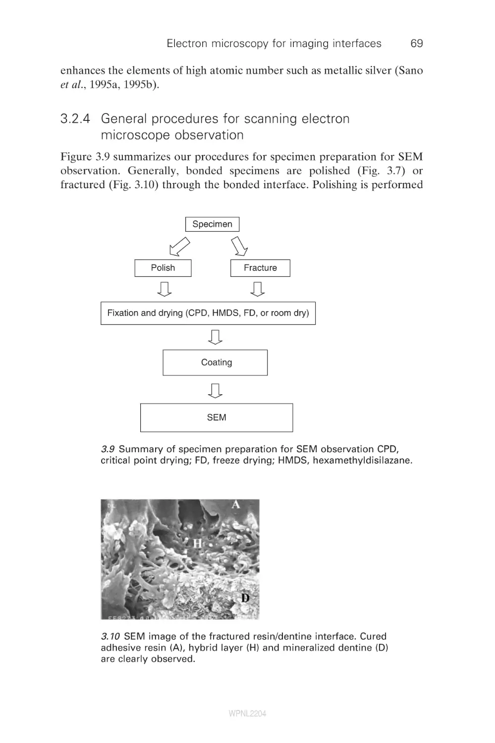
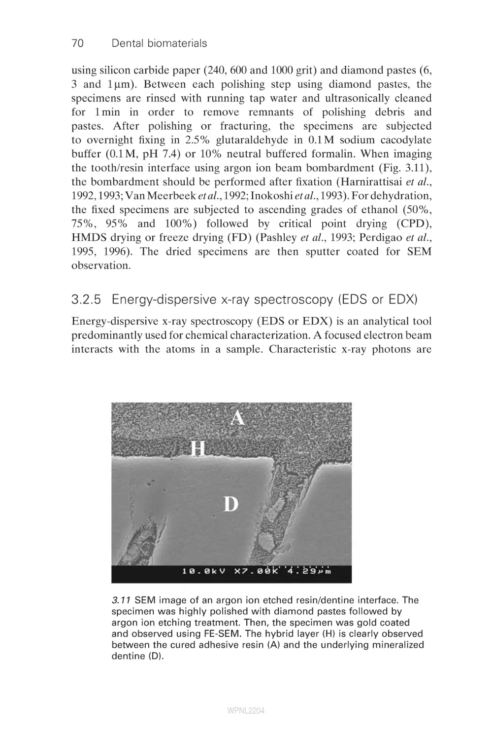
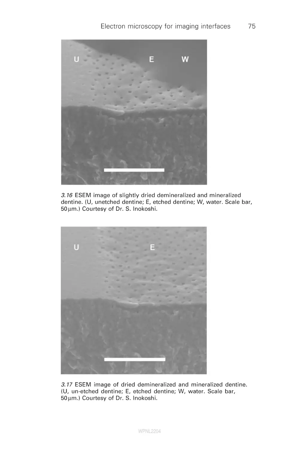
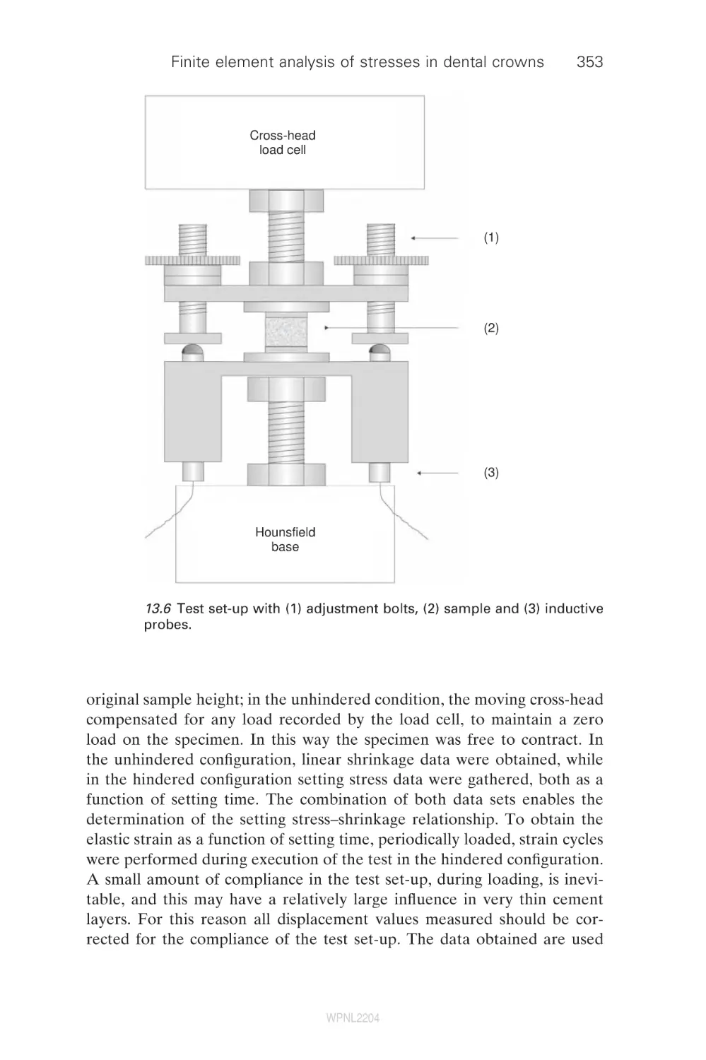
Текст
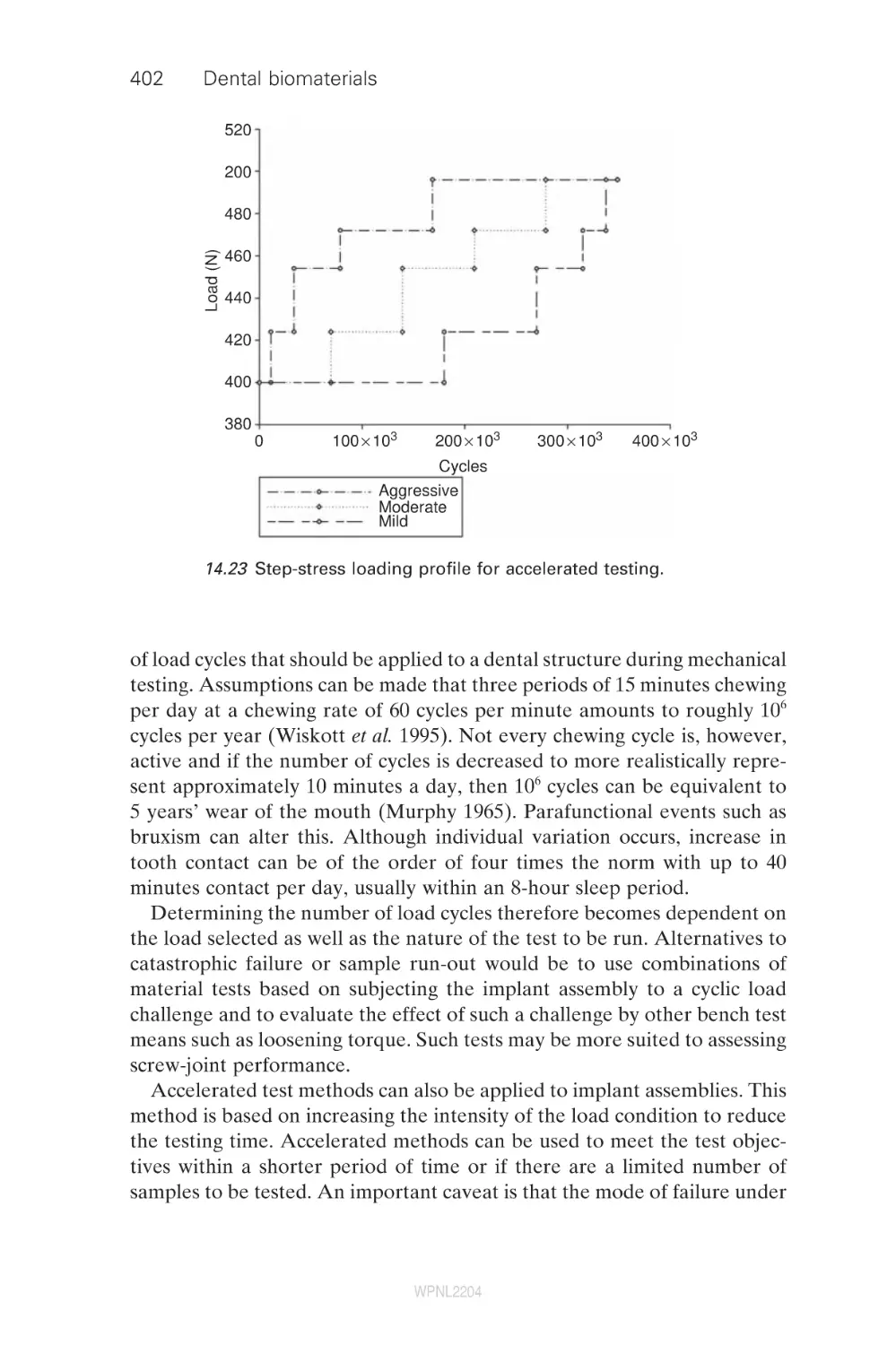
Dental biomaterials
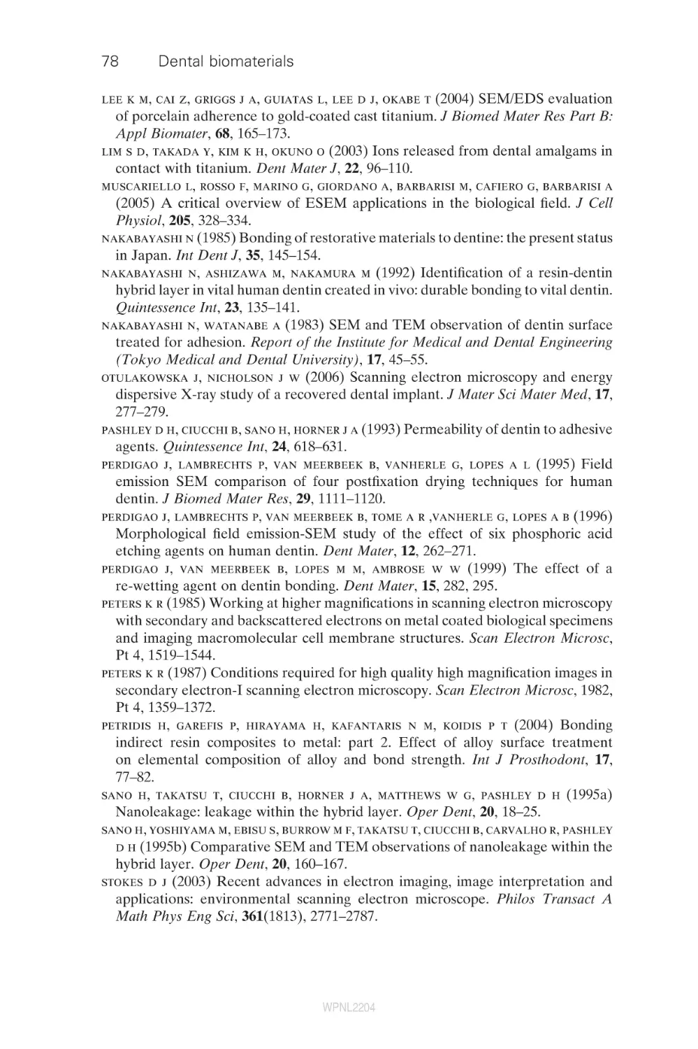
WPNL2204
Related titles
Bioceramics and their clinical applications
(ISBN 978-1-84569-204-9)
Bioceramics are potentially suitable for a wide range of important applications
within the medical device industry. Written by leading academics from around the
world, Bioceramics and their clinical applications provides an authoritative review
of this highly active area of research. Chapters in the first section of the book discuss
issues of significance to a range of bioceramics, such as their structure, mechanical
properties and biological interactions. The second part reviews the fabrication,
microstructure and properties of specific bioceramics and glasses, concentrating on
the most promising materials. The final group of chapters reviews the clinical applications of bioceramics.
Medical modelling: The application of advanced design and development techniques
in medicine
(ISBN 978-1-84569-138-7)
Medical modelling is an increasingly important tool in surgery and rehabilitative
medicine. This authoritative book describes the key steps in modelling including
acquisition of medical scan data, transfer and translation of data formats, methods
of utilising the data and finally using the information to produce physical models
using rapid prototyping techniques. Technologies are fully described, highlighting
their key characteristics, advantages and disadvantages. A series of case studies
illustrates a broad range of medical applications in surgery or prosthetic rehabilitation. The book is a valuable reference for a wide range of professionals involved in
such areas as orthopaedics, orthodontics and prosthetics.
Biomaterials, artificial organs and tissue engineering
(ISBN 978-1-85573-737-2)
Biomaterials are materials and devices that are used to repair, replace or augment
the living tissues and organs of the human body. The purpose of this wide-ranging
introductory textbook is to provide an understanding of the needs, uses and limitations of materials used in the human body and to explain the biomechanical
principles and biological factors involved in achieving the long-term stability of
replacement parts in the body. This book examines the industrial, governmental and
ethical factors involved in the use of artificial materials in humans and discusses the
principles and applications of engineering of tissues to replace body parts. This
approach necessarily incorporates a wide range of reference material because of
the complex multidisciplinary nature of the biomedical materials, biomechanics,
artificial organs and tissue engineering fields. An accompanying CD-ROM provides
supplementary information and illustrations to support the book.
Details of these and other Woodhead Publishing materials books, as well as
materials books from Maney Publishing, can be obtained by:
•
•
visiting our web site a www.woodheadpublishing.com
contacting Customer Services (e-mail: sales@woodhead-publishing.com; fax:
+44 (0) 1223 893694; tel.: +44 (0) 1223 891358 ext.130; address: Woodhead
Publishing Ltd, Abington Hall, Abington, Cambridge CB21 6AH, England)
If you would like to receive information on forthcoming titles, please send your address
details to: Francis Dodds (address, tel. and fax as above; e-mail: francisd@woodheadpublishing.com). Please confirm which subject areas you are interested in.
Maney currently publishes 16 peer-reviewed materials science and engineering
journals. For further information visit www.maney.co.uk/journals
WPNL2204
Dental biomaterials
Imaging, testing and
modelling
Edited by
Richard V. Curtis and Timothy F. Watson
Woodhead Publishing and Maney Publishing
on behalf of
The Institute of Materials, Minerals & Mining
WPNL2204
CRC Press
Boca Raton Boston New York Washington, DC
Cambridge England
WPNL2204
Woodhead Publishing Limited and Maney Publishing Limited on behalf of
The Institute of Materials, Minerals & Mining
Woodhead Publishing Limited, Abington Hall, Abington
Cambridge CB21 6AH, England
www.woodheadpublishing.com
Published in North America by CRC Press LLC, 6000 Broken Sound Parkway, NW,
Suite 300, Boca Raton, FL 33487, USA
First published 2008, Woodhead Publishing Limited and CRC Press LLC
© 2008, Woodhead Publishing Limited
The authors have asserted their moral rights.
This book contains information obtained from authentic and highly regarded
sources. Reprinted material is quoted with permission, and sources are indicated.
Reasonable efforts have been made to publish reliable data and information, but
the authors and the publishers cannot assume responsibility for the validity of all
materials. Neither the authors nor the publishers, nor anyone else associated with
this publication, shall be liable for any loss, damage or liability directly or
indirectly caused or alleged to be caused by this book.
Neither this book nor any part may be reproduced or transmitted
in any form or by any means, electronic or mechanical, including photocopying,
microfilming and recording, or by any information storage or retrieval system,
without permission in writing from Woodhead Publishing Limited.
The consent of Woodhead Publishing Limited does not extend to copying for
general distribution, for promotion, for creating new works, or for resale. Specific
permission must be obtained in writing from Woodhead Publishing Limited for
such copying.
Trademark notice: Product or corporate names may be trademarks
or registered trademarks, and are used only for identification and explanation,
without intent to infringe.
British Library Cataloguing in Publication Data
A catalogue record for this book is available from the British Library.
Library of Congress Cataloging in Publication Data
A catalog record for this book is available from the Library of Congress.
Woodhead Publishing ISBN 978-1-84569-296-4 (book)
Wookhead Publishing ISBN 978-1-84569-424-1 (e-book)
CRC Press ISBN 978-1-4200-7209-9
CRC Press order number: WP7209
The publishers’ policy is to use permanent paper from mills that operate a
sustainable forestry policy, and which has been manufactured from pulp which is
processed using acid-free and elementary chlorine-free practices. Furthermore,
the publishers ensure that the text paper and cover board used have met
acceptable environmental accreditation standards.
Typeset by SNP Best-set Typesetter Ltd., Hong Kong
Printed by TJ International Limited, Padstow, Cornwall, England
WPNL2204
Contents
Contributor contact details
Preface
1
1.1
1.2
1.3
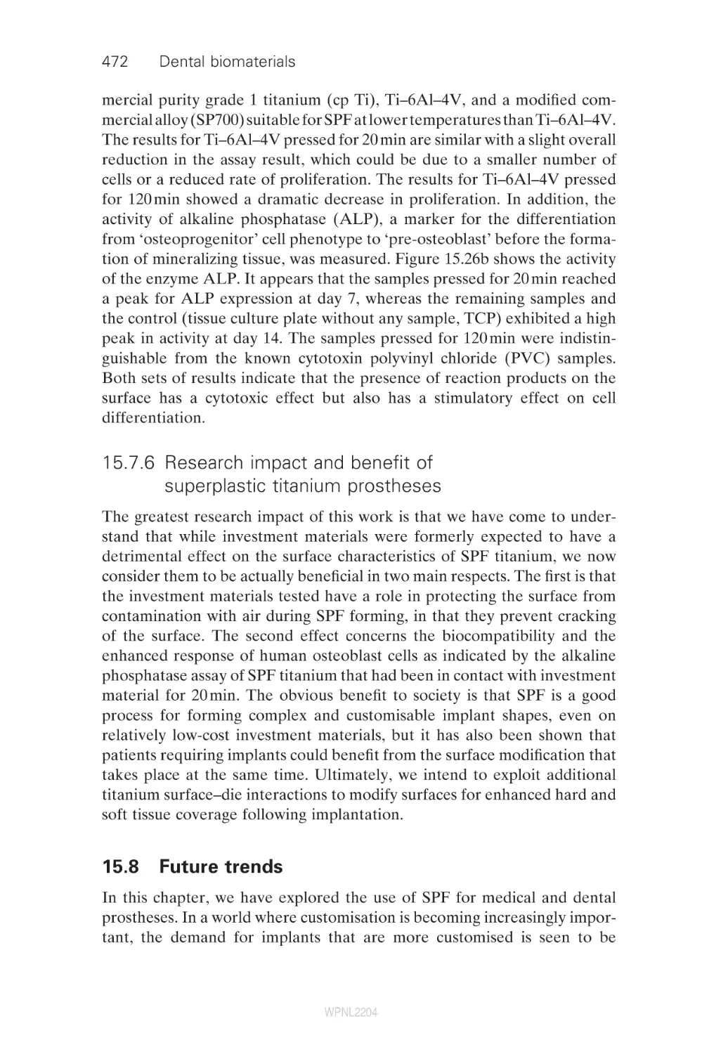
1.4
1.5
1.6
1.7
1.8
1.9
2
2.1
2.2
2.3
2.4
2.5
2.6
2.7
2.8
2.9
2.10
Characterizing the performance of dental
air-turbine handpieces
B. W. Darvell and J. E. Dyson, The University
of Hong Kong, Hong Kong
Outline
General importance: applications, benefit
Historical outline: development, features
Importance with respect to cutting: work done vs.
power in, duty cycle, load, nature of substrate
Testing: equipment, procedure, calculations
Hazards
Factors in selection and operation
Future trends
References
xi
xv
1
1
1
2
6
9
23
26
27
28
Optical imaging techniques for dental
biomaterials interfaces
37
T. F. Watson, R. J. Cook, F. Festy, P. Pilecki and S. Sauro,
King’s College London Dental Institute, UK
Introduction
37
Confocal microscopy
38
Conventional fluorescence and reflection imaging
40
Imaging water transit in materials
40
Imaging moisture-sensitive materials
47
Multi-photon imaging: deeper penetration
47
Fluorescence lifetime imaging
49
High-speed imaging of dynamic events within materials
53
Conclusion
54
References
55
v
WPNL2204
vi
Contents
3
Electron microscopy for imaging interfaces in
dental restorations
H. Sano, K. Koshiro and S. Inoue, Hokkaido University,
Japan
The transmission electron microscope (TEM)
The scanning electron microscope (SEM)
Summary
References
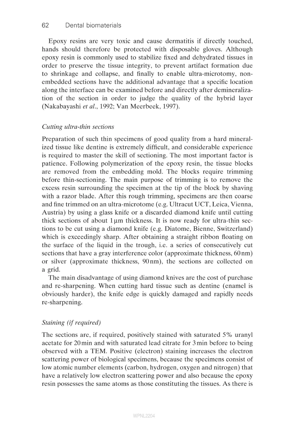
3.1
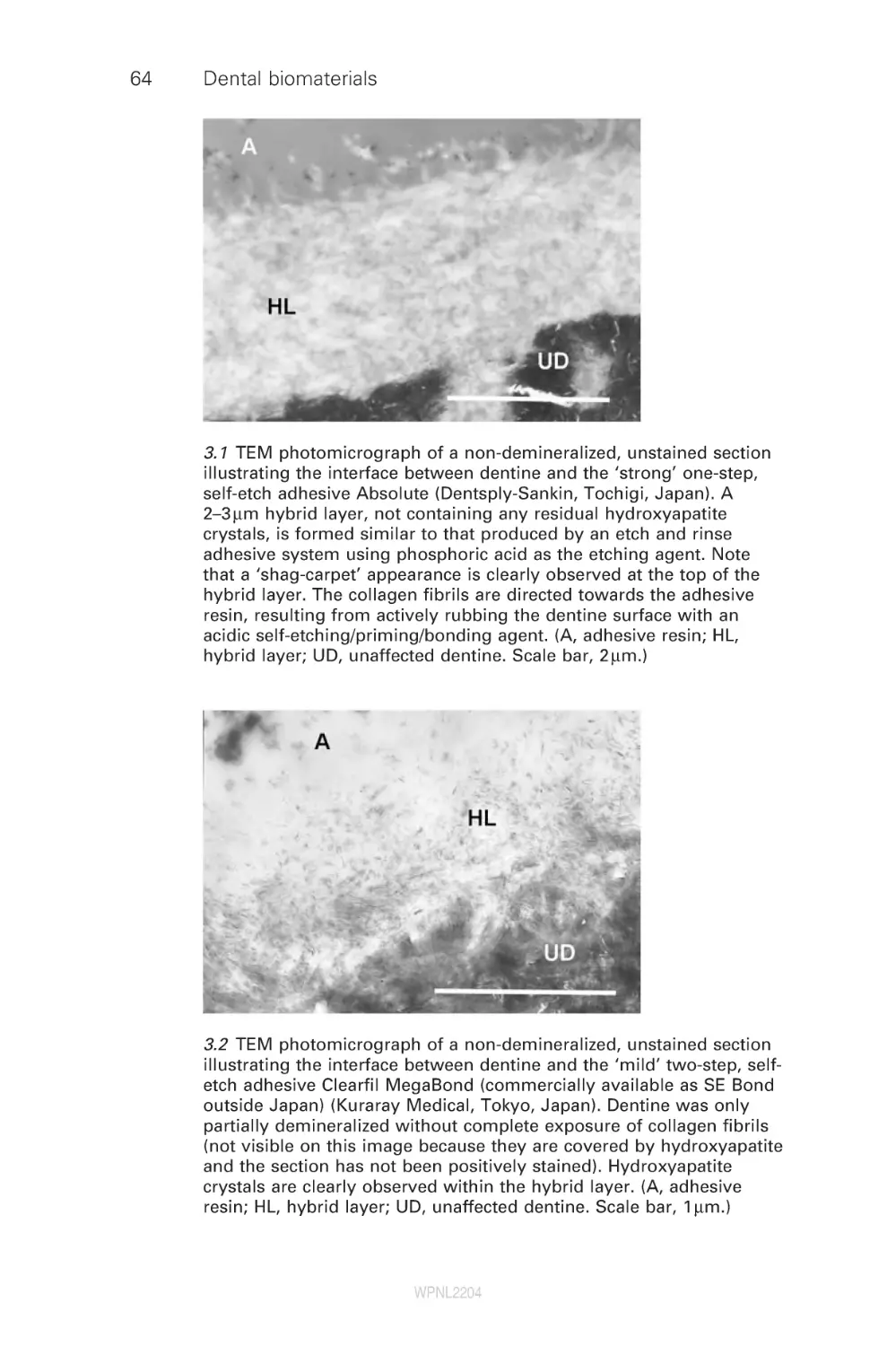
3.2
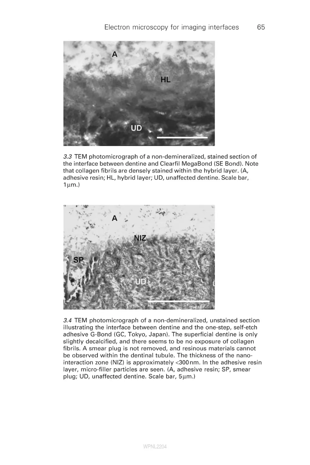
3.3
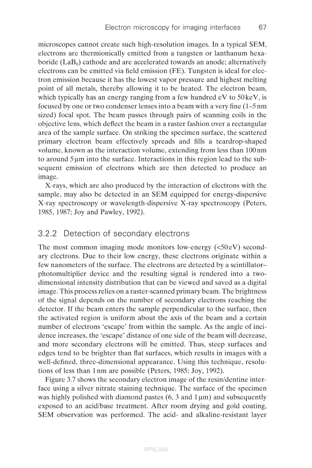
3.4
4
4.1
4.2
4.3
4.4
4.5
4.6
4.7
5
5.1
5.2
5.3
5.4
5.5
5.6
5.7
5.8
6
6.1
6.2
6.3
6.4
6.5
Dental adhesives and adhesive performance
B. Van Meerbeek, J. De Munck, K. L. Van Landuyt,
A. Mine, P. Lambrechts, M. Sarr,
Catholic University of Leuven, Belgium;
M. Sarr, Université Cheikh Anta Diop, Senegal;
Y. Yoshida and K. Suzuki, Okayama University, Japan
Introduction
The smear layer as an ‘obstacle’ to bonding
The hybridization process
Current concerns of one-step adhesives
Clinical performance of current adhesives
Conclusion
References
Mechanical stability of resin–dentine bonds
D. Pashley and F. Tay, Medical College of Georgia, USA
Introduction
Permeability of adhesive resins to water
Permeability of dentine
Hydrophilic versus hydrophobic properties of resins
Mechanisms responsible for degradation of
resin–dentine bonds
Summary
Acknowledgments
References
Dental cements: formulations and
handling techniques
S. B. Mitra, 3M Company, USA
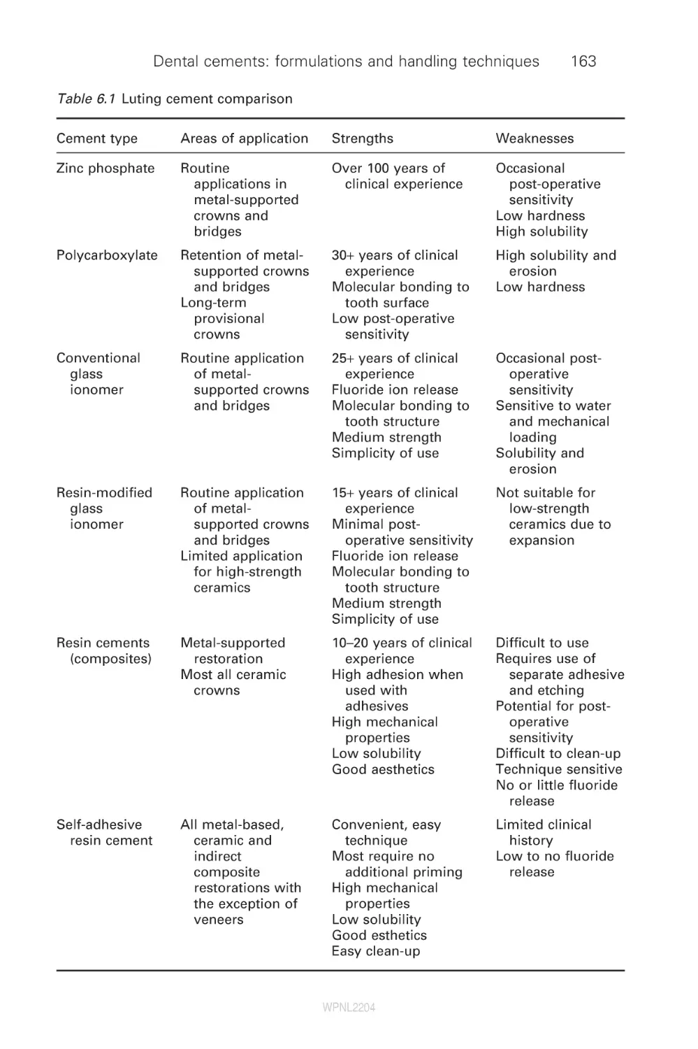
Introduction
Zinc phosphate cements
Zinc polycarboxylate cements
Conventional glass-ionomer cements
Resin-modified glass-ionomer cements
WPNL2204
58
58
63
76
76
81
81
81
85
97
103
105
106
112
112
117
130
134
145
152
153
153
162
162
165
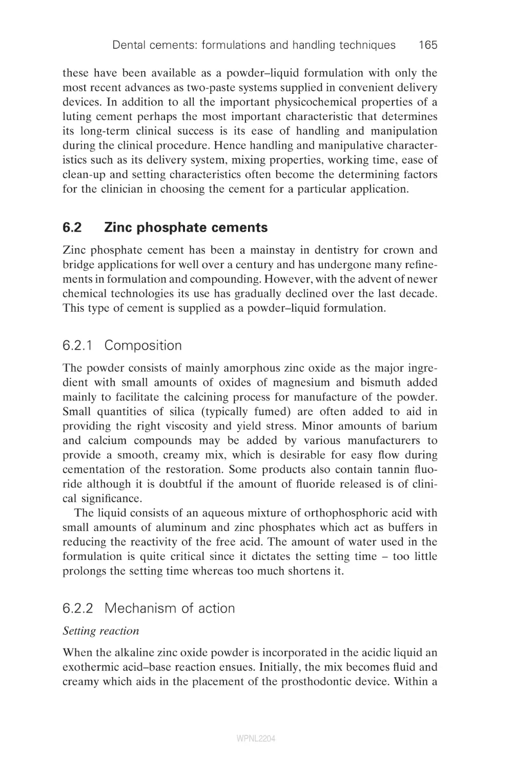
167
171
176
Contents
6.6
6.7
6.8
6.9
Traditional resin luting cements
Self-adhesive resin cements
Summary
References
7
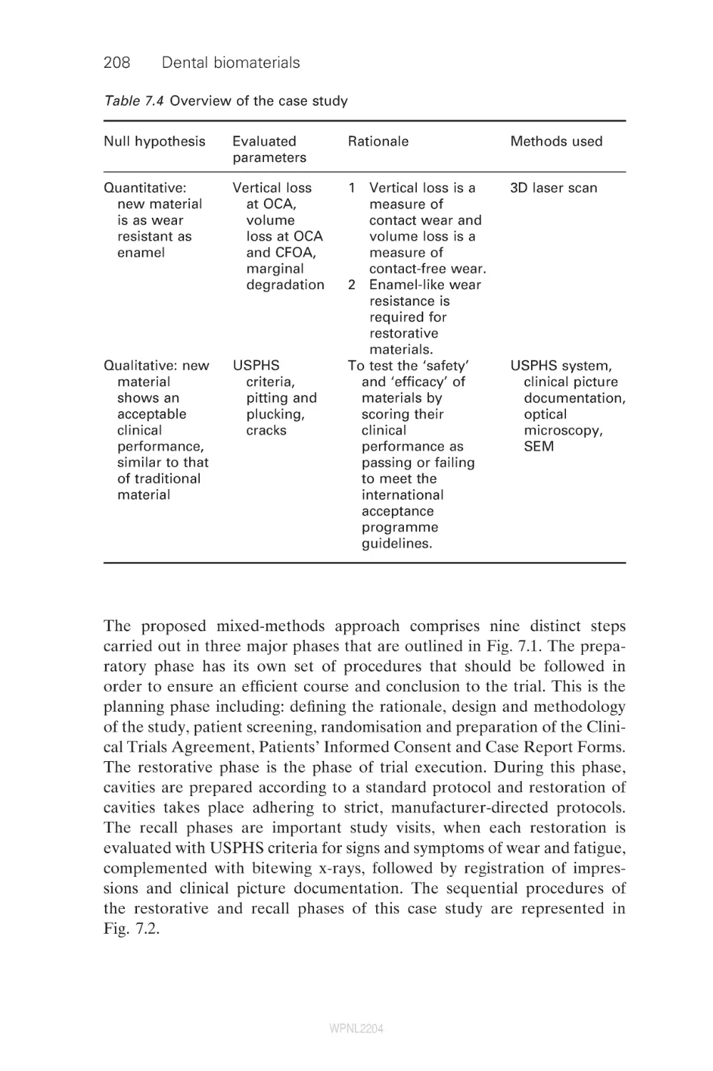
Mixed-methods approach to wear evaluation in
posterior composite dental restorations
P. Lambrechts, S. Palaniappan, B. Van Meerbeek,
M. Peumans, Catholic University of Leuven, Belgium
Introduction
Qualitative methods of wear evaluation
Quantitative methods of wear evaluation
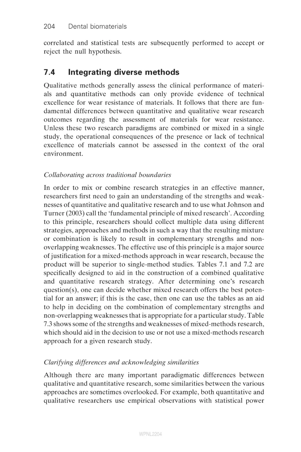
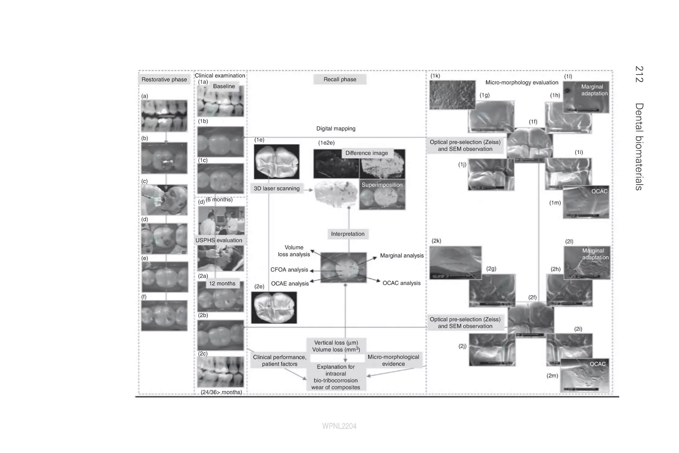
Integrating diverse methods
A case study – spanning paradigms and
combining methods
Future trends
References
7.1
7.2
7.3
7.4
7.5
7.6
7.7
8
8.1
8.2
8.3
8.4
8.5
9
9.1
9.2
9.3
9.4
9.5
9.6
9.7
9.8
9.9
10
10.1
10.2
vii
183
186
189
189
194
194
195
200
204
207
220
222
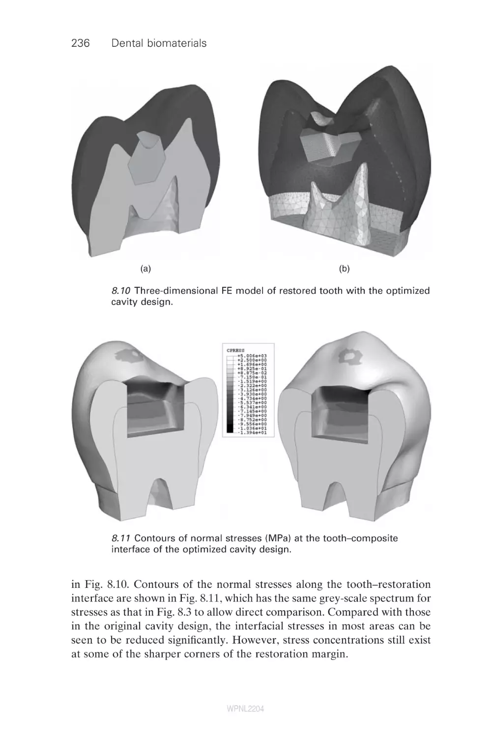
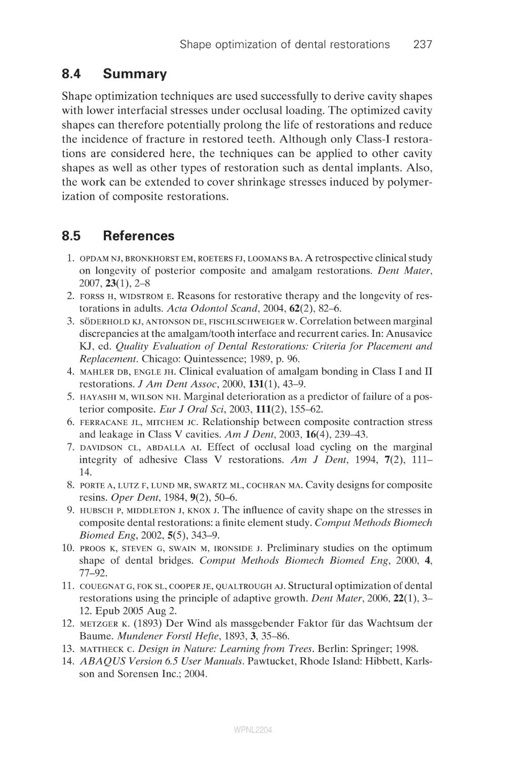
Shape optimization of dental restorations
A. Fok and L. Shi, The University of Manchester, UK
Introduction
Methods
Application
Summary
References
226
Fibre-reinforced composites for dental applications
P. K. Vallittu, University of Turku, Finland
Introduction
Structure and properties of fibre-reinforced composites
Removable dentures
Fixed partial dentures
Periodontal splints and retainers
Root canal posts
Future trends
Summary
References
239
Fracture mechanics characterization of
dental biomaterials
N. D. Ruse, The University of British Columbia, Canada
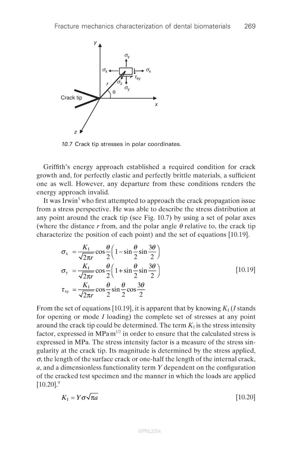
Introduction
Theoretical considerations
WPNL2204
226
229
231
237
237
239
239
246
248
250
250
252
253
254
261
261
262
viii
Contents
10.3
10.4
10.5
10.6
10.7
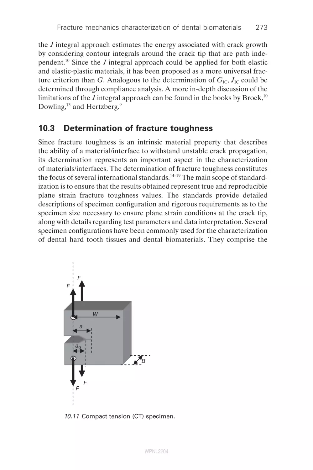
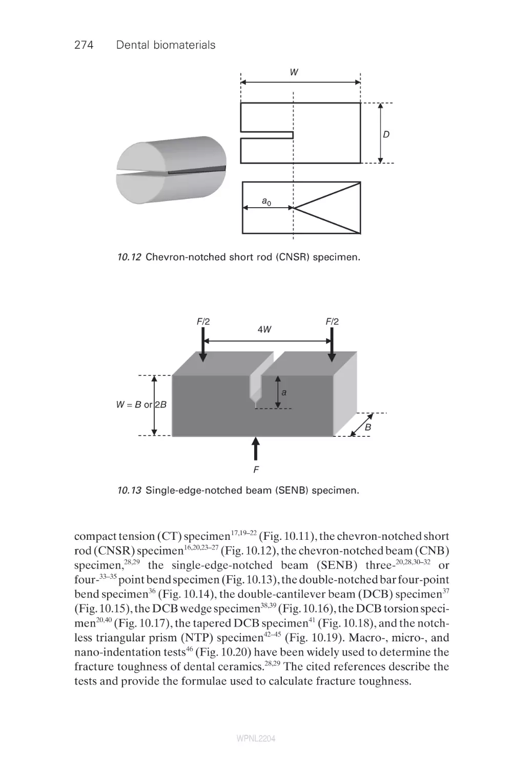
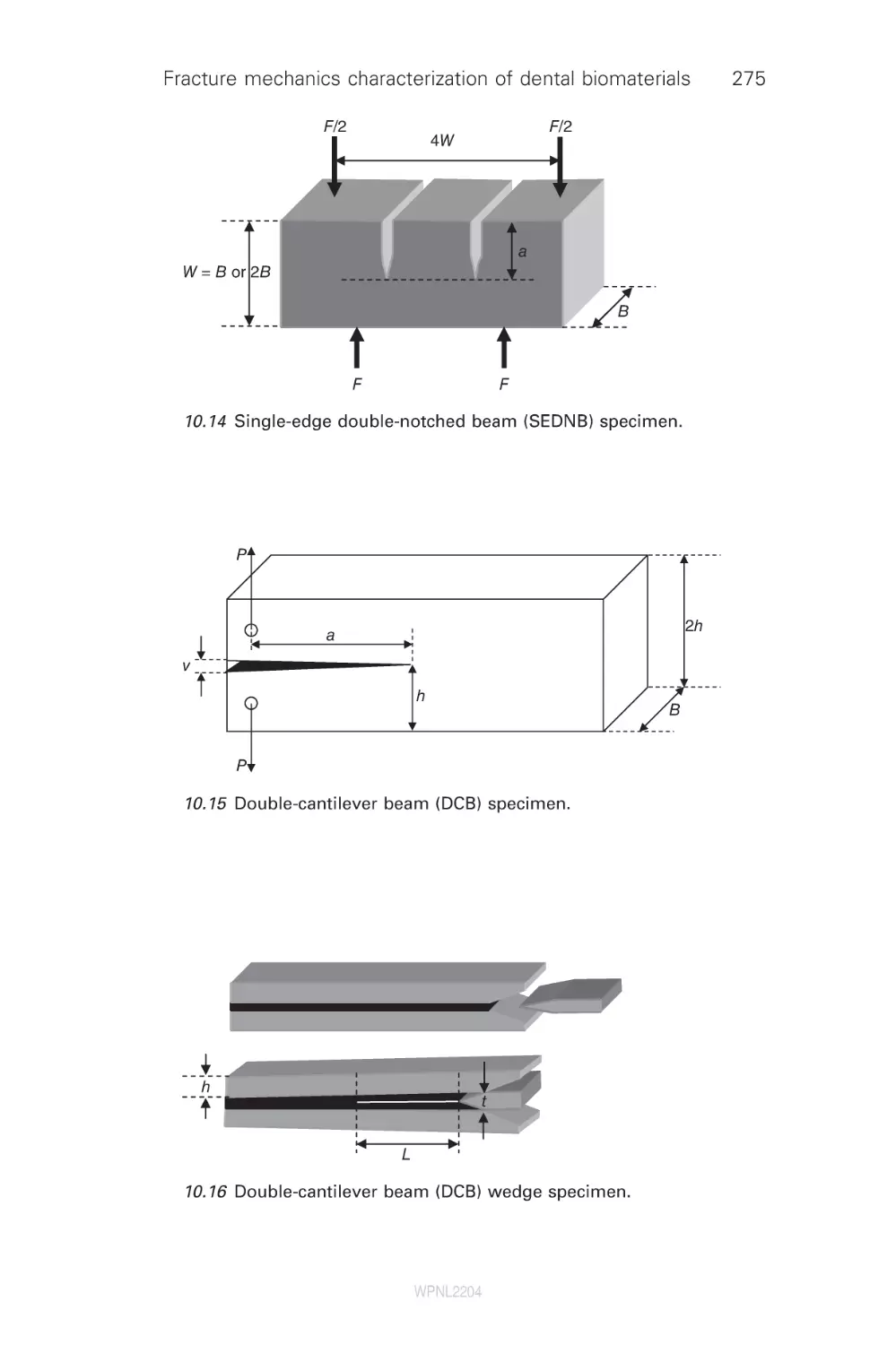
Determination of fracture toughness
Fatigue crack propagation (FCP)
Fracture mechanics and dentistry
Summary
References
273
277
279
284
284
11
Modelling bond strength in dental biomaterials
R. van Noort, University of Sheffield, UK
Introduction
Rationale for bond strength testing
Classification of dental adhesive testing techniques
Behavioural adhesive tests
Structural adhesive tests
Future trends
Summary
References
294
Fracture and aging of dentine
D. Arola, University of Maryland Baltimore County
and University of Maryland Dental School, USA
Introduction
Structure and chemistry
Elastic behavior and strength
Fatigue and fatigue crack growth
Fracture
Summary
Acknowledgements
References
314
Finite element analysis of stresses in dental crowns
N. de Jager, Academic Center for Dentistry Amsterdam
(ACTA), The Netherlands
Overview of finite element analysis
Finite element models for indirect restorations
Challenges involved in deriving material properties
for finite element analysis
Clinical significance
Summary
References
343
Testing the performance of dental implants
M. Suleiman, King’s College London Dental Institute, UK
Introduction: an overview of systems and
their development
360
11.1
11.2
11.3
11.4
11.5
11.6
11.7
11.8
12
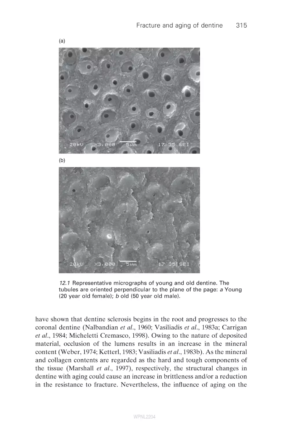
12.1
12.2
12.3
12.4
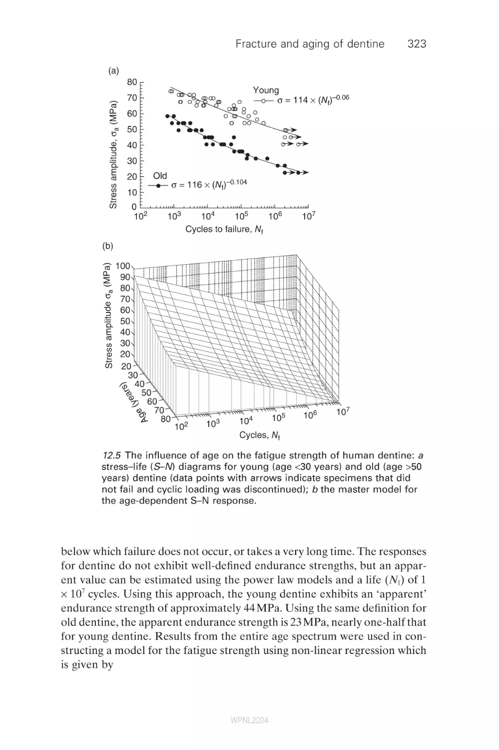
12.5
12.6
12.7
12.8
13
13.1
13.2
13.3
13.4
13.5
13.6
14
14.1
WPNL2204
294
296
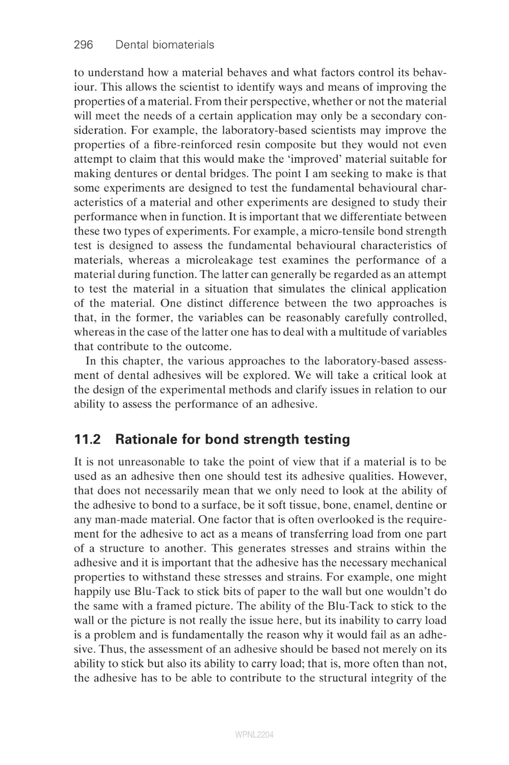
297
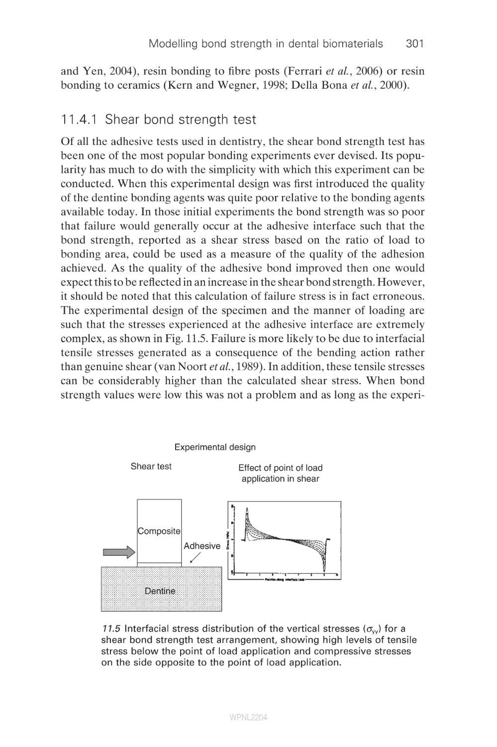
300
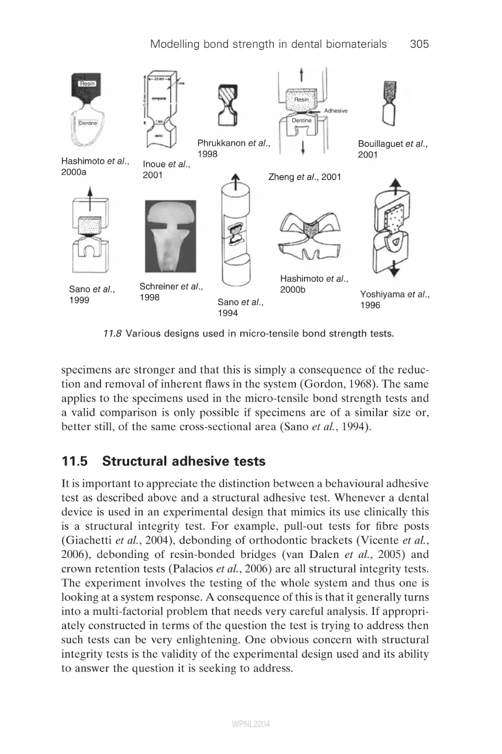
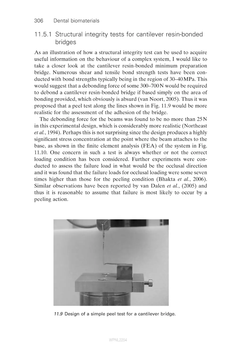
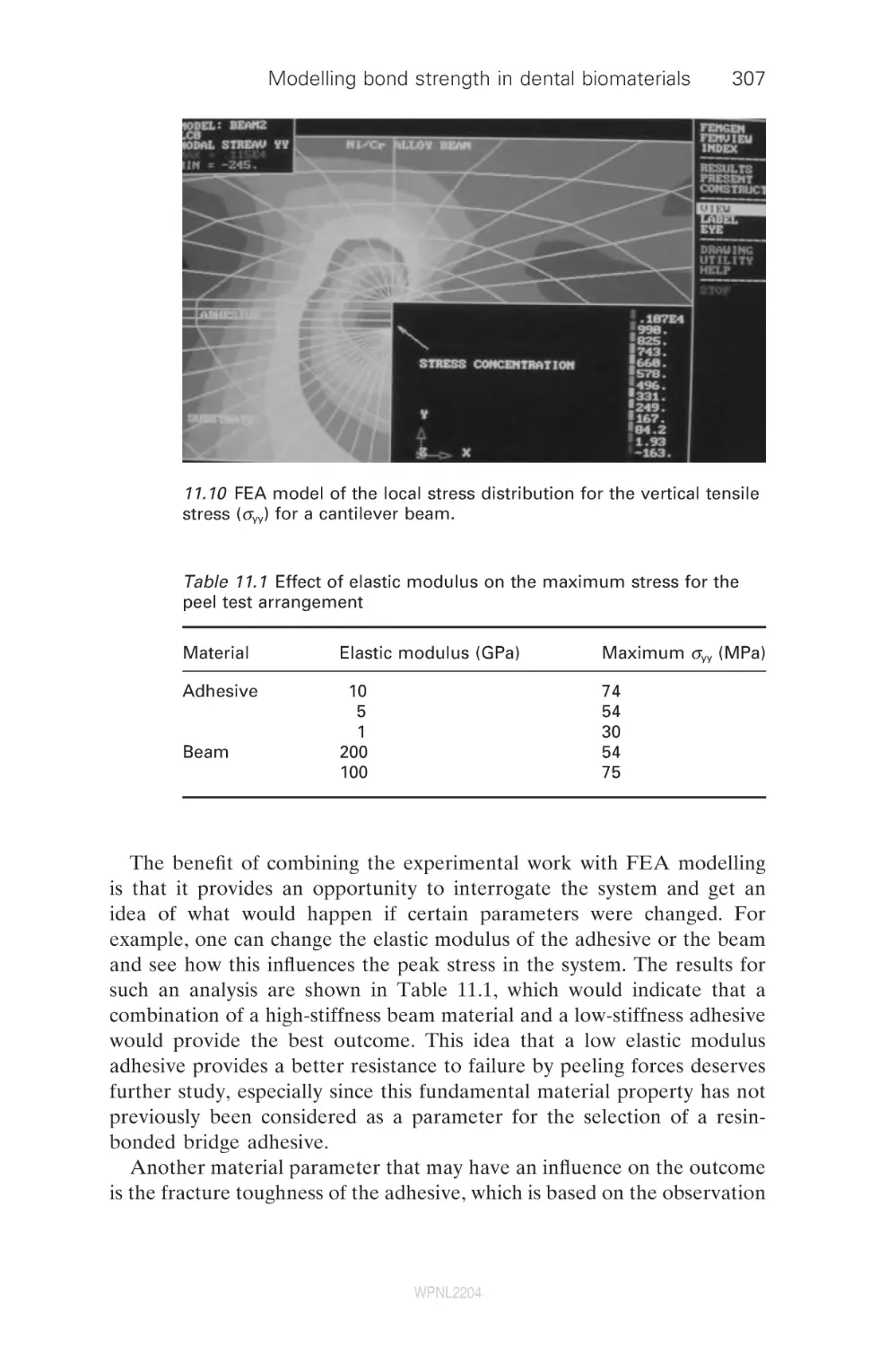
305
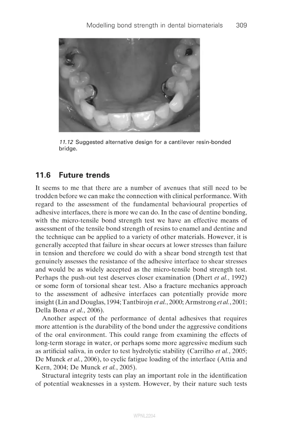
309
310
310
314
316
319
320
336
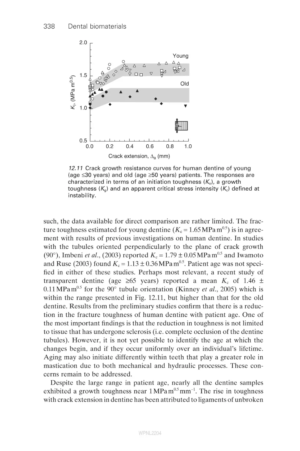
339
340
340
343
346
350
354
356
358
360
Contents
14.2
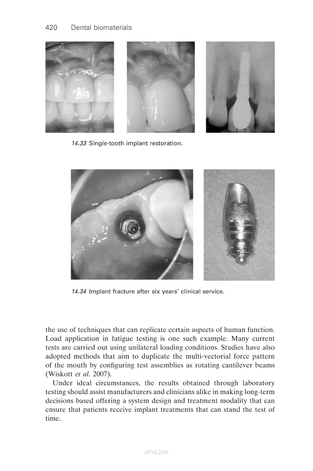
14.3
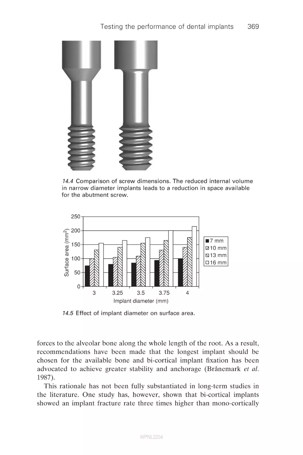
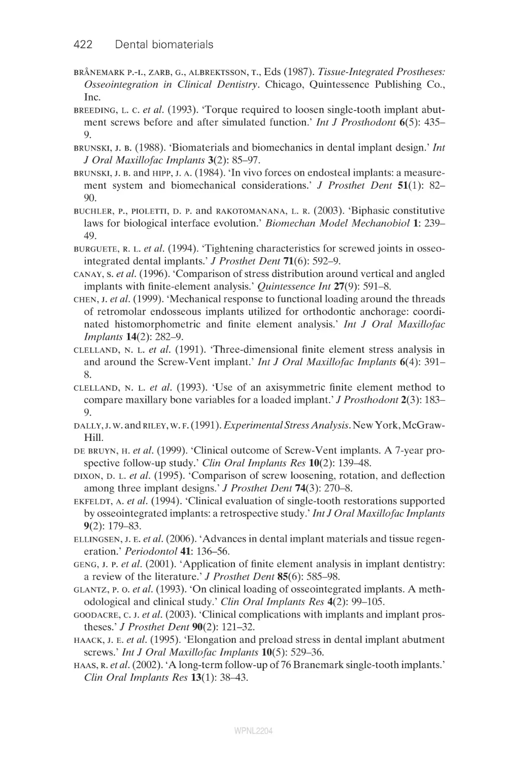
14.4
14.5
14.6
14.7
14.8
14.9
14.10
Biomechanical response to loading
The implant–abutment connection
Mechanical complications
Design variations within dental implant systems
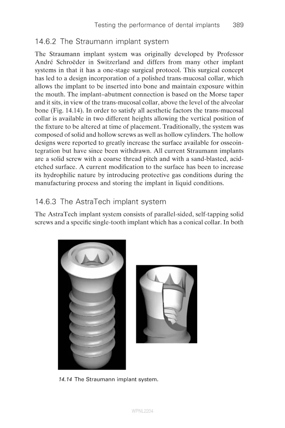
Overview of dental implant systems
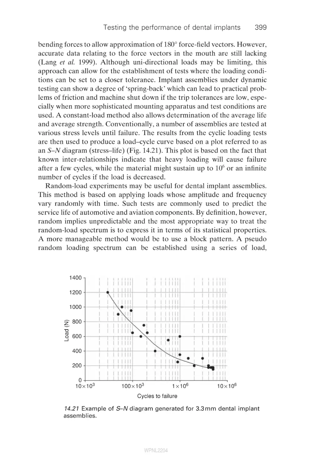
Testing dental implant assemblies
Stress analysis of the bone–implant interface
Summary
References
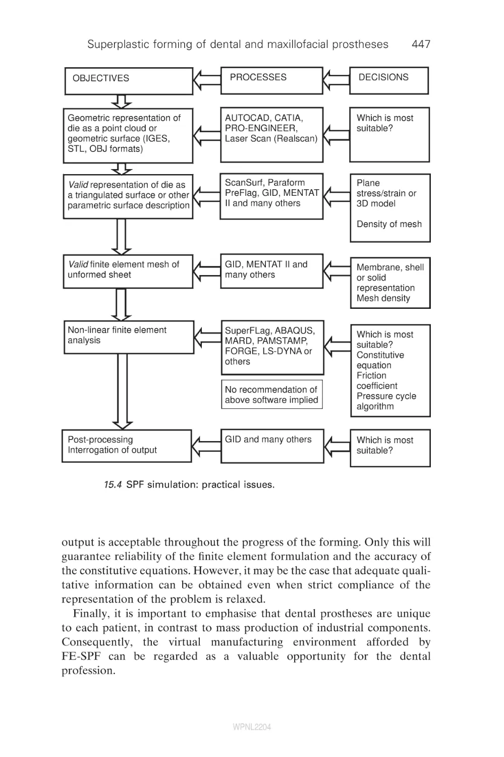
15
Superplastic forming of dental and
maxillofacial prostheses
R. Curtis, D. Garriga Majo, S. Soo and L. DiSilvio,
King’s College London Dental Institute, UK;
A. Gil and R. D. Wood, University of Wales Swansea, UK;
R. Atwood, Imperial College London, UK;
R. Said, Simpleware Ltd, UK
Introduction
Superplastic Prosthetic Forming – a process for the hot
forming of titanium alloys for biomedical applications
Finite element modelling and superplastic
forming simulation of SPF
Geometrical modelling and superplastic
forming simulation
Ceramic die materials for superplastic forming in
dentistry and medicine
Dental implant superstructures and surgical repair of
a defect or deformity of the skull (cranioplasty)
Multiscale simulation of the reactivity and
biocompatibility of superplastic titanium alloy prostheses
Future trends
References
15.1
15.2
15.3
15.4
15.5
15.6
15.7
15.8
15.9
16
16.1
16.2
16.3
16.4
16.5
Dental investment materials for casting metals
and alloys
C. Lloyd, University of Dundee, UK
Introduction
Chemistry and structure of binders in established
silica-based dental casting investment materials
New investment materials – responding to the
challenge of casting titanium
Surface coating the internal surface of the mould
The chemistry of new investment materials
WPNL2204
ix
370
377
383
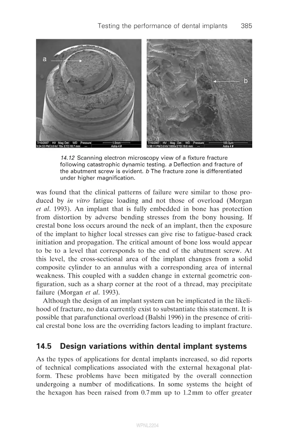
385
388
393
408
419
421
428
428
436
438
450
457
459
466
472
473
475
475
476
482
486
486
x
Contents
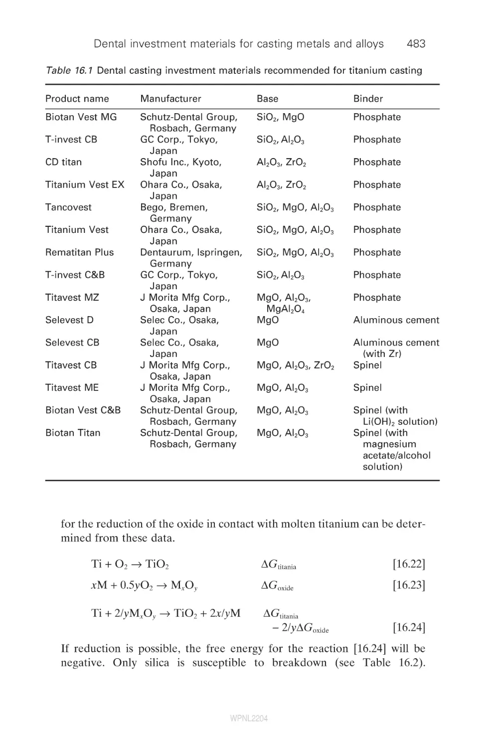
16.6
Effect of the hardened surface layer upon the
properties of a titanium dental casting
Issues concerning silica-based phosphate-bonded
investment
Rapid casting
Conclusions
Acknowledgement
References
492
496
497
498
498
Index
502
16.7
16.8
16.9
16.10
16.11
WPNL2204
491
Contributor contact details
(* = main contact)
Editors
Dr Richard V. Curtis and
Prof. Timothy F. Watson
King’s College London Dental
Institute
Biomaterials, Biomimetics &
Biophotonics Research
Group
Floor 17, Guy’s Tower
Guy’s Hospital
London Bridge
London
SE1 9RT
UK
E-mail: richard.curtis@kcl.ac.uk
and timothy.f.watson@kcl.ac.uk
Chapter 1
Prof. B. W. Darvell,
Dental Materials Science and
Dr J. E. Dyson,
Oral Rehabilitation
Faculty of Dentistry
The University of Hong Kong
Prince Philip Dental Hospital
34 Hospital Road
Hong Kong
E-mail: hrdubwd@hkucc.hku.hk;
jdyson@hku.hk
Chapter 2
Prof. Timothy F. Watson,*
Richard J. Cook, Frederic Festy,
Peter Pilecki and Salvatore Sauro
King’s College London Dental
Institute
Biomaterials, Biomimetics &
Biophotonics Research Group
Floor 17, Guy’s Tower
Guy’s Hospital
London Bridge
London
SE1 9RT
UK
E-mail: timothy.f.watson@kcl.ac.uk
Chapter 3
Hidehiko Sano,* K. Koshiro and
Satoshi Inoue
Graduate School of Dental
Medicine
Hokkaido University
Japan
E-mail: htphp334@ybb.ne.jp
xi
WPNL2204
xii
Contributor contact details
Chapter 4
Bart Van Meerbeek,*
Jan De Munck,
Kirsten L. Van Landuyt,
Atsushi Mine, Paul Lambrechts
and Mouhamed Sarr
Leuven BIOMAT Research
Cluster
Department of Conservative
Dentistry
School of Dentistry, Oral
Pathology and Maxillo-Facial
Surgery
Catholic University of Leuven
Kapucijnenvoer 7, 3000 Leuven
Belgium
E-mail: bart.vanmeerbeek@med.
kuleuven.be
Mouhamed Sarr
Service Odontologie
Conservatrice-Endodontie
Université Cheikh Anta Diop
Dakar
Senegal
Yasuhiro Yoshida and Kazuomi
Suzuki
Department of Biomaterials
Okayama University Graduate
School of Medicine, Dentistry
and Pharmaceutical Sciences
Okayama
Japan
Chapter 5
Prof. David Pashley and
Dr Frank Tay
Medical College of Georgia
1120 15th Street, CL-2112
Augusta
GA 30912-1129
USA
E-mail: dpashley@mail.mcg.edu
Chapter 6
Sumita B. Mitra
3M ESPE Dental Products
Division
3M Company
Building 260-2B-13, 3M Center
St Paul
MN 55144-1000
USA
E-mail: sbmitra@mmm.com
Chapter 7
Paul Lambrechts,*
Senthamaraiselvi Palaniappan,
Bart Van Meerbeek,
Marleen Peumans
Leuven BIOMAT Research
Cluster
Department of Conservative
Dentistry
Catholic University of Leuven
Kapucijnenvoer 7, 3000 Leuven
Belgium
E-mail: paul.lambrechts@med.
kuleuven.be
Chapter 8
Alex Fok and Li Shi
School of Mechanical,
Aerospace and Civil
Engineering
The University of Manchester
PO Box 88
Sackville Street
Manchester
M60 1QD
UK
E-mail: alex.fok@manchester.ac.uk
WPNL2204
Contributor contact details
Department of Endodontics,
Prosthodontics and Operative
Dentistry Baltimore College
of Dental Surgery
University of Maryland Dental
School
Baltimore
MD 21201
USA
E-mail: darola@umbc.edu
Chapter 9
Pekka Vallittu
Department of Prosthetic
Dentistry and Biomaterials
Science
Institute of Dentistry
University of Turku
Lemminkäisenkatu 2
FI-20520 Turku
Finland
E-mail: pekka.vallittu@utu.fi
Chapter 13
Dr Ir N. de Jager
Department of Material Science
Academic Center for Dentistry
Amsterdam (ACTA)
Louwesweg 1
1066 EA
Amsterdam
The Netherlands
E-mail: n.de.jager@acta.nl
Chapter 10
N. Dorin Ruse
Biomaterials
Faculty of Dentistry
The University of British
Columbia
Vancouver
BC
Canada
E-mail: dorin@interchange.ubc.ca
Chapter 14
Chapter 11
Prof. Richard van Noort
Department of Adult Dental Care
University of Sheffield
Sheffield
S10 2TA
UK
E-mail: r.vannoort@sheffield.ac.uk
Chapter 12
Dr Dwayne Arola
Mechanical Engineering
University of Maryland Baltimore
County
Baltimore
MD 21250
USA
Dr Mahmood Suleiman
King’s College London Dental
Institute
Biomaterials, Biomimetics &
Biophotonics Research
Group
Floor 17, Guy’s Tower
Guy’s Hospital
London Bridge
London
SE1 9RT
UK
E-mail: msdent@btinternet.com
Chapter 15
Dr Richard Curtis,*
D. Garriga Majo, S. Soo and
L. DiSilvio
WPNL2204
xiii
xiv
Contributor contact details
King’s College London Dental
Institute
Biomaterials, Biomimetics &
Biophotonics Research
Group
Floor 17, Guy’s Tower
Guy’s Hospital
London Bridge
London
SE1 9RT
UK
E-mail: richard.curtis@kcl.ac.uk
A. Gil and R. D. Wood
Civil and Computational
Engineering Centre
University of Wales Swansea
Swansea
UK
R. Atwood
Department of Materials
Imperial College London
London
SW7 2BP
UK
R. Said
Simpleware Ltd
Innovation Centre
Rennes Drive
Exeter
EX4 4RN
UK
Chapter 16
Dr Charles Lloyd
University of Dundee Dental
School
University of Dundee
Dundee
DD1 4HN
UK
E-mail: c.h.lloyd@dundee.ac.uk
WPNL2204
Preface
The dental and biomaterials science literature is full of excellent research
papers that give mention to many exciting techniques for the determination
of physical properties, chemical constituents and structural organisation of
biomaterials and their biological substrates. Equally, there are review papers
that look at materials from the clinical perspective without probing the
materials and biological background in depth. However, there are very few
sources of information available to the researcher who is setting out in a
new field of study, who wants to be updated in a particular area of newly
developing technology or who wants to give their postgraduate students a
source of primary information for their studies of the literature. Dental
biomaterials: imaging, testing and modelling may help to redress this
balance.
When assembling the list of authors for this book we aimed to incorporate individuals who are the leaders in their respective fields in dental biomaterials. The authors are from many different backgrounds and elegantly
illustrate the profitable results of collaboration between the laboratory and
the clinic. There is no doubt that there are many areas of endeavour that
have not been covered in this present edition, but a book can only be a
finite size. We hope that the collection of chapters covers a suitably wideranging suite of topics and that it may encourage individual researchers to
look to other, parallel, technologies to their own and so advance the exciting
world of dental biomaterials science.
Richard Curtis,
Senior Lecturer in Dental Biomaterials Science
Tim Watson,
Professor of Biomaterials Science and Restorative Dentistry
xv
WPNL2204
WPNL2204
1
Characterizing the performance of dental
air-turbine handpieces
B . W . D A R V E L L and J . E . D Y S O N ,
The University of Hong Kong, Hong Kong
1.1
Outline
After briefly outlining the general importance of air-turbine handpieces in
dentistry (Section 1.2), a historical account of their development puts their
present status into context (Section 1.3). However, in order to understand
performance in general, it is necessary to recognize the large number of
factors involved, and their complex interactions (Section 1.4). In essence,
it is not yet possible to characterize the cutting performance of these devices,
dependent as they are on the behaviour of cutter and substrate, amongst
other things. Accordingly, it is as yet only feasible to document the physical
aspects of the behaviour of the turbine itself (Section 1.5), but this leads
to a number of figures of merit that may be used for product comparisons
in an objective fashion that are tied to the physics of these machines. Even
so, because of their internal complexity, primarily in terms of gas flow, it
is necessary to resort to the ‘black-box’ approach and document input–
output relationships, subsuming much unresolvable detail in some fitted
parameters. Selection and application by the end-user nevertheless depends
on a number of further issues of great importance, and these are discussed
under the general heading of hazards (Section 1.6). The chapter closes with
some general remarks on selection, usage, and areas where further study
is essential.
1.2
General importance: applications, benefit
The dental air-turbine handpiece rapidly gained widespread acceptance by
the dental profession after its introduction in the late 1950s, and it continues
to be used as the main means of carrying out cutting work in clinical dental
practice, whether of tooth tissue or restorative materials. In comparison
with alternatives at the time, the reasons given for its usefulness included
the following.
•
Power: power-to-weight ratio very favourable, negligible transmission
loss;
1
WPNL2204
2
•
•
•
Dental biomaterials
Size: size and weight allow better control for long periods without tiring
as well as good intraoral access;
Speed: reduction of unpleasant vibration, finer control of cutting
process;
Effort: lower forces could be used yet with higher removal rates.
These considerations still appear to be pertinent.
1.3
Historical outline: development, features
A turbine is a motor in which a shaft is steadily rotated by the action of a
current of fluid upon the blades of a wheel. Turbines powered by various
fluids have evolved along several paths, and it is not possible to identify a
single source for the development of dental systems.
The first air-powered dental engine design was patented in 18681 although
in fact this was not a turbine but effectively a lobe pump operated in
reverse. It was intended to be operated by mouth, foot bellows, or a compressed air vessel. The first true turbine dental handpiece, with a 13-bladed
rotor, was patented in 1874,2 with similar suggestions for operation as the
lobe pump. It received little attention from the profession. A water-powered
device in 18773 also made provision for a fine stream of water to be directed
as coolant onto the cutting instrument. A more elaborate device with a
transmission clutch, a rotatable handpiece sheath, and revised mechanism
for the attachment of cutting instruments followed in 1879,4 although details
of the turbine rotor were not given and the drive fluid was not specified.
These machines were all somewhat bulky with their weight borne by the
dentist’s hand. However, a water-powered engine, produced by S. S. White
in 18815 avoided this problem by the motor being mounted on a floor
stand. A flexible shaft transmitted the drive in a fashion similar to that of
many foot-treadle engines of the time. Evidently, the problems were greater
than the advantages. Improvements made to foot-treadle and electric
dental engines in the late 1800s led to fluid-driven devices falling by
the wayside and, by the 1920s, the cord-arm drive had been adopted as the
de facto standard means of transmission from an electric motor to the
handpiece.6
In the 1870s, the maximum speeds were around 700 rpm (12 /s) and
1000 rpm (17 /s) for foot-driven and electrical devices, respectively.7 Speed,
recognized to be beneficial, progressively increased, but success depended
in part on suitable rotary cutting instruments being available, as well as
improved means of cooling the cutting site. An electric engine of 1911
reputedly achieved up to 10 000 rpm (167 /s);6,8–10 separating discs and grinding tools worked more smoothly with less patient discomfort. However, the
engine was unsuccessful because of overheating and seizure of the hand-
WPNL2204
Characterizing the performance of dental air-turbine handpieces
3
piece bearings.6,9 Effective means of achieving such speeds did not become
available until the 1940s.
Studies of vibration perception provided evidence in favour of increased
speeds.11–13 The upper frequency threshold of vibration perception was
found to be ∼650 Hz, with maximum unpleasantness in the range 100–
200 Hz. Using burs, stones, and diamond instruments at 3000–4000 rpm
(50–67 /s), the vibrations produced were ∼110–150 Hz. An air-turbine handpiece was then developed (see below) specifically to produce vibrations
above the limit of perception by virtue of its high rotation rate. In the end,
it was concluded that, in procedures that resulted in the same range of
temperature rise, high-speed devices could remove enamel some three
times as fast and at 1/30th of the operating load, as well as with better
control and less effort.14 Indeed, with proper cutting-site cooling, high-speed
rotation was not only possible but practical, safe, and effective,15,16 with
advantages for both patient and operator.17 In fact, it was said that ‘few
pieces of equipment in dentistry have caused more changes and improved
dental service to a greater degree than ultra-high-speed handpieces (i.e.
those rotating at 1000–5000 /s)’,18 allowing improved patient response,
shortened operating time, reduced vibration perception, and less patient
and operator fatigue. For these reasons this development was described as
‘one of the most significant contributions to dental health service’.19
Nevertheless, high-rotation-rate cutting only became possible when
instruments became available that could withstand such speeds. Until at
least 1870, steel burs were the only cutting instruments available and these
were individually shaped and finished by hand. The mass production of
carbon steel burs began by the 1870s.8 Corundum (Al2O3) separating discs
and stones were introduced in 18726,8,9 and provided the first satisfactory
means of cutting enamel, although subsequently supplanted by carborundum (SiC).
Diamond grit cutting instruments were first advertised in 187820 but,
being on a soft copper core, could not be used at high speed until the development in 1932 of galvanized bonding to harder alloy.6,8,9 Tungsten carbide
burs followed in 1948 and proved to be extremely successful in high-speed
applications.8 There has been no significant development since then.
The problem of heat generation remained, although recognized as much
as 2000 years ago21 for surgical trephines. A cooling system was fitted to one
handpiece in commercial production by 1874:22 water was applied from a
rubber bulb though a hose and nozzle, but an integral system soon after
was to apply a stream of water onto the cutting instrument.3 Many patented
designs followed,23–38 some of which allowed compressed air to be applied
to the cavity for debris removal. One even heated the air and water to
minimize patient discomfort, and they could be released simultaneously.
Alongside this, more effective aspiration was required.39,40 Hollow burs,
WPNL2204
4
Dental biomaterials
through which air is passed to supplement the cooling provided by air and
water jets, were devised in 197419,41 but failed to gain widespread use, despite
a similar principle being used in surgical instruments.
The start of the modern turbine era may be 1941, when a patent claimed
25 000 rpm (417 /s) for a design using compressed air at 45 psi (310 kPa).42
The turbine rotor was unusual: a cylinder with a circular arrangement of
holes through which air jets from two nozzles were directed. In addition,
ball bearings were to be used (as opposed to the sleeve bearings of earlier
handpieces), and the inner ball race of the bearing at the chuck was arranged
to cause the jaws to open and close by a sliding action, thus facilitating the
rapid change of instruments.
The first demonstrations of Norlén’s device in London, UK were in May
1958,43 although it had been patented in 1952.44 Turbine rotation was transmitted to the instrument via a mechanism in the body of the handpiece,
which was interchangeable by a slip-joint connection. Multiple nozzles
directed air onto inclined, slightly shovel-shaped turbine blades. Speed
control was by means of adjusting the opening of vent holes. Said to reach
a rotor speed of 120 000 rpm (2000 /s), a ball-race reduction drive gave an
instrument speed of 50 000 rpm (833 /s). A finger-operated spring released
a brake and progressively opened the air inlet.
There has been much debate over the history of the first handpiece with
a turbine in the head (see below),43,45 a distinct advance in design first
developed in New Zealand. Arising from the vibration studies mentioned
above, as an adaptation of a commercial air-powered drill, it reached
60 000 rpm (1000 /s), but was very noisy and exhausted excessive air into the
patient’s mouth. As no suitable bearings were available, overheating and
seizure occurred after a short period of use.46 The project was abandoned.
A water-driven, head-mounted turbine contra-angle handpiece was
reported in 1953.47 The small rotor (diameter, 7.5 mm; height, 4.8 mm) had
six notched blades and could rotate at 61 000 rpm (1017 /s). Hollow-shank
cutting instruments were fitted directly to the rotor shaft, retained by a
spring and keyway. Although referring to a number of earlier turbine
designs,2–4,42,44 the New Zealand design seems to have been unknown to
the authors.48 Further development had a complicated history,43,45 but by
1956 it was being sold as both straight and contra-angle handpieces and
could operate at up to 100 000 rpm (1667 /s).7 The drive water was recirculated by coaxial tubing to the pump, and threaded rotary instruments
were attached to the turbine shaft. This was said to be ‘extremely quiet
during operation’ and to have ‘the highest torque of any turbine angle
handpiece’.7
Meanwhile, development of cord-driven equipment continued, although
speed was limited by the difficulties of transmission. However, in 1951, a
10 000 rpm (167 /s) device using an ‘accelerating wrist joint’ was produced.6
WPNL2204
Characterizing the performance of dental air-turbine handpieces
5
Then, in 1955, with the elimination of gears, the Page–Chayes handpiece
reached 100 000 rpm (1667 /s), relying on a cord and pulley system inside
the handpiece sheath, and went on to reach 180 000 rpm (3000 /s) by 1960.7,49
Although the definite benefits of high rotation rate were obtained, the cord
arm mechanism remained cumbersome.
The most significant event in this history was the production in 1957 of
the first commercially-viable high-speed air-turbine handpiece, the Borden
Airotor. Said to be able to run at up to 300 000 rpm (5000 /s) it had oil-mist
bearing lubrication and an integral water jet for cooling.50 It sold quickly:
by 1958, it was claimed that 50 000 had been sold. Other manufacturers
rapidly followed suit. In 1960, the Borden Airotor 60 was advertised as
having the advantages of a smaller head, reduced noise, and an improved
cooling system with twin jets. The greater convenience and manoeuvrability
of the high-speed turbine handpieces led to their market dominance and
the disappearance of cord systems.
Patented designs continued to appear, including finger-operated air and
water coolant valves, and needle roller bearings for the rotor which acted
as the turbine blades.51 The ball bearings initially used were noisy, required
continuous oil-mist lubrication, and wore out rapidly.50,52,53 Air bearings,
introduced in the early 1960s, permitted speeds up to 528 000 rpm (8800 /s)
to be achieved with air at 60 psi (415 kPa).50,52,54 Said to be quieter, but
requiring a lower load during cutting than ball bearing devices because of
the ease of stalling, such handpieces are still in production. Since the 1970s,
however, improved, more durable ball races have been available,50 needing
only periodic oiling, and this design is still dominant. Ceramic bearings, said
to require no lubrication, were introduced in 1991.
Low-speed work was still considered appropriate in some contexts, but
cord systems remained problematic. The Dentatus air motor, introduced in
1960, could operate across a wide range of speeds with relatively high
torque. This was in effect, a piston motor: plastic balls acted as pistons in
an eccentric rotor. Several manufacturers produced similar devices, but all
were ‘rather noisy’.50
In the early 1960s, small high-torque 24 V dc electric servo-motors for use
in aircraft became the model for a quiet alternative: so-called ‘micromotors’.50 Air-drive vane motors – the rotor having radial slots containing
sliding vanes, rotating in a non-circular casing – were also developed.
Capable of 20 000 rpm (333 /s) with ‘remarkably high torque’, the advantage
was a simple air-driven control system, as have air-turbine handpieces. Both
air motors and low-voltage electric motors continue to be used today.
Perhaps prompted by the great success of the Borden Airotor and its
successors, there has been lively competition to attribute credit to various
individuals.43,45 As it turns out, the idea of placing the turbine in the head
of the handpiece appears to have occurred independently to two separate
WPNL2204
6
Dental biomaterials
groups and it is inappropriate, certainly invidious, to seek a single originator.
Subsequent developments in high-speed air-turbine handpiece design are
of two types: turbine modifications that affect speed and torque, and modifications affecting task suitability or convenience of use. Of these latter can
be mentioned multiple coupling connectors with rotatable joints, fibreoptic
illumination, push button and lever chuck systems, the ability of the handpiece to withstand routine autoclaving, and ceramic bearings. Larger diameter rotors give increased torque, while smaller rotors (both diameter and
length) reduce handpiece head size and thus improve accessibility in the
patient’s mouth. Improved bearings require simplified lubrication and last
longer, but there are no clear distinctions to be made between the many
variations of rotor blade design.
1.4
Importance with respect to cutting: work done
vs. power in, duty cycle, load, nature of substrate
Cutting performance is understood to relate to the rate of reduction of the
workpiece. This is affected by many factors, for example operator characteristics, the handpiece itself, rotary cutting instrument design, coolant
applied at the interface, and the workpiece material. Given this, it is not
possible to define a representative set of conditions for ‘normal’ clinical
service. Only benchmarking in certain respects, item by item, is presently
feasible. A detailed discussion has been given elsewhere,55 but an outline
follows here to illustrate the nature of the problem. It will be understood
that this must relate to all aspects of the system: powering device, cutting
instrument, cooling, and substrate.
Speed
‘Normal’ use does not involve constant speed (as in many other systems)
but rather an intermittent, continuously-varying rotation rate. As it is
expected that the interaction between cutter and substrate depends in part
on relative velocity (and thus the strain rate-sensitivity of the substrate),
this ‘duty cycle’ needs to be studied and standardized, and probably with
different conditions applying for different cutter–substrate combinations.
Furthermore, the volume swept by a cutter blade is proportional to speed,
so higher rotation rate means higher rate of removal, if other factors are
held fixed.
Angle of attack
This refers primarily to the geometry of the relationship of the blade
or cutting point to the surface of the substrate as it affects stresses, flow
WPNL2204
Characterizing the performance of dental air-turbine handpieces
7
patterns, and tool wear. However, the attitude and translational motion (i.e.
the direction and magnitude of the guiding forces) of the rotating instrument as a whole affects the interface with the substrate, for example: area
covered, cutting direction with respect to rotation axis, chip removal, and
coolant path, as well as the loads acting on the bearings.
Depth of cut
Obviously, the length of the contact between cutter and substrate affects
the volume swept by a blade or point, and thus the work required for
cutting.
Cutting instrument design
Factors include: number of blades and their type, e.g. straight, spiral, interrupted; blade rake and clearance angles; sharpness and wear rate, i.e. material properties. Chip clearance affects behaviour: clogging effectively
changes cutter design, as does wear, during the course of use.
Coolant
The properties of the substrate depend on temperature (as do those of the
cutter), hence on heat transfer rates, via effectiveness of delivery and clearance of coolant. Mechanical properties also depend on the chemical environment provided by the coolant (zeta potential), hence the work of cutting
is further affected. Temperature depends on heat delivery, which depends
on friction and plastic work done, as well as thermal mass: volume and
specific heat, and thermal diffusivity.
Substrate
Again, the mechanical properties of the substrate affect fracture work
required, chip behaviour, and cutter wear. No one material can substitute
for all possible dental substrates; standardization is therefore not possible.
Power
The rate of material removal depends on the delivery of the energy
of fracture and deformation (as well as friction), and thus on the efficiency
of the conversion of the drive power to cutting work, via cutter design
etc. Even so, this is fundamentally limited by the maximum power that
the device can deliver. For a given input, all work done reduces the
speed.
WPNL2204
8
Dental biomaterials
Torque and speed
Turbine design, including all aspects that affect air flow to and from the
device, determines unalterably the mechanical properties of the machine.
Torque and speed are complementary: at maximum, free-running speed no
external work can be done as there is no deliverable torque; at maximum
torque the machine is stalled. Power is the product of the two, and the
maximum occurs at the speed midpoint. The feedback between available
torque and actual speed is critical.
Air pressure
As pressure affects flow and the potential for doing useful work, so variation of source pressure affects outcome. Hence, factors such as: connector
design; tubing bore smoothness, internal edges and bends; local or remote
exhaust; leakage and use as coolant are also involved.
Temperature
Gas behaviour depends on temperature and thus heat flow into the expanding air affects work done.
Bearing friction
Work done in turning the bearings is not available for cutting. Bearing
design, conditions – size, design, wear, lubrication, alignment – therefore
have a significant influence.
Load
Referring to the normal force of the cutter on the substrate, this affects how
much material can be removed but also the forces in the bearings, and thus
their friction. However, load is not constant, and the load cycle needs to be
studied to ascertain a reasonable standardized pattern.
Substrate relationship
Unlike machine tools, handpieces are hand-held. There is no fixed geometrical relationship (cutting depth) or feed rate. Steady-state conditions cannot
be attained.
Feedback
The user has auditory and tactile feedback during the course of cutting,
depending on substrate material and cutter design. The interpretation and
WPNL2204
Characterizing the performance of dental air-turbine handpieces
9
effect of this must vary between operators, as well as expectations of handpiece behaviour, and are also affected by intention, i.e. whether gross material removal or fine adjustments are required.
It is clear that there is much interaction between all of these factors.
Furthermore, there are several significant impediments to full standardized
testing: load and duty cycles are unknown, and suitable standardized substrates for tooth tissue are not available. Thus, while the primary concern is
to understand actual cutting, it is clear that it is at present not possible to
address this in any useful fashion. Accordingly, we are limited to characterizing the machine driving the cutter. It is these measurements and tests that
are set out below.
1.5
Testing: equipment, procedure, calculations
Although it is the core of the device, the design requirements for the
rotor are poorly understood. In common with many other developments
in dentistry, there has been no theory to guide design. This is in contrast to that of large-scale industrial turbines, where a great deal is
known. At the scale relevant here, there is little that can be said about
which factors control which aspects of behaviour. Despite an extensive
search, the characteristics of a wide variety of handpieces could not
be explained in terms of the dimensions (other than diameter) of the
rotor, the number of blades or their shape.56 This is an area worthy of
further study, as the variety of existing designs suggests that, like tyre
treads, there is little to choose between them: they all work, indistinguishably. Other factors have greater importance. Nevertheless, devices
vary. It has been found necessary to resort to the ‘black-box’ approach
and determine the ‘pressure effectiveness’ of the unit. That said, air
flow is clearly controlling and, therefore, details of the plumbing, nozzles
and vents are important. Here, too, it is not possible to assign quantitative descriptions to these factors – a ‘black-box’ approach is again
necessary. This results in the ‘equivalent orifice’ determination described
below. Further information and background may be found in the
authors’ publications.43,45,55–61
The aspects of the performance of air-turbine handpieces of principal
concern with respect to turbine performance are free-running speed
(maximum rotation rate), that is, with no external load applied, and torque
(and hence power) as functions of speed, rate of air flow, and supply pressure. However, since the bearings are the primary source of internal friction
in most designs, a standardized lubrication protocol (and according to the
manufacturer’s requirements) is an essential first step in any testing, at least
for steel bearings. A self-contained test system has been designed to perform
the most important tests.61
WPNL2204
10
Dental biomaterials
1.5.1 Pressure
Air pressure is the principal input variable, and sufficiently precise, highquality pressure transducers are readily obtainable: with high accuracy and
linearity, low hysteresis, and high repeatability. However, it should be recognized that the value of the pressure observed in a flowing gas is not
directly usable in any calculations: there is a correction to be applied to
obtain the so-called ‘stagnation pressure’, of the stationary gas. This can be
done as described elsewhere.60 Pressure needs to be measured as close as
possible to the handpiece connector.
In order to control pressure a regulator is required in the supply line, but
while manual types are acceptable, for any work that involves measurements at a series of pressures, a stepping motor-driven regulator allows both
ready setting at fixed values and scanning when continuous recording is
undertaken. The linearity of such regulators is, however, only approximate
at best, and actual observed pressure (for subsequent conversion to stagnation pressure) should be recorded rather than controller setting; some variation will occur.
1.5.2 Flow
The accurate measurement of flow rate is a relatively difficult proposition.
Temperature variation in the supply pipework, whether from location or
the flow of the air (which entails expansion and thus cooling or heat absorption) needs to be carefully controlled. A thermostatted heat exchanger
(a long coil of copper tubing in a water bath) close to the point of use
has proved to be essential, as well as working in a closely temperaturecontrolled environment. No matter where the control mechanism is placed,
pressure must be measured close to the handpiece (and downstream of the
controller) because there is necessarily a pressure drop along any practical
size of tubing for this work. This latter also means that, where possible,
large-bore connections, without restrictions, are used. Of course, expansion
of air through the pressure controller affects temperature, but in practical
terms it is only necessary to ensure steady-state conditions and then record
the relevant values. Too great a pressure reduction should, even so, be
avoided, and the supply line should be arranged to be at a pressure only
slightly above the maximum ever required (typically about 4 bar) and of
sufficient bore that, when running at full capacity for the handpiece in test,
the pressure drop to the regulator does not become a problem, as some do
not have a completely independent output.
‘Rotameters’ are the most convenient device for measuring flow, but
rarely can they be read visually to better than a few percent of full scale. A
rotameter with an optical position-sensing mechanism is better and both
WPNL2204
Characterizing the performance of dental air-turbine handpieces
11
avoids reading errors and reduces the effect of the unavoidable noise in the
float position. Devices good to ± 1% full scale are available, but even so the
absolute accuracy is likely to be inadequate for precise work and a calibration curve needs to be constructed. It is beyond the present scope to give
full details of this, but it essentially requires: a direct measurement of the
amount of air delivered, corrected to 1 bar, in a measured time (or time for
a particular volume) at a large number of points in the range; a smoothing
function to be applied which preserves the non-linearity and local anomalies of the device; and a look-up table being constructed to convert each
discrete display value to an actual flow rate in equivalent terms at the
standardized conditions of temperature and pressure. This must allow for
the effect of varying density in the flowmeter (which affects the reading
directly) due to the actual pressure in the flowmeter. Note must also be
taken of the working altitude (barometric pressure), and corrections
made appropriately – the handpiece behaviour is also affected by these
variables.
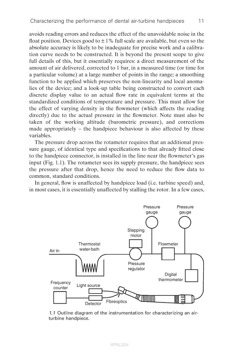
The pressure drop across the rotameter requires that an additional pressure gauge, of identical type and specifications to that already fitted close
to the handpiece connector, is installed in the line near the flowmeter’s gas
input (Fig. 1.1). The rotameter sees its supply pressure, the handpiece sees
the pressure after that drop, hence the need to reduce the flow data to
common, standard conditions.
In general, flow is unaffected by handpiece load (i.e. turbine speed) and,
in most cases, it is essentially unaffected by stalling the rotor. In a few cases,
Pressure
gauge
Pressure
gauge
Stepping
motor
Air in
Thermostat
water-bath
Flowmeter
Pressure
regulator
Frequency
counter
Digital
thermometer
Light source
Detector
Fibreoptics
1.1 Outline diagram of the instrumentation for characterizing an airturbine handpiece.
WPNL2204
12
Dental biomaterials
a small reduction (0.1–0.3 L/min) occurs in specific rotor positions (i.e. with
a rotor blade adjacent to the supply nozzle, effectively blocking it), although
slow rotation (>1/s) causes the effect to become undetectable and thus of
no practical importance.
Connection of the air supply to the handpiece needs to be made via the
appropriate three-hole or four-hole connector. In normal clinical use, fourhole connectors have flexible tubing attached to the exhaust port to carry
the exhaust gas back to the dental unit. Variation in the resistance to
exhaust flow is to be expected from this source, depending on the length,
bore, and degree of bending of the tubing. It is a matter for consideration
whether this effect is to included or avoided. No attached tubing is preferred for handpiece characterization. Typically, three-hole connectors have
apertures for the exhaust air, and these must be left unobstructed. It is
worthwhile checking that the entire system up to the handpiece itself is leak
tested. Pressurizing to 4 or 5 bar, say, and shutting off the air supply at
source, allows observation of any pressure drop with time. Less than, say,
0.05 bar in 2 min may be considered adequate.
Since the purpose is generally to measure flow through the turbine alone,
it is necessary to block any coolant nozzles that use air, or by closing the
supply tube at the handpiece connector. Otherwise, no attempt should be
made to close any leaks around the handpiece head as these are properly
part of the actual working design. Any internal flow restricting mechanism
in the handpiece (to allow a switch to be made between two alternative
supply pressures at the connector) should be noted, but most commonly
these are set in the open position in practice.
The complexity of the gas path in the handpiece means that no simple
theoretical equation exists to relate actual flow rate, V̇, after the necessary
corrections, to the supply (absolute) stagnation pressure, p0, and at that
pressure. The pragmatic ‘black-box’ approach entails a simple non-linear
curve fit. The following function provides an adequate description of the
behaviour:
b
A ⎤
⎡
V = V L ⎢1 − ⎛ ⎞ ⎥
⎝
p0 ⎠ ⎦
⎣
1/2
A and b are the parameters to be fitted and which control the curve shape
(A represents ambient pressure, but b cannot be interpreted in terms of a
specific feature of handpiece design), and V̇L is the limiting flow rate (i.e. at
‘choke’) which corresponds to the flow at some point in the system reaching
the sonic velocity. Since such a condition can occur even in a simple circular
orifice (such as the nozzle in the turbine head), the handpiece can be characterized as being equivalent to such an orifice via the equation for choke.
The relationship is:
WPNL2204
Characterizing the performance of dental air-turbine handpieces
13
V̇L = πre2c
where re is the effective radius of that orifice and c is the speed of sound,
itself given by:
c=
g p0
r
where r is the density under the prevailing conditions, p0 is the absolute
stagnation pressure, and g is the ratio of specific heats cp/cv (which may be
treated as a constant as the absolute temperature is sufficiently high and
changes are moderate). The area of the equivalent orifice, πre2, is therefore
a measure of the ability of the handpiece to deliver air to the turbine in a
strictly controlling sense.
If the flow rate needs to be expressed in terms of ‘free air’, i.e., at atmospheric pressure, to relate this to compressor pumping capacity, for example,
the isothermal gas law (Boyle’s) is used:
V2 = p1V1/p2
where p1, p2 are the pressures and V1, V2 the volumes before and after
expansion to atmospheric pressure, respectively.
1.5.3 Temperature
Supply air temperature can be measured well enough with a type-K thermocouple placed in the gas flow beyond the flowmeter, providing this does
not interfere with the flow, i.e. it is small enough. A T-piece such that the
thermocouple is level with the supply line wall is adequate. However, it
must be remembered that all gas calculations are in terms of absolute
temperature.
1.5.4 Speed
Many methods have been used to monitor rotation, with varying degrees
of success. These techniques have been reviewed in detail elsewhere,58 and
the deficiencies identified. Clearly, any technique that requires work from
the rotating system is unacceptable, and non-contact methods are essential.
Likewise, anything that appreciably changes the angular inertia or balance
of the system is inappropriate. Severe errors are introduced if these points
are not adhered to. The most effective means of speed monitoring is optical,
and a fibreoptic tachometer can be used to measure the rotational speed
of any handpiece, cutting instrument, or test mandrel; it provides no load
on the turbine and has minimal bulk. Ultimately, such an approach would
be intrinsically safe for patient contact.
WPNL2204
14
Dental biomaterials
A sheathed 1-mm-diameter acrylic optical fibre with polished ends can be
used to transmit light from a (heat-filtered) quartz halogen lamp onto the
shaft of the tool in the handpiece chuck. The shaft needs to have approximately one-half of its circumference close to the nose of the chuck coated
with a matt black ink (i.e. of very small mass), the remainder being left
bright. A second optical fibre, similar to the first and at right angles to it, is
then held in a position to receive light reflected from the unpainted half of
the shaft such that at each rotation the receiving fibre returns a pulse of
light. This is then to be applied to a photo-detector whose output is connected to a frequency counter. This latter needs to be of high stability and
with no zero-offset,62 but with a recordable output signal proportional to
frequency, and hence speed. Alignment of the optical fibres is best done
using an oscilloscope to view the signal, using auto-triggered time-sweep
mode. Adjustment should be aimed at obtaining an approximately 50%
on–off (duty) cycle.
1.5.5 Free-running speed
The mandrel with the half-black sector is fixed in the handpiece chuck and
the optical fibres adjusted and checked for correct operation (oscilloscope).
If a pressure scan is undertaken, the rate of pressure change needs to be
slow in relation to the response time constant of the system as a whole
(equilibration of the gas stream, inertia of the turbine assembly); this can
be determined by trial and error, but probably no more than about 1 or
1.5 bar/min is appropriate. The maximum pressure used depends on the
equipment used, but clearly it needs to be checked for safety. Even so, 4 bar
probably represents a general upper limit, depending on the relevant manufacturer’s recommendations. A double cycle of raising and then lowering
the pressure to zero allows a check of reproducibility. Supply pressure,
temperature, and rotation rate are logged.
The upper limit to the rotational speed attainable for a rotor is set by the
speed of sound, so the actual free-running speed Nf is expressed through
the peripheral Mach number Ma* at a given supply pressure:
Ma* = 2πrrNf/c
where rr is the radius of the rotor. There remain turbine behavioural variables that have yet to be resolved, as indicated above, so the ‘black-box’
approach is used to define a rotor performance coefficient, ar:
ar
{1 − (g − 1)(Ma *)2 }
=
−
g
g −1
−1
πr 2e p0 g
which takes into account all such remaining aspects, determined from the
free-running speed and absolute stagnation pressure of the air supply,
WPNL2204
Characterizing the performance of dental air-turbine handpieces
15
through the equivalent orifice. Note the subscript ‘g’; this is a gauge pressure, i.e. the difference between the actual absolute stagnation pressure and
the surrounding atmospheric pressure. However, as far as the user is concerned, it is how well the device utilizes or translates the supply pressure.
Hence, we may combine the effective orifice and the rotor performance
coefficient into a single descriptor, the ‘pressure effectiveness’, a:
g
⎡
⎤
2 −
a = a r πr 2e = ⎢{1 − (g − 1)( Ma *) } g − 1 − 1⎥ / p0 g
⎣
⎦
This can be determined as the slope of the least upper bound of a plot of
the square-bracketed term on the right vs. p0g. Numerically, free-running
speed can then be estimated from
5.0358
−0.2867
Nˆ f =
T {1 − (1 + a p0 g / pat )
}
r
where pat is the (absolute) atmospheric pressure in bar, and T is the absolute
temperature of the supply air.
1.5.6 Torque
Torque (t) is defined as the moment of the force that tends to produce
rotation. From Newton’s third law of motion, this force is equal and opposite to the shaft braking force:
t = Fr
where F is the braking force and r is the radial distance of the point of
application of that force from the axis of rotation. If the braking force is
gradually increased from zero, the turbine speed will progressively reduce
until it stalls. Thus, for a given turbine, t vs. rotation rate (N/Hz) can be
plotted, the maximum value for t being at the point of stall.
Braking force is most easily determined by the technique known as a
‘rope brake’.63 This requires a thread wrapped around the rotating shaft,
friction being applied by tension in that thread, the braking force. The
measurement is best performed with a load cell on a universal mechanical
testing machine, or equivalent frame, for stability and accuracy. The shaft
or drum in contact with the thread needs to be rather well-polished if
excessive wear (and frequent replacement) of the thread is to be avoided
in dynamic torque tests. Even so, replacement can be expected to be required
when oxidation becomes excessive and polishing no longer practical. The
shaft can become quite hot and it is important to allow it to cool between
runs if the thread is not to burn. While in principle almost any kind of thread
will suffice, in practice there are some factors to be borne in mind. The heat
WPNL2204
16
Dental biomaterials
of friction may melt thermoplastic polymers, and stable close approximation of thread to shaft is essential for steady values to be obtained. The
latter implies flexibility, as obtained from a fine-fibre yarn. Similarly, a yarn
that tends to flatten somewhat and obtain more points of contact will be
preferable. Overall, the most effective thread has been found to be braided
suture silk. Lubricants are of no benefit in this context. Displacement over
time causes erratic effects, and their stickiness can cause the fibres of the
thread to catch and bind.
The effective end of the moment arm does not lie at the surface of the
drum or shaft in contact with the thread, and a small error will be present
if this is assumed. For the braided suture silk that is recommended for the
thread, the correction amounts to one-third of the thickness when flattened
under load. This is measured well enough by a caliper gauge on the overall
diameter with the thread in place.
A universal mechanical testing machine fitted with two load cell amplifiers (LCAs) and two load cells (10 N full scale range is appropriate) can be
used to measure forces and thus deduce torque. One load cell is mounted
(say) on the upper, fixed, crosshead and the other to the upper surface of
the moveable crosshead, ensuring the two load axes are accurately aligned.
A self-centering thread attachment is required on each. Provision for clamping the handpiece accurately in place must be made so that its position with
respect to the load axis is preserved, most conveniently this is fixed to a
crosshead (a hard rubber ‘V-block’ mounting is satistfactory, but see reference 61 for a more precise approach).
1.5.7 Bearing resistance
This is the torque required to rotate the turbine against the friction of the
bearings. Note that this cannot be done for air bearings (which one hopes
would have negligible intrinsic friction) as they require air to be supplied
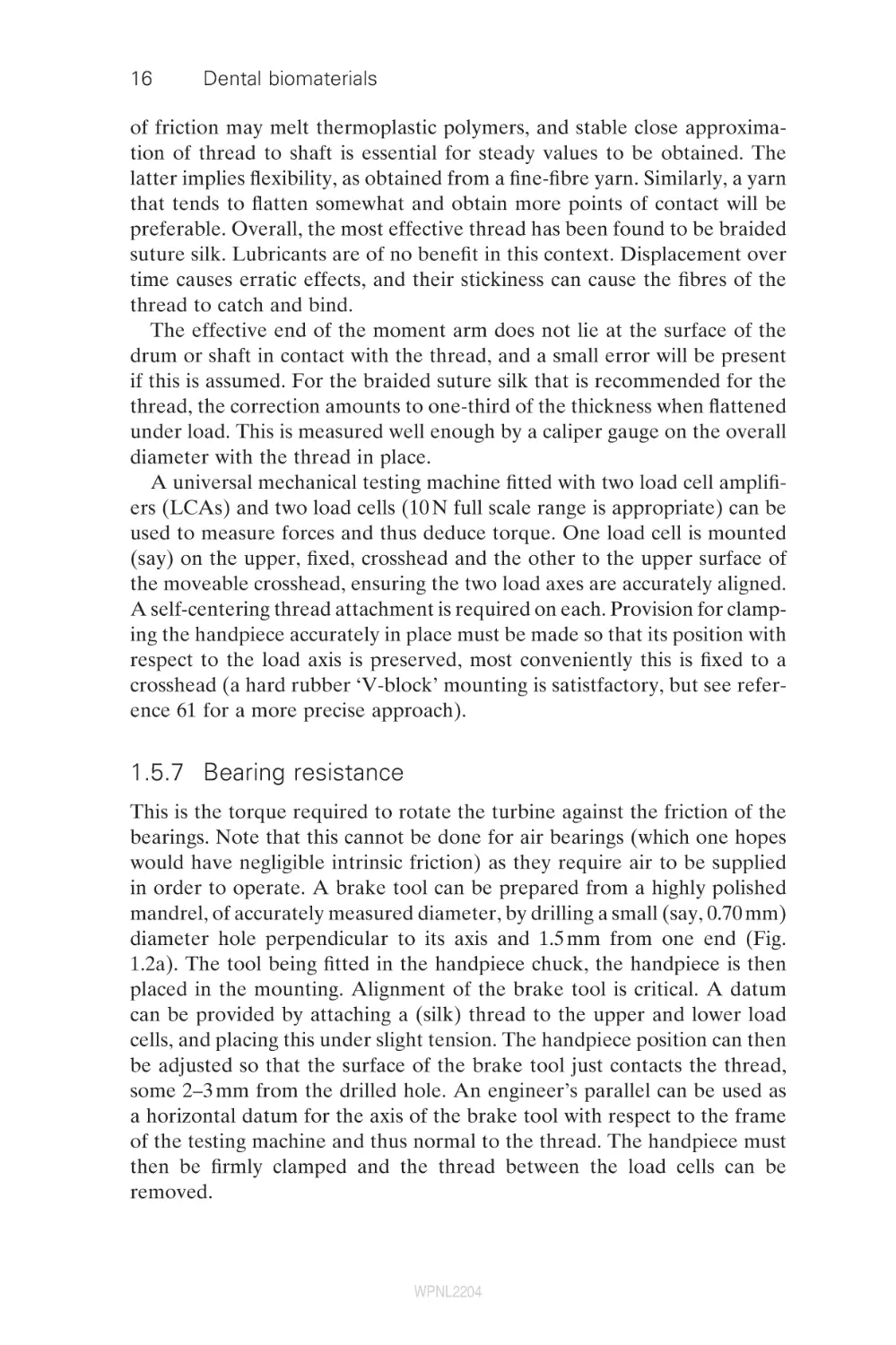
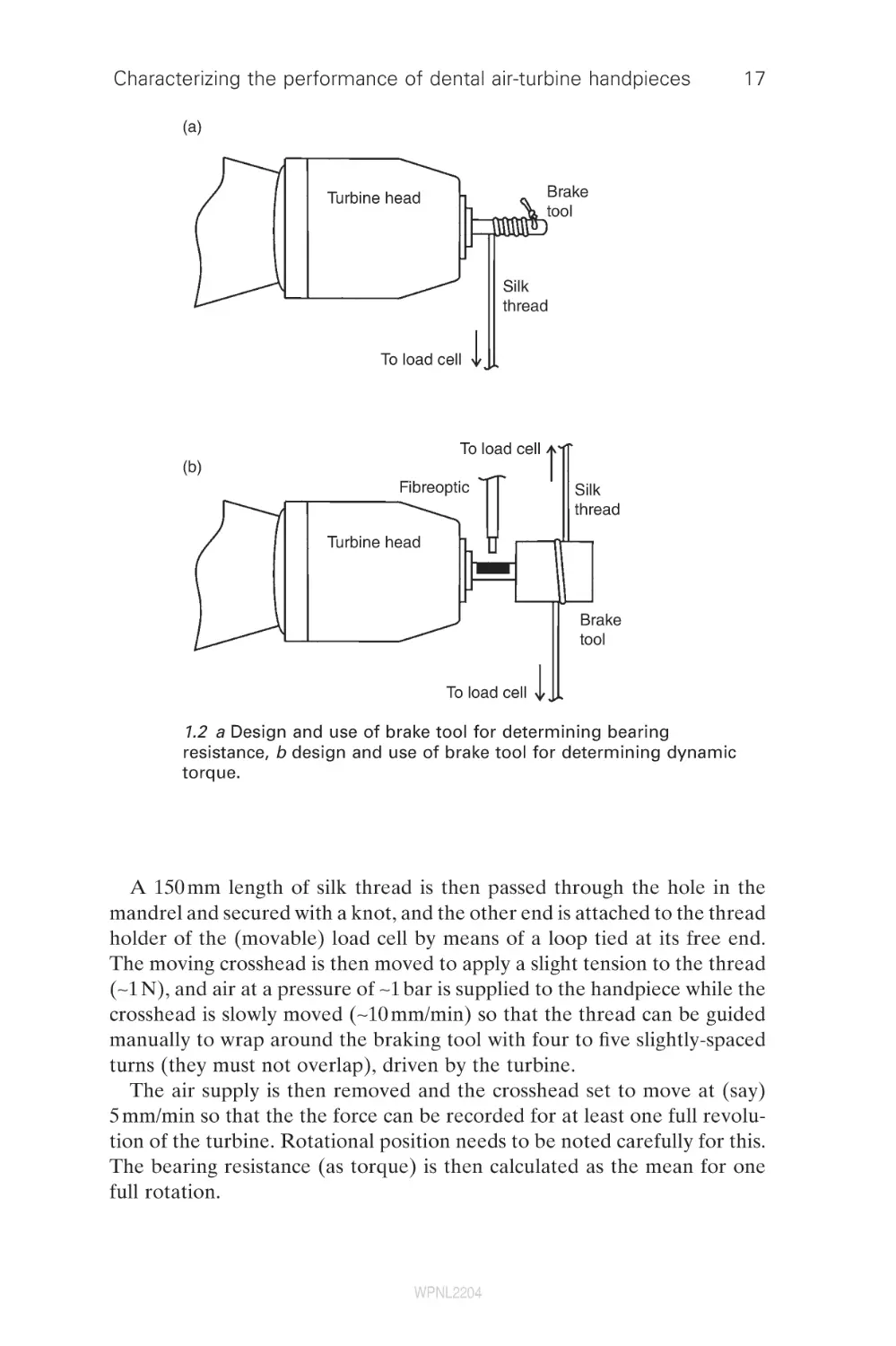
in order to operate. A brake tool can be prepared from a highly polished
mandrel, of accurately measured diameter, by drilling a small (say, 0.70 mm)
diameter hole perpendicular to its axis and 1.5 mm from one end (Fig.
1.2a). The tool being fitted in the handpiece chuck, the handpiece is then
placed in the mounting. Alignment of the brake tool is critical. A datum
can be provided by attaching a (silk) thread to the upper and lower load
cells, and placing this under slight tension. The handpiece position can then
be adjusted so that the surface of the brake tool just contacts the thread,
some 2–3 mm from the drilled hole. An engineer’s parallel can be used as
a horizontal datum for the axis of the brake tool with respect to the frame
of the testing machine and thus normal to the thread. The handpiece must
then be firmly clamped and the thread between the load cells can be
removed.
WPNL2204
Characterizing the performance of dental air-turbine handpieces
17
(a)
Brake
tool
Turbine head
Silk
thread
To load cell
To load cell
(b)
Fibreoptic
Silk
thread
Turbine head
Brake
tool
To load cell
1.2 a Design and use of brake tool for determining bearing
resistance, b design and use of brake tool for determining dynamic
torque.
A 150 mm length of silk thread is then passed through the hole in the
mandrel and secured with a knot, and the other end is attached to the thread
holder of the (movable) load cell by means of a loop tied at its free end.
The moving crosshead is then moved to apply a slight tension to the thread
(∼1 N), and air at a pressure of ∼1 bar is supplied to the handpiece while the
crosshead is slowly moved (∼10 mm/min) so that the thread can be guided
manually to wrap around the braking tool with four to five slightly-spaced
turns (they must not overlap), driven by the turbine.
The air supply is then removed and the crosshead set to move at (say)
5 mm/min so that the the force can be recorded for at least one full revolution of the turbine. Rotational position needs to be noted carefully for this.
The bearing resistance (as torque) is then calculated as the mean for one
full rotation.
WPNL2204
18
Dental biomaterials
1.5.8 Stall torque
This is the torque generated by the air flowing through the non-rotating
turbine. The same set-up is used as for bearing resistance (Section 1.5.7),
but now the air pressure is adjusted to that required for the test, allowing
a few seconds for stabilization. The moving crosshead can then be moved
away at, say, 5 mm/min for recordings to be made of pressure vs. load and
flow rate until the turbine has rotated through at least 360°e. For repeat
tests, or tests at other pressures, the crosshead is returned to its original
position while the thread is guided back into evenly spaced turns on the
tool as above. The rate of crosshead movement chosen must be slow enough
to effectively stall the turbine. No distinction can then be made between
the values obtained with this rate of movement and those achieved by stopping the crosshead at frequent small increments. Stall torque is then taken
as the average over a full rotation, as determined by reference to the variation (if any) with position and a knowledge of the number of blades and
nozzles in the device. Such recordings also allow the effect of rotor position
to be investigated. It is to be noted that averaged stall torque is not, in
general, the same as the mean of the upper and lower limits observed: the
variation with rotor position is more complicated than permits this simple
calculation. In effect, it is determined by the area under the curve for one
full rotation, a properly weighted mean over all positions.
Stall torque is directly proportional to the stagnation air pressure, p0g:
tp = Fp0g
where F is the stall torque coefficient, atmospheric pressure of 1 bar. Thus,
in principle, only one determination needs to be made in order to predict
behaviour at other pressures, providing the air flow remains subsonic (which
is the case in the dental context).
1.5.9 Dynamic torque
Although the theoretical torque behaviour of a driven rotating system is
well-understood, the effects of imbalance in rotor or tools can only be
detected dynamically. Thus, a direct measurement of dynamic torque may
be of value as a means of detecting imbalance or resonance which can only
reduce the available torque.
Brake tools, with highly polished drums, may be made by precise
machining from stainless steel. Because the balance of the brake tool is
crucial to this test, those to be used must first be screened using a handpiece that has been shown by trial to be well-balanced and to show no
resonance effects itself. A free-running speed vs. air pressure scan then
allows those tools with defects to be discarded. This is a very severe test,
WPNL2204
Characterizing the performance of dental air-turbine handpieces
19
but a discrepancy of more than 300 /s at any pressure can be taken as a
convenient criterion for discard. If the brake tool drum diameter is too
small, the thread tends to break before stall can be achieved; too large
and obtaining satisfactory balance becomes too difficult. Some 3.0 ± 0.5 mm
may be suitable.
The diameter of the brake drum needs to be determined accurately with
a micrometer screw gauge or equivalent device (and corrected for thread
thickness as described for stall torque) before being fitted in the handpiece
chuck. The handpiece is then mounted and aligned as for stall torque. A
check should be made that the speed detector is working properly and the
load cells zeroed and calibrated, confirming by applying a slight tension to
the thread (−2 N) that the outputs are equal. However, it is the difference
in load that is required for the actual test and this may be obtained directly
by a differential voltage recording, or by post-processing of the two load
signals.
The movable crosshead is then moved (no air pressure applied to the
handpiece) to allow a single turn of the thread to be passed over the circumference of the brake drum (Fig. 1.2b). The crosshead is then repositioned to tighten the thread sufficiently to prevent rotation of the turbine
at the maximum supply pressure to be tested. (Differential) force vs. speed
can then be recorded while the crosshead is raised and lowered, at 1 mm/
min between the points giving (close to) the free-running speed (with zero
difference signal from the load cells) and stall. It should be noted that the
slightest touch of the thread is enough to slow the turbine, and the true
free-running speed will not be reached in this test. Resonance effects can
lead to marked (negative) deviations of the torque–speed plot from the
expected straight line.
The supply pressure required to start a turbine may vary according
to the position of the rotor at stall. It is therefore easiest to determine
the stall pressure or torque only on lowering the pressure, although the
direct measurement of stall torque as described above is a simpler
procedure.
The expected torque at any supply pressure, t̂p, is expressed by the
following equation:
⎛
N ⎞
tˆ p = Fp0 g ⎜ 1 −
⎟
⎝
Nˆ fp ⎠
That is, it decreases linearly with speed N to zero at the free-running speed,
N̂fp, simply scaling the stall torque by the proportion of the free-running
speed then exhibited. (The subscript ‘p’ is added to the free-running speed
symbol to emphasize that it is pressure-dependent and specified for the
stated supply pressure, p0g).
WPNL2204
20
Dental biomaterials
1.5.10 Power
The rate at which a handpiece supplies energy to the cutting site, its power,
is determined by the handpiece’s torque and speed. These describe the
ability to carry out cutting work but such data will be essential for use in
the analysis of cutting behaviour, when this becomes feasible.
Power (P), the rate of doing work, is given by:
P = wt
where w is the angular velocity in radians/s
w = 2πN
i.e.
P = 2πNt
Determination of power thus, in principle, requires (dynamic) torque and
rotation rate to be determined simultaneously. We can, however, write for
the expected power, P̂ :
⎛
N ⎞
Pˆ = 2 πFp0 g ⎜ 1 −
⎟N
⎝
Nˆ fp ⎠
which is therefore a parabolic curve with zeros at stall and free-running.
The maximum expected power, P̂max, therefore occurs at half the freerunning speed, N = N̂fp/2:
π
Pˆmax = Fp0 g Nˆ fp
2
1.5.11 Efficiency
There are several possible approaches to the definition of efficiency in the
present context, but the primary interest may be in the demands placed
by the handpiece on the compressor. Thus, we take the efficiency of a
handpiece as the ratio of the useful work done at the rotary cutting instrument to the potential work in the supplied compressed air. Actual power
is obtained from torque and speed as above, while the potential energy
of the air supply is the maximum work available when the air expands to
atmospheric pressure. Here, we may reasonably assume that the air
behaves sufficiently like an ideal gas. As the expansion occurs quite rapidly
it may further be assumed (conservatively) that this process is adiabatic
and reversible (i.e. non-dissipative). The maximum work available on
expansion (W) for a given flow rate V̇ m3/s (at the supply pressure) is
given by:
WPNL2204
Characterizing the performance of dental air-turbine handpieces
W=
21
V
p 11/g p(2g − 1)/g − p1 )
(
1−g
where p1 and p2 (in Pa) are the inlet and outlet absolute stagnation pressures, respectively. Efficiency (h) is then given by:
h=
P
W
The difference between P and W depends on the rate at which ‘unused’
energy is discharged in the exhaust plus the total rate of energy loss due to
friction in rotor bearings, air flow within the handpiece, and noise emission
(which is in fact small). It may therefore be seen that handpiece efficiency
(h) at any particular speed (N) may be determined from measurements of
supply pressure (p1), air flow (V1/s), and torque (T). The maximum efficiency
is seen to occur at the maximum expected power:
hmax =
Pˆmax
W
1.5.12 Longevity
The working life of a dental air turbine is limited by the length of time its
bearings can adequately function under the conditions imposed during
clinical work. Standardized laboratory longevity tests of the rotor-bearing
assembly require that the handpiece is subjected to the same patterns of
use that might be expected in clinical practice, that is, in respect of duty
cycle, axial and lateral loading, lubrication state, and cleaning and sterilization procedures. This is very time consuming and laborious. Only one report
of a study involving this kind of work has been published.64 Bearing longevity tests in which only gross failure (such as collapse of bearing casings or
seizure) can be detected require the handpieces to be run for lengthy
periods, but, in view of the ordinary expectation of lubrication for metal
bearings, such results may not be very meaningful. However, bearing resistance may be monitored as a sensitive means of detecting wear or corrosion.
Acceptability criteria have not been established in this sense.
1.5.13 Comparisons
Given the sensitivity of several of the above measures to the supply pressure, it is clearly not easy to make comparisons between devices whose
recommended pressures differ, except in a restricted sense. Indeed, a manufacturer could raise the torque and power of a handpiece simply by specifying a higher working pressure. It is therefore informative to use standardized
WPNL2204
22
Dental biomaterials
measures at an arbitrary but representative supply pressure, say, 2 bar. We
can then define the following:
•
standardized free-running speed
Nf2
•
standardized power index
PI2 = πFN̂f2
•
standardized efficiency index
EI 2 =
•
PI 2
W
standardized air consumption
()
b 1/2
⎡
1 ⎤
pV2 = 3VL ⎢1 −
3 ⎥⎦
⎣
(where p0g = 2, so p0 = 3, and A is set to 1 bar in the equation on page 12)
It might also be convenient to determine the corresponding values for
the recommended supply pressure, when this differs.
1.5.14 Figures of merit
Table 1.1 summarizes the descriptors and performance measures detailed
in the above sections. The table is divided into two parts, the first containing
Table 1.1 Summary of the descriptive parameters and performance
figures of merit for handpiece air-turbine behaviour
Character of factor
Symbol
Values required in the course of testing
Turbine rotor radius
Limiting air flow
Flow exponent
Equivalent orifice radius
Standardized free-running speed (2 bar)
Rotor performance coefficient
r
V̇ L
b
re
Nf2
ar
Figures of merit of interest to the user
Handpiece pressure effectiveness
Weighted mean stall torque coefficient
Standardized free air consumption (2 bar)
Standardized power index (2 bar)
Standardized efficiency index (2 bar)
a
F
pV̇ 2
PI2
EI2
WPNL2204
Characterizing the performance of dental air-turbine handpieces
23
those items that need to be determined for the testing itself, and the second
those figures of merit that convey quantities that are directly comparable
between devices and which are therefore of interest to the user. Some
examples of values can be found elsewhere.56
1.6
Hazards
There is a vast literature dealing with the hazards posed to the patient and
dental personnel by air-turbine handpiece use. It is only possible to give a
brief account here of the problems of heat, airborne materials, sterility,
noise, projectiles and surgical emphysema.
1.6.1 Heat
Heat generation has possible harmful effects on the dental pulp, dental
hard tissues and restorative materials. Temperature changes occur because
of the thermalization of the work of friction and plastic deformation
occurring at the cutter–substrate interface. Actual temperature depends
on rate of power deposition and the thermal diffusivity of the materials
involved, including the effects of coolants. However, care must be taken
to distinguish purely thermal effects on vital teeth65–67 from damage that
occurs due to mechanical vibration,68,69 dehydration,67,70–72 and the chemical effects of solutions or restorative materials that are subsequently
applied.73
Effects range from internal resorption74 to dentinal reddening or ‘blushing’ due to dilatation and rupture of blood vessels, and extravasation of
erythrocytes.75 Histological changes include an inflammatory response (e.g.
vasodilatation, haemorrhage, oedema, and infiltration of polymorphonuclear leucocytes),76 changes in the layer of odontoblasts (e.g. the appearance of vacuoles within the layer,76 and displacement of odontoblastic nuclei
with separation from their cytoplasmic processes).77 Some practitioners
prefer to perform cavity preparation dry on the grounds that visibility is
improved78,79 but there is much evidence that this is hazardous to the
pulp.72,78–90 Air coolant alone is inadequate.91
Surface effects – such as smearing, cratering, and crack formation – that
may occur during preparation of cavities and finishing of restorations have
been observed,78,79,92–102 while dry cutting of enamel can induce sufficiently
high thermal stress to fracture it,101 possibly aided by cracks induced by
the hammering of blades. Raising the temperature of amalgam may melt
it peritectically, while polymer-based materials may be raised above
their glass-transition temperatures and suffer permanent plastic deformation or decomposition. Glass-ionomer and similar cements may be
dehydrated.
WPNL2204
24
Dental biomaterials
1.6.2 Airborne materials
Material may be dispersed through the air as an aerosol or vapour when
an air-turbine handpiece is used. An aerosol is a dispersion of solid or liquid
particles in a gas, and may contain micro-organisms, oil, or particles of solid
materials. Particles of all cut materials may be thrown up – including enamel,
dentine, cement, and restorative materials – but also from the cutter: steel,
tungsten carbide, diamond, and others.
Although such particles are generated by polishing lathes, air-abrasive
prophylaxis equipment, ultrasonic scalers, and air–water syringes, air-turbine
handpieces are among the most prolific producers of aerosols.103 About 95%
of the particles in dental aerosols have a diameter of less than 5 μm104,105
and may be fully inhaled.103–144 Larger particles may be carried considerable
distances as ‘splatter’, when they are said to be ballistic,123 and be deposited
on exposed surfaces in the dental surgery, including the clothing and skin
of the dentist and assistant, and into their eyes, noses, and mouths. Aerosols
may be carried to other rooms.105
Pathogenic micro-organisms of many kinds may be dispersed from the
patient’s saliva or other oral fluid, carious dental hard tissues and infected
calculus,117 the water supply to the handpiece coolant nozzle (either from
the water source, reservoirs and tubing or from the patient by fluid retraction),129,138,145–150 and contaminated surfaces of the handpiece or rotary
cutting instrument from use on a previous patient.151
1.6.3 Oil
Although continuous oil-mist lubrication is no longer required, bearing
lubricants will be expelled in ordinary use for a considerable period. This
may be inhaled, but oil contamination of surfaces for bonding procedures
may be detrimental.152 Oil-free compressors are important for the same
reasons.
1.6.4 Mercury vapour
Cutting amalgam generates mercury vapour as the peritectic melting of the
γ1 phase occurs at the relatively low temperature of about 70 °C and this
is easily attained under a cutting point. Water spray mitigates this
considerably.140,153,154
1.6.5 Airborne materials precautions
A number of precautions should be taken when using the air-turbine handpiece to avoid airborne material hazards:
WPNL2204
Characterizing the performance of dental air-turbine handpieces
•
•
•
•
•
•
•
•
•
25
Water coolant should be used to reduce solid aerosols, mercury vapour,155
as well as heat. However, this may result in an increased number of
bacteria being disseminated in aerosols;108,120 additional measures are
necessary.
High-velocity evacuation can capture large volumes of aerosol.
Rubber dam isolates the operating site from oral fluids.
Good ventilation of the surgery will maintain low ambient
concentrations.
Face masks,119,121,128 transparent shields,118,156 protective spectacles,119
rubber gloves,157,158 and appropriate protective clothing130 will protect
dental personnel.
Patient oral hygiene affects one source of bacteria.110,111,127,128,131
The dental unit water line should be properly maintained, regularly
flushed,148 treated, and filtered.
Surfaces exposed to aerosol and splatter should be cleaned and
disinfected.159
Lubricate handpieces with non-toxic oils.107,113
It may be advisable to avoid the use of an air-turbine handpiece (or other
device that produces profuse aerosols) when treating patients who are
known carriers of communicable diseases such as hepatitis B,157,160 tuberculosis,109,126 or AIDS,161 although, with respect to hepatitis B at least, it
has been pointed out that aerosols are ‘an uncommon and inefficient
method’162 of transmission. Carriers of such infections cannot always
be identified.163,164
1.6.6 Sterility
It is now generally accepted that handpieces ought to be sterilized between
patients. Surface disinfection by chemical agents165 or ultraviolet light are
inadequate. Older devices, however, may suffer destruction of plastic and
rubber parts, and corrosion (especially of aluminium alloys) on autoclaving.
Treatment dry may exacerbate this. Most current models appear capable of
withstanding many cycles of steam autoclaving, but instrument changing
tools, and the instruments themselves, should not be overlooked; nor should
lubrication equipment and other objects that come into contact. Corrosion
of bearings may affect performance.
1.6.7 Noise
The noise of air turbines, particularly the siren whine, may have several
effects: auditory, psychological, sociological, and physiological. There
may be some hearing loss in susceptible individuals, often temporary but
WPNL2204
26
Dental biomaterials
potentially permanent. It interferes with speech communication and the
perception of other auditory signals. It is a source of annoyance and interferes with the performance of detailed or complicated tasks as well as
adversely influencing mood. The repetitive exposure of dental personnel
may increase the risk and severity of effects, but there is no evidence of a
general problem.166
Noise may be aerodynamic, that is, generated by turbulence in the gas
flow, or structural, from moving parts such as bearings. Noise from the cutter
is also present. Smooth air line design can reduce turbulence noise, but
while silencers on the exhaust can be effective, they may restrict air flow
and change the behaviour of the device, and, if adding weight to the device,
would affect fatigue and precision of use. Four-hole as opposed to threehole connectors may be preferable, again with the caveat about air-flow
resistance.
1.6.8 Projectiles
The fracture of teeth, restorations, or indeed the cutting instrument, may
result in a high-velocity projectile that is a risk to soft tissue through penetrating wounds, in the mouth or externally, to all present.167–169 Inhalation
or swallowing of such fragments is also a concern. Attempting to straighten
bent cutters may exacerbate the risk of fracture; proper balance is unlikely
to be attained. Wear of the cutter may also lead to fracture.
1.6.9 Surgical emphysema
Surgical emphysema refers to the ingress of air into soft tissue as a result
of injury or surgical operation. This may be caused if there is a breach in
the oral epithelium, or when a tooth is opened for endodontic treatment,
and any equipment is used that exhausts compressed air into the mouth.
Air-turbine handpieces have been recommended in a number of contexts
where there would seem to be a particularly high risk of this, and there have
been many such reports:170–194 including pneumoparotid,195 subcutaneous
facial and cervical, mediastinal, and orbital. There may be grave or fatal
complications: dogs may die if air is introduced under pressure into the root
canals of their teeth, and indeed several people are thought to have died in
similar circumstances.
1.7
Factors in selection and operation
It will be apparent from the above that we are as yet far from a complete
characterization of handpieces that would enable clearly informed selection
by the user. This is not helped by the fact that performance depends in part
WPNL2204
Characterizing the performance of dental air-turbine handpieces
27
on other factors, primarily cutter and substrate. Thus, definitive guidelines
cannot be given, and only some general points can be made, more by way
of food for thought than advice:
•
•
•
•
•
There is a lack of satisfactory standards (the International Organization
for Standardization (ISO), for example, has limited requirements).
There is a lack of detailed specifications of performance provided by
most manufacturers – although the use of simple figures of merit given
here would allow comparisons.
Ability to be autoclaved repeatedly is essential.
Other less-commonly considered factors are also of interest: air consumption, ergonomics, noise, efficiency of coolant delivery.
However, the buyer is often guided by the reputation of the manufacturer, appearance, price, and prior use.
In operation:
• Avoid use in procedures that involve (or may create) a breach in the
oral mucosa; not for surgical or endodontic use; should also avoid use
deep in the gingival sulcus (surgical emphysema).
• Ensure that the rotary cutting instrument is undamaged (imbalance
leads to substantial vibration).
• Ensure that the lubrication routine is properly executed.
• Ensure that the chuck mechanism is operating correctly (risk of
projectiles).
• After cutting, degrease the operating site before bonding (continuing
oil discharge).
• High-volume aspiration (and rubber dam whenever appropriate) to
reduce aerosol dispersion (infection control concerns).
In summary, in spite of some known concerns about its safety and operating
convenience, the air-turbine handpiece remains as standard equipment for
most dental cutting work. Research is needed to address the issues of:
•
•
•
•
•
air and oil discharge into the mouth;
optimal rotary cutting instrument design and handpiece operation;
bearing longevity;
noise and vibration;
agreement between manufacturers on standards for describing their
products would allow buyers to make informed decisions when selecting
handpieces.
1.8
Future trends
Even with the movement towards minimalized preparation of teeth for
restoration (e.g. ‘minimally invasive dentistry’196 and ‘microdentistry’197),
WPNL2204
28
Dental biomaterials
there will remain a need for cutting methods that can cope with the sectioning and removal of old restorations and bulk removal of tooth tissue for
the provision of extracoronal restorations. Non-rotary removal techniques
such as air abrasion and laser tooth preparation are employed for certain
procedures that require minimal removal of material, but these are not
appropriate for use on toxic heavy metals. However, most cutting work is
still carried out using turbine handpieces or, in some cases, using electric
motors and speed-increasing handpieces (gearing ratio 1 : 4 or 1 : 5, speeds
80 000 rpm or above). Such speed-increasing handpieces depend on the
transmission of rotations through the handpiece body and head and are
subject to wear of the components of the transmission system. There are
arguments for and against electric devices.198 Even so, future developments
of both turbine and speed-increasing handpieces will depend on the availability of components such as bearings that will have lower maintenance
requirements and improved longevity. Given that the designs of dental air
turbines have changed little since they were first commercially introduced,
and that manufacturers do not appear to be taking a systematic approach
to development, it seems unlikely that any radically different turbine design,
or indeed more efficient devices, will emerge in the foreseeable future. This
is an economic constraint: it is not worth investing in detailed development
when the product appears to work satisfactorily. However, the possibility
of further improvement and acceptance of ceramic bearings, which will
require neither lubrication nor corrosion protection, displacing steel bearings, offers the prospect of simpler maintenance, better adherence to the
sterilization imperative, and removal of a source of oil contamination of
prepared surfaces.
1.9
References
1. green gf. Pneumatic tooth burr and drill. US Patent 77370. 1868.
2. straub aw. Improvement in implements for giving motion to tools. US Patent
154569. 1874.
3. wilkerson bm. Improvement in dental engines. US Patent 189409. 1877.
4. laurence h. Improvement in dental engines. US Patent 213909. 1879.
5. anonymous. A century of service to dentistry. Philadelphia: S.S. White Dental
Mfg. Co.; 1944.
6. hoffmann-axthelm w. History of dentistry. Chicago: Quintessence; 1981,
pp. 287–325.
7. sockwell cl. Dental handpieces and rotary cutting instruments. Dent Clin
North Am 1971;15:219–44.
8. vinski i. Two hundred and fifty years of rotary instruments in dentistry. Br Dent
J 1979;146:217–23.
9. lässig he, muller ra. Dentistry in the history of art and civilization.
Amsterdam: Elsevier; 1985.
WPNL2204
Characterizing the performance of dental air-turbine handpieces
29
10. brabant h. Emile Huet et la Fondation Documentaire dentaire. Rev Med Brux
1966;22:303–10.
11. walsh jp, symmons hp. Vibration perception in teeth during cavity preparation.
NZ Dent J 1948;44:39–41.
12. walsh jp, symmons hp. Vibration perception and frequencies. Part 2. NZ Dent
J 1949;45:106–14.
13. walsh jp. Vibration sensibility in teeth and its association with cavity preparation. DDSc Thesis, University of Melbourne, 1949.
14. walsh jp, symmons hp. A comparison of the heat production and mechanical
efficiency of diamond instruments, stones, and burs at 3,000 and 60,000 rpm.
NZ Dent J 1949;45:28–32.
15. peyton fa, henry ee. Problems of cavity preparation with modern instruments.
NY State Dent J 1952;22:147–57.
16. peyton fa, henry ee. The effect of high speed burs, diamond instruments and
air abrasive in cutting tooth tissue. J Am Dent Assoc 1954;49:426–35.
17. peyton fa. Evaluation of dental handpieces for high speed operations. J Am
Dent Assoc 1955;50:383–91.
18. christensen gj, wittrock jw. The use of ultra-high speed handpieces. J Ky Dent
Assoc 1966;18:18–24.
19. peyton fa. Status report on dental operating handpieces. Council on Dental
Materials and Devices. J Am Dent Assoc 1974;89:1162–70.
20. morrant ga, stephens rr. The development and application of modern methods
in cavity preparation. IX. The material and design of cutting points. Br Dent J
1960;109:334–9.
21. osborne j, anderson jn, lammie ga. Tungsten carbide and its application to the
dental bur. Br Dent J 1951;90:229–43.
22. henschel ch. The development of thermal control. J Am Dent Assoc
1946;33:194–200.
23. holson jc. Dental spraying apparatus. US Patent 739674. 1903.
24. lyman i. Chip blower and syringe attachment for dental engines. US Patent
743529. 1903.
25. craig sg. Dental tool moistener. US Patent 902942. 1908.
26. cunningham re, smith ac. Air and water attachment for dental engines. US
Patent 1000785. 1911.
27. bush iw. Automatic dental blower and syringe. US Patent 1080261. 1913.
28. adelman ch. Dental tool. US Patent 1494327. 1924.
29. hofschneider fj. Liquid controlling means for dental engines. US Patent
1557164. 1924.
30. hofschneider fj. Liquid feeding attachment for dental engines. US Patent
1592854. 1926.
31. hofschneider fj. Method and apparatus for grinding teeth. US Patent 1648273.
1927.
32. prather tf. Dental apparatus. US Patent 2098732. 1937.
33. henschel cj. Spray device for dental instruments. US Patent 2245036. 1941.
34. henschel cj. Dental engine accessory equipment. US Patent 2390710. 1945.
35. page rw. Dental apparatus. US Patent 2420338. 1947.
36. broussard rj, tilley jg. Air and water spray for dental engines. US Patent
2532054. 1950.
37. page rw. Dental engine control. US Patent 2542833. 1951.
WPNL2204
30
Dental biomaterials
38. page rw. Dental instrument. US Patent 2551458. 1951.
39. thompson wr. Principles of evacuative systems. Dent Clin N Am 1967;7:
367–81.
40. morrant ga, stephens rr. The development and application of modern methods
in cavity preparation. XI. Overcoming the difficulties of ultra-high-speed
equipmment. Br Dent J 1960;109:428–33.
41. simon wj. The hollow bur handpiece system. J Ky Dent Assoc 1976;28:19–22.
42. iseman jw. Dental tool. US Patent 2251057. 1941.
43. dyson je, darvell bw. The development of the dental high speed air turbine
handpiece – Part 1. Aust Dent J 1993;38(1):49–58.
44. norlén pi. Dental engine for compressed air. US Patent 2618064. 1952.
45. dyson je, darvell bw. The development of the dental high speed air turbine
handpiece – Part 2. Aust Dent J 1993;38(2):131–43.
46. brooking twh. A history of dentistry in New Zealand. Auckland: New Zealand
Dental Association; 1980.
47. nelsen rj, pelander ce, kumpula jw. Hydraulic turbine contra-angle handpiece. J Am Dent Assoc 1953;47:324–9.
48. walsh j. Difference of opinion. Letter to the Editor. J Am Dent Assoc
1965;70:704–5.
49. sockwell cl. Belt driven super speed equipment. J N Carolina Dent Soc
1963;46:114–21.
50. stephens rr. The dental handpiece – a history of its development. Aust Dent
J 1986;31:165–80.
51. ellis ca. Combined bearing and turbine element. US Patent 2891312.
1959.
52. norman dh. A preliminary appraisal of an air-bearing handpiece. Br Dent J
1963;114:90–2.
53. morrant ga, stephens rr. The development and application of modern methods
in cavity preparation. XII. Current and possible future development of apparatus for cavity preparation. Br Dent J 1960;109:474–9.
54. morrant ga, powell jw, hargreaves p. Air bearings and their application to
dental air turbine handpieces. Br Dent J 1964;116:531–9.
55. dyson je, darvell bw. The present status of dental rotary cutting tests. Aust
Dent J 1995;40(1):50–60.
56. dyson je, darvell bw. Torque, power and efficiency characterization of dental
air turbine handpieces. J Dent 1999;27(8):573–86.
57. dyson je, darvell bw. Aspects of the design of modern dental air turbine
handpieces. Aust Dent J 1993;38(6):456–70.
58. dyson je, darvell bw. Dental air turbine performance testing. Aust Dent J
1995;40(5):330–8.
59. dyson je, darvell bw. A laboratory evaluation of two brands of disposable air
turbine handpiece. Br Dent J 1997;182(1):15–21.
60. dyson je, darvell bw. Flow and free running speed characterization of dental
air turbine handpieces. J Dent 1999;27(7):465–77.
61. darvell bw, dyson je. A testing machine for dental air-turbine handpiece
characteristics: free-running speed, stall torque, bearing resistance. Oper Dent
2005;30(1):26–31.
62. darvell bw, lee pkd. Gould frequency converter: zero error correction. Lab
Pract 1987;36(3):82.
WPNL2204
Characterizing the performance of dental air-turbine handpieces
31
63. walker rt, morrant ga. Performance characteristics of air turbine handpieces.
Br Dent J 1975;139:227–32.
64. monaghan dm, wilson nhf, darvell bw. The performance of air-turbine handpieces in general dental practice. Oper Dent 2005;30(1):16–25.
65. bodecker cf. Demonstration of possible ill effects of heat on the pulp caused
by rapid operative technic. J Am Dent Assoc 1939;26:527.
66. stanley hr, swerdlow h. The potential abuse of high speed techniques. Dent
Clin North Am 1960(Nov):621–7.
67. stanley hr. Pulpal response to dental techniques and materials. Dent Clin
North Am 1971;15(1):115–28.
68. bernier jl, knapp mj. A new pulpal response to high-speed dental instruments.
Oral Surg Oral Med Oral Pathol 1958;11(2):167–83.
69. kawahara h, yamagami a. In vitro studies of cellular responses to heat and
vibration in cavity preparation. J Dent Res 1970;49(4):829–35.
70. brännström m. Dentinal and pulpal response. III. Application of an air stream
to exposed dentine, long observation periods. Acta Odontol Scand 1960;18:
235–52.
71. brännström m. Dentin sensitivity and aspiration of odontoblasts. J Am Dent
Assoc 1963;66:82–6.
72. cotton wr. Pulpal responses to cavity drying. J Dent Child 1971;38:85.
73. robinson h, lefkowitz w. Operative dentistry and the pulp. J Prosthet Dent
1962;12:985–1000.
74. dilts we, luebke rg. Internal resorption and crown preparation. J Prosthet
Dent 1967;18(2):126–30.
75. mullaney tp, laswell hr. Iatrogenic blushing of dentin following full crown
preparation. J Prosthet Dent 1969;22(3):354–9.
76. ciglar i, najzar-fleger d, stanicic t. Histopathological changes in dental
pulp after preparation of cavities with a high-speed drill. Acta Stom Croat
1982;16(2):87–91.
77. schuchard a. A histologic assessment of low-torque, ultrahigh-speed cutting
technique. J Prosthet Dent 1975;34(6):644–51.
78. schulein tm, field hm, jakobsen jr. Survey of high-speed cutting procedures
used by general practitioners in the United States. Gen Dent 1988;36:239–
41.
79. schulein tm. Wet and dry high-speed cutting procedures used by recent Iowa
graduates. Iowa Dent J 1987;73(3):28–31.
80. seltzer s, bender jb. Early human pulp reactions to full crown preparations.
J Am Dent Assoc 1959;59:915.
81. stanley hr, swerdlow h. Biological effects of various cutting methods in
cavity preparation: the part pressure plays in pulpal response. J Am Dent Assoc
1960;61:450–6.
82. brännström m. Cavity preparation and the pulp. Dent Progr 1961;2:4–8.
83. gardner af, hecht a. High speed – what does it do to the dental pulp? J Dent
Child 1962;29:72–84.
84. morrant ga, kramer ir. The response of the human pulp to cavity preparations
using turbine handpieces. Br Dent J 1963;115:99–110.
85. hamilton ai, kramer ir. Cavity preparation with and without waterspray effects
on the human dental pulp and additional effects of further dehydration of the
dentine. Br Dent J 1967;123(6):281–5.
WPNL2204
32
Dental biomaterials
86. langeland l, langeland lk. Cutting procedures with minimized trauma.
J Am Dent Assoc 1968;76:991–1005.
87. marsland ea, shovelton ds. Repair in the human dental pulp following cavity
preparation. Arch Oral Biol 1970;15(5):411–23.
88. ito a, okada t, nakamura y, asai y. Clinico-pathological studies of the response
and the protective procedures of the pulp tissues after jacket crown preparation under water-spray coolants on human permanent teeth. Bull Tokyo Dent
Coll 1980;21(1):1–20.
89. stanley hr, swerdlow h. Reaction of human pulp to cavity preparations:
results produced by eight different operative grinding technics. J Am Dent
Assoc 1959;58:49–59.
90. spouge jd, portnoy nr. The effects of cavity preparation and the placement
and polishing of gold-foil restorations in the teeth of dogs. Dent Pract
1966;17(2):44–50.
91. stanley hr. Traumatic capacity of high-speed and ultrasonic dental instrumentation. J Am Dent Assoc 1961;63:749–66.
92. kasloff z, swartz ml, phillips rw. An in vitro method for demonstrating
the effects of various cutting instruments on tooth structure. J Prosthet Dent
1962;12(6):1166–75.
93. kasloff z. Enamel cracks caused by rotary instruments. J Prosthet Dent
1964;14(1):109–16.
94. forsten l. Fracturing of marginal enamel when finishing composite fillings with
rotary instruments. Proc Finn Dent Soc 1977;73(1):38–9.
95. boyde a, knight pj. Scanning electron microscope studies of the preparation
of the embrasure walls of class II cavities. Br Dent J 1970;129:557–64.
96. boyde a, knight pj, jones sj. Further scanning electron microscope studies of
the preparation of class II cavities. Br Dent J 1972;133:447–57.
97. boyde a, knight pj. Scanning electron microscope studies of class II cavity
margins. Br Dent J 1972;133:331–7.
98. boyde a. Finishing techniques for the exit margin of the approximal portion of
class II cavities. Br Dent J 1973;134:319–28.
99. leidal ti, tronstad l. Scanning electron microscopy of cavity margins finished
with ultra-speed instruments. J Dent Res 1975;54(1):152–9.
100. boyde a. Enamel structure and cavity margins. Oper Dent 1976;1(1):13–28.
101. friskopp j, larsson u. Morphology of dentin surfaces in prepared cavities.
J Dent Child 1985;52(3):177–82.
102. grundy jr. Finishing posterior composities. Restorative Dent 1985;1:148–
58.
103. miller rl, micik re. Air pollution and its control in the dental office. Dent Clin
North Am 1978;22(3):453–76.
104. timbrell v, eccles jd. The respirability of aerosols produced in dentistry. J Dent
1973;2:21–31.
105. cooley rl. Aerosol hazards. In: Occupational hazards in dentistry. HS Goldman,
Editor. Chicago: Year Book Medical Publishers; 1984, pp. 21–33.
106. wilson ib, lamer vk. The retention of aerosol particles in the human respiratory tract as a function of particle radius. J Ind Hyg Toxicol 1948;30(5):265–
80.
107. kazantzis g. Air contamination from high-speed dental drills. Proc R Soc Med
1961;54:242–4.
WPNL2204
Characterizing the performance of dental air-turbine handpieces
33
108. stevens re. Preliminary study: air contamination with microorganisms during
use of air turbine handpieces. J Am Dent Assoc 1963;66:237–9.
109. belting cm, haberfelde gc, juhl lk. Spread of organisms from dental air rotor.
J Am Dent Assoc 1964;68:648–51.
110. mohammed ci, manhold jh, manhold bs. Efficacy of preoperative oral rinsing
to reduce air contamination during use of air turbine handpieces. J Am Dent
Assoc 1964;69:715–8.
111. brown rv. Bacterial aerosols generated by ultra high-speed cutting instruments.
J Dent Child 1965;32:112–7.
112. travaglini ea, larato dc. A disposable dental face mask with a plastic eye
shield for operating with the air turbine drill. J Prosthet Dent 1965;15(3):
525–7.
113. nixon gs, tilston dr. Inhalation of oil particles from air turbine handpieces.
Br Dent J 1965;119:114–7.
114. larato dc, ruskin pf, martin a. Effect of a dental turbine on the bacterial
counts in air. J Prosthet Dent 1966;16:758–65.
115. grundy jr. Symptoms attributed to the air turbine. Dent Pract 1966;17:17–20.
116. hausler wj, madden rm. Microbiologic comparison of dental handpieces. 2.
Aerosol decay and dispersion. J Dent Res 1966;45(1):52–8.
117. travaglini ea, larato dc, martin a. Dissemination of organism-bearing droplets by high speed dental drills. J Prosthet Dent 1966;16(1):132–9.
118. caldarone cv. A protective shield for high speed equipment. J Prosthet Dent
1966;16:583–4.
119. grundy jr. Enamel aerosols created during use of the air turbine handpiece.
J Dent Res 1967;46(2):409–16.
120. bailey r, pokowitz w, blechman h, nunez c. Streptomycin-resistant lactobacilli
as indicators of oral aerosols. J Oral Ther Pharmacol 1968;4(4):298–303.
121. bailey r, giglio p, blechman h, nunez c. Effectiveness of disposable face masks
in preventing cross contamination during dental procedures. J Dent Res
1968;47(6):1062–5.
122. knighton ht. Dissemination of microorganisms bearing droplets due to high
speed air turbine dental handpieces – a review. Va Dent J 1968;45(1):8–12.
123. micik re, miller rl, mazzarella ma, ryge g. Studies on dental aerobiology.
I. Bacterial aerosols generated during dental procedures. J Dent Res 1969;
48(1):49–56.
124. madden rm, hausler wj, leaverton pe. Study of some factors contributing
to aerosol production by the air-turbine handpiece. J Dent Res 1969;48(3):
341–5.
125. pollok nl, williams gh, shay de, barr ce. Laminar air purge of microorganisms in dental aerosols. J Am Dent Assoc 1970;81:1131–9.
126. duell rc, madden rm. Droplet nuclei produced during dental treatment of
tubercular patients. A preliminary study. Oral Surg Oral Med Oral Pathol
1970;30(5):711–6.
127. mohammed ci, monserrate v. Preoperative oral rinsing as a means of reducing
air contamination during use of air turbine handpieces. Oral Surg Oral Med
Oral Pathol 1970;29(2):291–4.
128. litsky by, mascis jd, litsky w. Use of an antimicrobial mouthwash to minimize
the bacterial aerosol contamination generated by the high-speed drill. Oral
Surg Oral Med Oral Pathol 1970;29:25–30.
WPNL2204
34
Dental biomaterials
129. abel lc, miller rl, micik re, ryge g. Studies on dental aerobiology. IV. Bacterial
contamination of water delivered by dental units. J Dent Res 1971;50(6):
1567–9.
130. miller rl, micik re, abel lc, ryge g. Studies on dental aerobiology: II. Microbial
splatter discharged from the oral cavity of dental patients. J Dent Res 1971;
50(3):621–5.
131. wyler d, miller rl, micik re. Efficacy of self-administered preoperative oral
hygiene procedures in reducing the concentration of bacteria in aerosols generated during dental procedures. J Dent Res 1971;50(2):509.
132. skirvin d. Bacterial aerosols generated during high speed instrumentation:
possible means of reduction. Dent Stud 1972;51(2):54–6.
133. timbrell v, eccles jd. The respirability of aerosols produced in dentistry. J Dent
1973;2:21–31.
134. grayson bh, li wk, benjaminson ma. Viability of bacteria in high-speed dental
drill aerosols with antimicrobial agents in the water coolant system. J Dent Res
1973;52(1):7–12.
135. legan j, madden r, thoma g, patten j. Biologic exposure to dental materials.
Oral Surg Oral Med Oral Pathol 1973;36(6):908–14.
136. miller rl. Generation of airborne infection by high speed dental equipment.
J Am Soc Prev Dent 1976;6(3):14–7.
137. ernst rc. Splatter, aerosols, and the dental assistant. IDDA Communique
1978;13(1):5–14.
138. dayoub mb, rusilko dj, gross a. A method of decontamination of ultrasonic
scalers and high speed handpieces. J Periodontol 1978;49(5):261–5.
139. ernst rc. Biohazards in dentistry. Part I. Splatter and aerosols. Dent Assist
1979;48(1):28–51.
140. brune d, hensten-pettersen a, beltesbrekke h. Exposure to mercury and
silver during removal of amalgam restorations. Scand J Dent Res 1980;88:
460–3.
141. lu dp, zambito rf. Aerosols and cross infection in dental practice: A historic
view. Gen Dent 1981;29:136–43.
142. hylin dl, henry ca. Effectiveness of rubber dam in control of bacterial aerosols
from high-speed handpieces. Tex Dent J 1985;102(3):10–1.
143. cochran ma, miller ch, sheldrake ma. The efficacy of the rubber dam as a
barrier to the spread of microorganisms during dental treatment. J Am Dent
Assoc 1989;119:141–44.
144. porter k, scully c, theyer y, porter s. Occupational injuries to dental personnel. J Dent 1990;18:258–62.
145. crawford jj, broderius c. Evaluation of a dental unit designed to prevent
retraction of oral fluids. Quintessence Int 1990;21(1):47–51.
146. gross a, devine mj, cutright de. Microbial contamination of dental units and
ultrasonic scalers. J Periodontol 1976;47(11):670–3.
147. kellett m, holbrook wp. Bacterial contamination of dental handpieces. J Dent
1980;8(3):249–53.
148. scheid rc, kim ck, bright js, whitely ms, rosen s. Reduction of microbes in
handpieces by flushing before use. J Am Dent Assoc 1982;105(4):658–60.
149. bagga bs, murphy ra, anderson aw, punwani i. Contamination of dental unit
cooling water with oral microorganisms and its prevention. J Am Dent Assoc
1984;109(5):712–6.
WPNL2204
Characterizing the performance of dental air-turbine handpieces
35
150. beierle jw. Dental operatory water lines. Calif Dent Assoc J 1993;21(2):
13–5.
151. pelzner rb, kempler d, stark mm, barkin pr, graham da. Laser evaluation of
handpiece contamination. J Dent Res 1977;56(12):1629–34.
152. pong asm, dyson je, darvell bw. Discharge of lubricant from air turbine handpieces. Br Dent J 2005;198:637–40.
153. mayer r. Arbeitshygienische untersuchungen bei der Verarbeitung von SilberZinn-Quecksilberlegierungen am zahnärztlichen Arbeitsplatz (in German with
English abstract). Dtsch Zahnärtzl Zeitschr 1975;30:181–8.
154. reinhardt jw, chan kc, schulein tm. Mercury vaporization during amalgam
removal. J Prosthet Dent 1983;50(1):62–4.
155. cooley rl, barkmeier ww. Mercury vapor emitted during ultraspeed cutting of
amalgam. J Indiana Dent Assoc 1978;57(2):28–31.
156. rogers kb. An investigation into the efficiency of disposable face masks. J Clin
Pathol 1980;33:1086–91.
157. sims w. Serum hepatitis and the dental surgeon. J Dent 1976;4(4):151–61.
158. rustage kj, rothwell ps, brook im. Evaluation of a dedicated dental procedure
glove for clinical dentistry. Br Dent J 1987;163:193–5.
159. douglas cwi, rothwell ps. Evaluation of a hygiene monitor for detection of
contamination in dental surgeries. Br Dent J 1991;170:331–5.
160. cottone ja. The global challenge of hepatitis B: implications for dentistry.
Int Dent J 1991;41(3):131–41.
161. cooley r, lubow r. AIDS: an occupational hazard. J Am Dent Assoc 1982;
107:28–31.
162. follett eac, macfarlane tw. Infectivity in hepatitis B surface antigen positive
patients. Br Dent J 1981;150:92–3.
163. goebel wm. Reliability of the medical history in identifying patients likely
to place the dentists at increased hepatitis risk. J Am Dent Assoc 1979;98:
907–13.
164. ross jw, clarke skr. Hepatitis B in dentistry: the current situation. Br Dent J
1981;150:89–91.
165. clappison ra. They do sterilize handpieces – don’t they? Oral Health
1986;76(6):7–8.
166. hyson jm. The air turbine and hearing loss – are dentists at risk? J Am Dent
Assoc 2002;133(12):1639–42.
167. cooley rl, cottingham aj, abrams h. Ocular injuries sustained in the dental
office. Methods of detection, treatment and prevention. J Am Dent Assoc
1978;97:985–8.
168. goldlist gi. Ocular injuries in dentistry. Ont Dent 1978;55(5):21–2.
169. blair gs, maxwell d, glancey i. The fractured bur as a projectile. Br Dent J
1979;146:214–6.
170. mcgrannahan ww. Tissue space emphysema from an air turbine handpiece.
J Am Dent Assoc 1965;71(4):884–5.
171. bowell gr. Surgical emphysema with air-operated equipment. Oral Surg Oral
Med Oral Pathol 1966;21(5):574–5.
172. bowell gr. How to avoid surgical emphysema. J Dent Assoc S Afr 1967;
22(8):252–3.
173. segal m, norton hd. Surgical emphysema occurring during conservative dental
surgery. Dent Pract Dent Rec 1967;17(8):274–6.
WPNL2204
36
Dental biomaterials
174. asrican p. Accidental subcutaneous surgical emphysema after extraction of the
upper right first molar: report of case. J Am Dent Assoc 1967;75(5):1169.
175. barber jw, burns jb. Subcutaneous emphysema of the face and neck after
dental restoration. J Am Dent Assoc 1967;75(1):167–9.
176. leroy nb, bregman ah. Subcutaneous emphysema. J Am Dent Assoc 1968;
76(4):798–9.
177. hunt rb, sahler ob. Mediastinal emphysema produced by air turbine dental
drills. J Am Med Assoc 1968;205(4):241–2.
178. trummer mj, fosburg rg. Mediastinal emphysema following the use of a highspeed air-turbine dental drill. Ann Thorac Surg 1970;9(4):378–81.
179. hayduk s, bennett cr, monheim lm. Subcutaneous emphysema after operative
dentistry: Report of case. J Am Dent Assoc 1970;80:1362.
180. nagel nj. Dental emphysema. J S Calif Dent Assoc 1971;39:451–4.
181. cardo va, mooney jw, stratigos gt. Iatrogenic dental-air emphysema: report
of case. J Am Dent Assoc 1972;85(1):144–7.
182. noble wh. Mediastinal emphysema resulting from extraction of an impacted
mandibular third molar. J Am Dent Assoc 1972;84:368–70.
183. meyerhoff wl, nelson r, fry wl. Mediastinal emphysema after oral surgery.
J Oral Surg 1973;31:477–9.
184. schlacter lb. Interstitial air emphysema during a restorative procedure. Case
report. NY State Dent J 1975;41(6):355.
185. fisher fj. Surgical emphysema following a simple conservation procedure:
a case report. J Dent 1976;4(3):129–30.
186. spaulding cr. Soft tissue emphysema. J Am Dent Assoc 1979;98(4):587–8.
187. kulla-mikkonen a, mikkonen m. Subcutaneous emphysema. Br J Oral Surg
1982;20:200–2.
188. bavinger jv. Subcutaneous and retropharyngeal emphysema following dental
restoration: an uncommon complication. Ann Emerg Med 1982;11:371–4.
189. hylton rp, laskin jl. Subcutaneous emphysema with pneumomediastinum
following tooth extraction. Gen Dent 1985;13:350–1.
190. horowitz md, hirshberg a, freedman a. Pneumomediastinum and subcutaneous emphysema following surgical extraction of mandibular third molars: three
case reports. Oral Surg Oral Med Oral Pathol 1987;63(1):25–8.
191. madden pw, averett jn. Subcutaneous emphysema. Gen Dent 1987;15:474–5.
192. misch ce. Coroner’s report: circumstances of a death related to implant surgery
procedures. Int J Oral Implantol 1989;6(1):50–63.
193. buckley mj, turvey ta, schumann sp, grimson bs. Orbital emphysema causing
vision loss after a dental extraction. J Am Dent Assoc 1990;120:421–4.
194. reznick jb, ardary wc. Cervicofacial subcutaneous air emphysema after dental
extraction. J Am Dent Assoc 1990;120:417–9.
195. piette e, walker rt. Pneumoparotid during dental treatment. Oral Surg Oral
Med Oral Pathol 1991;72(4):415–7.
196. murdoch-kinch ca, mclean me. Minimally invasive dentistry. J Am Dent Assoc
2003;134(1):87–95.
197. hamilton j. Microdentistry: the new standard of care? Part 3. Is air abrasion
safe? CDS Rev 1999:Sep;16–22.
198. christensen gj. Are electric handpieces an improvement? J Am Dent Assoc
2002;133(10):1433–4.
WPNL2204
2
Optical imaging techniques for dental
biomaterials interfaces
T. F. WATSON, R. J. COOK, F. FESTY,
P . P I L E C K I and S . S A U R O ,
King’s College London Dental Institute, UK
2.1
Introduction
With the naked eye it is practically impossible to detect structural failures
within restorative materials and tooth tissue until these have become quite
gross. Not surprisingly, microscopic techniques are therefore of great benefit
for the in vitro and in vivo assessment of these failures. Such techniques can
also be used to study the interactions between materials and the substrates
to which they are applied, such as enamel and dentine.
All microscopic techniques will involve the interaction of the sample
under examination with the interrogating system being used to probe it.
Consequently, the ability to discriminate features within or upon a substrate
will partly depend upon the wavelength, or spot size, of the interrogating
system being used. As an example, electrons, possessing smaller size and
higher energies, should enable better resolution of features than photons.
However, there have been many developments over the last 130 years following Ernst Abbé’s (1840–1905) determination of the resolution limit of
an optical microscope. It is thus possible to use these systems in a variety
of ways, to achieve the greatest level of resolution attainable, so giving
important information about the structure and composition of materials
interfaces. Unfortunately, there is also a risk that microscopists can become
so engrossed in one small area that the macroscopic perspective is lost.
Spanning the range from clinical observation to ultrastructural morphology
is beyond the scope of most microscopic techniques.
Light microscopic techniques can be used at very low magnification, such
as used by a clinician with an operating microscope, to much higher magnifications and resolution using techniques where the resolution of the
microscope images is no longer limited by the wavelength of the light, as
postulated by Abbé. Such techniques use sub-picosecond pulsed laser excitation to cause fluorescence emission of a dye molecule; this is then surrounded by an almost simultaneous longer wavelength quenching pulse
that absorbs most of the fluorescence from around the dye molecule, so
37
WPNL2204
38
Dental biomaterials
tuning the fluorescence emission to an incredibly small point source; this
technique is called ‘stimulated emission depletion’ or STED. Using this
technique, Hell has achieved resolutions of 20 nm, i.e. 10 times over the
Abbé limit (Klar et al. 2000). It may be a while before such methods are
widely applicable to biomaterials research, but such work indicates the
potential of optical imaging techniques.
Imaging alone is not the only aspect that should be considered for optical
techniques. Techniques such as fluorescence lifetime imaging (FLIM) measurements can give significant information regarding the interactions
between biomaterials and their substrates and will be discussed later. Other
optical techniques, e.g. Raman spectroscopy, will not be discussed here but
there is an extensive literature reporting its use in biomaterials research
(e.g. Wang et al. 2006). Raman instruments can also be used to generate
images, but it is common to find that a method of image contrast and resolution improvement that has been established in the dental field for over 20
years will probably also be used in conjunction with these techniques. That
method is confocal microscopy (Watson and Boyde 1987a,b,c). It is a technique that can be used both in the clinic and in the high-resolution microscopy suite. Instruments have been designed for use that are capable of
intra-oral imaging as well as resolving features, such as lateral dentinal
tubules, at sub-micron size.
2.2
Confocal microscopy
As with many imaging techniques in optical microscopy, the main function
of a confocal imaging system is to improve image contrast: to delineate
structures that would otherwise be difficult to see. The expression ‘confocal’
derives from the use of an aperture in the conjugate focal plane of an objective lens, in both the illuminating and imaging pathways of a microscope.
The area surrounding the aperture rejects stray light returning from areas
that are not in the focal plane of the lens. In order to see more than one
small patch of the sample some form of scanning device is required. This
type of scanning optical microscopy enables high-resolution images to be
made of samples, often below the surface of translucent materials, with
minimum requirements for specimen preparation.
High-resolution confocal microscopic images may derive from either the
surface of a sample or beneath the surface. These images are thin (>0.35 μm)
optical slices up to 200 μm below the surface of a transparent tissue. With
microscopes running under ‘normal’ conditions, the optical section thickness will be >1 μm and the effective penetration into enamel and dentine
a maximum of 100 μm. At this distance the sharpness and contrast of
the image may be poor, the best images being derived from structures
just below the surface (<20 μm). The technique generates significant
WPNL2204
Optical imaging techniques for dental biomaterials interfaces
39
improvements in resolution, lying somewhere between that of conventional
light microscopy and transmission electron microscopy/scanning electron
microscopy (Watson and Boyde 1987a,b). Recent developments have
allowed both clinical imaging and improvements in resolution at significant
depths within a sample (Watson and Boyde 1991; Watson 1997).
In this chapter, some of the practicalities and recent developments in
confocal microscopy will be reviewed as well as other related optical techniques as applied to dental biomaterials research. Readers should also be
aware that all microscopic techniques involve artefact and so appropriate
references should be consulted (Watson and Boyde 1991; Watson 1997;
Pawley 2006).
2.2.1 Sample preparation and mounting
The long accepted way to examine hard tissues for conventional light
microscopy is by sectioning them with a diamond saw and then making thin
ground sections (<100 μm thick) of the tissue. These are then placed on
slides in standard mounting media and observed using transmitted light
illumination. Most confocal microscopes are of the ‘reflected light’ or ‘epiillumination’ type so that samples can be imaged from their surfaces without
the need for thin section preparation. This has major advantages when
imaging biomaterials/tooth interfaces as relatively large intact tooth samples
can be placed on the microscope stage. All that is required is to section the
sample once and observe directly the subsurface structures, taking advantage of the optical sectioning characteristics of confocal microscopy. To get
a good quality image it is best to use a fine diamond saw, running very slowly
under water, to give the best surface finish possible in the ‘as cut’
condition.
It will be easier to image internal structures if the sample has been lightly
polished, as the smear layer produced on sectioning the sample will not be
acting as a light-diffusing structure. However, one then has to balance this
potential disruption to the sample structure against improvements in image
quality.
For subsurface analysis of the sample structure some sort of coupling or
immersion medium will be required. Where indicated for the lens being
used, cover slips will be necessary, but these need to be as thin as possible,
so as to give maximum depth penetration when focusing in to the sample.
Water can, of course, be used on a tooth and has the advantage of allowing
experiments to continue with the sample without any problems of contamination by oil. However, oil immersion objectives, with refractive indices of
tooth tissue and immersion medium well matched, will produce the best
images. Further methods for mounting samples are given in Watson and
Pilecki (1999).
WPNL2204
40
Dental biomaterials
2.3
Conventional fluorescence and reflection imaging
The simplest technique for using confocal microscopy in dental materials
research is to highlight the distribution of components within an adhesive
system with fluorescent labels. As mentioned previously, the principle of
fluorescence is the absorption by a dye molecule of a photon that triggers
the emission of another photon with a longer wavelength and lower energy.
Most conventional fluorescence microscopy is undertaken with dyes excited
in the ultraviolet (UV)–visible spectrum giving longer wavelength fluorescence, the difference in wavelength being called the ‘Stokes shift’ after Sir
George Stokes (1819–1903). When a molecule or atom absorbs light, it
enters an excited electronic state. The Stokes shift occurs because the molecule loses a small amount of the absorbed energy before re-releasing the
rest of the energy as luminescence or fluorescence, depending on the time
between the absorption and the re-emission. This energy is often lost as
thermal energy.
In fluorescence labelling experiments, it is important to be aware of any
potential artefacts that may arise, taking care to use control experimental
labelling techniques (Watson, 1997). While many researchers are only aware
of the fluorescence imaging capabilities of confocal microscopes, the value
of the back-scattered or reflected light signal should not be ignored, especially when produced using an incoherent light source with a tandem
scanning microscope (TSM) (Watson and Boyde 1987a,b,c). Many of the
resin-based adhesive systems will affect the refractive and reflective properties of dentine and enamel, so that it is possible to see differences due to
the hybrid layer without recourse to fluorescent dyes. It is also possible to
apply high-speed imaging techniques for the study of rapidly changing
events such as cutting of hard tissues (Watson and Cook 1995; Watson et al.
2000b) and the fracture of adhesive interfaces (Sidhu and Watson 1999;
Griffiths et al. 2000).
2.4
Imaging water transit in materials
The seal of restorative materials can be judged using high-resolution microleakage studies or, alternatively, micro-permeability studies (Griffiths et al.
1998). Modern simplified adhesives exhibit severe water sorption, which
lowers the mechanical properties of hydrophilic resins and promotes hydrolysis of resin and collagen fibrils (Tay et al., 2004 and also Chapter 5 of this
volume). The term ‘micro-permeability’ was first used by Sidhu and Watson
(1998) in the evaluation of the interfacial characteristics of resin-modified
glass ionomers. Fluid movement from the pulp chamber towards the resinbonded dentine interface through dentinal tubules can be detected by using
a solution of rhodamine B placed in the pulp chamber. Such movement
WPNL2204
Optical imaging techniques for dental biomaterials interfaces
41
provides an indication of the relative sealing ability of the bonded interface
and the hydrophillicity of the dentine adhesive (Griffiths et al., 1999). These
studies revealed important information regarding bonded-layer interfacial
porosity, especially in samples apparently free of interfacial gaps. The extent
of permeability is dependent upon the penetration of the adhesive components into etched dentine and on the development of porosities or gaps in
the bonded interface resulting from polymerization shrinkage of the primer,
adhesive, or resin components. Using confocal laser scanning microscopy,
fluorescent dyes have been shown to penetrate through dentine towards
the interfacial region thus allowing evaluation of micro-permeability in the
bonded interface. In this method, fluorophore presence would demonstrate
possible routes for micro-permeability either around resin tags, through the
porous base of the hybrid layer, and along the interface between the hybrid
layer and the adhesive agent. Use of this technique also allows identification
of resin tags that might have separated from or pulled away from dentinal
tubule walls, resulting from stress developed during photo-polymerization
of resin composite. Such separation will create a microscopic gap of sufficient size to make the interface permeable (Griffiths et al. 1999).
The importance of resin tags within dentinal tubules in achieving a successful seal is unknown, but the link between the intra-tubular dentine and
the resin may be of prime importance when determining restoration micropermeability (Prati et al. 1995; Sauro et al. 2007a,b; see also Chapter 5 of
this volume for an in-depth discussion of this problem). Similarly, impregnation of the primer and adhesive into the conditioned inter-tubular dentine
surface is relevant not only for maximizing bond strength, but also for providing interfacial sealing. Griffiths et al. (1999), using a control adhesive
system that retained a modified smear layer, confirmed that fluorescent dye
could penetrate the porosities within the smear layer as well as the bonded
interface. These findings relate to the term ‘nanoleakage’ and suggest possible pathways for permeability through the hybrid zone itself. Nanoleakage
occurs in the absence of gaps through nanometre-sized spaces of approximately 0.02 μm and starts at the bottom of the hybrid layer, where resin
monomers interface with decalcified dentine, and spreads throughout this
structure (see Chapter 3 of this volume).
Using confocal microscopy, Dörfer et al. (2000) observed fluid movement
at the junction of the adhesive resin and hybrid layer during flexure of the
restoration and the tooth. Such flexure may promote mechanical and chemical degradation of the cured resin and bonded interface, and may accelerate washout of water-soluble monomers.
Fluorescent dyes placed in the pulp chamber must be soluble in distilled
water or in phosphate-buffered saline. Otherwise, the fluorophores will
phase-separate and not be able to reach the interface. Use of solvents, such
as alcohol, should be avoided as they can impair the integrity of the hybrid
WPNL2204
42
Dental biomaterials
layer, causing leaching of uncured adhesive system components (Kaga et al.
2004) or dissolution of poorly formed polymer networks (Pioch et al. 1997)
which may then lead to formation of image artefacts. Thus, confounding
factors may cause misinterpretation of nanoleakage. Most of the dyes used
are very small and may permeate throughout dentine and erratically permeate the hybrid layer and adhesive layer.
From the preceding references, it can be seen that the micro-permeability
of the hybrid layer has generally been studied without the use of dye mixed
with adhesive systems. Incorporating dyes into dentine-bonding agents can
increase the scope of the imaging technique because the morphology of the
hybrid layer and the extension of resin tags can be analysed. The pulpally
placed dye can reach the bonded interface producing contrast to the dyelabelled adhesive. The penetration paths of the different dyes can therefore
be observed by recording the distribution of the different fluorescentlabelled agents. Thus, individual structures within the same specimen can
be better recognized and analysed (Pioch et al. 2001). As always, care should
be taken in the interpretation of results, with the correct use of controls and
careful analysis of the interaction between the dye and the adhesive material (Watson 1997; D’Alpino et al. 2006a). However, this type of study would
be better undertaken using FLIM (see below).
Using two different marker systems and confocal microscopy, it is possible to evaluate the effect of pulpal pressure on adhesive water sorption and
on the sealing ability of current adhesive systems (Sauro et al. 2007b). The
following describes a technique for achieving this, based upon the silver
staining nanoleakage technique of Sano (see chapter 3) and the micropermeability methods outlined above.
Deep dentine crown segments with remaining dentine thickness of 0.7–
0.8 mm are made by removing the occlusal enamel using a slow-speed,
water-cooled diamond saw. The roots are then removed by making a parallel cut 1 mm beneath the cemento-enamel junction. Pulpal tissue should be
removed, taking care to avoid damage of the pre-dentine surface. A standard smear layer can be created using 180 grit silicon carbide papers. The
sample is then attached to a PerspexTM support that is perforated by an 18
gauge stainless-steel tube and then connected to a hydraulic pressure device
delivering 20 cm H2O pressure. Different classes of adhesive materials can
then be applied according to the manufacturer’s instructions while connected to the permeability device and during simulated intra-pulpal pressure delivery. Following light-curing, a conventional and basic (i.e. slightly
alkaline) ammoniacal silver nitrate solution is delivered at 20 cm H2O for
24 h. Subsequently, a rhodamine solution is delivered for 3 h using the same
pressure device as described by Griffiths et al. (1998). The samples are then
sliced into 1 mm slabs, lightly polished using 1200 grit silicon carbide paper,
ultrasonicated for 2 min and photodeveloped under UV as suggested by Tay
WPNL2204
Optical imaging techniques for dental biomaterials interfaces
43
et al. (2002). Finally, the samples are washed using de-ionized water for 30 s
and further ultrasonicated for 2 min. The examination is undertaken in
reflection and fluorescence mode using a ×100 oil immersion lens with a
TSM/confocal laser scanning microscope (CLSM) and the appropriate excitation/emission filters.
Images can show the diffusion of the rhodamine dye through the adhesive interface where it is permeable from the pulp and the dentinal tubules,
while the silver staining technique shows the presence of nanoleakage
within the hybrid layer and water trees within the adhesive components as
a sign of water sorption. As an example, the 3M ESPE silorane bonding
system can be used to show the relative sealing ability of different components of an adhesive system (3M ESPE Seefeld, Germany). This adhesive
is a self-etch two-step system that is used to bond an intensely hydrophobic
silorane composite to wet dentine. After adhesive application on deep
sound dentine under 20 cm H2O, simulated pulpal pressure deposits of silver
grains were visible in the hybrid layer and within the thickness of the primer
layer while the adhesive layer was absolutely free from silver penetration
and water trees (Fig. 2.1). The confocal fluorescence evaluation showed
rhodamine penetration only within and at the bottom of the hybrid layer
(Fig. 2.2). However, when the 3M ESPE Scotchbond 1XT adhesive
2.1 Silver-stained reflection confocal image of silorane adhesive and
dentine showing some silver grains (black dots) dispersed throughout
the primer layer and hybrid zone, but with no uptake by the adhesive
(top of image) [×100/1.4 numerical aperture (NA) oil immersion
objective; fieldwidth, 60 μm].
WPNL2204
44
Dental biomaterials
2.2 Fluorescence confocal image of silorane adhesive showing
fluorescent dye restricted to the hybrid zone and minimally through
the primer layer. No dye uptake by the adhesive film (×100/1.4 NA oil
immersion objective; 546 nm excitation; 600 nm emission filter;
fieldwidth, 60 μm).
2.3 Silver-stained reflection confocal image of Scotchbond 1XT
adhesive showing extensive silver grains (black dots) dispersed
throughout the primer layer, hybrid zone, and adhesive (top of image)
(×100/1.4 NA oil immersion objective; fieldwidth, 60 μm).
(total-etch/all-in-one system) was applied under simulated pulpal pressure,
it was possible to observe an increased presence of silver grains and the
extension of water trees within the hybrid layer and along the full thickness
of the adhesive. Silver diffusion also occurred between the composite and
adhesive thereby indicating the high water permeability of this kind of
system (Fig. 2.3). The confocal fluorescence evaluation similarly showed
WPNL2204
Optical imaging techniques for dental biomaterials interfaces
45
2.4 Fluorescence confocal image of Scotchbond 1XT adhesive
showing fluorescent dye throughout the hybrid zone and particularly
noticeable within the adhesive, highlighting the bubbles due to water
transit (top of image). The blisters correlate well with the tubular
openings (×100/1.4 NA oil immersion objective; 546 nm excitation;
600 nm emission filter; fieldwidth, 60 μm).
2.5 Combined reflection and fluorescence image of S3 Bond and
dentine. Silver grains are showing as white reflective dots with grey
background showing fluorescence from rhodamine also showing
water permeation. The adhesive interface shows a gap at the hybrid
zone (×100/1.4 NA oil immersion objective; 514 nm excitation; 600 nm
emission filter).
rhodamine penetration within all the thickness of the adhesive and also
between the adhesive and composite, with water blisters being more easily
discerned in the adhesive layer superficial to the hybrid zone (Fig. 2.4). The
presence of water bubbles throughout the adhesive correlated well with the
dentinal tubule orifices (Fig. 2.4).
WPNL2204
46
Dental biomaterials
a
b
c
d
e
f
2.6 A series of confocal reflection images showing the uptake of water
and consequent swelling of a fully reacted glass ionomer–composite
‘Reactmer’: the crack visible within the material–tooth interface closed
over 600 s (×50/1.00 NA water immersion objective. Scale bar, 50 μm).
Combination of the fluorescence and reflection image of the dye uptake
and silver grain penetration from one field of view, in one image, shows the
different absorption paths present in an adhesive material; as shown by the
self-etch adhesive S3 Bond (Kuraray, Japan). In this image, a gap has formed
between the adhesive and the substrate (Fig. 2.5): the fluorescence image
is usually superior for showing the presence of bubbles or blisters within
the material, while the silver staining technique shows nanoleakage pathways through the components of the adhesive interface.
WPNL2204
Optical imaging techniques for dental biomaterials interfaces
2.5
47
Imaging moisture-sensitive materials
Confocal microscopy can be used to examine below the surface of samples
without dehydration damage due to vacuum. However, studies of dryingout effects on materials can be made using dry objectives (Griffiths et al.
2000). The maturation of glass-ionomer cements (GICs) can be a relatively
slow process and varies significantly between different types (Watson 1990).
Measuring the rate of crack opening and closure in different environments
will give an indication of their maturation rate. Experimental set-ups have
studied this water loss and water uptake in immature cements. Subsurface
imaging of cement that is drying out is difficult when using a dry objective,
because of surface reflections; using an immersion medium on the sample
can reduce these. If oil is placed below the cover glass, the sample will
remain hydrated, but if glycerine is used, the material will lose water to the
hygroscopic glycerine. The glycerine can be changed subsequently for water
and the effects of water influx on the same sample can then be studied
(Sidhu and Watson 1997; Watson et al. 1998; Sidhu et al. 2002). Such experimental procedures can also be applied to imaging the water uptake and the
swelling of other hybrid materials such as poly-acid-modified composites
and partially reacted or fully reacted glass ionomer–composite-type materials such as ‘Reactmer’ (Shofu Dental, Japan). It is evident that the fully
reacted glass ionomer–composite materials are unstable in a changing
aqueous environment (Fig. 2.6).
2.6
Multi-photon imaging: deeper penetration
The main difficulty in confocal imaging of dental materials is related to the
significant light-scattering properties of the hard tissues and the toothcoloured materials used to restore them. The ability of light to penetrate a
hard tissue–biomaterial-type sample will self-evidently depend upon its
translucency, with more difficulties in penetrating materials with great
opacity. When focusing deeply into a sample, reflective or opaque features
will interfere with light passing into, and returning from, the focused-on
plane. A signal may be returned from quite significant depths (up to 200 μm),
but will not always show adequate detail.
Fluorescence confocal imaging will work well when examining discrete,
isolated, structures within an interface. Visualizing features such as dentine
tubules impregnated with fluorescent-labelled resin will be relatively easy
if regions immediately above or below the plain of focus are not heavily
dosed with fluorescent dye (Sidhu and Watson 1997). Indiscriminate
fluorescent dye excitation by the illuminating light source can produce a
strong signal that may overwhelm weaker signals from deeper planes of
focus.
WPNL2204
48
Dental biomaterials
Two-photon laser fluorescence microscopy is a comparatively new form
of far-field fluorescence optical microscopy, having first been reported in
dental materials research in 2000 (Watson et al. 2000a; D’Alpino et al.
2006b). Commercial instrumentation is very similar to laser scanning confocal microscopy. However, the continuous-wave laser light source is replaced
by a mode-locked titanium:sapphire laser operating in the near-infrared
range with femtosecond (10−17) pulses. A conventional system uses a light
source emitting a continuous intensity of a few milliwatts, whereas a twophoton system has peak intensities at kilowatt levels. It is this combination
of very high power over a very short time period that allows the two-photon
mode of fluorescence excitation to occur. The laser produces tens of kilowatts of peak power in a series of low-energy pulses, which are approximately 10 nJ per pulse. The laser is tuned to a wavelength about twice that
of the intended absorption wavelength of the fluorescent sample, which
normally requires a nonlinear two-photon (or more) process to be excited
(Diaspro and Sheppard 2002). The energy of two photons may be absorbed
simultaneously by the fluorescent molecule and the energy is irradiated as
a single photon. Thus, the emission spectrum has a lower limit of approximately half the excitation wavelength. Since the cross-section for the twophoton process varies as the inverse fourth power of the distance from the
focus, only at the focal point will there be enough energy to excite fluorescent dyes with this long-wavelength light. This will therefore cause them to
emit light of a shorter wavelength, i.e. the reverse of normal (Watson 1994;
Pioch et al. 1997) Thus, the need for pinholes is reduced because there is
virtually no fluorescence outside of the focal plane. Two-photon (or multiphoton) imaging also offers the potential advantage of greater depth penetration, because increase in illumination wavelength (e.g. 450 nm/blue to
800 nm/infra red) will improve depth penetration.
In order for two-photon excitation to be more effective, new fluorescent
dyes have been developed that produce an optimal fluorescence output for
low illumination intensities (Denk et al. 1990). APSS dye (4-[N-(2-hydroxy
ethylamino)styryl]-N-methylpyridinium tetraphenylborate) has been developed for this purpose and attachment to resins such as hydroxy ethyl methacrylate (HEMA) (Bhawalkar et al. 1996). APSS dye can also be excited
using conventional blue (488 nm) light, with yellow (520 nm) emission
(Sidhu et al. 2002) (Fig. 2.7). Rhodamine, fluorescein, and other ‘conventional’ fluorophores may leach from the material they are labelling, being
readily alcohol- or water-soluble. However, this potential artefact can be
checked easily using a variety of control techniques, while the correspondence of confocal images with those derived from other imaging techniques
is very high (Watson 1997; Sidhu and Watson 1997). Dye movement can be
used as a useful indicator of dynamic events in a tooth–restoration
interface.
WPNL2204
Optical imaging techniques for dental biomaterials interfaces
49
2.7 Two-photon excitation fluorescence image (excitation, 890 nm;
emission, 510 nm) of the HEMA in Scotchbond 1XT adhesive labelled
with APSS dye. Due to the high efficiency of this dye, this highresolution (1024 × 1024 pixels, 156 × 156 μm) image was recorded in
10 s and has a lateral resolution of 760 nm.
When imaging these adhesive interface samples, two-photon excitation
gives twice the depth penetration (<120 μm), and better resolution of fine
detail at this depth, than conventional confocal microscopy. Volume reconstructions are therefore more likely to reflect accurately the structure being
imaged, without degradation due to problems of depth penetration of the
illuminating light. Resolution of fine structures (e.g. lateral dentine tubules
of 0.5 μm diameter) can readily be achieved with the new imaging technique
at deep focal planes, where normally these can only be resolved very close
to the section surface with conventional confocal imaging. Even so, superficial features, which are strong reflectors, can block light transmission to
the focused-on plane or interfere with the fluorescence signal from the
labelled material.
2.7
Fluorescence lifetime imaging
In standard fluorescence imaging, a sensitive detector, such as a cooled
charge-coupled device (CCD), images emission from a fluorophore.
Steady-state imaging suffers from the fact that fluorescence signal intensity
is extremely dependent on the intensity of the excitation light and the concentration of fluorophore. Fluorescence lifetime is, however, independent
WPNL2204
50
Dental biomaterials
of fluorophore concentration, but dependent on local environment. FLIM
thus allows researchers to obtain precise quantitative data about both fluorophore distribution and local environment. Two principal approaches to
FLIM implementation exist: one in the time domain, the other in the frequency domain. For time-domain measurements, a laser or light-emitting
diode (LED) excites the sample with femtosecond to nanosecond pulses. A
gated detector, typically an intensified CCD (ICCD) camera system, captures the exponential decay of the fluorescence. In a simple situation,
the investigator can compute the lifetime of a fluorophore with singleexponential decay by acquiring only two images at two different points in
time after the excitation. Further references should be examined for an
explanation of frequency domain imaging (Festy et al. 2007).
The application of FLIM to the imaging of adhesive interfaces in dental
materials allows improved discrimination of different dyes and adhesive
components, as can be seen in Fig. 2.8. In these images of SE Bond adhesive
(Kuraray, Japan) the primer was labelled with Lucifer yellow and the
bonding resin with rhodamine. Water blisters can be seen between the
hybrid layer and the adhesive. However, with the correct selection of dyes
with sufficient separation in excitation and emission wavelengths, coupled
with correct filter arrangements, a component distribution can be crudely
assessed using conventional fluorescence microscopy: Fig. 2.8 shows a
low-magnification view of the adhesive interface imaged with wide field
fluorescence microscopy (blue excitation–green emission for the Lucifer
yellow; green excitation–red emission for the rhodamine). However, there
(a)
(b)
2.8 Low-magnification view of the SE Bond dentine–adhesive interface
imaged with wide field fluorescence microscopy: a Blue excitation–
green emission for the Lucifer yellow; b green excitation–red
emission for the rhodamine.
WPNL2204
Optical imaging techniques for dental biomaterials interfaces
51
is a lack of resolution in this non-confocal view and some fluorescence
cross-talk.
Figures 2.9a and 2.10a, c, and e show the distribution of the adhesive
components with fluorescence separation being achieved by careful use of
emission filters with the two-photon excitation of the fluorescent dyes.
However, the FLIM images allow a more rigorous separation of the adhesive components as these are derived from the difference in fluorescence
decay characteristics of their respective labels. A small amount of mixing
between the adhesive with the primer is visible in the superficial region of
the hybrid zone, as seen in Figs. 2.10b and d.
Most importantly, FLIM can allow weak fluorescence derived from the
dental substrate itself to be discriminated from fluorescent dyes that may
have similar spectral characteristics or an overwhelmingly greater fluorescence efficiency or intensity. It is not the fluorescence intensity that is
recorded for the substrate but its decay rate. Applications such as determining adhesive penetration and hence bonding mechanisms to carious dentine
by using fluorescently labelled adhesives and carious dentine autofluorescence are now possible (McConnell et al. 2007), where previously it would
have been difficult to detect the weak autofluorescence signal in the
presence of a dye-labelled adhesive.
a
b
2.9a Fluorescence intensity alone does not permit correct dye
identification as the dyes have similar emission intensity levels when
illuminated with two-photon absorption at 890 nm and fluorescence
emission at 560 nm. b The FLIM image shows a strong contrast due
to the large difference in fluorescence decay between Lucifer yellow
and rhodamine (×40/1.4 NA oil immersion objective; fieldwidth,
156 μm).
WPNL2204
a
b
c
d
e
f
2.10 Same sample as in Figs 2.8 and 2.9: a 510 nm fluorescence
emission so that only the Lucifer yellow-labelled primer remains
visible; b the average fluorescence lifetime of Lucifer yellow is
5.3 ns; c Fluorescence emission wavelength of 560 nm does not
discriminate between the two dyes; d FLIM shows better
discrimination of the adhesive components; e The 610 nm
fluorescence emission selectively shows the rhodamine-labelled
primer; f indicates that the rhodamine average fluorescence lifetime
is 2.8 ns, showing excellent discrimination of the adhesive (twophoton absorption at 890 nm. ×40/1.4 NA oil immersion objective;
zoomed ×3; fieldwidth, 52 μm).
WPNL2204
Optical imaging techniques for dental biomaterials interfaces
2.8
53
High-speed imaging of dynamic events
within materials
Imaging of fracture events within materials can be undertaken using video
rate confocal microscopy. Previous studies have examined the interfacial
failure of resin–modified glass ionomer cements and resin-based materials
with dentine (Sidhu and Watson 1999; Griffiths et al. 2000). The TSM has
been employed extensively for the imaging of bur–tooth cutting interactions (Watson and Cook 1995; Watson et al. 2000b), imaging of air abrasion
cutting (Cook et al. 2001) and, more recently, pilot studies have begun to
examine the effects of lasers, such as erbium YAG (yttrium aluminium
garnet) on tooth tissue, using video confocal imaging techniques. This is
technically somewhat difficult as there is a significant risk of damage to the
end lens of the microscope objective using such cutting techniques. Current
configurations of the microscope have used ‘in vivo’ long focal range objectives in order to separate the cutting laser beam from the lens system of
the microscope. These lenses have a working range of up to 8 mm and have
a
b
c
d
2.11 Dentine lased with erbium YAG laser at 250 mJ, 7 pps, 10 pulses
in total (25 frames per second): a Surface after two pulses; b during
the next pulse; c after four pulses; d final image of dentine showing
the effect of sequential pulses (×24/0.60 NA glycerine immersion
objective; fieldwidth, 460 μm).
WPNL2204
54
Dental biomaterials
a
b
c
d
2.12 Enamel ablation with 350 mJ, 10 pps, 5 pulses (25 fps).
Progressive structural damage is shown (×24/0.60 NA glycerine
immersion objective; fieldwidth, 460 μm).
internally focusable elements to select the plain of tissue on which to focus
(Watson et al. 1992; Watson 1994). The laser energy pulses can be seen
ablating the tooth tissue and the pulses may also show debris fields along
the cutting path. Optical changes within the substrate may also be observed
just below the cut surface, as a function of removal of tubular dentine
structure as well as melt-derived material indicating each laser pulse (Fig.
2.11). Severe cracking of enamel was also visible following erbium YAG
ablation (Fig. 2.12). Recording rates can currently be <60 frames per second
(twice video rate), but there is clearly a need for increased speed of imaging
and recording: a feature becoming more available with better EM-CCD
camera sensitivity and ever increasing computing power.
2.9
Conclusion
Microscopical techniques have an obvious place in the evaluation of biomaterials. Thirty years ago, light microscopy was virtually written off as
having insufficient resolution. The advent of confocal microscopy 20 years
ago has reversed this trend and indeed optical imaging techniques have
WPNL2204
Optical imaging techniques for dental biomaterials interfaces
55
undergone a renaissance, especially within the biological sciences, for high
resolution imaging. The materials–biological science interface offers a
unique experimental envelope for pushing the development of new optical
microscopic techniques. The local environmental advantages for the specimen enable experiments to be undertaken with reduced preparation artefact, while modern developments can take resolution beyond what was once
thought to be the limits for the wavelengths employed.
2.10
References
bhawalkar jd, swiatkiewicz, pan sj (1996). Three-dimensional laser scanning
two-photon fluorescence confocal microscopy of polymer materials using a new,
efficient upconverting fluorophore. Scanning 18: 562–566.
cook rj, azzopardi a, thompson id, watson tf (2001) Real-time confocal imaging,
during active air abrasion – substrate cutting. J Microsc 203: 199–207.
d’alpino ph, pereira jc, svizero nr, rueggeberg fa, pashley dh (2006a) Factors
affecting use of fluorescent agents in identification of resin-based polymers.
J Adhes Dent 8: 285–292.
d’alpino ph, pereira jc, svizero nr, rueggeberg fa, pashley dh (2006b) A new
technique for assessing hybrid layer interfacial micromorphology and integrity:
two photon laser microscopy. J Adhes Dent 8: 279–284.
denk w, strickler jh, webb ww (1990) Two photon laser scanning fluorescence
microscopy. Science 248: 73.
diaspro a, sheppard cj (2002) Two-photon excitation fluorescence microscopy.
In: Diaspro A, editor. Confocal and Two-Photon Microscopy: Foundations,
Applications, and Advances, 1st edn. New York: Wiley-Liss, Inc., pp. 39–73.
dörfer ce, staehle hj, wurst mw, duschner h, pioch t (2000) The nanoleakage
phenomenon: influence of different dentin bonding agents, thermocycling and
etching time. Eur J Oral Sci 108: 346–351.
festy f, ameer-beg sm, ng t, suhling k (2007) Imaging proteins in vivo using
fluorescence lifetime microscopy. Mol BioSyst 3: 381–391
griffiths bm, watson tf, sherriff m (1998) The influence of dentine bonding systems
and their handling characteristics on the morphology and micropermeability of
dentine adhesive systems. J Dent 27: 63–71.
griffiths bm, sherriff m, watson tf (1999) Variable polymerisation shrinkage and
the interfacial micropermeabilty of a dentin bonding system. J Adhes Dent 2:
119–131.
griffiths bm, sherriff m, watson tf (2000) Video rate confocal microscopic imaging
of dentin/adhesive interfacial failure under load. Am J Dent 13: 271–279.
kaga m, noda m, ferracane jl, nakamura n, oguchi h (2004) The in vitro cytotoxicity of eluates from dentin bonding resins and their effect on tyrosine phosphorylation of L929 cells. Dent Mater 17: 333–339.
klar ta, jakobs s, dyba m, egner a, hell sw (2000) Fluorescence microscopy with
diffraction resolution limit broken by stimulated emission. Proc Natl Acad Sci
USA 97(15): 8206–8210.
mcconnell g, girkin jm, ameer-beg sm, barber pr, vojnovic b, ng t, banerjee a,
watson tf, cook rj (2007) Time-correlated single-photon counting fluorescence
WPNL2204
56
Dental biomaterials
lifetime confocal imaging of decayed and sound dental structures with a whitelight supercontinuum source. J Microsc 225(2): 126–136.
pawley j, editor (2006) Handbook of Biological Confocal Microscopy, 3rd edn. New
York: Plenum.
pioch t, stotz s, staehle hj, duschner h (1997) Applications of confocal laser
scanning microscopy to dental bonding. Adv Dent Res 11: 453–461.
pioch t, staehle hj, duschner h, garcia-godoy f (2001) Nanoleakage at the
composite–dentin interface: a review. Am J Dent 14: 252–258.
prati c, ferrieri p, galloni c, mongiorgi r, davidson cl (1995) Dentine permeability
and bond quality as affected by new bonding systems. J Dent 23: 217–226.
sauro s, pashley dh, montanari m, chersoni s, carvalho rm, toledano m, osorio
r, tay fr, prati c (2007a) Effect of simulated pulpal pressure on dentin permeability and adhesion of self-etch adhesives. Dent Mater 23: 705–713.
sauro s, watson t, pilecki p, mongiorgi r, prati c, mannocci f (2007b) Fluorescence
confocal microscopy study on water sorption of simplified adhesives. IADR/
AADR/CADR 85th General Session and Exhibition. J Dent Res; 2007 (special
issue).
sidhu sk, watson tf (1997) The effect of maturity and dehydration shrinkage on
resin-modified glass-ionomer cements. J Dent Res 76(8): 1495–1501.
sidhu sk, watson tf (1998) Interfacial characteristics of resin-modified glassionomer cements. J Dent Res 77(9): 1749–1759.
sidhu sk, watson tf (1999) Failure of resin-modified glass-ionomers subjected to
shear loading. J Dent 27: 373–381.
sidhu sk, pilecki p, cheng pc, watson tf (2002) The interface and stability of resinmodified glass-ionomer material. Am J Dent 15: 129–136.
tay fr, pashley dh, yoshiyama m (2002) Two modes of nanoleakage expression in
single-step adhesives. J Dent Res 81: 472–476.
tay fr, pashley dh, garcia-godoy f, yiu ck (2004) Single-step, self-etch adhesives
behave as permeable membranes after polymerization. Part II. Silver tracer penetration evidence. Am J Dent 17: 315–322.
watson tf (1990) A confocal microscopical study of some factors affecting the
adaptation of a light-cured glass ionomer to tooth tissue. J Dent Res 69: 1531–
1538.
watson tf (1994) Applications of high speed confocal imaging techniques in operative dentistry. Scanning 16: 168–173.
watson tf (1997) Fact and artefact in confocal microscopy. Adv Dent Res 11:
433–441.
watson tf (1999) Bonding to tooth structure. In: Davidson, CL and Mjor, I, editors.
Glass-ionomers and their Modifications: Theory and Practice. Berlin: Quintessence International, pp. 121–135.
watson tf, boyde a (1987a) Tandem scanning reflected light microscopy: a new
method for in-vitro assessment of dental operative procedures and restorations.
Clin Mater 2: 33–43.
watson tf, boyde a (1987b) The use of fluorescent markers for studying the distribution of a dentine bonding agent between a composite restoration and a tooth.
Clin Mater 2: 45–53.
watson tf, boyde a (1987c) Tandem scanning reflected light microscopy: applications
in clinical dental research. Scanning Microsc 1: 1979–1981.
WPNL2204
Optical imaging techniques for dental biomaterials interfaces
57
watson tf, boyde a (1991) A status report on a new light microscopic technique for
examining dental operative procedures and dental materials. Am J Dent 4:
193–200.
watson tf, cook rjc (1995) The influence of bur blade concentricity on high speed
tooth cutting interactions: a video-rate confocal microscopic study. J Dent Res 74:
1749–1755.
watson tf, pilecki p (1999) Methods of handling and holding dental samples for
confocal microscopy. Proc Roy Microsc Soc 34(4): 485–487.
watson tf, petroll wm, cavanagh h, jester jv (1992) In vivo confocal microscopy
in clinical dental research: an initial appraisal. J Dent 1992 20: 352–358.
watson tf, pagliari d, sidhu sk, naasan m (1998) Confocal microscopic observation
of structural changes in glass ionomer cements and tooth interfaces. Biomaterials
19: 581–588.
watson tf, azzopardi a, sidhu sk, etman m, cheng pc (2000a) Confocal and multiphoton microscopy of dental hard tissues and biomaterials. Am J Dent 13:
19D–24D.
watson tf, flanagan d, stone dg (2000b) High and low torque handpieces: cutting
dynamics, enamel cracking and tooth temperature. Br Dent J 188, 680–686.
wang y, spencer p, yao x (2006) Micro-Raman imaging analysis of monomer/mineral
distribution in intertubular region of adhesive/dentin interfaces. J Biomed Optics
11: 024005 (7 pages).
WPNL2204
3
Electron microscopy for imaging interfaces in
dental restorations
H . S A N O , K . K O S H I R O and S . I N O U E ,
Hokkaido University, Japan
3.1
The transmission electron microscope (TEM)
3.1.1 Introduction
Electron microscopy (EM) has played an important role in the field of
dental biomaterials for many years. The transmission electron microscope
(TEM) is the instrument that is most capable of elucidating the ultra-structural morphology of the resin/tooth interface produced by dental adhesives,
with high resolution and reliability. EM can be used to explore to the level
of collagen fibril cross-banding in dentine (nanometer resolution), which is
beyond the resolution limits of most conventional light microscopical
techniques.
A normal TEM basically consists of four systems.
1 The illuminating system to produce the electron beam and direct it onto
the sample; the system consists of the electron gun and the condenser
lens.
2 The imaging system, which consists of a series of electromagnetic lenses
that produce the final magnified images of the sample.
3 The image recording system, which consists of the observation screen
and photographic film and converts the electron image observed on a
fluorescent screen into a permanent record.
4 The high-vacuum system to remove all gases from the column that
would reduce resolution (Gabriel, 1982). Recently, digital image recording systems utilizing a high-resolution charge-coupled device (CCD)
camera have been used instead of photographic films.
Transmission electron microscopy involves the irradiation of the whole
specimen, which is thin enough to transmit at least 50% of the incident
electrons (Bancroft and Stevens, 1996). The emergent beam of transmitted
electrons is focused by a system of lenses to form a magnified, twodimensional image of the specimen. The major advantage of transmission
electron microscopy is its high resolving power. The maximum obtainable
58
WPNL2204
Electron microscopy for imaging interfaces
59
resolution is generally 1–2 nm for most biological materials but is limited
by the nature of the specimen and the techniques involved in specimen
preparation (Van Meerbeek et al., 2000).
TEM examination of the interaction of adhesives with tooth substrates,
especially dentine, was begun in the mid 1980s (Nakabayashi and Watanabe,
1983; Nakabayashi, 1985; Kiyomura, 1987; Watanabe and Nakabayashi,
1987). Since then, transmission electron microscopy has brought more
details of the adhesive/dentine interface, such as: the complex process of
hybridization (Eick et al., 1991; Nakabayashi et al., 1992, Van Meerbeek
et al., 1993, 1996, 1997, 1998a, 1998b, 2000, 2003, 2005, 2006; Koshiro et al.,
2006); the so-called wet-bonding technique (Kanca, 1992a, 1992b; Gwinett,
1992; Tay et al., 1994, 1995, 1996a, 1996b, 1996c, 1997; Perdigao et al., 1999);
nano-leakage phenomenon (Sano et al., 1995a, 1995b; Tay et al., 2002a,
2002b; Van Meerbeek et al., 2005); water-treeing phenomenon (Tay et al.,
2002c; Tay and Pashley, 2003); in vivo and in vitro degradation of the
dentine/adhesive interfaces (De Munck et al., 2002; Koshiro et al., 2005;
Inoue et al., 2005); and so on (see Chapter 4 of this volume). Recently,
transmission electron microscopy has also been used to observe adhesive/
enamel interfaces (Van Meerbeek et al., 2000, 2003, 2006).
3.1.2 Specimen preparation
A representative method of preparing specimens of the adhesive/dentine
interface for TEM observation is given below with some explanatory
notes.
Dentine surface to be bonded
A tooth is sectioned horizontally using a low-speed diamond saw (e.g.
Isomet, Buehler, Lake Bluff, IL, USA) under water coolant, to expose a flat
mid-coronal dentine surface. The surface is then ground with 600-grit silicon
carbide paper under running water to make a standardized smear layer.
Bonding treatment
The specimen is then subjected to the bonding treatment using the adhesive
according to the manufacturer’s instructions. After the bonding treatment,
a flowable resin (e.g. Clearfil Protect Liner F, Kuraray Medical, Tokyo,
Japan) is applied as thinly as possible and light-cured. The flowable resin
protects the bonded surface and replaces the clinical use of a heavily filled
resin composite, the filler particles of which will make thin-sectioning with
a diamond knife quite challenging. The bonded specimen is then stored in
water.
WPNL2204
60
Dental biomaterials
Demineralization (if needed)
The bonded specimen is cut to a mid-coronal dentine disk with a thickness
of approximately 2 mm. The disk is then cut in half perpendicular to the
adhesive/dentine interface. One half is further cut into three to four rectangular sections perpendicular to the interface. These sections are subjected
to demineralization (demineralized specimens) in a solution of 10% (v/v)
formaldehyde–formic acid (e.g. Surgipath Decalcifier I, Surgipath Medical
Industries, Grayslake, IL, USA) for at least 36 h: this enables simultaneous
demineralization and fixation if needed (Van Meerbeek et al., 1996, 1998a;
Koshiro et al., 2005). The sections from the other half are kept in distilled
water (non-demineralized specimens).
Thin-sectioning is more difficult in non-demineralized specimens because
cutting should be made through the interface of a relatively soft resin material bonded to a hard, mineralized tooth substrate. Nevertheless, this technique undoubtedly provides the most reliable and convincing image of the
resin/dentine interface.
Demineralization is performed to observe hard, mineralized tissues such
as dentine. The minerals are removed and the tissues are softened, thereby
making subsequent ultra-microtomy easier. The choice of decalcifier
depends on the urgency of the experiment, the degree of mineralization,
and the subsequent staining. Strong acidic decalcifiers such as nitric acid
and hydrochloric acid are not appropriate to demineralize dentine for TEM
observation. The most tissue-gentle and slow decalcifier is EDTA-2Na
(ethylenediamine tetraacetic acid disodium salt) (Van Meerbeek et al., 1993;
Tay et al. 1996a, 1996b).
TEM observation combining non-demineralized with demineralized sections cut from the same tooth has a useful advantage in testing the resistance of the produced hybrid layer to demineralization. As a result of the
demineralization, the collagen fibril network underneath the hybrid layer
is deprived of its mineral phase. Differential take-up of heavy metal ions
during staining, by the demineralized collagen fibril network, will indicate
whether the hybrid layer has been enveloped by the resin during bonding
hybridization and thus protected against demineralization; in other words,
whether the adhesive resin has completely penetrated and polymerized,
indicating the quality of the hybrid layer.
Fixation
After demineralization, the bonded specimens are subjected to chemical
fixation overnight in 2.5% glutaraldehyde in 0.1 M sodium cacodylate buffer
at pH 7.4 and 4 °C. Chemical fixation is performed to stabilize and preserve
the ultra-structure of the specimen. This needs to be accomplished as rapidly
as possible, so that any changes are kept to a minimum. Fixation protects
WPNL2204
Electron microscopy for imaging interfaces
61
the specimens against subsequent treatments – including rinsing, dehydration, staining, vacuum and exposure to the electron beam. Fixed specimens
show less shrinkage in the last steps of dehydration as well as during infiltration and embedding (Hayat, 1986).
Glutaraldehyde (glutaric acid dialdehyde, C5H8O2) is the best protein
fixative for EM, although it cannot fix soluble proteins and lipids. It introduces both inter- and intra-molecular cross-links into protein macromolecules; these cross-links are irreversible. Sodium cacodylate buffer is one of
the most commonly used buffers. This buffer contains arsenic which is a
health hazard. Hands should be protected by disposable gloves, and eyes
should be covered with gas-tight goggles. A fume hood should be used for
weighing the reagent and preparing the buffer solution.
Dehydration
The fixed specimens are rinsed in 0.1 M sodium cacodylate buffer for 1 min
with three changes, and then dehydrated in ascending grades of ethanol
(50%, 75%, 95% and 100%) for 10 min each, with two changes. Rinsing
before dehydration is needed to minimize the possible reaction between
the fixative and the dehydrating agent. If possible, rinsing should be accomplished in the same buffer as that used with the fixative, to minimize differences in effective osmolarity. Dehydration is necessary as commonly used
embedding resins are immiscible with water. Thus, all the free water from
the specimens must be replaced with a suitable organic solvent before
embedding. The water is removed by passing the specimens through a series
of solutions of ascending concentrations of either ethanol or acetone.
Embedding
Dehydrated specimens are then immersed in 1 : 1 absolute ethanol–epoxy
embedding resin (e.g. Epon 812, Polysciences, Warrington, PA, USA) for
4 h, followed by resin infiltration in 100% epoxy embedding resin for another
8 h, both with rotation at 4 rpm in a rotator (e.g. Taab Rotator type N, Taab
Laboratories, PA, USA), and, finally, embedding of the resin-infiltrated
samples in molds with 100% epoxy resin. The epoxy blocks are polymerized
in an oven at 60 °C for 48 h.
Embedding has the function of infiltrating the specimens with a material
that supports them without distortion but is still sufficiently elastic to be
cut into thin-enough sections. This process starts by infiltration with a
mixture of the dehydration reagent and the embedding medium, followed
by infiltration with pure embedding medium, and also placing the tissue in
a embedding mold, and finishes by polymerization of the embedding
medium, usually by heat.
WPNL2204
62
Dental biomaterials
Epoxy resins are very toxic and cause dermatitis if directly touched,
hands should therefore be protected with disposable gloves. Although
epoxy resin is commonly used to stabilize fixed and dehydrated tissues in
order to preserve the tissue integrity, to prevent artifact formation due
to shrinkage and collapse, and finally to enable ultra-microtomy, nonembedded sections have the additional advantage that a specific location
along the interface can be examined before and directly after demineralization of the section in order to judge the quality of the hybrid layer
(Nakabayashi et al., 1992; Van Meerbeek, 1997).
Cutting ultra-thin sections
Preparation of such thin specimens of good quality from a hard mineralized tissue like dentine is extremely difficult, and considerable experience
is required to master the skill of sectioning. The most important factor is
patience. Following polymerization of the epoxy resin, the tissue blocks
are removed from the embedding mold. The blocks require trimming
before thin-sectioning. The main purpose of trimming is to remove the
excess resin surrounding the specimen at the tip of the block by shaving
with a razor blade. After this rough trimming, specimens are then coarse
and fine trimmed on an ultra-microtome (e.g. Ultracut UCT, Leica, Vienna,
Austria) by using a glass knife or a discarded diamond knife until cutting
thick sections of about 1 μm thickness. It is now ready for ultra-thin sections to be cut using a diamond knife (e.g. Diatome, Bienne, Switzerland)
which is exceedingly sharp. After obtaining a straight ribbon floating on
the surface of the liquid in the trough, i.e. a series of consecutively cut
sections that have a gray interference color (approximate thickness, 60 nm)
or silver (approximate thickness, 90 nm), the sections are collected on
a grid.
The main disadvantage of using diamond knives are the cost of purchase
and re-sharpening. When cutting hard tissue such as dentine (enamel is
obviously harder), the knife edge is quickly damaged and rapidly needs
re-sharpening.
Staining (if required)
The sections are, if required, positively stained with saturated 5% uranyl
acetate for 20 min and with saturated lead citrate for 3 min before to being
observed with a TEM. Positive (electron) staining increases the electron
scattering power of biological specimens, because the specimens consist of
low atomic number elements (carbon, hydrogen, oxygen and nitrogen) that
have a relatively low electron scattering power and also because the epoxy
resin possesses the same atoms as those constituting the tissues. As there is
WPNL2204
Electron microscopy for imaging interfaces
63
little difference between the scattering power of the specimen and the resin,
the TEM image lacks contrast. Introduction of heavy metal ions (osmium,
uranium and lead) into either the tissue and/or the section increases the
scattering power, thereby improving contrast. Specimen contrast can also
be increased by using low accelerating voltages, a smaller objective aperture
and thicker sections (Hayat, 1986).
The most common positive staining procedure for observing adhesive/
dentine interfaces involves double staining of ultra-thin sections by the
successive use of uranyl acetate and lead citrate. Because uranyl acetate
reacts with phosphate ions, recent adhesives containing phosphate as
a functional monomer, like di-HEMA (2-hydroxyethyl methacrylate)
phosphate in Prompt L-POP (3M ESPE, St Paul, MN, USA) pick up
heavy metals abundantly from staining, allowing their infiltration in the
exposed collagen fibril network to be easily tracked (Van Meerbeek
et al., 2000).
The major issues in staining procedures are low specificity, contaminated
staining solutions and incomplete rinsing. Specificity can be improved by
carefully controlling the stain concentration, the pH and the duration of
staining. Freshly prepared solutions should be used. All the staining solutions should be thoroughly removed by rinsing with distilled water; otherwise they will dry on the surface of the section and form precipitations
(Hayat, 1986).
3.1.3 Typical transmission electron microscope images of
adhesive/dentine interfaces
Some typical TEM images of various types of adhesive/dentine interface
are shown in Figs 3.1 to 3.6. TEM images are always two-dimensional, and
show the ultra-structure inside the specimen, whereas scanning electron
microscope (SEM) images show three-dimensional surface ultra-morphologies. Moreover, TEM images originate from just a small area, therefore care
should be taken to ensure that it is a representative area for the whole
specimen. The most reliable information will be gathered when diverse
microscopy techniques are combined.
3.2
The scanning electron microscope (SEM)
3.2.1 Introduction
The scanning electron microscope (SEM) is a type of electron microscope
producing high-resolution images of sample surfaces. The images created
by an SEM have a three-dimensional black and white appearance with
a sharp focus over a great depth of field. Generally, conventional light
WPNL2204
64
Dental biomaterials
3.1 TEM photomicrograph of a non-demineralized, unstained section
illustrating the interface between dentine and the ‘strong’ one-step,
self-etch adhesive Absolute (Dentsply-Sankin, Tochigi, Japan). A
2–3 μm hybrid layer, not containing any residual hydroxyapatite
crystals, is formed similar to that produced by an etch and rinse
adhesive system using phosphoric acid as the etching agent. Note
that a ‘shag-carpet’ appearance is clearly observed at the top of the
hybrid layer. The collagen fibrils are directed towards the adhesive
resin, resulting from actively rubbing the dentine surface with an
acidic self-etching/priming/bonding agent. (A, adhesive resin; HL,
hybrid layer; UD, unaffected dentine. Scale bar, 2 μm.)
3.2 TEM photomicrograph of a non-demineralized, unstained section
illustrating the interface between dentine and the ‘mild’ two-step, selfetch adhesive Clearfil MegaBond (commercially available as SE Bond
outside Japan) (Kuraray Medical, Tokyo, Japan). Dentine was only
partially demineralized without complete exposure of collagen fibrils
(not visible on this image because they are covered by hydroxyapatite
and the section has not been positively stained). Hydroxyapatite
crystals are clearly observed within the hybrid layer. (A, adhesive
resin; HL, hybrid layer; UD, unaffected dentine. Scale bar, 1 μm.)
WPNL2204
Electron microscopy for imaging interfaces
65
3.3 TEM photomicrograph of a non-demineralized, stained section of
the interface between dentine and Clearfil MegaBond (SE Bond). Note
that collagen fibrils are densely stained within the hybrid layer. (A,
adhesive resin; HL, hybrid layer; UD, unaffected dentine. Scale bar,
1 μm.)
3.4 TEM photomicrograph of a non-demineralized, unstained section
illustrating the interface between dentine and the one-step, self-etch
adhesive G-Bond (GC, Tokyo, Japan). The superficial dentine is only
slightly decalcified, and there seems to be no exposure of collagen
fibrils. A smear plug is not removed, and resinous materials cannot
be observed within the dentinal tubule. The thickness of the nanointeraction zone (NIZ) is approximately <300 nm. In the adhesive resin
layer, micro-filler particles are seen. (A, adhesive resin; SP, smear
plug; UD, unaffected dentine. Scale bar, 5 μm.)
WPNL2204
66
Dental biomaterials
3.5 TEM photomicrograph of a non-demineralized, unstained section
illustrating the interface between dentine and the one-step, self-etch
adhesive Clearfil Tri-S Bond (S3 Bond) (Kuraray Medical). Many
hydroxyapatite crystals (arrows) are observed at the interface (within
the NIZ) and there appears to be no exposure of collagen fibers.
The thickness of the NIZ is approximately <300 nm. In the adhesive
resin layer, micro-filler particles are seen. (A, adhesive resin; NIZ,
nano-interaction zone; UD, unaffected dentine. Scale bar, 1 μm.)
3.6 TEM photomicrograph of a non-demineralized, unstained section
illustrating the interface formed at dentine by the two-step, self-etch
adhesive Clearfil MegaBond FA (Kuraray Medical; this product is
commercially available as Protect Bond outside Japan) containing
the anti-bacterial monomer, 12-methacryloyloxydodecylpyridinium
bromide (MDPB). The hybrid layer is very similar to that of Clearfil
MegaBond (Fig. 3.2) because this adhesive is basically made from
MegaBond. The existence of the NaF crystals (arrows) in the bonding
resin layer is very specific to this product. The hybrid layer is about
0.5 μm wide and many hydroxyapatite crystals are observed within
the hybrid layer. (A, adhesive resin; HL, hybrid layer; UD, unaffected
dentine. Scale bar, 1 μm.)
WPNL2204
Electron microscopy for imaging interfaces
67
microscopes cannot create such high-resolution images. In a typical SEM,
electrons are thermionically emitted from a tungsten or lanthanum hexaboride (LaB6) cathode and are accelerated towards an anode; alternatively
electrons can be emitted via field emission (FE). Tungsten is ideal for electron emission because it has the lowest vapor pressure and highest melting
point of all metals, thereby allowing it to be heated. The electron beam,
which typically has an energy ranging from a few hundred eV to 50 keV, is
focused by one or two condenser lenses into a beam with a very fine (1–5 nm
sized) focal spot. The beam passes through pairs of scanning coils in the
objective lens, which deflect the beam in a raster fashion over a rectangular
area of the sample surface. On striking the specimen surface, the scattered
primary electron beam effectively spreads and fills a teardrop-shaped
volume, known as the interaction volume, extending from less than 100 nm
to around 5 μm into the surface. Interactions in this region lead to the subsequent emission of electrons which are then detected to produce an
image.
X-rays, which are also produced by the interaction of electrons with the
sample, may also be detected in an SEM equipped for energy-dispersive
X-ray spectroscopy or wavelength-dispersive X-ray spectroscopy (Peters,
1985, 1987; Joy and Pawley, 1992).
3.2.2 Detection of secondary electrons
The most common imaging mode monitors low-energy (<50 eV) secondary electrons. Due to their low energy, these electrons originate within a
few nanometers of the surface. The electrons are detected by a scintillator–
photomultiplier device and the resulting signal is rendered into a twodimensional intensity distribution that can be viewed and saved as a digital
image. This process relies on a raster-scanned primary beam. The brightness
of the signal depends on the number of secondary electrons reaching the
detector. If the beam enters the sample perpendicular to the surface, then
the activated region is uniform about the axis of the beam and a certain
number of electrons ‘escape’ from within the sample. As the angle of incidence increases, the ‘escape’ distance of one side of the beam will decrease,
and more secondary electrons will be emitted. Thus, steep surfaces and
edges tend to be brighter than flat surfaces, which results in images with a
well-defined, three-dimensional appearance. Using this technique, resolutions of less than 1 nm are possible (Peters, 1985; Joy, 1992).
Figure 3.7 shows the secondary electron image of the resin/dentine interface using a silver nitrate staining technique. The surface of the specimen
was highly polished with diamond pastes (6, 3 and 1 μm) and subsequently
exposed to an acid/base treatment. After room drying and gold coating,
SEM observation was performed. The acid- and alkaline-resistant layer
WPNL2204
68
Dental biomaterials
3.7 Secondary electron image of resin/dentine interface. (A, cured
adhesive resin; D, dentine.)
3.8 Backscattered electron image of the resin/dentine interface.
(A, cured adhesive resin; D, dentine.)
(hybrid layer) was observed between the cured adhesive resin (A) and
underlying dentine (D). Silver penetration is just discernible at the base of
the hybrid layer. However, because of the relatively low contrast using a
secondary electron image, it was somewhat difficult to locate the exact sites
that were stained with silver nitrate (Sano et al., 1995a, 1995b).
3.2.3 Detection of backscattered electrons
In addition to the secondary electrons, backscattered electrons can also be
detected. Backscattered electrons may be used to detect contrast between
areas with different chemical compositions. These can be observed especially when the average atomic number of the various regions is different;
in effect atomic number contrast (Peters, 1985, 1987).
Figure 3.8 shows the backscattered electron image of the same resin/
dentine interface stained with silver nitrate. White structures between the
cured adhesive resin (A) and dentine (D) represent the metallic silver
accumulation within the hybrid layer. Silver deposits are more clearly
observed compared with Fig. 3.7, because the backscattered electron image
WPNL2204
Electron microscopy for imaging interfaces
69
enhances the elements of high atomic number such as metallic silver (Sano
et al., 1995a, 1995b).
3.2.4 General procedures for scanning electron
microscope observation
Figure 3.9 summarizes our procedures for specimen preparation for SEM
observation. Generally, bonded specimens are polished (Fig. 3.7) or
fractured (Fig. 3.10) through the bonded interface. Polishing is performed
Specimen
Polish
Fracture
Fixation and drying (CPD, HMDS, FD, or room dry)
Coating
SEM
3.9 Summary of specimen preparation for SEM observation CPD,
critical point drying; FD, freeze drying; HMDS, hexamethyldisilazane.
3.10 SEM image of the fractured resin/dentine interface. Cured
adhesive resin (A), hybrid layer (H) and mineralized dentine (D)
are clearly observed.
WPNL2204
70
Dental biomaterials
using silicon carbide paper (240, 600 and 1000 grit) and diamond pastes (6,
3 and 1 μm). Between each polishing step using diamond pastes, the
specimens are rinsed with running tap water and ultrasonically cleaned
for 1 min in order to remove remnants of polishing debris and
pastes. After polishing or fracturing, the specimens are subjected
to overnight fixing in 2.5% glutaraldehyde in 0.1 M sodium cacodylate
buffer (0.1 M, pH 7.4) or 10% neutral buffered formalin. When imaging
the tooth/resin interface using argon ion beam bombardment (Fig. 3.11),
the bombardment should be performed after fixation (Harnirattisai et al.,
1992, 1993; Van Meerbeek et al., 1992; Inokoshi et al., 1993). For dehydration,
the fixed specimens are subjected to ascending grades of ethanol (50%,
75%, 95% and 100%) followed by critical point drying (CPD),
HMDS drying or freeze drying (FD) (Pashley et al., 1993; Perdigao et al.,
1995, 1996). The dried specimens are then sputter coated for SEM
observation.
3.2.5 Energy-dispersive x-ray spectroscopy (EDS or EDX)
Energy-dispersive x-ray spectroscopy (EDS or EDX) is an analytical tool
predominantly used for chemical characterization. A focused electron beam
interacts with the atoms in a sample. Characteristic x-ray photons are
3.11 SEM image of an argon ion etched resin/dentine interface. The
specimen was highly polished with diamond pastes followed by
argon ion etching treatment. Then, the specimen was gold coated
and observed using FE-SEM. The hybrid layer (H) is clearly observed
between the cured adhesive resin (A) and the underlying mineralized
dentine (D).
WPNL2204
Electron microscopy for imaging interfaces
71
3.12 Line scanning mode of calcium analysis using EDS. The
specimen was highly polished with diamond pastes and sputtered
with gold (generally carbon coating is used but the peak of CaKα
does not overlap with the peak of gold; gold coating gives better
image contrast when compared with carbon coating). Scanning was
performed across the resin composite (C), cured adhesive resin (A)
and dentine (D). The image was made using backscattered mode
detection because this enhances the elemental or density differences
at the specimen surface (atomic number contrast).
generated by this interaction. The energy levels of the characteristic x-rays
are different among elements (Lee et al., 2004; Petridis et al., 2004;
Otulakowska and Nicholson, 2006).
In our field, EDS is generally used for elemental analysis. The characteristic feature of EDS is its multiple channel analysis which enables analysis
of a wide range of elements at the same time. EDS may be used to allow
microanalysis of which elements are present in a sample. Line scanning (Fig.
3.12) and elemental mapping to determine (Fig. 3.13) are also widely
used in our field. Figure 3.12 shows the calcium line scan through a
resin dentine interface superimposed upon a backscattered electron
image. The concentration of calcium appeared to be very low within the
resin composite (C) and gradually showed a slight increase within the
cured adhesive resin (A). Subsequently, the calcium concentration plateaus
within the dentine (D). Figure 3.13 shows calcium mapping of crosscut human enamel that has been subjected to a demineralization and
re-mineralization cycle. The brighter parts of the image represent higher
concentrations of calcium. The darker areas show the regions of low
calcium concentration which represents the subsurface demineralization
of superficial enamel.
WPNL2204
72
Dental biomaterials
3.13 Calcium mapping image of enamel using EDX (the original
photograph was a full color image). The different concentrations of
calcium can be evaluated qualitatively using the color bar, on the right.
3.2.6 Wavelength-dispersive x-ray spectrometer
The emission of characteristic x-rays in an SEM chamber for wavelengthdispersive x-ray spectroscopy (WDS) is caused by the same mechanisms as
EDS. Because the wavelengths of these x-rays are characteristic of the emitting species, the sample composition can be easily identified by recording
WDS spectra. Wavelength-dispersive x-ray spectrometers are based on
Bragg’s law and use various moveable, shaped monocrystals as monochromators (Hals et al., 1988; Ferracane et al., 1998; Lim et al., 2003). In other
words, WDS can be described as a single-channel micro-analyzer. Although
spectral resolution and detector dead time of WDS are much better than
EDS, when compared with EDS, WDS requires a flat specimen surface
and time-consuming procedures for multiple elemental analysis of the
specimen. Thus, EDS is perhaps a more useful tool for biomaterials
research.
3.2.7 Environmental scanning electron
microscope (ESEM)
An environmental scanning electron microscope (ESEM) permits the
imaging of wet systems with no prior specimen preparation (Inokoshi et al.,
1996; de Wet et al., 2000; Idriss et al., 2003; Bergmans et al., 2005). When
WPNL2204
Electron microscopy for imaging interfaces
73
1
3
2
4
Groove
Silicone
impression
material
5
Viewpoint
Unetched surface
Etched surface
6
Fractured
section
surface
Conductive
compound
7
ESEM of unetched–etched
boundary
Sample holder
3.14 Schematic drawing of specimen preparation for ESEM. Courtesy
of Dr. S. Inokoshi.
using an ESEM, the sample environment can be dynamically altered. As
vapor is tolerated in the sample chamber, the ESEM makes it possible to
carry out wet imaging of samples. In order to view a wet sample, the atmosphere in the sample chamber must be carefully controlled at all stages.
After the sample is placed in the chamber, air at atmospheric pressure must
be replaced by water vapor at a few torr. It is important to carry out the
pump-down carefully so that premature dehydration of the dispersion does
not occur (Stokes, 2003; Muscariello et al., 2005).
Figure 3.14 shows an example of specimen preparation for ESEM observation. A dentine disk without enamel remnants and pulp exposure was cut
from the coronal part of each tooth with a diamond saw microtome (Fig.
3.14, stage 1). The section surface was polished with wet silicon carbide
papers and diamond pastes. Each disk was further cut into quarters, producing four samples (Fig. 3.14, stage 2). The lateral edges of each quarter were
trimmed (Fig. 3.14, stage 3). A groove was cut on the bottom surface extending to the polished top surface, excluding the central region of the sample,
by means of a 0.15 mm thick diamond disk. Addition-type silicone
WPNL2204
74
Dental biomaterials
3.15 ESEM image of wet demineralized and mineralized dentine. All
images (Figs 3.9 to 3.11) were taken at 5 Torr and 5 °C. (U, unetched
dentine; E, etched dentine; W, water. Scale bar, 50 μm.) Courtesy of
Dr. S. Inokoshi.
impression material was mixed and a string of the material was placed on
the polished surface, so as to produce a reference surface without acid
conditioning, as shown in Fig. 3.14, stage 5.
Acid etching was applied to the surface for 60 s, followed by rinsing
with running tap water for 15 s. The string of impression material covering
the surface was then carefully removed with sharp-pointed tweezers taking
care not to damage the underlying surface. Small scissors were used to
fracture the sample into two pieces by applying force along the groove (Fig.
3.14, stage 6). The fractured sample was fixed with conductive compound
tilted on a sample holder, in order to view both top and fractured surfaces
of the etched and unetched boundary simultaneously (Fig. 3.14, stage 7). A
small amount of distilled water was supplied with a syringe to cover
the sample with water, in order to prevent the sample from dehydrating
before observation. The samples were then observed within the ESEM
chamber.
Figure 3.15 shows the wet etched (E) and unetched dentine (U) taken at
5 Torr and 5 °C. Most of the etched dentine is covered with water (W) which
shows as a flat and amorphous image. Some of the tubule apertures are
visible on the etched dentine that is very close to the unetched dentine. As
water evaporates, the region covered with water shows recession toward
WPNL2204
Electron microscopy for imaging interfaces
75
3.16 ESEM image of slightly dried demineralized and mineralized
dentine. (U, unetched dentine; E, etched dentine; W, water. Scale bar,
50 μm.) Courtesy of Dr. S. Inokoshi.
3.17 ESEM image of dried demineralized and mineralized dentine.
(U, un-etched dentine; E, etched dentine; W, water. Scale bar,
50 μm.) Courtesy of Dr. S. Inokoshi.
WPNL2204
76
Dental biomaterials
the right side of the image on the demineralized dentine surface, showing
the increased numbers and diameters of the tubule apertures (Fig. 3.16).
Figure 3.17 shows complete evaporation of water on the etched surface.
Unetched (U) and etched (E) dentine are clearly distinguished. Unetched
dentine shows as a flat surface with complete closure of the dentinal tubules
by smear plugs. The etched dentine surface appears to be collapsed because
of progressive dehydration, with larger tubular openings. The ESEM enables
us to observe water-containing specimens without coating or inducing other
artifacts. Moreover, it is possible to observe a wet restoration/tooth interface and then to remove the residual water and observe dehydration
effects.
3.3
Summary
EM imaging of specimens is indispensable in the biomaterials research field.
Increasing development of new techniques and/or materials requires proper
evaluation of both the techniques and the materials. Despite many new
developments, the nature of the interactions between restorations and the
tooth interface is still unclear. Mechanical and chemical testing helps us
to speculate about the interactions between the restoration and tooth.
However, without thorough EM imaging of the restoration/tooth interface,
it would be difficult to obtain a good understanding of this important structure. The specialized nature of EM equipment and the specialized techniques needed for its implementation as well as the associated significant
expense may place it out of reach for a single research institute. Collaboration between institutes makes it possible to share these techniques and
equipment for pioneering research projects. To reiterate, transmission and
scanning electron microscopy related analytical techniques are very useful
for disclosing the interactions between restorations and the tooth interface.
The skill of the researcher is based upon choosing the correct analytical
technique or methods to avoid inherent limitations, artifacts and errors
when undertaking such research projects.
3.4
References
bancroft j d, stevens a (1996) Theory and Practice of Histological Techniques. New
York, Churchill Livingstone.
bergmans l, moisiadis p, van meerbeek b, quirynen m, lambrechts p (2005)
Microscopic observation of bacteria: review highlighting the use of environmental
SEM. Int Endod J, 38, 775–788.
de munck j, van meerbeek b, yoshida y, inoue s, vargas m, suzuki k, lambrechts p,
vanherle g (2002) Four-year water degradation of total-etch adhesives bonded
to dentin. J Dent Res, 82, 136–140.
WPNL2204
Electron microscopy for imaging interfaces
77
de wet f a, van der vyver p j, eick j d, dusevich v m (2000) Environmental scanning
electron microscopy of hydrated conditioned/etched dentine. SADJ, 55, 603–
609.
eick j d, cobb c m, chappell r p, spencer p, robinson s j (1991) The dentinal surface:
its influence on dentinal adhesion. Part I. Quintessence Int, 22, 967–977.
ferracane j l, mitchem j c, adey j d (1998) Fluoride penetration into the hybrid
layer from a dentin adhesive. Am J Dent, 11, 23–28.
gabriel b l (1982) Biological Electron Microscopy. New York, Van Nostrand
Reinhold Company Inc.
gwinett a j (1992) Moist versus dry dentin: its effect on shear bond strength. Am J
Dent, 5, 127–129.
hals e, tveit a b, totdal b (1988) X-ray microanalysis of dentin: a review. Scanning
Microsc, 2, 357–369.
harnirattisai c, inokoshi s, shimada y, hosoda h (1992) Interfacial morphology of
an adhesive composite resin and etched caries-affected dentin. Oper Dent, 17,
222–228.
harnirattisai c, inokoshi s, shimada y, hosoda h (1993) Adhesive interface between
resin and etched dentin of cervical erosion/abrasion lesions. Oper Dent, 18,
138–143.
hayat m a (1986) Basic Techniques for Transmission Electron Microscopy. Orlando,
FL, Academic Press Inc.
idriss s, habib c, abduljabbar t, omar r (2003) Marginal adaptation of class II resin
composite restorations using incremental and bulk placement techniques: an
ESEM study. J Oral Rehabil, 30, 1000–1007.
inokoshi s, harada n, nakaoki y, nikaido t, urabe i, sano h, yamada t, tagami j
(1996) Quality of bonding agents: adhesion mechanism. In: Factors Influencing
the Quality of Composite Restorations: Theory and Practice. Carimate, Italy,
Ariesdue S.r.L.
inokoshi s, hosoda h, harnirattisai c, shimada y (1993) Interfacial structure
between dentin and seven dentin bonding systems revealed using argon ion beam
etching. Oper Dent, 18, 8–16.
inoue s, koshiro k, yoshida y, de munck j, nagakane k, suzuki k, sano h,
van meerbeek b (2005) Hydrolytic stability of self-etch adhesives bonded to
dentin. J Dent Res, 84, 1160–1164.
joy d c, pawley j b (1992) High-resolution scanning electron microscopy.
Ultramicroscopy, 47(1–3), 80–100.
kanca j (1992a) Effect of resin primer solvents and surface wetness on resin
composite bond strength to dentin. Am J Dent, 5, 213–215.
kanca j (1992b) Improving bond strength through acid etching of dentin and
bonding to wet dentin surfaces. J Am Dent Assoc, 123, 35–43.
kiyomura m (1987) Bonding strength to bovine dentin with 4-MERA/MMA-TBB
resin: long-term stability and influence of water. J Jpn Dent Mater, 6, 860–872.
koshiro k, inoue s, sano h, de munck j, van meerbeek b (2005) In vivo degradation
of resin-dentin bonds produced by a self-etch and an etch-and-rinse adhesive. Eur
J Oral Sci, 113, 341–348.
koshiro k, sidhu s k, inoue s, ikeda t, sano h (2006) New concept of resin-dentin
interfacial adhesion: the nanointeraction zone. J Biomed Mater Res Part B: Appl
Biomater, 77B, 401–408.
WPNL2204
78
Dental biomaterials
lee k m, cai z, griggs j a, guiatas l, lee d j, okabe t (2004) SEM/EDS evaluation
of porcelain adherence to gold-coated cast titanium. J Biomed Mater Res Part B:
Appl Biomater, 68, 165–173.
lim s d, takada y, kim k h, okuno o (2003) Ions released from dental amalgams in
contact with titanium. Dent Mater J, 22, 96–110.
muscariello l, rosso f, marino g, giordano a, barbarisi m, cafiero g, barbarisi a
(2005) A critical overview of ESEM applications in the biological field. J Cell
Physiol, 205, 328–334.
nakabayashi n (1985) Bonding of restorative materials to dentine: the present status
in Japan. Int Dent J, 35, 145–154.
nakabayashi n, ashizawa m, nakamura m (1992) Identification of a resin-dentin
hybrid layer in vital human dentin created in vivo: durable bonding to vital dentin.
Quintessence Int, 23, 135–141.
nakabayashi n, watanabe a (1983) SEM and TEM observation of dentin surface
treated for adhesion. Report of the Institute for Medical and Dental Engineering
(Tokyo Medical and Dental University), 17, 45–55.
otulakowska j, nicholson j w (2006) Scanning electron microscopy and energy
dispersive X-ray study of a recovered dental implant. J Mater Sci Mater Med, 17,
277–279.
pashley d h, ciucchi b, sano h, horner j a (1993) Permeability of dentin to adhesive
agents. Quintessence Int, 24, 618–631.
perdigao j, lambrechts p, van meerbeek b, vanherle g, lopes a l (1995) Field
emission SEM comparison of four postfixation drying techniques for human
dentin. J Biomed Mater Res, 29, 1111–1120.
perdigao j, lambrechts p, van meerbeek b, tome a r ,vanherle g, lopes a b (1996)
Morphological field emission-SEM study of the effect of six phosphoric acid
etching agents on human dentin. Dent Mater, 12, 262–271.
perdigao j, van meerbeek b, lopes m m, ambrose w w (1999) The effect of a
re-wetting agent on dentin bonding. Dent Mater, 15, 282, 295.
peters k r (1985) Working at higher magnifications in scanning electron microscopy
with secondary and backscattered electrons on metal coated biological specimens
and imaging macromolecular cell membrane structures. Scan Electron Microsc,
Pt 4, 1519–1544.
peters k r (1987) Conditions required for high quality high magnification images in
secondary electron-I scanning electron microscopy. Scan Electron Microsc, 1982,
Pt 4, 1359–1372.
petridis h, garefis p, hirayama h, kafantaris n m, koidis p t (2004) Bonding
indirect resin composites to metal: part 2. Effect of alloy surface treatment
on elemental composition of alloy and bond strength. Int J Prosthodont, 17,
77–82.
sano h, takatsu t, ciucchi b, horner j a, matthews w g, pashley d h (1995a)
Nanoleakage: leakage within the hybrid layer. Oper Dent, 20, 18–25.
sano h, yoshiyama m, ebisu s, burrow m f, takatsu t, ciucchi b, carvalho r, pashley
d h (1995b) Comparative SEM and TEM observations of nanoleakage within the
hybrid layer. Oper Dent, 20, 160–167.
stokes d j (2003) Recent advances in electron imaging, image interpretation and
applications: environmental scanning electron microscope. Philos Transact A
Math Phys Eng Sci, 361(1813), 2771–2787.
WPNL2204
Electron microscopy for imaging interfaces
79
tay f r, gwinett a j, pang k m, wei s h (1994) Structural evidence of a sealed tissue
interface with a total-etch wet-bonding technique in vivo. J Dent Res, 73,
629–636.
tay f r, gwinett a j, pang k m, wei s h (1995) Variability in microleakage observed
in a total-etch wet-bonding technique under different handling conditions. J Dent
Res, 74, 1168–1117.
tay f r, gwinett a j, pang k m, wei s h (1996a) Resin permeation into acid-conditioned moist, and dry dentin: a paradigm using water-free adhesive primers. J Dent
Res, 75, 1034–1044.
tay f r, gwinett a j, wei s h (1996b) The overwet phenomenon: a transmission
electron microscopic study of surface moisture in the acid-conditioned, resindentin interface. Am J Dent, 9, 161–166.
tay f r, gwinett a j, wei s h (1996c) Micromorphological spectrum from overdrying
to overwetting acid-conditioned dentin in water-free acetone-based, single-bottle
primer/adhesives. Dent Mater, 12, 236–244.
tay f r, gwinett a j, wei s h (1997) The overwet phenomenon in two-component
acetone-based primers containing aryl amine and carboxylic acid monomers. Dent
Mater, 13, 118–127.
tay f r, pashley d h (2003) Water-treeing – a potential mechanism for degradation
of dentin adhesives. Am J Dent, 16, 6–12.
tay f r, pashley d h, yoshiyama m (2002a) Two modes of nanoleakage expression
in single-step adhesives. J Dent Res, 81, 472–476.
tay f r, king n m, chan k m, pashley d h (2002b) How can nanoleakage occur in
self-etching adhesive systems that demineralize and infiltrate simultaneously?
J Adhes Dent, 4, 255–269.
tay f r, pashley d h, suh b i, carvalho r m, itthagarum a (2002c) Single-step adhesives are permeable membranes. J Dent, 30, 371–382.
van meerbeek b, inokoshi s, braem m, lambrechts p, vanherle g (1992) Morphological aspects of the resin-dentin interdiffusion zone with different dentin adhesive
systems. J Dent Res, 71, 1530–1540.
van meerbeek b, dhem a, goert-nicaise m, braem m, lambrechts p, vanherle g (1993)
Comparative SEM and TEM examination of the ultrastructure of the resin-dentin
interdiffusion zone. J Dent Res, 72, 495–501.
van meerbeek b, conn l j jr, duke e s, eick j d, robinson s j, guerrero d (1996)
Correlative transmission electron microscopy examination of nondemineralized
and demineralized resin-dentin interfaces formed by two dentin adhesive systems.
J Dent Res, 75, 879–888.
van meerbeek b, eick j d, robinson s j (1997) Epoxy-embedded versus nonembedded TEM examination of the resin-dentin interface. J Biomed Mater Res, 35,
191–197.
van meerbeek b, yoshida y, lambrechts p, vanherle g, duke e s, eick j d, robinson
s j (1998a) A TEM study of two water-based adhesive systems bonded to dry and
wet dentin. J Dent Res, 77, 50–58.
van meerbeek b, perdigao j, lambrechts p, vanherle g (1998b) The clinical performance of adhesives. J Dent, 26, 1–20.
van meerbeek b, vargas m, inoue s, yoshida y, perdigao j, lambrechts p, vanherle
g (2000) Microscopy investigations. Techniques, results, limitations. Am J Dent, 13,
3D–18D.
WPNL2204
80
Dental biomaterials
van meerbeek b, de munck j, yoshida y, inoue s, vargas m, vijay p, van landuyt k,
lambrechts p, vanherle g (2003) Adhesion to enamel and dentin: Current status
and future challenges. Oper Dent, 28, 215–235.
van meerbeek b, van landuyt k, de munck j, hashimoto m, peumans m, lambrechts
p, yoshida y, inoue s, suzuki k (2005) Technique-sensitivity of contemporary
adhesives. Dent Mater J, 24, 1–13.
van meerbeek b, van landuyt k, de munck j, inoue s, yoshida y, perdigao j,
lambrechts p, peumans m (2006) Bonding to enamel and dentin. In: Summitt J B,
Robbins J W, Hilton T J and Schwartz R S eds, Fundamentals of Operative
Dentistry. A contemporary approach (3rd edition). Chicago, Quintessence, pp.
183–260.
watanabe a, nakabayashi n (1987) TEM observation of demineralized dentin
surface for adhesion. Comparison of etching agent. Report of the Institute for
Medical and Dental Engineering (Tokyo Medical and Dental University), 21,
17–25.
WPNL2204
4
Dental adhesives and adhesive performance
B. VAN MEERBEEK, J. DE MUNCK,
K. L. VAN LANDUYT, A. MINE, P. LAMBRECHTS,
M . S A R R , Catholic University of Leuven, Belgium;
M . S A R R , Université Cheikh Anta Diop, Senegal;
Y . Y O S H I D A and K . S U Z U K I ,
Okayama University, Japan
4.1
Introduction
The use of composite filling materials along with adhesive techniques has
revolutionized today’s dental practice. The esthetic potential, handling and
wear properties of composite fillings have improved tremendously.1 In the
hands of a skillful dentist, composite fillings today are able to replace lost
tooth tissue in an invisible way. However, no matter how splendid the shape
and color, a good composite filling does not last long without a good bond
to the remaining tooth structure.
Basically, the main bonding mechanism of current adhesives can be
regarded as an exchange process involving substitution of inorganic tooth
material by resin monomers that upon in situ setting become micromechanically interlocked in the created micro-porosities.2 Diffusion is the
primary mechanism to obtain such micro-mechanical retention. Recently,
more evidence has corrobated the potentially important role of additional
chemical interactions at the biomaterial–tooth interface, especially with
regard to bond stability.3,4 In this chapter, the current status – circa 2007
– regarding bonding of dental adhesives to enamel and dentine is
reviewed.
4.2
The smear layer as an ‘obstacle’ to bonding
Cavity preparation alters the uppermost layer of tooth tissue, covering
the tooth surface with a smear layer. While cutting dentine, the heat and
shear forces produced by the rotary movement of the bur cause dentine
debris to compact and aggregate. The resultant smear layer is an adherent layer of debris and is revealed by scanning electron microscopy
(SEM) as a 1–2 μm layer of debris with a mainly granular substructure
that entirely covers dentine (Fig. 4.1).5 The orifices of the dentine tubules
81
WPNL2204
82
Dental biomaterials
Side view
Top view
Sm
lay ear
er
Smear
s
scratche
De
Tu
bu
l
nt
e
5 mm
in
e
2 mm
4.1 Field-emission-gun (FEG)-SEM photomicrographs of a smear layer
produced by a diamond bur on dentine.
are obstructed by debris tags, called smear plugs, that are contiguous
with the smear layer and may extend into the tubules to a depth of 1–
10 μm.6 The smear layer consists of shattered and crushed hydroxyapatite, as well as fragmented and denatured collagen that in clinical
conditions may also be contaminated by bacteria and saliva. Early nonacidic adhesives failed, as they did not penetrate profoundly enough to
establish a bond with intact dentine. In order to overcome this ‘smearlayer’ obstacle, a certain degree of etching is consequently required.
There are basically two options, i.e. removal of the smear layer before
bonding or the use of adhesives that can penetrate beyond the smear
layer while incorporating it.7 The first adhesives achieving clinically
acceptable results were based on smear-layer removal, and are known
as ‘etch&rinse’ adhesives.8 More recently, smear-layer incorporating or
‘self-etch’ adhesives have become popular, especially because of their
ease of use and faster application procedure (Table 4.1).8 Some of those
self-etch adhesives interact very superficially with the smear layer and
the underlying dentine. In addition to the shallow micro-mechanical
interlocking, they can also chemically interact with residual hydroxyapatite following a two-fold bonding mechanism similar to that of glass
ionomers. The latter glass-ionomer bonding strategy can be regarded as
a third strategy to achieve bonding to tooth tissue.8
WPNL2204
Dental adhesives and adhesive performance
83
Table 4.1 Overview of currently available adhesives categorized according to
the classification of Van Meerbeek et al.8
Adhesive
Manufacturer
Three-step etch&rinse adhesives (3-E&R)
Adper Scotchbond Multi-Purpose
Adper Scotchbond Multi-Purpose Plus
All-Bond 2
All-Bond 3
Bond-it
Clearfil Liner Bond
cmf Adhesive System
Ecusit-Primer/Mono
Gluma Solid Bond
Optibond
Optibond FL
PAAMA 2
PermaQuick
ProBond
Quadrant Unibond
Solobond Plus
Syntac
Two-step etch&rinse adhesives (2-E&R)
Adper Scotchbond 1 XT Adhesive
(Single Bond Plus)
Bond-1
Clearfil Photobond
Clearfil New Bond
Excite
Excite DSC
Gluma Comfort Bond
Gluma One Bond
Go!
Heliobond
One Coat Bond
One-Step
One-Step Plus
Optibond Solo Plus
Optibond Solo Plus Dual Cure
Peak LC Bond
Polibond
Prime&Bond NT
Prime&Bond NT dual cure
PQ1
Quadrant Uni-1-Bond
Solist
Solobond M
Stae
Superbond C&B
WPNL2204
3M ESPE, Seefeld, Germany
3M ESPE
Bisco Inc., Schaumburg, IL, USA
Bisco
Pentron Corporation, Wallingford,
CT, USA
Kuraray Medical Inc., Tokyo, Japan
Saremco, Rebstein, Switzerland
DMG, Hamburg, Germany
Heraeus Kulzer, Hanau, Germany
Kerr, Orange, CA, USA
Kerr
SDI Limited, Bayswater, Victoria,
Australia
Ultradent, South Jordan, UT, USA
Dentsply, Kontanz, Germany
Cavex Holland B.V., Haarlem, the
Netherlands
VOCO, Cuxhaven, Germany
Ivoclar Vivadent, Schaan,
Liechtenstein
3M ESPE
Pentron Corporation
Kuraray Medical Inc.
Kuraray Medical Inc.
Ivoclar Vivadent
Ivoclar Vivadent
Heraeus Kulzer
Heraeus Kulzer
SDI Limited
Ivoclar Vivadent
Coltene-Whaledent, Altstätten,
Switzerland
Bisco Inc.
Bisco Inc.
Kerr
Kerr
Ultradent
VOCO
Dentsply
Dentsply
Ultradent
Cavex Holland B.V.
DMG
VOCO
SDI Limited
Sun Medical Co., Shiga, Japan
84
Dental biomaterials
Table 4.1 Continued
Adhesive
Manufacturer
TECO
XP BOND
DMG
Dentsply
Two-step self-etch adhesives (2-SEA)
AdheSE
Adper Scotchbond SE
All-Bond SE (including All-Bond SE Liner)
Clearfil Liner Bond 2
(Clearfil Liner Bond II in Japan)
Clearfil Liner Bond 2V
(Clearfil Liner Bond II Σ in Japan)
Clearfil Protect Bond
Clearfil SE Bond (Clearfil Mega Bond in Japan)
Contax
FL Bond (Imperva Fluorobond in Japan)
Frog
Microbond/Microbond Duo
Nano-Bond
One Coat Self Etching Bond
Optibond Solo Plus Self-etch
One-step Plus/Tyrian SPE
Peak Self-Etch
Tokuso Mac Bond II
Unifil Bond
One-step self-etch adhesives (1-SEA)
Absolute 2
AdheSE One
Admira Bond
Adper Easy Bond
Adper Prompt L-Pop
All-Bond SE
AQ Bond (also Touch&Bond by Parkell, USA)
Bond Force
Clearfil S3 Bond
Futurabond NR
G-Bond
Hybrid Bond
iBond
James-2
OptiBond All-In-One
One-up F Bond
One-up Bond F Plus
Reactmer Bond
Tyrian SPE
Xeno III
(Xeno CF II in Japan)
Xeno IV
Xeno V
Ivoclar Vivadent
3M ESPE
Bisco Inc.
Kuraray Medical Inc.
Kuraray Medical Inc.
Kuraray Medical Inc.
Kuraray Medical Inc.
DMG
Shofu Inc., Kyoto, Japan
SDI Limited
Saremco
Pentron Corporation
Coltene-Whaledent
Kerr
Bisco Inc.
Ultradent
Tokuyama Dental Corporation,
Tokyo, Japan
GC, Tokyo, Japan
Dentsply
Ivoclar Vivadent
VOCO
3M ESPE
3M ESPE
Bisco Inc.
Sun Medical Co.
Tokuyama Dental Corporation
Kuraray Medical Inc.
VOCO
GC
Sun Medical Co.
Heraeus Kulzer
Saremco
Kerr
Tokuyama Dental Corporation
Tokuyama Dental Corporation
Shofu Inc.
Bisco Inc.
Dentsply
Dentsply
Dentsply
For more information with regard to composition and pH, see Van Landuyt et al.76
WPNL2204
Dental adhesives and adhesive performance
4.3
85
The hybridization process
Micro-morphological characterization of the interface is paramount to gain
insight into the bonding mechanism to tooth tissue. As the adhesive interaction process occurs over a couple of micrometers, electron microscopy is
preferred on grounds of the high resolution that can be achieved (see
Chapter 3 in this volume). In particular, the transmission electron microscope (TEM) provides highly informative images of both the interaction
zone with intact dentine and that with the resin layers.
All categories of adhesives exhibit the common adhesion mechanism of
hybridization. This is the process of micromechanical interlocking ensuing
a demineralization, infiltration and polymer setting process, and was first
described by Nakabayashi et al.9 A hybrid layer is the resulting resininfiltrated surface layer of dentine (and enamel).
4.3.1 Etch&rinse adhesives
Etch&rinse adhesives can readily be recognized by an initial etching step,
the so-called ‘conditioning step’, followed by a compulsory rinsing phase.
Another frequently used name for this category of adhesives is ‘total-etch’
adhesives; this is, however, less appropriate because self-etch adhesives also
etch and demineralize tooth tissue, and are also applied simultaneously to
enamel and dentine.8,10,11 This etching step produces etch pits within the
enamel, and demineralizes dentine in order to remove the smear layer and
smear plugs, and so achieves a micro-porous surface with enhanced bonding
receptiveness.
Originally, three-step etch&rinse systems typically consisted of three
separate application steps: (a) conditioning, (b) priming and (c) adhesive
resin application. In the search for fewer application steps and simplification, a two-step etch&rinse approach combines the priming and bonding
steps into one; these adhesives are frequently referred to as ‘one-bottle
adhesives’ and misleadingly suggest a single application step. Both threeand two-step etch&rinse adhesives pursue a similar adhesion mechanism.
In the conditioning step, phosphoric acid removes the smear layer while
concurrently demineralizing dentine over a depth of 3–5 μm, thereby
exposing a scaffold of collagen fibrils that is nearly totally depleted
of hydroxyapatite.12,13 The exposed collagen fibrils function as a microretentive network for micro-mechanical interlocking of resin monomers
that diffuse into it and polymerize in situ, eventually forming the so-called
hybrid layer (Fig. 4.2). Hydroxy ethyl methacrylate (HEMA) is often one
of the key components for this type of adhesive. Infiltration of the thick
(3–5 μm) and potentially collapsed demineralized collagen network
requires very hydrophilic and low molecular weight monomers such as
WPNL2204
86
Dental biomaterials
Particle-filled
adhesive
Hybrid layer
1 mm
Dentine
4.2 TEM photomicrograph of the adhesive–dentine interface produced
by the three-step etch&rinse adhesive cmf adhesive system (Saremco).
HEMA. The re-expansion of the collagen mesh that has collapsed upon
post-conditioning air-drying14 is especially crucial for bond strength
improvement.15
Neither the thickness of the hybrid layer, nor the length of the resin tags
seem to play an important role regarding the bond strength.16,17 True chemical adhesion between collagen and the methacrylate monomers is unlikely,
because of the inert nature of collagen fibrils and the low affinity of the
monomers for hydroxyapatite-depleted collagen.18 Consequently, the rather
poor adaptation of resin to the collagen fibrils leaves nanometer-sized gaps
that have been shown to absorb silver (Fig. 4.3 and Chapters 2, 3 and 5 of
this volume), representing the so-called ‘nano-leakage’ phenomena.19 This
process is thought to be primarily responsible for the gradual degradation
of the bond.20,21
Bonding to enamel is still today best accomplished using this etch&rinse
approach. A 35% phosphoric acid etch&rinse phase removes the enamel
top layer for a few micrometers, and selectively dissolves hydroxyapatite
crystals within prismatic and interprismatic enamel.22 This increases microscopic roughness, surface area and surface energy. The simple application
of a hydrophobic low-viscosity resin or ordinary bonding agent efficiently
infiltrates the etch pits by capillary attraction. Upon in situ polymerization
micro- and macro-tags are formed that are responsible for the durable
WPNL2204
Dental adhesives and adhesive performance
Ag infiltration from PULP during 24 h
87
Ag infiltration from PULP during 24 h
in
Adhes
ive res
in
ve
si
he
Ad
s
re
rid
r
ye
la
yb
H
Dentine
Dentine
2 mm
2 mm
4.3 Examples of nano-leakage that became observable by immersion
of the specimens in silver nitrate and eventually by TEM imaging.
micro-mechanical interlocking at the enamel achieved following this
etch&rinse procedure (Fig. 4.4). This bond to enamel not only effectively
seals the restoration margin, but even protects the more vulnerable bond
to dentine against degradation.21
So far, in vitro and in vivo research has indicated that etch&rinse adhesives can achieve high-quality adhesion to both enamel and dentine (Fig.
4.5).2,8,23,24 In laboratory and clinical studies, the performance of three-step
etch&rinse adhesives is commonly superior to that of two-step etch&rinse
adhesives.16,23,25,26 The latter are also associated with greater technique sensitivity than their three-steps counterparts, which is understandable as a
single solution combines the two separate functions of primer and bonding
resin.27 Moreover, after aging procedures in durability studies, the bonding
integrity of three-step etch&rinse adhesives is better maintained.21,28 Therefore, three-step etch&rinse adhesives are still today considered as the ‘gold
standard’ among adhesives, in spite of the rather elaborate and lengthy
working procedure.
The primer solvent within etch&rinse adhesives is a major factor affecting the handling29 and performance15 properties of etch&rinse adhesives.
Water-based adhesives are believed to be the most forgiving regarding
application errors, but the water content in the resultant interface jeopardizes the durability. Acetone-based adhesives on the other hand have
WPNL2204
88
Dental biomaterials
After Ag infiltration
Adhesive
resin
Enamel
hydroxyapatite
1 mm
4.4 TEM photomicrograph of the adhesive–enamel interface produced
after an etch&rinse procedure (OptiBond Fl, Kerr). The sample has
been immersed in a silver nitrate solution to check for nano-leakage.
No deposits of silver (black dots) can be observed, suggesting that the
interface is adequately sealed.
μTBS of some adhesives to dentine
70
60
μTBS (MPa)
50
40
30
20
10
ul
(2
ti-E
Pu
&R
Sc
rp
os
)
ot
e
ch
(3
bo
E&
nd
R)
1X
T
Cl
(
ea
2rfi
E&
lS
R)
E
(2
-S
XP
EA
Bo
)
nd
O
(2
pt
-E
ib
&R
on
d
)
FL
(3
-E
&R
)
-S
EA
)
d
NT
nd
Bo
n
e&
M
on
d
Pr
Sc
o
tc
hb
Pr
o
rfi
l
ea
Cl
im
te
ct
S3
ar
fil
Bo
Bo
n
d
III
NO
XE
(2
)
(1
-S
EA
)
(1
-S
EA
)
EA
-S
(1
nd
-B
o
G
Cl
e
Pr
om
pt
L-
Po
p
(1
-S
EA
)
0
4.5 Micro-tensile bond strength (μTBS) of some of today’s adhesives
to dentine, measured following the Leuven μTBS protocol.
WPNL2204
Dental adhesives and adhesive performance
89
water-free formulations, but require the challenging ‘wet-bonding’ technique.29,30 Ethanol-based adhesives are believed to be a good compromise
with regard to user-handling and performance.8 One of the most recent
new developments with regard to etch&rinse adhesives was the use of terbutanol in the recent two-step etch&rinse adhesive XP-Bond (Dentsply)
(Table 4.1). Ter-butanol is a solvent with a similar vapor pressure to ethanol,
but with a better capability for chemical reaction with monomers. This new
etch&rinse adhesive has recently shown good micro-tensile bond strength
data (Fig. 4.5), as well as performed well when tested following a conventional shear bond strength test by general practitioners in the so-called
‘Battle of the adhesives’ series by Degrange et al.31
4.3.2 Self-etch adhesives
Although the self-etch concept is not new,2 it has only in the last five years
come under extensive scrutiny. First, self-etch adhesives were developed
by raising the amount of acidic monomers in HEMA–water-based adhesives.10 Self-etch adhesives do not require a separate ‘etch&rinse’ phase,
as they contain acidic monomers that simultaneously condition and prime
enamel and dentine. As a result, the dissolved smear layer and demineralization products are not rinsed away, but incorporated in the adhesive
resin.32,33
Self-etch adhesives can be subdivided according to the number of application steps, and their acidity (pH) and resultant etching aggressiveness
(Fig. 4.6).2,34 Similarly to etch&rinse adhesives, a two-step and a simplified
one-step version of self-etch adhesives or so-called ‘all-in-one’ adhesives
exist.35
The morphological features of the hybrid layer produced by self-etch
adhesives depend a great deal on the aggressiveness of the functional
monomers.8,36 Consequently, three categories of self-etch adhesives can be
described according to their acidity: mild (pH ≥ 2), intermediate (pH ≈ 1.5)
and strong self-etch adhesives (pH ≤ 1) (Figs 4.6 and 4.7).34,37 ‘Mild’ self-etch
adhesives demineralize dentine only very shallowly, forming a rather shallow
hybrid layer with submicron dimensions, while leaving hydroxyapatite crystals around the collagen fibrils (Fig. 4.8). TEM images of ‘strong’ self-etch
adhesives applied on dentine strongly resemble the morphological aspect
of an etch&rinse adhesive with a thick hybrid layer, which is completely
devoid of hydroxyapatite crystals, and with resin tags (Fig. 4.7; left). The
more aggressive the adhesive, the deeper the hybridization.38 ‘Intermediary
strong’ self-etch adhesives exhibit morphological features that lie between
the ‘mild’ and ‘strong’ self-etch adhesives. Apart from the pH of the selfetch solution, other factors such as agitation during application, thickness
of the smear layer, viscosity and wetting characteristics also account for
WPNL2204
Dental biomaterials
Dentine
1.5–2.5 μm
0.5–1 μm
Self-etch intensity
‘Mild’
pH ± 2
3–4 μm
90
‘Intermediary’
pH ± 1.5
‘Strong’
pH < 1
4.6 Schematic demonstrating the difference in interfacial
ultrastructure depending on the pH of the self-etch adhesive.
The black dots represent residual hydroxyapatite.
the resultant depth of infiltration and demineralization by self-etch
adhesives.39,40
In spite of the small hybrid layer and the absence of resin tags (little
micro-mechanical retention), ‘mild’ self-etch adhesives such as Clearfil SE
(Kuraray) can reach satisfactory results as far as bond strength is concerned (Fig 4.5).8,16 Together with the finding that the thickness of the
hybrid layer and the presence of resin tags do not overly influence
the bonding performance,16,17 additional chemical interaction between the
monomers and hydroxyapatite may be a plausible explanation for the
good performance of some self-etch adhesives.4 One has to keep in mind
that the interaction of self-etch adhesives with tooth substrate is dependent to a great extent on the kind of acidic functional monomer and
eventually the overall composition of the adhesive. This results generally
in a larger variation in bonding performance of the different self-etch
adhesives available today than of the etch&rinse adhesives that all rely
largely on the use of phosphoric acid and the subsequent infiltration of
monomers. The carboxylic and phosphate groups that render these monomers hydrophilic and that function as proton donors, have been proven
to bond ionically with calcium in hydroxyapatite.41 Figure 4.9 shows some
WPNL2204
Dental adhesives and adhesive performance
‘Strong’ self-etch
91
‘Mild’ self-etch
±3 mm
<1 mm
4.7 TEM photomicrographs showing the adhesive–dentine interface
produced by, respectively, a ‘strong’ self-etch adhesive (left-handside,
Adper Prompt L-Pop, 3M ESPE) and a ‘mild’ self-etch adhesive (righthandside, Clearfil SE, Kuraray). Note the markedly different interfacial
ultrastructure with the formation of a deep (left) versus only a shallow
(right) hybrid layer. Only in the latter does hydroxyapatite (HAp) still
remain.
Ad
he
siv
e
Hy
bri
2 mm
De
res
in
dl
aye
r
nti
ne
4.8 TEM photomicrograph illustrating the adhesive-dentin interface
produced by a mild self-etch adhesive. The hybrid layer of about
1 μm thickness still contains residual hydroxyapatite (shown in inset)
that serves as receptor for chemical interaction with the adhesive’s
functional monomer.
WPNL2204
92
Dental biomaterials
Functional monomers
di-HEMA phosphate
MA
MMA
GPDM
HEMA-phosphate
HEMA
4-META
4-MET
4-AETA
4-AET
BPDH
BPGDM
10-MDP
TCB
MAC-10
Phenyl-P
Pyro-EMA
NPG-GMA
NTG-GMA
PEM-F
MMEP
DMAEMA
5-NMSA
PENTA
AMPS
MDPB
EAEPA
MAEPA
BPDM
4.9 Overview of functional monomers used in current self-etch
adhesives.
polycarboxyl- and phosphate-based monomers, as typically used in selfetch adhesives. The ability to bond chemically is monomer-specific and
depends on the hydrolytic stability of the calcium–monomer bond. Using
x-ray photoelectron spectroscopy (XPS), Yoshida et al.4 have shown that
10-MDP (10-methacryloxydecyl dihydrogen phosphate) exceeds the
bonding potential of 4-MET (4-methacryloxyethyl trimellitic acid) and
phenyl-P (2-methacryloxyethyl phenyl hydrogen phosphate) (Fig. 4.10).
The hydrolytic stability of the monomer itself is also important, especially
with regard to bond durability. Whereas micro-mechanical retention is
WPNL2204
400
Ca 3s
Ca 3p
P 2s
P 2p
P 2p
P 2p
Ca 3s
Ca 3p
O
600
10-MDP on HAp
C 1s
Ca 2s
OH
CO O (CH2)10 O P OH
10-MDP
Ca 2p
O 1s
COOH
P 2s
COOH
4-MET on HAp
C 1s
Ca 2s
CO O CH2 CH2 O CO
4-MET
Ca 2p
O 1s
CH3
H2C C
CH3
P 2s
OH
Phenyl-P
H2C C
Ca 3s
Ca 3p
CO O CH2 CH2 O P O
93
Phenyl-P on HAp
C 1s
O
H2C C
Ca 2p
Ca 3s
Ca 3p
Ca 2s
CH3
O 1s
HAp
P 2p
P 2s
C 1s
Ca 2p
Ca 2s
O 1s
Dental adhesives and adhesive performance
200
0
Binding energy (eV)
4.10 X-ray photoelectron spectroscopy (XPS) of the chemical
interaction of three functional monomers with synthetic HAp.
The significantly most intense C 1s peak was recorded for 10-MDP,
suggesting the most intense chemical interaction with HAp through
ionic bond formation.
thought to provide resistance to ‘acute’ de-bonding stresses, the relevance
of additional chemical bonding is suggested to lie in durability and
survival of adhesion.2,8
The composition of self-etch adhesives is unusual in that they contain
high concentrations of water and acidic monomers.36 Water is an indispensable ingredient of current self-etch systems; it provides an ionization
medium for the functional monomers.42 Two-step self-etch adhesives consist
of a hydrophilic aqueous primer solution and a separate hydrophobic adhesive resin. Similar to the combined primer–adhesive resin solution of twostep etch&rinse adhesives, one-step self-etch adhesives are complex
mixtures of both hydrophilic and hydrophobic components. In particular,
the high concentrations of water have raised questions about potentially
harmful effects on polymerization, given that complete water removal
is unrealistic.42,43 This also applies to the high concentrations of solvent
that may cause incomplete resin polymerization in case of incomplete
evaporation.
WPNL2204
94
Dental biomaterials
Etch&rinse
Self-etch
1 mm
500 nm
4.11 TEM photomicrographs showing the enamel–adhesive interface
produced by, respectively, an etch&rinse adhesive (left panel,
OptiBond FL, Kerr) and a ‘mild’ self-etch adhesive (right panel, Clearfil
SE, Kuraray). Note the markedly different interfacial ultra-structure
with deep (left) versus only shallow (right) resin tags.
When bonding to enamel, the ‘strong’ self-etch adhesives, in general,
perform better than the higher pH self-etch adhesives.8 Nevertheless, with
some ‘mild’ self-etch adhesives such as Clearfil SE (Kuraray), a quite
high and stable bond strength is achieved, which must most likely be attributed to the good chemical interaction potential of the functional monomer
(10-MDP in Clearfil SE, Kuraray). Ultrastructurally, the interaction with
enamel is very shallow with the sole formation of micro-tags only (Fig.
4.11).
While bonding to enamel may remain a problem, especially for ‘mild’
self-etch adhesives,25,40 bonding to dentine has given results similar to those
obtained by the gold-standard three-step etch&rinse adhesives.16 Recent
studies have also reported good clinical results for some self-etch adhesives.
Clearfil SE (Kuraray), which is a ‘mild’, two-step self-etch adhesive, was
reported to have high retention rates in non-carious class V cavities after,
respectively, 5 and 2 years.44,45
Compared with etch&rinse adhesives, many advantages have been attributed to self-etch adhesives. It has been suggested that they improve the
efficiency in clinical procedures by omitting the obligatory rinse phase in
WPNL2204
Dental adhesives and adhesive performance
95
etch&rinse adhesives and thus reducing the chairside time.46 Conditioning,
rinsing and drying steps, which may be critical and difficult to standardize
in clinical conditions, are eliminated in self-etch adhesives.40 Technique
sensitivity associated with bonding to dehydrated demineralized dentine is
eliminated, as rinsing and drying phases are no longer needed.47 Collapse
of the collagen network is prevented, as monomers infiltrate concomitantly
as they demineralize.22,23,48 Theoretically, incomplete resin infiltration is prevented in this way as well.33,36 However, recent nano-leakage observations
in the hybrid layer, and especially beyond the hybrid layer, have shed doubt
on the concept that self-etch adhesives ensure complete resin infiltration.49
As the smear layer and smear plugs are not removed before the actual
bonding procedure, rewetting of dentine by dentinal fluid from the dentine
tubules is prevented50 and potential postoperative sensitivity has been
reported to be reduced.42,51 Perdigão et al.,52 however, could not observe any
difference in postoperative sensitivity between a three-step etch&rinse
adhesive and a self-etch system.
4.3.3 Glass-ionomer approach
The third adhesive approach is based on the technology of glass ionomers
and their auto-adhesive capacity. Glass ionomers are the only true selfadhesive materials as they can adhere to both enamel and dentine by a
specific glass-ionomer interaction. Diverse formulae of glass ionomers are
on the market, varying in their uses: glass-ionomer restorative materials,
cements and even adhesives to bond composites to tooth tissue.
Glass ionomers have a specific composition, containing polyacrylic acid,
alkenoic copolymers, glass-filler particles and water. When resin components are added to glass ionomers, these are called ‘resin-modified glass
ionomers’. The adhesion reaction to tooth tissue is mainly based on the
glass-ionomer components and involves both a micro-mechanical hybridization and a chemical reaction. In the particular case of glass-ionomer
adhesives, which are actually resin-modified glass ionomers, the resin components ensure good bonding with the lining composite.
Regarding bonding mechanism, glass ionomers can be considered a
special group of self-etch adhesives based on glass-ionomer technology.
Like self-etch adhesives, their mechanism of adhesion is two-fold and
depends both on a limited demineralization of enamel and dentine with
subsequent infiltration and mechanical interlocking, and on a chemical
adhesion between calcium in hydroxyapatite and polyalkenoic acid (PAA)
(Fig. 4.12).41,53,54 The demineralization reaction is set off by the highmolecular-weight polyalkenoic acid. This acidic molecule exposes a microporous collagen network by selectively dissolving hydroxyapatite crystals.
Additionally, ionic bonding takes place between the carboxyl groups of the
WPNL2204
96
Dental biomaterials
Polyalkenoic acid
PO43–
Ca2+
H3O+
R-COO–
Gel phase
CH2
CH2
CH
COO–
COOH
CH
CH
C
COO–
r
Hybrid laye
OH–
Hydroxyapatite
500 nm
Ca2+ PO43–
Ca2+ PO43–
Dentine
4.12 Combined TEM photomicrograph and schematic explaining the
two-fold micro-mechanical (hybrid layer) and chemical interaction
mechanism of glass ionomers. On top of the hybrid layer, a typical gel
phase is deposited with some glass ionomers as a polycarboxylate
salt with calcium that was released from the underlining dentine.
polyalkenoic acid and calcium of remaining hydroxyapatite crystals. This
bond has been proven to be relatively stable, capable of withstanding
ultrasonic rinsing.41
Micro-morphologically, a shallow hybrid layer of 0.5–1 μm is formed (Fig.
4.13). Because of a mild and partial demineralization, hydroxyapatite crystals can be distinguished around the collagen fibrils within the hybrid layer.
Typically, a ‘gel phase’ closely attached to the hybrid layer can be observed
with some glass ionomers. This amorphous phase on top of the interface
has been reported to represent a salt of calcium polycarboxylate.55,56
A conditioning step with a weak PAA significantly improves the bond
strength.57 Its beneficial effect on bond strength lies in a three-fold mechanism: (a) the removal of the smear layer by PAA; (b) a shallow demineralization of the tooth tissue; (c) a chemical interaction of PAA with residual
hydroxyapatite.41
Clinically, the good adhesion of glass ionomers and resin-modified glass
ionomers is striking. Very high retention rates of more than 90% have been
observed for periods of up to five years in non-carious cervical lesions.26,58,59
Moreover, a recent study has revealed that glass-ionomer retention rates
exceed by far the retention rates of other adhesives.23 Other advantages of
glass ionomers are their biocompatibility and their fluoride release. The
main drawback of glass-ionomer restorations remains their inferior esthetic
and mechanical properties as compared with composites.
WPNL2204
Dental adhesives and adhesive performance
97
GI filler
GI matrix
Submicron
hybrid layer
Unaffected
dentine
Gel phase
500 nm
4.13 TEM photomicrograph illustrating the interface of a resinmodified glass ionomer (FujiBond LC, GC) with dentine. Note the
formation of a submicron hybrid layer, which results in an interfacial
ultrastructure resembling that of a ‘mild’ self-etch adhesive. Within
this hybrid layer, hydroxyapatite is available for additional chemical
interaction with the polyalkenoic acid of the glass ionomer. On top of
the hybrid layer, a typical gel phase representing a calcium
polycarboxylate salt is deposited.
4.4
Current concerns of one-step adhesives
One-step self-etch adhesives (1-SEAs) are marketed as the most userfriendly adhesives. In vitro and in vivo research, however, revealed considerable shortcomings related to many of these simplified adhesives.
4.4.1 Reduced bond strength
The relatively low bond strengths obtained by 1-SEAs are a major concern
(Fig. 4.5). Compared with multi-step self-etch and etch&rinse versions, onestep self-etch adhesives consistently achieve lower bond strengths.16,25,60,61
Clinically, these lower initial mechanical properties must particularly jeopardize their performance in minimally invasive cavities, and thus narrow
and deep cavities. Many 1-SEAs might not be able to withstand the resultant high polymerization shrinkage stress, giving rise to early failures and
postoperative sensitivity.62
4.4.2 Reduced bond durability
Due to their high hydrophilicity, cured one-step self-etch adhesives have
been demonstrated to act as permeable membranes, permitting water
WPNL2204
Dental biomaterials
μTBs (MPa)
98
40
35
30
25
20
15
10
5
0
24 h
6 months
S3 Bond
G-Bond
iBond
4.14 Micro-tensile bond strength of three one-step adhesives to
dentine after 24 h and 6 months of water storage.
movement across the adhesive layer.63,64 Reticular patterns of nano-leakage,
so-called ‘water trees’, have been found within the adhesive layer of 1-SEAs
and are considered as sites of incomplete water removal and subsequent
suboptimally polymerized resins.65 The actual clinical relevance of these
water trees remains unclear, but as they may function as water ducts,
they may contribute to accelerated degradation of tooth–resin bonds.20,66,67
The micro-tensile bond strength of some recent-generation one-step adhesives was found to significantly reduce upon water storage of the microspecimens in water for six months (Fig. 4.14).
4.4.3 Technique sensitivity
All 1-SEAs are very complex mixtures of monomers, solvents and filler
particles. These blends of hydrophilic and hydrophobic components have
to fulfill all adhesive tasks – namely etching, priming and bonding – in a
single step.8 This renders them rather sensitive to application mistakes. In
particular, the air-drying step subsequent to their application is crucial to
reduce the amount of solvent and water in the adhesive layer as much as
possible. It is known that thick adhesive layers of simplified adhesives
decrease bond strengths tremendously.68 On the other hand, this air-drying
procedure should also be done in such a way that a sufficient amount of
monomers is kept at the surface to provide sufficiently good mechanical
properties to the adhesive layer. In narrow and complex cavities, the correct
balance between too much and not enough air-drying is difficult to achieve;
while the adhesive may still pool in the cavity corners, the amount of monomers on the cavity walls may already be too low.69
4.4.4 Hydroxy ethyl methacrylate (HEMA)-free formulation
More recently, complex processes of phase separation have been shown to
occur in one-component, HEMA-free SEAs (Fig. 4.15).69,70 As soon as such
WPNL2204
Dental adhesives and adhesive performance
Droplets by light microscopy
99
Droplets by TEM
O2 -in
hibitio
n laye
r
Adhesive resin
Dentine
10 mm
4.15 Light microscopy and TEM photomicrographs illustrating the
formation of droplets due to phase separation within HEMA-free
one-step adhesives. O2-inhibition layer, oxygen inhibition layer.
an adhesive was dispensed onto a glass plate and the solvent started to
evaporate, simple light microscopy of one-step adhesive solutions revealed
a phase separation, yielding a multitude of droplets that slowly emerged
towards the top of the adhesive drop and then disappeared. If the adhesive
was light-cured, all remaining droplets were entrapped in the adhesive
layer. The explanation for these observations must be found in the complex
mixture of both hydrophobic and hydrophilic components, dissolved in an
organic solvent (usually ethanol or acetone). Gradual evaporation of the
solvents sets off the phase-separation reaction, in which water separates
from the other adhesive ingredients. HEMA plays a key role in this process,
as this monomer acts as a wetting agent due to its hydrophilic character and
can prevent water from separating from other adhesive ingredients. It is
self-evident that the incorporation of droplets may contribute to bond
degradation, but persistence of water in the adhesive layer may also affect
the bond strength adversely. However, somewhat surprisingly, no direct
negative effect of the entrapped droplets on the ultimate or fatigue strength
of adhesive bonds was noted.71 Moreover, these phase separations have
been regarded as beneficial, as they offer a way to remove water from the
adhesive interface (Fig. 4.16). Air-blowing of the primed surface will accelerate the evaporation of the solvent (acetone), by which water separates
WPNL2204
100
Dental biomaterials
Adhesive
drop
Solvent evaporation
Strong air
blow
Droplets and
water
removal
Dentine
4.16 Schematic illustrating the concept of HEMA-free, one-step
self-etch adhesives that make use of the solvent evaporation-initiated
phase separation between water and the other adhesive ingredients to
remove most of the water from the adhesive interface.
from the other adhesive components. The resultant droplets can then be
removed from the adhesive by a prolonged thorough air-blowing (using
maximum air pressure). In this way, HEMA-free, one-step self-etch adhesives possess a kind of built-in, relatively technique-insensitive, method of
achieving a low-water-containing adhesive interface.
4.4.5 Hydroxy ethyl methacrylate (HEMA)-rich formulation
In order to avoid phase separation, HEMA can be added to the adhesive
formulation, as explained in Section 4.4.4. One study has demonstrated that
a relatively high HEMA concentration is required to avoid phase separation.69 Such HEMA-rich adhesives are, however, prone to other problems,
in particular a higher sensitivity to water absorption from the outside environment as well as from the host dentine. When HEMA is cured in the
presence of water, polymerization is incomplete and a porous hydrogel is
formed. These areas of increased permeability allow water to permeate
through the adhesive layer, compromising in particular the long-term
bonding effectiveness.42 Another, but related phenomenon is osmosis. The
HEMA hydrogel produced upon curing of the all-in-one adhesive can act
as a semi-permeable membrane,64 of which the upper layer that is insufficiently polymerized due to oxygen inhibition is a hypertonic fluid. Both
effects combined result in an osmotic transfer of water from the underlying dentine towards the adhesive–composite interface. As this is a time-
WPNL2204
Dental adhesives and adhesive performance
101
Fractured dentine
free of smear layer
500 nm
5 mm
4.17 TEM photomicrographs showing the adhesive–dentine interface
produced by the ‘ultra-mild’ (pH = 2.7), one-step self-etch adhesive
(Clearfil S3 Bond, Kuraray) when applied to fractured dentine. Only
a very shallow hybrid layer of a few hundreds of nanometers was
formed.
dependent process, postponing the curing of the overlying composite will
result in severe droplet formation and premature failure at the adhesive–
composite interface.42 Although, in principle, this is valid for all one-step
self-etch adhesives, HEMA-rich adhesives are much more sensitive to this
osmotic breakdown.70 Due to the higher amount of small (HEMA) molecules, the interface produced by an HEMA-rich adhesive is more permeable; this fact, in combination with the high osmotic pressure at the
oxygen-inhibition layer, may explain why this osmotic blistering is a major
problem for HEMA-rich adhesives and almost no problem for HEMAfree adhesives.70
4.4.6 ‘Ultra-mild’ self-etch adhesive
In particular, the low stability of functional monomers in low pH solutions72,73 has driven some manufacturers to produce ‘ultra-mild’ self-etch
adhesives, such as Clearfil S3 Bond (Kuraray). TEM revealed that such an
adhesive with a relatively high pH (≈2.7) decalcified the dentine surface
only very superficially for up to a few hundreds of nanometers, with few
collagen fibrils exposed at the interface (Fig. 4.17). This particular interfacial
feature has therefore been termed a nano-interaction zone.74 The key factor
in this ultra-mild approach is the unique property of the functional monomer
10-MDP that has currently been documented with the significantly highest
WPNL2204
102
Dental biomaterials
100 μm
a
30 μm
b
15 μm
b
0
20
40
60
80
Two-way ANOVA + Tukey HSD
4.18 Micro-tensile bond strength of the ‘ultra-mild’, one-step self-etch
adhesive (Clearfil S3 Bond, Kuraray) to dentine when prepared by
diamond burs with different grit sizes. Different letters represent
statistical significance (two-way ANOVA and Tukey HSD: p < 0.05).
chemical bonding potential (Fig. 4.10).4 However, this nano-interaction
approach also re-introduced the above mentioned smear-layer ‘obstacle’.
‘Mild’ self-etch adhesives (pH ≈ 2) dealt relatively effectively with the
smear layer, even when produced by various surface preparation methods
such as diamond burs with different grit sizes, air-abrasion and sonoabrasion.32,75 Due to their increased pH, the newly introduced ‘ultra-mild’
self-etch adhesives are much more sensitive to the smear-layer characteristics. For example, Clearfil S3 Bond performed significantly better when an
extra-fine (15 μm grit-size) diamond bur was used, as opposed to a more
commonly used regular (100 μm grit-size) bur (Fig. 4.18) (R. B. Ermis et al.,
unpublished observations, 2007). If this is clinically relevant, it should
definitely be investigated.
4.4.7 Reduced shelf-life
Most resins used in dental adhesives are acrylates or methacrylates.
The ester groups of these resins are prone to hydrolysis, especially in an
acidic environment.72,73,76 This degradation results in the formation of acids
such as methacrylic acid; this enhances the self-etching aggressiveness but
is not necessarily accompanied by the needed deeper resin infiltration.72
Most of the currently commercially available adhesives are prone in
some way to such an in-the-bottle monomer degradation.73 One way to
overcome this problem is by producing water-free adhesives (e.g. Absolute
2, Dentsply-Sankin), since the monomer degradation is a hydrolytic process
WPNL2204
Dental adhesives and adhesive performance
103
that will not take place in a water-free environment. In order to activate
etching, such a water-free adhesive should be applied to a wet surface, which
immediately creates the problem of how wet the surface should be. Twocomponent one-step adhesives keep water separate from the functional
monomers (e.g. Adper Prompt L-Pop, 3M ESPE; Futurabond NR, VOCO;
One-up Bond F Plus, Tokuyama; Reactmer Bond, Shofu; Tyrian SPE, Bisco;
Xeno III, Dentsply). More recently synthesized monomers such as amidelinked polymerizable analogs, instead of conventional ester derivatives, and
phosphonic-acid monomers instead of phosphoric-acid monomers (both in
AdheSE, Ivoclar-Vivadent) are more hydrolytically stable,73 which should
improve the shelf-life of the adhesives.
4.4.8 Enzymes
Currently, bonding to dentine is achieved primarily through hybrid-layer
formation, either relatively deep with etch&rinse adhesives and low-pH
‘strong’ self-etch adhesives, or relatively superficial with ‘mild’ and ‘ultramild’ self-etch adhesives. The resultant hybrid layer then, respectively, consists of a completely or partially hydroxyapatite-deprived collagen mesh
infiltrated by resin. It has been shown that dental adhesives during the
production of this hybrid layer can also release enzymes from the dentine
matrix that have a low collagenolytic activity.77 Such host-derived enzymes
can hydrolyze the collagen fibrils that make up the hybrid layer and so
compromise the long-term clinical bonding effectiveness. Recent enzymographic research revealed that collagenase A is mostly responsible for the
hydrolytic breakdown of the hybrid layer (Fig. 4.19).78,79 The actual relevance of this enzymatic breakdown of the hybrid layer may, however, be
less dramatic clinically than has been suggested in some papers, as the
endogenic enzymes gradually decrease with age, generally disappearing
before the age of 40.80 A method of protecting the interface against such
enzymatic degradation processes is the use of matrix metalloproteinases
inhibitors, of which one, chlorhexidine, is already commonly used in dentistry and seems effective in vitro as well as in vivo.81,82
4.5
Clinical performance of current adhesives
The ultimate method of testing dental adhesives is performing clinical trials.
If the study objective is to investigate the bonding effectiveness of adhesives, only studies involving non-carious class-V adhesive restorations
should be considered; there are many reasons for this.11 The main reason is
that only class-V lesions do not provide any macro-mechanical retention,
so that ineffective bonding will result in early restoration loss, which is the
only objective parameter available. In a recent systematic review,23 the
WPNL2204
Dental biomaterials
De
nti
ne
H
3 PO
Ad 4
pe
Cle r Pro
m
ar
Cle fil S 3 pt L-P
ar
op
Pro fil SE
tec
G- t B
on
B
Op ond d
tiB
Sc ond
otc
FL
MM hbon
P-9 d 1
sta XT
nd
ard
104
kDa
200
144
92
72
MMP-2
48
4.19 SDS-PAGE test of different adhesive primers mixed with dentin
powder for 30 s. Matrix metalloprotease-2 (MMP-2) (gelatinase-A) was
released by etching with phosphoric acid and the etch&rinse
adhesives, and also slightly by the ‘strong’, one-step self-etch
adhesive (Adper Prompt L-Pop, 3M ESPE).
retention rate of different commercial adhesives that were tested in clinical
class-V studies worldwide was registered per category of adhesive approach
in order to get a better idea of the clinical effectiveness of today’s adhesives.
In this study, the following main conclusions were drawn (Fig. 4.20):
•
Regarding retention rate of class-V restorations, glass ionomers bonded
most effectively and durably to tooth tissue.
• Among the resin-based adhesives, the three-step etch&rinse adhesives
and the ‘mild’, two-step self-etch adhesives showed a clinically reliable
and predictably good clinical performance with retention rates
generally well above the American Dental Association (ADA)
specifications.
• The clinical effectiveness of two-step etch&rinse adhesives was less
favorable than that of their three-step etch&rinse precursors.
• A strongly varying and often inefficient clinical performance was noted
for the one-step self-etch adhesives.
WPNL2204
Annual failure rate
Dental adhesives and adhesive performance
20
18
16
14
12
10
8
6
4
2
0
105
10.6
6.0
5.4
4.2
5.4
6.3
7.9
3-E&R
2-E&R
1-SEA
1.6
5.2
1.8
2-SEA
GI
4.20 Annual failure rates of adhesive class-V restorations per adhesive
category. GI, glass ionomer.
Thus, although the one-step adhesives with the most simplified application procedure are clinically faster and easier to use, they generally perform
less well. The strongly varying results measured at different research centers
point to a relatively high technique sensitivity, in contrast with what is often
claimed by manufacturers. It definitely should be mentioned that the most
recent generation of one-step self-etch adhesives appear to perform better
clinically, as is suggested by a more recent review of class-V clinical data
(A. Mine et al., unpublished data, Catholic University of Leuven, 2007).83–86
These promising short-term (1–2 year) results are however, still far from
the near to perfect long-term (7–13 year) results of a gold standard,
three-step etch&rinse adhesive.87,88
4.6
Conclusion
A good classification of adhesives is indispensable for maintaining an overview of the current field. The strength of the proposed classification lies in
its simplicity and its scientific basis. Each category in this classification is
characterized by a specific bonding mechanism, a specific and distinct application protocol and by a specific interfacial ultrastructure as best imaged
using TEM.
With regard to the actual bonding effectiveness, it is now very clear that
an adhesive’s in vitro and in vivo performance greatly depends on its
specific ingredient composition and this is especially so for the more recent
one-step self-etch adhesives. In spite of the improved ease-of-use and faster
application, a simplified application procedure so far seems to entail a
reduced bonding effectiveness, and the advantages of these adhesives
should therefore be traded off against their major shortcomings. Presently,
the most acceptable trade-off seems to be a ‘mild’, two-step self-etch
WPNL2204
106
Dental biomaterials
adhesive that combines micro-mechanical interlocking to the tooth substrate with additional chemical interaction which definitely contributes to
the bond stability.
4.7
References
1. summit j, robbins jw, hilton tj, schwartz rs (2006). Fundamentals of Operative
Dentistry, a Contemporary Approach. Chicago: Quintessence Books.
2. van meerbeek b, vargas s, inoue s, yoshida y, peumans m, lambrechts p,
vanherle g (2001). Adhesives and cements to promote preservation dentistry.
Oper Dent 26:S119–S144.
3. inoue s, koshiro k, yoshida y, de munck j, nagakane k, suzuki k, sano h,
van meerbeek b (2005). Hydrolytic stability of self-etch adhesives bonded to
dentin. J Dent Res 84:1160–1164.
4. yoshida y, nagakane k, fukuda r, nakayama y, okazaki m, shintani h, inoue s,
tagawa y, suzuki k, de munck j, van meerbeek b (2004). Comparative study on
adhesive performance of functional monomers. J Dent Res 83:454–458.
5. pashley dh, tao l, boyd l, king ge, horner ja (1988). Scanning electron microscopy of the substructure of smear layers in human dentine. Arch Oral Biol
33:265–270.
6. prati c (1993). Mechanisms of dentin bonding. In: Vanherle G, Degrange M,
Willems G eds. State of the Art on Posterior Filling Materials and Dentine
Bonding. Proceedings of the International Symposium Euro Disney, Paris,
March 24–25 1993. Leuven, Belgium: Van der Poorten; pp. 171–191.
7. pashley dh, carvalho rm (1997). Dentine permeability and dentine adhesion.
J Dent 25:355–372.
8. van meerbeek b, de munck j, yoshida y, inoue s, vargas m, vijay p, van landuyt
k, lambrechts p, vanherle g (2003). Buonocore memorial lecture: adhesion to
enamel and dentin: current status and future challenges. Oper Dent 28:215–
235.
9. nakabayashi n, kojima k, masuhara e (1982). The promotion of adhesion by the
infiltration of monomers into tooth substrates. J Biomed Mater Res 16:265–
273.
10. tay fr, pashley dh (2003). Have dentin adhesives become too hydrophilic?
J Can Dent Assoc 69:726–731.
11. van meerbeek b, perdigao j, lambrechts p, vanherle g (1998). The clinical
performance of adhesives. J Dent 26:1–20.
12. perdigao j, lambrechts p, van meerbeek b, braem m, yildiz e, yucel t,
vanherle g (1996). The interaction of adhesive systems with human dentin.
Am J Dent 9:167–173.
13. van meerbeek b, inokoshi s, braem m, lambrechts p, vanherle g (1992).
Morphological aspects of the resin–dentin interdiffusion zone with different
dentin adhesive systems. J Dent Res 71:1530–1540.
14. nakabayashi n, takarada k (1992). Effect of HEMA on bonding to dentin.
Dent Mater 8:125–130.
15. carvalho rm, mendonca js, santiago sl, silveira rr, garcia fc, tay fr,
pashley dh (2003). Effects of HEMA/solvent combinations on bond strength
to dentin. J Dent Res 82:597–601.
WPNL2204
Dental adhesives and adhesive performance
107
16. inoue s, vargas ma, van meerbeek b, abe y, yoshida y, lambrechts p,
vanherle g, sano h (2001). Micro-tensile bond strength of eleven modern
adhesives to dentin. J Adhes Dent 3:237–246.
17. yoshiyama m, carvalho r, sano h, horner j, brewer pd, pashley dh (1995).
Interfacial morphology and strength of bonds made to superficial versus deep
dentin. Am J Dent 8:297–302.
18. van meerbeek b, yoshida y, lambrechts p, vanherle g, duke es, eick jd,
robinson sj (1998). A TEM study of two water-based adhesive systems bonded
to dry and wet dentin. J Dent Res 77:50–59.
19. sano h, takatsu t, ciucchi b, horner ja, matthews wg, pashley dh (1995).
Nanoleakage: leakage within the hybrid layer. Oper Dent 20:18–25.
20. de munck j, van landuyt k, peumans m, poitevin a, lambrechts p, braem m,
van meerbeek b (2005). A critical review of the durability of adhesion to tooth
tissue: methods and results. J Dent Res 84:118–132.
21. de munck j, van meerbeek b, yoshida y, inoue s, vargas m, suzuki k, lambrechts
p, vanherle g (2003). Four-year water degradation of total-etch adhesives
bonded to dentin. J Dent Res 82:136–140.
22. vargas m, van meerbeek b, inoue s, armstrong s (2002). Advances in adhesive
materials. In: Duke ES, ed. Proceedings of the 5th Annual Indiana Conference:
The Changing Practice of Restorative Dentistry, Indiana University School of
Dentistry, Indianapolis, Indiana, June. 8–10 2002.
23. peumans m, kanumilli pv, de munck j, van landuyt k, lambrechts p,
van meerbeek b (2005). Clinical effectiveness of contemporary adhesives: a
review of current clinical trials. Dent Mater 21:864–881.
24. van meerbeek b, kanumilli pv, de munck j, van landuyt k, lambrechts p,
peumans m (2004). A randomized, controlled trial evaluating the three-year
clinical effectiveness of two etch & rinse adhesives in cervical lesions. Oper Dent
29:376–385.
25. inoue s, vargas ma, abe y, yoshida y, lambrechts p, vanherle g, sano h,
van meerbeek b (2003). Micro-tensile bond strength of eleven contemporary
adhesives to enamel. Am J Dent 16:329–334.
26. van dijken jw (2000). Clinical evaluation of three adhesive systems in class
V non-carious lesions. Dent Mater 16:285–291.
27. finger wj, balkenhol m (1999). Practitioner variability effects on dentin bonding
with an acetone-based one-bottle adhesive. J Adhes Dent 1:311–314.
28. shirai k, de munck j, yoshida y, inoue s, lambrechts p, shintani h,
van meerbeek b (2005). Effect of cavity configuration and aging on the bonding
effectiveness of six adhesives to dentin. Dent Mater 21:110–124.
29. tay fr, gwinnett aj, pang km, wei sh (1996). Resin permeation into acidconditioned, moist, and dry dentin: a paradigm using water-free adhesive primers.
J Dent Res 75:1034–1044.
30. tay fr, gwinnett aj, wei sh (1996). The overwet phenomenon: an optical,
micromorphological study of surface moisture in the acid-conditioned, resin–
dentin interface. Am J Dent 9:43–48.
31. degrange m (2007). Les adhésifs qui requièrent un mordançage préalable
sont-ils obsolètes? L’ Information Dentaire 4:1–7.
32. tay fr, carvalho r, sano h, and pashley dh (2000). Effect of smear
layers on the bonding of a self-etching primer to dentin. J Adhes Dent
2:99–116.
WPNL2204
108
Dental biomaterials
33. tay fr, sano h, carvalho r, pashley el, pashley dh (2000). An ultrastructural
study of the influence of acidity of self-etching primers and smear layer thickness on bonding to intact dentin. J Adhes Dent 2:83–98.
34. inoue s, van meerbeek b, vargas m, yoshida y, lambrechts p, vanherle g (2000).
Adhesion mechanism of self-etching adhesives. In: Tagami J, Toledano M,
Prati C, eds. Proceedings of 3rd International Kuraray Symposium on Advanced
Adhesive Dentistry. Como, Italy: Grafiche Erredue; pp. 131–148.
35. frankenberger r, perdigao j, rosa bt, lopes m (2001). “No-bottle” vs “multibottle” dentin adhesives – a microtensile bond strength and morphological
study. Dent Mater 17:373–380.
36. watanabe i, nakabayashi n, pashley dh (1994). Bonding to ground dentin by a
phenyl-P self-etching primer. J Dent Res 73:1212–1220.
37. de munck j, van meerbeek b, vargas m, iracki j, van landuyt k, poitevin a,
lambrechts p (2005). One day bonding effectiveness of new self-etch adhesives
to bur-cut enamel and dentin. Oper Dent 30:39–49.
38. tay fr, pashley dh (2001). Aggressiveness of contemporary self-etching systems.
I: Depth of penetration beyond dentin smear layers. Dent Mater 17:296–308.
39. oliveira ss, marshall sj, hilton jf, marshall gw (2002). Etching kinetics of a
self-etching primer. Biomaterials 23:4105–4112.
40. toledano m, osorio r, de leonardi g, rosales-leal ji, ceballos l,
cabrerizo-vilchez ma (2001). Influence of self-etching primer on the resin
adhesion to enamel and dentin. Am J Dent 14:205–210.
41. yoshida y, van meerbeek b, nakayama y, snauwaert j, hellemans l, lambrechts
p, vanherle g, wakasa k (2000). Evidence of chemical bonding at biomaterial–
hard tissue interfaces. J Dent Res 79:709–714.
42. tay fr, king nm, chan km, pashley dh (2002). How can nanoleakage occur in
self-etching adhesive systems that demineralize and infiltrate simultaneously?
J Adhes Dent 4:255–269.
43. jacobsen t, soderholm kj (1995). Some effects of water on dentin bonding. Dent
Mater 11:132–136.
44. peumans m, de munck j, van landuyt k, lambrechts p, van meerbeek b (2007).
Five-year clinical effectiveness of a two-step self-etching adhesive. J Adhes Dent
9:7–10.
45. turkun sl (2003). Clinical evaluation of a self-etching and a one-bottle adhesive
system at two years. J Dent 31:527–534.
46. cho bh, dickens sh (2004). Effects of the acetone content of single solution
dentin bonding agents on the adhesive layer thickness and the microtensile
bond strength. Dent Mater 20:107–115.
47. haller b (2000). Recent developments in dentin bonding. Am J Dent 13:44–
50.
48. agee kl, pashley el, itthagarun a, sano h, tay fr, pashley dh (2003). Submicron hiati in acid-etched dentin are artifacts of desiccation. Dent Mater 19:60–
68.
49. carvalho rm, chersoni s, frankenberger r, pashley dh, prati c, tay fr
(2005). A challenge to the conventional wisdom that simultaneous etching and
resin infiltration always occurs in self-etch adhesives. Biomaterials 26:1035–
1042.
50. itthagarun a, tay fr (2000). Self-contamination of deep dentin by dentin fluid.
Am J Dent 13:195–200.
WPNL2204
Dental adhesives and adhesive performance
109
51. van meerbeek b, kanumilli p, de munck j, van landuyt k, lambrechts p,
peumans m (2005). A randomized controlled study evaluating the effectiveness
of a two-step self-etch adhesive with and without selective phosphoric-acid
etching of enamel. Dent Mater 21:375–383.
52. perdigão j, geraldeli s, hodges js (2003). Total-etch versus self-etch adhesive:
effect on postoperative sensitivity. J Am Dent Assoc 134:1621–1629.
53. yoshida y, van meerbeek b, nakayama y, yoshioka m, snauwaert j, abe y,
lambrechts p, vanherle g, okazaki m (2001). Adhesion to and decalcification
of hydroxyapatite by carboxylic acids. J Dent Res 80:1565–1569.
54. yoshioka m, yoshida y, inoue s, lambrechts p, vanherle g, nomura y,
okazaki m, shintani h, van meerbeek b (2002). Adhesion/decalcification mechanisms of acid interactions with human hard tissues. J Biomed Mater Res 59:
56–62.
55. coutinho e, yoshida y, inoue s, fukuda r, snauwaert j, nakayama y,
de munck j, lambrechts p, suzuki k, van meerbeek b (2007). Gel phase
formation at resin-modified glass-ionomer/tooth interfaces. J Dent Res 86:656–
661.
56. van meerbeek b, yoshida y, inoue s, fukuda r, okazaki m, lambrechts p,
vanherle g (2001). Interfacial characteristics of resin-modified glass-ionomers
bonded to dentin. J Dent Res 80 (special issue 739, abstract 1701).
57. inoue s, van meerbeek b, abe y, yoshida y, lambrechts p, vanherle g, sano h
(2001). Effect of remaining dentin thickness and the use of conditioner on
micro-tensile bond strength of a glass-ionomer adhesive. Dent Mater 17:445–
455.
58. folwaczny m, mehl a, kunzelmann kh, hickel r (2001). Clinical performance
of a resin-modified glass-ionomer and a compomer in restoring non-carious
cervical lesions. 5-year results. Am J Dent 14:153–156.
59. tyas mj, burrow mf (2002). Clinical evaluation of a resin-modified glass ionomer
adhesive system: results at five years. Oper Dent 27:438–441.
60. bouillaguet s, gysi p, wataha jc, ciucchi b, cattani m, godin c, meyer jm (2001).
Bond strength of composite to dentin using conventional, one-step, and
self-etching adhesive systems. J Dent 29:55–61.
61. fritz ub, finger wj (1999). Bonding efficiency of single-bottle enamel/dentin
adhesives. Am J Dent 12:277–282.
62. de munck j, van landuyt k, coutinho e, poitevin a, peumans m, lambrechts p,
van meerbeek b (2005). Micro-tensile bond strength of adhesives bonded to
Class-I cavity-bottom dentin after thermo-cycling. Dent Mater 21:999–1007.
63. tay fr, pashley dh (2001). Permeability of single-step, self-etch adhesives, the
cost of saving time. In: Tagami J, ed. Self-etching Primer: Current Status and its
Evolution. Proceedings of the International Symposium ’01, Tokyo, Japan, pp.
23–39.
64. tay fr, pashley dh, suh bi, carvalho rm, itthagarun a (2002). Single-step
adhesives are permeable membranes. J Dent 30:371–382.
65. tay fr, pashley dh, yoshiyama m (2002). Two modes of nanoleakage expression
in single-step adhesives. J Dent Res 81:472–476.
66. hashimoto m, tay fr, ohno h, sano h, kaga m, yiu c, kumagai h, kudou y,
kubota m, oguchi h (2003). SEM and TEM analysis of water degradation of
human dentinal collagen. J Biomed Mater Res Part B: Appl Biomater 66:287–
298.
WPNL2204
110
Dental biomaterials
67. tay fr, pashley dh (2003). Water treeing – a potential mechanism for
degradation of dentin adhesives. Am J Dent 16:6–12.
68. zheng l, pereira pn, nakajima m, sano h, tagami j (2001). Relationship between
adhesive thickness and microtensile bond strength. Oper Dent 26:97–104.
69. van landuyt kl, de munck j, snauwaert j, coutinho e, poitevin a, yoshida y,
inoue s, peumans m, suzuki k, lambrechts p, van meerbeek b (2005). Monomer–
solvent phase separation in one-step self-etch adhesives. J Dent Res 84:183–
188.
70. van landuyt kl, snauwaert j, de munck j, coutinho e, poitevin a, yoshida y,
suzuzki k, lambrechts p, van meerbeek b (2007). Origin of interfacial droplets
with one-step adhesives. J Dent Res 86:739–744.
71. de munck j, arita a, shirai k, van landuyt kl, coutinho e, poitevin a,
peumans m, lambrechts p, van meerbeek b (2007). Micro-rotary fatigue resistance of a HEMA-free all-in-one adhesive bonded to dentin. J Adhes Dent
9:373–379.
72. nishiyama n, tay fr, fujita k, pashley dh, ikemura k, hiraishi n, king nm (2006).
Hydrolysis of functional monomers in a single-bottle self-etching primer –
correlation of 13C NMR and TEM findings. J Dent Res 85:422–426.
73. salz u, zimmermann j, zeuner f, moszner n (2005). Hydrolytic stability of selfetching adhesive systems. J Adhes Dent 7:107–116.
74. koshiro k, sidhu sk, inoue s, ikeda t, sano h (2006). New concept of resin–
dentin interfacial adhesion: the nanointeraction zone. J Biomed Mater Res Part
B: Appl Biomater 77B:401–408.
75. van meerbeek b, de munck j, mattar d, van landuyt k, lambrechts p (2003).
Microtensile bond strengths of an etch&rinse and self-etch adhesive to enamel
and dentin as a function of surface treatment. Oper Dent 28:647–660.
76. van landuyt kl snauwaert j, de munck j, peumans m, yoshida y, poitevin a,
coutinho e, suzuki k, lambrechts p, van meerbeek b (2007). Systematic review
of the chemical composition of contemporary dental adhesives. Biomaterials
28:3757–3785.
77. pashley dh, tay fr, yiu c, hashimoto m, breschi l, carvalho rm, ito s (2004).
Collagen degradation by host-derived enzymes during aging. J Dent Res
83:216–221.
78. de munck j, van den steen p, mine a, coutinho e, van landuyt kl, lambrechts
p, van meerbeek b (2007). Extraction of gelatinase A from human dentin by
dental adhesives. International Association for Dental Research, Continental
European Division, IADR-CED, Thessaloniki, Greece (abstract).
79. mazzoni a, mannello f, tay fr, tonti ga, papa s, mazzotti g, di lenarda r,
pashley dh, breschi l (2007). Zymographic analysis and characterization of
MMP-2 and -9 forms in human sound dentin. J Dent Res 86:436–440.
80. martin-de las heras s, valenzuela a, overall cm (2000). The matrix metalloproteinase gelatinase A in human dentine. Arch Oral Biol 45:757–765.
81. carrilho mr, geraldeli s, tay f, de goes mf, carvalho rm, tjaderhane l,
reis af, hebling j, mazzoni a, breschi l, pashley d (2007). In vivo preservation
of the hybrid layer by chlorhexidine. J Dent Res 86:529–533.
82. hebling j, pashley dh, tjaderhane l, tay fr (2005). Chlorhexidine arrests
subclinical degradation of dentin hybrid layers in vivo. J Dent Res 84:741–746.
83. abdalla ai, garcia-godoy f (2006). Clinical evaluation of self-etch adhesives in
Class V non-carious lesions. Am J Dent 19:289–292.
WPNL2204
Dental adhesives and adhesive performance
111
84. dunn j, arambula m, wilson ac, santucci e (2007). 18 month clinical evaluation
of Xeno IV in cervical lesions. J Dent Res 86 (special issue B, abstract 0900).
85. kubo s, yokota h, yokota h, hayashi y (2007). One-year clinical evaluation of
one-step self-etch system with flowable composite. J Dent Res 86 (special issue
B, abstract 0897).
86. sugizaki j, morigami m, uno s, yamada t (2006). Short-term clinical evaluation
of Gradia direct restorations. J Dent Res 85 (special issue B, abstract 1630).
87. boghosian aa, drummond jl, lautenschlager e (2007). Clinical evaluation of
a dentin adhesive system: 13 year results. J Dent Res 86 (special issue B, abstract
0228).
88. peumans m, de munck j, van landuyt kl, lambrechts p, van meerbeek b (2005).
Seven-year clinical effectiveness of two 3-step etch-and-rinse adhesives. J Dent
Res 84 (special issue, IADR-CED, abstract 0147).
WPNL2204
5
Mechanical stability of resin–dentine bonds
D . P A S H L E Y and F . T A Y , Medical College of Georgia, USA
5.1
Introduction
5.1.1 Mechanical consequences of etching dentine
Resin–dentine bonds are created by acid-etching dentine to remove smear
layers and demineralize dentine enough to increase its surface porosity and
create resin tags. Solvated comonomers are then applied to replace the
volume of extracted mineral with polymerized resin. The original composition of dentine has been reported to be 45 vol% mineral, 48 vol% collagen
and 7 vol% water (Kinney et al., 1994). The stiffness of mineralized dentine
is 17–20 GPa and its tensile strength is about 100 MPa. After dissolving the
mineral phase with acid conditioner and rinsing with water, the demineralized dentine is 48 vol% collagen and 45 + 7 = 52 vol% water. During infiltration of the demineralized dentine by solvated comonomers, water is
supposed to be completely displaced and replaced. When the solvent is
evaporated, the matrix shrinks in proportion to the solvent concentration,
while the comonomer concentration rises. This results in matrix shrinkage
down to the pure comonomer volume.
Recent work has demonstrated that the thickness of the hybrid layer
depends upon how deeply the matrix is etched by the acid, how much solvated comonomers infiltrate into the demineralized matrix and how much
the matrix shrinks when the solvents are evaporated. Presumably, the
strength of the hybrid layer would be proportional to the strength of the
collagen fibrils, times their volume fraction, plus the volume fraction of
the resin times its strength which depends upon how well it is polymerized
and how well it is cross-linked by dimethacrylates. The stiffness of hybrid
layers would depend upon the modulus of elasticity of the resin infiltrated
into the matrix (c. 3–4 GPa) times its volume fraction and the modulus of
elasticity of the collagen fibril matrix times its volume fraction.
Before resin infiltration, the modulus of elasticity of demineralized
dentine matrix saturated with water has been reported to be as low as 100
kPa (Balooch et al., 1998) measured in compression, or 1–5 MPa in tension
112
WPNL2204
Mechanical stability of resin–dentine bonds
113
(Maciel et al., 1996). While the modulus of elasticity of collagen molecules
is 1–2 GPa (Sasaki and Odajima, 1996; Katz et al., 2003), the modulus of
elasticity of collagenous fibrous matrices or scaffolds is only about 1 MPa
because the volume fraction of collagen is 0.3 while the volume fraction of
the water-filled pores is 0.7 (D. Pashley, unpublished observation, 2006).
Under compressive stress, the water is extruded from the matrix and the
collagen fibrils come closer together until there is no space between the
fibrils. Under this condition, the compressed, collapsed collagen matrix
would have a modulus of elasticity of 1–2 GPa, which reflects the actual
stiffness of collagen molecules. However, in collagenous matrices infiltrated
with adhesive resin, the stiffness of the hybrid layer should be between that
of collagen (1–2 GPa) and that of the resin (3–4 GPa).
5.1.2 Mechanical consequences of resin infiltration
In simple experiments where resins were infiltrated into demineralized,
dehydrated dentine for hours to create ‘perfect’ hybrid layers, Sano et al.
(1995c) reported that these ‘hybrid layers’ had a modulus of elasticity of
3.6 ± 0.8 GPa and a toughness of 27.7 MN/mm3. Although the modulus of
elasticity is low, the toughness of resin-infiltrated dentine was higher than
that of mineralized dentine. In that same paper, Sano et al. (1995c) measured the tensile strength of adhesive resins; they varied from 31–83 MPa
with moduli of elasticity between 0.8 and 2.1 GPa. Thus, while the ultimate
tensile strength of acid-etched dentine can be restored to that of normal
mineralized dentine (c. 100 MPa), the modulus cannot be restored because
the moduli of resins are 3–4 GPa, while that of hydroxyapatite is 100 GPa.
Using more sophisticated techniques, Van Meerbeek et al. (1993) reported
that the modulus of elasticity of resin-bonded dentine was 4.9–9.7 GPa by
nanoindentation. Using atomic force microscopy (AFM) Schulze et al.
(2005) reported that hybrid layers created by Clearfil SE Bond had indentation moduli of 5–6 GPa while those made by Single Bond were less than
half as stiff. This more recent work showed that in the presence of water,
the mechanical properties of both resins and dentine matrices fall
significantly.
The generation of hybrid layers creates a three-dimensional ‘interphase’
of a new hybrid material. This is a very strong collagen fibril-reinforced resin
composite (tensile strength of c. >100 MPa). When resin–dentine bonds are
stressed in tension to failure, if the stressing is done uniformly, the failures
usually occur between the top of the hybrid layer and the bottom of the
adhesive layer. These failures are generally ‘interfacial’, not ‘interphasial’.
The presence of air bubbles, water droplets, resin globules, poor wetting,
etc. create regions of high stress concentration at the interface of the resin
and hybrid layer. The fact that one sees cohesive failures in the hybrid layer
WPNL2204
114
Dental biomaterials
probably indicates non-uniform stressing. Because hybrid layers are only
1–5 μm thick, they are very difficult to study. It is likely that dimethacrylates
in water/alcohol-based adhesives such as Scotchbond Multi-Purpose or
Single Bond, do not penetrate hybrid layers uniformly. That is, they may
only infiltrate the top-third of the hybrid layer, allowing monomethacrylates
such as hydroxy ethyl methacrylate (HEMA) to penetrate more deeply.
When polymerized, the top halves of such hybrid layers would have more
cross-links and be stiffer than the bottom halves. When stressed, the top
and bottom of the hybrid layers would undergo different degrees of strain
and hence, of stress, inducing failures within their ‘phases’.
When manufacturers mixed relatively hydrophobic dimethacrylates {2,2bis[4-(2-hydroxy-3-methacryloyloxypropoxy)]-phenyl propane (BisGMA);
triethyleneglycol dimethacrylate (TEGDMA); urethane dimethacrylate
(UDMA)} with more hydrophilic monomers in a single bottle, their resin
coatings behaved as if they contained continuous hydrophilic channels that
spanned the full thickness, but were surrounded by hydrophobic domains.
It is felt that this is responsible for the water permeability of polymerized
‘simplified’ adhesives. We speculate that the mechanical stability of resin–
dentine bonds depends upon the stability of the adhesive resin component
of the hybrid layer and the stability of the collagenous matrix of the hybrid
layer.
5.1.3 Goals of resin infiltration of demineralized dentine
Before discussing the mechanical stability of resin–dentine bonds, it is
appropriate to examine how well these bonds are created initially. Dentine
is a natural, biological composite that consists of the impregnation of platelike apatite crystallites of nanometer dimensions within the intrafibrillar
and interfibrillar spaces of a collagen network (Fig. 5.1). It is known that
both the intrafibrillar and interfibrillar apatites are responsible for the
mechanical properties of dentine (Kinney et al., 2003). Intrafibrillar crystallites, in particular, are deposited in an orderly manner within the gap zones
that exist among adjacent tropocollagen entities (Traub et al., 1989; Jäger
and Fratzl, 2000). In the absence of intrafibrillar mineralization, such as in
dentine derived from individuals with dentinogenesis imperfecta, the hardness and modulus of elasticity (stiffness) of such altered dentine has been
shown to be inferior to those of sound, mineralized dentine (Kinney et al.,
2003). It is prudent to point out that sound, mineralized dentine, in the
absence of partial demineralization, exists as a relatively stable composite.
Small sticks of mineralized dentine showed no changes in mechanical properties over one year of incubation (Carrilho et al., 2005a). The intrafibrillar
and interfibrillar mineral crystallites protect the soft collagen fibril from
denaturation induced by external challenges such as heat (Bigi et al., 1991),
WPNL2204
Mechanical stability of resin–dentine bonds
115
5.1 Mineralized dentine is a biological composite of a collagen fibril
matrix filled with nanometer-sized apatite crystallites located both
within (intrafibrillar; open arrowhead) and between (interfibrillar;
arrow) collagen fibrils.
exogenous bacterial collagenases (Wang et al., 2002) and sodium hypochlorite (De Munck et al., 2007).
The reliance on hybridization of partially demineralized hard tissues by
adhesive resin monomers as a bonding mechanism to dentine has not
changed since Nakabayashi et al. (1982) introduced this exciting concept a
quarter of a century ago. Theoretically, resin hybridization of dentine should
achieve three functions: (1) provide micromechanical and/or chemical
retention of methacrylate resin-based restorations; (2) restore the mechanical properties of the partially demineralized dentine to approximate those
of the original undemineralized dentine; (3) protect the collagen fibrils
within the hybridized dentine against subsequent exogenous and endogenous denaturation challenges, in a manner that is analogous to the protective function of the apatite phases in mineralized dentine. Ideally, dentine
hybridization should completely replace the bulk water that occupies the
interfibrillar and intrafibrillar spaces of demineralized collagen fibrils by
resin monomers that polymerize in situ. This ensures the absence of interfaces between the collagen fibrils and resins, making the hybridized dentine
resistant to subsequent degradation. If only interfibrillar hybridization is
achieved, an interface will be present between the interfibrillar resin and
WPNL2204
116
Dental biomaterials
the collagen fibril (Tay et al., 2000), allowing the resin to be pulled out from
the surrounding resin during rupture, instead of fracturing with the resin
(Nakabayashi and Pashley, 1998). From a more realistic perspective, perfect
interfibrillar resin infiltration has seldom been encountered with the use of
contemporary etch-and-rinse and self-etch adhesives. This may be due to
the presence of a resin diffusion gradient between the top and bottom of a
thick demineralized collagen matrix (Van Meerbeek et al., 1992). These sites
of incomplete interfibrillar resin infiltration occur within gap-free dentine
hybrid layers. The presence of porosities within resin-bonded interfaces is
called nanoleakage.
5.1.4 Nanoleakage – measuring porosity of bonded
interfaces
Nanoleakage (Sano et al., 1995a, 1995b) distinguishes nanometer-sized
porosities within hybrid layers from visibly discernible, 10–20 μm wide gaps
between restorative materials and cavity walls; the latter is classified as
microleakage.
Nanoleakage can be detected in hybrid layers created in both etch-andrinse and self-etching adhesives when these interfaces were immersed in a
silver nitrate tracer solution (Sano et al., 1995a, 1995b). The silver nitrate is
reduced into silver granules that are deposited as reticular patterns within
the interfibrillar spaces of the hybrid layer, which are then observed using
the back-scattered mode of a scanning electron microscope (Fig. 5.2) or in
thin sections prepared for transmission electron microscopy (TEM) (Fig.
5.3). Nanoleakage has also been observed using confocal light microscopy
when a fluorescent dye such as rhodamine (Fig. 5.4) was used as a tracer
(Pioch et al., 2001). The clinical significance of nanoleakage was initially that
it identified uninfiltrated interfibrillar spaces. These spaces were too small
to permit bacterial penetration, but were large enough for enzymes to enter.
It was hypothesized that nanoleakage revealed the location of defects at
the resin–dentine interface, and could be the pathway for degradation of
resin–dentine bonds over time.
When a 50% ammoniacal silver nitrate tracer solution was employed
instead of regular aqueous solutions, two different modes of nanoleakage
expression were also seen. The first mode consisted of the reticular interfibrillar deposits within the hybrid layer that were originally depicted using
the conventional acidic (pH 4.5) silver nitrate solution. The second mode
consisted of spotted silver grains that were seen within the adhesive layer
and the hybrid layer (Tay et al., 2002). These isolated spotted silver grains
were thought to represent interaction of the cationic diamine silver ion
complexes with the anionic functional groups of the hydrophilic resin
WPNL2204
Mechanical stability of resin–dentine bonds
117
5.2 Reticular patterns of silver nanoleakage (arrow) within interfibrillar
spaces of the hybrid layer (H) seen in back-scattered scanning electron
microscopy (SEM). A, adhesive; D, dentine. The hybrid layer is devoid
of calcium (Ca) and phosphorus (P), but contains silver (Ag) deposits.
monomers present in the polymer matrices of these adhesives (Fig. 5.5). The
locations depicted by these spotted silver grains probably represent sites
where subsequent water sorption within the polymer matrix occurs via
hydrogen bonding (Zaikov et al., 1988). For example, the spotted mode of
nanoleakage expression in the hybrid layer and the adhesive layer was
found to increase after water sorption. Nanoleakage patterns can change
over time (Li et al., 2001; Tay et al., 2003a; Reis et al., 2007).
5.2
Permeability of adhesive resins to water
5.2.1 Water sorption of adhesive resins
Very few polymers are absolutely impermeable to water. Water transport
in polymer systems is related to the availability of molecular-sized pores in
WPNL2204
118
Dental biomaterials
5.3 Nanoleakage patterns in hybrid layers (H; between open
arrows) shown by transmission electron microscopy. (C, composite;
A, adhesive; D, dentine.)
Composite
Dentine
10 mm
5.4 Nanoleakage (open arrowhead) revealed using the fluorescent
dye, rhodamine, and imaged in a confocal laser scanning microscope.
WPNL2204
Mechanical stability of resin–dentine bonds
119
5.5 Spotted silver grains (open arrowhead) from ammoniacal silver
nitrate nanoleakage within a hybrid layer (H) created by infiltration of
hydrophilic dental polymers into acid-etched dentine. Arrow, reticular
pattern of nanoleakage along interfibrillar spaces: A, adhesive;
D, dentine; T, dentinal tubule.
the polymer structure and the affinity of the polymer components with
water (Marom, 1985; Zaikov et al., 1988; VanLandingham et al., 1999).
The availability of nanopores depends on the polymer microstructure,
morphology and cross-link density, which are functions of degree of cure,
stoichiometry, molecular chain stiffness and the cohesive energy density of
the polymer (Soles et al., 2000). The affinity of the polymer to water is
related to the presence of hydrogen bonding sites along the polymer chains
which create attractive forces between the polymer and water molecules
(Soles and Yee, 2000). The water molecules that are free to move through
the holes, or the free volume of the polymer, are often referred to as
‘unbound’ molecules. By contrast, water molecules that attach to the
polymer chain via hydrogen bonding, referred to as ‘bound’ molecules,
disrupt interchain hydrogen bonding, inducing swelling, plasticizing of the
polymer, reducing its glass transition temperature and decreasing the
mechanical properties and stability of the polymerized resins (Nogueira
et al., 2001; Ito et al., 2005a, 2005b).
Water and ions can move across a polymer matrix by hopping from one
hydrophilic domain to another (Dürr et al., 2002). This ion hopping
WPNL2204
120
Dental biomaterials
mechanism has been commonly observed in polymeric ionic conductors,
in which ionic salts are incorporated in a polar polymer that possesses
significant ionic conductivity (Frisch and Stern, 1983). Diffusion of water
molecules through a polymer matrix occurs via micro-cavities of different
sizes that are formed and destroyed almost instantaneously in the polymer
(Müller-Plathesup et al., 1993). The more hydrophilic the polymer, the
greater is the ease of formation of these micro-cavities, because of the
reduced energy required to disrupt the adjacent polymer chains (Soles and
Yee, 2000). In the context of dentine adhesives, these hydrophilic domains
may be visualized as fine, discrete silver grains (i.e. the spotted mode of
nanoleakage) in the adhesive after immersion in ammoniacal silver nitrate
(Tay et al., 2002).
Although methacrylate-based resin monomers such as BisGMA,
TEGDMA, UDMA or bisphenol A dimethacrylate exhibit water sorption
and solubility to variable extents (Sideridou et al., 2003; Ito et al., 2005b),
their permeability to water increases when hydrophilic resin monomers
such as HEMA and 4-methacryloyloxyethyltrimellitic acid (4-MET) are
mixed into the blend (Patel et al., 2001; Unemori et al., 2003). Contemporary
dentine adhesives are rendered very hydrophilic in order to improve
their bonding to intrinsically wet substrates such as dentine (Malacarne
et al., 2006). The incorporation of high concentrations of hydrophilic and/or
ionic methacrylate-based resin monomers increases their attraction of
water, leading to increased water sorption (Yiu et al., 2006b; Nishitani
et al., 2007). In conventional three-step etch-and-rinse adhesives and twostep self-etching adhesives, these hydrophilic and ionic resin monomers are
employed sparingly in the form of primers. The primed dentine is eventually
covered with a layer of comparatively hydrophobic bonding resin. This
reduces the susceptibility of the bonded interfaces to water sorption as well
as minimizes water being incorporated within the adhesive interface when
the adhesive is applied to a wet dentine substrate, which in turn, improves
the mechanical stability of resin–dentine bonds.
5.2.2 Consequences of water sorption by
adhesive resins
Bond degradation is preceded by water sorption into a polymer matrix.
Water sorption is enhanced by the presence of hydrophilic and ionic resin
monomers (Tanaka et al., 1999), which in turn facilitate ion movement
within a polymerized resin matrix. The supramolecular structure of glassy
polymers is normally not in equilibrium. A non-equilibrium structural
state may be preserved for an unlimited period of time if the segmental
mobility of macromolecules is ‘frozen’, as exemplified by storing a piece
WPNL2204
Mechanical stability of resin–dentine bonds
121
of polymerized adhesive in a dry state below its glass transition temperature. Such a state is altered on water sorption, as the sorbed water acts as
a plasticizer, that reduces the glass transition temperature of the polymer,
increases the segmental mobility of the polymer chains and ‘defreezes’ the
physical process of structural relaxation (Zaikov et al., 1988). Although
absorbed fluids may plasticize and induce relaxation in the adhesive polymer
and swell the adhesive, leading to a loss of mechanical properties, degradation of the interface is the primary reason for failure of many adhesive joints
(Kinloch, 1979). When multi-step etch-and-rinse and two-step self-etch
adhesives were challenged with thermomechanical loading between 5 and
55°C and up to 100 000 cycles, their microtensile bond strengths fell 25–30%.
Conversely, the microtensile bond strengths of single-step self-etch adhesives fell 50–80% after thermomechanical loading (Frankenberger et al.,
2005). When dentine bonded with the four different classes of adhesives
(i.e. three-step etch-and-rinse, two-step etch-and-rinse, two-step self-etch
and single-step self-etch adhesives) was directly exposed to water using
miniature specimens that expedite water sorption, the microtensile bond
strengths of the three-step etch-and-rinse adhesive and the two-step selfetch adhesive did not significantly decrease after one year of direct water
storage. In contrast, the bonding effectiveness values of the two-step etchand-rinse adhesive and one-step self-etch adhesives were reduced to almost
zero after the same period of direct water exposure (De Munck et al.,
2006).
5.2.3 Morphological consequences of the presence of
water trees
As marketed simplified etch-and-rinse and self-etch adhesives lack nonsolvented resin coatings (Brackett et al., 2005; Van Landuyt et al., 2006),
they behave as permeable membranes (Tay et al., 2004c, 2004d) that permit
rapid through-and-through water movement (Fig. 5.6) across the polymerized adhesives (Chieffi et al., 2007) when they are applied on wet dentine
even in the absence of simulated pulpal pressure. Dentinal fluid transudation across simplified dentine adhesives has been shown to occur
when they were bonded to non-carious, deep, vital human dentine
(Chersoni et al., 2004; Tay et al., 2004a), and even from dowel spaces
created in vivo in endodontically treated teeth, which, presumably, contain
water within the dentinal tubules (Chersoni et al., 2005). These fluid droplets could be seen when impressions of the adhesive-coated dentine were
taken using a relatively hydrophobic polyvinylsiloxane material and subsequently replicated with epoxy resin (Fig. 5.7). This phenomenon could
be duplicated in vitro using bonded, extracted human teeth (Elgelaid
et al., 2004; Sauro et al., 2006, 2007). Entrapment of water droplets that
WPNL2204
122
Dental biomaterials
5.6 Through-and-through water movement within polymerized
adhesive layers in resin–dentine interfaces created by a very
hydrophilic one-step self-etch adhesive. Water droplets that traversed
the adhesive layer are trapped by the hydrophobic composite above
and appear as hemispherical voids along the composite–adhesive
interface.
emerged from the adhesive surfaces during the slow polymerizing of
chemical-cured resin composites (Carvalho et al., 2004) also accounts for
the apparent incompatibility when these composites were coupled to
acidic adhesives in the presence of non-amine-type ternary catalysts
(Cheong et al., 2003; Suh et al., 2003).
The fact that fluid transudation rapidly occurs across polymerized
dentine adhesives implies that there are interconnected porosities or
channels within the adhesives. This rapid water movement differs from
the relatively slower diffusional processes across bulk resin. Unfortunately, these very minute channels cannot be seen with standard electron
microscopic techniques, as the water is lost after desiccation of the specimens and the channels collapsed when specimens are examined under
vacuum. The water channels that are present when simplified dentine
adhesives are bonded to dentine may be ultrastructurally visualized by
using ammoniacal silver nitrate as a tracer before processing of the
bonded specimens for TEM. Different forms of silver-filled, interconnecting channels have been reported within the adhesive layers of some commercial brands of two-step etch-and-rinse and one-step self-etch adhesives
WPNL2204
Mechanical stability of resin–dentine bonds
123
5.7 Scanning electron micrograph of epoxy resin replica of water
droplets on the surface of a simplified one-step self-etch adhesive
bonded to vital human dentine.
(Tay and Pashley, 2003b). The term ‘water trees’ was used to describe
these silver-filled water channels within the adhesive layers. Water trees
were predominantly located along, and perpendicular to, the surface of
the hybrid layer, extending into the overlying adhesive layers. In their
mildest forms, they appeared as isolated fractal-like, branched structures
that extended from the surface of the bonded dentine into the adhesive
layer (Fig. 5.8). In their most severe forms that are usually found in onestep self-etch adhesives, more than 50% of the adhesive layer could be
occupied by heavy silver deposits, particularly after these interfaces were
subjected to mechanical stress and water sorption (Fig. 5.9). Other water
channels were seen ‘reflecting’ downwards from the junction between the
adhesive and the resin composite (Fig. 5.10). These ‘reverse water trees’
(Tay et al., 2005a) were thought to be caused by the redirection of water
that reached the top of a partially polymerized adhesive layer from the
heat generated during light-curing of a simplified adhesive. Occasionally,
through-and-through channels that were oriented perpendicular to the
hybrid layers could also be observed spanning the entire thickness of the
adhesive layer (Tay and Pashley, 2003a; Ito et al., 2005a). These throughand-through channels were often connected to hemispherical water droplets that were trapped between the adhesive and the resin composite
WPNL2204
124
Dental biomaterials
5.8 A mild form of silver-filled water trees (pointer) in the adhesive
layer emanating from the hybrid layer (H) approximately
perpendicular to the dentine surface (D). (C, composite; A, adhesive.)
5.9 Severe water-treeing in an adhesive, occupying more than half the
volume of the adhesive layer (A). This kind of severe fractal-like watertreeing was observed from thermomechanical stress of the adhesive
interface created by the use of a single-bottle, one-step self-etch
adhesive. C, composite; H, hybrid layer; D, dentine.
WPNL2204
Mechanical stability of resin–dentine bonds
125
5.10 ‘Reflecting’ or reverse water trees (asterisk) growing downward
from a water layer (W) trapped between the first and second adhesive
coats (A) of a one-step self-etch adhesive. (C, composite; H, hybrid
layer; D, dentine.)
(Fig. 5.6). Apart from water trees, spherical water droplets could also be
identified in HEMA-free, one-step self-etch adhesives (Fig. 5.11). These
water droplets were surmised to be caused by phase separation of the
water from the hydrophobic components following evaporation of the
adhesive solvent (Van Landuyt et al., 2005). HEMA is miscible with water
in all proportions and is often utilized as a transitional, polymerizable
solvent for other ionic resin monomers that are sparingly soluble in water.
When HEMA is absent, phase separation of the adhesive components
occurs. In contrast, when HEMA is present, the HEMA–water mixture
polymerizes to form a hydrogel.
Unlike the water droplets in the aforementioned HEMA-free, one-step
self-etch adhesives, which may be identified from intact, non-bonded adhesives before water sorption (King et al., 2005), water trees are only observed
when simplified dentine adhesives are applied to dentine. According to the
‘water flux’ theory of water-tree formation (Tay et al., 2005a, 2005b), water
trees are morphologic manifestations of water movement from the underlying dentine substrate into a partially polymerized adhesive resin matrix, in
which the polymer chains are not sufficiently cross-linked to resist their
displacement by the bulk free water.
WPNL2204
126
Dental biomaterials
5.11 Spherical water droplets (open arrow) scattered throughout the
adhesive layer (A) of a HEMA-free, one-step self-etch adhesive. These
water droplets represent phase separations of water from the more
hydrophobic adhesive. (C, composite; H, hybrid layer; D, dentine.)
5.2.4 Source of water for water trees
Three types of fluid movement may occur through the dentine: evaporative, osmotic and convective water fluxes. Convective water fluxes are
considerably reduced when smear layers and smear plugs remain intact
(such as during the application of mild self-etch adhesives), when vital
acid-etched dentine is treated with glutaraldehyde-containing desensitizers
to coagulate the plasma proteins in dentinal fluid (Schüpbach et al., 1997),
or when acid-etched dentine is treated with potassium oxalate salts to
block the subsurface dentinal tubular orifices with calcium oxalate crystals
(Pashley et al., 2001; Pereira et al., 2005). However, evaporative water flux
may be induced by air blasts (Goodis et al., 1990), such as those that occur
during air-drying of a dentine adhesive. The presence of the smear layer
and smear plugs offers little resistance to evaporative water loss. Dehydrating dentine with an air blast or with absorbent paper will generate capillary
forces that induce rapid outward fluid movement from dentinal tubules
(Matthews et al., 1993). Similarly, the application of a porous water-based
restorative material such as glass-ionomer cement does not completely
eliminate evaporative water flux (Sidhu et al., 2004). Because non-vital
WPNL2204
Mechanical stability of resin–dentine bonds
127
dentine also contains water, evaporative water flux may occur irrespective
of the tooth’s vitality status, even when smear plugs are retained within
the dentinal tubules. Although it is mandatory to remove adhesive solvents
and water (Yiu et al., 2005) from solvated adhesives before light-curing,
the same air-drying process induces outward evaporative water flux from
the smear-layer-covered dentine (Hashimoto et al., 2004a). The high concentrations of water-soluble ionic monomers in the presence of water may
also induce osmotic water flux from deep dentine if the osmolatities of
these comonomers exceed the osmolality of dentinal fluid (Pashley et al.,
1992, 1996). The high solute concentrations in dentine adhesives as
compared with the solute concentrations in dentinal fluid mean that the
water concentration of dental adhesives is much lower than the water
concentration in dentinal fluid, thus causing osmotic fluid movement from
dentinal fluid into these concentrated comonomer films. When the monomers are converted to polymers the osmotically induced water flux should
cease.
Both evaporative and osmotic fluxes may result in the permeation of
water along regions within the adhesive where interchain segmental mobility is increased by hydrogen bonding of retained bound water with functional groups in polymers capable of hydrogen bonding. This provides a
logical explanation for the predilection of water trees to be oriented perpendicular to the surface of the dentine. In particular, such a theory also
accounts for the observation that in the presence of smear plugs or mildly
sclerotic dentine (Fig. 5.12(a)), silver-containing tracks are observed around
the peritubular dentine (i.e. the channels with the least resistance) that are
continuous with silver-containing interfibrillar spaces in hybrid layers
formed by mild self-etching primers. These nanoleakage tracks, in turn, are
continuous with the vertically oriented water trees along the surface of the
hybrid layers.
The support for the ‘water flux’ theory of nanoleakage and water-tree
formation in simplified self-etch adhesives is based on work using these
adhesives for bonding to caries-affected dentine. When resin bonding is
performed on sound dentine with open dentinal tubules, it is difficult to
determine whether the entrapped water that causes the formation of
nanoleakage and water trees originates from water-containing self-etch
adhesives (the ‘remnant water theory’; Tay et al., 2004b) or from the hydrated
dentine. In order to differentiate residual water from permeating water, we
selected impermeable dentine as a bonding substrate. Caries-affected
dentine is heavily occluded with intratubular mineral deposits (Ogawa
et al., 1983; Silva et al., 2006). Tubular occlusion accounts for the relative
water impermeability of this type of bonding substrate (Tagami et al., 1992).
When convective and evaporative water fluxes are eliminated by bonding
to transparent carious dentine (Lee et al., 2003), any water entrapment
WPNL2204
(a)
(b)
5.12 a Transmission electron micrograph of water-filled channels (now
filled with silver); pointer followed by open arrowhead between a
sclerotic dentine tubule (arrow) and peritubular dentine, that are
continuous with silver-containing interfibrillar spaces in hybrid layers
and with water trees (open arrow) extending into the adhesive layer in
primary dentine; b Nanoleakage and water trees were absent from
resin bonds made to caries-affected dentine (CD) because the tubules
were heavily occluded with fine mineral crystals (open arrow). Note the
extensive uptake of silver (pointer) into the caries-affected dentine
beneath the hybrid layer (H). This is due to the high water content of
caries-affected dentine, which has lost about half of its mineral phase
and this phase has been replaced by water. (A, adhesive; C, composite.)
WPNL2204
Mechanical stability of resin–dentine bonds
129
within the adhesive should be attributed to the retention of water derived
from one-step self-etch adhesives. Surprisingly, despite the presence of
heavy silver deposits in the subsurface porous caries-affected dentine, both
nanoleakage and water trees that were seen in bonded sound primary
dentine (Fig. 5.12a) were completely absent in primary caries-affected
dentine (Fig. 5.12b). This demonstrates that the source of the water in water
trees is water from dentinal tubules, not residual water from the self-etching
adhesive.
The absence of interfacial nanoleakage following the use of self-etch
adhesives in transparent carious dentine provides reassurance of the validity of the concept of simultaneous etching and priming in self-etch adhesives. Although tubular occlusion by mineral crystals prevents water-treeing
and nanoleakage in one-step self-etch adhesives, it is unrealistic clinically
to assume that one can bond only to transparent carious dentine without
involving surrounding sound dentine. Unlike the use of etch-and-rinse
adhesives in which the dentinal tubules can first be occluded with mineral
deposits such as calcium oxalate before bonding (Pashley et al., 2001; Yiu
et al., 2006a), such a protocol is not applicable to the application of one-step
self-etch adhesives. At least from an in vitro aspect, improvements in bond
strength and reductions in nanoleakage and water-tree formation may be
achieved when multiple coats of one-step self-etch adhesives are used on
sound dentine, instead of the limited number of coats that are recommended by manufacturers (Ito et al., 2005a). Such a technique, however,
cannot reduce subsequent water sorption by these adhesives, as they are by
nature highly hydrophilic. Alternatively, one-step self-etch adhesives can be
rendered less permeable by treating the one-step self-etch adhesive as a
primer and covering it with a less hydrophilic resin coating such as those
that are employed in conventional etch-and-rinse adhesives. This extra step
converts one-step into two-step self-etch adhesives (Brackett et al., 2005;
King et al., 2005; Van Landuyt et al., 2006) and renders them less permeable
to water movement.
The susceptibility of highly hydrophilic adhesives to water sorption, and
the existence of potential water channels that expedited water sorption
when simplified versions of these adhesives are bonded to dentine, were
demonstrated when Class II resin composite restorations were challenged
under functional stresses (Frankenberger et al., 2005). Although high
percentages of gap-free margins were initially identified in enamel for all
the four classes of adhesives before in vitro thermomechanical loading,
etch-and-rinse adhesives exhibited significantly higher percentages of
gap-free margins (approximately 90%) when compared with two-step selfetch adhesives (approximately 75%) and one-step self-etch adhesives
(approximately 55%), after thermomechanical cycling. For dentine, 89–
100% gap-free margins were initially observed for all adhesives. After
WPNL2204
130
Dental biomaterials
thermomechanical cycling, there were no statistical differences among etchand-rinse (62–70%) and two-step self-etch (62–63%) adhesives. However,
the one-step self-etch adhesives exhibited significantly fewer gap-free
margins (15–40%).
5.3
Permeability of dentine
5.3.1 Permeation of intratubular versus
intertubular dentine
There are two different types of dentine permeability: permeation of solutes
and solvents across dentine via dentinal tubules, the so-called ‘intratubular
permeability’, and permeation of solutes and solvents into but not through
dentine. The former permeability is responsible for dentine sensitivity, while
the latter is responsible for water permeation during dentine bonding.
These two different types of dentine permeability are sometimes interrelated. That is, if during dentine bonding, adhesive resins do not seal dentinal tubules, then ‘bonded dentine’ may become sensitive. We will begin
this section of the review by discussing monomer permeation into intertubular dentine.
Mineralized dentine is not very porous except for the presence of dentinal tubules. If adhesive monomers are applied to mineralized dentine, the
amount of monomer uptake is very small (Pashley et al., 2000) and resin–
dentine bond strength is very low (Gwinnett, 1993) because the only continuity between dentine and the overlying resin is the presence of resin tags
if the dentine was fractured (i.e. smear-layer free). Grinding dentine creates
smear plugs and smear layers that prevent resin tag formation (Brännström,
1984; Pashley, 1984). Early adhesive products such as Scotchbond Dual
Cure were applied directly to smear-layer-covered dentine. The resin was
unable to penetrate through the smear layer and hence gave very low bond
strengths (c. 5–10 MPa). Examination of both sides of the failed resin–
dentine bonds revealed smear-layer material on both sides. Thus, the ‘bond
strength’ was not really a measure of bonding, but measured the cohesive
strength of the smear layer that split into upper and lower halves (Tao
et al., 1988).
5.3.2 Contribution of resin infiltration to resin–dentine
bond strength
It became clear that if resin–dentine bond strengths were to improve, the
smear layers would have to be partially or fully removed along with the
underlying smear plugs that prevented resin tag formation (Gwinnett,
1993). However, even smear-layer removal was insufficient for high
WPNL2204
Mechanical stability of resin–dentine bonds
131
resin–dentine bond strength. What was required was stripping the mineral
phase from the collagen fibrillar matrix of dentine to produce a large
increase in surface and subsurface porosity. Using weak acids, the top 5–
10 μm of the dentine surface could be stripped free of apatite crystallites
to expose the collagen fibril mesh. If monomers could flow into this meshwork and coat the fibrils with polymerized resin to provide micromechanical retention, they would produce high bond strengths. When HEMA
uptake into mineralized dentine was compared with HEMA uptake into
acid-etched dentine, the mineralized matrix only took up 4% as much as
the etched matrix (Pashley et al., 2000). This confirmed, in quantitative
terms, what Nakabayashi et al. (1982) demonstrated qualitatively. Their
1982 report of how monomers could be coaxed into a demineralized
dentine matrix was revolutionary. Although Buonocore (1955) had demonstrated how resins could be bonded to enamel, it was really Kramer and
McLean (1952) and later Nakabayashi et al. (1982) who demonstrated that
adhesive resins could penetrate into etched dentine. Nakabayashi and his
colleagues were the first to use TEM techniques that had sufficient resolution to show that the demineralized zone of the dentine matrix became
infiltrated with resin to create an entirely new biomaterial that was half
collagen fibrils and half resin. It was neither resin nor dentine but a hybrid
of the two (Nakabayashi and Pashley, 1998), hence the term, the ‘hybrid
layer’.
When hybrid layers were first described (Nakabayashi et al., 1982;
Inokoshi et al., 1990; Van Meerbeek et al., 1992), many clinicians believed
that the mechanism of bonding had been revealed in its entirety. Instead,
the complexities of bonding became apparent when the same adhesive
products produced hybrid layers of different thicknesses depending on
dentine depth and dentine condition (i.e. normal vs. caries-affected).
When it was discovered that acid-etching lowered the stiffness of dentine
from 18 000 MPa to 1–5 MPa (Maciel et al., 1996; Eddleston et al., 2003), the
susceptibility of the demineralized matrix to collapse became apparent. It
was discovered that even after primer infiltration (35% HEMA in 65%
water) into the matrix, the matrix was so compliant that evaporation of
solvent was enough to cause it to collapse and extrude much of the monomers it had taken up (Eddleston et al., 2003). The use of ethanol-solvated
primer mixtures stiffened the matrix enough to lower, but not prevent,
matrix collapse (Agee et al., 2006; Becker et al., 2007; Pashley et al., 2007).
The kinetics of monomer infiltration, solvent evaporation and the degree
of matrix collapse could not be measured in microscopic hybrid layers using
currently available technology. This led to the development of what has
been called the ‘macro-model of the hybrid layer’ (Pashley et al., 2007) to
permit quantitative measurements of the permeability of the dentine
matrix.
WPNL2204
132
Dental biomaterials
5.3.3 Permeability of smear layers to acidic adhesives
The recent development of self-etching adhesives revolutionized adhesive
dentistry. This was accomplished by adding 20–30% acidic methacrylates
(pH 1.9–2.8) to 20% water, 20% ethanol, 30% HEMA or dimethacrylates.
The acidic methacrylates can only dissociate in the presence of water. Acids
do not dissociate to form H+, but rather form hydronium ions with water
(H3O+). The presence of water requires the use of water-miscible hydrophilic comonomers (e.g. HEMA) and/or acetone or ethanol as a solvent to
prevent phase changes from occurring (Spencer and Wang, 2002; Van
Landuyt et al., 2005).
Self-etching adhesives are applied directly to smear-layer-covered dentine
under dry conditions, since they contain their own water. They are acidic
enough to etch through smear layers or at least demineralize the smear
layer via water-filled interfibrillar spaces (Pashley et al., 1992). Although
agitation or scrubbing of smear layers with self-etching adhesives can completely remove thick smear layers (Chan et al., 2003), that option is not
always possible in complex cavity preparations where the adhesive layer
may remain passive during the 20 s etch. Self-etching systems easily penetrate 1–2 μm of smear layers but only penetrate about 0.5 μm into the
underlying mineralized dentine (Fig. 5.13). This is due, in part, to the fact
that the acidity is partially buffered by the smear layer during comonomer
penetration (Reis et al., 2005), and because the underlying mineralized
dentine is less porous, and hence less permeable, than smear layers. Unlike
etch-and-rinse adhesives, self-etching adhesives are not rinsed. The calcium
and phosphate ions that are liberated from apatite crystallites during selfetching, presumably dissolve in the water of the adhesive blend. Some of
the calcium ions associate with the acidic monomers as calcium salts. That
mixture fills interfibrillar spaces and some of those ions may diffuse up into
the overlying adhesive layer. After etching for 20 s, the reaction is ‘terminated’ by evaporating the solvents including water. Any free calcium and
phosphate ions in that water presumably precipitate as calcium phosphates,
which become dispersed within the comonomers in the interfibrillar spaces
(Bayle et al., 2007).
Not all self-etching adhesives are equally effective. There are two major
classes of self-etching adhesives: self-etching primer adhesives where the
acid primer-treated dentine is covered with solvent-free more hydrophobic
adhesive; and self-etching adhesives that are not covered with solvent-free
more hydrophobic adhesive resins. Examples of the former include Clearfil
Liner Bond 2V and SE Bond (Kuraray Medical Inc.), Fluorobond (Shofu)
and Unifil Bond (GC Corp.). Examples of the latter include Adper Prompt
L-Pop (3M, ESPE), iBond (Hereaus Kulzer), G-Bond (GC Corp.) and
Xeno IV (Dentsply).
WPNL2204
Mechanical stability of resin–dentine bonds
133
5.13 Transmission electron micrograph showing a mild self-etching
adhesive (A) penetrating through 1–2 μm thick smear layers (Hs), but
only penetrating 0.5 μm to form a hybrid layer (H) in the underlying
intact dentine (D).
5.3.4 Permeability of resin-bonded dentine to water
When hydrophilic and hydrophobic monomers are mixed, as in the case of
one-step self-etch adhesives, the resulting resin films behave as hydrophilic
resins (Itthagarun et al., 2004). In contrast, when hydrophobic coatings are
made over hydrophilic resins, the combination behaves as if it were hydrophobic (Brackett et al., 2005; King et al., 2005). Apparently, when hydrophilic and hydrophobic monomers are mixed together, hydrophilic phases
or domains extend across the entire adhesive resin layer that permit not
only nanoleakage but bulk-water movement across the resin-bonded
dentine (Tay et al., 2003b; Chersoni et al., 2004; Sauro et al., 2006, 2007). In
the latter paper, the number of water droplets per unit area was shown to
correlate very well with quantitative fluid permeability. Thus, evidence is
accumulating that demonstrates that the use of solvated mixtures of hydrophilic and hydrophobic monomers for resin–dentine bonding creates polymerized resin coatings that are permeable to water.
Although the permeability properties of adhesive resins can be studied
independently of dentine (Hashimoto et al., 2005), they are best studied
together because the resin–dentine interface is the critical functional unit
(Hashimoto et al., 2004b; Spencer et al., 2006).
WPNL2204
134
Dental biomaterials
5.4
Hydrophilic versus hydrophobic properties
of resins
5.4.1 Use of Hoy’s solubility parameters
to rank hydrophilicity
Although the terms ‘hydrophilicity’ (i.e. water loving) and ‘hydrophobicity’
(i.e. water hating) are commonly used, they are seldom defined in quantitative terms. Solubility parameter theory has been shown to be very useful in
quantitating or ranking degrees of hydrophilicity of polymers. In dentistry,
the first use of solubility parameters was by Asmussen and his colleagues.
They were also the first to regard demineralized collagen as a porous solid
polymer. They reasoned that for primers to penetrate demineralized dentine,
the primers should have a solubility parameter that is very similar to the
polymeric substrate, as is true in general in polymer chemistry (Asmussen
et al., 1991; Asmussen and Uno, 1993; Finger et al., 1994). They found that
the higher the Hildebrand solubility parameter of their primers, the thicker
were the hybrid layers. This concept was expanded by Miller (1995) and by
Miller et al. (1998) using Hansen’s triple solubility parameters to calculate
the relative contribution of dispersion cohesive forces (dd), polar cohesive
forces (dp), hydrogen bonding forces (dh) and the total cohesive forces of
adhesives (dt). Miller’s other major contribution was the calculation of
Hansen’s solubility parameters for dentine collagen, assuming a water
content of 30 wt%. He summed the molar attractive constants of the functional groups of all the amino acids in collagen. The details of how this is
done can be found in previously published work (Miller, 1995; Agee et al.,
2006). Since manufacturers are unwilling to divulge the exact chemical
composition of their adhesives, the solubility parameters of their adhesive
cannot be calculated. In order to avoid this problem, Pashley et al. (2007)
formulated five resin blends of known composition, that range from hydrophobic to mildly hydrophilic to very hydrophilic (Table 5.1). As Hoy’s triple
solubility parameters are more widely used (Barton, 1991), Table 5.2 shows
how chemical structures modify the calculated Hoy’s solubility parameters
for dispersive forces (dd), polar forces (dp), hydrogen bonding forces (dh)
and total cohesive forces (dt). Miller (1995) calculated an interpeptide
hydrogen bonding force (dh) of dentine collagen of 23.6 (J/cm3)1/2 for a 30%
water–70% collagen peptide mixture. That is a good estimate for watersaturated collagen matrices but not for dried matrices (Table 5.1). We calculated a Hoy’s dh value of 14.8 (J/cm3)1/2 for 0% water–100% collagen
peptides (Agee et al., 2006). This is an estimate of the ‘strength’ of interpeptide hydrogen bonding that occurs when acid-etched dentine is airdried. These hydrogen bonding forces actively collapse the matrix, bringing
collagen peptides close together. This causes a loss of interfibrillar spaces
WPNL2204
Mechanical stability of resin–dentine bonds
135
Table 5.1 Composition of neat experimental resins 1 to 5 and Hoy’s solubility
parameters for the solvated comonomers and for demineralized dentine
(collagen)
Resin no.
1
2
3
4
5
Collagen
Collagen
Collagen
Ethanol
Water
Resin composition
Hoy’s solubility parameters
[(J/cm3)1/2]
dd
dp
dh
dt
70 wt% E-BisADM; 28.75%
TEGDMA; 1.0% EDMAB;
0.25% CQ
70% BisGMA; 28.75%
TEGDMA; 1.0%
EDMAB; 0.25% CQ
70% BisGMA; 28.75% HEMA;
1.0%
EDMAB; 0.25% CQ
40% BisGMA; 30% TCDM;
28.75%
TEGDMA; 1.0% EDMAB;
0.25% CQ
40% BisGMA; 30% BisMP;
28.75%
HEMA; 1.0% EDMAB;
0.25% CQ
15.0
10.3
6.6
19.4
15.9
12.4
6.5
21.2
15.6
13.0
8.5
22.1
16.5
12.9
7.0
22.1
15.1
13.5
11.1
23.1
30% water, 70% peptides
30% ethanol, 70% peptides
0% water, 100% peptides
11.8
12.0
11.7
12.6
12.2
15.3
12.5
12.1
11.2
22.8
22.5
18.1
14.8
20.0
40.4
30.1
25.1
22.5
26.1
48.0
All Hoy’s solubility parameters were calculated using commercially available
software (Computer Chemistry Consultancy: www.compchemconsul.com). dd,
Hoy’s solubility parameter for dispersive forces; dp, Hoy’s solubility parameter for
polar forces; dh, Hoy’s solubility parameter for hydrogen bonding forces; dt, Hoy’s
solubility parameter for the total cohesive forces, that is equivalent to Hildebrand’s
solubility parameter, d t = d 2d + d 2p + d 2h .
Abbreviations: BisGMA, 2,2-bis[4-(2-hydroxy-3-methacryloyloxypropoxy)]-phenyl
propane; TEGDMA, triethylene glycol dimethacrylate; EDMAB, 2-ethyl dimethyl4-aminobenzoate; CQ, camphorquinone; E-BisADM, ethoxylated bisphenol
A
diglycidyl
methacrylate;
HEMA,
2-hydroxyethyl
methacrylate;
TCDM, di(hydroxyethylmethacrylate)ester of 5-(2,5,-dioxotetrahydrofurfuryl)-3methyl-3-cyclohexane-1,2′-dicarboxylic acid; BisMP, bis[2-(methacryloyloxy)
ethyl] phosphate (Pashley et al., 2007).
WPNL2204
136
Dental biomaterials
Table 5.2 Hoy’s solubility parameters for nonpolar versus polar solvents
Solution
dd
Benzene
16.1
0.0
0.0
Cl
Chlorobenzene
17.4
9.4
0.0
NH2
Aniline
19.4
5.1
7.2
OH
Phenol
18.0
5.9
14.9
Hexanol
Water
15.0
12.2
8.5
22.8
13.7
40.4
Structure
CH3—(CH2)5—OH
HOH
dp
dh
dd, Hoy’s solubility parameter for dispersion forces; dp, Hoy’s solubility parameter
for polar forces; dh, Hoy’s solubility parameters for hydrogen bonding forces; all
in (J/cm3)1/2 (Pashley et al., 2007).
which are necessary for monomer penetration during bonding. These forces,
if allowed to develop, also produce large increases in matrix stiffness (Maciel
et al., 1996; Eddleston et al., 2003; Pashley et al., 2007). Thus, if the acidetched dentine matrix is air-dried, it becomes stiff and compact due to
spontaneous formation of interpeptide hydrogen bonds. When collagen
takes up water, the water breaks interpeptide hydrogen bonds because
water has a much higher dh value of 40 (J/cm3)1/2 compared with the 14.8
(J/cm3)1/2 value for interpeptide hydrogen bonds. The collagen re-expands
as water ‘plasticizes’ the biopolymer, thereby opening up interfibrillar
spaces for resin uptake (Becker et al., 2007). In this expanded state that is
obtained during wet bonding, the interfibrillar spaces are completely filled
with water. Unfortunately, many adhesive monomers are not very soluble
in water. That is why marketed adhesives are usually solvated in ethanol or
acetone. When solvated adhesives are placed on water-saturated acidetched dentine, their solvents try to diffuse into the water-filled spaces and
some of the water in the spaces diffuses into the solvent. This results in too
little solvent remaining in the infiltrating adhesive to keep BisGMA in
solution. The net result is incomplete penetration of BisGMA into watersaturated matrices (Spencer and Wang, 2002). When BisGMA–HEMA mixtures are placed on water-saturated dentine, the applied concentration
changes as the much more water-soluble HEMA diffuses to the base of the
demineralized zone, tending to enrich the surface concentration of BisGMA.
This has been considered as an example of molecular sieving, perhaps
due to the presence of proteoglycan hydrogels in the interfibrillar space.
WPNL2204
Mechanical stability of resin–dentine bonds
137
Alternatively, the same results might be explained by differential monomer
solubility in the ‘final solvent’ in the interfibrillar spaces. The initial solvent
is water, but during bonding some water is replaced by some ethanol or
other adhesive solvent; the exact composition of the final state is unknown
but probably contains too much water for BisGMA to remain soluble.
However, the width of interfibrillar spaces is only 20–30 nm. This may be
too small for phase changes to be seen by even scanning electron microscopy (SEM) or TEM. This problem can be avoided by replacing water in
the matrix by 100% ethanol. As the volume of ethanol applied to the matrix
is far in excess of the amount of water in the matrix, the water in the interfibrillar spaces rapidly diffuses into the ethanol. BisGMA and other dimethacrylates are very soluble in ethanol, therefore there are no phase changes
or solubility issues (Pashley et al., 2007).
5.4.2 Wet bonding with water- or ethanol-saturated dentine
We believe that many single-bottle etch-and-rinse adhesives are too
hydrophilic (Tay and Pashley, 2003b). That is, they contain too much HEMA
and other hydrophilic monomers that create hydrophilic copolymers. The
hydrophilic polymers attract too much water which causes swelling of resins
that are plasticized by water uptake, thereby reducing their mechanical
properties. If more hydrophobic resins such as BisGMA and TEGDMA
could be coaxed to coat collagen fibrils during resin bonding, they
would absorb much less water and may seal collagen fibrils from water,
thereby slowing or preventing enzyme-catalyzed hydrolytic cleavage of
collagen. The problem is that BisGMA and TEGDMA have poor water
solubilities.
However, the recent development of a new bonding technique called
‘ethanol-wet bonding’, replaces the water in acid-etched dentine with 100%
ethanol just before bonding. We speculate that this permits BisGMA/
TEGDMA mixtures to infiltrate deep into the hybrid layer without undergoing phase changes (Nishitani et al., 2006b: Pashley et al., 2007; Sadek
et al., 2007). Replacement of water by ethanol increases the bond strength
of most hydrophobic resins including BisGMA/TEGDMA mixtures by
bringing the Hoy’s solubility parameter for total cohesive forces (dt) of the
ethanol-saturated matrix very close to that of ethanol-solvated BisGMA/
TEGDMA mixtures. The dt values of water-saturated mixtures are too far
away from the dt of BisGMA/TEGDMA indicating that the solvated comonomers are not miscible with water-wet bonding (Pashley et al., 2007;
Sadek et al., 2007).
The use of water-free polar solvents is not new, since many bonding
systems have used acetone as the solvent. However, the high vapor pressure
of acetone causes it to evaporate too quickly. Ethanol does not evaporate
WPNL2204
138
Dental biomaterials
as fast as acetone does, providing more time in residence to chemically
dehydrate the matrix of water before comonomer infiltration.
5.4.3 Influence of solvents versus monomers on resin
penetration
As ethanol (Hoy’s dh = 20) replaces water (dh = 40), the collagen matrix will
spontaneously develop some interpeptide hydrogen bonds because the dh
value of ethanol is closer to the dh value of 14.8 (J/cm3)1/2 of the collagen
peptides than that of water. Hydrogen-bond formation depends on probability. In water-saturated collagen matrices (dh = 40), the probability of
forming interpeptide hydrogen bonds between adjacent collagen peptides
with a dh of 14.8 is zero. In ethanol-saturated matrices, there is a higher
probability at any instant, some adjacent peptides will develop interpeptide
hydrogen bonds, while most of those peptide groups capable of hydrogen
bonding will be hydrogen bonding with ethanol instead of themselves. This
slight tendency to form interpeptide hydrogen bonding causes a small
(c. 16–18%) shrinkage of the demineralized dentine matrix (Pashley et al.,
2007). This shrinkage is a small price to pay for filling the matrix spaces with
an excellent polar solvent for adhesive monomers that is volatile enough
to be evaporated by an air-syringe but not so volatile that it evaporates
before monomer infiltration is complete.
In polymer chemistry, an important rule is that solutions with similar
solubility parameters (i.e., dt, the solubility parameter for total cohesive
forces) are miscible. A corollary to that rule is that solutions with similar
solubility parameters (i.e. dt) to those of polymers, can permeate those
polymers, causing them to swell. Generally, ‘similar’ means that the
differences between the solvents or solvents and polymers do not exceed 5
(J/cm3)1/2. Table 5.1 lists the Hoy’s solubility parameters for common dental
adhesives and for dry collagen vs. water- and ethanol-saturated collagen
and for ethanol.
Dry collagen is relatively hydrophobic (Table 5.1), if that term is defined
as a substance with a dt value of 25 (J/cm3)1/2. Water-saturated collagen (30%
water–70% collagen) is more hydrophilic if we define that term as a substance having a dt value > 25 (J/cm3)1/2. That is, the dt of dry collagen is 22.5
(J/cm3)1/2 while that of water-wet collagen is 30.1 (J/cm3)1/2. The ‘hydrophilicity’ of water-wet collagen is due to its water content, not the collagen itself,
because water (Table 5.1) has such a high dt of 48 (J/cm3)1/2. BisGMA, with
a dt of 22.0 (J/cm3)1/2 is 8.1 (J/cm3)1/2 away from that of water-saturated collagen (dt = 30.1 (J/cm3)1/2); but is only 4.1 units away from ethanolsaturated collagen (dt = 22.5 (J/cm3)1/2, hence BisGMA should be soluble in
ethanol-saturated collagen. Because BisGMA molecules hydrogen-bond
to themselves, their effective molecular weight is a multiple of the true
WPNL2204
Mechanical stability of resin–dentine bonds
139
molecular weight, causing undiluted BisGMA to have such a high viscosity
that it can not be expected to diffuse into dentine matrices. This is why
BisGMA is usually mixed with HEMA or TEGDMA which serve as diluents. We prefer TEGDMA as a diluent because it is more hydrophobic than
HEMA and hence absorbs less water (Ito et al., 2005b; Malacarne et al.,
2006). Ethanol can also be used as a diluent for BisGMA (Tay et al., 2007).
Thus, solubility parameter theory is very useful in predicting how miscible
monomers should be in demineralized matrices saturated with various solvents (Pashley et al., 2007; Sadek et al., 2007). The above discussion also
provides the rationale for the use of Hoy’s solubility parameters for ranking
the degree of hydrophilicity or hydrophobicity of monomers or monomer–
solvent mixtures.
5.4.4 Effects of water sorption on mechanical properties
of resins
The five model adhesives shown in Table 5.1 represent a spectrum of resin
blends from relatively hydrophobic to relatively hydrophilic. Resins 1 and
2 represent non-solvated hydrophobic adhesives that are used in the final
step of three-step etch-and-rinse adhesives or pit-and-fissure sealants. Resin
3 is somewhat hydrophilic and represents typical single-bottle etch-andrinse adhesives. Resins 4 and 5 are acidic comonomers due to the presence
of carboxylic acid or phosphoric acid methacrylate derivatives, respectively,
making them more polar and more ionic than resins 1 to 3. In a recent paper
(Ito et al., 2005b), these experimental adhesives were used to measure water
sorption, solubility and changes in the modulus of elasticity of the disks
during immersion in water vs. oil (i.e. hexadecane) over time. When
immersed in oil, there was no significant decrease in the modulus of elasticity of the polymers over three days. In contrast, when the same experimental adhesives were immersed in water, they showed significant decreases in
moduli of elasticity that correlated with their dp values. The higher the dp,
the higher the water sorption; the higher the water sorption, the lower the
moduli of elasticity. Clearly, water, but not hexadecane, could be taken up
by the polymer blends, which, in turn, plasticized the polymers making them
lose up to 42% of their stiffness in only three days. This use of resin disks
with two free surfaces overestimates the likely rate of water sorption that
might occur in resin–dentine bonds where the adhesives are covered by
mineralized dentine below and resin composite above, but it demonstrates
the principle.
In a related paper (Nishitani et al., 2007), we formulated a series of
phenyl-P-based acidic primers containing varying amounts of BisGMA/
TEGDMA and HEMA as well as a constant phenyl-P concentration. Note
from Table 5.3, that phenyl-P is one of the most hydrophilic of dental
WPNL2204
140
Dental biomaterials
adhesive monomers (dt = 27.4 (J/cm3)1/2). Thus, these model primers were
very hydrophilic and absorbed water in proportion to their hydrophilicities
(Fig. 5.14a; Table 5.4). When we combined the Ito et al. (2005b) water sorption data with the Nishitani et al. (2007) water sorptions vs. dh values,
we obtained highly significant correlations (Fig. 5.14b). In this combined
data set, one can predict water sorption of polymers from their Hoy’s dt
values.
There was also a significant correlation between the composition of these
acidic primers and their modulus of elasticity (Hosaka et al., 2007). That is,
the higher the BisGMA/TEGDMA content, the higher the moduli of elasticity (Fig. 5.14c). Using three-point bending of beams of these primer
polymers, the stiffness of these dry polymers was shown to be inversely
related to the dp of the polymer blend, to a greater extent than the dh values
were. Polar groups like the phosphate group in phenyl-P would tend to
attract monovalent cations as counterions along with water sorption, making
these polymers very hydrophilic. The remarkable observation in that work
was the large differences in stiffness of these polymers when they were
tested dry vs. wet (Hosaka et al., 2007). This was also reported by Yiu et al.
(2004) when the ultimate tensile strength (UTS) of resins 1 to 5 were tested
before and after water vs. oil immersion. After oil immersion, there was no
decrease in the UTS of any of the resins. In contrast, after water immersion,
there was a decrease in UTS that was proportional to the dh values of the
resin (Fig. 5.15). That is, the higher the dh, the larger the fall in UTS, in a
manner similar to that reported by Hosaka et al. (2007).
The same result has been shown in demineralized dentine matrices.
Dry matrices are very stiff (c. 120 MPa) because there is maximal interpeptide hydrogen bonding (Fig. 5.16). However, within minutes after the addition of water, the collagen matrix becomes plasticized by water and the
Table 5.3 Hoy’s solubility parameters of dry collagen and of common adhesive
monomers
Concentration
Substance
dd
dp
dh
dt
Neat
Neat
Neat
Neat
Neat
Neat
Neat
BisGMA
HEMA
2-MP
Phenyl-P
MDP
TEGDMA
Dry collagen
15.6
14.8
16.9
17.6
17.9
15.6
11.7
12.5
14.4
17.0
17.1
13.0
11.2
12.1
9.4
11.5
12.1
12.2
8.7
7.0
14.8
22.0
23.6
26.8
27.4
23.4
20.4
22.5
2-MP, bis [2-(methacryloyloxy)ethyl] phosphate; MDP, 10-methacryloyloxy
decamethylene phosphate acid.
WPNL2204
Mechanical stability of resin–dentine bonds
141
(a)
Water sorption (μg/mm3)
250
200
y = 8E-11x10.64
R2 = 0.84
r = 0.92
p < 0.01
P1
150
P2
P4
100
P3
P5
50
P6
0
12.8 13 13.2 13.4 13.6 13.8
dp (MPa)1/2
(b)
14.2 14.4 14.6
250
200
Water sorption (μg/mm3)
14
y = 4E-0.9x9.23
R2 = 0.94
r = 0.97
p < 0.001
Primer 1
Resin 5
150
Primer 2
Primer 4
Resin 3
Primer 5
100
Primer A2
Resin 3
Primer 6
Resin 4
50
Primer A1
Resin 2
Resin 1
0
10
12
14
16
dp (MPa)1/2
(c)
Modulus of elasticity (MPa)
1600
1400
E
D
D
1200
1000
C
800
B
600
A
f
400
e
200
b
c
d
P1
-D
P1
-W
P2
-D
P2
-W
P3
-D
P3
-W
P4
-D
P4
-W
P5
-D
P5
-W
P6
-D
P6
-W
0
a
5.14 a Plot of increasing water sorption of a series of increasingly
hydrophilic blends of phenyl-P-containing acidic primer polymers.
b Same data combined with water sorptions of less hydrophilic
primers. c Bar graph of the modulus of elasticity of phenyl-P
polymers, when tested dry (-D) vs. after water sorption (-W). Different
upper and lower case letters over the bars indicate they are
statistically significantly different (P < 0.05).
WPNL2204
142
Dental biomaterials
Table 5.4 Chemical composition and Hoy’s solubility parameters of test primer
(P1 to P6)
Code
Monomer composition (wt%)
Phenyl-P
P1
P2
P3
P4
P5
P6
HEMA
20
20
20
20
20
20
56
56
40
40
24
—
BisGMA
—
12
12
20
28
40
Hoy’s solubility
parameters [(J/cm3)1/2]
TEGDMA
24
12
28
20
28
40
dd
dp
dh
dt
15.5
15.5
15.7
15.7
15.8
15.9
14.2
14.3
13.8
13.9
13.5
11.8
10.6
10.9
10.1
10.3
9.8
8.7
23.5
23.8
23.2
23.4
23.0
22.3
Percentage drop in resin UTS
after 12 months of water storage
Hoy’s solubility parameters: dd, dispersive forces; dp, polar forces; dh, hydrogen
bonding forces; dt, total cohesive forces (equivalent to Hildebrand’s d). All primers
(P) contained 20% water, 20% ethanol, 60% comonomers before evaporation.
All primers contained 0.5% CQ and 1.0% EDMAB. Abbreviations: phenyl-P,
2-methacryloyloxyethyl phenyl phosphoric acid; HEMA, 2-hydroxyethyl
methacrylate; BisGMA, 2,2-bis[4-(2-hydroxy-3-methacryloyloxy)]-phenyl propane;
TEGDMA, triethylene glycol dimethacrylate; EDMAB, 2-ethyldimethyl-4aminobenzoate; CQ, camphorquinone.
60
Bis-GMA + HEMA + 2MP
50
Bis-GMA + HEMA + TCDM
40
2.858
y = 0.0343x
R2 = 0.93
r = 0.96
p < 0.01
30
20
Bis-GMA + HEMA
Bis-GMA + TEGDMA
10
Bis-GMA-E + TEGDMA
0
6
7
8
9
dh
10
11
12
13
(J/cm3)1/2
5.15 Plots of the percentage decrease in the ultimate tensile strength
(UTS) of increasingly hydrophilic experimental resins 1 to 5 versus
their Hoy’s solubility parameter for hydrogen bonding cohesive forces
(dh) in oil for 12 months (Yiu et al., 2004).
WPNL2204
Water
5
6
7
9
Water
143
Water
Water
Glutaraldehyde (GA)
4
Water
GA + HEMA
HEMA
3
GA + E
Water
2
GA + A
Ethanol (E)
350
Water
400
Acetone (A)
Mechanical stability of resin–dentine bonds
300
Stiffness (MPa)
250
200
150
100
50
0
1
8
10 11 12 13 14 15
Solvent treatments
5.16 Plot of changes in the stiffness of demineralized dentine beams
when they were sequentially exposed to acetone, water, ethanol,
HEMA, glutaraldehyde, etc. for 10, 30 and 60 min each. Note how
rapidly water reversed the stiffness (Maciel et al., 1996).
stiffness falls to about 10 MPa (Maciel et al., 1996; Pashley et al., 2007). The
plasticization of the dentine matrix is much faster than that of polymers
because the dentine matrix is so much more porous and permeable than
resin matrices.
5.4.5 Reasons for the lack of durability of
resin–dentine bonds
Resin–dentine bonds are composed of resins bonded to a demineralized
dentine matrix. Anything that weakens either component should weaken
WPNL2204
144
Dental biomaterials
the bond strength. Clearly, the more hydrophilic the resins, the more water
the polymers absorb, the more the polymer becomes plasticized and the
polymers lose their mechanical properties. Thus, water plasticization of
resins (Carrilho et al., 2005a, 2005b; Ito et al., 2005b; Hosaka et al., 2007;
Nishitani et al., 2007) contributes to the decrease in durability of resin–
dentine bonds.
Now that we know how to coax both hydrophilic and hydrophobic resins
into acid-etched dentine saturated with ethanol, why should we continue to
use hydrophilic comonomer blends? They are absolutely necessary for selfetching adhesives because water is required to ionize the acidic monomers
so that they will etch through smear layers into the underlying hard tissues.
Water is also helpful for solubilizing the calcium and phosphate ions that
are liberated by the etching. Thus, for self-etching systems, water is a necessary ingredient and requires the use of hydrophilic resin blends. This was
not a problem in self-etching primer adhesive systems where the dried
hydrophilic primer was covered with a separate, solvent-free, more hydrophobic adhesive that sealed the hydrophilic primer with a hydrophobic
surface seal. This is not done in self-etching, all-in-one, single-bottle systems.
In such systems, water and hydrophilic and hydrophobic resins are all mixed
in the same bottle. They are homogenized to keep them in a single phase.
When applied to dentine, the homogenized coating behaves as if it contains
extremely hydrophilic sites that allow water to permeate the layer (Tay
et al., 2004a, 2004c, 2004d). Bond strengths are rather low, nanoleakage is
high and the bonds are not very durable. For etch-and-rinse adhesives, it
would seem that ethanol-wet bonding using relatively hydrophobic resins
would strengthen the resin side of resin–dentine bonds by preventing the
loss of mechanical properties that is seen in hydrophilic polymers following
water sorption. However, this prediction needs to be demonstrated as valid.
There are as yet no long-term in vitro or in vivo studies showing that
resin–dentine bonds made with hydrophobic resins are more durable over
time (i.e. show less decrease in bond strength over time).
The second component of resin–dentine bonds, the demineralized dentine
matrix, may be less stable than previously thought due to the presence of
endogenous matrix metalloproteinases (MMPs) in dentine (Martin De Las
Heras, 2000; Mazzoni et al., 2007; Sulkala et al., 2007). We are unaware of
any connective tissue in the body that contains type I collagen that does
not also contain MMPs designed to hydrolyze the very substrate to which
they are bound. In soft tissues, these collagenases are either secreted in a
latent or proform, or inhibited by tissue inhibitors of metalloproteinases
(TIMPs). In mineralized tissues, these enzymes may be active, secreted in
a proform or inhibited by TIMPs as well as being covered by apatite crystallites that fossilize the enzymes to block their activity. However, these crystallites are stripped away from the collagen and all of its bound proteins
WPNL2204
Mechanical stability of resin–dentine bonds
145
including MMPs during acid-etching. This may, under many circumstances,
activate these enzymes so that they can slowly, over many months, attack
any collagen fibrils that are not enveloped by adhesive resin. They may even
attack collagen fibrils covered by resins, especially hydrophilic resins that
promote water uptake. The evidence for this will be covered in the Section
5.5. below.
5.5
Mechanisms responsible for degradation of
resin–dentine bonds
5.5.1 Resin degradation – esterases versus
water sorption
Most dental resin monomers are esters of methacrylic acid and other derivatives that are used to make the monomers into more hydrophilic monomethacrylates or more hydrophobic dimethacrylates. These ester linkages
are theoretically susceptible to a number of esterases in body fluids. The
early demonstrations of esterase-induced hydrolysis of methacrylates were
reported by Freund and Munksgaard (1990) and Munksgaard and Freund
(1990) using liver esterases. Several years later, Bean et al. (1994) showed
that microsomal enzymes could also attack methacrylates. The most sophisticated study compared the activity of acetylcholinesterase, cholesterol
esterase, porcine liver esterase and pancreatic lipase on a wide variety of
polymers and measured their maximum velocity of esterase activity (Vmax)
and the concentration of the substrate that gives half the maximal velocity
(Km) (Yourtee et al., 2001). Those authors showed that aromatic methacrylate derivatives were more resistant to enzyme attack than aliphatic
derivatives.
Others have shown that cholesterol esterase can attack poly(ester) ureaurethanes (Wang et al., 1997) and resin composites (Santerre et al., 1999,
2001). Indeed, more recent work has shown that saliva contains sufficient
esterase activity to attack resin composites (Liu et al., 2005).
This enzyme activity can certainly soften exposed resin composite
surfaces and may facilitate wear by causing loss of filler particles
(Söderholm et al., 1984). Whether there are similar esterases in dentinal
fluid remains to be determined. How they might reach resin–dentine interfaces is also unclear. One would expect that resin tags would seal dentinal
tubules and prevent percolation of dentinal fluid into hybrid layers. However,
recent reports of the high permeability of single-bottle and self-etching
adhesives (see Section 5.3 above) indicates that this assumption needs to
be tested.
Clearly, resin–dentine bond strengths tend to fall over time (see Koshiro
et al., 2004; Shirai et al., 2005). Electron microscopy of the failed bonds
WPNL2204
146
Dental biomaterials
reveals a loss of resin from around the collagen fibrils of the hybrid layer.
How much the fall in bond strength is due to degradation of resin properties
vs. loss of collagen fibrils (see below) remains to be determined.
The loss of resin could be due to leaching of unpolymerized monomers
or oligomers and their replacement with water. Recent water sorption/solubility studies of contemporary dental adhesives (Ito et al., 2005b; Malacarne
et al., 2006; Yiu et al., 2006b) indicate that the hydrophilic adhesives in
common use have much higher water sorptions than the more hydrophobic
solvent-free BisGMA/TEGDMA resins used to seal three-step adhesives.
This water uptake swells and plasticizes the polymers, lowering their stiffness (Ito et al., 2005b), making them more compliant and lowering their
resin–dentine bond strengths (Carrilho et al., 2004; Yiu et al., 2004). We
believe that the influence of water sorption is underappreciated (Carrilho
et al., 2005a). The Ito et al. (2005b) study also compared reductions in hydrophilic vs. hydrophobic resins in water vs. hexadecane, a pure oil that is too
large to plasticize resins. Specimens stored in hexadecane showed no significant decrease in stiffness over the 3-day experiment. For etch-and-rinse
adhesives, the use of ethanol-wet bonding permits infiltration of hydrophobic resins into dentine. These resins absorb little water and may maintain
their mechanical properties much longer than hydrophilic resins. This technique has not yet been clinically evaluated.
5.5.2 Collagen degradation – matrix metalloproteinases
The first in vivo study of the degradation of resin–dentine bonds in humans
was performed by Hashimoto et al. (2000, 2001). They prepared cavities in
the primary molars of children as part of their regular dental care. They
bonded resin composites to the cavities using Scotchbond Multi-Purpose
(3M) on acid-etched enamel and dentine. After 1–3 years, when the teeth
were ready to exfoliate, they recovered the teeth and measured microtensile
bond strength as well as examining the bonds by SEM. They reported 47%
reductions in microtensile bond strength in 1 year and 68% reductions after
2–3 years. This was associated with a loss of resin and collagen fibrils from
the hybrid layer. They interpreted their results as being due to ‘hydrolysis’
of collagen, but did not specify any mechanism.
Several long-term in vitro TEM studies of resin–dentine bonds reported
a loss of staining and a loss of cross-banded collagen from the hybrid layers
after 4–5 years (De Munck et al., 2003; Armstrong et al., 2004; Garcia-Godoy
et al., 2007). The degradation was patchy and non-uniform but was extensive. The high resolution provided by TEM examination suggested that
collagen had been converted to gelatin. That is, the hybrid layer was not
empty but contained organic material that did not take up heavy metal
stains which are typically taken up by native cross-banded collagen fibrils.
WPNL2204
Mechanical stability of resin–dentine bonds
147
We believed that the loss of collagen was due to the action of endogenous
collagenases (MMPs) in the dentine matrix. Several studies reported the
presence of MMP-2 (gelatinases A) in dentine (Martin-De Las Heras et al.,
2000), or confirmed the presence of MMP-2 in dentine and reported the
presence of MMP-9 (gelatinase B) in dentine (Mazzoni et al., 2007). Recently,
the presence of MMP-8, a true collagenase, has also been reported in
dentine (Sulkala et al., 2007) along with MMP-2 and -9, all in their activated
forms.
To demonstrate the degradation of dentine matrices by endogenous
MMPs, we simply acid-etched disks of dentine with 37% phosphoric acid
for 15 s and then placed them in buffered calcium- and phosphate-containing media with or without four protease inhibitors that are used in biochemistry to inhibit MMPs during collagen extraction and purification (Pashley
et al., 2004). Half the etched specimens were incubated in buffer while the
other half were incubated in mineral oil. Specimens were removed and
processed for TEM observation of the quality of the collagen after 24 h, 90
days and 250 days. After 90 days of incubation in the absence of protease
inhibitors, the naked collagen fibrils began thinning on the ends and swelling in the center. By 250 days, the collagen had degraded down to the mineralized base. In specimens incubated in the presence of protease inhibitors,
the collagen fibrils appeared normal. Similarly, specimens incubated in oil
looked normal over the 250 days. MMPs are, technically, hydrolases. That
is, they catalyze the addition of water across specific peptide bonds. In the
absence of water, that is, in specimens immersed in oil, MMPs cannot cleave
collagen. In that same study, we incubated mineralized dentine powder with
fluorescein-labeled soluble collagen to determine if dentine powder could
split soluble collagen into fluorescent fragments. This functional assay measured low but detectable collagenase activity that was inhibited 73% by the
protease inhibitors, and almost 100% by 0.2% chlorhexidine digluconate, a
known inhibitor of MMP-2, -8 and -9 (Gendron et al., 1999).
Acid-etching with 37% phosphoric acid (15 s) produced a large (i.e. 65%)
decrease in the collagenolytic activity of dentine (Pashley et al., 2004). Since
the pH of those liquids or gels was between 0.1 and 0.4, it was thought that
the phosphoric acid denatured the enzyme(s) as rapidly as they were uncovered by demineralization. That observation was initially thought to be
therapeutically helpful. That is, if during bonding, etching dentine with
phosphoric acid denatured the MMPs bound to collagen, but did not denature collagen itself, then the subsequently created hybrid layers would
remain stable over time. Arguing against that idea were the TEM studies
(De Munck et al., 2003; Armstrong et al., 2004; Garcia-Godoy et al., 2007)
that showed large regions of destruction of etch-and-rinse hybrid layers,
presumably by MMP collagenases, in the absence of bacteria. The confusion was cleared up when Mazzoni et al. (2006) reported that although
WPNL2204
148
Dental biomaterials
phosphoric acid-etching did lower the collagenolytic activity of the dentine
matrix, subsequently applied adhesive agents (Single Bond, One Step,
Excite, Prime & Bond or Optibond Solo) were acidic enough (i.e. pHs
between 2.6 and 4.7) to expose and activate new MMPs. The pH of these
adhesives was sufficient to demineralize dentine without denaturing the
collagenases. The gelatinolytic activity of dentine powder was highest for
the etch-and-rinse adhesives with the lowest pH (Prime & Bond pH 2.6,
Optibond Solo pH 2.7) and lowest for One-Step which had the highest pH
(pH 4.6). One of the major MMPs in dentine is MMP-2 (Martin De Las
Heras et al., 2000; Mazzoni et al., 2006; Sulkaka et al., 2007). Although classified as a gelatinase, MMP-2 is also an effective collagenase (Aimes and
Quigley, 1995).
5.5.3 Effects of acids on dentine MMPs
Although the exposure of MMPs to acidic pH (c. pH 4.5) had been known
to activate MMPs in carious dentine (Tjäderhane et al., 1998), no one had
thought that self-etching dentine adhesives with pH values between 1.5 and
2.7 would uncover or activate the MMPs in normal dentine. This was
recently demonstrated (Nishitani et al., 2006a) when normal mineralized
human dentine powder was mixed with Clearfil Tri-S Bond, G-Bond or
Adper Prompt L-Pop for 20 s to 5 min. The etching was terminated by
extracting the adhesives from the powder with acetone. Functional enzyme
activity was evaluated with fluorescein-labeled gelatin or collagen. All selfetching adhesives increased the gelatinolytic and collagenolytic activity of
dentine powder more than 10-fold, but this activity could be almost completely inhibited with 0.2% chlorhexidine (CHX).
Similar increases in the collagenolytic activity of root canal dentine (Fig.
5.17) were reported following application of self-etching primers (Clearfil
Liner Bond 2V or Clearfil Tri-S Bond, Kuraray Medical Inc.) to dentine
shavings that came out of root canals during rotary filing and shaping with
Gates–Glidden burs (Tay et al., 2006).
Although in vitro studies are useful, is there any in vivo evidence of
degeneration of hybrid layers? In a recent study by Hebling et al. (2005),
carious primary molars were treated by restoring class I cavity preparations
with Single Bond. In a split-mouth design, teeth on one side were treated
with 2% CHX just after acid-etching, before bonding (experimental group)
or had no CHX treatment (control group). After 6 months, the exfoliating
teeth were extracted and processed for TEM. Control hybrid layers revealed
extensive loss of cross-banded collagen with the creation of voids in the
hybrid layer (Fig. 5.18a), while the CHX-treated experimental teeth were
shown to have normal hybrid layers (Fig. 5.18b) without any signs of degradation. These TEM observations were recently confirmed in normal
WPNL2204
Mechanical stability of resin–dentine bonds
4500
Chlorhexidine
before adhesive
application
Collagenolutic activity (RFU)
4000
Clearfil
Liner Bond 2V
Chlorhexidine
after adhesive
application
3500
3000
149
Clearfil
Tri-S Bond
2500
2000
1500
1000
500
0
1
2
3
4
5
Groups
6
7
8
9
5.17 Bar graph showing the collagenolytic activity of dentine chips
from root canals after various treatments. Bars 1 to 3 are the
background fluorescence of dentine chips before adding fluorescent
collagen.
a
b
5.18 Transmission electron micrographs of resin-bonded primary
caries-affected dentine after 6 months of function: a control bonding
loss of hybrid layer substance (asterisk) with remnant resin tags (open
arrowhead); b after pretreatment of acid-etched dentine with 2%
chlorhexidine digluconate for 30 s, showing the preservation of hybrid
layers (Hebling et al., 2005). (C, composite; H, hybrid layer; A,
adhesive; D, dentine.)
WPNL2204
150
a
Dental biomaterials
b
5.19 Transmission electron micrographs of resin-bonded normal
dentine after 14 months in function: a a low magnification view showing
a zone of more complete degradation (asterisk) and zones of partial
degradation of the collagen matrix (arrow) within the hybrid layer
(between open arrows). In the zone of more complete degradation, only
the surface of the hybrid layer remained (open arrowhead); b a highmagnification view of the region indicated by the asterisk in a. The
collagen fibrils within the original hybrid layer have completely
degraded into microfibrils (not shown) and further into a stainable,
amorphous material (asterisk) which probably consisted of peptides and
amino acids. (C, composite; A, adhesive; D, dentine.)
permanent dentine in function for 14 months in vivo (Fig. 19a and b; Carrilho et al., 2007). The control teeth bonded with Single Bond showed degradation of the hybrid layer while the experimental teeth treated with
2% CHX before bonding with Single Bond did not show any signs of
degradation.
What is the evidence that degenerative changes in the hybrid layer
produce lower bond strengths? In the De Munck et al. (2003) study that
showed extensive loss of cross-banded collagen in hybrid layers over four
years in vitro, OptiBond-, Single Bond- and Scotchbond Multi-Purposerestored teeth showed microtensile bond strengths of 53.6 ± 8.2, 52.2 ± 9.1
and 45.6 ± 11.1 MPa, respectively, after 24 h. After four years of direct in
vitro water storage, the bond strength of Single Bond fell significantly (p <
0.05) to about 22 MPa, while that of Scotchbond Multi-Purpose fell to
32 MPa (p = 0.069); however, OptiBond FL bonds did not decrease in
strength. In the Armstrong et al. (2004) study, the bond strength of OptiBond FL fell significantly (p < 0.001) from 46.7 to 17.7 MPa over five years
of in vitro storage. In a one-year in vitro study, microtensile dentine bond
strengths fell 53–71% (Carrilho et al., 2005b).
WPNL2204
Mechanical stability of resin–dentine bonds
151
In an in vivo monkey study, Koshiro et al. (2004), reported that Single
Bond-restored class V resin composites showed significantly lower bond
strengths (48.1 ± 7.4 vs. 11.7 ± 9.3 MPa) when one-day bonds were compared
with one-year bonds. Similarly, Unifil Bond, a self-etching primer adhesive
system, showed a fall in bond strength from 38.7 ± 9.0 to 14.4 ± 9.3 MPa in
one year. When the failed bonds were examined by high-resolution SEM,
the Unifil Bond specimens exhibited an increase in the porosity of the
hybrid layers, while the hybrid layers in the Single Bond group showed
fewer than normal collagen fibrils and a loss of resin in the hybrid layer.
An even more convincing in vivo study has been reported (Carrilho
et al., 2007). This clinical study was done on normal erupted human third
molars in a split-mouth design. Control teeth received class I cavity preparations that were restored with Single Bond and resin composite. Experimental teeth on the opposite side of the mouth were treated with 2%
CHX immediately after etching but before bonding with Single Bond.
Three pairs of teeth were extracted immediately to permit comparison of
the microtensile bond strength of Single Bond ± CHX and to reveal their
TEM ultrastructure. Nine additional pairs of teeth were extracted 14
months later. In the control group, the bond strengths had fallen from
29.3 ± 9.0 to 19.0 ± 5.2 MPa. The experimental CHX-treated teeth showed
one-day bond strengths of 32.7 ± 7.6 MPa, while the 14 month values were
32.2 ± 7.2 MPa. That is, there was no significant loss of bond strength in
the CHX-treated specimens. TEM examination of the control hybrid
layers after 14 months showed extensive loss of cross-linked collagen and
large voids within the hybrid layer, while the hybrid layers in the CHXtreated controls looked the same as the one-day control or experimental
specimens.
This body of accumulating evidence strongly suggests that endogenous
MMPs are uncovered and/or activated by many, if not all, dentine bonding
procedures. The collagen fibrils of the hybrid layer by being anchored into
the underlying mineralized matrix, provide micromechanical retention of
adhesive resins that, in turn, retain resin composites. The only continuity
between adhesively retained restorations and the hybrid layer are resin tags
in the tubules, and nanometer-wide adhesive resin extensions that pass
around and between collagen fibrils. When normal hybrid layers receive
tensile stressing, we speculate that the collagen fibrils share the stress with
this resin network by being loaded in parallel. If, however, endogenous collagenases/gelatinases are activated during dentine bonding procedures,
resulting in cleavage of collagen and its conversion to weaker gelatin (i.e.
loss of cross-banded collagen), then stresses applied to this weakened hybrid
layer will be borne by the stiffest surviving material. If that is resin, the resin
meshwork may pull out of the ‘gelatinized’ hybrid layer, producing lower
bond strengths (Tay et al., 2000).
WPNL2204
152
Dental biomaterials
5.5.4 Possible solutions to the loss of mechanical
stability of resin–dentine bonds
Clearly, the durability of resin–dentine bonds is much more complicated
than was previously thought. However, so much has been learned over
the past decade, that we believe that major advances can be achieved
to make these bonds much more durable. Obviously, one approach to
more stable resin–dentine bonds is the use of 2% CHX or other MMP
inhibitors applied to the dentine matrix in etch-and-rinse adhesives.
However, when we pretreated mineralized dentine powder with various
concentrations of CHX before bonding with self-etching adhesives to
inhibit the MMPs in dentine, the inhibiting effect of CHX was lost
because the self-etching acidic adhesives stripped the CHX from the
mineralized matrix during acid-etching (Y. Nishitani, unpublished observations, 2006). When we added CHX to the self-etching adhesives and
then applied the mixture to mineralized dentine, we were unable to
inhibit MMPs. Presumably, CHX cannot bind to the dentine matrix
in the presence of an acidic environment. It may be possible to find
MMP inhibitors that can remain bound to the matrix in an acidic
environment.
5.6
Summary
Studies on the stability of resin–dentine bonds have implicated instability in both resins and the dentine matrix. The notion that one can create
perfect resin coatings on wet dentine, in situ, at 37 °C, using solvated
comonomers that are light-cured for less than 1 min, would be regarded
by non-dental polymer chemists as absurd. That we are partially successful is a tribute to both dental manufacturers and clinician’s skills.
Non-dental experts in collagenous extracellular matrices are surprised
to discover that dentists have only recently considered the clinical implications of trying to encapsulate endogenous collagenase enzymes bound
to collagen fibrils with resin, without any attempts to inhibit their
activity.
Resin–dentine bonding is a unique form of tissue engineering in that
we utilize the natural collagen fibril matrix of demineralized dentine,
which is continuous with the underlying mineralized matrix, as our scaffold for resin infiltration. Unlike conventional engineering tissues that
are expected to degrade within weeks to months, dentists want the
matrix to last for decades. This may be possible if we focus more
research on how to stabilize dentine matrices and how to improve both
the comonomers that we use and the solvents employed in resin–dentine
bonding.
WPNL2204
Mechanical stability of resin–dentine bonds
5.7
153
Acknowledgments
This work was supported, in part, by grants R01 DE014911 and R01
DE015306 (D.H.P., Principal Investigator) from the National Institute of
Dental and Craniofacial Biology (NIDCR). The authors are grateful to
Michelle Barnes for secretarial support.
5.8
References
agee ka, becker td, joyce ap, rueggeberg fa, borke jl, waller jl, tay fr,
pashley dh (2006), ‘Net expansion of dried demineralized dentin matrix produced
by monomer/alcohol infiltration and solvent evaporation’, J Biomed Mater Res,
79A, 349–358.
aimes r, quigley j (1995), ‘Matrix metalloproteinase-2 is an interstitial collagenase.
Inhibitor-free enzyme catalyses the cleavage of collagen fibrils and soluble native
type I collagen generating specific 3/4 and 1/4 length fragments’, J Biol Chem, 270,
5872–5876.
armstrong sr, vargas ma, chung i, pashley dh, campbell ja, laffoon je,
qian f (2004), ‘Resin-dentin interfacial ultrastructure and microtensile
dentin bond strength after five-year water storage’, Oper Dent, 29 (6), 705–
712.
asmussen e, hansen ek, peutfeldt a (1991), ‘Influence of the solubility parameter
of intermediary resin on the effectiveness of the Gluma bonding system’, J Dent
Res, 70, 1290–1293.
asmussen e, uno s (1993), ‘Solubility parameters, fractional polarities, and bond
strengths of some intermediary resins used in dentin bonding’, J Dent Res, 72,
558–565.
balooch m, wu-magidi i-c, balaz a, lundkvist as, marshall sj, marshall gw,
siekhaus wj, kinney jh (1998), ‘Viscoelastic properties of demineralized human
dentin measured in water with atomic force microscope (AFM)-based indentation’, J Biomed Mater Res, 40, 539–544.
barton afm (1991), ‘Expanded cohesion parameters’, Chapter 5. In: CRC Handbook
of Solubility Parameters and Other Cohesion Parameters, 2nd edn., CRC Press,
Boca Raton, pp. 69–156.
bayle ma, grégoire g, sharrock p (2007), ‘The role of acrylophosphonic acid monomers in the formation of hybrid layers based on self-etch adhesives’, J Dent, 35,
302–308.
bean ta, zhung wc, tong py, eick jd, yourtee dm (1994) ‘Effect of esterase on
methacrylate polymers in an enzyme simulator for biodurability and biocompatibility testing’, J Biomed Mater Res, 28, 59–63.
becker td, agee ka, joyce ap, rueggeberg fa, borke jl, waller jl, tay fr,
pashley dh (2007), ‘Infiltration/evaporation-induced shrinkage of demineralized
dentin by solvated monomer mixtures’, J Biomed Mater Res B Appl Biomater,
80B, 156–165.
bigi a, ripamonti a, cojazzi g, pizzuto g, roveri n, koch mh (1991), ‘Structural
analysis of turkey tendon collagen upon removal of the inorganic phase’, Int J
Biol Macromol, 13, 110–114.
WPNL2204
154
Dental biomaterials
brackett ww, ito s, tay fr, haisch ld, pashley dh (2005), ‘Microtensile dentin bond
strength of self-etching resins: effect of a hydrophobic layer’, Oper Dent, 30,
734–739.
brännström m (1984), ‘Smear layer: pathological and treatment considerations’,
Oper Dent Suppl, 3, 35–42.
buonocore mg (1955), ‘A simple method of increasing the adhesion of acrylic filling
materials to enamel surfaces’, J Dent Res, 34, 849–853.
carrilho mro, carvalho rm, tay, pashley dh (2004), ‘Effects of storage media on
mechanical properties of adhesive systems’, Am J Dent, 17, 104–108.
carrilho mro, tay fr, pashley dh, tjäderhane l, carvalho rm (2005a), ‘Mechanical
stability of resin–dentin bond components’, Dent Mater, 21, 232–241.
carrilho mro, carvalho rm, tay fr, yiu c, pashley dh (2005b), ‘Durability of resin–
dentin bonds related to water and oil storage’, Am J Dent, 18, 315–319.
carrilho mro, geraldeli s, tay fr, de goes mf, carvalho rm, tjäderhane l, reis af,
hebling j, mazzoni a, breschi l, pashley dh (2007), ‘In vivo preservation of
hybrid layers by chlorhexidine’, J Dent Res, 86, 529–533.
carvalho rm, pegoraro ta, tay fr, pegoraro lf, silva nr, pashley dh (2004),
‘Adhesive permeability affects coupling of resin cements that utilise self-etching
primers to dentin’, J Dent, 32, 55–65.
chan km, tay fr, king nm, imazato s, pashley dh (2003), ‘Bonding of mild selfetching primers/adhesives to dentin with thick smear layers’, Am J Dent, 16,
340–346.
cheong c, king nm, pashley dh, ferrari m, toledano m, tay fr (2003), ‘Incompatibility of self-etch adhesives with chemical/dual-cured composites: two-step vs onestep systems’, Oper Dent, 28, 747–755.
chersoni s, suppa p, grandini s, goracci c, monticelli f, yiu c, huang c, prati c,
breschi l, ferrari m, pashley dh, tay fr (2004), ‘In vivo and in vitro permeability
of one-step self-etch adhesives’, J Dent Res, 83, 459–464.
chersoni s, acquaviva gl, prati c, ferrari m, grandini s, pashley dh, tay fr (2005),
‘In vivo fluid movement through dentin adhesives in endodontically treated
teeth’, J Dent Res, 84, 223–227.
chieffi n, chersoni s, papacchini f, vano m, goracci c, davidson cl, tay fr, ferrari
m (2007), ‘The effect of application sustained seating pressure on adhesive luting
procedure’, Dent Mater, 23, 159–164.
de munck j, van meerbeek b, yoshida y, inoue s, vargas m, suzuki k, lambrechts p,
vanherle g (2003), ‘Four-year water degradation of total-etch adhesives bonded
to dentin’, J Dent Res, 82, 136–140.
de munck j, shirai k, yoshida y, inoue s, van landuyt k, lambrechts p,
suzuki k, shintani h, van meerbeek b (2006), ‘Effect of water storage on the
bonding effectiveness of 6 adhesives to Class I cavity dentin’, Oper Dent, 31,
456–465.
de munck j, ermis rb, koshiro k, inoue s, ikeda t, sano h, van landuyt kl,
van meerbeek b (2007), ‘NaOCl degradation of a HEMA-free all-in-one adhesive
bonded to enamel and dentin following two air-blowing techniques’, J Dent, 35,
74–83.
dürr o, volz t, dieterich w, nitzan a (2002), ‘Dynamic percolation theory for particle diffusion in a polymer network’, J Chem Phys, 117, 441–447.
eddleston c, hindle a, rueggeberg fa, agee k, carvalho r, tay fr, pashley dh
(2003), ‘Dimensional changes in acid-demineralized dentin matrices following the
WPNL2204
Mechanical stability of resin–dentine bonds
155
use of HEMA-water vs. HEMA-alcohol primers’, J Biomed Mater Res, 67A,
900–907.
elgelaid to, youngson cc, mchugh s, hall af, creanor sl, foye rh (2004), ‘In vitro
dentin permeability: the relative effect of a dentin bonding agent on crown preparations’, J Dent, 32, 413–442.
finger wj, inoue m, asmussen e (1994), ‘Effect of wettability of adhesive resins on
bonding to dentin’, Am J Dent, 7, 35–38.
frankenberger r, pashley dh, reich sm, lohbauer u, petschelt a, tay fr (2005),
‘Characterisation of resin–dentin interfaces by compressive cyclic loading’,
Biomaterials, 26, 2043–2052.
freund m, munksgaard ec (1990), ‘Enzymatic degradation of BisGMA/TEGDMA
polymers causing decreased microhardness and greater wear in vitro’, Scand J
Dent Res, 98, 351–355.
frisch fl, stern sa (1983), ‘Diffusion of small molecules, polymers’ CRC Crit Rev
Solid State Mater Sci, 11, 123–147.
garcia-godoy f, tay fr, pashley dh, tjäderhane l, pashley el, king nm (2007), ‘In
vitro degradation of resin–dentin bonds after 3 years of storage’, Am J Dent, 19,
109–113.
gendron r, greiner d, sorsa t, mayrand d (1999), ‘Inhibition of the activities of
matrix metalloproteinases 2, 8, 9 by chlorhexidine’, Clin Diagn Lab Immunol, 6,
437–439.
goodis he, tao l, pashley dh (1990), ‘Evaporative water loss from human dentin in
vitro’, Arch Oral Biol, 35, 523–527.
gwinnett aj (1993), ‘Quantitative contribution of resin infiltration/hydridization to
dentin bonding’, Am J Dent, 6, 7–9.
hashimoto m, ohno h, kaga m, endo k, sano h, oguchi h (2000), ‘In vivo degradation
of resin–dentin bonds in humans over 1 to 3 years’, J Dent, 79, 1385–1391.
hashimoto m, ohno h, kaga m, endo k, sano h, oguchi h (2001), ‘Resin–tooth adhesive interfaces after long-term function’, Am J Dent, 14, 211–215.
hashimoto m, de munck j, ito s, sano h, kaga m, oguchi h, van meerbeek b,
pashley dh (2004a), ‘In vitro effect of nanoleakage expression on resin–dentin
bond strengths analyzed by microtensile bond test, SEM/EDX and TEM’,
Biomaterials, 25, 5565–5574.
hashimoto m, ito s, tay fr, svizero nr, sano h, kaga m, pashley dh (2004b), ‘Fluid
movement across resin–dentin interface during and after bonding’, J Dent Res,
83, 843–848.
hashimoto m, tay fr, ito s, sano h, kaga m, pashley dh (2005), ‘Permeability of
adhesive resin films’, J Biomed Mater Res Part B: Appl Biomater, 74B, 699–
705.
hebling j, pashley dh, tjäderhane l, tay fr (2005), ‘Chlorhexidine arrests subclinical degradation of dentin hybrid layers in vivo’, J Dent Res, 84, 741–746.
hosaka k, tagami j, nishitani y, yoshiyama m, carrilho m, tay fr, agee ka,
pashley dh (2007), ‘Effect of wet vs. dry testing on the mechanical properties of
hydrophilic self-etching primer polymers’, Eur J Oral Sci, 115, 239–245.
inokoshi s, hosoda h, harnirattisai c, shimada y, tatsumi t (1990), ‘A study on the
resin-impregnated layer of dentin. Part I. A comparative study on the decalcified
and undecalcified sections and the applications of argon ion beam etching
to disclose the resin-impregnated layer of dentin’, Jpn J Conser Dent, 33,
427–442.
WPNL2204
156
Dental biomaterials
ito s, tay fr, hashimoto m, yoshiyama m, saito t, brackett ww, waller jl,
pashley dh (2005a), ‘Effects of multiple coatings of two all-in-one adhesives on
dentin bonding’, J Adhes Dent, 7, 133–141.
ito s, hashimoto m, wadgaonkar b, svizero n, carvalho rm, yiu c, rueggeberg fa,
foulger s, saito t, nishitani y, yoshiyama m, tay fr, pashley dh (2005b), ‘Effects
of resin hydrophilicity on water sorption and changes in modulus of elasticity’,
Biomaterials, 26, 6449–6459.
itthagarun a, tay fr, pashley dh, wefel js, garcia-godoy f, wei shy (2004), ‘Singlestep, self-etch adhesives behave as permeable membranes after polymerization.
Part III. Evidence from fluid conductance and artificial caries inhibition’, Am J
Dent, 17, 394–400.
jäger i, fratzl (2000), ‘Mineralized collagen fibrils: a mechanical model with a staggered arrangement of mineral particles’, Biophy J, 79, 1737–1746.
katz jl, spencer p, nomura t, wagh a, wang y (2003), ‘Micromechanical properties
of demineralized dentin collagen with and without adhesive infiltration’, J Biomed
Mater Res, 66A, 120–128.
king nm, tay fr, pashley dh, hashimoto m, ito s, brackett ww,
garcia-godoy f, sunico m (2005), ‘Conversion of one-step to two-step self-etch
adhesives for improved efficacy and extended application’, Am J Dent, 18,
126–134.
kinloch aj (1979), ‘Interfacial fracture mechanical aspects of adhesive bonded joints
a review’, J Adhesion, 10, 193–219.
kinney jh, marshall gw, marshall sj (1994), ‘Three-dimensional mapping of
mineral densities in carious dentin: theory and method’, Scanning Microsc, 8,
197–205.
kinney jh, habelitz s, marshall sj, marshall gw (2003), ‘The importance of intrafibrillar mineralization of collagen on the mechanical properties of dentin’, J Dent
Res, 82, 957–961.
koshiro k, inoue s, tanaka t, koasek k, fujita m, hashimoto m, sano h (2004), ‘In
vivo degradation of resin dentin bonds produced by a self-etch vs. a total-etch
adhesive system’, Eur J Oral Sci, 112, 368–375.
kramer irh, mclean jw (1952), ‘Alternations in the staining reactions of dentin
resulting from a constituent of a new self-polymerizing resin’, Br Dent J, 92,
150–153.
lee kw, son hh, yoshiyama m, tay fr, carvalho rm, pashley dh (2003), ‘Sealing
properties of a self-etching primer system to normal caries-affected and cariesinfected dentin’, Am J Dent, 16 (Spec Issue.), 68A–72A.
li hp, burrow mf, tyas mj (2001), ‘The effect of long-term storage on nanoleakage’,
Oper Dent, 26, 609–616.
liu ba, jaffer f, duff md, tang yw, santerre jp (2005), ‘Identifying enzyme activities
within human saliva which are relevant to dental resin composite biodegradation’,
Biomaterials, 26, 4259–4264.
malacarne j, carvalho rm, de goes mf, svizero n, pashley dh, tay fr, yiu ck,
carrilho mro (2006), ‘Water sorption/solubility of dental adhesive resins’,
Dent Mater, 22, 973–980.
maciel kt, carvalho rm, ringle rd, preston cd, russell cm, pashley dh (1996), ‘The
effects of acetone, ethanol, HEMA and air on the stiffness of human decalcified
dentin matrix’, J Dent Res, 75, 1851–1858.
WPNL2204
Mechanical stability of resin–dentine bonds
157
marom g (1985), ‘The role of water transport in composite materials’. In: Polymer
Permeability, Elsevier Applied Science, UK, pp. 341–374.
martin de las heras s, valenzuela a, overall cm (2000), ‘The matrix
metalloproteinases gelatinase A in human dentin’, Arch Oral Biol, 45, 757–765.
matthews wg, showman cd, pashley dh (1993), ‘Air blast-induced evaporative
water loss from human dentin, in vitro’, Arch Oral Biol, 38, 517–523.
mazzoni a, pashley dh, nishitani y, breschi l, tjäderhane l, toledano m,
pashley el, tay fr (2006), ‘Reactivation of inactivated endogenous proteolytic
activities in phosphoric acid-etched dentin by etch-and-rinse adhesives’,
Biomaterials, 27, 4470–4476.
mazzoni a, mannello f, tay fr, tonti gam, papa s, mazzotti g, dilenarda r, pashley
dh, breschi l (2007), ‘Zymographic analyses and characterization of MMP-2 and
-9 forms in human sound dentin’, J Dent Res, 86, 436–440.
miller rg (1995), ‘Adhesive bonding to dentin with isocyanate copolymers. PhD
Thesis, University of Missouri-Columbia.
miller rg, bowles cq, chappelow cc, eick jd (1998), ‘Application of solubility
parameter theory to dentin bonding systems and adhesive strength correlation’,
J Biomed Mater Res, 41, 237–243.
müller-plathesup f, laaksonen l, van gunsteren wf (1993), ‘Cooperative effects
in the transport of small molecules through an amorphous polymer matrix’, J Mol
Graph, 11, 118–136.
munksgaard ec, freund m (1990), ‘Enzymatic hydrolysis of (di)methacrylates and
their polymers’, Scand J Dent Res, 98, 261–267.
nakabayashi n, kojima k, masuhara e (1982), ‘The promotion of adhesion by the
infiltration of monomers into tooth substrates’, J Biomed Mater Res, 16,
265–273.
nakabayashi n, pashley dh (1998), Hybridization of dental hard tissues,
Quintessence Publishing Co. Ltd, Tokyo, pp. 66–68.
nishitani y, yoshiyama m, wadgaonkar b, elrod d, breschi l, mannelo f,
carvalho rm, tjaderhane l, tay fr, pashley dh (2006a), ‘Activation of
gelatinolytic/collagenolytic activity in dentin by self-etching adhesives’, Eur J Oral
Sci, 114, 160–166.
nishitani y, yoshiyama m, donnelly am, agee ka, sword j, tay fr, pashley dh
(2006b), ‘Effects of resin hydrophilicity on dentin bond strength’, J Dent Res, 85,
1016–1021.
nishitani y, yoshiyama m, hosaka k, tagami j, donnelly a, carrilho m, tay fr,
pashley dh (2007), ‘Use of Hoy’s solubility parameters to rank water sorption/
solubility of experimental self-etching primers and adhesives’, Eur J Oral Sci, 115,
81–86.
nogueira p, ramírez c, torres a, abad j, cano j, lópez j, lópez-bueno i, barral l
(2001), ‘Effect of water sorption on the structure and mechanical properties of
an epoxy resin system’, J App Polym Sci, 80, 71–80.
ogawa k, yamashita y, ichijo t, fusayama t (1983), ‘The ultrastructure and hardness
of the transparent layer of human carious dentin’, J Dent Res, 62, 7–10.
pashley dh (1984), ‘Smear layer: physiological considerations’, Oper Dent Suppl, 3,
13–29.
pashley dh, horner ja, brewer pd (1992), ‘Interactions of conditioners on the dentin
surface’, Oper Dent Suppl, 5, 137–150.
WPNL2204
158
Dental biomaterials
pashley dh, matthews wg, zhang y, johnson m (1996), ‘Fluid shifts across human
dentin in vitro in response to hydrodynamic stimuli’, Arch Oral Biol, 41,
1065–1072.
pashley dh, zhang y, agee ka, rouse cj, carvalho rm, russell cm (2000), ‘Permeability of demineralized dentin to HEMA’, Dent Mater, 16, 7–14.
pashley dh, carvalho rm, pereira jc, villanueva r, tay fr (2001), ‘The use of oxalate
to reduce dentin permeability under adhesive restorations’, Am J Dent, 14,
89–94.
pashley dh, tay fr, yiu c, hashimoto m, breschi l, carvalho rm, ito s (2004),
‘Collagen degradation by host-derived enzymes during aging’, J Dent Res, 83,
216–221.
pashley dh, tay fr, carvalho rm, rueggeberg fa, agee ka, carrilho m, donnelly a
(2007), ‘From dry bonding to wet bonding to ethanol-wet bonding: a review of
the interactions between dentin matrix and solvated resins using a macromodel
of the hybrid layer’, Am J Dent, 20, 7–20.
patel mp, johnstone mb, hughes fj, braden m (2001), ‘The effect of two hydrophilic
monomers on the water uptake of a heterocyclic methacrylate system’, Biomaterials, 22, 81–86.
pereira jc, segala ad, gillam dg (2005), ‘Effect of desensitizing agents on the
hydraulic conductance of human dentin subjected to different surface pretreatments – an in vitro study’, Dent Mater, 21, 129–138.
pioch t, staehle hj, duschner h, garcía-godoy f (2001), ‘Nanoleakage at the
composite–dentin interface: a review’, Am J Dent, 14, 252–258.
reis a, grandi v, carlotto l, bortoli g, patzlaff r, accorinte mlr, loguercio ad
(2005), ‘Effect of smear layer thickness and acidity of self-etching solutions on
early and long-term bond strength to dentin’, J Dent, 33, 549–559.
reis af, giannini m, pereira pn (2007), ‘Long-term TEM analysis of the nanoleakage
patterns in resin–dentin interfaces produced by different bonding strategies’,
Dent Mater, 23, 1164–1172.
sadek ft, pashley dh, nishitani y, carrilho mr, donnelly a, ferrari m, tay fr (2008),
‘Application of hydrophobic resin adhesive to acid-etched dentin with an alternative wet bonding technique’, J Biomed Mater Res A, 84:19–29.
sano h, takatsu t, ciucchi b, horner ja, matthews wg, pashley dh (1995a), ‘Nanoleakage: leakage within the hybrid layer’, Oper Dent, 20, 18–25.
sano h, yoshiyama m, ebisu m, burrow mf, takatsu t, ciucchi b, carvalho r,
pashley dh (1995b), ‘Comparative SEM and TEM observations of nanoleakage
within the hybrid layer’, Oper Dent, 20, 160–167.
sano h, takatsu t, ciucchi b, russell cm, pashley dh (1995c), ‘Tensile properties of
resin-infiltrated demineralized human dentin’, J Dent Res, 74, 1093–1102.
santerre jp, shajii l, tsang h (1999), ‘Biodegradation of commercial dental
composites by cholesterol esterase’, J Dent Res, 78, 1459–1468.
santerre jp, shajii l, leung bw (2001), ‘Relation of dental composite formulations
to their degradation and the release of hydrolyzed polymeric-resin derived
products’, Crit Rev Oral Biol Med, 12, 136–151.
sasaki n, odajima s (1996), ‘Stress–strain curve and Young’s modulus of a collagen
molecule as determined by x-ray diffraction technique’, J Biomech, 29, 655–658.
sauro s, watson tf, tay fr, chersoni s, breschi l, bernardi f, prati c (2006), ‘Water
uptake of bonding systems applied on root dentin surfaces: a SEM and confocal
microscope study’, Dent Mater, 22, 671–680.
WPNL2204
Mechanical stability of resin–dentine bonds
159
sauro s, pashley dh, montanari m, chersoni s, carvalho rm, toledano m,
osorio r, tay fr, prati c (2007), ‘Effect of simulated pulpal pressure on
dentin permeability and adhesion of self-etch adhesives’, Dent Mater, 23,
705–713.
schulze ka, oliveira sa, wilson rs, gansky sa, marshall gw, marshall sj (2005),
‘Effect of hydration variability on hybrid layer properties of a self-etching versus
an acid-etching system’, Biomaterials, 26, 1011–1018.
schüpbach p, lutz f, finger wj (1997), ‘Closing of dentinal tubules by Gluma desensitizer’, Eur J Oral Sci, 105, 414–421.
shirai k, de munck j, yoshida y, inoue s, lambreschts p, suzuki k, shintani h,
van meerbeek b (2005), ‘Effect of cavity configuration and aging on the bonding
effectiveness of six adhesives to dentin’, Dent Mater, 21, 110–124.
sideridou i, tserki v, papanastasiou g (2003), ‘Study of water sorption, solubility
and modulus of elasticity of light-cured dimethacrylate-based dental resins’,
Biomaterials, 24, 655–665.
sidhu sk, agee ka, waller jl, pashley dh (2004), ‘In vitro evaporative vs. convective
water flux across human dentin before and after conditioning and placement of
glass-ionomer cements’, Am J Dent, 17, 211–215.
silva nr, carvalho rm, pegoraro lf, tay fr, thompson vp (2006), ‘Evaluation of a
self-limiting concept in dentinal caries removal’, J Dent Res, 85, 282–286.
söderholm k-jm, zigan m, regan m (1984), ‘Hydrolytic degradation of dental
composites’, J Dent Res, 63, 1248–1254.
soles cl, chang ft, gidley dw, yee af (2000), ‘Contribution of the nanovoid
structure to the kinetics of moisture transport in epoxy resins’, J Polym Sci Part
B: Polym Phy, 38, 776–791.
soles cl, yee af (2000), ‘A discussion of the molecular mechanisms of moisture
transport in epoxy resins’, J Polym Sci Part B: Polym Phys, 38, 792–802.
spencer p, wang y (2002), ‘Adhesive phase separation at the dentin interface under
wet bonding conditions’, J Biomed Mater Res, 62, 447–456.
spencer p, wang y, bohaty b (2006), ‘Interfacial chemistry of moisture-aged class II
composite restorations’, J Biomed Mater Res B Appl Biomater, 77B, 234–240.
suh bi, feng l, pashley dh, tay fr (2003), ‘Factors contributing to the incompatibility
between simplified-step adhesives and chemically-cured or dual-cured composites. Part III. Effect of acidic resin comonomers’, J Adhes Dent, 5, 267–282.
sulkala m, tervahartiala t, sorsa t, lamas m, salo t, tjäderhane l (2007),
‘Matrix metalloproteinase-8 (MMP-8) is the major collagenase in human dentin’,
Arch Oral Biol, 52, 121–127.
tagami j, hosoda h, burrow mf, nakajima m (1992), ‘Effect of aging and caries on
dentin permeability’, Proc Finn Dent Soc, 88 (Suppl 1), 149–154.
tanaka j, ishikawa k, yatani h, yamashita a, suzuki k (1999), ‘Correlation of dentin
bond durability with water absorption of bonding layer’, Dent Mater J, 18,
11–18.
tao l, pashley dh, boyd l (1988), ‘The effect of different types of smear layers on
dentin and enamel bond strengths’, Dent Mater, 4, 208–216.
tay fr, carvalho rm, yiu cky, king nm, zhang y, agee k, bouillaguet s, pashley dh
(2000), ‘Mechanical distruption of dentin collagen fibrils during resin–dentin bond
testing’, J Adhes Dent, 2, 175–192.
tay fr, pashley dh, yoshiyama m (2002), ‘Two modes of nanoleakage expression in
single-step adhesives’, J Dent Res, 81, 472–476.
WPNL2204
160
Dental biomaterials
tay fr, pashley dh (2003a), ‘Water treeing – a potential mechanism for degradation
of dentin adhesives’, Am J Dent, 16, 6–12.
tay fr, pashley dh (2003b), ‘Have dentin adhesives become too hydrophilic?’, J Can
Dent Assoc, 69, 724–731.
tay fr, hashimoto m, pashley dh, peters mc, lai sc, yiu ck, cheong c (2003a), ‘Aging
affects two modes of nanoleakage expression in bonded dentin’, J Dent Res, 82,
537–541.
tay fr, pashley dh, peters mc (2003b), ‘Adhesive permeability affects composite
coupling to dentin treated with a self-etch adhesive’, Oper Dent, 28, 610–621.
tay fr, frankenberger r, krejci i, bouillaguet s, pashley dh, carvalho rm, lai cns
(2004a), ‘Single-bottle adhesives behave as permeable membranes after polymerization. I. In vivo evidence’, J Dent, 32, 611–621.
tay fr, king nm, chan k, pashley dh (2004b), ‘How can nanoleakage occur in
self-etching adhesive systems that demineralize and infiltrate simultaneously?’,
J Adhes Dent, 4, 255–269.
tay fr, pashley dh, suh b, carvalho r, miller m (2004c), ‘Single-step, self-etch
adhesives behave as permeable membranes after polymerization. Part I. Bond
strength and morphologic evidence’, Am J Dent, 17, 271–278.
tay fr, pashley dh, garcia-godoy f, yiu cky (2004d), ‘Single-step, self-etch adhesives
behave as permeable membranes after polymerization. Part II. Silver tracer
penetration evidence’, Am J Dent, 17, 315–322.
tay fr, pashley dh, suh bi, hiraishi n, yiu cky (2005a), ‘Water treeing in simplified
dentin adhesives – Deja Vu? Buonocore Memorial Lecture’, Oper Dent, 30,
561–579.
tay fr, pashley dh, hiraishi n, imazato s, rueggeberg fa, salz u, zimmermann j,
king nm (2005b), ‘Tubular occlusion prevents water-treeing and through-andthrough fluid movement in a single-bottle, one-step self-etch adhesive model’,
J Dent Res, 84, 891–896.
tay fr, pashley dh, loushine rj, weller rn, monticelli f, osorio r (2006),
‘Self-etching adhesives increase collagenolytic activity in radicular dentin’,
J Endod, 32, 862–868.
tay fr, pashley dh, kapur rr, carrilho mro, hur yb, garrett lv, tay kcy (2007),
‘Bonding BisGMA to dentin – a proof of concept for hydrophobic dentin bonding’,
J Dent Res, 86, 1034–1039.
tjäderhane l, larjavava h, sorsa t, uitto v-j, larmas m, salo t (1998), ‘The activation and function of host matrix metalloproteinases in dentin matrix breakdown
in carious lesions’, J Dent Res, 77, 1622–1629.
traub w, arad t, weiner s (1989), ‘Three-dimensional ordered distribution of
crystals in turkey tendon collagen fibers’, Proc Natl Acad Sci USA, 86,
9822–9826.
unemori m, matsuya y, matsuya s, akashi a, akamine a (2003), ‘Water absorption of
poly(methyl methacrylate) containing 4-methacryloxyethyl trimellitic anhydride’,
Biomaterials, 24, 1381–1387.
vanlandingham mr, eduljee rf, gillespie jw (1999), ‘Moisture diffusion in epoxy
systems’, J Appl Polym Sci, 71, 787–798.
van landuyt kl, de munck j, snauwaert j, coutinho e, poitevin a, yoshida y,
inoue s, peumans m, suzuki k, lambrechts p, van meerbeek b (2005), ‘Monomersolvent phase separation in one-step self-etch adhesives’, J Dent Res, 84,
183–188.
WPNL2204
Mechanical stability of resin–dentine bonds
161
van landuyt kl, peumans m, de munck j, lambrechts p, van meerbeek b (2006),
‘Extension of a one-step self-etch adhesive into a multi-step adhesive’, Dent
Mater, 22, 533–544.
van meerbeek b, inokoshi s, braem m, lambrechts p, vanherle g (1992), ‘Morphological aspects of the resin–dentin interdiffusion zone with different dentin
adhesive systems’, J Dent Res, 71, 1530–1540.
van meerbeek b, willems g, celis jp, roos jr, braen m, lambrechts p, vanherle g
(1993), ‘Assessment by nano-indentation of hardness and elasticity of the resin–
dentin bonding area’, J Dent Res, 72, 1434–1442.
wang d, ding ws, huang al, wang zp (2002), ‘A study on the rate of collagenase in
the degradation of human root dentin in vitro’, Shanghai Kou Qiang Yi Xue, 11,
322–324.
wang gb, labow rs, santerre jp (1997), ‘Biodegradation of a poly(ester) ureaurethane by cholesterol esterase: Isolation and identification of principal biodegradation products’, J Biomed Mater Res, 36, 407–417.
yiu cky, king nm, pashley dh, suh bi, carvalho rm, carrilho mro, tay fr (2004),
‘Effect of resin hydrophilicity and water storage on resin strength’, Biomaterials,
25, 5789–5796.
yiu ck, pashley el, hiraishi n, king nm, goracci c, ferrari m, carvalho rm,
pashley dh, tay fr (2005), ‘Solvent and water retention in dental adhesive blends
after evaporation’, Biomaterials, 26, 6843–6872.
yiu cky, hiraishi n, chersoni s, breschi l, ferrari m, prati c, king nnm, pashley dh,
tay fr (2006a), ‘Single-bottle adhesives behave as permeable membranes after
polymerisation. II. Differential permeability reduction with an oxalate desensitiser’, J Dent, 34, 106–116.
yiu cky, king nm, carrilho mro, sauro s, rueggeberg fa, prati c, carvalho rm,
pashley dh, tay fr (2006b), ‘Effect of resin hydrophilicity and temperature on
water sorption of dental adhesive resins’, Biomaterials, 27, 1695–1703.
yourtee dm, smith re, russo ka, burmaster s, cannon jm, eick jd, kostoryz el
(2001), ‘The stability of methacrylate biomaterials when enzyme challenged:
kinetic and systematic evaluation’, J Biomed Mater Res, 57, 522–531.
zaikov ge, iordanskii al, markin vs (1988), Diffusion of Electrolytes in Polymers,
VSP BV (formerly VNU Science Press BV), Utrecht, The Netherlands, pp.
48–70.
WPNL2204
6
Dental cements: formulations and
handling techniques
S. B. MITRA, 3M Company, USA
6.1
Introduction
Cements are used in dental practice primarily for retaining or sealing restorations and prosthetic devices in a fixed position within the mouth. These
cements are often referred to as ‘luting cements’. Although cement materials are also used for a variety of special-purpose applications in dentistry –
e.g. cavity lining, direct restorations, and orthodontic, periodontic and
surgical procedures – the scope of this chapter is limited to dental luting
cements. The word ‘luting’ implies the use of a molded or moldable article
to seal a space or to cement two components together. Traditionally, cements
are formed by an acid–base reaction in which an acidic component (typically a liquid) is mixed with a basic component (typically a powder). The
search for better materials has inspired many chemical developments to
meet the ever-changing needs of the dental practitioner and, coupled with
innovations in delivery devices, has made the cementation procedures
faster, easier and more predictable. Functionally these cements must withstand masticatory stresses and maintain their integrity in the oral environment while transferring the stresses from the fixed prosthodontic device,
e.g. crowns, bridges, etc., to the tooth structure. A wide range of materials
with differing properties are available for final luting of crowns, bridges,
inlays, onlays, posts and pin restorations. This chapter addresses the six
major classes of cements used today: zinc phosphate, zinc polycarboxylate,
conventional glass-ionomer, resin-modified glass-ionomer (RMGI), traditional resin and self-adhesive resin cements.
6.1.1 General requirements of dental cements
An ideal luting cement should have physicomechanical properties resembling those of dentine. However, the cements available today have a wide
range of properties depending on their composition and hence are restricted
in their use to specific indications (Donovan and Cho, 1999). Table 6.1
162
WPNL2204
Dental cements: formulations and handling techniques
163
Table 6.1 Luting cement comparison
Cement type
Areas of application
Strengths
Weaknesses
Zinc phosphate
Routine
applications in
metal-supported
crowns and
bridges
Over 100 years of
clinical experience
Occasional
post-operative
sensitivity
Low hardness
High solubility
Polycarboxylate
Retention of metalsupported crowns
and bridges
Long-term
provisional
crowns
30+ years of clinical
experience
Molecular bonding to
tooth surface
Low post-operative
sensitivity
High solubility and
erosion
Low hardness
Conventional
glass
ionomer
Routine application
of metalsupported crowns
and bridges
25+ years of clinical
experience
Fluoride ion release
Molecular bonding to
tooth structure
Medium strength
Simplicity of use
Occasional postoperative
sensitivity
Sensitive to water
and mechanical
loading
Solubility and
erosion
Resin-modified
glass
ionomer
Routine application
of metalsupported crowns
and bridges
Limited application
for high-strength
ceramics
15+ years of clinical
experience
Minimal postoperative sensitivity
Fluoride ion release
Molecular bonding to
tooth structure
Medium strength
Simplicity of use
Not suitable for
low-strength
ceramics due to
expansion
Resin cements
(composites)
Metal-supported
restoration
Most all ceramic
crowns
10–20 years of clinical
experience
High adhesion when
used with
adhesives
High mechanical
properties
Low solubility
Good aesthetics
Difficult to use
Requires use of
separate adhesive
and etching
Potential for postoperative
sensitivity
Difficult to clean-up
Technique sensitive
No or little fluoride
release
Self-adhesive
resin cement
All metal-based,
ceramic and
indirect
composite
restorations with
the exception of
veneers
Convenient, easy
technique
Most require no
additional priming
High mechanical
properties
Low solubility
Good esthetics
Easy clean-up
Limited clinical
history
Low to no fluoride
release
WPNL2204
164
Dental biomaterials
Table 6.2 Specifications requirements for dental cements
Zinc
phosphate1
Setting time (min)
Minimum
2.5
Maximum
8.0
Film thickness
25
(m)
Lactic acid erosion
(m/h),
2.0
maximum
1
2
Zinc
polycarboxylate1
Conventional Resin luting
glass
cements2
ionomers1
2.5
8.0
25
2.5
8.0
25
2.0
0.05
10
50
—
Covered by ISO 9917-1 for dental water-based cements.
Covered by ISO 4049 polymer-based dental materials.
outlines the current material classes of luting cements, their areas of applications, advantages and weaknesses. The properties usually tested for a
cement are its setting time, film thickness, compressive strength, diametral
tensile strength, modulus of elasticity, fracture toughness, bond strength to
dentine (for adhesive luting cements), acid erosion and solubility. Several
international standards define the procedure for measuring the properties
and minimum acceptable levels (Table 6.2). When selecting cements it is
important to look for a balance of properties rather than focus on any particular characteristic. Thus, although high compressive strength, together
with good rigidity, is important to resist forces due to mastication, too high a
modulus may be the cause of brittleness of the cement. An overall good
combination of viscoelastic properties will ensure that the cement can
absorb stresses due to chewing. Retention of the crown also depends heavily
on its fit and the geometry of the core preparation. Hence properties such as
film thickness of the cement, minimal solubility and erosion, and its adhesive properties are also of paramount importance. The strength of the crown
or bridge material itself is also a determining factor in the choice of the
cement. An adequate marginal seal is essential to reduce plaque accumulation, periodontal disease and recurrent caries. The availability of high levels
of sustained fluoride release on a prolonged basis from certain cements is
beneficial since this feature is thought to reduce the risk of recurrent caries.
Luting cements are generally classified according to their chemical composition. Although the acid–base nature has been preserved in many of
the modern materials the resin-based luting cements differ significantly in
the cement-forming reaction. The cements are usually supplied as two-part
systems that have to be mixed just before use and achieve some sort of
chemical reaction in the oral environment to achieve setting. Historically,
WPNL2204
Dental cements: formulations and handling techniques
165
these have been available as a powder–liquid formulation with only the
most recent advances as two-paste systems supplied in convenient delivery
devices. In addition to all the important physicochemical properties of a
luting cement perhaps the most important characteristic that determines
its long-term clinical success is its ease of handling and manipulation
during the clinical procedure. Hence handling and manipulative characteristics such as its delivery system, mixing properties, working time, ease of
clean-up and setting characteristics often become the determining factors
for the clinician in choosing the cement for a particular application.
6.2
Zinc phosphate cements
Zinc phosphate cement has been a mainstay in dentistry for crown and
bridge applications for well over a century and has undergone many refinements in formulation and compounding. However, with the advent of newer
chemical technologies its use has gradually declined over the last decade.
This type of cement is supplied as a powder–liquid formulation.
6.2.1 Composition
The powder consists of mainly amorphous zinc oxide as the major ingredient with small amounts of oxides of magnesium and bismuth added
mainly to facilitate the calcining process for manufacture of the powder.
Small quantities of silica (typically fumed) are often added to aid in
providing the right viscosity and yield stress. Minor amounts of barium
and calcium compounds may be added by various manufacturers to
provide a smooth, creamy mix, which is desirable for easy flow during
cementation of the restoration. Some products also contain tannin fluoride although it is doubtful if the amount of fluoride released is of clinical significance.
The liquid consists of an aqueous mixture of orthophosphoric acid with
small amounts of aluminum and zinc phosphates which act as buffers in
reducing the reactivity of the free acid. The amount of water used in the
formulation is quite critical since it dictates the setting time – too little
prolongs the setting time whereas too much shortens it.
6.2.2 Mechanism of action
Setting reaction
When the alkaline zinc oxide powder is incorporated in the acidic liquid an
exothermic acid–base reaction ensues. Initially, the mix becomes fluid and
creamy which aids in the placement of the prosthodontic device. Within a
WPNL2204
166
Dental biomaterials
few minutes the mass hardens to a set cement which may contain varying
amounts of crystalline phosphates of zinc including the formation of hopeite,
Zn3(PO4)2·4H2O, in the presence of excess moisture.
6.2.3 Manipulation
The proper proportioning of the powder and liquid components and the
mixing technique are critical to ensuring adequate clinical success with
these materials. The proper amount of powder should be slowly incorporated in incremental amounts into the liquid on a cool slab (at approximately 21 °C) since the mixing temperature has a profound influence on the
setting characteristics. Aggressive mixing results in too high an exotherm
for this class of technique-sensitive material. Spreading the mix over a large
area on the cool glass slab helps to dissipate the heat. The liquid is rather
hygroscopic, absorbing water if exposed to excessive humidity, and losing
water if kept in a dry atmosphere or if the vial is not kept properly
sealed.
6.2.4 Properties
The clinically significant properties of zinc phosphate cements include
setting time, solubility and film thickness. The mechanical properties of
importance are strength, modulus of elasticity and hardness. Most commercial materials meet the American National Standards Institute/American Dental Association (ANSI/ADA) Specification 96 (ISO 9917-1: 2003).
Illustrative ranges are provided in Table 6.3. In comparison with the more
recent types of cements, the modulus of elasticity is quite high, which
causes them to be rather brittle materials that are prone to fracture.
The solubility of the set cement is relatively high at about 0.2% in 24 h
compared with some other classes of cements. Furthermore, these materials have virtually no adhesion to the dentinal core of the tooth
preparation.
6.2.5 Clinical usage
Zinc phosphate cements have had a long history of clinical usage for
routine luting of metal-supported crowns and bridges (Donovan and Cho,
1999). Other uses include cementation of orthodontic bands, as a basing
material and as temporary restorations. Occasional post-operative sensitivity has been reported by patients with the use of this type of cement
(Johnson et al., 1993). The exact cause of this is not known and has been
linked to acidity of the un-neutralized orthophosphoric acid residues in the
cement and/or the movement of dentinal fluid across the tubules in
WPNL2204
Dental cements: formulations and handling techniques
167
Table 6.3 Typical properties of luting cements
Resin
Zinc
Zinc
Conventional Resinphosphate polycarboxylate glass
modified luting
cements
ionomer
glass
ionomer
Compressive
strength
(MPa)
Tensile
strength
(MPa)
Elastic
modulus
(GPa)
Bond
Strength
to dentine
(MPa)
Fracture
toughness
(MN/m3/2)
Solubility in
water (%
in 24 h)
95–130
55–85
90–170
85–150
180–250
3.0–4.5
10–15
10–24
15–25
30–40
9.3–13.4
4.4–5.0
3.5–6.4
2.5–6.0
4.0–11.0
2–6
2–6
2–10
18–30
0
0
0.38
0.33–0.35
<0.20
<0.05
0.4–1.5
0.78
0.0–0.05
0.75–1.2
0.0–0.13
Adapted from: Craig (1997); Li and White (1999); RelyXTM Luting Cement and
Luting Plus Cement Technical product profile (3M-ESPE, 2004).
excessively desiccated dentine due to an improper seal. The use of resin
desensitizing agents has been advocated to counter post-operative sensitivity without compromising crown retention (Swift et al., 1997; Johnson et al.,
2004).
6.3
Zinc polycarboxylate cements
Zinc polycarboxylate cements, sometimes referred to simply as ‘polycarboxylate’ or ‘polyacrylate’ cements, are based on the reaction of zinc oxide
with polycarboxylic (same as polyalkenoic) acid in water (Smith, 1968).
Like the zinc phosphate cements these are also supplied as powder–liquid
compositions.
6.3.1 Composition
The powder is quite similar to that of zinc phosphate cements and consists
mainly of sintered zinc oxide ground to a fine particle size. The sintering
WPNL2204
168
Dental biomaterials
process reduces the reactivity of the amorphous zinc oxide and helps in the
manipulation of the cement. Small amounts of magnesium oxide (1–5%)
are added to aid the sintering process while the incorporation of fumed
silica helps in the mixing and flow of the cement. Fluoride salts, e.g. stannous fluoride, may also be incorporated in small amounts to improve
mechanical strength and to serve as a source of leachable fluoride. In some
commercial embodiments the powder is coated with 5–20% of anhydrous
polyacrylic acid to make it less technique-sensitive during the mixing
process.
The liquid consists of an aqueous solution of a polycarboxylic acid,
generally a homopolymer of polyacrylic acid or a copolymer of acrylic
acid with itaconic or maleic acids. The average molecular weight (weight
average) is usually in the range 20 000–50 000. The viscosity of the solution may be controlled by the addition of small amounts of tartaric
acid. For products where the powder is coated with polycarboxylic
acid, the liquid is either a dilute solution of the polyacid or simply
water.
6.3.2 Mechanism of action
Setting reaction
The polycarboxylic acid reacts with the basic zinc oxide in a neutralization
reaction forming a zinc polycarboxylate complex salt (Smith, 1983). This
results in the formation of a cross-linked polycarboxylate hydrogel reinforced by the oxide particles. The cross-linked gel is bound to the polyanion
chains by electrostatic interaction. The setting reaction has been studied by
infrared spectroscopy which shows that the carboxylic acid groups (COOH)
are progressively converted to carboxylate (COO−) groups as the cement
hardens.
Water plays several important roles in controlling the chemistry and
properties of all acid–base cements. These are outlined below.
1 As a diffusion medium. Water is needed for the acids to ionize so that
the protons can be dissociated and solvated and the acidic property
can be manifested. It is also needed for the diffusion of the metallic
ions of the bases (e.g. zinc oxide) so that these can enter the liquid
phases and thus react with the acid. In addition, it is essential
for the diffusion of fluoride ions, where present, out of the set
cement.
2 As a stabilizer of the carboxylate complexes. A portion of the water
coordinates with the zinc carboxylate complexes by electron donation
to stabilize them. This is known as bound water and cannot be easily
removed from the stabilized matrix.
WPNL2204
Dental cements: formulations and handling techniques
169
3 As a plasticizer. The residual water helps to plasticize the set cement
and makes it more resilient and less prone to failure by fracture.
6.3.3 Manipulation
The vast majority of the commercial polycarboxylate cements are supplied
with a bottle of powder, a measuring scoop and a vial dispenser containing
the liquid. In one product (DurelonTM, 3M ESPE) the liquid is provided in
a calibrated dispenser. It is recommended to dispense the liquid on a nonabsorptive surface, e.g. glass or a waxed paper mixing pad so as to avoid
loss of water and thickening of the liquid. The correct proportions of powder
and liquid are generally hand-spatulated with a metal mixing spatula for a
specified time (usually 30–45 s). The time from the start of mix to the end
of manipulation is referred to as the ‘working time’, which is dependent on
the ambient temperature, decreasing at higher temperatures. Although
typical working times at 23 °C are 2–4 min, a longer window may not necessarily be advantageous since it also translates to a longer set time in the
mouth (hence longer chair time). As with zinc phosphate cements, using a
cooled glass slab extends the working time. The mix should be creamy and
should be placed while it is still glossy and before the onset of the elastomeric phase, commonly referred to as ‘cobwebbing’. If the mix loses its gloss
before placement, it should be discarded since adhesion will be compromised. At least one product is supplied in a predosed capsule format, which
has to be activated and triturated before to placement. The mixed cement
is viscous yet thixotropic, i.e. it flows better under increasing pressure. Any
excess cement should be removed before it reaches a rubbery consistency.
6.3.4 Properties
Setting and working time
Setting and working time are two important clinically relevant parameters
for any cement. The working time is the time available for the manipulation
of the unset cement while the setting time is the time required by the material to set or harden from a fluid or plastic state to a rigid one. While at the
end of the setting time the hardening reaction may not be complete it generally progresses far enough for the dentist to proceed to successive steps
in the procedure without fear of premature dislodgement of the prosthesis.
There is no standard value for the working time, but it should be reasonably
long so that adequate time is available for mixing and placing the cement.
Since both the working time and setting time are dependent on the same
chemical reaction the former should not be too long to ensure the setting
of the cement within a reasonable time. The minimum and maximum
WPNL2204
170
Dental biomaterials
requirements of setting time are specified by the ISO 9917-1 specification
for water-based cements as outlined in Table 6.2. The rate of setting is
affected by the following parameters:
•
•
•
•
•
reactivity of the zinc oxide;
particle size of the zinc oxide;
presence of additives;
molecular weight and concentration of the polyacrylic acid;
powder/liquid ratio.
The first four parameters are controlled by the manufacturer. The last one
is dependent on the operator. Hence, accurate dispensing of the powder
and liquid are essential if consistent setting is to be obtained. For commercial cements the working times are 2–4 min and set times are between 5 and
8 min.
Strength
Table 6.3 shows typical values of properties of this class of cement compared with other luting cements. In general, zinc polycarboxylate cements
are lower in compressive strength than zinc phosphates but, due to the
presence of a polymeric matrix, are tougher and less brittle. Plastic deformation is exhibited at higher load values, which contributes to the increased
toughness of these cements. Compressive and diametral tensile strengths of
the cement develop rapidly within the first hour to about 60–80% of its
strength at maturity, while it takes about 24 h for maximum strength to be
attained.
Solubility and erosion
The solubility of the cements when tested in water alone is low (0.1–0.5%)
compared with the zinc phosphate cements, although solubility in distilled
water does not always correlate to solubility in oral conditions. These
cements are rather susceptible to erosion in an acidic environment, however.
A quantitative measure of this property is defined in the ISO 9917-1 specification using the impinging lactic acid jet method devised by Beech and
Bandyopadhyay (1983).
Film thickness
These cements appear to be more viscous than other cements but due to
their marked thixotropic nature flow well under seating pressure of a prosthetic device to yield acceptable film thickness as defined by specifications
(Table 6.2).
WPNL2204
Dental cements: formulations and handling techniques
171
Adhesion to tooth structure
Polycarboxylate cements can bond to enamel and dentine by ionic bond
formation with the calcium ions of the hydroxyapatite mineral. In order to
achieve this it is essential to have the prepared tooth surface free of debris
and contaminants. Bond strength values as measured in the laboratory are
dependent on the cohesive strength of the cement, particularly its modulus.
Measured values are therefore low (enamel 3–13 MPa; dentine 2–4 MPa)
compared with RMGIs and resin cements. However, it is debatable whether
in vitro bond strength measurements are a true reflection of clinical performance. In actual usage, the service life of prostheses cemented with polycarboxylates is quite acceptable clinically.
6.3.5 Clinical usage
Zinc polycarboxylate cements have a fairly long record of clinical success
when used for specified indications. The most frequent use is for cementation of cast alloy- and metal-supported inlays, onlays and single-unit crowns.
Because of the lower values of compressive modulus these materials should
not be used for permanent cementation of long-span bridges. Less frequently they are also used as cavity liners and orthodontic band cementation but in such cases a higher powder/liquid ratio is recommended by
manufacturers. The comparatively high long-term solubility and low hardness limit the utility of this class of materials for permanent cementation,
resulting in a decline in their use in recent times.
6.4
Conventional glass-ionomer cements
As with other dental materials, the chemistry of dental cements has undergone continual evolution. The conventional glass-ionomer cements combine
the technologies and chemistries from silicate and zinc polycarboxylate
cements in order to incorporate the desirable characteristics of both. Thus
they contain the ion-leachable fluoroaluminosilicate (FAS) glass of silicate
cements but avoid their susceptibility to dissolution by substituting the
phosphoric acid and its salts with the polymeric carboxylic acids of the zinc
polycarboxylate cements (Wilson and Kent, 1971). Like their predecessors,
the zinc polycarboxylates, these materials are primarily acid–base
cements.
6.4.1 Composition
Although the original systems developed by Wilson and Kent (1971) have
undergone several modifications, the essential components of this class of
WPNL2204
172
Dental biomaterials
materials are unchanged and consist of polycarboxylic acid, FAS glass,
water and tartaric acid. The polymeric components of most commercial
embodiments are copolymers of acrylic acid with itaconic or maleic acid.
Tartaric acid is added to the liquid to control the viscosity as well as the
working and setting properties of the cement. The basic component is an
acid-reactive FAS glass containing additional multivalent ions such as
calcium, strontium and lanthanum, some of which are added to provide
radiopacity to the set cement. The molar ratio of aluminum to silicon in the
glass network has to be carefully controlled (usually 2 : 3 to 1 : 1) to provide
the right balance of reactivity versus stability. These cements are supplied
as bulk powder–liquid formulations as described for the zinc polycarboxylates. Both hydrous and anhydrous forms are available, depending upon the
manufacturer. In the latter, the freeze-dried polyacid is mixed with the
powder and water is supplied as the liquid. In order to make it convenient
for the dentist, manufacturers have developed unit-dose capsules, which are
activated just before use by breaking a seal that allows the powder and
liquid to come into contact. An amalgam triturator is then used to mix the
components mechanically while specially designed delivery guns are provided to extrude the mixed paste directly into the oral cavity. The glassionomer luting cements contain a lower powder/liquid ratio, and hence are
less viscous upon mixing than the restorative products. Furthermore, the
particle size of the glass has to be quite small in order to meet the ISO
specifications of film thickness.
6.4.2 Mechanism of action
When the powder and liquid are combined, an acid–base reaction occurs
between the FAS glass and the polycarboxylic acid in the presence of water
eventually leading to a hardened mass. The actual process of ion extraction
from the glass and the resultant complexation reaction are quite elaborate
(Billington et al., 2006); however, the essential steps can be described as
follows. In the presence of water, the carboxylic acid (COOH) group of the
polyacid undergoes partial ionization to yield a carboxylate anion (COO−)
and a hydrated proton, H3O+. The hydrated proton attacks the surface of
the glass particles releasing ions such as calcium, strontium and aluminum
ions. The carboxylate ions from the polymer react with these metallic ions
to form a salt bridge, resulting in gelation and setting. During the initial
setting, non-network bivalent calcium or strontium ions are more rapidly
bound to the polyacrylate chains whereas binding to the aluminum ions
occurs at later stages. The strength of the cement builds up with time. Silicic
acid is initially formed when the glass breaks down, but rapidly polymerizes
to form silica hydrogel. As with the zinc carboxylate cements, water plays
several important roles in the overall setting of glass-ionomer cements.
WPNL2204
Dental cements: formulations and handling techniques
173
A very important by-product of the setting reaction is the release of fluoride ions from the glass matrix. This fluoride release process is sustained
and occurs over a long period of time. It is important to realize that this
fluoride ion release is a result of the setting reaction and the ion-exchange
process in the cement. In this process, the fluoride from the glass is replaced
by carboxylate groups and water. Hence, if properly formulated, there is
little chance of the cement losing its strength with time. Considerable
research has proved that no loss of strength of the glass-ionomer cement
occurs over extended storage in water (Mount, 1986).
Role of tartaric acid
Tartaric acid is added to prolong the working time of the cement mix,
improve the manipulative characteristics and narrow the range of the setting
time. In the absence of this component, the mix becomes rubbery within a
few seconds and is rather difficult to work with. The mechanism by which
tartaric acid operates is believed to be a temporary suppression of the ionization of the polyacid as well as a preferential extraction of the cations
from the glass so that polyacrylate complexes cannot form immediately,
thus leading to an increased working time. Later, it sharpens the set and
accelerates the hardening of the glass-ionomer mix.
6.4.3 Manipulation
Care must be taken when handling this class of materials since they are
quite technique-sensitive and errors could lead to a potentially compromised clinical outcome. Manufacturers of these cements recommend that
the powder and liquid are dispensed in defined ratios and then mixed
rapidly with a spatula within 30–45 s. The general rule is to first incorporate
half the amount of the powder into the liquid and then mix in the other
half. The stainless steel cement spatula is most often used, although in some
practices a plastic spatula is preferred to avoid potential discoloration. As
with all powder–liquid formulations care must be taken to dispense the
powder and liquid accurately so as to prevent operational variability. The
working and set times are dependent on the powder/liquid ratio. The cement
should be used immediately after mixing because the working time is only
a few minutes at room temperature. If the ambient temperature is high,
working time is even further decreased. If a skin forms over the cement,
the mix should be discarded – otherwise adhesion will be compromised. The
manipulation is easier for encapsulated versions although it is important to
follow the manufacturers’ recommended speed and times for trituration of
the capsules. Conventional glass ionomers are quite susceptible to moisture
contamination. After initial set and removal of excess cement, it is often
WPNL2204
174
Dental biomaterials
advisable to coat the cement margins with a sealing agent supplied by the
manufacturer.
6.4.4 Properties
Table 6.2 shows the requirements of this class of cements according to ISO
9917-1 specifications while Table 6.3 provides a comparison with the other
classes of luting cements covered in this chapter.
Setting and working time
The factors controlling the setting and working times are similar to those
described for the polycarboxylate cements except that here the reactivity
and the particle size of the FAS glass, rather than zinc oxide, are of
relevance.
Physical properties
The conventional glass ionomers are rather brittle materials with high
modulus of elasticity, low diametral tensile strength and low fracture toughness. They are susceptible to desiccation and hence must be protected with
a varnish or a resin bonding agent during the setting process. Compressive
strengths are similar to those of the zinc phosphate cements. Typical values
of the physical properties are given in Table 6.3.
Solubility and erosion
The conventional glass ionomers are susceptible to erosion in the oral
environment, particularly under acidic conditions. The maximum acid
erosion allowable by the lactic acid jet method is 0.05 μm per hour. The
solubility of this class of cements is higher than most other types of permanent luting cements.
Fluoride release
Glass-ionomer materials exhibit a sustained release of fluoride over a long
period of time. The uptake of the released fluoride ion in human saliva
(Rezk-Lega, 1991) and its incorporation into human enamel have been
reported (Scoville 1990). Although considerable debate exists about the
‘clinical proof’ of the benefits of fluoride, occurrence of recurrent caries in
the teeth where these cements have been used is reported to be rare.
Studies have shown that glass ionomers inhibit demineralization of the
surrounding tooth structures in vitro (Hicks et al., 1986) and in situ (ten
WPNL2204
Dental cements: formulations and handling techniques
175
Cate and van Duinen, 1995), and provide protection against recurrent
caries under clinical conditions for patients with high caries risk (Tyas,
1991). This can be attributed to the ability of glass-ionomer cements to
inhibit demineralization and enhance remineralization through release of
fluoride to the adjacent tissue and surrounding fluid. The rate of fluoride
release depends on a particular product brand. However, as a general class,
glass ionomers release more fluoride than other types of fluoride-releasing
materials.
Adhesion
Like the polycarboxylate cements, the conventional glass ionomers can
bond to the calcium of hydroxyapatite of tooth tissue. Despite the low in
vitro bond strength values shown in Table 6.3, the clinical retention of appliances and restorations with this class of materials is remarkably high.
Post-operative sensitivity
In the past, one of the common complaints against conventional glassionomer luting cements has been the high incidence of post-operative sensitivity (Wozniak, 1984) with greater incidence reported for the ‘anhydrous’
type (Simmons, 1986). The most frequent reasons cited for post-operative
dentinal hypersensitivity are as given below.
• Desiccation of the tooth. The glass ionomers require water for their
setting and may absorb water from the dentinal tubules during this
process. This phenomenon is thought to be more prevalent in the anhydrous cements where the dried polycarboxylic acid also needs water for
rehydration.
• Initial low pH of the material (although it increases rapidly during the
setting process) may irritate the pulp.
• Moisture contamination leading to poor sealing of the tooth and
improper margins, hence leakage to bacteria and their by-products.
• Too low a viscosity of the mix causing fluid to be forced down the dentinal tubules during seating of the prosthesis.
The lower values of pH (higher acidity) encountered for prolonged periods
during setting of conventional glass ionomers compared with other types
of cements was cited as a possible reason for pulp sensitivity (Smith and
Ruse, 1986). The diffusion of acid was observed through 0.25 mm dentine
disks (Hiraishi et al., 2003). However, it has been demonstrated that by following proper clinical procedures during cementation the operator can
minimize or eliminate the occurrence of post-operative sensitivity (Pameijer and Nilner, 1994; Kern et al., 1996).
WPNL2204
176
Dental biomaterials
6.4.5 Clinical usage
Although somewhat technique-sensitive, conventional glass-ionomer
luting cements have a good clinical history and are employed primarily
for the cementation of permanent metal and porcelain-fused-to-metal
(PFM) crowns, for cementation of posts and as orthodontic band cement.
The prolonged release of fluoride makes them particularly attractive for
conditions where the risk of secondary caries is high. According to some
manufacturers the use of polyacrylic acid conditioner is contraindicated
in crown and bridge procedures so that the smear layer on the abutments remains to act as a protective layer. Their prolonged maturation
time, however, allows for early water sensitivity (Curtis et al., 1993) and
they are also more susceptible to hydrolytic degradation than the more
insoluble RMGIs or composite luting cements. For this reason, it is advisable to use protective agents such as varnishes or resin-glazes along the
crown margins (Rodrigues-Garcia et al., 1995; McComb and Nathanson,
1999).
6.5
Resin-modified glass-ionomer cements
RMGIs, developed in the late 1980s (Mitra, 1989), are more recent entrants
into the dental cement arena, having been first introduced commercially as
a luting cement in 1994. This class of cements is less technique-sensitive
than the conventional glass-ionomer materials and possesses some very
favorable physicomechanical properties compared with conventional GI
materials (Mitra, 1994; Uno et al., 1996) yet releases similar levels of fluoride
(Mitra, 1991a, b; Nagamine et al., 1997; Tantbirojn et al., 2005). Since the
RMGI luting cements also allow easy removal of excess cement, show
minimal post-operative sensitivity and, so far, have exhibited good clinical
performance and durability, this class of material has rapidly become one
of the most popular materials for routine crown and bridge applications
(Christensen, 1995). Improvements in delivery format have now consolidated their use.
6.5.1 Composition
The first-generation materials were supplied as powder–liquid configurations and are available in hand-mix or encapsulated versions. Vast differences do exist between products from different manufacturers; hence care
has to be taken in choosing a particular commercial product for clinical use.
The essential components of a true RMGI are:
•
polycarboxylic acid copolymer often modified with pendant methacrylate groups;
WPNL2204
Dental cements: formulations and handling techniques
•
•
•
•
177
FAS glass;
water;
water-compatible methacrylate monomers;
free-radical initiators.
Polymeric component
The RMGIs contain some methacrylate components common in resin composites. There are two ways in which the methacrylate component can be
introduced. In the first RMGIs introduced to the market, the polycarboxylic
acid copolymer chain is modified to contain a pendant methacrylate group.
This was achieved by treating some of the carboxylic acid groups of the
polycarboxylic acid with isocyanatoethyl methacrylate to provide pendant
methacrylate groups connected through the hydrolytically stable amide
linkages. The first commercial glass-ionomer material (VitrebondTM RMGI
liner, 3M ESPE) was introduced in 1988 using this type of chemistry.
The RMGI luting cements from this manufacturer also use the same
chemistry.
In addition to the methacrylate-modified carboxylic acid, the liquid
portion contains a water-miscible methacrylate monomer, e.g. hydroxyethyl
methacrylate (HEMA), glycerol dimethacrylate (GDMA), etc. In the
second type of RMGI system, the polymer is unmodified polycarboxylic
acid. In this case, the liquid is formulated with a mixture of hydrophilic
methacrylate monomers and water. Generally, the water content of these
materials is lower and the monomer content higher than for the first type.
As a result, the coefficient of thermal expansion of these glass ionomers is
high. Free-radical initiators are added to trigger the curing of the methacrylate groups. Visible light initiators and/or self-cure redox initiators are
employed to effect this curing and covalent cross-linking reaction.
Nature of the glass
The FAS glass of the RMGI systems is similar in composition to the glasses
described for conventional glass ionomers, although some variations are
made in order to match the refractive index of the glass with that of the
matrix. It is also common to treat the surface of the glass with an organic
modifier, such as a methacryloyl functional alkoxysilane, to allow better
binding with the methacrylate matrix.
Two-paste versions
More recently, two-paste versions of the RMGI luting cements have become
available to the clinician in convenient metered double-barreled dispenser
WPNL2204
178
Dental biomaterials
systems. This ensures accuracy of the ratio of the polyacid to the FAS glass
and guards against the moisture sensitivity sometimes experienced by the
powder of the earlier systems. In addition to the FAS glass, finely ground
non-reactive radiopaque fillers, similar to those used in composites are
incorporated to stabilize the aqueous paste containing the modified polycarboxylic acid. Proprietary redox initiators are added to trigger the polymerization of the methacrylate groups.
6.5.2 Mechanism of action
Setting reactions of resin-modified glass ionomers
Two distinct types of curing reactions take place in a true light-cured glass
ionomer, the traditional acid–base glass-ionomer cure and the free-radical
methacrylate polymerization (Mitra, 1994). In the laboratory, the former
can be followed by infrared spectroscopy through the appearance of carboxylate ion peaks. The methacrylate reaction, being a chain polymerization, proceeds at a rate that is several orders of magnitude higher than the
acid–base reaction. In practice, the extent to which each of these two reactions occur is very dependent on a particular system. If the system is low in
water and high in the methacrylate components, the ionization of the polycarboxylic acid will be severely suppressed resulting in little acid–base
reaction. In one system, the redox initiators are microencapsulated in inert
components and mixed with the powder (Mitra and Mitra, 1991). When
spatulated with the liquid, the initiators are triggered and free-radical
polymerization of the methacrylate groups initiates. In some commercial
RMGI luting cements an additional light-curing initiation is provided.
However, light will polymerize only the cement exposed at the margins
leading to a false sense of security since the bulk of the cement under the
crown typically would take longer to undergo a clinical set.
Role of water and tartaric acid
As with conventional systems, water is an integral part of all true RMGIs,
being essential for the acid–base glass-ionomer reaction to proceed to any
appreciable extent and for the release of fluoride from the FAS glass by
this mechanism. Tartaric acid may be optionally added to modulate the
working time and acid–base glass-ionomer setting reaction.
6.5.3 Manipulation
RMGIs are easier to use than their conventional counterparts. The powder
and liquid type are easier to mix since the surface energies of the treated
WPNL2204
Dental cements: formulations and handling techniques
179
glass powder and the resin–polycarboxylic acid mix are more closely
matched. The cement is considered properly mixed (usually within 30 s)
when it forms a string between the pad and the spatula about 25 mm long.
Considerable variation occurs though between products from different
manufacturers regarding the viscosity and consistency of the cement mix.
A popular commercial RMGI cement has a mousse-like consistency which
makes the placement of the material in the crown easier since the cement
is readily scooped from the pad. Mixing of the two components is vastly
improved in paste–paste systems, thus reducing operator variability and
facilitating the attainment of optimal properties. Mixing time is shorter
(usually 10–20 s) than powder–liquid systems. The paste–paste RMGI
cements are delivered through a convenient double-barreled dispenser
called the ‘clicker’ (RelyXTM Luting Plus Cement, 3M ESPE) or the ‘pastepack’ (FujiTM CEM, GC Dental). It is important to remember that these are
still water-based systems and the cap of the double-barreled dispenser
should be securely replaced after each use to avoid loss of water and thickening of the pastes. Clean-up of the popular cements of this class is quite
easy since excess cement can be removed when it is in a waxy stage. If a
luting cement cures too rapidly and sets hard, the excess has to be removed
with a sharper, more aggressive instrument. This may lead to chipping at
the margin. This class of cement is neither as moisture-sensitive nor as prone
to desiccation as the conventional glass-ionomer (Cho et al., 1995).
6.5.4 Properties
As with conventional glass ionomers, the properties of RMGI luting cements
are regulated under the ISO 9917-1:2003 standard for dental water-based
cements and self-curing resin-modified cements.
Setting and working time
The working time is typically greater than 2.5 min from the start of mix at
ambient temperature of 23 °C. Higher temperatures and vigorous spatulation shorten the working time while lower temperatures prolong it. Excess
material can be removed when the cement reaches a waxy stage after placement in the mouth (2–3 min at 37 °C) using a suitable instrument. The restoration should be finished and the occlusion checked when the material
has completely set (about 5 min from placement, depending on brand).
Solubility and erosion
RMGI luting cements have greatly improved resistance to dissolution
when compared with zinc phosphate, polycarboxylate or conventional
WPNL2204
180
Dental biomaterials
glass-ionomer luting cements (Cho et al., 1995; Donovan and Cho, 1999).
The ISO 9917-1 erosion test for lactic acid shows the solubility to be virtually zero. This is one of the key advantages of this type of cement (Falsafi
et al., 2003a).
Fluoride release
Although differences exist between manufacturers’ brands, in general, the
fluoride release and rechargability of RMGI luting cements was found
to be similar to that of the conventional glass-ionomer cements (Ton
et al., 2006). The beneficial effect of fluoride from RMGIs has been shown
in vitro (Nagamine et al., 1997; Tantbirojn et al., 1997) and in vivo (Donly
et al., 1999; McComb et al., 2002; Haveman et al., 2003). The dentinal caries
inhibition of these materials due to sustained fluoride release was also
reported to be similar to the conventional glass ionomers (Tantbirojn et al.,
2005).
Physical and mechanical properties
Both the early mechanical properties, as well as the ‘matured’ properties,
of the RMGIs are much improved over the conventional glass-ionomer
luting systems. The additional covalent cross-linking in the matrix due to
the polymerization of the methacrylate groups contributes towards this
effect. Thus, these materials are considerably less brittle and have significantly higher tensile strengths, flexural strengths and fracture toughness
values than the corresponding conventional systems (Li et al., 1995). The
properties of one paste–paste system were found to be similar to those of
the corresponding powder–liquid type (Falsafi et al., 2003b). The modulus
values are in general lower for the RMGIs (Smith, 1999) and fracture
toughness is higher, contributing to the favorable clinical outcomes in high
stress-bearing areas (Akira et al., 2003). The combinations of these unique
characteristics make the RMGIs particularly attractive when used as luting
cements under crowns, since they can provide relief of stress created by
masticatory forces. All the ultimate properties build up rapidly during the
first 24 h and then increase slightly during the next 7 days. As with conventional systems, most resin-modified systems do not undergo significant
decrease in mechanical properties over time due to fluoride release (Mitra
and Kedrowski, 1994).
Adhesion
Several RMGI systems (e.g. RelyXTM Luting Cement and RelyXTM
Luting Plus Cement, 3M ESPE) do not require any etching, priming or
WPNL2204
Dental cements: formulations and handling techniques
181
conditioning of the tooth and thus can be considered as self-adhesive
cements. Others, such as AdvanceTM (Caulk/Dentsply) and FujiTM CEM or
FujiTM Plus (GC Dental), suggest the use of additional conditioning agents.
Thus Fuji Plus Luting Cement is used with a 10 : 2 citric acid–ferric chloride
etchant due to the more resinous characteristic of the cement (McComb
and Nathanson, 1999). Clinical retention of crowns with the RMGI luting
cements has also been found to be excellent in long-term clinical studies.
The measured in vitro bond strengths of RMGIs are considerably higher
than their conventional counterparts, although still not as high as resin
adhesive–composite combinations. The failure is usually cohesive in the
glass ionomer; hence, as with other glass-ionomer cements, the bond strength
measurements are not true reflections of interfacial adhesion. The mechanism of adhesion is a combination of two factors:
•
the modification of the dentinal smear layer and interpenetration of the
dentinal tubules by the fluid cement followed by polymerization and
entanglement with collagen fibers;
• ionic reaction of the polycarboxylate with the calcium ions of
hydroxyapatite.
The first mechanism has been observed by confocal microscopy studies.
The second reaction has been verified by Fourier-transformed infrared
spectroscopic studies. The additional feature of increased stress relief
afforded by these materials contributes to the long-term durability of the
prosthesis. Numerous studies of superior in vitro performance, often similar
to the high-strength resin cements, have been published (Thonemann
et al., 1995; Mitchell et al., 2000; Cheylan et al., 2002). A restoration adhesively cemented with an RMGI luting agent is more resistant to microleakage when compared with a non-adherent cement like zinc phosphate
(Lindquist and Connolly 2001). The RMGIs appear to exhibit minimal
microleakage similar to the performance of adhesive resin cements although
the latter yield higher in vitro bond strength values (Thonemann et al.,
1995).
Post-operative sensitivity
Perhaps the most attractive reason why this class of cements was readily
adopted in clinical practice is because the users of RMGI luting cements
observed remarkably low post-operative sensitivity in their patients (Christensen, 1995; Hilton et al., 2004). This is perhaps because these self-adhesive
materials do not need the removal of the dentinal smear layer and are
not as technique-sensitive as the conventional materials. The seal at
the dentinal margin is very good; hence, hydrodynamic fluid flow or the
ingress of bacteria do not appear to be a problem. Another factor that
WPNL2204
182
Dental biomaterials
may play a role (though a minor one) is that the RMGIs start out at a higher
pH (lower acidity) and, hence, do not cause an adverse reaction on the
pulp.
Film thickness and dimensional stability
Important differences exist between manufacturers’ brands; hence, the
user must select materials of this class with caution. Data on film thicknesses have shown good crown seating for RelyXTM Luting Cement (formerly VitremerTM Luting, 3M ESPE) similar to FujiTM I conventional
glass ionomer (GC Dental) but a substantially higher thickness was noted
for the hybrid cement AdvanceTM (Caulk/Dentsply) (Tan et al., 1998).
There has been concern about the volumetric expansion of RMGI luting
cements although the actual amount of shrinkage and deleterious effect
therefrom is very dependent on the brand. Because of the in vitro expansion observed, it has been suggested that this class of materials should not
be used for luting all-ceramic crowns and posts (Miller, 1995). However, it
is important to note that differences exist between different brands of
materials categorized in this class. In a recent study involving In-CeramTM
and VitaDurTM Alpha (Vident, Brea, California), porcelain jacket allceramic crowns luted with several RMGI, conventional glass-ionomer and
resin cements, only crowns cemented with AdvanceTM RMGI (Caulk/Dentsply) demonstrated fracture after two months (Leevailoj et al., 1998). Similarly, Snyder et al. (2003) did not see any incidence of fracture of Procera
copings cemented with VitremerTM Luting Cement (now RelyXTM Luting
Cement) or FujiTM Plus RMGI cement. The reason for the differences
between cements is to a great degree dependent on the toughness of the
particular material in question. The cements that are more resilient have
a better ability to dissipate stresses due to expansion (Li and White,
1999).
6.5.5 Clinical usage
RMGI luting cements are indicated for routine cementation of: PFM crowns
and bridges to tooth structure, amalgam, composite or glass-ionomer core
build-ups; metal inlays, onlays or crowns; prefabricated and cast posts. They
are also indicated for cementation of copings made with all-alumina or allzirconia cores and provide retention similar to adhesive luting cements
(Palacios et al., 2006). Retention of the all-ceramic crowns with RMGI
cement was reported to be excellent and similar to that achieved with
adhesive resin luting cements in vitro (Ernst et al., 2005) and with zinc
phosphate cements in a split-mouth randomized clinical trial (Jokstad,
2004).
WPNL2204
Dental cements: formulations and handling techniques
6.6
183
Traditional resin luting cements
Resin-based luting cements have been available for some time. The early
materials developed in the 1950s were primarily based on acrylic resin
chemistry. More recently, however, resin cement development has been
based on the adoption of the chemistry of resin composites and adhesives
(Christensen, 1993).
6.6.1 Composition
The early acrylic cements consisted of a powder containing poly(methyl
methacrylate) beads and inorganic fillers, and a liquid, which was primarily
methyl methacrylate monomer. Setting occurred through the self-cure peroxide–amine-initiator system. Since the 1970s, resin cements have been
formulated as two-paste systems and are based on dimethacrylate resin
chemistry similar to that used in resin composites and adhesives. The twopaste systems are easy to mix and cure at ambient temperature. These
cements rely on the acid-etching technique and dentine conditioning,
similar to composite restorations, to achieve high bond strengths. Although
the composition of the matrix of the two-paste systems varies from one
commercial product to another, the resin is usually a mixture of dimethacrylate monomers, e.g. 2,2-bis[4(2-hydroxy-3-methacryloyloxypropyloxy)ph
enyl]propane, commonly referred to as bisGMA, triethylene glycol dimethacrylate (TEGMA), 4-methacryloxyethyl trimellitic anhydride (4-META),
etc. The resin mixture is formulated into pastes by incorporating silanetreated inorganic fillers (60–70% by weight), similar to those used in
composite restorative materials. Small quantities of fumed silica or high
molecular weight oligomers or polymers may also be added to modify the
rheological properties so as to provide the practitioners with optimum
handling properties. Free-radical initiators are incorporated to effect the
curing of the cements. The two-paste resin cements are often provided as
dual-cure materials. One of the pastes contains a reducing amine and a
photoinitiator system. The other paste contains a peroxide, usually benzoyl
peroxide. In an interesting variation of the initiator system, the anerobic
cements begin polymerization only when the ambient oxygen supply is cut
off after placement of the prosthetic device. This feature provides extended
working and setting times and offers easy removal of excess materials.
Examples of this type of cement are PanaviaTM F2.0 and PanaviaTM 21
(Kuraray Dental, 2007). Unlike the polycarboxylate cements and the conventional and resin-modified glass ionomers, these cements have no inherent adhesion to tooth structure. Hence it is essential that these cements be
used with a dental adhesive or conditioning system in order to bond the
prosthetic device to the tooth.
WPNL2204
184
Dental biomaterials
6.6.2 Setting reactions
The curing of the methacrylate groups in the dual-cured resin cements can
occur when activated by visible light and/or through the free-radical redox
polymerization initiated when the two pastes are mixed. This chemistry is
similar to that of the peroxide–amine-initiated polymerization in self-cure
composites.
6.6.3 Manipulation
Since the resin cements do not have inherent adhesion to dental tissue, the
use of dental bonding agents is essential to obtain adequate bond strength
of the cement to the tooth structure. In addition, the use of an etchant, e.g.
37% phosphoric acid gel, is recommended for several commercial products.
As such, the use of these cements is somewhat technique-sensitive and
multiple steps are required to achieve the desired results. As with composite
bonding, moisture control is critical. The surface of the prosthetic device
also has to be prepared by sand-blasting or chemical treatments, e.g. with
a silane primer. Mixing of the two pastes of the cement systems is usually
quite easy. Products that are dispensed through mechanical devices that
ensure the delivery of equal amounts of the two pastes are subject to low
variability. The newer cements have good rheological properties so that
they are easy to place, do not slump and provide for easy clean-up after
placement. Working time is 2–4 min while set time is 5–10 min. It is very
important to clean up the cement within the window of time specified by
the manufacturer, otherwise the cement sets very hard and the excess is
extremely difficult to remove.
6.6.4 Properties
Setting properties
The working and setting times for resin luting cements are defined by
specification ISO/DIN 4049:2000. According to this specification the
working time is determined from the start of mix at room temperature and
has a minimum value of 90 s. The set time defined by the ISO specification
has a maximum value of 5 min. The actual clinical working time and set
time are somewhat different however. For procedures that require the
cement to self-cure it is advisable to clean up the margin 3–5 min after
seating and then allow the cement to set undisturbed for 10 min from start
of mix. For porcelain and pre-cured composite crowns, dual-cured cements
are the preferred choice. In these cases, the margins should be light-cured
for the length of time recommended by the manufacturer (usually
20–60 s).
WPNL2204
Dental cements: formulations and handling techniques
185
Erosion
Not surprisingly, the resin cements are quite resistant to erosion in an
acidic aqueous environment. The solubility in water is also very low
(Table 6.3).
Adhesion and post-operative sensitivity
These cements require the use of resin bonding agents and acid-etching
procedures. Laboratory measurement of bond strengths of various devices
cemented with the resin luting cements to dentine yield the highest values
among luting cements, typically in the 18–30 MPa range (Behr et al., 2003).
In practice, it is necessary to have adequate moisture control in order to
achieve good adhesion clinically. Use of the acid-etching procedure, which
removes the protective smear layer from the dentine, has been linked to a
greater incidence of post-operative sensitivity experienced with resin luting
cements (Donovan and Cho, 1999). The high incidence of post-operative
sensitivity noted clinically with this class of cements was found to be eliminated when the teeth were lined with VitrebondTM RMGI liner (Wat and
Chang, 1995). The use of ceramic primers to treat the surface of machinable
glass-ceramics and high-strength ceramics has been found to provide
significantly improved bond strengths (Begazo et al., 2004; Keiichi et al.,
2005).
Physical properties
The compositions of the resin cements are very similar to those of self-cured
or dual-cured composites, therefore the physical properties are also equivalent to those of low-filled composites. In particular, the mechanical properties are significantly higher than any of the other classes of cements
(Piwowarczyk and Lauer, 2003). This factor, coupled with the higher bond
strengths, indicate this class of cements as the preferred materials for nonretentive preparation and for cementing non-metallic prosthetic devices.
Fluoride release
These cements possess no intrinsic fluoride release and, hence, have no
anticariogenic benefit.
6.6.5 Clinical applications
The use of traditional resin luting cements requires several steps and adequate moisture control in order to obtain clinically successful results. These
WPNL2204
186
Dental biomaterials
cements are designed to be used with the corresponding resin bonding
agents. When used in this manner high bond strengths are achieved. The
combined systems are indicated for the cementation of esthetic indirect
restorations including crowns, inlays and onlays composed of porcelain and
all-ceramic or pre-cured composites. They are often regarded as being
rather technique-sensitive because of their inherent polymerization shrinkage and sensitivity to moisture (Sorensen et al., 1998). The need to use
total-etch bonding systems often results in post-operative sensitivity. The
use of many of the modern self-etch adhesive systems is contraindicated
since their residual acidity inhibits the chemical curing reaction of the
amine–peroxide redox initiator system of the cement. Light-curing of the
cements is useful for bonding thin porcelain veneers where adequate penetration of light is not a problem. Since these cement systems have high
bond strength, they are indicated for cementing indirect restorations composed of metal or PFM to preparations with minimal coronal tooth structure. Other limited applications of such cements include the cementation
of endodontic posts, amalgam restorations and orthodontic devices,
although in these cases specialized formulations are often made
available.
6.7
Self-adhesive resin cements
The newest type of luting cement is the self-adhesive resin cement designed
for adhesive luting of all-ceramic, metal or composite indirect restorations
and posts including fiber posts. These greatly simplify the luting procedure
needing only one application step (Duke, 2003; Radz, 2003). The first of this
class of materials was introduced in 2002 as a powder–liquid material provided in unit-dose capsules that have to be triturated (RelyXTM Unicem,
3M ESPE, 2002). Since then other self-adhesive luting cements have been
introduced in paste–paste dual-barrel delivery devices although a primer is
needed for at least one material (MultilinkTM cement system, IvoclarVivadent, 2006).
6.7.1 Composition
The benefits of conventional and adhesive luting techniques have been
combined in these materials by the incorporation of different components
from many of the prior generations of materials classes. The first material
of this class, RelyXTM Unicem (3M ESPE), contains a liquid consisting of
phosphorylated dimethacrylate monomers similar to those used in selfetching bonding agents. The filler consists of a reactive FAS glass, similar
to glass ionomers, and calcium hydroxide which can neutralize the acidic
monomer during the setting process, to avoid hydrolysis, thus providing
WPNL2204
Dental cements: formulations and handling techniques
187
long-term stability. The cement is dual-cured, i.e. it can be set by light initiation in addition to free-radical chemical curing. Proprietary redox polymerization initiators has been developed to provide curing of the methacrylate
groups during the setting reaction. More recently, newer paste–paste versions have been commercialized. These are easier to use since they do not
require trituration and are easier to mix. Several commercial systems where
a static mixer is provided at the end of the syringe also provide additional
convenience for the practitioner. Compositionally, the paste–paste versions
additionally utilize inert silanized fillers on the acidic paste side while nonacidic methacrylate monomers are incorporated to formulate the second
paste.
6.7.2 Mechanism of action
Important differences exist between different manufacturers’ products
in this category. For RelyXTM Unicem, the setting reaction predominantly involves radical polymerization which can be initiated by exposure to a dental curing light or through a redox-initiated self-cure
mechanism and proceeds in the same way as setting reactions for dualcured resin composite materials. Extensive cross-linking of the methacrylate monomers creates a dense hydrophobic network that is reinforced
by silane-treated fillers resulting in a material that has high mechanical
strength, minimal solubility and low water absorption. While still fluid
the phosphate groups of the monomer dissolve the smear layer which
allows penetration of the cement into the dentinal tubules, thus providing a good hybrid layer and strong adhesion. The use of basic fillers
also ensures that the remaining acidic groups are neutralized, thus preventing the possibility of hydrolytic degradation of the set cement and
ensuring long-term durability. The MultilinkTM system (Ivoclar-Vivadent,
2006) is self-cure only and requires the use of a primer system for
adhesion.
6.7.3 Manipulation
The powder–liquid versions are supplied in capsules and are triturated in
an amalgamator after activation, while the paste–paste versions can be
hand-mixed after dispensing. Some manufacturers supply static-mixer tips
through which the two pastes can be auto-mixed directly from the dualbarreled syringe into the crown preparation. Working time is about 2 min
from the start of mix. For the dual-cured versions excess cement is conveniently removed after a brief light exposure of about 20 s or during selfhardening after the gel phase is attained. Total set time after start of mix is
about 5 min after start of mix.
WPNL2204
188
Dental biomaterials
6.7.4 Properties
Although this is the newest class of luting cements, these cements have been
the subject of intense laboratory and clinical studies over the past few years
since their inception. Most published studies are on UnicemTM cement, the
first of this category. Understandably, the clinical history is short but the
data so far are very favorable.
Physical and mechanical properties
The in vitro compressive strengths have been reported to be similar
to traditional high-strength composite luting cements (Piwowarczyk
et al., 2002), while the stabilization of ceramic crowns against fracture was
also found to be similar (Burke, 2003).
Adhesion
Numerous reports of the excellent adhesive qualities to both tooth structure and fixed prosthodontic materials have been published (Piwowarczyk et al., 2004; Walter et al., 2005; Escribano and de la Maccora, 2006).
In one study, all-ceramic crowns were evaluated after bonding with
Unicem and simulation of oral stress. Scanning electron microscopy
showed amounts of perfect margin rating similar to traditional adhesively
bonded luting cements (Behr et al., 2004). In order to get optimum
adhesion it is important to use the correct seating force on the crown
with these cements to enable the cement to flow into the coronal dentinal structure after it is etched by the acidic phosphate monomer
(Goracci et al., 2006). The elimination of separate etching steps is a
major advantage and is directly related to the remarkably low incidence
of post-operative sensitivity and debonding (CRA Newsletter, 2003;
Cobb et al., 2004; Farah and Powers 2004). When bonding zirconia
ceramics, pre-treatment of the prosthesis (such as sandblasting with
alumina powder or tribomechanical coating with silica powder) has been
reported to provide greater bond strength (Piwowarczyk et al., 2005).
Excellent success with adhesive bonding of this new class of luting
cements to chair-side CAD/CAM inlays and onlays (Blatz et al., 2006)
has been reported.
Fluoride release
A few of these cements exhibit some fluoride release although the quantity
of fluoride is quite low compared with conventional and resin-modified
glass-ionomer cements.
WPNL2204
Dental cements: formulations and handling techniques
189
6.7.5 Clinical usage
This class of materials are very versatile in their use and are indicated for
final adhesive cementation of metal and PFM crowns, bridges, inlays and
onlays, all-ceramic and composite prosthodontic devices, strengthened-core
ceramic crowns and bridges, pre-fabricated and cast posts and pins as well
as, more recently, a fiber-post system. The cementation of veneers is not
indicated with some of these dual-cured systems. The simplification of clinical steps, extremely low incidence of post-operative sensitivity and early
clinical success (Burke et al., 2006) have quickly resulted in this class of
cement gaining in popularity amongst clinicians.
6.8
Summary
The last two decades have seen several remarkable shifts in dental practice
thanks to the rapid influx and assimilation of innovations in materials
science and technology. As a result, contemporary dentists have many
options available for consideration when choosing a luting cement. The
choice of the cement, whether old or new, should depend on the particular
clinical situation and specific criteria. While improved physical properties
or in vitro adhesion strengths may be considered advantageous, they have
not automatically resulted in improved clinical performance. Ease of
manipulation and handling, cement clean-up and minimal technique sensitivity are important factors in ensuring clinical success. These factors –
coupled with results of favorable long-term clinical studies including
absence of post-operative sensitivity, long-term retention of the prosthodontic device and marginal integrity – should be the deciding factors that
clinicians take into consideration while selecting the cement for a particular
procedure.
6.9
References
3m espe (2004), RelyXTM Luting Cement and RelyXTM Luting Plus Cement, Technical product profile, 3M ESPE, 3M Company, St. Paul, MN, USA.
3m espe (2002), RelyXTM Unicem self-adhesive universal resin cement, Technical
product profile, 3M ESPE, 3M Company, St. Paul, MN, USA.
akira m, koji h, terenaka t (2003), ‘Fracture toughness of resin-modified glass
ionomer materials: effect of powder/liquid ratio and particle size reduction on
fracture toughness’, Dent Mater, 19(8), 747–757.
beech dr, bandyopadhyay s (1983), ‘A new laboratory method for evaluating the
relative solubility and erosion of dental cements’, J Oral Rehab, 10(1), 57–63.
begazo c, de boer h, kleverlaan c, van waas m, feilzer a (2004), ‘Shear-bond
strength of different luting cements to an aluminum oxide-reinforced glass
ceramic core material’, Dent Mater, 20(10), 901–907.
WPNL2204
190
Dental biomaterials
behr m, rosentritt m, mangelkramer m, handel g (2003), ‘The influence of different
cements on the fracture resistance and marginal adaptation of all-ceramic and
fiber-reinforced crowns’, Int J Prosthodont, 16(5), 538–542.
behr m, rosentritt m, regnet t, lang r, handel g (2004), ‘Marginal adaptation in
dentin of a self-adhesive universal resin cement compared with well-tried systems’,
Dent Mater, 20, 191–197.
billington rw, williams ja, pearson gj (2006), ‘Ion processes in glass ionomer
cements’, J Dent, 34(8), 544–555.
blatz mb, ripps a, sadan a, holst s (2006), ‘Adhesive cementation of chairside
CAD/CAM inlays and onlays’, Dent Today, 25(1), 60–65.
burke fjt (2003), ‘Stabilization of ceramic crowns against fracture’, AADR 32nd
Annual Meeting San Antonio, USA, abstract 1651.
burke fj, crisp rj, richter b (2006), ‘A practice-based evaluation of the handling of
a new self-adhesive universal resin luting material’, Int Dent J, 56(3), 142–146.
cheylan jm, gonthier s, degrange m (2002), ‘In vitro push-out strength of seven
luting agents to dentin’, Int J Prosthodont, 15(4), 365–370.
cho e, kopel h, white sn (1995), ‘Moisture susceptibility of resin-modified glass
ionomer materials’, Quintessence Int, 26, 351–358.
christensen gj (1993), ‘The rise of resin for cementing restorations’, J Am Dent
Assoc, 124, 104–105.
christensen gj (1995), ‘A promising new category of dental cements’, J Am Dent
Assoc, 126, 781–782.
cobb d, timmons s, stanford c, dawson d, denehy j, vargas m, asmussen c, wefel j
(2004), ‘Post-operative sensitivity of bonded ceramic posterior inlays and
onlays’, IADR/AADR/CADR 82nd General Session, Honolulu, USA, abstract
1538.
cra newsletter (2003), Clinical Research Associates Newsletter, 27(9), 1.
craig rg ed. (1997), Restorative Dental Materials, 10th edition, Mosby, St. Louis,
USA, pp. 172–208.
curtis sr, richards mw, meiers jc (1993) ‘Early erosion of glass-ionomer cement at
crown margins’, Int J Prosthodont, 6, 553–557.
donly kj, segura a, kanellis m, erickson rl (1999), ‘Clinical performance and
caries inhibition of resin-modified glass ionomer cement and amalgam restorations’, J Am Dent Assoc, 130, 1459–1466.
donovan te, cho gc (1999), ‘Contemporary evaluation of dental cements’, Compend
Contin Educ Dent, 20(3), 197–219
duke es (2003), ‘New technology directions in resin cements’, Compend Contin
Educ Dent, 24(8), 606–610.
escribano n, de la maccora jc (2006), ‘Microtensile bond strength of self-adhesive
luting cements to ceramic’, J Adhes Dent, 8(5), 337–41.
ernst cp, cohnen u, stender e, willershausen b (2005), ‘In vitro retentive strength
of zirconium oxide ceramic crowns using different luting agents’, J Prosthet Dent,
93(6), 551–558.
falsafi a, mitra sb, ton t, ren cd (2003a), ‘Expansion and acid erosion of different
luting cements’, J Dent Res, 82(Special Issue B), abstract 1990.
falsafi a, mitra sb, winters ej, carufel rj, ton t (2003b), ‘Comparison of mechanical properties and adhesion of RMGI luting cements’, J Dent Res, 82 (Special
Issue A), abstract 234.
farah jw, powers jm eds, ‘Composite core materials’, Dent Advisor, 21(2), 20.
WPNL2204
Dental cements: formulations and handling techniques
191
goracci c, cury ah, cantoro a, papacchini f, tay fr, ferrari m (2006), ‘Microtensile
bond strength and interfacial properties of self-etching and self-adhesive resin
cements used to lute composite onlays under different seating forces’, J Adhes
Dent, 8, 327–335.
haveman cw, summitt jb, burgess jo, carlson k (2003), ‘Three restorative materials
and topical fluoride gel used in xerostomic patients: a clinical comparison’, J Am
Dent Assoc, 134(2), 177–184.
hicks mj, flaitz cm, silverstone lm (1986), ‘Secondary caries formation in vitro
around glass ionomer restorations’, Quintessence Int, 17(9), 527–532.
hilton t, hilton d, randall r, ferracane j (2004), ‘A clinical comparison of two
cements for levels of post-operative sensitivity in a practice-base setting’, Oper
Dent, 29(3), 241–248.
hiraishi n, kitasako y, nikaido t, foxton rm, tagami j, nomura s (2003), ‘Acidity
and conventional luting cements and their diffusion through bovine dentin’, Int
Endontic J, 36(9), 622–628.
ISO 4049: 2000, ‘Dentistry – polymer-based filling, restorative and luting materials’,
International Organization for Standardization, Geneva, Switzerland.
ISO 9917-1: 2003, ‘Dentistry – water-based cements – Part 1: Powder/liquid acid–base
cements’, International Organization for Standardization, Geneva, Switzerland.
ivoclar-vivadent (2006), MultilinkTM self-adhesive luting composite, Technical literature, Ivoclar-Vivadent, AG, Liechtenstein.
johnson gh, powell lv, derouen ta (1993), ‘Evaluation and control of postcementation pulpal sensitivity: zinc phosphate and glass ionomer luting cements’,
J Am Dent Assoc, 124(11), 38–46.
johnson gh, hazelton lr, bales dj, lepe x (2004), ‘The effect of resin-based sealer
on crown retention for three types of cements’, J Prosthet Dent, 91(5),
428–435.
jokstad a (2004), ‘A split-mouth randomized clinical trial of single crowns retained
with resin-modified glass-ionomer and zinc phosphate luting cements’, Int J
Prosthodont, 17(4), 411–416.
keiichi y, maki y, mitsuru a (2005), ‘Bond strength between machinable glassceramic and dual-cured resin luting cements using silane coupling agents’, Am J
Dent, 18(5), 327–330.
kern m, kleimeier b, schaller hg, strub jr (1996), ‘Clinical comparison of postoperative sensitivity of a glass ionomer and a zinc phosphate luting cement’, J
Prosthet Dent, 75, 159–162.
kuraray dental (2007), http://www.kuraray dental.com.
leevailoj c, platt ja, cochran ma (1998), ‘In vitro study of the incidence and compressive fracture load of all-ceramic crowns cemented with resin-modified glass
ionomer and other luting cements’, J Prosth Dent, 80, 699–707.
li j, von beetzen m, sundstrom f (1995), ‘Strength and setting behavior of resinmodified glass ionomer cements’, Acta Odontl Scand, 53, 311–317.
li zc, white sn (1999), ‘Mechanical properties of dental luting cements’, J Prosthet
Dent, 81, 597–609.
lindquist tj, connolly j (2001), ‘In vitro microleakage of luting cements and crown
foundation material’, J Prosthet Dent, 85(3), 292–298.
mccomb d, nathanson d (1999), ‘Glass-ionomer luting cements’, in Davidson CL
and Mjor IA eds, Advances in Glass-Ionomer Cements, Quintessence Publishing
Co., Chicago, USA, pp. 149–170.
WPNL2204
192
Dental biomaterials
mccomb d, erickson rl, maxymiw wg, wood re (2002), ‘A clinical comparison of
glass ionomer, resin-modified glass ionomer and resin composite restorations in
the treatment of cervical caries in xerostomic head and neck radiation patients’,
Oper Dent, 27(5), 430–437.
miller m ed. (1995), ‘Cements’, Reality Now, 68, July, 20.
mitchell ca, abbariki m, orr jf (2000), ‘The influence of luting cement on the probabilities of survival and modes of failure of cast full-coverage crowns’, Dent Mater,
16(3), 198–206.
mitra sb (1989), ‘Photocurable ionomer cement system’, European Patent Application, EP 0323120 A2.
mitra sb (1991a), ‘Adhesion to dentin and physical properties of a light-cured glass
ionomer liner/base’, J Dent Res, 70(1), 72–74.
mitra sb (1991b), ‘In vitro fluoride release from a light-cured glass ionomer liner/
base’, J Dent Res, 70(1), 75–78.
mitra sb, mitra s (1991), ‘Photocurable cements based on poly(alkenoates)/ionleachable glass hybrid systems’, Am Chem Soc Polym Preprints, 32(2),
517–518.
mitra sb (1994), ‘Curing reactions of glass ionomer materials’, Proceedings
of the 2nd International Conference on Glass Ionomers, 13–22 Philadelphia,
USA.
mitra sb, kedrowski bl (1994), ‘Long-term mechanical properties of glassionomers’, Dent Mater, 10(2), 78–82.
mount gj (1986), ‘Longevity of glass ionomer cements’, J Prosthet Dent, 55(6),
682–685.
nagamine m, toshiyuki i, irie m, staninec m, inoue k (1997), ‘Effect of resin-modified
glass-ionomer cements on secondary caries’, Am J Dent, 10, 173–178.
palacios rp, johnson gh, phillips km, raigrodski aj (2006), ‘Retention of zirconium
oxide ceramic crowns with three types of cements’, J Prosthet Dent, 96(2),
104–114.
pameijer ch, nilner k (1994), ‘Long term clinical evaluation of three luting cements’,
Swed Dent J, 18, 59–67.
piwowarczyk a, windmuller b, mahler a, lauer hc (2002), IADR 2002, San Diego,
USA, abstract 3342.
piwowarczyk a, lauer hc (2003), ‘Mechanical properties of luting cements after
water storage’, Oper Dent, 28(5), 535–542.
piwowarczyk a, lauer hc, sorensen, ja (2004), ‘In vitro shear bond strength of
cementing agents to fixed prosthodontic restorative materials’, J Prosthet Dent,
92(3), 265–273.
piwowarczyk a, lauer hc, sorensen, ja (2005), ‘The shear bond strength between
luting cements and zirconia ceramics after two pre-treatments’, Oper Dent, 30(3),
382–388.
radz (2003), ‘A new cement system for the general/cosmetic dental practice’,
Compend Contin Educ Dent, 24(4), 288–295.
rezk-lega f, ogaard b, rolla g (1991), ‘Availability of fluoride from glass-ionomer
luting cements in human saliva’, Scand J Dent Res, 99, 60–63.
rodrigues garcia rc, de goes mf, del bel cury aa (1995), ‘Influence of protecting
agents on the solubility of glass-ionomers’, Am J Dent, 8, 294–296.
rosentiel sf, land mf, crispin bj (1998), ‘Dental luting agents: A review of current
literature’, J Prosthet Dent, 80, 280–301.
WPNL2204
Dental cements: formulations and handling techniques
193
scoville rk, foreman f, burgess jo (1990), ‘In vitro fluoride uptake by enamel
adjacent to a glass ionomer luting cement’, ASDC J Dent Child, 57, 352–355.
simmons jj (1986), ‘Post-cementation sensitivity commonly associated with the
“anhydrous” forms of glass ionomer luting agents: a theory’, Texas Dent J, 103,
7–8.
smith dc (1968), ‘A new dental cement’, Br Dent J, 125, 381–384.
smith dc (1983), ‘Dental cements – current status and future prospects’, Dent Clin
North Am, 27, 763–792.
smith dc (1999), ‘Development of glass-ionomer systems’, Biomaterials, 19,
467–478.
smith dc, ruse nd (1986), ‘Acidity of glass ionomer cements during setting and its
relation to pulp sensitivity’, J Am Dent Assoc, 112(5), 654–657.
snyder md, lang br, razzoog me (2003), ‘The efficacy of luting all-ceramic crowns
with resin-modified glass-ionomer cements’, J Am Dent Assoc, 134(5), 609–612.
sorensen ja, choi c, fanuscu mi (1998), ‘IPS Empress crown system: three year
clinical trial results’, J Calif Dent Assoc, 26, 130–136.
swift ej, lloyd ah, felton da (1997), ‘The effect of resin desensitizing agents on
crown retention’, J Am Dent Assoc, 128(2), 195–200.
tan k, lim cc, chan ym (1998), ‘The effect of resin and resin ionomer cements on
crown seating’, J Dent Res, 77, 925, abstract 2347.
tantbirojn d, douglas wh, versluis a (1997), ‘Inhibitive effect of a resin-modified
glass ionomer cement on remote enamel artificial caries’, Caries Res, 31(4),
275–280.
tantbirojn d, falsafi a, mitra sb, delong r, douglas wh, ton t (2005), ‘Fluoride
release and dentin caries inhibition adjacent to resin-modified glass-ionomer
luting cements’, Chin Dent J, 24(3), 127–133.
ten cate jm, van duinen rn (1995), ‘Hypermineralization of dentinal lesions adjacent to glass ionomer cement and amalgam restorations’, J Dent Res, 74,
1266–1271.
thonemann b, federlin m, schmalz g, hiller ka (1995), ‘Resin-modified glass ionomers for luting posterior ceramic restorations’, Dent Mater, 11(3), 161–168.
ton a, falsafi a, mitra sb (2006), ‘Fluoride recharge and release of resin modified
glass ionomer cements’, ADEA/AADR/CADR Meeting, Orlando, FL, USA,
abstract 1887.
tyas mj (1991), ‘Cariostatic effect of glass ionomer cement: a five year clinical study’,
Aust Dent J, 36, 236–239.
uno s, finger wj, fritz u (1996), ‘Long term mechanical characteristics of resinmodified glass-ionomer restorative materials’, Dent Mater, 12(1), 64–69.
walter r, miguez pa, periera pn (2005), ‘Microtensile bond strength of luting materials to coronal and root dentin’, J Esthet Restor Dent, 17(3), 165–171.
wat p, chang gsp (1995), ‘Incidence of post-operative sensitivity following indirect
porcelain onlay restorations: preliminary results’, Asian J Aesthet Dent, 3, 3–7.
wilson ad, kent be (1971), ‘The glass-ionomer cement: a new translucent dental
filling material’, J Appl Chem Biotechnol, 21, 313.
wozniak w (1984), ‘Reported sensitivity to glass ionomer luting cements’, J Am Dent
Assoc, 109, 476.
WPNL2204
7
Mixed-methods approach to wear evaluation
in posterior composite dental restorations
P. LAMBRECHTS, S. PALANIAPPAN,
B. VAN MEERBEEK, M. PEUMANS,
Catholic University of Leuven, Belgium
7.1
Introduction
In vivo and in vitro wear evaluations of composites should be carried out
in parallel in a single study, with a view to correlating the technical excellence of novel posterior composites and their clinical wear behaviour. Intraoral wear tribology of dental composites is a cumulative effect of abrasion,
erosion and bio-tribocorrosion where the effects of patient factors on the
material wear are critical (Lambrechts et al., 2006). Clinical tools in qualitative in vivo wear studies do not quantify wear (Taylor et al., 1989) but rather
try to identify contributory patient factors (Vrijhoef et al., 1986; Söderholm
et al., 1998). A more sophisticated approach is the application of quantitative in vivo wear studies to report the link between the material properties
(Söderholm et al., 2001) and wear magnitude.
Unfortunately, qualitative and quantitative approaches are seldom combined and their respective strengths are ignored across traditional methodological boundaries. This trend is probably because researchers are often
taught to master only one type of method and, so, become comfortable with
their expertise in handling either qualitative or quantitative analysis, but
not both. The inherent danger in this strict separation of research perspectives will be the likely failure to validate the technical excellence of novel
composites in general practice settings.
In an attempt to encourage researchers to conduct combined-method
investigations in wear research, this chapter will:
• discuss the methodological basis of qualitative and quantitative
approaches to wear research in posterior composite restorations;
• assess and address specific points of critique of both approaches and
argue the case for combining both to maximise analytical leverage.
• present a case study to describe how both approaches can complement
rather than compete with each other.
194
WPNL2204
Mixed-methods approach to wear evaluation
7.2
195
Qualitative methods of wear evaluation
Qualitative research methods, in general, are most often associated with
inductive approaches. Inductive research begins by making observations,
usually in order to develop a new hypothesis or contribute to new theory,
or to look for patterns and processes that answer ‘how and why’ questions.
Qualitative research in wear is perceived as a method for using narrative
description in the form of observations and constant comparison, so seeking
a better understanding of the complex phenomenon of wear. Clinical trials
appraise the wear of materials in clinical service by observing their degrees
of deviation from the ideal aesthetic and functional properties of enamel,
which is the replaced or restored tooth tissue (Lambrechts et al., 1989). Such
qualitative clinical research studies on the wear of posterior composite
restorations have used inductive approaches in both retrospective and prospective evaluation.
In the past, very few observational clinical trials that have considered
resin composite restorations (Crabb, 1981; Elderton, 1983; Paterson,
1984) have used patient records of dental treatment in the retrospective
evaluation of wear. However, this type of evaluation has been criticised
because the studies do not take into consideration the many variables
such as quality of the restoration, patient oral hygiene and dietary habits,
materials used and placement conditions (Marynuik, 1984). Retrospective cross-sectional studies differ from controlled longitudinal investigations, in which selected clinicians treat selected patients under almost
ideal conditions for the materials investigated (Hickel and Manhart,
2001).
Recent clinical trials on prospective evaluation of wear of posterior
composite restorations have adopted rating scales both in vivo and
in vitro. Rating scales offer the possibility of producing meaningful
clinical information, rapidly and inexpensively, reflecting the aesthetic
and functional performance of restorations fabricated from a variety
of dental restorative materials. The use of clinical rating scales (in
vivo) for evaluating wear of posterior composite restorations in a
standardised way dates back to the early 1970s, following the publication of the Ryge, or United States Public Health Service (USPHS)
system criteria (Cvar and Ryge, 1971; Ryge and Snyder, 1972). The
scanning electron microscopy (SEM)-supported micro-morphologic
replica technique was introduced for the evaluation of posterior composite restorations, two decades ago. With the advent of this technique,
material loss is coded (in vitro) with great sensitivity on the occlusal
surfaces and the tooth–restoration interface to parallel the clinical
coding, in order to assess qualitatively the longitudinal wear behaviour
of restorations.
WPNL2204
196
Dental biomaterials
7.2.1 United States Public Health Service system
Ryge and Snyder (1972) provided a clinically meaningful approach for
evaluating the clinical performance of restorative materials three decades
ago. Since then, most of the existing information on composite restoration
wear from prospective studies has been based on this universally accepted
systematic approach.
Rationale for using the United States Public Health Service system
in wear evaluation
The system uses a grading concept based on subjective observations of such
parameters as colour-matching ability, marginal adaptation, recurrent caries,
loss of anatomical form, post-operative sensitivity and retention rate. The
restorations are graded for these parameters in order to assess the outcome
of material wear in aesthetic (colour-matching ability, loss of anatomical
form, roughness), functional (retention, marginal adaptation) and biological
properties of the material (recurrent caries, post-operative sensitivity).
Surface roughness induces surface staining, further influencing the colour
match and translucency of the composite restorations compared with the
neighbouring enamel surface. Wear alters the occlusal anatomy initially and
in long-term clinical service by fatigue, eventually degrading the functional
properties of the material through marginal and catastrophic bulk fractures.
Recording the pulpal response to restoratives is important for failure analysis of restorations in clinical wear studies.
Method of data collection
For each USPHS parameter, there are a range of scores (rating scales) from
Alpha (perfect) to Delta (failure), with clear descriptions of what clinical
factors are included for each score. Restorations should be replaced with a
grade of ‘Charlie’, i.e. the restoration has failed. The rating scales were
specifically designed for comparing two different dental materials or two
different dental procedures involving the same patient. The patient thus
serves as his or her own control. Training and testing of examiners for an
acceptable performance of 85% intra- and inter-examiner variability is
mandated. Two trained examiners and one recorder are required to perform
this procedure. When the first examiner has evaluated both members of the
pair, the second examiner takes his turn. If both examiners agree, the rating
becomes final; if they do not agree, the recorder requests that a joint examination be conducted, and that the examiners agree on a final rating. While
the USPHS methodology has served us well, a few issues remain
unsolved.
WPNL2204
Mixed-methods approach to wear evaluation
197
Limitations
• Current restorative materials have vastly improved clinical performance
and any changes over time are not easily detected by the limited sensitivity of the Ryge criteria in short-term clinical investigations (Taylor
et al., 1989).
• Many researchers have modified the criteria for their own study
needs (Allander et al., 1989). Consequently, insensitivity, combined with
the continually evolving and non-standard investigator modifications
of the categories and scales of original Ryge methods, might well lead
to the misinterpretation of many judgements as good clinical
performance.
• As this method requires an accurate calibration of the examiners (Ryge
et al., 1981), several researchers (Hickel and Manhart, 2001; Burke et al.,
2002; Mjör and Gordan, 2002; Manhart et al., 2004) pointed out the difficulties of applying the method in daily practice, where clinicians are
not calibrated.
• The inconsistent application and intentional variations incorporated in
the grading procedure may seriously weaken the study and are likely to
introduce bias, e.g. the use of the criteria by one examiner–operator as
opposed to the two independent non-operators that are recommended.
However, these assumptions have not been validated.
• The criteria for failure are not specific, due to both ‘Charlie’ and ‘Delta’
relating to an unacceptable restoration. Since the reasons for the clinical
choice of repairing or replacing a restoration are often not validated, it
is common for different practitioners to exercise their judgement in line
with certain written criteria without any efforts to check on interobserver (or even intra-observer) variation.
7.2.2 Micro-morphological feature analysis
In recent years, the application of SEM for characterisation of the microstructure of posterior composites in vivo and in vitro has increased. In
general, morphological information, such as filler morphology and filler
content, as well as surface information such as texture and roughness
parameters of restoration surfaces, can be obtained with SEM.
Specifically:
•
SEM complemented with high-magnification optical microscopy
can assess the composite-specific micro-morphologic in vivo behaviour
of the restoration material by characterising excess of material
after application, occlusal contact area wear (OCA wear), contact-free
occlusal area wear (CFOA wear), micro-gap formation and fatigue
cracks;
WPNL2204
198
Dental biomaterials
•
a qualitative SEM fracture analysis in dynamic in vitro studies, aids
confirmation of continued degradation at the filler–resin interface of
resin composites (Lin et al., 2000);
• the SEM digital imaging technique enables the in vitro development of
profile maps for resin-based composites to make valid correlations
between the filler particles within a composite and wear, since the size
and characterization of filler particles have also been considered to be
significant factors in the rate of wear of composites (Jaarda et al.,
1993).
Rationale for analysing the micro-morphology of composites in
wear evaluation
While loss of material in restoration margins is an important entity for in
vivo evaluation of the wear behaviour of composites, it should be evaluated
separately and differentiated from occlusal wear. Such differentiation is
difficult in clinical evaluation due to the presence of overhangs along the
margins and can be better detected on replicas by means of SEM. In vitro
SEM characterisation of the resin matrix microstructure and filler particle
distribution of composites enables the correlation of micro-morphology
with wear resistance.
Method of data collection
Selection of samples depends on the objective of the study and proper
sample preparation is the key to measuring high-quality data with SEM, as
with any other electron microscopic technique. Previous studies have demonstrated the use of epoxy dies obtained with indirect replication techniques (Ekfeldt et al., 1995) in SEM examination, for the in vivo assessment
of composite material loss at occlusal surfaces and margins (Roulet et al.,
1991), and the use of a suspension of filler particles in an in vitro study of
composite resin micro-morphology (Jaarda et al., 1993). The art of sample
preparation for in vivo and in vitro studies is in fact a simple procedure of
critical steps, where each step is indispensable for precise morphological
determination and unambiguous particle characterisation.
A common preparation technique for in vivo studies is to first mount
clean, completely dried epoxy replicas on sample holders or stubs and
subsequently coat the samples with a nanometre layer of conductive
material, such as gold, from a sputtering machine in a vacuum chamber.
Although impressions are cast in fine stone in clinical use, stone is inappropriate for use with SEM as it lacks details and cannot withstand the
procedures necessary for specimen production. This problem may be
overcome by casting using a low-viscosity, cold-cure acrylic resin
WPNL2204
Mixed-methods approach to wear evaluation
199
(Araldite-D, Ciba Geigy, Belgium), which is capable of withstanding the
desiccation and vacuum necessary for SEM viewing. Gold or carbon
coating renders the surface conductive for viewing in the scanning electron microscope. Evaluation of prepared, coated replicas obtained at
baseline and recalls thereafter are viewed under high-magnification
optical microscopy (OPMI PRO ergo, Carl Zeiss Surgical GmbH,
Germany), after subdividing the occlusal surface of each tooth into four
quadrants. SEM views of each quadrant of the acrylic casts can then be
obtained as photomicrographs for further qualitative interpretations such
as longitudinal micro-morphologic wear (Gaengler et al., 2001) and marginal behaviour (Gaengler et al., 2004).
In vitro wear studies to relate the filler composition and resin morphology
to wear rate use a wash–centrifuge–dehydrate–mount–coat protocol. Subsequent to the elimination of unpolymerised monomers by a washing technique (Lang et al., 1992), the composite material is dissolved in acetone and
centrifuged. The remaining filler particles including the pre-polymerised
fillers are then placed in absolute ethanol and the suspension of filler particles is smeared on a glass slide, dried and gold-sputtered in vacuum, to
perform morphological examination using SEM.
Limitations
•
Barnes (1978, 1979) and Ekfeldt et al. (1985) have presented reviews of
replication techniques and SEM. Artefacts are frequently seen when
replicas are studied using SEM and, unless recognised, may lead to
misinterpretation and render the eventual SEM photograph useless as
a research tool.
• Loss of surface detail may be due to faulty impression techniques, inadequate mixing, or removal of the impression before setting is complete. The use of a standardised technique to obtain the impressions and
the use of a skilled operator for SEM specimen preparation and viewing
can possibly limit these problems.
• Surface detail may also be lost in casting due to use of material beyond
its shelf-life or incorrect handling and manipulation of material containing air bubbles. This can be controlled as far as possible by the SEM
technician.
• The samples to be evaluated by SEM are subjected to adverse conditions inside the equipment, such as high vacuum and high temperature.
This may influence the evaluation of the sample, making small defects
on the surface of the specimen more pronounced.
When the question of qualitative assessment of restorations is of concern,
the patient’s opinion of a restoration – which includes satisfaction with
WPNL2204
200
Dental biomaterials
aesthetics, tooth sensitivity, surface texture and contour – should be of
primary interest. Comprehension of the tribological basis of the wear
observed, the clinical rating in patients and the micro-morphology of composites can be aided by the following:
•
dental history to explore the patient’s satisfaction with their restoration(s)
over time;
• medical history (e.g. general illnesses, long-term medication, injuries,
traumata, evaluation of the patient’s general condition);
• behavioural history (e.g. dietary and oral hygiene habits, smoking,
inability or unwillingness to cooperate).
7.3
Quantitative methods of wear evaluation
Quantitative research methodology is based on deductive approaches.
Deductive research begins with pre-specified hypotheses focused on testing
preconceived or known theories. Quantitative methods to evaluate wear
are predominantly indirect methods using impressions and casts to measure
the vertical loss of height and volume loss of resin composite restorations.
They are based either on visual evaluations made by the dentist or on physical measurements made by machines. Irrespective of the methodology, a
restoration’s wear resistance should be quantified in relation to that of
enamel (Lambrechts et al., 1989). Different quantitative techniques have
been used in dentistry to quantify the wear of resin-based composites such
as: volumetric techniques, grading systems and mechanical – leading to –
digitised scanning procedures.
7.3.1 Volumetric procedure
The University of Minnesota (or UMN) technique is a surface evaluation
technique for quantitative measurement of wear to determine the volumetric loss of material (Peters et al., 1999).
7.3.2 Grading system methods
Leinfelder developed a semi-quantitative or discrete, qualitative method
(Eick, 1985) describing a generalised system that takes into account the
entire periphery of the restoration. This method (Leinfelder et al., 1986)
estimates progressive wear in replicas compared with a series of calibrated
standard casts that demonstrate an increasing severity of wear at approximately 100 μm.
The method developed by Moffa–Lugassy (Lugassy and Moffa, 1985)
consists of an M–L scale using 18 calibrated standard casts to estimate the
WPNL2204
Mixed-methods approach to wear evaluation
201
early stages of wear in replicas at 25 μm increments. The Vivadent or the
Rheinberger scale (Bryant, 1990) is a combination of the Leinfelder and
M–L scales. It consists of a series of ivorine tooth-sized replicas to estimate
incremental wear ranging from 25 to 1000 μm.
7.3.3 Mechanical procedures
Some metric devices measuring the heights of the exposed cavity
wall (Kreulen and Amerongen, 1991) provide an objective quantification of wear. Examples of mechanical procedures using metric devices
include the following: stereomicroscopy (Jørgensen and Asmussen,
1978); laser interferometry (Atkinson et al., 1982); three-dimensional
(3D) microscopy (Lambrechts et al., 1984; Adams and Wilding, 1988);
3D optical scanners (Mehl et al., 1997); Moiré contouring (Mayhall
and Kageyama, 1997); contacting laser profilometry (Bartlett et al.,
1997); or the use of mechanical sensors such as LVDT (McDowell
et al., 1988) or extensometers (Lutz et al., 1979; DeLong et al., 1985).
A radioisotope technique has also been described (Glentworth et al.,
1984).
7.3.4 Digitised scanning procedures
Digital mapping methods
Digital mapping of tooth surfaces seems to be the most precise method of
scanning, with better accuracy for indirect wear measurements. According
to Perry et al. (2000), three techniques appear to achieve a high level of
accuracy. These digital mapping methods include the system developed by
Clinical Research Associates (CRA) (Bangerter et al., 1987), the Minnesota
system (Roulet, 1987) and the 3D laser digitizing method or 3D laser scanning (Roulet et al., 1983). The high level of accuracy in 3D data acquisition
rendered by the high-precision laser, the simplicity of the method and the
short measuring time justifies the preferred use of 3D laser digitizing
methods in larger clinical studies.
Scanning electron microscopy quantification procedures
Clinical studies have proven the use of SEM in ‘quantifying’ the material
loss at composite restoration margins (Roulet et al., 1989; Heintze et al.,
2000; Gaengler et al., 2001). SEM has also proven useful to demonstrate
‘quantitatively’ the filler particle content in terms of number, sizes and area
occupied by filler particles in correlating the filler content to the wear
behaviour of resin-based composites (Jaarda et al., 1993).
WPNL2204
202
Dental biomaterials
Limitations of visual and mechanical techniques
The grading system using visualisation techniques involves the categorisation of replica models by comparison with a set of standard casts. The
method, being simple and precise, makes the evaluation of models simpler
and more precise than a clinical evaluation (Kreulen and Amerongen,
1991). Despite its simplicity, the grading system has the disadvantages
that only discrete steps in wear can be evaluated (Mehl et al., 1997) and
it requires good calibration. In addition, regardless of the type of the mechanical device used, all seem to present measuring-device restrictions
(Lambrechts et al., 1984) and can achieve high accuracy or ease of use
but never both requirements at the same time (Hewlett et al., 1992).
In the light of the limitations of visual and mechanical methods, without
doubt the best method for quantifying wear is 3D laser scanning technology
with SEM as an adjunct. In addition, sophisticated 3D scanning with an
accurate, precise and reproducible measurement technique is recommended
for the scientific quantification of wear in contemporary restoratives (Hickel
et al., 2007).
Three-dimensional laser scanning: rationale
Three-dimensional scanning of the entire occlusal surface of the restoration
is a measurement technique with high reproducibility in the micrometre
range for measuring both clinically relevant parameters for wear quantification, i.e. vertical loss at OCAs and volume loss along the entire occlusal
surface. Evaluation of the wear resistance of restorative materials in clinical
service requires that quantification of both parameters is essential, since the
vertical loss is a measure of OCA wear and the volume loss is a measure
of bio-tribocorrosion. Since enamel-like wear resistance is one of the major
requirements for posterior resin composites, the technique enables the
comparison of OCA composite wear with enamel facet wear and can be
used to record the differential wear (OCA composite wear minus enamel
wear) at the same facet.
Method of data collection for digitised scanning procedures
Three-dimensional images are made by scanning a laser beam, under
computer control, over the replicas, with multiple reflected surface points
optically detected and recorded using a charge-coupled-device (CCD)
chip, which is integrated with the host computer. The captured surface
topography of the follow-up images is superimposed over baseline images
and the aligned surfaces are subtracted with image analysis software to
reveal changes over time. Using digital subtraction, the total substance
loss is determined for the entire restoration surfaces as average loss
WPNL2204
Mixed-methods approach to wear evaluation
203
(mean), as well as along the margins on dentine and enamel as maximum
depth of the area (0.5% quantile) at an accuracy of 10 μm (Mehl et al.,
1997). The total substance loss reported as the total volume in cubic millimetres is recorded as the total occlusal surface loss of the replica, in
addition to the measured vertical loss at OCA enamel, OCA composite
and CFOA in micrometres. The average wear rate is calculated for the
composite and referenced enamel at the OCA with subsequent differential wear calculations (compared with enamel). The results can be statistically analysed by considering each subject with restorations as a statistical
unit and the multiple restorations placed in one subject should be
regarded as dependent upon one another as the influence of the individual subject may play a crucial role. The null hypothesis that there is
no statistically significant difference between the materials can then be
accepted or rejected with the sign test at a confidence level of 95%
(P = 0.05).
Quantitative scanning electron microscopy: rationale
Material loss at margins should be assessed quantitatively as a proportion
(e.g. 25%) of the total length of the margin and should be differentiated
as being located on the occlusal or proximal part of the restoration. A satisfactory correlation between the clinical criterion defining marginal discoloration and the SEM quantification has to be established.
Method of data collection for quantitative scanning electron microscopy
In this technique, a semi-quantitative clinical evaluation (SQUACE) to
quantify marginal deterioration (Heintze et al., 2000) is combined with
SEM quantification of the proportion of degrading margins to differentiate materials loss at margins and cavo-marginal discoloration. The restorations are evaluated with the SQUACE method by making sketches of
restorations on an evaluation sheet and using different coloured pens to
trace the outline and mark the quality of the margin according to defined
criteria. Subsequently, epoxy replicas from the impressions are prepared
for SEM viewing as described previously. Using a comparative light microscope, the replicas are aligned and mounted identically in the scanning
electron microscope for longitudinal studies. The length of the restoration
margin is measured by tracing the margins on the scanning electron microscope screen with a digitiser and an interface. The traced length is simultaneously assessed for margin quality and assigned with corresponding
criteria. The tracing and assessment is carried out for every sample and
the percentage distribution of the quality criteria for each restoration
is then calculated. The percentage distributions of both methods are
WPNL2204
204
Dental biomaterials
correlated and statistical tests are subsequently performed to accept or
reject the null hypothesis.
7.4
Integrating diverse methods
Qualitative methods generally assess the clinical performance of materials and quantitative methods can only provide evidence of technical
excellence for wear resistance of materials. It follows that there are fundamental differences between quantitative and qualitative wear research
outcomes regarding the assessment of materials for wear resistance.
Unless these two research paradigms are combined or mixed in a single
study, the operational consequences of the presence or lack of technical
excellence of materials cannot be assessed in the context of the oral
environment.
Collaborating across traditional boundaries
In order to mix or combine research strategies in an effective manner,
researchers first need to gain an understanding of the strengths and weaknesses of quantitative and qualitative research and to use what Johnson and
Turner (2003) call the ‘fundamental principle of mixed research’. According
to this principle, researchers should collect multiple data using different
strategies, approaches and methods in such a way that the resulting mixture
or combination is likely to result in complementary strengths and nonoverlapping weaknesses. The effective use of this principle is a major source
of justification for a mixed-methods approach in wear research, because the
product will be superior to single-method studies. Tables 7.1 and 7.2 are
specifically designed to aid in the construction of a combined qualitative
and quantitative research strategy. After determining one’s research
question(s), one can decide whether mixed research offers the best potential for an answer; if this is the case, then one can use the tables as an aid
to help in deciding on the combination of complementary strengths and
non-overlapping weaknesses that is appropriate for a particular study. Table
7.3 shows some of the strengths and weaknesses of mixed-methods research,
which should aid in the decision to use or not use a mixed-methods research
approach for a given research study.
Clarifying differences and acknowledging similarities
Although there are many important paradigmatic differences between
qualitative and quantitative research, some similarities between the various
approaches are sometimes overlooked. For example, both quantitative and
qualitative researchers use empirical observations with statistical power
WPNL2204
Mixed-methods approach to wear evaluation
205
Table 7.1 Strengths and weaknesses of qualitative research methods
Strengths
• Qualitative methods focus on assessing specific features of restoration wear (e.g.
anatomic form, marginal degradation) rather than general state of the restoration.
• The results provide evidence for wear hypotheses (e.g. relation between wear
resistance and micro-morphology).
• Conducting research in a controlled environment enables the researcher to
reduce confounding variables (patient and operator factors) allowing one to
assess more credibly material-and-wear relationships.
• The methods (grading systems) attempt to score the performance of materials as
acceptable or unacceptable, addressing ‘safety’ and ‘efficacy’, rather than ranking.
• Results can describe the wear phenomenon of materials in the context of the oral
environment.
• The researcher (in clinical wear studies) identifies the patient’s opinion of a
restoration including satisfaction with aesthetics, tooth sensitivity, surface texture
and contour, which are related to the phenomenon of wear.
• The researcher (in SEM studies) can study the dynamic processes of wear (i.e.
observing fatigue crack growth and propagation).
• Qualitative approaches generate an explanatory theory about the wear
phenomenon (e.g. relating CFOA wear to the nature of the resin matrix).
Weaknesses
• Data collection is time consuming when compared with quantitative research.
• The results are more easily influenced by the researcher’s personal biases,
patient factors and idiosyncrasies.
Table 7.2 Strengths and weaknesses of quantitative research methods
Strengths
• Testing and validating already constructed theories (e.g. wear and fatigue theory,
protection theory) of how (and to a lesser extent why) wear phenomena occur.
• Testing wear hypotheses (Is new material as wear resistant as enamel?) that are
constructed before the data on material wear are collected.
• Conducting research in a controlled environment enables the researcher to
reduce confounding variables (patient and operator factors) allowing one to
assess more credibly material-and-wear relationships.
• It provides quantitative, precise, numerical data on wear, enabling ranking of the
in vivo performance of materials.
• Data collection using quantitative methods is relatively quick (e.g. automated
mechanical devices with computer software).
• The research results are relatively independent of operator-induced bias
(perceptual and judgement variations).
• It is useful in rapid and credible assessment of wear behaviour of materials in
larger clinical trials.
Weaknesses
• Quantitatively evaluates wear assessment parameters for technical excellence,
without appraising the clinical performance in general practice.
• Results of quantitative wear research are less likely to be used by general dental
practitioners, since these require knowledge of statistics and research
methodology.
• Research methods are less than ideal for general dental practice-based research
due to lack of access to expensive mechanical devices and training in
methodology.
• Inherent errors such as mechanical device restrictions, errors induced during
sample preparation techniques, difference in standardisation and calibration of
procedures.
WPNL2204
206
Dental biomaterials
Table 7.3 Strengths and weaknesses of mixed-method research
Strengths
• The clinical observational (qualitative) studies can be used to generate
hypotheses of wear behaviour of materials and the quantitative studies can
be used to test and validate the generated hypotheses.
• The validity of results can be strengthened by using more than one method
to study the same phenomenon. This approach – called triangulation – is
most often mentioned as the main advantage of the mixed-method
approach.
• Results of qualitative wear research can help explain the quantitative
material loss.
• It can provide qualitative and quantitative research strengths.
• The researcher can answer a broad and more complete range of research
questions on wear, because the research is not confined to a single method
or approach.
• The methods (grading systems) attempt to score the performance of
materials as acceptable or unacceptable, addressing ‘safety’ and ‘efficacy’,
rather than ranking.
• The researcher can use the strengths of an additional method to overcome
the weaknesses in another method by using both in a research study.
• Can add insights and understanding that might be missed when only a
singular method is used.
Weaknesses
• Can be difficult for a single researcher to carry out both qualitative and
quantitative research, especially if two or more approaches are expected to
be used concurrently; it may require a research team.
• Researcher has to learn about multiple methods and approaches and
understand how to mix them appropriately.
• More expensive.
• More time consuming.
to address research questions. Both methodologies describe the wear
phenomenon, construct explanatory arguments from their clinical (subjective) and laboratory (objective) data, and speculate about why the materials differ in their wear resistance. Additionally, both sets of researchers
incorporate safeguards into their inquiries in order to minimise confirmation bias and other sources of invalidity that have the potential to exist in
every research study. When the objectives, scope and nature of inquiry are
consistent across methods and across paradigms, researchers and research
methodologists need to be questioning when each research approach is
most helpful; also, when and how they should be mixed or combined in
their research studies. Greene et al. (1989; cited by Creswell, 1994) advanced
five reasons why a researcher should mix methods and/or integrate methodologies: one of them being triangulation. This involves reviewing and
analysing evidence from multiple sources such that a study’s findings are
based on the convergence of that information (Erlandson et al., 1993; Yin,
WPNL2204
Mixed-methods approach to wear evaluation
207
1994). The strength of the triangulation process lies in its capacity to
neutralise any bias inherent in a particular data source, investigator or
method when used in conjunction with other data sources, investigators
and methods.
7.4.1 Data triangulation study design for mixed-methods
wear research
The triangulation design model of mixed methods in wear research
can be seen as a third research paradigm that is needed to reconcile
and bring together the qualitative (USPHS, SEM, clinical photos) and
quantitative (vertical and volume loss assessed by digitised scanning)
data. The intent of this model is ‘data triangulation’ – to triangulate
or gather both quantitative and qualitative data at the same time, and
to integrate the two forms of data to best comprehend the phenomenon of wear. The insight and information gained in this manner can
then be applied to materials evaluation and application. This model
typically gives equal priority to quantitative and qualitative data and
analysis (often found in separate sections of the report), involves
concurrent or simultaneous collection of data and integrates both
quantitative and qualitative data in the results, interpretation or conclusion phase.
A typical structure for a triangulation study is to have separate sections
on quantitative data collection and qualitative data collection, as well as
separate sections on quantitative data analysis and qualitative data analysis.
The investigators then provide a results, discussion or conclusion section in
which they discuss the results of both analyses. Typically, investigators
present the two forms of results as supporting or conflicting evidence for
results, or they might transform one type of data into another form (e.g.
quantify the percentage of Alpha scores of the USPHS system) to converge
results.
An example of how a triangulation model of mixed-method approach
can help researchers to evaluate better the clinical wear performance
of materials is outlined in the following case study. This is an attempt
to promote the use of such an approach within the context of wear
research.
7.5
A case study – spanning paradigms and
combining methods
The case study involves a mixed-methods approach for wear assessment
of novel posterior resin composites in a three-year prospective randomised
controlled clinical trial. Table 7.4 provides an overview of the case study.
WPNL2204
208
Dental biomaterials
Table 7.4 Overview of the case study
Null hypothesis
Evaluated
parameters
Rationale
Methods used
Quantitative:
new material
is as wear
resistant as
enamel
Vertical loss
at OCA,
volume
loss at OCA
and CFOA,
marginal
degradation
1
3D laser scan
Qualitative: new
material
shows an
acceptable
clinical
performance,
similar to that
of traditional
material
USPHS
criteria,
pitting and
plucking,
cracks
Vertical loss is a
measure of
contact wear and
volume loss is a
measure of
contact-free wear.
2 Enamel-like wear
resistance is
required for
restorative
materials.
To test the ‘safety’
and ‘efficacy’ of
materials by
scoring their
clinical
performance as
passing or failing
to meet the
international
acceptance
programme
guidelines.
USPHS system,
clinical picture
documentation,
optical
microscopy,
SEM
The proposed mixed-methods approach comprises nine distinct steps
carried out in three major phases that are outlined in Fig. 7.1. The preparatory phase has its own set of procedures that should be followed in
order to ensure an efficient course and conclusion to the trial. This is the
planning phase including: defining the rationale, design and methodology
of the study, patient screening, randomisation and preparation of the Clinical Trials Agreement, Patients’ Informed Consent and Case Report Forms.
The restorative phase is the phase of trial execution. During this phase,
cavities are prepared according to a standard protocol and restoration of
cavities takes place adhering to strict, manufacturer-directed protocols.
The recall phases are important study visits, when each restoration is
evaluated with USPHS criteria for signs and symptoms of wear and fatigue,
complemented with bitewing x-rays, followed by registration of impressions and clinical picture documentation. The sequential procedures of
the restorative and recall phases of this case study are represented in
Fig. 7.2.
WPNL2204
Mixed-methods approach to wear evaluation
209
7.5.1 Preparatory phase
The design and writing of the clinical trial protocol, is followed by approval
by the local ethics committee. Subsequently, the patients are screened
after informed consent has been given and complete information provided on the study set-up and study goals. At the initial examination, a
comprehensive dental, medical and behavioural history is recorded in
association with clinical examination for dental caries and soft tissue
examination for pathology. The inclusion of dental, medical and behavioural histories in the preparatory phase provides additional focus on the
patient-related factors rather than exclusively investigating the material
performance. Subjects are also evaluated for pre-operative sensitivity of
the teeth to be treated. Dental bitewing radiographs of each tooth selected
for the study are taken at the initial appointment to evaluate the extent
of potential proximal caries. Following the screening, the study population
is selected based on a set of inclusion and exclusion criteria. Such predefined criteria coupled with randomisation of subjects and establishing
different operators and evaluators can effectively control the confounding
variables avoiding bias and standardising the study design. Table 7.5 shows
a sample set of inclusion and exclusion criteria for selecting the study
population in a clinical trial on posterior composite restorations. The
sample size of the study population should conform to American Dental
Association acceptance guidelines (American Dental Association, 2001).
According to these guidelines, a sample size greater than 20 will be
required to demonstrate a statistical power, subjects of the study population can have not more than three restorations of a given type per subject
and a minimum of 40 restorations in 20 patients must be evaluated after
three years for each trial.
7.5.2 Restorative phase
The use of a paired (‘split-mouth’) design is encouraged in clinical
trials, where each subject receives the so-called ‘experimental restoration’ as well as a ‘control’ restoration. A standard cavity preparation
protocol with a strict placement technique according to the manufacturer’s instructions is followed by adequate finishing and polishing procedures. Intraoral colour images of the selected teeth are taken before
cavity preparation, after cavity (and where needed bevel) preparation,
and after final finishing of the restoration (with and without occlusal
foil). This will allow better determination of the restored tooth portion
versus the unaltered peripheral enamel surface for further mapping and
image analysis.
WPNL2204
210
2
Patient selection
1.
Determine research questions
2.
Determine the appropriateness of
mixed-methods design
3.
Preliminary clinical trial
considerations
Restoration
placement
4. Restoration placement
3
Recall sessions
5. Data collection
Cavity preparation
• Qualitative data: photos USPHS
scores, radiographs, SEM images
Composite restoration
• Quantitative data: difference images,
vertical and volume loss
• Ethical issues, informed consent
• Patient selection
6. Data analysis
7. Interpret the data
8. Draw conclusions
9. Write final report
• Randomising materials for patients
WPNL2204
Dental biomaterials
1
Mixed-methods approach to wear evaluation
211
7.5.3 Recall phase
The recall period of three years is spilt into baseline – this means after 1
month of clinical service (in order to allow running-in wear for occlusal
adaptation) – and 6, 12, 24 and 36 month recalls. During each recall, qualitative and quantitative wear data are collected and subsequently analysed,
interpreted and eventually triangulated to evaluate the wear performance
of materials in the study as acceptable or unacceptable (or to accept or
reject the null hypothesis). A series of steps, as evident in Fig. 7.1 needs to
be carried out at every recall phase.
Data collection
The ‘data triangulation’ concept of the mixed-methods approach is introduced at this step. A researcher might use ‘within-method triangulation’
(mixing methods within the same research paradigm) or ‘between-method
triangulation’ (mixing methods across different research paradigms). The
7.1 Illustration of the nine steps carried out at three major phases of
the case study. The study begins with the preparatory phase: (1)
establishing the research questions or hypotheses for the study. (2)
The state-of-the-art research methodologies are thoroughly reviewed
to test the feasibility of the mixed-methods research design for the
proposed study. (3) The study protocol is written and submitted for
approval from the ethics committee. Following approval, the issues
concerning the clinical trial agreement, informed consent and clinical
report forms are dealt with. The patient population is screened for the
selection of a sample set of sufficient size, based on specific inclusion
and exclusion criteria. Dental, medical and behavioural histories are
recorded, complemented with pre-operative radiographic assessment,
dental and soft tissue examination. The restorative materials are
randomly allotted to teeth subject to restoration, in a ‘split-mouth’
design. The second phase is the restorative phase. (4) A standard
cavity preparation protocol with a strict placement technique
according to the manufacturer’s instructions is followed by adequate
finishing and polishing procedures. All restorations are documented
pre- and post-operatively, with and without articulation paper. The
third phase is the recall phase. (5) At every recall, a set of wear data is
collected from both quantitative and qualitative techniques of wear
evaluation, which are carried out simultaneously. (6) The collected
qualitative and quantitative data are separately analysed
systematically in three steps, namely: data entry, visualisation and
statistical analysis. (7) The separately analysed data are compared and
consolidated to interpret the laser scan difference images and
photomicrographs qualitatively and also to quantitate the marginal
degradation observed in the USPHS rating. (8) The interpretations are
summarised to either accept or reject the study hypotheses. (9) The
research results are reported.
WPNL2204
Clinical examination
(1a)
Baseline
(1k)
Recall phase
212
Restorative phase
(1l)
Micro-morphology evaluation
(1g)
(a)
(1f)
Digital mapping
(b)
(1e)
(1e2e)
Difference image
Optical pre-selection (Zeiss)
and SEM observation
(1c)
(1i)
(1j)
(c)
Superimposition
3D laser scanning
OCAC
(d) (6 months)
(1m)
(d)
Interpretation
USPHS evaluation
(2k)
Volume
loss analysis
(e)
(2l)
Marginal
adaptation
Marginal analysis
(2g)
CFOA analysis
(2h)
(2a)
12 months
(2e)
OCAC analysis
OCAE analysis
(f)
(2f)
(2b)
(2c)
(24/36> months)
Optical pre-selection (Zeiss)
and SEM observation
Vertical loss (μm)
Volume loss (mm3)
Clinical performance,
patient factors
Explanation for
intraoral
bio-tribocorrosion
wear of composites
WPNL2204
(2i)
(2j)
Micro-morphological
evidence
OCAC
(2m)
Dental biomaterials
(1b)
Marginal
adaptation
(1h)
Mixed-methods approach to wear evaluation
213
approach presented in this case study is based on ‘between-method triangulation’. This method makes use of qualitative methods (USPHS, SEM)
and quantitative (3D laser scan) methods simultaneously and with equal
priority.
Collection strategy
At baseline, i.e. after 1 month of clinical service, the investigator gets every
patient to brush his or her teeth immediately before the start of the assessment. Subsequently, a brief soft tissue survey is undertaken to ascertain that
7.2 Schematic representation of the sequential procedures of the
research study design, exemplifying baseline and 12 months’ recall.
Procedures during the restorative phase: (a) pre-operative radiograph
of the tooth to be restored; (b) pre-operative clinical photograph of
tooth in need of composite restoration (caries or amalgam
replacement); (c) cavity preparation; (d) isolated, prepared and
finished cavity; (e) post-operative clinical photograph of restored tooth
without articulation paper; (f) post-operative clinical photograph of
restored tooth with articulation paper. Procedures during the recall
phase, i.e. baseline and 12 months recall, are highlighted and the data
at 6 months or the long-term 24 and 36 months are not shown.
Routine clinical examination including USPHS evaluation, digital
mapping and micro-morphologic evaluation are repeated at each
recall. Baseline clinical examination: (1a) radiographic assessment of
the restored tooth; (1b) baseline clinical photograph of restored tooth
without articulating paper; (1c) baseline clinical photograph of
restored tooth with articulation marks; (1d) USPHS evaluation for
every recall. Baseline digital mapping: (1e) 3D laser scan image of
baseline gypsum replica. Baseline micro-morphology evaluation: (1f)
complete occlusal surface optical microscopic view of baseline resin
replica under ×24 magnification, during optical pre-selection, followed
by SEM view; (1g to 1j) quadrant-wise SEM view of the same sample;
(1k) SEM photomicrograph of occlusal contact area in enamel (OCAE);
(1l) SEM photomicrograph of marginal adaptation; (1m) SEM
photomicrograph of occlusal contact area in composite/(OCAC).
The legend of the procedures depicted in the images of baseline
recall from (1a) (1j) is not different from the legend of (2a) to (2j) for
the 12 months recall phase. In addition, during the digital mapping of
the 12 months recall phase, the scanned images of baseline replica
(1e) and 12 months replica (2e) are matched to generate difference
images (1e2e) in ‘difference modes’. The difference image is
subsequently superimposed on the clinical photograph of 12 months
(2c) to enable unambiguous interpretation of OCAE, OCAC and
degrading margins. Finally, the interpretation made during the clinical
examination – including histories and USPHS, digital mapping and
micro-morphology evaluation – is extrapolated to provide an
explanation for the intraoral bio-tribocorrosion wear behaviour of
composites observed in the study.
WPNL2204
214
Dental biomaterials
Table 7.5 Inclusion and exclusion criteria
Inclusion criteria
•
•
•
•
•
•
•
•
Exclusion criteria
•
Have a need for two posterior toothcoloured restorations.
•
A medical history that will not
complicate the outcome of the results.
Have a history of brushing his/her teeth
•
at least once a day.
The subject should have a low to
moderate caries rate, normal
periodontal status with good home
care and possess an uncompromised •
dentition.
•
Subjects should understand that a
minimum of two teeth per subject will
•
be included as part of the study and
that an extra restoration could be
•
placed depending on the treatment
need.
Subjects who have natural dentition
directly opposing the test restoration.
Exceptions are made if the opposing
dentition is a gold crown.
Only vital teeth with a normal
appearance on the radiograph, normal
response to palpation, percussion and
a favourable response to cold stimulus
will be selected.
Patients needing Class I or Class II
restorations in posterior teeth: first and/
or second mandibular and/or maxillary
molars.
Individuals with a chronic disease
with oral manifestations.
Individuals who exhibits gross
oral pathology, poor oral hygiene
or poor dental health.
Individuals with gross dental
caries or severe periodontal
problems that could compromise
the future of the tooth.
Subjects with allergy to any
materials to be used in the study.
Individuals who exhibit signs or
symptoms of severe bruxism.
Subjects with porcelain directly
opposing the test restoration.
Teeth that will be used as an
abutment for removable or fixed
partial dentures will be excluded.
there are no soft tissue lesions or pathological conditions. Gingival condition is recorded. Two calibrated investigators, as described by Cvar and
Ryge (1971), complete the direct clinical evaluation of restorations with the
modified USPHS criteria (Table 7.6). If a parameter is judged to be clinically unacceptable then the exact cause of failure has to be recorded and it
has to be decided whether the restoration can be repaired or requires
replacement. However, the repaired restorations can still be kept in the
study for further recalls. While grading the marginal adaptation, differentiation of cavo-marginal discoloration, recurrent caries and marginal deterioration are elucidated. Intraoral radiographs are taken and post-operative
WPNL2204
Mixed-methods approach to wear evaluation
215
Table 7.6 Modified USPHS criteria
Category
Rating and characteristics
Anatomical form
A: restoration’s contour is continuous with existing
anatomical form and margins.
B: restoration is slightly over contoured or under
contoured.
C: marginal overhang or tooth structure (dentine or
enamel) is exposed.
D: restoration is missing, traumatic occlusion or
restoration causes pain in tooth or adjacent tissue.
A: no visible caries.
C: caries contiguous with the margin of the
restoration.
A: no mismatch in colour, shade or translucency
between restoration and adjacent tooth structure.
B: mismatch between restoration and tooth structure
within the normal range of tooth colour.
C: mismatch between restoration and tooth structure
outside the normal range of tooth colour.
D: aesthetically displeasing colour, shade and
translucency.
A: present.
B: partial loss.
C: absent.
A: excellent continuity at resin–enamel interface; no
ledge formation, no discoloration.
B: slight discoloration at resin–enamel interface; ledge
at interface.
C: moderate discolouration at resin–enamel interface
measuring 1 mm or greater.
D: Recurrent decay at margin.
A: smooth and highly shiny, similar to enamel.
B: smooth and satin, highly reflective.
C: rough and shiny, satin, somewhat reflective.
D: rough and dull or satin, not reflective.
Secondary
caries
Colour match
Retention
Marginal
adaptation
Polishability
Surface
staining
Sensitivity
Soft tissue health
Proximal
contact points
A: absent.
C: present.
Pre-operative sensitivity, Yes/ No.
Post-operative sensitivity, Yes/No.
A: excellent response – no inflammation.
B: slight inflammation of gingival tissue.
C: moderate to severe gingival inflammation.
A: present.
C: absent.
WPNL2204
216
Dental biomaterials
sensitivity, if present, is evaluated by using a cold-based vitality test (e.g.
CO2 snow, Fricar, Odontotest, Zurich, Switzerland) and the sensitivity is
scored as positive or negative. An alginate impression is made initially and
then a gypsum cast, from which acrylic posterior custom trays are fabricated. The same custom trays are used for impression procedures at each
registration session. Each restoration is documented photographically (with
and without articulation paper). Impressions of restoration are made at
baseline. Two impressions per tooth are taken with polyvinyl siloxane
impression material using individualised custom trays. One impression is
poured with white stone gypsum GC Fujirock EP White (dental stone type
IV, GC Europe, Leuven, Belgium) for laser scanning and another impression with Araldite D, Ciba Geigy (Belgium), for morphological observation
complemented with SEM study. All replica models are uniformly trimmed
and mounted on aluminium stubs for easy handling and repositioning.
The epoxy replicas are prepared for SEM viewing. Before SEM viewing,
the prepared epoxy replicas are subjected to high-magnification dental
surgical optical microscopy (OPMI Pro ergo, Carl Zeiss Surgical GmbH,
Oberkochen, Germany), in order to downsize the samples for SEM viewing,
through pre-selection. The optical microscopy at high magnification (×12,
×24) has the potential to identify areas of interest – such as OCA, pitting,
fatigue cracks, degrading margins and wear steps – for further SEM viewing.
Replicas that do not exhibit such characteristic features using the screening
optical microscopy view are then eliminated from further SEM viewing,
thereby economising on time, effort and cost. The potential samples with
interesting ‘hot spots’ are further explored using SEM and quadrant-wide
photomicrographs of each sample are made.
The stone replicas are scanned (3D-Laser Pro, Willey Tec, GmbH, Munich,
Germany), the recall images digitally subtracted and the total substance
loss is determined on the entire filling surfaces as average loss (mean) as
well as along the margins on dentine and enamel as maximum depth of the
area (0.5% quantile). The wear values are then plotted, representing the
absolute wear, referring to baseline condition, as obtained at the recall
period.
The data collection strategy is repeated during additional recalls conducted at 6, 12, 24 and 36 months following the baseline recall.
Data analysis
After executing the data collection strategies simultaneously for quantitative and qualitative methods, the wear data must be gathered up for analysis, to see how the data support (or do not support) the study hypotheses.
The data analysis task is split into three stages: (1) data entry, (2) visualisation and (3) statistical analysis.
WPNL2204
Mixed-methods approach to wear evaluation
217
The analysis begins with data entry. Qualitative wear data (USPHS) can
make use of Excel’s good facilities including simple data forms, data validation and extensive importing facilities. Excel does not impose any discipline,
but the subsequent work will be made much easier if data are entered in a
structure that Excel calls a ‘List’. It is recommended that several worksheets
within one workbook can be saved to store data and to protect the entered
data from accidental changes by using Excel’s ‘Protection’ facility. Using a
statistics software (Statistica Version 7.0, Stat Soft Inc., Oklahoma, USA)
package would automatically impose some discipline on the method of data
entry that is more appropriate for quantitative wear data (vertical and
volume loss). To make the data visualisation facilities easier to use, it is
recommend that the dimensionality is reduced for the qualitative data (e.g.
percentage calculation for Alpha scores for each criteria at a recall) and
quantitative data (e.g. mean and standard deviation of vertical and
volume loss for the entire sample size at each recall, differential wear
calculation).
Visualisation, involves describing pictorially the qualitative data (e.g.
charts, graphs) and quantitative data (e.g. tables, graphs). The graphs are
indispensable in discerning the clinical assessment of materials for USPHS
criteria, differential wear and wear rate of materials over time. Excel’s
graphical (‘Charting’) facilities are generally very good.
Producing graphs from data in worksheets is simple, and the results can
easily be modified and tidied up using the extensive and dynamic editing
facilities. However, Excel’s charts are designed principally for business, and
there are some types of graphics needed for exploratory statistical work
that are difficult or tedious to produce. For this reason, Statistica can be
used to obtain additional types of graph such as box plot, category-value
plot and scatter plot. The clinical pictures (pre- and post-treatment, with
and without articulation paper), being a part of qualitative data, could be
visualised in PowerPoint slides, with all of them arranged in a sequence for
every subject. Preparation of patient-specific clinical picture slides renders
the interpretation of difference and SEM images much easier and later aids
in report submission.
Statistical analysis usually breaks into two parts: (a) descriptive statistics,
which summarise the structure and distribution of the data and (b) inference, which forms general conclusions from the observed data. Excel
provides a ‘Descriptive Statistics’ facility as part of the analysis. However,
it is rather restricted in scope, as it cannot easily be used to compare statistics of different columns or levels of a factor. Furthermore, the set of
statistics it gives is rather limited. For these reasons, the ‘Descriptive
Statistics’ facility of Statistica is recommended for specific statistical tests
for one or more columns of data to be described, and/or one or more
factors.
WPNL2204
218
Dental biomaterials
Once the data are made more accessible by visualisation and descriptive techniques, formal statistical analysis techniques are needed to identify the data, to investigate the data further and to draw general inferences
from them. A very large number of statistical techniques have been developed to handle many different types of data and relationships between
them, and it can be difficult and confusing to choose the correct techniques for a given set of data and the requirements of your investigation.
Users sometimes drift into statistical inference – which includes standard
errors, confidence limits, t tests and chi-square tests, etc – without realising
where this is leading. In general, it is recommended that advice from a
competent statistician be sought for the choice of the most appropriate
approach.
With reference to this case study, statistical analysis can be performed
with Statistica for the clinical USPHS data and the wear quantification data.
Statistica supports many of the standard statistical methods, is generally
easy to use and is reliable. The sign test can provide the comparative statistical analysis of the materials over the study period. For each evaluated
USPHS criteria of each material group, further analysis can be done using
the Friedman analysis of variance (ANOVA) (by ranks) and Kendall Concordance test for changes from baseline to 6, 12, 24 and 36 month data. The
McNemar test can assess the statistical significance of the changes in lower
ranking criteria. The level of significance needs to be set at P ≤ 0.05 for all
tests. In addition to ranking, the vertical loss, volume loss and differential
wear rates of materials are compared with those of referenced enamel for
inferring the statistical significance for the observed differences in rating
the clinical wear performance as acceptable or unacceptable.
Interpretation
Owing to the mixed-method research approach, the qualitative and
quantitative wear data need to be correlated and consolidated for effective
interpretation of data relating back to the research hypotheses of the study.
Data correlation involves the quantitative data being compared and correlated with the qualitised data or the qualitative data being correlated with
the quantitised data. This is followed by data consolidation, wherein both
quantitative and qualitative data are combined to create new or consolidated variables for further interpretation. One can design a correlation–
consolidation strategy as illustrated in Table 7.7. However, the researcher
can use study-specific strategies and not be limited by this example.
Although the strategy displayed in Table 7.7 overstates the significance
of clinical photos, the importance of other sorts of data is not to be underestimated. For example, the clinical photos aid in collating the material
loss at the restoration peripheries, seen in the difference image and SEM
WPNL2204
Mixed-methods approach to wear evaluation
219
Table 7.7 Wear data correlation and consolidation
Parameters
Correlation
Consolidation
Wear
Clinical photos – with
contact points, patient
histories, difference
image, vertical loss
values, volume loss
values
Clinical photos – with
contact points,
difference image,
SEM photomicrographs
Clinical photos – with
contact points, patient
histories, difference
image, vertical loss
values, SEM
photomicrographs
OCAE wear – heavy,
light OCAC wear
Wear steps
Fatigue
Restoration
periphery
Pitting
Plucking
Cracks
Degrading margins
Chipping of excess
material at
margins
photomicrographs, as degrading margins or disappearance of excess material at margins. However, this collation can only be achieved after manually
superimposing the difference image over the clinical picture of the restoration. Nevertheless, it is almost impossible to appreciate clinical material loss
at margins until the cavo-surface angle is exposed as much as 150–175 μm,
and, in such cases, the clinical photos do not stand alone, as other measures
will show these defects.
The addition of qualitative (USPHS ratings, patient histories, SEM photographs) and quantitative data (vertical loss in micrometres, volume loss
in cubic millimetres, magnitude of degrading margins) during interpretation, helps to decipher the multi-factorial nature of intraoral wear tribology
or bio-tribocorrosion. For instance, a patient’s complaint, as recorded during
their history-taking, of catching the margins of a restoration with fingernails,
may be sufficient evidence to interpret the colour gradients along the restoration’s margin and the micro-gap observed in SEM photomicrograph, as
marginal degradation. A correct behavioural history might attribute the
increased volume loss of posterior composite restorations to bruxism,
dietary habits and the type of articulation.
Drawing conclusions
Drawing valid conclusions involves summarising the interpretations with
supportive evidences and making judgments that will withstand scrutiny.
WPNL2204
220
Dental biomaterials
Based on the judgements, the null hypothesis (Table 7.4) is either accepted
or rejected.
Writing a final report
A clinical study report is prepared as a key document, accurately and completely reporting all relevant information arising from the investigation.
Investigators should make use of the CONSORT statement (Moher et al.,
2001) in reporting (a) the research study design and (b) the operational
procedures of the study. Slide presentations of the photo documentation in
a sequential manner such as pre-operative status of the tooth, stages of
cavity preparation, restoration and finishing, followed by the clinical photos
with and without the OCA registration with occlusal foil, help the reader
to appraise the study design and reproducibility. All failures have to be
reported, including the causes and the operational details of repair or
replacement undertaken in such cases. Statistical analysis including randomisation, choice of statistical tests and failure analysis deserve detailed
documentation.
The research study design presented in this case study has been framed
carefully to guide researchers interested in implementing mixed-methods
approach in a randomised controlled clinical trial to investigate wear.
Although the case study exclusively focuses on wear investigation in posterior composite restorations, the presented study design can be generalised
to any randomised controlled clinical trial investigating the clinical performance of dental restorative materials. Table 7.8 presents the features in
mixed-methods study design that overcome the existing shortcomings in
clinical research study design, as reported by Hickel et al. (2007). It is worth
mentioning that the features are already in compliance with the recent
recommendations published by Hickel et al., (2007) for conducting controlled clinical studies of dental restorative materials to overcome the
reported shortcomings.
7.6
Future trends
The mixed-methods approach in wear research is an attempt to legitimise
the use of multiple methods in evaluating wear of materials, rather than
restricting or constraining researchers’ choices. It is an expansive and creative form of research, not a limiting form of research. It is now time that
researchers formally recognise this third research paradigm and begin
using it systematically. In general, we accept that quantitative, qualitative
and mixed research are all superior under different circumstances and it is
the researcher’s task to examine the specific contingencies and make the
WPNL2204
Mixed-methods approach to wear evaluation
221
Table 7.8 Reported shortcomings versus features in mixed-methods study
designs
Reported shortcomings in
clinical study design
Features in mixed-methods research study
design that overcome the shortcomings
•
Incomplete reporting of
results.
Inappropriate statistical
analysis.
•
•
Inability to reproduce.
•
•
Non-evidence-based
evaluation criteria.
•
•
Inadequately considered
patient factors.
Insufficient reporting on
operational procedures.
Over-estimated secondary
caries scores
No evidence-based
acceptance level for
marginal deterioration
•
Uncontrolled confounding
variables and bias
•
•
•
•
•
•
•
•
•
•
Report preparation through the use of
CONSORT statement, slide preparation.
Statistical analysis considers each subject as
a single statistical unit, with dependence
between the different restorations.
Detailed documentation of study design,
operational and analysis procedures
permitting reproducibility.
USPHS system of grading is evidenced
qualitatively with SEM and qualitatively by
3D laser scanning.
Recording patient history focuses on patient
factors.
Slide presentation of the photo
documentation of operational procedures.
Careful discrimination of cavo-marginal
discolouration and secondary caries.
USPHS scores for marginal adaptation are
correlated qualitatively with SEM and
quantitatively with measured marginal gap in
3D laser scan.
Employing different operator and evaluator,
randomisation and predefined inclusion and
exclusion criteria.
decision about which research approach, or which combination of
approaches, should be used in a specific study. In this chapter, we have
outlined some of the common wear research methodologies, we have
described the concept of mixed-methods research, provided a specific triangulation model, and provided tables of quantitative and qualitative wear
research strengths and weaknesses to help apply the principle. In addition,
we have provided a mixed-methods case study design in compliance with
the recently published recommendations for conducting controlled clinical
studies of dental restorative materials, in order to promote the use of this
approach in wear research. We hope we have made the case that the mixedmethods approach is here to stay and that it should be widely recognised
in wear research as the third major research paradigm that has the potential to reduce some of the problems associated with singular methods. By
utilising quantitative and qualitative techniques within the same framework, mixed-methods research can incorporate the strengths of both methodologies. Most importantly, investigators who conduct mixed-methods
WPNL2204
222
Dental biomaterials
research are more likely to select methods and approaches with respect to
their underlying research questions, rather than with regard to some preconceived biases about which research paradigm should have domination
in wear research. By narrowing the divide between quantitative and qualitative researchers, mixed-methods wear research has a great potential to
promote a shared responsibility in clinically appraising the technical excellence of restorative materials, in the context of the oral environment. The
time has come for mixed-methods research to explore the intraoral wear
tribology of posterior composites.
7.7
References
adams l p and wilding r j c (1988), ‘Tooth wear measurements using a reflex microscope’, J Oral Rehabil, 15, 605–13.
allander l, birkhed d and bratthall d (1989), ‘Quality evaluation of anterior
restorations in private practice’, Odontol Tidskr, 13, 141–50.
american dental association (2001), ‘ADA acceptance program guidelines: Resin
based composites for posterior restorations’, Chicago, IL, ADA Council on
Scientific Affairs.
atkinson j t, groves d, lalor m j, cunningham m j and williams d f (1982), ‘The
measurement of wear in dental restorations using laser dual-source contouring’,
Wear, 76, 91–104.
bangerter v, christensen r and christensen g (1987), ‘Method for determination
of in vivo wear’, J Dent Res, 66, 126.
barnes i e (1978), ‘Replication techniques for the scanning electron microscope, 1.
History, material and techniques’, J Dent, 6, 327–41.
barnes i e (1979), ‘Replication techniques for the scanning electron microscope, 2.
Clinical and laboratory procedures: interpretation’, J Dent, 7, 25–37.
bartlett d w, blunt l and smith b g n (1997), ‘Measurement of tooth wear in
patients with palatal erosion’, Br Dent J, 182, 179–84.
bryant r w (1990), ‘Comparison of three standards for quantifying occlusal loss of
composite restorations’, Dent Mater, 6, 60–2.
burke f j t, wilson n h f, cheung w and mjör i a (2002), ‘Influence of the method
of funding on the age of failed restorations in general dental practice in the UK’,
Br Dent J, 192, 699–702.
crabb h s m (1981), ‘The survival of dental restorations in a teaching hospital’,
Br Dent J, 150, 315–22.
creswell j w (1994), Research Design in Qualitative and Quantitative Approaches,
Thousand Oaks, CA, Sage, p. 174.
cvar j and ryge g (1971), ‘Criteria for the clinical evaluation of dental restorative
materials’, San Francisco, CA, US Government Printing Office, USPHS publication no. 790–240.
delong r, pintado m and douglas w h (1985), ‘Measurement of change in surface
contour by computer graphics’, Dent Mater, 1, 27–30.
eick j d (1985), ‘In vivo wear measurement of composite resins’ In: Vanherle G and
Smith D C, Eds, Posterior Composite Resin Dental Restorative Materials, The
Netherlands, Peter Szulc, pp. 351–64.
WPNL2204
Mixed-methods approach to wear evaluation
223
ekfeldt a, floystrand f and oilo g (1985), ‘Replica techniques for in vivo
studies of tooth surfaces, and prosthetic materials’, Scand J Dent Res, 93,
560–65.
elderton r j (1983), ‘Longitudinal study of dental treatment in the General Dental
service in Scotland’, Br Dent J, 155, 91–6.
erlandson d a, harris e l, skipper b l and allen s d (1993), ‘Doing naturalistic
inquiry: A guide to methods’, Newbury Park, CA, Sage.
gaengler p, hoyer i and montag r (2001), ‘Clinical evaluation of posterior composite
restorations: the 10-year report’, J Adhes Dent, 3, 185–94.
gaengler p, hoyer i, montag r and gaebler p (2004), ‘Micromorphological evaluation of posterior composite restorations – a 10-year report’, J Oral Rehabil, 31,
991–1000.
glentworth p, harrison a and moores g e (1984), ‘Measurement of changes in
surface profile due to wear using a 147 Pm β particle backscatter technique. II.
Applications to the simulated wear of dental composite resin and amalgam
restorations’, Wear, 93, 53–9.
greene j c, caracelli v j and graham w f (1989), ‘Toward a conceptual
framework for mixed-method evaluation designs’, Educ Eval Policy Anal, 11,
255–74.
heintze s d, müssner r and reich e (2000), ‘A new method for the clinical evaluation
of direct posterior restorations’, J Dent Res, 79, 186.
hewlett e r, orro m e and clark g t (1992), ‘Accuracy testing of three-dimensional
digitizing systems’, Dent Mater, 8, 49–53.
hickel r and manhart j (2001), ‘Longevity of restorations in posterior teeth and
reasons for failure’, J Adhes Dent, 3, 45–64.
hickel r, roulet j f, bayne s, heintze s d, mjör i a, peters m, rousson v, randall
r, schmalz g, tyas m and vanherle g (2007), ‘Recommendations for conducting
controlled clinical studies of dental restorative materials’, Clin Oral Invest, 11,
5–33.
jaarda m j, lang b r, wang r f and edwards c a (1993), ‘Measurement of composite
resin filler particles by using scanning electron microscopy and digital imaging’,
J Prosthet Dent, 69, 416–24.
johnson r b and turner l a (2003), ‘Data collection strategies in mixed
methods research’. In Tashakkori A and Teddlie C, Eds, Handbook of Mixed
Methods in Social and Behavioral Research, Thousand Oaks, CA, Sage, pp.
297–319.
jørgensen k d and asmussen e (1978), ‘Occlusal abrasion of a composite restorative
resin with ultra-fine filler-an initial study’, Quintessence Int, 9, 73–8.
kreulen c m and amerongen v (1991), ‘Wear measurements in clinical studies of
composite resin restorations in the posterior region: A review’, J Dent Child, 2,
109–23.
lambrechts p, vanherle g, vuylsteke m and davidson c l (1984), ‘Quantitative
evaluation of the wear, resistance of posterior dental restorations: a new threedimensional measuring technique’, J Dent, 12, 252–67.
lambrechts p, braem m, vuylsteke-wauters m and vanherle g (1989), ‘Quantitative
in vivo wear of human enamel’, J Dent Res, 68, 1752–4.
lambrechts p, debels e, van landuyt k, peumans m and van meerbeek b (2006),
‘How to simulate wear? Overview of existing methods’, Dent Mater, 22,
693–701.
WPNL2204
224
Dental biomaterials
lang b r, jaarda m and wang r f (1992), ‘Filler particle size and composite resin
classification systems’, J Oral Rehabil, 19, 569–84.
leinfelder k f, taylor d f, barkmeier w w and goldberg a j (1986), ‘Quantitative
wear measurement of posterior composite resins’, Dent Mater, 2, 198–201.
lin c t, lee s y, keh e s, dong d r, huang h m and shih y h (2000), ‘Influence of
silanization and filler fraction on aged dental composites’, J Oral Rehabil, 27,
919–26.
lugassy a a and moffa j p (1985), ‘Laboratory model for the quantification of clinical
occlusal wear’, J Dent Res, 64, 181.
lutz f, imfeld t, meier c and firestone a (1979), ‘Composite versus amalgam – comparative measurements of in vivo wear resistance: one year report’, Quintessence
Int, 3, 77–87.
manhart j, chen h y, hamm g and hickel r (2004), ‘Review of the clinical survival
of direct and indirect restorations in posterior teeth of the permanent dentition’,
Oper Dent, 29, 481–508.
marynuik g a (1984), ‘In search of treatment longevity – a 30 year perspective’,
J Am Dent Assoc, 109, 739.
mayhall j t and kageyama i (1997), ‘A new, three-dimensional method for determining tooth wear’, Am J Phys Anthropol, 103, 463–9.
mcdowell g c, bloem t j, lang b r and asgar k (1988), ‘In vivo wear. Part I:
the Michigan computer-graphic measuring system’, J Prosthet Dent, 60, 112–
20.
mehl a, gloger w, kunzelmann k h and hickel r (1997), ‘A new optical 3-D device
for the detection of wear’, J Dent Res, 76, 1799–807.
mjör i a and gordan v v (2002), ‘Failure, repair, refurbishing and longevity of restorations’, Oper Dent, 27, 528–34.
moher d, jones a and lepage l (2001), ‘Use of the CONSORT statement and quality
of reports of randomized trials: a comparative before-and-after evaluation’,
JAMA, 285, 1992–5.
paterson n (1984), ‘The longevity of restorations. A study of 200 regular attenders
in a general dental practice’, Br Dent J, 157, 23–5.
perry r, kugel g, kunzelmann k h, flessa h p and estafan d (2000), ‘Composite
restoration wear analysis: Conventional methods vs. three-dimensional laser digitizer’, J Am Dent Assoc, 131, 1472–7.
peters m c r b, delong r, pintado m r, pallesen u, quist v and douglas w h (1999),
‘Comparison of two measurement techniques for clinical wear’, J Dent, 27,
479–85.
roulet j f (1987), ‘Development of appropriate measuring devices’. In Degradation
of Dental Polymers, Basel, Karger, p. 220.
roulet j f, reich t h and lutz f (1983), ‘High precision occlusal mapping: a new
method for measuring wear of posterior composites’, J Dent Res, 62, 220.
roulet j f, reich, t, blunck, u and noack m (1989), ‘Quantitative margin analysis in
the scanning electron microscope’, Scanning Microsc, 3, 147–59.
roulet j f, salchow b and wald w (1991), ‘Margin analysis of posterior composites
in vivo’, Dent Mater, 7, 44–9.
ryge g and snyder m a (1972), ‘Evaluating the clinical quality of restorations’, J Am
Dent Assoc, 87, 369–77.
ryge g, jendresen m d, glantz p o and mjör i a (1981), ‘Standardization of clinical
investigators for studies of restorative materials’, Swed Dent J, 52, 235–9.
WPNL2204
Mixed-methods approach to wear evaluation
225
söderholm k-j m, lambrechts p, sarrett d, willems g and longmate j (1998), ‘Clinical wear performance of eight experimental dental composites after three years’,
J Dent Res, 77, 787.
söderholm k-j m, lambrechts p, sarrett d, abe y, yang m c k, labella r, yildiz e
and willems g (2001), ‘Clinical wear performance of eight experimental dental
composites over three years determined by two measuring methods’, Eur J Oral
Sci, 109, 273–81.
taylor d f, bayne s c, sturdevant j r and wilder a d (1989), ‘Comparison of direct
and indirect methods for analyzing wear of posterior composite restorations’,
Dent Mater, 5, 157–60.
vrijhoef m m, hendriks f h, letzel h, lambrechts p and vanherle g (1986), ‘Influence of the patient and type of articulation on the loss of substance from posterior
composites: preliminary results’, J Dent, 14, 266–7.
yin r k (1994), Case Study Research: Design and Methods, Thousand Oaks, CA,
Sage.
WPNL2204
8
Shape optimization of dental restorations
A . F O K and L . S H I , The University of Manchester, UK
8.1
Introduction
8.1.1 Failure of restored teeth
Although the rapid developments in dental biomaterials and bonding techniques have significantly improved their mechanical performance, failures
of dental restorations still occur. A retrospective clinical study on the longevity of posterior restorations indicates that about 8% and 18% of
resin composite restorations fail at 5 years and 10 years, respectively.1 The
corresponding figures for amalgam restorations are 10% and 21%.1
There are many factors that cause failure of dental restorations, with
secondary caries and fracture of teeth or restorations cited as the most
important.1,2 Caries was found to be more common in composite restorations, while fracture of the tooth was more common in amalgam restorations. This was attributed to the fact that amalgam restorations are not
adhesively bonded to the cusps, causing them to be more susceptible to
crack initiation and propagation from the highly stressed internal line
angles.1
Secondary caries occurs at the margin of an existing restoration. In
amalgam restorations, marginal fracture is considered as a precursor to
secondary caries.3 Even in the absence of secondary caries, marginal fracture may still lead to premature replacement of the restoration.4 For composite restorations, an analysis of the findings of a multi-centre clinical trial
revealed that restorations with marginal deterioration at year 3 were more
likely to have failed by year 5 than restorations without marginal deterioration at year 3.5 There are many reasons for marginal deterioration. Experiments have shown that both occlusal load cycling and shrinkage of the
composite material undermine marginal integrity,6,7 with the stresses produced by occlusal loading and polymerisation shrinkage causing failure at
the tooth–restoration interface.
An ideal cavity shape should minimize stress concentrations along the
tooth–restoration interface due to sharp angles or differences in material
226
WPNL2204
Shape optimization of dental restorations
227
properties. If the stresses along the interface can be kept lower than the
mechanical strength of the bond, marginal deterioration in a composite
restoration can be reduced, thus prolonging the lifetime of the restoration.
Moreover, a lower stress level along the interface, with or without bonding,
could also reduce the likelihood of fracture of both the restoration and
tooth.1 Some cavity shapes were proposed by Porte et al.8 in an experiment
to investigate shrinkage stresses. Cavities with large cavo-surface angles,
which led to low stress concentrations near the free surface, resulted in
better marginal integrity. A subsequent finite element (FE) study confirmed
these findings.9
Figure 8.1 shows the FE model for the crown of a premolar tooth with a
Class-I composite restoration. The geometry and dimensions of the model
may be derived from computed tomography (CT) scan images of a real
restored tooth. Occlusal loading is applied through a rigid hemisphere in
contact with the cusps.
Figure 8.2 shows contours of the maximum principal stresses within the
tooth. The restoration has been removed from the figure to show the stresses
inside the cavity. Ignoring the contact stresses induced by the rigid hemisphere, the highest tensile stresses (darker grey) are located at the mesiodistal aspects of the restoration margin on the occlusal surface. These stress
concentrations may lead to marginal deterioration of the restoration as well
as crack initiation in the enamel.
(a)
(b)
8.1 FE model of a tooth with a Class-I restoration: a overall geometry,
b details of mesh.
WPNL2204
228
Dental biomaterials
8.2 Maximum principal stress contours (MPa) in the restored tooth
(restoration removed to show stresses within the cavity).
A
A′
8.3 Normal stresses (MPa) at the tooth–composite interface. CPRESS,
contact pressure, which is equivalent to the normal stresses in this
case.
Figure 8.3 shows contours of the interfacial stresses normal to the tooth–
composite interface. The tooth, with its restoration removed for clarity, is
split mesio-distally into two approximately equal halves to reveal stress
distributions on the cavity surfaces. As shown in this figure, very high tensile
stresses (darker grey) exist in the enamel region on the buccal and lingual
surfaces of the cavity, which can result in debonding of the restoration from
the tooth.
WPNL2204
Shape optimization of dental restorations
229
Attempts at applying shape optimization techniques to the design of
dental restorations have been made by Proos et al.10 and Guillaume et al.11
They optimized the designs of ceramic dental bridges and cavity shapes
respectively, using nature-inspired structural optimization methods to
minimize stresses in the restorations under occlusal loading. The work by
Guillaume et al.11 considered standard cavity shapes with weakened tooth–
restoration bonding and the modifications introduced were mainly to the
internal line angles only. This chapter describes how shape optimization
techniques may be used to derive alternative cavity shapes to minimize the
interfacial stresses for bonded restorations under occlusal loads.
8.2
Methods
8.2.1 Shape optimization based on the principle
of adaptive growth
Biological structures are able to adapt their growth to external mechanical
stimuli and impacts. For example, when plants are under external loads, such
as wind force and self-weight, the overloaded zones are reinforced by local
growth acceleration and the unloaded zones stop growing or even shrink.
Such phenomena are recorded in the annual rings of trees. Through his
observation of the stems of spruce, K. Metzger, a German forester and
author, realized that the final goal of the adaptive growth exhibited by biological structures over time is to achieve uniform stress distribution within
them. He published his discovery in 1893.12 A team of scientists at Karlsruhe
Research Centre adopted Metzger’s observations and developed them to
one single design rule: the axiom of uniform stress. The methods derived
from this rule are simple and brutally successful like nature itself. An excellent account of the uniform-stress axiom and the optimization methods
derived from it is given by Claus Mattheck in his book ‘Design in Nature’.13
The present study utilizes one of these methods, stress-induced material
transformation (SMT), to optimize the cavity shape of dental restorations.
8.2.2 Stress-induced material transformation (SMT)
As one of the simplest structural topology optimization methods, SMT can
be achieved computationally using the FE method, as illustrated in Fig. 8.4.
Firstly, the design space is filled with a material of a uniform Young’s
modulus E and the corresponding FE model under the anticipated loading
condition is analysed to obtain the stress distribution in the structure. Next,
the local E value is modified according to the stresses calculated in the
previous step using a predefined function (E = f (s)). For example, E can
be set to be proportional to the von Mises stress. In this way, more heavily
WPNL2204
230
Dental biomaterials
Design space
Create an FE model
FEM run with Young’s
modulus Ei(X)
No
Converged?
Yes
Proposed
structure
Variation of Young’s
modulus Ei+1(X) = f(si)
8.4 Flow diagram of the SMT optimization method. FEM, finite
element method; Ei, Young’s modulus at the ith iteration; s, the von
Mises stress; f(s), a predefined function of s.
loaded zones are strengthened and the lightly loaded zones are softened,
which is analogous to the deposition and resorption processes in living
bone. After that, the new and inhomogeneous structure is subjected to the
same loading condition and the process is repeated again and again until a
converged state is achieved, i.e. the material is iteratively redistributed
within the design space. The resulting material layout provides the optimal
starting point for the design.
The key in this first stage of the optimization process is the function E =
f(s), which could affect both the results and the efficiency of the process.
Several functions have been proposed. The simplest one used by Mattheck13
is the one-to-one function (E = s), but it has low efficiency. Moreover,
structures derived using this function have a wide range of Young’s modulus
values, making them difficult to manufacture. A better function, also proposed by Mattheck,13 uses the stress-increment-controlled method. With
this method, the Young’s modulus of an element is changed according to:
Ei+1 = Ei + k(si − sref)
[8.1]
where Ei and si are Young’s modulus and stress at the ith increment, respectively; sref is a reference or threshold stress above which changes to Young’s
modulus will occur; and k is a parameter that controls the rate of change
of Young’s modulus. The stress-increment-controlled method has high efficiency and can be used to adjust the volume of the structure being optimized by choosing different values of sref. However, the structure thus
created still has a wide distribution of Young’s modulus values. To avoid
this problem, equations [8.2] and [8.3] below were added to constrain the
change of Young’s modulus:
Ei+1 = E1
if Ei+1 < E1
[8.2]
Ei+1 = E2
if Ei+1 > E2
[8.3]
WPNL2204
Shape optimization of dental restorations
231
E1 and E2 are, respectively, the maximum and minimum values of Young’s
modulus allowed in the structure. The functions [8.1], [8.2] and [8.3] dictate
that there can only be two materials in the structure throughout the optimization process. For example, when dealing with cavity optimization, E1 is
the Young’s modulus of the tooth tissue, either enamel or dentine, depending on the region of the structure concerned. E2 is the Young’s modulus of
the composite. The reference stress sref is the failure stress of the interfacial
bond.
A user material subroutine (UMAT) in ABAQUS14 was created to implement the SMT method within the commercial FE program. The UMAT
contains a constitutive material model which is able to change its properties
according to the stresses as described above. The program is used iteratively
during the FE analysis until the spatial distribution of Young’s Modulus
converges.
8.3
Application
8.3.1 Shape optimization of cavity shape using
stress-induced material transformation
The SMT method is applied to tooth tissues, both enamel and dentine,
around the tooth–restoration interface in a restored tooth with a conventional Class-I cavity design. Bonding at the interface is assumed to be
perfect. The objective of the exercise is to improve the conventional cavity
shape by finding an alternative design with a more favourable interfacial
stress distribution under occlusal loading.
The two-dimensional FE model used for deriving the optimized cavity
design is shown in Fig. 8.5. Three-dimensional models were not used because
the computational effort required would be prohibitively expensive. Nevertheless, a very fine mesh, with an average element length of 0.04 mm in
the area of interest, is employed in the two-dimensional model to ensure
the accuracy of the solutions. Two user materials (UMAT) are defined, one
for the enamel (Eenamel = 80 GPa) region and the other for the dentine
(Edentine = 20 GPa) region, as shown in Fig. 8.5. The Young’s modulus of an
element at the tooth–restoration interface is changed from that of dentine
or enamel to that of the restorative material if the local interfacial stress
exceeds the reference stress, which is taken to be the microtensile bond
strength. The tooth–restoration interface gradually shifts in space until all
the interfacial stresses fall below the reference stress. In order to limit the
size of the problem, only elements within the rectangular box in Fig. 8.5 are
subjected to property changes.
The material properties of enamel, dentine and composite are assumed
to be isotropic and linearly elastic; their values are shown in Table 8.1.15–18
WPNL2204
232
Dental biomaterials
Composite
User material 2: the material
properties here change between
those of composite and those of
enamel
User material 1: material
properties here change between
those of composite and those of
dentine
8.5 The FE model with conventional cavity design to be optimized
using SMT.
Table 8.1 Restoration and tooth material properties
Composite
Enamel
Dentine
Pulp
Young’s modulus
Poisson’s ratio
19 GPa
80 Gpa
20 Gpa
2.07 MPa
0.24
0.30
0.31
0.45
Since the pulp is much softer than enamel, dentine or composite (see
Table 8.1), it is excluded from the FE model. Perfect bonding is assumed
between the tooth and the composite restoration. The model is fully constrained at the lower boundary close to the enamel–dentine junction. A
rigid ball with a diameter of 4.7 mm is used to apply occlusal loading to
the tooth.
The reference stress, sref, is chosen to be the strength of the bond between
tooth tissue and restoration, on the assumption that debonding of the
restoration is the more frequent failure mode. Much work has been done
to determine such bond strengths.19,20 However, depending on the type of
adhesive, method of surface preparation and test procedure, a wide range
of values have been reported.21 In this chapter, the tensile strengths of
bonds created using RelyX Unicem (3M ESPE),19 19.6 MPa for enamel
restoration and 15.9 MPa for dentine restoration, are chosen to be the basic
reference stresses. Assuming that the bond strength would deteriorate over
WPNL2204
Shape optimization of dental restorations
233
Tensile/shear stress (MPa)
15
CPRESS in 3D FEA
CPRESS in 2D FEA
CSHEAR in 2D FEA
12
9
6
3
0
0
0.2
0.4
0.6
0.8
1
–3
–6
Normalized distance along the interface
8.6 Interfacial stress distributions along the tooth–restoration interface
for a tooth with a Class-I restoration of conventional cavity design.
time, two other sets of reference stresses, which are lower than the original
values, are also considered.
The normal stresses, which are mostly tensile, along the tooth–restoration
interface before shape optimization are plotted in Fig. 8.6. The results from
the three-dimensional model (i.e. along the path AA′ in Fig. 8.3, which
covers both the buccal and lingual cavity walls and the dentinal floor) are
also plotted in Fig. 8.6 for comparison. As can be seen, the two sets of results
are very similar, which indicates that the two-dimensional model is representative and justifies its use in the optimization work. Figure 8.6 confirms
that the most vulnerable areas in terms of debonding are within the enamel–
composite interface. Under an occlusal load of 200 N, the maximum tensile
interfacial stress is about 10–12 MPa. Such high stress concentrations may
cause marginal deterioration or even fracture of the tooth.
8.3.2 Results from shape optimization
The results from using SMT to optimize the cavity shape are shown in Fig.
8.7 in the form of Young’s modulus distribution. The regions where material
transformation has taken place are indicated in darker shades of grey. Using
the first set of bond strengths as the reference stresses and an occlusal load
of 200 N results only in a very small change to the enamel region (Fig.
8.7a). When the reference stresses for enamel and dentine are reduced
to 8.0 and 6.5 MPa, respectively, more enamel and dentine are transformed
to composite, giving a more extended cavity space (Fig. 8.7(b)). Further
reduction of the reference stresses, to 6.2 MPa and 5.0 MPa, leads to an
even larger cavity. In this case, however, the cavity reaches the boundary
WPNL2204
234
Dental biomaterials
(a) sref for enamel: 19.6 MPa (b) sref for enamel: 8.0 MPa
sref for dentine: 15.9 MPa
sref for dentine: 6.5 MPa
(c) sref for enamel: 6.2 MPa
sref for dentine: 5.0 MPa
8.7 Cavity shape optimization using SMT with various reference
stresses. Regions where material transformation has taken place are
shown in darker shades of grey. Occlusal load, 200 N.
set for SMT (Fig. 8.7c), which means that the area of interest needs to be
extended if convergence is to be obtained.
The above results indicate that, under perfect bonding conditions, the
optimal cavity should have a wider cavo-surface opening in order to minimize the interfacial stresses under occlusal loads. It is interesting to note
that the resulting cavity shape, especially the one indicated in Fig. 8.7(b), is
rather similar to the curved bevel joint proposed by Hembree and Andrews
in their study on the effect of cavo-surface designs on microleakage in
composite restorations.22 The results also show that there are no material
changes at the floor of the cavity, which suggests that a deeper cavity is not
required.
An improved cavity shape may then be drawn up based on the SMT
results for the second set of reference stresses/bond strengths; see Fig.
8.7(b). The width of the cavity is increased where the stresses are highest,
while the depth is kept the same as in the original design. The new cavity
thus has the approximate shape of a hexagon, with the cavo-surface angle
being ∼90°. Further FE analysis (Fig. 8.8) is then performed to verify the
interfacial stresses in the new design.
8.3.3 Verification of the optimized design
Figure 8.9 shows the maximum principal stress contours and the corresponding stress distribution along the tooth–restoration interface. Compared with the stresses in the original design (Fig. 8.6), the two stress peaks
at the enamel–composite interfaces are reduced from 12 to 6 MPa, lower
than the reference stress of 8 MPa for enamel. Although the maximum
stress at the dentine–composite interface is increased slightly, it is still lower
WPNL2204
Shape optimization of dental restorations
235
8.8 FE model of restored tooth with the optimized cavity design.
15
Non-optimized
Optimized
Tensile stress (MPa)
12
9
6
3
0
0
0.2
0.4
0.6
0.8
1
-3
Normalized distance along the interface
8.9 Maximum principal stress contours (MPa) and stresses along the
tooth–restoration interface for the SMT optimized cavity design with
perfect bonding.
than the reference stress for dentine (6.5 MPa). The FE analysis results,
therefore, confirm that the new design would reduce the interfacial stresses
between the composite restoration and tooth tissues due to occlusal loading
and, thus, could potentially prolong the lifetime of the restoration.
Strictly speaking, the two-dimensional models are more relevant to a
tooth with a mesial–occlusal–distal (MOD) restoration, since the cavity
shape is assumed to be uniform over the thickness. It would be useful to
see whether the newly proposed cavity shape could actually reduce the
interfacial stresses in the more confined Class-I restoration. A three-dimensional FE model can, therefore, be created for the restored tooth with the
optimized cavity design. The model and its internal mesh density are shown
WPNL2204
236
Dental biomaterials
(a)
(b)
8.10 Three-dimensional FE model of restored tooth with the optimized
cavity design.
8.11 Contours of normal stresses (MPa) at the tooth–composite
interface of the optimized cavity design.
in Fig. 8.10. Contours of the normal stresses along the tooth–restoration
interface are shown in Fig. 8.11, which has the same grey-scale spectrum for
stresses as that in Fig. 8.3 to allow direct comparison. Compared with those
in the original cavity design, the interfacial stresses in most areas can be
seen to be reduced significantly. However, stress concentrations still exist
at some of the sharper corners of the restoration margin.
WPNL2204
Shape optimization of dental restorations
8.4
237
Summary
Shape optimization techniques are used successfully to derive cavity shapes
with lower interfacial stresses under occlusal loading. The optimized cavity
shapes can therefore potentially prolong the life of restorations and reduce
the incidence of fracture in restored teeth. Although only Class-I restorations are considered here, the techniques can be applied to other cavity
shapes as well as other types of restoration such as dental implants. Also,
the work can be extended to cover shrinkage stresses induced by polymerization of composite restorations.
8.5
References
1. opdam nj, bronkhorst em, roeters fj, loomans ba. A retrospective clinical study
on longevity of posterior composite and amalgam restorations. Dent Mater,
2007, 23(1), 2–8
2. forss h, widstrom e. Reasons for restorative therapy and the longevity of restorations in adults. Acta Odontol Scand, 2004, 62(2), 82–6.
3. söderhold kj, antonson de, fischlschweiger w. Correlation between marginal
discrepancies at the amalgam/tooth interface and recurrent caries. In: Anusavice
KJ, ed. Quality Evaluation of Dental Restorations: Criteria for Placement and
Replacement. Chicago: Quintessence; 1989, p. 96.
4. mahler db, engle jh. Clinical evaluation of amalgam bonding in Class I and II
restorations. J Am Dent Assoc, 2000, 131(1), 43–9.
5. hayashi m, wilson nh. Marginal deterioration as a predictor of failure of a posterior composite. Eur J Oral Sci, 2003, 111(2), 155–62.
6. ferracane jl, mitchem jc. Relationship between composite contraction stress
and leakage in Class V cavities. Am J Dent, 2003, 16(4), 239–43.
7. davidson cl, abdalla ai. Effect of occlusal load cycling on the marginal
integrity of adhesive Class V restorations. Am J Dent, 1994, 7(2), 111–
14.
8. porte a, lutz f, lund mr, swartz ml, cochran ma. Cavity designs for composite
resins. Oper Dent, 1984, 9(2), 50–6.
9. hubsch p, middleton j, knox j. The influence of cavity shape on the stresses in
composite dental restorations: a finite element study. Comput Methods Biomech
Biomed Eng, 2002, 5(5), 343–9.
10. proos k, steven g, swain m, ironside j. Preliminary studies on the optimum
shape of dental bridges. Comput Methods Biomech Biomed Eng, 2000, 4,
77–92.
11. couegnat g, fok sl, cooper je, qualtrough aj. Structural optimization of dental
restorations using the principle of adaptive growth. Dent Mater, 2006, 22(1), 3–
12. Epub 2005 Aug 2.
12. metzger k. (1893) Der Wind als massgebender Faktor für das Wachtsum der
Baume. Mundener Forstl Hefte, 1893, 3, 35–86.
13. mattheck c. Design in Nature: Learning from Trees. Berlin: Springer; 1998.
14. ABAQUS Version 6.5 User Manuals. Pawtucket, Rhode Island: Hibbett, Karlsson and Sorensen Inc.; 2004.
WPNL2204
238
Dental biomaterials
15. kinney jh, marshall sj, marshall gw. The mechanical properties of human
dentin: a critical review and re-evaluation of the dental literature. Crit Rev Oral
Biol Med, 2003, 14(1), 13–29.
16. habelitz s, marshall sj, marshall gw, balooch m. Mechanical properties of
human dental enamel on the nanometre scale. Arch Oral Biol, 2001, 46(2),
173–83.
17. abe y, lambrechts p, inoue s, braem mja, takeuchi m, vanherle g, van meerbeek
b. Dynamic elastic modulus of ‘packable’ composites. Dent Mater, 2001, 17(6),
520–5.
18. braem m, van doren ve, lambrechts p and vanherle g. Determination of Young’s
modulus of dental composites: a phenomenological model. J Mater Sci, 1987, 22,
2037–42.
19. de munck j, vargas m, van landuyt k, hikita k, lambrechts p, van meerbeek b.
Bonding of an auto-adhesive luting material to enamel and dentin. Dent Mater,
2004, 20(10), 963–71.
20. lafuente jd, chaves a, carmiol r. Bond strength of dual-cured resin cements
to human teeth. J Esthet Dent, 2000, 12(2), 105–10.
21. van noort r, noroozi s, howard ic, cardew g. A critique of bond strength measurements. J Dent, 1989, 17(2), 61–7.
22. hembree jh jr, andrews jt. Microleakage of composite resin restorations with
different cavosurface designs. J Prosthet Dent, 1980, 44(2):171–4.
WPNL2204
9
Fibre-reinforced composites for
dental applications
P . K . V A L L I T T U , University of Turku, Finland
9.1
Introduction
A new group of non-metallic dental biomaterials that are increasingly being
used in dental applications are fibre-reinforced composites (FRCs). These
materials were originally developed as part of a reinforcing system for
denture bases in the early 1960s.1 In principle, the FRCs could have been
developed as tough tooth-coloured materials at the time of the introduction
of Bowen’s resin (in 1962). Clearly, this did not happen because there were
problems in combining resin systems with reinforcing fibres, resulting in
difficult handling of the FRC both clinically and technically. Development
of the FRCs with new types of resin systems along with a better understanding of the design principles behind the construction of fibre-reinforced
devices, has led to the use of FRCs in a variety of disciplines and applications: in removable prosthodontics,2–7 fixed prosthodontics,7–26 restorative
dentistry,27–30 periodontology,31,32 and orthodontics33,34 and in repairs of fractured porcelain veneers.35,36 Critical evaluation of the available FRC materials and recommendations for patient selection are of great importance for
successful outcomes.
9.2
Structure and properties of fibre-reinforced
composites
FRC is a material combination of polymer matrix and reinforcing fibres.
Fibres of the composite act as the reinforcing phase when the load is applied
to the composite.37 Load is transferred to – and carried by – the fibres. The
reinforcing fibres can take the form of continuous unidirectional (rovings),
continuous bidirectional (weaves) or continuous random-oriented (mat)
configurations, or short random-oriented fibres.
Of the many types of fibre that are available, the most clinically suitable
have proved to be glass fibres which can be silanised and bonded to
the resin matrix of the FRC.38–40 Glass fibres vary according to their
239
WPNL2204
240
Dental biomaterials
Table 9.1 Factors contributing to the physical properties of FRCs
Properties of fibres versus properties of matrix polymer
Impregnation of fibres with resin
Adhesion of fibres to matrix
Quantity of fibres
Direction (orientation) of fibres
Location and volume fraction of fibres in construction
composition and the most commonly used fibre is E-glass (electrical glass)
which offers chemically stable and durable glass in the pH range of 4–11.41
Other fibres that have been used have included carbon/graphite fibres, but
their black appearance limited their clinical use.42 Attempts to use ultrahigh molecular-weight polyethylene (UHMWP) fibres have also been
made3–7,43–46 but there are problems in bonding these fibres to the resin
matrix.47,48 In addition, oral microbes have a high affinity for this material,
adhering to the UHMWP FRC; this may limit their use as a dental material,
as concluded by Tanner et al.49–51 and Vallittu.52 Obviously, the strength and
rigidity of a specific construction made from FRC is dependent on the
polymer matrix of the FRC and the type of fibre reinforcement. The factors
influencing the properties of FRCs are listed in Table 9.1.
In dental appliances of relatively small size, the quality of the loadbearing FRC substructure is of importance. From this perspective, all of
the aforementioned factors that influence the properties of FRCs must be
carefully taken into consideration. This is especially important because
mastication causes dental appliances to be subjected to patterns of cyclic
loading. Therefore, not only should the appliance have adequate static
strength, but also adequate dynamic (fatigue) strength. It should also be
noted that dental constructions are multiphase in nature, e.g. FRC-reinforced root-canal-post systems consist of dentine, resin composite cement,
core build-up resin composite, and, as a load-bearing component there is
the FRC root canal post. All of these materials need to have adequate
strength and adhesive compatibility. By increasing the fibre quantity in the
resin matrix, the strength of the FRC and the flexural modulus are increased
(Fig. 9.1).
An important parameter responsible for the strength of the FRC is the
impregnation of the fibres with resin. Reinforcing fibres are difficult to
impregnate with resin systems of high viscosity.52–54 Such highly viscous resin
systems are, in particular: those mixed from polymer powder and monomer
liquid which are used in denture bases, provisional fixed partial dentures
(FPDs), and removable orthodontic appliances; or those made of lightcuring resins and particulate fillers. A manufacturer-applied resin impregna-
WPNL2204
Fibre-reinforced composites for dental applications
241
30
1000
750
20
500
10
250
Flexural modulus (GPa)
Flexural strength (MPa)
1250
0
0
0
10
20
30
40
50
60
Fibre volume fraction (%)
9.1 Ultimate flexural strength and modulus of elasticity of
unidirectional FRC plotted against the E-glass fibre volume fraction
(solid line, flexural strength; dashed line, flexural modulus) (threepoint bending test, span 10 mm).
tion of fibres used in dentistry is recommended to ensure complete
impregnation of the fibres by the resin.55 The complete impregnation of
fibres by the resin allows the resin to come into contact with every fibre. If
complete impregnation is not reached due to high resin viscosity, or polymerisation shrinkage of the resin, then the mechanical properties of the
FRC will not reach the optimal values calculated from the laws of
mixture.54
Two types of resins, resulting from a cross-linked (thermoset) or linear
(thermoplastic) polymer matrix can be used in FRCs. A cross-linked matrix
is formed from multifunctional or dimethacrylate resins, whereas monofunctional methacrylates form a linear (non-cross-linked) polymer matrix.
There are also impregnation methods based on using combinations of
thermoset- and thermoplastic-type resins. The polymer matrix is multiphase in nature, and it is, by definition a semi-interpenetrating polymer
network (semi-IPN) having the cross-linked polymer and the linear polymer
mixed together.56–58 In polymerisation the dimethacrylate monomers form
a predominantly cross-linked semi-IPN structure with phases of the linear
polymer polymethyl methacrylate (PMMA). A cross-linked polymer matrix
forms a stiffer FRC than that obtained by thermoplastic or semi-IPN polymers.59–61 On the other hand, thermoplastic and semi-IPN polymer matrices
provide higher toughness than FRCs made of highly cross-linked thermosets. The semi-IPN polymer matrix of a FRC provides benefits over crosslinked dimethacrylate or epoxy polymer-type matrices in both handling
properties and the bonding of indirectly made restorations and root canal
posts to resin luting cements and veneering composites.27,57,62 Table 9.2 lists
currently available resin-impregnated or pre-impregnated dental FRC
WPNL2204
242
Dental biomaterials
Table 9.2 Resin-impregnated dental FRC products classified according to the
resin matrix and fiber type
Brand
Manufacturer
Fibre
Resin
Vectris
Ivoclar-Vivadent,
Liechtenstein
BisGMA
TEGDMA
FibreKor
Jeneric-Pentron,
USA
Jeneric-Pentron,
USA
Stick Tech,
Finland
Glass (continuous
unidirectional
and bidirectional)
Glass (continuous
unidirectional)
Glass (continuous
unidirectional)
Glass (continuous
unidirectional
and bidirectional)
Glass (continuous
unidirectional
and bidirectional)
Glass (continuous
unidirectional)
Glass (continuous
unidirectional)
Glass (continuous
unidirectional)
Glass (continuous
unidirectional)
BisGMA–UDMA
Splint-It
Stick, StickNet
everStick,
everStickNet
Stick Tech,
Finland
everStick POST
PERIO ORTHO
EG Fibres
Stick Tech,
Finland
Kuraray, Japan
Dentapreg Splint,
Retainer,
Bridge
Fibrex-Lab
Advanced Dental
Materials,
Czech Republic
Angelus Dental
Solutions,
Brazil
BisGMA
BisGMA
PMMA**
Semi-IPN of
BisGMA–PMMA
Semi-IPN of
BisGMA–PMMA
UDMA
BisGMA
* Abbreviations: TEGDMA, triethylene glycol dimethacrylate; BisGMA, bisglycidylA dimethacrylate; PMMA, polymethyl methacrylate, ** requires further manual
impregnation before use; UDMA, urethane dimethacrylate.
products. Figure 9.2 shows the bonding of resin composite luting cement to
root canal posts with a cross-linked or semi-IPN resin matrix.
9.2.1 Mechanical strength
The highest static strength (ultimate flexural strength) of the FRC requires
a fibre density of approximately 70 vol% (Fig. 9.2). A high-quality glass
FRC material with high fibre density provides high flexural properties (with
E-glass at 1250 MPa) (Fig. 9.1).59,60 Water sorption of the polymer matrix
reduces the strength and modulus of elasticity of the FRC of semi-IPN
polymer matrix by approximately 15% within 30 days of water storage at
37 °C.62 A positive correlation exists between water sorption of the polymer
matrix and the reduction of flexural properties.60 For instance, high water
sorption of a polyamide (nylon) matrix causes a reduction of over 50% in
WPNL2204
Fibre-reinforced composites for dental applications
243
(A)
(B)
(C)
9.2 Scanning election micrograph of the surface of an FRC root canal
post after being pushed out from the composite resin luting cement.
Post with (A) semi-IPN polymer matrix and (B and C) cross-linked
matrix with or without serrated surface. Note good bonding of cement
to semi-IPN post by secondary IPN bonding mechanism. (Courtesy of
Dr Anna-Maria Le Bell and Quintessence Publishing.)
WPNL2204
244
Dental biomaterials
0
1
0.50
0.25
0.38
9.3 Reinforcing efficiency (Krenchel’s factor) of fibres with different
fibre orientations in plane.
the strength of a FRC. The reduction of the flexural properties is reversible,
i.e. recovery of the mechanical properties of the FRC occurs following
dehydration.60 In another study, no significant reductions of flexural strength
and modulus were evident even after long-term water storage (up to 10
years).63,64
The strength of an FRC is also dependent on the fibre direction. The
efficiency of the fibre reinforcement (Krenchel’s factor) varies in FRC
laminates with different fibre orientations (Fig. 9.3).65 The continuous unidirectional fibres give the highest strength and modulus of elasticity for
the FRC but the property is available only when the direction of stress is
the same as that of the direction of the fibres. Anisotropic behaviour of
unidirectional FRCs can also be seen in other properties, such as thermal
expansion or polymerisation shrinkage.66 The reinforcing effect of fibres
can be divided into two or more directions and FRCs are called orthotropic and isotropic with regard to the thermal and physical properties,
respectively.
Variation of the fibre reinforcement type from continuous unidirectional
(fibre bundle) to the continuous bidirectional (fibre weave) also makes a
difference in the stress–strain diagram of the FRC material. Figure 9.4
shows the variation of high strength–high modulus for unidirectional FRCs
to high-toughness FRCs with bidirectional fibres. The diagram shows a
comparison of mechanical properties for various materials for the same
construction. For example, the pontic of an FPD, or a root canal post, where
high strength and rigidity are needed, can be reinforced with continuous
unidirectional fibres. On the other hand, crown margins, where toughness
is needed, can be reinforced with woven (bidirectional) fibres.67 For comparison, Fig. 9.4 also shows that the conventional prosthetic materials of
metal alloys and ceramics are brittle and cannot be tailor-made to have
specific mechanical properties.
WPNL2204
Fibre-reinforced composites for dental applications
ZrO2
CoCr
65 vol% unidirectional glass fibres
1250
Stress(MPa)
245
1000
500
0
Glass ceramic
18 vol% bidirectional
glass fibres
0 vol%
0
1
2
3
4
5
6
7
8 Strain (%)
9.4 Stress-strain curve for FRCs with unidirectional and bidirectional
fibres, and for conventional prosthetic materials (CoCr, cobalt
chromium alloy; ZrO2, yttrium-stabilized zirconium dioxide; glass
ceramic, Empress 2 type). Shaded area integrates the zero point and
end points of the 0, 18, and 65 vol% curves.
There are several studies dealing with FRC strength that may have shown
misleading values for the material strength. Testing of specimens of small
dimensions, such as root canal posts, can lead to incorrect results. It is known
that the mathematical formulae commonly used to calculate flexural
strength and modulus of elasticity of test specimens are dependent upon
the diameter (height) of the specimen and span length of the test set-up for
the three-point bending test.68 With a constant span length, thinner specimens reveal higher flexural strength and modulus of elasticity values than
those obtained with specimens of the same material but of larger dimension. Thus, for comparison of material strength values, specimens should be
of exactly the same diameter and span length in their test configuration.
This is of importance in the interpretation of results obtained from root
canal posts, for example.
9.2.2 Interfacial adhesion
Adhesion of particulate filler resin composite (PFC) (resin luting cement,
veneering composite) plays an important role for load transfer from the
surface of the device to the FRC framework and tooth. FRC as a bonding
substrate contains different types of materials, from polymers to inorganic
glass-fibre fillers and even particulate fillers (Fig. 9.5). Internal adhesion of
the FRC influencing the cohesive strength of the FRC is based on bonding
the fibres to the polymer matrix. In this respect, the most suitable fibres are
OH-group-containing glass and silica fibres which can be silanated for
improved adhesion to the polymer matrix.37–40 Less suitable fibres are
UHMWP fibres which have proved to be difficult for resin adhesion even
though the fibre surface has been activated with various types of highenergy treatment, for example.47,48
WPNL2204
246
Dental biomaterials
Intact fibre surface
Ground fibre surface
Polymer matrix
9.5 Cross-sectional structure of FRC showing the multiphasic nature of
FRC as an adhesional substrate for veneering composite or resin
composite luting cement.
In bonding new resin to FRCs, the fibres and polymer matrix are substrates for adhesion. If the fibres of the FRC are exposed on the bonding
surface, the adhesive properties of the fibres themselves play a role in
bonding the adhesive resin and resin composite luting cement to the FRC:
glass fibres can be bonded to partial fibre reinforcement (PFR) by silanation. Due to the cross-linked nature of the polymer matrix of most of the
dental FRC materials, there are two possibilities for obtaining adhesion of
the PFR to the FRC: mechanical interlocking or adhesion based on ongoing
polymerisation of the resin matrix of the FRC. If the FRC contains noncross-linked polymer phases, i.e. they are made of thermoplastics or semiIPN polymers, the adhesion can also be based on diffusion of monomers of
the new resin or resin composite into the non-cross-linked polymer
matrix.57,58 This requires the solubility parameter of the linear polymer to
be close to that of the monomer system of the PFR. In polymerisation of
the resin, an adhesive bond based on a secondary semi-IPN structure is
formed (Fig. 9.2). A well-known example of the secondary semi-IPN structure is found in repairs of fractured denture bases by repair acrylic resin.
The repair acrylic resin monomers dissolve and swell the surface to form a
durable secondary semi-IPN bond.69,70
Adhesion of PFC to directly (or chair-side-) made FRC differs from FRC
made indirectly in the dental laboratory. It is known that in polymerisation
of resins and resin-based composites for FRCs in air, a non-polymerised
surface layer, the so-called ‘oxygen-inhibited layer’, is formed on the
surface.71 PFCs can adhere to this layer by free radical polymerisation of
the PFR and form a durable bond.
9.3
Removable dentures
Research on dental FRCs started in the early 1960s when the first experiments on using glass fibres in denture base polymers were undertaken.
WPNL2204
Fibre-reinforced composites for dental applications
247
Besides the use of glass fibres, some tests were made of denture base polymers reinforced by carbon/graphite fibres. However, the reasons for the
poor performance of fibres when they were used with powder–liquid-type
denture base resins were not pursued at that time. In the 1990s, studies were
published that showed that highly viscous resin mixtures of PMMA powder
and monomer liquid were not able to impregnate around fibres adequately.52,53 The use of excess monomer liquid to lower the viscosity of the
resin mixture did not resolve the problem. The higher quantity of monomer
liquid in the resin mixture caused void formation in the composite by
polymerisation contraction.52 This led to the development of the preimpregnation system of reinforcing fibres with porous PMMA.72 Porous
PMMA between the silanised glass fibres behaves similarly to a polymer
powder in the acrylic resin mixture. It lowers the polymerisation shrinkage
of the resin between the fibres.
Fibre reinforcement in denture bases can be divided into two categories.
Ladizesky and co-workers reported a method whereby fibres were distributed throughout the entire denture base.6,7 On the other hand, the approach
by Vallittu2 is based on the concept that only the weakest part of the denture
base – the location of fracture initiation – is reinforced by fibres. The two
reinforcing concepts are called total fibre reinforcement (TFR) and partial
fibre reinforcement (PFR).2 Clinical studies have been performed with
FRC-reinforced removable dentures2,73 suggesting that PFR offers an effective method of eliminating fractures in denture bases, as demonstrated by
Narva.74
The successful use of PFR requires the correct positioning of the fibres
in the denture base.75,76 The fibres of the PFR should be placed in the region
of the denture base where the fracture initiates. The correct place for the
fibres in upper complete dentures is close to the denture teeth and fibres
should be directed along the ridge lap in a horseshoe shape. Continuous
unidirectional fibres offer the highest resistance against mid-line fractures.
In removable partial dentures, where the fracture is likely to occur in the
anterior margin of the denture, fibres in the form of a woven fabric are
preferred. On average, a 10 mm wide FRC region with woven glass fibres
eliminates denture fracture initiation and propagation. Overdentures are
also reinforced with woven fibres to eliminate denture base fractures of the
polymer close to the precision attachments of the dentures. It has been
suggested that FRCs can also reduce the problem of attachment
loosening.
There has been discussion concerning the beneficial use of light-curing
fibre reinforcement with a cross-linked polymer matrix using denture base
polymers. It is known that the denture base polymer does not properly bond
to the light-curing polymer matrix of the FRC. Therefore, light-curing FRC
reinforcement is not the first choice of reinforcement for removable
WPNL2204
248
Dental biomaterials
dentures. The aim is to have a polymer matrix of reinforcing FRC that is
chemically and structurally similar to that of the structure of the denture
base polymer, i.e. non-cross-linked PMMA. This allows the denture base
polymer to form a homogeneous polymer structure with the polymer of the
denture base. Use of a polymer (PMMA)-pre-impregnated fibre reinforcement can produce an optimised reinforcing effect.75,76 Glass fibres in denture
base polymers, even if they are exposed, do not show increased adhesion
of Candida albicans to the material surface.77
9.4
Fixed partial dentures
9.4.1 Permanent fixed partial dentures
FRCs can be used to produce definitive fixed partial dentures.78 Based on
the current clinical results, it is reasonable to expect FRC fixed partial
dentures (FPDs) to have good longevity.78 FPDs made of FRC are classified
as surface-retained FPDs, inlay/onlay-retained FPDs, full coverage crownretained FPDs and hybrid FPDs.79 The latter type is a combination of
various retaining elements according to the specific need of the dentition.
FRC FPDs can be made directly or indirectly. Implant-supported FPDs
have been fabricated from carbon/graphite FRC and glass FRC.80–82 All
permanent-type, indirectly made, tooth-supported FRC FPDs have to be
luted with resin composite luting cements, although there are reports that
conventional luting cements have been evaluated.20 Direct FRC FPDs can
be bonded to tooth by polymerisation of restorative composite resins. The
adhesive properties of FRCs bonded directly to the dentine and enamel
have been studied by Tezvergil et al.83,84 showing that only minor differences
could be found between the adhesive properties of FRC and PFC. In the
FRC FPDs, the framework between the abutments is made of continuous
unidirectional fibres which offer high flexural strength.67,85 The crowns can
be reinforced with woven fibres or, in some fabrication concepts, by making
a fibre loop of unidirectional fibres to surround the abutment.14 Recent
clinical studies have shown that FRC frameworks need to provide support
for the veneering resin composite and, therefore, additional fibres are
required inside the pontic.15 There are also studies that emphasise the
importance of the internal fibre geometry of the FRC framework to the
strength of the FPD construction.86,87
Surface-retained resin-bonded FPDs made of metals are normally supported and bonded from one end in order to reduce the number of debondings. In the case of surface-retained FRC FPDs, the bridgework can
be supported from both ends because of better bonding characteristics and
minor flexibility of the FRC framework.79 The flexibility allows abutment
teeth movement to occur to some extent without loosening the FPD. In the
WPNL2204
Fibre-reinforced composites for dental applications
249
surface-retained FRC FPDs, the location of the bonding wing in the vertical
dimension of the abutment is important. Fibres of the bonding wing should
be placed close to the incisal edge to eliminate the dislodging turning forces.
On the other hand, the bonding wing needs to cover as large a surface as
possible. The bonding wing is placed most often on the lingual surfaces of
the abutments but labial and buccal surfaces can also be used. To protect
the fibres of the bonding wings, a layer of PFR is placed to cover the wings.
In this situation, good interfacial adhesion between the FRC framework
and the particulate filler resin composite is important to avoid chipping of
the resin composite. In connectors, the continuous unidirectional fibres
should have a cross-sectional design which offers good resistance against
occlusal forces. It has been shown that the thickness of the connector versus
the width of the connector is an important parameter when stiffness and
strength are optimised. Normally the cross-section of the connector will be
full of fibres, but if there is excess of space, the highest strength is provided
by placing the fibres towards the tension side.85 Surface-retained FRC FPDs
are used in the anterior and premolar regions. Recent laboratory investigations have suggested that optimally designed FRC FPDs made on nonprepared abutments can provide an even higher load-bearing capacity than
conventional porcelain-fused-to-metal FPDs.88
Inlay/onlay-retained FPDs are made by placing continuous, unidirectional fibres in the abutment cavities. The FPD can be made indirectly or
directly. In a canine, it is recommended that an additional bonding wing be
placed buccally or palatally to the framework to avoid loosening of the inlay
in a canine-protected occlusion. In the case of existing old fillings, removal
of the filling normally provides space for the FRC framework and veneering
resin composite. Vertical support against occlusal loads is needed and, in
intact teeth, a proximal box preparation with a depth of more than 1 mm
will provide support for the FPD if the fibres are accurately placed into the
box.88 The load-bearing capacity of such FPDs is higher than the maximal
biting forces in the molar region.89 Veneering of the FRC framework is
completed using laboratory veneering resin composite or by restorative
resin composite. Optimal thickness of the veneering resin composite on the
occlusal surface of FRC frameworks is more than 1.5 mm.90,91
Full coverage crown-retained FPDs are made by layering woven FRC on
to prepared abutments. Abutments are connected with continuous unidirectional fibres with additional pieces of FRC to support cusps or the
pontics. Veneering is made with laboratory particulate filler resin composite.
The FRC framework is intended to be fully covered by veneering composite
in order to obtain a polishable and tooth-coloured surface. Special attention
needs to be paid to the interproximal regions. If the FRC framework is not
properly covered by the veneering composite, or preferably opaque paint,
the darkness of the oral cavity can be transmitted through the connectors
WPNL2204
250
Dental biomaterials
and cause cosmetic/aesthetic problems. CAD-CAM-processed FRC blocks
made of short random-fibre-oriented FRC in a polyamide matrix (nylon)
are also available for FRC framework fabrication. The mechanical properties of short FRCs are considerably lower than those of continuous unidirectional FRCs.65 The water sorption of polyamide causes reduction of the
flexural strength of the FRC by up to 60% in 30 days.92
9.4.2 Provisional fixed partial dentures
Provisional FPDs can be reinforced with fibres, as has been shown in several
investigations.67,85,93–96 The positioning of the fibre-rich layer plays a significant role in the load-bearing capacity. Optimally, continuous unidirectional
fibres should be placed close to the region of highest tensile stress in the
FPD. In order to avoid fractures of crown margins, the crowns can be reinforced with woven fibre fabrics.67 If the provisional FPD is made of the
powder–liquid type of acrylic resin, the polymer-pre-impregnated glassfibre reinforcement provides the highest reinforcing efficiency. Provisional
FPDs made of auto-mix temporary resins, can also be reinforced with lightcuring resin-impregnated FRCs. Some attempts have been made to incorporate antimicrobial substances in to FRCs used in temporary FPDs.97
9.5
Periodontal splints and retainers
Periodontal splints and orthodontic retainers made of FRCs are most often
based on using continuous unidirectional FRCs of smaller diameters than
in FPDs. Positioning of the fibres on etched enamel follows the same principles used in surface-retained adhesive FPDs. The fibres should be placed
in the region of highest tensile stress. In the anterior region these exist close
to the incisal edge from where the de-bonding begins. In molar regions, the
fibres are normally placed into continuous occlusal cavities and covered
with a layer of PFC. In order to protect the FRC from mechanical damage
and from oxygen inhibition during polymerisation, a layer of PFC (hybrid
or flowable resin composite) is applied on the FRC surface. The preliminary
clinical outcomes of FRC periodontal splints have been encouraging.32
9.6
Root canal posts
The use of FRCs in root canal posts to anchor cores and crowns has
rapidly increased.27,29,30,62,98 FRCs can be used in root canals as (a) prefabricated posts and (b) individually formed posts (Table 9.3). The prefabricated posts are made of reinforcing fibres (carbon/graphite, glass, quartz)
and a fully polymerised resin matrix between the fibres forming a solid
post with a predetermined diameter. Individually formed posts are made
WPNL2204
Fibre-reinforced composites for dental applications
251
Table 9.3 Summary of the mechanisms for bonding composite resin luting
cements to the FRC post
Type of post
Type of fibre
Type of
polymer
matrix
Bonding
mechanism
Prefabricated
Prefabricated
Carbon/graphite
Glass or quartz
Cross-linked
Cross-linked
Individually formed
(laboratory made)
Individually formed
(laboratory made)
UHMWP
Cross-linked
Mechanical retention
Mechanical retention
Silane-promoted
adhesion
Mechanical retention
Glass or quartz
Cross-linked
Individually formed
(laboratory made)
Glass
Semi-IPN
Individually formed
(chair-side made)
UHMWP, glass
or quartz
Cross-linked
Semi-IPN
Mechanical retention
Silane-promoted
adhesion
Mechanical retention
Silane-promoted
adhesion
Secondary semi-IPN
adhesion
Mechanical retention
Silane-promoted
adhesion
Secondary semi-IPN
adhesion
Free radical
polymerisation of
adhesion
of non-polymerised fibre–resin–pre-impregnated posts, consisting typically
of glass fibres and light-curing resin matrix. The rationale of the individually formed FRC post is to fill the entire space of the root canal with FRC
material.99–101 The increased fibre quantity, especially in the coronal part
of the root canal increases the load-bearing capacity of the system and
the biomechanics of a tooth can be better simulated because of the fibres
located closer to the dentine, where highest stresses exist. Due to some
contradictory in vitro results on the potential benefits of the individually
formed post with metal crowns102 further research into this topic is
required.
A tooth restored with a root-canal-post system should be able to withstand cyclic loading of high magnitude for a long period of time without
catastrophic failure or marginal breakdown of the crown, which can predispose the patient to secondary caries. The load-bearing phase of the rootcanal-post system, i.e. the FRC root canal post, should withstand the loads
WPNL2204
252
Dental biomaterials
and the crown margins should remain intact. Repeated stress cycles cause
microscopic cracks: mainly in the tension side of the construction and, after
a period of time, a number of cracks will increase to such a size that a
sudden fracture can occur even with a low stress level. Clinically, the
material-based weak fatigue resistance is compensated by designing and
dimensioning the cast metal or FRC post-and-core correctly, thus increasing
the quantity of reinforcing fibres in the cervical region of the tooth. This
approach can be taken into consideration by fabricating an individually
formed post instead of using a prefabricated post.
Fabrication of prefabricated FRC root canal posts is based on impregnation of fibres with thermoset resins, such as dimethacrylate or epoxy resins.
Thermoset resins forming the cross-linked polymer between the fibres do
not allow good bonding of the post to the resin cement (Fig. 9.2). In order
to overcome the problem of adhesion, some manufacturers have added
serrations to the post for mechanical retention to the cement. On the other
hand, if the semi-IPN polymer matrix is used between the fibres, as can be
the case in individually formed posts, adhesion of the post to the cement is
good.27,98 It has been shown by radioactive-labelled resins that monomers
of an adhesive resin diffused into the semi-IPN polymer matrix of the post
to a depth of 25 μm in a few minutes. These resins should also enable complete impregnation of the fibres. Unfortunately, there are some prefabricated FRC root canal posts on the market that do not entirely fulfil the
requirement of complete impregnation and, thus, the strength of the post
is lower than expected from the constituents.59
9.7
Future trends
A variety of dental FRC materials are available and they improve the
mechanical strength of the resins and particulate filler composites. The lightcuring resin-impregnated continuous unidirectional FRC materials can
provide similar bend strength values to those measured from cast cobalt
chromium alloy or yttrium-stabilised zirconium dioxide. However, the properties are anisotropic: the reinforcing effect is available only in one direction for the fibre-reinforced material. This, therefore, requires that the
dental professional better understands the biomechanics of the dentition
and design principles of FRC devices. If the reinforcing effect of the fibres
is divided in several directions, the maximum strength values are considerably lower. On the other hand, the toughness of the material is increased.
There has been critical discussion among prosthodontists about whether
FRC devices are permanent, semi-permanent, long-term temporary or temporary in nature. The current opinion based on materials science and clinical experience suggests that FRC devices, if they are made of high-quality
materials and designed correctly, fulfil device requirements for long-term
WPNL2204
Fibre-reinforced composites for dental applications
253
use. Therefore, the FRC FPDs are defined as definitive solutions. Furthermore, taking into consideration that the fabrication of many of the fixed
FRC devices require only minimal if any tooth preparation, it can be stated
that FRCs provide a modern adhesive alternative for single and multiple
tooth replacements. The use of FRC FPDs is not limited to single tooth
replacements. FRC FPDs can be used in the fabrication of multiple-unit
restorations of inlay, complete coverage crown or hybrid FPD design. Of
these, the hybrid FPDs provide greatest benefit to the patient by lowering
the biological price of the treatment, i.e. preserving tooth substance, making
it at the same time more economical. The long-term cost–benefit ratio of
FRC FPDs versus conventional FPDs or implant-retained FPDs needs to
be evaluated.
Furthermore, based on studies of the biomechanics of teeth and through
clinical experience, from the early 1990s, it is suggested that the use of
FRC root canal posts provides a good alternative to cast metal posts
which are more technique-sensitive in fabrication. However, criticism
needs to be focused on the load-bearing capacity of FRC root canal posts
of small diameter. Thus, thin FRC posts do not necessarily provide enough
strength for the crown–core–post–root–bone complex and this may lead
to breakdown of the adhesive interface of core build-up composite to
dentine and marginal secondary caries. In principle, the alternative FRC
post design of individually formed posts provides a solution to this
problem.
Future development in FRCs is focused on the optimisation of the
design of substructures in FRC devices. Attempts to use the semi-IPN
polymer matrix short-glass FRC in restorative filling material applications
have also been made. This is one field of future development for dental
FRCs.
9.8
Summary
FRCs have been introduced for use in a variety of clinical applications. FRC
is composed of reinforcing fibres which are embedded in resin matrix. At
present, the continuous unidirectional glass FRC provides the highest
strength for the dental FRC. Several parameters, including the fibre volume
fraction and fibre direction, considerably affect the properties of FRCs
which can be anisotropic, orthotropic or isotropic. Clinically, the FRC material is used in removable dentures, fixed partial dentures, periodontal splints,
orthodontic retainers and root canal posts. At present, FRCs can produce
definitive, as opposed to provisional, prostheses. The longest and most
encouraging clinical experience is obtained with removable dentures and
prefabricated root canal posts. In addition, other applications benefit from
the use of FRC material as an alternative for metal alloys and all ceramics.
WPNL2204
254
Dental biomaterials
The correct use and understanding of design principles for FRC devices
provides minimally invasive long-term restorations even for multiple tooth
replacement.
9.9
References
1. smith dc. Recent developments and prospects in dental polymers. Journal of
Prosthetic Dentistry 1962;12:1066–78.
2. vallittu pk. Glass fiber reinforcement in repaired acrylic resin removable
dentures: preliminary results of a clinical study. Quintessence International
1997;28:39–44.
3. cheng yy, chow tw. Fabrication of complete denture bases reinforced with
polyethylene woven fabric. Journal of Prosthodontics 1999;8:268–72.
4. ladizesky nh. The integration of dental resins with highly drawn polyethylene
fibres. Clinical Materials 1990;6:181–92.
5. ladizesky nh, chow tw, ward im. The effect of highly drawn polyethylene
fibres on the mechanical properties of denture base resins. Clinical Materials
1990;6:209–25.
6. ladizesky nh, ho cf, chow tw. Reinforcement of complete denture bases with
continuous high performance polyethylene fibers. Journal of Prosthetic Dentistry 1992;68:934–9.
7. ladizesky nh, chow tw, cheng yy. Denture base reinforcement using
woven polyethylene fiber. International Journal of Prosthodontics 1994;7:
307–14.
8. körber hk, körber s. Experimentelle Untersuchungen zur Passgenauigkeit con
GFK-Bruckengerusten ‘Vectris’. Quintessenze Zahntechik 1998;24:43–53.
9. kolbeck c, rosentritt m, behr m, lang r, handel g. In vitro examination of
the fracture strength of 3 different fiber composite and 1 all-ceramic posterior
inlay fixed partial denture systems. Journal of Prosthodonics 2002;11:248–53.
10. loose m, rosentritt m, leibrock a, behr m, handel g. In vitro study of fracture
strength and marginal adaptation of fiber-reinforced-composite versus all
ceramic fixed partial dentures. European Journal of Prosthodontics and Restorative Dentistry 1998;6:55–62
11. göhring tn, schmidlin pr, lutzt f. Two-year clinical and SEM evaluation of
glass-fiber-reinforced inlay fixed partial dentures. American Journal of Dentistry 2002;15:35–40.
12. behr m, rosentritt m, lang r, handel g. Flexural properties of fiber reinforced
composite using a vacuum/pressure or a manual adapatation manufacturing
process. Journal of Dentistry 2000;28:509–14.
13. freilich ma, karmarker ac, burstone cj, goldberg aj. Development and clinical applications of a light-polymerized fiber-reinforced composite. Journal of
Prosthetic Dentistry 1998;80:311–8.
14. freilich ma, duncan jp, alarcon ek, eckrote ka, goldberg aj. The design and
fabrication of fiber-reinforced implant prostheses. Journal of Prosthetic Dentistry 2002;88:449–54.
15. freilich ma, meiers jc, duncan jp, eckrote ka, goldberg aj. Clinical evaluation
of fiber-reinforced fixed bridges. Journal of the American Dental Association
2002;133:1524–34.
WPNL2204
Fibre-reinforced composites for dental applications
255
16. freilich ma, duncan jp, meiers jc, goldberg aj. Preimpregnated, fiberreinforced prostheses. Part I. Basic rationale and complete coverage and
intracoronal fixed partial denture design. Quintessence International 1998;29:
689–96.
17. ahlstrand wm, finger wj. Direct and indirect fiber-reinforced fixed partial
dentures: case reports. Quintessence International 2002;33:359–65.
18. behr m, hindelang u, rosentritt m, lang r, handel g. Comparison of failure
rates of adhesive-fixed partial dentures for in vivo and in vitro studies. Clinical
Oral Investigations 2000;4:25–30.
19. behr m, rosentritt m, handel g. Fiber-reinforced composite crowns and
FPDs: a clinical report. International Journal of Prosthodontics 2003;
15:239–43.
20. behr m, rosentritt m, ledwinsky e, handel g. Fracture resistance and marginal
adaptation of conventionally cemented fiber-reinforced composite three unit
FPDs. International Journal of Prosthodontics 2002;15:467–72.
21. göhring tn, mormann wh, lutz f. Clinical and scanning electron microscopic
evaluation of fiber-reinforced inlay fixed partial dentures: preliminary results
after one year. Journal of Prosthetic Dentistry 1999;82:662–8.
22. göhring tn, schmidlin pr, lutz f. Two-year clinical and SEM evaluation of
glass-fiber-reinforced inlay fixed partial dentures. American Journal of Dentistry 2002;15:35–40.
23. meiers jc, duncan jp, freilich ma, goldberg aj. Preimpregnated, fiberreinforced prostheses: Part II. Direct applications: splints and fixed partial
dentures. Quintessence International 1998;29:761–8.
24. meiers jc, freilich ma. Conservative anterior tooth replacement using fiberreinforced composite. Operative Dentistry 2000;25:239–43.
25. meiers jc, freilich ma. Chairside prefabricated fiber-reinforced composite
fixed partial dentures. Quintessence International 2001;32:99–104.
26. rosentritt m, behr m, lang r, handel g. Experimental design of FPD made
of all-ceramics and fibre-reinforced composite. Dental Materials 2000;16:
159–65.
27. mannocci f, sheriff m, watson tf, vallittu pk. Penetration of bonding resins
into fiber posts: a confocal microscopic study. Endodontic Journal 2005;38:
46–51.
28. fennis wmm, tezvergil a, kuijs rh, lassila lvj, kreulen cm, creugers nhj,
vallittu pk. In vitro fracture resistance of fiber reinforced cusp-replacing
composite restorations. Dental Materials 2005;21:565–72.
29. mannocci f, ferrari m, watson tf. Intermittent loading of teeth restored using
quartz fiber, carbon-quartz fiber, and zirconium dioxide ceramic root canal
posts. Journal of Adhesive Dentistry 1999;1:153–8.
30. qualthrough aj, chandler np, purton dg. A comparison of the retention of
tooth coloured posts. Quintessence International 2003;34:199–201.
31. friskopp j, blomlof l. Intermediate fibreglass splints. Journal of Prosthetic
Dentistry 1984;51:334–7.
32. sewón la, ampula l, vallittu pk. Rehabilitation of a periodontal patient with
rapidly progressing marginal alveolar bone loss. A case report. Journal of Clinical Periodontology 2000;27:615–9.
33. kirzioglu z, erturk ms. Success of reinforced fiber material space maintainer.
Journal of Dentistry for Children 2004;71:158–62.
WPNL2204
256
Dental biomaterials
34. rantala li, lastumaki tm, peltomaki t, valliuttu pk. Fatigue resistance of
removable orthodontic appliance reinforced with glass fibre weave. Journal of
Oral Rehabilitation 2003;30:501–6.
35. özcan m, van der sleen jm, kurunmäki h, vallittu pk. Comparison of repair
methods for ceramic-fused-to-metal crowns. Journal of Prosthodontics
2006;15:283–8.
36. vallittu pk. Use of woven glass fibres to reinforce a composite veneer. A
fracture resistance and acoustic emission study. Journal of Oral Rehabilitation
2002;29:423–9.
37. murphy j. The Reinforced Plastics Handbook. Oxford, UK, Elsevier Advanced
Technology, 1998, pp. 11–26.
38. rosen mr. From treating solution to filler surface and beyond. The life
history of a silane coupling agent. Journal of Coating Technology 1978;50:
70–82.
39. matinlinna jp, areva s, lassila lvj, vallittu pk. Characterization of siloxane
films on titanium substrate derived from three aminosilanes. Surface and Interfacial Analysis 2004;36:1314–22.
40. vallittu pk. Comparison of two different silane compounds used for improving
adhesion between fibers and acrylic denture base material. Journal of Oral
Rehabilitation 1993;20:533–9.
41. norström a, watson h, engström b, rosenholm j. Treatment of E-glass fibres
with acid, base and silanes. Colloids and Surfaces 2001;194:143–57.
42. schreiber ck. Polymethylmethacrylate reinforced with carbon fibres. British
Dental Journal 1971;130:29–30.
43. chow tw, ladizesky nh, clarke da. Acrylic resins reinforced with woven
highly drawn linear polyethylene fibres. 2. Water sorption and clinical trials.
Australian Dental Journal 1992;25:214–7.
44. gutteridge dl. The effect of including ultra-high-modulus polyethylene fibre
on the impact strength of acrylic resin. British Dental Journal 1988;164:
177–80.
45. gutteridge dl. Reinforcement of poly(methylmethacrylate) with ultra-highmodulus polyethene fibre. Journal of Dentistry 1992;20:50–4.
46. braden m, davy kwm, parker s, ladizesky nh, ward im. Denture base
poly(methylmethacrylate) reinforced with ultrahigh-modulus polyethylene
fibres. British Dental Journal 1998;164:109–13.
47. vallittu pk. Ultra-high-modulus polyethylene ribbon as reinforcement for
denture polymethyl methacrylate. A short communication. Dental Materials
1997:13:381–2.
48. takagi k, fujimatsu h, usami h, ogasawara s. Adhesion between high
strength and high modulus polyethylene fibers by use of polyethylene
gel as an adhesive. Journal of Adhesion Science Technology 1996;9:
869–82.
49. tanner j, vallittu pk, söderling e. Adherence of Streptococcus mutans to an
E-glass fiber-reinforced composite and conventional restorative materials used
in prosthetic dentistry. Journal of Biomedical Materials Research 2000;49:
250–6.
50. tanner j, vallittu pk, söderling e. Effect of water storage of E-glass fiberreinforced composite on adhesion of Streptococcus mutans. Biomaterials
2001;22:1613–8.
WPNL2204
Fibre-reinforced composites for dental applications
257
51. tanner j, carlén a, söderling e, vallittu pk. Adsorption of parotid saliva
proteins and adhesion of Streptococcus mutans ATCC 21752 to dental
fiber-reinforced composites. Journal of Biomedical Materials Research
2003;15:391–8.
52. vallittu pk. The effect of void space and polymerisation time on transverse
strength of acrylic-glass fiber composite. Journal of Oral Rehabilitation
1995;22:257–61.
53. vallittu pk. Impregnation of glass fibers with polymethylmethacrylate using
powder-coating method. Applied Composite Materials 1995;2:51–8.
54. vallittu pk. Some aspects of the tensile strength of unidirectional glass fiberpolymethyl methacrylate composite used in dentures. Journal of Oral Rehabilitation 1998;25:100–5.
55. goldberg aj, burstone cj, hadjinikolaou i, jancar j. Screening of matrices and
fibers for reinforced thermoplastics intended for dental applications. Journal
of Biomedical Materials Research 1994;28:167–73.
56. sperling lh. Overview of IPNs. In: Interpenetrating Polymer Networks.
Klempner D, Sperling LH, Utracti LA (eds). Advances in Chemistry Series
239. Washington, DC, American Chemical Society, 1994, pp. 4–6.
57. kallio tt, lastumäki tm, vallittu pk. Bonding of restorative and veneering
composite resin to some polymeric composites. Dental Materials 2001;17:
80–6.
58. lastumäki t, lassila lvj, vallittu pk. The semi-interpenetrating polymer
network matrix of fiber-reinforced composite and its effect on the surface
adhesive properties. Journal of Materials Science Materials in Medicine
2003;14:803–9.
59. lassila lvj, tanner j, lebell a-m, narva k, vallittu pk. Flexural properties of
fiber reinforced root canal posts. Dental Materials 2004;20:29–36.
60. lassila lvj, nohrström t, vallittu pk. The influence of short-term water
storage on the flexural properties of unidirectional glass fiber-reinforced composite. Biomaterials 2002;23:2221–9.
61. bouillaguet s, schutt a, alander p, vallittu pk, schwaller p, buerki g,
michler j, cattani-lorente m, krejci i. Hydrothermal and mechanical stresses
degrade fiber matrix interfacial bond strength in dental fiber-reinforced composites. Journal of Biomedical Materials Research B (Applied Biomaterials),
2006;76:98–105.
62. lebell a-m, tanner j, lassila lvj, kangasniemi i, vallittu pk. Bonding of
composite resin luting cement to fibre-reinforced composite root canal post.
Journal of Adhesive Dentistry 2004;6:319–25.
63. vallittu pk, ruyter ie, ekstrand k. Effect of water storage on the flexural
properties of E-glass and silica fiber acrylic resin composite. International
Journal of Prosthodontics 1998;11:340–50.
64. vallittu pk. Effect of 180 weeks water storage on the flexural properties of
E-glass and silica fiber acrylic resin composite. International Journal of Prosthodontics 2000;13:334–9.
65. krenchel h. Fibre reinforcement. Thesis. Technical University of Denmark,
Copenhagen, 1963.
66. tezvergil a, lassila lvj, vallittu pk. The effect of fiber orientation on the
thermal expansion coefficients of the fiber reinforced composites. Dental Materials 2003;19:471–7.
WPNL2204
258
Dental biomaterials
67. vallittu pk. The effect of glass fiber reinforcement on the fracture resistance
of a provisional fixed partial denture. Journal of Prosthetic Dentistry
1998;79:125–30.
68. alander p, lassila lvj, vallittu pk. The span length and crosssectional design affect values of strength. Dental Materials 2005;21:347–
53.
69. vallittu pk, ruyter ie. The swelling phenomenon of acrylic polymer teeth and
the interface with the denture base polymers. Journal of Prosthetic Dentistry
1997;78:194–9.
70. vallittu pk, ruyter ie. Swelling of polymethyl(methacrylate) resin at the repair
joint. International Journal of Prosthodontics 1997;10:254–8.
71. vallittu pk. Oxygen inhibition of autopolymerization of polymethylmethacrylate-glass fiber composite. Journal of Materials Science Materials in Medicine
1997;8:489–92.
72. vallittu pk. Flexural properties of acrylic polymers reinforced with
unidirectional and woven glass fibers. Journal of Prosthetic Dentistry 1999;81:
318–26.
73. narva k, vallittu pk, yli-urpo a. Clinical survey of acrylic resin removable
denture repairs with glass-fiber reinforcement. International Journal of Prosthodontics 2001;14:219–24.
74. narva k. Fibre-reinforced denture base polymers. Clinical performance and
mechanical properties. Thesis. Annales Universitatis Turkuensis, University of
Turku, 2004.
75. narva kk, lassila lvj, vallittu pk. The static strength and modulus
of fiber reinforced denture base polymers. Dental Materials 2005;21:
421–8.
76. narva kk, lassila lvj, vallittu pk. Flexural fatigue of denture base polymer
with fiber-reinforced composite reinforcement. Composites, Part A: Applied
Science and Manufacturing 2005;36:1275–81.
77. waltimo t, luo g, samaranayake lp, vallittu pk. Glass fibre-reinforced composite laced with chlorhexidine digluconate and yeast adhesion. Journal of
Materials Science Materials Medicine 2004;15:117–21.
78. kangasniemi i, vallittu pk, meiers j, dyer sr, rosentritt m. Consensus statement on fiber-reinforced polymers: current status, future directions, and how
they can be used to enhance dental care. International Journal of Prosthodontics 2003;16:209.
79. vallittu pk, sevelius c. Resin-bonded, glass fiber reinforced composite fixed
partial dentures – a clinical study. Journal of Prosthetic Dentistry 2000;
84:413–8.
80. behr m, rosentritt m, lang e, chazot c, handel g. Glass-fibre-reinforced
composite fixed partial dentures on dental implants. Journal of Oral Rehabilitation 2001;28:895–902.
81. bergendal t, ekstrand k, karlsson u. Evaluation of implant-supported
carbon/graphite fiber-reinforced poly(methyl methacrylate) prostheses. A
longitudinal multicenter study. Clinical Oral Implant Research 1995;6:
246–53.
82. ekstrand k, ruyter ie, wellendorf h. Carbon/graphite fiber reinforced polymethyl(methacrylate): properties under dry and wet conditions. Journal of
Biomedical Materials Research 1987;21:1065–80.
WPNL2204
Fibre-reinforced composites for dental applications
259
83. tezvergil a, lassila lvj, vallittu pk. Strength of adhesive-bonded fiberreinforced composites to enamel and dentine substrates. Journal of Adhesive
Dentistry 2003;5:301–11.
84. tezvergil a, lassila lvj, vallittu pk. The shear bond strength of bidirectional
and random-oriented fibre-reinforced composite to tooth structure. Journal of
Dentistry 2005;33:509–16.
85. nohrström tj, vallittu pk, yli-urpo a. The effect of placement and
quantity of glass fibers on the fracture resistance of interim fixed
partial dentures. International Journal of Prosthodontics 2000;13:72–
8.
86. dyer sc, lassila lvj, vallittu pk. The effect of internal fiber arrangement on
the delamination failure in hybrid composite dental prostheses. Journal of
Physical Mesomechanics 2004;7:119–22.
87. dyer sr, lassila lvj, jokinen m, vallittu pk. Effect of fiber position and orientation on fracture load of fiber-reinforced composite. Dental Materials
2004;20:947–55.
88. dyer sr, lassila lvj, alander p, vallittu pk. Static strength of molar region
direct technique glass-fibre-reinforced composite fixed partial dentures. Journal
of Oral Rehabilitation 2005;32:351–7.
89. özcan m, breuklander mh, vallittu pk. Effect of slot preparation on the
strength of glass fiber-reinforced composite inlay retained fixed partial dentures. Journal of Prosthetic Dentistry 2005;93:337–45.
90. garoushi s, lassila lvj, tezvergil a, vallittu pk. Load bearing capacity of
fibre-reinforced and particulate filler composite resin combination. Journal of
Dentistry 2006;34:179–84.
91. garoushi s, lassila lvj, tezvergil a, vallittu pk. Fiber-reinforced composite
substructure: load-bearing capacity of an onlay restoration and flexural properties of the material. Journal of Contemporary Dental Practice 2006;7(4):
1–8.
92. lastumäki t, lassila l, vallittu pk. Flexural properties of bulk fiber-reinforced
composite DC-Tell used in fixed partial dentures. International Journal of
Prosthodontics 2001;14:22–6.
93. gegauff ag, pryor hg. Fracture toughness of provisional resins for fixed prosthodontics. Journal of Prosthetic Dentistry 1987:58:23–9.
94. osman yi, owen cp. Flexural strength of provisional restorative materials.
Journal of Prosthetic Dentistry 1993;70:94–96.
95. chung kh, ling t, wang f. Flexural strength of a provisional resin material with
fibre addition. Journal of Oral Rehabitation 1998;25:214–7.
96. dixon dl, fincher m, breeding lc, mueninghoff la. Mechanical properties of a light polymerizing provisional restorative material with and
without reinforcement fibers. Journal of Prosthetic Dentistry 1995;73:
510–4.
97. lahdenperä ms, puska ma, alander pm, waltimo t, vallittu pk. Release of
chlorhexidine digluconate and flexural properties of glass fibre reinforced provisional fixed partial denture polymer. Journal of Materials Science Materials
Medicine 2004;15:1349–53.
98. lebell a-m, lassila lvj, kangasniemi i, vallittu pk. Bonding of fibrereinforced composite post to root canal dentin. Journal of Dentistry
2005;33:533–9.
WPNL2204
260
Dental biomaterials
99. nagase dy, takemoto s, hattori m, yoshinari m, kawada e, oda y. Influence of
fabrication techniques on retention force of fiber-reinforced composite posts.
Dental Materials Journal 2005;24:280–5.
100. island g, white ge. Polyethylene ribbon fibers: a new alternative for restoring
badly destroyed primary incisors. Journal of Clinical Pediatric Dentistry
2005;29:151–6.
101. qualthrough aj, mannocci f. Tooth-colored post systems: a review. Operative
Dentistry 2003;28:86–91.
102. fokkinga wa, lebell a-m, kreulen cm, lassila lvj, vallittu pk, creugers nhj.
Ex vivo fracture resistance of direct resin composite complete crowns with and
without posts on maxillary premolars. International Endodontic Journal
2005;38:230–7.
WPNL2204
10
Fracture mechanics characterization of
dental biomaterials
N . D . R U S E , The University of British Columbia, Canada
10.1
Introduction
Every year, there are several hundreds of articles published in the peerreviewed literature and many more hundreds of posters or oral presentations reporting results of mechanical tests on dental materials. It is therefore
rather astonishing to realize the minimal correlation that exists between the
available in vitro data on mechanical properties and the in vivo performance
of dental materials. Moreover, the in vitro data on mechanical properties
are poor predictors for the long-term in vivo performance of dental materials. The Technical Committee 106 (Dentistry) of the International Organization for Standardization (ISO), which is responsible for standards for dental
materials, often finds it difficult to establish minimum values for given properties and has been forced over the years to reduce previously set values
since it could not find strong evidence justifying the settings (e.g. ISO 9917-1,
compressive strength). One of the papers originating from a symposium
organized by the American Association for Dental Research (AADR)
during its 2006 annual meeting in Orlando, Florida, concluded that:
The results of bond strength tests did not correlate with laboratory tests that
evaluated the marginal seal of restorations such as microleakage or gap
analysis. The quantitative marginal analysis of Class V fillings in the laboratory
was unable to predict the performance of the same materials in vivo. Therefore, microleakage tests or the quantitative marginal analysis should be abandoned and research should focus on laboratory tests that are validated with
regards to their ability to satisfactorily predict the clinical performance of
restorative materials.1
The identified lack of correlation and of predictability may explain the
shift in focus of the dental materials research community over the past 10–15
years towards the application of fracture mechanics methodology for the
characterization of both dental materials and their adhesive interfaces. The
shift can be substantiated through a simple literature search of published
261
WPNL2204
262
Dental biomaterials
350
287
Number of articles
300
250
200
133
150
100
50
0
0
13
4
1960–1969 1970–1979 1980–1989 1990–1999 2000–2007*
Period
*Up to May 2007
10.1 Dental-related fracture mechanics articles (1960–2007; Web of
Science).
articles, using Web of Science and the search criterion ‘dent* and (fracture
toughness or fracture mechanics)’, the results of which are summarized in
Fig. 10.1.
The aim of this chapter is to review briefly some fundamental aspects of
fracture mechanics and the application of fracture mechanics methodology
to the characterization of dental hard tooth tissues, dental materials, and
their adhesive interfaces.
10.2
Theoretical considerations
Fracture mechanics is a relatively young discipline, the foundations of which
are regarded as having been laid by the pioneering work of Griffith,2 Irwin,3
and Orowan4 early in the twentieth century. In general, the characterization
of brittle materials/interfaces should be based on fracture mechanics investigations.5 Flaws in brittle materials, unlike ductile materials, do not allow
the blunting of a crack and the relaxation of concentrated stresses. Consequently, the fracture is initiated at the critical flaw and usually propagates
catastrophically through the specimen.2 Therefore, the strength of a brittle
material/interface is governed by the probability that a defect of critical size
will be encountered, a probability that can be described by a Weibull function.6,7 The close link between the presence of defects in brittle materials/
interfaces and their unpredictable catastrophic fracture makes performance
sensitive to processing conditions. The theoretical considerations of Inglis8
have shown that the stress smax at the tips of internal elliptical cracks/defects
WPNL2204
Fracture mechanics characterization of dental biomaterials
263
sa
r = b2/a
2b
2a
t
sa
10.2 Body with internal elliptical flaw subjected to tensile stresses.
present in an infinite body (see Fig. 10.2) is significantly higher than the
stress applied (sa) and is directly proportional to the crack length (a) and
inversely proportional to the crack radius (ρ).
s max = s a (1 + 2 a/r ) ≈ 2s a a/r
[10.1]
The radius (r) at the tip of an elliptical defect is given by:
r = b2 / a
[10.2]
It should be noted that for internal cracks, the crack length is denoted by 2a
while for external cracks, the crack length is denoted by a. The stress concentration at crack tips can lead to crack propagation and eventually to the
catastrophic failure of materials under applied stresses significantly lower
than the strength of materials. Based on theoretical considerations related
to attractive and repulsive forces between atoms, it can be estimated that the
cohesive strength (sc) of a material is approximately equal to one third of
the modulus of elasticity (E) of the material, or further estimated by:9
sc =
Eg
a0
[10.3]
In equation [10.3], a0 is the equilibrium distance between atoms and g is the
characteristic free surface energy of the material.
Griffith,2 based on the work of Inglis,8 approached the analysis of crack
propagation in a material with an internal defect subjected to external
loading from an energy balance point of view. He postulated that a crack
would extend if the internal energy of a body resulting from the application
of external forces (dU/da) equals the energy required to create the new
WPNL2204
264
Dental biomaterials
(a)
(b)
P
s
D
A
P1
a
C
2a
a+da
O
v
B
s
10.3 a Fixed grip condition for a body with an internal elliptical flaw
subjected to tensile stresses; b load versus displacement curve.
surfaces associated with the extension of the crack (dW/da; equation [10.4]).
Since the energy required to create the new surfaces opposes crack growth,
it is referred to as crack resistance, R.
dU dW
=
da
da
[10.4]
In a fixed grip situation, a sample with an elliptical crack is stressed to
a stress s and fixed at its ends (Fig. 10.3a). The area OAB in Fig. 10.3b
is the energy stored in the plate under these conditions. Should this
energy be sufficient for crack growth, the crack would extend by da,
which under the fixed grip conditions would lead to a relaxation of the
load from A to C and a consequent drop in energy given by the area of
the triangle OAC. This drop in energy is associated with the da crack
extension. Under fixed grip conditions, the crack will extend until the
available energy is equal to the energy required for the formation of new
surfaces.
Griffith2 evaluated the energy balance under the fixed grip condition
through equation [10.5]. The energy difference between the internal
energy of a body before (U0) and after (U) the introduction of an elliptical crack in the presence of an external stress (s) is given by the
decrease in energy associated with the presence of the crack and the
increase in energy associated with the creation of two new surfaces, each
of an area equal to 2at and having an associated surface energy gs (see
Fig. 10.2).
WPNL2204
Fracture mechanics characterization of dental biomaterials
265
Equilibrium
+
Energy
Usurface = 4atgs
U − U0
− Uellipse = −
πs 2a2t
E
–
10.4 Energy balance.
πs 2 a2 t
[10.5]
+ 4atg s
E
A graphical representation of the energies considered is presented in
Fig. 10.4. Equilibrium between the driving force (decrease in energy
associated with the presence of the crack) and the retarding force
(increase in energy associated with the creation of two new surfaces)
is reached when the slope of the resultant curve equals zero, i.e. when
the derivative of equation [10.5] with respect to crack length, a, equals
zero:
U − U0 =
∂U
2πs 2 at
= 4tg s −
=0
∂a
E
[10.6]
Reduction of terms in equation [10.6] leads to the equilibrium condition:
πs 2 a
[10.7]
E
In equation [10.7], 2gs is the crack resistance, R, and (πs 2a)/E is G, the
energy release rate. Re-writing equation [10.7], Griffith has established the
relationship between stress, modulus of elasticity, and energy release rate
for plane stress* (equation [10.8]) and plane strain* (equation [10.9]) conditions (where n is the Poisson’s ratio):
2g s =
s=
2 Eg s
=
πa
EG
πa
[10.8]
* In thin plates loaded perpendicular to their small dimension, the three components of
stress are zero for the two faces that are closest to each other, thus creating a state
of plane stress. In thick plates, the bulk and unstressed material constrains the extent of
deformation in one direction near the crack tip, thus creating a state of plane strain.
WPNL2204
266
Dental biomaterials
s=
2 Eg s
=
πa (1 − n 2 )
EG
πa (1 − n 2 )
[10.9]
The energy release rate, or the crack driving force, represents the energy
available for crack growth in a body under a given stress (s) and in the
presence of a crack of length a. The second derivative of equation [10.5]
characterizes the nature of the equilibrium reached and, since it is negative
(equation [10.10]), it indicates that the equilibrium is unstable and that once
reached the crack will grow.
∂ 2U
2
∂ a
=
2πs 2 t
E
[10.10]
At the point of instability, the increase in load has lead to a critical
stress, sC, and the critical energy release rate has reached a critical
value, GC, equal to the energy required for the formation of new surfaces, R. In mode I loading, i.e. in tension, this value is symbolized by
GIC, which can be determined by measuring the stress required to fracture a plate containing a crack of size 2a and using equations [10.8] or
[10.9].
The determination of GIC can also be achieved by investigating the change
in compliance of a specimen caused by the change in size of an existing
crack within it. Thus, in a constant load situation, the energy balance (equation [10.11]) involves the elastic energy stored in the body (U), the work
done by the external forces (F), and the resistance to crack propagation
W.
U−F+W=0
[10.11]
Under the application of external forces, the load-application points of a
cracked plate of thickness B (Fig. 10.5a) will undergo a displacement v that
will be reduced by a quantity dv when the crack extends by da. The corresponding energy change can be expressed as:
dF P dv
=
da B da
[10.12]
As long as there is no crack growth, v is proportional to the applied load
and can be calculated from the compliance (C) of the plate:
v = CP
[10.13]
The compliance of an uncracked plate of modulus E, length L, thickness B,
and width W is given by equation [10.14] and the elastic energy (U) stored
in such a plate is given by equation [10.15].
WPNL2204
Fracture mechanics characterization of dental biomaterials
(a)
267
(b)
P
P
B
A
P1
a
a
D
B
a+da
O
C
E
v
P
10.5 a Plate with surface crack subjected to constant tensile loads;
b load versus displacement curve used for compliance and graphical
determination of the critical energy release, GIC.
C = L/WBE
U=
[10.14]
1
1
Pv = CP 2
2
2
[10.15]
Equation [10.16] describes the equilibrium state where, as in the case of
fixed grips, the derivative of the resulting energy as a function of crack
growth (da) equals zero.
GIC =
d
dW
(F − U ) =
da
da
[10.16]
Considering equations [10.13] and [10.15], equation [10.16] can be re-written
as equation [10.17], which, after cancellation of terms, yields equation
[10.18].
GIC =
1 ⎛ dv dU ⎞ 1 ⎛ 2 ∂C
dP 1 2 ∂C
dP ⎞
+ CP
− P
− CP
=
P
−
P
∂a
∂a
B ⎝ da da ⎠ B ⎝
da 2
da ⎠
[10.17]
GIC =
P 2 ∂C
2 B ∂a
[10.18]
It is apparent from equation [10.18] that GIC can be obtained for any specimen for which the compliance calibration (∂C/∂a) had been determined by
noting the load at fracture, P.
WPNL2204
268
Dental biomaterials
A graphical derivation of GIC is also possible. Line OA in the load–
displacement diagram in Fig. 10.5b shows the elastic response of a body
with a crack of size a, subjected to constant loads. For a larger crack size,
i.e. a + da, the compliance of the sample changes and line OD is obtained.
Considering that the crack lengthening from a to a + da occurs at load P1,
one could analyse both the fixed grip situation and the increasing load situation. In a fixed grip situation, the displacement remains constant while the
load drops from A to B as a result of crack extension and the energy consumed in that process is equal to the area OAB. In a constant load situation,
the crack extension would lead to a change in compliance from OA to OD
and the energy consumed would be equal to the area OAD. The difference
between the two scenarios is the small, negligible energy corresponding to
the area ABD and, therefore, it could be concluded that the energy available for crack growth is the same in both cases. Under fixed grips, it is
delivered by the elastic energy while in the constant load it is delivered by
the applied load.
A generalized description of the criterion for crack growth could be
presented by discussing the diagram in Fig. 10.6. The diagram describes the
behaviour of a body with different crack sizes, subjected to constant loads.
Thus, when the internal crack size is a1 and the stress level is s1, the value
of G is inferior (point C) to R = GIC that is depicted as a straight line.
Increasing the load increases both the stress as well as the value of G; at a
stress s2, G equals GIC (point D) and crack extension can take place.
Beyond point D, under constant load, G will always be larger that GIC (line
AE) and therefore the crack will continue to extend. For an original crack
a2 larger than a1, the lower stress level s1 is sufficient to raise G to the level
of GIC (point D on line BF), leading therefore to crack extension.
G, R
E
F
D
s2
s1
B
a2
ai
a
C
a+da
R = GIC
s1
A
a1
O
10.6 Generalized energy analysis.
WPNL2204
Δa
Fracture mechanics characterization of dental biomaterials
269
y
sy
sx
sx
sz
r
θ
Crack tip
txy
sy
x
z
10.7 Crack tip stresses in polar coordinates.
Griffith’s energy approach established a required condition for crack
growth and, for perfectly elastic and perfectly brittle materials, a sufficient
one as well. However, any departure from these conditions renders the
energy approach invalid.
It was Irwin3 who first attempted to approach the crack propagation issue
from a stress perspective. He was able to describe the stress distribution at
any point around the crack tip (see Fig. 10.7) by using a set of polar axes
(where the distance r from, and the polar angle q relative to, the crack tip
characterize the position of each point) and the set of equations [10.19].
sx =
sy =
t xy =
KI
2 πr
KI
2 πr
KI
2 πr
3q
q
q
cos ⎛ 1 − sin sin ⎞
2⎝
2
2⎠
3q
q
q
cos ⎛ 1 + sin sin ⎞
2⎝
2
2⎠
[10.19]
q
q
3q
cos sin cos
2
2
2
From the set of equations [10.19], it is apparent that by knowing KI (I stands
for opening or mode I loading) the complete set of stresses at any point
around the crack tip could be determined. The term KI is the stress intensity
factor, expressed in MPa m1/2 in order to ensure that the calculated stress is
expressed in MPa. The stress intensity factor is a measure of the stress singularity at the crack tip. Its magnitude is determined by the stress applied,
s, the length of the surface crack or one-half the length of the internal crack,
a, and a dimensionless functionality term Y dependent on the configuration
of the cracked test specimen and the manner in which the loads are applied
[10.20].9
KI = Y s πa
[10.20]
WPNL2204
270
Dental biomaterials
When the applied stress is increased, KI reaches a critical value, KIC, leading
to crack propagation. The critical value of the stress intensity factor, KIC,
describes the ability of a material/interface to withstand unstable crack
propagation and is known as fracture toughness. The stress analysis proposed by Irwin established a required and sufficient condition for crack
growth. Fracture toughness is an intrinsic material property and, considering equation [10.20], the higher the KIC of a brittle material/interface, the
higher the stress (s) it can withstand for a given size of internal flaw (a).
For the ideal conditions of fixed-mode crack propagation and material
complying with the assumptions of the theory of elasticity, fracture toughness can be expressed through the critical value of either the stress intensity
factor, KIC (expressed in MPa m1/2), or the energy release rate, GIC (expressed
in J m−2), introduced earlier. Under these conditions, the two expressions
for fracture toughness (KIC and GIC) are equivalent, and can be calculated
from one another knowing the modulus of elasticity E.9,10 Equations [10.21]
and [10.22] express this equivalence for plane stress and plane strain conditions, respectively.
KIC = EGIC
[10.21]
EGIC
1 − u2
[10.22]
KIC =
The energy analysis (GIC) is rendered invalid for materials that do not comply
with the assumptions of the theory of elasticity since plastic deformation
occurs in the vicinity of the crack tip leading to energy dissipation. Irwin11
and Orowan4 attempted to correct Griffith’s energy balance analysis by
introducing a plastic deformation energy term (gp) into equation [10.8],
yielding:
s=
2 E (g s + g p )
πa
[10.23]
However, difficulties related to an accurate estimation of the magnitude of
gp12 render the energy approach unsuitable for materials that exhibit large
plastic deformations.
The stress analysis (KIC) remains valid as long as the plastic deformation
area around the crack tip remains small compared with the K-dominant area.
An analysis of the stresses near the crack tip (see Fig. 10.8a) shows that they
tend towards infinity. Since the yield stress of the material (sy) is reached,
the material at the crack tip will plastically deform and create a zone
of plastic deformation of a radius r*p. Such a structure would behave as if
the crack size has been extended by r*p and a new virtual crack tip and its
stress environment have to be re-evaluated (Fig. 10.8b). A new plastic zone
WPNL2204
Fracture mechanics characterization of dental biomaterials
271
(b)
(a)
s
s
sy
sy
r
r
2rp*
2rp
10.8 a Stresses and plastic zone size at crack tip; b subsequent
iteration of stresses and plastic zone size at crack tip.
Plane strain
(constrained deformation)
Crack tip
Plane stress
10.9 Constrained plastic deformation in thick plates (plane strain).
is then considered and through serial iterations the extent of the plastic zone,
rp, at the crack tip can be estimated.10 Several approaches, by Irwin, Dugdale,
Duffy, and others,10 have been made to estimate the size of the plastic zone
yielding similar results and demonstrating that it is directly proportional to
the square of the ratio of fracture toughness to yield strength:
rp (KIC /sy)2
[10.24]
This implies that in order to estimate the size of the plastic zone, an estimated value of the fracture toughness is required.
As previously stated, for valid KIC determinations, the size of the plastic
zone, rp, has to be small compared with the K-dominant area.13 Under plane
strain conditions, the bulk of the unstressed material confines the plastically
deformed zone (see Fig. 10.9) and, for all practical purposes, there is no
correction required in the calculation of KIC. In order to ensure plane strain
conditions, it has been experimentally determined that the ratio of the
plastic zone, rp, to the specimen thickness, B, has to be in the order of 0.025.10
Considering the estimates of the plastic zone, this condition translates into
WPNL2204
272
Dental biomaterials
the requirement that the crack size a and the thickness B of specimens, in
order to ensure valid plane strain conditions, have to be equal or larger than
2.5 times the square of the fracture toughness to yield stress ratio:9
⎛K ⎞
a, B ≥ 2.5 ⎜ IC ⎟
⎝ sy ⎠
2
[10.25]
The theoretical considerations have focused so far on materials that comply
with the assumptions of the theory of elasticity and with conditions of plane
strain that minimize the effects of departure from elasticity. It should be
underlined that valid fracture toughness (KIC) values are those obtained
under these conditions only. The interest in the fracture mechanics characterization of materials has lead to the expansion of the methodology to
elastic plastic materials and to plane stress conditions. Under these circumstances, it is possible for the resistance to crack propagation to change with
increasing crack length resulting therefore in a changing R, as illustrated in
Fig. 10.10. The conditions of crack extension for a material with a variable
R curve (plane stress) are similar to those discussed for an elastic material,
i.e. the crack will extend when the GI equals or exceeds R. For a sample
with a crack size ai, this condition is achieved at stress s2 (point B). It can
be seen that, for this sample, a stable crack growth will occur between stress
s2 and s3 (points B and C) and up to the critical stress sc (point D). Once
sc is reached and the crack has grown to a critical size ac, the value of GI
will always be larger that R leading to unstable crack growth.
When GI or KI analyses cannot be performed due to significant plastic
deformations, a so-called ‘J integral approach’ can be undertaken. Briefly,
G, R
R
(plane stress)
D
F
sc
C
E
B
s3
A
s2
s1
a
ai
O
Δa3
ac
10.10 Generalized R-curve energy analysis.
WPNL2204
R = GIC
(plane strain)
Δa
Fracture mechanics characterization of dental biomaterials
273
the J integral approach estimates the energy associated with crack growth
by considering contour integrals around the crack tip that are path independent.10 Since the J integral approach could be applied for both elastic
and elastic-plastic materials, it has been proposed as a more universal fracture criterion than G. Analogous to the determination of GIC, JIC could be
determined through compliance analysis. A more in-depth discussion of the
limitations of the J integral approach can be found in the books by Broek,10
Dowling,13 and Hertzberg.9
10.3
Determination of fracture toughness
Since fracture toughness is an intrinsic material property that describes
the ability of a material/interface to withstand unstable crack propagation,
its determination represents an important aspect in the characterization
of materials/interfaces. The determination of fracture toughness constitutes
the focus of several international standards.14–19 The main scope of standardization is to ensure that the results obtained represent true and reproducible
plane strain fracture toughness values. The standards provide detailed
descriptions of specimen configuration and rigorous requirements as to the
specimen size necessary to ensure plane strain conditions at the crack tip,
along with details regarding test parameters and data interpretation. Several
specimen configurations have been commonly used for the characterization
of dental hard tooth tissues and dental biomaterials. They comprise the
F
F
W
a
a0
B
F
F
10.11 Compact tension (CT) specimen.
WPNL2204
274
Dental biomaterials
W
D
a0
10.12 Chevron-notched short rod (CNSR) specimen.
F/2
F/2
4W
a
W = B or 2B
B
F
10.13 Single-edge-notched beam (SENB) specimen.
compact tension (CT) specimen17,19–22 (Fig. 10.11), the chevron-notched short
rod (CNSR) specimen16,20,23–27 (Fig. 10.12), the chevron-notched beam (CNB)
specimen,28,29 the single-edge-notched beam (SENB) three-20,28,30–32 or
four-33–35 point bend specimen (Fig. 10.13), the double-notched bar four-point
bend specimen36 (Fig. 10.14), the double-cantilever beam (DCB) specimen37
(Fig. 10.15), the DCB wedge specimen38,39 (Fig. 10.16), the DCB torsion specimen20,40 (Fig. 10.17), the tapered DCB specimen41 (Fig. 10.18), and the notchless triangular prism (NTP) specimen42–45 (Fig. 10.19). Macro-, micro-, and
nano-indentation tests46 (Fig. 10.20) have been widely used to determine the
fracture toughness of dental ceramics.28,29 The cited references describe the
tests and provide the formulae used to calculate fracture toughness.
WPNL2204
Fracture mechanics characterization of dental biomaterials
F/2
F/2
4W
a
W = B or 2B
B
F
F
10.14 Single-edge double-notched beam (SEDNB) specimen.
P
2h
a
v
h
B
P
10.15 Double-cantilever beam (DCB) specimen.
h
t
L
10.16 Double-cantilever beam (DCB) wedge specimen.
WPNL2204
275
276
Dental biomaterials
Loading
points
F
Pre-crack
W
Wm
t
a
Steel ball, half
embedded in the plate
10.17 Double-cantilever beam (DCB) torsion specimen.
P
Side
groove
a
W
P
10.18 Tapered double-cantilever beam (DCB) specimen.
(a)
(b)
(c)
10.19 Notchless triangular prism (NTP) specimen holder and test
assembly.
WPNL2204
Fracture mechanics characterization of dental biomaterials
277
Radial crack
Top view
I
I
2c
2a
2a
Cross-sectional view
Palmqvist crack
Median crack
10.20 Indentation (Vickers) fracture toughness test.
10.4
Fatigue crack propagation (FCP)
In general, a stress-based, a strain-based, or a fracture mechanics-based
approach could be used to study the effect of fatigue on materials/interfaces.13 In a stress-based approach, a material/structure is cyclically loaded
with a decreasing range of stresses and the number of cycles-to-failure is
recorded for each set stress. The results are plotted in the form of S–N
curves in which the stress (S) to cause failure is plotted against the logarithm of the number of cycles (N) at which failure occurs.47 The stress level
at which the S–N curve becomes asymptotic represents the fatigue or endurance limit of the investigated material/structure. In a strain-based approach,
the cyclic stress–strain curve is analysed and a strain versus life curve is
obtained.13
The fracture mechanics approach focuses on fatigue crack propagation
(FCP), the study of crack propagation under the effect of cyclic
loading.9,10,13,48 The presence of flaws/cracks in a material/interface suggests that a fracture mechanics approach should be used. The crack
propagation behaviour of materials under fatigue loading is governed by
the plane strain fracture toughness. It has been shown that KIC and
FCP – described by the change in crack length, a, with increasing number
of fatigue cycles, N – are related through a power expression of the
form:
FCP =
da
m
= C ( ΔK )
dN
[10.26]
where C is a constant related to the specimen geometry, m is the slope of
the log–log (with equal decades) plot of equation [10.26], and ΔK is the
amplitude of the stress intensity during cyclic loading, i.e. ΔK = KImax − KImin.
WPNL2204
Dental biomaterials
log(da/dN)
278
Zone III
Zone II
Zone I
0
ΔKth
log(ΔK )
10.21 Log–log fatigue crack propagation rate (da/dN) versus energy
release rate (ΔK).
Equation [10.26] is known as Paris’ law49 and is used to estimate the life
expectancy of materials under fatigue conditions.9,10,13,50 For some materials,
there is a threshold value of the amplitude of the stress intensity, ΔKth, below
which no crack growth occurs. While a log–log plot of equation [10.26]
should be a straight line, in general, an ‘S’-shaped curve is obtained, on
which three distinct zones can be identified (Fig. 10.21). At small ΔK, beyond
ΔKth, the crack progresses at very low rates (zone I); this is followed by a
proportional growth rate zone, where Paris’ law is respected (zone II); and
finally, at large ΔK, just before final failure, there is zone III where crack
growth is rapid and unstable. It should be mentioned that it has been shown
that Kmax also plays an important role in crack behaviour and there have
been different attempts to incorporate it in equations describing crack
growth rates.10
Crack growth rates can be used for life estimates of materials/structures,
as exemplified in Fig. 10.22. Figure 10.22a shows a typical plot of the crack
growth rate versus the number of cycles or time. Figure 10.22b shows a
graphical representation of the residual strength of a material as a function
of crack size or time and identifies the design strength along with the normal
and the maximum loads expected to be encountered during function. Using
such an approach, one can estimate that up to point A in time or up to a
size A crack, the material will be safe to use; between points A and B, the
material may fail under higher than normally expected loads; and, finally,
beyond point B the material is likely to fail under normally encountered
loads.
WPNL2204
Fracture mechanics characterization of dental biomaterials
279
(b)
Crack size
Residual strength
(a)
Design strength
Expected highest load
Normal service load
Safe
A
Cycles or time
Failure
?
B
Crack size or time
10.22 a Crack size versus number of cycles or time; b residual
strength versus crack size, used for lifetime predictions.
10.5
Fracture mechanics and dentistry
As early as the end of the nineteenth century, G.V. Black51 realized the
importance of characterizing the mechanical properties of hard tooth
tissues in order to be able to set requirements on the properties of
restorative materials. Basic mechanical properties including modulus of
elasticity,52–55 shear modulus,56 tensile strength,57 compressive strength,53,55
proportional limit,53,55 and Poisson’s ratio56 for both enamel and dentine
have been determined. However, due to the complexity of the structures
involved and the challenges raised by the small samples available, hard
tooth tissues are still not fully characterized. The following sections review
briefly the application of fracture mechanics to the characterization of
natural hard tooth tissues, dental materials, and dental-related adhesive
interfaces.
10.5.1 Enamel
Fracture mechanics and FCP methodology have not yet been applied extensively to the study of hard tooth structures and their adhesive interfaces.
Rasmussen et al.58 published the first report on the application of fracture
mechanics methodology to the characterization of dental enamel in 1976.
The authors fractured enamel specimens in a three-point bending test and,
from the stress–strain curve obtained, calculated the total energy required
to fracture the specimens. The total energy was then divided by the projected normal area of the two fractured surfaces to obtain what the authors
refer to as the work of fracture, Wf. Enamel proved to be anisotropic with
WPNL2204
280
Dental biomaterials
the work of fracture being significantly affected by the orientation of enamel
prisms relative to the plane of crack propagation, parallel specimens having
Wf = 13 J m−2 while for perpendicular specimens Wf = 200 J m−2. In a subsequent paper, the authors showed that the results obtained were not affected
by changes in temperature.59
Hassan et al.60 were the first to determine the fracture toughness of dental
enamel. The determination was conducted using a microindentation technique with a Vickers’ diamond indenter with 300 and 500 g loads. Fracture
toughness values ranged between 0.7 and 1.27 MPa m1/2, depending on the
teeth used and the site on the tooth where the determination was performed. Anisotropy was again identified with crack propagation occurring
in a direction parallel to the cervical–incisal axis, a fact attributed to the
structure of enamel.
Using a microindentation technique, Xu et al.61 determined the fracture toughness of enamel and studied the interaction of microcracks and
microstructure of enamel. The values reported, ranging between 0.44 and
1.55 MPa m1/2, are similar to those reported by Hassan et al.60 and were
dependent on enamel rod orientation. Similar approaches have been used
to determine the fracture toughness of enamel,46,62,63 the relationship
between structure and fracture toughness of enamel,64–66 and the effect of
bleaching67,68 and lasers69 on the fracture toughness of enamel.
No reports have been found on the application of FCP methodology to
the study of enamel.
10.5.2 Dentine
Rasmussen et al.58,59 reported the work of fracture of dentine and identified
a significant anisotropy as a function of the orientation of dentinal tubules
relative to the plane of crack propagation. Xu et al.61 were not able to
determine the fracture toughness of dentine using a microindentation technique due to the absence of radial–median cracks. Marshall et al.70 were
also unable to determine the fracture toughness of dentine since no cracks
were initiated under the experimental conditions of their nanohardness
study.
A fracture toughness of 3.08 MPa m1/2 was determined for human dentine
by el Mowafy and Watts71 using the compact tension test geometry. Due to
constraints regarding specimen size, the authors were not able to investigate
the effect on fracture toughness of the orientation of the plane of dentinal
tubules relative to the plane of crack propagation.
The determination of fracture toughness of human dentine and the study
of the effect of the orientation of the plane of dentinal tubules relative to
the plane of crack propagation have been reported.72,73 Three orientations
were tested: (a) the plane of crack propagation perpendicular (PE) to
WPNL2204
Fracture mechanics characterization of dental biomaterials
281
the plane of dentinal tubules; (b) the plane of crack propagation parallel
and aligned (PAA) to the plane of dentinal tubules; and (c) the plane
of crack propagation parallel and transverse (PAT) to the plane of
dentinal tubules. A significant anisotropy of dentine in relation to its
fracture toughness has been identified with fracture toughness values of
∼2 MPa m1/2 in both the PAA and PAT directions and ∼1 MPa m1/2 in the
PE direction. The identified anisotropy is in accordance with the work
of fracture results published by Rasmussen.58,59 It is interesting to note
that Kinney et al.74 concluded, based on an atomic force microscopy
(AFM) indentation study, that tubule orientation had no effect on the
elastic behaviour of normal dentine. The same authors, however, identified significant differences between peritubular and intertubular dentine
with respect to their elastic moduli and hardness. The determination of
the fracture toughness of dentine has been the focus of other reports
as well.75,76
Several research groups have undertaken the FCP characterization of
dentine22,37,77–89 showing that fatigue resistance is influenced by the orientation of dentinal tubules,80 is affected by the environment,87,88 and demonstrates an R-resistance type curve.85 Kruzic and Ritchie90 have suggested
that the application of the Kitagawa–Takahashi diagram could generate
quantitative predictions of the conditions, in terms of applied stress and
flaw size, for fatigue failure in human dentine.
10.5.3 Dentino-enamel junction
The dentino-enamel junction (DEJ) has received considerable interest
due to both its unique structure and the fact that there has been some
discussion regarding its ability to stop/deflect cracks originating in
enamel. Rasmussen determined an average work of fracture of 336 J m−2
for the DEJ.91 The author speculated that the dentine in the proximity
of the DEJ is more resistant to failure than dentine farther from
it. Marshall et al.70 reported difficulties in initiating cracks that would
traverse the DEJ. They were, however, able to monitor the change in
elastic modulus and hardness across the DEJ using nanohardness
testing.
Lin and Douglas,92 using a chevron-notched short bar configuration,
studied the crack propagation through enamel and dentine in a plane perpendicular to the DEJ. A fracture toughness value of 3.38 MPa m1/2 and a
corresponding strain energy release rate of 988.42 J m−2 were determined.
The authors identified a significant plastic deformation that occurred at the
DEJ. The fracture mechanics tests were correlated with fractographic characterizations and previous scanning electron microscopic studies of the
DEJ.93
WPNL2204
282
Dental biomaterials
The ability of the DEJ to deflect the FCP path as cracks propagated
across it was demonstrated by Dong and Ruse.42 Results of fracture mechanics investigations of the DEJ were also reported by others, highlighting the
critical role of the DEJ in protecting the integrity of the tooth structure
through crack deflection/crack arrest.83,94 Understanding the mechanism of
crack deflection could help in improving dentine–composite as well as
ceramic–cement interfacial qualities with the aim of decreasing the risk
of clinical failure of restorations. A modified cantilever beam was used to
assess the toughness (Gc) of the cementum–enamel junction in equine and
bovine teeth identifying the crack bridging mechanism responsible for the
higher toughness of equine teeth.95
10.5.4 Dental resin composites
Following the pioneering work of Lloyd in the 1980s,96–100 others have used
a fracture mechanics approach to characterize dental resin composites.30,40,101–121 Over the last several years, reviewing the relevance of materials testing for the clinical performance of resin composites, it has been
recommended to include fracture toughness and fatigue tests.122,123 Recognizing the importance of and the increased interest in the fracture mechanics characteristics of composites, even dental manufacturers have started
lately to list KIC values for their marketed composites.
While there are several papers on the fatigue behaviour of dental resin
composites (such as references 124–127), or on the effect of aging on their
fracture toughness,128 no reports have been found on the application of FCP
methodology to their study.
10.5.5 Enamel–composite interface
Rasmussen129 first reported the application of fracture mechanics methodology to the study of the enamel–resin composite adhesive interface. The
author determined a work of fracture of 61 J m−2 (range 34–130 J m−2) and
observed that failure consisted more of broken deep resin tags rather than
an interfacial failure. Twelve years later, de Groot et al.130 set out to determine the enamel–resin composite interfacial KIC and the J integral using a
single-edge-notched specimen loaded in three-point bending. The KIC values
determined ranged between 0.8 and 2.18 MPa m1/2 and were influenced by
the material used and the type of failure initiation (enamel, composite,
interface).
No other studies have been found on the application of fracture
mechanics methodology to the study of enamel–resin composite adhesive
interfaces. No reports have been found on the application of FCP methodology to the study of the enamel–resin composite adhesive interface.
WPNL2204
Fracture mechanics characterization of dental biomaterials
283
As far as this author is aware, there have been only three papers published on the fatigue behaviour of enamel–resin composite adhesive
interfaces.131–133
10.5.6 Dentine–composite interface
The dentine–resin composite adhesive interface has been investigated using
fracture mechanics methodology, a methodology that has been recommended over traditionally used shear bond strength tests.134,135 The notchless triangular prism specimen fracture toughness test was specifically
developed for the application of fracture mechanics methodology to the
study of adhesive interfaces.44,136–140 During the same time period, two other
research teams applied fracture mechanics methodology based on the
chevron-notched short rod specimen to the characterization of dentine–
resin composite adhesive interfaces.141,142 Armstrong et al.,143,144 Toparli and
Aksoy,145 and Ryan et al.146 used similar fracture mechanics approaches to
characterize adhesive interfaces involving dentine. The fracture mechanics
approach enabled researchers to better characterize the failure mechanism,147 to study the effect of dentine surface preparation,148 dentine depth,149
and interface stiffness150 on interfacial fracture toughness. A mixed mode,
chevron-notched, interfacial fracture toughness test has also been proposed to investigate the mixed-mode fracture of dentine–composite
interfaces.151,152
No reports have been found on the application of FCP methodology to
the study of the dentine–resin composite interface.
10.5.7 Dental cements
The fracture toughness of many commercially available dental cements has
been determined using different sample configurations: compact tension,21,153
single-edge-notched beam in three-154,155 and four-156 point bending, short
rod chevron-notched,23,26 ring-shaped,157 double-torsion,158–161 and notchless
triangular prism.138,162,163 The results obtained range from 0.12 MPa m1/2 for
zinc phosphate cements, to over 2 MPa m1/2 for adhesive resin cements
(Super Bond, Sun Medical, Japan)138 and they highlight the significant
improvement of resin-modified glass ionomer cements (0.8–0.9 MPa m1/2)
over glass ionomer cements (0.3–0.6 MPa m1/2).23,153,157,161
10.5.8 Dental ceramics
Indentation fracture toughness,46,164–166 single-edge-notched beam specimen
fracture toughness test,28,167,168 and fractographic characterization169–172 are
the most prevalent fracture mechanics methodologies used in the study of
WPNL2204
284
Dental biomaterials
dental ceramics and they have been extensively applied. The values reported
range from ∼1–1.4 MPa m1/2 for feldspathic porcelains to 8–10 MPa m1/2 for
zirconia-based ceramics.
10.5.9 Denture base materials
Fracture mechanics methodology has been applied to the determination
of fracture toughness of denture base materials using single-edge-notched
specimens32,41,173 and tapered double-cantilever beams.41 Fracture toughness
determinations enabled a better demonstration of the effects of resin
modifications than impact tests173 while the double-cantilever beam tests
provided a more precise view of the fracture process.41
10.6
Summary
In this chapter, an attempt has been made to present a succinct but comprehensive review of the application of fracture mechanics methodology in
the characterization of hard tooth tissues, dental materials, and dentally
related adhesive interfaces. The references provided should enable interested researchers to retrieve information regarding test methodologies,
sample parameters, and results obtained. It is hypothesized that results of
fracture crack propagation studies will provide better predictors for the in
vivo performance of restorative materials and restored teeth. Fracture
mechanics investigations could lead to the optimization of not only the
structure of materials and interfaces but also of the design of restorations.
It is quite encouraging to notice the significant increase in the number of
papers using fracture mechanics methodologies and the number of young
researchers involved in the field.
10.7
References
1. heintze s d (2007), ‘Systematic reviews: I. The correlation between laboratory
tests on marginal quality and bond strength. II. The correlation between marginal quality and clinical outcome’, J Adhes Dent, 9, 77–106.
2. griffith a a (1920), ‘The phenomenon of rupture and flow in solids’, Phil Trans
Roy Soc (London), A221, 163–198.
3. irwin g r (1958), Handbuch der Physik, Berlin, Springer.
4. orowan e (1955), ‘Energy criteria of fracture’, Weld J, 34, 157s–160s.
5. park j b and lakes r s (1992), Biomaterials: An Introduction, 2nd edn, New
York, Plenum Press.
6. mccabe j f and carrick t e (1986), ‘A statistical approach to the mechanical
testing of dental materials’, Dent Mater, 2, 139–142.
7. weibull w (1951), ‘A statistical distribution of wide applicability’, J Appl Mech,
18, 293–297.
WPNL2204
Fracture mechanics characterization of dental biomaterials
285
8. inglis c e (1913), ‘Stresses in a plate due to the presence of cracks and sharp
corners’, Proc Inst Naval Architects, 55, 219–241.
9. hertzberg r w (1996), Deformation and Fracture Mechanics of Engineering
Materials, 4th edn, New York, John Wiley & Sons.
10. broek d (1986), Elementary Engineering Fracture Mechanics, 4th edn, Boston,
MA, Kluwer Academic Publishers.
11. irwin g r (1948) ‘Fracture dynamics’, In: Proceedings of the ASM Symposium
on Fracturing of Metals, Cleveland, OH, pp. 147–166.
12. needleman a & van der giessen e (2001), ‘Micromechanics of fracture: Connecting physics to engineering’, MRS Bull, 26, 211–214.
13. dowling n e (1993), Mechanical Behavior of Materials: Engineering Methods
for Deformation, Fracture, and Fatigue, Englewood Cliffs, NJ, Prentice-Hall,
Inc.
14. astm (2007), ‘C1322-05b Standard practice for fractography and characterization of fracture origins in advanced ceramics’, West Conshohocken, PA, ASTM
International.
15. astm (2007), ‘C1421-01b Standard test methods for determination of fracture
toughness of advanced ceramics at ambient temperature’, West Conshohocken,
PA, ASTM International.
16. astm (2007), ‘E1304-97(2002) Standard test method for plane-strain (Chevronnotch) fracture toughness of metallic materials’, West Conshohocken, PA,
ASTM International.
17. astm (2007), ‘E1820-06e1 Standard test method for measurement of fracture
toughness’, West Conshohocken, PA, ASTM International.
18. astm (2007), ‘E1823-05ae1 Standard terminology relating to fatigue and fracture testing’, West Conshohocken, PA, ASTM International.
19. astm (2007), ‘E399-06e1 Standard test method for linear-elastic plane-strain
fracture toughness KIC of metallic materials’, West Conshohocken, PA, ASTM
International.
20. fujishima a and ferracane j l (1996), ‘Comparison of four modes
of fracture toughness testing for dental composites’, Dent Mater, 12, 38–
43.
21. kovarik r e and muncy m v (1995), ‘Fracture toughness of resin-modified glass
ionomers’, Am J Dent, 8, 145–148.
22. nalla r k, kinney j h, and ritchie r o (2003), ‘Effect of orientation on the in
vitro fracture toughness of dentin: the role of toughening mechanisms’, Biomaterials, 24, 3955–3968.
23. mitchell c a, douglas w h, and cheng y s (1999), ‘Fracture toughness of conventional, resin-modified glass-ionomer and composite luting cements’, Dent
Mater, 15, 7–13.
24. pilliar r m, smith d c, and maric b (1986), ‘Fracture toughness of dental composites determined using the short-rod fracture toughness test’, J Dent Res, 65,
1308–1314.
25. pilliar r m, vowles r, and williams d f (1987), ‘Note: Fracture toughness
testing of biomaterials using mini- short rod specimen design’, J Biomed Mater
Res, 21, 145–154.
26. ryan a k, orr j f, and mitchell c a (2001), ‘A comparative evaluation of dental
luting cements by fracture toughness tests and fractography’, Proc Inst Mech
Eng, Part H, J Eng Med, 215, 65–73.
WPNL2204
286
Dental biomaterials
27. tantbirojn d, versluis a, cheng y-s, and douglas w h (2003), ‘Fracture toughness and microhardness of a composite: do they correlate?’, J Dent, 31,
89–95.
28. wang h, isgro g, pallav p, feilzer a j, and chao y l (2005), ‘Influence of test
methods on fracture toughness of a dental porcelain and a soda lime glass’,
J Am Ceram Soc, 88, 2868–2873.
29. wang h, pallav p, isgro g, and feilzer a j (2007), ‘Fracture toughness comparison of three test methods with four dental porcelains’, Dent Mater, 23,
905–910.
30. bonilla e d, yashar m, and caputo a a (2003), ‘Fracture toughness of nine
flowable resin composites’, J Prosthet Dent, 89, 261–267.
31. luo x p, tian j m, zhang y l, and wang l (2002), ‘Strength and fracture toughness of MgO-modified glass infiltrated alumina for CAD/CAM’, Dent Mater,
18, 216–220.
32. segerstrom s, meric g, knarvang t, and ruyter i e (2005), ‘Evaluation of two
matrix materials intended for fiber-reinforced polymers’, Eur J Oral Sci, 113,
422–428.
33. charalambides p g, lund j, evans a g, and mcmeeking r m (1989), ‘A test specimen for determining the fracture resistance of bimaterial interfaces’, Trans
ASME, J Appl Mech, 56, 77–82.
34. kvam k (1992), ‘Fracture-toughness determination of ceramic and resin-based
dental composites’, Biomaterials, 13, 101–104.
35. lucksanasombool p, higgs w a j, higgs r j e d, and swain m v (2003), ‘Interfacial
fracture toughness between bovine cortical bone and cements’, Biomaterials,
24, 1159–1166.
36. nalla r k, kinney j h, and ritchie r o (2003), ‘On the fracture of human dentin:
Is it stress- or strain-controlled?’, J Biomed Mater Res Part A, 67A, 484–495.
37. arola d, zheng w, sundaram n, and rouland j a (2005), ‘Stress ratio contributes to fatigue crack growth in dentin’, J Biomed Mater Res Part A, 73A,
201–212.
38. asmussen e, attal j p, and degrange m (1995), ‘Factors affecting the adherence
energy of experimental resin cements bonded to a nickel-chromium alloy’,
J Dent Res, 74, 715–720.
39. asmussen e, attal j p, and degrange m (1996), ‘Bonding of resin cements to a
metal substrate: influence of pretreatment on the adherence energy’, Eur J
Oral Sci, 104, 595–599.
40. indrani d j, cook w d, televantos f, tyas m j, and harcourt j k (1995), ‘Fracture
toughness of water-aged resin composite restorative materials’, Dent Mater, 11,
201–207.
41. stafford g d, huggett r, and causton b e (1980), ‘Fracture toughness of
denture base acrylics’, J Biomed Mater Res, 14, 359–371.
42. dong x d and ruse n d (2003), ‘Fatigue crack propagation path across the
dentinoenamel junction complex in human teeth’, J Biomed Mater Res Part A,
66A, 103–109.
43. far c and ruse n d (2003), ‘Effect of bleaching on fracture toughness of composite-dentin bonds’, J Adhes Dent, 5, 175–182.
44. ruse n d, troczynski t, macentee m i, and feduik d (1996), ‘Novel fracture
toughness test using a notchless triangular prism (NTP) specimen’, J Biomed
Mater Res, 31, 457–463.
WPNL2204
Fracture mechanics characterization of dental biomaterials
287
45. setien v j, armstrong s r, and wefel j s (2005), ‘Interfacial fracture toughness
between resin-modified glass ionomer and dentin using three different surface
treatments’, Dent Mater, 21, 498–504.
46. sakar-deliormanli a and guden m (2006), ‘Microhardness and fracture toughness of dental materials by indentation method’, J Biomed Mater Res Part B,
76B, 257–264.
47. wiskott h w, nicholls j i, and taggart r (1991), ‘Fatigue strength of a Au–Pd
alloy/585 solder combination’, J Dent Res, 70, 140–145.
48. sih g c (1991), Mechanics of Fracture Initiation and Propagation, Dordrecht/
Boston/London, Kluwer Academic Publishers.
49. paris p c, gomez m p, and anderson w e (1961), ‘A rational analytic theory of
fatigue’, Trend Eng, 13, 9–14.
50. blanchard c, chateauminois a, and vincent l (1996), ‘A new testing methodology for the assessment of fatigue properties of structural adhesives’, Int J Adhes
Adhes, 16, 289–299.
51. black g v (1895), ‘Physical characters of the human teeth’, Dental Cosmos, 37,
353–421.
52. bowen r l and rodriquez m s (1962), ‘Tensile strength and modulus of elasticity
of tooth structure and several restorative materials’, J Am Dent Assoc, 64,
378–387.
53. craig r g and peyton f a (1958), ‘Elastic and mechanical properties of human
dentin’, J Dent Res, 37, 710–718.
54. meredith n, sherriff m, setchell d j, and swanson s a (1996), ‘Measurement
of the microhardness and Young’s modulus of human enamel and dentine
using an indentation technique’, Arch Oral Biol, 41, 539–545.
55. peyton f a, mahler d b, and hershenov m s (1952), ‘Physical properties of
dentin’, J Dent Res, 31, 366–370.
56. renson c e and braden m (1975), ‘Experimental determination of the rigidity
modulus, poisson’s ratio and elastic limit in shear of human dentine’, Arch Oral
Biol, 20, 43–47.
57. lehman m l (1967), ‘Tensile strength of human dentin’, J Dent Res, 46,
197–201.
58. rasmussen s t, patchin r e, scott d b, and heuer a h (1976), ‘Fracture properties of human enamel and dentin’, J Dent Res, 55, 154–164.
59. rasmussen s t and patchin r e (1984), ‘Fracture properties of human
enamel and dentin in an aqueous environment’, J Dent Res, 63, 1362–
1368.
60. hassan r, caputo a a, and bunshah r f (1981), ‘Fracture toughness of human
enamel’, J Dent Res, 60, 820–827.
61. xu h h k, smith d t, jahanmir s, romberg e, kelly j r, thompson v p, and rekow
e d (1998), ‘Indentation damage and mechanical properties of human enamel
and dentin’, J Dent Res, 77, 472–480.
62. okazaki k, nishimura f, and nomoto s (1989), ‘Fracture toughness of human
enamel’, Shika Zairyo, Kikai, 8, 382–387.
63. taira m, nomura y, wakasa k, yamaki m, and matsui a (1990), ‘Studies on fracture toughness of dental ceramics’, J Oral Rehab, 17, 551–563.
64. paine m l, white s n, luo w, fong h, sarikaya m, and snead m l (2001), ‘Regulated gene expression dictates enamel structure and tooth function’, Matrix
Biol, 20, 273–292.
WPNL2204
288
Dental biomaterials
65. white s n, luo w, paine m l, fong h, sarikaya m, and snead m l (2001), ‘Biological organization of hydroxyapatite crystallites into a fibrous continuum
toughens and controls anisotropy in human enamel’, J Dent Res, 80, 321–326.
66. white s n, paine m l, ngan a y w, miklus v g, luo w, wang h j, and snead m l
(2007), ‘Ectopic expression of dentin sialoprotein during amelogenesis hardens
bulk enamel’, J Biol Chem, 282, 5340–5345.
67. attin t, muller t, patyk a, and lennon a m (2004), ‘Influence of different
bleaching systems on fracture toughness and hardness of enamel’, Oper Dent,
29, 188–195.
68. seghi r r and denry i (1992), ‘Effects of external bleaching on indentation and
abrasion characteristics of human enamel in vitro’, J Dent Res, 71, 1340–1344.
69. okazaki k and nishimura f (1990), ‘Fracture toughness of human enamel
irradiated by CO2 laser’, Shika Zairyo, Kikai, 9, 487–494.
70. marshall g w jr, balooch m, gallagher r r, gansky s a, and marshall s j
(2001), ‘Mechanical properties of the dentinoenamel junction: AFM studies
of nanohardness, elastic modulus, and fracture’, J Biomed Mater Res, 54,
87–95.
71. el mowafy o m and watts d c (1986), ‘Fracture toughness of human dentin’,
J Dent Res, 65, 677–681.
72. iwamoto n and ruse n d (2001), ‘Fracture toughness of human dentin’, J Dent
Res, 80, 639-IADR Abstract 901.
73. iwamoto n and ruse n d (2001), ‘NTP specimen fracture toughness test applied
to human dentin’, Society for Experimental Mechanics, 2001 Annual Conference, Portland, OR, pp. 90–91.
74. kinney j h, balooch m, marshall g w, and marshall s j (1999), ‘A micromechanics model of the elastic properties of human dentine’, Arch Oral Biol,
44, 813–822.
75. imbeni v, nalla r k, bosi c, kinney j h, and ritchie r o (2003), ‘In vitro fracture
toughness of human dentin’, J Biomed Mater Res Part A, 66A, 1–9.
76. wang r z (2005), ‘Anisotropic fracture in bovine root and coronal dentin’, Dent
Mater, 21, 429–436.
77. arola d and reprogel r k (2005), ‘Effects of aging on the mechanical behavior
of human dentin’, Biomaterials, 26, 4051–4061.
78. arola d, rouland j a, and zhang d (2002), ‘Fatigue and fracture of bovine
dentin’, Exp Mech, 42, 380–388.
79. arola d and zheng w (2006), ‘Hydration and dynamic fatigue of dentin’,
J Biomed Mater Res Part A, 77A, 148–159.
80. arola d d and reprogel r k (2006), ‘Tubule orientation and the fatigue strength
of human dentin’, Biomaterials, 27, 2131–2140.
81. arola d d and rouland j a (2003), ‘The effects of tubule orientation on fatigue
crack growth in dentin’, J Biomed Mater Res Part A, 67A, 78–86.
82. bajaj d, sundaram n, nazari a, and arola d (2006), ‘Age, dehydration and
fatigue crack growth in dentin’, Biomaterials, 27, 2507–2517.
83. imbeni v, kruzic j j, marshall g w, marshall s j, and ritchie r o (2005), ‘The
dentin-enamel junction and the fracture of human teeth’, Nat Mater, 4,
229–232.
84. kahler b, swain m v, and moule a (2003), ‘Fracture-toughening mechanisms
responsible for differences in work to fracture of hydrated and dehydrated
dentine’, J Biomech, 36, 229–237.
WPNL2204
Fracture mechanics characterization of dental biomaterials
289
85. kruzic j, nalla r k, kinney j h, and ritchie r o (2003), ‘Crack blunting, crack
bridging and resistance-curve fracture mechanics in dentin: effect of hydration’, Biomaterials, 24, 5209–5221.
86. kruzic j j, nalla r k, kinney j h, and ritchie r o (2005), ‘Mechanistic
aspects of in vitro fatigue-crack growth in dentin’, Biomaterials, 26, 1195–
1204.
87. nalla r k, balooch m, ager j w, kruzic j j, kinney j h, and ritchie r o (2005),
‘Effects of polar solvents on the fracture resistance of dentin: role of water
hydration’, Acta Biomater, 1, 31–43.
88. nalla r k, kinney j h, tomsia a p, and ritchie r o (2006), ‘Role of alcohol in
the fracture resistance of teeth’, J Dent Res, 85, 1022–1026.
89. nalla r k, kruzic j j, and ritchie r o (2004), ‘On the origin of the toughness
of mineralized tissue: microcracking or crack bridging?’, Bone, 34, 790–798.
90. kruzic j j and ritchie r o (2006), ‘Kitagawa–Takahashi diagrams define the
limiting conditions for cyclic fatigue failure in human dentin’, J Biomed Mater
Res Part A, 79A, 747–751.
91. rasmussen s t (1984), ‘Fracture properties of human teeth in proximity to the
dentinoenamel junction’, J Dent Res, 63, 1279–1283.
92. lin c p and douglas w h (1994), ‘Failure mechanisms at the human dentin-resin
interface: a fracture mechanics approach’, J Biomech, 27, 1037–1047.
93. lin c p, douglas w h, and erlandsen s l (1993), ‘Scanning electron microscopy
of type I collagen at the dentin-enamel junction of human teeth’, J Histochem
Cytochem, 41, 381–388.
94. white s n, miklus v g, chang p p, caputo a a, fong h, sarikaya m, luo w, paine
m l, and snead m l (2005), ‘Controlled failure mechanisms toughen the dentinoenamel junction zone’, J Prosthet Dent, 94, 330–335.
95. wang r z, hu y x, and ng c (2006), ‘Microstructure and interfacial fracture at
the cementum–enamel junctions in equine and bovine teeth’, J Mater Res, 21,
2146–2155.
96. lloyd c h (1982), ‘The fracture toughness of dental composites. II. The environmental and temperature dependence of the stress intensification factor
(KIC)’, J Oral Rehab, 9, 133–138.
97. lloyd c h (1983), ‘Resistance to fracture in posterior composites. Measurement
of their fracture toughness and a comparison with other restorative materials’,
Br Dent J, 155, 411–414.
98. lloyd c h (1984), ‘The fracture toughness of dental composites. III. The effect
of environment upon the stress intensification factor (KIC) after extended
storage’, J Oral Rehab, 11, 393–398.
99. lloyd c h and iannetta r v (1982), ‘The fracture toughness of dental composites. I. The development of strength and fracture toughness’, J Oral Rehab, 9,
55–66.
100. lloyd c h and mitchell l (1984), ‘The fracture toughness of tooth coloured
restorative materials’, J Oral Rehab, 11, 257–272.
101. bonilla e d, mardirossian g, and caputo a a (2001), ‘Fracture toughness of
posterior resin composites’, Quintessence Int, 32, 206–210.
102. davis d m and waters n e (1987), ‘An investigation into the fracture behavior
of a particulate-filled bis-GMA resin’, J Dent Res, 66, 1128–1133.
103. de groot r, van elst h c, and peters m c (1988), ‘Fracture mechanics parameters for failure prediction of composite resins’, J Dent Res, 67, 919–924.
WPNL2204
290
Dental biomaterials
104. drummond j l, zhao d, and botsis j (1993), ‘Fracture characteristics of postcured dental composites’, J Dent Res, 72, IADR Abstract 591.
105. ferracane j l, antonio r c, and matsumoto h (1987), ‘Variables affecting the
fracture toughness of dental composites’, J Dent Res, 66, 1140–1145.
106. ferracane j l and berge h x (1995), ‘Fracture-toughness of experimental
dental composites aged in ethanol’, J Dent Res, 74, 1418–1423.
107. ferracane j l, ferracane l l, and braga r r (2003), ‘Effect of admixed
high-density polyethylene (HDPE) spheres on contraction stress and properties of experimental composites’, J Biomed Mater Res Part B, 66B,
318–323.
108. jandt k d, al jasser a m o, al ateeq k, vowles r w, and allen g c (2002),
‘Mechanical properties and radiopacity of experimental glass-silica-metal
hybrid composites’, Dent Mater, 18, 429–435.
109. kim k h, ong j l, and okuno o (2002), ‘The effect of filler loading and morphology on the mechanical properties of contemporary composites’, J Prosthet
Dent, 87, 642–649.
110. kim k h, park j h, imai y, and kishi t (1991), ‘Fracture toughness and acoustic
emission behavior of dental composite resins’, Engng Fracture Mech, 40,
811–819.
111. kovarik r e and ergle j w (1993), ‘Fracture toughness of posterior composite
resins fabricated by incremental layering’, J Prosthet Dent, 69, 557–560.
112. kovarik r e, ergle j w, and fairhurst c w (1991), ‘Effects of specimen geometry
on the measurement of fracture toughness’, Dent Mater, 7, 166–169.
113. lloyd c h (1988), ‘The fracture toughness (KIC) of composite filling materials
and crack-tip radius’, J Dent Res, 67, 883–885.
114. miyazaki m, oshida y, moore b k, and onose h (1996), ‘Effect of light exposure
on fracture toughness and flexural strength of light-cured composites’, Dent
Mater, 12, 328–332.
115. mueller h j (1990), ‘Fracture toughness and fractography of dental cements,
lining, build-up, and filling materials’, Scan Microsc, 4, 297–307.
116. oshida y and zuccari a g (1997), ‘On the three-point flexural tests of dental
polymeric resins’, Biomed Mater Engng, 7, 111–119.
117. pidaparti r m v, boehmer w a, and beatty m w (1993), ‘Fracture analysis of
dental composites’, Eng Fracture Mech, 45, 51–59.
118. pilliar r m, vowles r, and williams d f (1987), ‘The effect of environmental
aging on the fracture toughness of dental composites’, J Dent Res, 66,
722–726.
119. scherrer s s, botsis j, studer m, pini m, wiskott h w, and belser u c (2000),
‘Fracture toughness of aged dental composites in combined mode I and mode
II loading’, J Biomed Mater Res, 53, 362–370.
120. yamaga t, sato y, akagawa y, taira m, wakasa k, and yamaki m (1995), ‘Hardness
and fracture toughness of four commercial visible light-cured composite resin
veneering materials’, J Oral Rehab, 22, 857–863.
121. zhao d, botsis j, and drummond j l (1993), ‘Crack propagation studies in dental
composites’, J Dent Res, 72, IADR Abstract 1436.
122. baran g, boberick k, and mccool j (2001), ‘Fatigue of restorative materials’,
Crit Rev Oral Biol Med, 12, 350–360.
123. sarrett d c (2005), ‘Clinical challenges and the relevance of materials testing
for posterior composite restorations’, Dent Mater, 21, 9–20.
WPNL2204
Fracture mechanics characterization of dental biomaterials
291
124. lohbauer u, frankenberger r, kramer n, and petschelt a (2003), ‘Timedependent strength and fatigue resistance of dental direct restorative materials’, J Mater Sci Mater Med, 14, 1047–1053.
125. lohbauer u, frankenberger r, kramer n, and petschelt a (2006),
‘Strength and fatigue performance versus filler fraction of different types
of direct dental restoratives’, J Biomed Mater Res B Appl Biomater, 76,
114–120.
126. lohbauer u, rahiotis c, kramer n, petschelt a, and eliades g (2005), ‘The
effect of different light-curing units on fatigue behavior and degree of conversion of a resin composite’, Dent Mater, 21, 608–615.
127. lohbauer u, von der horst t, frankenberger r, kramer n, and petschelt a
(2003), ‘Flexural fatigue behavior of resin composite dental restoratives’, Dent
Mater, 19, 435–440.
128. ravindranath v, gosz m, de santiago e, drummond j l, and mostovoy s (2007),
‘Effect of cyclic loading and environmental aging on the fracture toughness of
dental resin composite’, J Biomed Mater Res Part B, 80B, 226–235.
129. rasmussen s (1978), ‘Fracture studies of adhesion’, J Dent Res, 57, 11–20.
130. de groot r, van elst h c, and peters m c (1990), ‘Fracture-mechanics parameters of the composite-enamel bond’, J Dent Res, 69, 31–35.
131. de munck j, braem m, wevers m, yoshida y, inoue s, suzuki k, lambrechts p,
and van meerbeek b (2005), ‘Micro-rotary fatigue of tooth-biomaterial interfaces’, Biomaterials, 26, 1145–1153.
132. erickson r l, de gee a j, and feilzer a j (2006), ‘Fatigue testing of enamel
bonds with self-etch and total-etch adhesive systems’, Dent Mater, 22,
981–987.
133. ruse n d, shew r, and feduik d (1995), ‘In vitro fatigue testing of a dental
bonding system on enamel’, J Biomed Mater Res, 29, 411–415.
134. tantbirojn d, cheng y s, versluis a, hodges j s, and douglas w h (2000),
‘Nominal shear or fracture mechanics in the assessment of composite-dentin
adhesion?’, J Dent Res, 79, 41–48.
135. versluis a, tantbirojn d, and douglas w h (1997), ‘Why do shear bond tests
pull out dentin?’, J Dent Res, 76, 1298–1307.
136. ruse n d (1993), ‘A new method for measuring plane fracture toughness’, In:
Proceedings of the 14th Annual Conference of the Canadian Biomaterials
Society, June 2–4, McMaster, Hamilton, ON.
137. ruse n d and chung c (1995), ‘Adhesion to dentin – interfacial fracture mechanics using a novel test’, J Dent Res, 74, 413-IADR Abstract 97.
138. ruse n d and feduik d (1996), ‘Notchless triangular prism (NTP) fracture
toughness testing of dental luting cements’, J Dent Res, 75, 20-IADR Abstract
23.
139. ruse n d and feduik d (1997), ‘Shear bond strength and interfacial fracture
toughness of dentin – universal bonding systems’, J Dent Res, 76, 38-IADR
Abstract 196.
140. ruse n d, troczynski t, and feduik d (1995), ‘Notchless triangular prism (NTP)
test for fracture toughness testing of dental ceramics’, The American Ceramic
Society, Pacific Coast Regional Meeting, November 1–3, Seattle, WA.
141. lin c p, douglas w h, and fields r p (1993), ‘Fracture toughness of dentinadhesive resin interfaces using short-bar geometry’, J Dent Res, 72, IADR
Abstract 252.
WPNL2204
292
Dental biomaterials
142. tam l e and pilliar r m (1993), ‘Fracture toughness of dentin/resin-composite
adhesive interfaces’, J Dent Res, 72, 953–959.
143. armstrong s r, boyer d b, keller j c, and park j b (1998), ‘Effect of hybrid
layer on fracture toughness of adhesively bonded dentin-resin composite joint’,
Dent Mater, 14, 91–98.
144. armstrong s r, keller j c, and boyer d b (2001), ‘Mode of failure in the dentinadhesive resin-resin composite bonded joint as determined by strength-based
(muTBS) and fracture-based (CNSB) mechanical testing’, Dent Mater, 17,
201–210.
145. toparli m and aksoy t (1998), ‘Fracture toughness determination of composite
resin and dentin/composite resin adhesive interfaces by laboratory testing and
finite element models’, Dent Mater, 14, 287–293.
146. ryan a k, mitchell c a, and orr j f (2002), ‘Fracture mechanics analysis of the
dentine-luting cement interface’, Proc Inst Mech Eng, Part H, J Eng Med, 216,
271–276.
147. tam l e and pilliar r m (1994), ‘Fracture surface characterization of dentinbonded interfacial fracture toughness specimens’, J Dent Res, 73, 607–
619.
148. tam l e and pilliar r m (1994), ‘Effects of dentin surface treatments on the
fracture toughness and tensile bond strength of a dentin-composite adhesive
interface’, J Dent Res, 73, 1530–1538.
149. tam l e and yim d (1997), ‘Effect of dentine depth on the fracture
toughness of dentine-composite adhesive interfaces’, J Dent, 25, 339–
346.
150. tam l e and pilliar r m (2000), ‘The effect of interface stiffness on dentincomposite interfacial fracture resistance’, J Dent, 28, 487–493.
151. cheng y s, douglas w h, versluis a, and tantbirojn d (1999), ‘Analytical study
on a new bond test method for measuring adhesion’, Eng Fracture Mech, 64,
117–123.
152. lin c p, cheng j h, versluis a, and douglas w h (2000), ‘Failure criteria of
dentin-resin adhesion – a mixed mode fracture mechanics approach’, Script
Mater, 42, 327–333.
153. knobloch l a, kerby r e, seghi r, berlin j s, and lee j s (2000), ‘Fracture toughness of resin-based luting cements’, J Prosthet Dent, 83, 204–209.
154. lucas m e, arita k, and nishino m (2003), ‘Toughness, bonding and fluoriderelease properties of hydroxyapatite-added glass ionomer cement’, Biomaterials, 24, 3787–3794.
155. mathis r s and ferracane j l (1989), ‘Properties of a glass-ionomer/resincomposite hybrid material’, Dent Mater, 5, 355–358.
156. lohbauer u, frankenberger r, clare a, petschelt a, and greil p (2004),
‘Toughening of dental glass ionomer cements with reactive glass fibres’, Biomaterials, 25, 5217–5225.
157. mitsuhashi a, hanaoka k, and teranaka t (2003), ‘Fracture toughness of resinmodified glass ionomer restorative materials: effect of powder/liquid ratio
and powder particle size reduction on fracture toughness’, Dent Mater, 19,
747–757.
158. griffin s and hill r (1998), ‘Influence of poly(acrylic acid) molar mass on
the fracture properties of glass polyalkenoate cements’, J Mater Sci, 33,
5383–5396.
WPNL2204
Fracture mechanics characterization of dental biomaterials
293
159. griffin s g and hill r g (1999), ‘Influence of glass composition on the properties of glass polyalkenoate cements. Part I: influence of aluminium to silicon
ratio’, Biomaterials, 20, 1579–1586.
160. griffin s g and hill r g (2000), ‘Influence of glass composition on the properties of glass polyalkenoate cements. Part II: influence of phosphate content’,
Biomaterials, 21, 399–403.
161. griffin s g and hill r g (2000), ‘Influence of glass composition on the properties of glass polyalkenoate cements. Part IV: influence of fluorine content’,
Biomaterials, 21, 693–698.
162. feduik d and ruse n d (2000), ‘Compressive strength vs fracture toughness for
quality control of cements’, J Dent Res, 79, 539-IADR Abstract 3163.
163. nouri m r and ruse n d (2000), ‘Fracture toughness, flexural strength, and
flexural modulus of five restorative materials’, J Biomed Mater Res, Sixth World
Biomaterials Congress Transactions Abstract 88.
164. albakry m, guazzato m, and swain m v (2003), ‘Fracture toughness and hardness evaluation of three pressable all-ceramic dental materials’, J Dent, 31,
181–188.
165. guazzato m, albakry m, ringer s p, and swain m v (2004), ‘Strength, fracture
toughness and microstructure of a selection of all-ceramic materials. Part I.
Pressable and alumina glass-infiltrated ceramics’, Dent Mater, 20, 441–448.
166. guazzato m, albakry m, ringer s p, and swain m v (2004), ‘Strength, fracture
toughness and microstructure of a selection of all-ceramic materials. Part II.
Zirconia-based dental ceramics’, Dent Mater, 20, 449–456.
167. kon m, ishikawa k, and kuwayam n (1990), ‘Effects of zirconia addition on
fracture toughness and bending strength of dental porcelains’, Dent Mater J, 9,
181–192.
168. scherrer s s, denry i l, and wiskott h w (1998), ‘Comparison of three fracture
toughness testing techniques using a dental glass and a dental ceramic’, Dent
Mater, 14, 246–255.
169. della bona a, anusavice k j, and mecholsky j j (2006), ‘Apparent interfacial
fracture toughness of resin/ceramic systems’, J Dent Res, 85, 1037–1041.
170. mecholsky j j (1995), ‘Fractography: determining the sites of fracture initiation’, Dent Mater, 11, 113–116.
171. mecholsky j j (1995), ‘Fracture mechanics principles’, Dent Mater, 11,
111–112.
172. scherrer s s, kelly j r, quinn g d, and xu k (1999), ‘Fracture toughness (KIC)
of a dental porcelain determined by fractographic analysis’, Dent Mater, 15,
342–348.
173. zappini g, kammann a, and wachter w (2003), ‘Comparison of fracture tests of
denture base materials’, J Prosthet Dent, 90, 578–585.
WPNL2204
11
Modelling bond strength in
dental biomaterials
R . V A N N O O R T , University of Sheffield, UK
11.1
Introduction
A considerable number of years ago, when I first joined the Dental School
in Sheffield, I raised the question as to which was the best resin composite
on the market. The only feedback I could get at the time was some comments about the relative merits of different materials based on personal
experience and personal interpretation of a limited array of laboratory data
about the products then on the market. In my naivety it seemed that a
clinical study should be able to answer that question without too much difficulty. Ten years later I realized that things were not quite as straightforward as I imagined. By the time the work was published (van Noort and
Davis, 1993), most of the materials that had been selected for the study no
longer existed and thus although it answered the fundamental question as
to which material was best, the question itself had become irrelevant.
The presumption with an evidence-based approach to the selection of
dental materials is that a material is developed and tried clinically and in
time we receive feedback on its clinical performance. In the meantime, a
new material comes along and as we receive clinical feedback on its performance we can then compare one with the other material and decide
which is the better of the two (Fig. 11.1) (see www.cebm.utoronto.ca). In
reality the life span of a dental material is probably no more than 3–4 years
before it is modified in the light of clinical experience and with each change
the gathering of an evidence base of performance has to start all over again
(Fig. 11.2). The extrapolation of data from one material to its supposed
improved version is fraught with danger and the path to better dental
materials is littered with casualties where the new improved version did not
live up to expectation. Thus, by the time we have the clinical data it is too
late to use it in our decision making as the material has changed or disappeared from the market.
My reason for recounting this story is that as a consequence of the short
life span of a dental material, enormous emphasis is placed on the proper294
WPNL2204
Modelling bond strength in dental biomaterials
295
Product life cycle
Product A
clinical
performance
Compare
Product B
clinical
performance
Handling
characteristics
Microstructure
and properties
Product B
11.1 The product life cycle as often assumed in definitions of
evidence-based medicine.
Product life cycle
Modified
product
Clinical
performance
New
product
Microstructure
and properties
Handling
characteristics
11.2 The product life cycle of a dental material as it goes through
repeated numbers of iterations.
ties of a dental material that can be measured in the research laboratory as
the gathering of clinical evidence takes such a long time. Thus, the collection
of laboratory data is often perceived as being driven by a desire to use such
data as a predictor of clinical performance. It is important that this point is
appreciated from the outset as this puts quite a different complexion on the
reasons why many laboratory-based experiments are carried out on dental
materials. Whereas the research of the clinically oriented scientist seeks to
establish a link between experiments carried out in the laboratory and the
potential clinical performance of a material, the materials scientist’s view
of laboratory experiments is, generally speaking, quite different from this.
The materials scientist will carry out experiments in the laboratory in order
WPNL2204
296
Dental biomaterials
to understand how a material behaves and what factors control its behaviour. This allows the scientist to identify ways and means of improving the
properties of a material. From their perspective, whether or not the material
will meet the needs of a certain application may only be a secondary consideration. For example, the laboratory-based scientists may improve the
properties of a fibre-reinforced resin composite but they would not even
attempt to claim that this would make the ‘improved’ material suitable for
making dentures or dental bridges. The point I am seeking to make is that
some experiments are designed to test the fundamental behavioural characteristics of a material and other experiments are designed to study their
performance when in function. It is important that we differentiate between
these two types of experiments. For example, a micro-tensile bond strength
test is designed to assess the fundamental behavioural characteristics of
materials, whereas a microleakage test examines the performance of a
material during function. The latter can generally be regarded as an attempt
to test the material in a situation that simulates the clinical application
of the material. One distinct difference between the two approaches is
that, in the former, the variables can be reasonably carefully controlled,
whereas in the case of the latter one has to deal with a multitude of variables
that contribute to the outcome.
In this chapter, the various approaches to the laboratory-based assessment of dental adhesives will be explored. We will take a critical look at
the design of the experimental methods and clarify issues in relation to our
ability to assess the performance of an adhesive.
11.2
Rationale for bond strength testing
It is not unreasonable to take the point of view that if a material is to be
used as an adhesive then one should test its adhesive qualities. However,
that does not necessarily mean that we only need to look at the ability of
the adhesive to bond to a surface, be it soft tissue, bone, enamel, dentine or
any man-made material. One factor that is often overlooked is the requirement for the adhesive to act as a means of transferring load from one part
of a structure to another. This generates stresses and strains within the
adhesive and it is important that the adhesive has the necessary mechanical
properties to withstand these stresses and strains. For example, one might
happily use Blu-Tack to stick bits of paper to the wall but one wouldn’t do
the same with a framed picture. The ability of the Blu-Tack to stick to the
wall or the picture is not really the issue here, but its inability to carry load
is a problem and is fundamentally the reason why it would fail as an adhesive. Thus, the assessment of an adhesive should be based not merely on its
ability to stick but also its ability to carry load; that is, more often than not,
the adhesive has to be able to contribute to the structural integrity of the
WPNL2204
Modelling bond strength in dental biomaterials
297
whole unit. This requires one to differentiate carefully between the need to
assess the integrity of an adhesive bond on the one hand and the requirement for a structure to carry load on the other. Some experiments are
designed to do the former, while others are designed to test the latter. Those
designed to test structural integrity can be recognized as experiments that
seek to simulate the clinical situation. Thus shear or micro-tensile bond
strength tests are experiments that test the integrity of the adhesive bond,
while the enamel debonding test for an orthodontic bracket is an experiment seeking to simulate the clinical situation.
When one sets out to design a research project, the starting point is
always to define the question one is seeking to address. Once one knows
the question to ask one can then design the experiment that will seek to
answer that question. This may all seem very obvious but it is noticeable in
the ways that data are manipulated and presented that this fundamental
point is often overlooked. When one considers this in the context of bond
strength testing then it is important to appreciate that most bond strength
tests are designed and conducted to answer a specific question. For example,
a bond strength experiment may be conducted to determine the quality of
the adhesion of a particular bonding system by examining the bond strength,
and perhaps more importantly the mode of failure. Based on the information obtained it may be possible to suggest a means of improving the adhesion by overcoming any weaknesses that have been identified. You will note
that this experiment would not provide an answer as to the clinical performance of the adhesive since that wasn’t the question that was addressed.
Nevertheless we regularly see attempts to try to extrapolate from bond
strength data to clinical performance. If one wants to ask the question:
‘What is the relationship between bond strength and clinical performance?’,
then one must design quite a different experiment to answer that question.
Conducting only bond strength tests will not answer that question. Thus, it
needs to be made clear from the outset what is the purpose of the experiment being conducted. In summary, one can look upon adhesive interface
testing as addressing different issues depending on how the experiment is
designed. It is vitally important that the experiment undertaken matches
the question asked such that one does not fall into the trap of making
unjustified extrapolations to situations that the original question was not
meant to address and for which the experiment was not designed.
11.3
Classification of dental adhesive
testing techniques
The types of laboratory experiments that can be conducted on dental adhesives can be classified into two types, namely behavioural tests and structural integrity tests. In the behavioural tests one seeks to establish the
WPNL2204
298
Dental biomaterials
fundamental material behavioural properties. Examples of the sorts of
things one might measure are tensile strength, elastic modulus, fracture
toughness, coefficient of thermal expansion and translucency. In structural
integrity tests, one sets out to provide an experimental arrangement that
simulates the usage of the materials. Typical examples of such tests in dentistry include strength and fatigue testing of crowns and bridges, wear tests
and microleakage tests. It is important to appreciate the distinction between
these two approaches to materials testing.
11.3.1 Behavioural tests
In the behavioural tests the focus is on understanding how the material
behaves and how one might be able to change the properties of the material
by changing such things as its composition. The critical feature of the design
of these experiments is that one needs to ensure that the data gathered are
correct and appropriate, otherwise they can very easily be misinterpreted
and the wrong conclusion may be drawn. For example, in the compressive
strength test of a cylinder, the failure of the materials is in fact a combination of shear and tension, and the calculation of the compressive strength
by dividing the stress at failure by the cross-sectional area of the cylinder
is actually not valid (Fig. 11.3).
If one simply uses the test as a means of monitoring the setting process
over time of a material such as a glass ionomer cement, or monitoring
whether the compressive strength of the material is improved or made
worse by a change in formulation, this does not matter, but if one were to
Compressive strength test
Shear
Tension
Tension
σ= 4P/πD2
Shear
11.3 Complex tensile and shear stresses generated in a compressive
strength test; s, stress; P, load; D, diameter.
WPNL2204
Modelling bond strength in dental biomaterials
299
try to extrapolate the data from the compressive strength test to a clinical
compressive loading situation then this would be an erroneous use of this
property of the material, since the stresses and strains generated under
clinical loading conditions will be quite different from those in a compressive strength test.
11.3.2 Structural integrity tests
In structural integrity tests, the material is being applied in a situation in an
attempt to provide some insight into how the material might respond to a
clinical environment and to learn what makes the structure fail. This will
be a complex interaction between material, design and environment. Thus,
the structural integrity test is seeking to establish a link between the material and its performance in a clinical situation. How effective this is depends
on the quality of the design of the structural integrity test and there will be
a need to validate the simulation.
The testing of crowns and bridges under various loading conditions is
an example of structural integrity testing. Some of these tests are designed
to answer the question as to whether or not the structural integrity is
compromised by a change in materials or design, of which a typical example
is the so-called ‘crunch the crown’ experiment. Often such experiments
are criticized for their lack of clinical relevance, but one has to remember
that these experiments are designed to assess the complex interaction
between materials and design. The question being addressed in such experiments is whether or not the structural integrity of the structure has been
compromised to such a degree that there is little point in carrying out
the much more complex and time-demanding experiments that test the
durability of the structure. If one now adds the ingredient of environment
along with those of materials and design, then the experimental design
needs to reflect that and issues such as cyclic loading and corrosion become
much more important (Fig. 11.4). One sees this for example in wear tests,
which try to examine simultaneously the complex interaction between
different loading conditions and environments, and where the validity of
the clinical wear simulation will determine the popularity of the wear
tester in terms of its ability to predict the clinical performance of a material or a device.
As the experimental design becomes more concerned with asking questions about the potential performance in the clinical situation, so the experiments make a paradigm shift from the evaluation of the physical and
behavioural characteristics of materials to what is more accurately described
as system performance. It is important that this distinction is appreciated,
otherwise one may fall into the trap of thinking that one is undertaking a
test to determine fundamental materials properties whereas in fact one is
WPNL2204
300
Dental biomaterials
SYSTEM PERFORMANCE
Materials
chemistry
Properties
• Strength
• Stiffness
• Toughness
• Optics
Design
• Size
• Shape
Environment
• Fatigue
• Creep
• Wear
• Corrosion
How do real
structures
behave?
• Under load
• Aesthetics
• Biology
Experiments
• Strain gauges
• Photoelasticity
• FEA
11.4 The factors influencing the performance of dental materials in
the oral environment. (FEA, finite element analysis.)
conducting a structural integrity test. For example, the testing of the bond
strength of orthodontic brackets is a structural integrity test, not a test of
behavioural characteristics, and is potentially open to misunderstanding if
one is unaware of this distinction (Eliades and Brantley, 2000).
It is important that the distinction between a behavioural test and a
structural integrity test does not become blurred as the danger is that the
experiment will not be able to provide valuable answers. Thus, the focus in
the behavioural test must be on ensuring that the measurements undertaken provide genuine and reliable information on the behavioural characteristics of the material, while the structural integrity test must be so
designed to provide a worthwhile simulation of the structure to be tested.
11.4
Behavioural adhesive tests
Next, I will explore some examples of what I consider to be behavioural
tests and address some of the issues that arise in relation to how these tests
are designed and conducted. However, before proceeding it is worth reiterating that in my view these experiments are not designed to assess the
clinical performance of the materials used. Thus, it is pointless to enter into
a discussion as to the clinical relevance of these experiments. What is important is that the experiments are designed such that the information obtained
can be understood and is open to the correct interpretation. The focus of
this discussion will be the methods used to assess the quality of adhesion
between dentine and resins, although there are obviously other examples
of fundamental tests of adhesion such as bone bonding to implants (Lin
WPNL2204
Modelling bond strength in dental biomaterials
301
and Yen, 2004), resin bonding to fibre posts (Ferrari et al., 2006) or resin
bonding to ceramics (Kern and Wegner, 1998; Della Bona et al., 2000).
11.4.1 Shear bond strength test
Of all the adhesive tests used in dentistry, the shear bond strength test has
been one of the most popular bonding experiments ever devised. Its popularity has much to do with the simplicity with which this experiment can be
conducted. When this experimental design was first introduced the quality
of the dentine bonding agents was quite poor relative to the bonding agents
available today. In those initial experiments the bond strength was so poor
that failure would generally occur at the adhesive interface such that the
bond strength, reported as a shear stress based on the ratio of load to
bonding area, could be used as a measure of the quality of the adhesion
achieved. As the quality of the adhesive bond improved then one would
expect this to be reflected in an increase in the shear bond strength. However,
it should be noted that this calculation of failure stress is in fact erroneous.
The experimental design of the specimen and the manner of loading are
such that the stresses experienced at the adhesive interface are extremely
complex, as shown in Fig. 11.5. Failure is more likely to be due to interfacial
tensile stresses generated as a consequence of the bending action rather
than genuine shear (van Noort et al., 1989). In addition, these tensile stresses
can be considerably higher than the calculated shear stress. When bond
strength values were low this was not a problem and as long as the experi-
Experimental design
Shear test
Effect of point of load
application in shear
Composite
Adhesive
Dentine
11.5 Interfacial stress distribution of the vertical stresses (syy) for a
shear bond strength test arrangement, showing high levels of tensile
stress below the point of load application and compressive stresses
on the side opposite to the point of load application.
WPNL2204
302
Dental biomaterials
mental design used was consistent in terms of size, shape and load application, different adhesives could be compared by calculating the nominal
shear bond strength.
Where one has to be really careful is in comparing shear bond strength
data from experiments carried out in different laboratories. Minor modifications in the method used can potentially have a profound influence on the
outcome of the experiment, such as, for example, the mode of application
of the adhesive. Quite different results can be obtained if the adhesive is
applied liberally over the dentine surface as compared with when it is constrained to the adhesive interface (van Noort et al., 1991). This problem is
exacerbated by all the other variables that can come into play when bonding
to dentine (Al-Salehi and Burke, 1997; Tay and Pashley, 2004).
Figure 11.6 shows that, for the unconstrained adhesive interface situation,
the maximum stresses tend to occur at the adhesive/composite interface,
while for the constrained condition the maximum stresses are at the dentine/
adhesive interface, which invariably will produce different results. Thus,
while it is reasonable to compare the adhesive performance of different
dentine bonding agents within a laboratory, the comparison of data from
different laboratories is fraught with danger, unless one can be sure that
exactly the same experimental conditions were used.
As dentine bonding agents improved so another problem came to light,
namely fractures no longer occurred at the adhesive interface but would
tend to be cohesive in nature, more often than not involving the dentine.
The reason for this is that the stresses generated by the bending action will
predispose any crack that forms to deviate into the dentine when confronted with a strong adhesive bond. In shear bond strength tests this deviation of the fracture mode from the interface into the dentine tends to occur
Experimental design
Finite element analysis
Composite
Composite
Adhesive
Adhesive
Dentine
Unconstrained adhesive
interface
Dentine
Constrained adhesive
interface
11.6 Finite element analysis of the stress distribution for an
unconstrained adhesive interface and a constrained adhesive
interface.
WPNL2204
Modelling bond strength in dental biomaterials
303
at a nominal shear stress of some 20 MPa. This has led some people to
suggest that the bond strength exceeds the cohesive strength of the dentine
and that the maximum bond strength that can be achieved to dentine is of
the order of 20 MPa, which seriously misunderstands the actual situation.
This interpretation does not fit comfortably with the observation that the
ultimate tensile strength of dentine may be as high as 100 MPa (Bouillaget
et al., 2001). It is much more likely that the transition from an interfacial
failure to a cohesive failure of the dentine is as much a consequence of the
improved adhesion as it is of the design of the experiment. A similar
problem arises with shear bond strength testing of resins to ceramics, where
fractures are frequently cohesive in the ceramic (Blatz et al., 2004), which
has been shown to be an experimental artefact (Della Bona and van Noort,
1995). The correct way to interpret the situation is that when cohesive
failure of the dentine becomes the dominant mode of failure, it is no longer
possible to differentiate between the different dentine bonding agents and
an alternative test needs to be used. One such test that is gaining in popularity is the micro-tensile bond strength test.
11.4.2 Micro-tensile bond strength
The micro-tensile bond strength test has been gaining in popularity since
it was first introduced in the early 1990s (van Meerbeek et al., 2003). The
most important difference between the micro-tensile test design and the
shear test design is the potential ability for the micro-tensile bond strength
test to be able to calculate the average tensile stress at the adhesive
interface. The concept is the same as one that has been used in engineering for decades whereby the stress strain behaviour of a material is assessed
using a dumbbell specimen design (Fig. 11.7). The idea behind this design
is that all measurements are taken in the central part of the specimen,
well away from the clamping site, such that a uniform stress field is generated and the local tensile stress can be calculated simply from the load
divided by the cross-sectional area. The wider section of the specimen at
each end is there to ensure that the specimen could be easily gripped
and to avoid failure within the clamping zone as this would invalidate
the experiment.
What this means is that it is then possible to assess the quality of the
adhesion by comparing the tensile stress at failure for different bonding
agents, evaluate the mode of failure and maybe identify the weakest link
in the system, without this being influenced by geometric design features.
The two notable differences that should strike one immediately when
examining micro-tensile bond strength data: firstly, the 20 MPa ceiling
observed for the shear bond strength test has disappeared and tensile bond
strengths in excess of 40 MPa can be achieved; secondly, cohesive failure of
WPNL2204
304
Dental biomaterials
11.7 Dumbell specimen design.
the dentine is a much less common occurrence. Thus, the constraints imposed
by the design of the shear bond strength test have been removed.
As with all new tests, within a very short time of its introduction, various
forms of the micro-tensile bond strength test have appeared (Fig. 11.8).
There is a danger with these alternative designs that the original premise
of producing a uniform stress at the interface is lost. The sorts of designs
now used include the simple stick, dumbbell and various re-entrant designs.
It is the latter that have become the main area of concern, since the interfacial stress will be affected by the degree of the re-entrant design. This
means that we could again find ourselves in the situation where it becomes
impossible to compare the results from different laboratories because of
the use of different specimen designs.
Recently published work has shown that the micro-tensile bonds strength
for the stick, dumbbell and parabolic designs are pretty much the same, but
that sharp re-entrant shapes underestimate the stress at failure due to the
stress-concentrating effect of such designs, which would suggest that one
might as well use the stick specimen design since it is the easiest to produce
(Betamar et al., 2007a, 2007b).
However, using the same design is not yet the complete answer to producing results that can be compared from one laboratory to another. There
is also the issue of size and results will not be comparable if widely different
specimen sizes are used, despite them having the same shape. Since the days
of Griffith’s experiment on glass fibres it has been known that smaller
WPNL2204
Modelling bond strength in dental biomaterials
305
Resin
Resin
Adhesive
Dentine
Dentine
Hashimoto et al.,
2000a
Sano et al.,
1999
Inoue et al.,
2001
Phrukkanon et al.,
1998
Schreiner et al.,
1998
Bouillaguet et al.,
2001
Zheng et al., 2001
Hashimoto et al.,
2000b
Sano et al.,
1994
Yoshiyama et al.,
1996
11.8 Various designs used in micro-tensile bond strength tests.
specimens are stronger and that this is simply a consequence of the reduction and removal of inherent flaws in the system (Gordon, 1968). The same
applies to the specimens used in the micro-tensile bond strength tests and
a valid comparison is only possible if specimens are of a similar size or,
better still, of the same cross-sectional area (Sano et al., 1994).
11.5
Structural adhesive tests
It is important to appreciate the distinction between a behavioural adhesive
test as described above and a structural adhesive test. Whenever a dental
device is used in an experimental design that mimics its use clinically this
is a structural integrity test. For example, pull-out tests for fibre posts
(Giachetti et al., 2004), debonding of orthodontic brackets (Vicente et al.,
2006), debonding of resin-bonded bridges (van Dalen et al., 2005) and
crown retention tests (Palacios et al., 2006) are all structural integrity tests.
The experiment involves the testing of the whole system and thus one is
looking at a system response. A consequence of this is that it generally turns
into a multi-factorial problem that needs very careful analysis. If appropriately constructed in terms of the question the test is trying to address then
such tests can be very enlightening. One obvious concern with structural
integrity tests is the validity of the experimental design used and its ability
to answer the question it is seeking to address.
WPNL2204
306
Dental biomaterials
11.5.1 Structural integrity tests for cantilever resin-bonded
bridges
As an illustration of how a structural integrity test can be used to acquire
useful information on the behaviour of a complex system, I would like to
take a closer look at the cantilever resin-bonded minimum preparation
bridge. Numerous shear and tensile bond strength tests have been conducted with bond strengths typically being in the region of 30–40 MPa. This
would suggest that a debonding force of some 300–700 N would be required
to debond a cantilever resin-bonded bridge if based simply on the area of
bonding provided, which obviously is absurd (van Noort, 2005). Thus it was
proposed that a peel test along the lines shown in Fig. 11.9 would be more
realistic for the assessment of the adhesion of the bridge.
The debonding force for the beams was found to be no more than 25 N
in this experimental design, which is considerably more realistic (Northeast
et al., 1994). Perhaps this is not surprising since the design produces a highly
significant stress concentration at the point where the beam attaches to the
base, as shown in the finite element analysis (FEA) of the system in Fig.
11.10. One concern in such a test is always whether or not the correct
loading condition has been considered. Further experiments were conducted to assess the failure load in what would be the occlusal direction
and it was found that the failure loads for occlusal loading were some seven
times higher than those for the peeling condition (Bhakta et al., 2006).
Similar observations have been reported by van Dalen et al., (2005) and
thus it is reasonable to assume that failure is most likely to occur by a
peeling action.
11.9 Design of a simple peel test for a cantilever bridge.
WPNL2204
Modelling bond strength in dental biomaterials
307
11.10 FEA model of the local stress distribution for the vertical tensile
stress (syy) for a cantilever beam.
Table 11.1 Effect of elastic modulus on the maximum stress for the
peel test arrangement
Material
Elastic modulus (GPa)
Maximum syy (MPa)
Adhesive
10
5
1
200
100
74
54
30
54
75
Beam
The benefit of combining the experimental work with FEA modelling
is that it provides an opportunity to interrogate the system and get an
idea of what would happen if certain parameters were changed. For
example, one can change the elastic modulus of the adhesive or the beam
and see how this influences the peak stress in the system. The results for
such an analysis are shown in Table 11.1, which would indicate that a
combination of a high-stiffness beam material and a low-stiffness adhesive
would provide the best outcome. This idea that a low elastic modulus
adhesive provides a better resistance to failure by peeling forces deserves
further study, especially since this fundamental material property has not
previously been considered as a parameter for the selection of a resinbonded bridge adhesive.
Another material parameter that may have an influence on the outcome
is the fracture toughness of the adhesive, which is based on the observation
WPNL2204
308
Dental biomaterials
that the fracture is initiated in the adhesive. As it happens, Knobloch et al.
(2000) had carried out a series of experiments on the fracture toughness of
luting agents and so this afforded us the opportunity to compare the peel
strength of these adhesives with their fracture toughness. The results of this
comparison are shown in Fig. 11.11 and there appears to be a very close
correlation between fracture toughness and peel strength (Al-Ghananeem
and van Noort, 2004). This would suggest that a combination of low elastic
modulus and high fracture toughness is required for an adhesive for cantilever resin-bonded bridges. Thus, it may be possible to link the material’s
fundamental behavioural properties to those of the system and point us to
a possible solution to a problem.
An alternative approach that can help to improve the performance
of the system is to consider a change in design. The fundamental weakness is the stress concentration that arises at the point of attachment
of the tooth. One way of dealing with this is to change the position of
the attachment, as shown in the clinical case study in Fig. 11.12. A
comparison of the peel force between the cantilever and lingual bar
designs showed a peel force for the old design of 7 N as compared with
38 N for the new design (Bhakta et al., 2006). There is no doubt that
there are potential problems with the proposed design, but the important
point that I wish to illustrate with this example is that sometimes we
need to take a step back and consider the whole system and how we
may change its behaviour rather than focusing on the materials that
make up that system.
9
Tensile peel strength (N)
8
7
6
5
4
3
2
1
0
0
0.2
0.4
0.6
0.8
Fracture toughness (MPa
1
1.2
m½)
11.11 The relationship between tensile peel strength and fracture
toughness of a range of luting agents.
WPNL2204
Modelling bond strength in dental biomaterials
309
11.12 Suggested alternative design for a cantilever resin-bonded
bridge.
11.6
Future trends
It seems to me that there are a number of avenues that still need to be
trodden before we can make the connection with clinical performance. With
regard to the assessment of the fundamental behavioural properties of
adhesive interfaces, there is more we can do. In the case of dentine bonding,
with the micro-tensile bond strength test we have an effective means of
assessment of the tensile bond strength of resins to enamel and dentine and
the technique can be applied to a variety of other materials. However, it is
generally accepted that failure in shear occurs at lower stresses than failure
in tension and therefore we could do with a shear bond strength test that
genuinely assesses the resistance of the adhesive interface to shear stresses
and would be as widely accepted as the micro-tensile bond strength test.
Perhaps the push-out test deserves closer examination (Dhert et al., 1992)
or some form of torsional shear test. Also a fracture mechanics approach
to the assessment of adhesive interfaces can potentially provide more
insight (Lin and Douglas, 1994; Tantbirojn et al., 2000; Armstrong et al., 2001;
Della Bona et al., 2006).
Another aspect of the performance of dental adhesives that requires
more attention is the durability of the bond under the aggressive conditions
of the oral environment. This could range from examining the effects of
long-term storage in water, or perhaps some more aggressive medium such
as artificial saliva, in order to test hydrolytic stability (Carrilho et al., 2005;
De Munck et al., 2006), to cyclic fatigue loading of the interface (Attia and
Kern, 2004; De Munck et al., 2005).
Structural integrity tests can play an important role in the identification
of potential weaknesses in a system. However, by their nature such tests
WPNL2204
310
Dental biomaterials
are more complex and thus the results are generally speaking more difficult
to interpret and also more prone to misinterpretation. Thus, it is important
that these tests are designed in such a way as to be able to address the
question that is being asked, and no more or no less.
Alongside the experimental testing of the structural integrity of a system,
computational modelling of the system is gaining more popularity, be it an
implant replacing a missing tooth (Pilliar et al., 2006), an orthodontic bracket
(Katona, 1997), a veneer (Magne and Douglas, 1999) or a filling (Borkowski
et al., 2006). One can approach this from the concept of benign design, by
which I mean how the interfacial stresses can be minimized (Richardson
et al., 2001; Bhakta et al., 2006). This is hard enough and an even greater
challenge is to try to link the data from behavioural tests, such as the microtensile bond strength test, to the interfacial behaviour of a bonded structure
under load (Fennis et al., 2005). This would provide us with the potential to
make a prediction as to where and at what load an adhesive interface in a
dental structure, such as a restored tooth, will fail and what we may have
to do to prevent this from happening. If that were possible then we would
have a seamless transition of understanding from the fundamental laboratory test to the clinical performance of our dental adhesives and we would
begin to bridge the gap between dental engineering and the other engineering disciplines.
11.7
Summary
We have a challenge to develop behavioural and structural tests for dental
adhesives that are relevant to their clinical application (van Meerbeek
et al., 2003). If we are prepared to accept that our starting point is to use
such tests to understand better how the materials we use and the structures
we create work in practice, then such understanding and knowledge can be
used to improve the system behaviour. In due course we may begin to move
closer to the goal of being able to carry out laboratory-based experiments
that will inform the clinical performance of the materials and systems being
evaluated.
11.8
References
al-ghananeem mm, van noort r (2004) Tensile peel strength versus fracture toughness of luting cements. BSDR Annual Meeting, Birmingham, UK, April 2004
(abstract).
al-salehi s, burke fjt (1997) Methods used in dentin bonding tests: An analysis of
50 investigations on bond strength. Quintessence Int 28: 717–723.
armstrong sr, keller jc, boyer db (2001) The influence of water storage and Cfactor on the dentin-resin composite microtensile bond strength and debond
pathway utilizing a filled and unfilled adhesive resin. Dent Mater 17: 268–276.
WPNL2204
Modelling bond strength in dental biomaterials
311
attia a, kern m (2004) Influence of cyclic loading and luting agents on the fracture
load of two all-ceramic crown systems. J Prosthet Dent 92: 551–556.
betamar n, cardew g, van noort r (2007a) Influence of specimen designs on the
microtensile bond strength to dentin. J Adhesive Dent 9 (2): 159–168.
betamar n, cardew g, van noort r (2007b) The effect of variations in hour glass
specimen design on the microtensile bond strength to dentin. J Adhesive Dent 9
(5): 427–436.
bhakta s, van noort r, cardew g (2006) Improved retention of anterior cantilever
resin bonded fixed partial dentures by design alteration: An experimental and
finite element study. J Prosthet Dent 95: 209–217.
blatz mb, sadan a, maltezos c, blatz u, mercante d, burgess jo (2004) In vitro
durability of the resin bond to feldspathic ceramics. Am J Dent 17: 169–172.
borkowski k, kotousov a, kahler b (2006) Effect of material properties of composite restoration on the strength of the restoration–dentine interface due to polymerization shrinkage, thermal and occlusal loading. Med Eng Phys 29: 671–
676.
bouillaguet s, gysi p, wataha jc, ciucchi b, cattani m, godin c, meyer jm (2001)
Bond strength of composite to dentin using conventional, one-step, and selfetching adhesive systems. J Dent 29: 55–61.
carrilho mr, carvalho rm, tay fr, yiu c, pashley dh (2005) Durability of resindentin bonds related to water and oil storage. Am J Dent 18: 315–319.
della bona a, van noort r (1995) Shear versus tensile bond strength of resin composite bonded to ceramic. J Dent Res 74: 1591–1596.
della bona a, anusavice kj, shen c (2000) Microtensile strength of composite
bonded to hot-pressed ceramics. J Adhes Dent 2: 305–313.
della bona a, anusavice kj, mecholsky jj jr (2006) Apparent interfacial fracture
toughness of resin/ceramic systems. J Dent Res 85: 1037–1041.
de munck j, braem m, wevers m, yoshida y, inoue s, suzuki k, lambrechts p, van
meerbeek b (2005) Micro-rotary fatigue of tooth-biomaterial interfaces. Biomaterials 26: 1145–1153.
de munck j, shirai k, yoshida y, inoue s, van landuyt k, lambrechts p, suzuki k,
shintani h, van meerbeek b (2006) Effect of water storage on the bonding effectiveness of 6 adhesives to Class I cavity dentin. Oper Dent 31: 456–465.
dhert wja, verheyen ccpm, braak lh, de wijn jr, klein cp, de groot k, rozing pm
(1992) A finite element analysis of the push-out test: influence of test conditions.
J Biomed Mater Res 26: 119–130.
eliades t, brantley wa (2000) The inappropriateness of conventional orthodontic
bond strength assessment protocols. Eur J Orthod 22: 13–23.
fennis wm, kuijs rh, barink m, kreulen cm, verdonschot n, creugers nh (2005)
Can internal stresses explain the fracture resistance of cusp-replacing composite
restorations? Eur J Oral Sci 113: 443–448.
ferrari m, goracci c, sadek ft, monticelli f, tay fr (2006) An investigation of the
interfacial strengths of methacrylate resin-based glass fiber post-core buildups.
J Adhes Dent 8: 239–245.
giachetti l, scaminaci russo d, bertini f, giuliani v (2004) Translucent fiber post
cementation using a light-curing adhesive/composite system: SEM analysis and
pull-out test. J Dent 32: 629–634.
gordon je (1968) The New Science of Strong Materials, 1st edn, Princeton University
Press, New Jersey.
WPNL2204
312
Dental biomaterials
hashimoto m, ohno h, kaga m, endo k, sano h, oguchi h (2000a) In vivo degradation
of resin-dentine bonds in humans over 1 to 3 years. J Dent Res 79: 1385–1391.
hashimoto m, ohno h, endo k, kaga m, sano h, oguchi h (2000b) The effect of hybrid
layer thickness on bond strength: demineralized dentine zone of the hybrid layer.
Dent Mater 16: 406–411.
inoue s, vargas m, abe y, yoshida y, lamberchts p, vanherle g, sano h, van meerbeek
b (2001) Microtensile bond strength of eleven contemporary modern adhesives
to dentine. J Adhes Dent 3: 237–234.
katona tr (1997) Stresses developed during clinical debonding of stainless steel
orthodontic brackets. Angle Orthod 67: 39–46.
kern m, wegner sm (1998) Bonding to zirconia ceramic: adhesion methods and their
durability. Dent Mater 14: 64–71.
knobloch la, kerby re, seghi r, berlin js, lee js (2000) Fracture toughness of resinbased luting cements. J Prosthet Dent 83: 204–209.
lin cm, yen sk (2004) Characterization and bond strength of electrolytic HA/TiO2
double layers for orthopedic applications. J Mater Sci Mater Med 15: 1237–
1246.
lin cp, douglas wh (1994) Failure mechanisms at the human dentin-resin interface:
a fracture mechanics approach. J Biomech 27: 1037–1047.
magne p, douglas wh (1999) Porcelain veneers: dentin bonding optimization and
biomimetic recovery of the crown. Int J Prosthodont 12: 111–121.
northeast se, van noort r, shaglouf as (1994) Tensile peel failure of resin-bonded
Ni/Cr beams: An experimental and finite element study. J Dent 22: 252–256.
palacios rp, johnson gh, phillips km, raigrodski aj (2006) Retention of zirconium
oxide ceramic crowns with three types of cement. J Prosthet Dent 96: 104–114.
phrukkanon s, burrow mf, tyas mj (1998) The influence of cross-sectional shape and
surface area on the microtensile bond test. Dent Mater 14: 212–221.
pilliar rm, sagals g, meguid sa, oyonarte r, deporter da (2006) Threaded versus
porous-surfaced implants as anchorage units for orthodontic treatment: threedimensional finite element analysis of peri-implant bone tissue stresses. Int J Oral
Maxillofac Implants 21: 879–889.
richardson cj, van noort r, howard ic (2001)The influence of elastic modulus of
restorative materials on the stress distribution in a canine tooth with an abrasionerosion lesion. In Computer Methods in Biomechanics and Biomedical Engineering – 3, J Middleton et al. (eds), Gordon and Breach Science Publishers, London,
pp. 595–604.
sano h, shono t, sonoda h, takatsu t, ciucchi b, carvalho r, pashley dh (1994)
Relationship between surface area for adhesion and tensile bond strength – evaluation of a micro-tensile bond test. Dent Mater 10: 236–240.
sano h, yoshikawa t, pereira pnr, kanemura n, morigami m, tagami j, pashley dh
(1999) Long-term durability of dentine bonds made with a self-etching primer, in
vivo. J Dent Res 78: 906–911.
schreiner rf, chappell rp, glaros ag, eick jd (1998) Microtensile testing of dentine
adhesives. Dent Mater 14: 194–201.
tantbirojn d, cheng ys, versluis a, hodges js, douglas wh (2000) Nominal shear
or fracture mechanics in the assessment of composite-dentin adhesion? J Dent
Res 79: 41–48.
tay fr, pashley dh (2004) Resin bonding to cervical sclerotic dentine: A review.
J Dent 32: 173–196.
WPNL2204
Modelling bond strength in dental biomaterials
313
van dalen a, feilzer aj, kleverlaan cj (2005) The influence of surface treatment
and luting cement on in vitro behavior of two-unit cantilever resin-bonded bridges.
Dent Mater 21: 625–632.
van meerbeek b, de munck j, yoshida y, inoue s, vargas m, vijay p, van landuyt k,
lambrechts p, vanherle g (2003) Buonocore memorial lecture. Adhesion to
enamel and dentin: current status and future challenges. Oper Dent 28: 215–235.
van noort r (2005) An overview of the clinical use of resin-to-metal bonding. In
Adhesive Technology for Restorative Dentistry, J-F Roulet and G van Herle (eds),
Quintessence Publishing Co., London, pp. 153–169.
van noort r, davis lg (1993) A prospective study of the survival of chemically activated resin composite restorations in general dental practice: five year results.
J Dent 21: 209–215.
van noort r, noroozi s, howard ic, cardew ge (1989) A critique of bond strength
measurements. J Dentistry 17: 61–76.
van noort r, cardew ge, howard ic, noroozi s (1991) The effect of local interfacial
geometry on the measurement of the tensile bond strength to dentin. J Dent Res
70: 889–893.
vicente a, navarro r, mena a, bravo la (2006) Effect of surface treatments on the
bond strength of brackets bonded with a compomer. Am J Dent 19: 271–274.
yoshiyama m, carvalho r, sano h, horner ja, brewer pd, pashley dh (1996) Regional
bond strengths of resins to human root dentine. J Dent 24: 435–442.
zheng l, pereira pnr, nakajima m, sano h, tagami j (2001) Relationship between
adhesive thickness and microtensile bond strength. Oper Dent 26: 97–104.
WPNL2204
12
Fracture and aging of dentine
D . A R O L A , University of Maryland Baltimore County and
University of Maryland Dental School, USA
12.1
Introduction
Due to a number of advances in dentistry over the past few decades, the
number of partially and/or fully dentate seniors is steadily increasing. With
this growth in senior patients there are new challenges. Seniors are seeking
restorative care more frequently and are at a greater risk of suffering from
recurrent decay and other forms of restorative failure (Chiappelli et al.,
2002). Nearly 40% of all restorations are placed in patients over 50 (ADA,
2002), and tooth fracture is most common in seniors (Ellis et al., 1999;
Ratcliff et al., 2001; Wahl et al., 2004). The greater incidence of tooth fracture
in these patients could simply arise from the prolonged period of oral function, or from changes in the structural behavior of dentine and enamel with
aging.
From a materials perspective, changes in the mechanical properties of
dentine with aging are not unexpected. Dentine exhibits a relatively complex
hierarchical structure (Kinney et al., 2003) and is comprised of both organic
and inorganic components. The dentine tubules exist as a network of microscopic channels that extend radially outward from the pulp towards the
dentine–enamel junction (DEJ) and cementum. The tubule lumens are
lined by a highly mineralized cuff of peritubular dentine consisting primarily of apatite crystals (Ten Cate, 1998). Intertubular dentine occupies the
regions between the tubules and consists of a collagen fibril mesh oriented
essentially perpendicular to the tubules and bound by apatite crystallites.
There is an increase in the number and size of the tubules as one moves
from the periphery toward the pulp chamber (Pashley, 1989). There is also
a gradual reduction in the tubule diameter with increasing age due to deposition of mineral within the lumens. A comparison of coronal dentine from
two patients of different ages is presented in Fig. 12.1. Filling of the tubule
lumens begins in the third decade of life. After an adequate degree of occlusion has taken place the tissue appears transparent and dentine that has
undergone this change is regarded as ‘sclerotic’. Histological evaluations
314
WPNL2204
Fracture and aging of dentine
315
(a)
(b)
12.1 Representative micrographs of young and old dentine. The
tubules are oriented perpendicular to the plane of the page: a Young
(20 year old female); b old (50 year old male).
have shown that dentine sclerosis begins in the root and progresses to the
coronal dentine (Nalbandian et al., 1960; Vasiliadis et al., 1983a; Carrigan
et al., 1984; Micheletti Cremasco, 1998). Owing to the nature of deposited
material, occlusion of the lumens results in an increase in the mineral
content (Weber, 1974; Ketterl, 1983; Vasiliadis et al., 1983b). As the mineral
and collagen contents are regarded as the hard and tough components of
the tissue (Marshall et al., 1997), respectively, the structural changes in
dentine with aging could cause an increase in brittleness and/or a reduction
in the resistance to fracture. Nevertheless, the influence of aging on the
WPNL2204
316
Dental biomaterials
mechanical properties of dentine has received limited attention. This chapter
aims to describe past and current research efforts addressing aging, structure and knowledge of their effects on the mechanical properties of human
dentine.
12.2
Structure and chemistry
While it is now well recognized that dentine sclerosis begins in the apical
root, there appears to be less knowledge of the progressive changes in
structure that precede sclerosis, particularly in the coronal dentine. Transparency of the tissue in regions of sclerosis results from a decrease in the
diffraction of light from about the lumens. Weber (1974) noted that not all
tubules were occluded within transparent regions, which indicates that the
initiation and progression of occlusion would be harder to recognize, and
potentially least distinct in the coronal dentine. Yet, the progressive changes
in structure and chemistry are particularly relevant to understanding the
age-dependence in mechanical behavior. To address this need, the changes
in lumen and peritubular cuff areas with age have been quantified using the
scanning electron microscope (SEM) and a complementary image analysis.
An example of a peritubular cuff examined in mid-coronal dentine using
backscatter electron imaging (BSE) mode is shown in Fig. 12.2a. Due to the
difference in their mineral content, BSE provides an effective means for
differentiating between the lumen, peritubular cuff and the surrounding
intertubular dentine. A quantitative description for the microstructure is
then available through a summation of pixels corresponding to the lumen
and distinct constituents. In Fig. 12.2a, a thresholding scheme has been used
to reassign the continuous grayscale image to a binary image, which then
enables a distinction of the image areas corresponding to the tubule lumen
and the peritubular cuff. A quantification of the structural changes in midcoronal dentine of fully erupted third molars using the ratio of lumen and
peritubular cuff areas is shown in Fig. 12.2b. According to this distribution,
there is a reduction in the lumen diameter beginning after the third decade
of life and continuing with age monotonically to complete occlusion. Note
that these results may not represent the nature of occlusion of anterior
teeth or those that play a more active role in mastication.
In addition to the importance of microstructure to the mechanical behavior, changes in chemistry and mineralization with aging are potentially
equally relevant. Few studies have been reported in this area, but there have
been some exceptional evaluations of sclerotic dentine within the recent
past (Balooch et al., 2001; Kinney et al., 2005; Porter et al., 2005). In a comparison of normal and sclerotic dentine using x-ray computed microtomography it was found that there is a significant increase in the degree
of mineralization within the transparent dentine (Kinney et al., 2005)
WPNL2204
Fracture and aging of dentine
317
(a)
1
2
2 μm
Inverted
Binary
BEI
(b)
0.25
Lumen area/cuff area
0.20
0.15
0.10
0.05
0.00
10
20
30
40
50
60
70
80
90
Age (years)
12.2 Quantitative measures for the changes in microstructure of
dentine with age: a a representative using under BSE imaging, the
binary image and inverted image for area measurements (example
from 50 year old male); b Change in tubule dimensions with aging.
regardless of anatomical location. Furthermore, an evaluation of the intertubular dentine using small angle x-ray scatter (SAXS) suggested that sclerotic dentine (of patients aged 80 ± 14 years) exhibits a lower average
crystallite size in comparison to normal (young: age = 24 ± 7 years) dentine.
Further work by this group using transmission electron microscopy (TEM)
distinguished that there is a reduction of the crystallite width in the intertubular dentine with sclerosis and that the mineral filling the tubule lumens
consisted of much coarser grains with larger plate-like crystals. Micro x-ray
analysis of the intratubular mineral showed that in addition to hydroxyapatite, some of the grains exhibited lattice plane spacing interpreted as CaO.
Based on the combined results of these studies, the investigators postulated
that occlusion of the lumens occurs by dissolution of intertubular crystals
WPNL2204
318
Dental biomaterials
and a re-precipitation of new mineral crystallites within the lumens (Porter
et al., 2005).
Similar to evaluations of structure, the progressive changes in chemistry
with aging have not been examined in detail. One approach for examining
the chemistry of hard tissues involves use of energy-dispersive x-ray analysis (EDX). Briefly, EDX is conducted within an SEM where the incident
electron beam promotes emission of x-rays from the substrate. The x-ray
energy corresponds to the material under examination and enables a
measure of the near-surface chemistry (Garret-Reed and Bell, 2003). In
evaluation of dentine, EDX enables determination of the calcium (Ca) and
phosphorus (P) content, among other elements. A preliminary examination
of coronal dentine was conducted using EDX and distinguished that there
is an increase in the Ca/P weight ratio in dentine with aging (Fig. 12.3).
Consistent with the onset and progression of occlusion (Fig. 12.2b), the
process appears to begin after the third decade of life and continues with
age thereafter. As evident from the individual measures of the Ca and P
content, the rise in Ca/P ratio occurred primarily through an increase in the
Ca. These results appear to agree with the identification of CaO in the
intratubular regions of sclerotic dentine that was interpreted using electron
diffraction measurements (Kinney et al., 2005).
The aforementioned studies provide some additional understanding of
the nature of structural and chemical changes with aging. According to the
quantitative descriptions in Fig. 12.2 and 12.3, dentine appears to remain
‘young’ through the third decade of life and there are continuous changes
2.6
Ca/P weight ratio
2.5
2.4
2.3
2.2
2.1
2.0
10
20
30
40
50
60
70
80
90
Age (years)
12.3 Increase in the Ca/P ratio of coronal dentine as a function of
patient age. The chemical evaluation was conducted using EDX.
WPNL2204
Fracture and aging of dentine
319
thereafter. It would be expected that these changes are reflected in the
mechanical behavior of dentine; and this will be explored through the
remainder of this chapter. Nevertheless, it is important to emphasize that
the results presented in Fig. 12.3 represent a preliminary assessment of the
changes that occur over a continuous age spectrum. There is considerably
more work required to understand the chemistry associated with the onset
and progression of occlusion, as well as the biological signals responsible
for this process. Furthermore, the aforementioned studies have not addressed
whether there are simultaneous and progressive changes in the collagen
matrix with aging. These aspects of the aging process should be examined
in more detail and coupled with future evaluations of chemistry.
12.3
Elastic behavior and strength
According to the higher mineral content, sclerotic dentine would be
expected to exhibit differences in mechanical behavior when compared
with normal (young) dentine. Balooch et al. (2001) were the first to examine
properties of sclerotic dentine in detail and used an atomic force microscope (AFM) to achieve independent evaluations of the intertubular, peritubular and intratubular (filling the tubules) components. They found that
there was no significant difference in either the hardness or elastic modulus
between the intertubular and peritubular components of normal and sclerotic root dentine. Properties of the material filling the tubules within sclerotic dentine were between those reported for the intertubular and
peritubular dentine. According to the consistency in chemistry of the peritubular and intratubular dentine (Kinney et al., 2005), it would appear that
the crystals formed within the lumens are less densely packed than in the
peritubular wall. An evaluation of the elastic constants for root dentine
using resonant ultrasound spectroscopy (RUS) also found no significant
differences in either the Young’s modulus or shear modulus between normal
and sclerotic tissue. However, in a comparison of tissue from young (22 ±
3 years) and old (61 ± 6 years) patients, Senawongse et al. (2006) recently
reported that there are regional differences in the hardness and elastic
modulus of dentine with age. While properties of transparent and normal
tissue were not significantly different, they identified that the old dentine
just beneath the DEJ (within 5 μm from the DEJ in the mantle dentine)
exhibited larger hardness and elastic modulus. The increase in hardness was
found to be concentrated in areas of enamel wear.
The author and his colleagues have been examining the importance of
aging on the mechanical behavior of dentine under both static and
fatigue loads (Arola and Reprogel, 2005, 2006). These investigations have
been conducted using the coronal dentine of third molars obtained
from patients ranging in age from 17 to 77 years old. Briefly, rectangular
WPNL2204
320
Dental biomaterials
beams are obtained using conventional diamond slicing equipment
and then subjected to four-point flexure within a hydration bath of Hanks’
balanced salt solution (HBSS) at 22 °C. In the quasi-static evaluations,
the load and load-line displacement are used with the beam geometry
and flexural arrangement to generate stress–strain diagrams for the
response.
Representative results from flexure tests are shown in Fig. 12.4a for
specimens prepared with the dentine tubules aligned perpendicularly to the
length and parallel to the plane of maximum normal stress. As evident in
this figure, the dentine of younger patients exhibited linear elastic behavior,
followed by a region of non-linear inelastic deformation to failure. In contrast, specimens obtained from older patients exhibited linear-elastic behavior only, and a lower strength and strain to failure in comparison with
responses of the young tissue. The flexure strength distribution over the
entire patient age range examined is shown in Fig. 12.4b. The energy to
fracture can be obtained from the area under the flexural stress-strain
curves and the distribution in this property with patient age is shown in Fig.
12.4c. There is a 50% reduction in strength and nearly a 90% reduction in
the energy to fracture over the 60 year age span presented. Both the
strength and energy to fracture undergo a decrease in magnitude throughout the period of aging, but the largest rate of reduction takes place shortly
following eruption. Beyond age 50, the reduction in strength and energy to
fracture were not significant. Interestingly, none of the beams examined
were completely sclerotic. Therefore, in the coronal dentine there are significant changes in the mechanical behavior that take place before sclerosis.
The property distributions in Fig. 12.4b and 12.4c suggest that the coronal
dentine undergoes a transition in mechanical behavior and approaches a
threshold near age ≥50 years. Earlier examinations of the structure and
chemistry appeared to suggest that the tissue remained young for age ≤30
years. Using these definitions for characterizing the ‘young’ (age ≤30 years)
and old (age ≥50 years) responses, the strength and energy to fracture of
the old dentine are significantly lower (p < 0.0001) than those of the young
dentine. However, there was no significant difference (p > 0.05) between
the flexure modulus of the young (mean age, 24 ± 5 years) and old (mean
age, 65 ± 13 years) tissue; the average flexure modulus of the dentine was
14.8 ± 2.6 GPa. These results are consistent with earlier evaluations in which
there was no significant difference between the elastic modulus of normal
and sclerotic dentine (Kinney et al., 2005; Senawongse et al., 2006).
12.4
Fatigue and fatigue crack growth
Fatigue failures can originate from existing inherent defects in a material
that coalesce with cyclic loading and enable fracture through a reduction
WPNL2204
Fracture and aging of dentine
321
(a)
160
Flexure strength (MPa)
140
120
100
80
60
Young
40
Old
20
0
0.000
(b)
0.005
0.010
Strain (m/m)
0.015
0.020
200
Flexure strength (MPa)
S = 760 × Age–0.52 R2 = 0.80
150
100
50
(c)
10
20
30
40
50
Age (years)
60
70
80
4.0
Energy to fracture (MPa)
E = 104 × Age–1.37 R2 = 0.86
3.0
2.0
1.0
0.0
10
20
30
40
50
Age (years)
60
70
80
12.4 Mechanical properties of dentine in terms of the patient age: a
typical flexural responses for dentine obtained from young (age = 17
years) and old (age = 77 years) patients; b flexure strength as a
function of patient age; c energy to fracture.
WPNL2204
322
Dental biomaterials
in load-bearing capacity (i.e. stress–life fatigue). Alternatively, fatigue failures can originate from a well-defined flaw (or crack) that undergoes extension under cyclic loading until reaching a critical length (i.e. fatigue crack
growth). In recognition of the nature of mastication, the fatigue of dentine,
enamel and the materials used for replacing tooth tissues is a relevant
concern. An understanding of the fatigue properties of dentine appears to
be developing (Arola et al., 2002, 2005; Arola and Rouland, 2003; Nalla
et al., 2003a, 2004; Arola and Reprogel, 2005, 2006; Kruzic et al., 2005; Arola
and Zheng, 2006; Bajaj et al., 2006; Kruzic and Ritchie, 2006). However, the
importance of aging has not been addressed in detail.
12.4.1 Stress–life fatigue
Tonami and Takahashi (1997) were the first to consider the importance of
aging on properties of tooth tissues. They identified that the fatigue strength
of ‘adult’ bovine dentine (46.9 MPa) was significantly less than that from
the teeth of young animals (51.0 MPa). However, the difference in age
between the two groups of animals was limited to only a few years. The
author and his colleagues have examined the influence of aging on the
fatigue behavior of human dentine. These studies were conducted using
four-point flexural loading of beams prepared from the coronal dentine of
third molars obtained from patients ranging from 17 to 80 years of age.
Consistent with quasi-static experiments described earlier, the tubules were
oriented perpendicular to the beam’s length (and parallel to the plane of
maximum normal stress). Cyclic loads were applied under load-control
actuation using a load ratio (R = Pmin/Pmax) of 0.1 and frequency of 5 Hz. A
haversine load profile was used resulting in a maximum cyclic stress range
(smax–smin) on the surface of the beams from 50 to 160 MPa; the stress distribution was estimated using simple beam theory (Popov, 1990). The cyclic
maximum stress remained constant over the duration of testing and the
minimum cyclic stress was always one-tenth of the maximum. All testing
was performed within a hydration bath of HBSS at room temperature
(22 °C). In these experiments, the maximum bend stress and the number of
cycles to failure were recorded for individual beams and then used in constructing fatigue life (i.e. stress–life (S–N)) diagrams for dentine of specific
age groups.
Fatigue life diagrams for young (17 ≤ age ≤ 30 years) and old (age ≥50
years) coronal dentine are shown in Fig. 12.5a. Power law models were
developed to describe the mean response for each age group and are presented for reference. Regardless of the magnitude of cyclic stress, the old
dentine exhibits a fatigue life that is significantly lower than that of young
dentine. In evaluations of stress–life fatigue behavior, many materials
exhibit an endurance strength, which represents a magnitude of cyclic stress
WPNL2204
Fracture and aging of dentine
323
(a)
Stress amplitude, σa (MPa)
80
Young
σ = 114 × (Nf)–0.06
70
60
50
40
30
Old
20
σ = 116 × (Nf)–0.104
10
0
102
103
104
105
106
Cycles to failure, Nf
107
100
90
80
70
60
50
40
30
20
20
30
40
50
60
70
80
Ag
e(
ye
a
rs)
Stress amplitude σa (MPa)
(b)
102
103
104
105
106
107
Cycles, Nf
12.5 The influence of age on the fatigue strength of human dentine: a
stress–life (S–N) diagrams for young (age <30 years) and old (age >50
years) dentine (data points with arrows indicate specimens that did
not fail and cyclic loading was discontinued); b the master model for
the age-dependent S–N response.
below which failure does not occur, or takes a very long time. The responses
for dentine do not exhibit well-defined endurance strengths, but an apparent value can be estimated using the power law models and a life (Nf) of 1
× 107 cycles. Using this approach, the young dentine exhibits an ‘apparent’
endurance strength of approximately 44 MPa. Using the same definition for
old dentine, the apparent endurance strength is 23 MPa, nearly one-half that
for young dentine. Results from the entire age spectrum were used in constructing a model for the fatigue strength using non-linear regression which
is given by
WPNL2204
324
Dental biomaterials
sa = 135 − 1.3A + 0.008A2 − 9 log(Nf)
[12.1]
where sa is the cyclic stress amplitude, A is age of the patient and Nf is the
number of cycles to failure. The cumulative age-dependent S–N response
for coronal dentine is presented in Fig. 12.5b. To the author’s knowledge,
these results represent the first continuous description for the age-dependent fatigue strength of a hard tissue.
Fatigue testing of the dentine specimens was conducted using a stress
ratio that resulted in a non-zero mean stress. If the Goodman model
(Goodman, 1899) is used to account for mean stress effects, the equivalent
endurance strength for fully reversed loading (se) of young and old dentine
is 67 and 32 MPa, respectively. Using the flexure strength presented earlier
in this chapter, the ratio of endurance strength to ultimate strength (sult) in
flexure for young and old dentine is approximately 0.5 and 0.38, respectively. These ratios are consistent with values that are often reported for
many engineering structural materials (0.3 ≤ se /sult ≤ 0.6). Nevertheless, the
smaller ratio for old dentine emphasizes the increased sensitivity to fatigue.
It is expected that the reduction in fatigue strength with aging is attributed
to an increase in the propensity for damage initiation from inherent defects
and an increase in the rate of damage coalescence. In other words, dentine
becomes less damage-tolerant with age. Overall, the observations suggest
that fatigue failures will occur in old dentine at much smaller cyclic stresses
than those that cause failure in young dentine, and they will occur within a
shorter period of clinical function.
A recent study of sclerotic dentine examined the S–N fatigue behavior
and reported that the largest difference in fatigue strength between normal
and sclerotic dentine occurred at larger cyclic stress ranges (Kinney et al.,
2005). In fact, there was no difference between the high-cycle (N ≥ 105)
fatigue life responses. Using power law models presented for describing the
fatigue strength distributions, the apparent endurance strength of the
normal and sclerotic dentine at Nf = 1 × 10⁷ cycles are 27 and 33 MPa,
respectively. These values are between those presented for young and old
dentine determined in four-point flexure, and there is surprisingly almost
no difference between the normal and sclerotic groups. That study was
conducted on the root dentine of molars by flexure loading of cantilever
beams at a loading frequency of 10 Hz. The cantilever configuration results
in a non-constant normal stress along the beam’s length and a superposition
of normal and shear stresses. In addition, previous investigations have identified that the fatigue strength of dentine increases with an increase in
loading frequency (Nalla et al., 2003a). Most important to this comparison,
the plane of fracture in Kinney et al. (2005) was described as being nominally perpendicular to the tubule direction, indicating that the tubules were
normal to the plane of maximum normal stress. Fatigue of dentine is
WPNL2204
Fracture and aging of dentine
325
dependent on tubule orientation and the largest fatigue strength is obtained
when the tubules are parallel to the plane of maximum normal stress (Arola
and Reprogel, 2006). Therefore, the contradicting influence of aging on the
fatigue behavior in these two studies is expected to result from the difference in tubule orientation. One interpretation of the difference is that
the effects of aging on the fatigue strength of dentine are orientationdependent. Results from Arola and Reprogel (2006) suggest that the collagen fibrils suppress the growth of fatigue damage when aligned with the
direction of cyclic normal stress, and their ability for toughening dentine
diminishes with patient age. Additional work is needed to identify if the
changes in fatigue properties with aging are orientation-dependent, and to
distinguish the contribution of collagen in suppressing the initiation and
propagation of damage in this tissue with cyclic loading. Perhaps equally
important, it is not known whether there is an interaction between aging
and gender that affects the aging process and diminution of fatigue strength.
Both the potential for tooth fracture and characteristics of the fracture
process could be dependent on the aforementioned concerns. Further work
is necessary to address adequately these issues.
12.4.2 Fatigue crack growth
Cyclic loading can also promote existing flaws and/or cracks to undergo
extension through a process regarded as fatigue crack growth. This process
can play a pivotal role in restored tooth failures as it represents a very viable
scenario for tooth fracture. If flaws are introduced within the hard tissue
foundation during restorative processes, they may undergo cyclic extension
under the forces of mastication, thereby facilitating tooth fracture (Arola
et al., 1999). As such, dentine’s resistance to fatigue crack growth is an
important aspect of material behavior.
The author and his colleagues have ongoing studies aimed at understanding the effects of aging on fatigue crack growth in human dentine. These
studies utilize compact tension (CT) specimens prepared from the coronal
dentine of second and third molars that were obtained from patients from
17 to nearly 90 years of age. The specimens are sectioned from the molars
under hydrated conditions using a commercial slicer/grinder with diamondimpregnated slicing wheels. A schematic diagram of the CT specimen geometry is shown in Fig. 12.6a. The specimen configuration enables the
initiation of a crack from a prepared notch and crack extension under cyclic
opening mode (Mode I) loads. Note that the specimen has a channel introduced on one side that serves to reduce the specimen’s apparent thickness
(from B to B*) along the projected path of crack growth. Preliminary
experiments showed that a channel was required to control the direction
of extension for specific tubule orientations (Arola et al., 2002). Also,
WPNL2204
326
Dental biomaterials
(a)
P
B*
1
4.5
a
W
P
2
2
B
6
(b)
12.6 Development and fatigue testing of the dentin CT specimens
(dimensions in millimeters; a details of the specimen geometry; b a
CT specimen prepared from the coronal dentine of a third molar
subjected to cyclic loading.
specimens prepared without the channel commonly fractured at the loading
holes during cyclic loading. The reduction in cross-section thickness about
the channel enabled lowering of the cyclic load magnitude. Additional
details regarding the methods of specimen preparation have been presented elsewhere (Bajaj et al., 2006).
Fatigue crack growth testing of the dentine CT specimens is achieved
using commercial universal testing equipment (Bose, Electroforce Model
3100 and Model 3200). The initiation of a crack from the notch root is
achieved by grinding in a sharp notch with a razor blade and diamond paste,
followed by a preliminary period of cyclic loading. The initiation period
utilizes a cyclic load with load ratio (R = Pmin/Pmax) of 0.5 and frequency of
5 Hz. Following crack initiation, cyclic loading is applied using load control
actuation with R = 0.1 and frequency of 5 Hz. Crack initiation is conducted
at higher load ratios to accelerate the rate of initiation (Arola et al., 2005).
WPNL2204
Fracture and aging of dentine
327
In both initiation and growth phases, the peak load of the waveform (Pmax)
is generally 8 ≤ Pmax ≤ 12 N and is chosen according to the position of the
pre-notch and crack initiation behavior. The loading process is conducted
in intervals (e.g. 50 kcycles), after which the crack length is measured using
an optical microscope (×100) with scaled reticule. Clarity of the crack tip is
achieved by staining the front face of the specimen (without channel) using
an indelible marker and illuminating it from the back of the specimen (with
channel) using a focused beam of white light. Each interval of cyclic loading
(ΔN) provides a new measurement of crack extension (Δa), which results
in acquisition of data pairs (Δa, ΔN) over the total crack growth history until
complete specimen fracture. The number of cycles between measurements
typically ranges between 10 000 and 50 000 cycles. Including the periods of
crack initiation and extension, a single experiment generally extends over
3–6 days and the time between extraction of the tooth and completion of
the experiments is restricted to less than 1 month. All testing is conducted
within a hydration bath of HBSS at room temperature (22 °C). According
to a study by Habelitz et al. (2002), the changes in mechanical properties of
dentine maintained in HBSS over this period are negligible.
Using the incremental crack length measurements obtained after each
interval of cyclic loading, the fatigue crack growth rate (da/dN) is plotted
in terms of the stress intensity range (ΔK) on a log–log scale to interpret
characteristics of the response. Due to the unique geometry of the dentine
CT specimens, a dedicated model for the ΔK distribution was developed
according to a numerical analysis of the energy release rate with crack
extension (Bajaj et al., 2006). For cyclic opening mode (Mode I) loading,
the stress intensity is described by
KI =
(
B*+1
B* W B + 1
P
)
0.5
(0.131 + 0.320α + 0.211a 2 )
[12.2]
where: P is the magnitude of opening mode loading; B*, B and W are geometric parameters as described in Fig. 12.6a; and a is a numerical value
equal to the ratio of average crack length over the growth increment [(ai +
ai−1)/2] to W. The ΔK for cyclic loading is computed using Eqn. [12.2] by
replacing the load with the load range (ΔP), which is estimated from the
difference in maximum and minimum cyclic loads (Pmax − Pmin).
A typical fatigue crack growth response for a dentine CT specimen is
presented in Fig. 12.7. The entire response from crack initiation to fracture
has been divided into three distinct regions. Region I is regarded as the
near-threshold region and is associated with the initiation of cyclic crack
extension. The second region (Region II) represents the ‘steady-state’
region of cyclic crack growth and is often regarded as the ‘Paris’ region.
Region III describes the unstable region of fatigue crack growth as the
crack progresses towards a critical length that enables fracture. Region II
WPNL2204
328
Dental biomaterials
da/dN (mm/cycle)
10–4
10–5
Region I
Region III
Region II
C
m
10–6
10–7
0.8
ΔKth 0.9
1.0
ΔK (MPa m0.5)
12.7 A typical fatigue crack growth response for a dentine CT
specimen (q = 90°). In evaluating fatigue crack growth responses using
the Paris law, m is the slope of the Region II response and quantifies
the sensitivity of the material to the crack length (and resulting stress
intensity). The crack growth coefficient (C) is the y-intercept of the
Region II response (at ΔK = 1) and quantifies the effective growth rate
of the material. Lastly, the stress intensity threshold (ΔKth) is the xintercept of the Region I response extrapolated to the ordinate and
quantifies the minimum stress intensity required for cyclic extension.
is often distinguished from the other two as the portion of cyclic extension
with minimum slope. Due to the comparatively low growth rate within this
region, it generally constitutes the majority of the fatigue life (Suresh, 1998).
Traditionally, it has been the region of most interest in evaluating a material’s resistance to fatigue crack growth. The Region II behavior can be
conveniently quantified using the Paris law (Paris and Erdogan, 1963)
according to
da
m
= C ( ΔK )
dN
[12.3]
where ΔK is the stress intensity range, and da and dN represent the incremental crack extension (Δa) and number of load cycles (ΔN), respectively.
The quantities m and C are defined as the fatigue crack growth exponent
and coefficient, respectively, and are considered material constants. When
evaluated on a log–log scale the quantities m and C are simply the slope
and y-intercept deduced from the linear trend line. These two measures
quantify the sensitivity of the material to fatigue crack growth extension and the effective growth rate, respectively. Note that there are other
analytical expressions available for modeling fatigue crack growth, but
WPNL2204
Fracture and aging of dentine
329
these are often reserved to account for the influence of additional factors
(e.g. stress ratio, frequency, etc.) on the growth response.
In evaluations of fatigue crack growth in young coronal dentine (17 ≤ age
≤ 35 years), specimens have been prepared with tubule orientations parallel
(0°), oblique (45°) and perpendicular (90°) to the direction of crack extension (Arola et al., 2007). Note that the age range has been expanded slightly
with respect to earlier definitions due to difficulties in obtaining molars with
adequate size for the 45° orientation. For the 0° orientation, the tubules
were aligned with the fracture surface and perpendicular to the direction
of crack extension. The Region II growth responses for specimens with 0°
and 90° orientations are shown in Fig. 12.8a; results for the 45° specimens
have been excluded for clarity. The Paris law parameters presented in this
figure were obtained by pooling the fatigue crack growth data of all specimens with the specific orientations. Regardless of the tubule orientation,
steady-state fatigue crack growth within the young tissue occurred over 0.65
≤ ΔK ≤ 1.2 MPa m0.5. The average cyclic growth rate is approximately 1.2 ×
10−5 mm/cycle and occurred at a ΔK of approximately 0.85 MPa m0.5. In
examining the Paris law exponents estimated from the pooled data, values
for the 0°, 45° and 90° tubule orientations are 7.9, 5.2 and 12.5, respectively.
Fatigue crack growth parameters calculated from the average of results
from individual specimens are listed in Table 12.1. The larger slope (m) for
the 90° orientation indicates that dentine is most sensitive to the stress
intensity (and presence of a flaw) when the crack is oriented perpendicular
to the tubules. Additional details concerning anisotropy in the fatigue crack
growth responses of dentine have been presented elsewhere (Arola et al.,
2007).
Studies concerning the influence of aging have concentrated on the tubule
orientation with highest apparent sensitivity to fatigue crack growth (90°).
Table 12.1 Average Paris law parameters for fatigue crack growth. Results for
young dentine include three unique tubule orientations (q = 0°, 45°, 90°).
Groups with the same letter are not significantly different.
Group (N)
Age (years)
m
p**
C (*)
p**
Young
q = 0° (8)
q = 45° (8)
q = 90° (9)
25
26
25
12.5
11.1
13.3
ab
b
a
1.58 × 10⁻⁵
8.13 × 10⁻⁵
1.74 × 10⁻⁵
a
b
ab
Old
q = 90° (8)
55
21.6
c
2.90 × 10⁻²
ab
* Units are (mm/cycle) × (MPa·m0.5)−m.
** a–b, p < 0.05; a–c and b–c, p < 0.001.
WPNL2204
Dental biomaterials
(a)
10–3
90°
m = 12.5
C = 5.11 × 10⁻⁵
da/dN (mm/cycle)
10–4
10–5
10–6
10–7
0.5
0°
m = 7.86
C = 1.37 × 10⁻⁵
0.6
0.7
0.8 0.9 1.0
ΔK (MPa m0.5)
(b)
10–3
10–4
da/dN (mm/cycle)
330
10–5
10–6
Old
Young
10–7
0.5
0.6
0.7 0.8 0.9 1.0
ΔK (MPa m0.5)
12.8 Fatigue crack growth in human coronal dentine: a a comparison
of growth responses in CT specimens with tubules oriented parallel
(0°) and perpendicular (90°) to the direction of crack extension; b a
comparison of the growth responses within young and old dentine.
All of the data are for growth perpendicular to the dentine tubules
(90° orientation).
WPNL2204
Fracture and aging of dentine
331
A comparison of the Region II crack growth responses for young and old
(age ≥50 years) dentine are shown in Fig. 12.8b. As evident from the steadystate growth responses in this figure, the old dentine has a lower resistance
to fatigue crack growth. The average fatigue crack growth exponent for the
old dentine (m = 21.6 ± 5.2) is significantly greater (p < 0.001) than that of
the young hydrated dentine, regardless of the tubule orientation. Similar to
the increase in m, the crack growth coefficient (C) for the old hydrated
dentine is greater than that for the young hydrated dentine, and is approaching significance (p = 0.07). Although there are clear differences in the Paris
law parameters, the importance of age is most evident in the average rate
of fatigue crack growth. For a stress intensity range of 0.85 MPa m0.5, the
average rate of fatigue crack growth in the young hydrated dentine is 2 ×
10−6 mm/cycle. At the same ΔK, the average growth rate in the old dentine
is 9 × 10⁻⁴ mm/cycle, which is more than 100 times that in young dentine.
Thus, cracks introduced within dentine during routine restorative procedures, or which develop through coalescence of intrinsic defects, are far
more likely to cause tooth fracture in senior patients, and within a shorter
period of oral function.
Regardless of age, the Paris law exponent for fatigue crack growth in
human dentine is greater than that reported for bone (2.8–9.5) (Wright and
Hayes, 1976; Nalla et al., 2005a) and bovine dentine (2.7–4.6) (Arola and
Rouland, 2003; Arola et al., 2005), and slightly lower than that for elephant
tusk dentine (12–32) (Kruzic et al., 2005). The difference in m values between
these hard tissues appears to signify the influence of structure on the mechanisms of fatigue crack growth. In examinations of engineering materials,
ductile metals, which are considered resistant to cyclic crack growth, exhibit
exponent (m) values near to 2. Brittle materials exhibit comparatively large
fatigue crack growth exponents (typically m ≥ 4) (Suresh, 1998) and are
more sensitive to flaws. In general, m provides an indirect measure of the
‘brittleness’ of the material. The fatigue crack growth exponents for all
specimens with tubule orientation of 90° are presented in terms of patient
age in Fig. 12.9a. As expected, there is an increase in m with age, highlighting the increase in sensitivity to fatigue crack growth. Interestingly, the
preliminary results presented in Fig. 12.9a suggest that gender may also
be important to the nature of property changes with aging as well. This
comment is speculative and fueled mostly by the well-recognized hormonal
changes occurring in women with age. Additional work is necessary to
determine whether the aging process progresses differently in the dentine
of male and female patients. As the organic and inorganic components
represent the tough and brittle components of the tissue, respectively, the
increase in mineral content resulting from occlusion of the lumens would
be expected to materialize in the apparent fatigue crack growth resistance.
The change in crack growth exponent with occlusion is plotted in terms of
WPNL2204
332
Dental biomaterials
(a)
Crack growth exponent (m)
35
Male
Female
30
25
20
15
10
0
20
40
60
80
100
Age (years)
(b)
y = 26.4 – 88x R2 = 0.64
Crack growth exponent (m)
30
25
20
15
Occlusion
10
0.00
0.05
0.10
0.15
0.20
0.25
Lumen area/cuff area
12.9 The influence of age and structure on the Paris law exponent for
fatigue crack growth in human dentine: a the increase in crack growth
exponent with age of the patient for dentine with q = 90°; b the
increase in fatigue crack growth sensitivity with occlusion of the
tubules. Note that the degree of occlusion increases with a decrease
in the ratio of lumen and cuff area.
the ratio of lumen and cuff areas for selected specimens in Fig. 12.9b.
Indeed, m increases with the quantitative description for the degree of
occlusion and there is a high degree of correlation (R2 = 0.64) between the
structure and the fatigue crack growth response.
The stress intensity threshold (ΔKth) represents a critical stress intensity
range below which an existing crack will remain essentially dormant and/or
WPNL2204
Fracture and aging of dentine
333
fatigue crack growth will not occur. It is often regarded as a measure of
resistance to the onset of fatigue crack extension. A distinction of the ΔKth
in the fatigue crack growth response of young dentine was presented in Fig.
12.7. A ΔKth was not readily apparent in the growth responses of all specimens, and was particularly difficult to identify in the experiments conducted
with old dentine. However, a first-order estimate for ΔKth can be obtained
by extrapolating the Region II growth response to an appreciably small
growth rate (e.g. 1 × 10⁻⁷ mm/cycle). Utilizing this approach for the responses
in Fig. 12.8 suggests that the ΔKth for young hydrated dentine is near to
0.65 MPa m0.5. Results presented in Fig. 12.8b for the old dentine show that
the first-order approximation for ΔKth is closer to 0.5 MPa m0.5. While these
values for ΔKth are comparatively small when compared with those for
more common engineering structural materials (Ritchie, 1999), the lower
value for old dentine indicates that cracks will undergo extension under
smaller driving forces and that fatigue crack growth will occur from smaller
flaws in the dentine of senior patients.
A material’s apparent resistance to fatigue crack growth is dependent on
the energy required for the development of new surface area (i.e. fracture)
and the contributing mechanisms to crack extension. For most common
structural materials, these mechanisms are well known, and can generally
be classified according to whether the material exhibits predominately
ductile or brittle behavior. As expected from the hierarchial microstructure
and combination of both organic and inorganic components, the mechanisms of fatigue crack growth in dentine are far more complex. An interesting mechanistic description has been offered by Kruzic et al. (2005) based
on experimental observations and suggests that crack propagation is comprised of a true cyclic fatigue crack growth mechanism that includes alternating blunting and resharpening of the crack tip. Crack extension occurs
through microcracking ahead of the crack tip, which initiates at defects or
the tubule lumens as a result of the effective stress concentration and high
mineral content of the peritubular cuff. Extrinsic toughening (behind the
crack) occurs through crack-bridging by a combination of collagen fibrils
and ligaments of unbroken tissue that develop in the crack’s wake. The
combination of bridging elements facilitates crack growth retardation
through a reduction in driving force at the crack tip. These specific mechanisms of toughening were also active and evident from an examination of
fatigue cracks in the young dentine specimens, as shown in Fig. 12.10.
Crack-tip blunting is also an important aspect of the mechanisms of
fatigue crack growth in dentine. Blunting is associated with near-tip nonlinear deformation, which can arise from the near-field microcracking, and
a component of time-dependent deformation that is potentially attributed
to the viscoelastic/viscoplastic response of the collagen network. A quantitative assessment of the propagation mechanisms in dentine suggests that
WPNL2204
334
Dental biomaterials
(a)
(b)
(c)
12.10 Mechanisms of toughening evident from fatigue crack growth in the coronal dentin obtained from a
19 year old male patient: a fatigue crack originating from the notch (×500); b ligaments of dentine bridging
the crack near the apparent tip (white arrows); c collagen fibrils (black arrows) spanning the crack behind
the crack tip.
WPNL2204
Fracture and aging of dentine
335
blunting and closure forces caused by bridging of unbroken ligaments
appear to be the most significant contributors to the crack growth resistance
(Nalla et al., 2003b). Recent studies in the author’s laboratory suggest that
the time-dependent component of deformation is potentially also attributed to a hydraulic phenomenon (Arola et al., 2005). Through cyclic loading,
the non-linear component of deformation appears to be exhausted due to
the redistribution of moisture. After sufficient fatigue, the local near-tip
region becomes ‘embrittled’ and enables an increment of crack growth,
which extends to the hydrated envelope. An examination of fatigue striations on the fracture surfaces of human dentine that form as a result of
cyclic crack extension provides further evidence of this possibility (Bajaj
et al., 2007).
The increase in sensitivity to fatigue crack growth (m) with age and corresponding increase in the rate of cyclic extension signifies that there is a
change in the mechanisms. One obvious contribution would be the potential
reduction in microcracking ahead of the crack tip due to occlusion of the
lumens. Sclerotic tissue would be most susceptible, as discussed by Kinney
et al. (2005). A reduction in the number of microcracks would also result in
a decrease in the formation of uncracked ligaments of dentine bridging the
crack. In general, fewer ligaments have been observed during cyclic crack
extension in the old dentine specimens. Due to the lower ultimate strength
(Fig. 12.4b) and fatigue strength (Fig. 12.5) unbroken ligaments of old
dentine would not be capable of providing the same degree of bridging
forces as those that develop in young dentine. Lastly, dentine appears to
lose its potential for non-linear inelastic deformation with age, as evident
from the reduction in strain to fracture. While not identified explicitly, it is
expected that there is a reduction in the capacity for viscoelastic/viscoplastic
deformation in dentine with age, and this is expected to be due, at least in
part, to degradation of the organic components. Further studies concerning
the physical and chemical changes of the collagen matrix with aging are
needed.
While there are obvious changes in structure that contribute to the reduction in fatigue crack growth resistance of dentine with age, the relative
importance of individual changes that are taking place in concert have yet
to be distinguished. Specifically, the increase in ‘brittleness’ with age can be
conveniently attributed to the rise in mineral content associated with occlusion of the lumens and the consequent transformations in the mechanisms
of fatigue crack growth. However, the role of the collagen matrix, and
potential changes in this system with age are not understood. The development of methods for successfully repairing cracks and ‘healing’ damaged
tooth structure requires a greater depth of understanding of the roles of
both the organic and inorganic components in providing resistance to crack
extension. This information is also of critical importance in conceiving
WPNL2204
336
Dental biomaterials
possible strategies for toughening of hard tissues. There is certainly more
work ahead.
12.5
Fracture
Chapter 10 described the clinical importance of the fracture toughness of
materials and testing methods. It also presented a review of studies examining the mechanics of fracture in dentine. Existing published work shows
that dentine exhibits anisotropic fracture behavior (Iwamoto and Ruse,
2003; Nalla et al., 2003b; Wang, 2005), it undergoes an increase in toughness
with crack extension (i.e. R-curve behavior) (Kruzic et al., 2003), and dehydration influences the apparent toughness (Kahler et al., 2003; Nalla et al.,
2005b, 2006). Aging presents a new and growing concern.
Research on the influence of aging on fracture of human dentine is
presently underway and complements the examinations of fatigue crack
growth. The experiments are presently conducted using CT specimens
prepared from the coronal dentine of third molars (17 ≤ age ≤ 80 years)
with tubules oriented perpendicular to the plane of fracture and direction of crack growth. The specimen geometry was presented in Fig. 12.6a.
Before testing, the specimens are subjected to cyclic loading using methods
and equipment outlined in the previous section to initiate a well-defined
crack from the prepared notch. The specimens are also subjected to a
surface preparation that involves the deposition of a very thin layer
(approximately 20 μm) of diluted correction fluid with addition of toner
powder; this enables application of imaging techniques for identifying
the crack tip and examining the mechanics of fracture. Additional details
of the specimen preparation have been described elsewhere (Zhang et
al., 2007).
Quasi-static loading of the CT specimens is achieved using a specially
designed miniature universal loading frame that is complimented with a
stereomicroscope (SMZ-800 Steromicroscope; Nikon, Tokyo, Japan),
charge-coupled device (CCD) camera (CV-A1 CCD camera; JAI America
Inc., Laguna Hills, CA) and supporting imaging equipment. The loading
frame is fully automated, enables load or displacement control actuation
and has a load range of 100 N with precision of 0.05%. In addition, the frame
utilizes a central lead screw with both left- and right-hand lead which results
in simultaneous actuation of both grips in opposite directions and minimizes changes in the field of view that are typical with single-lead systems.
Crack growth is monitored visually with the stereomicroscope and quantitatively through a correlation of digital images acquired throughout the
period of stable extension. The optical system allows up to ×180 magnification using the aforementioned microscope and camera. A single computer
is used to control the load frame and sample the load and displacement
WPNL2204
Fracture and aging of dentine
337
data, as well as to acquire and synchronize the digital images with the load/
displacement response. Hydration of the specimens is maintained through
use of a sponge that cradles the specimen and is saturated with HBSS
throughout testing using an eyedropper.
An individual experiment consists of subjecting the CT specimens to
Mode I loads, and acquisition of digital images before and during crack
growth. Loading is applied under displacement control actuation in increments until the crack begins to extend; the displacement increments are
chosen to result in 0.5 N reaction loads and smaller. After this period, the
crack is extended incrementally through application of modest increases in
load under displacement control. Digital images are acquired throughout
the loading and growth process. Crack length measurements are obtained
by post-processing the digital images using digital image correlation (DIC)
(Zhang and Arola, 2004). Briefly, the full-field displacement distribution is
calculated from the grayscale distribution of the speckles and the crack tip
is identified from the position corresponding to zero opening mode displacement. Then, the stress intensity is calculated using the load and crack
length measurements according to Eqn [12.2]. The apparent stress intensity
(KI) is quantified over the growth history to describe the resistance to crack
growth as a function of crack extension (Δa).
Crack growth resistance curves (R-curves) obtained from experiments
with CT specimens of young (age ≤30 years) and old (age ≥50 years) coronal
dentine are presented in Fig. 12.11. Stable crack extension was possible in
most specimens for between 1 and 2 mm of crack growth, with the largest
degree of extension achieved in the young tissue. Overall, the responses in
Fig. 12.11 show that there is a reduction in crack growth resistance with age.
To aid in characterization, the initiation toughness (Ko) has been defined at
the inception of crack extension, a growth toughness (Kg) is used to quantify
the increase in toughness with crack extension, and a critical stress intensity
(i.e. fracture toughness, Kc) is defined at either the plateau (if stable extension is achieved) or maximum toughness (in the case of unstable growth).
The Ko values for the young (1.4 ± 0.1 MPa m0.5) and old (1.1 ± 0.1 MPa m0.5)
groups are significantly different (p < 0.01).
Interestingly, the growth toughness is near 1 MPa m0.5 mm−1 for all of the
specimens, regardless of age, except for the oldest sample (age = 83 years),
which did not undergo toughening (Kg = 0). The average values of Kc for
young and old dentine are 1.20 ± 0.1 and 1.65 ± 0.1 MPa m0.5, respectively,
and these are significantly different (p < 0.001). According to these preliminary results, there is a decrease in the fracture toughness of human dentine
with age, and the reduction over the 60 year period of aging examined
exceeded 25%.
The R-curves presented in Fig. 12.11 represent the first descriptions for
the age-dependent crack growth resistance behavior of human dentine. As
WPNL2204
338
Dental biomaterials
2.0
KI, (MPa m0.5)
Young
1.5
Old
1.0
0.5
0.0
0.2
0.4
0.6
0.8
1.0
Crack extension, Δa (mm)
12.11 Crack growth resistance curves for human dentine of young
(age ≤30 years) and old (age ≥50 years) patients. The responses are
characterized in terms of an initiation toughness (Ko), a growth
toughness (Kg) and an apparent critical stress intensity (Kc) defined at
instability.
such, the data available for direct comparison are rather limited. The fracture toughness estimated for young dentine (Kc = 1.65 MPa m0.5) is in agreement with results of previous investigations on human dentine. In studies
with the tubules oriented perpendicularly to the plane of crack growth
(90°), Imbeni et al., (2003) reported Kc = 1.79 ± 0.05 MPa m0.5 and Iwamoto
and Ruse (2003) found Kc = 1.13 ± 0.36 MPa m0.5. Patient age was not specified in either of these studies. Perhaps most relevant, a recent study of
transparent dentine (age ≥65 years) reported a mean Kc of 1.46 ±
0.11 MPa m0.5 for the 90° tubule orientation (Kinney et al., 2005) which is
within the range presented in Fig. 12.11, but higher than that for the old
dentine. Results from the preliminary studies confirm that there is a reduction in the fracture toughness of human dentine with patient age. One of
the most important findings is that the reduction in toughness is not limited
to tissue that has undergone sclerosis (i.e. complete occlusion of the dentine
tubules). However, it is not yet possible to identify the age at which the
changes begin, and if they occur uniformly over an individual’s lifetime.
Aging may also initiate differently within teeth that play a greater role in
mastication due to both mechanical and hydraulic processes. These concerns remain to be addressed.
Despite the large range in patient age, nearly all the dentine samples
exhibited a growth toughness near 1 MPa m0.5 mm−1. The rise in toughness
with crack extension in dentine has been attributed to ligaments of unbroken
WPNL2204
Fracture and aging of dentine
339
tissue and collagen fibrils that reduce the apparent stress intensity
through development of posterior bridging stresses (Kruzic et al., 2003;
Nalla et al., 2003b). Ligaments of dentine were observed during the experiments identical to the observations of fatigue crack growth as shown in Fig.
12.10. The extent of toughening would be expected to decrease with patient
age due to a reduction in ligament strength. Indeed, the number of unbroken
ligaments was far fewer in the old dentine specimens. Furthermore, the
growth responses in Fig. 12.11 show that toughening occurred over a much
smaller extent of crack extension (0.2 mm) in comparison with the responses
for young dentine (0.4 mm). Although the reduction in process zone is at
least partly due to a decrease in ligament strength, there are probably other
important contributions that remain to be identified. Additional experiments are required to make more substantial statements regarding the
specific differences in toughening mechanisms between young and old
dentine. Future investigations on aging and fracture that are coupled
with an examination of the microstructure and chemistry of dentine are
necessary and will contribute to the development of a fundamental
understanding.
12.6
Summary
With the progressive increase in partially and fully dentate seniors, the
influence of aging on properties of the human tooth has become of substantial importance in the pursuit of lifelong oral health. A presentation of
current and ongoing investigations addressing aging and its importance to
the mechanical behavior of human dentine has been presented in this
chapter. Preliminary studies show that there are both structural and chemical changes in dentine that initiate after the third decade of life. Results of
recent experimental evaluations show that these changes are detrimental
to the mechanical behavior under both static and cyclic loading conditions.
In particular, dentine undergoes a decrease in strength, as well as a reduction in the resistance to crack extension under both quasi-static and cyclic
loading. Nearly all measures of mechanical behavior suggest that aging
promotes an embrittlement of dentine. While the evolution in properties
appears to stem from the onset and progression of minerals filling the
lumens, contributions from the collagen matrix remain unknown. Further
knowledge is needed on the relative roles of the organic and inorganic
components in the aging process, and the nature of biological signals responsible for the initiation and progression of the structural changes. Future
studies should also address whether the nature of aging is gender-specific.
This knowledge will help to identify patient characteristics and/or treatment
conditions that are most detrimental to the fatigue and fracture resistance.
Opportunities for toughening dentine, and/or therapies capable of retarding
WPNL2204
340
Dental biomaterials
the aging process will require further studies that are tightly coupled with
evaluations of the micostructure and chemistry.
12.7
Acknowledgements
The research presented in this chapter was supported by grants from the
American Association for Endodontics, the Whitaker Foundation, the
NIDCR (DE014640-01), the National Science Foundation (BES 0238237).
A number of individuals made valuable contributions including graduate
students D Bajaj, M Cox, A Nazari, R Reprogel, JA Rouland, M Soappman,
N Sundaram and W Zheng, and Dr D Zhang of the Department of Mechanics at Shanghai University. Lastly, the chapter was written while the author
was on sabbatical leave at the American Dental Association (ADA) facility
at the National Institutes of Standards and Technology (NIST). Special
thanks are extended to Dr Hockin HK Xu and Dr Gary E. Schumacher for
serving as hosts and colleagues during this period.
12.8
References
ada (american dental association). The 1999 Survey of Dental Services Rendered.
Chicago. American Dental Association, Survey Center, 2002.
arola d, huang mp and sultan mb. The failure of amalgam restorations due to cyclic
fatigue crack growth. J Mat Sci Mater Med 1999;10:319–327.
arola d, rouland ja and zhang d. Fatigue and fracture of bovine dentine. Exp
Mech 2002;42:380–388.
arola d and rouland ja. The effects of tubule orientation on fatigue crack growth
in dentine. J Biomed Mater Res 2003;67A:78–86.
arola d, zheng w, sundaram n and rouland ja. Stress ratio contributes to fatigue
crack growth in dentine. J Biomed Mater Res 2005;73A:201–212.
arola d and reprogel r. Effects of aging on the mechanical behavior of human
dentine. Biomaterials 2005;26:4051–4061.
arola d and reprogel r. Tubule orientation and the fatigue strength of human
dentine. Biomaterials 2006;27:2131–2140.
arola d and zheng w. Hydration and dynamic fatigue of dentine. J Biomed Mater
Res 2006;77:148–159.
arola d, reid j, cox me, bajaj d, sundaram n and romberg e. Transition behavior in
fatigue of human dentin: structure and anisotropy. Biomaterials 2007;28:3867–
3875.
bajaj d, sundaram n, nazari a and arola d. Aging, dehydration and fatigue crack
growth in human dentine. Biomaterials 2006;27:2507–2517.
bajaj d, sundaram n and arola d. An examination of fatigue striations in human
dentin: in vitro and in vivo. J Biomed Mater Res: Appl Biomater 2007;Sept 12
[Epub ahead of print].
balooch m, demos sg, kinney jh, marshall gw, balooch g and marshall sj. Local
mechanical and optical properties of normal and transparent root dentine. J Mater
Sci Mater Med 2001;12:507–514.
WPNL2204
Fracture and aging of dentine
341
carrigan p, morse dr, furst ml and sinai ih. A scanning electron microscopic evaluation of human dentine tubules according to age and location. J Endo 1984;
10:359–363.
chiappelli f, bauer j, spackman s, prolo p, edgerton m, armenian c, dickmeyer j
and harper s. Dental needs of the elderly in the 21st century. Gen Dent
2002;50:358–363.
ellis sg, macfarlane tv and mccord jf. Influence of patient age on the nature of
tooth fracture. J Prosthet Dent 1999;82:226–230.
garratt-reed aj and bell dc. Energy Dispersive X-ray Analysis in the Electron
Microscope, 1st Ed, Garland Science, Oxford, 2003.
goodman j. Mechanics Applied to Engineering, Longmans Green, London, 1899.
habelitz s, marshall gw jr, balooch m and marshall sj. Nanoindentation and
storage of teeth. J Biomech 2002;35:995–998.
imbeni v, nalla rk, bosi c, kinney jh and ritchie ro. In vitro fracture toughness of
human dentine. J Biomed Mater Res 2003;66A:1–9.
iwamoto n and ruse nd. Fracture toughness of human dentine. J Biomed Mater Res
A 2003;66:507–512.
kahler b, swain mv and moule a. Fracture-toughening mechanisms responsible for
differences in work to fracture of hydrated and dehydrated dentine. J Biomech.
2003;36:229–237.
ketterl w. Age-induced changes in the teeth and their attachment apparatus. Int
Dent J 1983;33: 262–271.
kinney jh, marshall sj and marshall gw. The mechanical properties of human
dentine: a critical review and re-evaluation of the dental literature. Crit Rev Oral
Biol Med 2003;14:13–29.
kinney jh, nalla rk, pople ja, breunig tm, ritchie ro. Age-related transparent root
dentine: mineral concentration, crystallite size, and mechanical properties. Biomaterials 2005;26:3363–3376.
kruzic jj, nalla rk, kinney jh and ritchie ro. Crack blunting, crack bridging and
resistance-curve fracture mechanics in dentine: effect of hydration. Biomaterials
2003;24:5209–5221.
kruzic jj, nalla rk, kinney jh and ritchie ro. Mechanistic aspects of in vitro fatiguecrack growth in dentine. Biomaterials 2005;26:1195–1204.
kruzic jj and ritchie ro. Kitagawa-Takahashi diagrams define the limiting conditions for cyclic fatigue failure in human dentine. J Biomed Mater Res A
2006;79:747–751.
marshall gw jr, marshall sj, kinney jh and balooch m. The dentine substrate:
structure and properties related to bonding. J Dent 1997;25:441–458.
micheletti cremasco m. Dental histology: study of aging processes in root dentine.
Boll Soc Ital Biol Sper 1998;74:19–28.
nalbandian j, gonzales f and sognnaes rf. Sclerotic age changes in root dentine
of human teeth as observed by optical, electron, and X-ray microscopy. J Dent
Res 1960;39:598–607.
nalla rk, imbeni v, kinney jh, staninec m, marshall sj and ritchie ro. In vitro
fatigue behavior of human dentine with implications for life prediction. J Biomed
Mater Res 2003a;66A:10–20.
nalla rk, kinney jh, ritchie ro. Effect of orientation on the in vitro fracture toughness of dentine: the role of toughening mechanisms. Biomaterials 2003b;24:
3955–3968.
WPNL2204
342
Dental biomaterials
nalla rk, kinney jh, marshall sj and ritchie ro. On the in vitro fatigue behavior
of human dentine: effect of mean stress. J Dent Res 2004;83:211–215.
nalla rk, kruzic jj, kinney jh, ritchie ro. Aspects of in vitro fatigue in human cortical bone: time and cycle dependent crack growth. Biomaterials. 2005a;26:2183–
2195.
nalla rk, balooch m, ager jw 3rd, kruzic jj, kinney jh and ritchie ro. Effects of
polar solvents on the fracture resistance of dentine: role of water hydration. Acta
Biomater 2005a;1:31–43.
nalla rk, kinney jh, tomsia ap and ritchie ro. Role of alcohol in the fracture resistance of teeth. J Dent Res 2006;85:1022–1026
paris pc and erdogan f. A critical analysis of crack propagation laws. J Basic Eng
1963;85:528–534.
pashley dh. Dentine: a dynamic substrate – a review. Scan Microsc 1989;3:161–
174.
popov ep. Engineering Mechanics of Solids, 2nd Edn, Prentice Hall Inc., New Jersey,
1990.
porter ae, nalla rk, minor a, jinschek jr, kisielowski c, radmilovic v, kinney jh,
tomsia ap and ritchie ro. A transmission electron microscopy study of mineralization in age-induced transparent dentine. Biomaterials 2005;26:7650–7660.
ratcliff s, becker im and quinn l. Type and incidence of cracks in posterior teeth.
J Prosthet Dent 2001;86:168–172.
ritchie ro. Mechanisms of fatigue crack propagation in ductile and brittle solids. Int
J Fract 1999;100:55–83.
senawongse p, otsuki m, tagami j and mjor i. Age-related changes in hardness and
modulus of elasticity of dentine. Arch Oral Biol 2006;51:457–463.
suresh s. Fatigue of Materials. 2nd Edn, Cambridge University Press, Cambridge,
1998.
ten cate ar. Oral Histology. Development, Structure, and Function, 5th Edn, Mosby,
St Louis, Missouri, 1998.
tonami k and takahashi h. Effects of aging on tensile fatigue strength of bovine
dentine. Dent Mater J 1997;16:156–169.
vasiliadis l, darling ai and levers bg. The amount and distribution of sclerotic
human root dentine. Arch Oral Biol 1983a;28:645–649.
vasiliadis l, darling ai and levers bg. The histology of sclerotic human root
dentine. Arch Oral Biol 1983b; 28:693–700.
wahl mj, schmitt mm, overton da and gordon mk. Prevalence of cusp fractures in
teeth restored with amalgam and with resin-based composite. J Am Dent Assoc
2004;135:1127–1132.
wang r. Anisotropic fracture in bovine root and coronal dentine. Dent Mater
2005;21:429–436.
weber df. Human dentine sclerosis: A microradiographic survey. Arch Oral Biol
1974; 19:163–169.
wright tm and hayes wc. The fracture mechanics of fatigue crack propagation in
compact bone. J Biomed Mater Res 1976;10:637–648.
zhang d and arola d. Applications of digital image correlation to biological tissues.
J Biomed Opt 2004;9:691–699.
zhang d, nazari a, soappman m, bajaj d and arola d. Methods for examining the
fatigue and fracture behavior of hard tissues. Exp Mech 2007;47:325–336.
WPNL2204
13
Finite element analysis of stresses
in dental crowns
N . d e J A G E R , Academic Center for
Dentistry Amsterdam (ACTA), The Netherlands
13.1
13.1.1
Overview of finite element analysis
Basic description
Finite element analysis (FEA) was originally developed within the aircraft
industry (Turner et al., 1956) and has since become widespread in engineering, ranging from the estimation of thermal stresses in reactor vessels to
structural analysis in civil engineering. In dentistry, FEA was shown to
provide reliable information concerning stress distribution in a tooth as far
back as the 1970s (Farah et al., 1973). The FEA method consists of dividing
the geometry of a structure into a finite number of elements, elements with
mechanical properties that are relatively easy to describe. The geometry of
these small elements can be bars, wedges, tetrahedrons or other shapes. The
approximation is made that the properties are uniform for a specific element.
On this basis, the stress distribution, for example, in an FEA model of a
tooth will not change gradually, but in steps. The classical theories of
mechanics, together with the division of the geometrical shape into a finite
number of elements, create the possibility of mathematically determining
the stresses in a structure, resulting from loads that are applied to the same
structure. The elements are connected by nodes at their corners. The displacement of a specific node due to load on the structure can be calculated
for each element connected to the node. The displacement is a function of
the force on that element.
Since it is one node, all calculated displacements of the node, each resulting from the function of the connected elements of the node, must be the
same. This results in a number, n, of equations combined with n unknown
displacements. The computer is used to solve this mathematical problem.
13.1.2 Necessary computing capacity
Nowadays, the impressive development of computing power, even with
standard personal computers, makes it possible to calculate accurately
343
WPNL2204
344
Dental biomaterials
the development of stresses in complex geometries, like a prepared
tooth restored with a crown, for example. According to Moore’s law
(a 40-year-old prediction by Gordon Moore, cofounder of the Intel
Corporation) computing capacity is doubling approximately every two
years (Fig. 13.1).
The use of multi-layer ceramics, in combination with an ultra-thin adhesive cement layer whose mechanical behaviour is associated with shrinkage
problems, makes an analysis of the mechanical response occurring in dental
restorations complex. This implies that three-dimensional (3D) FEA is
practically the only way to obtain a meaningful solution to the calculation
of stress and strain fields that are created in the structure, and which are
built up in various locations simultaneously. The approach used to model
the shrinkage of materials during setting, as with that used to model the
simulation of the behaviour of luting cements during setting, is solved using
an iterative process (de Jager et al., 2005b). The computing time required
for such an iterative process is still considerable, even for a personal computer with a high specification.
13.1.3 How to validate the results
The solution of the equations is an exact solution. However, the formulation
of the problem and the data used could give a discrepancy between the
physical reality and the FEA leading to approximate solutions. The function
used for the stress due to the load on the elements might be too simple to
10 000 000 000
Number of transistors
1 000 000 000
100 000 000
10 000 000
1 000 000
100 000
10 000
1 000
1970
1975
1980
1985
1990
1995
2000
2005
2010
13.1 The development of computing capacity, illustrating Moore’s law.
WPNL2204
Finite element analysis of stresses in dental crowns
345
represent the real stress in the element and the use of a finite number of
elements leads to such an approximation. For these reasons, it is necessary
to validate the model. First, a simple method of validation of the FEA
results is to compare the stresses or deformation on the geometry due to
the applied load with the results of loading on similar geometries or with
the anticipated results. When the results are similar or as expected one
might assume the results to be correct. In order to judge if the model is of
sufficient detail, with respect to the type of elements used and the number
of elements, most FEA programs are able to make posterior error estimates
for every output item, which guarantees a solution of high quality. An alternative approach for validation is to refine the model by increasing the
number of elements and using elements with a more sophisticated element
description, for example with the use of midside nodes. The solution is of
sufficient quality if these changes do not result in a substantial change in
the solution.
13.1.4 Future developments in the application of finite
element analysis
Although there are already many high technology applications in dentistry
– such as intra-oral cameras, digital cavity and pocket depth meters, bite
impression systems, CAD-CAM systems (computer aided design and computer aided manufacturing) and FEA – the integration of the different
features is lacking.
A breakthrough for integral computer applications will allow these
technologies to be combined. It might be expected that in the near future
an indirect restoration will be made based on an intra-oral scan of the
geometry of the preparation and surrounding environment inclusive of
the opposing teeth. Hereafter, this information can be transmitted to a
CAD program. The CAD program is used to design the final shape of
the crown restoration based on a standard shape selected from a library,
while the program designs the contact surface for optimal contact with
the opposing dentition. In fact, the CAD program designs the crown
including a cement layer. Before manufacturing the restoration, the design
can be transmitted to an FEA program to evaluate the stress distribution
and to identify possible intrinsic weaknesses. More specifically, the FEA
is executed to ensure that there are no stresses surpassing the stress limits
for the loading conditions on the specific tooth, indicating the points to
be modified in the CAD design. In this way a non-destructive test of the
design of the restoration before production is performed. Finally, the CAD
design can be transmitted to a CAM program for automated production
of the restoration.
WPNL2204
346
Dental biomaterials
13.2
Finite element models for indirect restorations
13.2.1 Stress analysis in the 1950s
The determination and improvement of the mechanical strength of dental
structures has been the subject of much study since the mid-point of the
last century. The stress analysis method used in those days was a wellrecognized engineering technique based on the change of reflection of light
due to stresses in the material – the photoelastic method. The first publication of these analyses in dental research appeared in 1949 (Noonan, 1949).
Three-dimensional composite studies based on photoelastic analysis have
been limited because of the complexity involved in the determination of
the complete state of stress in a three-dimensional irregularly shaped structure such as a restored tooth.
13.2.2 The coming of finite element analysis
The FEA method was introduced to dental research in the 1970s (Farah
et al., 1973). Models of a first molar with full gold crown preparation were
made. The axi-symmetric two-dimensional (2D) model consisted of 348
elements and was built by describing the coordinates of each nodal point
in a computer program. The FE approach provided a more detailed evaluation of the complete state of stress in the model. Two-dimensional models
were still being used in the 1990s (Kamposiora et al., 1994), because of the
disadvantages of constructing 3D FE models that were more complex and
the number of elements that were required for these models was beyond
the operating capacity of many computers at that time. Despite the difficulties of working in three dimensions, in 1990, a simple 3D model of glassceramic dental crowns consisting of 586 nodes and 456 elements was
developed (Hoijatie and Anusavice, 1990). In 2000, other researchers (Palamara et al., 2000) built a 3D model of an intact, non-carious premolar. In
order to construct this 3D model, a tooth was cleaned, dried and embedded
in an epoxy resin block, which was sliced in 25 transverse sections. Each
section was stained, photographed and digitized.
The digitized sections were used to recreate a 3D geometry in the FE
software. A simpler method to make 3D models is to rotate a 2D model
(Güngör et al., 2004) if the geometry is symmetric. In order to create a FE
model that will possess the necessary detail to reproduce the complexity of
structures within dental restorations, the modern technology of CAD-CAM
can be used (Ausiello et al., 2001; De Jager et al., 2005a) With CAD-CAM
a CAD design is used in a computer-driven milling machine to realize the
desired shape using the CAD information. The conversion of the CAD
model into an FE model is not simple and it is still necessary to make a
WPNL2204
Finite element analysis of stresses in dental crowns
347
conversion of the CAD model, to make it possible to read the model into
the FEA software. In the future, it would be expected that CAD (design)
software would provide routines to complete this task automatically or at
least interactively.
13.2.3 All-ceramic dental crown model
In order to show the potential of using FEA for modelling of the stresses
in indirect restorations, we will present an example of an FEA study of allceramic dental crowns using the CAD model, with the objective of establishing design parameters for dentists. For the study, the CAD models of
the crowns of three patients with crowns for posterior tooth 46 are prepared
for a 3D FEA using a commercial package. The FE modelling and postprocessing was carried out with FEMAP software (FEMAP 9.2, USG Corp.,
Plano, Texas, USA), while the analysis was done with NX Nastran software
(NX Nastran, USG Corp.). The crowns consist of a core made of a pressed,
high-strength, alumina-based porcelain, veneered with a leucite-free glass
ceramic.
The models consisted of between 50 000 and 65 000 parabolic wedge and
parabolic tetrahedron solid elements. Wedges are more sophisticated elements necessary for the thin cement layer whereas with the tetrahedrons it
is easer to mesh geometries. The FEA using meshes of this size can be processed quite adequately with the increased computing capacity available,
even using normal modern personal computers with sufficient processor
power (3 GHz) and working memory (2 GB). A crown with a chamfer knifeedge preparation and a uniform cement layer thickness (crown 1) was
compared with a crown with a chamfer and collar preparation and a uniform
cement layer (crown 2). For a third crown, with a chamfer and collar preparation, a cement layer that varied from 0.025 to 0.140 mm was compared
with the same model with a uniform cement thickness design. The final
model consisted of two ceramic layers (veneer and core), a cement layer
and the prepared tooth (Fig. 13.2).
There were three stress outputs calculated.
•
Stresses due to bite forces. The bite force was distributed uniformly on
the points of contact in occlusion, perpendicular to the surface. The
resulting vertical (z) component was 665 N.
• Residual stresses due to the difference in thermal expansion coefficients
of the two layers forming the crown. To determine the residual stresses
after production of the crown, caused by the difference in the coefficient
of thermal expansion of the two materials (the core material and the
veneering porcelain), the temperature–expansion diagrams of these
materials were used to calculate the expansion.
WPNL2204
348
Dental biomaterials
Veneering porcelain
Core
Cement
Preparation
13.2 The layers comprising the FEA model.
•
The influence of shrinkage of the cement. The setting of resin composites
is a complex and time-dependent process, during which material properties undergo a dramatic change in a relatively short period of time. To
determine the stresses due to shrinkage of the cement during hardening
of the resin composite a time-independent non-linear elastic-plastic
material model was used (De Jager et al., 2005b).
The stresses caused by the variables were calculated separately, then the
three outputs were combined using the linear combination facility, which
recalculates the combined stresses based on the output vectors of the linearly combined components (Fig. 13.3). The crowns are shown in distalmesial view, showing that the highest stress at the cervical surface is located
at the distal-lingual side. The relatively high principal tensile stress at the
cervical surface is caused by the different influences, where the shrinkage
stress of the cement layer, in particular, plays an important role. The use of
multi-layer ceramics in combination with an ultra-thin adhesive layer, whose
mechanical behaviour is largely associated with shrinkage problems, implies
that 3D FEA is the only practical way to obtain a meaningful description
of the crown under load, in which all of these processes that are having an
WPNL2204
Finite element analysis of stresses in dental crowns
Crown 1
Crown 2
Crown 3
Crown 3*
349
40
35
30
25
20
15
10
5
0
–5
–10
–15
–20
–25
–30
–35
–40
13.3 The stresses (in MPa) at the cervical surface in distal-mesial view.
influence on the stresses arising in the crown take place simultaneously. As
can be seen from the figures, the highest stresses are found in the crown
with the chamfer knife-edge preparation (see crown 1, Fig. 13.3). The relatively high principal tensile stress at the cervical surface is strongly influenced by the shrinkage of the cement. The principal tensile stress at this
location is mainly tangential.
Fracture could initiate at the cervical surface in spite of the lower FEA
calculated stress, because stress intensities can be high due to shape and
size factors, as well as increased susceptibility to flaw formation at the
crown margins. In the FEA models the veneering porcelain does not end
exactly at the margin, which is usually the case with production crowns;
otherwise the shrinkage of the cement could have resulted in still higher
stresses due to the more unfavourable loading conditions in those circumstances on the veneering porcelain. Although crown 3 has a chamfer with
collar preparation due to imperfect preparation at the distal-lingual side,
the shape of the preparation in this location is rather like a knife-edge.
It is still too labour intensive to evaluate the stresses for every crown that
is produced in a clinical setting, but with studies such as these, specific
design rules can be developed that should help dentists to prepare better
restorations. For example, using a chamfer with collar preparation instead
of having a knife-edge at the preparation line and to use uniform cement
layer thicknesses.
WPNL2204
350
Dental biomaterials
13.3
Challenges involved in deriving material
properties for finite element analysis
13.3.1 Material properties in general
For homogeneous, linearly elastic, isotropic materials – without considering
time – or temperature-dependent processes – the only two material properties needed as input for an FEA are the Young’s modulus and the Poisson’s
ratio. These properties are explained in Fig. 13.4. The Young’s modulus E
is, according to Hooke’s law (Timoshenko and Godier, 1980):
E=
s
ε
[13.1]
where the normal stress s is s = F/[(π/4)D2] and the strain ε is ε = ΔL/L.
The Poisson’s ratio n is:
n=
ΔD/D
ε
[13.2]
where D is the diameter and the strain ε is ε = ΔL/L.
These properties can be found in the literature or can be determined with
specific test configurations. However, materials properties are not always
homogeneous, linearly elastic and isotropic, and can be time-dependent. An
example of a non-isotropic material is fibreglass-reinforced resin composite.
F
ΔL
D – ΔD
L
D
F
13.4 The change in diameter with axial stress.
WPNL2204
Finite element analysis of stresses in dental crowns
351
The Young’s modulus and Poisson’s ratio for this material are different
in the length direction of the fibres compared with the properties in the
perpendicular direction. These variations can be modelled by most FEA
programs.
A relevant example of a time-dependent material property is the shrinkage of the cement layer. Knowledge of the development of polymerization
shrinkage in these layers, and of its distribution and height, is of key importance for a reliable risk assessment of the durability of dental indirect restorations. The observation of this process is difficult experimentally, as the
setting of resin composites is a complex time-dependent process, during
which material properties undergo a dramatic change in a relatively short
period of time. However, the setting reaction for resin composites is well
described in the literature (Dauvillier et al., 2001).
On the other hand, an FEA-based algorithm for the modelling of the
setting reaction is unavailable, so powerful FEA software algorithms, applying a multi-step approach, may be required. These are not available in most
standard software packages. In the literature many FEA studies are reported
where the setting process is simplified to a single-step process in which the
thermal expansion mode of the FEA software is used to mimic the shrinkage, assuming pure elastic behaviour of the restorative material (Ausiello
et al., 2001, 2002). Winkler et al. (1996, 2000) divided the curing process into
several steps with increasing depth of cure, and assuming single-step elastic
behaviour for the model system. For this approach, during FEA processing,
parts made of the material are simply scaled down in all directions (x, y, z)
according to their free linear shrinkage. Consequently, deformation and
stress will now occur, because the part that undergoes shrinkage remains
bonded to the fixed surfaces. The single-step approach assumes that all
deformation develops at the same rate, which is certainly not true in many
dental restorations. So the multi-step approach requires sophisticated software and difficult material property determination, while the single-step
approach can only be used in a very limited number of cases. Nevertheless,
it may be possible to use existing FEA features to mimic the complex
process of the development of setting stress in a rather simple way. Most
standard FEA software has the capability of dealing with elastic-plastic
behaviour.
This means that the material may be characterized by two linear stress–
strain relations: one characterizing the elastic part, the Young’s modulus E,
and a second approximating the portion beyond the elastic limit, i.e. the
hardening modulus H. The transition between the two moduli is the amount
of strain marked by the change in the stress–strain relation rather than a
point in time marking the onset and progression of the setting process (see
Fig. 13.5). The setting process can be expressed as a stress–shrinkage plot,
which is time-independent and consists of a liquid phase where the
WPNL2204
352
Dental biomaterials
20
sc
Elastic phase
15
E modulus
Stress (MPa)
sp
Viscoelastic
phase
10
5
Liquid phase
0
0.00
0.01
H modulus
0.02
0.03
0.04
0.05
0.06
Shrinkage
13.5 Relation between contraction stress s and shrinkage ε during
hardening. sc, cement point; sp, transition point.
materials shrink without the development of stress, a visco-elastic phase
where the shrinkage partly leads to stress formation and partly is relieved
by viscous flow, and an elastic phase where all shrinkage is transformed to
stress.
13.3.2 Model of the shrinkage of the cement layer
There follows an example of how to determine this property for the dualcuring luting cement, RelyX ARC (3M ESPE, MN USA). To assess the
stress–shrinkage relation of the material for the early stage of setting,
bonded luting cement discs were cured in a simple, straight-forward tensilometer test configuration (Fig. 13.6). Any axial displacement of the adhesive surfaces was determined with the aid of an extensometer consisting of
two inductive probes. The specimens were tested in two conditions: one in
which the curing contraction of the specimens was hindered (strain = 0) and
one in which the specimens were free to contract in the axial direction
(unhindered condition; load = 0).
In the hindered condition, the moving cross-head compensated automatically for any axial displacement of the adhesive surface, to maintain the
WPNL2204
Finite element analysis of stresses in dental crowns
353
Cross-head
load cell
(1)
(2)
(3)
Hounsfield
base
13.6 Test set-up with (1) adjustment bolts, (2) sample and (3) inductive
probes.
original sample height; in the unhindered condition, the moving cross-head
compensated for any load recorded by the load cell, to maintain a zero
load on the specimen. In this way the specimen was free to contract. In
the unhindered configuration, linear shrinkage data were obtained, while
in the hindered configuration setting stress data were gathered, both as a
function of setting time. The combination of both data sets enables the
determination of the setting stress–shrinkage relationship. To obtain the
elastic strain as a function of setting time, periodically loaded, strain cycles
were performed during execution of the test in the hindered configuration.
A small amount of compliance in the test set-up, during loading, is inevitable, and this may have a relatively large influence in very thin cement
layers. For this reason all displacement values measured should be corrected for the compliance of the test set-up. The data obtained are used
WPNL2204
354
Dental biomaterials
to calculate the Young’s modulus E and the hardening modulus H (Fig.
13.5). The initiation of stress development and the progression of stress
development in the hindered condition are equated to the onset of viscoelastic behaviour and of elastic behaviour, respectively. The data obtained
in this way can be used as input for a time-independent FEA model. The
data are tested in a simple FEA model, which represents the test set-up.
The results show that it is possible to predict contraction stresses with
these parameters.
13.4
Clinical significance
13.4.1 Dental decay
Less than 3% of the early hominid Paranthropus robustus, who lived
between 1.8 and 1.5 million years ago, had caries (Grine et al., 1990). Most
likely, changing food habits would have contributed to the fact that later
hominids developed more caries, so that in relatively modern times, individuals are in continuous need of prosthetic reconstructions.
In the Louvre in Paris, a dental appliance is on display that dates from
between 400 and 330 BC and is attributed to the Phoenicians, and which
may be considered to be the oldest known fixed partial denture. So, little
has changed and today mankind is still in need of prosthetic reconstructions,
despite increased efforts to prevent dental decay. Nowadays, modern production techniques and the materials available to practitioners make the
production of reliable restorations possible. However, the failure of restorations is far from unknown, especially when placed in the posterior region.
Various factors are attributed to this phenomenon. One of the most important ones may be the materials used, and the shape of the restoration and
the cement layer.
13.4.2 Guidelines for dentists
Ideally, we want to provide guidelines for all types of restorations so that
dentists following these guidelines will have good results. For restorations
that are produced manually (direct restorations), design weaknesses can
hardly be predicted, as the design of the restorations is an operator-dependent property.
However, for computer designed and manufactured (CAD-CAM) restorations, the design of the restoration and of the prepared tooth is available
digitally, making stress analysis and failure prediction possible. This analysis
can be done successfully using the FE method. For the clinical interpretation of the results from FEA studies of crowns, it should be taken into
account that the crown, placed clinically, will probably differ in some respect
WPNL2204
Finite element analysis of stresses in dental crowns
355
from the FE model. One possible error can be introduced following the
transformation of the CAD model into the FE model. A further error could
occur during crown production. For instance, the glazing of crowns will
round off sharp edges; this is not included in the design but could be simulated using smoothing features within the FE modelling software. Furthermore, the crown might differ from the FE model through contact damage
flaws and also the surface roughness of the porcelain will affect the strength
of the material (De Jager et al., 2000). FEA of crowns has shown that the
critical area of the crown is not the occlusal surface, just as the analysis of
clinically failed crowns has shown that failures do not initiate from flaws on
the occlusal surface (Kelly, 1999). During loading, restorations develop features that have come to be called ‘wear facets’. Clinicians recognize that
wear facets are usually not point contacts, as used in FE studies, but have
dimensions of up to approximately 3 mm in diameter (DeLong, 2006). This
effect will result in a distribution of bite forces over a greater area, which
will lower the stresses. In addition, the number of points of occlusion influences the development of stress within and under the occlusal surface layer.
For all-ceramic crowns, the thermal contraction mismatch of the core and
veneering porcelain might be expected to increase the maximum tensile
stress in the veneering porcelain at the core–veneer interface. Ceramic
materials do have a much higher strength when in a state of compression
than under tensile stresses. For this reason, a thermal contraction mismatch
is intended to subject the veneering porcelain to such a state of compression. However, FEA studies have shown that in contrast to this, in some
regions of the interface, the rather complicated shape of a crown causes
tensile stresses in the veneering porcelain. In addition, clinically, Cerestore
crowns (Ceramco, Johnson & Johnson) have shown failures mainly from
sites located at or near the core–veneer interface (Thompson et al., 1994).
Kelly et al. (1989) analysed Dicor crowns (Corning Inc, New York, USA)
that failed clinically at the cementation surface. The stresses found through
FEA in this region would have led to a high failure probability taking into
account the level of maximum strength of the materials used in 1989.
However, the strength of the core materials has since been improved considerably and nowadays failures should not occur at the cement interfaces.
Apparently, in FEA studies, no relationship has been found between the
maximum tensile stress in the core at the cementation surface and the
occlusal thickness, nor between the maximum tensile stresses and the shape
of the cement layer. This is in accordance with the literature for occlusal
thickness (Hojjatie and Anusavice 1990; Proos et al., 2003a) and for the
cement layer (Sjögren et al., 1999; Proos et al., 2003b).
We have seen earlier in this chapter (Section 13.2) that results from FEA
studies are able to provide general design rules for the design of dental
restorations, e.g. knife-edges at the margin should be avoided and for a
WPNL2204
356
Dental biomaterials
chamfer with collar preparation with imperfect cutting at the distal-lingual
side the preparation can be rather like a knife-edge. Clinicians will recognize the difficulty in fabricating perfect preparations, especially in the lower
jaw on the lingual side. This can be found in the literature (Begazo et al.,
2004); from their study, they observed that nearly all preparations are likely
to have one or more imperfect locations, most of these being in the lower
jaw. The results from Section 13.2 also show that the stresses in non-uniform
cement layers are considerably higher than in uniform cement layers. The
stresses in the non-uniform cement layer are higher than the bond strength
(Cobb et al., 1999; Braga et al., 2000). Indicating that the application of nonuniform cement layers in the clinical situation results in a considerable risk
of debonding. In general, results of FEA studies can provide clinicians with
good guidelines to follow in daily practice. In the future, FEA of restorations produced by CAD-CAM should provide a means of evaluating single
restorations in a non-destructive manner to check that the design is optimized before production of the restoration.
13.5
Summary
Mankind is still in need of prosthodontic restorations despite an increased
effort to prevent dental decay. Nowadays, modern production techniques
and materials available to practitioners and dental laboratories make the
manufacture of reliable restorations more likely. However, indirect restorations are still known to fail, especially when placed in the posterior regions
of the mouth. Various factors contribute to these phenomena, and it may
be argued that the most important ones could be the materials used, the
shape of the restoration and the cement layer. The determination and
improvement of mechanical strength of dental structures has been the
subject of study since the latter half of the last century, although it is now
better appreciated that other measures can be more important in some
cases, i.e. fracture toughness and fatigue strength. The method of stress
analysis used in the past, was a well-recognized engineering technique
based on the change of reflection of light due to stresses in the material.
FEA was originally developed in the aircraft industry and has proven to be
a very useful tool for dentistry also, providing reliable information concerning the stress distribution in a tooth since the 1970s. In the FEA method
the geometry of a structure is divided into a finite number of elements, with
relative ease, to describe mechanical properties; thus creating the possibility
of calculating the stresses in a structure mathematically. In order to make
long-lasting restorations it is advisable to have specific design rules for the
production of these restorations. For direct restorations, design weaknesses
can hardly be predicted as the design of the restoration is an operatordependent property. However, for computer designed and manufactured
WPNL2204
Finite element analysis of stresses in dental crowns
357
indirect restorations (CAD-CAM), these parameters, as well as those of the
preparation, are digitally available, making stress analysis and failure prediction possible.
This analysis can then be done using the FE method. For homogeneous,
linearly elastic, isotropic materials, without time- or temperature-dependent
processes, the only two material properties needed as input for the FEA
program are the Young’s modulus and the Poisson’s ratio. These properties
can be found from the literature or determined from specific mechanical
test configurations. However, material properties are not always homogeneous, linearly elastic and isotropic, and can also be time-dependent. Even
so, the most modern FEA programs can cope with these demands.
Section 13.1 provided a historical background of the development of
FEA in dentistry and its potential in this area has been made possible by
the developments that have taken place in computer processor speeds and
memory capacity, even with standard personal computers. A short explanation was given of the basic principles of FEA, extended to the possibilities
and limitations of the method and the necessity of validating the results.
Section 13.2 explained how FE models for indirect restorations can be realized and how this development has come about in recent years. An example
was given of an FEA study of all-ceramic dental crowns. The CAD models
of the crowns of three patients with crowns for posterior tooth 46 were
transformed for analysis in a 3D FEA program (FEMAP 9.2, USG
Corp.).
The results showed that the tensile stresses in crowns with chamfer knifeedge preparations might put the integrity of the current dental ceramic
materials at risk, while a non-uniform cement layer thickness could result
in stresses exceeding the bond strength, and differences in thermal expansion of the two ceramics could increase the tensile stresses in the veneering
porcelain. This should lead to rules for the manufacture and clinical handling of crowns, e.g. using a chamfer with collar preparation instead of a
knife-edge at the margin and to use uniform cement layer thickness for
these restorations.
In Section 13.3, material properties to be used in FEA studies were discussed and an example was given of how time-dependent material properties such as the shrinkage of the cement layer can be incorporated into the
models. The knowledge of the polymerization shrinkage of these layers is
of major importance for a reliable risk assessment of the durability of indirect dental restorations. It is shown that the setting process can be expressed
as a stress–shrinkage plot, which is time-independent. Section 13.4 dealt
with the clinical significance of FEA applied to dentistry. It was explained
that for a clinical interpretation of the results of FEA studies, e.g. in dental
crowns, it should be understood that the clinical crowns might differ from
the idealized FE models. Possible errors are introduced by transformation
WPNL2204
358
Dental biomaterials
of the CAD model into the FE model, or are introduced during the physical
production of the crowns. Glazing of crowns will round off sharp edges; this
is not included in the design but can possibly be simulated using smoothing
features provided within FEA software.
Furthermore, the crown could differ from the FEA simulation, as a result
of contact damage flaws and the surface roughness of the porcelain will
affect the strength of the materials. Even so, the results of FEA studies are
in line with results found in the clinical situation. This understanding makes
it possible to develop general rules for restorations that can be followed by
clinicians.
In the not too distant future, for an indirect restoration, with the high
technology applications already available in dentistry – such as intra-oral
cameras, digital cavity and pocket depth meters, bite impression systems,
CAD-CAM systems and FEA – a breakthrough for integral computer
applications will be become possible. In the integrated sequence of imaging,
modelling and testing, FEA can provide the control that there are no
stresses surpassing the stress limits under the loading conditions of the
specific tooth, indicating eventually the points to be corrected in the design.
In this way, non-destructive testing of the design of the restoration, before
production, can be performed.
13.6
References
ausiello p, apicella a, davidson cl and rengo s (2001), ‘3D-finite element analyses
of cusp movements in a human upper premolar, restored with adhesive resinbased composite’, J Biomech, 34(10), 1269–1277.
ausiello p, apicella a, davidson cl and rengo s (2002), ‘Effect of adhesive layer
properties on stress distribution in composite restorations – a 3D finite element
analysis’, Dent Mater, 18(4), 295–303.
begazo cc, van der zel jm, waas maj and feilzer aj (2004), ‘Effectiveness of preparation guidelines for an all-ceramic restorative system’, Am J Dent, 17(6),
437–442.
braga rr, ballester ry and daronch m (2000), ‘Influence of time and adhesive
system on the extrusion shear strength between feldspathic porcelain and bovine
dentin’, Dent Mat, 16(4), 303–310.
cobb ds, denehy ge and vargas ma (1999), ‘Amalgam shear bond strength to dentin
using single-bottle primer/adhesive systems’, Am J Dent, 12(5), 222–226.
dauvillier bs, hubsch pf, aarnts mp and feilzer aj (2001), ‘Modelling of viscoelastic
behaviour of dental chemically activated resin composites during curing’, J
Biomed Mater Res, 58(1), 16–26.
de jager n, feilzer aj and davidson cl (2000), ‘The influence of surface roughness
on porcelain strength’, Dent Mat, 16, 381–388.
de jager n, pallav p and feilzer aj (2005a), ‘The influence of design parameters on
the FEA-determined stress distribution in CAD-CAM produced all-ceramic
dental crowns’, Dent Mater, 21(3), 242–251.
WPNL2204
Finite element analysis of stresses in dental crowns
359
de jager n, pallav p and feilzer aj (2005b), ‘Finite element analysis model to simulate the behavior of luting cements during setting’, Dent Mater, 21(11),
1025–1032.
delong r (2006), ‘Intra-oral restorative materials wear: rethinking the current
approaches: How to measure wear’, Dent Mater, 22, 702–711.
farah jjw, craig rg and sikarskie dl (1973), ‘Photo elastic and finite element stress
analysis of a restored axisymmetric first molar’, Biomechanics, 6, 511–520.
grine fe, gwinnett aj and oaks jh (1990), ‘Early hominid dental pathology: interproximal caries in 1.5 million-year-old Paranthropus robustus from Swartkrans’,
Arch Oral Biol, 34(50), 381–386.
güngör ma, küçük m, dündar m, karaoǧlu ç and artunç c (2004), ‘Effect of temperature and stress distribution on all-ceramic restorations by using a threedimensional finite element analysis’, J Oral Rehabil, 31, 172–178.
hojjatie b and anusavice kj (1990), ‘Three-dimensional finite element analysis of
glass-ceramic dental crowns’, J Biomech, 23(11), 1157–1166.
kamposiora p, papavasilious g, byne sc and felton da (1994), ‘Finite element analysis estimates of cement microfracture under complete veneer crowns’, J Prosthet
Dent, 71, 435–441.
kelly jr (1999), ‘Clinically relevant approach to failure testing of all-ceramic restorations’, J Prosthet Dent, 81, 652–661.
kelly jr, campbell sd and bowen hk (1989), ‘Fracture-surface analysis of dental
ceramics’, Prosthet Dent, 62, 536–541.
noonan ma (1949), ‘The use of photo elasticity in a study of cavity preparation’, J
Dent Child, 16, 24–28.
palamara d, palamara jea, tyas mj and messer hh (2000), ‘Strain patterns in cervical
enamel of teeth subjected to occlusal loading’, Dent Mat, 16, 412–419.
proos ka, swain mv, ironside j and steven gp (2003a), ‘Influence of core thickness
on a restored crown of a first premolar using finite element analysis’, Int J Prosthodont, 16, 474–480.
proos ka, swain mv, ironside j and steven gp (2003b), ‘Influence of cement on a
restored crown of a first premolar using finite element analysis’, Int J Prosthodont,
16(1), 82–90.
sjögren g, lantto r and tillberg a (1999), ‘Clinical evaluation of all-ceramic crowns
(Dicor) in general practice’, J Prosthet Dent, 81, 277–284.
thompson jy, anusavice kj and morris hf (1994), ‘Fracture surface characterization
of clinically failed all-ceramic crowns’, J Dent Res, 73(12), 1824–1832.
timoshenko sp and godier jn (1980), Theory of elasticity, Singapore, McGraw Hill.
turner mj, clough rw, martin hc and top lj (1956), ‘Stiffness and deflection analysis
of complex structures’, J Aeronaut Sci, 23, 805–823.
winkler mm, katona tr and paydar nh (1996), ‘Finite element stress analysis of
three filling techniques for class V light-cured composite restorations’, J Dent Res,
75(7), 1477–1483.
winkler mm, chen j, qian h, hamula dw, carlson tj and katona tr (2000), ‘Experimental validation of a finite element model of light-activated polymerization
shrinkage’, J Biomed Mater Res, 53(5), 554–559.
WPNL2204
14
Testing the performance of dental implants
M . S U L E I M A N , King’s College London Dental Institute, UK
14.1
Introduction: an overview of systems and their
development
14.1.1 History of dental implants
The history of dental implants is inextricably linked to the process of tooth
loss, either through disease or trauma. Evidence from ancient civilisations
has reported the use of many materials including wood, seashells, stone and
carved ivory. Apart from artificial materials, transplantation of teeth from
animals or other humans also commonly occurred. The aim in these situations was to create a functional connection to the new site by re-establishing
the periodontal ligament. In reality, the antigenic nature of the transplanted
tooth led to a host immune response that either rejected the tooth or led
to ankylosis with subsequent root resorption leading to failure and loss
(Powers and Sakaguchi 2006).
It is thought that the first reference to a modern-style manufactured
implant occurred early in the nineteenth century when J. Maggiolo described
a tooth-root-shaped implant cast from 18-carat gold. These were inserted
into fresh extraction sockets. Following a healing period, a porcelain crown
could then be constructed to attach to the ‘new root’ (Ring 1995). Further
developments in both metallic and root-shaped implants have occurred
mainly within the twentieth century in tandem with developments in dental
materials. This period also marked the advent of experimental implantology
as well as research into tissue biocompatibility. Implants were manufactured from chrome alloys and from Vitallium due to their electrolytically
passive nature. Strock, in 1939, first attempted to change the shape of a
dental implant from that of a tooth-root by using Vitallium to construct an
implant with threads resembling a wood screw (Spiekermann 1995). Other
implant materials used included ceramics, sapphire, vitreous carbon and
even methyl methacrylate. All of the above-mentioned materials had one
thing in common: their success and survival rates were greatly variable and
unpredictable. Although some of these could function well for several years,
360
WPNL2204
Testing the performance of dental implants
361
many display failure from infection or by fibrous encapsulation leading to
loosening and eventual rejection. It can be considered that there are two
elements to replacing a tooth: material for the replacement of teeth and
some form of attachment mechanism into the jaw bone (Worthington et al.
2003). Teeth are secured into the jawbone by the periodontal ligament
(PDL). This complex also has the ability to act as a shock absorber and
have a sensory role. The PDL can also mediate bone maintenance and
influence tooth movement. Historically, the establishment of such a complex
around implants was seen to be the ideal environment. What is of importance, however, is that the implanted material is physically and biologically
compatible with alveolar bone and that it has some form of retention
mechanism to that bone.
It was an accidental discovery, during experimental work carried out
by Professor Per-Ingvar Brånemark in Sweden that has led to the modern
era of implant dentistry based on osseointegrated techniques. In the 1950s
Brånemark, a Swedish orthopaedic surgeon researching bone growth using
vital microscopy, observed the fusion of his titanium chambers to bone in
the femur of the rabbits under observation. As the aim of his studies was
to observe living bone, these chambers had been introduced into bone using gentle surgical techniques. When attempts were made to remove these
chambers following the killing of the animals, it soon became apparent that
these structures had bonded irreversibly to the living bone. He then went
on to repeat the effect and subsequently demonstrated that certain conditions were necessary to allow titanium to fuse into living bone. Brånemark
named this phenomenon ‘osseointegration’ and started to look for applications of its use within the field of dentistry. Osseointegration was defined
as the direct structural and functional connection between ordered living
bone and the surface of a load-carrying implant (Brånemark et al. 1987). It
is now known that a structural connection does not exist and that implants
are secured by anchorage created by the close apposition of bone to the
implant surface. As such it is more like the phenomenon of anklyosis.
Brånemark together with his co-workers then went on, over several years,
to develop a two-stage implant system using titanium threaded implants.
The first implantation of titanium screws was carried out in an edentulous
patient in 1965. There then followed a period of controlled, prospective
clinical studies to assess the survivability of the implants.
The prognosis for implant-retained oral superstructures had come to be
regarded with scepticism until Professor Brånemark finally reported the
success of the osseointegrated method in 1978 at the Toronto Conference
on Osseointegration in Clinical Dentistry. This was followed in 1981 by the
publication of a 15-year initial study with the installation of 2768 implants.
Previous to this seminal work, no objective complete experimental analysis
had been carried out to demonstrate the biological pre-requisites for
WPNL2204
362
Dental biomaterials
permanent anchorage of a dental prosthesis in the jawbone (Adell et al.
1981). It is worth noting that Brånemark was not the only investigator who
had focused on the role of titanium in modern implant dentistry. In 1981,
Professor André Schroëder in Switzerland introduced a titanium plasmasprayed, one-piece trans-mucosal screw based on previous work carried out
by Dr Ledermann. The research accompanying this development was only
published in the German literature and hence did not initially gain as much
recognition as the work of Brånemark. Of note was that both parties had
demonstrated, with differing protocols and designs, the ability for dental
implants to be predictably secured within alveolar bone and both focused
their efforts into understanding the process by which this occurred.
14.1.2 Types of dental implants
Historically, dental implants have been classified into categories based on
the method of surgical implantation. The three types of implants used over
the last 50 years are the subperiosteal, transosseous and the endosseous.
The subperiosteal implant consisted of a metallic frame designed to rest on
the alveolar bone beneath the periosteum. These frameworks were custommade on models made from an impression of the edentulous jaw taken with
the muco-periosteum surgically reflected. Cast from a cobalt-chromium–
molybdenum alloy, they were subsequently inserted at a second surgical
procedure. Such frameworks had posts that penetrated the mucosa into the
mouth and were commonly used to support overdentures (Fig. 14.1a). Transosseous implants included the transmandibular staple. The application of
(a)
(b)
14.1 a Subperiosteal implant. These were usually cast in cobaltchromium (reprinted from Worthington et al. (2003) with permission).
b Trans-mandibular staple implant. Illustration shows the general
design of a staple bone plate (reprinted from Worthington et al. (2003)
with permission).
WPNL2204
Testing the performance of dental implants
363
this implant was limited to the anterior mandible and consisted of a plate
with post projections. The device was surgically placed on the inferior
border of the mandible through an external approach. Some of the posts
were then inserted into the lower border of the jaw while others were
designed to penetrate through the bone and project through the mucosa
covering the edentulous ridge (Fig. 14.1b).
The essential difference with the endosseous form of implants is that
the implant is embedded into the jawbone as opposed to resting on it. It
also commonly only penetrates one cortical plate. Three basic types exist
(Fig. 14.2). The ramus frame consists of a custom-made supramucosal
framework that is inserted into the mandibular symphysis and into each
ascending rami. The blade implant consists of a flat plate often with a
coating of hydroxyapatite or with fenestrations. Due to its slender body
design the implant can be placed in bone with limited width. Insertion
consists of the preparation of an accurate trough in the jawbone into
which the implant would be snugly inserted to achieve primary stability.
By far the most common type of endosseous implant is the root form
variety. Both cylinder-shaped and screw thread varieties exist. The placement of a root form implant is based on drilling an exact hole into the
jawbone using drills matched to the implant size. Cylinder-shaped implants
can be inserted using a ‘press-fit’ technique. In the case of screw thread
implants either the osteotomy site can be tapped or the implant itself has
self-tapping features allowing it to be inserted by rotating it into place.
These implants are positioned either flush with the surface of the bone
Blade
Cylinder
Screw
14.2 Endosseous implant designs. Currently the most common type is
the root form endosseous variety (reprinted from Worthington et al.,
2003, with permission).
WPNL2204
364
Dental biomaterials
or slightly protruding. The internal chamber of the implant is usually
threaded with locking features to allow for a tooth or teeth to be connected to it via an abutment. The latter is usually screwed through the
mucosa into the body of the implant. The predictability of the root form
endosseous screw thread implant has made it the most commonly used
implant since 1986 and the remainder of this chapter will focus entirely
on this type of implant.
14.1.3 Osseointegration
Osseointegration is now formally defined as the close approximation of
bone to an implant material and can only be achieved if bone is viable. It
has been stated that in real terms the process is that host bone responds – in
a safe, predictable and versatile manner – to surgery and implant placement
into a sterile wound, with a healing cascade leading to interfacial osteogenesis and mechanical stability of the implant. The crucial point is that the
bone and marrow around an implant must heal as highly differentiated
tissues and not a slow differentiation scar tissue.
Implant placement is a multi-dimensional problem associated with the
insertion of a foreign device into the body. Brånemark and subsequently
Albrektsson stated that the successful outcome of any implant procedure
is dependent on the interrelationship of the various components of an equation that include material biocompatibility, implant surface, implant design,
the surgical technique and patient-related factors associated with the status
of the implant site and the loading conditions endured by the implant. With
regards to the latter, not only is it important to consider the magnitude and
direction of loads sustained on a dental implant in function but also the
period of time that the implant is left to heal unloaded.
The choice of material for an implant has to be based on many different requirements including mechanical strength, machinability and
topography. One property of prime importance is that of biological compatibility. This biocompatibility needs to occur on both a macroscopic and
microscopic basis. Within a biological environment, a variety of responses
can occur with a biomaterial with, at one end of the scale, reactive pathological processes leading to corrosion products. On the other hand, passive
reactions are possible mainly due to passivated surface oxides (Stanford
et al. 1994). The current trend towards titanium is based on a general
consideration of the desirable properties mentioned above. As a lightweight
metal it offers a high strength-to-weight ratio, with good fatigue resistance
and the ability to be corrosion resistant due its tenacious surface oxide
which provides a stable interface for bone deposition. Early implants
were based on a single design concept, prepared into a screw-type form
of varying lengths from commercially pure titanium without any surface
WPNL2204
Testing the performance of dental implants
365
modifications and commonly known as a machined surface implant. Historically, high clinical success rates have been achieved by screw-type
implants with a machined surface. However, these implants have also
shown an increased failure rate in compromised sites of low bone density
and reduced vertical bone height where short implants have been used.
In recent years, differing surface configurations have been proposed aimed
at improving the cohesive properties of the implant–abutment interface,
maximising load transfer in an effort to lengthen the service life of the
construct. Considerable effort has been spent in developing surfaces that
will also accelerate the process of bone apposition to allow healing times
to be reduced. Anatomically, it is also known that differences exist in the
type and density of bone in different areas of the jaws. This can also be
compounded by patient-related conditions that can compromise the
response to healing. Implants have been coated with hydroxyapatite (HA)
on the basis that this material replicates the inorganic phase found in
tooth and bone, and hence better bonding would be expected. Current
methods of HA application have, however, led to considerable changes
in its in vitro dissolution behaviour, with the major clinical limitation of
the inability to predict and maintain bond strength of the coating to the
metal. The long-term stability of many HA-coated implants is therefore
uncertain. Surface-roughened implants, sometimes also known as textured
implants, have also been implemented into clinical practice. In an effort
to improve long-term fixation, increasing its surface roughness can modify
the topography of an implant. It is known that the response of osteoblasts
to roughened surfaces is more favourable and that there can be better
interlocking between implant and bone at the micrometric level (Natali
2003). Roughened surfaces can be created by blasting with a variety of
materials, including titanium dioxide, or grit, and also by surface treatments including sand blasting and acid etching. These methods are used
to erode the substrate, forming an irregular surface with pits and depressions that vary in size and shape depending on the blasting conditions.
An optimal surface has been defined as one with roughness created by
surface pits or holes ranging from 1.5 to 5 μm (Hansson 2000). A more
recent development has been based on altering the surface chemistry of
an implant in an effort to improve the osteogenic potential and create
greater mechanical bone interlocking with the specific aim of more rapid
integration. Hydrogen fluoride has been used to incorporate small amounts
of fluoride into the crystal structure of the titanium dioxide. Such ion
implantation into the superficial layer of a biomaterial may change the
biological response to the implant. Future strategies are likely to attempt
to increase osteoinductivity by making the metal surface carriers for biomolecules capable of controlling the early peri-implant response (Ellingsen
et al. 2006).
WPNL2204
366
Dental biomaterials
14.1.4 Implant design
Implant design has usually referred to the design of the intra-osseous
component. However, the design of the implant-abutment junction is also
of great importance when it comes to prosthodontic management and
long-term maintenance (Palmer et al. 2002). In general, implant reconstructions consist of an intra-osseous component sometimes referred to
as a fixture. This is the component that is surgically placed into alveolar
bone. The protruding surface of the fixture is designed with some form
of locking configuration, which not only allows the engagement of a fixture
mount to facilitate surgical implant insertion, but also allows for an abutment to be connected into the internal machining. In most situations, the
abutment is attached to the implant by a screw mechanism thus creating
a screw joint. The third part of the reconstruction is commonly referred
to as the superstructure and this can be a single crown cemented over
the abutment or in a multiple setting a coping that is secured by a further
screw.
The design of a dental implant is based on many interrelated factors
including the geometry of the fixture and the design characteristics of the
implant–abutment connection so that there can not only be long-term stability of the implant–tissue interface but also of the implant–abutment
interface. In general, developing an ‘optimal’ implant requires the integration of many factors; material, physical, chemical, biological and economic.
In reality all these factors cannot be optimised in a given design, particularly
when the envelope of construction, namely approximately 4 mm of biomaterial, is restricted.
To date, the clinician is confronted with over 100 root-form endosseous
implants to select from, with a variety of diameters, lengths, surfaces, platforms, interfaces and body designs (Fig. 14.3). Categorisation of these can
be made in a number of different ways. A logical analysis can be based on
general characteristics based on length, diameter and screw thread geometry, implant body shape and the different characteristics of the varied
implant–abutment connections (Binon 2000).
14.1.5 General characteristics of a screw thread implant
The design characteristics of a dental implant can have a bearing on both
the biological response to fixture loading as well as on the biomechanical
strength and integrity of the prosthodontic components and superstructure.
A dental implant must be capable of supporting the superstructure, able to
withstand occlusal loading and subsequently transfer this load to the supporting tissues in a way that maintains tissue viability. Of importance in this
role are the screw thread geometry and implant length and diameter.
WPNL2204
Testing the performance of dental implants
367
14.3 Types of threaded implants.
Alteration of these features can alter the total surface area available for
osseointegration and subsequently stress distribution.
Thread geometry
Historical development of the fixture led to the incorporation of threads to
the fixture design, based on the rationale that macroscopically they effected
the transfer of forces to the supporting bone (Brånemark et al. 1977). These
threads, sometimes known as macro-threads also have an important function in affording a newly installed implant primary stability through
mechanical means. Altering aspects of thread geometry such as the pitch,
depth or flare can change the nature of the force applied to the surrounding
bone by altering the ratio of compressive and shear stresses. Three thread
shapes are currently used, the standard V-shaped thread (Brånemark
System, Nobel Biocare AB, Göteborg, Sweden) is similar to the buttress
thread (Steri-Oss System, Nobel Biocare AB). Both of these have tenfold greater shear component of force than the square thread (Maestro
System, BioHorizons Inc., Birmingham, Alabama) (Misch 1999a). With
early designs, the thread feature commonly stopped short of the crestal
portion of the implant with the rationale that a smooth surface could be
offered up to the soft tissues. An increasing number of implant systems are
now producing dental implants with threads up to the coronal portion. An
WPNL2204
368
Dental biomaterials
early pioneer of this concept was Dr S. Hansson. His work in developing
new design concepts was based on the understanding that the tissue response
around an implant was intrinsically related to the biomechanical aspects of
a fixture. Hansson went on to develop the concept of engineering an implant
with microthreads in the coronal portion (Hansson 1997).
Implant diameter
The early work by Professor P.-I. Brånemark was based on a single implant
concept, although differing lengths were used, with the implant diameter
set at 3.75 mm. Further development of implant systems has led to the production of narrower and wider diameter implants that have specific indications for use. Implants with a narrower diameter (3–3.5 mm) have been
indicated for use particularly in maxillary lateral incisor and mandibular
incisor sites. On the other hand, wider-diameter implants (5 mm) have been
indicated for use in posterior areas of the mouth as being suitable for molar
tooth replacements.
Changes in diameter can, however, affect fixture strength. Although a
reduction of diameter by 0.25 mm can lead to, on average, a decrease in
surface area of 5–8%, what is more important is the effect that reduction
has on strength. Implant bodies are prone to fatigue fractures at the point
of the apical extension of the abutment screw (Morgan et al. 1993) as the
residual wall thickness of the fixture, taking into account the external thread
depth and the internal screw thread, controls the resistance to fatigue fracture (Misch 1999a). This can increase the potential for fatigue fracture,
especially in the presence of progressive crestal bone loss. The reduced
loading platform can also have an effect on the overall strength of the
prosthetic components (Binon 2000) as a reduced implant diameter ultimately affects dimension and hence the strength of the abutment screw (Fig.
14.4). The benefit of increased width has been shown in finite element
analysis studies in that the greater diameter decreases the amount of stress
at the crestal bone level (Matsushita et al. 1990). There is, however, the possibility that inadequate strain may be transmitted to the bone leading to
resorption. There is no doubt that increasing the width of an implant has a
bearing on the strength of the fixture, and also the strength of the prosthetic
components secured within the fixture, while offering a greater surface area
for osseointegration (Fig. 14.5).
Implant length
It has also been postulated that teeth with longer roots are better equipped
to resist lateral loads, representing a better biomechanical system (Misch
1999b) with the supporting periodontal ligament capable of distributing
WPNL2204
Testing the performance of dental implants
369
14.4 Comparison of screw dimensions. The reduced internal volume
in narrow diameter implants leads to a reduction in space available
for the abutment screw.
Surface area (mm2)
250
200
7 mm
10 mm
13 mm
16 mm
150
100
50
0
3
3.25
3.5
3.75
Implant diameter (mm)
4
14.5 Effect of implant diameter on surface area.
forces to the alveolar bone along the whole length of the root. As a result,
recommendations have been made that the longest implant should be
chosen for the available bone and bi-cortical implant fixation has been
advocated to achieve greater stability and anchorage (Brånemark et al.
1987).
This rationale has not been fully substantiated in long-term studies in
the literature. One study has, however, shown that bi-cortical implants
showed an implant fracture rate three times higher than mono-cortically
WPNL2204
370
Dental biomaterials
anchored implants with no appreciable improvement in success rates
(Ivanoff et al. 2000). In addition, the stress transfer dynamics of osseointegrated implants, are somewhat different to those of teeth supported by
a periodontal ligament. Photoelastic and finite element studies have shown
that high stresses exist in the crestal bone around implants, both in function and in parafunction. It would appear from finite element analysis
that 70% of stresses are concentrated in the crestal third of an implant
regardless of implant length, and that changes in implant length have no
effect in reducing the stress distribution around the crestal bone region
(Misch 1999a). Applying principles relating to teeth, it would be logical
to assume that an increase in implant length gives rise to a better crown/
implant ratio. It has not, however, been shown that this principle relates
to implants as it does to teeth. The stability of the structure and the stress
distribution are more likely to relate to the stability of the abutment–
implant interface and strength characteristics of this joint as opposed to
implant length. The inter-relationship of width and length in the dimensions of an implant can have a role to play in situations where bone
volume is compromised. The clinician has the ability to optimise the surface
area available for osseointegration by altering the implant dimension. Such
changes may, in some circumstances, have a negative impact on the strength
characteristics of the prosthodontic restoration. Importance needs to be
attached to the consideration of these factors, particularly in cases where
narrower diameter implants are being considered, and the general implications considered would suggest that the width of an implant is more
critical than its length.
14.2
14.2.1
Biomechanical response to loading
Transmission of loads
When a load is applied to a prosthesis supported by implants, two stages of
load transmission are important for the successful performance of the entire
design. The prosthodontic superstructure is primarily subjected to occlusal
loading which has to be relayed to the implant. Secondly the load must be
successfully distributed to the surrounding bone while maintaining its viability. The close apposition of bone to titanium allows for this successful
stress distribution without any relative motion between the implant and the
bone (Brånemark et al. 1987), although the acceptable load limit of bone
under these circumstances is not fully known (Glantz et al. 1993). The nature
and magnitude of forces generated will therefore have a bearing on the
ability of the whole implant assembly to resist loads such that the superstructure, the implant or the bone are not stressed beyond their long-term
fatigue capacity (Skalak 1983).
WPNL2204
Testing the performance of dental implants
371
14.2.2 The mechanics of occlusal forces
Occlusal forces can be generated during mastication, deglutition, intercuspation and in impact conditions. In addition, in some individuals, parafunctional habits can produce abnormally high loads during clenching or
grinding. The amount of load applied during normal chewing can vary
greatly. Dental factors that affect the degree of bite force generated include
parafunction, position of tooth in the arch, masticatory dynamics, the nature
of the opposing arch, direction of load forces and the crown/tooth ratio
(Misch 1999b). As bite forces are three-dimensional, they can also be
affected by the size and hardness of a bolus of food, cuspal inclination of
the teeth and chewing motion (Weinberg and Kruger 1995). Variations in
bite forces have also been reported, with factors such as occlusion, age,
anatomy and ethnic, dietary, gender and health status making many of the
results difficult to interpret (Brånemark et al. 1977).
Numerous studies have attempted to quantify the bite forces generated
in human beings in edentulous, partially edentulous and dentate subjects,
and, consequently, a wide range of values have been reported in the literature. The diversity of reporting has also been compounded by the different
types of bite forces that can be recorded, including maximum bite, chewing
and swallowing forces among others (Schnitman et al. 1988). Many different
measuring techniques and devices have also been used, ranging from force
transducers placed between the teeth and capable of evaluating forces
parallel to the measuring axis, to strain gauges small enough to be placed
in dental restorations which are capable of precise measurement (Osborn
and Mao 1993). The latter can more readily be applied to dental implant
studies as the nature of the restoration can allow for the gauges to be
directly attached to the desired level of the implant stack (Brunski and
Hipp 1984; Richter 1995). The net result of these factors would explain the
wide variations in the reporting of bite forces within the various regions of
the oral cavity (Table 14.1). A qualitative analysis of bite forces would allow
certain assumptions in that the preferred chewing side is generally where
the bite force is greatest, with occlusal forces generated in posterior sites
being greater than in anterior sites. As would be expected, progression from
a natural full dentition to removable dentures leads to a decrease in bite
force and, conversely, functional improvement occurs when dentures are
abandoned for osseointegrated bridges (Haraldson and Zarb 1988). Table
14.2 shows the effect that implant-retained restorations can have on the
ability of the masticatory complex to increase bite and chewing forces when
compared with the edentulous state.
What is of greater importance is the quantitative analysis of bite forces
as this information is of more use in experimental and clinical bioengineering. Tremendous variation can be seen within the data and this can have a
WPNL2204
372
Dental biomaterials
Table 14.1 Maximum bite force
Reference
Age (years) Number Bite force (N)
Incisor Canine
Braun et al. 26–41
(1995)
van Eijden
(1991)
Premolar Molar
142
31.1 ± 4.9
Dean et al. Adult
(1992)
Bakke et al. 21–30
(1990)
31–40
41–50
51–60
61–70
Braun et al. 18–20
(1996)
Comments
710
7
57
323–485 424–583
150
20
20
20
17
8
Between
premolar and
molar, male
789 N, female
596 N
475–749 Second
premolar and
second molar,
left and right.
450
Converted
figures
572
Measured in left
481
and right first
564
molar
485
374
176
First molar or
first premolar
Dentate or partially dentate subjects without dental implants; adapted from Misch, 1999a.
Table 14.2 Implant-related bite and chewing forces
Maxilla
Mandible
Total
subjects
Maximum bite
force (N)
Chewing
force (N)
Nature
Fixed bridge
Cantilever
Part denture
Full denture
Full denture
Full denture
Full denture
Full denture
Natural
Natural/fixed
Natural/fixed
Part denture
Part denture
Implant bridge
Implant bridge
Cantilever
Full denture
1059
36
24
24
31
14
15
14
399
295–660
320
264
199–214
87–142
44–253
50–128
32
18–196
95–258
100
50
NA
NA
NA
NA
NA
17–153
NA, not analysed. Adapted from Schnitman et al. (1988).
WPNL2204
Testing the performance of dental implants
373
direct effect on any study aimed at investigating the ability of a biomaterial
to withstand oral forces. With regard to dental implants, many in vitro
studies are based on the application of loads to investigate the mechanical
endurance and failure mode of a particular component or fixture. One can
therefore scientifically justify in vitro testing of dental implant structures
across a wide and excessive range of loading values based on the wide variability of data reported in the dental literature.
14.2.3 Types of forces
The forces that are generated are typically three-dimensional with components directed along one or more of the clinical co-ordinate axes. The effect
of this is to resolve the force into a combination of components in any given
plane, with the same magnitude of force having a different effect on the
bone–implant interface depending on the direction in which it is applied.
The main types of loading on the implant assembly that need to be considered are axial (compression/tension) forces and bending moments (Rangert
et al. 1989; Quirynen et al. 1992).
Axial forces
Axial loads generate a greater proportion of compressive stress than tension
or shear forces; this is of importance as both the implant structure and bone
are more capable of handling compressive stresses than shear forces (Misch
1999b). A predominance of axial loading usually indicates a high load
bearing capacity for the implant and supporting bone (Fig. 14.6) (Palacci
et al. 1995).
Bending moments
In both multiple- and single-unit restorations, bite forces create components
of vertical loads and also transversal forces that give rise to bending
moments on the crown–abutment–implant complex. Specific transverse
bending loads can also be caused by premature contacts, bruxism or significantly angled implants (Misch 1999a). Bending movements can create
high stress levels in implant components causing fatigue or component
fracture. Adverse reactions at crestal bone levels surrounding the implant
(Brunski 1988; Rieger et al. 1990a) can be caused by bending moments
due to the higher concentration of stress gradients at the bone–implant
interface (Fig. 14.7) when compared with true vertical loads (Rangert
et al. 1989). High bending moments can exceed the mechanical load limits
of the implants and are therefore more significant than axial forces (Glantz
et al. 1993).
WPNL2204
374
Dental biomaterials
14.6 Axial load distribution. The morphology of the threads can have
an influence on the nature of compressive force created within the
bone around a machined implant (figure adapted from Palacci et al.
1995).
14.2.4 Prosthetic superstructure
The nature of the prosthodontic rehabilitation has a direct influence on the
type of loads transmitted to the implants. The full-arch restoration is based
on the placement of multiple implants in a curved line which would appear
to create an inherent capacity to counteract the transverse forces with axial
forces. Any bending moments created around a line combining two implants
is counteracted by the implants placed off the line experiencing axial forces
(Fig. 14.8). The superstructure has the inherent feature of cross-arch stabilisation (Palacci et al. 1995). In a small, multiple-unit or single-tooth restoration, any force directed beyond the implant support can lead to bending
moments. Even axial forces on these types of reconstruction can give rise
WPNL2204
Testing the performance of dental implants
375
14.7 Transversal forces. Lateral forces challenge the body of the
fixture as well as the crestal bone interface (figure adapted from
Palacci et al. 1995).
to bending moments. Vertical load can be applied to an incisal or cusp tip
offset from the implant resulting in the edge of the abutment acting as a
fulcrum. The lever arm in this instance is the distance from the contact of
occlusion to the junction between the abutment and fixture (Fig. 14.9). The
effect of the bending moment is hence either directed to the bone–implant
interface or at the abutment screw joint inducing high internal forces
(Rangert et al. 1989). This situation can be more common in the singleimplant molar restoration where the tooth crown dimension is much larger
than the diameter of the fixture, leading to possible bending in all directions.
Similarly the incisal tip of an anterior single-tooth restoration may be offset
with regards to the implant body leading to high leverage forces.
The design of the implant system therefore has to be able to transfer the
forces encountered at the most coronal aspect of the superstructure, through
the intermediary prosthetic components to the bone supporting the implant,
WPNL2204
376
Dental biomaterials
14.8 Cross-arch stabilisation. Multiple-implant reconstructions can
react to off-axial forces, with similar principles to those found in civil
engineering (figure adapted from Palacci et al. 1995).
h
14.9 Bending moments on a single-tooth restoration. The effect of the
bending moment is related to the length of the lever arm (h).
WPNL2204
Testing the performance of dental implants
377
with little relative displacement of either the bone or the implant. Design
features are also important as the successful dissipation of these forces is
completely controlled by the geometry of the implant system and superstructure (Misch 1999b).
14.3
The implant–abutment connection
An important factor relating to the abutment–implant interface is the
ability for it to transfer occlusal and other loads to the bone through the
connection mechanism without a technical failure of the assembly.
The geometry of this joint is one of the primary determinants of joint
strength and stability (Binon 2000).
In the seminal work carried out by Brånemark et al. (1987), the connection mechanism was based on an external hexagon coupling mechanism. In
its inception, this design primarily existed to permit engagement of a torque
transfer coupling mount during surgical insertion, allowing the implant to
be rotated into place. Subsequently the hexagon served as an indexing
mechanism between the implant and the abutment component and with
the growing application of dental implants in the single-tooth restoration,
it also acted as an anti-rotational feature for the single crown. Long-term
clinical data on the performance of the implant–abutment connection up
to the mid 1990s were solely based on the external hexagon. This was mainly
because most emerging implant systems at that time were clones of the
Brånemark external hexagon design. From a performance perspective,
however, the expanded utilisation of the hexagonal design resulted in a
number of significant prosthetic and restorative complications. As a result
many existing companies altered the specification of the hexagon while
others adopted different engineering principles in the design of their
implant–abutment connection. In 2000, there were some 20 different
implant–abutment interface geometric variations available (Binon 2000).
Although product improvement is commonly claimed by manufacturers of
implant systems, little long-term data exists on many of these and the divide
between optimisation and innovative marketing can remain somewhat
blurred.
Notwithstanding the differences, in most systems, the implant–abutment
connection is based on a screw-joint mechanism. An understanding of this
mechanism, and the mechanical factors that are associated with it, is therefore important and the basic principles of screw joints can be illustrated
using the external hexagonal connection.
The external hexagonal extension is used in mediating a butt joint with
a matching internal hexagonal recess in the prosthetic abutment, creating
a primary docking device (Binon 1995). The implant–abutment assembly
is then secured with an abutment screw creating the classical engineering
WPNL2204
378
Dental biomaterials
Bridge unit
Gold screw
Mucosa
Gold cylinder
Abutment screw
Fixture
Bone
14.10 Cross-section of an implant assembly.
screw joint. In multiple-unit prosthetic reconstructions, a secondary screw
which is used to secure the superstructure to the abutment may further
extend the screw-joint mechanism. Therefore, in screw-retained restorations, the implant anchorage unit consists of a fixture, the abutment and the
tooth reconstruction, which are connected by the abutment screw and the
gold screw respectively (Fig. 14.10).
14.3.1 Mechanical principles of a screw joint
The mechanical principles of a screw-joint assembly are based on the screw
being tightened to a level where the component parts are clamped together
such that the application of stresses to the joint do not result in its loosening. This is usually achieved by applying a known tightening force (torque)
to the screw which causes it to elongate. The elongation of the screw, which
should be within its elastic limit, induces a preload which produces a clamping force between the screw head and its seat, placing the components
under tension and preventing their separation when subjected to external
forces. Achieving optimal preload allows the joint to resist repeated loads
from normal masticatory forces, which may introduce stress exceeding the
fatigue life of the screw. It also prevents external forces from eroding the
WPNL2204
Testing the performance of dental implants
379
preload, leading to a loosening of the joint (Rangert et al. 1989). Of importance is the fact that a screw joint will start to open when any externally
applied force starts to exceed the joint strength of the assembly created by
the preload. This leads to the process of screw loosening.
An apt description by Bickford of the process of screw loosening, which
occurs in two stages, is provided by Burguete et al. (1994).
Initially external forces applied to the screw joint, for instance, during chewing,
lead to the effective erosion of the preload in the screwed joint. The screw
can be thought of as a spring, stretched by the preload, for which the stretch
is maintained by the friction forces in the threads. Any transverse or axial
external force that causes a small amount of slippage between the threads, no
matter how small releases some of the stretch and some of the preload is lost.
At this stage, the greater the joint preload, the greater will be the resistance
to loosening, because the friction forces between the threads will be greater
and a large external force is required to cause slippage. In the second stage
of loosening, the preload is below the critical value so that the external forces
and vibrations cause the mating threads to turn or ‘back off’. Once this stage
has been reached, the screwed joint ceases to perform the function for which
it was intended and has failed.
The problem can be further compounded in a screw-retained restoration.
Initially, the abutment screw secures the abutment to the implant head with
the optimal preload applied. When the gold retaining screw is torqued into
the superstructure, the compressive stress created by the preload on the
gold retaining screw can reduce the preload at abutment screw level by as
much as 50% (Sakaguchi and Borgersen 1995). In vitro testing has also
shown that the weak link in such an assembly is the abutment screw and
not the gold retaining screw (Basten et al. 1996).
14.3.2 Factors affecting screw loosening
Several factors can cause screw loosening and loss of preload. In addition,
there are also factors that can increase the preload making a joint more
resistant to breakdown.
Overload
Occlusal overload and excessive bending moments can create forces on an
implant assembly that are larger than the yield strength of the screw, resulting in the plastic deformation of the screw. This results in a loss of preload
in the screw stem and, consequently, loosening would occur. Similarly, overload can also occur if the implant position is not optimal. In such cases,
offset loads can lead to excessive bending moments (Jorneus et al. 1992).
WPNL2204
380
Dental biomaterials
Torque applied to screws
Screw joints require the application of torque to achieve the necessary
clamping. From a clinical point of view, specified torque values are recommended for both the abutment screw and the gold retaining screw for most
implant systems. For a given screw joint, optimal preload and torque values
can be determined on the basis of mechanical and material properties
(Binon 1996a). The degree to which a screw is tightened in relation to its
properties will determine the preload. It is important to select an appropriate level of tightness based on the fatigue life of the screw and the optimum
preload of 75% of a screw’s yield strength has been recommended allowing
the screw to function within its elastic range (Haack et al. 1995). Overtightening a screw beyond its yield strength can drastically decrease the
fatigue performance of a screw (Burguete et al. 1994).
Physical properties of the screw
One of the most critical aspects is the ability for small screws within the
implant complex to hold the various components together. Manufacturers
have, over a period of time, altered screw designs to improve the stability
of the implant–abutment connection. The emphasis has been on lowering
the loss of input torque to friction, allowing a higher preload to develop.
Changes have included an increase in screw stem length together with a
shortening of thread lengths. Changes have been made to the material of
the screw, as this is seen as one of the most significant factors determining
bolting characteristics. Titanium screws within a titanium implant can result
in ‘galling’, a form of adhesive wear that occurs during sliding contact; this
together with the frictional resistance can limit the preload characteristics
(Binon 2000). In contrast, a gold alloy abutment screw has been shown to
have three times the yield strength of a titanium screw of the same dimensions, allowing a higher torque application with better maintenance of
preload. It is possible to produce a higher preload by lowering the effect
that friction can have on the input torque. Changes such as shortening the
thread lengths and applying dry lubricant coatings can help to reduce the
frictional resistance encountered during screw tightening. By applying dry
lubricant coatings such as pure gold to a gold–palladium abutment screw,
the preload can on average be increased by 25% for a given torque when
compared with identical non-coated screws (Porter and Robb 1998). The
design of the head of the screw is also of significance. A conical shape to
the screw head can lead to the loss of a major part of the torque due to
increased friction between it and the abutment (Jorneus et al. 1992). From
a practical viewpoint, components are often passed from surgery to laboratory during the various trial and construction stages. The condition and age
WPNL2204
Testing the performance of dental implants
381
of the screw may have a bearing on the preload attained, it would seem
prudent to differentiate between laboratory screws and definitive restoration screws.
Component fit
A major proportion of components are machined and there can be a
significant variation with regards to the external hexagon assembly in
the quality of fit and the degree of rotational freedom between abutments and implant head (Binon 1995). This problem can be compounded
when, in the presence of clone abutment–implant connections, components
are used from different manufacturers. With regards to the external
hexagon, the degree of rotational freedom can be doubled from approximately 5° to as high as 10° when components are paired from different
manufacturers. It is interesting to note that rotational misfit of more than
5° can gave rise to a 63% reduction in the number of cycles to loosening
(Binon 1996b).
Other factors, such as debris and the presence of asperities from the
machining process, can lead to embedment relaxation of mating thread and
component surfaces leading to a loss of up to 10% of preload. Micromovement when external loads are applied can also lead to wear of irregularities,
leading to settling with loss of preload (Jorneus et al. 1992).
Framework misfits
Another aspect of component fit becomes more pertinent with multiple
units. In a full-fixed-arch reconstruction, the implant superstructure is the
part of the prosthesis that is attached to the implants. It usually consists
of cast metalwork onto which prosthetic teeth are constructed. Within
such a casting, all of the mating sections should meet accurately, intimately
and simultaneously allowing for a passive fit. Stresses created by ill-fitting
superstructures can result in screw loosening and implant overload (Lang
et al. 1999). Theoretical calculations have shown that the safe life expectancy of a gold retaining screw is approximately 12 years based on sound
construction and loading. This figure can be reduced to an order of weeks
if the quality of fit is compromised (Patterson and Johns 1992). The level
of acceptable fit still remains to be defined, with clinical judgement underlying the subjective nature of evaluation. Discrepancies of fit ranging from
30 to 150 μm have been suggested as acceptable (Klineberg and Murray
1985). Investigations for framework fit can be carried out using the photo
elastic method. Under such scrutiny, fit discrepancies as small as 6 μm
can induce stress on a cast superstructure with the area of maximum
stress found among the intermediate abutments regardless of where the
WPNL2204
382
Dental biomaterials
Superstructure
Abutments
14.11 Superstructure misfit. Top panel, a passive fit results in
simultaneous contact between all aspects of the superstructure and
the abutments allowing the preload to be optimised within the
retaining screws. Bottom panel, a misfit creates undesirable stress
within the retaining screws, superstructure, abutments and
surrounding bone.
discrepancy was noted (Millington and Leung 1995). Fig. 14.11 shows the
effect that a misfit can have on stress distribution. For illustration purposes
the exaggerated misfit has been represented by altering the abutment
height. In reality the superstructure would show a deformation. The dimension of a framework is largely determined by anatomical constraints and
is also dependent on the number and distribution of the implants. Both
the design of the prosthesis, and the number and position of the supporting implants, have a significant influence on stresses in bone and within
the components of the assembly. Where implant placement is not a feasible
option in posterior sections of the jaws through the lack of bone height,
it may become necessary to add cantilever sections to the framework. The
length of such extensions, which can be in the range of 10–20 mm, with
the longer length better tolerated in the mandible, having further bearing
on stress distribution.
Based on the above discussion, in any screw joint, the conditions that
need to be met to accomplish the desired function should ensure that
optimal preload is achieved with recommended tightening torques to maximise the fatigue life of the assembly. Precise fit between the components of
the implant assembly should exist and the external forces placed on the
assembly should be within the yield strength of the screw.
WPNL2204
Testing the performance of dental implants
14.4
383
Mechanical complications
The early development of the osseointegrated technique was based on the
use of multiple implants, framework and gold retaining screws for the rehabilitation of the completely edentulous arch. In these early stages, technical
complications mainly related to loosening screws and implant fracture
(Brånemark et al. 1977). Further problems related to mechanical failure can
also occur within other aspects of a dental implant assembly, particularly
when the single-implant restoration is concerned. The nature, direction and
magnitude of loads on the single-tooth implant are considerably different
from multi-unit restorations. Different component combinations need to be
used to be able to cope with this. As a result, the nature and presentation
of complications can differ (Jemt et al. 1989; Adell et al. 1990; Naert et al.
1992b; Babbush and Shimura 1993; Polizzi et al. 1999).
14.4.1 Screws: loosening and fractures
A common problem associated with osseointegrated implants is loosening
of either the gold retaining screw that attaches the superstructure to the
abutments or the abutment screw itself.
Gold retaining screws
The gold retaining screw historically has been seen as the weakest link in
the implant assembly. The aim of having built-in safety and hence retrievability was based on the principle of protecting the bone–implant interface
from overloading (Zarb and Schmitt 1990). The stability of the retaining
screw can be dependent on the nature of the prosthetic design and the
variability of biting forces (Haack et al. 1995). Improperly fitting frameworks can also place undue stresses on the screw and so affect its performance. The configuration of implant position in relation to mechanical
loading can also have an effect. If any of these factors compound with
parafunctional behaviour then the risk of screw fracture can also exist
(Zarb and Schmitt 1990). Gold screws can also be more prone to loosening
in reconstructions within the maxilla compared with the mandible based on
the anatomical differences between the two jaws together with issues of
configuration (Jemt et al. 1992).
Abutment screws
Abutment screw loosening and fractures can also occur. The evolution of
osseointegrated techniques for single units and cemented restorations has
meant that the screw joint must function differently. It has to maintain the
WPNL2204
384
Dental biomaterials
integrity of the abutment–fixture complex without loosening or fracture
due to its inaccessibility. In essence, this means that the screw joint can no
longer function as the safety or retrievable feature, particularly in the singletooth restoration. The material specification of the screw can have an influence on stability. Gold abutment screws can show greater stability compared
with titanium screws in some implant–abutment connections. The predominant complication in one single-tooth study involved loose abutment screws
that occurred in 43% of restorations. Loosening occurred once in 30% and
twice or more in 13% of the restorations completed. Retrievable titanium
abutment screws were replaced with gold ones without further complications (Ekfeldt et al. 1994).
An important factor in maintaining screw stability is the application of
the correct torque to ensure that the optimal preload has been achieved.
Historically, many of the screws have been tightened purely by hand, and
operator variability and design of the screwdriver handle can have a dramatic effect on this. When asked to produce a specific torque, clinicians
showed variances between 0.71–13.1 for the 10 N cm test; 1.4–33.7 for the
20 N cm test; and 8.2–36.2 for the 30 N cm test (Burguete et al. 1994). Specified torque application using either manual or mechanical torque wrenches
has helped to considerably reduce the frequency of screw loosening (Jorneus
et al. 1992; Haas et al. 2002). The design of the implant–abutment connection
has a considerable influence on the vulnerability of the abutment screw to
loosening, and this will be discussed later in this chapter. An important
aspect of increasing screw stability is that the fixture strength has to match
the screw-joint strength in situations of high lateral bending forces (Dixon
et al. 1995).
14.4.2 Implant fractures
Although fracture of the fixture component of an implant assembly can
be a rare occurrence, the clinical consequences of such an event can have
a significant impact on the patient (Morgan et al. 1993). Many factors can
be implicated in the aetiology of implant fractures. The design and material of the implant system, non-passivity of the framework, and physiological or biomechanical overload can be critical factors for fixture fracture
(Balshi 1996; Lang et al. 1999). Implant fractures can occur due to overload
or fatigue. Comparing the characteristics of the fracture surface can enable
a differentiation between the two. It has been reported that fixtures that
fracture in clinical use appear to do so by fatigue. In one study, clinically
fractured implants were removed and the crack characteristics compared
with implants subjected to fatigue and overload bench tests (Fig. 14.12).
Experimentally induced overload fractures together with clinical screw
fractures were observed using scanning electron microscopy (SEM). It
WPNL2204
Testing the performance of dental implants
385
14.12 Scanning electron microscopy view of a fixture fracture
following catastrophic dynamic testing. a Deflection and fracture of
the abutment screw is evident. b The fracture zone is differentiated
under higher magnification.
was found that the clinical patterns of failure were similar to those produced by in vitro fatigue loading and not those of overload (Morgan
et al. 1993). An implant that is fully embedded in bone has protection
from distortion by adverse bending stresses from the bony housing. If
crestal bone loss occurs around the neck of an implant, then the exposure
of the implant to higher local stresses can give rise to fatigue-based crack
initiation and propagation. The critical amount of bone loss would appear
to be to a level that corresponds to the end of the abutment screw. At
this level, the cross-sectional area of the implant changes from a solid
composite cylinder to an annulus with a corresponding area of internal
weakness. This coupled with a sudden change in external geometric configuration, such as a sharp corner at the root of a thread, may precipitate
failure (Morgan et al. 1993).
Although the design of an implant system can be implicated in the likelihood of fracture, no data currently exist to substantiate this statement. It is
possible that parafunctional overload (Balshi 1996) in the presence of critical crestal bone loss are the overriding factors leading to implant fracture.
14.5
Design variations within dental implant systems
As the types of applications for dental implants increased, so did reports
of technical complications associated with the external hexagonal platform. These problems have been mitigated by the overall connection
undergoing a number of modifications. In some systems the height of
the hexagon has been raised from 0.7 mm up to 1.2 mm to offer greater
WPNL2204
386
Dental biomaterials
lateral resistance. The flat platform width has also been altered to offer
more resistance against bending moments. The abutment screw has undergone changes of material, length of the shank, thread design and coating
to improve preload characteristics. Various companies, in order to overcome the intrinsic deficiencies of the hexagonal connection, have introduced entirely new implant–abutment connections with considerable
changes in design and coupling mechanisms. As the geometry of the
connection is one of the primary determinants of joint strength, changes
in design and type can affect the performance and stability of the dental
implant assembly.
The sheer variety of different implants on the market can make categorisation difficult. For a simplified approach it would make sense to
make a distinction between two surgical concepts that affect implant
design and focus on the implant–abutment connection as a differentiating
factor. The general shape and features of an implant can be based on
the surgical approach used to place the implant. The traditional development by the Brånemark team is based on a two-stage surgical approach.
The fixture component is inserted into the alveolar bone and the soft
tissues are closed to allow for a suitable healing period. A second surgical procedure is then undertaken to expose the fixture into the oral
cavity and to place a healing abutment which projects through the mucosa.
The purpose of this trans-mucosal element is to allow the establishment
of a mucosal cuff through which a direct connection for the superstructure
can be made at the restorative stage. The fixture design therefore has to
allow for it to be positioned flush with the alveolar bone. In contrast,
the approach developed by the Schroëder team is based on advancing
the development of the trans-mucosal screws originally designed by Ledermann. The surgical approach to this concept is based on a one-stage
surgical technique with the neck of the fixture component left exposed
into the oral cavity at insertion surgery. This procedure obviates the need
for second-stage exposure surgery as the inserted fixture has an attached
extension that extends it from the alveolar bone and through the mucosa.
Although it is not the remit of this chapter to discuss the concepts
described, it suffices to say that both methods are accepted procedures
from a surgical point of view, although debate exists between the supporters of each method as to the validity of the other. What is obvious
when both generic designs are scrutinised is that the biomechanical forces
that the fixture is subjected to are going to be different in each case due
to the presence of an extension on one of the designs. This will be discussed later.
Currently there are some 20 different implant–abutment interface geometric variations available. Implant–abutment connections are generally
described as internal or external. The external joint has a flat platform with
WPNL2204
Testing the performance of dental implants
387
the hexagon extending above the bearing surface resulting in a butt joint
between the implant and the abutment. The internal connection is generally based on having a deep internal chamber with an anti-rotation and
indexing feature. The development of these connections has been based
on the theoretical assumption that the screw is protected from loads or
subjected to lower loads as the connector provides a more intimate contact
with the implant walls, thereby resisting micromovement. The ability to
engage an internal space within the implant has also allowed for abutment
connections at varying depths and configurations depending on system
design. Internal connections, as a result, display a variety of mating configurations, including the butt joint, internal or external bevels and the
internal cone connection.
The internal butt joint can be based on an internal hexagonal feature
or use lateral cam engagements to provide seating and indexing. The
deeper cylindrical joint can offer improved resistance to lateral loads with
a resistance to micromovement and consequently joint opening (Mollersten
et al. 1997). In some systems the internal cylinder can engage the internal
walls of the implant with reports that this design makes the implant 60%
stronger than the external hexagonal connection (Hutmacher et al. 1998).
The internal bevel connection is based on internally sloping the flat platform of the butt joint on the implant and having the male hexagon
extending from the abutment. The design has effectively reduced the
vertical height of the platform and made seating components easier.
However, in narrower diameter implants, this can lead to thin implant
walls at a critical level, which in combination with overload can result
in wall fracture (De Bruyn et al. 1999). This has led to a design modification introducing a horizontal shelf immediately below the lead-in bevel
along with an increased wall thickness, thereby improving strength and
fatigue resistance. The rationale of the internal cone connection is that
it yields a mechanically sound, stable and self-locking interface. The connection has been based on a form of Morse taper, although in general
the mating angle between the components is around 8–11° depending on
the system. Almost all of the connections featured in implant systems
are based on a screw retention design with either single components
incorporating the configuration of the connection and the screw or twopiece components where the screw is separate. One novel design has
eliminated the screw altogether by introducing a true Morse taper of 1–2°.
The tapered post is designed to fit inside a smooth-mirror image shaft
within the implant. Insertion is by means of a sharp blow on the long
axis of the implant. Removal is based on a twist and turn manoeuvre
using forceps. Although this type of connection has demonstrated stability
in function, it has been claimed that it lacks flexibility from a restorative
perspective (Binon 2000).
WPNL2204
388
Dental biomaterials
14.6
Overview of dental implant systems
A comprehensive review of dental implant systems cannot be possible
within the context of this chapter as there are approximately 100 root-form
implant systems available worldwide from different manufacturers. There
are many design variations on the generic types of implant–abutment connections together with different implant shapes, thread specifications and
surfaces. Implant system manufacturers have a tendency to highlight variations as being superior to their competitors and also suggest that the integrated relationship of all the design features creates a functional complex
essential for long-term success. The following discussion is not meant to be
exhaustive but aims to illustrate different implant system types by highlighting the collective features of some of the commonly used variations.
14.6.1 The Brånemark implant system
The Brånemark implant system consists of parallel-sided, threaded rootform fixtures, which are solid screws of differing diameters. The implant–
abutment connection is based on the external hexagon and has a flat top,
which offers a butt joint (Fig. 14.13). These implants originally had a
machined surface, which under high magnification exhibited surface irregularities and ridges. The type of surface was considered to be optimal as
smoother surfaces failed to integrate and rougher surfaces were thought to
be more prone to corrosion. With developments in surface technology the
current system has an oxidised surface known as TiUnite. More recently,
different thread forms have been introduced to enlarge the product
portfolio.
14.13 The Brånemark implant system.
WPNL2204
Testing the performance of dental implants
389
14.6.2 The Straumann implant system
The Straumann implant system was originally developed by Professor
André Schroëder in Switzerland and differs from many other implant
systems in that it has a one-stage surgical protocol. This surgical concept
has led to a design incorporation of a polished trans-mucosal collar, which
allows the implant to be inserted into bone and maintain exposure within
the mouth. The implant–abutment connection is based on the Morse taper
and it sits, in view of the trans-mucosal collar, above the level of the alveolar
bone (Fig. 14.14). In order to satisfy all aesthetic factors the trans-mucosal
collar is available in two different heights allowing the vertical position of
the fixture to be altered at time of placement. Traditionally, the system was
composed of solid and hollow screws as well as hollow cylinders. The hollow
designs were reported to greatly increase the surface available for osseointegration but have since been withdrawn. All current Straumann implants
are a solid screw with a coarse thread pitch and with a sand-blasted, acidetched surface. A current modification to the surface has been to increase
its hydrophilic nature by introducing protective gas conditions during the
manufacturing process and storing the implant in liquid conditions.
14.6.3 The AstraTech implant system
The AstraTech implant system consists of parallel-sided, self-tapping solid
screws and a specific single-tooth implant which has a conical collar. In both
14.14 The Straumann implant system.
WPNL2204
390
Dental biomaterials
designs the implant–abutment connection is a conical one based on an 11°
taper. The implant system is based on a two-stage surgical procedure and
the coronal portion of this system is characterised by a zone of microthreads
that are claimed to distribute stress more favourably at the marginal bone
level. The implants have a roughened surface produced by grit blasting with
titanium oxide. The current surface, termed Osseospeed, has surface chemistry modification by the application of a weak solution of hydrofluoric acid.
This treatment claims to give a faster bone response resulting in a shorter
healing time. Many reports for this system have shown that these implants
do not show the degree of apical bone migration demonstrated by other,
and in particular the butt joint, systems. It has been postulated that the
combination of the features above lead to a stability around the implant–
abutment junction facilitating a stable junctional epithelium within the
periodontium (Fig. 14.15).
14.6.4 The Osteocare implant system
The Osteocare system is characterised by the presence of an internal hexagonal connection based on a bevelled platform. This design is also incorporated within the Zimmer Dental Implant System. Like most internal
connections, the internal hexagon offers a more precise seating of the abutment than the external hexagon with a lower risk of component mismatch.
In common with the internal cone connections, the internal hexagon offers
a reduced vertical height for restorative components and the ability to dis-
14.15 The AstraTech implant system.
WPNL2204
Testing the performance of dental implants
391
tribute lateral loading within the implant offers some degree of protection
to the screw (Fig. 14.16).
14.6.5 The Replace implant system
The Replace system presents with an internal butt-joint connection with the
anti-rotation element defined by the presence of three lateral cam engagements. The system has been designed in response to the problems associated
with the external hexagon and shares the same surface and screw thread
configurations as the current Brånemark implants. The internal connection
again facilitates the clinical process although the flat platform has the
potential for micromovement and the presence of a microgap (Fig. 14.17).
14.6.6 The Bicon implant system
The Bicon system appears to be the only one available without a screwretained abutment connection. It also lacks an anti-rotational feature. A
1.5° locking taper frictionally holds the components together. The implants
themselves have fin or plateau root form designs allowing for shorter
implant placement. The superstructures are tapped into place without using
cement retention and it is claimed that this tapering lock offers a superior
seal against bacteria thereby eliminating the microgap (Fig. 14.18).
14.16 The Osteocare implant system.
WPNL2204
392
Dental biomaterials
14.17 The Replace implant system.
14.18 The Bicon implant system.
WPNL2204
Testing the performance of dental implants
14.7
393
Testing dental implant assemblies
Ideally, implants should not fracture, yield, fatigue, wear or otherwise
degrade during in vivo use. To achieve the long-term success of surgical and
prosthetic integrity for an implant-retained restoration it is important to
investigate the effect of in vivo forces, load transmission at the various
interfaces and the interfacial tissue response. Mechanical testing, numerical
simulation and stress analyses are important methods that can be used in
an effort to prevent failures, such that new materials and components can
be observed before controlled clinical testing (Brunski 1988).
It is generally accepted that the majority of implant designs can transmit
occlusal forces to the supporting tissues quite successfully without systematic failure (Natali 2003). What is of interest, however, is the fact that early
implants were not designed with engineering principles in mind. A lack of
knowledge on implant loading, bone–implant contact area and bone properties to mention a few, meant that design objectives could not be set before
product development. This has been addressed in part by using the finite
element method, although many of the parameters required for such analyses are still unknown.
The mechanical reliability of dental implants depends on a determination
of the loading acting on the implant and how this is transmitted to the periimplant bone through the implant itself. Occlusal forces create a complex
configuration of loading which induce a consequent distribution of stress in
both the implant components and the surrounding bone. In testing dental
implant assemblies it becomes important that all the components involved
are investigated, not only to allow for a greater understanding of the characteristics of the assembly but also to identify weaknesses within the design
or the material. It has to be remembered that the type of loading, superstructure configuration, nature of the implant–abutment connection, shape
and dimension of the implant, the implant surface and the properties of
surrounding bone affect the load-bearing capacity of the whole system.
It has been suggested that the aim of mechanical testing should be to
replicate wherever possible the conditions relating to mechanical and biological failure using models representing the clinical situation. The problem
that exists is whether or not in vitro models and test conditions can accurately relate to the in vivo condition as described above. This problem also
exists within stress analyses investigations. Evaluating the load transmission from an implant to the surrounding tissues in an effort to understand
biological failure using techniques such as the finite element method and
photoelasticity also has limitations. Nonetheless, engineering methods, both
experimental and numerical, can make a significant contribution by simulating and characterising the critical conditions that an implant system can
experience.
WPNL2204
394
Dental biomaterials
14.7.1 Mechanical testing
An important aspect of failure is time. In general, short-term failure and
acute overload conditions can be fairly rare and are usually attributed to
trauma or material and design flaws. The majority of mechanical failures
can be attributed to catastrophic failure of an implant component from
cyclic stresses over a period of several years. Mechanical testing can broadly
be classified as static or dynamic. In a dynamic loading situation, loads are
repeatedly applied at pre-determined stress amplitudes until failure occurs
as a result of fatigue. Static tests such as compression bending, three-point
bending and torsion tests are performed using test machines that slowly
increase the load until failure occurs. Screw-joint mechanisms can also be
investigated by characterising the behaviour of a screw in response to tightening and loosening. Conventional material testing can often be based on
a single material, section or a sample of it. With dental implant systems,
similar tests can be carried on individual components or on the whole
assembly.
14.7.2 Torsional tests
Torsional loading tests can be utilised to test for maximum anti-rotational
stability. Applying this test to an external hexagonal system has shown that
torsional forces are capable of causing damage to either the mating surface
of the abutment or to the anti-rotational element of the implant (Balfour
and O’Brien 1995). There is a questionable validity in using torsional tests
for dental implant assemblies. In systems with an anti-rotation feature, the
common values for breakdown or deformation are likely to far exceed any
forces generated within the mouth – by occlusal forces, hand instruments
or calibrated torque wrenches. Torsional tests would, however, appear to be
valuable investigations in abutment–implant designs with internal connections based on cone screw connections (Arvidson et al. 1992; Sutter 1993)
which do not rely on positive indexing and are capable of rotation. Measuring the torque values and the degree of relative movement between the
implant and the abutment would allow for an analysis of the degree of stability offered by the connection in the absence of any anti-rotational feature
(Ubhi 2000).
14.7.3 Three-point bending tests
The three-point method of testing has also been applied to the implant–
abutment assembly, as it is an appropriate method of testing the strength of
a material or joint from an engineering perspective. The assembled samples
in this test are subjected to a force perpendicular to the unit axis across
WPNL2204
Testing the performance of dental implants
395
the interface to be tested. The test can be of value when comparing different
types of joint configurations as it allows a relative comparison of bending
moments and also a visual realisation of the deformation that has occurred.
With dental implants, the test can have relevance when analysing the
implant–abutment connection or the superstructure–abutment junction
(Norton 1997).
14.7.4 Rotational movement tests
Rotational movement tests can be used in evaluating the degree of misfit
between components and the effect that this has on screw-joint stability
(Balfour and O’Brien 1995; Binon 1995). It has been claimed that as external loads always amplify dynamic changes in screw joints, any misfits and
pre-existing deformation within the component stack will further enhance
screw loosening (Binon 1996a). This test is likely to have more importance
in comparative assessments of clone components in order to quantify the
machining tolerances of manufacture.
14.7.5 Compressive bending tests
Compressive bending tests can provide valuable information on the characteristics of a screw-joint assembly when subjected to static conditions.
Resistance to bending forces in an implant system is essential for long-term
success. In engineering terms, the strength of a material is defined by its
ability to resist applied forces without yielding or fracturing. The rationale
behind the compressive bending test is that it allows the application of
ultimate failure loads in a manner similar to clinical cantilevers or severe
single-tooth bending moments (McGlumphy et al. 1992; Balfour and O’Brien
1995). Although such severe conditions are unlikely to be encountered in
the oral environment, the components under test can be analysed for the
effects of this nature of loading. The tests can also be of use when comparing different implant systems (Mollersten et al. 1997), or in evaluating different parameters such as changes in component specification. Analysis can
be based on the maximum force to total failure, although the nature of the
test means that any implant assembly subjected to an attenuated force will
deform. Characterising or quantifying gross distortion or failure can be
considered meaningless, as these events tend to occur at loads beyond those
generated within the mouth. The author’s preference is to evaluate resistance to bending by using data based on the elastic limit of the assembly
(Suleiman 2000). This can allow for analysis at a more relevant critical point
of failure and can also allow for comparative evaluations (Fig. 14.19). In an
effort to standardise with other testing standards, testing should be carried
out at an angulation of 30° (Balfour and O’Brien 1995; Binon 1996a, 1996b;
WPNL2204
Dental biomaterials
Force (N)
396
Displacement (mm)
14.19 Analysis method for compressive bending tests. The method is
based on the concept of proof stress with values determined by the
intersection of a line parallel to that of the proportional limit of the
test. The standardised lateral shift in measurement allows for
interpretation of test results that may not show a specific yield point.
Boggan et al. 1999). Altering the degree of angulation would have a bearing
on the results obtained. Testing at a 90° angulation (McGlumphy et al. 1992;
Mollersten et al. 1997) can represent a ‘worst-case’ approach although it
may have little or no relevance to clinical situations. Calculations have
shown that the failure mechanism for an implant system with a joint will
be the same at all loading angles between approximately 6° and 90°. This
has been explained on the basis that 0° loading gives rise to purely compressive loads which would not result in failure but that as the angle increases,
a ‘critical’ angle is reached above which tensile loads occur and failure can
be expected. The premise is that the failure mechanism would be the same
but the magnitude of failure forces would differ according to the angle of
testing (Mollersten et al. 1997). Cross-sectional analysis of progressive compressive bending tests can also help characterise the nature of deformation
encountered within the implant–abutment complex. Figure 14.20 illustrates
the changes that can occur within the implant–abutment connection.
Loading initially challenges the preload within the abutment screw with a
microgap at the junction of the connection (Fig. 14.20a). Further loading
(Fig. 14.20b) increases the microgap (a) and creates compression within the
ipsilateral aspect of the abutment screw threads (b), deformation of
the shank of the abutment screw (c) and flexure of the body of the
fixture (d).
WPNL2204
Testing the performance of dental implants
(a)
397
(b)
14.20 Cross-section of test assemblies subjected to compressive
bending. a joint opening, b abutment screw threads under
compression, c distortion of the shank of the abutment screw, d
distortion of the neck of the fixture.
14.7.6 Cyclic load tests
Cyclic loading tests can give valuable information on the dynamic failure
characteristics of an implant assembly. Dynamic testing is commonly associated with fatigue, a mode of fracture whereby a structure eventually fails
after being repeatedly subjected to a number of external dynamic load
applications (Dally and Riley 1991). Failure occurs by the development of
microscopic cracks in areas of stress concentration. Continuous loading
leads to an insidious weakening of the structure leading to catastrophic
failure resulting from a final loading cycle that exceeds the mechanical
capacity of the structure. As such, the progression of fatigue failure is classified in terms of crack initiation and propagation leading ultimately to
complete fracture and catastrophic failure (Suresh 1998). Dynamic loading
tests on implants related to fracture mechanics are relevant in that reports
of time-related fixture fractures in the clinical environment indicate that
the fractures are fatigue induced (Morgan et al. 1993), although in many
cases failure of the assembled components is possibly of greater importance.
With an implant assembly, other events, equally time-related, such as screw
loosening or fracture, may occur that signify failure of the restoration
although visible cracks or fractures may not be present. Failure in such
assemblies can therefore be defined as material yielding, deformation or
WPNL2204
398
Dental biomaterials
fracture and it becomes important to identify the critical failure point and
the location of failure initiation.
With an implant assembly, although fatigue analysis is of importance in
understanding fracture mechanics, dynamic loading tests that create conditions for screw loosening are more desirable and can be more pertinent in
identifying mechanical failure other than crack development. Four factors
significantly influence fatigue failure in implant dentistry: the biomaterial,
the geometry of the structure, the force magnitude and the number of cycles
(Misch 1999a). Changes in the biomaterial or structural design of an implant
or implant assembly can therefore be tested using the variables of load
application and number of cycles.
Current International Organization for Standardization (ISO) guidelines
for the fatigue testing of dental implants (ISO 14801) suggest that testing
is carried out for the worst-case situation within the recommended use. The
specimen has to be either rigidly mounted or within an embedding material
with a modulus of elasticity higher than 3 GPa and at a 30° inclination. The
fixture should be clamped at a distance 3 mm apical to the nominal bone
level with loads applied through a hemispherical loading member not
exceeding 15 Hz. A load–cycle diagram needs to be generated that shows a
lower limit at which at least three specimens survive and none fail in the
specified number of cycles (2 × 10⁶ for tests conducted at ≤2 Hz, or 5 × 10⁶
at < 2 and > 15 Hz). The standards suggest that an appropriate starting load
is 80% of the load to failure in a static test performed using the same test
geometry, and that at least four load conditions are used. Although these
requirements, together with an assurance of good manufacturing practice,
may satisfy standards and regulatory organisations, the conditions for an
in-depth analysis of the mechanical behaviour of dental implant assemblies
from a material testing perspective may differ.
To establish the fatigue characteristics of an implant assembly it is essential to identify the load amplitude, spectrum, cycles and geometry, and the
method of mounting of the fixture component of the assembly. These conditions can be inextricably related and test conditions need to be established appreciating the inter-relationship of the individual factors.
Load amplitude
Most test conditions are based on the application of a constant uni-directional dynamic load, commonly sinusoidal, between a nominal peak value
and within 5% of this value. Uni-directional loads do not, however, simulate
the clinical setting where a more complicated pattern of randomly varying
stress amplitudes and frequencies exists. Rotational models (Basten et al.
1996) can be used to try to refine the test conditions although it would be
desirable to have testing machines capable of alternating rotating and
WPNL2204
Testing the performance of dental implants
399
bending forces to allow approximation of 180° force-field vectors. However,
accurate data relating to the force vectors in the mouth are still lacking
(Lang et al. 1999). Although uni-directional loads may be limiting, this
approach can allow for the establishment of tests where the loading conditions can be set to a closer tolerance. Implant assemblies under dynamic
testing can show a degree of ‘spring-back’ which can lead to practical problems of friction and machine shut down if the trip tolerances are low, especially when more sophisticated mounting apparatus and test conditions are
used. A constant-load method also allows determination of the average life
and average strength. Conventionally, a number of assemblies are tested at
various stress levels until failure. The results from the cyclic loading tests
are then used to produce a load–cycle curve based on a plot referred to as
an S–N diagram (stress–life) (Fig. 14.21). This plot is based on the fact that
known inter-relationships indicate that heavy loading will cause failure
after a few cycles, while the material might sustain up to 106 or an infinite
number of cycles if the load is decreased.
Random-load experiments may be useful for dental implant assemblies.
This method is based on applying loads whose amplitude and frequency
vary randomly with time. Such tests are commonly used to predict the
service life of automotive and aviation components. By definition, however,
random implies unpredictable and the most appropriate way to treat the
random-load spectrum is to express it in terms of its statistical properties.
A more manageable method would be to use a block pattern. A pseudo
random loading spectrum can be established using a series of load,
1400
1200
Load (N)
1000
800
600
400
200
0
10 × 103
100 × 103
1 × 10⁶
10 × 106
Cycles to failure
14.21 Example of S–N diagram generated for 3.3 mm dental implant
assemblies.
WPNL2204
400
Dental biomaterials
frequency and cycle combinations, and this block is repeated over a test
period (Fig. 14.22). Recent developments in equipment and software technology have led to the development of chewing simulators for dental material testing. These have a bi-axial testing configuration where the masticatory
cycle is characterised into: the preparatory phase during which the mandible is positioned, the crushing phase and the grinding phase. The ability for
these phases to operate under different system control modes can allow for
multi-axial control and synchronisation together with the ability of the
apparatus to work in displacement and load control modes. The complex
nature of loading and displacement can create operational problems and
the frequency of testing may need to be limited to 2 Hz or less.
Load spectrum
The lack of consistent data on the forces generated in the various zones of
the mouth can have a direct effect on any study that is aimed at investigating the ability of a biomaterial to withstand oral forces. One can therefore
scientifically justify mechanical testing across a wide and excessive range of
loading values in order to ensure that the potential loads experienced
14.22 Example of a block loading pattern. Cyclic testing machines can
be programmed to deliver varying loads for pre-determined cycles on
a repetitive basis to simulate the effect of parafunction or random
loading.
WPNL2204
Testing the performance of dental implants
401
within the oral cavity sit within the spectrum used. Dental implant assemblies can show incredibly high levels of endurance at loads well within the
yield strength of the assembly and it becomes important to base the load
application to allow for a predicted event to occur within a realistic time
frame, with the aim of making that event predictable.
The compressive bending test is commonly used in material tests, to
determine an initial load within the proportional limit for cyclic loading.
Dental implant assemblies can differ in this respect. As a static test, it predominantly tests the yield characteristics of the abutment screw. In an
assembly with adequate torque application, the screw is protected from
loads by the clamping force. Primarily, the application of load would lead
to a decrease in the clamping force present in the mating components
(Misch 1999a). Increases in the magnitude of load beyond the clamping
force of the joint would primarily result in a small increase in screw tension
within the elastic limit of the screw. Further increase of loading would result
in a loss of preload followed by screw-joint failure. Aggressive loading
conditions can be justified in any preliminary tests so that different modes
of failure can be identified. This can allow for realistic further testing as well
as acting as an initial reference point for any clinical complications subsequently encountered.
One of the problems in generating an S–N data curve in high-cycle test
conditions is that run-out tests can often occur with no failure experienced.
Such data points are normally indicated on a plot with an arrow. A disadvantage of this method is that no information can ever be gained on whether
these samples would have ever failed. An alternative test method, which
results in a data point for each test, is the step-stress loading method
(Nicholas 2002). This method offers great potential for improvements in
reliability demonstration bench testing and can be an efficient tool to assess
life distribution for highly reliable products. In contrast, life testing can be
a lengthy procedure with results generally becoming available too late to
be of much use. Step-stress testing can be achieved by testing an implant
assembly at stress levels greater than operational levels in a stepwise fashion
(Fig. 14.23) to reduce the time-to-failure (Lee and Lu 2006). For ferrous
materials, however, it has been noted that materials can be made to withstand stresses higher than the conventional fatigue limit when they are
exposed to periods of cycling in steps of increasing magnitude. This phenomenon is known as ‘coaxing’. This effect has not been demonstrated in
titanium alloys (Nicholas 2002).
Load cycles
Accurate data quantifying the number of chewing cycles of an average
individual over a period of years would be useful to determine the number
WPNL2204
402
Dental biomaterials
520
200
Load (N)
480
460
440
420
400
380
0
100 × 103
200 × 103
300 × 103
400 × 103
Cycles
Aggressive
Moderate
Mild
14.23 Step-stress loading profile for accelerated testing.
of load cycles that should be applied to a dental structure during mechanical
testing. Assumptions can be made that three periods of 15 minutes chewing
per day at a chewing rate of 60 cycles per minute amounts to roughly 106
cycles per year (Wiskott et al. 1995). Not every chewing cycle is, however,
active and if the number of cycles is decreased to more realistically represent approximately 10 minutes a day, then 106 cycles can be equivalent to
5 years’ wear of the mouth (Murphy 1965). Parafunctional events such as
bruxism can alter this. Although individual variation occurs, increase in
tooth contact can be of the order of four times the norm with up to 40
minutes contact per day, usually within an 8-hour sleep period.
Determining the number of load cycles therefore becomes dependent on
the load selected as well as the nature of the test to be run. Alternatives to
catastrophic failure or sample run-out would be to use combinations of
material tests based on subjecting the implant assembly to a cyclic load
challenge and to evaluate the effect of such a challenge by other bench test
means such as loosening torque. Such tests may be more suited to assessing
screw-joint performance.
Accelerated test methods can also be applied to implant assemblies. This
method is based on increasing the intensity of the load condition to reduce
the testing time. Accelerated methods can be used to meet the test objectives within a shorter period of time or if there are a limited number of
samples to be tested. An important caveat is that the mode of failure under
WPNL2204
Testing the performance of dental implants
403
accelerated conditions should be the same as under anticipated normal
operating conditions. Analysis of the data from small-sample accelerated
tests can be achieved by applying the principles of Weibull distribution both
for failure forecasting and failure analysis (Abernethy 2005). Accelerated
testing can therefore offer an alternative to the staircase method of testing.
The latter relies on an estimation of fatigue strength for a desired life and
the first test run determines whether the load for subsequent tests is
increased or decreased. The staircase method does, however, require a large
sample size (>20).
Load geometry
The direction and distance of loading in relation to the implant assembly
can have a bearing on the results obtained from cyclic and other forms of
bench testing. Varying the angle of load application will vary the relative
vector components of axial, transverse and bending force. Clinically, most
critical types of load involve some element of a bending moment and therefore test conditions should attempt to recreate such loads either by sufficiently off-setting a vertical load (Binon 1996a) or by introducing angulation
into the test conditions (Boggan et al. 1999). The bending moment experienced by an implant structure is dependent on the physical relationship of
the magnitude of force applied and the length of the lever arm, which can
be dependent on the direction and distance of the force above the fulcrum.
Although an abutment height of 8 mm has been universally accepted for
material testing (Balfour and O’Brien 1995; Binon 1996a; Boggan et al.
1999), within the clinical setting, it is possible to be confronted with clinical
situations where, due to marginal bone loss, the proposed level of the head
of the fixture may give rise to restoration lengths in excess of 8 mm. In such
situations, the whole implant pillar would be subjected to bending moments
relative to restoration height. The variance in restorative height can therefore have a significant effect on the performance of an implant assembly.
An increased restoration height creates a greater challenge on the clamping
force of the joint and the preload within the abutment screw. Using test
assemblies of varying heights (Fig. 14.24) can facilitate the analysis of the
effect of increasing the lever arm on the implant components (Fig. 14.25).
Load geometry can also be affected by the level at which a fixture is
mounted within an assembly. The ISO guidelines are aimed at replicating
the worst-case scenario with performance based on aggressive bone loss of
3 mm apical to the manufacturer’s nominal level. Within a clinical setting,
the majority of dental implants are unlikely to show that degree of bone
loss. In view of this, it can be considered reasonable for fixtures to be
mounted at a level best suited to the investigation proposed. A greater
exposure of the fixture above norm would subject areas of the fixture to
WPNL2204
404
Dental biomaterials
14.24 Test assemblies at varying restorative heights.
14.25 Lever arm at varying restorative heights.
WPNL2204
Testing the performance of dental implants
405
loading, possibly provoking implant fractures (L. Jorneus, personal communication, 1999). Totally embedding the fixture into the mounting medium
would place greater emphasis on the performance of the abutment–implant
junction.
14.7.7 Loosening torque tests
Loosening torque tests can be carried out where the torque required to
loosen a screw is measured. They have been shown to reflect the loss of
abutment screw preload following function and can be used to quantify the
effect of loading an abutment–implant complex. The removal torque of a
screw is usually lower than the tightening torque and can depend on the
material used. Gold alloy abutment screws would appear to require approximately 75–80% of placement torque to remove them (Haack et al. 1995).
Implant systems based on a cone-screw abutment connection have shown
the loosening torque to be 80–85% of clinically relevant levels of tightening
torque. The presence of a cone within such connections does seem to affect
the loosening torque value (LTV). In some cases, the LTV can be 104–124%
of the tightening torque (Sutter et al. 1993; Suleiman 2006). In situations
where the implant assembly has been subjected to forces, removal torque
tests can be used to evaluate the loss of preload based on the above premise
(Dixon et al. 1995). The reduction of torque noted on loosening is unlikely
to be deleterious if it is not progressive, as long as the remaining clamping
action is sufficient to prevent slippage within the joint (Breeding et al. 1993).
An unknown factor is the degree of preload or residual torque required in
a screw joint to resist loosening, particularly in relation to masticatory
forces and adverse bending moments.
Various types of hand-held torque gauges exist both analogue and digital.
Analogue models such as the Tohnichi torque gauge (Model Number
BTG36CN-S, Tohnichi NV, Ota-Ku, Japan) can verify the absolute torque
applied or loosened but are limited in other forms of data collection. Digital
torque gauges, examples of which are the Mark-10 torque gauges (Model
BG1, Mark-10 Co., Hicksville, New York), can capture the peak torque in
both directions and have selectable units of measurement. By using a data
acquisition and device control interface software package (WinWedge 32
Pro, TALtech Inc., Philadelphia, Pennsylvania) real-time data can be captured allowing a more extensive analysis of the developing clamping force.
For accurate measurement, it is important that the test assembly is centred
within the gauge and that the device is held in an upright fashion (Fig.
14.26).
Torque test stands (Model ESM, Mark-10 Co) can be of benefit in ensuring that the sample is correctly positioned for the torque test. The motorised
capability allows for the test to be operated at variable rotation speeds of
WPNL2204
406
(a)
Dental biomaterials
(b)
14.26 Torque tests with a digital gauge and motorised drive. a The
test assembly should be mounted in the true vertical when applying
torque. b The use of a motorised apparatus standardises the rate of
torque application.
13–330 mm/min allowing for a standardised technique to be used from one
test assembly to another. Another feature of the motorised stand of importance is the ability to measure the number of rotational degrees a screw
travels through in the process of tightening to the recommended torque
level.
14.7.8 Torque–angle signature analysis
By standardising the application of torque to an assembly and by collecting the data mentioned above it becomes possible to verify the tightness of a screw using torque–angle signature analysis (TSA). In addition,
the characteristic of a screw can be determined and comparison of its
performance against other screws of differing materials or design can be
made. Traditionally, torque measurement has been used to determine the
optimal assembly of a bolted joint. It is a practical and relatively easy
measurement method either dynamically during the tightening process
or in a post-assembly audit. In critical joints, however, it may not be
sufficient to measure solely the torque applied. The process of tightening
a screw can be defined in various stages. Primarily, there is an aligning
WPNL2204
Testing the performance of dental implants
407
period during which the screw aligns the parts and draws them together.
An elastic clamping stage during which the joint has been stabilised and
the screw is ‘snugging-up’ the joint follows this. Torque application is
usually at a level of 75–80% of yield strength of a screw and hence this
point should lie within the elastic clamping zone. If torque application
is viewed as a process of energy transfer then in the above sequence not
all the energy applied gets transferred into preload. A variable amount
of energy is used in overcoming the friction of the two parts when tightening the screw and, hence, the clamping or preload established may not
be representative of the torque applied. It has been stated that the majority of the energy applied goes into overcoming the friction that exists
under the screw head (50%) and within the threads (40%), potentially
leaving a residual of 10% of the energy to be transferred into clamping
force (Source: RS Technologies Ltd website). What would appear to be
a more accurate measure of the clamping force would be to measure the
angle of rotation of the screw, as this measurement is more directly proportional to the clamp load than the measurement of torque. The significance of the method lies in defining the relationship of the screw rotation
to clamp load. The angle of rotation can then be used to predict the
amount of clamp load with the intention that the screw can be tightened
to a preliminary torque, allowing all the components to be aligned, and
the screw can then be rotated a specific angle to produce the correct
clamp load (Miller 2007). TSA also has diagnostic value as it allows the
characteristic of an assembly to be evaluated to determine if underlying
problems exist within an assembly, its embedment features and screw
features. This method is a relatively new development within the engineering world and has only recently been introduced into testing dental
implant assemblies (Fig. 14.27).
(a)
(b)
Control assembly
Torque (N)
20
Dynamic loading 500 000 cycles at 500 N
30
Tightening profile
20
Torque (N)
30
10
0
–10
–20
10
0
–10
–20
–30
Reduced loosening torque
–30
Angle of rotation (deg)
Angle of rotation (deg)
14.27 Torque signature analysis plots. Torque applications under
control conditions create a tightening profile and loosening torque
value of approximately 75–80% (a). Following a strength challenge the
loosening torque value is diminished and can be characterised (b).
WPNL2204
408
Dental biomaterials
14.7.9 Combining mechanical test methods
Existing single mechanical test methods have shown that results can be
obtained on the strength of an implant–abutment connection and insight
can be gained into strength characteristics. However, many of the conventional tests can lack the sensitivity required to detect joint deterioration
under test conditions. As most dental assemblies are based on the mechanical principles of a threaded bolt, combination test methods can give greater
insight into screw-joint performance. Assessing preload before and after a
test involving strength challenge can help to quantify loss of preload and
the effect this may have on future screw loosening. Although preload may
not be directly measured, it is accepted that LTV and torque audit analysis
can be representative of the loss of preload.
14.8
Stress analysis of the bone–implant interface
The role of the dental implant is to transfer the mechanical forces
created during chewing to the supporting osseous tissues within the
mandible and maxilla (Inan and Kesim 1999). It is of benefit to evaluate the effects of stresses exerted on the supporting bone as a result
of the stress and strain fields around a fixture (Rieger et al. 1990a). At
present, there are no in vivo techniques that allow for an accurate
realisation of stress, although numerous physical and theoretical methods
are available to analyse stress distribution for complex structures in
vitro. The aim of in vitro testing should be to replicate wherever possible the conditions relating to mechanical and biological failure using
models representing the clinical situation. The problem that exists is
whether or not the in vitro models can relate accurately to the in vivo
condition. Stress analyses tests are used commonly to evaluate the load
transmission from an implant to the surrounding tissues in an effort to
understand biological failure, and various models exist using techniques
such as finite element stress analysis and photoelasticity. Historically,
stress analysis methods have included strain lacquers and elapsed-time
holographic interferometry although their use can be considered dated
and there has been no validation of this method for analysis of dental
components.
There are an increasing number of studies targeting the causes of
failure in clinical practice using various stress analysis methods. The major
expectation from these studies is to extrapolate findings relevant to the
risk factors instead of discovering these factors by clinical experience.
Biomechanical principles and their application to dental implant structures,
therefore, have to be the focus of stress studies (Akca and Iplikcioglu
2001).
WPNL2204
Testing the performance of dental implants
409
14.8.1 Photoelastic stress analysis
Photoelasticity is a technique used in stress analysis testing based on the
ability of a transparent non-crystalline material that is isotropic when free
of stress to become optically anisotropic displaying stress characteristics
when stressed. These characteristics persist while loads are maintained but
disappear when the loads are removed. When a photoelastic material is
subjected to load and viewed with polarised light, colourful patterns are
seen which are directly proportional to the stresses and strains in the material. The method was developed at the turn of the twentieth century and
found widespread use in many industrial applications as it exceeded all
other techniques in reliability, scope and practicability. The process consists
of embedding a dental implant within a coating material manufactured with
a controlled formulation of resins blended to provide known and repeatable
properties. As the photoelastic coating is intimately and uniformly bonded
to the surface of the implant, on load application the strains are faithfully
transmitted to the coating. The method has the ability to demonstrate the
quality, quantity and distribution of force around an object by means of
fringes that appear as a series of successive and contiguous bands. Interpretation is based on the principles that the larger the number of fringes, the
higher the stress magnitude and the closer the fringes are to each other, the
higher the stress concentration. The nature of the fringes is both isochromatic and isoclinic. Various models can be used to study fringe patterns.
Two-dimensional techniques rely on models created from sections of a
structure under test. Fringe patterns are based on planar stress distribution.
Three-dimensional analysis requires sectioning the model after each load
sequence. Sequential loading tests require the production of multiple
models making comparable analyses difficult, as different inherent stress
patterns would exist in each model produced. The load transfer characteristic of implants can be studied using the quasi-three-dimensional model.
This allows for the model to be constructed maintaining the structural
integrity of a fixture and for the model to remain intact after each loading
sequence. The quasi-three-dimensional model can be relevant to single- or
multiple-implant test models.
Photoelastic models have to be viewed through polarised light. This can
be achieved by using either a plane or circular polariscope. The preferred
method is based on the circular polariscope, which introduces further polarising filters known as ‘quarter-wave plates’ thereby restricting the display
to isochromatic fringes. A schematic of the polarising set-up is shown in
Fig. 14.28. Fringe generation occurs when an unloaded model is incrementally loaded. Fringes first appear at the most highly stressed points and as
the load is increased new fringes appear, pushing the earlier fringes
towards areas of lower stress. This process continues until the maximum
WPNL2204
410
Dental biomaterials
Camera
Model
White
board
at 45°
Analyser
Polariser
Quarter-wave plate
Light source
Quarter-wave plate
14.28 Photoelastic lighting arrangement.
load detectable by the photoelastic material is reached. Each fringe can be
assigned an ordinal number and they retain their individual identity
(‘orders’) throughout the loading sequence. The benefit of the analysis is
that each fringe is not only ordered, and always maintains its respective
position in the ordered sequence, but is also orderly in that each is a continuous contour highlighting the same principal stress magnitude. The different fringes never cross or merge.
The photoelastic technique is not without its limitations. Bone consists
of an outer cortical plate and an inner cancellous section. The material
properties and characteristics are known to be different. Although the
modulus of elasticity of photoelastic resin is similar to that of cancellous
bone, the resin is a homogeneous substance and hence the stress patterns
around an implant in this medium are likely to be more consistently distributed than in bone, allowing for controlled comparisons in different
loading conditions. The homogeneity of the resin may mean that the magnitude and pattern of stress may be different from that of real bone. Using
plastics of different modulus to simulate cortical and trabecular bone can
create composite photoelastic models. Analysis of these models can show
a different distribution of fringe patterns that is possibly more realistic to
the clinical condition (Jeong et al. 2003). An implant, particularly in the
partially dentate patient, is placed within the boundaries of other teeth and
surrounded by varying amounts of buccal, lingual and marginal cortical
bone that can influence stress distribution. Differences in fringe pattern
generation can be highlighted by comparing photoelastic models of a single
implant and that of an implant interposed between two teeth. The production of photoelastic models is also a very technique-sensitive procedure.
The polymerisation process can lead to the introduction of internal stresses
that may not be entirely eliminated. These stresses can make accurate
quantitative analysis difficult.
WPNL2204
Testing the performance of dental implants
411
The extent to which the photoelastic method can be of benefit in stress
analysis around a single implant remains debatable. Multiple-implant
models can be generated in photoelastic resin in order to gain an insight
into the implications of framework fit on stresses induced around implants.
Distortions around cast, implant-borne superstructures can have an effect
on stress distribution within the screws retaining the framework. In addition, when such a framework is torqued into position, undesired forces and
moments can be applied to the implants resulting in undue stresses within
the bone. Fringe pattern analysis in this type of model can give an insight
into the distribution and magnitude of adverse stresses. Stressed photoelastic models can show adequate recovery if the load is removed and the model
allowed to rest. This feature can help in repeated use of the same model
under different test conditions enabling comparative analysis studies. Analysis needs to be based on evaluating the fringe patterns at designated points
around a fixture (Fig. 14.29).
The photoelastic method has also been useful in situations where mathematical methods can become cumbersome, although the advent of superior computer processing power has meant that the finite element method
has become the dominant stress analysis technique. Nonetheless, photoelasticity can still offer accurate rendition of critical stress points around materials of irregular geometry.
14.8.2 Finite element stress analysis
In recent years, the finite element method has been used to investigate
stress analyses within implant dentistry. The National Agency for Finite
a
b
c
14.29 Method for photoelastic fringe analysis. Fringe orders can be
recorded at pre-determined points (a, b, c) within the bone simulant to
quantify implant loading.
WPNL2204
412
Dental biomaterials
Element Methods has defined finite element stress analysis as ‘a theoretical
method that can be used for calculating the behaviour of a real structure
by performing algebraic solutions of a set of equations describing an idealised model structure with a finite number of variables.’
Finite element analysis can provide a non-destructive system for quantifying stresses generated at the various interfaces of similar or dissimilar
materials. The method is capable of simulating complex geometric shapes,
material properties and various boundary conditions, which can be difficult
to replicate in laboratory or clinical experiments (Huang et al. 2002). As a
result, it can be seen as an ideal tool to investigate the functional responses
of dental implants in different conditions. It allows the investigation of the
relative merits of different parameters, shapes or designs as well as offering
insight into the internal state of stress in components or materials within
the implant or at the implant–bone interface. The mathematical relations
for finite element analysis are based on standard matrix structural analysis
methods where matrix operations are used to formulate the problems and
solutions (Ural 1973). The development of computers has allowed the
method to be developed further and with increasing computational power,
more complex structures can not only be modelled in two and three dimensions but can also be analysed in increasingly shorter times.
The finite element method also allows for the study of the internal state
of stress of components (Meijer et al. 1993) as well as the stress patterns in
two or more dissimilar materials adjacent to each other without affecting
their independent behaviour. This method is therefore ideally suitable for
the biomechanical analysis of orthopaedic, cardiovascular and dental structures (Tuncelli et al. 1997). The method relies upon two concepts. Primarily,
the structure under investigation needs to be divided (hypothetically) into
a collection of much smaller and simpler domains known as finite elements.
These should be small enough to allow approximation of the shape of the
displacement or stress field, leaving only the magnitude to be determined
(Geng et al. 2001). Secondarily, the individual finite elements need to be
connected together at nodal points such that the points can then be subjected to certain loading conditions resulting in the behaviour of the model
being similar to that of the structure it represents (Tuncelli et al. 1997). The
process of dividing the structure of interest into nodes and elements to
create a mesh is referred to as discretisation and computationally a system
of simultaneous equations is generated to relate all the forces and displacements at the nodes. The problem is therefore transformed into one of matrix
algebra, the solution of which describes the displacements, strains and
stresses within a structure (Holmes et al. 1997). Both two- and three-dimensional models, together with axisymmetric techniques, can be used although
the three-dimensional model can offer a more precise prediction of stress
distribution (Fig. 14.30). In particular, due to the non-destructive nature of
WPNL2204
Testing the performance of dental implants
413
14.30 Three-dimensional modelling of an implant component.
the analysis, finite element analysis has become an increasingly useful tool
for the prediction of effects of stress on a dental implant and its surrounding
bone (Geng et al. 2001). The method has been used to evaluate the effect
of various parameters including implant geometry, prosthesis design and
load conditions on stress and strain distribution in the peri-implant region
(O’Mahony et al. 2001).
Early efforts in the finite element method were method-oriented and not
problem-oriented, with solutions generated without carefully formulating
the problem. Progress towards closer and more precise definitions of the
problems requiring solution by finite element analysis has meant that
although many analyses have not led to solutions for realistic problems,
WPNL2204
414
Dental biomaterials
they have served to guide experimental biomechanical research in areas of
material testing and functional force evaluation. In these fields, utilising a
problem-oriented approach, the finite element method can play a significant
role with models that do not need to be complicated in construction (Huiskes
and Chao 1983). Creating a model for analysis by the finite element method
primarily requires the structure to be divided into finite elements and then
idealised into some form of a mesh. This process relies on approximation
and the consequences of these approximations have to be understood in
order to minimise their effects within the solutions reached.
However, problems do exist with experimental analysis of any nature.
The limitations of finite element analysis mean that the analyses have to be
based on certain assumptions and approximations to enable the modelling
and solving process to be carried out. The validity is therefore dependent
on the nature of the assumptions and it becomes important to evaluate the
modelling method and the sequence of analysis to evaluate the results that
can be obtained. The principal difficulty in simulating the mechanical behaviour of dental implants in finite element studies lies in the modelling process.
Knowledge of the biological geometry and material properties of human
bone tissue and its response to applied mechanical force is not comprehensive (Geng et al. 2001). There appears to be a considerable difference in the
understanding of the physico-chemical nature of the bone–implant interface (Huja et al. 1998; Van Oosterwyck et al. 1998; Chen et al. 1999). The
masticatory forces that are generated are typically three-dimensional with
components directed along one or more of the clinical co-ordinate axes. In
vivo they are cyclic and dynamic and these features need to be modelled
so that the load cases applied can represent the direction, magnitude and
nature of loading likely to affect implant stability. In finite element models,
conditions need to be attributed to the bone–implant interface. As the exact
mechanical properties of the interface have not been clearly defined, various
assumptions have to be made and varying results can be gained. The interface between the implant and bone is generally modelled in one of two
ways. It can be considered as a free contact or a fixed bond. Relative displacement with no resistance to tensile force can be allowed within a free
contact and many smooth, machined implant surfaces have been modelled
using this assumption (Akca et al. 2003). On the other hand, a fixed bond
can be modelled with an infinite strength in tension and shear to simulate
ideal osseointegration (Rieger et al. 1990a; Stegaroiu et al. 1998). This can
be represented in a finite element model by a higher friction of coefficient
acting at this interface (Vaillancourt et al. 1996). A fixed bond can also
prevent any relative motion between bone and implant under loading
(Meijer et al. 1996). Bone bonded modelling can also be used to represent
implants with bioactive coatings and roughened implants created by grit
blasting or acid etching (Rieger et al. 1989; Hansson 1999). The results
WPNL2204
Testing the performance of dental implants
415
generated by finite element analysis can vary depending on the nature of
the interface modelled. It can be possible to demonstrate a two- to five-fold
increase in the values of maximum compressive stress adjacent to an
unbonded implant when compared with a fully bonded implant (Siegele
and Soltesz 1989). In general, it is important to define the contact between
bone and implant with non-penetration constraints keeping both aspects
deformable (Van Oosterwyck et al. 1998). Although the pure sliding contact
and the bone bonded models can be separately described, it may be possible
that these interfaces occur simultaneously in different regions of the interface in the clinical situation (Buchler et al. 2003). Modelling the implant can
be aided by product descriptions that state accurately the specification of
the components. Certain modifications, however, are commonly carried out
in studies to simplify the calculation process. As most implant fixtures are
manufactured with continuous screw thread designs, modelling thread characteristics can be an important factor. The assumptions assigned to the
interface condition can be of importance. With some interface conditions
the presence of threads can have little effect on the overall stress and
strains, and modelling can be simplified to purely cylindrical reconstruction
(Clelland et al. 1993). To replicate the potential clinical condition, it can
make sense to model threads that engage bone and hence have a role in
resisting displacement (O’Mahony et al. 2000). Continuous screw threads
can be difficult to reproduce and they can be commonly remodelled as
concentric circles in fixtures and other components (Kunavisarut et al. 2002)
for computational analyses, with the assumption that the stresses are not
significantly affected by this design (Rieger et al. 1990b). However, it can
be viewed that stress distribution in threaded connections is important, as
are specific thread details. Thread form, pitch, number of starts and nominal
diameters can alter the stiffness of the threaded connection and affect the
possibility of screw loosening or fatigue failure (Johnson 2002). Differences
in modelling implant shapes can also affect results based on interface
conditions.
While the focus of analysis is on the stress distribution within bone, the
design of the implant–abutment interface can be simplified to a rigid fixation with the abutment modelled as an extension of the implant (Clelland
et al. 1991; Canay et al. 1996; Sertgoz 1997; O’Mahony et al. 2000). It is also
possible to have abutment components separately modelled with a rigid
connection (Holmes et al. 1997). Both types of modelling are likely to have
little significance when models are axially loaded and the analysis restricted
to that of stress distribution within the bone. In analyses where the model
is subjected to non-axial loads, the effect of a rigid continuation of the
implant into the abutment has the benefit of allowing cantilever-type loads
to be applied. However, it is known that stresses can exist within the
implant–abutment connection and hence in most cases it would be
WPNL2204
416
Dental biomaterials
important to observe the effect the loading has on the implant–abutment
junction. In the absence of an accurate design of the implant–abutment
junction, these stresses would only be able to reflect the geometry of the
model and not be representative of the true connection. Without accurate
and representative geometry for this complex, it becomes difficult to analyse
the area for any internal stresses and the resultant effects of masticatory
loading.
Problems can exist in modelling the implant–abutment junction. The
geometry of such a junction is quite complex with many areas of dead space,
screw threads and internal faceting. Nonetheless, finite element analysis can
be considered a valid scientific approach to determine the effect of varying
certain features of an implant–abutment connection to try to establish the
parameters that may be relevant to joint strength, and to assist in the production of a more optimal design (Fig. 14.31). Boundary conditions need to
be established in any finite element analysis. Analysis of stresses or strains
INC: 14
SUB: 0
TIME: 1.400e+01
FREQ: 0.000e+00
2.407e+02
2.045e+02
1.682e+02
1.320e+02
9.957e+01
5.956e+01
2.334e+01
–1.288e+01
–4.911e+01
–8.533e+01
–1.216e+02
Z
Abutment arch retaining screws with protected
1st Comp of Total Stress
Y
X
14.31 Axial stresses within the implant–abutment complex (reprinted
from Sakaguchi and Borgersen 1995 with permission).
WPNL2204
Testing the performance of dental implants
417
in any structure requires that the laws of equilibrium, motion and strain
compatibility be followed. The boundary of the model has to be attributed
conditions that support either a complete model or a section of the structure under analysis. This may involve restraining any displacement as would
be expected in the real-life situation. Without restraint, the computational
analysis would carry on infinitely and not converge to a solution. The finite
element method can accommodate large varieties of loading conditions
and the direction of loading can also be varied. In many circumstances,
particularly in linearly elastic materials, the effect of any force can be simply
computed if the effect of the unit force is known. In effect, this means that
unit-static loads (1 N) can be applied (Stegaroiu et al. 1998). This is based
on the direct proportionality between loads and stresses if the theory of
elasticity is applied, provided that the deformations and displacements are
not so large that the geometry of the structure is changed (Hansson 1999).
Forces applied to models can be idealised as normal point loading. This can
lead to a concentration of stresses under the applied load and results in this
region need to be ignored as they occur due to the mathematical idealisation of the model. In reality, masticatory forces are actually spread over a
region as opposed to occurring at one point (Lewinstein et al. 1995). It is
also possible to model axial loads with loads applied at an oblique direction
of 30° (Papavisiliou et al. 2005) or in a horizontal direction (Abu-Hammad
et al. 2000). Off-axial loading can also be simulated by applying a load and
a bending moment directly to an abutment crown at designated distances
lateral to the long axis (O’Mahony et al. 2000). Simplified simulation can
also be carried out by analysing the vertical and horizontal components
separately (Abu-Hammad et al. 2000).
Mechanical testing of dental implants can be limited by the fact that
commonly only one specific test can be carried out on the experimental
set-up at a given time, and also by the inability to re-use components
that have been through test procedures. In addition, the design, prototype
and re-design test cycle can be time-consuming and costly. In contrast,
the finite element method is capable of being applied to many different
forms of analysis based on the material, the desired investigation and
the nature of the test. The nature of modelling can allow analysis in
numerous directions. With axial loading, analysis of the bucco-lingual
section can be made and assumed to be equivalent in all radial directions. With oblique loading, more information can be gained by analysing
in both bucco-lingual and mesio-distal directions (Lin et al. 2000). The
numerical values gained are mathematical calculations without variance
and hence statistical analysis is not required (Akca and Iplikcioglu 2002).
The stress distribution pattern of choice is usually the von Mises stress
value as it best represents the bi-axial stress state that is commonly
modelled. It is calculated from the six stress components normally present
WPNL2204
418
Dental biomaterials
in three-dimensional stress analysis of homogeneous structures (van Zyl
et al. 1995).
The von Mises yield criterion is based on an internal energy concept.
Failure occurs when the von Mises stress value exceeds the material yield
strength of the implant material. The material therefore no longer behaves
elastically and deforms permanently (Lewinstein et al. 1995). The criterion
may also be used to predict which component is most likely to fail (Murphy
et al. 1995; Kunavisarut et al. 2002). In effect, von Mises stress values define
the beginning of deformation for ductile materials such as metallic implants.
This analysis can be important in interpreting the stresses that occur within
the implant material and components (Fig. 14.32). Finite element analysis
can, however, give the impression of extreme accuracy because of the math-
LOAD CASE = 1
Increment 1
RESULTS FILE = 0
STRESS
CONTOURS OF SE
0
2.66667
5.33333
8
10.6667
13.3333
16
18.6667
21.3333
24
26.6667
29.3333
32
34.6667
37.3333
40
Max 199.7 at Node 474
Min 0.5263E-01 at Node 898
14.32 Von Mises stress values for off-axial loading. Two-dimensional
static model depicting von Mises stress values resulting from
application of load and bending moments lateral to the long axis
(adapted from Murphy et al. 1995).
WPNL2204
Testing the performance of dental implants
419
ematical calculations that can be presented in a study. However, care must
be taken in evaluating the absolute values generated in a calculation, as the
stress values that actually cause biological changes such as resorption and
remodelling in bone are not known. In addition, the values of stress provided by analysis, in view of the inherent limitations, are not necessarily
identical to actual ones.
In summary, it would appear that the limitations related to the geometry
of bone and implant structures in finite element modelling can affect the
validity of results obtained, as they cannot be supported by experimental
approaches (Pietrabissa et al. 2000). Results can also be affected by the
assumptions that need to be built into the analysis, particularly the properties of bone, making either averaging or evaluation of worst-case scenarios
necessary (Kim et al. 1999). This means that although finite element results
can have limited quantitative significance, qualitative conclusions can be
considered valid results of an analysis. It can be said that the true value of
finite element analysis in testing dental implant assemblies can only be
appreciated when the tool is used with bench test methods. While mechanical testing can determine if and when an assembly will break, the finite
element method can provide an insight into the inherent mechanics of a
given technical system by depicting the internal stress of a situation and by
exhibiting the location of any weaknesses (Merz et al. 2000).
14.9
Summary
Under ideal clinical conditions, dental implants can survive for considerable periods with good bone maintenance, stable soft tissue and component
integrity (Fig. 14.33). With product and design developments, technical
complications associated with components, such as screw loosening, can
be infrequent. All components, however, can be susceptible to fracture
with devastating consequences for the patient. Studies have shown that
implant fracture rates of 0.4% can exist at five years (Fig. 14.34) increasing to 1.8% at 10 years (Pjetursson et al. 2004). Within the implant stack,
the mean incidence of fracture for the abutment screw has been reported
as 2% with gold retaining screws showing an incidence of 4% (Goodacre
et al. 2003). In view of the potential for complications, the in vitro testing
of dental implant assemblies can be justified, particularly if the laboratory
tests can offer a predictive value relating to clinical complications (Wiskott
et al. 2007). The benefit of laboratory testing lies in the ability for individual aspects of an assembly to be tested and analysed without the confounding variables of the biomechanical properties of bone, the effect of
the oral environment and characteristics of loading that exist within the
patient population. The nature of laboratory tests that should be carried
remains under discussion with proponents for simple testing methods or
WPNL2204
420
Dental biomaterials
14.33 Single-tooth implant restoration.
14.34 Implant fracture after six years’ clinical service.
the use of techniques that can replicate certain aspects of human function.
Load application in fatigue testing is one such example. Many current
tests are carried out using unilateral loading conditions. Studies have also
adopted methods that aim to duplicate the multi-vectorial force pattern
of the mouth by configuring test assemblies as rotating cantilever beams
(Wiskott et al. 2007).
Under ideal circumstances, the results obtained through laboratory
testing should assist manufacturers and clinicians alike in making long-term
decisions based offering a system design and treatment modality that can
ensure that patients receive implant treatments that can stand the test of
time.
WPNL2204
Testing the performance of dental implants
421
14.10 References
abernethy, r. b. (2005). The New Weibull Handbook Student Version. Florida, Robert
B. Abernethy.
abu-hammad, o. a. et al. (2000). ‘The effect of a hydroxyapatite-reinforced polyethylene stress distributor in a dental implant on compressive stress levels in surrounding bone.’ Int J Oral Maxillofac Implants 15(4): 559–64.
adell, r. et al. (1981). ‘A 15-year study of osseointegrated implants in the treatment
of the edentulous jaw.’ Int J Oral Surg 10(6): 387–416.
adell, r. et al. (1990). ‘Long-term follow-up study of osseointegrated implants in
the treatment of totally edentulous jaws.’ Int J Oral Maxillofac Implants 5(4):
347–59.
akca, k. and iplikcioglu, h. (2001). ‘Evaluation of the effect of the residual
bone angulation on implant-supported fixed prosthesis in mandibular posterior
edentulism. Part II: 3-D finite element stress analysis.’ Implant Dent 10(4): 238–
45.
akca, k. and iplikcioglu, h. (2002). ‘Finite element stress analysis of the effect of
short implant usage in place of cantilever extensions in mandibular posterior
edentulism.’ J Oral Rehabil 29(4): 350–6.
akca, k. et al. (2003). ‘Evaluation of the mechanical characteristics of the implant–
abutment complex of a reduced-diameter morse-taper implant. A nonlinear finite
element stress analysis.’ Clin Oral Implants Res 14(4): 444–54.
arvidson, k. et al. (1992). ‘A 3-year clinical study of Astra dental implants in
the treatment of edentulous mandibles.’ Int J Oral Maxillofac Implants 7(3): 321–
9.
babbush, c. a. and shimura, m. (1993). ‘Five-year statistical and clinical observations
with the IMZ two-stage osteointegrated implant system.’ Int J Oral Maxillofac
Implants 8(3): 245–53.
balfour, a. and o’brien, g. r. (1995). ‘Comparative study of antirotational single
tooth abutments.’ J Prosthet Dent 73(1): 36–43.
balshi, t. j. (1996). ‘An analysis and management of fractured implants: a clinical
report.’ Int J Oral Maxillofac Implants 11(5): 660–6.
basten, c. h. et al. (1996). ‘Load fatigue performance of two implant-abutment combinations.’ Int J Oral Maxillofac Implants 11(4): 522–8.
binon, p. p. (1995). ‘Evaluation of machining accuracy and consistency of selected
implants, standard abutments, and laboratory analogs.’ Int J Prosthodont 8(2):
162–78.
binon, p. p. (1996a). ‘The effect of implant/abutment hexagonal misfit on screw joint
stability.’ Int J Prosthodont 9(2): 149–60.
binon, p. p. (1996b). ‘The spline implant: design, engineering, and evaluation.’ Int J
Prosthodont 9(5): 419–33.
binon, p. p. (2000). ‘Implants and components: entering the new millennium.’ Int J
Oral Maxillofac Implants 15(1): 76–94.
boggan, r. s. et al. (1999). ‘Influence of hex geometry and prosthetic table width
on static and fatigue strength of dental implants.’ J Prosthet Dent 82(4): 436–
40.
brånemark, p.-i., hansson, b. o. and adell, r. (1977). Osseointegrated Implants in
the Treatment of the Edentulous Jaw, Experience from a 10-year Period. Stockholm, Almqvist & Wiksell International.
WPNL2204
422
Dental biomaterials
brånemark p.-i., zarb, g., albrektsson, t., Eds (1987). Tissue-Integrated Prostheses:
Osseointegration in Clinical Dentistry. Chicago, Quintessence Publishing Co.,
Inc.
breeding, l. c. et al. (1993). ‘Torque required to loosen single-tooth implant abutment screws before and after simulated function.’ Int J Prosthodont 6(5): 435–
9.
brunski, j. b. (1988). ‘Biomaterials and biomechanics in dental implant design.’ Int
J Oral Maxillofac Implants 3(2): 85–97.
brunski, j. b. and hipp, j. a. (1984). ‘In vivo forces on endosteal implants: a measurement system and biomechanical considerations.’ J Prosthet Dent 51(1): 82–
90.
buchler, p., pioletti, d. p. and rakotomanana, l. r. (2003). ‘Biphasic constitutive
laws for biological interface evolution.’ Biomechan Model Mechanobiol 1: 239–
49.
burguete, r. l. et al. (1994). ‘Tightening characteristics for screwed joints in osseointegrated dental implants.’ J Prosthet Dent 71(6): 592–9.
canay, s. et al. (1996). ‘Comparison of stress distribution around vertical and angled
implants with finite-element analysis.’ Quintessence Int 27(9): 591–8.
chen, j. et al. (1999). ‘Mechanical response to functional loading around the threads
of retromolar endosseous implants utilized for orthodontic anchorage: coordinated histomorphometric and finite element analysis.’ Int J Oral Maxillofac
Implants 14(2): 282–9.
clelland, n. l. et al. (1991). ‘Three-dimensional finite element stress analysis in
and around the Screw-Vent implant.’ Int J Oral Maxillofac Implants 6(4): 391–
8.
clelland, n. l. et al. (1993). ‘Use of an axisymmetric finite element method to
compare maxillary bone variables for a loaded implant.’ J Prosthodont 2(3): 183–
9.
dally, j. w. and riley, w. f. (1991). Experimental Stress Analysis. New York, McGrawHill.
de bruyn, h. et al. (1999). ‘Clinical outcome of Screw-Vent implants. A 7-year prospective follow-up study.’ Clin Oral Implants Res 10(2): 139–48.
dixon, d. l. et al. (1995). ‘Comparison of screw loosening, rotation, and deflection
among three implant designs.’ J Prosthet Dent 74(3): 270–8.
ekfeldt, a. et al. (1994). ‘Clinical evaluation of single-tooth restorations supported
by osseointegrated implants: a retrospective study.’ Int J Oral Maxillofac Implants
9(2): 179–83.
ellingsen, j. e. et al. (2006). ‘Advances in dental implant materials and tissue regeneration.’ Periodontol 41: 136–56.
geng, j. p. et al. (2001). ‘Application of finite element analysis in implant dentistry:
a review of the literature.’ J Prosthet Dent 85(6): 585–98.
glantz, p. o. et al. (1993). ‘On clinical loading of osseointegrated implants. A methodological and clinical study.’ Clin Oral Implants Res 4(2): 99–105.
goodacre, c. j. et al. (2003). ‘Clinical complications with implants and implant prostheses.’ J Prosthet Dent 90(2): 121–32.
haack, j. e. et al. (1995). ‘Elongation and preload stress in dental implant abutment
screws.’ Int J Oral Maxillofac Implants 10(5): 529–36.
haas, r. et al. (2002). ‘A long-term follow-up of 76 Branemark single-tooth implants.’
Clin Oral Implants Res 13(1): 38–43.
WPNL2204
Testing the performance of dental implants
423
hansson, s. (1997). Towards an optimized dental implant and implant bridge design.
PhD Thesis, Department of Polymeric Materials, Chalmers University of Technology, Gothenburg.
hansson, s. (1999). ‘The implant neck: smooth or provided with retention elements.
A biomechanical approach.’ Clin Oral Implants Res 10(5): 394–405.
hansson, s. (2000). ‘Surface roughness parameters as predictors of anchorage
strength in bone: a critical analysis.’ J Biomech 33(10): 1297–303.
haraldson, t. and zarb, g. (1988). ‘A 10-year follow-up study of the masticatory
system after treatment with osseointegrated implant bridges.’ Scand J Dent Res
96(3): 243–52.
holmes, d. c. et al. (1997). ‘Finite element stress analysis of IMZ abutment designs:
development of a model.’ J Prosthodont 6(1): 31–6.
huang, h. m. et al. (2002). ‘Resonance frequency assessment of dental implant stability with various bone qualities: a numerical approach.’ Clin Oral Implants Res
13(1): 65–74.
huiskes, r. and chao, e. y. (1983). ‘A survey of finite element analysis in orthopedic
biomechanics: the first decade.’ J Biomech 16(6): 385–409.
huja, s. s. et al. (1998). ‘Effects of callus and bonding on strains in bone surrounding
an implant under bending.’ Int J Oral Maxillofac Implants 13(5): 630–8.
hutmacher, d., kirsch, a. and merkle, h. (1998). Finite element analysis on different
dental implant systems. National University of Singapore.
inan, o. and kesim, b. (1999). ‘Evaluation of the effects of restorative materials used
for occlusal surfaces of implant-supported prostheses on force distribution.’
Implant Dent 8(3): 311–6.
ivanoff, c. j. et al. (2000). ‘Influence of bicortical or monocortical anchorage on
maxillary implant stability: a 15-year retrospective study of Branemark system
implants.’ Int J Oral Maxillofac Implants 15(1): 103–10.
jemt, t. et al. (1989). ‘Osseointegrated implants in the treatment of partially edentulous patients: a preliminary study on 876 consecutively placed fixtures.’ Int J Oral
Maxillofac Implants 4(3): 211–17.
jemt, t. et al. (1992). ‘Failures and complications in 127 consecutively placed fixed
partial prostheses supported by Branemark implants: from prosthetic treatment
to first annual checkup.’ Int J Oral Maxillofac Implants 7(1): 40–4.
jeong, c. m. et al. (2003). ‘Bicortically stabilized implant load transfer.’ Int J Oral
Maxillofac Implants 18(1): 59–65.
johnson, r. (2002). ‘Finite-element techniques for the representation of screw
threads.’ Benchmark 4: 2–5.
jorneus, l. et al. (1992). ‘Loads and designs of screw joints for single crowns supported by osseointegrated implants.’ Int J Oral Maxillofac Implants 7(3): 353–
9.
kim, w. d. et al. (1999). ‘In vitro stress analyses of dental implants supporting screwretained and cement-retained prostheses.’ Implant Dent 8(2): 141–51.
klineberg, i. j. and murray, g. m. (1985). ‘Design of superstructures for osseointegrated fixtures.’ Swed Dent J Suppl 28: 63–9.
kunavisarut, c. et al. (2002). ‘Finite element analysis on dental implant-supported
prostheses without passive fit.’ J Prosthodont 11(1): 30–40.
lang, n. p., karring, t. and lindhe, j., Eds (1999). Proceedings of the 3rd Workshop
on Periodontology: Implant Dentistry. Chicago, Quintessence Publishing Co.,
Inc.
WPNL2204
424
Dental biomaterials
lee, y. and lu, m. (2006). Damage-based models for step-stress accelerated life
testing. J Testing Evaluation 34(6): DOI 10.1520/JTE100172.
lewinstein, i. et al. (1995). ‘Finite element analysis of a new system (IL) for supporting an implant-retained cantilever prosthesis.’ Int J Oral Maxillofac Implants
10(3): 355–66.
lin, s. et al. (2000). ‘Three-dimensional finite element analyses of four designs of a
high-strength silicon nitride implant.’ Implant Dent 9(1): 53–60.
matsushita, y. et al. (1990). ‘Two-dimensional FEM analysis of hydroxyapatite
implants: diameter effects on stress distribution.’ J Oral Implantol 16(1): 6–
11.
mcglumphy, e. a. et al. (1992). ‘Implant superstructures: a comparison of ultimate
failure force.’ Int J Oral Maxillofac Implants 7(1): 35–9.
meijer, h. j. et al. (1993). ‘A three-dimensional, finite-element analysis of bone
around dental implants in an edentulous human mandible.’ Arch Oral Biol 38(6):
491–6.
meijer, h. j. et al. (1996). ‘Loading conditions of endosseous implants in an edentulous human mandible: a three-dimensional, finite-element study.’ J Oral Rehabil
23(11): 757–63.
merz, b. r. et al. (2000). ‘Mechanics of the implant-abutment connection: an 8-degree
taper compared to a butt joint connection.’ Int J Oral Maxillofac Implants 15(4):
519–26.
miller, d. (2007). ‘Quality text and inspection: tight not always right.’ Quality,
January 1: 46–51.
millington, n. d. and leung, t. (1995). ‘Inaccurate fit of implant superstructures.
Part 1: Stresses generated on the superstructure relative to the size of fit discrepancy.’ Int J Prosthodont 8(6): 511–16.
misch, c. e. (1999a). Contemporary Implant Dentistry. St Louis, Mosby Inc.
misch, c. e. (1999b). ‘Implant design considerations for the posterior regions of the
mouth.’ Implant Dent 8(4): 376–86.
mollersten, l. et al. (1997). ‘Comparison of strength and failure mode of seven
implant systems: an in vitro test.’ J Prosthet Dent 78(6): 582–91.
morgan, m. j. et al. (1993). ‘Fractures of the fixture component of an osseointegrated
implant.’ Int J Oral Maxillofac Implants 8(4): 409–14.
murphy, t. r. (1965). ‘The timing and mechanism of the human masticatory stroke.’
Arch Oral Biol 10(6): 981–94.
murphy, w. m., williams, k. r. and gregory, m. c. (1995). ‘Stress in bone adjacent to
dental implants.’ J Oral Rehabil 22: 897–903.
naert, i. et al. (1992a). ‘A six-year prosthodontic study of 509 consecutively inserted
implants for the treatment of partial edentulism.’ J Prosthet Dent 67(2): 236–
45.
naert, i. et al. (1992b). ‘A study of 589 consecutive implants supporting complete
fixed prostheses. Part II: Prosthetic aspects.’ J Prosthet Dent 68(6): 949–56.
natali, a., Ed. (2003). Dental Biomechanics. London, Taylor and Francis.
nicholas, t. (2002). ‘Step loading for a very high cycle fatigue.’ Fatigue Fract Eng
Mater Struct 25: 861–9.
norton, m. r. (1997). ‘An in vitro evaluation of the strength of an internal conical
interface compared to a butt joint interface in implant design.’ Clin Oral Implants
Res 8(4): 290–8.
WPNL2204
Testing the performance of dental implants
425
o’mahony, a. et al. (2000). ‘Stress distribution in the single-unit osseointegrated
dental implant: finite element analyses of axial and off-axial loading.’ Implant
Dent 9(3): 207–18.
o’mahony, a. m. et al. (2001). ‘Anisotropic elasticity of cortical and cancellous bone
in the posterior mandible increases peri-implant stress and strain under oblique
loading.’ Clin Oral Implants Res 12(6): 648–57.
osborn, j. w. and mao, j. (1993). ‘A thin bite-force transducer with three-dimensional
capabilities reveals a consistent change in bite-force direction during human jawmuscle endurance tests.’ Arch Oral Biol 38(2): 139–44.
palacci, p., ericsson, i., engstrand, p. and rangert, b. (1995). Optimal Implant
Positioning and Soft Tissue Management for the Branemark System. Chicago,
Quintessence Publishing Co., Inc.
palmer, r. m., smith, b. j., howe, l. c. and palmer, p. j. (2002). Implants in Clinical
Dentistry. London, Martin Dunitz Ltd.
papavisiliou, g., kamposiora, p. and bayne, s. c. (2005). ‘3D-FEA of osseointegration
percentages and patterns on implant-bone interfacial stresses.’ J Dent 6: 485–91.
patterson, e. a. and johns, r. b. (1992). ‘Theoretical analysis of the fatigue life of
fixture screws in osseointegrated dental implants.’ Int J Oral Maxillofac Implants
7(1): 26–33.
pietrabissa, r. et al. (2000). ‘Experimental and computational approach for the
evaluation of the biomechanical effects of dental bridge misfit.’ J Biomech 33(11):
1489–95.
pjetursson, b. e. et al. (2004). ‘A systematic review of the survival and complication
rates of fixed partial dentures (FPDs) after an observation period of at least 5
years.’ Clin Oral Implants Res 15(6): 625–42.
polizzi, g. et al. (1999). ‘Clinical application of narrow Branemark System implants
for single-tooth restorations.’ Int J Oral Maxillofac Implants 14(4): 496–503.
porter, s. r. and robb, t. t. (1998). ‘Implant-abutment preload by thin-gold coating
abutment screws.’ J Dent Res (IADR Abstracts) 77: 1642.
powers, j. m. and sakaguchi, r. l. (2006). Craig’s Restorative Dental Materials. St
Louis, Mosby Inc.
quirynen, m. et al. (1992). ‘Fixture design and overload influence marginal bone loss
and fixture success in the Branemark system.’ Clin Oral Implants Res 3(3):
104–11.
rangert, b. et al. (1989). ‘Forces and moments on Branemark implants.’ Int J Oral
Maxillofac Implants 4(3): 241–7.
richter, e. j. (1995). ‘In vivo vertical forces on implants.’ Int J Oral Maxillofac
Implants 10(1): 99–108.
rieger, m. r. et al. (1989). ‘Finite element analysis of bone-adapted and bone-bonded
endosseous implants.’ J Prosthet Dent 62(4): 436–40.
rieger, m. r. et al. (1990a). ‘A finite element survey of eleven endosseous implants.’
J Prosthet Dent 63(4): 457–65.
rieger, m. r. et al. (1990b). ‘Finite element analysis of six endosseous implants.’ J
Prosthet Dent 63(6): 671–6.
ring, m. e. (1995). ‘A thousand years of dental implants: a definitive history–part 2.’
Compend Contin Educ Dent 16(11): 1132, 1134, 1136 passim.
sakaguchi, r. l. and borgersen, s. e. (1995). ‘Nonlinear contact analysis of preload
in dental implant screws.’ Int J Oral Maxillofac Implants 10(3): 295–302.
WPNL2204
426
Dental biomaterials
schnitman, p. a. et al. (1988). ‘Implants for partial edentulism.’ J Dent Educ 52(12):
725–36.
sertgoz, a. (1997). ‘Finite element analysis study of the effect of superstructure
material on stress distribution in an implant-supported fixed prosthesis.’ Int J
Prosthodont 10(1): 19–27.
siegele, d. and soltesz, u. (1989). ‘Numerical investigations of the influence of
implant shape on stress distribution in the jaw bone.’ Int J Oral Maxillofac
Implants 4(4): 333–40.
skalak, r. (1983). ‘Biomechanical considerations in osseointegrated prostheses.’
J Prosthet Dent 49(6): 843–8.
spiekermann, h. (1995). Implantology. New York, Thieme Medical Publishers Inc.
stanford, c. m. et al. (1994). ‘Bone cell expression on titanium surfaces is altered by
sterilization treatments.’ J Dent Res 73(5): 1061–71.
stegaroiu, r. et al. (1998). ‘Influence of restoration type on stress distribution in
bone around implants: a three-dimensional finite element analysis.’ Int J Oral
Maxillofac Implants 13(1): 82–90.
suleiman, m. (2000). An in vitro analysis of the performance of the 3.3 mm narrow
diameter implant from the Branemark System. MSc Thesis, Department of Biomaterials, King’s College London.
suleiman, m. (2006). Development of torque signature analysis methods for dental
implant screws. London, King’s College London.
suresh, s. (1998). Fatigue of Materials. Cambridge, Cambridge University Press.
sutter, f., weber, h. p., sorensen, j. and belser, u. (1993). ‘The new restorative
concept of the ITI dental implant system: design and engineering.’ Int J Periodont
Rest Dent 13: 409–31.
tuncelli, b. et al. (1997). ‘Comparison of load transfer by implant abutments of
various diameters.’ Eur J Prosthodont Restor Dent 5(2): 79–83.
ubhi, k. s. (2000). Mechanical evaluation of the Astra Tech implant system for the
single tooth replacement. MSc Thesis, Department of Biomaterials, King’s College
London.
ural, o. (1973). Finite Element Method – Basic Concepts and Applications. New
York, Intext Educational Publishers.
vaillancourt, h. et al. (1996). ‘Factors affecting crestal bone loss with dental implants
partially covered with a porous coating: a finite element analysis.’ Int J Oral Maxillofac Implants 11(3): 351–9.
van oosterwyck, h. et al. (1998). ‘The influence of bone mechanical properties and
implant fixation upon bone loading around oral implants.’ Clin Oral Implants Res
9(6): 407–18.
van zyl, p. p. et al. (1995). ‘Three-dimensional finite element model of a human
mandible incorporating six osseointegrated implants for stress analysis
of mandibular cantilever prostheses.’ Int J Oral Maxillofac Implants 10(1): 51–
7.
weinberg, l. a. and kruger, b. (1995). ‘A comparison of implant/prosthesis loading
with four clinical variables.’ Int J Prosthodont 8(5): 421–33.
wiskott, h. w. et al. (1995). ‘Stress fatigue: basic principles and prosthodontic implications.’ Int J Prosthodont 8(2): 105–16.
wiskott, h. w. et al. (2007). ‘Resistance of internal-connection implant connectors
under rotational fatigue loading.’ Int J Oral Maxillofac Implants 22(2): 249–
57.
WPNL2204
Testing the performance of dental implants
427
worthington, p., lang, b. r., rubenstein, j. e., Eds (2003). Osseointegration in Dentistry: An Overview, 2nd edition. Washington, Quintessence Publishing Co. Inc.
zarb, g. a. and schmitt, a. (1990). ‘The longitudinal clinical effectiveness of osseointegrated dental implants: the Toronto study. Part III: Problems and complications encountered.’ J Prosthet Dent 64(2): 185–94.
WPNL2204
15
Superplastic forming of dental and
maxillofacial prostheses
R. CURTIS, D. GARRIGA MAJO, S. SOO and
L . D I S I L V I O , King’s College London Dental Institute, UK;
A . G I L and R . D . W O O D , University of Wales Swansea, UK;
R . A T W O O D , Imperial College London, UK;
R . S A I D , Simpleware Ltd, UK
15.1
Introduction
There is a continuous demand for dental and maxillofacial prostheses
resulting from both disease and trauma. Specifically, the main causes of skull
defects requiring implants are reported to be severe intracranial traumata,
tumours, cerebral infarcts and osteomyelitis (Wehmoller et al., 2004). Cancerous tumours often account for the necessary removal of significant
amounts of hard and soft tissues in order to prevent the disease from
spreading and surgery is a major treatment option. In such cases, significant
reconstruction may be required to allow the person to return to as near
normal living conditions as possible. Such reconstruction can often involve
the use of biomaterials that ideally would integrate with the tissues and
perform in a manner that would illicit an appropriate host response. Ideally,
the appropriate response would be site specific.
The biomaterials that have been used for such reconstructions are many
and include materials from the major classes – namely metals, polymers and
ceramics, and various composites of these. The properties of such materials
vary considerably and some are more ideal than others for specific implant
types. For example, the ideal properties of a biomaterial for craniotomies
have been reported to be inert or biocompatible, non-thermal conducting,
radio-transparent, non-magnetic, light-weight, with appropriate physical
and mechanical properties, and economically viable (Wehmoller et al.,
2004). In this situation, however, it is still the case that metallic alloys, and
particularly titanium alloys are widely used, in both the commercially pure
and the Ti–6Al–4V alloy forms, for this and several other maxillofacial
hard-tissue reconstructions including malar augmentation and orbital floor
reconstructions.
It has already been explained that the range of metallic alloys used
for surgical applications includes commercially pure titanium and the
428
WPNL2204
Superplastic forming of dental and maxillofacial prostheses
429
Ti–6Al–4V alloy. Titanium alloys have some of the best biocompatible
properties of all metallic alloys and, for this reason, many dental and
medical implants and devices are manufactured from these grades. Other
properties that make these alloys good for surgical use are the relative
transparency on plain x-rays, which leads to minimal artefacts on computed tomography (CT) and magnetic resonance imaging (MRI). As a
result, titanium is a good material for implantation and radiographic
follow-up. Moreover, among the biocompatible metals, titanium has the
lowest Young’s modulus (115 000 MN m−2). Thus titanium is a very favourable material for the reconstruction of hard tissues. Furthermore, the
yield stress of titanium varies between 200 and 890 MN m−2 and the tensile
strength between 290 and 930 MN m−2, depending on the grade of the
titanium (Pattijn et al., 2002). The lower strengths are found for the commercially pure grades 1–4 while grade 5 (Ti–6Al–4V) exhibits the higher
strengths.
When manufacturing with these grades of titanium alloy, the purer grades
(CP grades) would be expected to show elongations of up to 50% over a
50 mm length. However, interstitial impurities have a strong influence on
tensile properties; for example, 0.15 wt% nitrogen can reduce the elongation to 30% (Boyer, 1993c). Usually, the expectation would be that the alloy
grades would show reduced ductilities compared with the CP grades, and
at room temperature Ti–6Al–4V alloy typically exhibits 10–14% tensile
elongation, in keeping with expectations (Boyer, 1993b). However, at high
temperatures, the observations are reversed and peculiarly unexpected
behaviour is observed in Ti–6Al–4V in the mill-annealed condition (see
note 1 below) because of an interesting change in deformation mechanism
leading to expectedly high ductilities resembling those of amorphous glasses
rather than crystalline metals. The phenomenon is known as ‘superplasticity’ and most researchers attribute the mechanism of deformation to be one
of grain rotation coupled with grain boundary sliding, with an inherent
resistance to necking and thus to fracture, resulting in extremely high ductilities of the order of several thousand per cent in some materials, including
this titanium alloy. It is the exploitation of this process that is described in
this chapter for the manufacture of medical and dental devices and customised prostheses.
Note 1. The mill-annealed condition is a less controlled form of
recrystallisation annealing which combines high fracture toughness, good
hot formability and a high strength. For this condition, the material is heat
treated in the α + β phase field and then recrystallised at subtransus
temperatures. When the subsequent recrystallisation anneal is performed
below the martensite start temperature, a fine microstructure consisting of
α and β grains forms (Boyer, 1993a).
WPNL2204
430
Dental biomaterials
15.1.1 Mass customisation and customising prostheses
The customisation of prostheses has been growing decade by decade and,
as with many products, the demand and the requirement for items that are
unique to the individual is considerable. ‘The medical field is one in which
it could be argued there is a growing need for customisation, that will
increasingly provide tailored devices and implants for unique physiologies,
resulting in better overall treatment than the use of “off the shelf” devices
and implants.’ (Dalgarno et al., 2006). Rather than being based on market
forces associated with fashion, the need for customisation of medical devices
and prostheses is arguably justified and in most cases customisation should
lead to better performance and possibly to longer life of the implant.
However, the customisation of implants is still in its infancy and currently
means modularisation for certain types of implant, such as the total joint
replacement. True customisation has not yet been attained. Designs and
process developments leading to more cost-effective solutions are required
which will allow prostheses such as these to be mass produced in shorter
timescales (perhaps while the patient waits). Thus, the concept of mass
customisation has been born and recently reviewed with reference to
medical devices (Dalgarno et al., 2006). This chapter dealing with the applications of superplastic forming (SPF) in medicine and dentistry is concerned, in part, with this issue.
The medical professions have for a long time used customisation at a craft
based level in order to generate treatments and devices which are individual.
In recent years more technological approaches to customisation have emerged
within the medical arena, driven by advances in scanning technology, manufacturing technologies, and approaches to regenerative medicine. These
advances have been in parallel with advances in computing technology which
have allowed the data required to be communicated and analysed within a
useful time scale (Dalgarno et al., 2006).
These same advances in computer technology have also driven advances in
computer modelling and simulation of the processes that may be used to
manufacture prostheses.
One example of the use of computer technology to achieve customisation involves the use of the SPF process and the manufacture of dental
and maxillofacial devices (Fig. 15.1). In this example, scanning techniques
are used to image the region of interest in the patient once the injury has
been stabilised. The scanning techniques may be laser scanning, to create
a better fit to the outside of a patient, or MRI or CT scanning where
information regarding the internal structure of the body is required. CT
scanning is generally considered to be the more accurate approach for
hard tissue, while MRI offers the better approach for soft tissue (Dalgarno
et al., 2006).
WPNL2204
Patient
Prostheses
Simpleware
solution
3D data import
e.g. MRI. CT.
MicroCT. etc.
ScanIP Software
Image processing and
CAD model generation
STL export
for CAD and rapid
prototyping
logs
Die
+ScanCAD module
+ScanFE module
Integration of CAD
models within image
Volume/surface mesh
generation for FE/CFD
Ti–6AI–4V
CAD import
IGES, STL
log e&
FE/CFD export
e.g. Ansys, Abaqus,
Fluent, LS-Dyna, etc.
Pressure (HPa.)
3.5
Case (1.0)
Energ.
Ser_Rate
Stress
3
2.5
2
1.5
1
In this case, Simpleware
Software allows conversion
of 3D images into high-quality
meshes which can be used for
FEA, CAD and RP, enabling
implant design and manufacture
0.5
0
0
2000
4000
6000
8000
Times (sec.)
10000 12000
Pressure cycle
FE meshes
FE-SPF
simulation
WPNL2204
431
15.1 A schematic of the typical cycle for superplastic prosthetic forming in which the combination of
imaging, computer modelling and rapid prototyping is used to manufacture an accurately fitting titanium
alloy prosthesis for a patient. This can be done by incorporating the Simpleware software solution into the
manufacturing cycle.
Superplastic forming of dental and maxillofacial prostheses
w
e
i
v
r
Ove
SP forming
432
Dental biomaterials
Computer software, such as SimplewareTM, can be used for different
stages of the project to produce the customisable device. The modules that
make up SimplewareTM can be described as follows. The ScanIP module is
used for image processing and computer aided design (CAD) model generation; regions of interest from the scan can be isolated and even exported
for CAD and rapid prototyping, an important step for die production. At
the same time, the ScanFE module allows for volume and/or surface mesh
generation and export to in-house or commercial finite element/computational fluid dynamics (FE/CFD) packages. In an FE/CFD package (the use
of the FE-SPF SuperFlag© software solution is described in some detail in
Section 15.3), the forming process itself can be simulated once sufficient
material characterisation has been completed and suitable constitutive
models that describe the material behaviour during large plastic deformation or flow have been developed. One further module in Simpleware, the
ScanCAD module, also permits integration of CAD models with the CT/
MRI/MicroCT image. ‘The assistance which is offered to surgeons from
customised components is normally related to situations where some
removal of tissue must occur in order to locate or secure an implant . . .
The use of CAD tools can . . . be valuable in situations where the part of
the body which is to be covered no longer exists (Tsuji et al., 2004)’. For the
manufacture of a facial prosthesis for a patient who had undergone surgery
for cancer, the researchers had no geometric information for the side of the
face for which the prosthesis was being manufactured, but after laser scanning, could, in CAD, mirror the other side of the patient’s face to create an
appropriate prosthesis, which was then produced using CAD/CAM techniques (Dalgarno et al., 2006).
The approach described in brief above using commercial software and
metal forming is not entirely new. It has been foreseen by others that such
an approach, which integrates support for the surgeon and the development
of a device for long-term patient use, could be developed by the production
of titanium plates for use in bone reconstruction, where the titanium plate
would be customised to the implantation location (Pattijn et al., 2002),
(Wehmoller et al., 2004). For this particular case, the approach, which had
been based on CT imaging to determine the required geometry, and software for planning, used a layer manufacturing technique to create a mould
against which the titanium plate could be formed. The titanium plate was
intended for use after the removal of a tumour, and was expected to result
in immediate stability and to aid in bone regeneration by acting as a stiff
retainer for bone graft material held in a cavity created by removing the
tumour. The bone graft material had been packed tightly into the defect
before securing the outer titanium membrane, better facilitating the development of new bone. As the exact amount of material removed by the
surgeon could not be known beforehand, the titanium plate was made
WPNL2204
Superplastic forming of dental and maxillofacial prostheses
433
oversize, together with a Perspex replica of the titanium plate. In surgery,
after the tumour had been removed the surgeon could use the transparent
plate to assess how big the titanium plate needed to be for appropriate
coverage, then the plate could be trimmed to size before attaching it to the
outside of the bone (Pattijn et al., 2002).
15.1.2 What is superplastic forming?
This brief introduction to the actual use of titanium membranes throughout
the human body now leads us to consider how SPF might be useful in the
production of similar prostheses and, furthermore, whether this process
might have advantages over existing forming techniques, sometimes likened
to auto-body forming methods. Before we consider in detail the SPF process
itself, it is worth considering the nature of superplasticity.
Background to superplasticity and the unique characteristics of
superplastically formable materials
Dealing now with the phenomenon of superplasticity, the term ‘parepisteme’ has recently been used in materials science (Cahn, 2001), referring
to a subsidiary topic of research. Its literal meaning is a subsidiary domain
of knowledge. Parepistemic research is not directly aimed at solving practical problems, even though industrial applications have arisen out of such
work. In this context, it could be argued that the phenomenon of superplasticity might have been described as a parepisteme before mid 1970.
Initially, the discovery of the superplastic phenomenon in metallic materials,
which can be first traced back to Bengough in the early part of the twentieth
century, was largely a scientific curiosity and it took more than half a
century for a first patent to appear in 1970. Then, in 1976, the first major
industrial advance was patented for SUPRAL 100 (Al–6 wt% Cu–
0.5 wt% Zr) and was published in Britain (Grimes et al., 1976). The superplastically formed material could be formed at reasonably fast strain rates
and maintained its small grain size because of a fine dispersion of secondphase particles. Only modest stresses were required for forming; therefore,
costly tool steels were not necessary. Currently, SPF is utilised in commercial production in the space, aeronautical, automotive, rail, architectural,
sports and entertainment sectors, among others. Superplasticity has been
shown to occur in many materials including ceramics and composites (Nieh
et al., 1997). Ductilities of the order of 1000–2000% are commonly observed
in metallic superplastic materials although, commercially, elongations of
300% are usually sufficient to form even the most complex component
geometries. The important features of a superplastic microstructure are
fine grain size, stable microstructure, high-angle grain boundaries, grain
WPNL2204
434
Dental biomaterials
boundary diffusion and accommodation. Superplasticity is strain rate sensitive and typical forming rates are such that low to medium batch production
is the norm, but that is now changing with the introduction of high strain
rate superplastic materials and modifications in the technology resulting in
similar forming techniques, such as Quick Plastic FormingTM developed by
General Motors in the United States.
Applications in medicine and dentistry
With the developments that have been taking place in the last few years in
microstructural refinement, leading to the production of small quantities of
materials exhibiting high strain rates and superplastic elongations (Chandra,
2000), the SPF process is increasingly being applied to higher numbers in
production runs and to other applications. Recently, the current authors and
co-workers have been developing superplastic applications in dentistry and
medicine. The driving force behind this work was initially the manufacture
of dental implant superstructures using high-strength, mill-annealed titanium alloy (Curtis et al., 2000). Since then, the range of applications has
expanded and now encompasses: lower and upper complete and partial
denture frameworks, implant-retained over dentures, cleft palate plates and
hollowed-bulb obturators in dentistry, with further studies on maxillofacial
applications such as skull plates for surgical repair of a defect or deformity
of the skull (cranioplasty), superstructures for nose reconstruction and
ridge augmentation membranes. Work also continues on the further development of customised fracture plates and augmentation devices such as
malar augmentation and orbital floor reconstruction.
In contrast to the use of SPF, hot forming of titanium for implants is
actually well documented and the benefits of using hot forming technology
can be summarized as shown in the next section.
Benefits and guidelines for the hot forming of titanium for implants
• The best mechanical properties for metallic prostheses are achieved by
forging.
• Both pure titanium as well as traditional α + β titanium alloys (Ti–6Al–
4V and Ti–6Al–7Nb) can be forged into joint prosthesis components at
temperatures between 900 and 950 °C.
• For hip prostheses, stem blanks are initially pre-heated in a furnace. The
ensuing forming process in the slightly pre-heated dies (150–300 °C)
causes the temperature of the forging blanks to drop rapidly and thus
lose their good formability.
• In most cases it is necessary to achieve the final shape in several forging
steps with intermediate heating up of the blanks.
WPNL2204
Superplastic forming of dental and maxillofacial prostheses
435
•
A more recent development based on the conventional forging technique is the so-called ‘isothermal hot-die forging’; with this process, the
dies are kept at the forging temperature (900–950 °C, rather than at
150–300 °C, as in conventional forging) by induction heating.
• Forming of the incandescent titanium blanks in the superplastic range
can last as long as required, so that the material is able to flow into and
around very complex die shapes with very small local radii without the
necessity for intermediate re-heating.
• This process is particularly suitable for manufacturing complicated, thinwalled profiles without having to finish the work pieces using metalcutting processes to net or near-net shape.
• Isothermal hot-die forging leads to uniformly textured structures, both
in the less-deformed core region and also in the superplastically
deformed regions of the alloy.
There are obvious advantages to isothermal hot-die forging as described
above and these principles are most akin to fine-structure superplasticity
(Nieh et al., 1997) or the process of Superplastic Prosthetic Forming (a
term coined by the authors) used for the manufacture of medical and
dental prostheses. Other forms of superplastic deformation exist and
include internal stress superplasticity and high strain rate superplasticity.
Interestingly, commercially pure (CP) titanium lends itself more readily to
hot deformation by internal stress superplasticity since the material exhibits
an allotropic phase transformation at high temperature. If the material is
thermally cycled through this phase transformation then higher ductilities
can be achieved. However, the close-packed hexagonal α phase has fewer
slip systems and a self-diffusivity that is approximately two orders of magnitude slower than that in the high-temperature body-centered cubic β
phase. As a result, ductilities of only 100% have been observed in CP-Ti
when deformed in this cyclic manner (Pilling and Ridley, 1988), and it is
unlikely that this could truly be described as a superplastic deformation
mechanism.
So, to move towards the development and commercialisation of finestructure SPF of medical and dental prostheses, a press was commissioned
to explore the technology in greater detail.
Equipment for superplastic forming of medical and dental prostheses
The designed press was a 20 tonne hydraulic press of the four-pillar, upstroking type that is actuated by a precision screw jack with servo motor
drive, with very accurate positional control for clamping the alloy sheet
to create a gas seal. Induction heating is used to raise the temperature
of a steel chamber and investment die insert to the forming temperature.
WPNL2204
436
Dental biomaterials
The die assembly (steel chamber plus ceramic die insert) is mounted on
a ceramic insulating block and the induction coil with thermal insulation
is mounted within the press frame. The induction coil is water cooled
and is rated with a cold-start input power of 60 kW and a maximum
demand of 75 kV A for heating the die assembly from room temperature
to 900 °C. It operates from a power supply of 415 V, three-phase and
50 Hz. The water passing through the closed circuit of the induction coil
also passes through a heat exchanger. Chilled water at 10 °C cools the
water in the closed circuit to less than 25 °C. The press is controlled by
a programmable logic controller (plc) which itself is linked to a personal
computer (pc). The plc is capable of running the press independently of
the pc except for defining temperature set-points and pressure–time profiles. These are entered into the pc and downloaded to the plc and gas
controller (in this case a Tescom unit – ER3000) before start-up. Once
a die has been inserted into the steel chamber and the whole placed into
the press, induction heating takes approximately 95 min to reach the sheet
insertion temperature, somewhere between 800 and 900 °C. Temperature
loss can be as little as 20 °C when the press is opened to insert the titanium alloy sheet (140 mm diameter and up to 3 mm thickness). A low
clamping pressure is applied at this stage to maintain argon gas flow
above and below the forming sheet to protect against oxygen contamination. At the forming temperature, usually between 830 and 930 °C, a clamping pressure of 6 tonne is applied, well within the 20-tonne capability of
the machine, and gas pressure above the titanium sheet is raised in accordance with the pressure–time cycle. The pressure cycle runs automatically
and consists of 32 pre-set data points. Between each pair of data points
the pressure increases in a linear manner. On completion of the pressure
cycle, the machine reverts to the lower clamping force until the temperature drops to the temperature for titanium sheet extraction, between 700
and 900 °C.
15.2
Superplastic Prosthetic Forming – a process for
the hot forming of titanium alloys for biomedical
applications
15.2.1 Available materials and relationship to existing
standards for implant surgery
It has already been explained that at high temperatures, peculiarly unexpected behaviour is observed in Ti–6Al–4V in the mill-annealed condition
because of an interesting change in deformation mechanism leading to
high ductilities resembling those of amorphous glasses rather than
WPNL2204
Superplastic forming of dental and maxillofacial prostheses
437
crystalline metals. The phenomenon was described as superplasticity and
most researchers attribute the mechanism of deformation to be one of
grain rotation coupled with grain boundary sliding, with an inherent resistance to necking and thus to fracture. Such behaviour is characterised by
high values of strain rate sensitivity index m, (>0.3); m, is the gradient of
the log (flow stress) versus log (strain rate) relationship in the superplastic
region – region II. Other titanium alloys (Pilling and Ridley, 1988) have
also been shown to exhibit superplastic properties at specific strain rates
and at temperature >0.5Tm (Tm, melting point of the material). Experiments using the alloy SP700 will be described in Section 15.6.4 targeting
maxillofacial applications.
Manufacturers of titanium alloys supplying material to medical device
manufacturers must ensure that the materials conform to British and
International standards for use as surgical alloys. The relevant British
Standards for titanium alloys include: BS 7252-11:1995 for wrought titanium 6-aluminium 7-niobium alloy; BS 7252-10:1997 for wrought titanium
5-aluminium 2,5-iron alloy; and BS 7252-3:1997 for wrought titanium 6aluminium 4-vanadium alloy. The standards call for specific requirements
for mechanical properties and for composition. Some mill-annealed Ti–
6Al–4V sheet products certainly meet the specification for both mechanical
properties and composition in the as-received condition. The wrought
Ti–6Al–7Nb alloy has also been shown to deform superplastically and has
been described for use in medical implantation (Semlitsch et al., 1992)
and in biocompatibility studies (Spriano et al., 2005) to assess in vitro
behaviour as a prelude to implantation. Following similar studies, it is
then up to the medical device manufacturer to show that the finished
prosthesis is fit for purpose.
15.2.2 Requirements of a metal alloy for superplastic
forming of medical and dental prostheses
The superplastically formed prosthesis should:
(a) be manufactured from an alloy that meets the relevant international
standard of alloys used for surgical implantation;
(b) ideally, possess enhanced biocompatible properties after the hot
(superplastic) forming operation;
(c) fully adapt to the region of interest on the die surface;
(d) be of sufficient thickness to allow for adaptation to the hard or soft
tissue surface within the body, but should not deform under the inservice loads that may be applied to the prosthesis during normal
bodily function;
(e) be shown to be fit for purpose for the intended application;
WPNL2204
438
Dental biomaterials
(f)
not suffer from excessive loss of ductility due to pick-up of interstitials
during the hot (superplastic) forming operation;
(g) be cleaned in accordance with current practices relevant to the use of
a medical grade alloy for the manufacture of prostheses, which will
thus allow the prosthesis to integrate with hard and soft tissues in an
appropriate manner;
(h) ideally be cut from the formed sheet in an accurate and effective
manner and/or finished accordingly, e.g. round edges using a form of
barrel polishing.
15.3
Finite element modelling and superplastic
forming simulation of SPF
15.3.1 What is a finite element-superplastic forming
simulation?
Finite element simulation of superplastic forming (FE-SPF) is currently in
use in industry and provides a useful virtual manufacturing environment
where SPF components and the SPF process can be subject to investigation
without the need for costly experimentation. In principle, for a given pressure cycle, FE-SPF simulation is able to predict the progress of forming
through to complete or near complete contact with the die, giving the
developing thickness distribution, grain size, equivalent flow stress and
equivalent strain rate. Alternatively, for a given flow stress or strain rate,
the simulation can provide an optimum pressure cycle. In this manner, FESPF can be considered as a virtual manufacturing environment within
which SPF process ideas can be subject to investigation without the need
for expensive practical experimentation.
15.3.2 Mathematical modelling
Modelling of the SPF process involves the mathematical representation
of the physical forming process in terms of variables – for example,
displacement or velocity. This modelling procedure must enshrine equations that fundamentally describe the process. Generally, these are the
equilibrium, compatibility and constitutive equations. Equilibrium refers
to the balance between the external pressure acting on the component
and the internal stresses developed by the deformation or by the rate
of deformation (in the SPF case). This balance is expressed as a differential equation relating external pressure and internal stresses. Compatibility implies a satisfaction of the boundary or support conditions
together with equations that ensure physical continuity of the deformation. In general, this latter requirement is expressed as a differential
WPNL2204
Superplastic forming of dental and maxillofacial prostheses
439
equation involving displacements. The relationship between the internal
stresses and the strain produced by the deformation (or its rate) is
provided by the so-called ‘constitutive equations’ (alternatively called a
‘material law’).
In order to develop the mathematical representation, it is almost inevitable that some approximations have to be made. These may involve restrictions, such as the geometrical description of the component and the manner
in which it can deform, and almost certainly some approximations of the
material behaviour (the constitutive equations). Having achieved a mathematical model of the real SPF process, it is now necessary to solve these
equations in order to find the variables (velocity or displacement) that
eventually provide the simulation of the real process.
The solution of the mathematical model can be attained either analytically or numerically. Analytical solutions are confined to simple uniaxial or
axisymmetrical situations such as bulge forming where an equation may be
determined yielding an explicit relation between the input pressure and
output velocities throughout the material. In the absence of an analytical
solution, further approximations can be made to the mathematical model
resulting in a so-called ‘numerical model’. These may be of a finite element
or a non-finite element nature.
15.3.3 Numerical finite element modelling
In a finite element analysis, the continuous variables in the mathematical
model are represented by a discrete set of variables. These discrete variables
are located at so-called ‘nodes’, which define regions known as finite elements over which the variables can be simply interpolated. In this manner,
the continuous problem is approximated. A collection of interconnected
finite elements is called a ‘mesh’. If the variable itself is the position of a
node, then the interpolation approximates the geometry of the region, see
Fig. 15.2. Specifically, the velocity vector v(x,t) can be interpolated throughout an element as follows:
n
n ( x, t ) = ∑ N a ( x ) n a (t )
[15.1]
a=1
where: Na(x) is an interpolation function associated with node a in the
element, known as a shape function; x is the position within the element
where the velocity is required; while va(t)is the velocity vector at node a
corresponding to time t. If the geometry and the variable fields are interpolated in the same way, the finite element is known as an isoparametric
finite element.
WPNL2204
440
Dental biomaterials
Membrane element
Shell element
z
y
Actual forming material
x
Solid element
15.2 Alternative finite element idealisations.
15.3.4 Superplastic forming simulation using finite element
analysis
FE-SPF is an inelastic large deformation, incompressible (i.e. constant
material volume) process and deformation-dependent pressure loading. In
addition, the constitutive equations involve a non-linear viscous behaviour
dependent upon an evolving grain size, the latter requiring an evolution
law. Recall that a viscous material implies the relationship between the flow
stress in the material and the strain rate developed as a result of the continuous deformation process. In so far as the flow stress depends upon the
strain rate, the velocity of the deforming material emerges as the primary
kinematic variable requiring solution. Alternatively, the velocity can be
expressed in terms of displacement occurring over an increment in time. A
kinematic description based on velocity is known as the ‘flow formulation’,
while a description based on displacement is called the ‘incremental flow
formulation’.
In order to make progress, it is now necessary to summarise the equations
that emerge from an FE-SPF formulation. This enables the definition of
several key variables required to characterise alternative approaches to the
numerical solution. The finite element discretisation referred to above leads
to a set of non-linear dynamic equations equivalent to Newton’s second law
of motion relating mass M, acceleration a and force R, as:
R(vkn+1, xkn+1, t) = M(xkn+1)akn+1
WPNL2204
[15.2]
Superplastic forming of dental and maxillofacial prostheses
R(vkn+1, xkn+1, t) = T(vkn+1, xkn+1) − p(t)F(xn+1)
441
[15.3]
The apparent simplicity of the above equations disguises the fact that they
are a large set of non-linear simultaneous equations depending upon the
number of nodes representing the forming material. Consequently, a, v and
x contain the acceleration, velocity and position, respectively, of all nodes
in the problem arranged in a column format. R represents the net effect of
the internal forces, T, due to the internal stresses and the external forces,
pF, where F is a set of nominal loads acting at the nodes and p is the pressure varying with time. Obviously, since R and a are column lists, M must
be a matrix. Indeed, how M may be approximated or even included at all
(since the material density is negligible in SPF) is reflected in the explicit
and implicit solution schemes discussed below.
Irrespective of the solution scheme adopted the solution proceeds through
time in a series of discrete time steps (i.e. from tn to tn+1), and depending on
the particular solution technique an iterative scheme may be required
where k indicates the iteration number.
15.3.5 Software/solution options
Simulation software, whether produced by individual research groups or by
commercial companies, falls into two overall categories: that developed
specifically for FE-SPF and that of a general nature suitable for a variety
of viscoplastic (or creep) processes. In addition, as mentioned in the previous section, a further categorisation relates to the numerical solution scheme
which may be either implicit or explicit.
Recognising that the density of the component is likely to be negligible,
the mass matrix M can be omitted from equation [15.2], resulting in the
quasi-static equilibrium equations given as:
R(vkn+1, xkn+1, t) = T(vkn+1, xkn+1) − p(t)F(xn+1) = 0
[15.4]
In an implicit solution the position, xkn+1, in equation [15.3] is related to the
velocity as:
xkn+1 = xn + Δtvkn+1;
Δt = tn+1 − tn
[15.5]
By substituting equation [15.5] into equation [15.4], the only unknowns in
equation [15.4] now become vkn+1, the position xkn+1 now being ‘implied’. The
well-known Newton–Raphson technique for solving non-linear equations
is now employed to solve the above non-linear equations. Such an implicit
scheme repeatedly involves the solution of a set of linear equations at each
time step in the simulation in order to determine velocities and geometry
that satisfy the quasi-static equilibrium equations. Generally a Newton–
Raphson scheme involves iteration yielding increasingly accurate
WPNL2204
442
Dental biomaterials
approximations to the solution of the problem. For the problem under
consideration this implies values of vkn+1 and xkn+1 that ensure that the quasistatic equilibrium equation [15.3] is satisfied within a specified tolerance.
This is known as convergence towards a solution. This fundamental requirement can lead to occasional failure to achieve a solution and consequent
overall failure of the simulation. The authors ‘in-house’ program SuperFLag© adopts an implicit approach.
Alternatively, in an explicit approach the mass matrix in equation [15.2]
is retained and the forces calculated based on the previous time step tn to
give:
R(vn, xn, t) = M(xn)an+1
[15.6]
Observe that the above equation is an approximation to equation [15.2]
and consequently an explicit analysis is no guarantee of satisfaction of
Newton’s second law of motion. The simulation of the forming process can
now be regarded as a dynamic analysis involving a time step by step calculation of the acceleration, an+1, from which the velocity can be updated as:
vn+1 = vn + Δtan+1;
Δt = tn+1 − tn
[15.7]
and the position updated using equation [15.5] omitting the iterative superscript k. Usually the mass matrix is approximated by having diagonal
terms only and the acceleration can be calculated without the need to
solve any system of linear equations. Such a procedure can be accurate
and stable, and guaranteed to yield a solution provided that the time step
is sufficiently small. This is directly proportional to the element size and
the mass density, consequently a large number of small elements increases
the computational time and artificial mass density has to be introduced
to limit this problem.
While explicit dynamic simulation can avoid some of the convergence
problems that may be experienced with the implicit approach, it is computationally time consuming due to the small time steps required for stability
of the process. Even though an explicit scheme does not ensure satisfaction
of the equations of motion, nevertheless a sufficiently small time step will
provide a simulation of practical worth. Implicit solution schemes employ
much larger time steps than explicit schemes and consequently can be
computationally faster with the additional guarantee of the satisfaction of
the equations of motion.
15.3.6 Constitutive equations
Superplastic constitutive equations are usually derived from uniaxial tests,
or, more recently, from biaxial multi-dome tests. However, the simplest
superplastic uniaxial constitutive equation is given by the Norton–Hoff
WPNL2204
Superplastic forming of dental and maxillofacial prostheses
443
relationship between the equivalent flow stress, s̃, and the equivalent strain
rate, ẽ˙ , as:
∂ ln σ
s = K ( g, T ) e m( g ,T ) ; m =
∂ lne
[15.8]
where the viscosity K depends on the grain size g and the temperature T,
and m is the strain rate sensitivity index whose value is crucial to the success
of SPF. Accompanying this constitutive equation is a grain growth evolution
equation which is expressed in terms of the sum of static and dynamic grain
growth rates which are explicitly integrated as:
gt+Δt = gt + [ġstat (g,T) + ġdyn (ẽ˙ ,g,T)]Δt
[15.9]
A review of the literature reveals that there are many other superplastic
constitutive equations of varying complexity.
15.3.7 Pressure cycle calculation
The success of SPF is strongly dependent on maintaining an optimal
strain rate sensitivity index, m, which can only be achieved by varying
the pressure with respect to time. Pressure cycle calculations employ a
variety of formulations usually based on a maximum allowed desired
target strain rate occurring anywhere in the forming material. Often, ad
hoc rules are used to determine the pressure based on calculated ratios
of actual to desired strain rate. The current authors prefer a more general
algorithm whereby the rate of work done by the pressure is equated to
the rate of energy dissipated in the forming material, which enables a
direct calculation of the pressure evolution with respect to time. The
rate of energy dissipated can be determined by targeting either the strain
rate or the flow stress.
Assuming that the pressure cycle is unknown, an additional equation is
required for its determination. This may be provided by constraining the
average rate of energy dissipation per unit volume to match a target value
e0. Since the rate of energy dissipation per unit volume is s̃ ẽ˙ the average
can be easily found as:
e0 =
1
V
sed
v ∫v
[15.10]
where v is the volume of the forming material excluding that in contact with
the die. A number of alternative ways are available to calculate the target
average rate of energy dissipation, for example weighting the actual strain
rate ẽ˙ by a target flow stress s̃ 0 (i.e. replacing s̃ by s̃ 0 in equation [15.10]
or weighting the actual flow stress s̃ by a target strain rate ẽ˙ 0; the latter is
usually preferred in practice. In order to incorporate the target rate of
WPNL2204
444
Dental biomaterials
energy dissipation, e0, into the numerical scheme, it can be observed that e0
is equal to the rate of work done by the pressure forces, that is:
e0 =
1
( pV )
v
or
e0v
p=
V
where
V − Vn
V = n+1
Δt
[15.11]
and V is the volume of the gas enclosed within the forming sheet.
15.3.8 Idealisation issues
Idealisation is the way in which the deformation of the forming material is
represented in the finite element formulation. It should be remembered
that the analysis requires the division of the region of interest into an
assemblage of finite elements. The shape of a finite element can vary from
the simplest plane triangle to complex three-dimensional solid elements
with curved boundaries. From a structural analysis perspective it is well
known that the material can be idealised as a membrane, a shell or a solid.
Membranes support the forming pressure by a uniform force (a stress
resultant) only in the plane of the sheet. Shells support the load by an inplane stress, which varies linearly in the thickness direction resulting in inplane forces and bending moments. Neither include through-thickness
stresses. Finally, solid elements include all six independent Cartesian stress
components. The element employed in any particular analysis is largely
dependent upon the ratio of the local thickness to radius of curvature occurring at any location and at any time during forming. It has been suggested
that if the thickness is greater than one-sixth of the radius shell, solid elements should be used. Unfortunately, this is not known a priori: consequently, unless an estimate of the final thickness with respect to the smallest
die radius can be made, experience is the only resolution. If membrane or
shell elements are used, one layer represents the sheet, and triangles are
usually better able to characterise the deformation. If solid elements are
used, care needs to be exercised in the choice of element and the number
used through the thickness direction. Figure 15.2 shows possible alternative
idealisations of a forming sheet. Usually, elements of a different nature are
not mixed in an FE-SPF analysis.
15.3.9 Meshing
Meshing means the way in which both the die and the forming material are
represented in the analysis. Accurate and valid geometric definition of the
die is the most challenging to achieve. Smooth semi-analytical NURBS
modelling of the die surface can be employed. However, it is more useful
to represent the die by a faceted surface mesh. The initial geometric definition is likely to be in the form of an IGES (or STL or OBJ) formatted file
WPNL2204
Superplastic forming of dental and maxillofacial prostheses
445
derived from some imaging technique. It is essential that the resulting
surface definition is valid in the sense that the component surfaces are
properly connected, that no overlapping occurs and that unintended holes
do not exist.
If these problems can be overcome, many software packages are available
to convert such geometrical definitions into faceted surface meshes of triangles and occasionally quadrilaterals. Again these meshes must be valid in
that unique connectivity must pertain (corners must connect to corners),
holes must not appear and normals to the surface must be in a consistent
direction (say outward in the direction of the pressure); the latter requirement being crucial for pressure and contact calculations. In contrast to the
mesh required for the discretisation of the forming material, the density of
the die mesh can be considerably finer (see Fig. 15.3). Observe that the die
mesh is simply a geometric representation of the die used to impose the
boundary contact constraints and as such it is not an intrinsic part of the
finite element formulation.
The mesh representing the forming sheet should be such that higher
density meshes should be located in those areas anticipated to come into
contact with die surfaces exhibiting complex detail. Since these cannot be
predicted accurately, simulation software containing the potential for mesh
refinement is desirable. The authors have employed this facility for membrane elements whereby mesh enrichment occurs when elements show
excessive stretching or curvature based on average nodal information.
Equally important is a procedure recently introduced by other investigators
whereby pre-emptive mesh refinement occurs when a coarse mesh is near
a die region having geometrical complexity incapable of being represented
by the approaching mesh. Wherever possible, advantage should be taken of
mesh-enrichment opportunities available in simulation software.
Example of die mesh
Example of formed sheet mesh
15.3 Contrasting die and sheet meshes.
WPNL2204
446
Dental biomaterials
15.3.10 Contact
Contact refers to the numerical procedure by which it is ensured that the
forming material remains on and does not penetrate the die. Inclusion of
friction between the forming material and the die relates to those procedures that constrain the forming material to move tangentially to the die
surface according to classical friction laws.
Inclusion of friction in the simulation of SPF is a challenge since coefficients of friction are largely unknown and indeed are likely to change
during the process. In practice, valuable information may be obtained from
simulations assuming complete sticking or sliding contact between the
forming sheet and the die. However, sliding and frictional contact simulation is likely to be another source of convergence problems in implicit
solution procedures. If, as is often the case, the die surface comprises flatfaced facets then the equations that are repeatedly solved in the Newton–
Raphson iteration can change significantly as the node on the sheet moves
from one facet to a neighbour with a different orientation. A myriad of
techniques have been developed to alleviate the resulting convergence
problems with considerable expertise being invested in commercial codes.
The lack of strict adherence to the satisfaction of the laws of motion pertaining to an explicit analysis, enables contact and friction constraints to be
more readily achieved.
15.3.11 Practical considerations
The success or failure of the SPF simulation using the finite element method
is dependent upon many factors. These can be categorised into two groups:
those independent of the finite element method and those dependent upon
the finite element formulation and the accompanying solution procedures.
In the former category can be included the constitutive equations and
their characterisation, the friction conditions existing between sheet and
die, the validity and geometric accuracy of the die description and the
dimensions of the die in comparison with the thickness of the sheet. The
latter category can include the element type used to represent the sheet
(membrane, shell or solid), the material model employed (viscous flow or
elasto-viscoplastic), choice of primary variables (velocities or displacements), formulation of sticking, sliding and frictional contact conditions,
pressure control algorithm and method of solution of the non-linear equilibrium equations (explicit dynamic or implicit quasi-static), not all being
mutually exclusive.
A guide to the many issues discussed above is summarised diagrammatically in Fig. 15.4. Ultimately, the success or failure of the simulation rests
largely on whether the correlation between experiment and numerical
WPNL2204
Superplastic forming of dental and maxillofacial prostheses
OBJECTIVES
PROCESSES
447
DECISIONS
Geometric representation of
die as a point cloud or
geometric surface (IGES,
STL, OBJ formats)
AUTOCAD, CATIA,
PRO-ENGINEER,
Laser Scan (Realscan)
Which is most
suitable?
Valid representation of die as
a triangulated surface or other
parametric surface description
ScanSurf, Paraform
PreFlag, GID, MENTAT
II and many others
Plane
stress/strain or
3D model
Density of mesh
Valid finite element mesh of
unformed sheet
GID, MENTAT II and
many others
Membrane, shell
or solid
representation
Mesh density
Non-linear finite element
analysis
SuperFLag, ABAQUS,
MARD, PAMSTAMP,
FORGE, LS-DYNA or
others
Which is most
suitable?
Constitutive
equation
Friction
coefficient
Pressure cycle
algorithm
No recommendation of
above software implied
Post-processing
Interrogation of output
GID and many others
Which is most
suitable?
15.4 SPF simulation: practical issues.
output is acceptable throughout the progress of the forming. Only this will
guarantee reliability of the finite element formulation and the accuracy of
the constitutive equations. However, it may be the case that adequate qualitative information can be obtained even when strict compliance of the
representation of the problem is relaxed.
Finally, it is important to emphasise that dental prostheses are unique
to each patient, in contrast to mass production of industrial components.
Consequently, the virtual manufacturing environment afforded by
FE-SPF can be regarded as a valuable opportunity for the dental
profession.
WPNL2204
448
Dental biomaterials
15.3.12 Simulation of a forming of a ridge augmentation
membrane
Ridge augmentation membranes (RAMs) are used in the rehabilitation of
patients who have undergone extensive ablative surgery (cancers) or who
have lost hard tissues from trauma. Implantation of this type of prosthesis
comprises three major phases. The first is the initial fitting of the prosthesis
to the bone surface which requires accurate matching of those areas on the
prostheses that are attached to the patient. Once the prosthesis has been
attached, then bone growth can be stimulated. This is achieved by osteopromotion or by means of autogenous bone grafting using the iliac crest as
a donor site. Within 15 months, the bone density below the titanium membrane is sufficient to be able to sustain the introduction of dental implants
and restore function to the patient’s jaws. Figure 15.5 shows the ceramic die
and Fig. 15.6 a partially forming prosthesis.
Membrane element analysis
The initial sheet thickness is 2 mm, the radius is 55 mm and the target flow
stress is 6.334 MPa. The RAM die comprises 54 885 ‘elements’ with 27 561
points. For the simulation using three-node triangular membrane elements,
the mesh comprised 10 268 elements and 5198 nodes which increased to
10 320 elements and 5224 nodes due to automatic mesh refinement. A predicted forming time of 9093 s was achieved in 158 increments, resulting in
a maximum pressure of 2.48 MPa. Figure 15.7 shows the final thickness distribution. Observe that automatic mesh refinement is an important facility
15.5 Ridge augmentation membrane (RAM) ceramic die.
WPNL2204
Superplastic forming of dental and maxillofacial prostheses
449
15.6 Ridge augmentation membrane (RAM) unfinished as formed
sheet.
Thickness (mm)
1.9943
1.7994
1.6044
1.4095
1.2146
1.0179
0.82476
0.62983
0.43491
0.24001
15.7 Ridge augmentation membrane (RAM) final thickness
distribution.
in that it enables an initially relatively coarse mesh to be automatically
refined in those areas requiring increasingly higher geometric definition.
Figure 15.8a shows the pressure cycles for various friction conditions
between the sheet and the die. However, it should be noted that even an
estimation of the friction coefficient is by no means trivial.
Solid element analysis
The analysis was repeated using 19 200 solid eight-node elements with
38 /722 nodes, and a predicted forming time of 22 704 s was achieved in 212
increments, resulting in a maximum pressure of 4.63 MPa. Figure 15.8b
shows a comparison between pressure cycles predicted using the membrane
WPNL2204
450
Dental biomaterials
(a)
(b)
3.5
1.5
3
1.25
2.5
Pressure (MPa)
Pressure (MPa)
1.75
1
0.75
RAM membrane sliding
0.5
RAM solid element sticking
2
1.5
1
RAM membrane friction μ = 0.3
0.25
RAM membrane element sticking
0.5
RAM membrane sticking
0
0a
0
1000 2000 3000 4000 5000 6000 7000 8000 9000
Time (s)
0
2000
4000
6000
Time (s)
8000
10 000
15.8 Ridge augmentation membrane (RAM), various pressure cycles.
(a)
(b)
15.9 Ridge augmentation membrane (RAM) comparison of thickness
by: a experiment; and b solid analysis.
or solid element analyses. In so far as the single-layer solid element mesh
accounts for bending behaviour in an over-stiff manner, it is to be expected
that the solid element analysis requires a higher pressure profile.
Figure 15.9 shows a comparison between experimental and solid analysis
thickness along a section of the die (see Fig. 15.5). The analysis reveals that
grain size in the undercut region has increased from an initial value of 5 μm
to approximately 11 μm.
15.4
Geometrical modelling and superplastic forming
simulation
To continue the theme of SPF modelling by computer simulation, an alternative approach to the finite element method has been developed which is
based solely on the geometry of the die.
WPNL2204
Superplastic forming of dental and maxillofacial prostheses
451
15.4.1 Why adopt a geometrical approach to modelling?
The prediction of final thickness is always a crucial issue during the design
stage of an SPF component, partly because a difficult compromise exists
between the mechanical strength of the component and its weight. The most
important factor controlling the final thickness of the component is the
geometry of the surface of the tool. The average of the final thickness is, for
instance, equal to the ratio between the initial volume of the sheet and the
area of the tool surface. However, under usual industrial conditions, uniform
thickness is rarely achieved, so an understanding of the thinning process
becomes decisive. Other parameters like the pressure cycle, the superplastic
properties and the lubrication have less influence, to the first degree of
approximation. The initial thickness of the sheet is certainly also critical,
but its influence on the final thickness distribution is absolute, not
relative.
During forming, the superplastic sheet has to adjust its shape under at
least four constraints: the clamping boundary conditions, the gas pressure
on one surface, the reaction of the die on the other surface and its own
internal stresses due to deformation. Numerical simulations like the finite
element methods described above, have made tremendous progress during
recent decades in accurately modelling these interactions (Wood and Bonet,
1996). Although the determination of optimised pressure cycles and the use
of advanced constitutive models for superplasticity have now reached
maturity, the sheet–die interactions are often a source of difficulties. The
contact formulation may also reduce considerably the speed of numerical
simulation. This is partly due to the fact that contact is evaluated without
considering the global geometric relations between the die surface and the
sheet. In addition, criteria for adaptive meshing usually do not take into
account the geometric properties of the die.
On the other hand, geometric approaches to SPF have regularly provided
useful numerical methods to simulate the process. Although these methods
generally make rough assumptions about the mechanical behaviour, their
results may be sufficiently accurate and rapid to provide useful parameter
optimisations of the process. The geometrical methods, however, are not
easily applied to truly non-symmetrical, three-dimensional problems and
are usually restricted to axisymmetrical or plane strain situations. What are
the reasons that make the ‘jump’ from two-dimensional to threedimensional so difficult?
Firstly, the problem is transferred from mechanics to geometry by
making a radical but intuitive assumption: the superplastic sheet behaves
like a soap bubble. By doing this, many important aspects of SPF are
deliberately ignored. After considering the shape of a soap film bounded
by a given curve, the effect of applying a differential pressure on one
WPNL2204
452
Dental biomaterials
of the surfaces is studied. Then, the rigid surface of the mould is introduced to present a new way of looking at the contact formulation. Finally,
the two-dimensional case is exposed with practical applications in superplasticity and then ideas for the exploration of the general threedimensional case are proposed.
15.4.2 Soap films and their shape
At the interface between a liquid and air, the fluid molecules are on average
pulled into the fluid due to electrical forces. This phenomenon produces the
so-called ‘surface tension’ in the region of the interface. As a soap film
consists of two such interfaces with a thin layer of fluid between them, it
will naturally tend to minimise its surface area (and more generally its
potential energy). In 1760, after L. Euler, J. L. Lagrange established the
important relationship between the minimal area condition and the shape
of the surface, i.e. the mean curvature H at each point of a minimal surface
is zero:
Minimal surface: H = 0
Several famous mathematicians such as K. F. Gauss and M. S. Germain have
contributed to a better understanding of the concept of surface curvature.
Then, in the middle of the nineteenth century, after many soap film experiments, a Belgian physicist, J. Plateau, set the famous Plateau’s problem:
Given a curve G, find a minimal surface M having G as boundary
This difficult problem was only solved a century later, and independently
by several mathematicians, namely Garnier (1928), Radò (1930) and
Douglas (1931). Even the father of the finite element method, R. Courant,
was also involved in the study of minimal surfaces and their physical counterparts: the soap films. More recently minimal surfaces have found remarkable applications in architecture, for example, the Olympic Stadium in
Munich. The German architect Frei Otto actually used soap models with
mechanical loading during the design stages of the project. Introductory
literature about the mathematical study of soap films can be found elsewhere (Hildebrandt and Tromba, 1985; Berest, 1997; O’Neill, 1997; Oprea,
2000).
15.4.3 Incorporating pressure in the analysis
When a differential pressure is applied to one side of a soap film, the newly
born soap bubble adopts a different shape. Due to the surface tension, the
soap bubble still tends to minimise its surface area, but this time under
volume constraint. The relationship between the differential pressure and
WPNL2204
Superplastic forming of dental and maxillofacial prostheses
453
the shape of the soap bubble was established circa 1800 by P. S. Laplace and
T. Young and is simply:
p = 2Ht
[15.12]
where p is the differential pressure and t is the surface tension. In other
words, at each point of a soap bubble, the mean curvature is constant. This
leads to a new family of surfaces: the constant mean curvature surfaces or
CMC surfaces.
CMC surfaces: H = Ho
During the past decade, the study of CMC surfaces has become an active
branch of mathematical research thanks to the continual improvements of
computer graphics. Also, there are now a number of methods available to
compute CMC surfaces numerically, but mathematicians have devoted their
efforts mainly to the construction of abstract surfaces (infinite periodic, etc.)
rather than to specific physical situations. Nevertheless, the generalisation
of Plateau’s problem, when the differential pressure is different from zero,
is now:
Given a curve G, find a CMC surface M having G as boundary
and H as mean curvature
15.4.4 Introducing the die surface into the analysis
Obviously, the principal aim of SPF in technological applications is to
manufacture components of prescribed geometry. So, the introduction of
the die into the process will lead to a sort of ‘curvature contest’, i.e. a competition between the natural tendency of the superplastic sheet to minimise
its area, and the obstacle presented by the shape of the tool (Fig. 15.10). A
recapitulation of the SPF process from the curvature point of view is presented in Fig. 15.11. As the superplastic sheet progresses under the influence
15.10 The curvature contest during superplastic forming.
WPNL2204
454
Dental biomaterials
(a)
G
H =0
(b)
p
G
H = cst
(c)
Hcst → Hdie
15.11 The three stages of superplastic forming from the curvature
point of view: a clamping without pressure, the sheet is a minimal
surface; b free forming, the sheet is a surface of constant mean
curvature; c contact with the tool, the sheet progressively adopts the
curvature of the die.
of the forming pressure, the area of contact with the die increases, and the
G boundary curves of the free bulges are altered. Unfortunately, this
complex evolution is not readily predictable in the general case.
15.4.5 Use of the Möbius transformation
In order to simplify the situation, we can start to examine the twodimensional case. CMC surfaces become simply circular arcs, and the G
boundary curves are reduced to pairs of points. The contact formulation is
better illustrated by the help of elliptic Möbius transformations (Fig. 15.12),
where one of the contact points (b) is mapped to the origin and the other
WPNL2204
Superplastic forming of dental and maxillofacial prostheses
a
F(z) =
a
z–b
z–a
455
~
b
~
c
a
b
c
~
a=∞
b
a
c
15.12 The two-dimensional contact algorithm is greatly simplified by
mapping the plane R2 to itself with an elliptic Möbius transformation
or by immersing the problem onto the sphere S2 in R3.
(a) to infinity (Needham, 1997). After mapping the plane to itself with this
transformation, the forming sheet becomes simply a line rotating about the
origin. This method allows us to find the next contact point (c) directly,
without having to check the whole die surface. Another interesting way to
visualise this process is to map the plane onto the sphere in threedimensional space. Now, the contact points are mapped to the poles of the
sphere and the forming sheet becomes half a meridian revolving about the
pole axis. As so often happens in physics and mathematics, this type of
immersion facilitates the resolution of a rather difficult problem in the
original space. Recently, this methodology has been successfully applied to
the SPF of dental prostheses.
15.4.6 Implementing the geometrical approach
A form of modelling of SPF quite distinct from FE-SPF and using a
solely geometrical approach has been developed and is based on a
WPNL2204
456
Dental biomaterials
condition of plane strain and using complex number analysis (GarrigaMajo and Curtis, 2001). Firstly, the cross-section of a stone model is scanned
on a flat-bed scanner. The resulting image is interrogated by grey-level
scale to determine the surface contour. A predetermined number of points
are chosen to represent this surface. These points representing the die
surface are then used in software, known as ‘Multiform’, to simulate the
adaptation of the sheet. Before running Multiform, the flow characteristics
of the sheet must have been determined. Multiform generates a gas pressure cycle by determining the pressure that will bring the deforming sheet,
represented by arcs, into contact with the die surface at some new point
– arc a–b reaching point c in Fig. 15.12 (NB The arc length depends on
the number of points chosen to represent the titanium sheet). This approach
currently assumes sticking contact. Complex number analysis is applied
by associating a complex number to each point on the contact curve. In
this way, intrinsic features of the contact curve, such as arc length between
two points and total arc length, can be evaluated. The information that
is derived about the surface and its contour is later used to assess the fit
(Fig. 15.13).
15.4.7 From three dimensions to four dimensions
Surprisingly, immersion again could help to resolve the complex general
situation, for CMC surfaces in three dimensions to become minimal surfaces onto S3, the unit ‘sphere’ in four dimensions. The generalisation of the
elliptic Möbius transformation to predict the new contact points with the
die surface, however, is not straightforward, and would necessitate further
Thickness
1.5
Variable
Uniform
Initial
1
0.5
0
0
0.2
0.4 0.6 0.8
Arc length
15.13 Determination of the final thickness profile by using the
two-dimensional contact formulation in the geometric analysis
of superplastic forming.
WPNL2204
1
Superplastic forming of dental and maxillofacial prostheses
457
investigations. This would also require working with quaternions instead of
complex numbers to manipulate geometric entities in four dimensions.
Monitoring the G boundary curves would also certainly require special care
in order to correctly follow the generation, the splitting and the coalescence
of these curves throughout the specific forming operation.
15.4.8 A final perspective on geometrical modelling
Many aspects of the SPF have been deliberately ignored in this brief exploration into non-finite element methods of modelling in order to emphasise
the geometric aspect of the process. Starting from soap films and minimal
surfaces it has been shown that the superplastic sheet could be represented
by surfaces of constant mean curvature, to the first degree of approximation.
An efficient contact formulation has been presented for the twodimensional case but requires generalisation to the three-dimensional situation. Nevertheless, it could be possible to bring the soap bubble back into
finite element methods in the near future, by introducing a new type of
element: the CMC element (G, H) for instance. Finally, a better knowledge
of the geometry of SPF is always beneficial. Anticipation of the shape of
the superplastic sheet, especially during the final stage of the process, could
lead to a better optimisation of the tooling design process. With the actual
progress in computer graphics, it is now easier to design shapes with geometrical constraints such as surface curvatures, and we could envisage a
new type of modelling coming into existence, known as ‘geometrically
enhanced SPF tooling’.
15.5
Ceramic die materials for superplastic
forming in dentistry and medicine
A significant benefit of forming maxillofacial prostheses from titanium
sheet is the biocompatibility of the metal surface which consists of TiO2.
Recent studies have shown that fluoride modification can enhance the rate
of osseointegration of dental implants and also the level of bone support
(OsseoSpeedTM). We have already indicated that for maxillofacial prostheses the approach adopted is usually to cold form commercially pure titanium under relatively high levels of load and for considerable periods of
time to overcome the springback that occurs. Splitting of the sheet is often
expected, depending on the shape being formed, requiring judicial positioning of the key features of the prosthesis in the die. Dies used for these cold
forming operations may be based on layered paper sheet structures or even
various gysum products.
WPNL2204
458
Dental biomaterials
On the other hand, the ideal requirements of a die material for SPF are
quite specific and in some cases different from those demanded above. The
perceived ideal requirements of an SPF die material for applications in
medicine and dentistry are listed below.
15.5.1 Requirements of a die material for applications of
superplastic forming in medicine and dentistry
The die for SPF of medical and dental prostheses should:
(a)
(b)
(c)
(d)
(e)
(f)
(g)
(h)
(i)
(j)
(k)
(l)
have sufficient strength and durability to resist hot creep
deformation;
harden and set in a reasonable time scale to be used in accordance
with current dental and maxillofacial laboratory procedures;
have excellent sag resistance under its own weight at high temperatures and under the pressures of the forming metal sheet;
exhibit resistance to crack initiation and/or propagation either inherently or through the design of physical features incorporated into the
tool that prevents crack propagation into the region of interest;
where necessary, allow for re-entrant surfaces to be incorporated into
the die;
be strong in compression to resist hot deformation and accompanying
loss of accuracy of the prosthesis;
be relatively weak in tension to allow the fully adapted sheet to be
removed from the die surface if there are re-entrant (undercut) surfaces present in the die;
expand and contract in a reproducible manner;
allow for appropriate dimensional compensation of the forming sheet
resulting from a mismatch in thermal properties between the metal
sheet and the die material;
allow for accurate reproduction of surface features of hard and soft
tissues;
enhance the biocompatibility of the formed prosthesis rather than
cause a loss of potency for direct bone or soft tissue integration;
be easy to handle and cost effective.
The strength of dental investment casting materials and their resistance to
hot deformation will not be dealt with here. Studies have been carried out
to attempt to measure these properties and the reader is referred elsewhere
(Juszczyk et al., 2000, 2002, 2007). The remainder of this chapter will be
concerned with examples of SPF prostheses, highlighting the need for compatibility between the thermal properties of the forming metal sheet and
the investment die materials, and the need for biocompatibility of the asformed titanium alloy surfaces.
WPNL2204
Superplastic forming of dental and maxillofacial prostheses
15.6
459
Dental implant superstructures and surgical
repair of a defect or deformity of the skull
(cranioplasty)
In order to illustrate the key properties required of a die for Superplastic
Prosthetic Forming, we now describe the use of SPF to produce two types
of prosthesis; namely, a dental implant superstructure and a titanium alloy
cranioplasty. A range of titanium alloys could potentially be used to form
maxillofacial prostheses, but in these examples the alloys used are Ti–6Al–
4V and Ti–4.5Al–3V–2Fe–2Mo (SP700) and the materials used for the die
are commercial dental casting investment materials.
Finite element modelling using the SuperFlag© FE-SPF program (already
described in some detail in previous sections) was used to simulate SPF and
to calculate the argon gas pressure profiles required for SPF following the
FE-SPF theory and methods described earlier. Temperature can be used as
a variable to assess the relative importance of the thermal properties of the
sheet and die materials, and their compatibility; more specifically, that
similar ranges of expansion are obtained on heating to the forming temperatures (Soo et al., 2001, 2004). Using this approach, accurate prostheses
have been formed at King’s College London using the SPF technique and
dimensional tolerances measured using contacting scanning surface mapping
techniques.
15.6.1 The requirement for accurate fit
Typically, the forming of dental and maxillofacial prostheses relies upon the
use of traditional techniques such as lost-wax casting for crowns, bridges,
partial denture frameworks and implant superstructures, and a simple cold
forming technique for maxillofacial prostheses such as cranioplasties and
other skull defects. These techniques are reasonably successful at achieving
the desired complex shapes of such components; however, with the developments that have occurred in implant dentistry and the demand for metallic
prostheses in areas such as the zygomatic arch where in 100% of cases
implants fitted in the area could not be fitted without an initial gap (Wehmoller et al., 2004), it has become apparent that more accurate forming techniques are required for some customised implants.
In dental restorative treatment, probably the most accurate fit is required
for implant superstructures. The fit is particularly important because tolerances outside ±30 μm, considered by many to be the clinically acceptable
fit, may contribute significantly to mechanical failure of one of the components in a reconstruction. An implant superstructure is described as that
part of the prosthesis that is attached to the transmucosal elements of the
implants and onto which the replacement prosthetic teeth are constructed
WPNL2204
460
Dental biomaterials
(Fig. 15.14). The superstructure is usually made out of metal and can be
screwed or cemented in position.
The function of the superstructure is to provide a base onto which the
missing tissues are constructed. It is attached to the implant fixtures via the
transmucosal element of the implant system. In addition to this, the superstructure must have sufficient strength to withstand masticatory forces, be
of a shape that is in harmony with the oral cavity, and fit accurately and
passively.
The dimensions of superstructure frameworks have largely been determined by anatomical constraints, available space and factors associated with
the mechanical properties of the alloys used in their construction. They are
also dependent on the number, length and distribution of implants.
The design of the prosthesis and implant position has a significant influence on the bone stress in addition to the stress on the screws, and these
factors are especially important when designing any cantilever portion of
the framework. Often it is not possible to construct a framework to ‘ideal
dimensions’ since they are custom-made and other factors may take precedence in their design. The resulting restoration may already be compromised and could show a reduced lifespan. The ‘ideal dimensions’, considering
all factors, need to be determined in each case.
The purpose of a cranioplasty, on the other hand, is to achieve morphological and functional rehabilitation of the cranial vault affected with a
severe bony defect resulting from trauma, infection, tumour or a cerebral
decompression procedure. A cranioplasty may be required to replace up to
three-quarters of the surface area of the calvarium, and can be fashioned
from titanium mesh or plate. The requirements of a cranioplasty are that
15.14 Implant-supported superstructure.
WPNL2204
Superplastic forming of dental and maxillofacial prostheses
461
the material should be inert or biocompatible, non-thermal conducting,
radio-transparent, non-magnetic, lightweight, possess appropriate physical
and mechanical properties, and be economically viable.
Therefore, specifically, it is necessary to establish the optimum expansion
of a number of dental casting investments for use in the SPF of titanium
alloys to successfully form titanium dental implant superstructures and
cranioplasties.
15.6.2 Investigating appropriate combinations of titanium
sheet and investment die materials
In order to find appropriate combinations of alloys and investment die
materials to form implant superstructures and cranioplasties, models for
SPF have been made using different types of dental casting investment
materials and different special liquid proportions. In the following sections,
we describe the investigation of these materials and combinations.
15.6.3 Dental implant superstructures by
superplastic forming
A steel master model was constructed to incorporate two stainless
steel implant abutment analogues (DCB-175, Nobel Biocare, Göteborg,
Sweden) with their centres 8 mm apart. Two holes were drilled into
the baseplate and the abutment replicas were secured into the baseplate
with resin adhesive (Quick Set Epoxy Adhesive, RS Components, Corby,
UK). A plastic beam that measured 50 mm × 10 mm × 4 mm was made. Two
holes were countersunk into the undersurface of the beam so that they
fitted over the abutments of the master model, then resin adhesive was
put into the holes and the beam placed onto the abutments so that
when set the plastic beam could be removed and replaced back over the
abutments.
The plastic beam was used as a transfer jig to ‘pick-up’ two Nobel Biocare
abutment analogues (DCB-175, Nobel Biocare, Göteborg, Sweden) in the
holes of the undersurface, thus eliminating the need for an impression when
transferring the position of the abutments via an impression coping. The
undersurface of the plastic beam was lightly coated with petroleum jelly
(Vaseline, Chesebrough-Ponds Ltd, London, UK) to act as a separator. For
each model, 100 g of dental casting investment were weighed and three different proportions of special liquid and water (Table 15.1) were measured
with a 25 cm3 pipette (Technico Pipette, London, UK) then hand mixed with
the powder for 60 s and vibrated for 30 s (Vibrating Platform, Castellano,
Torino, Italy). For the DM/D investments three powder ratios of DM
WPNL2204
462
Dental biomaterials
powder and D powder were used. The investment mixture was poured into
a rubber mould and the plastic beam with the abutment analogues inverted
into the investment. This was allowed to set at room temperature for 1 h
(2 h for DM/D investment), after which the plastic beam was removed
leaving the abutment analogues embedded in the investment.
A Perspex® mould, the same size as the heat-resistant ring that holds the
SPF die and goes inside the die chamber of the in-house SPF machine, was
lined with wetted casting ring liner (ceramic fibre casting ring liner, Bracon
Ltd, Etchingham, East Sussex, UK). Then 1 kg of Croform WB dental
casting investment (Davis Schottlander and Davis, Letchworth, Hertfordshire, UK) was weighed and hand-mixed with 137 ml of water. The mixture
was poured into the mould and three investment models (one of each
special liquid or powder proportion) were pushed into the wet investment
ensuring they were at the same level. This was allowed to set for 1 h before
removal from the mould (Fig. 15.15a) and insertion into the heat-resistant
steel SPF ring. The die was then left for 2 days before forming following
the schedule for SPF.
Table 15.1 Investments and liquid or powder ratios used to make SPF models
Investment
materials
Powder
(g)
Model 1 (30%
special liquid/30%
DM powder
Model 2 (50%
special liquid/50%
DM powder
Model 3 (70%
special liquid/70%
DM powder
RT
RE
Fuji
DM/D
100
100
100
100
4.8 ml
4.8 ml
6.6 ml
30 g (17.7 ml H2O)
8.0 ml
8.0 ml
11.0 ml
50 g (17.5 ml H2O)
11.2 ml
11.2 ml
15.4 ml
70 g (17.2 ml H2O)
RT: Rematitan; RE: Rema-Exact; Fuji: Fujivest super; DM/D: types of Selevest
Investment.
(a)
(b)
15.15 a SPF die containing three investment models representing the
position of two dental implant abutment heads and b SPF dies for
forming cranioplasties.
WPNL2204
Superplastic forming of dental and maxillofacial prostheses
463
940
920
900
880
860
840
820
800
780
Inter-abutment length (μm)
2 mm
Master model
Ti–6AI–4V
Model 1 (30% SL) with RT PBI
Model 2 (50% SL)
Model 3 (70% SL)
Max. beam length
Min. beam length
760
C (Fuji)
A (RT)
B (RE)
D (DM/D)
(c)
Temperature (°C)
SPF die
(f)
V - model 2c
1 mm
SP700
810 °C
with DM/D (AC)
V - model 2b
50% DM Powder
Max. beam length
Min. beam length
V - model 2a
8260
8240
8220
8200
8180
8160
8140
8120
8100
8080
8060
8040
8020
8000
7980
7960
7940
7920
7900
Master model
2 mm
Ti–6AI–4V
at 810 °C
with DM/D (AC)
Inter-abutment length (μm)
50% DM powder
Max. beam length
Min. beam length
U - model 2c
L (RT)
Inter-abutment length (μm)
(e)
8260
8240
8220
8200
8180
8160
8140
8120
8100
8080
8060
8040
8020
8000
7980
7960
7940
7920
7900
SPF die
U - model 2b
SPF die
8260
8240
8220
8200
8180
8160
8140
8120
8100
8080
8060
8040
8020
8000
7980
7960
7940
7920
7900
2 mm
Ti–6AI–4V
at 810 °C
U - model 2a
Inter-abutment length (μm)
(b)
Model 1 (30% SL/DM pwdr)
Model 2 (50% SL/DM pwdr)
Model 3 (70% SL/DM pwdr)
Max. beam length
Min. beam length
Master model
C (Fuji)
D (DM/D)
A (RT)
B (RE)
8260
8240
8220
8200
8180
8160
8140
8120
8100
8080
8060
8040
8020
8000
7980
7960
7940
7920
7900
Master model
(d)
2 mm
Model 1 (30% SL)
Model 2 (50% SL) Ti–6AI–4V
Model 3 (70% SL)
810 °C
Max. beam length
Min. beam length with RT (PBI)
K (RT)
8260
8240
8220
8200
8180
8160
8140
8120
8100
8080
8060
8040
8020
8000
7980
7960
7940
7920
7900
2 mm
Ti–6AI–4V
at 900 °C
SPF die
J (RT)
Inter-abutment length (μm)
(a)
Model 1 (30% SL)
Model 2 (50% SL)
Model 3 (70% SL)
Max. beam length
Min. beam length
Master model
8260
8240
8220
8200
8180
8160
8140
8120
8100
8080
8060
8040
8020
8000
7980
7960
7940
7920
7900
Master model
Inter-abutment length (μm)
The degree of fit, as measured in two dimensions of the SPF formed
titanium beams (representing implant superstructures), onto the implant
abutment master model as a function of investment material, water to
power ratio and temperature is shown in Fig. 15.16. Figure 15.16a shows
that all investments selected have clinically unacceptable fit using Ti–6Al–
4V alloy at 900 °C. Apparently 30% special liquid improves fit compared
with other special liquid ratios. In Fig. 15.16b a marginal improvement in
fit is observed when forming Ti–6Al–4V at 810 °C, although in some cases
the fit is still clinically unacceptable. In Fig. 15.16c the Ti–6Al–4V alloy
shows improving fit as the forming temperature is reduced from 900 to
810 °C and Fig. 15.16d confirms that at 810 °C the fit is consistently maintained for more than one die model of RT investment. The same result is
observed for Ti–6Al–4V alloy on DM/D investment at 810 °C. When the
SP700 alloy is used in place of Ti–6Al–4V alloy at 810 °C on DM/D investment a clinically acceptable fit is also achieved.
SPF die
15.16 Fit of SPF titanium alloy sheet onto master model representing
two implant abutments: (a) 2 mm Ti–6Al–4V sheet at 900 °C; (b) 2 mm
Ti–6Al–4V sheet at 810 °C (c) 2 mm Ti–6Al–4V sheet with RT phosphatebonded investment (PBI) die material; (d) 2 mm Ti–6Al–4V sheet at
810 °C with RT phosphate-bonded investment die material; (e) 2 mm
Ti–6Al–4V sheet at 810 °C with DM/D aluminous cement (AC)
investment die material; (f) 1 mm Sp700 sheet at 810 °C with DM/D
aluminous cement investment die material.
WPNL2204
464
Dental biomaterials
This study has shown that clinically acceptable fits can be obtained when
forming implant superstructures using the SPF technique and low-cost die
materials made from dental casting investments. Both Ti–6Al–4V alloy and
SP700 can be formed at lower temperatures of 810 °C to achieve this fit.
However, practically, the SP700 alloy would be preferred since the flow
stresses of the Ti–6Al–4V alloy are far too high at this temperature and the
alloy is outside its SPF regime. SP700 alloy at 810 °C on the other hand
exhibits similar flow stresses to Ti–6Al–4V alloy formed at 900 °C. Further
work has been done to form a superstructure of a design suitable for use
in the clinic, but additional work on the fatigue properties of such a component must be conducted to prove its use for patient treatment.
15.6.4 Cranioplasty by superplastic forming
An ABS (Acrylonitrite Butadiene Styrene) master model was built by
fused deposition modelling from a modified .stl file captured from CT data
as supplied by The Morriston Hospital Swansea. Additional working models
(dies) were prepared from this master model using silicone duplicating
material and a similar procedure for the implant superstructures. Six dies
were prepared for forming at temperatures of 787, 810, 837, 877, 900 and
927 °C. SP700 alloy was to be used at the three lower temperatures and Ti–
6Al–4V alloy at the three higher temperatures. A Renishaw Cyclone (Renishaw plc, Wotton-under-edge, Gloucestershire) was used to scan the master
model and the fit surface of the formed titanium sheet after the cranioplasty
had been cut from the formed disc.
The software used to register the scanned surfaces was 3DD Scansurf®
(3D Digital Corporation) and Surface Viewer® (Robin Richards, Medical
Physics, UCL) was used to output the fit data in the form of histograms
such as the one shown in Fig. 15.17a. The magnitude of difference between
the formed cranioplasty and the ABS master model as a function of percentage surface considered is shown in Fig. 15.17b. The fit of all the cranioplasties formed at the six different temperatures was excellent by visual
inspection and there were no detectable gaps. In order to quantify the misfit
it was necessary to use the Renishaw CycloneTM contacting scanner. Whatever the percentage of the surface of the region of interest chosen to
measure fit (Fig. 15.17b), the order of degree of fit of the six cranioplasties
onto the master model is the same. The mean magnitude differences are
shown in Fig. 15.18a. Figure 15.18a shows that Ti–6Al–4V can be used at a
forming temperature within its superplastic range to produce accurately
fitting prostheses using a CF phosphate-bonded investment die. The six
cranioplasties were formed using the profile in Fig. 15.18b generated using
the SuperFlag© program of the University of Wales Swansea (Wood et al.,
2001). The similarity between a simulation and a component at the end of
a pressure cycle is shown in Fig. 15.18c and d.
WPNL2204
14 000
AC - 837 °C
12 000
Frequency
10 000
8000
6000
4000
2000
0
0.00 0.05 0.10 0.15 0.20 0.25
Difference between cranioplasty
and skull model
(a)
Difference between surfaces (mm)
Superplastic forming of dental and maxillofacial prostheses
0.25
465
DM/D-AC (787 °C)
DM/D-AC (810 °C)
DM/D-AC (837 °C)
CF-PBI (877 °C)
CF-PBI (900 °C)
CF-PBI (927 °C)
0.20
0.15
0.10
0.05
Cranioplasty fit
0.00
0
(b)
20 40 60 80 100 120
Percentage surface coverage
(a)
(c)
55
50
Aluminous cement
CF-phosphate-bonded investment
45
40
35
30
Cranioplasty
25
780 800 820 840 860 880 900 920 940
Temperature (°C)
Pressure profile for cranioplasties
4
Gas pressure (MPa)
Mean magnitude difference (mm)
15.17 a An example of fit data (grey-level scale indicates level if
misfit) for one titanium disc formed at 837 °C. b Fit of all cranioplasties
formed at six different temperatures. AC: aluminous cement; CF:
Croform WB investment; PBI: Phosphate bonded investment; DM/D:
types of selevest investment.
3
2
1
0
(b)
0
1000 2000 3000 4000 5000 6000
Time (s)
(d)
15.18 a Mean magnitude fit of the six cranioplasties to the master
model. b Pressure profile used for all cranioplasties. c Predicted
thickness distribution of cranioplasty as output from SuperFlag©
displayed in GIDTM software package. d SPF formed titanium
cranioplasty.
WPNL2204
466
Dental biomaterials
15.7
Multiscale simulation of the reactivity
and biocompatibility of superplastic
titanium alloy prostheses
The motivation for this work was the need to ensure that biocompatibility
was not compromised during the manufacture of implantable prostheses by
SPF. In the long term, it is envisaged that equations derived from these
experimental investigations into the changes in biological response due to
specific parameters of the manufacturing process could be incorporated
into the existing FE-SPF process simulation software (described in Section
15.3) for the design and manufacture of customised prostheses.
15.7.1 Application to titanium
The goal was to study the interaction between titanium alloy and dental
investment ceramic material during the extended high-temperature contact
required for SPF, and to gauge the effect of the change in properties and
composition on the response of human-derived cells in vitro.
The SPF process takes advantage of the properties of certain alloys,
notably Ti–6Al–4V, that exhibit large deformation under low applied stress.
A process using gas pressure at less than 800 psi has been under investigation by the authors for the purpose of forming individually tailored prostheses from Ti–6Al–4V sheet. The die providing the shape is constructed
from dental investment ceramic, allowing shapes that fit the patient to be
produced using some established dental techniques. The use of argon gas
pressure allows the forming of complicated shapes including undercut
sections.
Typically, the forming of such shapes takes between 15 min and 3 h at
temperatures ranging from 700 to 950 °C, during which time chemical reactions may occur. Titanium is a highly reactive metal that under normal
ambient conditions is protected by a passive oxide film. At high temperatures such as these, the oxide becomes soluble in the metal, and the protection is decreased, so reaction with the substrate is expected to occur.
15.7.2 Assessment of surface alteration
A titanium sheet and die geometry was designed to assess the degree of
surface alteration of titanium as a function of the time in contact with the
ceramic die substrate. Computational simulation was used to predict the
contact time at each point and develop a time–pressure profile that would
yield the desired contact time profile. To simplify the experiment, a flat
substrate was used and only the time–pressure profile was altered to give
a pressed titanium sheet with three concentric zones of different contact
WPNL2204
Superplastic forming of dental and maxillofacial prostheses
467
time. The initially flat sheet was formed into a 20 mm deep flat-bottomed
die, and at three points during forming the pressure was lowered to pause
the forming process, as shown in Fig. 15.19a. This resulted in the predicted
contact time distribution and sample shape shown in Fig. 15.19b. Similarly,
the contact time distribution for an actual cranioplasty prosthesis is predicted in Fig. 15.19c.
The formed sheet was then sectioned into 10 mm discs by wire electrostatic discharge machining. Images of the surface of the samples are shown
in Fig. 15.20. The dark-field conditions highlight the surface topography.
Of particular interest is the observation that the surfaces with less time
in contact with the substrate have larger cracks. Metallographic sections
reveal a thicker scale layer on the surface in a sample from zone 3 as shown
in Fig. 15.21. This led to the conclusion that in this SPF process titanium is
protected from contamination when in contact with the substrate. The
excess contamination in zone 3 is thought to be due to gases in the forming
Pressure (MPa)
(a)
(b)
(c)
4
3
1
2
Nodes time
0 (s)
1
2
0
0
2000
4000
Time (s)
3
6000
6000 (s)
0
Min
70
15.19 a Time–pressure profile and b predicted contact times for threezoned superplastically formed sheet. c Contact times during the
forming of a cranioplasty implant.
Zone 1
Zone 3
Zone 2
200 μm
Approx. 20 μm deep
15.20 Dark-field micrographs of the surface of samples from a zone 1,
b zone 2 and c zone 3 that were shown in Fig. 15.19b.
WPNL2204
468
Dental biomaterials
Z3
Metal
Z2
Metal
Mount
Mount
250 μm
15.21 Metallographic cross-sections of the samples from zones 2 (Z2)
and 3 (Z3) described in Fig. 15.19b.
environment, while in zone 1 the contamination from the substrate is
significantly less and must occur at lower rates.
15.7.3 Samples for in vitro testing
Biocompatibility remains the central theme for biomaterials applications in
medicine. A biomaterial is deemed biocompatible if it is free of any severe
deleterious effects on the organism and is also biofunctional. Biofuntionality deals with the ability of the biomaterial to perform with an appropriate
host response in a specific application.
In order to assess the effect of the contamination, in vitro cell culture
tests were performed on samples from the pressed sheet. The cytotoxicity
of any leachable materials from the samples were tested using the MTT
(tetrazolium reduction) assay. This quantifiable test is a measure of metabolic function, and is dependent on the intact activity of the mitochondrial
enzyme, succinate dehydrogenase, which is impaired after exposure of cells
to toxic surroundings. A human osteosarcoma cell line was used (HOS TE
85 ECACC 87070202) for the indirect cytotoxicity screening. HOS cells
were cultured in the presence of eluants from the test materials and exposed
to each sample for 24 and 72 h. The results showed that the degree of cytotoxicity decreases with increasing contact time in these samples. Figure
15.22 shows a comparison of these results, and similar results from asreceived Ti–6Al–4V similarly sectioned into discs, cell culture medium not
exposed to any alloy, and cell culture medium plus 10% ethanol – a known
cytotoxin.
It was not expected that oxidised titanium would exhibit cytotoxicity, so
it was hypothesised that the deep cracking observed in the outer zone (Figs
15.19 and 15.20) allowed greater contamination from the substrate, even
WPNL2204
Superplastic forming of dental and maxillofacial prostheses
(b)
Alloy
Z2 24
Z2 72
Z3 24
Z3 72
alc 5%
alc 10%
24 hour 72 hour culture
Cp1 24
Cp1 72
sp700 24
sp700 72
Ti64 24
Ti64 72
Z1 24
Z1 72
MTT assay results
Medium 24
Medium 72
0.9
0.8
0.7
0.6
0.5
0.4
0.3
0.2
0.1
0
Fresh medium
MTT result
(a)
469
Medium and Ti–641–4V only (pressed and unpressed
0.6
0.4
0.2
0.0
–0.2
–0.4
–0.6
–0.8
–1.0
–1.2
Elution time Culture time Pressing zone Alloy
Pressing
15.22 Relative cell metabolism assessed with the MTT (tetrazolium
reduction) test. a Results for several samples including ethanol (alc),
fresh cell culture medium and medium agitated for the same time as
the elutions, along with unpressed and pressed titanium alloys. Z1,
Z2, Z3 refer to the zones described in Fig. 15.19b. b Factor effects
considering only samples of Ti-641-4v alloy and medium alone,
illustrating that zone 3 elution (least time pressed against the
substrate) has a strong negative effect on the cell metabolism.
though the contact time was less, due to greater adhesion and entrapment
of particles of the substrate rather than reaction and diffusion). In order to
test this hypothesis, the cytotoxicity of the substrate itself was assessed.
15.7.4 Biocompatibility of the investment material
Following SPF pressing, investment material of two types was investigated
indirectly for effects on the growth of HOS cells. This was done by testing
media agitated with powdered investment material for cytotoxic effects
using the MTT test, and directly, by culturing cells on powders placed in
the wells of cell culture plates. The latter were assessed using the Alamar
Blue (resazurin reduction) test and also by live/dead stain (ethidium
bromide/fluorescein diacetate) with fluorescence microscopy. The results
shown in Fig. 15.23 seemed to indicate that the leachables from the Croform
investment have a consistently negative effect on cell metabolism, increasing with increasing concentration of the elution. However, the Selevest
investment did not seem to have the same effect.
15.7.5 Constant-time pressings
To eliminate the confounding process of the reaction with the surrounding
atmosphere, it was decided to use titanium metal pressed with one substrate
contact time condition per sheet, by using a pressure profile that formed
the Ti–6Al–4V into a 20 mm deep, flat-bottomed investment die in approximately 5 min. The pressure was then maintained for a predetermined time
WPNL2204
470
Dental biomaterials
period. Two times were chosen to bracket the range expected for SPF
manufacturing of prostheses, namely 20 and 120 min at 900 °C. Subsequently,
10 mm discs were cut from these pressed titanium alloy sheets.
Figure 15.24 shows the appearance of the surface of these Ti–6Al–4V
samples. Occasional pits were observed on the surface; some investigation
into the nature of these pits revealed that they contained some ceramic and
Normalized MTT
Ratio with fresh medium results on each plate
1.6
1.4
1.2
1
0.8
24 h
48 h
0.6
72 h
0.4
0.2
0
10
0
10
10
50
100
10
50
100
50
100
0
e
f
m
s
s
s
c
c
c
m
m
f
15.23 Relative cell metabolism assessed with the MTT (tetrazolium
reduction) test. Letters represent type of material: e, ethanol; f, fresh
medium; m, medium agitated for the contact time but without
investment; s, Selevest investment; c, Croform investment. The
numbers on the horizontal axis represent the amount (in vol.%) of the
test substance added to fresh medium before applying to the cell
culture. The bars are in the same order as the samples on the plate.
(a)
(b)
100 μm
15.24 Surface appearance of Ti–6Al–4V sheet from the a 20 min and
b 120 min pressings.
WPNL2204
Superplastic forming of dental and maxillofacial prostheses
471
reaction products that contained aluminium and silicon (Fig. 15.25). In this
case, the substrate chosen for the experiments was the phosphate-bonded
investment (Croform) which does not contain aluminium, suggesting that
aluminium from the Ti–6Al–4V alloy has segregated into the reaction
products.
The effect of contact between titanium metal and investment on HOB
cells in vitro is shown in Fig. 15.26. In Fig. 15.26a, the assessment of cell
proliferation by the Alamar Blue (resazurin reduction) test showed little
difference between unpressed discs of three different titanium alloys: com-
(a)
(b)
50 μm
Al
O
Si
Ti
25 μm
15.25 a Cross-section of a sample from the 120 min pressing and
b EDX elemental map of the (dotted) area. The metal is at the top.
Aluminium (Al) and silicon (Si) are present in the reaction zone.
(a)
(b)
Day 4
Day 7
Day 14
Day 21
Day 28
Day 3
Day 7
Day 14
0.2
15.26 Assays of the behaviour of cultured cells in contact with the
materials. a Proliferation assessed by Alamar Blue (resazurin
reduction). b Expression of alkaline phosphatase in cell lysate
assessed by the transformation rate of 4-nitrophenol phosphate to
4-nitrophenol.
WPNL2204
PVC
TCP
120 min
20 min
SP700
TI64
CP-1
pvc
TCP2
TCP
120 min
20 min
SP700
0.0
Ti64
0.1
CP1
Arbitrary units
0.3
472
Dental biomaterials
mercial purity grade 1 titanium (cp Ti), Ti–6Al–4V, and a modified commercial alloy (SP700) suitable for SPF at lower temperatures than Ti–6Al–4V.
The results for Ti–6Al–4V pressed for 20 min are similar with a slight overall
reduction in the assay result, which could be due to a smaller number of
cells or a reduced rate of proliferation. The results for Ti–6Al–4V pressed
for 120 min showed a dramatic decrease in proliferation. In addition, the
activity of alkaline phosphatase (ALP), a marker for the differentiation
from ‘osteoprogenitor’ cell phenotype to ‘pre-osteoblast’ before the formation of mineralizing tissue, was measured. Figure 15.26b shows the activity
of the enzyme ALP. It appears that the samples pressed for 20 min reached
a peak for ALP expression at day 7, whereas the remaining samples and
the control (tissue culture plate without any sample, TCP) exhibited a high
peak in activity at day 14. The samples pressed for 120 min were indistinguishable from the known cytotoxin polyvinyl chloride (PVC) samples.
Both sets of results indicate that the presence of reaction products on the
surface has a cytotoxic effect but also has a stimulatory effect on cell
differentiation.
15.7.6 Research impact and benefit of
superplastic titanium prostheses
The greatest research impact of this work is that we have come to understand that while investment materials were formerly expected to have a
detrimental effect on the surface characteristics of SPF titanium, we now
consider them to be actually beneficial in two main respects. The first is that
the investment materials tested have a role in protecting the surface from
contamination with air during SPF forming, in that they prevent cracking
of the surface. The second effect concerns the biocompatibility and the
enhanced response of human osteoblast cells as indicated by the alkaline
phosphatase assay of SPF titanium that had been in contact with investment
material for 20 min. The obvious benefit to society is that SPF is a good
process for forming complex and customisable implant shapes, even on
relatively low-cost investment materials, but it has also been shown that
patients requiring implants could benefit from the surface modification that
takes place at the same time. Ultimately, we intend to exploit additional
titanium surface–die interactions to modify surfaces for enhanced hard and
soft tissue coverage following implantation.
15.8
Future trends
In this chapter, we have explored the use of SPF for medical and dental
prostheses. In a world where customisation is becoming increasingly important, the demand for implants that are more customised is seen to be
WPNL2204
Superplastic forming of dental and maxillofacial prostheses
473
beneficial to the performance and longevity. SPF could become a niche
manufacturing tool for certain types of customised prostheses especially
since the combined advantages of low forming pressures, low-cost tooling,
high dimensional accuracy and appropriate surface modification could
make the process comparatively cost effective. An important aspect of the
application of SPF to the medical and dental sectors is the development of
sophisticated modelling tools based on finite element and geometrical simulation. The combined package is a powerful tool that will enable manufacturers to deliver customised components in a predictable manner. Further
developments are expected in this field, including die shape optimisation
based on the geometry of the required prosthesis and the use of laser-based
heating sources to complete most stages in the superplastic hot forming
operation, including further surface modification where needed (http://
www.listechnology.com).
15.9
References
berest p (1997). Calcul des Variations, Application a la Mecanique et a la Physique,
Ellipses.
boyer r (1993a). Materials Properties Handbook: Titanium Alloys. ASM International, Materials Park, Ohio, USA.
boyer r (1993b). Materials Properties Handbook: Titanium Alloys. ASM International, Materials Park, Ohio, USA.
boyer r (1993c). Materials Properties Handbook: Titanium Alloys. ASM International, Materials Park, Ohio, USA.
cahn rw, Ed. (2001). The Coming of Materials Science. Pergamon. Press, Oxford,
UK.
chandra n, Ed. (2000). Superplasticity in Advanced Materials, ICSAM-2000. Materials Science Forum 357–359. Trans Tech Publications Inc., Zurich, Switzerland.
curtis rv, garriga-majo d, juszczyk as, soo s, pagliara d, walter jd (2000). Dental
implant superstructures by superplastic forming. Materials Science Forum 357–
359. Superplasticity in Advanced Materials, ICSAM-2000. Trans Tech Publications
Inc., Zurich, Switzerland, pp. 47–52.
dalgarno kw, pallari jh, woodburn j, xiao k, wood dj, goodridge rd, ohtsuki c
(2006). Mass customisation of medical devices and implants: state of the art and
future directions. Virtual and Physical Prototyping 1(3):137–145.
garriga-majo d, curtis rv (2001). Geometric analysis of thinning during superplastic forming. Materials Science Forum 357–359 Superplasticity in Advanced
Materials ICSAM-2000. Trans Tech Publications Inc., Zurich, Switzerland, pp.
213–218.
grimes r, stowell mj, watts bm (1976). Superplastic aluminium-based alloys. Metals
Technology 3:154–160.
hildebrandt s, tromba a (1985). Mathematics and Optimal Forms. Scientific American Books, New York.
juszczyk as, radford dr, curtis rv (2000). The influence of handling technique
on the strength of phosphate-bonded investments. Dental Materials 16(1):26–
32.
WPNL2204
474
Dental biomaterials
juszczyk as, radford dr, curtis rv (2002). Sensitivity of a disc rupture strength test
to air bubble pores in phosphate-bonded investment materials at elevated temperatures. Dental Materials 18(3):255–262.
juszczyk as, radford dr, curtis rv (2007). Deformation of phosphate-bonded
investment materials at elevated temperatures. Dental Materials 23(5):579–585.
needham t (1997). Visual Complex Analysis. Oxford University Press, Oxford,
UK.
nieh tg, wadsworth j, sherby od (1997). Superplasticity in Metals and Ceramics.
Cambridge University Press, Cambridge, UK.
o’neill b (1997). Elementary Differential Geometry, 2nd edn. Academic Press, New
York.
oprea j (2000). The Mathematics of Soap Films: Exploration with Maple. AMS
Student Mathematical Library Vol. 10. American Mathematical Society, Rhode
Island, USA.
pattijn v, samson i, vander loten j, van audekercke r, swaelens b, de buck v (2002).
Medical image based, preformed titanium membranes for bone reconstructions:
design study and first clinical evaluation. Proceedings of the Institution of Mechanical Engineers, Part H, Journal of Engineering in Medicine 216(H1):
13–21.
pilling j, ridley n (1988). Superplasticity in Crystalline Solids. Maney Publishing,
Leeds, UK.
semlitsch mf, weber h, streicher rm, schon r (1992). Joint replacement components made of hot-forged and surface-treated Ti-6Al-7Nb alloy. Biomaterials
13(11):781–788.
soo s, palmer r, curtis rv (2001). Measurement of the setting and thermal expansion
of dental investments used for the superplastic forming of dental implant superstructures. Dental Materials 17(3):247–252.
soo s, garriga-majo d, palmer rm, curtis rv (2004). The longitudinal accuracy of fit
of titanium implant superstructures superplastically formed on investment models.
Dental Materials 20(3):269–276.
spriano s, bosetti m, bronzoni m, verne e, maina g, bergo v, cannas m (2005).
Surface properties and cell response of low metal ion release Ti-6Al-7Nb alloy
after multi-step chemical and thermal treatments. Biomaterials 26(11):1219–
1229.
tsuji m, noguchi n, ihara k, yamashita y, shikimori m, goto m (2004). Fabrication
of a maxillofacial prosthesis using a computer-aided design and manufacturing
system. Journal of Prosthodontics 13(3):179–183.
wehmoller m, weihe s, rasche c, scherer p, eufinger h (2004). CAD/CAM-prefabricated titanium implants for large skull defects – clinical experience with 166
patients from 1994 to 2000. CARS. 2004 – Computer Assisted Radiology and
Surgery. International Congress Series 1268. Elsevier, The Netherlands pp.
667–672.
williams df, Ed. (1987). Definitions in Biomaterials. Proceedings of a Consensus
Conference of the European Society for Biomaterials, Chester, UK, March 3–5
1986. Elsevier, The Netherlands.
wood rd, bonet j (1996). A review of the numerical analysis of superplastic forming.
Journal of Materials Processing Technology 60:45–53.
wood rd, bonet j, said r, curtis rv, garriga-majo d (2001). Numerical simulation
of pressure control for the superplastic forming of dental prostheses.
WPNL2204
16
Dental investment materials for casting
metals and alloys
C . L L O Y D , University of Dundee, UK
16.1
Introduction
2007 marked the centenary of dental casting by the lost wax process for
tooth restoration. In 1907, Dr William Henry Taggart, a Chicago dentist
presented his research to the New York Odontological Society (Taggart,
1907). Production of a wax pattern, investing, burn-out and centrifugal
casting were described. Today’s practice can be traced to that publication.
Unfortunately for Taggart, less than 15 years later, a paper revealing prior
discovery was found in the dental library at the University of Iowa. Dr B.
J. Philbrook, a Denison dentist, had reported gold casting for dental restoration to the Iowa State Dental Society at Des Moines (Philbrook, 1897).
Although Taggart’s technique was more complete, patents were revoked.
Nevertheless, Taggart’s achievement deserves recognition for establishing
dental casting as we know it.
Through the twentieth century, the technique was refined, initially to
obtain accurate and detailed dental gold castings, then to repeat this success
for higher fusing cobalt- and nickel-based alloys. Requirements for the
investment material are established, agreed and listed in any dental student
textbook. Investment materials developed in the first half of the twentieth
century meet these requirements in general, to give clinically acceptable
dental castings. A substantial volume of research was published in this
period. More recently, the attention of researchers has concentrated on
other materials (such as an amalgam replacement). Patient demand has
driven the commercial imperative and academics have been attracted
to these other materials to enjoy a higher research profile. Wrongly, many
assume that dental casting investment materials have reached a level of
development that makes them completely fit for purpose and that the technology is stable. This is not the case. Casting titanium and the requirement
for increased precision have given new challenges. In recent years, unresolved issues on silica-based phosphate-bonded casting investment material
and solving the problem of casting titanium have dominated publications
and are the main focus of this chapter.
475
WPNL2204
476
Dental biomaterials
16.2
Chemistry and structure of binders in established
silica-based dental casting investment materials
16.2.1 Gypsum-bonded material
The chemistry of this material was investigated several decades ago. It sets
by crystallisation:
2(CaSO4 · ½H2O) + H2O → 2(CaSO4 · 2H2O)
[16.1]
When heated, evaporation of the excess water required for mixing takes
place between 60 and 100 °C, followed by the loss of water of crystallisation.
With further heating, the structure of the anhydrite changes from hexagonal
to orthorhombic.
2(CaSO4 ·2H2O) → 2(CaSO4 · ½H2O) + 3H2O↑ (at ∼120 °C)
[16.2]
2(CaSO4 ·½H2O) → 2(IIICaSO4)(hexagonal) + H2O↑
(at ∼160 °C)
[16.3]
III CaSO4 (hexagonal) → II CaSO4 (orthorhombic)
(>200+ °C)
[16.4]
II CaSO4 (orthorhombic) → I CaSO4 (cubic)
(>1200+ °C)
[16.5]
Higher setting and thermal expansions are recorded when stone replaces
plaster. Stone produces a workable mix at a lower water–powder ratio,
hence a denser set structure. Although the mould is heated in air, a localised
wet environment is created in the initial stage of burn-out, more so if the
mould still contains a significant part of the excess water required for effective mixing. A dense set structure and wet environment favours the formation of stone when the mould is heated (equation [16.2]). After the remaining
water of crystallisation has been lost, the transformation of the anhydrite
from III CaSO4 to II CaSO4 takes place more rapidly and at a lower temperature when stone has formed during heating (of the mould). The matrix
contracts less as a result of the denser structure and rapid transformation
(Mori et al., 2003).
Empiric development led to small additions of boric acid and sodium
chloride to reduce shrinkage resulting from the loss of water of crystallisation during heating. In the localised wet environment in the first stage of
dehydration (equation [16.2]), the presence of sodium chloride favours the
formation of stone. This accelerates the transformation of the anhydrite
WPNL2204
Dental investment materials for casting metals and alloys
477
from III CaSO4 to II CaSO4 (equation [16.4]), which is completed 200 °C
lower than normal. The denser structure resulting from stone formation and
rapid transformation lead to less contraction in the matrix during heating.
Unfortunately, most of the gain appears transient. Sintering decreases the
difference between modified and unmodified materials. The action of boric
acid is different. Upon heating, it decomposes to B2O3 which inhibits evaporation of the last water of crystallisation to prevent the prompt initiation of
the III CaSO4 to II CaSO4 transition and suppress densification of the
porous structure (Mori, 1986).
As an additive, boron has other uses. The cast surface on some precious alloys is discoloured. Although the reaction product, CuO, can be
removed by pickling, preventing its formation would be preferable. An
addition of a powdered reactive element, such as boron, to the investment powder can achieve this. It would be misleading to suggest this
is totally effective since black CuO is replaced by the less conspicuous
red Cu2O. At the level required to be effective, 0.2%, all properties
with the exception of strength are unaffected. Strength is increased,
attributed to B2O3 acting as a sintering agent. While higher strength is
a bonus, it may not be significant (Kakuta et al., 2003; Nakai et al., 2003;
Meng et al., 2004a).
An addition of up to 1% fine polytetrafluoroethylene (PTFE) particles
will prevent the undesirable loss of fine investment particles during production of the investment (Horiuchi et al., 1996). On burn-out, PTFE decomposes to form HF as an intermediate compound which reacts immediately
with the calcium sulphate.
(C2F4)n + 4CaSO4 · ½H2O → 4CaSO4 + 4HF + 2CO↑
[16.6]
2HF + CaSO4 → CaF2 + SO3↑ + H2O↑
[16.7]
The calcium fluoride is believed to coat the anhydrite to produce a more
refractory matrix, thereby eliminating gas evolution from anhydrite decomposition at the surface in contact with the molten alloy. Less than 1% PTFE
is sufficient to overcome the manufacturing problem but insufficient to
confer improved mould surface properties. If a low addition of PTFE is
selected, substituting 2–40% of the silica with a more stable oxide, nitride
or carbide restores the surface improvement.
16.2.2 Phosphate-bonded material
Set investment
All commercial dental products utilise the reaction of a blend of NH4H2PO4
and MgO powders mixed with water. Allan and Asgar (1966) positively
WPNL2204
478
Dental biomaterials
identified struvite (crystalline MgNH4PO4 · 6H2O) in the set investment and
proposed a simple reaction to account for its formation.
NH4H2PO4 + MgO + 5H2O → NH4MgPO4 · 6H2O
[16.8]
Nieman and Sarma (1980) confirmed its presence and provided a mechanism for its formation. The acid phosphate dissolves rapidly and saturates
the solution, thereby lowering the pH which leads to dissociation of the
magnesia. As a consequence of that dissociation the pH rises and colloidal struvite particles form to produce setting by gel formation. More
recently, Soudee and Pera (2000) have proposed an alternative mechanism
in which nucleation of struvite takes place on the surface of the magnesia
particles (not in the body of the liquid), and grows outward using hydrated
magnesium ions from solution. When the magnesia surface is fully covered
with a monolayer of hydrated magnesium ions [Mg(H2O)62+], magnesium
ions can no longer be released, a point that corresponds with setting.
This model allows acid phosphate, magnesia and struvite to co-exist in
the set material and provides an explanation for Allan and Asgar’s (1966)
comment that co-existence is possible since some of the magnesia is
non-reactive.
In addition to recording the presence of struvite, 31P solid-state Magic
Angle Spinning Nuclear Magnetic Resonance (MAS-NMR) spectroscopy
has revealed the existence of amorphous Mg3(PO4)2 (Scrimgeour et al.,
2007a, 2007b). A lack of crystallinity does not prevent positive identification
of a structure by solid-state MAS-NMR spectroscopy, as it does when using
x-ray spectroscopy.
2NH4H2PO4 + 3MgO → Mg3(PO4)2 + 2NH4+ + H2O + 2OH− [16.9]
The existence of a fine amorphous Mg3(PO4)2 structure and the absence of
Mg3(PO4)2 peaks in x-ray powder diffraction spectra are consistent with the
proposition that a gel forms first during setting. Across a product range,
amorphous Mg3(PO4)2 and struvite are present in variable amounts and
either can dominate. Since a manufacturer is able to formulate an effective
dental casting investment product with considerable freedom, it is not surprising that this freedom is reflected in a variation in the relative amounts
of each phase.
The exotherm from the main setting reaction produces a temperature
rise which is dependent upon product formulation and affected by differences in mould volume, mixing equipment and ambient conditions. It
appears that a different rise can lead to conditions that are favourable to
the formation of other phases. In some products, amorphous MgHPO4 and
newberyite (MgHPO4 · 3H2O) have been detected by 31P solid-state MASNMR spectroscopy.
WPNL2204
Dental investment materials for casting metals and alloys
479
NH4H2PO4 + MgO + 3H2O → MgHPO4 · 3H2O
+ NH4+ + OH−
[16.10]
NH4H2PO4 + MgO → MgHPO4 + NH4+ + OH−
[16.11]
Since solid-state MAS-NMR spectroscopy gives information on structure
at an interatomic level, a microstructure with distinct and homogeneous
volumes cannot be assumed when two or more structures are recorded.
Crystalline newberyite had not been reported previously. As it is present in
a minor amount, it might not have registered above the ragged saw-tooth
background in the multi-peaked x-ray diffraction spectrum. However, it
is known to be the binding compound formed when an alternative to
NH4H2PO4 is used in dental casting investment (Takashiba et al., 2002) and
exists in related civil engineering cements (Sugama and Kukacka, 1983).
In theory, it is possible to employ acid phosphate compounds other than
NH4H2PO4 as a reactant in dental phosphate-bonded investments. Health
and safety concerns about the release of hot ammonia gas during burn-out
has prompted research on an ammonium-free replacement (Zhang et al.,
2001; Takashiba et al., 2002). Therefore, Mg(H2PO4)2, preferably predissolved in water, produces an investment with potential. Newberyite
forms as a binding matrix. A setting expansion of 2% is available, but overreliance upon setting expansion is questionable since it is associated with
anisotropic expansion.
Mg(H2PO4)2 + MgO + 2H2O → 2MgHPO4 · 3H2O
[16.12]
The mould surface that sets in contact with silicone duplicating material
can have a salt-like crust of crystalline alkali metal phosphates which
adversely affects the accuracy and detail of the cast. Its formation can be
prevented by the presence of an organic acid such as citric acid in the investment powder. However, the organic acid has an adverse effect on other
properties and a zeolite is a more suitable alternative (Schwabe et al.,
1996).
Burnt-out material
In general, the results of x-ray powder diffraction spectroscopy and differential thermal analysis have been interpreted to identify structures and
temperatures at which they exist. With the progressive loss of water of
crystallisation and ammonia, an amorphous ionic glass, (MgP2O7)n′ forms.
Its existence was hypothesised from the x-ray powder diffraction spectra
obtained at temperatures either side of the range within which the glass
occurs (Nieman and Sarma, 1980). This range varies from study to study,
but there is general agreement on 300–620 °C (Nieman and Sarma, 1980;
Higuchi et al., 1982a, 1982b).
WPNL2204
480
Dental biomaterials
2(NH4MgPO4 · 6H2O) → (Mg2P2O7)n′ + 13H2O↑ + 2NH3↑
[16.13]
As the temperature increases further, this ionomeric structure is replaced
by crystalline magnesium pyrophosphate.
(Mg2P2O7)n′ → nMg2P2O7
[16.14]
At higher temperatures, excess magnesia reacts with the magnesium pyrophosphate to produce crystalline magnesium orthophosphate, farringtonite
and a two-phase pyrophosphate/orthophosphate structure.
Mg2P2O7 + MgO → Mg3(PO4)2
[16.15]
The temperature at which this commences is also inconsistent between
studies: above 600 °C (Higuchi et al., 1982b), 750 °C (Nieman and Sarma,
1980) or 1300 °C (Higuchi et al., 1982a).
Although crystalline magnesium metaphosphate can be formed by
heating a mixture of unreacted MgO and NH4MgPO4 · 6H2O powders
(Higuchi et al., 1982b), x-ray powder diffraction spectral lines have not
been seen when set dental phosphate investment material is burnt-out
(Allan and Asgar, 1966; Nieman and Sarma, 1980; Higuchi et al., 1982a;
Wakasa and Yamaki, 1992). However, metaphosphate peaks are present
in 31P solid-state MAS-NMR spectra (Scrimgeour et al., 2007a). If the
structure is glassy, x-ray powder diffraction and MAS-NMR spectra are
consistent.
Thermal decomposition of struvite can produce a mixture of meta- and
ortho-phospates. A two-compound structure has been found in some burntout investment products by applying 31P solid-state MAS-NMR (Scrimgeour et al., 2007a).
4(NH4MgPO4 · 6H2O) → Mg3(PO4)2 + Mg(PO3)2 + 4NH3↑
+ 26H2O↑
[16.16]
Magnesium metaphosphate can be formed also by P2O5 (released by the
thermal decomposition of any ammonium dihydrogen phosphate that
remains after setting) reacting with struvite or the minor constituent newberyite in the set investment. The net effect being:
NH4H2PO4 + NH4MgPO4 · 6H2O → Mg(PO3)2 + 2NH3↑
+ 8H2O↑
[16.17]
NH4H2PO4 + MgHPO4 → Mg(PO3)2 + NH3↑ + 2H2O↑
[16.18]
Metaphosphates are characterised by a PO43− tetrahedron sharing two
oxygen atoms with adjacent tetrahedra (Wells, 1962), which leads to a
variety of ring and linear structures.
WPNL2204
Dental investment materials for casting metals and alloys
481
A lower burn-out temperature appears to favour the formation of magnesium metaphosphate together with minor quantities of farringtonite
(Scrimgeour et al., 2007a). The appearance of crystalline farringtonite at
the expense of some of the amorphous orthophosphate is the result of
devitrification. Both 31P solid-state MAS-NMR and x-ray powder diffraction spectroscopy agree that at high burn-out temperatures pyrophosphate
and orthophosphate are present (Nieman and Sarma, 1980; Higuchi et al.,
1982a, 1982b; Scrimgeour et al., 2007a). Magnesium pyrophosphate could
reform at the expense of both magnesium metaphosphate and magnesium
orthophosphate through a simple reaction:
Mg(PO3)2 + Mg3(PO4)2 → 2Mg2P2O7
[16.19]
Once the metaphosphate has been consumed, orthophosphate will be
formed by the reaction of the magnesium pyrophosphate with magnesia
(equation [16.15]). At the limit to which the material is usually heated
(1000–1300 °C), magnesium pyrophosphate may remain in the structure
(Higuchi et al., 1982a; Scrimgeour et al., 2007a) or may be replaced totally
with magnesium orthophosphate (Nieman and Sarma, 1980; Higuchi et al.,
1982b).
Product-specific amounts of sodium, calcium and zinc are present. These
elements are not normally associated with textbook setting reactions and
may result from different levels of impurity in the source for magnesia or
undisclosed additives. In many products, calcia is present in a significant
amount (3–30%), seemingly as an additive and not an impurity. Calcia
might produce improvements in the performance of refractory or binder.
There are several possibilities, but in the absence of definitive evidence
speculation is not advisable. Compounds, formed by additives or impurities
during the later stages of burn-out, that soften or melt at lower temperatures than the phosphate or silica could be the cause of greater plasticity
during casting (Luk and Darvell, 1997a). The benefit of up to 5% boron
nitride to prevent reaction between the investment and nickel alloys has
been demonstrated. Cast surfaces were smoother, brighter cast and did not
adhere to the mould (Wakasa and Yamaki, 1991).
Decomposition of ammonium-free investment is similar to that of conventional commercial products (Zhang et al., 2001; Takashiba et al., 2002).
Heating leads to the loss of water of crystallisation and a contraction above
160 °C. Naturally, ammonia is not released.
MgHPO4 · 3H2O → MgHPO4 + 3H2O↑
[16.20]
Further contraction is attributed to the formation of pyrophosphate.
2MgHPO4 → Mg2P2O7 + H2O↑
WPNL2204
[16.21]
482
Dental biomaterials
Integrity of the mould is a concern when there are large volume changes
over narrow temperature ranges. In this case, it may not be an issue since
significant strength (∼15 MPa) is retained after burn-out. The net thermal
expansion at the 900 °C burn-out temperature is low, just 0.2%. Ultimately,
casting accuracy is the proof of concept, which is still due.
16.3
New investment materials – responding to the
challenge of casting titanium
16.3.1 The problem of casting titanium for dental use and
strategies to resolve this
Casting titanium for dental applications has acted as a major spur to investment development. Titanium presents two major problems; a high melting
point (1670 °C) and high reactivity. The unsuitability of silica-based phosphate-bonded moulds has been illustrated by Takahashi et al. (1990) and by
Yan and Takahashi (2006). To reduce the degree of surface reaction, but
retain some thermal expansion, the mould is cooled before casting. Even at
a reduced temperature an unwanted hardened surface layer extends to a
depth of about 200 μm on the casting. In theory, an increase in setting expansion could compensate for the reduction in thermal expansion. In reality,
this is a high-risk strategy and the development of a new investment is a
more promising solution than pursuit of alternatives to the expansion lost
by casting into cool moulds.
In more conservative products, an alumina/magnesia base is adopted and
the phosphate binder retained. Other products employ entirely new chemistries for both binder and refractory. There is no consensus on which
chemistry will become dominant. Even if a particular chemistry produces
an acceptable investment material, it could become redundant through
market preference for another. Table 16.1 lists casting investment products
that have been recommended for titanium casting. This list is not intended
to be all-inclusive. Its purpose is to illustrate recent diversity.
There is an alternative and apparently simple solution. Place a thin layer
of material more stable than titania on the internal surface of the mould.
The wax pattern is coated with the compound then invested in conventional
silica-based phosphate-bonded investment. Thus, existing alloy shrinkage
compensation remains available. However, care must be exercised if silica
sol is used in the investment mix. It can penetrate the thin and porous inert
barrier.
A number of oxides have been investigated, either to replace silica in the
investment or to form the protective barrier. Table 16.2 lists their stability,
according to the Gibbs free energy of formation (ΔGoxide), calculated at
the most relevant temperature, the melting point of titanium. The feasibility
WPNL2204
Dental investment materials for casting metals and alloys
483
Table 16.1 Dental casting investment materials recommended for titanium casting
Product name
Manufacturer
Base
Binder
Biotan Vest MG
Schutz-Dental Group,
Rosbach, Germany
GC Corp., Tokyo,
Japan
Shofu Inc., Kyoto,
Japan
Ohara Co., Osaka,
Japan
Bego, Bremen,
Germany
Ohara Co., Osaka,
Japan
Dentaurum, Ispringen,
Germany
GC Corp., Tokyo,
Japan
J Morita Mfg Corp.,
Osaka, Japan
Selec Co., Osaka,
Japan
Selec Co., Osaka,
Japan
J Morita Mfg Corp.,
Osaka, Japan
J Morita Mfg Corp.,
Osaka, Japan
Schutz-Dental Group,
Rosbach, Germany
Schutz-Dental Group,
Rosbach, Germany
SiO2, MgO
Phosphate
SiO2, Al2O3
Phosphate
Al2O3, ZrO2
Phosphate
Al2O3, ZrO2
Phosphate
SiO2, MgO, Al2O3
Phosphate
SiO2, MgO, Al2O3
Phosphate
SiO2, MgO, Al2O3
Phosphate
SiO2, Al2O3
Phosphate
MgO, Al2O3,
MgAl2O4
MgO
Phosphate
MgO
MgO, Al2O3, ZrO2
Aluminous cement
(with Zr)
Spinel
MgO, Al2O3
Spinel
MgO, Al2O3
Spinel (with
Li(OH)2 solution)
Spinel (with
magnesium
acetate/alcohol
solution)
T-invest CB
CD titan
Titanium Vest EX
Tancovest
Titanium Vest
Rematitan Plus
T-invest C&B
Titavest MZ
Selevest D
Selevest CB
Titavest CB
Titavest ME
Biotan Vest C&B
Biotan Titan
MgO, Al2O3
Aluminous cement
for the reduction of the oxide in contact with molten titanium can be determined from these data.
Ti + O2 → TiO2
ΔGtitania
[16.22]
xM + 0.5yO2 → MxOy
ΔGoxide
[16.23]
Ti + 2/yMxOy → TiO2 + 2x/yM
ΔGtitania
− 2/yΔGoxide
[16.24]
If reduction is possible, the free energy for the reaction [16.24] will be
negative. Only silica is susceptible to breakdown (see Table 16.2).
WPNL2204
484
Dental biomaterials
Table 16.2 Thermodynamic properties of oxides used in dental casting
investment materials and mould surface coatings. Values of DG are calculated
from data given by Kubaschewski and Evans (1965). DGfeasibility = DGtitania − 2/y.
DGoxide for an oxide with the formula MxOy (see equation [16.24]). Reduction of
the oxide titanium is feasible when this has a negative value.
Oxide
Gibbs Free
Energy of
formation at
1943 K ΔGoxide
(kJ mol-1)
Feasibility for
reduction by
titanium at
1943 K ΔGfeasibility
(kJ mol-1)
Melting
point (K)
Melting point
of titanium ÷
melting point
of the oxide
CaO
MgO
SiO2
TiO2
ZrO2
Al2O3
Y2O3
MgAl2O4
−557
−569
−790
−845
−987
−1573
−1742
−2187
+269
+293
−55
0
+142
+611
+949
+497
2973
2943
1986
2193
2973
2303
2683
2408
0.69
0.68
0.97
0.91
0.65
0.87
0.72
0.82
Thermodynamic data are obtained using pure and stoichiometric compounds. With comparatively impure commercial compounds used in investments, it is possible to get a trace reaction.
A third proposal is to accept an inadequate expansion of a casting investment material provided it is consistent and predictable. Full compensation
for metal contraction could be created during production of the wax pattern.
Dental computer aided design/computer aided manufacturing (CAD/CAM)
allows oversize wax patterns to be cut with great precision. This would allow
the chemistry of the investment to be optimised for low reactivity (Zhang
et al., 2006).
16.3.2 Surface reaction on dentally cast titanium
Whichever refractory base and binder are employed, a hardened surface
layer appears to exist. A general structure can be described. Up to four
zones form the hardened surface layer – reaction zone, α-case zone, inhomogeneous zone and acicular needle-shaped α-grains in prior β-grain
boundaries (Luo et al., 2002; Meng et al., 2004b; Atwood et al., 2005). A
normal cast structure lies below this hardened layer. There are productspecific differences that can be understood by reference to this general
model and composition of the investment material.
WPNL2204
Dental investment materials for casting metals and alloys
485
Consider the casting of titanium into a silica-based phosphate-bonded
mould. All four zones are present and the hardened surface extends to its
greatest depth compared with that produced by any other investment. Pure
titanium solidifies at 1670 °C as β-titanium and transforms to α-titanium at
882 °C. Reaction with the mould alters solidification, transformation and
microstructure, to a depth at which contaminants from the investment can
diffuse. The temperature of titanium entering the mould will be about
1750 °C, to ensure the mould is filled before solidification commences. When
the molten titanium comes into contact with the investment, a friable titania
scale a few micrometres thick will form (Wang et al., 1998). This reaction
zone is removed during the normal devesting and sand-blasting procedures.
Reduction of the investment leads to solution of the constituent elements
(oxygen, silicon, phosphorus, magnesium), to become contaminants in the
surface metal after solidification. Oxygen, interstitial and the predominant
contaminant, stabilises α-titanium (in which it is soluble up to 32%) to the
extent that α-titanium can form directly from the liquid as an α-case up to
25 μm thick. Silicon, a substitutional element (relatively insoluble in αtitanium), segregates to liquid between growing α-titanium dendrites,
thereby creating a second zone. Detailed analysis of this inhomogeneous
zone reveals the presence of three phases – α-titanium, β-titanium and Ti3Si
(Papadopoulos et al., 1999). Since silicon is more soluble in, and stabilises
β-titanium, the presence of β-titanium is not surprising. This zone in which
silicon is non-uniformally distributed is present to a depth of 50 μm (Atwood
et al., 2005). Being interstitial, oxygen can diffuse to a greater depth. Beyond
the limit to which silicon can diffuse acicular α-titanium grains exist within
prior β-grain boundaries, indicating solidification as β which transforms to
α on cooling. The presence of oxygen is presumed to favour acicular grains
since a normal equiaxed cast structure is found below them, at depths
beyond the diffusion limit. Hardening is attributed to the presence of the
dissolved oxygen to a depth of 200 μm (Papadopoulos et al., 1999; Luo
et al., 2002; Meng et al., 2004b; Atwood et al., 2005).
At the other extreme, when an yttria coating is present on the internal
surface of a mould made with low-reactivity investment, only the acicular
grains exist to any notable extent and the hardened layer is at a minimum
thickness.
Hardening at the surface of dentally cast titanium is the sum of two
effects. Firstly, contamination, primarily by oxygen from reaction with the
investment, and secondly, an altered cast microstructure at the surface.
Realisation that the extent of the hardened layer depends on normal reaction kinetics led to casting into moulds held at 300 °C or lower. Rapid
cooling of the metal reduces the opportunity for reaction. This adaptation
in the dental casting process is now established. The temperature of the
mould is just one factor. A larger casting volume results in slower cooling,
WPNL2204
486
Dental biomaterials
which allows greater diffusion of elements and in turn increases the thickness of the hardened layer. Even with a low mould temperature the hardened layer might be 75 μm on a thin section but double that on a thicker
section. The layer might change in thickness, but its structure is maintained.
The volume of the casting, contamination by the investment and the temperature of the poured alloy, affect the microstructure, particularly the size
of the acicular grains (Oda et al., 1996; Meng et al., 2004b; Atwood et al.,
2005).
16.4
Surface coating the internal surface of the mould
Stable oxides such as alumina, zirconia or yttria can be applied as a powder
to the surface of the wax pattern to create a low-reactivity barrier separating the mould from the molten metal. Either conventional or new investment can be used. Complete protection is claimed when zirconia slurry is
used (Wang et al., 1998; Papadopoulos et al., 1999). This may be optimistic
since other evidence suggests coatings reduce but do not eliminate the
reaction (Oda et al., 1996; Luo et al., 2002; Koike et al., 2003; Atwood et
al., 2005). Solution of the elements from the coating and investment still
occurs though their concentration in the surface is more limited (Oda et
al., 1996; Koike et al., 2003). A zirconia surface coating applied as slurry
halves the surface layer thickness (Koike et al., 2003); yttria is more effective. The method of application affects performance; dry spraying the
pattern with yttria powder is not as effective as slurry application (Wang
et al., 1998).
A zirconite (SiO2 · ZrO2) coating is effective (Luo et al., 2002), limiting
the hardened layer to 75 μm. Oxygen remains the predominant contaminant
in an α-case. Silicon (from the coating and investment) is retained in the
liquid when the α-titanium nucleates and grows. In time, other structures
form below the α-case to accommodate a higher silicon content (β-titanium
and Ti3Si). Zirconium, the other substitutional contaminating element,
simply decreases progressively with depth since its solubility limit in α-titanium exceeds the concentration present.
16.5
The chemistry of new investment materials
16.5.1 Magnesia- and alumina-based phosphate-bonded
investment materials
In general, the chemistry of the binder is the same as that for silica-based
investment. At least four refractory oxides have been used to replace
some or all of the silica. The reaction with a magnesia-/alumina-/silicabased investment (Rematitin Plus®) releases aluminium into the molten
titanium. An α-case forms to a depth of ∼20 μm, confining the aluminium
WPNL2204
Dental investment materials for casting metals and alloys
487
(an α-stabiliser). Silicon segregates ahead of this, concentrating in a zone
extending to 70 μm. The hardened layer is limited to the depth to which
oxygen can penetrate. A third zone of oxygen-containing acicular α-titanium grains takes the hardened layer to a total of 200 μm (Atwood
et al., 2005). The microstructure produced by silica-/alumina-based investment (T-invest CB®) is similar. Silicon, aluminium, phosphorus and oxygen
are found in the first 50 μm with acicular grains extending to a depth of
150 μm (Oda et al., 1996; Watanabe et al., 1997; Meng et al., 2004b). The
same microstructure results when CD-titan® is used. However, silicon is
not a contaminant since this is an alumina-/zirconia-based product (Oda
et al., 1996).
16.5.2 Alumina-based gypsum-bonded investment
materials
Ultimately, silica-based gypsum-bonded investment is limited by the reaction between anhydrite and silica. The temperature for this breakdown is
usually taken to be around 1250 °C. If alumina replaces silica the resulting
investment material has a low, but usable set strength and the same setting
expansion (∼0.5%) as that of silica-based material. When this experimental
investment is heated to a conventional burn-out temperature, contraction
from decomposition of the gypsum exceeds thermal expansion to give a net
contraction. Fortunately, if heating is continued to 1200 °C, the anhydrite
decomposes and the calcia that is created reacts with alumina to form two
crystalline mixed oxides:
CaO + 6Al2O3 → CaO · 6Al2O3 (hibonite)
[16.25]
CaO + 2Al2O3 → CaO · 2Al2O3 (grossite)
[16.26]
These reactions produce an expansion of 3%, which can be adjusted by
altering the alumina–gypsum ratio; 4 : 1 appears to be the optimum. Most
of this reaction expansion is retained when the mould is cooled. However,
the strength of the cooled burnt-out material is very low (Yan and Takahashi, 1998). A blend of magnesia and alumina powders (1 : 6) as the refractory phase, with 2% solution of K2SO4 in place of water, refines the chemistry.
The setting expansion becomes very low (0.03%) which is seen as a positive
feature since the overall expansion is less anisotropic. The reaction temperature increases to 1400 °C and the reaction leads to 2.4% expansion.
Titanium can be cast to an acceptable accuracy with the mould at room
temperature, answering the question as to whether its strength is sufficient.
Reaction between the mould and hot metal is reduced, though not eliminated. Such improvement is expected, given the presence of highly stable
Al2O3, CaO and MgO (Yan et al., 2004). Sulphur dioxide will be released
when the alumina-based investment is heated (as it is from overheated
WPNL2204
488
Dental biomaterials
silica-based investment). No information is available on whether it is a
problem.
16.5.3 Magnesia-based silica-bonded investment materials
Magnesia- (Wakasa and Yamaki, 1995) and magnesia–alumina–zirconia(1 : 1:trace) (Wakasa and Yamaki, 1994) based experimental investments
have been developed to cast titanium. It is surprising that silica was chosen
as a binder considering that oxides more stable than silica replaced it as the
refractory phase. Setting is accompanied by contraction. A low thermal
expansion would be anticipated since neither magnesia nor alumina possess
the inversion expansions of silica. Nevertheless, the investment expands up
to 1% at the burn-out temperature of 900 °C. To minimise surface reaction
the mould is cooled to 70 °C and cast at that temperature. At first, it is difficult to reconcile an acceptable fit for a titanium crown casting with an
expectation of no setting and trivial thermal expansion. Though speculative,
a reaction seems the obvious cause of expansion. At 830 °C, there is a
strongly exothermic reaction between these oxides, which results in the
formation of orthorhombic enstatite.
MgO + SiO2 → MgSiO3
(enstatite)
[16.27]
Thus, reactivity of the investment could be reduced and if enstatite formation is accompanied by expansion, this will be retained on cooling with the
potential for accurate castings.
16.5.4 Magnesia-based aluminous cement-bonded
investment materials
An investment with this chemistry is available commercially, Selevest D®.
Since the investment contains about one-third aluminous cement binder,
negligible change on setting should be anticipated. Aluminous cement was
developed through the twentieth century for civil engineering, in which
application near-zero dimensional change on setting is a prerequisite. Aluminous cement contains equal quantities of two components, calcium aluminate and calcium dialuminate. Mixed with water, they dissolve to release
Ca2+, Al(OH)−4 and OH− ions. Hydrates precipitate almost immediately to
produce setting:
3CaAl2O4 + 3CaAl4O7 + 42H2O → 3(2CaO · Al2O3 · 8H2O) + 12Al(OH)3
[16.28]
Over time, this octahydrate converts to a hexahydrate:
→ 2(3CaO · Al2O3 · 6H2O) + 9H2O
+ 14Al(OH)3
[16.29]
WPNL2204
Dental investment materials for casting metals and alloys
489
The time between setting and burn-out is unlikely to be sufficient for
this conversion. Selevest D® contracts during setting. When heated, the
cement dehydrates which offsets thermal expansion and, at the 900 °C
burn-out temperature, the result is a small net expansion. If the mould
is cooled to room temperature for cold casting, changes in the binder
during the burn-out leave a net contraction, 0.32% (Kitahara et al.,
2004). Others have confirmed a seemingly inadequate expansion for
Selevest D®, contracting 0.07% on setting and expanding to a net 0.13%
on heating to burn-out at 700 °C (Soo et al., 2001). A binary experimental investment (85 MgO : 15 aluminous cement) has a net 0% change
at burn-out (700 °C) then contracts 0.9% on cooling to room temperature
(for casting) (Zhang et al., 2006). Contraction is inherent to the
system.
To overcome this deficiency, 2.7% zirconium powder has been added.
(Product names Selevest DM® and Selevest CB® appear in the literature.
The difference, if any, is not given.) The setting contraction remains
unchanged, 0.04% (Soo et al., 2001). However, between 550 and 700 °C, the
investment expands rapidly, to 1.1% for Selevest CB® (Hung et al., 2004)
and to 1.4% for Selevest DM® (Soo et al., 2001) due to oxidation. Nearly
all of this expansion is retained when the mould is cooled to room temperature for casting. Mixing appropriate proportions of zirconium-free and zirconium-containing variants has been proposed to adjust the expansion (Soo
et al., 2001).
Other reactive additives could be used to the same effect. Experimental
zirconium carbide or nitride additions to Selevest D® produce expansion
though oxidation (Kitahara et al., 2004). For casting titanium, the optimum
addition is 3.3% ZrC or 4.9% ZrN. Although the rapid expansion during
reaction reduces strength (presumably by microcrack formation), the
strength appears to be adequate. Surprisingly, a non-reactive addition can
expand the aluminous cement binder when heated. Adding 5% zirconia to
the zirconium-containing product Selevest CB® increases the thermal
expansion by 0.5% (a 45% improvement) by a mechanism that has yet to
be determined (Hung et al., 2004).
α-Stabilisers, aluminium and oxygen, are to be found in a thin α-case on
titanium cast in a Selevest CB® mould. As expected, fine acicular grains
extend hardening to a depth of 100 μm. Raising the mould temperature
from 100 to 200 °C coarsens acicular grains significantly, but does not alter
the hardness profile which suggests that the presence of this structure and
not its refinement is the key factor (Meng et al., 2004b). As might be
expected, a further increase in mould temperature increases the depth to
which aluminium can diffuse, thickening the α-case (to 30 μm) although the
total surface-hardened-layer thickness remains unchanged (Koike et al.,
2003).
WPNL2204
490
Dental biomaterials
16.5.5 Alumina–magnesia-based spinel-bonded
investment materials
Titavest CB®, intended for casting titanium, is a blend of 70% MgO, 25%
Al2O3 and 5% ZrO2 which is mixed with a 30% magnesium acetate solution
containing 5% ethanol. An undisclosed but small addition of ZrN is present
to aid thermal expansion. (It is a flexible chemistry. Other formulations are
available for refractory model production: Titavest ME®, 80% MgO, 20%
Al2O3; Titavest MZ®, 50% MgO, 25% Al2O3 and 25% MgAl2O4.) The mould
expands 1.2% as it sets. Upon heating, decomposition of the binding
compound causes a contraction until the spinel (MgAl2O4) forms at 880 °C
whereupon the investment expands rapidly to 1.3%. Cooling to the 600 °C
casting temperature reduces the expansion to 1.0%.
Commonly, spinels are produced by co-precipitation using mixed acetates
(or nitrates) followed by calcination. A patent, assigned to K. K. Morita of
Kyoto, for a spinel-binder dental casting investment discloses a chemistry
(Ogino and Nishimura, 1990). At least 10% of the particles in a mixture of
magnesia and alumina powders are less than 100 μm in size. These ‘fine’
particles give a reactive powder, which dissolves when mixed with water
leading to the formation of hydroxides. The process is enhanced if magnesium acetate solution is used in place of water. As the mix ‘hardens’ it
expands. Heating to 600 °C leads to formation of the spinel. The mould can
be cooled to 150 °C for casting. Striking similarities point to the use of such
a chemistry in the commercial product (Titavest), although this is not proof
that it has been used.
After burning out, a Titavest MZ® mould contains magnesia and spinel
but not alumina (Oda et al., 1996). Oxygen is reported as the only contaminant in an α-case that has a significant thickness, 50 μm (Meng et al.,
2004b). Formation of spinel during burn-out to make the investment less
reactive is a feasible explanation for the absence of dissolved metals. This
contrasts with the discovery of Oda et al. (1996), who found aluminium,
magnesium and silicon as well as oxygen contamination to a depth of
30 μm in titanium cast into a hot (700 °C) mould. It suggests that spinel
can be reduced by molten titanium even though the thermodynamic prediction is stability (Table 16.2). Lowering the mould temperature reduces
contamination although aluminium can still diffuse to a depth of 5 μm
when a Titavest CB® mould is at room temperature (Syverud et al., 1995).
There is agreement that acicular α-titanium grains are formed below the
α-case to complete the hardened layer. If the mould is cold they extend
to a depth of between 80 μm (Syverud et al., 1995) and 125 μm (Meng
et al., 2004b). If hot they extend further, to 200 μm (Meng et al.,
2004b).
WPNL2204
Dental investment materials for casting metals and alloys
491
16.5.6 Calcia-based lost resin-bonded investment materials
Dispersing the refractory powder in a monomer to produce an investment
that sets by polymerisation is a radically different approach. Organic binder
and wax pattern burn off together, after which sintering provides cohesion.
This pre-existing technology (for the production of crucibles) has been
adapted to give a calcia-based experimental investment containing 78%
CaO, 2% CaF2 and 20% methylmethacrylate monomer. The autopolymerised acrylic binder gives a composite with adequate set compressive strength
(∼22 MPa) and burns off completely by 400 °C. Unfortunately, polymerisation produces a setting shrinkage which sintering worsens. Calcium fluoride
is required as a sintering agent. If absent, the strength after burn-out is
inadequate. Closure of pores by sintering increases strength at the expense
of greater shrinkage; a compromise is necessary. Sintering at 900 °C avoids
excessive contraction and produces low but acceptable strength. To create
the expansion required for an accurate casting, titanium powder is present
in the investment. There is an expansion when it oxidises at 700–900 °C. A
6% inclusion leads to an expansion of 1.7%, which is retained on cooling
to room temperature to allow casting into a cold mould. Absorbed oxygen
creates a hardened surface layer, an α-case, overlying acicular grains. The
effect (if any) that the fluoride has on the cast titanium has yet to be determined (Nakai, 2000, 2002; Meng et al., 2004b).
16.6
Effect of the hardened surface layer upon the
properties of a titanium dental casting
A hardened surface layer is considered undesirable with the potential to
affect key properties. At the time when casting titanium for dental uses was
first considered, the investment materials available were not fit for the
purpose. New investments have improved matters. The effect on properties
should be reviewed to consider whether the residual layer still presents a
problem.
The chemical composition of the layer is a factor in corrosion resistance.
Its composition changes with the investment used, by virtue of elements
picked up from the mould. Better corrosion resistance results from casting
into a magnesia-based mould than one that is silica based (Cai et al., 1999).
Casting into a mould that has a high-stability oxide (zirconia or yttria)
coating on the mould walls does not result in better corrosion resistance
than is obtained by casting directly into a mould with a stable oxide base
(Watanabe et al., 2004). Whereas the presence of a hardened surface layer
produced by casting into magnesia-based investment might by its chemistry
make no difference to corrosion resistance, the greater surface roughness
WPNL2204
492
Dental biomaterials
accompanying its formation gives lower corrosion resistance (Koike et al.,
2003). A finishing procedure that smoothes the surface gives a significantly
better corrosion resistance even without the total removal of the hardened
(contaminated) surface layer. It follows that corrosion behaviour can be
influenced as much by the finishing process as by the presence and composition of the surface layer (Cai et al., 1999).
The hardened layer has no effect on machinability (Ohkubo et al., 2006)
and does not alter cytotoxicity to any significant extent (Watanabe et al.,
2004). However, it is more brittle and may contain cracks (Meng et al.,
2004b). Subsurface porosity can form when some investments are used
(Wang et al., 1998; Meng et al., 2004b). There may be a higher risk of fracture
and less corrosion resistance compared with titanium that has not been cast,
but the relatively low level of the difference makes the cast material clinically acceptable.
16.7
Issues concerning silica-based
phosphate-bonded investment
16.7.1 The continuing problem of setting expansion
For some silica-based phosphate-bonded products, the setting expansion is
particularly sensitive to the mixing method (Taira et al., 2000). Change in
the growth and morphology of the struvite crystals formed during setting
is an obvious explanation. The cause is multi-factorial with mixing ratio,
temperature, mixing time, mixing speed and air pressure influencing the
result. While it is possible to specify the temperature and mixing ratio, the
other factors are characteristics of the mixing equipment, which makes it
difficult to reproduce the setting expansion (between laboratories) with any
degree of certainty. Placing mixers in an order according to the expansions
produced in the setting investment is inconsistent from product to product
(Lloyd et al., 2004). Taira et al. (2000) state,
It seems important to set specific mixing conditions including the P/L ratio
and mixing time for a combination of each investment and each mixing
machine. The mixing condition which is recommended by the manufacturer
is not always applicable and best suited to every dental mixing machine. When
changing the mixing machine it seems necessary to calibrate the mixing condition for each investment used.
This is an important observation. It implies that the manufacturer should
not give a numerical value for setting expansion and puts the onus upon
the technician to adjust his/her casting procedure if he/she elects to buy
a new product, using trial and error castings until a satisfactory result
is achieved. This may well reflect existing practice in dental laboratories,
WPNL2204
Dental investment materials for casting metals and alloys
493
but it is far from a satisfactory position. Given the number of mixer
models on the market, it would be an excessive burden to expect the
manufacturer of an investment product to produce a comprehensive list
of settings. Two practical alternatives exist. First, the manufacturer could
specify settings for selected mixers and the corresponding expansions.
There is a precedent for this; the instructions for use that accompany
amalgam products give trituration times for a limited number of amalgamators. The second alternative is to remove the problem by developing
binders with near-zero setting expansion and rely upon thermal expansion alone.
The absence of constraint at the end of the mould leads to a vertical
expansion that is similar to free expansion (Earnshaw et al., 1997;
Takahashi et al., 1999). Horizontal expansion is constrained, thus less. In
all cases, the effective expansion has to be considered in both horizontal
and vertical directions. They may differ significantly. Compressibility of the
lining and absence of constraint at mould end surfaces assist expansion
while the wax pattern and casting ring constrain expansion. Inhomogeneous
expansion is expected, but becomes a major concern only when the setting
expansion is large.
Internal constraint arises from the rigidity of the pattern material when
the pattern surrounds part of the investment, as in the core of the mould
for a crown. Since a wax pattern constrains only part of the mould (i.e.
material that is surrounded by the pattern), the question of inhomogeneous
expansion arises. As much as 80% of setting expansion will be lost in an
investment core that is surrounded by a wax pattern (Earnshaw and Morey,
1992a, 1992b). Investment in the core of a crown patterned in soft inlay
wax expands in a ratio of 5 : 3 (vertical : horizontal). This ratio changes to
15 : 1 when more rigid acrylic pattern resin is used (Takahashi et al., 1999).
Consequently, there could be negligible setting expansion over much of
the fitting surface of an acrylic pattern. This calls into question the reliance on setting expansion when a rigid pattern material is used. There is
a further complication. Beyond the gingival line, there is no pattern to
constrain the expansion and expansion in the region of the gingival line
increases to match that of the main body of investment, creating ‘flaring’
on the casting.
16.7.2 The measurement of strength
Convenience and pre-existing testing practice for silica-based gypsumbonded products led to the adoption of room temperature compression
testing for determining the strength of silica-based phosphate-bonded
material. Invariably, the strength of set material is quoted. With some
justification, this can be described as inadequate. The material is brittle
WPNL2204
494
Dental biomaterials
and susceptible to tensile failure. Room temperature is not the temperature
at which in-service failure takes place and the composition of the binder
changes during burn-out. Knowledge of the strength before burn-out has
a value, but this is limited to events experienced by the mould at that
stage alone. There is a belief that room temperature strength can be used
as a guide to high temperature strength. As for any belief, evidence – no
matter how slim – is cited to justify this. The simple truth is that room
temperature compressive strength is not a reliable guide to fracture
strength at burn-out temperature. The rank order of products is not the
same at each temperature (Luk and Darvell, 1991). This underlines the
inappropriateness of room temperature measurements (Earnshaw et al.,
1997; Chew et al., 1999).
Is the strength of this investment more than sufficient or, in some cases,
too great? Significant underestimates for strength (by using low-temperature values) have led to a suggestion that it is unnecessary to take this into
account since lower strength gypsum-bonded moulds have sufficient
strength for casting and it follows that such a strength should be sufficient
for phosphate-bonded moulds, as well (Chew et al., 1999). A combination
of high strength and a non-linear shrinkage coefficient will restrict shrinkage of the metal at higher temperatures, thereby creating a potential distorting mechanism. This has led to a call for the introduction of products with
lower hot strength (Earnshaw et al., 1997). Reformulation to the advantage
of other properties could be considered even if the consequence is a fall in
strength.
Deficiencies inherent in conventional strength testing are removed by
adopting the disc rupture test introduced by Luk and Darvell (1991). The
disc-shaped specimen is set horizontally in a dental casting mould. Cylindrical cavities either side of the disc do not extend to the circumference
of the disc. The upper cavity is sprued. After the mould is heated and
burnt-out, the alloy is melted and cast into the mould using a centrifugal
casting machine. Molten metal enters the mould on one side of the disc
and applies a force according to the mass selected. If the force is sufficient,
the disc ruptures by tensile loading. This test has one limitation. It is
unsuitable for temperatures less than 400 °C since wax must be burnt-out
completely. This limitation is acceptable since 400 °C is below temperatures
relevant to failure in-service. Although production of each specimen for
this disc rupture test is more time consuming and the number of specimens is greater, the test is conducted under conditions that simulate the
service state precisely (temperature, specimen size, loading rate, stress
state). Technical correctness that gives rise to a valid result must outweigh
questionable simplification for the sake of easy testing. The utility of the
disc rupture test has been confirmed by independent evaluation (Juszczyk
et al., 2002).
WPNL2204
Dental investment materials for casting metals and alloys
495
In general, as the burn-out temperature increases (above the 400 °C lower
limit for the test), the tensile (disc rupture) strength falls due to progressive
decomposition of the binder and the quartz α → β transformation. A
minimum strength is reached, beyond which strength may increase significantly. This rise is attributed to magnesium orthophosphate formation.
Beyond 900 °C densification by sintering increases the strength. Although
a degree of commonality exists between products, variation of strength with
temperature is product-specific resulting from differences in formulation,
sourcing of constituents, additives and impurities (Luk and Darvell, 1997a,
1997b). The relative strength of products differs at the burn-out temperature compared with that at room temperature (Juszczyk et al., 2002).
It is important to distinguish between the temperature to which the
mould is heated (burn-out or casting temperature) and the actual temperature experienced by the investment. The molten alloy might be 100 °C
higher than the investment. Consequently, the inflowing liquid will raise the
temperature significantly. The part of the mould in contact with the metal
is at an elevated temperature for a time sufficient to allow the investment
to deform plastically before solidification (Luk and Darvell, 1997a). Such
deformation also occurs in silica-based gypsum-bonded moulds (Luk and
Darvell, 2003). Melting of the investment in contact with the molten alloy
has been seen (Juszczyk et al., 2002). This begs the question: is there inherent inaccuracy in all castings from such deformation when a silica-based
investment mould is used to cast a high melting point alloy? Fortunately,
although the answer is yes, in most cases the magnitude of the deformation
is within the casting tolerance for removable metal-frame prostheses (Juszczyk et al., 2007). However, despite this positive outcome, there is still cause
for concern when the required accuracy is greater than that which is acceptable for a partial denture.
Handling technique has a marked effect on strength (Juszcsyk et al.,
2000). Mixing protocols and procedures before setting that minimise porosity produce a set investment that has greater and more reliable strength.
Large pores initiate fracture. Eliminate these and fracture must be initiated
by other structural features that have the ability to act as stress concentrators, features such as large refractory particles. It follows that combining an
investment with a finer particle size and a technique that eliminates porosity
should lead to greater strength. As with setting expansion, strength is dependent upon structure and affected by the same mixing variables. Surprisingly,
there is no correlation between compressive strength and setting expansion
(Taira et al., 2000)!
The fracture toughness (K1C) of silica-based phosphate-bonded products
has been calculated assuming crack initiation at the largest visible pore (size
= a) and applying the relationship with stress (sF) derived from linear elastic
fracture mechanics, sF = K1C (πa)−0.5. In their set state, three products have
WPNL2204
496
Dental biomaterials
values 3.0, 3.2 and 5.3 MPa m0.5 (Juszczyk et al., 2000). Compared with dental
porcelain (K1C = 1.2–2.0 MPa m0.5) or fully sintered alumina (K1C = 4–
6 MPa m0.5) these values might overstate the fracture toughness of the
investment. The methodology can be criticised, but these are the only
published values for dental casting investment materials and stand until
contradicted.
There is a strong case for adopting changes universally. Strength should
be measured at both room temperature and at the burn-out temperature.
The heating produced by the molten alloy should be added to the burn-out
temperature. The investment is a brittle material and a form of tensile
loading is required to replace the compression test. Ideally, the fracture
toughness (K1C) should be measured directly.
16.8
Rapid casting
Until relatively recently, most (perhaps all) technicians believed that slow
or incremental mould heating is necessary to avoid cracking. Products that
withstand rapid heating are available today, to be used in a rapid (also
known as an accelerated) casting technique. Typically, a silica-based gypsumbonded mould can be placed directly in a burn-out oven set at 750 °C 30 min
from the start of mixing, held there for a further 30 min and then cast. The
cycle is reduced from 6 h to 1 h, an obvious attraction. Rapid heating without
fracture is made possible by the presence of both crystobalite and quartz
in the investment. This combination reduces the rapid inversion expansions
that must be accommodated at each temperature (Murakama et al., 1994).
The control of setting expansion has to be a concern. At 30 min, the investment is still expanding at a significant rate. Obviously, the oven insertion
time has to be defined with some precision for each product, and adhered
to. For silica-based gypsum-bonded products intended for rapid casting, it
seems advisable to have a low setting expansion to minimise the effect of
variability.
In common with gypsum-bonded products, rapid casting has been
applied to silica-based phosphate-bonded products. Since phosphatebonded investment sets rapidly, it is possible to reduce the bench holding
time to 15 min, by which time the peak in the setting exotherm has
passed. Crowns produced this way have an acceptable fit (Konstantoulakis
et al., 1998; Schilling et al., 1999; Yan and Takahashi, 2006). There appears
to be no difference in the fit of castings made by the conventional and rapid
casting techniques. The choice of product has a greater effect than the
technique employed (Yan and Takahashi, 2006). Products have been formulated specifically for rapid casting. In addition to increasing the
quartz : crystobalite ratio, metal powder has been included by one manufac-
WPNL2204
Dental investment materials for casting metals and alloys
497
turer with the intention of reducing the temperature gradient in the mould.
Although there are tailored products, it may be possible to use conventional
products. If this is attempted, expect to modify elements of the procedure;
for example, explosive cracking can occur at the end of the mould, but
effective countermeasures are available (Konstantoulakis et al., 1998;
Schilling et al., 1999).
16.9
Conclusions
Far from being a stable technology, dental casting investment material is
still undergoing a sea change in formulation. The casting of metallic restorations and implant components in substantial numbers continue to make this
material a key element in dental technology. CAD/CAM offers an alternative method for fabrication, but does not have the flexibility with cost
effectiveness of lost wax casting. The requirements set many years ago hold
true to this day. While the two types most widely used today (silica-based
gypsum-bonded and silica-based phosphate-bonded) perform well, it is
clear that improvements are still possible. For example, the setting expansion of phosphate-bonded material is very sensitive to restraining force,
technical manipulation and environment – to the extent that the International Organization for Standardization (ISO) technical committee for dentistry has not set a requirement in the standard since the interlaboratory
variability was unacceptable. The development of products that do not rely
upon this expansion would be desirable. However, in the hands of competent operators who use consistent techniques, both types perform more than
adequately, given the low level of complaint. Perhaps, the greatest and most
recognised issue with users is deterioration of powder left exposed to the
environment for some time. Arguably, this problem is user created and user
solvable. Once a package is opened it must be resealed and the seal must
be moisture-proof. The manufacturer’s packaging is required (by the ISO
standard) to prevent the entry of moisture into resealed packages. Packages
suitable for a single mould should be used if deterioration is an issue in the
laboratory. Casting titanium presented a significant challenge which appears
to have been met by new chemistries. Minimal surface reaction has been
achieved with expansion by reaction adding to that of setting (if it is
available).
ISO publishes standards for dental products that are adopted as national
standards in many countries; notable among these are nations in the European Union. In 1999, alarmed at the ever increasing number of standards
across all areas, the European Committee for Standardization (CEN)
requested all of its technical committees to examine the standards in their
respective areas with a view to combining existing standards. Dentistry
had three standards for casting investment materials (for gypsum-,
WPNL2204
498
Dental biomaterials
phosphate- and ethyl silicate-bonded products), each dating from the
product type entering general use. Once feasibility was shown, detailed
work on combining these (together with standards for the closely related
refractory die materials) was undertaken within the ISO technical committee for dentistry (ISO TC106). A new standard – ISO15912. 2007; Dentistry
– casting investments and refractory die materials – was published in 2007,
to replace five existing ISO standards. Compared with the obsolete standards, it contains changes to harmonise text and procedures as well as revisions to reflect current knowledge and understanding. This development
has a consequence that was peripheral to the original remit, but clearly has
considerable importance. All products, without regard to chemistry, are now
within the scope of an ISO standard for casting investment material. There
is no bar to products with new chemistries seeking to comply with the ISO
standard, to give the consumer an assurance that the product is fit for
purpose. Thus, the centenary of Taggart’s publication has been marked by
a very significant development.
16.10 Acknowledgement
This contribution is dedicated to Professor Dick Earnshaw who passed
away in 2006. This recognises his great achievements in the field and his
legacy in Australian and ISO standards for dental casting investment and
refractory die materials.
16.11 References
allan f c and asgar k, ‘Reaction of cobalt-chromium casting alloy with investment’,
J Dent Res, 1966 45 1516–28.
atwood r c, lee p d and curtis r v, ‘Modelling the surface contamination of dental
titanium castings’, Dent Mater, 2005 21 178–86.
cai z, nakajima h, woldu m, berglund a, bergman m and okabe t, ‘In vitro corrosion
resistance of titanium using different fabrication methods’, Biomaterials, 1999 20
183–90.
chew c l, land m f, thomas c c and norman r d, ‘Investment strength as a function
of time and temperature’, J Dent, 1999 27 297–302.
earnshaw r and morey e f, ‘The fit of gold-alloy full-crown castings made with
ceramic casting ring liners’, J Dent Res, 1992a 71 1865–70.
earnshaw r and morey e f, ‘The fit of gold-alloy full-crown castings made with prewetted casting ring liners’, J Dent Res, 1992b 71 1858–64.
earnshaw r, morey e f and edelman d c, ‘The effect of potential investment expansion and hot strength on the fit of full crown castings made with phosphate
bonded investment’, J Oral Rehab, 1997 24 532–9.
higuchi h, matsuya s and yamane m, ‘Thermal behaviour of phosphate-bonded
investment: Part 1. Thermal behaviour of MgNH4PO4.6H2O’, Shika Rikogaku
Zasshi, 1982a 23 1–5.
WPNL2204
Dental investment materials for casting metals and alloys
499
higuchi h, matsuya s and yamane m, ‘Thermal behaviour of phosphate-bonded
investment: Part 2. Reactions of the systems of MgO-MgNH4PO4.6H2O and MgONH4H2PO4’, Shika Rikogaku Zasshi, 1982b 23 6–11.
horiuchi h, iiyama k and mamada k, ‘Dental gypsum bonded investment composition’, US Patent 5718749, 1996.
hung c-c, hou g-l, tsai c-c and huang c-c, ‘Pure titanium casting into zirconia-modified magnesia-based investment molds’, Dent Mater, 2004 20 846–51.
juszczyk a s, radford d r and curtis r v, ‘The influence of handling technique on
the strength of phosphate-bonded investments’, Dent Mater, 2000 16 26–32.
juszczyk a s, radford d r and curtis r v, ‘Sensitivity of a disc rupture strength test
to air bubble pores in phosphate-bonded investment materials at elevated temperatures’, Dent Mater, 2002 18 255–62.
juszczyk a s, radford d r and curtis r v, ‘Deformation of phosphate-bonded investment materials at elevated temperatures’, Dent Mater, 2007 23 579–85.
kakuta k, nakai a, goto s, wakamatsu y, yara a, miagawa y and ogura h, ‘Development of casting investment preventing blackening of noble metal alloys: Part 1.
Application of developed investment for Ag-Pd-Cu-Au alloy’, Dent Mater J, 2003
22 87–95.
kitahara k, kubo f and takahashi j, ‘Thermal expansion typed investments for
casting titanium’, Dent Mater J, 2004 23 1–7.
koike m, cai z, fujii h, brezner m and okabe t, ‘Corrosion behaviour of cast titanium
with reduced surface reaction layer made by surface-coating method’, Biomaterials, 2003 24 4541–9.
konstantoulakis e, nakajima h, woody r d and miller a w, ‘Marginal fit and surface
roughness of crowns made with accelerated casting technique’, J Prosthet Dent,
1998 80 337–45.
kubaschewski o and evans e l (1965), Metallurgical Thermochemistry, Oxford,
Pergamon Press.
lloyd c h, yearn j a, cowper g a and gentens k, ‘Measurement of the setting expansion of phosphate bonded investments: Part II. An evaluation of the casting ring
test at 10 laboratories’, J Oral Rehab, 2004 31 703–9.
luk h w-k and darvell b w, ‘Strength of phosphate-bonded investments at high
temperature’, Dent Mater, 1991 7 99–102.
luk h w-k and darvell b w, ‘Effect of burn-out temperatures on the strength of
phosphate-bonded investments: Part 2. Effect of metal temperature’, J Dent,
1997a 25 423–30.
luk h w-k and darvell b w, ‘Effect of burnout temperature on strength of phosphate-bonded investments’, J Dent, 1997b 25 153–60.
luk w k and darvell b w, ‘Effect of burnout temperature on strength of gypsumbonded investments’, Dent Mater, 2003 19 552–7.
luo x-p, guo t-w, ou y-g and liu q, ‘Titanium casting into phosphate bonded investment with zirconite’, Dent Mater, 2002 18 512–5.
meng y, nakai a and ogura h, ‘Development of casting investment preventing
blackening of noble metal alloys. Part 3. Effect of reducing agent addition on
the strength and expansion of the investments’, Dent Mater J, 2004a 23 129–
35.
meng y, nakai a, goto s and ogura h, ‘Study of resin bonded calcia investment: Part
3. Hardness of titanium castings’, Dent Mater J, 2004b 23 46–52.
WPNL2204
500
Dental biomaterials
mori t, ‘Thermal behaviour of the gypsum binder in dental casting investments’,
J Dent Res, 1986 65 877–84.
mori t, mcaloon j and aghajani f, ‘Gypsum-bonded investment and dental precision
casting (1). Two investments’, Dent Mater J, 2003 22 412–20.
murakama s, kozono y, asao t, yokoyama y, sera m, lu y-s and uchida y, ‘Effects of
rapid burnout type gypsum-bonded investment on performance of castings: Part
1. Surface aspects and fit of crowns’, Dent Mater J, 1994 13 240–50.
nakai a, ‘Study of resin-bonded calcia investment: Part 1. Setting time and compressive strength’, Dent Mater J, 2000 19 283–93.
nakai a, ‘Study of resin-bonded calcia investment: Part 2. Effect of the titanium
content on the dimensional change of the investment’, Dent Mater J, 2002 21
191–9.
nakai a, kakuta k, goto s, kato k, yara a and ogura h, ‘Development of casting
investment preventing blackening of noble metal alloys. Part 2. Application
of developed investment for Type 4 gold alloy’, Dent Mater J, 2003 22 321–
7.
nieman r and sarma a c, ‘Setting and thermal reactions of phosphate investments’,
J Dent Res, 1980 59 1478–85.
oda y, kudoh y, kawada e, yoshinari m and hasegawa k, ‘Surface reactions between
titanium castings and investments’, Bull Tokyo Dent Coll, 1996 37 129–36.
ogino s and nishimura m, ‘Investment compound for use in precision casting mold’,
US Patent 4947926, 1990.
ohkubo c, hosoi t, ford j p and watanabe i, ‘Effect of surface reaction layer on
grindability of cast titanium alloys’, Dent Mater, 2006 22 268–74.
papadopoulos t, zinelis s and vardavoulias m, ‘A metallurgical study of the contamination zone at the surface of dental Ti castings, due to the phosphate-bonded
investment material: Protection efficacy of a ceramic coating’, J Mater Sci, 1999
34 3639–46.
philbrook b f, ‘Cast fillings’, Iowa State Dent Soc Trans, 1897 277–9.
schilling e r, miller b h, woody r d, miller a w and nunn m, ‘Marginal gap of
crowns with a phosphate-bonded investment and accelerated casting method’,
J Prosthet Dent, 1999 81 129–34.
schwabe p, grunwald m and puppe l, ‘Casting investment compounds’, US Patent
5520726, 1996.
scrimgeour s n, chudek j a, lloyd c h, ‘The determination of phosphorus containing
compounds in dental casting in vestment products by 31P solid-state MAS-NMR
spectroscopy’, Dent Mater, 2007a 27 415–24.
scrimgeour s n, chudek j a, cowper g a, lloyd c h, ‘31P solid-state MAS-NMR
spectroscopy of the compounds that form in phosphate-bonded dental casting
investment materials during setting’, Dent Mater, 2007b 27 934–43.
soo s, palmer r and curtis r v, ‘Measurement of setting and thermal expansion of
dental investments used for superplastic forming of dental implant superstructures’, Dent Mater, 2001 17 247–52.
soudee e and pera j, ‘Mechanism of setting in magnesia-phosphate cements’, Cem
Concr Res, 2000 30 315–21.
sugama t and kukacka l e, ‘Characteristics of magnesium polyphosphate cements
derived from ammonium polyphosphate solutions’, Cem Concr Res, 1983 13
499–506.
WPNL2204
Dental investment materials for casting metals and alloys
501
syverud m, okabe t and hero h, ‘Casting of Ti-6Al-4V alloy compared with pure Ti
in an Ar-arc casting machine’, Eur J Oral Sci, 1995 103 327–30.
taggart w h, ‘A new and accurate method for making gold inlays’, Dent Cosmos,
1907 47 1117–21.
taira m, okazaki m, takahashi j and kubo f, ‘Effects of four mixing methods on
setting expansion and compressive strength of six commercial phosphate-bonded
silica investments’, J Oral Rehab, 2000 27 306–11.
takahashi j, kimura h, lautenschlager e p, chern lin j h, moser j b and greener
e h, ‘Casting pure titanium into commercial phosphate-bonded SiO2 investment
molds’, J Dent Res, 1990 69 1800–5.
takahashi j, okazaki m, taira m and kubo f, ‘Nonuniform vertical and horizontal
expansion of a phosphate-bonded investment’, J Prosthet Dent, 1999 81 386–
91.
takashiba s, zhang z t and tamaki y, ‘Experimental ammonia-free phosphatebonded investments using Mg(H2PO4)2 solution’, Dent Mater J, 2002 21 322–31.
wakasa k and yamaki m, ‘A modified dental cast investment for nickel base alloy: a
preliminary study’, J Mater Sci Lett, 1991 10 1093–4.
wakasa k and yamaki m, ‘Thermoanalytical characteristics of powders in dental
casting investment’, J Mater Sci: Mater Med, 1992 3 141–4.
wakasa k and yamaki m, ‘Dental magnesia-based investment for casting titanium’,
J Mater Sci Lett, 1994 13 416–8.
wakasa k and yamaki m, ‘Dental magnesia-based investments for cast titanium
crown: setting and fineness’, J Mater Sci: Mater Med, 1995 6 479–82.
wang r r, welsch g e and castro-cedeno m, ‘Interfacial reactions of cast titanium
with mold materials’, Int J Prosthodont, 1998 11 33–43.
watanabe i, watkins j h, nakajima h, atsuta m and okabe t, ‘Effect of pressure difference on the quality of titanium casting’, J Dent Res, 1997 76 773–9.
watanabe i, wataha j c, lockwood p e, shimizu h, cai z and okabe t, ‘Cytotoxicity
of commercial and novel binary titanium alloys with and without surface reaction
layer’, J Oral Rehab, 2004 31 185–9.
wells a f (1962), Structural Inorganic Chemistry, 3rd Ed, Oxford, Oxford University
Press, pp. 654 and 790.
yan m and takahashi h, ‘Gypsum-bonded alumina dental investment for high fusing
casting’, Dent Mater J, 1998 17 174–85.
yan m and takahashi h, ‘Titanium casting using commercial phosphate-bonded
investments with quick heating method’, Dent Mater J, 2006 25 391–8.
yan m, takahashi h and nishimura f, ‘Dimensional accuracy and surface property
of titanium casting using gypsum-bonded alumina investment’, Dent Mater J, 2004
23 539–44.
zhang z, tamaki y, miyazaki t, ‘Experimental ammonia-free phosphate-bonded
investments using Mg(H2PO4)2’, Dent Mater J, 2001 20 339–44.
zhang z, tamaki y, hotta y and miyazaki t, ‘Novel method for titanium crown
casting using a combination of wax patterns fabricated by a CAD.CAM system
and non-expanded investment’, Dent Mater, 2006 22 681–7.
WPNL2204
Index
acetylcholinesterase 145
acid etching 131
adaptive growth principle 229
adhesives 81–6
classification of currently available
adhesives 83–4
clinical performance of current
adhesives 103–5
clinical performance of
current annual failure
rates 105
concerns over one-step adhesives
(1-SEAs) 97
air turbine handpieces 1
characteristics 1–2
cooling 3–4
cutting instruments
development 3
cutting performance 6
air pressure 8
angle of attack 6–7
bearing friction 8
coolants 7
depth of cut 7
feedback 8–9
instrument design 7
load 8
power 7
speed 6, 8
substrate 7
substrate relationship 8
temperature 8
torque 8
hazards 23
air-borne materials 24
heat 23
mercury vapour 24
noise 25–6
oil 24
projectiles 26
sterility 25
surgical emphysema 26
historical development 2–6
selection and operation 26–7
speeds 6, 8, 13–15
testing 9
air pressure 10
bearing resistance 16–17
comparisons 21–2
dynamic torque 18–19
efficiency 20–1
flow 10–13
free-running speed 14–15
longevity 21
power 20
speed 13–14
stall torque 18
summary of parameters 22–3
temperature 13
torque 15–16
vibration 3
alumina-based gypsum-bonded
investment materials 487–8
alumina-based phosphate-bonded
investment materials
486–7
502
WPNL2204
Index
aniline
Hoy’s solubility parameters 136
AstraTech implant system 389–90
benzene
Hoy’s solubility parameters 136
Bicon implant system 391, 392
bisphenol A-dimethacrylate
water sorption 120
bite forces 371–3
implant bite and chewing
forces 372
maximum bite force 372
bond strength modelling 294–6
adhesive test classification 297–8
behavioural tests 298–9
structural integrity tests 299–300
behavioural adhesive tests 298–9,
300–1
micro-tensile bond strength
303–5
shear bond strength test 301–3
structural adhesive tests 305
cantilever resin-bonded
bridges 306–8
testing rationale 296–7
brake tools 16–17
Brånemark implant system 388
bridges, cantilever resin-bonded
structural adhesive tests 306–8
calcia-based lost resin-bonded
investment materials 491
cements 162, 189
conventional glass-ionomer 171–6
general requirements 162–5
resin-modified glass-ionomer
(RMGI) 176–82
self-adhesive resins 186–9
traditional luting resins 183–6
zinc phosphate 165–7
zinc polycarboxylate 167–71
ceramics
fracture mechanics 283–4
chevron-notched short rod (CNSR)
specimen 274
503
chlorhexidine (CHX)
inhibition of collagenolytic
activity 148–51
chlorobenzene
Hoy’s solubility parameters 136
cholesterol esterase 145
cohesive strength 262
collagen
afinity for water 138
degradation 146–8
Hoy’s solubility parameters 135, 140
modulus of elasticity 113
collagenolytic activity of dentine
powder 148–51
compact tension (CT) specimens
fatigue crack growth in
dentine 325–8
anisotropy 329–30
compact tension specimen 273–4
compliance of a plate 266–7
compressive strength test 298
confocal laser scanning microscope
(CLSM) 43
constant mean curvature (CMC)
surfaces 453
contact-free occlusal area wear
(CFOA wear) 197
crack driving force 266
critical value under tension 266–8
crack growth resistance curves
(R-curves) 337–8
crack propagation 262–73
fatigue crack growth in
dentine 325–36
fatigue crack propagation
(FCP) 277–9
generalized energy analysis 268
stress-based approach 269–72
crack resistance 264
equilibrium condition 265
crack-tip blunting 333–5
cranioplasty using superplastic
forming (SPF) 459, 464–5
accuracy 459–61
dental implant superstructures
461–4
WPNL2204
504
Index
titanium/investment die
combinations 461
cross-arch stabilisation 376
crowns 356–8
all-ceramic dental crown
model 347–9
application of finite element
analysis (FEA)
all-ceramic dental crown
model 347–9
introduction of FEA 346–7
stress analysis in 1950s 346–7
clinical significance of finite
element analysis (FEA)
dental decay 354
guidelines for dentists 354–6
introduction of FEA 346–7
stress analysis in 1950s 346–7
cutting instruments
design 7
development 3
cyclic load testing of implants
397–8
load amplitude 398–400
load cycles 401–3
load geometry 403–5
load spectrum 400–1
cyclic stress amplitude 324
dentine
collagenolytic activity
inhibition by chlorhexidine
148–51
demineralized
modulus of elasticity 112–13
protection 114–15
elastic behaviour and
strength 319–20
etching
mechanical consequences
112–13
fatigue behaviour 320–2
crack growth 325–36
flexure strength 321
stress–life (S–N) fatigue 322–5
fracture and ageing 314–16, 336–40
fracture mechanics 280–1
permeability
contribution to bond
strength 130–1
intratubular versus
intertubular 130
smear layer permeability to acidic
adhesives 132
resin infiltration
goals of 114–16
mechanical consequences
113–14
modulus of elasticity 113
structure and chemistry 316–19
Ca/P ratio 318
dentino-enamel junction (DEJ)
fracture mechanics 281–2
dentures, base materials
fracture mechanics 284
dentures, fixed part
fibre-reinforced composites (FRCs)
permanent 248–50
provisional 250
dentures, removable
fibre-reinforced composites
(FRCs) 246–8
digitised scanning 201–4
double-cantilever beam (DCB)
specimen 275
double-cantilever beam (DCB)
torsion specimen 276
double-cantilever beam (DCB)
wedge specimen 275
dumbell specimen 304
electron microscopy (EM) 58–76
scanning electron microscopy
(SEM) 63–7
general observational
procedures 69–70
wavelength dispersive X-ray
spectroscopy (WDS) 72
transmission electron microscopy
(TEM) 58–9
specimen preparation 59–63
typical images 63–7
enamel
fracture mechanics 279–80
WPNL2204
Index
enamel–composite interface
fracture mechanics 282–3
endosseous implant 363
energy dispersive X-ray spectroscopy
(EDS or EDX) 70–1
environmental scanning electron
microscopy (ESEM) 72–6
esterases
resin degradation 145–6
etch&rinse adhesives 85–9
ethanol
adhesive solubility 136
advantage over acetone
137–8
Hoy’s solubility parameters 135
fibre-reinforced composites (FRCs)
239, 253–4
fixed partial dentures (FPDs)
permanent 248–50
provisional 250
peridontal splints and
retainers 250
removable dentures 246–8
resin-impregnated dental
products 242
root canal posts 250–2
bonding mechanisms 251
structure and properties 239–42
contributing factors 240
flexural strength and modulus of
elasticity 241
interfacial adhesion 245–6
mechanical strength 242–5
stress–strain plot 245
finite element analysis (FEA)
modelling 227–8, 229–31
basic description 343
cantilever resin-bonded bridges
306–7
clinical significance of results
dental decay 354
guidelines for dentists 354–6
computing power 343–4
dental crowns 356–8
all-ceramic dental crown
model 347–9
505
introduction of FEA 346–7
stress analysis in 1950s 346–7
future developments in
application 345
material property derivation
cement layer shrinkage 352–4
general properties 350–2
result validation 344–5
ridge augmentation membrane
(RAM) simulation 448
membrane element analysis 448–9
solid element analysis 449–50
stress analysis of bone–implant
interface 411–19
stress distribution 302
superplastic forming (SPF)
background 438
constitutive equations 442–3
contact 446
idealisation issues 444
mathematical modelling 438–9
meshing 444–5
numerical finite element
modelling 439
practical considerations 446–7
pressure cycle calculation 443–4
simulation 440–1
software/solution options 441–2
fluorescence imaging 40
fluorescence lifetime imaging
(FLIM) 49–52
fluorescent dyes 41–2
fluoride, long-term release
conventional glass-ionomer
cements 174–5
RMGI cements 180
self-adhesive resin cements 188
traditional resin cements 185
fluoroaluminosilicate (FAS)
glass 171–2
fractal-like water trees 124
fracture mechanics 261–2, 284
dentistry applications 279
ceramics 283–4
dentine 280–1
dentino-enamel junction
(DEJ) 281–2
WPNL2204
506
Index
denture base materials 284
enamel 279–80
enamel–composite interface 282–3
resin cements (composites) 282
resin–dentine bonds 283
fatigue crack propagation
(FCP) 277–9
fracture toughness
measurement 273–6
number of published articles 262
theoretical background 262–73
compliance of a plate 266–7
crack driving force 266–8
crack resistance 264, 265
internal energy 264–5
galling of implants 380
gelatinase A (MMP-2) 147
gelatinase B (MMP-9) 147
geometric modelling 450–7
glass-ionomer adhesives 95–6
glass-ionomer cement, conventional
clinical usage 176
composition 171–2
general features 163
manipulation 173–4
mechanism of action 172–3
role of tartaric acid 173
physical properties 167
properties 174–5
glass-ionomer cement, resinmodified see resin-modified
glass-ionomer (RMGI)
cement
glass-ionomer cements (GICs) 47
Hansen’s triple solubility
parameters 134
hardening modulus 351
hexanol
Hoy’s solubility parameters 136
Hildebrand solubility parameters 134
Hooke’s law 350
Hoy’s solubility parameters 134–7
hybrid layer 131
hydroxy ethyl methacrylate (HEMA)
85–6, 114
Hoy’s solubility parameters 140, 142
one-step adhesives (1-SEAs) 100–1
(2,2-bis[4-(2-hydroxy-3methacryloyloxypropoxy)]phenyl propane (BisGMA) 114
Hoy’s solubility parameters 140, 142
resin penetration 138–9
water sorption 120
wet bonding 137–8
hydroxyapatite (HA)
implants 365
implants 419–20
biomechanical response to loading
force types 373–4
force types 375
load transmission 370
mechanics of occlusal forces
371–3
prosthetic superstructure
374–7
design variations 385–7
implant–abutment connection 377–8
cross-section 378
mechanical principles of screw
joints 378–9
screw-loosening factors 379–82
mechanical complications 383
implant fractures 384–5
screw-loosening and
fractures 383–4
overview 360–70
overview of systems 388–92
stress analysis of bone–implant
interface 408
finite element stress analysis
411–19
photoelastic stress analysis 409–11
testing implant assemblies 393
combining mechanical test
methods 408
compressive bending tests 395–6
cyclic load tests 397–405
loosening torque tests 405–6
mechanical tests 394
rotational movement tests 395
three-point bending tests 394–5
WPNL2204
Index
torque–angle signature analysis
(TSA) 406–7
torsional tests 394
indentation (Vickers) fracture
toughness test 277
internal energy 264–5
equilibrium condition for crack
resistance 265
investment materials 475, 497
chemistry and structure of binders
silica-based phosphate-bonded
material 477–82
silicon-based gypsum-bonded
material 476–7
chemistry of new materials
alumina-/magnesia-based spinelbonded materials 490
alumina-based gypsum-bonded
materials 487–8
alumina-based spinel-bonded
investment materials 490
calcia-based lost resin-bonded
materials 491
magnesia- and aluminabased phosphate-bonded
materials 486–7
magnesia-based aluminous
cement-bonded materials 488–9
magnesia-based spinel-bonded
investment materials 490
hardened surface layer effects
491–2
mould internal surface coating 486
rapid casting 496–7
silica-based phosphate-bonded
material issues
setting expansion 492–3
strength measurement 493–6
titanium casting
problems and strategies 482–4
surface reaction 484–6
Krenchel’s factor 244
laser techniques
confocal laser scanning microscope
(CLSM) 43
507
YAG (yttrium aluminium garnet)
lasers 53–4
loosening torque value (LTV) 405
luting cements see cements
Mach number 14
magnesia-based aluminous cementbonded investment
materials 488–9
magnesia-based phosphate-bonded
investment materials 486–7
matrix metalloproteinases
(MMPs) 144
collagen degration 146–8
effects of acids 148–51
mesial–occlusial–distal (MOD)
restoration 235–6
10-methacryloxydecyl dihydrogen
phosphate (10-MDP) 92–3
Hoy’s solubility parameters 140
2-methacryloxyethyl phenyl hydrogen
phosphate (phenyl-P) 92–3
Hoy’s solubility parameters
140, 142
water sorption 141
4-methacryloxyethyl trimellitic acid)
(4-MET) 92–3
bis[2-(methacryloyloxy)ethyl]
phosphate (2-MP)
Hoy’s solubility parameters 140
micro-morphological feature analysis
qualitative wear evaluation of
composites 197–8
data collection methods 198–9
limitations 199–200
rationale 198
micro-permeability 40–1
microscopy, light see also electron
microscopy (EM)
confocal 38–9
sample preparation and
mounting 39
confocal laser scanning microscope
(CLSM) 43
micro-tensile bond strength 303–5
specimen designs 305
minimal surface 452
WPNL2204
508
Index
Möbius transformation 454–5
Moffa–Lugassy (M–L) scale 200–1
Moore’s law 344
multi-photon imaging 47–9
nanoleakage 41–2, 116–17, 118, 119
Newton’s second law 440–1, 442
Norton–Hoff relationship 442–3
notchless triangular prism (NTP)
specimen holder 276
occlusal contact area wear (OCA
wear) 197
three-dimensional laser
scanning 202
one-step adhesives (1-SEAs) 97–103
optical imaging techniques 37–8, 54–5
confocal microscopy 38–9
confocal microscopy, light
sample preparation and
mounting 39
fluorescence and reflection
imaging 40
fluorescence lifetime imaging
(FLIM) 49–52
high-speed imaging of dynamic
events 53–4
moisture-sensitive materials 47
multi-photon imaging 47–9
water in transit materials 40–6
osseointegration of implants 364–5
Osteocare implant system 390–1
Paris law 328, 331, 332
parameters 329
partial fibre reinforcement (PFR) 246
particulate filler resin composite
(PFC) 245
peridontal splints and retainers
fibre-reinforced composites
(FRCs) 250
periodontal ligament (PDL) 361
phenol
Hoy’s solubility parameters 136
photoelastic stress analysis 409–11
plastic deformation 270–3
Plateu’s problem 452
ployalkenoic acid (PAA) 95–6
Poisson’s ratio 350, 351
polymethyl methacrylate (PMMA) 241
removable dentures 247–8
power 20
product life cycles 295
prostheses 428–9
finite element analysis (FEA)
modelling of SPF 438–446
future trends 472–3
geometric modelling of SPF 450
final perspective 457
implementation 455–6
incorporating pressure 452–3
introducing die surface 453–4
Möbius transformation 454–5
rationale 451–2
soap film shapes 452
three-dimensional to fourdimensional 456–7
mass customisation and customising
prostheses 430–3
overview 431
superplastic prosthetic forming (SPF)
alloy requirements 437–8
materials and standards 436–7
reflection imaging 40
Replace implant system 391, 392
resin cements (composites) 183
clinical applications 185–6
composition 183
fracture mechanics 282
general features 163
manipulation 184
physical properties 167
properties
adhesion and post-operative
sensitivity 185
erosion 185
fluoride release 185
physical features 185
setting properties 184
setting reactions 184
resin–dentine bonds 152
background
dentine etching 112–13
WPNL2204
Index
nanoleakage 116–17, 118, 119
resin infiltration 113–14
resin infiltration, goals of 114–16
bond permeability to water 133
degradation mechanisms
collagen degration 146–8
effects of acids on MMPs 148–51
esterases versus water
sorption 145–6
possible solutions to loss of
mechanical stability 152
dentine permeability
contribution to bond
strength 130–1
intratubular versus
intertubular 130
smear layer permeability to acidic
adhesives 132
fracture mechanics 283
hydrophilic versus hydrophobic
resins
effects of water sorption on
mechanical properties 139–43
Hoy’s solubility parameters 134–7
influence of solvents versus
monomers on penetration 138–9
reasons for lack of
durability 143–5
wet bonding 137–8
resin permeability to water
consequences 120–1
water sorption 117–20
water trees 121–5
water trees, sources of
water 126–30
resin-modified glass-ionomer (RMGI)
cement 176
clinical usage 182
composition 176–7
nature of glass 177
polymeric component 177
two-paste versions 177–8
general features 163
manipulation 178–9
mechanism of action
role of water and tartaric
acid 178
509
setting reactions 178
physical properties 167
properties 179
adhesion 180–1
film thickness and dimensional
stability 182
fluoride release 180
physical and mechanical
features 180
post-operative sensitivity 181–2
setting and working time 179
solubility and erosion 179–80
restorations
failure of restored teeth 226–9
reverse water trees 123, 125
ridge augmentation membranes
(RAMs)
finte element simulation 448
membrane element
analysis 448–9
solid element analysis 449–50
root canal posts
fibre-reinforced composites
(FRCs) 250–2
bonding mechanisms 251
rotameters 10–11
scanning electron microscopy
(SEM) 63–7
detection of backscattered
electrons 68–9
detection of secondary
electrons 67–8
energy dispersive X-ray spectroscopy
(EDS or EDX) 70–1
environmental scanning electron
microscopy (ESEM) 72–6
general observational
procedures 69–70
wavelength dispersive X-ray
spectroscopy (WDS) 72
screw thread implants 366–7
implant diameter 368
implant length 368–70
mechanical principles 378–9
screw-loosening and fractures 383
abutment screws 383–4
WPNL2204
510
Index
gold retaining screws 383
screw-loosening factors 379
component fit 381
framework misfits 381–2
overload 379
physical properties of screw
380–1
torque applied to screws 380
thread geometry 367–8
types 367
self-adhesive resin cements 186
clinical usage 189
composition 186–7
general features 163
manipulation 187
mechanism of action 187
properties 188
adhesion 188
fluoride release 188
physical and mechanical
features 188
self-etch adhesives 89–95
nanoleakage, absence of 129
overview of functional
monomers 92
smear layer permeability 132
ultra-mild 101–2
semi-interpenetrating polymer network
(semi-IPN) 241–2, 246
shape optimization 237
applications
cavity shape optimization by stressinduced material transformation
(SMT) 231–3
results of optimization by stressinduced material transformation
(SMT) 233–4
verification of optimization
by stress-induced material
transformation (SMT) 234–6
background
failure of restored teeth 226–9
methods
adaptive growth principle 229
stress-induced material
transformation (SMT) 229–31
shear bond strength test 301–3
silica-based phosphate-bonded
investment material
burnt-out material 479–82
issues
setting expansion 492–3
strength measurement 493–6
set investment 477–9
silicon-based gypsum-bonded
investment material 476–7
silver-staining techniques 43–6
single-edge double-notch beam
(SEDNB) specimen 275
single-edge-notched beam (SENB)
specimen 274
SQUACE 203–4
stagnation pressure 10, 12, 14–15, 21
Straumann implant system 389
stress intensity 327
stress intensity threshold 332–3
stress-induced material transformation
(SMT) 229–31
application to cavity shape
optimization 231–3
results 233–4
verification 234–6
stress–life (S–N) fatigue of
dentine 322–5
subperiosteal implant 362
superplastic forming (SPF) 430–3
alloy requirements 437–8
ceramic die materials 457–8
requirements 458
cranioplasty 459, 464–5
accuracy 459–61
dental implant
superstructures 461–4
titanium/investment die
combinations 461
finite element analysis (FEA)
modelling
background 438
constitutive equations 442–3
contact 446
idealisation issues 444
mathematical modelling
438–9
meshing 444–5
WPNL2204
Index
numerical finite element
modelling 439
practical considerations 446–7
pressure cycle
calculation 443–4
ridge augmentation membrane
(RAM) simulation 448–50
simulation 440–1
software/solution options 441–2
future trends 472–3
geometric modelling 450
final perspective 457
implementation 455–6
incorporating pressure 452–3
introducing die surface 453–4
Möbius transformation 454–5
rationale 451–2
soap film shapes 452
three-dimensional to fourdimensional 456–7
materials and standards 436–7
overview 431, 433
applications 434
background 433–4
equipment 435–6
titanium hot forming 434–5
reactivity and biocompatibility
simulation 466
constant-time pressings 469–72
in vitro testing 468–9
investment material 469
research impact 472
surface alteration assessment 466–
8
titanium 466
surgical emphysema 26
tandem scanning microscope
(TSM) 40
tapered double-cantilever beam
(DCB) specimen 276
tartaric acid
use with conventional glass-ionomer
cements 173
use with RMGI cements 178
tissue inhibitors of metalloproteinases
(TIMPs) 144, 436–7
511
titanium
casting
problems and strategies 482–4
surface reaction 484–6
reactivity and biocompatibility
simulation 466
SPF hot forming 434–5
alloy requirements 437–8
materials and standards
torque 15–16
bearing resistance 16–17
dynamic torque 18–19
stall torque 18
torque–angle signature analysis
(TSA) 406–7
total fibre reinforcement (TFR) 247
trans-mandibular staple implant 362
transmission electron microscopy
(TEM) 58–9
specimen preparation 59
bonding treatment 59
dehydration 61
demineralization 60
dentine surface preparation 59
embedding 61–2
fixation 60–1
staining 62–3
ultra-thin sectioning 62
typical images of dentine/adhesive
interfaces 63
Absolute 64
Clearfil MegaBond 64, 65, 66
Clearfil Tri-S Bond 66
G-Bond 65
triethylene-glycol dimethacrylate
(TEGDMA) 114
Hoy’s solubility parameters 140, 142
resin penetration 138–9
water sorption 120
wet bonding 137–8
turbine motors 2, 4
ultimate tensile strength (UTS) of
resins 140
ultra-high molecular-weight
polyethylene (UHMWP)
fibres 240, 245
WPNL2204
512
Index
WPNL2204
urethane dimethacrylate
(UDMA) 114
water sorption 120
US Public Health Service
qualitative methods for wear
evaluation of composites 196
criteria modified for case
study 215
data collection methods 196
limitations 197
rationale 196
Vitallium 360
von Mises stress 229–30
water
Hoy’s solubility parameters 135, 136
optical imaging techniques 40–6
permeability of resins 117–20
bond degradation 146
consequences 120–1
water trees 121–5
water trees, sources of
water 126–30
water flux theory of water tree
formation 125, 127
wavelength dispersive X-ray
spectroscopy (WDS) 72
wear evaluation of composites 194
case study 207–8
collection strategy 213–16
data analysis 216–18
data collection 211–13
inclusion and exclusion
criteria 214
interpretation 218–19
methodology 210, 212
modified USPHS criteria 215
overview 208
preparatory phase 209
recall phase 211–20
restorative phase 209
wear data correlation and
consolidation 219
writing final report 220
future trends 220–2
integrated diverse methods 204
appreciating differences and
similarities 204–7
collaborating across traditional
boundaries 204
data triangulation 207
reported shortcomings versus
features 221
strengths and weakness 206
qualitative methods 195
micro-morphological feature
analysis 197–8
strengths and weakness 205
US Public Health Service 196–7
quantitative methods 200
digitised scanning
procedures 201–4
grading system methods 200–1
mechanical procedures 201
strengths and weakness 205
volumetric procedure 200
Weibull function 262
YAG (yttrium aluminium garnet)
lasers 53–4
Young’s modulus 229–31, 351
zinc phosphate cement 165
clinical usage 166–7
composition 165
general features 163
manipulation 166
mechanism of action 165–6
properties 166
zinc polycarboxylate cement 167
clinical usage 171
composition 167–8
general features 163
manipulation 169
mechanism of action 168–9
physical properties 167
properties 169–71
WPNL2204