/


Теги: dvd receiver service


Текст
DVD/CD RECEIVER
SERVICE MANUAL
MODEL : LH-T6341
LH-T6341X
LH-T6341T, LHS-T6341W
SERVICE MANUAL MODEL : LH-T6341 LH-T6341X, LH-T6341T, LHS-T6341W
-1-1-
[CONTENTS]
SECTION 1.GENERAL
•SERVICINGPRECAUTIONS...............................................1-2
•ESDPRECAUTIONS.....................................................1-4
•SPECIFICATIONS........................................................1-5
SECTION 2. AUDIO PART
•AUDIOTROUBLESHOOTINGGUIDE.........................................2-1
•BLOCKDIAGRAM........................................................2-5
•SCHEMATICDIAGRAMS..................................................2-7
•WIRINGDIAGRAM......................................................2-17
•PRINTEDCIRCUITDIARGAMS............................................2-19
SECTION 3.DVD PART TROUBLESHOOTING GUIDE
•ELECTRICALTROUBLESHOOTINGGUIDE....................................3-1
•DVDPARTSCHEMATICDIAGRAMS..........................................3-7
SECTION4.EXPLODEDVIEWS...................................4-1
SECTION5.SPEAKERPART.....................................5-1
SECTION6.REPLACEMENTPARTSLIST...........................6-1
-1-2-
SECTION 1. GENERAL
SERVICING PRECAUTIONS
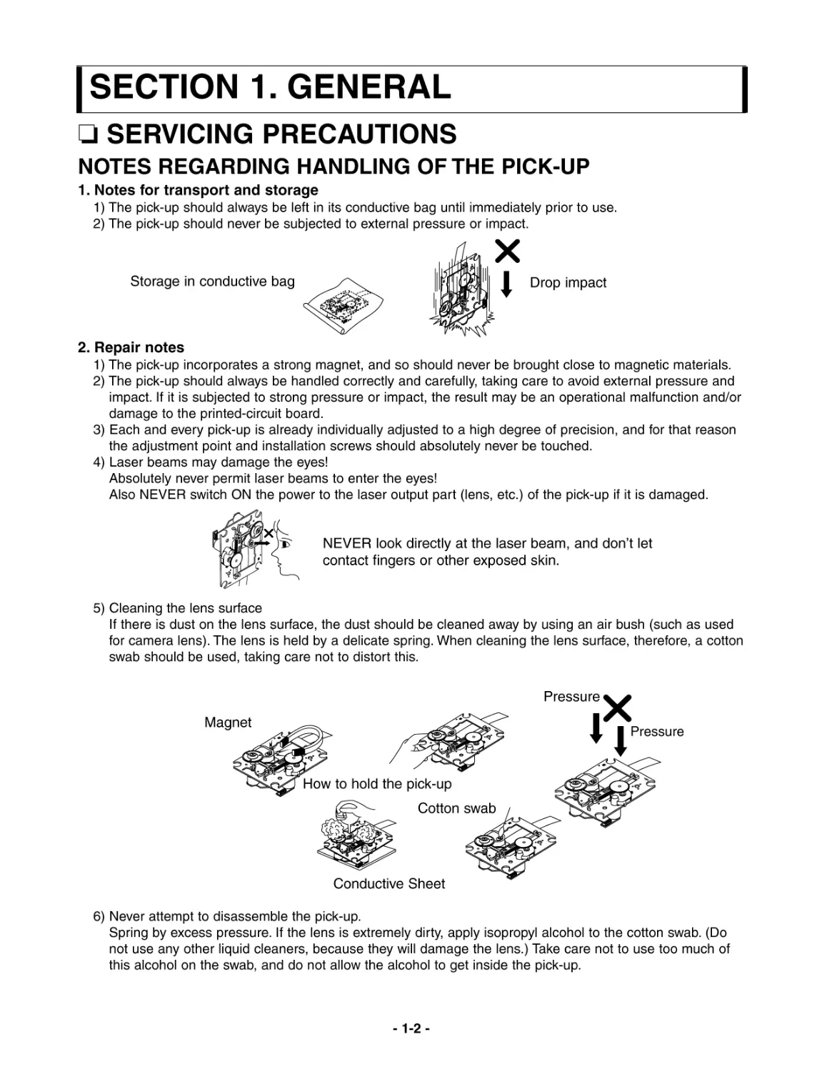
NOTES REGARDING HANDLING OF THE PICK-UP
1. Notes for transport and storage
1) The pick-up should always be left in its conductive bag until immediately prior to use.
2) The pick-up should never be subjected to external pressure or impact.
2. Repair notes
1) The pick-up incorporates a strong magnet, and so should never be brought close to magnetic materials.
2) The pick-up should always be handled correctly and carefully, taking care to avoid external pressure and
impact. If it is subjected to strong pressure or impact, the result may be an operational malfunction and/or
damage to the printed-circuit board.
3) Each and every pick-up is already individually adjusted to a high degree of precision, and for that reason
the adjustment point and installation screws should absolutely never be touched.
4) Laser beams may damage the eyes!
Absolutely never permit laser beams to enter the eyes!
Also NEVER switch ON the power to the laser output part (lens, etc.) of the pick-up if it is damaged.
5) Cleaning the lens surface
If there is dust on the lens surface, the dust should be cleaned away by using an air bush (such as used
for camera lens). The lens is held by a delicate spring. When cleaning the lens surface, therefore, a cotton
swab should be used, taking care not to distort this.
6) Never attempt to disassemble the pick-up.
Spring by excess pressure. If the lens is extremely dirty, apply isopropyl alcohol to the cotton swab. (Do
not use any other liquid cleaners, because they will damage the lens.) Take care not to use too much of
this alcohol on the swab, and do not allow the alcohol to get inside the pick-up.
Storage in conductive bag
Drop impact
NEVER look directly at the laser beam, and don't let
contact fingers or other exposed skin.
Magnet
How to hold the pick-up
Conductive Sheet
Cotton swab
Pressure
Pressure
-1-3-
NOTES REGARDING COMPACT DISC PLAYER REPAIRS
1. Preparations
1) Compact disc players incorporate a great many ICs as well as the pick-up (laser diode). These components
are sensitive to, and easily affected by, static electricity. If such static electricity is high voltage, components
can be damaged, and for that reason components should be handled with care.
2) The pick-up is composed of many optical components and other high-precision components. Care must be
taken, therefore, to avoid repair or storage where the temperature of humidity is high, where strong magnet-
ism is present, or where there is excessive dust.
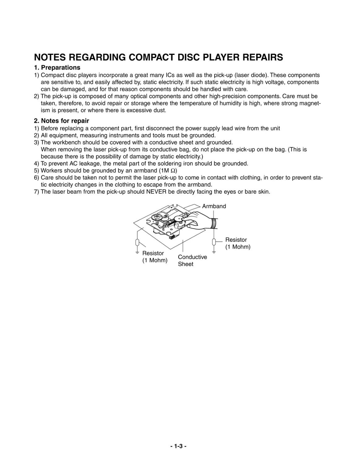
2. Notes for repair
1) Before replacing a component part, first disconnect the power supply lead wire from the unit
2) All equipment, measuring instruments and tools must be grounded.
3) The workbench should be covered with a conductive sheet and grounded.
When removing the laser pick-up from its conductive bag, do not place the pick-up on the bag. (This is
because there is the possibility of damage by static electricity.)
4) To prevent AC leakage, the metal part of the soldering iron should be grounded.
5) Workers should be grounded by an armband (1M Ω)
6) Care should be taken not to permit the laser pick-up to come in contact with clothing, in order to prevent sta-
tic electricity changes in the clothing to escape from the armband.
7) The laser beam from the pick-up should NEVER be directly facing the eyes or bare skin.
Resistor
(1 Mohm) Conductive
Sheet
Resistor
(1 Mohm)
Armband
-1-4-
ESD PRECAUTIONS
Electrostatically Sensitive Devices (ESD)
Some semiconductor (solid state) devices can be damaged easily by static electricity. Such components
commonly are called Electrostatically Sensitive Devices (ESD). Examples of typical ESD devices are integrated
circuits and some field-effect transistors and semiconductor chip components. The following techniques should
be used to help reduce the incidence of component damage caused by static electricity.
1. Immediately before handling any semiconductor component or semiconductor-equipped assembly, drain off
any electrostatic charge on your body by touching a known earth ground. Alternatively, obtain and wear a
commercially available discharging wrist strap device, which should be removed for potential shock reasons
prior to applying power to the unit under test.
2. After removing an electrical assembly equipped with ESD devices, place the assembly on a conductive sur-
face such as aluminum foil, to prevent electrostatic charge buildup or exposure of the assembly.
3. Use only a grounded-tip soldering iron to solder or unsolder ESD devices.
4. Use only an anti-static solder removal device. Some solder removal devices not classified as "anti-static" can
generate electrical charges sufficient to damage ESD devices.
5. Do not use freon-propelled chemicals. These can generate electrical charges sufficient to damage ESD
devices.
6. Do not remove a replacement ESD device from its protective package until immediately before you are
ready to install it. (Most replacement ESD devices are packaged with leads electrically shorted together by
conductive foam, aluminum foil or comparable conductive materials).
7. Immediately before removing the protective material from the leads of a replacement ESD device, touch the
protective material to the chassis or circuit assembly into which the device will by installed.
CAUTION : BE SURE NO POWER IS APPLIED TO THE CHASSIS OR CIRCUIT, AND OBSERVE ALL
OTHER SAFETY PRECAUTIONS.
8. Minimize bodily motions when handing unpackaged replacement ESD devices. (Otherwise harmless motion
such as the brushing together of your clothes fabric or the lifting of your foot from a carpeted floor can gen-
erate static electricity sufficient to damage an ESD device).
CAUTION. GRAPHIC SYMBOLS
THE LIGHTNING FLASH WITH APROWHEAD SYMBOL. WITHIN AN EQUILATERAL TRIANGLE, IS
INTENDED TO ALERT THE SERVICE PERSONNEL TO THE PRESENCE OF UNINSULATED "DANGER-
OUS VOLTAGE" THAT MAY BE OF SUFFICIENT MAGNITUDE TO CONSTITUTE A RISK OF ELECTRIC
SHOCK.
THE EXCLAMATION POINT WITHIN AN EQUILATERAL TRIANGLE IS INTENDED TO ALERT THE
SERVICE PERSONNEL TO THE PRESENCE OF IMPORTANT SAFETY INFORMATION IN SERVICE
LITERATURE.
-1-5-
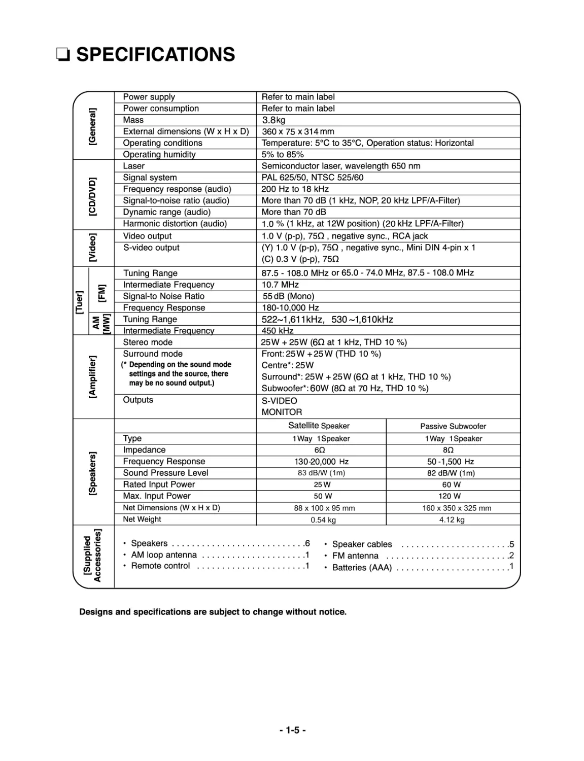
SPECIFICATIONS
83 dB/W (1m)
88x100x95mm
0.54 kg
160x350x325mm
4.12 kg
21
-1-6-
-2-1-
SECTION 2. AUDIO PART
AUDIO TROUBLESHOOTING GUIDE
1. POWER SUPPLY CIRCUIT
-2-2-
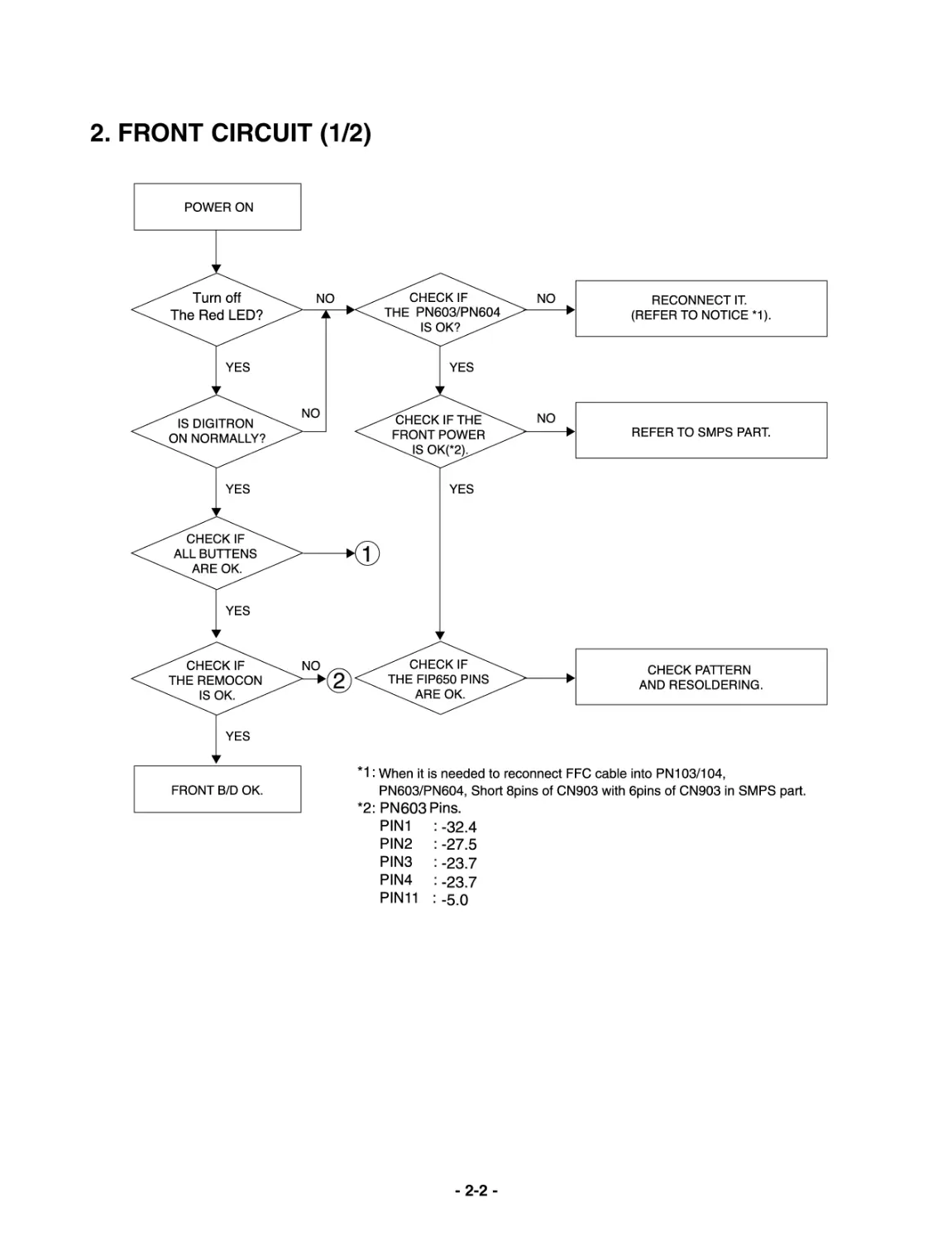
2. FRONT CIRCUIT (1/2)
-2-3-
3. FRONT CIRCUIT (2/2)
-2-4-
MEMO
BLOCK DIAGRAM
2-5
2-6
2-7
2-8
SCHEMATIC DIAGRAMS
• POWER SCHEMATIC DIAGRAM
2-9
2-10
• MICOM SCHEMATIC DIAGRAM
2-11
2-12
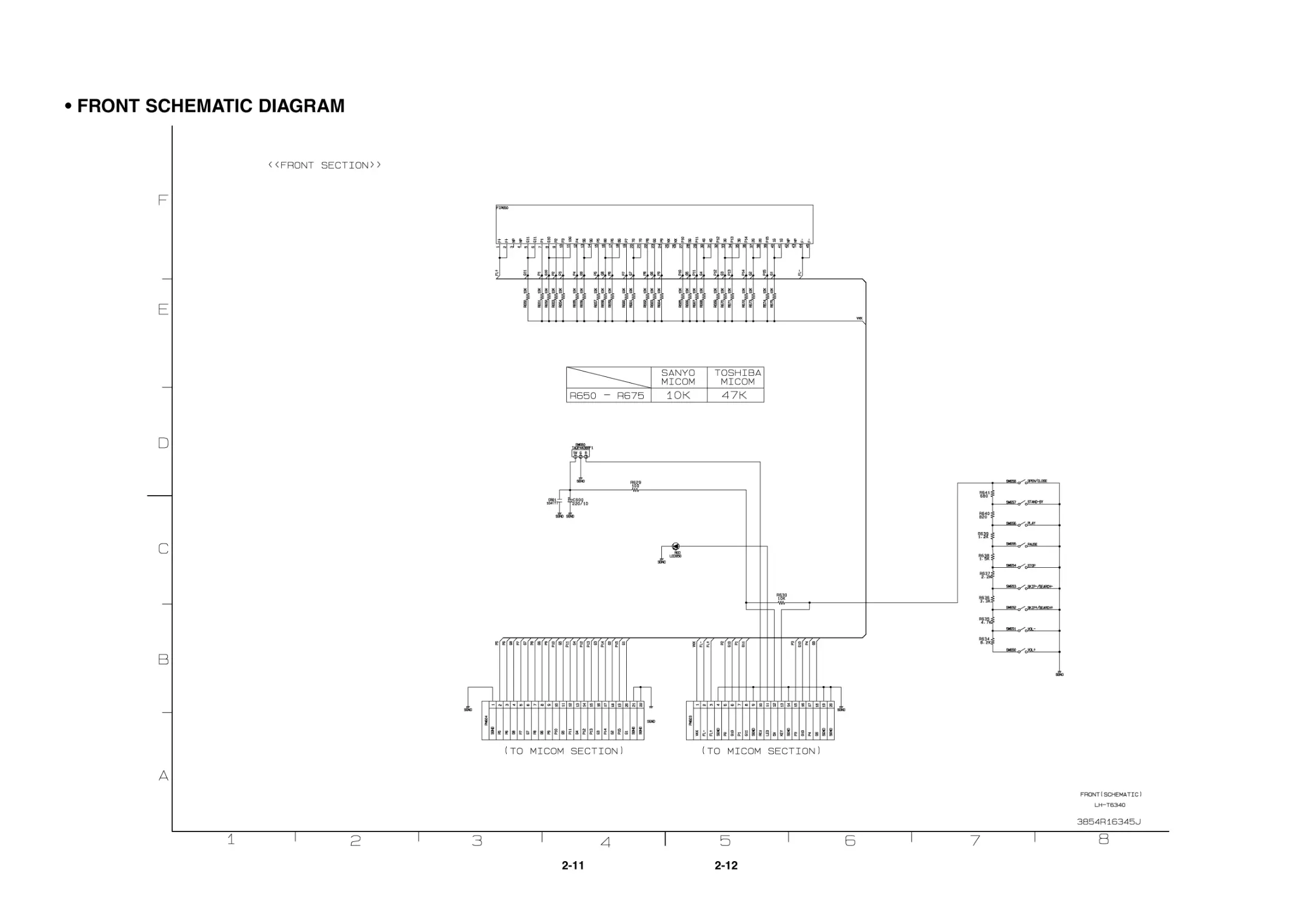
• FRONT SCHEMATIC DIAGRAM
2-13
2-14
• DSP& SCHEMATIC DIAGRAM
2-15
2-16
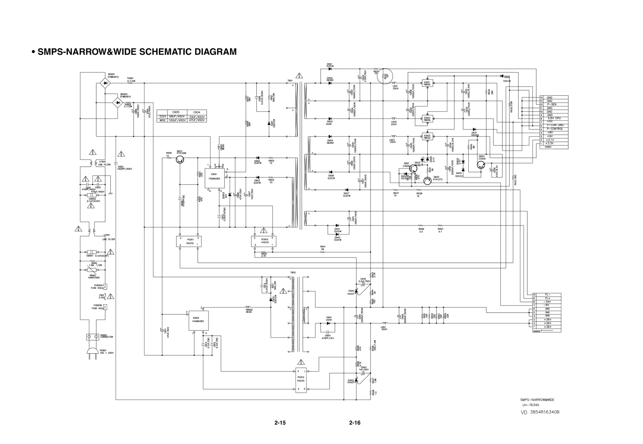
• SMPS-NARROW&WIDE SCHEMATIC DIAGRAM
2-17
2-18
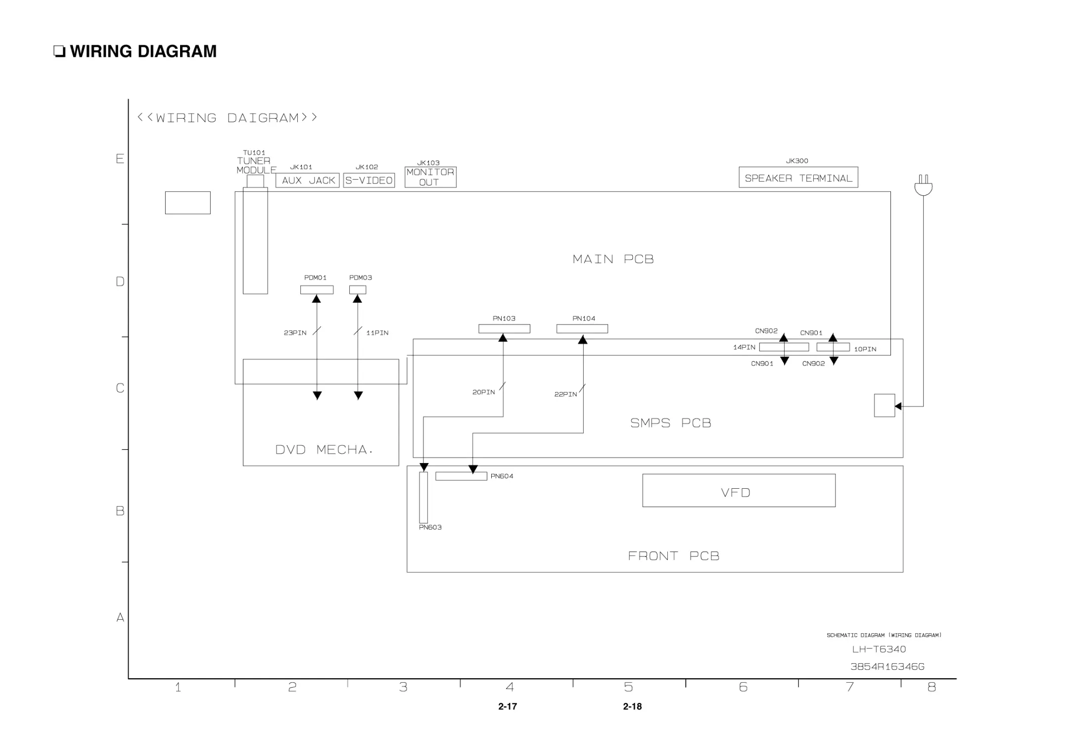
WIRING DIAGRAM
2-19
2-20
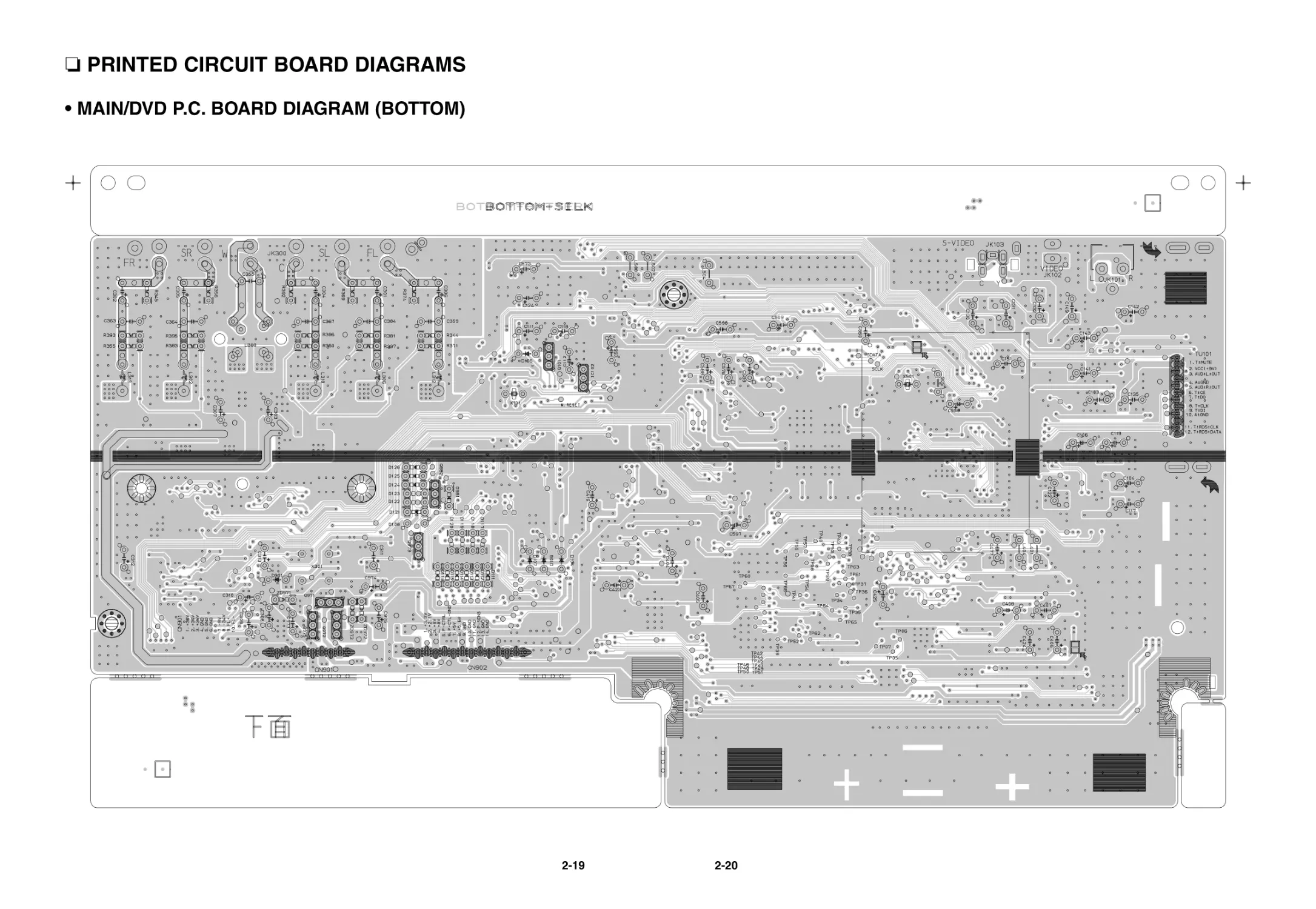
PRINTED CIRCUIT BOARD DIAGRAMS
• MAIN/DVD P.C. BOARD DIAGRAM (BOTTOM)
2-21
2-22
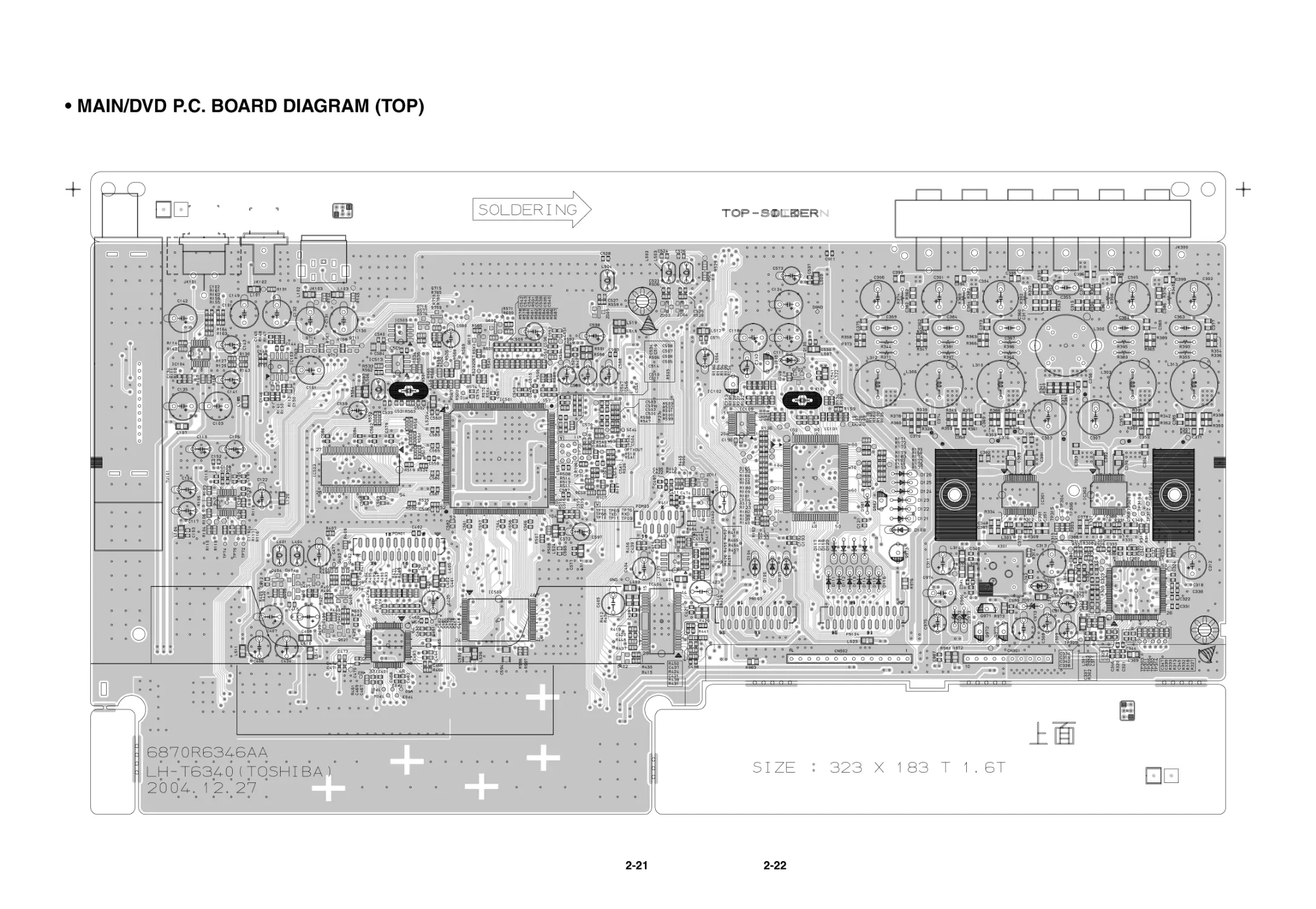
• MAIN/DVD P.C. BOARD DIAGRAM (TOP)
2-23
2-24
• FRONT P.C. BOARD (TOP)
2-25
2-26
• FRONT P.C. BOARD (BOTTOM)
2-27
2-28
• SMPS P.C. BOARD
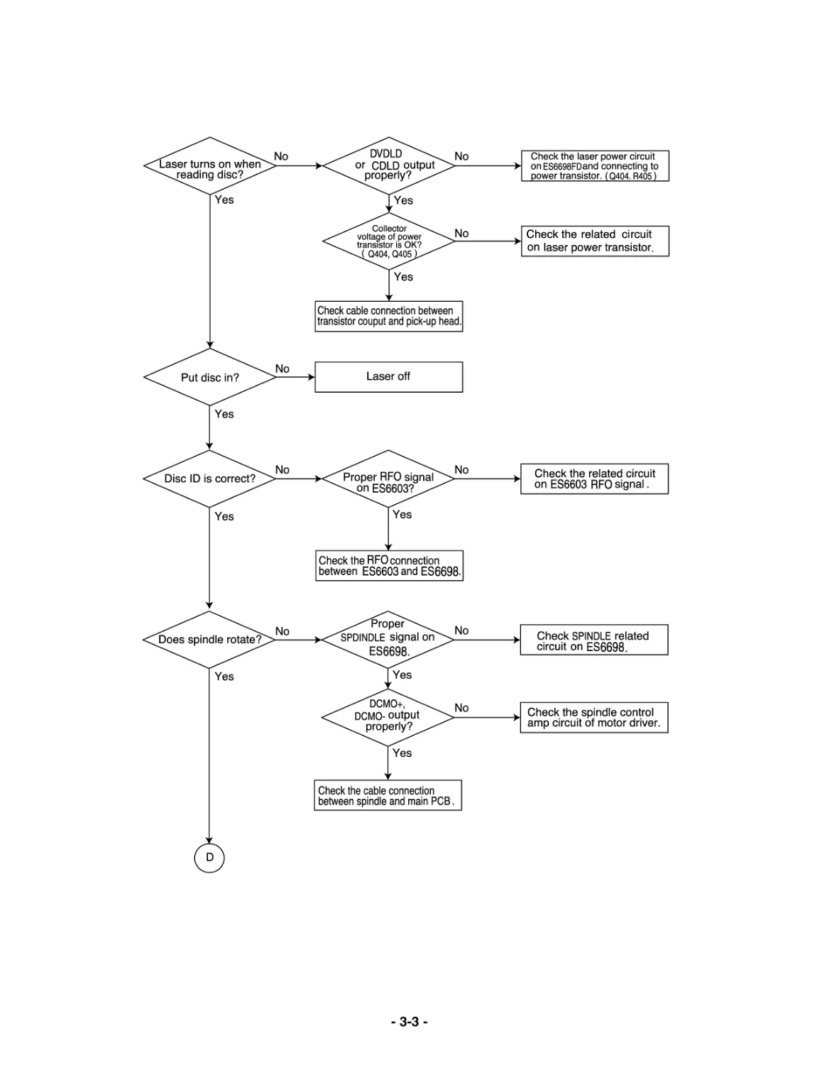
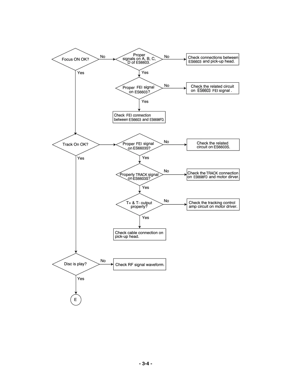
-3-1-
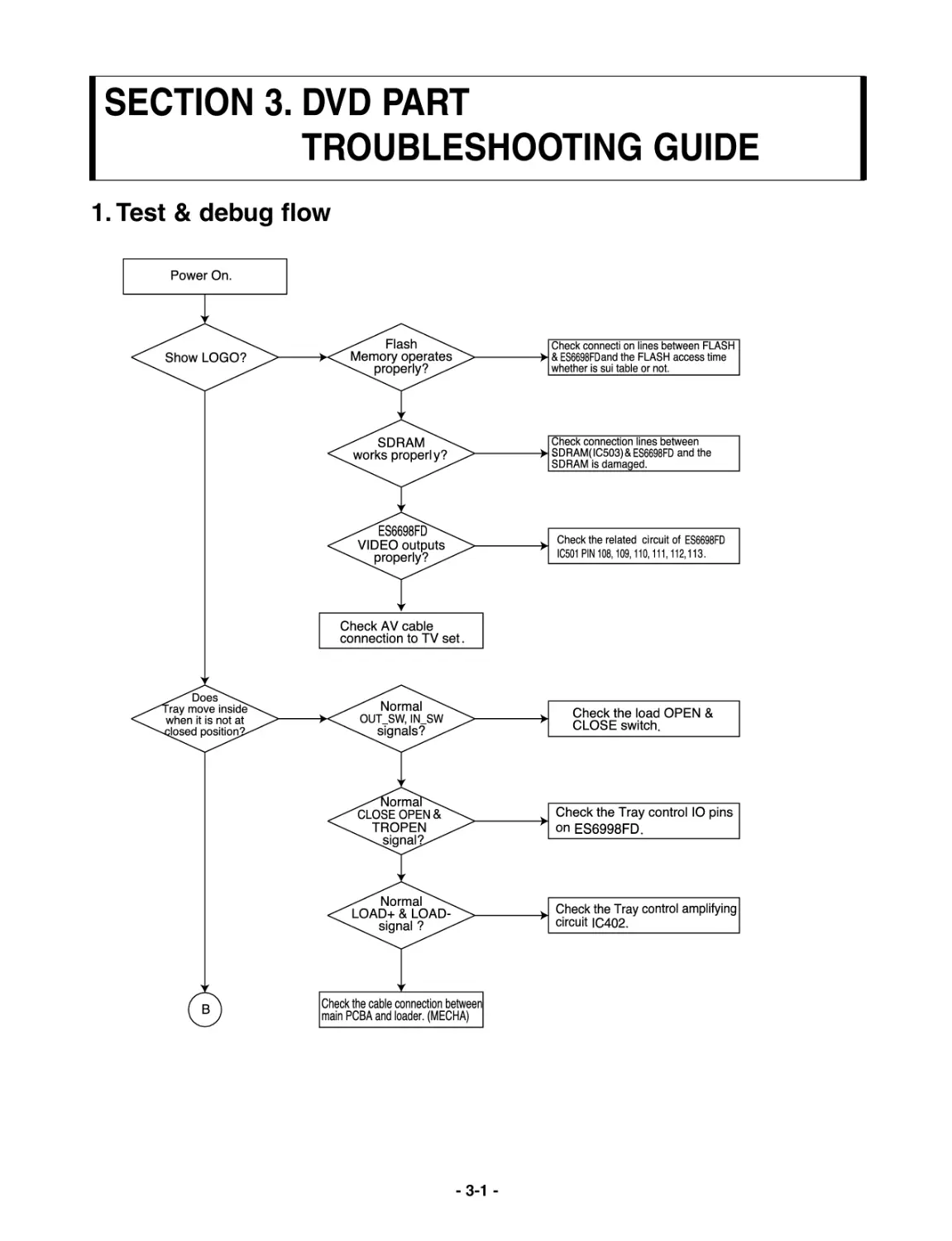
SECTION 3. DVD PART
TROUBLESHOOTING GUIDE
1. Test & debug flow
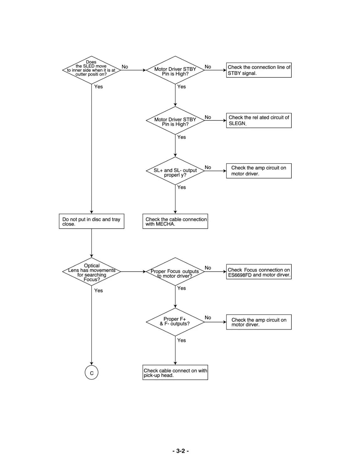
-3-2-
-3-3-
-3-4-
-3-5-
-3-6-
3-7
3-8
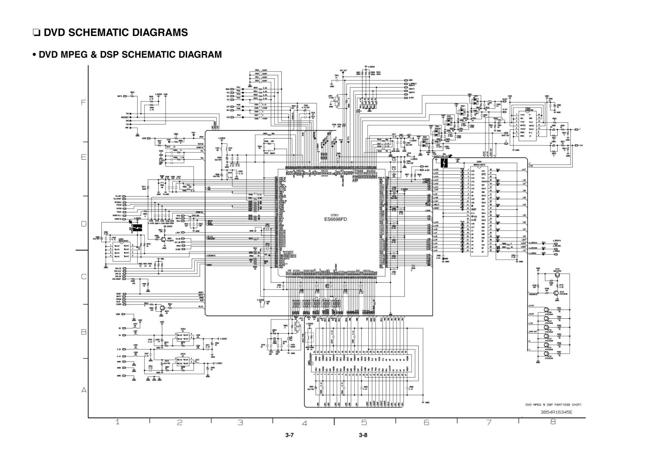
DVD SCHEMATIC DIAGRAMS
• DVD MPEG & DSP SCHEMATIC DIAGRAM
ES6698FD
3-9
3-10
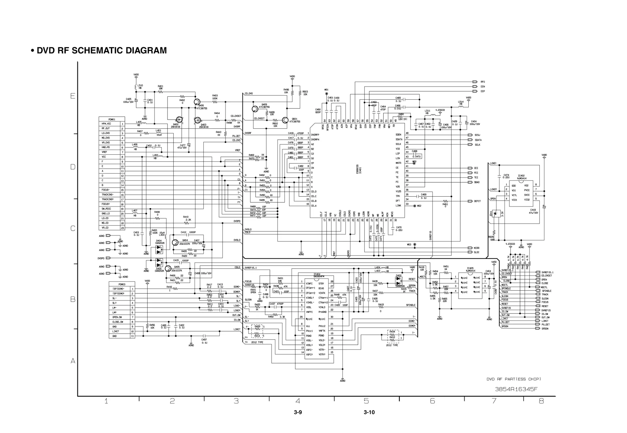
• DVD RF SCHEMATIC DIAGRAM
4-1
4-2
351
305
313
A47
302
303
451
451
A46
451
451
A26
451
A43
286
454
280
275
CABINET AND MAIN FRAME SECTION
SECTION 4. EXPLODED VIEWS
4-3
4-4
• DECK MECHANISM EXPLODED VIEW
LOCA. NO. PART NO.
DESCRIPTION
SPECIFICATION
A26
6721RJ0856E
DECK ASSEMBLY,AUDIO
DECK/MECHA DP-7T(HZ)-ESS -(M:M
A01
4861R-0016D
CLAMP ASSEMBLY
DECK/MECHA DISC DP-7C(7A) -HZ
A02
3041R-M040A
BASE ASSEMBLY
MAIN DP-7T-HZ
A03
3041R-M061D
BASE ASSEMBLY
SLED DP-7A-HZ ESS (M: MITSUMI
001
3300R-0547A
PLATE
CLAMP
002
5016H-1016B
MAGNET
CLAMP(LDM-R608,10*5,1*1.5T)
003
4860R-0021A
CLAMP
UPPER DP7
004
4930R-0402A
HOLDER
CLAMP DP-7A
010
6850R-GK22Z CABLE,FLAT
P=1.0 FFC UL2896(0.05X0.65) 11
011
3210R-M002A
FRAME
UP/DOWN MOLD DP7C
011A
6850R-JW16B CABLE,FLAT
P=1.0 FFC UL2896(0.035X0.7) 23
012
5040R-0075D
RUBBER
DAMPER DP7 (YAMAUCHI 30)
013
4400R-0006B
BELT
DECK/MECHA DP2-5, DP7C,DP7A OT
014
4470R-0055A
GEAR
PULLEY
015
6871RJ4415A
PWB(PCB) ASSEMBLY,JACK PWB(PCB) TOTAL LOADING-HZ
015A
4681R-1023G
MOTOR ASSEMBLY
DECK/MECHA LOADING-HZ
015B
4560R-0008A
PULLEY
MOTOR
015C
4680R-E010A
MOTOR(MECH)
FEEDING BCZ3B51 SANKYO FOR DP7
017
4470R-0056A
GEAR
LOADING
018
4974R-0023A
GUIDE
UP/DOWN
020
3040R-D005A
BASE
MAIN DP-7T MOLD (SLIM)
021
4680R-C011A
MOTOR(MECH)
SPINDLE JCL9B68 SANKYO FOR COM
022
4681R-0034D
MOTOR ASSEMBLY
DECK/MECHA FEEDING DP-7C(7A) -
024
4470R-0131A
GEAR
PINION DP7C
024A
5006R-0044A
CAP
SKEW-T DP7C
024B
5006R-0043A
CAP
SKEW DP7C
025
4470R-0130A
GEAR
MIDDLE DP7C
026
3390R-0026A
TRAY
DVD DP-7T MOLD DISC
028
4370R-0082B
SHAFT
DECK/MECHA PU R DP-7C OTHER
029
4370R-0082A
SHAFT
PU DP-7C
030
4471R-0013D
GEAR ASSEMBLY
DECK/MECHA RACK DP-7C(7A) -HZ
031
6716DPH005B PICK UP,DVD
PVR-502W R52 0219 MITSUMI PLAY
429
1SZZR-0012A SCREW,DRAWING
B-TITE
430
1SZZH-1003A SCREW,DRAWING
+ D2.0 6MM SWRCH16A/NIY 4.5MM
431
1SZZH-1007B SCREW,DRAWING
+ D2.0 6MM SWRCH16A/ZNBK 4MM 1
432
1SZZR-0023B SCREW,DRAWING
+ 1 D1.7 L6.0 SWRCH16A/FZY RAC
433
1SZZR-0050A SCREW,DRAWING
+ 1 D2.0 L4.5 SWRCH16A/ZNY S-T
435
1SZZR-0011A SCREW,DRAWING
MACHINE
-5-1-
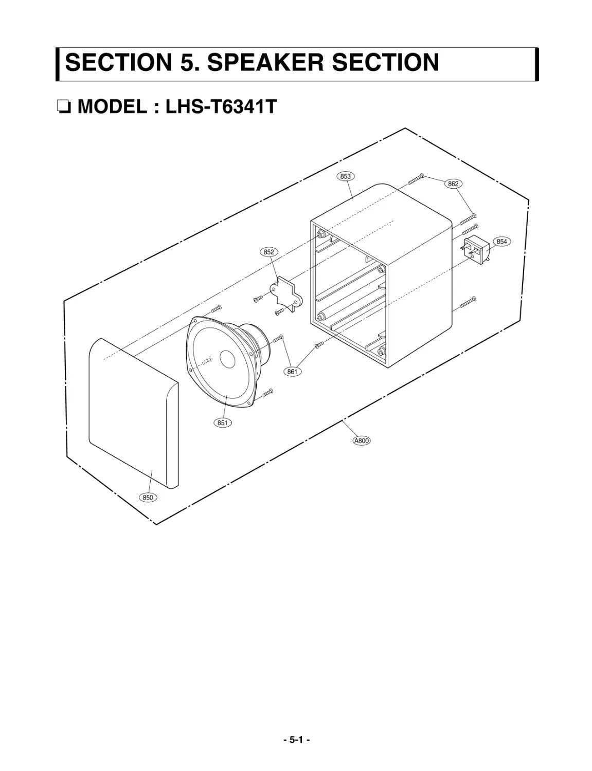
SECTION 5. SPEAKER SECTION
853
852
851
850
861
854
862
A800
MODEL : LHS-T6341T
-5-2-
MODEL : LHS-T6341W
952
954
955
953
951
961