/


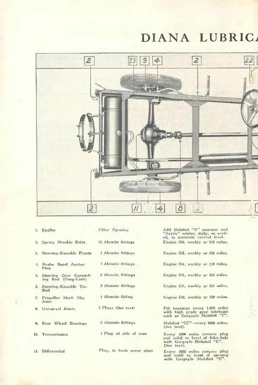
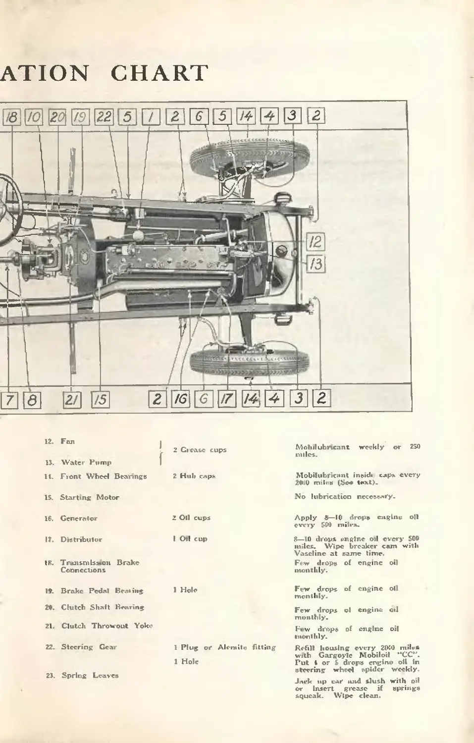


Теги: care instructions technique


Текст
INSTRUCTION
for the Care & Operation of
Г
INSTRUCTIONS
for the Care & Operation of
the Light siraight
Built by the MOON MOTOR CAR COMPANY
for the DIANA MOTORS COMPANY
St. Louis
President
LICENSE DATA AND
SHIPPING WEIGHTS
Car Serial Number.. Stamped on plate on front of dash
Engine Serial Number. .Stamped on plate on crankcase
of engine and on plate on front of dash.
Cylinder Bore . ... 3 inches
Stroke ........... ................4 lx inches
Number of Cylinders.............................. 8
S. A, K. Horse Power Rating.................. .28.8
Piston Displacement ..240.3 cubic inches
Shipping Weights *
Phaeton .31CU Lb.
Roadster . . .2995 Lb
Cabriolet Roadster .3160 Lb.
Two-Door Coach....................3170 Lb.
Four-Door Sedan, 5 Passenger.. .3275 Lb
Four-Door Sedan, 7 Passenger.. 3640 Lb
" 'These weights are of standard cars equipped with
wood wheels, standard size balloon tires aid spare tire
with rim.
Foreword
BETTER understanding ol the ccmsimr.licm and
operation of hie car will enable the Diana owner
to appreciate to a fuller extent the attention,
small in amount though it may be. that this
faithful servant deserves.
Lt is with this m mind that wc have gone somewhat at
length into the desci.plio.i of tile cat and its operation.
Especially is this true of the ‘‘eight-in-line'" engine, the
newness of its design making this desirable to the service
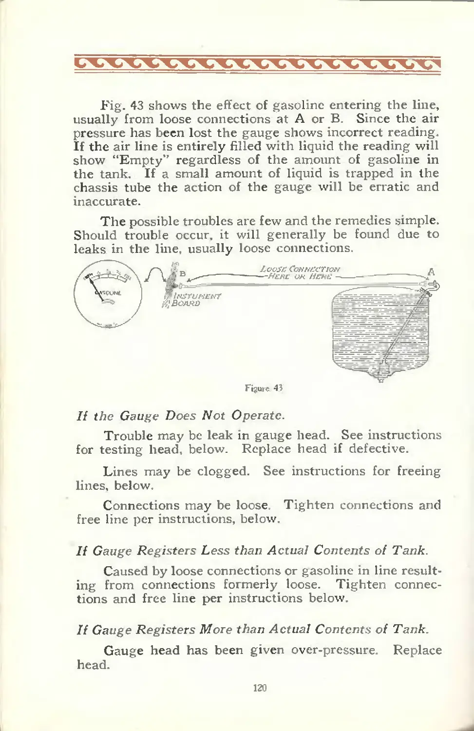
station and to the owner with the mcch-miial tarn ol mind.
Lt is important that during the 5rst one thousand
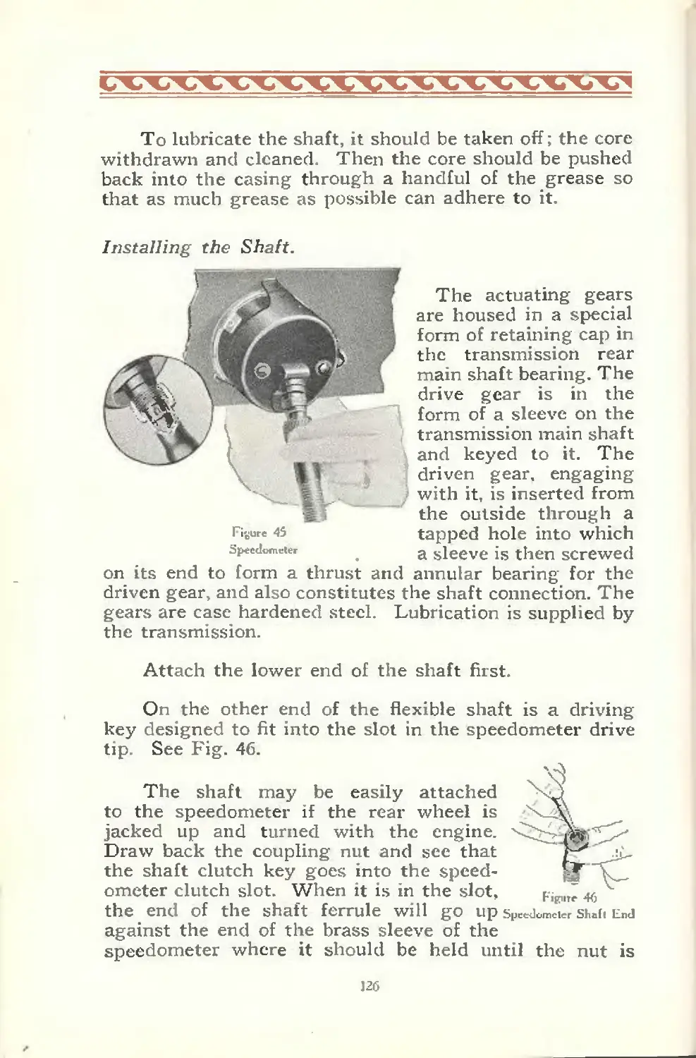
miles a speed of twenty-five mile.; an hour is not exceeded.
A study of these pages will make this evident: it will also
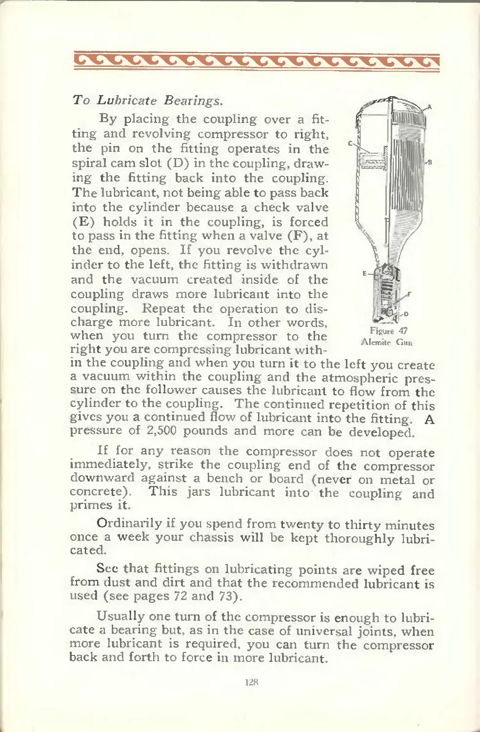
emphasize the importance of following the rules of Collect
lubrication.
The quality of results your Diana gives depends in
large nicasiiie u >0:1 tile caie it leceives. The necessary
periodic adjustment* and regular, thorough lubrication will
enable you tc get out of your car the many miles ot service,
cci-ifoi l and enjoyment we Have endeavored to build into it.
Should the necessity loi expensive lepaiis 01 adjust-
ments ever arise, yo-.tr car should be placed in the hands
of your Diana dealer, where it will receive the attention of
an organization du voted to your interests, with mechanics
especially trained in the maintenance of Diana cars and
using genuine Diana replacement materia'..
DIANA MOTORS COMPANY
SPECIFICATIONS
ENGINE—See engine specifications, page 34.
COOLING—Water circulated through engine and radiator by centri-
fugal pump. Large fan aids cooling. Shutter on radiator permits
temperature control.
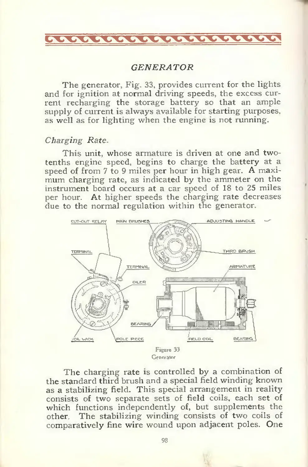
ELECTRICAL EQUIPMENT—Delco starting, lighting and igni-
tion. Two unit, single wire system. Distributor, double
breaker type with single ignition coil. Battery, U. S. L. three-
cell, six volt, 15 plate.
CLUTCH—Borg and Beck, ten-inch, dry plate. Self lubricating
throw-out bearing.
TRANSMISSION—Special Diana-Warner, unit with engine and
clutch. Selective sliding gear type, thtee speeds forward and
one reverse. Positive lock on gear shift lever.
UNIVERSAL JOINTS—Mechanics, with large diameter drive tube
to eliminate whipping at high speeds.
AXLES—Timken bearings throughout. Spiral bevel drive gears.
BRAKES—Service: Four-wheel hydraulic external contracting.
Positive, equalized action requiring only slight foot pressure-
No lubrication required. Hand or parking: Mounted on trans-
mission.
FRAME—Heavy channel side bars. Eight cross members tie side
bars rigidly together.
SPRINGS—Alloy steel, semi-elliptic, 2 inches wide. Front, 36 inches
long and real springs, 54 inches long. Spring eyes bronze bushed,
equipped with large hardened and ground spring bolts. Spring
clips of alloy steel.
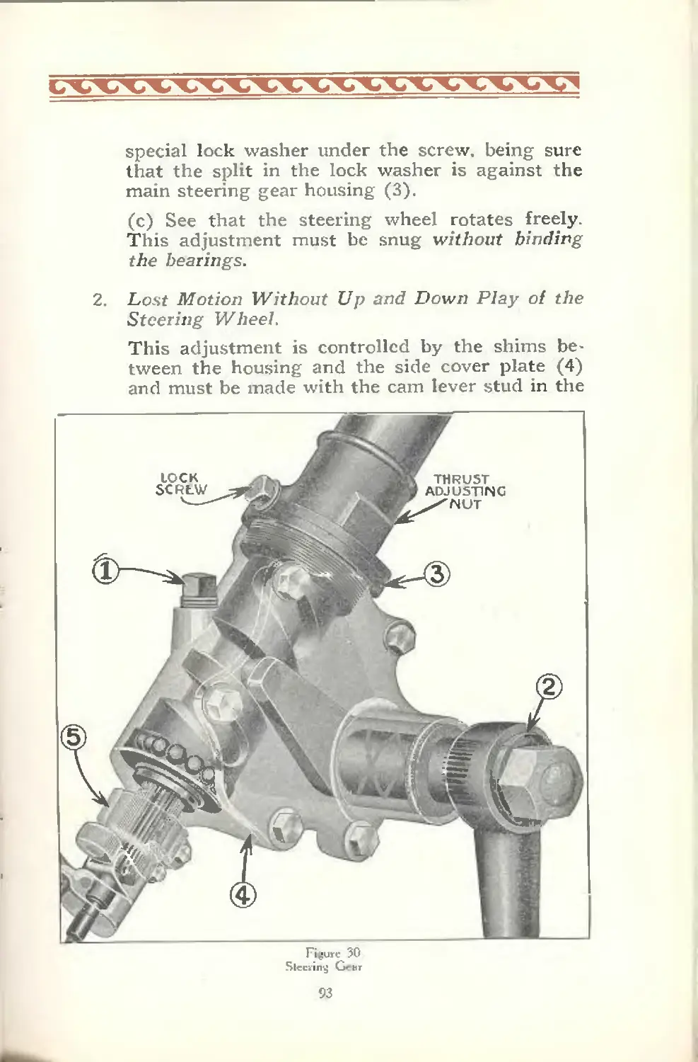
STEERING GEAR—Special Diana-Ross cam and lever balloon tire
type. 18 inch corrugated grip, walnut steering wheel.
GASOLINE SUPPLY—Vacuum feed. Gasoline tank in rear.
Gasoline gauge on instrument board.
BODY—Constructed of silver-finish steel, finished in Duco. Super-
structure of hardwoods. Deep one-piece stamped fenders, 10%"
crown.
LAMPS—Adjustable with nickel rims, deflecting lens and dimming
device.
TIRES—Genuine balloon, 32 x 6.00, with demountable rims. (32x6.20
on 7 passenger sedan)
WHEELS—Wood. Artillery type. Include spare tim on iear
WHEELBASE—125 inches. (7 passenger sedan—135")
LENGTH—175 inches over all (without bumpers). (7 passenger
sedan—185’).
STANDARD EQUIPMENT—Complete tool kit, jack, ammeter, oil
gauge, gasoline gauge, radimeter, speedometer, carburetor dash
control, motor-driven horn.
CHASSIS LUBRICATION—Alemite system.
(/,. oil correspondence perLiiniria to pour car, be sure to give the serial number. Il
will be tountl on lire dash when Uic right side of the hood is raise I).
Gasoline Gauge
Radimeter----
Speedometer^
Oil Gauge—
Ammeter-^
Gas Lever—
Spark Lever
Hom Button
Light ->
Control
Lever
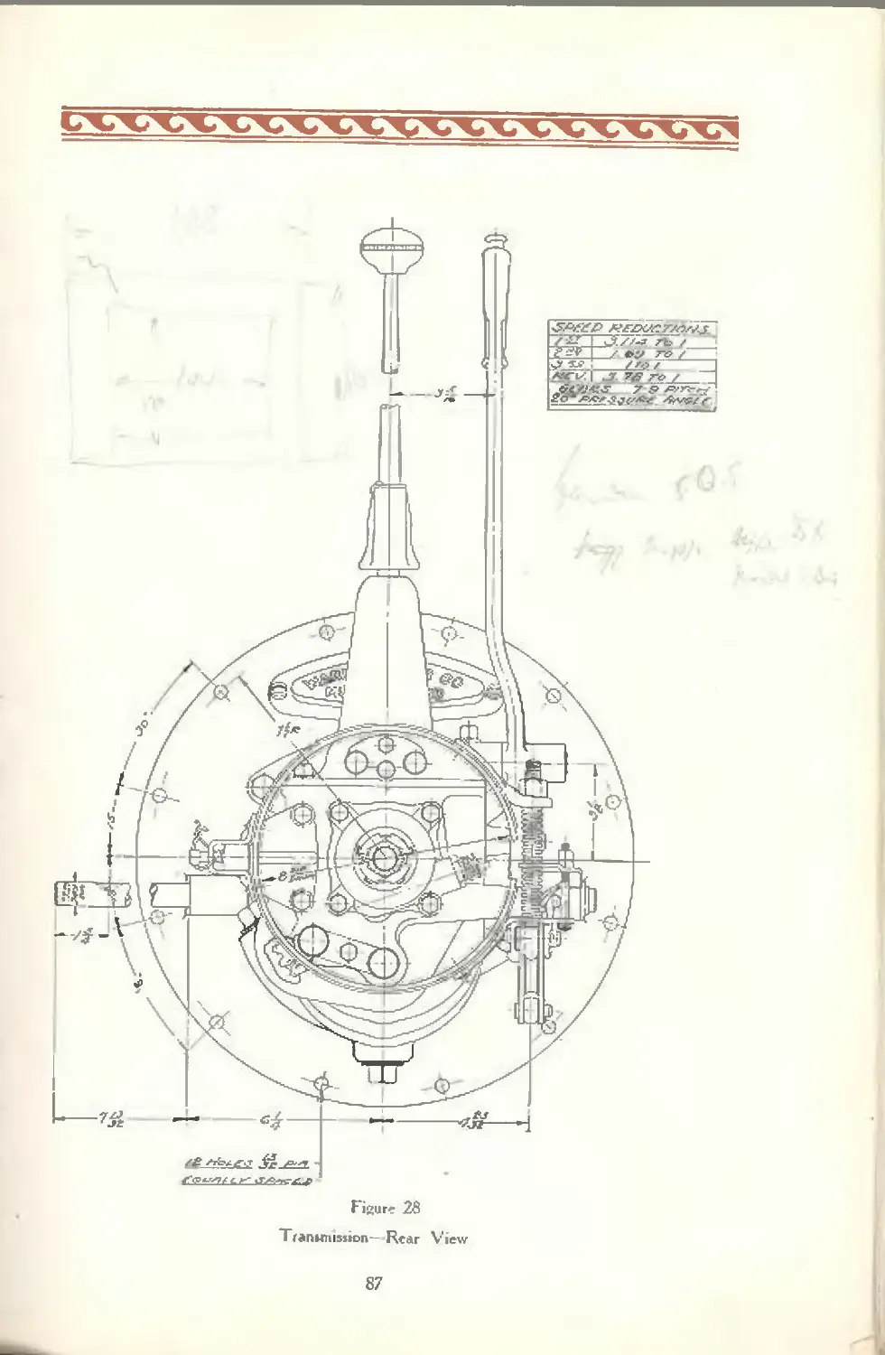
Gear Shift Lfevei
ussion Lock-v
’Foot /
ccel tutor
Button
Accelerator
Foot Rest
Hand Brake Lever —
у Clutch Pedal
Brake Pedal
Speedometer
/Trip Regulator
/ Speedometer
Shaft
Cowl Ventilator
й\~ КпоЬ
Ignition , , Uh Button
Carburetor Д .
< Choke \
Button \жЫ
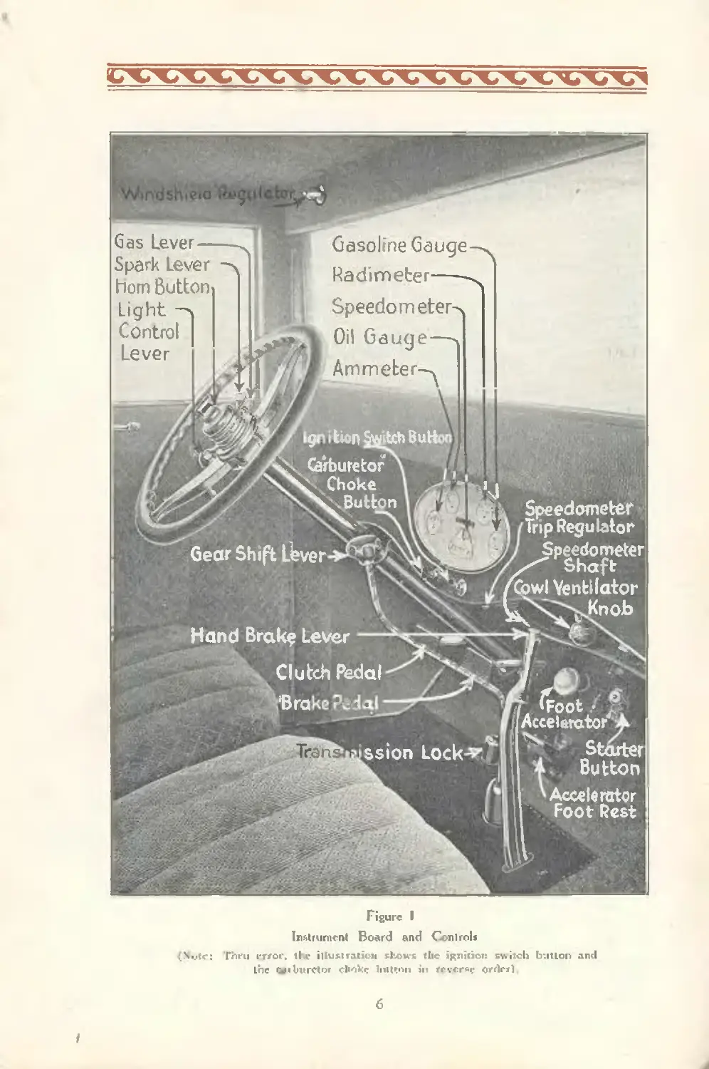
Figure I
Instrument Board and Controls
{.Muir: Thru rrror. the illustration shows the ignition switch button and
Lne Qfibvretor cliokr liutrnn in rrvcrsr orrlcrl
i
OPERATION
To Prepare Car for Service:
1. Fill gasoline tank.
2. Fill radiator with clean, soft water. (Capacity
of cooling system, 18 quarts).
3. Fill crankcase to proper level with correct grade
of oil. See page 65.
4. Lubricate all parts of car. See chart, pages
72-73.
5 Inflate tires. See page 129.
6. Check storage battery. See page 107.
7. Test pressure on brake pedal. (Capacity of
hydraulic system, 1 quart) See page 10.
Starting the Engine
See that the gear shift lever is in the mid position or
in “neutral” as shown in Fig. 2.
Retard the spark by moving the spark lever (the
uppermost of the three levers on the steering wheel) one-
fourth way in the direction “retard”.
Advance the hand throttle lever about % inch from
the position “close”.
Pull out the ignition button.
Step on the starter button and allow the engine to
make several revolutions before touching the choke
control.
Now pull out the choke control slowly; when the
proper choking limit is reached the engine will start
readily.
Advance the spark lever all the way.
When the engine becomes warm push in the choke
button all the way and move the hand throttle lever to
the “close” position.
7
Before starting out, speed up the motor slightly to
see if the ammeter and oil gauge are operating properly.
(See under “Ammeter” for proper charging rate and under
“Engine” for proper oil pressure).
Caution: (1) Avoid stepping on the starting button
when the engine is running, as doing so might strip the
teeth on the flywheel or break the Bendix on the starting
motor. (2) Give the engine time to become uniformly
heated before attempting to drive car at high speed.
Cold Weather Precautions.
In cold weather, when the lubricant in the transmis-
sion is thickened, there is much resistance to the turning
of the gears. To avoid excessive drain on the battery,
depress the clutch pedal before stepping on the starter
button.
Do not, under any circumstances, “race” the engine.
This is an especially dangerous practice in winter when
the oil has become thickened and cannot reach the cyl-
inder walls. Run the engine slowly until the engine
warms up and the oil becomes fluid again.
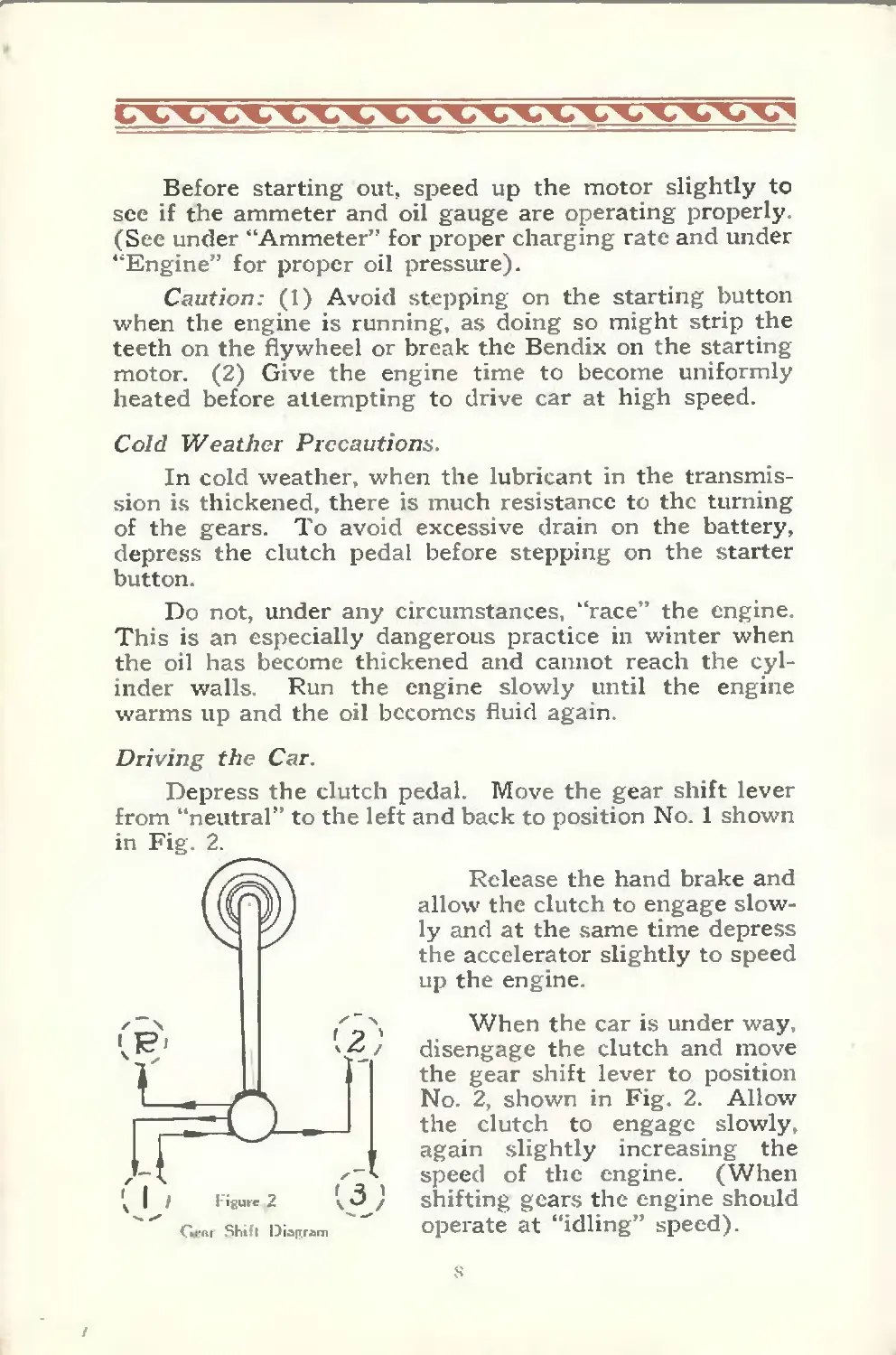
Driving the Car.
Depress the clutch pedal. Move the gear shift lever
from “neutral” to the left and back to position No. 1 shown
Release the hand brake and
allow the clutch to engage slow-
ly and at the same time depress
the accelerator slightly to speed
up the engine.
When the car is under way,
disengage the clutch and move
the gear shift lever to position
No. 2, shown in Fig. 2. Allow
the clutch to engage slowly,
again slightly increasing the
speed of the engine. (When
shifting gears the engine should
operate at “idling” speed).
When the car has gained sufficient momentum, disen-
gage the clutch and move the gear shift lever straight back
into third (or high) speed position, No. 3, as shown in
Fig. 2. Allow the clutch to engage. The car is now in
high gear, the position used for general driving, and vari-
ation in speed can be obtained by use of the accelerator
pedal
A slight hesitation of the gear shift lever at the
neutral position, when passing from a lower to a higher
speed, will greatly assist in shifting gears.
In moving the gear shift lever to change from a higher
to a lower speed, as when ascending a grade, the operator
will obtain the best results by disengaging the clutch and
simultaneously speeding up the engine slightly, then,
quickly making the shift With a little experience this
shift can be made quietly.
An experienced driver does not hesitate to use the
two lower speeds when climbing steep grades or in pull-
ing through deep sand.
When descending long grades, close the throttle and
with the clutch engaged, allow the car to turn the engine
over against compression. On steep grades the car should
be in second speed before the descent is started and on
exceptionally steep inclines it is advisable to use first or
low speed. Always shift into the lower gear before start-
ing downward, as shifting gears with the car coasting
rapidly down hill is dangerous and well-nigh impossible
for the average driver.
To stop the car, disengage the clutch and depress the
brake pedal. Because of the remarkable efficiency of the
hydraulic four-wheel brakes only a moderate pressure need
be applied to bring the car smoothly and quickly to a stop
Move the gear shift lever to the neutral position, then
allow the clutch to engage
To back the car, first bring it to a full stop. Disen-
gage the clutch and move the gear shift lever to the for-
9
ward left position marked *’R”, Fig. 2. Allow the clutch
slowly to engage, at the same time slightly increasing
the engine speed by depressing the accelerator pedal.
Before leaving the car, push in the ignition switch
button. With the gear shift lever in the neutral posi-
tion, set the hand brake and lock the transmission by re-
moving the key and depressing the lock with the foot
until the lock clicks.
Caution: For the first 1000 miles do not drive the car
at a speed to exceed 25 miles an hour.
Skidding.
Skidding can be prevented by driving carefully and by
using tire chains. There is much less tendency to skid
when braking on wet or slippery pavement if the clutch
is not disengaged until the car speed has been brought
down to five or six miles per hour. Skidding can usually
be checked by turning the front wheels in the same direc-
tion that the rear wheels are sk dding.
HYDRAULIC BRAKES
General Description.
The Lockheed hydraulic four wheel brake system
used on Diana cars is one in which the brake bands are
brought in contact with the drums by means of a column
of liquid forced through pipes. This liquid being incom-
pressible, transmits pressure applied to the foot pedal to
each wheel brake by means of displacement of liquid in
the master cylinder to the wheel cylinders. Inasmuch as
hydraulic pressure is equal on all surfaces, it follows that
the brakes are self-equalizing and not subject to individual
adjustment, except for wear of brake lining.
io
The system comprises a master cylinder in which the
hydraulic pressure is originated, a cylinder operating the
brake bands on each wheel drum in which the hydraulic
pressure is applied, a supply tank by which the operating
fluid in the system is replenished, and the “line”, consist-
ing of copper tubing, flexible hose and brackets connecting
the master cylinder, wheel cylinders and supply tank.
There is no pressure in the system when the foot pedal
is in release or in the “off” position. When pressure is
applied to the foot pedal, the master cylinder piston, with
which the foot pedal is mechanically connected, is forced
backward and causes the fluid to flow through the entire
line, exerting the pressure, created in the master cylinder,
in each wheel cylinder with equal and undiminished
force. The column of incompressible liquid entering the
wheel cylinders between their opposed pistons causes the
pistons to move outwardly and against the pressure of the
retractor springs. By means of mechanical connection
between the pistons and brake bands, the bands are
brought into contact with the drums and the pressure on
all bands of all four wheels is completely equalized.
When pressure on the foot pedal is released, the re-
tracting springs force the wheel cylinder pistons to their
original ‘'off” position and the liquid is forced out of the
cylinders and back into the line. This same incompres-
sible hydraulic column forces the master cylinder piston
forward and in position ready for pressure to be applied
again on the foot pedal.
Bleeding of the “Line”.
Whenever any part of the system has been discon-
nected, with the exception of the supply tank and the tube
leading from it to the master cylinder, it is necessary to
“bleed” the system in order to expel all air
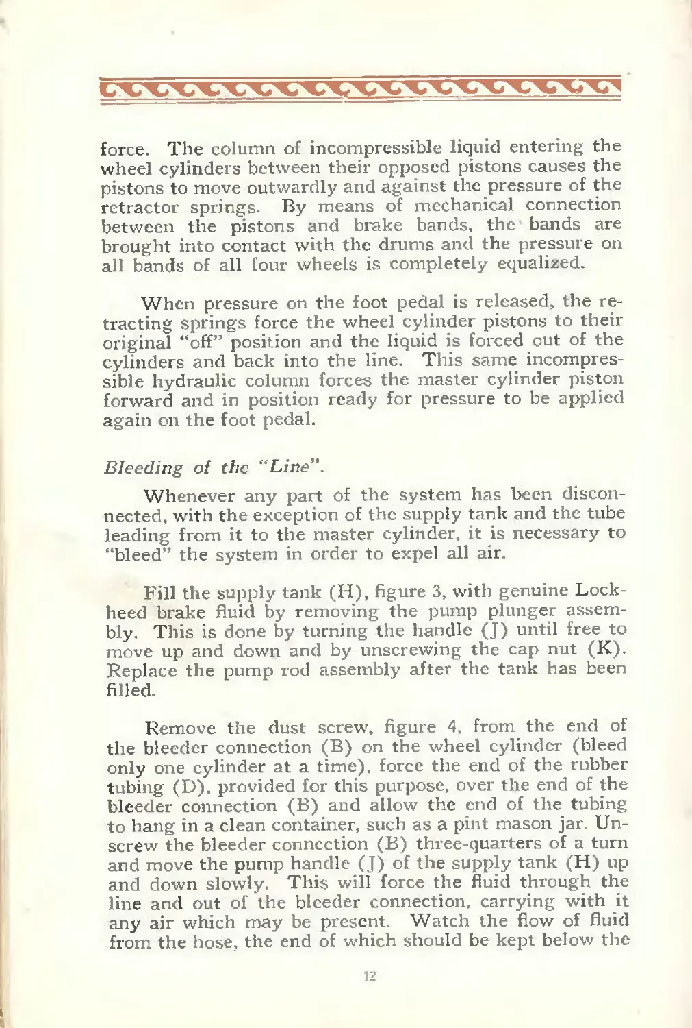
Fill the supply tank (H), figure 3, with genuine Lock-
heed brake fluid by removing the pump plunger assem-
bly. This is done by turning the handle (J) until free to
move up and down and by unscrewing the cap nut (K).
Replace the pump rod assembly after the tank has been
filled.
Remove the dust screw, figure 4. from the end of
the bleeder connection (B) on the wheel cylinder (bleed
only one cylinder at a time), force the end of the rubber
tubing (D), provided for this purpose, over the end of the
bleeder connection (B) and allow the end of the tubing
to hang in a clean container, such as a pint mason jar. Un-
screw the bleeder connection (B) three-quarters of a turn
and move the pump handle (J) of the supply tank (H) up
and down slowly. This will force the fluid through the
line and out of the bleeder connection, carrying with it
any air which may be present. Watch the flow of fluid
from the hose, the end of which should be kept below the
12
surface of the fluid, and when all air bubbles cease to
appear, or when the stream is a solid fluid mass, close the
bleeder connection (B). Open the connection again to
allow a slight amount of fluid to drain, then tighten the
bleeder connection securely.
Fluid withdrawn in the '‘bleeding” operation should
not be used again The bleeding operation should be re-
peated on each wheel cylinder, and the fluid should be
replenished in the supply tank each time. Should the
supply tank be drained during the bleeding operation
air will enter the system and “rebleeding” will then be
necessary.
To remove air from the master cylinder, unscrew the
handle (J), Fig. 3, which opens the valve (G) in the supply
tank (II), and force the foot pedal slowly down to the floor
board with the hand. This will force the liquid in the
master cylinder up into the supply tank, carrying with it
any air which may be present in the master cylinder. Fill
В Bleeder
D Bleeder Twbing
E Bleeder Wrench
F Flexible Hose Assembly
G Wkeel Cylinder
Figure 4
13
the supply tank (H), replace the pump plunger (J) and
pump slowly until the brake pedal is returned to its normal
off position, or until free play is eliminated. Screw down
the pump handle (J) and tighten securely with the hand.
(Do not use a wrench, as the force thus applied is apt to
groove the valve scat, causing it to leak). Apply pressure
to the brake pedal. If the pedal appears springy and can
be pushed to floor board with little effort, it is an indica-
tion that air is still present in the system and the bleeding
process must be repeated in order to obtain a satisfactory
condition.
Maintenance of Brakes.
The frequency of adjustment will depend upon the
character of service to which the brakes have been sub-
jected. If the brakes appear unequal in braking effect
the cause will often be found to be in the lining itself.
Foreign substances on the brake lining, changing its
frictional value, is the most common cause of this condi-
tion. If the bands are thoroughly cleaned with gasoline
or alcohol (not distillate) to remove grease or other
foreign material, and the surface of the lining is roughened
with a file or wire brush, a satisfactory condition will, in
the majority of cases, be obtained. If, however, the brake
linings are so saturated with oil or grease that cleansing
will not correct the unequal braking effect, it will be neces-
sary to reline the bands.
Adjustments.
To adjust brake bands, raise the car by means of a jack
until the wheel clears the ground. Remove the cotter pin
(A), Fig. 5, from the anchor bracket (B) on the brake
band and turn the adjusting screw (C) until the gap be-
tween the lining and drum will admit a .015 feeler. Re-
place the cotter pin. It is important that the anchor post
be free in the anchor bracket (B). If this point is not
free, the band will be slow in releasing, which will cause
the brakes to drag and heat the drum. Back off or take
up the brake band adjusting nut (D) on the brake band
14
ends until the lining clears the drum sfficiently to admit
the .015 feeler gauge above referred to. This gauge should
clear at all points from the anchor bracket to the band ends.
If it is impossible to get equal clearance, it is an indication
that the band is deformed, and it will be necessary to shape
it to the drum. Place a piece of thin metal between the
drum and band, at the point of least clearance. Then use
the ball peen end of a hammer to form it to the radius of
the drum. When the bands are formed and adjusted to
admit the feeler gauge at all points, the brake adjustment
is complete. Proceed in like manner on all four wheels
A Cotier Pin
В Anchor Brocket
C Adjusting Screw
D Brake Bund Clip Ntifi
E Broke Band Clip
F Brake Band Return Spring
G Brake Band Lever Впк-krt
11 Broke Lever
J Piston
К Piston Cup
L Piiton Cup Step
VI Bool
Figure 5
I lydr&ulk Brake Adjmlmeni»
Relining Brake Bands.
When relining brake bands is necessary it is impera-
tive that lining of the same specifications be used on the
bands of all four wheels. Tf this is not done the braking
action on all four wheels will not be equal.
15
Loss of Fluid.
Loss of fluid, which may result in ineffective braking,
is indicated by free movement of the brake pedal before
resistance is felt. The loss may be the result of leaks in
the system. To replenish the fluid in the “line”, proceed
as follows: With the foot pedal in the full release posi-
tion, release the pump handle (J), Fig. 3, of the supply
tank by turning counter-clockwise until it is free to move
up and down. Liquid can now be forced into the system
by giving the handle a few strokes. Continue until free
movement in the pedal is taken out. Depress the pump
handle and turn clock-wise with your hand until it is firmly
seated. It is important that the handle be tightened
securely so that no fluid can return to the supply tank
under the braking pressure but do not use a wrench or
other mechanical means for this purpose.
If a leak is located in fittings or hose connections, due
to looseness, tighten union nuts with wrench. If, how-
ever, a leak is located in one of the cylinders it is recom-
mended that another cylinder be procured.
Caution
Do not allow grease or oil to come in contact with the
brake lining.
Do not permit fluid to get on the brake lining during
the bleeding operation.
Do not allow fluid in the supply tank to get low—keep
it filled.
Do not reline one wheel with a different make of
lining than is used on the others. You cannot expect equal
braking effect if you do.
Do not attempt to adjust brakes by pumping fluid into
the line. The supply tank is not designed for this purpose;
in fact, no pressure can be built up in the system as the
pump and valve are designed to prevent this. This device
is for the sole purpose of filling the system.
16
FRONT AXLE
The I-beam axle center is of extra sturdy construc-
tion particularly designed for use with four-wheel brakes.
Provis’on is made for the double clipping of the front
springs to the axle center.
The steering arms and steering knuckles are heavy
drop forgings.
If the I-beam is bent due to accident, do not attempt
to straighten it even if heating facilities are available as
ordinary heating destroys the effect of original heat-treat-
ment. It is best to return it to the factory for alignment.
Front Wheel Alignment and Tie Rod Adjustment.
Correct alignment of front wheels must be main-
tained to assure continuous, easy, comfortable steering
and long tire mileage. Guard against excessive “toe-in”
as it not only shortens tire life but is apt to cause the
front wheels to “wobble” or “si mmy”.
The distances between the front wheels when
measured in front, just inside the rims, about 14 inches
above the floor, and in rear from similar points, should be
greater at the rear by % to 3,16 of an inch for balloon
tires. Be sure that measurements, front and rear, are
taken at equal distances from the floor, and that wheel
bearings are properly adjusted before measuring.
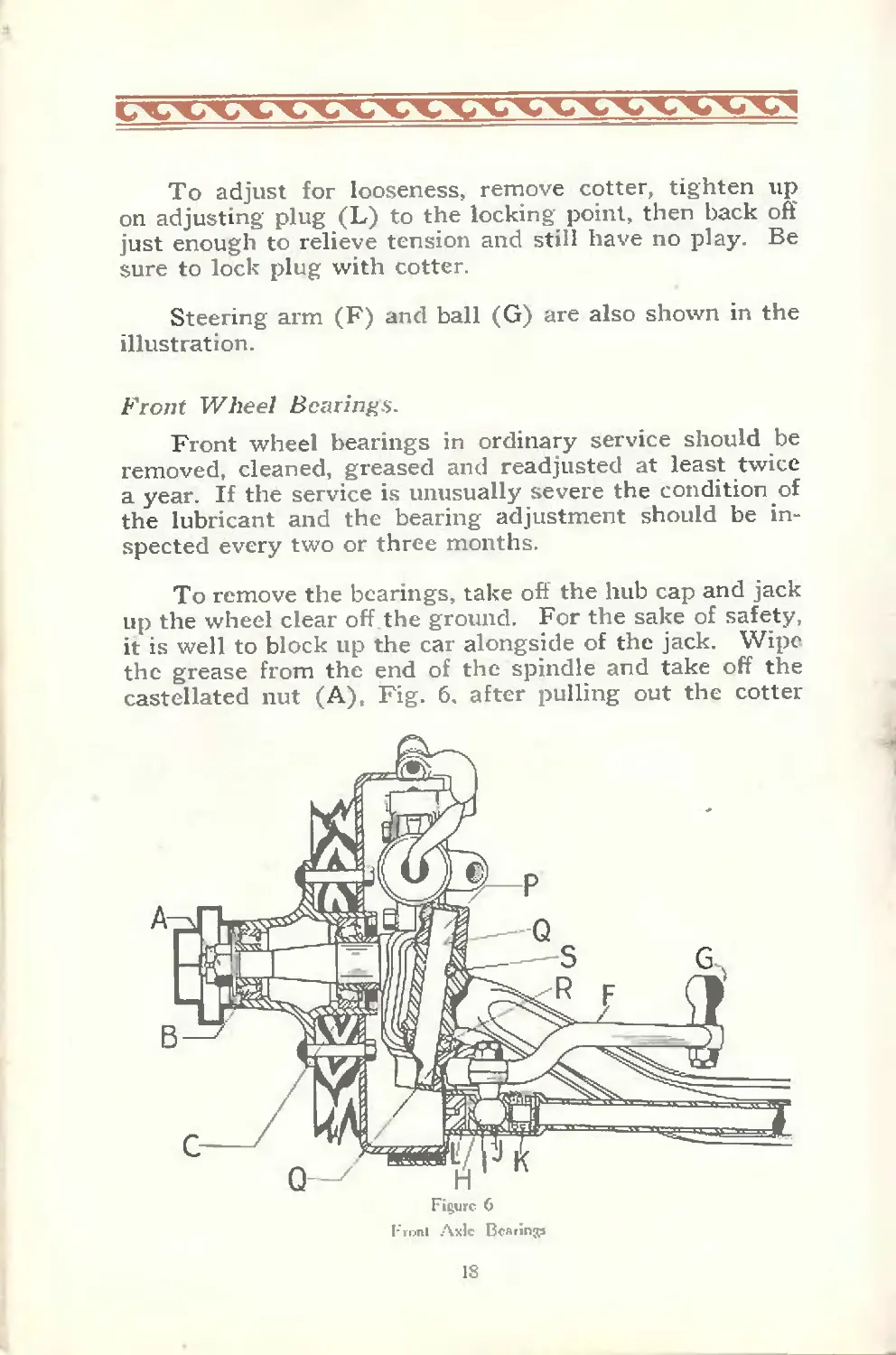
The ball (H), Fig. 6, on each arm works in a socket,
consisting of two halves (I & J) and is held in position
by spring (K) and adjusting plug (L) and locked with
a cotter pin.
Shims are provided in the tie rod for changing the
distance between the right and left steering balls (H). To
increase the amount of toe-in, rearrange these shims so as
to increase the distance between ball centers. To decrease,
reverse the operation.
17
To adjust for looseness, remove cotter, tighten up
on adjusting plug (L) to the locking point, then back off
just enough to relieve tension and still have no play. Be
sure to lock plug with cotter.
Steering arm (F) and ball (G) are also shown in the
illustration.
Front Wheel Bearings.
Front wheel bearings in ordinary service should be
removed, cleaned, greased and readjusted at least twice
a year. If the service is unusually severe the condition of
the lubricant and the bearing adjustment should be in-
spected every two or three months.
To remove the bearings, take off the hub cap and jack
up the wheel clear off the ground. For the sake of safety,
it is well to block up the car alongside of the jack. Wipe
the grease from the end of the spindle and take off the
castellated nut (A), Fig. 6. after pulling out the cotter
18
pin which locks it. Now, kneeling at the side of the
wheel and facing it, grasp the rim with both hands and
pull directly toward you, being careful not to let the outer
bearing (B) slip from the hub and fall to the floor, as this
may bend or damage the cage so that the bearing will not
render perfect service when replaced. After removing the
outer bearing, lift the wheel off the spindle, exposing the
inner bearing (C).
With a stiff brush and gasoline or kerosene clean all
old grease from the bearings, spindle and inside of the hub.
It is not necessary to remove the inner bearing (C) from
the spmdle to clean it, although t can be removed if you
so desire. Occasionally both bearings should be removed,
placed in a solution of washing soda and water and brought
to a boil. This cleans off any grease from behind the
rollers which may not have been removed by the brush and
gasoline.
Having thoroughly cleaned and dried the bearings, re-
place the larger, or inner, bearing on the spindle, covering
it well with good clean grease free from acid, grit or any
solid matter. Care should be taken to have no grit or dirt
on the paddle. Pack the inside of the hub between the
two bearing cups and cover the outer bearing with a high
grade grease such as Mobi lubricant.
Now replace the wheel and, holding it firmly in posi-
tion, slide the smaller or outer bearing on the spindle,
pressing it firmly into the hub. Slide on the keyed lock
washer and screw the adjusting nut tightly up against it
so that the wheel bearings bind slightly, at the same time
revolving the wheel to insure all working surfaces of the
bearings coming in contact. Now back off the adjusting
nut just enough to allow the wheel to rotate freely but
without noticeable end play. Lock the nut at this point
with the cotter pin.
Be sure the bearing adjustment is right before locking
it— the wheel should be loose enough to oscillate, that is,
when spun it should come to a stop and then start to turn
19
back in the opposite direction, but not loose enough to have
any amount of “shake.”
In making bearing adjustments on front wheel brake
equipment, be sure that bands are free on drums before
adjusting.
King Pin Bearings.
Should the king pin bearings develop shake, jack up
the car and remove wheels as already described.
Now remove the brake, drive out tapered locking pin
(S), Fig. 6. This will permit removal of king pin (P).
Clean all parts with brush and gasoline or kerosene. Open
up all ducts. Inspect for wear.
Special bronze bushings (Q) are used. These are
pressed into the spindles and then burnished. As a general
rule these bushings do not need replacing, as the wear
takes place on the king pin, the replacement of which
should be sufficient.
Do not attempt to remove bushings until you have
tried new king pins and are absolutely sure that bushings
are necessary.
When putting in new bushings use caution. Never
drive bushings in with a hammer. Always press them into
the spindle by supporting arms so as not to spring spindle.
After bushings are pressed into place they should be line-
reamed. using a soft automobile soap mixed with warm
water as a cutting compound for the reamer. The bush-
ings are too hard to ream any other way.
In re-assembling parts make sure that king pin (P)
is properly locked to I-beam with locking pin (S).
Be sure that all nuts and locking cotter pins are in
place. Many accidents may be traced to a failure to
properly lock the very important retaining nuts on the
front axle.
The ball bearings (R), which make for easier steer-
ing, require no attention other than an occasional inspec-
tion and lubrication.
Thoroughly lubricate all parts as you are reassem-
bling. (See Lubrication Chart, Pages 72 and 73).
20
REAR AXLE
The functions of the rear axle can be divided into
two phases:—
First—Through the springs it must support the car’s
weight together with the weight of its occupants. Also,
it must carry increased loads due to the sudden shocks
caused by road inequalities.
Second—It is required to transmit the engine's power
to the driving of the rear wheels. In addition to this it
must be able to withstand a certain amount of abuse caused
by inexperienced drivers suddenly “dropping in” the
clutch, which sets up much greater stresses than en-
countered by proper driving.
Diana axles are of the semi-floating type. In this de-
sign the tapered outer ends of the shafts are affixed to the
hubs of the wheels by hardened steel keys and locked
castellated nuts. The axle shafts have the bearings
mounted directly upon them, thus they carry the full
stresses encountered in service—that is, the radial loads
due to the weight of the vehicle and the shocks the wheels
encounter, the lateral loads due to the centrifugal force
of the vehicle in turning corners, inadvertent bumps
against the curb, etc., and the torsional load represented
by the torque transmitted from the engine to drive the
car—or conversely, the braking strain when the transmis-
sion brake is used.
In designing the axle shafts for this semi-floating rear
axle, the magnitude of each of these forces—and combin-
ations of them— has been considered and the shafts have
been liberally proportioned to provide an ample factor
of safety.
The rear axle consists principally of five parts:—(1)
the pinion shaft, which is connected to the propeller shaft
by the universal joint, (2) the bevel-drive pinion, which is
integral with the pinion shaft so that it turns with it, (3)
the bevel-drive (ring) gear, which is meshed with the
21
Figure 7
Salisbury Rear Axle
bigure 8
Columbia Rear Axle
22
pinion and turns at right angles to it, (4) the differential
assembly, on the case of which the bevel-drive gear is
mounted, and (5) the drive shafts, which connect the dif-
ferential with the rear wheels.
Driving Gears
The bevel-drive pinion is smaller in diameter than the
bevel-drive gear, and has fewer teeth. This difference in
size and number of teeth determines what is called the
gear ratio of the axle. All rear axles used in automobiles
to-day have a reduction of this character in order that the
power of the engine may be applied to propel the car
under all possible conditions without the necessity of al-
most constantly shifting gears, which would otherwise be
necessary.
Differential.
The power of the engine, instead of being delivered
from the bevel-drive gear directly to the two axle shafts,
is first transmitted through the differential. The purpose
of the differential is to permit one wheel to turn faster than
the other when turning corners and going over uneven
road surfaces. When rounding corners, it is evident that
the outer wheel has considerably greater distance to travel
than the inner in order to cover the curve. Hence, if there
is to be no dragging or slipping of wheels the outer wheel
must turn faster than the inner. The diff erential provides
for this equalization and also provides a means of equaliz-
ing the power delivered to the wheels regardless of their
relative speeds.
Lubrication.
The differential and drive gear assembly is lubricated
by the oil from the housing through the action of the gears
and oil circulating carrier. The best lubricant for this
purpose is a gear oil similar in body and character to
Gargoyle Mobiloil “C”.
After every 1,000 miles of operation the level testing
plug should be removed and the level determined. If the
23
oil is low, replenish with fresh oil to the level of this
opening.
Do not over-fill, otherwise leakage will occur on the
brake drums.
After every six months, or 5,000 miles of service, the
housing should be drained thoroughly, washed out with
kerosene and refilled to the proper level.
A djustments.
There are four conditions that make adjustment of
gears and bearings necessary:
(A)—Objectionable noise.
(B)—Excessive backlash in gears.
(C)—Loose pinion shaft or differential bearings.
(D)—Incorrect lubrication.
To eliminate noise, first make sure all parts that go
inside of the gear housing are thoroughly cleaned; any
chips, grit or other hard substances grind out the bearings
very quickly. All studs and nuts must be a good fit in the
threads, so as to hold the gears and bearings in place. If
these are loose they will let the gears vibrate.
Next, set the ring gear and pinion flush and with
approximately .008" backlash, or operating clearance, be-
tween the gear and pinion. The exact amount of this
backlash will vary from one gear set to another and de-
pends largely on the original cutting of the gears and their
variation in heat-treatment after cutting. This backlash
will vary from free running, which means at least a thous-
andth of an inch backlash in all positions of ring gear, to
a maximum of .015".
Jack up the rear wheels and paint the gear teeth with
a thin coat of red lead and oil, using just enough oil with
the red lead to make it a sort of paste. If too much oil is
used it will be difficult to make a paint that will stay on the
24
teeth and not run. Then run the rear wheels by means of
the motor, placing the transmission in high gear, throwing
on the brakes to provide proper load, and also run the job
in reverse. This will show the surfaces of tooth contact
by wearing off the red lead.
At C, Fig. 9, is what is termed a desirable contact on
the spiral tooth ring gears. A condition as illustrated in
at H may be found. This means that the pinion must be
moved in towards the ring gear. If a condition as illus-
trated at G is found, it is necessary to move the pinion
in the opposite direction.
Contact as shown at F is preferable to the condition
shown at E, although contact should not be centered there
too much To correct, move the ring gear away from the
pinion in the proper way. If the contact on the tooth
appears as shown at E, it should be corrected by moving
the ring gear closer to the pinion.
Summarizing: Moving gear out changes bearing
toward heel, also slightly raises bearing. Moving pinion
out changes bearing toward face, also slightly towards
heel For original setting, set the end of the pinion teeth
Axlr Gvar Tonlh Cunlftcl»
25
flush with the inside of the ring gear teeth and with
approximately .008" backlash.
Pay no attention whatever to noise while adjusting
the gear on jacks. After you have adjusted the gear so
that it is as nearly perfect as you can get it for tooth
contact, repaint it and take the car off the jacks and run
it around the block dry. It won’t harm the gear, and you
can then see before putting in the lubricant whether the
gear is adjusted properly both for noise and wear. You
may have to move the pinion one or two notches either
way for noise. This will change the tooth contact but
very slightly. A slight movement of the pinion in this
way is not harmful, but if the ring is turned more than an
inch and a half, it will be well to paint the teeth again in
order to assure proper tooth contact.
The vehicle may run for many thousands of miles
without the need of pinion bearing adjustment, but the
following tests should be made with reasonable frequency,
particularly after a new car has run the first few hun-
dred miles and all initial wear has taken place.
Do not adjust pinion bearings unless you are sure end
play is present. Noise developing when the vehicle is
coasting indicates loose pinion bearings. Therefore at the
first sign of noise check carefully as follows:
Salisbury Axle (Used Up to Car No. 81296)
Check for end play in the pinion bearings and be sure
that these are adjusted so that they turn freely without
appreciable play. The end play should not exceed one
and one-half thousandths of an inch checked with an in-
dicator. Adjustment of pinion bearings is made by means
of removing shims (A), Fig. 10. In removing the pinion
bearing cover to get at these shims, remove the 8 cap
screws (B). If the cover fits tightly it can be removed
by means of re-inserting cap screws in the two tapped
holes which are there for that purpose. To make sure of
proper adjustment it will be necessary to remove the
26
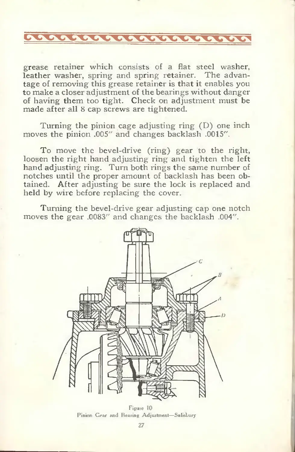
grease retainer which consists of a flat steel washer,
leather washer, spring and spring retainer. The advan-
tage of removing this grease retainer is that it enables you
to make a closer adjustment of the bearings without danger
of having them too tight. Check on adjustment must be
made after all 8 cap screws are tightened.
Turning the pinion cage adjusting ring (D) one inch
moves the pinion .005" and changes backlash .0015".
To move the bevel-drive (ring) gear to the right,
loosen the r'ght hand adjusting ring and tighten the left
hand adjusting ring. Turn both rings the same number of
notches until the proper amount of backlash has been ob-
tained. After adjusting be sure the lock is replaced and
held by wire before replacing the cover.
Turning the bevel-drive gear adjusting cap one notch
moves the gear .0083" and changes the backlash .004".
Figure 10
Pinion Gear and Bearing Adjujtment—Salisbury
27
Bevel-Drive Pinion and Bearings—Columbia
(Car No. 81296 and Up).
Take hold of dust washer (B), Fig. 11. If this washer
shows looseness when turned back and forth by hand, it
indicates end play in the pinion bearings.
If it has been determined by test that these bearings
require adjustment, proceed with caution and avoid a too
tight adjustment which will cause heating and the prob-
able subsequent destruction of the bearings and gears.
To adjust, first loosen nut (C) and back it off far
enough to allow for removal of locking washer (D) from
dowel in nut (E). This will then permit adjustment to
be made by adjusting nut (E).
Draw up on nut (E) to a good snug, but not strained,
fit until you get no movement of dust washer (B) but
still have bearings turning freely. Now place locking
washer (D) in position (making sure it fits properly) over
dowel on nut (E), then draw up on outer nut (C) until
28
snug, and lock by center punching nut (C) on the flat so
as to throw metal into one of the notches on outer edge of
washer (D). Make no further adjustment, but test for
noise.
If after making bevel-drive pinion bearing adjustment
you decide that a pinion (gear) adjustment is necessary,
proceed in accordance with the following instructions:
Loosen the clamp bolt nuts (A) and (B), Fig. 12, and
hit the head of these bolts several times with a hammer to
be sure that the bearing cups are free Next remove the
pinion adjuster lock (C) (removal of two small screws
and lock washers permits removal of this adjuster lock).
Using a small bar. turn the adjuster (D) to the right, if
you desire to move the pinion gear forward, toward front
end of vehicle, or to the left if you desire to move the
pinion gear backward, toward the rear end of vehicle. As
a general rule move the pinion forward for coast noise,
backward for drive noise. Move only one notch at a time
then test.
Figure 12
Pinion Ge.tr Adj oilmen 1—Coltinibip
29
Now tighten up the clamp bolt nuts (A) and (B), then
replace the adjuster lock (C) and run the car around the
block in high gear. If objectionable noise has been elim-
inated, make no further adjustments, but if some of the
excess noise is still in evidence, repeat the adjustment
described above, but move the adjuster only one notch at
a time (not complete turns) in one direction or the other
until the quietest running position has been secured.
Never run the vehicle without first tightening up the
clamp bolts (A) and (B) and locking the adjuster (D)
with the adjuster lock (C). You cannot test your adjust-
ment by running the axle on jacks; an actual road test is
necessary after each adjustment.
Bevel-Drive Gear and Differential Bearings—Columbia.
Do not adjust the bevel-drive (ring) gear until you
are positive that adjustment is necessary and have carried
out the previous instructions.
The bevel-drive gear (A), Fig. 13, and differential
bearings (B), are adjusted to the correct position with
30
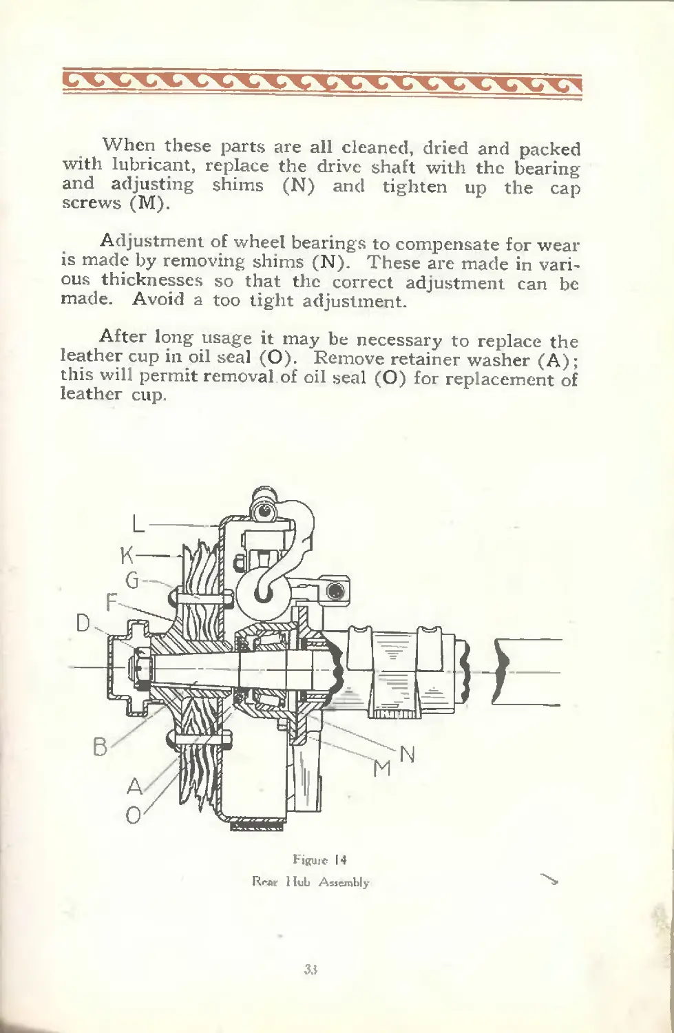
When these parts are all cleaned, dried and packed
with lubricant, replace the drive shaft with the bearing
and adjusting shims (N) and tighten up the cap
screws (M).
Adjustment of wheel bearings to compensate for wear
is made by removing shims (N). These are made in vari-
ous thicknesses so that the correct adjustment can be
made. Avoid a too tight adjustment.
After long usage it may be necessary to replace the
leather cup in oil seal (O). Remove retainer washer (A) ;
this will permit removal of oil seal (O) for replacement of
leather cup.
Figure 14
Rear 1 hit Assembly
33
ENGINE
S pacifications:— General 3" bore x 4%" stroke Piston displacement—240.3 cu. in. S. A. E. H. P. rating—28.8 Actual brake H. P.—72 at 2950 R.P.M. Maximum torque—153 lb. ft. at 1200 R. P. M. Clearance volume—21.44%. Compres- sion ratio—4.66 to 1. Weight—675 lb. with generator and distributor. Suspension—4 point.
Cylinders Gray iron, L head type, cast en bloc with upper half of crankcase. Detach- able head. Parting line below center of crankshaft for rigidity.
Crankshaft S. A. E. No. 1045 steel. Drop forged and heat treated. 5 main bearings 2%" diameter, length No. 1-2-3 and 4 —1%?; length No. 5—2 15/32".
T iming Firing order—16258374 Exhaust opens 41 degrees early, closes 1 degree late. Intake opens 4 degrees late, closes 46 degrees late. Crank sprocket—24 teeth, cam sproc- ket—48, generator sprocket—20.
Pistons Gray cast iron fitted in cylinder to .002" to .003" clearances. Permissable varia- tion in weight—% ounce. Three 3. 16 rings above pin. Lower ring—oil regulator type.
Piston Pin S. A. E. No. 1020 special steel hardened and burnished—tubular type, 55/64" diameter. Locked in piston. Bronze bearing in connecting rod— 1%" long.
л
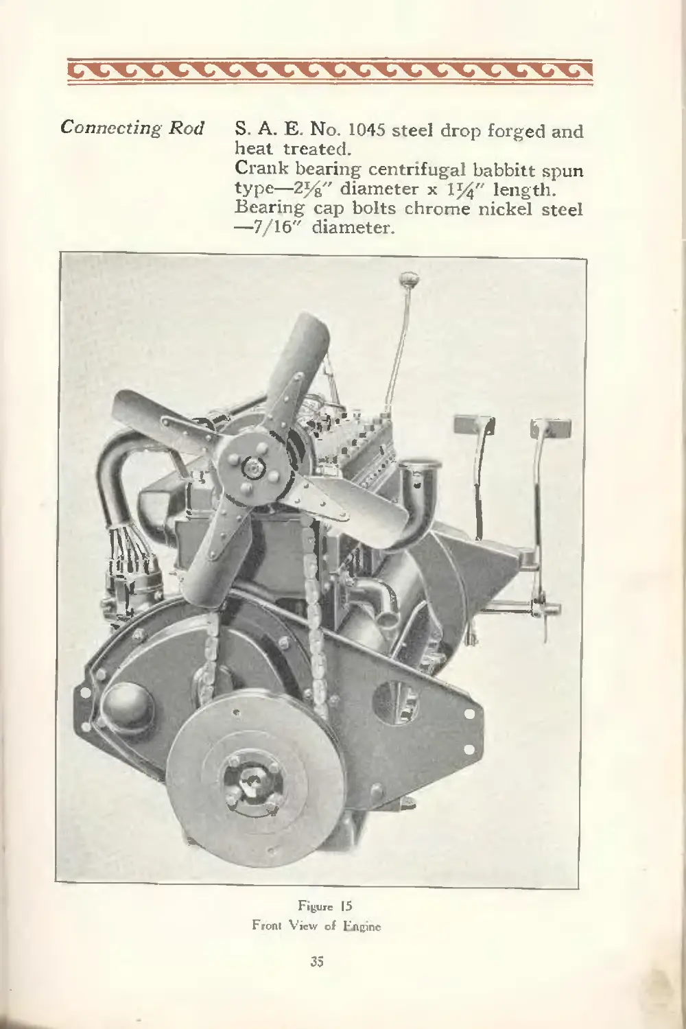
Connecting Rod
S. A. E. No. 1045 steel drop forged and
heat treated.
Crank bearing centrifugal babbitt spun
type—2%" diameter x 1%" length.
Bearing cap bolts chrome nickel steel
—7/16" diameter.
Figure 15
Fronl View of I'lnpinc
35
Valves “Ascoloy” alloy steel.
Diameter of intake valve—1 7 16".
Area intake opening—1.1813 sq. in.
Diameter of exhaust valve—1 5 16".
Area exhaust opening—1.0824 sq. in.
Diameter stem—%". Lift—5/16".
Valve spring—1 5 16" diameter elec-
tric furnace vanadium steel; 60-65 lbs
Cam Shaft S A. E. No. 1020 steel. 1 piece drop
forging heat treated. Five bronze back
bearings as follows:
12 3 4 5
Dia — 2-1 16 2 1-15 16 1-H l-%
Length— 1-5 16 % 7/s 7/s 1-И
Diameter of shaft between bearings—
1J4"
Tappets—mushroom type.
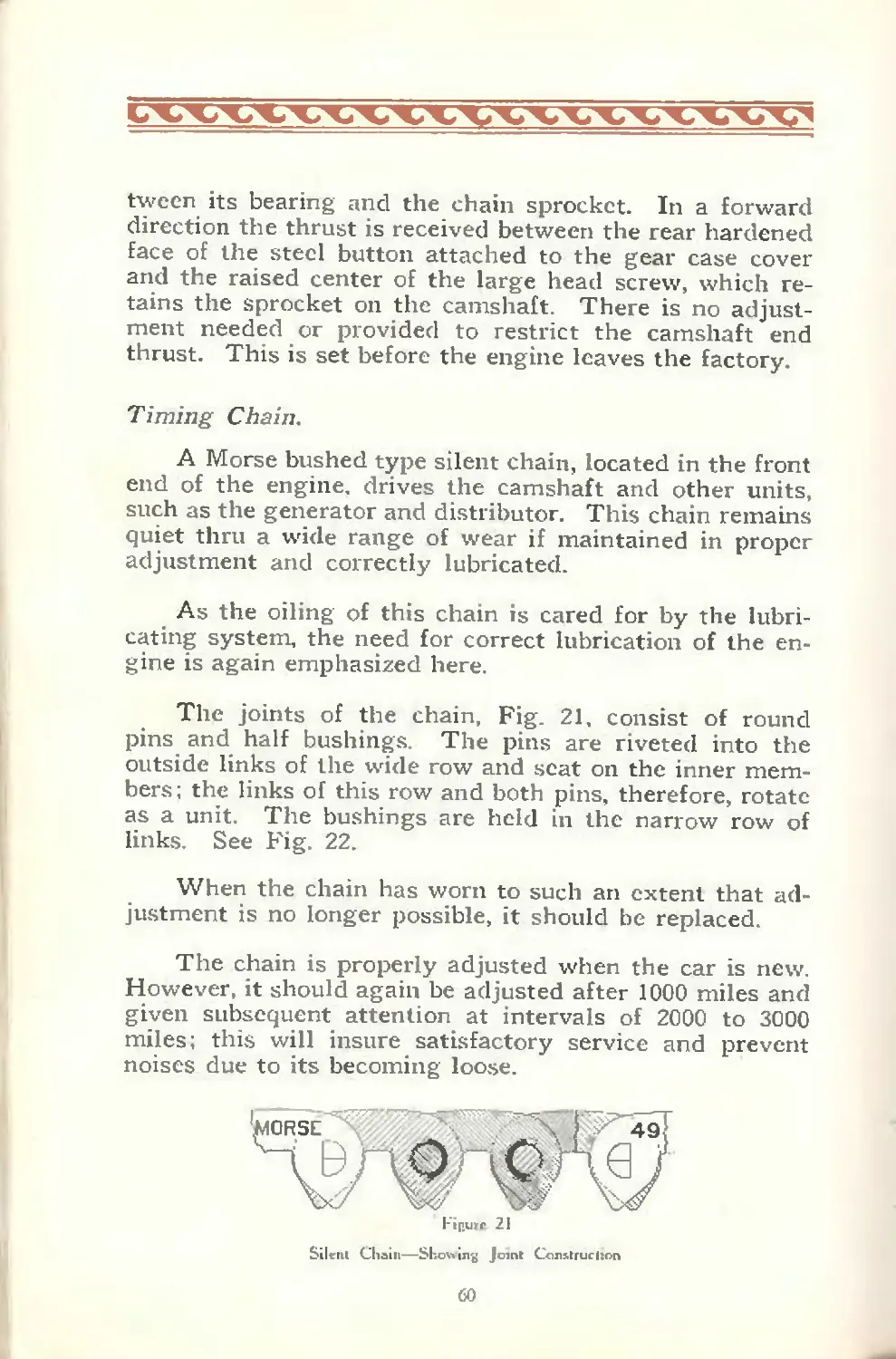
Front End Drive Morse silent chain type No. 49—%" pitch 1%" width—76 links.
Oiling System Pressure feed by gear pump. Crankcase capacity—see page 65.
Water Cir- culation Centrifugal pump, located at front of engine Pump shaft mounted on roller bearings.
Carburetor Cross throttle, vertical type. 1%" flange.
Electrical Equipment Delco 2 unit system. Distributor—2 breaker arm type with single coil
Spark Plugs Champion—7/s"—18 thread.
Lanchester Vibration Damper
The Lanchester vibration damper, used on the Diana,
overcomes vibration periods, and insures a velvety smooth
operation at all speeds. It is located at the forward end
of the crankcase and is easily accessable.
36
This damper. Fig. 16. consists of a small split flywheel
(A) placed at the forward end of the engine, supported
by the crankshaft (G) but not rigidly fastened thereto.
A series of coil springs (E) hold it under pressure be-
tween two composition friction discs (B) held in position
by a housing and pulley (C and D) which are rigidly keyed
and clamped on crankshaft (G). At the critical engine
speed there is a tendency for the crankshaft to thrash. The
damper, however, has considerable inertia and any sud-
den variation in the motion of the forward end of the
crankshaft will cause the friction discs in the vibration
damper to slip. Drive pins (F) prevent halves from slip-
ing independently. This slippage, of course, absorbs
energy.
Without the vibration damper, there is very little re-
sistance to torsional vibration, as steel, within its elastic
limit, is perfectly elastic, consequently
the entire energy imparted to it sets it
in vibration and keeps it vibrating for
a considerable time.
Repair and Adjustments.
The following instructions, written
primarily to enable the authorized service
station to make repairs expeditiously,
will prove interesting to the owner who
likes to know the “workings'* of his en-
gine.
Valve Tappets.
The mushroom type of valve tappet
is used. The heads are within .005" of
being flat, that is, they have practically
Figure T6
Vibration Damper
no “crown” to them. The stems are nominally 5/$" in
diameter and are drilled for lightness
37
Where the tappets or guide blocks have worn so that
the clearance between their sliding surfaces is greater
than .004", a slight click may possibly be audible. New
guide blocks may be necessary. Select those with which
it may be possible to fit the present tappets close enough
so that a snug sliding fit will exist.
The tappet adjusting screws should not be set up
closer than .006" in the case of the exhaust tappets, and
.004" in the case of the inlets. Adjustment should be made
when the engine is warm. If lesser clearances than these
are maintained, the cam faces of the camshaft, and the
mushroom faces of the tappets are liable to become cut
or roughened It will then be impossible to adjust for
quietness for other than very short periods. Eventually
a stage will be reached where it will be necessary to re-
place not only the tappets but the camshaft as well.
In case the surfaces, mentioned in the preceding para-
graph, have become cut. it will be necessary to regrind
the tappets. This should be done in a machine suitable
for the purpose, so that a perfectly flat contact surface is
obtained. Do not remove any more metal than is abso-
lutely necessary, for there is the possibility of cutting
through into the soft metal core. In the case of the cam-
shaft, light scratches or cuts may be corrected by stoning
the surfaces with a very fine grit oil stone When severely
cut, the cams may require a complete regrinding. In such
case it will be necessary that the shaft be returned to the
factory, since special equipment in the way of master
cams and grinding tools are needed to do this work ac-
curately.
Should you remove the valve tappet assemblies, you
will notice what appears to be surface cracks in the head
of the tappet where it rides on the cam. These very minute
marks can be removed by polishing the heads, using a
piece of Double Naught (00) emery cloth, which has pre-
viously been laid over a flat machined surface. This pol-
ishing should be done by hand, giving the tappet a circular
winding motion and holding it firmly against the emery
cloth.
38
Figure 17
Engine and Transmitsiun Assembly Right Side
(-
d
J
t
*
A
When replacing tappet and guide assemblies, be cer-
tain that the finished faces of the guide blocks fit squarely
up against corresponding surfaces on the side of the
cylinder block. If this is not done, there is a possibility
of the tappet faces not lining up properly, and this would
not only cause unnecessary noise, but would undoubtedly
result in the tappets, as well as the cams, wearing where
they come in contact with each other.
Valves.
The valves used have a nickel alloy steel head and low
carbon steel stem. This is to provide against seat pitting
and stem warpage caused by extreme high temperatures
of the exhaust gases.
Valves should always seat properly. The necessity
of regrinding, and sometimes reseating, is brought about
by the burning of the seat of the valve in the cylinder
block. This condition is frequently caused by too close
tappet adjustment. The valve not being permitted to
seat properly, allows the hot gasses to pass over the seats,
burning and carbonizing them. Often too, pieces of hard
carbon are deposited on the seat and become imbedded
in the valve. This will cause them to remain open with
the same results.
In regrinding the valves, proceed in the preliminary
operations, as follows:
(1) Remove valve chamber covers.
(2) Remove cylinder head. (Previously draining
water jacket).
(3) With a suitable valve lifter, release all valve
springs and remove all spring cups and retaining
pins.
(4) Remove all valves from cylinder and thoroughly
clean. Use a dull knife to scrap off carbon.
(5) Carefully remove all carbon in and about valve
ports and seats.
40
After the above has been done, you ate now ready to
proceed with the actual grinding operation. It will be
noted that each valve has a number stamped on it, the
front eight be ng numbered from one to eight inclusively.
The rear eight will be stamped 1-R, 2-R, and etc., to 8-R
inclusive. This “R’’ stands for rear. Be careful in re-
seating or regrinding the valves that each is replaced in
its respective guide and seat.
Beginning with the number one valve, place a light
spring on the valve stem and insert the latter in its guide.
This spring should have just enough tension to raise the
valve from its seat about 3. 32" when pressure is released.
Before putting the valve in position for grinding, it will,
of course, have had its face, only, covered with a fine grade
of valve grinding compound. Next, with a screw driver,
or other suitable tool, grind the valve to a seat, turning the
valve from one-half to three quarters turn, first in one direc-
tion then in the other. At the end of each stroke slightly
release the downward pressure and the small spring, re-
ferred to above, will raise the valve, permitting the grind-
ing compound, which has been worked away from the seat,
to return. Do not turn the valve through a complete
revolution as this grooves the seat.
When a smooth seat appears to have been obta ned,
clean both the valve and the block around the ports very
carefully and then with a soft lead pencil, mark lines across
the seat of the valve, spacing them approximately %"
apart, around the entire seat of the valve. (These lines,
if extended, would meet in the axis of the valve stem).
Next, replace the valve and, pressing down firmly with
the screw driver, turn the valve backward and forward as
before. If the work has been completely and satisfactorily
done, all of the pencil lines will be broken where contact
has been made. If this is not the case, continue grinding
until such time as each one of the pencil marks will show
some sign of erasure. Do not construe these instructions
to mean that the entire pencil mark must be rubbed out:
simply that part of it at one point on the seat, where the
valve comes in contact with the seat in the block.
41
After regrinding the valves, and before permanently
assembling, make certain that every trace of grinding com-
pound has been removed from all surfaces As a pre-
caution against some abrasive getting into the cylinder
bore, it is recommended that the latter be filled with a
clean cloth at the time of grinding. One small particle of
grinding paste coming in contact with the cylinder and
piston walls, might be the beginning and cause of a scored
cylinder bore.
When the amount of wear is such that the stem has
side play in the guide amounting to .004" or more, replace-
ment of either or both parts is necessary. After such
guides as requires changing have been replaced, they
must be line reamed to an exact 9/s" diameter so that the
valve stems will be just a snug sliding fit; not so tight,
however, as to prevent the valves from just nicely drop-
ping by their own weight when inserted in place.
Valve Timing
Valve operation can be conveniently timed, or checked,
by using, as a basis, the number of teeth of the timing gear
chain between the crank and camshaft sprockets, as de-
tailed in the following paragraphs.
The crankshaft and camshaft sprockets each have a
figure “O’’ stamped in a certain tooth space which is in
definite relationship to the keyway and dowel screw hole
in these sprockets. Inasmuch as each of these sprockets
can only be assembled in one certain position on its re-
spective shaft, because of this keyway or dowel hole, a
certain relationship will exist between each of the figure
“O’s” on the two sprockets.
The procedure to time the valves or camshaft is to
first turn the crankshaft until the marking No. 1 Ex. C.
is located exactly beneath the flywheel pointer, then, turn
the camshaft in a clockwise direction until the No. 1 ex-
haust valve will have just closed. The chain is then to be
placed in position, meshing it with the crank and camshaft
sprockets first and finally slipp’ng it over the generator
sprocket.
42
5
When placing the chain in position over the crank-
shaft and camshaft sprockets, referred to, the right tri-
angle formed by the chain is to be perfectly straight, and
should have fourteen teeth between the tooth spaces
marked zero in the two sprockets. This includes the first
two teeth that are fully engaged in the marked spaces of
both sprockets.
The engine fires in the order of 1-6-2-5-8-3-7-4; number
one cylinder being nearest the radiator. The crankshaft
design is such that the number one and number eight
cranks are at the top at the same time; number two and
number seven in a like manner coming to the top at the
same moment. The third pair is number three and number
six and, the fourth pair, number four and five. This knowl-
edge is necessary when checking up complete valve action
and timing. For all general purposes, however, the timing
of the number one exhaust valve is all that is necessary,
all others following in order because their relationship has
been determined when the various cams were machined.
Connecting Rod Bearings.
The bearing construction of the Diana connecting rod
at the “big end” is known as the “spun-in” type. In such
construction, the babbitt lining and the rod blade are in-
tegral. This also applies to the cap. The blade and cap
are revolved at high speed while the babbitt is being
poured. The resulting centrifugal force set up causes the
babbitt to become a dense solid mass free from pores.
The cap is separated from the rod by a laminated liner
or shim, one on each side, made up in each instance of
four laminations .002" thick.
When sufficient wear to cause a looseness of .002" in
diameter of these bearings has taken place a slight knock
may be noticed and if a correction is not made promptly
the babbitt lining is liable to pound out of shape. The
crank pins also will be affected unless adjustment is
promptly made. To do this work proceed, as follows:
Remove oil-pan. Remove all the cotter pins. Back
off the rod bolt nuts and remove the cap and liner assem-
43
blies of numbers one and eight rods. Now turn the crank-
shaft so that numbers one and eight pins, which were pre-
viously at the extreme bottom, will be at right angles to the
first position. Next, push up the piston and rod assemblies
(No. 1 and No. 8) far enough to permit the lower ends
swinging free of the crank pins. Be careful at this point
that you do not push the piston up too far, thereby per-
mitting the upper ring to leave the cylinder bore and ex-
pand in the, combustion chamber preventing the removal
of the piston. You will now be able to draw down and
remove the numbers one and eight piston and connecting
rod assemblies. Repeat these operations until you have
removed the other six piston and rod assemblies, in pairs.
A caution might be in order at this point to the effect
that it is always well to provide some clean place to lay
the pistons after they are withdrawn from the cylinders.
To adjust the rod bearings, first peel off one of the
.002" laminations or wafers from each of the two shims,
beginning with the number one rod. This should be very
carefully done, making certain that the lamination does
not tear, leaving a part of it attached to the shim. Next,
with a smooth file carefully remove from the edge of the
remaining shim all burrs which will be caused by the re-
moval of the lamination.
The next step is to fit the rod to its crank pin, but
with the piston hanging downward, instead of being in the
cylinder bore. At this point bear in mind that the big end
bosses are offset, that is they are not directly in the center
of the straight part of the rod. Therefore be sure that the
rod is in the correct position, using for a guide the tabula-
ted paragraph at the end of this subject.
If the .002" shim, which you have removed, is just
about right, you will find, upon drawing up the bolt nuts,
that the bearing will be just tight enough to support the
weight of the piston and free end of the rod when the
latter is swung out as far as it is possible, horizontally.
Right here is where a fine point of bearing adjustment is
noticed. With the correct fitting obtained, it should be
+4
Fan
"an Belt« Pulley CylmderWater
Lock-)
Vibration
Dampener
Water Inlet Elbow
„ Oil Pan Drain Plug
Bayonet Gauge
Transmission
Lubricant
Filler Plug
'Clutch Pedal Adjuster
Propeller
Clutch Pedal
Return Spring
Figure 1Й
Engine «nd Тгыипн&зшп Awcrnbly Left Side
possible to move the rod and piston assembly from the
horizontal position by a gentle touch of the fingers and
come at rest immediately this pressure is removed.
After you have peeled off the correct number of lam-
inations to obtain a proper fit. the cap is to be removed and
the rod and piston assembly reversed endwise and reas-
sembled in its cylinder bore, care being taken at this stage
to see that the piston and cylinder walls are carefully
wiped off with a clean cloth, that carbon is removed from
the top of the piston and that a generally clean condition
of all bearing surfaces is obtained.
Do not turn the bolt nuts up very tightly at this
time. The bearing should be left quite free so that the
crank can be easily turned while making the adjustment
of the remaining bearings. By keeping this recommenda-
tion in mind, it will be possible for the operator, while be-
neath the car, to turn the crankshaft without resorting to
the hand crank. When finally all of the eight rods have
been adjusted and reassembled, the final tightening up is
to be done beginning at the number one crank first, the
number eight second, the number two next, then the num-
ber seven, the number three and six, and finally, the
numbers four and five. By following out this routine, a
mechanic will be saved a number of unnecessary opera-
tions in the turning of the crankshaft.
In replacing the piston and rod assemblies note that
each rod is correctly placed in its respective cylinder. By
this we refer to the offset of each big end boss mentioned
in preceding paragraphs. The offset boss should extend
as indicated in the following:
Number one to the rear
Number two to the front
Number three to the rear
Number four to the front
Number five to the rear
Number six to the front
Number seven to the rear
Number eight to the front
46
If these are correctly positioned, you will find that all
of the figures stamped in the side of the rod bosses, indi-
cating their location as regards the cylinders, will be on
the camshaft side.
Provision is made through our distributors and dealers
to provide for the exchange of rod blades and caps for
others which have had bearing linings respun in them,
charging only for the work of rebabbitting.
Main Bearings.
ЛИ five main bearings are constructed as follows : The
upper halves are removable, die cast bushings provided
with suitable anchorage bosses and retaining screws. The
lower halves are, as in the case of the big end bearings of
the connecting rods, “spun-in”, that is, the babbitt lining
is made an integral part of the forged steel caps.
The caps are separated from the upper halves through
the use of laminated shims .008“ thick, one in each side of
the bearing. These liners are made up of four .002" lamin-
ations sweated together with a thin film of soft solder.
Main bearing looseness of more than .003" in diameter
will very likely be the cause of a slight knock. Failure to
correct this condition promptly will result in the same
general condition as described under “Connecting Rod
Bearings”.
The first step is to remove all of the piston and con-
necting rod assemblies as explained in detail under the
heading of piston replacement.
After the piston assemblies have been removed from
the engine, remove the aluminum filler block to the rear
of the main bearing. Then, cut and remove all lock wires
from the main bearing stud nuts. Next, with the trans-
mission control lever in neutral, test to see if the crank-
shaft turns freely by grasping the throws with the bare
hands.
47
Beginning with the number three bearing, remove the
stud nuts and cap, as well as the liner assemblies.
Carefully peel off one of the .002" shims, removing re-
maining burrs and sharp edges with a smooth file. Be
certain to take off only one .002" wafer from each pair of
liners at a time Replace shims, also cap, and draw the nuts
up tightly. If this .002" is just the correct amount to be
removed, you should be able to just turn the crankshaft,
manually, by its throws. This ascertained, the nuts should
be backed off about one turn, so as to allow the shaft to
revolve freely, and number two bearing adjusted in the
same manner. Continue until you have adjusted the
fourth, first and fifth bearings, in the order named, back-
ing off the nuts in each case so as to be able to test the fit
of the next bearing which you are about to adjust.
After the necessary shims have been removed from all
of the bearings, finally set up all stud nuts, exercising care
to get them just sufficiently tight. This means that the
caps shall be drawn up tight enough to make a good firm
contact against the shims provided for the purpose, and
yet not so tight that an unnecessary strain will be set up
in the threads of the case bosses, the studs or the nuts.
This is something which cannot be described and must be
felt or, rather, sensed by the mechanic.
After the nuts have all been properly tightened, re-
place all of the lock wires, running these in to form a
figure eight, so that the tendency of one nut to loosen up,
would cause the other one to tighten. At this juncture,
be certain to replace all oil packing wicks and gaskets
provided for in the rear bearing filler block.
If your judgement has been correct in making all of
the adjustments, you should be able to turn the crankshaft
freely with the starting crank, but not so freely that the
shaft will continue rotating after the turning pressure is
removed
When the pistons and rods have been assembled, and
the bearings adjusted as already detailed, you should be
<18
able to just turn the crankshaft with the starting crank: in
fact, some slight effort should be required to do this.
Caution: Never take up main or connecting rod bear-
ings or both so tightly that the starter in addition to the
crank, or towing the car, is necessary to start the engine.
Some mechanics believe this is an indication of good work-
manship. This is not true.
The main bearing adjustment of the Diana engine is
such that under ordinary conditions, it should not be
necessary to replace bearings until the engine has, in
general, reached a worn condition that would warrant it
being returned to the factory for a complete overhauling.
There are cases, however, where through lack of quantity
or quality of the oil furnished to the main bearings, they
may burn out or become cut to such an extent that it is not
possible to fit and adjust by the removal of the four .002"
shims.
Wherever possible, it would be well to return the
engine to the factory or some station where suitable line
reamers can be had. Usually the difference in cost will
offset the transportation charges:
In case it is necessary to have the work done locally,
the following instructions are to be carefully observed:—
It is first necessary to remove the entire engine from
the car and place it up-side-down. After this has been ac-
complished, the pistons, connecting rods and main bearing
caps are to be removed. Follow the instructions on the
preceding pages. Next, remove the crankshaft, and fin-
ally the upper bearing bushing halves. Carefully clean
the crankcase bosses and new bearing halves, i emoving all
burrs and foreign matter.
When the upper bearing bushings and lower bearing
caps, with their integrally cast linings having been
properly assembled in position, the next operation is to
“scrape them in”. This operation, whether done with a
line reamer or hand scraper, must be carried to a point
|ч
where a bearing contact of at least 85' f is obtained. The
triteness of fit is, of course, tested in the usual manner us-
ing Prussian blue. The work should be carried on alter-
nately on all five of the bearings, so as to fit them all down
to size at the same time. This is a long and tedious job,
the exact details of which it is almost impossible to de-
scribe by printed words. Only experience and a lot of it
will develop a mechanic into a good bearing scraper.
The above applies to the upper halves. In case it is
necessary to replace the lower halves only, it will not be
necessary, of course, to remove the engine from the car.
The operation further differs from the one preceding in
that entire new cap assemblies with "spun in” babbitt lin-
ing will be required instead of the upper bearing halves.
When fitting in new main bearings, either upper or lower
halves, or both, use new shims.
As in the case of a connecting rod exchange, service
arrangements have been made through our distributors
and dealers to provide for the exchange of the cap for a
new one, charging only for the rebabbitting operation.
Crankshaft End Play.
The end thrust of the crankshaft is received by the
front main beanng, between the forward throw of the
number one crank and the rear face of the bearing, and
between the rear face of the thrust collar (located just
behind the crankshaft sprocket) and the front face of the
bearing. The maximum amount of end play permissible is
.012". When more than this exists, there must be prompt
adjustment, otherwise the end surfaces of the front bear-
ing will rapidly be pounded out of condition. This adjust-
ment is accomplished as detailed in the following para-
graphs.
The first thing to do is to determine just how much
end play must be taken up. This is accomplished by re-
moving the timing gear housing and with a pinch bar, or
heavy screw driver, force the crankshaft as far forward
50
as possible by carefully prying behind the crankshaft
sprocket. Be careful not to mutilate the teeth. Then,
with feelers, determine just how much clearance exists
behind the thrust collar. The correct amount should be
.004". By subtracting this amount from what is actually
found to be the case, it will show just how many of the
shims, are to be removed These are .002" and .008" thick.
The next step is to partially remove the crankshaft
sprocket. (This can most conveniently be accomplished
through the use of a gear puller). Having drawn off the
sprocket approximately уг" with a small hook or the blade
of a knife, reach in and cut or tear off enough of the
shims to reduce the maximum end play to approximately
.004" as mentioned. The crankshaft sprocket is then, of
course, to be returned to its normal position and later when
the crankshaft oil thrower and fan pulley have been assem-
bled, and tightly drawn into position, the end play will
have been eliminated due to the thrust collar moving
further back on the crankshaft the distance equal to the
shims which have been removed.
Do not omit the oil thrower. Reports have been re-
ceived of oil leaks at the front end, and upon investigation
it has been found that either the oil thrower has not been
properly assembled or, in some instances, entirely omitted.
Piston Rings.
Properly fitting piston rings are absolutely necessary
to maintain compression, to keep down oil consumption
and to obtain maximum power. In the Diana engine a
combination of plain diagonal cut rings for the two uppers
and a scraper oil ring in the third or lower groove is
employed.
Wear, either of the rings or the cylinder walls that
will permit of the rings expanding to form a gap of .020"
or more, between the ends, will be certain to defeat the
purpose for which any ring is installed Similarly, a clear-
ance of more than .002" between the side of a ring and
si
that of its groove is detrimental to the satisfactory per-
formance of the engine and will likew'se necessitate ring
replacement.
When it is found necessary to replace piston rings, be
very certain to use only genuine Diana rings. They can
always be purchased through our distributors or dealers.
The rings used in this motor are not ground on the outside
diameter. This is to permit of rapid seating or “wearing
in”; the average time being about ten hours with the motor
at idling speed.
A replacement ring should be of such width that when
rolled in the groove, to which it is to be fitted, a slight
resistance will be felt. Ring side fits are proper when the
ring will remain suspended with the piston held parallel
to the floor, and the ring rolled in as described. Having
selected rings of the proper width, the next operation will
be the fitting of these rings to their respective cylinders
This is as detailed in the follow ng paragraph.
Beginning with the number one cylinder, insert its
piston so that the head of the latter is approximately 2"
below the top of the cylinder. Next, with the ring care-
fully held in a vise, provided with copper or lead jaws,
file just enough stock from the piston ring ends so that
when placed in the cylinder, flat against the previously
installed piston head, the clearances between the ends will
be as follows:
.006" for the top ring
.004" for the center ring
.002" for the bottom ring
After the rings have been fitted to the bores as in-
dicated above, they should be assembled in their respec-
tive grooves. The lower ring is to be slid over the bottom
end or skirt of the piston and snapped into its groove.
The center and upper rings should be slid over the top of
the piston pin in the order named.
If your selection of rings and their fitting have been
correct as regards width, they should be tight enough to
52
prevent rattling or motion in the grooves when the piston
and ring assembly is shaken, yet, loose enough to freely
expand when the piston is removed from the cylinder bore.
We can, through our distributors and dealers, furnish
rings in steps of .005" from standard size to .060" over-
size, inclusive.
If it is desired to fit a set of rings to a .003" oversize
cylinder, .005" oversize rings should be used. The oversize
ring can readily be filed to size as explained above.
Piston Pins.
When piston pins have become worn .002" or more,
it will be necessary to replace them to correct the slight
noise or click which will undoubtedly be noticed. Use
only genuine Diana parts.
Pins of standard, .002", .003", .005" and .010" oversize
are obtainable, providing for cases in which a piston pin
bushing, as well as the holes in the piston, have become
worn or elongated. Ream to the next standard oversize
and install new oversize pins. Select a pin of such size,
that it can be just driven into the newly reamed holes
in the pin with the palm of the hand or a very small raw-
hide mallet.
When reaming piston pin holes, bear in mind that
these holes must be within .001" of being exactly at 90'
to the skirt of the piston. That is, with the piston placed
on a surface plate with the sides exactly at 90 to its
surface, the holes on either side of the piston skirt must
be within .001" of the same distance from the surface of
the plate.
The reaming of the piston pin bushing to fit the new
pin is explained in detail under the next heading “Re-
placement of Piston Pin Bushing in Rod.” The testing
for alignment of piston and connecting rod assembly, after
new pins have been installed, is also described under this
heading.
5.i
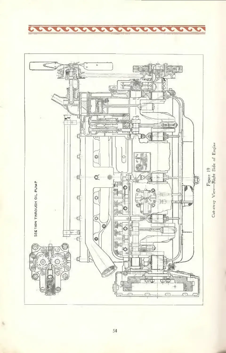
Figure 19
Cul-rtWJiy View—Riflht Side rsf Engine
Figure 20
Transverse Setliun of Hngioe
55
To test the fit of the pin in the rod bushing, first
lightly drive the pin into its position in the rod, then clamp
the pin by the ends in a vise and swing the connecting rod
up to a hor'zontal position. If the correct fit has been
made, the friction will be such as just to support the
weight of the rod. It should require but very little effort
to move the rod up or down, when held in this position.
After the piston pins have been properly fitted and
tested in the rod and bushing, they are to be assembled in
such a manner that the lock screw hole in one end will
line up with the corresponding hole in one of the bosses
of the pistons. The threaded lock screw should be screwed
into position, care being taken that the lock nut is firmly
set and locked.
Caution: Draw this screw up tightly enough to
hold the piston pin securely in position, but not enough
to cause undue strain on the screw. A special lock washer,
which has been put on the screw before installation, is to
be bent up around the flattened sides of the lock nut head
and down about the piston boss to lock the screw per-
manently.
Replacement of Piston Pin Bushing in Rod.
These bushings are made of a high grade phospher
bronze bearing metal and are machined within .0005"
limits with regard to trueness of diameter and taper.
Sufficient stock is left on the inside diameter to allow for
reaming to fit a standard size pin, after the bushing has
been pressed into the rod.
When these bushings have become worn, so that there
is .002" or more looseness, new oversize piston pins must
be fitted or bushings replaced. Where the latter operation
is necessary, the following instructions should be followed:
First, carefully press out the old bushings. If an arbor
press is used, be sure that the rod is held true on the sur-
face plate so that in pressing the old bushing out the rod
56
will not be distorted, or bent. The same caution applies
when pressing the new bushings into place.
You will note, upon examining the new bushings, that
there is an annular groove turned in the outside diameter
midway between the ends, also that there are two holes
drilled in from the bottom of this groove and at the oppo-
site sides of the diameter. Locate the bushings in the rod
just prior to pressing into place, in such a position that
a center line through these two holes will be approximately
45 from the oil hole, drilled in the boss in the top of the
rod. This is to cause the oil, which will be fed through the
rod hole, to circulate around the annular groove and find
its way to the bearing surface through the two holes re-
ferred to Do not locate this bushing in the rod so that
either of the holes will register with the hole in the rod.
After pressing the bushings into their proper position
in the rods, ream them to fit the piston pins in the follow-
ing manner:
Clamp the rod lightly in a vise. The reamer should
be turned by hand using a T handle reamer wrench. If
it is desired to use a machine reamer, this can be done with
the reamer in a drill press or lathe. Operate at a low
reaming speed in this case and be sure that the rod is
held squarely in line with the reamer, when beginning the
operation.
To test the fit of the pin in the rod bushing, first
lightly drive the pin into its position in the rod, then clamp
the pin by the ends in a vise and swing the connecting rod
up to a horizontal position. If the correct fit has been
made, the friction will be such as to just support the weight
of the rod. It should require but very little effort to move
the rod up or down, when held in this position.
After the rod and piston have been assembled, the
bushing should be tested for alignment. This can best
be done in fixtures especially designed for this purpose,
which may be obtained thru our service department. The
piston must be exactly at right angles to the crank pin
57
so as not to cause unequal pressure at opposite sides o£
the top and bottom of the piston. Also the piston pins
must lie in the same plane as that of the crank pin.
Pistons.
The pistons of the Diana Engine need only be re-
placed when they have become out of round or the cyl-
inders worn to such an extent that regrinding is neces-
sary, or when the clearance between the piston and cyl-
inder walls exceeds .005".
In the case of simply refitting new pistons, without
regrinding cylinder bores, the clearance that should be
maintained with the new pistons installed is .003". In
the case of reground cylinder bores and new pistons the
latter may be fitted a bit closer, in this instance .0025"
being correct. In addition to this point of sizes, select
pistons that are within one ounce of being exactly the
same weight as any of the other five in a given set. All
pistons are marked on the head to show decimal diameter
and weight in ounces so there will be no difficulty in
obtaining the proper size or weight It is well to check
up also the skirt diameters to see that through handling
they have not lost their true shape. They should be with-
in .0005" of being a true circle.
To test the fit of pistons, each in its respective cylin-
der bore, make use of what is known in the mechanical
trade as “feeler stock”. This is ribbon steel J4" wide; a
piece of approximately 12" long should be used, of .003"
thickness. Place this feeler in the cylinder far enough so
that it will extend almost, if not actually, through to the
open end. Now, take the piston, and holding it in a con-
venient manner attempt to insert it in the cylinder bore.
If the piston is of the correct diameter, it will be possible,
with a light pressure, to force it through the bore to the
top of the cylinder. With the piston in this position, it
should not be possible to pull the feeler out with the bare
handc.
58
While making this test, note that about the same
pressure is required throughout the entire stroke. If
greater pressure is required at any one point, this indi-
cates that the cylinder bore is somewhat tapered. This
test should be made with the feeler in three or four dif-
ferent positions, around the cylinder bore, to learn if its
diameter is true.
The piston and connecting rod assembly can be re-
moved from the bottom of the crankcase, as described on
preceding pages. If the same pistons are to be reassembled,
use care in drawing them out to make certain that they do
not strike the crankshaft and become knocked out of round.
Genuine Diana pistons may be obtained through our
distributors and dealers.
Camshaft.
The camshaft runs in five babbitt faced bronze backed
bearings. It will generally be found that, because of the
grade of material used and the extreme accuracy with
which the parts are fitted, they will not require refitting
or replacing until the engine has reached a stage requir-
ing a complete overhaul.
When camshaft bearings do finally require recondi-
tioning, it is done through a line reaming operation.
(Hand scraping is not feasible). It will be found that
when it is necessary to replace a camshaft due to bearing
conditions, the faces of the cams will have become worn
to such an extent that the camshaft itself will require
replacement. The amount of usage that will bring about
the necessity of camshaft replacement, cither because of
bearings or cams, is indefinite and in general it might be
stated that each camshaft is good for the life of the engine.
The end thrust of the camshaft is taken in a rear-ward
direction between the front face of the front bearing, and
the rear face of the hardened and ground steel thrust
washer, which is carried on the end of the camshaft be-
59
tween its bearing and the chain sprocket. In a forward
direction the thrust is received between the rear hardened
face of the steel button attached to the gear case cover
and the raised center of the large head screw, which re-
tains the sprocket on the camshaft. There is no adjust-
ment needed or provided to restrict the camshaft end
thrust. This is set before the engine leaves the factory.
Timing Chain.
A Morse bushed type silent chain, located in the front
end of the engine, drives the camshaft and other units,
such as the generator and distributor. This chain remains
quiet thru a wide range of wear if maintained in proper
adjustment and correctly lubricated.
As the oiling of this chain is cared for by the lubri-
cating system, the need for correct lubrication of the en-
gine is again emphasized here.
The joints of the chain. Fig. 21, consist of round
pins and half bushings. The pins are riveted into the
outside links of the wide row and scat on the inner mem-
bers ; the links of this row and both pins, therefore, rotate
as a unit. The bushings are held in the narrow row of
links. See Fig. 22.
When the chain has worn to such an extent that ad
justment is no longer possible, it should be replaced.
The chain is properly adjusted when the car is new.
However, it should again be adjusted after 1000 miles and
given subsequent attention at intervals of 2000 to 3000
miles; this will insure satisfactory service and prevent
noises due to its becoming loose.
Figure 21
Silent Chain—Showing Joint Construe ixon
60
1’ifturc 22 fq ' rv?
Silent Chain—Method of Assembly
Means of adjustment are provided for by mounting
the generator on the rear face of the chain case in such a
manner that it can be swung out and away from the crank-
case. See Fig. 17. This movement will increase the dis-
tance between the centers of the crank and generator
shafts, and in so doing compensate for any chain stretch
or wear The generator is held in position through the
use of two bolts through its flange and that of the chain
case. These bolts pass through slots in the generator
flange, and through clearance holes in the chain case
flange. The lower bolt, termed a pivot, passes through
fairly snug fitting holes in both the generator and chain
case flanges.
By loosening the nuts of the two bolts mentioned,
approximately two turns, the generator will be free to
swing about the lower pivot bolt. This movement is
limited by the length of the upper slot which provides
for a maximum that amounts to increasing the shaft center
distances approximately ^8 inch. After the proper chain
tension (as described later) has been arrived at, the two
nuts in question must be carefully tightened to secure the
generator in position.
When it has been found that an adjustment is needed,
do not remove the chain case cover; instead, loosen
the two bolt nuts referred to, approximately two turns.
«I
and by means of the adjusting screw, pull the generator
away from the crankcase until all rattling and scraping
noises have disappeared and a slight whine or hum de-
velops. Then permit the generator to be moved in just
slightly toward the crank case until this noise or whine
has just barely disappeared. The chain will then be at the
proper tension. Care should be taken that a tight adjust-
ment is not maintained. Adjustment should be made with
motor warm and running as slowly as possible.
LUBRICATION OF ENGINE
The Essentials of Correct Lubrication
To correctly lubricate an engine it is not only essential
that the oil be of highest quality, but it must be of the
proper body and character to meet the operating condi-
tions with scientific exactness. To satisfy all the con-
ditions met with in service it must be intelligently selected
and properly used, so that the proper amount of oil, in good
condition, is delivered to all friction surfaces at all times.
Unless these conditions are consistently fulfilled the
neglect will quickly be apparent in interrupted service and
costly repairs. It is a known fact that incorrect lubrication
is responsible for more than 50% of the expensive repairs
and costly interruptions encountered in service.
Determining the Correct Lubricant
The selection of the correct body and character of oil
for an automotive engine is a problem requiring careful
study by competent engineers, familiar with the design
and construction of automotive units, as well as with the
performance of lubricants under the various conditions
of service encountered.
It is based upon many different features of design,
construction and operation of the engine all of which may
62
be classified generally under four basic lubrication factors,
namely, operating temperatures, oil distribution, piston
seal and carbon formation.
Engine operating temperatures are affected princi-
pally by the service the engine perforins, the type of cool-
ing system, kind of fuel employed, the engine speed and
the size of the cylinder bore.
As the proper functioning of the lubricating system
depends almost entirely upon the use of the correct oil,
this must be of such body and character as will be re-
liably circulated and distributed to all the worki ig parts
under all temperature conditions encountered in service.
Some lubricating systems are adapted for the perfect cir-
culation of all oils, from the heaviest to the lightest bodied.
Others require oils of special fluidity. To make sure that
the oil. which satisfactorily meets the temperature condi-
tions, will be properly distributed, the characteristics of
the lubricating system must be analized.
Again, the lubricant which is correct for both operat-
ing temperatures and the lubricating system must also be
of such character as to minimize carbon formation and at
the same time seal the piston rings against the highly
compressed gases on the compression and power strokes.
Lubricating System.
The lubricating system of the Diana engine is of the
force feed type. A gear pump, located on the right side
of the engine, draws oil from the reservoir in the lower
half of the crankcase and delivers it under pressure,
through a suitable oil header or “gallery tube”, to the five
crankshaft bearings then, through drillings in the main
bearing webs, to the camshaft bearings. After lubricating
the crankshaft bearings, the oil passes on into ducts in the
crankshaft to the connecting rod bearings.
Excess oil forced out of the connecting rod bearings
is converted by the whirling action of the crankshaft,
63
into a fine mist, which permeates the interior of the crank-
case, thus providing lubrication for the cylinder walls,
piston pin bearings and all other friction surfaces not
directly fed by the pump.
The timing chain and sprockets are lubricated by the
overflow from the generator bearing pocket which in turn
gets its supply of oil from an open extension of the
“gallery line”.
All surplus oil returns to the reservoir where it is
screened and circulated again.
An adjustable, spring controlled regulator (by-pass)
valve is included in the body of the pump. Its principal
function is to control oil pumping by regulating the
amount of oil projected by the bearings on the cylinder
walls.
When the discharge of the pump becomes greater
than that required to lubricate the bearings and cylinder
walls, the excess pressure automatically raises the valve
against the adjusted resistance of the spring, discharging
the surplus oil, through a suitable opening, to the crank-
case.
It also serves as a safety valve to keep the pressure
within bounds, should excessive resistance develop in the
discharge line.
Lubricant Recommended.
Summer To satisfactorily meet the conditions of
operation and design referred to, we recom-
mend the use of a high grade oil, of the
body and character of Gargoyle Mobiloil
“A”, for use during the summer months.
Winter When freezing temperatures are ex-
pected, a somewhat more fluid lubricant,
such as Gargoyle Mobiloil “Arctic”, is de-
sirable to assure immediate circulation
throughout the system and facilitate start-
Detailed Instruction for Engine Lubrication.
Filling
Caution
The location of the oil filler and the oil
bayonet gauge, is shown in Fig. 18.
Fill the crankcase reservoir through the
filler pipe to the proper level, as indicated
by the “FULL" mark on the oil measuring
gauge, which is of the bayonet type.
Never permit the oil level to fall more
than half way between the two notches on
the rod. The safest plan is to check the oil
supply daily.
Be careful not to overfill. Too much oil
will bring the level high enough for the
connecting rods to dip, which will result in
an excessive quantity of oil being thrown
to the cylinder walls, resulting in oil pump-
ing, smoking, excessive carbon deposits
and fouled spark plugs.
Never fill reservoir when engine is run-
ning. Always wipe oft' bayonet with a
cloth before taking a reading.
When the crankcase is empty, 6 quarts
of oil will bring the oil level to the proper
mark on the bayonet gauge, in engines of
the first series; 7% quarts in engines of
the second series. (The first series is
recognized by the water pump being on
top of the cylinder head; the second series
by it being at the front of the cylinder
block).
Oil Pressure.
On the instrument board in front of the operator is
the oil pressure gauge, which should always register
pressure when the engine is running. If no pressure is
indicated, the engine should be stopped immediately and
65
an examination made to determine the cause. If the en-
gine is operated with no oil pressure indicating, damage,
in the form of burned-out bearings or scored cylinders and <
pistons, is likely to result.
In the use of engines having force feed lubricating
systems, many people have been led to believe that high
oil pressures are essential for proper lubrication. This is
not necessarily the case. On starting the engine a higher
pressure will be observed than when the engine has be-
come warmed up. This is due to the fact that when cold,
the lubricant is heavier in body and does not flow so
freely through the various oil passages in the engine.
When warm, however, although the pressure may be-
come less, the oil will flow at a greater rate through these
passages and through the bearings, so that actually more
oil is supplied to the cylinder walls and other engine parts.
If the bearings wear, the oil will flow at a greater
rate through them, thus causing a slightly lower pres-
sure reading than may have been noticed when the bear-
ings were new and snugly fitted. When bearings are worn
in this way, it is a mistake to increase the pressure in the
system, through the medium of the oil pressure regulator
valve, since by increasing the pressure it will tend to force
considerably more oil through the bearings than is neces-
sary for the proper lubrication of both the pistons and
cylinder walls.
The pressure is set at the factory to read 25 pounds
at a car speed of approximately 25 miles per hour, with the
engine warm. This seldom need be changed. But in the
event adjustment of the pressure relief is necessary, have
it done by a competent Diana service man.
There are certain other factors which may cause a
reduction in the pressure registered on the gauge. They
should all be carefully checked before any change is made
in the adjustment of the oil relief valve.
Too low oil pressure may be due to any of the follow-
ing causes.
65
1. Use of an oil too light in body. Follow the recom-
mendations on page 64.
2. Oil excessively diluted with unvaporized portions
of the fuel. Follow instructions for draining and
refilling the crankcase.
3. Loose bearings (particularly end play) due to
wear or improper adjustment. Refit or readjust
bearings.
4. A leaky or broken oil tube. Tighten connections
and have tubes replaced if necessary.
5. Clogged oil screen. Follow instructions for
cleaning.
6. Defective oil gauge. Have new one installed.
7- Poorly fitting bearing shims. Readjust.
Draining Crankcase Oil.
Periodic draining of the oil reservoir is one of the
most important factors in reducing wear and maintaining
maximum efficiency of the engine.
Even the best of oil deteriorates in service. Its lubri-
cating value is not actually destroyed, but the oil becomes
thinned with fuel, absorbed by the oil film on the cylinder
walls, which is blown by or scraped back by the piston
rings and mixed with the crankcase oil. This dilution
is of course greatly increased when the choke is used ex-
cessively or when the carburetor is adjusted for an over-
rich mixture. The dilution of fuel is most rapid on new
engines, or when engines are operated in cold weather
without some provision being made to insure proper
operating temperatures.
The crankcase oil also becomes contaminated by road
dust drawn through the breather, by particles of worn
metal and by carbon flaking off the underside of the piston
heads. Due to the wearing-in process of all friction sur-
faces the accumulation of worn metal particles is greatest
in a new engine.
b7
During cold weather, unless the engine is kept warm
by partial covering of the radiator, water is likely to ac-
cumulate in the crankcase. This is due to condensation
of the steam which is always present in the gases that
blow past the rings when the oil becomes diluted by the
cold operation of the engine; the steam being one of the
products of combustion of the fuel. With dirty oil this
water may form a sludge or emulsion which is likely to
clog the oil screen and passages. In order to avoid trouble
from these sources, the following procedure should be ad-
hered to:—
Drain the crankcase oil after the first 500 miles of
service of a new engine and then after every 1000 miles in
summer and every 500 miles in winter. To do this, remove
the crankcase dram plug which is at the bottom of the
crankcase. (Fig 18).
The best time to drain the oil is after a run when the
engine is heated. The oil is more fluid at the higher
temperatures, is thoroughly agitated and will therefore
carry off most of the loose sediment.
When kerosene is used to flush out a lubricating sys-
tem, a large percentage of it will remain in the system,
regardless of how much care is taken to remove it. When
fresh oil is added, this kerosene will dilute it and reduce
its lubricating value.
After draining, replace the plug. It is preferable, in-
stead of using kerosene, to put a quart or two of fresh oil
into the crankcase and turn the engine over several times
to wash out the system. Remove the plug and drain again.
Finally refill crankcase to proper level with fresh oil
of the correct grade.
To Clean the Oil Screen.
At least once every 2500 miles the oil screen should
be cleaned to prevent possible stoppage of the oil flow.
To do this, it is necessary to drop the oil pan, wash out
68
the oil screen and the oil pan with kerosene or gasoline
and dry with compressed air or a lintless cloth. Do not
use waste. A few strands of lint or hair will quickly clog
a screen.
How to Avoid Excessive Thinning of Oil or '‘Dilution”
1. Avoid excessive use of the “choke.” After start-
ing, give the engine time to warm up somewhat
before driving.
2. In winter, keep the radiator shutter closed as long
as necessary to allow the engine to warm up.
3. Avoid idling for long periods or excessively slow'
driving.
4 Keep your engine in good mechanical condition.
IK/ien excessive wear has once set in, the use of
a heavier oil will not alleviate the condition. In
fact, such practice temporarily acts as a narcotic
only to invite trouble of a different nature later
on. It is not possible to satisfactorily replace
metal that has been worn awray with a heavy
bodied lubricant.
5. Drain the engine crankcase frequently, at least as
often as specified elsewhere in this book.
6. Do not flush the crankcase with kerosene.
How to Avoid Oil Pumping and Objectionable Carbon
Deposits.
“Oil pumping,” in the common use of the term, refers
to the accumulation of oil in the combustion chamber
rather than to the quantity which actually passes the
pistons. With adequate cylinder lubrication, there is
normally a certain quantity of oil passing into the com-
bustion chamber.
An engine operating under a fairly heavy load will
burn up cleanly even an excess of oil, while one which is
lightly loaded or running idle cannot consume large quan-
tities of oil, particularly if the lubricant is heavier than the
69
operating temperatures call for. The result is oil in vari-
ous stages of decomposition in combination with road dust,
etc., forming the commonly known cylinder carbon. Such
formations are always aggravated when an oil heavier
than recommended is used.
Wear of cylinders and pistons which has increased
the normal clearance, or wear of the piston rings may be
responsible for an excess of oil in the combustion chamber.
Wear of the rings in their grooves will cause a definite
pumping action—lifting the oil mechanically into the com-
bustion chamber. When wear occurs, it must be remedied
by renewing or refitting the parts affected. With correct
lubrication, wear of this nature will be greatly reduced.
Oil pumping and excessive carbon deposits may be
controlled by careful observation of the following sug-
gestions:
1. Fill the crankcase carefully to its proper level
daily. Do not over-fill. Over-filling may cause over-oiling
with consequent oil pumping and carbon formation.
2. Use a high quality oil of the body and character
recommended on page 64. Either an incorrect grade or
a poor quality oil may make trouble.
3. Do not try to compensate for wear by using a
heavier bodied oil than has been recommended. The
heavy oil when heated will pass the pistons almost as
readily and will be harder to burn. The trouble will there-
fore be aggravated instead of corrected.
4. If the oil pressure falls off gradually a probable
cause is worn bearings, which allow too much oil to be
sprayed from the bearing clearances to the cylinder walls.
If this is the case, it is obviously wrong to try to correct
the condition by increasing the pressure and feeding still
more oil, or by changing to oil of a heavier grade. If the
oil pressure is not what it should be, an investigation
should be made by a competent service man. Oil diluted
by fuel will also cause a falling off in the oil pressure.
70
It is therefore advisable to drain the crankcase completely
and refill with fresh oil before concluding that the bearings
are at fault.
5. Be sure that the carburetor is not feeding too rich
a mixture. If there is not enough air to consume all the
fuel, there certainly will not be enough to consume any
excess oil which passes into the combustion chamber.
Incomplete combustion means carbon.
6. “Missing” promotes oil pumping and carbon form-
ation because the oil normally passing into the combustion
chamber is not burned. Keep the ignition system in good
condition and when using the engine as a brake on long
hills do not turn the switch off.
7. Compression losses affect the efficiency of the
engine and the complete combustion of oil and fuel. Keep
the valves properly ground in—the tappets properly ad-
justed—and the cylinder head gaskets tight.
How to Avoid Sludge Formation.
“Sludge”, as already stated, is an emulsion of oil,
impurities and water which accumulates most frequently
in engines run too cold. Water vapor constitutes a large
percentage of the exhaust gas in normal combustion. Un-
less the piston seal is absolutely perfect, a small portion
of this burned gas passes into the crankcase. If the crank-
case is kept normally hot, the water vapor will pass off
through the breather without condensing. In a cold
crankcase, it will condense. The water may settle to the
bottom of the case or may be continually circulated and
mixed with the oil. In either case, sludge is apt to form
from the agitation of the oil and water, together with
the impurities which are always found in the crankcase.
In winter this difficulty is aggravated because crankcase
temperatures are lower and condensation is more rapid.
There is also danger that the condensed water may freeze
and completely stop oil circulation.
71
DIANA LUBRICj
Fillrf Opvniit if
1. fc'.nE?l*l!
2. Spring Shncklv Colts 12 Alemite fitting*
3. Steering-Knuckle Pivot* i /Memitc fittings
1. Brake Band Ajichuf Pin* t Alcmite fitting*
S, Steering Gear Connect- ing Rod <Di«g-Linh) 2 AluniiU fitting*
C. Steering-Knuckle Tie- Rod 2 Alcmite (ittinge
7. Propeller Sit nit Slip Joint 1 Alcmite fitting
Л. Universal Joints 2 Plug* fS** text)
Rear Wheel Bearings 2 Alcmite fitting*
10. Transmission
Add Mobilod витпег and
'Arctic” winter, daily, ай wrd-
ed, to maintain correct level.
Engine Oil. weekly or 2S0 milve.
Engine Oil, weekly or t30 milcB.
Engine Oil, weekly or 250 milctj.
Engine Oil, weekly or mile*.
Engine Oil, weekly or 250 ntilil*.
Engine* Oil. weekly or 2S0 inil«*.
11. Differential
1 Plug at side of ease
Pitiy, in back cover plate
Fill housings every 1.000 mile*
with high grade gear lubric^Mtt
such ns Gargoyle MobiloH '*CO.
M obi toil ”CC”—every 1 (ID mile*.
(See text).
Evin у low miles remove ping
and rwfi|l to level of fillerhole
with Gargoyle Mobiloil ”C*'.
(See text).
Every 1000 miles remove plug
and refill to lrv*4 ol opining
with Gargoyle Mwbitoil ''C*.
ATION CHART
12. Fan j ( 2 Crease cups Moliiluhrtcant weekly or 250 miles.
13. Water Pump |
IL Fiont Wheel Bcannce 2 Hub глрй Mobiluhricant inpidi елр* every 2W0 mikia (Sc* text).
IS. Startinc Motor No lubrication necessary.
It. Generator 2. 011 cups Apply -8—10 drop» engine oil every 5W mih-x.
it. Die tri tutor I Oil cup 8—10 drops engine oil every 500 miles. Wipe breaker cam with Vaseline at ваше time.
tE. Tridi ini lsa«on Brake Few «кора of engine oil
Connections monthly.
19. Brake Pedal Bc-ni ing I Hole Few drops of engine oil monthly.
St. Clutch Shaft Bearing Few drops cl engine od monthly.
21. Clutch Throwout Yoke Few drop* of engine oil knonlltly.
22. Steering Gear 1 Plug ci* Ak-mite fitting 1 Hole Refill housing every 20C0 miles with Gargoyle Mobiloil **CCM.
Put 4 or 5 drops engine oil in
2 J. Spring Leaves steering wheel «pidcr weekly. Jack up car iutd slush with oil
or Insert grease if spring*
squeak. Wipe clean.
If the water has not been thoroughly mixed with the
oil, this freezing may localize at the lowest point in the
crankcase. If the quantity of water is sufficient, the oil
circulation may be blocked with ice. If the water is kept
in constant agitation, it may freeze in crystalline form
through the whole body of the oil, with the apparent re-
sult of thickening the oil so that it will not circulate. The
oil screen may strain out an accumulation of this snow
or ice deposit so that circulation will be completely
stopped.
This difficulty is most evident at extremely low tem-
peratures and can only be avoided by the use of adequate
means to keep the engine and crankcase normally warm.
Sludge formation can be controlled by careful atten-
tion to the following details:
1. Drain the oil at specified intervals—or oftener if
the sen ice consists of short intermittent runs in which the
engine does not reach its normal operating temperatures.
This will prevent the accumulation of too much water.
2. In winter, keep the radiator shutter closed as long
as necessary to allow the engine to warm up.
3. Clean the oil screen at least as often as specified
on page 68.
4. If the oil shows signs of thickening when the
crankcase is drained, remove the oil pan and clean it
thoroughly with a lintless cloth. All trace of sludge should
be removed as its presence will start new foi mations.
How to Prevent Rust and Corrosion Troubles.
Occasionally some of the polished parts of engines,
such as the piston pins and valve stems, are found to be
rusted or corroded. This trouble is due, first, to the pres-
ence of water in the crankcase and, second, to the fact
that badly diluted oil does not protect the working parts
from the rusting action of the moisture. If this moisture
is made acid, as it can be through the use of fuels contain-
ing excessive amounts of sulphur, the surfaces may be-
come corroded very rapidly.
74
Any sulphur which is contained in the fuel burns in
the cylinders and forms sulphur trioxide (SO>). If there
is leakage past the pistons and rings, part of this sulphur
trioxide will find its way into the crankcase along with a
considerable quantity of water vapor, one of the products
of combustion. After the engine is cold, this water vapor
will condense into liquid form and unite with the sulphur
trioxide to form sulphuric acid (H^SO»). If the crankcase
oil is badly diluted, it will drain off of the parts, leaving
them exposed to the action of tins acidulated moisture
which of course tends to corrode them. Even if the fuel
is free from sulphur compounds which would form acid,
the parts may rust due to their becoming coated with
moisture.
Rusting and corrosion troubles may be avoided by
observing the following precautions:
1. Keep the engine warm so that excessive dilution
will not take place or water collect in the crankcase. There
can be no rusting or acid formation without water, or cor-
rosive action if the parts are protected by oil.
2. When using fuels containing benzol, be sure that
this material contains less than .25% of sulphur com-
pounds. Straight gasolines are usually free from de-
trimental sulphur compounds.
3. Keep the engine in such mechanical condition
that the burning gases will not readily pass the pistons
and rings.
4. Use the correct oil and keep it in good condition
so that the pistons will be sealed against leakage.
5. Follow the draining suggestions given in the
section “Draining Crankcase Oil”.
6. When storing your car for a prolonged period
drain the engine crankcase, refill it with fresh oil and run
the engine only long enough to assure thorough distribu-
tion of the fresh oil to every working part.
75
COOLING SYSTEM
The repeated explosions in the cylinders create con-
siderable heat, and in order to make lubrication possible
and keep the engine temperature within workable limits,
the excessive heat must be dissipated. This is accom-
plished by the cooling system, wherein water is circulated
around the cylinders and valves in jackets. The water
enters the jackets at the bottom, and in flowing upward
absorbs the heat and passes out the top into the radiator
mounted on the front of the car. The hot water entering
the top of the radiator circulates down through many thin
tubes whose outer surfaces offer a large area to a constant
stream of air which passes by them and through the radia-
tor when the engine is running.
The flow of air is caused by the movement of the car
as well as by a rapidly revolving fan driven by the engine
and located just in back of the radiator. By the time the
water reaches the bottom of the radiator it is quite cool,
having dissipated most of the heat to the air; so it can
now be used again and, consequently, the water is taken
out through the lower connection and forced up into the
cylinder jackets again, when the operation is repeated
until the engine is stopped.
The amount of air passing thru the radiator can be
regulated by means of the radiator shutter. The shutter
control knob may be found on the left side of the dash,
behind the instrument board.
An important point in the care of the cooling system,
other than keeping it filled, is to be very careful not to
allow the water to freeze in cold weather. The expansion
of the water in freezing would be very apt to crack the
cylinders or burst the radiator.
Do not under any circumstances run the motor if the
circulating system is frozen.
Anti-Freeze Solution.
To avoid the need of draining the cooling system
to prevent the water from freezing when leaving the car
76
with the motor stopped and subject to freezing tempera-
tures, it is advisable to fill the system with an anti-freeze
solution. A popular solution consists of a mixture of de-
natured alcohol and water. To assist you in preparing
it we give, in the following table, the freezing point of
various solutions containing different percentages of de-
natured alcohol.
Alcohol Freezing Specific Gravity
Content Temperature at 60 ' F.
20% 20 Fahr. .978
40% 0 Fahr. .955
50% —20° Fahr. .946
The capacity of the cooling system is 18 quarts.
Since the alcohol in the solution evaporates more
rapidly than the water, the percentage of alcohol conse-
quently decreases. If the evaporated alcohol is not re-
placed the solution will in time lose all of its anti-freeze
properties. For this reason you should occasionally check
the freezing point by measuring the specific gravity of the
mixture by means of a hydrometer. If a hydrometer is
not available good results may be obtained by replacing
the evaporated solution with 25 per cent water and 75 per
cent alcohol.
Alcohol is one of the few substances that will affect
the Duco finish. For that reason care must be exercised
not to spill raw alcohol on the hood. Do not pour cold alcohol
into a hot radiator as this is apt to cause the alcohol to
foam and splash, ruining the finish.
The use of kerosene in the cooling system is unde-
sirable as the inflammability of its vapor makes it danger-
ous and its high and uncertain boiling point may lead to
serious overheating of the engine or even to the melting of
the solder in the radiator. It also has a solvent action
on rubber, and its vapors, besides being of disagreeable
odor, leave a greasy mist on the car.
77
Calcium chloride, or any form of acid or alkaline solu-
tion, is injurious to metal parts and soldered joints and
should not be used.
Glycerine—more specifically, distilled yellow glyc-
erine and water—is growing in favor as a radiator cool-
ant. This product is superior to alcohol in that it will not
evaporate at the temperatures generally reached by the
coolant in winter.
The freezing points of the various solutions of glycer-
ine and water are about the same as that giver in the fore-
going table for alcohol. Some precautions, however, are
necessary in its use.
If the radiator reaches the boiling point soon after
starting the engine on a cold morning, it is a sign fl at the
cooling solution has congealed and does not circulate That
means that the solution is not strung enough Under such
conditions the car should not be started at once but the
engine allowed to run for some time, when it will be noted
that the temperature begins to recede. This proves that
the slush has become fluid again and that circulation has
started. The car may then be driven safely, but glycerine
should be added to the solution as soon as possible.
Before filling the cooling system with glycerine water
solution it is well to take off the hose connections and see
that they are not partially clogged by loosened and de-
cayed inner layers of fabric. Any defective hose should
be replaced. The use of wire for fastening the hose is
not to be recommended- Strap type hose clamps, as
furnished with the car. are to be used.
Hose connections should be kept tight, but they
should not be shellaced, as glycerine dissolves shellac.
The nipples or connectors over which the hose fits should
be greased and the clamps should then be drawn up tight.
The radiator must be kept filled with clean water. If
the water is allowed to become low the engine will over-
heat and steam will issue from the radiator vent tube.
78
Should the radiator steam when it is full of water, the
first thing to look for is a stoppage in one of the hose con-
nections. After a time the rubber lining in the hose is apt
to separate and. by breaking loose or bulging, restrict the
flow of water.
Remember also that running the engine with the
spark retarded or on too rich a gasoline mixture will also
cause overheating.
The radiator should be drained at least once each
season; especially in the spring when the anti-freeze solu-
tion is no longer required and when, if left in the cooling
system, it might cause the motor to overheat.
Under normal conditions the water in the radiator be-
comes very hot, but should never boil. Should it persist
in boiling and if you are sure that the fan belt is not slip-
ping and the circulation is not impeded, the trouble may
be due to the formation of a scale or coating on the interior
of the radiator. This scale can be removed in most cases
by uncoupling the hose connections and, after plugging
up the holes, filling the radiator with a strong saturated
solution of common washing soda and water. Allow the
cleansing solution to stand in the radaitor for several
hours, then drain off and flush out the interior by directing
a strong stream of water through the filler tube. Be care-
ful not to spill the solution on the body as it will destroy
the lustre.
Caution: Never pour water into an empty or partly
emptied radiator when the engine is hot. The cold water
striking the hot cylinders might crack them.
Water Pump and Fan.
The water pump and fan of the Diana engine are
combined into one unit and located at the forward end of
the cylinder block. Motion is imparted by the belt to a V
shaped pulley which in turn drives the shaft upon which
both the fan and pump impeller arc mounted.
75
The pump requires but little attention other than to
occasionally repack the bushing gland. The packing nut
has a right hand thread and turning to the right em-
presses the packing. Reversing the direction will permit
of backing out the nut to allow the insertion of new
pack ng.
If the pack’ng gland leaks, and one or two turns of the
packing nut will not correct it. back out the nut and gland
which surrounds the shaft and examine the latter to learn
if it is cut. Should this be the case, either replace the
shaft, or, as a temporary repair, partially fill the packing
box with a turn or two of candle wi king which has pre-
viously been well saturated with a combination ol tallow
and graphite.
The fan end of the assembly requires little or no atten-
tion, except to adjust the belt tension. To do this, turn
back the set screw, with its lock nut, in the forward flange,
three or four turns, which will release the front flange so
that it can he screwed to the rear by hand. This will close
up the “V” shaped opening, causing the belt to ride
higher in the groove and in effect tightening it. Be sure
that this set screw- is firmly seated in one of the grooves
in the threaded portion of the hub when the desired ad-
justment has been obtained and that the lock nut is drawn
up tight.
Be careful to keep the far. belt adjusted at all times.
Should the belt slip, neither t’ne fan nor the water pump
will operate and the engine will overheat.
Lubrication of the fan-impeller shaft bearings is pro-
vided for by two grease cups which should be kept filled
with a high grade grease, such as Mobilubricant, and turned
down once every 100 miles.
Hadimder.
A temperature recording instrument, called a Radi-
so
meter, is incorporated in the panel of the instrument board
on cars beginning with serial No. 81,001. This is for the
purpose of indicating the temperature of the water in the
cooling system of the engine. See Fig. 1.
CLUTCH
The Borg and Beck, type QL clutch, Figs. 23-26, is
of the single plate dry disc type. The mechanism is en-
closed in a recess machined in the flywheel. Its design
permits of a very gradual application of the full power of
the motor to the rear wheels, thus eliminating all jerk and
vibration.
Release is accomplished by depressing the clutch
pedal, which moves the throwout bearing toward the fly-
wheel. The heavy helical spring (7) located on the rear
face of the clutch cover (9) provides pressure. All parts
of the clutch except the driven plate are locked to the fly-
wheel and rotate with it, the driven plate coming to rest
when the clutch is released.
The release sleeve (8) is supported in the hub of the
clutch cover and does not run on the shaft It is prevented
from turning in the cover by a key. The rear face is made
wide and smooth to provide contact for the release bearing.
The release bearing (10) is made of a special graphite
composition and is carried in a throw-out cup (11)
mounted on the pedal shaft throw-out yoke. When the
clutch pedal is depressed to release the clutch, the bearing
is moved forward against the flat, smooth surface of the
release sleeve.
Three pressure levers (5) are mounted directly on
the clutch cover (9). The outer ends of these levers
bear against the three cam surfaces of the pressure plate
(4). It will be readily understood that the ends of the
levers come in contact with the thicker sections of the
81
CXXXV УХУУ’УУХ.УХ.УХХХХУ
pressure plate, or higher on the cams, when the clutch
cover is turned to the right, or clockwise into a new
position, when being adjusted.
The driven plate drives the clutch shaft, by means of
10 splines. It is faced on each side with asbestos fabric
friction material riveted on and floats in the flywheel at
rest until pressure is applied to the pressure plate, thus
gripping the driven plate between the pressure plate on
one side and the face of the flywheel on the other side
The pressure plate moves slightly in a direction parallel
to the axis of the shaft when the clutch is engaged or re-
leased, and is driven with the flywheel by three equally
spaced dowel pins.
Adjust the clutch at once should it start slipping. The
better plan is to inspect it at regular intervals and adjust
before slipping starts This is a simple operation and
can be done by anyone in a few moments.
As the clutch facings wear the engaged position of the
release collar changes, allowing increased travel toward
the transmission. This action is transmitted through the
release yoke to the clutch pedal, causing it to come closer
to the under side of toe board. The clutch adjustment is
provided to compensate for this wear, and by moving the
adjustment bolts (A) to the right, the collar travel is de-
creased and the pedal is moved away from the board. The
correct engaged position of the release collar is indicated
at B, Figs. 23 and 24.
If the clutch seems to drag and gear shifting is diffi-
cult, it may be caused by accumulation of oil and waste
material in the clutch housing. To correct, wash out the
clutch by pouring about % pint of kerosene into it with a
funnel or long spout oil can. This can be done by remov-
ing one of the adjustment bolts. With the motor running
and a gear in mesh, the liquid is permitted to work its way
between the friction surfaces by operation of the clutch
pedal.
Do not drive with your foot on the clutch pedal.
R2
Do not slip the clutch excessively instead of shifting
gears.
If the clutch starts to slip, have it adjusted immedi-
ately, as the friction due to the clutch slipping causes
excessive heat and may ruin your clutch.
If the clutch is to be removed from the flywheel, first
remove all holding bolts and clamps, which allows the
cover assembly to come off; then lift out the pressure
plate. Next remove the dowel pins with pliers and last
the driven plate assembly.
When placing the driven plate back in the flywheel
be sure that flange end of the hub is toward the outside.
Place small amount of oil in splines.
clutch cover holding bolts,
pulling out shaft
Pressure plate must
slide freely on the three
dowel pins in the fly-
wheel. Don’t file slots if
the ring sticks. See that
pins are turned so that
the flat sides are parallel
with the slots in the plate.
Line up pilot bearing
and driven plate with stub
shaft before tightening
Tighten holding bolts before
Do not under any circumstances let the transmission
hang in the clutch assembly.
When the clutch is released, the position of the re-
lease sleeve (8) is always the same distance from the fly-
wheel. because this position is not affected by wear or
clutch adjustment However, the release sleeve may not
reach its correct position (C) if the clutch pedal adjust-
ment is rot set right or changed from its correct setting.
This can he corrected by following the instructions given
below.
7'o Adjust Clutch.
1. Loosen all holding bolts (A) about % inch, or
until clutch cover will turn in flywheel.
2. Turn clutch cover to the right, or clockwise, about
% inch.
3. Tighten holding bolts and throw out clutch once
or twice
4. Now measure distance from rear face of release
sleeve. (8) to clutch cover (9), as shown at D,
Fig. 23 This distance should be inches and
a gauge made of wire with a inch bend at one
end may be used to advantage.
5. If this space is more than 2% inches, loosen bolts
(A) as above and tarn cover a little more to the
right. If less than 2-3's inches, turn cover a little to
the left, or anti-clockwise. After correct setting
has been obtained, Lighten holding bolts. This
completes clutch adjustment.
6. The pedal pad should come in contact with the
toe board when the pedal is pressed down. See
Fig. 24. 11 it stops before moving that far, shift
the pedal down a little by means of the clutch
pedal adjustment (G), Fig. 23.
7. Press pedal down and note distance release sleeve
travels. It should be pushed toward the flywheel
about % inch, which is necessary for a clean re-
lease. If it does not travel that distance, shift
the pedal up a little.
8. The clutch pedal adjustment lias now been set in
its correct position and should not he touched
again, because adjusting the clutch automatically
returns pedal to its correct position and restores
clearance under toe board. Don’t change the pedal
adjustment instead of adjusting the clutch.
FlLlirC 26
Detail's
TRANSMISSION
The purpose of the transmis; ion is to increase the
pulling power of the engine for driving the car through
heavy roads and up steep grades, to provide a riieans of
readily starting the car from a standstill, and also to make
the hacking of the car possible without reversing the
engine.
86
87
Construction.
The mainshaft is mounted in annular ball bearings at
either end, and the forward end of the sliding gear shaft is
piloted in a Hyatt roller bearing. The countershaft and
reverse idler bearings are. of a special bronze. The gears
are of alloy steel. A spiral oil groove at the front and oil
fling washers at the rear, prevent oil leakage around the
mainshaft bearings. Oil grooves and oil holes in the main
shaft pilot, countershaft and idler gears provide proper
circulation of the oil to lubricate these parts. The shifter
forks are slideably mounted on stationary rails An inter-
locking means is provided, making it impossible to move
either fork out oi neutral position unless the other fork
is in neutral position, thus eliminating all danger of strip-
ping gears on account of two speeds being engaged at once.
A Johnson Theft Proof Lock is mounted at the base
of the gear shift lever. Pressing the lock down with the
foot when the gear shift lever is in the neutral position
locks the lever so that it cannot be moved A turn of the
key unlocks it.
Care.
Like the motor and other working units of the car,
the transmission should be careful.у broken in if maxi-
mum service is to be obtained. Using the gears frequently
under light loads while the car is new will polish the teeth,
bearings, shafts, and bushings to perfect surfaces; where-
as. abusive use of the transmission before these parts are
properly worn in. will damage them in such a way that
they will not wear to the smooth-running fit.
Lubrication.
It is very essential that the proper lubricant be used
in the Transmission. We recommend a heavy bodied gear
oil, such as Mobiluil tfC”. for this work Grease or light
oils should never be used as the former not only will not
lubricate, but will stop up the oil passages, while the latter
will not properly cushion the gear teeth to prevent wear
£8
and noise. Cheap oils or “soap-oil” mixtures should not
be used.
The transmission should be filled thru the plug open-
ing on the left hand side, to the edge of this opening. This
level should be tested every 1,000 miles and the supply
replenished if low.
After the first 500 miles of service, the transmission
should be drained by removing the plug at the bottom
of the case, flushed out with light engine oil, and refilled
with fresh lubricant. This should then be repeated every
six months or after every 5,000 miles of service.
Transmission Brake.
The transmission brake is of the external contracting
type and operates on a drum at the forward end of the pro-
peller shaft.
When the brake becomes worn, it should be adjusted,
first, by loosening the jam nut on the small bolt at the
right hand side, Fig. 28, and screwing both nuts down
until the lower half of the brake band is drawn up to where
the lining clears the drum 1 16”; then tightening the large
nut at the top of the clamping bolt and running in the
screw at the left of the band, until the entire lining clears
the drum 1/16". The wire should then be replaced thru
the head of the screw on the left hand side to keep it in
place. Do not attempt to adjust the brake by changing
the length of the pull rod that connects to the lower end
of the hand lever. This rod length should be such that the
cam surfaces rest flatly against the lower brake band
bracket when the hand lever is in released position. This
adjustment is made at the factory and should never require
further adjustment.
When the linings become worn, the brake should be
relined with a good grade of brake lining 5 32" thick and
2" wide.
89
PROPELLER SHAFT AND UNIVERSAL JOINTS
The propeller shaft with a universal joint on each end
serves as a driving mechanism between the transmission
main shaft and the rear axle pinion shaft. The rear axle
is allowed by the springs to move up and down relative to
the frame which carries the transmission, so that the pro-
peller shaft must transmit the power at constantly varying
angles. The function of the universal joints is to provide
the necessary flexible connection.
Mechanics oil lubricated universal joints, Fig 29,
arc used. The principal parts of each joint arc, the hous-
ing—made in two parts, the two yokes with driving- trun-
nions and the four bushings. End thrust is taken on the
ends of trunnions, thus relieving the bearing surfaces with-
in the joint of such strains. The housing, which also serves
as the connecting driving member, is made of two steel
stampings, the edges of which are surface ground. The
narrow surfaces and the extremely great pressure that the
eight nuts exert when drawn into place make for a very
high unit pressure between the surfaces in contact and
keep the joint tight.
Because of these desirable features of construction,
every bearing joint operates within the oil chamber where
it can be thoroughly flooded with oil, arid the moment that
the joint begins to revolve, a pressure due to centrifugal
force is set up in the oil which provides the bearings with
oil under pressure.
Should it be necessary to disassemble the joints, care
should be taken in their reassembling to see that all four
packing washers are in place, and that the ground surfaces
are not damaged where the two half housings join. To
make an oil tight joint, it is advisable to shellac the ground
surfaces. The eight stud nuts should be drawn up, a
little at a time, so that all arc brought home together.
The front and rear universal joint trunnions are
properly lined up with respect to each other when the car
leaves the factory, and to disassemble the slip joint is to
run the risk of getting the assembly out of balance. Should
it be necessary to remove the propeller shaft from the
transmission, disconnect it at the flange and not at the
slip joint.
It should be apparent, from the foregoing, that the
universal joints perform a very important function and,
consequently, should receive, periodically, what little
attention they require in the way of lubrication.
bigure 29
Uni vernal Joint
Lubrication.
There are two oil plugs provided in each joint. One
of these serves as an air vent when lubricant is being
added. A heavy bodied, high grade gear oil suitable for
rear axle or transmission lubrication, such as Gargoyle
Mobiloil “C”, is recommended. The oil in the joints should
be replenished every 1000 miles.
When the joints are completely filled there will be a
very slight leakage of oil at high speed. This is due to
the fact that the temperature rises slightly under high
speeds and heavy loads, causing a slight expansion which
has a tendency to force out a very small amount of lubri-
cant. As the joint continues in service the leakage ceases
9J
STEERING GEAR
The actuating member is a cam, very similar in
appearance to a single thread screw of variable p tch,
mounted between ball bearings which take both thrust and
radial load. It is connected by a serrated splined joint
with the steering tube, at the upper end of which the steer-
ing wheel is attached. When the steering wheel is turned,
the cam turns in its bearings and the stud projection on
the inner side of the lever and in contact with the cam
moves up or down. This rotates the lever and in turn
rotates the trunnion shaft and the steering arm. The
steering arm is attached to the outer end of the shaft by
a 36 tooth V-shaped, serrated tapered spline.
Longitudinal serrations on the sector tube fitting into
corresponding grooves in the lower end of the housing,
prevent this tube from rotating and hold the upper spark
and throttle control set in stationary position whenjthe
steering wheel is turned. These grooves also prevent the
oil from leaking out of the bottom of the steering gear.
Up or down movement of the sector tube is prevented
by means of the clamp (5), Fig. 30.
♦
Adjustments.
1. Lost Motion With Up and Down Play of the
Steering Wheel.
This is due to improper adjustment or wear in the
thrust bearing and is controlled by the adjusting
nut in the top end of the housing.
(a) Loosen and back off the locking screw. Loosen
clamp on instrument board and with a wrench
tighten adjusting nut until all end play is removed,
then back off just enough to free bearings. It may
be necessary to remove a shim if the end play is
excessive.
(b) Tighten clamp on instrument board and screw
down locking screw as far as it will go. Use
92
special lock washer under the screw, being sure
that the split in the lock washer is against the
main steering gear housing (3).
(c) See that the steering wheel rotates freely.
This adjustment must be snug without binding
the bearings.
2. Lost Motion Without Up and Down Play of the
Steering Wheel
This adjustment is controlled by the shims be-
tween the housing and the side cover plate (4)
and must be made with the cam lever stud in the
Figure 30
Steeling Gear
93
mid-position. More wear will occur in the mid-
position so the cam is cut to give, when new, less
play in the mid-position than in the end.
(a) Move the cam lever shaft back and forth end-
wise and estimate the amount of movement (in
mid-position).
(b) Remove the cover plate cap screws and the
cover plate. (Do not tear paper gaskets). Re-
move one or more shims so that the total thickness
removed will nearly equal the end movement of
the shaft.
(c) Replace cover plate and cap screws.
(d) Try gear. In the mid-position it should have
at least .002" end play in shaft.
Note: If any shims are removed to take гф end
play when the steering gear is in right or left
hand extreme, then the gear will bind when it is
in center position or straight-away driving; under
such circumstances the wearing parts of the gear
can easily be ruined.
3. Steering Aim.
Should it be necessary to remove the steering arm,
do not use a hammer for this purpose as in so do-
ing you are apt to break the internal parts of the
gear. If the fit is very tight, use a puller—a device
similar to the familiar wheel puller—for removing
the arm.
The position of the steering arm with respect to
the front wheels is correct when the car leaves
the factory, but in the event the arm has been re-
moved, observe the following instructions when
replacing it.
When the steering arm is attached to the trunnion
shaft be sure that the steering wheel is in a position mid-
91
way between its max mum movement to the right and to
the left. The front wheels should then be placed for
straight ahead driving.
This is important in order to take advantage of the
variable reduction of the steering gear which eliminates
road shock in the mid-position with quick steering wheel
movement on turns.
Do not drive the steering arm on with a hammer.
Put the arm on and draw the nut tight with a long wrench.
See that it is inspected to keep it tight. Be sure that lock
washer (2) is in place.
Lubrication.
To lubricate the steering gear, remove the large pipe
plug (1) from the housing and fill the housing with a high
grade semi-fluid lubricant of the body and character of
Gargoyle Mobiloil “CO”. The lubricant should be in-
serted slowly with a gun in order to give the air a chance
to escape so that the housing will be completely filled.
The supply of the lubricant in the housing should be
replenished every 2.000 miles.
STARTING MOTOR
The starting motor, Fig. 31, cranks the engine when
the circuit between the starting motor and the storage
battery is completed by the motor switch, Fig. 32, mounted
in the floor board. Hand cranking is eliminated by the
starting motor. Starting of the engine and its subsequent
operation depend upon the proper performance of the
carburetion and ignition systems as well as upon the
general mechanical condition of the engine itself.
The starting motor is a four-pole series wound unit,
having the negative side of the circuit grounded to the
motor frame and is held in the flywheel housing by the
standard S. A. E. flange mounting. It is prevented from
turning by three cap screws. The four brushes are mounted
in box type brush holders.
У5
Engagement with the flywheel during cranking is
accomplished through the Bendix gear. When the arma-
ture starts to revolve, the spiral shaft of the Bendix assem-
bly turns within the Bendix gear, moving it endwise and
meshing it with the flywheel teeth for cranking. When
the engine begins running on its own power, the flywheel
drives the Bendix gear at a higher speed than the armature
is driving it. The Bendix gear then automatically de-
meshes from the flywheel. A heavy coiled spring is ar-
ranged to absorb the sudden shock when the gear meshes
with the flywheel.
Lubrication.
The armature shaft bearings are made of bronze
inlaid with graphite. When assembled, these bearings are
saturated with oil and, due to the graphite in the material,
do not require further lubrication in service.
Figure 31
Starting Motor
No lubricant should be applied to the spiral shaft of
the Bendix. Keep this part free from oil, grease and dirt
to obtain satisfactory operation.
Cranking.
If the engine for any reason only runs for a second or
two after the first application of the starting motor, be
sure to wait until the engine flywheel has ceased rocking
backward and forward and has come completely to rest
before applying the starting motor the second time.
Observance of these two rules will very largely eliminate
95
breakage of starting motor parts and damage of the fly-
wheel teeth.
Cranking Current.
A large amount of current is required from the storage
battery during cranking. Therefore there must be no
loose or corroded connections in this circuit, which in-
cludes the storage battery terminals, grounded lead from
the battery to the frame of the car, motor terminal and
motor switch connections, and contact of the starting
motor brushes. Inspect the entire cranking circuit regu-
larly each 2,000 miles keeping the above points in mind.
Locked Bendix.
In case the Bendix gear becomes locked in mesh with
the flywheel teeth, it can be readily removed by placing
the gear shift lever in “high” and rocking the car back-
ward and forward a few times.
STARTING MOTOR SWITCH
Fig 32 indicates the design of the starting motor
switch. It has self-cleaning contacts and requires no
attention. In operating the switch it should be fully de-
pressed and after the engine begins running, quickly
released
97
GENERATOR
The generator, Fig. 33, provides current for the lights
and for ignition at normal driving speeds, the excess cur-
rent recharging the storage battery so that an ample
supply of current is always available for starting purposes,
as well as for lighting when the engine is not running.
Charging Rate.
This unit, whose armature is driven at one and two-
tenths engine speed, begins to charge the battery at a
speed of from 7 to 9 miles per hour in high gear. A maxi-
mum charging rate, as indicated by the ammeter on the
instrument board occurs at a car speed of 18 to 25 miles
per hour. At higher speeds the charging rate decreases
due to the normal regulation within the generator.
Figure 33
Geno sinr
The charging rate is controlled by a combination of
the standard third brush and a special field winding known
as a stabilizing field. This special arrangement in reality
consists of two separate sets of field coils, each set of
which functions independently of, but supplements the
other. The stabilizing winding consists of two coils of
comparatively fine wire wound upon adjacent poles. One
98
end of this winding is connected to the positive main brush
and the other end to the negative, or ground brush. The
other set of field coils is composed of larger wire wound on
the two remaining poles, and has the ends connected to
the positive main brush, and the third brush respectively.
A common terminal located on the top of the generator is
connected to a lead directly from the positive main brush,
to one side of the stabilizing field coils and to one side of
the standard third brush field winding.
With this method of regulation the charging rate of
the generator is uniform at all average driving speeds,
and accurate adjustment of the third brush is obtainable
without procuring too large a variation in the charging
rate.
The charging rate may be adjusted for cases where
the driver operates under conditions which are out of the
ordinary and require either a higher or lower output.
When the geneiator leaves the factory, however, it is set
for the average driving conditions.
The third brush is mounted on an adjustable plate.
If it is desired to change the charging rate this may be
accomplished by a shifting of the third brush. To adjust
the charging rate remove the cover band from over the
brushes. The third brush mounting plate will be disclosed.
Upon this plate will be noted a small lug or projection
which may be pried upon with a screw driver or other
suitable tool. The plate is held in position by means of
friction clamp washers, and there are no nuts or adjusting
screws to loosen. If it is desired to increase the charging
rate, simply pry the third brush mounting plate projection
in the direction of armature rotation( counter-clockwise).
To decrease the rate shift the plate in the opposite direc-
tion. The plate will remain stationary in whatever posi-
tion it is set. The charging rate on the Diana generator
should not exceed 14 amperes (measured at the dash am-
meter) when the unit is hot. When cold the readings will
be approximately 2 amperes higher.
When the position of the third brush is changed in
adjusting the charging rate, it may be found necessary to
90
reseat the brush on the commutator to obtain the true
charging rate. To reseat the third brush, or either of the
main brushes, place a strip of sand-paper or sand-cloth
having a width slightly greater than that of the brushes,
around the commutator with the rough side next to the
brush. Drawing the sand cloth back and forth a few
times will seat the brush. Do not waste the brush material
through excessive sanding. Never use emery cloth.
Lubrication.
The generator armature is carried by a Durex bearing
at the commutator end and an annular ball bearing at the
front end. Lubrication of the bearings is accomplished by
oilers located at each end of the housing. Apply 8 or 10
drops of engine oil every 500 miles.
CUT-OUT RELAY
The cut-out relay, mounted on top of the generator,
is used to complete the circuit between the generator and
the storage battery when the engine is in operation and
to automatically open the circuit when the engine is idl-
ing slowly or stopped. This prevents the storage battery
from discharging through the generator windings.
The cut-out relay is magnetically operated, the con-
tacts being closed when the generator voltage exceeds that
of the storage battery and opened as soon as the voltage
of the generator becomes lower than that of the battery.
Adjustment of the cut-out relay is properly made at the
factory and should require no attention other than to note
occasionally that the silver contacts are clean and making
good contact. Adjustments of the contacts should not be
attempted except by one familiar with their repair.
IGNITION ANO LIGHTING SYSTEM
Distributor.
This unit is provided for the purpose of timing and
distributing the ignition current to the spark plugs at the
proper time and in the correct firing order of the engine.
100
and the high voltage ignition
ignition coil.
Fig. 34 shows the gen-
eral construction of the
unit. The distributor
shaft carrying the distrib-
utor cam and the rotor is
driven through spiral
gears in a clockwise direc-
tion at one-half engine
speed.
Timing of the ignition
current is effected by the
interruption of the prim-
ary ignition current by
the tungsten contact
points in the distributor.
At the instant of separa-
tion, the primary low vol-
tage current is interrupted
current produced by the
Spark Advance Control.
The manual spark advance control is linked up with
the spark lever on the steering wheel. Travel of the spark
lever on the steering wheel through full range causes full
travel of the advance lever at the distributor. This con-
trol provides the proper retard of the ignition for starting
the engine, and for very slow idling speeds, and also per-
mits control of the spark for maximum power at high
engine speeds.
The automatic advance mechanism is of the centri-
fugal type and automatically advances the breaker cam a
predetermined amount at different speeds at which the
engine might be run during average driving conditions.
The spark lever should be retarded while the engine is
being cranked by the starting motor. When the engine
runs under its own power the spark lever should be placed
in a position known as the driving position.
101
The driver’s experience with a certain engine and car
often assists him to locate the position of the spark lever
at which the best performance is secured. The automatic
then gives the ignition the proper amount of advance for
all average driving speeds without manipulation of the
spark lever. Therefore the engine develops the maximum
power possible at these average driving speeds.
Lubrication
The distributor shaft revolves in two bronze bushings
filled with graphite. Additional lubrication is provided
by the oiler in the side of the distributor cup, which should
receive 8 or 10 drops of engine oil every 500 miles.
Condenser.
The condenser which is mounted on the inside of the
distributor housing is made of two strips of thin tinfoil
separated by sheets of waxed paper. It is rolled into
compact form and inclosed in a moisture-proof metal case.
It has for its purpose the decreasing of the amount of
burning at the timing contacts, it also assists the ignition
coil in the production of a strong ignition spark.
Adjusting Timing Contacts.
The adjustment of the timing contacts should be such
that when they are separated the maximum distance by
the cam, the distance apart will be .025”. The tension on
the contact arm spring should be 13-16 oz. This may be
measured by a small spring scale attached very close to
the contact on the arm.
Due to the wearing to a seat of the rubbing block on
the contact arm, one or two adjustments may be necessary
during the first 2,000 miles, after which no attention is
necessary other than to occasionally note that the adjust-
ment of the contacts conforms well with the specifications.
The contact points are made of tungsten metal, which
is so hard that it cannot be filed. Should it become neces-
sary to clean the points, simply rub them on an oil stone.
Ml2
It will be more satisfactory to remove them for this pur-
pose. It is not necessary to entirely remove by grinding
each small pit from the point surface to secure proper
performance. To do so wastes the material of the point.
Simply brighten up the surface of the pitted contact and
remove the small raised portion of tungsten from the sur-
face of the opposite contact.
Ignition Coil.
The ignition coil. Fig. 35, is for the purpose of con-
verting the low voltage current from the storage battery
or generator to a current of very high voltage that will
jump the gap in the spark plugs. It consists essentially
of an iron core, with a primary winding of a comparatively
few turns of copper wire, and a secondary winding of
several thousand turns of very fine wire.
..ХОГЧ CQFC.CL
fHOUrrrirHG PLATE
reeaVSTANCET OMIT
Figure 35
Ignition Cui I
When current from the storage battery or generator
flows through the primary winding, it magnetizes the iron
core, and when the current is interrupted by the timing
contacts in the distributor the magnetism dies out. The
dying out of the magnetism in the iron core induces in
the secondary winding a high voltage current. This is
conducted from the high tension terminal to the distributor
head, rotor and spark plugs.
KU
Timing the Ignition.
The ignition is properly timed when the car leaves the
factory. However should it be necessary for any reason
to retime the ignition, the following instructions should
be followed:
1. Turn over the engine slowly until the piston in
number eight cylinder is on top dead center of
compression stroke. The timing cup (pet cock)
on number eight cylinder will facilitate determin-
ing this position. See under Valve Timing,
page 42.
2. Note the position of No. 8 high tension terminal
on distributor head, and make mark on side of
distributor cup directly under center of this
terminal.
3. Remove distributor head and rotor
4. Loosen timing adjustment screw in center of cam
5. Using the rotor as wreiich. turn earn until rotor
button is directly under the position of No. 8 high
tension terminal.
6. Carefully adjust cam so that one set of contacts
is just separating.
7. Tighter clamp screw.
8. Replace distributor head.
After driving the car, it may be found that a slight
change in this adjustment will be required.
Lighting and Ignition Switchon.
The lighting and ignition switches are mounted
separately on this system. The ignition switch is of the
standard push and pull button type, and is mounted on
the instrument board. The circuits of the lighting and
ignition switches arc clearly shown in the wiring diagram,
Fig 36.
1П4
The lighting switch is mounted at the base of the
steering column. It is of a rectangular shape and so
mounted that the wiring is simplified and easily accessible.
Control of the lighting circuits is obtained by a lever, simi-
lar to the spark lever, located on the steering wheel.
Behind the instrument board, to the left of the igni-
tion switch button, is a switch for controlling the instru-
ment board lamp.
Circuit Breaker.
A circuit breaker is mounted on the switch. This is
a protective device which takes the place of fuses which
are commonly used for this purpose. The normal current
of the lighting circuits does not affect the circuit breaker,
but in the event of an abnormally heavy flow of current,
such as would be caused by a ground on any of the lighting
circuits, the circuit breaker operates and intermittently
cuts off the flow of current, thus causing a clicking sound
which gives a distinctive warning that abnormal condi-
tions exist in the circuit. This will continue until the
ground is removed or the switch is operated to cut off the
circuit on which the ground exists. In this manner the
circuit breaker protects the wiring, switch and storage
battery. As soon as the ground is removed the circuit
breaker restores the circuit.
Ammeter.
The ammeter permits the driver to keep a check on
the performance of the electrical system. It indicates the
net amount of current that the generator is supplying to
the storage battery when the engine is running, and the
amount of current that the battery is furnishing for lights
when the engine is not operating.
At all car speeds faster than 8 miles an hour, with the
lights “OFF” the ammeter should always indicate
‘Charge”. With the lights ON” a slight discharge will
be indicated at slow speeds. The lamp load will also re-
duce the charging rate at high speeds.
iOS
Wir»n«, ГЪялглт
1V5
Caution—Do not attempt to operate the system with
the storage battery disconnected or removed from the car.
Very serious damage to the apparatus may result from
such action.
Before attempting to remove or repair the starting
motor or disconnect any wires from the ignition and light-
ing switch, be sure to first disconnect the lead from one
of the storage battery terminals.
STORAGE BATTERY
The storage battery is located under the front seat
at the left hand side. It furnishes the electric current
for operating the starting motor, ignition system, horn and
lamps, when the engine is stopped or running so slowly
that the output of the generator is insufficient to take care
of the load. The operation of the starting system depends
practically entirely on the condition of the storage battery,
therefore it is highly important that the following in-
structions be carefully observed.
1 Keep terminals and “ground” connections clean
and tight and terminals greased with vaseline.
Corroded or loose terminal connections cause by
far the most of the trouble in starting.
2. Avoid overheating the battery on long drives,
particularly in hot weather. Turn on the lights if
the metal connectors on top of the battery feel
warm to the hand.
3. Keep battery securely clamped in position.
4. Avoid placing tools or metal on top of battery. In
tightening a terminal, protect the other metal
parts from accidental short-circuit by covering
107
them with a cloth, blowout patch, or other non-
conductor of electricity.
5. Keep open flame away from battery.
6. Have the battery stored with a service station or
recharged regularly if idle in winter.
7. Add distilled water to bring level of electrolyte in
each cell above plate tops every two weeks in
summer, or every month in winter.
As a substitute for distilled water, melted artifi-
cial ice or fresh rain water, that has not come in
contact with metal or cement, may be used. Do
not use spring water, river water or well water;
they are 1 able to contain iron or other mineral
matter that is detrimental to the battery. Be care-
ful not to fill the cells to the top, since, when
being charged, the solution expands and would
then overflow.
8. Have battery recharged by a service station if
specific gravity falls below 1.225. The gravity at
full charge is between 1.275 and 1.300.
A hydrometer is used for testing the battery solution
to determine, by measuring its specific gravity, the amount
of electrical charge the battery contains in each of its 3
cells. It can be purchased at any accessory store for
approximately one dollar.
If the gravity is found to be as low as 1.225 the battery
should be charged immediately until the gravity of each
cell is up to normal. The charging can be accomplished by
driving the car or running the engine at a speed propor-
tionate to fifteen miles per hour for sufficient length of
time to raise the gravity to at least 1.270. The output of
the generator is sufficient to keep the battery charged
under normal conditions—but you must remember that
any excessive use of current must be compensated for—
by driving the car for greater periods at a speed of fifteen
miles per hour or more without the lamps lighted and
without using the starter frequently.
108
The changing rate should fit the service. For instance,
a salesman driving 100 miles a day may need a charging
rate of only 6 to 8 amperes while a physician driving 10
miles a day may be unable to keep his battery charged
with a rate as high as 14 amperes.
In cold weather the battery must be kept charged to
prevent free ing. A fully charged battery will not freeze
until the temperature is down to 60 degrees below zero—
but if the battery is only one-quarter charged, it will freeze
at zero.
Cold, thickened oil in the engine and transmission, the
greater use of lights because of early evenings and the
decreased volatility of gasoline impose an additional load
on the starting battery, which, of course, must be com-
pensated for by an increased output of the generator.
It is therefore advisable that the generator be checked
up to make sure that it is charging at the normal rate of
12 to 14 amperes when the car is being driven at from 18
to 25 miles per hour. (Instructions for regulating the
charging rate of the generator will be found on page 99).
U. S. L. Service Policy.
All standard U. S. L. Batteries are guaranteed to be
free from defects in material or workmanship and the
service of such batteries is insured under the following
service and adjustment policies:
The purchaser of a new car should immediately drive
his car to the nearest U. S. L. Service Station for initial
test. This test, which covers complete inspection of the
battery and its relation to the electrical system, will be
made without cost to the Diana owner.
During the first ninety days of service, if repairs to
the battery are necessary, such repairs will be made by
any U. S. L. Service Station without cost to the owner,
unless it is apparent that such repairs are made necessary
by neglect or abuse. It is of course understood that the
owner will be expected to pay for any necessary re-
charging.
109
Figure 37
ТеЯшр Battery HORN
After the expiration of
the ninety-day warranty
period, but within fifteen
months of the date indi-
cated in code on the num-
ber plate of the battery,
the owner will, in case of
battery failure, have the
option of paying for
necessary repairs or of
obtaining at any U. S. L.
Service Station a new
U. S. L. battery in ex-
change at a price f. o. b.
factory, equal to one-
fifteenth of the list price
for every month of the
fifteen months guaran-
teed adjustment period
which has elapsed.
The quality of the tone and service of the horn will
depend on the attention it receives. Once every month
the horn motor cover should be removed. Set the motor
in motion by pushing the horn button on steering wheel,
and clean the commutator by holding a soft cloth moist-
ened with light engine oil on the revolving commutator.
no
To adjust tone of horn, first loosen large lock nut
(LN) and start the current by pressing the horn button
at the head of the steering column. While the horn motor
is revolving, unscrew stud (AS) until no sound is heard
but the buzzing of the motor. Then screw stud back until
the note is loud and clear. Tighten lock nut.
LAMPS
Bulb Sizes.
Head lamp—21 candle power—single contact
Side lamp— 2 candle power—single contact
Tail lamp— 2 candle power—single contact
Instrument board lamp—2 candle power—single
contact.
Dome lamp—4 candle power—double contact.
All bulbs are 6—8 volt type.
Adjusting Head Lamps.
Remove doors by rotating in a left hand direction.
If reflectors are dirty, polish them with a soft cloth
and ordinary lampblack, rubbing them with an in and out
motion from the edge of the reflector to the bulb socket.
After cleaning reflectors, examine lamp bulbs carefully,
and if they are blackened, replace with new ones, making
sure that they are of standard construction, 21 c. p., gas
filled, 6-8 volt with “V” type filament located in the center
of the bulbs. The head lamps are equipped with snap
terminal sockets and connectors and any defective parts
can be easily replaced. Electrical fittings should be ex-
amined to see that they are in perfect condition. If socket
does not fit tightly in reflector sleeve, pull out the small
spring in the side of the main bulb socket which will give
it a better tension in the sleeve. This is very important
as a loose socket will cause a drop in voltage, and will
cause the bulb to be out of center with the reflector. After
these adjustments are complete, the door should be re-
placed. It is well to apply a small amount of grease to
the packing cord to facilitate removal of the door.
in
Select a level spot on the floor 25 feet from a wall and
mark a horizontal line on the wall at the same height as
the center of the headlights, see Fig. 39. Cover up one
head lamp and focus the other lamp by moving the bulb
m and out by means of a screw-driver engaged on the
focus button on the back of the lamp. This should be
moved forward and backward until the smallest vertical
width of beam is obtained. Repeat this operation on the
other lamp.
Finnic 39
Headlight Focusing Chait
The bracket for mounting head lamps is the standard
S. A. E., and provides adjustment up, down and sideways.
Cover one head lamp and loosen nut underneath bracket
of the other, and move the head lamp forward and back-
ward until the extreme top of the beam just grazes the
line on the wall which is the same height as the center of
the headlights. Repeat this operation on the other head
lamp, and then line up the fronts of the two lamps to-
gether by means of a straight edge or a piece of string.
After this adjustment, if vertical lines are drawn to
the right and left of the center vertical hne( obtained by
sighting from the center of the car over the radiator cap)
thru the center of the beam from each lamp, these lines
should be a distance apart equal to the distance between
lamp centers, and both lines should be the same distance
from the center line.
The foregoing adjustment is for lamps on cars fully
loaded. If the cars are not loaded, the following allow-
ances should be made for the unloaded car. Phaeton—
tilt down 7" additional for 25 feet; sedan—tilt 6" addi-
tional ; coupe—5" additional; roadster—4" additional. The
final result should be as shown in the cut. It is of extreme
importance that focusing instructions be followed care-
fully, and if properly adjusted, the head lamp will show
no glare on a level road.
CARBURETOR
The purpose of the carburetor is to mix gasoline and
air in the proper ratio and to supply this mixture in a
highly vaporized state to the intake manifold, which in
turn distributes the vapor to the cylinders.
Stromberg Carburetor Type OX-2. (Fig. 40)
This carburetor is one of the newest forms of the
plain tube type, so called because, having no air valves or
metering needles, both the air passages and fuel jet are
of fixed size for all engine speeds. This model has been
particularly developed for the use of low grade gasoline
fuels and contains the following special features:
A gasoline feed above the throttle, with separate ad-
justment for idling the engine; an “accelerating well,”
which gives an extra supply of fuel just for a moment as
the throttle is opened; and an “economizer,” which per-
mits the carburetor to operate on a very lean and econ-
omical mixture at the closed throttle positions of average
driving but automatically shifts to the needed richer set-
ting when the full power of the engine is called for.
The economizer needle valve is properly set at the
time the carburetor is installed on the engine and no ad-
justment is needed.
Adjustments.
The High Speed, or main driving adjustment, is regu-
113
lated by the high speed adjustment needle; turning this
down clockwise gives less fuel; up, counter-clockwise,
more.
To obtain an exact adjustment, advance spark lever
to normal driving position; set throttle lever on steering
wheel to a position which will give about twenty-five miles
per hour speed on a smooth level road; then adjust high
speed needle to the minimum opening that will give
smooth running, and the maximum engine speed for that
throttle opening. This should give a good average ad-
justment, though several notches less opening may give
best economy for continuous driving or touring; and one
or two notches more may prove satisfactory for short runs
in cold weather, when the engine does not get up to
normal heat.
Figure -40
Carburetor
114
The Idling Mixture and closed throttle running up to
about eight miles per hour are controlled by the knurled
button, or idle adjustment needle. This operates on the
air, so that screwing it in, clockwise, gives a richer mix-
ture, outward a leaner one.
When engine is idling properly there should be a
steady hiss in the carburetor. If there is a weak cylinder
or a manifold leak the hiss may be unsteady. For the en-
gine to idle steadily on present fuel the spark plug gap
must not be less than .025" and the intake manifold above
the carburetor must feel at least warm to the hand.
If, after making the low speed adjustment, as above
described, to give steady running, the engine idles too
fast, turn the small throttle stop screw to the left
(counter-clockwise) until the proper idling speed is
reached. If engine idles too slow and stops, turn screw
to the right (clockwise) until proper speed is reached.
If the engine fires unevenly, as indicated by an irregu-
lar exhaust sound at the muffler outlet, at part throttle
opening, regardless of mixture adjustment, this is prob-
ably due to the valves of the engine not seating tightly
or their being held open by insufficient tappet clearance.
If the engine misses at full open throttle on what other-
wise seems to be a proper mixture adjustment, there may
be insufficient heat on the intake manifold or the ignition
system may be at fault.
In all cases adjustment should be made when the en-
gine has reached normal working temperatures. In cold
weather the fuel economy and satisfaction of driving will
be increased by manipulation of the radiator shutter so
as to keep the outlet water temperature above 140’F
Choke Control.
When the engine is cold it is best not to open the
throttle so far that the engine misfires, as this is a frequent
cause of sooted spark plugs and fuel in the crankcase.
115
For more detailed instruction as to the proper use
of the choke see page 7, under “Operation”.
Float Level Adjustment.
The proper float level w: th engine not running is one
inch from the top surface of the float chamber or just even
with the bottom of the hole in which the float chamber
plug is inserted. Should the level be more than one-
sixteenth of an inch higher or lower, the float needle
should be readjusted. Remove float needle cap and upper
end of float needle stem will be seen. If level is too high,
loosen lock nut, hold needle sleeve from turning by putting
small wrench on flat sides and screw needle down, clock-
wise. one turn, which should lower level about three thirty-
seconds of an inch; if too low, screw needle a full turn
upward which will raise level same distance.
Cautions.
If engine, after running, suddenly ceases to perforin
properly, look over carburetor connections, etc , but do not
start to change the adjustments until other causes of
trouble have been investigated. Carburetor adjustments
should only be necessitated by changes in fuel or seasonal
changes in weathei There are many other things on the
engine subject to derangement besides the carburetor.
Ninety per cent of the so-called carburetor trouble is due
to fouled spark plugs, spark plug or ignition breaker
points improperly spaced, intake manifold leaks, or lack
of compression in the cylinders, due to valves not seating
tightly, worn piston rings, etc.
If engine regularly refuses to start, see whether choke
valve operated by choke control closes securely. Always
be sure that choke valve is fully open, and choke control
all the way in for normal driving.
To find whether fuel is feeding to the carburetor, re-
move float needle nut and feel if needle plunger inside is
all the way down. If up, fuel is not reaching the float
chamber. Gasoline should be visible when the float cham-
ber plug is removed.
П6
Once a month remove the strainer plug and clean
out the wire strainer.
The present low grade fuels contain varying percent-
ages of unvaporized kerosene fractions which remain in
the intake manifold after the engine has stopped. In
cold weather, these fractions, which have adhered to the
inside walls of the intake manifold, may drain back out
of the carburetor for several minutes. This is unavoid-
able and should not be taken as an indication that the
carburetor is '‘flooding” or “leaking’’.
The internal specifications of the carburetor and the
adjustments given above have been selected for the use
of fuel 56 to 60 degrees Baume, with end boiling point
400 to 450 degrees Fahrenheit. Information regarding
the adjustments for very light, high grade fuels may be
obtained at the Stromberg Carburetor Service Stations in
the sections of the country where these fuels are sold.
Spark plug points or breaker points burn in the course
of time and result in faulty idling, poor economy, lack of
speed, poor acceleration and uneven running. Too often
such troubles are blamed on the carburetor. Before
attempting any carburetor adjustments see that all valves
are seating, by checking compression; set the ignition so
the breaker points are just starting to open with the spark
fully retarded and the piston on top dead center; also
make sure that the breaker points are clean and set at
.025". See that the spark plugs are all good and that the
points are set at .025" on all plugs; and lastly see that the
car runs freely and is not held back by dragging brakes.
The Stromberg Guarantee.
The carburetor is positively guaranteed as to material
and workmanship, and any parts proving defective within
a period of one year will be repaired or replaced free of
charge upon return of such parts to the Stromberg factory.
(See page 137).
117
GASOLINE TANK
The gasoline supply tank is suspended at the rear of
the car. Make it a practice to notice the gasoline gauge to
be sure the tank contains plenty of fuel every time you go
out. This habit may save you the annoyance of running
out of gasoline on the road. A drain plug is located in the
bottom of the tank—every 1,000 miles remove the plug and
allow a small quantity of gasoline to run out. This will
draw off any water or sediment that may have settled in
the bottom of tank.
The gasoline filler cap is the bayonet type and there-
fore does not contain screw threads—care must be taken
to see that it is properly replaced, so as to prevent its loss.
DASH TYPE GASOLINE GAUGE
The “National” gasoline gauge is operated on the
hydrostatic principle, i. e., the we'ght of the gasoline in
the tank causes an indication on a pressure gauge on the
dash.
When an ordinary water glass is inverted in a vessel
of water, the air which is trapped in the glass is under
pressure, and the deeper the glass is forced, the greater
the pressure on the trapped air. If the glass were con-
nected by an air-tight line to a pressure gauge, the gauge
would register the pressure on the trapped air, but as
this is proportional to the depth to which the glass is
forced, it also registers that depth. If the glass is forced
to the bottom of the vessel the gauge then registers the
depth of water in the vessel. If part of the water were
drawn out of the vessel, the pressure in the glass would
decrease, and vice versa.
The hydrostatic gasoline gauge works on this same
principle and the inverted cup at the lower end of the
tank unit replaces the glass. See figures 41, 42, 43. A tube
rises from the cup and is connected to the long chassis
tube, which is coupled with the gauge at the dash.
118
The gasoline gauge is inter-connected with the
vacuum system, owing to the need of frequently replen-
ishing the air in the tube, due to atmospheric changes, etc.
As a result the hand will drop back to zero during every
operation of the vacuum tank, resuming its proper position
when the vacuum tank is filled. This action indicates the
proper operation of both the vacuum tank and the gauge.
To insure the proper operation of the gauge all tubes
and all connections between the tank and the instrument
must be air-tight The line must be free or the pressure
will not reach the indicating head The vacuum feed
system must operate properly.
Figure 41
Fig. 41 shows the gauge and connections when the
tank is empty. All tubes are filled with air and the hand
is at “Empty”.
Figure 42
Fig. 42 shows the gauge operating properly with a
full gasoline tank The hand is at “Full”. The line is
full of air. To insure this condition, connection (A) at the
tank fitting, and connection (B) at the gauge head must
be tight.
119
Fig. 43 shows the effect of gasoline entering the line,
usually from loose connections at A or B. Since the air
pressure has been lost the gauge shows incorrect reading.
If the air line is entirely filled with liquid the reading will
show “Empty” regardless of the amount of gasoline in
the tank. If a small amount of liquid is trapped in the
chassis tube the action of the gauge will be erratic and
inaccurate.
The possible troubles are few and the remedies simple.
Should trouble occur, it will generally be found due to
leaks in the line, usually loose connections.
Figure 43
If the Gauge Does Not Operate.
Trouble may be leak in gauge head. See instructions
for testing head, below. Replace head if defective.
Lines may be clogged. See instructions for freeing
lines, below.
Connections may be loose. Tighten connections and
free line per instructions, below.
If Gauge Registers Less than Actual Contents of Tank.
Caused by loose connections or gasoline in line result-
ing from connections formerly loose. Tighten connec-
tions and free line per instructions below.
If Gauge Registers More than Actual Contents of Tank.
Gauge head has been given over-pressure. Replace
head.
120
To Test Gauge Head.
Disconnect line at connection back of instrument
board. As extension, to permit test of gauge without re-
moval from panel, slip a small rubber tube over gauge
socket and apply sufficient pressure by blowing gently to
bring the gauge to the mark. Seal tube with tongue
and tap glass over gauge. If hand holds position, gauge
head is tight. If it drops steadily toward “Empty”, re-
place gauge head. Do not attempt repairs on head. (If
no rubber tube can be procured remove gauge head from
board for this test but handle very carefully).
Gauge head can be ruined by over-pressure. In test-
ing, use lung pressure only, and not over % scale reading.
To Free Lines.
Remove tank filler cap to prevent blowing up tank.
Disconnect line at connection back of instrument
board.
Tighten the connection at top of gas tank, using two
wrenches.
Blow back through the chassis tube with tire pump or
tire air line until air is heard bubbling freely through the
gasoline in tank. Any obtainable pressure may be safely
applied to line back to tank. A tire pump is preferable
to air compressor, due to moisture and oil in compressor.
Lung pressure is not sufficient for clearing chassis tube.
After gauge head tests О. K. and line is clear, recon-
nect line, using two No. 25 wrenches on connections.
Make sure vent in filler cap is open.
In order to displace the gasoline in the tank fitting,
the motor must be run sufficiently to operate the vacuum
tank half a dozen times.
At the Filling Station.
When tank is being filled it takes a few moments for
pressure to reach gauge head. Tapping the dash board
while filling will facilitate quick action.
Gauge heads, chassis tubes or tank fittings found de-
fective will be replaced without charge if returned to the
manufacturer, the National Gauge and Equipment Co.,
La Crosse, Wisconsin.
VACUUM TANK
The Stewart Vacuum Fuel Feed System provides a
means of maintaining steady, uninterrupted flow of fuel
at a constant head (from a constant height) to the car-
buretor, and allows the main supply tank to be located
at a lower level than the carburetor.
The driver will seldom experience trouble with the
vacuum tank so long as the suction and fuel lines are kept
tight and clean. The strainers should occasionally be
removed and cleaned.
Should the tank overflow and flood the engine, you will
find it is very likely due to a leaking float (F), Fig. 44,
which cannot trip the atmospheric valve (C). Remove
the head and then the rivet from the float stem. If the
hole in the float is slight, it may be punched and drained,
then repaired by soldering, but if extensive, it is best to
replace the float. When assembling, be careful not to
bend the stem. The gasket under the head must be abso-
lutely air tight
To start the engine when vacuum tank is empty, close
the hand throttle and crank with starter for 10 or 15
seconds. This will quickly draw a supply of gasoline from
the tank at rear
General Description.
The vacuum tank has two separate chambers—the
inner or vacuum chamber (M) and the outer or reserve
chamber (N).
The cover and, therefore, the inner chamber has three
openings:
12г
1. The fuel inlet (A), which is connected to the main
supply tank. The fuel passes through the
screen (S).
2. The vacuum opening (P), which is connected to
the intake manifold.
3. The atmospheric opening (K).
The outer or reserve chamber also has three openings:
1. At the top the opening (II) to the atmosphere at
all times through vent tube (K) and atmospheric
passage (H).
2. In the bottom, opening (D). This is closed by
drain cock or pipe plug which may be removed
for draining or cleaning the tank.
3. Outlet (E) which is connected to the carburetor
float bowl.
How It Operates.
The pumping action
of the pistons in the
motor creates a suc-
tion or vacuum in the
4 J>5ftKF /Лл*
intake manifold. By 'п'ииа/«<•
connecting the vac-
uum tank to the in-
take manifold, air is
withdrawn from the
inner chamber, thus
reducing the pressure
below that of the at-
mosphere. The fuel
in the m< n supply
tank being under at-
mospheric pressure
is forced into the in-
ner chamber (this
action is commonly
called suction) from
where it flows to the
V’zeW ЛЙ
Vacuum Tank
- 7 fWZXs-
Z'fW&r
МЫ
..Ч
outer chamber, as explained later. As the tank is in-
stalled at a point higher than the carburetor, the fuel flows
by gravity to the carburetor.
123
By means of an arrangement of four levers and two
springs, float (F) in the inner or vacuum chamber (M)
operates the vacuum valve (B) and the atmospheric
valve (C).
When the vacuum chamber (M) is empty the float is
down, the atmospheric valve (C) is closed, and the vacuum
valve (B) is open. The suction of the intake manifold is
applied to the inner chamber (M) through the vacuum
connection and open vacuum valve (B) and reduces the
pressure in inner chamber (M) below that of the atmos-
phere. This closes flapper valve (G) as outer chamber
(N) is at atmospheric pressure. Fuel from the main
supply tank at rear of car is, therefore, forced into inner
chamber (M), through screen (S) and fuel inlet (A), as
this also is at atmospheric pressure.
As inner chamber (M) fills with fuel, float (F) rises.
As float (F) reaches the top of its stroke the spring lever
is pushed above pivot (Z) causing the springs to lift the
valve lever which closes vacuum valve (B) and opens
atmospheric valve (C), allowing atmospheric pressure to
be established in chamber (M).
As the pressure in both chambers is now equal the
fuel flows by gravity through flapper valve (G) into outer
or reserve chamber (N) allowing the float to drop gradu-
ally.
As the float (F) reaches the bottom of its stroke the
springs are pulled below pivot (Z) and the valve lever
opens vacuum valve (B) and closes atmospheric valve
(C). The intake manifold vacuum again lowers the pres-
sure in inner chamber (M), fuel is forced into inner cham-
ber and the operation is repeated.
The operation is continued at a rapid rate until the
fuel level in chamber (N) comes to a balance with the fuel
level in chamber (M) and operates thereafter as the car-
buretor demands the fuel.
As the gravity chamber (N) is always open to the
atmosphere, through passage (H) and vent tube (K), a
perfect, even flow of fuel to the carburetor is maintained
by gravity.
124
SPEEDOMETER
The speedometer is a very intricate mechanism, con-
sisting of a great number of parts, yet will record the life
history of your car with very little attention being re-
quired of it.
Look over the installation to make sure the shaft has
no short radius bend in it and that its coupling nuts are
screwed up tight. A short radius bend in the shaft will
cause noisy operation and breakage of the core within a
short while.
If any imperfections of equipment or its operation are
noted, call at once or write your nearest Stewart Warner
service station. It is not necessary to first go to your
dealer, as Stewart-Warner assumes sole responsibiltiy to
the user for all its products. All free replacement made
and free service rendered must be by a Stewart Authorized
Service Station only.
Lubrication.
Do not oil your speedometer
Though most Stewart Speedometers do operate
properly for the life of the car without any attention what-
ever, this is more than is reasonable to expect of any such
equipment. It is, therefore, recommended that they be
cleaned and relubricated every 10,000 miles at a Stewart
service station. If this is attempted by others it is likely
to result in an excess of oil getting onto the dials, causing
unbalance of the speed dial and making it necessary to
have the entire instrument disassembled for cleaning—and
this is a very expensive procedure.
The flexible shaft should be lubricated every 10,000
miles with Mobilubricant or with a grease of similar con-
sistency This grease will not melt and run out of the
casing, unless the shaft is placed very close to the exhaust
pipe, and will not get too stiff in cold weather.
125
To lubricate the shaft, it should be taken off; the core
withdrawn and cleaned. Then the core should be pushed
back into the casing through a handful of the grease so
that as much grease as possible can adhere to it.
Installing the Shaft.
Figure 45
Speccltxn tiler
The actuating gears
are housed in a special
form of retaining cap in
the transmission rear
main shaft bearing. The
drive gear is in the
form of a sleeve on the
transmission main shaft
and keyed to it. The
driven gear, engaging
with it, is inserted from
the outside through a
tapped hole into which
a sleeve is then screwed
on its end to form a thrust and annular bearing for the
driven gear, and also constitutes the shaft connection. The
gears are case hardened steel. Lubrication is supplied by
the transmission.
Attach the lower end of the shaft first.
On the other end of the flexible shaft is a driving
key designed to fit into the slot in the speedometer drive
tip. See Fig. 46.
The shaft may be easily attached ' Jt
to the speedometer if the rear wheel is x_X
jacked up and turned with the engine.
Draw back the coupling nut and see that
the shaft clutch key goes into the speed-
ometer clutch slot. When it is in the slot, Fi J
the end Of the Shaft ferrule Will gO Up Speedometer Shafi End
against the end of the brass sleeve of the
speedometer where it should be held until the nut is
J 26
screwed up tight. The shaft will then be rigid with the
speedometer If it is not, the nut is either not tight or
the key is bound against the lower end of the speedometer
clutch and the core will be broken when the car is started.
See Fig. 45.
Resetting Trip Odometer.
When desiring to reset the trip odometer, simply pull
out the knob. Then, by turning the knob, you can reset
the figures to any tenth of a mile desired, or back to zero.
Be sure that after resetting the odometer you again
push the knob to its original position, otherwise it will
fail to record.
ALE MITE GUN
Compressor.
This compressor is of the type, known as the Alemite
Twist Gun. It differs from other compressors in that there
is no handle to turn: the mere act of attaching it to a
fitting develops high pressure that forces lubricant into
the bearing. The high pressure is developed in the hose-
piece or coupling of the compressor, and atmospheric pres-
sure keeps the coupling primed.
To Fill Compressor.
To load the “Twist Gun” unscrew the cap (A) from
the cylinder (B) and remove the follower (C) from the
cylinder. (See illustration, Fig. 47). Hold the cylinder
in the left hand with the coupling (D) down and put a
small quantity of lubricant into the cylinder. Strike the
coupling end of the compressor gently against wood or
any other yielding object (not stone, cement or metal)
to jar the lubricant to the coupling end of compressor. This
excludes air from within the grease. Continue this oper-
ation until the cylinder is full to within a half inch of the
top. Replace the follower and, in doing so, press firmly
against it in order to exclude air from the cylinder Re-
place the cap on cylinder, and compressor is ready for
operation.
127
Figure 47
Alemilr Gun
То Lubricate Bearings.
By placing the coupling over a fit-
ting and revolving compressor to right,
the pin on the fitting operates in the
spiral cam slot (D) in the coupling, draw-
ing the fitting back into the coupling.
The lubricant, not being able to pass back
into the cylinder because a check valve
(E) holds it in the coupling, is forced
to pass in the fitting when a valve (F), at
the end, opens. If you revolve the cyl-
inder to the left, the fitting is withdrawn
and the vacuum created inside of the
coupling draws more lubricant into the
coupling. Repeat the operation to dis-
charge more lubricant. In other words,
when you turn the compressor to the
right you are compressing lubricant with-
in the coupling and when you turn it to the left you create
a vacuum within the coupling and the atmospheric pres-
sure on the follower causes the lubricant to flow from the
cylinder to the coupling. The continued repetition of this
gives you a continued flow of lubricant into the fitting. A
pressure of 2,500 pounds and more can be developed.
If for any reason the compressor does not operate
immediately, strike the coupling end of the compressor
downward against a bench or board (never on metal or
concrete) This jars lubricant into the coupling and
primes it.
Ordinarily if you spend from twenty to thirty minutes
once a week your chassis will be kept thoroughly lubri-
cated.
See that fittings on lubricating points are wiped free
from dust and dirt and that the recommended lubricant is
used (see pages 72 and 73).
Usually one turn of the compressor is enough to lubri-
cate a bearing but, as in the case of universal joints, when
more lubricant is required, you can turn the compressor
back and forth to force in more lubricant.
12S
When a plugged shackle bolt hole is encountered the
bearing can often be opened up by jacking up the chassis
frame four to six inches, thereby taking the weight off the
springs. By tapping the end of the bolt with a hammer,
at the same time using the compressor, the old caked
lubricant is loosened.
If this does not put the lubricant through, loosen the
nut on the bolt and drive out the bolt about 2 inches, at
the same time applying the compressor.
TIRES
Inflation Pressures for Balloon Tires.
Model Tire Size Pressure
Roadster................ ... 32x6.00.......... 28
Phaeton........................32 x 6.00........ 28
Cabriolet Roadster...............32x6.00........ 28
2 Door Coach...................32 x 6.00........ 30
4 Door Sedan—5 Passenger .... 32 x 6.00........ 30
4 Door Sedan—7 Passenger .... 32 x 6.20........ 32
Inflate front and rear tires to same pressure.
A properly inflated tire is one of the best shock absor-
bers that can be put on a car. Under-inflation allows the
fabric to work against the rubber, creating internal friction
that makes the tire structure flabby, while over-inflation
makes the car hard-riding, increases tendency to skid and
renders car unsteady at high speeds. Use a tire gauge
and test the tires after putting in air. Furthermore, test
them regularly each week and see that they are kept in-
flated to the recommended pressure, which will result in
maximum tire life.
The prescribed toe-in for wheels with balloon tires
is from %" to 3/16", which should be measured at the
felloe. Care should be taken to see that the wheel runs
true before any measurements are taken. See page 17.
129
GENERAL CARE OF CAR
Washing and Polishing.
The nickel silver parts, enameling, and Duco finish-
ing of the Diana receive very careful attention at the
factory and it is natural that the owner should want to
keep the car looking new and bright.
Care must be taken to keep it housed from the weather
—also not to store it or park it near where chemicals are
kept which are injurious to the surfaces of the car.
Do not use soap on the body, hood or fenders (unless
it is a very weak solut’on of Castile or Ivory). Mud, water,
grease or oil should never be allowed to remain on the
body. If there is mud on the car. use a hose with little
pressure, as a heavy pressure drives the grit into the finish.
With a large, soft, wool sponge, rub lightly with a down-
ward motion, keeping the stream of water on the body
surface around the sponge. Clean the sponge frequently.
Do not wash the hood of the car while it is warm. Water
applied to a warm hood will destroy its luster. Do not
wash the car in the hot sun as this will dry the water
before it is possible to wipe it off.
In washing car, begin at the top and work down. The
undersides of the fenders and running gear should be
flooded with water. After most of the mud is soaked
off, a warm water soapsuds will take off the remainder.
Then thoroughly rinse with running water. Never use
the same sponge on both the body and running gear. After
washing the car, dry it thoroughly with a soft chamois
skin.
Soap a d water, or Bon Ami, is excellent for cleaning
the windshield and windows.
Cleaning Upholstcry.
For removing dust from cloth upholstery a vacuum
cleaner will no doubt prove best. A light beating followed
by brushing with a whisk broom is also effective.
131
For removing spots, ether may be used or a solution
of Ivory soap and luke warm water applied with a piece
of clean white cloth.
A method of cleaning leather upholstery is to rub
briskly with a soft cloth previously dipped in a weak am-
monia water solution.
Gasoline and kerosene dry out and crack leather and
should not be used for cleaning purposes.
The life of leather upholstery can be prolonged by
the use of a good leather dressing. A mixture of two
parts of linseed oil and one part of turpentine makes a
good dressing.
Windshield.
Examine the windshield anchor bolts (open body
type cars) from time to time. See that they are well
tightened. Apply a few drops of oil occasionally to the
windshield hinges and other movable parts to keep them
in good operating condition.
Door Hinges and Locks.
These require practically no attention. At times a
tendency to bind may develop, but a few drops of oil
applied to the movable parts will keep this equipment in
good condition.
Top and Storm Curtains.
Dust or dirt on the outside of the top should be re-
moved with a sponge and soapsuds. Use a pure, high-
grade linseed oil soap and do not get soapsuds on the
finish of the car. All paint and enamel work should be
fairly wet before washing the top.
Rinse off with clean water, then dry with chamois.
Gasoline cleaners and most of the so-called top polishes
are detrimental to the top material and should never be
used. The inside of the top may be cleaned with a stiff
brush. Upholstered interiors and seat covers may be
cleaned in the same manner.
Each curtain is marked to assist in its identification.
The rods or curtain irons for the two front doors of the
phaeton are % inch longer than the two for the rear
doors. Бе sure to get these rods in the proper doors, as
otherwise the curtains will not fit snugly when the doors
are shut The curtains are attached by means of “Lift-the
Dot” fasteners. Be sure to “Lift the Dot”, otherwise the
curtain fastener will tear out of the curtain. When stow-
ing away the side curtains be careful to fold them so that
the celluloid panes will not be broken or scratched.
Curtains should be thoroughly dry before being put away,
otherwise they will rot.
Storing the Car.
Thoroughly wash and dry the car, brush the top and
curtains. Paint all unpainted metal parts with slushing
oil to prevent rust and corrosion. Keep in a dry place and
as near an even temperature as possible. Avoid the close
proximity of steam pipes and other heating apparatus. A
subdued light evenly distributed will best preserve the
finish. Never store the car in the same building with
horses or other animals. Thoroughly drain the water
from the cooling system. Change oil in engine (see page
76). Remove spark plugs, pour in a few teaspoonsful of
engine oil through spark plug holes, and replace the plugs.
Crank the motor over several times by hand. Do this
every sixty or ninety days while the car is in storage.
Partly disengage the clutch and block the pedal so
that it will be held in this position. This prevents corrosion
developing between the plates. Release hand brake. The
storage battery should be removed and placed with battery
service station for attention during the period of storage.
Jack up the car until all wheels clear the floor. Re-
duce air pressure in tires leaving only enough for them
to hold their normal shape. If convenient, remove from
rim and place in temperature about 60 degrees. Protect
them from light.
1.53
DON’TS
DON’T put oil in the engine without first making sure
that it is free from dirt and lint.
DON’T race the engine when it is not moving the car.
There is no worse abuse.
DON’T neglect to keep the radiator filled with water.
Also use a good anti-freeze solution in cold
weather.
DON’T run your motor with battery disconnected.
DON'T neglect your tires; use the pressure gauge and
maintain pressure recommended by tire makers.
DON’T fail to inspect the level of liquid in the storage
battery at least twice monthly in summer and
monthly in winter.
DON’T drive with your feet on the clutch or brake pedals.
DON’T drive with fully retarded spark.
DON’T start motor with wide-open throttle.
DON’T neglect the lubrication of your car.
DON’T drive fast around turns or over rough roads.
DON’T apply brakes suddenly except in case of emer-
gency.
DON’T attempt to shift into reverse gear when going
ahead.
DON’T allow your clutch to engage suddenly.
DON’T leave your ignition switch “on” when motor is
not running.
DON’T tamper with your carburetor unless you know it
is out of adjustment, and not even then unless you
know just what you are doing.
DON’T fail to tighten up spring clip nuts at end of 800
to 1,000 miles.
DON’T fail to tighten up all body bolts at end of every 800
to 1 000 miles.
134
DON’T hold the choke closed too long after starting
motor.
DON’T fail to keep wheels tight on hubs.
DON’T allow the frame to rust. A few dabs of asphaltum
paint applied at the first signs of rust may save
needless repair bills.
DON T permit the floor boards to squeak. A little grease
rubbed on the edges of the boards will eliminate
the noise.
DON’T allow the motor to run in a closed room—the
exhaust gas is poisonous.
DON’T forget that periodic attention to your car will
save you time and money.
DON’T forget that “Traffic Courtesy” will do much
towards the elimination of accidents.
DON’T fail to take new car to Diana dealer for periodic
inspection and adjustments.
ENGINE TROUBLES
Every driver should make it a point to learn the
fundamental principles of the car’s construction.
When in doubt, study the Instruction Book, then if
the cause of the trouble is not learned, do not tamper with
the car, otherwise you may get everything out of adjust-
ment Consult the nearest Diana dealer.
Engine Fails to Start.
(a) No gasoline. See that tank is full and gasoline
line is free.
(b) Lack of ignition current.
(c) Spark plugs fouled. Points improperly set.
Engine Stops.
(a) No gasoline.
(b) Wires or switch disconnected or shorted.
135
(c) No oil.
(d) Carburetor flooded.
Engine Misses.
(a) Wire broken or disconnected.
(b) Spark plugs dirty. Remove plugs and clean, and
be sure that porcelain is not cracked.
(c) Points of spark plugs not set properly. If the
points are set too closely or too far apart, miss-
ing may be the result. Points should be set about
the thickness of a smooth dime (.025").
(d) Carburetor out of adjustment.
(e) Water in gasoline. This is generally indicated
by the engine stopping and running again by fits
and starts.
(f) Loss of compression in any cylinder. This con-
dition may be caused by a valve sticking or rid-
ing the cam.
(g) Engine over-heating.
(h) Distributor points dirty or not properly ad-
justed.
(i) Stray currents in conduit tube. Remove high
tension cable leading to coil and tape to outside
of tube
Lack of Good Compression.
This is generally due to leaky valves. These should
be either adjusted or their seats re-ground See that there
are no leaks in the cylinder head gasket.
Loss of Power.
The engine will run, but will not pull the car under a
heavy load. May be due to:
(a) Loss of compression.
(b) Too rich mixture because of carburetor flooding.
136
Engine Knocks.
(a) Connecting rod bearings too loose. Loose bear-
ings give a slight knock at high speed. If you
are sure that faulty bearing adjustment is the
cause of the trouble, it is best to have these bear-
ings adjusted by a Diana dealer.
(b) Lack of proper lubrication within the engine.
(c) Faulty carburetor adjustment.
(d) Loose or worn pistons. Consult Diana dealer.
(e) Engine overloaded on hill. Retard spark.
(f) Ignition knock. Have Diana dealer check t m-
ing.
ACCESSORY REPAIRS.
Should trouble ever arise with any of the different
accessory units, such as battery, horn, speedometer, tires,
vacuum tank, etc., it is best to go direct to one of the
service stations, operated by the manufacturer of the
parti ular unit, which will be found in all the principal
cities of the United States. These stations are specially
equipped for the servicing of their products.
The locations of the service stations of the various
manufacturers of Diana accessories may be obtained by
writing direct to their main offices, or to the Service De-
partment, Diana Motors Company, St. Louis, Mo.
Battery—U. S. Light and Heat Corpn., Niagara Falls,
New York.
Carburetor—Stromberg Motor Devices Co., 58-68 East
25th Street, Chicago, Ill.
Gasoline Gauge—National Gauge and Equipment Co..
La Crosse, Wise.
Horn—Manufactured by Klaxon Company, Anderson,
Ind., but serviced by United Motors Service, Detroit, Mich.
l.v
Ignition Units—Manufactured by Dayton Engineer-
ing Laboratories Co., Dayton, Ohio, but serviced by United
Motors Service, Detroit, Mich.
Speedometer and Vacuum Tanks—Stewart Warner
Speedometer Corpn., Chicago, Ill.
Tires, rims, ignition apparatus, horns, starting de-
vices, generators, batteries, speedometers, vacuum tanks,
carburetors and gasoline gauges are warranted separately
by their respective manufacturers. All claims for adjust-
ments should be taken up direct with the respective manu-
facturer’s nearest service station.
INSTRUCTIONS FOR ORDERING PARTS
The car owner should order replacement parts from his
Diana dealer. Should there be no local agency, the order
should be placed with the distributor for the territory in
which the car owner lives. Only from districts not served
by Diana distributors should orders be sent direct to the
factory by the car owner. Written orders must contain
the following information:
1. Car Number—To be found on a plate on the dash
underneath the hood.
The importance of giving the car number cannot be
over stressed. The DIANA car is constantly being im-
proved—the car number enables us to refer to our records
and ascertain the complete history of any particular car.
If there has been a change in design of the part ordered
there is a possibility of shipping the wrong part unless
the car number is given in your order.
2. Quantity—State specifically. Simply “one pair” or
“one set” is Not sufficient.
3. Name Of Part In Full and part number
4. Description—State whether Right or Left, Front or
Rear, as determined from the driver’s seat Be sure to
us
specify Color when required. Should there be any doubt
as to the correct specifications of the part wanted, send
with the order a full description of the part and a com-
plete description of the car, or Send A Sketch, or, better
still. Return The Broken Part. Such parts must be tagged
to show the Name Of Sender. A letter should be written
to inform us whether the part has been sent by freight,
express, or parcel post, to aid in identifying the package
when it arrives. In all cases the Carrying Charges Must
Be Prepaid or the returned goods will not be accepted.
5. Shipping Instructions—Specify whether shipment is
desired by Freight, Express Or Parcel Post. In the absence
of these instructions we reserve the right to ship either
by express or parcel post. All shipments from the DIANA
Service Department are sent collect. When remitting
for parts to be sh'pped parcel post be sure to include suffi-
cient postage to cover shipment.
Shipments will be made C.O.D. unless sufficient cash is
received with the order. This enables us to handle orders
promptly, eliminating the delay in connection with the
formality of opening an account. Remittance to cover
transportation charges must accompany all С. O. D. orders
Unless the utmost care is exercised in wording telegrams
they are extremely difficult to decipher. Every precaution
must be taken to make them intelligible. Confirm all tele-
grams by mail. Telegrams must be sent paid, otherwise
they will not be accepted.
Receipt of your order will be acknowledged by our
sending an Acknowledgment Copy of your order, specify-
ing when we will make shipment.
All shipments are complete, properly packed, and in
good order when delivered to the Transportation Com-
pany. Claims arising from damage to, or shortage of.
goods while in transit must be made by the consignee
against the Transportation Company from whose hands
the shipment was taken. Our responsibility ceases
when the goods are receipted for by the Transportation
Company.
l.w
WARRANTY
(Standard form approved by National Automobile Chamber of Commerce)
This ts to certify that we, Diana Motors Company of St. Touts,
Mo., warrant each new motor vehicle manufactured by us. whether
passenger car or commercial vehicle, to be free from defects in material
and Wor/f manship under normal use and service, our obligation under
this Warranty being limited to malfe good at our factory any J art or-parts
therefore which shall, within ninety (90) days after delivery of such
vehicle to the original purchaser, be returned to us with transportation
charges prepaid, and which our examination shall disclose to our satis-
faction to have been thus defective; this warranty being expressly in
lieu of all other Warranties expressed or implied and of all other obliga-
tions or liabilities on our part, and We neither assume nor authorize any
other person to assume for us any other liability in connection with
the sale of our vehicle.
This Warranty shall not apply to any vehicle which shall have
been repaired or altered outside of our factory in any Waj; so as. in
our judgment, to affect its stability or reliability, nor which has been
subject to mi use, negligence or accident, nor any commercial vehicle
made by ns which shall have been operated at a speed exceeding the
factory rated speed or loaded beyond the factory rated load capacity.
IV e make no Warranty whatever in respects to Tires, Rims,
ignition Apparatus, Horns, or other Signaling Devices, Start'ng Devices,
Generators, Batteries, Speedometers or other trade accessories, inasmuch
as they are usually Warranted separately by their respective matin
facturers.
In witness whereof we have caused this Warranty to be signed
by our duly authorized officers,
(Signed) DIANA MOTORS COMPA X'Y,
Stewart McDonald, /’resident.
I l'
A'olc: Should a part be found defective within the ninety day warranty period, the
matter of adjustment should be taken up with the denier from whom the car was purchased,
and not with the Diena factory.
Wc reserve the rtf-lil to alter the construction of our product at any lime without binding
Cut$dvr$ to make thebe alterations in cars previously cold.
INSIST ON GENUINE PARTS
Order Only From Authorized Diana Dealers
Copyrighted 1926
Printed in U. S. A
DIANA MOTORS COMPANY
ST. LOUIS, MISSOURI
U. S. A.
141
INDEX
Actvjsuty Reffltirs .... 137
Aleufitc Gun . ............ 127
Ammeter ................ ... b>5
A.vic, Front 17
Axle, Rear..................... 21
battery .................... 107
Brake, 'I'ran^M^kin (Hand)... 89
Brakes, Hydraulic.............. 10
Bearings, Connecting Rod....... 43
Bearings, Algin . 47
Camshaft__________________ ... 59
Car, General Care of...... 131
Carburetor.................. 113
Chain. Timing ................. 60
Charging Rate of Generator . 98
Choke, Use of................... 7
Circuit Breaker .............. 105
Clutch ...................... 81
Connecting Rod Bearing?........ 43
Cooling System _________... . 76
Crank shaft ................... 50
Damper, Vibration ............. 36
Distributor .................. 100
Dim’lt ....................... 134
Engine ........................ 34
Engine Sped beat ion.*......... 34
Engine Lubrication ............ 62
Engine Troubles .............. 135
Firing Order .................. 34
Front Axle .................... 17
Gasoline Gaxege ............ . 115
Gasoline Tank ................ 118
Gear (.hanging ................. 8
Generator - - 98
Horn ___________________ . HO
Hydrometer, Use uf............ 108
Ignition System .. ........... 100
Insurance Deta ..... ........... 5
Instructions for Urdeiing I’arb 138
tamps ....................... Hl
Licence Dnia ................... 2
Lighting System .............. LOO
Lubrication Chart ..........72, 73
Lubrication of Engine ......... 62
Main Bearings ... ... 47
Oil IVvUtue ................ 66
Operation ................. 7
Ordering Parts, Instruction? for 138
Piston Pint -................... 53
P'--t<in Ring? , 51
Propeller Shaft ____ ----------- 9U
Radiator Shutter , , /6
Radimeter ...................... $0
Rew Axk- ..................... 21
Relay, Cut-out ............. ... ICO
Rings, Piston .. 51
Shutter. Radiator .... ..... 76
Specifications (General) ..... 5
Speedrtcaiions, Engine ... 34
Speedometer _________________ 125
Starting Motor ... 95
Steering Gear................... 92
Storage Battery ............... 107
Switch. Starting Motor ......... 97
Switches, Lightning & Ignition 104
Timing Chain . oO
Timing at Valves ............. 42
Tires ......................... 129
Transmission ............... . 86
Troubles, Engine .............. 135
Universal Joints SO
Vacuum Tank .................. 122
Valve Timing ................... 42
Valve Tappet Ac’jn*tniciii .. 37
Vibration Damper ............... 36
Warranty ............... 140
Washing and Polishing ...... 131
Weights. Shipping ............ 2
Wheel Bearing Adjustment
(Front) ..................... IS
Wheel Bearing Adjust nieit I
(Rear} ...................... 33
Wheel Alignment ............. ]7
142
INDEX ГО ILLUSTRATIONS
Figure
Subject
Page
1
г
з
4
6
7
8
9
10
11
12
13
14
15
16
17
18
19
20
21
21
23
21
26
27
28
29
311
31
32
.53
34
36
37
38
19
411
41
42
45
44
45
46
17
48
liihtnn'jcni B6ar-< and CunttV'U ...........
Gear Shift Diagram ................................................. K
Hydraulic Brake Pedal and Si >p у T ink Assembly. II
I Heeding Hydraulic Brakes ....................................... 13
Hydraulic Brake Adjust incuts ....................................... 15
I ron Axle Bearings ................................................. R>
Salisbury Rear Axle ............... . ... . - •. 22
Columbia Rear Ax*: ................. ... ...... ...... .. 2?
Axle Gear Tooth Contacts............................................ 2.'
Pinion Gear and Bearing Adjustment—Salisbury '
Pinion Bearing Adjustment -Columbia . ....................... 28
Pinion Gear Adjustment—Columbia ..... - ..................... 29
Bevel-Drive Gear and Differential Bearing Adjustment—Columbia . 3(1
Rear Hub Assembly ...................................... .... 33
Front View of Engine .... ........ .'5
Vibration Damper ............................................. .37
Engine ; nd Transmission Assembly- Right Side .... 39
Engine and Transmission Assembly l.cit Side 45
Cut away View Right of Engine ............................... >*
Transverse Section of Engine ................................. "
Silctit Chain- Showing Joint Construction .. Wl
Silent Chain—Method of Assembly . ... 1 1
DIANA LUBRICATION’ CHART................................... -72-73
Clutch ! hfcaged .............................................. 8*
CJutch—Disengaged ...................................... . .. .. tx’
Chiteh—Rear View ..................... W
Clutch Details ..........................
Transmission—Cut-away View .................................. 86
Transmission—Rear X tew . ............ .................... 8'
Universal Joint .......................................... 91
Steering Gear ............................................... 93
Starling Motor . .. ............ ....................... 96
Starting Motor Switch ................................... 9?
Generator ................................................ '°
Distributor .... I**'
Ignition Coil ..........
Wiring Diagram
Testing Battel у .......
Horn Adjustment
Headlight Focusing Chart
Carburetor .............
Gasoline Gauge Hook-up
Gasoline Gauge I look-up
Gasoline Gauge Hiaik-up
X tcuum Tank ...........
Speedometer ............
Speedometer Shaft End ,
Alcmite Gun .. .........
Valve Can ..............
103
106
Un
I Hi
112
114
119
119
120
123
126
126
128
1.50
14Л