/


Текст
PLURIMAT S
OPERATOR'S INSTRUCTION MANUAL
INTERTECHNIQUE
Plurimat.narod
PLURIMAT S
1.75 .445
MARCH 1975
OPERATOR'S INSTRUCTION MANUAL
Page
CHAPTER I GENERAL DESCRIPTION j }
I. 1. Introduction ....................
1.1.1. Possibilities..................... j.2
1.1.2. Versatility ......................... j 3
I. 1. 2. 1. Immediate operation I 2
I. 1.2.2. Programmed operation.................... 1-2
I. 2. Description of a typical system configuration . 1-3
I. 3. Execution time.......................... I«3
CHAPTER II STARTING THE SYSTEM ................................. П-1
II. I. Initial set-up ......................... H-2
II. 2. System-program loading procedure........ II-2
II. 2. 1. When using the TTY reader............... II-2
II. 2. 2. When using the high-speed reader........ II-2
II. 3. Peripheral units........................ П-3
II. 4. Error messages.......................... II-3
II. 5. Notes .................................. II-3
II. 6. List of error messages.................. II-4
CHAPTER III DATA ORGANIZATION ................................... HI-1
HI. 1. Introduction................................. HI-2
III. 2. General description of the Multi-20 computer . Ill—2
III. 3. Data format and structure................... III-3
III. 3.1. Information word.......................... III-3
III. 3.2. Data block................................ HI-3
III. 3.2.1. Block size.............................. HI-3
III. 3. 2. 2. Number of blocks...................... HI-3
III. 3. 2. 3. Exponent............................... HI-4
III. 3. 3. General data block configuration......... Ш-5
III. 3. 3. 1. Time-domain configuration.............. HI-5
III. 3. 3. 2. Frequency-domain configuration........ III-5
III. 3. 3. 3. Configuration in the histogram mode... Ш-6
III. 3.4. ”lnput-to-blockH configuration............ III-6
III. 4. Programmable ’’variables’’.................. HI-8
CHAPTER IV COMMANDS AND MODES OF OPERATION .............. JV-1
IV. 1. Command description.......................... IV"2
IV. 1.1. Format selection .......................... IV‘3
IV. 1.2. Operations on blocks....................... IV-3
IV. 1.3- Operating on programmable variables........ IV-4
IV. 1.4. Editing and execution of keyboard programs . . IV -4
CHAPTER IV
(cont’d. )
IV. 2.
IV.2.1.
IV. 2. 2.
IV.2.2. 1.
IV. 2.2.2.
IV. 2.2.3.
IV. 2. 2.4.
Modes of operation .......
Immediate mode..........
Sequential programmed mode Programming commands..............’ ’ * * ’
a. Label................
b. Jump..................
c. ”GO TO” subroutine................
d. Return...................
e. Loop ...............
f. Conditional jumps................
Operating on indices.....................
Example of a keyboard program............
Editing and I/O commands.................
a. Edit...............................
b. Output print.........................
c. Delete..............................
d. Insert ..............................
IV-5 П -5 IV-5 IV-5 IV-5 IV-6 IV-6 IV-6 IV-6 IV-7 IV-7 IV-8 IV-8 IV-8 IV-9 IV-9 IV-9
e. Total or partial keyboard program change IV-10
f. "End Mod. "............................ IV-11
g. Storing a keyboard program on punched tape...................................... IV-11
IV. 2.2. 5.
h. Input of a program recorded on punched tape.................................... IV-11
i. End of the programmed mode .......... IV-12
Execution of a keyboard program......... IV-12
a. Pointer.............................. IV-12
b. Sequential mode........................ IV-13
c. Single-step mode....................... IV-13
IV. 2.3. Real-time programmed mode................ IV-14
IV . 2.3.1. Wait mode................................ IV-14
CHAPTER V
INPUT / OUTPUT ........................................ V-l
V. 1. Introduction.............................. V-2
V. 2. , Visual display............................ V-2
V. 2. 1. Single-parameter display.................. V-2
V. 2.2. ‘‘Complex" representation................. V-2
V. 2. 3. Intensification........................... V-3
V. 2.4. Spectrum sweep............................ V-3
V. 2. 5. Dual-parameter display.................... V-3
V. 2. 6. Character generator (general)............. V-3
V.2. 7. X-Y plotter .............................. V-3
V. 2.8. Front-panel description................... V-5
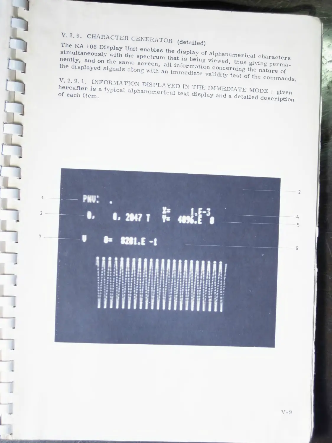
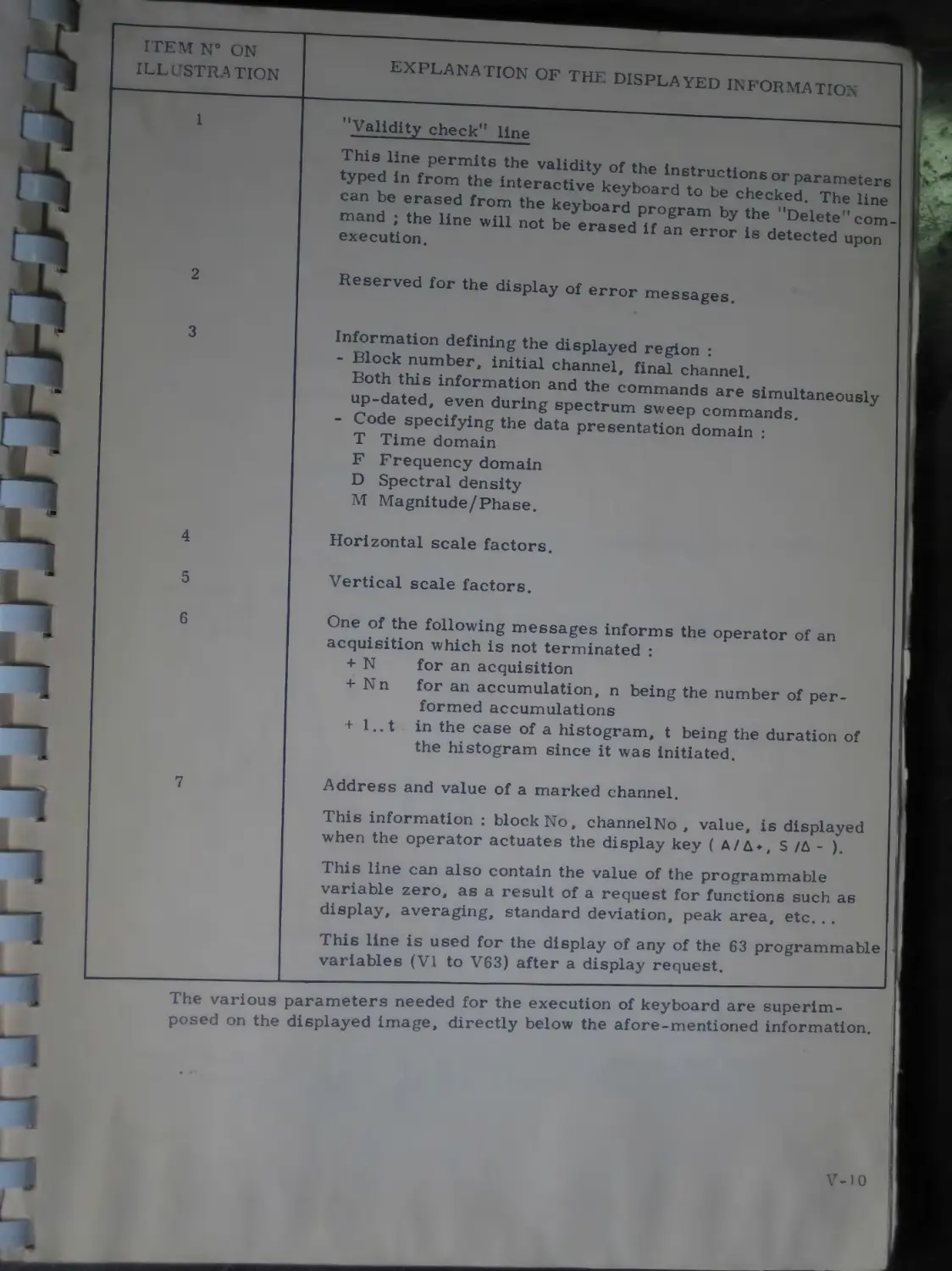
V. 2.9. Character generator (detailed)............ V-9
V. 2. 9. 1 . Information displayed in the immediate mode, V-9
V. 2. 9. 2. Information displayed in the programmed mode .................................................. V-1
CHAPTER V
(cont’d. )
V. 3.
V. 4.
V.4. 1.
V.4.1.1.
V.4.1.2.
V.4. 1.3.
V.4.1.4.
V. 4.2.
А-D conversion..........
Parameter definition........ ’ *.........
Time-domain parameters "requency-domain parameters Clock .....................................
Sampling frequency..........
Sampling period...........
Number of inputs............
Triggering modes...........................
External trigger input.........
External clock................
Stop-at-overflow.................
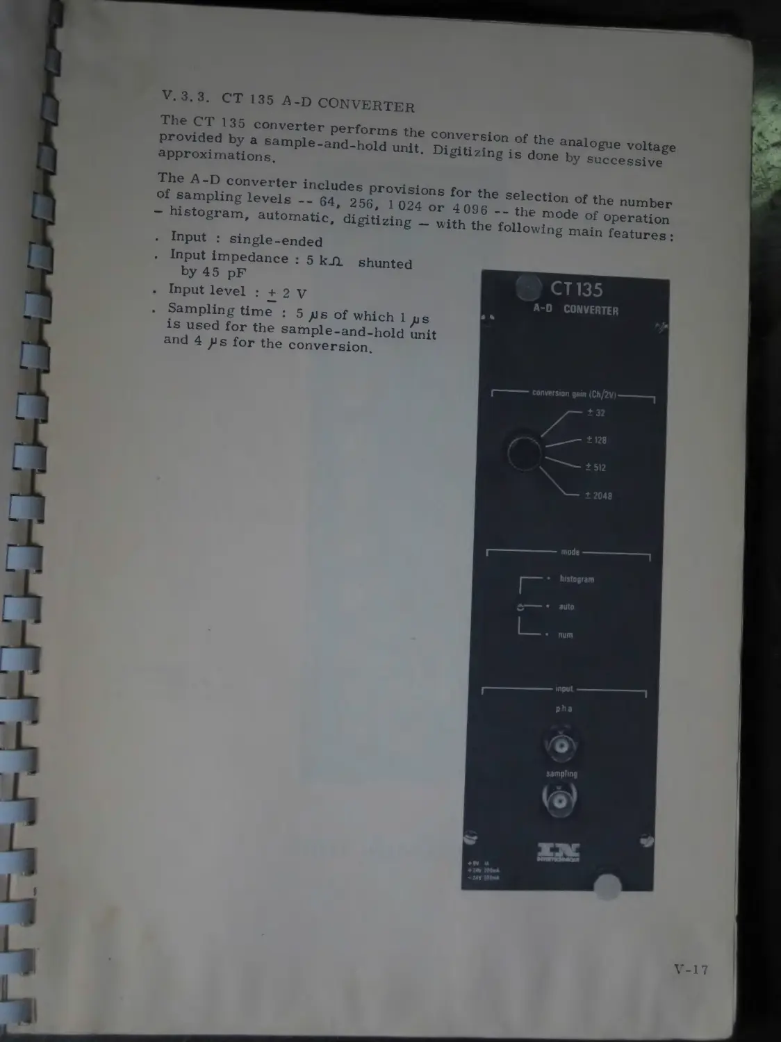
CT 135 А-D converter.......................
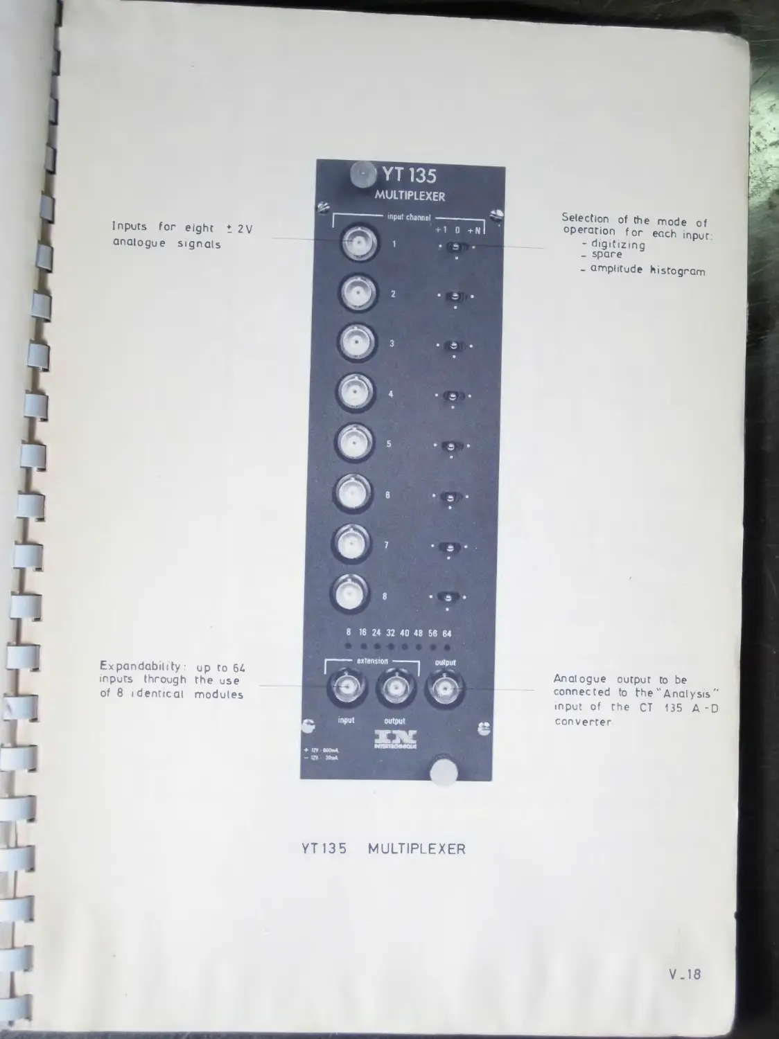
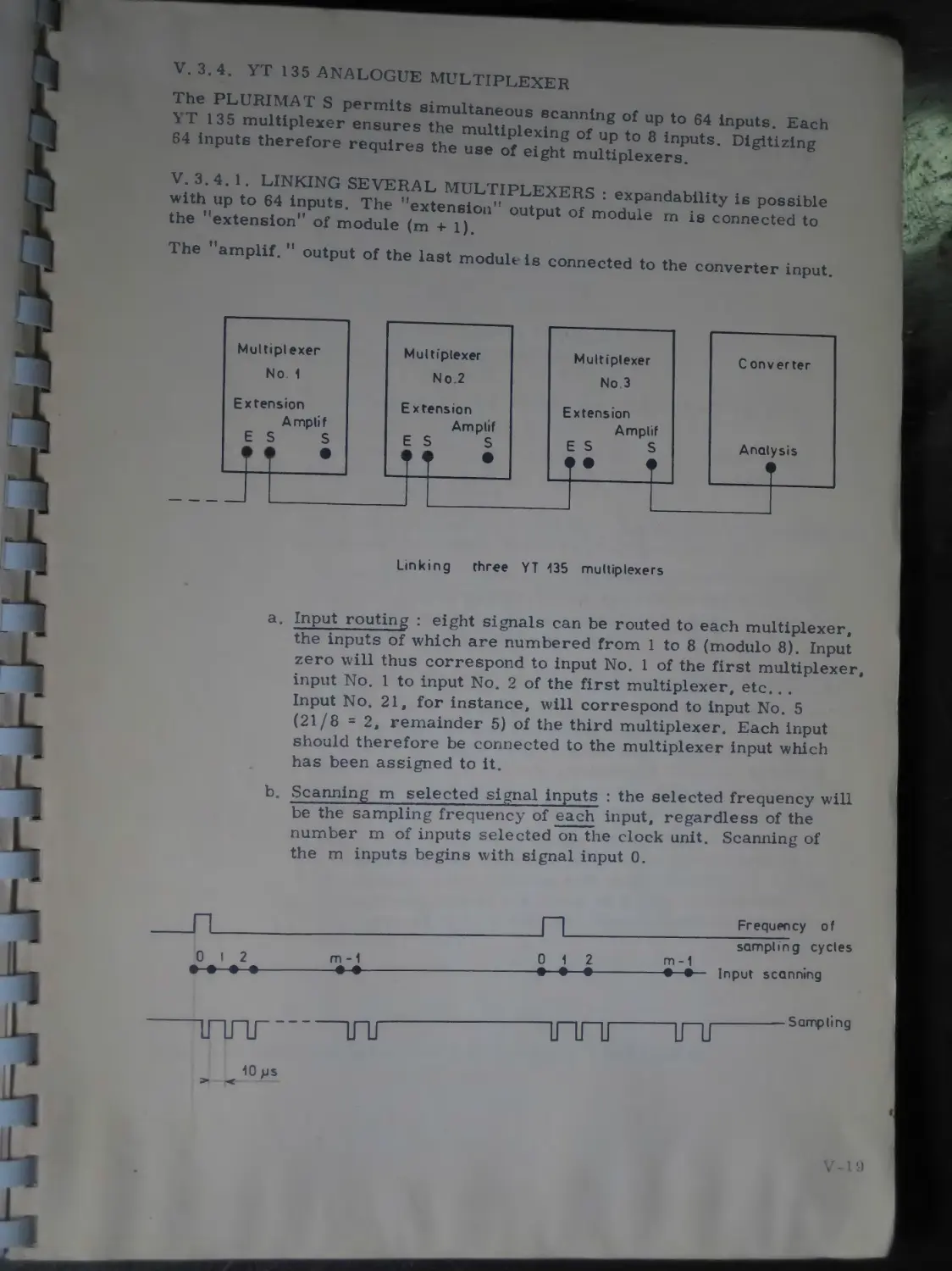
YT 135 analogue multiplexer................
Linking several multiplexers...............
a. Input routing ..........................
b. Scanning m selected signal inputs.......
c. Variation of the maximum sampling frequency as a function of the number of selected inputs.........................
V-ll
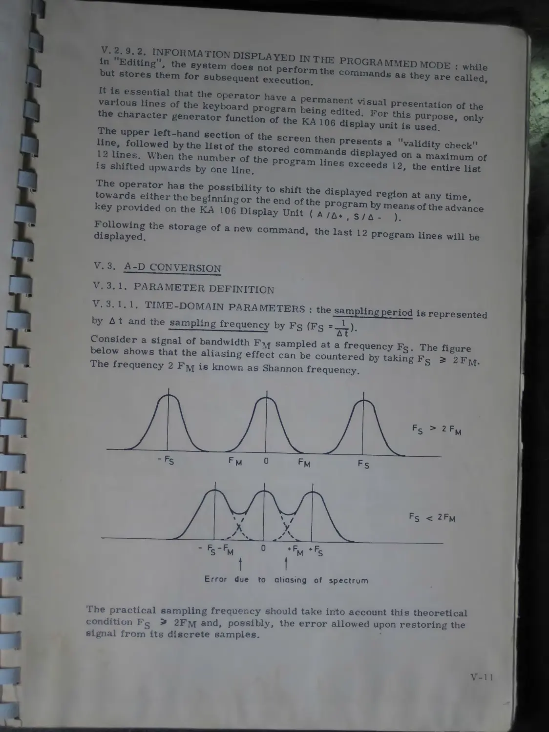
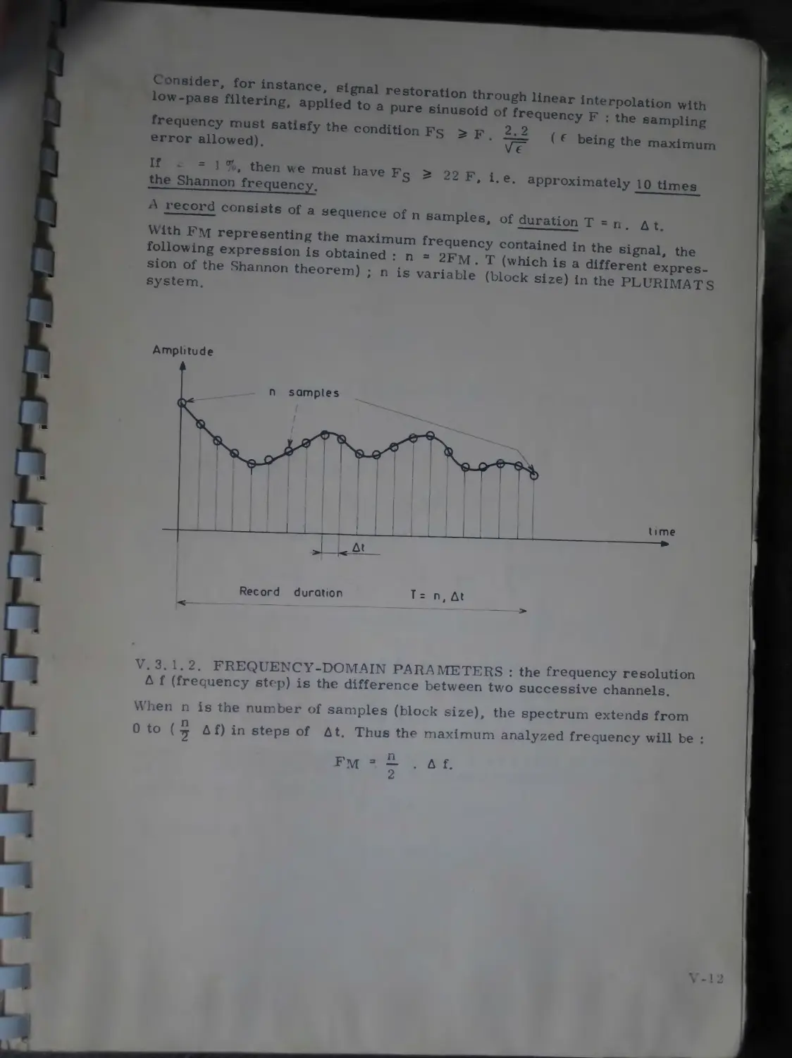
V-11
V-ll
V-12
V-14
V-14
V-15
V-15
V-15
V-15
V-15
V-15
V-17
V-19
V-19
V-19
V-19
V-20
d. Operation of the three-position switch provided for each input....................... V-20
e. Memory allocation of the sampling results V-21
Correlation................................... V-22
LT 135 hybrid correlator ................... V-22
Computational speed ........................ V-22
Modular design.............................. V-22
Simultaneous functions...................... V-22
Time-origin shift .......................... V-22
Correlation function selection.............. V-24
a. “Cxx” position........................... V-24
b. ”Cyy” position........................... V-24
c. “Cxy“ position........................... V-24
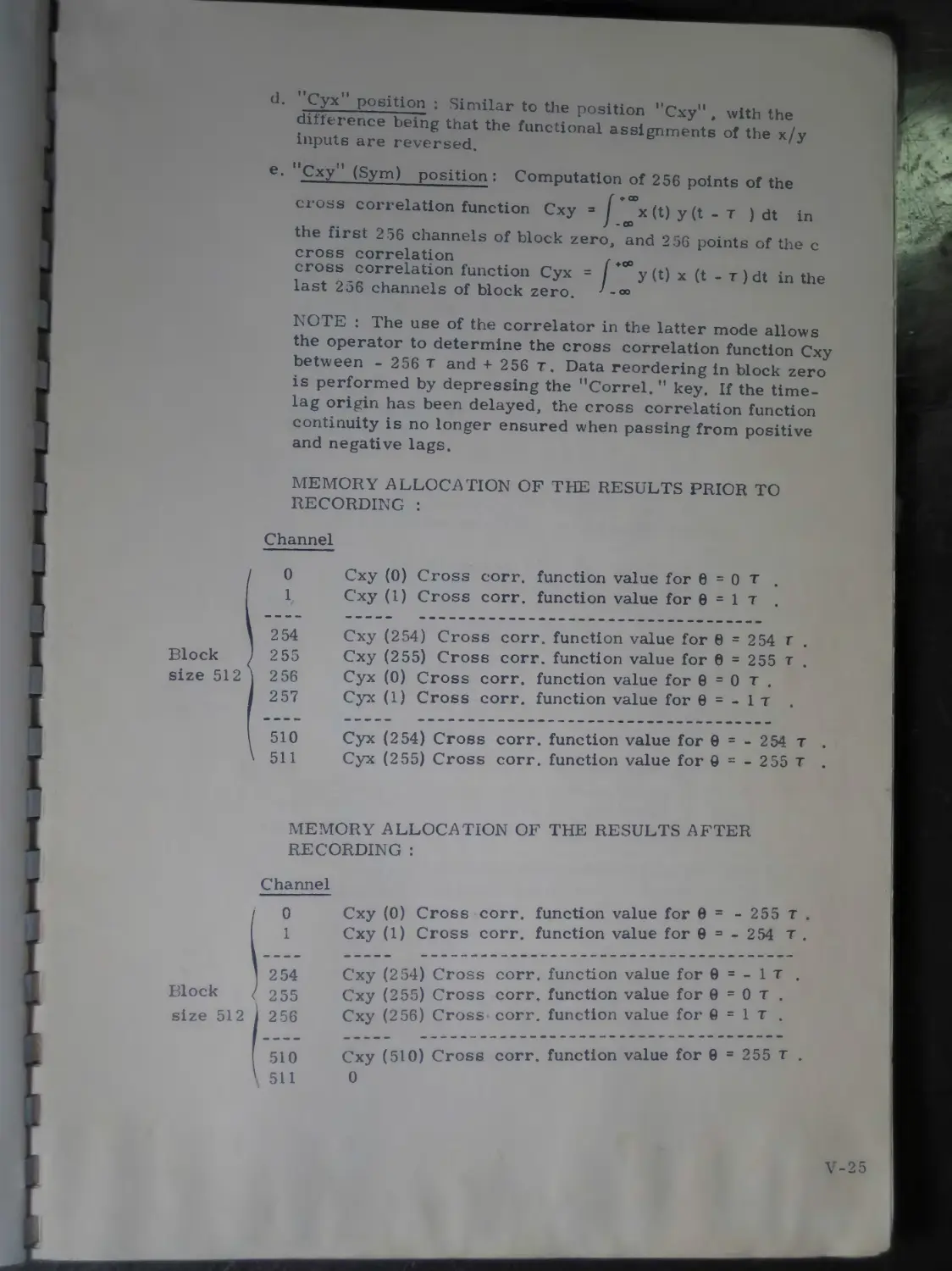
d. ”Cyx" position........................... V-25
e. “Cxy“ (Sym) position..................... V-25
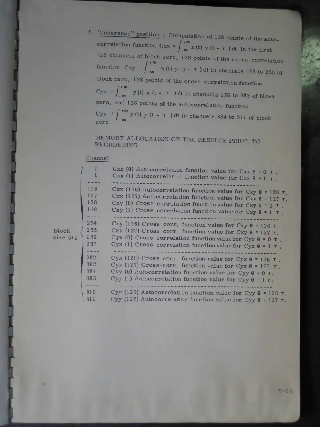
f. “Coherence” position..................... V-26
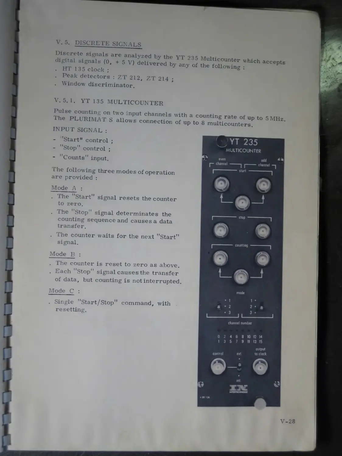
Discrete signals ........................... V-28
YT 135 multicounter......................... V-28
Digital I/O ................................ V-29
I/O systems................................. V-29
Teletype ................................... V-29
Using the TTY in the immediate mode........ V-29
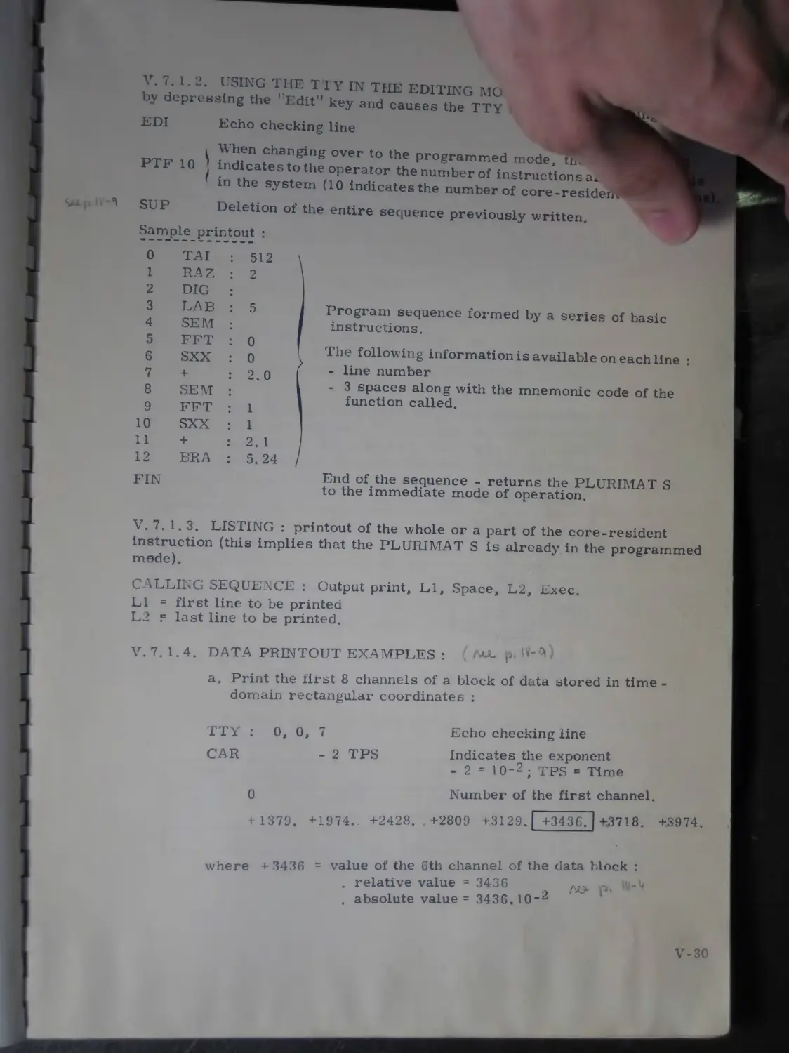
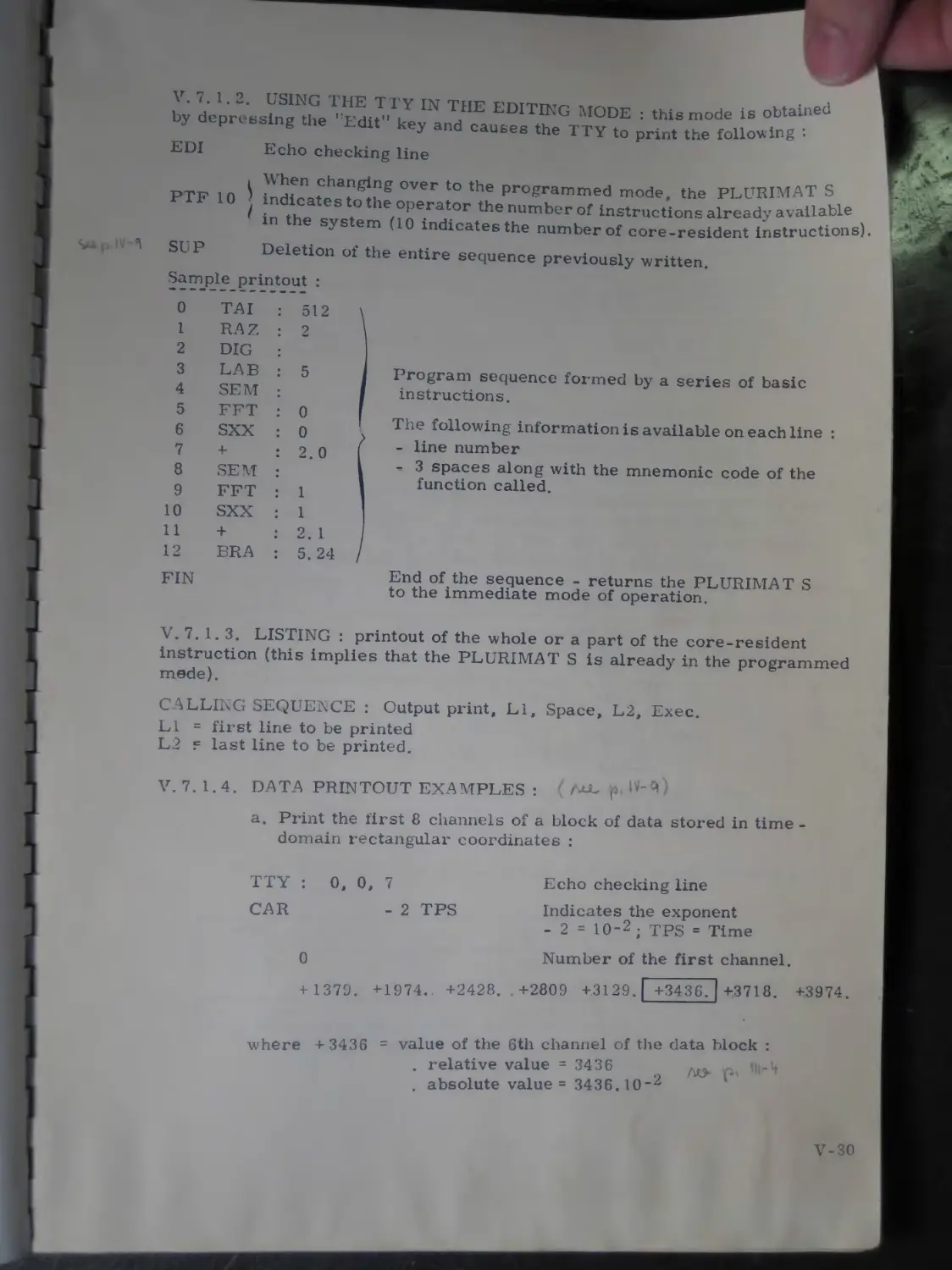
Using the TTY in the editing mode .......... V-30
Listing..................................... V-30
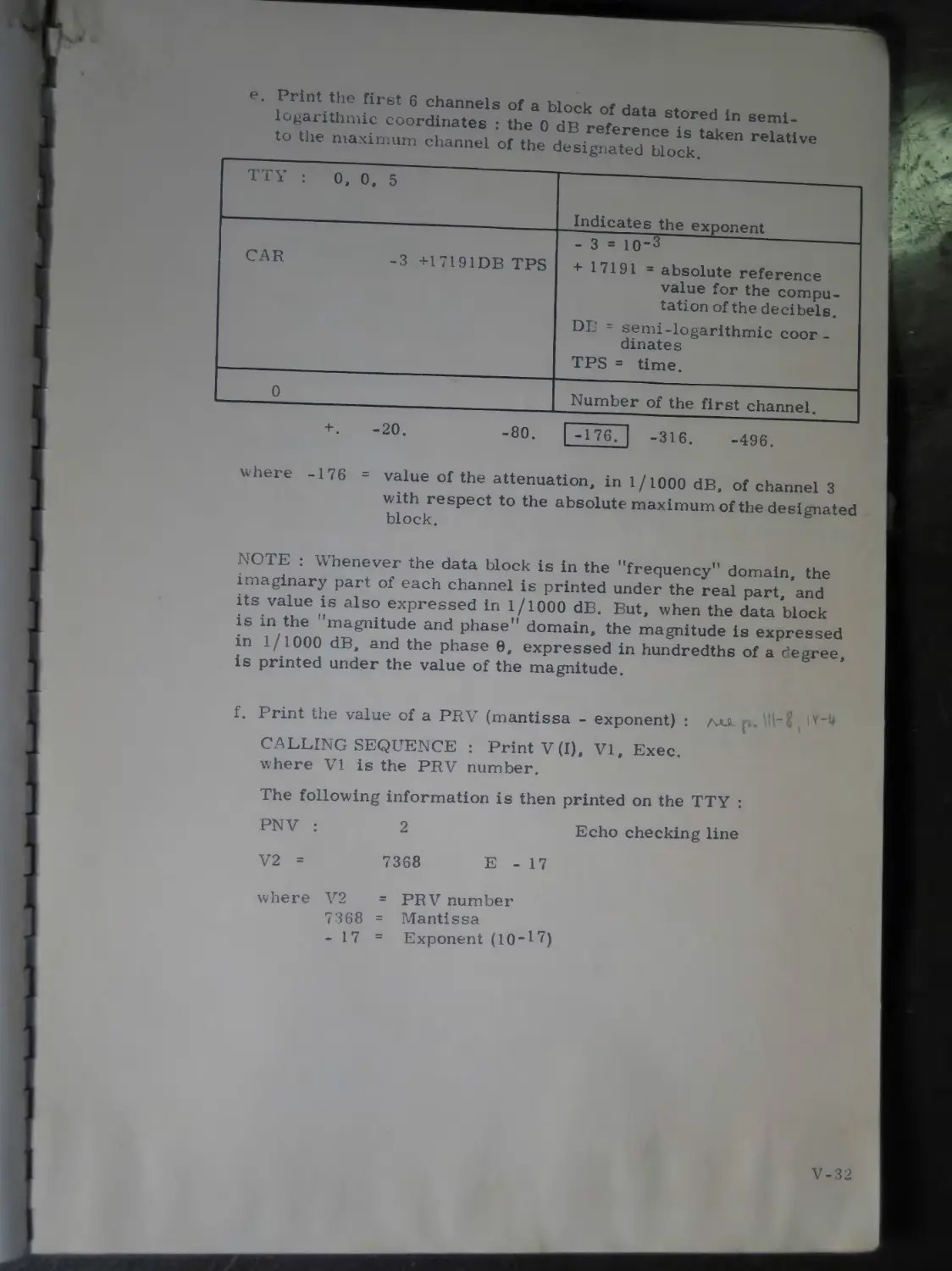
Data printout examples...................... V-30
Punched tape I/O operations................. V-33
Examples of use.............................. “33
3.
CHAPTER V
(cont’d. )
V. 3.
V.3. 1.
V. 3.1.1.
V. 3.1.2.
V. 3.2.
V. 3.2. 1.
V.3.2.2.
V.3.2.3.
V. 3. 2.4.
V. 3. 2. 5.
V. 3.2.6.
V.3.2.7.
V. 3.3.
V. 3.4.
V. 3.4. 1.
V.4.
V.4.1.
V.4.1. 1.
V.4. 1.2.
V.4. 1.3.
V.4. 1.4.
V . 4.2.
V . 5.
V . 5. 1.
V . 6.
V . 7.
V .7.1.
V .7. 1. 1.
V. 7. 1.2.
V. 7. 1.3.
V. 7. 1.4.
V.7.2.
V.7.2. 1.
А-D conversion...............
Parameter definition...... ..........
Time-domain parameters *' у ц
Frequency-domain parameters ..............
ci°ck.........................:::::::::::: v-il
Sampling frequency........................ V-14
Sampling period......................• • • • •
Number of inputs....................... * V-15
Triggering modes.......................... V-15
External trigger input...................* V-15
External clock..........................* ’ yel 5
Stop-at-overflow.......................... V-15
CT 135 А-D converter...................... V-17
YT 135 analogue multiplexer............... V-19
Linking several multiplexers.............. V-19
a. Input routing .......................... V-19
b. Scanning m selected signal inputs....... V-19
c. Variation of the maximum sampling
frequency as a function of the number of selected inputs....................... V-20
d. Operation of the three-position switch
provided for each input.................. V-20
e. Memory allocation of the sampling results V-21
Correlation................................. V-22
LT 135 hybrid correlator ................... V-22
Computational speed ........................ V-22
Modular design.............................. V-22
Simultaneous functions...................... V-22
Time-origin shift .......................... V-22
Correlation function selection.............. V-24
a. "Cxx” position.......................... V-24
b. "Cyy’’ position......................... V-24
c. ”Cxy” position.......................... V-24
d. "Cyx” position.......................... V-25
e. "Cxy" (Sym) position.................... V-25
f. "Coherence” position.................... V-26
Discrete signals ........................... 4 -28
YT 135 multicounter......................... V-28
Digital I/O ................................ V-29
I/O systems.................................. "29
Teletype ................................... V-29
Using the TTY in the immediate mode......... V-29
Using the TTY in the editing mode .......... V-30
Listing..................................... v‘3°
Data printout examples...................... V-30
Punched tape I/O operations................. V-33
Examples of use............................. v“33
3.
CHAPTER VI DETAILED (cont’d.) VI. 1.
VI. 2. VI. 2. 1. VI. 2. 1. 1. VI. 2.1.2. VI. 2. 2.
V I. 2. 3.
V I. 2.4.
V I. 3.
V I. 3. 1.
V I. 3.1. 1.
V I. 3. 1.2.
V I. 3. 1.3.
V I. 3. 2.
V I. 3. 2. 1.
V I. 3.2. 2.
V I. 3. 3.
V I. 3. 3. 1.
V I. 3. 3. 2.
V I. 3.4.
V I. 3.4. 1.
V I. 3.4. 2.
V I. 3. 5.
V I. 3. 6.
V I. 3. 7.
V I. 3.8.
V I. 3. 8. 1.
V I. 3.8. 2.
V I. 3. 9.
V I. 4.
V I. 4. 1.
V I. 4. 2.
V I. 4. 3.
V I. 4. 3. 1.
V I. 4. 3. 2.
V I. 4.4.
V I.4.4. 1.
V I.4.4. 2.
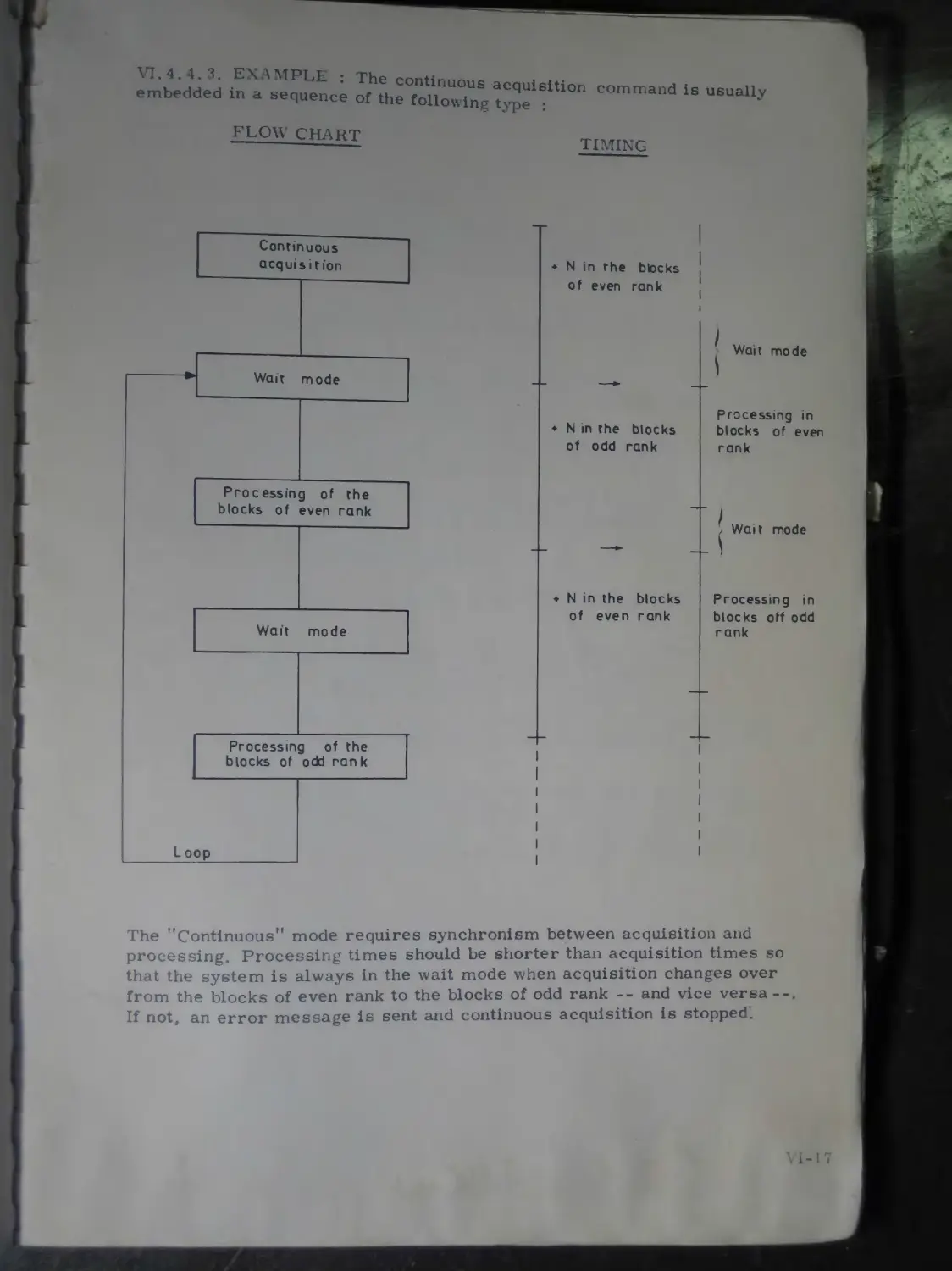
V I. 4. 4. 3.
DESCRIPTION OF THE FUNCTION vi-1
Introduction ............... .............. VI~2
Display functions............. ............ VI-2
Partial or total block display ............ yj 2
Display the entire block ......... VI 2
Display a given block slice ....... yj 2
Change-over to real and imaginary coordinates..................... VI-3
Conversion from rect. to polar coordinates . VI-3 Conversion from polar to rect. coordinates VI-4 Input-Output functions VI-5
Partial or total block printout............ VI-5
Print the entire block .................... VI-5
Print the block portion starting with channel C2 ................................ VI-5
Print a given block slice.................. VI-5
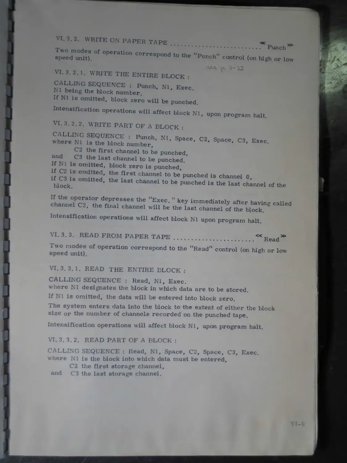
Write on paper tape........................ VI-6
Write the entire block .................... VI-6
Write part of a block...................... VI-6
Read from paper tape....................... VI-6
Read the entire block...................... VI-6
Read part of a block....................... VI-6
Total or partial block plot ............... VI-7
Plot the entire block and all of the alphanumerical text........................ VI-7
Plot part of a block and the alphanumerical text ...................................... VI-7
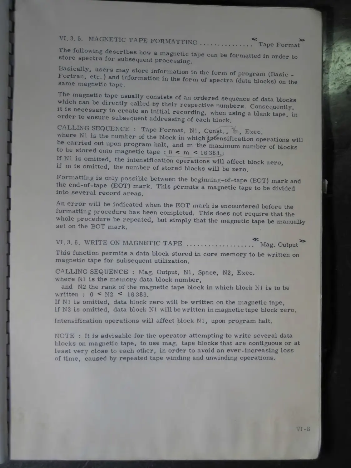
Magnetic tape formatting .................. VI-8
W rite on magnetic tape ................... VI-8
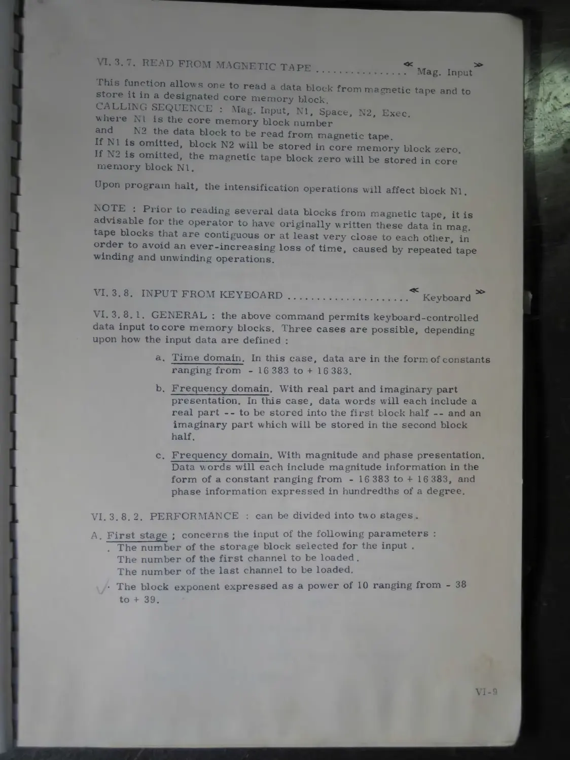
Read from magnetic tape.................... VI-9
Input from keyboard ....................... VI-9
General ................................... VI-9
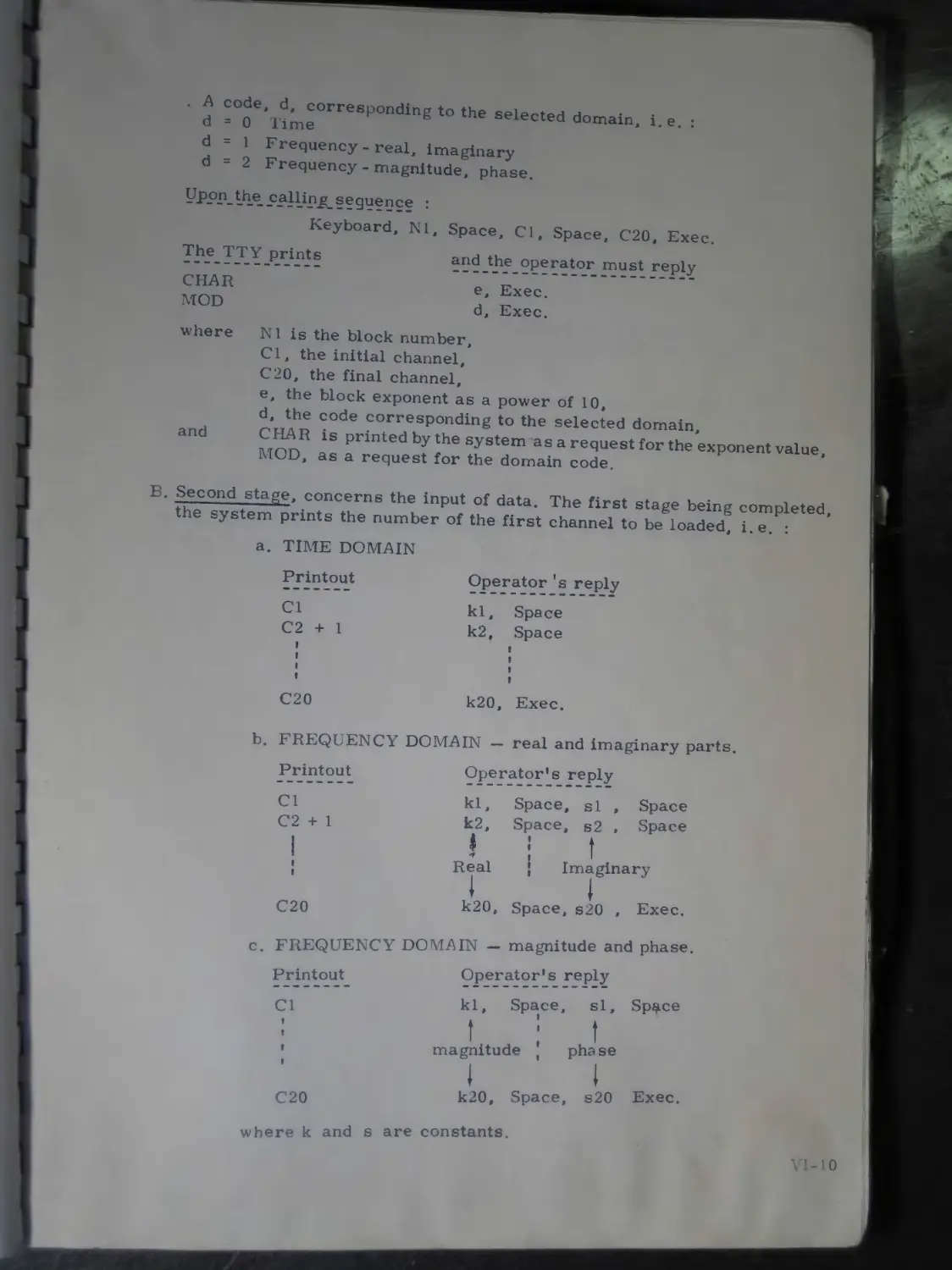
Performance ............................... VI-9
Enable digital output...................... VI-11
Acquisition functions...................... VI-12
Single acquisition......................... VI-12
Recycled acquisition....................... VI-12
Accumulation .............................. VI-13
Accumulation without prior clearing of the corresponding area ........................ VI-13
Accumulation with prior clearing of the corresponding area ........................ VI-13
Ping-pong or continuous acquisition........ VI-14
Introduction............................... VI-14
Setting up a continuous acquisition........ VI-15
Example.................................... VI-17
4.
CHAPTER VI VI. 4. 5. Amplitude histogram
(Cont'd.) VI. 4. 5.1. Amplitude histogram without prior......... '
clearing of the storage area VI 18
V I. 4. 5. 2. Amplitude histogram with prior clearing.........
of the storage area ............... VI 18
V I. 4.6. Enable digital input............ VI-19
V I. 4.7. Halt the acquisition.................... VI-19
V I. 4. 8. Restart the accumulation (or histogram)........ VI-19
V I. 4. 9. Select the correlator................... VI-20
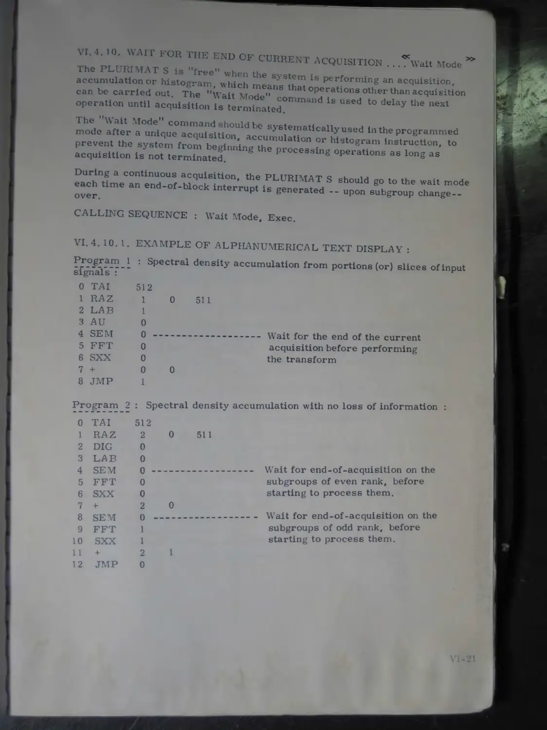
1.4. 10. Wait for the end of current acquisition...... VI-21
V I. 4. 10. 1. Example of alphanumerical text display......... VI-21
V I. 5. Format selection functions VI 22
V I. 5. 1. Data block size ........................ VI-22
V I. 5.2. Select 3-byte word length VI 22
V I. 5. 3. Select 2-byte word length...................... VI-23
V I. 5.4. Select PRV operation ................... VI-23
V I. 6. Operating on programmable variables ........... VI-24
V I. 6.1. Exclusive PRV functions ................ VI-24
V I. 6. 1 . 1. Assign a floating-point const, to a PRV. VI-24
V I. 6. 1.2. Transfer data into a PRV ............... VI-25
V I. 6. 1. 3. Transfer a PRV into a channel........... VI-25
V I. 6.1.4. Display the contents of a PRV .......... VI-25
V I. 6. 2. Other functions involving PRV’s......... VI-26
V I. 6.2. 1. Arithmetical functions.................. VI-26
a. Addition ................................ VI-26
b. Subtraction ............................. VI-26
c. Multiplication ................................. VI-26
d. Division ................................ VI-26
e. Square root .................................... VI-26
f. Absolute value.................................. VI-26
g. Logarithm ...................................... VI-27
h. Sine .................................... VI-27
i. Cosine................................... VI-27
V I. 6.2.2. Assign to a PRV the contents of another PRV. VI-27
V I. 6.2.3. Special function assigned to variable VO....... VI-27
V I. 7. Harmonic analysis ............................. VI-28
V I. 7. 1. Fast Fourier Transform.................. VI-28
A7!. 7. 1. 1. Fourier transform of a ’’complex” block........ VI-28
V I. 7.2. Inverse Fast Fourier Transform.......... VI-28
V I. 7. 3. Hanning window.......................... VI-29
V I. 7.4. Centred Hanning window.................. VI-29
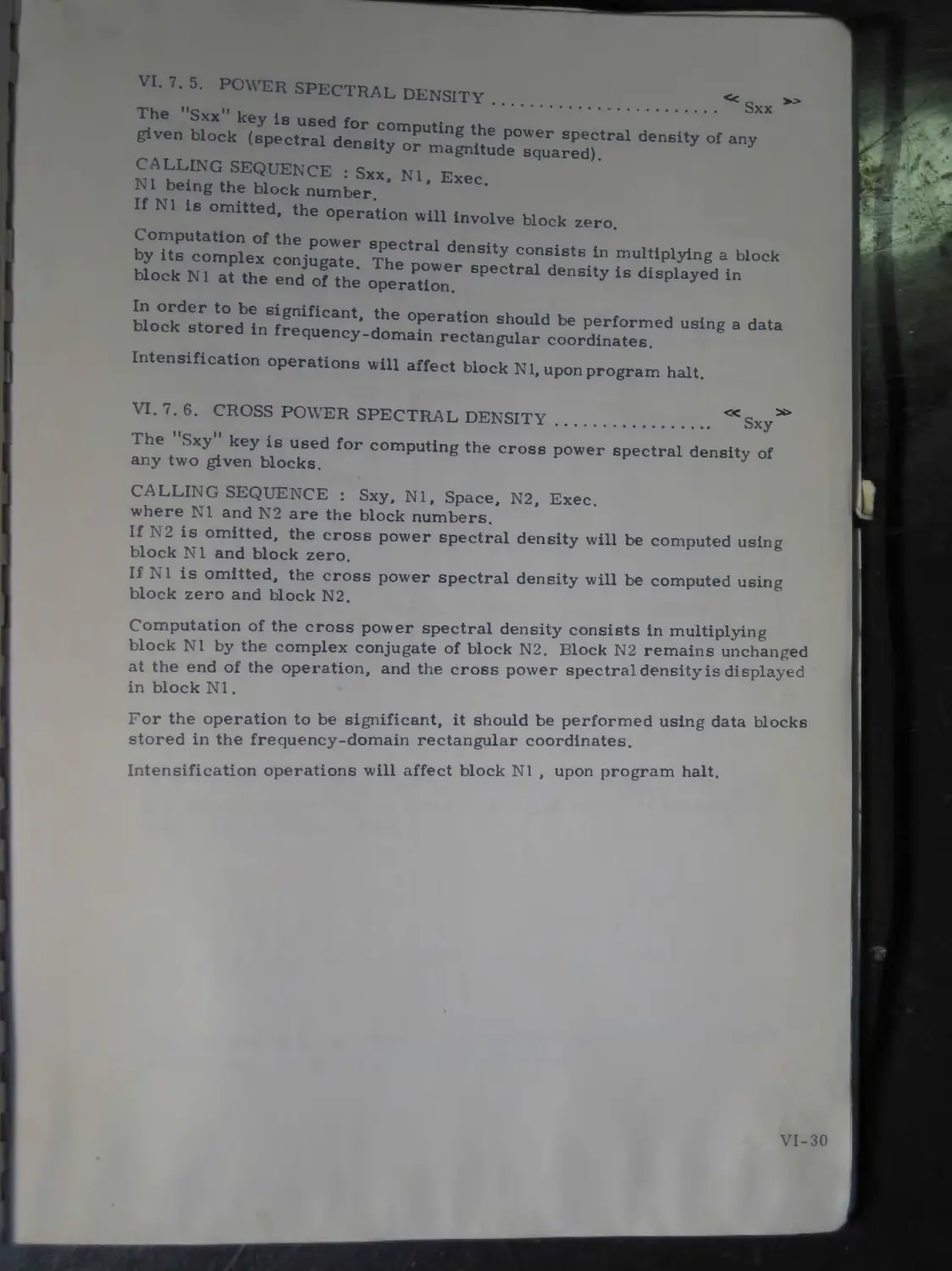
V I. 7. 5. Power spectral density.................. VI-30
V I. 7.6. Cross power spectral density............ VI-30
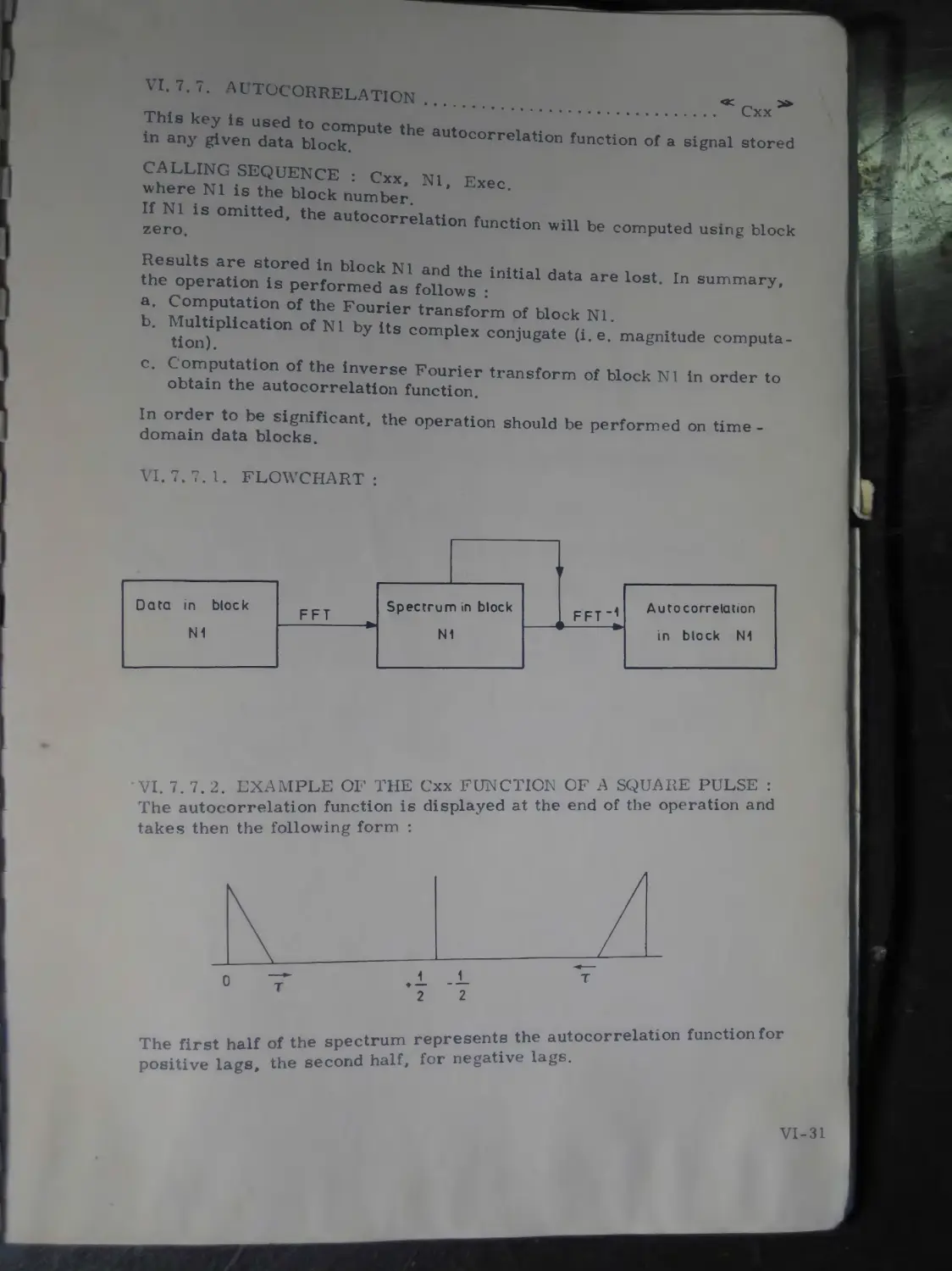
V I. 7. 7. Autocorrelation................................ VI-31
V I. 7.7.1. Flowchart .............................. VI-31
V I 7 7 2. Example of the Cxx function of a square
pulse....................................... VI-31
• VI 49
V I 7 8 Cross correlation..............................
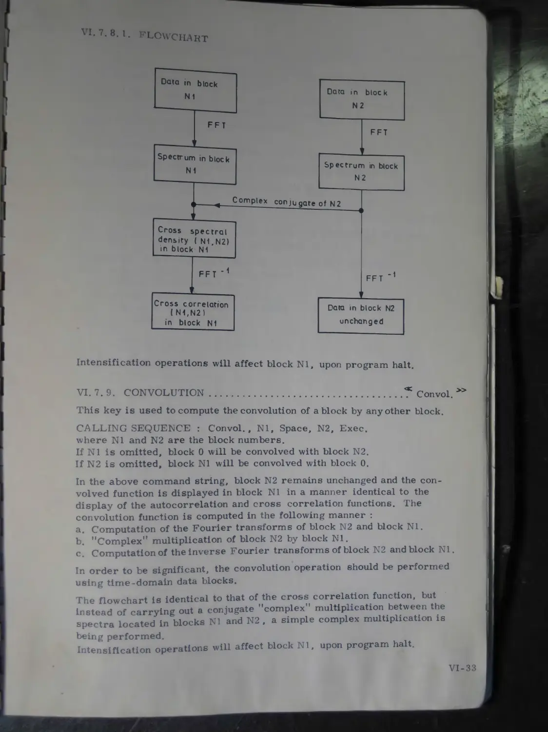
V I. 7. 8.1. Flowchart............................... VI-33
5.
CHAPTER VI
(Cont’d. )
V I. 7
V I. 7
V I. 7
V I. 7
V I. 8
V I. 8
V I. 8
V I. 8
V I. 8
V I. 8
V I. 8
V I. 8
V I. 8
V I. 8
V I. 8
V I. 8
V I. 8
V I. 8
V I. 8
V I. 8
V I. 8
V I. 8
V I. 8
V I. 8
V I. 8
V I. 8
V I. 8
V I. 8
V I.8
V I. 8
9.
10.
11.
12.
1.
2.
3.
3. 1.
3. 2.
4.
4. 1.
4. 2.
5.
5. 1.
5. 2.
6.
6. 1.
6. 2.
7.
7. 1.
7.2.
8.
8.1.
8.2.
9.
9.1.
9.2.
10.
11.
Convolution.....
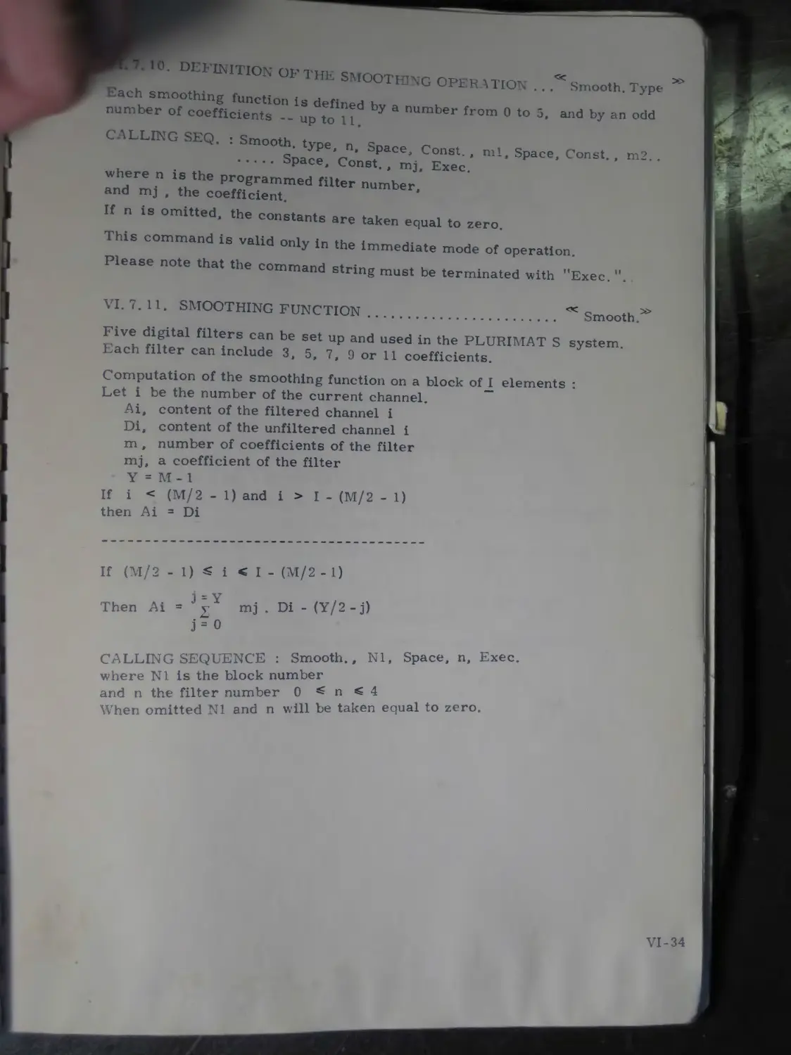
Definition of the smoothing operation
Smoothing function
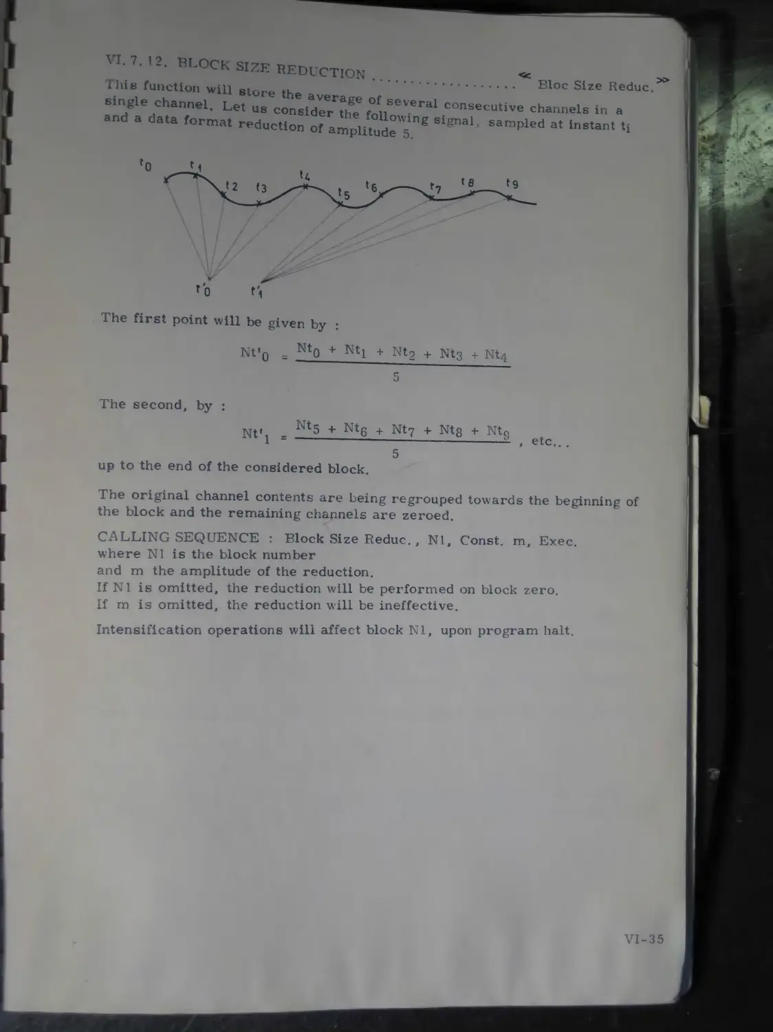
Block size reduction
Logical and arithmetical operations
Digital descrimination C———
Programmed histogram................
Addition and subtraction
Operation involving two blocks
Operation involving a block and a constant * . .
Multiplication..............
Operation involving two blocks.........
Operation involving a block and a constant
Division ..................
Operation involving two blocks
Operation involving a block and a constant
Averaging..........................
Operation involving the entire block
Operation involving a portion of the block . ..
Standard deviation ........................
Operation involving the entire block.......
Operation involving a portion of the block . ..
Area computation ..........................
Operation involving the entire block.......
VI-33
VI-34
VI-34 VI-35 VI-36
VI-36
VI-36
VI-37
VI-37
VI-37
VI-37 VI-37
VI-38 VI-38 VI-38 VI-38
VI-39
VI-39 VI-39 VI-39 VI-39
VI-40
VI-40 VI-40
Operation involving a portion of the block .. . VI-40
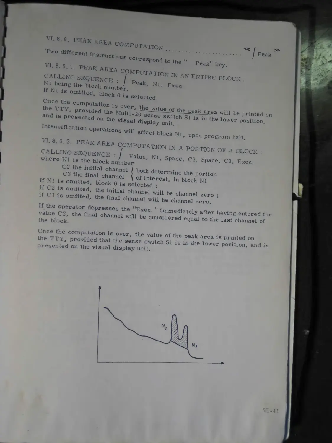
Peak area computation
VI-41
Peak area computation in an entire block .... VI-41
Peak area computation in a portion of a block VI-41
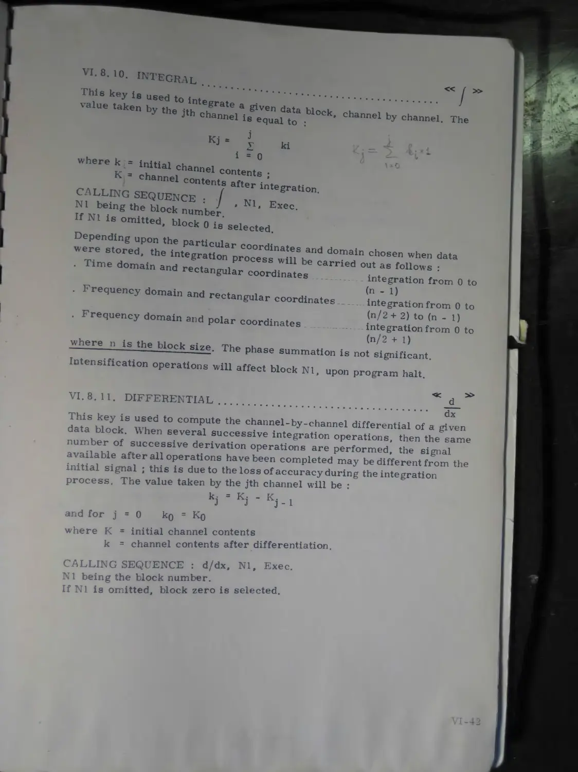
Integral .................................... VI-42
Differential................................. VI-42
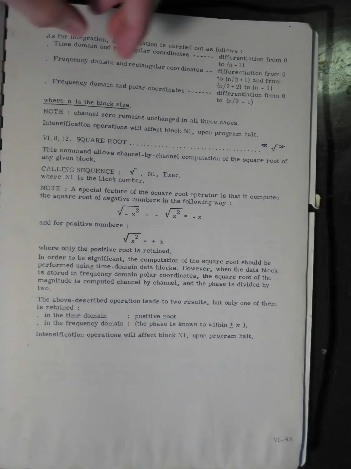
V I. 8. 12. Square root....................... VI-43
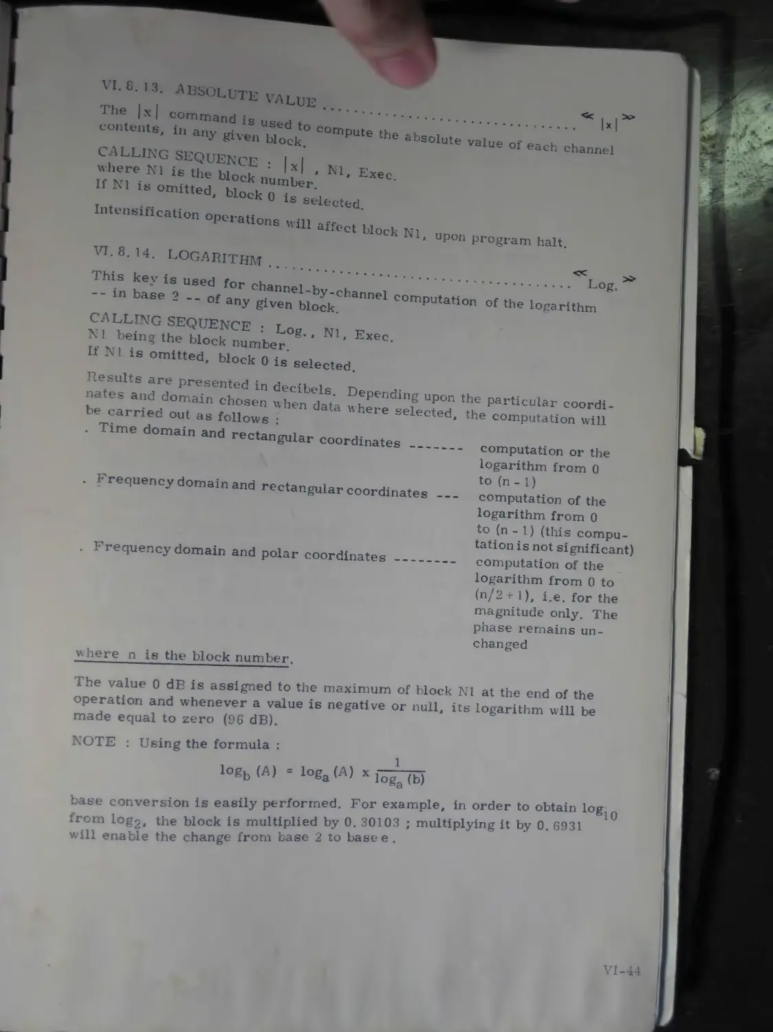
V I. 8. 13. Absolute value ..................... VI-44
V I. 8. 14. Logarithm........................... VI-44
V I. 8. 15. Inverse logarithm .................. VI-45
V I. 8. 16. Block transfer...................... VI-45
V I. 8. 17. Block permutation................... VI-45
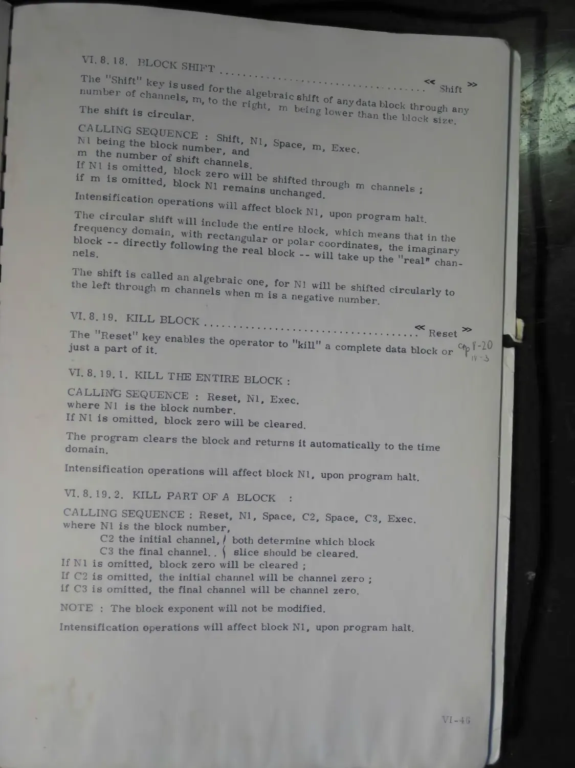
V I. 8. 18. Block shift ........................ VI-4G
V I. 8. 19. Kill block ......................... VI-46
V I. 8. 19.1. Kill the entire block............... VI-46
V I. 8. 19. 2. Kill part of a block ............... VI-46
V I. 8. 20. Block reversal in the time domain... VI-47
V I. 9. Editing, programming and execution functions.......................................... VI-48
V I. 9. 1. Enable the programmed mode ......... VI-48
V I. 9 2. Disable the programmed mode......... VI-48
V I. 9. 3. Delete program.................... VI-48
V I. 9. 3. 1. Delete program, starting with a given line .. VI-48
V I. 9. 3. 2. Delete program, in the range of L2 and L3
inclusive............................... VI-48
6.
CHAPTER VI
(Cont’d. )
V I. 9.4.
V I. 9. 5.
V I. 9.5. 1.
V I. 9. 5.2.
V I. 9. 6.
V I. 9. 7.
V I. 9. 7. 1.
V I. 9.7.2.
V I. 9.8.
V I. 9. 9.
V I. 9. 9. 1.
V I. 9. 9. 2.
V I. 9. 10.
V I. 9. 11.
V I. 9. 12.
V I. 9. 13.
V I. 9. 14.
V I. 9. 15.
V I. 9. 16.
isertion of one or several instructions Modify the program........
Modify, starting with a given line....
Modify, in the range of L2 to L3 inclusive
Terminate insertion/modification........' ’
Print command ..............
Print all statements starting with a
given line .................
Print all statements in the range of L2
to L3 inclusive..................
Input from punched tape...............
Punch command ......................
Punch all statements starting with a given line ......................................
Punch all statements in the range of L2 to L3 inclusive............................
Label definition...........................
Unconditional jump.........................
Conditional jump ..........................
Repeated execution.........................
VI-49
VI-49
VI-49
VI-49
VI-50 VI-50
VI-50
VI-50 VI-51 VI-51
VI-51
VI-51 VI-51 VI-52
VI-52
VI-52
Return jump ................................ VI-53
Return from a subroutine ................... VI-53
’’Pointer” command ......................... VI-53
V I. 9. 16. 1. Used to define the start of a keyboard program ................................................. VI-53
V I. 9. 16.2. Used to keep track of pointer position..... VI-53
V I. 9.17. Enable sequential execution................... VI-54
V I. 9.18. Execute a single instruction.................. VI-54
7.
CHAPTER I
GENERAL DESCRIPTION
I. I. INTRODUCTION
The PLURIMAT S is a conversational system designed for REAL-TIME signal analysis.
Through modular upgradability and a variety of powerful programs it combines the speed of a hard-wired system with the power of a stored-program computer.
1.1.1. POSSIBILITIES
a. Input signals . Continuous
. Discrete, or in
. Digital form
b. Acquisition . А-D conversion
. Iteration
. Histograms
. Correlation
c. Processing
d. Input/Output
. Harmonic analysis
. Statistics
. Arithmetical and logical operations on curves
. Manipulation of programmable variables (PRV)
Permanent visual display
Dialogue through digital I/O devices Peripheral unit options.
1.1.2. VERSATILITY
The operator can call a function by simply pressing one or several keys of the interactive keyboard ; a routine especially written for a particular application is then executed. Two modes of operation are provided for this purpose :
I. 1.2. 1. IMMEDIATE OPERATION : each function is executed immediately after having been called.:
I. 1.2. 2. PROGRAMMED OPERATION : consists of two consecutive phases :
. 1st phase : Definition of the sequence of the desired functionsand of the simultaneity of the acquisition, processing and data output operations ;
2nd phase : Execution of the thus defined sequence.
The above-mentioned functions are executed through routines stored in the MULTI-20 minicomputer. All the stored routines are relocatable, which enables each user to optimize the system in accordance with his particular requirements, and facilitates the addition of specific routines.
1-2
L2- INSCRIPTION OF A TYPICAL SYSTEM CONFIGl RATION
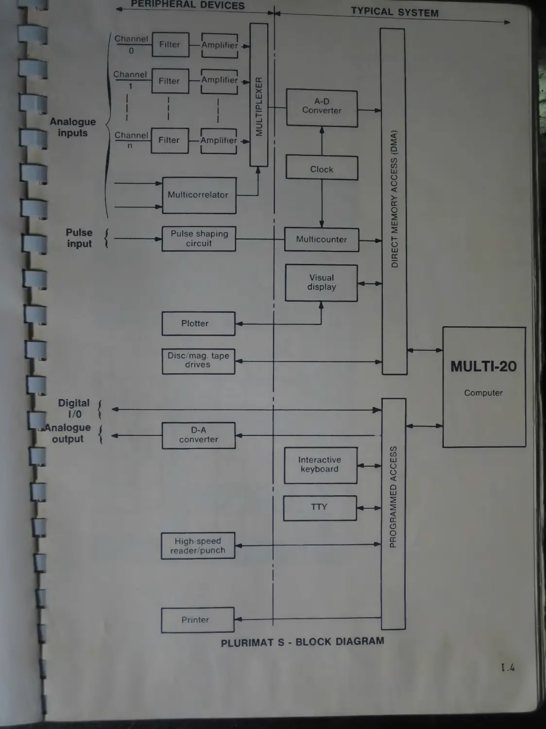
The PLLRIMAT S system consists of the following building blocks •
* n'ul^O minicomputer : handles acquisition and processing, the simul taneity of which is achieved through the use of a two-level priority chain • . the first level corresponds to a triple direct memory access ensuring ' the acquisition, display and data transfer to magnetic tape or disc •
. the second level concerns all the operations directly handled by the pro-cessor whether under microprogram or program control.
An acquisition system, which consists of :
. a clock (0.02 Hz to 1 MHz) ;
. an А-D converter with a capacity of 11 bits plus sign ;
. a 64-input multiplexer consisting of 8-input modules ;
. a multicounter ;
. plug-in modules : amplifiers, filters, window discriminator, peak detector . . .
A multicorrelator : performs autocorrelation and crosscorrelation at a maximum sampling rate of 1 MHz.
A display unit : continuously monitors acquisition and displays calculations, together with an alphanumerical character generator.
An interactive keyboard : enables the dialogue between the operator and the system.
Standard peripheral units : Teletype, high-speed punch, X-Y plotter, magnetic tape or disc drives . . .
I. 3. EXECUTION TIME
The execution times are given for the routines written in the assembler language.
a. Fourier transform
. 1024-point block
. 128-point block
: 5 s, programmed mode
0.6 s, microprogrammed mode
: 0. 6 s, programmed mode
0.1s, microprogrammed mode.
b. Spectral density accumulation
1024-point block : 5.5 s (with microprogrammed FFT :0.95s) 128-point block : 800 ms (with microprogrammed FFT : 150 ms).
c. А-D conversion and storage on magnetic tape with no loss of information
5 kHz on-line for 1024-channel block (1 channel, 2 eight-bit bytes).
d А-D conversion and storage on disc with no loss of information
50 kHz on-line for 1024 channel block (1 channel, 2 bytes).
1-3
PEHIPHERAL DEVICES
TYPICAL SYSTEM
/ Channel
0
Filter
Channel
Filter —Amplifier
Ш
X Ш
A-D Converter
Analogue inputs
Channel n
Filter —Amplifier
i
Clock
co CD Ш
Multicorrelator
ш
Pulse input
Pulse shaping circuit
Multicounter
ш
Plotter
DiscAnag. tape drives
Digital
Analogue j output (
D-A converter
High-speed reader/punch
Printer
Visual display
Interactive keyboard
PLURIMAT S - BLOCK DIAGRAM
MULTI-20
Computer
CD CD Ш
Q ш
1.4
T>
4
PLURIMAT S
BRTK
aaaa
BBHH
□ SQB
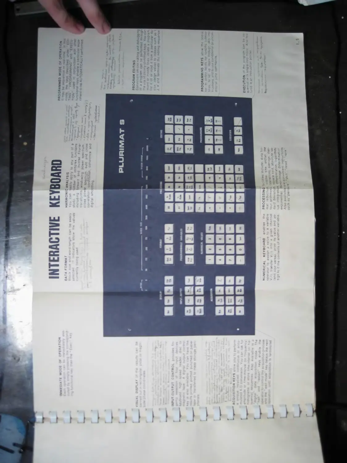
NUMERICAL KEYBOARD enables the op< ra-ti r to assign a value to a variable V( I) transfer V->) mto a fl-ven channel (and vice versi.i punt its value and assign to it the contents of another variable
PROGRAMMING KEYS at tow the opei.1-tor to define taoels ‘or specific subroutines to set up 'oops through skip instructions. and to use conditional or uncon-d t onal jumo commends
EXECUTION of the program can be sequential о» >n sinoie-step mode Also featured is an instruction pointer
an have 'h« «• 1 >n pnn«r Homo* pen
•о» loCfWiii,)! acQuitilion priH • M ' wa ' a. <te' «, de ,,, |i,a ne<t АМН» u»»hl <»qijiaifioo «« l«rmin>it*d
CONTROL ; . tn. -
f
Wared ‘••Jot diac r A i ta> eujfaul -nnir.
tXECUTRM
BBS
uW| I ATt M'AOC i)F»t»ATI N
V lUAl C* 4₽.AY
•<► T-OUTPUT
ACQUISITION KEYS , IM
p«»rfo«rr> >r accu-' in i»h lor -nt (Or f'<<-|U«r>r , ( ••interval iqr fr<-Vj aid (pl* ।
J»'e 1'1 .i|ir>Vf n,,,,je Th»
INTERACTIVE KEYBOARD
DATA FORMAT г • i.'» v i word length । an b- easily »«iint!e*l if indicators sr< <w the
HARMONIC ANALYSIS
X/’." 'JUZ 10 M"01» n/h.d r ° C0,nP'e* functwns
niludrg torwafd and |nvefM Fn|jftr f endowing, power spectrum.
FOiS ponw tpACt'ijm 8ufn and Аве
PROGRAMMED MODE OF OPERATION 'ea‘-tin>e in if, “ »eys det
T.NG F-RSGRAMMING” ano
t' on ai •ь
i <ment to btt A1. tOMAT!CAll Y пег*пгп»м
PROGRAM EDITING
Convenient on-n.ne editing and dabuggteg of a program can be performed m the use ot leer . иЗеРМ-еЯ *evs You can insert or mejity finss delete a program list it CT, Of inOUt it fn><n a par’ : ilir rj --vce assign values to indices such as i J К and term iMe m э editing sequ₽rce
□BOD DBQD
DODD ааоа
аевва аеваа наввв аавв
НОВО HDDS HBOS
D 03S3
DSBB
аевва QDBO
PROCESSING Jacim es ,nclud®r^'a f°r' mat reduction, cosine, s ‘
four arithmetic °Рега,10??п» absolute va-da,d ;
ue integrati »n .таае determination exponential m rrof-£ 9 t instructions Also available are con и^г. llrank„ such as per-wute sn
1.5
II. 1. INITIAL SET-UP
\ main switch controls the supply of power to the PLURIMAT S
A separate power supply and mains power switch are provided for the fol lowing modules :
- MULTI-20 computer ;
- Visual display unit ;
- I/O NIM chassis ;
- Teletype.
Check that all modules are switched on.
If the program is already loaded, the PLURIMAT S is ready for operation
II. 2. SYSTEM-PROGRAM LOADING PROCEDURE
Loading of the system-program is required in the following cases :
- upon initial starting ;
- whenever the MULTI-20 has been operated as a stand-alone computer.
II. 2. 1. WHEN USING THE TTY READER
A. On the MULTI-20 computer console :
First, position the sense switches as indicated :
Sense switch 1 : down
Sense switch 2 : up
Sense switch 3 : up
Sense switch 4 : down.
Then, successively depress the keys : STEP CLOCK RESET RUN.
Insert the program tape in the reader with the first rub-out character at the read station.
C. Press the TTY reader lever to the ’’Start” position.
II. 2. 2. WHEN USING THE HIGH-SPEED READER
Set the MULTI-20 controls as indicated under II. 1.
Insert the ’’high-speed reader basic loader in the FT\ reader with the first rub-out character at the read station.
Insert the program tape in the high-speed reader.
Press the TTY reader lever to the Start” position.
NOTE * If reading stops during a loading procedure (computer changing over to halt), reposition the tape on the preceding rub-out (record sepa-rator) and depress the MULTI-20 RUN key.
II. 1. INITIAL SET-UP
main switch controls the supply of power to the PLURIMAT S
A separate power supply and mains power switch are provided for the fol lowing modules :
- MULTI-20 computer ;
- Visual display unit ;
- I/O NIM chassis ;
- Teletype.
Check that all modules are switched on.
If the program is already loaded, the PLURIMAT S is ready for operation
II. 2. SYSTEM-PROGRAM LOADING PROCEDURE
Loading of the system-program is required in the following cases :
- upon initial starting ;
- whenever the MULTI-20 has been operated as a stand-alone computer.
II. 2. 1. WHEN USING THE TTY READER
A. On the MULTI-20 computer console :
First, position the sense switches as indicated :
Sense switch 1 : down
Sense switch 2 : up
Sense switch 3 : up
Sense switch 4 : down.
Then, successively depress the keys : STEP CLOCK RESET RUN.
Insert the program tape in the reader with the first rub-out character at the read station.
C. Press the TTY reader lever to the ’’Start” position.
II. 2. 2. WHEN USING THE HIGH-SPEED READER
Set the MULTI-20 controls as indicated under II. 1.
Insert the ’’high-speed reader basic loader in the TT\ reader with the first rub-out character at the read station.
Insert the program tape in the high-speed reader.
Press the TTY reader lever to the ’’Start” position.
NOTE * If reading stops during a loading procedure (computer changing over to halt), reposition the tape on the preceding rub-out (record sepa-rator) and depress the MULTI-20 Tv UN key.
II-2
П. 3. PERIPHERAL UNITS
(Refer to the individual operating instructions optional peripheral units).
respectively concerning the
The system is automatically set for a 2-byte format and a 512-word size at the end of the loading procedure, and the display unit gives a visual presen tation of the full acquisition and processing area.
The PLURIMAT S is then ready to operate.
II. 4. ERROR MESSAGES
A complete list of the error messages is appended to the present chapter.
There are two types of errors :
. Errors detected while calling a command or writing a routine ;
. Command (or routine) execution errors : parameters not compatible with the system (block number, block size, channel number . . .), overflows
An error indication will appear on the interactive keyboard (blinking of the 'error” indicator light), on the display unit and, when in operation (sense switch SI of the MULTI-20 in the lower position), on the Teletype.
Keyboard control is restored after a time delay of a few seconds and the nature of the error remains on the display until the next command is called.
II. 5. NOTES
II. 5. 1. The keyboard commands are ignored during a processing operation (“Busy” indicator light on), with the following exceptions :
. “Halt of acquisition” : causes continuous acquisition, recycled acquisition and accumulation to halt at the end of block. The same command also causes the immediate halt of the histogram ;
. “Continue* : causes an accumulation or histogram having been previously stopped to be resumed ;
. “Sequential Mode” : triggers routine sequential execution ;
“Step Mode” : executes one routine instruction or stops routine sequential execution (previously started by “Seq. Mode".
II. 5. 2. An acquisition performed with an external clock or external gating can be inhibited (elimination of the clock or gating).
In such a case, and if the system is in standby waiting for the acquisition to end, inhibition is effectively achieved. The same operation is enabled again if the clock — or gating - is restored or if the MULTI-20 keys (STEP, CLOCK, RESET, RUN) are actuated (sense switches 1 and 4 being in the upper position).
II-3
И. 6. LIST OF ERROR MESSAGES
RIO : The block number is not compatible with the size of the blocks
R 11 : The input value was not correctly entered.
R 12 : The number is higher than 16 383 in absolute value.
R 13 : Invalid channel number.
R 14 : Overflow of the block exponent.
R 15 : Routine not compatible with 3 bytes.
R 16 : Incorrect size.
R 17 : Block exponent ^39, «38
R 18 : Reduction field > Block size.
R 19 : The requested histogram is not feasible.
R 20 : The number of channels requested is excessive.
R 21 : The system is already editing.
R 22 : The command is not accepted in the program mode.
R 23 : The label is too large or negative.
R 24 : Address 2 < Address 1.
R 25 : The programmable variable (PRV) number is inexistent.
R 26 : Exponent incorrect.
R 27 : Undefined label - this error is followed by the printing of the
line number involved.
R 28 : Overflow of the area reserved for the keyboard program.
R 29 : Inexistent line.
R 30 : Incorrect pointer value.
R 36 : Overflow of block exponent during an operation performed on a PRV.
R 50 : The number of called subroutines is lower than 4.
R 54 : Upon execution, the block number is found to be incompatible with
the selected size.
R 56 : Negative index.
R 60 : Invalid programmable variable (PRV) number.
R 62 : Division by zero.
II-4
RLG : Upon reading the keyboard program, the processor found the word length to be different from initial setting.
RCE : Incompatibility between the request and the data length.
RER : Line inexistent upon reading (see RLG).
RCO : Error in request for correlator operation.
RDI : Error during continuous acquisition.
RCT : Contents overflow.
RVI : Request for the display of a single point.
CHAPTER Ш
DATA ORGANIZATION
Ш. 1. INTRODUCTION
This chapter provides general information on the system organization and implementation.
Detailed information concerning the I/O system, processing, operating modes hardware and software organization, standard peripheral units, is given in the subsequent chapters.
This chapter is divided into three sections :
- General description of the Multi-20 computer ;
- Data format and structure ;
- Definition of the variables.
III. 2. GENERAL DESCRIPTION OF THE MULTI-20 COMPUTER
The MULTI-20 is a microprogrammed digital computer. The internal structure of the MULTI-20 computer has been based on an eight-bit byte configuration. Words of variable length can be processed : single precision (8 bits), double precision (16 bits) or triple precision (24 bits);
The MULTI-20 computer features 30 general registers, a read-only-memory (ROM) including up to 16K words (16-bit length) and a main core memory with a capacity of up to 64K words (8-bit length).
ROM cycle time : 200 ns.
Core memory cycle time : 1 ps.
The MULTI-20 computer is available in various standard versions, each of which corresponds to a particular instruction repertoire.
The 1305 version features about 100 instructions. A full line of peripherals is available with the MULTI-20 computer, namely :
- Teletype ;
- High-speed tape reader/punch ;
- Card reader ;
- Semi-fast printer ;
- Magnetic tape drive ;
- Removable-cartridge disc drive.
The software package includes :
- Microprogramming software ;
- Basic software (loaders, assemblers, mathematical library. ..) ;
- Real-time monitor ;
- LP high-level programming language.
Ill-2
HI. 3. DATA FORMAT AND STRUCTURE
III. 3.1. INFORMATION WORD
The basic information processed by the PLURIMAT S system is the word (or channel).
Most of the functions relate to 16-bit words (2-byte format).
The 16-bit word is broken down as follows :
- The most significant bit is used as a marking bit (Intensification) in the dialogue between the system and the visual display ;
- 15 information bits represent a whole number ranging from - 16 384 to + 16 383. The information is binary coded. Negative numbers are ex-pressed in the two’s complement form.
For some functions, e. g. accumulation and histogram, the word length may extend to 24 bits (3-byte format), i.e. :
- 1 marking bit (most significant bit) ;
- 23 information bits representing an integer ranging from - 8 388 608 to + 8 388 607.
The word or channel (or information) represents either the result of an A-D conversion, or the result of a processing operation.
III. 3.2. DATA BLOCK
The data block is a sequence of words which, depending upon the current operation, may represent :
- A sample of the time function ;
- A probability density curve ;
- A spectrum.
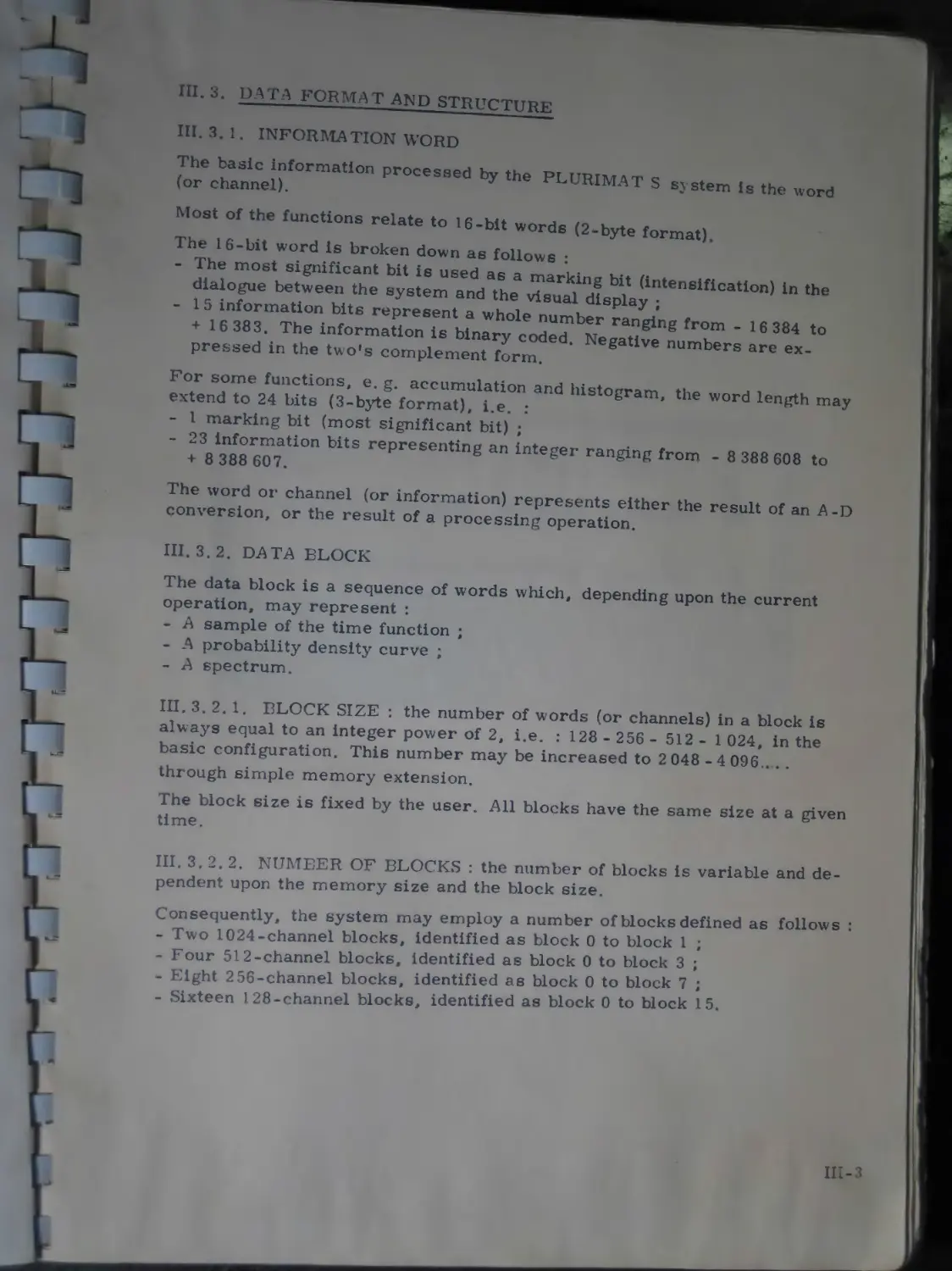
III. 3. 2. 1. BLOCK SIZE : the number of words (or channels) in a block is always equal to an integer power of 2, i.e. : 128 - 256 - 512 - 1 024, in the basic configuration. This number may be increased to 2 048 -4 096.. . . through simple memory extension.
The block size is fixed by the user. All blocks have the same size at a given time.
III. 3. 2. 2. NUMBER OF BLOCKS : the number of blocks is variable and dependent upon the memory size and the block size.
Consequently, the system may employ a number of blocks defined as follows : - Two 1024-channel blocks, identified as block 0 to block 1 ;
- Four 512-channel blocks, identified as block 0 to block 3 ;
- Eight 2 56-channel blocks, identified as block 0 to block 7 ;
- Sixteen 128-channel blocks, identified as block 0 to block 15.
III-3
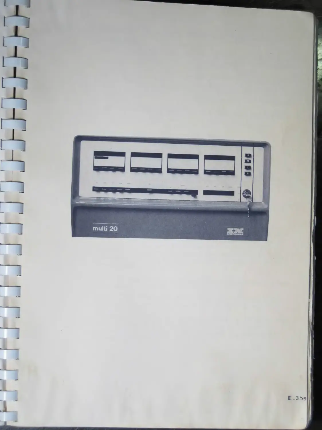
multi 20
Ш-ЗЬз
III. 3. 2.
. a
3. EXPONENT : this a 4-byte word assigned to each data block.
a. First byte
Bit 0 - space Indicator : 0 = time domain (the channels repre-sent the successive values taken by the time function) ;
1 = frequency domain (the channels represent the various spectral lines obtained, for instance, after a Fourier-transform operation).
1 type of representation : 0 = rectangular coordinates ;
1 = polar coordinates.
Eit 2 -- scale : 0 « linear-scale ordinate ;
1 « logarithmic-scale (decibels) ordinate.
Bits 3 to 7 -- clock frequency indicator set upon acquisition in the associated block (25 different positions). This indicator permits the time scale or the frequency scale to be defined upon termination of a Fourier-transform operation.
b. Second byte : it include the actual exponent of the block, i.e.the integer power of two by which all the block channels should be multiplied. This exponent ranges from 2*128 to 2+127.
A good compromise between processing speed and computational precision is achieved through this numerical representation. The exponent is incremented by the overflow count in the course of any operation on the block. It thus contains the number of overflows. Inversely it is decremented when scaling is required. Scaling is carried out in a way such that the use of 16-bit words is optimal.
NOTE : It is worthy of note that the block exponent varies as indicated hereafter whenever the block size is changed :
REDUCTION : if the size is divided by 2 (the number of blocks is doubled), the exponent of block zero is then extended to blocks 2, 3 and so on . ..
EXPANSION : there is generally no variation in the exponent of the new blocks and it is advisable either to set the blocks to zero (reset) or to request a new acquisition (the exponents of the associated blocks are then reset).
Ill-4
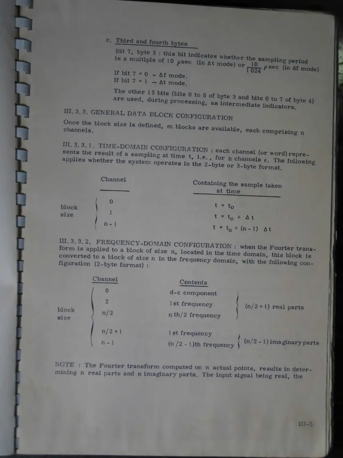
c- Third and fourth bytes
1. . multiple o(T0‘
ИШ..С.и„л, ^~«model
If bit 7 = 1 — At mode.
ar"6 u^d" duXgProceSXg 3 Шв ° to 7 byte 4) К processing, as intermediate indicators.
HI. 3. 3. GENERAL DATA BLOCK CONFIGURATION
Once the block size is defin nd m ui >
channels. ’ Jre available, each comprising n
1П. 3.3.1. TIME-DOMAIN CONFIGURATION . u «.
sents the result of a sampling at time tie' fm^ ch,annel (or word)repre-applies whether the system operates ip ’the
Channel
block size
0
1
Containing the sample taken _____ at time________ _
t = to
t = to + д t
t = to + (n- 1) At
1П. 3. 3.2.
form is .рр™?о“ br„e,;Do?s“”-C<?№I.OYRATION ‘ "1™ Fourier trans-converted to a block of size n figuration (2-byte format) :
n, located in the time in the frequency domain,
domain, this block is with the following con-
block size
Channel
I °
I 2
J n/2
| n/2 + 1
i n - 1
Contents d-c component 1st frequency nth/2 frequency
(n/2 + 1) real parts
1 st frequency .
(n /2 - 1 )th frequency ( (n'2 " 1 > imaginary parts
NOTE : The Fourier transform computed on n actual points, results in deter 1Г ng n real parts and n imaginary parts. The input signal being real, the
Ш-5
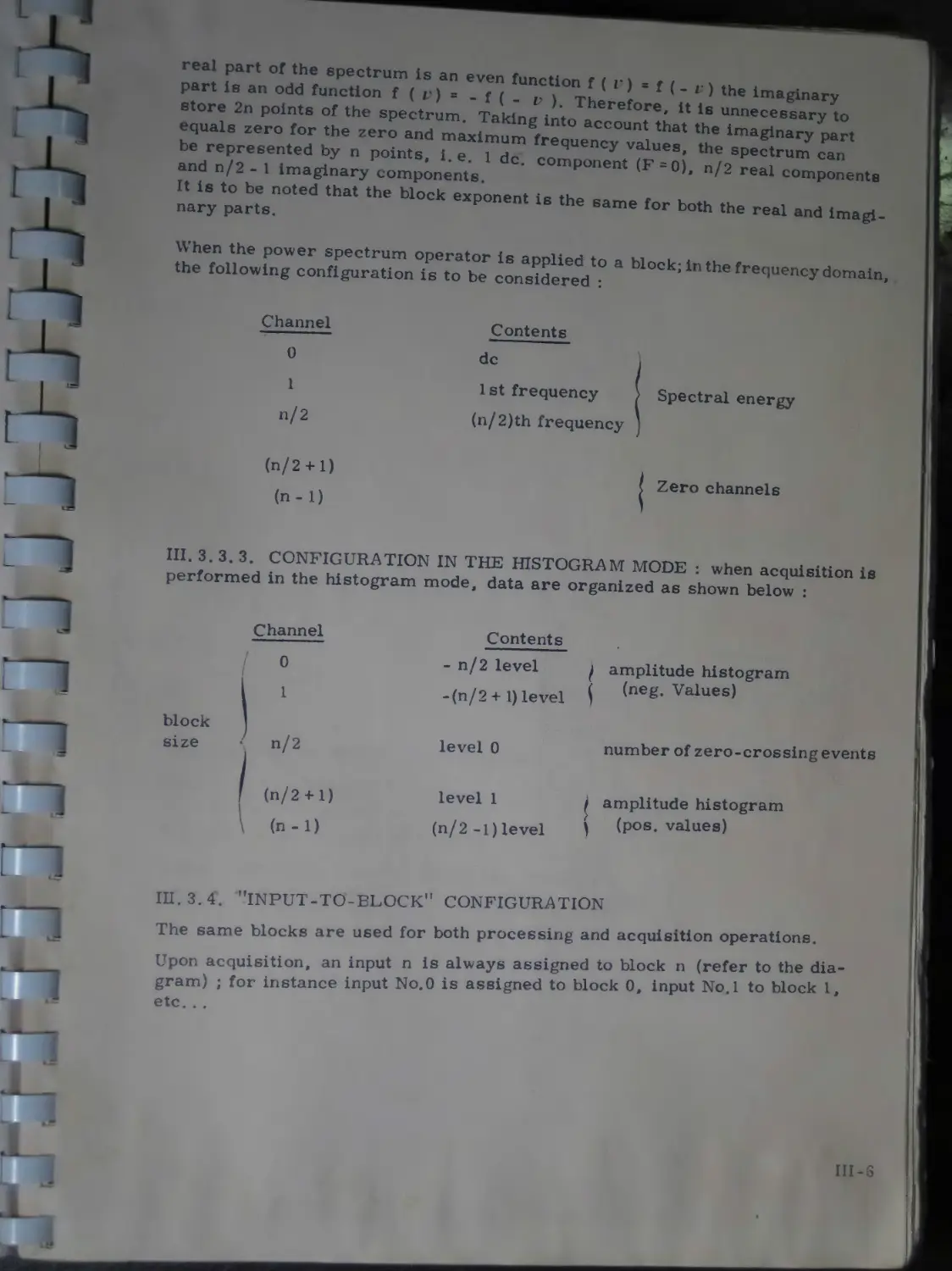
г) the imaginary is unnecessary to the imaginary part the spectrum can
real part of the spectrum is an even function f ( г) = f ( _ part is an odd function f ( r) = . f ( . ) Therefore it
store 2n points of the spectrum. Taking into account that equals zero for the zero and maximum frequency values, be represented by n points, i.e. 1 de. component (F = 0), n/2 real components and n/2 - 1 imaginary components.
It is to be noted that the block exponent is the same for both the real and imaid nary parts.
When the power spectrum operator is applied to a block; in the frequency domain the following configuration is to be considered : *
Channel
0
1
n/2
(n/2 4-1) (n-1)
Contents
de
1 st frequency
(n/2)th frequency
Spectral energy
Zero channels
III. 3.3.3. CONFIGURATION IN THE HISTOGRAM MODE : when acquisition is performed in the histogram mode, data are organized as shown below :
block size
Channel
Contents
-n/2 level
-(n/2 + 1) level
level 0
level 1
(n/2 -1)level
amplitude histogram ( (neg. Values)
number of zero-crossing events
amplitude histogram (pos. values)
III. 3.4. "INPUT-TO-ELOCK’* CONFIGURATION
The same blocks are used for both processing and acquisition operations.
Upon acquisition, an input n is always assigned to block n (refer to the diagram) ; for instance input No.O is assigned to block 0, input No.l to block 1, etc. . .
III-S
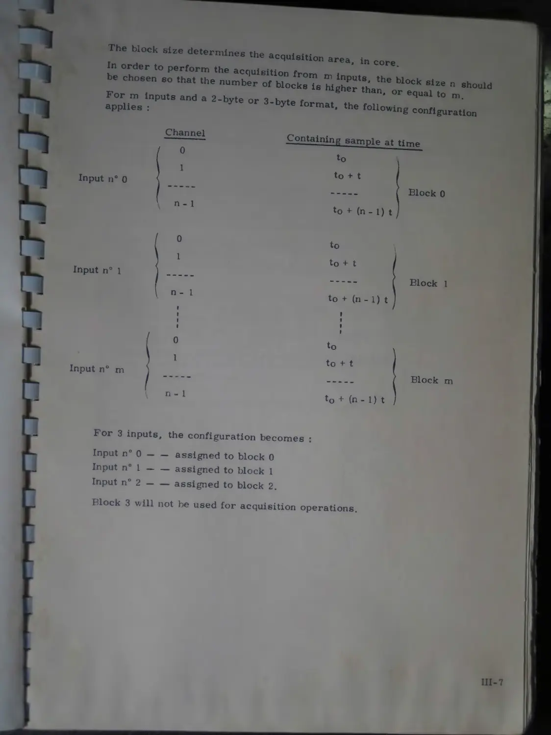
Th. K«. ,lz. de.erml„e. the aoqulelUon arM_ in
In order to perform the acquisition r
be chosen so that “ooh „„ „
inputs and a 2-hyte „ 3 bvtB , °r •»
: 3-byte th<, ,oUowing юппеигаци1
applies
Channel
0
1
--Gaining sample at time
Input n° 0
\ n - 1
Block 0
Input n° 1
Input n° m
0
1
n - 1
t । t
0
n - 1
Block 1
Block m
For 3 inputs, the configuration becomes :
Input n° 0---assigned to block 0
Input n° 1----assigned to block 1
Input n° 2---- assigned to block 2.
Г rt be used for acquisition operations.
Ill-7
III. 4. PROGRAMMABLE "VARIABLES"
In the proceding section we have described the data format and structure and indicated that the data were stored per block.
It is often of interest to work on one or several basic data elements (items) • this can be done by means of the "variables".
An index may be assigned to a variable, a data block or a data item in a block.
Since these indices can be automatically incremented or decremented, users can carry out a series of arithmetical operations on a data block or among several data blocks.
A PROGRAMMABLE VARIABLE V (I) is a 4-byte word. Three bytes are assigned to the mantissa and one byte to the exponent, this being due to the use of floating point arithmetic. The variables, 64 in number, can be transferred to/from the memory area reserved for the programs.
A numerical value may be assigned to a variable :
- Through the keyboard ;
- By assigning to it either the result of a computation or an acquisition data item.
The main available OPERATIONS are : (p v-ЛЧ)
- Assignment of a constant (or the result of a particular computation) to a programmable variable (PRV) ;
- Addition, subtraction, multiplication and division of each variable by either a constant or another variable ;
- Square root, logarithm and absolute value of each PRV ;
- Sine, cosine and arctan of each PRV ;
- Logic operation between PRV’s ;
- Conditional branching ;
- Alphanumerical display of the contents of a particular PRV.
Ill-8
CHAPTER IV
COMMANDS AND
MODES OF OPERATION
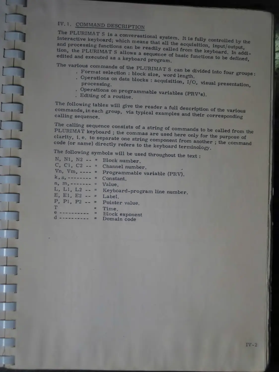
IV. 1. COMMAND DESCRIPTION
The PLURIMAT S is a conversational system. It is fully controlled by the interactive keyboard; which means that all the acquisition, input/output, and processing functions can be readily called from the keyboard. In addition, the PLURIMAT S allows a sequence of basic functions to be defined, edited and executed as a keyboard program.
The various commands of the PLURIMAT S can be divided into four groups: . Format selection : block size, word length.
. Operations on data blocks : acquisition, I/O, visual presentation, processing.
. Operations on programmable variables (PRV’s).
. Editing of a routine.
The following tables will give the reader a full description of the various commands, in each group, via typical examples and their corresponding calling sequence.
The calling sequence consists of a string of commands to be called from the PLURIMAT keyboard ; the commas are used here only for the purpose of clarity, i. e. to separate one string component from another ; the command code (or name) directly refers to the keyboard terminology.
The following symbols will be used throughout the text :
N, Nl, N2 -- =
C, Cl, C2 -- = Vn, Vm, ---- = k, s,--------=
Block number.
Channel number.
Programmable variable (PRV).
Constant.
Value.
Keyboard-program line number.
Label.
Pointer value.
Time.
Block exponent
Domain code
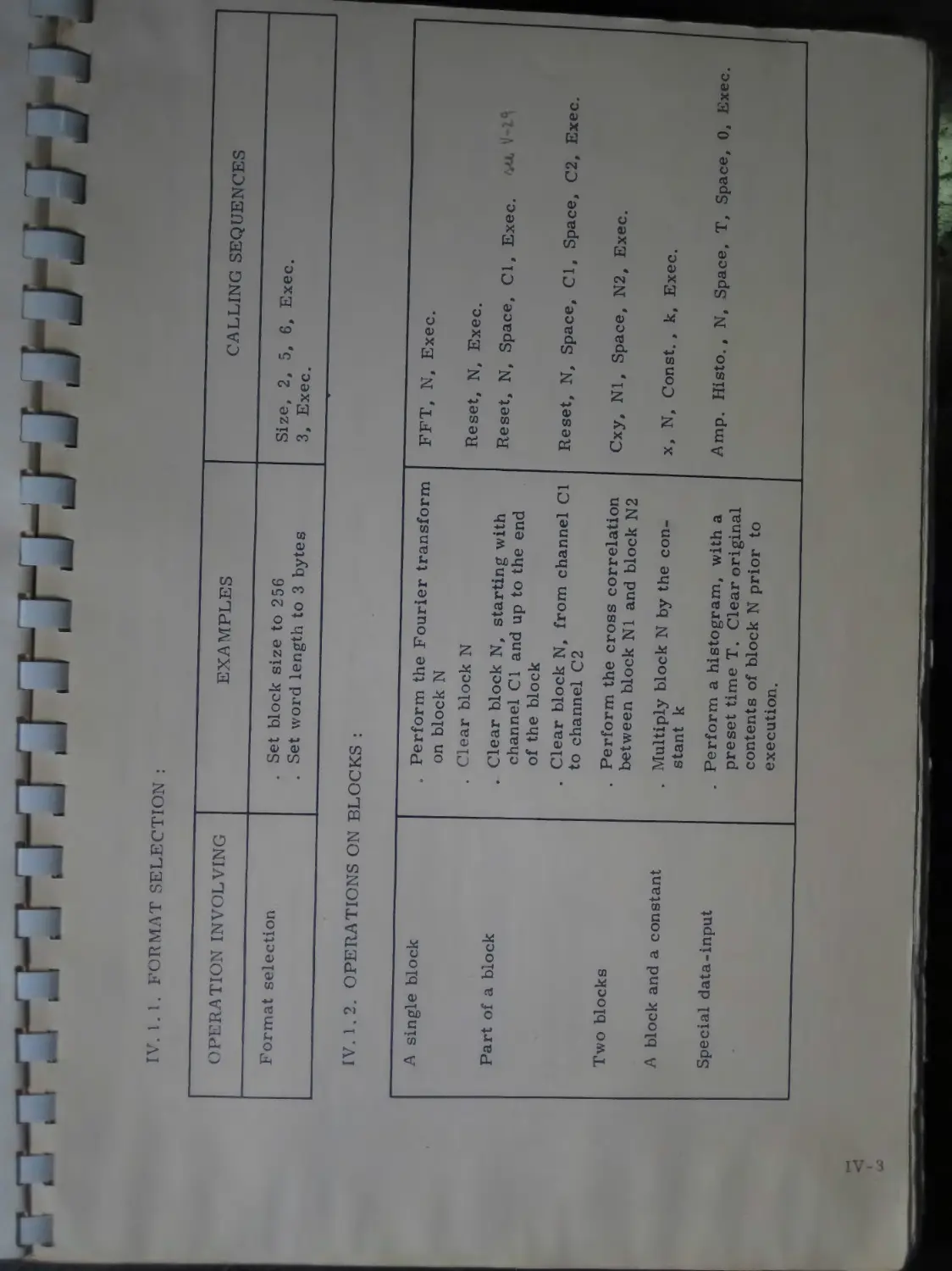
IV. I. 1. FORMAT SELECTION :
OPERATION INVOLVING EXAMPLES CALLING SEQUENCES
Format selection . Set block size to 256 . Set word length to 3 bytes Size, 2, 5, 6, Exec. 3, Exec.
IV. 1.2. OPERATIONS ON BLOCKS :
A single block
Part of a block
Two blocks
A block and a constant
Special data-input
. Perform the Fourier transform on block N
. Clear block N
. Clear block N, starting with channel Cl and up to the end of the block
. Clear block N, from channel Cl to channel C2
. Perform the cross correlation between block N1 and block N2
. Multiply block N by the constant к
. Perform a histogram, with a preset time T. Clear original contents of block N prior to execution.
FFT, N, Exec.
Reset, N, Exec.
Reset, N, Space, Cl, Exec. • "
Reset, N, Space, Cl, Space, C2, Exec.
Cxy, Nl, Space, N2, Exec.
x, N, Const. , k, Exec.
Amp. Histo., N, Space, T, Space, 0, Exec.
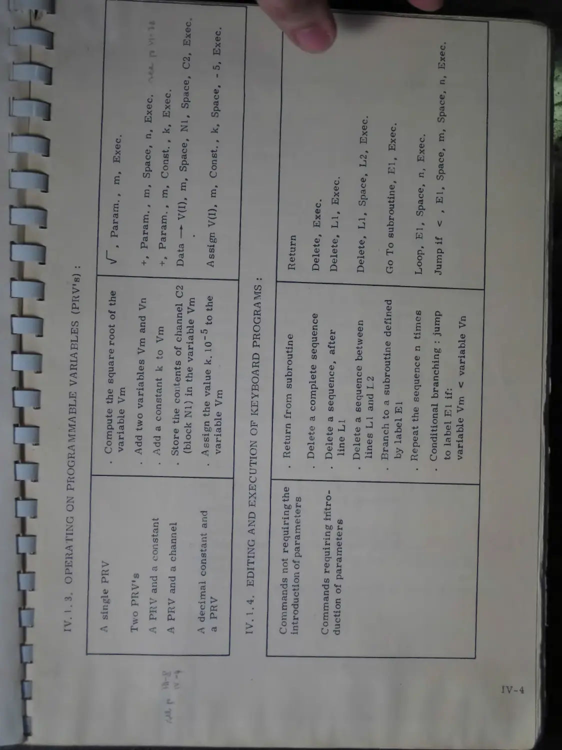
IV. 1.3. OPERATING ON PROGRAMMABLE VARIABLES (PRV's) :
A single PRV
Two PRV’s
A PRV and a constant
A PRV and a channel
A decimal constant and a PRV
Compute the square root of the variable Vm
Add two variables Vm and Vn
Add a constant к to Vm
Store the contents of channel C2 (block Nl) in the variable Vm
Assign the value k. 10’5 to the variable Vm
IV. 1.4. EDITING AND EXECUTION OF KEYBOARD PROGRAMS :
Commands not requiring the introduction of parameters
Commands requiring introduction of parameters
. Return from subroutine
. Delete a
. Delete a
complete sequence
sequence, after
. Delete a lines LI
. Branch to a subroutine defined by label El
. Repeat the sequence n times
sequence between and L 2
. Conditional branching : jump to label El if: variable Vm < variable Vn
» Param., m, Exec.
+ > Param. , m, Space, n. Exec.
+ , Param., m, Const., k. Exec.
Data — V(I), m, Space, Nl, Space, C2, Exec
Assign V(I), m. Const. , k, Space, -5, Exec.
Return
Delete, Exec.
Delete, LI, Exec.
Delete, LI, Space, L2, Exec.
Go To subroutine. El, Exec.
Loop, El, Space, n, Exec.
Jump if < , El, Space, m. Space, n, Exec.
IV. 2. MODES OF OPERATION
The various functions performed by the system (acquisition, display Dro cessing output of results) are called by depressing the corresponding key’s on the interactive keyboard. s y
Three modes of operation are provided : . Immediate operation ;
. Sequential programmed operation ;
. Real-time programmed operation.
IV. 2. 1. IMMEDIATE MODE
In this mode the operator depresses the key corresponding to the desired command and selects the corresponding input parameters ; he then starts the execution by depressing the ’’EXEC. " key. The ’’Busy” indicator light stays on throughout the time required for the execution. Meanwhile, no other function can be called.
The only exceptions are the acquisition, accumulation and histogram functions which can be performed in parallel with another processing operation.
The system changes over to the ’’free” status as soon as an acquisition is initiated ; the information ’’current acquisition”, “current histogram”, visually displayed enables the operator to check for the end-of-acquisition, and maintain the system in the “free” state.
IV. 2. 2. SEQUENTIAL PROGRAMMED MODE
This mode of operation enables the user to tailor a program to his own needs and to request the execution at a later time.
Such a custom-tailored program can include all the functions currently performed in the immediate mode of operation (filter input, keyboard input excepted), as well as a few specific functions required for the setting up of a program.
IV. 2. 2. 1. PROGRAMMING COMMANDS
a. Label : this is a no-operation function ; it allows one entry point to be labeled, either for a branching or to define the beginning of a subroutine.
CALLING SEQUENCE : Lab., El, Exec.
The label number El ranges from 0 to 127.
Whenever El is omitted, the label will automatically be equalled to zero.
This command is invalid in the immediate mode of operation.
IV-5
b- this function causes the routine to be rerouted towards the label whose number El is specified as a parameter.
CALLING SEQUENCE : Jump, El, Exec.
If El is missing, the label number is equalled to zero.
This command is invalid in the immediate mode of operation.
c* GO TO 1 subroutine : this function causes the routine to be rerouted towards a label specified as a parameter, with storage of the next line number.
It is used to perform a branching to a subroutine*.
CALLING SEQUENCE : Go To, El, Exec.
If El is missing, the label number is taken equal to zero.
This command is invalid in the immediate mode of operation.
d. Return : the "Return” function causes a program rerouting to the instruction directly following the last ”Go To” function performed.
CALLING SEQUENCE : Return, Exec.
This command is invalid in the immediate mode of operation.
e. Loop : this function performs n branching operations to a label El.
It is advisable to define the label El before the "Loop” function.
CALLING SEQUENCE : Loop, El, Space, n. Exec.
If El and n are omitted, they will be taken equal to zero.
This command is invalid in the immediate mode of operation.
NOTE : After an interruption in the execution of a routine, the number m of loops remaining to be performed is printed in addition to the two parameters El and n.
A subroutine is a sequence of operations preceded by a label and terminated by a "return” function.
A subroutine is called by a "Go To" instruction. After the completion of the subroutine operations, the "return" instruction causes a jump to the instruction directly following the "Go To" instruction. Multiple subroutine jumps can be performed (up to four levels are allowed).
IV-6
f. Conditional jumps : ’’smaller than”, ’’equal to” and ’’larger than” tests can be applied to the PRV’s.
The three corresponding command (<; = ;>) cause a jump to a specified label if the condition is satisfied and the next instruction will be carried out if the test require ments are not satisfied.
CALLING SEQUENCE : < , El, Space, m. Space, n. Exec. El, Vm, Vn, when missing, are taken equal to zero.
This command can be used only in the programmed mode of operation.
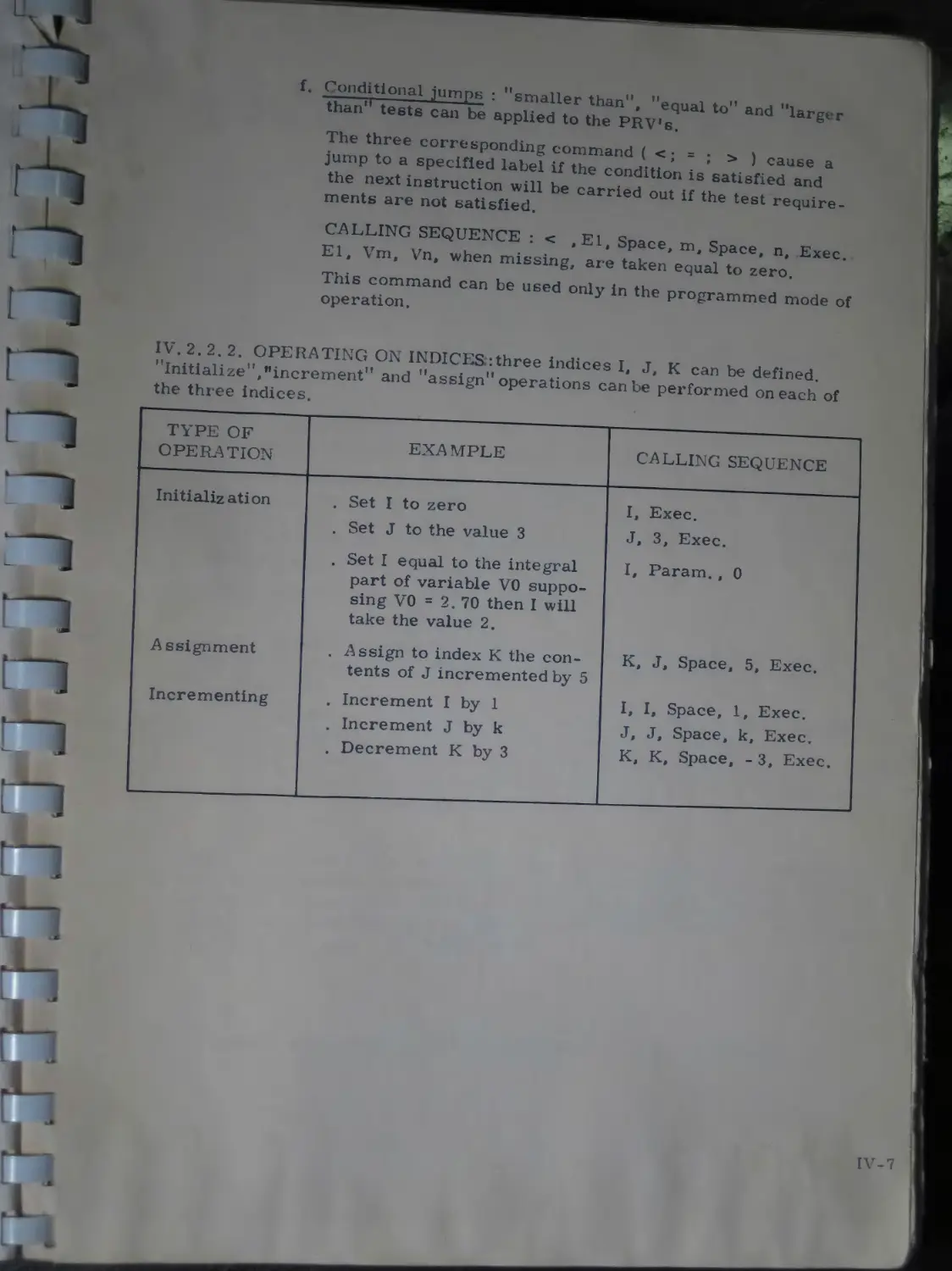
IV. 2. 2. 2. OPERATING ON INDICES :three indices I, J, К can be defined. ’’Initialize'’^increment” and ’’assign” operations can be performed on each of the three indices.
TYPE OF OPERATION EXA MPLE CALLING SEQUENCE
Initialization Assignment Incrementing . Set I to zero . Set J to the value 3 . Set I equal to the integral part of variable VO supposing VO = 2. 70 then I will take the value 2. . Assign to index К the contents of J incremented by 5 . Increment I by 1 . Increment J by к . Decrement К by 3 I, Exec. J, 3, Exec. I, Param., 0 K, J, Space, 5, Exec. I, I, Space, 1, Exec. J, J, Space, k. Exec. К, K, Space, -3, Exec.
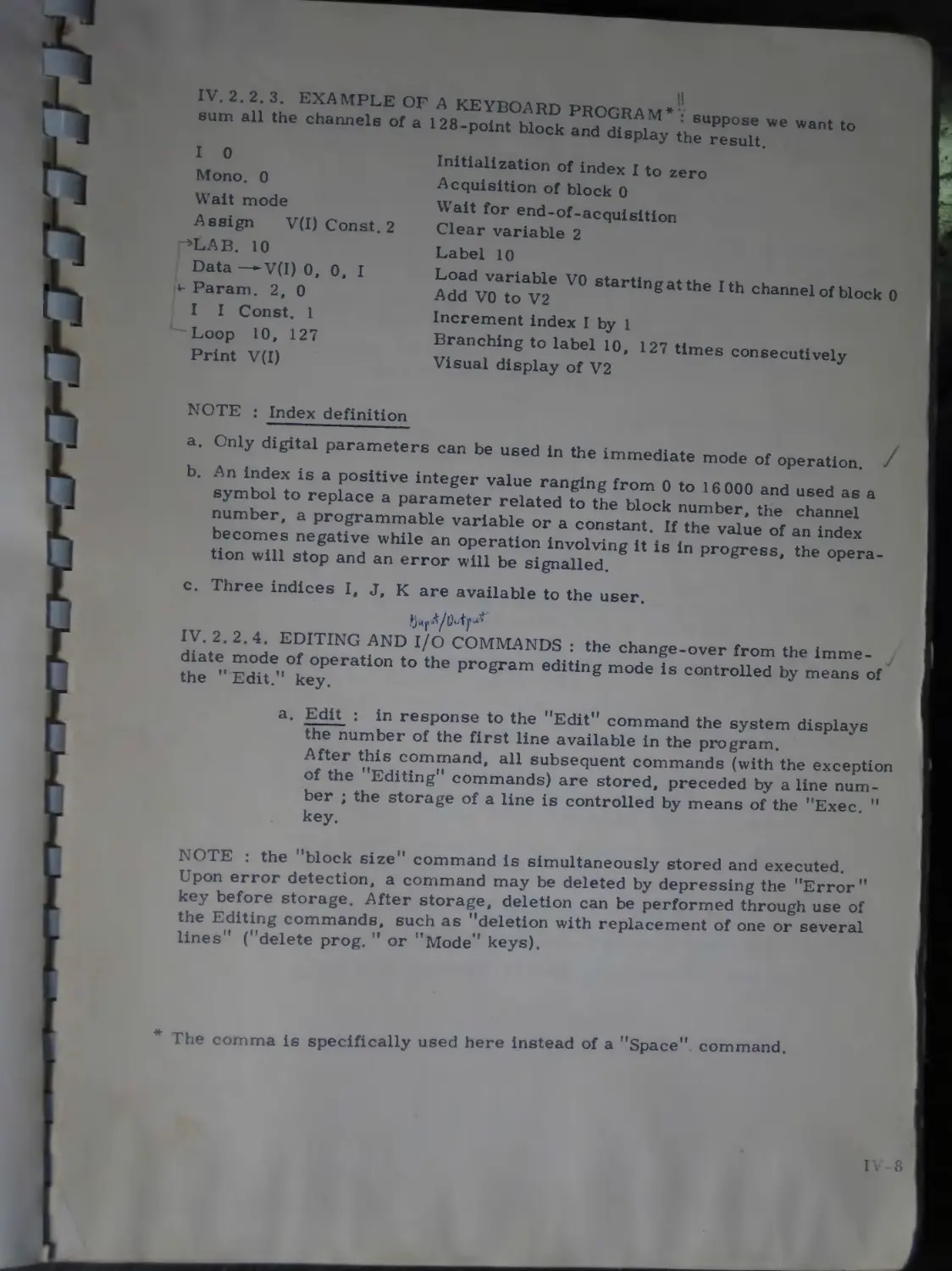
IV. 2.2.3. EXAMPLE OF A KEYBOARD PROGRAM* sum all the channels of a
suppose we want to 128-point block and display the result.
I 0
Mono. 0
Wait mode
Assign V(I) Const. 2
*LAB. 10
Data —V(I) 0, 0, I
v Param. 2, 0
I I Const. 1
Loop 10, 127
Print V(I)
Initialization of index I to zero
Acquisition of block 0
Wait for end-of-acquisition
Clear variable 2
Label 10
Load variable V0 starting at the I th channel of block 0
Add V0 to V2
Increment index I by 1
Branching to label 10, 127 times consecutively
Visual display of V2
NOTE : Index definition
a. Only digital parameters can be used in the immediate mode of operation.
b. An index is a positive integer value ranging from 0 to 16 000 and used as a symbol to replace a parameter related to the block number, the channel number, a programmable variable or a constant. If the value of an index becomes negative while an operation involving it is in progress, the operation will stop and an error will be signalled.
c. Three indices I, J, К are available to the user.
IV. 2.2.4. EDITING AND I/O COMMANDS : the change-over from the immediate mode of operation to the program editing mode is controlled by means of the ” Edit.” key.
a. Edit : in response to the ’’Edit” command the system displays the number of the first line available in the program.
After this command, all subsequent commands (with the exception of the ’’Editing” commands) are stored, preceded by a line number ; the storage of a line is controlled by means of the “Exec. ” key.
NOTE : the “block size” command is simultaneously stored and executed. Upon error detection, a command may be deleted by depressing the “Error key before storage. After storage, deletion can be performed through use of the Editing commands, such as “deletion with replacement of one or several lines ‘ (“delete prog. ” or ’’Mode” keys).
* The comma is specifically used here ins-ec, 1 of a Space command.
I . 8
b. Output print : the "output print" command permits the contents of the program area to be viewed by the display unit KA 106 ^“itch 1 the M2° in the upper P°sltion). or printed on the TTY (sense switch I in the lower position).
In the case of a visual presentation, only the last 12 lines are displayed when the number of stored lines exceeds 12.
However, the operator has the possibility to shift the displayed area at any time towards the beginning or end of the program by means of the advance key provided on the KA 106 unit.
After storage of a new command has been completed, the display will always select the last 12 lines of the program.
э CALLING SEQUENCE : Output Print, LI, Space, L2, Exec.
LI = number of the initial line
L2 = number of the final line.
This command controls program display, from line LI to line L2. If LI is omitted, it is automatically equalled to zero, if L2 is omitted, it takes the value of the last stored line.
The above command is invalid in the immediate mode of operation.
c. Delete : this command is used for the deletion of one or several program lines with reordering.
The CALLING SEQUENCE : Delete, LI, Space, L2, Exec, deletes the keyboard routine between lines LI and L2, delimiters included. This causes automatic line compression.
If omitted, LI is taken equal to zero.
Similarly, L2 takes the value of the last program line
and the STRING : Delete, Exec.
deletes the complete keyboard program.
This command is invalid in the immediate mode of operation.
d. Insert : this command enables the operator to insert one or several new functions in a keyboard program, starting at a given line. The command '‘insert" consists of three phases :
Phase_one : Indication of the number of the line at which the function is to be inserted, i.e. :
Insert, LI, Exec.
LI representing the line where the insertion should begin.
The insertion will automatically begin at line zero if LI is omitted. Phase two : Indication of the function(s) to be inserted.
: End-of-insertion command "End Mod. ".
NOTE : The command "End Mod. " is required for the insertion to be effective.
Only one insertion level is permitted by the system.
The command is not effective unless the system operates in the programmed mode.
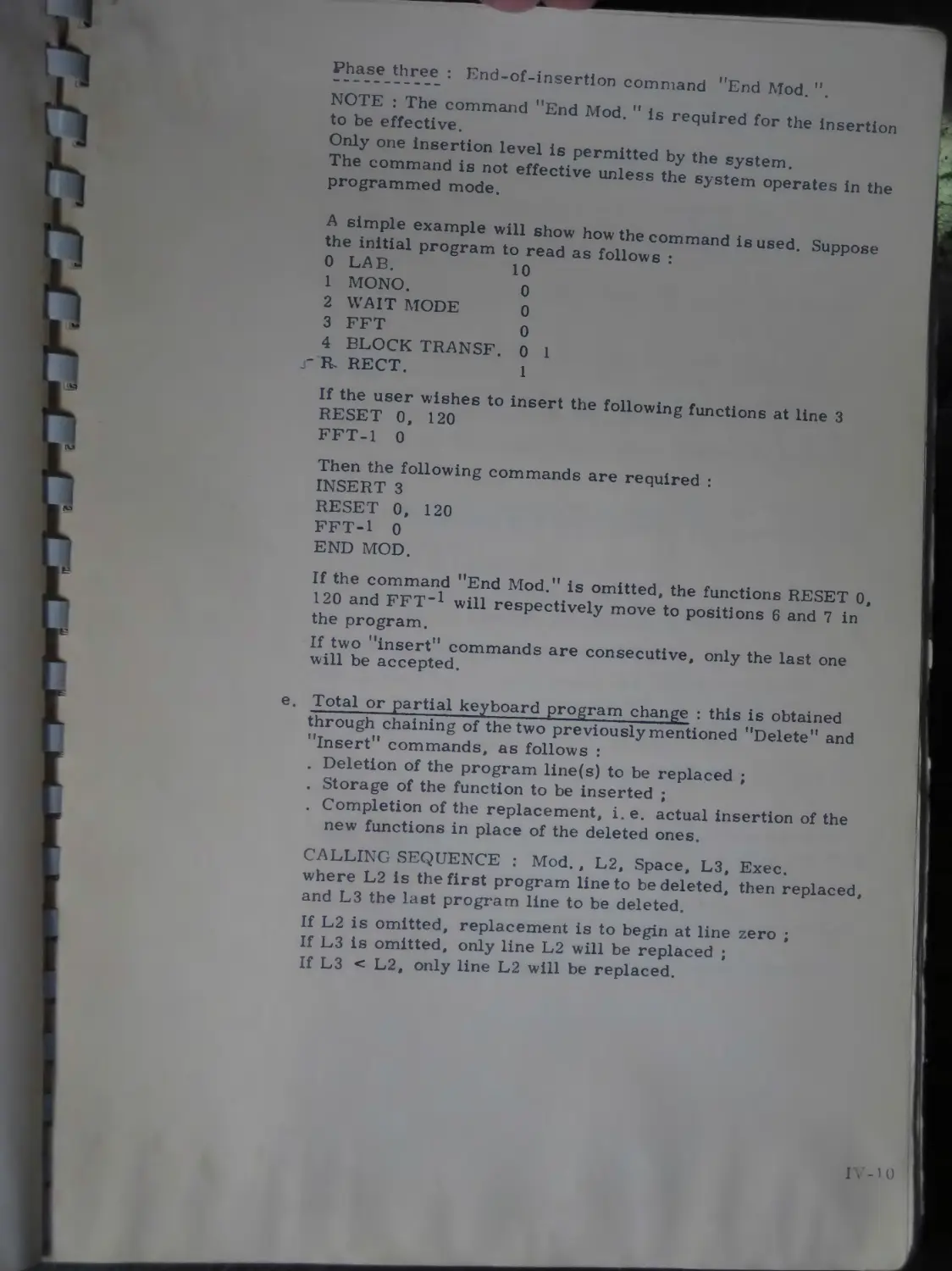
A simple example will show how the command is used. Suppose the initial program to read as follows :
0 LAB. io
1 MONO. о
2 WAIT MODE 0
3 FFT о
4 BLOCK TRANSF. 0 1
R. RECT. 1
If the user wishes to insert the following functions at line 3
RESET 0, 120
FFT-1 0
Then the following commands are required :
INSERT 3
RESET 0, 120
FFT-1 0
END MOD.
If the command ’’End Mod.” is omitted, the functions RESET 0, 120 and FFT~1 will respectively move to positions 6 and 7 in the program.
If two ’’insert” commands are consecutive, only the last one will be accepted.
Total or partial keyboard program change : this is obtained through chaining of the two previously mentioned ’’Delete” and ’’Insert" commands, as follows :
. Deletion of the program line(s) to be replaced ;
. Storage of the function to be inserted ;
. Completion of the replacement, i.e. actual insertion of the new functions in place of the deleted ones.
CALLING SEQUENCE : Mod. , L2, Space, L3, Exec.
where L2 is the first program line to be deleted, then replaced, and L3 the last program line to be deleted.
If L2 is omitted, replacement is to begin at line zero ;
If L3 is omitted, only line L2 will be replaced ;
If L3 < L2, only line L2 will be replaced.
The command should be followed by a list of the functions to be inserted.
The last stop is the end-of-acquisition indication actually represented by the command "End Mod.".
NOTE . The system provides only one replacement level If the "End Mod." command is omitted, the deletion will still be effective, but the functions to be inserted will be stored at the end of the program.
The command is effective only when used in the programmed mode.
f. Mod. " : this command actually indicates to the system the end of the replacement of one or several instructions by one or several others, as well as the end of the insertion of one or several instructions into a program.
The use of the "End Mod." command is mandatory, upon deletion or insertion.
g. Storing a keyboard program on punched tape : the "Punch" key is used to implement a program library. Two modes of operation are available :
. OUTPUT, STARTING WITH LINE L2.
Calling sequence : Punch, L2, Exec.
Whenever L2 is missing, the whole program is punched.
. OUTPUT, FROM LINE L2 TO LINE L3.
Calling sequence : Output punch, L2, Space, L3, Exec.
If L2 is omitted, the first punched line will be line zero ;
If L3 is omitted, the last punched line will be line L2 ;
If L3 < L2 only line L2 will be punched.
This command is not effective unless the system operates in the programmed mode,
h. Input of a program recorded on punched tape : this command is used to load in core memory a program, previously recorded on punched tape (through use of the "Punch" command).
CALLING SEQUENCE : Input reader, LI, Exec.
where LI is the number of the "Starting line" on the punched tape.
If LI is missing, ranking of the functions begins at line zero.
IV-11
NOTE : When the syetem operates in the programmed mode a program previously recorded on punched tape can be stored either directly, or during a program replacement or an inser-tion.
This command is valid only in the programmed mode.
i. End of the programmed mode : this command causes the system to switch from the programmed mode to the immediate mode of operation. A validity test is performed on the previously edited program and the indicator light corresponding to the programmed mode goes out on the interactive keyboard.
If an error is detected, the system prints the number of the line in error, mainly in the case of one or several undefined labels.
In order to exit from the programmed mode, it is necessary to define all the labels.
This command is valid only when the system operates in the programmed mode.
NOTE : The command ’’End Prog.” causes the instruction pointer to be initialized to zero for subsequent execution.
After the command ’’End Prog. ” has been executed, the system goes in the immediate mode of operation ; the user can then request the immediate execution of functions or start the execution of a previously edited program.
IV. 2. 2. 5. EXECUTION OF A KEYBOARD PROGRAM : two modes of execution are provided for this purpose :
. Sequential mode ;
. Single-step mode.
The execution can begin at any program line previously defined by means of the ’’Pointer” key.
a. Pointer : the instruction ’’Pointer” will contain the number of the line with which execution is to start, after the following sequence is carried out :
CALLING SEQUENCE : Pointer, Pl, Space, LI, Exec, where Pl is the actual pointer value (automatically printed), and LI the number of the line with which program execution should start.
If LI is omitted, the execution will start at line zero.
NOTE : The command string : Pointer, Pl, Exec allows the operator to keep track of the'pointer position The pointer is initialized to zero with the ’’End Prog. " command.
b. Aecluentlal mode : this command is used to start the execution of a program in the sequential mode, starting with a line previously defined by the ’’Pointer'’ command.
The program will run in the sequential mode (each function can be printed on the TTY, before execution, provided sense switch S2 is in the lower position). It will halt in one of the three following cases :
END OF EXECUTION : the program has just performed the last function ; this is the normal program halt.
DISPLAY : if the command ’’Rect. ” is called during execution, the program halts after having carried out that command and displays the requested block.
STEP MODE : could be part of the keyboard program. The program is halted as soon as the processor encounters a ’’Step Mode” instruction.
c. Single-step mode : depressing the ’’Step Mode” key causes the program to halt after the current operation has been completed. This command is valid only when the system does not operate in the ’’programmed mode” ; it is accepted even if the system is ’’busy”.
In fact, this command performs two operations :
It ensures the execution of that function of a stored program, which is designated by the instruction pointer ;
It causes a halt after execution of the current instruction, when the system operates in the sequential mode.
NOTE : The command string ; Pointer, Pl, Exec allows the operator to keep track of the'pointer position The pointer is initialized to zero with the ’’End Prog. ” command.
Sequential mode : this command is used to start the execution of a program in the sequential mode, starting with a line previously defined by the ’’Pointer” command.
The program will run in the sequential mode (each function can be printed on the TTY, before execution, provided sense switch S2 is in the lower position). It will halt in one of the three following cases :
END OF EXECUTION : the program has just performed the last function ; this is the normal program halt.
DISPLAY : if the command ’’Rect. ” is called during execution, the program halts after having carried out that command and displays the requested block.
STEP MODE : could be part of the keyboard program. The program is halted as soon as the processor encounters a "Step Mode” instruction.
Single-step mode : depressing the ’’Step Mode” key causes the program to halt after the current operation has been completed. This command is valid only when the system does not operate in the ’’programmed mode” ; it is accepted even if the system is ’’busy”.
In fact, this command performs two operations :
It ensures the execution of that function of a stored program, which is designated by the instruction pointer ;
It causes a halt after execution of the current instruction, when the system operates in the sequential mode.
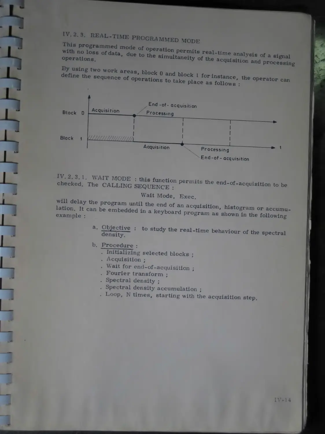
IV. 2. 3. REAL-TIME PROGRAMMED MODE
This programmed mode of operation permits real-time analysis of a signal with no loss of data, due to the simultaneity of the acquisition and processing operations.
By using two work areas, block 0 and block 1 for instance, the operator can define the sequence of operations to take place as follows :
IV. 2. 3. 1. WAIT MODE : this function permits the end-of-acquisition to be checked. The CALLING SEQUENCE :
Wait Mode, Exec.
will delay the program until the end of an acquisition, histogram or accumulation. It can be embedded in a keyboard program as shown in the following example :
a. Objective : to study the real-time behaviour of the spectral density.
b. Procedure :
. Initializing selected blocks ;
. Acquisition ;
. Vvait for end-of-acquisition ;
. Fourier transform ;
. Spectral density ;
Spectral density accumulation ;
Loop, N times, starting with the acquisition step.
IV-14
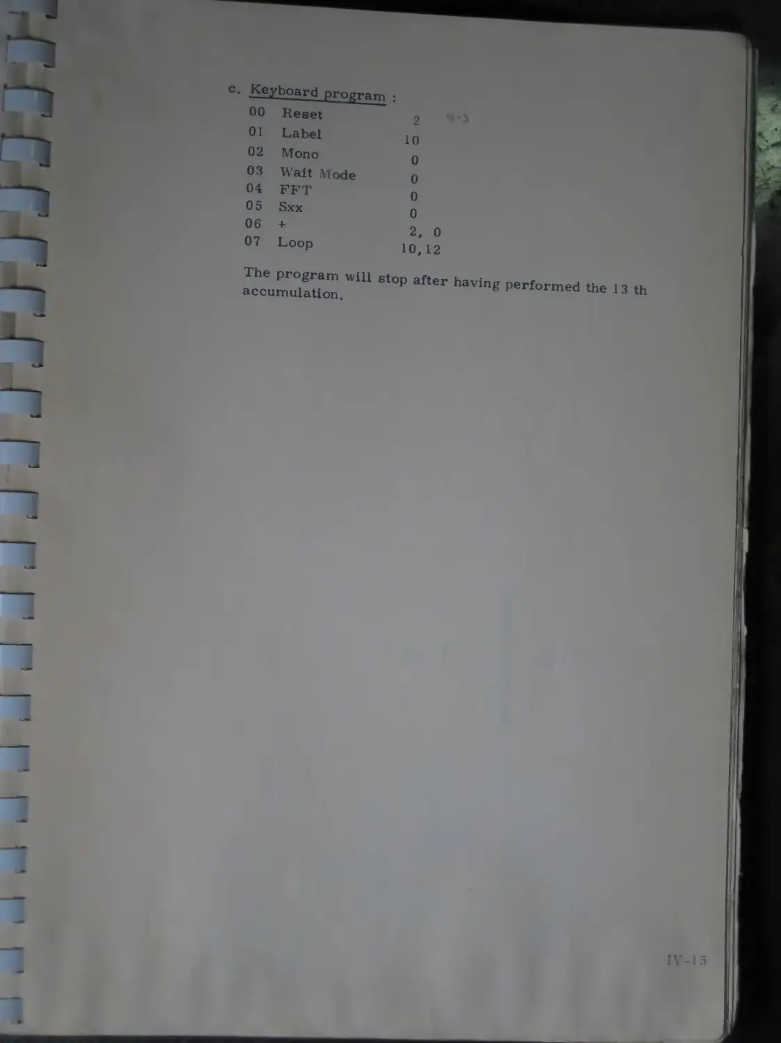
c. Keyboard program :
00 Reset 2
01 Label 10
02 Mono 0
03 04 05 06 07 Wait Mode 0 FFT 0 Sxx 0 + 2, 0 Loop 10,12
The program will stop after having performed the 13 th accumulation.
CHAPTER V
INPUT / OUTPUT
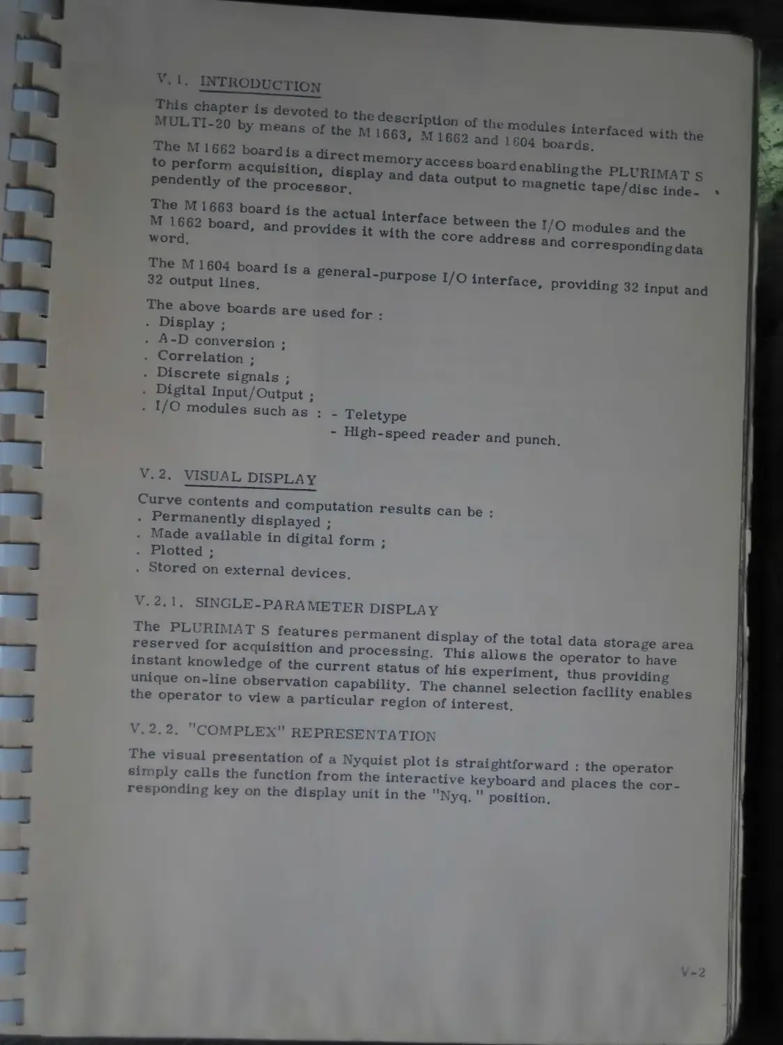
V. 1. INTRODUCTION
™S chapter is devoted to the description of the modules interfaced with the MULTI-20 by means of the M 1663, M 1662 and 1604 boards.
The vl 1662 boardis a direct memory access board enabling the PLURIMAT S to perform acquisition, display and data output to magnetic tape/disc inde- • pendently of the processor.
The M 1663 board is the actual interface between the I/O modules and the
M 1662 board, and provides it with the core address and corresponding data word.
The M 1604 board is a general-purpose I/O interface, providing 32 input and 32 output lines.
The above boards are used for :
. Display ;
. А-D conversion ;
. Correlation ;
. Discrete signals ;
. Digital Input/Output ;
. I/O modules such as : - Teletype
- High-speed reader and punch.
V. 2. VISUAL DISPLAY
Curve contents and computation results can be :
. Permanently displayed ;
. Made available in digital form ;
. Plotted ;
. Stored on external devices.
V. 2. 1. SINGLE-PARAMETER DISPLAY
The PLURIMAT S features permanent display of the total data storage area reserved for acquisition and processing. This allows the operator to have instant knowledge of the current status of his experiment, thus providing unique on-line observation capability. The channel selection facility enables the operator to view a particular region of interest.
V. 2.2. '’COMPLEX” REPRESENTATION
The visual presentation of a Nyquist plot is straightforward : the operator simply calls the function from the interactive keyboard and places the corresponding key on the display unit in the Nyq. position.
V, 2.3. INTENSIFICATION
Each channel, in any data block, maybe intensified by means of three triple position switches controlling a variety of functions such as :
- Sweep/stop control of the marking dot ;
- Intensify/erase ;
- Digital display of the contents of an intensified channel ;
- Sweep/stop control of a keyboard program
V. 2. 4. SPECTRUM SWEEP
Regions of interest can be readily selected ; the display then acts as a "window" looking over a portion of the spectrum which may then be continuously displaced either way past the "window", through front-panel control.
V. 2. 5. DUAL-PARAMETER DISPLAY
Dual-parameter experiments require that a number of curves be displayed as a surface N = f (X, Y), where N represents the contents of a particular point of address X, located on a particular curve of rank Y.
The sophisticated dual-parameter display offered with the PLURIMAT S,not only allows such experiments to be readily performed, but also enables further image-manipulation through the use of the rotation and tilt facilities. Images can be rotated and/or tilted, thereby allowing the operator to view the same information in a different perspective.
V. 2.6. CHARACTER GENERATOR (general)
This generator greatly simplifies interpretation of the displayed data by providing alphanumerical information on the screen (16 lines x 32 columns). The parameters that can be viewed include :
. Scale factors ;
. Type of display : time domain, frequency domain . .. ;
. Number of cycles ;
. Elapsed time ;
. Numerical value of a particular PRV ;
Coordinates of a particular point on a curve.
V. 2. 7. X-Y PLOTTER
The X-Y plotter (type RA 102) connects directly to the PLURIMAT S. It is used to plot the data and text available on the display unit.
MON
and Y
ice, when (dual-
1 is used to the al cornier.
эг, i. e. d along
t points en.
displayed J Y axes.
"magnifi-espect to the sepa- I
*re pro-
?r to in->ugh to enlarge to view a say, theX ion on the
>r.
Э of
the full
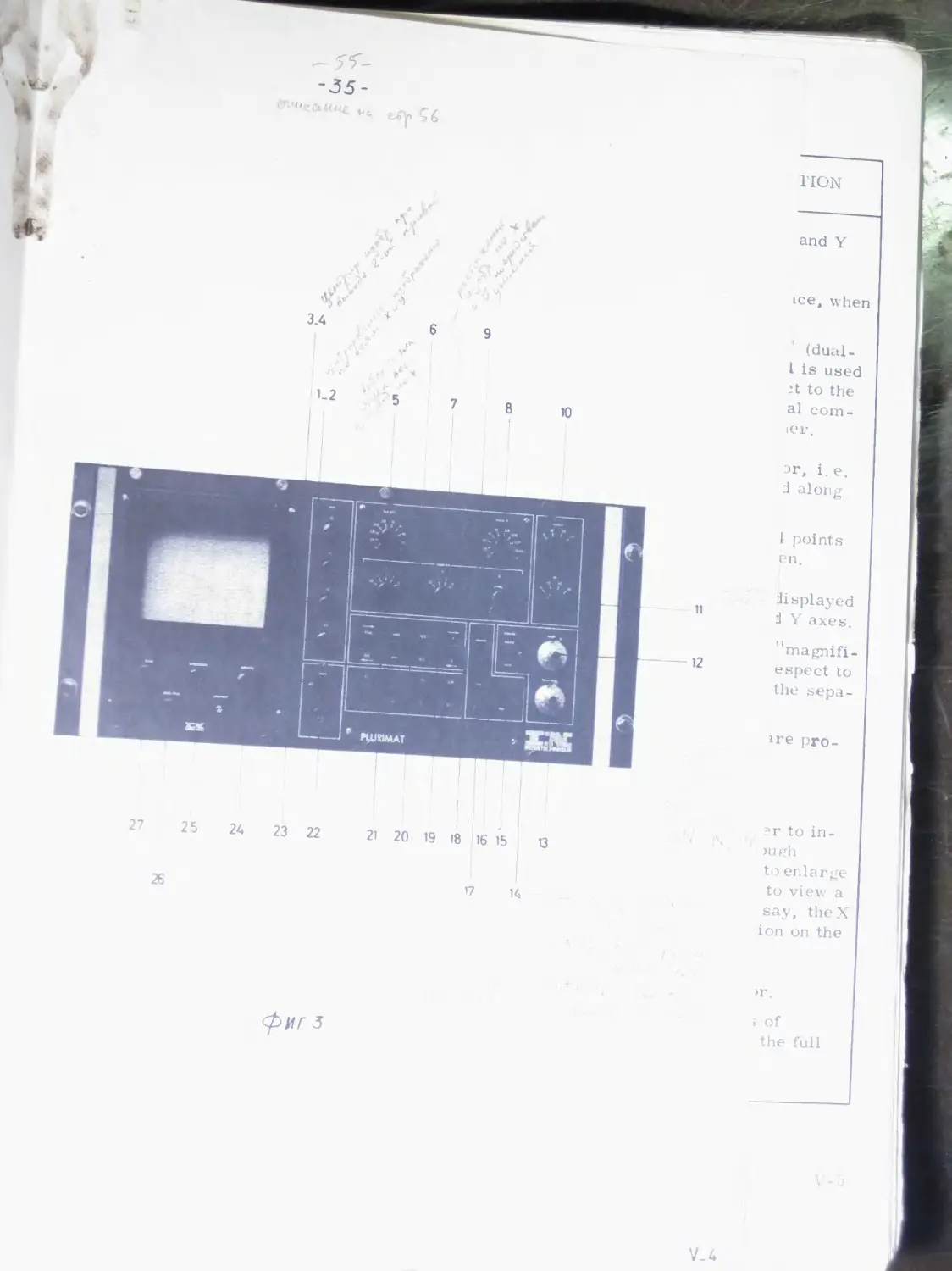
V.2.8. FRONT-PANEL. DESCRIPTION
ITEM No. ON
ILLUSTRATION
2
3,
(
8
DESIGNATION
X2, Y2 shift
X Format
X, Y expansion
N Format
ACTION AND EXPLANATION
directions.
Same as 1, 2, but for the 2nd trace, when displaying curves.
When switch (15) is in the ’Dual” (dualparameter) position, this control is used to shift the 2nd trace with respect to the first one, thus permitting a visual comparison of one curve with the other.
Selects horizontal deflection factor, i.e. the number of channels displayed along
Variation in steps of 32 to 16 384 points across the full width of the screen.
Expansion (or reduction) of the displayed image along the horizontal X and Y axes.
Expansion of the image through ’’magnification” effect is achieved with respect to the screen center, by means of the separate X and Y controls.:
The following expansion ratios are provided : X-axis
0.5-1 - 2- 4- 8
0. 5 - 1 - 2 - 4.
controls are used either to in-
The size
crease the picture contrast through reduction of the dimensions, or to enlarge a precise portion of the picture to view a region of interest. Needless to say, theX and Y size controls have no action on the alphanumerical text.
Selects vertical deflection factor.
The scale is adjustable in steps of 26 = 32 to 223 = 8 192 k, across the full height of the screen.
ITEM No. ON
ILLI STRATION
DESIGNATION
ACTION AND EXPLANATION
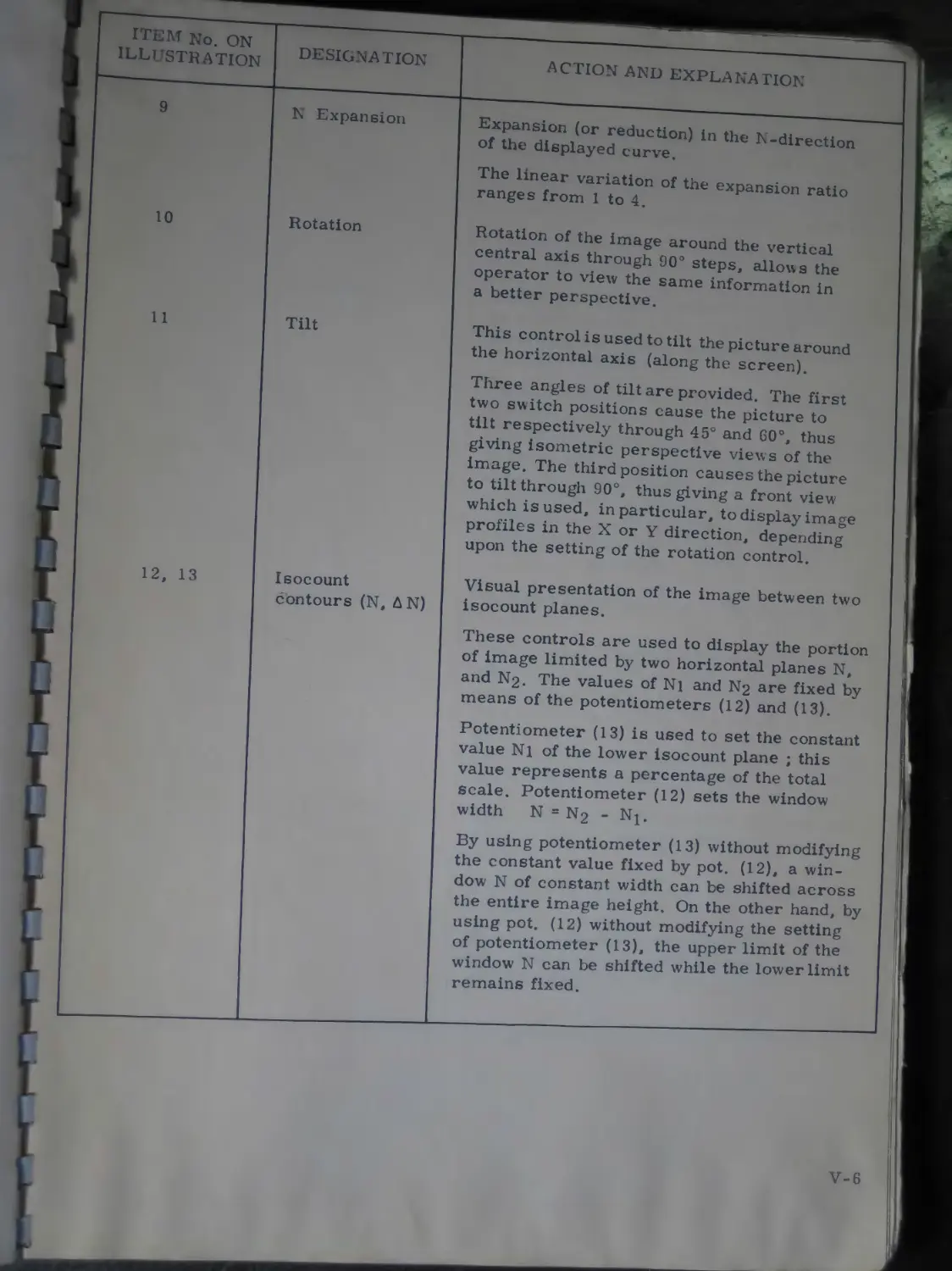
9
N Expansion
Expansion (or reduction) in the N-direction of the displayed curve.
The linear variation of the expansion ratio ranges from 1 to 4.
10
11
Rotation
Tilt
Rotation of the image around the vertical central axis through 90° steps, allows the operator to view the same information in a better perspective.
This control is used to tilt the picture around the horizontal axis (along the screen).
Three angles of tilt are provided. The first two switch positions cause the picture to tilt respectively through 45° and 60°, thus giving isometric perspective views of the image. The third position causes the picture to tilt through 90°, thus giving a front view which is used, in particular, to display image profiles in the X or Y direction, depending upon the setting of the rotation control.
12, 13
Isocount contours (N, AN)
Visual presentation of the image between two isocount planes.
These controls are used to display the portion of image limited by two horizontal planes N, and N2. The values of N1 and N2 are fixed by means of the potentiometers (12) and (13).
Potentiometer (13) is used to set the constant value N1 of the lower isocount plane ; this value represents a percentage of the total scale. Potentiometer (12) sets the window width N = N2 - Np
By using potentiometer (13) without modifying the constant value fixed by pot. (12), a window N of constant width can be shifted across the entire image height. On the other hand, by using pot. (12) without modifying the setting of potentiometer (13), the upper limit of the window N can be shifted while the lower limit remains fixed.
ITEM No.ON
ILLI’S TRATION
DESIGNATION
ACTION AND EXPLANATION
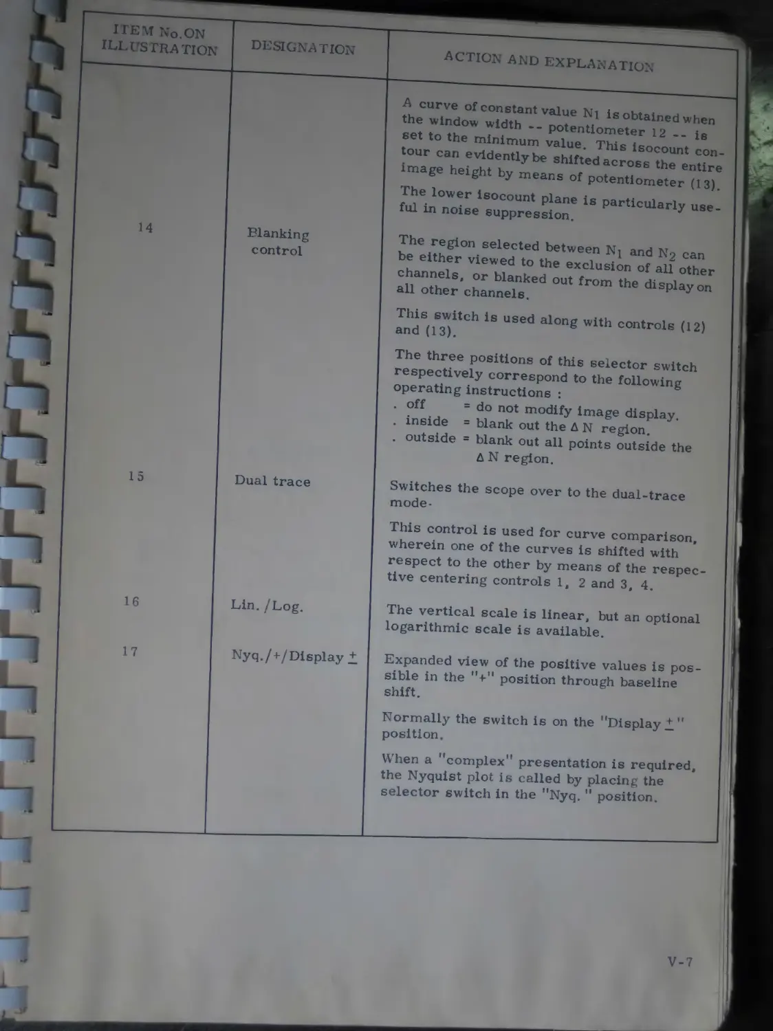
A curve of constant value Nl is obtained when the window width -- potentiometer 12 -- is set to the minimum value. This isocount contour can evidently be shifted across the entire image height by means of potentiometer (13). The lower isocount plane is particularly useful in noise suppression.
14
Blanking control
Dual trace
Lin. /Log.
The region selected between N; and N2 can be either viewed to the exclusion of all other channels, or blanked out from the display on all other channels.
This switch is used along with controls (12) and (13).
The three positions of this selector switch respectively correspond to the following operating instructions :
. off = do not modify image display.
. inside = blank out the AN region.
. outside = blank out all points outside the A N region.
Switches the scope over to the dual-trace mode-
This control is used for curve comparison, wherein one of the curves is shifted with respect to the other by means of the respective centering controls 1, 2 and 3, 4.
The vertical scale is linear, but an optional logarithmic scale is available.
Nyq./+/Display ±
Expanded view of the positive values is possible in the position through baseline shift.
Normally the switch is on the "Display!" position.
When a ’’complex” presentation is required, the Nyquist plot is called by placing the selector switch in the ”Nyq. ” position.
ITEM No. ON
ILLUSTRATION
DESIGNATION
ACTION AND EXPLANATION
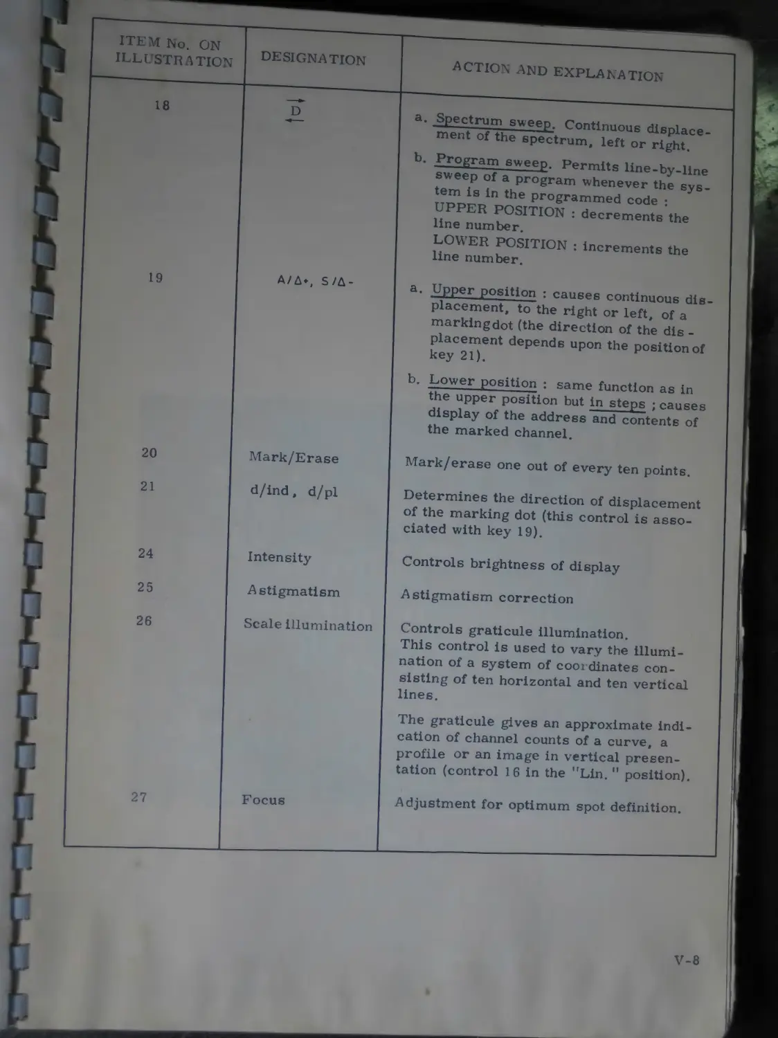
18
Spectrum sweep. Continuous displacement of the spectrum, left or right.
b. Program sweep. Permits line-by-line sweep of a program whenever the system is in the programmed code : UPPER POSITION : decrements the line number.
LOWER POSITION : increments the line number.
19
A/A*, S/A-
a. Upper position : causes continuous displacement, to the right or left, of a marking dot (the direction of the dis -placement depends upon the position of key 21).
b. Lower position : same function as in the upper position but in steps ; causes display of the address and contents of the marked channel.
20
Mark/Erase
Mark/erase one out of every ten points.
21
d/ind, d/pl
Determines the direction of displacement of the marking dot (this control is associated with key 19).
24
25
Intensity
Astigmatism
Controls brightness of display
Astigmatism correction
26
Scale Illumination
Controls graticule illumination.
This control is used to vary the illumination of a system of coordinates consisting of ten horizontal and ten vertical lines.
The graticule gives an approximate indication of channel counts of a curve, a profile or an image in vertical presentation (control 16 in the ”Lin. ” position).
27
Focus
Adjustment for optimum spot definition.
V-8
V. 2.9. CHARACTER GENERATOR (detailed)
The KA 106 Display Unit enables the display of alphanumerical characters simultaneously with the spectrum that is being viewed, thus giving permanently, and on the same screen, all information concerning the nature of the displayed signals along with an immediate validity test of the commands.
V. 2.9. 1. INFORMATION DISPLAYED IN THE IMMEDIATE MODE : given hereafter is a typical alphanumerical text display and a detailed description of each item.
2
5
6
: и tt
:: :5 z* t: ’z ” :• H •: - • И « H Z
— J -- .• z» u •. xi л •: n zz j- ~ •* тг :• t
iHlIllillIllIIIIllHI
ILLUSTRATION
EXPLANATION OF THE DISPLAYED INFORMATION
"Validity check" line
This line permits the validity of the instructions or parameters typed in from the interactive keyboard to be checked. The line can be erased from the keyboard program by the "Delete" com mand ; the line will not be erased if an error is detected upon execution.
Reserved for the display of error messages
Information defining the displayed region :
- Block number, initial channel, final channel.
Both this information and the commands are simultaneously up-dated, even during spectrum sweep commands.
- Code specifying the data presentation domain :
T Time domain
F Frequency domain
D Spectral density
M Magnitude/Phase.
Horizontal scale factors.
Vertical scale factors.
6
One of the following messages informs the operator of an acquisition which is not terminated :
+ N for an acquisition
+ Nn for an accumulation, n being the number of performed accumulations
+ l..t in the case of a histogram, t being the duration of the histogram since it was initiated.
Address and value of a marked channel.
This information : block No, channelNo , value, is displayed when the operator actuates the display key ( AM*, S /Д - ).
This line can also contain the value of the programmable variable zero, as a result of a request for functions such as display, averaging, standard deviation, peak area, etc. . .
This line is used for the display of any of the 63 programmable variables (VI to V63) after a display request.
The various parameters needed for the execution of keyboard are superimposed on the displayed image, directly below the afore-mentioned information.
V-10
У'щЛЛ/ ™F°RMATIONDISpLAYED IN THE PROGRAMMED MODE : while in Editing , the system does not perform the commands as they are called but stores them for subsequent execution.
It is es ei tial that the operator have a permanent visual presentation of the various lines of the keyboard program being edited. For this purpose only the character generator function of the KA 106 display unit is used.
The upper left-hand section of the screen then presents a "validity check" line, followed by the list of the stored commands displayed on a maximum of 12 lines. When the number of the program lines exceeds 12, the entire list is shifted upwards by one line.
The operator has the possibility to shift the displayed region at any time, towards either the beginning or the end of the program by means of the advance key provided on the KA 106 Display Unit ( A /, S / Д - ).
Following the storage of a new command, the last 12 program lines will be displayed.
V. 3. А-D CONVERSION
V. 3. 1. PARAMETER DEFINITION
V. 3. 1. 1. TIME-DOMAIN PARAMETERS : the sampling period is represented by A t and the sampling frequency by Fg (Fg = —L).
Consider a signal of bandwidth Ft\,| sampled at a frequency Fg. The figure below shows that the aliasing effect can be countered by taking Fg Э 2Fjvf. The frequency 2 Fpj is known as Shannon frequency.
Error due to abasing of spectrum
The practical sampling frequency should take into account this theoretical condition Fg > 2Fm and, possibly, the error allowed upon restoring the signal from its discrete samples.
V-U
C onsider, for instance, signal restoration through linear interpolation with low-pass filtering, applied to a pure sinusoid of frequency F : the sampling frequency must satisfy the condition Fs F . -2---2 ( 6 being the maximum
error allowed).
If = 1 %, then we must have F the Shannon frequency.
A record consists of a sequence of n samples, of duration T = n . At.
With FM representing the maximum frequency contained in the signal, the follow in CT PYnrOCC< ЛП 4 - дм
approximately 10 times
following expression is obtained : n sion of the Shannon theorem) ; n system.
s 2FM . T (which is a different expres-is variable (block size) in the PLURIMATS
n, At
Record duration
V. 3. 1. 2. FREQUENCY-DOMAIN PARAMETERS : the frequency resolution A f (frequency step) is the difference between two successive channels.
When n is the number of samples (block size), the spectrum extends from
0 to ( $ A f) in steps of At. Thus the maximum analyzed frequency will be :
Spectral density
The frequency resolution A f is directly related to the record duration T
Af
Example 1 :
10 seconds
“ .-Hz
Asa result, size n.
Af is directly related to the sampling frequency Fg and block
n . At
The analyzed frequency range extends from 0 to Fm =
Example 2 : if
then
and
e = 1 000 Hz and n : 1 024
f = * 99т- Hz, or approx. 0, 998
A V ТГ
max = 500 Hz.
NOTE : A step A f multiple or submultiple of the Hz can be obtained by selecting on the clock ( Af mode) a sampling frequency F»s close to Fs and given by the expression :
F’s = Fs x 1.024
which leads to :
if = 1 Hz and Fmax = 512 Hz.
n
<
The choice of parameters depends upon the purpose to be achieved :
. Maintaining a sampling period At ;
. Obtaining a frequency resolution Af ;
. Analyzing up to a maximum frequency F^ ;
. Using a record duration T.
The following Shannon relation should be adhered to in any case :
FS » 2Fm
which may require the use of analogue low-pass filters.
The following table can be used as a guide in the choice of the parameters, the block size n being variable (n is always equal to an integer power of 2, and its maximum value is limited by the chosen memory size).
Choice of rhe original parameter Parameter imposed by this choice Parameter depending upon size N
A t 1 FM - - 2 At Af - —— n At T = n At
Af 1 T = Af At = —1— n Af
FM At = —! 2 FM Af = n T = --- 2FM
T Af = —— T At = — N n 4 FM - — — 2 T
V. 3.2. CLOCK
The HT 135 clock times the PLURIMAT S sampling and conversion operations.
V 3. 2. 1 SAMPLING FREQUENCY : variable from 0.02 Hz to 1 MHz in the sequence 1 - 2 - 5 - 10 :
12-bit, 100 kHz sampling in performed using the CT 135 converter
(200 kHz sampling if display is cut-off).
Sampling at 1 MHz using the correlator.
V. 3. 2. 2. SAMPLING PERIOD : two modes of operation are available :
A t*; the sampling period is a multiple of the ^s ;
A f*: the sampling period is multiplied by , which allows
resolution to be a multiple of the Hz in the ’’frequency domain”,
V. 3. 2. 3. NUMBER OF INPUTS : the number of inputs can be selected from 1 to 64 (1, 2, 4, 8, 16, 32, 64) by means of a switch also including a position reserved for correlation (the product of the number of inputs by the sampling frequency should always be lower than 100 kHz),
V. 3. 2.4. TRIGGERING MODES
• Interna* syn5 : starts sampling at the first clock pulse which follows the acquisition ^’initialize” step.
* External sync : starts sampling in synchronism with an external 5-volt, 0-volt digital signal ; minimum duration : 1 у s (TTL compatible).
V. 3. 2. 5. EXTERNAL TRIGGER INPUT : allows the operator to condition the sampling through application of an external 0 to 5-volt digital signal (TTL compatible).
V. 3. 2. 6. EXTERNAL CLOCK : the sampling operations may be timed by an external clock. The product n x Fg (number of inputs multiplied by the sampling frequency) should be lower than 50 kHz in this mode of operation.
V. 3. 2. 7. STOP-AT-OVERFLOW : gives the possibility to stop an accumulation or histogram as soon as an overflow of the channel capacity occurs (on 16 or 24 bits).
Refer to V 3 1 2
Two modes of operation ДТ'. Time domain ДЕ. Frequency domain
Choice of the clock and of external or internal sync
External clock input
Frequency selection from 0,02 Hz to 1 MHz
Selection of the number of inputs| to be sampled (with one input for the correlator )
Stop - at-overf low
External trigger
External trigger input
External sync input
HT 135 CLOCK
V 16
V. 3.3. СТ 135 А-D CONVERTER
The СТ 135 converter performs the conversion of the analogue voltage provided by a sample-and-hold unit. Digitizing is done by successive approximations.
The А-D converter includes provisions for the selection of the number of sampling levels -- 64, 256, 1 024 or 4 096 -- the mode of operation - histogram, automatic, digitizing — with the following main features:
. Input : single-ended
, Input impedance : 5 k_CL shunted
by 4 5 pF
. Input level : + 2 V
. Sampling time : 5 /js of which 1 jus is used for the sample-and-hold unit and 4 ^s for the conversion.
CT 135
А-D CONVERTER * * - 'l
р------- conversion goin (Ch/2V)--1
---- ±32
л / -—±128
1512 >--- ± 2048
।-----------— mode------------ 1
— - • histogram
o."1—"— • auto
w
I------- num
r---------------input-------------1
pha
I sampling ta)
! Г
+w u
- 24V
V-17
Inputs for eight t 2V analogue signals
YT135
MULTIPLEXER
input channel
Selection of the mode of operation for each input - digitizing _ spare
- amplitude histogram
Expandability: up to 64 inputs through the use of 8 identical modules
8 16 24 32 40 48 56 64
Analogue output to be connected to the " Analysis " input of the CT 135 A-D converter
YT135 MULTIPLEXER
V. 18
V. 3,4. YT 135 ANALOGUE MULTIPLEXER
VT61 ЧА URIu!AT S permlts simultaneous scanning of up to 64 inputs Each 'kT 135 multiplexer ensures the multiplexing of up to 8 incuts Dirfti^ina 64 inputs therefore requires the use of eight multiplexers. g
V. 3.4. 1. LINKING SEVERAL MULTIPLEXERS : expandability is possible with up to 64 inputs. The ’’extension” mitn.it nf V • 3 possible
tv a ч •’ p Л exien6ion output of module m is connected to
the extension of module (m + 1).
The ’’amplif. ” output of the last module is
connected to the
converter input.
Linking three YT 435 multiplexers
a. Input routing : eight signals can be routed to each multiplexer, the inputs of which are numbered from 1 to 8 (modulo 8). Input zero will thus correspond to input No. 1 of the first multiplexer, input No. 1 to input No. 2 of the first multiplexer, etc.. . Input No. 21, for instance, will correspond to input No. 5 (21/8 = 2, remainder 5) of the third multiplexer. Each input should therefore be connected to the multiplexer input which has been assigned to it.
b. Scanning m selected signal inputs : the selected frequency will be the sampling frequency of each input, regardless of the number m of inputs selected on the clock unit. Scanning of the m inputs begins with signal input 0.
Frequency of
sampling cycles m -1
•— Input scanning
40 ps
Sampling
V-19
c- of the maximum sampling frequency as a function
oi the number of selected inputs : sampling at ths ?oo № " frequency is possible without multiplexer. But, since the time required by the multiplexer to switch from one input to the next one is 10 >s (9.76 jjs in the Af mode), the maximum sampling frequency in the internal clock mode will be :
Fs 100 kHz for one input
b's 50 kHz for two inputs
FS 25 kHz for four inputs
Fs 12.5kHz for eight inputs.
Fs 6. 25 kHz for 16 inputs
Fg 3. 115 kHz for 32 inputs
FS < 1. 5625 kHz for 64 inputs.
In the ’’external clock” mode, the product (m x Fs) should be lower than, or equal to 50 kHz.
The number of inputs selected on the clock module should always be higher than, or equal to the number of the last input actually scanned.
So, if 10 inputs are to be scanned, the channel*selector switch, on the clock module, should be positioned on ”16”.
Referring to the previously mentioned maximum sampling frequencies, it is advisable for the operator to assign the first multiplexer inputs to the input signals, in order to minimize the number of inputs to be selected.
d. Operation of the three-position switch provided for each input:
. FUNCTION 0 : No digitizing of an input signal may be performed when its corresponding function switch is in the position ”0”. Upon receiving the code of an input whose function is set to ”0”, the multiplexer returns ’’sampling disabled” signal to the HT 135 clock, thereby protecting the original contents of the corresponding memory block.
. FUNCTION + 1 : The result provided by the converter is considered as an address and the memory contents' corresponding to that address will be incremented by 1. The function switches of the inputs on which an amplitude histogram is to be performed, should therefore be positioned on ”+ 1”.
* In this context, the word "channel" refers to "input channel".
. FUNCTION + N : The result provided by the converter is considered as a content ; it is either stored at a core memory address, in the case of digitizing, or added to the preceding contents of the same memory address, in the case of accumulation. The function switches of the inputs on which digitizing (or accumulation) is to be performed should therefore be positioned on ” + N”
e* ^ТетогУ allocation of the sampling results : for simplification purpos s, all data obtained from the sampling process are stored in the acquisition memory blocks corresponding to the inputs that have actually been scanned.
Input No. 0 will be stored in block zero
Input No. 1 will be stored in block one
Input No. M will be stored in block m and this regardless of the size of said blocks.
Now, this shows that for a given block size it is not possible to request sampling of m inputs with a product (m x block size) that exceeds the size of the acquisition area. Consequently, a check is carried out whenever an acquisition is requested from the interactive keyboard.
NOTE : The operator should not modify the number of input channels after an acquisition has been initialized by means of the interactive keyboard, as long as that acquisition has not been terminated.
EXAMPLE : Study of the behaviour of a moving body during an impact. The memory body will be fitted with three accelerometers so that the movement along the x, у and z axes can be studied. Acceleration data are transmitted by radio to a receiver located near the PLURIMAT S. At an initial stage, let us consider the requirement that three input be digitized.
The number of selected inputs should be higher than, or equal to three. The selection of three channels not being possible, at least four channels must be selected. Asa result, the maximum permissible sampling frequency will be 100 : 4 = 25 kHz, or 25 kHz, or 20 kHz when operating in the internal clock mode.
The selected number of inputs being higher than the number of actual input signals, the operator has the possibility to connect those to the multiplexer, in any desired order.
Upon digitizing or accumulation, the operator must check that the function switches corresponding to the scanned inputs are positioned on ”+ N”, and that those corresponding to the inputs which are not investigated are positioned on "0”, in order to prevent results, saved in core memory, to be accidentally changed.
V-21
V.4. CORRELATION
V. 4.1. LT 135 HYBRID CORRELATOR
The LT 13 > hybrid correlator is a plug-in module, directly compatible with the HISTOMAT S and PLURIMAT S signal analysis system, with the fob lowing features :
. Real-time operation
. "Monocorrelation" mode
. ’’Multicorrelation'’ mode
: sampling frequency : — Hz to 1 MHz dU
: Cxx, Cyy autocorrelation functions and
Cxy cross correlation function
determines simultaneously Cxx, Cyy and Cxy thus leading to the coherence function.
V.4.1.1. COMPUTATIONAL SPEED : the LT 135 module enables successive, or simultaneous real-time autocorrelation or cross correlation of analogue signals. High-speed capability stems from the fact that the correlation points are computed in parallel with a maximum sampling frequency of 1 MHz.
V.4. 1.2. MODULAR DESIGN : a hybrid computation technique is implemented in the LT 135 correlator by means of special Integrated circuits (IC). Each IC performs the simultaneous computation of 8 correlation points. Grouping 8IC’s on the same board provides a sub-assembly which will handle 64 correlation points. Modular extension therefore allows for 256 - 512 - 1 024 - 2 048 .... correlation points to be implemented.
V. 4. 1. 3. SIMULTANEOUS FUNCTIONS : an essential feature of the LT 135 correlator is the possibility to carry out simultaneous operations (Intertechnique-Leti patent). Taking n as the number of correlation points -- 256, 512, .. . --one may obtain the following functions :
. Cxx or Cyy autocorrelation : asymmetrical ; computed on n points.
. Cxy or Cyx cross correlation : asymmetrical ; computed on n points ; positive lags.
. Cxy cross-correlation : symmetrical ; computed on n points ; positive and negative lags.
. ’’Multicorrelation” : Cxx on n/4 points ; Cyy on n/4 points ; Cxy (sym. ) on n/2 points.
Once acquisition has been carried out are can easily determine the normalized cross correlation and the coherence functions.
V. 4. 1.4. TIME-ORIGIN SHIFT : the input signal can be delayed by 64, 128, 256 or 512 points to shift the n computed cross correlation points. This arrangement permits the apparent capacity of the correlator (number of points to be doubled or quadrupled by performing two or four accumulations.
EXAMPLE : If n = 512 points, we can compute 1 024 points for the cross correlation function Cxy, 1 024 pointe for the cross correlation function Cxy.
LT 135 CORRELATOR
FUNCTION
_ Cx*
СУУ у 1 /Сух схх_ .
.. —
—Coherence
READ CONTROL
Gating clock
Gating interval
Time-origin shift
INTERNAL
100ms Is
25ms \ / Scope
EXTERNAL
64 П|8 256
О / 512
Ext. clock
Trigger
LT 135 HYBRID CORRELATOR
V.23
V.4.2. CORRELATION FUNCTION SELECTION
the desired correlation function can be selected by means of the "Function” selector switch.
a. " Cxx" position : Computation of 512 points of the autocorrelation
function Cxx = j _ x (t) x (t - r ) dt of the signal x (t).
The delay ? per channel is equal to the sampling period of
the HT 135 clock.
MEMORY ALLOCATION OF THE RESULTS :
Channel
Block size 512
Cxx (0) Autocorr. function value for 0 = (0 + n) т
Cxx (1) Autocorr. function value for 0 = (1 + n) т
Cxx (510) Autocorr. function value for 0 = (510 + n) т .
Cxx (511) Autocorr. function value for 0 = (511 + n) т
NOTE : The autocorrelation function Cxx can be delayed by n T , n being equal to 64, 128, 256 or 512 basic lags, depending on the positioning of the ’’Time-origin shift” selector switch.
b. ”Cyy” position : Similar to the position ”Cxx”, but for a signal у (t).
c. ”Cxy” position : Computation of 512 points of the cross corre-[ >oo
lation function Cxy = / x (t) у (t - т ) dt.
J - oo
The delay т of each channel is equal to the sampling period of the HT 135 clock.
NOTE : The cross-correlation function Cxy can be delayed by n т , n being equal to 64, 128, 256 or 512 basic lags, depending upon the positioning of the ’’Time-origin shift” selector switch.
MEMORY ALLOCATION OF THE RESULTS :
Channel
Block size 512
0
1
I 510
\ 511
Cxy (0) Cross corr. function value for 0 = (0 + n) т .
Cxy (1) Cross corr. function value for 0 3 (1 + n) т .
Cxy (510) Cross corr. function value for 0 3 (510 + n) r.
Cxy (511) Cross corr. function value for 0 = (511 +n) t.
d. "Сух" position : Similar to the position "Cxy" , with the difference being that the functional assignments of the x/ inputs are reversed.
e- ПРХУП (Sym) position: Computation of 256 points of the cross correlation function Cxy = J x (t) у (t - т ) dt in the first 256 channels of block zero, and 2 56 points of the c cross correlation f
cross correlation function Cyx = / * у (t) x (t - т ) dt in the last 256 channels of block zero.
NOTE : The use of the correlator in the latter mode allows the operator to determine the cross correlation function Cxy between - 256 т and + 256 t. Data reordering in block zero is performed by depressing the "Correl. ” key. If the timelag origin has been delayed, the cross correlation function continuity is no longer ensured when passing from positive and negative lags.
MEMORY ALLOCATION OF THE RESULTS PRIOR TO RECORDING :
Channel
Block size 512
0
1
254
255 2 56
257
510
\ 511
Cxy (0) Cross corr. function value for 6 = 0 т .
Cxy (1) Cross corr. function value for 0 = 1 т .
Cxy (254) Cross corr. function value for 0 = 254 r .
Cxy (255) Cross corr. function value for 0 = 255 т .
Сух (0) Cross corr. function value for 0 = 0 т .
Сух (1) Cross corr. function value for 0 = - 1 т .
Сух (254) Cross corr. function value for 0 = - 254 т .
Сух (255) Cross corr. function value for 9 = - 255 т .
MEMORY ALLOCATION OF THE RESULTS AFTER
RECORDING :
Channel
SO
1
254
255
size 512 | 256
510 \ 511
Cxy (0) Cross corr. function value for 0 = - 255 т .
Cxy (1) Cross corr. function value for 0 = - 254 т .
Cxy (254) Cross corr. function value for 0 = - 1т .
Cxy (255) Cross corr. function value for 9 " 0 т .
Cxy (256) Cross corr. function value for 9 = 1 т .
Cxy (510) Cross corr. function value for 0 = 255 т .
0
V-25
f- Coherence" position : Computation of 128 points of the auto-correlation function Cxx = / ’J x (t) у (t - r ) dt in the first j 28 channels of block zero, 128 points of the cross correlation function Cxy = I x (t) у (t - т ) dt in channels 128 to 255 of block zero, 128 points of the cross correlation function
Cyx y(t) x (t - т ) dt in channels 256 to 383 of block
zero, and 128 points of the autocorrelation function /♦CO y(t) у (t - т ) dt in channels 384 to 511 of block - 00 zero.
MEMORY ALLOCATION OF THE RESULTS PRIOR TO REORDERING :
Channel
0 1
* 126 127
I 128
I 129
I 254
Block 7 255 size 512 ] 256 2 57
382 383
I 384 385
‘ 510 \ 511
Cxx (0) Autocorrelation function value for Cxx 0 = 0 т .
Cxx (1) Autocorrelation function value for Cxx 0 = 1 т .
Cxx (126) Autocorrelation function value for Cxy 0 = 126 t.
Cxx (127) Autocorrelation function value for Cxx 0 = 127 t.
Cxy (0) Cross correlation function value for Cxy 0 = 0 т ,
Cxy (1) Cross correlation function value for Cxy 0 = 1 т .
Cxy (126) Cross corr. function value for Cxy 0 = 126 t.
Cxy (127) Cross corr. function value for Cxy 0 = 127 t.
Cyx (0) Cross correlation function value for Cyx 0 = 0 r .
Сух (1) Cross correlation function value for Cyx 0 = 1 т .
Cyx (126) Cross corr. function value for Cyx 0 = 126 т . Cyx (127) Cross-corr. function value for Cyx 0 = 127 т . Cyy (0) Autocorrelation function value for Cyy 0 = 0 t. Cyy (1) Autocorrelation function value for Cyy 0 = 1 t.
Cyy (126) Autocorrelation function value for Cyy 0 = 126 t.
Cyy (127) Autocorrelation function value for Cyy 0 = 127 t.
\ -26
AFTER REORDERING AND PROCESSING, and through the use of the “Correl. '* key, the coherence function Yx, у is obtained in the first 256 channels of block zero, as follows :
Channel
!0 Yxy(O) value of the coherence function, Tq
1 у (1) value of the coherence function, ST
254 yxy(254) value of the coherence function, Y254
255 Уху (255) value of the coherence function, Y255 2 56 \
257 1
-----> Null channels , 510 \
511 )
Each value of IT xy is given by the relation :
where Sxx, Xyy and Sxy are respectively the Fourier transforms of Cxx, Cyy and Cxy.
V. 5. DISCRETE SIGNALS
Discrete signals are analyzed by the YT 23 5 Multicounter which accepts digital signals (0, 4- 5 V) delivered by any of the following :
. HT 13 5 clock ;
. Peak detectors : ZT 212, ZT 214 ;
. Window discriminator.
V . 5. 1. YT 135 MULTICOUNTER
Pulse counting on two input channels with a counting rate of up to 5 MHz The PLURIMAT S allows connection of up to 8 multicounters.
INPUT SIGNAL :
- ’Start11 control ;
- "Stop” control ;
- "Counts” input.
The following three modes of operation are provided :
Mode A :
. The ’’Start" signal resets the counter to zero.
. The "Stop" signal determinates the counting sequence and causes a data transfer.
. The counter waits for the next "Start" signal.
Mode В :
. The counter is reset to zero as above.
. Each "Stop" signal causes the transfer of data, but counting is not interrupted.
Mode C :
. Single "Start/Stop" command, with resetting.
c YT 235
~ MULTICOUNTER
channel number
0 2 4 6 8 10 12 14
1 3 5 7 9 11 13 15
output control ext to clock
V-28
V. 6. DIGITAL I/O
The digital I/O functions are handled by the M 1604 board.
Signals can be easily routed to the M 1604, through the PLURIMAT S rear panel board including 32 Input and 32 output connectors.
V. 7. I/O SYSTEMS
V. 7.1. TELETYPE
The use of an A SR 33 Teletype is not necessary when the PLURIMAT S includes high-speed peripheral units such as an optical reader, magnetic tape or disc dri\e, arid is provided with the appropriate microprogrammed basic loader. The commands for the PLURIMAT S are called from the interactive keyboard and visually presented on the display unit. The information presented on the display unit can be printed on the Teletype which can thus be used as a system log book.
During ’’on-line’’ operation of the Teletype, printing of the various types of messages is authorized when the sense switch SI of the Multi-20 is in the lower position. The next paragraphs describe the type of information obtained.
V. 7. 1. 1. USING THE TTY IN THE IMMEDIATE MODE : suppose we want to reset all channels included between channels 121 and 1 022, in data block n° 2. ^-3)
CALLING SEQUENCE : Reset. 2, Space, 121, Space, 1 022, Exec.
Sample printout : RAZ : 2, 121, 1 022
Explanation of the printed message :
”RAZ 3-character mnemonic code of the function called from the
interactive keyboard
” : ” Separator
” 2 ” Number identifying the block to be reset.
”121” Number of the first channel to be reset.
”1 022” Number of the last channel to be reset.
Depressing the ’’Exec" key causes a TTY carriage return (CR) and a line feed (LF).
NOTE : Any error detected upon calling a command in the parameter input phase, will effect a CR and an LF followed by the printing of the message "Rxx", where "xx" is the error code (2 digits or two letters).
V. 7. 1.2. USING THE TTY IN THE EDITING MO by depressing the "Edit" key and causes the TTY
EDI
PTF 10
SUP
Echo checking line
i When changing over to the programmed mode, tn indicates to the operator the number of instructions aA ’ in the system (10 indicates the number of core-residen
Deletion oi the entire sequence previously written
Sample printout :
0 TAI 512
1 RAZ 2
2 DIG
3 LAB 5
4 SEM
5 FFT 0
6 SXX 0
7 + 2.0
8 SEM
9 FFT 1
10 SXX 1
11 2. 1
12 FIN BRA 5. 24
Program sequence formed by a series of basic instructions.
The following information is available on each line :
- line number
- 3 spaces along with the mnemonic code of the function called.
/
End of the sequence - returns the PLURIMAT S to the immediate mode of operation.
V. 7. 1.3. LISTING : printout of the whole or a part of the core-resident instruction (this implies that the PLURIMAT S is already in the programmed mode).
CALLING SEQUENCE : Output print, LI, Space, L2, Exec.
LI = first line to be printed
L2 •= last line to be printed.
V.7.1.4. DATA PRINTOUT EXAMPLES : p
a. Print the first 8 channels of a block of data stored in time domain rectangular coordinates :
TTY : 0, 0, 7
CAR - 2 TPS
0
4- 1379. +1974. +2428.
Echo checking line
Indicates the exponent
- 2 = IO-2; TPS = Time
Number of the first channel.
+2809 +3129.1 +3436.1 +3718. +3974.
where
+ 3436 = value of the 6th channel of the data block :
. relative value - 3436 -4
absolute value = 3436.10-2
V-30
V. 7.1.2. USING THE TTY IN THE EDITING MODE : this mode is obtained by depressing the ' Edit" key and causes the TTY to print the following : EDI Echo checking line
I When changing over to the programmed mode, the PLURIMAT S PTF 10 indicates to the operator the number of instructions already available in the system (10 indicates the number of core-resident instructions).
S( P Deletion of the entire sequence previously written.
Sample printout :
0 TAI 512
1 RAZ 2
2 DIG
3 LAB 5
4 SEM
5 FFT 0
6 SXX 0
7 + 2.0
8 SEM
9 FFT 1
10 SXX 1
11 4“ 2. 1
12 BRA 5. 24
FIN
Program sequence formed by a series of basic instructions.
The following information is available on each line :
- line number
- 3 spaces along with the mnemonic code of the function called.
End of the sequence - returns the PLURIMAT S to the immediate mode of operation.
V. 7. 1.3. LISTING : printout of the whole or a part of the core-resident instruction (this implies that the PLURIMAT S is already in the programmed mede).
CALLING SEQUENCE : Output print, LI, Space, L2, Exec.
LI = first line to be printed
L2 p last line to be printed.
V.7.1.4. DATA PRINTOUT EXAMPLES : Mb
a. Print the first 8 channels of a block of data stored in time -domain rectangular coordinates :
TTY : 0,0,7 Echo checking line
CAR - 2 TPS Indicates the exponent
- 2 = 10-2 ; TPS = Time
0 Number of the first channel.
+1379. +1974. +2428. +2809 +3129. +3436. +3718. +3974.
where +3436 = value of the 6th channel of the data block :
, relative value = 3436 hi-4
absolute value = 3436.10”^
V-30
b. Print the first 7 channels of a block of data stored in frequenc domain rectangular coordinates : in this case, an information actually consists of both real and imaginary parts. The value of the imaginary part will always be printed exactly under the real part.
TTY : o, 0, 6 Echo checking line
CAR - 3FRQ Indicates the exponent - 3 = 10*3 . FRQ : Frequency
0 Number of the first channel
+7235. +7173. +6994. +6701. +6305. +5815. +5249
-795. -1571. -2306. -2983. -3585. -4099
where +7235
+ 5815
- 3585
= value lower than 1 in relative value
= value of the real part of channel 5
= value of the imaginary part of channel 5.
c. Print the first 7 channels of a block of data stored in magnitude/ phase coordinates : in this case, an information consists of a magnitude and a phase 8. The value of the phase will always be printed exactly under the value of the magnitude.
TTY : 0, 0, 6 Echo checking line
CAR - 3 POL Indicates the - 3 = 10-3 j POL = Polar coordinates for the FFT.
0 Number of the first channel
+7234. +7217. +7168. +7087. +6975. +6831. +6659.
-630 -1262 -1898 -2538 -3182 -3816
where +6975
-2538
- value of the magnitude of the fourth channel
= value of the phase of the 4th channel in 1/100 of a degree.
d. Print the first 8 channels of a block of data stored in rectangular coordinates.
TTY : 0, 0, 7 Echo checking line
CAR - 2 SXX Indicates the exponent - 2 = IO"2 ; SXX = Spectral density
0 Number of the first channel.
+ 5234. +5207. +5138. +5022. f-4864. +4666. +4434. +4170.
V-31
e. Print the first 6 channels of a block of data stored in semi-logarithmic coordinates : the 0 dB reference is taken relative to the maximum channel of the designated block.
TTY : 0, 0, 5 Indicates the exponent
CAR -3 +17191DB TPS - 3 = IO*3 + 17191 = absolute reference value for the computation of the decibels. DE = semi-logarithmic coor -dinates TPS = time.
0 Number of the first channel.
+ . -20. -80. -176. -316. -496.
where -176 = value of the attenuation, in 1/1000 dB, of channel 3 with respect to the absolute maximum of the designated block.
NOTE : Whenever the data block is in the "frequency” domain, the imaginary part of each channel is printed under the real part, and its value is also expressed in 1/1000 dB. But, when the data block is in the "magnitude and phase" domain, the magnitude is expressed in 1/1000 dB, and the phase 0, expressed in hundredths of a degree, is printed under the value of the magnitude.
f. Print the value of a PRV (mantissa - exponent) : ллл ..
CALLING SEQUENCE : Print V (I), VI, Exec, where VI is the PRV number.
The following information is then printed on the TTY :
PNV : 2 Echo checking line
V2 = 7368 E - 17
where V2 = PRV number
7368 = Mantissa
- 17 = Exponent (10-17)
V-3
V. 7.2. PUNCHED TAPE I/O OPERATIONS v| C
Total or partial output of a data block on punched tape is readily available through appropriate kej 'oard commands, Computation or acquisition results can thus be saved for later use.
V. 7.2.1. EXAMPLES OF USE
a. Punch data block 0
CALLING SEQUENCE : Punch, 0, Exec.
b. Punch block 1, from channel 100 to channel 200
CALLING SEQUENCE : Punch, 1, Space, 100, Space, 200, Exec.
c. Read Into block 0 : data punched in the PLURIMAT S format can be read and stored in a memory block, under keyboard command.
CALLING SEQUENCE : Read, 0, Exec.
d. Read into block 1, between channel 100 and 200
CALLING SEQUENCE : Read, 1, Space, 100, Space, 200
This command string allows storage of data, from paper tape, into memory block 1 starting with channel 100 and up to channel 200.
If the number of values n recorded on punched tape is lower than 100, they will be stored in core from channel 100 and up to channel 100 4- n.
If the number n is higher than 100, the first hundred values recorded on the tape will be stored in core from channel 100 to channel 200.
When the recorded data words are 3 bytes long, the system must be set in the 3-byte mode upon reading, otherwise an error condition is created. This also applies to data words consisting of two bytes.
о о о
о о
о о о о о
О о
О о
о
О о
О О
О о
О О
О О °О
ООООО ° ООО О0ООО оООО
о
О ОО
О о
ООо о
о
о о о о о
о '
о о
О оОО о
ОО О
О О
ОО
О оо
О О
О о
О о о о ООО ОО оОО
О о о ОО оО ОО О о о
ОО оООО
О о О ООО
о ОО оо о о ° ОО
OQ о
ОО о оо ОО О ОО о
о о °о
о о
о о
о о
о о
о о
о о
о о
о о
о о
о о
о о
о о
о о
о о
о о
о о
о о
о о
о о
о о
о о
о о
о о
о
о о
- Level 8
- Level 6_7
- Level 5
- Level 1.4
Leader
Leader/ Trailer
Not used within a record Controls print suppression Contain a hexadecimal digit
Separator ( 2 rubouts)
1 Blank frame
Record mark (value of 2328 )
Block exponent on four by^es
Record size recorded on 2 bytes (value of 6 )
Word length, a data word can be 2 or 3 bytes long (value of 6 )
First data channel \
Second data channel! Third data channel [ Fourth data channel i
Fifth data channel
Sixth data channel
Channel contents (data words) can be stored as 2. byte or 3. byte words ; here we have used four frames per channel i e 2 _byte format as indicated by th e "word I eng th ”
1
I
। least significant bits —
nO
_______________________ 2 or
___ ________________________2 1 or
____________________________________ 2 2 or
_________________________________23 or
most significant bits
2 4
25
26
2 7
PAPER TAPE FORMAT
DETAILED DESCRIPTION
CHAPTER VI
OF THE FUNCTIONS
VI. 1. INTRODUCTION
The various functions have been grouped according to the position of the corresponding keys on the interactive keyboard.
. Display.
. Input/Output.
. Acquisition.
. Format.
. Programmable variables (PRV).
. Harmonic analysis.
. Logical and arithmetical operations.
. Editing, programming and execution functions.
VI-1
V I. 2. DISPLAY FUNCTIONS
V I. 2.1. PARTIAL OR TOTAL BLOCK DISPLAY................ . . ^Rect.^
Two modes of operation correspond to the display command.
V I. 2. 1. 1. DISPLAY THE ENTIRE BLOCK :
CALLING SEQUENCE : Rect., Nl, Exec.
where Nl is the block number.
If Nl is omitted, block zero will be displayed.
Intensification operations will affect block Nl.
V I. 2. 1.2. DISPLAY A GIVEN BLOCK SLICE :
CALLING SEQUENCE : Rect., Nl, Space, C2, Space, C3, Exec, where Nl is the block number,
C2 the first channel of the area to be displayed, C3 the last channel of the area to be displayed.
If Nl is omitted, block zero will be displayed ;
if C2 is omitted, the first channel displayed ;
if C3 is omitted, the last channel to be displayed will be the last channel of the designated block.
If the operator depresses the "Exec" key immediately after having called channel C2, the final channel will be taken as equal to the last channel of the block.
By varying the number of displayed channels (X-format selector) and by modifying the area to be displayed, any part of the data block can be expanded (refer to the description of the display unit).
Intensification operations will affect the displayed part of block Nl.
1-2
V I. 2. 2. CHANGE-OVER TO REAL AND IMAGINARY COORDINATES........................................... ** P<lar
he Polar control permits a complex signal contained in one of the system blocks to be displayed in the p, 0 form (Nyquist plot).
CALLING SEQUENCE : Polar, Nl, Exec.
Nl being the block number.
If Nl is omitted, block zero will be displayed.
Following the above-mentioned command string, it is necessary to place the corresponding switch in the ’’Nyquist" position on the display unit.
The data previously contained in block Nl are lost ; it is not possible to return to rectangular coordinates after the display of a "Nyquist" plot.
Intensification of an area is not possible when the switch is in the "Nyquist" position. If continuous displacement of the marking dot is authorized by the operator, the displayed curve will be erroneous.
A block included in the Nyquist plot cannot be transferred. The result of such a transfer would be erroneous.
V I. 2. 3. CONVERSION FROM RECT. TO POLAR COORDINATES. ..
The above-illustrated key is used to compute the magnitude and phase ( O) as a function of the real and the imaginary parts of a data block.
CALLING SEQUENCE : ° / <P , Nl, Exec.
Nl representing the block number.
If Nl is omitted, block zero will be converted to polar coordinates.
At the end of the operation, and if block Nl is displayed, the magnitude and phase will have respectively replaced the real part and the imaginary part.
In order for the function to be significant, it should be performed on a spectrum located in the frequency domain rectangular coordinates.
The phases are represented in hundredths of a degree between - ” and + t or directly between - 18 000 and + 18 000.
Intensification operations will affect block Nl upon program halt.
VI-3
V I. 2. 4. CONVERSION FROM POLAR TO RF.CT. COORDINATES . . *Clear P/o
This key is used to compute the real and imaginary parts of any block, from the magnitude and phase information.
C ALLING SEQUENCE : Clear Q, Nl, Exec.
Nl being the block number.
If Nl is omitted, block zero is converted to rectangular coordinates
At the end of the operation, if block N1 is displayed, the real and imaginary parts of the spectrum will have respectively replaced the magnitude and phase.
In order for the function to be significant, it should be related to a frequency spectrum in polar coordinates.
This is the reverse of the operation called by means of the р/ (P key.
Intensification operations will affect block Nl upon program halt.
VI -4
V I. 3. INPUT-OUTPUT FUNCTIONS
V I. 3. 1. PARTIAL OR TOTAL BLOCK PRINTOUT .............^Print^
Three modes of operation correspond to the ’’Print” control (sense switch SI on the Multi-20 should be in the lower position).:
V I. 3. 1. 1. PRINT THE ENTIRE BLOCK :
CALLING SEQUENCE : Print, Nl, Exec.
Nl being the block number.
If Nl is omitted, block zero will be printed.
Intensification operations will affect block Nl, upon program halt.
V I. 3. 1. 2. PRINT THE BLOCK PORTION STARTING WITH CHANNEL C2 :
CALLING SEQUENCE : Print, Nl, Space, C2, Exec, where Nl is the block number and C2 the first channel to be printed.
If Nl is omitted, block zero will be printed, if C2 is omitted, printing of block Nl starts with channel zero.
Intensification operations will affect block Nl, upon program halt.
V I. 3. 1.3. PRINT A GIVEN BLOCK SLICE :
CALLING SEQUENCE : Print, Nl, Space, C2, Space, C3, Exec, where Nl is the block number,
C2 the first channel to be printed, and C3 the last channel to be printed. If Nl is omitted, block zero will be printed, if C2 is omitted, channel zero will be printed first, if C3 is omitted, the last channel to be printed will be the last channel of block Nl.
Intensification operations will affect block Nl, upon program halt.
Teletype printing is effective only when the Multi-20 sense switch SI is in the lower position and the Teletype is energized. The operator thus has a possibility to stop data block printout at any time by returning SI to the upper position.
VI-5
VI. 3. 2. WRITE ON PAPER TAPE
......................... Punch
Two modes of operation correspond to the "Punch" control (on high or low speed unit). b
VI. 3. 2. 1. WRITE THE ENTIRE BLOCK :
CALLING SEQUENCE : Punch, Nl, Exec. Nl being the block number.
If Nl is omitted, block zero will be punched.
Intensification operations will affect block Nl, upon program halt.
VI. 3. 2. 2. WRITE PART OF A BLOCK :
CALLING SEQUENCE : Punch, Nl, Space, C2, Space, C3, Exec, where Nl is the block number,
C2 the first channel to be punched, and C3 the last channel to be punched. If Nl is omitted, block zero is punched, if C2 is omitted, the first channel to be punched is channel 0, if C3 is omitted, the last channel to be punched is the last channel of the block.
If the operator depresses the ’’Exec. ” key immediately after having called channel C2, the final channel will be the last channel of the block.
Intensification operations will affect block Nl upon program halt.
V I. 3. 3. READ FROM PAPER TAPE.........................^Read**
Two modes of operation correspond to the "Read" control (on high or low speed unit).
V I. 3.3.1. READ THE ENTIRE BLOCK :
CALLING SEQUENCE : Read, Nl, Exec.
where Nl designates the block in which data are to be stored.
If Nl is omitted, the data will be entered into block zero.
The system enters data into the block to the extent of either the block size or the number of channels recorded on the punched tape.
Intensification operations will affect block Nl, upon program halt.
V I. 3. 3. 2. READ PART OF A BLOCK :
CALLING SEQUENCE : Read, Nl, Space, C2, Space, C3, Exec.
where Nl is the block into which data must be entered,
C2 the first storage channel,
and C3 the last storage channel.
If NI is omitted, da.ta will be stored in block zero,
if C2 is omitted, the first storage channel will be channel zero,
if C3 is omitted, the last storage channel will be the last channel of the block.
Storage in block Nl will always begin with the first channel recorded on the paper tape.
Intensification operations will affect block Nl, upon program halt.
V I. 3. 4. TOTAL OR PARTIAL BLOCK PLOT
X-Y Record
Two modes of operation correspond to this command.
V I. 3.4.1. PLOT THE ENTIRE BLOCK AND ALL OF THE ALPHANUMERICAL TEXT :
CALLING SEQUENCE : X-Y Record, Nl, Exec.
Nl being the block number.
If Nl is omitted, block zero will be plotted.
Block Nl will be displayed and intensified upon program halt.
V I. 3.4. 2. PLOT PART OF A BLOCK AND THE ALPHANUMERICAL TEXT :
CALLING SEQUENCE : X-Y Record, Nl, Space, C2, Space, C3, Exec, where Nl is the block number,
C2 the first channel to be plotted,
and C3 the last channel to be plotted.
If the operator depresses the "Exec. ” key immediately after having called channel C2, the final channel will be the last channel of the block.
Upon program halt, the block portion involved in a ’’plot" command is displayed on the CRT screen and intensified.
A given curve can be plotted simultaneously with the acquisition and processing operations, provided the latter do not concern the block to be plotted.
V I. 3. 5. MAGNETIC TAPE FORMATTING.................^Tape Format
The following describes how a magnetic tape can be formatted in order to store spectra for subsequent processing.
asically, users may store information in the form of program (Basic -Fortran, etc. ) and information in the form of spectra (data blocks) on the same magnetic tape.
The magnetic tape usually consists of an ordered sequence of data blocks which can be directly called by their respective numbers. Consequently, it is necessary to create an initial recording, when using a blank tape, in order to ensure subsequent addressing of each block.
CALLING SEQUENCE : Tape Format, Nl, Const., m, Exec.
where Nl is the number of the block in which (intensification operations will be carried out upon program halt, and m the maximum number of blocks to be stored onto magnetic tape : 0 < m < 16 383.)
If N L is omitted, the intensification operations will affect block zero, if m is omitted, the number of stored blocks will be zero.
Formatting is only possible between the be ginning-of-tape (ВОТ) mark and the end-of-tape (EOT) mark. This permits a magnetic tape to be divided into several record areas.
An error will be indicated when the EOT mark is encountered before the formatting procedure has been completed. This does not require that the whole procedure be repeated, but simply that the magnetic tape be manually set on the ВОТ mark.
« »
V I. 3. 6. WRITE ON MAGNETIC TAPE ................... Mag. Output
This function permits a data block stored in core memory to be written on magnetic tape for subsequent utilization.
CALLING SEQUENCE : Mag. Output, Nl, Space, N2, Exec.
where Nl is the memory data block number,
and N2 the rank of the magnetic tape block in which block Nl is to be written : 0 < N2 < 16 383.
If Nl is omitted, data block zero will be written on the magnetic tape, if N2 is omitted, data block Nl will be written in magnetic tape block zero.
Intensification operations will affect block Nl, upon program halt.
NOTE : It is advisable for the operator attempting to write several data blocks on magnetic tape, to use mag. tape blocks that are contiguous or at least very close to each other, in order to avoid an ever-increasing loss of time, caused by repeated tape winding and unwinding operations.
VI-8
VI. 3. 7. READ FROM MAGNETIC TAPE
Mag.
Input
This function allows one to read a data block from magnetic tape and to store it in a designated core memory block.
CALLING SEQUENCE : Mag. Input, Nl, Space, N2, Exec.
uheie Nl is the core memory block number
and N2 the data block to be read from magnetic tape.
If N1 is omitted, block N2 will be stored in core memory block zero.
If N2 is omitted, the magnetic tape block zero will be stored in core memory block Nl.
Upon program halt, the intensification operations will affect block Nl.
NOTE : Prior to reading several data blocks from magnetic tape, it is advisable for the operator to have originally written these data in ma:, tape blocks that are contiguous or at least very close to each other, in order to avoid an ever-increasing loss of time, caused by repeated* tape winding and unwinding operations.
VI. 3. 8. INPUT FROM KEYBOARD........................Keyboard
VI. 3. 8. 1. GENERAL : the above command permits keyboard-controlled data input to core memory blocks. Three cases are possible, depending upon how the input data are defined :
a. Time domain. In this case, data are in the form of constants ranging from - 16 383 to + 16 383.
b. Frequency domain. With real part and imaginary part presentation. In this case, data words will each include a real part -- to be stored into the first block half -- and an imaginary part which will be stored in the second block half.
c. Frequency domain. With magnitude and phase presentation. Data words will each include magnitude information in the form of a constant ranging from - 16 383 to + 16 383, and phase information expressed in hundredths of a degree.
VI. 3.8.2. PERFORMANCE : can be divided into two stages .
\ First stage * concerns the input of the lollowing parameters .
The number of the storage block selected for the input .
The number of the first channel to be loaded .
The number of the last channel to be loaded.
• The block exponent expressed as a power of 10 ranging from - 38 to + 39.
VI- 9
. A code, d, corresponding to the selected domain i e : d = 0 lime
d = 1 Frequency - real, imaginary
d - 2 Frequency - magnitude, phase.
Upon the calling sequence : Keyboard, Nl,
The TTY prints
CHAR
MOD
Space, Cl, Space, C20, Exec and the operator must reply e. Exec, d. Exec.
where Nl is the block number,
Cl, the initial channel,
C20, the final channel,
e, the block exponent as a power of 10,
d, the code corresponding to the selected domain,
and CHAR is printed by the system as a request for the exponent value, MOD, as a request for the domain code.
B. Second stage, concerns the input of data. The first stage being completed, the system prints the number of the first channel to be loaded, i.e. :
a. TIME DOMAIN
Printout
Cl
C2 + 1
i t
। t
C20
Operator ’s reply
kl, Space
k2. Space
f I t
I
k20, Exec.
b. FREQUENCY DOMAIN — real and imaginary parts.
Printout
Operator’s reply
Cl
C20
kl, k2,
I
Real
k20.
Space, si , Space
Space, s2 , Space
; Imaginary
Space, s20 , Exec.
। ।
c. FREQUENCY DOMAIN — magnitude and phase.
Printout Ope1S- ГРРЙ
C1 kl, Space, si, Sp^ce
* f ’ f
» I . I
t magnitude t phase
r20 k20, Space, s20 Exec.
where к and s are constants.
T-’O
If XI, Cl are omitted, they are taken equal to zero,
if C20 is omitted, it is taken equal to the last channel of the block, if e, d are omitted, they are taken equal to zero.
Please note that depressing the "Exec.” key causes the keyboard input function to stop.
This command is valid only in the immediate mode of operation.
V I. 3. 9. ENABLE DIGITAL OUTPUT........................T Dig. Output^
This command is used for the output of from 1 to 16 independent digital pulses of 50 p s duration (5 V, 0 V) on bytes 3 and 4 of the 32-input/32-output board.
CALLING SEQUENCE : Dig. Output, Bi, Space, Bj,---------, Bk, Exec,
where Ei, Bj, Bk represent the bit positions -- in the 16-bit word-- to be activated.
If Bj, Bj, Bj- = 0, bit 0 will be activated.
The digital level input/output possibilities provide the PLURIMAT S with increased flexibility in the control of an experiment, since they permit digital levels and, consequently, digital states to be tested and activated in on-off control systems.
VI-i I
V I. 4. ACQUISITION FUNCTIONS
V I. 4. 1. SINGLE ACQUISITION............................... « - ,ono »
The Mono" key is used for the А-D conversion and storage of signals, ^rigina ir t оь one or several inputs, in one or several data blocks depending upon the parameters selected on the acquisition modules (YT 135 Multiplexer, HT 135 Clock, CT 135 А-D Converter).
CALLING SEQUENCE : Mono, Exec.
Acquisition starts either immediately when operating in the "internal sync" mode (clock module), or after the first sync signal has been received on the "external sync" input when operating in the latter mode.
[Acquisition ends when the number of points stored in the data block is equal to the block size.
The system is considered as being free during the time required for the acquisition operation, and the operator may call any command that does not involve the acquisition section.
The intensification operations will affect block zero at the end-of-acquisition except if the operator has specified -- after the ’’Mono” command -- the number of the block in which intensification is to take place, and if he has not modified the display parameters during the acquisition operation.
V I. 4. 2. RECYCLED ACQUISITION..........................^Recycle
The ’’Recycle” key is used for the А-D conversion and storage of signals, originating from one or several inputs, in one or several data blocks depending upon the parameters selected on the acquisition modules.
CALLING SEQUENCE : Recycle, Exec.
Acquisition starts either immediately when operating in the ’’internal sync” mode (clock module), or after the first sync signal has been received on the "external sync” input when operating in the latter mode.
Acquisition ends when the number of points stored in the data block equals the block size, and is then initialized again in the same conditions (particularly for synchronization).
The total operation ends when the operator depresses the ’’Halt-' key.
The system is considered as being free during the time required for the acquisition operation, and the operator may call any command that does not involve the acquisition section.
The intensification operations will affect block zero when the recycled acquisition is stopped, except if the operator has specified -- a tei he R‘ cy< le command -- the number of the block in which intensification is to take place, and if he has not called other functions during the acquisition operation.
VI-12
VI.4.3. ACCUMULATION * v
The Л ’ key is used for the A -D conversion and accumulation of signals originating from one or several inputs, in one or several data blocks depending upon the parameters selected on the acquisition modules.
Accumulation can be performed either on 15-bit words, or on 23-bit words
VI. 4. 3.1. ACCUMULATION WITHOUT PRIOR CLEARING OF THE CORRESPONDING AREA :
CALLING SEQUENCE : Z , Space, m. Exec.
m being the number of successive accumulations to be performed.
If m is omitted, the number of accumulations will be equal to 1.
If the operator depresses the "Exec, ” key immediately after having depressed the ” Z ” key, the number of accumulations will be arbitrarily set to 16 383.
Accumulation can be stopped in three different ways :
. Through a preset count (1 to 16 383 accumulation cycles) ;
. By depressing the ’’Halt” key ;
. By using the ”stop-at-overflow” feature.
VI. 4. 3. 2. ACCUMULATION WITH PRIOR CLEARING OF THE CORRESPONDING AREA
CALLING SEQUENCE : £ , Space, m. Space, 0, Exec, m being the number of accumulations to be performed.
If m is omitted, the number of accumulations will be equal to 1.
Accumulation can be ended as described in the preceding paragraph.
The system is considered as being ’’free’’ during the time required for the accumulation, and the operator may call any command that does not involve the acquisition section.
The intensification operations affect block zero when the accumulation is stopped, except if the operator has specified --after the ” Z ” command— the number of the block in which intensification is to take place, and if he has called other functions during the accumulation operation.
VI-13
VI. 4.4. PING-PONG OR CONTINUOUS ACQUISITION . . . Cont.
VI. 4. 4. 1. IN TRODUCPION : (continuous acquisition's one of the most important functions of the PLURIMAT S, since it actually controls the simultaneity of the A - D conversion of one or several analogue signals, the processing and the output operations. Such a simultaneity requires the processing and transfer times to be compatible with those of the data acquisition.
Continuous acquisition requires the use of a multiplexer and operates as follows : when this mode of operation is initialized, acquisition begins in a first subgroup (or block) ; when this subgroup is full the А-D conversion function is automatically switched to the next subgroup. When this second subgroup is also full, the А-D conversion function is re-switched to the first subgroup and so on . . . (Ping-Pong acquisition).
Each time the acquisition is switched to either one of the two subgroups, an interrupt is sent to the computer, in order to enable synchronized acquisition and processing operations.
In this mode, each mulbiplexer can handle only four inputs ; ping-pong operation is restricted to even inputs (0, 2, 4, 6 for each multiplexer).
M.4.4.2. SETTING UP A CONTINUOUS ACQUISITION ;
analogue signals to be digitized can be received either directly from detectors, or after having been conditioned by optional amplifiers and filters. The first input signal should be applied to input 0 of the multiplexer, the second to input 2 and so on
n the continuous” mode of operation, the “+ 1, 0, + N “
it c s should be placed in the position “+ N“ for the even channels (0, 2, 4, 6), and in the “0“ position for the odd channels (I, 3, 5, 7), on each multiplexer.
b. Select the conversion gain (6 to 12 bits).
c. Select tne sampling frequency (same as for acquisition). The following two requirements should be taken into consideration when selecting the sampling frequency :
. The product of the number of inputs to be digitized and the sampling frequency should not exceed 100 kHz ;
. The sampling frequency should be compatible with the times required for the processing operation to be carried out on each acquisition subgroup.
d. Select the number of inputs (same as for acquisition).
e. Select the sampling mode (same as for acquisition).
f. Preset count stop : this switch is meaningless in the “continuous” mode.
g. Select the sync mode :
. The ’internal sync” mode will generally be used in continuous acquisition ;
. In the “external sync” mode, subgroup changeover could only be triggered bu the application of a sync signal.
h. External trigger : the sampling can be conditioned by an externally applied digital signal.
“External Trigger” selector switch set to “without” : the sampling ignores signals that would be applied to the corresponding BNC connector ;
“External Trigger” selector switch set to “with” : the sampling is condifioned'by'tJie'presence'of'a'Jigital'signal (0 V) on the corresponding BNC connector.
NOTE : the “external trigger” can actually be used as a first synchronization for the continuous acquisition, but the digital signal must then be maintained throughout the А-D conversion phase.
\ 1-15
i. Simultaneity of the processing and continuous acquisition operations . the continuous acquisition, or ping-pong acquisition, is of interest to the extent w here processing operations can be performed during such an acquisition. This is the leason why the "continuous acquisition" function will always be used within a keyboard program stored in the PLURIMATS. All the PROCESSING operations available in the PLURIMATS can be performed during the continuous acquisition :
Transfer to magnetic tape or disc for delayed processing ; - Power spectrum accumulation ;
- Study of the variation of a power spectrum ;
- Guidance of missiles, etc.
THE FOLLOWING KEYBOARD PROGRAM ILLUSTRATES A POWER SPECTRUM ACCUMULATION :
Block size Reset Cont. Label Mait mode FFT Sxx + Wait mode FFT Sxx + Loop Rect.
512
Accumulation block (Block 2 for instance) Continuous acquisition 7
Wait for end-of-acquisition
Block 0
Block 0
2, 0
Wait for end-of-acquisition
Block 1
Block 1
2, 1
7, 20 times
Block 2.
j. Command string.
FIRST, check that the various controls are correctly positioned, in the following sequence :
. Sampling frequency ;
. Number of channels ;
. At or Af mode ;
. Internal, external clock ;
. Internal or external sync ;
Input switches on ’’+ N" or "0" ;
Input cable connection ;
With or without external trigger.
THEN, initialize the acquisition from the interactive keyboard (generally in the programmed mode) by depressing the following keys :
Cont. , Exec.
\ 1-16
' \ : The continuous acquisition
embedded tn a sequence of the follow in ; type :
command is usually
FLOW CHART
TIMING
♦ N in rhe blocks of even rank
♦ N in the blocks
of odd rank
♦ N in the blocks of even rank
Wait mode
Processing in blocks of even rank
Wait mode
Processing in blocks off odd rank
The '’Continuous'1 mode requires synchronism between acquisition and processing. Processing times should be shorter than acquisition times so that the system is always in the wait mode when acquisition changes over from the blocks of even rank to the blocks of odd rank -- and vice versa -• If not, an error message is sent and continuous acquisition is stopped.
t c pSmAT S m acquisition is not initialized within a program, the PLl RIMAT b will not be in the wait mode ("Free" indicator light glowing) upon change-over from, say, odd to even blocks, thus leading to an error condition. *
V I. 4. 5. AMPLITUDE HISTOGRAM...................*Amp. Histo.
This command permits an amplitude histogram to be built up from one or on the acquisition either 15-bit or
several inputs, depending upon the parameters selected modules. The amplitude histogram can be performed on 23-bit words.
V I. 4. 5. 1. AMPLITUDE HISTOGRAM WITHOUT PRIOR CLEARING OF THE STORAGE AREA :
CALLING SEQUENCE : Amp. Histo. , Space, T, Exec.
wnere T represents the time in seconds required to perform the histogram.
If T is omitted, the histogram will last 1 second.
If the operator depresses the “Exec” key immediately after the "Amp. Histo” key, the histogram will last 16 383 seconds.
The histogram can be stopped in three different ways :
. Through preset time selection (from 1 to 16 383 seconds) ;
. By depressing the "Halt" key ;
. By using the stop-at-overflow feature.
V I. 4. 5. 2. AMPLITUDE HISTOGRAM WITH PRIOR CLEARING OF THE STORAGE AREA :
CALLING SEQUENCE : Amp. Histo., Space, T, Space, 0, Exec, where T represents the time required to perform the histogram.
If T is omitted, the histogram duration will be 1 second.
The system is considered as being free during the time required for the acquisition, and the operator may call any command that does not involve the acquisition section.
The intensification operations affect block zero when the histogram is stopped, except if the operator has specified -- after the "Amp. Histo. " command -- the number of the block in which intensification is to take place, and if he has not called other functions during the count operation.
1-13
The 'Digit" command is used for the input of from I to 16 logic levels (negative logic) corresponding to bytes 3 and 4 of the 32 input/32 output
Г ’ 1 Л°т ЛП.е result of such a logic configuration is stored in the
programmable variable VO.
S=Q“EKCE = “git. El. Space. B,. Space. ..... Bk. Exec. ' 1 f н b L ’* represent the bit positions -- in a 16-bit data word. The lolloping value will be stored in the PRV VO :
Vo = 2Bi. ( 1) + 2Bj . (^) + 2Bk. (1) .
the matrix (q ) teing equal to 1 or 0, depending upon the state of the cor responding bit.
If Bi, Bj, Bfc = 0, the value of bit 0 will be stored
EXAMPLE : To test a configuration of four digital inputs connected to bits 0, 3, 7 and 12 of byte 4 :
15 14 | 13 [ 12 11 10 9 8 7 6 | 5 | 4 3 П? | 1 | 0
4 bits to be tested
CALLING SEQUENCE : Digit, 3, Space, 0, Space, 7, Space, 12, Exec. If the bits 3, 0, 7 and 12 are in state 1, the following value will be found in V0 :
V0 = 8 + 1 + 128 + 4 096 = 4 233.
V I. 4. 7. HALT THE ACQUISITION
Halt
Simply depressing the "Halt" key enables the operator to stop : . A recycled acquisition ;
. An accumulation ;
. An amplitude histogram ;
. A continuous А-D conversion.
In the case of an acquisition, accumulation or continuous А-D conversion, the current acquisition proceeds up to the block end. In the case of a histogram, the latter halts immediately.
V I. 4. 8. RESTART THE ACCUMULATION (or HISTOGRAM) .... Restart Depressing the ’’Restart” key enables the operator to restart an accumulation (or histogram) that has been previously stopped by means of the ’’Halt” key.
I -19
V I. 4. 9. SELECT THE CORRELATOR.................................ТсоггЛ
This program is used in connection with the LT 135 Hybrid Correlator, which is a standard peripheral unit of the PLURIMAT S. Two different processing operations may be carried out, depending on the position of the control knob located on the front panel of the LT 135 :
• ГЧ/х" positions : no processing is performed.
. ’’CxyjSym)” position : the PLURIMAT S enables acquisition or accumulation of the Cxy cross correlation function in the first 256. points, and of the Cyx function in the remaining 256 points. The above-mentioned program -- the routine corresponding to the "Corr. ” key -- reorganizes the data so that the Cxy cross correlation function may be represented from - 256 to + 2 56 , provided that no time delay has been preset.
. ’’Coherence” position : the PLURIMAT S authorizes the acquisition or accumulation of :
128 points of the Cxx autocorrelation function ;
128 points of the Cxy cross correlation function ;
128 points of the Cyx cross correlation
128 points of the Cyy autocorrelation function.
The various correlation functions can be rearranged for the determination of the coherence coefficients. Upon program halt, the system is automatically positioned on a block size equal to 256.
The function [Sxy ( 09 )]~ and the function [Sxx (<•>) • Syy ( a>)] arerespec-tively available in block zero and in block one. All the operator has to do, is to carry out the division of block zero by block one to obtain the coherence coefficients.
NOTE 1 : The program should be initialized with the system block size set to 512.
NOTE 2 : Upon program halt, the system block size is 256 if the control knob is set to ’Coherence”.
CALLING SEQUENCE : Corr. , 0, Exec.
The above-mentioned command string is necessarily executed using block zero which is the only subgroup available for the А-D conversion of the signals delivered by the correlator.
The intensification operations affect block zero, upon program halt.
VI. 4. W. WAIT FOR THE END OF CURRENT ACQUISITION . . *Wait Mode : ThC PLL^MAT|S- V* "free" V hen the s> stem is performing an acquisition apCUh2 , 1О1ПяГ J " hich means that operations other than acquisition
can be cairied out. The Wait Mode" command is used to delay the next operation until acquisition is terminated
The, Jode comt«and should be systematically used in the programmed mode after a unique acquisition, accumulation or histogram instruction, to prevent the system from beginning the processing operations as long as acquisition is not terminated.
During a continuous acquisition, the PLURIMAT S should go to the wait mode each time an end-of-block interrupt is generated -- upon subgroup changeover.
CALLING SEQUENCE : Wait Mode, Exec.
VI. 4.10.1. EXAMPLE OF ALPHANUMERICAL TEXT DISPLAY :
' Spectral density accumulation from portions (or) slices of input signals :
0 TAI 512
1 RAZ 1 0 511
2 LAB 1
3 AU 0
4 SEM 0------------------------Wait for the end of the current
5 FFT 0 acquisition before performing
6 SXX 0 the transform
7 + 0 0
8 JMP 1
Program 2 : Spectral density accumulation with no loss of information :
0 TAI 512
1 RAZ 2 0 511
2 DIG 0
3 LAB 0
4 SEM 0_________________ Wait for end-of-acquisition on the
5 FFT 0 subgroups of even rank, before
6 SXX 0 starting to process them.
7+20
8 SE 0 __________________ Wait for end-of-acquisition on the
9 FFT 1 subgroups of odd rank, before
0 Sxx 1 starting to process them.
11 + 2 1
12 JMP 0
^1. 5. FORMA T SELECTION FUNCTIONS
VI. S.l DATA BLOCKSIZE...................................«ВЮек Size
, "whteh '°r °< >b« »Ue ot data blocks (or subgroups)
on which ths acquisition and processing operations will be carried out.
the PLCR.MAT A g, t“CU°n ?'"dee ,he "«isltlon and processing area of ine FLLHl MAT S into m subgroups of identical length.
The block sizt snould be an integer power of 2
CALLING SEQUENCE : Block Size, 5, 1, 2, Exec.
The above command string causes the acquisition and processing area to be divided into subgroups, and the visual display to encompass the total acquisition area.
If the new subgroup size is lower than the preceding one, there will be an extension of the exponent to the new subgroups.
If the new subgroup size is higher than the preceding one, there is no rearrangement of the exponent, the information available in the acquisition area being generally no longer significant.
VI. 5. 2. SELECT 3-BYTE WORD LENGTH.............................^3 Bytes>:>
The purpose of the "3 Bytes” command is to extend system precision to 3 bytes and to initialize it for the acquisition, accumulation, histogram and a number of processing operations. The data format is then of 22 bits + 1 sign bit + 1 intensification bit. The display unit is also initialized in the 3-byte mode throughout the acquisition area.
The resultii g mode of operation is generally used for the accumulation and histogram operations.
The stored data are not modified (blocks and exponents).
CALLING SEQUENCE : 3 Bytes, Nl, Exec.
Nl being the number of the block to be intensified upon program halt.
If Nl is omitted, block zero will be intensified.
The acquisition areas are identical for operation on 2 or 3 bytes.
List of the processing operations authorized in the 3-byte mode :
. Total or partial block display ;
. All input/output operations ;
. All acquisition operations ;
. Block transfer, permute and reset.
The change-over to 3 bytes suppresses the intensification of the marked points.
X I. 5. 3. SELECT 2-BYTE WORD LENGTH................ 2 Bytes^
. le purpose of the, 2 Bytes command is to reduce system precision to
}tes and to reinitialize it for acquisition, accumulation, histogram and all processing operations. The data format is reduced to 14 bits + 1 sign bit + intensification. The display unit is reinitialized in the 2-bvte mode throughout the acquisition area.
The stored data are rearranged according to a 2-byte format, the number of rearrangements being stored in the exponent.
CALLING SEQUENCE : 2 Bytes, Nl, Exec.
Nl being the number of the block to be intensified upon program halt. If Nl is omitted, block zero will be intensified.
If the operator changes the system over to 3 bytes and returns it again to 2 bytes without having performed any intermediate processing operation, he will recover his data — unmodified --in the 2-byte mode.
VI. 5.4. SELECT PRV OPERATION............................ V(I)
The "V (I)” command is used to indicate that the operations are being performed on one or two programmable variables (PRV’s) and not on data blocks.
The calling sequence :
+, Nl, Space, N2, Exec.
will add block Nl to block N2 ;
and the calling sequence :
+, V(I), n, Space, m. Exec.
7 л. /" Ц •
will add the Vn to Vm.
OPERATING ON programmable variables
e P I, IM S acquisition and processing operations concern mainly a a oc s which can be stored on 15 or 23 bits, depending upon the selected format.
As a result, operations concerning a large number of data (for instance, multiplication of a 1024-point block by a constant ; Fourier transform on 1024 points, etc. . .) can be controlled through a single command.
However, it is sometimes necessary to have the possibility to isolate a value belonging to a block, to include it in a particular sequence - -to compute for instance, the maxima of a curve -- or to modify one or several elements of a block -- for instance, to study the behaviour of the spectral density between two boundaries.
To achieve this, the PLURIMAT S performs the processing operations on a set of 64 PRV’s numbered from 0 to 63. Each PRV is represented in floating-point arithmetic with 16 bits for the mantissa and 8 bits for the exponent.
The accuracy of the results is the same whether the operations are performed on PRV’s or on blocks.
V I. 6.1. EXCLUSIVE PRV FUNCTIONS
V I. 6. 1. 1. ASSIGN A FLOATING-POINT CONST. TO A PRV ..^Assign V(I)>:>
The calling sequence :
Assign V{I), m. Const., 1000, Space, 2, Exec.
where : m = PRV number with 0 < m <63 1000 = mantissa 2 = exponent
will cause the constant 1000.102 to be assigned to the variable Vm. Also, the sequence :
Assign V(I), m, Space, 200, Exec.
will cause Vm 3 200. 10°, and the sequence :
Assign V(I), m. Exec.
will cause Vm 3 0.
A floating-point constant cannot be assigned to V(I) in the programmed mode.
Data -*V(I)
^(I)> 30, Space, 2, Space, 100, Exec.
V I. 6. 1.2. TRANSFER DATA INTO A PRV he calling sequence :
Data—। where 30 = PRV No.
2 B Block No.
100 e Channel No.
Lauses variable V 30 to take the value contained in channel 100, block 2. stride mlMed Paranieter19 taken equal to zero. For instance, the command *3 LX XXI er ,
Data—*V(I), Exec.
will automatically cause V0 to equal the value contained in channel 0, block 0. With this loading operation, the mantissa of the variable will take the exact va ue of the channel contents, and the exponent will become that of the block to which the channel belongs.
VI. 6. 1.3. TRANSFER A PRV INTO A CHANNEL..........* V(I)—- Data *
The calling sequence :
V(I) —►Data, m, Space, 3, Space, 100, Exec.
where m = PRV No.
3 = Block No.
100 = Channel No.
will transfer variable Vm into channel 100, block 3.
If the value of the variable to be transferred is very much higher then the maximum value of the receiving block, the latter will be normalized, with the risk of total information loss when the difference between the two values exceeds 2^.
In the case where the variable Vm is very much lower than the block maximum,Vm is normalized.
VI. 6. 1.4. DISPLAY THE CONTENTS OF A PRV....... Print V(I)
The contents of a given PRV can be either printed on the TTY -- sense switch SI, located on the Multi-20 front panel, is down -- or viewed on the Ki 106 display unit -- with S2 down.
CALLING SEQUENCE : Print V (I), m, Exec.
where m is the PR numbei.
If the display is requested, the value will remain displayed until the next command is called for.
' I. 6. 2. OTHER FUNCTIONS INVOLVING PRV s.
VI. 6.2.1. ARITHMETICAL FUNCTIONS :
a. Addition. The calling sequence :
aram., m, Space, n. Exec.
adds Vn to Vm, the result being put in Vm.
Any missing parameter is implicitly taken equal to z.erb. he addition of a constant ranging from - 16 383 to
+ 16 383 will go as follows :
+ , Param., m,, Const. 123, Exec whereby 123 is added to Vm
b* Subtraction. The calling sequence :
- , Param. , m, Space, n, Exec, subtracts variable Vn from variable Vm, the result being contained in Vm. And the calling sequence ;
Param., m, Const., 123, Exec, subtracts constant 123 from variable Vm, the result being contained in Vm.
c. Multiplication. The calling sequence :
x. Param. , m, Space, n, Exec.
will multiply variable Vm by variable Vn, the result being contained in Vm. And the string :
x. Param., m, Const., k. Exec.
multiply a variable Vm by a constant к ranging from - 16 383 to + 16 383.
d. Division. The calling sequence :
+ , Param. , m, Space, n, Exec.
will divide variable Vm by variable Vn, the result being contained in Vm. Also, division of a variable Vm by a constant к may be called for via the following string :
+ , Param., m, Const., k, Exec.
e. Square root. The calling sequence :
V , Param., m. Exec.
computes the square root of the variable Vm -- the
result being stored in Vm — with the following rules :
V - x2 = - \Лх^ = - |x|
and V x^ = + x
Absolute value. It can be determined through the following lx I , Param., m, Exec.
I 1 . Л t _ -X_
string . । । ^ param., m, Exec.
whereby the absolute value of Vm is stored in Vm.
If Vm is omitted, the absolute value of variable VO is con -
sidered.
£»• Logarithm. The calling sequence :
Log. , Param., m, Exec.
computes the base 10 logarithm of variable Vm, the result being stored in Vm.
h. Sine. The calling sequence :
Sin. , m, Exec.
computes the sine function of variable Vm, the result being stored in Vm.
1. Cosine. The calling sequence :
Cos., m, Exec.
computes the cosine function of variable Vm, the result being stored in Vm.
IMPORTANT : The Sine and Cosine functions being particular to the processing of variables, it is not necessary to depress the ’’Param. " key after the "Sin. " or "Cos. function has been called.
VI. 6. 2. 2. ASSIGN TO A PRV THE CONTENTS OF ANOTHER PRV.......................................... Assign V(I)
The calling sequence :
Assign V(I), Param. , m, Space, n. Exec.
will cause the contents of variable Vm to be stored in variable Vn.
VI. 6. 2. 3. SPECIAL FUNCTION ASSIGNED TO VARIABLE VO :
The result of a computation such as average, standard deviation, integral and peak area, is automatically stored in variable VO.
7 1-27
м. 7. harmonic analysis
VI. 7.1. FAST FOURIER TRANSFORM "* *
transform of any given^locV411681 COmputatton of the fast Fourier CALLING SEQUENCE : FFT, Nl Exec where Nl is the block numhpr mu- »* are lost). ’ results are stored in Nl (original data
If Nl is omitted, the operation will be performed on block zero.
Hi°the^time domain S^iflcantl U must be performed on a data block located in reoMnlT Je reSUlt iS always obtained in the frequency domain
--in rectangular coordinates.
The intensification operations affect block Nl. upon program halt.
Actually, the real part, i.e. (n/2 + 1) points -- when counting the de component - is displayed in the first block half, immediately followed by (n/2 - 1) points of the imaginary part, with n = block size.
The imaginary parts of the de component and of the highest frequency are not being displayed.
V I. 7. 1. 1. FOURIER TRANSFORM OF A "COMPLEX” BLOCK : if the FFT operation is applied to a block of "frequency domain" data, the PLURIMATS will compute the Fourier transform with the assumption that the real part of the complex signal was even (symmetrical), and the imaginary part odd (antisymmetrical).
NOTE : Two consecutive FFT operations applied to the same signal s (t), lead to an identical signal which is reversed in time.
V I. 7. 2. INVERSE FAST FOURIER TRANSFORM
FFT'1
The "FFT-1" key is used to request the inverse Fourier transform of any given data block.
CALLING SEQUENCE : FFT-1. Nl, Exec.
where Nl is the block number.
If Nl is omitted, the operation will be performed on block zero, he result is stored in block Nl and the original data are lost.
For the FFT’1 to be significant, it must be performed on a data block located in the frequency-domain rectangular coordinates.
The intensification operations affect block Nl upon program halt.
When computing the Inverse Fourier transform, the PLURIMAT S assumes the real part of the complex signal to be even (symmetrical), and the imagi-nary part to be odd.
If block Nl is in polar coordinates upon performance of an FFT'J «Peration’ conversion to rectangular coordinates will automatically be carried out at the beginning of the FFT”1 routine.
VI-28
W. 7. 3. HAN xing WINDOW «
rp, . . .................... Ho Window
and channel Ьу^аппе!^^^6^^ЬУ ти1иР1У1п6 " ln the time domain у cnannei -- the signal by the function :
the following function31”’ corre8ponds to a convolution operation using
М2
Ml* ML
CALLING SEQUENCE : Ho Window, Nl, Exec, sll being the block number.
If Nl is omitted, window correction is done on block zero and the corrected block Nl is displayed at the end of the operation.
For the window correction to be significant, it should be performed on a spec*rum stored in frequency-domain rectangular coordinates.
This function is equivalent to a low-pass filter in the time domain.
Intensification operations will affect block Nl, upon program halt.
V I. 7. 4. CENTRED HANNING WINDOW........................<<: Hl Window^
This key performs window correction by multiplying --in the time domain and channel by channel -- the signal by the function :
(1/2 - 1/2 cos (2 7i t/T))
In the frequency domain, this corresponds to a convolution operation using the following function :
♦ 1/2
-1/4 -1/4
CALLING SEQUENCE : Hl Window, Nl, Exec.
No. being the block number.
If Nl is omitted, window correction is done on block zero.
Intensification operations will affect block N 1 upon program halt.
In order to be significant, window correction should be performed on a spectrum stored on frequency-domain rectangular coordinates.
VI-29
Sxx
VI. 7. 5. POWER SPECTRAL DENSITY
given block^sp^ctral^derTsity^r'magnttude^quared)1?1'^ den6U* °f апУ
\LLING SEQUENCE : Sxx, Nl, Exec.
Nl being the block number.
If \1 is omitted, the operation will involve block zero.
omputation of the power spectral density consists in multiplying a block у ts complex conjugate. The power spectral density is displayed in block Nl at the end of the operation.
In order to be significant, the operation should be performed using a data block stored in frequency-domain rectangular coordinates.
Intensification operations will affect block Nl, upon program halt.
power spectral density of
Exec.
VI. 7. 6. CROSS POWER SPECTRAL DENSITY
The ”Sxy" key is used for computing the cross any two given blocks.
CALLING SEQUENCE : Sxy, Nl, Space, N2, where Nl and N2 are the block numbers.
If N2 is omitted, the cross power spectral density will be computed using block Nl and block zero.
If Nl is omitted, the cross power spectral density will be computed using block zero and block N2.
Computation of the cross power spectral density consists in multiplying block Nl by the complex conjugate of block N2. Block N2 remains unchanged at the end of the operation, and the cross power spectral density is displayed in block Nl.
For the operation to be significant, it should be performed using data blocks stored in the frequency-domain rectangular coordinates.
Intensification operations will affect block Nl , upon program halt.
VI-30
VI. 7. 7. AUTOCORRELATION.
h -3 key is used to compute thp « ........ XX
in any given data block U Ocorre^a^on function of a signal stored
CALLING SEQUENCE : Cxx. Nl Exec
where Nl is the block number '
zerJ.1S °mitted’ the autocorre^tion function will be computed using block
Results are stored in block для i ,
the operation is performed as follows 1П 8иттагУ-
ь muT0" °f the F°Urier ‘reform of block Nl
t on)1 °f N1 ЬУ ltS C°mpleX COnju^ate e- magnitude
VA vJL I J 9
computa-
С.
v-omputation of the inverse Fourier transform of block Nl obtain the autocorrelation function
in order to
In order to be significant, the operation should be performed on time -domain data blocks.
VL 7. 7. 1. FLOWCHART :
VI. 7. 7. 2. EXAMPLE OF THE Cxx FUNCTION OF A SQUARE PULSE : The autocorrelation function is displayed at the end of the operation and takes then the following form :
The first half of the spectrum represents the autocorrelation functionfoi positive lags, the second half, for negative lags.
VI-31
I he autocorrelation funct*
a number of channels equaTtoCentred b>’ shifting block Nl through autocorrelation function n 2 ” supposing n is the block size. The refer to the subsequent tov+?S the following ^rm (’’shift*' function,
ntensitication operations will affect block Nl, upon program halt.
VI. 7. 8. CROSS CORRELATION.................................<< Cxy >>
' ey is used g compute the cross correlation function of one data block with another.
CALLING SEQUENCE : Cxy, Nl, Space, N2, Exec.
where Nl and N2 are the block number.
f 1 is omitted, the cross correlation function will be computed using block 0 and block N2.
If N2 is omitted, the cross correlation function will be computed using block Nl and block 0.
At the end of the operation block N2 remains unchanged and the crosscorrelation function is stored in block Nl ; data initially stored in block Nl are lost.
The cross correlation function is computed in the following manner :
a. Computation of the Fourier transforms of block and block N2.
b. Multiplication of Nl by the complex conjugate of block N2.
c. Computation of the inverse Fourier transforms of block Nl and block N2. In order to be significant, the operation should be performed using timedomain data blocks.
• 8. 1. FLOWCHART
Intense iication operations will affect block Nl, upon program halt.
VI. 7. 9. CONVOLUTION..........................................Con vol.
This key is used to compute the convolution of a block by any other block.
CALLING SEQUENCE : Convol. , Nl, Space, N2, Exec.
where Nl and N2 are the block numbers.
If Nl is omitted, block 0 will be convolved with block N2.
If N2 is omitted, block Nl will be convolved with block 0.
In the above command string, block N2 remains unchanged and the convolved function is displayed in block Nl in a manner identical to the display of the autocorrelation and cross correlation functions. The convolution function is computed in the following manner :
a. Computation of the Fourier transforms of block N2 and block Nl.
b. "Complex” multiplication of block N2 by block Nl.
c. Computation of the inverse Fourier transforms of block N2 and block Nl.
In order to be significant, the convolution operation should be performed using time-domain data blocks.
The flowchart is identical to that of the cross correlation function, but instead of carrying out a conjugate "complex" multiplication between the spectra located in blocks Nl and N2 , a simple complex multiplication is being performed.
Intensification operations will affect block Nl, upon program halt.
VI-33
рг. Г. 10. DEMNITION OF THE SMOOTHING OPERATION . . Smooth. Type >:> ach smoothing function is defined by a number from 0 to 5, and by an odd number of coefficients -- up to 11.
CALLING SEQ. ; Smooth, type, n, Space, Const. , ml. Space, Const. , m2. . .....................Space, Const. , mj, Exec.
where n is the programmed filter number, and mj , the coefficient.
If n is omitted, the constants are taken equal to zero.
This command is valid only in the immediate mode of operation.
Please note that the command string must be terminated with "Exec. ".
VI. 7. 11. SMOOTHING FUNCTION
Smooth.
Five digital filters can be set up and used in the PLURIMAT S system. Each filter can include 3, 5, 7, 9 or 11 coefficients.
Computation of the smoothing function on a block of_I elements : Let i be the number of the current channel.
Ai, content of the filtered channel i
Di, content of the unfiltered channel i m , number of coefficients of the filter mj, a coefficient of the filter
Y = M - 1
If i < (M/2 - 1) and i > I - (M/2 - 1)
then Ai 3 Di
If (M/2 - 1) i < I - (M/2 - 1)
Then Ai = mj . Di - (Y/2-j) j = 0
CALLING SEQUENCE : Smooth., Nl, Space, n, Exec, where Nl is the block number and n the filter number 0 n 4
When omitted Nl and n will be taken equal to zero.
VI-34
VI. 7. 1 2. BLOCK SIZE REDUCTION *
This function will store the aver» J............ PX°C SlZe
single channel. Let us consider tlfe consecutive channels in a
and a data format reduction of атпНтнГ^"® Signal sampled at lnstant И
°"IUQ6
t'o t'1
The first point will be given by :
N't'o = Nt0 + N*1 + Nt? + №3 + Nt4
5
The second, by :
Nt, Nt5 + Nt6 + Nt7 + Ntg + Nto
1 = ---------------------------— ' , etc.. .
5
up to the end of the considered block.
The original channel contents are being regrouped towards the beginning of the block and the remaining channels are zeroed.
CALLING SEQUENCE : Block Size Reduc. , Nl, Const, m, Exec.
where Nl is the block number
and m the amplitude of the reduction.
If Nl is omitted, the reduction will be performed on block zero.
If m is omitted, the reduction will be ineffective.
Intensification operations will affect block Nl, upon program halt.
VI-35
V L8, —?ICAL AND arithmetical operations.
V I. 8.1. DIGITAL DISCRIMINATION «
_. ..... ................ Level Reduc.
The purpose of the "Level " <
- — ’ a certain level chosen 'relative to tie° С1ваГ Я channel if its contents ьеп relative to the maximum channel contents in
Nl, Const., к, Exec.
are below the block.
CALLING SEQUENCE : Level Reduc where Nl is the block number, and к the level of discrimination relative to the maximum value contained in Nl ; any channel having a magnitude lower than Block Max wU1 be cleared If Nl is omitted, the block number will be zero, if к is omitted, the operation will not be performed.
If block Nl is in rectangular coordinates, the maximum will be equal to the absolute value of the larger channel contents.
b ( cfc is in irequency-domain coordinates, magnitude/phase or spectral densit mesentation, the maximum will be taken equal to the maximum magnitude.
the operation will not be performed.
rectangular coordinates, the maximum will be equal to the
If block Nl is in frequency-domain coordinates (real and imaginary parts), the computation is erroneous, and will also be erroneous in logarithmic presentation.
Intensification operations will affect block Nl, upon program halt.
V I. 8. 2. PROGRAMMED HISTOGRAM............................Prog. Histo. *
The ’ Prog. Histo. " function is used to compute in a given block the amplitude histogram of a set of data stored in another block. The number of classes over which the histogram is distributed should be lower than the block size by an integer power of 2.
CALLING SEQUENCE : Prog. Histo., Nl, Space, N2, Space, m, Exec, where Nl is the number of the block in which the histogram is built up, N2 the number of the block on which the histogram is to be performed, m the number of classes to be determined.
If Nl is omitted, the operation will be performed in block zero, using data from No.
If N2 is omitted, the operation will be performed in block Nl, using data from block 0.
If m is omitted, an error will be echoed.
NOTE 1 : Nl should be different from N2.
NOTE 2 • It is possible to accumulate indefinitely in block Nl. In case of overflow/the corresponding channel will be cleared. Thus, the histogram will be obtained as modulo 2^.
VI-36
\ I. 8. 3. ADDITION AND SUBTRACTION «
The above two keys have tha described. 8ame characteristics and are simultaneously
V I. 8. 3. 1. OPERATION INVOLVING TWO BLOCKS : CALLING SEQUENCE : + or Nl с where Nl and N2 are the two block number^' The operation is performed on block Nl If Nl is omitted, block N2 will be added to block zero stored in block zero.
If N2 is omitted, block zero will be added to block Nl stored in block Nl.
and the result will be
and the result will be
n о de • 3 obtain a significant result, both Nl and N2 should refer to the same domain (time or frequency). If one of the blocks is in polar or loga-r cooidinates, the result is meaningless.
Intensification operations will affect block Nl, upon program halt.
V I. 8. 3. 2. OPERATION INVOLVING A BLOCK AND A CONSTANT :
CALLING SEQUENCE : + or -, Nl, Const., k, Exec.
where Nl is the block number,
and N2 the constant to be added.
If Nl is omitted, N2 will be added to block zero.
If N2 is omitted, zero will be added to block Nl.
The constant к ranges from - 16 383 to + 16 383.
Intensification operations will affect block Nl, upon program halt.
V I. 8.4. MULTIPLICATION.................................... * x
The ”x” key is used for the multiplication, channel by channel, of one block by any other block, or for the multiplication of each channel of a block by a constant.
V I. 8.4. 1. OPERATION INVOLVING TWO BLOCKS :
CALLING SEQUENCE : x, Nl, Space, N2, Exec.
where Nl and N2 are the two block numbers.
If Nl is omitted, block zero will be multiplied by block N2.
If N2 is omitted, block Nl will be multiplied by block zero.
The result of the operation is stored in Nl. Block N2 remains unchanged.
In order to obtain significant results, Nl and N2 must refer to the same domain (time or frequency).
Intensification operations will affect block Nl, upon program halt.
NOTE : If N2 ” Nl, the square of block Nl will be obtained.
VI-37
X I. 8, 4. .. OP1 .RATION INVOLVING A BLOCK AND A CONSTANT
C?LLIn? SEQUENCE ' x* N1- Const., к Exec where Nl is the block number, and к the constant.
If N 1 is omitted, block zero will be multiplied by к If к is omitted, block Nl will be entirely cleared.’
The constant к ranges from - 16 383 to + 16 383.
Intensification operations will affect block Nl, upon program halt,
V I. 8. 5. DIVISION.................... «
e a< 11 ’ vs u e °Perator to divide, channel by channel, a block by any )ther block, or to divide each channel of a block by a constant.
V I. 8. 5. 1. OPERATION INVOLVING TWO BLOCKS :
CALLING SEQUENCE : + , Nl, Space, N2, Exec.
where Nl and N2 are the two block numbers.
If Nl is omitted, block zero will be divided by block N2 ;
if N J is omitted, block Nl will be divided by block zero.
The result of the operation (N1/N2) is stored in Nl.
Block N2 remains unchanged.
In order to obtain significant results, Nl and N2 must refer to the same domain (time or frequency).
Intensification operations will affect block Nl, upon program halt.
V I. 8. 5. 2. OPERATION INVOLVING A BLOCK AND A CONSTANT :
CALLING SEQUENCE : +, Nl, Const., k. Exec.
where Nl is the block number,
and к the constant.
If Nl is omitted, block zero will be divided by к ;
if к is omitted, block Nl will be entirely cleared.
The constant к ranges from - 16 383 to + 16 383.
VI-38
VI. 8. 6. AVERAGING... « _ >:
1 wo different operations are related tr. -•—.< ....
is alway. stored into the programmable ™паы. ~~1«
VI. в. 6. .. OPERATION INVOLVING THE ENTIRE BLOCK i
CALLING SEQUENCE : m, Nl Exec where Nl is the block number. ' If vl is omitted, block zero is selected
'Vo t' ,he - printed »n the TTY
ith the Multi-20 sense switch Si in the lower position - and intensi fication operations will affect block Nl. intensi
In addition, the result will be presented on the visual display unit.
VI. 8. 6. 2. OPERATION INVOLVING A PORTION OF THE BLOCK : CALLING SEQUENCE : m, Nl, Space, C2, Space, C3, Exec where Nl is the block number,
the initial channel, / both determine the portion
C3 the final channel \ of interest, in block Nl
If Nl is omitted, block zero is selected ;
if C2 is omitted, the initial channel will be channel zero ;
if C3 is omitted, the final channel will be channel zero.
If the "Exec. " key is depressed immediately after C2, i.e. in place of "Space", channel C3 will be considered equal to the last channel of the block.
Upon program halt, the result is printed on the TTY, provided sense switch SI is in the lower position, and is presented on the visual display unit.
Intensification operations will affect block Nl, upon program halt.
<k »
VI. 8. 7. STANDARD DEVIATION.............................. °
Two different operations are related to the " " key. The result is always
stored into the programmable variable VO.
VI. 8. 7. 1. OPERATION INVOLVING THE ENTIRE BLOCK
CALLING SEQUENCE : , Nl, Exec.
Nl being the block number.
If Nl is omitted, block zero is selected.
Upon program halt, the value of the standard deviation is printed on the TTY, provided the Multi-20 sense switch SI is in the lower position, and 1S presented on the visual display unit.
l„t.o.ille.uon operations »Ш a«.« block Nl. upon program halt.
OPERAT.ON INVOLVING A PORTION OF THE pEOCK .
SEQUENCE; N1 c_ „„ _ BLOCK .
C3, Exec.
If Nl
if C3
If the
having entered the value C2 channel C3~wiH be
CALLING
where Nl is the block number °PaCe' C2, сз“: t ~™,„. th.
1. «mined. bloetX ,e\:';T"‘-ln ыоск m
IS omitted, the initial channel win ь» u
is «mined, .be oha„Z'tn^“TlT ‘
«peea.ee depr.ese. .be "Exec. ” key l„s,e.d ot th. k.y
channel of the block. ~ considered equal to the last
X ь S°u7„ the reeu!'“ ₽Hn"d “TTY- -»
.«Uch SI th. poslUon> a„d ls pr.sa„,.d on the viEual d.eplay
Intensification operations will affect block Nl, upon program halt.
V I. 8. 8. AREA COMPUTATION
Two different instructions correspond to the ” stored in the programmable variable VO.
/ »
................. J Value
Value” key. The result is
V I. 8. 8. 1. OPERATION INVOLVING THE ENTIRE BLOCK : CALLING SEQUENCE : / Value, Nl, Exec.
Nl being the block number.
If Nl is omitted, block 0 is selected.
Upon program halt, the value of the area is printed on the TTY, provided the Multi-20 sense switch SI is in the lower position, and is presented on the visual display unit.
Intensification operations will affect block Nl, upon program halt.
V I. 8. 8. 2. OPERATION INVOLVING A PORTION OF THE ELOCK :
CALLING SEQUENCE : Value, Nl, Space, C2, Space, C3, Exec.
where Nl is the block number
C2 the initial channel / both determine the portion of
C3 the final channel ( interest, in block Nl.
If Nl is omitted, block 0 is selected ;
if C2 is omitted, the initial channel will be channel zero ;
if C3 is omitted, the final channel will be channel zero.
operator depresses the "Exec. " key immediately after having entered the final channel will be considered equal to the last channel
If the
the value N2
of the block.
Upon program
Tr holt the result is printed on the TTY, provided the sense
XhPs7.7?n“ •l«“r"o=1U«n. and is pr«s.n..d on .be e.xna. d.np.nynn...
I„te„.ineatlon operations w.ll affe«. block Ni. upon program halt.
VI. 8. 9. PEAK .AREA COMPUTATION
»
Peak
Two different instructions correspond to the " Peak" key.
\I. 8. 9. I. PEAK AREA COMPUTATION IN AN ENTIRE BLOCK :
C ALLING SEQUENCE : / Peak, Nl Exec Nl being the block number.
If Nl is omitted, block 0 is selected.
C * ' comPUtation is over, the value of the peak area will be printed on e , provided the Multi-20 sense switch SI is in the lower position, a d is piesvnted on the visual display unit.
ei i i nation operations will affect block Nl, upon program halt.
V I. 8. 9. 2. PEAK AREA COMPUTATION IN A PORTION OF A BLOCK :
CALLING SEQUENCE : j Value, Nl, Space, C2, Space, C3, Exec, where Nl is the block number
C2 the initial channel / both determine the portion
C3 the final channel \ of interest, in block Nl
If Nl is omitted, block 0 is selected ;
if C2 is omitted, the initial channel will be channel zero ;
if C3 is omitted, the final channel will be channel zero.
If the operator depresses the ’’Exec. ” immediately after having entered the value C2, the final channel will be considered equal to the last channel of the block.
Once the computation is over, the value of the peak area is printed on the TTY, provided that the sense switch SI is in the lower position, and is presented on the visual display unit.
» Nl, Exec.
VI. 8. 10. INTEGRAL... «(
This key i8 used to inte . .
value taken by the jth channel Ь1°Ск' channel ЬУ channel. The
iB equal to ;
Kj = v ki -
i = 0 ,,r
where к = initial channel contents ;
14 = channel contents after integration.
CALLING SEQUENCE : f Nl being the block number.
If Nl is omitted, block 0 is selected.
Aep^ .ding upon the particular coordinates and domain chosen when data were stored, the integration process will be carried out as follows : . Time domain and rectangular coordinates integration from 0
(n - 1)
. reque icy domain and rectangular coordinates_______ integration from 0
(n/2 + 2) to (n - 1)
. I requency domain and polar coordinates__________ integration from 0
to
to
where n is the block size. The phase summation is not significant. Intensification operations will affect block Nl, upon program halt.
VI. 8. 11. DIFFERENTIAL
dx
This key is used to compute the channel-by-channel differential of a given data block. When several successive integration operations, then the same number of successive derivation operations are performed, the signal available after all operations have been completed may be different from the initial signal ; this is due to the loss of accuracy during the integration process The value taken by the jth channel will be :
kj = Kj-Kj-l
and for j = 0 kg = Ko
where К = initial channel contents
к = channel contents after differentiation.
CALLING SEQUENCE : d/dx, Nl, Exec.
Nl being the block number.
If Nl is omitted, block zero is selected.
As for integration, . Time domain and
tation is carried out as follows :
ti ar coordinates-------- differentiation from
0
. Frequency domain and rectanto(n-l)
gu r coordinates -- differentiation from
0
. Frequency domain and polar coordinates
where n is the block si7,e.
to (n/2 + 1) and from (n/2 + 2) to (n - 1) differentiation from 0
to (n/2 - 1)
NOTF : channel zero remains unchanged in all three cases.
Intensification operations will affect block Nl. upon program halt
VI. 8. 12. SQUAREROOT « у»
This command allows channel-by-channel computation of the square root of any given block.
CALLING SEQUENCE : V" , Nl, Exec where Nl is the block number.
NOTE : A special feature of the square root operator is that it computes the square root of negative numbers in the following way :
J 2 JT
v - X = - V X = - X
and for positive numbers : лгт V x = + X
where only the positive root is retained.
In order to be significant, the computation of the square root should be performed using time-domain data blocks. However, when the data block is stored in frequency domain polar coordinates, the square root of the magnitude is computed channel by channel, and the phase is divided by two.
The above-described operation leads to two results, but only one of them is retained :
in the time domain • positive root
in the frequency domain : (the phase is known to within + 7T ). Intensification operations will affect block Nl. upon program halt.
VI - 4 3
VI. 8. 13. ABSOLUTE VALUE ... «
The |x| command is used to ............ ..... 'X
contents, in any given block Pute the absolute value of each channel
CALLING SEQUENCE • |xl K1 t-where Nl is the block number' ’ ХвС‘ If Nl is omitted, block 0 is selected.
Intensification operations will affect block Nl
upon program halt.
VI. 8. 14. LOGARITHM
Phis key is used for channel-by-channel --in base 2 -- of any given block.
computation of the logarithm
CALLING SEQUENCE : Log., Nl, Exec.
Nl being the block number.
If Nl is omitted, block 0 is selected.
lesults are presented in decibels. Depending upon the particular coordi-e s and ’omain chosen when data where selected, the computation will be carried out as follows :
. Time domain and rectangular coordinates--------- computation or the
logarithm from 0 to (n - 1)
. Frequency domain and rectangular coordinates---- computation of the
logarithm from 0 to (n - 1) (this computation is not significant)
. Frequency domain and polar coordinates---------- computation of the
logarithm from 0 to (n/2 + 1), i.e. for the magnitude only. The phase remains unchanged
where n is the block number.
The value 0 dB is assigned to the maximum of block Nl at the end of the operation and whenever a value is negative or null, its logarithm will be made equal to zero (96 dB).
NOTE : Using the formula :
(A) = x loga (b)
base conversion Is easily performed. For example in order to obtain lo^ from log,, the block 1. multiplied by 0. 30103 ; multiplying It by 0. 6031 will enable the change from base 2 to base e .
VI-44
XL 8. 15. INVERSE LOGARITHM -1 >:>
...................... Log
Srat^^sfntificant f° 1 relUrninS the system to linear coordinates. This coordinates ° У bl°ck has Piously been in logarithmic
-LLING SEQUENCE : Log~^, Nl Exec
Nl being the block number.
If Nl is omitted, block zero is selected.
Intensification operations will affect block Nl, upon program halt.
VI. 8. 16. BLOCK TRANSFER............................. Block Transf.:
This key is used for the transfer of data from block Nl to block N2, the data initially stored in block Nl remaining unchanged.
CALLING SEQUENCE : Block Transf. , Nl, Space, N2, Exec.
where Nl and N2 are the block numbers.
If Nl is omitted, block zero will be transferred to block N2, if N2 is omitted, block Nl will be transferred to block zero.
Intensification operations will affect block Nl, upon program halt.
VI. 8. 17. BLOCK PERMUTATION
Permute
The ’’Permute” key is used for the channel-by-channel permutation of two blocks Nl and N2.
CALLING SEQUENCE : Permute, Nl, Space, N2, Exec.
where Nl and N2 are the block numbers.
If Nl is omitted, block zero will be permuted with block N2, if N2 is omitted, block Nl will be permuted with block zero.
If Nl = N2, the blocks remain unchanged.
Intensification operations will affect block Nl, upon program halt.
18. BLOCK SHIFT A.................................. «
Shift” key is used for the i • ........
“ gebraic shift of any data block through any m being lower than the block size.
Space, m, Exec.
The ” number of channels, m, to the right, The shift is circular.
CALLING SEQUENCE : Shift Nl Nl being the block number, and ’ m the number of shift channels If Nl is omitted, block zero will be if m is omitted, block Nl remains
. e si cation operations will affect block Nl, The circular shift will include the entire block frequency domain, with rectangular or polar coordinates" block -- directly following the real block - will take un 1 nels.
The shift is called an algebraic one, for Nl will be shifted circularly to e left through m channels when m is a negative number.
shifted through m channels ; unchanged.
upon program halt.
which means that in the , the imaginary - will take up the ’’real" chan-
V I. 8. 19. KILL BLOCK.....................................<< Reset
The ’’Reset’’ key enables the operator to ’’kill” a complete data block or
V I. 8. 19. 1. KILL THE ENTIRE ELOCK :
CALLING SEQUENCE : Reset, Nl, Exec.
where Nl is the block number.
If Nl is omitted, block zero will be cleared.
The program clears the block and returns it automatically to the time domain.
Intensification operations will affect block Nl, upon program halt.
V I. 8. 19. 2. KILL PART OF A BLOCK :
CALLING SEQUENCE : Reset, Nl, Space, C2, Space, C3, Exec, where Nl is the block number,
C2 the initial channel, / both determine which block
C3 the final channel. . ( slice should be cleared.
If Nl is omitted, block zero will be cleared ;
If C2 is omitted, the initial channel will be channel zero ;
if C3 is omitted, the final channel will be channel zero.
NOTE • The block exponent will not be modified.
Intensification operations will « block Nl, upon program halt.
v 1-46
VI. 8. 20. BLOCK REversal
The "Sym." command ^^DOMi’K « »
of the block beCOInes theT"**8 a data block to b .... Sym-
«о. Г.Г., channel< the °ebe The
calling sequence <t " ,h'
и nt block ' K1- E“c-
и Nl „ omitted, block zero wU1 ,
А пятоеtaageor block m ' гете"е0.
—i-oo opeeatiooe wlll .°₽'"U”
Ck N1’ uP°n program halt.
VI-47
н.™.
. J .............................................. Fdit p
\\ hen depressed, the ’’Edit. Proa ”
to the programmed mode for aii У causes the system to change over heading will only be accented „u commands grouped under the EDITING of operation. An indicator liaht e system is in the programmed mode the operator ot the X^Tbe °" Г '“Г*" Aboard irforms pointer position is printed on the TTY P " lndlcatIng the 1,ne
V I. 9. 2. DISABLE THE PROGRAMMED MODE............ ^End Prog.**
When depressed, the ’’End Prog.” key causes the system to change over to
? i Time di ate mode of operation after having performed a validity test on e previously edited program. The indicator light corresponding to the programmed mode goes out on the interactive keyboard. The error message R is echoed when the system has detected one or several undefined labels : in order to exit from the programmed mode, it is necessary to define all labels.
This command is valid only when the system operates in the programmed mode.
NOTE : This command also initializes the instruction pointer to zero for subsequent execution.
V I. 9. 3. DELETE PROGRAM
Delete Prog.
V I. 9.3.1. DELETE PROGRAM, STARTING WITH A GIVEN LINE :
CALLING SEQUENCE : Delete Prog., LI, Exec.
where LI is the line number.
If LI is omitted, the program will be deleted from line zero to the end.
VI. 9. 3. 2. DELETE PROGRAM, IN THE RANGE OF L2 CALLING SEQUENCE : Delete Prog. , L2, Space, L3, L2 being the first line to be deleted , L3 the last line to be deleted.
If L2 is omitted, the first line to be deleted w ill be lin if L3 is omitted, only line L2 will be deleted ;
if L3 « I 2, only line L2 will be deleted.
NOTE . statements are renumbered.
This command is '— mode.
AND L3 INCLUSIVE :
Exec.
zero ;
Шег the deletion h.. been performed, the remaining program valid only when the system operate» in the programmed
VI-48
The "I SERTI°N °F ONE °R SEVERAL INSTRUCTIONS . . * Insert The Insert" command enable instructions in a keyboard nr operat°r to insert one or several command is carried out in th gFai?’ starting with a given line. The * jjxicises
command is carried out
tion should begin. di cation of the number of the line where inser-
C ALLING SEQUENCE : Insert, L2 Exec
L2 being the line number.
If L2 is omitted, the insertion will begin at line zero.
VI. 9. 4. 2. PHASE TWO.
Indication of the instruction(s) to be inserted.
VI. 9. 4.3. PHASE insertion.
THREE. The ’’End Mod. " command terminates the
IMPORTANT :
. The End Mod. command must be used in order for the system to exit from the insertion mode.
. The system allows only one level of insertion.
. This command is valid only when the system operates in the programmed mode.
VI. 9. 5. MODIFY THE PROGRAM....................................’KMod.>>
/he execution of the ’’Mod.” command is divided into three phases :
. Phase one : deletion of the program line(s) that is/are to be replaced.
. Phase two : indication of the new Instruction(s) to be inserted.
. Phase three : completion of the replacement, i.e. actual insertion of the new instruction(s) in place of the deleted one(s).
It is possible to replace one or several instructions by one or several others. The instructions are automatically renumbered in the memory.
Phase one of this command covers two different modes of operation.
V I. 9. 5. 1. MODIFY, STARTING WITH A GIVEN LINE :
CALLING SEQUENCE : Mod., LI, Exec.
LI being the line number.
If LI is omitted, the entire program will be
deleted and replaced.
TO L3 INCLUSIVE :
L3, Exec.
V I. 9. 5. 2. MODIFY, IN THE RANGE OF L2 CALLING SEQUENCE : Mod., L2, Space, where L2 is the first line to be modified and L3 the last line to be modified ,
If LI is omitted, modification will begi i wt h И if L2 is omitted, only line L2 will b• ™*fied ’ if L3 * L2, only line L2 will be modified.
VI-49
sequence with the "End Mod. "
The second phas^ * replacing th Ле °* this
P lng the °Id ones °mmand includes The third phase termi * comraand ailnat.. th, replacemcnt
IMPORTANT ;
. The "End Mod "
a modificatM°mniand must be us₽rt • • The system аП? ₽Го₽гат. USed ln . This command is valid" °?в leVel of r ' mode. vah<f only when the
system operates in the n™
ne Programmed
order for the system to exit Modification.
.с:--;?.:.-:..-.--...............
ot one or several instructions int Several others. or The use of the "End Mod " * Э pro6ram.
modification or an insertion?0"^1 iS ma"datory in order to terminate a
The "г program,
V I. 9. 7. PRINT COMMAND
Output Print" key is used ............. Output Print
on the TTY. Two mode^XXtTo^a °f a ^oard
operation are available.
7 ‘ 1. PRIN Г ALL STATEMENTS ST Wttk-п
c alling SEQUENCE : Output PriM ы E "ITH A G,VE« LINE , where LI Is the „rst line to i’„ L1- E™«-
11 Ы is omitted, the listin a of
total program is listed. Program will begin at line zero, i. e. the
INCLUSIVE^114T ALL STATEMENTS IN THE RANGE OF L2 TO
QJLLJNC SEQUENCE : Output Print, L2, Space L2 ₽v»
L2 being the first line to be listed ; ' ' xec‘
o last line to be listed.
If L2 is omitted, the first line will be line 0 ;
If L3 is omitted, the last line will be line 0 / f L3 < L2 only line L2 will be listed.
fhe command is effective only when used in the programmed mode.
VI-50
VI. 9. 8. INPUT FROM PUNCHED tape
This command cause» the system t„ .................... Reader *
recorded in punched tape (through memory a p„vlonsly
CALLING SEQUENCE : Input Read
Lt being the number of the line with Exec>
-- being read from the tape -- will start renumberin£ of the instructions
II Ll is omitted, r.„Umb«„6 thc
stored in punched 1арГс111ье^^7п?Га1Тт<?нтО<3Г’ * program Prev*ously or during an insertion. еГ 1гес^У, during a program change
The command is eltectlve only „hen used in the programmed mode.
V I. 9. 9. PUNCH COMMAND
» . s key allots build-up of a library of keyboard paper tape punch as follows.
............ Output Punch programs by controlling the
V I. 9. 9. 1. PUNCH ALL STATEMENTS STARTING WITH A GIVEN LINE :
CALLING SEQUENCE : Output Punch, LI, Exec, where LI is the first line to be punched.
If LI is omitted, the entire program will be punched.
V I. 9. 9. 2. PUNCH ALL STATEMENTS IN THE RANGE OF L2 TO L3 INCLUSIVE :
CALLING SEQUENCE : Output Punch, L2, Space, L3, Exec.
L2 being the first line to be punched ;
L3 the last line to be punched.
If L2 is omitted, the first line will be line zero ;
if L3 is omitted, the last line will be line L2 ;
if L3 < L2, only line L2 will be punched.
The command is effective only when used in the programmed mode.
V I. 9. 10. LABEL DEFINITION................................. Label
The use of this key is mandatory when one deals with instructions such as Loop. Go To Subroutine. End Subroutine, Jump and Jump If.
CALLING SEQUENCE : Label. E1\ E*®C- . , bel
El being the integer value to be a£*sl8n
If El is omitted, the label value will be zero.
я ь Modes several identical labels, only the first defined label If a program includes scvexo.
will
The system differentiates up
The
be accepted.
to 128 labels (0 to 127).
, 4 ‘ Z7tive only when used in the programmed mode, command is effective у
VI- 51
V I. 9.11. unconditional jump
The "Jump1 key is used f«~ .. ..................
ruur wm, ™~»<HUo„al Jump l0 . label
El being the label lo^hlX™.’ E*’ Ex'C’
If Bl 1. omitted, the Jump ls m^e to’ubel‘ае’™”-
In case label El was not defined prior to the т
indicated subsequently in the program тр .к Jump statement> n should be the programmed mode he can rmi, a ’ . operator wishes to exit from
' he can only do so after label El has been defined The command is effective only when used in tho
j tin used m the programmed mode.
Jump
VI.9.12. CONDITIONAL JUMP « <->»
The three keys are respectively used for program jump to a given label as a function of smaller than , equal to" or "larger than" tests performed on any two programmable variables.
CALLING SEQUENCE : < or = or > , El, Space, m, Space, n, Exec,
where El = label No.
m = PRV N o. n = PRV No.
The content of the variable m is compared with the content of the variable Vn, if the test requirements are satisfied, the program will jump to label El.
If El is omitted, the program will jump to label zero ;
if m is omitted, variable VO is selected ;
if p is omitted, variable VO is selected.
The three commands are effective only when used in the programmed mode.
VI. 9. 13. REPEATED EXECUTION
Loop
The ’’Loop” command permits a keyboard program sequence to be executed a given number of times ; when this has been completed, the program will branch to the next instruction.
CALLING SEQUENCE : Loop. E, Space, n. Exec.
E being a label which defines the beginning of the sequence ;
n the number of loops.
If E is omitted, the program will branch to label zero ;
if n is omitted, the loop command will be ineffectiv .
, . iK effective only if label N has been defined before
NOTE : The loop instruction is eitecuve у
the "Loop" function is called.
л , only when used in the programmed mode.
The command is effective omy
VI. 9. 14. RETURN JUMP .
The "Go To Subroutine" command .....................* Go To Subroutine
subroutine, with return. ed to Perf°rm the branching to a
CALLING SEQUENCE ; Go To «
E being a label which defines the Ьеи \Пв’ E’ Exec‘
If E is omitted, it will be taken equaf to zLo & SUbr°utine-
n case .abel E was not defined prior to th₽ "rn т " ♦ *
indicated subsequently in the program If th₽ « sta‘e™ent' xt ehould be the programmed mode he can nniv a » Perator wishes to exit from к moae, he can only do so after label E has been defined
The system allows multiple subroutine jumps (up to 4 levels).
The command is effective only when used in the programmed mode.
VI. 9. 15. RETURN FROM A SUBROUTINE....................End Subroutine
6 I nd Subroutine command indicates the end of a subroutine.
Thus, a subroutine is characterized by a label and must be terminated by a return instruction.
The command is effective only when used in the programmed mode.
V I. 9. 16. ’’POINTER” COMMAND ....................
Pointer
V I. 9. 16. 1. USED TO DEFINE THE START OF A KEYBOARD PROGRAM :
CALLING SEQUENCE : Pointer, Pl, Space, P2, Exec.
Pl being the actual pointer value, echoed by the system ;
P2 the new value entered by the operator.
If P2 is omitted, execution will start at line zero.
NOTE : The ’’Pointer” command also allows the operator to keep track of the pointer position during program execution.
V I. 9. 16. 2. USED TO KEEP TRACK OF POINTER POSITION :
— ьУ ш.
. . initialized to zero with the ’ End Prog, command.
NOTE : The pointer is initiaiizeu
This command line indicated The program
с.
SEWEI. mL
^AECUTION «
Ьу“ьГХЧ“,П:‘а‘ or a ................. S'4' ',Ode
»‘4 halt ln "J' <,"«°«y ’“h ’
f the three following cas₽E P°mter.
тр j ° '“accb •
£ndof execution • Th„
STT7 ihe - ₽~
~sPlaJL : И the "Rent "
the program halts after /°mmand is called during execution
“a -«Piays tb. ГеХ,Хо8еГГ‘е<1 °U, 1
^T^ProgrM°bairt’,Or dePr’“o1 the current function.
The command is valid only when th» .
8™med mt>de'' -u;*” v •
VI. 9.18. EXECUTE A SINGLE INSTRUCTION...
The Step Mode 1 command allows :
.• ' ЬУ «>= instruction pointer,
in the sequential mode сигге«‘ instruction, when the program runs
after • — the "Step Mode”
г having completed execution of
Step Mode
\ i - 54