/


Теги: тракторы


Текст
KUBOTA
www.tractorillo.ru
О СЕБЕ. Муж и Жена, занимаемся Японскими тракторами уже с 2005 года -это наш семейный бизнес. Мы прямые поставщики из Японии - мы сами приезжаем за техникой в Японию и НЕ покупаем тракторы «вслепую» через интернет.
ТРАКТОРЫ. Все тракторы покупаем лично у «частников» на Японских авторынках. Там лично пробуем двигатель под нагрузкой, испытываем гидравлику, внимательно осматриваем и прослушиваем все механизмы. Доставляем тракторы в Россию НЕ в контейнере - поэтому наши тракторы НЕ «конструкторы» (наши тракторы для доставки не разбираются).
ДОКУМЕНТЫ. На тракторы есть полный пакет документов для регистрации и постановки на учёт. Все тракторы уже растаможены и готовы к отправке своему новому хозяину.
НАВЕСНОЕ. Наши тракторы уже продаются с навесной почвофрезой в комплекте, а также все отечественное или импортное навесное легко подходит к Японскому трактору с минимальной доработкой.
ДОСТАВКА не дорогая - проверенной автотранспортной компанией в любой город России. Вам во время покупки пришлём дополнительные фотографии всех сальников и уплотнений, снимем видео - запуск холодного двигателя, работу навесной фрезы, работу рулевого управления. Расскажем, как покупать для наших тракторов запчасти и расходные материалы.
ГАРАНТИЯ Проживаем по одному и тому же адресу уже много лет, построен дом на Амуре, есть дети и внуки. Возить из Японии трактора - это наша основная работа. Обманывать или «дурить» кого-то совсем не в наших интересах - ведь в миг разлетятся по интернет отрицательные отзывы и погубят накопленную за много лет нашу честную репутацию.
минитракторы из
Японии с
доставкой на дом
нами в
Одноклассниках
одноклассники
Андрен Постников Жмите на эту кнопку и свяжитесь с нами в Контакте (SB
E-mail:
postlor60@mail.ru
LORPOST60
телефон
+7-924-219-04-40
www.tractorillo.ru
SHOP MANUAL
KUBOTA
Models
L185-L235-L245L275-L285L295-L305L345-L355
INDEX (By Starting Paragraph)
L185 L235 L245 L275 L285 L295 L305 L345 L355
BRAKES
Adjustment ... 105 105 105 105 105 105 105 105 105
R&R and Overhaul 106 106 106 106 107 106 106 106 106
CLUTCH
Adjustment 63 63 63 63 63 63 63 63 63
Overhaul Remove and 65 65 65 65 65 65 66 66 65
Reinstall 64 64 64 64 64 64 64 61 64
COOLING SYSTEM
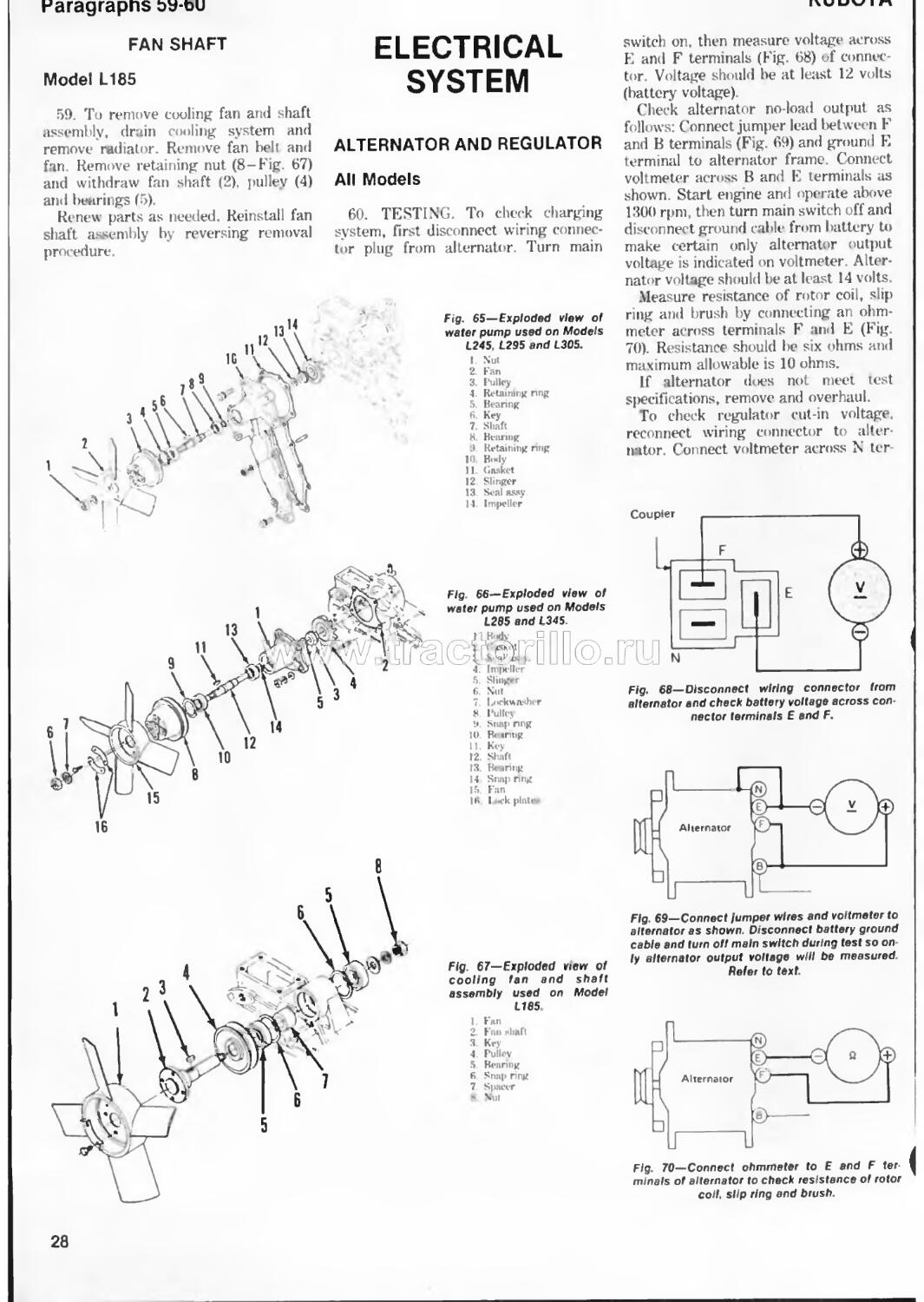
Fan Shaft 59
Radiator 56 56 56 56 56 56 56 56 56
Thermostat 57 57 57 57 57 57 57 57
Water Pump 58 58 58 58 58 58 58 58
DIESEL FUEL SYSTEM Fuel Filter Glow Plugs □RS 44 54 11 54 44 54
Injection Nozzles 50 50 50 50 50 50 50 50 50
Injection Pump 46 16 46 46 16 16 46 16 46
DIFFERENTIAL AND BEVEL GEARS
Differential Lock 97 97 97 97 97 97 97 97 97
Overhaul 92 92 92 92 92 93 93 93 93
Remove and Reinstall .... 91 91 91 91 91 91 91 91 91
ELECTRICAL SYSTEM
Alternator and
Regulator Starter Motor and 60 60 60 60 60 60 60 60 60
Magnetic switch 62 62 62 62 62 62 62 62 62
Wiring Diagrams — Pages 61 through 64 —
ENGINE AND COMPONENTS
Cam Followers Camshaft - 29 33 29 33 29 33 29 33 29 33 29 33 29 33 29 33 29 33
Compression Release Connecting Rods and 24 24 24 21 24 24 24 24 24
Bearings Crankshaft and Main 38 38 38 38 38 38 38 38 38
Bearings Crankshaft Rear Oil 39 39 39 39 39 39 39 39 39
Seal 40 40 40 40 40 40 40 10 10
Cylinder Head 23 23 23 23 23 23 23 23 23
Cylinder Sleeves 37 37 37 37 37 37 37 37 37
Flywheel 41 41 11 11 11 11 41 41 11
Oil Pump 42 42 42 42 42 42 42 42 42
Piston and Rings 35 35 35 35 35 35 35 35 35
2
INDEX (CONT.)
LI 85 L235 L245 L275 L285 L295 L305 L345 L355
ENGINE AND COMPONENTS (CONT ) Piston Pins 36 36 36 36 36 36 36 36 36
Remove and
Reinstall engine . . . 22 22 22 22 22 22 22 22 22
Rod and Piston
Units 34 34 31 34 34 34 34 34 34
Timing Gear Cover 31 31 31 31 31 31 31 31 31
Timing Gears 32 32 32 32 32 32 32 32 32
Valve Guides 26 26 26 26 26 26 26 26 26
Valve Levers 28 28 28 28 28 28 28 28 28
Valves and Seats 25 25 25 25 25 25 25 25 25
Valve Springs 27 27 27 27 27 27 27 27 27
Valve Timing 30 30 30 30 30 30 30 30 30
FINAL DRIVE
Overhaul... 101 103 101 103 102 104 104 104 104
Remove and
Reinstall 100 100 100 100 100 100 100 100 100
FRONT SYSTEM (Except FW D) Axle 1 1 1 1 1 1 1 1
Steering Spindle
and Wheel Hub 3 3 3 3 3 3 3 3
Tie Rods and
Toe-In 2 2 2 2 2 2 ‘J 2
FRONT-WHEEL DRIVE Differential and Bevel Gear Assembly 7^© ftcqpOD© 8 8 8
Drive Shaft 9 9 9 9 9 9 9 9
Front Axle 6 6 6 6 6 6 6 6
Outer Drive Assembly ... 7 7 7 7 7 7 7 7
Tie Rods and Toe-In. . 5 I~y 5 5 К 5 5
Transfer Case 10 10 10 10 10 10 10 10
HYDRAULIC SYSTEM
Fluid and Filter 114 114 114 114 114 114 114 114 114
Hydraulic Valves 121 121 121 121 121 121 121 121 121
Pump 119 119 119 119 119 119 120 120 120
Rockshaft Housing 127 127 127 127 127 127 127 127 127
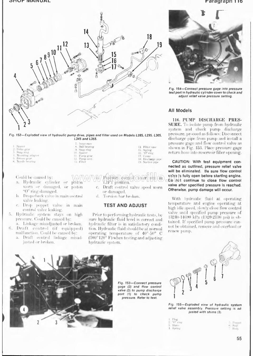
Test and Adjust 116 116 116 116 116 116 116 116 116
Troubleshooting 115 115 115 115 115 1 15 115 115 115
POWER TAKE-OFF
Overrunning Clutch 109 111 109 111 109 109
Remove and Reinstall Ю8 110 108 110 108 108 112 112 113
SHUTTLE TRANSMISSION
Shuttle Clutches 90
Shuttle Control Valve .... 88
STEERING SYSTEM
Manual Steering. . 1 1 11 11 11 11 II
Power Steering . . 13 13 13 13 13
Steering Pump . 18 18 18 18 18
TRANSMISSION
Front Transmission . 70 81 70 81 70 70 70 70 83
Rear Transmission. . 74 85 71 85 74 74 74 74 85
Shifter Rails and
Forks 68 79 68 79 68 68 69 69 80
3
DUAL DIMENSIONS
This service manual provides specifications in both the U.S. Customary and Metric (SI) systems of measurement. The first specification is given in the measuring system perceived by us to be the preferred system when servicing a particular component, while the second specification (given in parenthesis) is the converted measurement. For instance, a specification of “0.28 mm (0.011 inch)” would indicate that we feel the preferred measurement, in this instance, is the metric system of measurement and the U.S. system equivalent of 0.28 mm is 0.011 inch.
CONDENSED SERVICE DATA
L185 L235 L245 L275 L285
GENERAL Engine Make Engine Model Number of Cylinders Bore Stroke Displacement Cylinder Sleeves Battery-Volts Ground Polarity Forward Speeds Z751A 2 76 mm (3 in.) 743 cc (45.3 cu.in.) D1102A 3 76 mm (3 in.) 1115 cc (68.3 cu.in.) Own DU01A 3 76 mm (3 in.) 82 mm (3.23 in.) 1115 cc (68.3 cu.in.) Dry 12 Negative 8 D1302A 3 82 mm (3.23 in ) 1299 cc (79.3 cu.in.) V1501A 4 76 mm (3 in.) 1487 cc (90.7 cu.in.)
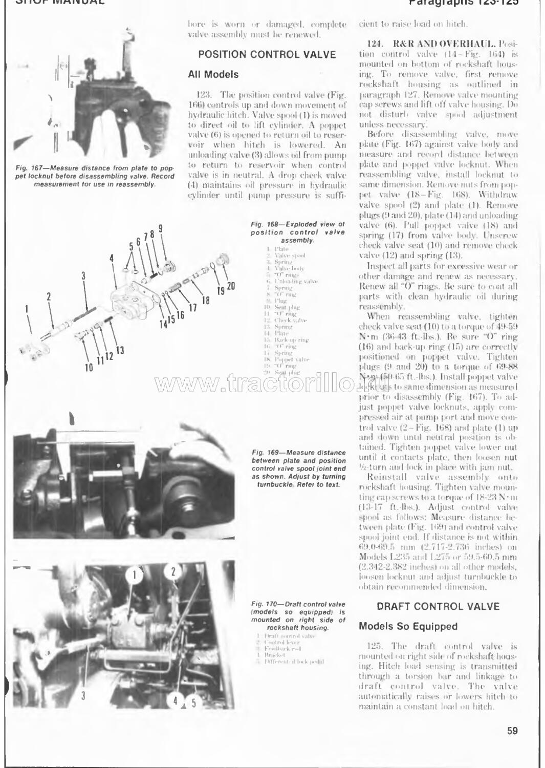
TUNE-LP Compression Pressure ... Firing Order Valve Clearance - Intake and Exhaust Injection Timing (BTDC) Timing Mark Location Injection Pressure . . Low Idle Speed (rpm) High Idle Speed (rpm) Rated Speed (rpm) Rated Power at Pto Shaft 1-2 (r 3.235 kPa (470 psi) 1-2-3 1-2-3 /1 □ п n 1[FП(' 18 0dimTI Д- 1-2-3 1 -3-4-2
V/w \J\J \_/\_/ □ v (О.007-(ГОЬ9 in.)
2950 2800 11.5 kW (15.45 HP) 2750 2600 14.6 kW (19.59 HP) Flywheel -13720-14700 kPa (1990-2135 psi) 800-850 2950 2800 16.4 kW (22 HP) 2750 2600 17.5 kW (23.42 HP) 2550 2400 19.8 kW (26.45 HP)
SIZES-CLEARANCES
Crankshaft Main Journal-
Diameter 51.921 -51.940 mm (2.0441-2.0449 in.)
Bearing Clearance-
Front Bearing 0.040-0.118 mm (0.0016-0.0046 in.)
All Other Bearings 0.040-0 104 mm (0.0016-0.0041 in.)
Crankshaft Crankpin Journal -
Diameter — — 43.959-43.975 mm (1.7307-1.7313 in.)
Bearing Clearance 0.035-0.093 mm i0.0014-0.0037 in.)
Crankshaft End Play 0.15-0.31 mm (0.006-0.012 in.)
Camshaft Journal -
Diameter 39.934-39.950 mm (1.5722-1.5728 in.)
Bearing Clearance 0.050-0.091 mm (0.0020-0.0036 in.)
4
CONDENSED SERVICE DATA (CONT.)
SIZES-l LEARAN'f ES (( ONT.) Cam Heightinlake and Exhaust L185 1,235 1,245 1,275 1.285 . 33.30 mm (1.3134 in.)
Piston Pin-Dianieler 23.002-23.011 mm
Clearance in Rod .... (0.9056-0.9059 in.) - 0.014 -0.038 nun ((I.O0O6-0.O015 in.)
Vai vx1 Seat \ngle-Intake and Exhaust 45°
CAPUTTIES
Crankcase Oil 3.8 1. 6.1 L 6.1 L 6 l L
Cooling System . . (1.0 qts ) (6.1 qts ) (6 1 qts.) (6.4 qts.)
5.3 1, 6.6 L 6.6 L 6.6 L
Transmission - (5.6 qts.) (7.0 qts.) (7.0 <tts.) (7.0 qts.)
2WD I 21 L 22 L 24 L
1WD (23 qts ) (25 qts.) (23 qts.) (25 qts.)
23 L 21 L 23 I. 21 I.
Fluid Type Front Axle Differential (24 qts.) (25 qts.) (24 qts.) (25 (its.)
Kubota 1 ' I)T Transmission Fluid
Case( IWD). . .... 1.1 L 2.3 L l.l I, 2.6 L
Fluid Tvpe (1.2 qts.) (2.1 qts.) (12 qts.) (2.7 qts.)
Front Axle < hirer Drive
Casc(-IWl))- Each.....
n.S L (0.8 qts.)
0.3 1. 0.8 L 0.3 L
(0.3 qts.) (0.8 qts.) (0.3 qts.) SAE KO or 90 (lear Oil -------------------------------
8.9 L (9.4 qts.) 7.0 L (7.1 qts.)
27 L (29 qts.)
Fluid Type
Steering Clear Box (Manual)
Fluid Type
- ----------------------------s \E 80 or 90 Gear Oil
CONDENSED SERVICE DATA
GEN'FR \L 1.295 1.305 1.315 L355
Engine Make
Engini Model Number of ( vlinders . Bore . .. Stroke DI 301A 82 mm (3.23 in.) 1НЗЛ1А \ 150IA 3 1 82 mm 76 mm (3.23 in.) (3 in.) VI7O2A 1 82 mm (3.23 in.)
Displacement (Minder Sleeves 1299 cc (79.3 cu.in.) (3.23 in.) 1299 ce 1 187 cc (79 3 cu.in.) (90.7 cu.in.) Drv 1732 ec (105.6 cu.in.)
Batterv \ olts . . I
Ground Polarity
Forward Speeds TINE-1 P Compression Pressure Firing Order Valve Clearance - Intake and Exhaust
3°35 к 1 'a
1-2-3 (470 psi) 123 1 3-1-2 1 -3-4-2
Injection Timing (ВТ! M ') Timing Mark Location Injection Pressure (П.007-0.009 in.) Q-0
13720-147oo kPa—
(19911-2135 psi)
5
CONDENSED SERVICE DATA (CONT.) 1,295 L305 1,345 TUNE-UP (CONT.) I T,ll« КОП-ЦЛО 1.355
UUVT 14 11V k. JJR С-Л1 \ I J II 1 If High Idle Speed (rpm) Rated Speed (rpm) Rated Power at Pto Shaft 2950 2800 19.7 kW (26.46 HP) 2950 2950 2800 2800 19.5 кW 21.9 к W (26.21 HP) (29.35 HP) 2750 260b 21 6 kW (29 HP)
SIZES-CLEARANCES Crankshaft Main Journal -Diameter Bearing Clearance-Front Bearing All Other Bearings Crankshaft Crankpin Journal - — 51.921 -51.910 mm (2 0411-2.0119 in.) 0.040-0 118 mm (0 0016-0.0016 in.) 0.01(»-0.1()4 mm (0.0016-0.0011 in.) 13 959-43 975 mm -
Bearing Clearance Crankshaft End Play Camshaft Journal-Diameter Bearing Clearance Cam Height -Intake and Exhaust Piston Pin- . • Diameter <Vu Clearance in Rod Valve Seat Angle-Intake and Exhaust — (1.7307 1.7313 in.) 0.035-0.095 mm (0.01» 14-0.0037 in ) 0.15-0.31 min (0.006-0.012 in.) 39.934-39.950 mm (1.5722-1.5728 in.) 0 050-0 091 mm
(0.009-0.0036 in.) —— 33 36 mm (1.3134 in.) лтПД
\J\J \J\y U IjU (0.9056-0.9059 in.) 0.014-0.038 mm (0.0006-0 0015 in.) 15°
CAPACITIES Crankcase Oil Cooling System Transmission-2WD 4WD Fluid Type Front Axle Differential Case (4WD) Fluid Type Front Axle Outer Drive Case (4 WD)-Each Fluid Type Steering Gear Box (Manual) Fluid Type • • Power Steering Reservoir Fluid Type *Same as transmission. 6.1 L (6.1 qts.) 5.8 I, (6.1 qts.) 26 I, (27.5 qts.) 27 L (28.5 qts.) 2.0 I, (2.1 qts.) 6.1 I. 9.1 L (6.1 qts.) (9.6 qts.) 5.8 I, 7.0 L (6.1 qts.) (7.1 qts.) 22 L 22 L (23.2 qts.) (23.2 qts.) 22 I 22 1, (23.2 qts.) (23.2 qts.) К ul >ota U DT Transmission Fluid 5.0 I. 5.0 I, (5.3 qts.) (5.3 qts:) 9.1 I, (9.6 qts.) 7.0 L (7.4 qts.) 32 L (33.8 (jts.) 5.0 L (5.3 qts )
1.5 I, (1.6 qts.) 0.3 I, (0.3 qts.) SAE 80 or 90 (Jear Oil 0 7 1, 0.7 1, (0.7 qts.) (0.7 qts.) SAE 80 or 90 Gear Oil 0.2 I, (0.2 qts.) SAE 80 or 90 Gear Oil • 1.5 L (1.6 qts.) Kubota I DT Transmission Fluid 0.7 I, (0.7 qts.) 1.5 L (1.6 qts.) '
6
SHOP MANUAL
Paragraphs 1-3
FRONT SYSTEM (TWO-WHEEL DRIVE)
FRONT AXLE
All Models So Equipped
1. Fig. I shows an exploded view' of typical tread front axle assembly used oh Models LI 85 and L235. Model L275 uses an adjustable tread front axle as shown in Fig. 2. All other models are equipped with an adjustable tread front axle as shown in Fig. 3.
Service procedures are basically similar for all models. Front axle pivot pin (3) is retained by a spring pin (9) at rear and by an adjusting nut (I) at front.
Diametral clearance between pivot pin and bushings (4) should not exceed 0.5 mm (0.020 inch). Renew bushings and pivot pin as needed if clearance is ex-
Fig 1—Exploded view of fix ed tread front axle used on Models L185 and L23S.
1. Adjusting nut
2. Adjusting collar
3. Pivot pin
4 Pivot bushings
5. Spindle bushings
6. Axle
7. “(>" ring
8. Washer
!). Spring pin
10. Axle bracket
When reinstalling front axle assembly, lubricate pivot pin anil bushings with multi-purpose grease, then check and adjust axle end play as follows: Use a spring scale to measure force required to pivot axle as shown in Fig. ЗЛ. Turn pivot pin adjusting nut as require<W7\ tain pivot force between 49-117 N 11 pounds). Secure nut w'ith cotter pin.
TIE RODS AND TOE-IN
All Models So Equipped
2. Tit* rod and drag link ends are non-adjustable, automotive type. Renew' ends that art* excessively worn.
Adjust front wheel toe-in to 2-8 mm ('/8-5/16 inch) by shortening or lengthening tie rod. Adjust length of drag link, if necessary, to permit equal turning radius in either direction.
Fig. 2—Exploded view of ad-lustable tread front axle used on Model L275. Except for axle extension (11). refer to Fig. 1 legend.
STEERING SPINDLE AND WHEEL HUB
All Models So Equipped
3. Refer to appropriate Fig. 4 or Fig. 5 for exploded view of steering spindle and associated parts. To remove spindle (11), remove front wheel and steering arm. then lower spindle from axle. Use a suitable puller to remove wheel hub and bearings.
Inspect all parts for excessive wear, corrosion or other damage. Maximum recommended diametral clearance between spindle and bushings is 9.4 mm (0.016 inch).
Fig. 3—Exploded view of adjustable tread front axle used on Models L24S. L285. L295, L305 and L345.
1. Adjusting nut
2. Adjusting collar
3. Pivot pin
4. Pivot bushings
5. Spindle bushings fi. Axle
7. "(1" ring
8. Washer !». Spring pin 10. Axle bracket 11. Axle extension 12. Bumper
7
Paragraphs 4-6
KUBOTA
Fig. ЗА—Use a spring scale to measure force required to pivot axle.
Up
Fig. 6—Position spindle thrust bearing as shown when reinstalling spindle assembly.
To reassemble, pack wheel bearings and hub with mutlti-purpose grease and press bearings and hub onto spindle shaft. Tighten slotted nut securely and install cotter pin. Lubricate spindle and bushings with mult-purpose grease. Reinstall spindle assembly making certain thrust bearing is positioned correct-
10
11
j 14
7.
8.
9.
10.
Fig. 4—Exploded view of typical spindle, wheel hub and steering linkage used on Models L1B5 and L235.
1. Steering arm R.H.
2. Tie rod
4. Drag link end
5. Drag link
6. Tie rod end Steering arm L.H Axle Thrust bearing Seal Spindle
12. Dust cover
13. Seal
14. Bearing (inner)
15. Wheel hub
l213 18
19. Nut
20. Cap
ly as shown in Fig. 6 Push upward on spindle assembly to remove end play, then install steering arm and tighten clamp bolt.
FRONT-WHEEL DRIVE
All Models So Equipped
4. Front-wheel drive assembly includes transfer case, drive shaft, front axle, differential, axle shafts and axle hub assemblies. The transfer case is rno^n{i?^lto bottom of range transmission housing. Transmission oil lubricates transfer case assembly. Refer to Fig. 7 for cross-sectional view of front-wheel drive axle assembly.
TIE RODS AND TOE-IN
Fig. 5—Exploded view of spindle, wheel hub and steering linkage used on tractors equipped with adjustable tread front axle.
Refer to Fig. 4 legend
All Models So Equipped
5. Tie rod ends are non-adjustable type. Tie rod ends that are excessively worn should be renewed.
Toe-in on all models should be 2-8 mm (*/8-5/16 inch) Adjust by lengthening or shortening tie rod.
FRONT DRIVE AXLE
All Models So Equipped
6. REMOVE AND REINSTALL. To remove front axle assembly, proceed as follows: Remove drag link end from steering arm and disconnect drive shaft. Support front of tractor behind front axle. Support axle with a suitable floor jack and remove front wheels. Remove axle front pivot pin, then carefully lower and move axle forward to remove from axle support bracket.
Check clearance between pivot pin (1-Fig. 8) and bushing (5) and between differential housing (6) and rear bushing
8
SHOP MANUAL
Paragraph 7
9
10
II
l. Knurkli- pin
2. Stecrfng irm
3. Bev» I Re ir
4 Piffi-relltial y«>kv shaft
5. Axle housing I..H
6. I>iff«T«-nl‘.»l < list-
7 1‘initMin Rears
Fig. 7—Crosssectional view of front wheel drive axle assembly.
* kxle h-«using R II
*.1 Axl«' n.iiigi К». А» e shaft II R<4elR»r 12 lUveluear Г. B<-wl ж-ir housing II Se.il IS \xk« < ise
I • H<w «I g«'ar shaft
17 Bev<«l gear l>« Beiniv ease I4. Bevel pinion shaft 2<>. ('Milling
21. Prive shaft
22 llifferential side giUr
2.". Haig gear
7 Thrusl irjsher
1 >" rmg
,xle mounting
oorrents for tractors equip ped with front wheel drive. “O” rings (4,11 and 12) are not used on some models and front bushing (5) Is a two piece assembly on some models.
I Pivut pin Л bracket
2. .Shims
.4. I'hnist w a«h>-r O' rings Busi mg
9 Hushing
10 Seal Cover
(9). If clearance exceeds 0.4 mm (0.016 inch), renew components as needed. Renew all “O ’ rings.
Reinstall axle assembly by reversing disassembly procedure using original pivot pin shim pat к i2). Apply grease to front and rear pivot bushings. Use a spring scale to measure force required to pivot axle from lowest position to highest position as snown in Fig. 9. Add or remove j ivot pin shims as necessary to obtain rt commended pivot force of 19-117N (11-26 pounds). Recommended lubr cant for front axle and differential case is SAE 90 gear oil.
OUTER DRIVE ASSEMBLY
All Models So Equipped
7. R&R AND OVERHAUL. To remove outtr drive issembly, find raise and support irnnt of tractor. Remove fr-mt wheel, then disconnect drag link (left side) and tie rod Support drive housing, remove cap sen ws mounting housing to axle housing and withdraw drive housing assembly from axle. Retain shims (3-Fig. 10) for use in reassembly Pull differential yoke shaft, (I) with bevel gear (7) and bearing (6) fn-rn адle housing.
To disassemble, remove axle flange (33) with bevel gear (26) and axle (34) and allots oil to drain into a sui hable con-Ж Re move inner bearing (25) and ear from axle shaft. Remove re taining rings (27 and 28) and thrust washer (29). then press axle out of bearing (30) and flange. >rive oil seal («31) out of flange
Remoxe knuck e support (right side) or steering arm (left side), then remove knuckle pin (Ю-Fig 11). Retain shims (-Il for use in reassembly. Remove lower hearing cap (22-F g. 10), bearing (21) and bevel gear (23). Keep shims (20) together for use in reassembly Fap bevel gear shaft (13) upward and remove upper bearing (8) and split collar (!*). then tap shaft downward and separate bevel gear housing (10) from axle case (21). Remove bearings and oil seal (17) from bevel gear shaft
F>g. 9— Use a spring scale to check force required to pivot front axle. Refer to text.
Examine gt^rs tor chipped, cracked or missing teeth. Inspect bearings for roughness, corrosion or other damage. Check diametral clearance of knuckle pin (Ю Fig. 11) in bushing (8). If clearance exceeds 0.4 mm (0.016 inch), renew parts as needed. Renew all “0" rings and oil seals. Lubricate parts with clean oil prior tc. reassembly.
To rea. semb e. reverse the • lisa -eml ly procedure. Renew all gaskets. "()” rings and seals during reassembly. I uliricate lip of oil seals with grease during rvassqmbly. Baek ash between upper bevel gear
9
Paragraph 7 Cont.
KUBOTA
Fig. io—Exploded view of outer drive assembly used on tractors equipped with front-wheel drive. Some models have a spacer between bearing (€) and bevel gear (7) and retain gear with a cap screw and washer Instead of snap rings (5 and 11).
1. Axle housing
2. "O" nng
3. Shim
4 Differential yoke shaft
S"*1 ' Bearing Bevel gear Bearing Split ring
12- Bevel gear
13 Bevel gear »hnft
14 Biaring
15. Snap nng
16. Sleeve
17. Oil seal
Shim Bi nnng Bearing cap Bevel genr Axle case Bearing
Thrust washer Bearing Oil seal ‘ f)" ring Flange Axle shaft
Fig. 11
View of front wheel drive steering linkage end knuckle pins.
Drag link Arms Knuckle support fill
4 Shim
5. Tie пи!
6. Tie r»d rrxi
7. Sk vring arm
Я. Bushing
9. “(Г ring
IO Knuckle pin 11. Gask-t
Fig. 12—Use a dial Indicator to check backlash between upper bevel gear and yoke shaft bevel gear Add or remove shims (1) between housings to obtain desired backlash
(12-Fig. 10) and differential yoke shaft gear (7) should be 0.15-0.30 mm (0 006-0.012 inch). Use a dial indicator to check backlash as shown in Fig 12, then add or remove shims (1) between l>evel gear housing and axle housing to obtain desired backlash. Recommended backlash between lower lievel gear (23-Fig. Ю) and axle shaft l>evel gear (26) is 0.15-0.30 mm (0.006-0.012 inch). Use a dial indicator to check backlash as shown in Fig. 13, then add or remove shims (2) at lower bearing cap to obtain desired backlash. Tighten axle flange nf Liriing cap screws to a torque of 20-31 N-m (15-25 ft.-lbs.). Tighten bevel gear case to axle housing mounting cap screws to a torque of 98-132 N*m (75-95 ft.-lbs.). Tighten knuckle support or steering arm mounting nuts to a torque of 80-90 N’-m (60-65 ft.-lbs.), then measure clearance between support and pivot pin bracket wth a feeler gage as shown in Fig. 14 Adjust shim pack under knuckle support as needed to obtain desired clearance of 0.1-0.2 mm (0 001-0.008 inch). Check end play of ax-
Flg 13—Check backlash between lower bevel gear and axle bevel gear and adjust as necessary with shims (2) at lower bearing cap.
10
SHOP MANUAL
Paragraph 8
Fig. 14—Use a feeler gage to check knuckle pin to support clearance. Add or remove knuckle support mounting shims to obtain desired clearance.
le shaft using a dial intbrator as shown in Fig. 15. Maximum allowable end play is 0.5 mm (0.020 inch). If encl play is excessive. check condition of thrust washer (2!)-Fig. Ill) and retainer (27). Refill unit with S \F. *><» gear oil.
DIFFERENTIAL AND BEVEL
GEAR ASSEMBLY
All Models So Equipped
8. R&R ANfi O' ERIIAU L. Drain oil from axle housing, then remove outer dr\e assemblies and differential yoke shafts as outlined in prex olu paragraph. Disconnect drive shaf^' ^/py port differential housing, then remove front pivot pin and separate axle housing assembly from tractor.
To remove differential assembly, remove mounting cap screws and separate left axle housing (3(1-Fig. 16) from differential housing (11). Remove differential assembly from housing Remove bevel pinion case (6) mounting cap screws, then withdraw pinion assembly from differential housing Retain shims for use in reassembly.
To disassemble differential, remove carrier bearings (16 and 27) using a
Fig. 15—Axial end play of axle shaft should not exceed 0.5 mm (0.020 inch). Use a dial indicator as shown to measure end play.
Fig. 16—Exploded view of front wheel drive differential and bevel drive gear assembly. Spacer (9) Is not used on all models.
1 ViljuMinK out 2 OilM-.il
3. "O' rintr
1 SIwv й Bearing
I Hi tring l .L4‘ 7 "О" ппи
11 Kl-vvl pinion sh.ift
12 \xh‘ houbini; K.ll
13 “О” nug
11 Differential hoiiMiit
15 Shim
Ifi. Carrier liearitiK’
17 hifferenthi case
21 Side ge.irs
22 llirW w. isIiit
2-1 Itii'-li-uK
21 l*ini»u k< >r
2 7 BiibliiliK
2<> H.t>K Hear
27 I’ lrncr 1н «пик
24 Shim
’_!• "O" nnj!
«1 \xli- llollMIIK L il
suitable puller. Remove ring gear mounting caps screws and remove ring gear (26). side gear (21). thrust washer (20) and bushing (25). Scribe match marks on pinion gears (21) and side gear (21) so gears can be reinstalled in their ongmal positions. I’se a punch to remove pinion shaft dowel pins (1!)). then withdraw pinion shaft (1R) and gears fn«m differential ease.
Plate bevel pinion drive gear (I I) in a suitable holding fixture, then remove nut (1). Press bevel gear shaft out of hearings and bearing сам*.
Inspect all gears and hearings for ex-
F‘g. 17—Backlash between side gears and pinion gears should not exceed 0.4 mm (0.016 inch).
cessive wear or other damage. Maximum allowab e operating < learance between differential side gears (21) and differential cast (17) and ring gear bushing (25) is 0.4 mm (0.016 inch). Pinion shaft (18) to pinion gear bushing (23) clearance shoii d not exceed 0.3 mm (0 U|2 inch). Renew all parts as needed. Ring gear and p ni >n are available only as a matched set.
Reassemble differential making certain match marks made during disassembly are aligned Check side gt .ar tn pinion gear backlash using a dial indicator as shown in Fig. 17. Backlash should not exceed 0 i mm (0.016 ini h).
Fig. 18—Bevel pinion shaft bearing preload should be adjusted to obtain recommended rolling torque of 1.27-1 67 N m (11-15 In.-lbs.)
11
Paragraph 8 Cont.
KUBOTA
Fig. 19—Rolling torque of bevel pinion shaft with differential assembly Installed should be within range ot 1.96-2 94 N-m (17-26 In. lbs.). Refer to text.
Side ge»r thrust washers (20-Fig. 16) are available in three different thicknesses to adjust backlash to desired value. Tighten ring gear mounting cap screws to a torque of 61-68 N-m (45-50 ft.-lbs.).
Assemble bevel pinion shaft using new bearings anil oil seal. Tighten adjusting nut finger tight, then reinstall pinion shaft and case into differential housing. Use a torque wrench to measure torque required to turn pinion shaft as shown m Fig. 18. Tighten adjusting nut (1-F.g. 16) to obtain recommended rolling torque of 1.27-1 67 N-m (11-15 in.-lbs.). Stake adjusting nut after bearing adjustment is completed.
Install differential assembly and ring gear into differential case and reinstall axle housing.Measure torque required to
Fig. 20—Use a dial Indicator to check backlash between ring gear and pinion Recommended backlash Is 0.15 mm (0.0060.010 Inch).
ElO- 21—Exploded view of one piece drive shaft assembly used on some models.
I. front tube
2. "О” ring 5. Ihivr shaft
3. Snap ring 6. Rear cover
4. Cflupling 7. Gasket
Fig. 22—Exploded view ot two- piece drive shaft assembly with center carrier bearing used on some models.
I. Snap nng
2. Coupling
3 front drive shaft I front tube
5. Gasket
6. Rear drive titafl
7. it tnng case
8. Oil seals
9 Retaining rings
10. Rearing
11. Snap ring
12. Center tube
13. “O' ring LI Rear lube
rotate bevel pinion shaft and differential as shown in Fig. 19. Rolling torque should be within the range of 1.96-2.94 N-m (17-26 in.-lbs.). Adjust as needed by changing shim thickness (15 and 8-Fig. 16) in differential case and bevel pinion case.
30
Fig. 23—Transfer case Is mounted to bottom of range transmission housing and is lubricated with transmission oil. Idler gear assembly shown in Inset (40 through 44) Is used on MOdels L305, L345 and
I Shift lever
2 “O' ring
3 Seal washer
4 Plug
5 Shift lever
6 Rublier guide
7 SuptHtrt
8 . Guide
9 . Shift ami
I (I. Spring
11. Cover
12 Shaft
L355.
13. Retiring
14 Driven gear
15. Bearing
16 Sleeve
17. Snap ntig
IK Oil «eal
19. Rearing
20, Spacer
2). Washer*
22. Thrust washer
23. Inner race
Check and adjust ring gear to bevel pinion backlash as follows: Secure ring gear by inserting a screwdriver through oil drain hole in housing. Set dial indicator on bevel pinion shaft spline as shown in Fig. 20. then move pinion shaft and measure backlash. Recommended
24 Bearings
25. Idler gear
26. Rearing
27 14n shaft
28. Drive gear
29. Bean ng'
30 Bevel pininn shaft
10. Sparer
11. Shim
12. Snap nng
13. Thrust washers
44. Washer
12
backlash is 0 15-0.25 mm (0.000-0.010 inch). If measured backlash is excessive, decrease shims (15- Fig. Id) on differential rase side and add shims (28) of same thickness between lett axle housing and differential case. If backlash is insufficient. decrease shims (28) and add Mime thickness to shims (15).
Complete reassembly anti installation of axle assembly. Refill axle housing with S \E 90 gear oil.
DRIVE SHAFT
All Models So Equipped
!). Models 1.305, 1.315 anti 1.355 use a two-piece drive shaft with a center carrier bearing (I* ig 22). Ml other models use a one-piece drive shaft as shown in Fig. 21-
Removal oi drive shall consists of removing mounting screws from drive shaft tubes, disengaging retaining rings and sliding drive shaft out of couplers. Remove center carrier bwaring and oil seals on models so equipped
Inspect shaft splines and couplers for excessive wear or other damage. Reinstall drive shaft by reversing removal procedure.
TRANSFER CASE
All Models So Equipped
10 R&R AND OVERHAUL. Drive gear (28 Fig. 23) an<I idlt r gear (25) are located in rang». transmission housing. Refer to appropriate transmission section for service procedures.
To service transfer case, first drain oil from transmission housing Disconnect drive shaft and shift linkage. Remove transfer case mounting cap screws and lower unit from transmission housing.
To disassemble, remove oil seal (18). retaining ring (17) and plug (I). Tap shaft (12) out front of ease and remove gear (I I). I >rive pin (1 <») out of shift arm (9) and remove shift lever i1).
To reassemble. reverse the disassembly procedure. Apply liquid gasket maker to surfaces of drive case mounting gasket when reinstalling.
STEERING SYSTEM
MANUAL STEERING
All Models So Equipped
All models equipped with manual steering box use a recirculating hall nut steering gear similar to type shown m Fig. 21.
Fig. 24—Exploded view of manual steering gear assembly Components shown tn Inset are used on Models L185. L24S and L2BS
1 Nut
2 Nut
3 . Sult- coo-r
4 Gasket
5 . Shim
fi. Adjusting mtvw
”. Sector luift
И I <mr rase
9 Rushing
in Seal
11 i’itrwi згт
12 Bearings
13 Bill nut assy.
11 X>” ring
15. Column
If. Nut
17 “O" rings
IK Sup|M>rt bratket
19 Spring
2<i Pin & rio-l
21 Steering shaft
22 Bushing
23 . Seal
24 Seal
25 Shim
2fi. <j>ver
27. Column 2H Support 2t< Bushing
11. WJL'STMENT. Steering wheel
free play should be within the range of 20-5(1 mm (13/1(1-2 inches) measured at
desired free play (Turning adjusting screw clockwise will reduce free play.) Tighten locknut to secure adjusting screw.
On Models LI85, 1.215 anti 1.285, steering shaft end play should Ik* approximately 0.2 mm (0.008 inch). If end play is excessive, adjust by changing cover shim (25) thickness
12. |{&R AND OVERHAUL. To remove steering gear assembly, first remove storming wheel using a suitable puller. Remove instrument panel, cowl and fuel tank. Discount ct drag link from pitman arm. Remove steering gear mounting cap screws and withdraw steering gear assembly.
To disassemble, first drain oil from housing. Make sure match marks are present on pitman arm (II- Fig. 21) and sector shaft (7). then remove pitman arm using a suitable puller. Remove side cover mounting cap screws and ad justing screw locknut Turn adjusting screw (•>) t<> remove side cover, then tap sector shaft out side cover opening. Remove Steering column and steering shaft with ball nut assembly (13). Ball nut is available only as an assembled unit and disassembly is not recommended.
To reassemble unit, reverse the
disassembly procedure while noting the following Re sure to renew all “0” rings ami oil seals. Install sector shaft into FrSG) Rnd turn fully clockwise, then in-0 sttne wall nut and engage it with sector
gear Install side cover using liquid gasket oti mounting surfaces of gasket. On Models L185. 1.245 and 1.285, install cover (2H) with shim (25) thickness required to obtain 0.2 mm (0.008 inch) steering shaft end play. On all other models, install steering shaft assembly without ipper bushing (22) and seal (23). Use a torque wrench (Fig 23) to check torque required to turn steering shaft which should be less than 1.7 N*m (15 in. lbs.). Turn steering column (1) into or out of sector housing to obtain desired turning torque, then tighten column locknut (2) securely. Be sure to align
Fig. 25—Ad/USt steering Shalt bearing preload by turning sfeermg column (7) info or out of housing Refer to text
l Slrt-nu b.M-i •> |.«kiuit
13
raragrapns 10-14
rUDUIM
match marks when reinstalling pitman arm. Refill unit with approximately 0.2 L (% pint) of SAE 90 gear oil.
Rc install steer ng unit on tractor and adjust steering wheel free play as previous^ outlined.
POWER STEERING
Integral Type
13. ADJUSTMENT. Steering wheel free play should be within range of 25-50 mm (13/16 -2 inches) measured at steer ing wheel rim. To adjust free play, turn adjusting screw (1 - Fig. 26) clockwise to reduce free play or counter-clockwise to increase free play.
To check and adjust relief valve pressure setting, connect a 0-20000 kPa (0-3000 psi) pressure gage at test port (2-Fig. 27) in steering valve housing Operate steering: until ©il is at operating temperature. With engine running at 2600 rpm, turn and hold steering wheel fully in one direction and observe pressure reading when rel ef valve is actuated. Pressure should be 10000-10700 kPa (1150-1550 psi) on all m< idols. To adjust relief valve pressure setting, turn adjuster (1) to obtain desired opening pressure
If unable to obtain recommended
Fig. 26—Turn steering gear adjusting screw (1) to adjust steering wheel free play.
Fig. 27—To check integral type power steering pressure, attach a pressure gage at test port (2). Pressure setting can be adjusted by turning adjuster (1). Refer to text.
pressure check hydraulic pump output
as outlined in paragraph 19. If pump output is satisfactory, remove sped relief valve poppet and (33-Fig. 28).
И. R&R AND OXFRHAIL To remove steering gear assembly, first remove steering wheel using a suitable puller. Remove instrument panel, cowl and fuel tank. Disconnect drag link from pitman arm using i suitable puller. Disconnect hydraulic oil tubes, remove steering box mounting cap screws and withdraw steering gear assembly.
To disassemble, first place match marks on pitman arm and sector shaft. Use a suitable puller to remove pitman arm. Drain oil from housing Remove steering column (41 -F g 28) Drive out rivet and spring pin (13) and remove steering shaft (45), then unbolt and remove top cover (38). Seiure worm shaft (18) and remove locknut (36). Separate valve assembly and thrust bearings from housing Remove side cover mounting cap screws, then turn adjusting screw (5) clockwise to remove side cover (2). Remove sector shaft
41
43
"40
39 38
is. i«.
1 Nul 2. Side 3. "O" ring 4 Vljuste r
5. Adjusting мтеи
6. “I ' hacking
". Bwtirlng
8. Sector haft
9. В ir.ng lli “U" packing 11. Oil seal 12. Snap ring 13. End cover 14 ’О" ring
Enuring “(>" ring
through side cover opening. Remove retaining ring (12) and Ircttom cover (13). Withdraw ball nut assembly (21).
NOTE: Ball nut assembly Is available only as a complete unit and disassembly Is not recommended.
Fig. 26—Exploded view of Integral type power steering used on some models.
IK Worm shaft 19. Seal rings 2<i. Spring 21 Hutt nut 22 Seal ring 23 1Г rng 21 ring 26. Sent ring
26. Housing
27. O" ring
28. "O" ring
<9. Si it nng
30 ' IГ ring
31. Washers
32. Thrust bearing .‘£1. Relief v live assj
34. Reaction pistons & spring
35. Valv, iponl
36. Nut
37 (>" nng
3H 1 । (кт cover
39 Bearing
40 Oil seal
41 . Snap mg
42 Nut
43 Rivet & pm
14 Column
45 Steering shaft
46 Bushing
47 Seal
IS. Valve h- using
14
SHOPMAN AL
Paragraph 14 Cont.
Fig. 29—Open side of sector shaft “U” packing (3) should face Inward and open side of seal (4) should face outward.
1. Gear housing .4 ’I " packing
2 Mmile h-nrrng t Seat
Separate components of valve assembly and inspect for war, scoring or other damage Valve spool (35) and valve housing (18) must be renewed as a matched sot. ( neck all components for
Fig. 33—Side cover seal and bearing installation. Be sure open side of "U" packing faces inward
I. ’ Oering 3 "1 ~ |wkii.g
2. Siilv cover 1 \*чч|1е (и-.ir ng
Ff4 30—Be sure “O" ring (1) Is installed behind Teflon seal ring (2) when reinstalling worm shaft seals In housing.
wear and correct f t and renew any which do not meet the follow .ng specifications: Clearance between cylinder anti ball nut should be Q.030-0.079 mm (0.0012-0.0031 inch).
»rm shaft ux al end play in ball nut should be 0.02 mm (0.0008 inch) and maximum allowable end play is 0.12 mm (0.0047 inch) Worm shaft must rotate smoothly in ball nut. Worm shaft lower bearing journal outside diameter should be 28 562-28.575 mnt (1.1245 1.1250 inches) with minimum allowable diameter of 28.475 mm (1.1211 inches). Clearance between valve housing and spool should be 0.00b 0.015 mm (0.0003-0.0006 inch) and maximum allowable clearance is O.025 mm (0.001 inch). Be sure that spool and sleeve art fre • of scratches, nicks or burrs and that spool slides smoothly in sleeve. Sector shaft bearing journal diameter should be Sb 059 38.075 mm (1 1981-1 1990 inches). Renew shaft if diameter is less than 38.025 mm (1.1970 .nchc*s).
\\ hen renewing needle bearings, position bearings in housings so press force* is applied against side of bearing with manufacturer’s marks. Install new oil seals. -O rings anil Teflon seal rings as shown in Figs 29 through 31. Lubricate seals an I “0" rings prior to reassembly. Apply molybdenum disulfide “MolyccKit” to stec ring column bushing (46- Fig 28) and oil seal (I?)
' iserilile steering unit by reversing □4нс 4наь>етЫу procedure. Be sure to align ‘‘I’" marks on valve spool (5-Fig. 35) and valve housing (2). Position ball nut and worm shaft assembly, valve housing assembly and thrust hearings into steering gear hous ng. then, install spec ial mounting plate (1 - Fig. 36) to retain components in housing. (Special plate (an be* fabricated using dimensions shown in Fig. 36Л ) Turn worm shaft clockwise tighten locknut hand tight and stake locknut threads with a pin punch. Install sector shaft and tighten side cove r mounting cap screws to 10-55 4-m (30 10 ft.-lhs.) torque. Remove
Fig. 32—View of lower cover seal ring and bearing installation
t Ti-rii.ii w И
2 Xei-iih- iH-.irmn i . c riiij!
Fig. 35—Be sure to align "P” marks on spool (5} and valve (2) when reassembling.
I li.-tu-t i iiln- le-«}
2 \ .ill 1>11||>1||Ц
15
Paragraphs 15-17
KUBOTA
Fig. 36—Install special mounting plate (If to retain ball nut and thrust bearings while tightening worm shaft locknut. See Fig. 36A.
Fig. 38—As a final assembly check, measure torque required to start rotation of worm shaft. Torque should not exceed 1.7 N m (15 In.lbs.)
special plate and install top cover. Tighten retaining screws to a torque of 40-55 N*m (30-40 ft.-lbs.). Align match marks and install pitman arm onto sector shaft. Tighten retaining nut to a torque of 120-155 N*m (90-115 ft.-lbs.).
Check backlash between sector gear and ball nut using a dial indicator as shown in Fig. 37. Turn adjusting screw (5 - Fig. 28) as required to obtain recommended backlash of 0.1-0.4 mm (0.004-0.016 inch). To check for proper
final assembly of steering gear, use a lined
torque wrench as shown in Fig 38 to measure torque required to start rotation of worm shaft. Torque should be less than 1.7 N*m (15 in.-lbs.). If
measured torque exceeds 1.8 N*m (16 type power steering, a manual steering
11 and 12. The power booster unit is
Fig. 36A—Mounting plate can be fabricated using dimensions shown.
Fig. 37—Check sector gear backlash using a dial Indicator.
in -lbs.), correct problem before reinstalling unit on tractor Install steering shaft and column tulie and tighten nut to a torque of 98-127 N*m (75-94 ft.-lbs.).
Reinstall steering gear on tractor by reversing removal procedure On models equipped with separate reservoir tank, refill hydraulic system with approximately 1.5 L (1.6 quarts) of Kulwta l'DT fluid Adjust steering pressure relief valve setting as previously out-
Booster Type
15. On models equipped with booster
mounted on left side of tractor and transfers hydraulic power assist directly to steering drag link which is attached to booster unit The lx oster unit consists of a hydraulic cylinder wr,th a valve housing built into the cylinder When steering w'heel is turned, valve spool shifts and directs hydraulic fluid to one side of power cylinder which actuates cylinder and assists in turning front wheels.
Ftg 39—Exploded view of power steering booster unit used on some tractors.
1. Retainer
2. Sell
3 Ball stud
4 Housing
5. Slop plate Screw
7 Spring
H Seats
9 Vi lualnr rod
III . Sleeve
11 Pin
12 Cap
13 Washer
11 Vain* spool retainers
15 Centering spring
16 . Relief valve assy
17 “O" rings 1H Valve assv, 19 Nut 20. “O“ ring 21 Cylinder 22 Piston ring 2.1 Piston & rod 2t “O” ring 25 Cylinder end 26 Rod senl assy
16. ADJUSTMENT. St ering w heel free play is adjusted as outlined in paragraph 11.
To check and adjust booster relief valve pressure setting, proceed as follows: Be sure hydraulic fluid is at normal operating temperature Remove plug from test port in bottom of valve housing and install a pressure gage as shown in Fig. 39A. Operate engine at rated speed, turn steering wheel in one direction until front wheels stop and
observe pressure gage reading. When relief valve opens, pressure should be approximately 6900 kPa (1000 psi). To adjust pressure, turn relief valve adjusting screw (16-Fig. 39), located in valve housing, clockwise to increase fjresHure or counter-clockwise to reduce pr^Jure
17 . K&R AND OVERHAUL. To remove booster unit, first disconnect hydraulic hoses and drain oil. Disconnect drag link end from booster unit. Discon nect booster unit from front mounting bracket and pitman arm and remove from tractor.
To disassemble unit, first move piston rod in and out of cylinder to drain oil. Remove retainer (I-Fig. 39) and dust
16
Onur IVIMIMUML
Fig. 39A— To check relief valve opening pressure on booster type steering, install a pressure gage in valve housing test port as shown
Refer to text
st tl (2) from s’ ><>l housing (I) Remove retaining cap screws, then separate spool valve assembly, valve housing and cylinder assembly Remove nut (19) securing valve spool, then separate valve spool, center spring (15) and retainers (14) from actuator rod (9). Remove stud adjusting screw (6). spring (7), seats (8). stud (3) and sleeve (10) from housing (1) Count number of turns required to remove relief valve adjuster screw (16) from valve body. I nscrevv piston rod retainer (25) anti withdraw piston an<i rod assembly. Remove anti discard all seals anti "()" rings.
Clean and inspect all parts for excessive wear, scoring or other damage. Renew components which do noUmre’-following specifications: MaxlS , allowable clearance between valve spool and housing is 9.91 mm (9.9П16 inch). Maximum allowable clearance between piston and cylinder bore should not exceed 0.2 mm (0.008 inch).
To reassemble booster unit, reverse the disassemb ly procedure. Renew all seals and “O’ rings. Lubricate all parts with clean hydraulic oil prior to reassembly. Tighten cylinder roti end (25) to torqia of 79-98 N'*m (69-70 ft lbs.). When reinstalling relief valve assembly, turn adjuster screw into valve
body same number of turns required for removal. Apply light coat of grease to valve sleeve and ball stud (3). Reassemble valve spool and centering spring being careful not to damage “0” ring in cap (12). Tighten retaining nut to a torque of 7.8 N*m (70 in. lbs.) Xssemble actuator housing, valve housing ami cylinder assembly anti tighten mounting cap screws evenly to a torque of 19.6 N-m (15 ft. lbs.).
To reinstall booster unit, reverse the removal procedure. Operate steering in both directions several times to purge air from system. Cheek ami adjust relief valve pressure setting as outlined in paragraph 16.
STEERING PUMP
1». Hydraulic power supply for power steering system on Models 1,235, 1,275 and 1,305 is the hydraulic system [lump mounted on right side of engine Pump output is first routed to a now-divider valve which directs a priority flow of oil to power steering, the remain ing pump flow is directed to hitch control valve.
On Models 1,345 and L355, a separate hydraulic pump is used for steering
raragrduri' io-zu
system. The pump is mounted in tandem behind hydraulic hitch system pump. All [lumps are located on right side of engine and are driven by engine fuel camshaft.
All Models So Equipped
19 PRESS! RE TEST. Го check [>ump discharge pressure, disconnect pump pressure outle pipe and connect a 29000 к Га (3000 psi) pressure gage with flow control valve as shown in Eig. 10 or 41. Direct return hose from flow control valve back into reservoir.
CAUTION- With test equipment connected as outlined pressure relief valve will be eliminated BE SURE flow control valve is fully open before starting engine. DO NOT close control valve further after specified pressure is reached. Otherwise, pump damage will occur.
With flow control valve open, start engine and operate until fluid reaches operating temperature Set engine speed at 2600 rpni then slowly close flow control valvi until pump delivery pressure is within range of 13259-11700 kPa (1929-2130 psi). If specified pressure cannot be obtained, hydraulic pump should be removed and repaired or renewed.
Models L235, L275 and L305
20 R&K \M> OVEIill.WL. To remove hydraulic pniiip. first thoroughly clean pump and hydraulic lines. Disconnect hydraulic lines from pump. Remove pump mounting rap screws and withdraw pump assembly.
On Models 1,235 and L275. remove hydraulic filter and base. On all models, place a scribe mark across pump sections then remove end cover (10-Eig 12 or 13) (’arefully separate pump c<»m-
Fig. 40—Pressure gage and flow control valve connected to check hydraulic pump discharge pressure on Models L235 L275 and L305.
I Ihilraulle pump
2 Pri-AMin- g.»n<-
X Fl»»u 11 nit nd y.ikt* I K' hirn ••• rvMTVnir
Fig. 41—On Models L34S and L355. connect test gage and flow control valve as shown to check output of steering pump (2).
17
raragrapn^d
r\UDVI “
ponents noting location so parts can be reinstalled in their original position. Remove oil seal from pump front plate if renewal is necessary.
Inspect all parts for excessive wear, scoring or other damage. The only parts available are seal rings and front oil seal Renew pump if the following specifica tions are not met Clearance between gear outside diameter and case inside diameter should not exceed 0.15 mm (0.006 inch). Maximum allowable clearance lietween hushing and gear shaft is 0 12 mm (0 003 inch).
Lubricate all parts with clean oil dur ing reassembly Renew all seal rings and front oil seal. Assemble pump sections aligning match marks macle during
disassembly. Tighten end cover mounting cap screws evenly to a torque of 32-39 N-m (24-29 ft.-lbs.).
Re sure oil supply and discharge tube “0” rings are in place when reconnecting to pump. Check fluid level of reservoir and add recommended hydraulic oil if necessary. Start engine and turn steer ing from side to side to purge air from system.
Models L345 and L355
Fig. 43—Exploded view of hydraulic pump used on Model (.305.
1. Oil seal
2. Front cover
3. Seat ring
4. Bushing seal
5. Gasket ring
Ci. Bushings
7. Case
К Drive gear J Idler gear I" End cover
21. R&R AND OVERHAUL. Thoroughly clean outside of pump and surrounding area prior to removal Disconnect hydraulic lines, remove pump mounting cap screwsy^tyd withdraw pump assembly. W V
Prior to disassembling pump, scribe a mark across pump sections to aid in reassembly. Remove end cover (1-Fig 4 I) and carefully separate components from case (9). Note location of com ponents so they can l>e reinstalled in their original [msitions.
Inspect all parts for excessive wear, scoring, corrosion or other damage and renew as necessary. If the following wear specifications are exceeded, renew pump assembly. Inside diameter of pump case must not exceed 31.09 mm (1 224 inches). Maximum allowable clearance between bushing and gear shaft is 0.18 mm (0.007 inch).
Lubricate all parts with clean oil during reassembly. Renew all seal rings and oil seal. Align match marks when reinstalling end cover and tighten cap screws evenly to a torque of 26-32 N-m (19-24 ft.-lbs.) Be careful not to damage "0” ring (12) w hen assembling pump to adapter plate (13). Tighten mounting cap screws to a torque of 24-27 N-m (18-19 ft. -lbs.) Make sure “0" rings are in place when reconnecting oil supply and discharge tubes to pump.
Refill reservoir w.th rcommended hydraulic fluid. Start engine and cycle steering several times to purge air from
Fig. 42—Exploded view of hydraulic pump used on Models L235 and L275.
1 Snap ring
2 Oil seal
3. Ca.sc
4. “0" rings Б Bushings 6. Idler gear 7. Drive gear 8. “O' ring’ 9. “O" ring 10. End cover
Fig 44—Exploded view of tandem hydraulic pumps used on Models L345 and 1355. Rear pump
(items 1 through 10) supplies power steering system.
system.
18
Onur IVIPIMUM-
raragrapns ггга
ENGINE AND COMPONENTS
R&R ENGINE
All Models
22. Г< remove engine and dutch as a unit, first drain cooling system, engine oil. transmission oil. power steering reservoir (if equipped) and front wheel drive differential housing (if equipped). Remove* front axle assembly as follows: Removi hood side panels and upper support rail (if equipped), muffler anti battery. Disconnect radiator hoses and
air cleaner hose. Disconnect drag link end using a suitable puller. On front wheel drive models, unbolt and remove drive shaft. On all models, support tractor under clutch housing and support fn>nt end unit with a suitable hoist <>r splitting stand Remove front axle bracket mounting cap screws. then roll front end away from engine. 'Го separate engine from dutch housing, discount с t wiring to engine as necessary Disconnect fuel supply line, fuel return line and hydraulic hoses and tubes. Disconnect throttle control linkage, engine stop rod (if equipped), hour-meter cable and decompression cable. Support engine with a suitable hoist, remove cap screws securing flywheel housing to dutch housing and separate engine from transmission.
Го reinstall qngint.
removal procedure Tighten clutch housing mounting cap screws to a torque of 10 5 I N-m (36-11 ft.-IIis.*. Tighten front axle bracket fasienurs to (hi following torques: Ml о nut to 61-71 X-m (15-50 ft.-lbsj, Ml(* bolt to 18 56 \-in ( Ki-Il ft.-lbs.) and M12 nut or bolt <>t 78 ;*(* N • m (58 i>6 ft lbs.)
CYLINDER HEAD
All Models
23. To removt cylinder head first drain cooling system and disconnect bat tery cables. Remove hood, muffler and side covers (if equipped). Remove upper radiator hose, coolant return hose anil intake manifold hose Disconnect decoin pressor control cable Remove injection lines and nozzle assemblies and cap all exposed fittings to prevent entry of dirt. Remove alternator adjusting bracket. Remove valve lever cover. Remove valve levers and shaft assembly and withdraw push rods. Remove* cap screws and nuts securing cylinder head and lift head off cylinder block
One or more shims may be installed between gasket and cylinder head to adjust clearance between cylinder head and piston tops. Identify shims when
cylinder head is removed, then install an equal number of shims when head is reinstalled To check piston to head clearance, insert a soft lead wire through injection nozzle holder hoh Rotate crankshaft by hand until lead wire is flattened by piston lop. Measure thickness of flattened wire to determine top clearance which should be <*.7-0.!* mm (0.02S-0.(Ц)5 inch*.
NOTE: Because of minimum amount of clearance that exists between valves and
piston tops, loosen valve lever adjusting screws before reinstalling valve levers and shaft assembly to prevent possible damage to valves.
( heck cylinder head surface for distortion using a straightedge and feeler gage If a <*.<*.» mm (<*.002 inch* feeler gage can he inserted between cylinder head and straightedge, head surface should be refaced with a surface grinder Л maximum of 0.5 mm (<*.02<* inch) of material may In* removed to true cylinder head surface. Refer to paragraph 25 for valve head recession specifications
When installing cylinder head, use new head gasket ami install shims (if used) between gasket and cylinder head.
threads of retaining nuts and cap
screws. Tightening torque on all models is 73.1-78.4 N*m (55-58 ft.-lbs.). On all models, tighten nuts and cap screws evenly in three stages using reiommend-ed sequence shown in Fig. 15
\djust valve clearance as outlined in paragraph 25 and compression release mechanism as outlined in paragraph 21. Retorque cylinder head cap screws and nuts after running engine for approximately 30 minutes using proper tightening sequence.
COMPRESSION RELEASE
All Models
21 ( ompression release mechanism is contained within valve lever cover. When decompressor knob is pulled, decompressor shaft rotates allowing adjusting screws to contact exhaust valve levers. The decompressor strews will hold exhaust valves slightly open, reducing compression resistance when starting engine, until decompressor knob is returned to normal operating position.
To adjust compn ssion release, remove adjusting wvers from valve lever cover (Fig. 16) Pull decompressor knob out. then turn crankshaft by hand until exhaust valve being adjusted is 1‘tely closed (piston at T1X' combi stroke). Turn decompressor
screw down until it contacts valve lever.
Ftg. 45—When tightening cylinder head bolts, use ap propnate sequence shown *or two. three or four cylinder engines
19
Faragrapns zt>-zb
IWI UV I ЛЛ
Fig 46—Cross sectional view of decompressor mech anism and adlustment point.
(0.007-0.009 inch) for lx>th intake and exhaust on all mi idols.
CAUTION: Due to close clearance between valves a pistons, severe damage can result from inserting feeler gage between valve stem and valve lever with engine running. DO NOT attempt to adjust valve clearance with engine running.
To adjust valve clearance, proceed as follows: Loosen valve lever adjusting screw locknuts. Rotate crankshaft by hand to position number one piston at top dead center of compression stroke. Using a feeler gage to measure clearance, adjust valves for number one cylinder. Adjust remaining valves in sequence of firing order after positioning each piston at top dead center of compression stroke.
VALVE GUIDES
All Models
then turn screw down an additional I to IV2 turns to obtain specified valve open ing of 0.750-1.125 mm (0.030-0.041 inch). Tighten locknut while holding adjusting screw Repeat adjustment procedure for remainder of exhaust valves.
NOTE: After adjustment is completed, геЦа pull knob out and turn crankshaft b о in ' II t' to make certain valves do not contact piston tops.
VALVES AND SEATS
for all valves. Face of valves should be recessed 1 I 1.3 mm (0.013-0 051 inch) below surface of cylinder head. Maximum allowable recession is l.G mm (0.063 inch).
Whenever valves are renewed or reseated, be sure to adjust compression
stem end and valve lever, is adjusted with engine cold on all models. Recom mended gap is 0 18-0.22 mm
26. Intake and exhaust valve guides are semi finished and must be reamed after installation in cylinder head. Intake and exhaust valve guides are not interchangeable as exhaust guide is equipped with a "carbon scraper” at lower end of guide (Fig. 17). Press new guides into cylinder head until guide shoulder is seated against surface of head All models are equipped with eup-ty .iJ Litem seals which fit over stem end of valve guide.
Desired operating clearance of salve stem in guide is 0 04 0.07 mm (0.0016-0.0028 inch). Maximum
All Models
25. Intake and exhaust valves are not interchangeable. All valves seat directly in cylinder head. \ alve face and seat angles are 45 degrees for all valves. Recommended valve seat w idth is 2.1 mm (O.U80 inch). Valve stem diameter is 7 960 7.975 mm (0 3131-0.31 10 inches)
Fig. 47—Exhaust valve guide is equipped with a “c erbon scraper" (C) and is not interchangeable with Intake guide. Note scraper area when measuring Inside diameter (A and B) of guides.
Fig. 48—Exploded view of valves and valve lever assembly.
I Intnke cnlvr
2 Exhaust vnlvi-
3 V «Ive «urn-ч-al
1 Spring
5 . Ih-t.-iiniT
6 Kcv|M-r<
7 Cap
8 Sjnip nng !l W.isher
Hl Bushing
11 Adjusting strew
12. Spring l.< Val«- Inver 11 Brackvt 15 Shift
20
ОI IUI—MHIVUHL
raragrapns z/-o i
allowable clearance is 0.1b mm (0.0039 inch) Recommended finished inside diameter of valve guides is 8.015-8.030 mm (0.3156 0.3161 meh)
VALVE SPRINGS
All Models
27. Valve springs are inter-i hangeable for intake and exhaust valves. Approximate free length is 12 mm (1 05 inches) and minimum illowable free length is 4 1.2 mm (I .62 inches) on all models Renew springs which are distorted, heat discolored or fail to meet following test specifications: Springs should test 117.7 \ (20.5 pounds) when compressed to a length of 35.15 mm (1.381 inches). Minimum test specifications arc 100 X (22.5 pounds) at 35.1.5 mm (1.381 inches)
VALVE LEVERS
All Models
28. Intake and exhaust valve levers
(rocker arms) are interchangeable on all models. However, it is recommended that valve levers be reinstalled in their original pisitions if not being renewed \ I valve levers are equipped with renewable bushings (ID- Fig 18). \\Ъеп installing ntvv bushing, be sure hole in bushing is aligned with correspoi^ hole in valve lever Recommei_ operating clearance of shaft in valve levers is 0.02-0.07 mm (0.0008(1.0028
Fig. 50—On Models L285. L34S and L35S. timing gear marks should be aligned as shown
I H-rk k-\vr
*» Swirl -prinj: »• Гтппц if, .ir r
Fig. 51—View of governor linkage end springs.
meh) and allow ilile limit is 0 15 mm (0 006 inch). Shaft diameter should be 13.973-13.984 mm (0.5501-0.5506 inch) and bushing inside diameter should be 11.002-11 о 13 mm (0.5513-0.5529 inch).
Valve levers and shaft are lubricated by oil metered to shaft support bracket from rear camshaft bearing. When assembling valve lever assembly. make sure all oil passages are open and properly positioned.
CAM FOLLOWERS
All Models
29. All models are equipped with Lar rel type cam followers (tappets) which can be removed from the top after removing cylinder head, ('am followers operate directly in unbushed crankcase bores on all models.
('heck for wear or other damage and rt new if necessary Check camshaft at same time and renew if cam lobe surfaci is chipped, scored or excessivijy worn Refer to paragraph 33.
VALVE TIMING
All Models
Valve timing is correct when tim
follow i ng
timing marks. Refer paragraph.
Fig 49—View nf timmg gear marks correctly aligned for Models L185 L235 L24S L27S. L295 end L305
TIMING GEAR COVER
All Models
31. To rcmovt timing gear cover, first separate front axle assembly from engine as follows: Drain cooling system. Remove hood, muffler, side covers and side rails (if equipped). Disconnect battery cables and remove battery. Disconnect upper and lower radiator hoses and intake manifold hose. Disconnect steering drag link from front axle. On tractors equipped with booster type power steering, disconnect booster cylinder from front support On tractors with front-wheel drive, remove drive shaft On all models, support tractor underneath dutch housing and front axle. Remove fasteners securing front axle support to engine block, then roll front axle assembly and radiator as a unit away from engine.
Remove injection pump side cover, then disconnect governor spring (I-Fig. 51) from governor lever (3). Remove speed control plate (2), then disconnect start spr ng (5) from gear cover (6). Remove fan bolt, then use a suitable puller to remove crankshaft pulley. Remove alternator and mounting bracket Remove hcurmeter drive (if equipped) from front cover. Disconnect water pump by pass hose. Remove retaining cap screws and withdraw timing gt^O’Hjver.
□ D'lia^i-shaft front oil seal can be renewed at this tinu Seal should be installed with lip to the rear and front edge flush with front of cover bore. Apply grease to oil seal 1() prior to reinstalling front cover.
When reinstalling timing gear cover, be sure all “(Г rings are in position and water inlet nipple in cylinder Nock is free of rust, burrs or other imperfections which might damage “I) ring Be sun- hourmeter drive tang engages slot
21
rdtdgidpiib oz-04
in end of fuel camshaft. Complete reassembly by reversing disassembly procedure.
TIMING GEARS
All Models
32. Refer to Fig. 52 for an exploded view of typical timing gear set and associated parts. Normal backlash between any two gears in timing train is 0.012-0 115 mm (0 0017 0.0045 inch) with a maximum allowable limit of 0.3 mm (0.012 inch).
Crankshaft gear (33) is light press fit on shaft ami can he removed using a suitable puller On Models L285 and L315. a separate oil pump drive gear, installed in front of crankshaft gear, is also a light press fit. To install new gear, heat first to a temperature of 80°-95 C (175°-2O0°F) and install immediately Make sure timing mark faces forward
Camshaft gear (35) is a light press fit on shaft. Hear and shaft should be removed from cylinder block as a unit, then press shaft out of gear.
Fig. 52—Exploded view of timing gears and associated parts used on all tractors Models L285 and
L34S are equipped
I. Snap ring
2. Injection pump gear
3. Ball guide
4. Governor balls
5 Sleeve
6. Thrust liearing
7. Case
8. Retaining ring
9. Retaining ring
10. Shift
11 Fork lever holder
a separate oil pump
12. Spring
13. Governor lever
14. Fork lever
15. Retainer pLit»
16. Bearing
17. Kuy
IS. Fuel camshaft
IS. Bearing
20. Stiap nng
21. Slutted washer
22 Bushing
gear mounted in front
23 Idler gear
24 Birthing
25 Washer
26 Lock plite
27 Idler gear shaft
28. Seal
29 Sleeve
30 “O" ring
31. Oil slinger
32. Washer
33. Crankshaft ge ir
crankshaft gear.
34 Snap ring
35 Camshaft gmr
36 Washer [«lit»
37. Thrust plate
3S Hug
39 Camshaft
40 Nut
41 Washer
42. Oil pump gear
43. Oil pump assv.
14 Gasket
Injection pump gear (2) is a light press fit on fuel camshaft and is retained by a snap ring Gear contains injection pump governor flyball components and service procedures are outlined in DIESEL FUEL SYSTEM section.
Idler gear (23) is equipped with renewable bushings (22 an 21)
When reassembling timing gears, align timing marks as shown in Fig. 19 or 50.
CAMSHAFT
All Models
33. To remove camshaft, first remove timing gear cover as previously outlined. Remove cylinder head and lift out cam followers. Remove two cap screws retaining camshaft thrust plate, then withdraw camshaft and drive gear as a unit. Be careful not to damage camshaft or bearing bores. Gear can be removed using a suitable press Thrust plate controls camshaft or bearing bores. Gear can be removed using a suitable press. Thrust plate controls
camshaft end play.
Camshaft bearing journal diameter should be 39.934-39.950 mm (1 5722 1.5728 inches). Camshaft operates in unbushed bores in cylinder block. Bearing bore inside diameter should be 40.000-40.025 mm (1.5748-1.5758 inches). Desired operating clearance is 0 050-0.091 mm (0.0020-0.0036 inch) with a maximum limit of 0.15 mm (0.006 inch). Measured cam height should be 33.36 mm (1.313 inches) anti minimum allowable height is 33.31 mm (1.311 inches).
When reinstalling camshaft, thoroughly lubricate cams and bearing journals. Be sure to align timing marks as shown in Fig. 49 or 50.
ROD AND PISTON UNITS
All Models
34. Connecting rod and piston units may be removed from above after remov ng cylinder head and oil pan Be sure to remove ring ridge (if present) from top of cylinder before attempting to push piston out Be sure to identify piston, rod and cylinder from which they came so units can lx- reassembled in original positions.
Before removing piston from rod, mark top of piston m relation to alignment marks on connecting rod (Fig. 53) ^ncFindentify piston and connecting rod a '> > pair to ensure correct assembly.
When reinstalling piston and rod units, be sure connecting rod match marks (F'g. 53) are aligned and facing toward injection pump side of engine. Apply engine oil to connecting rod cap screws and tighten to a torque of 37-11 N-m (27-30 ft.-lbs.)
Fig. S3—Mark top of piston in relation to Identification marks on connecting rod prior to disassembly Marks should lace away from camshaft side of engine. Be sure piston rings are Installed as shown.
22
rdidyiapiib оэ-оу
PISTON AND RINGS
All Models
35. Three ring, earn ground aluminum pistons arc used on all models. Pistons and rings are available in standard size and 0 5 mm (O.()2() inch) oversize.
Piston ring end gap should be 0.3<i-0.15 nim (0.012-0.018 inch) for compression rings and 0.25-0 10 mm (0.010-0.OIK inch) for oil control ring. Maximum allowable end gap for any ring is 1.25 mm (0.010 inch). 'Гор compression ring is half keystone type as shown in Fig. 53 and side clearance is not measured Second compression ring should have a side clearance of 0.09-0.12 mm (0 oo |-0.005 inch). Oil control ring side clearance should be 0.02-0.05 mm (0.(101-0.002 inch).
When installing rings onto piston be sun manufactun r's name or "TOP" mark on ring is towards top of piston. Make certain notched outer edge on second compression ring (Fig. 53) is facing down Position coil » xpander joint on op posite side of oil control ring gap. Stagger rings on piston so end gaps arc 90 degrees apart with no gap aligned with piston pin.
PISTON PINS
All Models
D О© XSJS
;. The full floating piston pin Ys\v CRANKSHAFT AND outward.
transition fit in piston bosses at room temperature Heat piston prior to reassembly to ease piston pin inslalla tion. Piston pins ire available in standard size only.
Inside diameter of pin bore in piston should be 23.000-23.013, mm (0.9055-0.9(160 inch) anil maximum usable bare diameter is 23.053 mm (0.9076 inch).
Piston pin diameter should be 23.(‘02-23.011 mm (0.905(1-0.90:59 inch) Pin should haw an operating clearance of (>.oi I '1.038 mm (0.0006-0.(1015 inch) in connecting md hushing Maximum allowable clearance is 0.15 mm (o.o<>6 inch).
CYLINDER SLEEVES
All Models
37. ( у linder sic» ves used in all models are dry-type sleeves which are a tight press fit in cylinder block Sleeves which are worn beyond the allowable limit of 0 15 mm (0.006 inch) may be bored and honed to accept 0 5 mm (0.020 inch) oversize pistons and rings W hen oversized slvew is worn heyoml allowable limit, sleeve must he renewed. New sleeve should be pressed into block
bore until flush with top of block New sleeves are semi-finished and must be hired and honed to obtain desired clearance of 0.075 0.100 mm (0.003-0.00-1 inch) for piston skirl Stan dard finished diameter of sleeve is as follows: (hi Models 1,185. 1,235. 1,215, 1,285 and 1.345. diameter is 76.00-76.02 mm (2.992-2.993 inches). On Models 1,275. 1,295,1,305 and I <55, diameter is 82.00-82.02 mm (3.228-3.229 inches).
CONNECTING RODS AND BEARINGS
All Models
38 Connecting rod bi arings are slipin. precision type, renewable from below after removing oil pan and connecting rod cap. When installing connecting rods, make certain match marks on cap and rod are aligned (!• ig. >3) and face AW \Y from camshaft side of engine. Connecting rod bolt torque is 37-11 N*m (27-30 ft.-lbs.) with threads oiled.
Standard crankpin diameter is 13.959-13 975 mm (1.7307-1.7313 inches) for all models. Desired operating clearance between crankpins and hearings is 0.035-0.093 mm (0.0011-0.003,7 inch) and maximum allowable clearance
is o.2o mm (0.008 inch). Connecting rod bearings are available in standard size
ami also 0.20 mm (0.008 inch) ami 0. Ю
MAIN BEARINGS
All Models
39. On all models crankshaft and main bearing assemblies are removed from rear of engine as follows: Remove engine assembly, then remove rod and
Fig. 54—Exploded view of crankshaft, mam bearings, connecting rod and piston of the type used on all models Some models do not use lock plates 8 and 11).
I iruuk 4i.it»
2 Vt.un >H-;inii|'(IroiiU
3 I'llul l»-.iring
I ClHkel * i йг-ki-i
•» tliliriTIV •-OVIT 7 S-.il X |.«kpk»i-Flywh—I
I» L«-k pl:it-11 t,.i'k pl:ili-12 H-:iniig iiwn 13 1 iiih'i Ung n i| 11 Hii4iiii|r
I.'. S„:«|. ring
I II I *1 »<!, pill 17 IV l*,»i IX Oil , ..,iln,| Г1К, I < ". |npr. >»• ring 2*1 I « ilutg .ip n-w 21 M.un Iw.iring u-. 22' Iлн-к pint, or л.-1-h-r 23 Гл]>.'пч» 21 M.io, k-tring in- -rl 2"> I’lini-l w:i h-r
piston Hints, timing gear cover, crankshaft gear, flywheel and rear bearing cover Remove bearing case retain ing cap screws (20 - 1 ig 5 I), then bump crankshaft and bearings rearward out of cylinder block Note that bearing cases are minimum clear inc» in cylinder block hires to provide oil pre ssure transfer through drillings in hearing cases.
Front main bearing (2) is a one-piece bushing type, pressed into front fact* of cylinder block. Roma ruler of mam bear ing> are two piece bushing type contain e»l in two-piece haring cases (21) Crankshaft end play is controlled by thrust washers (25i l< rated on rear main bearing.
Standard main journal diameter is 51 921 51 910 mm (2.044 2.015 inches) Desired diametral »learance in front main bearing is O.O-IO-0.118 mm (O.O016-0.0016 inch)and in remainder of hearing.- is 0.040 '*. | и l mm (O.Oo 16-0.00 11 inch) Maximum allowable clearance for all main h-arings is 0.20 min (0.008 inch). Bearings are available in Standard size is well as 0.20 mm (0.008 inch) and О Ш mm (0.016 inch) undersizes.
('rankshaft eml play should be 0.15-0.30 mm (0.006-0.012 inch) with and allowable limit of о 5 mm (0.020
inch) Thrust washers (25-Fig. 51) unavailable in standard size and also 0.20
mm (0.004* inch) and о io mm (o.olb
Reinstall crankshaft by reversing the removal procedure while noting follow ing items: Assemble '»»iaring cases star ling with smallest iHttside diameter case at front of crankshaft. Bt sure to align bearing case malcl marks. Tighten bearing case cap screws to a torque of 3,0-3) N*m (22-2.5 ft.-lbs.) and case
23
гагаугарпъ чи-ч
locating cap screws to 61 68 N • m (47 50 ft.-lbs.). Lubricate lip of rear oil seal (7) before reinstalling rear cover over crankshaft hub Tighten flywheel retaining cap screws to a torque of 98 108 N-m (73-80 ft.-lbs.).
CRANKSHAFT REAR OIL SEAL
All Models
40. The lip type crankshaft rear oil seal (7-Fig. 54) is contained in rear bearing cover and can be renewed after splitting tractor between engine and clutch housing as outlined in paragraph 61 and removing clutch and flywheel.
Install new seal with lip towards inside and coat seal lip with grease prior to reassembly. Refer to following [mragraph when reinstalling flywheel.
FLYWHEEL
All Models
41. Flywheel is retained to crankshaft flange by six evenly spaced cap screw’s and can be installed in any of six positions. To be sure fly w heel will be reinstalled correctly, remove one of the retaining cap screws and spray Пу wheel and exposed cap screw hole with quickdrying paint. Then, when reinstalling flywheel, make certain paint in in register
Flywheel ring gear is a shrink fit on flywheel. Heat gear evenly prior to in stallation, then install with beveled end of teeth towards front of flywheel.
Inspect pilot bearing and renew if necessary. Make sure mating surfaces of flywheel and crankshaft flange are dean and free of dirt, rust or burrs. Tighten retaining cap screw s evenly to a torque of 98-108 N-m (73-80 ft.-lbs.).
OIL PUMP
All Models
maximum allowable clearance is 0.20 mm (0.008 inch). Clearance lietween body and outer rotor (Fig. 57) should be 0.11-0.19 mm (0.004-0.007 inch) and a maximum allowable clearance of 0.25 mm (0.010 inch). End clearance lietweeii rotors and cover should not exceed 0.2
Fig. 55—Remove oil pressure switch and Install pressure gage to check engine oil pressure-
ark.- ’O’V fig, 56- Maximum all wable c/eiuiice be-\Vav/ \VaV/twb'en oil op rod Met rcto I 0- 0
UU CFxL Tnm'juOOo/neh). J L-1 LI LJ\
Fig. 57—Clearance between oil pump body and outer rotor should not exceed 0.25 mm (0.010 Inch}.
mm (0.008 inch) (til pump is available only as an assembled unit. Renew complete pump if it fails to meet specifications.
DIESEL FUEL SYSTEM
43. All models an equipped with an inline, multiple plunger type injection pump, pintle nozzles and glow' plugs. Because of extremely close tolerences and precise requirements of all diesel components, it is of utmost importance that dean fuel and careful maintenance be practiced at all times. Unless necessary special tools are available, service on injectors and injection pump should be limited ot removal, installation and exchange of complete assemblies. It is impossible to re-etilibrate an injection pump or reset an injector without proper specifications, equipment and train ing.
FUEL FILTER
All Models
14. MAINTENANCE. On all models, filter life depends more on careful fuel system maintenance than it does on hours or conditions of operation. Necessity for careful filling with dean Tie, Icannot be over-stressed.
Fuel filter should be renewed after every 100 hours of operation or once a year, whichever occurs first. Renew filter immediately if water contamination is discovered or a decrease in engine power is evident At must Ik* bled from system as outlined in following paragraph after installing new filter.
15. BLEEDING To bleed air from fuel system, open fuel shut-off valve and loosen air vent plug (Fig. 58) on filter base. When steady stream of fuel appears at vent plug, tighten plug. Loosen vent plug on fuel injection pump until
12. The rotary type engine oil pump mounts on front of cylinder block and is driven by crankshaft gear Pump can be removed after removing timing gear cover.
To check engine oil pressure, remove oil pressure switch and install a pressure gage (Fig. 55). With engine at operating temperature, check oil pressure at idle speed and rated speed. Pressure should he at least 100k Pa (11 psi) at idle speed and should be within range of 295-411) kPa (13-60 psi) at rated engine speed
Oil pump inner rotor to outer rotor operating clearance (Fig. 56) should Ik* 0.10-0 16 mm (0.<i04-0.<)06 inch) and
Fig. 58—Location ot fuel system air vent plugs.
24
г> TWC IV1A 4 JAL
Paragraphs 46-47
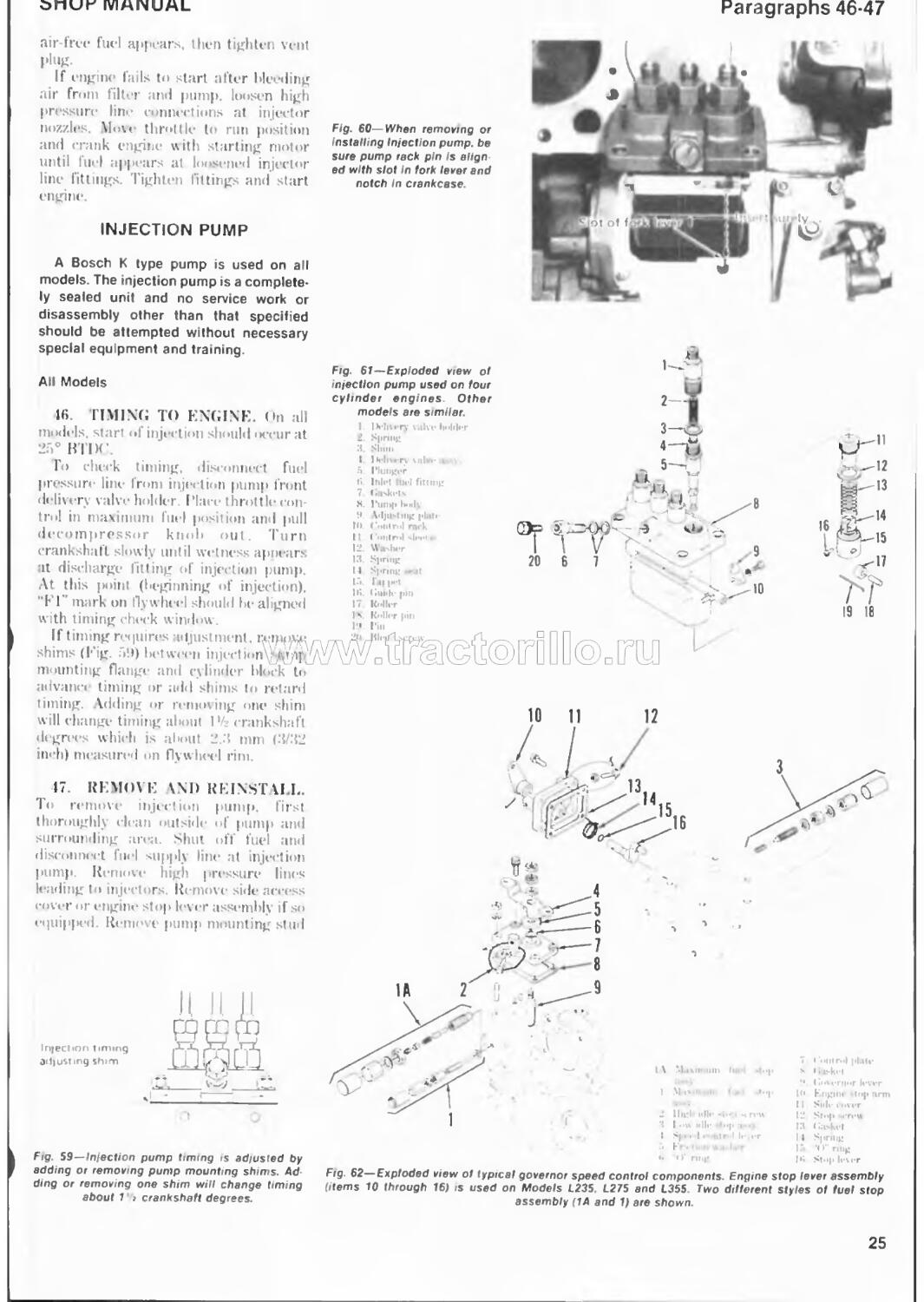
air-free fuel appears, then tighten vent plug.
If engine fails to start after bleeding air from filter anti pump, loosen high pressure line connect ions at injector nozzles. Mo\< throttle to run position and crank engine with starting motor until fuel appears at loosened injector line fittings. Tighten fittings and start engine
Fig. 60—When removing or Installing Injection pump, be sure pump reck pin Is align ed with slot In fork lever and notch in crankcase
Fig 61—Exploded view of infection pump used on four cylinder engines Other models are similar.
11
19 18
IV'llvr pill
ST
12
13
'\l
INJECTION PUMP
A Bosch К type pump is used on all models. The injection pump is a completely sealed unit and no service work or disassembly other than that specified should be attempted without necessary special equipment and training.
All Models
16. TIMING TO ENGINE. On all models, start of injection should occur at 25° В I DC.
Го check timing, disconnect fuel pressure line from injection pump front delivery valve holder Place throttle control in maximum fuel position and pull decompressor knob out. 'I urn crankshaft slowly until wetness apnears at discharge fitting of injection pump. At this point (beginning of injection). "El ' mark on flywheel should be aligned with timing check window.
If timing requires adjustment, ixnppvu shims (Eig. '»•)) between injection ДИ] mounting flange and cylinder block to advance timing or add shims to retard timing. Adding or removing one shim will change timing about 1’4 crankshaft degrees which is about 2.3 mm (3/32 inch) measured on flywheel rim.
'1 SL-15
(7 REMOVE \ND REINSTALL. To remove injection pump, first thoroughly clean outside of pump ami surrounding area. Shut off fuel and disconnect fuel supply line at injection pump. Remove high pressure lines leading to injectors Remote side access cover or engine stop lever assembly if so equipped. Remove pump mounting stud
Injection timing adjusting shim
M p '
Fig. 59—Injection pump timing is adjusted by adding or removing pump mounting shims. Adding or removing one shim will change timing about 1' > crankshaft degrees.
10
IM ullr
Fig. 62—Exploded view ol typical governor speed control components. Engine stop lever assembly (items 10 through 16) is used on Models L235. L275 and L355. Two different styles of fuel stop assembly (1A and 1) are shown.
25
Paragraphs
r\U DV I M
nuts, align control rack pm with slot in crankcase (Fig. 60) and lift pump assembly from crankcase. Do not lose or damage shim pack located between pump flange and crankcase. Shims control pump timing and same number of shims must be reinstalled unless timing is to be changed.
When reinstalling pump, be sure to guide rack control pin into notch in governor arm and crankcase. Use removed shim pack unless timing is to Iи* changed. Bleed air from system as previously outlined.
48. GOVERNOR LINKAGE ADJUSTMENT. High speed adjustment screw (2-Fig. 62) and maximum fuel limit stop (1 or I A) should not normally require adjustment unless governor or injection pump is overhauled Adjustments should b- made by qualified personnel only.
Recommended slow idle speed is 800 to 850 rpm for all models. Adjustment is made by turning slow idle stop (3). High idle speed should be 2550 rpm for Model L285; 2750 rpm for Models L235, L275 and L355 and 2950 rpm for Models LI85. L245. L295, L303 and L345. Turn high idle stop screw (2) for adjustment.
49. GOVERNOR AND FUEL
CAMSHAFT. Governor assembly can be removed with the drive gear apdf^cl camshaft as a unit after removing n^ct tiqn pump, fuel feed pump (if so equipped). timing gear cover as outlined in paragraph 31, and hydraulic pump and drive gear from rear end of fuel cam-
shaft. Remove governor mounting cap screws and withdraw governor and camshaft as an assembly.
To disassemble, remove fork pivot shaft (18-Fig. 62A) and separate fork levers (21 and 22) and fork lever holder (24). Remove drive gear retaining ring (1), then remove gear and weight assembly (2 through 8) using a suitable puller Governor weight thrust bearing (6) contains 39 loose halls. Be careful that none are lost when weight unit is disassembled.
Examine cupped race (5), balls (I) and bail travel surface on back of gear for furrowing or pitting and renew if damaged. Inspect fuel camshaft and liearings for scoring, wear or other damage and renew as necessary.
Reassemble by reversing the disassembly procedure. Be sure hydraulic pump drive gear is installed with hub facing forward. Bleed air from system, check timing and adjust governor linkage as previously outlined.
INJECTOR NOZZLES
WARNING. Fuel leaves Injector nozzle with sufficient force to penetrate the skin. When testing, keep exposed portions of your body clear of nozzle spray and wear suitable eye protection Make sure testing is performed in a well vented area.
□
□
FAl LTY NOZZLE. If engine does not run properly and a faulty injection nozzle is suspected, check for faulty nozzle
Fig 62A—Exploded view ol engine governor assembly and fuel camshaft. On some models, torque rist adjustment screw (19) is included In maximum fuel stop assembly (1A Fig. 60)
I Snap ring
2. Injection pump ю ar
3. К ill prill»
I. Bills
5. Sleeve
fi, Thrust branny (3V Nils)
7 Case
8. KeLuiuriK riiijis ! Bearing retainer
10. Bearing
II. Key
12. Fuel ranishaft
13. Bearing
14. Injection pump
15. Shims
16. Governor lever
17 Governor spring
18. Pivot shaft
III. TorqiH rise adjuster
20 Start spring
21 Governor lev er
22 . Fork lever
23 . Pivot tuns 2-1 Pivot bl'ick
as follows: U ith engine running at slow idle speed, loosen injector line at each nozzle in turn to allow' fuel to escape at union rather than enter the cylinder As in checking spark plugs in a spark ignition engine, the faulty nozzle is the one that least affects engine operation when its fuel line is loosened.
Remove and test suspected nozzle (or install a new or reconditioned unit) as outlined in appropriate following paragraphs.
51. REMOVE AND REINSTALL. Before removing an injector, throughly clean injector, lines and surrounding area. Remove high pressure fuel line and disconnect bleed line Unscrew nozzle holder from its mounting position on cylinder head.
When reinstalling injector, make sure seating surface in cylinder head is completely clean and free from carbon build up. Use a new seal washer underneath nozzle holder and tighten to 30-19 NT,m (22-36 ft.-lbs.) torque.
52. TESTING. A complete job of testing and adjusting injector requires use of special test equipment. Only clean, approved testing oil should be used in tester tank. Nozzle should lx* tested for opening pressure, nozzle leakage and spray pattern.
Before conducting test, operate tester lover until fuel flows, then attach injec-h\JUlose valve to tester gage and pump tester lever a few quick strokes to clear air from tester and to lx! sure nozzle valve is not stuck. Nozzle should open with a buzzing sound and cut off quickly at end of injection.
OPENING PRESSURE. Open valve to tester gage and operate tester lever slowly while observing gage reading. Opening pressure should he 13730-14700 kPa (1990-2135 psi) for all models
Opening pressure is adjusted by changing thickness of shim (5-Fig. 63). A change in shim thickness of 0 1 mm (0.001 inch) will change opening pressure approximately 965 kPa (116 psi).
SEAT LEAKAGE To check for leakage, actuate tester lever slowly to maintain a pressure 1001» kPa (156 psi) lielow opening pressure There should be no accumulation of fuel at nozzle tip. A slight wetting is allowed after 10 seconds if no drops are formed. If fuel leakage is evident, injector must be disassembled, cleaned and overhauled as outlined in paragraph 53.
SPRAY PATTERN. Spray pattern should l>e well atomized and uniform.
26
onui—IVIHHUML
paragraphs ьз-ьи
emerging in a straight axis from nozzle tip If pattern is wet. ragged or intermittent. nozzle must be overhauled or renewed
53. OVERHALL. Hani or sharp tools. emery cloth, wire brush or grinding compound must never be used. An approved nozzle cleaning kit is available through a number of specialized sources.
W ipe all dirt anil loose carbon front exterior of nozzle assembly. Seeure nozzle in a soft-jawed vise or holding fixture and remove nozzle nut (10-Eig. 03). < arefully separate parts and place in clean calibrating oil or diesel fuel as (hey an rejnoved Re sun parts from each injector are kept together and separate from other units.
( lean exterior surfaces w.th a brass
He movement is rough or sticky, reclean or renew nozzle valve assembly as necessary
Reassemble injector while parts are immersed in diesel fuel to avoid con-lamination. Make sure pressure adjusting shim (-”>) is in place. Tighten nozzle nut to a torque of 59-78 N-m (11 -58 ft.-lbs.) Do not overtighten as distortion may cause nozzle valve to stick and no amount of overtightening can stop a leak caused by scratches or dirt. Retest injector as previously outlined
GLOW PLUGS
All Models
54. One glow plug is provided in precombustion chamber of each
RADIATOR
All Models
50. Radiator cap pressure valve is set to open it 8S.3 kPa (12.8 psi) on all models. Some models are equipped with a u'histle type warning device attached to radiator overflow pipe. Make sure whistle is operative and properly connected to radiator
'Го remove radiator, first drain coolant and remove hood. Disconnect radiator hoses and air cli-aner hose. Remove mounting cap screws, (hen lift radiator from tractor
THERMOSTAT
All Models Except L185
wire brudi. soaking in an approved car bon solvent, if necessary, to loosen hard carlxm deposits. Rinse parts in clean
cylinder. To check glow plugs, disconnect wiring cable from glow plug terminal. then connect an ohmmeter across
diesel fuel immediately after cleaning to neutralize the solvent and prevent etch
glow plug terminal and body. Resistance should be approximately 1.5 ohms. If
57. (hi models so equipped, (he bypass type thermostat is located in coolant outlet elbow. Thermostat should
ing of polished surfaces.
(’lean noezle spray hole from inside using a pointed hardwood stick. Scrape carbon from pressure chamber using hooked scraper. Clean valve seat using brass scraper. Reclean all parts by rinsing in clean diesel fuel. Check nozzle fit by holding nozzle body vertically and lifting needle valve U[ about ’A of its length, then release needle Needle must rf... itsUv as Ж
resistance is zero ohms, glow plug is shorted. If resistance is infinite, an open circuit exists in glow plug.
begin to open at about 82' (' (l.SO' E) and be fully open at 95°C (203° E).
WATER PUMP
All Models Except L185
COOLING SYSTEM
All models use a pressurized cool-
pcller type centrifugal pump to provide force»! coolant circulation anti a ther-
58. R&R \M) OVERII \( L. Refer to appropriate Eig. 01. 05 or 00 for an exploded view of water pump. To remove pump, drain cooling system and remove radiator, if necessary. for access |p. Remove fan belt, then unbolt _______nave water pump.
To disassemble pump, remove fan pulley using a suitable puller. Unseat
mostat Io stabilize operating temperature.
Model I I85 uses natural circulation in which the relative density of hot anti cold liquid provides the means of coolant circulation. No coolant pump or thermostat is used in this system. It is of utmost importance that coolant level be maintained at a level which fully covers upper coolant hose inlet elbow
pump shaft bearing front retaining ring, then press shaft and bearings forward out of impeller and pump body. Remove seal assembly from pump body.
All water pump parts are available individually Го reassemble pump, reverse the disassembly procedure, (hi pumps equipped with fan pulley retaining nut. tighten nut to a torque of 70-78 \*m (50-58 ft.-lbs.).
Fig. 63— Exploded view of in/ector unit used on
all models.
Fig. 64—Exploded view of water pump used on Models L235. L27S end L355.
1 Cnlli-i
2 ll«h
3 I<«-|.U!ht
I Sh.ift Л- > -г
i Slllijli <
•; b -i>
7 »iil'l l-l ’ S* ,il * Ini|w lli-r
27
Haragrapns эу-ou
FAN SHAFT
Model L185
59. To remove cooling fan and shaft assembly, drain cooling system and remove radiator. Remove fan belt and fan Remove retaining nut (8-Fig 67) and withdraw fan shaft (2) pulley (4) and be«riiigs (5).
Renew parts as needed. Reinstall fan shaft assembly by reversing removal procedure
Fig. 67—Exploded view of cooling fan and shaft assembly used on Model £765.
I. Fan
2. Fan shaft
3 Key 4 Pullev 5 Bearing fi. Snap ring 7 Spacer M Nut
ELECTRICAL SYSTEM
ALTERNATOR AND REGULATOR
All Models
60. TESTING. To check charging system, first disconnect wiring connector plug from alternator. Turn main
Fig. 65— Exploded view of water pump used on Models 1245, £295 and £305.
I Nut
2. Fan
3. Pulley
4. Retaining nng
5. Bearing
6. Key
7. Shaft
8. Bearing J Retaining nng 10 B<xiy 11. Gasket 12 Slinger 13. Seal assy 14. Impeller
switch on. then measure voltage across E and F terminals (Fig. 68) of connector. Voltage should he at least 12 volts (battery voltage).
Check alternator no-load output as follows. Connect jumper lead between F and В terminals (Fig. 69) and ground E terminal to alternator frame. Connect voltmeter across R and E terminals as shown. Start engine anti operate above 1300 rpm, then turn main switch off and disconnect ground cable from battery to make certain only alternator output voltage is indicated on voltmeter. Alternator voltage should be at least 14 volts.
Measure resistance of rotor coil, slip ring and brush by connecting an ohmmeter across terminals F and E (Fig. 70). Resistance should be six ohms and maximum allowable is 10 ohms.
If alternator does not meet test sjiecifications, remove and overhaul.
To check regulator cut-in voltage, reconnect wiring connector to alter nator. Connect voltmeter across N ter-
Fig. 68—Disconnect wiring connector from alternator and check battery voltage across connector terminals E and F.
Fig. 69—Connect lumper wires and voltmeter to alternator as shown Disconnect battery ground cable and turn of! main switch during test so only alternator output voltage will be measured. Refer to text.
Fig. 70—Connect ohmmeter to E and F terminals ->t alternator to check resistance of rotor coil, slip ring and brush.
28
Onur JVIMNUML
raragrapn oi
Fig. 71—To check regulator cut in voltage, con^ nect voltmeter to N terminal as shown and m stall a 30W bulb tn place ot 10A fuse
minal and ground (Eig. 71). Remove |()A fuse (connecting red wires) from fuse panel and connect a 3o\\ l>ull> in its place. Start engine and increase speed until charge indicator lamp goes off or dims. Al this point, voltage reading should be 4.5-n.X volts. If cut-in voltage is too high, bend voltage relay adjusting arm (4-Eig. 72) closer to coil. If cut-in voltage is low, bend adjusting arm away from coil
To check no load regulating voltage, connect voltmeter across R terminal and ground (Eig. 73). Start engine anil operate above 1300 rpm. then disconnect battery ground cable. Increase engine speed to obtain maximum
Fig. 74—Exploded view ot typical alternator used on all models
7 Fnmt <чл<т x Fell ш4пт
'• Г rt it
Ih Bi-.inng
11 Ri'Uiiiht |>b(<-
Hnrh
BfihIi 'I'rinu Hniili Iwlilvr ll<ilr-lt>K Fwlr....T IriMll.ll-ir
voltage reading. Regulated voltage should be between 13.b I 1 X volts. If voltage is too high, bend regulator ad justing arm (2-Eig. 72) closer to coil. If voltage is low. bend adjusting arm away from coil
lor unit. To disassemble alternator, first scribe match marks across frame halves
to ensure correct n assembly. Remove pulley nil’ (1). then remove pulley and Ian. Remove through-bolts and separate drive end frame (7) and rotor (13). Remove rectifier retaining nuts and withdraw end cover (21). rectifier (l<»)
Tindrstator (la).
m ohmmeter to check rotor coil
Suicc across slip rings (Eig. 7.7). If resistance is not tpproxitnalely 1.2 ohms, renew rotor ( heck for continuity
voltage.
Fig 72—Cut-in voltage can be adjusted by bend Ing voltage relay adjusting arm (4). Bend voltage regulator adjusting arm (2) to adjust reguiated
Fig. 75—Check resistance across rotor slip rings. Resistance should be approximately 4.2
Fig 73—Connect voltmeter across В terminal and ground to check noload regulated voltage.
There should not Ih continuity, (’heck stator coil leads (I* ig. 77) for continuity and renew if open circuit is found. < ’heck
for Continuity Renew -later if grounded circuit is found Check diodes by placing negative probe on outside diode pin and positive probe on mounting studs (Eig. 79). then reverse position of probes. Ohmmeter should indicate continuity in one direction and indicate inlinitv in the
other direction if diode is satisfactory. Repeat test for each diode and renew
ohms.
tween slip ring and rotor frame. Fig 77—Check stator coil leads for continuity.
29
Paragraph ы uont.
1XUDU I M
diode assembly if any are defective Check for continuity between N terminal (I - Fig. 80) and inside coil connecting terminals. If open circuit is found, renew diode assembly. If length of brushes is less than 10.5 mm (13/32 inch), renew brushes.
When reassembling alternator, be sure insulating washers are installed on positive diode holder studs (1 - Fig. 81). Before reinstalling rotor, insert a win1 or plastic rod through hole in end frame (Fig 82) to hold brushes up. Be sure to remove wire after rotor is installed
17 181920
14 15 16
H
9 Pinion pur & clutch assj
10 Frame
11. Field coil
12 Brush
13 Brush spring
14 Brush & holder
KSKJ.
15. Bushing
16. End frame
17. Gasket
18. Spring
19. Retainer
20. Cap
Fig. 78—Check for continuity (short circuit) across stator leads and stator frame.
Fig 84—Exploded view of starter motor used on Model L185.
i. «‘lug
2. Bu'-hing
3. Drive end fruae
4 Drive lever
5 Magnetic switch
6. Armature
7. Snap nng
8. Spactr
Fig 81—Make certain insulating washers (1) are Installed on positive diode mounting studs.
Fig 82—Insert a wire or plastic rod through end frame to hold brushes up when reinstalling rotor.
Fig. 83— Disconnect lead at C terminal of magnetic switch, then connect battery positive terminal directly to starter to check starter motor operation.
3
Fig. 79—Check diodes by placing negative probe on outside terminal and positive probe on mounting stud, then reverse test lead positions.
Fig. 80— There should be continuity between inside terminals and N terminal (1).
Fig. 85—Exploded view of starter used on Models L235. L245 and
L275. Refer to Fig. 84 legend except tor following Items:
21 Spring holder 22 Center hearing 23. Washer
30
Make certain match marks are aligned when assembling end frames.
STARTER MOTOR AND MAGNETIC SWITCH
All Models
62. To check starter and switch operation, disconnect lead from (’ terminal (Fig. 43) of magnetic switch ami connect battery positive terminal direct ly to starter ( lead Connect battery negative terminal to starter fra motor rims smoothly, maynetic sw\ defective: if not, motor is defective. Maynetic switch pull-in coil and hold in
coil should operate1 porperly with ’/« of rated voltage (six volts) applied to switch terminals. Renew maynetic switch as a unit if defective.
Refer to Fig. X 1, s5 and S6 for explod eel view of starter motors, When servicing starter motor, check armature and field coils for shorted or open circuits and renew as no -ded ( heck armature
bushings and bearings for excessive wear and renew as necessary. Minimum allowable brush length before renewal is
Fig 91 — Measure clutch pedal tree travel at lop ol pedal Adjust length ot clutch rod (1) 10 obtain recommended free travel. Adjust safety start switch clearance (A) as necessary.
Refer to text
Fig. 86 — Exploded view ot starter used on Models L28S. L295. L305 L345 and L355
.1
2 BniOi
3 \rm iture
I Gakkel
'• Kni*<h hobh r
•• Brush ч>nrig
7 Ga<kc<
> Magnviir «witch
•J Kill'
l<> Pinion gear & riuteh a? a
Il Hi-tiiii Inin gear*
12 I >n\e cn>| frame
10.5 mm (0.1 inch) on Model LIX5 and 12 7 mm (0.5 inch) on all other models. Pinion enyagement depth is set by ad justing maynetic switch hook (II-Fig. XI or X5) With starter pinion in engaged position, distance between stop collar (X) and pinion should be о l-o. | mm (0.00 I <>OI6 inch) on Model 1,1X5 ami (i l и 5 mm (O.oo t o.irjo inch) on Models 1,235. 1,215 md 1,275.
CLUTCH c , nyorai o D ©□ m
All Models
63. < lutrh pedal free travel should be measured at top of pedal. Adjust length of clutch linkage1 rod (I Fig 91) as necessary to obtain following n-rom mended free travel: 25-3.5 mm (I to I 4 inches) on all models except Models 1,235 ami L275 with dual stage clutches which should be 30-10 mm (1-3/16 to
1-9/16 inches) On all models, make* certain clutch releases completely after adjusting free travel ami readjust if
necessary.
Adjust safety start switch (Fig. ‘.Hl to obtain rv-onunen led yap between switch an<l operating arm. On Model 1,355, clearance should be 2.0-3.о mm (0.0X0-0.120 inch) On Models 1,235 and 1,275 with dual plate dutch, clearance should be I 0-2.0 mm (o.o io 0.0X0 inch). On all other models, clearance should be 0.5-1.0 mm (0.020-0.1) Ю inch) Make certain start» r will not operate until clutch pedal is fully depressed
REMOVE AND REINSTALL
All Models
•>l. ( 1,1 ГГ('11 SPLIT. To separate (split) tractor between engine and clutch housing, proceed as follows: Remove muffler an<l hood Disconnect battery cables. Drain oil from transmission
housing, power steering reservoir (if so equipped) ami engine oil. On models equipptd with front wheel drive, detach drive shaft. On all models. disconnect steering drag link and booster cylinder (if so equipped). Disconnect wiring as necessary at alternator, start» r glow plugs, safety switch, oil pressure switch and water UmiperaUire switch. Disconnect engine stop rod (if so equipped), throttle control rod, decompressor control cable, tractor meter cable and hydraulic tubing as needed. Shut off fuel
isconnect fuel supply pipe and fuel ....n pipe Support engine transmission with suitable stands or overhead hoist
a ml splitting Remove
engine- mounting holts, then separate engine1 from flywheel housing.
Reconnect tractor by reversing .splitting pr icedurc Tightening r<‘taming bolts to i torque of 50-56 N'-m (37-11 fl.-lbs.)
OVERHAUL
Single Plate Clutch
65. Refer to Fig. $)3 for an exploded
view of single plate dutch assembly, (.'hitch cover ami pressure plate (2) are available only as an assembly; all other components are available individually.
Check backlash between clutch disc and main shaft spines. Backlash should not exceed 2.0 mm (0.0X0 inch), ('heck clutch facing wear by measuring from clutch disc surface to top of rivet. If depth is ess than 0.3 mm (0.012 inch), renew clutch disc. Renew clutch disc if it is W’.irped, burned or oil soaked, ('heck pressure plate. flatness using a straightedge and feeler gage. Plate should be flat within 0.2 mm (0.00X inch). Inspect release bearing for ex eessive wear or roughness when turned and renew as needed.
31
Paragraphs 66-68
киви IA
Fig. 93—Exploded view ot single plate clutch assembly used on some models.
1. Clutch div
2. Pressure plate nssj
3. Release sleeve
4 Pork
5. Case
6. Release bearing
7 Return spring
8 Spacer
9 ”<> nng
10. Clutch shaft
Fig. 95—Clearance between top of adjusting screw and pto pressure plate should be 1 0 mm (0.039 Inch}.
Dual Plate Clutch
G6. An exploded view of dual plate clutch assembly used on some models is shown in Fig 91. Before removing clutch assembly from flywheel, scribe match marks across clutch assembly and flywheel. Clutch assembly is dynamically balanced and should I -e reassembled in its original position.
To disassemble clutch, use a press or mount clutch on clutch tool (Code No. 07916-90050) to depress clutch cover and relieve spring tension on release levers. Remove release lever p.vot pins, then separate clutch components.
Inspect all parts for excessive wear or other damage. Backlash between clutch
Fig 94—Exploded view of dual plate clutch assembly used on some models.
I. Ihafhragm springs
2. Release rod
3. Release к ver
4. Front cover
5. Pto clutch disc
6 Pto pressure piate
7 Ke.tr cover
8 Pin
9 Traction clutch disc
10 Traction prc-sur.-| law
I). Adjusting bolt
12. Release bearing
13. Hub
14 Fork
t5. Clutch shaft
16. Return spring
discs and transmission shaft splines should not exceed 2.0 mm (0.080 inch). Depth from clutch disc surface to top of rivet should not be loss than 0.3 mm (0.012 inch). Renew clutch discs if warped, burned or oil soaked. Renew pressure plates if not flat within 0.2 mm (0.008 inch). Inspect release bearing for wear or roughness when turned and renew as necessary
To reassemble clutch, mount clutch components on clutch alignment tool (Code No. О79Ю-9ОО50) making certain match marks made prior to disassembly are aligned. Measure clearance between top of adjusting bolts (Fig. 95) and pto pressure plate with a feeler gage. Turn adjusting bolts as needed to obtain
Fig. 96—Clearance between gage block (1) end release lever adjusting screws should be 0.3 mm (0.12 Inch).
recommended clearance of l.V mm (0.039 inch). Position gage block (1 - Fig. 9(>) onto clutch assembly tool Adjust iTOhane lever bolts to obtain clearance of □ D-ijun (0.012 inch) between top of bolt and gage block
Use clutch centering tool to align clutch discs and support clutch when reinstalling unit on flywheel Tighten clutch mounting cap screws to a torque of 24-28 N-m (18-20 ft.-lbs.).
TRANSMISSION
(Models L185-L245-
L285-L295-L305-L345)
67. A four-speed sliding gear main transmission unit is combined with a high-low range transmission to provide eight forward speeds and two reverse speeds.
SHIFTER RAILS AND FORKS
Models L185-L245-L285-L295
68. R&K AND UV ERH L. Shift rails, forks and associated parts are shown in Fig. 97 Models LI85, L245 and L295 are equipped with three speed
32
>-ПОН MANUA
Paragraph 68 Cont.
pto and use two pto shift forks (26). Model L2X5 is <M|uip|>e<i with two speed pto and uses a single pto shift fork.
To disassemble main transimission shift mechanism, first unbolt and remove lever housing (9) and remove shift rail detent springs (12) and balls (13). Main shift lever (2) ind pto shift lever (Dare withdrawn from below after removing lever knob, snap ring (3), washers and spring (a). Positioning pins (1<>) can In punched out and renewal if worn or damaged.
With shift housing removed, drive spring pins (2t>) down out of shift forks. Bump shift rails rearward out of housing. Note that interlock balls (11) occupy
a cross drilling between rails. When one rail is moved from neutral, balls enter grooves in adjoining rails, thus locking rails and preventing shift forks from moving into two gears at one time. \ suggested method of disassembly is to remove center rail first, then dump both interlock balls out through hole where center rail was removed. Make certain interlock balls are reinstalled when shift housing is reassembled.
To remove range shift fork (39) and rail 110), tractor must he split between front and rear transmission housings and hydraulic lift housing must be removed Rt move retaining set screw (11) and snap pin. then push pin rail
rearward catching detent ball and spring as rail is removed. Drive out spring pin and remove plaU (31) to disassemble shift lever(33)and arm (36)
To reinstall shift mechanism, remove lever housing (9) if not already done. Position all shift forts anti slitting gears to neutral position. Hold main shift forks together to hold neutral stops (18) in position, then carefully install shift cover making sure each fork correctly meshes with its respective slot in sliding gears and pto levers (30) engage pins (29) in pto shift forks. Tighten shift housing retaining screws, then move all shift forks to be sure they operate pro perly. Install lever cover guiding ends of
Fig. 97— Exploded view of transmission shift rails and forks used on Models L185. L245 and L295.
Models L285, 1305 and L345 are similar except a single pto shift fork Is used
1’1.. 'lllfl IrUT M Illi 'Juft li-vi-r Snap ring W;i«i . r Spring W:i*I, r
o’ ring Shn-hi til «1411g
15 Slut' nil hi Shift mil 17 Shift r.nl IS Ni-utr.il top 111 Spring JI Spring pin 21 Shill fork 22 Shift fork
2H Bill JU fin
.Ml Shift Ь-чгГ' |pti 31 Itltl-rhn-k Kill .42 Shut nnl> (pto) ,’U Ring* Ititfi .’M. Slop pl«!«' ar., -tr nng 3t> Shift .«rni
Paragraphs 69-71
KUbUIP.
Fig. 98—Exploded view of shifter forks and shafts used on Models L305 and L345.
1 Shift lever
2. Snap ring
3. Washer
4 Spring
5. "O' nng
6. S1ih4cI
7. Shift cover
8 Pins
9 Shielil
10. Balls
11 Shift rails
12. Shift fork
13 Spnng
14 Neutral stops
15. Shift fork
16. Shift fork
17 Detent toll
18. Detent spring
19. Shift arm {pto)
20. Shift rail
21. Shift fork (range)
22. Spring
23. Detent ball
24. Shift arm
25. *()" nng
16. Retaining pin
27. Shaft rvU.nn r
28. Range »hift lever
29. Set screw
30. O” ring
31 Pto shift lever
3*2. Shift f rk (pt*>)
33. Shift rail
levers into proper position as cover is To reassemble shift assemblies, by reversing removal procedure
on., Shift cover. Mo №ls L18S-L245-L295
Models L305-L345
69. R&R AND OVERHAUL. Refer to Fig. 98 for an exploded view of shift rails, forks and associated parts.
To disassemble main shift housing, unbolt and remove lever cover (7) and dump out detent springs (18) and balls (17). Remove shift lever knob and unseat spring retaining ring (2). then lower shift lever (1) out bottom of cover. Positioning pins (8) can lie punched out and renewed if worn or damaged. Drive spring pins out of shift forks. Rails (11) are removed rearward out of cover A suggested method of disassembly is to remove center rail first, dump both interlock balls (10) out through hole where center rail was removed, then remove outer rails. Be sure interlock balls are reinstalled when cover is reassembled.
To remove pto shift fork (32), tractor must be split between front and rear transmission housings. Remove retainer (27) and remove shift rail (33) out front of center case.
To remove range shift fork (21). rockshaft housing and differential assembly must be removed as outlined in paragraph 91 Remove set screw (29) and retainer pin (26), then pull rail (20) rearward and withdraw shift fork.
forks and sliding gears in neutral position. Carefully install shift housing making sure each fork correctly meshes with
its respective slot m sliding gear. Tighten housing mounting cap screws, then move all shift forks to be sure they
operate correctly.
FRONT TRANSMISSION
All Models
70. REMOVE AND REINSTALL. To remove front transmission housing, first split tractor between engine and clutch housing as outlined in paragraph 61. Support front transmission housing and rear transmission housing separately. Remove steering wheel, instrument panel. fuel tank and steering gear assembly. Remove steps and brake and clutch pedal assemblies. Disconnect hydraulic pipes from lift cylinder and transmission housing. Disconnect wiring harness as needed. Remove transmission mounting stud nuts, then separate front transmission from rear housing.
When reconnecting transmission, be sure couplings are installed on transmission and pto shafts. Tighten mounting stud nuts to a torque of 47-56 N-m (35-40 ft.-lbs.) and complete installation
71. OVERHAUL. To disassemble main transmission, remove shift housing and forks. Remove clutch release bearing. fork and shaft, then unbolt and remove front oil seal retainer. Remove retaining rings from countershaft (14-Fig. 99 or 100), then tap shaft forward until front l>earing is out of housing. Remove bearing retaining ring, then remove front bearing using a suitable puller. Tap countershaft rear ward and withdraw gears as shaft is removed. Use a brass drift to Lap input shaft (26) and bearings forward out of housing. Remove bearings and gears from shaft as necessary. Remove set screw (2) retaining reverse idler shaft (1), then withdraw shaft and gear. Remove set screw securing pto shift fork shaft, then Lap shaft forward and remove shift fork. Tap pto countershaft (37-Fig. 99 or 41-Fig. 100) forward until front bearing is out of housing. Use a suitable puller to remove front bearing, then tap shaft rearward and withdraw gears and pto drive one-way clutch assembly.
To reassemble transmission, reverse the disassembly procedure w hile observing the following items. Be sure thrust washers are reinstalled with their
34
□ nur IVIHI4UAL
aragraph 72
grooves facing the gears. Make certain set screw indentation in pto shift fork shaft and revers»* idler shaft are positioned correctly. Grease lip of input shaft oil seal before reinstalling.
Model L285
72. Overhaul. t<. disassemble main transmission, proceed as follows; Remove shift housing and forks.
Remove dutch release bearing, fork and shaft, then unbolt and remove input shaft seal retainer. Tap countershaft (II—Fig. U>1) forward and remove cover (6) and snap ring (7). Tap shaft rearward and withdraw gears as shaft is removed from housing. Гар input shaft assembly (17) forward and remove from housing. Remove bearings md gear as necessary. Remove retainer plate (1). then withdraw reverse idler shaft (3) and gear (o). Tap pto countershaft (21)
forward and remove cover (2<>). snap ring and front bearing. Tap shaft rearward out of housing .md withdraw gears (23) and overrunning clutch assembly (21» through 33).
Inspect all gears and shafts for excessive wear, chipped or cracked teeth or other damage and renew as necessary
Го reassemble main transmission, reverse the disassembly procedure.
Fig 99—Exploded view ot gears and shafts located in front transmission housing on Models L185 and L245
35
Paragraph 73
kubuim
I. Reverse idler shaft 2, Set screw
3. Rushings
4. Reverse idler gear
5. Cover
6 Snap ring
7. Bearing
Я Thrust washer
9. Retaining ring
10. Gear(32T) 11 Spline boss 12. Retainer dip
13 Gear (4 IT)
14 Countershaft
15 . (наг(45Т)
16 . Gear (45T)
17 Rearing IK Washer 20 (hl seal 21 Snap nng 22. Washer M Bearing 24 Getrf23T) 25 Gear(17T) 26. Input shaft 27. Washer 28. Snap ring 29. Bearing 30. Washer 31 Spacer
32. Washer & dowel pin 33. Washer
34. Cap screw
35 Cover
36 Snap nng
37. Washer
38. Bearing
39. Sjiacer
40. Gear (4 IT)
41 Pto countershaft
42 Gear (45T)
13. Retainer dip
44 Spline boss 45. Gear(45T)
46. Thrust waeher
47 Blaring
48. Washer IP Spring 60. Pto clutch cams 51. Snap ring 52. Spacer
Fig 100—Exploded view ot gears and shafts located In front transmission housing on Model L295.
Models L305-L345
73. OVERHAUL. To disassemble ma.n transmission, first remove shift housing and forks if not already removed. Remove clutch release bearing, fork and shaft. Remove mounting cap screws from front cover (25-Fig. 102), then use tw'o jackscrews to lift off cover and input shaft (28) as a unit. Remove snap ring and pto drive gear (51). then unbolt and pull gear case (1) with spacers (3 and 55) from housing. Remove clips (11) and retaining rings from countershaft (13), then slide coupling (17) rearward until disengagefl from countershaft. Use a suitable puller to remove front bearing (6), then lift countershaft and gears from housing. Remove center case from front transmission housing. Remove set screw (22) and withdraw reverse idler shaft (21) and gear (24). Screw two bolts into mainshaft spacer (29) and pull spacer from housing. Remove retaining ring securing front bearing (34), then tap mainshaft (41) rearward out of housing Tap pto countershaft (GO) to the rear and remove shaft, gear and washers. Needle bearings (58) can be driven out and renewed if worn or damaged.
Fig 101—Exploded view of gears and shafts located in front transmission housing Model L285.
1 Retainer plate
2 . "O" ring 3 Idler shaft 4. Bushings
5 . Revins.' idler gear
6 Over
7 Snap ring я Bearing
9 Gears (23-36T)
10 Gears (33 38T)
11 Countersh ift
12 l< aring
13 . Coupling It Oil seal 15 Washer 16. Bearing 17 lii(ut «haft 18. Gear(l9T) 19 Bearing 20. Cover 21. Snap ring 22 Bearing 23. Gears (33-38T) 34 |*t« countershaft 25. Bearing 26. Snap ring 27. Bearing 28. Coupling 29 Sprag clutch 30. S[iui-er 31. Bearing 32. Clutch case 33. Coupling 34 Shaft 35 Bearing
36
SHOP MANUAL
Paragraph 74
To disassemble center ease, tap shaft (19) forward to remove bearing and shaft from case. Remove snap ring, gear C’.o) and spacer (36) from center shaft then tap shaft nut of case. Remove retainers (27-Rig. 9<S), then drive spring pin out of pto shift lever (31) Remove arm (19), shift rail (33) and fork (32). Remove retaining ring from rear of countershaft (63-Fig. |02). then lap shaft forward out <»f case.
To reassemble main transmission, reverse the disassembly procedure.
REAR TRANSMISSION HOUSING
All Models
71 REMOVE AM) REINSTALL. To remove rear housing, first drain oil from transmission housingsand rear ax le housings. Remove hydraulic pressure
and intake pipes leading to pump. Disconnect electrical wiring and brake control rods. Wedge front a.xk to prevent unit from tipj ing and support tractor under front transmission housing. Support rear housing with a suitable hoist or stand, then remove fenders, rear wheels and final drive units as outlined in paragraph ion. Remove seat and rockshaft housing, then separate housing from tractor.
Fig. 102—Exploded view ot gears and shafts located in front and center transmission housings on Models L305 and L34S Fan brake on gear /59) was used on early models only
'• >" ring Sp:i. er SlKip Г11Щ Wa-lx-r He in ng rliribt •• i*)x*r [(•Uiining ring
Spill»' Ih.S-[{<•!.1ЦН Г .'Jip i;-.(r<ii ti < .(Ullter ll.lf’l /:.пг||5Г) Gi.irilM) Bunring Coupling
B* .iring Sh-jfl Coupling Idler 4uiH Sri -i-rrw KuMiing U....Г-. I П.-r ge.lf
hr -III >«« r Oil 'i'll Bearing' Input -1 I’ ipt il Sp к er •O* ring
Oil seal 11Л1Г.1 Snap ring W.-> er
.’»ii Snap ring a lleir <3‘‘T>
*nt Sn ip ring
•53 Bearing
37
Paragraphs 75-76
KUBOIA
When reinstalling rear transmission housing, make sure shaft couplings are installed. Tighten mounting stud nuts to a torque of 47-56 N'*m (35-10 ft.-lbs.) and rockshaft housing. Remove stud nuts securing rear housing, then separate housing from tractor
Models L185-L245-L295
75. OXERHALL. To disassemble rear transmission housing, tap countershaft (4-Fig. 103 or 104) forward until front bearing is out of housing. Tilt rear of shaft upward for working clearance, then remove rear bearing using a suitable puller. Withdraw shaft and gear (6) from housing. Insert a brass rod to lock differential ring gear, then remove locknut (9) from bevel pinion shaft (18). Remove differential lock, hearing cases and differential assembly from housing. Remove set screw retaining range shift fork shaft. Pull shaft rearward and remove shift fork. Use a suitable puller to remove front bearing case (13) and
bearings from bevel pinion shaft. B< sure to retain shims (11) for use in reassembly. Bull pinion shaft rearward from housing and withdraw gears (15). Remove retaining ring and press shaft out of rear hearings (17) if renewal is necessary. Remove pto shaft front bearing retainer and cap screws securing rear bearing case (28-Fig. 103 or 31-Fig 104). Tap pto output sha ' 'ЛТ or 32) rearward out of housing. Remove
locknut (23 or 27) and bearing retaining ring, then press rear hearing and case off pto shaft. Drive oil seal (26 or 30) out of bearing case
Bevel pinion shaft (18) is available only as a matched set with bevel ring gear. If renewing shaft or bearings, backlash and mesh position must be checked and adjusted when reassembling. Refer to paragraphs 95 and 96 for procedure.
To reassemble rear transmission, reverse the disassembly procedure Tighten bevel pinion shaft locknut to a torque of 150-195 N*m(110-118 ft.-lbs.).
Model L285
76. OVERHAUL. To disassemble rear transmission housing, proceed as follows: Remove rear snap ring from range countershaft (3 —Fig- 105). then tap shaft forward out of housing and remove gear (4). Inset a brass drift into differential ring gear teeth to prevent bevel pinion shaft (14) from turning, then remove locknut (9). Remove differential assembly as outlined in paragraph 91 Remove front bearing case mounting cap screws, then tap bevel pinon shaft rearward and remove shaft and gear (11) from housing. Remove snap nng and press pinion shaft
Fig. 103—Exploded view ot gears and shafts located In rear transmission housing on Models L165 adn L245.
I. ('< upling
2 Snap ring
3. Bearing
4 Countersliaft
5. Snap ring
6. Gear GUT)
7. Spicer
8 Bearing
9. Nut
10. Cover
11 Spacer
12. Bearings
1.4. Bearing case
14. Shim
15. Gear (29-48T)
16. Snap ring
17. Bi inng
IS Bi vel pinion shaft
19. Spacer
20. Bearing
21. Pto shaft
22. Bearing retainer
23. Nut
21 Snap nng
25. Bearing
26. Oil wal
27 < lasket
28 Beuring case
29. Slinger
30. Cap
out of rear bearings (13). Be sure to retain shims (8) for use in reassembly. Remove snap ring from front of pto output shaft (18). Remove cap screws from bearing case (25). then tap pto shaft rearward from housing. Remove nut (19) and snap ring (2O)4 then press shaft
Fig. 104—Exploded view ot gears and shafts located In rear transmission on Model L295
1 Coupler
2. Snap ring
3. Bearing 4 (’•untersh ift
5. Snap nng
6. Geir(2lT)
7 S|iacer
Я. Bearing
9. Nut
III. Couer
12. Bean ng
13. Rearing case
14 Shim
15 Gear (I5-37T)
16 Snap ring
17 Branugv
18. Bevel pini<*n 4haft
19 Coupler
20. Snap ring
21. Rearing
22. Shaft
23. Snap rings
24. Bearing
25. Shaft
26. Coupler
27 Nut
28. Snap ring
29. Bearing
30. Oil seal
31 Sleeve
32. Pio shaft
33. Gasket
34 Bi aring case
35. Slinger
36. Cap
seal (23) out of case.
Inspect all parts for excessive wear or other damage and renew as necessary Bevel pinion shaft (11) is available only as a matched set with bevel ring gear If shaft or liearings are being renewed, backlash and gear mesh must lx* check-adjusted when reassembling as
38
outlined in paragraphs 95 and 90.
To reassemble rear transmission housing. reverse the disassembly procedure. Bi sure original shim pack (S) is reinstalled if original bevel pinion shaft and bearings are being reinstalled. Tighten locknut (9) to a torque of 150-195 N-m (110-115 ft.-lbs.). Stake nut after tightening.
Fig. 105—Exploded view of gears and shafts located In rear transmission housing on Model L285.
1 Snap ring
2 Bearing
3 Krvvrw idler di-ifl I HeMTM* idltr gear Bearing
7 Retiring сим-S SI im
!’ Silt
l<i Rearing' 11 । ;.tir~ (2G 12 Si ap ring 13 B< (rings 1-1 Revel pinion shaft 15 ( • upler Hi Slap ring 17 Buinng
IS l‘to out [nil -h 1ft IH Sul
JO Snap ring
21 Bearing
22 Sp o'er 2.4 I >n seal 21 < .iisket 25 Rear.ng <* w 2<; t up
other damage and renew as necessary Bevel pinion shaft (15) is available only as a matched set with bevel ring gear. If renewing shaft or bearings, backlash and gear mesh must be checked and adjusted when reassembling as outlined in paragraphs 95 and 9(>
To reassemble rear 'ransmissflin hpus-
Tighten pto shaft locknut (20) to a torque of 150-195 N*m (110-1-15 in.-lbs.) Stake nut after lightening. Tighten bevel pinion shaft nut to a torque of 15019a N-m (110-115 ft.-lbs.). then stake nut.
TRANSMISSION
(Models L235-L275-L355)
78 On al] models, a four 'peril main transmission unit is coupled with high-low range transmission to provide eight forward speeds. M< dels 1/235 and 1/275. a mechanical shuttle (forward-reverse) section allows forw ird operation in any of the eight speeds and reverse operation in first seven speeds. Eighth speed is locked out in reverse for safety reasons.
On Model L355, a hydraulically actuated forward-reverse shuttle transmission
allows forward or ‘evci any of the eight speeds.
SHIFTER RAILS AND FORKS
Models L235-L275
79 R&H \\l) 0V ERH VI L Shift rails, forks and associated parts are shown in Fig. 107 Pto shift components
Models L305-L345
77 OVERHVI L. Го disassemble rear transmission housing, proceed as follows: Remove differential lock actuator shaft and shift fork. Remove snap ring Irom rear of countershaft (3-Fig. 10G). then tap shaft forward from housing and remove gear (1) ami hearings. Insert a brass rod between ring gear and bevel pinion gear to prevent shaft from turning, then remove nut (7) from bevel pinion shaft (15). Remove differential carrier hearing cases and withdraw differential assembly. Uiosen set screw securing range shift rail (20-Fig. 98). remove snap pin (2G) ami pull rail forward out of housing and withdraw fork (21). Remove shift lever (28) and arm (21). Remove cap screws securing bevel pinion bearing case (10-Fig. 10G). Tap bevel pinion shaft rearward out of housing. then remove front hearing case and bearing. R< sure to retain shims (11) for use in reassembly Remove snap ring (13) and press shaft out of bearings (II). To remove pio output shaft (2fi). remove front bearing (17) using a suitable puller. Remove bearing case (28) mounting cap screws, then withdraw shaft assembly rearward from transmission housing. Remove nut (20)and retaining ring (21). then press shaft out of hearing ease.
Fig 106—Exploded view of gears and shafts located In rear transmission housing on Models L305 and L345
I Snap ring
2 Rearing
3 C-uinters|iafl (r lllgi'l
i <;«-.iri2iTi
’> Spacer
•> Bearing
7 Sul
Ц Rearing 111 Rearing । .
11 Shim
12 <мпг(|5-37Т1
13 Snap ring
11 Hi lring'
15 Revel pttlion 'lisfl
IB (Ivar (2213
17 Bearing
IS Snap ring
!'• Rearing
20 Nnl
21 Snap ring
22 Spai-i r d.3il.r>|
23 Bearing
21 Oil-eil
25 Sleeve
2B 13" "input -haft
2S Bearing । ,t-.
ill Slinger
3" I ar
39
Paragraph 80
To remove main shift housing (l<i). disconnect shift lockout control cable and remove shift lever guide housing. Shift transmission into neutral, then unbolt and remove housing with shift rails and forks.
To disassemble main shift housing, remove shift cover with shift levers Remove retaining ring (3), then withdraw shift lever from bottom of shift cover. Remove detent balls (1(5) and springs. Drive spring pins out of shift forks (11 and 12) and remove shift rails (13) rearward from housing. Drive spring pins out of holder (17) and shuttle shift lever (19). Remove shift rail (18), holder and lever.
To remove shuttle shift fork (21) or range shift fork (27). tractor must be spin between front transmission housing and rear transmission housing. Rockshaft housing must also be removed from rear transmission housing for access to range shift fork Loosen set
22 Detent ball
Fig. 107—Exploded view of shifter rails and shafts used on Models L235 and L27S. I Shuttle shift lever
2. Main shift lever 3. Retaining ring
4 Washer
5. Spring 6 "<r ring 7. Shield
8. Pins
9. Shield
12. Shift fork
13. Shift rails
14 Interlock tiall
1ft. Spring
14>. Detent ball
17 Holder
18 Shift rad
19. Shift arm
23 Set screw
24 Range shift lever
2ft Retainer
2f- Shift rail
27. Range shift fork
28 Shift arm
29 "O' ring
30. Ball
10. Shift housing 11 Shift fork
20. Shift rail
21 Shuttle shift fork
screw (23) and remove snap pin (32). Pull shift rail (26) forward and remove shift fork. Remove retainer (25) and drive shift pin from shift lever. Remove shift lever (24) and arm (28). To remove shuttle shift fork, remove center case from front transmission housing. Drive spring pin out of fork (21), then pull rail (20) out of housing and remove fork.
To reinstall shift linkage, reverse the removal procedure. Adjust shift lever lockout cable (4-Fig Ю8) as follows: Place range shift lever (5) in high speed position and shuttle lever (2) in reverse position. Push down lightly on lockout lever (I) and move main speed shift lever (3) to neutral position and to the right. There should be a gap (A) of 1-2 mm (3/64-5/61 inch) between lockout lever and shift lever. Adjust cable length (B) to obtain recommended lever setting. Re sure shift lever is free to go up into seventh speed position but cannot l>e moved down into eighth speed slot when
31 Spring ЗЙ. Retainer pm
KUbUIA
shuttle lever is in reverse position.
Model L355
80. R&R AND OVERHAUL. Shift rails, forks and associated parts are shown in Fig. 109. To remove main shift housing, shift transmission into neutral and unbolt and remove shift cover and housing. Remove shift lever knob and retaining ring (2), then withdraw shift lever (1) from bottom of cover (7). Remove detent springs and I Kills (15) and drive spring pins out of shift forks (12). Remove shift rails (11) rearward and withdraw forks.
To remove range shift fork (20) or pto shift fork (31), front transmission housing must be separated from rear housing. Rockshaft housing must also lie removed from rear transmission housing for access to range shift fork. Loosen set screw (27) and withdraw snap pin (22). Pull shift rail (19) forward and remove range shift fork (20). Remove retainer (25) and drive out spring pin, then remove range shift lever (26) and arm (23). Center case must lie removed from front transmission housing to remove pto shift fork (31). Remove retainer (33), then pull rail (32) forward and remove fork Remove retainer (29) and drive out spring pin then remove shift lever (28) and arm (18).
Renew all worn or damaged parts. Il^apssemble by reversing the diissasembly procedure.
Fig. 108—A shift lockout lever (1) is used on Models L235 and L275 to prevent operating tractor in eighth speed when shuttle is In reverse.
I Lockout lever
2. Shuttle shift lever 4 Lockout cable
3 Mau. shift lever Б Range sh.ft lever
40
Onur MANUAL
Paragraphs 81-82
Fig 109—Exploded v-ew of shift rails.
1 Mun shift lewr
2 . Ri'tariinir ring
" W.lshlTS
t Shi-in*!
". *< •" rinn Shit'll I
S I’ills
" S|i|,.|t| It* Inti-rltH'k li ill II. Shift rills 12. Shift fiirks l.t. Spring 14 N<-ulral stop l.'i Ih-ti-M lull l*‘- Spring 17 ‘fl" nilg IS Shfi irm |pi<>) 19 SI ift rail Irangv) S> St iff fork (r.ingel 21 Ball 22. fin
23. Shift irm trnniti*)
24 "< I ’ ring
2-'> Iv itinivr
2<‘-. Shift «it ir.ingi'f
_’S Shift evtripln)
29 Ih l.niH-r
3H Ball
31 Sinti <тк tptui
32 Shift iTiil
33 Ki-tiiitHT
forks and associated parts used on Model L355.
FRONT TRANSMISSION
Models L235 L275
81. REMOVE AND REINSTALL. ____
To remove front transmission as A Wriin,-'*
firs, split lra«ti>r lK.lw«-n ^№^4 Ц” OS dutch housing as outlined in paragraph t»l. Remove steering wheel, instrument panel, fuel tank and steering gear assembly. Disconnect shifter lockout cable from range shift lever. Remove both steps, clutch and brake pedals as an assembly and hydraulic suction and pressure pipes. Support rear housing with a suitable stand and front housing with a splitting stand or hoist. Remove housing
mounting stud nuts, then front housing from rear lious-
mg.
V\ hen housings, tighten stud nuts to a torque of 103 108 N-m (7<« so ft.-lbs.). Tighten engine- mounting holts to t torque of 18 ."><• N • m (3G 11 fl. Iks.). \djiist shifter lockout cable» as outlined in paragraph
recount ding transmission
82. OVERHAUL. To reassemble main transmission, first shift transmission into neutral anil remove shift guide housing. I nl>olt and lift off shifter housing with forks. Remove clutch release bearing, hub. fork and shaft from clutch housing On tractors with single plate engine clutch, remove front cover < I - Eig. Ilc>) from main shaft On traitors equipped with dual plate engine clutch, remove front cover (I - Eig. 111)
4
M-itnsluifl
II
Be.iring
37
Fig. 110—Exploded view of main transmission gears and shafts used on Models L235 and L275 equipped with single plate engine clutch. Models equipped
•o" ring ’it si>ai Simp riri| Washer Rearing
< nplilig Be irillg R inge 'liafl <l< ar <21 Hi -iiring
к! Shift । nllar
fl.....
Ret lining г Sphneii >lei
- 5
N ring
Ri-annii
Spline l»i . Retaining Clear <3X l i
41
Paragraph 83
KUBOIA
with pto input shaft (1) using two jackscrews to lift cover off housing. Remove retaining ring and pto countershaft gear (16). Remove mounting cap screws from front case (5), then tap pto countershaft rearward and remove case.
Remove retaining clips (38-F ig. 110) from splined bosses (37). Remove retaining ring and slide coupling (44) rearward. Remove bearing (33) from front of countershaft using a suitable puller, then lift countershaft (40) and gears from housing.
On tractors with single plate engine clutch, remove pto clutch cam (27-Fig. 110), spring (26) and spacer (28) from pto countershaft (19). On all models, unbolt and remove center case from rear of transmission housing.
To remove main shaft (10-Fig. HOor 14 - Fig. Ill), screw two cap screws into spacer (2 or 8) and pull spacer out of housing Remove snap ring from front of shaft, then tap shaft assembly rearward out of housing.
Remove pto shift rail and shift fork On tractors with single plate clutch, remove snap rings from pto countershaft (19-Fig. 110) and tap shaft forward to remove from housing. On trae-
Fig 111—Exploded view of mainshaft. pto countershaft and pto Input shaft used on Models L235 and L27S equipped with dual plate clutch.
I Front cover
2. Oil sen! Я Bearing 4 Pto input shaft 5. Frort case fi. V ring 7. Oil seal Я Spacer 9 "O" ring
III. Bearing 11 Snip ring 12. Washer Lt Be tring 14 Mainshaft If Snap nng Ifi (mu-17 Snap ring IK Bearing 19. Pto countershaft 20. Bearing 21. Spacer 22. Shift collar
tors with dual plate clutch, tap counter-
shaft (19-Fig. 111) rearward to remove
from housing. gear housing (dual plate clutch type)
To disassemble center housing, proceed mounting cap screws to a torque of as follows: Drive spring pin out of 48-56 N*l(35-4O ft.-lb§.). Вс бцгяЛо in-reverse shift fork, then remove i([де
fork, shift collar and shift rail Reiwvr 1 i4) bn Shift housing. Tighten seal
nut (55-Fig. 110) and splined sleeve (54). then tap countershaft (46) forward out of case. Remove bearing retainer (8-Fig. 112) from rear of reverse shaft (13) and snap ring from front of shaft. Tap shaft rearward from housing. Remove retainer (7) and tap reverse idler shaft (6) rearward out of ease. On
tractors equipped w’ith dual plate clutch, separate pto gearcase (18-Fig. IH) from center housing. Remove bearing retainer (2) and snap ring from rear of pto gear shaft (8), then tap shaft forward and withdraw gears (6 and 7). Remove snap ring from front of pto countershaft (22). then tap shaft rearward and withdraw gears (19 and 21).
inspect ail parts for excessive wear or other damage and renew as necessary To reassemble transmission, reverse the disassembly procedure while observing the following: Be sure oil holes in reverse idler gear (4-Fig. 112) and bushing (3) are aligned and oil groove in spacer (2) is facing gear. When reinstalling countershaft (16-Fig. 110) into center housing, be sure thrust washers (50) fit on inner sleeve (51) and oil groove of thrust collar (49) is towards gear (53). Install a new nut (55) and tighten to a torque of 39-59 N-m (30-13 ft.-lbs.), then stake nut. Tighten front
washer bolt to a torque of 12-20 N*m (10-15 ft.-lbs.) and remainder of mounting liolts to 21-28 N*m (18-20 ft.-lbs.)
Model L355
83 REMOVE IND REINSTALL.
To remove front transmission housing
Fig. 112—Exploded view of reverse shaft and gears focated In center housing on Models L235 and L275. Be sure oil holes in bushing (3) and Idler gear (4) are aligned when reassembling.
I Outer housing
2. Spacer
3. Bushing 1. lillergenr 5. Thrust washer Л. Idler shaft 7 Retainer b Retainer !i Snap ring IO. (rt-ar(22T) 11 Bearing li (h-ar(l9T) 1.4. Reverse 'h ift 14 Bearing
as a unit, first split tractor between engine and clutch housing as outlined in paragraph 64. Remove steering wheel «1 ti ument pane), fuel tank and steering gear assembly. Remove both steps, clutch and brake pedals as an assembly and hydraulic suction and pressure pipes. Remove hydraulic supply pipe at shuttle valve and disconnect clutch rod at clutch release lever. Unbolt and remove clutch housing with shuttle transmission from main transmission housing. Suitably support front and rear
42
ънин MANUAL
Paragraphs 84-85
Fig. 113— Exploded view ot pto drive gears, shafts and case used on tractors equipped with dual plate clutch.
I Center housing
2. Hearing retainer .4. Snap ring I Wa-her
5. Bearing I» Gear (2<iT) 7 Gi-arlU.T) К I'Ui gear shaft 9. Biwiring
in Spacer 11. Shift collar 12 Snap ring 1.4. Spncer 11 Spur» r )>'». Bearings hi Snap ring 17 Bearing IS Gearnbe 19. liearrlfiT) 20. Thrust washer 21 Gear (2214 22 Countershaft 23. Washers 21 Bearing
25 Coupling 2fi. B>-nnng 27 Pt-.Inve sliaft
(3) from front «if pto gear shaft (5). Remove bearing retainer (9), then tap shaft rearward out of case. Remove bearing retainer, then tap p*o countershaft (11) out front of case. Remove pto shift rail and fork.
To reassemble transmission, reverse the disassembly procedure while noting the following: Be sure pto gear (6-Eig. lift) is installed with chamfered side forward. Make certain oil grooves in thrust washers (5- Eig. 115) are toward splined sleeves (8). Tighten mainshaft cap screw to a torque of 50-70 N*m (36-52 ft.-lbs.) Be suri* seal washer (2-Eig. 117) is installed on shift housing (1) in proper location. Tighten seal washer cap screw to a torque of 12-20 N-m (9-15 ft.-IBs.) anti remainder of mounting cap screws to 21-27 N-rn (18 20 ft.-lbs.)
REAR TRANSMISSION HOUSING
transmission housings, then remove mounting stu«l nuts ami separate housings.
Wlien reconnecting tractor, tighten housing mounting stud nuts to a torque of 103-1 Hi N-m (76-86 ft.-lhs.). dutch housing mounting holts to 78-90 N*m (57-66 ft.-Ilts.) and engine mounting bolts to a torque of 19-56 N-m (36-11 ft.-lbs.) Be sure "O" rings are correctly positioned when reinstalling hydraulic
81. OVERHAUL. To <lisass^/t\ main transmission, first shift gears into neutral position and remove shifter housing. Withdraw range countershaft anil pto countershaft from rear of transmission housing. Shift sliding gears into two speeds to lock mainshaft, then remove cap screw, washer, gear (27 - Eig 115) an I spacer (28) from fr(mt of mainshaft (31) Remove front be iring (29) ami hearing case (30) using a suit
able puller. Remove retainer clips (9), front snap ring, spacer (3). and retaining ring (6) from countershaft (It»). Tap countershaft rearwanl from housing and lift out gears. Tap mainshaft rear
Fig 114—Install seal washer at location “Д" when reinstalling shift housing (1},
ward out of housing and withdraw gears (32 and 33).
Го disassemble center case, remove snap ring, gear (2- Fig. 116) ami spacer
Fig 115—Exploded view ot gears and shafts located in front transmission housing on Model L355.
1» l
II <лмг(ЗЯТ>
12 Gi-ardlTl
1.4 Gi-ur (I5T>
11 Bearing
15 Coupling !•'. Snap nng
17 Hi «ring I* «'ountershifl (rangi'l
19 Coupling
2<> I oiipling
21 Coi.nti-r4i.ift ipl
22 Ml Ip ring
24 B-- iring
21 < nipling
25 < ip'irew 2«i Л -her \ |»»i 27 Guar 11X14
I Snap ring
2 WiUii-r
'! Spacer
I Btviring
’• I lirnst w ч»1нт li Returning ring 7 laurCUTl
S Splirail -lei-м-> Rvtaini r rhp
Models L235-L275-L355
85. REMOVE kN!) REINSTALL.
'Го remove rear transmission housing.
•» Sparer 29 Bearing 10 «4М-U Bearing «2 I ivar 12 111 «3. Gv.ir <2<U‘> 11 M.un'hnfi «’. Rearing
Snap ring
43
Paragraph 86
mjduim
first drain oil from transmission housings and rear axle housings. Disconnect brake rods, electrical wiring and hydraulic pipes as necessary. Remove steps and on Models L235 and 1*275 disconnect shift lockout cable from range shift lever. On models equipped with front wheel drive, disconnect drive shaft Support front transmission housing with a suitable stand and wedge front axle to prevent tipping. Support rear transmission housing with a suitable splitting stand or hoist, then remove rear axle housings as outlined in paragraph 100. Remove housing mounting stud nuts, then separate rear housing fmm tractor
To reinstall transmission housing, reverse the disassembly procedure. Tighten stud nuts to a torque of 103-118 N-m (76-86 ft -lbs.).
Models L235-L275-L355
Fig. 117—A seal washer is used on shifter housing front mounting cap screw.
I Shifter housing 2. Seal wash' r
and remove retainer pin, then pull shift rad forward and withdraw shift fork. Disengage snap ring (15) from its groove, then tap pinion shaft (18) rear-
ward and remove gears. Unlxtlt and remove front hearing (10) anti bearing case (11). Retain shims (12) for use in reassembly. On Models L235 and 1*275, remove cap screws securing pto shaft hearing case (35-Fig. 118), then pull pto output shaft (33) and bearing case rearward as a unit from housing. Remove snap ring from rear of pin drive shaft (21) and bearing retainer (13) from front of shaft, then tap shaft toward out of housing. On Model 1*355, remove snap ring from front of pto output shaft (33- Fig. 119) and remove front liearing (21) with a suitable puller. Remove retainer (22), thrust washers (23 and 24), bearings (25) and gear (26). Remove bearing case mounting screws, then pull shaft and bearing case (35) rearward from housing On all models, remove nut (28- Fig. 118 or 119) and snap ring (29), then press bearing case and bearing off shaft. Drive oil seal (32) out of case.
86, OVERHAUL. To disassemble rear transmission housing, proceed as follows: Remove differential lock shaft and shift fork. Remove bearing retainer from front of countershaft (2-Fig 118 or 119) and snap ring (6) from rear of shaft. Tap shaft forward out of housing and lift out gear (3). Wedge a brass rod in ring gear teeth to lock bevel pinion shaft (18), then remove nut (8) from front of shaft. Remove differential bearing cases and lift differential assembt rear housing Be sure to retain with each bearing case for i reassembly. Loosen shift rail set screw
8 •
33
Range < •ninten.liafl ('„•nr (ITT)
27. Coupling 2X Nul
Fig. IIS—Exploded view of gears and shafts located In center case on Model L355
1 Snap nng 2 Gear (23T)
3. Spacer
Bearing
I’ll ge ir shaft
Gear (1 IT) Bearing
b. Thrurt washer
Fig 118—Exploded view of gears and shafts located in rear transmission housing on Models L235 and L275.
5. 6
7
14
Ifi
Btsinng retainer < 'enter case Pto countershaft Snip ring Gear(I IT Sj<acer Hearing Snap ring
5. Bearing
Г, Snap nng
К Nut
Rearing
He icing casi Slum
13. I (wiring refciinei
io
<rt-.ir (23 4<>T)
Snnji ring B*nnngs Bvvi‘1 pinion shaft Snap ring Rearing Pin <lrivc shaft Thru4 u usher
no. Buinng
.42. ОИ я-.il
33. •u
:W.
Spacer
I’Ul output shift "(>* ring Bearing case Slinger Cap
44
Pararaphs 87-89
Fig. 119—Exploded view of gears and shafts located in rear transmission housing on Model L35S
I Be irtllg 2 Runge I'ounterxh.ift
nut after tightening. Be sure countershaft gear (3) is installed with chamfer facing forward.
SHUTTLE TRANSMISSION
(Model L355)
87. A hydraulically controlled shuttle transmission (forward-reverse) is used on all 1.355 tractors. Hydraulic pressure supply from main hydraulic pump passes through а Пои priority valve which directs a constant flow of oil to shuttle control valve regardless of engine speed. Clutch pressure and lubricating oil pressure are regulated by relief valves located in shuttle control valve assembly. Hydraulic shuttle clutch packs are located in clutch housing.
SHUTTLE CONTROL VALVE
Model L355
Sut
11 Be in
12. Slum
88. TEST \M) \DJI ST. To check clutch relief pressure and lubricating oil pressure, proceed <is follows: Remove hood and install a pressure gage at plug location “I." (Fig. 120) to check lubricating oil press ire. Forw ard clutch -I iiinist w h г и и itflh Гк pressure is checked at port "F” and
lx
Srrip ring < и-дг (27T1
Bearing»
Bevel |illiiiin shift
Rv.inug Xui
Siui|i ring
lh-аппк
Ret шит
I >ll - il
J'b. output -hdft
To reassemble rear transmission housing. reverse the disassembly procedure while noting the following: I'se a new nut (28) on pto output shaft anti tighten to a torque <d 15() 195 \-m (110-115 ft.-lbs.). Stake nut after lightening. Be sure oil groove of thrust washers faces gear (23-Fig. IIS or 26-Fig. 119). Bevel pinion shaft (18- Fig. 1 18 or 119)
Fig 120 — Location of hydraulic pressure test ports on shuttle valve used on Model L355.
I. | UI p I pn lire I* клг I dtu. h pti in К kvwr-** «•hili h |ir< -^.Lire
is available only as a matched set with bevel ring gear. If renewing shaft <>r bearings, backlash and gear mesh must be checked and adjusted when reassembling as outlined in paragraphs 95 and 96 Rein tall bevel pinion shaft assembly using original shims. Install a new nut (8) and tighten to a torque of 117-196 N-m (109-145 ft.-lbs.). Stake
mal operating temperature when checking pressure. Operate engine at 2600 rpm and observe lubricating pressure which should Ik* 100-I95 kPa (14-28 psi). Position shuttle control lever at "For ward" or "Reverse" and check clutch pressun reading. Clutch pressure relief setting should be 1590-1740 kPa (230-250 psi) in either direction.
If pressure readings an not within specifications, change thickness of shims (12 or 30-Fig. 121) to obtain recommended relief pressure. Changing shim (30) thickness l.o mm (o.<>| inch) will change lubricating oil pressure approx imately 11 kPa (1.5 psi). Changing thickness of shim (12) 1.0 mm (0.04 inch) will change clutch relief pressure approximately 182 kPa (26.5 psi).
89. R&R VXD OVERHAUL. To remove shuttle control valve, first remove steering wheel, instrument panel and fuel tank assembly. Disconnect control cable and hydraulic supply pipe from valve. Rt move mounting cap screws and w ithdraw valve from clutch housing.
To disassemble shuttle valve remove selector cover (24-Fig. 121) and selector valve (20) as a unit. Remove retaining nut and separate selector lever (27),
45
Paragraph 89 Cont.
к BUI A
Fig. 123—Exploded view of hydraulic shuttle mainshaft assembly
view of shuttle control valve used on Model
Fig. 121—Exploded
1 Spring pin
2 Orifice lever
Я Spring 4 Detent ball a. Balls 6. Valve cover 7 Gasket Я “O'ring 9. Rot«rv orifice
10 Piston
Il Pin
L355.
12. Shims
13. Spring
14 Spring
15. Relief valve (dutch)
Ifi. Check valve
17 Spring IK Dowel 19. Valve body 20. Selector valve 21. Thrust Is'anng
22. '<>" ring
23. “(>" ring
21. Selector cover
25. Detent lull
26. Spring
27. \ alve lever
2Я Mounting spacer
29. Washer
30. Shims
1 llvdrnultc manifi Id
2. Gnskel
3. Oil seal
4. Rearing <«ssc
5. "O' nng
6. Roarings
7 Mainshaft Я Ri nring
9. Gear
10. Washer
11 Snap nng
cover, thrust hearing (21) and valve. Remove valve cover (6) and withdraw check valve (16), piston (10), springs, shims (12) and pi ippet (15) Remove plug and withdraw lubricating oil relief piston (32) Drive out spring pin (1) and remove orifice lever (2) and rotary valve (9) from cover.
Fig. 124—Exploded view ot forward (bottom clutch pack) and reverse (top clutch pack) shuttle clutch assembly-used on Model L355.
Fig. 122—Exploded view ot shuttle gearcase and reverse Idler gear used on Model L355.
I “O" ring
2. Seal n tiuners
3 "O' ring t Seel rings 3 Snap ring й W .isher 7 Re iring я Thrust washer *.< Retaining ring lu. Gear
11 Inner ra< e
12. <'Iulchin.se
I.'I. ”()“ ring
I I I'iston
15. Spring lit. Spring seat 17. Snap nng IX Steel plate (I) 111. <'hitch disc (41 20 Rick upplutc 21 Snap ring 22. Set sen-w 23. t hitch shaft 21 (’hitch «hnft 25. Thrust washer 2<« Needle la-aring 27. Gear
2H. Ge.ir
29 Be iring 30. Washer 31 Snap ring 32. Housing
1. Inner race
2. Thrust washers
3. Needle liearings
4. Reverse idler gear
5. Idler shaft
6. (carcase
7 Set screw
46
bHUH MANUAL
Paragraphs 90-91
Inspect all pails for wear, scoring or other damage and renew as necessary. Be sure to renew all ‘1)' rings.
Reassemble valve by reversing disassembly procedure Reinstall valve assembly using new “()" rings anti lighten mounting bolts to a torque of 21-27 X• m (18-20 ft.-lbs.). (’heck and adjust relief valve pressure as outlined in paragraph 88.
SHUTTLE CLUTCHES
Model L355
90. R&R OVERH ML. To remove shuttle transmission, tractor must first be split between engine and clutch housing as outlined in paragraph 6 1 Remove steering wheel, instrument panel, fuel tank and support assembly and steering gear assembly. Remove hydraulic pipe from shuttle valve and disconnect clutch rod from clutch releast lever Support transmission housing and clutch housing separately, then remove clutch housing mounting bolts. Separate clutch housing from transmission housing.
To disassemble shuttle transmission, remove set screw (7-Fig. 122) and mounting cap screws from gearcase (15). I'sc two jackscrews to lift gearcase from
dutch housing. Remove reverse idler shaft (5). gear (4) and bearings from gearcase Remove shuttle control valve and valve spacer block. Remove n ting cap screws from hydraulic mar (1-Fig. 123), then use two jackscrews to lift manifold off clutch housing. Screw
two cap screws into upper and lower shaft seal retainers (2-Fig. 121), then
pull retainers out of housing. Remove sea rings (1) and snap ring (5), then tap shafts rearward to remove clutch assemblies Remove cap screws from mainshaft bearing case (1-Fig. 123), then withdraw mainshaft assembly from
Fig. 125—Use special tool (1) or similar horseshoe shape tool and a press to compress piston return spring during disassembly and reassembly.
clutch housing. Remove snap ring (11) and gear (9). then Lip mainshaft out of I taring case.
Di assembly procedure is the same for either clutch pack. Remove retaining ring (9-Fig. 12-1), gear (10) and inner race (11), then separate clutch shaft assembly from clutch pack Remove snap ring (31), then tap clutch shaft (23 or 21) out of hearings and gear (27 or 28). Remove snap ring (21) and remove back-up plate (20). clutch discs (19) and steel plates (18) from clutch case (12). Use special clutch tool (I-Fig. 125) . Code No. O7916-52O71 or a similar horseshoe shaped tool and a press to compress piston return spring(15-Fig. 121). Remove snap ring(17), then slowly release spring tension and remove spring seat (16). spring (15) and piston (11) from clutch case.
Inspect all parts for excessive wear or other damage Renew dutch discs and plates if worn. burned or warped Renew all "<)” rings, seal rings and oil seals.
To reassemble clutch pack, reverse the disassembly procedure. Be sure thrust washers are installed with their oil groove toward gears Lubricate seals and “()” rings with clean oil prior to reassembly. Tighten hydraulic manifold mounting cap screws to a torque of 24-27 N-m (18 20 ft |l> ) Be sure “()“'
valve rings are in place when r< installing,shut- If main drive bevel pinion shaft re-
ing Remove bevel pinion shaft as out lined in TRANSMISSION section.
screws to a torque of 21 27 N-m (18-20 ft lbs.).
Fig. 126—Exploded view of differential assembly and related components used on Models L185. L235. L245 and L275 Pinion gear bushings (7) are not used on Model L275.
I lhffi-л nti:il -liiflrr
•J Hvvrl гшк к»мг t thfllTCIIIlul 1-.ЧМ' I Pinion sli.ift h<\
•> Ihru.-t «аНп'Г
7 Boslunn X I’lninn K«-.ir '.» 'П1П1Ч w.’blur
111 Si.lc 1Г1ЧГ 11 Kenrinir 12 Shim 13 Kfiinnit ‘"I"’ II Oil м-tl I'. Kv.iritilt' I»', hilfa.roiti.il -ЬмН
17 ) hffa-rvnl nl Ин к 11!
IS Spring p.l Pi-l.ll lir.irkl-t 20 Shift fork 21 •’.ini
DIFFERENTIAL AND BEVEL GEARS
All Models
91. REMOVE XXI) REINSTALL To remove different al and main drive bevel ring gear, first drain oil from transmission and final drive housings. Wedge front axle to prevent tractor from tipping, securely block front and rear transmission housing and remove rear wheels, fenders and seat. Remove differential lock pedal. Support final drive housing with a suitable hoist, remove mounting cap screwsand detach Ixith final drives from transmission housing. Disconnect brake linkage from brake cam lever. Remove brake assemblies and differential gear shafts from transmission housing. Disconnect hydraulic pipes from rockshaft housing, remove mounting cap screws and lift housing off IranniL-sion housing. Remove differential lock cam lever and shift fork. Support differential issembly, then use two jackscrews to lilt bearing casytj off housing. Lift differential assembly out of rear housing. Be sure to identify shims and bearing cases so they can be reinstalled in their original positions. Bearing vases are not interchangeable
47
Paragraphs 92-93
KUBUIA
When reinstalling differential unit, make certain bearing cases and shim packs are reinstalled in their original positions. Cheek and adjust hearing preload, backlash and tooth contact as outlined in paragraphs 94, 95 and 96.
Models L185-L235 L245-L275-L285
92. OVERH Al L. An exploded view of differential assembly is shown in Fig, 126 or 127 To disassemble, unbolt and lift off main drive bevel ring gear (2). Remove bearings (11) and differential lock shifter (1) from differential case (3). Push differential pinion shaft (4) out key (5) end of housing and remove pinion gears (8) and side gears (10).
Maximum allowable clearance of side gears (10) in differential case is 0.4 mm (0.016 inch). Maximum allowable clearance of pinion gear bushing (7) on shaft (4) is 0.3 mm (0.012 inch). Backlash between side gears and pinion gears should not exceed 0 4 mm (0.016 inch). If backlash is excessive, adjust by renewing thrust washers (6 and 9).
When reassembling differential, lubricate side gears, pinion shaft, pinion gear and bushing with moylbdenum disulfide. Tighten bevel ring gear mounting bolts to a torque or 69-81 N-m (50-60 ft lbs.).
Fig. 127—Exploded view of differential assembly and related components used on Model L285. Refer to Fig. 126 legend except tor shaft oil seal (22).
93. OV ERII AL L. An exploded view of differential assembly is shown in Fig 128. To disassemble, unbolt and remove main drive hevel ring gear (15). Remove case cover (3) and side gear (5). Use a punch through dowel pin holes in case cover to tap off carrier bearing (27). Pull carrier bearing off differential case (14) and remove differential lock shifter (16). Remove snap rings (9) and set collars (10). then screw two cap screws into bushings (13) and pull bushings out of case. Scribe match marks on side gears and pinion gears. Remove keys (12) and pull pinion shafts (11) out of case. Remove pinion gears (6), side gear and washers,
Maximum allowable clearance between side gear boss and bore of differential case or case cover is 0.-1 mm (0.016 inch). Clearance between pinion shaft and pinion gear bushings should not exceed 0.3 mm (0.012 inch). Maximum allowable backlash between side gears and pinion gears is 0 4 mm (0.016 inch). If backlash is excessive, adjust by changing thickness of thrust washers (4) and (8). Be sure thrust washers are same thickness on both side gears.
When reassembling differential, apply molybdenum disulfide to side gear Iwsses and bores of differential ease anil
12
9 JO 11
V
11. Pinion shaft (2)
12 by
1.1 Bu«hiti|!
11 Diffvn-nlutl cum
18
-----19
21
F>g 128— Exploded view of differential assembly and related components used on Models L295. L305. L345 and L3S5.
I Lock pl.it» 2. Dowel pin (2) 3. Cover
I Thrust washer 5 Side g< nr (2) 6 Pinion gear r-t I 7 Rushing S Thrust wiishi-r
lli Inffen-ulutl lock shifter 17 Ehffcrential lick peilal IS. Spring
III Pedal bracket
2<> Shift fork
21 I’nm
22. Benring
23. Brake housing
21 Splined sleeve
25. Bearing i ise
2*>. Shinw
27 Bearing
2S. I hl seal
2!> Differential gear shaft
:«». Coupling
.41. Bearing
32. Shaft
48
MANUAL
Hararapns 94-99
Fig. 129—Position set collars (1) and snap rings (2) as shown when reinstalling differential pinion shafts (3) on Models 1295. L305. L345 and L355.
Fig. 131—Use dial indicator to check backlash between bevel ring gear and pinion gear.
cover, \ligu match marks on side and pinion gears made prior to disassembly. Position set collars (1-l ig. 129) and snap rings (2) as shown. Tighten bevel ring gear mounting bolts to a torque of 61-70 N*m (45-50 ft. lbs.) Be sure* lockplates (1 - Fig. 128)cov< rdowi I pins (2)-
All Models
94. BEARING PRELOAD. Го
check differential bearing preload.
measure torque required to rotate bevel pinion shaft and differential assembly
using a torque wrench as shown in Fig.
130. Rotating torque should be (I 1-0.9 ring gear teeth (mesh position), apply a
Model L235; 3.9-6.1 N*m (35-66 in.-lbs.)
on Model L275; 0.9 11 N-m (8-10
in. lbs.Jon Models L295. L3U5. 1.345 and
I,3.">.">. Adjust preload by changing thickness of differential carrier bearing
shims until desired rotating torque is obtained.
95. BACKLASH \D.Jl STMENT. Backlash between bevel pinion gear and bevel ring gear should be 0.20-0.25 mm (0.0080.010 inch) To check backlash, position a dial indicator against tip of one ring gear tooth (Fig. 131). Secure pinion shaft, move ring gear by hand and
Fig 130—Use a torque wrench as shown to checAc torque required to rotate differential assembly Peter to text.
note dial indicator reading.
If backlash is too large, remove bearing case shims from ring gear side and install removed shims on opposite side. If backlash is too small, remove shims from differential case side and install removed shims on opposite side.
NOTE. Do not change total shim pack thickness as bearing preload adjustment would be affected.
96 MESH POSITION To check tooth contact between bevel pinion and
around ring gear Turn pinion shaft (Fig. 132) while applying resistance to ring gear rotation by pressing a block of wood against ring gear ('heck gear tooth contact area (red lead will be wiped off) and compare with patterns shown in Fig. 133.
Desired tooth engagement is shown at "A ( ontact at top of luet h “B" indicates shallow meshing. Remove bearing case shim from ring gear side and install on opposite side. Meshing too deep as shown in is corrected by removing shim from differential case side and installing same shim on ring gear side. Tooth contact at toe of ring gear “D" in-
Fig. 132—To check mesh postion of ring gear and pinion teeth, turn pinion shaft while applying light resistance to ring gear
dicates pinion shaft nerds to be moved toward ring gear. Remove pinion shaft shim to move pinion gear doser to ring gear. To maintain correct backlash, bevel ring gear must be moved to the right (away from bevel pinion gear). Mesh pattern “E" indicates tooth contact is too deep ami pinion gear should be moved away from ring gear. \<]<l shims to pinion shaft bearing case as necessary Move ring gear toward pinion gear (remove shim from ring gear side and install same shim on differential case side) to maintain correct backlash setting.
DIFFERENTIAL LOCK
97. On all models, differential lock coupler mounts on differential case. When pedal is actuated, differential side gear is locked to differential ease by pins machined on differential lock coupler. With one side gear locked, differential must turn as a unit and rear wheels turn together regardless of traction.
98. REMOVE AND REINSTALL. To remove differential lock actuating mechanism, first remove seal and rockshaft housing. Remove pin securing foot pedal to mounting bracket (19- Fig. 126 or 128). then remove pedal and bracket. Drive spring pin from shift fork (20). then withdraw actuating cam (21) araFfrrk. Drive out seals (I I-Fig. 126 □dr Ixcl-Fig. 128). Differential lock shifter (I or Hi) can be removed after differential unit is removed.
To reinstall differential lock actuating mechanism, reverse the removal procedure.
Model L285
99. REMOVE LND REINSTALL. To remove differential lock actuating mechanism, first remove seat and rockshaft housing. Drive spring pin out
Fig. 133—Typical gear tooth mesh patterns on ring gear Desired tooth contact is indicated in pattern “A". Refer to text for adjustment procedure.
49
paragraphs luu-ius
l\UDUIM
of cam (21 - Fig. 127), then withdraw actuator pedal (17) and lift out cam, shift fork and spring. Drive oil seal (14) out right side of housing. Differential unit must be removed to remove differential lock shifter (1).
To reinstall differential lock actuating mechanism, reverse the removal procedure.
FINAL DRIVE
All Models
100. REMOVE AND REINSTALL. To remove final drive assemblies, first dram oil from transmission housing and final drive housings. Support rear of tractor with a suitable stand and wedge front axle to prevent tipping. Remove rear wheel and fenders On all tractors except Model L185, remove differential lock pedal and mounting bracket On Model LI85, remove brake assemblies as outlined in paragraph 107. On all models, support axle housing with a
suitable hoist. Remove axle housing mounting cap screws and stud nuts, then separate final drive from transmission housing.
To reinstall final drive assembly, reverse the removal procedure. Be sure to tighten cap screws or stud nuts (1 and 2-Fig 134) first, then tighten гл»пцтг-ing cap screws and nuts in diLguha, order to a torque of 75-90 N*m (55-65 ft..-lbs.) on all tractors except Model L355 which should be 105-115 N*m
(75-85 ft.-lbs.).
Models L185-L245
101. OVERH \l L. To disassemble final drive, first remove axle case mounting bolts and separate axle case (3 - Fig 135) from c.over (11). Secure a x-le (13) in a vise, then remove nut (4) and bearing (5). Remove bull gear (8) and differential gear shaft (2) as an assembly from cover. Tap axle shaft out of cover
Fig. 134—When reinstalling final drive, tighten cap screws or stud nuts (1 and 2) first.
Fig. 135—Exploded view ot finel drive assembly used on Model L245. Final drive used on Model LI85 Is similar ex cnpt a single axle outer bearing (13) is used.
I. Bvanng^
2. tliffi-rciitial gear xhnft
3. Axle ow I Nut .* Bearing Shun
7. S|Mfer H Bull ge «г •J. Sjiacer 10. Shim 11 ('over 12. Snap ring Ct. Beerings 14. Oil seal 15. Axle shaft
(1 - Fig. 138) from cover (7). Secure axle shaft (11) in a vise and remove nut (3). Remove bull gear (4) and differential gear shaft (13) as a unit. Tap axle shaft out of housing being careful not to should not exceed 0.5 mm (0.020 inch). damage shaft Remove bearings (9) and
parts for «ear or other damage and renew as necessary. Maximum allowable backlash between drive gear (13) and bull gear (4) is 0.5 mm
and remove bearings (13) and oil seal (M).
Inspect all parts for excessive wear or other damage. Backlash between differential gear shaft (2) and bull gear (8)
sure to reinstall gear shaft (2) and bull gear (8) together. Make certain spacers (7 and 9) are against bull gear and shims
(6 and IO) are against bearings. Tighten xxle nut (4) to a torque of 150-195 N*m (110 115 ft.-lbs.). Tighten axle cover
alignment bolts (A Fig. 136) first, then tighten cover mounting cap screws evenly to a torque of 48-56 N*m (36-41 ft.-lbs.).
Model L285
102. OVERIIAl L. To disassemble final drive assembly, secure axle shaft (10-Fig, 137) and remove nut (1). Remove bearing (2) and bull gear (3). Remove cap screws securing seal retainer (9). then tap axle shaft out of axle housing.
Inspect all parts for wear or other damage and renew as necessary.
To reassemble final drive, reverse the disassembly procedure. Be sure to lubricate lip of oil seal (7) before reinstalling axle shaft. Tighten nut (1) to a torque of 195-243 N*m (145 180 ft.-lbs.).
Models L235-L275
103. OVERHAUL. To disassemble final dnxe, first separate axle case
(0.020 inch)
When reassembling final drive, be sure to install oil seal (10) u th lip facing
Fig 138—When reassembling cover to axle case, tighten alignment bolts (A) first, then tighten remainder ot mounting cap screws.
50
ьмиг MAIN JAL
Paragraphs 104-106
inward and lubricate seal lip with grease before reinstalling axle shaft. Differential gear shaft and bull gear must be
reinstalled at the same time Tighten ax le nut (3) to a torque <>f 196-245 N-m (145-180 ft.-lbs.). then stake nut after
Fig. 137—Exploded view ot final drive assembly used on Model L285
I. Nut 2 B>tirui|* t Hull p-.ir I < *• WiiUu-r
B'tirtiiK
7 Oil )«-:il
ч I ia<kel
•• S<‘.il n-t’<iiM*r
III X\l. -Ji.-ift
11 I liffvn-nti il K«ir sheft
12 Itairilig
Sn.ip пик II Oil <») I.» Axli'Ihusiiik
tightening. Tighten axle cover alignment bolts (A-Pig. 136) first, then tighten remainder of cover cap screws evenly to a torque of 18 56 N-m (36-41 ft.-lbs.).
Models L295-L305-L345-L355
101. OVERHAUL. To disassemble final drive, first separate axle case (I - Fig. 139) from cover (11). Secure axle shaft in a vise, then remove bearing (4) and nut (5). A thdraw bull gear (6) and pinion gear (17) together from cover. Tap axle shaft (13) out of cover being careful not to damage shaft. Remove hearings (10) and oil seal (12).
To reassemble final drive reverse the disassembly procedure. Be sure to lubricate oil sea) lip with grease prior to reinstalling axle shaft. Tighten axle nut (.’>) tn a torque of 24 i-295 \*m (180-215 ft.-lbs.). Tighten axle cover alignment bolts (A - Fig 136, first then tighten remainder <>f cover cap screws evenly to a torque of 54 59 N-n. (40-43 ft.-lbs.)
Fig 139—Exploded view ot final drive assembly used on Models L305 and 1345. Mod els L295 and L355 are similar except a single axle shaft outer bearing (1) is used on Model L295 and plug (3) and snap ring (2) are not used on either model.
BRAKES
ADJUSTMENT
All Models
105. Brake pedal free travel. p^sO-ed at top of pedals (Fig. 140). Dshowtbv approximately 30 mm (1-3/16 inches). Difference between right and left pedal free play must not exceed 5 mm (3/16 inch).
To adjust pedal free travel, loosen brake rod jam nuts arid adjust turnbuckle (8- Fig. 141) to obtain desired pedal free travel. Be sure both pedals are adjusted equally.
R&R AND OVERHAUL
All Models Except L285
• sl*,r
- Пя.-lu»
• Siaup nnp
I*» Bv.iniiHt
II <'<IV.T
12 I hl tail
Ct 4i.ifl
I I IhffiTi lilial shift
1.7 Ciuiplitiu
l<‘. Hi-:iri;i>i>
17 Bull I’Hiloli :ir
106. To 14 move disc brake assembly, first remove final drive assembly as
Fig 140—Adjust brake pedal linkage to obtain approximately 30 mm (13/16 inches) pedal free travel.
51
Paragraph 107
r\UDU I M
Fig. 141—Exploded view of typical brake control linkage
1. Pedal R.H.
2. Pedal L.H.
3. Bushings
4. Bushings
5. Shaft support
6. Pedal shaft
7 Brake rods
8. Turnbuckle
9. Park brake rod
10. Park brake ratchet
Fig 142—Exploded view of internal, wet, disc type brake assembly used on Models L235, L245, L275, L295, L305, L345 and L355. Model L1B5 brake is similar except a single brake disc (7) is used Model L2B5 brake is shown in Fig. 145.
I. Ball seat
2. Ball
3. Cam plate
4. Cam .5. “0" ring 6. Snap ring 7. Brake disc 8. Brake plate 9. Splined sleeve 10. Gasket 11. Dowel 12. Brake housing
Fig. 143—Check flatness of brake cam plate using a feeler gage and surface plate.
outlined in paragraph 100. Disconnect brake rod from brake cam lever, then remove brake housing assembly, balls (2-Fig. 142) and seats (1) from rear housing. Separate cam plate (3), brake discs (7) and plate (8) from brake housing (12).
Inspect all parts for excessive wear or other damage and renew as necessary. Move cam lever (14) by hand to check
operation. If cam (4) binds, remove and clean. Be sure to renew “0” ring (5). Check cam plate flatness (Fig. 143) using a surface plate and feeler gage. If a 0.3 mm (0.012 inch) feeler gage can be inserted between surface plate and machined surface of cam plate, renew cam plate. Measure thickness of cam plate with a ball installed as shown in Fig. 144. If thickness is less than 20.6 mm (0 811 inch), renew cam plate. Minimum allowable thickness of brake disc is 4.2 mm (0.165 inch). Minimum allowable brake plate thickness is 2.1 mm (0.083 inch).
To reinstall brake assembly, reverse the removal procedure. Apply coating of grease to balls (2- Fig. 142) and seats (1) to hold them in place. Be sure brake cam plate fits snugly onto the four projections of differential bearing case Renew brake housing “0” ring (13). Adjust brake pedal free travel as previously outlined.
Model L285
107. To remove brake assembly, disconnect brake rod and remove brake cover (12 - Fig. 145). Remove outer snap ring (9) and withdraw brake drum (10). Remove brake shoes (7) and return spring (8). Unbolt and remove anchor plate (5). Remove retaining ring (6) and withdraw brake cam (2). To renew brake .pinion shaft oil seal, carefully pry old seat ,ut of final drive case. Lubricate lip of new seal with grease, then install over pinion shaft being careful not to damage
seal lip.
Brake shoes (7) should be renewed when lining is worn to within 0.3 mm (0.012 inch) of rivet heads. Maximum allowable inside diameter of brake drum is 147 mm (5.79 inches). Check operation of cam and clean and polish rotating surfaces as needed. Renew “0” ring (4) and gasket (1).
To reinstall brake, reverse the removal procedure, Adjust brake pedal free travel as outlined in paragraph 105.
Fig. 144—Measure cam plate thickness with a ball Installed as shown. Refer to text.
Fig. 145—Exploded view of external, dry, drum and shoe type brake used on Model L2B5.
1. Gasket
2. (’.ini assy.
3. Dowel
4. "O’’ ring
5. Anchor plate
6. Snap ring
7. Brake shoes
8. Return spring
9. Snap ring
10. Brake drum
11. Gasket
12. Cover
52
dHUH MANUAL
paragraphs 108-112
POWER TAKEOFF
Models L185-L245-L285-L295
108. REMOVE AND REINSTALL. Procedure for removing pto countershaft is outlined in paragraph 71 for Models LI 85, L2-I5 nd L295 and in paragraph 72 for Model L285. Removal procedure for pto output shaft is given paragraph 75 for Models L185, L215 and L295 and in paragraph 76 for Model L285. Refer to paragraph 68 for removal and overhaul of pto shift linkage on all models.
109. OVERRUNNING CLUTCH. An overrunning clutch assembly is used to transmit power from pto countershaft to output shaft. Overrunning clutch allows pto output shaft to continue to turn without driving tractor forward when clutch is depressed. Overrunning
Fig. 146—Exploded view of pto overrunning dutch used on Models L185 and L285. Model L245 is similar except washer (5) and spiined coupling '8) are not used
1. Snap ring !>. Washer
2. Bearing i>. Bearing
3 Front coupling 7. ('hitch case
1 Sprag chit ch 8. Rear coupling
Fig. 147—Exploded view of pto countershaft, overrunning clutch and pto output shaft used on Model L295. Models L235 and L275 equipped with single plate engine clutch use a similar style overrunning clutch.
I. I’to countershaft
2. Washer
3 Spring I Clutch arms ’> Sjiacrr ti Pto ilri.e shaft 7. I’to output shaft
clutch can be removed after splitting tractor between front and rear transmission housings.
A sprag-type overrunning clutch (Fig. 146) is used on Models L185, L245 and L285. With clutch installed on pto countershaft, clutch case (7) and rear coupling (8) should turn freely and smoothly in a clockwise direction but should not turn counterclockwise. If trouble is experienced, disassemble unit and examine internal clutch surface of case and outer surface of front coupling (3) for ridging or scoring. Renew components if damage is found Be sure new sprag unit (4) is reinstalled correctly as engaging action will be reversed if sprag unit is reversed, ('heck for correct rotation as previously outlined when unit is reassembled.
A simple, spring-loaded, cam-type clutch (4-Fig. 147) is used on Model L295. Service consists of renewing worn parts. Clutch cams are interchangeable.
Models L235-L275
110. REMOVE AND REINSTALL. Procedure for removal of pto counter-
shaft and gears is outlined in paragraph 82. Removal of pto output shaft is covered in paragraph 86.
Removal of pto shift linkage requires removal of front transmission housing as outlined in paragraph 81. Unbolt and
Drive spring pins out of shift rail holder (5) and shift arm (7), then push shift rail
(6) out of shifter housing. Remove set screw (14-Fig. 1 IS) or plug (17-Fig. 149) and detent ball (16). Drive spring pins out of shift fork (11- Fig. 149), then remove shift rail and fork.
To reinstall pto shift linkage, reverse the removal procedure.
Fig. 148— Exploded view of pto shift linkage used on Models L235 and L275 equipped with single plate engine clutch.
I. Shift hanillr 2. Check lever .4. Shift plate 4. Shift lever 5. Rail holder
6. Shift rail 7. Shift anti
8. Pin
9. Ball
IO. Spring
ll. Shift fork
12. K»il
13. “<)" ring
14. Set screw
111. OVERRUNNING CLUTCH.
Models L235 and L275 equipped with a single plate engine clutch use an over-
running clutch similar to the one shown in Fig. 147. Clutch service consists of renewing worn parts. Clutch cams (4) are interchangeable.
Models L305-L345
-ll & REMOVE AND REINSTALL. Procedure for removing pto countershaft is given in par agraph 73 and pto
Fig. 149—Exploded view ot pto shift linkage used on Models L235 and L275 equipped with dual stage engine clutch Refer to Fig. 148 legend except for the following:
In. Shift collar
|li lietent kill 17 Plug
53
Paragraphs 113-115
кивот
Fig. 150—Exploded view of hydraulic pump drive, pipes and hydraulic filter on Models L185 and L245.
1. Spacer 5. Driven gear 9. Filter
2. Drive gear 6. Pump assy. 10. Spring
3. Snap ring 7. Suction tube 11. “O rings
I. Mounting adapter 8. Discharge tula- 12- Cover
TROUBLESHOOTING
All Models
115. The following are problems which may occur during the operation of hydraulic lift system. Use this information in conjunction with Test and Adjust information when servicing hydraulic lift system.
1 Hitch will not lift load. Could be caused by
a. Control linkage damagvd.
b. Control valve improperly adjusted.
c. Relief valve defective or set too low
d. Insufficient transmission oil or
output shaft removal procedure is outlined in paragraph 77. Refer to paragraph 69 for removal of pto shift mechanism.
Model L355
113. REMOVE AND REINSTALL.
cleaned after every 300 hours of operation.
On Models L235 and L275, a spin-on type hydraulic filter is located on top of hydraulic pump on inlet side. Filter (il-Fig. 151) should be renewed after every 300 hours of operation.
On Models L285, L295, L305, L345
Removal of pto countershaft is covered in paragraph 84 and removal of pto output shaft is outlined in parap
Refer to paragraph 80 for rei______
pbr shift mechanism.
and L355, hydraulic filter (13-Fig. 152)
filter plugged.
e. Unloading valve in main control valve defective.
f. Drop poppet valve in main control valve leaking.
g. “0” ring seals on main control valve damaged.
h. Faulty hydraulic pump.
i. Lift cylinder or piston damaged or piston “O" ring faulty.
2. Hitch will not raise fully Could be caused by:
a. Feedback rod improperly adjusted.
b. Control valve improperly
of pto out- is located in filter case (14) op, in et side 3. F
operation, damaged.
Be sure
every to
adjusted.
Hitch will not lower or lowers too dowly. Could be caused by: a. Drop poppet valve misadjusted.
renew element if b. Drop speed valve misadjusted.
4. Hitch will not maintain position.
HYDRAULIC SYSTEM
FLUID AND FILTER
All Models
114 Transmission and differential lubricant serves as hydraulic fluid and the transmission housing is fluid reservoir. Recommended oil is Kubota UDT hydraulic fluid. Refer to “Condensed Service Data” specifications section for reservoir capacities.
NOTE: Early “L” series tractors contained SAE 80 gear oil in transmission housing Gear oil should be drained and UDT fluid installed if not already done.
Transmission and hydraulic fluid should be drained and renewed after every 300 hours of operation.
On Models L185 and L245, an intake strainer is located in lower left section of rear transmission housing. Strainer (9-Fig. 150) should be removed and
Fig. 151—Exploded view of hydraulic pump drive, pipes and filter used on Models L235 and L275.
I. Spacer
2. Drive gear
3. Snap ring
4. Mounting adapter
5. I (riven gear fi. Bear,ng
7 Spacer
8. Snap ring
9. Pump assy.
10. Filter housing
11. Filter
12. Suction tube
13. Discharge tul>e
54
onui—IVIHHUHL
Fig. 752—Exploded view of hydraulic pump drive, pipes and filter used on Models L285, L295. L305, L345 and L355
I S|U€vr
2 Dni.-K--ir
*1 Simp ring
I M uriling .uiapiiT
5 Driven gear
•’>. NimuIIi- iN-anng
HI. 11 12.
i:i
Inner гиг** Mil bearing Sn ip ring Sp.u-er I'ump gear I’unip .‘ISsV Filler
Could be caused by: a. Hydraulic cylinder
worn or damaged, or piston 0 ring damaged
b. I irop check valve in main control
valve leaking.
c. Drop poppet valve in main control valve leaking
Hydraulic >\stem stays on high pH jsure. Could be caused by: a. Linkage misadjusted or hr* ken. Draft control (if equipped) malfunction. Could be caused by: a. Draft control linkage misadjusted or brokiin.
Fig. 753—Connect pressure gage (2) and flow control valve (3) to pump discharge port (1) to check pump pressure. Refer to text.
11 Filti-r rase
!.'• Spring
Hi “0" ring
IH Discharge pi[a-
Г> Suetinn pipe
c. Draft control valve spool worn or damaged.
d. Torsion bar hr <ken.
TEST AND ADJUST
Prior to performing hydraulic tests, lie sure hydraulic fluid level is correct and hydraulic filter is in satisfactory condition. Hydraulic fluid should Leal normal operating temperature of 4b° a0o C (11)0* I2yr E) when tesi ing and ad justing hydraulic system
rarayrapn i id
Fig. 754—Connect pressure gage into pressure test port in hydraulic cylinder cover to check and adiust relief valve pressure setting.
All Models
116. Pl MP DISCHARGE PRESSURE. To isolate pump from hydraulic system and cheek pump discharge pressure, proceed as follows: Disconnect discharge pipe from pump and install a pressure gage and flow control valve as shown in Fig. 153. Place pressure gage return hose into reserve>ir filler opening.
CAUTION* With test equipment connected as outlined, pressure relief valve will be eliminated. Ele sure flow control v".!v3 is fully open before starting engine. □ to ret continue to close flow control valve after specified pressure Is reached. Otherwise pump damage will occur.
With iviirauhc luid at operating temperature anil engine operat ng at high idle speed, slowly close flow control valve until specified pump pressure of 13240-116‘M> kPa (1920-2130 psi) is obtained If specified pump pressure cannot be obtained, remove and overhaul or renew pump.
Fig. 755—Exploded view of hydraulic system rehef valve assembly. Pressure setting is ad lusted with shims (3).
1 Plug
2 "О" ring "• PopiH I
*! Shimv i’i Seat
I Spruill 7 BihIv
55
naragrapns 1i/-1 io
RUDUIM
117. SYSTEM PRESSURE. Hydraulic sy stem relief pressure should be 13240-14690 kPa (1920-2130 psi) on all models. To check relief pressure, remove plug from test port in hydraulic cylinder cover and install a pressure gage as shown in Fig. 154. Disconnect linkage feedback rod (1 - Fig 156) and remove position control lever upper stop. With hydraulic fluid temperature at approximately 40°C (100°F) and engine operating at high idle speed, move draft control lever (if equipped) and position control lever to highest positions and note pressure gage reading when relief valve is actuated. If pressure is not within specified limits, remove plug (1-Fig. 155) from relief valve assembly and add or remove shims (3) to obtain desired pressure relief setting. Reconnect and adjust linkage feedback rod as outlined in following paragraph.
118. LINKAGE ADJUSTMENT To adjust position control feedback rod. start engine and move position control lever to “LIFT" position. Shorten feed back rod (Fig 156) until relief valve is actuated, then lengthen rod one full turn and tighten locknut. Operate jxisition control lever from full down position to full up position to make sure relief valve is not actuated.
Fig. lS7—Use a test bar to lift top link holder fully for ward when adjusting draft control linkage
Fig. 158—Adjust length of draft control rod (3) so hitch starts to raise when draft control lever (1) aligns with “1" marking on lever guide
1. Draft control lever
2 Ixcknut
{ Draft control mil
To adjust draft control (if so equipped), attach a weight of imately 10 kg (20 pounds) to hitelutiAe: links. Place position control lever in “LIFT" position and draft control lever in “DOWN" position. Operate engine at rated speed and use a test bar (Fig. 157) to lift top link holder all the way forward. Hitch should start to raise when draft control lever is moved to “1" mark
Fig. 159—Dimensions for test bar used In draft control adjustment.
ing on lever guide. Adjust length of draft control rod (3-Fig. 158), if necessary, tn obtain recommended draft control operation
Fig. 156—View of position control feedback rod adjustment on Model L275. Other models are similar. Refer to text for adjustment procedure.
Fig 160—Exploded view of typical hydraulic pump used on Models L185. L235. L24S. L285 and L295.
I Retaining nng
2. < lit se.il
It. Roily
4. "O" rings
5 Rushings
S Key
7. Driven gear Я Drive gear 9 “O" ring H> Kn I covtr 11 X)" ring
56
IWIAA 'IUML
rat ay i api ib i iy-izu
NOTE Test bar can be fabricated using dimensions given in Fig, 159.
I’se a spring scale attached at top of control lever to check control lever friction adjustment. It should require 1.5-3.5 kg (3.4-7.5 jmunds) to move control lever. To adjust, tighten or loosen control lever shaft nut
PUMP
Models L185-L235-L245-L275-L285-L295
119. R&R AM) OVERHAUL. (Jear-tvpe hydraulic pump is mounted on right side of engine and gear driven from rear of injection pump camshaft. To remove pump, disconnect suction and discharge pipes from pump. Remove pump mounting cap screws and stud nuts, then slide pump rearward off drive housing Cover suction and discharge pipe openings to prevent entry of dirt.
i'o disassemble pump, remove retaining nut and drive gear on Models LI85 and L24». On all models, scribe a match mark across end cover and pump body
to ensure correct reassembly Remove end cover mounting screws, then carefully separate cover and components as shown in Eig. 1G0 Be sure to identify location of bushings (.5) and driven gear (7) so they can be reinstalled in their original positions. Bushin] should not lie interchanged. Remo seal (2) from pump body ami discaM seal rings.
Radial clearance between tip of gear tooth and inside diameter of pump body-should not exceed 0.05 mm (0.00*2 meh)
on Models L185, 1.21 >. 1/285 and 1/295 or 0.15 mm (0.<H»<> inch) on Models L235 and 1/275. Renew pump if clearance is excessive. Maximum allow ible clearance between bushings(5) ami gear shafts is 9.18 mm (9.9<>7 inch) on Models 1.185, 1.245, 1.285 and 1/295 or 9.12 mm
Ftg. 162— Exploded view of front and rear hydraulic pump sections used on Models L345 and L355 equip ped with power steering.
I End iihit
2 "О" riiic
3, Bni-k-up ring
I Sval ring Bushings f. [irivi- gi-.ir i Itnvrngmr ч "О" ring •j B.hIi
10 Oil 4-.il
1! Dnn* muplmg
12. “<»'ring
13. AiUpl'-r plat.-
1 I "O“ ring
1 > Center pole HI. Bi«h
17 Bushing simI IS Gasket rings I'.' Bustlings 20 Driven gi-ar 21 Drue pur 22. B-h
23. Mounting fl.ingi-
21 Oil 4-.il
(I1.005 inch) on .Models 1/235 and 1/275. Bushing length should riot be less than 18.07 mm (0.735 inch) on Models 1.185. L245. 1/285 anti 1/295 or 18.8 mm (0.71 inch) on Models 1/235 and L275. Be sure surfaces of bushings arc not scored or
divider valve provides a priority supply of oil to power steering ami remainder of pump How is directed to hydraulic lift. On all models, hydraulic pump is mounted on right side of engine and gear driven from rear of injection pump ЛЛв^И)о №’«'«• ритр^-тЫу. .limned aim all When "renistalrTng pump, attach mletand dischargi tubes from pump body. Remove mounting boltsand nuts, then withdraw pump assembly rearward from engine. Scribe a match mark across pump body and cover to ensure
pitted and guar shafts rotate smoothly in bushings.
When reassembling pump, lubricate all parts with clean hydraulic oil during assembly. Be sure Io renew all seal rings. Tighten rover mounting screws evenly t<yii tomue of....
discharge line to pump first. Kill pump with clean oil through ink t opening, then inst ill inlet line. I’se grease to hold "O'* rings in place when reinstalling
hydraulic pipes.
Models L305-L345-L355
120. R&R \M) OVERH \l L. Гап dem. gear-type hydraulic pumps are used on Models 1.31. and 1,355 equipped
with power steering Ri ar pump section supplies power steering anti front pump section supplies hydraulic lift. A single, gear-type pump is used on Model L345 equipped with manual steering anti all L305 tractors. On Model L395, a Bow
correct reassembly Separate rear section (I - Eig 191) and drive coupling (2) from front pump section (I) on tandem pumps.
To disassemble rear pump section (if so equipped), remove end cover (1 - Eig. 192). Remove drive gear (6) and driven
Fig. 161 —Pear pump section (1) suppl.es power steering and front pump section (4) supplies hydraulic lift on Model L345 (with power steer ing) and L355
I III-1Г |>||П>|> о nnj>
2 1>пч vniiplitii* I t- nml piuii|> Inn.
Fig 163—Exploded view of single hydraulic pump used on model L305 Pump used on Model L345 equipped with manual steering is similar. Except for end cover (25), refer to Fig 162 legend.
24
17
57
paragraphs izi-izz
I\UDU I M
gear (7) from body and separate components as shown. Be sure to identify bushings (5) so they can be reinstalled in their original positions. Drive oil seal (10) out of b< >dy (9).
To disassemble front pump, remove adapter plate (13-Fig. 102) and center plate (15) on tandem pumps. On single pump, remove end cover (25-Fig. 163). On all models, push gears and bushings from body. Identify bushings so they can be reinstalled in their original positions Drive oil seal (24-Fig. 162 or 163)out of mounting flange (23) Discard all “0” rings and seal rings.
Inspect all parts for excessive wear, scoring or other damage. Inside diameter of pump body should not exceed 39.575 mm (1.558 inches) on front pump and 31.088 mm (1.2239 inches) on rear pump. Clearance between bushings and gear shafts should not exceed 0.188 mm (0.0074 inch) on front pump and 0.177 mm (0.0069 inch) on rear pump section. Minimum allowable bushing length is 18.92 mm (0.745 inch) on front pump and 18.67 mm (0.735 inch) on rear pump Renew’ all “0 rings and seal rings
When reassembling pump sections, lubricate all parts with clean hydraulic oil. Tighten center plate (15) mounting cap screw's to a torque of 16 19 N-m (34 36 ft.-lbs.) Tighten adapter plate (13) mounting screws to a torque of 26-32 N-m (19-24 ft.-lbs.). Tighten reap nunnry end cover (1) cap screws to a torqw/ V 26 32 N-m (19-24 ft -lbs.)
Reinstall pumps and connect discharge hydraulic pipes. Fill pump bodies with clean hydraulic oil. then connect inlet pipes.
HYDRAULIC VALVES
All Models
Fig 164—View ot hydraulic valves and operating linkage. Flow priority valve (10) is not used on all models.
I Position control Irindli-
2. Control lever
3 Spring washer»
I F*44lb:ick lever
5. Feedback rod
6. Sparer block
7 Block cover
H. Oil pressure bl ч’к
!>. Relief valve assy
Ifi Flow priority valve 11. Control arm 12. Joint 13. Turnbuckle M Position control valve
IS. Feedback lever
16. hmft control vnlir
17. Lexer guide
IS Control lever
19 I‘raft control hnndli
121. RELIEF VALVE. Hydraulic system relief valve (9-Fig. 164) is mounted on left side of rockshaft housing Pressure relief setting is adjusted by adding or removing shims (3-Fig. 155) Refer to paragraph 117 for pressure test procedure When reinstalling valve assembly, tighten through bolt to a torque of 78-90 N-m (58-66 ft.-lbs.).
Models So Equipped
122. FLOW PRIORITY VALV E. A flow divider valve (10-Fig 164) is used on Models L235 and L275 equipped with power steering and all Models L305 and L355. Flow divider valve is mounted on left side of rockshaft housing. To disassemble valve, remove plugs and push valve spool (8-Fig. 165) and spring out of valve body. If spool or valve
Fig. 166—Cross-sectional view ot position control valve.
I V'alve »|«ю1
2 Pump port 3 f’nl> iuling valve
I Drop eheck valve .». Cylinder jKirt 6 I*i>p|>et valve
58
Wl IVIAAIV UIAAU
Fig. 167—Measure distance from plate to poppet locknut before disassembling valve. Record
measurement for use tn reassembly.
bore is worn or damped. complete valve assembly must be rem wed.
POSITION CONTROL VALVE
All Models
123. The position control valve (F'-K 1» 6) controls up and down movement of hydraulic hitch Valve spool (1) is moved to direct oil to lift cylinder. A poppet vahe (6) is opened to return oil to reservoir when hitch is lowered An unloading valve (3) allows oil from pump t<* return to reservoir when control valve is in rttutral. \ drop cheek valve
(4) maintains oil pressure in hydraulic cylinder until pump pre. sure is suffi-
У
"O" r»iK
SnrinK 14;ili-Н.п к up ruin
"O' nnu,--I "п|**л. |тц v ilv< Spnnu
“O' nuu’
I "lug
Ftg 168—Exploded view of position control assembly.
I 1’lali
valve
Fig. 169—Measure distance between plate and position control valve spool joint end as shown. Adfust by turning turnbuckle Refer to text.
Fig. 170—Draft control valve (models so equipped) is mounted on right side of rockshaft housing.
1 llr.ifi Kllriil V
2. < '**ulr**l 1*-ч r F"*’*-11*ack r*"l
I Hr i.'k.t I hff*-r*’llll it l*R’k |R‘lll
— dTdLpdpilO
cient to raise load on hitch
121. RAK \NI) OVERHAUL. Position control valve (1-1 Fig. 164) is mounted on bottom of rockshaft housing. T-> rtmove valve. first remove rockshaft housing as outlined in paragraph 127. Remove valve mounting cap screws and lift <>ff valv e housing. I)< < not disturb valve spool adjustment unless necessary
Before disassembl ng valve, move plate (Fig. 167) against valve body and measure and record distance between plate and poppet valve locknut. When reassembling valve, install locknut to
same dimension. Remove nuts from poppet vahe- (18-F.g. 168). \\ thdravv valve spool (*) and plate (1). Remove
plugs (9 and 20), plate (14) and unloading valve (6). Pull poppet valv* (18) and spring (17) from valve body. I nsvrew check valve seat (10) and remove check valve (12) md spring (1 a)-
Inspect all parts for excessive- w< ar or other damage and re lew as necessary. Renew all “()” rings. Be sure to coat all parts with clean hydraulic oil during reassemh.y
When reassembling v live, tighten check valve seat (10) to a torque of 19-59 \*m (36-43 ft.-lbs.). Be sure “()" ring (16) an«l back-up ring (15) are correctly positioned on poppet valve. Tighten plugs (9 and 20) to a torque of 69-88 • 65 ft.-lbs.). Install p<*ppet valve s to same dime nsion as measured
prior Io disassembly (Fig 167). To ad-
just popptt valve locknuts, apply coin-pressed air at pmnp port and move control valve (2- Fig. 168) and plait (!) up and down until neutral position is obtained. Tightt n poppet valve lower nut until it contacts platy then loosen nut •A-lurn and lock in place with jam nut.
Reinstall valve assembly onto rockshaft housing. Tighten valve mounting cap screws to a torque of 18-23 N* 111 (13-17 ft. lbs.). Adjust control xalve spool as lollows; Measure distance he tween plate (Fig 169) and control valve spool joint end. If distance is not within
69.(1-69.5 mm (2.717-2 736 inches) on
Models 1,235 and L275 or 59 5-60.5 mm (2.342-2.382 inches) on all other models, loosen locknut and adjust turnbuckle to obtain recommended dimension.
DRAFT CONTROL VALVE
Models So Equipped
125. 'I he draft control valve is mounted on right side of rockshaft housing. Hitch load sensing is transmitted through a torsion bar and linkage to draft control valve The valve automatically raises or lowers hitch to maintain a constant load on hitch
59
Paragrapns izo-izb
f\UDU I ЛЛ
Fig. 171—Exploded view of draft control valve used on models so equipped
1. Plug
2. "0” ring
». Sprng
I Valve spool
5. Valve 1нк|у
6. Nuts
7 Control kn< r shaft
x "O“ ring
!> Washer»
|<>. Spring washers
II. "O" rings
12- Arm
13, Link
14, Arm
15 Case Ifi. Retaining nng 17, Control roil shift IS “O’ ring
Fig 173—Be sure to match alignment marks on rockshaft, rockshaft arm and lift arms.
ROCKSHAFT HOUSING
All Models
126. R&R AM) OVERHAUL. To remove draft control valve (1 - F g. 170), proceed as follows: Disconnect feedback rod (3) and remove control lever (2). Remove differential lock pedal (5) and bracket (4). Unbolt and remove valve assembly.
To disassemble valve, remove plug (1-Fig. 171) and spring (3). Remove through-bolts and separate case (15) from valve body (5). Withdraw valve spool (4) from body. Drive out spring pins and remove shafts (7 and 17). arms
Fig 172—Exploded view of rockshaft assembly and Utt cylinder assembly used on all models.
I. Knob
2. Spring pin
I Oil seal
4 Snap ring
5. Adjusting screw
fi “O” ring
7 Cylinder cover Я. “O" ring
(12 and 14) and link (13).
Inspect all parts for excessive wear or other damage Spool (4) must be free of scratches and move smoothly in valve bore Valve spring free length should be approximately 49 mm (1 15/16 inches) and test 78.4 N (17.6 pounds) when compressed to a length of 11 mm (l-% inches). Renew all “0” rings and lubricate with clean oil during reassembly.
Reassemble valve by reversing disassembly procedure. Tighten plug(l) to a torque of 59-69 N-m (45-50 ft.-lbs.).
9 Adjusting <»llnr 10. Snap ring
II "О" ring
12 Back-up ring
13. “O" ring
11 । ylindcr liner 15 "O" ring Hi. Rai к-up nng 17. Piston
IM. Piston rod 111 Retaining pin 8(1 Ruckshafl urn> 21. SjMuer 22 "O’ ring 23. Rockshaft 21 Bushing 25. I ifi arms
127. REMOVE AND REINSTAI J- To remove rockshaft housing, disconnect hydraulic pipes and hitch lift links. Remove seat. Remove housing mounting cap screws, then lift rockshaft housing off transmission housing.
To reinstall rockshaft housing, reverse the removal procedure. Tighten housing mounting cap screws to a torque of 80-90 N-m (60-65 ft lbs.).
128. OVERHAUL,. To remove hydraulic cylinder head (7-Fig. 172), cylinder liner (14) or piston (17), first if ijbve cylinder head mounting cap screw s. Apply down pressure to lift arms to force off cylinder head. Cylinder liner and piston may come out with cylinder head If they do not come out. hand push piston and liner out of housing.
To remove drop speed valve, drive out spring pin (2) and remove knob (1). Remove snap rings (4 and 10), then w;thdraw adjusting screw (5) and collar (9). Drive out oil seal (3).
To remove rockshaft and components, first be sure lift arms and shaft splines and rockshaft arm (Fig. 173) arc punch marked for correct alignment at reassembly.
Fig. 174—When renewing rockshaft bushings, press bushings Into housing bores to dimension "A " on right side and dimension "B" on left side.
) 30.5-11.5 mm
(1.20-1.24 inches) I Spacer
B. 21 >.5-27.5 mm "°" ring
(1.05-1.OX inches) 3. Rushing
60
Remove retaining pin (10-Fig. 172). piston rod (lb) and lift arms (25) Bump rockshaft (23) out right side of housing. S|iacers (21), “(>' rings (22) and bushings (21) can be removed at this time.
Inspect cylinder liner and piston for excessive wear, scoring or other damage. Renew cy Under liner if wear exceeds 0,15 mm ((1.006 inch) ( learancc between rockshaft and bushings should not exceed 0.5 mm ((1.020 inch) Press m w bushings (3- Fig.171) into housing until 30.5-31.5 mm (1.20-1.24 inches) below < niter surface (Л) on right side and 20.5-27.5 mm (1.05-1 .OS inches) below outer surface (B) on left side. Clearance between piston rod (18 - Eig. 172)and pin (10) should not ex ceed 0.1 mm (0.01 Ci inch).
When reassembling rockshaft and components, be sure to match alignment marks as shown in Eig. 173. Make cer tain back-up rings and “(Г rings are in-
Fig. 175—Install backup rings and “0" rings on piston (5) and cylinder head (1) as shown.
I Cylinder head
2 "< 1" ring
3. B.uk-чр ring I "I Г ring 5. Pisloti ri 4>" ring 7 |1 uk up nng
stalled correctly <>n piston and cylinder head as shown in Fig. 175. Tighten cylinder head cap screws to a torque of 80-00 X-m (60-65 ft.-lbs.).
Fig. 176— Wiring diagram tor Model L285.
61
»» и my Miayidiiib
Head lamp 12V 3S/35W
Head lamp 12V 35/35W
Wire harness 2
Color of Wire Harness
В Black
W White
R Red
G Green
0< Orange
Y Yellow
Br Brown
L Blue
WB Wh.te/Black
BW Black Wh te
WR Whiic'Red
WG Wh te'Green
RB Red/Black
RW Red/Wh.te
GB Grew/'Black
GW Green/White
LW Blue/White
2BW
Battery charge
3BW
WB
WG
Glow plug indicator
WB
WG
Main switch
Wire harness 1
BA Fuse
0 B5R
Hazard unit
RB
Hazard lamp (Opt onal) I2V 32 cp.
Hazard lamp (Optron.il) 12V 32cp
Tail lamp (Optional) 12V 8W
(Opt onal) 12V 8W
Working lamp (Optional) 12V 35W
Wire harness 6
JBSR 2BW
В 3R Br Or
Light
Sw il ch
OB' R
GB
Hazard switch
3R| 2RW RB
Salety switch
Fuse box
Wire harness 7
Wire harness 5
Fig. 177—Wiring diagram tor Models L235 and L275.
62
63
Fig. 179—Hiring diagram for Models L185 and L245
Fig. 180—Wiring diagram for Models L295, L305 and L345.
64