/


Автор: 3Com Corporation
Теги: engineering electrical engineering electronics microelectronics diy
Год: 1998


Текст
,
U.S. Robotics V.Everything
•
Getting Started Guide
P/N 1.024.1154-02
http://www.3com.com/
Part No. 1 .024 .1154-02
Published Ju ly 1998
U.S. Robotics V.Everything
Getting Started Guide
3Com Corporation
5400 Bayfront Plaza
Santa Clara, California
95052-8145
Copyright© 1998, 3Com Corporation. All rights reserved. No part of this documentation may be reproduced
in any form or by any means or used to make any derivative work (such as translation, transformation, or
adaptation) without written permission from 3Com Corporation.
3Com Corporation reserves the right to revise this documentation and to make changes in content from time
to time w ithout obligation on the part of 3Com Corporation to provide notification of such revision or change.
3Com Corporation provides this documentation without warranty, term, or condition of any kind, either
implied or expressed, including, but not limited to, the implied warranties, terms or conditions of
merchantability, sat isfactory quality, and fitness for a particular purpose. 3Com may make improvements or
changes in the product(s) and/or the program(s) described in this documentation at any time.
If there is any software on removable media described in this documentation, it is furnished under a license
agreement included with the product as a separate document, in the hard copy documentation, or on the
removable med ia in a d irectory file named LICENSE.TXT or !LICENSE.TXT. If you are unable to locate a copy,
please contact 3Com and a copy will be provided to you.
UNITED STATES GOVERNMENT LEGEND
If you are a United States government agency, then this documentation and the software described herein are
provided to you subject to the following:
All technical data and computer software are commercial in nature and developed so lely at private expense.
Software is delivered as "Commercial Computer Software" as defined in DFARS 252.227-7014 (June 1995) or
as a "commercial item" as defined in FAR 2.101(a) and as such is provided with only such rights as are
provided in 3Com's standard commercial license for the Software. Technical data is provided with limited rights
only as provided in DFAR 252 .227 -7015 (Nov 1995) or FAR 52.227 -14 (June 1987), whichever is applicable.
You agree not to remove or deface any portion of any legend provided on any licensed program or
documentation contained in, or de livered to you in conjunction with, this User Guide.
Portions of this documentation are reproduced in whole or in part with permission from (as appropriate).
Unless otherwise indicated, 3Com registered trademarks are reg istered in the United States and may or may not
be registered in other countries.
3Com, the 3Com logo, Boundary Routing, EtherDisk, Etherlink, Etherlink II, LinkBuilder, Net Age, NETBuilder,
NETBuilder 11, OfficeConnect, Parallel Tasking, SmartAgent, SuperStack, TokenDisk, Tokenlink, Transcend, and
ViewBuilder are registered trademarks of 3Com Corporation. ATMLink, Autolink, CoreBuilder, DynamicAccess,
FDDILink, NetProbe, and PACE are trademarks of 3Com Corporation. 3ComFacts is a service mark of
3Com Corporation .
Artisoft and LANtastic are registered trademarks of Artisoft, Inc. Banyan and VINES are reg istered trademarks
of Banyan Systems Incorporated. CompuServe is a registered trademark of CompuServe, Inc. DEC and
PATHWORKS are registered trademarks of Digital Equipment Corporation. Intel and Pentium are registered
trademarks of Intel Corporation. A IX, AT, IBM, NetView, and OS/2 are registered trademarks and Warp is a
trademark of International Business Machines Corporation. Microsoft, MS-DOS, Windows, and Windows NT
are registered trademarks of Microsoft Corporation. Novell and NetWare are registered trademarks of
Novell, Inc. PictureTel is a reg istered trademark of PictureTel Corporation . UNIX is a registered trademark of
X/Open Company, Ltd. in the United States and other countries.
Al l other company and product names may be trademarks of the respective companies with which they are
associated.
CONTENTS
INTRODUCTION
Using this guide .. ...... ..... ....... ... ............. ...... .... . .. ..... ......... ... .. ...... ... ...... 1-2
Related Documentation ..... .. .. .... .. ..... ..... ... .. .... .. .. ................. .. ... ............. 1-2
Conventions ............. ....... ......... .. ........ ............. .............. ...... ...... .... ....... 1-2
Contacting 3Com ...... .... ......... .. .......... ... ...... .... . ....... ............ .. ... .......... ... 1-3
INSTALLING THE EXTERNAL V.EVERYTHING
What you need ........ .. ..... .. .... .... .. ....... .... ... .... ........ .... ... ....................... .. 2-1
Package contents ... ... .. ... ...... ........ .... ... ..... ....... ... ....... ..... .... .... .... ... ........ 2-2
Installing your external V. Everything ... ... .... .... .. ..... ............. ....... .. .... ....... . 2-2
Step One: Configuring with DIP Switches ... ..... ... .. .................... ... ... .. 2-3
Step Two: Choosing a Seria l Cable ............. ...... ..... ................. .... ...... 2 -3
Step Thre e: Connecting the Cables ... ... .. .. ... ..... ... ... .... .. .... ............ .. ... 2 -5
Test ing the In sta llation .... ... ... ..... .. ............................. ... ....... ....... .. .. ..... ... 2-6
INSTALLING THE INTERNAL V.EVERYTHING
What you need ...... ........... .... ... .. ..... .. .... ... ... ......... .... ... ... ...... ............ ..... 3-1
Package Contents ..... ....... .......... ..... .. ........ .. ... ..... ... ...... ....... ... .. ..... ....... . 3-2
Important note about Plug and Play ..... .... .. ... ..... .. .. ........ .... . ........ .. .... .... 3-2
If your computer is Plug and Play compliant ..................... ... ............. 3-2
If your computer does not support Plug and Play ........... .. .. ............... 3-3
Installing Yo ur Internal V.Everything ................ ....... .. .. ....... .. ...... ... .... .. ... . 3 -3
Step One: Configuring w ith jumpers ................ ... .. .... .... .... .............. 3-3
Step Two: Configuring with DIP Switches ..... ................. .. ................. 3-4
Step Three: Inserting the Modem into an ISA slot ... ... ................... ... . 3-4
Step Fou r: Connecting the Cables .... .. ....... ... ............. .... ...... ..... .... ... 3-6
Testing the Installation .... ............ ... ...... .. ............ ....... ..... ..... .. .. ...... ..... .... 3-7
CONFIGURING THE V.EVERYTHING WITH DIP SWITCHES
AND JUMPERS
DIP switches on the external V.Everything .. .. .. ... .... .. .. .. ........ .... ... ... ....... .. .4 -1
Locating DIP Switches ..... . ... ..... . ... ... . .. .. .... .... ....... .. ..... .. .... ...... .... ... ... .4 -1
Defau lt DIP Switches .... .. .... .... .... .. ............ .. .. .... ..... ...... ... ... ........ .... ... .4 -1
DIP Switches on the Internal V.Everything ....... .. ... ...... .. ...... ..... ......... ..... ..4 -2
Locating DIP Switches ........ .......... ... .. ...... .... .. .. .. .. .. ... ... ... . .. .... .... ....... .4 -2
Default DIP Switches .. ...... .... ..... . .. .......... .... . .. ... .. .......... .. .... .... .. ... ..... .4 -2
Using DIP Switches to Configure your V.Everything .. ..... ... ..... ..... .. .. ... 4-3
Jumpers on the Internal V. Everything ...... .. ...... .... ... ... .. ......... .. .. ... ... .. ...... .4-4
Locating Jumpers .... ... .. .. .... ...... .. ...... ...... ... ......... ..... ....... ... .. ...... ... ... ..4 -4
Changing Jumper Settings ........ ... .. .... .. ...... . .. ... .. ..... ..... ... ... .... ..... .... ..4 -5
Setting Jumpers for a Specific COM Port ..... .. .... ... .. ..... .... .. .. .... .. .. .....4 -6
Setting Jumpers for a Specific IRQ ....... ..... ... ......... ... .... ............. .. ...... .4 -7
INDEX
1......
.
.
·······
INTRODUCTION
This chapter includes
•
Using this guide
•
Related Documentation
•
Conventions
•
Contacting 3Com
If the information in the release notes shipped with your product differs
from the information in this guide, follow the instructions in the release
notes.
1...~~-~... CH APTER 1: INTR ODUCTION
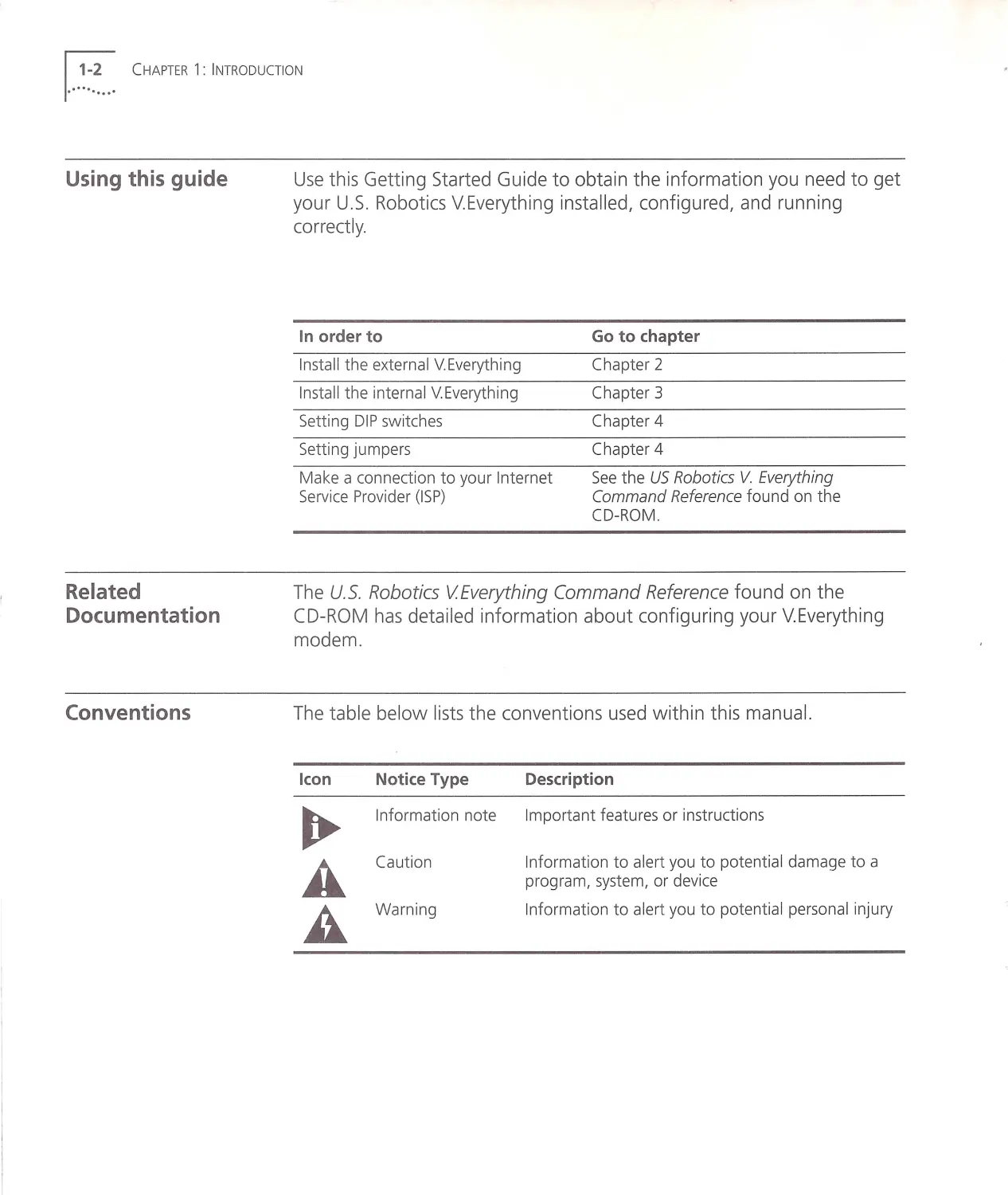
Using this guide
Related
Documentation
Conventions
Use this Getting Started Guide to obtain the information you need to get
your U.S. Robotics V.E verything installed, configured , and running
correctl y.
In order to
Go to ch apter
Install th e ext ernal V. Everything
Chapter 2
In st all the internal V. Every thing
Chapter 3
Setting DIP switch es
Chapter 4
Setting jumpers
Chapter 4
Make a connection to your Internet
Service Prov id er (ISP )
See the US Robotics V. Everything
Command Reference found on the
CD-ROM.
The U.S . Robotics VEverything Command Reference found on the
CD-RO M has detailed information about configuring your V.Everything
modem.
The table belo w lists the conventions used within this manual.
Icon
Notice Type
Information note
Cauti o n
Wa rning
Description
Imp o rt ant features or instruction s
Information to alert you to potential damage to a
program, system, or device
Information to alert you to potential personal injury
Contacting 3Com
Contacting 3Com ...~~.~. . .1
Please contact 3Com if you have any questions.
To do this
Contact Technical Support
Use the Fa x-on-Demand service
Contact
1.800 .231.8770
7a.m.to8p.m.CST
Monday - Friday
1.800 .762.6163
Download updated V.Everything code from 847 .2 62.6000
the 3Com Bulletin Board System
Download updated V.Everything code from http://totalservice.usr.com
the TOTALservice Online web site.
Visit the 3Com web site
http://www.3com.com
1. ..~ ~~... CHAPTER 1 : INTRODUCTION
2.······ ....... ·
What you need
INSTALLING THE EXTERNAL
V.EVERYTHING
Use this chapter to install the external V. Everything.
•
What you need
•
Package Contents
•
Installing your external V.Everything
•
Testing the installation
You need the following to install your V.Everything:
•
Computer or terminal with a serial port (16650 UART recommended)
•
Analog telephone line
•
Communications software
WARNING: The U.S . Robotics VEverything requires a standard, analog
telephone line . Do not connect your V Everything to a digital telephone
line. Digital lines are commonly used in office buildings and hotels. If you
are unsure whether your line is analog or digital, ask your network
administrator or your local telephone company
1.. .~~.~... CHAPTER 2: INSTALLING THE EXTERN AL V .EVER YTHING
Package contents
Installing your
external
V.Everything
Your U.S. Robotics V.Everything package contains the following items:
•
The U.S . Robotics V.Everything modem
•
Power adapter
•
Telephone cable
•
Quick Reference card
•
Customer Support card
•
This Getting Started manual
•
The Connections CD-ROM, which contains :
•
The U.S. Robotics V.Everything Command Reference Guide
•
Special offers
•
Updated U.S. Robotics V.Everything INF file
You need a serial cable to connect your modem to your computer
Because there are a variety of connector types that different computers
require, a serial cable is not provided with your modem. Many users may
already have an existing modem and serial cable
To install your external V.Everything, do the following :
Step One: Configure your U.S. Robotics V.Everything with DIP (dual in-line
package) switches
Step Two : Choose a serial cable
Step Three : Connect the cables
Step One:
Configuring with DIP
Switches
Step Two: Choosing a
Se rial Cable
1
Installing your external V.Everything .. .~---~. .. ,
You may need to change your DIP switch settings . See Chapter 4,
Configuring your Modem with DIP Sw itches and Jumpers for more
information .
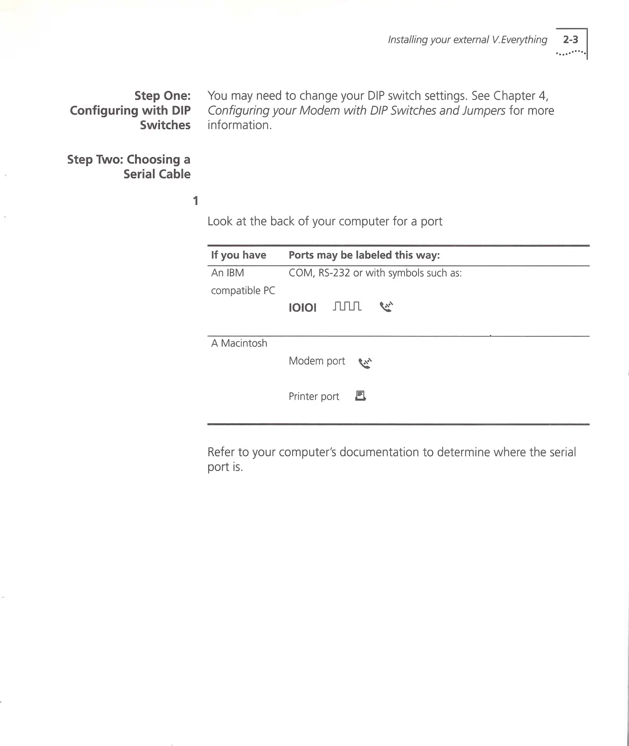
Loo k at the back of your computer for a port
If you have
An IBM
compatible PC
A Macintosh
Ports may be labeled this way:
COM, RS-232 or w ith sym bols such as
10101 nml ~'
Modem port ~'
Prin ter port J!L
Refer to your computer's documentation t o determine w here the serial
port is .
1...~~~... CH APTER 2 : INSTALLING THE EXTERN AL V .E VERYTHING
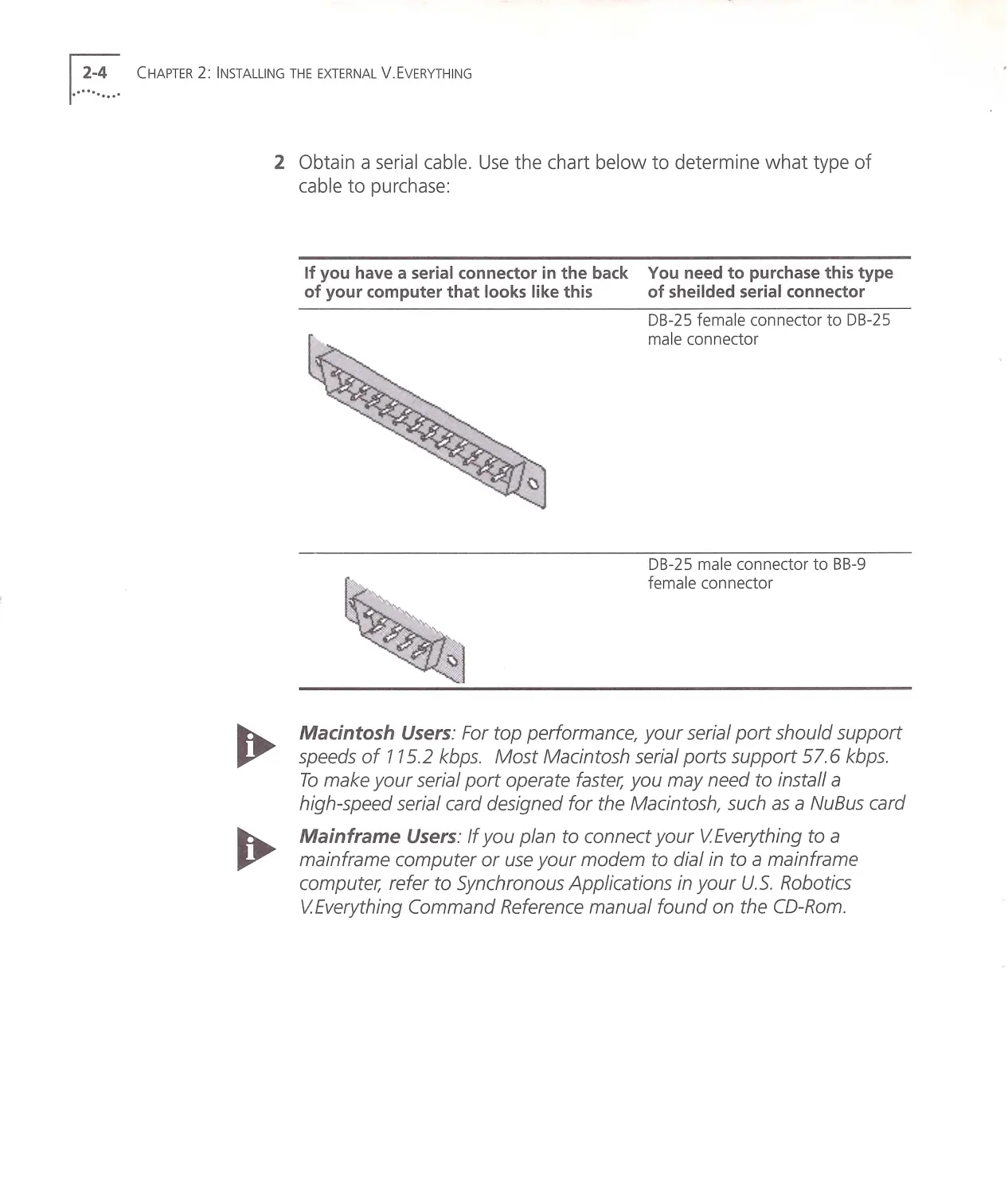
2 Obtain a serial cable. Use the chart below to determine what type of
cable to purchase:
If you have a serial conn ector in the back You need to purch ase this type
of your computer th at looks like this
of sh eilded seria l connector
DB-25 fema le connector to DB -2 5
male connector
DB-25 ma le connector to BB-9
fema le connector
Macintosh Users : For top performance, your serial port should support
speeds of 115.2 kbps . Most Macintosh serial ports support 57.6 kbps .
To make your serial port operate faster, you may need to install a
high-speed serial card designed for the Macintosh, such as a NuBus card
Mainframe Users: If you plan to connect y our VEverything to a
mainframe computer or use your modem to dial in to a mainframe
computer, refer to Synchronous Applications in your U.S. Robotics
VEverything Command Reference manual found on the CD-Rom .
Step Three:
Connecting the
Cables
Installing your external V.Everything ...~~.~. ..1
~I
r!
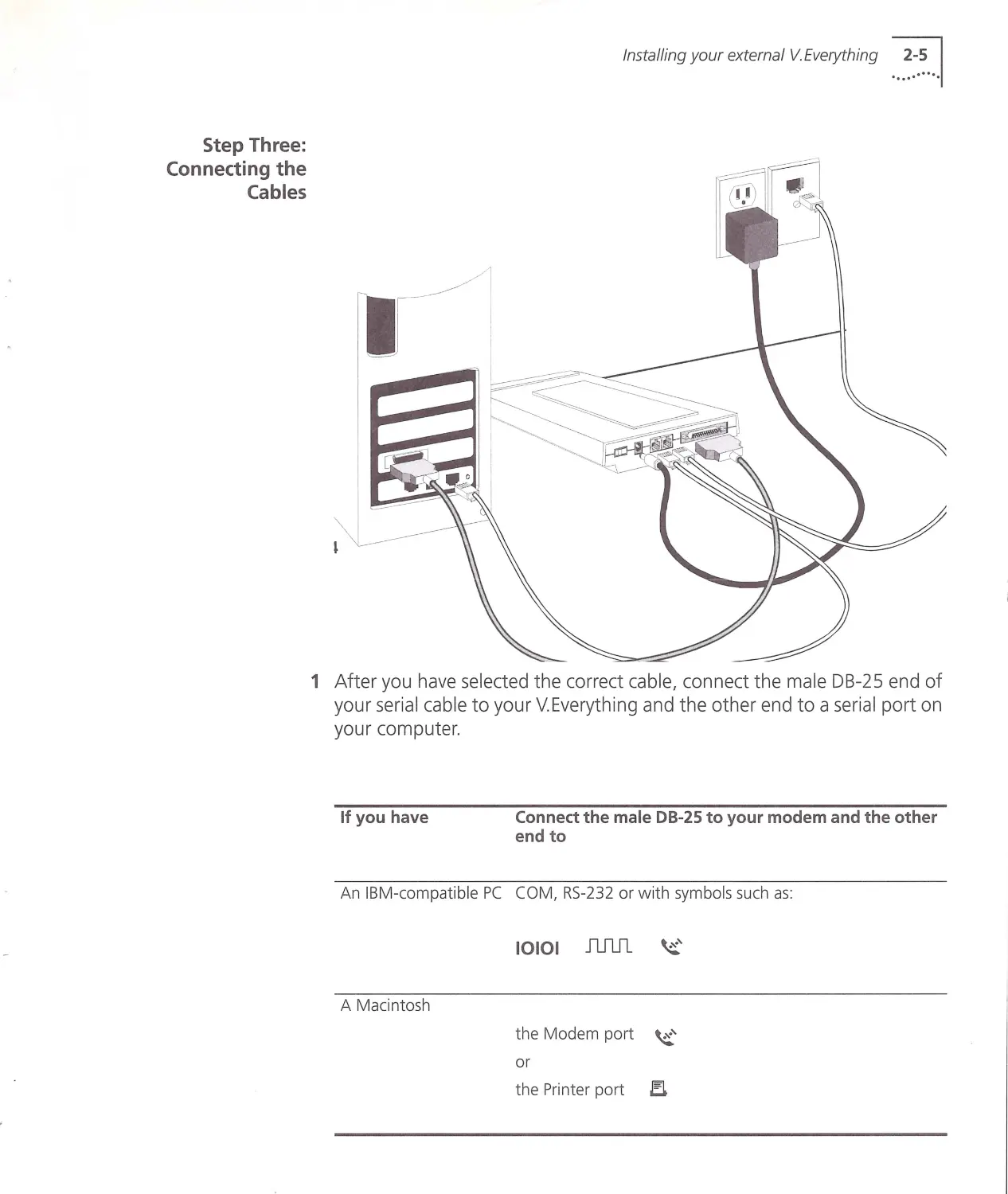
1 After you have selected the correct cable, connect the male DB-25 end of
your serial cable to your V.Everything and the other end to a serial port on
your computer.
If you have
Connect the male DB-25 to your modem and the other
end to
An IBM-compatible PC COM, RS -232 or with symbols such as:
A Macintosh
10101 JU1J1 ~'
the Modem port ~'
or
the Printer port EL
!...~~.~... CHAPTER 2: INSTALLING THE EXTERN AL V .E VER YTHING
Test ing the
Installation
Write down the number of the serial port to which you connect your
VEverything. If your serial ports are lettered instead of numbered, A is
COM 1 and B is COM2. If you cannot find a serial port, consult the
documentation that came with your computer.
2 Connect one end of the phone cable to the wall jack and the other end
to your V.Everything port labeled JACK.
3 If you have a telephone that you'd like to connect to your modem, plug
the phone cable into the your modem port labeled PHONE.
4 Plug one end of the power adapter to your V.Everything and the other
end to a standard AC power outlet.
5 Turn on your computer.
To test the installation of your modem, use any communications software
package, such as Windows Terminal, HyperTerminal, Procomm Plus, or
RapidComm . HyperTerminal is used in this documentation as an example.
Every communications program is different; consult the documentation
that came with your communications program for more information.
1 Run HyperTerminal.
2 When the first window appears, enter the name of your connection in
the Name field and click OK.
3 Enter the phone number you want to dial and click OK. If you only want
to test your modem , you may enter any number.
4 See the table below.
In order to
Cl ic k this button
Dial a number
Dial
Test without dialing a number Cancel
When the HyperTerminal terminal window appears, type AT and hit
<ENTER> . If your modem is connected properly, "OK" will appear on the
terminal screen.
You are now ready to configure your V.Everything . See Chapter 4,
Configuring the V.Everything with DIP Switches and Jumpers.
3.······ ....... ·
What you need
INSTALLING THE INTERNAL
V.EVERYTHING
This chapter contains the following information :
•
What you need
•
Package Contents
•
Important Note about Plug and Play
•
Installing your internal V.Everything
•
Testing your insta llation
You need the following to install your V.Everything:
•
IBM-compatible computer with a free ISA interface ca rd slot
•
Analog telephone line
•
Communications software
WARNING: The U.S . Robotics VEverything requires a standard, analog
telephone line. Do not connect your V Everything to a digital telephone
line. Digital lines are commonly used in office buildings and hotels. Ifyou
are unsure whether your line is analog or digital, ask your network
administrator or your local telephone company
1...~~~... CH A PTER 3: INSTALLING THE INTERNAL V.EVERYTHING
Package Contents
Important note
about Plug and Play
If your compute r is
Plug and Pl ay
complia nt
Your V.Everything package contains the following items:
•
The U.S. Robotics V.Everything modem
•
Telephone cable
•
Quick Reference card
•
Customer Support card
•
This Getting Started manual
•
The Connections CD-ROM, which contains:
•
U.S. Robotics V.Everything Command Reference Guide
•
Special offers
•
Updated V.Everything INF file
The V.Everything must be assigned a unique communications (COM) port
number and a unique interrupt request (IRQ) number.
If you are using a computer with a Plug and Play compliant BIOS and
operating system, set the V.Everything's jumpers to Plug and Play (the
default). Your computer's operating system will take care of the COM and
IRQ settings for you.
First, determine whether your computer has a Plug and Play ISA bus.
Check your computer's documentation to be sure. Keep these points
about Plug and Play in mind:
•
Your computer's operating system must support Plug and Play
(examples of those that do: OS/2 Warp, Windows 95/98), or your
computer's manufacturer must supply you with Plug and Play
software .
•
Your computer's Basic lnpuVOutput System (BIOS) must support Plug
and Play.
If your computer
does not support
Plug and Play
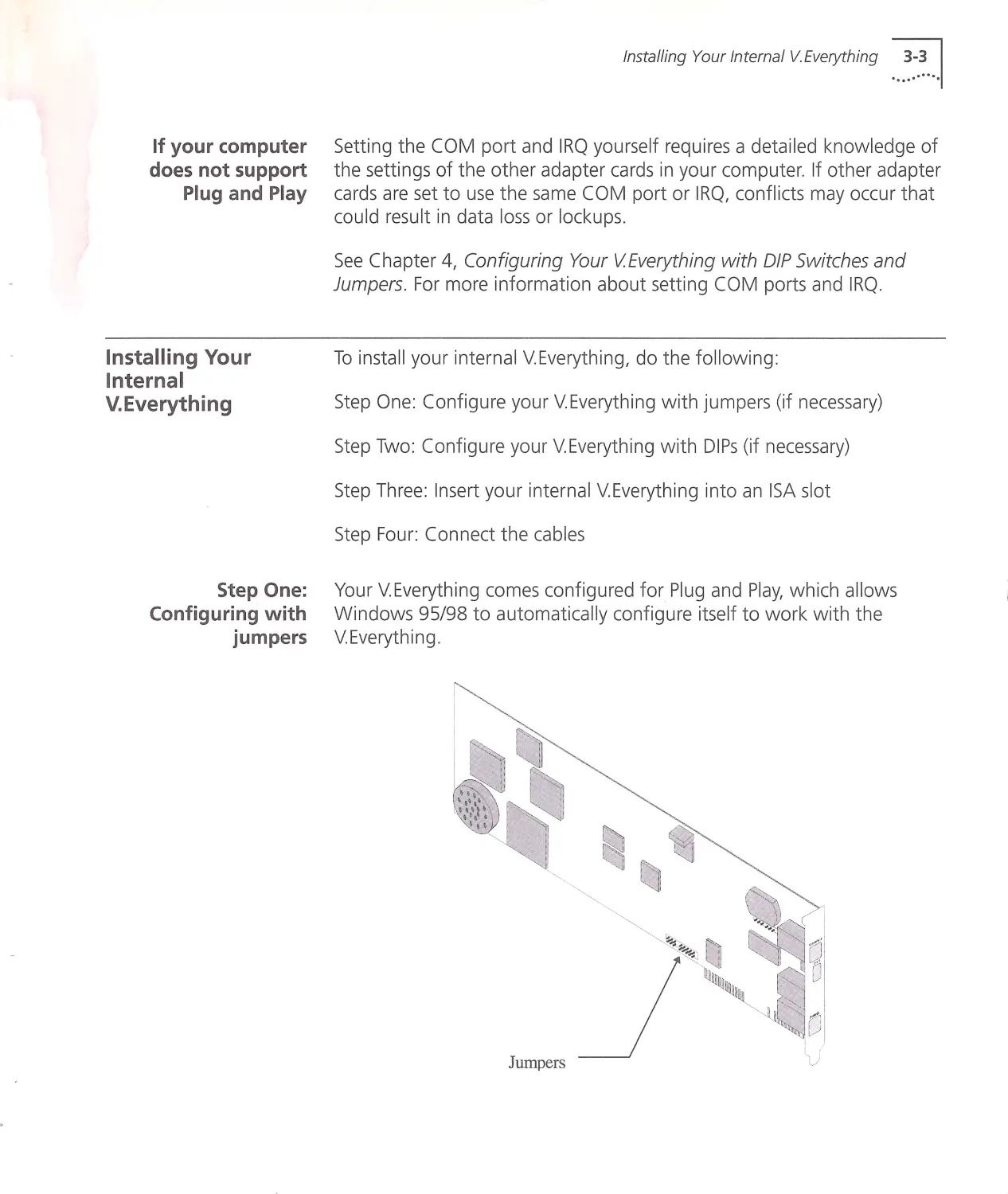
Installing Your
Internal
V.Everything
Step One:
Configuring with
jumpers
Installing Your Internal V.Everything ...~~.: ...1
Setting the COM port and IRQ yourself requires a detailed kno w ledge of
the settings of the other adapter cards in your computer. If other adapter
cards are set to use the same COM port or IRQ, conflicts may occur that
could result in data loss or lockups .
See Chapter 4, Configuring Your VEverything with DIP Switches and
Jumpers . For more information about setting COM ports and IRQ.
To install your internal V.Everything, do the follow ing:
Step One: Configure your V.Everything with jumpers (if necessary)
Step Two: Configure your V.Eve rything with DIPs (if necessary)
Step Three: Insert your internal V.Everything into an ISA slot
Step Four: Connect the cables
Your V.Everything comes configured for Plug and Play, which allows
Windows 95/98 to automatically configure itself to work with the
V.Everything .
Jumpers
1...~~~... CH APTER 3: INSTA LLING THE INTERNAL V.EVERYTH ING
Step Two:
Configuring with DIP
Switches
Step Three: Inserting
the Modem into an
ISA slot
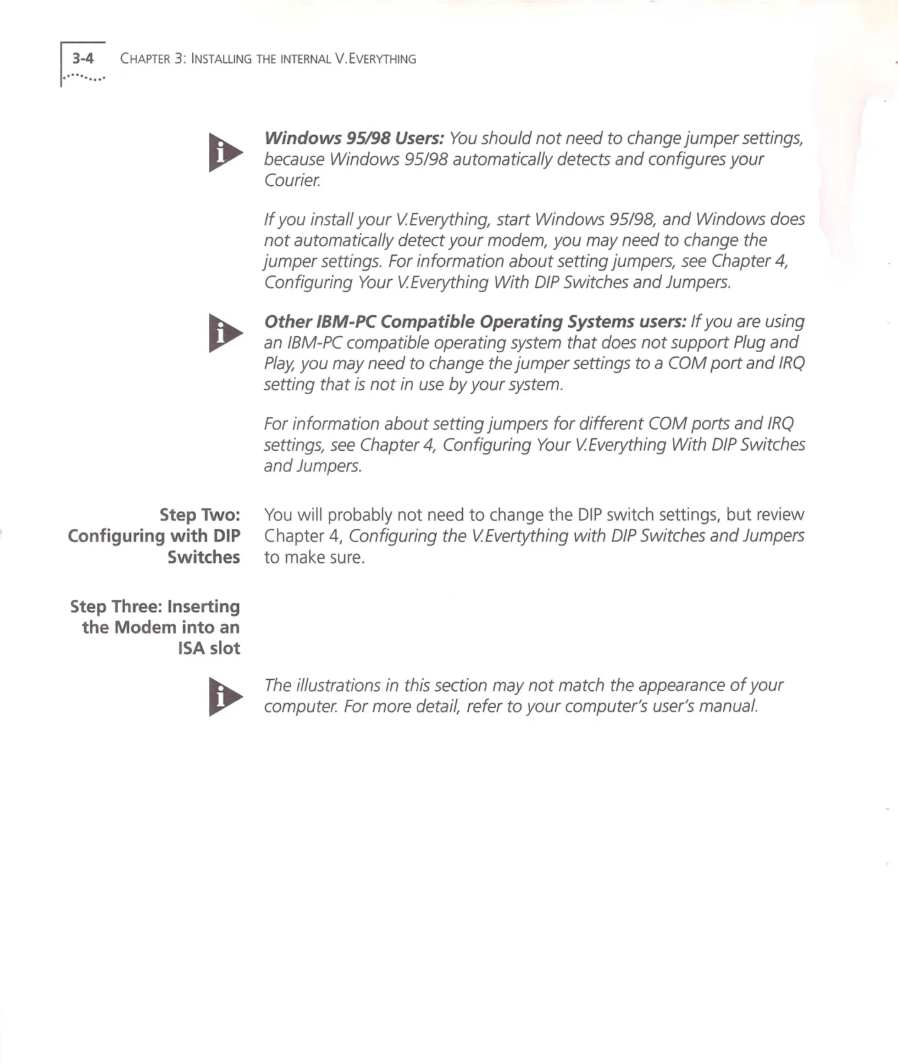
Windows 95198 Users : You should not need to change jumper settings,
because Windows 95198 automatically detects and configures your
Courier
If you install your VEverything, start Windows 95198, and Windows does
not automatically detect your modem, you may need to change the
jumper settings . For information about setting jumpers, see Chapter 4,
Configuring Your VEverything With DIP Switches and Jumpers.
Other IBM-PC Compatible Operating Systems users: If you are using
an IBM-PC compatible operating system that does not support Plug and
Play, you may need to change the jumper settings to a COM port and IRQ
setting that is not in use by your system .
For information about setting jumpers for different COM ports and IRQ
settings, see Chapter 4, Configuring Your VEverything With DIP Switches
and Jumpers.
You w ill probably not need to change the DIP switch settings, but review
Chapter 4, Configuring the VEvertything w ith DIP Switches and Jumpers
to make sure .
The illustrations in this section may not match the appearance of your
computer. For more detail, refer to your computer's user 's manual.
Installing Your Internal V.Everything ...~:.~ ...1
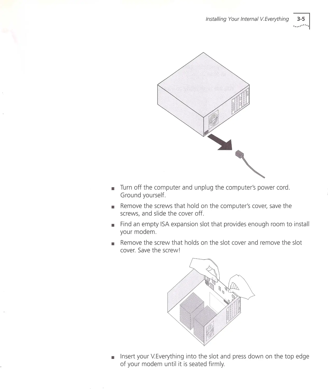
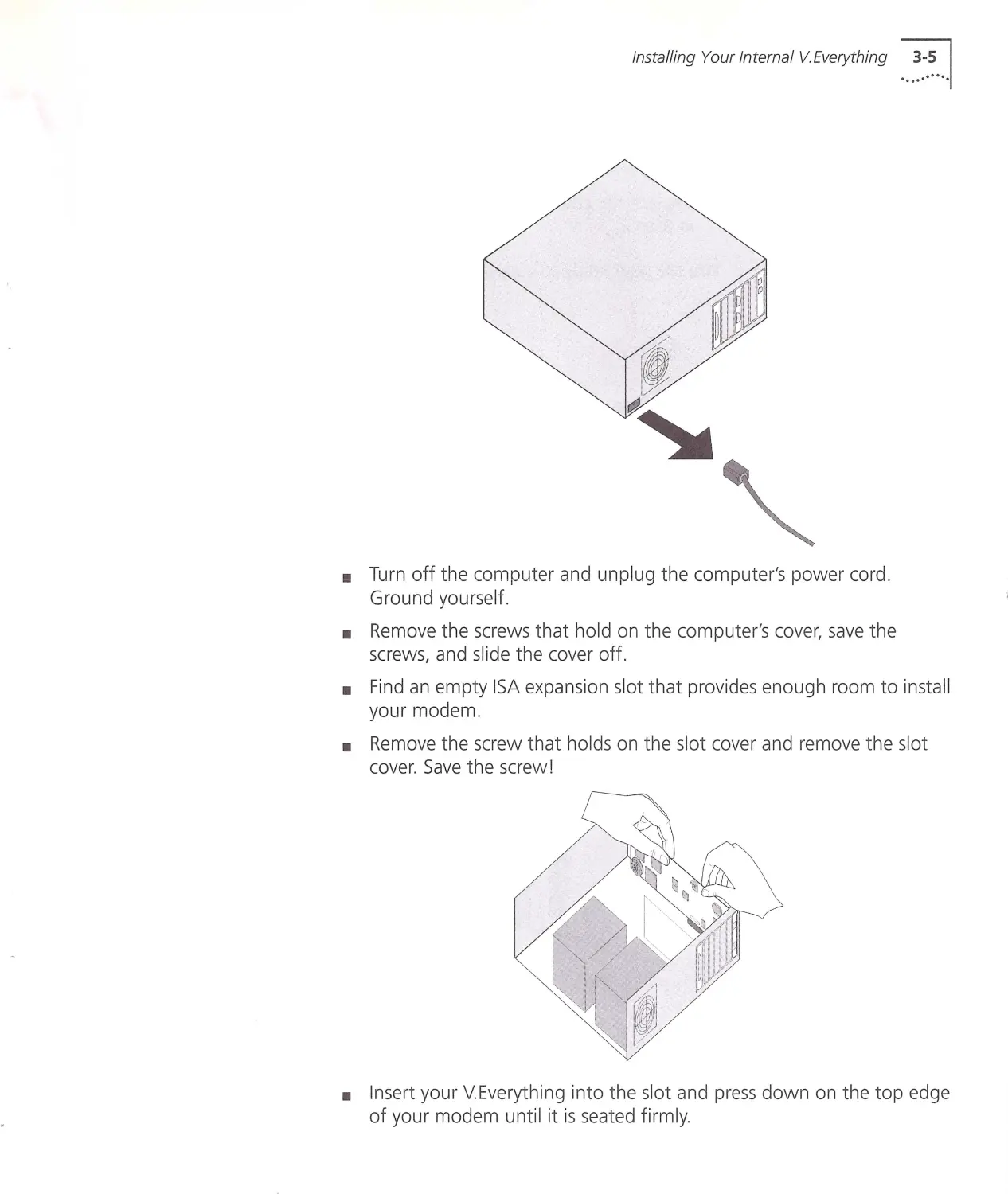
11 Turn off the computer and unplug the computer's power cord.
Ground yourself.
•
Remove the screws that hold on the computer's cover, save the
screws, and slide the cover off.
•
Find an empty ISA expansion slot that provides enough room to install
your modem.
•
Remove the screw that holds on the slot cover and remove the slot
cover. Save the screw!
•
Insert your V.Everything into the slot and press down on the top edge
of your modem until it is seated firmly.
1...~~.~. .. CHA PTER 3: INSTALLING THE INTERN AL V .E VERYTHIN G
Step Four:
Connecting the
Cables
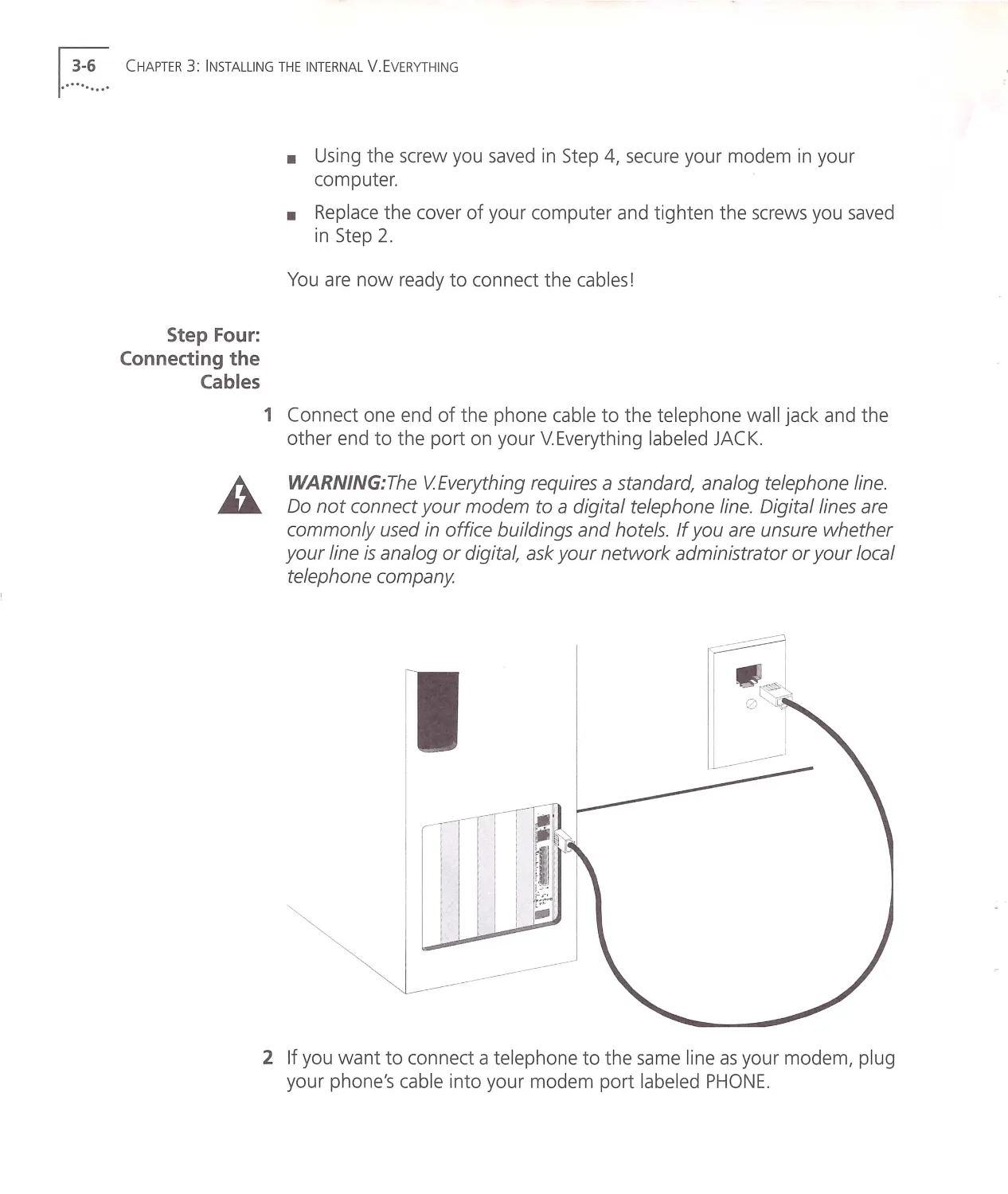
•
Using the screw you sa ved in Step 4, secu re your modem in your
computer.
•
Replace the cover of you r computer and tighten the screws you saved
in Step 2.
You are now ready to connect the cables!
1 Connect one end of the phone cable to the telephone wall jack and the
other end to the port on your V.Everything labeled JACK.
WARNING: The VEverything requires a standard, analog telephone line.
Do not connect your modem to a digital telephone line. Digital lines are
commonly used in office buildings and hotels. If you are unsure w hether
your line is analog or digital, ask your network administrator or your local
telephone company
2 If you want to connect a telephone to the same line as your mod em, plug
your phone's cable into your modem port labe led PHONE .
Installing Your Internal V.Everything ...~~.~...1
11 Turn off the computer and unplug the computer's power cord .
Ground yourself.
•
Remove the screws that hold on the computer's cover, save the
screws, and slide the cover off.
•
Find an empty ISA expansion slot that provides enough room to install
your modem .
•
Remove the screw that holds on the slot cover and remove the slot
cover. Save the screw!
•
Insert your V.Everything into the slot and press down on the top edge
of your modem until it is seated firmly.
1...~~-~... C HAPTER 3 : INSTALLI NG THE INTERN AL V .E VERYTH ING
Step Four:
Connecting the
Cables
•
Using the screw you sav ed in Step 4, secure your modem in your
computer.
•
Replace the cover of you r computer and tighten the screws you saved
in Step 2.
You are now ready to connect the cables!
1 Connect one end of the phone cable to the telephone wall jack and the
other end to the port on your V.Everything labeled JACK.
WARNING: The VEverything requires a standard, analog telephone line.
Do not connect your modem to a digital telephone line. Digital lines are
commonly used in office buildings and hotels. If you are unsure w hether
your line is analog or digital, ask your network administrator or your local
telephone company
2 If you want to connect a telephone to the same line as your modem, plug
your phone's cable into your modem port labe led PHONE .
Testing the
Installation
Testing the Installa tion ...~~.~ . . . 1
To test the installation of your modem , use any communication s softw are
pac kage, such as Windows Terminal , HyperTerminal, Procomm Plus , or
RapidComm . HyperTe rminal is used in this documentation as an example .
Every communication s program is different; consult the documentation
that came w ith your communications program for more information .
1 Run HyperTerminal.
2 When the first w indow appears, enter the name of your connection in
the Name field and click OK.
3 Enter the phone number you w ant to dial into and click OK. If you only
want to test your modem, you may enter any number.
4
In order to
Click this button
Dial a number
Dial
Test w ithout dialing a number
Cancel
5 When the Hyp erTermin al terminal w indow appears , type AT and hit
< ENTER >. If your modem is connected properly, "O K " w ill app ear on the
terminal screen.
You are now ready to configure your V.Everything! See Chapter 4,
Configuring the V.Everything w ith DIP Switches and Jumpe rs.
1...~ ~.~... CHAPTER 3: INSTALLING THE INTERN AL V .E VERYTHING
4......
.
.
·······
DIP switches on the
external
V.Everything
CONFIGURING THE V.EVERYTHING
WITH DIP SWITCHES AND
JUMPERS
This chapter contains information about:
•
DIP switches on the external V. Everything
•
DIP switches on the internal V. Ever ything
•
Jumpers on the internal modem
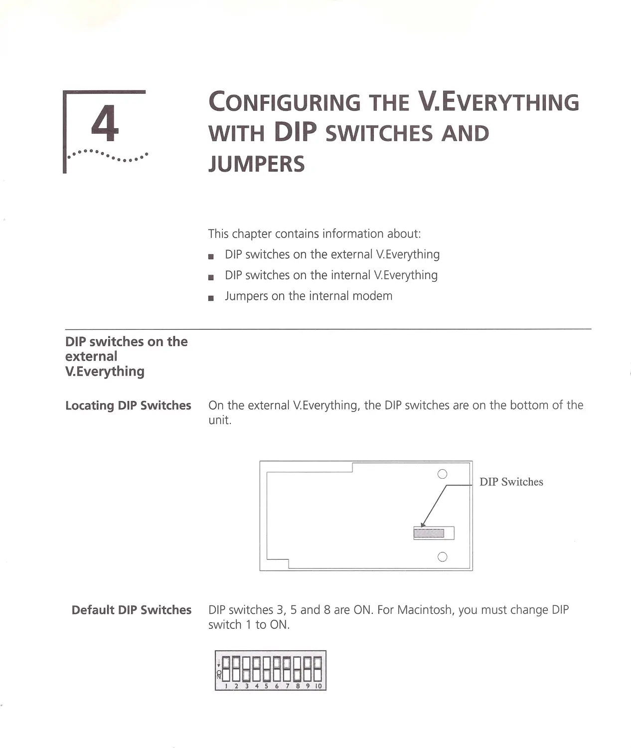
Locating DIP Switches On the external V.Everything, the DIP switches are on the bottom of t he
unit.
0
DIP Switches
0
Default DIP Switches DIP sw itches 3, 5 and 8 are ON. For M acintosh, you mu st chan ge DIP
switch 1toON.
~B88B88BBBB
I2345678910
1.. ~~.~... CH APTER 4: CONFIGURING THE V .E VER YTHING W ITH DIP SW ITCHES AND JU M PERS
DIP Switches on the
Internal
V.Everything
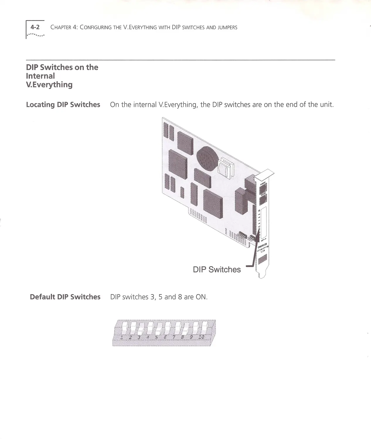
Locating DIP Switches On the internal V. Everything, the DIP switches are on the end of the unit.
DIP Switches
Default DIP Switches DIP sw itches 3, 5 and 8 are ON .
DIP Switches on the Internal V.Every t h in g ...::.~ .. .1
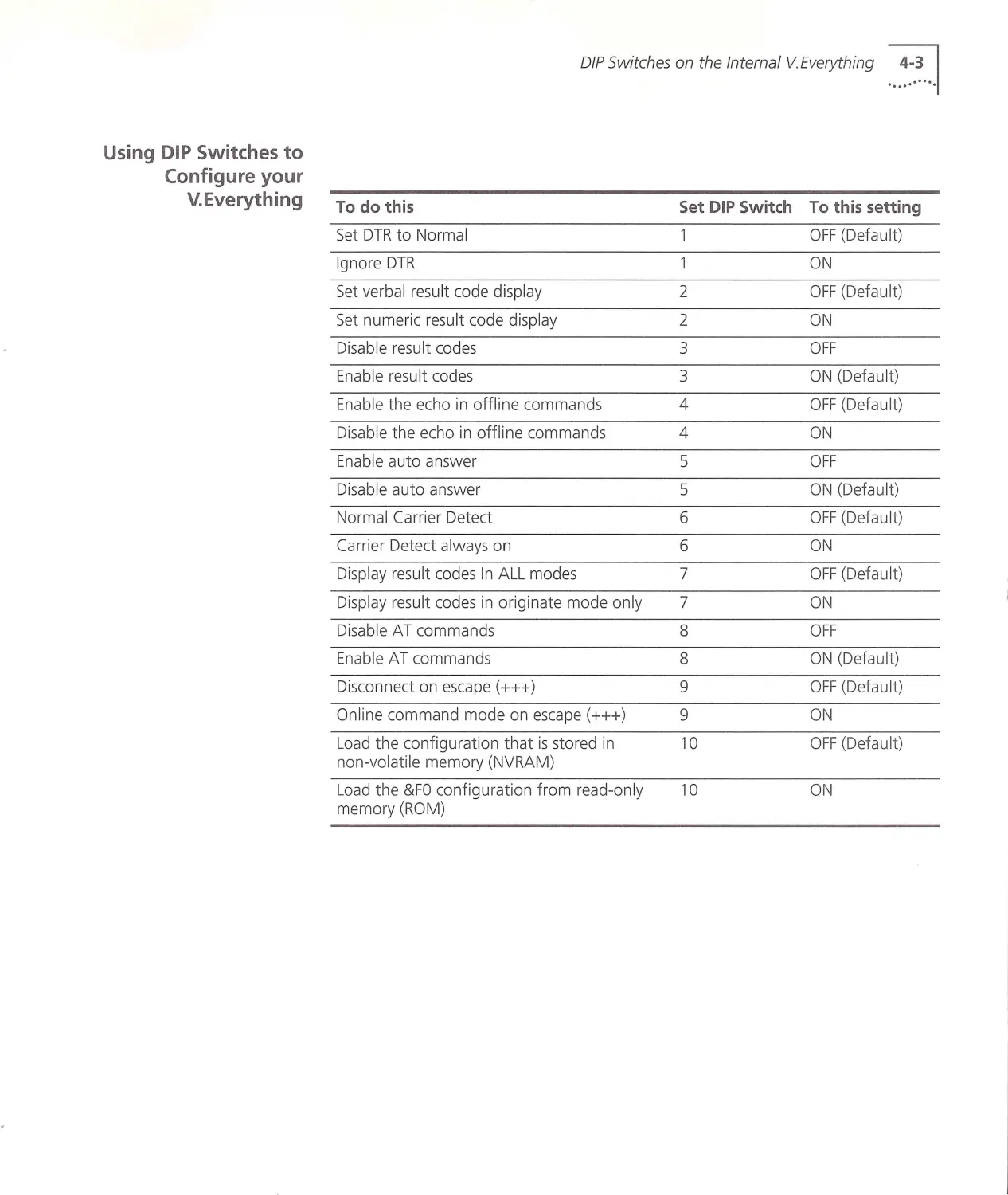
Using DIP Switches to
Configure your
V.Everything To do this
Set DIP Switch To this setting
Set DTR to Normal
OFF (Default)
Ignore DTR
1
ON
Set ve rba l result code d isplay
2
OFF (Default)
Set numeric result code d isplay
2
ON
Disable result codes
3
OFF
Enable result codes
3
ON (Defau lt)
Enab le the echo in offl ine command s
4
OFF (D efault)
Disable the echo in offline commands
4
ON
Enable auto answer
5
OFF
Disable auto ans w er
5
ON (Default)
Normal Carrier Detect
6
OFF (Defau lt )
Carrier Detect al w ays on
6
ON
Disp lay result codes In ALL modes
7
OFF (D efault)
Displa y result codes in orig inate mode only
7
ON
Disab le A T commands
8
OFF
Ena bl e AT command s
8
ON (Defa ult)
Disconnect on escape (+++)
9
OFF (Defa u lt)
Online command mode on escape (+++)
9
ON
Load the configuration that is stored in
10
OFF (Defau lt)
non-volatile memory (NVRA M)
Load th e & FO configuration from read -onl y
10
ON
m emory (ROM)
!..~~~... CH APTER 4: CONF IGURING THE V .E VERYTH ING WITH DIP SWITCHES AN D JU MPERS
Jumpers on the
Internal
V.Everything
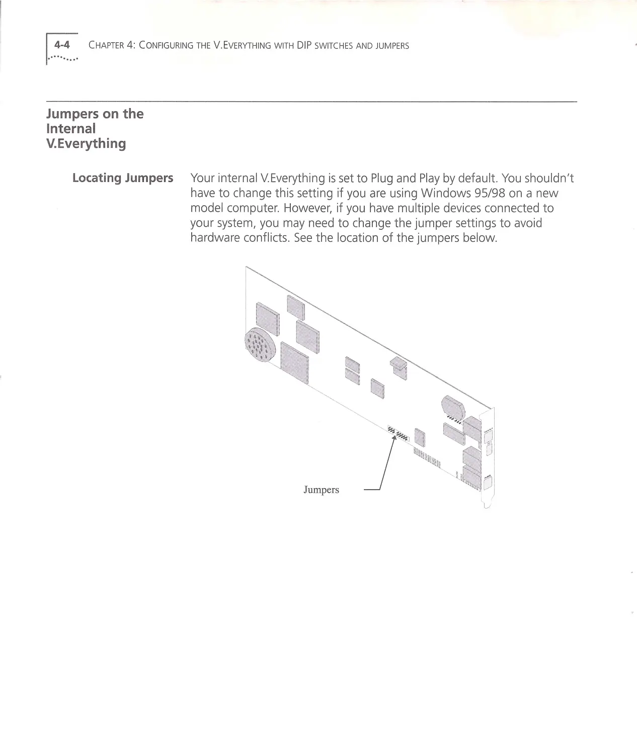
Locating Jumpers Your internal V.Everything is set to Plug and Play by default. You shouldn't
have to change this setting if you are using Windows 95/98 on a ne w
model computer. However, if you have multiple devices connected to
your system, you may need to change the jumper settings to avoid
hardware conflicts . See the location of the jumpers below.
Jumpe rs
Changing Jumper
Settings
Jumpers on the Internal V.Everything ...:~.~.. .1
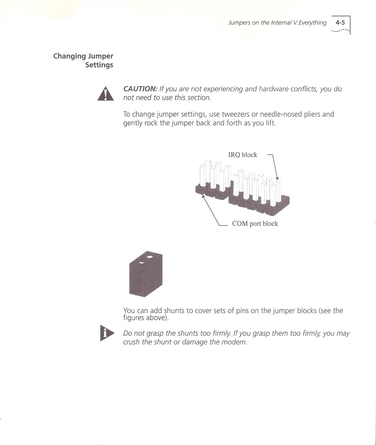
CAUTION: If you are not experiencing and hardware conflicts, you do
not need to use this section.
To change jumper settings, use tweezers or needle-nosed pliers and
gently rock the jumper back and forth as you lift.
COM port block
You can add shunts to cover sets of pins on the jumper blocks (see the
figures above).
Do not grasp the shunts too firmly If you grasp them too firmly, you may
crush the shunt or damage the modem.
1.. ~~.~... CH APTER 4: CONFIGURING THE V.EVERYTHING WITH DIP SWITCHES AND JUMPERS
Setting Jumpers for a
Specific COM Port
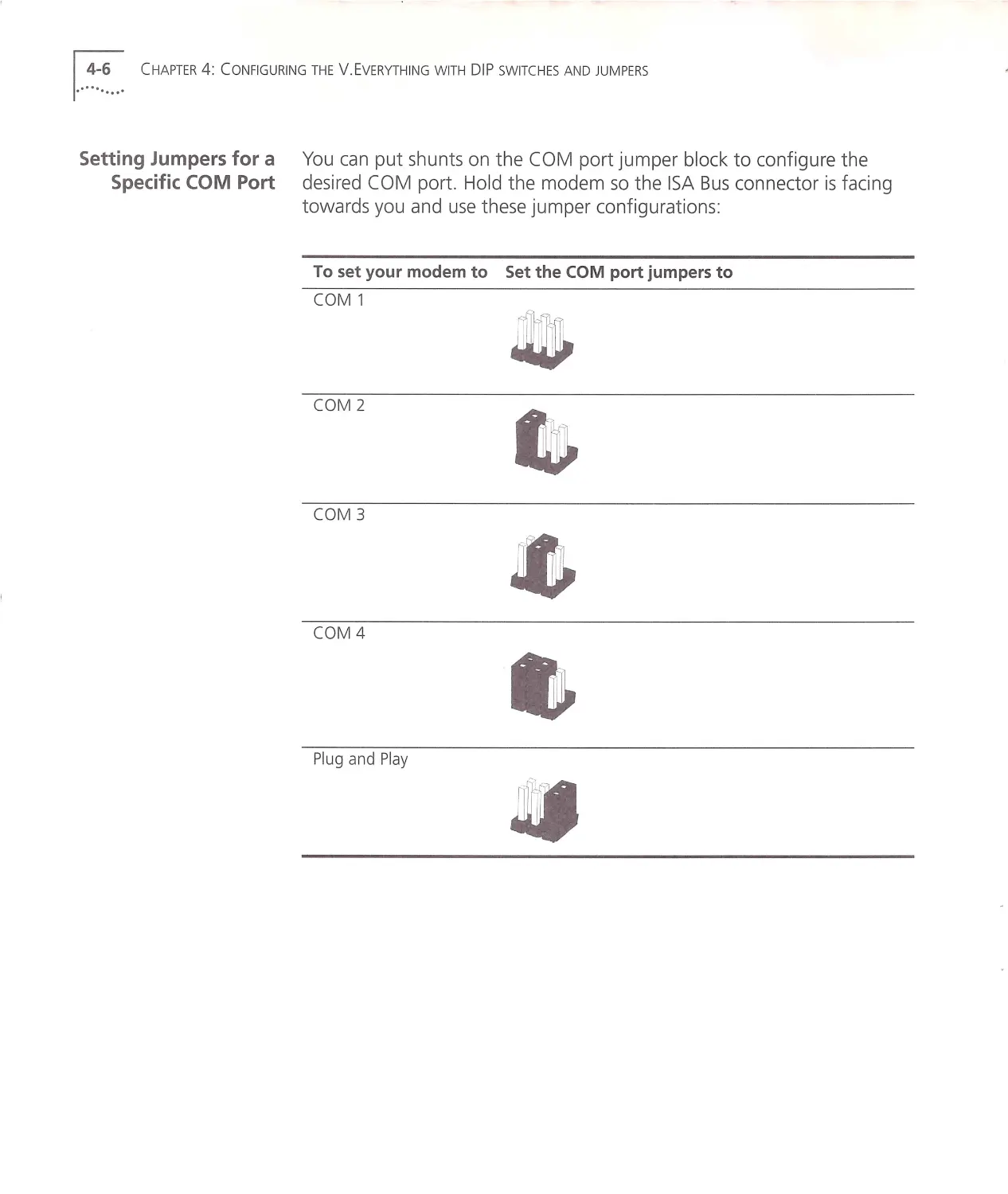
You can put shunts on the COM port jumper block to configure the
desired CO M port. Hold the modem so the ISA Bus connector is facing
towards you and use these jumper configurations:
To set your modem to Set the COM port jumpers to
COM 1
COM 2
COM 3
COM 4
Plug and Play
~~]
....,
Setting Jumpers for a
Specific IRQ
Jumpers on the Internal V. Everything ...~~.~ . . .!
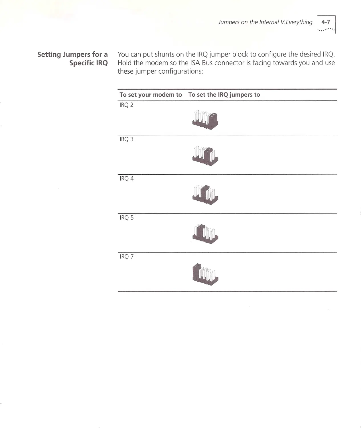
You can put shunts on the IRQ jumper block to configure the desired IRQ .
Hold the modem so the ISA Bus connector is facing towards you and use
these jumper configurations:
To set your mod em to To set the IRQ jumpers to
IRQ 2
IRQ 3
IRQ 4
IRQ 5
IRQ 7
1.. ~~.~... CHAPTER 4: CONFIGURING THE V .E VER YTHING W ITH DIP SW ITCHE S AND JUMPERS
INDEX
c
CAUTION
4-5
Changing Jumper Settings 4-5
Configuring the V.Eve rything with DIP switches and
jumpers 4-1
Contacting 3Com 1-3
Conventions 1-2
D
Default DIP Switches 4-1 4 -2
DIP switches on the exter~al V.Everything 4 -1
DIP Switches on the Internal V. Everyth ing 4-2
If your computer does not support Plug and
Play 3-3
If your computer is Plug and Play compliant 3-2
Important note about Plug and Play 3-2
Installing the external V. Everything 2-1
Installing the internal V. Everything 3-1
Installing your external V. Everything 2-2
Installing Your Internal V.Everyth ing 3-3
Introduction 1-1
J
Jumpers on the Internal V.Everything 4-4
L
Locating DIP Switches 4-1, 4-2
Locating Jumpers 4 -4
p
Package Contents 3-2
Package contents 2-2
R
INDE X •••• ~····.I
Related Documentation 1-2
s
Setting Jumpers for a Specific COM Port 4-6
Setting Jumpers for a Specific IRQ 4-7
Step Four
Connecting the Cables 3-6
Step One
Configuring with DIP Switches 2-3
Configu ring w ith jumpers 3-3
Step Three
Connecting the Cables 2-5
Inserting the Modem into an ISA slot 3-4
Step Two
T
Choosing a Serial Cable 2-3
Configuring w ith DIP Switches 3-4
Testing the Installation 2-6, 3-7
u
UNITED STATE S GOVERNMENT LEGEND 2
Using DIP Switches to Configure your
V.Everything 4-3
Using this guide 1-2
w
WARNING
3-6
2-1, 3-1
What you need 2-1, 3-1
®
3Com Corporation
5400 Bayfront Plaza
f'O. Box 58145
Santa Clara, CA
95052-8145
©1998
3Com Corporation
All rights reserved
Printed in the U.SA
p/n 1.024.1 154-02